/


Author: Zimmer Vincent Rothman Michael Marisetty Suresh
Tags: programming software
ISBN: 978-1-5015-1478-4
Year: 2017
Similar


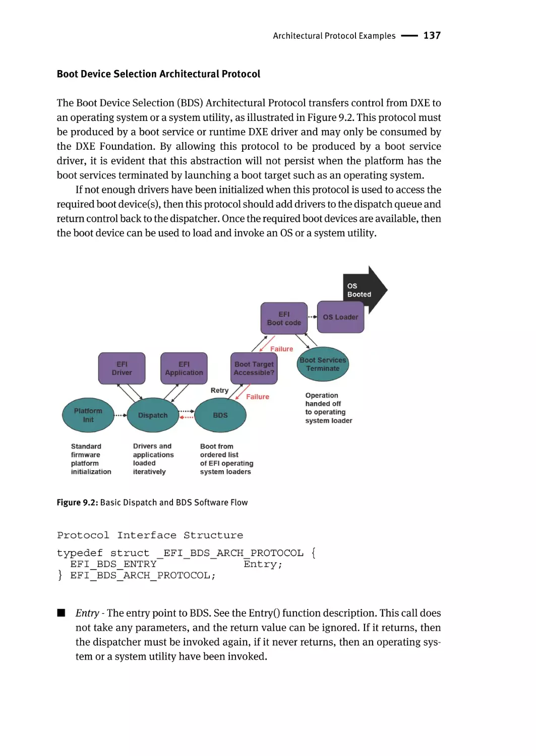
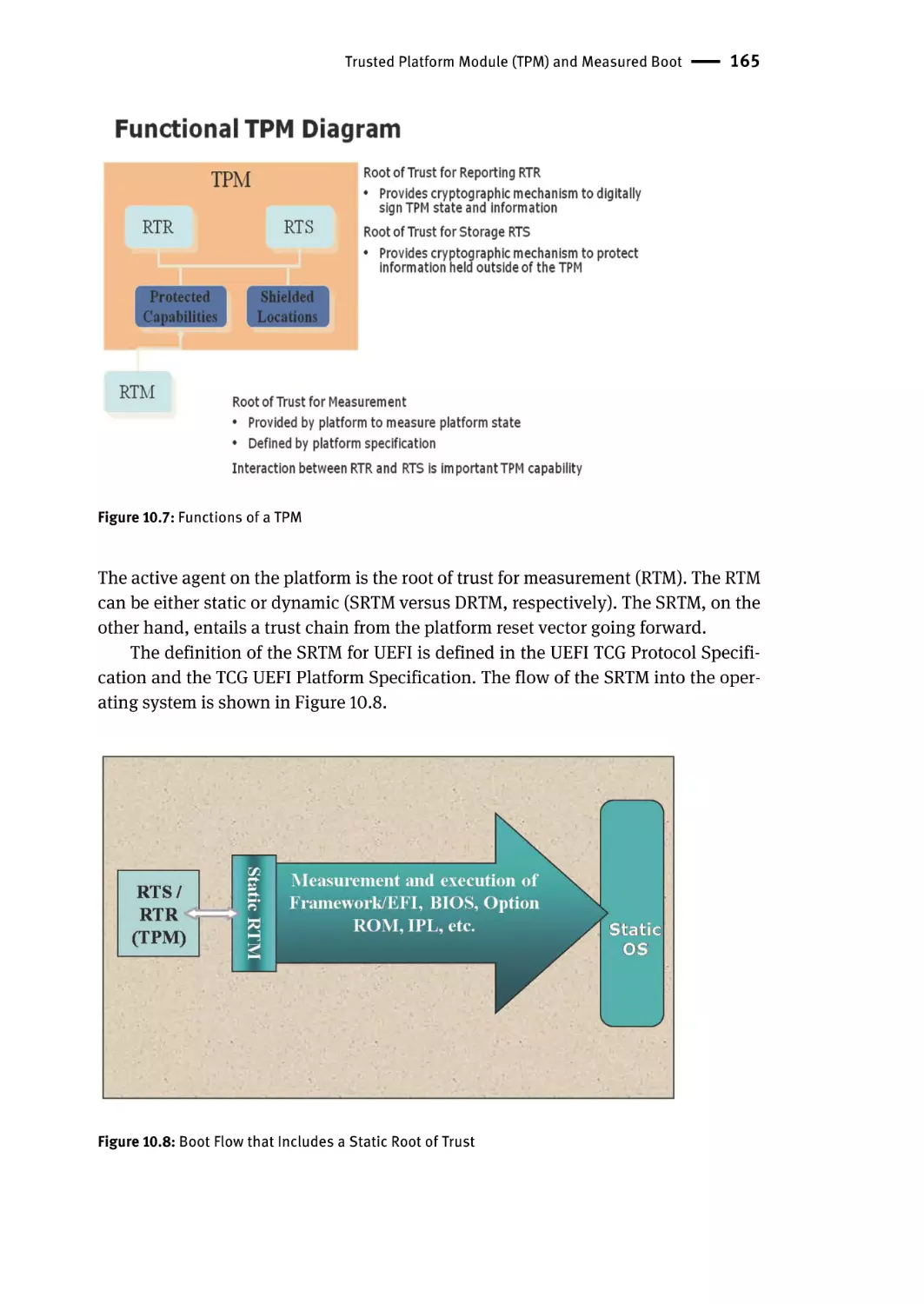
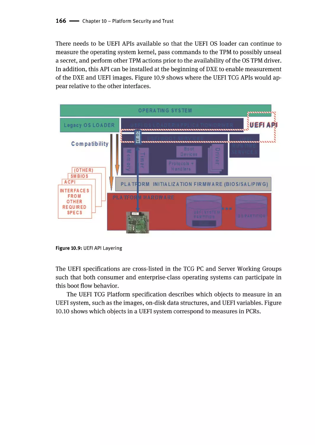
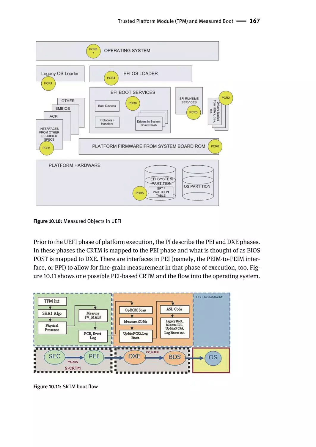
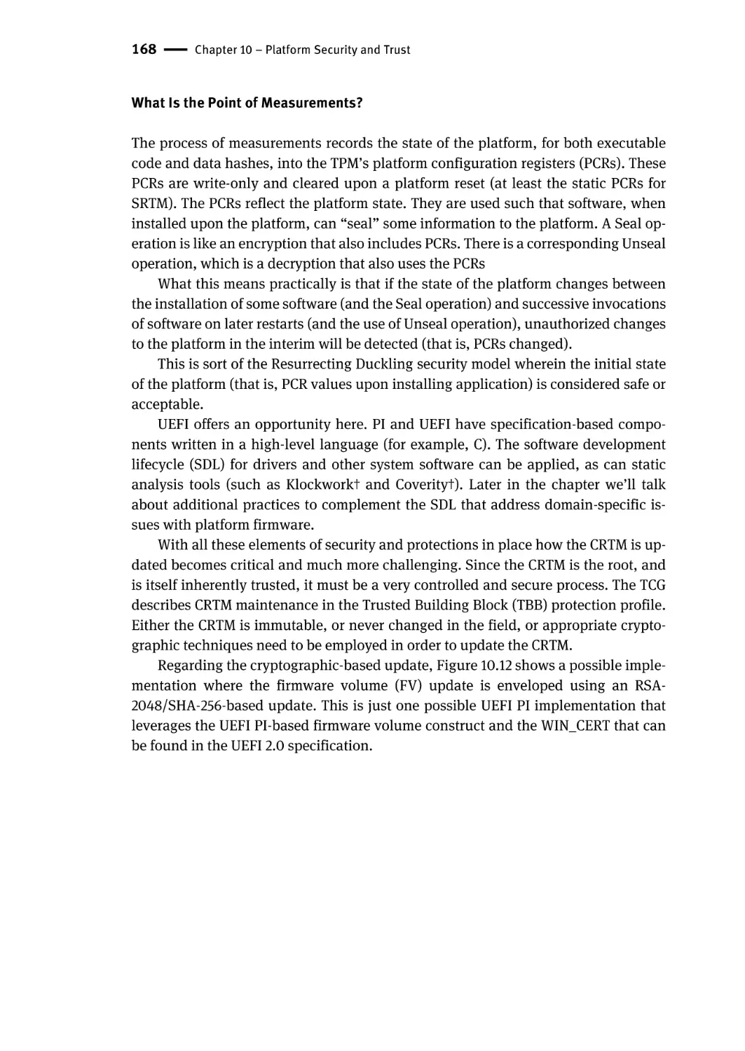
Text
Vincent Zimmer, Suresh Marisetty, Michael Rothman
Beyond BIOS
Developing with the Unified Extensible Firmware Interface
Vincent Zimmer
Suresh Marisetty
Michael Rothman
Beyond BIOS
Developing with the
Unified Extensible Firmware Interface
Third Edition
PRESS
ISBN 978-1-5015-1478-4
e-ISBN (PDF) 978-1-5015-0569-0
e-ISBN (EPUB) 978-1-5015-0583-6
Library of Congress Cataloging-in-Publication Data
A CIP catalog record for this book has been applied for at the Library of Congress.
Bibliographic information published by the Deutsche Nationalbibliothek
The Deutsche Nationalbibliothek lists this publication in the Deutsche Nationalbibliografie;
detailed bibliographic data are available on the Internet at http://dnb.dnb.de.
© 2017 Walter de Gruyter Inc., Boston/Berlin
Printing and binding: CPI books GmbH, Leck
♾ Printed on acid-free paper
Printed in Germany
www.degruyter.com
Acknowledgements
The authors recognize the efforts and contribution of the two men and a dog: Mark
Doran, Ken Reneris, and Andrew Fish, who conceived and hatched EFI.
The authors recognize and thank the other original Framework (Tiano) architects Andrew Fish, Bob Hale, Mike Kinney, Barnes Cooper, Will Stevens, Krithivas,
ER Uber, Mahesh Natu, Rahul Khanna, Jim Ewertz, Kirk Brannock, and others
whose names are lost to time and the team’s intrepid leader, Mark Doran. We thank
Isaac Oram, John Lambino, and the entire Tiano Architecture Team (TAT) team for
fleshing out and enhancing the architecture. Thank you to the Tiano engineering
team for their patience while implementing the first versions and to our internal and
external customers. The innovation in this book is from these fertile brains. Also,
many of this team will recall over ten years of “design discussions” at R&R.
We thank our managers, past and present, for giving us the chance and the time
to work on the architecture and this book including Doug Fisher, Richard Wirt, Stu
Goossen, Mike Richmond, Kah Loh, Jeff Griffen, Michael Greene, Ju Lu, and Ron
Story.
We acknowledge the ever-supportive marketing team: Shala, Laurie, Harry,
Fadi, Elmer, and Bailey.
No Intel book is published without peer review. We’d like to thank all the reviewers for identifying errors and for providing valuable insight and encouragement
along the way. Without their help, this book would not have been a success. From
Intel, these individuals participated, at one time or another, in the review of this
project: Rob Branch, Mallik Bulusu, Brad Davis, Michael Krau, John Suresh Kumar,
Matthew Parrish, Mike Richmond, Lee Rosenbaum, and Sudhakar Otturu. Other
reviewers included Cameron Esfahani from Apple Computer Corporation, Todd
Greene from QLogic Corporation, Penny Huang from Micro-Star International Company, Limited, Jimmy Hwang from American Megatrends, Incorporated, and Dong
Wei from Hewlett-Packard Development Company, L.P.
A book like this describes the efforts of a large number of talented individuals.
The authors would like to thank all of them for their efforts and support. Please
accept our apologies if we missed you. We can only say that space is as limited here
as it is in ROMs and time as limited here as it is in schedules. We’ll try to fix it in the
next release.
DOI 10.1515/9781501505690-001
Preface
There are two mistakes one can make on the road to truth…not going all the way, and not
starting.
Buddha
This is a book about a new way to solve an old set of problems that are persistent as
well as fundamental, but not always well understood: How should you boot a computer? What sits at the reset vector? What can the operating system count on when it
is loaded and initially receives control? What should the internal structures be between these two endpoints? How can the same basic structure work for handhelds
and megaservers? How do we convince ourselves today’s design will work 10 or 20
years from now? How much will it cost to switch? How much will it cost steady
state? What comes after BIOS (Basic Input/Output System)?
Beyond BIOS is a book about a largely invisible subject. The general user, if they
have any view of BIOS at all, tends to view it as ten unnecessary seconds on the way
to booting the operating system or as setup. The community that knows and uses
the BIOS has tended to view it as an uncontrolled place of kludge, myth, bug, and
legend. The very small community of BIOS developers has viewed their code not
only as highly mutable and embodying much of the compatibility that has made the
PC and its offspring so successful, but also as their livelihood.
This is a book that is about what comes after BIOS, which we call the Unified Extensible Firmware Interface (UEFI) and Platform Initialization (PI). In doing so, it
must also be a book at least partly about what a BIOS or its replacement is called
upon to do. It is not a cookbook on how to port the PI from platform to platform. It is
not a rehash of the specifications. Instead, it tries to fit in the middle ground between specifications and cookbook. It tries to focus on the concepts and constructs
that are cross-platform and implied, if not stated, by the architecture. It is supposed
to help to get to some of the “why” behind the specs and make the porting work
make some sense.
This book is a child of its time. Both the UEFI and the PI are under the control of
the UEFI Forum, an industry-wide group in which you are encouraged to participate. Beyond BIOS mainly focuses on the current state of the PI and UEFI since the
2005 formation of the Forum, its working groups, and its sub-teams. This is not to
say that this is only a history book or a simple summary of the standard. Instead, we
believe it remains valuable as an introduction to the newer versions of the specifications no matter who “has the pen.”
If you find this book to be useful, then we encourage you to obtain Harnessing the
UEFI Shell: Moving the Platform beyond DOS by Rothman, Zimmer and Lewis, De|G
Press, February 2017.
DOI 10.1515/9781501505690-002
viii | Preface
The Chapters
Chapter 1 provides a description of the evolution.
The rest of the book is organized into two major sections. The earlier chapters present an introduction to UEFI, and the later chapters cover the Platform Initialization.
Chapter 2 provides an overview of the basic UEFI architecture. This is a must-read
for anyone seeking an understanding of the Unified Extensible Firmware Interface
(UEFI).
Chapter 3 describes the UEFI driver model. This is important for vendors writing
device drivers for output devices (such as video), input devices (such as keyboards
or mice), networking adapters, and block devices. These drivers can be stored in the
host-bus adapter, the platform ROM, or loaded from the UEFI system partition.
Chapter 4 describes of series of commonly used UEFI protocols. This chapter complements the earlier two chapters and includes data on additional boot services
application interfaces.
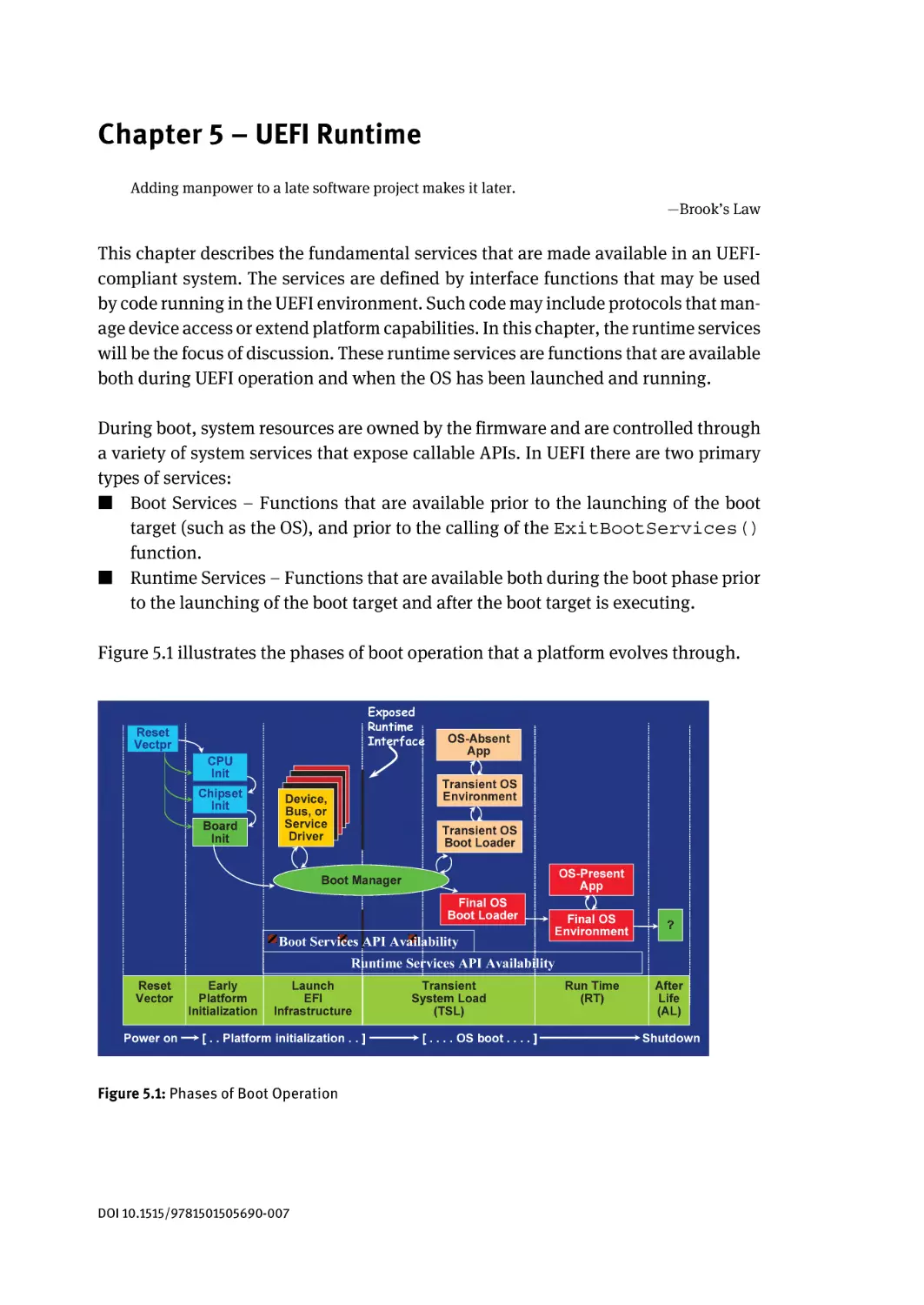
Chapter 5 includes information on the UEFI runtime operational environment. This
chapter is important for operating system vendors who need to interact with the
platform during the operating system execution.
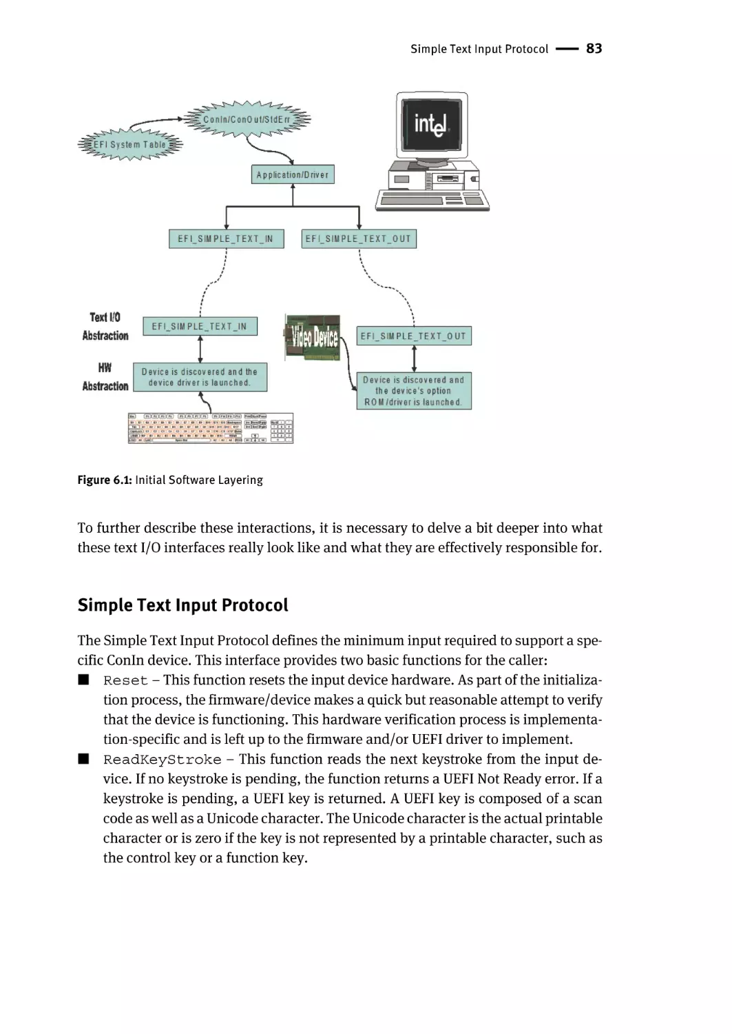
Chapter 6 describes UEFI input and output console services. This chapter provides
details on the particular capabilities, interfaces, and relationships of the console
services.
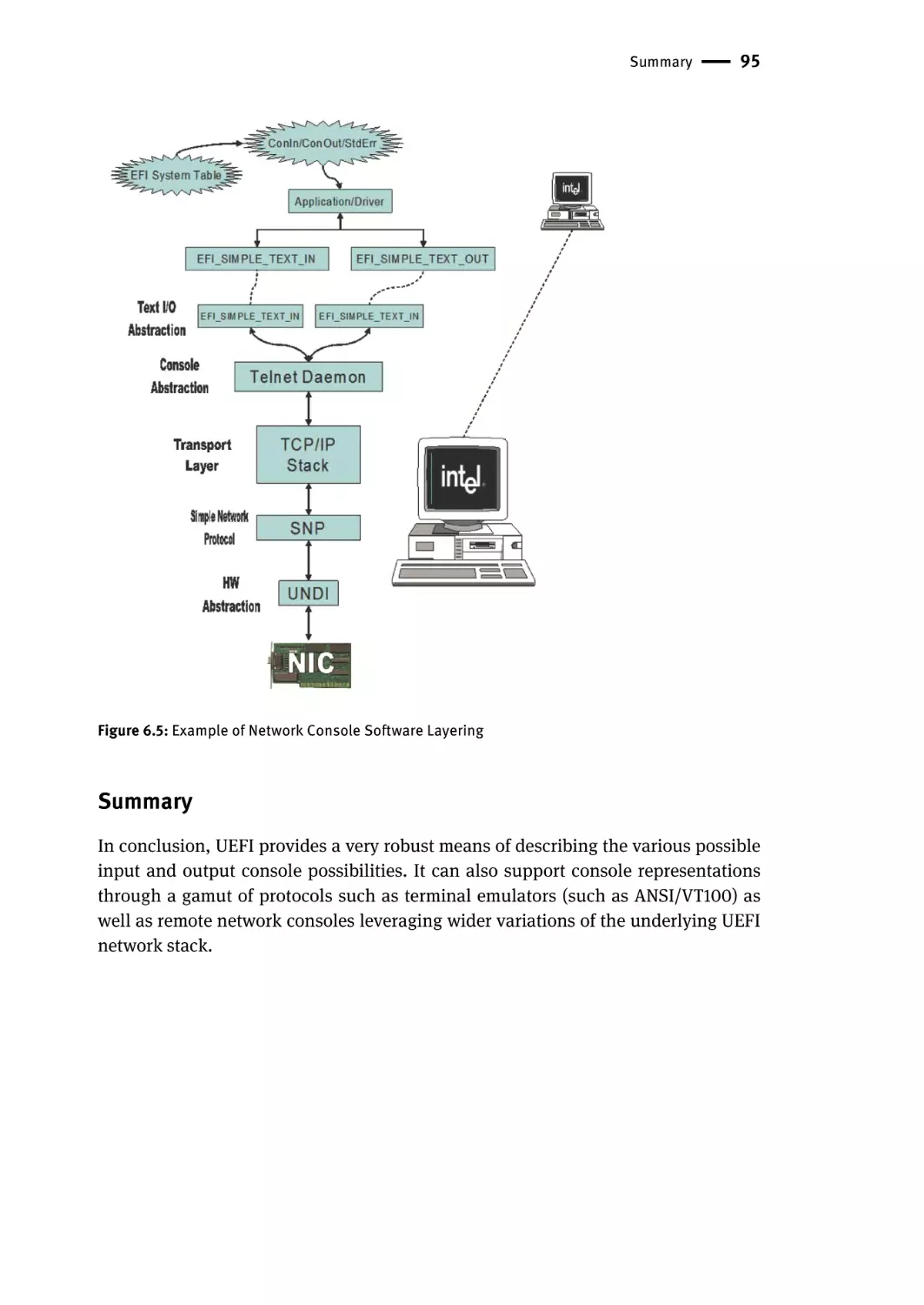
Chapter 7 includes a list of different platforms and the Platform Initialization-based
implementations. This chapter demonstrates the flexibility of the Platform Initialization by mapping the infrastructure to widely varying hardware platforms.
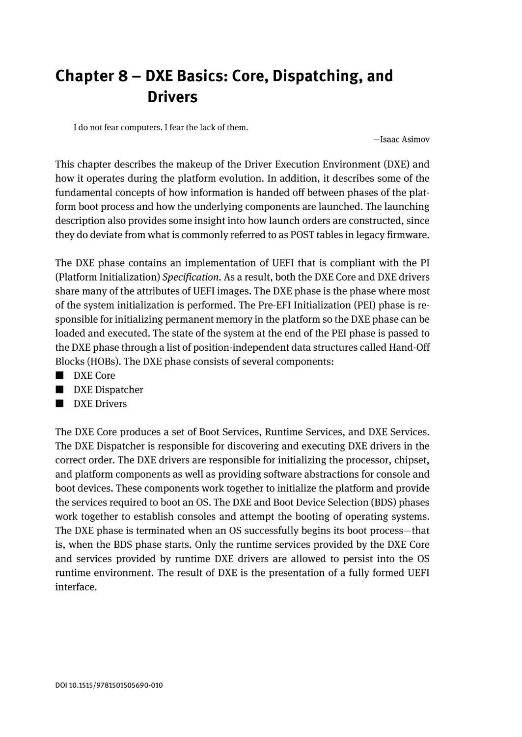
Chapter 8 describes the basics of the Platform Initialization Driver Execution Environment (DXE). This is important to read for anyone working on the phase of execution prior to UEFI service availability but after early pre-EFI initialization (PEI).
Chapter 9 describes some common UEFI interfaces. This chapter includes information on interfaces that are important for both UEFI and DXE development.
Preface | ix
Chapter 10 describes UEFI and platform initialization issues around security and
platform trust. This is important because beyond the basic UEFI and Platform Initialization specifications, which describe mechanism, further discussion is included
on composition and construction of technology.
Chapter 11 describes Boot Device Selection (BDS). This includes the policy by which
Framework platforms decide look-and-feel, in addition to how to boot.
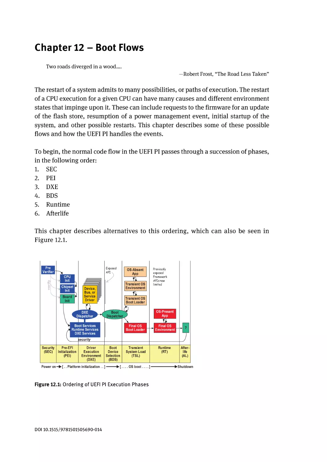
Chapter 12 describes the various boot flows that can occur within a platform. These
include power-event restarts, and so on.
Chapter 13 describes the Pre-EFI Initialization environment. This is the phase of
execution that occurs after reset and is responsible for the early hardware state and
memory initialization.
Chapter 14 includes information on emulation of a firmware environment within an
operating system.
Chapter 15 describes mechanisms and capabilities for reducing platform boot time.
Since “visible” firmware is often broken firmware, decreasing time for a system
restart is key.
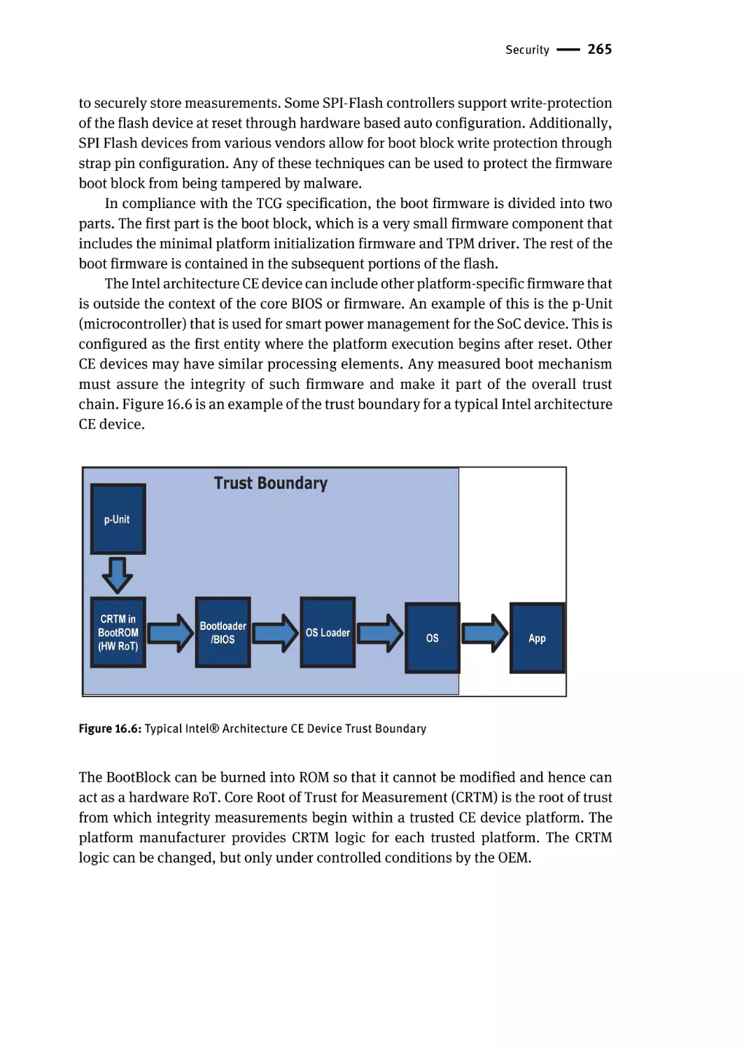
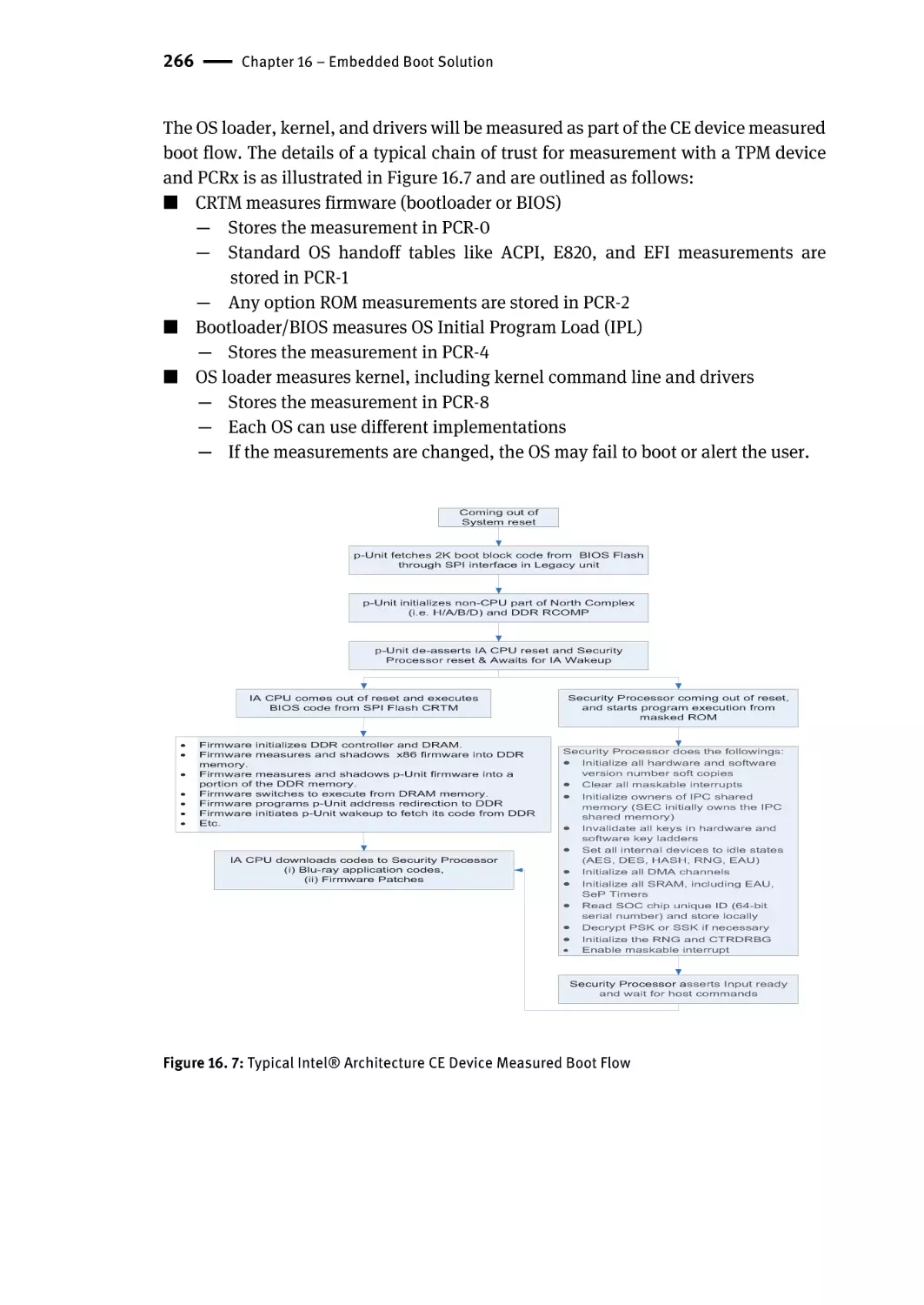
Chapter 16 describes the application of firmware for an embedded boot solution.
The bulk of shipping systems are embedded computing environments, so the use of
UEFI and Platform Initialization for this class of system is becoming more important.
Chapter 17 includes details on manageability. The platform and firmware play a
pivotal role in both bare-metal, OS-absent scenarios and also as a complement to OS
runtime manageability usages.
The Appendixes include source code data types and commonly-used interfaces.
Contents
Acknowledgements | v
Preface | vii
Chapter 1 – Introduction | 1
Terminology | 4
Short History of EFI | 5
EFI Becomes UEFI—The UEFI Forum | 6
PIWG and USWG | 8
Platform Trust/Security | 11
Embedded Systems: The New Challenge | 12
How the Boot Process Differs between a Normal Boot and an
Optimized/Embedded Boot | 13
Summary | 14
Chapter 2 – Basic UEFI Architecture | 15
Objects Managed by UEFI-based Firmware | 15
UEFI System Table | 16
Handle Database | 16
Protocols | 18
Working with Protocols | 21
Multiple Protocol Instances | 21
Tag GUID | 21
UEFI Images | 22
Applications | 25
OS Loader | 25
Drivers | 26
Events and Task Priority Levels | 27
Summary | 30
Chapter 3 – UEFI Driver Model | 31
Why a Driver Model Prior to OS Booting? | 31
Driver Initialization | 32
Host Bus Controllers | 33
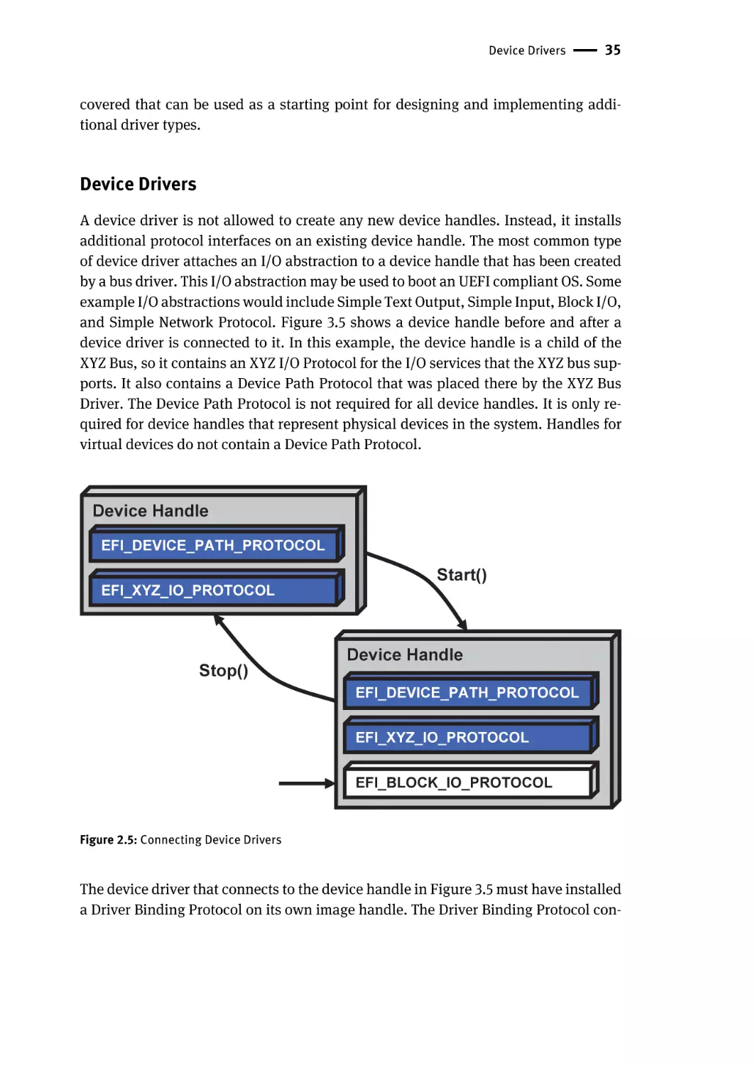
Device Drivers | 35
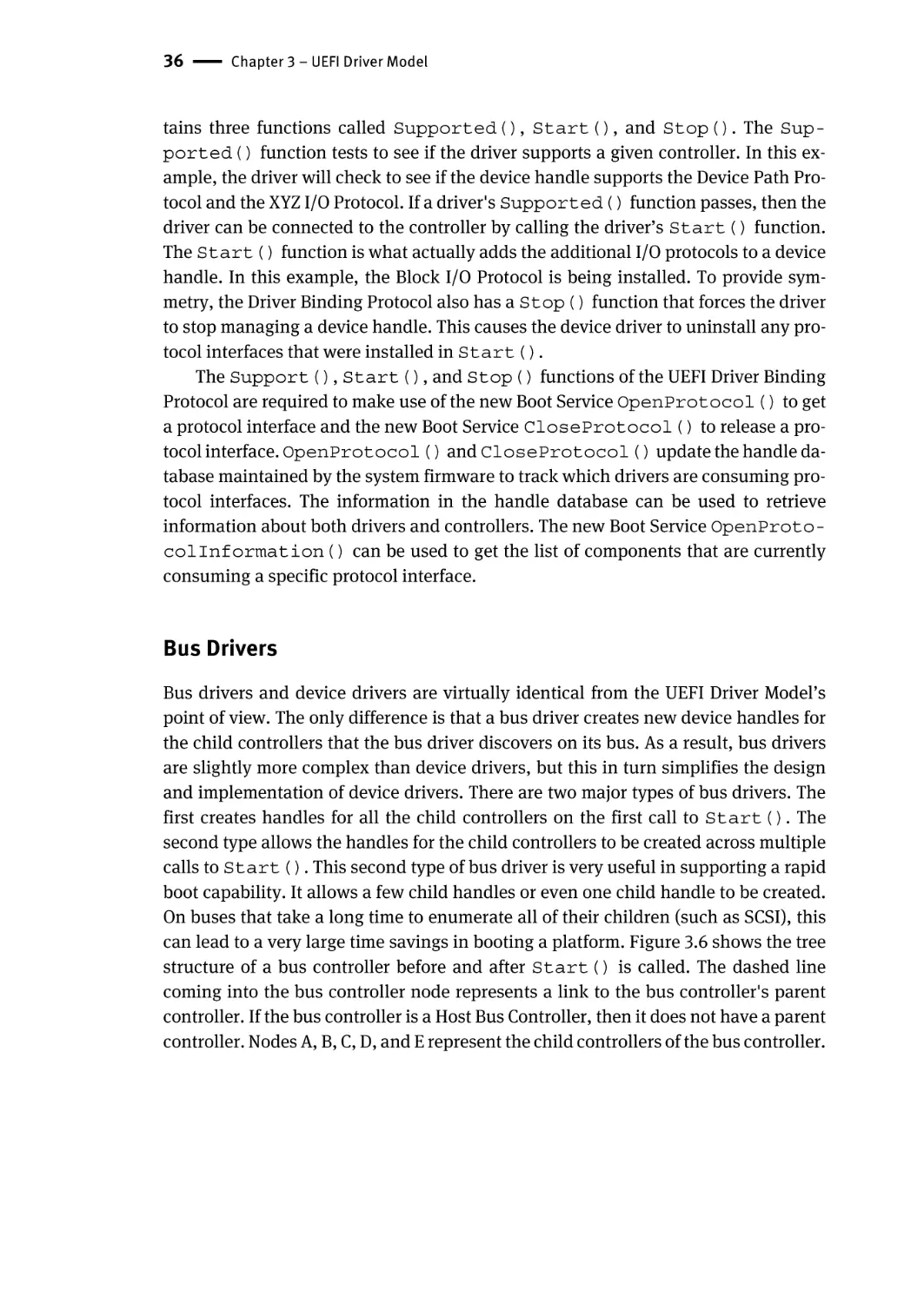
Bus Drivers | 36
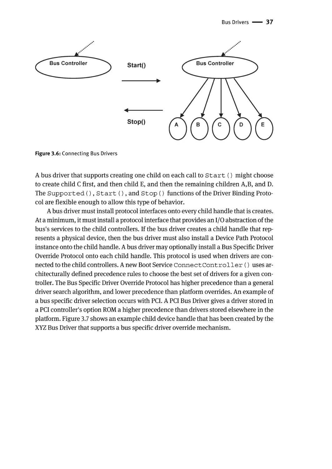
Platform Components | 38
Hot Plug Events | 38
Pseudo Code | 41
Device Driver | 41
xii | Contents
Bus Driver that Creates All of Its Child Handles on the First Call to
Start() | 42
Bus Driver that Is Able to Create All or One of Its Child Handles on Each Call
to Start(): | 43
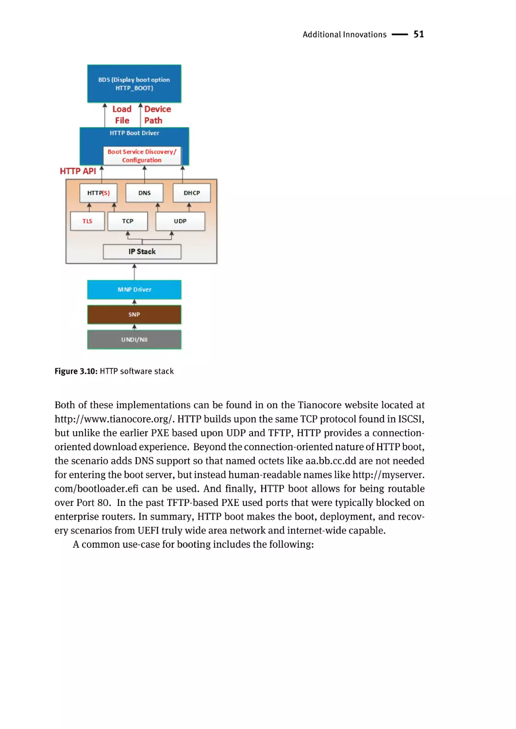
Additional Innovations | 47
Security | 47
Manageability | 48
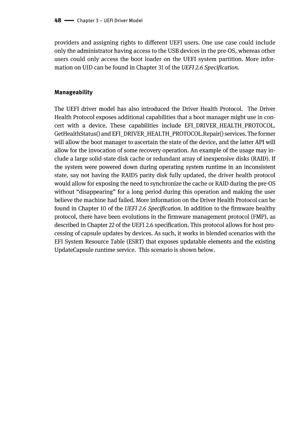
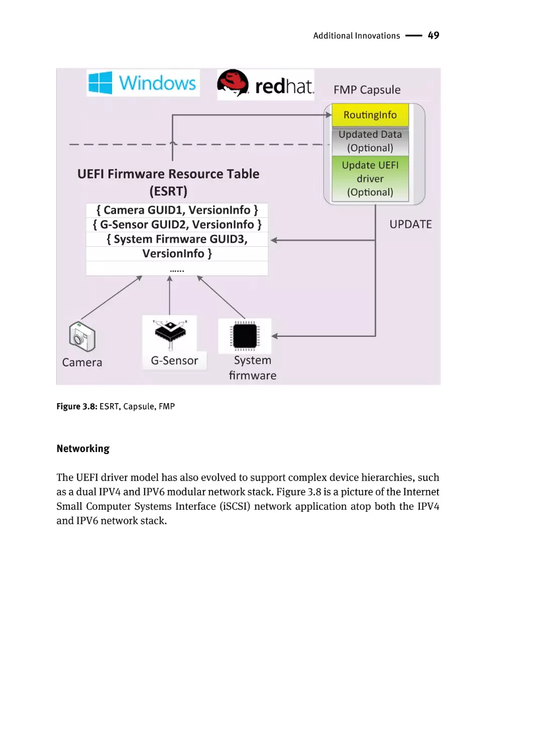
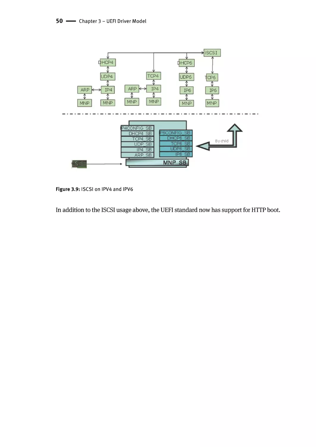
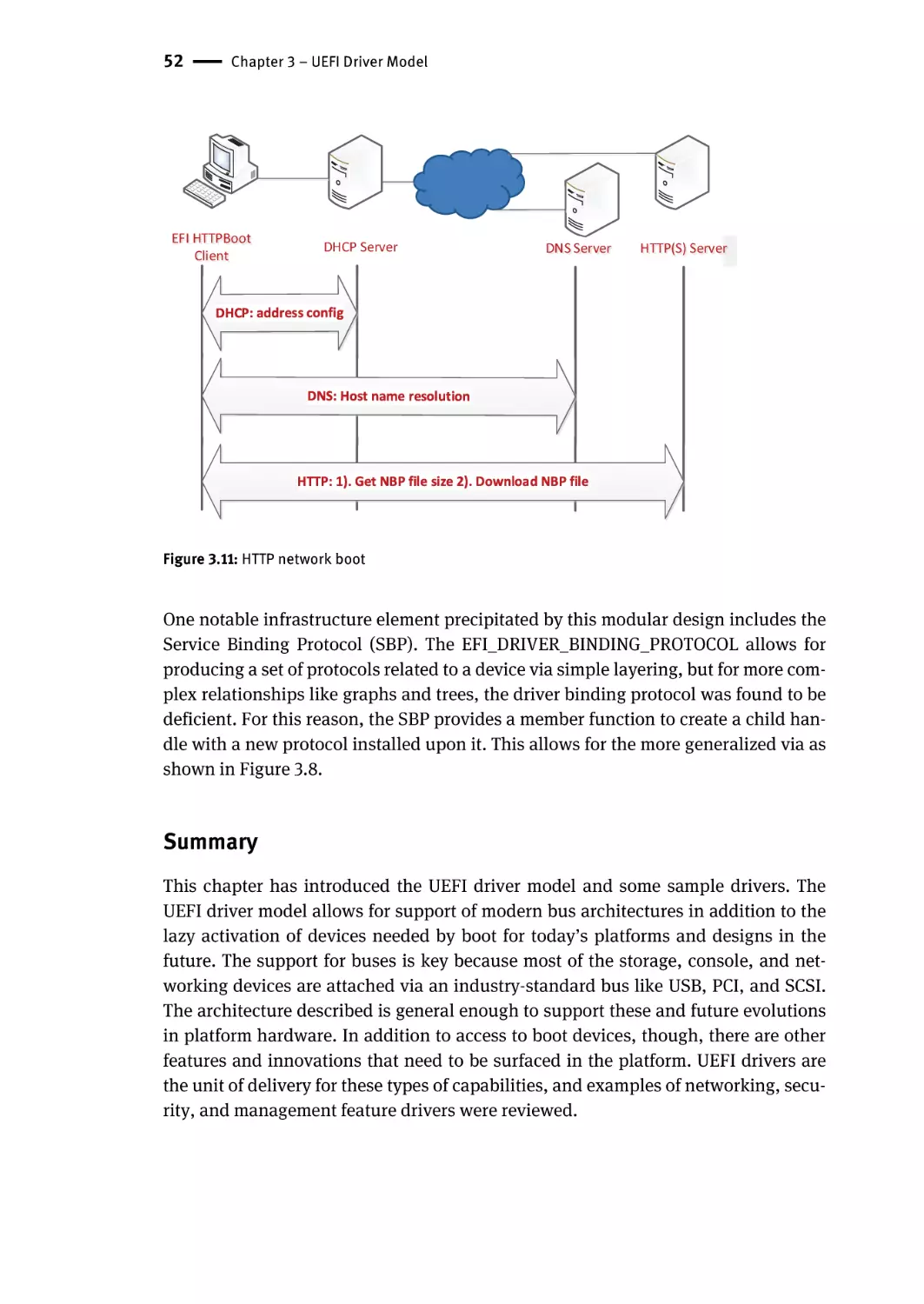
Networking | 49
Summary | 52
Chapter 4 – Protocols You Should Know | 53
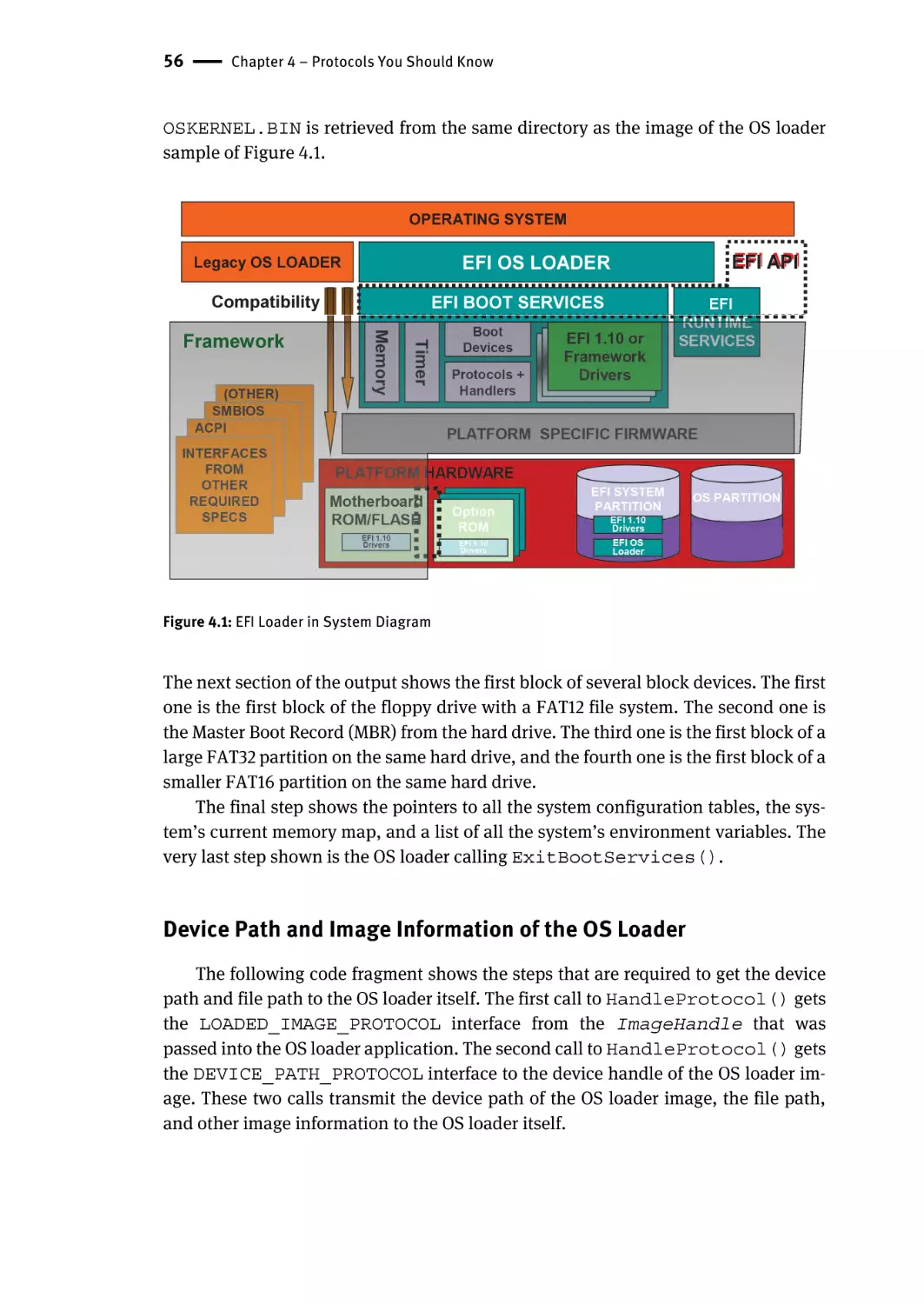
EFI OS Loaders | 55
Device Path and Image Information of the OS Loader | 56
Accessing Files in the Device Path of the OS Loader | 57
Finding the OS Partition | 58
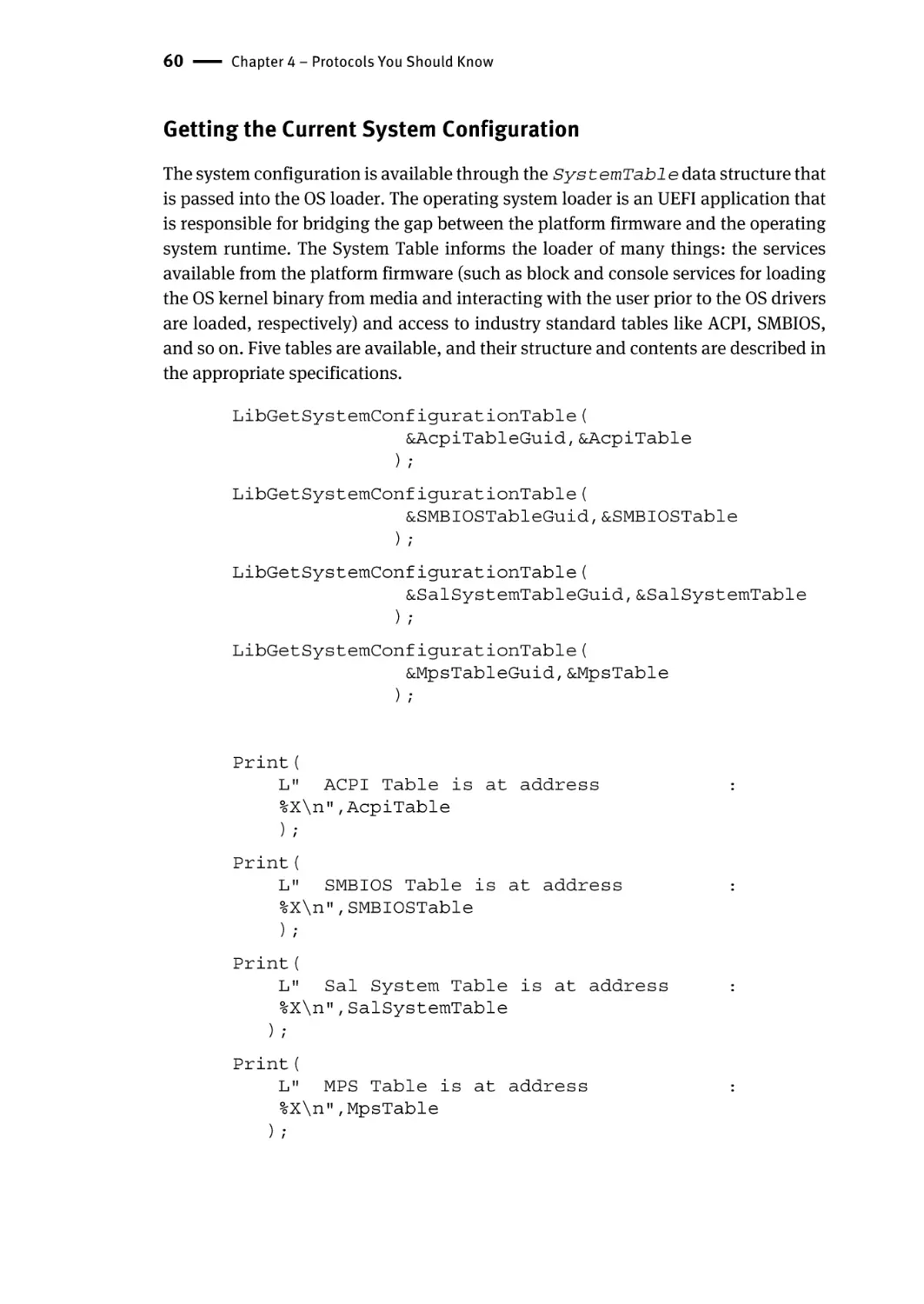
Getting the Current System Configuration | 60
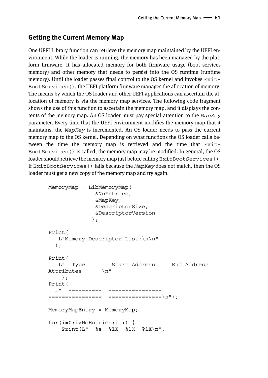
Getting the Current Memory Map | 61
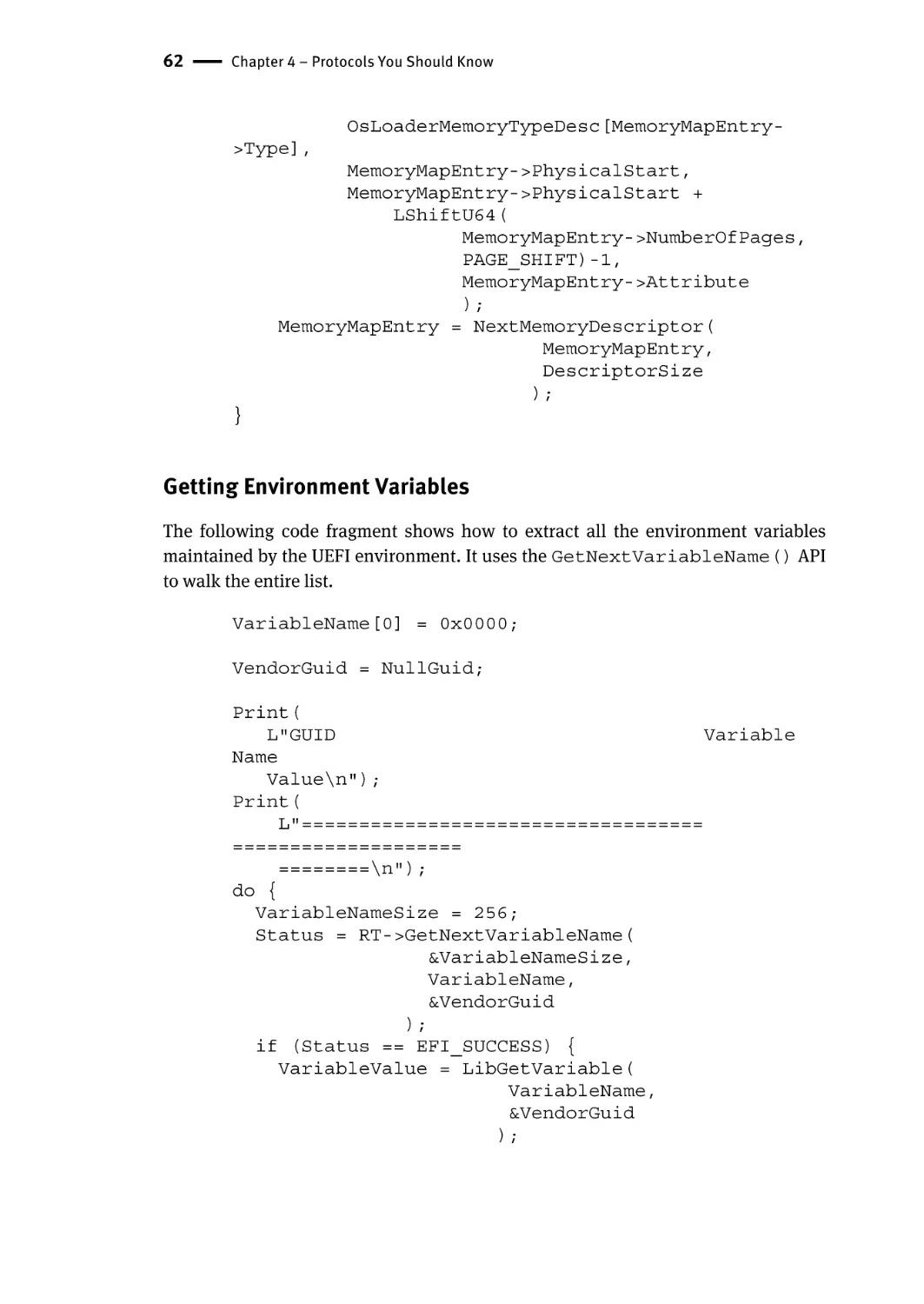
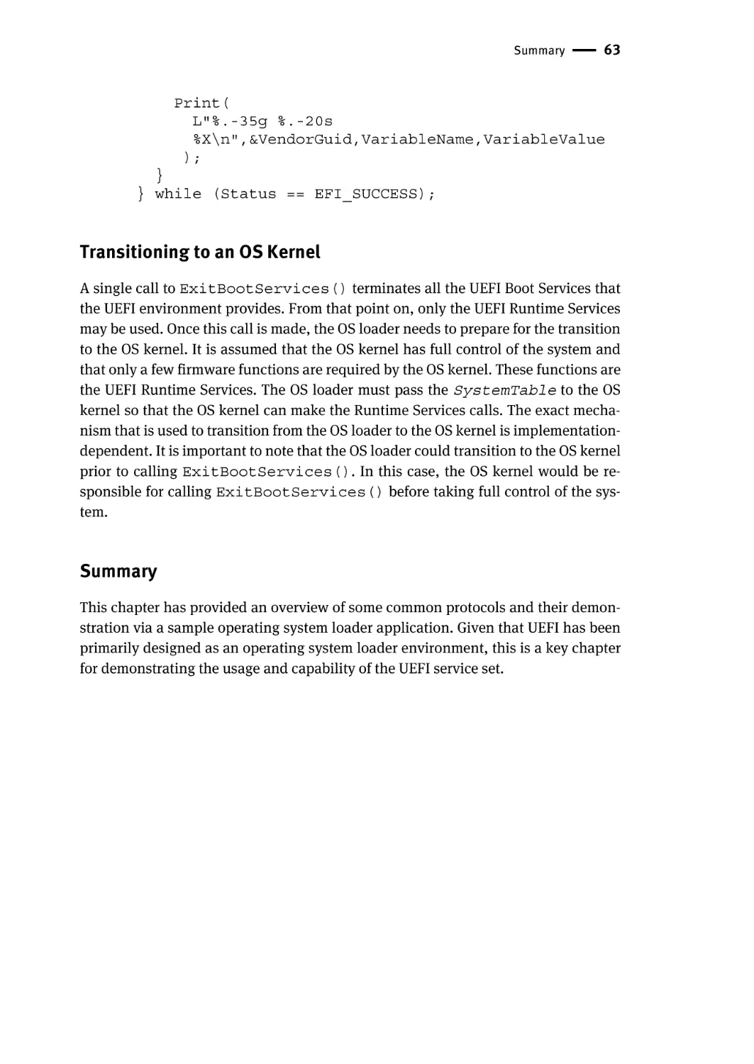
Getting Environment Variables | 62
Transitioning to an OS Kernel | 63
Summary | 63
Chapter 5 – UEFI Runtime | 65
Isn’t There Only One Kind of Memory? | 66
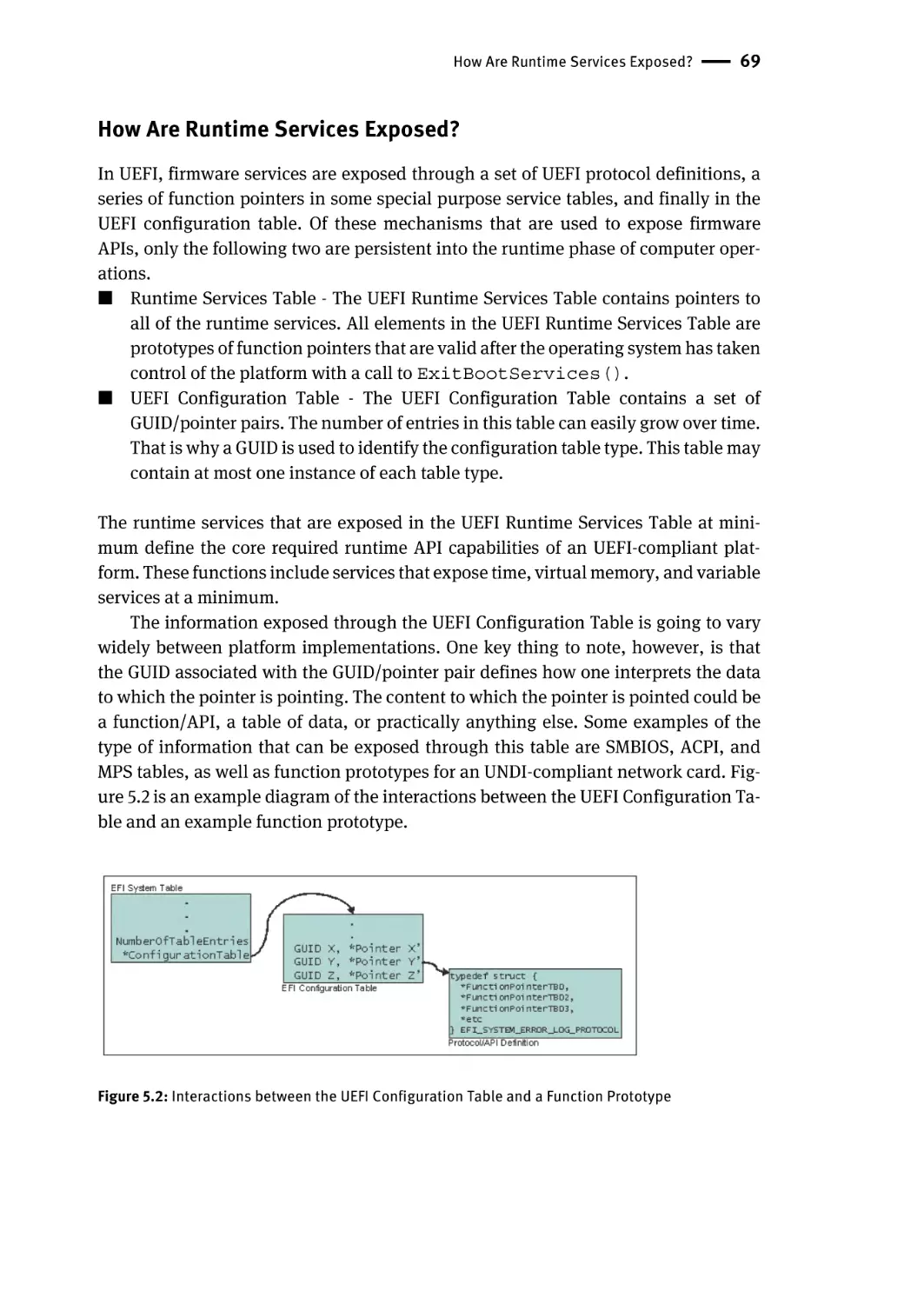
How Are Runtime Services Exposed? | 69
Time Services | 70
Why Abstract Time? | 70
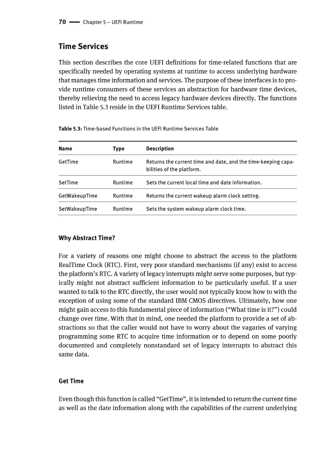
Get Time | 70
Set Time | 71
Get Wakeup Time | 72
Set Wakeup Time | 72
Virtual Memory Services | 72
Set Virtual Address Map | 73
ConvertPointer | 73
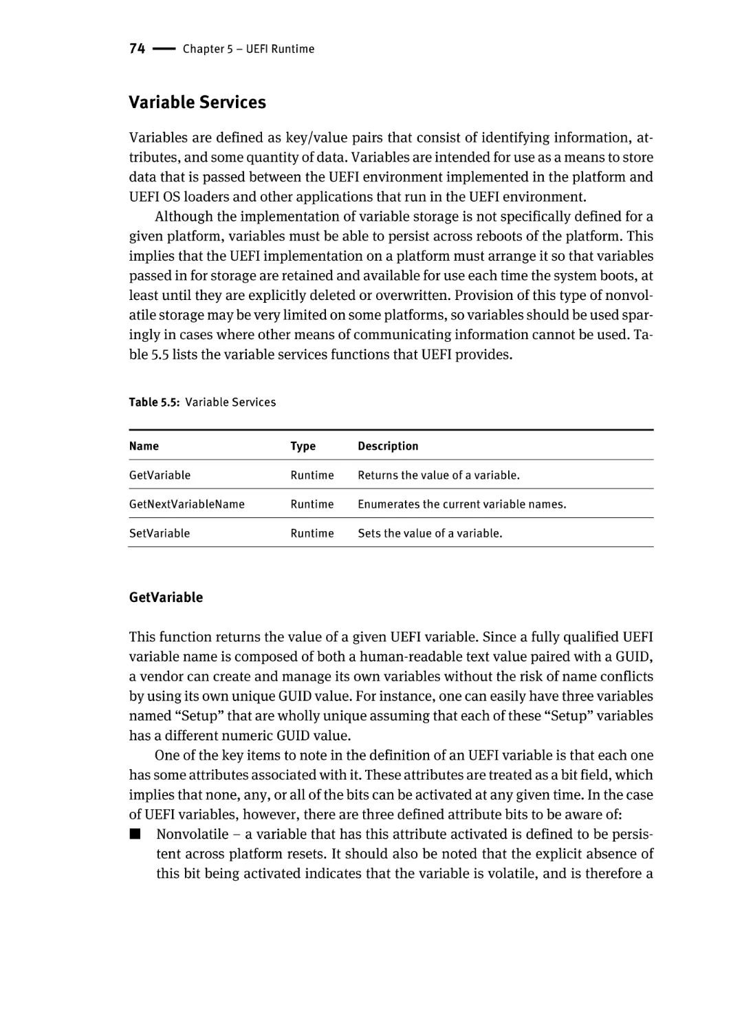
Variable Services | 74
GetVariable | 74
GetNextVariableName | 75
SetVariable | 75
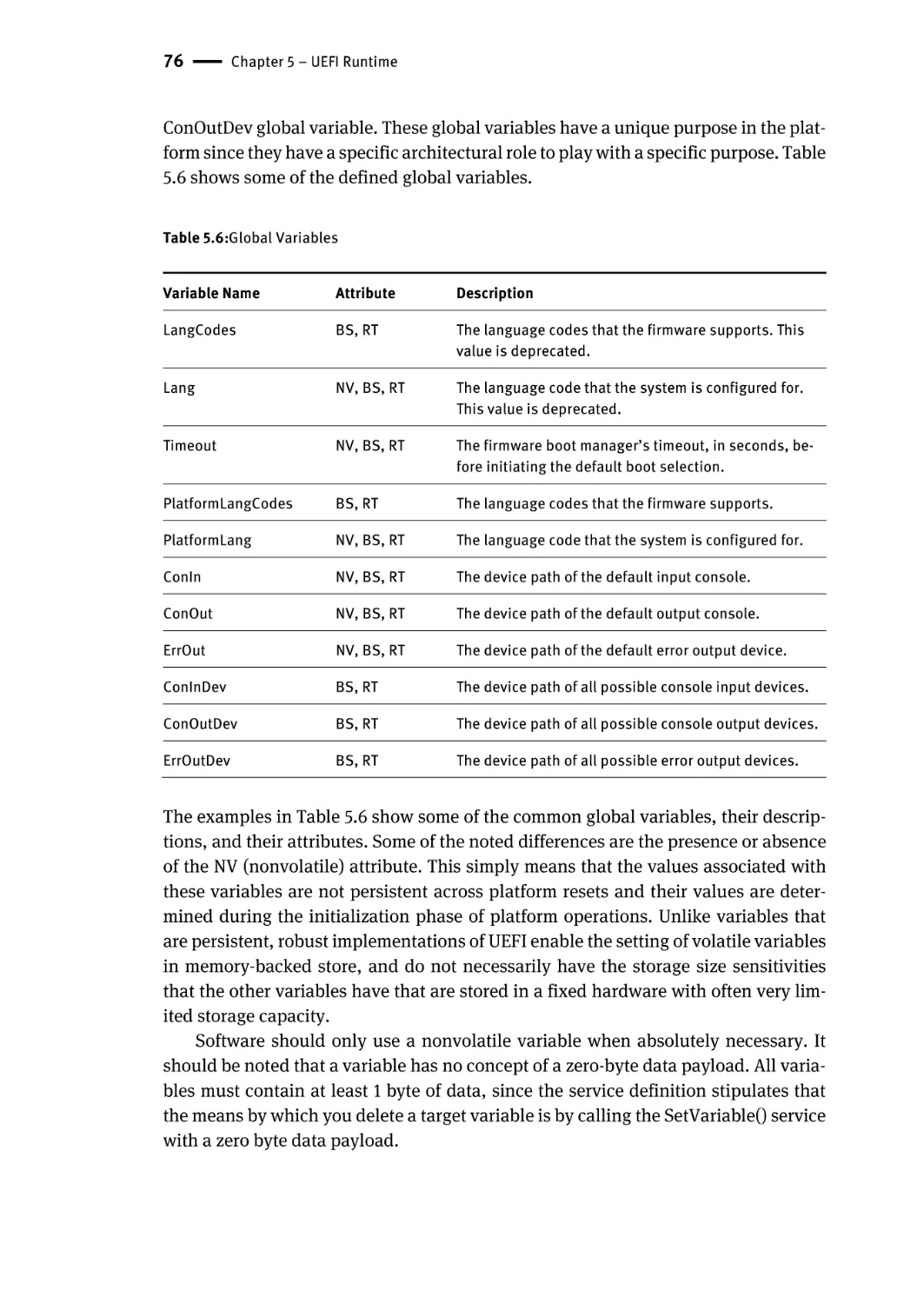
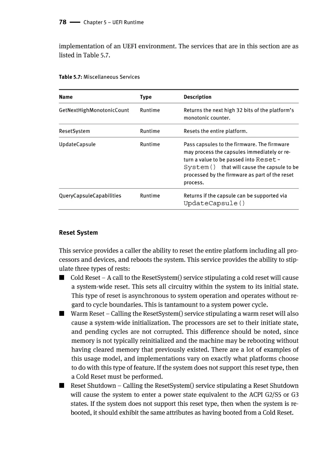
Miscellaneous Services | 77
Reset System | 78
Get Next High Monotonic Count | 79
UpdateCapsule | 79
QueryCapsuleCapabilities | 80
Contents | xiii
Summary | 80
Chapter 6 – UEFI Console Services | 81
Simple Text Input Protocol | 83
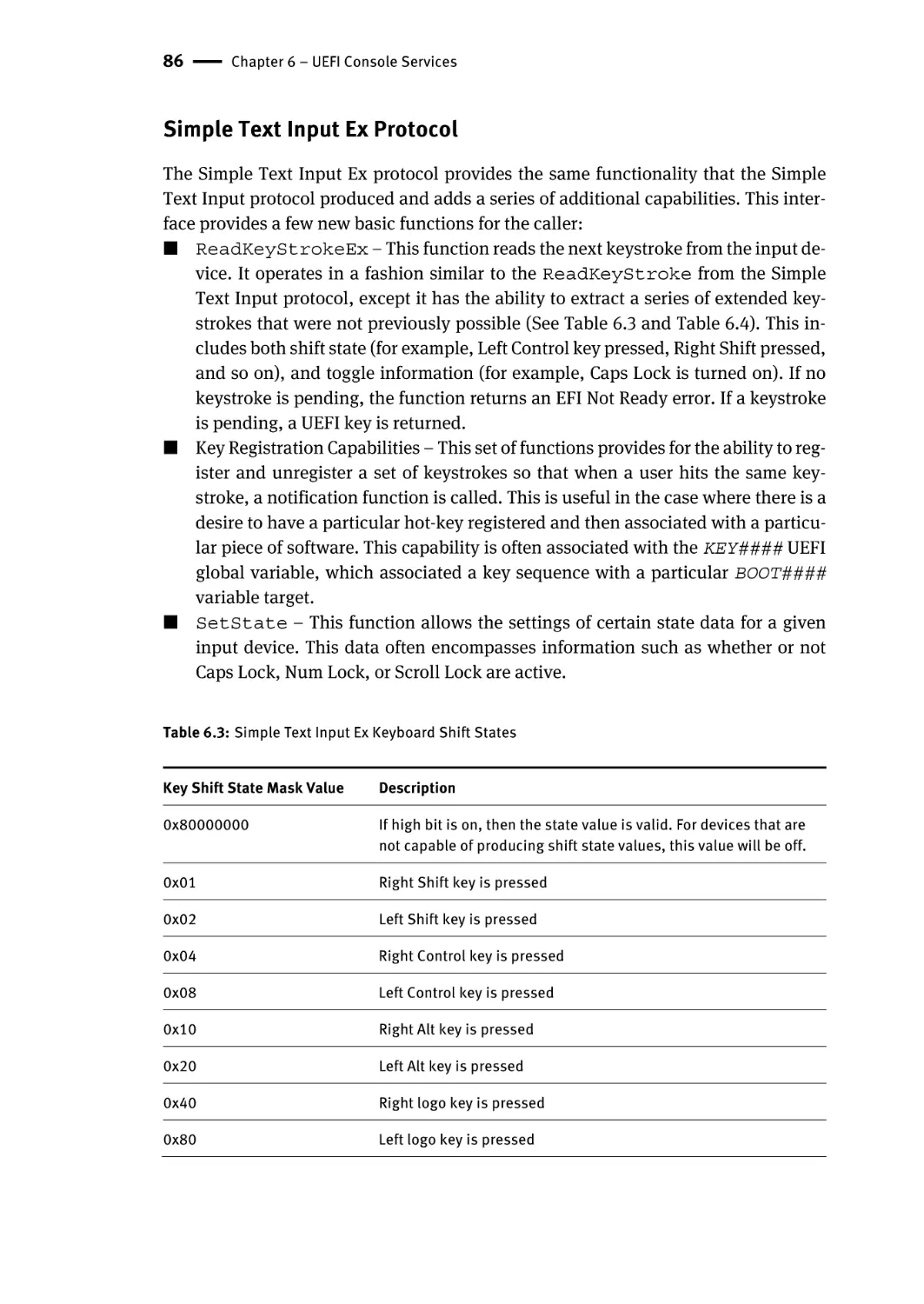
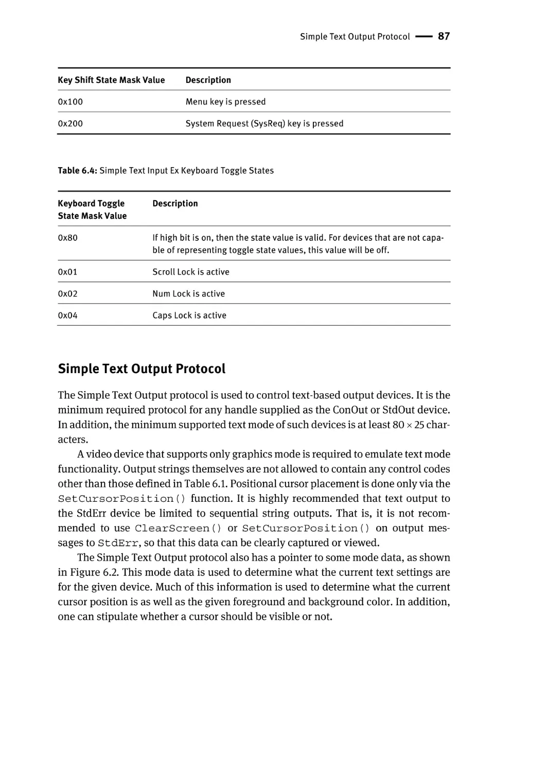
Simple Text Input Ex Protocol | 86
Simple Text Output Protocol | 87
Remote Console Support | 89
Console Splitter | 92
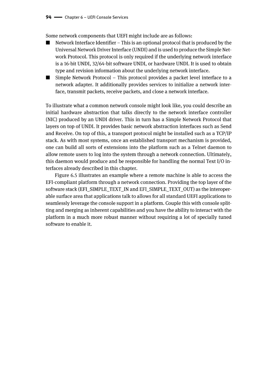
Network Consoles | 93
Summary | 95
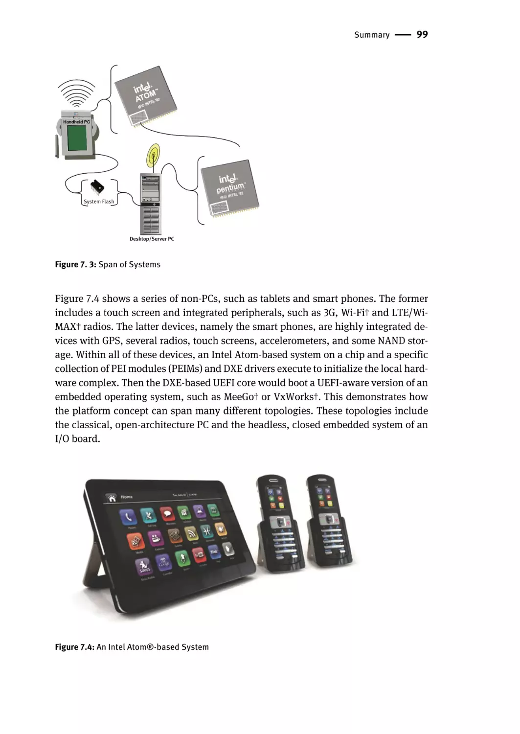
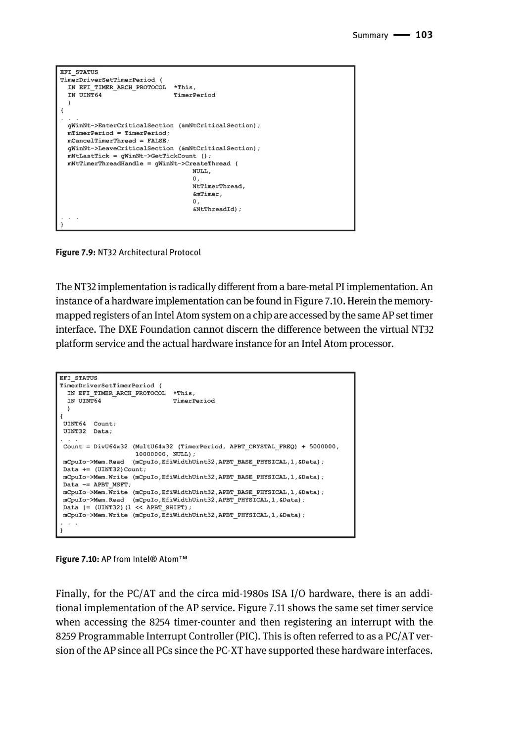
Chapter 7 – Different Types of Platforms | 97
Summary | 110
Chapter 8 – DXE Basics: Core, Dispatching, and Drivers | 111
DXE Core | 112
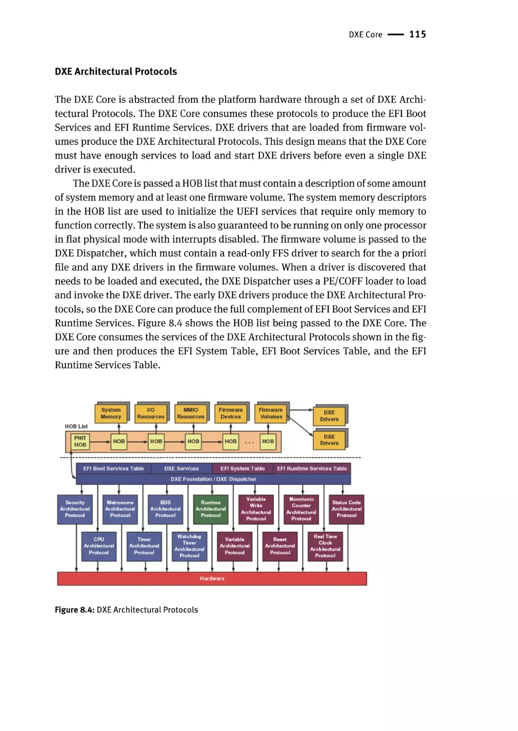
Hand-Off Block (HOB) List | 114
DXE Architectural Protocols | 115
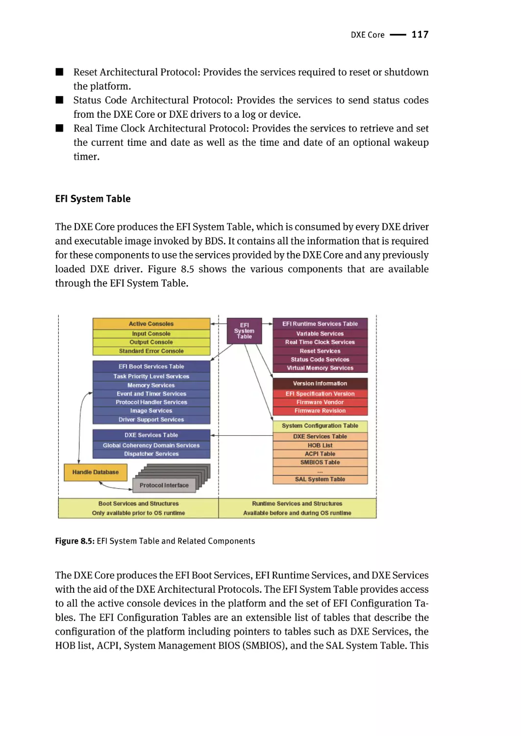
EFI System Table | 117
EFI Boot Services Table | 118
EFI Runtime Services Table | 119
DXE Services Table | 119
Global Coherency Domain Services | 120
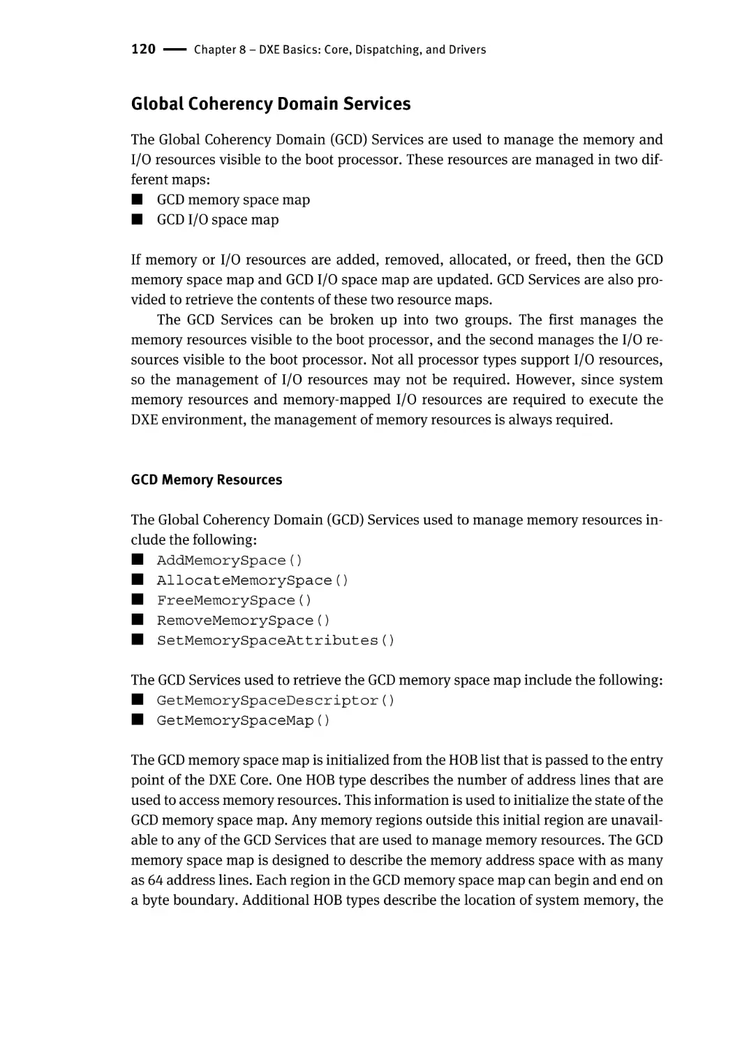
GCD Memory Resources | 120
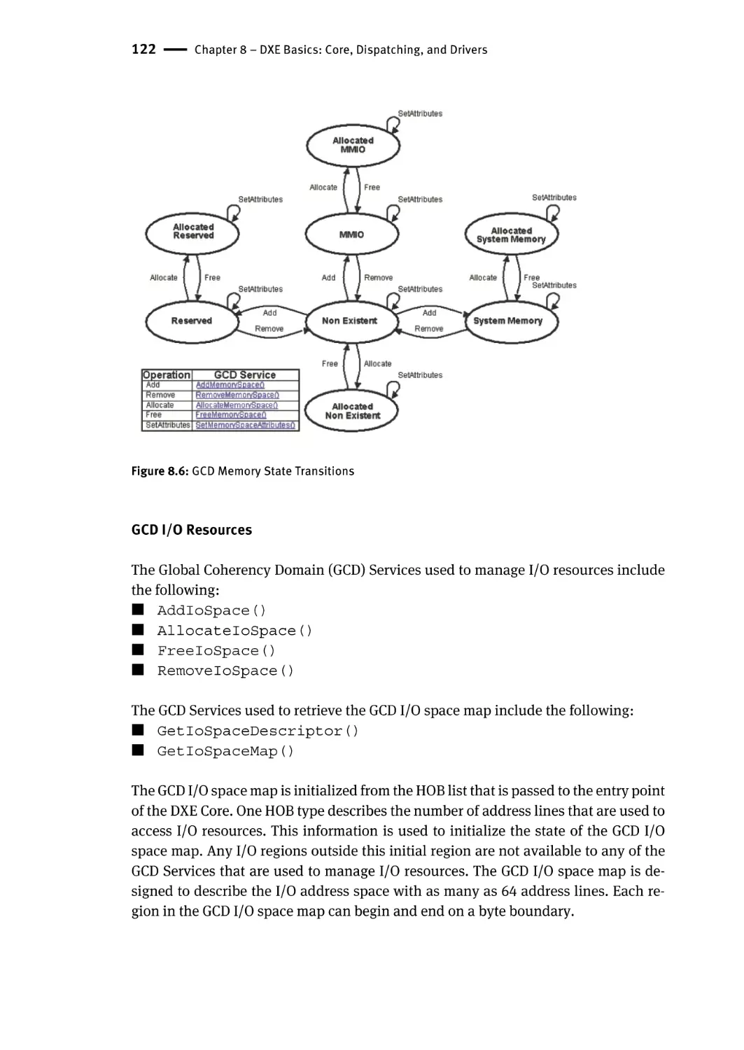
GCD I/O Resources | 122
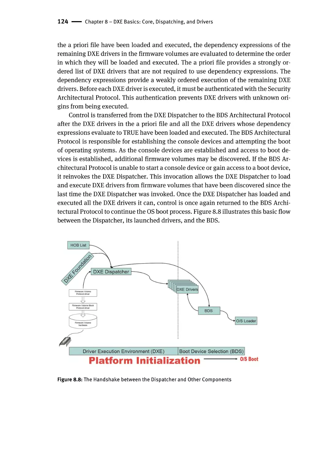
DXE Dispatcher | 123
The a priori File | 125
Dependency Grammar | 125
DXE Drivers | 126
Boot Device Selection (BDS) Phase | 127
Console Devices | 128
Boot Devices | 129
Boot Services Terminate | 129
Summary | 130
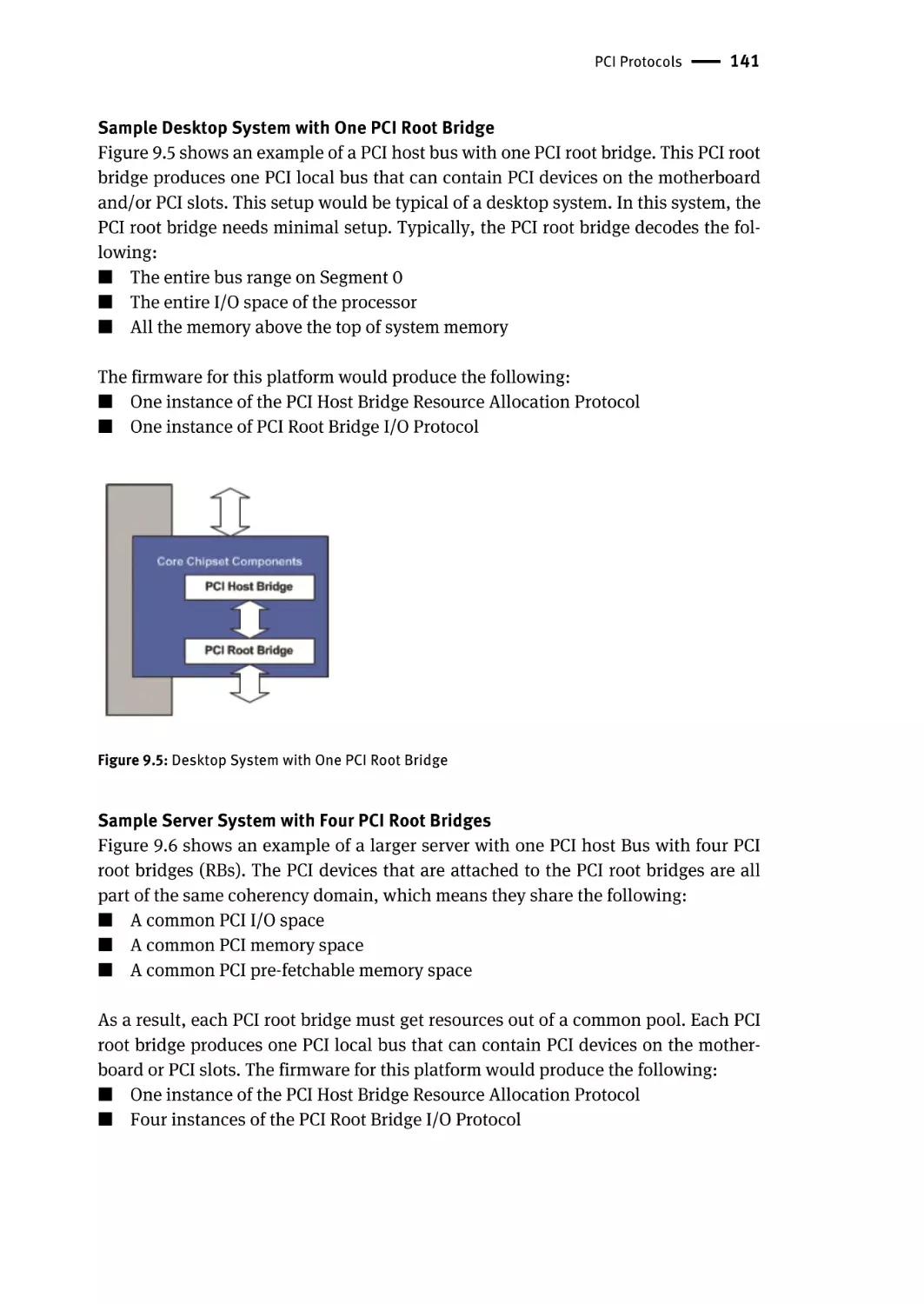
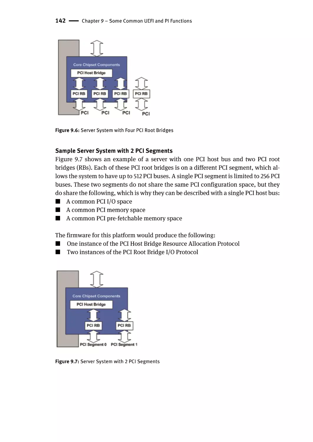
Chapter 9 – Some Common UEFI and PI Functions | 131
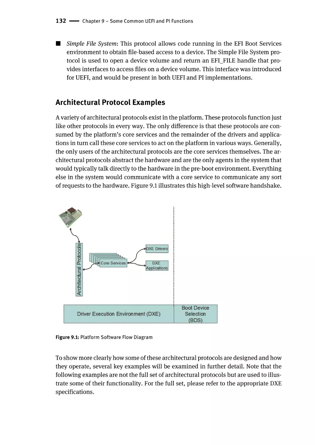
Architectural Protocol Examples | 132
CPU Architectural Protocol | 133
Real Time Clock Architectural Protocol | 135
Timer Architectural Protocol | 135
Reset Architectural Protocol | 136
Boot Device Selection Architectural Protocol | 137
xiv | Contents
Variable Architectural Protocol | 138
Watchdog Timer Architectural Protocol | 138
PCI Protocols | 139
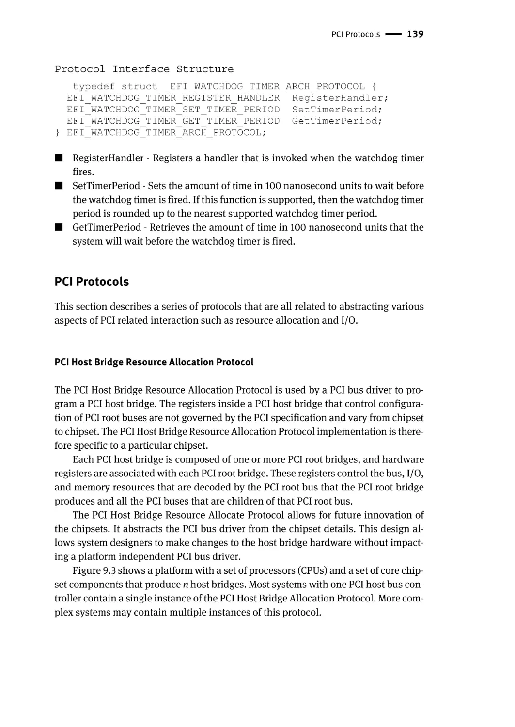
PCI Host Bridge Resource Allocation Protocol | 139
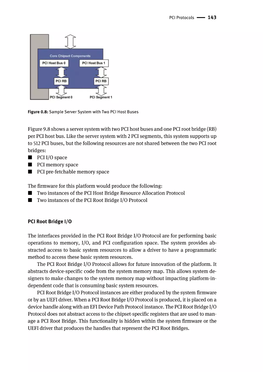
PCI Root Bridge I/O | 143
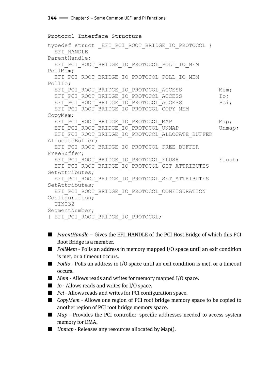
PCI I/O | 145
Block I/O | 147
Disk I/O | 149
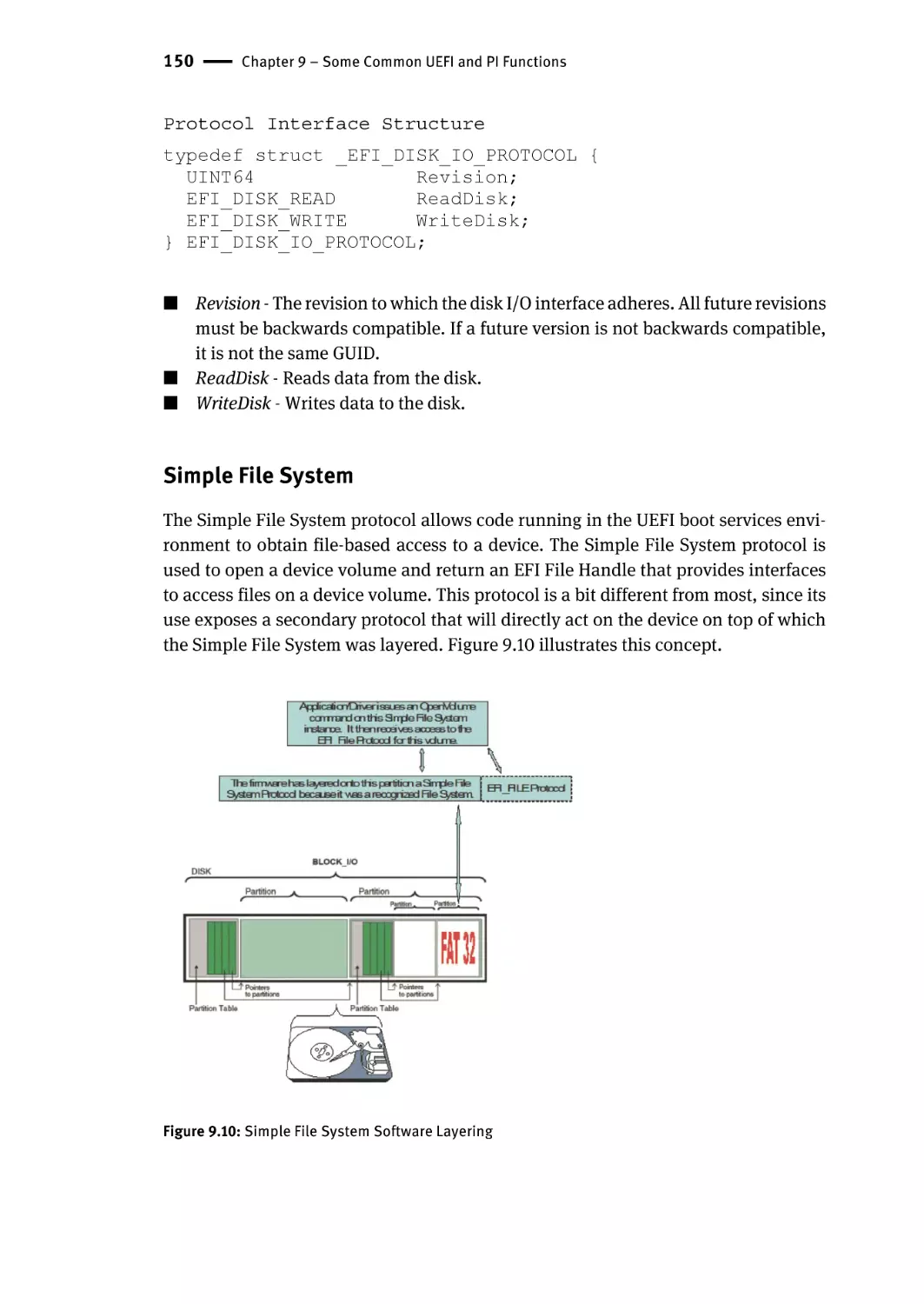
Simple File System | 150
EFI File Protocol | 151
Configuration Infrastructure | 152
Using the Configuration Infrastructure | 153
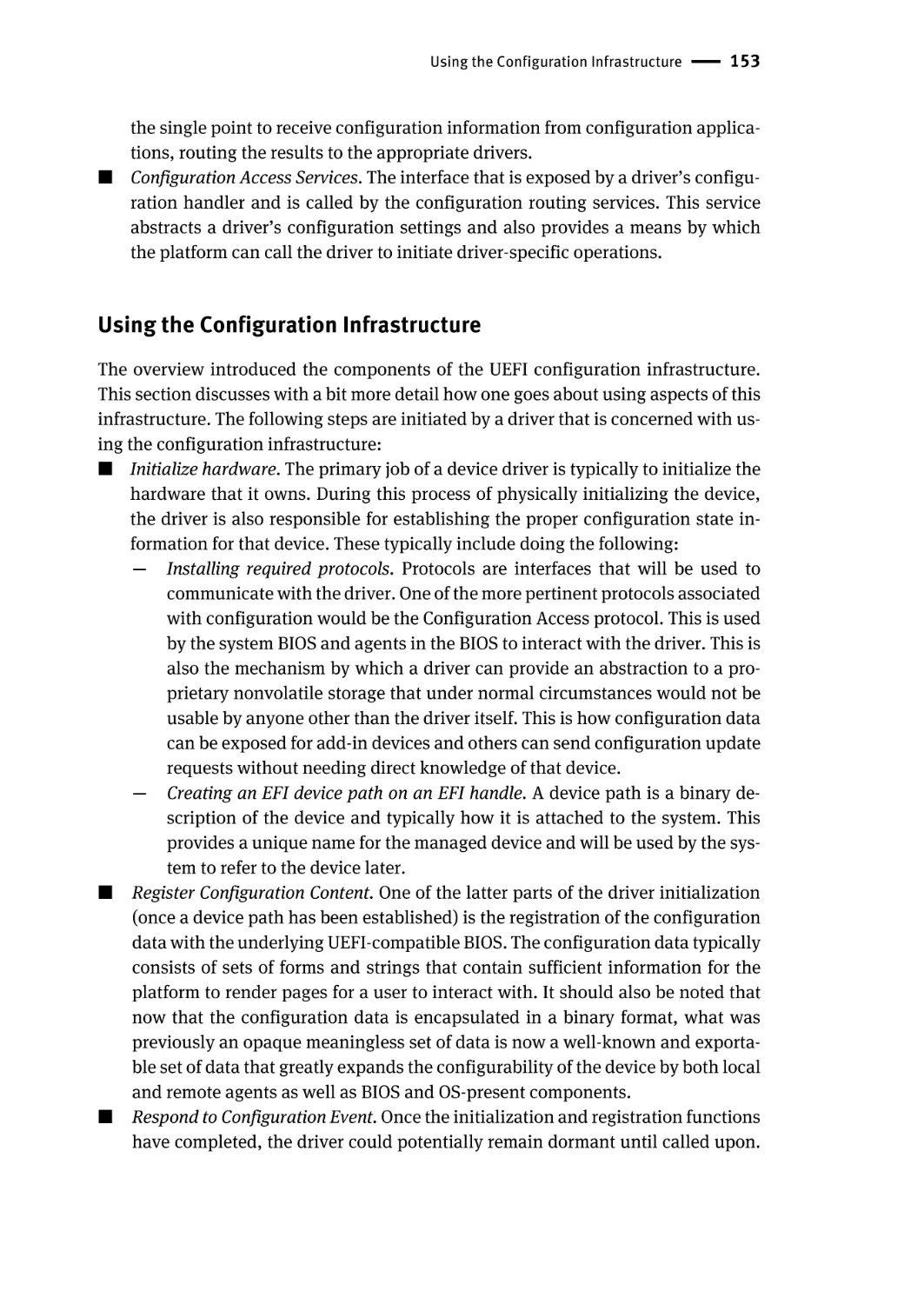
Driver Model Interactions | 154
Provisioning the Platform | 155
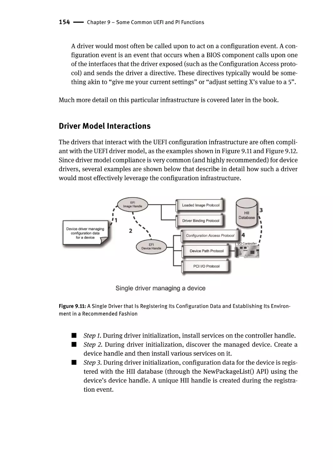
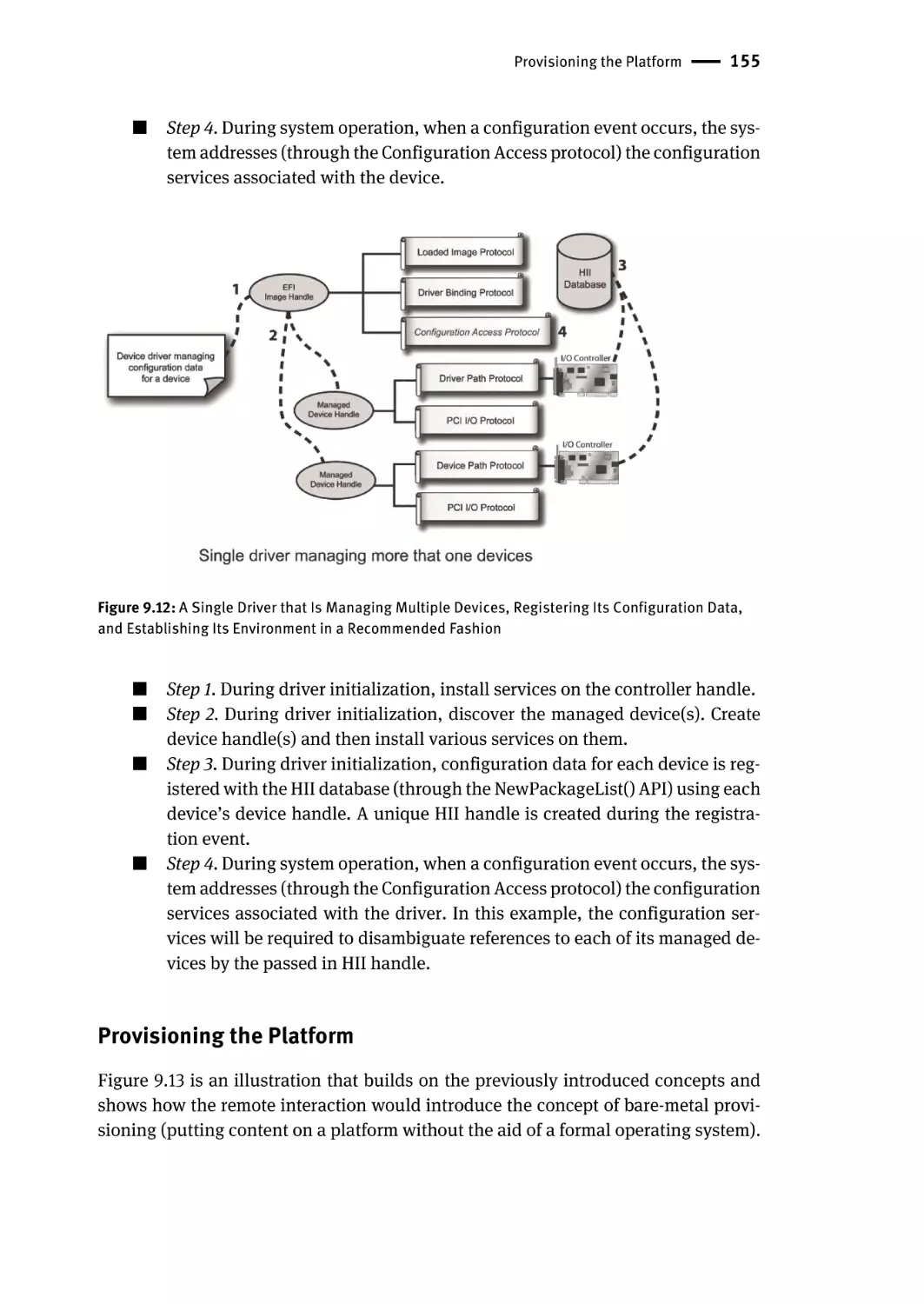
Summary | 156
Chapter 10 – Platform Security and Trust | 157
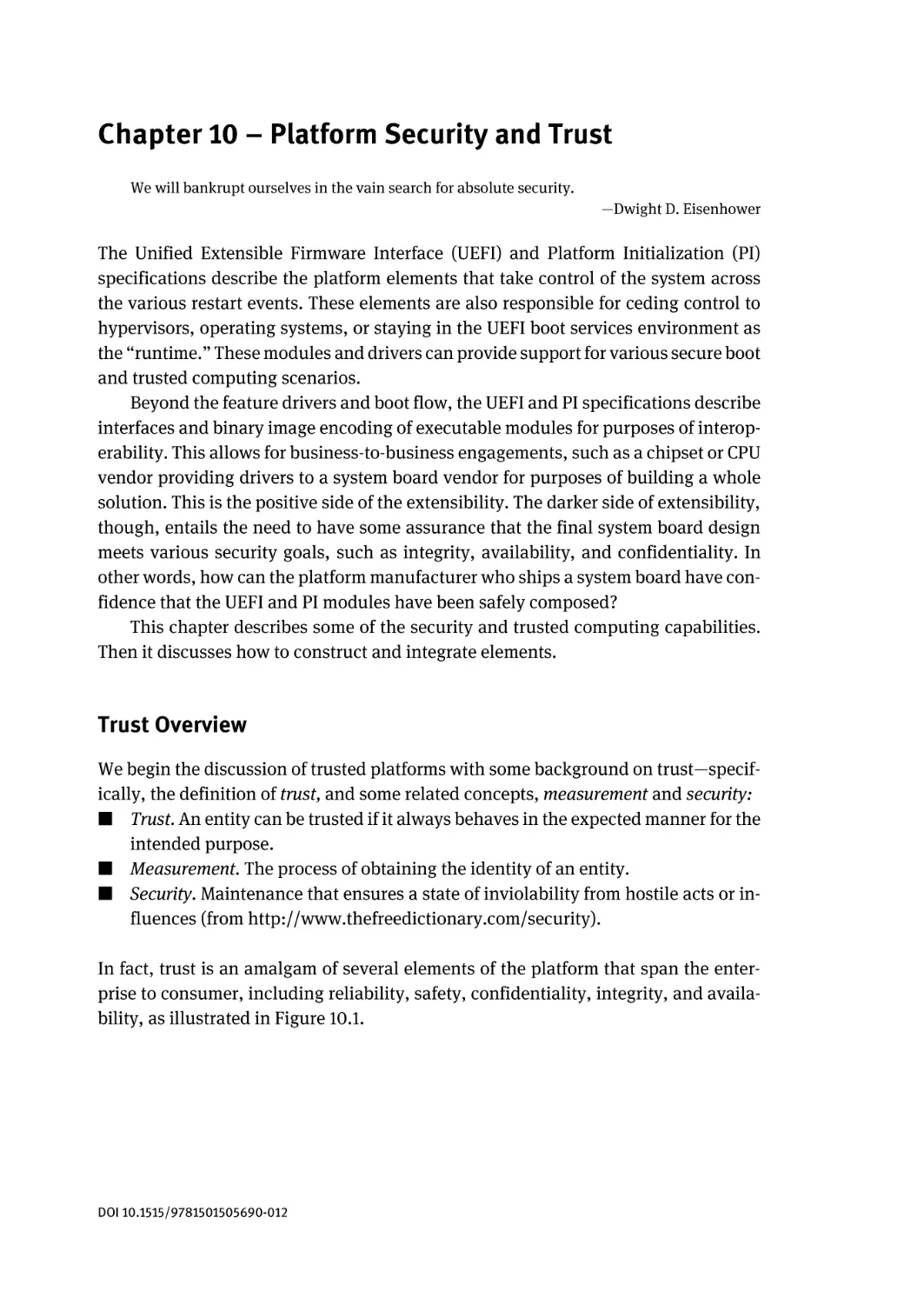
Trust Overview | 157
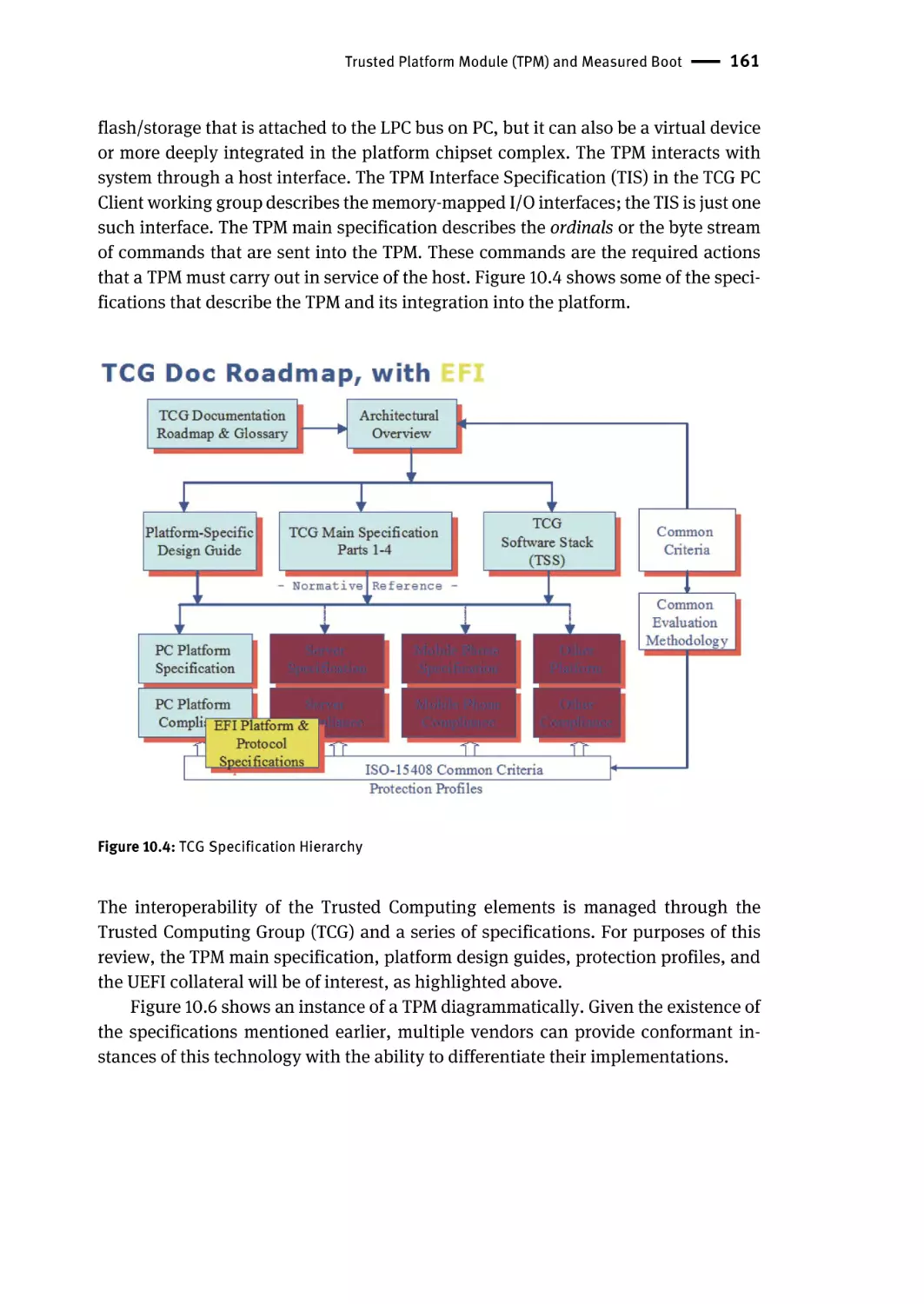
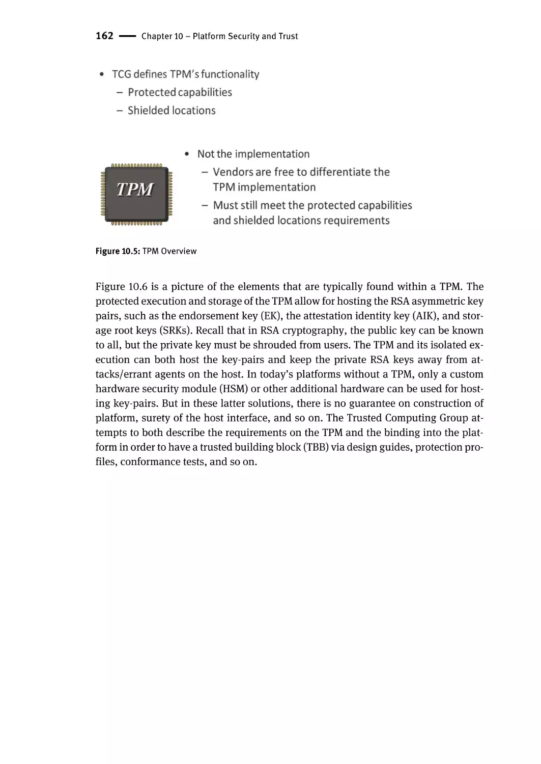
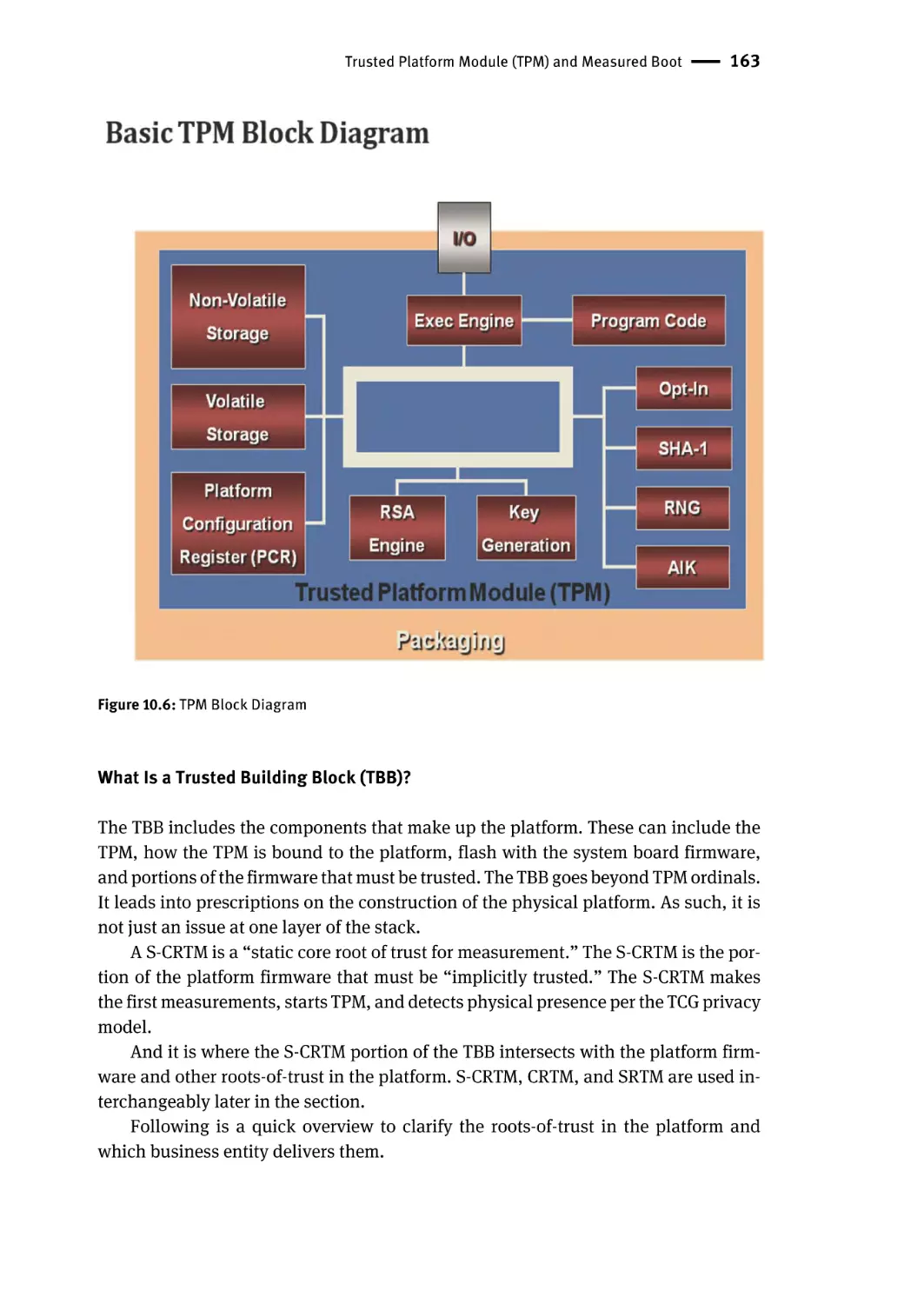
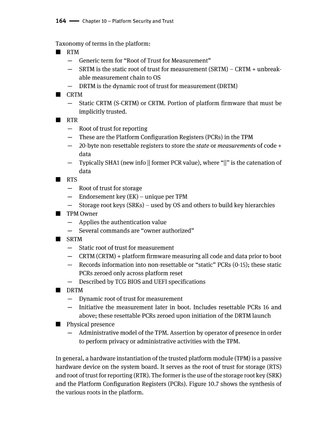
Trusted Platform Module (TPM) and Measured Boot | 160
What Is a Trusted Building Block (TBB)? | 163
What Is the Point of Measurements? | 168
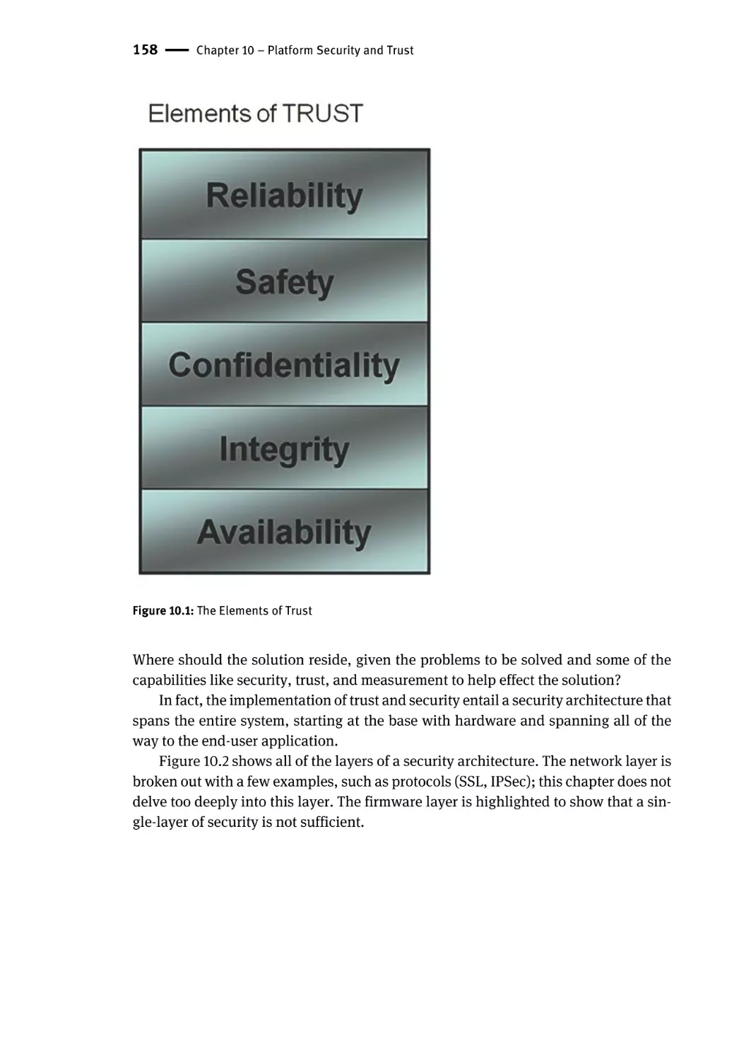
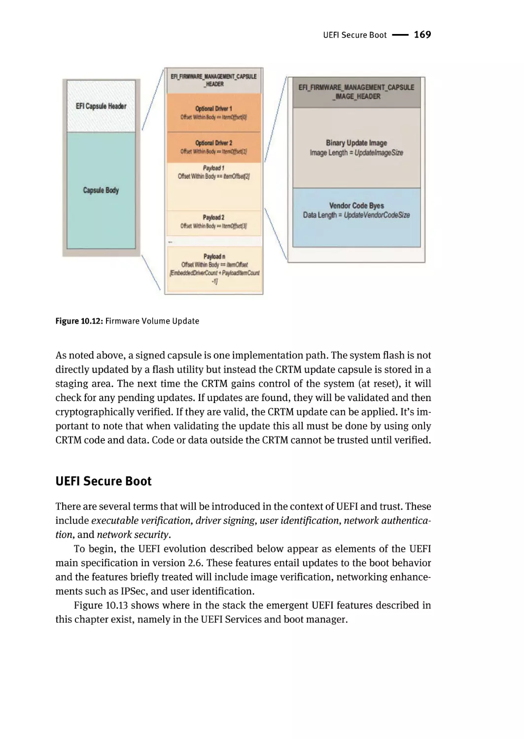
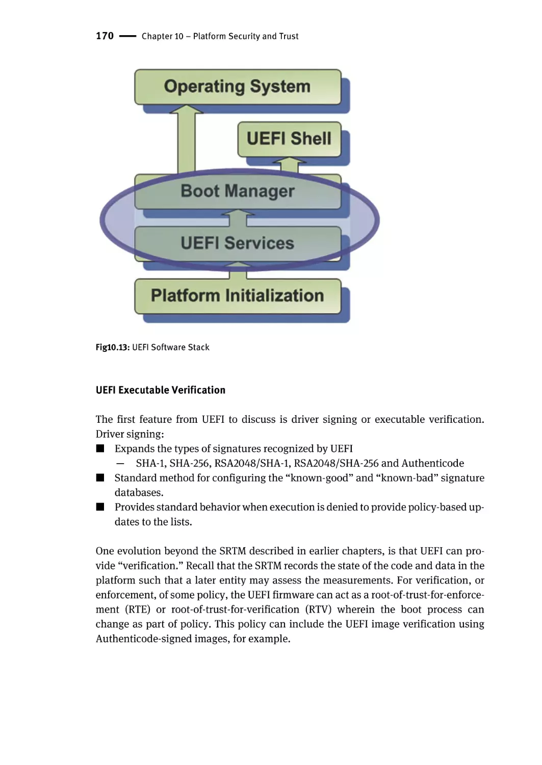
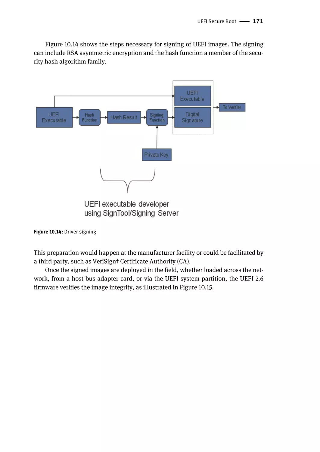
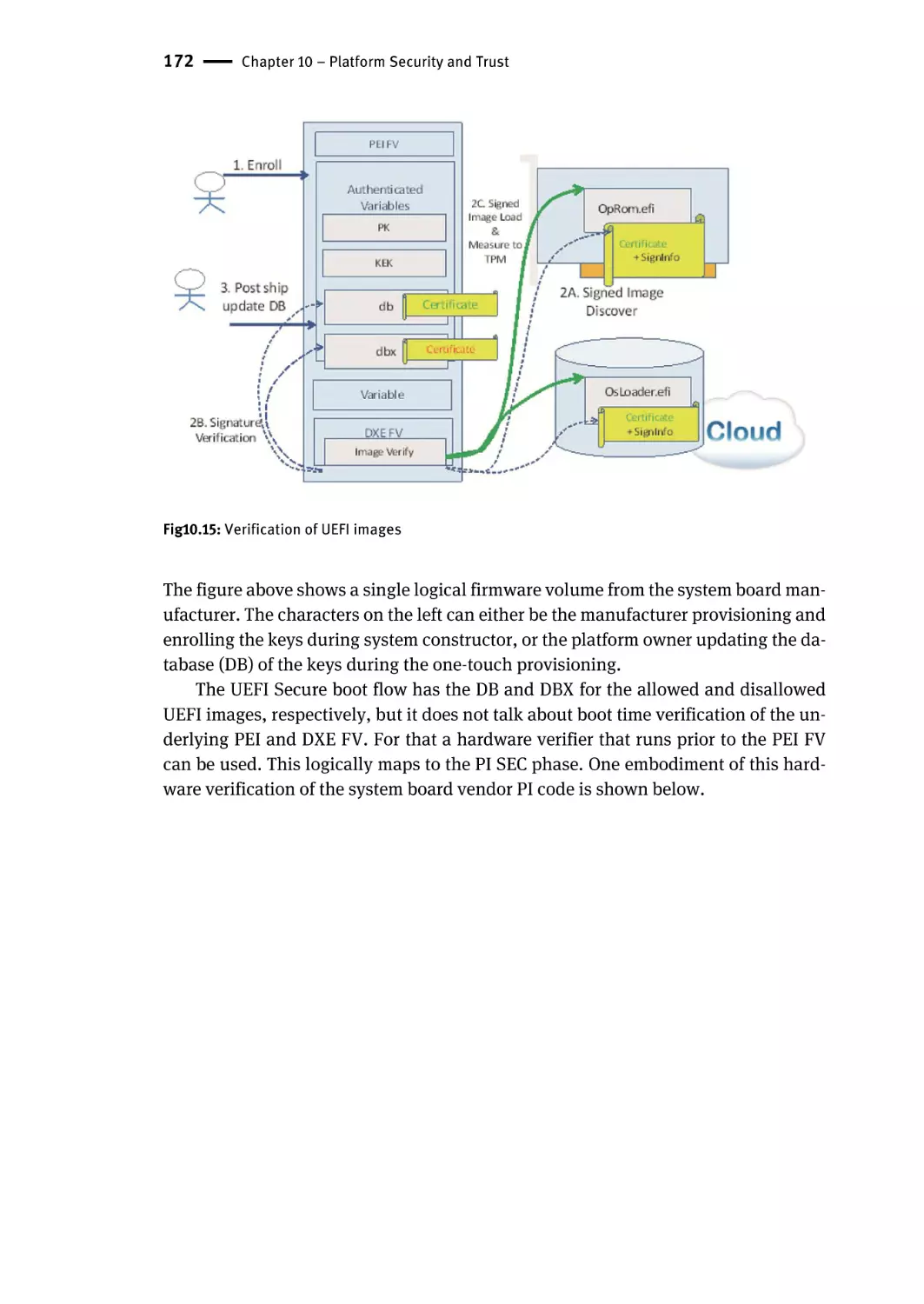
UEFI Secure Boot | 169
UEFI Executable Verification | 170
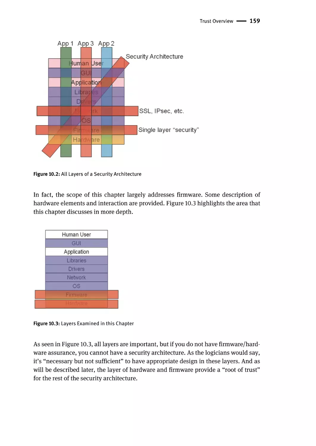
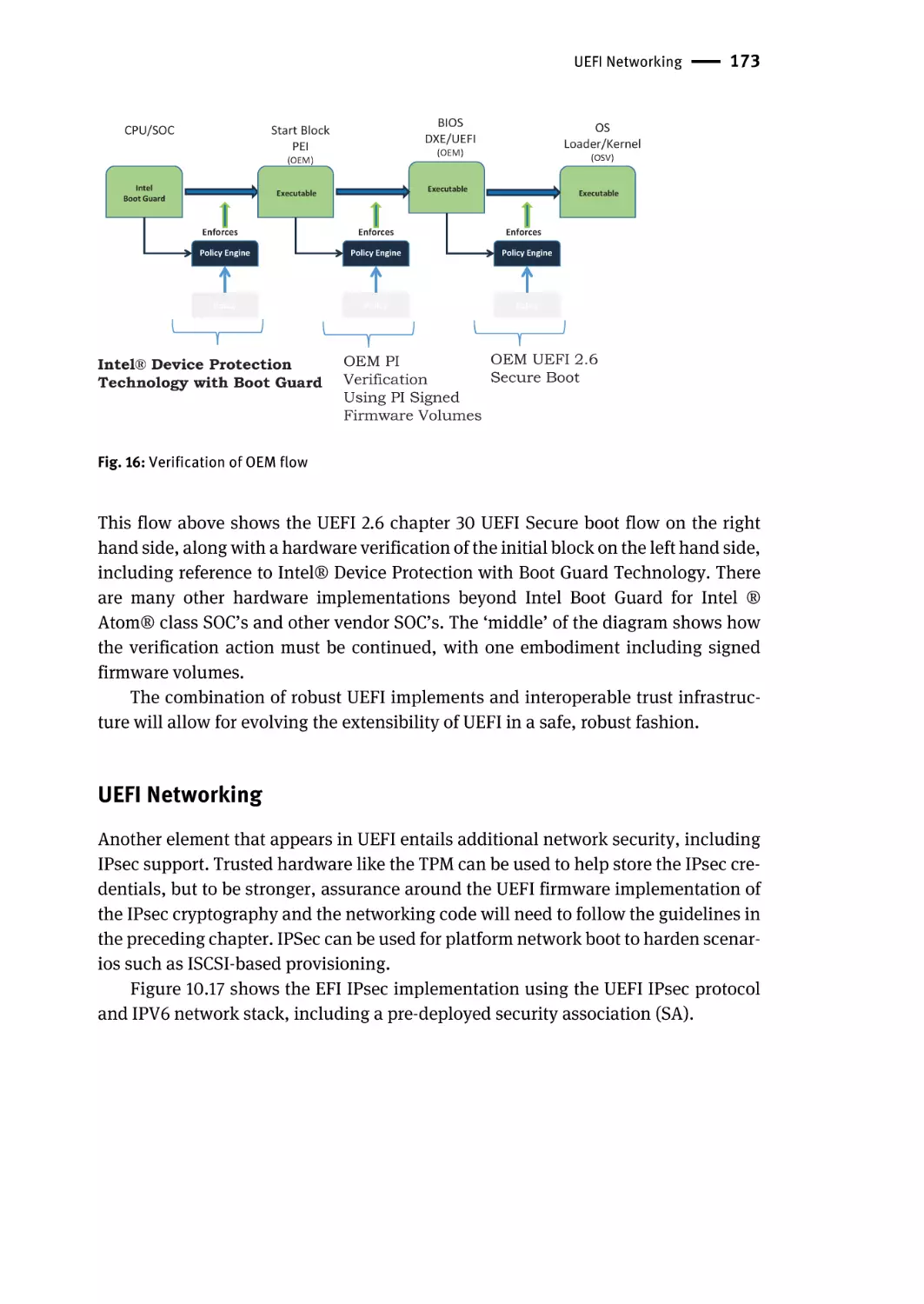
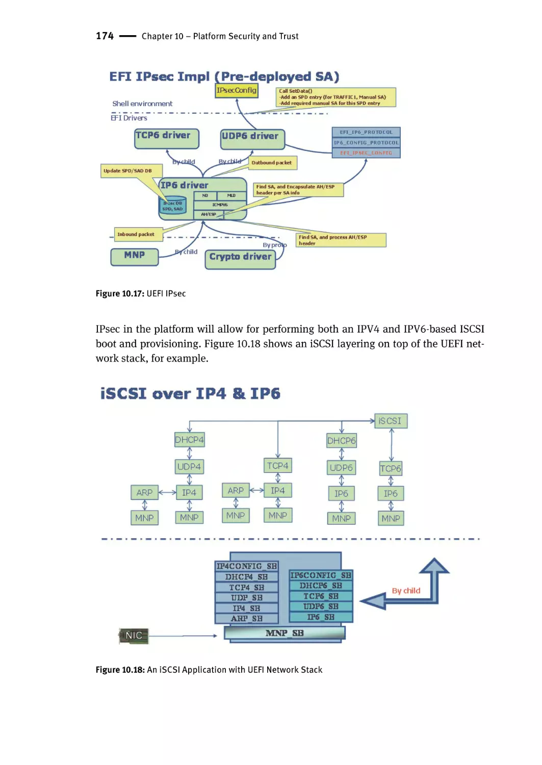
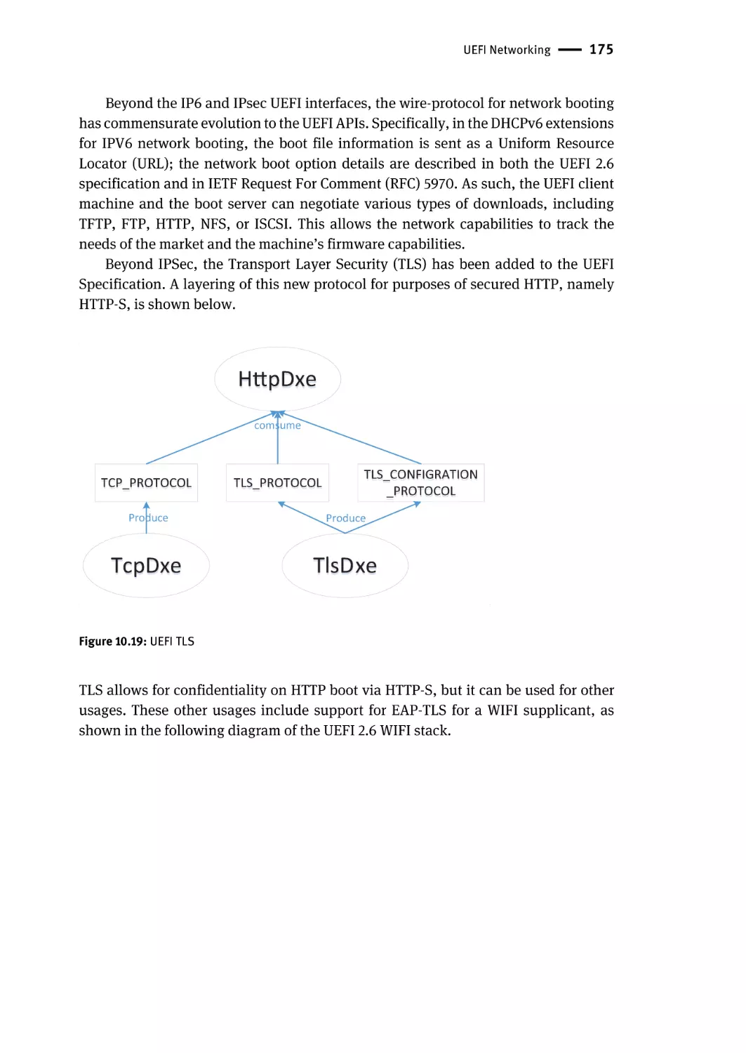
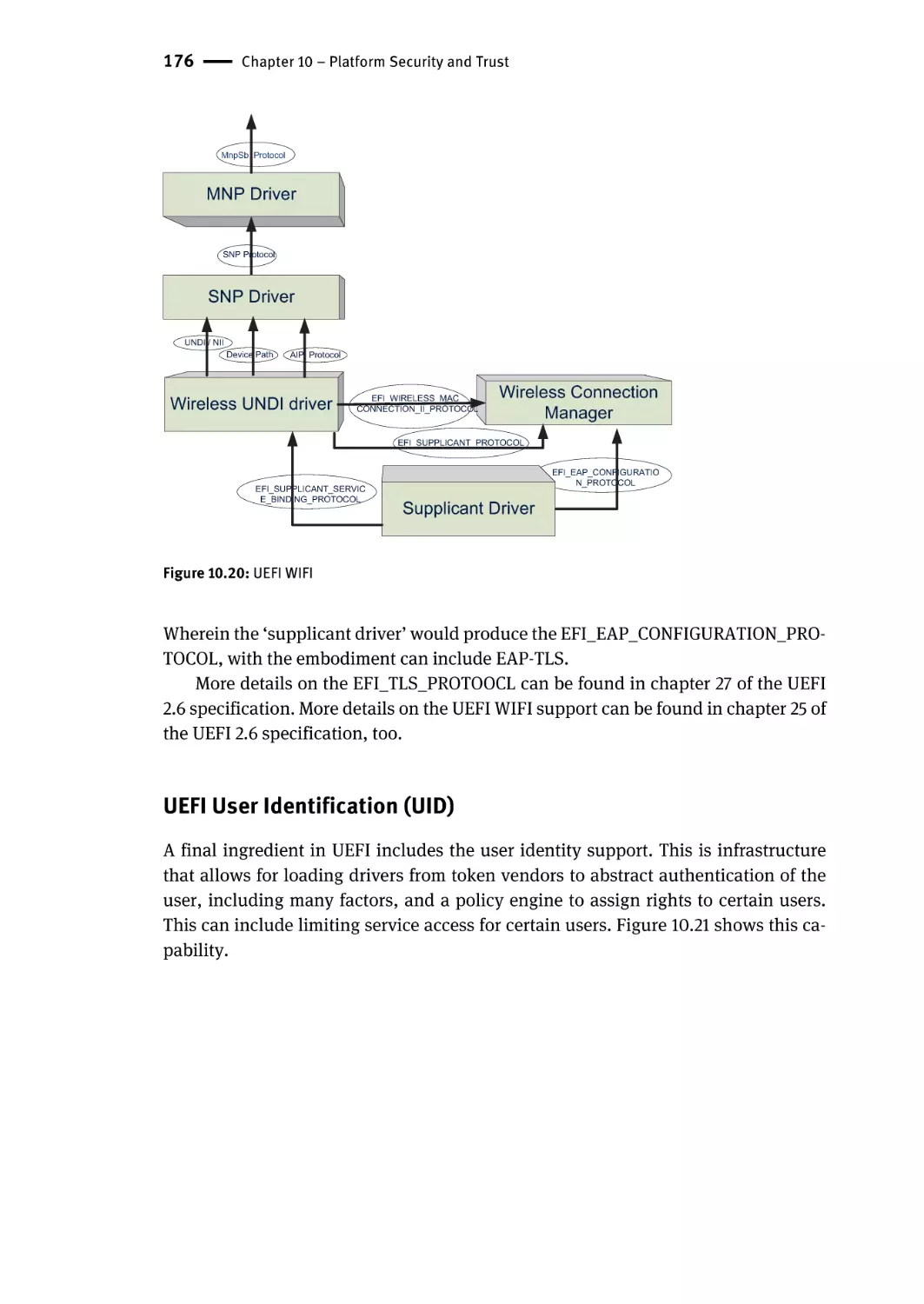
UEFI Networking | 173
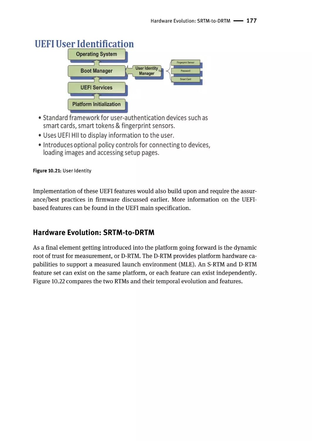
UEFI User Identification (UID) | 176
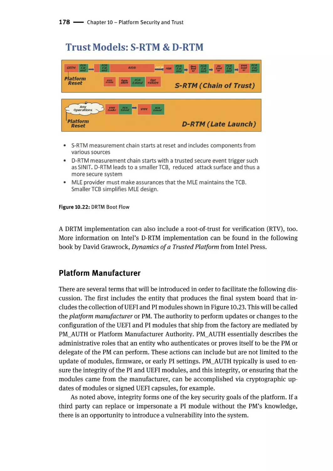
Hardware Evolution: SRTM-to-DRTM | 177
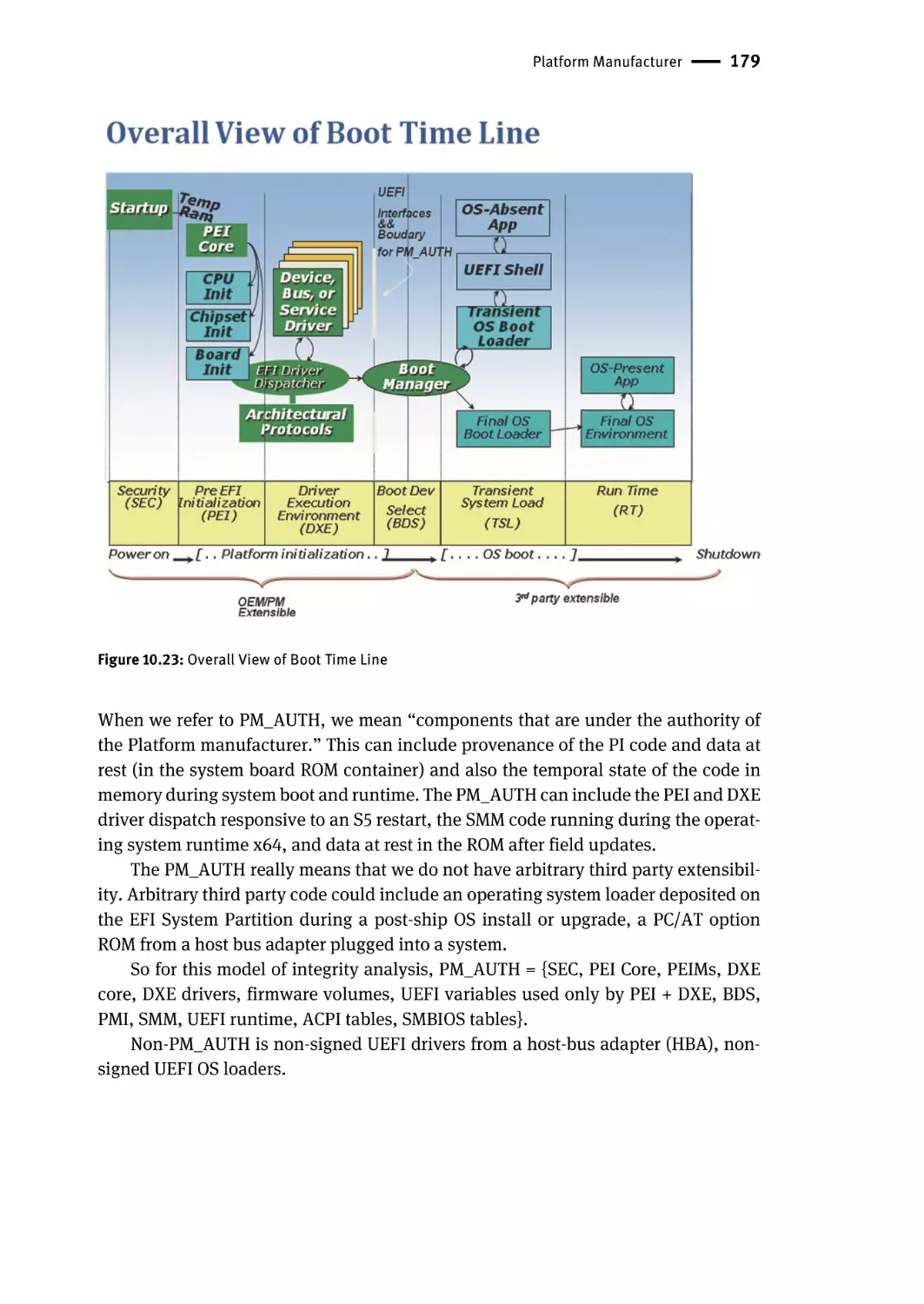
Platform Manufacturer | 178
Vulnerability Classification | 180
Roots of Trust/Guards | 180
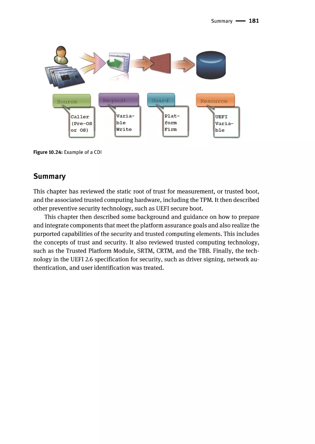
Summary | 181
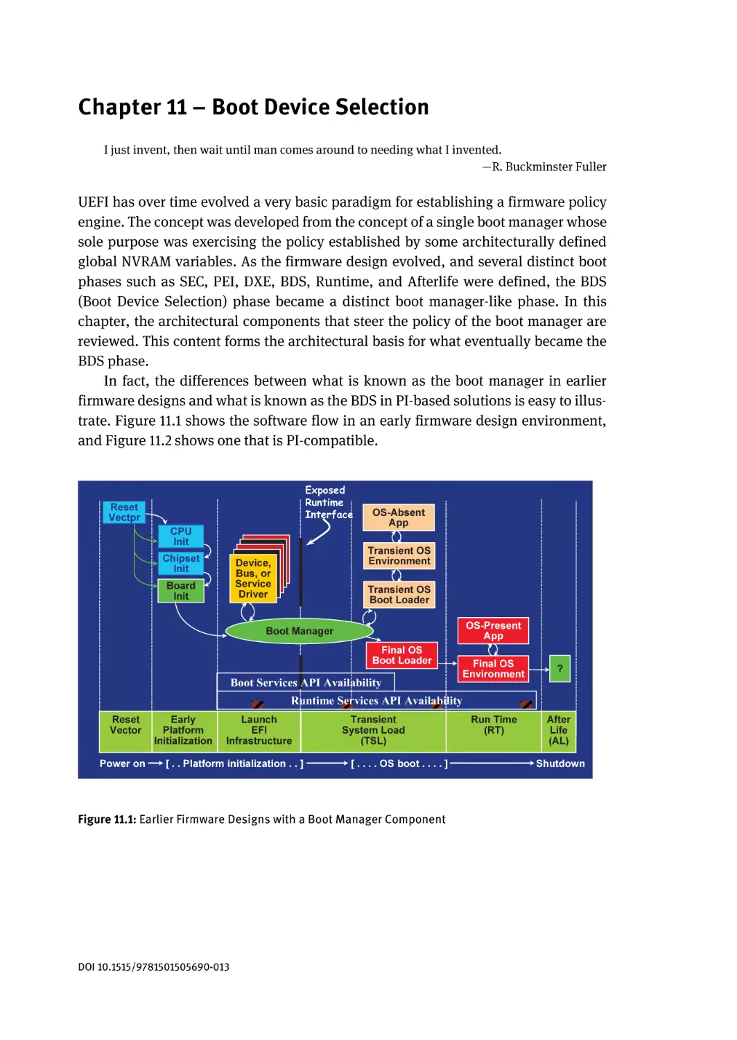
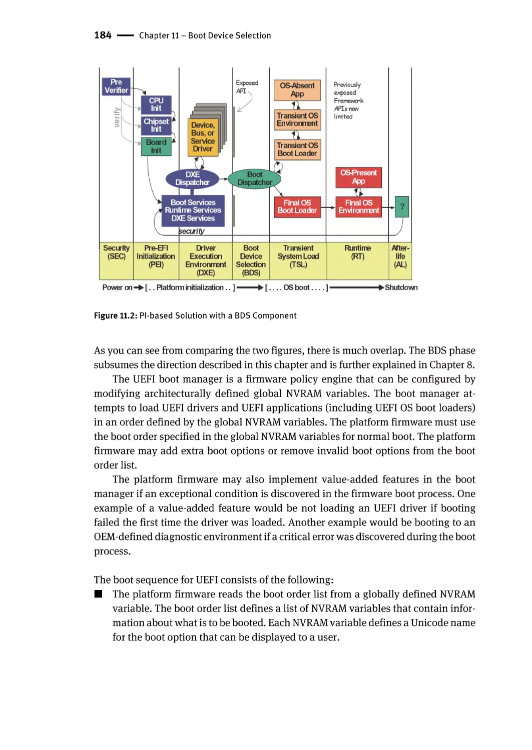
Chapter 11 – Boot Device Selection | 183
Firmware Boot Manager | 185
Related Definitions | 188
Globally-Defined Variables | 188
Default Behavior for Boot Option Variables | 191
Boot Mechanisms | 191
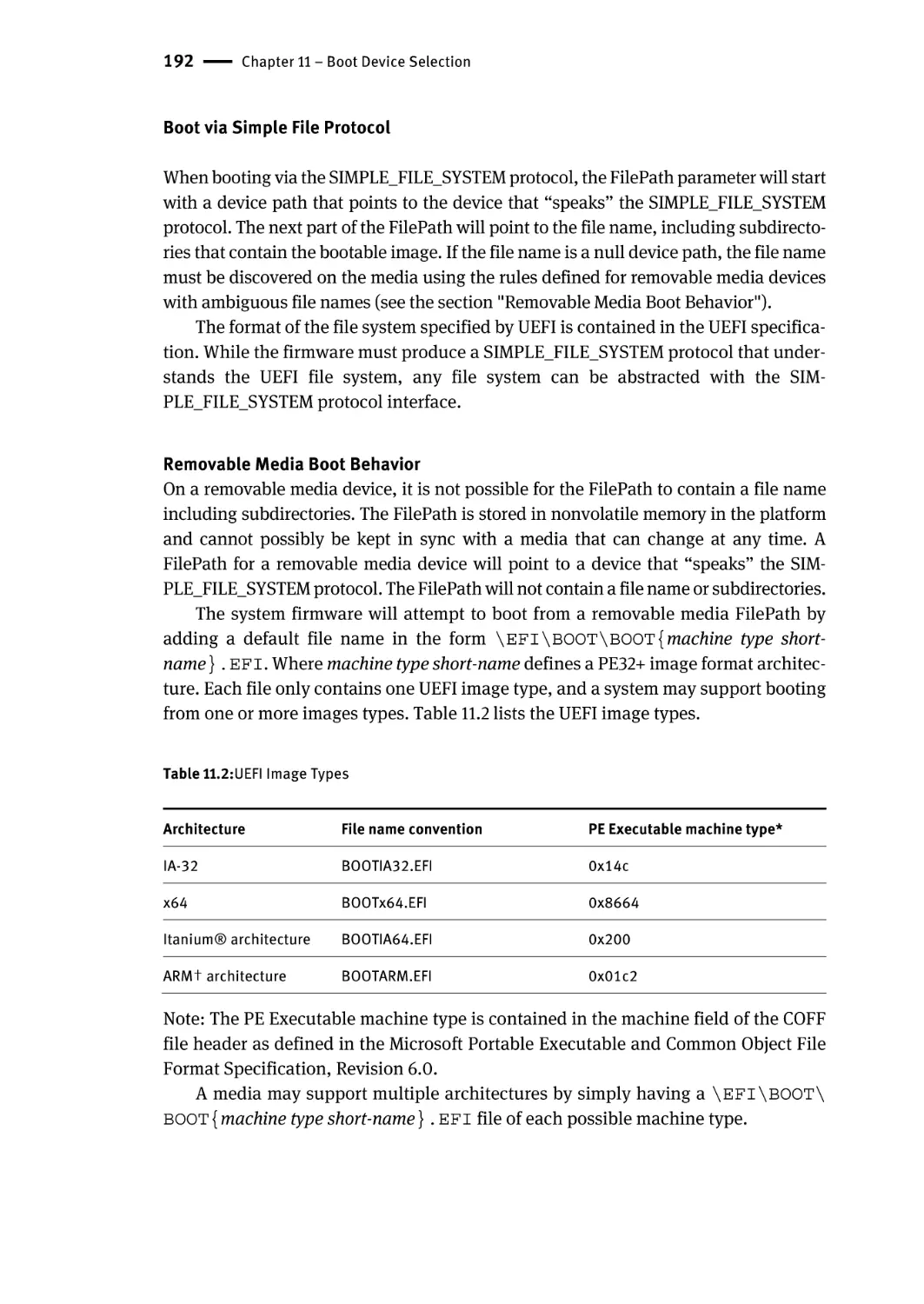
Boot via Simple File Protocol | 192
Boot via LOAD_FILE Protocol | 193
Summary | 194
Contents | xv
Chapter 12 – Boot Flows | 195
Defined Boot Modes | 196
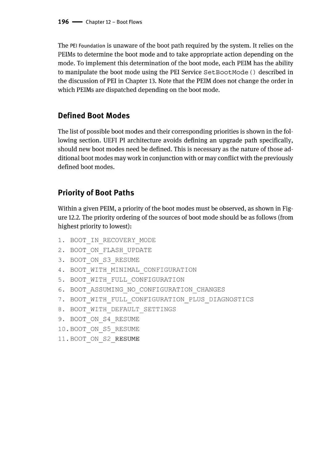
Priority of Boot Paths | 196
Reset Boot Paths | 198
Intel® Itanium® Processor Reset | 198
Non-Power-On Resets | 199
Normal Boot Paths | 199
Basic G0-to-S0 and S0 Variation Boot Paths | 200
S-State Boot Paths | 200
Recovery Paths | 201
Discovery | 201
General Recovery Architecture | 202
Special Boot Path Topics | 203
Special Boot Paths | 203
Special Intel Itanium® Architecture Boot Paths | 203
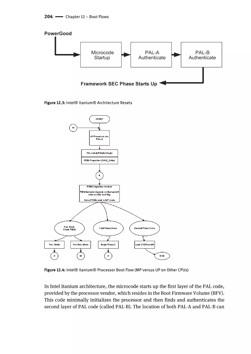
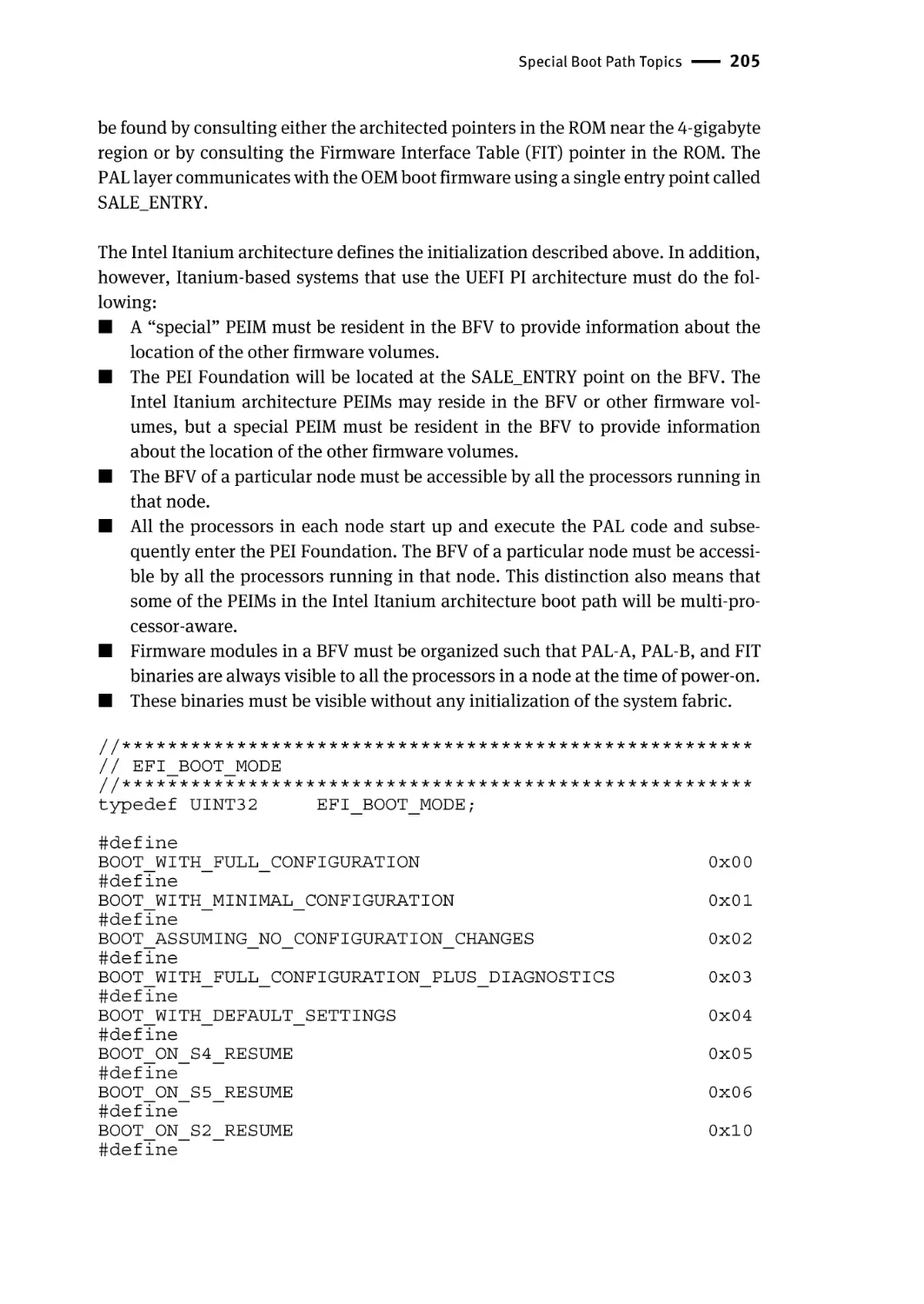
Intel Itanium® Architecture Access to the Boot Firmware Volume | 203
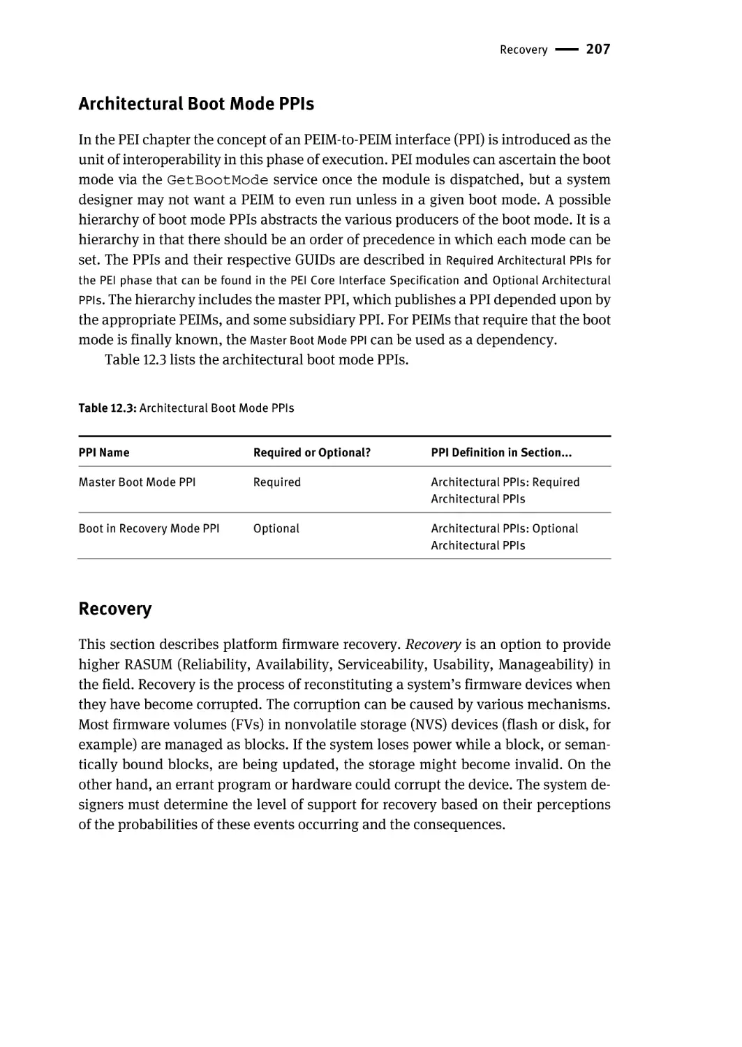
Architectural Boot Mode PPIs | 207
Recovery | 207
Discovery | 208
Summary | 208
Chapter 13 – Pre-EFI Initialization (PEI) | 209
Scope | 209
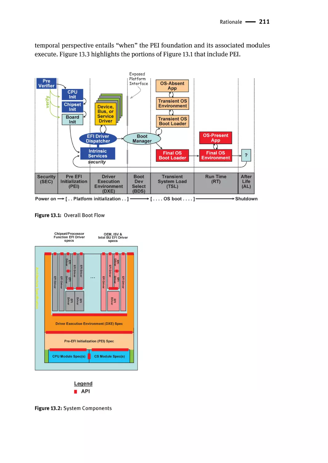
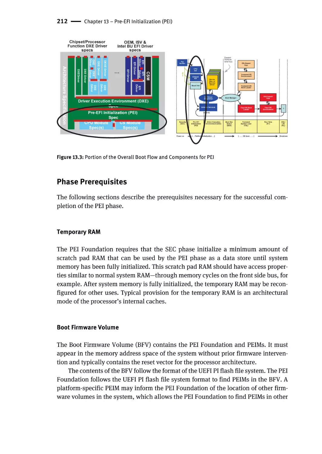
Rationale | 210
Overview | 210
Phase Prerequisites | 212
Temporary RAM | 212
Boot Firmware Volume | 212
Security Primitives | 213
Concepts | 213
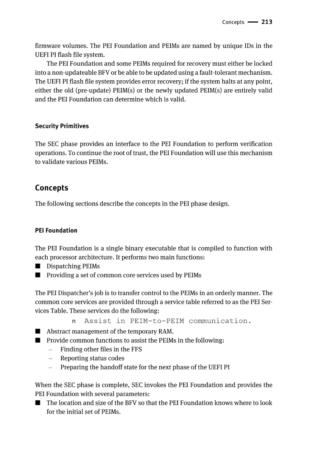
PEI Foundation | 213
Pre-EFI Initialization Modules (PEIMs) | 214
PEI Services | 215
PEIM-to-PEIM Interfaces (PPIs) | 215
Simple Heap | 216
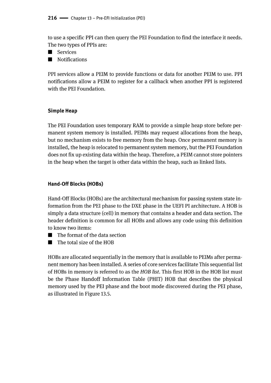
Hand-Off Blocks (HOBs) | 216
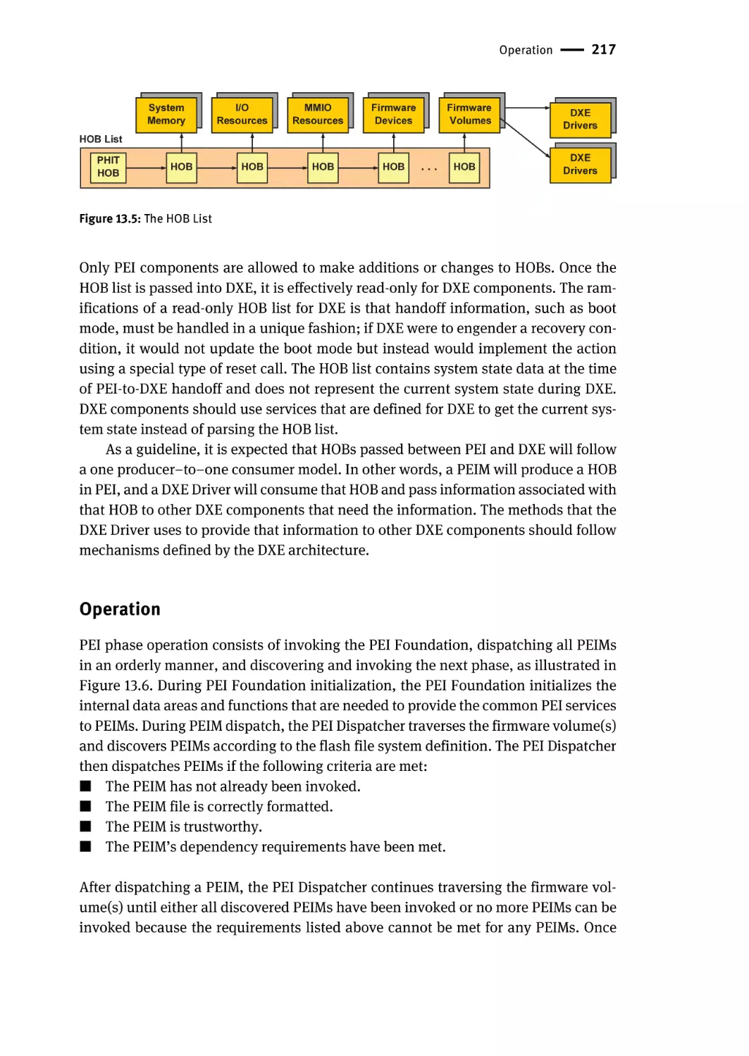
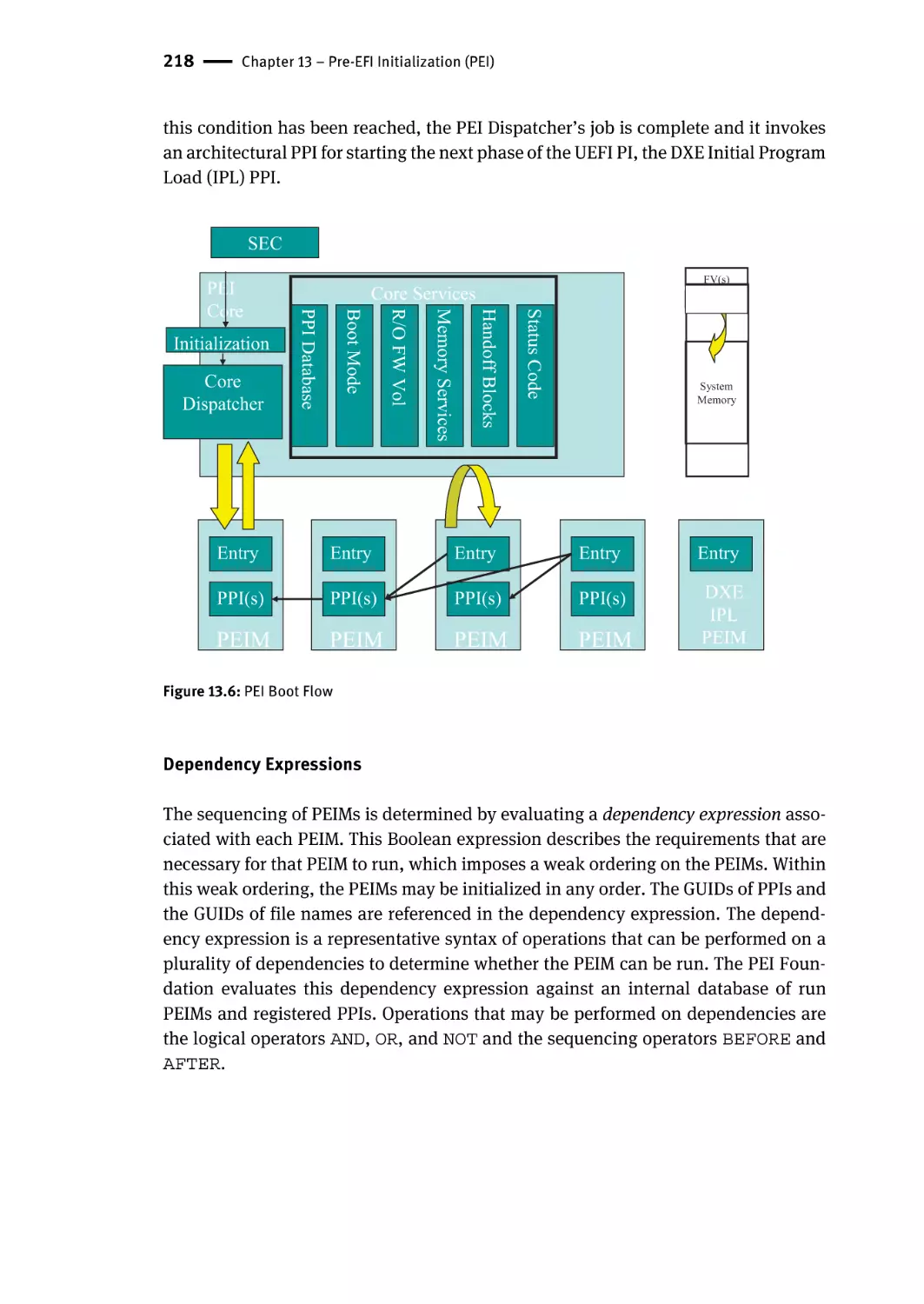
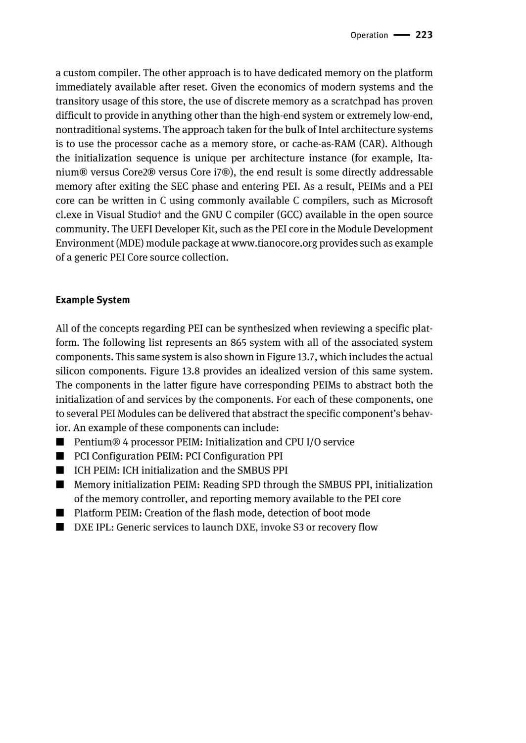
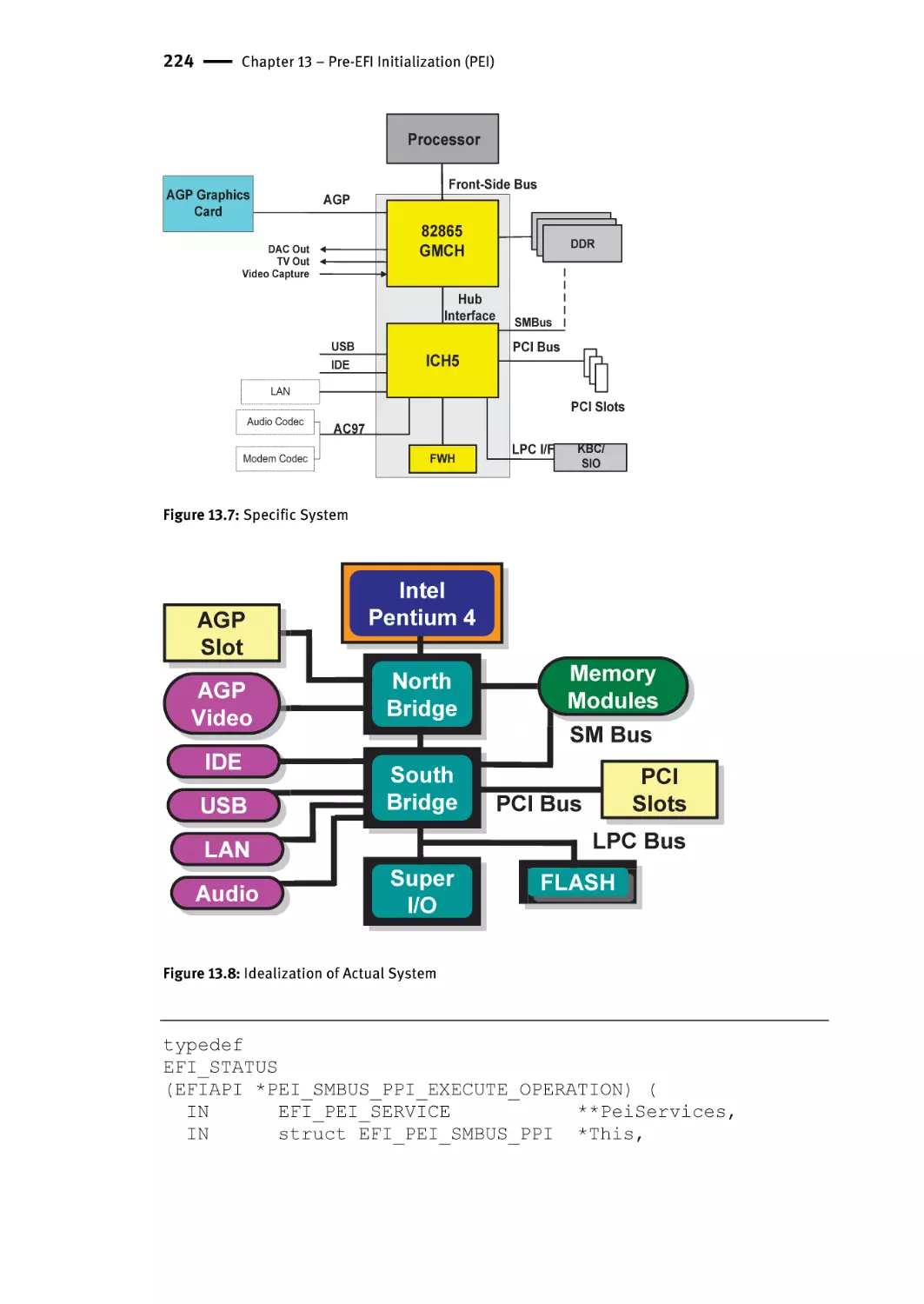
Operation | 217
Dependency Expressions | 218
Verification/Authentication | 219
PEIM Execution | 219
Memory Discovery | 219
Intel® Itanium® Processor MP Considerations | 220
xvi | Contents
Recovery | 220
S3 Resume | 221
The “Terse Executable” and Cache-as-RAM | 222
Example System | 223
Summary | 226
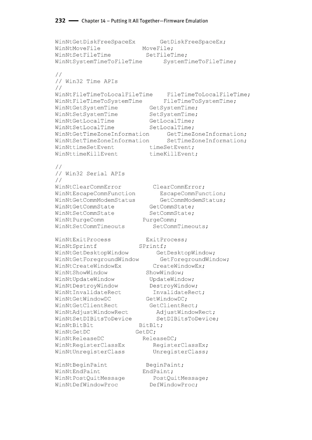
Chapter 14 – Putting It All Together—Firmware Emulation | 227
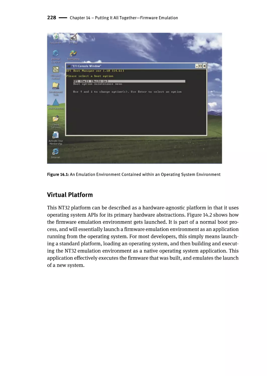
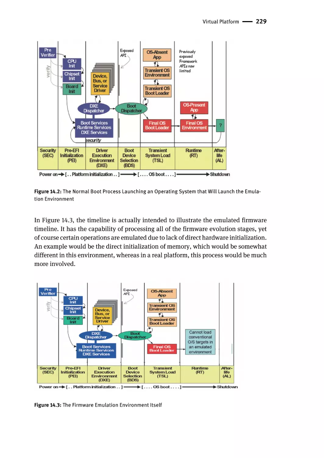
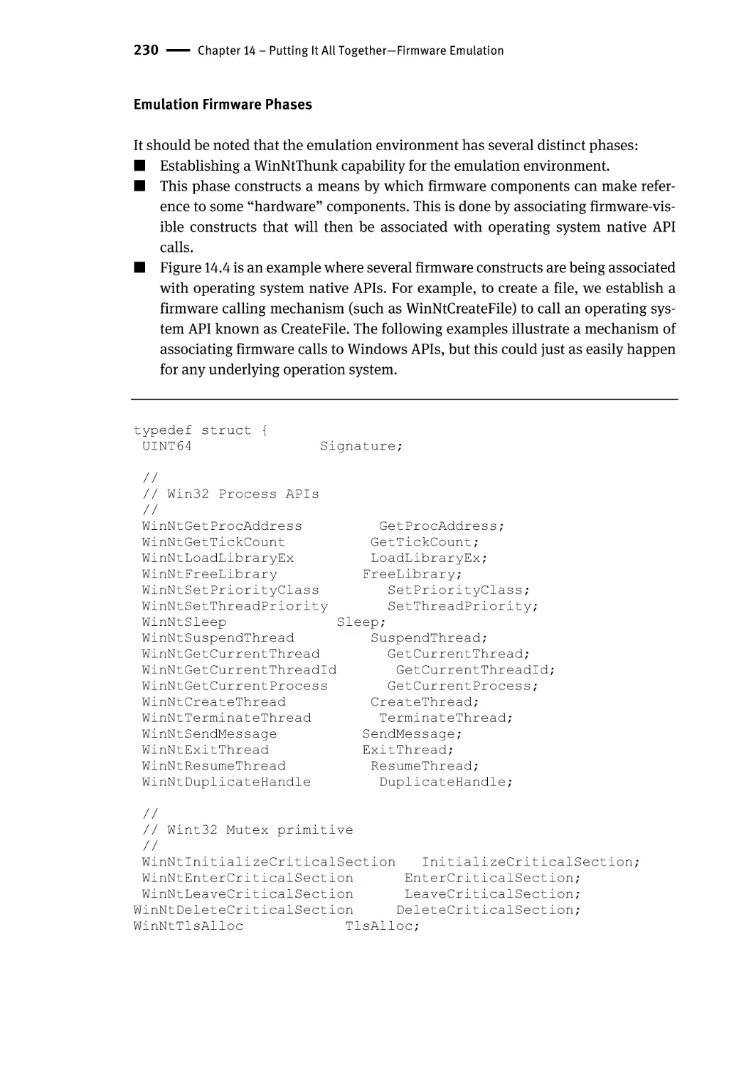
Virtual Platform | 228
Emulation Firmware Phases | 230
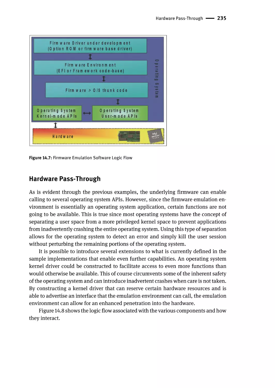
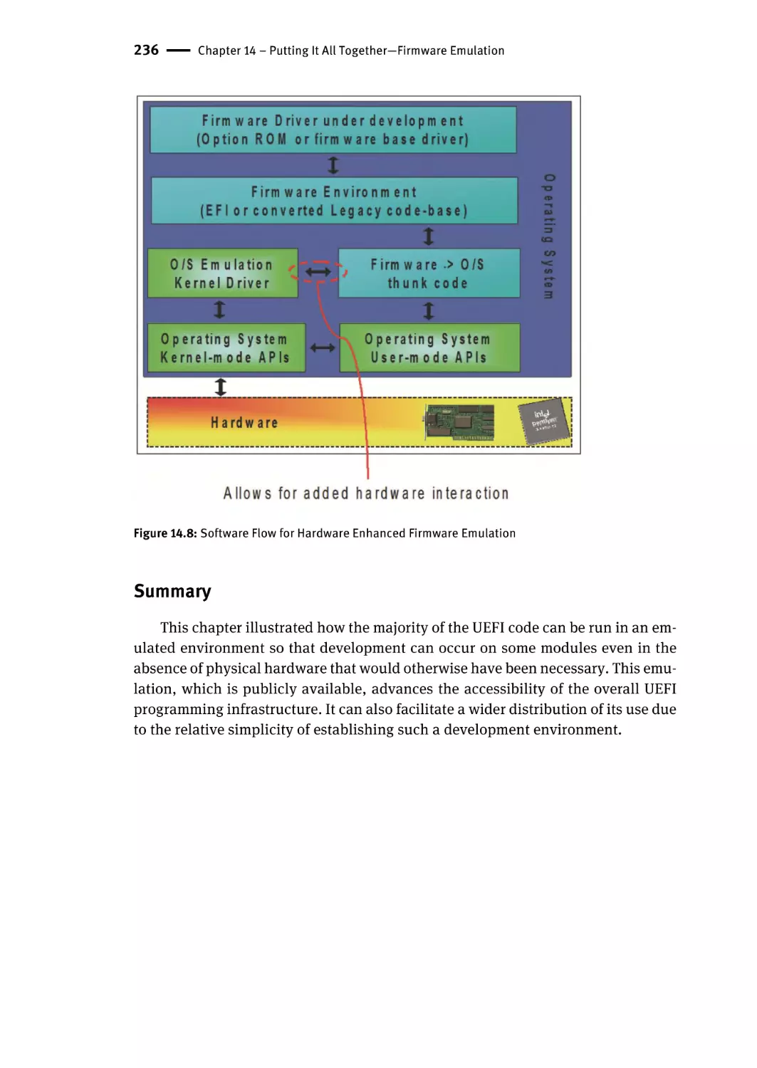
Hardware Pass-Through | 235
Summary | 236
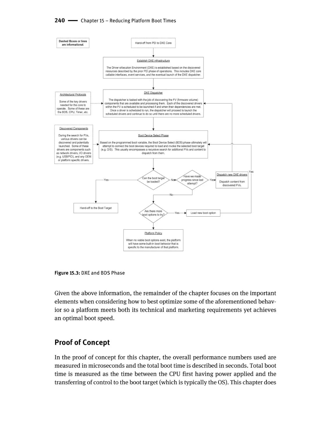
Chapter 15 – Reducing Platform Boot Times | 237
Proof of Concept | 240
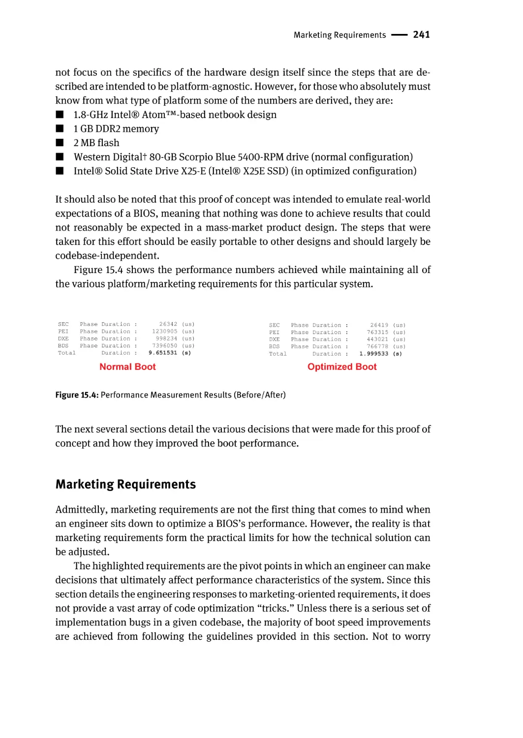
Marketing Requirements | 241
What Are the Design Goals? | 242
Platform Policy | 242
What Are the Supported OS Targets? | 243
Do We Have to Support Legacy Operating Systems? | 243
Do We Have to Support Legacy Option ROMs? | 243
Are We Required to Display an OEM Splash Screen? | 244
What Type of Boot Media Is Supported? | 244
What Is the BIOS Recovery/Update Strategy? | 245
When Processing Things Early | 245
Is There a Need for Pre-OS User Interaction? | 246
Additional Details | 246
Adjusting the BIOS to Avoid Unnecessary Drivers | 246
What Is the Boot Target? | 247
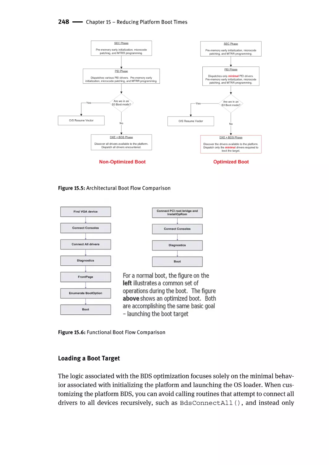
Steps Taken in a Normal and Optimized Boot | 247
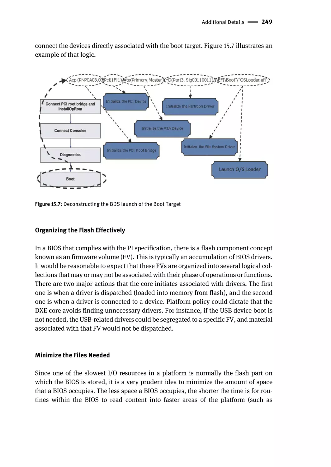
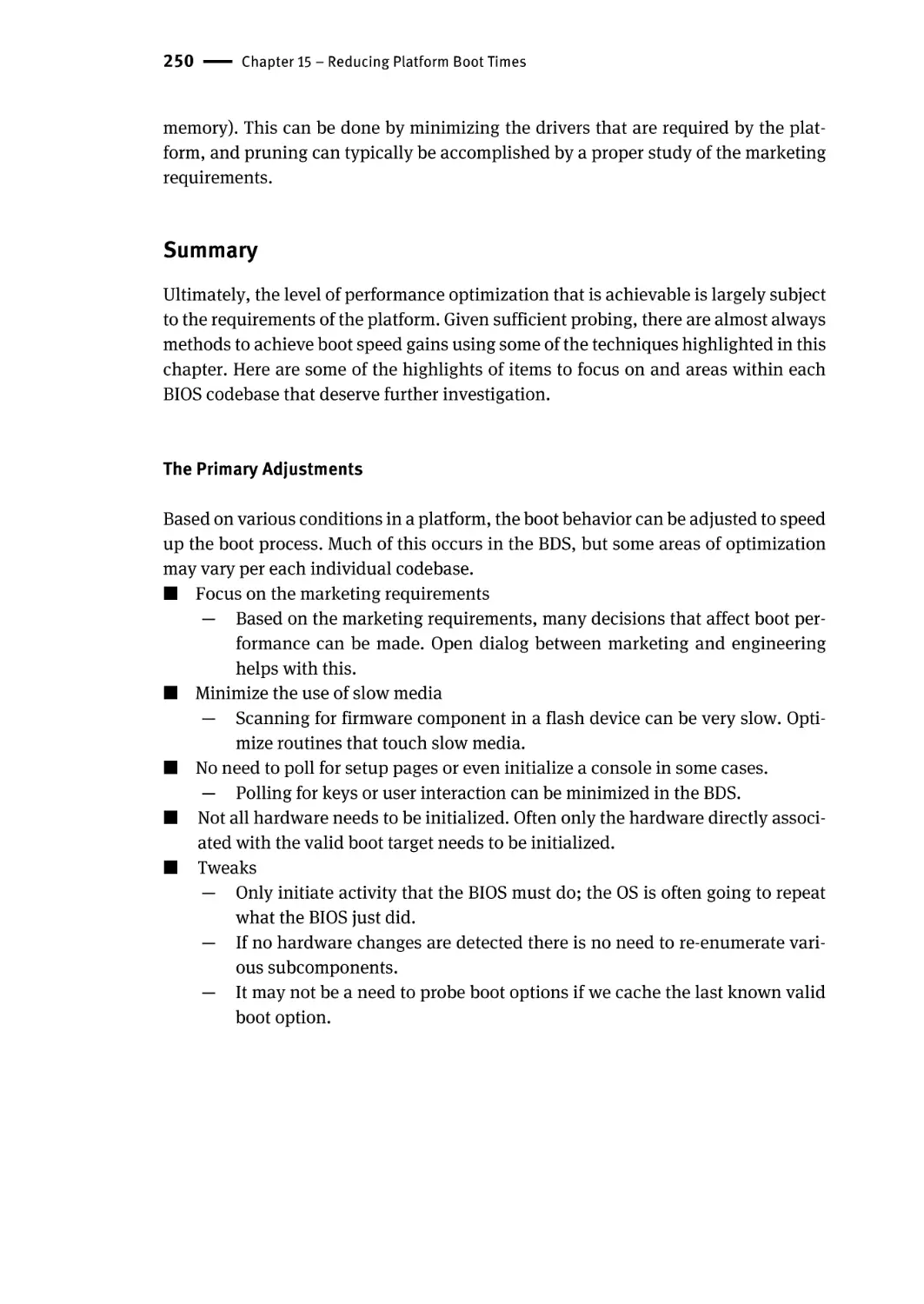
Loading a Boot Target | 248
Organizing the Flash Effectively | 249
Minimize the Files Needed | 249
Summary | 250
The Primary Adjustments | 250
Suggested Next Steps | 251
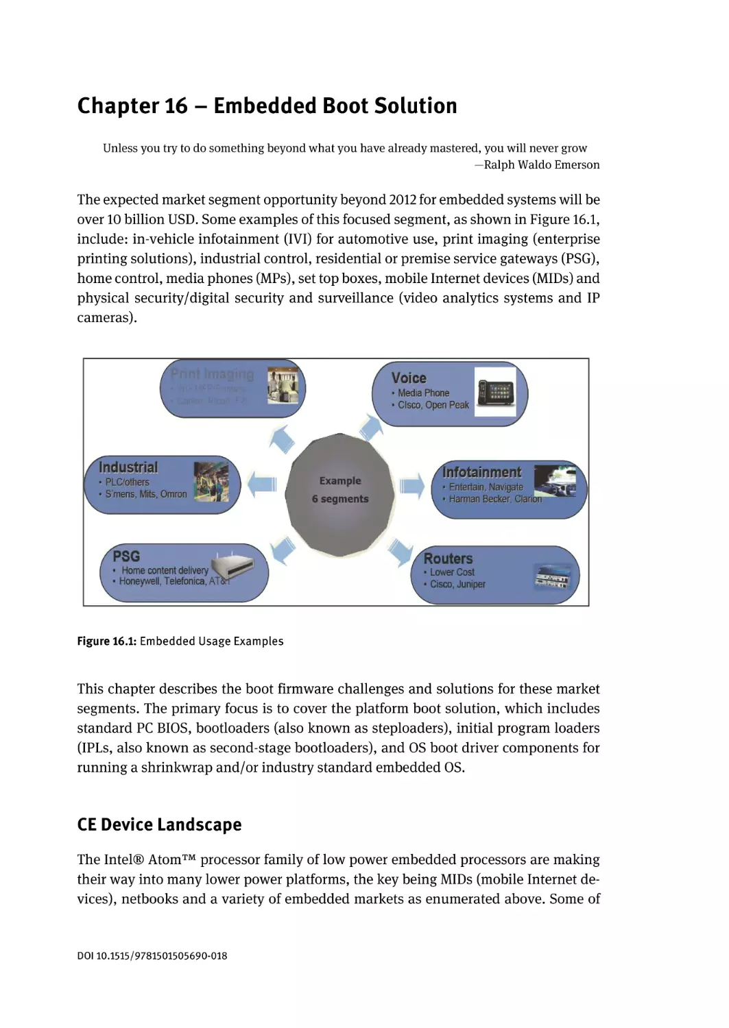
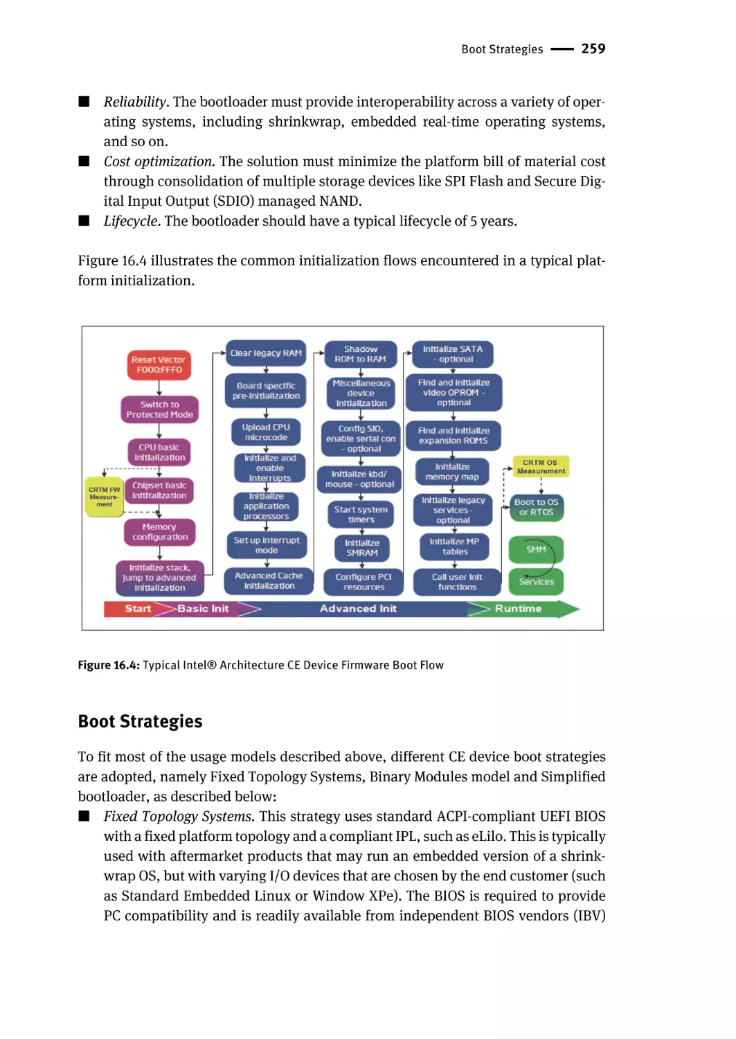
Chapter 16 – Embedded Boot Solution | 253
CE Device Landscape | 253
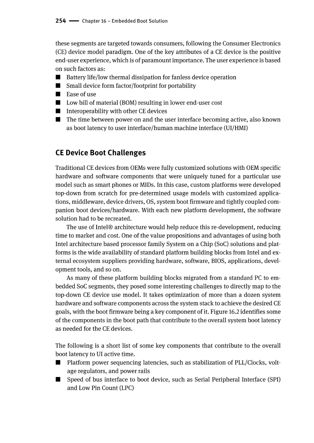
CE Device Boot Challenges | 254
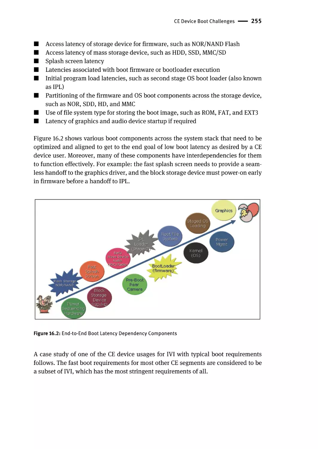
In-Vehicle Infotainment | 256
Other Embedded Platforms | 257
Generic Requirements | 258
Contents | xvii
Boot Strategies | 259
Power Management | 261
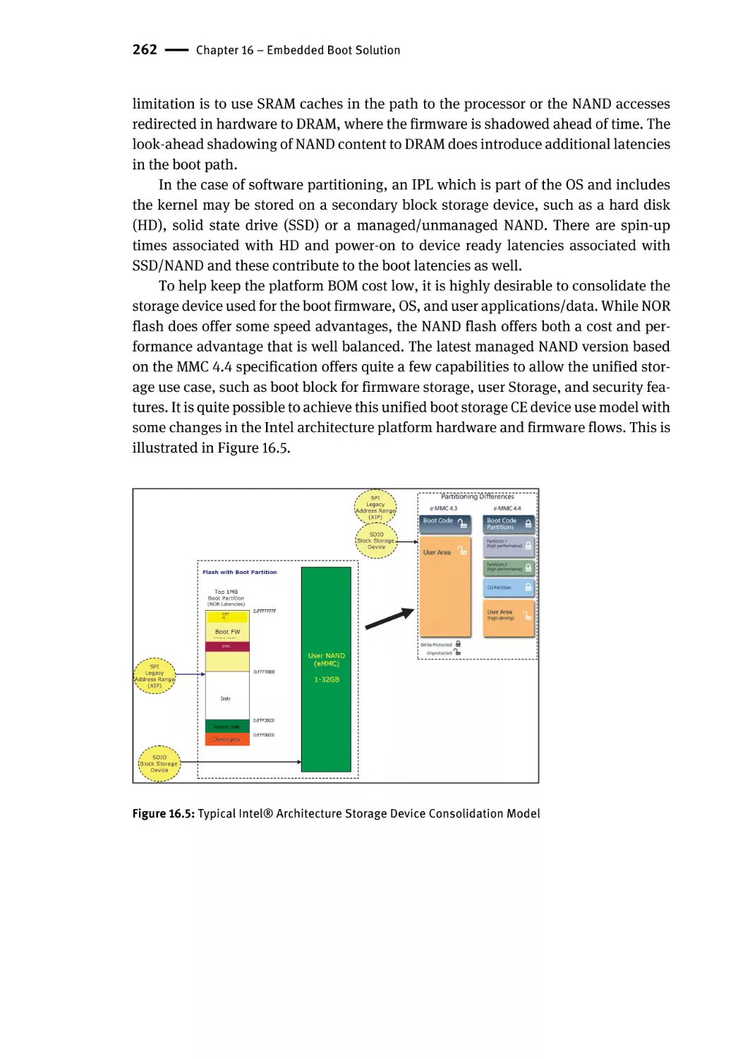
Boot Storage Devices | 261
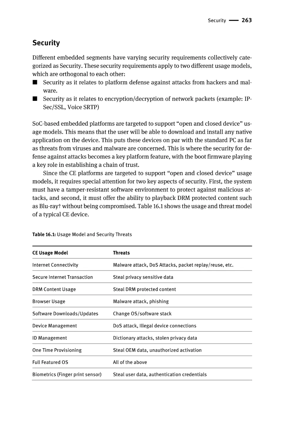
Security | 263
Manageability | 267
Summary | 268
Chapter 17 – Manageability | 269
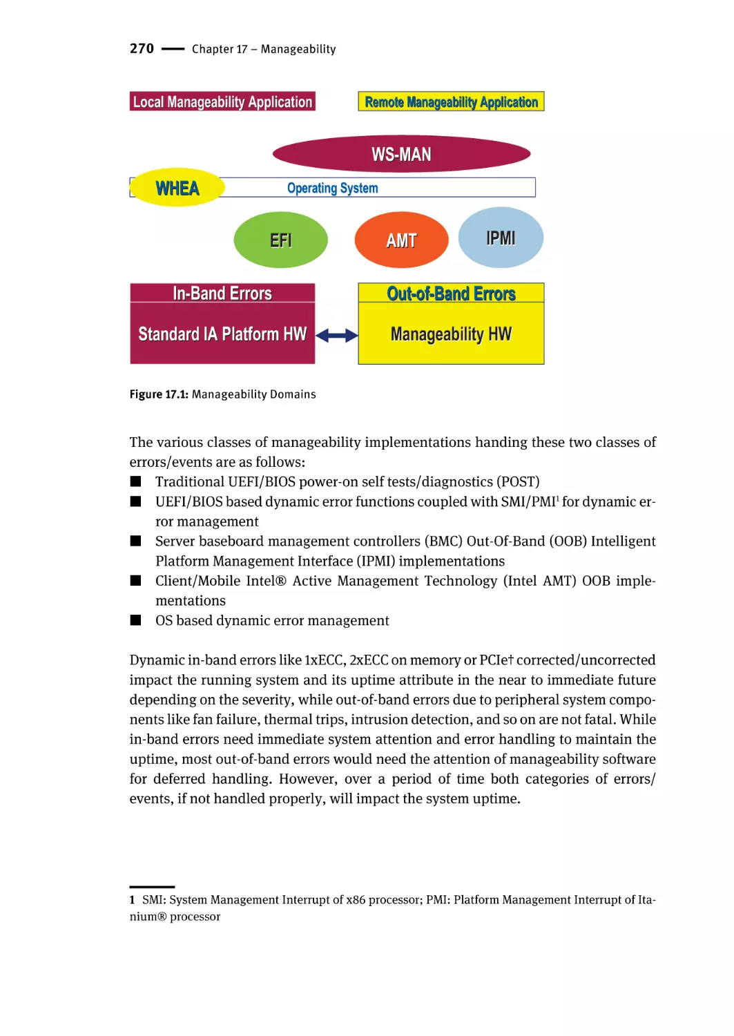
Overall Management Framework | 269
Dynamic In-Band | 271
Out-of-Band | 271
Distributed Management Task Force (DMTF) | 271
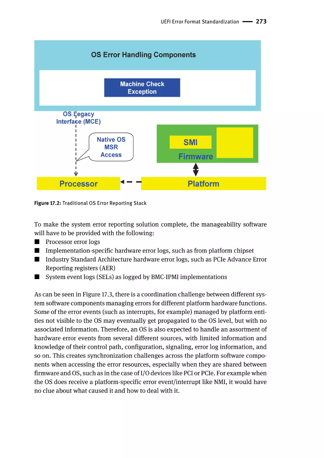
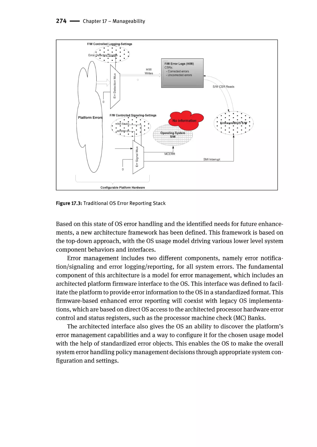
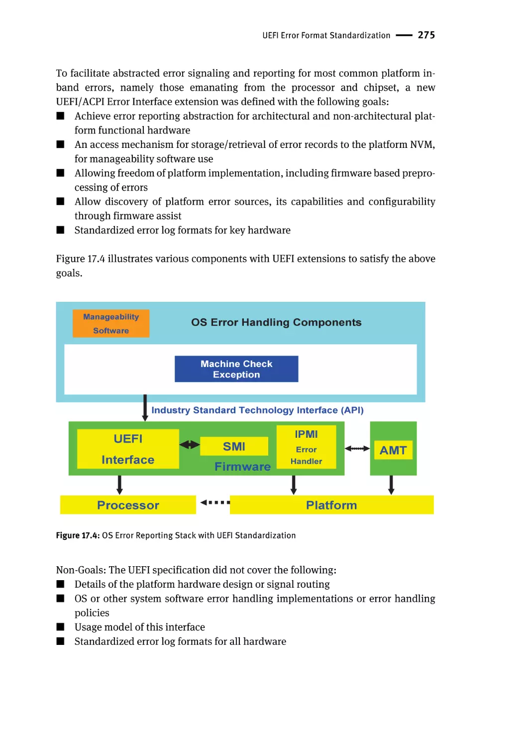
UEFI Error Format Standardization | 272
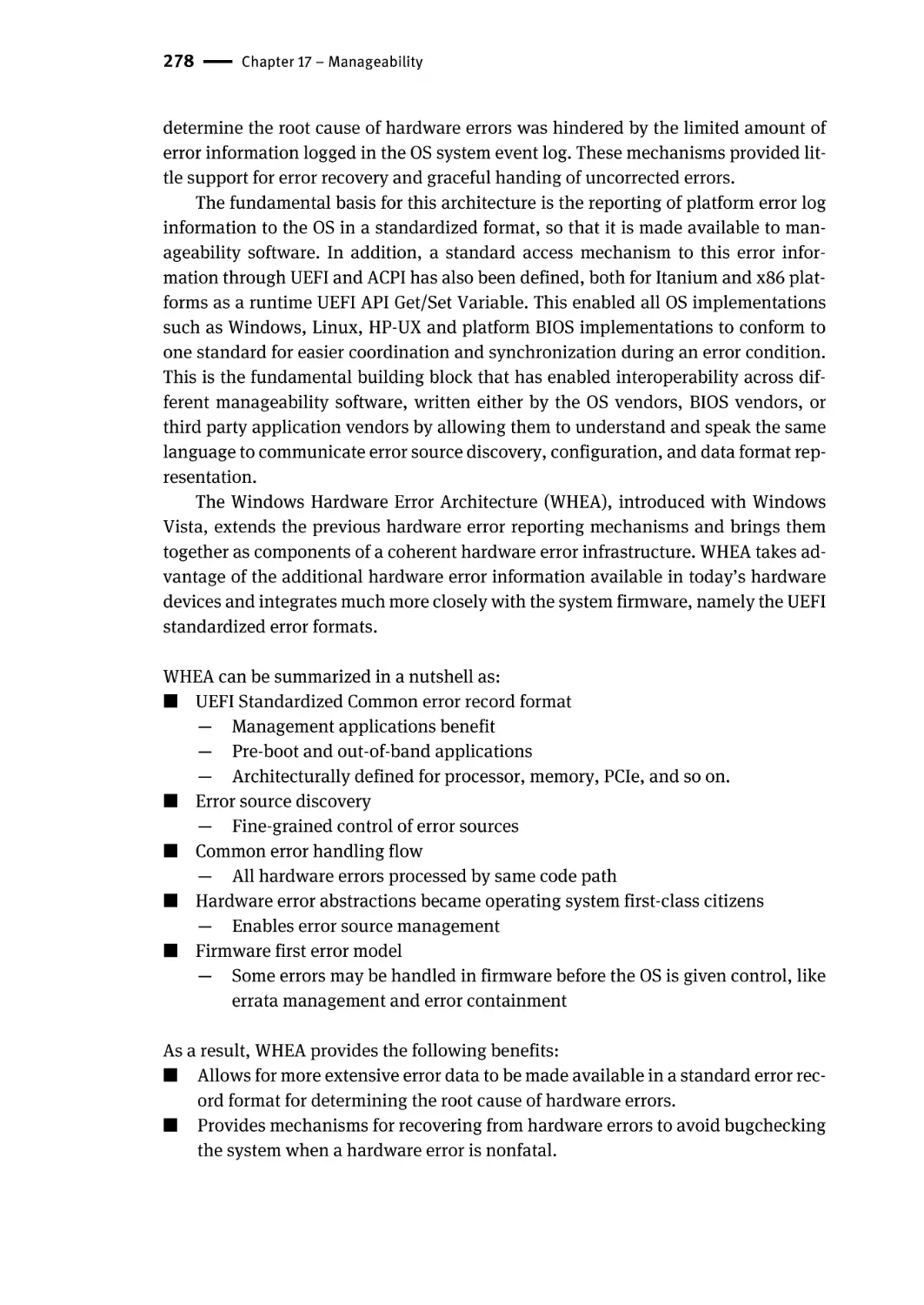
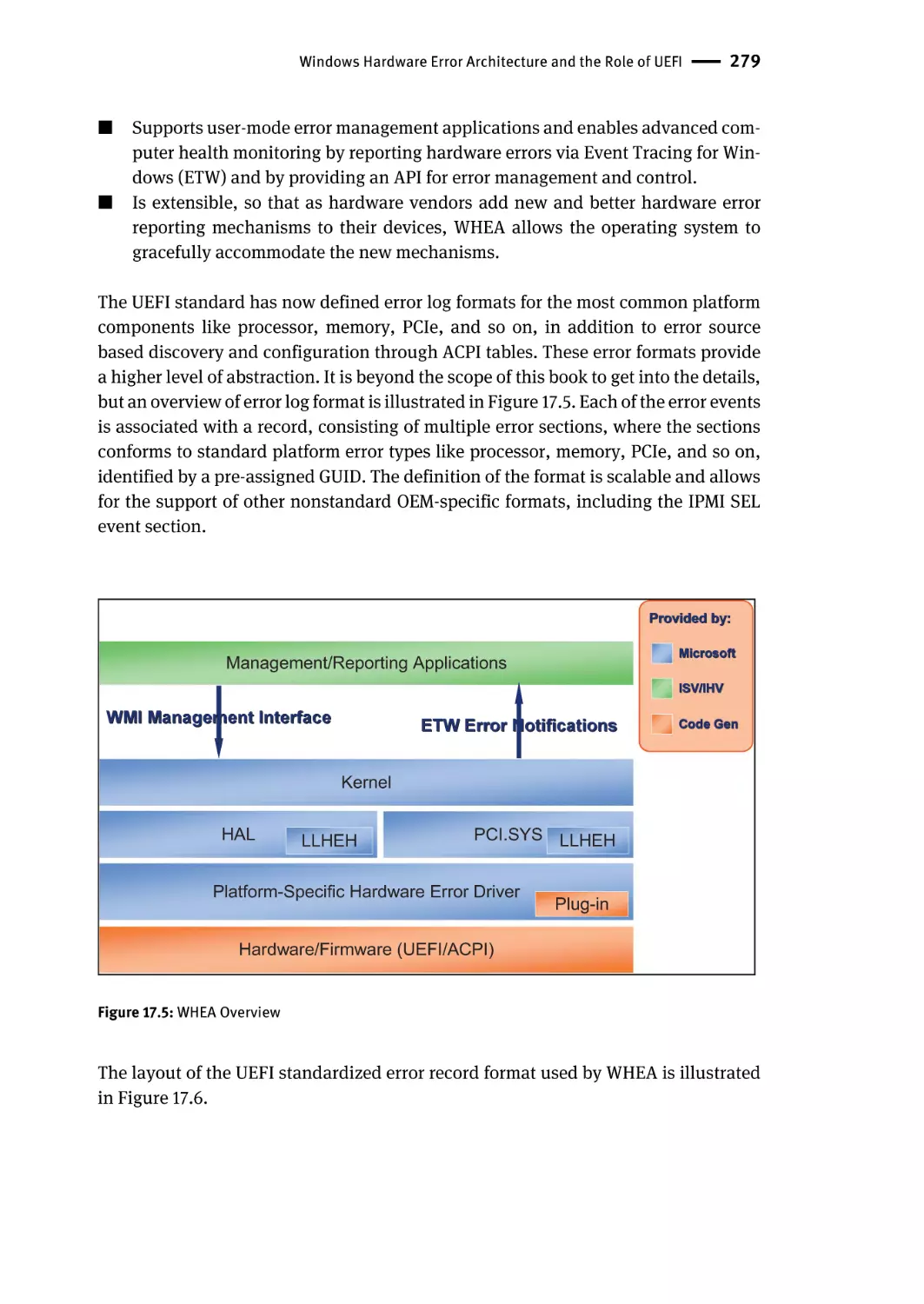
UEFI Error Format Overview | 276
Error Record Types | 276
Windows Hardware Error Architecture and the Role of UEFI | 277
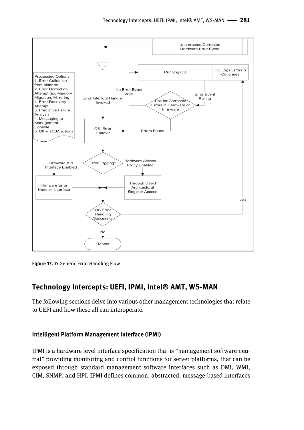
Technology Intercepts: UEFI, IPMI, Intel® AMT, WS-MAN | 281
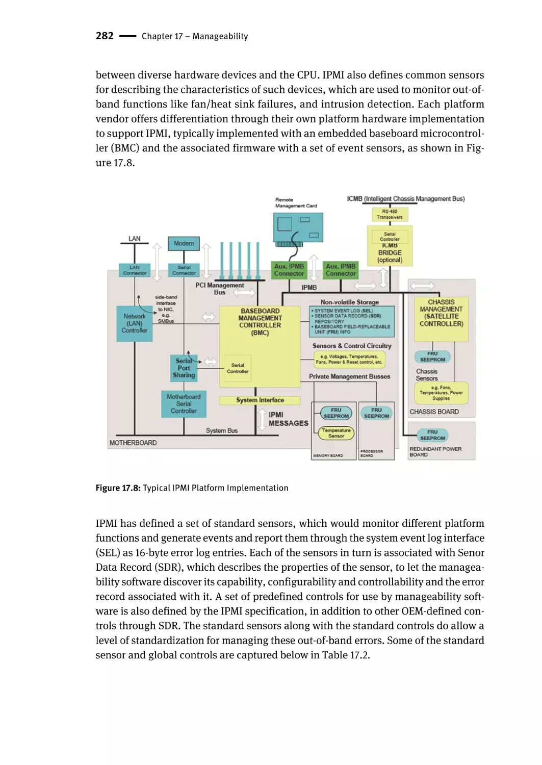
Intelligent Platform Management Interface (IPMI) | 281
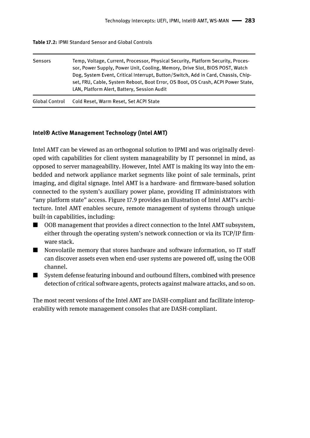
Intel® Active Management Technology (Intel AMT) | 283
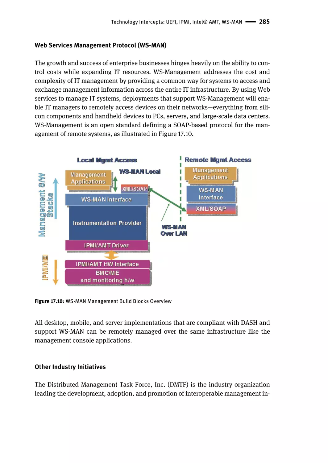
Web Services Management Protocol (WS-MAN) | 285
Other Industry Initiatives | 285
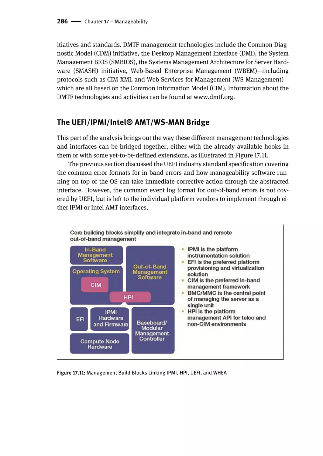
The UEFI/IPMI/Intel® AMT/WS-MAN Bridge | 286
IPMI Error Records to UEFI | 287
UEFI Error Records to IPMI | 287
Intel® AMT and IPMI | 287
Future Work | 288
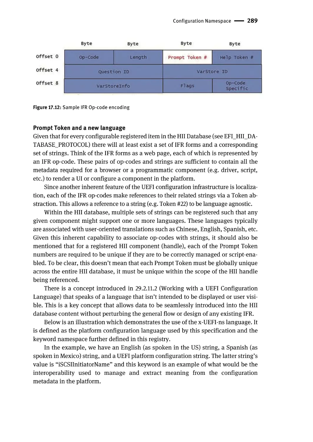
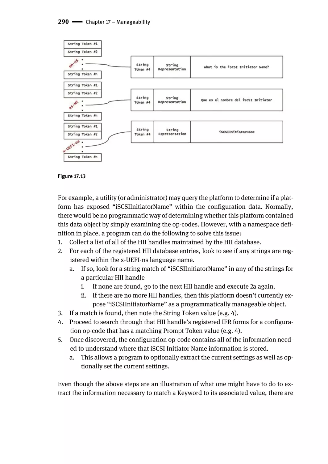
Configuration Namespace | 288
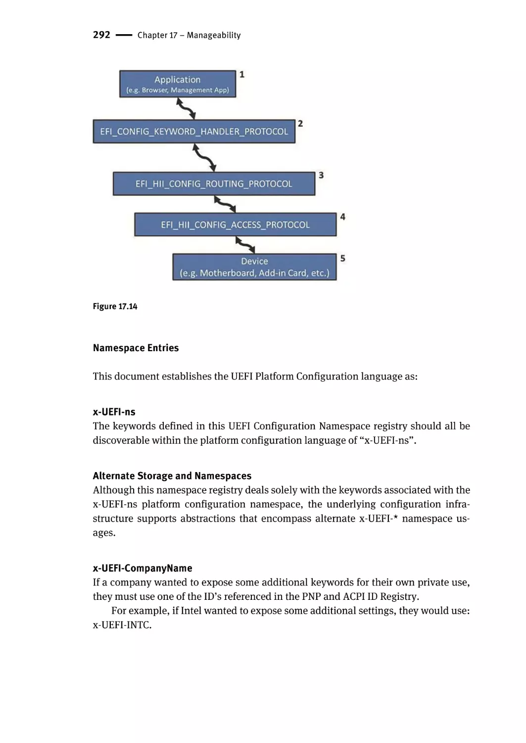
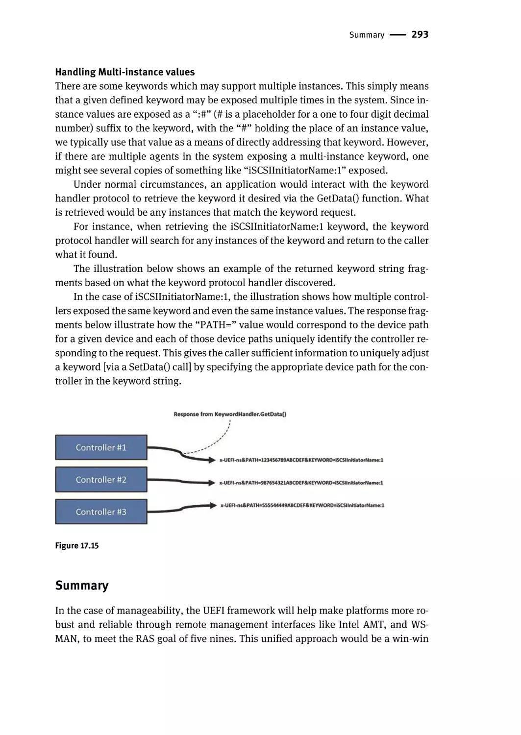
Namespace Entries | 292
Summary | 293
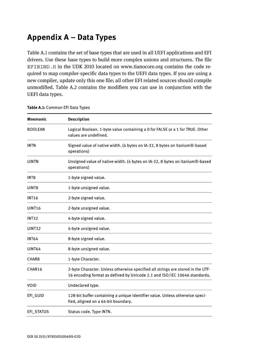
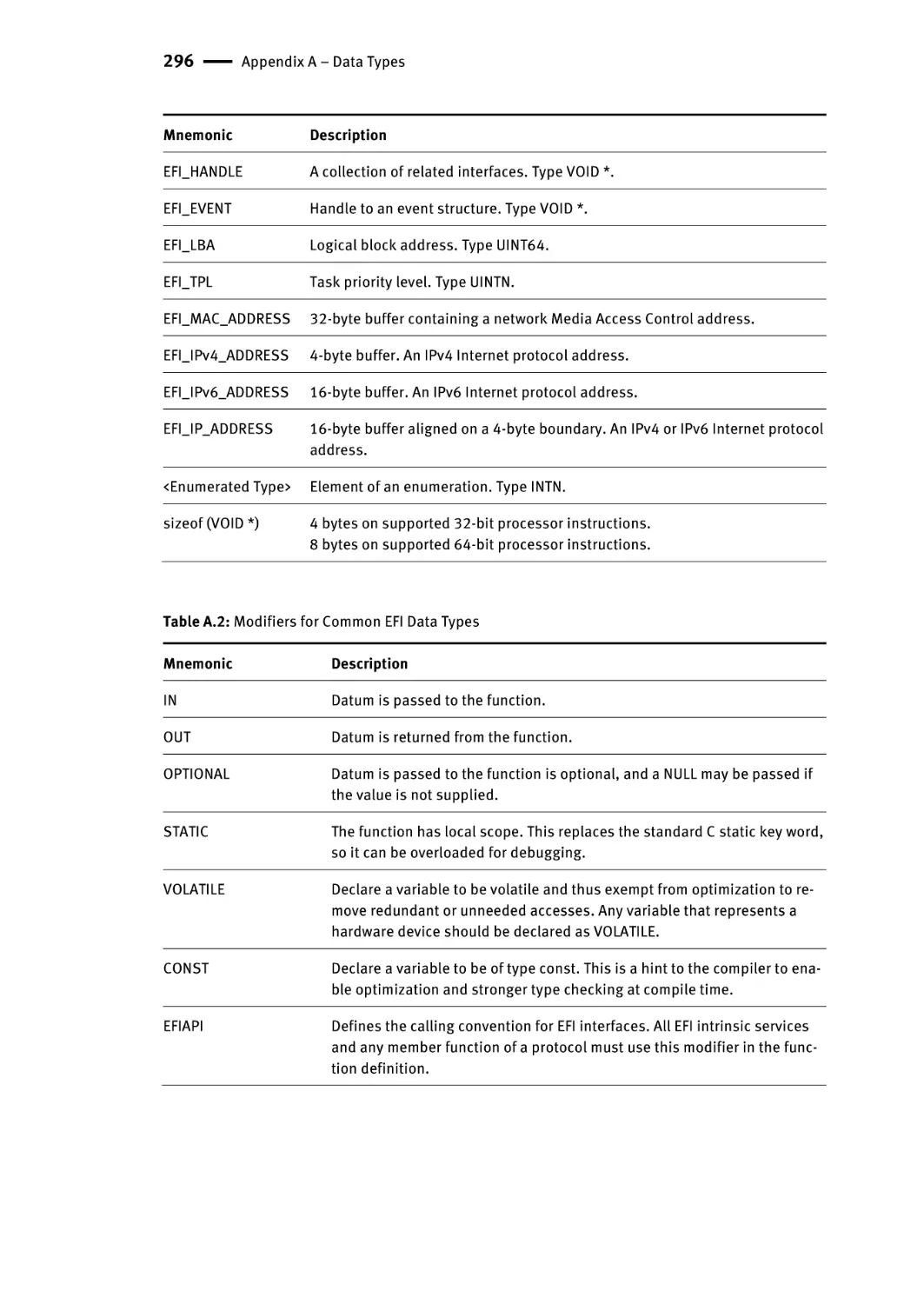
Appendix A – Data Types | 295
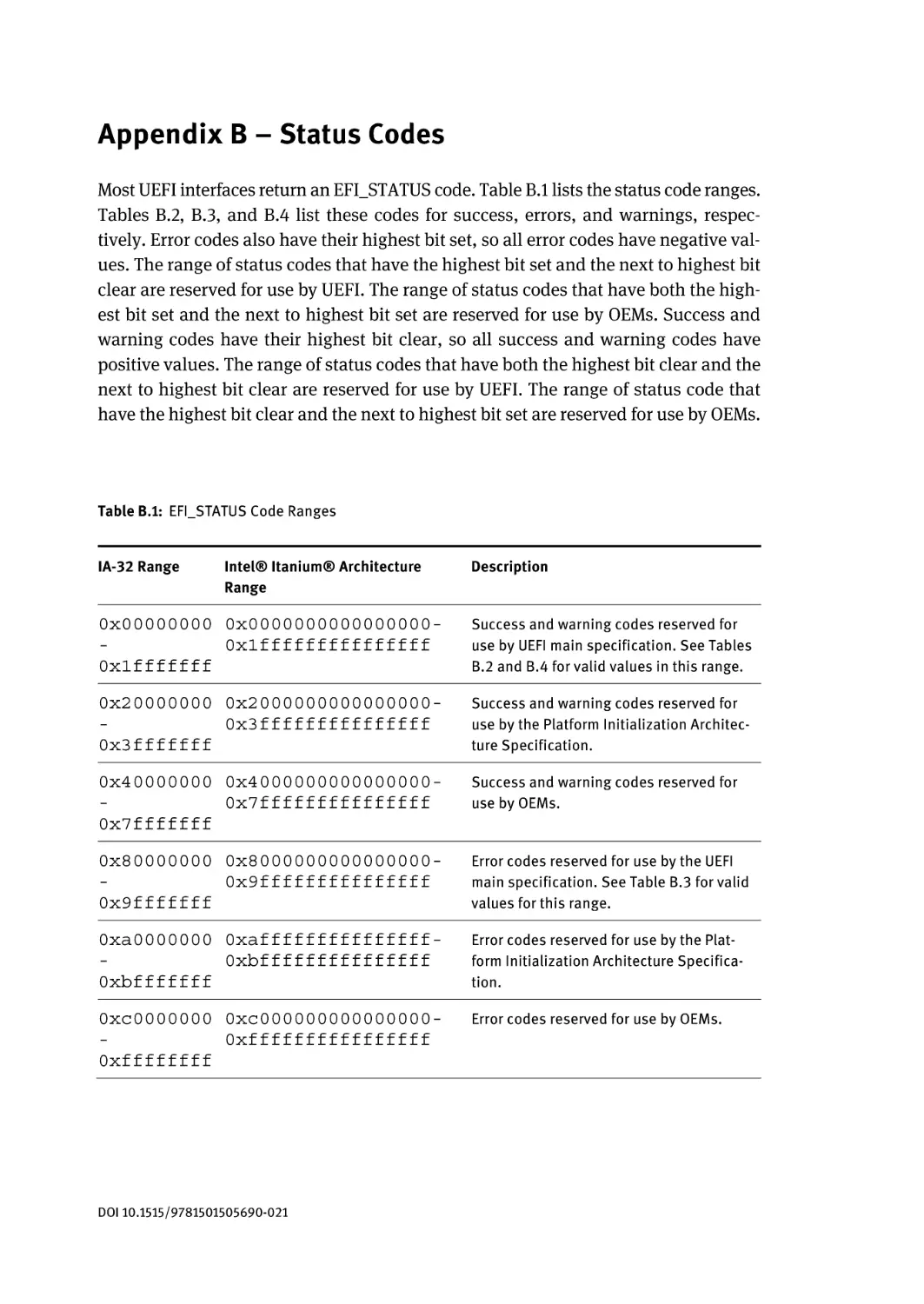
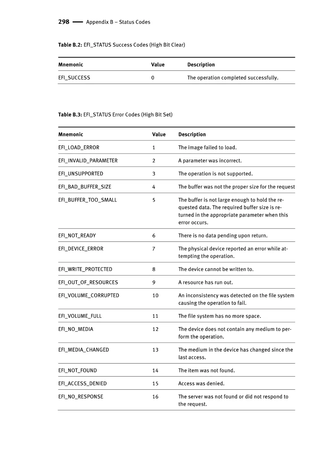
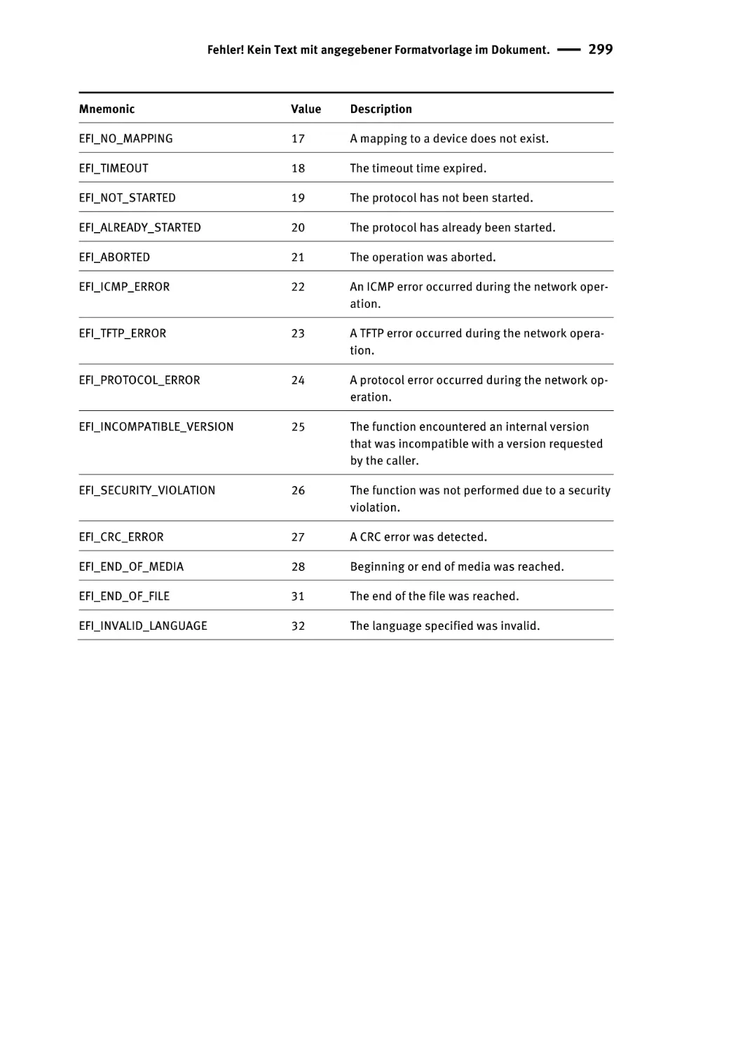
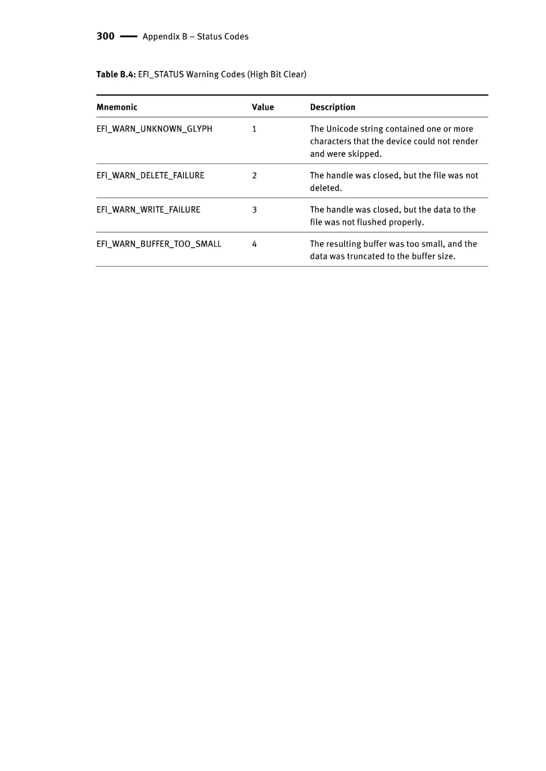
Appendix B – Status Codes | 297
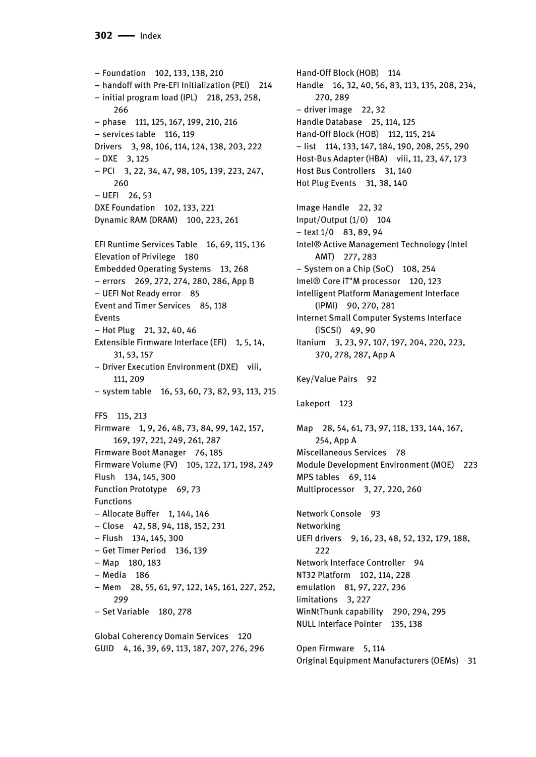
Index | 301
Chapter 1 – Introduction
The suddenness of the leap from hardware to software cannot but produce a period of anarchy
and collapse, especially in the developed countries.
—Marshall McLuhan
This chapter provides an overview of the evolution of the Extensible Firmware Interface (EFI) to the Unified Extensible Firmware Interface (UEFI) and from the Intel
Framework specifications to the UEFI Platform Initialization (PI) specifications. Note
the omission of the word “Framework” from the title of the present volume. Some of
the changes that have occurred since the first edition of this book include the migration of much of the Intel Framework specification content into the five volumes of the
UEFI Platform Initialization (PI) specifications, which are presently at revision 1.5 and
can be found at the Web site www.uefi.org. In addition to the PI evolution from
Framework, additional capabilities have evolved in both the PI building-block specifications and in the UEFI specification. The UEFI specification itself has evolved to
revision 2.6 in the time since the first edition of this text, as well.
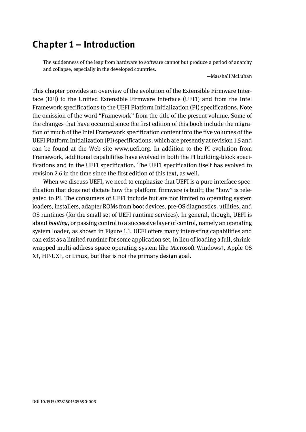
When we discuss UEFI, we need to emphasize that UEFI is a pure interface specification that does not dictate how the platform firmware is built; the “how” is relegated to PI. The consumers of UEFI include but are not limited to operating system
loaders, installers, adapter ROMs from boot devices, pre-OS diagnostics, utilities, and
OS runtimes (for the small set of UEFI runtime services). In general, though, UEFI is
about booting, or passing control to a successive layer of control, namely an operating
system loader, as shown in Figure 1.1. UEFI offers many interesting capabilities and
can exist as a limited runtime for some application set, in lieu of loading a full, shrinkwrapped multi-address space operating system like Microsoft Windows†, Apple OS
X†, HP-UX†, or Linux, but that is not the primary design goal.
DOI 10.1515/9781501505690-003
2 | Chapter 1 – Introduction
Figure 1.1: Where EFI and UEFI Fit into the Platform Boot Flow
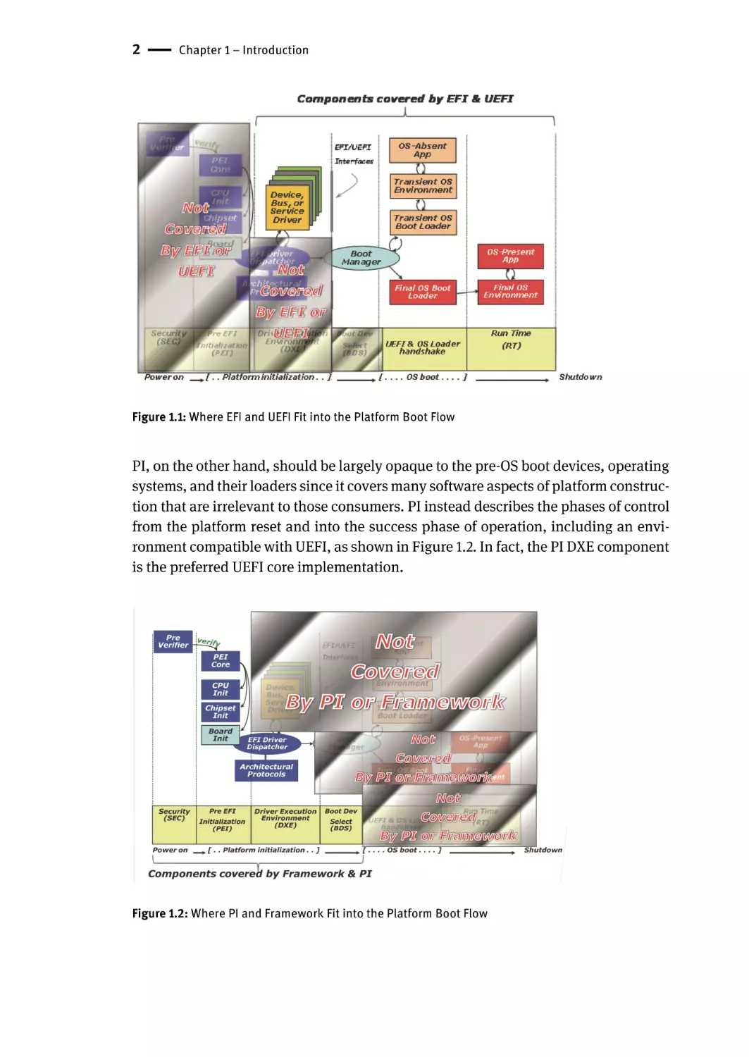
PI, on the other hand, should be largely opaque to the pre-OS boot devices, operating
systems, and their loaders since it covers many software aspects of platform construction that are irrelevant to those consumers. PI instead describes the phases of control
from the platform reset and into the success phase of operation, including an environment compatible with UEFI, as shown in Figure 1.2. In fact, the PI DXE component
is the preferred UEFI core implementation.
Figure 1.2: Where PI and Framework Fit into the Platform Boot Flow
Terminology | 3
Within the evolution of Framework to PI, some things were omitted from inclusion in
the PI specifications. As a result of these omissions, some subjects that were discussed in the first edition of Beyond BIOS, such as the compatibility support module
(CSM), have been removed from the second edition in order to provide space to describe the newer PI and UEFI capabilities. This omission is both from a scope perspective, namely that the PI specification didn’t want to codify or include the CSM, but
also from a long-term perspective. Specifically, the CSM specification abstracted booting on a PC/AT system. This requires an x86 processor, PC/AT hardware complex (for
example, 8254, 8259, RTC). The CSM also inherited other conventional BIOS boot limitations, such as the 2.2-TB disk limit of Master Boot Record (MBR) partition tables.
For a world of PI and UEFI, you get all of the x86 capabilities (IA-32 and x64, respectively), ARM†, Itanium®, and future CPU bindings. Also, via the polled driver model
design, UEFI APIs, and the PI DXE architectural protocols, the platform and component hardware details are abstracted from all consumer software. Other minor omissions also include data hub support. The latter has been replaced by purpose-built
infrastructure to fill the role of data hub in Framework-based implementations, such
as SMBIOS table creation and agents to log report status code actions.
What has happened in PI beyond Framework, though, includes the addition of a
multiprocessor protocol, Itanium E-SAL and MCA support, the above-listed reportstatus code listener and SMBIOS protocol, an ACPI editing protocol, and an SIO protocol. With Framework collateral that moved to PI, a significant update was made to
the System Management Mode (SMM) protocol and infrastructure to abstract out various CPU and chipset implementations from the more generic components. On the
DXE front, small cleanup was added in consideration of UEFI 2.3 incompatibility.
Some additions occurred in the PEI foundation for the latest evolution in buses, such
as PCI Express†. In all of these cases, the revisions of the SMM, PEI, and DXE service
tables were adjusted to ease migration of any SMM drivers, DXE drivers, and PEI module (PEIM) sources to PI. In the case of the firmware file system and volumes, the
headers were expanded to comprehend larger file and alternate file system encodings, respectively. Unlike the case for SMM drivers, PEIMs, and DXE drivers, these
present a new binary encoding that isn’t compatible with a pure Framework implementation.
The notable aspect of the PI is the participation of the various members of the
UEFI Forum, which will be described below. These participants represent the consumers and producers of PI technology. The ultimate consumer of a PI component is
the vendor shipping a system board, including multinational companies such as Apple, Dell, HP, IBM, Lenovo, and many others. The producers of PI components include
generic infrastructure producers such as the independent BIOS vendors (IBVs) like
AMI, Insyde, Phoenix, and others. And finally, the vendors producing chipsets, CPUs,
and other hardware devices like AMD, ARM, and Intel would produce drivers for their
respective hardware. The IBVs and the OEMs would use the silicon drivers, for example. If it were not for this business-to-business transaction, the discoverable binary
4 | Chapter 1 – Introduction
interfaces and separate executable modules (such as PEIMs and DXE drivers) would
not be of interest. This is especially true since publishing GUID-based APIs, marshalling interfaces, discovering and dispatching code, and so on take some overhead in
system board ROM storage and boot time. Given that there’s never enough ROM
space, and also in light of the customer requirements for boot-time such as the need
to be “instantly on,” this overhead must be balanced by the business value of PI module enabling. If only one vendor had access to all of the source and intellectual property to construct a platform, a statically bound implementation would be more efficient, for example. But in the twenty-first century with the various hardware and
software participants in the computing industry, software technology such as PI is
key to getting business done in light of the ever-shrinking resource and time-to-market constraints facing all of the UEFI forum members.
There is a large body of Framework-based source-code implementations, such as
those derived or dependent upon EDK I (EFI Developer Kit, which can be found on
www.tianocore.org. These software artifacts can be recompiled into a UEFI 2.6, PI 1.5compliant core, such as UDK2015 (the UEFI Developer Kit revision 2015), via the EDK
Compatibility Package (ECP). For new development, though, the recommendation is
to build native PI 1.5, UEFI 2.6 modules in the UDK2015 since these are the specifications against which long-term silicon enabling and operating system support will occur, respectively.
Terminology
The following list provides a quick overview of some of the terms that may be encountered later in the book and have existed in the industry associated with the BIOS
standardization efforts.
■ UEFI Forum. The industry body, which produces UEFI, Platform Initialization
(PI), and other specifications.
■ UEFI Specification. The firmware-OS interface specification.
■ EDK. The EFI Development Kit, an open sourced project that provides a basic implementation of UEFI, Framework, and other industry standards. It, is not however, a complete BIOS solution. An example of this can be found at www.tianocore.org.
■ UDK. The UEFI Development Kit is the second generation of the EDK (EDK II), which
has added a variety of codebase related capabilities and enhancements. The inaugural UDK is UDK2015, with the number designating the instance of the release.
■ Framework. A deprecated term for a set of specifications that define interfaces
and how various platform components work together. What this term referred to
is now effectively replaced by the PI specifications.
■ Tiano. An obsolete codename for an Intel codebase that implemented the Framework specifications.
Short History of EFI | 5
Short History of EFI
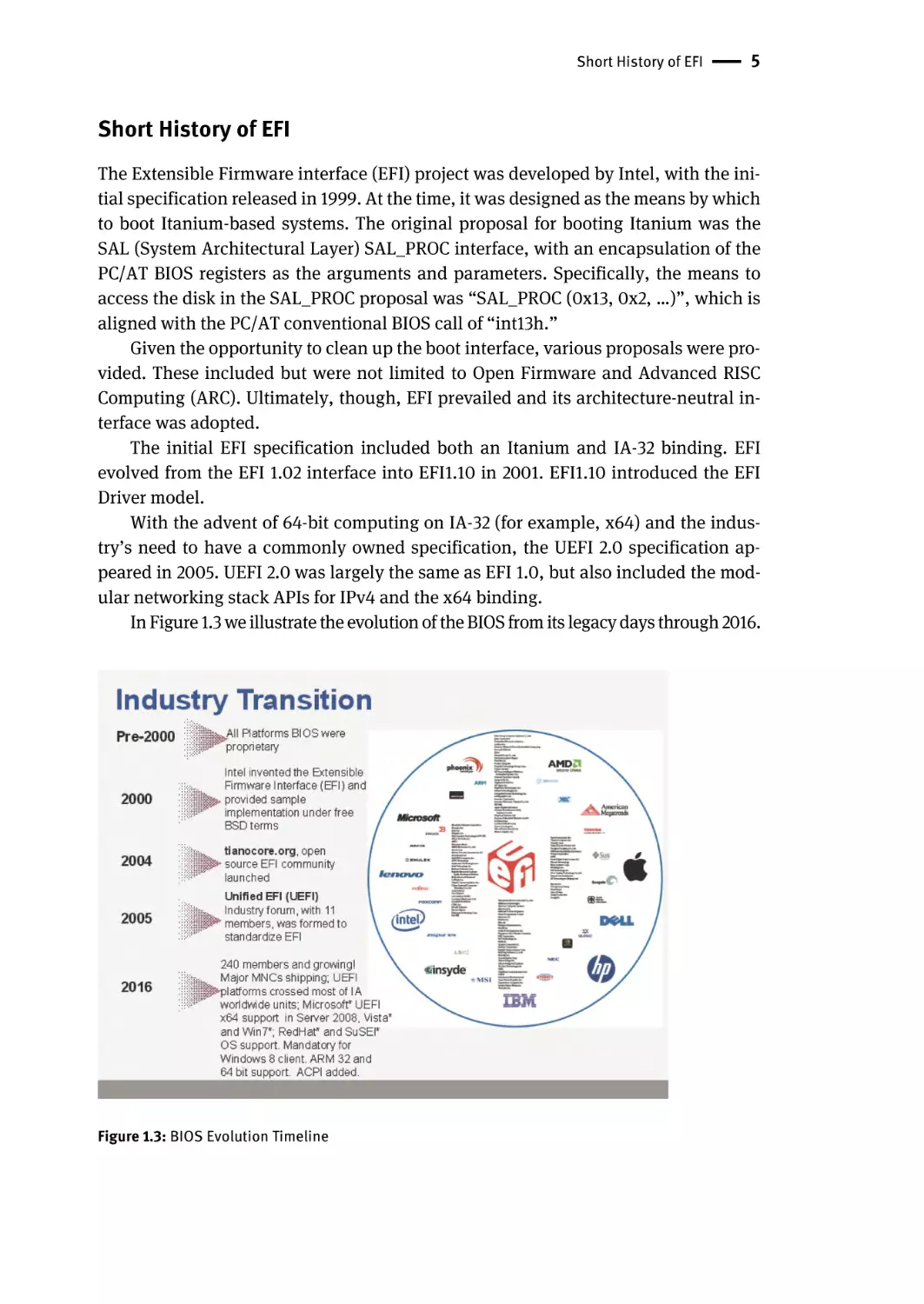
The Extensible Firmware interface (EFI) project was developed by Intel, with the initial specification released in 1999. At the time, it was designed as the means by which
to boot Itanium-based systems. The original proposal for booting Itanium was the
SAL (System Architectural Layer) SAL_PROC interface, with an encapsulation of the
PC/AT BIOS registers as the arguments and parameters. Specifically, the means to
access the disk in the SAL_PROC proposal was “SAL_PROC (0x13, 0x2, …)”, which is
aligned with the PC/AT conventional BIOS call of “int13h.”
Given the opportunity to clean up the boot interface, various proposals were provided. These included but were not limited to Open Firmware and Advanced RISC
Computing (ARC). Ultimately, though, EFI prevailed and its architecture-neutral interface was adopted.
The initial EFI specification included both an Itanium and IA-32 binding. EFI
evolved from the EFI 1.02 interface into EFI1.10 in 2001. EFI1.10 introduced the EFI
Driver model.
With the advent of 64-bit computing on IA-32 (for example, x64) and the industry’s need to have a commonly owned specification, the UEFI 2.0 specification appeared in 2005. UEFI 2.0 was largely the same as EFI 1.0, but also included the modular networking stack APIs for IPv4 and the x64 binding.
In Figure 1.3 we illustrate the evolution of the BIOS from its legacy days through 2016.
Figure 1.3: BIOS Evolution Timeline
6 | Chapter 1 – Introduction
EFI Becomes UEFI—The UEFI Forum
Regarding the UEFI Forum, there are various aspects to how it manages both the UEFI
and PI specifications. Specifically, the UEFI forum is responsible for creating the UEFI
and PI specifications.
When the UEFI Forum first formed, a variety of factors and steps were part of the creation process of the first specification:
■ The UEFI forum stakeholders agree on EFI direction
■ Industry commitment drives need for broader governance on specification
■ Intel and Microsoft contribute seed material for updated specification
■ EFI 1.10 components provide starting drafts
■ Intel agrees to contribute EFI test suite
As this had established the framework of the specification material that was produced, which the industry used, the forum itself was formed with several thoughts in
mind:
■ The UEFI Forum is established as a Washington non-profit Corporation
– Develops, promotes and manages evolution of Unified EFI Specification
– Continue to drive low barrier for adoption
■ The Promoter members for the UEFI forum are:
– AMD, AMI, Apple, Dell, HP, IBM, Insyde, Intel, Lenovo, Microsoft, Phoenix
■ The UEFI Forum has a form of tiered Membership:
– Promoters, Contributors and Adopters
– More information on the membership tiers can be found at: www.uefi.org
■ The UEFI Forum has several work groups:
– Figure 1.4 illustrates the basic makeup of the forum and the corresponding
roles.
EFI Becomes UEFI—The UEFI Forum | 7
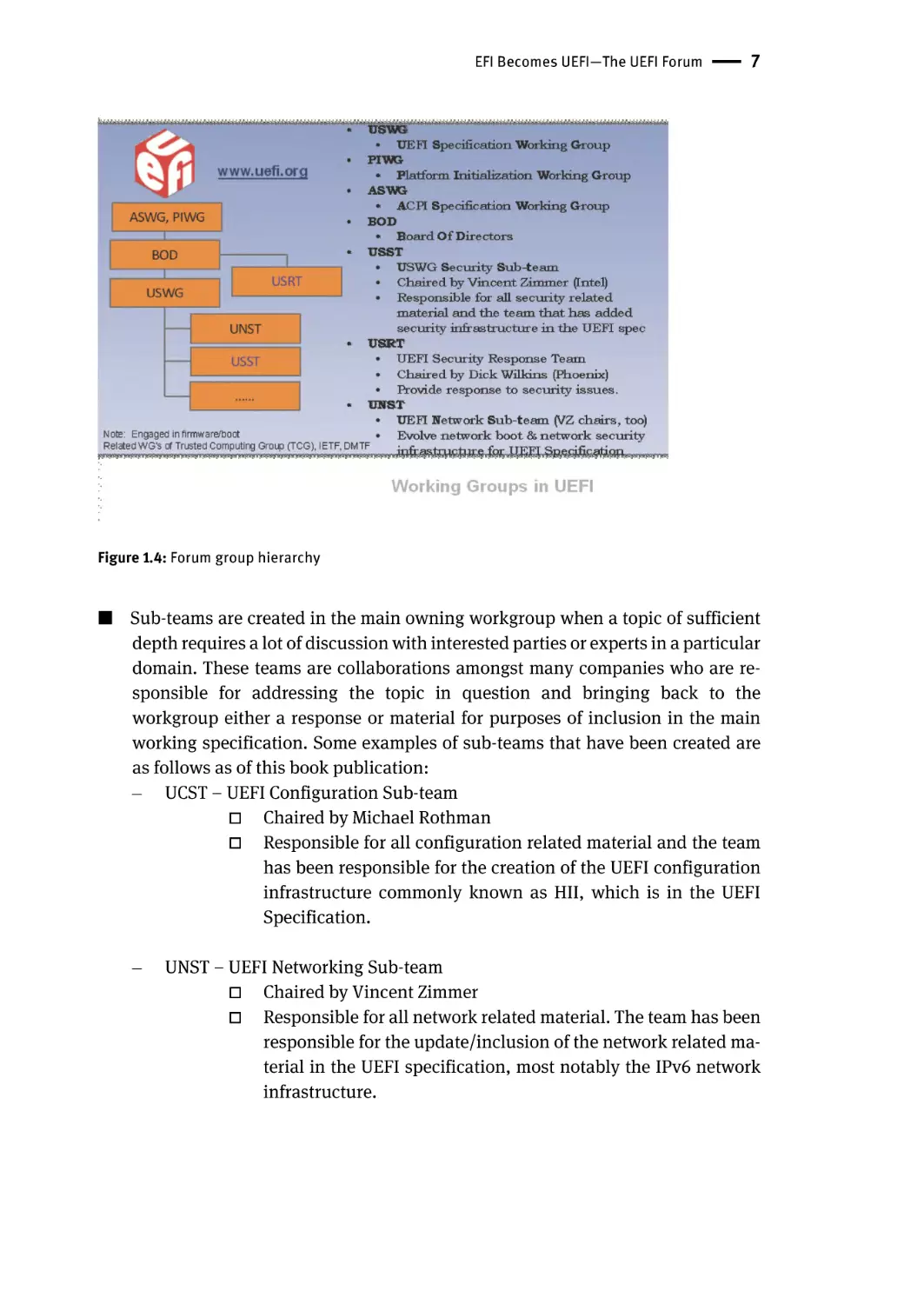
Figure 1.4: Forum group hierarchy
■ Sub-teams are created in the main owning workgroup when a topic of sufficient
depth requires a lot of discussion with interested parties or experts in a particular
domain. These teams are collaborations amongst many companies who are responsible for addressing the topic in question and bringing back to the
workgroup either a response or material for purposes of inclusion in the main
working specification. Some examples of sub-teams that have been created are
as follows as of this book publication:
– UCST – UEFI Configuration Sub-team
□ Chaired by Michael Rothman
□ Responsible for all configuration related material and the team
has been responsible for the creation of the UEFI configuration
infrastructure commonly known as HII, which is in the UEFI
Specification.
–
UNST – UEFI Networking Sub-team
□ Chaired by Vincent Zimmer
□ Responsible for all network related material. The team has been
responsible for the update/inclusion of the network related material in the UEFI specification, most notably the IPv6 network
infrastructure.
8 | Chapter 1 – Introduction
–
USHT – UEFI Shell Sub-team
□ Chaired by Michael Rothman
□ Responsible for all command shell related material. The team
has been responsible for the creation of the UEFI Shell specification and continue to maintain the contents as technology
evolves.
–
USST – UEFI Security Sub-team
□ Chaired by Vincent Zimmer
□ Responsible for all security related material. The team has been
responsible for the added security infrastructure in the UEFI
specification.
PIWG and USWG
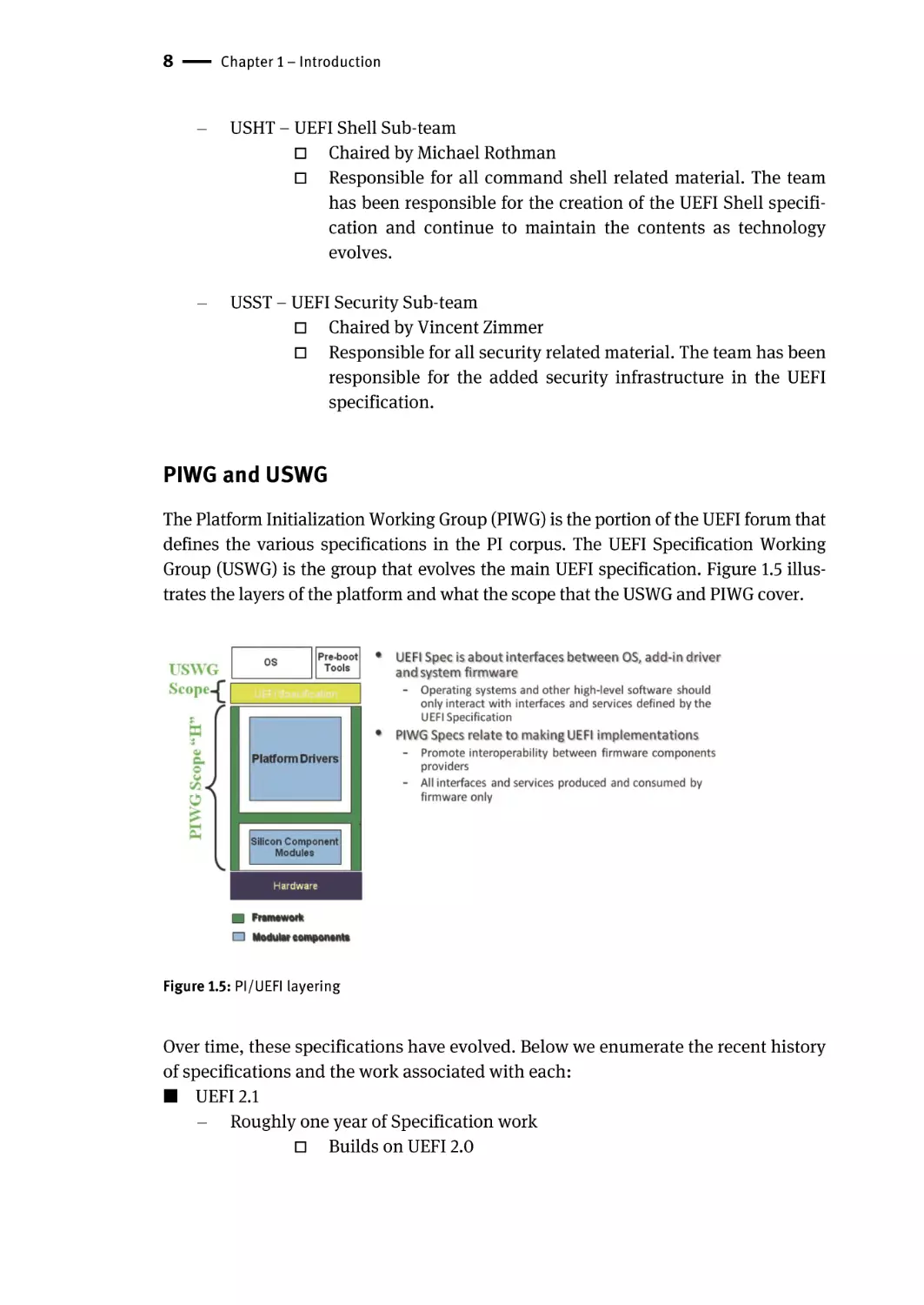
The Platform Initialization Working Group (PIWG) is the portion of the UEFI forum that
defines the various specifications in the PI corpus. The UEFI Specification Working
Group (USWG) is the group that evolves the main UEFI specification. Figure 1.5 illustrates the layers of the platform and what the scope that the USWG and PIWG cover.
Figure 1.5: PI/UEFI layering
Over time, these specifications have evolved. Below we enumerate the recent history
of specifications and the work associated with each:
■ UEFI 2.1
– Roughly one year of Specification work
□ Builds on UEFI 2.0
PIWG and USWG | 9
–
New content area highlights:
□ Human Interface Infrastructure
□ Hardware Error Record Support
□ Authenticated Variable Support
□ Simple Text Input Extensions
□ Absolute Pointer Support
■ UEFI 2.2
– Follow-on material from existing 2.1 content
□ Backlog that needed more gestation time
–
Security/Integrity related enhancements
□ Provide service interfaces for UEFI drivers that want to operate
with high integrity implementations of UEFI
–
Human Interface Infrastructure enhancements
□ Further enhancements pending to help interaction/configuration of platforms with standards-based methodologies.
–
Networking
□
–
–
IPv6, PXE+, IPsec
Various other subject areas possible
More boot devices, more authentication support, more networking updates,
etc.
■ UEFI 2.3
– ARM binding
– Firmware management protocol
■ UEFI 2.4
– Disk IO2 was added as symmetry to Block IO2
– AIP Protocol (FCoE/Image/iSCSI)
– Timestamp Protocol
– RNG/Entropy Protocol
– FMP delivery via capsule
– Capsule on Disk
■ UEFI 2.5
– HASH2 Protocol
– ESRT
– Smart Card Reader
– IPV6 for UNDI
– Inline Cryptographic Interface Protocol
– Persistent Memory Types
10 | Chapter 1 – Introduction
– PKCS7 Signature Verification Services
– AArch64
– NVMe Pass-through Protocol
– HTTP Boot
– Bluetooth Support
– REST Protocol
– Smartcard Edge Protocol
– Regular Expression Protocol
– x-UEFI Keyword Support
– Transport Layer Security(TLS) support
■ UEFI 2.6
– SD/eMMC Pass-through Protocol
– FontEx/Font Glyph Generator protocol
– Wireless MAC Connection Protocol
– RAM Disk Protocol
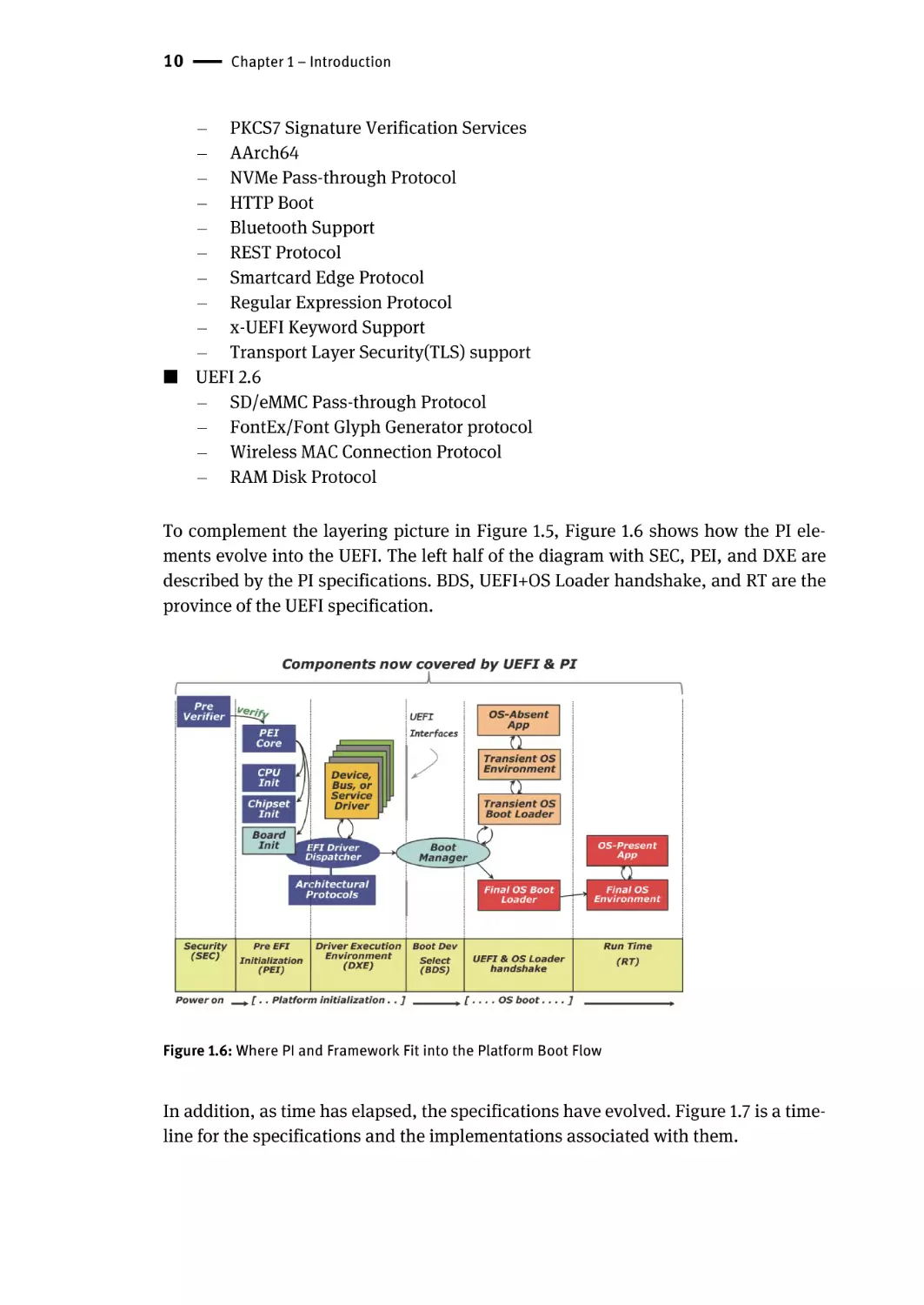
To complement the layering picture in Figure 1.5, Figure 1.6 shows how the PI elements evolve into the UEFI. The left half of the diagram with SEC, PEI, and DXE are
described by the PI specifications. BDS, UEFI+OS Loader handshake, and RT are the
province of the UEFI specification.
Figure 1.6: Where PI and Framework Fit into the Platform Boot Flow
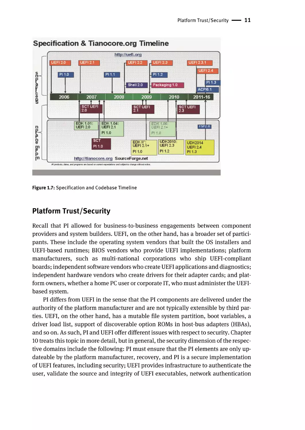
In addition, as time has elapsed, the specifications have evolved. Figure 1.7 is a timeline for the specifications and the implementations associated with them.
Platform Trust/Security | 11
Figure 1.7: Specification and Codebase Timeline
Platform Trust/Security
Recall that PI allowed for business-to-business engagements between component
providers and system builders. UEFI, on the other hand, has a broader set of participants. These include the operating system vendors that built the OS installers and
UEFI-based runtimes; BIOS vendors who provide UEFI implementations; platform
manufacturers, such as multi-national corporations who ship UEFI-compliant
boards; independent software vendors who create UEFI applications and diagnostics;
independent hardware vendors who create drivers for their adapter cards; and platform owners, whether a home PC user or corporate IT, who must administer the UEFIbased system.
PI differs from UEFI in the sense that the PI components are delivered under the
authority of the platform manufacturer and are not typically extensible by third parties. UEFI, on the other hand, has a mutable file system partition, boot variables, a
driver load list, support of discoverable option ROMs in host-bus adapters (HBAs),
and so on. As such, PI and UEFI offer different issues with respect to security. Chapter
10 treats this topic in more detail, but in general, the security dimension of the respective domains include the following: PI must ensure that the PI elements are only updateable by the platform manufacturer, recovery, and PI is a secure implementation
of UEFI features, including security; UEFI provides infrastructure to authenticate the
user, validate the source and integrity of UEFI executables, network authentication
12 | Chapter 1 – Introduction
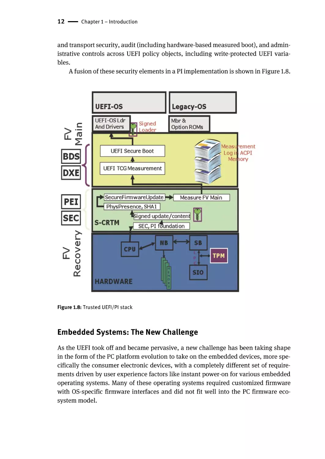
and transport security, audit (including hardware-based measured boot), and administrative controls across UEFI policy objects, including write-protected UEFI variables.
A fusion of these security elements in a PI implementation is shown in Figure 1.8.
Figure 1.8: Trusted UEFI/PI stack
Embedded Systems: The New Challenge
As the UEFI took off and became pervasive, a new challenge has been taking shape
in the form of the PC platform evolution to take on the embedded devices, more specifically the consumer electronic devices, with a completely different set of requirements driven by user experience factors like instant power-on for various embedded
operating systems. Many of these operating systems required customized firmware
with OS-specific firmware interfaces and did not fit well into the PC firmware ecosystem model.
Embedded Systems: The New Challenge | 13
The challenge now is to make the embedded platform firmware have similar capabilities to the traditional model such as the being OS-agnostic, being scalable
across different platform hardware, and being able to lessen the development time to
port and to leverage the UEFI standards.
How the Boot Process Differs between a Normal Boot and an Optimized/Embedded
Boot
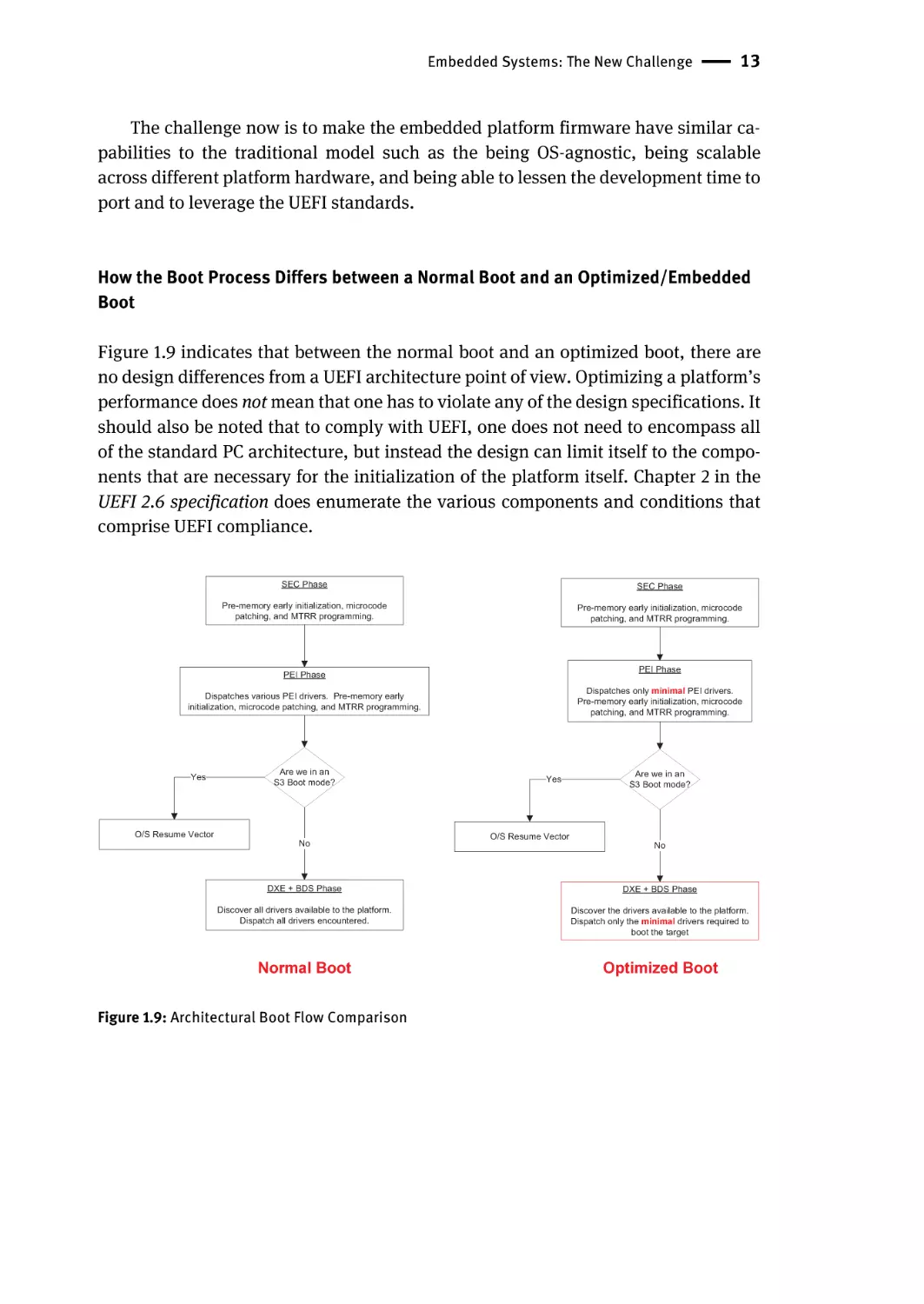
Figure 1.9 indicates that between the normal boot and an optimized boot, there are
no design differences from a UEFI architecture point of view. Optimizing a platform’s
performance does not mean that one has to violate any of the design specifications. It
should also be noted that to comply with UEFI, one does not need to encompass all
of the standard PC architecture, but instead the design can limit itself to the components that are necessary for the initialization of the platform itself. Chapter 2 in the
UEFI 2.6 specification does enumerate the various components and conditions that
comprise UEFI compliance.
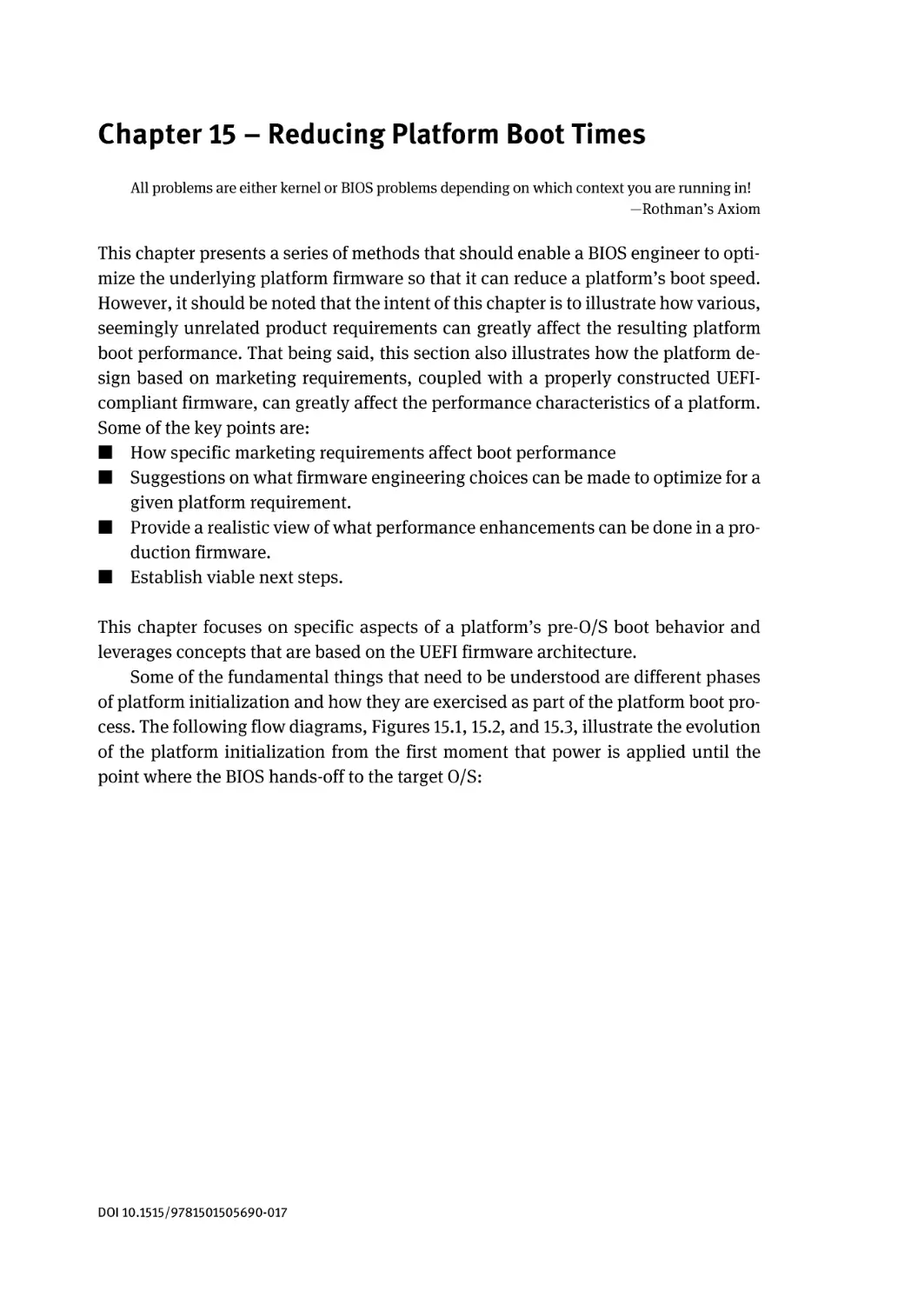
SEC Phase
SEC Phase
Pre-memory early initialization, microcode
patching, and MTRR programming.
Pre-memory early initialization, microcode
patching, and MTRR programming.
PEI Phase
PEI Phase
Dispatches only minimal PEI drivers.
Pre-memory early initialization, microcode
patching, and MTRR programming.
Dispatches various PEI drivers. Pre-memory early
initialization, microcode patching, and MTRR programming.
Yes
Are we in an
S3 Boot mode?
O/S Resume Vector
No
Yes
Are we in an
S3 Boot mode?
O/S Resume Vector
No
DXE + BDS Phase
DXE + BDS Phase
Discover all drivers available to the platform.
Dispatch all drivers encountered.
Discover the drivers available to the platform.
Dispatch only the minimal drivers required to
boot the target
Normal Boot
Optimized Boot
Figure 1.9: Architectural Boot Flow Comparison
14 | Chapter 1 – Introduction
Summary
We have provided some rationale in this chapter for the changes from Beyond BIOS:
Implementing the Unified Extensible Firmware Interface with Intel’s Framework to
Beyond BIOS: Implementing UEFI – the Unified Extensible Firmware Interface. These
elements include the industry members’ ownership and governance of the UEFI specification. Beyond this sea change, the chapter describes the migration of Framework
to PI and the evolution of PI over the former Framework feature set. In addition, the
section describes the evolution of UEFI to UEFI 2.6 from UEFI 2.0 matter in the first
edition. Finally, some of the codebase technology to help realize implementations of
this technology was discussed.
So fasten your seatbelt and dive into a journey through industry standard firmware.
Chapter 2 – Basic UEFI Architecture
I believe in standards. Everyone should have one.
—George Morrow
The Unified Extensible Firmware Interface (UEFI) describes a programmatic interface
to the platform. The platform includes the motherboard, chipset, central processing
unit (CPU), and other components. UEFI allows for pre-operating system (pre-OS)
agents. Pre-OS agents are OS loaders, diagnostics, and other applications that the
system needs for applications to execute and interoperate, including UEFI drivers and
applications. UEFI represents a pure interface specification against which the drivers
and applications interact, and this chapter highlights some of the architectural aspects of the interface. These architectural aspects include a set of objects and interfaces described by the UEFI Specification.
The cornerstones for understanding UEFI applications and drivers are several UEFI
concepts that are defined in the UEFI 2.6 Specification. Assuming you are new to UEFI,
the following introduction explains a few of the key UEFI concepts in a helpful framework to keep in mind as you study the specification:
■ Objects managed by UEFI-based firmware - used to manage system state, including I/O devices, memory, and events
■ The UEFI System Table - the primary data structure with data information tables
and function calls to interface with the systems
■ Handle database and protocols - the means by which callable interfaces are registered
■ UEFI images - the executable content format by which code is deployed
■ Events - the means by which software can be signaled in response to some other
activity
■ Device paths - a data structure that describes the hardware location of an entity,
such as the bus, spindle, partition, and file name of an UEFI image on a formatted
disk.
Objects Managed by UEFI-based Firmware
Several different types of objects can be managed through the services provided by
UEFI. Some UEFI drivers may need to access environment variables, but most do not.
Rarely do UEFI drivers require the use of a monotonic counter, watchdog timer, or
real-time clock. The UEFI System Table is the most important data structure, because
it provides access to all UEFI-provided the services and to all the additional data
structures that describe the configuration of the platform.
DOI 10.1515/9781501505690-004
16 | Chapter 2 – Basic UEFI Architecture
UEFI System Table
The UEFI System Table is the most important data structure in UEFI. A pointer to the
UEFI System Table is passed into each driver and application as part of its entry-point
handoff. From this one data structure, an UEFI executable image can gain access to
system configuration information and a rich collection of UEFI services that includes
the following:
■ UEFI Boot Services
■ UEFI Runtime Services
■ Protocol services
The UEFI Boot Services and UEFI Runtime Services are accessed through the UEFI Boot
Services Table and the UEFI Runtime Services Table, respectively. Both of these tables
are data fields in the UEFI System Table. The number and type of services that each
table makes available is fixed for each revision of the UEFI specification. The UEFI Boot
Services and UEFI Runtime Services are defined in the UEFI 2.6 Specification.
Protocol services are groups of related functions and data fields that are named
by a Globally Unique Identifier (GUID), a 16-byte, statistically-unique entity defined
in Appendix A of the UEFI 2.6 Specification. Typically, protocol services are used to
provide software abstractions for devices such as consoles, disks, and networks, but
they can be used to extend the number of generic services that are available in the
platform. Protocols are the mechanism for extending the functionality of UEFI firmware over time. The UEFI 2.6 Specification defines over 30 different protocols, and
various implementations of UEFI firmware and UEFI drivers may produce additional
protocols to extend the functionality of a platform.
Handle Database
The handle database is composed of objects called handles and protocols. Handles
are a collection of one or more protocols, and protocols are data structures that are
named by a GUID. The data structure for a protocol may be empty, may contain data
fields, may contain services, or may contain both services and data fields. During
UEFI initialization, the system firmware, UEFI drivers, and UEFI applications create
handles and attach one or more protocols to the handles. Information in the handle
database is global and can be accessed by any executable UEFI image.
Handle Database | 17
The handle database is the central repository for the objects that are maintained by
UEFI-based firmware. The handle database is a list of UEFI handles, and each UEFI
handle is identified by a unique handle number that is maintained by the system firmware. A handle number provides a database “key” to an entry in the handle database.
Each entry in the handle database is a collection of one or more protocols. The types
of protocols, named by a GUID, that are attached to an UEFI handle determine the
handle type. An UEFI handle may represent components such as the following:
■ Executable images such as UEFI drivers and UEFI applications
■ Devices such as network controllers and hard drive partitions
■ UEFI services such as UEFI Decompression and the EBC Virtual Machine
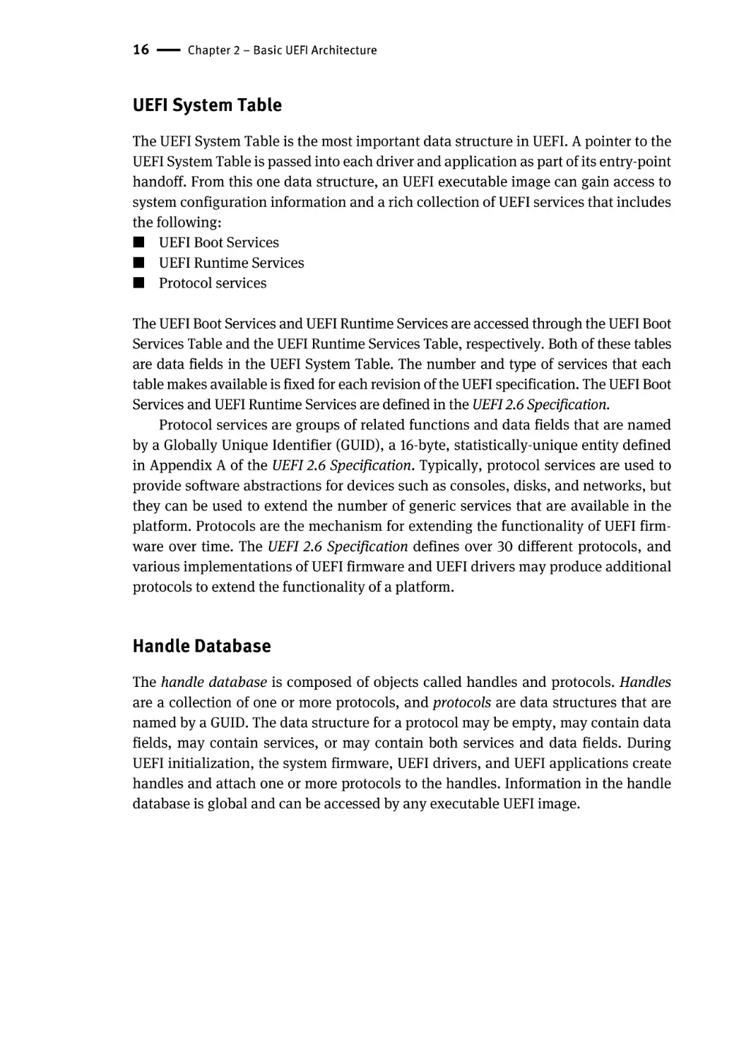
Figure 2.1 below shows a portion of the handle database. In addition to the handles
and protocols, a list of objects is associated with each protocol. This list is used to
track which agents are consuming which protocols. This information is critical to the
operation of UEFI drivers, because this information is what allows UEFI drivers to be
safely loaded, started, stopped, and unloaded without any resource conflicts.
First Handle
...
Handle
GUID
Protocol
Interface
GUID
Agent Handle
Controller Handle
Attributes
Protocol
Interface
Agent Handle
Controller Handle
Attributes
Agent Handle
Agent Handle
Controller Handle
Attributes
Controller Handle
Attributes
Agent Handle
Controller Handle
Attributes
Handle
GUID
Protocol
Interface
...
Figure 2.1: Handle Database
Agent Handle
Controller Handle
Attributes
GUID
GUID
Protocol
Interface
Protocol
Interface
...
18 | Chapter 2 – Basic UEFI Architecture
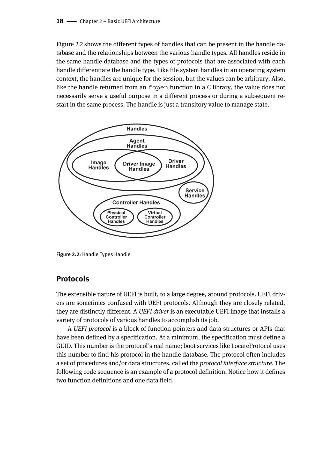
Figure 2.2 shows the different types of handles that can be present in the handle database and the relationships between the various handle types. All handles reside in
the same handle database and the types of protocols that are associated with each
handle differentiate the handle type. Like file system handles in an operating system
context, the handles are unique for the session, but the values can be arbitrary. Also,
like the handle returned from an fopen function in a C library, the value does not
necessarily serve a useful purpose in a different process or during a subsequent restart in the same process. The handle is just a transitory value to manage state.
Handles
Agent
Handles
Image
Handles
Driver Image
Handles
Controller Handles
Physical
Controller
Handles
Driver
Handles
Service
Handles
Virtual
Controller
Handles
Figure 2.2: Handle Types Handle
Protocols
The extensible nature of UEFI is built, to a large degree, around protocols. UEFI drivers are sometimes confused with UEFI protocols. Although they are closely related,
they are distinctly different. A UEFI driver is an executable UEFI image that installs a
variety of protocols of various handles to accomplish its job.
A UEFI protocol is a block of function pointers and data structures or APIs that
have been defined by a specification. At a minimum, the specification must define a
GUID. This number is the protocol’s real name; boot services like LocateProtocol uses
this number to find his protocol in the handle database. The protocol often includes
a set of procedures and/or data structures, called the protocol interface structure. The
following code sequence is an example of a protocol definition. Notice how it defines
two function definitions and one data field.
Protocols | 19
Sample GUID
#define EFI_COMPONENT_NAME2_PROTOCOL_GUID \
{0x6a7a5cff, 0xe8d9, 0x4f70, 0xba, 0xda, 0x75, 0xab,
0x30, 0x25, 0xce, 0x14}
Protocol Interface Structure
typedef struct _EFI_COMPONENT_NAME2_PROTOCOL {
EFI_COMPONENT_NAME_GET_DRIVER_NAME
GetDriverName;
EFI_COMPONENT_NAME_GET_CONTROLLER_NAME
GetControllerName;
CHAR8
*SupportedLanguages;
} EFI_COMPONENT_NAME2_PROTOCOL;
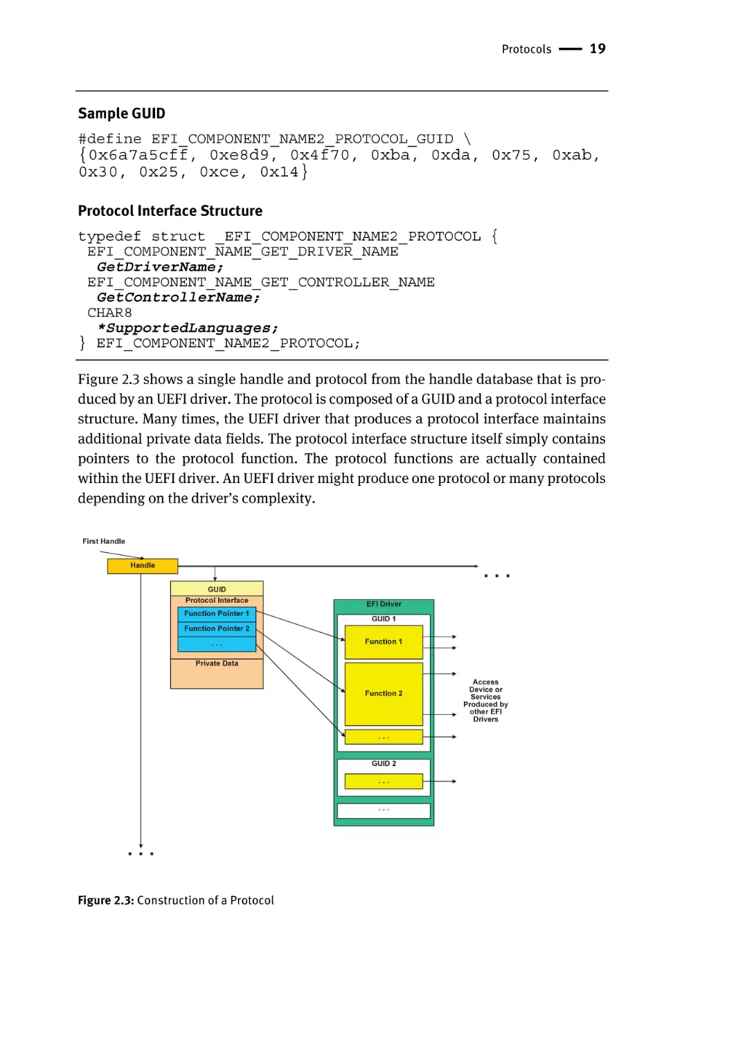
Figure 2.3 shows a single handle and protocol from the handle database that is produced by an UEFI driver. The protocol is composed of a GUID and a protocol interface
structure. Many times, the UEFI driver that produces a protocol interface maintains
additional private data fields. The protocol interface structure itself simply contains
pointers to the protocol function. The protocol functions are actually contained
within the UEFI driver. An UEFI driver might produce one protocol or many protocols
depending on the driver’s complexity.
First Handle
...
Handle
GUID
Protocol Interface
Function Pointer 1
Function Pointer 2
...
EFI Driver
GUID 1
Function 1
Private Data
Function 2
...
GUID 2
...
...
...
Figure 2.3: Construction of a Protocol
Access
Device or
Services
Produced by
other EFI
Drivers
20 | Chapter 2 – Basic UEFI Architecture
Not all protocols are defined in the UEFI 2.6 Specification. The EFI Developer Kit II
(EDKII) includes many protocols that are not part of the UEFI 2.6 Specification. This
project can be found at http://www.tianocore.org. These protocols provide the wider
range of functionality that might be needed in any particular implementation, but
they are not defined in the UEFI 2.6 Specification because they do not present an external interface that is required to support booting an OS or writing an UEFI driver.
The creation of new protocols is how UEFI-based systems can be extended over time
as new devices, buses, and technologies are introduced. For example, some protocols
that are in the EDK II but not in the UEFI 2.6 Specification are:
■ Varstore – interface to abstract storage of UEFI persistent binary objects
■ ConIn – service to provide a character console input
■ ConOut – service to provide a character console output
■ StdErr – service to provide a character console output for error messaging
■ PrimaryConIn – the console input with primary view
■ VgaMiniPort – a service that provides Video Graphics Array output
■ UsbAtapi – a service to abstract block access on USB bus
The UEFI Application Toolkit also contains a number of UEFI protocols that may be
found on some platforms, such as:
■ PPP Daemon – Point-to-Point Protocol driver
■ Ramdisk – file system instance on a Random Access Memory buffer
■ TCP/IP – Transmission Control Protocol / Internet Protocol
■ The Trusted Computing Group interface and platform specification, such as:
– EFI TCG Protocol – interaction with a Trusted Platform Module (TPM).
The OS loader and drivers should not depend on these types of protocols because they
are not guaranteed to be present in every UEFI-compliant system. OS loaders and
drivers should depend only on protocols that are defined in the UEFI 2.6 Specification
and protocols that are required by platform design guides such as Design Implementation Guide for 64-bit Server.
The extensible nature of UEFI allows the developers of each platform to design
and add special protocols. Using these protocols, they can expand the capabilities of
UEFI and provide access to proprietary devices and interfaces in congruity with the
rest of the UEFI architecture.
Because a protocol is “named” by a GUID, no other protocols should have that
same identification number. Care must be taken when creating a new protocol to define a new GUID for it. UEFI fundamentally assumes that a specific GUID exposes a
specific protocol interface. Cutting and pasting an existing GUID or hand-modifying
an existing GUID creates the opportunity for a duplicate GUID to be introduced. A
system containing a duplicate GUID inadvertently could find the new protocol and
think that it is another protocol, crashing the system as a result. For these types of
bugs, finding the root cause is also very difficult. The GUID allows for naming APIs
Protocols | 21
without having to worry about namespace collision. In systems such as PC/AT BIOS,
services were added as an enumeration. For example, the venerable Int15h interface would pass the service type in AX. Since no central repository or specification
managed the evolution of Int15h services, several vendors defined similar service
numbers, thus making interoperability with operating systems and pre-OS applications difficult. Through the judicious use of GUIDs to name APIs and an association
to develop the specification, UEFI balances the need for API evolution with interoperability.
Working with Protocols
Any UEFI code can operate with protocols during boot time. However, after ExitBootServices() is called, the handle database is no longer available. Several
UEFI boot time services work with UEFI protocols.
Multiple Protocol Instances
A handle may have many protocols attached to it. However, it may have only one
protocol of each type. In other words, a handle may not have more than one instance
of the exact same protocol. Otherwise, it would make requests for a particular protocol on a handle nondeterministic.
However, drivers may create multiple instances of a particular protocol and attach each instance to a different handle. The PCI I/O Protocol fits this scenario, where
the PCI bus driver installs a PCI I/O Protocol instance for each PCI device. Each instance of the PCI I/O Protocol is configured with data values that are unique to that
PCI device, including the location and size of the UEFI Option ROM (OpROM) image.
Also, each driver can install customized versions of the same protocol as long as
they do not use the same handle. For example, each UEFI driver installs the Component Name Protocol on its driver image handle, yet when the EFI_COMPONENT_NAME2_PROTOCOL.GetDriverName() function is called, each handle
returns the unique name of the driver that owns that image handle. The EFI_COMPONENT_NAME2_PROTOCOL.GetDriverName() function on the USB bus
driver handle returns “USB bus driver” for the English language, but on the PXE
driver handle it returns “PXE base code driver.”
Tag GUID
A protocol may be nothing more than a GUID. In such cases, the GUID is called a tag
GUID. Such protocols can serve useful purposes such as marking a device handle as
22 | Chapter 2 – Basic UEFI Architecture
special in some way or allowing other UEFI images to easily find the device handle by
querying the system for the device handles with that protocol GUID attached. The EDKII uses the HOT_PLUG_DEVICE_GUID in this way to mark device handles that represent devices from a hot-plug bus such as USB.
UEFI Images
All UEFI images contain a PE/COFF header that defines the format of the executable
code as required by the Microsoft Portable Executable and Common Object File Format
Specification (Microsoft 2008). The target for this code can be an IA-32 processor, an
Itanium® processor, x64, ARM, or a processor agnostic, generic EFI Byte Code (EBC).
The header defines the processor type and the image type. Presently there are three
processor types and the following three image types defined:
■ UEFI applications – images that have their memory and state reclaimed upon
exit.
■ UEFI Boot Service drivers – images that have their memory and state preserved
throughout the pre-operating system flow. Their memory is reclaimed upon invocation of ExitBootServices() by the OS loader.
■ UEFI Runtime drivers – images whose memory and state persist throughout the
evolution of the machine. These images coexist with and can be invoked by an
UEFI-aware operating system.
The value of the UEFI Image format is that various parties can create binary executables
that interoperate. For example, the operating system loader for Microsoft Windows† and
Linux for an UEFI-aware OS build is simply an UEFI application. In addition, third parties can create UEFI drivers to abstract their particular hardware, such as a networking
interface host bus adapter (HBA) or other devices. UEFI images are loaded and relocated
into memory with the Boot Service gBS->LoadImage(). Several supported storage
locations for UEFI images are available, including the following:
■ Expansion ROMs on a PCI card
■ System ROM or system flash
■ A media device such as a hard disk, floppy, CD-ROM, or DVD
■ A LAN boot server
In general, UEFI images are not compiled and linked at a specific address. Instead,
the UEFI image contains relocation fix-ups so the UEFI image can be placed anywhere
in system memory. The Boot Service gBS->LoadImage() does the following:
■ Allocates memory for the image being loaded
■ Automatically applies the relocation fix-ups to the image
■ Creates a new image handle in the handle database, which installs an instance of
the EFI_LOADED_IMAGE_PROTOCOL
UEFI Images | 23
This instance of the EFI_LOADED_IMAGE_PROTOCOL contains information about
the UEFI image that was loaded. Because this information is published in the handle
database, it is available to all UEFI components.
After an UEFI image is loaded with gBS->LoadImage(), it can be started with a
call to gBS->StartImage(). The header for an UEFI image contains the address
of the entry point that is called by gBS->StartImage(). The entry point always
receives the following two parameters:
■ The image handle of the UEFI image being started
■ A pointer to the UEFI System Table
These two items allow the UEFI image to do the following:
■ Access all of the UEFI services that are available in the platform.
■ Retrieve information about where the UEFI image was loaded from and where in
memory the image was placed.
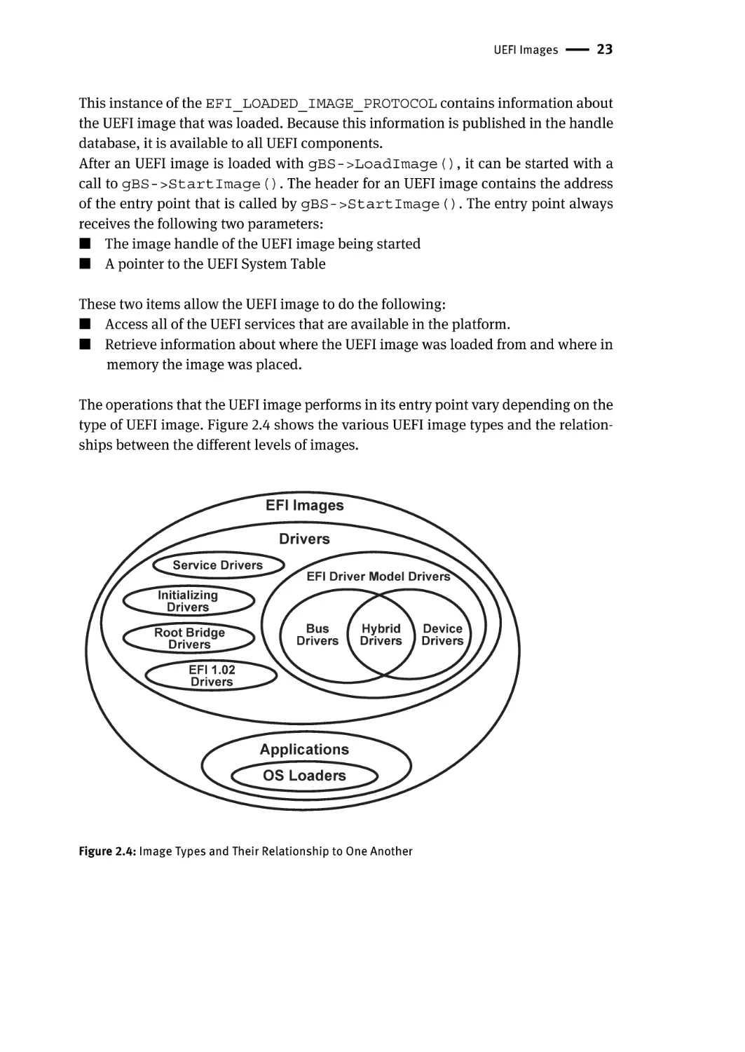
The operations that the UEFI image performs in its entry point vary depending on the
type of UEFI image. Figure 2.4 shows the various UEFI image types and the relationships between the different levels of images.
EFI Images
Drivers
Service Drivers
EFI Driver Model Drivers
Initializing
Drivers
Root Bridge
Drivers
Bus
Drivers
Hybrid
Drivers
EFI 1.02
Drivers
Applications
OS Loaders
Figure 2.4: Image Types and Their Relationship to One Another
Device
Drivers
24 | Chapter 2 – Basic UEFI Architecture
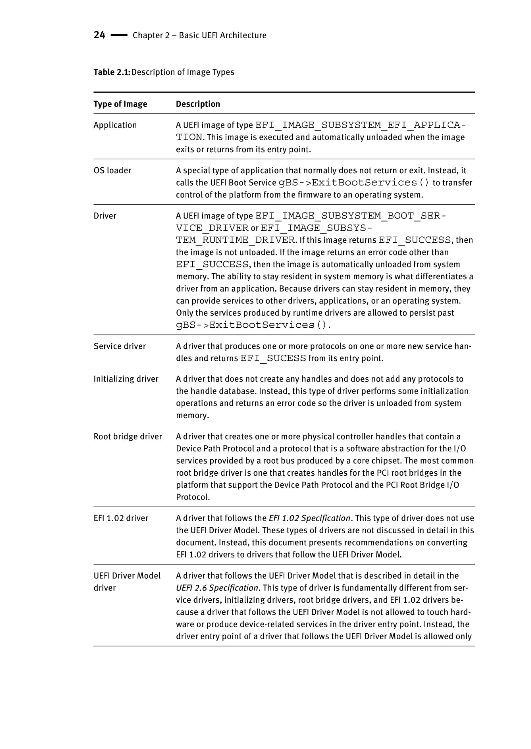
Table 2.1: Description of Image Types
Type of Image
Description
Application
A UEFI image of type EFI_IMAGE_SUBSYSTEM_EFI_APPLICATION. This image is executed and automatically unloaded when the image
exits or returns from its entry point.
OS loader
A special type of application that normally does not return or exit. Instead, it
calls the UEFI Boot Service gBS->ExitBootServices() to transfer
control of the platform from the firmware to an operating system.
Driver
A UEFI image of type EFI_IMAGE_SUBSYSTEM_BOOT_SERVICE_DRIVER or EFI_IMAGE_SUBSYSTEM_RUNTIME_DRIVER. If this image returns EFI_SUCCESS, then
the image is not unloaded. If the image returns an error code other than
EFI_SUCCESS, then the image is automatically unloaded from system
memory. The ability to stay resident in system memory is what differentiates a
driver from an application. Because drivers can stay resident in memory, they
can provide services to other drivers, applications, or an operating system.
Only the services produced by runtime drivers are allowed to persist past
gBS->ExitBootServices().
Service driver
A driver that produces one or more protocols on one or more new service handles and returns EFI_SUCESS from its entry point.
Initializing driver
A driver that does not create any handles and does not add any protocols to
the handle database. Instead, this type of driver performs some initialization
operations and returns an error code so the driver is unloaded from system
memory.
Root bridge driver
A driver that creates one or more physical controller handles that contain a
Device Path Protocol and a protocol that is a software abstraction for the I/O
services provided by a root bus produced by a core chipset. The most common
root bridge driver is one that creates handles for the PCI root bridges in the
platform that support the Device Path Protocol and the PCI Root Bridge I/O
Protocol.
EFI 1.02 driver
A driver that follows the EFI 1.02 Specification. This type of driver does not use
the UEFI Driver Model. These types of drivers are not discussed in detail in this
document. Instead, this document presents recommendations on converting
EFI 1.02 drivers to drivers that follow the UEFI Driver Model.
UEFI Driver Model
driver
A driver that follows the UEFI Driver Model that is described in detail in the
UEFI 2.6 Specification. This type of driver is fundamentally different from service drivers, initializing drivers, root bridge drivers, and EFI 1.02 drivers because a driver that follows the UEFI Driver Model is not allowed to touch hardware or produce device-related services in the driver entry point. Instead, the
driver entry point of a driver that follows the UEFI Driver Model is allowed only
UEFI Images | 25
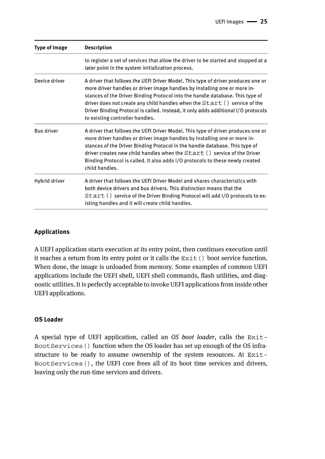
Type of Image
Description
to register a set of services that allow the driver to be started and stopped at a
later point in the system initialization process.
Device driver
A driver that follows the UEFI Driver Model. This type of driver produces one or
more driver handles or driver image handles by installing one or more instances of the Driver Binding Protocol into the handle database. This type of
driver does not create any child handles when the Start() service of the
Driver Binding Protocol is called. Instead, it only adds additional I/O protocols
to existing controller handles.
Bus driver
A driver that follows the UEFI Driver Model. This type of driver produces one or
more driver handles or driver image handles by installing one or more instances of the Driver Binding Protocol in the handle database. This type of
driver creates new child handles when the Start() service of the Driver
Binding Protocol is called. It also adds I/O protocols to these newly created
child handles.
Hybrid driver
A driver that follows the UEFI Driver Model and shares characteristics with
both device drivers and bus drivers. This distinction means that the
Start() service of the Driver Binding Protocol will add I/O protocols to existing handles and it will create child handles.
Applications
A UEFI application starts execution at its entry point, then continues execution until
it reaches a return from its entry point or it calls the Exit() boot service function.
When done, the image is unloaded from memory. Some examples of common UEFI
applications include the UEFI shell, UEFI shell commands, flash utilities, and diagnostic utilities. It is perfectly acceptable to invoke UEFI applications from inside other
UEFI applications.
OS Loader
A special type of UEFI application, called an OS boot loader, calls the ExitBootServices() function when the OS loader has set up enough of the OS infrastructure to be ready to assume ownership of the system resources. At ExitBootServices(), the UEFI core frees all of its boot time services and drivers,
leaving only the run-time services and drivers.
26 | Chapter 2 – Basic UEFI Architecture
Drivers
UEFI drivers differ from UEFI applications in that the driver stays resident in memory
unless an error is returned from the driver’s entry point. The UEFI core firmware, the
boot manager, or other UEFI applications may load drivers.
EFI 1.02 Drivers
Several types of UEFI drivers exist, having evolved with subsequent levels of the specification. In EFI 1.02, drivers were constructed without a defined driver model. The
UEFI 2.6 Specification provides a driver model that replaces the way drivers were built
in EFI 1.02 but that still maintains backward compatibility with EFI 1.02 drivers.
EFI 1.02 immediately started the driver inside the entry point. Following this method
meant that the driver searched immediately for supported devices, installed the necessary I/O protocols, and started the timers that were needed to poll the devices. However, this method did not give the system control over the driver loading and connection policies, so the UEFI Driver Model was introduced in Section 10.1 of the UEFI 2.6
Specification to resolve these issues.
The Floating-Point Software Assist (FPSWA) driver is a common example of an
EFI 1.02 driver; other EFI 1.02 drivers can be found in the EFI Application Toolkit
1.02.12.38. For compatibility, EFI 1.02 drivers can be converted to UEFI 2.6 drivers that
follow the UEFI Driver Model.
Boot Service and Runtime Drivers
Boot-time drivers are loaded into area of memory that are marked as
EfiBootServicesCode, and the drivers allocate their data structures from
memory marked as EfiBootServicesData. These memory types are converted
to available memory after gBS->ExitBootServices() is called.
Runtime drivers are loaded in memory marked as EfiRuntimeServicesCode, and they allocate their data structures from memory marked as EfiRuntimeServicesData. These types of memory are preserved after gBS->ExitBootServices() is called, thereby enabling the runtime driver to provide
services to an operating system while the operating system is running. Runtime drivers must publish an alternative calling mechanism, because the UEFI handle database does not persist into OS runtime. The most common examples of UEFI runtime
drivers are the Floating-Point Software Assist driver (FPSWA.efi) and the network
Universal Network Driver Interface (UNDI) driver. Other than these examples,
runtime drivers are not very common. In addition, the implementation and validation
of runtime drivers is much more difficult than boot service drivers because UEFI supports the translation of runtime services and runtime drivers from a physical addressing mode to a virtual addressing mode. With this translation, the operating system
can make virtual calls to the runtime code. The OS typically runs in virtual mode, so
Events and Task Priority Levels | 27
it must transition into physical mode to make the call. Transitions into physical mode
for modern, multiprocessor operating systems are expensive because they entail
flushing translation look-up blocks (TLB), coordinating all CPUs, and other tasks. As
such, UEFI runtime offers an efficient invocation mechanism because no transition is
required.
Events and Task Priority Levels
Events are another type of object that is managed through UEFI services. An event can
be created and destroyed, and an event can be either in the waiting state or the signaled state. A UEFI image can do any of the following:
■ Create an event.
■ Destroy an event.
■ Check to see if an event is in the signaled state.
■ Wait for an event to be in the signaled state.
■ Request that an event be moved from the waiting state to the signaled state.
Because UEFI does not support interrupts, it can present a challenge to driver writers
who are accustomed to an interrupt-driven driver model. Instead, UEFI supports polled
drivers. The most common use of events by an UEFI driver is the use of timer events that
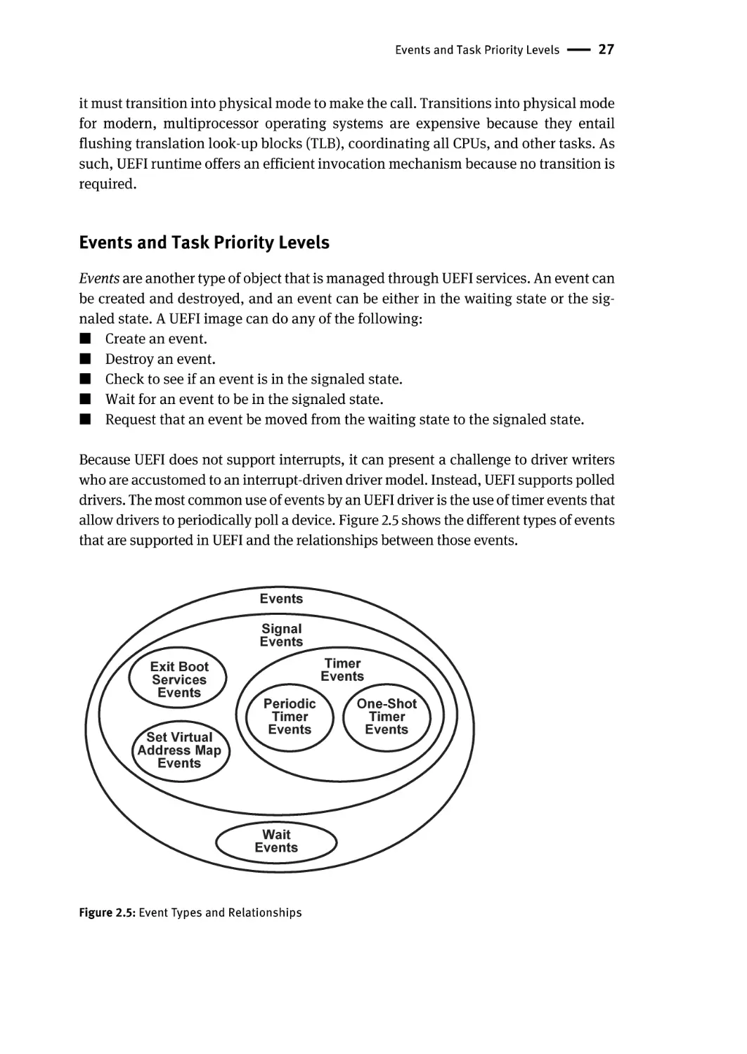
allow drivers to periodically poll a device. Figure 2.5 shows the different types of events
that are supported in UEFI and the relationships between those events.
Events
Signal
Events
Exit Boot
Services
Events
Set Virtual
Address Map
Events
Timer
Events
Periodic
Timer
Events
Wait
Events
Figure 2.5: Event Types and Relationships
One-Shot
Timer
Events
28 | Chapter 2 – Basic UEFI Architecture
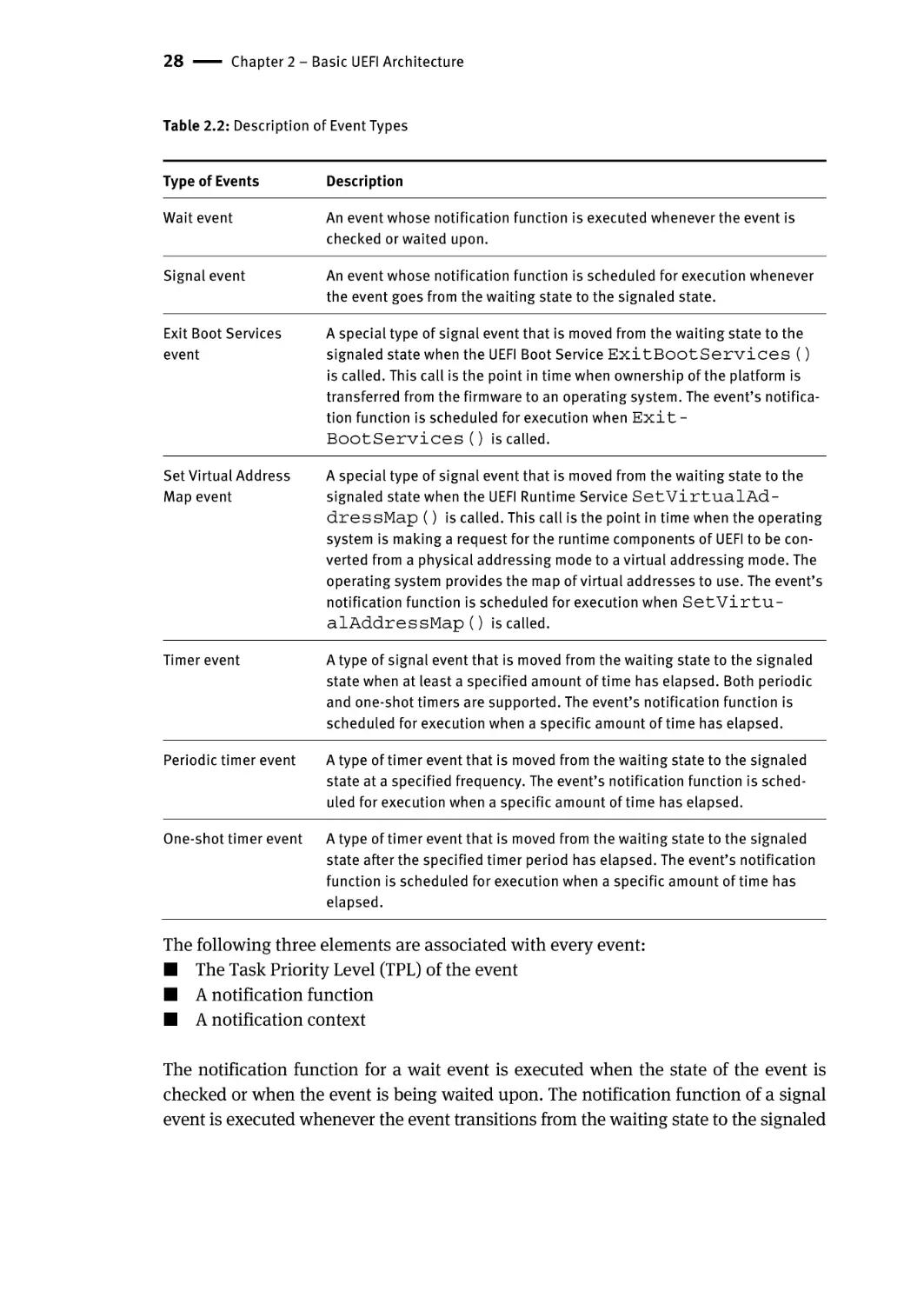
Table 2.2: Description of Event Types
Type of Events
Description
Wait event
An event whose notification function is executed whenever the event is
checked or waited upon.
Signal event
An event whose notification function is scheduled for execution whenever
the event goes from the waiting state to the signaled state.
Exit Boot Services
event
A special type of signal event that is moved from the waiting state to the
signaled state when the UEFI Boot Service ExitBootServices()
is called. This call is the point in time when ownership of the platform is
transferred from the firmware to an operating system. The event’s notification function is scheduled for execution when ExitBootServices() is called.
Set Virtual Address
Map event
A special type of signal event that is moved from the waiting state to the
signaled state when the UEFI Runtime Service SetVirtualAddressMap() is called. This call is the point in time when the operating
system is making a request for the runtime components of UEFI to be converted from a physical addressing mode to a virtual addressing mode. The
operating system provides the map of virtual addresses to use. The event’s
notification function is scheduled for execution when SetVirtualAddressMap() is called.
Timer event
A type of signal event that is moved from the waiting state to the signaled
state when at least a specified amount of time has elapsed. Both periodic
and one-shot timers are supported. The event’s notification function is
scheduled for execution when a specific amount of time has elapsed.
Periodic timer event
A type of timer event that is moved from the waiting state to the signaled
state at a specified frequency. The event’s notification function is scheduled for execution when a specific amount of time has elapsed.
One-shot timer event
A type of timer event that is moved from the waiting state to the signaled
state after the specified timer period has elapsed. The event’s notification
function is scheduled for execution when a specific amount of time has
elapsed.
The following three elements are associated with every event:
■ The Task Priority Level (TPL) of the event
■ A notification function
■ A notification context
The notification function for a wait event is executed when the state of the event is
checked or when the event is being waited upon. The notification function of a signal
event is executed whenever the event transitions from the waiting state to the signaled
Events and Task Priority Levels | 29
state. The notification context is passed into the notification function each time the notification function is executed. The TPL is the priority at which the notification function
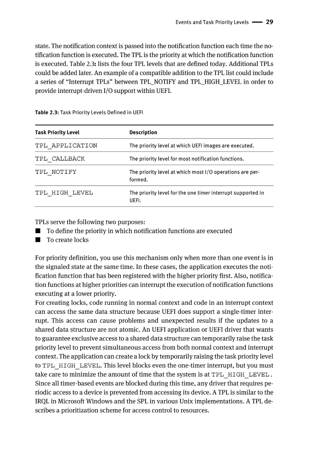
is executed. Table 2.3: lists the four TPL levels that are defined today. Additional TPLs
could be added later. An example of a compatible addition to the TPL list could include
a series of “Interrupt TPLs” between TPL_NOTIFY and TPL_HIGH_LEVEL in order to
provide interrupt-driven I/O support within UEFI.
Table 2.3: Task Priority Levels Defined in UEFI
Task Priority Level
Description
TPL_APPLICATION
The priority level at which UEFI images are executed.
TPL_CALLBACK
The priority level for most notification functions.
TPL_NOTIFY
The priority level at which most I/O operations are performed.
TPL_HIGH_LEVEL
The priority level for the one timer interrupt supported in
UEFI.
TPLs serve the following two purposes:
■ To define the priority in which notification functions are executed
■ To create locks
For priority definition, you use this mechanism only when more than one event is in
the signaled state at the same time. In these cases, the application executes the notification function that has been registered with the higher priority first. Also, notification functions at higher priorities can interrupt the execution of notification functions
executing at a lower priority.
For creating locks, code running in normal context and code in an interrupt context
can access the same data structure because UEFI does support a single-timer interrupt. This access can cause problems and unexpected results if the updates to a
shared data structure are not atomic. An UEFI application or UEFI driver that wants
to guarantee exclusive access to a shared data structure can temporarily raise the task
priority level to prevent simultaneous access from both normal context and interrupt
context. The application can create a lock by temporarily raising the task priority level
to TPL_HIGH_LEVEL. This level blocks even the one-timer interrupt, but you must
take care to minimize the amount of time that the system is at TPL_HIGH_LEVEL.
Since all timer-based events are blocked during this time, any driver that requires periodic access to a device is prevented from accessing its device. A TPL is similar to the
IRQL in Microsoft Windows and the SPL in various Unix implementations. A TPL describes a prioritization scheme for access control to resources.
30 | Chapter 2 – Basic UEFI Architecture
Summary
This chapter has introduced some of the basic UEFI concepts and object types. These
items have included events, protocols, task priority levels, image types, handles,
GUIDs, and service tables. Many of these UEFI concepts, including images and protocols, are used extensively by other firmware technology, including the UEFI Platform
Initialization (PI) building blocks, such as the DXE environment. These concepts will
be revisited in different guises in subsequent chapters.
Chapter 3 – UEFI Driver Model
Things should be made as simple as possible—but no simpler.
—Albert Einstein
The Unified Extensible Firmware Interface (UEFI) provides a driver model for support
of devices that attach to today’s industry-standard buses, such as Peripheral Component Interconnect (PCI) and Universal Serial Bus (USB), and architectures of tomorrow. The UEFI Driver Model is intended to simplify the design and implementation of
device drivers, and produce small executable image sizes. As a result, some complexity has been moved into bus drivers and to a greater extent into common firmware
services. A device driver needs to produce a Driver Binding Protocol on the same image handle on which the driver was loaded. It then waits for the system firmware to
connect the driver to a controller. When that occurs, the device driver is responsible
for producing a protocol on the controller’s device handle that abstracts the I/O operations that the controller supports. A bus driver performs these exact same tasks. In
addition, a bus driver is also responsible for discovering any child controllers on the
bus, and creating a device handle for each child controller found.
The combination of firmware services, bus drivers, and device drivers in any
given platform is likely to be produced by a wide variety of vendors including Original
Equipment Manufacturers (OEMs), Independent BIOS Vendors (IBVs), and Independent Hardware Vendors (IHVs). These different components from different vendors are
required to work together to produce a protocol for an I/O device than can be used to
boot a UEFI compliant operating system. As a result, the UEFI Driver Model is described in great detail in order to increase the interoperability of these components.
This chapter gives a brief overview of the UEFI Driver Model. It describes the entry
point of a driver, host bus controllers, properties of device drivers, properties of bus
drivers, and how the UEFI Driver Model can accommodate hot plug events.
Why a Driver Model Prior to OS Booting?
Under the UEFI Driver Model, only the minimum number of I/O devices needs to be
activated. For example, with today’s BIOS-based systems, a server with dozens of
SCSI drives needs to have those drives “spun-up” or activated. This is because the
BIOS Int19h code does not know a priori which device will contain the operating system loader. The UEFI Driver Model allows for only activating the subset of devices
that are necessary for booting. This makes a rapid system restart possible and pushes
the policy of which additional devices need activation up into the operating system.
With the more aggressive boot time requirements more along the lines of consumer
electronics devices being pushed to all open platforms, this capability is imperative.
DOI 10.1515/9781501505690-005
32 | Chapter 3 – UEFI Driver Model
Driver Initialization
The file for a driver image must be loaded from some type of media. This could include
ROM, flash, hard drives, floppy drives, CD-ROM, or even a network connection. Once
a driver image has been found, it can be loaded into system memory with the Boot
Service LoadImage(). LoadImage() loads a Portable Executable/Common File
Format (PE/COFF) formatted image into system memory. A handle is created for the
driver, and a Loaded Image Protocol instance is placed on that handle. A handle that
contains a Loaded Image Protocol instance is called an Image Handle. At this point,
the driver has not been started. It is just sitting in memory waiting to be started. Figure
3.1 shows the state of an image handle for a driver after LoadImage() has been
called.
Image Handle
Figure 3.1: Image Handle
After a driver has been loaded with the Boot Service LoadImage(), it must be
started with the Boot Service StartImage(). This is true of all types of UEFI applications and UEFI drivers that can be loaded and started on an UEFI compliant system.
The entry point for a driver that follows the UEFI Driver Model must follow some strict
rules. First, it is not allowed to touch any hardware. Instead, it is only allowed to install protocol instances onto its own Image Handle. A driver that follows the UEFI
Driver Model is required to install an instance of the Driver Binding Protocol onto its
own Image Handle. It may optionally install the Driver Configuration Protocol, the
Driver Diagnostics Protocol, or the Component Name Protocol. In addition, if a driver
wishes to be unloadable it may optionally update the Loaded Image Protocol to provide its own Unload() function. Finally, if a driver needs to perform any special
operations when the Boot Service ExitBootServices() is called, it may optionally create an event with a notification function that is triggered when the Boot Service ExitBootServices() is called. An Image Handle that contains a Driver
Binding Protocol instance is known as a Driver Image Handle. Figure 3.2 shows a possible configuration for the Image Handle from Figure 3.1 after the Boot Service
StartImage() has been called.
Host Bus Controllers | 33
Driver Image Handle
EFI_LOADED_IMAGE_PROTOCOL
EFI_DRIVER_BINDING_PROTOCOL
EFI_DRIVER_CONFIGURATION_PROTOCOL
EFI_DRIVER_DIAGNOSTICS_PROTOCOL
EFI_COMPONENT_NAME2_PROTOCOL
Figure 3.2: Driver Image Handle
Host Bus Controllers
Drivers are not allowed to touch any hardware in the driver's entry point. As a result,
drivers are loaded and started, but they are all waiting to be told to manage one or
more controllers in the system. A platform component, like the UEFI Boot Manager,
is responsible for managing the connection of drivers to controllers. However, before
even the first connection can be made, some initial collection of controllers must be
present for the drivers to manage. This initial collection of controllers is known as the
Host Bus Controllers. The I/O abstractions that the Host Bus Controllers provide are
produced by firmware components that are outside the scope of the UEFI Driver
Model. The device handles for the Host Bus Controllers and the I/O abstraction for
each one must be produced by the core firmware on the platform, or an UEFI Driver
that may not follow the UEFI Driver Model. See the PCI Host Bridge I/O Protocol description in Chapter 13 of the UEFI 2.6 specification for an example of an I/O abstraction for PCI buses.
A platform can be viewed as a set of CPUs and a set of core chip set components
that may produce one or more host buses. Figure 3.3 shows a platform with n CPUs,
and a set of core chipset components that produce m host bridges.
34 | Chapter 3 – UEFI Driver Model
CPU 1
CPU 2
CPU n
Front Side Bus
Core Chipset Components
HB 1
HB 2
HB m
Figure 3.3: Host Bus Controllers
Each host bridge is represented in UEFI as a device handle that contains a Device Path
Protocol instance, and a protocol instance that abstracts the I/O operations that the
host bus can perform. For example, a PCI Host Bus Controller supports the PCI Host
Bridge I/O Protocol. Figure 3.4 shows an example device handle for a PCI Host Bridge.
Device Handle
EFI_DEVICE_PATH_PROTOCOL
EFI_PCI_HOST_BRIDGE_IO_PROTOCOL
Figure 3.4: Host Bus Device Handle
A PCI Bus Driver could connect to this PCI Host Bridge, and create child handles for
each of the PCI devices in the system. PCI Device Drivers should then be connected to
these child handles, and produce I/O abstractions that may be used to boot a UEFI
compliant OS. The following section describes the different types of drivers that can
be implemented within the UEFI Driver Model. The UEFI Driver Model is very flexible,
so not all the possible types of drivers are discussed here. Instead, the major types are
Device Drivers | 35
covered that can be used as a starting point for designing and implementing additional driver types.
Device Drivers
A device driver is not allowed to create any new device handles. Instead, it installs
additional protocol interfaces on an existing device handle. The most common type
of device driver attaches an I/O abstraction to a device handle that has been created
by a bus driver. This I/O abstraction may be used to boot an UEFI compliant OS. Some
example I/O abstractions would include Simple Text Output, Simple Input, Block I/O,
and Simple Network Protocol. Figure 3.5 shows a device handle before and after a
device driver is connected to it. In this example, the device handle is a child of the
XYZ Bus, so it contains an XYZ I/O Protocol for the I/O services that the XYZ bus supports. It also contains a Device Path Protocol that was placed there by the XYZ Bus
Driver. The Device Path Protocol is not required for all device handles. It is only required for device handles that represent physical devices in the system. Handles for
virtual devices do not contain a Device Path Protocol.
Device Handle
EFI_DEVICE_PATH_PROTOCOL
EFI_XYZ_IO_PROTOCOL
Stop()
Start()
Device Handle
EFI_DEVICE_PATH_PROTOCOL
EFI_XYZ_IO_PROTOCOL
EFI_BLOCK_IO_PROTOCOL
Figure 2.5: Connecting Device Drivers
The device driver that connects to the device handle in Figure 3.5 must have installed
a Driver Binding Protocol on its own image handle. The Driver Binding Protocol con-
36 | Chapter 3 – UEFI Driver Model
tains three functions called Supported(), Start(), and Stop(). The Supported() function tests to see if the driver supports a given controller. In this example, the driver will check to see if the device handle supports the Device Path Protocol and the XYZ I/O Protocol. If a driver's Supported() function passes, then the
driver can be connected to the controller by calling the driver’s Start() function.
The Start() function is what actually adds the additional I/O protocols to a device
handle. In this example, the Block I/O Protocol is being installed. To provide symmetry, the Driver Binding Protocol also has a Stop() function that forces the driver
to stop managing a device handle. This causes the device driver to uninstall any protocol interfaces that were installed in Start().
The Support(), Start(), and Stop() functions of the UEFI Driver Binding
Protocol are required to make use of the new Boot Service OpenProtocol() to get
a protocol interface and the new Boot Service CloseProtocol() to release a protocol interface. OpenProtocol() and CloseProtocol() update the handle database maintained by the system firmware to track which drivers are consuming protocol interfaces. The information in the handle database can be used to retrieve
information about both drivers and controllers. The new Boot Service OpenProtocolInformation() can be used to get the list of components that are currently
consuming a specific protocol interface.
Bus Drivers
Bus drivers and device drivers are virtually identical from the UEFI Driver Model’s
point of view. The only difference is that a bus driver creates new device handles for
the child controllers that the bus driver discovers on its bus. As a result, bus drivers
are slightly more complex than device drivers, but this in turn simplifies the design
and implementation of device drivers. There are two major types of bus drivers. The
first creates handles for all the child controllers on the first call to Start(). The
second type allows the handles for the child controllers to be created across multiple
calls to Start(). This second type of bus driver is very useful in supporting a rapid
boot capability. It allows a few child handles or even one child handle to be created.
On buses that take a long time to enumerate all of their children (such as SCSI), this
can lead to a very large time savings in booting a platform. Figure 3.6 shows the tree
structure of a bus controller before and after Start() is called. The dashed line
coming into the bus controller node represents a link to the bus controller's parent
controller. If the bus controller is a Host Bus Controller, then it does not have a parent
controller. Nodes A, B, C, D, and E represent the child controllers of the bus controller.
Bus Drivers | 37
Bus Controller
Bus Controller
Start()
Stop()
A
B
C
D
E
Figure 3.6: Connecting Bus Drivers
A bus driver that supports creating one child on each call to Start() might choose
to create child C first, and then child E, and then the remaining children A,B, and D.
The Supported(), Start(), and Stop() functions of the Driver Binding Protocol are flexible enough to allow this type of behavior.
A bus driver must install protocol interfaces onto every child handle that is creates.
At a minimum, it must install a protocol interface that provides an I/O abstraction of the
bus's services to the child controllers. If the bus driver creates a child handle that represents a physical device, then the bus driver must also install a Device Path Protocol
instance onto the child handle. A bus driver may optionally install a Bus Specific Driver
Override Protocol onto each child handle. This protocol is used when drivers are connected to the child controllers. A new Boot Service ConnectController() uses architecturally defined precedence rules to choose the best set of drivers for a given controller. The Bus Specific Driver Override Protocol has higher precedence than a general
driver search algorithm, and lower precedence than platform overrides. An example of
a bus specific driver selection occurs with PCI. A PCI Bus Driver gives a driver stored in
a PCI controller's option ROM a higher precedence than drivers stored elsewhere in the
platform. Figure 3.7 shows an example child device handle that has been created by the
XYZ Bus Driver that supports a bus specific driver override mechanism.
38 | Chapter 3 – UEFI Driver Model
Child Device Handle
EFI_DEVICE_PATH_PROTOCOL
EFI_XYZ_IO_PROTOCOL
Optional
EFI_BUS_SPECIFIC_DRIVER_OVERRIDE_PROTOCOL
Figure 3.7: Child Device Handle with a Bus Specific Override
Platform Components
Under the UEFI Driver Model, the act of connecting and disconnecting drivers from
controllers in a platform is under the platform firmware's control. This will typically
be implemented as part of the UEFI Boot Manager, but other implementations are
possible. The new Boot Services ConnectController() and DisconnectController() can be used by the platform firmware to determine which
controllers get started and which ones do not. If the platform wishes to perform system diagnostics or install an operating system, then it may choose to connect drivers
to all possible boot devices. If a platform wishes to boot a pre-installed operating system, it may choose to only connect drivers to the devices that are required to boot the
selected operating system. The UEFI Driver Model supports both of these modes of
operation through the new Boot Services ConnectController() and DisconnectController(). In addition, since the platform component that is in charge
of booting the platform has to work with device paths for console devices and boot
options, all of the services and protocols involved in the UEFI Driver Model are optimized with device paths in mind.
The platform may also choose to produce an optional protocol named the Platform Driver Override Protocol. This is similar to the Bus Specific Driver Override Protocol, but it has higher priority. This gives the platform firmware the highest priority
when deciding which drivers are connected to which controllers. The Platform Driver
Override Protocol is attached to a handle in the system. The new Boot Service ConnectController() will make use of this protocol if it is present in the system.
Hot Plug Events
In the past, system firmware has not had to deal with hot plug events in the pre-boot
environment. However, with the advent of buses like USB, where the end user can
add and remove devices at any time, it is important to make sure that it is possible to
describe these types of buses in the UEFI Driver Model. It is up to the bus driver of a
Hot Plug Events | 39
bus that supports the hot adding and removing of devices to provide support for such
events. For these types of buses, some of the platform management is going to have
to move into the bus drivers. For example, when a keyboard is added hot to a USB bus
on a platform, the end user would expect the keyboard to be active. A USB Bus driver
could detect the hot add event and create a child handle for the keyboard device.
However, since drivers are not connected to controllers unless ConnectController() is called the keyboard would not become an active input device. Making the
keyboard driver active requires the USB Bus driver to call ConnectController()
when a hot add event occurs. In addition, the USB Bus driver would have to call DisconnectController() when a hot remove event occurs.
Device drivers are also affected by these hot plug events. In the case of USB, a
device can be removed without any notice. This means that the Stop() functions of
USB device drivers must deal with shutting down a driver for a device that is no longer
present in the system. As a result, any outstanding I/O requests must be flushed without actually being able to touch the device hardware.
In general, adding support for hot plug events greatly increases the complexity
of both bus drivers and device drivers. Adding this support is up to the driver writer,
so the extra complexity and size of the driver must be weighed against the need for
the feature in the pre-boot environment.
The two example code sequences below provide guidance on how a device driver
writer might discover if it in fact manages the candidate hardware device. These
mechanisms include looking at the controller handle in the first example and examining the device path in the second example.
extern EFI_GUID
gEfiDriverBindingProtocolGuid;
EFI_HANDLE
gMyImageHandle;
EFI_HANDLE
DriverImageHandle;
EFI_HANDLE
ControllerHandle;
EFI_DRIVER_BINDING_PROTOCOL *DriverBinding;
EFI_DEVICE_PATH_PROTOCOL
*RemainingDevicePath;
//
// Use the DriverImageHandle to get the Driver Binding
Protocol
// instance
//
Status = gBS->OpenProtocol (
DriverImageHandle,
&gEfiDriverBindingProtocolGuid,
&DriverBinding,
gMyImageHandle,
NULL,
EFI_OPEN_PROTOCOL_HANDLE_PROTOCOL
);
40 | Chapter 3 – UEFI Driver Model
if (EFI_ERROR (Status)) {
return Status;
}
//
// EXAMPLE #1
//
// Use the Driver Binding Protocol instance to test to
see if
// the driver specified by DriverImageHandle supports the
// controller specified by ControllerHandle
//
Status = DriverBinding->Supported (
DriverBinding,
ControllerHandle,
NULL
);
if (!EFI_ERROR (Status)) {
Status = DriverBinding->Start (
DriverBinding,
ControllerHandle,
NULL
);
}
return Status;
//
// EXAMPLE #2
//
// The RemainingDevicePath parameter can be used to
initialize
// only the minimum devices required to boot. For
example,
// maybe we only want to initialize 1 hard disk on a SCSI
// channel. If DriverImageHandle is a SCSI Bus Driver,
and
// ControllerHandle is a SCSI Controller, and we only
want to
// create a child handle for PUN=3 and LUN=0, then the
// RemainingDevicePath would be SCSI(3,0)/END. The
following
// example would return EFI_SUCCESS if the SCSI driver
supports
// creating the child handle for PUN=3, LUN=0. Otherwise
it
// would return an error.
//
Hot Plug Events | 41
Status = DriverBinding->Supported (
DriverBinding,
ControllerHandle,
RemainingDevicePath
);
if (!EFI_ERROR (Status)) {
Status = DriverBinding->Start (
DriverBinding,
ControllerHandle,
RemainingDevicePath
);
}
return Status;
Pseudo Code
The algorithms for the Start() function for three different types of drivers are presented here. How the Start() function of a driver is implemented can affect how
the Supported() function is implemented. All of the services in the
EFI_DRIVER_BINDING_PROTOCOL need to work together to make sure that all
resources opened or allocated in Supported() and Start() are released in
Stop().
The first algorithm is a simple device driver that does not create any additional
handles. It only attaches one or more protocols to an existing handle. The second is a
simple bus driver that always creates all of its child handles on the first call to
Start(). It does not attach any additional protocols to the handle for the bus controller. The third is a more advanced bus driver that can either create one child handles at a time on successive calls to Start(), or it can create all of its child handles
or all of the remaining child handles in a single call to Start(). Once again, it does
not attach any additional protocols to the handle for the bus controller.
Device Driver
1.
Open all required protocols with OpenProtocol(). If this driver allows the
opened protocols to be shared with other drivers, then it should use an Attribute of EFI_OPEN_PROTOCOL_BY_DRIVER. If this driver does not allow the
opened protocols to be shared with other drivers, then it should use an Attribute of EFI_OPEN_PROTOCOL_BY_DRIVER | EFI_OPEN_PROTOCOL_EXCLUSIVE. It must use the same Attribute value that was used in
Supported().
42 | Chapter 3 – UEFI Driver Model
2.
If any of the calls to OpenProtocol() in Step 1 returned an error, then close
all of the protocols opened in Step 1 with CloseProtocol(), and return the
status code from the call to OpenProtocol() that returned an error.
3. Ignore the parameter RemainingDevicePath.
4. Initialize the device specified by ControllerHandle. If an error occurs, close
all of the protocols opened in Step 1 with CloseProtocol(), and return
EFI_DEVICE_ERROR.
5. Allocate and initialize all of the data structures that this driver requires to manage
the device specified by ControllerHandle. This would include space for
public protocols and space for any additional private data structures that are related to ControllerHandle. If an error occurs allocating the resources, then
close all of the protocols opened in Step 1 with CloseProtocol(), and return
EFI_OUT_OF_RESOURCES.
6. Install all the new protocol interfaces onto ControllerHandle using InstallProtocolInterface(). If an error occurs, close all of the protocols
opened in Step 1 with CloseProtocol(), and return the error from InstallProtocolInterface().
7. Return EFI_SUCCESS.
Bus Driver that Creates All of Its Child Handles on the First Call to Start()
Open all required protocols with OpenProtocol(). If this driver allows the
opened protocols to be shared with other drivers, then it should use an Attribute of EFI_OPEN_PROTOCOL_BY_DRIVER. If this driver does not allow
the opened protocols to be shared with other drivers, then it should use an Attribute of EFI_OPEN_PROTOCOL_BY_DRIVER | EFI_OPEN_PROTOCOL_EXCLUSIVE. It must use the same Attribute value that was used in
Supported().
2. If any of the calls to OpenProtocol() in Step 1 returned an error, then close
all of the protocols opened in Step 1 with CloseProtocol(), and return the
status code from the call to OpenProtocol() that returned an error.
3. Ignore the parameter RemainingDevicePath.
4. Initialize the device specified by ControllerHandle. If an error occurs, close
all of the protocols opened in Step 1 with CloseProtocol(), and return
EFI_DEVICE_ERROR.
5. Discover all the child devices of the bus controller specified by ControllerHandle.
6. If the bus requires it, allocate resources to all the child devices of the bus controller specified by ControllerHandle.
7. FOR each child C of ControllerHandle
1.
Hot Plug Events | 43
8. Allocate and initialize all of the data structures that this driver requires to manage
the child device C. This would include space for public protocols and space for
any additional private data structures that are related to the child device C. If an
error occurs allocating the resources, then close all of the protocols opened in
Step 1 with CloseProtocol(), and return EFI_OUT_OF_RESOURCES.
9. If the bus driver creates device paths for the child devices, then create a device
path for the child C based upon the device path attached to ControllerHandle.
10. Initialize the child device C. If an error occurs, close all of the protocols opened
in Step 1 with CloseProtocol(), and return EFI_DEVICE_ERROR.
11. Create a new handle for C, and install the protocol interfaces for child device C.
This may include the EFI_DEVICE_PATH_PROTOCOL.
12. Call OpenProtocol() on behalf of the child C with an Attribute of
EFI_OPEN_PROTOCOL_BY_CHILD_CONTROLLER.
13. END FOR
14. Return EFI_SUCCESS.
Bus Driver that Is Able to Create All or One of Its Child Handles on Each Call to
Start():
Open all required protocols with OpenProtocol(). If this driver allows the
opened protocols to be shared with other drivers, then it should use an Attribute of EFI_OPEN_PROTOCOL_BY_DRIVER. If this driver does not allow the
opened protocols to be shared with other drivers, then it should use an Attribute of EFI_OPEN_PROTOCOL_BY_DRIVER | EFI_OPEN_PROTOCOL_EXCLUSIVE. It must use the same Attribute value that was used in
Supported().
2. If any of the calls to OpenProtocol() in Step 1 returned an error, then close
all of the protocols opened in Step 1 with CloseProtocol(), and return the
status code from the call to OpenProtocol() that returned an error.
3. Initialize the device specified by ControllerHandle. If an error occurs, close
all of the protocols opened in Step 1 with CloseProtocol(), and return
EFI_DEVICE_ERROR.
4. IF RemainingDevicePath is not NULL, THEN
5. C is the child device specified by RemainingDevicePath.
6. Allocate and initialize all of the data structures that this driver requires to manage
the child device C. This would include space for public protocols and space for
any additional private data structures that are related to the child device C. If an
error occurs allocating the resources, then close all of the protocols opened in
Step 1 with CloseProtocol(), and return EFI_OUT_OF_RESOURCES.
1.
44 | Chapter 3 – UEFI Driver Model
7.
8.
9.
10.
11.
12.
13.
14.
15.
16.
17.
18.
19.
20.
21.
22.
If the bus driver creates device paths for the child devices, then create a device path
for the child C based upon the device path attached to ControllerHandle.
Initialize the child device C.
Create a new handle for C, and install the protocol interfaces for child device C.
This may include the EFI_DEVICE_PATH_PROTOCOL.
Call OpenProtocol() on behalf of the child C with an Attribute of
EFI_OPEN_PROTOCOL_BY_CHILD_CONTROLLER.
ELSE
Discover all the child devices of the bus controller specified by ControllerHandle.
If the bus requires it, allocate resources to all the child devices of the bus controller specified by ControllerHandle.
FOR each child C of ControllerHandle
Allocate and initialize all of the data structures that this driver requires to manage
the child device C. This would include space for public protocols and space for
any additional private data structures that are related to the child device C. If an
error occurs allocating the resources, then close all of the protocols opened in
Step 1 with CloseProtocol(), and return EFI_OUT_OF_RESOURCES.
If the bus driver creates device paths for the child devices, then create a device
path for the child C based upon the device path attached to ControllerHandle.
Initialize the child device C.
Create a new handle for C, and install the protocol interfaces for child device C.
This may include the EFI_DEVICE_PATH_PROTOCOL.
Call OpenProtocol() on behalf of the child C with an Attribute of
EFI_OPEN_PROTOCOL_BY_CHILD_CONTROLLER.
END FOR
END IF
Return EFI_SUCCESS.
Listed below is sample code of the Start() function of device driver for a device on
the XYZ bus. The XYZ bus is abstracted with the EFI_XYZ_IO_PROTOCOL. This
driver does allow the EFI_XYZ_IO_PROTOCOL to be shared with other drivers, and
just the presence of the EFI_XYZ_IO_PROTOCOL on ControllerHandle is
enough to determine if this driver supports ControllerHandle. This driver installs the EFI_ABC_IO_PROTOCOL on ControllerHandle. The gBS and
gMyImageHandle variables are initialized in this driver’s entry point.
The following code sequence provides a generic example of what a driver can do
in its start routine in the hope of particularizing the guidance listed above.
Hot Plug Events | 45
extern EFI_GUID
extern EFI_GUID
EFI_BOOT_SERVICES_TABLE
EFI_HANDLE
gEfiXyzIoProtocol;
gEfiAbcIoProtocol;
*gBS;
gMyImageHandle;
EFI_STATUS
AbcStart (
IN EFI_DRIVER_BINDING_PROTOCOL
IN EFI_HANDLE
IN EFI_DEVICE_PATH_PROTOCOL
OPTIONAL
)
*This,
ControllerHandle,
*RemainingDevicePath
{
EFI_STATUS
EFI_XYZ_IO_PROTOCOL
EFI_ABC_DEVICE
Status;
*XyzIo;
AbcDevice;
//
// Open the Xyz I/O Protocol that this driver consumes
//
Status = gBS->OpenProtocol (
ControllerHandle,
&gEfiXyzIoProtocol,
&XyzIo,
gMyImageHandle,
ControllerHandle,
EFI_OPEN_PROTOCOL_BY_DRIVER
);
if (EFI_ERROR (Status)) {
return Status;
}
//
// Allocate and zero a private data structure for the
Abc
// device.
//
Status = gBS->AllocatePool (
EfiBootServicesData,
sizeof (EFI_ABC_DEVICE),
&AbcDevice
);
if (EFI_ERROR (Status)) {
goto ErrorExit;
}
ZeroMem (AbcDevice, sizeof (EFI_ABC_DEVICE));
46 | Chapter 3 – UEFI Driver Model
//
// Initialize the contents of the private data
structure for
// the Abc device. This includes the XyzIo protocol
instance
// and other private data fields and the
EFI_ABC_IO_PROTOCOL
// instance that will be installed.
//
AbcDevice->Signature
= EFI_ABC_DEVICE_SIGNATURE;
AbcDevice->XyzIo
= XyzIo;
AbcDevice->PrivateData1
AbcDevice->PrivateData1
. . .
AbcDevice->PrivateData1
= PrivateValue1;
= PrivateValue2;
= PrivateValueN;
AbcDevice->AbcIo.Revision =
EFI_ABC_IO_PROTOCOL_REVISION;
AbcDevice->AbcIo.Func1
= AbcIoFunc1;
AbcDevice->AbcIo.Func2
= AbcIoFunc2;
. . .
AbcDevice->AbcIo.FuncN
= AbcIoFuncN;
AbcDevice->AbcIo.Data1
AbcDevice->AbcIo.Data2
. . .
AbcDevice->AbcIo.DataN
= Value1;
= Value2;
= ValueN;
//
// Install protocol interfaces for the ABC I/O device.
//
Status = gBS->InstallProtocolInterface (
&ControllerHandle,
&gEfiAbcIoProtocolGuid,
EFI_NATIVE_INTERFACE,
&AbcDevice->AbcIo
);
if (EFI_ERROR (Status)) {
goto ErrorExit;
}
return EFI_SUCCESS;
ErrorExit:
//
// When there is an error, the provate data structures
need
Additional Innovations | 47
// to be freed and the protocols that were opened need
to be
// closed.
//
if (AbcDevice != NULL) {
gBS->FreePool (AbcDevice);
}
gBS->CloseProtocol (
ControllerHandle,
&gEfiXyzIoProtocolGuid,
gMyImageHandle,
ControllerHandle
);
return Status;
}
Additional Innovations
In addition to the basic capabilities for booting, such as support for the various buses,
there are other classes of feature drivers that provide capabilities to the platform.
Some examples of these feature drivers include security, manageability, and networking.
Security
In addition to the bus driver-based architecture, the provenance of the UEFI driver
may be a concern for some vendors. Specifically, if the UEFI driver is loaded from a
host-bus adapter (HBA) PCI card or from the UEFI system partition, the integrity of
the driver could be called into question. As such, the UEFI 2.6 Specification describes
a means by which to enroll signed UEFI drivers and applications. The particular signature format is Authenticode, which is a well-known usage of X509V2 certificates
and PKCS#7 signature formats. The use of a well-known embedded signature format
in the PE/COFF images of the UEFI drivers allows for interoperable trust, including
the use of Certificate Authorities (CAs), such as Verisign, to sign the executables and
distribute the credentials. More information on the enrollment can be found in Chapter 27 of the UEFI 2.6 Specification. Information on the Windows Authenticode Portable Executable Signature Format can be found at http://www.microsoft.com/whdc/
winlogo/drvsign/Authenticode_PE.mspx.
Other security features in UEFI 2.6 include the User Identity (UID) infrastructure.
The UID allows for the inclusion of credential provider drivers, such as biometric devices, smart cards, and other authentication methods, into a user manager framework. This framework will allow for combining the factors from the various credential
48 | Chapter 3 – UEFI Driver Model
providers and assigning rights to different UEFI users. One use case could include
only the administrator having access to the USB devices in the pre-OS, whereas other
users could only access the boot loader on the UEFI system partition. More information on UID can be found in Chapter 31 of the UEFI 2.6 Specification.
Manageability
The UEFI driver model has also introduced the Driver Health Protocol. The Driver
Health Protocol exposes additional capabilities that a boot manager might use in concert with a device. These capabilities include EFI_DRIVER_HEALTH_PROTOCOL.
GetHealthStatus() and EFI_DRIVER_HEALTH_PROTOCOL.Repair() services. The former
will allow the boot manager to ascertain the state of the device, and the latter API will
allow for the invocation of some recovery operation. An example of the usage may include a large solid-state disk cache or redundant array of inexpensive disks (RAID). If
the system were powered down during operating system runtime in an inconsistent
state, say not having the RAID5 parity disk fully updated, the driver health protocol
would allow for exposing the need to synchronize the cache or RAID during the pre-OS
without “disappearing” for a long period during this operation and making the user
believe the machine had failed. More information on the Driver Health Protocol can be
found in Chapter 10 of the UEFI 2.6 Specification. In addition to the firmware healthy
protocol, there have been evolutions in the firmware management protocol (FMP), as
described in Chapter 22 of the UEFI 2.6 specification. This protocol allows for host processing of capsule updates by devices. As such, it works in blended scenarios with the
EFI System Resource Table (ESRT) that exposes updatable elements and the existing
UpdateCapsule runtime service. This scenario is shown below.
Additional Innovations | 49
FMP Capsule
RoungInfo
Updated Data
(Oponal)
UEFI Firmware Resource Table
(ESRT)
{ Camera GUID1, VersionInfo }
{ G-Sensor GUID2, VersionInfo }
{ System Firmware GUID3,
VersionInfo }
Update UEFI
driver
(Oponal)
UPDATE
…...
Camera
G-Sensor
System
firmware
Figure 3.8: ESRT, Capsule, FMP
Networking
The UEFI driver model has also evolved to support complex device hierarchies, such
as a dual IPV4 and IPV6 modular network stack. Figure 3.8 is a picture of the Internet
Small Computer Systems Interface (iSCSI) network application atop both the IPV4
and IPV6 network stack.
50 | Chapter 3 – UEFI Driver Model
Figure 3.9: ISCSI on IPV4 and IPV6
In addition to the ISCSI usage above, the UEFI standard now has support for HTTP boot.
Additional Innovations | 51
Figure 3.10: HTTP software stack
Both of these implementations can be found in on the Tianocore website located at
http://www.tianocore.org/. HTTP builds upon the same TCP protocol found in ISCSI,
but unlike the earlier PXE based upon UDP and TFTP, HTTP provides a connectionoriented download experience. Beyond the connection-oriented nature of HTTP boot,
the scenario adds DNS support so that named octets like aa.bb.cc.dd are not needed
for entering the boot server, but instead human-readable names like http://myserver.
com/bootloader.efi can be used. And finally, HTTP boot allows for being routable
over Port 80. In the past TFTP-based PXE used ports that were typically blocked on
enterprise routers. In summary, HTTP boot makes the boot, deployment, and recovery scenarios from UEFI truly wide area network and internet-wide capable.
A common use-case for booting includes the following:
52 | Chapter 3 – UEFI Driver Model
EFI HTTPBoot
Client
DHCP Server
DNS Server
HTTP(S) Server
Figure 3.11: HTTP network boot
One notable infrastructure element precipitated by this modular design includes the
Service Binding Protocol (SBP). The EFI_DRIVER_BINDING_PROTOCOL allows for
producing a set of protocols related to a device via simple layering, but for more complex relationships like graphs and trees, the driver binding protocol was found to be
deficient. For this reason, the SBP provides a member function to create a child handle with a new protocol installed upon it. This allows for the more generalized via as
shown in Figure 3.8.
Summary
This chapter has introduced the UEFI driver model and some sample drivers. The
UEFI driver model allows for support of modern bus architectures in addition to the
lazy activation of devices needed by boot for today’s platforms and designs in the
future. The support for buses is key because most of the storage, console, and networking devices are attached via an industry-standard bus like USB, PCI, and SCSI.
The architecture described is general enough to support these and future evolutions
in platform hardware. In addition to access to boot devices, though, there are other
features and innovations that need to be surfaced in the platform. UEFI drivers are
the unit of delivery for these types of capabilities, and examples of networking, security, and management feature drivers were reviewed.
Chapter 4 – Protocols You Should Know
Common sense ain’t common.
—Will Rogers
This chapter describes protocols that everyone who is working with the Unified Extensible Firmware Interface (UEFI), whether creating device drivers, UEFI pre-OS applications, or platform firmware, should know. The protocols are illustrated by a few examples, beginning with the most common exercise from any programming text, namely
“Hello world.” The test application listed here is the simplest possible application that
can be written. It does not depend upon any UEFI Library functions, so the UEFI Library is not linked into the executable that is generated. This test application uses the
SystemTable that is passed into the entry point to get access to the UEFI console
devices. The console output device is used to display a message using the OutputString() function of the SIMPLE_TEXT_OUTPUT_INTERFACE protocol,
and the application waits for a keystroke from the user on the console input device
using the WaitForEvent() service with the WaitForKey event in the SIMPLE_INPUT_INTERFACE protocol. Once a key is pressed, the application exits.
/*++
Module Name:
helloworld.c
Abstract:
This is a simple module to display behavior of a
basic UEFI application.
Author:
Waldo
Revision History
--*/
#include "efi.h"
EFI_STATUS
InitializeHelloApplication (
IN EFI_HANDLE
ImageHandle,
IN EFI_SYSTEM_TABLE
*SystemTable
)
{
UINTN Index;
DOI 10.1515/9781501505690-006
54 | Chapter 4 – Protocols You Should Know
//
// Send a message to the ConsoleOut device.
//
SystemTable->ConOut->OutputString (
SystemTable->ConOut,
L"Hello application started\n\r");
//
// Wait for the user to press a key.
//
SystemTable->ConOut->OutputString (
SystemTable->ConOut,
L"\n\r\n\r\n\rHit any key to exit\n\r");
SystemTable->BootServices->WaitForEvent (
1,
&(SystemTable->ConIn->WaitForKey),
&Index);
SystemTable->ConOut->OutputString (
SystemTable->ConOut,L"\n\r\n\r");
//
// Exit the application.
//
return EFI_SUCCESS;
}
To execute an UEFI application, type the program’s name at the UEFI Shell command
line. The following examples show how to run the test application described above
from the UEFI Shell. The application waits for the user to press a key before returning
to the UEFI Shell prompt. It is assumed that hello.efi is in the search path of the
UEFI Shell environment.
Example
Shell> hello
Hello application started
Hit any key to exit this image
EFI OS Loaders | 55
EFI OS Loaders
This section discusses the special considerations that are required when writing an
OS loader. An OS loader is a special type of UEFI application responsible for transitioning a system from a firmware environment into an OS environment. To accomplish this task, several important steps must be taken:
1. The OS loader must determine from where it was loaded. This determination allows an OS loader to retrieve additional files from the same location.
2. The OS loader must determine where in the system the OS exists. Typically, the
OS resides on a partition of a hard drive. However, the partition where the OS
exists may not use a file system that is recognized by the UEFI environment. In
this case, the OS loader can only access the partition as a block device using only
block I/O operations. The OS loader will then be required to implement or load
the file system driver to access files on the OS partition.
3. The OS loader must build a memory map of the physical memory resources so
that the OS kernel can know what memory to manage. Some of the physical
memory in the system must remain untouched by the OS kernel, so the OS loader
must use the UEFI APIs to retrieve the system’s current memory map.
4. An OS has the option of storing boot paths and boot options in nonvolatile storage in the form of environment variables. The OS loader may need to use some of
the environment variables that are stored in nonvolatile storage. In addition, the
OS loader may be required to pass some of the environment variables to the OS
kernel.
5. The next step is to call ExitBootServices(). This call can be done from either the OS loader or from the OS kernel. Special care must be taken to guarantee
that the most current memory map has been retrieved prior to making this call.
Once ExitBootServices() had been called, no more UEFI Boot Services
calls can be made. At some point, either just prior to calling ExitBootServices() or just after, the OS loader will transfer control to the OS
kernel.
6. Finally, after ExitBootServices() has been called, the UEFI Boot Services
calls are no longer available. This lack of availability means that once an OS kernel has taken control of the system, the OS kernel may only call UEFI Runtime
Services.
A complete listing of a sample application for an OS loader can be found below. The
code fragments in the following sections do not perform any error checking. Also, the
OS loader sample application makes use of several UEFI Library functions to simplify
the implementation.
The output shown below starts by printing out the device path and the file path
of the OS loader itself. It also shows where in memory the OS loader resides and how
many bytes it is using. Next, it loads the file OSKERNEL.BIN into memory. The file
56 | Chapter 4 – Protocols You Should Know
OSKERNEL.BIN is retrieved from the same directory as the image of the OS loader
sample of Figure 4.1.
OPERATING SYSTEM
Compatibility
INTERFACES
FROM
OTHER
REQUIRED
SPECS
Timer
(OTHER)
SMBIOS
ACPI
EFI BOOT SERVICES
Memory
Framework
EFI API
EFI OS LOADER
Legacy OS LOADER
Boot
Devices
Protocols +
Handlers
EFI 1.10 or
Framework
Driver
Driver
Drivers
EFI
RUNTIME
SERVICES
PLATFORM SPECIFIC FIRMWARE
PLATFORM HARDWARE
Motherboard
ROM/FLASH
EFI 1.10
Drivers
Option
Option
Option
ROM
ROM
ROM
EFI 1.10
Drivers
EFI SYSTEM
PARTITION
OS PARTITION
EFI 1.10
Drivers
EFI OS
Loader
Figure 4.1: EFI Loader in System Diagram
The next section of the output shows the first block of several block devices. The first
one is the first block of the floppy drive with a FAT12 file system. The second one is
the Master Boot Record (MBR) from the hard drive. The third one is the first block of a
large FAT32 partition on the same hard drive, and the fourth one is the first block of a
smaller FAT16 partition on the same hard drive.
The final step shows the pointers to all the system configuration tables, the system’s current memory map, and a list of all the system’s environment variables. The
very last step shown is the OS loader calling ExitBootServices().
Device Path and Image Information of the OS Loader
The following code fragment shows the steps that are required to get the device
path and file path to the OS loader itself. The first call to HandleProtocol() gets
the LOADED_IMAGE_PROTOCOL interface from the ImageHandle that was
passed into the OS loader application. The second call to HandleProtocol() gets
the DEVICE_PATH_PROTOCOL interface to the device handle of the OS loader image. These two calls transmit the device path of the OS loader image, the file path,
and other image information to the OS loader itself.
Accessing Files in the Device Path of the OS Loader | 57
BS->HandleProtocol(
ImageHandle,
&LoadedImageProtocol,
LoadedImage
);
BS->HandleProtocol(
LoadedImage->DeviceHandle,
&DevicePathProtocol,
&DevicePath
);
Print (
L"Image device : %s\n",
DevicePathToStr (DevicePath)
);
Print (
L"Image file
: %s\n",
DevicePathToStr (LoadedImage->FilePath)
);
Print (
L"Image Base
: %X\n",
LoadedImage->ImageBase
);
Print (
L"Image Size
: %X\n",
LoadedImage->ImageSize
);
Accessing Files in the Device Path of the OS Loader
The previous section shows how to retrieve the device path and the image path of the
OS loader image. The following code fragment shows how to use this information to
open another file called OSKERNEL.BIN that resides in the same directory as the OS
loader itself. The first step is to use HandleProtocol() to get the FILE_SYSTEM_PROTOCOL interface to the device handle retrieved in the previous section.
Then, the disk volume can be opened so file access calls can be made. The end result
is that the variable CurDir is a file handle to the same partition in which the OS
loader resides.
58 | Chapter 4 – Protocols You Should Know
BS->HandleProtocol(
LoadedImage->DeviceHandle,
&FileSystemProtocol,
&Vol
);
Vol->OpenVolume (
Vol,
&RootFs
);
CurDir = RootFs;
The next step is to build a file path to OSKERNEL.BIN that exists in the same directory as the OS loader image. Once the path is built, the file handle CurDir can be
used to call Open(), Close(), Read(), and Write() on the OSKERNEL.BIN
file. The following code fragment builds a file path, opens the file, reads it into an
allocated buffer, and closes the file.
StrCpy(FileName,DevicePathToStr(LoadedImage>FilePath));
for(i=StrLen(FileName);i>=0 && FileName[i]!='\\';i-);
FileName[i] = 0;
StrCat(FileName,L"\\OSKERNEL.BIN");
CurDir->Open (CurDir, &FileHandle, FileName,
EFI_FILE_MODE_READ, 0);
Size = 0x00100000;
BS->AllocatePool(EfiLoaderData, Size,
&OsKernelBuffer);
FileHandle->Read(FileHandle, &Size,
OsKernelBuffer);
FileHandle->Close(FileHandle);
Finding the OS Partition
The UEFI sample environment materializes a BLOCK_IO_PROTOCOL instance for
every partition that is found in a system. An OS loader can search for OS partitions by
looking at all the BLOCK_IO devices. The following code fragment uses LibLocateHandle() to get a list of BLOCK_IO device handles. These handles are then
Finding the OS Partition | 59
used to retrieve the first block from each one of these BLOCK_IO devices. The
HandleProtocol() API is used to get the DEVICE_PATH_PROTOCOL and
BLOCK_IO_PROTOCOL instances for each of the BLOCK_IO devices. The variable
BlkIo is a handle to the BLOCK_IO device using the BLOCK_IO_PROTOCOL interface. At this point, a ReaddBlocks() call can be used to read the first block of a
device. The sample OS loader just dumps the contents of the block to the display. A
real OS loader would have to test each block read to see if it is a recognized partition.
If a recognized partition is found, then the OS loader can implement a simple file system driver using the UEFI API ReadBlocks() function to load additional data from
that partition.
NoHandles = 0;
HandleBuffer = NULL;
LibLocateHandle(ByProtocol, &BlockIoProtocol, NULL,
&NoHandles, &HandleBuffer);
for(i=0;i<NoHandles;i++) {
BS->HandleProtocol (
HandleBuffer[i],
&DevicePathProtocol,
&DevicePath
);
BS->HandleProtocol (
HandleBuffer[i],
&BlockIoProtocol,
&BlkIo
);
Block = AllocatePool (BlkIo->BlockSize);
MediaId = BlkIo->MediaId;
BlkIo->ReadBlocks(
BlkIo,
MediaId,
(EFI_LBA)0,
BlkIo->BlockSize,
Block
);
Print(
L"\nBlock #0 of device
%s\n",DevicePathToStr(DevicePath));
DumpHex(0,0,BlkIo->BlockSize,Block);
}
60 | Chapter 4 – Protocols You Should Know
Getting the Current System Configuration
The system configuration is available through the SystemTable data structure that
is passed into the OS loader. The operating system loader is an UEFI application that
is responsible for bridging the gap between the platform firmware and the operating
system runtime. The System Table informs the loader of many things: the services
available from the platform firmware (such as block and console services for loading
the OS kernel binary from media and interacting with the user prior to the OS drivers
are loaded, respectively) and access to industry standard tables like ACPI, SMBIOS,
and so on. Five tables are available, and their structure and contents are described in
the appropriate specifications.
LibGetSystemConfigurationTable(
&AcpiTableGuid,&AcpiTable
);
LibGetSystemConfigurationTable(
&SMBIOSTableGuid,&SMBIOSTable
);
LibGetSystemConfigurationTable(
&SalSystemTableGuid,&SalSystemTable
);
LibGetSystemConfigurationTable(
&MpsTableGuid,&MpsTable
);
Print(
L" ACPI Table is at address
%X\n",AcpiTable
);
Print(
L" SMBIOS Table is at address
%X\n",SMBIOSTable
);
Print(
L" Sal System Table is at address
%X\n",SalSystemTable
);
Print(
L" MPS Table is at address
%X\n",MpsTable
);
:
:
:
:
Getting the Current Memory Map | 61
Getting the Current Memory Map
One UEFI Library function can retrieve the memory map maintained by the UEFI environment. While the loader is running, the memory has been managed by the platform firmware. It has allocated memory for both firmware usage (boot services
memory) and other memory that needs to persist into the OS runtime (runtime
memory). Until the loader passes final control to the OS kernel and invokes ExitBootServices(), the UEFI platform firmware manages the allocation of memory.
The means by which the OS loader and other UEFI applications can ascertain the allocation of memory is via the memory map services. The following code fragment
shows the use of this function to ascertain the memory map, and it displays the contents of the memory map. An OS loader must pay special attention to the MapKey
parameter. Every time that the UEFI environment modifies the memory map that it
maintains, the MapKey is incremented. An OS loader needs to pass the current
memory map to the OS kernel. Depending on what functions the OS loader calls between the time the memory map is retrieved and the time that ExitBootServices() is called, the memory map may be modified. In general, the OS
loader should retrieve the memory map just before calling ExitBootServices().
If ExitBootServices() fails because the MapKey does not match, then the OS
loader must get a new copy of the memory map and try again.
MemoryMap = LibMemoryMap(
&NoEntries,
&MapKey,
&DescriptorSize,
&DescriptorVersion
);
Print(
L"Memory Descriptor List:\n\n"
);
Print(
L" Type
Start Address
End Address
Attributes
\n"
);
Print(
L" ========== ================
================ ================\n");
MemoryMapEntry = MemoryMap;
for(i=0;i<NoEntries;i++) {
Print(L" %s %lX %lX
%lX\n",
62 | Chapter 4 – Protocols You Should Know
OsLoaderMemoryTypeDesc[MemoryMapEntry>Type],
MemoryMapEntry->PhysicalStart,
MemoryMapEntry->PhysicalStart +
LShiftU64(
MemoryMapEntry->NumberOfPages,
PAGE_SHIFT)-1,
MemoryMapEntry->Attribute
);
MemoryMapEntry = NextMemoryDescriptor(
MemoryMapEntry,
DescriptorSize
);
}
Getting Environment Variables
The following code fragment shows how to extract all the environment variables
maintained by the UEFI environment. It uses the GetNextVariableName() API
to walk the entire list.
VariableName[0] = 0x0000;
VendorGuid = NullGuid;
Print(
L"GUID
Variable
Name
Value\n");
Print(
L"===================================
====================
========\n");
do {
VariableNameSize = 256;
Status = RT->GetNextVariableName(
&VariableNameSize,
VariableName,
&VendorGuid
);
if (Status == EFI_SUCCESS) {
VariableValue = LibGetVariable(
VariableName,
&VendorGuid
);
Summary | 63
Print(
L"%.-35g %.-20s
%X\n",&VendorGuid,VariableName,VariableValue
);
}
} while (Status == EFI_SUCCESS);
Transitioning to an OS Kernel
A single call to ExitBootServices() terminates all the UEFI Boot Services that
the UEFI environment provides. From that point on, only the UEFI Runtime Services
may be used. Once this call is made, the OS loader needs to prepare for the transition
to the OS kernel. It is assumed that the OS kernel has full control of the system and
that only a few firmware functions are required by the OS kernel. These functions are
the UEFI Runtime Services. The OS loader must pass the SystemTable to the OS
kernel so that the OS kernel can make the Runtime Services calls. The exact mechanism that is used to transition from the OS loader to the OS kernel is implementationdependent. It is important to note that the OS loader could transition to the OS kernel
prior to calling ExitBootServices(). In this case, the OS kernel would be responsible for calling ExitBootServices() before taking full control of the system.
Summary
This chapter has provided an overview of some common protocols and their demonstration via a sample operating system loader application. Given that UEFI has been
primarily designed as an operating system loader environment, this is a key chapter
for demonstrating the usage and capability of the UEFI service set.
64 | Chapter 4 – Protocols You Should Know
Chapter 5 – UEFI Runtime
Adding manpower to a late software project makes it later.
—Brook’s Law
This chapter describes the fundamental services that are made available in an UEFIcompliant system. The services are defined by interface functions that may be used
by code running in the UEFI environment. Such code may include protocols that manage device access or extend platform capabilities. In this chapter, the runtime services
will be the focus of discussion. These runtime services are functions that are available
both during UEFI operation and when the OS has been launched and running.
During boot, system resources are owned by the firmware and are controlled through
a variety of system services that expose callable APIs. In UEFI there are two primary
types of services:
■ Boot Services – Functions that are available prior to the launching of the boot
target (such as the OS), and prior to the calling of the ExitBootServices()
function.
■ Runtime Services – Functions that are available both during the boot phase prior
to the launching of the boot target and after the boot target is executing.
Figure 5.1 illustrates the phases of boot operation that a platform evolves through.
Reset
Vectpr
Exposed
Runtime
Interface
CPU
Init
Chipset
Init
Board
Init
OS-Absent
App
Transient OS
Environment
Device,
Bus, or
Service
Driver
Transient OS
Boot Loader
OS-Present
App
Boot Manager
Final OS
Boot Loader
Boot Services API Availability
Final OS
Environment
?
Runtime Services API Availability
Reset
Vector
Power on
Early
Platform
Initialization
Launch
EFI
Infrastructure
[ . . Platform initialization . . ]
Figure 5.1: Phases of Boot Operation
DOI 10.1515/9781501505690-007
Transient
System Load
(TSL)
[ . . . . OS boot . . . . ]
Run Time
(RT)
After
Life
(AL)
Shutdown
66 | Chapter 5 – UEFI Runtime
In Figure 5.1, it is clearly evident that the two previously mentioned forms of services
(Boot Services and Runtime Services) are available during the early launch of the
UEFI infrastructure and only the runtime services are available after the remainder of
the firmware stack has relinquished control to an OS loader. Once an OS loader has
loaded enough of its own environment to take control of the system’s continued operation it can then terminate the boot services with a call to ExitBootServices().
In principle, the ExitBootServices() call is intended for use by the operating system to indicate that its loader is ready to assume control of the platform and
all platform resource management. Thus, boot services are available up to this point
to assist the OS loader in preparing to boot the operating system. Once the OS loader
takes control of the system and completes the operating system boot process, only
runtime services may be called. Code other than the OS loader, however, may or may
not choose to call ExitBootServices(). This choice may in part depend upon
whether or not such code is designed to make continued use of UEFI boot services or
the boot services environment.
Isn’t There Only One Kind of Memory?
When UEFI memory is allocated, it is “typed” according to certain classifications
which designate the general purpose of a particular memory type. For instance, one
might choose to allocate a buffer as an EfiRuntimeServicesData buffer if it
was desired that a buffer containing some data remained available into the runtime
phase of platform operations. When allocated memory, one might think “Why not
allocate everything as a runtime memory type ‘just in case’?” Such activity is hazardous because when the platform transitions from Boot Services phase into Runtime
phase, all of the buffers which might have been allocated as runtime as now frozen
and unavailable to the OS. Since there is an implicit assumption that items which
request runtime-enabled memory know what they are doing, one can imagine a proliferation of memory leaks if we simply assumed a single type of memory usage. With
this situation in mind, UEFI establishes a certain set of memory types with certain
expected usage associated with each.
Isn’t There Only One Kind of Memory? | 67
Table 5.1: UEFI Memory Types and Usage Prior to ExitBootServices()
Mnemonic
Description
EfiReservedMemoryType
Not used.
EfiLoaderCode
The code portions of a loaded application. (Note that UEFI
OS loaders are UEFI applications.)
EfiLoaderData
The data portions of a loaded application and the default
data allocation type used by an application to allocate pool
memory.
EfiBootServicesCode
The code portions of a loaded Boot Services Driver.
EfiBootServicesData
The data portions of a loaded Boot Serves Driver, and the
default data allocation type used by a Boot Services Driver
to allocate pool memory.
EfiRuntimeServicesCode
The code portions of a loaded Runtime Services Driver.
EfiRuntimeServicesData
The data portions of a loaded Runtime Services Driver and
the default data allocation type used by a Runtime Services
Driver to allocate pool memory.
EfiConventionalMemory
Free (unallocated) memory.
EfiUnusableMemory
Memory in which errors have been detected.
EfiACPIReclaimMemory
Memory that holds the ACPI tables.
EfiACPIMemoryNVS
Address space reserved for use by the firmware.
EfiMemoryMappedIO
Used by system firmware to request that a memory-mapped
IO region be mapped by the OS to a virtual address so it can
be accessed by UEFI runtime services.
EfiMemoryMappedIOPortSpace
System memory-mapped IO region that is used to translate
memory cycles to IO cycles by the processor.
EfiPalCode
Address space reserved by the firmware for code that is part
of the processor.
Table 5.1 lists memory types and their corresponding usage prior to launching a boot
target (such as an OS). The memory types that would be used by most runtime drivers
would be those with the keyword “runtime” in them.
However, to better illustrate how these memory types are used in the runtime
phase of the platform evolution, Table 5.2 illustrates how these UEFI Memory types
are used after the OS loader has called ExitBootServices() to indicate the transition from the pre-boot, to the runtime phase of operations.
68 | Chapter 5 – UEFI Runtime
Table 5.2:UEFI Memory Types and Usage after ExitBootServices()
Mnemonic
Description
EfiReservedMemoryType
Not used.
EfiLoaderCode
The Loader and/or OS may use this memory as they see fit.
Note: the OS loader that called ExitBootServices() is utilizing one or more EfiLoaderCode ranges.
EfiLoaderData
The Loader and/or OS may use this memory as they see fit.
Note: the OS loader that called ExitBootServices() is utilizing one or more EfiLoaderData ranges.
EfiBootServicesCode
Memory available for general use.
EfiBootServicesData
Memory available for general use.
EfiRuntimeServicesCode
The memory in this range is to be preserved by the loader
and OS in the working and ACPI S1–S3 states.
EfiRuntimeServicesData
The memory in this range is to be preserved by the loader
and OS in the working and ACPI S1–S3 states.
EfiConventionalMemory
Memory available for general use.
EfiUnusableMemory
Memory that contains errors and is not to be used.
EfiACPIReclaimMemory
This memory is to be preserved by the loader and OS until
ACPI is enabled. Once ACPI is enabled, the memory in this
range is available for general use.
EfiACPIMemoryNVS
This memory is to be preserved by the loader and OS in the
working and ACPI S1–S3 states.
EfiMemoryMappedIO
This memory is not used by the OS. All system memorymapped IO information should come from ACPI tables.
EfiMemoryMappedIOPortSpace
This memory is not used by the OS. All system memorymapped IO port space information should come from ACPI
tables.
EfiPalCode
This memory is to be preserved by the loader and OS in the
working and ACPI S1–S3 states. This memory may also
have other attributes that are defined by the processor implementation.
In Table 5.2, one can see how the runtime memory types are preserved, and the
BootServices type of memory is available for the OS to reclaim as its own.
How Are Runtime Services Exposed? | 69
How Are Runtime Services Exposed?
In UEFI, firmware services are exposed through a set of UEFI protocol definitions, a
series of function pointers in some special purpose service tables, and finally in the
UEFI configuration table. Of these mechanisms that are used to expose firmware
APIs, only the following two are persistent into the runtime phase of computer operations.
■ Runtime Services Table - The UEFI Runtime Services Table contains pointers to
all of the runtime services. All elements in the UEFI Runtime Services Table are
prototypes of function pointers that are valid after the operating system has taken
control of the platform with a call to ExitBootServices().
■ UEFI Configuration Table - The UEFI Configuration Table contains a set of
GUID/pointer pairs. The number of entries in this table can easily grow over time.
That is why a GUID is used to identify the configuration table type. This table may
contain at most one instance of each table type.
The runtime services that are exposed in the UEFI Runtime Services Table at minimum define the core required runtime API capabilities of an UEFI-compliant platform. These functions include services that expose time, virtual memory, and variable
services at a minimum.
The information exposed through the UEFI Configuration Table is going to vary
widely between platform implementations. One key thing to note, however, is that
the GUID associated with the GUID/pointer pair defines how one interprets the data
to which the pointer is pointing. The content to which the pointer is pointed could be
a function/API, a table of data, or practically anything else. Some examples of the
type of information that can be exposed through this table are SMBIOS, ACPI, and
MPS tables, as well as function prototypes for an UNDI-compliant network card. Figure 5.2 is an example diagram of the interactions between the UEFI Configuration Table and an example function prototype.
Figure 5.2: Interactions between the UEFI Configuration Table and a Function Prototype
70 | Chapter 5 – UEFI Runtime
Time Services
This section describes the core UEFI definitions for time-related functions that are
specifically needed by operating systems at runtime to access underlying hardware
that manages time information and services. The purpose of these interfaces is to provide runtime consumers of these services an abstraction for hardware time devices,
thereby relieving the need to access legacy hardware devices directly. The functions
listed in Table 5.3 reside in the UEFI Runtime Services table.
Table 5.3: Time-based Functions in the UEFI Runtime Services Table
Name
Type
Description
GetTime
Runtime
Returns the current time and date, and the time-keeping capabilities of the platform.
SetTime
Runtime
Sets the current local time and date information.
GetWakeupTime
Runtime
Returns the current wakeup alarm clock setting.
SetWakeupTime
Runtime
Sets the system wakeup alarm clock time.
Why Abstract Time?
For a variety of reasons one might choose to abstract the access to the platform
RealTime Clock (RTC). First, very poor standard mechanisms (if any) exist to access
the platform’s RTC. A variety of legacy interrupts might serve some purposes, but typically might not abstract sufficient information to be particularly useful. If a user
wanted to talk to the RTC directly, the user would not typically know how to with the
exception of using some of the standard IBM CMOS directives. Ultimately, how one
might gain access to this fundamental piece of information (“What time is it?”) could
change over time. With that in mind, one needed the platform to provide a set of abstractions so that the caller would not have to worry about the vagaries of varying
programming some RTC to acquire time information or to depend on some poorly
documented and completely nonstandard set of legacy interrupts to abstract this
same data.
Get Time
Even though this function is called “GetTime”, it is intended to return the current time
as well as the date information along with the capabilities of the current underlying
Time Services | 71
time-based hardware. This service is not intended to provide highly accurate timings
beyond certain described levels. During the Boot Services phase of platform initialization, there are other means by which to do accurate time stall measurements (for
example, see the Stall() boot services function in the UEFI specification).
Even though Figure 5.3 shows the smallest granularity of time measurement in
nanoseconds, this is by no means intended as an indication of the accuracy of the
time measurement of which the function is capable. The only thing that is guaranteed
by the call to this function is that it returns a time that was valid during the call to the
function. This guarantee is more understandable when one thinks about the processing time for the call to traverse various levels of code between the caller and the
service function actually talking to the hardware device and this data then being
passed back to the caller. Since this is a call initiated during the runtime phase of
platform operations, the highly accurate timers that are needed for small granularity
timing events would be provided by alternate (likely OS-based) solutions.
//*******************************************************
//EFI_TIME
//*******************************************************
// This represents the current time information
typedef struct {
UINT16
UINT8
UINT8
UINT8
UINT8
UINT8
UINT8
UINT32
INT16
UINT8
UINT8
} EFI_TIME;
Year;
Month;
Day;
Hour;
Minute;
Second;
Pad1;
Nanosecond;
TimeZone;
Daylight;
Pad2;
//
//
//
//
//
//
1998 - 20XX
1 - 12
1 - 31
0 - 23
0 - 59
0 - 59
// 0 - 999,999,999
// -1440 to 1440 or 2047
Figure 5.3 Example Time Definition
Set Time
This function provides the ability to set the current time and date information on the
platform.
72 | Chapter 5 – UEFI Runtime
Get Wakeup Time
This function provides the abstraction for obtaining the alarm clock settings for the
platform. This is often used to determine if a platform has been set for being woken
up, and if so, at what time it should be woken up.
Set Wakeup Time
Setting a system wakeup alarm causes the system to wake up or power on at the set
time. When the alarm fires, the alarm signal is latched until acknowledged by calling
SetWakeupTime() to disable the alarm. If the alarm fires before the system is put
into a sleeping or off state, since the alarm signal is latched the system will immediately wake up.
Virtual Memory Services
This section contains function definitions for the virtual memory support that may be
optionally used by an operating system at runtime. If an operating system chooses to
make UEFI runtime service calls in a virtual addressing mode instead of the flat physical mode, then the operating system must use the services in this section to switch
the UEFI runtime services from flat physical addressing to virtual addressing. Table
5.4 lists the virtual memory services functions that UEFI provides.
Table 5.4: Virtual Memory Services
Name
Type
Description
SetVirtualAddressMap
Runtime
Used by an OS loader to convert from physical addressing to virtual addressing.
ConvertPointer
Runtime
Used by UEFI components to convert internal pointers
when switching to virtual addressing.
By using these functions, the platform provides a mechanism by which components
that will exist during the runtime phase of operations can adjust their own data references to the new virtual addresses that the runtime caller has supplied. This makes
it possible for the underlying firmware component(s) to adjust from a physical address mode to virtual address mode entity.
This conversion applies to all functions in the runtime services table as well as
the pointers in the UEFI System Table. However, this is not necessarily the case for
the UEFI Configuration Table. In the UEFI Configuration Table, one is dealing with
Virtual Memory Services | 73
GUID/pointer pairs, and since the pointers are all physical to start with in the firmware, one might think that the pointers are converted during the transition to the
runtime phase of platform operations, right? In this particular case, you would be
wrong.
The GUID portion of the GUID/pointer pair defines the state of the pointer itself.
In theory, one might have a particular GUID that during runtime has a virtual address
pointer paired with it, but the next GUID’ in the table might very well be a physical
pointer. This is because the UEFI Configuration Table can often be used to advertise
certain pieces of information and the consumer of this information might have reason
for interpreting the pointer as a physical pointer even though the OS has converted
all other pertinent data to virtual addresses. In addition, the UEFI Configuration Table
often might be pointing to a runtime enabled function prototype. In most cases, the
pointers for this function would be converted, while other items that might be pointed
at by the UEFI Configuration Table (Data Tables, for instance) might have no reason
to have any data be converted.
Set Virtual Address Map
By calling this service, the agent that is the owner of the system’s memory map (the
component that called ExitBootServices()) can change the runtime addressing mode of the underlying UEFI firmware from physical to virtual. The inputs of
course are the new virtual memory map which shows an array of memory descriptors
that have mapping information for all runtime memory ranges.
When this service is called, all runtime-enabled agents will in turn be called
through a notification event triggered by the SetVirtualAddressMap() function.
ConvertPointer
The ConvertPointer function is used by an UEFI component during the SetVirtualAddressMap() operation. When the platform has passed control to an
OS loader and it in turn calls SetVirtualAddressMap(), a function is called in
most runtime drivers that responds to the virtual address change event that is triggered. This function uses the ConvertPointer service to convert the current physical
pointer to an appropriate virtual address pointer. All pointers that the component has
allocated should be updated using this mechanism.
74 | Chapter 5 – UEFI Runtime
Variable Services
Variables are defined as key/value pairs that consist of identifying information, attributes, and some quantity of data. Variables are intended for use as a means to store
data that is passed between the UEFI environment implemented in the platform and
UEFI OS loaders and other applications that run in the UEFI environment.
Although the implementation of variable storage is not specifically defined for a
given platform, variables must be able to persist across reboots of the platform. This
implies that the UEFI implementation on a platform must arrange it so that variables
passed in for storage are retained and available for use each time the system boots, at
least until they are explicitly deleted or overwritten. Provision of this type of nonvolatile storage may be very limited on some platforms, so variables should be used sparingly in cases where other means of communicating information cannot be used. Table 5.5 lists the variable services functions that UEFI provides.
Table 5.5: Variable Services
Name
Type
Description
GetVariable
Runtime
Returns the value of a variable.
GetNextVariableName
Runtime
Enumerates the current variable names.
SetVariable
Runtime
Sets the value of a variable.
GetVariable
This function returns the value of a given UEFI variable. Since a fully qualified UEFI
variable name is composed of both a human-readable text value paired with a GUID,
a vendor can create and manage its own variables without the risk of name conflicts
by using its own unique GUID value. For instance, one can easily have three variables
named “Setup” that are wholly unique assuming that each of these “Setup” variables
has a different numeric GUID value.
One of the key items to note in the definition of an UEFI variable is that each one
has some attributes associated with it. These attributes are treated as a bit field, which
implies that none, any, or all of the bits can be activated at any given time. In the case
of UEFI variables, however, there are three defined attribute bits to be aware of:
■ Nonvolatile – a variable that has this attribute activated is defined to be persistent across platform resets. It should also be noted that the explicit absence of
this bit being activated indicates that the variable is volatile, and is therefore a
Variable Services | 75
■
■
temporary variable that will be absent once the system resets or the variable is
deleted.
BootService – a variable that has this attribute activate provides read/write access to it during the BootService phase of the platform evolution. This simply
means that once the platform enters the runtime phase, the data will no longer
be able to be set through the SetVariable service.
Runtime – a variable that has this attribute activated must also have the
BootService attribute activated. With this, the variable is accessible during all
phases of the platform evolution.
GetNextVariableName
Since the UEFI variable repository is very similar in concept to a file system, the ability
to parse the repository is provided by the GetNextVariableName service. This service
enumerates the current variable names in the platform, and with each subsequent
call to the service the previous results can be passed into the interface, and on output
the interface returns the next variable name data. Once the entire list of variables has
been returned, a subsequent call into the service providing the previous “last” variable name will provide the equivalent of a “Not Found” error.
It should be noted that this service is affected by the phase of platform operations.
Variables that do not have the runtime attribute activated are allocated typically from
some type of BootServices memory. Since this is the case, once ExitBootServices() is performed to signify the transition into the runtime phase,
these variables will no longer show up in the search list that GetNextVariableName
provides.
One other behavior that should be noted is that one might conceive that if a variable has the ability to be named the same human-readable name (such as “Setup”)
and the only thing that differs is the GUID, one could seed the search mechanism for
this service by walking a common GUID-based list of variables. This is not the case.
The usage of this service is typically initiated with a call that starts with a pointer to a
Null Unicode string as the human-readable name; the GUID is ignored. Instead, the
entire list of variables must be retrieved, and the caller may act as a filter if you choose
to have it do so.
SetVariable
UEFI variables are often used to provide a means by which to save platform-based
context information. For instance, when the platform initializes the I/O infrastructure
and has probed for all known console output devices, it will likely construct a
76 | Chapter 5 – UEFI Runtime
ConOutDev global variable. These global variables have a unique purpose in the platform since they have a specific architectural role to play with a specific purpose. Table
5.6 shows some of the defined global variables.
Table 5.6:Global Variables
Variable Name
Attribute
Description
LangCodes
BS, RT
The language codes that the firmware supports. This
value is deprecated.
Lang
NV, BS, RT
The language code that the system is configured for.
This value is deprecated.
Timeout
NV, BS, RT
The firmware boot manager’s timeout, in seconds, before initiating the default boot selection.
PlatformLangCodes
BS, RT
The language codes that the firmware supports.
PlatformLang
NV, BS, RT
The language code that the system is configured for.
ConIn
NV, BS, RT
The device path of the default input console.
ConOut
NV, BS, RT
The device path of the default output console.
ErrOut
NV, BS, RT
The device path of the default error output device.
ConInDev
BS, RT
The device path of all possible console input devices.
ConOutDev
BS, RT
The device path of all possible console output devices.
ErrOutDev
BS, RT
The device path of all possible error output devices.
The examples in Table 5.6 show some of the common global variables, their descriptions, and their attributes. Some of the noted differences are the presence or absence
of the NV (nonvolatile) attribute. This simply means that the values associated with
these variables are not persistent across platform resets and their values are determined during the initialization phase of platform operations. Unlike variables that
are persistent, robust implementations of UEFI enable the setting of volatile variables
in memory-backed store, and do not necessarily have the storage size sensitivities
that the other variables have that are stored in a fixed hardware with often very limited storage capacity.
Software should only use a nonvolatile variable when absolutely necessary. It
should be noted that a variable has no concept of a zero-byte data payload. All variables must contain at least 1 byte of data, since the service definition stipulates that
the means by which you delete a target variable is by calling the SetVariable() service
with a zero byte data payload.
Miscellaneous Services | 77
There are certain rules that should definitely be noted when it comes to the use of the
attributes:
■ Attributes are only applied to a variable when the variable is created. If a preexisting variable is rewritten with different attributes, the result is indeterminate
and may vary between implementations. The correct method of changing the attributes of a variable is to delete the variable and recreate it with different attributes.
■ Setting a data variable with no access attributes or a zero size data payload causes
it to be deleted.
■ Runtime access to a data variable implies boot service access.
■ Once ExitBootServices() is performed, data variables that did not have the
runtime access attribute set are no longer visible. This simply enforces the paradigm that once in runtime phase, variables without the runtime attribute are not
to be read from.
■ Once ExitBootServices() is performed, only variables that have the runtime and
the nonvolatile access attributes set can be set with a call to the SetVariable()
service. In addition, variables that have runtime access but that are not nonvolatile are now read-only data variables. The reason for this situation is that once
the platform firmware has handed off control to another agent (such as the OS),
it no longer controls the memory services and cannot further allocate services
that might be backed by memory. Since the SetVariable service typically uses
memory to spill content to store a volatile variable, this capability is no longer
available during the runtime phase of operations.
By providing a mechanism for shared data content such as an UEFI variable, the use
of variables can be seen as a fairly flexible and highly available mechanism for firmware components to communicate. The variables shown in Table 5.6 are some of the
architectural variables that steer the behavior of a platform. In this case aspects of the
platform configuration can be seen in the data reflected by these variables. Another
usage of the variable services can be to use the volatile (one must stress volatile, and
not nonvolatile) variable as means by which two disparate components can have a
common repository that is independent of a nonvolatile backing store (such as a hard
disk), yet can act as a temporary repository of data such as registry content that is
discovered by one agent and retrieved by another. This infrastructure provides for a
lot of flexibility in implementation.
Miscellaneous Services
This section contains the remaining function definitions for runtime services that
were not talked about in previous sections but are required to complete a compliant
78 | Chapter 5 – UEFI Runtime
implementation of an UEFI environment. The services that are in this section are as
listed in Table 5.7.
Table 5.7: Miscellaneous Services
Name
Type
Description
GetNextHighMonotonicCount
Runtime
Returns the next high 32 bits of the platform’s
monotonic counter.
ResetSystem
Runtime
Resets the entire platform.
UpdateCapsule
Runtime
Pass capsules to the firmware. The firmware
may process the capsules immediately or return a value to be passed into ResetSystem() that will cause the capsule to be
processed by the firmware as part of the reset
process.
QueryCapsuleCapabilities
Runtime
Returns if the capsule can be supported via
UpdateCapsule()
Reset System
This service provides a caller the ability to reset the entire platform including all processors and devices, and reboots the system. This service provides the ability to stipulate three types of rests:
■ Cold Reset – A call to the ResetSystem() service stipulating a cold reset will cause
a system-wide reset. This sets all circuitry within the system to its initial state.
This type of reset is asynchronous to system operation and operates without regard to cycle boundaries. This is tantamount to a system power cycle.
■ Warm Reset – Calling the ResetSystem() service stipulating a warm reset will also
cause a system-wide initialization. The processors are set to their initiate state,
and pending cycles are not corrupted. This difference should be noted, since
memory is not typically reinitialized and the machine may be rebooting without
having cleared memory that previously existed. There are a lot of examples of
this usage model, and implementations vary on exactly what platforms choose
to do with this type of feature. If the system does not support this reset type, then
a Cold Reset must be performed.
■ Reset Shutdown – Calling the ResetSystem() service stipulating a Reset Shutdown
will cause the system to enter a power state equivalent to the ACPI G2/S5 or G3
states. If the system does not support this reset type, then when the system is rebooted, it should exhibit the same attributes as having booted from a Cold Reset.
Miscellaneous Services | 79
Get Next High Monotonic Count
The platform provides a service to get the platform monotonic counter. The platform’s
monotonic counter is comprised of two 32-bit quantities: the high 32 bits and the low
32 bits. During boot service time the low 32-bit value is volatile: it is reset to zero on
every system reset and is increased by 1 on every call to GetNextMonotonicCount().
The high 32-bit value is nonvolatile and will be increased by 1 whenever the system
resets or whenever the low 32-bit count overflows.
Since the GetNextMonotonicCount() service is available only at boot services time,
and if the operating system wishes to extend the platform monotonic counter to
runtime, it may do so by utilizing the GetNextHighMonotonicCount() runtime service.
To do this, before calling ExitBootServices() the operating system would call GetNextMonotonicCount() to obtain the current platform monotonic count. The operating system would then provide an interface that returns the next count by:
■ Adding 1 to the last count.
■ Before the lower 32 bits of the count overflows, call GetNextHighMonotonicCount(). This will increase the high 32 bits of the platform’s nonvolatile portion
of the monotonic count by 1.
This function may only be called at runtime.
UpdateCapsule
This runtime function allows a caller to pass information to the firmware. UpdateCapsule is commonly used to update the firmware FLASH or for an operating system to have
information persist across a system reset. Other usage models such as updating platform configuration are also possible depending on the underlying platform support.
A capsule is simply a contiguous set of data that starts with an EFI_CAPSULE_HEADER. The CapsuleGuid field in the header defines the format of the capsule.
The capsule contents are designed to be communicated from an OS-present environment to the system firmware. To allow capsules to persist across system reset, a
level of indirection is required for the description of a capsule, since the OS primarily
uses virtual memory and the firmware at boot time uses physical memory. This level
of abstraction is accomplished via the EFI_CAPSULE_BLOCK_DESCRIPTOR. The
EFI_CAPSULE_BLOCK_DESCRIPTOR allows the OS to allocate contiguous virtual address space and describe this address space to the firmware as a discontinuous set of
physical address ranges. The firmware is passed both physical and virtual addresses
and pointers to describe the capsule so the firmware can process the capsule immediately or defer processing of the capsule until after a system reset.
80 | Chapter 5 – UEFI Runtime
Depending on the intended consumption, the firmware may process the capsule
immediately. If the payload should persist across a system reset, the reset value returned from QueryCapsuleCapabilities must be passed into ResetSystem() and will
cause the capsule to be processed by the firmware as part of the reset process.
QueryCapsuleCapabilities
This runtime function allows a caller to check whether or not a particular capsule can
be supported by the platform prior to sending it to the UpdateCapsule routine. Many
of these checks are based on the type of capsule being passed and their associated
flag values contained within the capsule header.
Summary
This chapter has introduced some of the basic UEFI runtime capabilities. These are
unique in that they are the few aspects of the firmware that will reside in the system
even when the target software (such as the operating system) is running. These are
the functions that can be leveraged any time during the platform’s evolution from preOS through the runtime phases.
Chapter 6 – UEFI Console Services
Never test for an error condition you don’t know how to handle.
—Steinbach’s Guideline for Systems Programming
This chapter describes how UEFI extends the traditional boundaries of console support in the pre-boot phase and provides a series of software layering approaches that
are commonly used in UEFI-compliant platforms. Most platforms, at minimum,
would have a text-based console for a user to either locally or remotely interact with
the system. A variety of mechanisms can accomplish this communication in UEFI.
Whether it is through a remote interface, through a local keyboard and monitor, or
even a remote network connection, each has a common root that can be thought of as
the basic UEFI console support. This support is used to handle input and output of
text-based information intended for the system user during the operation of code in
the UEFI boot services environment. These console definitions are split into three
types of console devices: one for input, and one each for normal output and errors.
These interfaces are specified by function call definitions to allow maximum flexibility in implementation. For example, a compliant system is not required to have a
keyboard or screen directly connected to the system. As long as the semantics of the
functions are preserved, implementations may direct information using these interfaces in any way that succeeds in passing the information to the system user.
The UEFI console is built out of two primary protocols: UEFI Simple Text Input
and UEFI Simple Text Output. These two protocols implement a basic text-based console that allows platform firmware, UEFI applications, and UEFI OS loaders to present
information to and receive input from a system administrator. The UEFI console consists of 16-bit Unicode characters, a simple set of input control characters known as
scan codes, and a set of output-oriented programmatic interfaces that give functionality equivalent to an intelligent terminal. In the UEFI 2.1 specification, an extension
to the Simple Text Input protocol was introduced (now referred to as Simple Text Input Ex), which greatly expanded the supportable keys as well as state information
that can be retrieved from the keyboard. This text-based set of interfaces does not
inherently support pointing devices on input or bitmaps on output.
To ensure greatest interoperability, the UEFI Simple Text Output protocol is recommended to support at least the printable basic Latin Unicode character set to enable standard terminal emulation software to be used with a UEFI console. The basic
Latin Unicode character set implements a superset of ASCII that has been extended
to 16-bit characters. This provides the maximum interoperability with external terminal emulations that might otherwise require the conversion of text encoding to be
down-converted to a set of ASCII equivalents.
DOI 10.1515/9781501505690-008
82 | Chapter 6 – UEFI Console Services
UEFI has a variety of system-wide references to consoles. The UEFI System Table
contains six console-related entries:
■ ConsoleInHandle – The handle for the active console input device. This handle must support the UEFI Simple Text Input protocol and the UEFI Simple Text
Input Ex protocol.
■ ConIn – A pointer to the UEFI Simple Text Input protocol interface that is associated with ConsoleInHandle.
■ ConsoleOutHandle – The handle for the active console output device. This
handle must support the UEFI Simple Text Output protocol.
■ ConOut – A pointer to the UEFI Simple Text Output protocol interface that is
associated with ConsoleOutHandle.
■ StandardErrorHandle – The handle for the active standard error console
device. This handle must support the UEFI Simple Text Output protocol.
■ StdErr – A pointer to the UEFI Simple Text Output protocol interface that is
associated with StandardErrorHandle.
Other system-wide references to consoles in UEFI are contained within the global variable definitions. Some of the pertinent global variable definitions in UEFI are:
■ ConIn – The UEFI global variable that contains the device path of the default
input console.
■ ConInDev – The UEFI global variable that contains the device path of all possible console input devices.
■ ConOut – The UEFI global variable that contains the device path of the default
output console.
■ ConOutDev – The UEFI global variable that contains the device path of all possible console output devices.
■ ErrOut – The UEFI global variable that contains the device path of the default
error console.
■ ErrOutDev – The UEFI global variable that contains the device path of all possible console output devices.
Figure 6.1 illustrates the software layering discussed so far. An UEFI application or
driver that wants to communicate through a text interface can use the active console
shown in the UEFI System Table to call the interface that supports the appropriate
text input or text output protocol. During initialization, the system table is passed to
the launched UEFI application or driver, and this component can then immediately
start using the console in question.
Simple Text Input Protocol | 83
Figure 6.1: Initial Software Layering
To further describe these interactions, it is necessary to delve a bit deeper into what
these text I/O interfaces really look like and what they are effectively responsible for.
Simple Text Input Protocol
The Simple Text Input Protocol defines the minimum input required to support a specific ConIn device. This interface provides two basic functions for the caller:
■ Reset – This function resets the input device hardware. As part of the initialization process, the firmware/device makes a quick but reasonable attempt to verify
that the device is functioning. This hardware verification process is implementation-specific and is left up to the firmware and/or UEFI driver to implement.
■ ReadKeyStroke – This function reads the next keystroke from the input device. If no keystroke is pending, the function returns a UEFI Not Ready error. If a
keystroke is pending, a UEFI key is returned. A UEFI key is composed of a scan
code as well as a Unicode character. The Unicode character is the actual printable
character or is zero if the key is not represented by a printable character, such as
the control key or a function key.
84 | Chapter 6 – UEFI Console Services
When reading a key from the ReadKeyStroke() function, an UEFI Input Key is
retrieved. In traditional firmware, all PS/2 keys had a hardware specific scan code,
which was the sole item firmware dealt with. In UEFI, things have been changed a bit
to facilitate the reasonable transaction of this data both with local and remote users.
The data sent back has two primary components:
■ Unicode Character – The Simple Text Input protocol defines an input stream that
contains Unicode characters. This value represents the Unicode-encoded 16-bit
value that corresponds to the key that was pressed by the user. A few Unicode
characters have special meaning and are thus defined as supported Unicode control characters, as described in Table 6.1.
Table 6.1: UEFI-supported Unicode Control Characters
Mnemonic
Unicode
Description
Null
U+0000
Null character ignored when received.
BS
U+0008
Backspace. Moves cursor left one column. If the cursor is
at the left margin, no action is taken.
TAB
U+0x0009
Tab.
LF
U+000A
Linefeed. Moves cursor to the next line.
CR
U+000D
Carriage Return. Moves cursor to left margin of the current
line.
■ Scan Code - The input stream supports UEFI scan codes in addition to Unicode
characters. If the scan code is set to 0x00 then the Unicode character is valid and
should be used. If the UEFI scan code is set to a value other than 0x00, it represents a special key as defined in Table 6.2.
Table 6.2: UEFI-supported Scan Codes
UEFI Scan Code
Description
0x00
Null scan code.
0x01
Move cursor up 1 row.
0x02
Move cursor down 1 row.
0x03
Move cursor right 1 column.
0x04
Move cursor left 1 column.
Simple Text Input Protocol | 85
UEFI Scan Code
Description
0x05
Home.
0x06
End.
0x07
Insert.
0x08
Delete.
0x09
Page Up.
0x0a
Page Down.
0x0b
Function 1.
0x0c
Function 2.
0x0d
Function 3.
0x0e
Function 4.
0x0f
Function 5.
0x10
Function 6.
0x11
Function 7.
0x12
Function 8.
0x13
Function 9.
0x14
Function 10.
0x17
Escape.
The ReadKeyStroke function provides the additional capability to signal an UEFI
event when a key has been received. To leverage this capability, one must use either
the WaitForEvent or CheckEvent services. The event to pass into these services
is the following:
■ WaitForKey – The event to use when calling WaitForEvent() to wait for a
key to be available.
The activity being handled by the Simple Text Input protocol is very similar to the INT
16h services that were available in legacy firmware. Some of the primary differences
are that the legacy firmware service returned only the ASCII equivalent 8-bit value for
the key that was pressed along with the hardware-specific (such as PS/2) scan codes.
86 | Chapter 6 – UEFI Console Services
Simple Text Input Ex Protocol
The Simple Text Input Ex protocol provides the same functionality that the Simple
Text Input protocol produced and adds a series of additional capabilities. This interface provides a few new basic functions for the caller:
■ ReadKeyStrokeEx – This function reads the next keystroke from the input device. It operates in a fashion similar to the ReadKeyStroke from the Simple
Text Input protocol, except it has the ability to extract a series of extended keystrokes that were not previously possible (See Table 6.3 and Table 6.4). This includes both shift state (for example, Left Control key pressed, Right Shift pressed,
and so on), and toggle information (for example, Caps Lock is turned on). If no
keystroke is pending, the function returns an EFI Not Ready error. If a keystroke
is pending, a UEFI key is returned.
■ Key Registration Capabilities – This set of functions provides for the ability to register and unregister a set of keystrokes so that when a user hits the same keystroke, a notification function is called. This is useful in the case where there is a
desire to have a particular hot-key registered and then associated with a particular piece of software. This capability is often associated with the KEY#### UEFI
global variable, which associated a key sequence with a particular BOOT####
variable target.
■ SetState – This function allows the settings of certain state data for a given
input device. This data often encompasses information such as whether or not
Caps Lock, Num Lock, or Scroll Lock are active.
Table 6.3: Simple Text Input Ex Keyboard Shift States
Key Shift State Mask Value
Description
0x80000000
If high bit is on, then the state value is valid. For devices that are
not capable of producing shift state values, this value will be off.
0x01
Right Shift key is pressed
0x02
Left Shift key is pressed
0x04
Right Control key is pressed
0x08
Left Control key is pressed
0x10
Right Alt key is pressed
0x20
Left Alt key is pressed
0x40
Right logo key is pressed
0x80
Left logo key is pressed
Simple Text Output Protocol | 87
Key Shift State Mask Value
Description
0x100
Menu key is pressed
0x200
System Request (SysReq) key is pressed
Table 6.4: Simple Text Input Ex Keyboard Toggle States
Keyboard Toggle
State Mask Value
Description
0x80
If high bit is on, then the state value is valid. For devices that are not capable of representing toggle state values, this value will be off.
0x01
Scroll Lock is active
0x02
Num Lock is active
0x04
Caps Lock is active
Simple Text Output Protocol
The Simple Text Output protocol is used to control text-based output devices. It is the
minimum required protocol for any handle supplied as the ConOut or StdOut device.
In addition, the minimum supported text mode of such devices is at least 80 25 characters.
A video device that supports only graphics mode is required to emulate text mode
functionality. Output strings themselves are not allowed to contain any control codes
other than those defined in Table 6.1. Positional cursor placement is done only via the
SetCursorPosition() function. It is highly recommended that text output to
the StdErr device be limited to sequential string outputs. That is, it is not recommended to use ClearScreen() or SetCursorPosition() on output messages to StdErr, so that this data can be clearly captured or viewed.
The Simple Text Output protocol also has a pointer to some mode data, as shown
in Figure 6.2. This mode data is used to determine what the current text settings are
for the given device. Much of this information is used to determine what the current
cursor position is as well as the given foreground and background color. In addition,
one can stipulate whether a cursor should be visible or not.
88 | Chapter 6 – UEFI Console Services
typedef struct {
INT32
// current settings
INT32
INT32
INT32
INT32
BOOLEAN
} SIMPLE_TEXT_OUTPUT_MODE;
MaxMode;
Mode;
Attribute;
CursorColumn;
CursorRow;
CursorVisible;
Figure 6.2: Mode Structure for UEFI Simple Text Output Protocol
The Simple Text Output protocol also has a variety of text output related functions;
however, this chapter focuses on some of the most commonly used ones:
■ OutputString – Provides the ability to write a NULL-terminated Unicode
string to the output device and have it displayed. All output devices must also
support some of the basic Unicode drawing characters listed in the UEFI 2.1 Specification. This is the most basic output mechanism on an output device. The string
is displayed at the current cursor location on the output device(s) and the cursor
is advanced according to the rules listed in Table 6.3.
Table 6.5: Cursor Advancement Rules
Mnemonic
Unicode
Description
Null
U+0000
Ignore the character, and do not move the cursor.
BS
U+0008
If the cursor is not at the left edge of the display, then move the cursor left one column.
LF
U+000A
If the cursor is at the bottom of the display, then scroll the display
one row, and do not update the cursor position. Otherwise, move the
cursor down one row.
CR
U+000D
Move the cursor to the beginning of the current row.
Other
U+XXXX
Print the character at the current cursor position and move the cursor
right one column. If this moves the cursor past the right edge of the
display, then the line should wrap to the beginning of the next line.
This is equivalent to inserting a CR and an LF. Note that if the cursor
is at the bottom of the display, and the line wraps, then the display
will be scrolled one line.
By providing an abstraction that allows a console device, such as a video driver, to
produce a text interface, this can be compared to legacy firmware support for INT 10h.
The producer of the Simple Text Output interface is responsible for converting the
Remote Console Support | 89
Unicode text characters into the appropriate glyphs for that device. In the case where
an unrecognized Unicode character has been sent to the OutputString() API, the
result is typically a warning that indicates that these characters were skipped.
■ SetAttribute – This function sets the background and foreground colors for
both the OutputString() and ClearScreen() functions. A variety of foreground and background colors are defined by the UEFI 2.1 Specification. The color
mask can be set even if the device is in an invalid text mode. Devices that support
a different number of text colors must emulate the specified colors to the best of
the device’s capabilities.
■ ClearScreen – This function clears the output device(s) display to the currently selected background color. The cursor position is set to (0,0).
■ SetCursorPosition – This function sets the current coordinates of the cursor position. The upper left corner of the screen is defined as coordinate (0,0).
Remote Console Support
The previous sections of this chapter described some of the text input and output protocols, and used some examples that were generated through local devices. UEFI also
supports many types of remote console. This support leverages the pre-existing local
interfaces but enables the routing of this data to and from devices outside of the platform being executed.
When a remote console is instantiated, it typically results from UEFI constructing
an I/O abstraction that a console driver latches onto. In this case, the discussion initially concerns serial interface consoles. A variety of console transport protocols, such
as PC ANSI, VT-100, and so on, describe the format of the data that is sent to and from
the machine.
The console driver responsible for producing the Text I/O interfaces acts as a filter
for the I/O. For example, when a remote key is pressed, this might require a variety of
pieces of data to be constructed and sent from the remote device and upon receipt,
the console driver needs to interpret this information and convert it into the corresponding UEFI semantics such as the UEFI scan code and Unicode character. The
same is true for any application running on the local machine that prints a message.
This message is received by the console driver and translated to the remote terminal
type semantics.
Table 6.6 gives examples of how an UEFI scan code can be mapped to ANSI X3.64
terminal, PC-ANSI terminal, or an AT 101/102 keyboard. PC ANSI terminals support
an escape sequence that begins with the ASCII character 0x1b and is followed by the
ASCII character 0x5B, “[“. ASCII characters that define the control sequence that
should be taken follow the escape sequence. The escape sequence does not contain
spaces, but spaces are used in Table 6.6 for ease of reading. For additional information on UEFI terminal support, see the latest UEFI Specification.
90 | Chapter 6 – UEFI Console Services
Table 6.6: Sample Conversion Table for UEFI Scan Codes to other Terminal Formats
EFI
Scan Code
Description
ANSI X3.64
Codes
PC ANSI
Codes
AT 101/102 Keyboard
Scan Codes
0x00
Null scan code
N/A
N/A
N/A
0x01
Move cursor up 1 row
CSI A
ESC [ A
0xe0, 0x48
0x02
Move cursor down 1 row
CSI B
ESC [ B
0xe0, 0x50
0x03
Move cursor right 1 column
CSI C
ESC [ C
0xe0, 0x4d
0x04
Move cursor left 1 column
CSI D
ESC [ D
0xe0, 0x4b
0x05
Home
CSI H
ESC [ H
0xe0, 0x47
0x06
End
CSI K
ESC [ K
0xe0, 0x4f
0x07
Insert
CSI @
ESC [ @
0xe0, 0x52
0x08
Delete
CSI P
ESC [ P
0xe0, 0x53
0x09
Page Up
CSI ?
ESC [ ?
0xe0, 0x49
0x0a
Page Down
CSI /
ESC [ /
0xe0, 0x51
Table 6.7 shows some of the PC ANSI and ANSI X3.64 control sequences for adjusting
display/text display attributes for text displays.
Table 6.7: Example Control Sequences that Can Be Used in Console Drivers
PC ANSI
Codes
ANSI X3.64
Codes
Description
ESC [ 2 J
CSI 2 J
Clear Display Screen.
ESC [ 0 m
CSI 0 m
Normal Text.
ESC [ 1 m
CSI 1 m
Bright Text.
ESC [ 7 m
CSI 7 m
Reversed Text.
ESC [ 30 m
CSI 30 m
Black foreground, compliant with ISO Standard 6429.
ESC [ 31 m
CSI 31 m
Red foreground, compliant with ISO Standard 6429.
ESC [ 32 m
CSI 32 m
Green foreground, compliant with ISO Standard 6429.
ESC [ 33 m
CSI 33 m
Yellow foreground, compliant with ISO Standard 6429.
ESC [ 34 m
CSI 34 m
Blue foreground, compliant with ISO Standard 6429.
Remote Console Support | 91
Figure 6.3 illustrates the software layering for a remote serial interface with Text I/O
abstractions. The primary difference between this illustration and one that exhibits
the same Text I/O abstractions on local devices is that this one has one additional
layer of software drivers. In the former examples, the local device was discovered by
an agent, launched, and it in turn would establish a set of Text I/O abstractions. In
the remote case, the local device is a serial device, which has a console driver that is
layered onto it, and it in turn would establish a set of Text I/O abstractions.
Figure 6.3: Remote Console Software Layering
92 | Chapter 6 – UEFI Console Services
Console Splitter
The ability to describe a variety of console devices poses interesting new possibilities.
In previous generations of firmware, one had a single means by which one could describe what the Text I/O sources and targets were. Now the UEFI variables that specify
the active consoles are specified by a device path. In this case, these device paths are
multi-instance, meaning that more than one target device could be the active input
or output. For instance, if one wanted to be able to have an application print text to
the local screen as well as to the screen of a remote terminal, it would be highly impractical for anyone to customize their software to accommodate that particular scenario. In the solution that UEFI provides with its console splitting/merging capability,
an application can simply use the standard text interfaces that UEFI provides and the
console splitter routes the text requests to the appropriate target or targets. This works
for both input as well as output streams.
This is how it works: when the UEFI-compliant platform initializes, the console
splitter installs itself in the UEFI System Table as the primary active console. In doing
so, it can then proceed to monitor the platform as other UEFI text interfaces get installed as protocols and the console splitter keeps a running tally of the user selected
devices for a given console variable, such as ConOut, ConIn, or ErrOut.
Figure 6.4 illustrates a scenario where an application is calling UEFI text interfaces, which in turn calls the UEFI System Table console interfaces. These interfaces
belong to the console splitter, and the console splitter then sends the text I/O requests
from the application to the platform-configured consoles.
Network Consoles | 93
Figure 6.4: Software Layering Description of the UEFI Console Splitter
Network Consoles
UEFI also provides the ability to establish data connections with remote platforms
across a network. Given the appropriate installed drivers, one could also enable an
UEFI-compliant platform to support a text I/O set of abstractions. Similar to previously discussed concepts where the hardware interface (for example, serial device,
keyboard, video, network interface card) has an abstraction, other components build
on top of this hardware abstraction to provide a working software stack.
94 | Chapter 6 – UEFI Console Services
Some network components that UEFI might include are as follows:
■ Network Interface Identifier – This is an optional protocol that is produced by the
Universal Network Driver Interface (UNDI) and is used to produce the Simple Network Protocol. This protocol is only required if the underlying network interface
is a 16-bit UNDI, 32/64-bit software UNDI, or hardware UNDI. It is used to obtain
type and revision information about the underlying network interface.
■ Simple Network Protocol – This protocol provides a packet level interface to a
network adapter. It additionally provides services to initialize a network interface, transmit packets, receive packets, and close a network interface.
To illustrate what a common network console might look like, you could describe an
initial hardware abstraction that talks directly to the network interface controller
(NIC) produced by an UNDI driver. This in turn has a Simple Network Protocol that
layers on top of UNDI. It provides basic network abstraction interfaces such as Send
and Receive. On top of this, a transport protocol might be installed such as a TCP/IP
stack. As with most systems, once an established transport mechanism is provided,
one can build all sorts of extensions into the platform such as a Telnet daemon to
allow remote users to log into the system through a network connection. Ultimately,
this daemon would produce and be responsible for handling the normal Text I/O interfaces already described in this chapter.
Figure 6.5 illustrates an example where a remote machine is able to access the
EFI-compliant platform through a network connection. Providing the top layer of the
software stack (EFI_SIMPLE_TEXT_IN and EFI_SIMPLE_TEXT_OUT) as the interoperable surface area that applications talk to allows for all standard UEFI applications to
seamlessly leverage the console support in a platform. Couple this with console splitting and merging as inherent capabilities and you have the ability to interact with the
platform in a much more robust manner without requiring a lot of specially tuned
software to enable it.
Summary | 95
Figure 6.5: Example of Network Console Software Layering
Summary
In conclusion, UEFI provides a very robust means of describing the various possible
input and output console possibilities. It can also support console representations
through a gamut of protocols such as terminal emulators (such as ANSI/VT100) as
well as remote network consoles leveraging wider variations of the underlying UEFI
network stack.
Chapter 7 – Different Types of Platforms
Variety's the very spice of life, that gives it all its flavor.
—William Cowper
This chapter describes different platform types and instantiations of the Platform Initialization (PI), such as embedded system, laptop, smart phone, netbook, tablet,
PDA, desktop, and server. In addition to providing a “BIOS replacement” for platforms that are commonly referred to as the Personal Computer, the PI infrastructure
can be used to construct a boot and initialization environment for servers, handheld
devices, televisions, and so on. These sundry devices may include the more common
IA-32 processors in the PC, but also feature the lower-power Intel Atom® processor,
or the mainframe-class processors such as the Itanium®-based systems. This chapter
examines the PEI modules and DXE drivers that are necessary to construct a standard
PC platform. Then a subset of these modules used for emulation and Intel Atom-based
netbooks and smart phones is described.
Figure 7.1 is a block diagram of a typical system, showing the various components, integrating the CPU package, south bridge, and super I/O, beyond other possible components. These blocks represent components manufactured on the system
board. Each silicon and platform component will have an associated module or driver
to handle the respective initialization. In addition to the components on the system
board, the initial system address map of the platform has specific region allocations.
Figure 7.2 shows the system address map of the PC platform, including memory allocation. The system flash in this platform configuration is 1 megabyte in size. The system flash appears at the upper end of the 32-bit address space in order to allow the
Intel® Core i7™ processor to fetch the first opcodes from flash upon reset. The reset
vector lies 16 bytes from the end of the address space. In the SEC, the initial opcodes
of the SEC file allow for initial control flow of the PI-based platform firmware. From
the SEC, a collection of additional modules is executed. The Intel Core i7 processor
has both the central processing unit (CPU), or core, and portions of the chipset, or
uncore. The latter elements include the integrated memory controller (IMC) and the
system bridge, such as to PCI.
DOI 10.1515/9781501505690-009
98 | Chapter 7 – Different Types of Platforms
Figure 7.1: Typical PC System
Figure 7.2: System Address Map
Before going through the various components of the PC firmware load, a few other
platforms will be reviewed. These include the wireless personal digital assistant,
which can be a low-power x64 or IA-32 CPU or an Intel Atom processor/system-on-achip (SoC). The platforms then scale up to a server. This is shown in Figure 7.3.
Summary | 99
System Flash
Desktop/Server PC
Figure 7. 3: Span of Systems
Figure 7.4 shows a series of non-PCs, such as tablets and smart phones. The former
includes a touch screen and integrated peripherals, such as 3G, Wi-Fi† and LTE/WiMAX† radios. The latter devices, namely the smart phones, are highly integrated devices with GPS, several radios, touch screens, accelerometers, and some NAND storage. Within all of these devices, an Intel Atom-based system on a chip and a specific
collection of PEI modules (PEIMs) and DXE drivers execute to initialize the local hardware complex. Then the DXE-based UEFI core would boot a UEFI-aware version of an
embedded operating system, such as MeeGo† or VxWorks†. This demonstrates how
the platform concept can span many different topologies. These topologies include
the classical, open-architecture PC and the headless, closed embedded system of an
I/O board.
Figure 7.4: An Intel Atom®-based System
100 | Chapter 7 – Different Types of Platforms
Now let’s examine the components for the PC in Figure 7.1 in greater detail. The PEI
phase of execution runs immediately after a restart event, such as a power-on reset,
resume from hibernate, and so on. The PEI modules execute in place from the flash
store, at least until the main memory complex (such as DRAM) has been initialized.
Figure 7.5 displays the collection of PEIMs for the PC platform. Different business
interests would supply the modules. For example, in the platform codenamed Lakeport, Intel would provide the Intel™ Core™ i7 CPU with an integrated Memory Controller Hub Memory Controller PEIM and the PCH (Platform Controller Hub) PEIM. The
PCH is also known as the “South Bridge.” In addition, for the SMBUS (System management bus) attached to the PCH, there would be a PCH-specific SMBUS PEIM. The
status code PEIM would describe a platform-specific means by which to emit debug
information, such as an 8-bit code emitted to I/O port 80-hex
Figure 7.5: Components of PEI on PC
The SMBUS PEIM for the PCH listed in Figure 7.5 provides a standard interface, or
PEIM-to-PEIM interface (PPI), as shown in Figure 7.6. This allows the memory controller PEIM to use the SMBUS read command in order to get information regarding
the dual-inline memory module (DIMM) Serial Presence Detect (SPD) data on the
memory. The SPD data includes the size, timing, and other details about the memory
modules. The memory initialization PEIM will use the EFI_PEI_SMBUS_PPI so that
the GMCH-specific memory initialization module does not need to know which component provides the SMBUS capability. In fact, many integrated super I/O (SIO) components also provide an SMBUS controller, so this platform could have replaced the
PCH SMBUS PEIM with an SIO SMBUS PEIM without having to modify the memory
controller PEIM.
Summary | 101
typedef
EFI_STATUS
(EFIAPI *PEI_SMBUS_PPI_EXECUTE_OPERATION) (
IN
EFI_PEI_SERVICE
**PeiServices,
IN
struct EFI_PEI_SMBUS_PPI *This,
IN
EFI_SMBUS_DEVICE_ADDRESS SlaveAddress,
IN
EFI_SMBUS_DEVICE_COMMAND Command,
IN
EFI_SMBUS_OPERATION
Operation,
IN
BOOLEAN
PecCheck,
IN OUT UINTN
*Length,
IN OUT VOID
*Buffer
);
typedef struct {
PEI_SMBUS_PPI_EXECUTE_OPERATION
PEI_SMBUS_PPI_ARP_DEVICE
} EFI_PEI_SMBUS_PPI;
Execute;
ArpDevice;
Figure 7.6: Code Fragment for a PEIM PPI
Many implementations are possible beyond the EFI_PEI_SMBUS_PPI shown earlier.
Figure 7.7 shows a code fragment that implements the SMBUS read operation for the
PCH component listed earlier. Note the use of the CPU I/O abstraction for performing
the I/O operations against the PCH component. The fact that the logic is written in C
means that this same PCH on an Intel Atom or Itanium-based system could reuse the
same source code through a simple compilation for the target microarchitecture.
#define SMBUS_R_HD0
#define SMBUS_R_HBD
0xEFA5
0xEFA7
EFI_PEI_SERVICES
SMBUS_PRIVATE_DATA
UINT8 Index, BlockCount
UINT8
*PeiServices;
*Private;
*Length;
*Buffer;
BlockCount = Private->CpuIo.IoRead8 (
*PeiServices,Private->CpuIo,SMBUS_R_HD0);
if (*Length < BlockCount) {
return EFI_BUFFER_TOO_SMALL;
} else {
for (Index = 0; Index < BlockCount; Index++) {
Buffer[Index] = Private->CpuIo.IoRead8 (
*PeiServices,Private->CpuIo,SMBUS_R_HBD);
}
}
Figure 7.7: Code Fragment of PEIM Implementation
Beyond the PEI phase, the DXE core requires a series of platform-, CPU-, and chipsetspecific drivers in order to provide a fully-instantiated set of DXE/EFI services. Figure
7.8 lists the collection of architectural protocols that are necessary for the PC platform
under study.
102 | Chapter 7 – Different Types of Platforms
Watchdog
Monotonic Counter
Runtime
CPU
BDS
Timer
Metronome
Reset
Real Time Clock
Security
Status Code
Variable
Generic Uses Timer-based Events
Generic Uses Variable Services
Generic Platform Independent
Generic Pentium 4 DXE Driver
Generic Use Sample One for Now
PCAT
Uses 8254 Timer
PCAT
Uses 8254 Timer
PCAT
I/O 0xCF9
PCAT
I/O 0x70-0x71
Platform Platform Specific Authentication
Platform Debug Messages
Platform Depends on FLASH Map
Figure 7.8: Architectural Protocols
The fact that the DXE Foundation does not presume anything about the timekeeping
logic, interrupt controller, instruction set, and so on, means that the DXE Foundation
C code can be retargeted for a large class of platforms without reengineering the Foundation code itself. Instead, a different collection of the architectural protocols (APs)
can affect the Foundation port.
One aspect of the system that needs to be abstracted is the management of time.
The timekeeping hardware on a PC/AT compatible chipset, such as the 8254 timer,
differs from the CPU-integrated timer-counter (ITC) on the Itanium processor or the
timekeeping logic specific to the Intel Atom processor. As such, in order to have a
single implementation of the DXE Foundation watchdog-timer logic, the access to
CPU/chipset-specific timing hardware is implemented via the Timer Architectural
Protocol. This AP has a series of services, such as getting and setting the time period.
The setting of the time period will be reviewed across our reference class of platforms.
To begin, Figure 7.9 provides an instance of the set timer service for the NT32
platform. NT32 is a virtual PI platform that executes upon a 32-bit Microsoft Windows
system as a user-mode process. It is a “soft” platform in that the platform capabilities
are abstracted through Win32 services. As such, the implementation of this AP service
doesn’t access an I/O controller or chipset control/status registers. Instead, the AP
invokes a series of Win32 services to provide mutual exclusion and an operating system thread to emulate the timer action.
Summary | 103
EFI_STATUS
TimerDriverSetTimerPeriod (
IN EFI_TIMER_ARCH_PROTOCOL *This,
IN UINT64
TimerPeriod
)
{
. . .
gWinNt->EnterCriticalSection (&mNtCriticalSection);
mTimerPeriod = TimerPeriod;
mCancelTimerThread = FALSE;
gWinNt->LeaveCriticalSection (&mNtCriticalSection);
mNtLastTick = gWinNt->GetTickCount ();
mNtTimerThreadHandle = gWinNt->CreateThread (
NULL,
0,
NtTimerThread,
&mTimer,
0,
&NtThreadId);
. . .
}
Figure 7.9: NT32 Architectural Protocol
The NT32 implementation is radically different from a bare-metal PI implementation. An
instance of a hardware implementation can be found in Figure 7.10. Herein the memorymapped registers of an Intel Atom system on a chip are accessed by the same AP set timer
interface. The DXE Foundation cannot discern the difference between the virtual NT32
platform service and the actual hardware instance for an Intel Atom processor.
EFI_STATUS
TimerDriverSetTimerPeriod (
IN EFI_TIMER_ARCH_PROTOCOL *This,
IN UINT64
TimerPeriod
)
{
UINT64 Count;
UINT32 Data;
. . .
Count = DivU64x32 (MultU64x32 (TimerPeriod, APBT_CRYSTAL_FREQ) + 5000000,
10000000, NULL);
mCpuIo->Mem.Read (mCpuIo,EfiWidthUint32,APBT_BASE_PHYSICAL,1,&Data);
Data += (UINT32)Count;
mCpuIo->Mem.Write (mCpuIo,EfiWidthUint32,APBT_BASE_PHYSICAL,1,&Data);
Data ~= APBT_MSFT;
mCpuIo->Mem.Write (mCpuIo,EfiWidthUint32,APBT_BASE_PHYSICAL,1,&Data);
mCpuIo->Mem.Read (mCpuIo,EfiWidthUint32,APBT_PHYSICAL,1,&Data);
Data |= (UINT32)(1 << APBT_SHIFT);
mCpuIo->Mem.Write (mCpuIo,EfiWidthUint32,APBT_PHYSICAL,1,&Data);
. . .
}
Figure 7.10: AP from Intel® Atom™
Finally, for the PC/AT and the circa mid-1980s ISA I/O hardware, there is an additional implementation of the AP service. Figure 7.11 shows the same set timer service
when accessing the 8254 timer-counter and then registering an interrupt with the
8259 Programmable Interrupt Controller (PIC). This is often referred to as a PC/AT version of the AP since all PCs since the PC-XT have supported these hardware interfaces.
104 | Chapter 7 – Different Types of Platforms
For the PC example in this chapter, these ISA I/O resources are supported by the PCH
component, versus discrete components in the original PC.
EFI_STATUS
TimerDriverSetTimerPeriod (
IN EFI_TIMER_ARCH_PROTOCOL *This,
TimerPeriod
IN UINT64
)
{
UINT64 Count;
UINT8
Data;
. . .
Count = DivU64x32 (MultU64x32(119318, (UINTN) TimerPeriod) + 500000,
1000000, NULL);
Data = 0x36;
mCpuIo->Io.Write(mCpuIo,EfiCpuIoWidthUint8,TIMER_CONTROL_PORT, 1, &Data);
mCpuIo->Io.Write(mCpuIo,EfiCpuIoWidthFifoUint8,TIMER0_COUNT_PORT,2,&Count);
mLegacy8259->EnableIrq (mLegacy8259, Efi8259Irq0, FALSE);
. . .
}
Fig7.11: AP for PC/AT
Beyond the many implementation options for an AP to provide the breadth of platform porting, additional capabilities in DXE support various platform targets. In
UEFI, the interaction with the platform occurs through the input and output console
services. The console input for a PC is typically a PS/2 or USB keyboard, and the output is a VGA or enhanced video display. But the I/O card studied earlier has no traditional “head” or display. These deeply embedded platforms may only have a simple
serial interface to the system. Interestingly, the same PC hardware can also run without a traditional display and interact with the user via a simple serial interface. Figure
7.12 displays a console stack for an UEFI system built upon a serial interface.
BDS / EFI Shell
Simple Input
Protocol
Simple Text
Output Protocol
Virtual
Console
Simple Input
Protocol
Simple Text
Output Protocol
Physical
Console
Serial I/O Protocol
ISA I/O Protocol
PCI I/O Protocol
PCI Root Bridge
I/O Protocol
PCI Host Bridge Resource
Allocation Protocol
Figure 7.12: Console Stack on a PC
ISA ACPI Protocol
Summary | 105
In order to build out this stack, the boot-device selection (BDS) or the UEFI shell provides an application or command line interface (CLI) to the user. The Simple Input
and output protocols are published via a console driver that layers upon the Serial
I/O protocol. For the PCI-based PC, a PCI root bridge protocol allows access to the
serial port control and status registers; for the Intel Atom platform with an internallyintegrated UART/serial port, an alternate low-level protocol may exist to access these
same registers.
For this platform layering, the components listed in Figure 7.13 describe the DXE
and UEFI components needed to build out this console stack. Just as in the case of the
PEI modules, different interests can deliver the DXE and UEFI drivers. For example,
the Super I/O vendor may deliver the ISA ACPI driver, the silicon vendor PCI root
bridge (such as the GMCH in this PC), a platform console driver, and then a set of
reusable components based upon the PC/AT ISA hardware.
Figure 7.13: Components for Console Stack
Beyond the console components, several other PEI modules and DXE components
need to be included into the firmware volume. These other components, listed in Figure 7.14, provide for other capabilities. These include the platform-specific means by
which to store UEFI variables, platform policy for security, and configuration.
106 | Chapter 7 – Different Types of Platforms
Figure 7.14: DXE Drivers on a PC
The UEFI variables can be stored in various regions of the flash part (or a service processor on a server), so a driver needs to abstract this store. For security, the vendor
may demand that field component updates be signed or that modules dispatched be
hash-extended into a Trusted Platform Module (TPM). The security driver will abstract these security capabilities.
A final feature to describe the component layering of DXE drivers is support for
the disk subsystem, namely the Integrated Device Electronics (IDE) and a UEFI file
system. The protocol layering for the disk subsystem up to the file system instance
are shown in Figure 7.15.
BDS / EFI Shell
File Sys Protocol
File Sys Protocol
Disk I/O Protocol
Disk I/O Protocol
Block I/O Protocol Block I/O Protocol Partition
Disk I/O Protocol
Disk I/O Protocol
Block I/O Protocol Block I/O Protocol Physical Disk
PCI I/O Protocol
PCI Root Bridge
I/O Protocol
Figure 7.15: IDE Stack
PCI Host Bridge Resource
Allocation Protocol
IDE Controller Init
Summary | 107
The same UEFI shell or BDS resides at the top of the protocol layering. Instances of
the simple file system (FS) protocol provide the read/write/open/close capability to
applications. The FS protocols layer atop disk I/O protocol. A disk I/O provides bytelevel access to a sector-oriented block device. As such, disk I/O is a software-only
driver that provides this mapping from hardware-specific block I/O abstractions. The
disk I/O layer binds to a series of block I/O instances. The block I/O protocol is published by the block device interest, such as the PCH driver in DXE that abstracts the
Serial AT-Attachment (SATA) disk controller in the PCH. The disk driver uses the PCI
Block I/O protocol to access the control and status registers in the PCH component.
The components that provide these capabilities in the file system stack can be
found in Figure 7.16. The file system components include the File Allocation Table
(FAT) driver, a driver that provides FAT12/16/32 support. FAT is the original file system for MS-DOS on the original PC that has been extended over time, culminating in
the 32-bit evolution of FAT in Windows95 as FAT32. In addition, providing different
performance options of the storage channel can be abstracted via the IDE Controller
Initialization component. This provides an API so that a platform setup/configuration
program or diagnostic can change the PCH settings of this feature.
Figure 7.16: Components for IDE Init
This same console stack for the serial port and file system stack for the SATA controller only depends upon the PCH components, a PCI abstraction, and appropriate
support components. As such, putting this same PCH, or a logically-equivalent version of this chip integrated into another application-specific integrated circuit
(ASIC), will admit reuse of these same binaries on other like systems (such as an
x64 desktop to an x64 server). Beyond this binary reuse across IA32 and x64 platform classes, the C code allows for reuse. The use of this PCH, whether the literal
component or the aforementioned logical integration, on the Itanium Processor,
can occur via a recompilation of the component C code with the Itanium Processor
as the target for the binary.
108 | Chapter 7 – Different Types of Platforms
Pre-boot
Tools
OS
UEFI Specificaon
Platform
Drivers
Silicon
® FSP
Component
PEIMs
Intel
Modules
Hardware
Figure 7.17: Intel ® FSP
Beyond the platforms listed above, there is an increasing focus on open source. This
open source of a UEFI conformant core, such as one based upon the EFI Developer Kit
II, must be tempered with the need to preserve intellectual property. As such, one
approach to deployment to open source core plus closed source binary includes leveraging the Intel ® Firmware Support Package, or Intel FSP. The idea behind the Intel
FSP is to encapsulate low-level flows, such as the memory initialization PEIM’s, into
a well-defined binary.
This is the familiar layering diagram with the Green H of the generic EDKII UEFI
core, the yellow line designating the UEFI API conformance, the newly introduced
element of the Intel FSP at the bottom, and finally, the platform drivers. The platform
drivers include board specific PEIM’s and DXE drivers that encapsulate board specific
details like GPIO programming, ACPI tables, and silicon drivers based upon public
documentation.
The Intel FSP will allow for a work flow wherein a developer can take an open
source set of schematics, such as the Minnow Board Max for the Intel® Atom® E3800series CPU, and combine with the EDKII core and platform code from GitHub, along
with the Intel ® FSP binary from an alternate public repository. These elements can
be combined together to provide a full platform bootable solution.
The original Intel FSP was used by several open source boot environments, such
as coreboot, U-Boot, and EDKII. There was inconsistency in the interface implementation that was retrospectively locked down into what was called Intel FSP 1.0. This
entailed separating out the generic interfaces to the Intel FSP from the system on a
chip (SOC) specific details. From 1.0 the architecture was evolved slightly to 1.1 to ease
integration.
Summary | 109
Boot Flow 1.0
Boot Flow 1.1
Switch to 32-bit Mode
Find FSP_INFO_HEADER
Call to TempRamInit API
Switch to 32-bit Mode
Find FSP_INFO_HEADER
Call to TempRamInit API
TempRamInit
Pre Memory Init
Call FspInit API
FspInit
(Pass Continuation Func)
Continuation Func
(Parse FSP Return Data)
Bus and Device Init
Call NotifyPhase
- Memory, Chipset & CPU Init
- Migrate data
- Tear down Temp RAM
- Load microcode
- Enable CAR
Pre MemoryInit
Call FspMemoryInit API
FspMemoryInit
- Memory Init
Switch Stack &
Temp RAM migration
Call TempRamExit API
TempRamExit
- Tear down CAR
FspSiliconInit
Call to FspSiliconInit API
- CPU /Chipset Init
Bus and Device Init
Call NotifyPhase
NotifyPhase
(PostPciEnumeration)
- Complete Init
- Lock settings
(PostPciEnumeration)
Boot Device Init
Boot Device Init
Figure 7.18: Intel ® FSP1.0 versus 1.1
Y
Reset System
Xx
Intel® FSP
Reset Vector
Switch to 32 bit Mode
Find FSP Header in FSP-T
call TempRamInit()
Setup Stack
Pre-Mem Init
FSP-T
API
FSP INFO
Header
C
F
G
FSP-S
Find FSP Header in FSP-S
call FspSiliconInit()
CFG
Reset
Required?
Yes
Y
No
Find FSP Header in FSP-M
call FspMemoryInit()
CFG
Yes
Y
Bus and Device Init
call NofyPhase() API
(post PCI)
FSP-M
API
Boot Device Init
call NofyPhase() API
(ReadyToBoot)
Reset
Required?
API
No
Migrate Temp Stack
call TempRamExit()
FSP INFO
Header
FSP INFO
Header
Load OS / Payload
call NofyPhase() API
(EndOfFirmware)
FW handoff to OS
X
Figure 7.19: Intel ® FSP 2.0
Finally, the need for memory-mapped tables in 1.0 and 1.1, and dependency upon
memory-mapped SPI-attached SPI NOR, led to decoupling the header. This led to the
definition of the Intel FSP 2.0 now seem in the market.
From a code re-use, the Intel FSP re-uses the PI Firmware Volume (FV) and internal PEI Modules. So even though the aggregate Intel FSP is a large binary, the internal
contents are PI-based art, as shown below.
110 | Chapter 7 – Different Types of Platforms
FSP Firmware Volume
FspInfo
PeiMain
MemoryInit
PlatformEarlyInit
SocInit
…...
CpuInit
PlatformLateInit
DxeIpl
FspVpd
PadFile
SecCore
Figure 7.20: Intel ® FSP binary
Intel FSP2.0 comprehends a world of source plus binary. This is not the only path to
implementation, of course. The Intel Galileo Quark-based EDKII firmware is fully
open source, for example.
Summary
This chapter has provided an overview of some platforms that are based upon UEFI
and PI firmware technology. The power of the abstractions of the interfaces comes
into play as the firmware can be implemented on a PC/AT system, Itanium, and nonPC/AT system on a chip (SoC). In addition to the portability of the abstractions, this
chapter has also shown have various modules are integrated in order to provide a full
console and storage stack. It is through these detailed platform realizations that the
composition of the industry APIs and their interoperation comes into light.
Chapter 8 – DXE Basics: Core, Dispatching, and
Drivers
I do not fear computers. I fear the lack of them.
—Isaac Asimov
This chapter describes the makeup of the Driver Execution Environment (DXE) and
how it operates during the platform evolution. In addition, it describes some of the
fundamental concepts of how information is handed off between phases of the platform boot process and how the underlying components are launched. The launching
description also provides some insight into how launch orders are constructed, since
they do deviate from what is commonly referred to as POST tables in legacy firmware.
The DXE phase contains an implementation of UEFI that is compliant with the PI
(Platform Initialization) Specification. As a result, both the DXE Core and DXE drivers
share many of the attributes of UEFI images. The DXE phase is the phase where most
of the system initialization is performed. The Pre-EFI Initialization (PEI) phase is responsible for initializing permanent memory in the platform so the DXE phase can be
loaded and executed. The state of the system at the end of the PEI phase is passed to
the DXE phase through a list of position-independent data structures called Hand-Off
Blocks (HOBs). The DXE phase consists of several components:
■ DXE Core
■ DXE Dispatcher
■ DXE Drivers
The DXE Core produces a set of Boot Services, Runtime Services, and DXE Services.
The DXE Dispatcher is responsible for discovering and executing DXE drivers in the
correct order. The DXE drivers are responsible for initializing the processor, chipset,
and platform components as well as providing software abstractions for console and
boot devices. These components work together to initialize the platform and provide
the services required to boot an OS. The DXE and Boot Device Selection (BDS) phases
work together to establish consoles and attempt the booting of operating systems.
The DXE phase is terminated when an OS successfully begins its boot process—that
is, when the BDS phase starts. Only the runtime services provided by the DXE Core
and services provided by runtime DXE drivers are allowed to persist into the OS
runtime environment. The result of DXE is the presentation of a fully formed UEFI
interface.
DOI 10.1515/9781501505690-010
112 | Chapter 8 – DXE Basics: Core, Dispatching, and Drivers
Figure 8.1 shows the phases that a platform with UEFI compatible firmware goes
through on a cold boot. This chapter covers the following:
■ Transition from the PEI to the DXE phase
■ The DXE phase
■ The DXE phase’s interaction with the BDS phase
Figure 8.1: Platform Boot Phases
DXE Core
The DXE Core is designed to be completely portable with no processor, chipset, or
platform dependencies. This portability is accomplished by incorporating several features:
■ The DXE Core depends only upon a HOB list for its initial state. This single dependency means that the DXE Core does not depend on any services from a previous phase, so all the prior phases can be unloaded once the HOB list is passed
to the DXE Core.
■ The DXE Core does not contain any hard-coded addresses. As a result, the DXE
Core can be loaded anywhere in physical memory, and it can function correctly
no matter where physical memory or where firmware volumes are located in the
processor’s physical address space.
■ The DXE Core does not contain any processor-specific, chipset-specific, or platform-specific information. Instead, the DXE Core is abstracted from the system
DXE Core | 113
hardware through a set of architectural protocol interfaces. These architectural
protocol interfaces are produced by a set of DXE drivers that are invoked by the
DXE Dispatcher.
Below is an illustration showing how data is handed off between the PEI and DXE
phases.
Figure 8.2: Early Initialization Illustrating a Handoff between PEI and DXE
The DXE Core produces the EFI System Table and its associated set of EFI Boot Services and EFI Runtime Services. The DXE Core also contains the DXE Dispatcher,
whose main purpose is to discover and execute DXE drivers stored in firmware volumes. The order in which DXE drivers are executed is determined by a combination
of the optional a priori file (see the section on the DXE dispatcher) and the set of dependency expressions that are associated with the DXE drivers. The firmware volume
file format allows dependency expressions to be packaged with the executable DXE
driver image. DXE drivers utilize a PE/COFF image format, so the DXE Dispatcher
must also contain a PE/COFF loader to load and execute DXE drivers.
The DXE Core must also maintain a handle database. A handle database is a list
of one or more handles, and a handle is a list of one or more unique protocol GUIDs.
A protocol is a software abstraction for a set of services. Some protocols abstract I/O
114 | Chapter 8 – DXE Basics: Core, Dispatching, and Drivers
devices, and other protocols abstract a common set of system services. A protocol typically contains a set of APIs and some number of data fields. Every protocol is named
by a GUID, and the DXE Core produces services that allow protocols to be registered
in the handle database. As the DXE Dispatcher executes DXE drivers, additional protocols are added to the handle database including the DXE Architectural Protocols
that are used to abstract the DXE Core from platform-specific details.
Hand-Off Block (HOB) List
The HOB list contains all the information that the DXE Core requires to produce its
memory-based services. The HOB list contains information on the boot mode, the processor’s instruction set, and the memory that was discovered in the PEI phase. It also
contains a description of the system memory that was initialized by the PEI phase,
along with information about the firmware devices that were discovered in the PEI
phase. The firmware device information includes the system memory locations of the
firmware devices and of the firmware volumes that are contained within those firmware devices. The firmware volumes may contain DXE drivers, and the DXE Dispatcher is responsible for loading and executing the DXE drivers that are discovered
in those firmware volumes. Finally, the HOB list may contain the I/O resources and
memory-mapped I/O resources that were discovered in the PEI phase.
Figure 8.3 shows an example HOB list. The first entry in the HOB list is always the
Phase Handoff Information Table (PHIT) HOB that contains the boot mode. The rest
of the HOB list entries can appear in any order. This example shows the different types
of system resources that can be described in a HOB list. The most important ones to
the DXE Core are the HOBs that describe system memory and the HOBs that describe
firmware volumes. A HOB list is always terminated by an end-of-list HOB. The one
additional HOB type that is not shown in Figure 8.3 is the GUID extension HOB that
allows a PEIM to pass private data to a DXE driver. Only the DXE driver that recognizes
the GUID value in the GUID extension HOB can understand the data in that HOB. The
HOB entries are all designed to be position-independent. This independence allows
the DXE Core to relocate the HOB list to a different location if it is not suitable to the
DXE Core.
Figure 8.3: HOB List
DXE Core | 115
DXE Architectural Protocols
The DXE Core is abstracted from the platform hardware through a set of DXE Architectural Protocols. The DXE Core consumes these protocols to produce the EFI Boot
Services and EFI Runtime Services. DXE drivers that are loaded from firmware volumes produce the DXE Architectural Protocols. This design means that the DXE Core
must have enough services to load and start DXE drivers before even a single DXE
driver is executed.
The DXE Core is passed a HOB list that must contain a description of some amount
of system memory and at least one firmware volume. The system memory descriptors
in the HOB list are used to initialize the UEFI services that require only memory to
function correctly. The system is also guaranteed to be running on only one processor
in flat physical mode with interrupts disabled. The firmware volume is passed to the
DXE Dispatcher, which must contain a read-only FFS driver to search for the a priori
file and any DXE drivers in the firmware volumes. When a driver is discovered that
needs to be loaded and executed, the DXE Dispatcher uses a PE/COFF loader to load
and invoke the DXE driver. The early DXE drivers produce the DXE Architectural Protocols, so the DXE Core can produce the full complement of EFI Boot Services and EFI
Runtime Services. Figure 8.4 shows the HOB list being passed to the DXE Core. The
DXE Core consumes the services of the DXE Architectural Protocols shown in the figure and then produces the EFI System Table, EFI Boot Services Table, and the EFI
Runtime Services Table.
Figure 8.4: DXE Architectural Protocols
116 | Chapter 8 – DXE Basics: Core, Dispatching, and Drivers
Figure 8.4 shows all the major components present in the DXE phase. The EFI Boot
Services Table and DXE Services Table shown on the left are allocated from UEFI boot
services memory. This allocation means that the EFI Boot Services Table and DXE Services Table are freed when the OS runtime phase is entered. The EFI System Table and
EFI Runtime Services Table on the right are allocated from EFI Runtime Services
memory, and they do persist into the OS runtime phase.
The DXE Architectural Protocols shown on the left in Figure 8.4 are used to produce the EFI Boot Services. The DXE Core, DXE Dispatcher, and the protocols shown
on the left are freed when the system transitions to the OS runtime phase. The DXE
Architectural Protocols shown on the right are used to produce the EFI Runtime Services. These services persist in the OS runtime phase. The Runtime Architectural Protocol in the middle is special. This protocol provides the services that are required to
transition the runtime services from physical mode to virtual mode under the direction of an OS. Once this transition is complete, these services can no longer be used.
The following is a brief summary of the DXE Architectural Protocols:
■ Security Architectural Protocol: Allows the DXE Core to authenticate files stored
in firmware volumes before they are used.
■ CPU Architectural Protocol: Provides services to manage caches, manage interrupts, retrieve the processor’s frequency, and query any processor-based timers.
■ Metronome Architectural Protocol: Provides the services required to perform very
short calibrated stalls.
■ Timer Architectural Protocol: Provides the services required to install and enable
the heartbeat timer interrupt required by the timer services in the DXE Core.
■ BDS Architectural Protocol: Provides an entry point that the DXE Core calls once
after all of the DXE drivers have been dispatched from all of the firmware volumes. This entry point is the transition from the DXE phase to the BDS phase, and
it is responsible for establishing consoles and enabling the boot devices required
to boot an OS.
■ Watchdog Timer Architectural Protocol: Provides the services required to enable
and disable a watchdog timer in the platform.
■ Runtime Architectural Protocol: Provides the services required to convert all
runtime services and runtime drivers from physical mappings to virtual mappings.
■ Variable Architectural Protocol: Provides the services to retrieve environment
variables and set volatile environment variables.
■ Variable Write Architectural Protocol: Provides the services to set nonvolatile environment variables.
■ Monotonic Counter Architectural Protocol: Provides the services required by the
DXE Core to manage a 64-bit monotonic counter.
DXE Core | 117
■ Reset Architectural Protocol: Provides the services required to reset or shutdown
the platform.
■ Status Code Architectural Protocol: Provides the services to send status codes
from the DXE Core or DXE drivers to a log or device.
■ Real Time Clock Architectural Protocol: Provides the services to retrieve and set
the current time and date as well as the time and date of an optional wakeup
timer.
EFI System Table
The DXE Core produces the EFI System Table, which is consumed by every DXE driver
and executable image invoked by BDS. It contains all the information that is required
for these components to use the services provided by the DXE Core and any previously
loaded DXE driver. Figure 8.5 shows the various components that are available
through the EFI System Table.
Figure 8.5: EFI System Table and Related Components
The DXE Core produces the EFI Boot Services, EFI Runtime Services, and DXE Services
with the aid of the DXE Architectural Protocols. The EFI System Table provides access
to all the active console devices in the platform and the set of EFI Configuration Tables. The EFI Configuration Tables are an extensible list of tables that describe the
configuration of the platform including pointers to tables such as DXE Services, the
HOB list, ACPI, System Management BIOS (SMBIOS), and the SAL System Table. This
118 | Chapter 8 – DXE Basics: Core, Dispatching, and Drivers
list may be expanded in the future as new table types are defined. Also, through the
use of the Protocol Handle Services in the EFI Boot Services Table, any executable
image can access the handle database and any of the protocol interfaces that have
been registered by DXE drivers.
When the transition to the OS runtime is performed, the handle database, active
consoles, EFI Boot Services, and services provided by boot service DXE drivers are
terminated. This termination frees more memory for use by the OS and leaves the EFI
System Table, EFI Runtime Services Table, and the system configuration tables available in the OS runtime environment. You also have the option of converting all of the
EFI Runtime Services from a physical address space to an operating system specific
virtual address space. This address space conversion may only be performed once.
EFI Boot Services Table
The following is a brief summary of the services that are available through the EFI
Boot Services Table:
■ Task Priority Services: Provides services to increase or decrease the current task
priority level. This priority mechanism can be used to implement simple locks
and to disable the timer interrupt for short periods of time. These services depend
on the CPU Architectural Protocol.
■ Memory Services: Provides services to allocate and free pages in 4 KB increments
and allocate and free pool on byte boundaries. It also provides a service to retrieve a map of all the current physical memory usage in the platform.
■ Event and Timer Services: Provides services to create events, signal events, check
the status of events, wait for events, and close events. One class of events is timer
events, which supports periodic timers with variable frequencies and one-shot
timers with variable durations. These services depend on the CPU Architectural
Protocol, Timer Architectural Protocol, Metronome Architectural Protocol, and
Watchdog Timer Architectural Protocol.
■ Protocol Handler Services: Provides services to add and remove handles from the
handle database. It also provides services to add and remove protocols from the
handles in the handle database. Additional services are available that allow any
component to look up handles in the handle database and open and close protocols in the handle database.
■ Image Services: Provides services to load, start, exit, and unload images using
the PE/COFF image format. These services depend on the Security Architectural
Protocol.
■ Driver Support Services: Provides services to connect and disconnect drivers to
devices in the platform. These services are used by the BDS phase to either connect all drivers to all devices, or to connect only the minimum number of drivers
DXE Core | 119
to devices required to establish the consoles and boot an OS. The minimal connect strategy is how a fast boot mechanism is provided.
EFI Runtime Services Table
The following is a brief summary of the services that are available through the EFI
Runtime Services Table:
■ Variable Services: Provides services to lookup, add, and remove environment
variables from nonvolatile storage. These services depend on the Variable Architectural Protocol and the Variable Write Architectural Protocol.
■ Real Time Clock Services: Provides services to get and set the current time and
date. It also provides services to get and set the time and date of an optional
wakeup timer. These services depend on the Real Time Clock Architectural Protocol.
■ Reset Services: Provides services to shut down or reset the platform. These services depend on the Reset Architectural Protocol.
■ Status Code Services: Provides services to send status codes to a system log or a
status code reporting device. These services depend on the Status Code Architectural Protocol.
■ Virtual Memory Services: Provides services that allow the runtime DXE components to be converted from a physical memory map to a virtual memory map.
These services can only be called once in physical mode. Once the physical to
virtual conversion has been performed, these services cannot be called again.
These services depend on the Runtime Architectural Protocol.
DXE Services Table
The following is a brief summary of the services that are available through the DXE
Services Table:
■ Global Coherency Domain Services: Provides services to manage I/O resources,
memory-mapped I/O resources, and system memory resources in the platform.
These services are used to dynamically add and remove these resources from the
processor’s Global Coherency Domain (GCD).
■ DXE Dispatcher Services: Provides services to manage DXE drivers that are being
dispatched by the DXE Dispatcher.
120 | Chapter 8 – DXE Basics: Core, Dispatching, and Drivers
Global Coherency Domain Services
The Global Coherency Domain (GCD) Services are used to manage the memory and
I/O resources visible to the boot processor. These resources are managed in two different maps:
■ GCD memory space map
■ GCD I/O space map
If memory or I/O resources are added, removed, allocated, or freed, then the GCD
memory space map and GCD I/O space map are updated. GCD Services are also provided to retrieve the contents of these two resource maps.
The GCD Services can be broken up into two groups. The first manages the
memory resources visible to the boot processor, and the second manages the I/O resources visible to the boot processor. Not all processor types support I/O resources,
so the management of I/O resources may not be required. However, since system
memory resources and memory-mapped I/O resources are required to execute the
DXE environment, the management of memory resources is always required.
GCD Memory Resources
The Global Coherency Domain (GCD) Services used to manage memory resources include the following:
■
■
■
■
■
AddMemorySpace()
AllocateMemorySpace()
FreeMemorySpace()
RemoveMemorySpace()
SetMemorySpaceAttributes()
The GCD Services used to retrieve the GCD memory space map include the following:
■ GetMemorySpaceDescriptor()
■ GetMemorySpaceMap()
The GCD memory space map is initialized from the HOB list that is passed to the entry
point of the DXE Core. One HOB type describes the number of address lines that are
used to access memory resources. This information is used to initialize the state of the
GCD memory space map. Any memory regions outside this initial region are unavailable to any of the GCD Services that are used to manage memory resources. The GCD
memory space map is designed to describe the memory address space with as many
as 64 address lines. Each region in the GCD memory space map can begin and end on
a byte boundary. Additional HOB types describe the location of system memory, the
Global Coherency Domain Services | 121
location memory mapped I/O, the location of firmware devices, the location of firmware volumes, the location of reserved regions, and the location of system memory
regions that were allocated prior to the execution of the DXE Core. The DXE Core must
parse the contents of the HOB list to guarantee that memory regions reserved prior to
the execution of the DXE Core are honored. As a result, the GCD memory space map
must reflect the memory regions described in the HOB list. The GCD memory space
map provides the DXE Core with the information required to initialize the memory
services such as AllocatePages(), FreePages(), AllocatePool(),
FreePool(), and GetMemoryMap().
A memory region described by the GCD memory space map can be in one of several
different states:
■ Nonexistent memory
■ System memory
■ Memory-mapped I/O
■ Reserved memory
These memory regions can be allocated and freed by DXE drivers executing in the DXE
environment. In addition, a DXE driver can attempt to adjust the caching attributes of a
memory region. Figure 8.6 shows the possible state transitions for each byte of memory
in the GCD memory space map. The transitions are labeled with the GCD Service that
can move the byte from one state to another. The GCD services are required to merge
similar memory regions that are adjacent to each other into a single memory descriptor,
which reduces the number of entries in the GCD memory space map.
122 | Chapter 8 – DXE Basics: Core, Dispatching, and Drivers
Figure 8.6: GCD Memory State Transitions
GCD I/O Resources
The Global Coherency Domain (GCD) Services used to manage I/O resources include
the following:
■
■
■
■
AddIoSpace()
AllocateIoSpace()
FreeIoSpace()
RemoveIoSpace()
The GCD Services used to retrieve the GCD I/O space map include the following:
■ GetIoSpaceDescriptor()
■ GetIoSpaceMap()
The GCD I/O space map is initialized from the HOB list that is passed to the entry point
of the DXE Core. One HOB type describes the number of address lines that are used to
access I/O resources. This information is used to initialize the state of the GCD I/O
space map. Any I/O regions outside this initial region are not available to any of the
GCD Services that are used to manage I/O resources. The GCD I/O space map is designed to describe the I/O address space with as many as 64 address lines. Each region in the GCD I/O space map can begin and end on a byte boundary.
DXE Dispatcher | 123
An I/O region described by the GCD I/O space map can be in several different
states. These include nonexistent I/O, I/O, and reserved I/O. These I/O regions can be
allocated and freed by DXE drivers executing in the DXE environment. Figure 8.7
shows the possible state transitions for each byte of I/O in the GCD I/O space map.
The transitions are labeled with the GCD Service that can move the byte from one state
to another. The GCD Services are required to merge similar I/O regions that are adjacent to each other into a single I/O descriptor, which reduces the number of entries
in the GCD I/O space map.
Figure 8.7: GCD I/O State Transitions
DXE Dispatcher
After the DXE Core is initialized, control is handed to the DXE Dispatcher. The DXE
Dispatcher is responsible for loading and invoking DXE drivers found in firmware volumes. The DXE Dispatcher searches for drivers in the firmware volumes described by
the HOB list. As execution continues, other firmware volumes might be located. When
they are, the DXE Dispatcher searches them for drivers as well.
When a new firmware volume is discovered, a search is made for its a priori file.
The a priori file has a fixed file name and contains the list of DXE drivers that should
be loaded and executed first. There can be at most one a priori file per firmware volume, although it is acceptable to have no a priori file at all. Once the DXE drivers from
124 | Chapter 8 – DXE Basics: Core, Dispatching, and Drivers
the a priori file have been loaded and executed, the dependency expressions of the
remaining DXE drivers in the firmware volumes are evaluated to determine the order
in which they will be loaded and executed. The a priori file provides a strongly ordered list of DXE drivers that are not required to use dependency expressions. The
dependency expressions provide a weakly ordered execution of the remaining DXE
drivers. Before each DXE driver is executed, it must be authenticated with the Security
Architectural Protocol. This authentication prevents DXE drivers with unknown origins from being executed.
Control is transferred from the DXE Dispatcher to the BDS Architectural Protocol
after the DXE drivers in the a priori file and all the DXE drivers whose dependency
expressions evaluate to TRUE have been loaded and executed. The BDS Architectural
Protocol is responsible for establishing the console devices and attempting the boot
of operating systems. As the console devices are established and access to boot devices is established, additional firmware volumes may be discovered. If the BDS Architectural Protocol is unable to start a console device or gain access to a boot device,
it reinvokes the DXE Dispatcher. This invocation allows the DXE Dispatcher to load
and execute DXE drivers from firmware volumes that have been discovered since the
last time the DXE Dispatcher was invoked. Once the DXE Dispatcher has loaded and
executed all the DXE drivers it can, control is once again returned to the BDS Architectural Protocol to continue the OS boot process. Figure 8.8 illustrates this basic flow
between the Dispatcher, its launched drivers, and the BDS.
Figure 8.8: The Handshake between the Dispatcher and Other Components
DXE Dispatcher | 125
The a priori File
The a priori file is a special file that may be present in a firmware volume. The rule is
that there may be at most one a priori file per firmware volume present in a platform.
The a priori file has a known GUID file name, so the DXE Dispatcher can always find
the a priori file. Every time the DXE Dispatcher discovers a firmware volume, it first
looks for the a priori file. The a priori file contains the list of DXE drivers that should
be loaded and executed before any other DXE drivers are discovered. The DXE drivers
listed in the a priori file are executed in the order that they appear. If any of those DXE
drivers have an associated dependency expression, then those dependency expressions are ignored.
The purpose of the a priori file is to provide a deterministic execution order of
DXE drivers. DXE drivers that are executed solely based on their dependency expression are weakly ordered, which means that the execution order is not completely deterministic between boots or between platforms. Some cases, however, require a deterministic execution order. One example would be to list the DXE drivers that are
required to debug the rest of the DXE phase in the a priori file. These DXE drivers that
provide debug services might have been loaded much later if only their dependency
expressions were considered. By loading them earlier, more of the DXE Core and DXE
drivers can be debugged. Another example is to use the a priori file to eliminate the
need for dependency expressions. Some embedded platforms may require only a few
DXE drivers with a highly deterministic execution order. The a priori file can provide
this ordering, and none of the DXE drivers would require dependency expressions.
The dependency expressions do have some amount of firmware device overhead, so
this method might actually conserve firmware space. The main purpose of the a priori
file is to provide a greater degree of flexibility in the firmware design of a platform.
Dependency Grammar
A DXE driver is stored in a firmware volume as a file with one or more sections. One
of the sections must be a PE/COFF image. If a DXE driver has a dependency expression, then it is stored in a dependency section. A DXE driver may contain additional
sections for compression and security wrappers. The DXE Dispatcher can identify the
DXE drivers by their file type. In addition, the DXE Dispatcher can look up the dependency expression for a DXE driver by looking for a dependency section in a DXE
driver file. The dependency section contains a section header followed by the actual
dependency expression that is composed of a packed byte stream of opcodes and operands.
Dependency expressions stored in dependency sections are designed to be small
to conserve space. In addition, they are designed to be simple and quick to evaluate
to reduce execution overhead. These two goals are met by designing a small, stack-
126 | Chapter 8 – DXE Basics: Core, Dispatching, and Drivers
based instruction set to encode the dependency expressions. The DXE Dispatcher
must implement an interpreter for this instruction set to evaluate dependency expressions. Table 8.1 gives a summary of the supported opcodes in the dependency expression instruction set.
Table 8.1: Supported Opcodes in the Dependency Expression Instruction Set
Opcode
Description
0x00
BEFORE <File Name GUID>
0x01
AFTER <File Name GUID>
0x02
PUSH <Protocol GUID>
0x03
AND
0x04
OR
0x05
NOT
0x06
TRUE
0x07
FALSE
0x08
END
0x09
SOR
Because multiple dependency expressions may evaluate to TRUE at the same time,
the order in which the DXE drivers are loaded and executed may vary between boots
and between platforms even though the contents of their firmware volumes are identical. This variation is why the ordering is weak for the execution of DXE drivers in a
platform when dependency expressions are used.
DXE Drivers
DXE drivers have two subclasses:
■ DXE drivers that execute very early in the DXE phase
■ DXE drivers that comply with the UEFI Driver Model
The execution order of the first subclass, the early DXE drivers, depends on the presence and contents of an a priori file and the evaluation of dependency expressions.
These early DXE drivers typically contain processor, chipset, and platform initialization code. They also typically produce the DXE Architectural Protocols that are required for the DXE Core to produce its full complement of EFI Boot Services and EFI
Boot Device Selection (BDS) Phase | 127
Runtime Services. To support the fastest possible boot time, as much initialization as
possible should be deferred to the second subclass of DXE drivers, those that comply
with the UEFI Driver Model.
The DXE drivers that comply with the UEFI Driver Model do not perform any hardware initialization when they are executed by the DXE Dispatcher. Instead, they register a Driver Binding Protocol interface in the handle database. The set of Driver
Binding Protocols are used by the BDS phase to connect the drivers to the devices
required to establish consoles and provide access to boot devices. The DXE Drivers
that comply with the UEFI Driver Model ultimately provide software abstractions for
console devices and boot devices but only when they are explicitly asked to do so.
All DXE drivers may consume the EFI Boot Services and EFI Runtime Services to
perform their functions. However, the early DXE drivers need to be aware that not all
of these services may be available when they execute because not all of the DXE Architectural Protocols might have been registered yet. DXE drivers must use dependency expressions to guarantee that the services and protocol interfaces they require
are available before they are executed.
The DXE drivers that comply with the UEFI Driver Model do not need to be concerned with this possibility. These drivers simply register the Driver Binding Protocol
in the handle database when they are executed. This operation can be performed
without the use of any DXE Architectural Protocols. The BDS phase will not be entered
until all of the DXE Architectural Protocols are registered. If the DXE Dispatcher does
not have any more DXE drivers to execute but not all of the DXE Architectural Protocols have been registered, then a fatal error has occurred and the system will be
halted.
Boot Device Selection (BDS) Phase
The Boot Device Selection (BDS) Architectural Protocol executes during the BDS
phase. The BDS Architectural Protocol is discovered in the DXE phase, and it is executed when two conditions are met:
■ All of the DXE Architectural Protocols have been registered in the handle database. This condition is required for the DXE Core to produce the full complement
of EFI Boot Services and EFI Runtime Services.
■ The DXE Dispatcher does not have any more DXE drivers to load and execute.
This condition occurs only when all the a priori files from all the firmware volumes have been processed and all the DXE drivers whose dependency expression
have evaluated to TRUE have been loaded and executed.
The BDS Architectural Protocol locates and loads various applications that execute in
the pre-boot services environment. Such applications might represent a traditional
OS boot loader or extended services that might run instead of or prior to loading the
128 | Chapter 8 – DXE Basics: Core, Dispatching, and Drivers
final OS. Such extended pre-boot services might include setup configuration, extended diagnostics, flash update support, OEM services, or the OS boot code.
Vendors such as IBVs, OEMs, and ISVs may choose to use a reference implementation, develop their own implementation based on the reference, or develop an implementation from scratch.
The BDS phase performs a well-defined set of tasks. The user interface and user interaction that occurs on different boots and different platforms may vary, but the boot
policy that the BDS phase follows is very rigid. This boot policy is required so OS installations will behave predictably from platform to platform. The tasks include the
following:
■ Initialize console devices based on the ConIn, ConOut, and StdErr environment variables.
■ Attempt to load all drivers listed in the Driver#### and DriverOrder environment variables.
■ Attempt to boot from the boot selections listed in the Boot#### and BootOrder environment variables.
If the BDS phase is unable to connect a console device, load a driver, or boot a boot
selection, it is required to reinvoke the DXE Dispatcher. This invocation is required
because additional firmware volumes may have been discovered while attempting to
perform these operations. These additional firmware volumes may contain the DXE
drivers required to manage the console devices or boot devices. Once all of the DXE
drivers have been dispatched from any newly discovered firmware volumes, control
is returned to the BDS phase. If the BDS phase is unable to make any additional forward progress in connecting the console device or the boot device, then the connection of that console device or boot selection fails. When a failure occurs, the BDS
phase moves on to the next console device, driver load, or boot selection.
Console Devices
Console devices are abstracted through the Simple Text Output and Simple Input Protocols. Any device that produces one or both of these protocols may be used as a console device on a UEFI-based platform. Several types of devices are capable of producing these protocols, including the following:
■ VGA Adapters: These adapters can produce a text-based display that is abstracted
with the Simple Text Output Protocol.
■ Video Adapters: These adapters can produce a Graphics Output Protocol (GOP)
which is a graphical interface that supports Block Transfer (BLT) operations. A
text-based display that produces the Simple Text Output Protocol can be simulated on top of a GOP display by using BLT operations to send Unicode glyphs
Boot Device Selection (BDS) Phase | 129
into the frame buffer. GOP is also the means by which graphics is typically rendered to the local video device.
■ Serial Terminal: A serial terminal device can produce both the Simple Input and
Simple Text Output Protocols. Serial terminals are very flexible, and they can support a variety of wire protocols such as PC ANSI, VT-100, VT-100+, and VTUTF8.
■ Telnet: A telnet session can produce both the Simple Input and Simple Text Output Protocols. Like the serial terminal, a variety of wire protocols can be supported including PC ANSI, VT-100, VT-100+, and VTUTF8.
■ Remote Graphical Displays (HTTP): A remote graphical display can produce both
the Simple Input and Simple Text Output Protocols. One possible implementation
could use HTTP, so standard Internet browsers could be used to manage a UEFIbased platform.
Boot Devices
Several types of boot devices are supported in UEFI:
■ Devices that produce the Block I/O Protocol and are formatted with a FAT file
system
■ Devices that directly produce the File System Protocol
■ Devices that directly produce the Load File Protocol
■ Disk devices typically produce the Block I/O Protocol, and network devices typically produce the Load File Protocol.
A UEFI implementation may also choose to include legacy compatibility drivers.
These drivers provide the services required to boot a traditional OS, and the BDS
phase could then also support booting a traditional OS.
Boot Services Terminate
The BDS phase is terminated when an OS loader is executed and an OS is successfully
booted. An OS loader or an OS kernel may call a single service called ExitBootServices() to terminate the BDS phase. Once this call is made, all of the boot
service components are freed and their resources are available for use by the OS.
When the call to ExitBootServices() returns, the Runtime (RT) phase has been
entered.
130 | Chapter 8 – DXE Basics: Core, Dispatching, and Drivers
Summary
In conclusion, the DXE phase encompasses the establishing of the entire infrastructure necessary for UEFI compliant components to operate. This includes the establishment of the service tables and other requisite architectural protocols. As the DXE
phase completes and passes control to the BDS, the platform then proceeds to complete any initialization required to launch of boot target.
Chapter 9 – Some Common UEFI and PI Functions
Never let the future disturb you. You will meet it, if you have to, with the same weapons of reason
which today arm you against the present.
—Marcus Aurelius Antoninus
UEFI provides a variety of functions that are used for drivers and applications to communication with the underlying UEFI components. Many of the designs for interfaces
have historically been short-sighted due to their inability to predict changes in technology. An example of such shortsightedness might be where a disk interface assumed that a disk might never have more than 8 gigabytes of space available. It is
often hard to predict what changes technology might provide. Many famous statements have been made that fret about how a personal computer might never be practical, or assure readers that 640 kilobytes of memory would be more than anyone
would ever need. With these poor past predictions in mind, one can attempt to learn
from such mistakes and design interfaces that are robust enough for common practices today, and make the best attempt at predicting how one might use these interfaces years from today.
This chapter describes a selection of common interfaces that show up in UEFI as well
as the PI specifications:
■ Architectural Protocols: These are a set of protocols that abstract the platform
hardware from the UEFI drivers and applications. They are unusual only in that
they are the protocols that are going to be used by the UEFI compatible firmware
implementation. These protocols in their current form were introduced into the
PI specifications.
■ PCI Protocols: These protocols abstract all aspects of interaction with the underlying PCI bus, enumeration of said bus, as well as resource allocation. These interfaces were introduced for UEFI, and would be present in both UEFI and PI implementations.
■ Block I/O: This protocol is used to abstract mass storage devices to allow code
running in the EFI Boot Services environment to access them without specific
knowledge of the type of device or controller that manages the device. This interface was introduced for UEFI, and would be present in both UEFI and PI implementations.
■ Disk I/O: This protocol is used to abstract the block accesses of the Block I/O protocol to a more general offset-length protocol. The firmware is responsible for
adding this protocol to any Block I/O interface that appears in the system that
does not already have a Disk I/O protocol. File systems and other disk access code
utilize the Disk I/O protocol. This interface was introduced for UEFI, and would
be present in both UEFI and PI implementations.
DOI 10.1515/9781501505690-011
132 | Chapter 9 – Some Common UEFI and PI Functions
■ Simple File System: This protocol allows code running in the EFI Boot Services
environment to obtain file-based access to a device. The Simple File System protocol is used to open a device volume and return an EFI_FILE handle that provides interfaces to access files on a device volume. This interface was introduced
for UEFI, and would be present in both UEFI and PI implementations.
Architectural Protocol Examples
A variety of architectural protocols exist in the platform. These protocols function just
like other protocols in every way. The only difference is that these protocols are consumed by the platform’s core services and the remainder of the drivers and applications in turn call these core services to act on the platform in various ways. Generally,
the only users of the architectural protocols are the core services themselves. The architectural protocols abstract the hardware and are the only agents in the system that
would typically talk directly to the hardware in the pre-boot environment. Everything
else in the system would communicate with a core service to communicate any sort
of requests to the hardware. Figure 9.1 illustrates this high-level software handshake.
Figure 9.1: Platform Software Flow Diagram
To show more clearly how some of these architectural protocols are designed and how
they operate, several key examples will be examined in further detail. Note that the
following examples are not the full set of architectural protocols but are used to illustrate some of their functionality. For the full set, please refer to the appropriate DXE
specifications.
Architectural Protocol Examples | 133
CPU Architectural Protocol
The CPU Architectural Protocol is used to abstract processor-specific functions from
the DXE Foundation. This includes flushing caches, enabling and disabling interrupts, hooking interrupt vectors and exception vectors, reading internal processor
timers, resetting the processor, and determining the processor frequency. This protocol must be produced by a boot service or runtime DXE driver and may only be consumed by the DXE Foundation and DXE drivers that produce architectural protocols.
By allowing this protocol to be produced by a boot service driver, it is evident that this
abstraction will not persist when the platform has the boot services terminated by
launching a boot target such as an operating system.
The GCD memory space map is initialized by the DXE Foundation based on the
contents of the HOB list. The HOB list contains the capabilities of the different
memory regions, but it does not contain their current attributes. The DXE driver that
produces the CPU Architectural Protocol is responsible for maintaining the current
attributes of the memory regions visible to the processor.
This means that the DXE driver that produces the CPU Architectural Protocol
must seed the GCD memory space map with the initial state of the attributes for all
the memory regions visible to the processor. The DXE Service SetMemorySpaceAttributes() allows the attributes of a memory range to be modified. The SetMemorySpaceAttributes() DXE Service is implemented using the SetMemoryAttributes() service of the CPU Architectural Protocol.
To initialize the state of the attributes in the GCD memory space map, the DXE
driver that produces the CPU Architectural Protocol must call the DXE Service SetMemorySpaceAttributes() for all the different memory regions visible to the processor
passing in the current attributes. This, in turn, will call back to the SetMemoryAttributes() service of the CPU Architectural Protocol, and all of these calls must return
EFI_SUCCESS, since the DXE Foundation is only requesting that the attributes of the
memory region be set to their current settings. This forces the current attributes in the
GCD memory space map to be set to these current settings. After this initialization is
complete, the next call to the DXE Service GetMemorySpaceMap() will correctly show
the current attributes of all the memory regions. In addition, any future calls to the
DXE Service SetMemorySpaceAttributes() will in turn call the CPU Architectural Protocol to see if those attributes can be modified, and if they can, the GCD memory space
map will be updated accordingly.
The CPU Architectural Protocol uses the following protocol definition:
134 | Chapter 9 – Some Common UEFI and PI Functions
Protocol Interface Structure
typedef struct _EFI_CPU_ARCH_PROTOCOL {
EFI_CPU_FLUSH_DATA_CACHE
FlushDataCache;
EFI_CPU_ENABLE_INTERRUPT
EnableInterrupt;
EFI_CPU_DISABLE_INTERRUPT
DisableInterrupt;
EFI_CPU_GET_INTERRUPT_STATE
GetInterruptState;
EFI_CPU_INIT
Init;
EFI_CPU_REGISTER_INTERRUPT_HANDLER
RegisterInterruptHandler;
EFI_CPU_GET_TIMER_VALUE
GetTimerValue;
EFI_CPU_SET_MEMORY_ATTRIBUTES
SetMemoryAttributes;
UINT32
NumberOfTimers;
UINT32
DmaBufferAlignment;
} EFI_CPU_ARCH_PROTOCOL;
■ FlushDataCache - Flushes a range of the processor’s data cache. If the processor
does not contain a data cache, or the data cache is fully coherent, then this function can just return EFI_SUCCESS. If the processor does not support flushing a
range of addresses from the data cache, then the entire data cache must be
flushed. This function is used by the root bridge I/O abstractions to flush data
caches for DMA operations.
■ EnableInterrupt - Enables interrupt processing by the processor. See the EnableInterrupt() function description. This function is used by the Boot Service
RaiseTPL() and RestoreTPL().
■ DisableInterrupt - Disables interrupt processing by the processor. See the DisableInterrupt() function description. This function is used by the Boot Service
RaiseTPL() andRestoreTPL().
■ GetInterruptState - Retrieves the processor’s current interrupt state.
■ Init - Generates an INIT on the processor. This function may be used by the Reset
Architectural Protocol depending upon a specified boot path. If a processor cannot programmatically generate an INIT without help from external hardware,
then this function returns EFI_UNSUPPORTED.
■ RegisterInterruptHandler - Associates an interrupt service routine with one of the
processor’s interrupt vectors. This function is typically used by the
EFI_TIMER_ARCH_PROTOCOL to hook the timer interrupt in a system. It can also
be used by the debugger to hook exception vectors.
■ GetTimerValue - Returns the value of one of the processor’s internal timers.
■ SetMemoryAttributes - Attempts to set the attributes of a memory region.
■ NumberOfTimers – Gives the number of timers that are available in a processor.
The value in this field is a constant that must not be modified after the CPU Architectural Protocol is installed. All consumers must treat this as a read-only
field.
Architectural Protocol Examples | 135
■ DmaBufferAlignment – Gives the size, in bytes, of the alignment required for DMA
buffer allocations. This is typically the size of the largest data cache line in the
platform. This value can be determined by looking at the data cache line sizes of
all the caches present in the platform, and returning the largest. This is used by
the root bridge I/O abstraction protocols to guarantee that no two DMA buffers
ever share the same cache line. The value in this field is a constant that must not
be modified after the CPU Architectural Protocol is installed. All consumers must
treat this as a read-only field.
Real Time Clock Architectural Protocol
The Real Time Clock Architectural Protocol provides the services required to access a
system’s real time clock hardware. This protocol must be produced by a runtime DXE
driver and may only be consumed by the DXE Foundation.
The DXE driver that produces this protocol must be a runtime driver. This driver
is responsible for initializing the GetTime(), SetTime(), GetWakeupTime(), and
SetWakeupTime() fields of the EFI Runtime Services Table. See the section “Time Services” in Chapter 5 for details on these services. After the four fields of the EFI Runtime
Services Table have been initialized, the driver must install the Real Time Clock Architectural Protocol on a new handle with a NULL interface pointer. The installation
of this protocol informs the DXE Foundation that the real time clock-related services
are now available and that the DXE Foundation must update the 32-bit CRC of the EFI
Runtime Services Table.
Timer Architectural Protocol
The Timer Architectural Protocol provides the services to initialize a periodic timer
interrupt and to register a handler that is called each time the timer interrupt fires. It
may also provide a service to adjust the rate of the periodic timer interrupt. When a
timer interrupt occurs, the handler is passed the amount of time that has passed since
the previous timer interrupt. This protocol enables the use of the SetTimer() Boot Service. This protocol must be produced by a boot service or runtime DXE driver and may
only be consumed by the DXE Foundation or DXE drivers that produce other DXE Architectural Protocols. By allowing this protocol to be produced by a boot service
driver, it is evident that this abstraction will not persist when the platform has the
boot services terminated by launching a boot target, such as an operating system.
136 | Chapter 9 – Some Common UEFI and PI Functions
Protocol Interface Structure
typedef struct _EFI_TIMER_ARCH_PROTOCOL {
EFI_TIMER_REGISTER_HANDLER
RegisterHandler;
EFI_TIMER_SET_TIMER_PERIOD
SetTimerPeriod;
EFI_TIMER_GET_TIMER_PERIOD
GetTimerPeriod;
EFI_TIMER_GENERATE_SOFT_INTERRUPT
GenerateSoftInterrupt;
} EFI_TIMER_ARCH_PROTOCOL;
■ RegisterHandler - Registers a handler that is called each time the timer interrupt
fires. TimerPeriod defines the minimum time between timer interrupts, so TimerPeriod is also the minimum time between calls to the registered handler.
■ SetTimerPeriod - Sets the period of the timer interrupt in 100 nanosecond units.
This function is optional and may return EFI_UNSUPPORTED. If this function is
supported, then the timer period is rounded up to the nearest supported timer
period.
■ GetTimerPeriod - Retrieves the period of the timer interrupt in 100 nanosecond
units.
■ GenerateSoftInterrupt - Generates a soft timer interrupt that simulates the firing
of the timer interrupt. This service can be used to invoke the registered handler if
the timer interrupt has been masked for a period of time.
Reset Architectural Protocol
The Reset Architectural Protocol provides the service required to reset a platform. This
protocol must be produced by a runtime DXE driver and may only be consumed by
the DXE Foundation. This driver is responsible for initializing the ResetSystem() field
of the EFI Runtime Services Table. After this field of the EFI Runtime Services Table
has been initialized, the driver must install the Reset Architectural Protocol on a new
handle with a NULL interface pointer. The installation of this protocol informs the
DXE Foundation that the reset system service is now available and that the DXE Foundation must update the 32-bit CRC of the EFI Runtime Services Table.
Architectural Protocol Examples | 137
Boot Device Selection Architectural Protocol
The Boot Device Selection (BDS) Architectural Protocol transfers control from DXE to
an operating system or a system utility, as illustrated in Figure 9.2. This protocol must
be produced by a boot service or runtime DXE driver and may only be consumed by
the DXE Foundation. By allowing this protocol to be produced by a boot service
driver, it is evident that this abstraction will not persist when the platform has the
boot services terminated by launching a boot target such as an operating system.
If not enough drivers have been initialized when this protocol is used to access the
required boot device(s), then this protocol should add drivers to the dispatch queue and
return control back to the dispatcher. Once the required boot devices are available, then
the boot device can be used to load and invoke an OS or a system utility.
Figure 9.2: Basic Dispatch and BDS Software Flow
Protocol Interface Structure
typedef struct _EFI_BDS_ARCH_PROTOCOL {
EFI_BDS_ENTRY
Entry;
} EFI_BDS_ARCH_PROTOCOL;
■ Entry - The entry point to BDS. See the Entry() function description. This call does
not take any parameters, and the return value can be ignored. If it returns, then
the dispatcher must be invoked again, if it never returns, then an operating system or a system utility have been invoked.
138 | Chapter 9 – Some Common UEFI and PI Functions
Variable Architectural Protocol
The Variable Architectural Protocol provides the services required to get and set environment variables. This protocol must be produced by a runtime DXE driver and
may be consumed only by the DXE Foundation. This driver is responsible for initializing the GetVariable(), GetNextVariableName(), and SetVariable() fields of the EFI
Runtime Services Table. See the section “Variable Services” in Chapter 5 for details
on these services. After the three fields of the EFI Runtime Services Table have been
initialized, the driver must install the Variable Architectural Protocol on a new handle
with a NULL interface pointer. The installation of this protocol informs the DXE Foundation that the read-only and the volatile environment variable related services are
now available and that the DXE Foundation must update the 32-bit CRC of the EFI
Runtime Services Table. The full complement of environment variable services is not
available until both this protocol and Variable Write Architectural Protocol are installed. DXE drivers that require read-only access or read/write access to volatile environment variables must have this architectural protocol in their dependency expressions. DXE drivers that require write access to nonvolatile environment variables
must have the Variable Write Architectural Protocol in their dependency expressions.
Watchdog Timer Architectural Protocol
The Watchdog Timer Architectural Protocol is used to program the watchdog timer
and optionally register a handler when the watchdog timer fires. This protocol must
be produced by a boot service or runtime DXE driver and may be consumed only by
the DXE Foundation or DXE drivers that produce other DXE Architectural Protocols.
If a platform wishes to perform a platform-specific action when the watchdog timer
expires, then the DXE driver containing the implementation of the BDS Architectural
Protocol should use this protocol's RegisterHandler() service.
This protocol provides the services required to implement the Boot Service
SetWatchdogTimer(). It provides a service to set the amount of time to wait before
firing the watchdog timer, and it also provides a service to register a handler that is
invoked when the watchdog timer fires. This protocol can implement the watchdog
timer by using the event and timer Boot Services, or it can make use of custom hardware. When the watchdog timer fires, control will be passed to a handler if a handler
has been registered. If no handler has been registered, or the registered handler returns, then the system will be reset by calling the Runtime Service ResetSystem().
PCI Protocols | 139
Protocol Interface Structure
typedef struct _EFI_WATCHDOG_TIMER_ARCH_PROTOCOL {
EFI_WATCHDOG_TIMER_REGISTER_HANDLER RegisterHandler;
EFI_WATCHDOG_TIMER_SET_TIMER_PERIOD SetTimerPeriod;
EFI_WATCHDOG_TIMER_GET_TIMER_PERIOD GetTimerPeriod;
} EFI_WATCHDOG_TIMER_ARCH_PROTOCOL;
■ RegisterHandler - Registers a handler that is invoked when the watchdog timer
fires.
■ SetTimerPeriod - Sets the amount of time in 100 nanosecond units to wait before
the watchdog timer is fired. If this function is supported, then the watchdog timer
period is rounded up to the nearest supported watchdog timer period.
■ GetTimerPeriod - Retrieves the amount of time in 100 nanosecond units that the
system will wait before the watchdog timer is fired.
PCI Protocols
This section describes a series of protocols that are all related to abstracting various
aspects of PCI related interaction such as resource allocation and I/O.
PCI Host Bridge Resource Allocation Protocol
The PCI Host Bridge Resource Allocation Protocol is used by a PCI bus driver to program a PCI host bridge. The registers inside a PCI host bridge that control configuration of PCI root buses are not governed by the PCI specification and vary from chipset
to chipset. The PCI Host Bridge Resource Allocation Protocol implementation is therefore specific to a particular chipset.
Each PCI host bridge is composed of one or more PCI root bridges, and hardware
registers are associated with each PCI root bridge. These registers control the bus, I/O,
and memory resources that are decoded by the PCI root bus that the PCI root bridge
produces and all the PCI buses that are children of that PCI root bus.
The PCI Host Bridge Resource Allocate Protocol allows for future innovation of
the chipsets. It abstracts the PCI bus driver from the chipset details. This design allows system designers to make changes to the host bridge hardware without impacting a platform independent PCI bus driver.
Figure 9.3 shows a platform with a set of processors (CPUs) and a set of core chipset components that produce n host bridges. Most systems with one PCI host bus controller contain a single instance of the PCI Host Bridge Allocation Protocol. More complex systems may contain multiple instances of this protocol.
140 | Chapter 9 – Some Common UEFI and PI Functions
Figure 9.3: Example Host Bus Controllers
Figure 9.4 shows how the PCI Host Bridge Resource Allocation Protocol is used to
identify the associated PCI root bridges. After the steps shown in Figure 9.4 are completed, the PCI Host Bridge Resource Allocation Protocol can then be queried to identify the device handles of the associated PCI root bridges.
DXE driver produces
PCI Host Bridge
Resource Allocation
Protocol.
Protocol is placed on
the device handle
corresponding to the
PCI host bridge.
Same driver creates
device handles for all
associated PCI root
bridges.
Same driver installs an
instance of the
PCI Root Bridge
I/O Protocol on each
handle.
Figure9.4: Producing the PCI Host Bridge Resource Allocation Protocol
PCI Protocols | 141
Sample Desktop System with One PCI Root Bridge
Figure 9.5 shows an example of a PCI host bus with one PCI root bridge. This PCI root
bridge produces one PCI local bus that can contain PCI devices on the motherboard
and/or PCI slots. This setup would be typical of a desktop system. In this system, the
PCI root bridge needs minimal setup. Typically, the PCI root bridge decodes the following:
■ The entire bus range on Segment 0
■ The entire I/O space of the processor
■ All the memory above the top of system memory
The firmware for this platform would produce the following:
■ One instance of the PCI Host Bridge Resource Allocation Protocol
■ One instance of PCI Root Bridge I/O Protocol
Figure 9.5: Desktop System with One PCI Root Bridge
Sample Server System with Four PCI Root Bridges
Figure 9.6 shows an example of a larger server with one PCI host Bus with four PCI
root bridges (RBs). The PCI devices that are attached to the PCI root bridges are all
part of the same coherency domain, which means they share the following:
■ A common PCI I/O space
■ A common PCI memory space
■ A common PCI pre-fetchable memory space
As a result, each PCI root bridge must get resources out of a common pool. Each PCI
root bridge produces one PCI local bus that can contain PCI devices on the motherboard or PCI slots. The firmware for this platform would produce the following:
■ One instance of the PCI Host Bridge Resource Allocation Protocol
■ Four instances of the PCI Root Bridge I/O Protocol
142 | Chapter 9 – Some Common UEFI and PI Functions
Figure 9.6: Server System with Four PCI Root Bridges
Sample Server System with 2 PCI Segments
Figure 9.7 shows an example of a server with one PCI host bus and two PCI root
bridges (RBs). Each of these PCI root bridges is on a different PCI segment, which allows the system to have up to 512 PCI buses. A single PCI segment is limited to 256 PCI
buses. These two segments do not share the same PCI configuration space, but they
do share the following, which is why they can be described with a single PCI host bus:
■ A common PCI I/O space
■ A common PCI memory space
■ A common PCI pre-fetchable memory space
The firmware for this platform would produce the following:
■ One instance of the PCI Host Bridge Resource Allocation Protocol
■ Two instances of the PCI Root Bridge I/O Protocol
Figure 9.7: Server System with 2 PCI Segments
PCI Protocols | 143
Figure 0.8: Sample Server System with Two PCI Host Buses
Figure 9.8 shows a server system with two PCI host buses and one PCI root bridge (RB)
per PCI host bus. Like the server system with 2 PCI segments, this system supports up
to 512 PCI buses, but the following resources are not shared between the two PCI root
bridges:
■ PCI I/O space
■ PCI memory space
■ PCI pre-fetchable memory space
The firmware for this platform would produce the following:
■ Two instances of the PCI Host Bridge Resource Allocation Protocol
■ Two instances of the PCI Root Bridge I/O Protocol
PCI Root Bridge I/O
The interfaces provided in the PCI Root Bridge I/O Protocol are for performing basic
operations to memory, I/O, and PCI configuration space. The system provides abstracted access to basic system resources to allow a driver to have a programmatic
method to access these basic system resources.
The PCI Root Bridge I/O Protocol allows for future innovation of the platform. It
abstracts device-specific code from the system memory map. This allows system designers to make changes to the system memory map without impacting platform-independent code that is consuming basic system resources.
PCI Root Bridge I/O Protocol instances are either produced by the system firmware
or by an UEFI driver. When a PCI Root Bridge I/O Protocol is produced, it is placed on a
device handle along with an EFI Device Path Protocol instance. The PCI Root Bridge I/O
Protocol does not abstract access to the chipset-specific registers that are used to manage a PCI Root Bridge. This functionality is hidden within the system firmware or the
UEFI driver that produces the handles that represent the PCI Root Bridges.
144 | Chapter 9 – Some Common UEFI and PI Functions
Protocol Interface Structure
typedef struct _EFI_PCI_ROOT_BRIDGE_IO_PROTOCOL {
EFI_HANDLE
ParentHandle;
EFI_PCI_ROOT_BRIDGE_IO_PROTOCOL_POLL_IO_MEM
PollMem;
EFI_PCI_ROOT_BRIDGE_IO_PROTOCOL_POLL_IO_MEM
PollIo;
EFI_PCI_ROOT_BRIDGE_IO_PROTOCOL_ACCESS
EFI_PCI_ROOT_BRIDGE_IO_PROTOCOL_ACCESS
EFI_PCI_ROOT_BRIDGE_IO_PROTOCOL_ACCESS
EFI_PCI_ROOT_BRIDGE_IO_PROTOCOL_COPY_MEM
CopyMem;
EFI_PCI_ROOT_BRIDGE_IO_PROTOCOL_MAP
EFI_PCI_ROOT_BRIDGE_IO_PROTOCOL_UNMAP
EFI_PCI_ROOT_BRIDGE_IO_PROTOCOL_ALLOCATE_BUFFER
AllocateBuffer;
EFI_PCI_ROOT_BRIDGE_IO_PROTOCOL_FREE_BUFFER
FreeBuffer;
EFI_PCI_ROOT_BRIDGE_IO_PROTOCOL_FLUSH
EFI_PCI_ROOT_BRIDGE_IO_PROTOCOL_GET_ATTRIBUTES
GetAttributes;
EFI_PCI_ROOT_BRIDGE_IO_PROTOCOL_SET_ATTRIBUTES
SetAttributes;
EFI_PCI_ROOT_BRIDGE_IO_PROTOCOL_CONFIGURATION
Configuration;
UINT32
SegmentNumber;
} EFI_PCI_ROOT_BRIDGE_IO_PROTOCOL;
Mem;
Io;
Pci;
Map;
Unmap;
Flush;
■ ParentHandle – Gives the EFI_HANDLE of the PCI Host Bridge of which this PCI
Root Bridge is a member.
■ PollMem - Polls an address in memory mapped I/O space until an exit condition
is met, or a timeout occurs.
■ PollIo - Polls an address in I/O space until an exit condition is met, or a timeout
occurs.
■ Mem - Allows reads and writes for memory mapped I/O space.
■ Io - Allows reads and writes for I/O space.
■ Pci - Allows reads and writes for PCI configuration space.
■ CopyMem - Allows one region of PCI root bridge memory space to be copied to
another region of PCI root bridge memory space.
■ Map - Provides the PCI controller–specific addresses needed to access system
memory for DMA.
■ Unmap - Releases any resources allocated by Map().
PCI Protocols | 145
■
■
■
■
AllocateBuffer - Allocates pages that are suitable for a common buffer mapping.
FreeBuffer – Frees pages that were allocated with AllocateBuffer().
Flush - Flushes all PCI posted write transactions to system memory.
GetAttributes - Gets the attributes that a PCI root bridge supports setting with
SetAttributes(), and the attributes that a PCI root bridge is currently using.
■ SetAttributes - Sets attributes for a resource range on a PCI root bridge.
■ Configuration - Gets the current resource settings for this PCI root bridge.
■ SegmentNumber - The segment number that this PCI root bridge resides.
PCI I/O
The interfaces provided in the PCI I/O Protocol are for performing basic operations to
memory, I/O, and PCI configuration space. The system provides abstracted access to
basic system resources to allow a driver to have a programmatic method to access
these basic system resources. The main goal of this protocol is to provide an abstraction that simplifies the writing of device drivers for PCI devices. This goal is accomplished by providing the following features:
■ A driver model that does not require the driver to search the PCI busses for devices to manage. Instead, drivers are provided the location of the device to manage or have the capability to be notified when a PCI controller is discovered.
■ A device driver model that abstracts the I/O addresses, Memory addresses, and
PCI Configuration addresses from the PCI device driver. Instead, BAR (Base Address Register) relative addressing is used for I/O and Memory accesses, and device relative addressing is used for PCI Configuration accesses. The BAR relative
addressing is specified in the PCI I/O services as a BAR index. A PCI controller
may contain a combination of 32-bit and 64-bit BARs. The BAR index represents
the logical BAR number in the standard PCI configuration header starting from
the first BAR. The BAR index does not represent an offset into the standard PCI
Configuration Header because those offsets will vary depending on the combination and order of 32-bit and 64-bit BARs.
■ The Device Path for the PCI device can be obtained from the same device handle
that the PCI I/O Protocol resides.
■ The PCI Segment, PCI Bus Number, PCI Device Number, and PCI Function Number of the PCI device if they are required. The general idea is to abstract these
details away from the PCI device driver. However, if these details are required,
then they are available.
■ Details on any nonstandard address decoding that are not covered by the PCI device’s Base Address Registers.
■ Access to the PCI Root Bridge I/O Protocol for the PCI Host Bus for which the PCI
device is a member.
■ A copy of the PCI Option ROM if it is present in system memory.
146 | Chapter 9 – Some Common UEFI and PI Functions
■ Functions to perform bus mastering DMA. This includes both packet based DMA
and common buffer DMA.
Protocol Interface Structure
typedef struct _EFI_PCI_IO_PROTOCOL {
EFI_PCI_IO_PROTOCOL_POLL_IO_MEM
EFI_PCI_IO_PROTOCOL_POLL_IO_MEM
EFI_PCI_IO_PROTOCOL_ACCESS
EFI_PCI_IO_PROTOCOL_ACCESS
EFI_PCI_IO_PROTOCOL_CONFIG_ACCESS
EFI_PCI_IO_PROTOCOL_COPY_MEM
EFI_PCI_IO_PROTOCOL_MAP
EFI_PCI_IO_PROTOCOL_UNMAP
EFI_PCI_IO_PROTOCOL_ALLOCATE_BUFFER
EFI_PCI_IO_PROTOCOL_FREE_BUFFER
EFI_PCI_IO_PROTOCOL_FLUSH
EFI_PCI_IO_PROTOCOL_GET_LOCATION
EFI_PCI_IO_PROTOCOL_ATTRIBUTES
EFI_PCI_IO_PROTOCOL_GET_BAR_ATTRIBUTES
GetBarAttributes ;
EFI_PCI_IO_PROTOCOL_SET_BAR_ATTRIBUTES
SetBarAttributes;
UINT64
VOID
} EFI_PCI_IO_PROTOCOL;
PollMem;
PollIo;
Mem;
Io;
Pci;
CopyMem;
Map;
Unmap;
AllocateBuffer;
FreeBuffer;
Flush;
GetLocation;
Attributes;
RomSize;
*RomImage;
■ PollMem - Polls an address in PCI memory space until an exit condition is met, or
a timeout occurs.
■ PollIo - Polls an address in PCI I/O space until an exit condition is met, or a
timeout occurs.
■ Mem - Allows BAR relative reads and writes for PCI memory space.
■ Io - Allows BAR relative reads and writes for PCI I/O space.
■ Pci - Allows PCI controller relative reads and writes for PCI configuration space.
■ CopyMem - Allows one region of PCI memory space to be copied to another region
of PCI memory space.
■ Map - Provides the PCI controller–specific address needed to access system
memory for DMA.
■ Unmap - Releases any resources allocated by Map().
■ AllocateBuffer - Allocates pages that are suitable for a common buffer mapping.
■ FreeBuffer - Frees pages that were allocated with AllocateBuffer().
■ Flush - Flushes all PCI posted write transactions to system memory.
■ GetLocation - Retrieves this PCI controller’s current PCI bus number, device number, and function number.
■ Attributes - Performs an operation on the attributes that this PCI controller supports. The operations include getting the set of supported attributes, retrieving
Block I/O | 147
■
■
■
■
the current attributes, setting the current attributes, enabling attributes, and disabling attributes.
GetBarAttributes - Gets the attributes that this PCI controller supports setting on
a BAR using SetBarAttributes(), and retrieves the list of resource descriptors for a
BAR.
SetBarAttributes - Sets the attributes for a range of a BAR on a PCI controller.
RomSize – Gives the size, in bytes, of the ROM image.
RomImage – Returns a pointer to the in memory copy of the ROM image. The PCI
Bus Driver is responsible for allocating memory for the ROM image, and copying
the contents of the ROM to memory. The contents of this buffer are either from the
PCI option ROM that can be accessed through the ROM BAR of the PCI controller,
or from a platform-specific location. The Attributes() function can be used to determine from which of these two sources the RomImage buffer was initialized.
Block I/O
The Block I/O Protocol is used to abstract mass storage devices to allow code running
in the UEFI boot services environment to access them without specific knowledge of
the type of device or controller that manages the device. Functions are defined to read
and write data at a block level from mass storage devices as well as to manage such
devices in the UEFI boot services environment.
The Block interface constructs a logical abstraction of the storage device. Figure
9.9 shows how a typical device that has multiple partitions will have a variety of Block
interfaces constructed on it. For example, a partition that is a logical designation of
how a disk might be apportioned will have a block interface for it. It should be noted
that a particular storage device will have a block interface that has a scope that spans
the entire storage device, and the logical partitions will have a scope that is a subset
of the device. For instance, in the example shown in Figure 9.8, Block I/O #1 has access to the entire disk, while Block I/O #2 has its first LBA starting at the physical
location of the partition it is associated with.
148 | Chapter 9 – Some Common UEFI and PI Functions
Fig. 9: Software Layering of the Storage Device
Protocol Interface Structure
typedef struct _EFI_BLOCK_IO_PROTOCOL {
UINT64
Revision;
EFI_BLOCK_IO_MEDIA
*Media;
EFI_BLOCK_RESET
EFI_BLOCK_READ
EFI_BLOCK_WRITE
EFI_BLOCK_FLUSH
Reset;
ReadBlocks;
WriteBlocks;
FlushBlocks;
} EFI_BLOCK_IO_PROTOCOL;
—
—
—
—
—
—
Revision - The revision to which the block IO interface adheres. All future
revisions must be backward compatible. If a future version is not backward
compatible it is not the same GUID.
Media - A pointer to the EFI_BLOCK_IO_MEDIA data for this device. Type
EFI_BLOCK_IO_MEDIA is defined in the next code sample.
Reset - Resets the block device hardware.
ReadBlocks - Reads the requested number of blocks from the device.
WriteBlocks - Writes the requested number of blocks to the device.
FlushBlocks - Flushes and cache blocks. This function is optional and only
needs to be supported on block devices that cache writes.
Disk I/O | 149
Protocol Interface Structure
typedef struct {
UINT32
BOOLEAN
BOOLEAN
MediaId;
RemovableMedia;
MediaPresent;
BOOLEAN
BOOLEAN
BOOLEAN
LogicalPartition;
ReadOnly;
WriteCaching;
UINT32
UINT32
BlockSize;
IoAlign;
EFI_LBA
LastBlock;
} EFI_BLOCK_IO_MEDIA;
Disk I/O
The Disk I/O protocol is used to abstract the block accesses of the Block I/O protocol
to a more general offset-length protocol. The firmware is responsible for adding this
protocol to any Block I/O interface that appears in the system that does not already
have a Disk I/O protocol. File systems and other disk access code utilize the Disk I/O
protocol.
The disk I/O functions allow I/O operations that need not be on the underlying
device’s block boundaries or alignment requirements. This is done by copying the
data to/from internal buffers as needed to provide the proper requests to the block
I/O device. Outstanding write buffer data is flushed by using the Flush() function of
the Block I/O protocol on the device handle.
The firmware automatically adds a Disk I/O interface to any Block I/O interface that
is produced. It also adds file system, or logical block I/O, interfaces to any Disk I/O
interface that contains any recognized file system or logical block I/O devices. UEFI
compliant firmware must automatically support the following required formats:
■ The UEFI FAT12, FAT16, and FAT32 file system type.
■ The legacy master boot record partition block. (The presence of this on any block
I/O device is optional, but if it is present the firmware is responsible for allocating
a logical device for each partition).
■ The extended partition record partition block.
■ The El Torito logical block devices.
■ The Disk I/O interface provides a very simple interface that allows for a more general offset-length abstraction of the underlying Block I/O protocol.
150 | Chapter 9 – Some Common UEFI and PI Functions
Protocol Interface Structure
typedef struct _EFI_DISK_IO_PROTOCOL {
UINT64
Revision;
EFI_DISK_READ
ReadDisk;
EFI_DISK_WRITE
WriteDisk;
} EFI_DISK_IO_PROTOCOL;
■ Revision - The revision to which the disk I/O interface adheres. All future revisions
must be backwards compatible. If a future version is not backwards compatible,
it is not the same GUID.
■ ReadDisk - Reads data from the disk.
■ WriteDisk - Writes data to the disk.
Simple File System
The Simple File System protocol allows code running in the UEFI boot services environment to obtain file-based access to a device. The Simple File System protocol is
used to open a device volume and return an EFI File Handle that provides interfaces
to access files on a device volume. This protocol is a bit different from most, since its
use exposes a secondary protocol that will directly act on the device on top of which
the Simple File System was layered. Figure 9.10 illustrates this concept.
Figure 9.10: Simple File System Software Layering
Simple File System | 151
Protocol Interface Structure
typedef struct {
UINT64
Revision;
EFI_VOLUME_OPEN
OpenVolume;
} EFI_SIMPLE_FILE_SYSTEM_PROTOCOL;
■ Revision - The version of the EFI Simple File System Protocol. The version specified by this specification is 0x00010000. All future revisions must be backward
compatible. If a future version is not backward compatible, it is not the same
GUID.
■ OpenVolume - Opens the volume for file I/O access.
EFI File Protocol
On requesting the file system protocol on a device, the caller gets the instance of the
Simple File System protocol to the volume. This interface is used to open the root directory of the file system when needed. The caller must Close() the file handle to the
root directory and any other opened file handles before exiting. While open files are
on the device, usage of underlying device protocol(s) that the file system is abstracting must be avoided. For example, when a file system is layered on a DISK_IO /
BLOCK_IO protocol, direct block access to the device for the blocks that comprise the
file system must be avoided while open file handles to the same device exist.
A file system driver may cache data relating to an open file. A Flush() function is
provided that flushes all dirty data in the file system, relative to the requested file, to
the physical medium. If the underlying device may cache data, the file system must
inform the device to flush as well.
Protocol Interface Structure
typedef struct _EFI_FILE {
UINT64
Revision;
EFI_FILE_OPEN
Open;
EFI_FILE_CLOSE
Close;
EFI_FILE_DELETE
Delete;
EFI_FILE_READ
Read;
EFI_FILE_WRITE
Write;
EFI_FILE_GET_POSITION
GetPosition;
EFI_FILE_SET_POSITION
SetPosition;
EFI_FILE_GET_INFO
GetInfo;
EFI_FILE_SET_INFO
SetInfo;
EFI_FILE_FLUSH
Flush;
} EFI_FILE;
■ Revision - The version of the EFI_FILE interface. The version specified by this
specification is 0x00010000. Future versions are required to be backward compatible to version 1.0.
152 | Chapter 9 – Some Common UEFI and PI Functions
■
■
■
■
■
■
■
■
■
■
Open - Opens or creates a new file.
Close - Closes the current file handle.
Delete - Deletes a file.
Read - Reads bytes from a file.
Write - Writes bytes to a file.
GetPosition - Returns the current file position.
SetPosition - Sets the current file position.
GetInfo - Gets the requested file or volume information.
SetInfo - Sets the requested file information.
Flush - Flushes all modified data associated with the file to the device.
Configuration Infrastructure
The modern UEFI configuration infrastructure that was first described in the UEFI 2.1
specification is known as the Human Interface Infrastructure (HII). HII includes the
following set of services:
■ Database Services. A series of UEFI protocols that are intended to be an inmemory repository of specialized databases. These database services are focused
on differing types of information:
— Database Repository – This is the interface that drivers interact with to manipulate configuration related contents. It is most often used to register data
and update keyboard layout related information.
— String Repository – This is the interface that drivers interact with to manipulate string-based data. It is most often used to extract strings associated with
a given token value.
— Font Repository – The interface to which drivers may contribute font-related
information for the system to use. Otherwise, it is primarily used by the underlying firmware to extract the built-in fonts to render text to the local monitor. Note that since not all platforms have inherent support for rendering
fonts locally (think headless platforms), general purpose UI designs should
not presume this capability.
— Image Repository – The interface to which drivers may contribute image-related information for the system to use. This is for purposes of referencing
graphical items as a component of a user interface. Note that since not all
platforms have inherent support for rendering images locally (think headless
platforms), general purpose UI designs should not presume this capability.
■ Browser Services. The interface that is provided by the platform’s BIOS to interact
with the built-in browser. This service’s look-and-feel is implementation-specific,
which allows for platform differentiation.
■ Configuration Routing Services. The interface that manages the movement of configuration data from drivers to target configuration applications. It then serves as
Using the Configuration Infrastructure | 153
the single point to receive configuration information from configuration applications, routing the results to the appropriate drivers.
■ Configuration Access Services. The interface that is exposed by a driver’s configuration handler and is called by the configuration routing services. This service
abstracts a driver’s configuration settings and also provides a means by which
the platform can call the driver to initiate driver-specific operations.
Using the Configuration Infrastructure
The overview introduced the components of the UEFI configuration infrastructure.
This section discusses with a bit more detail how one goes about using aspects of this
infrastructure. The following steps are initiated by a driver that is concerned with using the configuration infrastructure:
■ Initialize hardware. The primary job of a device driver is typically to initialize the
hardware that it owns. During this process of physically initializing the device,
the driver is also responsible for establishing the proper configuration state information for that device. These typically include doing the following:
— Installing required protocols. Protocols are interfaces that will be used to
communicate with the driver. One of the more pertinent protocols associated
with configuration would be the Configuration Access protocol. This is used
by the system BIOS and agents in the BIOS to interact with the driver. This is
also the mechanism by which a driver can provide an abstraction to a proprietary nonvolatile storage that under normal circumstances would not be
usable by anyone other than the driver itself. This is how configuration data
can be exposed for add-in devices and others can send configuration update
requests without needing direct knowledge of that device.
— Creating an EFI device path on an EFI handle. A device path is a binary description of the device and typically how it is attached to the system. This
provides a unique name for the managed device and will be used by the system to refer to the device later.
■ Register Configuration Content. One of the latter parts of the driver initialization
(once a device path has been established) is the registration of the configuration
data with the underlying UEFI-compatible BIOS. The configuration data typically
consists of sets of forms and strings that contain sufficient information for the
platform to render pages for a user to interact with. It should also be noted that
now that the configuration data is encapsulated in a binary format, what was
previously an opaque meaningless set of data is now a well-known and exportable set of data that greatly expands the configurability of the device by both local
and remote agents as well as BIOS and OS-present components.
■ Respond to Configuration Event. Once the initialization and registration functions
have completed, the driver could potentially remain dormant until called upon.
154 | Chapter 9 – Some Common UEFI and PI Functions
A driver would most often be called upon to act on a configuration event. A configuration event is an event that occurs when a BIOS component calls upon one
of the interfaces that the driver exposed (such as the Configuration Access protocol) and sends the driver a directive. These directives typically would be something akin to “give me your current settings” or “adjust setting X’s value to a 5”.
Much more detail on this particular infrastructure is covered later in the book.
Driver Model Interactions
The drivers that interact with the UEFI configuration infrastructure are often compliant with the UEFI driver model, as the examples shown in Figure 9.11 and Figure 9.12.
Since driver model compliance is very common (and highly recommended) for device
drivers, several examples are shown below that describe in detail how such a driver
would most effectively leverage the configuration infrastructure.
Figure 9.11: A Single Driver that Is Registering Its Configuration Data and Establishing Its Environment in a Recommended Fashion
■
■
■
Step 1. During driver initialization, install services on the controller handle.
Step 2. During driver initialization, discover the managed device. Create a
device handle and then install various services on it.
Step 3. During driver initialization, configuration data for the device is registered with the HII database (through the NewPackageList() API) using the
device’s device handle. A unique HII handle is created during the registration event.
Provisioning the Platform | 155
■
Step 4. During system operation, when a configuration event occurs, the system addresses (through the Configuration Access protocol) the configuration
services associated with the device.
Figure 9.12: A Single Driver that Is Managing Multiple Devices, Registering Its Configuration Data,
and Establishing Its Environment in a Recommended Fashion
■
■
■
■
Step 1. During driver initialization, install services on the controller handle.
Step 2. During driver initialization, discover the managed device(s). Create
device handle(s) and then install various services on them.
Step 3. During driver initialization, configuration data for each device is registered with the HII database (through the NewPackageList() API) using each
device’s device handle. A unique HII handle is created during the registration event.
Step 4. During system operation, when a configuration event occurs, the system addresses (through the Configuration Access protocol) the configuration
services associated with the driver. In this example, the configuration services will be required to disambiguate references to each of its managed devices by the passed in HII handle.
Provisioning the Platform
Figure 9.13 is an illustration that builds on the previously introduced concepts and
shows how the remote interaction would introduce the concept of bare-metal provisioning (putting content on a platform without the aid of a formal operating system).
156 | Chapter 9 – Some Common UEFI and PI Functions
This kind of interaction could be used in the manufacturing environment to achieve
the provisioning of the platform or in the after-market environment where one is remotely managing the platform and updating it.
Figure 9.13: Remote Interaction Occurs with a Target System; the System in Turn Accesses the Configuration Abstractions Associated with a Device or Set of Devices
■
■
■
Step 1. Remote administrator sends a query to a target workstation. This
query could actually be a component of a broadcast by the administrator to
all members of the network.
Step 2. Request received and an agent (possibly a shell-based one) proxies
the request to the appropriate device.
Step 3. The agent responds based on interaction with the platform’s underlying configuration infrastructure.
MAR – X-UEFI Config and Redfish
Summary
In conclusion, this chapter describes a series of the common protocols one would encounter in a UEFI enabled platform, and also highlights the common scenarios where
one would leverage their use. With these protocols, one should be armed well for the
future environments (both hardware and software) that will be encountered as the
platform ecosystem evolves.
Chapter 10 – Platform Security and Trust
We will bankrupt ourselves in the vain search for absolute security.
—Dwight D. Eisenhower
The Unified Extensible Firmware Interface (UEFI) and Platform Initialization (PI)
specifications describe the platform elements that take control of the system across
the various restart events. These elements are also responsible for ceding control to
hypervisors, operating systems, or staying in the UEFI boot services environment as
the “runtime.” These modules and drivers can provide support for various secure boot
and trusted computing scenarios.
Beyond the feature drivers and boot flow, the UEFI and PI specifications describe
interfaces and binary image encoding of executable modules for purposes of interoperability. This allows for business-to-business engagements, such as a chipset or CPU
vendor providing drivers to a system board vendor for purposes of building a whole
solution. This is the positive side of the extensibility. The darker side of extensibility,
though, entails the need to have some assurance that the final system board design
meets various security goals, such as integrity, availability, and confidentiality. In
other words, how can the platform manufacturer who ships a system board have confidence that the UEFI and PI modules have been safely composed?
This chapter describes some of the security and trusted computing capabilities.
Then it discusses how to construct and integrate elements.
Trust Overview
We begin the discussion of trusted platforms with some background on trust—specifically, the definition of trust, and some related concepts, measurement and security:
■ Trust. An entity can be trusted if it always behaves in the expected manner for the
intended purpose.
■ Measurement. The process of obtaining the identity of an entity.
■ Security. Maintenance that ensures a state of inviolability from hostile acts or influences (from http://www.thefreedictionary.com/security).
In fact, trust is an amalgam of several elements of the platform that span the enterprise to consumer, including reliability, safety, confidentiality, integrity, and availability, as illustrated in Figure 10.1.
DOI 10.1515/9781501505690-012
158 | Chapter 10 – Platform Security and Trust
Figure 10.1: The Elements of Trust
Where should the solution reside, given the problems to be solved and some of the
capabilities like security, trust, and measurement to help effect the solution?
In fact, the implementation of trust and security entail a security architecture that
spans the entire system, starting at the base with hardware and spanning all of the
way to the end-user application.
Figure 10.2 shows all of the layers of a security architecture. The network layer is
broken out with a few examples, such as protocols (SSL, IPSec); this chapter does not
delve too deeply into this layer. The firmware layer is highlighted to show that a single-layer of security is not sufficient.
Trust Overview | 159
Figure 10.2: All Layers of a Security Architecture
In fact, the scope of this chapter largely addresses firmware. Some description of
hardware elements and interaction are provided. Figure 10.3 highlights the area that
this chapter discusses in more depth.
Figure 10.3: Layers Examined in this Chapter
As seen in Figure 10.3, all layers are important, but if you do not have firmware/hardware assurance, you cannot have a security architecture. As the logicians would say,
it’s “necessary but not sufficient” to have appropriate design in these layers. And as
will be described later, the layer of hardware and firmware provide a “root of trust”
for the rest of the security architecture.
160 | Chapter 10 – Platform Security and Trust
So now that we have trust, security, measurement, and a layered picture of the
security architecture, the goals of the security architecture and assets that are protected are as follows.
The first security goal is integrity, and this entails the protection of content and information from unauthorized modification. The next goal is authenticity, and this provides guarantee or assurance in the source of the code or data. Another important goal
is availability, or the ability to ensure behavior and the responsiveness of the system.
Availability also protects from destruction or denial of access. And finally, another goal
is confidentiality, or the protection of information from unauthorized access.
Through the subsequent discussion of trusted platforms and UEFI, some of these
integrity, authenticity, and availability goals will be discussed in more detail.
It is outside the scope of this chapter to describe confidentiality since this is typically a concern of higher-level applications, but errors in lower layers of the trusted
platform may imperil this goal. Specifically, this relates to the introduction of vulnerability via a flaw in integrity or authenticity implementations of a layer that wants to
provide confidentiality (say an application) when the hardware or firmware or network underneath is errant.
A final item that will be discussed in this chapter is a final goal that spans all of
the above, namely assurance. By assurance we mean having some guarantee of the
correctness of an implementation. And for this study, assurance will be treated in detail for the case when platform firmware and trusted computing hardware elements
are the embodiment of the platform.
And given the trust definition above, we see that these features are especially important in the enterprise, such as a high-end server, where reliability and safety goals
are co-equal to the other concerns like integrity and confidentiality.
Trusted Platform Module (TPM) and Measured Boot
In building out the hardware layer of the security architecture, one problem with open
platforms is that there hasn’t been a location on the system to have a root of trust. The
trusted platform module (TPM) and the infrastructure around this component are an
industry attempt to build a series of roots of trust in the platform.
The maintenance and evolution of the capabilities of the TPM are managed
through an industry standards body known as the Trusted Computing Group (TCG).
The TCG members include systems manufacturers, TPM manufacturers, CPU and
chipset vendors, operating system vendors, and other parties that contribute hardware and software elements into a trusted platform. HP and IBM are examples of vendors that span many of these categories. Intel also participates in the TCG as CPU and
chipset vendor.
To begin, what is a trusted platform module? It features a series of protected regions and capabilities. Typically, a TPM is built as a microcontroller with integrated
Trusted Platform Module (TPM) and Measured Boot | 161
flash/storage that is attached to the LPC bus on PC, but it can also be a virtual device
or more deeply integrated in the platform chipset complex. The TPM interacts with
system through a host interface. The TPM Interface Specification (TIS) in the TCG PC
Client working group describes the memory-mapped I/O interfaces; the TIS is just one
such interface. The TPM main specification describes the ordinals or the byte stream
of commands that are sent into the TPM. These commands are the required actions
that a TPM must carry out in service of the host. Figure 10.4 shows some of the specifications that describe the TPM and its integration into the platform.
Figure 10.4: TCG Specification Hierarchy
The interoperability of the Trusted Computing elements is managed through the
Trusted Computing Group (TCG) and a series of specifications. For purposes of this
review, the TPM main specification, platform design guides, protection profiles, and
the UEFI collateral will be of interest, as highlighted above.
Figure 10.6 shows an instance of a TPM diagrammatically. Given the existence of
the specifications mentioned earlier, multiple vendors can provide conformant instances of this technology with the ability to differentiate their implementations.
162 | Chapter 10 – Platform Security and Trust
Figure 10.5: TPM Overview
Figure 10.6 is a picture of the elements that are typically found within a TPM. The
protected execution and storage of the TPM allow for hosting the RSA asymmetric key
pairs, such as the endorsement key (EK), the attestation identity key (AIK), and storage root keys (SRKs). Recall that in RSA cryptography, the public key can be known
to all, but the private key must be shrouded from users. The TPM and its isolated execution can both host the key-pairs and keep the private RSA keys away from attacks/errant agents on the host. In today’s platforms without a TPM, only a custom
hardware security module (HSM) or other additional hardware can be used for hosting key-pairs. But in these latter solutions, there is no guarantee on construction of
platform, surety of the host interface, and so on. The Trusted Computing Group attempts to both describe the requirements on the TPM and the binding into the platform in order to have a trusted building block (TBB) via design guides, protection profiles, conformance tests, and so on.
Trusted Platform Module (TPM) and Measured Boot | 163
Figure 10.6: TPM Block Diagram
What Is a Trusted Building Block (TBB)?
The TBB includes the components that make up the platform. These can include the
TPM, how the TPM is bound to the platform, flash with the system board firmware,
and portions of the firmware that must be trusted. The TBB goes beyond TPM ordinals.
It leads into prescriptions on the construction of the physical platform. As such, it is
not just an issue at one layer of the stack.
A S-CRTM is a “static core root of trust for measurement.” The S-CRTM is the portion of the platform firmware that must be “implicitly trusted.” The S-CRTM makes
the first measurements, starts TPM, and detects physical presence per the TCG privacy
model.
And it is where the S-CRTM portion of the TBB intersects with the platform firmware and other roots-of-trust in the platform. S-CRTM, CRTM, and SRTM are used interchangeably later in the section.
Following is a quick overview to clarify the roots-of-trust in the platform and
which business entity delivers them.
164 | Chapter 10 – Platform Security and Trust
Taxonomy of terms in the platform:
■ RTM
— Generic term for “Root of Trust for Measurement”
— SRTM is the static root of trust for measurement (SRTM) – CRTM + unbreakable measurement chain to OS
— DRTM is the dynamic root of trust for measurement (DRTM)
■ CRTM
— Static CRTM (S-CRTM) or CRTM. Portion of platform firmware that must be
implicitly trusted.
■ RTR
— Root of trust for reporting
— These are the Platform Configuration Registers (PCRs) in the TPM
— 20-byte non-resettable registers to store the state or measurements of code +
data
— Typically SHA1 (new info || former PCR value), where “||” is the catenation of
data
■ RTS
— Root of trust for storage
— Endorsement key (EK) – unique per TPM
— Storage root keys (SRKs) – used by OS and others to build key hierarchies
■ TPM Owner
— Applies the authentication value
— Several commands are “owner authorized”
■ SRTM
— Static root of trust for measurement
— CRTM (CRTM) + platform firmware measuring all code and data prior to boot
— Records information into non-resettable or “static” PCRs (0-15); these static
PCRs zeroed only across platform reset
— Described by TCG BIOS and UEFI specifications
■ DRTM
— Dynamic root of trust for measurement
— Initiative the measurement later in boot. Includes resettable PCRs 16 and
above; these resettable PCRs zeroed upon initiation of the DRTM launch
■ Physical presence
— Administrative model of the TPM. Assertion by operator of presence in order
to perform privacy or administrative activities with the TPM.
In general, a hardware instantiation of the trusted platform module (TPM) is a passive
hardware device on the system board. It serves as the root of trust for storage (RTS)
and root of trust for reporting (RTR). The former is the use of the storage root key (SRK)
and the Platform Configuration Registers (PCRs). Figure 10.7 shows the synthesis of
the various roots in the platform.
Trusted Platform Module (TPM) and Measured Boot | 165
Figure 10.7: Functions of a TPM
The active agent on the platform is the root of trust for measurement (RTM). The RTM
can be either static or dynamic (SRTM versus DRTM, respectively). The SRTM, on the
other hand, entails a trust chain from the platform reset vector going forward.
The definition of the SRTM for UEFI is defined in the UEFI TCG Protocol Specification and the TCG UEFI Platform Specification. The flow of the SRTM into the operating system is shown in Figure 10.8.
Figure 10.8: Boot Flow that Includes a Static Root of Trust
166 | Chapter 10 – Platform Security and Trust
There needs to be UEFI APIs available so that the UEFI OS loader can continue to
measure the operating system kernel, pass commands to the TPM to possibly unseal
a secret, and perform other TPM actions prior to the availability of the OS TPM driver.
In addition, this API can be installed at the beginning of DXE to enable measurement
of the DXE and UEFI images. Figure 10.9 shows where the UEFI TCG APIs would appear relative to the other interfaces.
Figure 10.9: UEFI API Layering
The UEFI specifications are cross-listed in the TCG PC and Server Working Groups
such that both consumer and enterprise-class operating systems can participate in
this boot flow behavior.
The UEFI TCG Platform specification describes which objects to measure in an
UEFI system, such as the images, on-disk data structures, and UEFI variables. Figure
10.10 shows which objects in a UEFI system correspond to measures in PCRs.
Trusted Platform Module (TPM) and Measured Boot | 167
Figure 10.10: Measured Objects in UEFI
Prior to the UEFI phase of platform execution, the PI describe the PEI and DXE phases.
In these phases the CRTM is mapped to the PEI phase and what is thought of as BIOS
POST is mapped to DXE. There are interfaces in PEI (namely, the PEIM-to-PEIM interface, or PPI) to allow for fine-grain measurement in that phase of execution, too. Figure 10.11 shows one possible PEI-based CRTM and the flow into the operating system.
Figure 10.11: SRTM boot flow
168 | Chapter 10 – Platform Security and Trust
What Is the Point of Measurements?
The process of measurements records the state of the platform, for both executable
code and data hashes, into the TPM’s platform configuration registers (PCRs). These
PCRs are write-only and cleared upon a platform reset (at least the static PCRs for
SRTM). The PCRs reflect the platform state. They are used such that software, when
installed upon the platform, can “seal” some information to the platform. A Seal operation is like an encryption that also includes PCRs. There is a corresponding Unseal
operation, which is a decryption that also uses the PCRs
What this means practically is that if the state of the platform changes between
the installation of some software (and the Seal operation) and successive invocations
of software on later restarts (and the use of Unseal operation), unauthorized changes
to the platform in the interim will be detected (that is, PCRs changed).
This is sort of the Resurrecting Duckling security model wherein the initial state
of the platform (that is, PCR values upon installing application) is considered safe or
acceptable.
UEFI offers an opportunity here. PI and UEFI have specification-based components written in a high-level language (for example, C). The software development
lifecycle (SDL) for drivers and other system software can be applied, as can static
analysis tools (such as Klockwork† and Coverity†). Later in the chapter we’ll talk
about additional practices to complement the SDL that address domain-specific issues with platform firmware.
With all these elements of security and protections in place how the CRTM is updated becomes critical and much more challenging. Since the CRTM is the root, and
is itself inherently trusted, it must be a very controlled and secure process. The TCG
describes CRTM maintenance in the Trusted Building Block (TBB) protection profile.
Either the CRTM is immutable, or never changed in the field, or appropriate cryptographic techniques need to be employed in order to update the CRTM.
Regarding the cryptographic-based update, Figure 10.12 shows a possible implementation where the firmware volume (FV) update is enveloped using an RSA2048/SHA-256-based update. This is just one possible UEFI PI implementation that
leverages the UEFI PI-based firmware volume construct and the WIN_CERT that can
be found in the UEFI 2.0 specification.
UEFI Secure Boot | 169
Figure 10.12: Firmware Volume Update
As noted above, a signed capsule is one implementation path. The system flash is not
directly updated by a flash utility but instead the CRTM update capsule is stored in a
staging area. The next time the CRTM gains control of the system (at reset), it will
check for any pending updates. If updates are found, they will be validated and then
cryptographically verified. If they are valid, the CRTM update can be applied. It’s important to note that when validating the update this all must be done by using only
CRTM code and data. Code or data outside the CRTM cannot be trusted until verified.
UEFI Secure Boot
There are several terms that will be introduced in the context of UEFI and trust. These
include executable verification, driver signing, user identification, network authentication, and network security.
To begin, the UEFI evolution described below appear as elements of the UEFI
main specification in version 2.6. These features entail updates to the boot behavior
and the features briefly treated will include image verification, networking enhancements such as IPSec, and user identification.
Figure 10.13 shows where in the stack the emergent UEFI features described in
this chapter exist, namely in the UEFI Services and boot manager.
170 | Chapter 10 – Platform Security and Trust
Fig10.13: UEFI Software Stack
UEFI Executable Verification
The first feature from UEFI to discuss is driver signing or executable verification.
Driver signing:
■ Expands the types of signatures recognized by UEFI
— SHA-1, SHA-256, RSA2048/SHA-1, RSA2048/SHA-256 and Authenticode
■ Standard method for configuring the “known-good” and “known-bad” signature
databases.
■ Provides standard behavior when execution is denied to provide policy-based updates to the lists.
One evolution beyond the SRTM described in earlier chapters, is that UEFI can provide “verification.” Recall that the SRTM records the state of the code and data in the
platform such that a later entity may assess the measurements. For verification, or
enforcement, of some policy, the UEFI firmware can act as a root-of-trust-for-enforcement (RTE) or root-of-trust-for-verification (RTV) wherein the boot process can
change as part of policy. This policy can include the UEFI image verification using
Authenticode-signed images, for example.
UEFI Secure Boot | 171
Figure 10.14 shows the steps necessary for signing of UEFI images. The signing
can include RSA asymmetric encryption and the hash function a member of the security hash algorithm family.
Figure 10.14: Driver signing
This preparation would happen at the manufacturer facility or could be facilitated by
a third party, such as VeriSign† Certificate Authority (CA).
Once the signed images are deployed in the field, whether loaded across the network, from a host-bus adapter card, or via the UEFI system partition, the UEFI 2.6
firmware verifies the image integrity, as illustrated in Figure 10.15.
172 | Chapter 10 – Platform Security and Trust
Fig10.15: Verification of UEFI images
The figure above shows a single logical firmware volume from the system board manufacturer. The characters on the left can either be the manufacturer provisioning and
enrolling the keys during system constructor, or the platform owner updating the database (DB) of the keys during the one-touch provisioning.
The UEFI Secure boot flow has the DB and DBX for the allowed and disallowed
UEFI images, respectively, but it does not talk about boot time verification of the underlying PEI and DXE FV. For that a hardware verifier that runs prior to the PEI FV
can be used. This logically maps to the PI SEC phase. One embodiment of this hardware verification of the system board vendor PI code is shown below.
UEFI Networking | 173
CPU/SOC
BIOS
DXE/UEFI
Start Block
PEI
(OEM)
Intel
Boot Guard
(OSV)
Executable
Executable
Enforces
OS
Loader/Kernel
(OEM)
Enforces
Executable
Enforces
Policy Engine
Policy Engine
Policy Engine
Policy
Policy
Policy
Intel® Device Protection
Technology with Boot Guard
OEM UEFI 2.6
OEM PI
Secure Boot
Verification
Using PI Signed
Firmware Volumes
Fig. 16: Verification of OEM flow
This flow above shows the UEFI 2.6 chapter 30 UEFI Secure boot flow on the right
hand side, along with a hardware verification of the initial block on the left hand side,
including reference to Intel® Device Protection with Boot Guard Technology. There
are many other hardware implementations beyond Intel Boot Guard for Intel ®
Atom® class SOC’s and other vendor SOC’s. The ‘middle’ of the diagram shows how
the verification action must be continued, with one embodiment including signed
firmware volumes.
The combination of robust UEFI implements and interoperable trust infrastructure will allow for evolving the extensibility of UEFI in a safe, robust fashion.
UEFI Networking
Another element that appears in UEFI entails additional network security, including
IPsec support. Trusted hardware like the TPM can be used to help store the IPsec credentials, but to be stronger, assurance around the UEFI firmware implementation of
the IPsec cryptography and the networking code will need to follow the guidelines in
the preceding chapter. IPSec can be used for platform network boot to harden scenarios such as ISCSI-based provisioning.
Figure 10.17 shows the EFI IPsec implementation using the UEFI IPsec protocol
and IPV6 network stack, including a pre-deployed security association (SA).
174 | Chapter 10 – Platform Security and Trust
Figure 10.17: UEFI IPsec
IPsec in the platform will allow for performing both an IPV4 and IPV6-based ISCSI
boot and provisioning. Figure 10.18 shows an iSCSI layering on top of the UEFI network stack, for example.
Figure 10.18: An iSCSI Application with UEFI Network Stack
UEFI Networking | 175
Beyond the IP6 and IPsec UEFI interfaces, the wire-protocol for network booting
has commensurate evolution to the UEFI APIs. Specifically, in the DHCPv6 extensions
for IPV6 network booting, the boot file information is sent as a Uniform Resource
Locator (URL); the network boot option details are described in both the UEFI 2.6
specification and in IETF Request For Comment (RFC) 5970. As such, the UEFI client
machine and the boot server can negotiate various types of downloads, including
TFTP, FTP, HTTP, NFS, or ISCSI. This allows the network capabilities to track the
needs of the market and the machine’s firmware capabilities.
Beyond IPSec, the Transport Layer Security (TLS) has been added to the UEFI
Specification. A layering of this new protocol for purposes of secured HTTP, namely
HTTP-S, is shown below.
HpDxe
comsume
TCP_PROTOCOL
TLS_PROTOCOL
TLS_CONFIGRATION
_PROTOCOL
Produce
Produce
TcpDxe
TlsDxe
Figure 10.19: UEFI TLS
TLS allows for confidentiality on HTTP boot via HTTP-S, but it can be used for other
usages. These other usages include support for EAP-TLS for a WIFI supplicant, as
shown in the following diagram of the UEFI 2.6 WIFI stack.
176 | Chapter 10 – Platform Security and Trust
MnpSb Protocol
MNP Driver
SNP Protocol
SNP Driver
UNDI / NII
Device Path
AIP Protocol
Wireless UNDI driver
EFI_WIRELESS_MAC_
CONNECTION_II_PROTOCOL
Wireless Connection
Manager
EFI_SUPPLICANT_PROTOCOL
EFI_SUPPLICANT_SERVIC
E_BINDING_PROTOCOL
EFI_EAP_CONFIGURATIO
N_PROTOCOL
Supplicant Driver
Figure 10.20: UEFI WIFI
Wherein the ‘supplicant driver’ would produce the EFI_EAP_CONFIGURATION_PROTOCOL, with the embodiment can include EAP-TLS.
More details on the EFI_TLS_PROTOOCL can be found in chapter 27 of the UEFI
2.6 specification. More details on the UEFI WIFI support can be found in chapter 25 of
the UEFI 2.6 specification, too.
UEFI User Identification (UID)
A final ingredient in UEFI includes the user identity support. This is infrastructure
that allows for loading drivers from token vendors to abstract authentication of the
user, including many factors, and a policy engine to assign rights to certain users.
This can include limiting service access for certain users. Figure 10.21 shows this capability.
Hardware Evolution: SRTM-to-DRTM | 177
Figure 10.21: User Identity
Implementation of these UEFI features would also build upon and require the assurance/best practices in firmware discussed earlier. More information on the UEFIbased features can be found in the UEFI main specification.
Hardware Evolution: SRTM-to-DRTM
As a final element getting introduced into the platform going forward is the dynamic
root of trust for measurement, or D-RTM. The D-RTM provides platform hardware capabilities to support a measured launch environment (MLE). An S-RTM and D-RTM
feature set can exist on the same platform, or each feature can exist independently.
Figure 10.22 compares the two RTMs and their temporal evolution and features.
178 | Chapter 10 – Platform Security and Trust
Figure 10.22: DRTM Boot Flow
A DRTM implementation can also include a root-of-trust for verification (RTV), too.
More information on Intel’s D-RTM implementation can be found in the following
book by David Grawrock, Dynamics of a Trusted Platform from Intel Press.
Platform Manufacturer
There are several terms that will be introduced in order to facilitate the following discussion. The first includes the entity that produces the final system board that includes the collection of UEFI and PI modules shown in Figure 10.23. This will be called
the platform manufacturer or PM. The authority to perform updates or changes to the
configuration of the UEFI and PI modules that ship from the factory are mediated by
PM_AUTH or Platform Manufacturer Authority. PM_AUTH essentially describes the
administrative roles that an entity who authenticates or proves itself to be the PM or
delegate of the PM can perform. These actions can include but are not limited to the
update of modules, firmware, or early PI settings. PM_AUTH typically is used to ensure the integrity of the PI and UEFI modules, and this integrity, or ensuring that the
modules came from the manufacturer, can be accomplished via cryptographic updates of modules or signed UEFI capsules, for example.
As noted above, integrity forms one of the key security goals of the platform. If a
third party can replace or impersonate a PI module without the PM’s knowledge,
there is an opportunity to introduce a vulnerability into the system.
Platform Manufacturer | 179
Figure 10.23: Overall View of Boot Time Line
When we refer to PM_AUTH, we mean “components that are under the authority of
the Platform manufacturer.” This can include provenance of the PI code and data at
rest (in the system board ROM container) and also the temporal state of the code in
memory during system boot and runtime. The PM_AUTH can include the PEI and DXE
driver dispatch responsive to an S5 restart, the SMM code running during the operating system runtime x64, and data at rest in the ROM after field updates.
The PM_AUTH really means that we do not have arbitrary third party extensibility. Arbitrary third party code could include an operating system loader deposited on
the EFI System Partition during a post-ship OS install or upgrade, a PC/AT option
ROM from a host bus adapter plugged into a system.
So for this model of integrity analysis, PM_AUTH = {SEC, PEI Core, PEIMs, DXE
core, DXE drivers, firmware volumes, UEFI variables used only by PEI + DXE, BDS,
PMI, SMM, UEFI runtime, ACPI tables, SMBIOS tables}.
Non-PM_AUTH is non-signed UEFI drivers from a host-bus adapter (HBA), nonsigned UEFI OS loaders.
180 | Chapter 10 – Platform Security and Trust
Vulnerability Classification
There are several terms that will be introduced in this section. These include spoofing,
tampering, repudiation, information disclosure, denial of service, and elevation of
privilege.
In order to talk about platform security, some terms will be introduced. Specifically,
a vulnerability in a software or firmware product can subject the computer on which
it is running to various attacks. Attacks may be grouped in the following categories:
■ Spoofing. An attacker pretends that he is someone else, perhaps in order to inflict
some damage on the person or organization impersonated.
■ Tampering. An attacker is able to modify data or program behavior.
■ Repudiation. An attacker, who has previously taken some action, is able to deny
that he took it.
■ Information Disclosure. An attacker is able to obtain access to information that he
is not allowed to have.
■ Denial of Service. An attacker prevents the system attacked from providing services to its legitimate users. The victim may become bogged down in fake workload, or even shut down completely.
■ Elevation of Privilege. An attacker, who has entered the system at a low privilege
level (such as a user), acquires higher privileges (such as those of an administrator).
Roots of Trust/Guards
When discussing integrity, a more formal model helps define some of the terms. A
popular commercial integrity model includes that defined by Clark-Wilson (CW). In
the CW model, there are controlled data items (CDIs) and uncontrolled data items
(UDIs). The former must have some administrative control for changes, whereas the
latter do not.
An example of a UDI can include a UEFI variable like the language code, whereas
a CDI can include authenticated variables such as the signature data base used for
managing the x509V3 certificates. Figure 10.24 shows an example of a CDI, such as
UEFI variables, and the Guard. Typically the caller would be a UEFI or OS application,
the “request” would be the “set variable,” the Guard would be the UEFI implementation of the variable services, and the variable itself could include the EFI_VARIABLE_AUTHENTICATED_WRITE_ACCESS bit set.
Summary | 181
Figure 10.24: Example of a CDI
Summary
This chapter has reviewed the static root of trust for measurement, or trusted boot,
and the associated trusted computing hardware, including the TPM. It then described
other preventive security technology, such as UEFI secure boot.
This chapter then described some background and guidance on how to prepare
and integrate components that meet the platform assurance goals and also realize the
purported capabilities of the security and trusted computing elements. This includes
the concepts of trust and security. It also reviewed trusted computing technology,
such as the Trusted Platform Module, SRTM, CRTM, and the TBB. Finally, the technology in the UEFI 2.6 specification for security, such as driver signing, network authentication, and user identification was treated.
Chapter 11 – Boot Device Selection
I just invent, then wait until man comes around to needing what I invented.
—R. Buckminster Fuller
UEFI has over time evolved a very basic paradigm for establishing a firmware policy
engine. The concept was developed from the concept of a single boot manager whose
sole purpose was exercising the policy established by some architecturally defined
global NVRAM variables. As the firmware design evolved, and several distinct boot
phases such as SEC, PEI, DXE, BDS, Runtime, and Afterlife were defined, the BDS
(Boot Device Selection) phase became a distinct boot manager-like phase. In this
chapter, the architectural components that steer the policy of the boot manager are
reviewed. This content forms the architectural basis for what eventually became the
BDS phase.
In fact, the differences between what is known as the boot manager in earlier
firmware designs and what is known as the BDS in PI-based solutions is easy to illustrate. Figure 11.1 shows the software flow in an early firmware design environment,
and Figure 11.2 shows one that is PI-compatible.
Reset
Vectpr
Exposed
Runtime
Interface
CPU
Init
Chipset
Init
Transient OS
Environment
Device,
Bus, or
Service
Driver
Board
Init
OS-Absent
App
Transient OS
Boot Loader
OS-Present
App
Boot Manager
Final OS
Boot Loader
Boot Services API Availability
Final OS
Environment
?
Runtime Services API Availability
Reset
Vector
Power on
Early
Platform
Initialization
Launch
EFI
Infrastructure
[ . . Platform initialization . . ]
Transient
System Load
(TSL)
[ . . . . OS boot . . . . ]
Figure 11.1: Earlier Firmware Designs with a Boot Manager Component
DOI 10.1515/9781501505690-013
Run Time
(RT)
After
Life
(AL)
Shutdown
184 | Chapter 11 – Boot Device Selection
Figure 11.2: PI-based Solution with a BDS Component
As you can see from comparing the two figures, there is much overlap. The BDS phase
subsumes the direction described in this chapter and is further explained in Chapter 8.
The UEFI boot manager is a firmware policy engine that can be configured by
modifying architecturally defined global NVRAM variables. The boot manager attempts to load UEFI drivers and UEFI applications (including UEFI OS boot loaders)
in an order defined by the global NVRAM variables. The platform firmware must use
the boot order specified in the global NVRAM variables for normal boot. The platform
firmware may add extra boot options or remove invalid boot options from the boot
order list.
The platform firmware may also implement value-added features in the boot
manager if an exceptional condition is discovered in the firmware boot process. One
example of a value-added feature would be not loading an UEFI driver if booting
failed the first time the driver was loaded. Another example would be booting to an
OEM-defined diagnostic environment if a critical error was discovered during the boot
process.
The boot sequence for UEFI consists of the following:
■ The platform firmware reads the boot order list from a globally defined NVRAM
variable. The boot order list defines a list of NVRAM variables that contain information about what is to be booted. Each NVRAM variable defines a Unicode name
for the boot option that can be displayed to a user.
Firmware Boot Manager | 185
■ The variable also contains a pointer to the hardware device and to a file on that
hardware device that contains the UEFI image to be loaded.
■ The variable might also contain paths to the OS partition and directory along with
other configuration-specific directories.
The NVRAM can also contain load options that are passed directly to the UEFI image.
The platform firmware has no knowledge of what is contained in the load options.
The load options are set by higher level software when it writes to a global NVRAM
variable to set the platform firmware boot policy. This information could be used to
define the location of the OS kernel if it was different than the location of the UEFI OS
loader.
Firmware Boot Manager
The boot manager is a component in the UEFI firmware that determines which UEFI
drivers and UEFI applications should be explicitly loaded and when. Once the UEFI
firmware is initialized, it passes control to the boot manager. The boot manager is
then responsible for determining what to load and any interactions with the user that
may be required to make such a decision. Much of the behavior of the boot manager
is left up to the firmware developer to decide, and details of boot manager implementation are outside the scope of this specification. Likely implementation options
might include any console interface concerning boot, integrated platform management of boot selections, possible knowledge of other internal applications or recovery
drivers that may be integrated into the system through the boot manager.
Programmatic interaction with the boot manager is accomplished through globally defined variables. On initialization, the boot manager reads the values that comprise all of the published load options among the UEFI environment variables. By using the SetVariable() function the data that contain these environment
variables can be modified.
Each load option entry resides in a Boot#### variable or a Driver#### variable where the #### is replaced by a unique option number in printable hexadecimal
representation using the digits 0–9, and the uppercase versions of the characters A–
F (0000–FFFF). The #### must always be four digits, so small numbers must use
leading zeros. The load options are then logically ordered by an array of option numbers listed in the desired order. There are two such option ordering lists. The first is
DriverOrder that orders the Driver#### load option variables into their load
order. The second is BootOrder that orders the Boot#### load options variables
into their load order.
For example, to add a new boot option, a new Boot#### variable would be
added. Then the option number of the new Boot#### variable would be added to
the BootOrder ordered list and the BootOrder variable would be rewritten. To
186 | Chapter 11 – Boot Device Selection
change boot option on an existing Boot####, only the Boot#### variable would
need to be rewritten. A similar operation would be done to add, remove, or modify
the driver load list.
If the boot via Boot#### returns with a status of EFI_SUCCESS the boot manager stops processing the BootOrder variable and presents a boot manager menu
to the user. If a boot via Boot#### returns a status other than EFI_SUCCESS, the
boot has failed and the next Boot#### in the BootOrder variable will be tried
until all possibilities are exhausted.
The boot manager may perform automatic maintenance of the database variables. For example, it may remove unreferenced load option variables, any unparseable or unloadable load option variables, and rewrite any ordered list to remove
any load options that do not have corresponding load option variables. In addition,
the boot manager may automatically update any ordered list to place any of its own
load options where it desires. The boot manager can also, based on its platform-specific behavior, provide for manual maintenance operations as well. Examples include
choosing the order of any or all load options, activating or deactivating load options,
and so on.
The boot manager is required to process the Driver load option entries before the
Boot load option entries. The boot manager is also required to initiate a boot if the
boot option specified by the BootNext variable as the first boot option on the next
boot, and only on the next boot. The boot manager removes the BootNext variable
before transferring control to the BootNext boot option. If the boot from the BootNext boot option fails, the boot sequence continues utilizing the BootOrder variable. If the boot from the BootNext boot option succeeds by returning EFI_SUCCESS, the boot manager will not continue to boot utilizing the BootOrder
variable.
The boot manager must call LoadImage(), which supports at least SIMPLE_FILE_PROTOCOL and LOAD_FILE_PROTOCOL for resolving load options. If
LoadImage() succeeds, the boot manager must enable the watchdog timer for 5
minutes by using the SetWatchdogTimer() boot service prior to calling
StartImage(). If a boot option returns control to the boot manager, the boot manager must disable the watchdog timer with an additional call to the SetWatchdogTimer() boot service.
If the boot image is not loaded via LoadImage(), the boot manager is required
to check for a default application to boot. Searching for a default application to boot
happens on both removable and fixed media types. This search occurs when the device path of the boot image listed in any boot option points directly to a SIMPLE_FILE_SYSTEM device and does not specify the exact file to load. The file discovery method is explained in the section “Default Behavior for Boot Option Variables”
later in this chapter. The default media boot case of a protocol other than SIMPLE_FILE_SYSTEM is handled by the LOAD_FILE_PROTOCOL for the target device
path and does not need to be handled by the boot manager.
Firmware Boot Manager | 187
The boot manager must also support booting from a short-form device path that
starts with the first element being a hard drive media device path. The boot manager
must use the GUID or signature and partition number in the hard drive device path to
match it to a device in the system. If the drive supports the GPT partitioning scheme
the GUID in the hard drive media device path is compared with the UniquePartitionGuid field of the GUID Partition Entry. If the drive supports the PC-AT MBR
scheme the signature in the hard drive media device path is compared with the
UniqueMBRSignature in the Legacy Master Boot Record. If a signature match is made,
then the partition number must also be matched. The hard drive device path can be
appended to the matching hardware device path and normal boot behavior can then
be used. If more than one device matches the hard drive device path, the boot manager picks one arbitrarily. Thus, the operating system must ensure the uniqueness of
the signatures on hard drives to guarantee deterministic boot behavior.
Each load option variable contains an EFI_LOAD_OPTION descriptor that is a bytepacked buffer of variable-length fields. Since some of the fields are of variable length,
an EFI_LOAD_OPTION cannot be described as a standard C data structure. Instead,
the fields are listed here in the order that they appear in an EFI_LOAD_OPTION descriptor:
■ UINT32
Attributes;
UINT16
FilePathListLength;
CHAR16
Description[];
EFI_DEVICE_PATH
FilePathList[];
UINT8
OptionalData[];
■ Attributes - The attributes for this load option entry. All unused bits must be zero
and are reserved by the UEFI specification for future growth. See “Related Definitions.”
■ FilePathListLength - Length in bytes of the FilePathList. OptionalData starts at offset sizeof(UINT32) + sizeof(UINT16) + StrSize(Description) + FilePathListLength
of the EFI_LOAD_OPTION descriptor.
■ Description - The user readable description for the load option. This field ends
with a Null Unicode character.
■ FilePathList - A packed array of UEFI device paths. The first element of the array
is an UEFI device path that describes the device and location of the Image for this
load option. The FilePathList[0] is specific to the device type. Other device paths
may optionally exist in the FilePathList, but their usage is OSV specific. Each element in the array is variable length, and ends at the device path end structure.
Because the size of Description is arbitrary, this data structure is not guaranteed
to be aligned on a natural boundary. This data structure may have to be copied
to an aligned natural boundary before it is used.
188 | Chapter 11 – Boot Device Selection
■ OptionalData - The remaining bytes in the load option descriptor are a binary data
buffer that is passed to the loaded image. If the field is zero bytes long, a Null
pointer is passed to the loaded image. The number of bytes in OptionalData can
be computed by subtracting the starting offset of OptionalData from total size in
bytes of the EFI_LOAD_OPTION.
Related Definitions
The load option attributes are defined by the values
below.
//
// Attributes
//
#define LOAD_OPTION_ACTIVE
0x00000001
#define LOAD_OPTION_FORCE_RECONNECT 0x00000002
Calling SetVariable() creates a load option. The size of the load option is the
same as the size of the DataSize argument to the SetVariable() call that created the variable. When creating a new load option, all undefined attribute bits must
be written as zero. When updating a load option, all undefined attribute bits must be
preserved. If a load option is not marked as LOAD_OPTION_ACTIVE, the boot manager will not automatically load the option. This provides an easy way to disable or
enable load options without needing to delete and reload them. If any Driver####
load option is marked as LOAD_OPTION_FORCE_RECONNECT, then all of the UEFI
drivers in the system will be disconnected and reconnected after the last
Driver#### load option is processed. This allows an UEFI driver loaded with a
Driver#### load option to override an UEFI driver that was loaded prior to the execution of the UEFI Boot Manager.
Globally-Defined Variables
This section defines a set of variables that have architecturally defined meanings. In
addition to the defined data content, each such variable has an architecturally defined attribute that indicates when the data variable may be accessed. The variables
with an attribute of NV are nonvolatile. This means that their values are persistent
across resets and power cycles. The value of any environment variable that does not
have this attribute will be lost when power is removed from the system and the state
of firmware reserved memory is not otherwise preserved. The variables with an attribute of BS are only available before ExitBootServices() is called. This means
that these environment variables can only be retrieved or modified in the preboot environment. They are not visible to an operating system. Environment variables with
Globally-Defined Variables | 189
an attribute of RT are available before and after ExitBootServices() is called.
Environment variables of this type can be retrieved and modified in the preboot environment, and from an operating system. All architecturally defined variables use the
EFI_GLOBAL_VARIABLE VendorGuid:
#define EFI_GLOBAL_VARIABLE \
{8BE4DF61-93CA-11d2-AA0D-00E098032B8C}
To prevent name collisions with possible future globally defined variables, other internal firmware data variables that are not defined here must be saved with a unique
VendorGuid other than EFI_GLOBAL_VARIABLE. Table 11.1 lists the global variables.
Table 11. 1: Global Variables
Variable Name
Attribute
Description
LangCodes
BS, RT
The language codes that the firmware supports.
Lang
NV, BS, RT
The language code that the system is configured for.
Timeout
NV, BS, RT
The firmwares boot manager’s timeout, in seconds,
before initiating the default boot selection.
ConIn
NV, BS, RT
The device path of the default input console.
ConOut
NV, BS, RT
The device path of the default output console.
ErrOut
NV, BS, RT
The device path of the default error output device.
ConInDev
BS, RT
The device path of all possible console input devices.
ConOutDev
BS, RT
The device path of all possible console output devices.
ErrOutDev
BS, RT
The device path of all possible error output devices.
Boot####
NV, BS, RT
A boot load option, where #### is a printed hex
value. No 0x or h is included in the hex value.
BootOrder
NV, BS, RT
The ordered boot option load list.
BootNext
NV, BS, RT
The boot option for the next boot only.
BootCurrent
BS, RT
The boot option that was selected for the current boot.
Driver####
NV, BS, RT
A driver load option, where #### is a printed hex
value.
DriverOrder
NV, BS, RT
The ordered driver load option list.
190 | Chapter 11 – Boot Device Selection
The LangCodes variable contains an array of 3-character (8-bit ASCII characters)
ISO-639-2 language codes that the firmware can support. At initialization time the
firmware computes the supported languages and creates this data variable. Since the
firmware creates this value on each initialization, its contents are not stored in nonvolatile memory. This value is considered read-only.
The Lang variable contains the 3-character (8-bit ASCII characters) ISO-639-2
language code for which the machine has been configured. This value may be
changed to any value supported by LangCodes; however, the change does not take
effect until the next boot. If the language code is set to an unsupported value, the
firmware chooses a supported default at initialization and sets Lang to a supported
value.
The Timeout variable contains a binary UINT16 (unsigned 16-bit value) that
supplies the number of seconds that the firmware waits before initiating the original
default boot selection. A value of 0 indicates that the default boot selection is to be
initiated immediately on boot. If the value is not present, or contains the value of
0xFFFF, then firmware waits for user input before booting. This means the default
boot selection is not automatically started by the firmware.
The ConIn, ConOut, and ErrOut variables each contain an EFI_DEVICE_PATH descriptor that defines the default device to use on boot. Changes to these
values do not take effect until the next boot. If the firmware cannot resolve the device
path, it is allowed to automatically replace the value(s) as needed to provide a console
for the system.
The ConInDev, ConOutDev, and ErrOutDev variables each contain an
EFI_DEVICE_PATH descriptor that defines all the possible default devices to use on
boot. These variables are volatile, and are set dynamically on every boot. ConIn,
ConOut, and ErrOut are always proper subsets of ConInDev, ConOutDev, and
ErrOutDev.
Each Boot#### variable contains an EFI_LOAD_OPTION. Each Boot#### variable is the name “Boot” appended with a unique four-digit hexadecimal number. For
example, Boot0001, Boot0002, Boot0A02, and so on.
The BootOrder variable contains an array of UINT16s that make up an ordered
list of the Boot#### options. The first element in the array is the value for the first
logical boot option, the second element is the value for the second logical boot option,
and so on. The BootOrder order list is used by the firmware’s boot manager as the
default boot order.
The BootNext variable is a single UINT16 that defines the Boot#### option
that is to be tried first on the next boot. After the BootNext boot option is tried the
normal BootOrder list is used. To prevent loops, the boot manager deletes this variable before transferring control to the preselected boot option.
The BootCurrent variable is a single UINT16 that defines the Boot#### option that was selected on the current boot.
Boot Mechanisms | 191
Each Driver#### variable contains an EFI_LOAD_OPTION. Each load option
variable is appended with a unique number, for example Driver0001,
Driver0002, and so on.
The DriverOrder variable contains an array of unsigned 16-bit values that
make up an ordered list of the Driver#### variable. The first element in the array
is the value for the first logical driver load option, the second element is the value for
the second logical driver load option, and so on. The DriverOrder list is used by
the firmware’s boot manager as the default load order for UEFI drivers that it should
explicitly load.
Default Behavior for Boot Option Variables
The default state of globally defined variables is firmware vendor specific. However,
the boot options require a standard default behavior in the exceptional case that valid
boot options are not present on a platform. The default behavior must be invoked any
time the BootOrder variable does not exist or only points to nonexistent boot options.
If no valid boot options exist, the boot manager enumerates all removable UEFI
media devices followed by all fixed UEFI media devices. The order within each group
is undefined. These new default boot options are not saved to nonvolatile storage.
The boot manager then attempts to boot from each boot option. If the device supports
the SIMPLE_FILE_SYSTEM protocol, then the removable media boot behavior (see the
section “Removable Media Boot Behavior”) is executed. Otherwise the firmware attempts to boot the device via the LOAD_FILE protocol.
It is expected that this default boot will load an operating system or a maintenance utility. If this is an operating system setup program it is then responsible for
setting the requisite environment variables for subsequent boots. The platform firmware may also decide to recover or set to a known set of boot options.
Boot Mechanisms
UEFI can boot from a device using the SIMPLE_FILE_SYSTEM protocol or the
LOAD_FILE protocol. A device that supports the SIMPLE_FILE_SYSTEM protocol
must materialize a file system protocol for that device to be bootable. If a device does
not support a complete file system, it may produce a LOAD_FILE protocol that allows
it to create an image directly. The boot manager will attempt to boot using the SIMPLE_FILE_SYSTEM protocol first. If that fails, then the LOAD_FILE protocol will be
used.
192 | Chapter 11 – Boot Device Selection
Boot via Simple File Protocol
When booting via the SIMPLE_FILE_SYSTEM protocol, the FilePath parameter will start
with a device path that points to the device that “speaks” the SIMPLE_FILE_SYSTEM
protocol. The next part of the FilePath will point to the file name, including subdirectories that contain the bootable image. If the file name is a null device path, the file name
must be discovered on the media using the rules defined for removable media devices
with ambiguous file names (see the section "Removable Media Boot Behavior").
The format of the file system specified by UEFI is contained in the UEFI specification. While the firmware must produce a SIMPLE_FILE_SYSTEM protocol that understands the UEFI file system, any file system can be abstracted with the SIMPLE_FILE_SYSTEM protocol interface.
Removable Media Boot Behavior
On a removable media device, it is not possible for the FilePath to contain a file name
including subdirectories. The FilePath is stored in nonvolatile memory in the platform
and cannot possibly be kept in sync with a media that can change at any time. A
FilePath for a removable media device will point to a device that “speaks” the SIMPLE_FILE_SYSTEM protocol. The FilePath will not contain a file name or subdirectories.
The system firmware will attempt to boot from a removable media FilePath by
adding a default file name in the form \EFI\BOOT\BOOT{machine type shortname}.EFI. Where machine type short-name defines a PE32+ image format architecture. Each file only contains one UEFI image type, and a system may support booting
from one or more images types. Table 11.2 lists the UEFI image types.
Table 11.2:UEFI Image Types
Architecture
File name convention
PE Executable machine type*
IA-32
BOOTIA32.EFI
0x14c
x64
BOOTx64.EFI
0x8664
Itanium® architecture
BOOTIA64.EFI
0x200
ARM† architecture
BOOTARM.EFI
0x01c2
Note: The PE Executable machine type is contained in the machine field of the COFF
file header as defined in the Microsoft Portable Executable and Common Object File
Format Specification, Revision 6.0.
A media may support multiple architectures by simply having a \EFI\BOOT\
BOOT{machine type short-name}.EFI file of each possible machine type.
Boot Mechanisms | 193
Non-removable Media Boot Behavior
On a non-removable media device, it is possible for the FilePath to contain a file name
including subdirectories. The FilePath will be used for the boot target and the platform will launch the target according to normal system policy.
The platform policy will leverage the BOOT#### variables referenced by the
BootOrder variable in the system. These BOOT#### variables are the ones which contain the FilePath data for the boot target and are what typically are used for the boot
process to occur.
Boot via LOAD_FILE Protocol
When booting via the LOAD_FILE protocol, the FilePath is a device path that points
to a device that “speaks” the LOAD_FILE protocol. The image is loaded directly from
the device that supports the LOAD_FILE protocol. The remainder of the FilePath contains information that is specific to the device. UEFI firmware passes this device-specific data to the loaded image, but does not use it to load the image. If the remainder
of the FilePath is a null device path it is the loaded image's responsibility to implement a policy to find the correct boot device.
The LOAD_FILE protocol is used for devices that do not directly support file systems. Network devices commonly boot in this model where the image is materialized
without the need of a file system.
Network Booting
Network booting is described by the Preboot eXecution Environment (PXE) BIOS Support Specification that is part of the Wired for Management Baseline specification.
PXE specifies UDP, DHCP, and TFTP network protocols that a booting platform can
use to interact with an intelligent system load server. UEFI defines special interfaces
that are used to implement PXE. These interfaces are contained in the
PXE_BASE_CODE protocol defined in the UEFI specification.
Future Boot Media
Since UEFI defines an abstraction between the platform and the operating system and
its loader it should be possible to add new types of boot media as technology evolves.
The OS loader will not necessarily have to change to support new types of boot. The
implementation of the UEFI platform services may change, but the interface will remain constant. The operating system will require a driver to support the new type of
boot media so that it can make the transition from UEFI boot services to operating
system control of the boot media.
194 | Chapter 11 – Boot Device Selection
Summary
In conclusion, this chapter indicates the mechanism by which a UEFI compliant system determines what the boot target(s) is and in what order such execution would
occur. This methodology also provides a cooperative mechanism that is highly extensible and that third parties (such as an OS vendor) can use for their own installation
and execution.
Chapter 12 – Boot Flows
Two roads diverged in a wood….
—Robert Frost, “The Road Less Taken”
The restart of a system admits to many possibilities, or paths of execution. The restart
of a CPU execution for a given CPU can have many causes and different environment
states that impinge upon it. These can include requests to the firmware for an update
of the flash store, resumption of a power management event, initial startup of the
system, and other possible restarts. This chapter describes some of these possible
flows and how the UEFI PI handles the events.
To begin, the normal code flow in the UEFI PI passes through a succession of phases,
in the following order:
1. SEC
2. PEI
3. DXE
4. BDS
5. Runtime
6. Afterlife
This chapter describes alternatives to this ordering, which can also be seen in
Figure 12.1.
verify
Pre
Verifier
Exposed
API
CPU
Init
Chipset
Init
Board
Init
OS-Absent
App
Transient OS
Environment
Device,
Bus, or
Service
Driver
DXE
Dispatcher
Previously
exposed
Framework
APIs now
limited
Transient OS
Boot Loader
OS-Present
App
Boot
Dispatcher
Boot Services
Runtime Services
DXE Services
Final OS
Boot Loader
Final OS
Environment
?
Transient
System Load
(TSL)
Runtime
(RT)
Afterlife
(AL)
security
Security
Pre-EFI
(SEC) Initialization
(PEI)
Power on
Driver
Execution
Environment
(DXE)
[ . . Platform initialization . . ]
Boot
Device
Selection
(BDS)
[ . . . . OS boot . . . . ]
Figure 12.1: Ordering of UEFI PI Execution Phases
DOI 10.1515/9781501505690-014
Shutdown
196 | Chapter 12 – Boot Flows
The PEI Foundation is unaware of the boot path required by the system. It relies on the
PEIMs to determine the boot mode and to take appropriate action depending on the
mode. To implement this determination of the boot mode, each PEIM has the ability
to manipulate the boot mode using the PEI Service SetBootMode() described in
the discussion of PEI in Chapter 13. Note that the PEIM does not change the order in
which PEIMs are dispatched depending on the boot mode.
Defined Boot Modes
The list of possible boot modes and their corresponding priorities is shown in the following section. UEFI PI architecture avoids defining an upgrade path specifically,
should new boot modes need be defined. This is necessary as the nature of those additional boot modes may work in conjunction with or may conflict with the previously
defined boot modes.
Priority of Boot Paths
Within a given PEIM, a priority of the boot modes must be observed, as shown in Figure 12.2. The priority ordering of the sources of boot mode should be as follows (from
highest priority to lowest):
1. BOOT_IN_RECOVERY_MODE
2. BOOT_ON_FLASH_UPDATE
3. BOOT_ON_S3_RESUME
4. BOOT_WITH_MINIMAL_CONFIGURATION
5. BOOT_WITH_FULL_CONFIGURATION
6. BOOT_ASSUMING_NO_CONFIGURATION_CHANGES
7. BOOT_WITH_FULL_CONFIGURATION_PLUS_DIAGNOSTICS
8. BOOT_WITH_DEFAULT_SETTINGS
9. BOOT_ON_S4_RESUME
10. BOOT_ON_S5_RESUME
11. BOOT_ON_S2_RESUME
Priority of Boot Paths | 197
Special PEIM Warm/Cold Start Detect
P EI_SP ECIAL_BOOT_MODE_P EIM_P PI
S3 Detect
P EI_S _STA TE_BOOT_MODE_PEIM_PP I
Boot Path Type PEIM
-Ascertain this state, incl. Full
Config, Min config, etc.
P EI_S _STA TE_BOOT_MODE_PEIM_PP I
Master/Special PEIM
PEI_MASTER_BOOT_MODE_PEIM_PPI
Other PEIM 1
Other PEIM N
Any P EIM ’s
that need different
behavior
on Boot M ode
Figure 12.2: Priority of the Boot Modes
Table 12.1 lists the assumptions that can and cannot be made about the system for
each sleep state.
Table 12.1: Boot Path Assumptions
System State
Description
Assumptions
R0
Cold Boot
Cannot assume that the previously stored
configuration data is valid.
R1
Warm Boot
May assume that the previously stored
configuration data is valid.
S3
ACPI Save to RAM Resume
The previously stored configuration data
is valid and RAM is valid. RAM configuration must be restored from nonvolatile
storage (NVS) before RAM may be used.
The firmware may only modify previously
reserved RAM. There are two types of reserved memory. One is the equivalent of
the BIOS INT15h, E820 type-4 memory
and indicates that the RAM is reserved
for use by the firmware. The suggestion
is to add another type of memory that allows the OS to corrupt the memory during
runtime but that may be overwritten during resume.
198 | Chapter 12 – Boot Flows
System State
Description
Assumptions
S4,
S5
Save to Disk Resume,
“Soft Off”
S4 and S5 are identical from a PEIM's
point of view. The two are distinguished
to support follow-on phases. The entire
system must be reinitialized but the
PEIMs may assume that the previous configuration is still valid.
Boot on Flash Update
This boot mode can be either an INIT, S3,
or other means by which to restart the
machine. If it is an S3, for example, the
flash update cause will supersede the S3
restart. It is incumbent upon platform
code, such as the Memory Initialization
PEIM, to determine the exact cause and
perform correct behavior (that is, S3
state restoration versus INIT behavior).
Reset Boot Paths
The following sections describe the boot paths that are followed when a system encounters several different types of reset.
Intel® Itanium® Processor Reset
Intel® Itanium® architecture contains enough hooks to authenticate PAL-A and PALB code that is distributed by the processor vendor. The internal microcode on the processor silicon, which starts up on a PowerGood reset, finds the first layer of processor
abstraction code (called PAL-A) that is located in the Boot Firmware Volume (BFV)
using architecturally defined pointers in the BFV. It is the responsibility of this microcode to authenticate that the PAL-A code layer from the processor vendor has not
been tampered with. If the authentication of the PAL-A layer passes, control then
passes to the PAL-A layer, which then authenticates the next layer of processor abstraction code (called PAL-B) before passing control to it. In addition to this microarchitecture-specific authentication, the SEC phase of UEFI PI is still responsible for locating the PEI Foundation and verifying its authenticity.
In an Itanium-based system, it is also imperative that the firmware modules in
the BFV be organized such that at least the PAL-A is contained in the fault-tolerant
regions. This processor-specific PAL-A authenticates the PAL-B code, which is usually contained in the regions of the firmware system that do not support fault-tolerant
Normal Boot Paths | 199
updates. The PAL-A and PAL-B binary components are always visible to all the processors in a node at the time of power-on; the system fabric should not need to be initialized.
Non-Power-On Resets
Non-power-on resets can occur for many reasons. Some PEI and DXE system services
reset and reboot the entire platform, including all processors and devices. It is important to have a standard variant of this boot path for cases such as the following:
■ Resetting the processor to change frequency settings
■ Restarting hardware to complete chipset initialization
■ Responding to an exception from a catastrophic error
This reset is also used for Configuration Values Driven through Reset (CVDR) configuration.
Normal Boot Paths
A traditional BIOS executes POST from a cold boot (G3 to S0 state), on resumes, or in
special cases like INIT. UEFI covers all those cases but provides a richer and more
standardized operating environment
The basic code flow of the system needs to be changeable due to different circumstances. The boot path variable satisfies this need. The initial value of the boot mode
is defined by some early PEIMs, but it can be altered by other, later PEIMs. All systems
must support a basic S0 boot path. Typically a system has a richer set of boot paths,
including S0 variations, S-state boot paths, and one or more special boot paths.
The architecture for multiple boot paths presented here has several benefits:
■ The PEI Foundation is not required to be aware of system-specific requirements
such as multi-processor capability and various power states. This lack of awareness allows for scalability and headroom for future expansion.
■ Supporting the various paths only minimally impacts the size of the PEI Foundation.
■ The PEIMs required to support the paths scale with the complexity of the system.
Note that the Boot Mode Register becomes a variable upon transition to the DXE
phase. The DXE phase can have additional modifiers that affect the boot path more
than the PEI phase. These additional modifiers can indicate if the system is in manufacturing mode, chassis intrusion, or AC power loss or if silent boot is enabled.
200 | Chapter 12 – Boot Flows
In addition to the boot path types, modifier bits might be present. The recoveryneeded modifier is set if any PEIM detects that it has become corrupted.
Basic G0-to-S0 and S0 Variation Boot Paths
The basic S0 boot path is boot with full configuration. This path setting informs all
PEIMs to do a full configuration. The basic S0 boot path must be supported.
The UEFI PI architecture also defines several optional variations to the basic S0 boot
path. The variations that are supported depend on the following:
■ Richness of supported features
■ If the platform is open or closed
■ Platform hardware
For example, a closed system or one that has detected a chassis intrusion could support a boot path that assumes no configuration changes from last boot option, thus
allowing a very rapid boot time. Unsupported variations default to basic S0 operation.
The following are the defined variations to the basic boot path:
■ Boot with minimal configuration: This path is for configuring the minimal amount
of hardware to boot the system.
■ Boot assuming no configuration changes: This path uses the last configuration
data.
■ Boot with full configuration plus diagnostics: This path also causes any diagnostics to be executed.
■ Boot with default settings: This path uses a known set of safe values for programming hardware.
S-State Boot Paths
The following optional boot paths allow for different operation for a resume from S3,
S4, and S5:
■ S3 (Save to RAM Resume): Platforms that support S3 resume must take special
care to preserve/restore memory and critical hardware.
■ S4 (Save to Disk): Some platforms may want to perform an abbreviated PEI and
DXE phase on a S4 resume.
■ S5 (Soft Off): Some platforms may want an S5 system state boot to be differentiated from a normal boot—for example, if buttons other than the power button can
wake the system.
Recovery Paths | 201
An S3 resume needs to be explained in more detail because it requires cooperation
between a G0-to-S0 boot path and an S3 resume boot path. The G0-to-S0 boot path
needs to save hardware programming information that the S3 resume path needs to
retrieve. This information is saved in the Hardware Save Table using predefined data
structures to perform I/O or memory writes. The data is stored in a UEFI equivalent of
the INT15 E820 type 4 (firmware reserved memory) area or a firmware device area that
is reserved for use by UEFI. The S3 resume boot path code can access this region after
memory has been restored.
Recovery Paths
All of the previously described boot paths can be modified or aborted if the system
detects that recovery is needed. Recovery is the process of reconstituting a system’s
firmware devices when they have become corrupted. The corruption can be caused
by various mechanisms. Most firmware volumes on nonvolatile storage devices
(flash, disk) are managed as blocks. If the system loses power while a block, or semantically bound blocks, are being updated, the storage might become invalid. On
the other hand, the device might become corrupted by an errant program or by errant
hardware. The system designers must determine the level of support for recovery
based on their perceptions of the probabilities of these events occurring and their
consequences.
The following are some reasons why system designers may choose not to support recovery:
■ A system’s firmware volume storage media might not support modification after
being manufactured. It might be the functional equivalent of ROM.
■ Most mechanisms of implementing recovery require additional firmware volume
space, which might be too expensive for a particular application.
■ A system may have enough firmware volume space and hardware features that
the firmware volume can be made sufficiently fault tolerant to make recovery unnecessary.
Discovery
Discovering that recovery is required may be done using a PEIM (for example, by
checking a “force recovery” jumper) or the PEI Foundation itself. The PEI Foundation
might discover that a particular PEIM has not validated correctly or that an entire
firmware has become corrupted.
202 | Chapter 12 – Boot Flows
General Recovery Architecture
The concept behind recovery is to preserve enough of the system firmware so that the
system can boot to a point where it can do the following:
■ Read a copy of the data that was lost from chosen peripherals.
■ Reprogram the firmware volume with that data.
Preserving the recovery firmware is a function of the way the firmware volume store
is managed, which is generally beyond the scope of this book. For the purpose of this
description, it is expected that the PEIMs and other contents of the firmware volumes
required for recovery are marked. The architecture of the firmware volume store must
then preserve marked items, either by making them unalterable (possibly with hardware support) or must protect them using a fault-tolerant update process. Note that a
PEIM is required to be in a fault-tolerant area if it indicates it is required for recovery
or if a PEIM required for recovery depends on it. This architecture also assumes that
it is fairly easy to determine that firmware volumes have become corrupted.
The PEI Dispatcher then proceeds as normal. If it encounters PEIMs that have
been corrupted (for example, by receiving an incorrect hash value), it itself must
change the boot mode to recovery. Once set to recovery, other PEIMs must not change
it to one of the other states. After the PEI Dispatcher has discovered that the system is
in recovery mode, it will restart itself, dispatching only those PEIMs that are required
for recovery. A PEIM can also detect a catastrophic condition or a forced-recovery
event and inform the PEI Dispatcher that it needs to proceed with a recovery dispatch.
A PEIM can alert the PEI Foundation to start recovery by OR-ing the BOOT_IN_RECOVERY_MODE_MASK bit onto the present boot mode. The PEI Foundation then resets the boot mode to BOOT_IN_RECOVERY_MODE and starts the dispatch from the
beginning with BOOT_IN_RECOVERY_MODE as the sole value for the mode.
It is possible that a PEIM could be built to handle the portion of the recovery that
would initialize the recovery peripherals (and the buses they reside on) and then to
read the new images from the peripherals and update the firmware volumes.
It is considered far more likely that the PEI will transition to DXE because DXE is
designed to handle access to peripherals. This transition has the additional benefit
that, if DXE then discovers that a device has become corrupted, it may institute recovery without transferring control back to the PEI.
If the PEI Foundation does not have a list of what it is to dispatch, how does it
know whether an area of invalid space in a firmware volume should have contained
a PEIM or not? It seems that the PEI Foundation may discover most corruption as an
incidental result of its search for PEIMs. In this case, if the PEI Foundation completes
its dispatch process without discovering enough static system memory to start DXE,
then it should go into recovery mode.
Special Boot Path Topics | 203
Special Boot Path Topics
The remaining sections in this chapter discuss special boot paths that might be available to all processors or specific considerations that apply only for Intel Itanium processors.
Special Boot Paths
The following are special boot paths in the UEFI PI architecture. Some of these paths
are optional and others are processor-family specific.
■ Forced recovery boot: A jumper or an equivalent mechanism indicates a forced
recovery.
■ Intel Itanium architecture boot paths: See the next section.
■ Capsule update: This boot mode can be an INIT, S3, or some other means by
which to restart the machine. If it is an S3, for example, the capsule cause will
supersede the S3 restart. It is incumbent upon platform code, such as a memory
initialization PEIM, to determine the exact cause and perform the correct behavior—that is, S3 state restoration versus INIT behavior.
Special Intel Itanium® Architecture Boot Paths
The architecture requires the following special boot paths:
■ Boot after INIT: An INIT has occurred.
■ Boot after MCA: A Machine Check Architecture (MCA) event has occurred.
Intel Itanium processors possess several unique boot paths that also invoke the dispatcher located at the System Abstraction Layer entry point SALE_ENTRY. The processor INIT and MCA are two asynchronous events that start up the SEC code/dispatcher in an Itanium-based system. The UEFI PI security module is transparent
during all the code paths except for the recovery check call that happens during a
cold boot. The PEIMs or DXE drivers that handle these events are architecture-aware
and do not return the control to the core dispatcher. They call their respective architectural handlers in the OS.
Intel Itanium® Architecture Access to the Boot Firmware Volume
Figure 12.3 shows the reset boot path that an Intel Itanium processor follows. Figure
12.4 shows the boot flow.
204 | Chapter 12 – Boot Flows
PowerGood
Microcode
Startup
PAL-A
Authenticate
PAL-B
Authenticate
Framework SEC Phase Starts Up
Figure 12.3: Intel® Itanium® Architecture Resets
Figure 12.4: Intel® Itanium® Processor Boot Flow (MP versus UP on Other CPUs)
In Intel Itanium architecture, the microcode starts up the first layer of the PAL code,
provided by the processor vendor, which resides in the Boot Firmware Volume (BFV).
This code minimally initializes the processor and then finds and authenticates the
second layer of PAL code (called PAL-B). The location of both PAL-A and PAL-B can
Special Boot Path Topics | 205
be found by consulting either the architected pointers in the ROM near the 4-gigabyte
region or by consulting the Firmware Interface Table (FIT) pointer in the ROM. The
PAL layer communicates with the OEM boot firmware using a single entry point called
SALE_ENTRY.
The Intel Itanium architecture defines the initialization described above. In addition,
however, Itanium-based systems that use the UEFI PI architecture must do the following:
■ A “special” PEIM must be resident in the BFV to provide information about the
location of the other firmware volumes.
■ The PEI Foundation will be located at the SALE_ENTRY point on the BFV. The
Intel Itanium architecture PEIMs may reside in the BFV or other firmware volumes, but a special PEIM must be resident in the BFV to provide information
about the location of the other firmware volumes.
■ The BFV of a particular node must be accessible by all the processors running in
that node.
■ All the processors in each node start up and execute the PAL code and subsequently enter the PEI Foundation. The BFV of a particular node must be accessible by all the processors running in that node. This distinction also means that
some of the PEIMs in the Intel Itanium architecture boot path will be multi-processor-aware.
■ Firmware modules in a BFV must be organized such that PAL-A, PAL-B, and FIT
binaries are always visible to all the processors in a node at the time of power-on.
■ These binaries must be visible without any initialization of the system fabric.
//*******************************************************
// EFI_BOOT_MODE
//*******************************************************
typedef UINT32
EFI_BOOT_MODE;
#define
BOOT_WITH_FULL_CONFIGURATION
#define
BOOT_WITH_MINIMAL_CONFIGURATION
#define
BOOT_ASSUMING_NO_CONFIGURATION_CHANGES
#define
BOOT_WITH_FULL_CONFIGURATION_PLUS_DIAGNOSTICS
#define
BOOT_WITH_DEFAULT_SETTINGS
#define
BOOT_ON_S4_RESUME
#define
BOOT_ON_S5_RESUME
#define
BOOT_ON_S2_RESUME
#define
0x00
0x01
0x02
0x03
0x04
0x05
0x06
0x10
206 | Chapter 12 – Boot Flows
BOOT_ON_S3_RESUME
#define
BOOT_ON_FLASH_UPDATE
#define
BOOT_IN_RECOVERY_MODE
0x11
0x12
0x20
0x21 - 0xF..F Reserved Encodings
Table 12.2 lists the values and descriptions of the boot modes.
Table 12.2: Boot Mode Register
REGISTER BIT(S)
VALUES
DESCRIPTIONS
MSBit-0
000000b
Boot with full configuration
000001b
Boot with minimal configuration
000010b
Boot assuming no configuration changes from last
boot
000011b
Boot with full configuration plus diagnostics
000100b
Boot with default settings
000101b
Boot on S4 resume
000110b
Boot in S5 resume
000111b-001111b
Reserved for boot paths that configure memory
010000b
Boot on S2 resume
010001b
Boot on S3 resume
010010b
Boot on flash update restart
010011b-011111b
Reserved for boot paths that preserve memory context
100000b
Boot in recovery mode
100001b-111111b
Reserved for special boots
Recovery | 207
Architectural Boot Mode PPIs
In the PEI chapter the concept of an PEIM-to-PEIM interface (PPI) is introduced as the
unit of interoperability in this phase of execution. PEI modules can ascertain the boot
mode via the GetBootMode service once the module is dispatched, but a system
designer may not want a PEIM to even run unless in a given boot mode. A possible
hierarchy of boot mode PPIs abstracts the various producers of the boot mode. It is a
hierarchy in that there should be an order of precedence in which each mode can be
set. The PPIs and their respective GUIDs are described in Required Architectural PPIs for
the PEI phase that can be found in the PEI Core Interface Specification and Optional Architectural
PPIs. The hierarchy includes the master PPI, which publishes a PPI depended upon by
the appropriate PEIMs, and some subsidiary PPI. For PEIMs that require that the boot
mode is finally known, the Master Boot Mode PPI can be used as a dependency.
Table 12.3 lists the architectural boot mode PPIs.
Table 12.3: Architectural Boot Mode PPIs
PPI Name
Required or Optional?
PPI Definition in Section...
Master Boot Mode PPI
Required
Architectural PPIs: Required
Architectural PPIs
Boot in Recovery Mode PPI
Optional
Architectural PPIs: Optional
Architectural PPIs
Recovery
This section describes platform firmware recovery. Recovery is an option to provide
higher RASUM (Reliability, Availability, Serviceability, Usability, Manageability) in
the field. Recovery is the process of reconstituting a system’s firmware devices when
they have become corrupted. The corruption can be caused by various mechanisms.
Most firmware volumes (FVs) in nonvolatile storage (NVS) devices (flash or disk, for
example) are managed as blocks. If the system loses power while a block, or semantically bound blocks, are being updated, the storage might become invalid. On the
other hand, an errant program or hardware could corrupt the device. The system designers must determine the level of support for recovery based on their perceptions
of the probabilities of these events occurring and the consequences.
208 | Chapter 12 – Boot Flows
Discovery
Discovering that recovery is required may be done using a PEIM (for example, by
checking a “force recovery” jumper) or the PEI Foundation itself. The PEI Foundation
might discover that a particular PEIM has not validated correctly or that an entire
firmware has become corrupted.
Note
At this point a physical reset of the system has not occurred. The PEI Dispatcher has
only cleared all state information and restarted itself.
It is possible that a PEIM could be built to handle the portion of the recovery that
would initialize the recovery peripherals (and the buses they reside on) and then to
read the new images from the peripherals and update the FVs.
It is considered far more likely that the PEI will transition to DXE because DXE is
designed to handle access to peripherals. This has the additional benefit that, if DXE
then discovers that a device has become corrupted, it may institute recovery without
transferring control back to the PEI.
Since the PEI Foundation does not have a list of what to dispatch, how does it
know if an area of invalid space in an FV should have contained a PEIM or not? The
PEI Foundation should discover most corruption as an incidental result of its search
for PEIMs. In this case, if the PEI Foundation completes its dispatch process without
discovering enough static system memory to start DXE, then it should go into recovery mode.
Summary
This chapter has described the various boot modes that the UEFI PI firmware can support. This concept is important to understand as both a provider of PEI modules and
DXE drivers, along with platform integrators. The former constituency needs to design their code to handle the boot modes appropriately, whereas the latter group of
engineers needs to understand how to compose a set of modules and drivers for the
respective boot paths of a resultant system.
Chapter 13 – Pre-EFI Initialization (PEI)
Small is Beautiful
—E.F. Schumacher
The UEFI Platform Initialization (PI) pre-EFI initialization (PEI) phase of execution
has two primary roles in a platform’s life: determine the source of the restart and provide a minimum amount of permanent memory for the ensuing DXE phase. Words
such as small and minimal are often used to describe PEI code because of hardware
resource constraints that limit the programming environment. Specifically, the PreEFI Initialization (PEI) phase provides a standardized method of loading and invoking specific initial configuration routines for the processor, chipset, and system
board. The PEI phase occurs after the Security (SEC) phase. The primary purpose of
code operating in this phase is to initialize enough of the system to allow instantiation
of the Driver Execution Environment (DXE) phase. At a minimum, the PEI phase is
responsible for determining the system boot path and initializing and describing a
minimum amount of system RAM and firmware volume(s) that contain the DXE Foundation and DXE Architectural Protocols. As an application of Occam’s razor to the
system design, the minimum amount of activity should be orchestrated and located
in this phase of execution; no more, no less.
Scope
The PEI phase is responsible for initializing enough of the system to provide a stable
base for subsequent phases. It is also responsible for detecting and recovering from
corruption of the firmware storage space and providing the restart reason (bootmode).
Today’s PC generally starts execution in a very primitive state, from the perspective of the boot firmware, such as BIOS or the UEFI PI. Processors might need updates
to their internal microcode; the chipset (the chips that provide the interface between
processors and the other major components of the system) require considerable initialization; and RAM requires sizing, location, and other initialization. The PEI phase
is responsible for initializing these basic subsystems. The PEI phase is intended to
provide a simple infrastructure by which a limited set of tasks can easily be accomplished to transition to the more advanced DXE phase. The PEI phase is intended to
be responsible for only a very small subset of tasks that are required to boot the platform; in other words, it should perform only the minimal tasks that are required to
start DXE. As improvements in the hardware occur, some of these tasks may migrate
out of the PEI phase of execution.
DOI 10.1515/9781501505690-015
210 | Chapter 13 – Pre-EFI Initialization (PEI)
Rationale
The design for PEI is essentially a miniature version of DXE that addresses many of
the same issues. The PEI phase consists of several parts:
■ A PEI Foundation
■ One or more Pre-EFI Initialization Modules (PEIMs)
The goal is for the PEI Foundation to remain relatively constant for a particular processor architecture and to support add-in modules from various vendors for particular processors, chipsets, platforms, and other components. These modules usually
cannot be coded without some interaction between one another and, even if they
could, it would be inefficient to do so.
PEI is unlike DXE in that DXE assumes that reasonable amounts of permanent system
RAM are present and available for use. PEI instead assumes that only a limited
amount of temporary RAM exists and that it could be reconfigured for other uses during the PEI phase after permanent system RAM has been initialized. As such, PEI does
not have the rich feature set that DXE does. The following are the most obvious examples of this difference:
■ DXE has a rich database of loaded images and protocols bound to those images.
■ PEI lacks a rich module hierarchy such as the DXE driver model.
Overview
The PEI phase consists of some Foundation code and specialized drivers known as
PEIMs that customize the PEI phase operations to the platform. It is the responsibility
of the Foundation code to dispatch the plug-ins in a sequenced order and provide
basic services. The PEIMs are analogous to DXE drivers and generally correspond to
the components being initialized. It is expected that common practice will be that the
vendor of the component will provide the PEIM, possibly in source form so the customer can quickly debug integration problems.
The implementation of the PEI phase is more dependent on the processor architecture than any other UEFI PI phase. In particular, the more resources that the processor provides at its initial or near initial state, the richer the PEI environment will
be. As such, several parts of the following discussion note requirements for the architecture but are otherwise left less completely defined because they are specific to the
processor architecture.
PEI can be viewed from both temporal and spatial perspectives. Figure 13.1 provides the overall UEFI PI boot phase. The spatial view of PEI can be found in Figure
13.2. This picture describes the layering of the UEFI PI components. This figure has
often been referred to as the “H”. PEI compromises the lower half of the “H”. The
Rationale | 211
temporal perspective entails “when” the PEI foundation and its associated modules
execute. Figure 13.3 highlights the portions of Figure 13.1 that include PEI.
Exposed
Platform
Interface
Pre
Verifier
OS-Absent
App
verify
CPU
Init
Chipset
Init
Transient OS
Environment
Device,
Bus, or
Service
Driver
Board
Init
Transient OS
Boot Loader
EFI Driver
Dispatcher
Intrinsic
Services
security
Security
(SEC)
Pre EFI
Initialization
(PEI)
Power on
Driver
Execution
Environment
(DXE)
[ . . Platform initialization . . ]
Figure 13.1: Overall Boot Flow
Chipset/Processor
Function EFI Driver
specs
OEM, ISV &
Intel BU EFI Driver
specs
EFI
Driver
EFI Driver
EFI
Driver
EFI Driver
EFI Driver
EFI Driver
EFI Driver
EFI
Driver
EFI Driver
EFI
Driver
EFI Driver
EFI
Driver
EFI
Driver
EFI
Driver
Architecture Specification
•••
Driver Execution Environment (DXE) Spec
Pre-EFI Initialization (PEI) Spec
CPU Module Spec(s)
OS-Present
App
Boot
Manager
CS Module Spec(s)
Legend
API
Figure 13.2: System Components
Boot
Dev
Select
(BDS)
Final OS
Boot Loader
Final OS
Environment
?
Transient
System Load
(TSL)
Run Time
(RT)
After
Life
(AL)
[ . . . . OS boot . . . . ]
Shutdown
212 | Chapter 13 – Pre-EFI Initialization (PEI)
OEM, ISV &
Intel BU EFI Driver
specs
EFI
Driver
CSM
EFI
Driver
EFI Driver
EFI Driver
DEXE Driver
DXE
Driver
DXE Driver
DXE
Driver
DXEDriver
DXE Driver
Chipset
Init
Board Init
Transient OS
Environment
Device,
Bus, or
Service
Driver
EFI Driver
Dispatcher
Driver Execution Environment (DXE)
Spec
Pre-EFI Initialization (PEI)
Spec
CPU Module
CS Module
Spec(s)
Spec(s)
OS-Absent
App
CPU
Init
EFI
Driver
DXE
Driver
DXE
Driver
Architecture Specification
•••
Exposed
Platform
Interface
Pre
Verifier
verify
Chipset/Processor
Function DXE Driver
specs
Transient OS
Boot Loader
OS-Present
App
Boot Manager
Intrinsic Services
Final OS Boot
Loader
Final OS
Environment
?
Transient
System Load
(TSL)
Run Time
(RT)
After
Life
(AL)
security
Security
(SEC)
Power on
Pre EFI
Initialization
(PEI)
Driver Execution
Environment (DXE)
[ . . Platform initialization . . ]
Boot Dev
Select
(BDS)
[ . . . . OS boot . . . . ]
Shutdown
Figure 13.3: Portion of the Overall Boot Flow and Components for PEI
Phase Prerequisites
The following sections describe the prerequisites necessary for the successful completion of the PEI phase.
Temporary RAM
The PEI Foundation requires that the SEC phase initialize a minimum amount of
scratch pad RAM that can be used by the PEI phase as a data store until system
memory has been fully initialized. This scratch pad RAM should have access properties similar to normal system RAM—through memory cycles on the front side bus, for
example. After system memory is fully initialized, the temporary RAM may be reconfigured for other uses. Typical provision for the temporary RAM is an architectural
mode of the processor’s internal caches.
Boot Firmware Volume
The Boot Firmware Volume (BFV) contains the PEI Foundation and PEIMs. It must
appear in the memory address space of the system without prior firmware intervention and typically contains the reset vector for the processor architecture.
The contents of the BFV follow the format of the UEFI PI flash file system. The PEI
Foundation follows the UEFI PI flash file system format to find PEIMs in the BFV. A
platform-specific PEIM may inform the PEI Foundation of the location of other firmware volumes in the system, which allows the PEI Foundation to find PEIMs in other
Concepts | 213
firmware volumes. The PEI Foundation and PEIMs are named by unique IDs in the
UEFI PI flash file system.
The PEI Foundation and some PEIMs required for recovery must either be locked
into a non-updateable BFV or be able to be updated using a fault-tolerant mechanism.
The UEFI PI flash file system provides error recovery; if the system halts at any point,
either the old (pre-update) PEIM(s) or the newly updated PEIM(s) are entirely valid
and the PEI Foundation can determine which is valid.
Security Primitives
The SEC phase provides an interface to the PEI Foundation to perform verification
operations. To continue the root of trust, the PEI Foundation will use this mechanism
to validate various PEIMs.
Concepts
The following sections describe the concepts in the PEI phase design.
PEI Foundation
The PEI Foundation is a single binary executable that is compiled to function with
each processor architecture. It performs two main functions:
■ Dispatching PEIMs
■ Providing a set of common core services used by PEIMs
The PEI Dispatcher’s job is to transfer control to the PEIMs in an orderly manner. The
common core services are provided through a service table referred to as the PEI Services Table. These services do the following:
n
Assist in PEIM-to-PEIM communication.
■ Abstract management of the temporary RAM.
■ Provide common functions to assist the PEIMs in the following:
– Finding other files in the FFS
– Reporting status codes
– Preparing the handoff state for the next phase of the UEFI PI
When the SEC phase is complete, SEC invokes the PEI Foundation and provides the
PEI Foundation with several parameters:
■ The location and size of the BFV so that the PEI Foundation knows where to look
for the initial set of PEIMs.
214 | Chapter 13 – Pre-EFI Initialization (PEI)
■ A minimum amount of temporary RAM that the PEI phase can use
■ A verification service callback to allow the PEI Foundation to verify that PEIMs
that it discovers are authenticated to run before the PEI Foundation dispatches
them
The PEI Foundation assists PEIMs in communicating with each other. The PEI Foundation maintains a database of registered interfaces for the PEIMs, as shown in Figure
13.4. These interfaces are called PEIM-to-PEIM Interfaces (PPIs). The PEI Foundation
provides the interfaces to allow PEIMs to register PPIs and to be notified (called back)
when another PEIM installs a PPI.
GUID Pointer
PPI Pointer
Flags
PPI Descriptor Ptr A
PPI Descriptor
PPI Descriptor Ptr B
PPI Descriptor Ptr C1
PPI
PPI Descriptor Ptr D
PPI Descriptor Ptr C2
NULL
GUID
Example Foundation Database
Figure 13.4: How a PPI Is Registered
The PEI Dispatcher consists of a single phase. It is during this phase that the PEI Foundation examines each file in the firmware volumes that contain files of type PEIM. It
examines the dependency expression (depex) within each firmware file to decide if a
PEIM can run. A dependency expression is code associated with each driver that describes the dependencies that must be satisfied for that driver to run. The binary encoding of dependency expressions for PEIMs is the same as that of dependency expressions associated with a DXE driver.
Pre-EFI Initialization Modules (PEIMs)
Pre-EFI Initialization Modules (PEIMs) are executable binaries that encapsulate processor, chipset, device, or other platform-specific functionality. PEIMs may provide
interface(s) that allow other PEIMs or the PEI Foundation to communicate with the
PEIM or the hardware for which the PEIM abstracts. PEIMs are separately built binary
modules that typically reside in ROM and are therefore uncompressed. A small subset
Concepts | 215
of PEIMs exist that may run from RAM for performance reasons. These PEIMs reside
in ROM in a compressed format. PEIMs that reside in ROM are execute-in-place modules that may consist of either position-independent code or position-dependent code
with relocation information.
PEI Services
The PEI Foundation establishes a system table named the PEI Services Table that is
visible to all PEIMs in the system. A PEI service is defined as a function, command, or
other capability that is manifested by the PEI Foundation when that service’s initialization requirements are met. Because the PEI phase has no permanent memory available until nearly the end of the phase, the range of services created during the PEI
phase cannot be as rich as those created during later phases. Because the location of
the PEI Foundation and its temporary RAM is not known at build time, a pointer to
the PEI Services Table is passed into each PEIM’s entry point and also to part of each
PPI. The PEI Foundation provides the following classes of services:
■ PPI Services: Manages PPIs to facilitate inter-module calls between PEIMs. Interfaces are installed and tracked on a database maintained in temporary RAM.
■ Boot Mode Services: Manages the boot mode (S3, S5, normal boot, diagnostics,
and so on) of the system.
■ HOB Services: Creates data structures called Hand-Off Blocks (HOBs) that are
used to pass information to the next phase of the UEFI PI.
■ Firmware Volume Services: Scans the FFS in firmware volumes to find PEIMs and
other firmware files in the flash device.
■ PEI Memory Services: Provides a collection of memory management services for
use both before and after permanent memory has been discovered.
■ Status Code Services: Common progress and error code reporting services, that is,
port 080h or a serial port for simple text output for debug.
■ Reset Services: Provides a common means by which to initiate a restart of the system.
PEIM-to-PEIM Interfaces (PPIs)
PEIMs may invoke other PEIMs through interfaces named PEIM-to-PEIM Interfaces
(PPIs). The interfaces themselves are named using Globally Unique Identifiers
(GUIDs) to allow the independent development of modules and their defined interfaces without naming collision. A GUID is a 128-bit value used to differentiate services
and structures in the boot services. The PPIs are defined as structures that may contain functions, data, or a combination of the two. PEIMs must register their PPIs with
the PEI Foundation, which manages a database of registered PPIs. A PEIM that wants
216 | Chapter 13 – Pre-EFI Initialization (PEI)
to use a specific PPI can then query the PEI Foundation to find the interface it needs.
The two types of PPIs are:
■ Services
■ Notifications
PPI services allow a PEIM to provide functions or data for another PEIM to use. PPI
notifications allow a PEIM to register for a callback when another PPI is registered
with the PEI Foundation.
Simple Heap
The PEI Foundation uses temporary RAM to provide a simple heap store before permanent system memory is installed. PEIMs may request allocations from the heap,
but no mechanism exists to free memory from the heap. Once permanent memory is
installed, the heap is relocated to permanent system memory, but the PEI Foundation
does not fix up existing data within the heap. Therefore, a PEIM cannot store pointers
in the heap when the target is other data within the heap, such as linked lists.
Hand-Off Blocks (HOBs)
Hand-Off Blocks (HOBs) are the architectural mechanism for passing system state information from the PEI phase to the DXE phase in the UEFI PI architecture. A HOB is
simply a data structure (cell) in memory that contains a header and data section. The
header definition is common for all HOBs and allows any code using this definition
to know two items:
■ The format of the data section
■ The total size of the HOB
HOBs are allocated sequentially in the memory that is available to PEIMs after permanent memory has been installed. A series of core services facilitate This sequential list
of HOBs in memory is referred to as the HOB list. This first HOB in the HOB list must
be the Phase Handoff Information Table (PHIT) HOB that describes the physical
memory used by the PEI phase and the boot mode discovered during the PEI phase,
as illustrated in Figure 13.5.
Operation | 217
System
System
Memory
Memory
System
I/O
Memory
Resources
System
MMIO
Memory
Resources
System
Firmware
Memory
Devices
System
Firmware
Memory
Volumes
HOB List
PHIT
HOB
HOB
HOB
HOB
HOB
...
HOB
System
DXE
Memory
Drivers
System
DXE
Memory
Drivers
Figure 13.5: The HOB List
Only PEI components are allowed to make additions or changes to HOBs. Once the
HOB list is passed into DXE, it is effectively read-only for DXE components. The ramifications of a read-only HOB list for DXE is that handoff information, such as boot
mode, must be handled in a unique fashion; if DXE were to engender a recovery condition, it would not update the boot mode but instead would implement the action
using a special type of reset call. The HOB list contains system state data at the time
of PEI-to-DXE handoff and does not represent the current system state during DXE.
DXE components should use services that are defined for DXE to get the current system state instead of parsing the HOB list.
As a guideline, it is expected that HOBs passed between PEI and DXE will follow
a one producer–to–one consumer model. In other words, a PEIM will produce a HOB
in PEI, and a DXE Driver will consume that HOB and pass information associated with
that HOB to other DXE components that need the information. The methods that the
DXE Driver uses to provide that information to other DXE components should follow
mechanisms defined by the DXE architecture.
Operation
PEI phase operation consists of invoking the PEI Foundation, dispatching all PEIMs
in an orderly manner, and discovering and invoking the next phase, as illustrated in
Figure 13.6. During PEI Foundation initialization, the PEI Foundation initializes the
internal data areas and functions that are needed to provide the common PEI services
to PEIMs. During PEIM dispatch, the PEI Dispatcher traverses the firmware volume(s)
and discovers PEIMs according to the flash file system definition. The PEI Dispatcher
then dispatches PEIMs if the following criteria are met:
■ The PEIM has not already been invoked.
■ The PEIM file is correctly formatted.
■ The PEIM is trustworthy.
■ The PEIM’s dependency requirements have been met.
After dispatching a PEIM, the PEI Dispatcher continues traversing the firmware volume(s) until either all discovered PEIMs have been invoked or no more PEIMs can be
invoked because the requirements listed above cannot be met for any PEIMs. Once
218 | Chapter 13 – Pre-EFI Initialization (PEI)
this condition has been reached, the PEI Dispatcher’s job is complete and it invokes
an architectural PPI for starting the next phase of the UEFI PI, the DXE Initial Program
Load (IPL) PPI.
SEC
Status Code
Handoff Blocks
Memory Services
R/O FW Vol
Core
Dispatcher
Boot Mode
Initialization
FV(s)
BFV
T-RAM
Core Services
PPI Database
PEI
Core
Memory
Map
System
Memory
Entry
Entry
Entry
Entry
Entry
PPI(s)
PPI(s)
PPI(s)
PPI(s)
PEIM
PEIM
PEIM
PEIM
DXE
IPL
PEIM
Figure 13.6: PEI Boot Flow
Dependency Expressions
The sequencing of PEIMs is determined by evaluating a dependency expression associated with each PEIM. This Boolean expression describes the requirements that are
necessary for that PEIM to run, which imposes a weak ordering on the PEIMs. Within
this weak ordering, the PEIMs may be initialized in any order. The GUIDs of PPIs and
the GUIDs of file names are referenced in the dependency expression. The dependency expression is a representative syntax of operations that can be performed on a
plurality of dependencies to determine whether the PEIM can be run. The PEI Foundation evaluates this dependency expression against an internal database of run
PEIMs and registered PPIs. Operations that may be performed on dependencies are
the logical operators AND, OR, and NOT and the sequencing operators BEFORE and
AFTER.
Operation | 219
Verification/Authentication
The PEI Foundation is stateless with respect to security. Instead, security decisions
are assigned to platform-specific components. The two components of interest that
abstract security include the Security PPI and a Verification PPI. The purpose of the
Verification PPI is to check the authentication status of a given PEIM. The mechanism
used therein may include digital signature verification, a simple checksum, or some
other OEM-specific mechanism. The result of this verification is returned to the PEI
Foundation, which in turn conveys the result to the Security PPI. The Security PPI
decides whether to defer execution of the PEIM or to let the execution occur. In addition, the Security PPI provider may choose to generate an attestation log entry of the
dispatched PEIM or provide some other security exception.
PEIM Execution
PEIMs run to completion when invoked by the PEI Foundation. Each PEIM is invoked
only once and must perform its job with that invocation and install other PPIs to allow
other PEIMs to call it as necessary. PEIMs may also register for a notification callback
if it is necessary for the PEIM to get control again after another PEIM has run.
Memory Discovery
Memory discovery is an important architectural event during the PEI phase. When a
PEIM has successfully discovered, initialized, and tested a contiguous range of system RAM, it reports this RAM to the PEI Foundation. When that PEIM exits, the PEI
Foundation migrates PEI usage of the temporary RAM to real system RAM, which involves the following two tasks:
■ The PEI Foundation must switch PEI stack usage from temporary RAM to permanent system memory.
■ The PEI Foundation must migrate the simple heap allocated by PEIMs (including
HOBs) to real system RAM.
Once this process is complete, the PEI Foundation installs an architectural PPI to notify any interested PEIMs that real system memory has been installed. This notification allows PEIMs that ran before memory was installed to be called back so that they
can complete necessary tasks—such as building HOBs for the next phase of DXE—in
real system memory.
220 | Chapter 13 – Pre-EFI Initialization (PEI)
Intel® Itanium® Processor MP Considerations
This section gives special consideration to the PEI phase operation in Intel Itanium
processor family multiprocessor (MP) systems. In Itanium-based systems, all of the
processors in the system start up simultaneously and execute the PAL initialization
code that is provided by the processor vendor. Then all the processors call into the
UEFI PI start-up code with a request for recovery check. The start-up code allocates
different chunks of temporary memory for each of the active processors and sets up
stack and backing store pointers in the allocated temporary memory. The temporary
memory could be a part of the processor cache (cache as RAM), which can be configured by invoking a PAL call. The start-up code then starts dispatching PEIMs on each
of these processors. One of the early PEIMs that runs in MP mode is the PEIM that
selects one of the processors as the boot-strap processor (BSP) for running the PEIM
stage of the booting.
This BSP continues to run PEIMs until it finds permanent memory and installs the
memory with the PEI Foundation. Then the BSP wakes up all the processors to determine their health and PAL compatibility status. If none of these checks warrants a
recovery of the firmware, the processors are returned to the PAL for more processor
initialization and a normal boot.
The UEFI PI start-up code also gets triggered in an Itanium-based system whenever an INIT or a Machine Check Architecture (MCA) event occurs in the system. Under such conditions, the PAL code outputs status codes and a buffer called the minimum state buffer. A UEFI PI-specific data pointer that points to the INIT and MCA code
data area is attached to this minimum state buffer, which contains details of the code
to be executed upon INIT and MCA events. The buffer also holds some important variables needed by the start-up code to make decisions during these special hardware
events.
Recovery
Recovery is the process of reconstituting a system’s firmware devices when they have
become corrupted. The corruption can be caused by various mechanisms. Most firmware volumes on nonvolatile storage devices are managed as blocks. If the system
loses power while a block or semantically bound blocks are being updated, the storage might become invalid. On the other hand, the device might become corrupted by
an errant program or by errant hardware. Assuming PEI lives in a fault-tolerant block,
it can support a recovery mode dispatch.
A PEIM or the PEI Foundation itself can discover the need to do recovery. A PEIM
can check a “force recovery” jumper, for example, to detect a need for recovery. The
PEI Foundation might discover that a particular PEIM does not validate correctly or
that an entire firmware volume has become corrupted.
Operation | 221
The concept behind recovery is that enough of the system firmware is preserved
so that the system can boot to a point that it can read a copy of the data that was lost
from chosen peripherals and then reprogram the firmware volume with that data.
Preservation of the recovery firmware is a function of the way the firmware volume store is managed. In the UEFI PI flash file system, PEIMs required for recovery
are marked as such. The firmware volume store architecture must then preserve
marked items, either by making them unalterable (possibly with hardware support)
or protect them using a fault-tolerant update process.
Until recovery mode has been discovered, the PEI Dispatcher proceeds as normal.
If the PEI Dispatcher encounters PEIMs that have been corrupted (for example, by
receiving an incorrect hash value), it must change the boot mode to recovery. Once
set to recovery, other PEIMs must not change it to one of the other states. After the PEI
Dispatcher has discovered that the system is in recovery mode, it will restart itself,
dispatching only those PEIMs that are required for recovery. It is also possible for a
PEIM to detect a catastrophic condition or to be a forced-recovery detect PEIM and to
inform the PEI Dispatcher that it needs to proceed with a recovery dispatch. The recovery dispatch is completed when a PEIM finds a recovery firmware volume on a
recovery media and the DXE Foundation is started from that firmware volume. Drivers
within that DXE firmware volume can perform the recovery process.
S3 Resume
The PEI phase on S3 resume (save-to-RAM resume) differs in several fundamental
ways from the PEI phase on a normal boot. The differences are as follows:
■ The memory subsection is restored to its pre-sleep state rather than initialized.
■ System memory owned by the OS is not used by either the PEI Foundation or the
PEIMs.
■ The DXE phase is not dispatched on a resume because it would corrupt memory.
■ The PEIM that would normally dispatch the DXE phase instead uses a special
Hardware Save Table to restore fundamental hardware back to a boot configuration. After restoring the hardware, the PEIM passes control to the OS-supplied
resume vector.
■ The DXE and later phases during a normal boot save enough information in the
UEFI PI reserved memory or a firmware volume area for hardware to be restored
to a state that the OS can use to restore devices. This saved information is located
in the Hardware Save Table.
222 | Chapter 13 – Pre-EFI Initialization (PEI)
The “Terse Executable” and Cache-as-RAM
The flash storage where the PEI modules and core execute has several constraints.
The first is that the amount of flash allocated for PEI is limited. This stems both from
the economics of system board design and from the fact that the PEI phase supports
critical operations, such as crisis recovery and early memory initialization. These robustness requirements mean that many systems have two instances of PEI: a backup
and/or truly read-only one that never changes and may only be used for recovery and
a security root-of-trust, and a second PEI block used for normal boots that is the dual
of the former one. Also, the execute-in-place (XIP) nature of code-fetches from flash
means that PEI is not as performant as DXE modules that are loaded into host
memory. In order to minimize the amount of space occupied by the PEI firmware volume (FV), the Terse Executable (TE) image format was designed. The TE image format
is a strict subset of the Portable Executable/Common File Format (PE/COFF) image
used by UEFI applications, UEFI drivers, and DXE drivers.
The advantages of having TE as a subset of PE include the ability to use standard,
available tools, such as linkers, which can be used during the development process.
Only during the final phases of the FV image creation does the tool chain need to
convert the PE image into a TE. This similarity extends to the headers and the relocation records. In order to have an in-situ agent, such as a debugger nub, distinguish
between the PE and TE images, the signature field has been slightly modified. For the
PE, the signature is “MZ” for Mark Zbikowski, the designer of the Microsoft DOS† image format, the origin of the PE/COFF image. For the TE image, the signature is “VZ”,
as found at the end of Volume 1 of the UEFI PI specification:
#define EFI_TE_IMAGE_HEADER_SIGNATURE 0x5A56 // “VZ”
This one character difference allows for sharing of debug scripts and code that only
need to distinguish between the PE and TE via this one character of the signature
field. Although the development and design team eschewed use of proper names in
code or the resultant binaries, the “VZ” and “Vincent Zimmer” association appeared
harmless, especially given the interoperability advantages.
In addition to the TE image, the “temporary memory” used during PEI is another
innovation on Intel architecture platforms. Recall that the goal of PEI is to provide a
basic system fabric initialization and some subset of memory that will be available
throughout DXE, UEFI, and the operating system runtime. In order to program a modern CPU, memory controller, and interconnect, thousands of lines of C code may be
required. In the spirit of using standard tools to write this code, though, some memory
store prior to the permanent Dynamic RAM (DRAM) needed to be found.
Other approaches to this challenge in the past include the Coreboot use of the
read-only-memory C compiler (romcc), or a compiler that uses processor registers as
the “temporary memory.” This approach has proven difficult to maintain and entails
Operation | 223
a custom compiler. The other approach is to have dedicated memory on the platform
immediately available after reset. Given the economics of modern systems and the
transitory usage of this store, the use of discrete memory as a scratchpad has proven
difficult to provide in anything other than the high-end system or extremely low-end,
nontraditional systems. The approach taken for the bulk of Intel architecture systems
is to use the processor cache as a memory store, or cache-as-RAM (CAR). Although
the initialization sequence is unique per architecture instance (for example, Itanium® versus Core2® versus Core i7®), the end result is some directly addressable
memory after exiting the SEC phase and entering PEI. As a result, PEIMs and a PEI
core can be written in C using commonly available C compilers, such as Microsoft
cl.exe in Visual Studio† and the GNU C compiler (GCC) available in the open source
community. The UEFI Developer Kit, such as the PEI core in the Module Development
Environment (MDE) module package at www.tianocore.org provides such as example
of a generic PEI Core source collection.
Example System
All of the concepts regarding PEI can be synthesized when reviewing a specific platform. The following list represents an 865 system with all of the associated system
components. This same system is also shown in Figure 13.7, which includes the actual
silicon components. Figure 13.8 provides an idealized version of this same system.
The components in the latter figure have corresponding PEIMs to abstract both the
initialization of and services by the components. For each of these components, one
to several PEI Modules can be delivered that abstract the specific component’s behavior. An example of these components can include:
■ Pentium® 4 processor PEIM: Initialization and CPU I/O service
■ PCI Configuration PEIM: PCI Configuration PPI
■ ICH PEIM: ICH initialization and the SMBUS PPI
■ Memory initialization PEIM: Reading SPD through the SMBUS PPI, initialization
of the memory controller, and reporting memory available to the PEI core
■ Platform PEIM: Creation of the flash mode, detection of boot mode
■ DXE IPL: Generic services to launch DXE, invoke S3 or recovery flow
224 | Chapter 13 – Pre-EFI Initialization (PEI)
Processor
AGP Graphics
Card
Front-Side Bus
AGP
82865
GMCH
DAC Out
TV Out
Video Capture
Hub
Interface
USB
IDE
ICH5
DDR
SMBus
PCI Bus
LAN
Audio Codec
PCI Slots
AC97
Modem Codec
FWH
LPC I/F
KBC/
SIO
Figure 13.7: Specific System
AGP
AGP
Slot
Slot
AGP
AGP
Video
Video
IDE
IDE
USB
USB
LAN
LAN
Audio
Audio
Intel
Pentium 4
North
Bridge
South
Bridge
Super
I/O
Memory
Memory
Modules
Modules
SM Bus
PCI Bus
PCI
PCI
Slots
Slots
LPC Bus
FLASH
FLASH
Figure 13.8: Idealization of Actual System
typedef
EFI_STATUS
(EFIAPI *PEI_SMBUS_PPI_EXECUTE_OPERATION) (
IN
EFI_PEI_SERVICE
**PeiServices,
IN
struct EFI_PEI_SMBUS_PPI *This,
Operation | 225
IN
IN
IN
IN
IN OUT
IN OUT
);
EFI_SMBUS_DEVICE_ADDRESS
EFI_SMBUS_DEVICE_COMMAND
EFI_SMBUS_OPERATION
BOOLEAN
UINTN
VOID
typedef struct {
PEI_SMBUS_PPI_EXECUTE_OPERATION
PEI_SMBUS_PPI_ARP_DEVICE
} EFI_PEI_SMBUS_PPI;
SlaveAddress,
Command,
Operation,
PecCheck,
*Length,
*Buffer
Execute;
ArpDevice;
Figure 13.9: Instance of a PPI
What is notable about a PPI is that it is like an EFI protocol in that it has member
services and/or static data. The PPI is named by a GUID and can have several instances. The SMBUS PPI, for example, could be implemented for SMBUS controllers
in the ICH, in another vendor’s integrated Super I/O (SIO), or other component. Figure
13.10 illustrates an instance of an SMBUS PPI for an Intel ICH.
#define SMBUS_R_HD0
#define SMBUS_R_HBD
0xEFA5
0xEFA7
EFI_PEI_SERVICES
SMBUS_PRIVATE_DATA
UINT8 Index, BlockCount
UINT8
*PeiServices;
*Private;
*Length;
*Buffer;
BlockCount = Private->CpuIo.IoRead8 (
*PeiServices,Private->CpuIo,SMBUS_R_HD0);
if (*Length < BlockCount) {
return EFI_BUFFER_TOO_SMALL;
} else {
for (Index = 0; Index < BlockCount; Index++) {
Buffer[Index] = Private->CpuIo.IoRead8 (
*PeiServices,Private>CpuIo,SMBUS_R_HBD);
}
}
Figure 13.10: Code that Supports a PPI Service
226 | Chapter 13 – Pre-EFI Initialization (PEI)
Summary
This chapter has provided an overview of the PEI phase of the UEFI PI environment.
PEI provides a unique combination of software modularity so that various business
interests can provide modules, while at the same time have purpose-built technologies to support the robustness and resource constraints of such an early phase of machine execution. Aspects of PEI discussed in this chapter include the concept of temporary memory, the PEI Core services, PEI relative to other UEFI PI components,
recovery, and some sample PEI modules.
Chapter 14 – Putting It All Together—Firmware
Emulation
An expert is a man who has made all the mistakes which can be made in a very narrow field.
—Niels Bohr
In the preceding chapters, various stages of the firmware initialization process were
described. In addition, various possible usage models have been described that can
be implemented on a target hardware platform. By now it should have become evident that many of the UEFI firmware interfaces do not in and of themselves talk directly to hardware; instead they actually talk to underlying components that are responsible for talking to hardware. Traditionally, firmware development has not been
an activity that could be performed without an in-circuit emulator (ICE) or other hardware debug facility. Taking into consideration UEFI’s design and the fact that very
few components in the firmware actually have direct interaction with hardware devices, it is possible to introduce a mechanism that allows the emulation of vast
amounts of the firmware in a standard deployment operation system environment.
In the UEFI sample implementation, a new target platform was introduced called
NT32. This environment features the ability to run much of the firmware code as an
application running from the operating system, and provides the ability to establish
a robust development and debug environment. Much of the firmware codebase was
developed initially using the emulation environment with off-the-shell compilers and
debuggers, and without the need of a real hardware debugger. Of course, this emulation has its limitations, since some components of the firmware must talk to hardware. It is much more difficult to emulate such components, though later in this chapter, some possibilities are discussed to alleviate some of this issue. Figure 14.1 shows
an example of a firmware emulation environment running the UEFI shell within an
operating system context.
DOI 10.1515/9781501505690-016
228 | Chapter 14 – Putting It All Together—Firmware Emulation
Figure 14.1: An Emulation Environment Contained within an Operating System Environment
Virtual Platform
This NT32 platform can be described as a hardware-agnostic platform in that it uses
operating system APIs for its primary hardware abstractions. Figure 14.2 shows how
the firmware emulation environment gets launched. It is part of a normal boot process, and will essentially launch a firmware emulation environment as an application
running from the operating system. For most developers, this simply means launching a standard platform, loading an operating system, and then building and executing the NT32 emulation environment as a native operating system application. This
application effectively executes the firmware that was built, and emulates the launch
of a new system.
Virtual Platform | 229
Figure 14.2: The Normal Boot Process Launching an Operating System that Will Launch the Emulation Environment
In Figure 14.3, the timeline is actually intended to illustrate the emulated firmware
timeline. It has the capability of processing all of the firmware evolution stages, yet
of course certain operations are emulated due to lack of direct hardware initialization.
An example would be the direct initialization of memory, which would be somewhat
different in this environment, whereas in a real platform, this process would be much
more involved.
Figure 14.3: The Firmware Emulation Environment Itself
230 | Chapter 14 – Putting It All Together—Firmware Emulation
Emulation Firmware Phases
It should be noted that the emulation environment has several distinct phases:
■ Establishing a WinNtThunk capability for the emulation environment.
■ This phase constructs a means by which firmware components can make reference to some “hardware” components. This is done by associating firmware-visible constructs that will then be associated with operating system native API
calls.
■ Figure 14.4 is an example where several firmware constructs are being associated
with operating system native APIs. For example, to create a file, we establish a
firmware calling mechanism (such as WinNtCreateFile) to call an operating system API known as CreateFile. The following examples illustrate a mechanism of
associating firmware calls to Windows APIs, but this could just as easily happen
for any underlying operation system.
typedef struct {
UINT64
Signature;
//
// Win32 Process APIs
//
WinNtGetProcAddress
GetProcAddress;
WinNtGetTickCount
GetTickCount;
WinNtLoadLibraryEx
LoadLibraryEx;
WinNtFreeLibrary
FreeLibrary;
WinNtSetPriorityClass
SetPriorityClass;
WinNtSetThreadPriority
SetThreadPriority;
WinNtSleep
Sleep;
WinNtSuspendThread
SuspendThread;
WinNtGetCurrentThread
GetCurrentThread;
WinNtGetCurrentThreadId
GetCurrentThreadId;
WinNtGetCurrentProcess
GetCurrentProcess;
WinNtCreateThread
CreateThread;
WinNtTerminateThread
TerminateThread;
WinNtSendMessage
SendMessage;
WinNtExitThread
ExitThread;
WinNtResumeThread
ResumeThread;
WinNtDuplicateHandle
DuplicateHandle;
//
// Wint32 Mutex primitive
//
WinNtInitializeCriticalSection
InitializeCriticalSection;
WinNtEnterCriticalSection
EnterCriticalSection;
WinNtLeaveCriticalSection
LeaveCriticalSection;
WinNtDeleteCriticalSection
DeleteCriticalSection;
WinNtTlsAlloc
TlsAlloc;
Virtual Platform | 231
WinNtTlsFree
TlsFree;
WinNtTlsSetValue
TlsSetValue;
WinNtTlsGetValue
TlsGetValue;
WinNtCreateSemaphore
CreateSemaphore;
WinNtWaitForSingleObject
WaitForSingleObject;
WinNtReleaseSemaphore
ReleaseSemaphore;
//
// Win32 Console APIs
//
WinNtCreateConsoleScreenBuffer
CreateConsoleScreenBuffer;
WinNtFillConsoleOutputAttribute
FillConsoleOutputAttribute;
WinNtFillConsoleOutputCharacter
FillConsoleOutputCharacter;
WinNtGetConsoleCursorInfo
GetConsoleCursorInfo;
WinNtGetNumberOfConsoleInputEvents GetNumberOfConsoleInputEvents;
WinNtPeekConsoleInput
PeekConsoleInput;
WinNtScrollConsoleScreenBuffer
ScrollConsoleScreenBuffer;
WinNtReadConsoleInput
ReadConsoleInput;
WinNtSetConsoleActiveScreenBuffer SetConsoleActiveScreenBuffer;
WinNtSetConsoleCursorInfo
SetConsoleCursorInfo;
WinNtSetConsoleCursorPosition
SetConsoleCursorPosition;
WinNtSetConsoleScreenBufferSize
SetConsoleScreenBufferSize;
WinNtSetConsoleTitleW
SetConsoleTitleW;
WinNtWriteConsoleInput
WriteConsoleInput;
WinNtWriteConsoleOutput
WriteConsoleOutput;
//
// Win32 File APIs
//
WinNtCreateFile
CreateFile;
WinNtDeviceIoControl
DeviceIoControl;
WinNtCreateDirectory
CreateDirectory;
WinNtRemoveDirectory
RemoveDirectory;
WinNtGetFileAttributes
GetFileAttributes;
WinNtSetFileAttributes
SetFileAttributes;
WinNtCreateFileMapping
CreateFileMapping;
WinNtCloseHandle
CloseHandle;
WinNtDeleteFile
DeleteFile;
WinNtFindFirstFile
FindFirstFile;
WinNtFindNextFile
FindNextFile;
WinNtFindClose
FindClose;
WinNtFlushFileBuffers
FlushFileBuffers;
WinNtGetEnvironmentVariable
GetEnvironmentVariable;
WinNtGetLastError
GetLastError;
WinNtSetErrorMode
SetErrorMode;
WinNtGetStdHandle
GetStdHandle;
WinNtMapViewOfFileEx
MapViewOfFileEx;
WinNtReadFile
ReadFile;
WinNtSetEndOfFile
SetEndOfFile;
WinNtSetFilePointer
SetFilePointer;
WinNtWriteFile
WriteFile;
WinNtGetFileInformationByHandle
GetFileInformationByHandle;
WinNtGetDiskFreeSpace
GetDiskFreeSpace;
232 | Chapter 14 – Putting It All Together—Firmware Emulation
WinNtGetDiskFreeSpaceEx
GetDiskFreeSpaceEx;
WinNtMoveFile
MoveFile;
WinNtSetFileTime
SetFileTime;
WinNtSystemTimeToFileTime
SystemTimeToFileTime;
//
// Win32 Time APIs
//
WinNtFileTimeToLocalFileTime
FileTimeToLocalFileTime;
WinNtFileTimeToSystemTime
FileTimeToSystemTime;
WinNtGetSystemTime
GetSystemTime;
WinNtSetSystemTime
SetSystemTime;
WinNtGetLocalTime
GetLocalTime;
WinNtSetLocalTime
SetLocalTime;
WinNtGetTimeZoneInformation
GetTimeZoneInformation;
WinNtSetTimeZoneInformation
SetTimeZoneInformation;
WinNttimeSetEvent
timeSetEvent;
WinNttimeKillEvent
timeKillEvent;
//
// Win32 Serial APIs
//
WinNtClearCommError
WinNtEscapeCommFunction
WinNtGetCommModemStatus
WinNtGetCommState
WinNtSetCommState
WinNtPurgeComm
WinNtSetCommTimeouts
ClearCommError;
EscapeCommFunction;
GetCommModemStatus;
GetCommState;
SetCommState;
PurgeComm;
SetCommTimeouts;
WinNtExitProcess
ExitProcess;
WinNtSprintf
SPrintf;
WinNtGetDesktopWindow
GetDesktopWindow;
WinNtGetForegroundWindow
GetForegroundWindow;
WinNtCreateWindowEx
CreateWindowEx;
WinNtShowWindow
ShowWindow;
WinNtUpdateWindow
UpdateWindow;
WinNtDestroyWindow
DestroyWindow;
WinNtInvalidateRect
InvalidateRect;
WinNtGetWindowDC
GetWindowDC;
WinNtGetClientRect
GetClientRect;
WinNtAdjustWindowRect
AdjustWindowRect;
WinNtSetDIBitsToDevice
SetDIBitsToDevice;
WinNtBitBlt
BitBlt;
WinNtGetDC
GetDC;
WinNtReleaseDC
ReleaseDC;
WinNtRegisterClassEx
RegisterClassEx;
WinNtUnregisterClass
UnregisterClass;
WinNtBeginPaint
WinNtEndPaint
WinNtPostQuitMessage
WinNtDefWindowProc
BeginPaint;
EndPaint;
PostQuitMessage;
DefWindowProc;
Virtual Platform | 233
WinNtLoadIcon
LoadIcon;
WinNtLoadCursor
LoadCursor;
WinNtGetStockObject
GetStockObject;
WinNtSetViewportOrgEx
SetViewportOrgEx;
WinNtSetWindowOrgEx
SetWindowOrgEx;
WinNtMoveWindow
MoveWindow;
WinNtGetWindowRect
GetWindowRect;
WinNtGetMessage
GetMessage;
WinNtTranslateMessage
TranslateMessage;
WinNtDispatchMessage
DispatchMessage;
WinNtGetProcessHeap
GetProcessHeap;
WinNtHeapAlloc
HeapAlloc;
WinNtHeapFree
HeapFree;
} EFI_WIN_NT_THUNK_PROTOCOL;
Figure 14.4: Thunk Protocol that Associates Some Firmware Names with Operating System APIs
■
■
Construct an UEFI hardware API handler that will be specific to the emulation
platform.
In Figure 14.5, the EFI_SERIAL_IO_PROTOCOL interface is being seeded with a
variety of information associated with platform specific function data. In this
case, these platform-specific functions are tuned to the emulation environment.
SerialIo.Revision
= SERIAL_IO_INTERFACE_REVISION;
SerialIo.Reset
= WinNtSerialIoReset;
SerialIo.SetAttributes = WinNtSerialIoSetAttributes;
SerialIo.SetControl = WinNtSerialIoSetControl;
SerialIo.GetControl = WinNtSerialIoGetControl;
SerialIo.Write
= WinNtSerialIoWrite;
SerialIo.Read
= WinNtSerialIoRead;
SerialIo.Mode
= SerialIoMode;
Figure 14.5: Establishing an UEFI API to Call Platform-Specific Operations
■ Platform-specific functions (such as emulation platform) that are handling the
calls to UEFI interfaces and in turn will call the established WinNtThunk APIs
that will end up making operating specific API calls.
Figure 14.6 features several calls that could occur from within an API handler to accomplish several tasks.
234 | Chapter 14 – Putting It All Together—Firmware Emulation
//
// Example of reading from a file
//
Result = WinNtThunk->ReadFile (
NtHandle,
Buffer,
(DWORD)*BufferSize,
&BytesRead,
NULL
);
//
// Example of resetting a serial device
//
WinNtThunk->PurgeComm (
NtHandle,
PURGE_TXCLEAR | PURGE_RXCLEAR
);
//
// Example of getting local time components
//
WinNtThunk->GetLocalTime (&SystemTime);
WinNtThunk->GetTimeZoneInformation (&TimeZone);
Figure 14.6: Example Calls to the WinNtThunk Protocol
In summary, Figure 14.7 shows the software logic contained within the operating system, firmware emulation component, and their associated interaction logic. It should
be noted that this logical software flow has three primary components:
■ Firmware component under development
■ Basic firmware codebase
■ Firmware-to-Operating System thunk code
Hardware Pass-Through | 235
Figure 14.7: Firmware Emulation Software Logic Flow
Hardware Pass-Through
As is evident through the previous examples, the underlying firmware can enable
calling to several operating system APIs. However, since the firmware emulation environment is essentially an operating system application, certain functions are not
going to be available. This is true since most operating systems have the concept of
separating a user space from a more privileged kernel space to prevent applications
from inadvertently crashing the entire operating system. Using this type of separation
allows for the operating system to detect an error and simply kill the user session
without perturbing the remaining portions of the operating system.
It is possible to introduce several extensions to what is currently defined in the
sample implementations that enable even further capabilities. An operating system
kernel driver could be constructed to facilitate access to even more functions than
would otherwise be available. This of course circumvents some of the inherent safety
of the operating system and can introduce inadvertent crashes when care is not taken.
By constructing a kernel driver that can reserve certain hardware resources and is
able to advertise an interface that the emulation environment can call, the emulation
environment can allow for an enhanced penetration into the hardware.
Figure 14.8 shows the logic flow associated with the various components and how
they interact.
236 | Chapter 14 – Putting It All Together—Firmware Emulation
Figure 14.8: Software Flow for Hardware Enhanced Firmware Emulation
Summary
This chapter illustrated how the majority of the UEFI code can be run in an emulated environment so that development can occur on some modules even in the
absence of physical hardware that would otherwise have been necessary. This emulation, which is publicly available, advances the accessibility of the overall UEFI
programming infrastructure. It can also facilitate a wider distribution of its use due
to the relative simplicity of establishing such a development environment.
Chapter 15 – Reducing Platform Boot Times
All problems are either kernel or BIOS problems depending on which context you are running in!
—Rothman’s Axiom
This chapter presents a series of methods that should enable a BIOS engineer to optimize the underlying platform firmware so that it can reduce a platform’s boot speed.
However, it should be noted that the intent of this chapter is to illustrate how various,
seemingly unrelated product requirements can greatly affect the resulting platform
boot performance. That being said, this section also illustrates how the platform design based on marketing requirements, coupled with a properly constructed UEFIcompliant firmware, can greatly affect the performance characteristics of a platform.
Some of the key points are:
■ How specific marketing requirements affect boot performance
■ Suggestions on what firmware engineering choices can be made to optimize for a
given platform requirement.
■ Provide a realistic view of what performance enhancements can be done in a production firmware.
■ Establish viable next steps.
This chapter focuses on specific aspects of a platform’s pre-O/S boot behavior and
leverages concepts that are based on the UEFI firmware architecture.
Some of the fundamental things that need to be understood are different phases
of platform initialization and how they are exercised as part of the platform boot process. The following flow diagrams, Figures 15.1, 15.2, and 15.3, illustrate the evolution
of the platform initialization from the first moment that power is applied until the
point where the BIOS hands-off to the target O/S:
DOI 10.1515/9781501505690-017
238 | Chapter 15 – Reducing Platform Boot Times
Reset Vector
Flush cache and jump into main initialization
routine in the ROM.
Switch to protected mode
Transition to a non-paged flat-model protected mode
Initialize MTRRs for BSP
Set cache states for various memory ranges to a known state.
Microcode Patch Update
Execute Microcode Patch Update for all of the present CPUs.
(Common process, but an optional behavior in closed-box
controlled configuration systems)
Initialize No-Eviction Mode (NEM)
Prior to the discovery of memory on the platform, a data area will
be established within the CPU cache so that a stack-based
programming language can be used early in the initialization.
Various early BSP/AP interactions
A series of standard steps which contain some fixed delay events such as:
Send INIT IPI to all APs
Send Start-up IPI (SIPI) to all Aps
Collect BIST data from the APs
Hand-off to PEI entry point
Figure 15.1: SEC Phase
Proof of Concept | 239
Dashed Boxes or lines
are informational.
Hand-off from SEC to PEI Core
Establish use of “memory”
Transfer services from being ROM-based to data running from early
memory (e.g. CPU cache). This includes the presence of PEI
services such as memory, PEI module interfaces, and security.
PEI Dispatcher
Loads a series of PEI modules (PEIM) based on a series of criterion. Dispatching starts with modules which have no
prerequisites and proceed through other modules which have more complex dependencies. This is typically a loop which
is exhausted when there are no further modules that need dispatching and there are no newly discovered modules.
CPU PEIM
Module which exposes a series of CPU-related functions.
Some of these functions are the CPU Cache interface (Set/
Reset), and CPU Frequency Select Interface.
Miscellaneous Platform PEIM
Executes a series of early hardware initialization such as
memory controller hub (MCH) init, I/O controller hub (ICH)
init, initialize built-in platform interfaces (e.g. Stall, SMBUS
Policy, Reset, etc). Also determines what the boot mode is
we are currently booting with (e.g. Normal, Recovery, S3,
etc.). This is also where the platform exposes the boot
mode so that subsequent modules can potentially have
boot mode based behavior.
MCH Init
Programs some key
aspects of the MCH such
as the base address of
several key components.
ICH Init
Do absolute minimal ICH
programming. This includes
basic ACPI/GPIO initialization,
and programming Flash map
access into ICH
Memory Initialization PEIM
Execute Memory Initialization for the platform. Assign memory for remainder of PEI and subsequent boot
phases. In this case, some optimizations are enabled for performance such as eliminating memory test
during S3 resume or re-programming captured memory reference code state in S3 resume mode.
Are we in an
S3 Boot mode?
No
Yes
Multiprocessor CPU PEIM For S3 Boot Mode
Initializes a variety of components within the CPU domain with optimizations
associated with S3. Basic initialization of CPU to establish various CPU-specific
settings (e.g. VMX, SMRR, Thermal Throttling settings, MTRR Synchronization, etc.)
S3 Boot Script Executor
Executes the S3 Boot Script to re-establish hardware
programming in a very low-overhead manner.
O/S Resume Vector
Figure 15.2: PEI Phase
Hand-off to DXE entry point
240 | Chapter 15 – Reducing Platform Boot Times
Dashed Boxes or lines
are informational.
Hand-off from PEI to DXE Core
Establish DXE infrastructure
The Driver eXecution Environment (DXE) is established based on the discovered
resources described by the prior PEI phase of operations. This includes DXE core
callable interfaces, event services, and the eventual launch of the DXE dispatcher.
DXE Dispatcher
Architectural Protocols
Some of the key drivers
needed for the core to
operate. Some of these are
the BDS, CPU, Timer, etc.
The dispatcher is tasked with the job of discovering the FV (firmware volume)
components that are available and processing them. Each of the discovered drivers
within the FV is scheduled to be launched if and when their dependencies are met.
Once a driver is scheduled to run, the dispatcher will proceed to launch the
scheduled drivers and continue to do so until there are no more scheduled drivers.
Discovered Components
During the search for FVs,
various drivers can be
discovered and potentially
launched. Some of these
drivers are components such
as network drivers, I/O drivers
(e.g. USB/PCI), and any OEM
or platform specific drivers.
Boot Device Select Phase
Based on the programmed boot variable, the Boot Device Select (BDS) phase ultimately will
attempt to connect the boot devices required to load and invoke the selected boot target
(e.g. O/S). This usually encompasses a recursive search for additional FVs and content to
dispatch from them.
Yes
Yes
Can the boot target
be loaded?
Have we made
progress since last
attempt?
No
Dispatch new DXE drivers
Yes
Dispatch content from
discovered FVs.
No
Hand-off to the Boot Target
Are there more
boot options to try?
Yes
Load new boot option
Platform Policy
When no viable boot options exist, the platform
will have some built-in boot behavior that is
specific to the manufacturer of that platform.
Figure 15.3: DXE and BDS Phase
Given the above information, the remainder of the chapter focuses on the important
elements when considering how to best optimize some of the aforementioned behavior so a platform meets both its technical and marketing requirements yet achieves
an optimal boot speed.
Proof of Concept
In the proof of concept for this chapter, the overall performance numbers used are
measured in microseconds and the total boot time is described in seconds. Total boot
time is measured as the time between the CPU first having power applied and the
transferring of control to the boot target (which is typically the OS). This chapter does
Marketing Requirements | 241
not focus on the specifics of the hardware design itself since the steps that are described are intended to be platform-agnostic. However, for those who absolutely must
know from what type of platform some of the numbers are derived, they are:
■ 1.8-GHz Intel® Atom™-based netbook design
■ 1 GB DDR2 memory
■ 2 MB flash
■ Western Digital† 80-GB Scorpio Blue 5400-RPM drive (normal configuration)
■ Intel® Solid State Drive X25-E (Intel® X25E SSD) (in optimized configuration)
It should also be noted that this proof of concept was intended to emulate real-world
expectations of a BIOS, meaning that nothing was done to achieve results that could
not reasonably be expected in a mass-market product design. The steps that were
taken for this effort should be easily portable to other designs and should largely be
codebase-independent.
Figure 15.4 shows the performance numbers achieved while maintaining all of
the various platform/marketing requirements for this particular system.
SEC
PEI
DXE
BDS
Total
Phase
Phase
Phase
Phase
Duration
Duration
Duration
Duration
Duration
:
:
:
:
:
26342
1230905
998234
7396050
9.651531
(us)
(us)
(us)
(us)
(s)
SEC
PEI
DXE
BDS
Total
Normal Boot
Phase
Phase
Phase
Phase
Duration
Duration
Duration
Duration
Duration
:
:
:
:
:
26419
763315
443021
766778
1.999533
(us)
(us)
(us)
(us)
(s)
Optimized Boot
Figure 15.4: Performance Measurement Results (Before/After)
The next several sections detail the various decisions that were made for this proof of
concept and how they improved the boot performance.
Marketing Requirements
Admittedly, marketing requirements are not the first thing that comes to mind when
an engineer sits down to optimize a BIOS’s performance. However, the reality is that
marketing requirements form the practical limits for how the technical solution can
be adjusted.
The highlighted requirements are the pivot points in which an engineer can make
decisions that ultimately affect performance characteristics of the system. Since this
section details the engineering responses to marketing-oriented requirements, it does
not provide a vast array of code optimization “tricks.” Unless there is a serious set of
implementation bugs in a given codebase, the majority of boot speed improvements
are achieved from following the guidelines provided in this section. Not to worry
242 | Chapter 15 – Reducing Platform Boot Times
though, there are codebase independent “tricks” included that provide additional
help.
What Are the Design Goals?
How does the user need to use the platform? Is it a “closed box” system? Is it a traditional desktop? Is it a server? How the platform is thought of ultimately affects what
the user expects. Making conscious design choices to either enable or limit some of
these expectations is where the platform policy can greatly affect the resulting performance characteristics.
Platform Policy
One of the first considerations when looking at a BIOS and the corresponding requirements is whether or not an engineer can limit the number of variables associated with
what the user can do “to” the system. For instance, it might be reasonable to presume
that in a platform with no add-in slots, a user will not be able to boot from a RAID
controller since the user cannot physically plug one in.
This is where a designer enters the zone of platform policy. Even though a platform may not expose a slot, the platform might expose a USB connection. A conscious
decision needs to be made for how and when these components are used. A good
general performance optimization statement would be:
“If you can put off doing something in BIOS that the OS can do—then put it off!”
Since a user can connect anything from a record player to a RAID chassis via USB, the
user might think that they would be able to boot from a USB-connected device if physically possible. Though this is physically possible, it is within the purview of the platform design to enable or disable such a behavior.
In this particular platform, the decision was made to not support booting from
USB media and to not support the user interrupting the boot process. This means that
during the DXE/BDS phase, the BIOS was able to avoid initializing the USB infrastructure to get keystrokes and this resulted in a savings of nearly 0.5 second in boot time.
Note
Even though 0.5 second of boot time was saved by eliminating late BIOS USB initialization, upon launching the platform OS, the OS was able to interact with plugged-in
USB devices without a problem.
Platform policy ultimately affects how an engineer responds to the remaining questions.
Marketing Requirements | 243
What Are the Supported OS Targets?
Understanding the requirements of a particular platform-supported OS greatly affects
what optimization paths can be taken in the BIOS. Since many “open” platforms (platforms without a fixed software or hardware configuration) have a wide variety of operating systems that they choose to support, this limits some of the choices available.
In the case of the proof-of-concept platform, only two main operating systems were
required to be supported. This enabled the author to make a few choices that allowed
the codebase to save roughly 400 ms of boot time by avoiding the reading of some of
the DIMM SPD data for creating certain SMBIOS records since they weren’t used by
the target operating systems.
Note
Changes in the BIOS codebase that avoided the unnecessary creation of certain tables saved roughly 400 ms in the boot time.
Do We Have to Support Legacy Operating Systems?
The main consideration was whether a particular OS target was UEFI-compliant or
not. If all the OS targets were UEFI-compliant, then the platform could have saved
roughly 0.5 second in the underlying initialization of the video option ROM. In this
case, we had conflicting requirements: one was UEFI-compliant and one was not.
There are a variety of tricks that could have been achieved by the platform BIOS when
booting the UEFI-compliant OS but for purposes of keeping fair measurement numbers, the overall boot speed numbers reflect the overhead of supporting legacy operating systems as well.
To save an additional 0.5 second or more of boot time when booting a UEFI-compliant OS, the BDS could analyze the target BOOT#### variable to determine if the
target were associated with an OS loader and thus it is a UEFI target. The platform in
this case at least has the option to avoid some of the overhead associated with the
legacy compatibility support infrastructure.
Do We Have to Support Legacy Option ROMs?
Whether or not to launch a legacy option ROM depends on several possible variables:
■ Does the motherboard have any devices built in that have a legacy option ROM?
■ Does the platform support adding a device that requires the launch of a legacy
option ROM?
■ If any of the first two are true, does the platform need to initialize the device associated with that option ROM?
244 | Chapter 15 – Reducing Platform Boot Times
One reason why launching legacy option ROMs is fraught with peril for boot performance is that there are no rules associated with what a legacy option ROM will do
while it has control of the system. In some cases, the option ROM may be rather innocuous regarding boot performance, but not always. For example, the legacy option
ROM could attempt to interact with the user during launch. This normally involves
advertising a hot-key or two for the user to press, which would delay the BIOS in finishing its job for however long the option ROM pauses waiting for a keystroke.
For this particular situation, we avoided the launching of all of the drivers in a
particular BIOS and instead opted to launch only the drivers necessary for reaching
the boot target itself. Since the device we were booting from was a SATA device for
which the BIOS had a native UEFI driver, there was no need to launch an option ROM.
This action alone saved approximately three seconds on the platform. More details
associated with this trick and others are in the section “Additional Details.”
Are We Required to Display an OEM Splash Screen?
This is often a crucial element for many platforms, especially from a marketing point
of view. The display of the splash screen itself typically does not take that much time.
Usually initializing the video device to enable such a display takes a sizable amount
of time. On the proof-of-concept platform, it would typically take 300 ms. An important question is how long does marketing want the logo to be displayed? The answer to this question will focus on what is most important for the OEM delivering the
platform. Sometimes speed is paramount (as it was with this proof of concept), and
the splash screen can be eliminated completely. Other times, the display of the logo
is deemed much more important and all things stop while the logo is displayed. An
engineer’s hands are usually tied by the decisions of the marketing infrastructure.
One could leverage the UEFI event services to take advantage of the marketingdriven delay to accomplish other things, which effectively parallelizes some of the
initialization.
What Type of Boot Media Is Supported?
In the proof of concept platform description, one element was a bit unusual. There
was a performance and a standard configuration associated with the drive attached
to the system. Though it may not be obvious, the choice of boot media can be a significant element in the boot time when you consider that some drives require 1–5 seconds (or much more) to spin up. The characteristics of the boot media are very important since, regardless of whatever else you might do to optimize the boot process,
the platform still has to read from the boot media and there are some inherent tasks
Marketing Requirements | 245
associated with doing that. Spin-up delays are one of those tasks that are unavoidable
in today’s rotating magnetic media.
For the proof of concept, the boot media of choice was one which incurs no spinup penalty; thus a solid state drive (SSD) was chosen. This saved about two seconds
from the boot time.
What Is the BIOS Recovery/Update Strategy?
How a platform handles a BIOS update or recovery can affect the performance of a
platform. Since this task may be accomplished in many ways, this may inevitably be
one of those mechanisms that has significant platform variability. There are a few
very common ways a BIOS update is achieved from a user’s perspective:
■ A user executes an OS application, which they likely downloaded from the OEM’s
Website. This will eventually cause the machine to reboot.
■ A user downloads a special file from an OEM’s Website and puts it on a USB dongle and reboots the platform with the USB dongle connected.
■ A user receives or creates a CD or floppy with a special file and reboots the platform to launch the BIOS update utility contained within that special file.
These user scenarios usually resolve into the BIOS, during the initialization caused
by the reboot, reading the update/recovery file from a particular location. Where that
update/recovery file is stored and when it is processed is really what affects performance.
When Processing Things Early
Frequently during recovery one cannot presume that the target OS is working. For a
reasonable platform design, someone would need to design a means by which to update or recover the BIOS without the assistance of the OS. This would lead to user
scenarios #2 or #3 listed above.
The question an engineer should ask themselves is, how do you notify the BIOS
that the platform is in recovery mode? Depending on what the platform policy prescribes, this method can vary greatly. One option is to always probe a given set of
possible data repositories (such as USB media, a CD, or maybe even the network) for
recovery content. The act of always probing is typically a time-consuming effort and
not conducive to quick boot times.
There is definitely the option of having a platform-specific action, which is easy
and quick to probe that “turns on” the recovery mode. How to turn on the recovery
mode (if such a concept exists for the platform) is very platform-specific. Examples of
this are holding down a particular key (maybe associated with a GPIO), flipping a
246 | Chapter 15 – Reducing Platform Boot Times
switch (equivalent of moving a jumper), which can be probed for, and so on. These
methods are highly preferable since they allow a platform to run without much burden (no extensive probing for update/recovery.)
Is There a Need for Pre-OS User Interaction?
Normally the overall goal is to boot the target OS as quickly as possible and the only
expected user interaction is with the OS. That being said, the main reason for people
today to interact with the BIOS is to launch the BIOS setup. Admittedly, some settings
are within this environment that are unique and cannot be properly configured outside of the BIOS. However at least one major OEM (if not more) has chosen to ship
millions of UEFI-based units without exposing what is considered a BIOS setup. It
might be reasonable to presume for some platforms that the established factory default settings are sufficient and require no user adjustments. Most OEMs do not go
this route. However, it is certainly possible for an OEM to expose “applets” within the
OS to provide some of the configurability that would have otherwise been exposed in
the pre-OS timeframe.
With the advent of UEFI 2.1, and more specifically the HII (Human Interface Infrastructure) content in that specification, the ability for configuration data in the
BIOS to be exposed to the OS was made possible. This makes it possible for many of
the BIOS settings to have methods exposed and configured in nontraditional (pre-OS)
ways.
If it is deemed unnecessary to interact with the BIOS, there is very little reason
(except as noted in prior sections) for the BIOS to probe for a hot key. This only takes
time from a platform boot without being a useful feature of the platform.
Additional Details
When it comes time to address some codebase issues, the marketing requirements
clearly define the problem space an engineer has to design around. With that information, several methods can help that are fairly typical of a UEFI-based platform.
These are not the only methods, but they are the ones that most any UEFI codebase
can use.
Adjusting the BIOS to Avoid Unnecessary Drivers
It is useful to understand the details of how we avoided executing some of the extra
drivers in our platform. It is also useful to reference the appropriate sections in the
Additional Details | 247
UEFI specification to better understand some of the underlying parts that cannot, for
conciseness, be covered in this chapter.
The BDS phase of operations is where various decisions are made regarding what
gets launched and what platform policy is enacted. That being said, this is the code
(regardless of which UEFI codebase you use) that will frequently get the most attention in the optimizations. If we refer again to the boot times for our proof of concept,
it should be noted that the BDS phase was where the majority of time was reduced.
Most of the reduction had to do with optimizations as well as some of the design
choices that were made and the phase of initialization where that activity often takes
place.
At its simplest, the BDS phase is the means by which the BIOS completes any
required hardware initialization so that it can launch the boot target. At its most complex, you can add a series of platform-specific, extensive, value-added hardware initializations that are not required for launching the boot target.
What Is the Boot Target?
The boot target is defined by something known as an EFI device path (see UEFI specification). This device path is a binary description of where the required boot target is
physically located. This gives the BIOS sufficient information to understand what
components of the platform need to be initialized to launch the boot target.
Below is an example of just such a boot target:
Acpi(PNP0A03,0)/Pci(1F|1)/Ata(Primary,Master)/HD(Part3,Si
g00110011)/’’\EFI\Boot’’/’’OSLoader.efi’’
Steps Taken in a Normal and Optimized Boot
Figure 15.5 indicates that between the non-optimized boot and an optimized boot,
there are no design differences from a UEFI architecture point of view. In addition,
Figure 15.6 shows how significantly the behavior of the platform might be in each of
the contrasting scenarios, however optimizing a platform’s boot performance does
not mean that one has to violate any of the design specifications.
248 | Chapter 15 – Reducing Platform Boot Times
SEC Phase
SEC Phase
Pre-memory early initialization, microcode
patching, and MTRR programming.
Pre-memory early initialization, microcode
patching, and MTRR programming.
PEI Phase
PEI Phase
Dispatches only minimal PEI drivers.
Pre-memory early initialization, microcode
patching, and MTRR programming.
Dispatches various PEI drivers. Pre-memory early
initialization, microcode patching, and MTRR programming.
Yes
Are we in an
S3 Boot mode?
O/S Resume Vector
No
Yes
Are we in an
S3 Boot mode?
O/S Resume Vector
No
DXE + BDS Phase
DXE + BDS Phase
Discover all drivers available to the platform.
Dispatch all drivers encountered.
Discover the drivers available to the platform.
Dispatch only the minimal drivers required to
boot the target.
Non-Optimized Boot
Optimized Boot
Figure 15.5: Architectural Boot Flow Comparison
Figure 15.6: Functional Boot Flow Comparison
Loading a Boot Target
The logic associated with the BDS optimization focuses solely on the minimal behavior associated with initializing the platform and launching the OS loader. When customizing the platform BDS, you can avoid calling routines that attempt to connect all
drivers to all devices recursively, such as BdsConnectAll(), and instead only
Additional Details | 249
connect the devices directly associated with the boot target. Figure 15.7 illustrates an
example of that logic.
Figure 15.7: Deconstructing the BDS launch of the Boot Target
Organizing the Flash Effectively
In a BIOS that complies with the PI specification, there is a flash component concept
known as an firmware volume (FV). This is typically an accumulation of BIOS drivers.
It would be reasonable to expect that these FVs are organized into several logical collections that may or may not be associated with their phase of operations or functions.
There are two major actions that the core initiates associated with drivers. The first
one is when a driver is dispatched (loaded into memory from flash), and the second
one is when a driver is connected to a device. Platform policy could dictate that the
DXE core avoids finding unnecessary drivers. For instance, if the USB device boot is
not needed, the USB-related drivers could be segregated to a specific FV, and material
associated with that FV would not be dispatched.
Minimize the Files Needed
Since one of the slowest I/O resources in a platform is normally the flash part on
which the BIOS is stored, it is a very prudent idea to minimize the amount of space
that a BIOS occupies. The less space a BIOS occupies, the shorter the time is for routines within the BIOS to read content into faster areas of the platform (such as
250 | Chapter 15 – Reducing Platform Boot Times
memory). This can be done by minimizing the drivers that are required by the platform, and pruning can typically be accomplished by a proper study of the marketing
requirements.
Summary
Ultimately, the level of performance optimization that is achievable is largely subject
to the requirements of the platform. Given sufficient probing, there are almost always
methods to achieve boot speed gains using some of the techniques highlighted in this
chapter. Here are some of the highlights of items to focus on and areas within each
BIOS codebase that deserve further investigation.
The Primary Adjustments
Based on various conditions in a platform, the boot behavior can be adjusted to speed
up the boot process. Much of this occurs in the BDS, but some areas of optimization
may vary per each individual codebase.
■ Focus on the marketing requirements
— Based on the marketing requirements, many decisions that affect boot performance can be made. Open dialog between marketing and engineering
helps with this.
■ Minimize the use of slow media
— Scanning for firmware component in a flash device can be very slow. Optimize routines that touch slow media.
■ No need to poll for setup pages or even initialize a console in some cases.
— Polling for keys or user interaction can be minimized in the BDS.
■ Not all hardware needs to be initialized. Often only the hardware directly associated with the valid boot target needs to be initialized.
■ Tweaks
— Only initiate activity that the BIOS must do; the OS is often going to repeat
what the BIOS just did.
— If no hardware changes are detected there is no need to re-enumerate various subcomponents.
— It may not be a need to probe boot options if we cache the last known valid
boot option.
Summary | 251
Suggested Next Steps
Some common procedures can be applied to all platforms:
■ Make full use of platform cache
— Especially in PEI phase where the code is XIP (eXecute-In-Place), caching
the flash region can contribute significantly to code fetch and execution improvements.
■ Minimize the use of slow media
— Scanning for a firmware component in a flash device can be very slow.
Optimize routines that touch slow media. For instance, the variable region is normally stored in flash and it is very time-consuming to traverse
the whole flash region for each variable search. It would be a reasonable
optimization to use memory-based cache to store the whole variable region or just the variable index to speed up the variable search time.
■ Analyze drivers that spend time blocking the boot progress. More often than not,
these drivers can gain improvements in performance with minor adjustments.
— If hard disk spin-up time is a blocking factor in the platform boot times,
the BIOS owner could adjust some of the logic to initiate the disk spinup in an earlier stage of the boot logic to mitigate some of this slowdown and avoid a blocking behavior. Using an EFI event for such an
optimization may be very reasonable.
First focus optimization work on the components that the BIOS spends the most time
on. Usually more optimization results can be achieved in these components.
Chapter 16 – Embedded Boot Solution
Unless you try to do something beyond what you have already mastered, you will never grow
—Ralph Waldo Emerson
The expected market segment opportunity beyond 2012 for embedded systems will be
over 10 billion USD. Some examples of this focused segment, as shown in Figure 16.1,
include: in-vehicle infotainment (IVI) for automotive use, print imaging (enterprise
printing solutions), industrial control, residential or premise service gateways (PSG),
home control, media phones (MPs), set top boxes, mobile Internet devices (MIDs) and
physical security/digital security and surveillance (video analytics systems and IP
cameras).
Figure 16.1: Embedded Usage Examples
This chapter describes the boot firmware challenges and solutions for these market
segments. The primary focus is to cover the platform boot solution, which includes
standard PC BIOS, bootloaders (also known as steploaders), initial program loaders
(IPLs, also known as second-stage bootloaders), and OS boot driver components for
running a shrinkwrap and/or industry standard embedded OS.
CE Device Landscape
The Intel® Atom™ processor family of low power embedded processors are making
their way into many lower power platforms, the key being MIDs (mobile Internet devices), netbooks and a variety of embedded markets as enumerated above. Some of
DOI 10.1515/9781501505690-018
254 | Chapter 16 – Embedded Boot Solution
these segments are targeted towards consumers, following the Consumer Electronics
(CE) device model paradigm. One of the key attributes of a CE device is the positive
end-user experience, which is of paramount importance. The user experience is based
on such factors as:
■ Battery life/low thermal dissipation for fanless device operation
■ Small device form factor/footprint for portability
■ Ease of use
■ Low bill of material (BOM) resulting in lower end-user cost
■ Interoperability with other CE devices
■ The time between power-on and the user interface becoming active, also known
as boot latency to user interface/human machine interface (UI/HMI)
CE Device Boot Challenges
Traditional CE devices from OEMs were fully customized solutions with OEM specific
hardware and software components that were uniquely tuned for a particular use
model such as smart phones or MIDs. In this case, custom platforms were developed
top-down from scratch for pre-determined usage models with customized applications, middleware, device drivers, OS, system boot firmware and tightly coupled companion boot devices/hardware. With each new platform development, the software
solution had to be recreated.
The use of Intel® architecture would help reduce this re-development, reducing
time to market and cost. One of the value propositions and advantages of using both
Intel architecture based processor family System on a Chip (SoC) solutions and platforms is the wide availability of standard platform building blocks from Intel and external ecosystem suppliers providing hardware, software, BIOS, applications, development tools, and so on.
As many of these platform building blocks migrated from a standard PC to embedded SoC segments, they posed some interesting challenges to directly map to the
top-down CE device use model. It takes optimization of more than a dozen system
hardware and software components across the system stack to achieve the desired CE
goals, with the boot firmware being a key component of it. Figure 16.2 identifies some
of the components in the boot path that contribute to the overall system boot latency
as needed for the CE devices.
The following is a short list of some key components that contribute to the overall
boot latency to UI active time.
■ Platform power sequencing latencies, such as stabilization of PLL/Clocks, voltage regulators, and power rails
■ Speed of bus interface to boot device, such as Serial Peripheral Interface (SPI)
and Low Pin Count (LPC)
CE Device Boot Challenges | 255
■
■
■
■
■
■
■
■
Access latency of storage device for firmware, such as NOR/NAND Flash
Access latency of mass storage device, such as HDD, SSD, MMC/SD
Splash screen latency
Latencies associated with boot firmware or bootloader execution
Initial program load latencies, such as second stage OS boot loader (also known
as IPL)
Partitioning of the firmware and OS boot components across the storage device,
such as NOR, SDD, HD, and MMC
Use of file system type for storing the boot image, such as ROM, FAT, and EXT3
Latency of graphics and audio device startup if required
Figure 16.2 shows various boot components across the system stack that need to be
optimized and aligned to get to the end goal of low boot latency as desired by a CE
device user. Moreover, many of these components have interdependencies for them
to function effectively. For example: the fast splash screen needs to provide a seamless handoff to the graphics driver, and the block storage device must power-on early
in firmware before a handoff to IPL.
Figure 16.2: End-to-End Boot Latency Dependency Components
A case study of one of the CE device usages for IVI with typical boot requirements
follows. The fast boot requirements for most other CE segments are considered to be
a subset of IVI, which has the most stringent requirements of all.
256 | Chapter 16 – Embedded Boot Solution
In-Vehicle Infotainment
An IVI user expects an instant power-on experience, similar to that of most consumer
appliances like TVs. To meet this same expectation, one of the key requirements of
the IVI platform is the sub-second cold boot time, which helps facilitate the user experience when the ignition key/button is turned on. The typical boot latency requirements are as illustrated in Figure 16.3.
Figure 16.3: Typical CE Device Boot Latency Requirements
Within the requirements highlighted above, there are multiple key latency checkpoints where the boot firmware plays a key role. These include:
■ Power-on to splash screen active. The time between hardware power-on and
splash screen active is key because it helps improve the user perception with an
early audio/visual experience. This is accomplished by displaying a static image
bitmap or a logo on the display device. The pre-OS boot environment is where
this typically gets activated, immediately after the memory initialization is done.
Several of the initialization functions are needed to enable the display to occur
in parallel while the boot firmware is busy performing its other unrelated boot
functions in the background, such as memory and chipset initialization. Once the
splash screen is enabled, the firmware typically does a handshake with the OS
environment for a seamless handoff of the splash screen display status and related information, such as frame buffer physical address and display mode. If the
firmware can hand-off to the OS in less than 50–100 ms, it is possible to leave this
function for the OS to enable, thereby making it a post-OS boot feature.
Other Embedded Platforms | 257
■
■
■
■
Power-on to rear view camera active. This is another operation that may have to
get activated in the background and be presented to the user with a motion image
from the rear view camera. This function is typically used when backing up an
automobile and the function needs to be activated upon entering reverse (“R”
gear). In some use cases, video from an embedded camera may be preferred in
place of a static splash screen image. The initialization and activation of the camera interface can be done in parallel with bootloader flows through hardware
state machine assist. The event generation and notification mechanism (“R”)
also needs to be enabled early on in the boot sequence.
Power-on to the boot storage device active. The time between these functions impacts the speed at which the OS can be shadowed and launched by the Initial
Program Load. This is typically done in the early firmware boot sequence as part
of the chipset initialization, to hide the boot device ready latency such as hard
disk spin-up, eMMC/SD device ready, and so on.
Power-on to OS handoff (IPL). This function is done in the background and is a
measure of overall firmware latency of the boot firmware. All actions beyond this
fall into the OS boot domain for a typical bootloader.
OEM-specific functions. Other OEM device-specific functions such as Controller
Area Network (CAN)/Media Oriented Systems Transport (MOST) interface activation, FM radio activation, and TPM measured boot, are orthogonal to the core
platform functions and are managed by OEM-specific hardware/firmware. Typically the events from CAN and data over MOST can be used as trigger events for
operation of functions such as rear view camera activation.
All other boot latency checkpoints illustrated are outside the scope of the boot firmware and have a dependency on the kernel components and device drivers that are
associated with the key boot devices: storage (such as NAND), audio, graphics, video,
and so on.
Other Embedded Platforms
As noted above, IVI is just one of the many embedded segments with rapid boot time
requirements. The interesting thing to note is that when all the segments are taken
into consideration, the fundamental common denominator across all of them is the
boot firmware, which needs to work with a variety of operating systems including
Fedora Linux†, QNX†, Microsoft XP Embedded†, Microsoft WinCE†, WindRiver Automotive Grade Linux†, Microsoft Automotive† (based on Win CE), WindRiver
VxWorks†, Microsoft Windows XP†, Microsoft Vista Embedded†, 4690/DOS†,
MeeGo†, SuSe†, Microsoft Windows for Point-of-Sales (WEPOS) †, Win7e†, and Win8.
258 | Chapter 16 – Embedded Boot Solution
For a typical CE platform, the boot firmware must support interoperability with multiple types of OS IPLs as follows:
■ ACPI-compliant UEFI BIOS with an UEFI OS IPL (such as eLilo): this is typically
used with aftermarket products that may run an embedded version of a shrinkwrap OS such as Standard Embedded Linux or Window XPe that requires PC compatibility and is readily available from the BIOS vendors or original device manufacturers (ODM).
■ Embedded OS IPL: this solution is meant to work with an OS that does not rely on
the PC BIOS compatibility such as an embedded OS and some variants of Linux.
This approach requires specialized IPL that is customized for the platform topology and the nonstandard secondary storage device such as managed NAND (also
known as an eMMC device).
Note
Reducing the bill of material cost of a CE platform is quite critical, hence consolidating
the SPI Flash (NOR) and NAND storage to one device like eMMC is beneficial. However,
this comes with some challenges for Intel boot architecture and the firmware flow that
depends on various aspects such as execute in place ROM (XIP), secure and writeprotected regions offered by SPI flash controllers, and so on.
Generic Requirements
Traditional platforms typically have boot latencies to UI active times that average 10–
40 seconds. Getting this UI active latency down to below 5–6 seconds, with an active
splash screen in less than 500 ms is a big challenge. To reduce time to market and
product development costs, it is highly desired to develop one boot firmware and OS
solution that can scale across different CE device platforms from each of the OEMs
with varying topologies, but based on the same SoC core. Many optimizations were
done to both the BIOS and bootloader solutions to fit into the IVI platform and the
same can be easily extended to any CE device. The key being the reordering and early
initialization of user-visible I/O like display activation, initial program load (IPL) boot
menus, enabling processor cache usage at boot as high speed RAM (CAR), and so on.
The basic or generic bootloader for any CE device model requires the following attributes:
■ Low Boot Latency. The generic boot requirements for a CE device can be summarized as: power-on to OS handoff in less than one second and splash screen in
less than 500 ms.
■ Footprint. The firmware code size needs to be small, reusable, and portable across
all platforms using the same SoC without modifications, such as a size of less than
384 KB.
Boot Strategies | 259
■ Reliability. The bootloader must provide interoperability across a variety of operating systems, including shrinkwrap, embedded real-time operating systems,
and so on.
■ Cost optimization. The solution must minimize the platform bill of material cost
through consolidation of multiple storage devices like SPI Flash and Secure Digital Input Output (SDIO) managed NAND.
■ Lifecycle. The bootloader should have a typical lifecycle of 5 years.
Figure 16.4 illustrates the common initialization flows encountered in a typical platform initialization.
Figure 16.4: Typical Intel® Architecture CE Device Firmware Boot Flow
Boot Strategies
To fit most of the usage models described above, different CE device boot strategies
are adopted, namely Fixed Topology Systems, Binary Modules model and Simplified
bootloader, as described below:
■ Fixed Topology Systems. This strategy uses standard ACPI-compliant UEFI BIOS
with a fixed platform topology and a compliant IPL, such as eLilo. This is typically
used with aftermarket products that may run an embedded version of a shrinkwrap OS, but with varying I/O devices that are chosen by the end customer (such
as Standard Embedded Linux or Window XPe). The BIOS is required to provide
PC compatibility and is readily available from independent BIOS vendors (IBV)
260 | Chapter 16 – Embedded Boot Solution
or Original Device Manufacturers (ODM). This solution provides the most flexibility for seamless addition of I/O for each of the OEM machine topologies, but at
the expense of higher boot latencies. Many of the initialization sequences in the
boot path are optimized to reduce the latencies significantly in the order of 5–10
seconds. Some of the noncritical PC BIOS functions such as PCIe device enumeration, OptionROM scanning, memory testing, POST, and video BIOS usage may
be eliminated or simplified during the boot sequence. The disabling of these and
other functions helps reduce boot latencies significantly. Refer to the white paper
on one such implementation and the optimizations done for it:
■ http://download.intel.com/design/intarch/papers/320497.pdf
■ Binary Modules with Configuration. This is the most highly optimized solution for
the CE platform for low boot latencies and is tightly coupled to the functions on
the SoC. Since the functions of the SoC do not change across different OEM implementations, one single firmware image compiled from a set of object libraries
would suffice to boot all platforms built around the SoC. The OEM may use a development kit, which would allow customization facilitated through a set of exposed application programming interfaces (APIs) in the objects. These object
API’s could perform basic and advanced initialization and control tasks like the
following:
– Processor initialization (including multiprocessor support, cache configuration, and control)
– Chipset and memory initialization
– Core libraries for I/O initialization such as PCI resource allocation, and IDE
HD initialization.
– Flash Storage (NOR, NAND), Super I/O support
– Pre-boot graphics (splash screen) support where available
This solution is primarily meant to work with an OS, which does not rely on the PC
BIOS compatibility, such as an embedded OS and some variants of Linux. The boot
latencies achieved are deterministically optimized for a fixed CE device model built
around the same SoC. The goal of this approach is to allow the OS to enable other
standard non-boot and OEM-specific I/O device enabling through the use of loadable
device drivers in the OS. Refer to the white paper on one such approach and the optimizations done for it:
http://download.intel.com/design/intarch/papers/323246.pdf
■ Simplified Bootloader. This is the third category of firmware bootloader that has a
subset of functionality of the above two mechanisms. In this type of implementation, the bootloader firmware consists of the basic initialization functionality of
the CPU, flash, and the DRAM subsystem. The subsequent portion of chipset
hardware and I/O device initialization is left for the OS hardware abstraction
Boot Storage Devices | 261
layer (HAL) to deal with, essentially moving much of the firmware platform initialization function to the OS. This gives the OS more control to optimize the boot
latencies by allowing it to touch or initialize devices on a demand basis, thereby
eliminating the latency associated with non-boot related platform device initialization. The major disadvantage of this approach is that for every new SoC and
platform topology, the HAL component for each OS needs to be rewritten and this
is a major undertaking.
Power Management
Traditional Intel architecture platforms support various power management capabilities to conserve power of battery powered devices and to reduce thermal dissipation
for AC powered devices. The CE device will leverage from the same power states as
defined in the ACPI specification (Sx) and (Dx), but with or without ACPI support in
the firmware. A simplified ACPI table or its equivalent, with a capability to communicate standby (S3) state wake-up vector information between the OS and the firmware
is the minimum requirement for this usage model.
As highlighted earlier, one of the key design goals of the CE device is a fast boot
in the order of seconds. Typically, any resumption from Suspend/Hibernate back to
active state involves restoring the previous state. In certain CE device use cases, the
Resume from Sleep (suspend to RAM) could be used for sub-second fast boot purposes. However, Sleep mode is undesirable for some CE device use cases like IVI, due
to the battery drain from DRAM leakage current in an extended park scenario or a
need to avoid inadvertently restoring one user context for another for a rental car scenario. This makes the fast cold boot with a completely fresh state on every power-on
a key requirement for the CE device architecture.
Boot Storage Devices
Another factor that plays a significant role in helping reduce the overall boot latency
is the choice of the boot storage device and the system interconnect to it, such as LPC
and IDE.
Firmware is typically stored on a flash device, which can take the form of NOR,
Raw NAND or Managed NAND (MMC-NAND). Each of these is connected through different system interfaces like LPC/SPI, Open NAND Flash Interface (ONFI), or SDIO.
Depending on the combination of the bus interface and storage device used, the read
throughputs can vary anywhere from 1.5 MB/s to 52 MB/s at the time of writing of this
book. It is to be noted that to satisfy the Intel architecture platform boot sequence and
legacy compatibility, XIP flash (NOR) is best. NAND is a block storage device and does
not lend itself very well as the XIP memory. The mitigation to overcome this NAND
262 | Chapter 16 – Embedded Boot Solution
limitation is to use SRAM caches in the path to the processor or the NAND accesses
redirected in hardware to DRAM, where the firmware is shadowed ahead of time. The
look-ahead shadowing of NAND content to DRAM does introduce additional latencies
in the boot path.
In the case of software partitioning, an IPL which is part of the OS and includes
the kernel may be stored on a secondary block storage device, such as a hard disk
(HD), solid state drive (SSD) or a managed/unmanaged NAND. There are spin-up
times associated with HD and power-on to device ready latencies associated with
SSD/NAND and these contribute to the boot latencies as well.
To help keep the platform BOM cost low, it is highly desirable to consolidate the
storage device used for the boot firmware, OS, and user applications/data. While NOR
flash does offer some speed advantages, the NAND flash offers both a cost and performance advantage that is well balanced. The latest managed NAND version based
on the MMC 4.4 specification offers quite a few capabilities to allow the unified storage use case, such as boot block for firmware storage, user Storage, and security features. It is quite possible to achieve this unified boot storage CE device use model with
some changes in the Intel architecture platform hardware and firmware flows. This is
illustrated in Figure 16.5.
SPI
Legacy
Address Range
(XIP)
SDIO
Block Storage
Device
Flash with Boot Partition
Top 1MB
Boot Partition
(NOR Latencies)
CRT
M
Boot FW
CMC
User NAND
(eMMC)
SPI
Legacy
Address Range
(XIP)
1-32GB
Descriptor
SDIO
Block Storage
Device
Figure 16.5: Typical Intel® Architecture Storage Device Consolidation Model
Security | 263
Security
Different embedded segments have varying security requirements collectively categorized as Security. These security requirements apply to two different usage models,
which are orthogonal to each other:
■ Security as it relates to platform defense against attacks from hackers and malware.
■ Security as it relates to encryption/decryption of network packets (example: IPSec/SSL, Voice SRTP)
SoC-based embedded platforms are targeted to support “open and closed device” usage models. This means that the user will be able to download and install any native
application on the device. This puts these devices on par with the standard PC as far
as threats from viruses and malware are concerned. This is where the security for defense against attacks becomes a key platform feature, with the boot firmware playing
a key role in establishing a chain of trust.
Since the CE platforms are targeted to support “open and closed device” usage
models, it requires special attention for two key aspects of security. First, the system
must have a tamper-resistant software environment to protect against malicious attacks, and second, it must offer the ability to playback DRM protected content such
as Blu-ray† without being compromised. Table 16.1 shows the usage and threat model
of a typical CE device.
Table 16.1: Usage Model and Security Threats
CE Usage Model
Threats
Internet Connectivity
Malware attack, DoS Attacks, packet replay/reuse, etc.
Secure Internet Transaction
Steal privacy sensitive data
DRM Content Usage
Steal DRM protected content
Browser Usage
Malware attack, phishing
Software Downloads/Updates
Change OS/software stack
Device Management
DoS attack, Illegal device connections
ID Management
Dictionary attacks, stolen privacy data
One Time Provisioning
Steal OEM data, unauthorized activation
Full Featured OS
All of the above
Biometrics (Finger print sensor)
Steal user data, authentication credentials
264 | Chapter 16 – Embedded Boot Solution
Based on the usage model described in Table 16.1, the assets on the platform that need
to be protected from a hacker are as follows:
■ Platform resources including: CPU, memory, and network (3G, WiMax, Wi-Fi)
■ Privacy sensitive data including: ID, address book, location, e-mails, DRM protected copyrighted content such as music and video
■ Trusted services including: financial, device management and provisioning,
trusted kernel components
Based on the techniques needed for threat mitigation, one of the fundamental mechanisms to achieve security is to make the software tamper-resistant (TRS). TRS goal is
achieved by having platform and software mechanisms in place to check for software
integrity, both at system boot and runtime. The high level overview of this is as follows:
■ Boot Time. This is typically accomplished through a mechanism called measured
boot, where the core platform software components (firmware or OS) are checked
for unauthorized changes.
■ Runtime. This runtime security protection is typically achieved by having software agents monitoring the system against attacks (for example, anti-virus software) and also by securing through application sandboxing, which restricts the
application accesses to limited resources and contains the malware attack impact
to the restricted domain.
In addition, any runtime software updates or patching will be limited to trusted software from trusted entities, which may be digitally signed for authenticity.
The mitigation against the security threats requires the embedded platform security
architecture to use a combination of hardware and software security ingredients such
as:
■ Measured boot with TPM coupled with appropriate hardware-based Root of Trust
(RoT); examples: Intel® Trusted Execution Technology (Intel TXT) or BootROM
as Root of Trust.
■ DRM content protection based on commercial media players executing on Intel
architecture
■ Application isolation through OS-based mechanisms
■ Trusted domains and isolation through OS-based mechanism
■ OEM/OSV trusted binaries, which are digitally signed by an authentic source
■ Secure storage and key management through TPM assist
■ Anti-virus through third party software libraries and application design
■ Device management/provisioning through industry standard mechanisms
BootROM RoT: To provide Measured Boot functionality, an embedded platform can
support BootROM as hardware RoT and a trusted platform module (TPM) can be used
Security | 265
to securely store measurements. Some SPI-Flash controllers support write-protection
of the flash device at reset through hardware based auto configuration. Additionally,
SPI Flash devices from various vendors allow for boot block write protection through
strap pin configuration. Any of these techniques can be used to protect the firmware
boot block from being tampered by malware.
In compliance with the TCG specification, the boot firmware is divided into two
parts. The first part is the boot block, which is a very small firmware component that
includes the minimal platform initialization firmware and TPM driver. The rest of the
boot firmware is contained in the subsequent portions of the flash.
The Intel architecture CE device can include other platform-specific firmware that
is outside the context of the core BIOS or firmware. An example of this is the p-Unit
(microcontroller) that is used for smart power management for the SoC device. This is
configured as the first entity where the platform execution begins after reset. Other
CE devices may have similar processing elements. Any measured boot mechanism
must assure the integrity of such firmware and make it part of the overall trust
chain. Figure 16.6 is an example of the trust boundary for a typical Intel architecture
CE device.
Trust Boundary
p-Unit
CRTM in
BootROM
(HW RoT)
Bootloader
/BIOS
OS Loader
OS
App
Figure 16.6: Typical Intel® Architecture CE Device Trust Boundary
The BootBlock can be burned into ROM so that it cannot be modified and hence can
act as a hardware RoT. Core Root of Trust for Measurement (CRTM) is the root of trust
from which integrity measurements begin within a trusted CE device platform. The
platform manufacturer provides CRTM logic for each trusted platform. The CRTM
logic can be changed, but only under controlled conditions by the OEM.
266 | Chapter 16 – Embedded Boot Solution
The OS loader, kernel, and drivers will be measured as part of the CE device measured
boot flow. The details of a typical chain of trust for measurement with a TPM device
and PCRx is as illustrated in Figure 16.7 and are outlined as follows:
■ CRTM measures firmware (bootloader or BIOS)
— Stores the measurement in PCR-0
— Standard OS handoff tables like ACPI, E820, and EFI measurements are
stored in PCR-1
— Any option ROM measurements are stored in PCR-2
■ Bootloader/BIOS measures OS Initial Program Load (IPL)
— Stores the measurement in PCR-4
■ OS loader measures kernel, including kernel command line and drivers
— Stores the measurement in PCR-8
— Each OS can use different implementations
— If the measurements are changed, the OS may fail to boot or alert the user.
Coming out of
System reset
p-Unit fetches 2K boot block code from BIOS Flash
through SPI interface in Legacy unit
p-Unit initializes non-CPU part of North Complex
(i.e. H/A/B/D) and DDR RCOMP
p-Unit de-asserts IA CPU reset and Security
Processor reset & Awaits for IA Wakeup
IA CPU comes out of reset and executes
BIOS code from SPI Flash CRTM
•
•
•
•
•
•
•
Firmware
Firmware
memory.
Firmware
portion of
Firmware
Firmware
Firmware
Etc.
initializes DDR controller and DRAM.
measures and shadows x86 firmware into DDR
measures and shadows p-Unit firmware into a
the DDR memory.
switches to execute from DRAM memory.
programs p-Unit address redirection to DDR
initiates p-Unit wakeup to fetch its code from DDR
Security Processor coming out of reset,
and starts program execution from
masked ROM
Security Processor does the followings:
Initialize all hardware and software
version number soft copies
• Clear all maskable interrupts
•
•
•
•
IA CPU downloads codes to Security Processor
(i) Blu-ray application codes,
(ii) Firmware Patches
•
•
•
•
•
•
Initialize owners of IPC shared
memory (SEC initially owns the IPC
shared memory)
Invalidate all keys in hardware and
software key ladders
Set all internal devices to idle states
(AES, DES, HASH, RNG, EAU)
Initialize all DMA channels
Initialize all SRAM, including EAU,
SeP Timers
Read SOC chip unique ID (64-bit
serial number) and store locally
Decrypt PSK or SSK if necessary
Initialize the RNG and CTRDRBG
Enable maskable interrupt
Security Processor asserts Input ready
and wait for host commands
Figure 16. 7: Typical Intel® Architecture CE Device Measured Boot Flow
Manageability | 267
Measured Boot Latency: Measured boot introduces latencies in the boot path of a CE
device due to the following:
■ TPM initialization
■ Calculation of SHA1 checksum of various binaries
■ Appending the checksum in TPM PCR
The measure boot components of the TPM are distributed across the standard firmware boot flow The CRTM algorithm would play a key role in optimizing for the CE
device fast boot. It is beyond the scope of this chapter to describe the various techniques that can be used for this optimization. However, a carefully designed CRTM
might use a combination of the following:
■ Execute-in-place (out of flash) with processor caches enabled
■ Measure only portions of firmware after it is shadowed into memory or before
Manageability
The manageability framework, also known as the Device Management (DM) framework, provides services on the client platform for use by IT personnel remotely. These
services facilitate key device management functions such as provisioning, platform
configuration changes, system logs, event management, software inventory, and
software/firmware updates. The actual services enabled on a particular platform are
a CE OEM choice. The following sections describe the two key frameworks in use for
a CE device, namely OMA-DM and AMT.
Open Mobile Alliance - Device Management (OMA-DM) is one of the popular protocols that would allow manufacturers to cleanly build DM applications that fit well
into the CE device usage model. Many of the standard operating systems support
OMA-DM or a variation of it with enhanced security. The data transport for OMA-DM
is typically over a wireless connectivity such as WiMax, 3G/4G, and so on. This protocol can run well on top of the transport layers such as HTTPS, OBEX, and WAP-WSP.
The CE device platform would be able to support this, as long as the OEM supports
the connectivity and the client services.
The other possible framework for manageability is Intel® Active Management
Technology (Intel AMT). Intel AMT provides a full featured DASH-compliant manageability solution that can discover failures, proactively alert, remotely heal-recover,
and protect. Intel AMT Out of Band (OOB) device management allows remote management regardless of device power or OS state. Remote troubleshooting and recovery
could significantly reduce OEM service calls. Proactive alerting decreases downtime
and minimizes time to repair.
In the manageability space, making DASH-compliant manageability on CE platform is opportunity that allows OEM differentiation and provides a much richer manageability features.
268 | Chapter 16 – Embedded Boot Solution
Summary
The need for a boot solution that is low cost, has a small footprint, offers low boot
latencies, and is platform-agnostic provides an exciting opportunity to ISVs and
OSVs to develop and deliver such tool kits. This also creates opportunities for CE
device OEMs to provide creative solutions of their own, making their products more
competitive and unique. In addition, device vendors can take advantage of opportunities to provide hardware IP (Intellectual Property) that are self-initializing,
thereby relieving the boot software from doing the same and giving back some time
to improve latencies.
The challenge that remains to be addressed is a single boot firmware solution that
can boot both shrinkwrap operating systems that require PC compatibility and embedded operating systems. There are multiple challenges to be addressed with innovative solutions like supporting security features, manageability, and a unified storage device like an eMMC, all with the key low boot latency attribute. Finally, there are
opportunities for the OS vendors to come up with innovative optimizations within the
OS boot flows to achieve faster boots.
Chapter 17 – Manageability
I came, I saw, I conquered
—Julius Caesar
RAS is a critical requirement for enterprise class servers, which includes high availability server platforms. System uptime is measured against the goal of “five nines,”
which represents 99.999 percent availability. One of the key aims of manageability
software is to help achieve this goal, by implementing functions like dynamic error
detection, correction, hardware failure prediction, and the taking of corrective actions like replacing or turning off failing components before the failure actually happens. In addition, other noncritical manageability functions enable IT personal to remotely manage a system by performing such operations as remote power up/down,
diagnostics, and inventory management. Manageability software can be part of the
inline system software (the SMI handler in BIOS and OS) or inline OS user-level application software running on the local processor or on a remote system.
This chapter describes the enhanced Intel® architecture platform dynamic error
handling framework, a system-level error management infrastructure that is now an
integral part of most industry standard server class operating systems. In addition to
the above framework, different remote manageability standards are introduced, by
comparing and contrasting various aspects and their interoperability at a platform
level in achieving the five nines goal.
Overall Management Framework
A robust reporting of platform errors to the OS and a remote management of the platform are considered fundamental building blocks that enable OS-level decision making for various error types and possible actions by remote IT personnel upon notification of the associated events. The framework encompasses a collection of components internal to the OS, platform chipset fabric, and more specifically an enhanced firmware interface for communicating hardware error information between
the OS and the platform.
By standardizing the interfaces and error reporting through which hardware errors are presented to, configured for, signaled to, and reported through the framework, the management software would be presented with a myriad of opportunities.
The two categories of error/event types that need active management in a platform
are illustrated in Figure 17.1 and can be enumerated as in-band and out-of-band mechanisms.
DOI 10.1515/9781501505690-019
270 | Chapter 17 – Manageability
Local Manageability Application
Remote Manageability Application
WS-MAN
WHEA
Operating System
EFI
AMT
IPMI
In-Band Errors
Out-of-Band Errors
Standard IA Platform HW
Manageability HW
Figure 17.1: Manageability Domains
The various classes of manageability implementations handing these two classes of
errors/events are as follows:
■ Traditional UEFI/BIOS power-on self tests/diagnostics (POST)
■ UEFI/BIOS based dynamic error functions coupled with SMI/PMI1 for dynamic error management
■ Server baseboard management controllers (BMC) Out-Of-Band (OOB) Intelligent
Platform Management Interface (IPMI) implementations
■ Client/Mobile Intel® Active Management Technology (Intel AMT) OOB implementations
■ OS based dynamic error management
Dynamic in-band errors like 1xECC, 2xECC on memory or PCIe† corrected/uncorrected
impact the running system and its uptime attribute in the near to immediate future
depending on the severity, while out-of-band errors due to peripheral system components like fan failure, thermal trips, intrusion detection, and so on are not fatal. While
in-band errors need immediate system attention and error handling to maintain the
uptime, most out-of-band errors would need the attention of manageability software
for deferred handling. However, over a period of time both categories of errors/
events, if not handled properly, will impact the system uptime.
||
1 SMI: System Management Interrupt of x86 processor; PMI: Platform Management Interrupt of Itanium® processor
Overall Management Framework | 271
Dynamic In-Band
In-Band error management is typically handled by software that is part of the standard system software stack consisting of system BIOS (SMI/PMI), operating system,
device drivers/ACPI control methods, and user mode manageability applications running on the target system. The key technologies that are covered in this context are as
follows:
■ Standardized UEFI error format
■ Various platform error detection, reporting, and handling mechanisms
■ Windows Hardware Error Architecture (WHEA) as an example that leverages
UEFI standards.
Out-of-Band
Out-of-band error management is handled by out-of-band firmware such as, for example, firmware running on BMCs conforming to IPMI standards. The key technologies that are covered in this space are:
■ IPMI
■ Intel AMT
■ DMTF and DASH as they relate to IPMI and Intel AMT
IPMI is prevalent on server class platforms through the use of an industry standard
management framework or protocol like WS-MAN. The following section focuses
more on the in-band error domain and the most recent advancements, followed by
out-of-band error management technology domain(s) and a way to bridge the two in
a seamless way at the target platform level: servers, desktop client, mobile, and so on.
The other domain of management for client and mobile system is through the Intel AMT feature, which allows IT to better discover, heal, and protect their networked
client and desktop computing assets using built-in platform capabilities and popular
third-party management and security applications. Intel AMT today is primarily
based on the out-of-band implementations as explained above and allows access to
information on a central repository stored in the platform nonvolatile memory (NVM).
Distributed Management Task Force (DMTF)
The DMTF is an industry organization that is leading the development, adoption, and
promotion of interoperable management initiatives and standards. Further details on
this will be covered later in this chapter.
272 | Chapter 17 – Manageability
UEFI Error Format Standardization
In this section, we delve into the first level details of the in-band errors and their handling based on the UEFI standard.
On most platforms, standard higher level system software like shrink-wrap operating systems directly log available in-band system dynamic error information from
the processor and chipset architectural error registers to a nonvolatile storage. These
errors are signaled at system runtime through various event notification mechanisms
like machine check exception on Intel® architecture processors (example: int-18) or
NMI, system management interrupt (SMI) or standard interrupts like ACPI defined
SCI. The challenge is and always has been to get non-architectural information from
the platform, which is typically not visible to a standard OS, but to the system-specific
firmware only. Partial platform error information from the architectural sources (such
as Machine Check Bank machine specific registers (MSR) as in x86 processor or as
returned by the processor firmware PAL on Itanium®) alone is not sufficient for detailed and meaningful error analysis or corrective action. Moreover, neither the OS
nor other third party manageability software has knowledge about how to deal with
raw information from the platform, or how to parse and interpret it for meaningful
error recovery or manageability healing actions.
The Figure 17.2 illustrates a typical dynamic error handling on most platforms
with shrink-wrap OS implementations, for two different error-handling components
of notification/signaling and logging. In this model, a component of the OS kernel
directly logged the error information from the processor architectural registers, while
platform firmware logged non-architectural error information to a nonvolatile storage
for its private usage, with no way to communicate this back to the OS and vice versa.
Both the platform events (SMI) and processor events (MCE) are decoupled from each
other.
UEFI Error Format Standardization | 273
OS Error Handling Components
Machine Check
Exception
OS Legacy
Interface (MCE)
Native OS
MSR
Access
Processor
SMI
Firmware
Platform
Figure 17.2: Traditional OS Error Reporting Stack
To make the system error reporting solution complete, the manageability software
will have to be provided with the following:
■ Processor error logs
■ Implementation-specific hardware error logs, such as from platform chipset
■ Industry Standard Architecture hardware error logs, such as PCIe Advance Error
Reporting registers (AER)
■ System event logs (SELs) as logged by BMC-IPMI implementations
As can be seen in Figure 17.3, there is a coordination challenge between different system software components managing errors for different platform hardware functions.
Some of the error events (such as interrupts, for example) managed by platform entities not visible to the OS may eventually get propagated to the OS level, but with no
associated information. Therefore, an OS is also expected to handle an assortment of
hardware error events from several different sources, with limited information and
knowledge of their control path, configuration, signaling, error log information, and
so on. This creates synchronization challenges across the platform software components when accessing the error resources, especially when they are shared between
firmware and OS, such as in the case of I/O devices like PCI or PCIe. For example when
the OS does receive a platform-specific error event/interrupt like NMI, it would have
no clue about what caused it and how to deal with it.
274 | Chapter 17 – Manageability
F/W Controlled Logging-Settings
Error Detection Enable
Err Detection Mux
H/W
Writes
F/W Error Logs (H/W)
CSRs:
- Corrected errors
- Uncorrected errors
S/W CSR Reads
0
Platform Errors
F/W Controlled Signaling-Settings
No information
SMI Enable
MCERR En
Firmware/BIOS S/W
Err Signal Mux
Operating System
S/W
MCERR
SMI Interrupt
0
Configurable Platform Hardware
Figure 17.3: Traditional OS Error Reporting Stack
Based on this state of OS error handling and the identified needs for future enhancements, a new architecture framework has been defined. This framework is based on
the top-down approach, with the OS usage model driving various lower level system
component behaviors and interfaces.
Error management includes two different components, namely error notification/signaling and error logging/reporting, for all system errors. The fundamental
component of this architecture is a model for error management, which includes an
architected platform firmware interface to the OS. This interface was defined to facilitate the platform to provide error information to the OS in a standardized format. This
firmware-based enhanced error reporting will coexist with legacy OS implementations, which are based on direct OS access to the architected processor hardware error
control and status registers, such as the processor machine check (MC) Banks.
The architected interface also gives the OS an ability to discover the platform’s
error management capabilities and a way to configure it for the chosen usage model
with the help of standardized error objects. This enables the OS to make the overall
system error handling policy management decisions through appropriate system configuration and settings.
UEFI Error Format Standardization | 275
To facilitate abstracted error signaling and reporting for most common platform inband errors, namely those emanating from the processor and chipset, a new
UEFI/ACPI Error Interface extension was defined with the following goals:
■ Achieve error reporting abstraction for architectural and non-architectural platform functional hardware
■ An access mechanism for storage/retrieval of error records to the platform NVM,
for manageability software use
■ Allowing freedom of platform implementation, including firmware based preprocessing of errors
■ Allow discovery of platform error sources, its capabilities and configurability
through firmware assist
■ Standardized error log formats for key hardware
Figure 17.4 illustrates various components with UEFI extensions to satisfy the above
goals.
Manageability
OS Error Handling Components
Software
Machine Check
Exception
Industry Standard Technology Interface (API)
UEFI
Interface
SMI
Firmware
IPMI
Error
Handler
Processor
AMT
Platform
Figure 17.4: OS Error Reporting Stack with UEFI Standardization
Non-Goals: The UEFI specification did not cover the following:
■ Details of the platform hardware design or signal routing
■ OS or other system software error handling implementations or error handling
policies
■ Usage model of this interface
■ Standardized error log formats for all hardware
276 | Chapter 17 – Manageability
UEFI Error Format Overview
The error interface consists of a set of OS runtime APIs implemented by system firmware accessed through UEFI or a SMI runtime interface mechanisms. These standardized APIs will provide the following capabilities:
■ Error reporting to OS through standardized error log formats as defined by other
specifications
■ The ability to store OS and OEM specific records to the platform nonvolatile storage in a standardized way and manage these records based on an implementation-specific usage model
■ Ability to discover platform implementation capabilities and their configuration
through standardized platform specific capability record representation
This specification only covers the runtime API details. It is based on coordination between different system stack components through architected interfaces and flows. It
requires cooperation between system hardware, firmware, and software components.
The platform nonvolatile storage services are the minimum required features for this
error model.
Error Record Types
The API provides services to support different predefined record types. Each record
type being acessed is identified by an architected unique Record ID, which is managed by the interface. These Record IDs will remain constant across all implementations, allowing different software implementations to interoperate in a seamless way.
Record types can include GUIDs representing records belonging to different categories as follows:
1. Notification Types. Standard GUIDs as defined in the common error record format
for each of the error record types, which are associated with information returned
for different event notification types (examples: NMI, MCE, and so on).
2. Creator Identifier. This can correspond to the CreatorID GUID as specified in the
common error record format or other additional vendor defined GUID.
3. Error Capability. This is a GUID as defined by the platform vendor for platform
implemented error feature capability discovery and configuration record types.
Error Notification Type
Error notification type records are based on notification types that are associated with
standard event signaling/interrupts, each of which is identified by an architecturally
assigned GUID and are defined below:
■ Corrected Machine Check (CMC)
Windows Hardware Error Architecture and the Role of UEFI | 277
■
■
■
■
■
■
■
Corrected Platform Error (CPE)
Machine Check Exception (MCE)
PCI Express error notification (PCIe)
Initilization (INIT)
Non-Maskable Interrupt (NMI)
Boot
DMAr
Recently enhancements to the UEFI includes ARM64 processor and platform specific
error notification types with the associated error records & section as follows:
■ Synchronous External Abort (SEA)
■ Asynchronous Error Interrupt (SEI)
■ Platform Error Interrupt (PEI)
Creator Identifier
Creator ID record types are associated with event notification types, but the actual
creator of the error record can be one of the system software entities. This creator ID
is a GUID value pre-assigned by the system software vendor. This value may be overwritten in the error record by subsequent owners of the record than the actual creators, if it is manipulated. The standard creator IDs defined are as follows:
■ Platform Firmware as defined by the firmware vendor
■ OS vendor
■ OEM
An OS saved record to the platform nonvolatile storage will have an ID created by the
OS, while platform-generated records will have a firmware creator ID. The creator ID
has to be specified during retrival of the error record from platform storage. Other
system software vendors (OS or OEM) must define a valid GUID.
Error Capability
The error capability record type is associated with platform error capability reporting
and configuration. Error capability is reserved for discovering platform capabilities
and its configuration.
For further details on the APIs to get/set/clear error records from the non-volatile
storage on the platform through UEFI, refer to the UEFI 2.3 or above specification.
Windows Hardware Error Architecture and the Role of UEFI
Prior to the UEFI common error format standardization, most of the operating systems
supported several unrelated mechanisms for reporting hardware errors. The ability to
278 | Chapter 17 – Manageability
determine the root cause of hardware errors was hindered by the limited amount of
error information logged in the OS system event log. These mechanisms provided little support for error recovery and graceful handing of uncorrected errors.
The fundamental basis for this architecture is the reporting of platform error log
information to the OS in a standardized format, so that it is made available to manageability software. In addition, a standard access mechanism to this error information through UEFI and ACPI has also been defined, both for Itanium and x86 platforms as a runtime UEFI API Get/Set Variable. This enabled all OS implementations
such as Windows, Linux, HP-UX and platform BIOS implementations to conform to
one standard for easier coordination and synchronization during an error condition.
This is the fundamental building block that has enabled interoperability across different manageability software, written either by the OS vendors, BIOS vendors, or
third party application vendors by allowing them to understand and speak the same
language to communicate error source discovery, configuration, and data format representation.
The Windows Hardware Error Architecture (WHEA), introduced with Windows
Vista, extends the previous hardware error reporting mechanisms and brings them
together as components of a coherent hardware error infrastructure. WHEA takes advantage of the additional hardware error information available in today’s hardware
devices and integrates much more closely with the system firmware, namely the UEFI
standardized error formats.
WHEA can be summarized in a nutshell as:
■ UEFI Standardized Common error record format
— Management applications benefit
— Pre-boot and out-of-band applications
— Architecturally defined for processor, memory, PCIe, and so on.
■ Error source discovery
— Fine-grained control of error sources
■ Common error handling flow
— All hardware errors processed by same code path
■ Hardware error abstractions became operating system first-class citizens
— Enables error source management
■ Firmware first error model
— Some errors may be handled in firmware before the OS is given control, like
errata management and error containment
As a result, WHEA provides the following benefits:
■ Allows for more extensive error data to be made available in a standard error record format for determining the root cause of hardware errors.
■ Provides mechanisms for recovering from hardware errors to avoid bugchecking
the system when a hardware error is nonfatal.
Windows Hardware Error Architecture and the Role of UEFI | 279
■
■
Supports user-mode error management applications and enables advanced computer health monitoring by reporting hardware errors via Event Tracing for Windows (ETW) and by providing an API for error management and control.
Is extensible, so that as hardware vendors add new and better hardware error
reporting mechanisms to their devices, WHEA allows the operating system to
gracefully accommodate the new mechanisms.
The UEFI standard has now defined error log formats for the most common platform
components like processor, memory, PCIe, and so on, in addition to error source
based discovery and configuration through ACPI tables. These error formats provide
a higher level of abstraction. It is beyond the scope of this book to get into the details,
but an overview of error log format is illustrated in Figure 17.5. Each of the error events
is associated with a record, consisting of multiple error sections, where the sections
conforms to standard platform error types like processor, memory, PCIe, and so on,
identified by a pre-assigned GUID. The definition of the format is scalable and allows
for the support of other nonstandard OEM-specific formats, including the IPMI SEL
event section.
Provided by:
Microsoft
Management/Reporting Applications
ISV/IHV
WMI Management Interface
ETW Error Notifications
Code Gen
Kernel
HAL
LLHEH
PCI.SYS LLHEH
Platform-Specific Hardware Error Driver
Plug-in
Hardware/Firmware (UEFI/ACPI)
Figure 17.5: WHEA Overview
The layout of the UEFI standardized error record format used by WHEA is illustrated
in Figure 17.6.
280 | Chapter 17 – Manageability
Figure 17.6: UEFI Standard Error Record Format
Some of the standard error sources and global controls covered by WHEA/UEFI are as
described in Table 17.1.
Table 17.1: Standard Error Sources and Global Controls Covered by WHEA/UEFI
Error Sources
System Interrupts and Exceptions: NMI, MCE, MCA, CMCI, PCIe, CPEI, SCI,
INTx, BOOT
Standard Error Formats
Processor, Platform Memory, PCIe, PCI/PCI-X Bus, PCI Component
It is beyond the scope of this chapter to go into the details of the dynamic error handling flow. However, Figure 17.7 provides an overview of the error handling involving
the firmware and OS components.
Technology Intercepts: UEFI, IPMI, Intel® AMT, WS-MAN | 281
Uncorrected/Corrected
Hardware Error Event
Running OS
Processing Options:
1. Error Collection
from platform
2. Error Correction
Attempt (ex: Memory
Migration, Mirroring
4. Error Recovery
Attempt
3. Predictive Failure
Analysis
4. Messaging to
Management
Console
5. Other OEM actions
Firmware API
Interface Enabled
No Error Event
Valid
Error Interrupt Handler
Invoked
OS Error
Handler
Error Logging?
Poll for Corrected
Errors in Hardware or
Firmware
OS Logs Errors &
Continues
Error Event
Polling
Errors Found
Hardware Access
Policy Enabled
Through Direct
Architectural
Register Access
Firmware Error
Handler Interface
Yes
OS Error
Handling
Successful
No
Reboot
Figure 17. 7: Generic Error Handling Flow
Technology Intercepts: UEFI, IPMI, Intel® AMT, WS-MAN
The following sections delve into various other management technologies that relate
to UEFI and how these all can interoperate.
Intelligent Platform Management Interface (IPMI)
IPMI is a hardware level interface specification that is “management software neutral” providing monitoring and control functions for server platforms, that can be
exposed through standard management software interfaces such as DMI, WMI,
CIM, SNMP, and HPI. IPMI defines common, abstracted, message-based interfaces
282 | Chapter 17 – Manageability
between diverse hardware devices and the CPU. IPMI also defines common sensors
for describing the characteristics of such devices, which are used to monitor out-ofband functions like fan/heat sink failures, and intrusion detection. Each platform
vendor offers differentiation through their own platform hardware implementation
to support IPMI, typically implemented with an embedded baseboard microcontroller (BMC) and the associated firmware with a set of event sensors, as shown in Figure 17.8.
Figure 17.8: Typical IPMI Platform Implementation
IPMI has defined a set of standard sensors, which would monitor different platform
functions and generate events and report them through the system event log interface
(SEL) as 16-byte error log entries. Each of the sensors in turn is associated with Senor
Data Record (SDR), which describes the properties of the sensor, to let the manageability software discover its capability, configurability and controllability and the error
record associated with it. A set of predefined controls for use by manageability software is also defined by the IPMI specification, in addition to other OEM-defined controls through SDR. The standard sensors along with the standard controls do allow a
level of standardization for managing these out-of-band errors. Some of the standard
sensor and global controls are captured below in Table 17.2.
Technology Intercepts: UEFI, IPMI, Intel® AMT, WS-MAN | 283
Table 17.2: IPMI Standard Sensor and Global Controls
Sensors
Temp, Voltage, Current, Processor, Physical Security, Platform Security, Processor, Power Supply, Power Unit, Cooling, Memory, Drive Slot, BIOS POST, Watch
Dog, System Event, Critical Interrupt, Button/Switch, Add in Card, Chassis, Chipset, FRU, Cable, System Reboot, Boot Error, OS Boot, OS Crash, ACPI Power State,
LAN, Platform Alert, Battery, Session Audit
Global Control
Cold Reset, Warm Reset, Set ACPI State
Intel® Active Management Technology (Intel AMT)
Intel AMT can be viewed as an orthogonal solution to IPMI and was originally developed with capabilities for client system manageability by IT personnel in mind, as
opposed to server manageability. However, Intel AMT is making its way into the embedded and network appliance market segments like point of sale terminals, print
imaging, and digital signage. Intel AMT is a hardware- and firmware-based solution
connected to the system’s auxiliary power plane, providing IT administrators with
“any platform state” access. Figure 17.9 provides an illustration of Intel AMT’s architecture. Intel AMT enables secure, remote management of systems through unique
built-in capabilities, including:
■ OOB management that provides a direct connection to the Intel AMT subsystem,
either through the operating system’s network connection or via its TCP/IP firmware stack.
■ Nonvolatile memory that stores hardware and software information, so IT staff
can discover assets even when end-user systems are powered off, using the OOB
channel.
■ System defense featuring inbound and outbound filters, combined with presence
detection of critical software agents, protects against malware attacks, and so on.
The most recent versions of the Intel AMT are DASH-compliant and facilitate interoperability with remote management consoles that are DASH-compliant.
284 | Chapter 17 – Manageability
Figure 17.9: Intel® AMT Architecture Stack
Intel AMT offering includes Manageability Engine hardware with the associated firmware, which is integrated onto silicon as building blocks such as IOH or PCH. Intel
AMT allows users to remotely perform power functions, launch a serial over LAN session to access a system's BIOS and enable IDE-Redirect to boot a system from a floppy,
image, or CD/DVD device installed within the central monitor. Some of the key services provided through Intel AMT are as shown in Table 17.3.
Table 17.3: Key Services Provided through Intel® AMT
Services
Security Administration Interface, Network Administration Interface, Hardware
Asset Interface, Remote Control Interface, Storage Interface, Event Management Interface, Storage Administration Interface, Redirection Interface, Local
Agent Presence Interface, Circuit Breaker Interface, Network Time Interface,
General Info. Interface, Firmware Update Interface
Global Control
Cold Reset, Warm Reset, Power Up and Down, Set Power/ACPI State, Change
ACL, Retrieve Hardware/Software Inventory, Firmware Update, Set Clock, Set
Firewall Configuration, Configure Platform Events for Alert and Logging
Like IPMI, one of the key interfaces of Intel AMT is event management, which allows
configuring hardware and software events to generate alerts and to send them to a
remote console and/or log them locally.
Technology Intercepts: UEFI, IPMI, Intel® AMT, WS-MAN | 285
Web Services Management Protocol (WS-MAN)
The growth and success of enterprise businesses hinges heavily on the ability to control costs while expanding IT resources. WS-Management addresses the cost and
complexity of IT management by providing a common way for systems to access and
exchange management information across the entire IT infrastructure. By using Web
services to manage IT systems, deployments that support WS-Management will enable IT managers to remotely access devices on their networks—everything from silicon components and handheld devices to PCs, servers, and large-scale data centers.
WS-Management is an open standard defining a SOAP-based protocol for the management of remote systems, as illustrated in Figure 17.10.
Figure 17.10: WS-MAN Management Build Blocks Overview
All desktop, mobile, and server implementations that are compliant with DASH and
support WS-MAN can be remotely managed over the same infrastructure like the
management console applications.
Other Industry Initiatives
The Distributed Management Task Force, Inc. (DMTF) is the industry organization
leading the development, adoption, and promotion of interoperable management in-
286 | Chapter 17 – Manageability
itiatives and standards. DMTF management technologies include the Common Diagnostic Model (CDM) initiative, the Desktop Management Interface (DMI), the System
Management BIOS (SMBIOS), the Systems Management Architecture for Server Hardware (SMASH) initiative, Web-Based Enterprise Management (WBEM)—including
protocols such as CIM-XML and Web Services for Management (WS-Management)—
which are all based on the Common Information Model (CIM). Information about the
DMTF technologies and activities can be found at www.dmtf.org.
The UEFI/IPMI/Intel® AMT/WS-MAN Bridge
This part of the analysis brings out the way these different management technologies
and interfaces can be bridged together, either with the already available hooks in
them or with some yet-to-be-defined extensions, as illustrated in Figure 17.11.
The previous section discussed the UEFI industry standard specification covering
the common error formats for in-band errors and how manageability software running on top of the OS can take immediate corrective action through the abstracted
interface. However, the common event log format for out-of-band errors is not covered by UEFI, but is left to the individual platform vendors to implement through either IPMI or Intel AMT interfaces.
Figure 17.11: Management Build Blocks Linking IPMI, HPI, UEFI, and WHEA
The UEFI/IPMI/Intel® AMT/WS-MAN Bridge | 287
IPMI Error Records to UEFI
UEFI can act as a conduit for all the SEL event log information for out-of-band errors
logged by IPMI and provide it to UEFI, encapsulated as a UEFI standardized OEMspecific error format to the OS. This requires a private platform-specific interface between UEFI and the IPMI firmware layers for exchange of this information. It is also
possible for the UEFI to extend and define yet another error format for IPMI SEL logs
identified with a new GUID. This way, an OS or manageability application would be
able to get complete platform errors for in-band and out-of-band errors in a standardized format through one single UEFI-based interface. UEFI can intercept the IPMI sensor events through the firmware first model as defined by Microsoft WHEA and provide the SEL logs to the OS. This type of extension can be modeled along the Itanium
Processor Machine Check Architecture specification for IPMI error logging and is an
area of opportunity of future standardization effort.
UEFI Error Records to IPMI
The IPMI has already defined standard event sensors like Processor, Memory, System
Event, Chipset and Platform Alert. It is also possible to define a new UEFI or WHEA
sensor type for IPMI and channel the UEFI defined standard error formatted information over to IPMI, encapsulated as OEM-specific data of a variable size. IPMI SEL
log size is currently defined to be 16-bytes and hence would require a change in IPMI
specification to support variable size SEL log size. This way, a remote or local manageability application would be able to get complete in-band and out-of-band error
information through one single IPMI.
Intel® AMT and IPMI
These two interfaces, which were defined with different usage models in mind, do
have an overlap in functionality. Intel AMT defines an entire hardware and firmware
framework for client system management, while IPMI only defined the firmware interface without any hardware support for server system manageability. IPMI can be
implemented on the hardware needed for Intel AMT if the ME hardware becomes a
standard feature on all Intel solutions or chipsets.
288 | Chapter 17 – Manageability
Future Work
Table 17.4 shows the four areas of potential work for standardization that offers interesting possibilities:
■ Bridge over the Intel AMT/IPMI functionality over to the UEFI-OS error reporting
■ Bridge over of the OS-UEFI error management over to the Intel AMT/IPMI functionality
■ Manageability application leveraging from WS-MAN or other similar abstracted
interfaces with a unified error reporting and management for the entire platform,
either obtained through the OS or Intel AMT/IPMI
Table 17.4: Manageability and error management standards and possible future work.
Error Management Feature
UEFI/WHEA
IPMI
AMT
WS-MAN
Bridging Over Possibilities
IPMI/AMT
AMT
IPMI
UEFI/WHEA
Configuration Namespace
The UEFI platform configuration infrastructure has been designed to facilitate the extraction of meaningful configuration data whether manually or via a programmatic
(script-based) mechanism. By discerning meaning from what might otherwise be
opaque data objects, the UEFI platform configuration infrastructure makes it possible
to manage the configuration of both motherboard-specific as well as add-in device
configuration settings.
Associating meaning with a question
To achieve programmatic configuration each configuration-related IFR op-code must
be capable of being associated with some kind of meaning (e.g. “Set iSCSI Initiator
Name”).
Below is an illustration that depicts an EFI_IFR_QUESTION_HEADER. Each configuration-related IFR op-code is preceded with such a header, and the 3rd byte in the
structure is highlighted because it becomes the lynchpin upon which meaning can be
associated to the op-code.
Configuration Namespace | 289
Figure 17.12: Sample IFR Op-code encoding
Prompt Token and a new language
Given that for every configurable registered item in the HII Database (see EFI_HII_DATABASE_PROTOCOL) there will at least exist a set of IFR forms and a corresponding
set of strings. Think of the IFR forms as a web page, each of which is represented by
an IFR op-code. These pairs of op-codes and strings are sufficient to contain all the
metadata required for a browser or a programmatic component (e.g. driver, script,
etc.) to render a UI or configure a component in the platform.
Since another inherent feature of the UEFI configuration infrastructure is localization, each of the IFR op-codes make references to their related strings via a Token abstraction. This allows a reference to a string (e.g. Token #22) to be language agnostic.
Within the HII database, multiple sets of strings can be registered such that any
given component might support one or more languages. These languages typically
are associated with user-oriented translations such as Chinese, English, Spanish, etc.
Given this inherent capability to associate op-codes with strings, it should also be
mentioned that for a registered HII component (handle), each of the Prompt Token
numbers are required to be unique if they are to be correctly managed or script-enabled. To be clear, this doesn’t mean that each Prompt Token must be globally unique
across the entire HII database, it must be unique within the scope of the HII handle
being referenced.
There is a concept introduced in 29.2.11.2 (Working with a UEFI Configuration
Language) that speaks of a language that isn’t intended to be displayed or user visible. This is a key concept that allows data to be seamlessly introduced into the HII
database content without perturbing the general flow or design of any existing IFR.
Below is an illustration which demonstrates the use of the x-UEFI-ns language. It
is defined as the platform configuration language used by this specification and the
keyword namespace further defined in this registry.
In the example, we have an English (as spoken in the US) string, a Spanish (as
spoken in Mexico) string, and a UEFI platform configuration string. The latter string’s
value is “iSCSIInitiatorName” and this keyword is an example of what would be the
interoperability used to manage and extract meaning from the configuration
metadata in the platform.
290 | Chapter 17 – Manageability
Figure 17.13
For example, a utility (or administrator) may query the platform to determine if a platform has exposed “iSCSIInitiatorName” within the configuration data. Normally,
there would be no programmatic way of determining whether this platform contained
this data object by simply examining the op-codes. However, with a namespace definition in place, a program can do the following to solve this issue:
1. Collect a list of all of the HII handles maintained by the HII database.
2. For each of the registered HII database entries, look to see if any strings are registered within the x-UEFI-ns language name.
a. If so, look for a string match of “iSCSIInitiatorName” in any of the strings for
a particular HII handle
i. If none are found, go to the next HII handle and execute 2a again.
ii. If there are no more HII handles, then this platform doesn’t currently expose “iSCSIInitiatorName” as a programmatically manageable object.
3. If a match is found, then note the String Token value (e.g. 4).
4. Proceed to search through that HII handle’s registered IFR forms for a configuration op-code that has a matching Prompt Token value (e.g. 4).
5. Once discovered, the configuration op-code contains all of the information needed to understand where that iSCSI Initiator Name information is stored.
a. This allows a program to optionally extract the current settings as well as optionally set the current settings.
Even though the above steps are an illustration of what one might have to do to extract the information necessary to match a Keyword to its associated value, there are
Configuration Namespace | 291
facilities defined in the EFI_HII_CONFIG_ROUTING_PROTOCOL, and more specifically the ExtractConfig() and RouteConfig() functions to facilitate the getting and setting of keyword values.
Software Layering
Below is an illustration which shows a common sample implementation’s interaction
between agents within a UEFI-enabled platform. Some implementations may vary on
the exact details.
1. Any application which wants to get or set any of the values abstracted by a keyword can interact with the API’s that are defined within the UEFI specification. It
would be the responsibility of this application to construct and interpret keyword
strings that are passed or returned from the API’s.
2. An agent within the system will expose the EFI_CONFIG_KEYWORD_HANDLER_
PROTOCOL interface with its GetData() and SetData() functions. These services
will interact both with the application that called it and the underlying routing
routines within the system.
3. The EFI_HII_CONFIG_ROUTING_PROTOCOL is intended to act as a mechanism
by configuration reading or writing directives are proxied to and from the appropriate underlying device(s) that have exposed configuration access abstractions.
4. Configurable items in the platform will expose an EFI_HII_CONFIG_ACCESS_
PROTOCOL interface that allows the setting or retrieving of configuration data.
5. The component in the platform which has exposed configuration access abstractions.
292 | Chapter 17 – Manageability
Figure 17.14
Namespace Entries
This document establishes the UEFI Platform Configuration language as:
x-UEFI-ns
The keywords defined in this UEFI Configuration Namespace registry should all be
discoverable within the platform configuration language of “x-UEFI-ns”.
Alternate Storage and Namespaces
Although this namespace registry deals solely with the keywords associated with the
x-UEFI-ns platform configuration namespace, the underlying configuration infrastructure supports abstractions that encompass alternate x-UEFI-* namespace usages.
x-UEFI-CompanyName
If a company wanted to expose some additional keywords for their own private use,
they must use one of the ID’s referenced in the PNP and ACPI ID Registry.
For example, if Intel wanted to expose some additional settings, they would use:
x-UEFI-INTC.
Summary | 293
Handling Multi-instance values
There are some keywords which may support multiple instances. This simply means
that a given defined keyword may be exposed multiple times in the system. Since instance values are exposed as a “:#” (# is a placeholder for a one to four digit decimal
number) suffix to the keyword, with the “#” holding the place of an instance value,
we typically use that value as a means of directly addressing that keyword. However,
if there are multiple agents in the system exposing a multi-instance keyword, one
might see several copies of something like “iSCSIInitiatorName:1” exposed.
Under normal circumstances, an application would interact with the keyword
handler protocol to retrieve the keyword it desired via the GetData() function. What
is retrieved would be any instances that match the keyword request.
For instance, when retrieving the iSCSIInitiatorName:1 keyword, the keyword
protocol handler will search for any instances of the keyword and return to the caller
what it found.
The illustration below shows an example of the returned keyword string fragments based on what the keyword protocol handler discovered.
In the case of iSCSIInitiatorName:1, the illustration shows how multiple controllers exposed the same keyword and even the same instance values. The response fragments below illustrate how the “PATH=” value would correspond to the device path
for a given device and each of those device paths uniquely identify the controller responding to the request. This gives the caller sufficient information to uniquely adjust
a keyword [via a SetData() call] by specifying the appropriate device path for the controller in the keyword string.
Figure 17.15
Summary
In the case of manageability, the UEFI framework will help make platforms more robust and reliable through remote management interfaces like Intel AMT, and WSMAN, to meet the RAS goal of five nines. This unified approach would be a win-win
294 | Chapter 17 – Manageability
to all (OEM, IBV, OSV), to deliver a great end user value and experience with a complete solution for in-band and out-of-band error and event management.
The net result of the level of abstraction provided by UEFI/WHEA and Intel
AMT/IPMI technologies in security and manageability space will now enable many
vendors to develop OS-agnostic unified tools and application software for all embedded/client/server platforms. This would allow them to spend their efforts on innovation with a rich set of features at the platform level rather than on developing multiple
platform-specific implementations for the same manageability functionality.
Appendix A – Data Types
Table A.1 contains the set of base types that are used in all UEFI applications and EFI
drivers. Use these base types to build more complex unions and structures. The file
EFIBIND.H in the UDK 2010 located on www.tianocore.org contains the code required to map compiler-specific data types to the UEFI data types. If you are using a
new compiler, update only this one file; all other EFI related sources should compile
unmodified. Table A.2 contains the modifiers you can use in conjunction with the
UEFI data types.
Table A.1: Common EFI Data Types
Mnemonic
Description
BOOLEAN
Logical Boolean. 1-byte value containing a 0 for FALSE or a 1 for TRUE. Other
values are undefined.
INTN
Signed value of native width. (4 bytes on IA-32, 8 bytes on Itanium®-based
operations)
UINTN
Unsigned value of native width. (4 bytes on IA-32, 8 bytes on Itanium®-based
operations)
INT8
1-byte signed value.
UINT8
1-byte unsigned value.
INT16
2-byte signed value.
UINT16
2-byte unsigned value.
INT32
4-byte signed value.
UINT32
4-byte unsigned value.
INT64
8-byte signed value.
UINT64
8-byte unsigned value.
CHAR8
1-byte Character.
CHAR16
2-byte Character. Unless otherwise specified all strings are stored in the UTF16 encoding format as defined by Unicode 2.1 and ISO/IEC 10646 standards.
VOID
Undeclared type.
EFI_GUID
128-bit buffer containing a unique identifier value. Unless otherwise specified, aligned on a 64-bit boundary.
EFI_STATUS
Status code. Type INTN.
DOI 10.1515/9781501505690-020
296 | Appendix A – Data Types
Mnemonic
Description
EFI_HANDLE
A collection of related interfaces. Type VOID *.
EFI_EVENT
Handle to an event structure. Type VOID *.
EFI_LBA
Logical block address. Type UINT64.
EFI_TPL
Task priority level. Type UINTN.
EFI_MAC_ADDRESS
32-byte buffer containing a network Media Access Control address.
EFI_IPv4_ADDRESS
4-byte buffer. An IPv4 Internet protocol address.
EFI_IPv6_ADDRESS
16-byte buffer. An IPv6 Internet protocol address.
EFI_IP_ADDRESS
16-byte buffer aligned on a 4-byte boundary. An IPv4 or IPv6 Internet protocol
address.
<Enumerated Type>
Element of an enumeration. Type INTN.
sizeof (VOID *)
4 bytes on supported 32-bit processor instructions.
8 bytes on supported 64-bit processor instructions.
Table A.2: Modifiers for Common EFI Data Types
Mnemonic
Description
IN
Datum is passed to the function.
OUT
Datum is returned from the function.
OPTIONAL
Datum is passed to the function is optional, and a NULL may be passed if
the value is not supplied.
STATIC
The function has local scope. This replaces the standard C static key word,
so it can be overloaded for debugging.
VOLATILE
Declare a variable to be volatile and thus exempt from optimization to remove redundant or unneeded accesses. Any variable that represents a
hardware device should be declared as VOLATILE.
CONST
Declare a variable to be of type const. This is a hint to the compiler to enable optimization and stronger type checking at compile time.
EFIAPI
Defines the calling convention for EFI interfaces. All EFI intrinsic services
and any member function of a protocol must use this modifier in the function definition.
Appendix B – Status Codes
Most UEFI interfaces return an EFI_STATUS code. Table B.1 lists the status code ranges.
Tables B.2, B.3, and B.4 list these codes for success, errors, and warnings, respectively. Error codes also have their highest bit set, so all error codes have negative values. The range of status codes that have the highest bit set and the next to highest bit
clear are reserved for use by UEFI. The range of status codes that have both the highest bit set and the next to highest bit set are reserved for use by OEMs. Success and
warning codes have their highest bit clear, so all success and warning codes have
positive values. The range of status codes that have both the highest bit clear and the
next to highest bit clear are reserved for use by UEFI. The range of status code that
have the highest bit clear and the next to highest bit set are reserved for use by OEMs.
Table B.1: EFI_STATUS Code Ranges
IA-32 Range
Intel® Itanium® Architecture
Range
Description
0x00000000 0x00000000000000000x1fffffffffffffff
0x1fffffff
Success and warning codes reserved for
use by UEFI main specification. See Tables
B.2 and B.4 for valid values in this range.
0x20000000 0x20000000000000000x3fffffffffffffff
0x3fffffff
Success and warning codes reserved for
use by the Platform Initialization Architecture Specification.
0x40000000 0x40000000000000000x7fffffffffffffff
0x7fffffff
Success and warning codes reserved for
use by OEMs.
0x80000000 0x80000000000000000x9fffffffffffffff
0x9fffffff
Error codes reserved for use by the UEFI
main specification. See Table B.3 for valid
values for this range.
0xa0000000 0xafffffffffffffff0xbfffffffffffffff
0xbfffffff
Error codes reserved for use by the Platform Initialization Architecture Specification.
0xc0000000 0xc0000000000000000xffffffffffffffff
0xffffffff
Error codes reserved for use by OEMs.
DOI 10.1515/9781501505690-021
298 | Appendix B – Status Codes
Table B.2: EFI_STATUS Success Codes (High Bit Clear)
Mnemonic
Value
Description
EFI_SUCCESS
0
The operation completed successfully.
Table B.3: EFI_STATUS Error Codes (High Bit Set)
Mnemonic
Value
Description
EFI_LOAD_ERROR
1
The image failed to load.
EFI_INVALID_PARAMETER
2
A parameter was incorrect.
EFI_UNSUPPORTED
3
The operation is not supported.
EFI_BAD_BUFFER_SIZE
4
The buffer was not the proper size for the request
EFI_BUFFER_TOO_SMALL
5
The buffer is not large enough to hold the requested data. The required buffer size is returned in the appropriate parameter when this
error occurs.
EFI_NOT_READY
6
There is no data pending upon return.
EFI_DEVICE_ERROR
7
The physical device reported an error while attempting the operation.
EFI_WRITE_PROTECTED
8
The device cannot be written to.
EFI_OUT_OF_RESOURCES
9
A resource has run out.
EFI_VOLUME_CORRUPTED
10
An inconsistency was detected on the file system
causing the operation to fail.
EFI_VOLUME_FULL
11
The file system has no more space.
EFI_NO_MEDIA
12
The device does not contain any medium to perform the operation.
EFI_MEDIA_CHANGED
13
The medium in the device has changed since the
last access.
EFI_NOT_FOUND
14
The item was not found.
EFI_ACCESS_DENIED
15
Access was denied.
EFI_NO_RESPONSE
16
The server was not found or did not respond to
the request.
Fehler! Kein Text mit angegebener Formatvorlage im Dokument. | 299
Mnemonic
Value
Description
EFI_NO_MAPPING
17
A mapping to a device does not exist.
EFI_TIMEOUT
18
The timeout time expired.
EFI_NOT_STARTED
19
The protocol has not been started.
EFI_ALREADY_STARTED
20
The protocol has already been started.
EFI_ABORTED
21
The operation was aborted.
EFI_ICMP_ERROR
22
An ICMP error occurred during the network operation.
EFI_TFTP_ERROR
23
A TFTP error occurred during the network operation.
EFI_PROTOCOL_ERROR
24
A protocol error occurred during the network operation.
EFI_INCOMPATIBLE_VERSION
25
The function encountered an internal version
that was incompatible with a version requested
by the caller.
EFI_SECURITY_VIOLATION
26
The function was not performed due to a security
violation.
EFI_CRC_ERROR
27
A CRC error was detected.
EFI_END_OF_MEDIA
28
Beginning or end of media was reached.
EFI_END_OF_FILE
31
The end of the file was reached.
EFI_INVALID_LANGUAGE
32
The language specified was invalid.
300 | Appendix B – Status Codes
Table B.4: EFI_STATUS Warning Codes (High Bit Clear)
Mnemonic
Value
Description
EFI_WARN_UNKNOWN_GLYPH
1
The Unicode string contained one or more
characters that the device could not render
and were skipped.
EFI_WARN_DELETE_FAILURE
2
The handle was closed, but the file was not
deleted.
EFI_WARN_WRITE_FAILURE
3
The handle was closed, but the data to the
file was not flushed properly.
EFI_WARN_BUFFER_TOO_SMALL
4
The resulting buffer was too small, and the
data was truncated to the buffer size.
Index
ACPI
3, 60, 67, 68, 69, 78, 105, 108, 117, 179,
197, 247, 258, 261, 266, 271, 272, 278,
279
Allocate Buffer 144, 146
API 21, 48, 59, 62, 69, 89, 107, 109, 154, 166,
230, 276, 279
Applications 15, 24, 25, 47, 74, 107, 127, 131,
132, 160, 185, 235, 254, 262, 271, 278, 285
Architectural Protocols (APs) 3, 102, 112, 116,
124, 132, 136
– CPU Architectural Protocol 116, 133
– Driver Execution Environment (DXE) viii, 3,
10, 30, 97, 111, 122, 132, 166, 180, 195,
209, 222, 240, 248
– Metronome Architectural Protocol 116, 118
– Real Time Clock Architectural Protocol 117,
119, 135
– Reset Architectural Protocol 117, 119, 134,
136
– Security Architectural Protocol 116, 118, 124
– Timer Architectural Protocol 102, 116, 118,
135, 138
– Variable Architectural Protocol 116, 119,
138
– Watchdog Timer Architectural Protocol 116,
118, 138
ASCII 81, 85, 89, 190
Attributes
– Firmware Boot Manager 76, 185
– Authenticode 47, 170
BIOS 271, 278, 283, 286
– evolution vi, 3, 12, 21, 48, 67, 75, 107, 160
Block I/0 Protocol 36, 107, 129, 147
Boolean Expression 276
Boot
– Devices 161, 257
– Firmware 198, 203, 209, 253
– flow 2, 10, 157, 167, 195, 211, 248, 264
– Loader 26, 48, 125, 184, 255
– manager 26, 38, 48, 76, 169, 183
– mode 196, 203, 215, 223
– network booting 175, 193
– performance 237, 241, 244, 247, 250
– boot media 193, 244
– marketing requirements 237, 243, 246
– optimized 13, 38, 241, 247, 255
– EFI Boot Services Table 115, 118
– target 216, 227, 240, 244, 254, 271
– variables 11, 16, 193
Boot Device Selection (BOS) ix, 106, 112, 127,
138, 184, 194
– phase 183
Boot Firmware Volume (BFV) 197, 206, 213
– Processor Abstraction Layer (PAL) 67, 220,
272
– UEFI PI architecture 258
Boot Mode
– sleep state 197, 221
Bus
– driver 22, 25, 31, 38, 139, 147, 180
Cache-as-RAM (CAR) 222
Central Processing Unit (CPU) 15, 97
Configuration Access Protocol 153, 156
Configuration Table 56, 69, 117
Console
– devices 38, 53, 83, 94, 117, 126
– services 60, 81, 88, 94, 104
Consumer Electronics (CE) Device
– firmware 259, 286
Controlled Data Items (CDis) 180
Controllers
– Host Bus Controllers 33, 140
Coreboot 108, 222
CPU Architectural Protocol 116, 133, 135
CRC 135, 138, 299
Dependency Expression 113, 124, 128, 138,
214
Device Drivers 25, 31, 144, 154, 254, 271
Device Handle 22, 32, 57, 140, 155
Device Path Protocol 25, 34, 43, 56, 143
Distributed Management Task Force (DMTF)
271, 285
Driver Binding Protocol 24, 31, 39, 52, 127
Driver Execution Environment (DXE) viii, 111,
211
– components 107, 121, 221
– core 111, 127, 179
– dispatcher 112, 116, 119, 128
– drivers 3, 97, 106, 112, 124, 136, 203, 222
302 | Index
– Foundation 102, 133, 138, 210
– handoff with Pre-EFI Initialization (PEI) 214
– initial program load (IPL) 218, 253, 258,
266
– phase 111, 125, 167, 199, 210, 216
– services table 116, 119
Drivers 3, 98, 106, 114, 124, 138, 203, 222
– DXE 3, 125
– PCI 3, 22, 34, 47, 98, 105, 139, 223, 247,
260
– UEFI 26, 53
DXE Foundation 102, 133, 221
Dynamic RAM (DRAM) 100, 223, 261
EFI Runtime Services Table 16, 69, 115, 136
Elevation of Privilege 180
Embedded Operating Systems 13, 268
– errors 269, 272, 274, 280, 286, App B
– UEFI Not Ready error 85
Event and Timer Services 85, 118
Events
– Hot Plug 21, 32, 40, 46
Extensible Firmware Interface (EFI) 1, 5, 14,
31, 53, 157
– Driver Execution Environment (DXE) viii,
111, 209
– system table 16, 53, 60, 73, 82, 93, 113, 215
Hand-Off Block (HOB) 114
Handle 16, 32, 40, 56, 83, 113, 135, 208, 234,
270, 289
– driver image 22, 32
Handle Database 25, 114, 125
Hand-Off Block (HOB) 112, 115, 214
– list 114, 133, 147, 184, 190, 208, 255, 290
Host-Bus Adapter (HBA) viii, 11, 23, 47, 173
Host Bus Controllers 31, 140
Hot Plug Events 31, 38, 140
Image Handle 22, 32
Input/Output (1/0) 104
– text 1/0 83, 89, 94
Intel® Active Management Technology (Intel
AMT) 277, 283
– System on a Chip (SoC) 108, 254
Imel® Core iT"M processor 120, 123
Intelligent Platform Management Interface
(IPMI) 90, 270, 281
Internet Small Computer Systems Interface
(iSCSI) 49, 90
Itanium 3, 23, 97, 107, 197, 204, 220, 223,
370, 278, 287, App A
Key/Value Pairs
Lakeport
FFS 115, 213
Firmware 1, 9, 26, 48, 73, 84, 99, 142, 157,
169, 197, 221, 249, 261, 287
Firmware Boot Manager 76, 185
Firmware Volume (FV) 105, 122, 171, 198, 249
Flush 134, 145, 300
Function Prototype 69, 73
Functions
– Allocate Buffer 1, 144, 146
– Close 42, 58, 94, 118, 152, 231
– Flush 134, 145, 300
– Get Timer Period 136, 139
– Map 180, 183
– Media 186
– Mem 28, 55, 61, 97, 122, 145, 161, 227, 252,
299
– Set Variable 180, 278
Global Coherency Domain Services 120
GUID 4, 16, 39, 69, 113, 187, 207, 276, 296
92
123
Map
28, 54, 61, 73, 97, 118, 133, 144, 167,
254, App A
Miscellaneous Services 78
Module Development Environment (MOE) 223
MPS tables 69, 114
Multiprocessor 3, 27, 220, 260
Network Console 93
Networking
UEFI drivers 9, 16, 23, 48, 52, 132, 179, 188,
222
Network Interface Controller 94
NT32 Platform 102, 114, 228
emulation 81, 97, 227, 236
limitations 3, 227
WinNtThunk capability 290, 294, 295
NULL Interface Pointer 135, 138
Open Firmware 5, 114
Original Equipment Manufacturers (OEMs)
31
Index | 303
OS Kernel 55, 60, 186, 272
OS Loader 10, 21, 55, 61, 74, 82, 166, 179,
193, 248, 266
OS Partition 55, 185
Output Devices viii, 76, 82, 189
Partition viii, 3, 11, 47, 147, 171, 187, 255
PC 3, 12, 89, 99, 129, 161, 166, 187, 253, 258,
268, 285
PCI. See Peripheral Component Interconnect
(PCI) 22, 33, 47, 105, 131, 139, 223, 247,
260, 273
PCI Protocols 132, 140, 146
PCI Host Bridge Resource Allocation Protocol
140
Peripheral Component Interconnect (PCI) 31,
142
– bus drivers 25, 31
– buses 3, 20, 32, 52, 139, 164, 202, 208
– base address registers 145
– host bus controllers 31, 139
– host buses 33, 143
– memory space 120, 133, 141, 146
– n host bridges 174
– root bridges 25, 139, 144
– segments 142, 253, 257, 283
Platform components 4, 38, 111, 278
Platform Controller Hub (PCH) 100
Platform Driver Override Protocol 38
Platform Error Reporting
– in-band errors 270, 286
– intelligent platform management interface
(IPMI) 270, 281
– out-of-band errors 270, 282, 286
Platform Firmware 13, 38, 53, 60, 77, 82, 97,
160, 184, 194, 207, 238, 274
– initialization 1, 16, 30, 71, 83, 100, 127, 154,
186, 210, 238, 259, 297
Platform Initialization (PI) 1, 30, 97, 157, 209
– Specification ix, 111
– Unified Extensible Firmware Interface (UEFI)
274, 278
Platform Manufacturer (PM) 11, 158, 178, 266
Platform Security 158, 176, 265
– architecture viii, 5, 16, 30, 99, 159, 192, 254
Portable Executable/Common File Format (PE/
COFF) 32, 160, 222
– Driver Execution Environment (DXE) drivers
47
Preboot eXecution Environment (PXE) BIOS
193
Pre-EFI Initialization (PEI) viii, 111, 209
– Dispatcher 112, 202, 221
– Foundation 3, 102, 133, 196, 213
– Hand-Off Block (HOB) list 114
– PEI-to DXE handoff 217
– modules (PEIMs) 99, 210
– operation 2, 24, 48, 68, 101, 145, 168, 200,
257
PEIM-to-PEIM interface (PPI) 100, 207
– phase 112, 167, 196, 226, 257
Pre-operating system (pre-OS) agents 15
Priori File 113, 123, 128
Protocols
– Device Path Protocol 25, 34, 44, 59, 144
– Driver Binding Protocol 25, 33, 40, 127
Pseudo code 41
Real Time Clock
– architectural protocols (APs) 102
– services 1, 16, 41, 57, 84, 152, 210, 264
Repudiation 180
Reset
– architectural protocols (APs) 102
Samples
– application 11, 22, 55, 128, 153, 201, 235,
254, 287
– OS loader 10, 21, 55, 74, 166, 266
System configuration 16, 56, 118, 275
Scan Codes 81, 84, 90
Security ix, 8, 47, 105, 119, 158, 178, 210, 254
– User Identity (UID) infrastructure 47, 299
Simple File System Protocol 132, 150, 191
Smart phone 97, 254
SMBIOS 3, 60, 69, 117, 286, 243, 179
S-State Boot Path 199
Status Code architectural protocols (APs) 102
System Address Map 97
System Management Bus (SMBUS) 100, 223,
226
System Management Mode (SMM) 3, 179
System Memory descriptors 61, 73, 115, 147
System Table 15, 53, 74, 82, 113
Extensible Firmware Interface (EFI) 5, 14, 32,
54, 157
304 | Index
Tablet 97
Tampering 227
Telnet 94, 129
Terse Executable 222
Text Interface 82, 89
Thunk Protocol 233
Timer Architectural Protocol 102, 116, 136
– architectural protocols (APs) 3, 101, 114,
127, 210
Translation Look-up Blocks (TLB) 27
Trusted Building Block (TBB) 162, 168
Trusted Computing Group (TCG) 21, 160
Trusted Platform Module (T PM) 21, 106, 160,
167, 181, 265
– CRTM 163, 181, 265
– DRTM 163, 177
– measured boot 12, 160, 257, 264
– PCR 164, 266
– platform configuration registers (PCRs)
164, 168
– RTM 163, 167
– SRTM 163, 177
– UEFI Apis 3, 55, 166, 175
– layering 8, 52, 82, 91, 105, 148, 291
UCST - UEFI Configuration Sub-team 7
UEFI API 3, 55, 108, 166, 234, 278, 291
UEFI Application Toolkit 20, 291
UEFI Boot Manager 33, 184, 189
UEFI Development Kit (UDK) 4
UEFI Error Format Standardization 272
– Windows Hardware Error Architecture (WHEA)
271, 277
UEFI Forum 3, 7
UEFI Image 15, 22, 112, 166, 185, 192
– types 9, 15, 21, 28, 39, 66, 79, 89, 98, 120,
152, 170, 256, 270
UEFI OS loaders 67, 74, 82, 179
UEFI runtime services table 16, 69
UEFI Secure Boot 17, 169, 181
UEFI Shell 7, 26, 54, 105, 234
UEFI Simple Text Input 81
UEFI Simple Text Input Ex 82
UEFI Simple Text Output 81, 88
UEFI Specification 2, 8, 16, 71, 90, 164, 188,
247, 276, 291
Unicode Characters 82, 86
Unified Extensible Firmware Interface (UEFI)
applications 10, 16, 24, 62, 94, 184, 222,
295
architecture 13, 20, 30, 247
– BIOS 258, 270
– boot manager 33, 38, 184, 189
– boot services 16, 55, 63, 82, 116, 147, 158,
193
– components 23, 73, 103, 130
– configuration infrastructure 7, 149, 289
– configuration table 69, 73
– driver model viii, 25, 32, 44, 126, 154
– drivers 9, 15, 26, 47, 105, 131, 179, 188, 222
– firmware 16, 69, 171, 185, 193, 228, 238
– root-of-trust-for-verification (RTV) 170
– GUID 4, 16, 30, 40, 69, 73, 113, 125, 150,
187, 207, 276, 287
– memory 15, 32, 66, 80, 98, 133, 190, 219,
241, 260, 278
– Platform Initialization (PI) ix, 1, 30, 71, 126,
157, 209, 238, App B
– Components 3, 13, 32, 73, 84, 94, 129, 139,
168, 181, 199, 223, 234, 247, 264, 270
– flash file system 212, 221
– pre-operating system (pre-OS) agents 1, 16,
23, 48, 54, 81, 246, 257
– protocols 3, 16, 30, 52, 82, 89, 102, 127,
152, 159, 210, 267, 286
– security 8, 47, 105, 116, 124, 159, 176, 210,
262, 284, 294
– boot 16, 24, 38, 66, 82, 116, 148, 184, 194
– console 53, 82, 93
– runtime 2, 16, 27, 63, 74, 179
– specifications 164
– system table 15, 23, 53, 63, 73, 93, 115, 118
Universal Network Driver Interface (UN DI) 27,
32, 96
Variable architectural 96, 116, 138
– architectural protocols (APs) 3, 101, 115,
118, 127, 210
– environment 2, 15, 30, 40, 55, 74, 80, 98,
118, 138, 150, 177, 186, 210, 229, 257, 263
– firmware boot manager 76, 185
– load option 185
– nonvolatile 55, 74, 80, 138, 154, 190, 220
– NVRAM 184
– services 1, 10, 25, 35, 48, 63, 75, 88, 103,
113, 152, 189, 210, 244, 264, 284
Index | 305
Variable Write 117, 138
– architectural protocols (APs) 3, 101, 114,
127, 138
Virtual Address 27, 67, 73, 80, 118
Virtual Memory Services 72, 118
VT-100 89, 129
Web Services Management Protocol 285
Windows Hardware Error Architecture (WHEA)
271, 277
WinNtThunk Capability 230