/


Tags: electronics wiring diagrams
Year: 1998


Text
MITSUBISHI MOTORS
Workshop Manual
electrical wiring
SPACE STAR'
Pub. No. EMXE99E1
SPACE STAR
ELECTRICAL WIRING group index
00109001370
FOREWORD
This Electrical Wiring Manual contains information necessary for inspection and servicing of electrical wiring of Mitsubishi SPACE STAR edited in the form of wiring harness configuration diagrams and function-separated circuit diagrams.
It is recommended that all service mechanics engaged in the servicing of the vehicle refer to the following publications as well as this manual.
TECHNICAL INFORMATION MANUAL
IMXE99E1
WORKSHOP MANUAL
CHASSIS GROUP
CMXE99E1
BODY REPAIR MANUAL
BMXE99E1
ENGINE GROUP
PWEEnnnn
(Looseleaf edition)
PARTS CATALOGUE
N606H509DD
All information, illustrations and product descriptions contained in this manual are current as of time of publication. We, however, reserve the right to make changes at any time without prior notice or obligation.
HOW TO READ THE WIRING DIAGRAMS................
WIRING HARNESS
CONFIGURATION DIAGRAMS ....
SINGLE PART INSTALLATION POSITION ..................
CIRCUIT DIAGRAM.............
INDEX......................
1
2
3
4
A MITSUBISHI MOTOR SALES
Europe B.V.
“GDI” is the trade mark which Mitsubishi Motors Corporation holds
© Mitsubishi Motors Corporation September 1998
HOW TO USE THIS MANUAL
CONTENTS
The preceding page contains GROUP INDEX that lists the group title and group number.
PAGE NUMBERS
All page numbers consist of two sets of digits separated by a dash. The digits preceding the dash identify the number of the group. The digits following the dash represent the consecutive page number within the group. The page number can be found on the top left or right of each page.
OPERATION AND TROUBLESHOOTING HINTS
In the GROUP 4 circuit diagrams, the operation and troubleshooting hints are given on the previous page or following page for each circuit where necessary.
00100010241
HOW TO READ THE WIRING DIAGRAMS
CONTENTS 00109001387
MODELS
COMPOSITION AND CONTENTS OF WIRING DIAGRAMS...............
1-2 HOW TO READ CIRCUIT DIAGRAMS.... 1-4
MARKINGS FOR CONNECTOR 1-2 EARTHING.................... 1-6
HOW TO READ CONFIGURATION DIAGRAMS ...................... 1-3
WIRE COLOUR CODES ......... 1-9
ABBREVIATION SYMBOLS............1-10
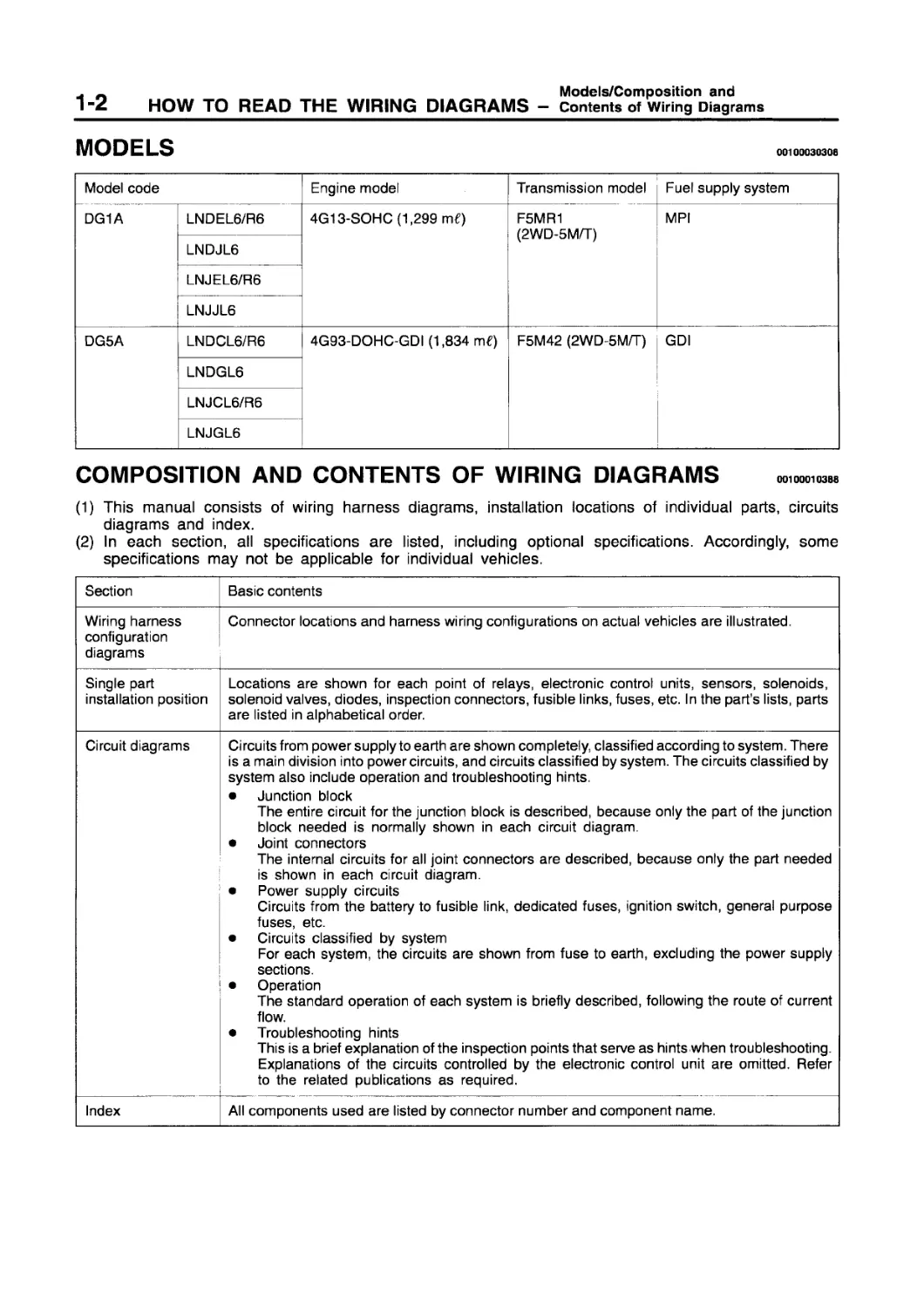
MODELS
00100030308
Model code Engine model Transmission model Fuel supply system
DG1A LNDEL6/R6 LNDJL6 LNJEL6/R6 LNJJL6 4G13-SOHC (1,299 m€) F5MR1 (2WD-5M/T) MPI
DG5A LNDCL6/R6 LNDGL6 LNJCL6/R6 LNJGL6 4G93-DOHC-GDI (1,834 m€) F5M42 (2WD-5M/T) GDI
COMPOSITION AND CONTENTS OF WIRING DIAGRAMS
(1) This manual consists of wiring harness diagrams, installation locations of individual parts, circuits diagrams and index.
(2) In each section, all specifications are listed, including optional specifications. Accordingly, some specifications may not be applicable for individual vehicles.
Section Basic contents
Wiring harness configuration diagrams Connector locations and harness wiring configurations on actual vehicles are illustrated.
Single part installation position Locations are shown for each point of relays, electronic control units, sensors, solenoids, solenoid valves, diodes, inspection connectors, fusible links, fuses, etc. In the part's lists, parts are listed in alphabetical order.
Circuit diagrams Circuits from power supply to earth are shown completely, classified according to system. There is a main division into power circuits, and circuits classified by system. The circuits classified by system also include operation and troubleshooting hints. • Junction block The entire circuit for the junction block is described, because only the part of the junction block needed is normally shown in each circuit diagram. • Joint connectors The internal circuits for all joint connectors are described, because only the part needed is shown in each circuit diagram. • Power supply circuits Circuits from the battery to fusible link, dedicated fuses, ignition switch, general purpose fuses, etc. • Circuits classified by system For each system, the circuits are shown from fuse to earth, excluding the power supply sections. • Operation The standard operation of each system is briefly described, following the route of current flow. • Troubleshooting hints This is a brief explanation of the inspection points that serve as hints when troubleshooting. Explanations of the circuits controlled by the electronic control unit are omitted. Refer to the related publications as required.
Index All components used are listed by connector number and component name.
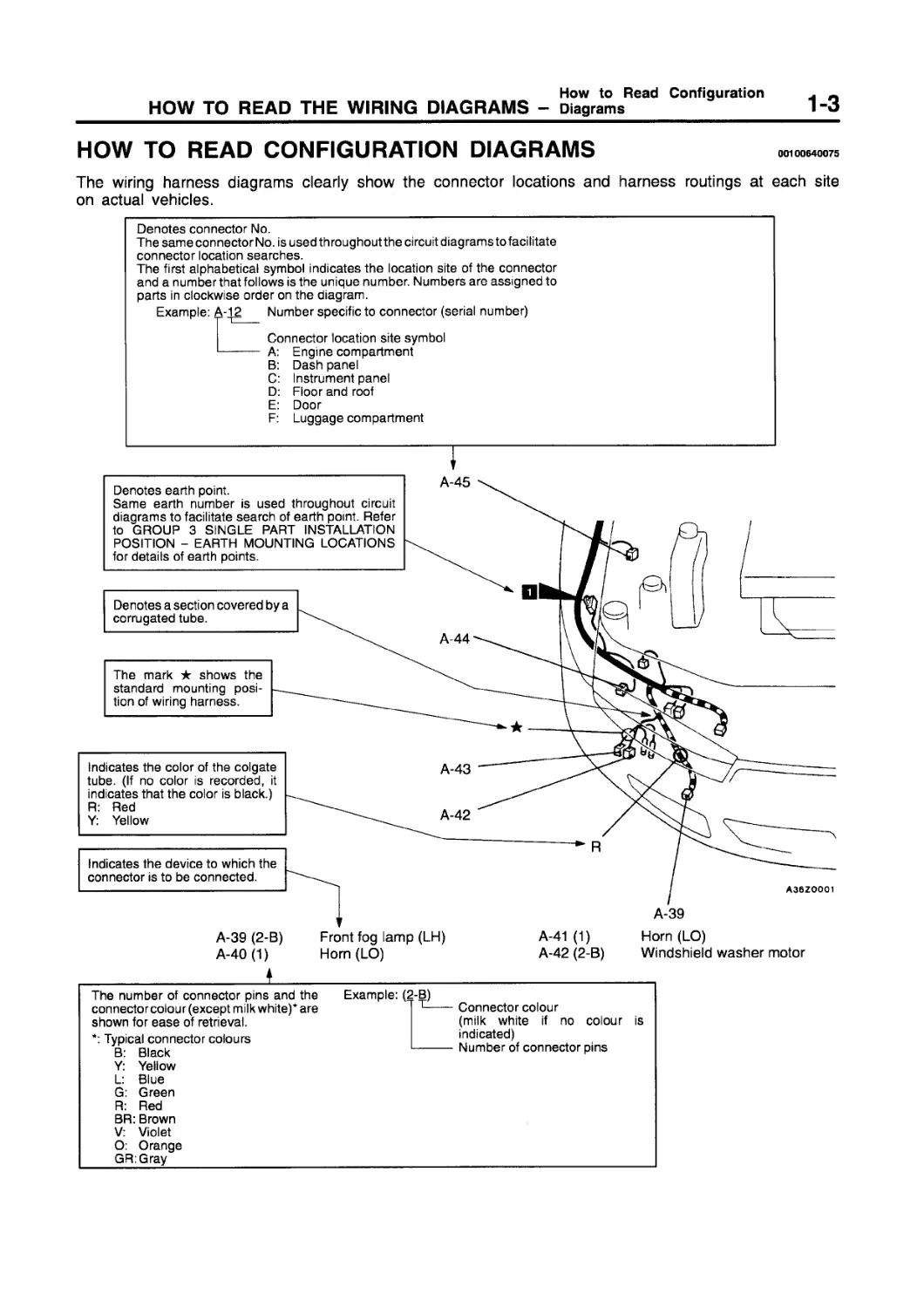
HOW TO READ CONFIGURATION DIAGRAMS
00100640075
The wiring harness diagrams clearly show the connector locations and harness routings at each site on actual vehicles.
Denotes connector No.
The same connector No. is used throughout the circuit diagrams to facilitate connector location searches.
The first alphabetical symbol indicates the location site of the connector and a number that follows is the unique number. Numbers are assigned to parts in clockwise order on the diagram.
Example: A-12___ Number specific to connector (serial number)
Connector location site symbol
------- A: Engine compartment
B: Dash panel
C: Instrument panel
D: Floor and roof
E: Door
F: Luggage compartment
I
A-45
A-43
Indicates the device to which the connector is to be connected.
The mark ★ shows the standard mounting position of wiring harness.
Denotes a section covered by a corrugated tube.
Indicates the color of the Colgate tube. (If no color is recorded, it indicates that the color is black.) R: Red Y: Yellow
A-42
A36ZOOO1
Denotes earth point.
Same earth number is used throughout circuit diagrams to facilitate search of earth point. Refer to GROUP 3 SINGLE PART INSTALLATION POSITION - EARTH MOUNTING LOCATIONS for details of earth points.
A-44
A-39
A-39 (2-B) Front fog lamp (LH)
A-40(1) Horn (LO)
A-41 (1) Horn(LO)
A-42 (2-B) Windshield washer motor
The number of connector pins and the connector colour (except milk white)* are shown for ease of retrieval.
*: Typical connector colours
B: Black
Y: Yellow
L: Blue
G: Green
R: Red
BR: Brown
V: Violet
O: Orange
GR:Gray
Example: (2-B)
7 T----Connector colour
(milk white if no colour is indicated)
Number of connector pins
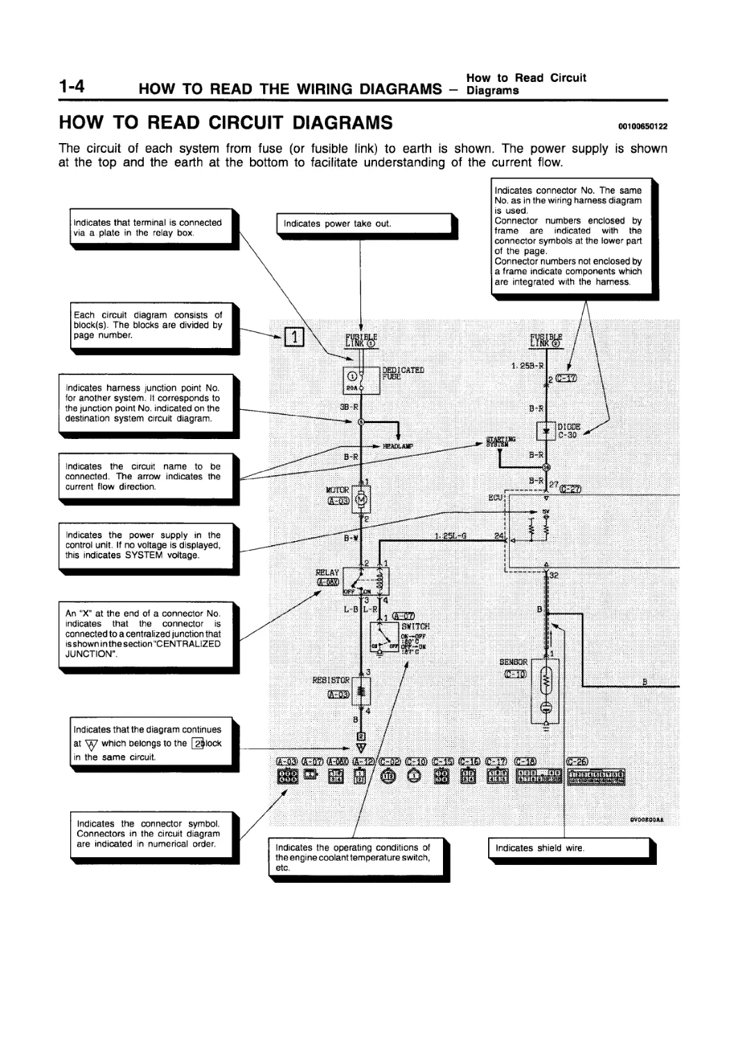
HOW TO READ CIRCUIT DIAGRAMS
00100650122
The circuit of each system from fuse (or fusible link) to earth is shown. The power supply is shown at the top and the earth at the bottom to facilitate understanding of the current flow.
Indicates power take out.
Each circuit diagram consists of block(s). The blocks are divided by page number.
Indicates that terminal is connected via a plate in the relay box.
В
Indicates connector No. The same No. as in the wiring harness diagram is used.
Connector numbers enclosed by frame are indicated with the connector symbols at the lower part of the page.
Connector numbers not enclosed by a frame indicate components which are integrated with the harness.
Indicates harness junction point No. for another system. It corresponds to the junction point No. indicated on the destination system circuit diagram.
© 20A
зв к
3ED1CATEE
<>
B-R
Indicates the circuit name to be connected. The arrow indicates the current flow direction.
Tsi250sR
и
DIODE
t
MCTCR
EC’J|
Ж
1.251.-G
I. В
SWITCH
Indicates the power supply in the control unit. If no voltage is displayed, this indicates SYSTEM voltage.
Indicates that the diagram continues at which belongs to the |~2^lock in the same circuit.
An “X” at the end of a connector No. indicates that the connector is connected to a centralized junction that isshown in the section “CENTRALIZED JUNCTION”.
В R
—~О
B-R r
L-RI
SENSOR
REB ВТО
[RTaTal
QV0OB00AA
Indicates shield wire.
Indicates the operating conditions of the engine coolant temperature switch, etc.
B-W
.2
а
RELAY
Indicates the connector symbol. Connectors in the circuit diagram are indicated in numerical order.
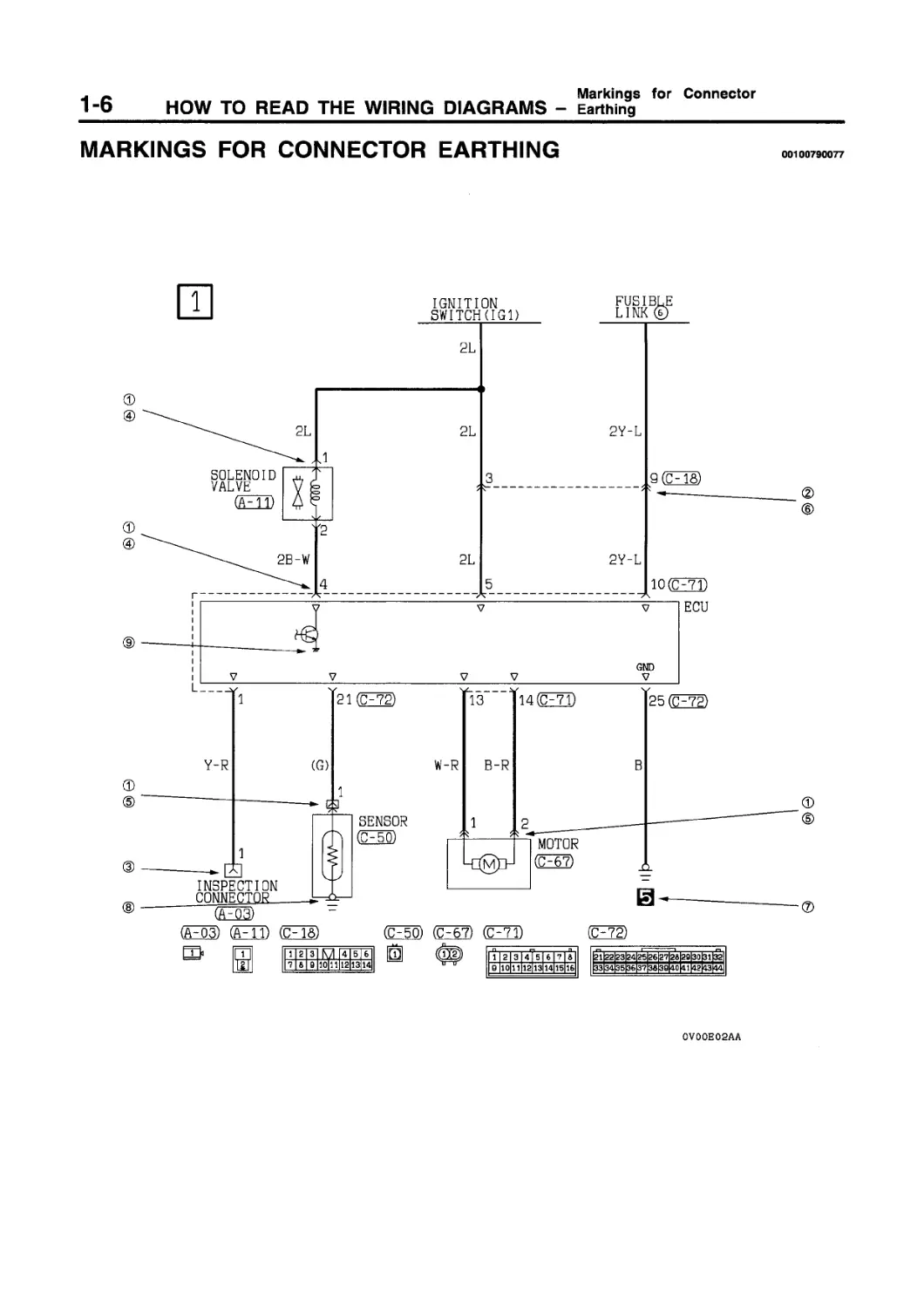
MARKINGS FOR CONNECTOR EARTHING
00100790077
IGNITION
SWITCH(IG1)
FUSIBLE LINK ©
Item
No.
Symbol
Contents
Connector and terminal marking
Connector/Earthing
Male terminal
16Z0021
Male connector
Female terminal
16Z0022
Female connector
16Z0017
The male and female terminals are indicated as shown. The connector with male terminal(s) is called as male connector and indicated by double connector contour lines, while the connector with female terminal(s) is called as female connector and indicated by single connector contour line.
Connector symbol marking
The symbol indicates the vehicle connector as viewed from the illustrated direction. At the connection with a device, the connector symbol on the device side is shown, and for an intermediate connector, a male connector symbol is shown. For spare connectors and check connectors, no device is connected, and so the harnessside connector symbol is shown for these connectors. The details for the diagnosis connector differ from the above description. For details, refer to the “MUT-II operation instructions”.
Spare connector, check connector
16Z0017
16Z0031
Item
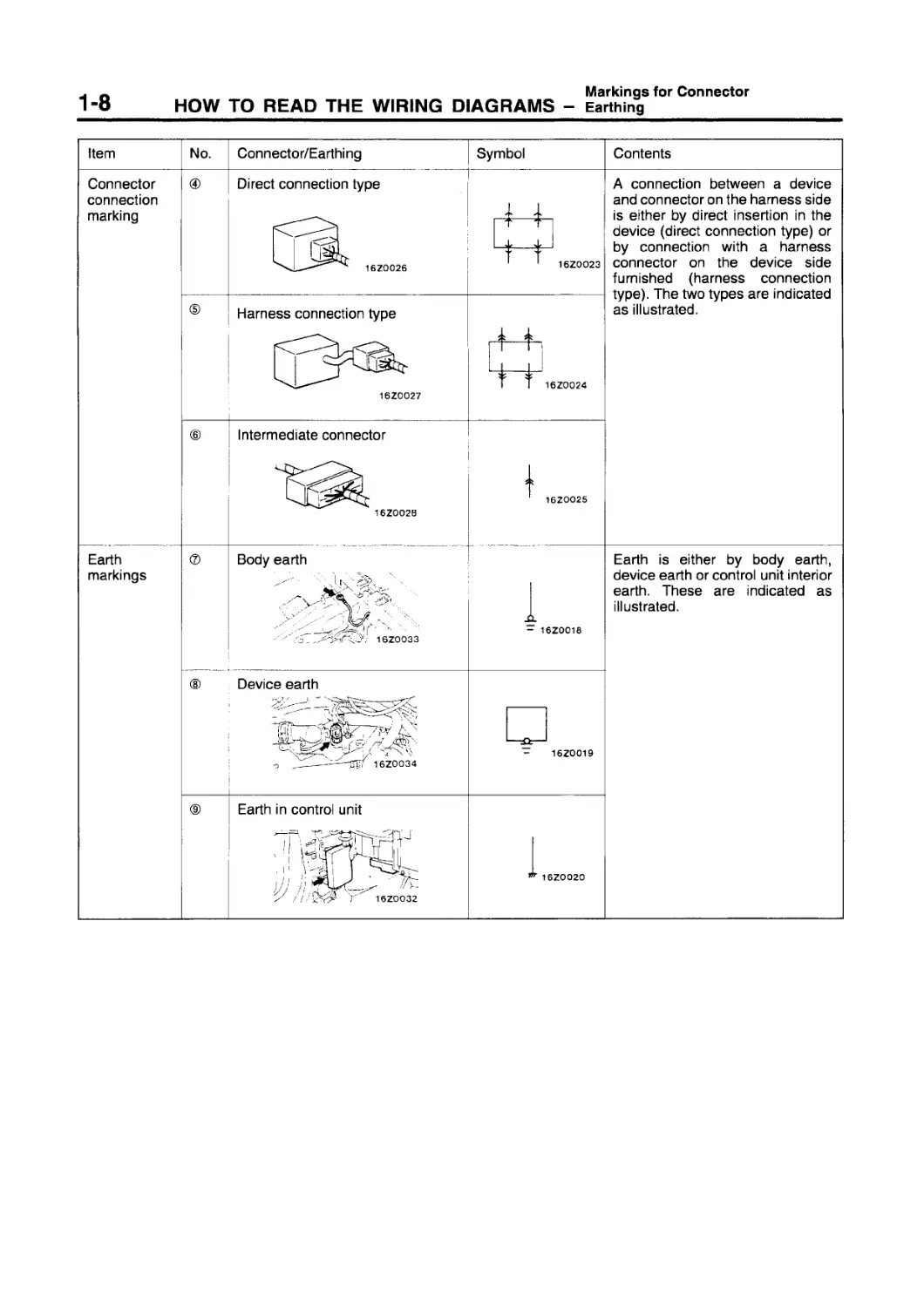
Connector connection marking
Contents
A connection between a device and connector on the harness side is either by direct insertion in the device (direct connection type) or by connection with a harness connector on the device side furnished (harness connection type). The two types are indicated as illustrated.
Earth markings
16ZOO25
A - 16Z0018
Earth is either by body earth, device earth or control unit interior earth. These are indicated as illustrated.
16Z0019
*16Z0020
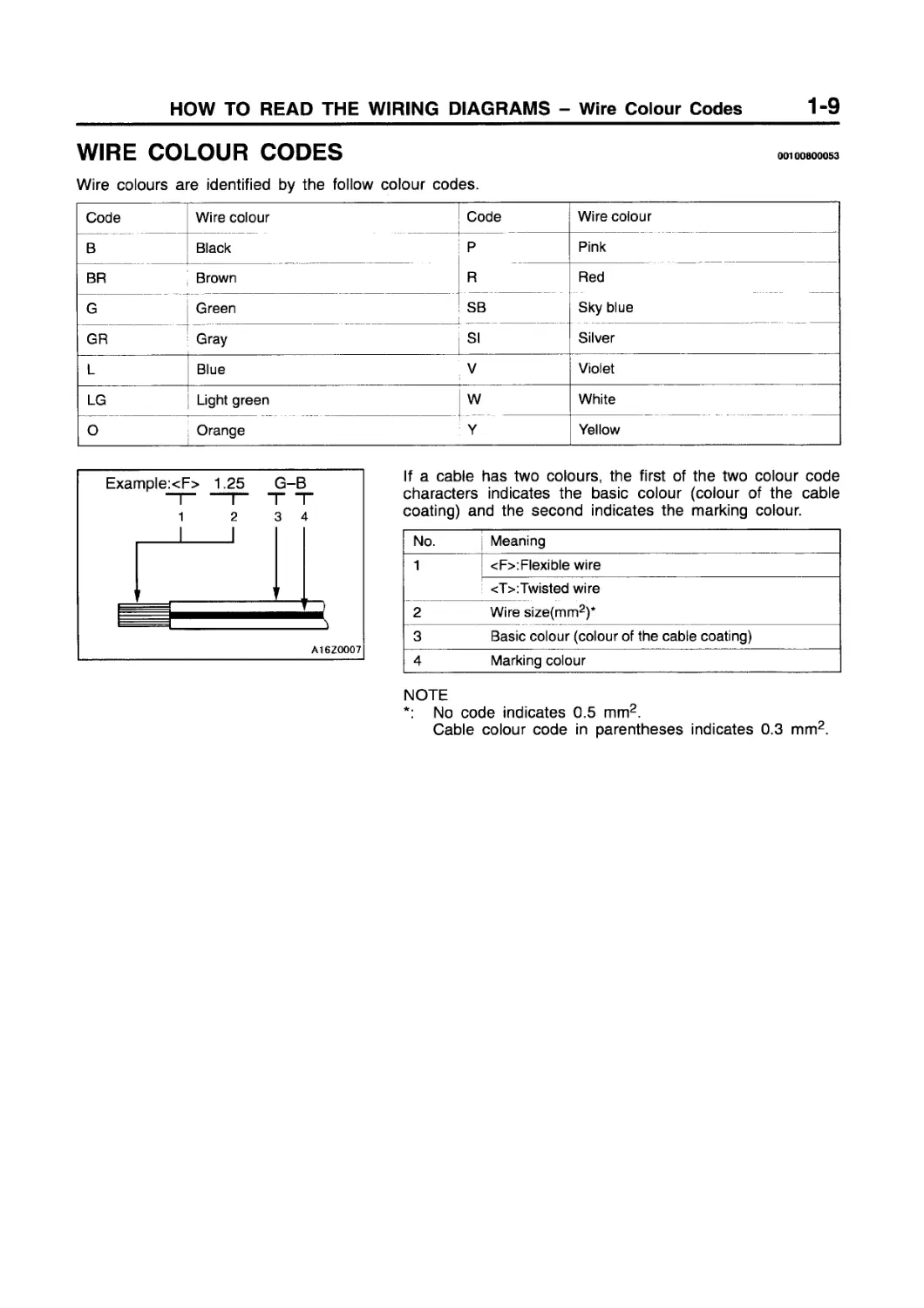
WIRE COLOUR CODES
Wire colours are identified by the follow colour codes.
Code Wire colour Code Wire colour
В Black P Pink
BR Brown R Red
G Green SB Sky blue
GR Gray SI Silver
L Blue V Violet
LG Light green w White
О Orange Y Yellow
Example:<F> 1.25 G-B -|-------------r~ T T
If a cable has two colours, the first of the two colour code characters indicates the basic colour (colour of the cable coating) and the second indicates the marking colour.
No. Meaning
1 <F>:Flexible wire
2 <T>:Twisted wire Wire size(mm2)*
3 Basic colour (colour of the cable coating)
4 Marking colour
NOTE
*: No code indicates 0.5 mm2.
Cable colour code in parentheses indicates 0.3 mm2.
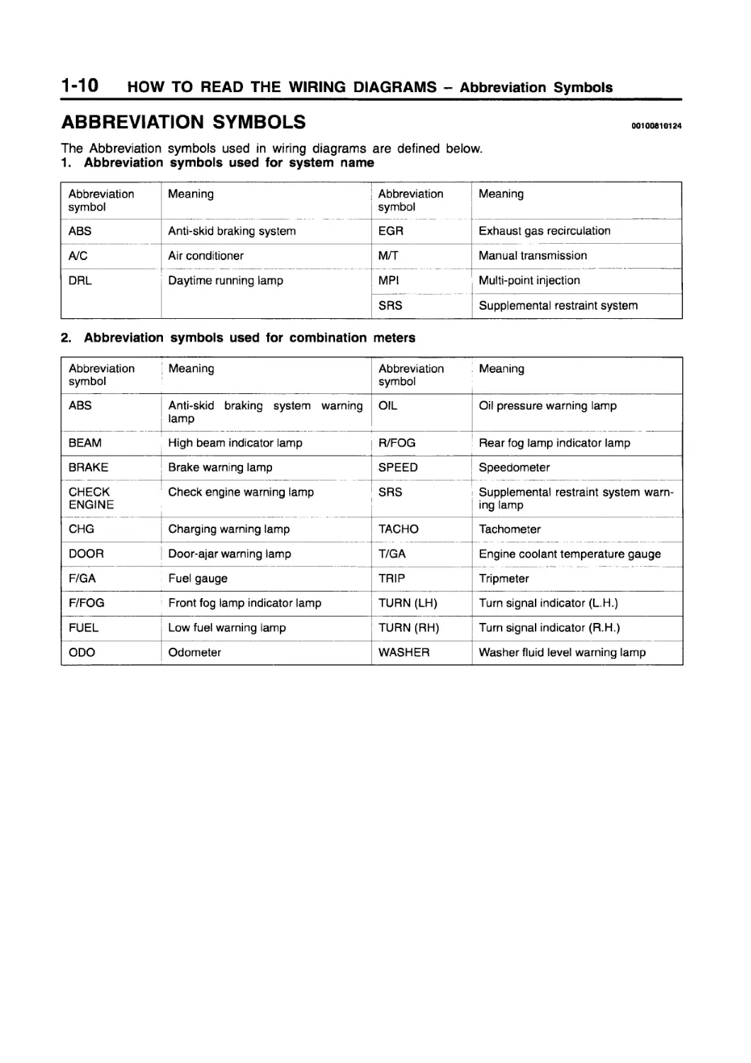
ABBREVIATION SYMBOLS
The Abbreviation symbols used in wiring diagrams are defined below.
1. Abbreviation symbols used for system name
Abbreviation symbol Meaning Abbreviation symbol Meaning
ABS Anti-skid braking system EGR Exhaust gas recirculation
A/C Air conditioner M/T Manual transmission
DHL Daytime running lamp MPI Multi-point injection
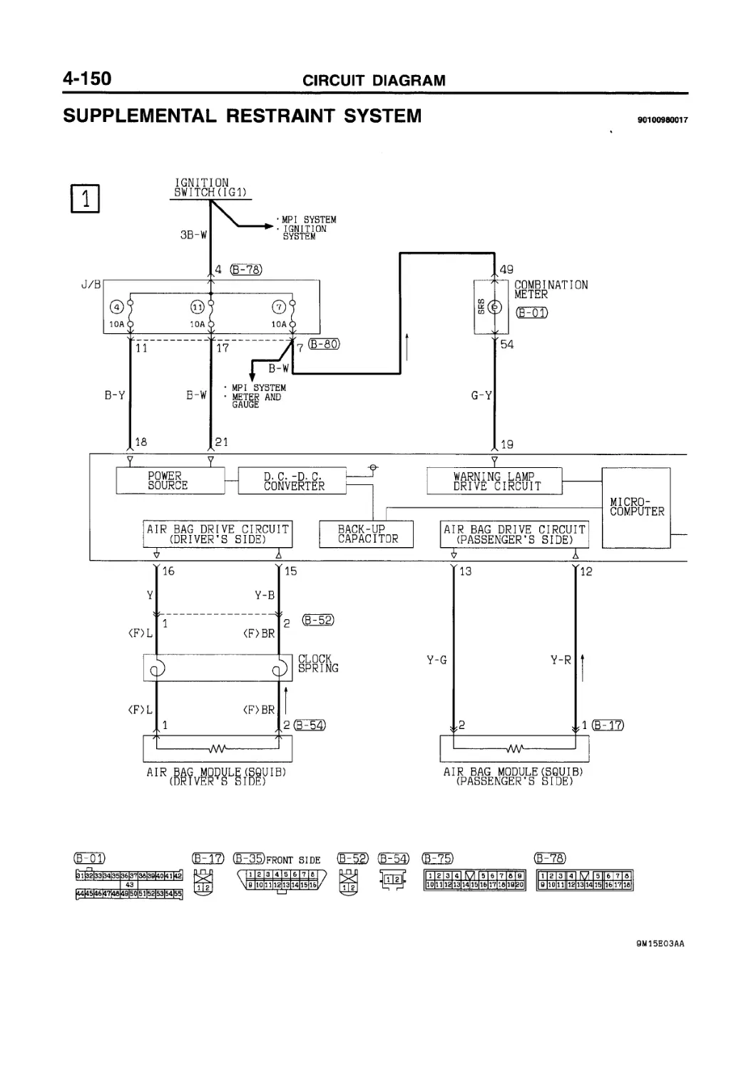
SRS Supplemental restraint system
2. Abbreviation symbols used for combination meters
Abbreviation symbol Meaning Abbreviation symbol Meaning
ABS Anti-skid braking system warning lamp OIL Oil pressure warning lamp
BEAM High beam indicator lamp R/FOG Rear fog lamp indicator lamp
BRAKE Brake warning lamp SPEED Speedometer
CHECK Check engine warning lamp SRS Supplemental restraint system warn-
ENGINE ing lamp
CHG Charging warning lamp TACHO Tachometer
DOOR Door-ajar warning lamp T/GA Engine coolant temperature gauge
F/GA Fuel gauge TRIP Tripmeter
F/FOG Front fog lamp indicator lamp TURN (LH) Turn signal indicator (L.H.)
FUEL Low fuel warning lamp TURN (RH) Turn signal indicator (R.H.)
ODO Odometer WASHER Washer fluid level warning lamp
3. Abbreviation symbols used for switches and relays
Name of switches and relays Abbreviation symbol Operation Name of switches and relays Abbreviation symbol Operation
Blower switch LO Blower operates at low speed Power window switch UP Window closes
DOWN Window opens
ML Blower operates at medium low speed AUTO UP Window is easily closed with one action
MH Blower operates at medium high speed AUTO DOWN Window is easily opened with one action
HI Blower operates at high speed LOCK Window locked
Dimmer passing switch LO Low beams ON UNLOCK Window unlocked
HI High beams ON Remote controlled mirror switch LH L.H. mirror operates
Door lock actuator, door lock keycylinder switch or door lock switch LOCK Door locked RH R.H. mirror operates
UNLOCK Door unlocked Room lamp switch DOOR Room lamps ON when a door is open
Heated seat switch LO Normal heating Sunroof switch OPEN Sunroof slides to open
HI Rapid heating UP Sunroof tilts up
Ignition switch ACC When turned to the ACC (ACCESSORY) or ON position, the power circuit will start CLOSE/ DOWN Sunroof tilts down or slides to close
IG1 Even when at the ST (START) position, the power circuit will start Turn signal switch LH L.H. turn signal lamps ON
RH R.H. turn signal lamps ON
IG2 When at the ST (START) position, the power circuit will not start functioning Variable intermittent wiper control switch SLOW Pause time for intermittent operation lengthen
FAST Pause time for intermittent operation shorten
Lighting switch TAIL Position, tail, licence plate and other illumination lamps ON Windshield wiper switch or rear wiper switch LO Wipers operate at low speed
HEAD Headlamps ON HI Wipers operate at high speed
Others ON Switched on
OFF Switched off INT Wipers operate intermittently
4. Other abbreviation symbols
Abbreviation symbol Meaning Abbreviation symbol Meaning
ECU Electronic control unit LCD Liquid crystal display
GND Earth LH Left hand
ILL Illumination lamp LHD L.H. drive vehicles
IND Indicator lamp RH Right hand
J/B Junction block RHD R.H. drive vehicles
J/C Joint connector
WIRING HARNESS CONFIGURATION DIAGRAMS
CONTENTS 80109000449
OVERALL WIRING DIAGRAM
INSTRUMENT PANEL
L.H. drive vehicles .....................2-2
R.H. drive vehicles......................2-3
ENGINE COMPARTMENT
4G13 <L.H. drive vehicles>...............2-4
4G93 <L.H. drive vehicles>...............2-8
4G13 <R.H. drive vehicles>..............2-12
4G93 <R.H. drive vehicles>..............2-16
DASH PANEL
L.H. drive vehicles ....................2-20
R.H. drive vehicles.....................2-24
LH. drive vehicles ...................2-28
R.H. drive vehicles...................2-29
FLOOR AND ROOF
L.H. drive vehicles ..................2-30
R.H. drive vehicles...................2-32
DOOR
L.H. drive vehicles ..................2-34
R.H. drive vehicles...................2-35
LUGGAGE COMPARTMENT .....................2-36
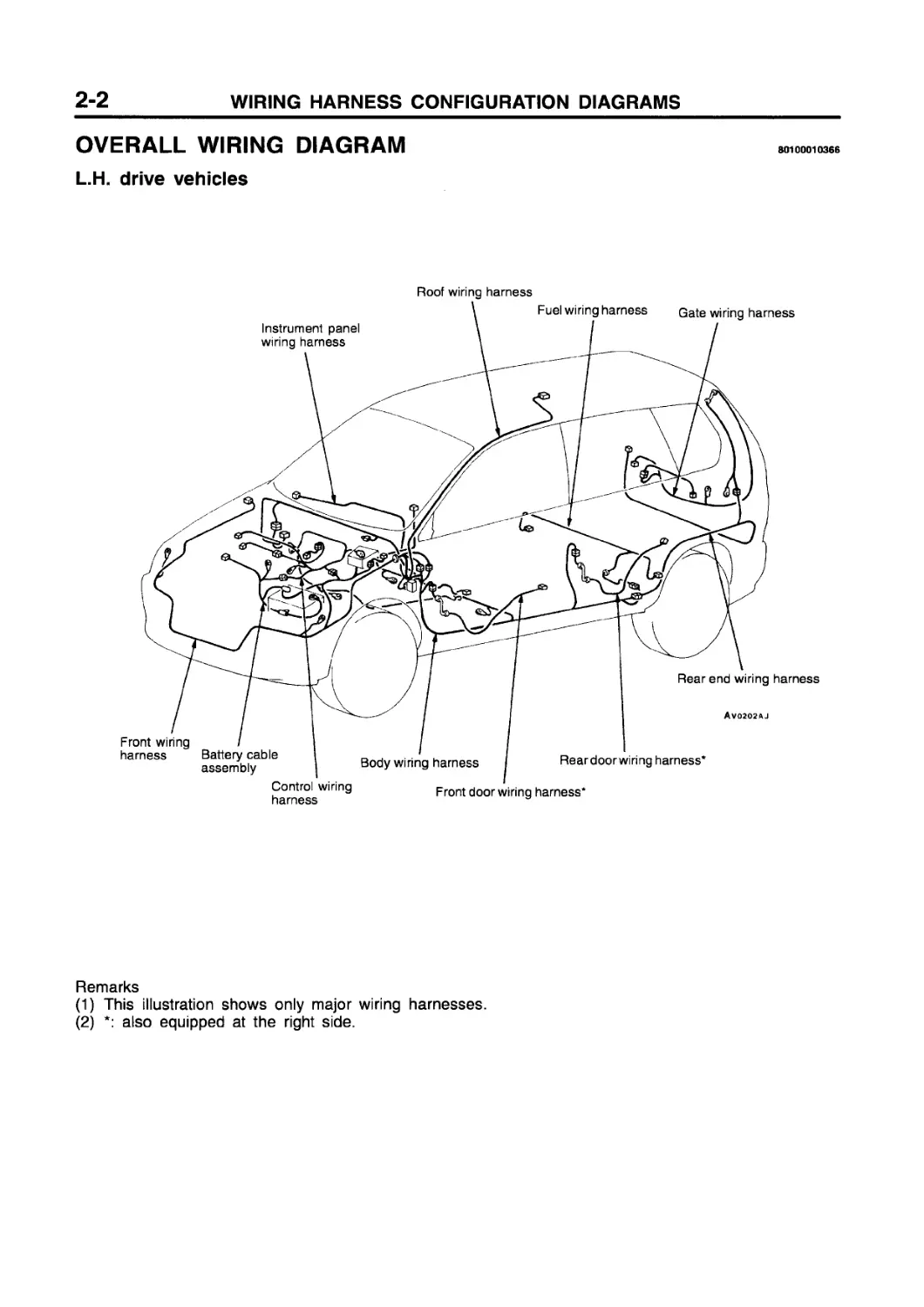
OVERALL WIRING DIAGRAM
80100010366
L.H. drive vehicles
Roof wiring harness
Remarks
(1) This illustration shows only major wiring harnesses.
(2) *: also equipped at the right side.
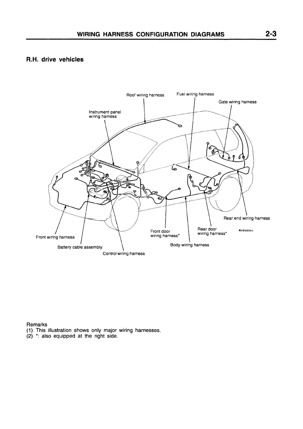
R.H. drive vehicles
Control wiring harness
Remarks
(1) This illustration shows only major wiring harnesses.
(2) *: also equipped at the right side.
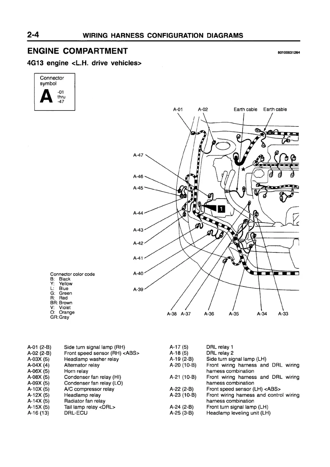
ENGINE COMPARTMENT
4G13 engine <L.H. drive vehicles>
80100031264
Connector symbol
Connector color code B: Black Y: Yellow L: Blue G: Green R: Red BR: Brown V: Violet O: Orange GR:Gray
A-01 A-02 Earth cable Earth cable
A-47
A-46
A-45
A-44
A-43
A-42
A-41
A-40
A-39
A-38 A-37 A-36 A-35 A-34 A-33
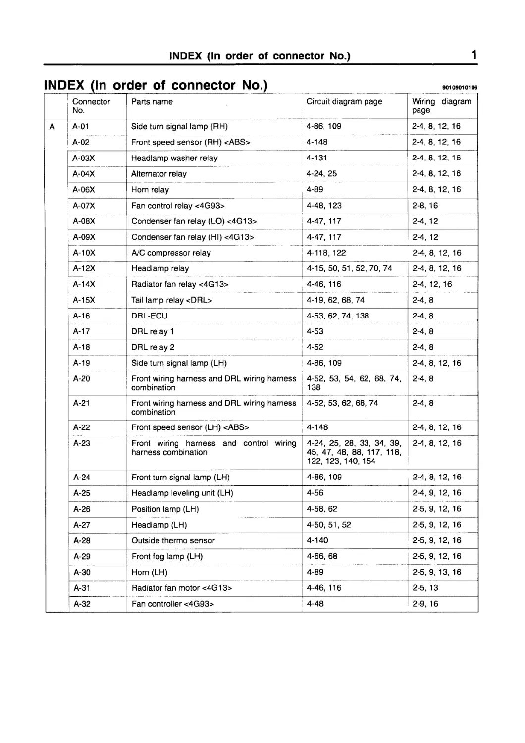
A-01 (2-B) Side turn signal lamp (RH) A-17 (5)
A-02 (2-B) Front speed sensor (RH) <ABS> A-18 (5)
A-03X (5) Headlamp washer relay A-19 (2-B)
A-04X (4) Alternator relay A-20 (10-B)
A-06X (5) Horn relay
A-08X (5) Condenser fan relay (HI) A-21 (10-B)
A-09X (5) Condenser fan relay (LO)
A-10X (5) A/C compressor relay A-22 (2-B)
A-12X (5) Headlamp relay A-23 (10-B)
A-14X (5) Radiator fan relay
A-15X (5) Tail lamp relay <DRL> A-24 (2-B)
A-16 (13) DRL-ECU A-25 (3-B)
DRL relay 1
DRL relay 2
Side turn signal lamp (LH)
Front wiring harness and DRL wiring harness combination
Front wiring harness and DRL wiring harness combination
Front speed sensor (LH) <ABS>
Front wiring harness and control wiring harness combination
Front turn signal lamp (LH)
Headlamp leveling unit (LH)
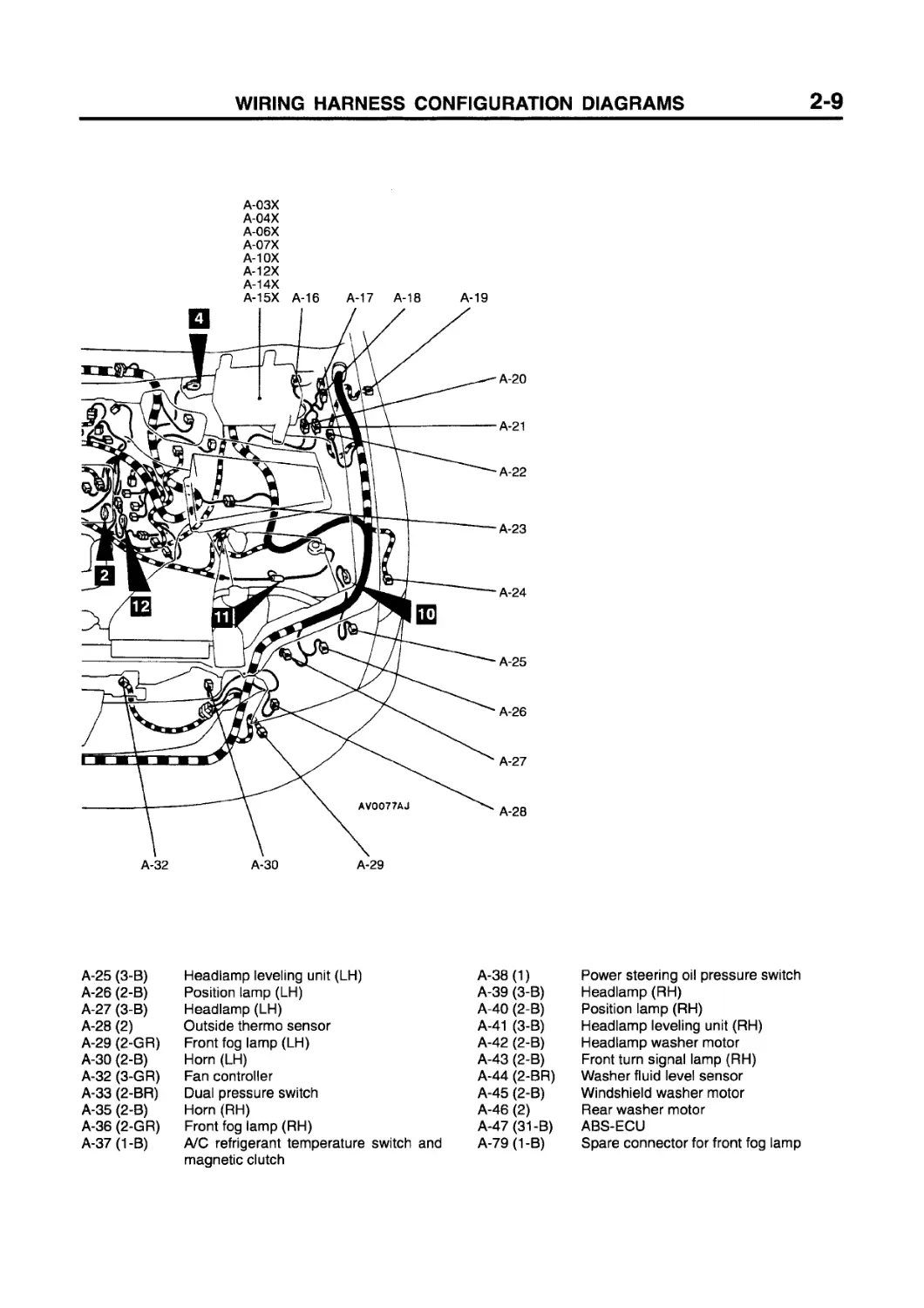
A-03X
A-04X
A-06X
A-08X
A-09X
A-10X
A-12X
A-14X A-15XA-16 A-17 A-18 A-19
A-20
A-21
A-22
A-23
A-24
A-25
A-26
A-27
A-28
A-29
A-31 A-79 A-30
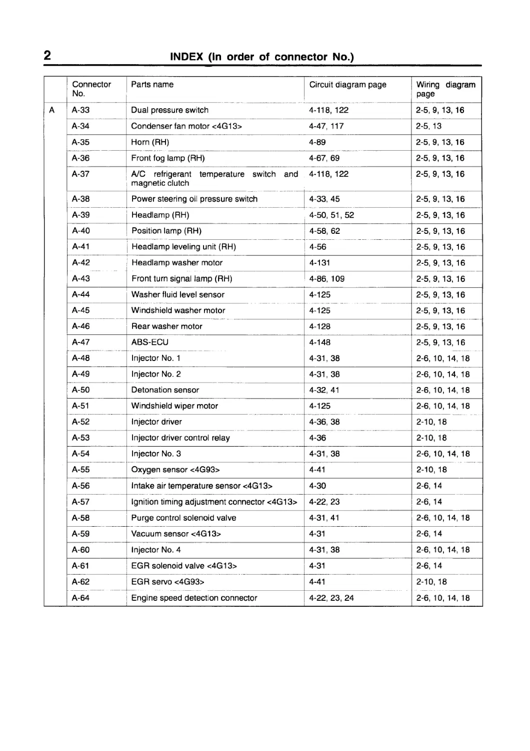
A-26 (2-B) Position lamp (LH) A-38 (1) Power steering oil pressure switch
A-27 (3-B) Headlamp (LH) A-39 (3-B) Headlamp (RH)
A-28 (2) Outside thermo sensor A-40 (2-B) Position lamp (RH)
A-29 (2-GR) Front fog lamp (LH) A-41 (3-B) Headlamp leveling unit (RH)
A-30 (2-B) Horn (LH) A-42 (2-B) Headlamp washer motor
A-31 (2-B) Radiator fan motor A-43 (2-B) Front turn signal lamp (RH)
A-33 (2-BR) Dual pressure switch A-44 (2-BR) Washer fluid level sensor
A-34 (4-B) Condenser fan motor A-45 (2-B) Windshield washer motor
A-35 (2-B) Horn (RH) A-46 (2) Rear washer motor
A-36 (2-GR) Front fog lamp (RH) A-47 (31-B) ABS-ECU
A-37 (1-B) A/C refrigerant temperature switch and A-79 (1-B) Spare connector for front fog lamp
magnetic clutch
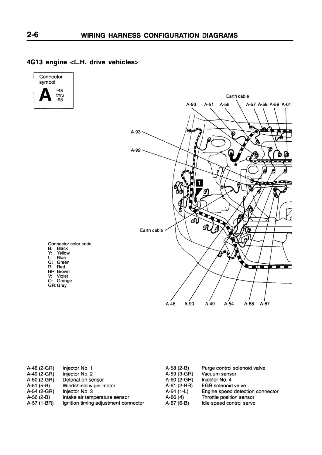
4G13 engine <L.H. drive vehicles>
Connector symbol
A -48 thru -93
Connector color code
B: Black Y: Yellow L: Blue G: Green R: Red BR: Brown V: Violet O: Orange GR:Gray
A-48 (2-GR)
A-49 (2-GR)
A-50 (2-GR)
A-51 (5-B)
A-54 (2-GR)
A-56 (2-B)
A-57 (1-BR)
Injector No. 1
Injector No. 2
Detonation sensor
Windshield wiper motor
Injector No. 3
Intake air temperature sensor
Ignition timing adjustment connector
A-58 (2-B)
A-59 (3-GR)
A-60 (2-GR)
A-61 (2-BR)
A-64 (1-L)
A-66 (4)
A-67 (6-B)
Purge control solenoid valve
Vacuum sensor
Injector No. 4
EGR solenoid valve
Engine speed detection connector
Throttle position sensor
Idle speed control servo
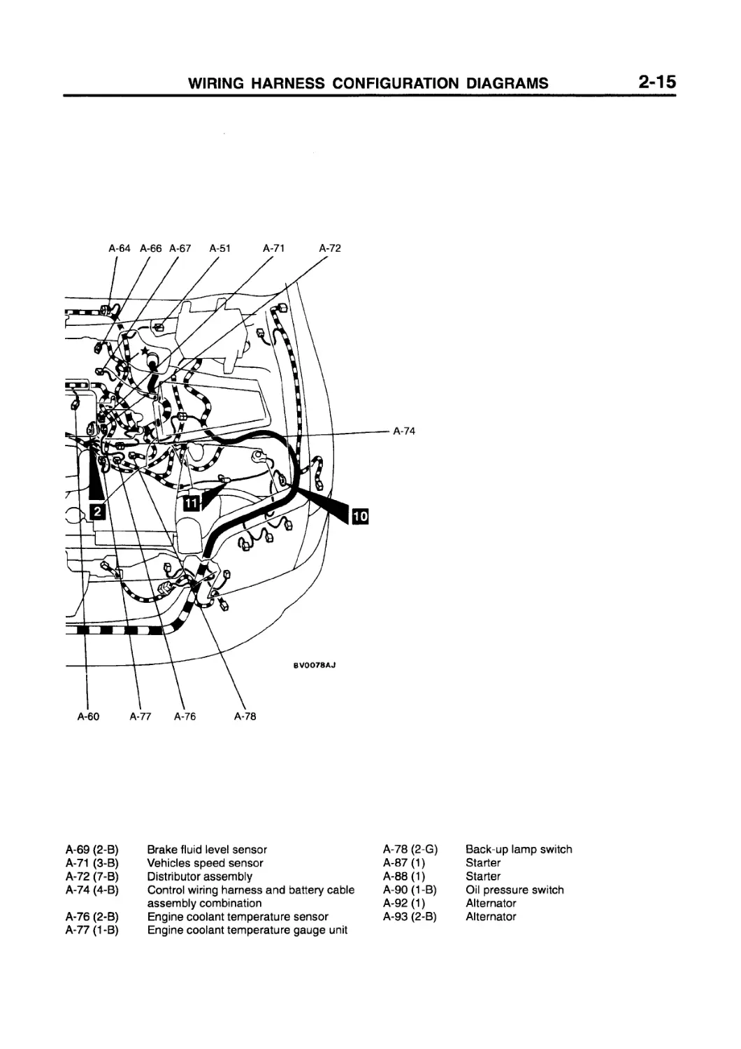
A-64 A-66 A-67 A-69 A-71 A-72
A-60 A-77 A-76 A-78
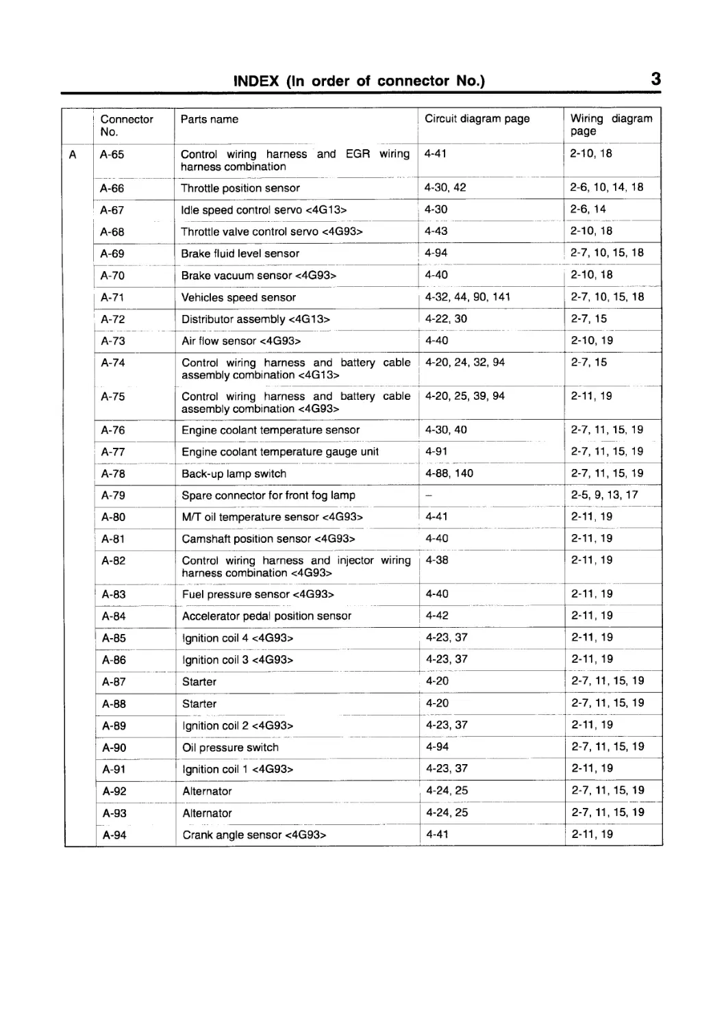
A-69 (2-B) Brake fluid level sensor A-78 (2-G) Back-up lamp switch
A-71 (3-B) Vehicles speed sensor A-87 (1) Starter
A-72 (7-B) Distributor assembly A-88(1) Starter
A-74 (4-B) Control wiring harness and battery cable A-90 (1 -B) Oil pressure switch
assembly combination A-92(1) Alternator
A-76 (2-B) Engine coolant temperature sensor A-93 (2-B) Alternator
A-77 (1-B) Engine coolant temperature gauge unit
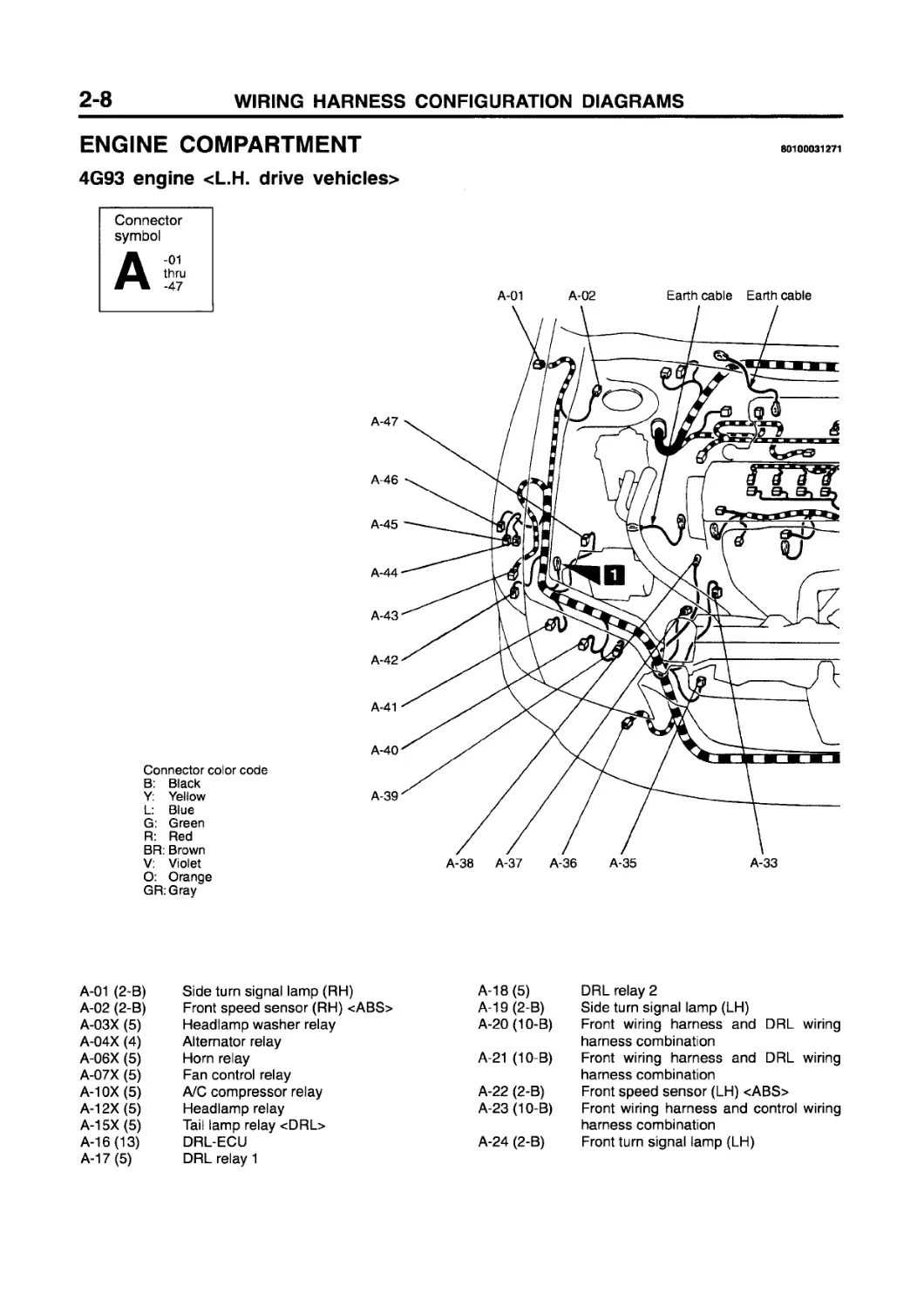
ENGINE COMPARTMENT
4G93 engine <L.H. drive vehicles>
80100031271
Connector symbol
Connector color code B: Black Y: Yellow L: Blue G: Green R: Red BR: Brown V: Violet O: Orange GR:Gray
A-01 A-02 Earth cable Earth cable
A-47
A-46
A-45
A-44
A-43
A-42
A-41
A-40
A-39
A-38 A-37 A-36 A-35 A-33
A-01 (2-B) Side turn signal lamp (RH) A-18 (5) DRL relay 2
A-02 (2-B) Front speed sensor (RH) <ABS> A-19 (2-B) Side turn signal lamp (LH)
A-03X (5) Headlamp washer relay A-20(10-B) Front wiring harness and DRL wiring
A-04X (4) Alternator relay harness combination
A-06X (5) Horn relay A-21 (10-B) Front wiring harness and DRL wiring
A-07X (5) Fan control relay harness combination
A-10X (5) A/C compressor relay A-22 (2-B) Front speed sensor (LH) <ABS>
A-12X (5) Headlamp relay A-23(10-B) Front wiring harness and control wiring
A-15X (5) Tail lamp relay <DRL> harness combination
A-16(13) DRL-ECU A-24 (2-B) Front turn signal lamp (LH)
A-17 (5) DRL relay 1
A-03X
A-04X
A-06X
A-07X
A-10X
A-12X
A-14X
A-15X A-16
A-17 A-18 A-19
A-20
A-21
A-22
A-23
A-24
A-25
A-26
A-27
A-28
A-32 A-30 A-29
A-25 (3-B) Headlamp leveling unit (LH) A-38 (1) Power steering oil pressure switch
A-26 (2-B) Position lamp (LH) A-39 (3-B) Headlamp (RH)
A-27 (3-B) Headlamp (LH) A-40 (2-B) Position lamp (RH)
A-28 (2) Outside thermo sensor A-41 (3-B) Headlamp leveling unit (RH)
A-29 (2-GR) Front fog lamp (LH) A-42 (2-B) Headlamp washer motor
A-30 (2-B) Horn (LH) A-43 (2-B) Front turn signal lamp (RH)
A-32 (3-GR) Fan controller A-44 (2-BR) Washer fluid level sensor
A-33 (2-BR) Dual pressure switch A-45 (2-B) Windshield washer motor
A-35 (2-B) Horn (RH) A-46 (2) Rear washer motor
A-36 (2-GR) Front fog lamp (RH) A-47 (31-B) ABS-ECU
A-37(1-B) A/C refrigerant temperature switch and A-79 (1-B) Spare connector for front fog lamp
magnetic clutch
4G93 engine <L.H. drive vehicles>
Connector symbol
Connector color code
B: Black Y: Yellow L: Blue G: Green R: Red BR: Brown V: Violet O: Orange GR:Gray
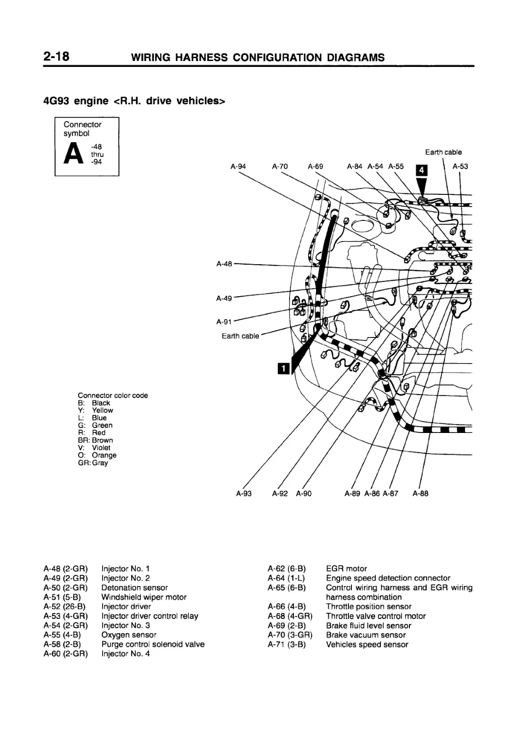
A-48 (2-GR) Injector No. 1 A-62 (6-B) EGR servo
A-49 (2-GR) Injector No. 2 A-64 (1-L) Engine speed detection connector
A-50 (2-GR) Detonation sensor A-65 (6-B) Control wiring harness and EGR wiring
A-51 (5-B) Windshield wiper motor harness combination
A-52 (26-B) Injector driver A-66 (4-B) Throttle position sensor
A-53 (4-GR) Injector driver control relay A-68 (4-GR) Throttle valve control servo
A-54 (2-GR) Injector No. 3 A-69 (2-B) Brake fluid level sensor
A-55 (4-B) Oxygen sensor A-70 (3-GR) Brake vacuum sensor
A-58 (2-B) Purge control solenoid valve A-71 (3-B) Vehicles speed sensor
A-60 (2-GR) Injector No. 4 A-73 (7-B) Air flow sensor
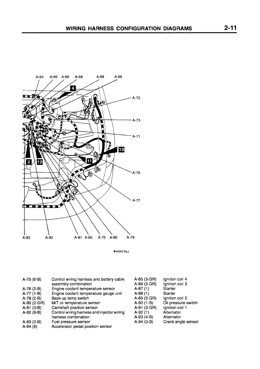
A-64 A-65 A-66 A-58 A-68 A-69
A-83 A-82
A-81 A-50 A-75 A-80 A-79
BVOO77AJ
A-75 (6-B) Control wiring harness and battery cable A-85 (3-GR) Ignition coil 4
assembly combination A-86 (3-GR) Ignition coil 3
A-76 (2-B) Engine coolant temperature sensor A-87 (1) Starter
A-77 (1-B) Engine coolant temperature gauge unit A-88(1) Starter
A-78 (2-B) Back-up lamp switch A-89 (3-GR) Ignition coil 2
A-80 (2-GR) M/T oil temperature sensor A-90(1-B) Oil pressure switch
A-81 (3-B) Camshaft position sensor A-91 (3-GR) Ignition coil 1
A-82 (8-B) Control wiring harness and injector wiring A-92 (1) Alternator
harness combination A-93 (4-B) Alternator
A-83 (3-B) Fuel pressure sensor A-94 (3-B) Crank angle sensor
A-84 (8) Accelerator pedal position sensor
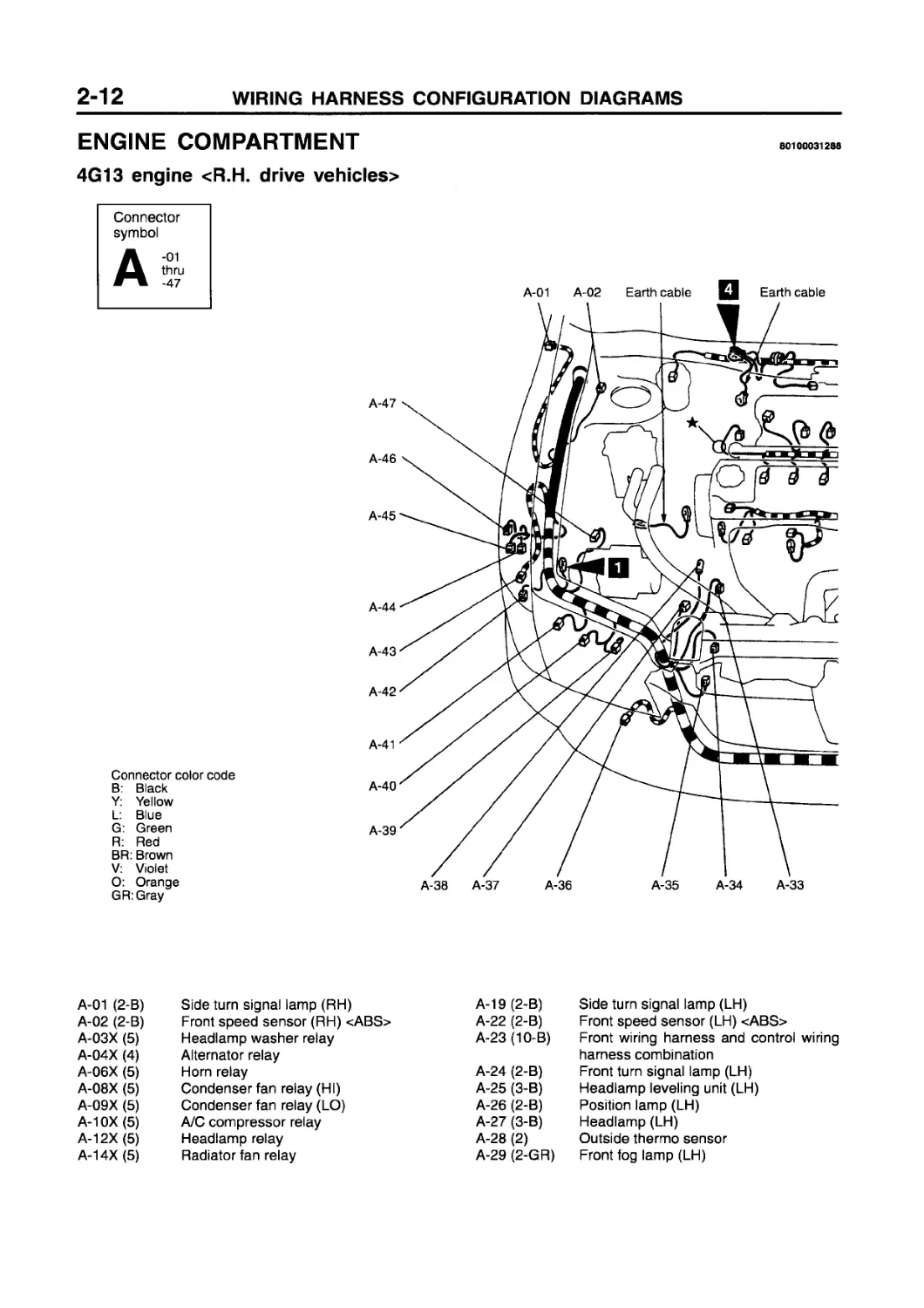
ENGINE COMPARTMENT
4G13 engine <R.H. drive vehicles>
80100031288
Connector symbol
Connector color code
B: Black
Y: Yellow
L: Blue
G: Green
R: Red
BR: Brown
V: Violet
O: Orange
GR:Gray
A-01 A-02 Earth cable Q Earth cable
A-47
A-46
A-45
A-44
A-43
A-42
A-41
A-40
A-39
A-38 A-37 A-36 A-35 A-34 A-33
A-01 (2-B) Side turn signal lamp (RH) A-19 (2-B) Side turn signal lamp (LH)
A-02 (2-B) Front speed sensor (RH) <ABS> A-22 (2-B) Front speed sensor (LH) <ABS>
A-03X (5) Headlamp washer relay A-23 (10-B) Front wiring harness and control wiring
A-04X (4) Alternator relay harness combination
A-06X (5) Horn relay A-24 (2-B) Front turn signal lamp (LH)
A-08X (5) Condenser fan relay (HI) A-25 (3-B) Headlamp leveling unit (LH)
A-09X (5) Condenser fan relay (LO) A-26 (2-B) Position lamp (LH)
A-10X (5) A/C compressor relay A-27 (3-B) Headlamp (LH)
A-12X (5) Headlamp relay A-28 (2) Outside thermo sensor
A-14X (5) Radiator fan relay A-29 (2-GR) Front fog lamp (LH)
A-03X
A-04X
A-06X
A-08X
A-09X
A-10X
A-12X
A-14X A-19
A-22
A-23
A-24
A-25
A-26
A-27
A-28
A-31 A-79 A-30 A-29
A-30 (2-B) Horn (LH) A-40 (2-B)
A-31 (2-B) Radiator fan motor A-41 (3-B)
A-33 (2-BR) Dual pressure switch A-42 (2-B)
A-34 (4-B) Condenser fan motor A-43 (2-B)
A-35 (2-B) Horn (RH) A-44 (2-BR)
A-36 (2-GR) Front fog lamp (RH) A-45 (2-B)
A-37 (1-B) A/C refrigerant temperature switch and A-46 (2)
magnetic clutch A-47 (31-B)
A-38 (1) Power steering oil pressure switch A-79 (1-B)
A-39 (3-B) Headlamp (RH)
Position lamp (RH)
Headlamp leveling unit (RH) Headlamp washer motor Front turn signal lamp (RH) Washer fluid level sensor Windshield washer motor Rear washer motor ABS-ECU
Spare connector for front fog lamp
4G13 engine <R.H. drive vehicles>
Connector symbol
Connector color code B: Black
Y: Yellow
L: Blue
G: Green
R: Red
BR: Brown V: Violet O: Orange GR:Gray
A-48 (2-GR)
A-49 (2-GR)
A-50 (2-GR)
A-51 (5-B)
A-54 (2-GR)
A-56 (2-B)
A-57 (1-BR)
Injector No. 1
Injector No. 2
Detonation sensor
Windshield wiper motor
Injector No. 3
Intake air temperature sensor
Ignition timing adjustment connector
A-58 (2-B)
A-59 (3-GR)
A-60 (2-GR)
A-61 (2-BR)
A-64 (1-L)
A-66 (4)
A-67 (6-B)
Purge control solenoid valve
Vacuum sensor
Injector No. 4
EGR solenoid valve
Engine speed detection connector
Throttle position sensor
Idle speed control servo
A-69 (2-B) Brake fluid level sensor A-78 (2-G) Back-up lamp switch
A-71 (3-B) Vehicles speed sensor A-87 (1) Starter
A-72 (7-B) Distributor assembly A-88(1) Starter
A-74 (4-B) Control wiring harness and battery cable A-90(1-B) Oil pressure switch
assembly combination A-92(1) Alternator
A-76 (2-B) Engine coolant temperature sensor A-93 (2-B) Alternator
A-77(1-B) Engine coolant temperature gauge unit
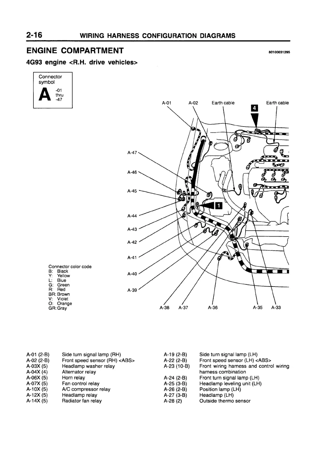
ENGINE COMPARTMENT
4G93 engine <R.H. drive vehicles>
80100031295
Connector symbol
Connector color code B: Black Y: Yellow L: Blue G: Green R: Red BR: Brown V: Violet O: Orange GR:Gray
A-01 (2-B) Side turn signal lamp (RH) A-19 (2-B) Side turn signal lamp (LH)
A-02 (2-B) Front speed sensor (RH) <ABS> A-22 (2-B) Front speed sensor (LH) <ABS>
A-03X (5) Headlamp washer relay A-23 (10-B) Front wiring harness and control wiring
A-04X (4) Alternator relay harness combination
A-06X (5) Horn relay A-24 (2-B) Front turn signal lamp (LH)
A-07X (5) Fan control relay A-25 (3-B) Headlamp leveling unit (LH)
A-10X (5) A/C compressor relay A-26 (2-B) Position lamp (LH)
A-12X (5) Headlamp relay A-27 (3-B) Headlamp (LH)
A-14X (5) Radiator fan relay A-28 (2) Outside thermo sensor
A-03X
A-04X
A-06X
A-07X
A-10X
A-12X
A-14X A-19
A-29 (2-GR) Front fog lamp (LH) A-40 (2-B)
A-30 (2-B) Horn (LH) A-41 (3-B)
A-32 (3-GR) Fan controller A-42 (2-B)
A-33 (2-BR) Dual pressure switch A-43 (2-B)
A-35 (2-B) Horn (RH) A-44 (2-BR)
A-36 (2-GR) Front fog lamp (RH) A-45 (2-B)
A-37(1-B) A/C refrigerant temperature switch and A-46 (2)
magnetic clutch A-47 (31-B)
A-38 (1) Power steering oil pressure switch A-79 (1-B)
A-39 (3-B) Headlamp (RH)
Position lamp (RH)
Headlamp leveling unit (RH) Headlamp washer motor Front turn signal lamp (RH) Washer fluid level sensor Windshield washer motor Rear washer motor ABS-ECU
Spare connector for front fog lamp
4G93 engine <R.H. drive vehicles>
Connector symbol
Connector color code
B: Black
Y: Yellow
L: Blue
G: Green
R: Red
BR: Brown
V: Violet
O: Orange
GR:Gray
A-48 (2-GR)
A-49 (2-GR)
A-50 (2-GR)
A-51 (5-B)
A-52 (26-B)
A-53 (4-GR)
A-54 (2-GR)
A-55 (4-B)
A-58 (2-B)
A-60 (2-GR)
Injector No. 1
Injector No. 2
Detonation sensor
Windshield wiper motor
Injector driver
Injector driver control relay
Injector No. 3
Oxygen sensor
Purge control solenoid valve
Injector No. 4
A-62 (6-B) EGR motor
A-64 (1-L) Engine speed detection connector
A-65 (6-B) Control wiring harness and EGR wiring harness combination
A-66 (4-B)
A-68 (4-GR)
A-69 (2-B)
A-70 (3-GR)
A-71 (3-B)
Throttle position sensor Throttle valve control motor Brake fluid level sensor Brake vacuum sensor Vehicles speed sensor
A-52 A-64 A-65 A-66 A-51
A-58
A-62
A-68
A-73
A-71
A-82
A-76
A-77
A-50
A-75
A-85 A-60 A-83 A-81 A-80 A-79
A-73 (7-B) Air flow sensor A-84 (8)
A-75 (6-B) Control wiring harness and battery cable A-85 (3-GR)
assembly combination A-86 (3-GR)
A-76 (2-B) Engine coolant temperature sensor A-87 (1)
A-77 (1-B) Engine coolant temperature gauge unit A-88(1)
A-78 (2-B) Back-up lamp switch A-89 (3-GR)
A-80 (2-GR) M/T oil temperature sensor A-90 (1-B)
A-81 (3-B) Camshaft position sensor A-91 (3-GR)
A-82 (8-B) Control wiring harness and injector wiring A-92 (1)
harness combination A-93 (4-B)
A-83 (3-B) Fuel pressure sensor A-94 (3-B)
Accelerator pedal position sensor
Ignition coil 4
Ignition coil 3
Starter
Starter
Ignition coil 2
Oil pressure switch
Ignition coil 1
Alternator
Alternator
Crank angle sensor
DASH PANEL
L.H. drive vehicles
Connector symbol
Connector color code
B: Black
Y: Yellow
L: Blue
G: Green
R: Red
BR: Brown
V: Violet
O: Orange
GR:Gray
80100060705
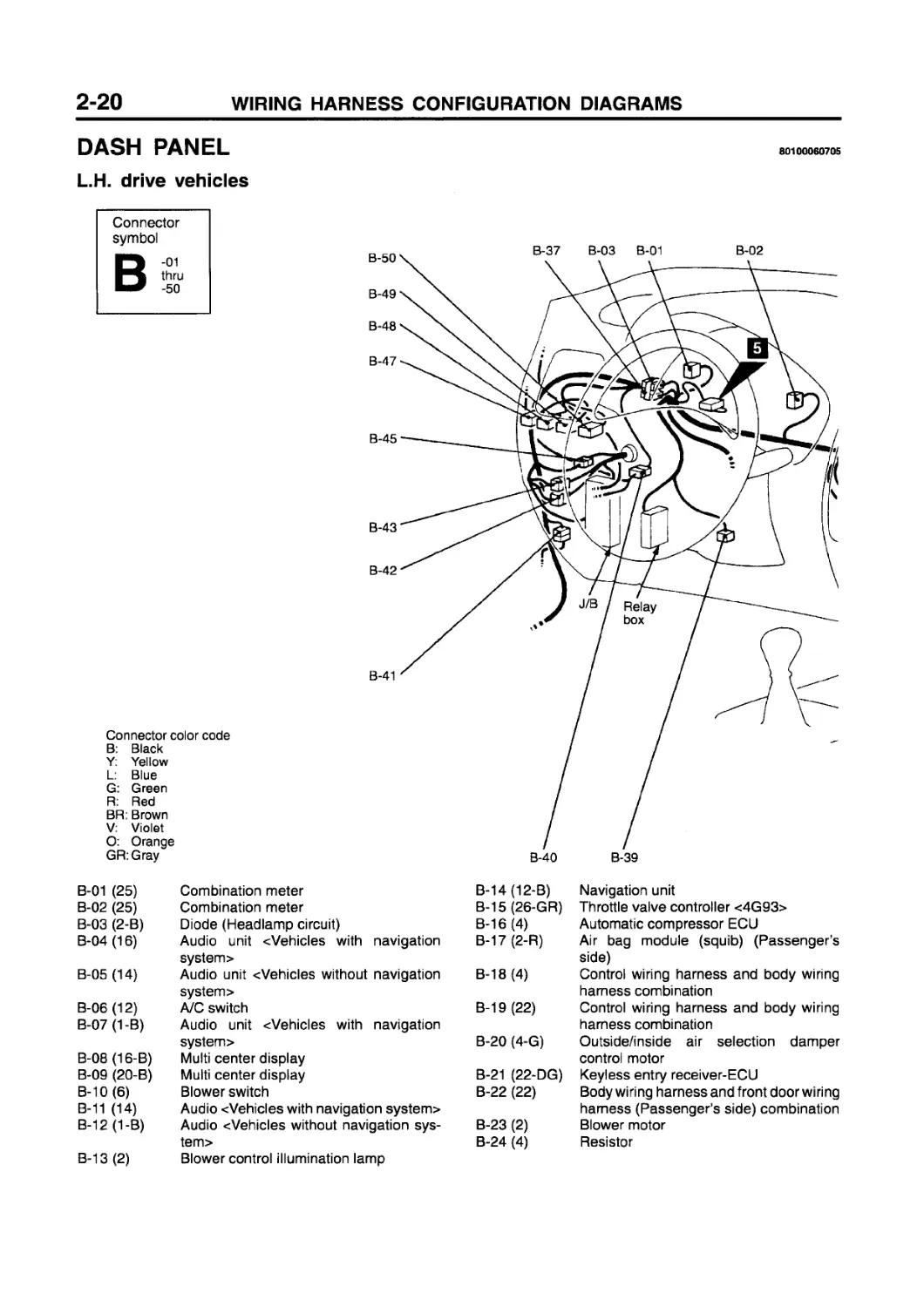
B-01 (25) Combination meter B-14(12-B) Navigation unit
B-02 (25) Combination meter B-15 (26-GR) Throttle valve controller c4G93>
B-03 (2-B) Diode (Headlamp circuit) B-16 (4) Automatic compressor ECU
B-04 (16) Audio unit cVehicles with navigation B-17 (2-R) Air bag module (squib) (Passenger’s
system > side)
B-05 (14) Audio unit <Vehicles without navigation B-18 (4) Control wiring harness and body wiring
system > harness combination
B-06 (12) A/C switch B-19 (22) Control wiring harness and body wiring
B-07 (1-B) Audio unit cVehicles with navigation harness combination
system> B-20 (4-G) Outside/inside air selection damper
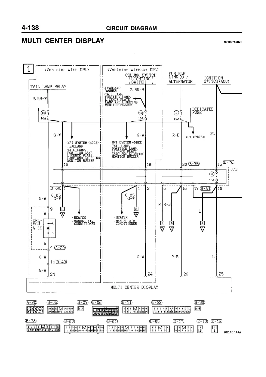
B-08 (16-B) Multi center display control motor
B-09 (20-B) Multi center display B-21 (22-DG) Keyless entry receiver-ECU
B-10 (6) Blower switch B-22 (22) Body wiring harness and front door wiring
B-11 (14) Audio cVehicles with navigation system> harness (Passenger’s side) combination
B-12 (1-B) Audio cVehicles without navigation sys- B-23 (2) Blower motor
tem> B-24 (4) Resistor
B-13 (2) Blower control illumination lamp
B-16
B-17
B-18
B-19
B-20
B-21
B-22
B-23
B-29
B-30
B-31
B-26 (4) Engine control relay B-40 (4) Body wiring harness and instrument
B-27 (4) B-28 (26-Y) Fuel pump relay Engine-ECU B-41 (32) panel wiring harness combination Body wiring harness and front door wiring
B-29(16-Y) B-30(12-Y) Engine-ECU Engine-ECU B-42 (18) harness (Driver’s side) combination Front wiring harness and body wiring
B-31 (22-Y) B-32 (4) Engine-ECU Throttle valve control relay <4G93> B-43 (22-GR) harness combination Front wiring harness and body wiring
B-33(12) B-34 (4) Diagnosis connector Oxygen sensor (Front) <4G13> B-45(10-B) harness combination Front wiring harness and body wiring
B-35 (16-B) B-36(12-B) Diagnosis connector Immobilizer-ECU B-47 (10) harness combination Fog lamp switch
B-37 (2-B) Diode (Keyless entry system circuit) B-48 (6) Headlamp leveling switch
B-38(16) Audio unit «Vehicles without navigation B-49(12) Remote controlled door mirror switch
B-39 (3-B) system> Stop lamp switch B-50 (3) Rheostat
L.H. drive vehicles
B-51 (12) Column switch B-59 (2) Ignition key ring antenna
B-52 (2-R) Clock spring <SRS> B-60X (33) J/C (1)
B-53 (1) Horn switch <SRS> B-61X(33) J/C (2)
B-54 (2) Air bag module (squib) (Driver’s side) B-62X (3-B) Diode
B-55 (3) Clock spring <SRS> B-64X (5) Front fog lamp relay
B-56 (10) Column switch B-65X (5) Rear fog lamp relay
B-57 (6) Column switch B-66X (7) Rear intermittent wiper relay
B-58 (6) Ignition switch B-67X (9) Door lock ECU
(Rear view)
Connector color code B: Black
Y: Yellow
L: Blue
G: Green
R: Red
BR: Brown
V: Violet
O: Orange
GR: Gray
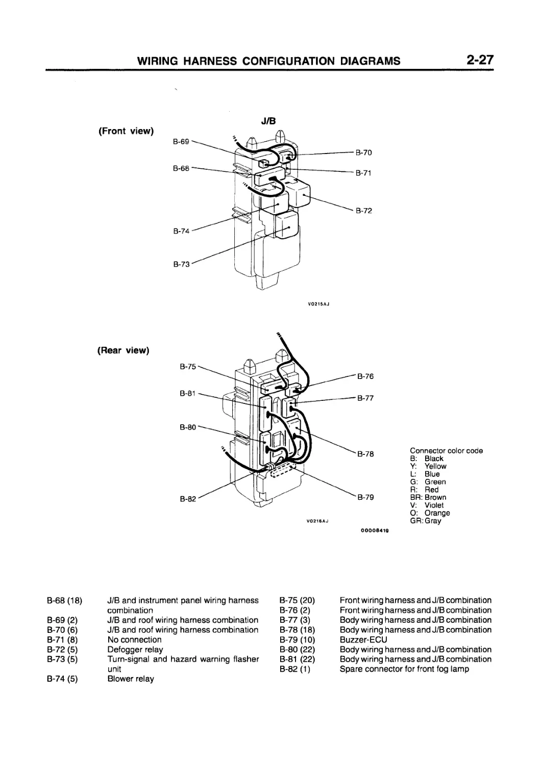
B-68(18) J/B and instrument panel wiring harness combination B-75 (20) B-76 (2) Front wiring harness and J/B combination Front wiring harness and J/B combination
B-69 (2) J/B and roof wiring harness combination B-77 (3) Body wiring harness and J/B combination
B-70 (6) J/B and roof wiring harness combination B-78 (18) Body wiring harness and J/B combination
B-71 (8) No connection B-79 (10) Buzzer-ECU
B-72 (5) Defogger relay B-80 (22) Body wiring harness and J/B combination
B-73 (5) Turn-signal and hazard warning flasher B-81 (22) Body wiring harness and J/B combination
B-74 (5) unit Blower relay B-82(1) Spare connector for front fog lamp
DASH PANEL
R.H. drive vehicles
80100060712
Connector symbol
B-17
B-18
B-19
B-20
B-21
B-22
B-23
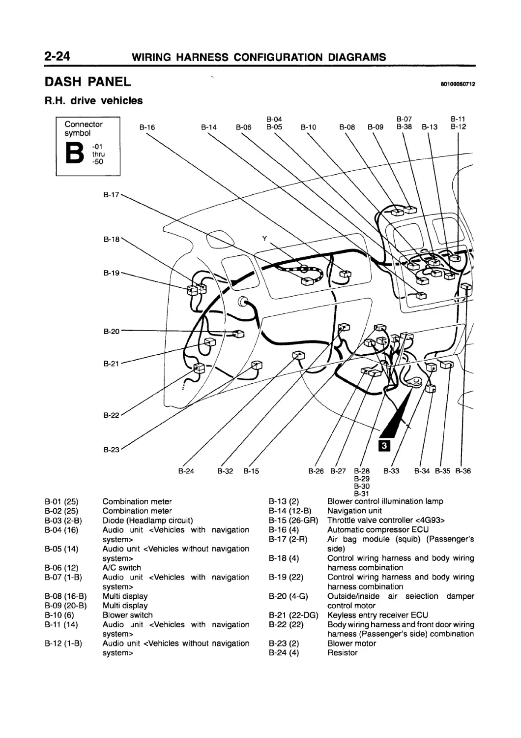
B-01 (25) Combination meter
B-02 (25) Combination meter
B-03 (2-B) Diode (Headlamp circuit)
B-04(16) Audio unit «Vehicles with navigation system >
B-05 (14) Audio unit «Vehicles without navigation system >
B-06 (12) A/C switch
B-07 (1-B) Audio unit «Vehicles with navigation system>
B-08(16-B) Multi display
B-09 (20-B) Multi display
B-10(6) Blower switch
B-11 (14) Audio unit «Vehicles with navigation
system >
B-12 (1-B) Audio unit -«Vehicles without navigation system>
B-29
B-30
B-31
B-13 (2) Blower control illumination lamp
B-14(12-B) Navigation unit
B-15(26-GR) Throttle valve controller <4G93>
B-16 (4) Automatic compressor ECU
B-17 (2-R) Air bag module (squib) (Passenger’s side)
B-18 (4) Control wiring harness and body wiring harness combination
B-19 (22) Control wiring harness and body wiring harness combination
B-20 (4-G) Outside/inside air selection damper control motor
B-21 (22-DG) Keyless entry receiver ECU
B-22 (22) Body wiring harness and front door wiring harness (Passenger’s side) combination
B-23 (2) Blower motor
B-24 (4) Resistor
Connector color code B: Black Y: Yellow L: Blue G: Green R: Red BR: Brown V: Violet O: Orange GR:Gray
B-26 (4) Engine control relay B-40 (4) Body wiring harness and instrument
B-27 (4) B-28 (26-Y) Fuel pump relay Engine-ECU B-41 (32) panel wiring harness combination Body wiring harness and front door wiring
B-29(16-Y) B-30(12-Y) Engine-ECU Engine-ECU B-42 (18) harness (Driver’s side) combination Front wiring harness and body wiring
B-31 (22-Y) B-32 (4) Engine-ECU Throttle valve control relay <4G93> B-43 (22-GR) harness combination Front wiring harness and body wiring
B-33(12) B-34 (4) Diagnosis connector Oxygen sensor (Front) <4G13> B-45 (10-B) harness combination Front wiring harness and body wiring
B-35(16-B) B-36(12-B) Diagnosis connector Immobilizer-ECU В-47 (10) harness combination Fog lamp switch
B-37 (2-B) Diode (Keyless entry system circuit) B-48 (6) Headlamp leveling switch
B-38(16) Audio unit (Vehicles without navigation B-49 (12) Remote controlled door mirror switch
B-39 (3-B) system> Stop lamp switch B-50 (3) Rheostat
R.H. drive vehicles
Relay box in passenger compartment
B-51 (12) Column switch B-59 (2) Ignition key ring antenna
B-52 (2-R) Clock spring <SRS> B-60X (33) J/C(1)
B-53 (1) Horn switch <SRS> B-61X(33) J/C (2)
B-54 (2) Air bag module (squib) (Driver’s side) B-62X (3-B) Diode
B-55 (3) Clock spring <SRS> B-64X (5) Front fog lamp relay
B-56 (10) Column switch B-65X (5) Rear fog lamp relay
B-57 (6) Column switch B-66X (7) Rear intermittent wiper relay
B-58 (6) Ignition switch B-67X (9) Door lock ECU
(Front view)
(Rear view)
Connector color code
B: Black
Y: Yellow
L: Blue
G: Green
R: Red
BR: Brown
V: Violet
O: Orange
GR:Gray
B-68(18) J/B and instrument panel wiring harness combination B-75 (20) B-76 (2) Front wiring harness and J/B combination Front wiring harness and J/B combination
B-69 (2) J/B and roof wiring harness combination B-77 (3) Body wiring harness and J/B combination
B-70 (6) J/B and roof wiring harness combination B-78 (18) Body wiring harness and J/B combination
B-71 (8) No connection B-79 (10) Buzzer-ECU
B-72 (5) Defogger relay B-80 (22) Body wiring harness and J/B combination
B-73 (5) Turn-signal and hazard warning flasher B-81 (22) Body wiring harness and J/B combination
B-74 (5) unit Blower relay B-82 (1) Spare connector for front fog lamp
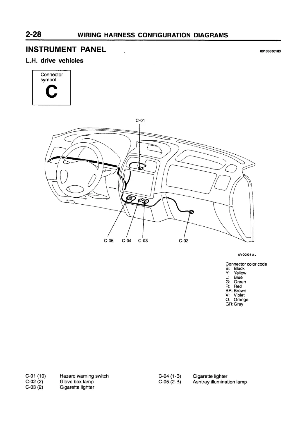
INSTRUMENT PANEL
L.H. drive vehicles
80100080183
Connector symbol
AVO2O4AJ
Connector color code
B: Black
Y: Yellow
L: Blue
G: Green
R: Red
BR: Brown
V: Violet
O: Orange
GR:Gray
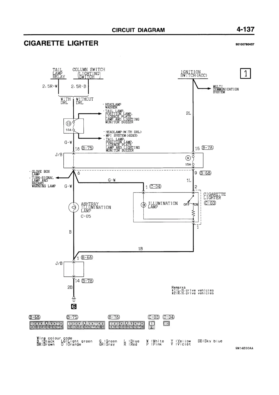
C-01 (10)
C-02 (2)
C-03 (2)
Hazard warning switch Glove box lamp Cigarette lighter
C-04 (1 -B) Cigarette lighter
C-05 (2-B) Ashtray illumination lamp
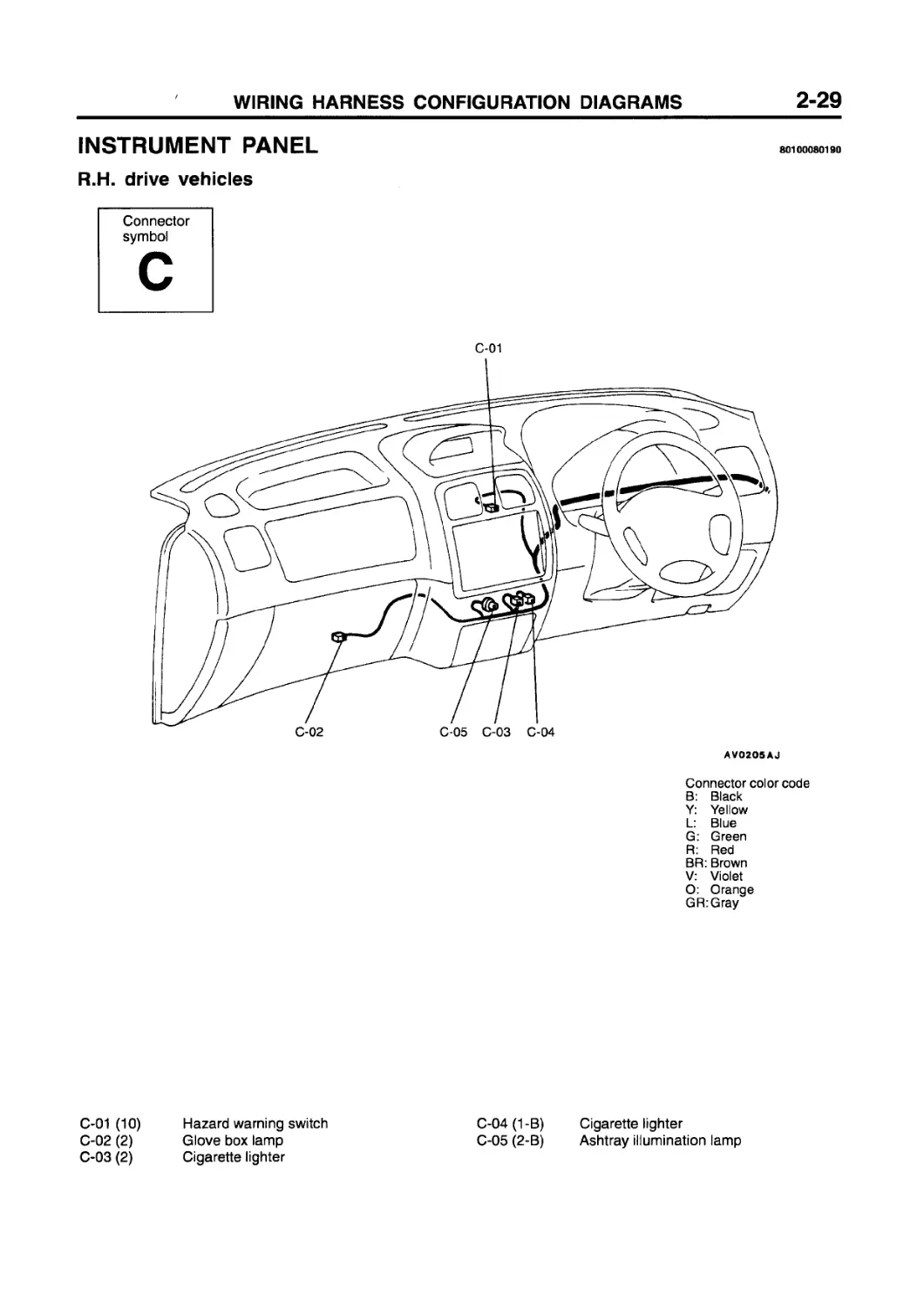
INSTRUMENT PANEL
R.H. drive vehicles
80100080190
Connector symbol
C-01
C-02 C-05 C-03 C-04
AVO2O5AJ
Connector color code
B: Black
Y: Yellow
L: Blue
G: Green
R: Red
BR: Brown
V: Violet
O: Orange
GR:Gray
C-01 (10) Hazard warning switch
C-02 (2) Glove box lamp
C-03 (2) Cigarette lighter
C-04 (1-B) Cigarette lighter
C-05 (2-B) Ashtray illumination lamp
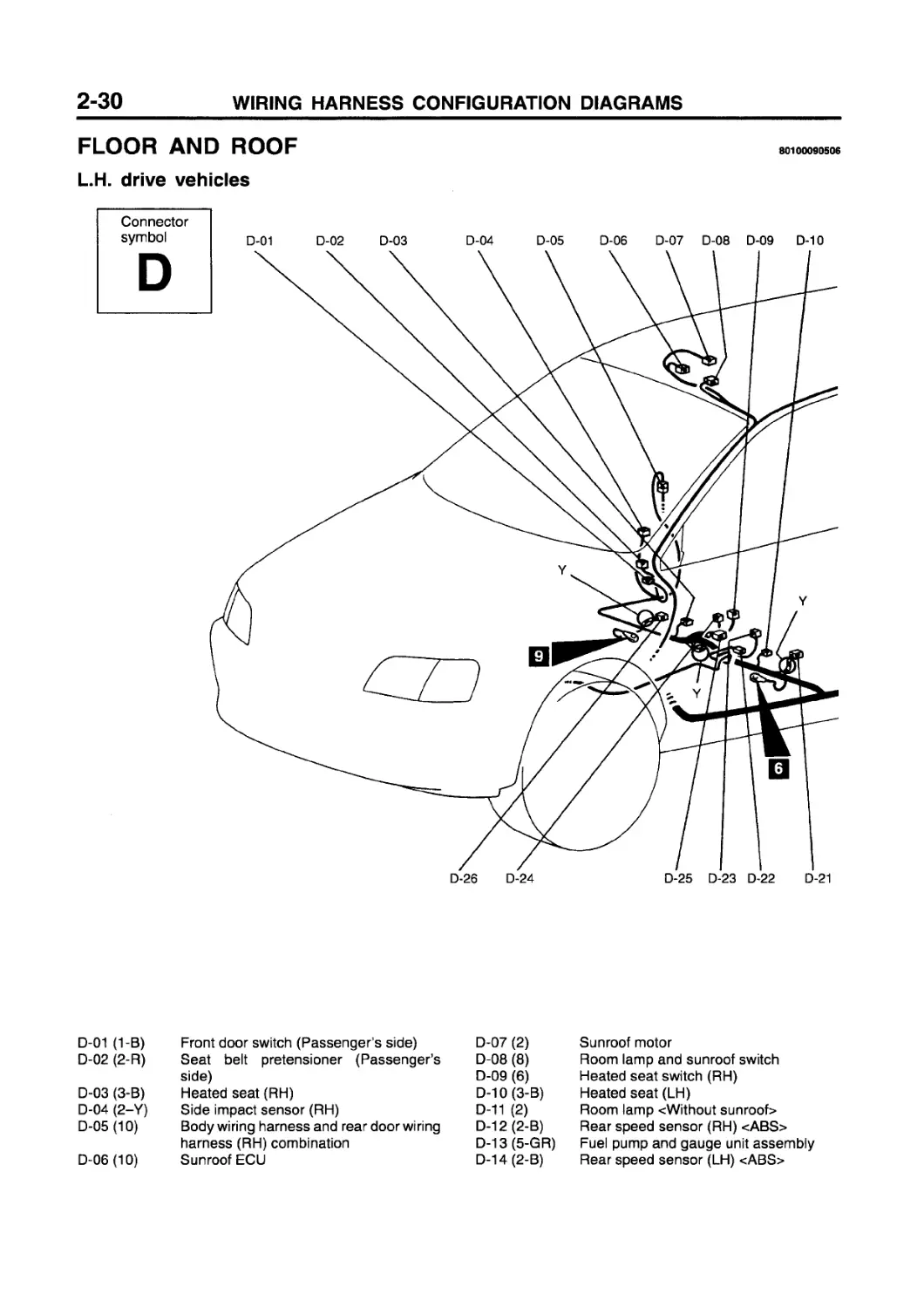
FLOOR AND ROOF
80100090506
L.H. drive vehicles
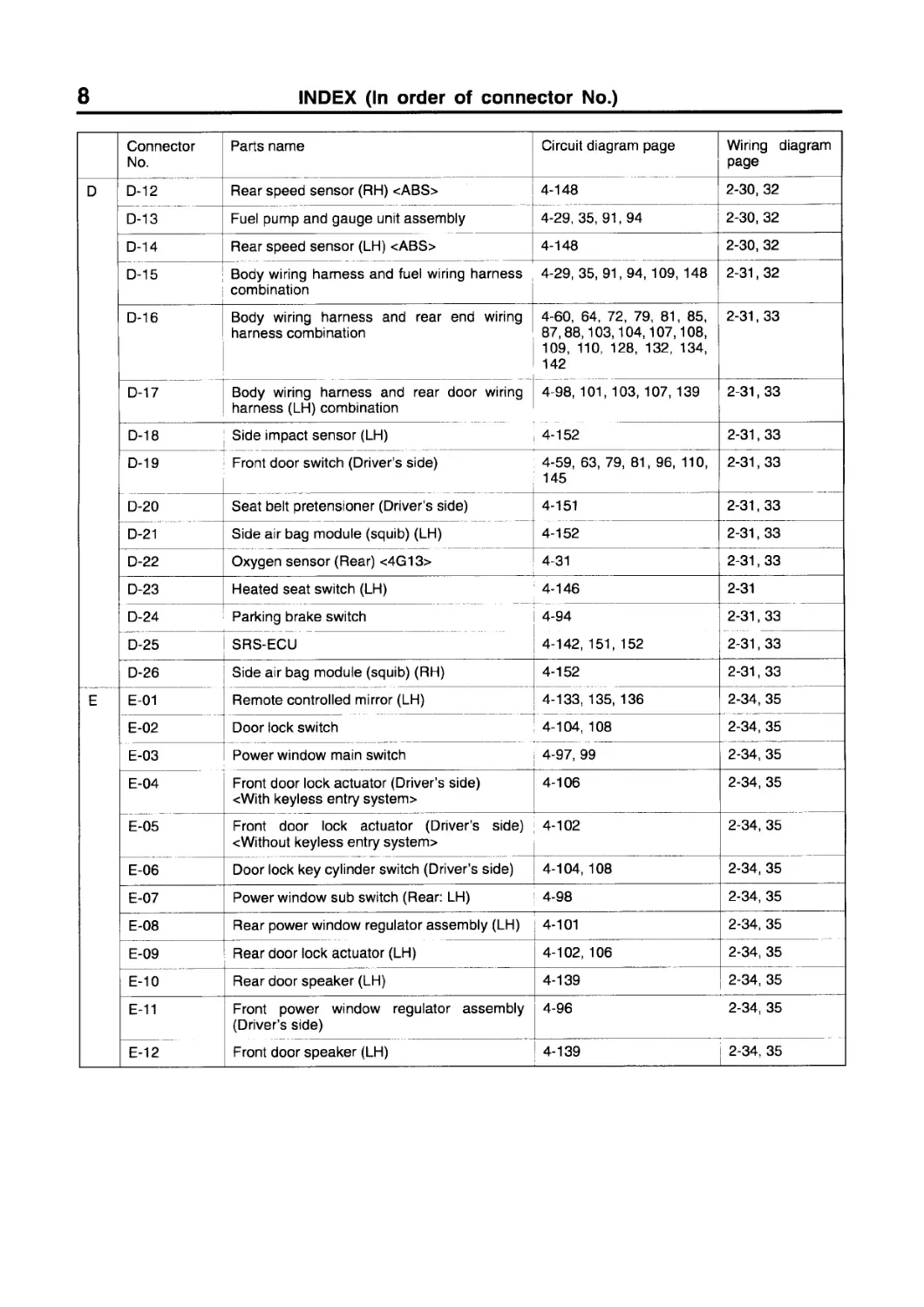
D-01 (1-B) Front door switch (Passenger's side)
D-02 (2-R) Seat belt pretensioner (Passenger’s side)
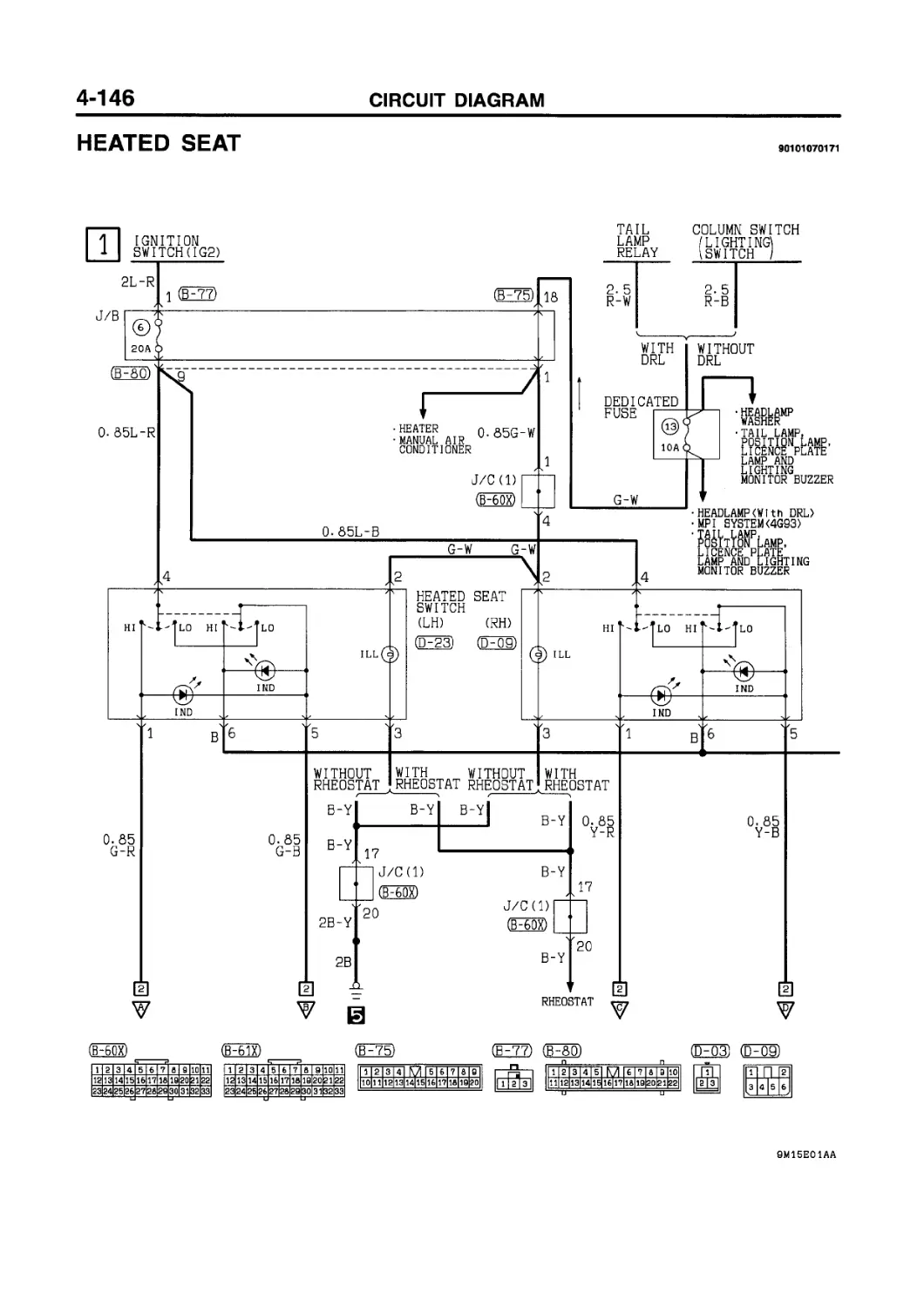
D-03 (3-B) Heated seat (RH)
D-04 (2-Y) Side impact sensor (RH)
D-05 (10) Body wiring harness and rear door wiring harness (RH) combination
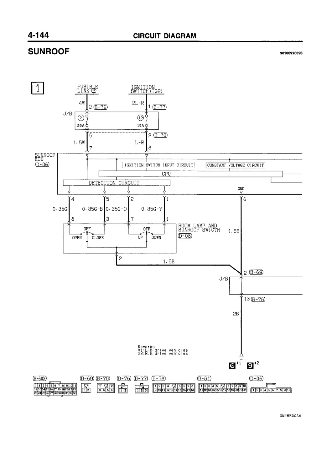
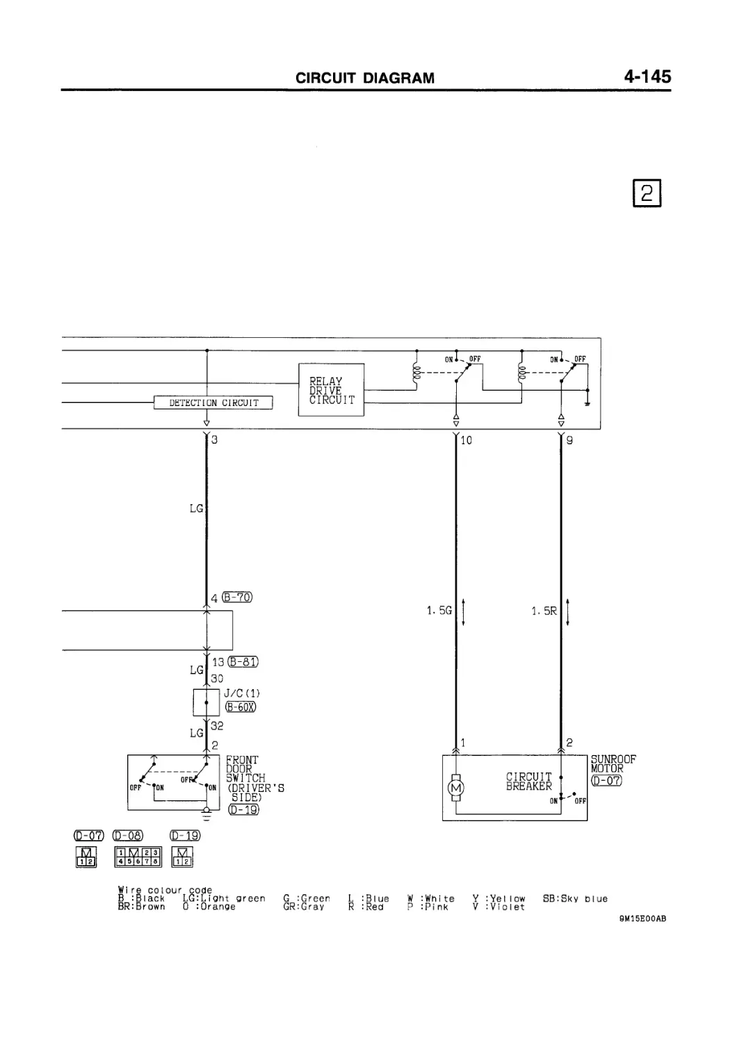
D-06(10) Sunroof ECU
D-07 (2)
D-08 (8)
D-09 (6)
D-10(3-B)
D-11 (2)
D-12 (2-B)
D-13 (5-GR)
D-14 (2-B)
Sunroof motor
Room lamp and sunroof switch
Heated seat switch (RH)
Heated seat (LH)
Room lamp <Without sunroof>
Rear speed sensor (RH) <ABS> Fuel pump and gauge unit assembly Rear speed sensor (LH) <ABS>
Connector color code
B: Black
Y: Yellow
L: Blue
G: Green
R: Red
BR: Brown
V: Violet
O: Orange
GR:Gray
D-15(10) Body wiring harness and fuel wiring harness combination D-20 (2-R) D-21 (2-R) Seat belt pretensioner (Driver's side) Side air bag module (squib) (LH)
D-16(22) Body wiring harness and rear end wiring harness combination D-22 (4-B) D-23 (6) Oxygen sensor (Rear) <4G13> Heated seat switch (LH)
D-17 (10) Body wiring harness and rear door wiring harness (LH) combination D-24(1-B) D-25 (36-0) Parking brake switch SRS-ECU
D-18(2-Y) D-19(2) Side impact sensor (LH) Front door switch (Driver’s side) D-26 (2-R) Side air bag module (squib) (RH)
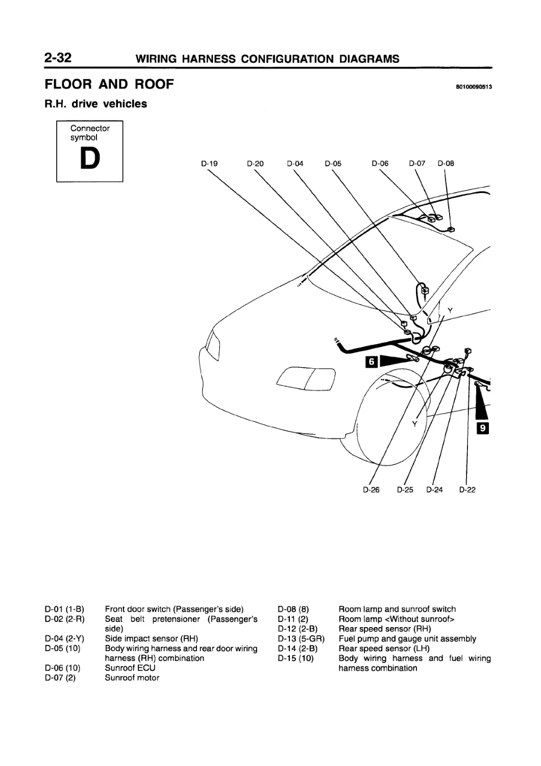
FLOOR AND ROOF
R.H. drive vehicles
Connector symbol
D
80100090513
D-01 (1-B) Front door switch (Passenger’s side) D-08 (8) Room lamp and sunroof switch
D-02 (2-R) Seat belt pretensioner (Passenger’s D-11 (2) Room lamp <Without sunroof>
D-04 (2-Y) side) Side impact sensor (RH) D-12 (2-B) D-13 (5-GR) Rear speed sensor (RH) Fuel pump and gauge unit assembly
D-05 (10) Body wiring harness and rear door wiring D-14 (2-B) Rear speed sensor (LH)
D-06 (10) D-07 (2) harness (RH) combination Sunroof ECU Sunroof motor D-15 (10) Body wiring harness and fuel wiring harness combination
D-11
D-12
D-13
D-14
D-15
D-16
Connector color code B: Black Y: Yellow L: Blue G: Green R: Red BR: Brown V: Violet O: Orange GR: Gray
D-16 (22) Body wiring harness and rear end wiring D-20 (2-R) Seat belt pretensioner (Driver’s side) harness combination D-21 (2-R) Side air bag module (squib) (LH)
D-17 (10) Body wiring harness and rear door wiring D-22 (4-B) Oxygen sensor (Rear) <4G13> harness (LH) combination D-24(1-B) Parking brake switch
D-18(2-Y) D-19(2) Side impact sensor (LH) D-25 (36-0) SRS-ECU Front door switch (Driver’s side) D-26 (2-R) Side air bag module (squib) (RH)
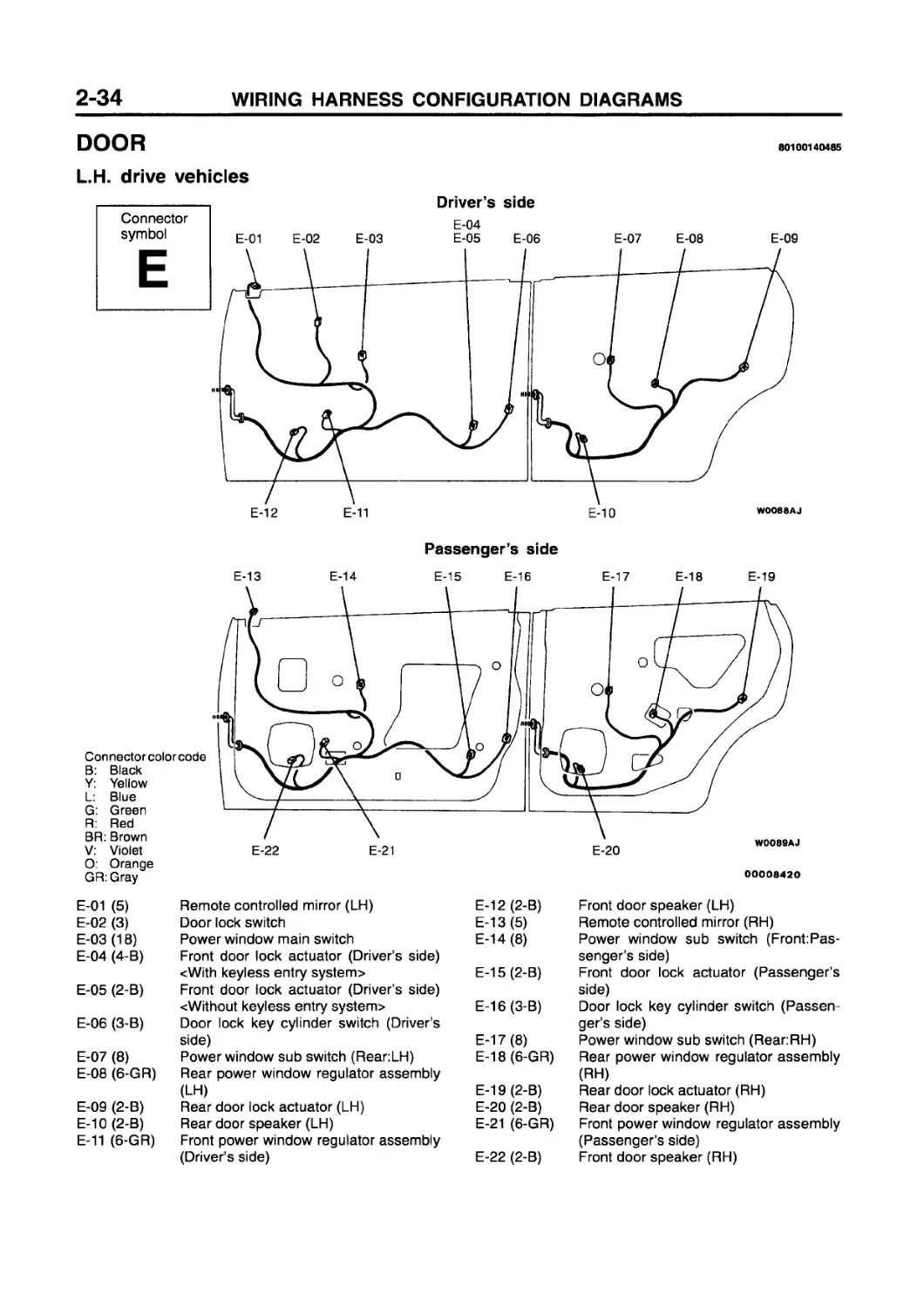
DOOR
80100140485
L.H. drive vehicles
Connector color code B: Black Y: Yellow L: Blue G: Green R: Red BR: Brown V: Violet
00008420
O: Orange GR: Gray
E-01 (5) Remote controlled mirror (LH) E-12 (2-B) Front door speaker (LH)
E-02 (3) Door lock switch E-13(5) Remote controlled mirror (RH)
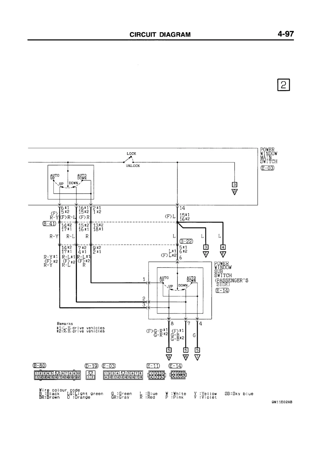
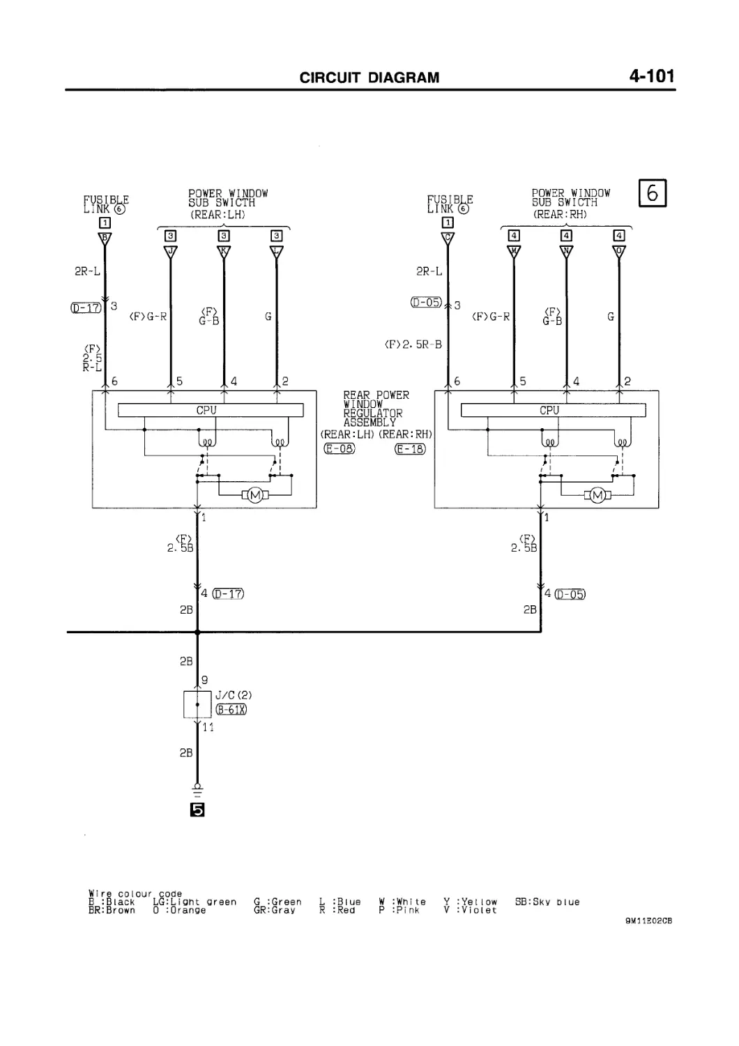
E-03 (18) Power window main switch E-14(8) Power window sub switch (Front:Pas-
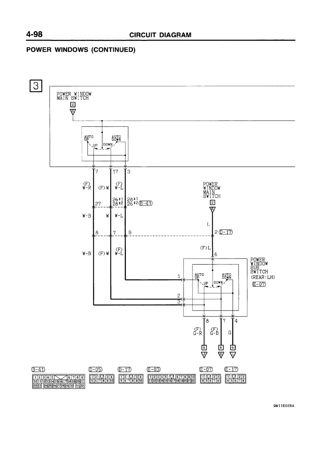
E-04 (4-B) E-05 (2-B) E-06 (3-B) E-07 (8) Front door lock actuator (Driver’s side) <With keyless entry system> Front door lock actuator (Driver’s side) <Without keyless entry system> Door lock key cylinder switch (Driver’s side) Power window sub switch (Rear:LH) E-15 (2-B) E-16(3-B) E-17 (8) E-18(6-GR) senger’s side) Front door lock actuator (Passenger’s side) Door lock key cylinder switch (Passenger’s side) Power window sub switch (RearRH) Rear power window regulator assembly
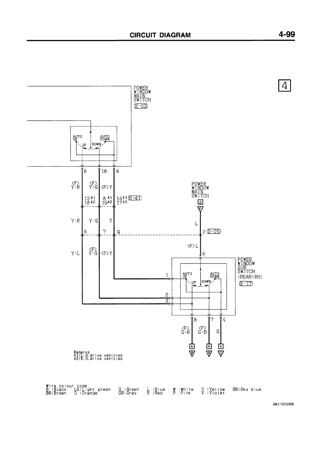
E-08 (6-GR) E-09 (2-B) Rear power window regulator assembly (LH) Rear door lock actuator (LH) E-19 (2-B) E-20 (2-B) (RH) Rear door lock actuator (RH) Rear door speaker (RH)
E-10 (2-B) Rear door speaker(LH) E-21 (6-GR) Front power window regulator assembly
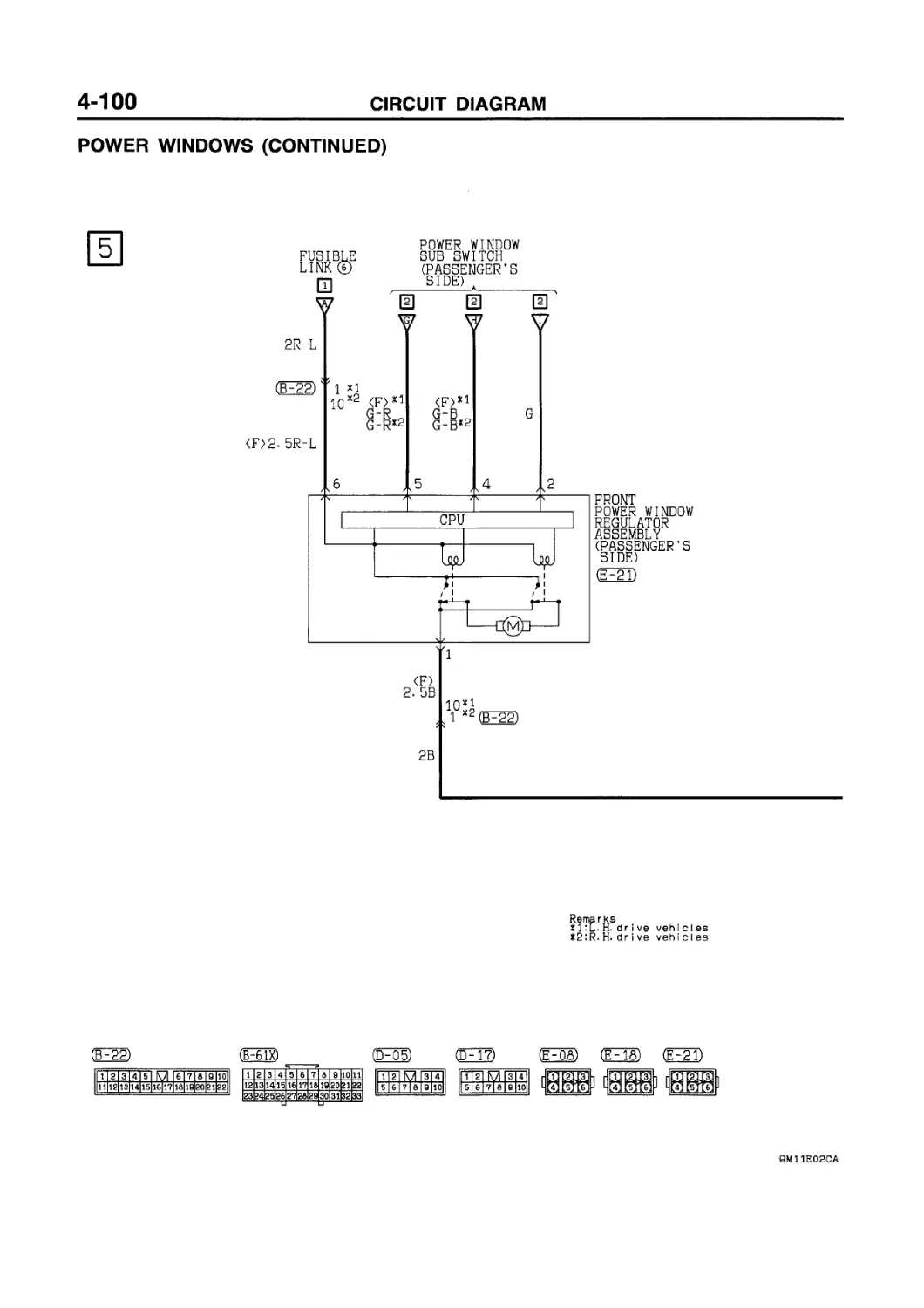
E-11 (6-GR) Front power window regulator assembly (Driver’s side) E-22 (2-B) (Passenger’s side) Front door speaker (RH)
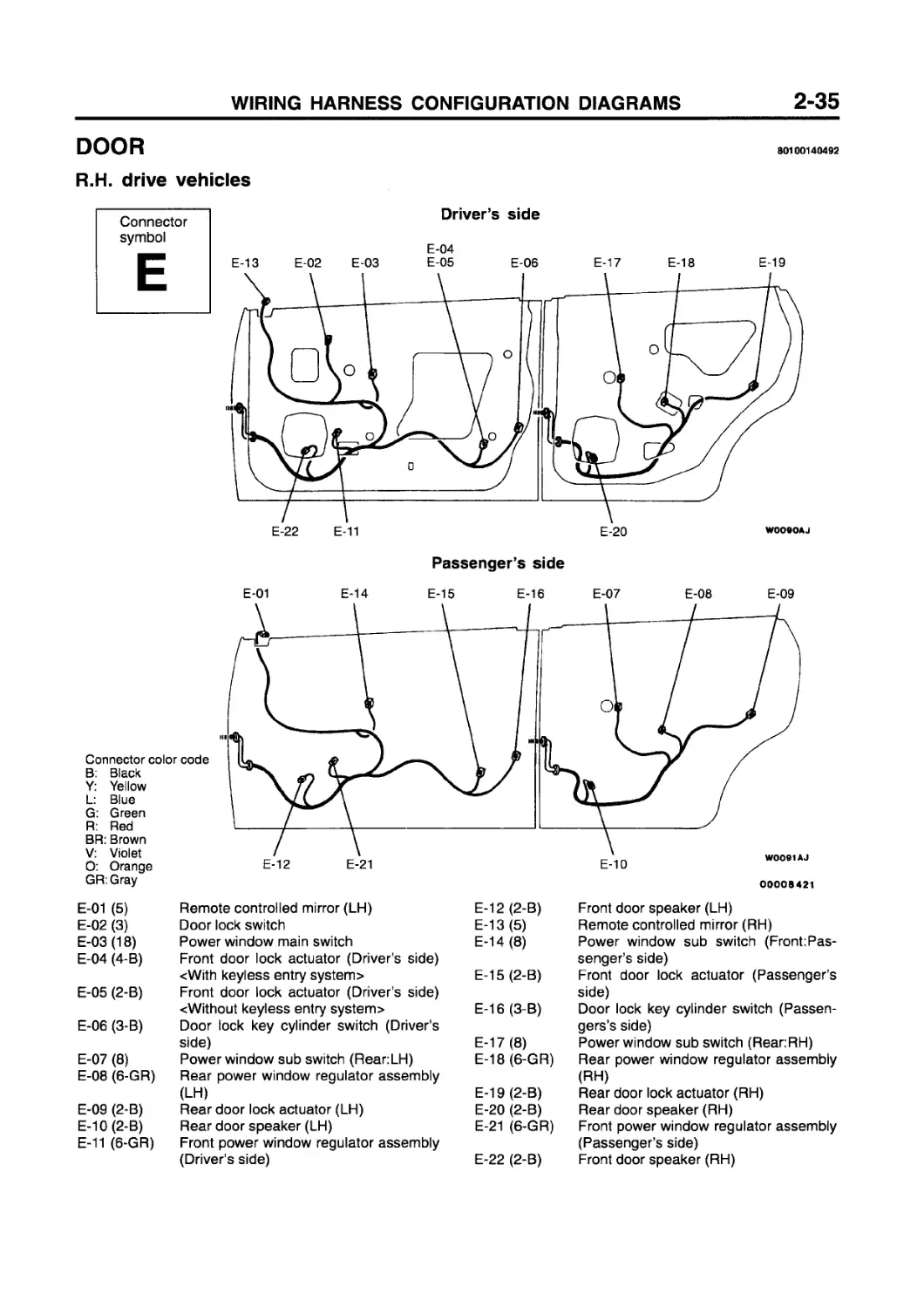
DOOR
R.H. drive vehicles
80100140492
Connector symbol
Driver’s side
E-04
Passenger’s side
Connector color code
B: Black
Y: Yellow
L: Blue
G: Green
R: Red
BR: Brown
V: Violet
O: Orange
GR:Gray
E-01 (5) Remote controlled mirror (LH)
E-02 (3) Door lock switch
E-03 (18) Power window main switch
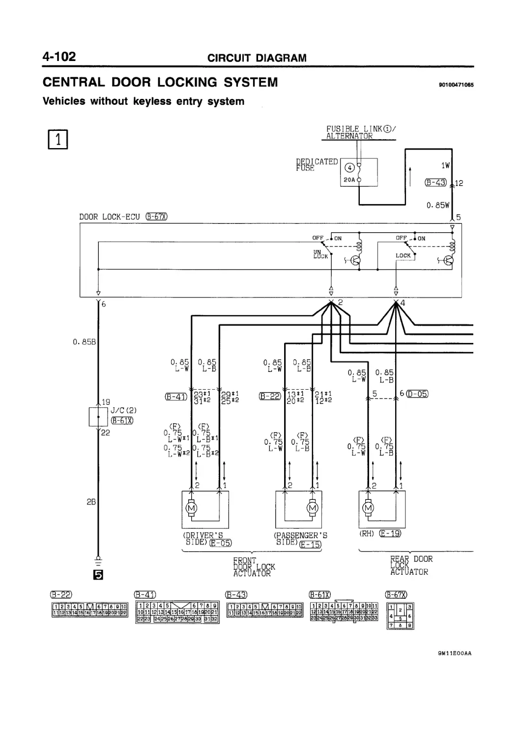
E-04 (4-B) Front door lock actuator (Driver's side) <With keyless entry system>
E-05 (2-B) Front door lock actuator (Driver’s side) «Without keyless entry system>
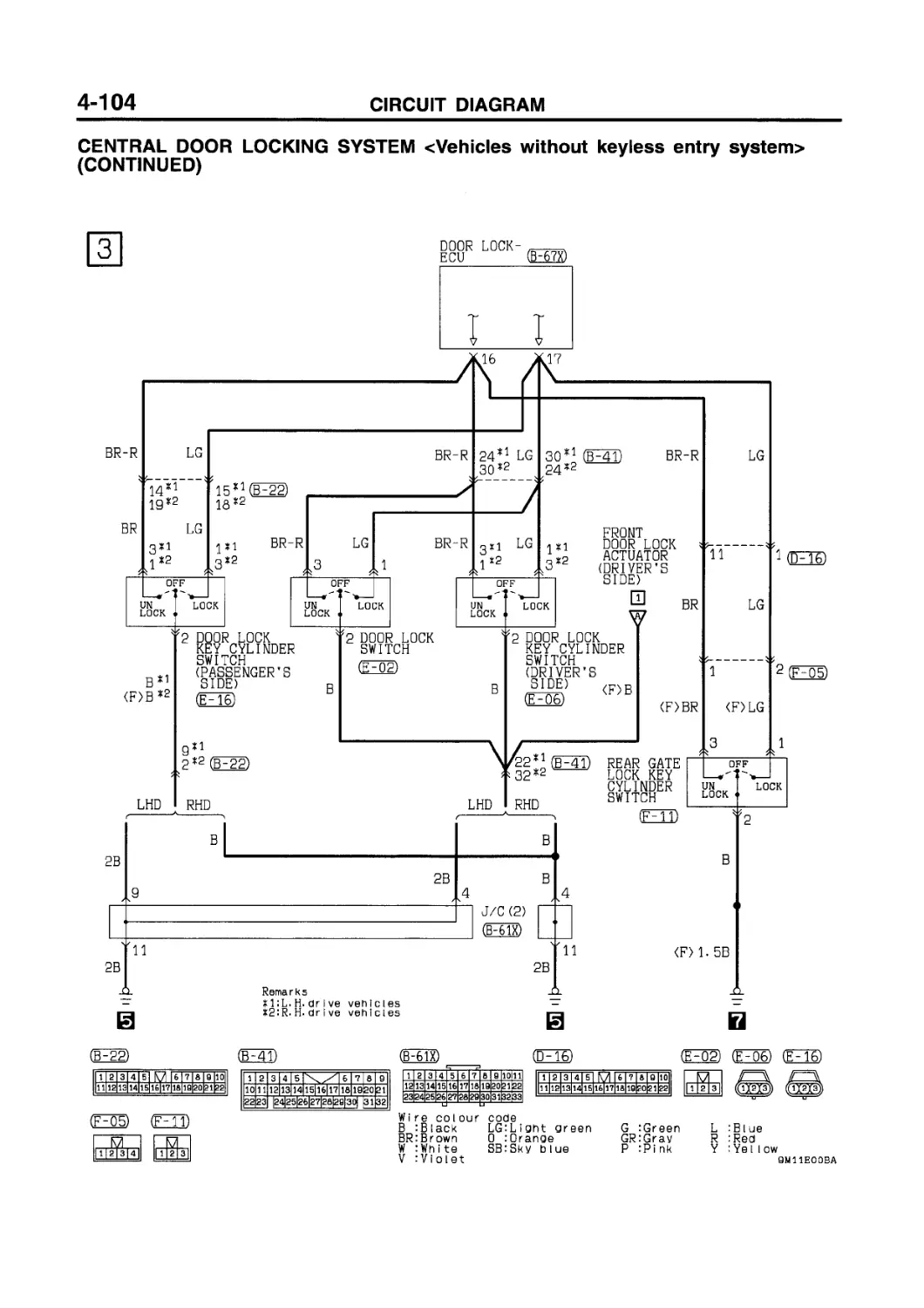
E-06 (3-B) Door lock key cylinder switch (Driver’s side)
E-07 (8) Power window sub switch (Rear:LH)
E-08 (6-GR) Rear power window regulator assembly (LH)
E-09 (2-B) Rear door lock actuator (LH)
E-10(2-B) Rear door speaker (LH)
E-11 (6-GR) Front power window regulator assembly (Driver's side)
E-12 (2-B) Front door speaker (LH)
E-13 (5) Remote controlled mirror (RH)
E-14 (8) Power window sub switch (Front:Passenger’s side)
E-15 (2-B) Front door lock actuator (Passenger’s side)
E-16 (3-B) Door lock key cylinder switch (Passengers’s side)
E-17 (8) Power window sub switch (Rear:RH)
E-18(6-GR) Rear power window regulator assembly (RH)
E-19 (2-B) Rear door lock actuator (RH)
E-20 (2-B) Rear door speaker (RH)
E-21 (6-GR) Front power window regulator assembly (Passenger’s side)
E-22 (2-B) Front door speaker (RH)
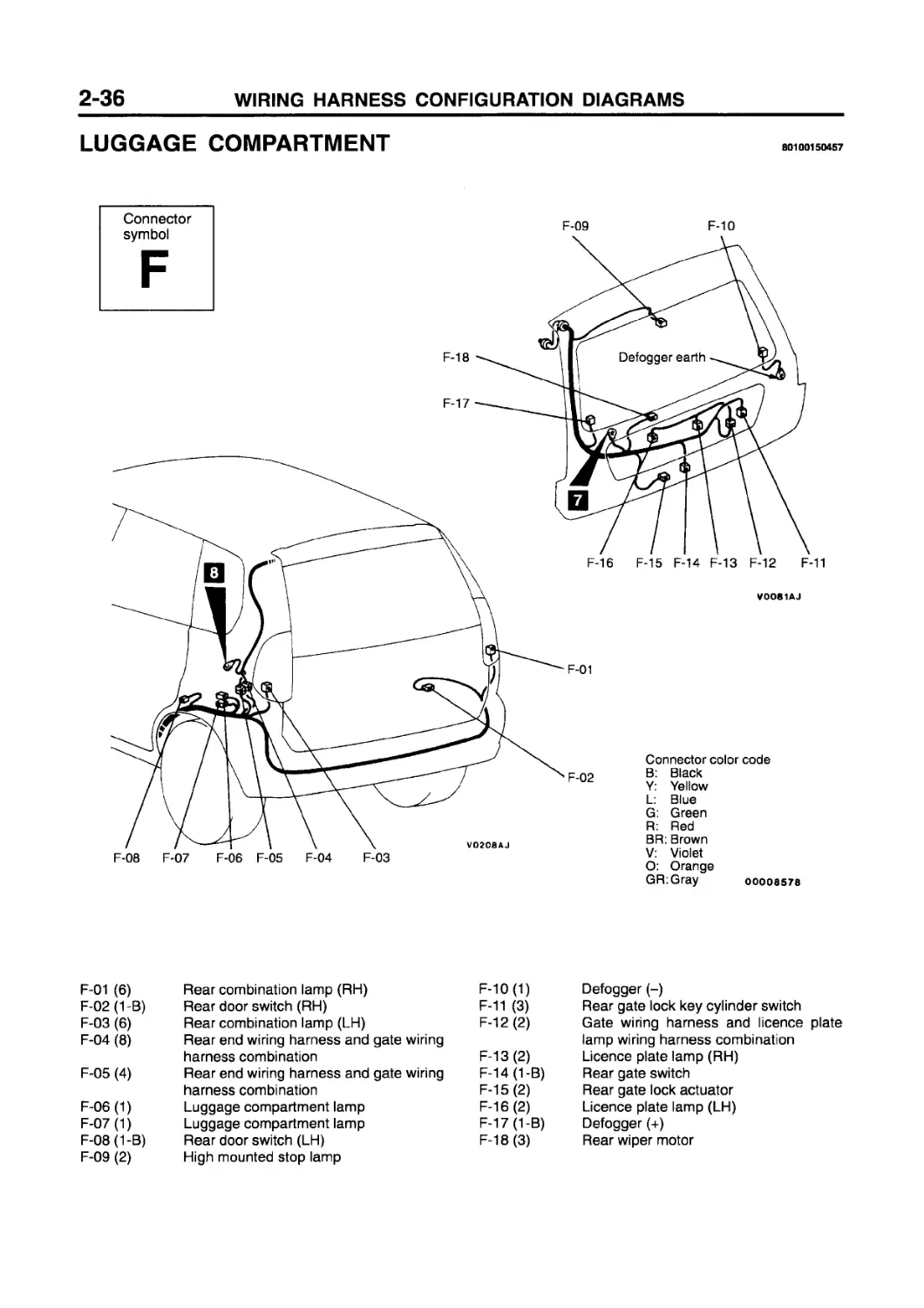
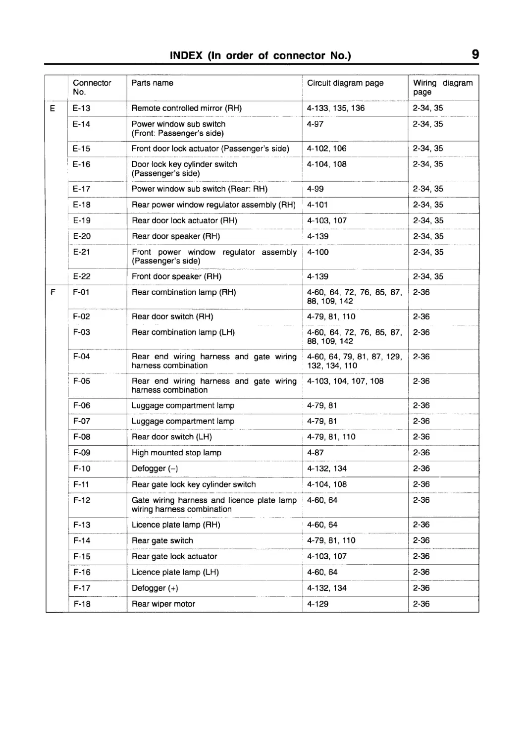
LUGGAGE COMPARTMENT
80100150457
Connector symbol
F-01 (6) Rear combination lamp (RH)
F-02(1-B) Rear door switch (RH)
F-03 (6) Rear combination lamp (LH)
F-04 (8) Rear end wiring harness and gate wiring harness combination
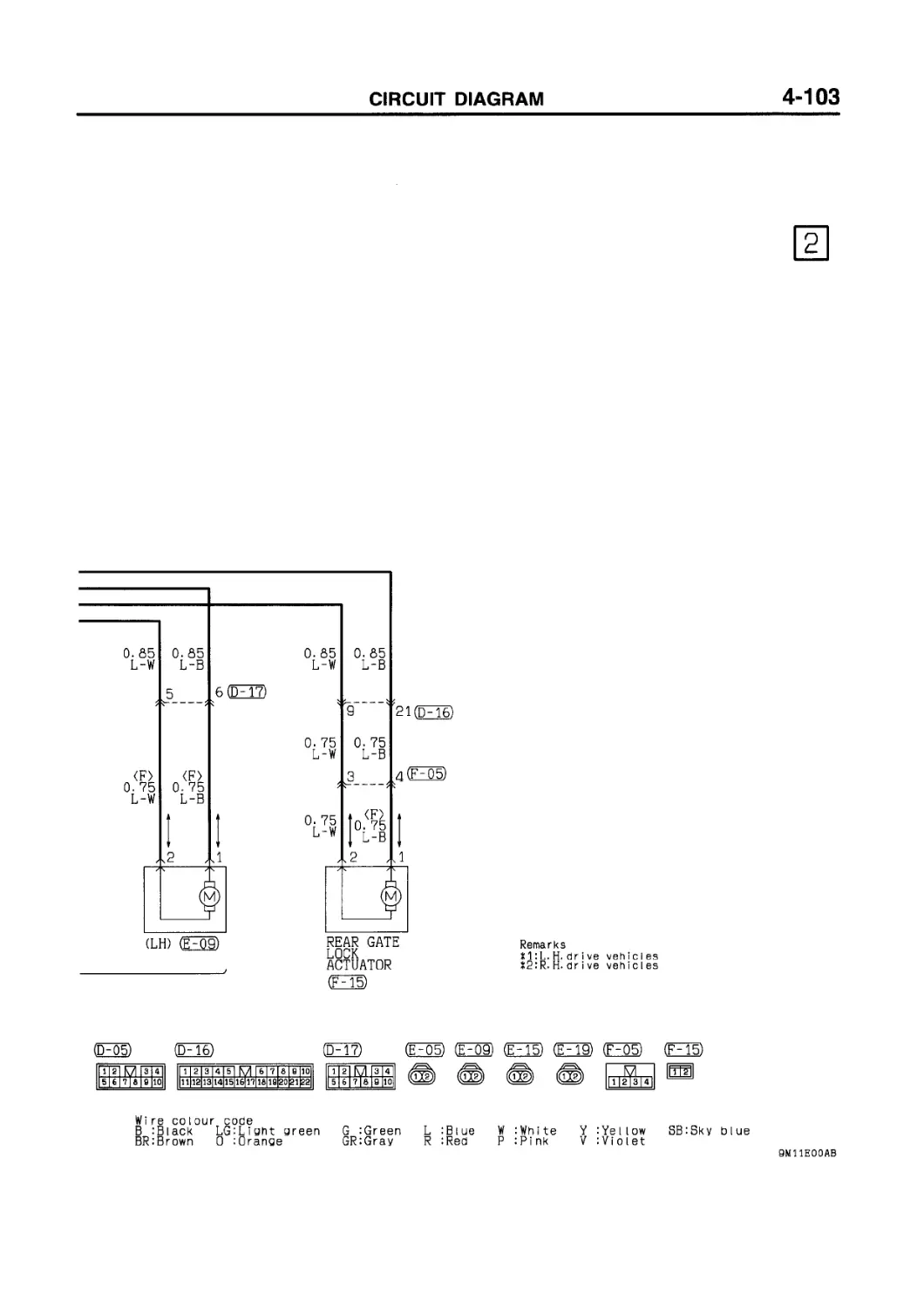
F-05 (4) Rear end wiring harness and gate wiring harness combination
F-06(1) Luggage compartment lamp
F-07 (1) Luggage compartment lamp
F-08(1-B) Rear door switch (LH)
F-09 (2) High mounted stop lamp
F-10(1) Defogger (-)
F-11 (3) Rear gate lock key cylinder switch
F-12 (2) Gate wiring harness and licence plate
lamp wiring harness combination
F-13(2) Licence plate lamp (RH)
F-14 0-B) Rear gate switch
F-15(2) Rear gate lock actuator
F-16(2) Licence plate lamp (LH)
F-17(1-B) Defogger (+)
F-18(3) Rear wiper motor
3-1
SINGLE PART INSTALLATION
POSITION
CONTENTS 70109000402
RELAY ........................ 3-2
ECU............................3-4
SENSOR.........................3-6
SOLENOID AND SOLENOID VALVE....3-9
DIODE...........................3-10
INSPECTION CONNECTOR AND SPARE
CONNECTOR ....................3-11
FUSIBLE LINK AND FUSE ........3-12
EARTH CABLE ..................3-13
EARTH ........................3-14
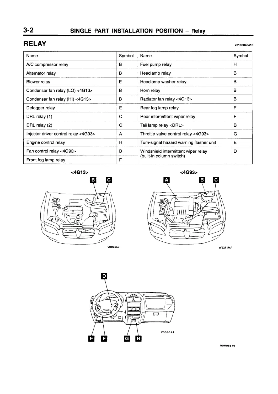
RELAY
70100040410
Name Symbol Name Symbol
A/C compressor relay В Fuel pump relay H
Alternator relay В Headlamp relay В
Blower relay E Headlamp washer relay В
Condenser fan relay (LO) <4G13> В Horn relay В
Condenser fan relay (HI) <4G13> В Radiator fan relay <4G13> В
Defogger relay E Rear fog lamp relay F
DRL relay (1) С Rear intermittent wiper relay F
DRL relay (2) С Tail lamp relay <DRL> В
Injector driver control relay <4G93> А Throttle valve control relay <4G93> G
Engine control relay Н Turn-signal hazard warning flasher unit E
Fan control relay <4G93> В Windshield intermittent wiper relay (built-in column switch) D
Front fog lamp relay F
OOOOB579
AV0286AJ
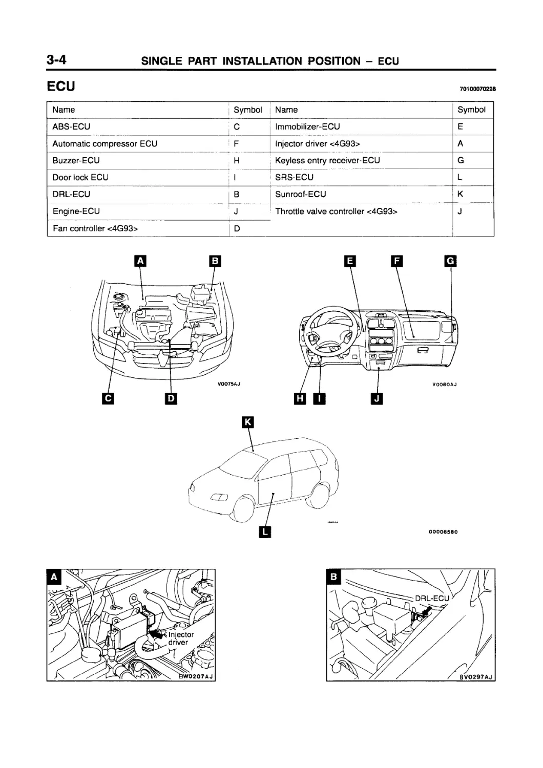
ECU
70100070228
Name Symbol Name Symbol
ABS-ECU C Immobilizer-ECU E
Automatic compressor ECU F Injector driver <4G93> A
Buzzer-ECU H Keyless entry receiver-ECU G
Door lock ECU I SRS-ECU L
DRL-ECU B Sunroof-ECU К
Engine-ECU J Throttle valve controller <4G93> J
Fan controller <4G93> D
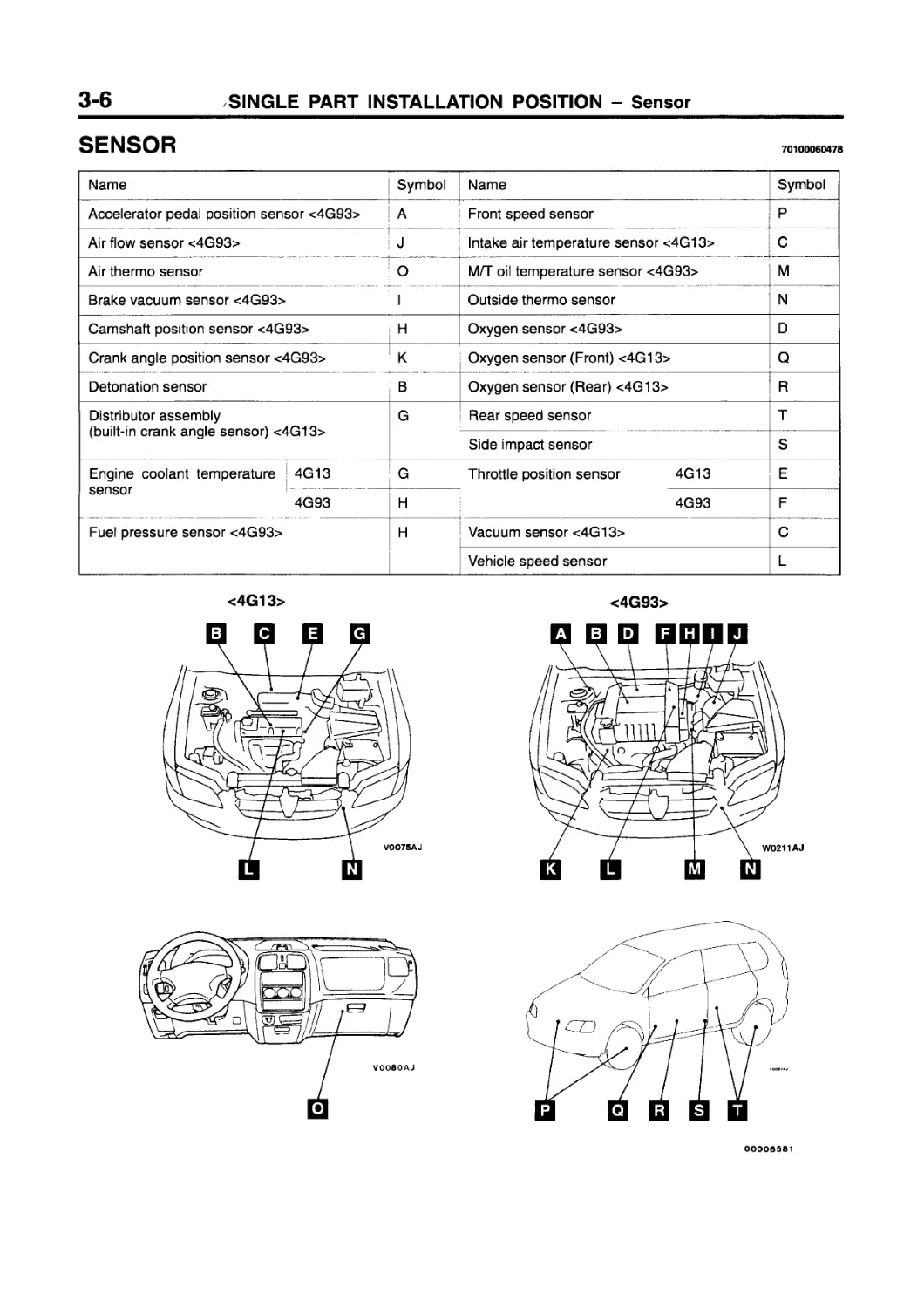
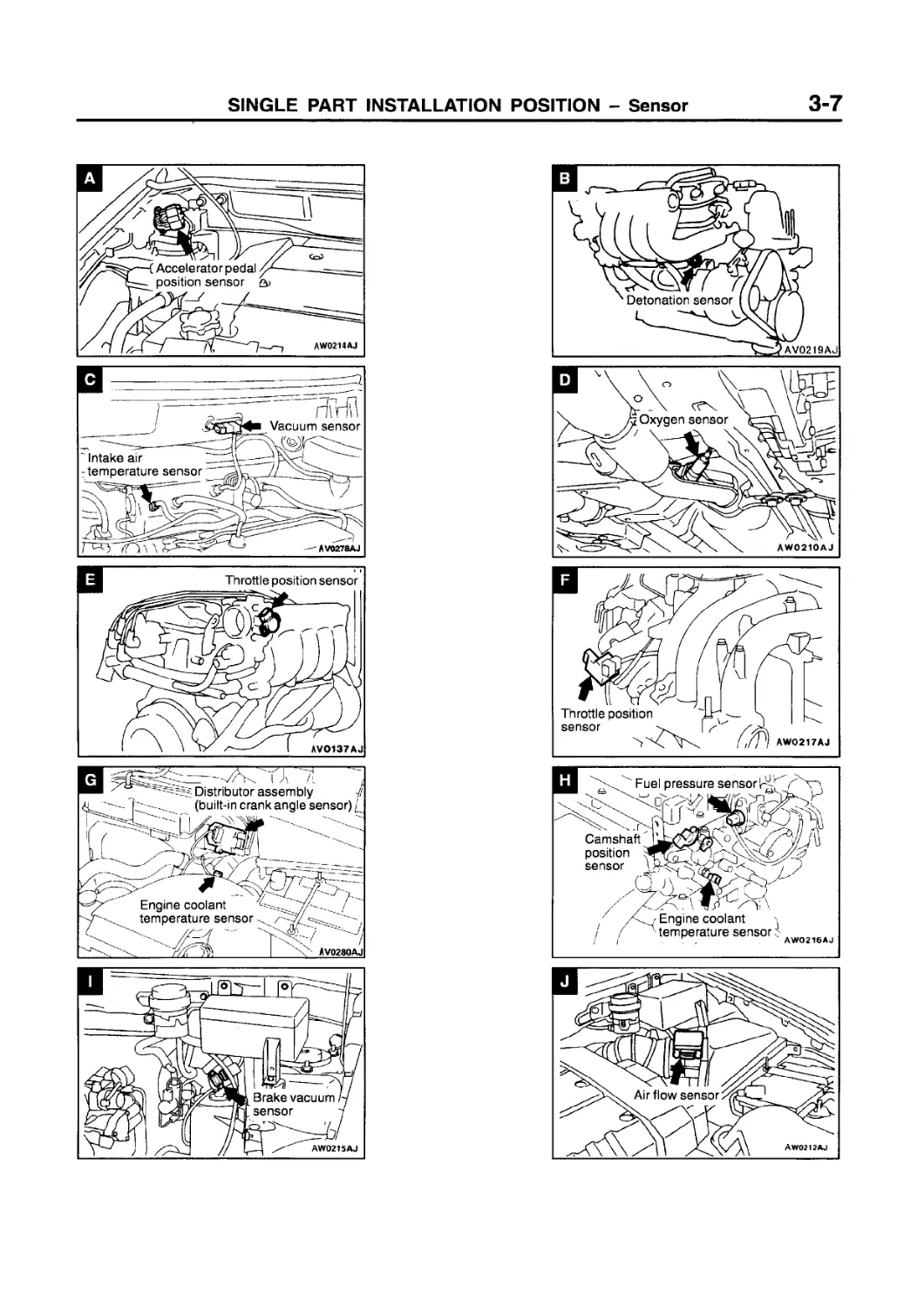
SENSOR
70100060478
Name Symbol Name Symbol
Accelerator pedal position sensor <4G93> A Front speed sensor P
Air flow sensor <4G93> J Intake air temperature sensor <4G13> C
Air thermo sensor 0 M/T oil temperature sensor <4G93> M
Brake vacuum sensor <4G93> I Outside thermo sensor N
Camshaft position sensor <4G93> । H Oxygen sensor <4G93> D
— Crank angle position sensor <4G93> К Oxygen sensor (Front) <4G13> Q
Detonation sensor В Oxygen sensor (Rear) <4G13> R
Distributor assembly (built-in crank angle sensor) <4G13> G Rear speed sensor T
Side impact sensor s
Engine coolant temperature 4G13 G Throttle position sensor 4G13 E
sensor 4G93 H 4G93 F
Fuel pressure sensor <4G93> H Vacuum sensor <4G13> C
Vehicle speed sensor L
<4G93>
00006581
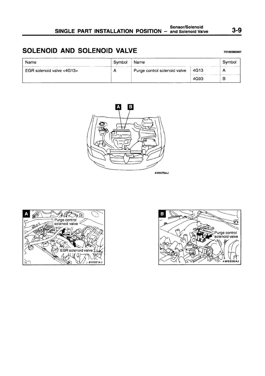
Sensor/Solenoid
SINGLE PART INSTALLATION POSITION — and Solenoid Valve
SOLENOID AND SOLENOID VALVE
70100080467
Name Symbol Name Symbol A В
EGR solenoid valve <4G13> A Purge control solenoid valve 4G13 4G93
AV0075AJ
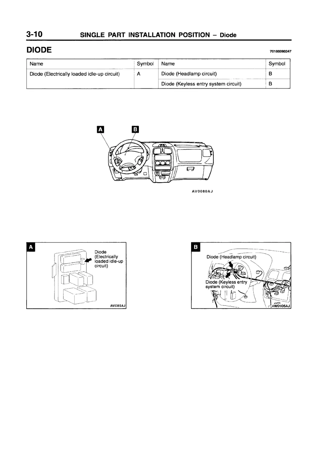
DIODE
70100090347
Name Symbol Name Symbol
Diode (Electrically loaded idle-up circuit) A Diode (Headlamp circuit) В
Diode (Keyless entry system circuit) В
AV0080AJ
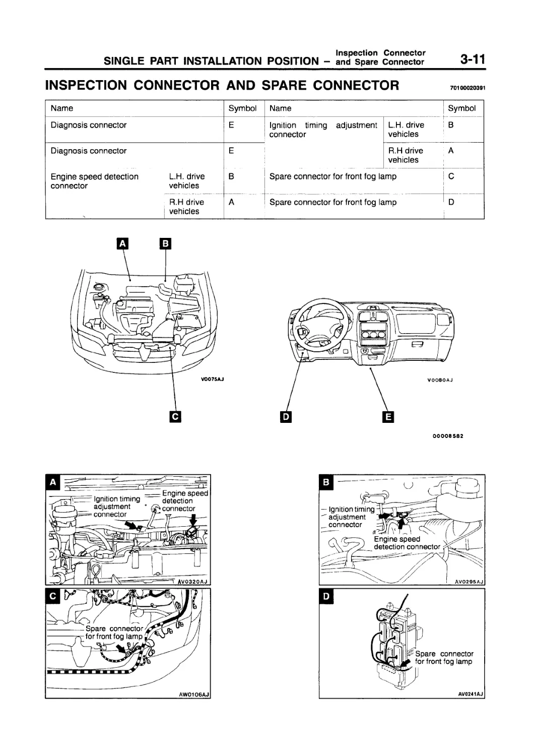
Inspection Connector
SINGLE PART INSTALLATION POSITION — and Spare Connector
INSPECTION CONNECTOR AND SPARE CONNECTOR
70100020391
Name Symbol Name Symbol
Diagnosis connector E Ignition timing adjustment connector L.H. drive vehicles В
Diagnosis connector E R.H drive vehicles A
Engine speed detection connector L.H. drive vehicles В Spare connector for front fog lamp C
R.H drive vehicles A Spare connector for front fog lamp D
00008582
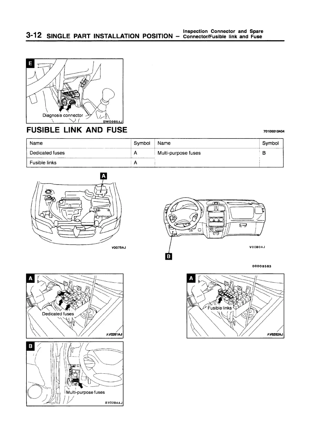
FUSIBLE LINK AND FUSE
70100010404
Name Symbol Name Symbol
Dedicated fuses A Multi-purpose fuses В
Fusible links A
V0075AJ
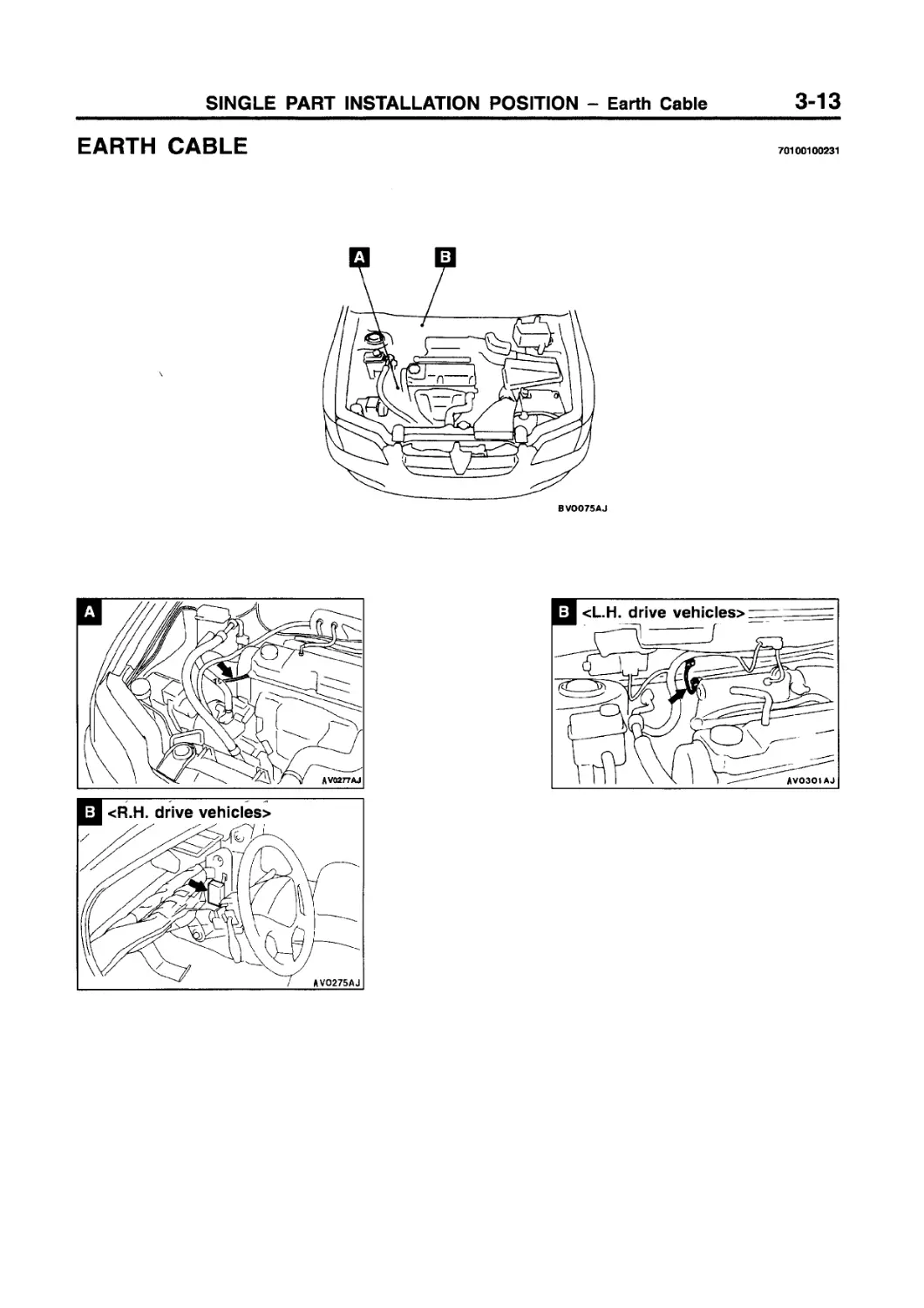
EARTH CABLE
70100100231
BVOO75AJ
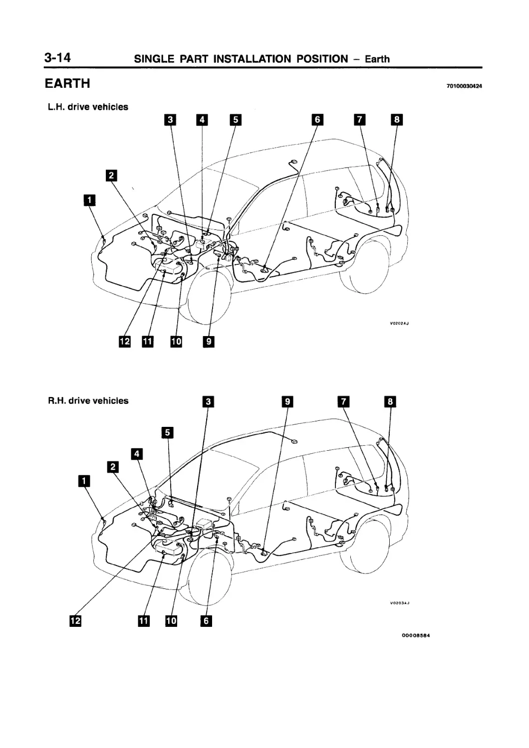
EARTH
70100030424
L.H. drive vehicles
00008584
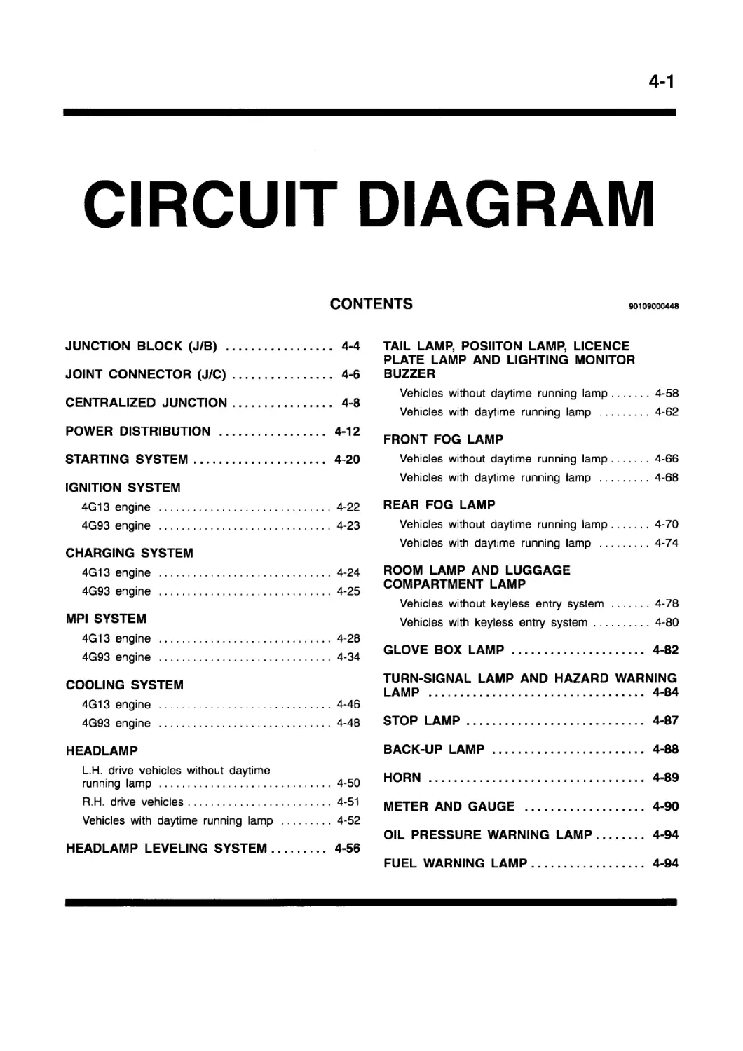
CIRCUIT DIAGRAM
CONTENTS
90109000448
JUNCTION BLOCK (J/B) ................. 4-4
JOINT CONNECTOR (J/C)................. 4-6
CENTRALIZED JUNCTION.................. 4-8
POWER DISTRIBUTION .................. 4-12
STARTING SYSTEM...................... 4-20
IGNITION SYSTEM
4G13 engine ........................4-22
4G93 engine ....................... 4-23
CHARGING SYSTEM
4G13 engine ........................4-24
4G93 engine ........................4-25
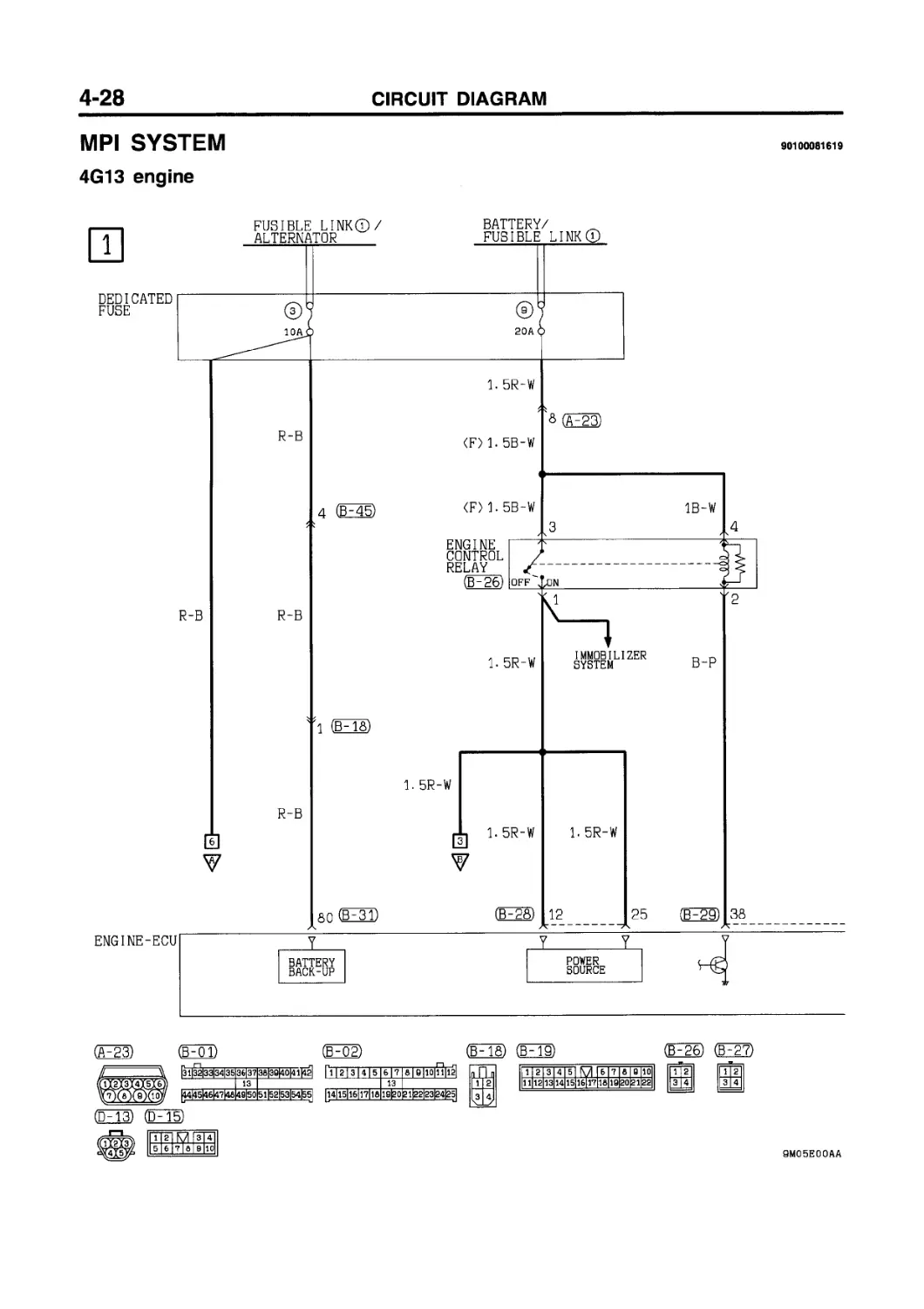
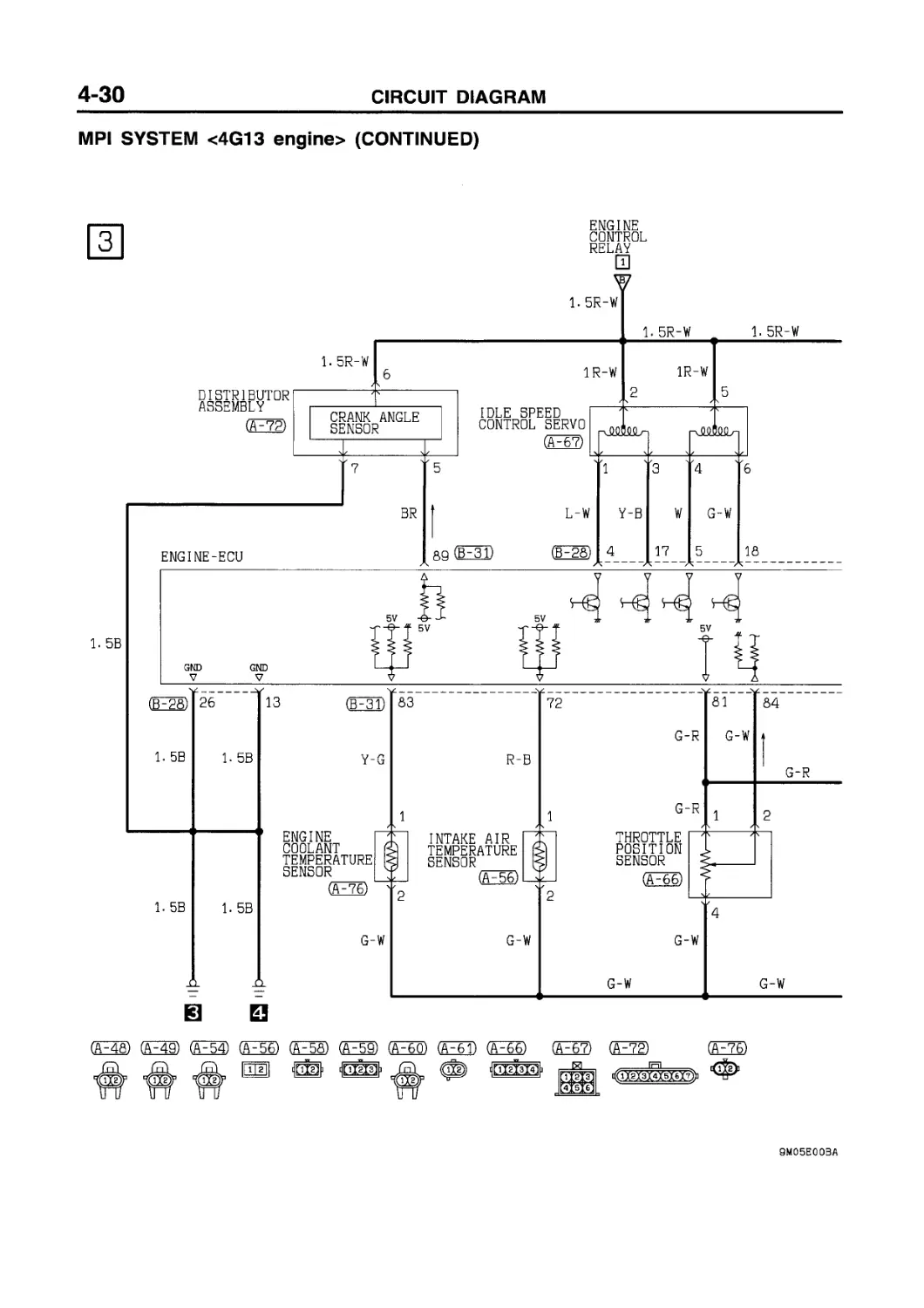
MPI SYSTEM 4G13 engine ......................4-28
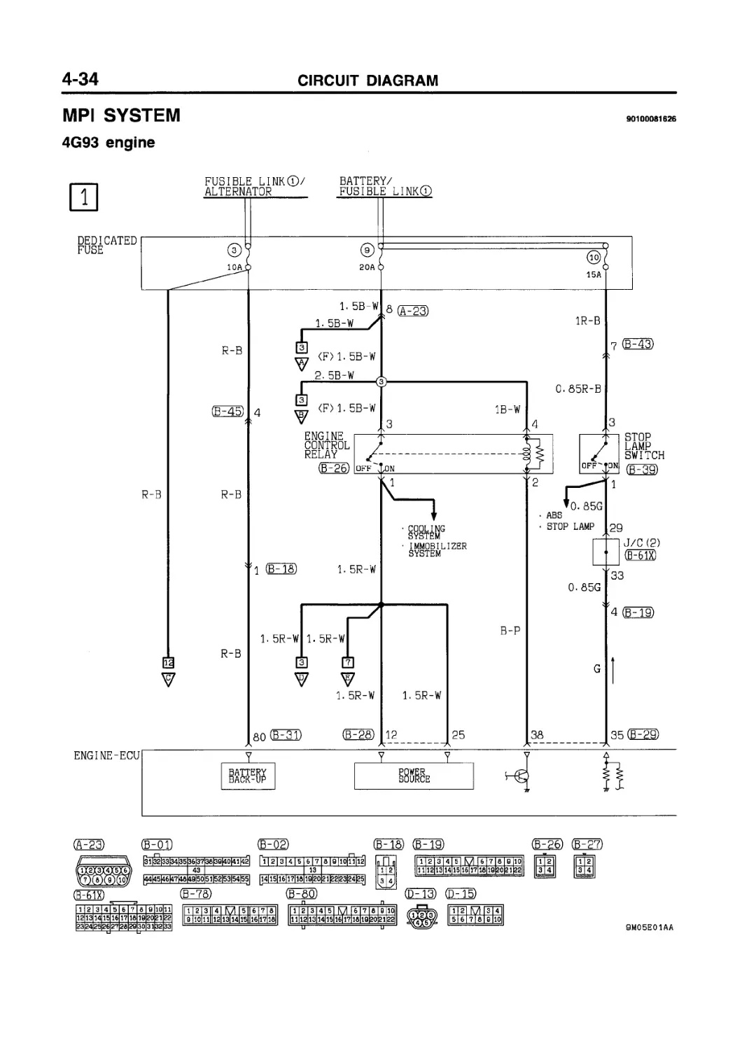
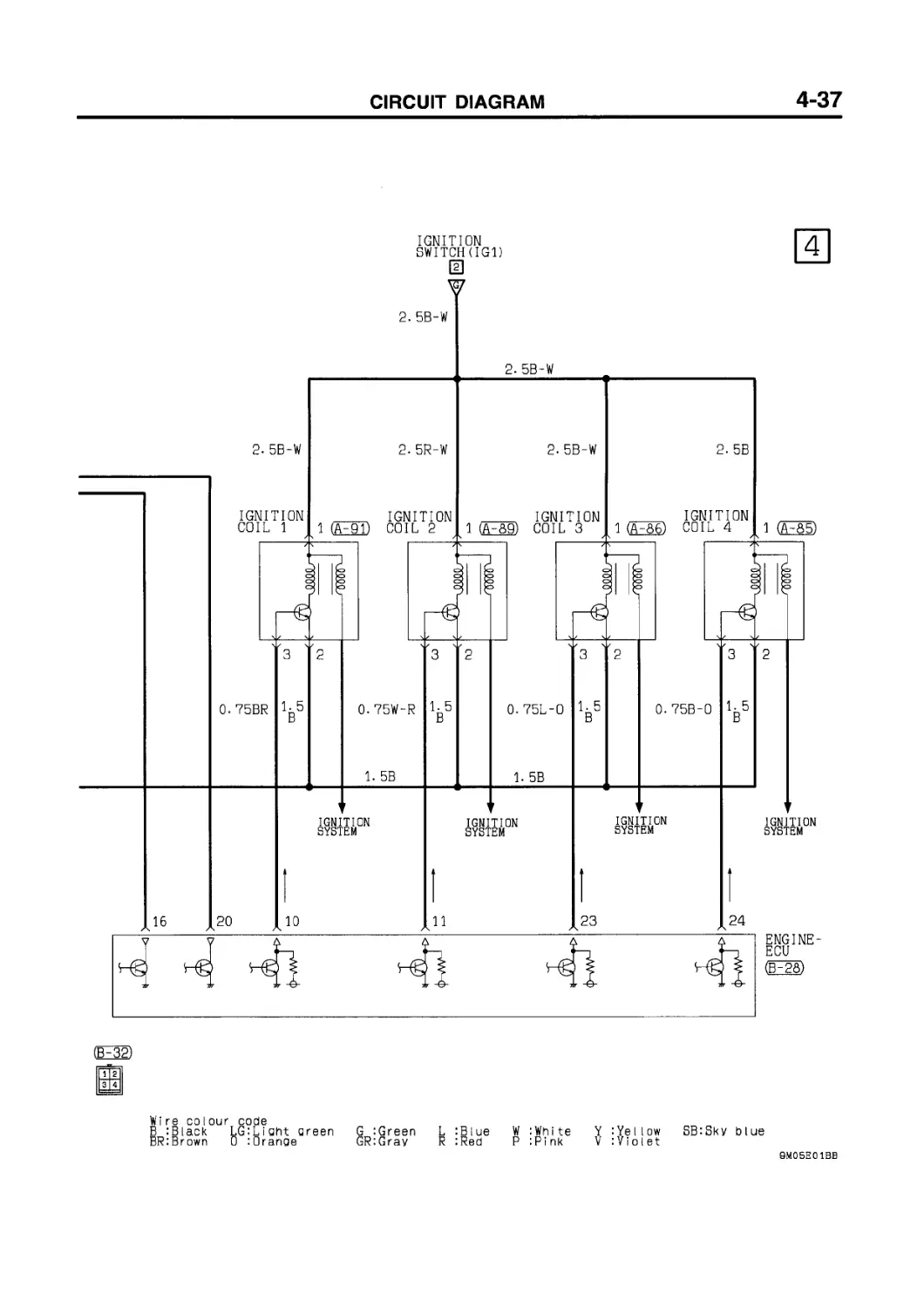
4G93 engine ....................... 4-34
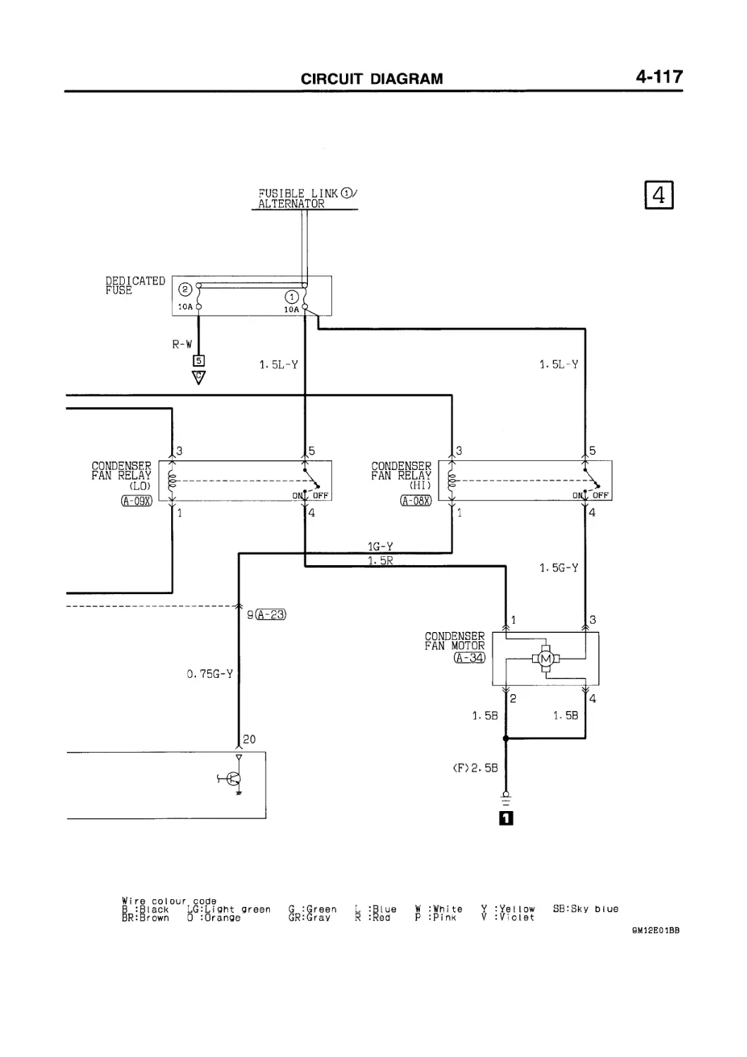
COOLING SYSTEM 4G13 engine ......................4-46
4G93 engine ........................4-48
HEADLAMP
L.H. drive vehicles without daytime running lamp ...................... 4-50
R.H. drive vehicles.................4-51
Vehicles with daytime running lamp .4-52
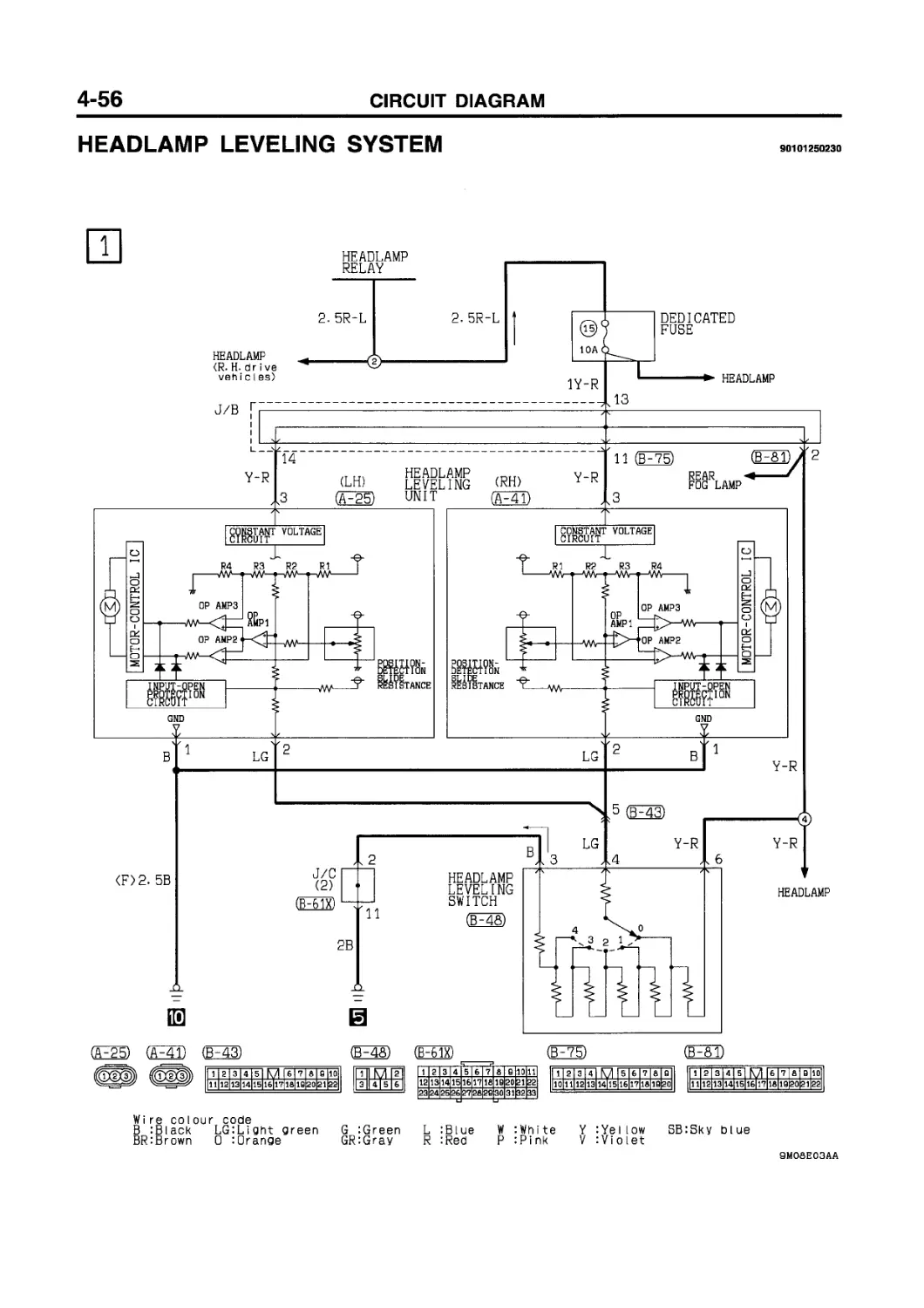
HEADLAMP LEVELING SYSTEM........ 4-56
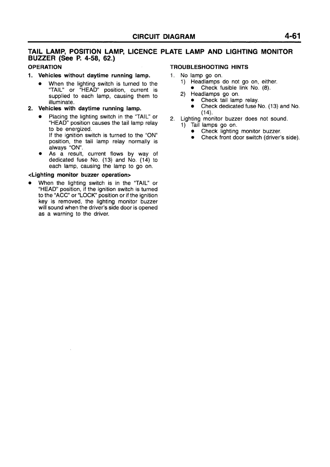
TAIL LAMP, POSIITON LAMP, LICENCE PLATE LAMP AND LIGHTING MONITOR BUZZER
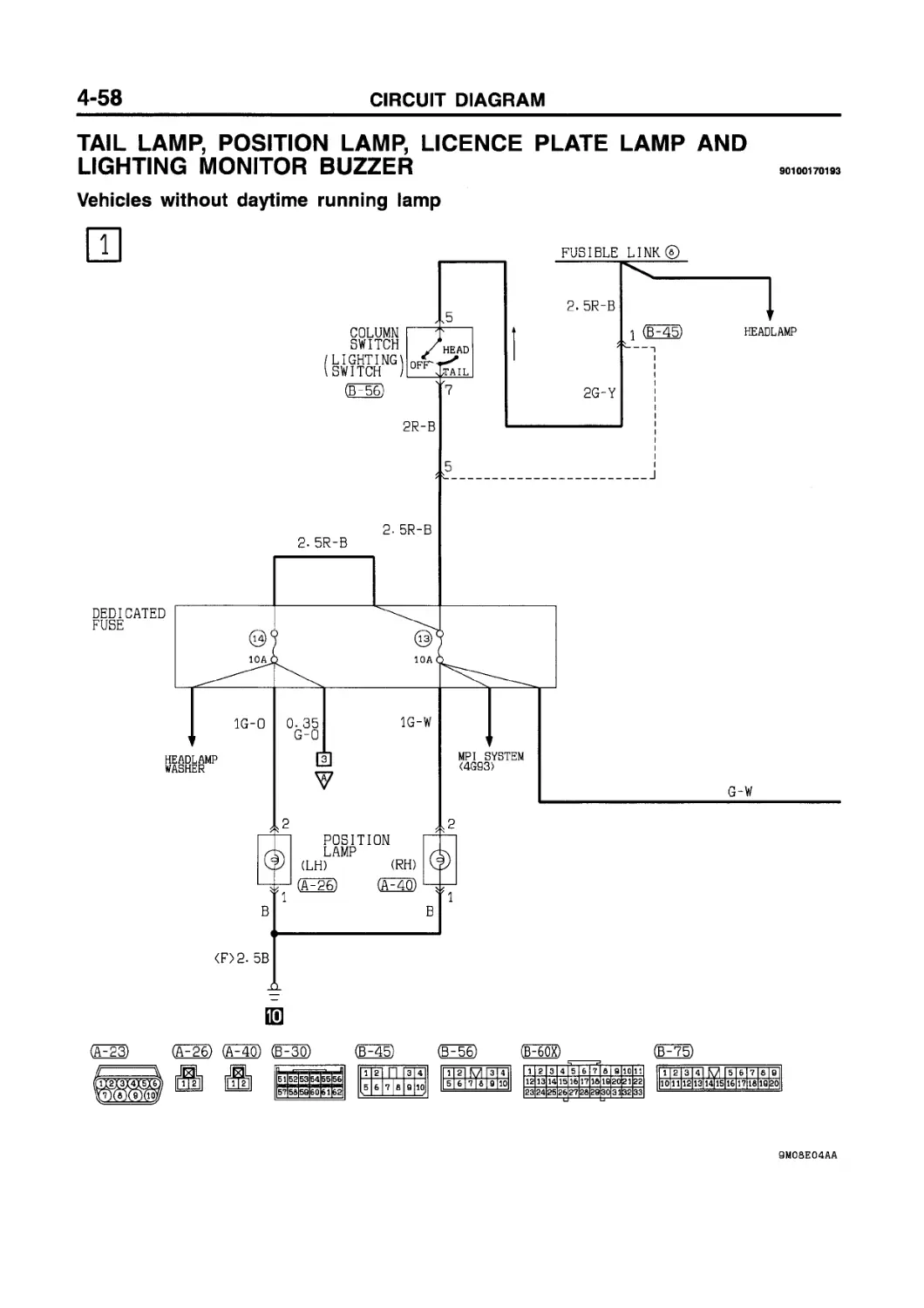
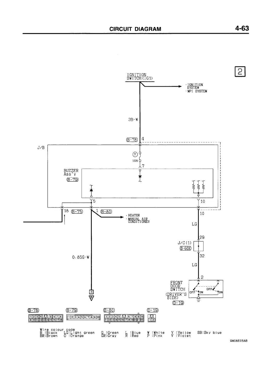
Vehicles without daytime running lamp.4-58
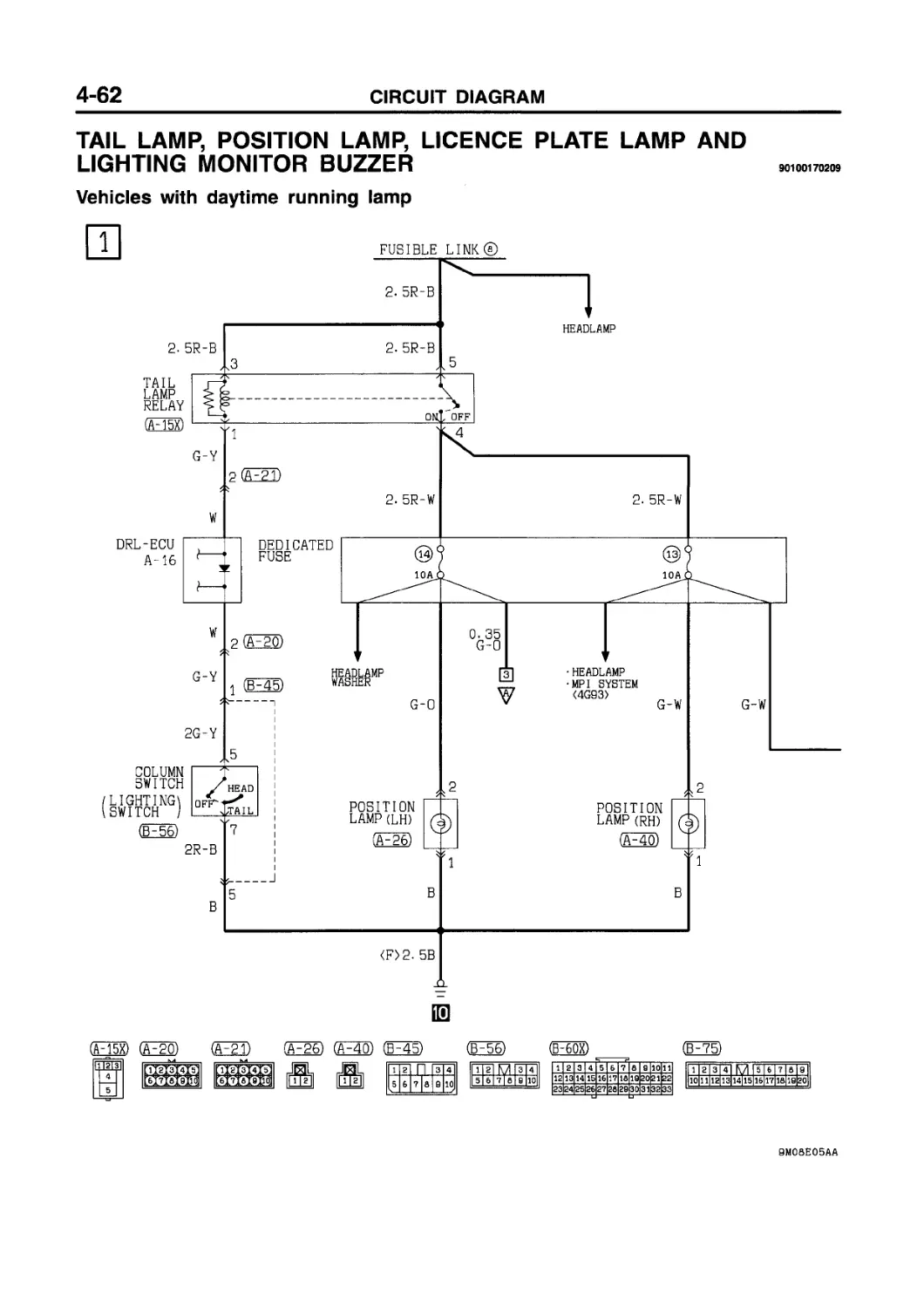
Vehicles with daytime running lamp ... 4-62
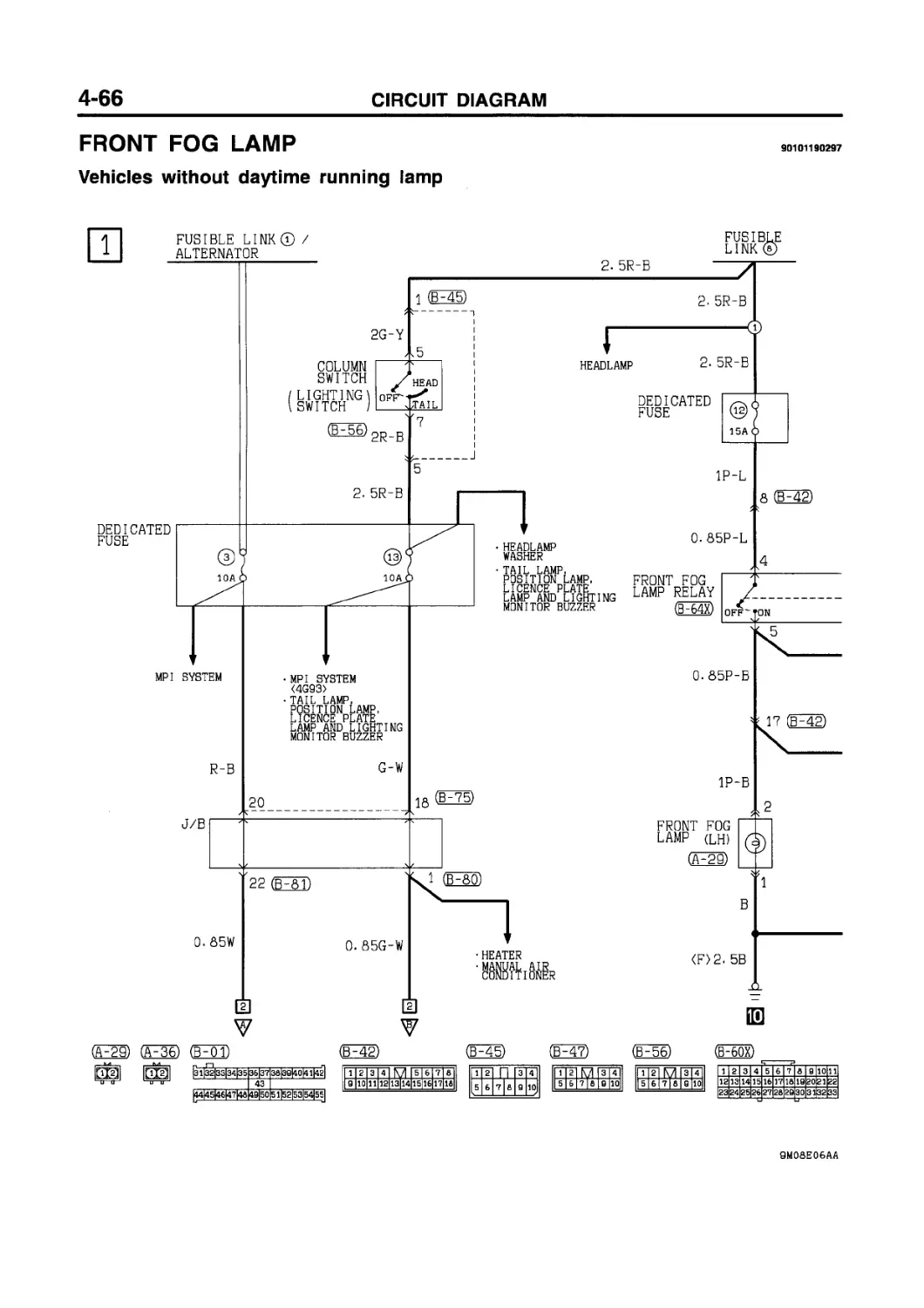
FRONT FOG LAMP
Vehicles without daytime running lamp.4-66
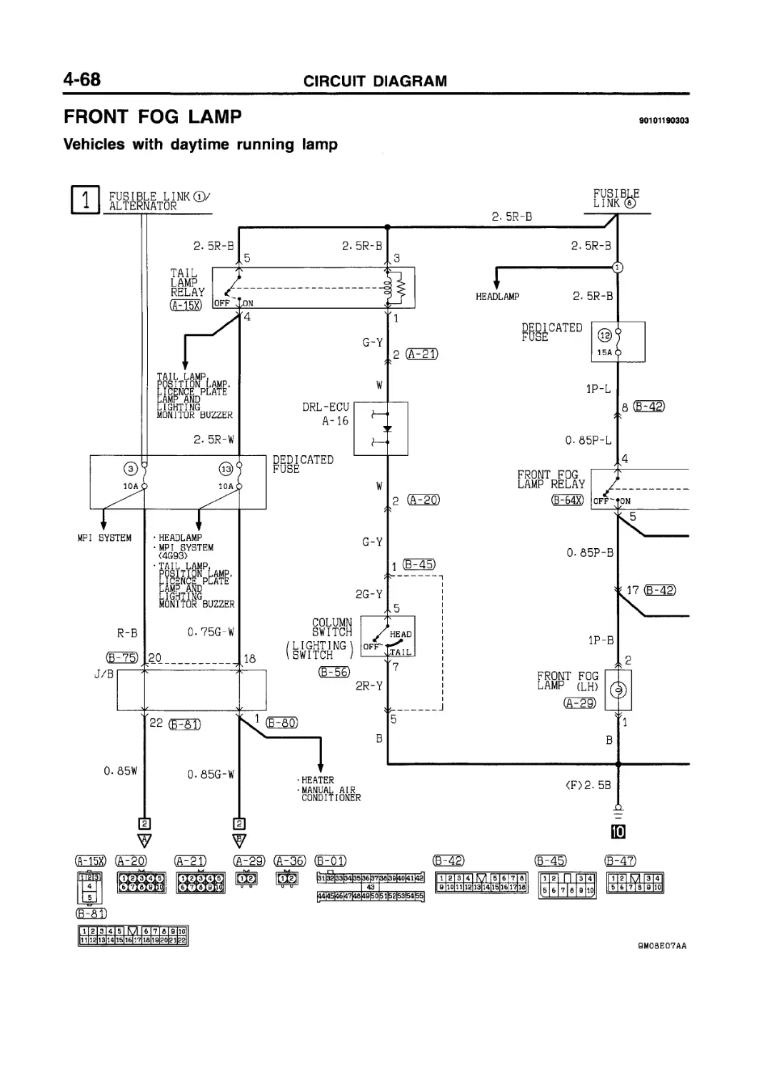
Vehicles with daytime running lamp ....4-68
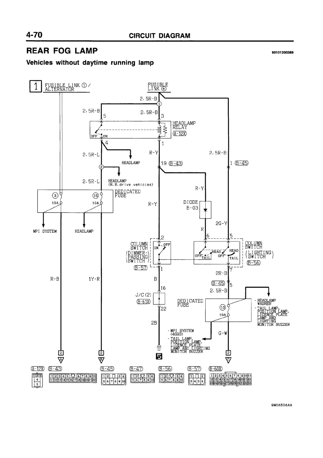
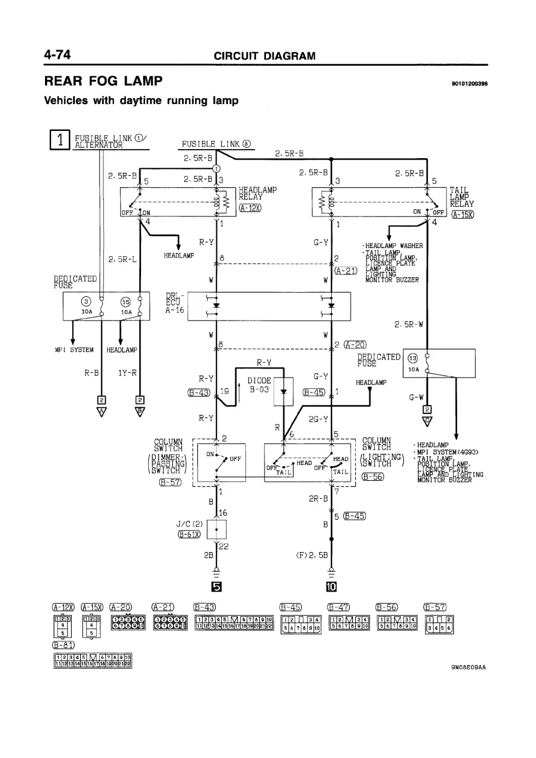
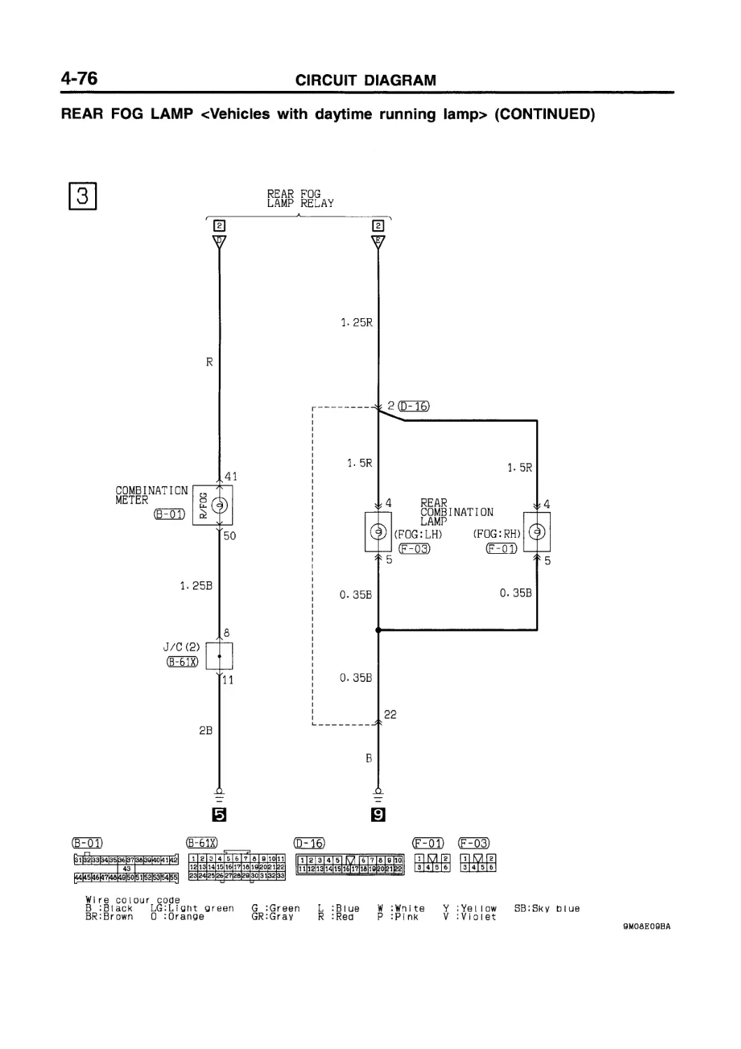
REAR FOG LAMP
Vehicles without daytime running lamp.4-70
Vehicles with daytime running lamp ....4-74
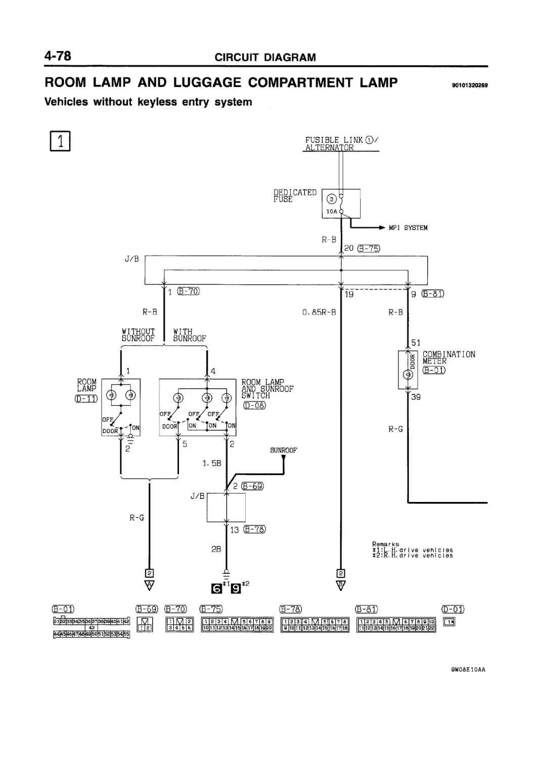
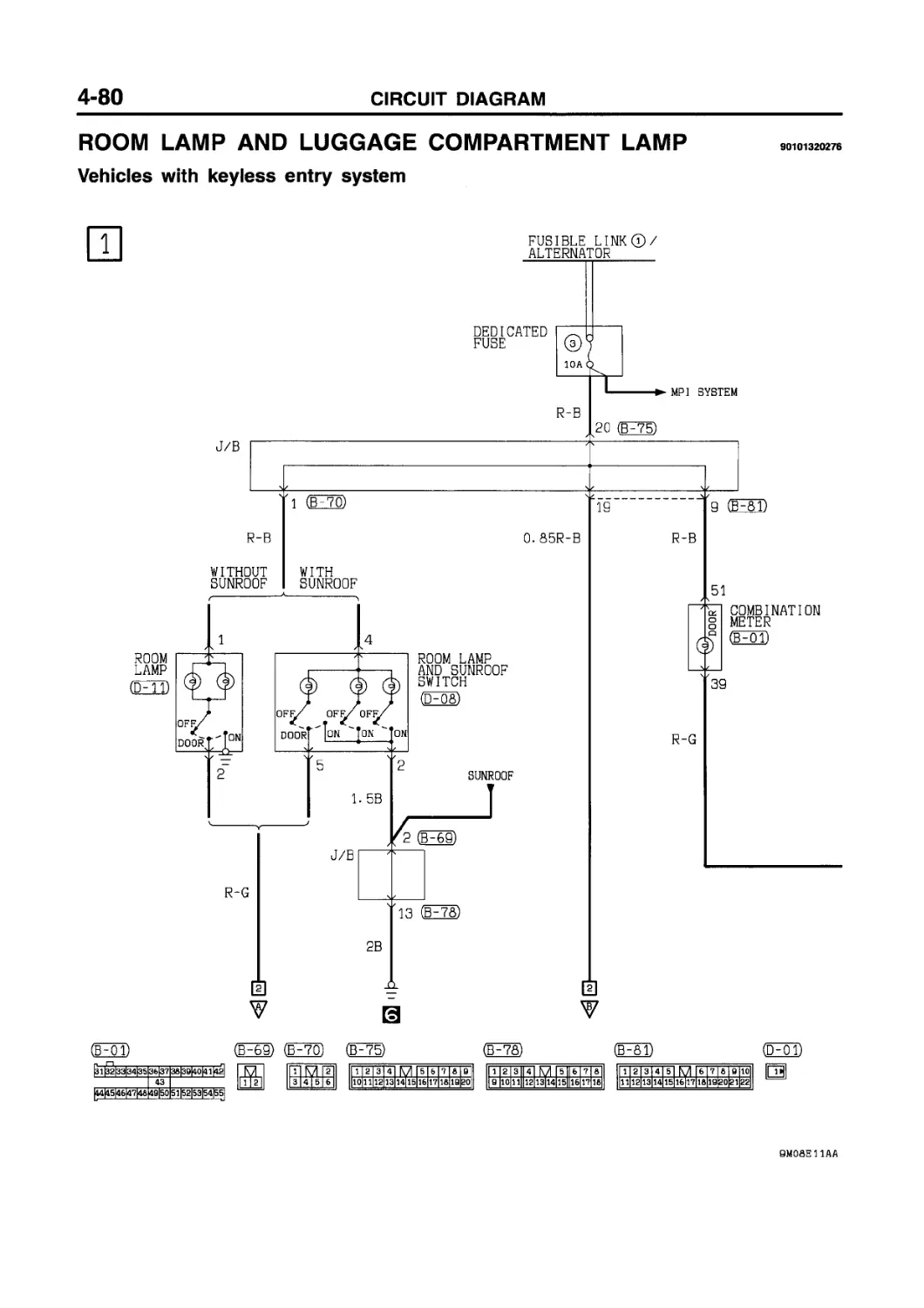
ROOM LAMP AND LUGGAGE COMPARTMENT LAMP
Vehicles without keyless entry system .4-78
Vehicles with keyless entry system.....4-80
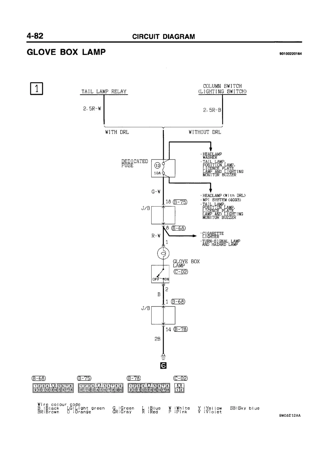
GLOVE BOX LAMP ......................... 4-82
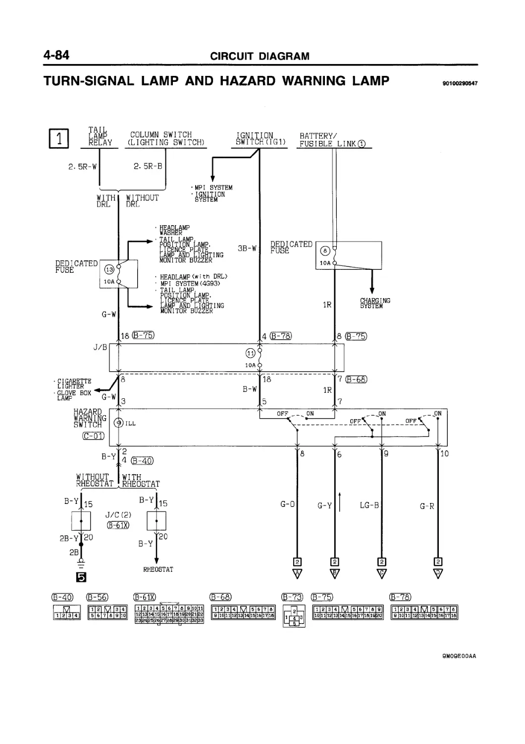
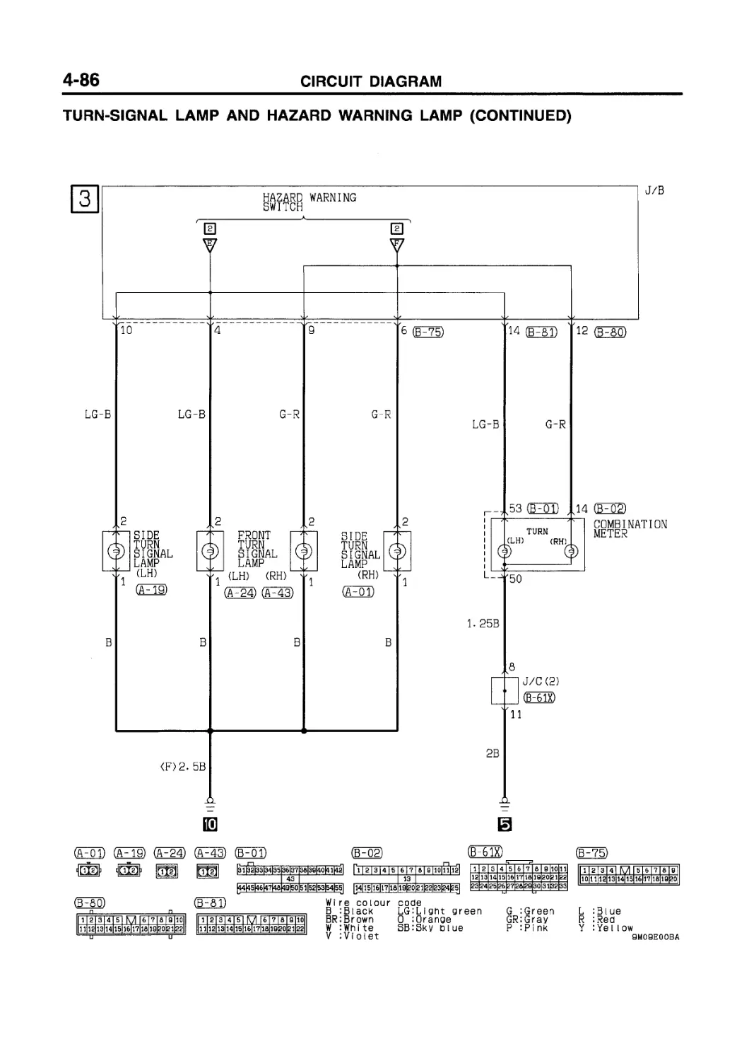
TURN-SIGNAL LAMP AND HAZARD WARNING LAMP ................................... 4-84
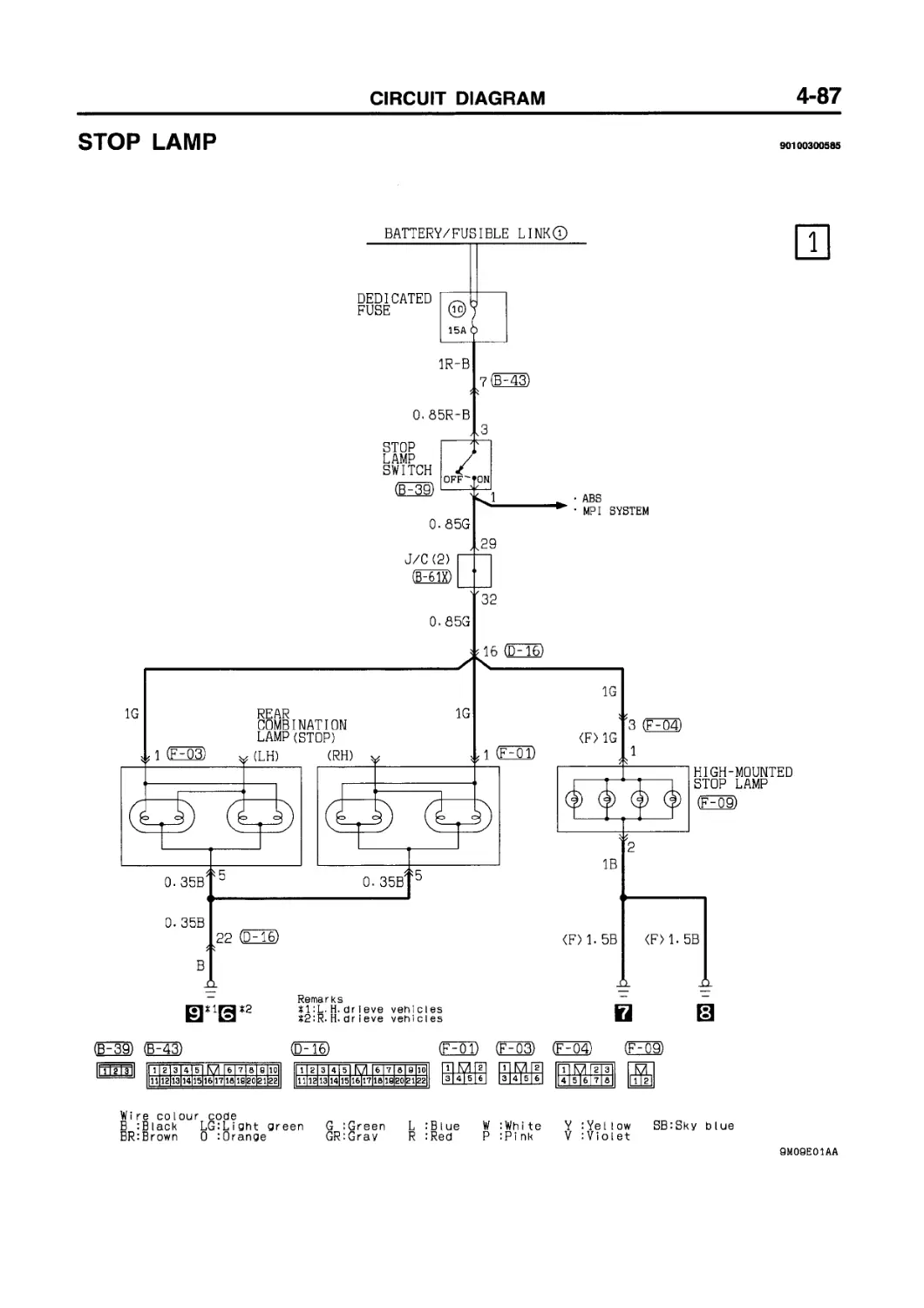
STOP LAMP............................... 4-87
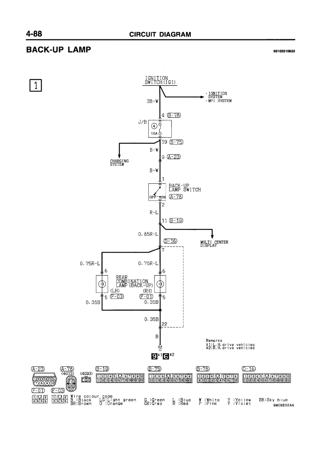
BACK-UP LAMP ........................... 4-88
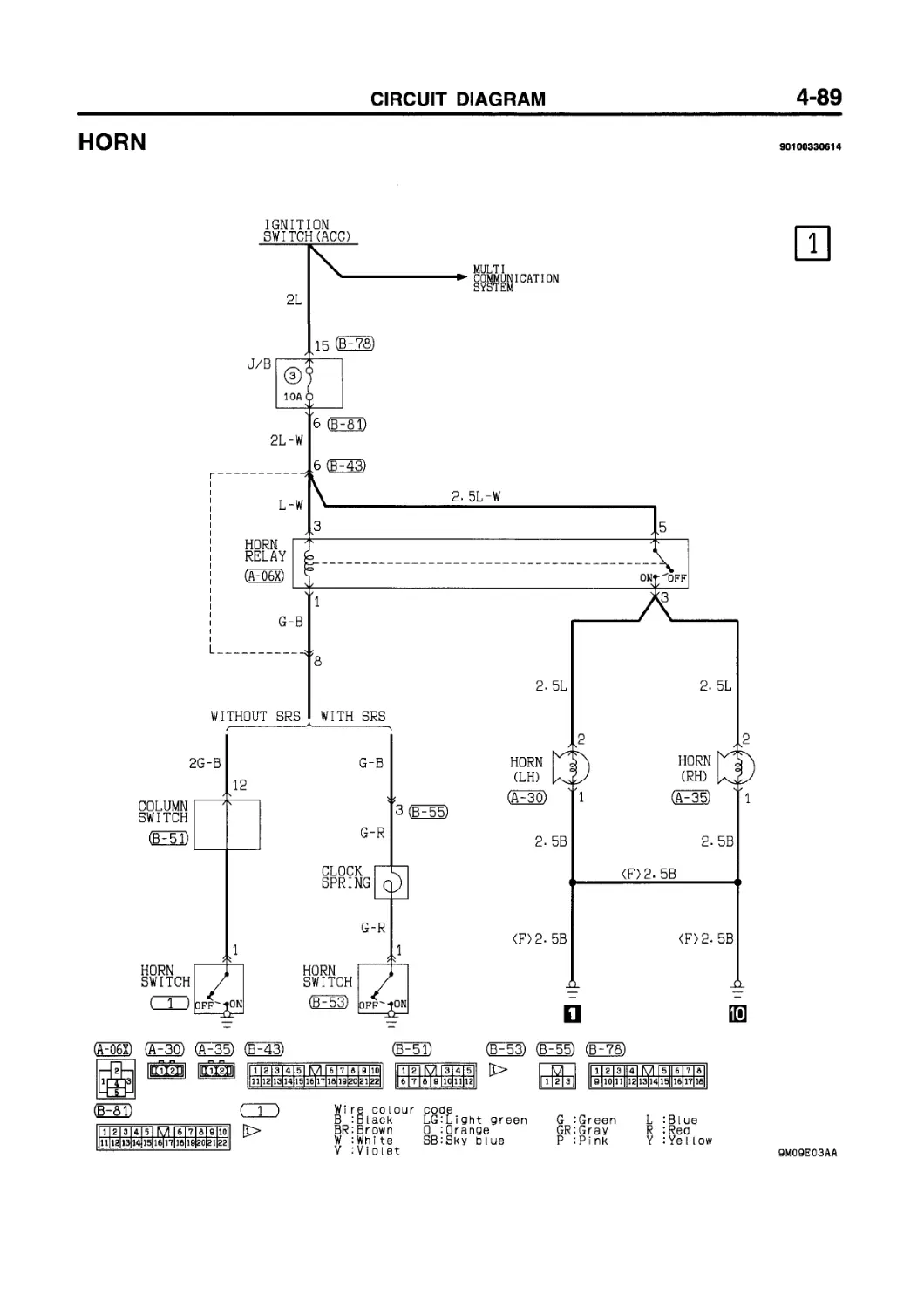
HORN ................................... 4-89
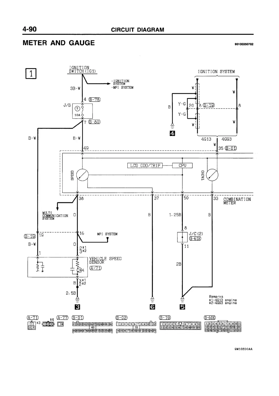
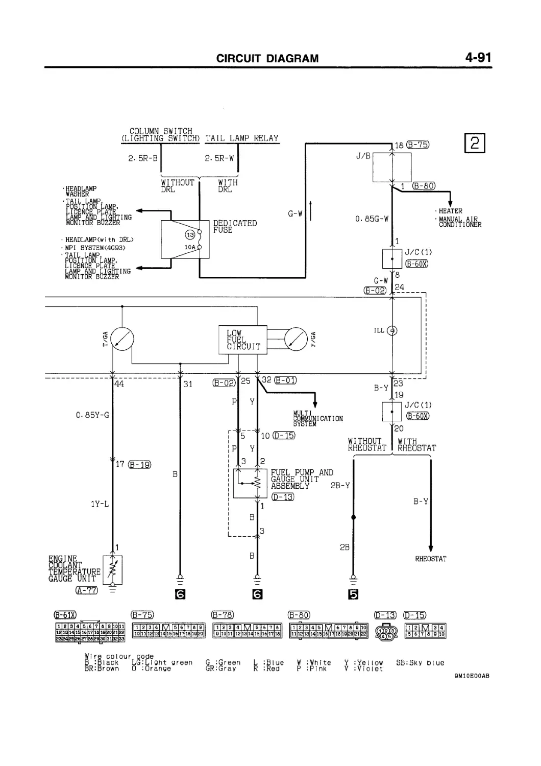
METER AND GAUGE ........................ 4-90
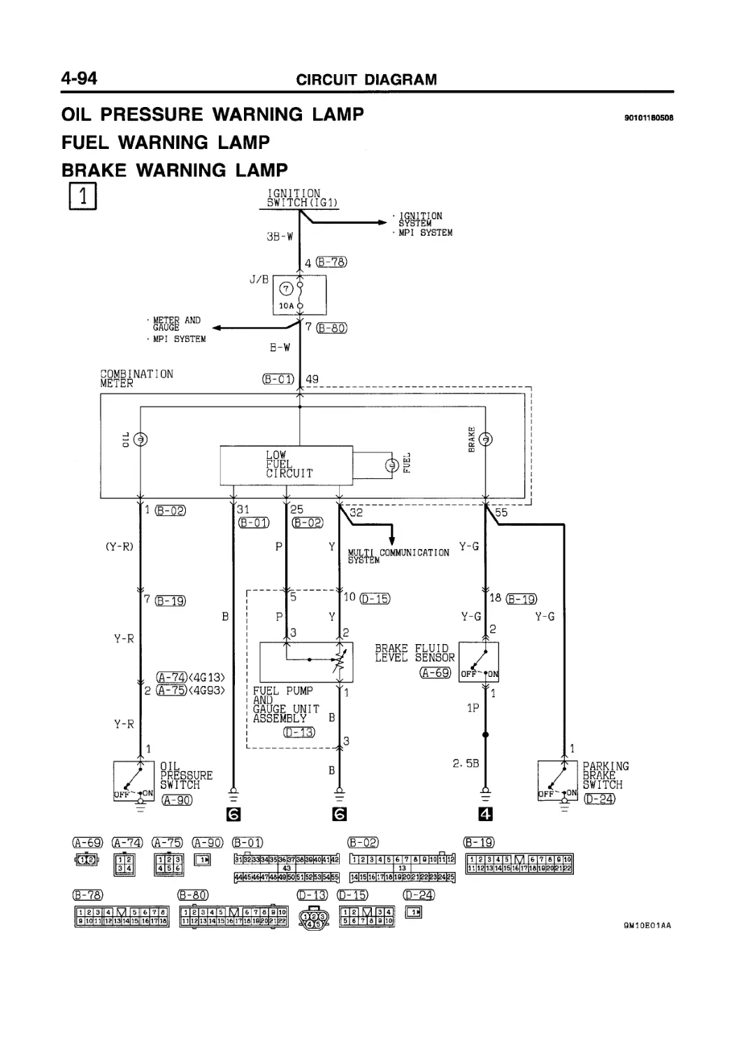
OIL PRESSURE WARNING LAMP............... 4-94
FUEL WARNING LAMP....................... 4-94
BRAKE WARNING LAMP....................... 4-94
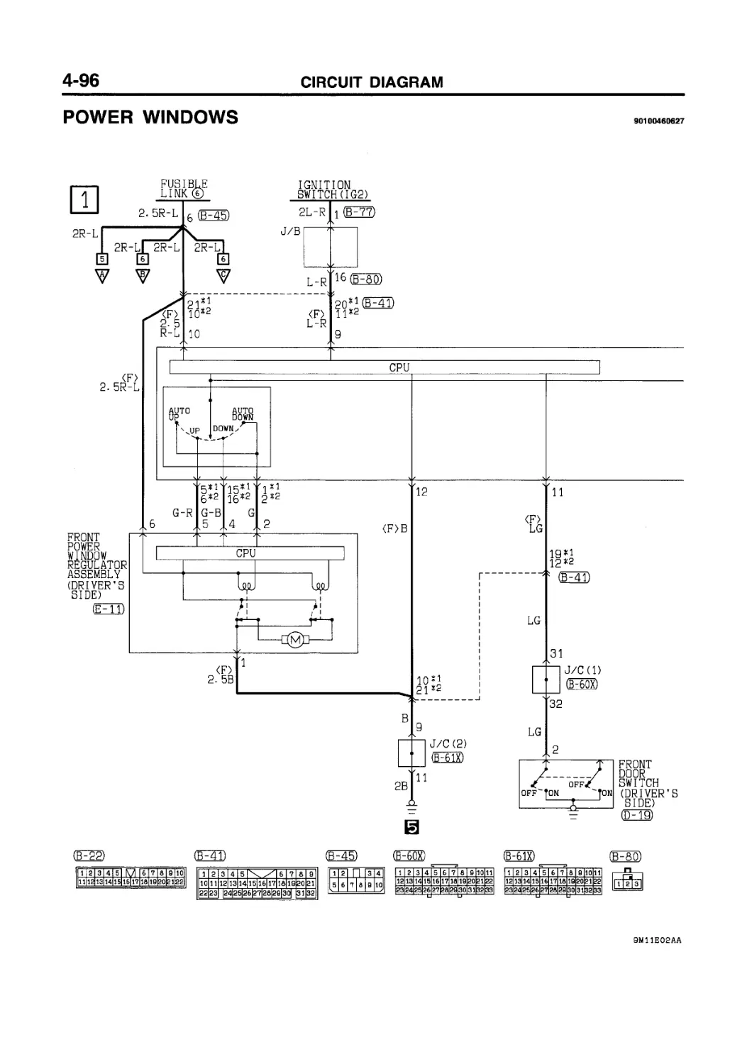
POWER WINDOWS ........................... 4-96
CENTRAL DOOR LOCKING SYSTEM
Vehicles without keyless entry system .4-102
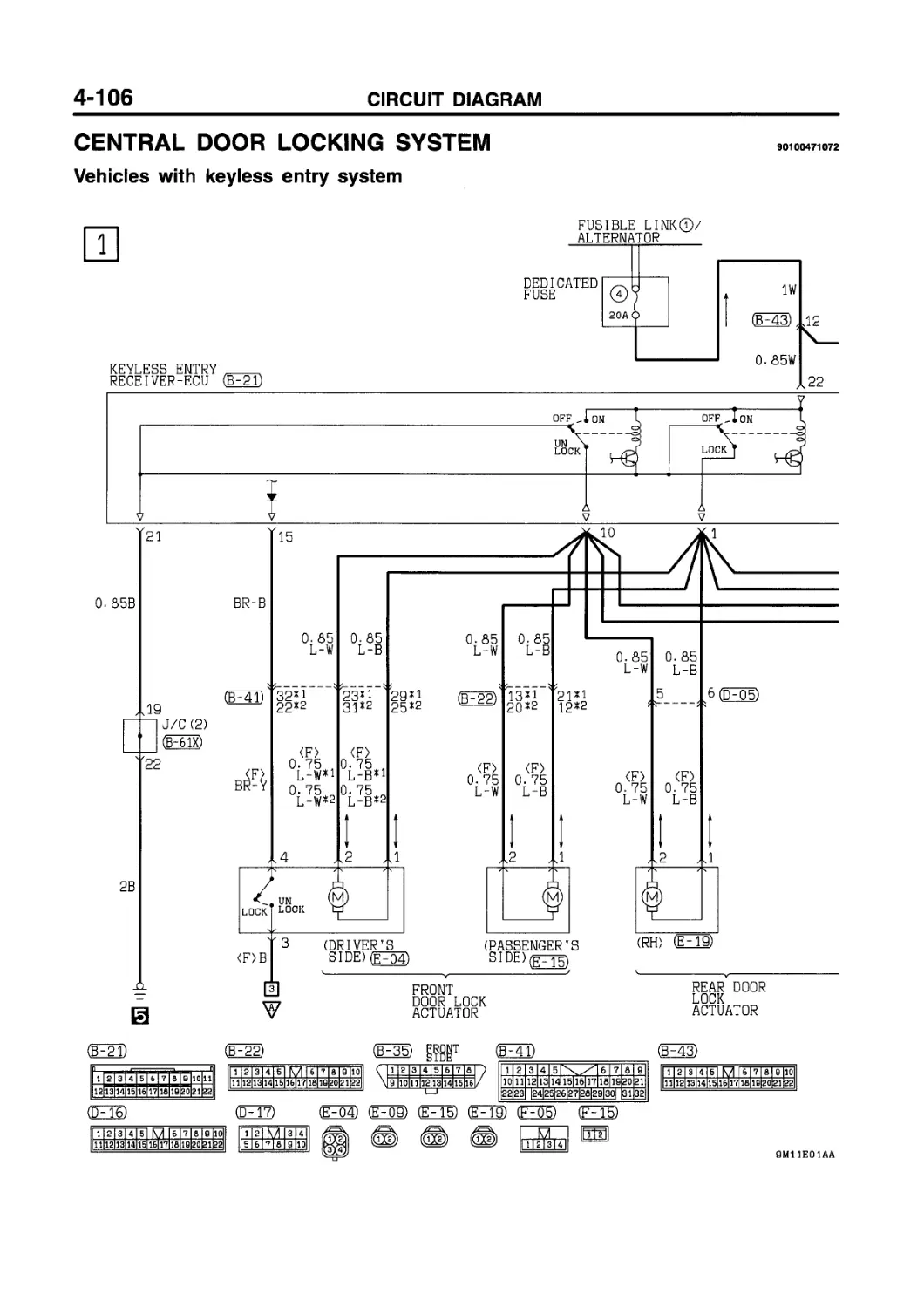
Vehicles with keyless entry system.....4-106
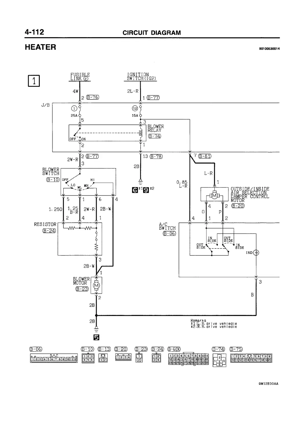
HEATER.................................. 4-112
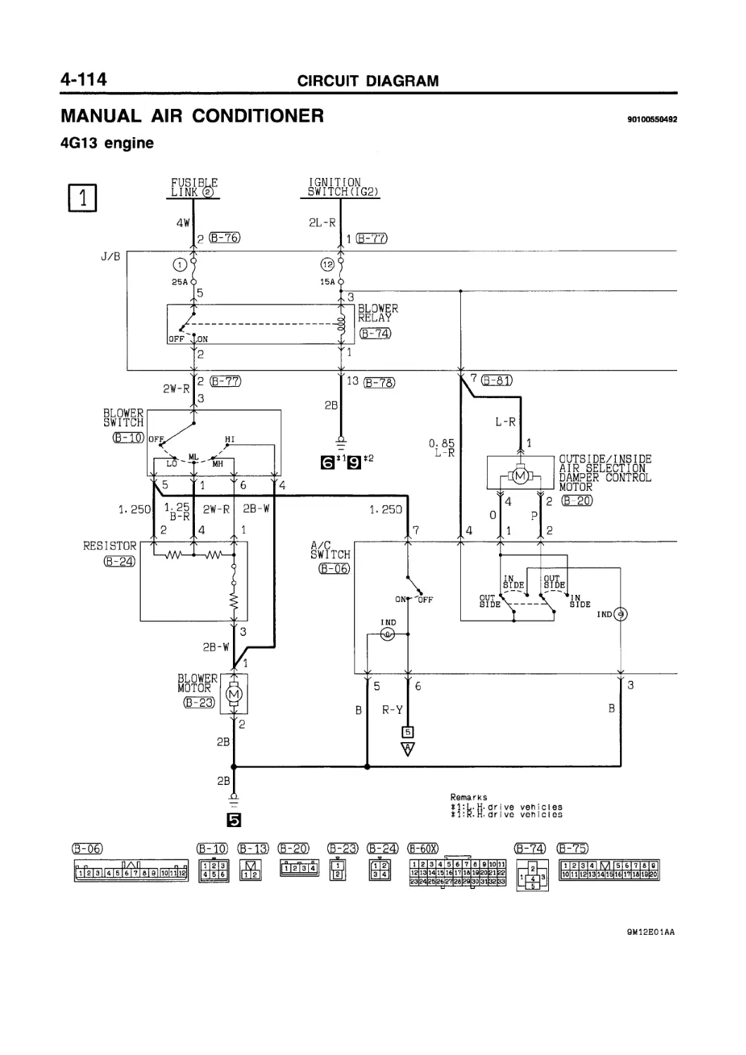
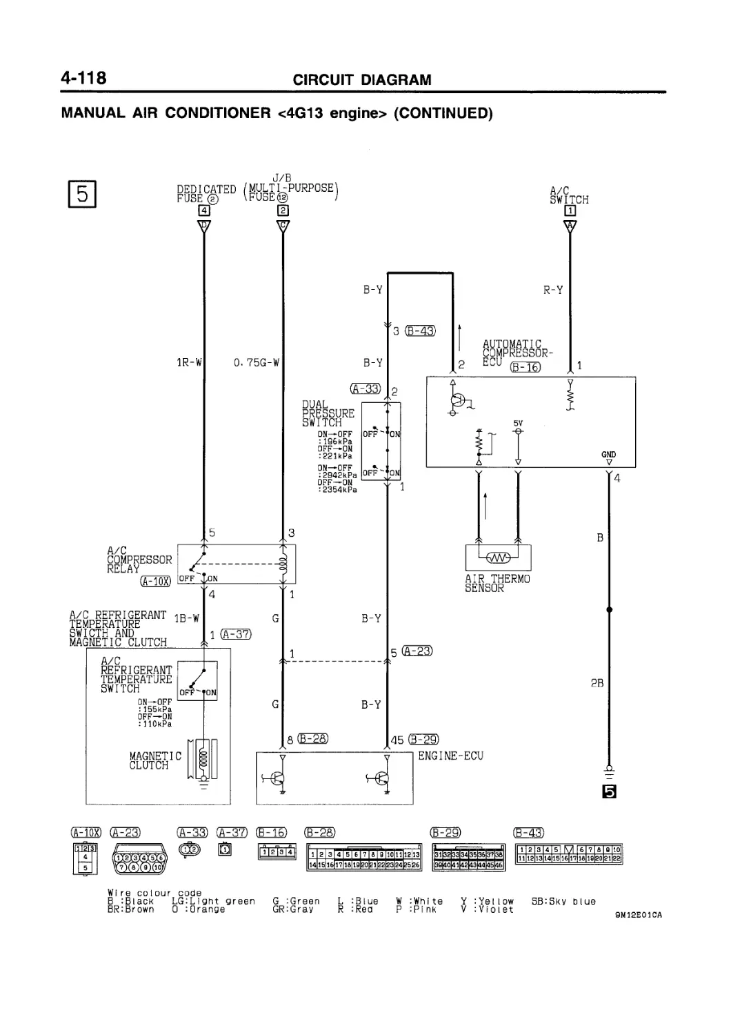
MANUAL AIR CONDITIONER 4G13 engine ................. 4-114
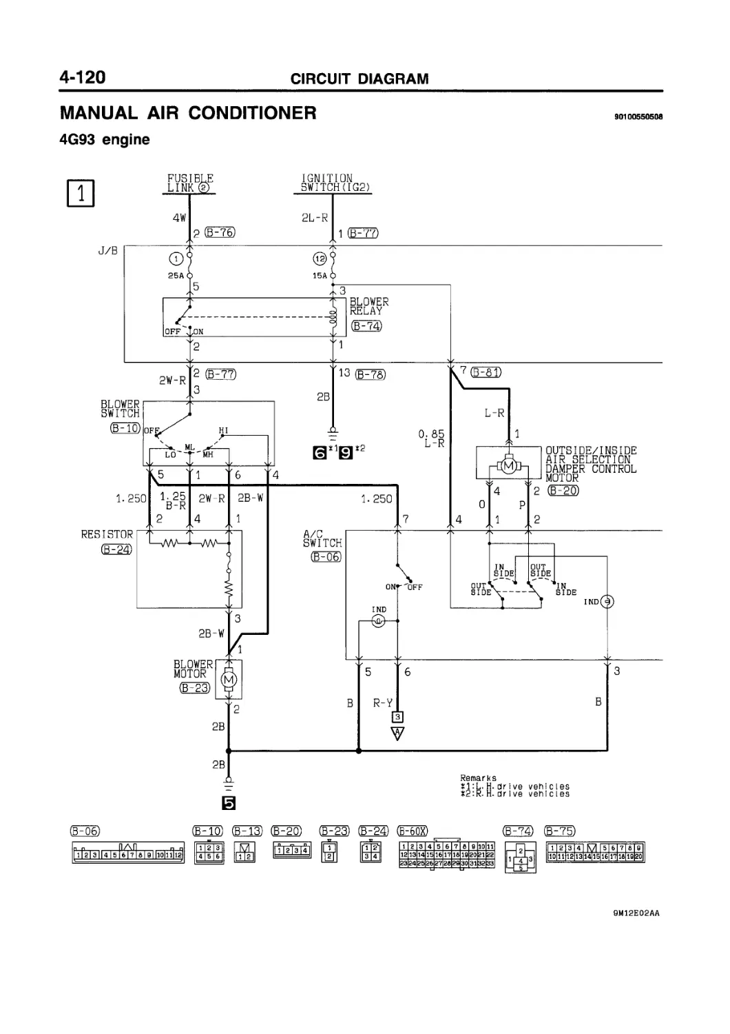
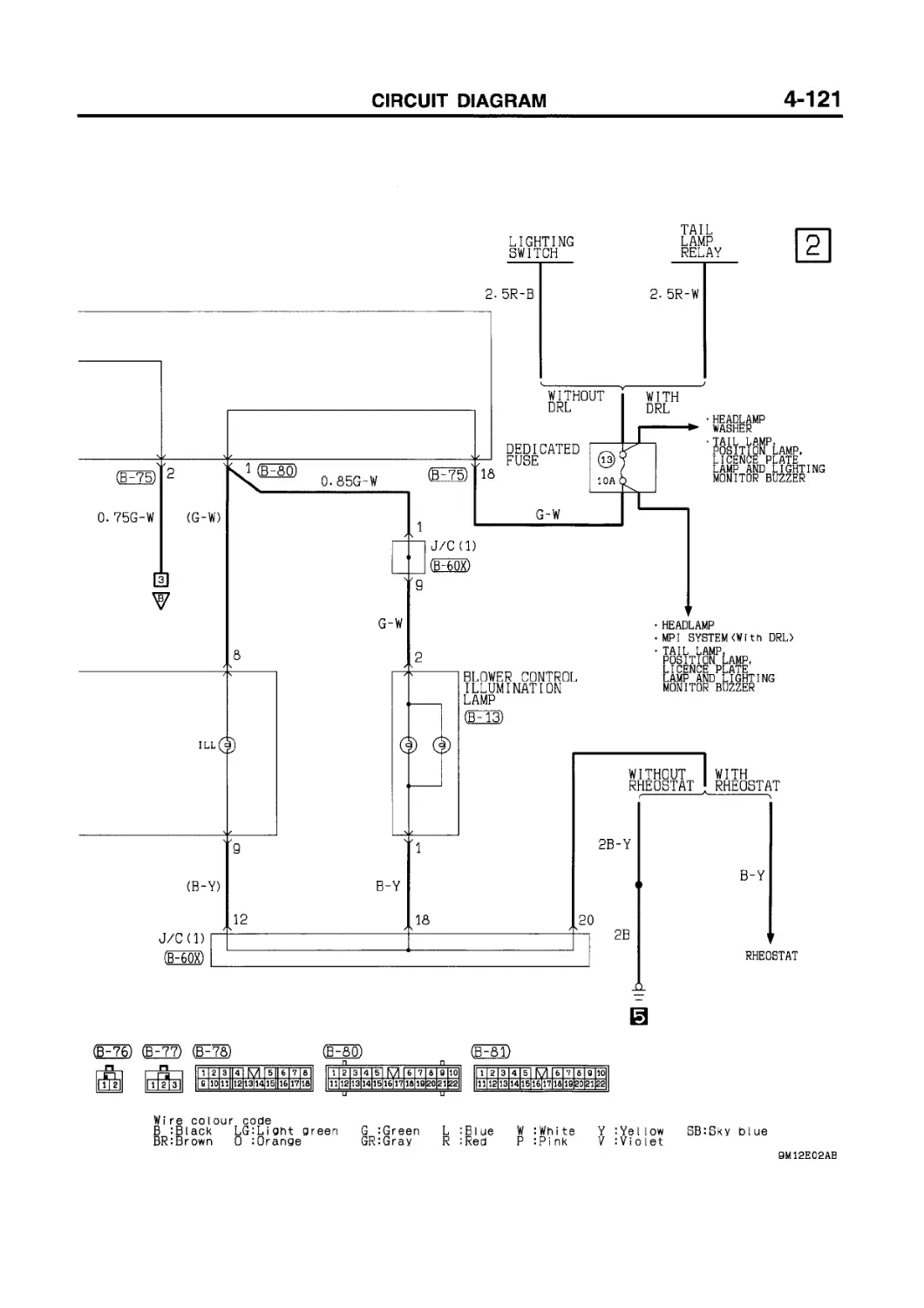
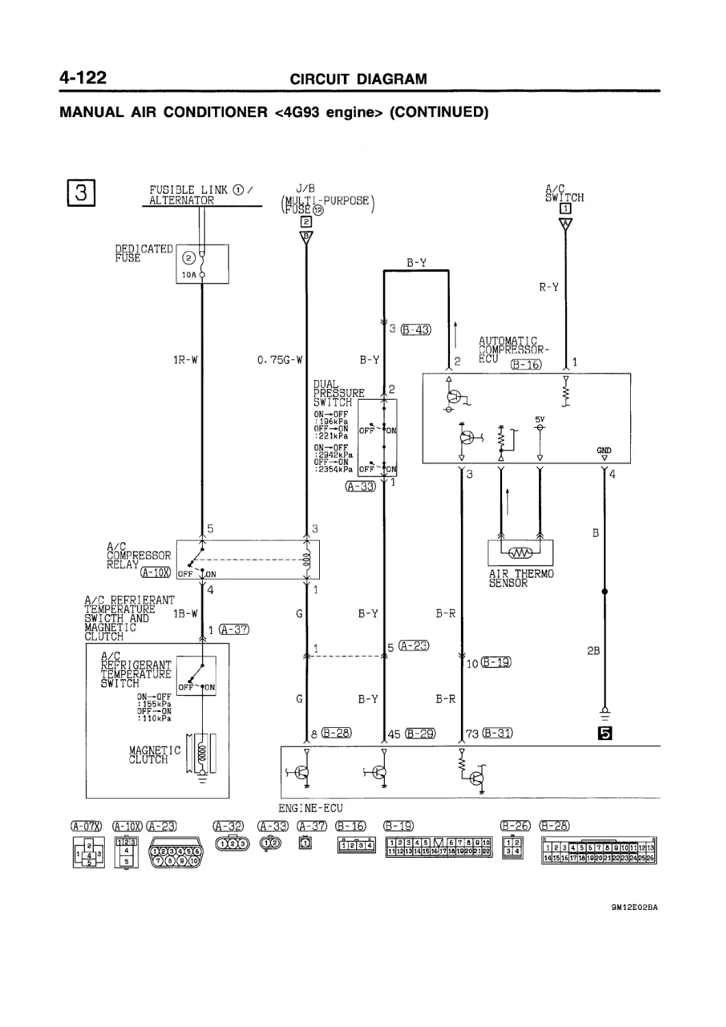
4G93 engine ...........................4-120
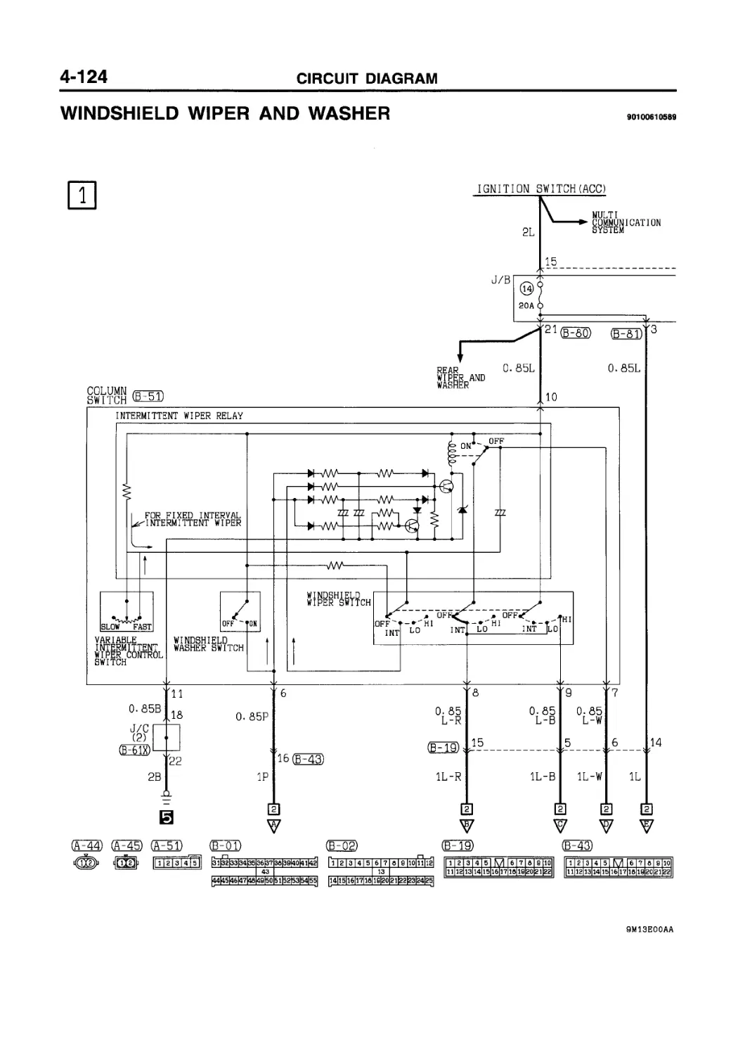
WINDSHIELD WIPER AND WASHER .... 4-124
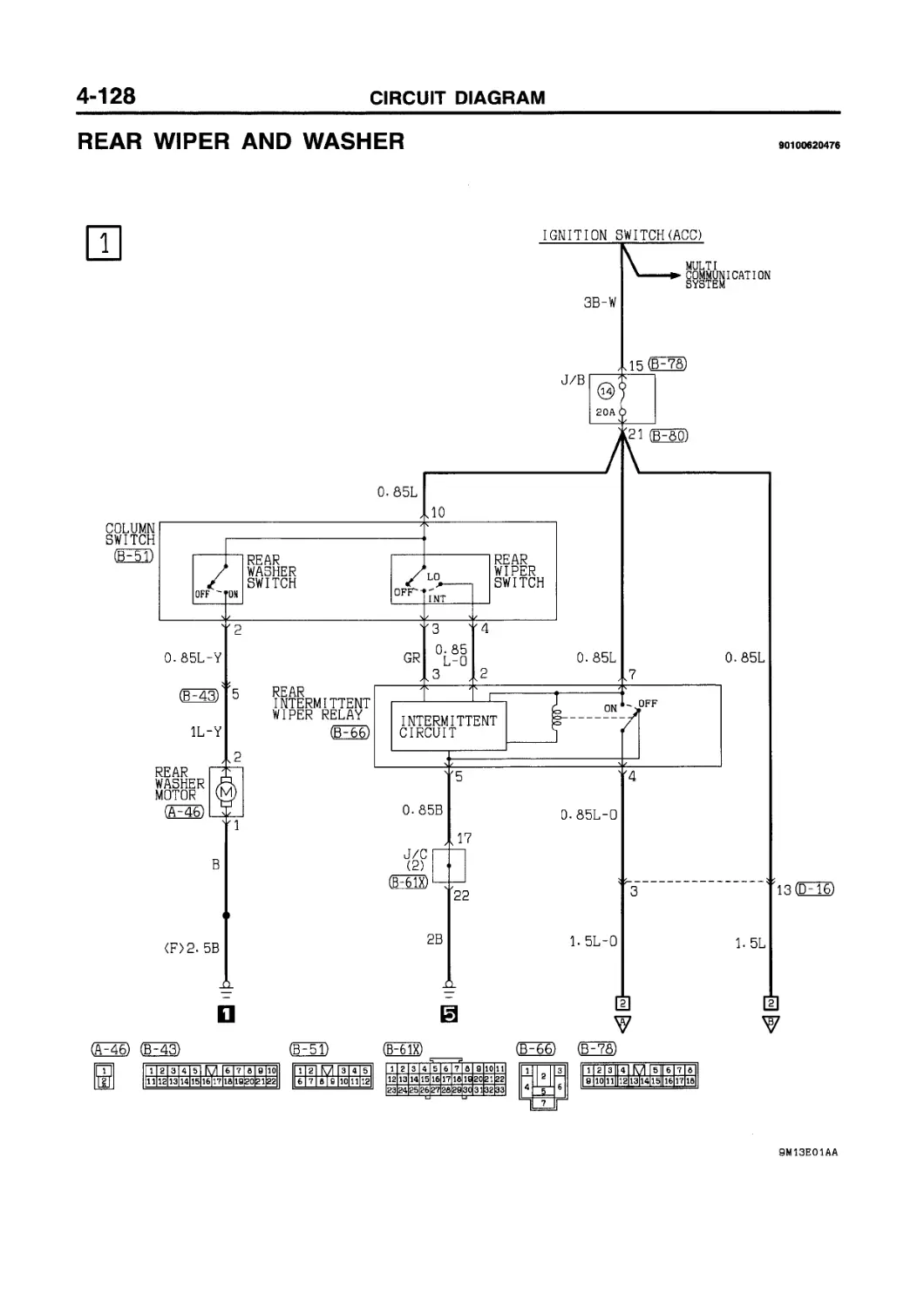
REAR WIPER AND WASHER................... 4-128
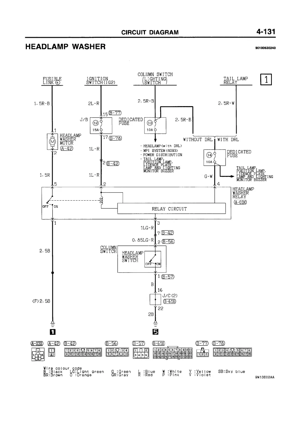
HEADLAMP WASHER......................... 4-131
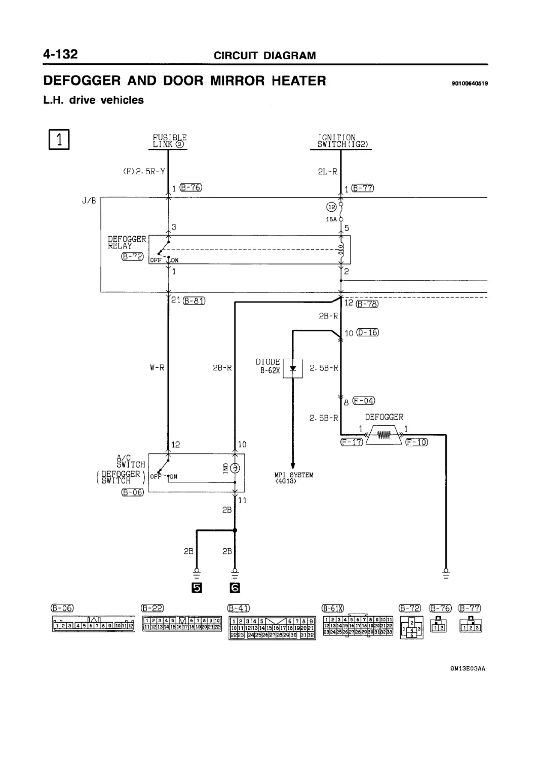
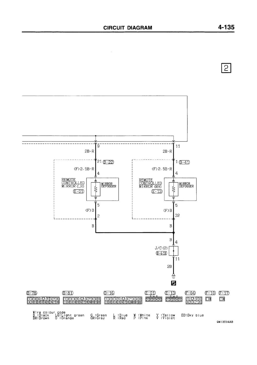
DEFOGGER AND DOOR MIRROR HEATER
L.H. drive vehicles ..........4-132
R.H. drive vehicles...........4-134
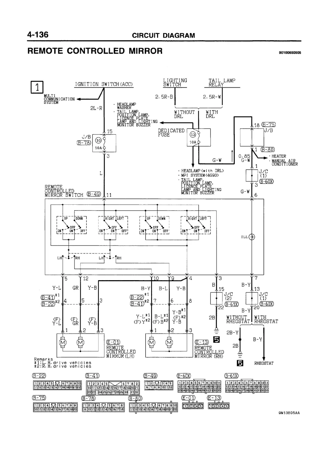
REMOTE CONTROLLED MIRROR........ 4-136
CIGARETTE LIGHTER.............. 4-137
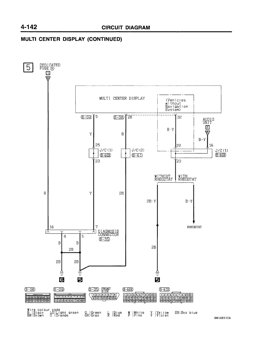
MULTI CENTER DISPLAY .......... 4-138
SUNROOF........................ 4-144
HEATED SEAT.................... 4-146
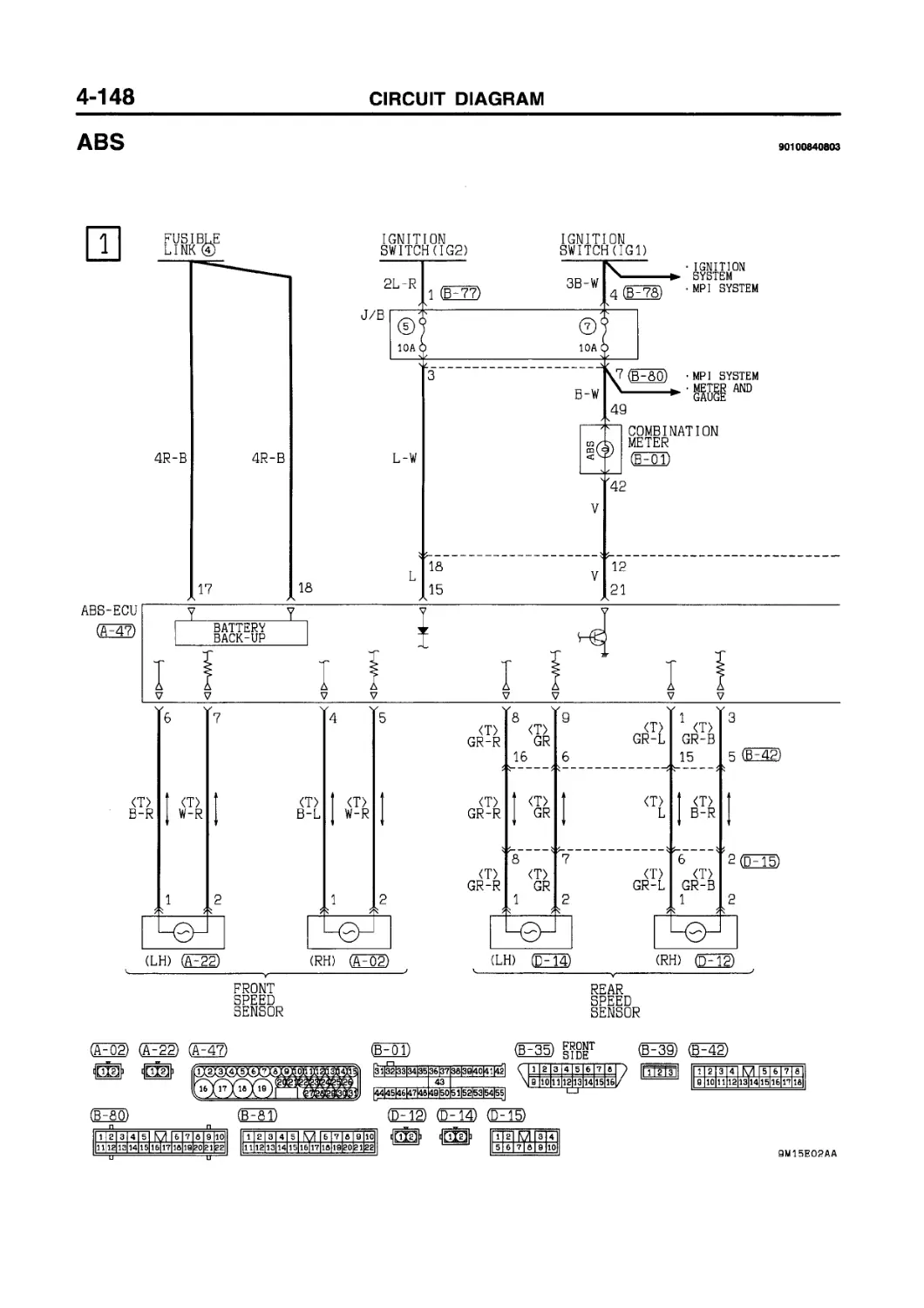
ABS............................ 4-148
SUPPLEMENTAL RESTRAINT SYSTEM......................... 4-150
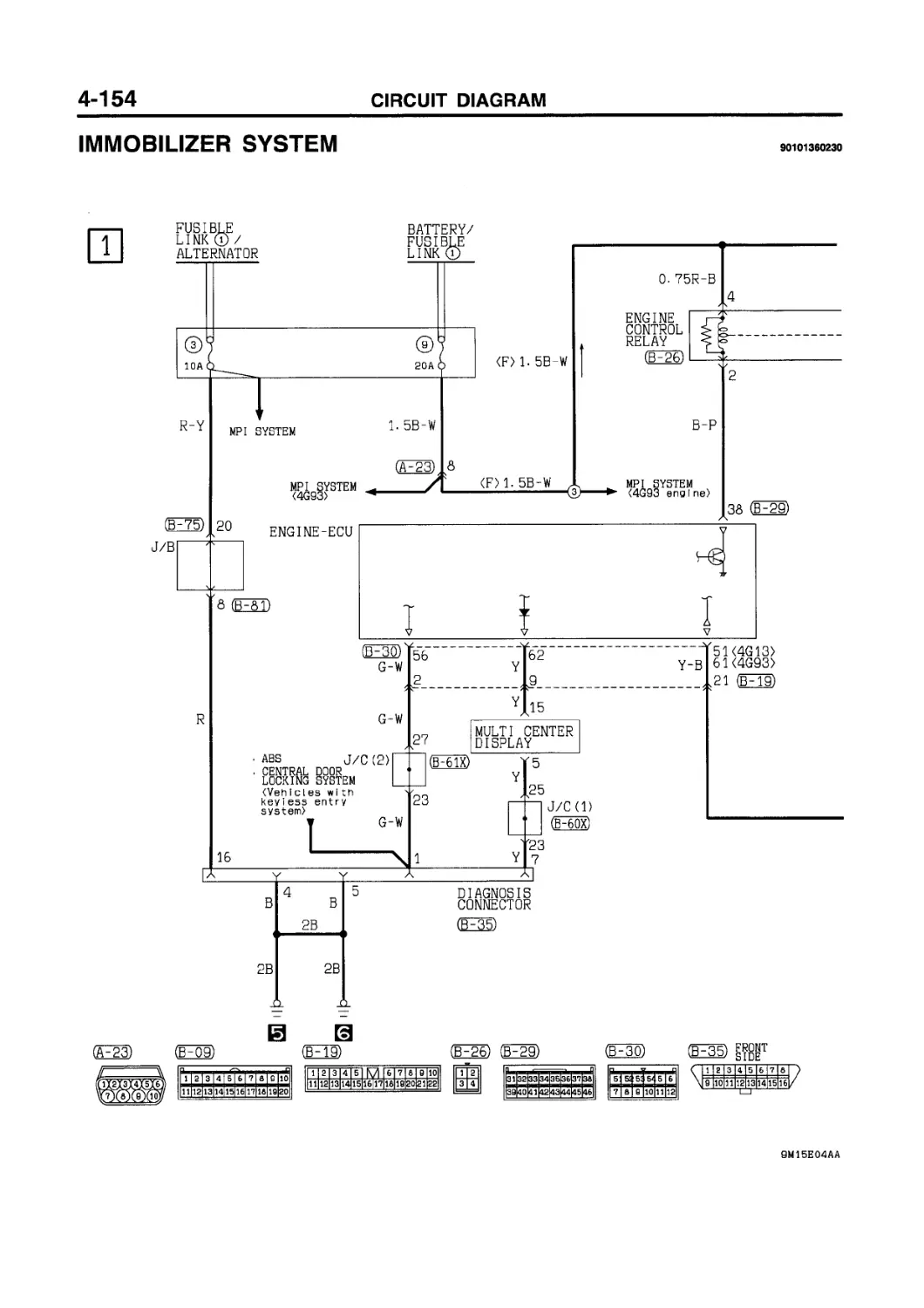
IMMOBILIZER SYSTEM............. 4-154
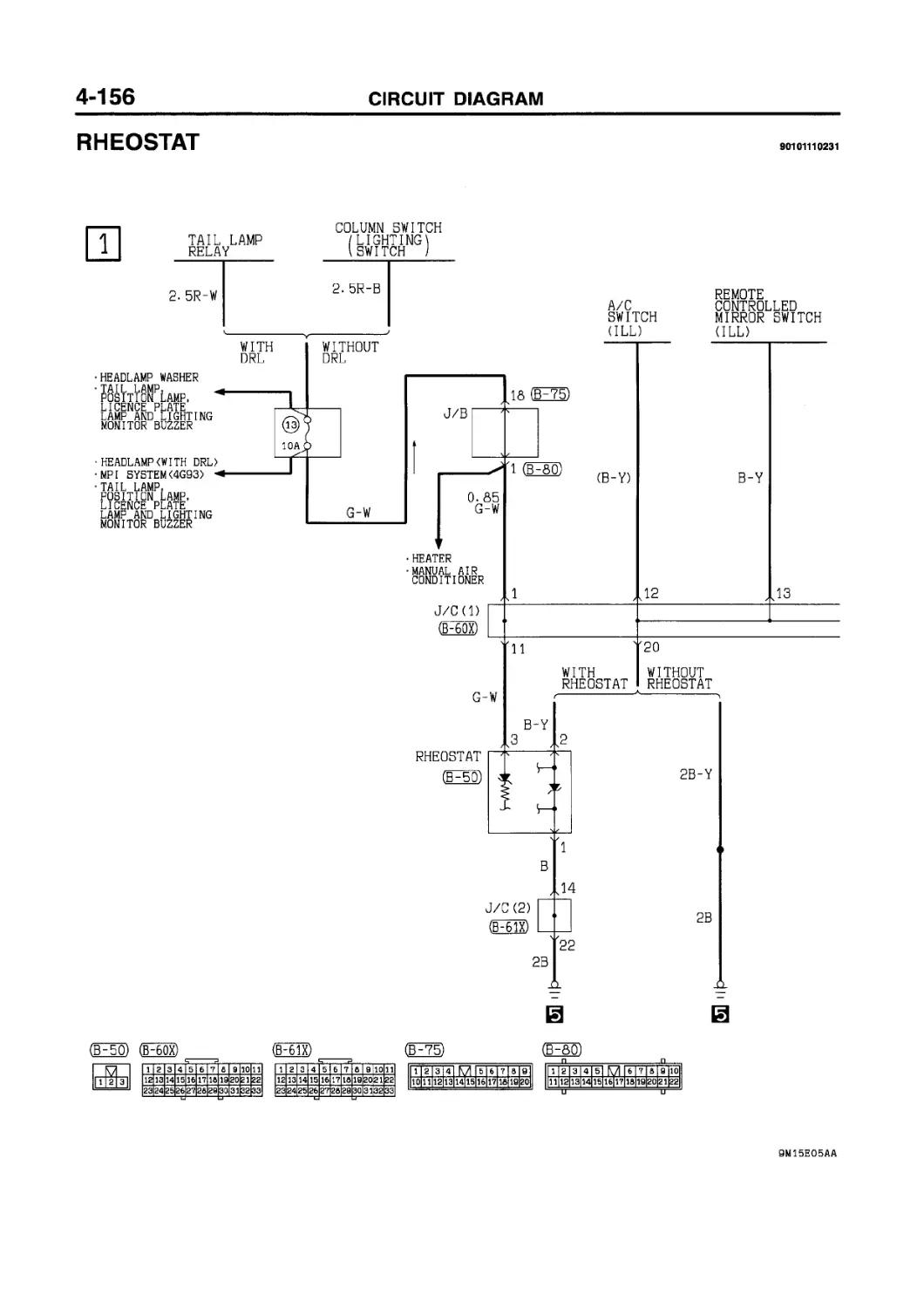
RHEOSTAT ...................... 4-156
NOTES
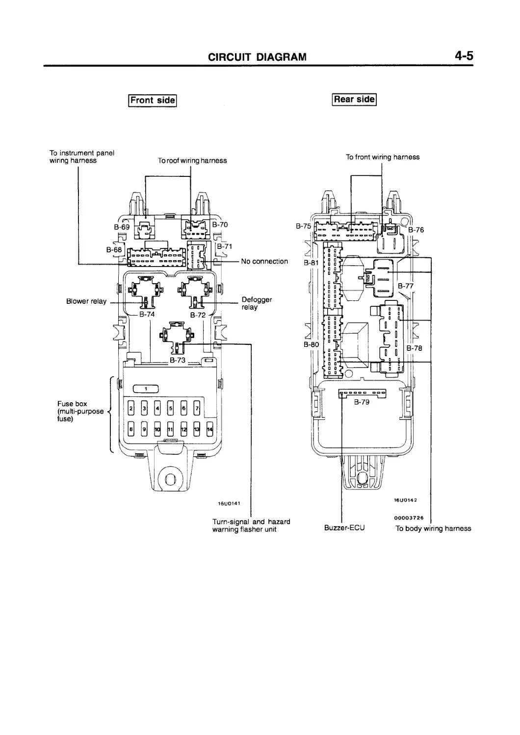
JUNCTION BLOCK (J/B)
90100020412
GES) (B-79)
REMARK CONNECTOR NUMBERS ARE KEYED TO THE CONFIGURATION DIAGRAM(DASH PANEL)AND EACH CIRCUIT DIAGRAM.
GE78)
F68) (ТГ69) GE7Q)
(FTP (EES) (EES) (eFm) (b-75)
GEZ5) (FT?)
1 м 2
12 ffs 6]
MR1-a 151 e 171 a
1 |2 [3 141 M I 5 |6 I 7|8 |S
Ш
(FTfl) (ёРТэ)
1 2 3 4 5 6 7 a
8 10 11 12 1з|14 15 16 17 la
|1O| a |8| 7 |6 I 5| 4| 3 I 2| 1 |
(Fao)
[ 11 2 I 3 I 4 I 5 I KI I 6 17 18 I S |10l
(EEfiD
|ШЕЕЕЕЕЕ[ЙШЕВЕЕ^31^|
1 2|3 4 fyl 7|e|a 10
|11|12|13 141 516|171 в isfeogi 2g|
Front side
Rear side
16U0141
To front wiring harness
16U0142
Turn-signal and hazard warning flasher unit
00003726
Buzzer-ECU To body wiring harness
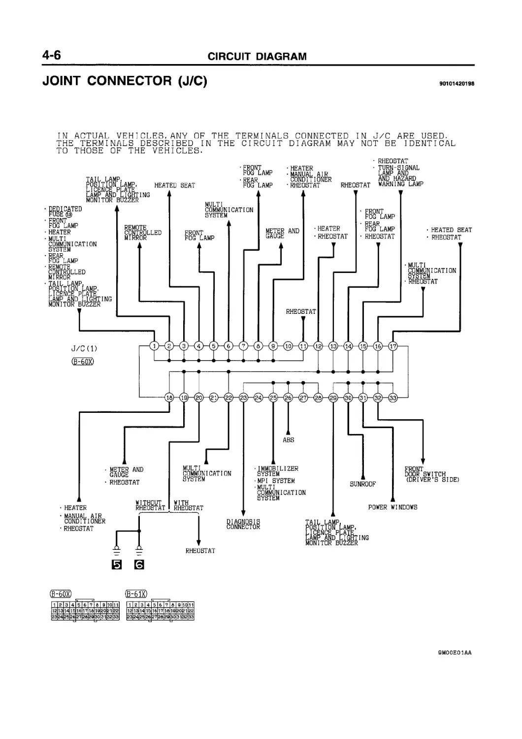
JOINT CONNECTOR (J/C)
90101420198
IN ACTUAL VEHICLES,ANY OF THE TERMINALS CONNECTED IN J/C AREUSED. THE TERMINALS DESCRIBED IN THE CIRCUIT TO THOSE OF THE VEHICLES-
DIAGRAM MAY NOT BE IDENTICAL
TAIL LAMP POSITION LICENCE P LAMP AND MONITOR '
.AMP, ATE . LIGHTING BUZZER
HEATED SEAT
• FRONT FOG LAMP
• REAR
FOG LAMP
HEATER
• MANUAL AIR CONDITIONER
RHEOSTAT
• RHEOSTAT
• TURN-SIGNAL LAMP AND AND HAZARD -------- LAMP
RHEOSTAT WARNING
• DEDICATED FUSE®
• FRONT FOG LAMP
• HEATER
• MULTI COMMUNICATION SYSTEM
• REAR FOG LAMP
REMOTE CONTROLLED MIRROR
TAIL LAMP POSITION LICENCE P LAMP AND ______
MONITOR BUZZER
MULTI
COMMUNICATION SYSTEM
REMOTE CONTROLLED MIRROR
FRONT
FOG LAMP
METER GAUGE
AND
HEATER
• RHEOSTAT
• FRONT
FOG LAMP
• REAR
FOG LAMP • RHEOSTAT
HEATED SEAT
• RHEOSTAT
(ES®
,AMP, ATE TGHTING
ABS
• MULTI COMMUNICATION SYSTEM
RHEOSTAT
• METER AND GAUGE
RHEOSTAT
RHEOSTAT
J/C(l)
MULTI COMMUNICATION SYSTEM
• HEATER
• MANUAL AIR CONDITIONER
• RHEOSTAT
WITHOUT RHEOSTAT
WITH RHEOSTAT
IMMOBILIZER SYSTEM
•MPI SYSTEM
MULTI
COMMUNICATION SYSTEM
SUNROOF
POWER
Oox)
FRONT
DOOR SWITCH (DRIVER'S SIDE)
WINDOWS
RHEOSTAT
(ЁНЙХ)
1 2 3 4 5 6 7 6 9 10 11
12 13 14 15 16 17 16 19 20 21 22
23 24 25 26 27 26 28 30 31 32 33
DIAGNOSIS CONNECTOR
TAIL LAMP POSITION LICENCE P LAMP AND L____
MONITOR BUZZER
,AMP, ATE IlGHTING
QMOOEOIAA
FRONT FOG LAMP
METER AND GAUGE
• REAR FOG LAMP
• TURN-SIGNAL LAMP AND HAZARD WARNING LAMP
CENTRAL DOOR LOCKING SYSTEM <L. H.dr i ve vehicles)
DEFOGGER AND DOOR MIRROR HEATER
<L- H- dr i ve veh i c les)
POWER WINDOWS
HEADLAMP
LEVE SYST
ING
:m
MULTI
COMMUNICATION SYSTEM
J/C (2)
CENTRAL DOOR LOCKING SYSTEM
•DEFOGGER AND DOOR MIRROR HEATER
REAR
FOG LAMP
FRONT
FOG LAMP
FRONT
FOG LAMP
MULTI COMMUNICATION
SYSTEM
REAR WIPER AND WASHER
TURN-SIGNAL LAMP AND HAZARD WARNING LAMP
• HEADLAMP
• HEADLAMP WASHER
• REAR
FOG LAMP
RHEOSTAT
ABS
STOP LAMP
CENTRAL LOCKING
DOOR SYSTEM
STOP LAMP SWITCH
CENTRAL DOOR LOCKING SYSTEM <Veh i cles with keyless entry system)
MP I SYSTEM <4G93 engine)
IMMOBILIZER SYSTEM
WINDSHIELD WIPER AND WASHER
HEADLAMP EARTH
DIAGNOSIS CONNECTOR
IMMOBILIZER SYSTEM
•MPI SYSTEM
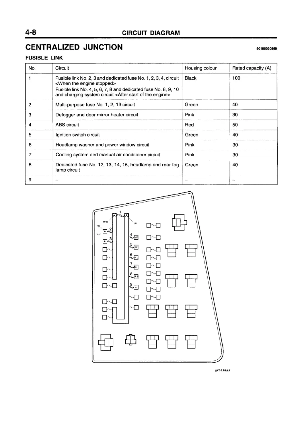
CENTRALIZED JUNCTION
FUSIBLE LINK
No. Circuit Housing colour Rated capacity (A)
1 Fusible link No. 2,3 and dedicated fuse No. 1,2,3,4, circuit <When the engine stopped> Fusible link No. 4, 5, 6, 7, 8 and dedicated fuse No. 8, 9, 10 and charging system circuit <After start of the engine> Black 100
2 Multi-purpose fuse No. 1,2, 13 circuit Green 40
3 Defogger and door mirror heater circuit Pink 30
4 ABS circuit Red 50
5 Ignition switch circuit Green 40
6 Headlamp washer and power window circuit Pink 30
7 Cooling system and manual air conditioner circuit Pink 30
8 Dedicated fuse No. 12, 13, 14, 15, headlamp and rear fog lamp circuit Green 40
9 - - -
AVO220AJ
DEDICATED FUSE
Power supply circuit No. Rated capacity (A) Housing colour Circuit
Battery/Alternator (Fusible link No. 1) 1 20 Yellow Condenser fan circuit <4G13>
2 10 Red A/C compressor circuit
3 10 Red Audio circuit, door warning lamp, front fog lamp, MPI system, MUT-II power supply, rear fog lamp and room lamp and luggage compartment lamp circuit
4 20 Yellow Central door locking system circuit
Ignition switch ACC 5 10 Red Audio circuit
- 6 - - -
- 7 - - -
Battery/Alternator (Fusible link No. 1) 8 10 Red Charging and hazard warning circuit
9 20 Yellow Cooling system <4G93>, immobilizer system and MPI system circuit
10 15 Blue ABS, MPI system <4G93> and stop lamp circuit
- 11 - - -
Fusible link No. 8 12 15 Blue Front fog lamp circuit
13 10 Red Front fog lamp, illumination, MPI system, rheostat, tail lamp, position lamp and lighting monitor buzzer circuit
14 10 Red Headlamp washer, tail lamp and poisition lamp circuit
15 10 Red Headlamp leveling system circuit, high beam indicator lamp, MPI system <4G13> and rear fog lamp circuit
- 16 - - -
- 17 - - -
- 18 - - -
- 19 - - -
MULTI-PURPOSE FUSE
Power supply circuit No. Rated capacity (A) Housing colour Load circuit
Fusible link No. 2 1 25 Transparent A/C switch (Manual airconditioner), blower motor and resistor
2 20 Yellow Sunroof-ECU
Ignition switch ACC 3 10 Red Horn and horn relay
IG1 4 10 Red Alternator relay, back-up lamp and SRS-ECU
IG2 5.... 6 10 Red ABS-ECU
20 Yellow Heated seat
IG1 7 10 Red Buzzer ass’y, combination meter and multi center display
8 - - -
Ignition switch ACC 9 15 Blue Cigarette lighter and multi-center display
10 10 Red Keyless entry receiver ECU and remote controlled mirror switch
IG1 11 10 Red Hazard warning switch and SRS-ECU
IG2 12 15 Blue Condenser fan relay <4G13>, DRL-ECU cVehicles with daytime running lamp>, defogger relay, blower relay, headlamp washer relay, outside/inside air selection damper control motor and radiator fan relay
Fusible link No. 2 13 15 Blue Combination meter and rear combination lamp (Rear fog lamp)
14 20 Yellow Column switch clntermittent wiper relay>, rear intermittent wiper relay, rear wiper motor and windshield wiper motor
CENTRALIZED RELAY
Connector No. Name Connector No. Name
A-03X Headlamp washer relay A-14X Radiator fan relay <4G13>
A-04X Alternator relay A-15X Tail lamp relay <DRL>
A-05X - B-60X J/C (1)
A-06X Horn relay B-61X J/C (2)
A-07X Fan control relay <4G93> B-62X Diode (Engine circuit)
A-08X Condenser fan relay (HI) <4G13> B-63X -
A-09X Condenser fan relay (LO) <4G13> B-64X Front fog lamp relay
A-10X A/C compressor relay B-65X Rear fog lamp relay
A-11X - B-66X Rear intermittent wiper relay
A-12X Headlamp relay B-67X Door lock ECU
— cVehicles without keyless entry>
A-13X
VO228AJ
00008422
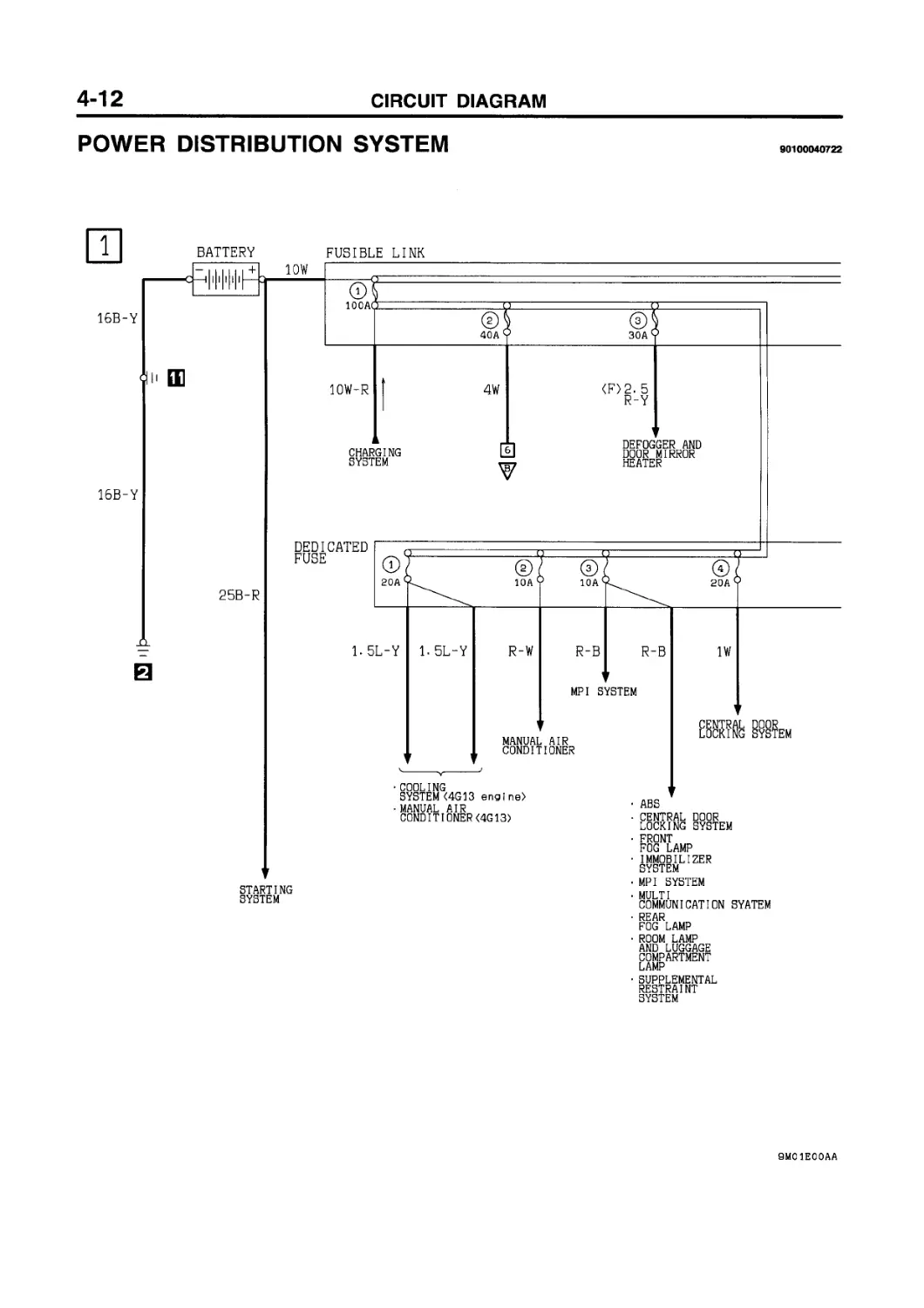
POWER DISTRIBUTION SYSTEM
90100040722
BATTERY
FUSIBLE LINK
10W
16B-Y
100AC
Q2J
40A
(3J
30A
10W-R
4W
<F>2. 5
R-Y
16B-Y
25B-R
CHARGING SYSTEM
DEDICATED FUSE
STARTING SYSTEM
6
DEFOGGER AND DOOR MIRROR HEATER
1. 5L-Y
1. 5L-Y
R-W
R-B
R-B
1W
MPI
SYSTEM
MANUAL AIR CONDITIONER
CENTRAL DOOR
LOCKING SYSTEM
• COOLING
SYSTEM <4G 13 engine)
• MANUAL AIR
CONDITIONER<4G13>
• ABS
• CENTRAL I LOCKING i
• FRONT FOG LAMP
IMMOBILIZER SYSTEM
• MPI SYSTEM
MULTI
COMMUNICATION SYATEM
• REAR FOG LAMP
ROOM LAMP
AND LUGGAGE COMPARTMENT
LAMP
SUPPLEMENTAL RESTRAINT SYSTEM
DOOR SYSTEM
2
Wi re colour code
В :Black LG:Light green G :Green
BRiBrown 0 idrange GRiGray
L :Blue W :White Y :Yellow SB:Sky blue
R :Red P :Pink V :Violet
POWER DISTRIBUTION SYSTEM (CONTINUED)
3
COMMUNICATION SYSTEM
1 2 3 4 5 6 7 в
g 10 11 12 1з|14 15 16 17 IS
OX) (B^42) (B-45) QF58)
4
5
2- 5R-B
2. 5R-B
2. 5R-B
2. 5R-B
HEADLAMP RELAY
(Flap
5
2. 5R-L
OFFTTon
4
2- 5R-L
HEADLAMP
2. 5R-L
2. 5R-B
2. 5R-B
WITHOUT WITH
DRL DRL
R-Y
HEADLAMP
<R. H. dr i ve ven i cles>
2. 5R-L
HEADLAMP
<L. H. dr i vb __
without daytime running lamp)
<Vehi с Ies with dayt i me running I amp>
HEADLAMP
<Veh i cles with daytime running I amp>
vehi cles
• HEADLAMP
REAR
FOG LAMP
REAR FOG LAMP
Wire colour code
В :Black LGiLight green
BR:Brown 0 :0range
G :Green L :Blue W :White
GR:Gray R :Red P :Pink
Y :Yellow SB:Sky blue
V :Vi о let
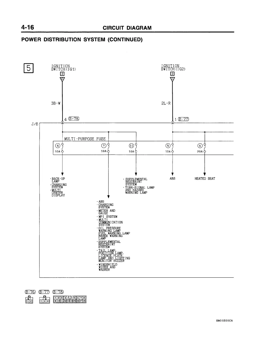
POWER
DISTRIBUTION SYSTEM (CONTINUED)
IGNITION SWITCH(IG1)
IGNITION SWITCH(IG2)
3
Ш
3B-W
2L-R
4 (OS)
1 FT?)
J/B
MULTI-PURPOSE FUSE
BACK-UP LAMP
CHARGING SYSTEM
MULTI CENTER DISPLAY
• SUPPLEMENTAL RESTRAINT SYSTEM
• TURN-SIGNAL LAMP AND HAZARD WARNING LAMP
ABS
HEATED SEAT
• ABS
CHARGING SYSTEM
METER AND GAUGE
MPI SYSTEM
MULTI COMMUNICATION SYSTEM
•OIL PRESSURE WARNING LAMP FUEL WARNING LAMP BRAKE WARNING LAMP
• SUPPLEMENTAL RESTRAINT SYSTEM
•TAIL LAMP POSITION LICENCE P LAMP AND L.....
MONITOR BUZZER
WINDSHIELD WIPER AND WASHER
,AMP, ATE UGHTING
(FT©
F77) (ЁР78)
1 2 3 4 5 lie 7 в
|g 10 11 12 1з|14 15lll6 17 1&|
SWITCH(ACC)
[U
FUSIBLE LINK ©
2L 4W
15
P(EP?6)
HORN
• CIGARETTE LIGHTER
MULTI COMMUNICATION SYSTEM
• REAR WIPER AND WASHER
• WINDSHIELD WIPER AND WASHER
SUNROOF
REAR
FOG LAMP
•DEFOGGER AND DOOR MIRROR HEATER
• HEADLAMP
(Venicies witn daytime running lamp)
• HEADLAMP WASHER
• HEATER
• MANUAL AIR CONDITIONER
SUNROOF
CENTRAL LOCKING
DOOR SYSTEM
(Veh icels With keyless entry)
• HEATER
MANUAL AIR CONDITIONER
• REMOTE CONTROLLED MIRROR
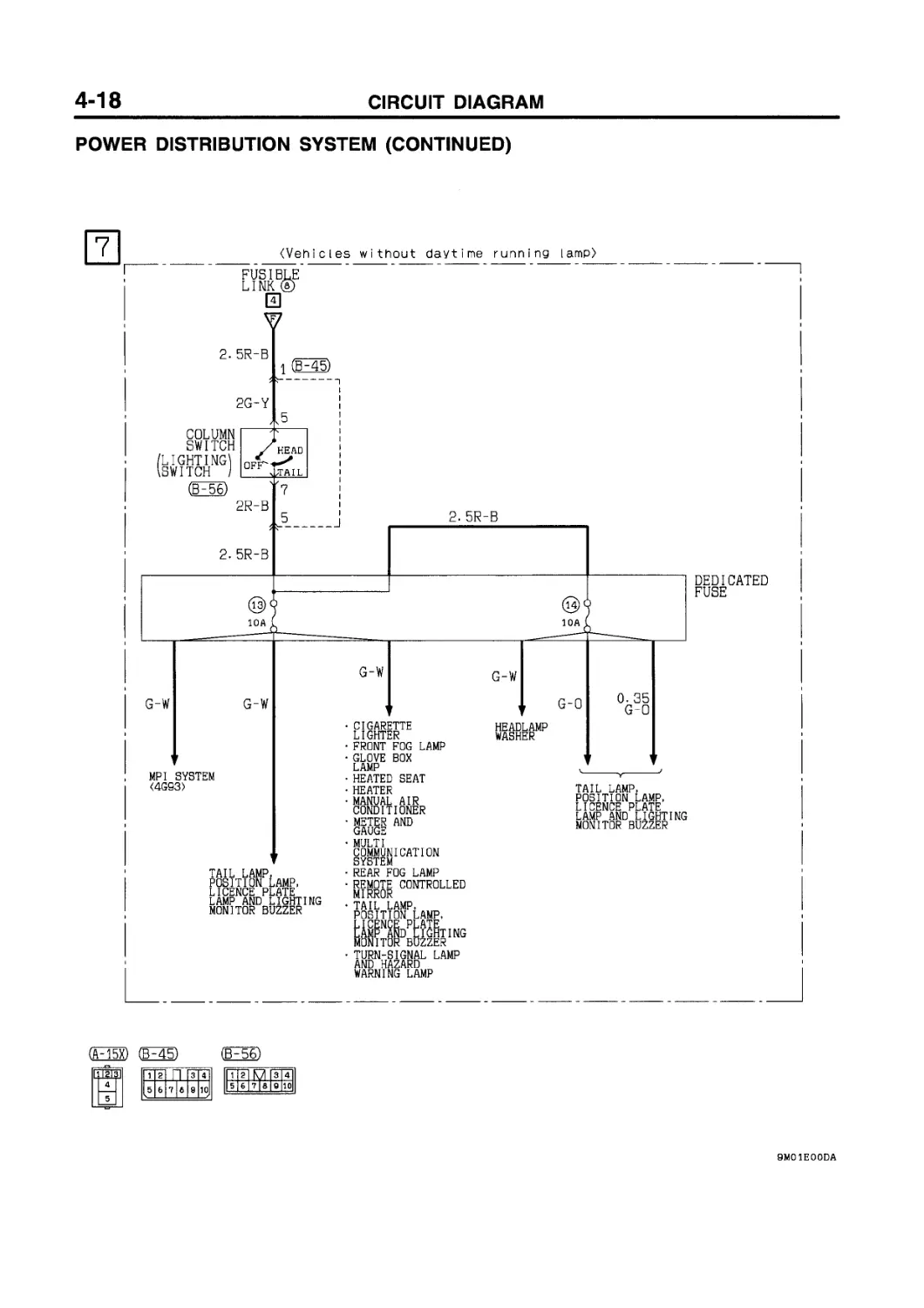
POWER DISTRIBUTION SYSTEM (CONTINUED)
(Vehicles without daytime running lamp>
FUSIBLE
LINK @
Fl
2. 5R-B
2G-Y
COLUMN
SWITCH /LIGHTING! \SWITCH I
(В^Бб)
(F15X)
I 12131
5
1 (BH45)
2R-B
2. 5R-B
2. 5R-B
DEDICATED FUSE
G-W
MPI SYSTEM <4G93>
(B-45)
G-W
G-W
G-W
TAIL LAMP, POSITION LAMP, LICENCE PLATE LAMP AND LIGHTING MONITOR BUZZER
CIGARETTE LIGHTER FRONT FOG LAMP GLOVE BOX LAMP HEATED SEAT HEATER MANUAL AIR CONDITIONER METER AND GAUGE MULTI COMMUNICATION SYSTEM REAR FOG LAMP REMOTE CONTROLLED MIRROR TAIL LAMP POSITION LICENCE P LAMP AND
,AMP, ATE ........ Lighting MONITOR BUZZI”
:r
• TURN-SIGNAL LAMP AND HAZARD WARNING LAMP
G-0
0. 35
G-0
(F56)
HEADLAMP WASHER
TAIL LAMP, POSITION LAMP, LICENCE PLATE LAMP AND LIGHTING MONITOR BUZZER
I 1 |g I П |3 4 lE6 Z1
9
10
1 2
3
5 6 7|8 9
4
10
(Vehicles with daytime running lamp)
FUSIBLE LINK @
4
• GLOVE BOX LAMP
HEATED SEAT
HEATER
MANUAL AIR CONDITIONER
METER AND GAUGE
• MULTI COMMUNICATION SYSTEM
• REAR FOG LAMP
• REMOTE CONTROLLED MIRROR
• TAIL LAMP POSITION LICENCE P LAMP AND L._......
MONITOR BUZZER
• TURN-SIGNAL LAMP AND HAZARD WARNING LAMP
tail LAMP, POSITION LAMP, LICENCE PLATE LAMP AND LIGHTING MONITOR BUZZER
MPI SYSTEM
<4G93>
tail LAMP POSITION LICENCE P
LAMP AND _____
MONITOR BUZZER
.AMP, ATE Lighting
,AMP, ATE Lighting
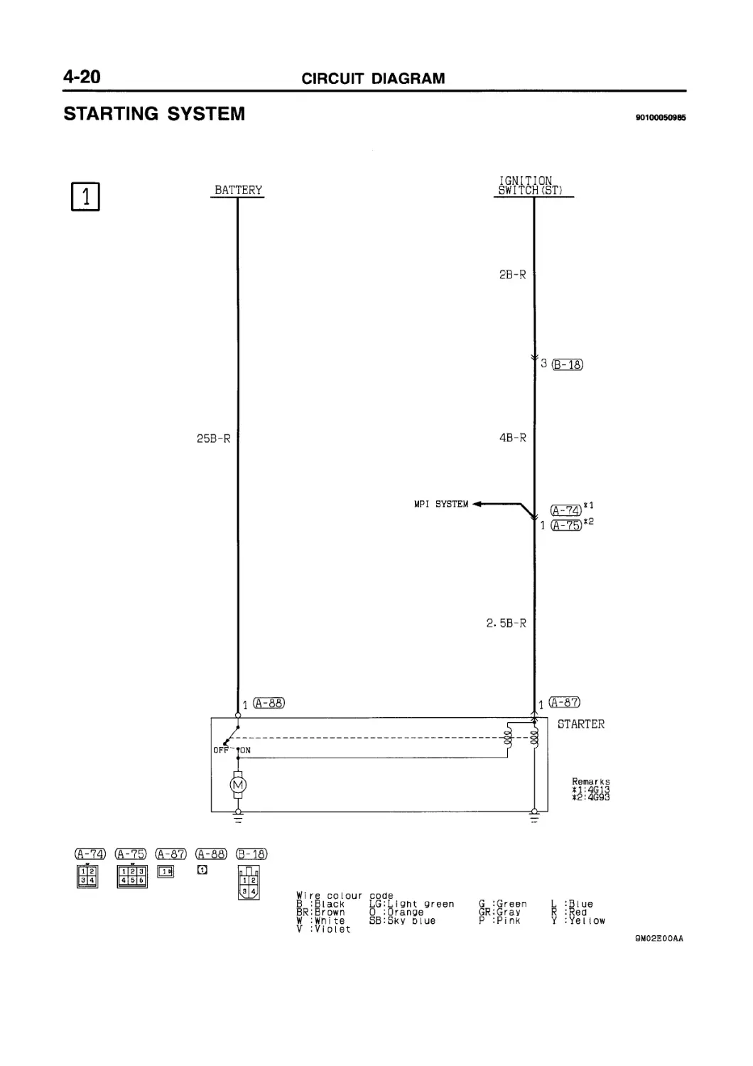
STARTING SYSTEM
90100050985
1
IGNITION
Wi re co lour code
В iBlack LGiLiont green G :Green L :Blue
BRiBrown 0 :0range GRiGray R :Red
W :Wnite SB:Sky blue P :Pink Y :Yellow
V :Violet
STARTING SYSTEM (See P. 4-20.) OPERATION When the ignition switch is turned to the ST position, the starter contacts (magnet switch) turns ON and the starter motor starts turning over. TROUBLESHOOTING HINTS 1. Starter motor does not turn over at all. • Check starter (coil). • Check battery terminals for proper contact. 2. Starter motor does not stop rotating. • Check starter (magnet switch).
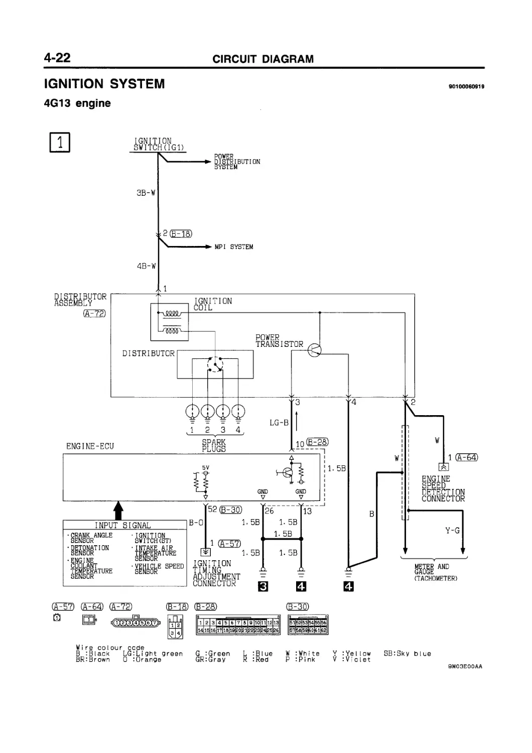
IGNITION SYSTEM
4G13 engine
90100060919
IGNITION
SWITCH(IGl)
POWER
DISTRIBUTION SYSTEM
3B-W
MPI SYSTEM
4B-W
DISTRIBUTOR ASSEMBLY
1
(F72)
DISTRIBUTOR
ENGINE-ECU
IGNITION COIL
POWER TRANSISTOR
3
12 3 4
LG-B
SPARK PLUGS
'4
52 (FW
26
13
INPUT SIGNAL
CRANK ANGLE SENSOR
•DETONATION SENSOR
•ENGINE COOLANT TEMPERATURE SENSOR
IGNITION SWITCH (ST)
INTAKE AIR TEMPERATURE SENSOR
• VEHICLI SENSOR
,E SPEED
(A-57) (A-64) (Fra
Й |f=r=|L ,-----И------.
ы фХгХзХ4МбХ7>
B-0
1. 5B
1 (F57)
1. 5B
IGNITION TIMING ADJUSTMENT CONNECTOR
1. 5B
1. 5B
1. 5B
1. 5B
В
(F18)
Гз 4]
(B-25) (F30)
Г11213 iioiiT 12I ial
Wire colour code
В :Black LG:Light green
BR:Brown 0 :Orange
G '-Green L :Blue W :White Y :Yellow
GR:Gray R :Red P :Pink V :Violet
W
1 (A-64)
I i
I
L J
ENGINE SPEED DETECTION CONNECTOR
Y-G
METER AND GAUGE (TACHOMETER)
SB:Sky blue
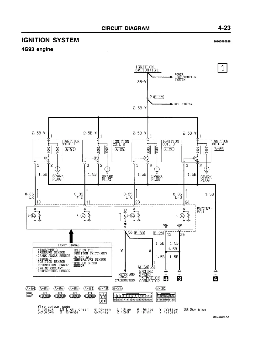
IGNITION SYSTEM
4G93 engine
90100060926
(F64) (ES) (ES) (Fsg) GF5T) (EFTS) (FgS) (EE)
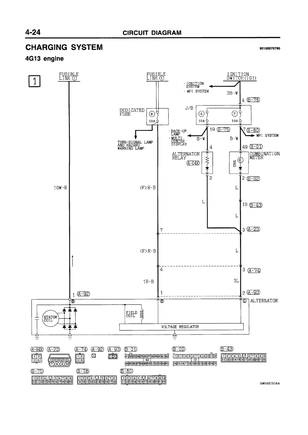
CHARGING SYSTEM
90100070790
4G13 engine
O4X) О (A~74) 02) (A~93) O' (B^oa (£43)
3 4
□
(НЕЗЭ
(£E7S)
11 2] 3 | 4 | О I 5 |6 |7 Id I 9 I
1 |2|3|Г4| M I 5 II 6 I 7 I 8
|НШД]|ЕЁЁЕ1ШШ[Е|
1 2 1112
3 4 5
6 7 8 9110
13 14 15 16|17 18 19 20 21|22
9M04E00AA
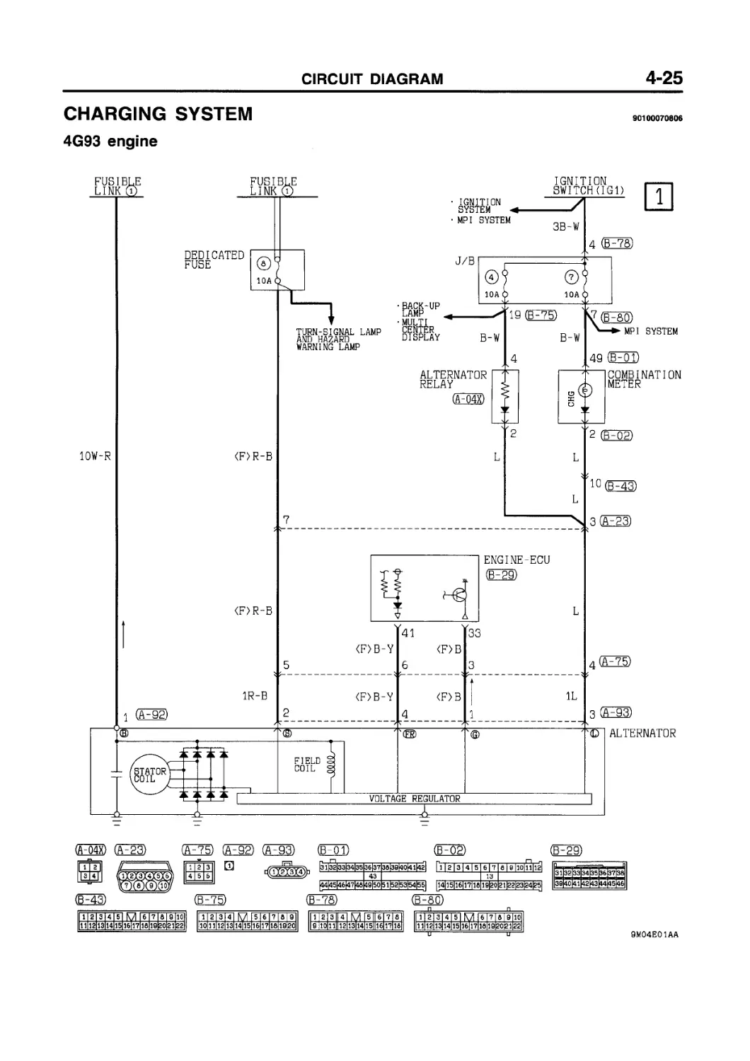
CHARGING SYSTEM
4G93 engine
90100070806
FUSIBLE
LINK CD
IGNITION SYSTEM
MP I SYSTEM
IGNITION
SWITCH(IGl)
3B-W
TURN-SIGNAL LAMP
AND HAZARD
4
BACK-UP LAMP
MULTI CENTER DISPLAY
49 (FOl)
WARNING LAMP
4
(A-Q4X)
ALTERNATOR RELAY
2
COMBINATION METER
2 (FO^
10W-R
<F>R-B
L
L
L
7
<F>R-B
5
1Q(F43)
\ 3 (03)
(A-Q4X) (F23) (05) (02) 03) (FOl) (F02)
(Fgg)
(F43)
(F75)
CHARGING SYSTEM (See P. 4-24, 25.)
OPERATION
When engine is stationary
• When the ignition switch is turned to the ON position, current flows the alternator L terminal to the field coil and, at the same time, the charge warning lamp illuminates.
When engine is started and after engine has started
• When the engine is started, the charge warning lamp goes out because of the charging voltage begin applied to the alternator L terminal.
• The battery voltage being applied to the alternator S terminal is monitored by the voltage regulator. Therefore, the amount of electricity produced by the alternator is controlled by allowing and cutting off the current flowing to the field coil.
• The alternator В terminal supplies power to each load.
Remark
The alternator relay is provided to back up the flow of current to the field coil when the charge warning lamp is open.
TROUBLESHOOTING HINTS
1. Charging indicator lamp does not illuminate when the ignition switch is turned to ON position, before the engine starts.
• Check multi-purpose fuse No. (7)
• Check the bulb.
2. Charging indicator lamp fails to switch off once the engine starts.
• Check voltage regulator of alternator.
3. Discharged or overcharged battery.
• Check voltage regulator of alternator.
4. Charge warning lamp illuminates dimly.
• Check combination meter diode (for short).
NOTES
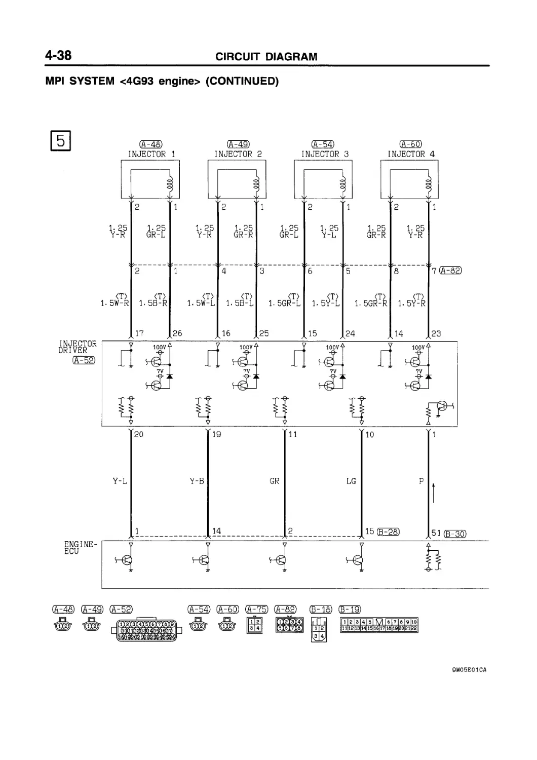
MPI SYSTEM
4G13 engine
90100081619
(F23) (EH)
O)
09) Об) 03)
О) (D-15)
Г11 г 1 з 1415 le 171 a 19|ioTiiTial
1I2I3|4|5| M I 6 17 IS I 0 1101 1112
|д]ПЗЕЕЕВЕПЗШПЗ[ЕЗ!13В
J__2_ 3 4
(HE23) (B^gg) (в^зП
MPI SYSTEM <4G13 engine> (CONTINUED)
(A~48) (F49) (A-54) (F56) (F55) (F58) (F6© (Ш (И© (А^бТ) O (FT©
4
1-5R-W 1.5R-W 1.5R-W 1. 5R-W 1. 5R-W 1.5R-W
VACUUM (A-59) OXYGEN (в-34) ci OXYGEN (D-22)
SENSOR SENSOR Ei SENSOR
(FRONT) (REAR)
(FOD F34) (Fgg)
Wi re colour code
В :Black LGiLignt green G :Green L :Blue W :White Y :Yeiiow SBiSky Clue
BR:Brown 0 :Orange GR:Gray R :Red P :Pink V :Vlolet
MPI SYSTEM <4G13 engine> (CONTINUED)
c J/B
О (MULTI-PURPOSE FUSE©)
ГЙ
IGNITION
SWITCH(ST)
VEHICLE SPEED SENSOR
OP
OS)
08) (OS) (07)
Q> ICpfell 0
(FTP OP
дП 0Й
|аТз| з 4
(Fog) га (Fig)
(EE)
(ЕЗз)
Ox)
DQEJQHD
71 a | 9 |-10|lW2l
Ipjeeeeeeeeeeieee^sebI
Il 112|3 |4Ts] M 16 I 7 I 6 I 9 |10|
1 2 3 4 5 6 7 8 8 10 11
12 13 14 15 16 17 16 IS 20 21 22
23 24 25 26 27 26 29 30 31 32 33
1 2 3 4 5 6 7 6 9 10 11
12 13 14 15 16 17 16 IS 20 21 22
23 24 25 26 27 26 29 30 31 32 33
1 2 3 4 5 6 7 6 9
|10 11 12 13 14(15 16 17 18 19 20]
DEFOGGER AND DOOR MIRROR
52
DEDICATED
FUSE @
□
20 (jp75)
8 (B^aD
0. 75Y
0. 75Y
37 (B-gg')
B-0
2 (F23)
1
1
OFF'-'jOM
22
(Y-B)
IGNITION TIMING ADJUSTMENT CONNECTOR (03
POWER STEERING OIL PRESSURE SWITCH (F38)
(B-28)
|ШЕЕшшеед^^вёдЕЕ|
(FFD
111 2 I 3 I 4 I 5 I M I 6I 7 I 6 I 9 |10|
|ШЕ[ЕЕЕЕЕЕЁШЕЕЕ£ЭЗШ
56
2 (B49)_ J Y
ABS
• CENTRAL DOOR LOCKING SYSTEM <Vehicles with keyless entry system)
G-W
G-W
21
DIAGNOSIS
CONNECTOR
Fl)
(Foo)
Fao)
(Ей)
EDESESEBESESEEES
ЩШЗЗЕЕЕШЕЕЕ
|57|5а|5о|бо|б1|б2|
27
“I J/C (2)
(F61X)
23
1
7
5
2B
2B
16
DIAGNOSIS CONNECTOR (B~35)
(в^зз)
05)
|?1|7г|73|74175|тбр7|78|т9|во|в11
Wi re colour code
В :Black LGiLight green
BR:Brown 0 lOrange
W :White SB:Sky Blue
V :Violet
21 22
26 27
13 24 25
10 3132
1эшшеееевебев!
G :Green L :Blue
GRiGray R :Red
P :Pink Y :Ye I low
MPI SYSTEM
90100081626
4G93 engine
(F23) (FOT) (5^02) (ВЧ8) (B~19)
I 11 2 I 3 I 4| 5 I M | 6 ( 7 la I 8 ilOl
(рПз) (рЧб)
(B^26) (ЁПГ?)
11 |2| 111 2 I 3 4 3 4
~Пг] М
5 6 7|8
_3 _4 6 10
(F28) (B^gg) (ёьзП (в^зэ) (ЕЗЭ CFZs)
1 2 3 4 5 6 7 6 I 9 110
11 12 13 14 15 leliT IS 19 2o|21|22
1 2 1,1 3 4
5 4_J 6 7 |в 9 10 _z
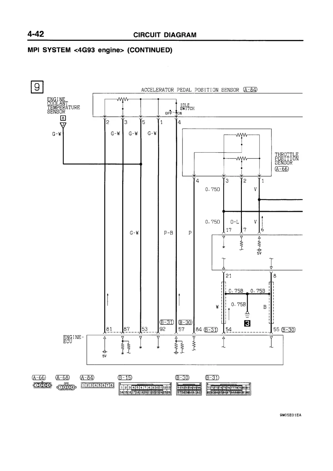
MPI SYSTEM <4G93 engine> (CONTINUED)
^52) (ДТ53) (ДТ35)
(Fap
(ВИ5) (B~28)
(5^32)
03
3 I 4
Wire col our code
В :Black LGiLiaht areen G :Green L :Blue W :White Y :Yellow SB:Sky blue
BRiBrown 0 :0range GRiGray R :Red P :Pink V iviolet
MPI SYSTEM <4G93 engine> (CONTINUED)
ENGINEER
(E28)
fl I 2 I Э Г4 I 5 I 6 I 71 8 I 9 110|11112|1з|
(Fao)
Г1 12 I 3T41 5 I el
|ПИНЕЕШШ|
ОНИ) (FS^
Wi re co lour code
В :Black LG:Light green G :Green L :Blue W :Wnite
BR:Brown 0 :0range GR:Gray R :Red P :Pink
Y :Ye I low V :Vi 0 let
SB:Sky blue
MPI SYSTEM <4G93 engine> (CONTINUED)
CF50) (А^ББ) (A-5&) @762) EE) (FT© (F73)
Iffi Л dh ЛЧФЫФМ1
ЧкЧлЗХбиг i=====j
(O© (O© (FaD (F83)
(A33)
5
(£28)
(ЕзБ
^ЭЭЁЯЕВЕЁЕЁВЗЗ
|т 1|?г|7з]т4Ь5|7б|тт|?в|?9|воЬ 11
TfT
Wi re co lour code
В :Black LGiLignt green
BRiBrown 0 :0range
G :Green GR:Gray
L :Blue W :White Y :Yellow SB:Sky blue
R :Red P :Pink V :Violet
MPI SYSTEM <4G93 engine> (CONTINUED)
(Об) (05) О
(ЕНЕ)
О) (BED
f 1121 з [71 5^|Т|71Т|^|1о|и|12|1з|
M А И1Ф1Ф№1»1|
MPI SYSTEM <4G93 engine> (CONTINUED)
J/B
(F23)
(A-38)
(ra) (F7T)
(EFTW
(BH28)
(OlX)
ЕШЁЩйВИЕШШ ШЕЁШЕЕШЕШН
1ЕДЕЕЕЕВШШШЕВЕЭЭЗВ
2 3 4 5 6 7 8 9 10
13 14 15 16 17 IB 19 20 21
23 34 25 26 27 28 29 30 31 32
од
в
1 3 M 6 8 9
|io|i 112 1 3 14|15 1 6171 elwfeol
11 I 21 3141 5 [ M I 6 17 IВ 19 |10|
|Щ[ЕЕШШШШЕП~ВЗИ
(И)
(Ею)
(В^ЗБ
(R-35) PROMT
'п side
(Г60Х)
ЁИЁЭЁЕЕЕЩЕЗ
2i|22l I23I24I25
гб|27|га|29|зо|з1|з2
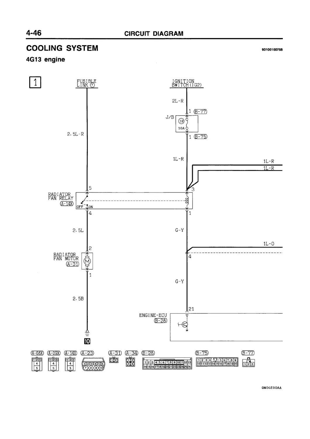
COOLING SYSTEM
4G13 engine
90100100758
(OSX) (Hl) (£^23) (А^ЗТ) (АЧЙ) (В^З® (F75) (В7??)
FUSIBLE LINK®
2
Wi re co lour code
В :Black LG:Light green G :Green L
BRiBrown 0 :0range GR:Gray R
:Вlue W :White Y :Yellow SB:Sky blue
: Red P : PI nk V : VI о I et
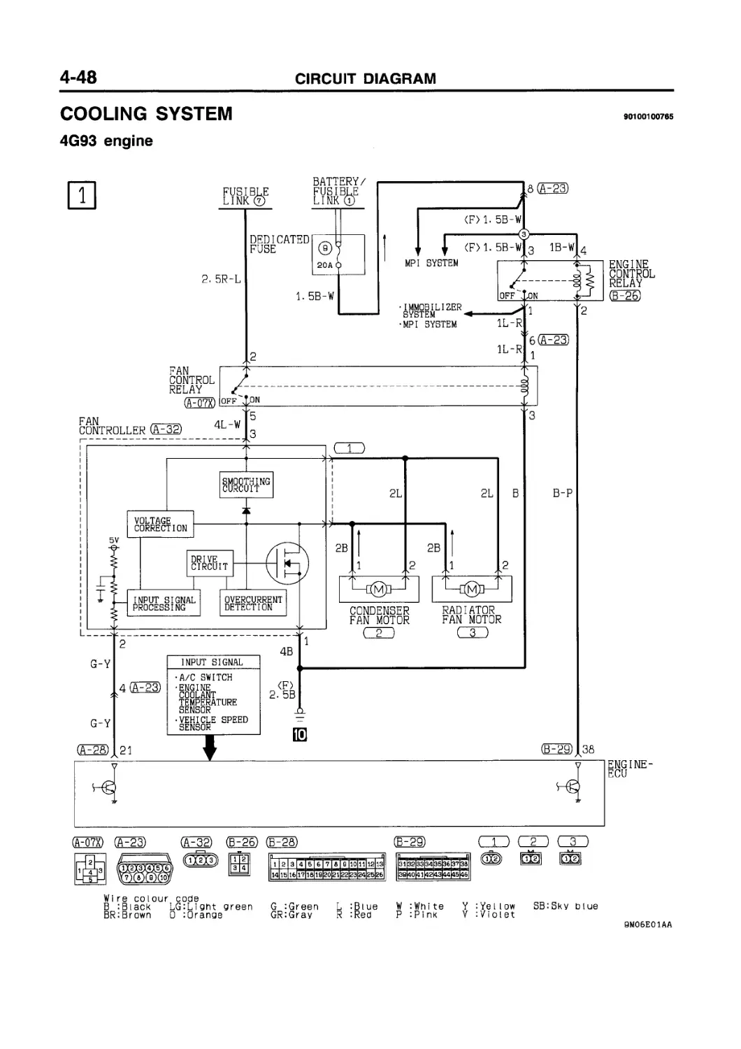
COOLING SYSTEM
4G93 engine
90100100765
ENGINE
CONTROL
RELAY
(£26)
ENGINE-
ER
(A-Q7X) (£23)
(£32)
£26)
(£28)
(B-29)
Ifrryj luiz;
Wi re colour code
В :Biack LG:Lignt green
BRiBrown 0 :Orange
G :Green L :Blue
GRiGray R :Red
W :White Y :Yellow SBiSky blue
P : P i nk V :Violet
BM06E01AA
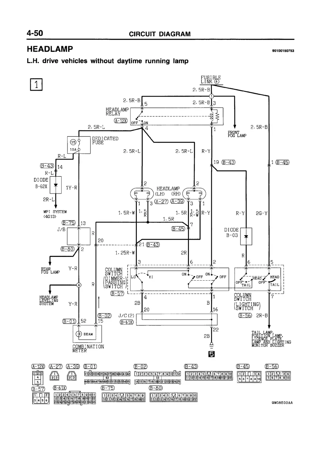
HEADLAMP <Vehicles without daytime running lamp> (See P. 4-50, 51.)
OPERATION TROUBLESHOOTING HINTS
Headlamp Relay ON Conditions Refer to the table below.
<Low-beam operation»
• Placing the lighting switch in the HEAD position causes the headlamp relay to be energized.
• If the dimmer/passing switch is placed in the LO position at this time, the headlamps light up in low beam.
<Upper-beam operation»
• Placing the lighting switch in the HEAD position causes the headlamp relay to be energized.
• If the dimmer/passing switch is placed in the HI position at this time, the headlamps light up in upper beam.
<Upper-beam indicator lamp»
• This lamp lights up when the upper/passing beams are on, indicating that the headlamps are on in upper beam.
<Passing operation»
• When the dimmer/passing switch is set to the “ON” position, the headlamp relay is switched ON and the upper beam of the headlamps illuminates.
1. Headlamps don’t go on.
1) But the tail lamps illuminate.
• Check the headlamp relay.
• Check the lighting switch.
2) The tail lamps also don’t illuminate.
• Check the fusible link No. (8).
2. The low beam at both sides doesn’t illuminate.
• Check the dimmer switch LO contacts.
3. The upper beam at both sides doesn't illuminate.
1) The passing signal functions OK.
• Check the dimmer switch HI contacts.
2) The passing signal doesn’t function.
• Check the dimmer switch.
4. One headlamp doesn't illuminate.
• Check the lamp bulb.
5. Can’t switch from low to upper beam or vice-versa.
• Check the dimmer switch.
6. Upper-beam indicator lamp does not go on.
1) Headlamp upper beams are operational.
• Check dedicated fuse No. (15).
• Check the indicator lamp bulb.
2) Headlamp upper beams doesn’t illuminate.
• Check the dimmer switch.
Lighting switch Dimmer/passing switch Headlamp relay
“HEAD” — ON
— ON ON
HEADLAMP
90100150753
L.H. drive vehicles without daytime running lamp
METER
(A-12X) (F27) (F39) (B^OD
(B^OR) (B~43)
1 2 3 4 5 6 7 в 9 10
11 12 13 14 15 1б|17 IB ia 20 21 22|
СВ-1Г?) (BzfeW
P~| П |g~| 3 4 | 5 6
|23|24|25|26|27|2B|29|30|31|32|33|
1112| 3| 4 I 5 I 6 I 7 I 5 I allOlllI
1 2 3 4 5 6 7 8 9
10 11 12 13 14|15 16 17 18 1G 20
1 2 3 4 5 6 7 8 9 10
11 12 13 14 15 1б|17 18 19 20 21
9M0&E00AA
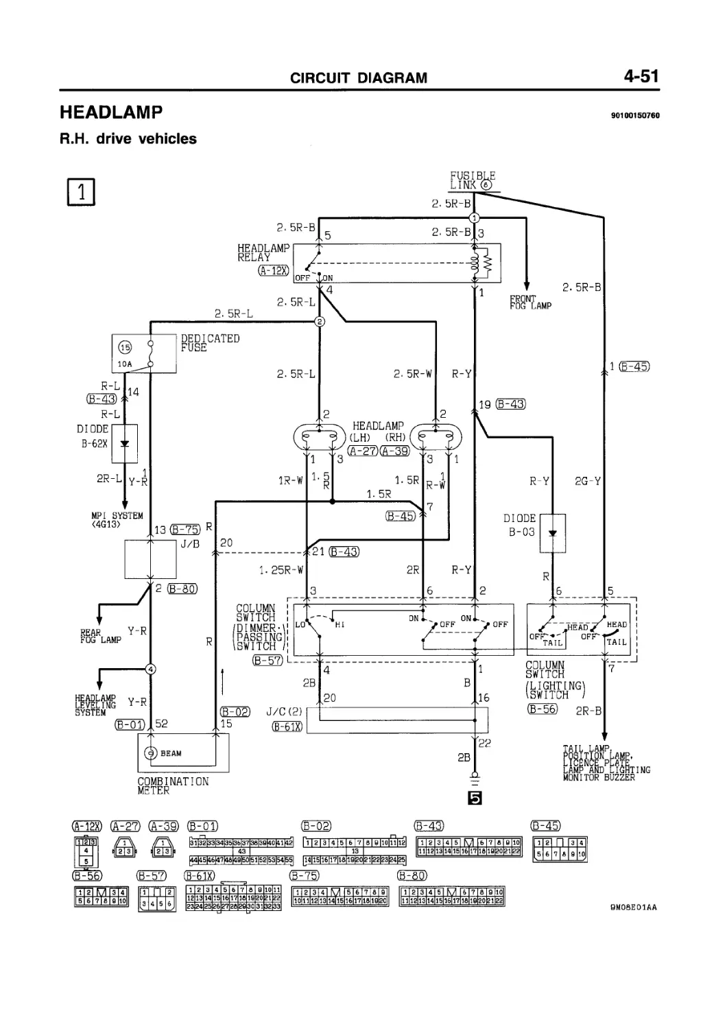
HEADLAMP
R.H. drive vehicles
90100150760
METER
(£01)
И)
(£43)
jHEBgE!EEEEgHEEg3EE]EElEHESI
SEES] ЕЕЕВЕЗЕЕНЕПЗИИ^ИШЕЕИШЕШИ 3133^1 S!1SI
(£61X)
43
(£75)
|EEEEEEEEEEEEEEEE2i]3J^I
|g3|24|25|26]27|28|29j30|31|32|33|
1 2 4 M 7 I a I 9 10
11121 3 141 5 16Ц71 8 lapopi 22
(£45)
11 el П з a s
5 6 7 18
10
(£80)
|ШШЕЕЕЕЕЕЕЕБШШ1Е^1|
1 2 3|4 5 6|7 8 9 10
111 12 13|14 15 1б|17 18|19 20р1 gg|
SMOfiEOlAA
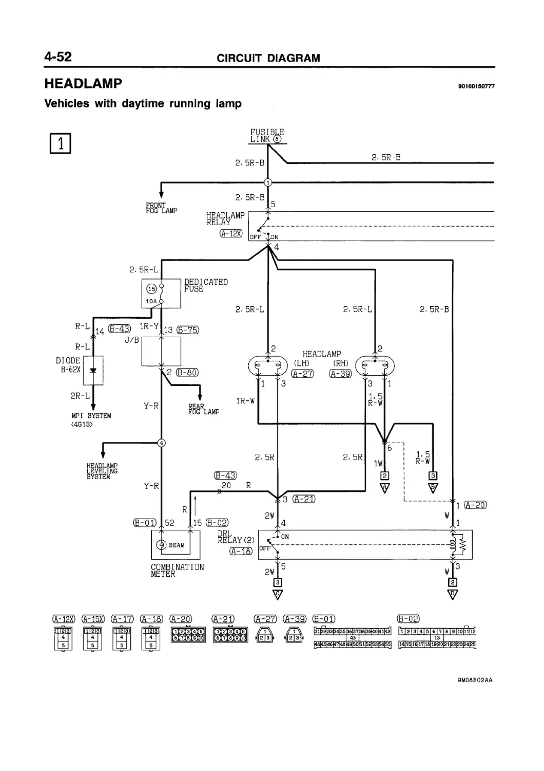
HEADLAMP
90100150777
Vehicles with daytime running lamp
(F12X) гпётзп 4
5
(йТэх) (FT?) ra Грйз]| |ИЩ]| irpilal 4 4 4
5 5 5
(Oo) (ОТ)
(ATT) (OS)
веоооИ 00000 |еееофМ1о€>0ОФ-|
(М2)
(BTT)
SYSTEM
(Е7Э
(B~43)
(Ft?) (Tao)
ГЧ nf^3l
Wire col our code
В :Black LGiLight green
BRiBrown 0 :Oranoe
G :Green L :Blue W :White
GR:Gray R :Red P :Pink
Y :Ye I low SB:Sky blue
V :Viо let
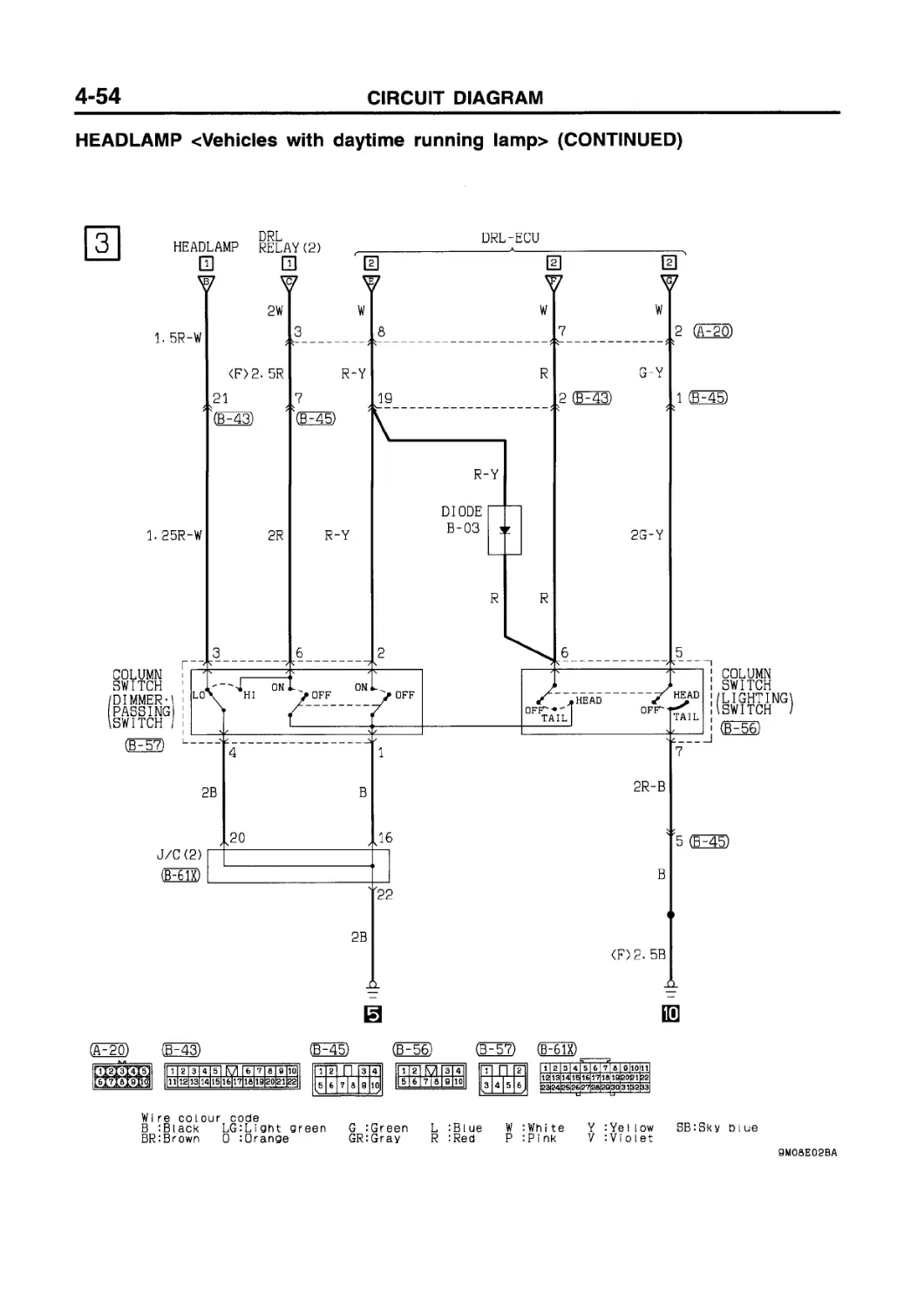
HEADLAMP cVehicles with
daytime running lamp> (CONTINUED)
(3H57)
ГТ п F|
3 4 5 6
ЕЕЕЕЕЕЕЕЕЕЕЕШЕ33513
|23j24|2S|26j27|2S|29|30|31|3S|33|
(F61X)
I 11 2 |з| 4Г5 I 6 ! fi I SllOlllI
Wire col our code
В :Black LG:Light green G :Green L :Blue
BRiBrown 0 :0range GR:Gray R :Red
W :White Y :Yellow SB:Sky blue
P :P i nk V : Vi 01et
HEADLAMP <Vehicles with daytime running lamp> (See P. 4-52.)
OPERATION TROUBLESHOOTING HINTS
Headlamp Relay ON Conditions Refer to the table below.
<Daytime running lamp operation>
• Turning the ignition switch to the ON position causes the headlamp relay, daytime running lamp relay (I), and tail lamp relay to be energized, which causes the headlamps, tail lamps, etc. to go on.
<Low-beam operation>
• Placing the lighting switch in the HEAD position causes the headlamp relay and daytime running lamp relay (II) to be energized.
• If the dimmer/passing switch is placed in the LO position at this time, the headlamps light up in low beam.
<Upper-beam operation>
• Placing the lighting switch in the HEAD position causes the headlamp relay and daytime running lamp relay (II) to be energized.
• If the dimmer/passing switch is placed in the HI position at this time, the headlamps light up in upper beam.
<Upper-beam indicator lamp>
• This lamp lights up when the upper/passing beams are on, indicating that the headlamps are on in upper beam.
<Passing operation>
• When the dimmer/passing switch is set to the “ON” position, the headlamp relay is switched ON and the upper beam of the headlamps illuminates.
1. Headlamps don’t go on.
1) But the tail lamps do illuminate.
• Check the headlamp relay.
• Check the lighting switch.
2) The tail lamps also don’t illuminate.
• Check the fusible link No. (8).
2. The low beam at both sides doesn’t illuminate.
• Check the dimmer switch LO contacts.
3. The upper beam at both sides doesn’t illuminate.
1) The passing signal functions OK.
• Check the dimmer switch HI contacts.
2) The passing signal doesn’t function.
• Check the dimmer switch.
• Check the daytime running lamp relay (П).
• Check the daytime running lamp control unit.
4. One headlamp doesn’t illuminate.
• Check the lamp bulb.
5. Can’t switch from low to upper beam or vice-versa.
• Check the dimmer switch.
6. With the ignition switch at the “ON” position, the headlamps’ low beam does not illuminate.
• Check the daytime running lamp relay (I).
• Check the daytime running lamp control unit.
7. Upper-beam indicator lamp does not go on.
1) Headlamp upper beams are operational.
• Check dedicated fuse No. (15).
• Check the indicator lamp bulb.
2) Headlamp upper beams doesn’t illuminate.
• Check the dimmer switch.
Ignition switch Lighting switch Dimmer/passing switch Headlamp relay
“ON" “OFF” — ON
— “HEAD” — ON
— — "PASS” ON
HEADLAMP LEVELING SYSTEM
90101250230
(F25)
(A-41;
dxi^j
(BH43)
(E38)
(EE®
(F75)
F81)
1 2 3 4 5 6 7 8 9 10
111 12 13 14 15 1б|17 18 19 20 21 22|
Wi re colour code
В :Black LG:Light green G :Green L :Blue W :White Y :Yellow SB:Sky blue
BR:Brown 0 :Orange GR:Gray R :Red P :Pink V :Violet
HEADLAMP LEVELING SYSTEM (See P. 4-56.)
OPERATION TROUBLESHOOTING HINTS
1. Headlamps angle-downward operation
• When the lighting switch is set to the “HEAD” position, the headlamp relay is switched ON, and battery voltage is applied, through the headlamp-leveling unit, to dedicated fuse No. (15).
• When the headlamp-leveling switch setting is changed from “0” to “1”, the positive (+) input terminal voltage of the comparator OP AMP 1 (located within the headlamp-leveling unit) becomes greater than the negative (-) input terminal standard reference voltage value, and OP AMP 1 outputs HIGH signals to OP AMP 2 and OP AMP 3.
• As a result of these HIGH signals, OP AMP 2 outputs LOW signals and OP AMP 3 outputs HIGH signals to the motor-control IC.
• When this happens, the motor-control IC is switched ON, current flows to the motor, and the motor rotates in the forward direction.
• The rotation of the motor, after passing through the gears and the output shaft, causes the headlamp reflectors to move to a downward angle, thus changing the angle of headlamp illumination.
• At this time, the position-detection sliding resistance is activated in the direction of the low resistance value, after which the OP AMP 1 negative (-) input terminal voltage value and positive (+) input terminal voltage value become equivalent, and OP AMP 2 and OP AMP 3 both output HIGH signals.
• When this happen, the motor-control IC is switched OFF and the motor stops.
NOTE
( 1) The same operation occurs if the headlamp-leveling siwtch is set to another position.
( 2) The input open protection circuit functions to stop the operation of the motor if there is an abnormal condition, such as damaged or disconnected wiring within the headlamp-leveling unit or of the wiring harness.
2. Headlamps angle-upward operation
• The headlamp angle-upward operation is the opposite logic of the downward operation; the motor operates in the reverse direction and then stops.
1. Absolutely no change of the headlamp angle (1) The upper-beam indicator lamp illuminates.
• Check the headlamp-leveling switch.
• Check the headlamp-leveling unit.
(2) The upper-beam indicator lamp does not illuminate.
• Check dedicated fuse No. (15).
2. There is one setting of the headlamp-leveling switch at which the headlamp angle does not change.
• Check the headlamp-leveling switch.
TAIL LAMP, POSITION LAMP, LICENCE PLATE LAMP AND LIGHTING MONITOR BUZZER
90100170193
(F23) (A^SS) (A-40) (В^ЗО)
22232233 3)*ё
GE60X) (£75)
11 2 I 3 I 4 I R7 I 5 I 6 I 7|&I 9
IGNITION
SWITCH(IGl)
(РЧ9)
(FTa) F7g) (в^йо)
|ИШШ1ЕЁЁЕЕЕ1Ш!ЕШ|
|[l|S|3|4|5|6|?|8|9|10j|
1 2 3 4 5 6 7 8 0 10
111 12 13 14 15 1б|1Т 18 19 20 21 22|
ilshhl о |5||б|?|в
2
Wire cdiour code
В :Black LG:Lignt green
BR:Brown 0 :0range
G :Green L :Blue
GR:Gray R :Red
W :Wnite Y :Yeilow SB:Sky blue
P : P i nk V :Vi оlet
TAIL LAMP, POSITION LAMP, LICENCE PLATE LAMP AND LIGHTING MONITOR BUZZER cVehicles without daytime running lamp> (CONTINUED)
FUSE ®
□
J/B
0. 35G-0
0.85G-W
,51S (F43)
J/C (1) (В^ббх)
G-W
L
*2
(F43) (ЁЕ60Х)
(РЧ6)
11 2 I 3 I 4 I 5 I Г7 |6 I 7 Id |9 |10[
1 2 3 4 5 6 7 6 9 10 11
12 13 14 15 16 17 16 19 20 21 22
23 24 25 26 27 26 29 30 31 32 33
1 2 3 4 5 6 т| 10 10
11 12 13 14 15 1б|17 16 ia|2 Ф1 ?2
(Г^СЗ) (F^M)
~П M [^1 EBB з |4 I 5 6 | y 4j sJ 6j 7J e
(М2) (FM3)
(FT6) driT2j|i
Wire colour code
В :Black LGiLight green
BRiBrown 0 :0range
G :Green L :Blue
GRiGray R :Red
W :White Y :Yellow SB:Sky blue
P :Pi nk V : VIolet
TAIL LAMP, POSITION LAMP, LICENCE BUZZER (See P. 4-58, 62.)
OPERATION
1. Vehicles without daytime running lamp.
• When the lighting switch is turned to the “TAIL” or “HEAD” position, current is supplied to each lamp, causing them to illuminate.
2. Vehicles with daytime running lamp.
• Placing the lighting switch in the “TAIL” or “HEAD” position causes the tail lamp relay to be energized.
If the ignition switch is turned to the “ON” position, the tail lamp relay normally is always “ON”.
• As a result, current flows by way of dedicated fuse No. (13) and No. (14) to each lamp, causing the lamp to go on.
cLighting monitor buzzer operation>
• When the lighting switch is in the “TAIL” or “HEAD” position, if the ignition switch is turned to the “ACC” or “LOCK” position or if the ignition key is removed, the lighting monitor buzzer will sound when the driver’s side door is opened as a warning to the driver.
PLATE LAMP AND LIGHTING MONITOR
TROUBLESHOOTING HINTS
1. No lamp go on.
1) Headlamps do not go on, either.
• Check fusible link No. (8).
2) Headlamps go on.
• Check tail lamp relay.
• Check dedicated fuse No. (13) and No. (14).
2. Lighting monitor buzzer does not sound.
1) Tail lamps go on.
• Check lighting monitor buzzer.
• Check front door switch (driver’s side).
TAIL LAMP, POSITION LAMP, LICENCE PLATE LAMP AND LIGHTING MONITOR BUZZER
Vehicles with daytime running lamp
IQ
(A-15X) OS)
(FTP
(£56)
SETS)
o©©o© 0OQO>X
O00O0 0О0ОФ
(A^SS) (F40) F45;
Щ1М. 5 6 7 8
3 4
9 10
(ГбОХ)
1 2 3 4 5 6 7 8 9 10 11
12 13 14 15 16 17 16 19 20 21 22
23 24 25 26 27 28 29 30 31 32 33
1 2 3 I 4 5 6 7 8 |9
10 11 1213 14|15 16 17 18 igpo
IGNITION
SWITCH(IG1)
(ЁР78)
111 г I з II41 K7| 15II e I t I e
|ВШШ1ЕЕЁЕ1ШШВЭ|
(ЁР79)
|p |2|3|4|5|e]7|a|B|10j|
(РЛ9)
2
Wi re co lour code
В :Black LG:Light green G :Green
BR:Brown 0 :0range GR:Gray
L :Blue W :White Y :YeUow SB:Sky blue
R :Red P :Pink V :Violet
TAIL LAMP, POSITION LAMP, LICENCE PLATE LAMP AND LIGHTING MONITOR BUZZER cVehicles with daytime running lamp> (CONTINUED)
H) та о (гчи) o) s
О (ЁЛз)
11 2| 3 I 4 I 5 I M I 6 I 7 Id I 8 llOl
1 2 3 4 5 6 7 d 9 10 11
12 13 14 15 16 17 Id 18 20 21 22
23 24 25 26 27 2d 29 30 31 32 33
s ijriMb
Wire col our code
В :Black LG:Lignt green
BR:Brown D :Qrange
G :Green L :Blue W :White Y :Yellow GRiGrav R :Red P :Pink V :Yiolet
ВВ:8ку blue
FRONT FOG LAMP (See P. 4-66, 68.)
OPERATION
1. Vehicles without daytime running lamp.
• When the lighting switch is at the “TAIL” or “HEAD” position and the front fog lamp switch is turned to “ON”, the front fog lamps illuminate.
2. Vehicles with daytime running lamp.
• Placing the lighting switch in the “TAIL” or “HEAD” position causes the tail lamp relay to be energized.
If the ignition switch is turned to the “ON” position, the tail lamp relay normally is always “ON”.
• When the front fog lamp switch is turned “ON” in this condition, the front fog lamp goes on.
TROUBLESHOOTING HINTS
1. The front fog lamp does not light up.
1) The tail lamp lights up.
• Check front fog lamp relay.
• Check front fog lamp switch.
• Check dedicated fuse No. (3).
FRONT FOG LAMP
90101190297
Vehicles without daytime running lamp
1112131415 |б|7|б|9 liollll
OS) O) (FOI)
|э1йз3|34|35|3б|37|3в|3а|4о^1|4г1
|23|24|25|2б|27|2а|29|30|31)32|33|
(Д OD1
1 2 3 4 5 6 7 d 9
10 11 12 13 1415 16 17 id 19 20
Wire col our code
В :Blaok LGiLight green G :Green
BR:Brown 0 :0range GR:Grav
L :Blue W :White Y :Yellow SB:Sky blue
R :Red P :Pink V :VIolet
ЭМОЙЕОбАВ
FRONT FOG LAMP
90101190303
Vehicles with daytime running lamp
(ЙЧ5Х)
GEE©
(A~2T)
~ТгТэ1 4 "Г
oeooG OOOO'b
O0OO0 0О0ОФ
(A3© (EFoT)
|31|32|33|34|35l36t37pa|3a|40|41|42|
(6^42)
1 2 3 4 5 6 7 в
9 10 11 12 1з|14 15 16 17 18]
(B~45)
111gI П F7
10
5 6 7 18
9
1 2
3 4
5 6 7|B 9 10
B-8
11 2 I 3 I 4 I 5 I Г7 I 6 17 |8| SllOl
(EHS)
I1 |g| M |3|4 | 5 16 171819110
(F60X)
OS1
1 2 3 4 5 6 7 8 8 10 11
12 13 14 15 16 17 18 18 20 21 22
23 24 25 26 27 28 29 30 31 32 33
1 2 3 4 5 6 7 a 19
10 11 12 13 m|15 16 17 18 igpo
Wi re colour code
В :Black LG:Light green G :Green L :Blue
BRiBrown 0 :0range GR:Gray R :Red
W :White Y :Yeilow SB:Sky blue
P :Pi nk V :Vi о let
REAR FOG LAMP
90101200389
Vehicles without daytime running lamp
(ВЕЛЮ (Ш (ЁР75) (F76) (ra (EFaT)
Wi re go lour code
В iBlack LG:Liaht green G :Green L :Blue W :White Y lYellow SB:Skv blue
BRiBrown 0 :0range GR:Gray R :Red P :Pink V iViolet
REAR FOG LAMP cVehicles without daytime running lamp> (CONTINUED)
(D46)
I 11 2 I 3 I 4 I 5 I Г7 I 6 I 7 I fl I 8 |10|
(EEED OS
|з 1|32|33|34|35|36|37|38|3S|4°H1
|ШЕЕЕЕЕЕБЙЗШЕВ1Е^Э1^1
Wi re colour code
В :Black LG:Light green G :Green L :Blue
BR:Brown 0 :0range GR:Gray R :Red
P
:Wh i te Y :Ye I Iow :Pi nk V :Vi diet
SB:Sky blue
REAR FOG LAMP (See P. 4-70, 74.)
OPERATION
Rear Fog Lamp Relay ON Conditions
cVehicles without daytime running lamp>
Refer to the table I.
cVehicles with daytime running lamp>
Refer to the table II.
• Placing the lighting switch in the “HEAD” position causes the rear fog lamp relay to be energized.
For vehicles with daytime running lamps, if the ignition switch is in the “ON” position, and the lighting switch is in the “OFF” position, the rear fog lamp relay will be energized.
• When the rear fog lamp switch is turned “ON” in this condition, the rear fog lamp goes on.
I
TROUBLESHOOTING HINTS
1. The rear fog lamp does’t illuminate.
1) Headlamps go on.
• Check the rear fog lamp relay.
• Check the rear fog lamp switch.
• Check the dedicated fuse No. (13).
1) Headlamps do not go on, either.
• Check the lighting switch.
• Check the fusible link No. (8).
2. The rear fog lamp at the one side does’t illuminate.
• Check the lamp bulb.
Ignition switch Lighting switch Rear fog lamp relay
— “HEAD" ON
II
Ignition switch Lighting switch Rear fog lamp relay
— “HEAD” ON
“ON” “OFF” or “HEAD” ON
REAR FOG LAMP
90101200396
Vehicles with daytime running lamp
(F12X) (АЧ5Х) (F20)
(F2l)
(HEED (ЁЬБ?)
’H3 Д
бМ» а
O0OO0 OOOO-l
1 2 и 3 4
5 kJ 6 т | а 9 10 L-?
1 2_ 5 6
3 4_ a io
_1_ 2. 5 6
з_ A
9 10
И п И |з 4 15 6 J
11 2 I 3 I 4 I 5 | О |6 I 7 Ifi Id 110|
RS
(B-75)
(ЁР76) (Rao)
1 2 3 4 5 6 7 6 9 10 11
12 13 14 15 16 1? 18 19 20 =1 22
23 24 25 26 27 28 29 30 31 32 33
ЕШ 4
5
11 2 1 3 | 4 I 5 I M I 6 I 7 I 8 I 9 |10|
|щ{Е11ЕЕВЕЕШЕВШ^^Е%1
Wire col our code
В :Black LG:Light green
BR:Brown 0 :Orange
G :Green L :Blue W iWhite Y :Yellow SB:Sky blue
GR:Gray R :Red P :Pink V :Violet
SMOaEOSAB
REAR FOG LAMP cVehicles with daytime running lamp> (CONTINUED)
(FoT)
|31|32|33|34|35|36|3T|3a|39|40|41|42]
1 2 3 4 5 6 7 8 ЕКП
12 13 14 15 16 17 18 19 333JS
23 24 25 26 27 28 22 30
(РЧ6)
(F~0~l) (F^03)
1 2 4 R7 7|8|9|10
11121 3141 516Ц71 8 19|20|21|22
Wire colour code
В ;Btack LGiLiaht green G :Green L :Blue W :Wnite Y lYellow SB:Sky blue
BR:Brown 0 :0range GR:Gray R :Red P :Pink V :Vioiet
ROOM LAMP AND LUGGAGE COMPARTMENT LAMP (See P. 4-78, 80.)
OPERATION
<Room lamp>
• Placing the room lamp switch in the ON position causes the room lamp to come on at all times.
• Opening any one of the doors with the room lamp switch in the DOOR position causes the room lamp to come on.
• Closing all doors causes the room lamp to go out.
cLuggage compartment lamp>
• Battery voltage is being applied at all times to the luggage compartment lamp through the dedicated fuse No. (3).
• Opening the tailgate turns ON the tailgate switch, causing the luggage compartment lamp to light up.
TROUBLESHOOTING HINTS
1. Room lamp does not come on.
1) Rear fog lamp does not illuminate.
• Check dedicated fuse No. (3).
2) Room lamp does not come on when any door is opened with the room lamp switch in the DOOR position.
• Check bulb.
• Check room lamp switch.
3) Room lamp does not come on when a door is opened with the room lamp switch in the DOOR position.
• Check door switch (of the suspected door).
2. Luggage compartment lamp does not come on.
1) Room lamp is normal.
• Check bulb.
• Check tailgate switch.
2) Room lamp does not illuminate.
• Check dedicated fuse No. (3).
ROOM LAMP AND LUGGAGE COMPARTMENT LAMP
90101320269
Vehicles without keyless entry system
FUSIBLE LINK®/ ALTERNATOR
ROOM LAMP (FTP
*2
(FOP
|з1|й|зз|34^5|зб|зт1за|за|40|4 i|4a|
(F69)
(ЁЕ75)
'Fl (ЁР8Р (FOP
3 4 I 5 6
1 2 3 4 5 6 7 8 9
|10 11 12 13 14)35 16 17 18 19 2o|
111а|з 14| 51 f\7 16171e|aliol
И
FRONT DOOR SWITCH REAR DOOR SWITCH
(Foa) (FTD (оИб)
(F19) (Fog) (F04)
(F06) (FOT) (F08) (FT4)
E3
E3
4 5 I & 7 a
И
Wire col our code
В :Black LG:Lignt green
BR:Brown 0 :0range
G :Green L :Blue W :White
GR:Gray R :Red P :Pink
Y :Ye I low SB:Sky blue
V :VI о 1et
ROOM LAMP AND LUGGAGE COMPARTMENT LAMP
90101320276
Vehicles with keyless entry system
FUSIBLE LINK®/ ALTERNATOR
20 (ЁЕ75)
J/B
1 (BO)
IS
g (Oi)
R-B
WITHOUT SUNROOF
WITH SUNROOF
(CTl)
(в^бэ)
CT
(05)
0.85R-B
(OS)
[2
Oi)
R-B
R-G
(03)
^1|32|33|34|35|36|37|36|Э9|4О|41|42| । fy]
10
2 11
3
12
131411516
567 a|9
12 3
17
18
19120
9 10
HI
[6 7. A 11617 16
1112131415 16]
9М08ЕИАА
3 4 I 5
2
6
4
1 2 3 4 5
FRONT DOOR SWITCH REAR DOOR SWITCH
(D~08) (FTP (D46)
(ЛЕШ) (F-Q2)
(F04) (Fci6) (For) (Fob) (FEB
1 2 3 4 5 5 7 la 9 |10
11 12 13 14 15 1б|17 18 19|20 21,22
4 5 I 6 7|a
И ЕЗ И 03
g и
Wi re col our code
В :Black LGiLidht dreen G :Green L :Blue W :White Y lYellow SBiSky blue
BRiBrown 0 :Orange GR:Gray R :Red P :Pi nk V iViolet
SMOSEllAB
GLOVE BOX LAMP
90100220164
1
TAIL LAMP RELAY
COLUMN SWITCH
(LIGHTING SWITCH)
IS (075)
J/B
MPI SYSTEM <4G93)
TAIL LAMP, POSITION LAMP, LICENCE PLATE LAMP AND LIGHTING MONITOR BUZZER
R-W
,8 (068)
GLOVE LAMP (Pop)
•CIGARETTE LIGHTER
•TURN-SIGNAL LAMP AND HAZARD LAMP
BOX
В
2
06) j/b I—”—
'14 (078)
2B
(068)
(075)
(078)
(002)
1 2 3 4 5 6 7 8
9 10 11 12 ia|14 15 16 17 16
1 2 3 4 5 6 7 В 9
|10 11 12 13 14|15 16 17 IB 10 20
1 2 3 4 5 6 7 В
|g 10 11 12 1з|14 15 16 17 IB
s
Wire colour code
В :Black LGiLight green G :Green L :Blue W :White Y :Yellow SB:Sky blue
BRiBrown 0 :Orange GRiGray R :Red P :Pink V :Violet
TURN-SIGNAL LAMP AND HAZARD WARNING LAMP (See P. 4-84.)
OPERATION TROUBLESHOOTING HINTS
<Turn-signal lamp>
1. In standard operating condition
• When the ignition switch is placed in the ON position, battery voltage is applied through the hazard warning switch to the turn-signal and hazard warning flasher unit.
• When the turn signal switch is turned to the "LH” or “RH” position, the relay contact turns “ON” and “OFF” repeatedly due to the switching operation of the capacitor and transistor inside the flasher unit, and the turn signal lamp and the “LH” and “RH” of the turn signal indicator lamp flash.
2. When one bulb is burnt
• When either one of the turn signal lamp is burnt, the resistance of the entire lamp circuit increases, so that the time required for charging and discharging of the capacitor is shortened, causing the “ON” “OFF” cycle of the relay to become faster than standard and the number of flashes to increase.
cHazard warning lamp>
• When the hazard warning switch is turned to the “ON” position, current flows via dedicated fuse No. (7) to the flasher unit, the flasher unit relay contacts repeatedly close and open, which results in the RH and LH turn-signal lamps, turn-signal indicator lamps, and hazard warning indicator lamps flashing on and off at the same time.
Remark
• The number of times the hazard warning lamps flash on and off does not change even when one bulb is out.
1. Neither the turn-signal lamp nor hazard warning lamps operate.
• Check hazard warning switch contacts (on power source end).
• Check flasher unit.
2. All LH or RH turn-signal lamps do not operate.
(1) Hazard warning lamp is fully operational.
• Check turn-signal switch.
3. Flashing cycle of turn signal lamps is shorter.
• Check the lamp bulb.
• Check flasher unit.
4. Hazard warning lamp does not operate.
(1) Turn-signal lamps are operational.
• Check dedicated fuse No. (8).
• Check hazard warning switch contacts (on hazard lamp end).
TURN-SIGNAL LAMP AND HAZARD WARNING LAMP
90100290547
RHEOSTAT
(F4Q)
(B-56) (F61X)
(HEED
(ГТЗ) (ЕВ
(FtS)
1 2 3 4 5 6 7 d
_8 10 11 12 is|l4 15 16 17 IS
1 2 3 4 5 6 7 I a I 9
10 11 12 13 1«|15 16 17 ia|ig|20
HAZARD WARNING LAMP
J/B
1
(FSo)
CT (HD
(PCT)
(FoT) (F03)
1 2 3|4 5 6 7|8|9|10
1_1 12 13p4 15 1б|1Т 18 w|2o|21|22
3__4 9 10
1 2 4 M 71819 10
11 121 3 14 1 5 16|17 1 aiggopi 22
Wire co lour code
В :Black LG:Light green
BR:Brown 0 :Qrange
G :Green L :Blue W :White
GR:Gray R :Red P :Pink
Y :Yellow SB:Sky blue
V : V i о I e t
9ЫОЭЕООАВ
TURN-SIGNAL LAMP AND HAZARD WARNING LAMP (CONTINUED)
ОТ; (019) 024)
(043)
075)
(Oso) П
1 2 3 4 5 6 8 10
1112 13 14 15 1б|17 161 9 20 2 1Ы
1 2 3 4 5 6 7 6 9 10 11
12 13 14 15 16 17 16 19 20 21 22
23 24 25 26 27 26 29 30 31 32 33
(SEO
I 1121 3 I 4 I 5 | K7I 16 17 I в I S1101
Wi re co lour code
В :Black LG:Lignt green
BR:Brown 0 ;Orange
W :White SB:Skv blue
V :Violet
G :Green GR:Gray P :Pink
: В l не
: Red
: Ye U ow
STOP LAMP
90100300585
(B~39) (5^43) (РЧЮ (F^OT) (Г^ОЗ)
(F^og)
irwii
I 4 I 5 16 I 7 I a
Wi re colour code
В :Black LGiLight green G iGreen L :Blue
BR:Brown 0 :Qrange GR:Gray R :Red
W :White Y lYellow SB:Sky blue
P :Pi nk V :VI о Iet
BACK-UP LAMP
90100310632
(F23) (F78)
(БИэ)
(Fts)
(FTS)
(РИб)
<4G93>
1 2 3 4 5 6 7 6
_9 10 Й| 12 1з|14 15 1б|17 16
1 2 3 4 5 6 7 1 6 I 6 10
11 12 13 14 15 1б|17 16 18120(21 гг
Wire colour code
В :Black LGiLight green
BRiBrown 0 :0range
G :Green L :Blue
GR:Gray R :Red
W :White Y rYellow SB:Sky blue
P :Pmk V :Violet qmo9EO2AA
HORN
90100330614
(B~43)
I l[2l3l4 I 5 I KI I 6 I 7 I в 1 9 liol
(Той)
(A~30) (A-35) itragni |gw
(В^БТ) (в^бз)
OB
|ШЕЕЕШЕЕЁЙЕВЕЕ3131ЕВ|
11121 з 14151 K7 16171 al a liol
Wi re co lour code
В :Black LGiLight green
BR:Brown 0 :Orange
W :Wni te SB:Sky Clue
V :Vi оlet
G :Green L :Blue
GR:Gray R :Red
P :Pink Y :Ye I low
METER AND GAUGE
90100350702
COLUMN SWITCH (LIGHTING SWITCH)
TAIL LAMP RELAY
18(8^75)
2- 5R-B
2. 5R-W
J/B
• HEADLAMP WASHER
•TAIL LAMP POSITION LICENCE P LAMP AND
.AMP, .ATE ........ LIGHTING MONITOR BUZZr"
:r
• HEADLAMP<with DRL>
• MPI SYSTEM<4G93>
TAIL LAMP POSITION LAMP, LICENCE PLATE LAMP AND LIGHTING MONITOR BUZZER
WITHOUT DRL
WITH DRL
G-W
~'<1_ (F80)
DEDICATED FUSE
0.S5G-W
J/C(l) £1
G-W
8
(ЕЖЯ-
HEATER
• MANUAL AIR CONDITIONER
0
44
31
(B-02) 25 \32 (B-01)
P Y
B-Y 23
19
0.85Y-G
5
P Y
1Y-L
ENGINE COOLANT TEMPERATURE GAUGE UNIT
(A-77)
(F6ix)
17 (ВЧ9)
(BH75)
11121314 Гб 16171 a! aliolul
E ц? ЕЕ ЕЕ Ш Ш ЕЕ ЕЕ S3 31ЗЭ
|2Э|24|26|2б|27|28|29|30|31|Э2|33|
12 3 4
В
5 6 7 8 8
10 11121314115
1617 1618 20
MULTI COMMUNICATION SYSTEM
10(D-~15)
3 2
FUEL PUMP AND GAUGE UNIT ASSEMBLY
O)
В
(£75)
1 2
9 10
3
В
[Тб 17 18
(5^80)
J/C (1)
(F60X)
20
WITHOUT WITH
RHEOSTAT RHEOSTAT
2B-Y
2B
B-Y
RHEOSTAT
(£13) (£15)
1 I 2 I 3 |4 I 5 I M I 6 I 7 I S] 9 |1O|
|ЕПЕЕЕЕВЕЕШШЕВЕЕ23Е1Е2|
1 2
5 6 718 9 10
3 4
Wi re colour code
В :Black LGiLignt green G :Green L :Blue W :White Y :Yellow SB:Sky blue
BR:Brown 0 :Qrange GR:Gray R :Red P :PInk V :Violet
METER AND GAUGE (See P. 4-90.)
OPERATION
<Fuel gauge>
• When the ignition switch is at the “ON” position, the fuel gauge is activated.
• When there is much fuel, the unit’s resistance is small and the current flowing in the circuit is great, so the gauge’s indicator indicates in the “Full” area.
• When there is little fuel, the unit’s resistance is high and the current flowing in the circuit is small, so the gauge’s indicator indicates in the “Empty” area.
<Engine coolant temperature gauge>
• When the ignition switch is at the “ON” position, the engine coolant temperature gauge is activated.
• When the engine coolant temperature is high, the unit's resistance is low and there is a great flow of current in the circuit, so the gauge’s indicator indicates in the “H” area.
• When the engine coolant temperature is low, the unit’s resistance is high and there is a small flow of current in the circuit, so the gauge’s indicator indicates in the “C” area.
TROUBLESHOOTING HINTS
1. Fuel gauge does not operate, or registers incorrectly.
(1) The fuel gauge indicates “F” when the fuel gauge unit connector is disconnected and the “2” terminal is earthed.
• Check fuel gauge.
2. Engine coolant temperature gauge does not operate, or registers incorrectly.
(1) When the engine coolant temperature gauge is earthed with its connector unplugged, it registers “H”.
• Check engine coolant temperature gauge unit.
3. Meter illumination lamp does not illuminate.
(1) Tail lamps illuminate.
• Check rheostat.
NOTES
OIL PRESSURE WARNING LAMP
90101180508
FUEL WARNING LAMP
BRAKE WARNING LAMP
PARKING
BRAKE
SWITCH
(F69) (A-74)
(f?5) ra
(E24)
(EjED (Fop) (E19)
И
(E78) (E8© (E13) (ET5) (E24)
1 2 3 4 5 6 7 6
|g 10 11 12 1з|14 15 16 17 ia|
1 2 3 4 5 6 7 8 8 10
111 12 13 14 15 1б|1Т 16 18 20 21 gg|
1 £ 5 6
_3 4_
S 10
OIL PRESSURE WARNING LAMP (See P. 4-94.) FUEL WARNING LAMP (See P. 4-94.)
BRAKE WARNING LAMP (See P. 4-94.)
OPERATION
<Oil pressure warning lamp>
• When the lubrication system fails after engine starting, resulting in the oil pressure failing to build up, the oil pressure switch turns on causing the oil pressure warning lamp to illuminate.
<Fuel warning lamp>
• When the ignition switch is at the ON position and the fuel level drops, the resistance of the unit increases. When the resistance rises to a value that is higher than the specified value, the fuel warning lamp illuminates to inform the driver that the fuel level is low.
<Brake warning lamp>
• When the brake fluid level goes down below a predetermined level with the ignition switch in the ON position, the brake fluid level sensor is activated or the parking brake switch is turned on, causing the brake warning lamp to illuminate.
POWER WINDOWS
90100460627
(B=22)
Ess (raa
(oix) oa
1 2 3 4 5 6 7 els 10
111 1^ 13 14 15 1б|17 IS 19 20pi 22|
1 2 3 4 5 6 7 8 9
10 11 12 13 14 15|16|17 18 10 20 21
|g2 23 |24|25|26|27|2a|28|30| 31 321
1 2
5 6
<l
П 7 8 9
10
1 2 3 4 5 6 7 8 9 10 11
12 15 14 15 16 17 18 1£ 20 ?1 ?2
23 24 25 26 27 28 29 30 31 32 33
2
(ВИО)
111 2 I 3 |4 I 5 I M | 6 I 7 I 6 I 9 |10|
POWER WINDOW MAIN SWITCH
О
|шеешеееёшшешзш
(D~-~19) (FOSl
(ЁПТ) (ЁП4)
1 2 3 4 5 6 7 в
£ 10 13 12 1з|14 15 15 17 IB
POWER WINDOWS (CONTINUED)
(ЁПТ)
(D4)5)
(РИТ)
±-2_ 10 11
2223
12] 1з| 14| 15| 16| 17|ia|19 20 21 |24[25|26|27|2a|2g[30| |э 1132
_1_£ 5 6
7|8 g 10
EE) (FoT) (EED
I 11 2 I 3 I 4 I 5 I M 16 I 7 I a I 8 lio] ГТ1 M 2j3 Г71 M I 2 I 3
Wi re colour code
В iBlack LG:Light green
BRiBrown 0 :0range
G :Green L :Blue W :White
GRiGrav R :Red P :Pink
Y : Ye l 1 ow SB:Sky t> lue V :Vi о Iet
POWER WINDOWS (CONTINUED)
5
Remarks
*1 :L-H-dr I ve vehicles
X2:R.H.drive vehicles
(ВЕ2Э
(ЁН)5) AFT?) (E^oa) (НЕЙ) (ЁЧГТ)
9M11E02CA
Wire co lour code
В :Black LG:Lignt green G :Green
BR:Brown 0 :0range GR:Gray
L :Blue W :Wnite Y :Yellow SB:Sky Blue
R :Red P :Pink V :Violet
CENTRAL DOOR LOCKING SYSTEM
90100471065
Vehicles without keyless entry system
Remarks
11 :L. H. dr I ve veh i с I es
*2:R.H.drive vehicles
(D~05)
(рйб) (ЁПТ) 05) Fog)
(FT5) (ЁЛ9) ra (FT5)
5 6
1 2 4 M 6 8 | 9 |10
11121 3141 51 б|т7 181 9 20₽l|22
J_£ 5 6
M 3 4
Tjj 9 10
Wire col our code
В :Black LGiLight green
BRiBrown 0 iQrange
G :Green L :Blue
GRiGray R :Red
9МИЕ00АВ
CENTRAL DOOR LOCKING SYSTEM <Vehicles without keyless entry system> (CONTINUED)
drive vehicles
»2:R.H.drive vehicles
(B^gg)
11121 з 14151 Г7 1617 la la liol
(F^05) (Mj)
(B-41)
1 2 3 4 5 6 7 6 9
10 11 12 13 14 15|16|17 18 19 20 21
I22 23 |24|25|26|27|28j2g|30| 31 32
та
1 2 3 4 5 6 7 8 9 10 11
12 13 14 15 16 17 18 19 20 ’1 22
23 24 25 26 27 28 29 30 31 32 33
(DEE) (EE)
(E06) (ЁЧ6)
Wire col our code
В :Black LGiLight green G :Green L :Blue
BR:Brown 0 :0range GR:Grav R :Red
W :White SB:Sky blue P :Pink Y :Yellow
V iViOlet 9M11E00BA
NOTES
CENTRAL DOOR LOCKING SYSTEM
90100471072
Vehicles with keyless entry system
(fEZD
(Fi6)
(5^43)
1 2 3 4 5 6 7 fl 6 10
|и 12 13 14 15 16|1? Ifl IB 20 21 22|
(FT?) (ЕЧЙ) (Е^ОЭ) (ЕЛ5) SETS) (F^os) (FHK)
1121 314 I 51 M 16 17 la |9 I1O|
1 M 3 4
5 Tja 0 10
0 В
Oix)
(£75)
(£78) £81) (£05)
1 2 3 4 5 6 7 els
10 11 12 13 14|15 16 17 16 19|20
Vi re colour code
В iBlack LGiLight green G iGreen
BRiBrown 0 iOrange GRiGray
L :Blue W :White Y iYellow SB:Sky blue
R :Red P :Pink V iViolet
9M11E01AB
CENTRAL DOOR LOCKING SYSTEM <Vehicles with keyless entry system>
(CONTINUED)
KEYLESS ENTRY ,___,
RECEIVER-ECU (ОБ
(Foi) О 03)
га та
re
re
TFT
re
(РЧ6)
(HO)
О (НЕЮ FoTi (мз) (моб)
re
1 121 3141 5 I О 16 17 I a I 9110|
|ИПШЕЕЕЕЕБВЗШШЕЕИЕИЗш
1 2 4 K7I 71 a I e |io
|11|12|1 3141 5 16|17 1 81920I21I22
1 2 3
'll2jh dfTYT
SEED
111 г I з 14 Is I M Is 171 в I g liol
(ЕИ)
CT (E75) (B~80)
_1__2_ 10 11
22 23
1 I 2 I 3 I 4l Fl I 5 I 6 I 7 I 6 18 I
|ПЗШЕ1ЕЕВЕШШПЗШШ
1 |2 I 3141 51 M 16 I 7 I в lg |10l
|ШЕЕЕЕЕБШШЕ1Е^31^|
Wire colour code
В :Black LG:Lioht oreen G :Green L :Blue W :White Y :Yellow SB:Sky blue
BR:Brown 0 :Oranae GR:Gray R :Red P :Pink V :Vioiet
CENTRAL DOOR LOCKING SYSTEM <Vehicles with keyless entry system> (CONTINUED)
TRANSMITTER
(EM)
(MOD (РЛ6)
(ЕГО (Е0Й (E04)
(EOS) (E14)
f 1 Г21 3 I 4 i 5 I 6 I 7 I В I olioll 11
1 2 3 4 5 6 7 a 9 10
111 12 13 14 15 1б|1Т IB 19 20 21 22]
a s 16 ? 8
Wi re colour code
В :Black LGiLioht green
BRiBrown 0 :Orange
G :Green L :Blue W :White Y :Yellow SB:Sky blue
GR:Grav R :Red P :Pink V iViolet
HEATER (See P. 4-112.)
OPERATION
• When the ignition switch is turned ON, the blower relay is energized. If the blower switch is turned ON (LO, ML, MH, or HI position) in this condition, the blower is activated through the circuit via resistor at a speed corresponding to the blower switch postion.
TROUBLESHOOTING HINTS
1. Blower motor is energized at one switch position and not energized at another.
• Check harness and connectors between defective switch position and resistor (or blower motor in HI position).
2. Blower motor is energized only when switch is positioned in HI.
• Check resistor.
3. Blower motor speed does not represent the switch position.
• Check blower switch.
HEATER
90100530014
Гбб) (Fio) (ВИЗ) (OO)
(виз) 03) ЕЕ®
О) 05)
fl [g| э|| 41 5 Г&|У| 8| 9||10|li]ig|
Il 11а"з |4|
1 2 3 4 5 6 7 6 I 9
1D И 12 13 14|15 16 17 15 tspo
И)
(M7)
O)
(OS)
(OP
1 2 3 si 6 7 a
_a 10 11 12 1з|14 16 17 ia
1 I 2 I 3 |4 |5 I fvl I 6 I 7 I в I 8 llOl
i 2 3 4 5 6 ? I a 9 110
и 12 13 14 15 1617 ia 19(20 21(22
Wire __. В :Black BR:Brown
colour
code
LG:Lignt green 0 :0range
_ :Green GRiGray
G
L :Blue R :Red
W :Wni te
P :Pi nk
Y :Yellow V : Vi о Iet
MANUAL AIR CONDITIONER
90100550492
4G13 engine
*1: L. H- dr i ve veh icles
*1: R. H. dr i ve veh i с I es
(3 = 06) (EMO; (ВЧЗ)
_1_ 2_ 3_ 4 5 6
(В-ЁО) (ЕЁЗ) (В^ЁЗ) i^i й Й
(вЧох)
(B~74) EE75)
1 2 3 4 5 6 7 6 I 9
10 И 12 13 14,|1S 16 17 16 1В|20
(BE?© (EFT?) (ES) ira FM)
1 3 || 4 5||6 7 & 1 3 51 M 7|S|9|10 1 2 4 M 7 1 a 1 9 |10
9 1 011Ц12 1з|14 15||16 17 le 111 213 1 4 15|16|17 1 6 19|20|21|22 1 121 3141 516|17 1 аюроЫгг
Wi re colour code
В :Black LG:Lignt green G :Green L :Blue W :White Y :Yellow
BR:Brown 0 :0range GRiGray R :Red P :Pink V :Vioiet
MANUAL AIR CONDITIONER <4G13 engine> (CONTINUED)
(A-Q8X) (F09X) (F14X) (£23) (A~3~l) (F34) (В^ЁВ)
FUSIBLE LINK©/
4
Blue W :White Y :Yellow SB:Sky blue
Red P : P i nк V :Vi о Iet
MANUAL AIR CONDITIONER <4G13 engine> (CONTINUED)
(Ачох) GE23)
(Из) О?)
га га
И
1 I 2 I 3 Г4|5|б|7|а|911о|11112|1а
ЙЕЕЕЕШЕЕЗЯЗгёЭЕйЭЗ
<D<EjgS2^Ej3jg32 ЕЕД EBES EEBE S3
(5^43)
I 1 I 2 13 14 I 5 ! K7 I 6 I 7 I 8 I 9 I'.Ol
|ШЕЕ£ВГО^ШПЗП?1333щ
Wire colour code
В :Black LGiLight green G :Green
BR:Brown 0 :0range GR:Gray
L :Blue W :White Y :Yellow SB:Sky blue
R :Red P :Pink V :Vioiet
NOTES
MANUAL AIR CONDITIONER
90100550508
4G93 engine
(Fra (B-75)
11 г | з 141 M 1516171e191
Fra (Fra (Fra (Fra
J |г|з |<i
(Fra (Fra ffl Й
|ШШ8Е[ЕЕЁЕШШШ[Е^|
(F76) F77)
(Fra)
(FSO)
(Fsi)
I 11 2 13 14 I 5 I KI I 6 I 7 I 6 | 9 |1O|
|ШЕЕШЕЕШВВЕВЕЕВВ31^|
Wi re colour code
В :Black LGiLight green G :Green L :ВIue V :White Y lYellow SB:Sky blue
BRiBrown 0 :0range GR:Gray R :Red P :Pink V :Violet
9M12E02AB
MANUAL AIR CONDITIONER
<4G93 engine> (CONTINUED)
ENGINE-ECU
(A-Q7X) (ЕШ>(ЙЕ23)
(02) (03) (07) (06)
(09) (06) (08)
И)
I 11 2 I 3 |4 I 5 I О I 6 I 7 I 6 I 9 |10|
IfflEEEEFBFB EBEBEESSEHsSl
Wi re colour code
В :Black LGiLignt green
BRiBrown 0 idrange
G :Green L :Blue
GR:Gray R :Red
W rWnite Y :Yeuow SB:Sky Olue
P :Pi nk V :Vi о let
WINDSHIELD WIPER AND WASHER
90100610589
(F44) (A-45) (A~51) i(fiw)i dCiXgjb II i |г|з|
(FFD
[э1|32|33|За|35|36|ЗТ|38|ЗВ|40|41|4г|
(FOE)
(F19)
(F43)
Г1 |g 13]4151 e| 71 al 9 |10|ll|lg|
ЕЕЕШЕЕЕЕ^аз^ш
1 I 2 I 3 I 4 I 5 I M 6|T|S|S|10|
1 2 3 4 5 6 7 8 8 10
11 12 13 14 15 1б|1Т 18 IE 20 21 22
□ В И
(B~51) (ЁНИХ) (8^78)
|ШЕЕЕЕЕЁШЕЕИДаВ
(Fso)
I 11 21 3 14 15 I f\7 |6|T|ele|10|
u и
Oi)
I 1 I 2 I 3 I 4 I 5 I О ГёТ? I'eloliol
|ШЕЕВЕВЕЁШЕЕЕЕ131Э]^|
Wire colour code
В :Black LGiLight green G :Green L :Blue W :White Y :Yellow SB:Sky blue
BRiBrown 0 :0range GRiGray R :Red P :Pink V :Violet
WINDSHIELD WIPER AND WASHER (See P. 4-124.)
OPERATION
<Low-speed (and high-speed) wiper operation>
• When the wiper switch is placed in the LO position with the ignition switch in the ACC or ON position, wipers operate continuously at low speed.
• Placing the wiper switch in the HI position causes the wipers to operate at high speed.
<Automatic wiper stopping operation>
• When the wiper switch is placed in the OFF position, the cam contacts of wiper motor caused current to flow through the automatic wiper stopping circuit, allowing the wiper blades to cycle before they reach to the stop positions.
«Intermittent wiper operation>
• When the wiper switch is placed in the INT position with the ignition switch in ACC or ON position, the intermittent wiper relay is energized causing the intermittent wiper relay contacts to close and open repeatedly.
• When the contacts are closed, the wiper motor is energized.
• When the wiper motor is energized, the relay contacts open, however, the cam contacts keep the wiper motor energized until the wiper blades return to their stop position.
<Washer-activated wiper operation>
• When the washer switch is turned on, the intermittent wiper relay contacts close causing wipers to cycle two to three times.
TROUBLESHOOTING HINTS
1. Wipers do not operate.
(1) Washer is not operative, either.
• Check multi-purpose fuse No. (14).
• Check earth.
2. Low-speed (or high-speed) wiper operation only is inoperative.
• Check wiper switch.
3. Wipers do not stop.
• Check wiper motor.
• Check intermittent wiper relay.
• Check wiper switch.
4. Intermittent wiper operation is inoperative.
• Check terminal voltage of steering-column switch (with a built-in intermittent wiper relay) with the intermittent wiper relay energized, (see below)
5. The length of pause for intermittent operation cannot be varied.
• Check variable intermittent wiper control switch.
• Check intermittent wiper relay.
6. Washer is inoperative.
(1) Wiper is operative on washer-activated wiper operation.
• Check washer motor.
(2) Washer-activated wiper operation is inoperative also.
• Check washer switch.
7. Washer-activated wiper operation is inoperative.
• Check intermittent wiper relay.
Terminal No. Voltage Check
8 OV Intermittent wiper relay or wiper switch
System voltage Intermittent wiper relay
OV <-> System voltage (alternating) - (Normal)
REAR WIPER AND WASHER (See P. 4-128.)
OPERATION
• When the wiper switch is placed in the ON or LO position with the ignition switch in the ACC or ON position, wipers operate continuously.
<Automatic wiper stopping operation>
• When the wiper switch is placed in the OFF position, the cam contacts of wiper motor causes current to flow through the automatic wiper stopping circuit, allowing the wiper blades to cycle before they reach to the stop positions.
clntermittent wiper operation>
• When the wiper switch is placed in the INT position with the ignition switch in ACC or ON position, the intermittent wiper relay is energized causing the intermittent wiper relay contacts to close and open repeatedly.
• When the contacts are closed, the wiper motor is energized.
• When the wiper motor is energized, the relay contacts open, however, the cam contacts keep the wiper motor energized until the wiper blades return to their stop position.
TROUBLESHOOTING HINTS
1. Wipers do not operate.
(1) Washer is not operative, either.
• Check multi-purpose fuse No. (14).
• Check wiper switch.
2. Wipers do not stop.
• Check wiper motor.
• Check intermittent wiper relay.
• Check wiper switch.
3. Intermittent wiper operation is inoperative.
• While the intermittent wiper relay is being operated, check terminal voltage of the intermittent wiper relay energized. (Refer to the table below.)
4. Washer is inoperative.
• Check washer motor.
• Check washer switch.
HEADLAMP WASHER (See P. 4-151)
OPERATION
• When the headlamp washer switch is turned ON with ignition switch in ON and lighting switch in TAIL or HEAD position, the headlamp washer relay is energized causing the headlamp washer motor to start.
Terminal No. Voltage Check
4 OV Intermittent wiper relay or wiper switch
System voltage Intermittent wiper relay
OV «-> System voltage (alternating) - (Standard)
REAR WIPER AND WASHER
90100620476
REAR
INTERMITTENT WIPER RELAY
J/B
2
H_____________________П .. ..........
1 г 314151M n 7 | & | Q |10 2 3 4 5 M 7 | 8|9 10
11 1213|14|15|16|171 u 1 1 1 1 6 19₽o|21|22 LI [1_ 1213 14 1516|171 619|20 2122
Fm)
|4|5|6|T|8
(F48) ж
Wi re colour code
В :Black LG:Liaht areen G :Green L
BR:Brown 0 :0range GR:Gray R
:Blue W :White Y :Yellow SB:Sky blue
:Red P :P i nk V :Vi о Iet
9M13E01AB
NOTES
HEADLAMP WASHER
90100630240
Wi re colour code
В :Black LGiLioht green
BR:Brown 0 :0range
G :Green L :Blue W :White Y :YeUow
GR:Gray R :Red P :Pink V :Vlolet
SB:Sky blue
DEFOGGER AND DOOR MIRROR HEATER
L.H. drive vehicles
90100640519
J/B
(F06)
OP
та о Об) о?)
1 2 3 4 5 6 7 | в | 9 |10
и 12 13 14 15 1б|17 Id 19₽o|2122
1 2 3 4 5 6 7 в 9
10 И 12 13 14 15|16|17 ia 19 20 21
|gg 23 |24|25|26|27|2В|29|30| 31 3g|
п~Мз1
2
(F78) ОБ (РЧб) (FoT) (E-~13) (F-O4) (FTP) (FT?)
DEFOGGER AND DOOR MIRROR HEATER
R.H. drive vehicles
90100640326
J/B
(£41) o® (£72) (£76) (£77)
(F06) (£22)
10 И 12|1з|14|15|16|17|1а|1Э go ai еа|аз| |гф5|2б|2?|аа|га|зо| |з1|за
n n___________
1Та| | 1 [^3
2
и
га
[ШЕпаЕГДЗШШПЗЕЕЗЗЗВ
(ЕЕ)
I 1 I 2 | з[4 I 5 I Г7 I 6 I 7 I 6 I 0 |10|
ES)n (ET3\
03)
ЙЖЖ
4| 5|6 7 &
FI6) (FT?)
ЕЗ E3
9M13E04AB
REMOTE CONTROLLED MIRROR
90100650505
(F22)
(B~49)
О6Й
OE)
12 3 4 5 M 7 18 I 9 1101
11121314 15 16|17 1 B19|2o|21|22|
10 11 jg| 1з|14|15|16|17|1а|1В go 21 gg|gs| |2Д|25|26|27|2а|2е|Зо| |31|з2
1 2 3 4 5
7 & | 9 10 11 12
1 2 3 4
12 13 14 15
23 24 25 26
ISI
iEEl
6 17 28
OS)
1 3 м 6 8 9
101 1121 314|151 6 171 8 19 20
1 2 3 4 M 5 6 7 8
9 1011 1213|141* 161718
1ЕШЕП :2:31a
8 19 30
(Ё-oi) (ЁПз)
18
28
1 2 3 4 5 6 7 a
12 13 14 15 16 17 18 19
23 24 25 26 27 28 29 30
IEJI
И: IEEE
I[2[3[4|5[м|6|7|a|s|io[[ IhYgYay^Ysll IhYaYaY^Ysjl
|ШЕЕЕЕЕБЕЕВШЕЕЕ^Э1^1
CIGARETTE LIGHTER
90100780457
0
та (В-75) (вта таз) (таз)
1 2 3 4 5 6 7 8 9
10 11 12 13 14115 16 17 18 19 20
1 2 3 4 5 6 7 8
9 10 11012 !3|14 15 16 17 18
MULTI CENTER DISPLAY
90100750021
(Vehicles with DRL>
TAIL LAMP RELAY
2. 5R-W
(Vehicles without DRL>
COLUMN SWITCH I LIGHTING ) \ SWITCH )
FUSIBLE LINK® / ALTERNATOR
IGNITION SWITCH(ACC)
HEADLAMP WASHER
•TAIL LAMP, POSITION LAMP, LICENCE PLATE "* LAMP AND LIGHTING MONITOR BUZZER
2. 5R-B
G-W
G-W
R B MPI
DEDICATED FUSE
SYSTEM
2L
MPI SYSTEM <4G93> '
• HEADLAMP
•TAIL LAMP POSITION LAMP, LICENCE PLATE LAMP AND LI"'"
18
ATE
........ „IGHTING
MONITOR BUZZER
• MPI SYSTEM <4G93>
•TAIL LAMP, POSITION LAMP, LICENCE PLATE LAMP AND LIGHTING MONITOR BUZZER
18
20(EH75)
15™
J/B
G-W
DRL-ECU
A-16
(A~20)
(ЁЙ8б)
0. 85 G-W
9
w
W
G-W
G-W
O00O0 0000'1
078)
_1_ 2__3 9 1011
1
2
4 (F20)
1102)
24
(5^05)
2
0. 85
G-W
8
18
17 ra / 18
R R-B
HEATER
MANUAL AIR CONDITIONER
(F07)
2
L
HEATER
MANUAL AIR CONDITIONER
0
G-W
R-B
L
24
26
25
MULTI CENTER DISPLAY
(Й6) И) 02) (B~38)
(B-80) 081) (D-05) ОТТ) ОТО) (EE)
5 6 7 8
12 13|14 15 161713
1 2 3 4 5 6 7 8 9 110 I 11 2 | 3 | 4 | 5 | М | 6 | 7 | 8 | 9 |10 1 2 3 4 1 2 3 4
|11| 12 13 14 15 1б|17 18 10 20 2122 5 6 7 | в 9 10 5 6 7 | в 9 ю|
(Fig) (FOT)
*3
*4
2B
1 «3 21*4
<T>
W-L
<F-T> W-L
(F4Dn (F22)*g
35« 43*3 36*3 44*3
5 *4 13*4 6 *4 14*4
<T> <T> <T>
W-L W-R B-R
31s1 25*1 11*1 22*1
22*2 _ ,11*2 23*2 ' 29*2
(B-22) (B-41)
<F'T> <F-T> <F-T>
B-L W-R B-R
2 ,1 2
* 1
*2
<T>
Y-L
<T>
32*3 38*3 31*3 37*3
2 *4 8 *4 ! *4 7 *4
<T> <T> <T>
GR-L Y-R GR-R
_4 s /0 4 j ,10
(D-17) (D-05)
<T> <T> <T>
GR-L Y-R GR-R
2 J 2
—*00.-»— >O_Q>
+ A /+ 2
REAR DOOR
SPEAKER(RH)
B-Y
42*3 (B-05) 12м (FTT)
FRONT DOOR
FRONT DOOR
SPEAKER(LH) SPEAKER(RH)
REAR DOOR
SPEAKER(LH)
(FTP)
(F12) (F22)
(F20)
L :Blue
R : Red
Y :Yellow V :Vi о let
В :Black BRiBrown
G :Green GRiGray
W :Wnite
P :P i nk
LGiLignt green 0 :Oranae
SB:Sky Dlue
MULTI CENTER DISPLAY (CONTINUED)
(B~38) « (В-04) »4
(F23) OS) OP J2 ra
(FTs) (EFTS)
(FoS)
1 2 3 4 5 6 7 8 9 10
111 12 13 14 15 1б|17 18 19 20 21 22|
111 2 |3 I 4|5 I 6 I 7 | 8 I SllOlllI
IEEEEEEEEEEEEEESD31SI
|23|24|25|26|27|2a|29|30|31|32|33|
1 2 3 4 M Is 6 7 8 9
|10 И 12 13 14Ц5116 17 18 1G 20|
1 9
2 10
5 15
6__7_ a_
16 17 18
(Vehicles with Navigation System) DEDICATED MULT I-PURPOSE
О
(ВЛ4)
Fill I 3T4 TйТбЧ
(вчэ)
(вЕЖ (Ей)
(E38)
|пие1шд]е1
1 2 3 4 5 6 7 6 9 10
11 12 13 14 15 1б|1Т 16 18 20 21 22
(F80)
1I2 3|4|S 6171 a 19 10
11112 13Ц4Ц5 1б|1Т idishopi 22
Wi re colour code
В :Black LG:Light green G :Green
BR:Brown 0 :Qrange GR:Gray
W :White SB:Sky blue P :Pink
V :Vi о Iet
L R
Y
: ВI ue :Red :Yellow
MULTI CENTER DISPLAY (CONTINUED)
OS)
IflQEiEEEEEEOaEEESil
(F69)
Г11 a f з 141 sTe 171 a I о ]iol
03 FRONT
(Oox)
(F61X)
1 2 3 4 5 6 7 6 9 10 11
12 13 14 15 16 17 16 19 20 21 22
23 24 25 26 27 2d 29 30 31 32 33
Wi re colour code
В :Black LG:Liaht green G :Green
BR:Brown 0 :Oranoe GR:Grav
L :Blue W :White Y :Yellow SB:Sky blue
R :Red P :Pinк V :Violet
NOTES
SUNROOF
90100990393
Oox)
(F69) (B^TO) (F76) O) (E?s)
(B^sD
(O©
Ieeeeeeeeeeeeeeee^s^I
|2Э|24|25|2б|27|28|29|30|31|32|33|
11 12 I Э I 4 I s I 6 I v l a I 9 lioll 11
2
3 4Г5 6
1 9
2 10
? a
17 la
i и
a
12
3
13
4 5 1415
h|g|3|4|5|e|7Wli5|1
2
СТ и (PCT
Wi re co lour code
В :Black LG:Light green G :Green L :Blue W :White Y :Yellow SB:Sky blue
BR:Brown 0 :0range GR:Gray R :Red P :Pink V :Violet
HEATED SEAT
90101070171
(F61X)
(E77)
(Esq)
(E03) (E09)
1 2 3 4 5 6 7 a 9 10 11
12 13 14 15 16 17 16 19 20 21 22
23 24 25 26 27 26 29 30 31 32 33
1 2 3 4 5 6 7 6 9
|1O 11 12 13 14|15 16 17 18 19 2p|
0_____________________n
1 2 3 4 5 6 7 6 9 10
|11 12 13 14 15 1б|17 18 19 20 21 22
и u
P~] n [g] |з 4 15 б]
HEATED SEAT
SWITCH (LH)
HEATED SEAT
SWITCH(RH)
2
ano) ra m cd cd ш
Wi re colour code
0 :Black LG:Light green G :Green L :Blue W :White Y :Yellow SB:Skv blue
BRlBrown 0 :0range GRiGray R :Red P :Pink V :Violet
ABS
90100840803
(LH) 02)
(RH) (F02)
(LH) F14)
(RH) O)
FRONT SPEED SENSOR
REAR SPEED SENSOR
(F02) (F22) O)
(ЁНШ
(£35) ₽
И
□_____________________□
1 2 3 4 5 6 7 8 9 10
111 12 13 14 15 1б|17 18 19 20 21 22]
□---------------------□
(Oi)
1 2 4 5 6 8 10
|1 l|lg|l 314 15 1б(1Т 161 9 20 2 1рг|
(вза)
I 112|3|4|5| KI 16 I 71 в I 0 |10|
Oox)
(F77i (F7S)
|ШЕЕЕШЕЁБЁЕ EBEE Sil
1 2 3 4 5 6 7 5 9 10 11
12 13 14| 15 16 17 15 1£ 20 31 32
22 24 25 26 27 25 29 30 31 32 33
1 2 3 4 5 6 7 5
9 10 11 12 1з|14 15 16 17 18
Wl re co lour code
В iBlack LG:Light green G :Green L :Blue
BRiBrown 0 :0range GR:Gray R :Red
V :Wnite Y :Yellow SB:Sky blue
P : P i n к V : V i о I e t
SUPPLEMENTAL RESTRAINT SYSTEM
90100980017
AIR BAG MODULE (SQUIB)
(DRIVER'S SIDE)
AIR BAG MODULE(SQUIB)
(PASSENGER'S SIDE)
(FOT)
[31|32|33|34|35ta6|3-'M3a|40|41|42l
(FT?) (F35) front SIDE (F52) О) (F75) (F75)
2 io
1 I 2 I 3 I4| О I 5 I 6 I 7 |5 I 9
lEEEBEEEEBflSEBEEEE^ll
1 3 4 M 5 6|7 &
9 1 Oil 2 13|14 IS 1б|1? 16
В @ @
(ITso)
(ЁЬ81)
1 1 I 2 I 3 I 4 | 5 I M I 6 I 7 | В I 9 110]
(D~02) (D~2Q) (05) 0.0.
£L
|щ[ЕЕЕЕВЕЕШШШЕЕЗЭ21^1
□ . П
1 2 3 4 5 6 7 | В 9 |10 11 12|13 14 1б|16 17 1& igpo 21 22|231 24|2E
L— 26 27 26 29 30 31 32 33 34 35 36
b [
1121 3| 41 5 I M I 6 171 в 19 |10|
IffiEEEEBEEEBEEEBEESSSlESl
Wi re colour code
В :Black LGiLight green G :Green L :Blue W iWhite Y :Yellow SBiSky blue
BRiBrown 0 :Orange GRiGray R :Red P :Pink V iViolet
SUPPLEMENTAL RESTRAINT SYSTEM (CONTINUED)
3
(ЕЙ)
(БЕ26)
SRS-ECU (ДНЙБ)
SIDE AIR BAG MODULE(SQUIB)
SIDE AIR BAG MODULE(SQUIB)
(LH) (RH)
SIDE IMPACT SENSOR SIDE IMPACT SENSOR
(LH) (RH)
(0^04) (D48) О (D~25)
(0^26)
1 2 3 4 5 6 71 a 9 |10 11 12|13 14 15|16 17 18 iq|sc 21 22|2S 24|25
26 27 28 29 30 31 32 33 34 35 36
NOTES
IMMOBILIZER SYSTEM
90101360230
09)
та та
та
□□□□□□□□□EE
ЩДВПЁШЕШШШНИ
I 1 I 2 I 3 14 I 5 I M 161 716 | 9 |10] | 1 |g
ЙЙ^^ЙЙ ПЙЙЁИШЕ
05)
( 11 |2 |3 |4 |5 |б (7 |в I
IGNITION KEY
(F36)
(ESS (ЮГ;
(Era)
(EES)
KJQEJDSB
ппеиеше
1 2 3 4 5 6 7 8 9 10 11
12 IC 14 15 16 17 16 19 20 21 22
23 24 25 26 27 26 29 30 31 32 33
1 2 4| M 6 8 9
io|n|i 2 13|14|15 1 6171 8 19 20
RHEOSTAT
90101110231
TAIL LAMP RELAY
COLUMN SWITCH /LIGHTING!
I SWITCH )
2. 5R-W
2. 5R-B
A/C SWITCH (ILL)
REMOTE CONTROLLED MIRROR SWITCH (ILL)
(В-50) (Г60Х) (B4ix)
(E75)
I1I213 I 4I Г7 I 5 | 6 I 7I в |9
И
1еееиеееешёешеезз|
FOG LAMP SWITCH (ILL)
RADIO
HEATER
Wire colour code
В :Black LG:Light green G :Green L
BR:Brown □ :Orange GR:Gray R
:Blue W :White Y :Yellow SB:Sky Clue
:Red P :Pink V iViolet
INDEX (In order of connector No.)
Connector No. Parts name Circuit diagram page Wiring diagram page
A A-01 A-02 Side turn signal lamp (RH) 4-86, 109 2-4, 8, 12, 16
Front speed sensor (RH) <ABS> 4-148 2-4, 8, 12, 16
A-03X Headlamp washer relay 4-131 2-4, 8, 12, 16
A-04X Alternator relay 4-24, 25 2-4, 8, 12, 16
A-06X Horn relay 4-89 2-4, 8, 12, 16
A-07X A-08X Fan control relay <4G93> 4-48, 123 2-8, 16
Condenser fan relay (LO) <4G13> 4-47, 117 2-4, 12
A-09X Condenser fan relay (HI) <4G13> 4-47, 117 2-4, 12
A-10X A/C compressor relay 4-118,122 2-4,8,12,16
A-12X Headlamp relay 4-15, 50, 51,52, 70, 74 2-4, 8, 12, 16 2-4, 12, 16 2-4, 8
A-14X Radiator fan relay <4G13> 4-46, 116 4-19, 62, 68, 74
A-15X Tail lamp relay <DRL>
A-16 DRL-ECU 4-53, 62, 74, 138 2-4, 8 2-4, 8
A-17 DRL relay 1 4-53
A-18 DRL relay 2 4-52 2-4, 8
A-19 Side turn signal lamp (LH) 4-86, 109 2-4, 8, 12, 16
A-20 Front wiring harness and DRL wiring harness combination 4-52, 53, 54, 62, 68, 74, 138 2-4, 8
A-21 Front wiring harness and DRL wiring harness combination 4-52, 53, 62, 68, 74 2-4, 8
A-22 Front speed sensor (LH) <ABS> 4-148 2-4, 8, 12, 16
A-23 Front wiring harness and control wiring harness combination 4-24, 25, 28, 33, 34, 39, 45, 47, 48, 88, 117, 118, 122, 123, 140, 154 2-4, 8, 12, 16
A-24 Front turn signal lamp (LH) 4-86, 109 2-4, 8, 12, 16
A-25 Headlamp leveling unit (LH) 4-56 2-4, 9, 12, 16
A-26 Position lamp (LH) 4-58, 62 2-5, 9, 12, 16
A-27 Headlamp (LH) 4-50, 51,52 2-5, 9, 12, 16
A-28 Outside thermo sensor 4-140 2-5,9,12,16
A-29 Front fog lamp (LH) 4-66, 68 2-5, 9, 12, 16
A-30 Horn (LH) 4-89 2-5, 9, 13, 16
A-31 Radiator fan motor <4G13> 4-46, 116 2-5, 13
A-32 Fan controller <4G93> 4-48 2-9, 16
Connector No. Parts name Circuit diagram page Wiring diagram page
A A-33 Dual pressure switch 4-118, 122 2-5, 9, 13, 16
A-34 Condenser fan motor <4G13> 4-47,117 2-5, 13
A-35 Horn (RH) 4-89 2-5, 9, 13, 16
A-36 Front fog lamp (RH) 4-67, 69 2-5, 9, 13, 16
A-37 A/C refrigerant temperature switch and 4-118, 122 magnetic clutch 2-5, 9, 13, 16
A-38 Power steering oil pressure switch 4-33, 45 2-5, 9, 13, 16
A-39 Headlamp (RH) 4-50, 51,52 2-5, 9, 13, 16
A-40 Position lamp (RH) 4-58, 62 2-5, 9, 13, 16
A-41 Headlamp leveling unit (RH) 4-56 2-5, 9, 13, 16
A-42 A-43 Headlamp washer motor 4-131 2-5, 9, 13, 16
Front turn signal lamp (RH) 4-86, 109 2-5, 9, 13, 16
A-44 Washer fluid level sensor 4-125 4-125 2-5, 9, 13, 16
A-45 Windshield washer motor 2-5, 9, 13, 16
A-46 Rear washer motor 4-128 2-5, 9, 13, 16
A-47 ABS-ECU 4-148 4-31, 38 2-5, 9, 13, 16 2-6, 10, 14, 18
A-48 Injector No. 1
A-49 Injector No. 2 4-31, 38 2-6, 10, 14, 18
A-50 Detonation sensor 4-32, 41 2-6, 10, 14, 18
A-51 Windshield wiper motor 4-125 2-6, 10, 14, 18
A-52 A-53 Injector driver Injector driver control relay 4-36, 38 4-36 2-10, 18 2-10, 18
A-54 Injector No. 3 4-31, 38 2-6, 10, 14, 18
A-55 Oxygen sensor <4G93> 4-41 2-10, 18
A-56 Intake air temperature sensor <4G13> 4-30 2-6, 14
A-57 Ignition timing adjustment connector <4G13> 4-22, 23 2-6, 14
A-58 Purge control solenoid valve 4-31, 41 2-6, 10, 14, 18
A-59 Vacuum sensor <4G13> 4-31 2-6, 14
A-60 Injector No. 4 4-31,38 2-6, 10, 14, 18
A-61 EGR solenoid valve <4G13> 4-31 2-6, 14
A-62 EGR servo <4G93> 4-41 2-10, 18
A-64 Engine speed detection connector 4-22, 23, 24 2-6, 10, 14, 18
Connector No. Parts name Circuit diagram page Wiring diagram page
A A-65 Control wiring harness and EGR wiring harness combination 4-41 2-10, 18
A-66 Throttle position sensor 4-30, 42 2-6, 10,14, 18
A-67 A-68 Idle speed control servo <4G13> 4-30 2-6, 14
Throttle valve control servo <4G93> 4-43 2-10, 18
A-69 Brake fluid level sensor 4-94 2-7, 10, 15, 18
A-70 Brake vacuum sensor <4G93> 4-40 2-10, 18
| A-71 i Vehicles speed sensor 4-32, 44, 90, 141 2-7, 10, 15, 18
A-72 Distributor assembly <4G13> 4-22, 30 2-7, 15
A-73 Air flow sensor <4G93> 4-40 2-10, 19
A-74 A-75 Control wiring harness and battery cable assembly combination <4G13> 4-20, 24, 32, 94 2-7, 15
Control wiring harness and battery cable assembly combination <4G93> 4-20, 25, 39, 94 2-11, 19
A-76 Engine coolant temperature sensor 4-30, 40 2-7, 11, 15, 19 2-7, 11, 15, 19
A-77 Engine coolant temperature gauge unit 4-91
A-78 Back-up lamp switch 4-88, 140 2-7, 11, 15, 19
A-79 Spare connector for front fog lamp - 2-5, 9, 13, 17
A-80 M/T oil temperature sensor <4G93> 4-41 2-11, 19
A-81 Camshaft position sensor <4G93> 4-40 2-11, 19
A-82 Control wiring harness and injector wiring harness combination <4G93> 4-38 2-11, 19
A-83 Fuel pressure sensor <4G93> 4-40 2-11, 19
A-84 Accelerator pedal position sensor 4-42 2-11, 19
A-85 Ignition coil 4 <4G93> 4-23, 37 2-11, 19
A-86 Ignition coil 3 <4G93> 4-23, 37 2-11, 19
A-87 Starter 4-20 2-7, 11, 15, 19
A-88 Starter 4-20 2-7, 11, 15, 19
A-89 Ignition coil 2 <4G93> 4-23, 37 2-11, 19
A-90 Oil pressure switch 4-94 2-7, 11, 15, 19
A-91 Ignition coil 1 <4G93> 4-23, 37 2-11, 19
A-92 Alternator 4-24, 25 2-7, 11, 15, 19
A-93 A-94 Alternator 4-24, 25 2-7, 11, 15, 19
Crank angle sensor <4G93> 4-41 2-11, 19
Connector No. Parts name Circuit diagram page Wiring diagram page
в B-01 Combination meter 4-24, 25, 29, 35, 50, 51, 52, 67, 69, 72, 76, 78, 80, 86, 90, 94, 109, 125, 141, 148, 150 2-20, 24
B-02 Combination meter 4-24, 25, 29, 35, 50, 51, 52, 86, 91,94, 109, 125 2-20, 24
B-03 Diode (Headlamp circuit) 4-50, 51,54, 70, 74 2-20, 24
B-04 Audio unit <Vehicles with navigation system> 4-140, 141 2-20, 24
B-05 Audio unit cVehicles without navigation system> 4-139 2-20, 24
B-06 A/C switch 4-112, 114, 120, 134 2-20, 24
B-07 Audio unit <Vehicles with navigation system> 4-139 2-20, 24
B-08 Multi center display 4-140,142 2-20, 24
B-09 Multi center display ' 4-33, 45, 140, 141, 142 2-20, 24
B-10 Blower switch 4-112, 114, 120 2-20, 24
B-11 B-12 Audio unit <Vehicles with navigation system> 4-139 2-20, 24
Audio unit «Vehicles without navigation system> 4-139 2-20, 24
B-13 Blower control illumination lamp 4-113, 115, 121 2-20, 24
B-14 Navigation unit 4-141 2-20, 24
B-15 Throttle valve controller <4G93> 4-36, 43 2-20, 24
B-16 Automatic compressor ECU 4-118, 122 2-20, 24
B-17 Air bag module (squib) (Passenger’s side) 4-150 2-20, 24
B-18 Control wiring harness and body wiring harness combination 4-20, 22, 23, 28, 29, 32, 34, 35, 39 2-20, 24
B-19 Control wiring harness and body wiring harness combination 4-29, 32, 33, 34, 35, 39, 44,45, 88, 90,91,94,122, 124, 140, 141, 154, 155 2-20, 24
B-20 Outside/inside air selection damper control motor 4-112, 114, 120 2-20, 24
B-21 Keyless entry receiver-ECU 4-106, 108, 110 2-20, 24
B-22 Body wiring harness and front door wiring harness (Passenger’s side) combination 4-97, 100, 102, 104, 106, 108, 133, 135, 136, 139 2-20, 24
B-23 Blower motor ' 4-112, 114, 120 2-20, 24
B-24 Resistor 4-112, 114, 120 2-20, 24
B-26 Engine control relay 4-28, 34, 48, 123, 154 2-21,25
B-27 Fuel pump relay 4-29, 35 2-21,25
Connector No. Parts name Circuit diagram page Wiring diagram page
в B-28 Engine-ECU 4-22, 23, 28, 29, 30, 32, 34, 35, 37, 38, 39, 40, 41, 45, 46, 48, 116, 118, 122, 123 2-21,25
B-29 Engine-ECU 4-28, 32, 33, 34, 40, 41, 45,48, 118, 122, 123, 154 2-21,25
B-30 Engine-ECU 4-22, 23, 31, 33, 38, 39, 42, 44, 45, 140, 154 2-21,25
B-31 Engine-ECU 4-28, 30, 31, 32, 33, 34, 35, 39, 40, 41, 42, 44, 45, 122, 141 2-21,25
B-32 B-33 B-34 Throttle valve controller <4G93> 4-36 2-21,25
Diagnosis connector 4-33, 45 2-21,25
Oxygen sensor (Front) <4G13> 4-31 2-21,25
B-35 Diagnosis connector 4-33, 45, 107, 142, 149, 151, 154 2-21,25
B-36 Immobilizer-ECU 4-33, 39, 155 2-21,25
B-37 Diode (Keyless entry system circuit) 4-81, 110 2-21,25
B-38 Audio unit cVehicles without navigation system> 4-140 2-21,25
B-39 Stop lamp switch 4-34, 87, 149 2-21,25
B-40 Body wiring harness and instrument panel wiring harness combination 4-84 2-21,25
B-41 Body wiring harness and front door wiring harness (Driver's side) combination 4-96, 97, 98, 99, 102, 104, 106, 108, 133, 135, 136, 139 2-21,25
B-42 B-43 Front wiring harness and body wiring harness combination Front wiring harness and body wiring harness combination 4-15,66, 68,131,148,149 4-24, 25, 33, 34, 50, 51, 52, 53, 54, 56, 60, 64, 70, 74, 87, 89, 102, 106, 118, 122, 124, 125, 128, 138, 139, 140, 149 2-21,25 2-21,25
B-45 Front wiring harness and body wiring harness combination 4-14, 18, 28, 34, 50, 51, 54, 58, 62, 66, 68, 70, 74, 96, 139 2-21,25
B-47 Fog lamp switch 4-67, 69, 71,75 2-21,25
B-48 Headlamp leveling switch 4-56 2-21,25
B-49 Remote controlled door mirror switch 4-136 2-21,25
B-50 Rheostat 4-156 2-21,25
B-51 Column switch 4-89, 124, 128 2-22, 26
Connector No. Parts name Circuit diagram page Wiring diagram page
в B-52 Clock spring <SRS> 4-150 2-22, 26
B-53 Horn switch <SRS> 4-89 2-22, 26
B-54 Air bag module (squib) (Driver’s side) 4-150 2-22, 26
B-55 Clock spring <SRS> 4-89 2-22, 26
B-56 Column switch 4-18, 50, 51, 54, 58, 62, 66,68, 70, 74, 85, 131 2-22, 26
B-57 Column switch 4-50, 51,54, 70, 74, 131 2-22, 26
B-58 Ignition switch 4-14 2-22, 26
B-59 Ignition key ring antenna 4-155 2-22, 26
B-60X B-61X J/C (1) 4-6, 33, 45, 59, 60, 63, 64, 67,69,71,75,91,96,113, 115, 121, 136, 139, 142, 145, 146, 149, 154, 156 2-22, 26
J/C (2) 4-6, 33, 34, 45,50,51,54, 56, 67, 69, 70, 71,72, 74, 75, 76, 84, 86, 87, 90, 96, 101, 102, 104, 106, 107, 108, 109, 124, 128, 131, 133, 135, 136, 141, 142, 147, 149, 154, 155, 150 2-22, 26
B-62X Diode (Electrically loaded idle-up circuit) 4-33, 50, 51,52, 132, 134 2-22, 26
B-64X B-65X Front fog lamp relay 4-71, 75 2-22, 26
Rear fog lamp relay 4-66, 68 2-22, 26
B-66X Rear intermittent wiper relay 4-128 2-22, 26
B-67X Door lock ECU 4-102, 104 2-22, 26
B-68 J/B and instrument panel wiring harness combination 4-4, 82, 84, 85, 137 2-23, 27
B-69 J/B and roof wiring harness combination 4-4, 78, 80, 144 2-23, 27
B-70 J/B and roof wiring harness combination 4-4, 78, 79, 80, 81, 144, 145 2-23, 27
B-71 No connection 4-4 2-23, 27
B-72 Defogger relay 4-4, 132, 134 2-23, 27
B-73 Turn-signal and hazard warning flasher unit 4-4, 85 2-23, 27
B-74 Blower relay 4-4, 112, 114, 120 2-23, 27
B-75 Front wiring harness and J/B combination 4-4, 24, 25, 33, 45, 46, 50, 51,52, 53, 56, 59, 63, 66, 68, 71,75, 78, 80, 82, 84, 86, 88, 91, 107, 109, 112, 113, 115, 121, 136, 137, 138, 140, 146, 149, 151, 154, 156 2-23, 27
Connector No. Parts name Circuit diagram page Wiring diagram page
в B-76 Front wiring harness and J/B combination 4-4, 17, 71, 75, 112, 114, 120, 132, 134, 144 2-23, 27
B-77 Body wiring harness and J/B combination 4-4, 16, 46, 53, 96, 114, 120, 131, 132, 134, 144, 146, 148 2-23, 27
B-78 Body wiring harness and J/B combination 4-4,16,17, 24,25, 29,35, 59, 63, 78, 80, 82, 84, 85, 88, 89, 90, 94, 107, 112, 114, 120, 125, 128, 131, 132, 134, 136, 137, 138, 140, 144, 148, 150 2-23, 27
B-79 Buzzer-ECU 4-4, 59, 63 2-23, 27
B-80 Body wiring harness and J/B combination 4-4, 24, 25, 29, 35, 50, 51, 52, 59, 63, 66, 68, 71, 75, 85,86,90,91,94, 96,109, 113, 114, 121, 124, 125, 128, 136, 138, 140, 142, 146, 148, 150, 156 2-23, 27
B-81 Body wiring harness and J/B combination 4-4, 33,45, 56,66,68, 71, 75, 78, 79, 80, 81,85, 86, 89, 109, 112, 114, 120, 124, 132, 134, 138, 145, 149, 151, 154 2-23, 27
B-82 Spare connector for front fog lamp - 2-23, 43
c C-01 Hazard warning switch 4-84 2-28, 29
C-02 Glove box lamp 4-82 2-28, 29
C-03 Cigarette lighter 4-137 2-28, 29
C-04 Cigarette lighter 4-137 2-28, 29
C-05 Ashtray illumination lamp 4-137 2-28, 29
D D-01 Front door switch (Passenger’s side) 4-79, 81,110 2-30, 32
D-02 Seat belt pretensioner (Passenger’s side) 4-151 2-30, 32
D-03 Heated seat (RH) 4-147 2-30
D-04 Side impact sensor (RH) 4-152 2-30, 32
D-05 Body wiring harness and rear door wiring harness (RH) combination 4-99, 101, 102, 106, 139 2-30, 32
D-06 Sunroof ECU 4-144 2-30, 32
D-07 Sunroof ECU 4-145 2-30, 32
D-08 Room lamp and sunroof switch 4-78, 80, 144 2-30, 32
D-09 Heated seat switch (RH) 4-146 2-30
D-10 Heated seat (LH) 4-147 2-30
D-11 Room lamp <Without sunroof> 4-78, 80 2-30, 32
Connector No. Parts name Circuit diagram page Wiring diagram page
D D-12 Rear speed sensor (RH) <ABS> 4-148 2-30, 32
D-13 Fuel pump and gauge unit assembly 4-29, 35, 91,94 2-30, 32
D-14 Rear speed sensor (LH) <ABS> 4-148 2-30, 32
D-15 Body wiring harness and fuel wiring harness combination 4-29, 35, 91,94, 109, 148 2-31, 32
D-16 Body wiring harness and rear end wiring harness combination 4-60, 64, 72, 79, 81, 85, 87,88,103,104,107,108, 109, 110, 128, 132, 134, 142 2-31,33
D-17 Body wiring harness and rear door wiring harness (LH) combination 4-98, 101, 103, 107, 139 2-31,33
D-18 Side impact sensor (LH) 4-152 2-31,33
D-19 Front door switch (Driver’s side) 4-59, 63, 79, 81, 96, 110, 145 2-31,33
D-20 Seat belt pretensioner (Driver’s side) 4-151 2-31,33
D-21 Side air bag module (squib) (LH) 4-152 2-31, 33
D-22 Oxygen sensor (Rear) <4G13> 4-31 2-31,33
D-23 Heated seat switch (LH) 4-146 2-31
D-24 Parking brake switch 4-94 4-142, 151, 152 2-31,33
D-25 SRS-ECU 2-31,33
D-26 Side air bag module (squib) (RH) 4-152 2-31,33
E E-01 Remote controlled mirror (LH) 4-133, 135, 136 2-34, 35
E-02 Door lock switch 4-104, 108 2-34, 35
E-03 Power window main switch 4-97, 99 2-34, 35
E-04 Front door lock actuator (Driver’s side) <With keyless entry system> 4-106 2-34, 35
E-05 Front door lock actuator (Driver’s side) <Without keyless entry system> 4-102 2-34, 35
E-06 Door lock key cylinder switch (Driver’s side) 4-104, 108 2-34, 35
E-07 Power window sub switch (Rear: LH) 4-98 2-34, 35
E-08 Rear power window regulator assembly (LH) 4-101 2-34, 35
E-09 Rear door lock actuator (LH) 4-102, 106 2-34, 35
E-10 Rear door speaker (LH) 4-139 2-34, 35
E-11 Front power window regulator assembly (Driver’s side) 4-96 2-34, 35
E-12 Front door speaker (LH) 4-139 2-34, 35
Connector No. Parts name Circuit diagram page Wiring diagram page
E E-13 Remote controlled mirror (RH) 4-133, 135, 136 2-34, 35
E-14 Power window sub switch (Front: Passenger’s side) 4-97 2-34, 35
E-15 Front door lock actuator (Passenger’s side) 4-102, 106 2-34, 35
E-16 Door lock key cylinder switch (Passenger’s side) 4-104, 108 2-34, 35
E-17 Power window sub switch (Rear: RH) 4-99 2-34, 35
E-18 Rear power window regulator assembly (RH) 4-101 2-34, 35
E-19 Rear door lock actuator (RH) 4-103, 107 2-34, 35
E-20 Rear door speaker (RH) 4-139 2-34, 35
E-21 Front power window regulator assembly (Passenger's side) 4-100 2-34, 35
E-22 Front door speaker (RH) 4-139 2-34, 35
F F-01 Rear combination lamp (RH) 4-60, 64, 72, 76, 85, 87, 88, 109, 142 2-36
F-02 F-03 Rear door switch (RH) Rear combination lamp (LH) 4-79, 81, 110 4-60, 64, 72, 76, 85, 87, 88, 109, 142 2-36 2-36
F-04 Rear end wiring harness and gate wiring harness combination 4-60, 64, 79, 81, 87, 129, 132, 134, 110 2-36
F-05 Rear end wiring harness and gate wiring 4-103,104,107,108 harness combination 2-36
F-06 Luggage compartment lamp 4-79, 81 2-36
F-07 Luggage compartment lamp 4-79, 81 2-36
F-08 Rear door switch (LH) 4-79, 81,110 2-36
F-09 High mounted stop lamp 4-87 2-36
F-10 Defogger (-) 4-132, 134 2-36
F-11 Rear gate lock key cylinder switch 4-104, 108 2-36
F-12 Gate wiring harness and licence plate lamp 1 4-60, 64 wiring harness combination 2-36
F-13 Licence plate lamp (RH) 4-60, 64 2-36
F-14 Rear gate switch 4-79, 81,110 2-36
F-15 Rear gate lock actuator : 4-103, 107 2-36
F-16 Licence plate lamp (LH) 4-60, 64 2-36
F-17 Defogger (+) 4-132, 134 2-36
F-18 Rear wiper motor 4-129 2-36
INDEX (In order of parts name)
A Parts name Connector No. Circuit diagram page Wiring diagram page
A/C compressor relay A-10X 4-118, 122 2-4, 8, 12, 16
A/C refrigerant temperature switch and magnetic clutch A-37 4-118, 122 2-5, 9, 13, 16
A/C switch B-06 4-112, 114, 120, 134 2-20, 24
ABS-ECU A-47 4-148 2-5, 9, 13, 16
Accelerator pedal position sensor A-84 4-42 2-11, 19
Air bag module (squib) (Driver’s side) B-54 4-150 2-22, 26
Air bag module (squib) (Passenger's side) B-17 4-150 2-20, 24
Air flow sensor <4G93> A-73 4-40 2-10, 19
Alternator A-93 4-24, 25 2-7, 11, 15, 19
Alternator A-92 4-24, 25 2-7, 11, 15, 19
Alternator relay A-04X 4-24, 25 2-4, 8, 12, 16
Ashtray illumination lamp C-05 4-137 2-28, 29
Audio unit cVehicles with navigation system> B-04 4-140, 141 2-20, 24
Audio unit cVehicles with navigation system> B-07 4-139 2-20, 24
Audio unit cVehicles with navigation system> B-11 4-139 2-20, 24
Audio unit B-05 cVehicles without navigation system> 4-139 2-20, 24
Audio unit cVehicles without navigation system> B-12 4-139 2-20, 24
Audio unit cVehicles without navigation system> B-38 4-140 2-21,25
Automatic compressor ECU B-16 4-118, 122 2-20, 24
В Back-up lamp switch A-78 4-88, 140 2-7, 11, 15, 19
Blower control illumination lamp B-13 4-113, 115, 121 2-20, 24
Blower motor B-23 4-112, 114, 120 2-20, 24
Blower relay B-74 4-4, 112, 114, 120 2-23, 27
Blower switch B-10 4-112, 114, 120 2-20, 24
Body wiring harness and front door wiring harness (Driver’s side) combination B-41 4-96, 97, 98,99,102,104, 106, 108, 133, 135, 136, 139 2-21,25
Body wiring harness and front door wiring harness (Passenger’s side) combination B-22 4-97, 100, 102, 104, 106, 108, 133, 135, 136, 139 2-20, 24
Body wiring harness and fuel wiring harness combination D-15 4-29, 35, 91, 94, 109, 148 2-31,32
Parts name Connector No. Circuit diagram page Wiring diagram page
в Body wiring harness and instrument panel wiring harness combination B-40 4-84 2-21,25
Body wiring harness and J/B combination B-77 4-4, 16, 46, 53, 96, 114, 120, 131, 132, 134, 144, 146, 148 2-23, 27
Body wiring harness and J/B combination B-78 4-4, 16, 17,24,25,29, 35, 59, 63, 78, 80, 82, 84, 85, 88, 89, 90, 94, 107, 112, 114, 120, 125, 128, 131, 132, 134, 136, 137, 138, 140, 144, 148, 150 2-23, 27
Body wiring harness and J/B combination B-80 4-4, 24,25,29,35,50,51, 52, 59, 63, 66, 68, 71, 75, 85,86, 90,91,94, 96,109, 113, 114, 121, 124, 125, 128, 136, 138, 140, 142, 146, 148, 150, 156 2-23, 27
Body wiring harness and J/B combination B-81 4-4, 33, 45, 56, 66, 68, 71, 75, 78, 79, 80, 81,85, 86, 89, 109, 112, 114, 120, 124, 132, 134, 138, 145, 149, 151, 154 2-23, 27
Body wiring harness and rear door wiring harness (LH) combination D-17 4-98, 101, 103, 107, 139 2-31, 33
Body wiring harness and rear door wiring harness (RH) combination D-05 4-99, 101, 102, 106, 139 2-30, 32
Body wiring harness and rear end wiring harness combination D-16 4-60, 64, 72, 79, 81, 85, 87,88,103,104,107,108, 109, 110, 128, 132, 134, 142 2-31,33
Brake fluid level sensor A-69 4-94 2-7, 10, 15, 18
Brake vacuum sensor <4G93> A-70 4-40 2-10, 18
Buzzer-ECU B-79 4-4, 59, 63 2-23, 27
c Camshaft position sensor <4G93> A-81 4-40 2-11, 19
Cigarette lighter C-03 4-137 2-28, 29
Cigarette lighter C-04 4-137 2-28, 29
Clock spring <SRS> B-52 4-150 2-22, 26
Clock spring <SRS> Column switch B-55 4-89 2-22, 26
B-51 4-89, 124, 128 2-22, 26
Column switch B-56 4-18, 50, 51, 54, 58, 62, 66, 68, 70, 74, 85, 131 2-22, 26
Column switch B-57 4-50, 51,54, 70, 74, 131 2-22, 26
Parts name Connector No. Circuit diagram page Wiring diagram page
c Combination meter B-01 4-24, 25, 29, 35, 50, 51, 52, 67, 69, 72, 76, 78, 80, 86, 90, 94, 109, 125, 141, 148, 150 2-20, 24
Combination meter B-02 4-24, 25, 29, 35, 50, 51, 52, 86, 91,94, 109, 125 2-20, 24
Condenser fan motor <4G13> A-34 4-47, 117 2-5, 13
Condenser fan relay (HI) <4G13> A-09X 4-47, 117 2-4, 12
Condenser fan relay (LO) <4G13> A-08X 4-47, 117 2-4, 12
Control wiring harness and battery cable assembly combination <4G13> A-74 4-20, 24, 32, 94 2-7, 15
Control wiring harness and battery cable assembly combination <4G93> A-75 4-20, 25, 39, 94 2-11, 19
Control wiring harness and body wiring harness combination B-18 4-20, 22, 23, 28, 29, 32, 34, 35, 39 2-20, 24
Control wiring harness and body wiring harness combination B-19 4-29, 32, 33, 34, 35, 39, 44,45, 88, 90,91,94,122, 124, 140, 141, 154, 155 2-20, 24
Control wiring harness and EGR wiring harness combination A-65 4-41 2-10, 18
Control wiring harness and injector wiring harness combination <4G93> A-82 4-38 2-11, 19
Crank angle sensor <4G93> A-94 4-41 2-11, 19
D Defogger (-) F-10 4-132, 134 2-36
Defogger (+) F-17 4-132, 134 2-36
Defogger relay B-72 4-4, 132, 134 2-23, 27
Detonation sensor A-50 4-32, 41 2-6, 10, 14, 18
Diagnosis connector B-33 4-33, 45 2-21,25
Diagnosis connector B-35 4-33, 45, 107, 142, 149, 151,154 2-21,25
Diode (Headlamp circuit) B-03 4-50, 51,54, 70, 74 2-20, 24
Diode (Keyless entry system circuit) B-37 4-81, 110 2-21,25
Diode (Electrically loaded idle-up circuit) B-62X 4-33, 50, 51, 52, 132, 134 2-22, 26
Distributor assembly <4G13> A-72 4-22, 30 2-7, 15
Door lock ECU B-67X 4-102, 104 2-22, 26
Door lock key cylinder switch (Driver’s side) E-06 4-104, 108 2-34, 35
Door lock key cylinder switch (Passenger’s side) E-16 4-104, 108 2-34, 35
Parts name Connector No. Circuit diagram page Wiring diagram page
D Door lock switch E-02 4-104, 108 2-34, 35
DRL-ECU A-16 4-53, 62, 74, 138 2-4, 8
DRL relay 1 A-17 4-53 2-4, 8
DRL relay 2 A-18 4-52 2-4, 8
Dual pressure switch A-33 4-118, 122 2-5, 9, 13, 16
E EGR servo <4G93> A-62 4-41 4-31 2-10, 18 2-6, 14
EGR solenoid valve <4G13> A-61
Engine control relay B-26 4-28, 34, 48, 123, 154 2-21,25
Engine coolant temperature gauge unit A-77 4-91 2-7, 11, 15, 19
Engine coolant temperature sensor A-76 4-30, 40 2-7, 11, 15, 19
Engine-ECU B-28 4-22, 23, 28, 29, 30, 32, 34, 35, 37, 38, 39, 40, 41, 45, 46, 48, 116, 118, 122, 123 2-21,25
Engine-ECU B-29 4-28, 32, 33, 34, 40, 41, 45, 48, 118, 122, 123, 154 2-21,25
Engine-ECU B-30 4-22, 23, 31, 33, 38, 39, 42, 44, 45, 140, 154 2-21,25
Engine-ECU B-31 4-28, 30, 31, 32, 33, 34, 35, 39, 40, 41,42, 44, 45, 122,141 2-21,25
Engine speed detection connector A-64 4-22, 23, 24 2-6, 10, 14, 18
F Fan control relay <4G93> A-07X 4-48, 123 2-8, 16
Fan controller <4G93> A-32 4-48 2-9, 16
Fog lamp switch B-47 4-67, 69, 71,75 2-21,25
Front door lock actuator (Driver’s side) <With keyless entry system> E-04 4-106 2-34, 35
Front door lock actuator (Driver’s side) <Without keyless entry system> E-05 4-102 2-34, 35
Front door lock actuator (Passenger's side) E-15 4-102, 106 2-34, 35
Front door speaker (LH) E-12 4-139 2-34, 35
Front door speaker (RH) E-22 4-139 2-34, 35
Front door switch (Driver’s side) D-19 4-59, 63, 79, 81, 96, 110, 145 2-31,33
Front door switch (Passenger’s side) D-01 4-79, 81, 110 2-30, 32
Front fog lamp relay B-64X 4-71, 75 2-22, 26
Front fog lamp (LH) A-29 4-66, 68 2-5, 9, 12, 16
Parts name Connector No. Circuit diagram page Wiring diagram page
F Front fog lamp (RH) A-36 4-67, 69 2-5, 9, 13, 16
Front power window regulator assembly (Driver’s side) E-11 4-96 2-34, 35
Front power window regulator assembly (Passenger’s side) E-21 4-100 2-34, 35
Front speed sensor (LH) <ABS> A-22 4-148 2-4, 8, 12, 16
Front speed sensor (RH) <ABS> A-02 4-148 2-4, 8,12, 16
Front turn signal lamp (LH) A-24 4-86, 109 2-4, 8, 12, 16
Front turn signal lamp (RH) A-43 4-86, 109 2-5, 9, 13, 16
Front wiring harness and body wiring harness combination B-42 4-15, 66,68,131,148,149 2-21,25
Front wiring harness and body wiring harness combination B-43 4-24, 25, 33, 34, 50, 51, 52, 53, 54, 56, 60, 64, 70, 74, 87, 89, 102, 106, 118, 122, 124, 125, 128, 138, 139, 140, 149 2-21,25
Front wiring harness and body wiring harness combination B-45 4-14, 18, 28, 34, 50, 51, 54, 58, 62, 66, 68, 70, 74, 96, 139 2-21,25
Front wiring harness and control wiring harness combination A-23 4-24, 25, 28, 33, 34, 39, 45, 47, 48, 88, 117, 118, 122, 123, 140, 154 2-4, 8, 12, 16
Front wiring harness and DRL wiring harness combination A-20 4-52, 53, 54, 62, 68, 74, 138 2-4, 8
Front wiring harness and DRL wiring harness combination A-21 4-52, 53, 62, 68, 74 2-4, 8
Front wiring harness and J/B combination B-75 4-4, 24, 25, 33, 45, 46, 50, 51,52, 53, 56, 59, 63, 66, 68, 71,75, 78, 80, 82, 84, 86, 88, 91, 107, 109, 112, 113, 115, 121, 136, 137, 138, 140, 146, 149, 151, 154, 156 2-23, 27
Front wiring harness and J/B combination B-76 4-4, 17, 71, 75, 112, 114, 120 2-23, 27
Fuel pressure sensor <4G93> A-83 4-40 2-11, 19
Fuel pump and gauge unit assembly D-13 4-29, 35, 91, 94 2-30, 32
Fuel pump relay B-27 4-29, 35 2-21,25
G Gate wiring harness and licence plate lamp wiring harness combination F-12 4-60, 64 2-36
Glove box lamp C-02 4-82 2-28, 29
H Hazard warning switch C-01 4-84 2-28, 29
Parts name Connector No. Circuit diagram page Wiring diagram page
H Headlamp leveling switch B-48 4-56 2-21,25
Headlamp leveling unit (LH) A-25 4-56 2-4, 9, 12, 16
Headlamp leveling unit (RH) A-41 4-56 2-5, 9, 13, 16
Headlamp relay A-12X 4-15, 50, 51,52, 70, 74 2-4, 8, 12, 16
Headlamp washer motor A-42 4-131 2-5, 9, 13, 16
Headlamp washer relay A-03X 4-131 2-4, 8, 12, 16
Headlamp (LH) A-27 4-50, 51,52 2-5, 9, 12, 16
Headlamp (RH) A-39 4-50, 51,52 2-5, 9, 13, 16
Heated seat switch (LH) D-23 4-146 2-31
Heated seat switch (RH) D-09 4-146 2-30
Heated seat (LH) D-10 4-147 2-30
Heated seat (RH) D-03 4-147 2-30
High mounted stop lamp F-09 4-87 2-36
Horn relay A-06X 4-89 2-4, 8, 12, 16
Horn switch <SRS> B-53 4-89 2-22, 26
Horn (LH) A-30 4-89 2-5, 9, 13, 16
Horn (RH) A-35 4-89 2-5, 9, 13, 16
I Idle speed control servo <4G13> A-67 4-30 2-6, 14
Ignition coil 1 <4G93> A-91 4-23, 37 2-11, 19
Ignition coil 2 <4G93> A-89 4-23, 37 2-11, 19
Ignition coil 3 <4G93> A-86 4-23, 37 2-11, 19
Ignition coil 4 <4G93> A-85 4-23, 37 2-11, 19
Ignition key ring antenna B-59 4-155 2-22, 26
Ignition switch B-58 4-14 2-22, 26
Ignition timing adjustment connector <4G13> A-57 4-22, 23 2-6, 14
Immobilizer-ECU B-36 4-33, 39, 155 2-21,25
Injector driver A-52 4-36, 38 2-10, 18
Injector driver control relay A-53 4-36 2-10, 18
Injector No. 1 A-48 4-31, 38 2-6, 10, 14, 18
Injector No. 2 A-49 4-31, 38 2-6, 10, 14, 18
Injector No. 3 A-54 4-31, 38 2-6, 10, 14, 18
Injector No. 4 A-60 4-31, 38 2-6, 10, 14, 18
Parts name Connector No. Circuit diagram page Wiring diagram page
I Intake air temperature sensor <4G13> A-56 4-30 2-6, 14
J J/B and instrument panel wiring harness combination B-68 4-4, 82, 84, 85, 137 2-23, 27
J/B and roof wiring harness combination —- B-69 4-4, 78, 80, 144 2-23, 27
J/B and roof wiring harness combination B-70 4-4, 78, 79, 80, 81, 144, 145 2-23, 27
J/C (1) B-60X 4-6, 33, 45, 59, 60, 63, 64, 67,69, 71,75,91,96,113, 115, 121, 136, 139, 142, 145, 146, 149, 154, 156 2-22, 26
J/C (2) B-61X 4-6, 33, 34, 45, 50, 51,54, 56, 67, 69, 70, 71,72, 74, 75, 76, 84, 86, 87, 90, 96, 101, 102, 104, 106, 107, 108, 109, 124, 128, 131, 133, 135, 136, 141, 142, 147, 149, 154, 155, 156 2-22, 26
к Keyless entry receiver-ECU B-21 4-106, 108, 110 2-20, 24
L Licence plate lamp (LH) F-16 4-60, 64 2-36
Licence plate lamp (RH) F-13 4-60, 64 2-36
Luggage compartment lamp F-06 4-79, 81 2-36
Luggage compartment lamp F-07 4-79, 81 2-36
M M/T oil temperature sensor <4G93> A-80 4-41 2-11, 19
Multi center display B-08 4-140, 142 2-20, 24
Multi center display B-09 4-33, 45, 140, 141, 142 2-20, 24
N Navigation unit B-14 4-141 2-20, 24
No connection B-71 4-4 2-23, 27
0 Oil pressure switch A-90 4-94 2-7, 11, 15, 19
Outside thermo sensor A-28 4-140 2-5, 9, 12, 16
Outside/inside air selection damper control motor B-20 4-112, 114, 120 2-20, 24
Oxygen sensor (Front) <4G13> B-34 4-31 2-21,25
Oxygen sensor (Rear) <4G13> D-22 4-31 2-31, 33
Oxygen sensor <4G93> A-55 4-41 2-10, 18
P Parking brake switch D-24 4-94 2-31,33
Position lamp (LH) A-26 4-58, 62 2-5, 9, 12, 16
Position lamp (RH) A-40 4-58, 62 2-5, 9, 13, 16
Power steering oil pressure switch A-38 4-33, 45 2-5, 9, 13, 16
Parts name Connector No. Circuit diagram page Wiring diagram page
p Power window main switch E-03 4-97, 99 2-34, 35 2-34, 35
Power window sub switch (Front: Passenger’s side) E-14 4-97
Power window sub switch (Rear: RH) E-17 4-99 2-34, 35 2-34, 35
Power window sub switch (Rear: LH) E-07 4-98
Purge control solenoid valve A-58 4-31, 41 2-6, 10, 14, 18 2-5, 13
R Radiator fan motor <4G13> A-31 4-46, 116
Radiator fan relay <4G13> A-14X 4-46, 116 2-4, 12, 16
Rear combination lamp (LH) F-03 4-60, 64, 72, 76, 85, 87, 88, 109, 142 2-36
Rear combination lamp (RH) F-01 4-60, 64, 72, 76, 85, 87, 88, 109, 142 2-36
Rear door lock actuator (LH) E-09 4-102, 106 2-34, 35
Rear door lock actuator (RH) E-19 4-103, 107 2-34, 35
Rear door speaker (LH) E-10 4-139 2-34, 35
Rear door speaker (RH) E-20 4-139 2-34, 35
Rear door switch (LH) F-08 4-79, 81, 110 2-36 2-36
Rear door switch (RH) F-02 4-79, 81, 110
Rear end wiring harness and gate wiring harness combination F-04 4-60, 64, 79, 81, 87, 129, 132, 134, 110 2-36
Rear end wiring harness and gate wiring harness combination F-05 4-103, 104, 107, 108 2-36
Rear fog lamp relay B-65X 4-66, 68 2-22, 26
Rear gate lock actuator Rear gate lock key cylinder switch F-15 F-11 4-103, 107 4-104, 108 2-36 2-36
Rear gate switch F-14 4-79, 81, 110 2-36
Rear intermittent wiper relay B-66X 4-128 2-22, 26
Rear power window regulator assembly (LH) E-08 4-101 2-34, 35
Rear power window regulator assembly (RH) E-18 D-14 4-101 2-34, 35
Rear speed sensor (LH) <ABS> 4-148 2-30, 32
Rear speed sensor (RH) <ABS> D-12 4-148 2-30, 32
Rear washer motor A-46 4-128 2-5, 9, 13, 16
Rear wiper motor F-18 4-129 2-36
Remote controlled door mirror switch B-49 4-136 2-21,25
Parts name Connector No. Circuit diagram page Wiring diagram page
R Remote controlled mirror (LH) E-01 4-133, 135, 136 2-34, 35
Remote controlled mirror (RH) E-13 4-133, 135, 136 2-34, 35
Resistor B-24 4-112, 114, 120 2-20, 24
Rheostat B-50 4-156 2-21,25
Room lamp and sunroof switch D-08 4-78, 80, 144 2-30, 32
Room lamp <Without sunroof> D-11 D-20 4-78, 80 2-30, 32
S Seat belt pretensioner (Driver’s side) 4-151 2-31,33
Seat belt pretensioner (Passenger’s side) D-02 4-151 2-30, 32
Side air bag module (squib) (LH) D-21 4-152 2-31,33
Side air bag module (squib) (RH) D-26 4-152 2-31,33
Side impact sensor (LH) D-18 4-152 2-31,33
Side impact sensor (RH) D-04 4-152 2-30, 32
Side turn signal lamp (LH) A-19 4-86, 109 2-4, 8, 12, 16
Side turn signal lamp (RH) A-01 4-86, 109 2-4, 8, 12, 16
Spare connector for front fog lamp A-79 - 2-5, 9, 13, 17
Spare connector for front fog lamp j B-82 - 2-23, 27
SRS-ECU D-25 4-142, 151, 152 2-31,33
Starter A-87 4-20 2-7, 11, 15, 19
Starter A-88 4-20 2-7, 11, 15, 19
Stop lamp switch B-39 4-34, 87, 149 2-21,25
Sunroof ECU D-06 4-144 2-30, 32
Sunroof ECU D-07 4-145 2-30, 32
T Tail lamp relay <DRL> A-15X 4-19, 62, 68, 74 2-4, 8
Throttle position sensor A-66 4-30, 42 2-6, 10, 14, 18
Throttle valve control servo <4G93> A-68 4-43 2-10, 18
Throttle valve controller <4G93> B-15 4-36, 43 2-20, 24
Throttle valve controller <4G93> B-32 4-36 2-21,25
Turn-signal and hazard warning flasher unit B-73 4-4, 85 2-23, 27
V Vacuum sensor <4G13> A-59 4-31 2-6, 14
Vehicles speed sensor A-71 4-32, 44, 90, 141 2-7, 10, 15, 18
w Parts name Connector No. Circuit diagram page Wiring diagram page
Washer fluid level sensor A-44 4-125 2-5, 9, 13, 16
Windshield washer motor A-45 4-125 2-5, 9,13, 16
Windshield wiper motor A-51 4-125 2-6, 10, 14, 18