/

Tags: weapons military affairs patent
Year: 1992

Text
United States Patent [19]
Walsh, Jr.
IIIIIIMIIIIIIIIIIIIIIIIIIIIIIIM
US005136923A
[11] Patent Number: 5,136,923
[45] Date of Patent: Aug. 11,1992
[54] FIREARM SILENCER AND FLASH
ATTENUATOR
[76] Inventor: Donald J. Walsh, Jr., 1941 S.
Arlington Ridge Rd., Arlington, Va.
22202
[21] Appl. No.: 728,056
[22] Filed: Jul. 8,1991
Related U.S. Application Data
[63] Continuation of Ser. No. 384,848, Jul. 17, 1989, aban-
doned, which is a continuation of Ser. No. 403,445, Jul.
30, 1982, abandoned.
[51] Int. a.’........................F41A21/00
[52] U.S. a.....................89/14.2; 89/14.4
[58] Field of Search .............. 89/14.2, 14.4
[56] References Cited
U.S. PATENT DOCUMENTS
984,890 2/1911 Dudderar .
1,127,250 2/1915 Humm .
2,043,731 6/1936 Bourne .
2,112,660 3/1938 Hudson .
2,150,161 3/1939 Green .
2,271,892 2/1942 Bourne .
2,351,037 6/1944 Green .
2,359,365 10/1944 Katcher .
2.448,382 8/1948 Mason ..................... 89/14 D
2,448,593 9/1948 Heising ................... 89/14 В
2,448,593 9/1948 Heising ................... 89/14 В
2,451,514 10/1948 Sieg .
2,503,491 4/1950 Janz .
2,515,180 7/1950 Barker................... 89/1.7
2,583,366 1/1952 Engels .
2,780.962 2/1957 Reasler et al............. 89/14
2,798,569 7/1957 Fischer, Jr. .
2,883,781 4/1959 Harvey ........................... 42/1
3,149,532 9/1964 Pittaway et al. .
3,399,597 9/1968 Perrine .
3,858,481 1/1975 Elliott ......................... 89/14
4,024,790 5/1977 Heiderer...................... 89/14 В X
FOREIGN PATENT DOCUMENTS
220470 4/1910 Fed. Rep. of Germany .
2448865 4/1976 Fed. Rep. of Germany . 89/14 D
401168 8/1909 France .
OTHER PUBLICATIONS
“Silencers”, Report R-1896 (Dept, of Army) Frankford
Arsenal, (Aug. 1968), pp. 19-29, 104-109.
“Schall Dampeer” Waffen Journal, pp. 468-471.
“Acoustic Study Program-Phase III,” Final Report,
American Machine and Foundry Company, Paladin
Press, pp.-22-24, 54-55, 189-192.
"The Silent War,” U.S. Military Report, Defense &
Foreign Affairs, (May, 1982), pp. 24-25 & 29.
Truby, J. David, “Hear No Evil”, Solider of Fortune,
(Aug. 1982), pp. 60-63.
Primary Examiner—John S. Maples
Attorney, Agent, or Firm—Pollock, Vande Sande &
Priddy
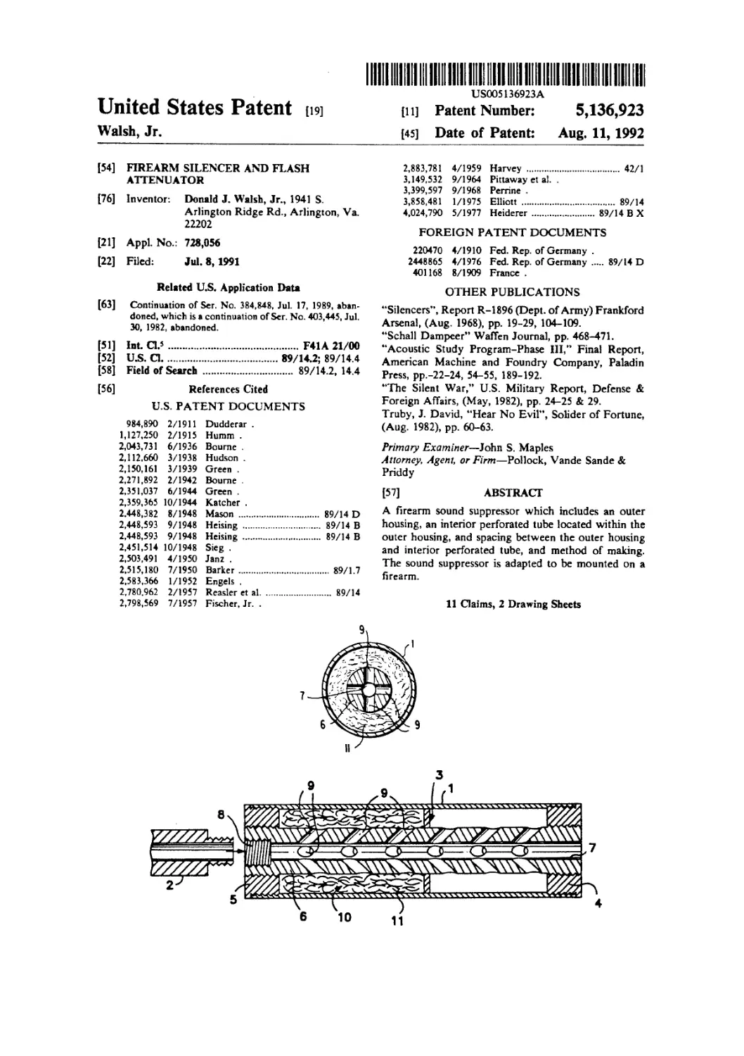
[57] ABSTRACT
A firearm sound suppressor which includes an outer
housing, an interior perforated tube located within the
outer housing, and spacing between the outer housing
and interior perforated tube, and method of making.
The sound suppressor is adapted to be mounted on a
firearm.
11 Claims, 2 Drawing Sheets
10
11
U.S. Patent
Aug. 11, 1992
Sheet 1 of 2
5,136,923
FIGI
U.S. Patent
Aug. 11, 1992
Sheet 2 of 2
5,136,923
5,136,923
1 2
FIREARM SILENCER AND FLASH ATTENUATOR
This application is a continuation of Ser. No.
07/384,848 filed on Jul. 17, 1989, now abandoned which 5
is a continuation of Ser. No. 06/403,445, filed Jul. 30,
1982, now abandoned.
TECHNICAL FIELD
The present invention is concerned wit sound sup- 10
pressors and flash attenuators for firearms Devices ac-
cording to the present invention are suitable for both
single barrelled weapons and for multibarrelled revolv-
ing cannons. The present invention is also directed to a
method for making a silencer 15
BACKGROUND ART
One general type of sound suppressor or silencer now
available includes an assembly of spaced baffles located
in an outer casing or housing. These baffles may be
perpendicular to the bore, conical (usually rearward-
slanting), or helical. The spacing between the baffles
provides discrete expansion chambers.
A somewhat different, but structurally similar ap-
proach includes packing the outer casing with washer-
like members cut from, for example, woven wire screen
mesh or compressed knitted wire mesh.
The above types of silencers have a central bore for
passage of the projectile. This bore is larger than the
projectile to preclude contact between the silencer and
the projectile which could result in loss of accuracy and
damage to the silencer.
Extensive research has been conducted over the
years with baffle-type silencers, the better examples of
which perform well accoustically However, baffle-type
silencers are difficult and expensive to manufacture,
which has significantly limited their utilization. This
difficulty is due io the conflicting requirement of mini-
mum clearance for the projectile to yield maximum
attenuation, and the multiplicative tolerances of the
components which must be maintained to ensure align-
ment along these lines (see pages 23 and 54 of AMF
Final Report Phase III, Paladin Press). These types of
suppressors suffer from the disadvantage of being rela-
tively heavy. Such suppressors are unlikely to be inter-
changeable between guns of the same model and can be
easily misaligned by rough handling in the field. For the
most part, these suppressors have to be custom made
and fitted for any particular weapon.
The wire screen washer packed silencer performs
well, both accoustically and as a muzzle flash reducer,
when initially installed. The good performance is be-
lieved to be due to the rapid heat exchange between the
propellant gases and the large surface area of conduc-
tive metal. Such silencers are generally more efficient
on a volume basis and for a given projectile clearance
than baffle silencers. Accordingly, those types of silenc-
ers can be smaller than baffle silencers while achieving
similar performance.
However, gradual fraying of the cut woven mesh
packing requires periodic maintenance. In addition,
such can be easily misaligned by rough handling in the
field. A few isolated suggestions have appeared in the
literature that a thin walled central tube can be used to
support packing material. Specifically, it has been sug-
gested to wrap the thin walled tube with packing such
as screen, steel wool, fiberglass, metal shavings, and
turnings.
20
25
30
35
40
45
50
55
60
65
DISCLOSURE OF THE INVENTION
The sound suppressors of the present invention are
useful for attenuation of flash and blast for a wide as-
sortment of small arms. Moreover, the sound suppres-
sors of the present invention are useful for recoil attenu-
ation for various small arms. The silencers of the pres-
ent perform better as compared to prior art silencers for
a given silencer volume. Accordingly, a relatively
greater amount of clearance for the bullet can be em-
ployed for a given silencer volume and/or desired level
of performance for the silencers of the present inven-
tion.
One aspect of the present invention is concerned with
a silencer adapted to be mounted on a firearm. The
silencer includes an outer housing and an interior tube
within said housing. The interior tube is spaced from the
inside walls of the housing. The interior tube extends at
least substantially the entire length of the housing which
is adapted to be forward of the muzzle of a firearm to
which the silencer is to be attached. In addition, the
interior tube is adapted to receive a projectile dis-
charged from the firing chamber of the firearm. The
interior tube is perforated with a plurality of rows of
ports. The minimum diameter of the ports in the inner
tube is at least about 50% of the inside diameter of the
inner tube. The minimum thickness of the wall of the
interior tube, at least where perforated, is the lesser of
either at least about 50% the inside diameter of the
interior tube or at least about } inches.
In, a preferred aspect of the present invention, the
spacing between the outer housing and inner tube is at
least substantially (e.g., less than about 2% of the vol-
ume occupied), if not entirely, free from packing mate-
rial.
In another aspect of the present invention, packing is
located in the space between the outer housing and
interior tube.
Additional aspects of the present invention include
dividing the space between the outer housing and inner
tube into multiple radially extending chambers, such as
by providing at least one radially extending wall or
partition in both of the above types of silencers of the
present invention.
Another aspect of the present invention is a sound
suppressed firearm having a barrel with an axis and an
inner diameter; and a silencer. The silencer has a thin
walled outer tubular shell or housing and an interior
tube with walls thicker than the walls of said shell. The
interior tube has radial ports. As used herein, “radial”
means simply transverse to the axis of the interior tube,
but not necessarily normal to that axis. Also, the si-
lencer has means between the outer shell and interior
tube for defining a volume therebetween. In addition,
means are provided for directly attaching the interior
tube to the muzzle of the weapon, whereby the axis of
the barrel is at least substantially aligned with the axis of
the interior tube.
If desired, the volume between the outer and interior
tube can include baffle material and/or at least one
radially extending partition.
A still further aspect of the present invention is a
method of making a silencer. The method includes
a) providing a relatively thick walled interior tube
having radial performations;
b) wrapping knitted metallic fabric around the out-
side diameter of said interior tube; and
5,136,
3
c) enclosing the wrapped interior tube within a thin
walled outer shell or housing having walls thinner
than the walls оГ said interior tube.
BRIEF DESCRIPTION OF THE DRAWINGS 5
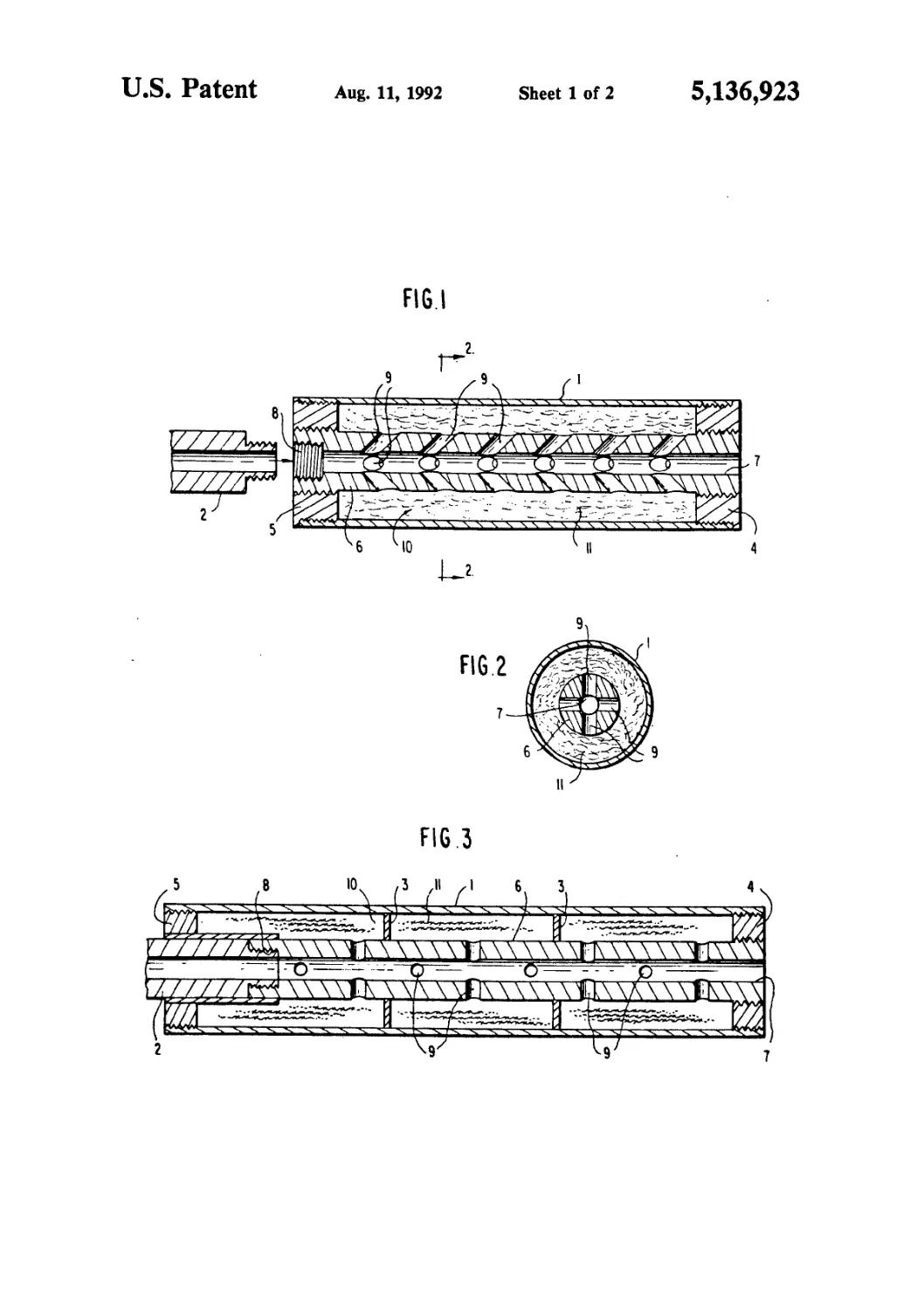
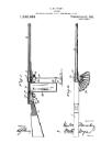
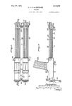
FIG. 1 shows an axial cross-section of a silencer em-
bodying the present invention.
FIG. 2 shows a view taken on line 2—2 of FIG. 1.
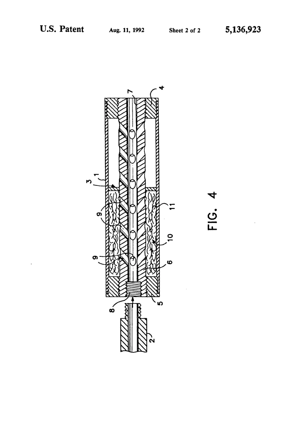
FIG. 3 shows an axial cross-section of another si-
lencer within the scope of the present invention. 10
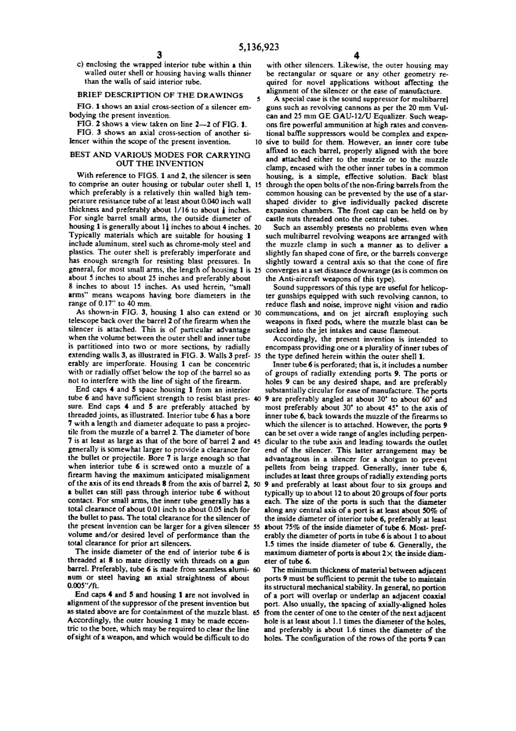
BEST AND VARIOUS MODES FOR CARRYING
OUT THE INVENTION
With reference to FIGS. 1 and 2, the silencer is seen
to comprise an outer housing or tubular outer shell 1, 15
which preferably is a relatively thin walled high tem-
perature resistance tube of at least about 0.040 inch wall
thickness and preferably about 1/16 to about i inches.
For single barrel small arms, the outside diameter of
housing 1 is generally about Ц inches to about 4 inches. 20
Typically materials which are suitable for housing 1
include aluminum, steel such as chrome-moly steel and
plastics. The outer shell is preferably imperforate and
has enough strength for resisting blast pressures. In
general, for most small arms, the length of housing 1 is 25
about 5 inches to about 25 inches and preferably about
8 inches to about 15 inches. As used herein, “small
arms” means weapons having bore diameters in the
range of 0.17" to 40 mm.
As shown-in FIG. 3, housing 1 also can extend or 30
telescope back over the barrel 2 of the firearm when the
silencer is attached. This is of particular advantage
when the volume between the outer shell and inner tube
is partitioned into two or more sections, by radially
extending walls 3, as illustrated in FIG. 3. Walls 3 pref- 35
erably are imperforate. Housing 1 can be concentric
with or radially offset below the top of the barrel so as
not to interfere with the line of sight of the firearm.
End caps 4 and 5 space housing 1 from an interior
tube 6 and have sufficient strength to resist blast pres- 40
sure. End caps 4 and 5 are preferably attached by
threaded joints, as illustrated. Interior tube 6 has a bore
7 with a length and diameter adequate to pass a projec-
tile from the muzzle of a barrel 2. The diameter of bore
7 is at least as large as that of the bore of barrel 2 and 45
generally is somewhat larger to provide a clearance for
the bullet or projectile. Bore 7 is large enough so that
when interior tube 6 is screwed onto a muzzle of a
firearm having the maximum anticipated misalignment
of the axis of its end threads 8 from the axis of barrel 2, 50
a bullet can still pass through interior tube 6 without
contact. For small arms, the inner tube generally has a
total clearance of about 0.01 inch to about 0.05 inch for
the bullet to pass. The total clearance for the silencer of
the present invention can be larger for a given silencer 55
volume and/or desired level of performance than the
total clearance for prior art silencers.
The inside diameter of the end of interior tube 6 is
threaded at 8 to mate directly with threads on a gun
barrel. Preferably, tube 6 is made from seamless alumi-
num or steel having an axial straightness of about
0.005'7ft.
End caps 4 and 5 and housing 1 are not involved in
alignment of the suppressor of the present invention but
as stated above are for containment of the muzzle blast.
Accordingly, the outer housing 1 may be made eccen-
tric to the bore, which may be required to clear the line
of sight of a weapon, and which would be difficult to do
923
4
with other silencers. Likewise, the outer housing may
be rectangular or square or any other geometry re-
quired for novel applications without affecting the
alignment of the silencer or the ease of manufacture.
A special case is the sound suppressor for multibarre]
guns such as revolving cannons as per the 20 mm Vul-
can and 25 mm GE GAU-12/U Equalizer. Such weap-
ons fire powerful ammunition at high rates and conven-
tional baffle suppressors would be complex and expen-
sive to build for them. However, an inner core tube
affixed to each barrel, properly aligned with the bore
and attached either to the muzzle or to the muzzle
clamp, encased with the other inner tubes in a common
housing, is a simple, effective solution. Back blast
through the open bolts of the non-firing barrels from the
common housing can be prevented by the use of a star-
shaped divider to give individually packed discrete
expansion chambers. The front cap can be held on by
castle nuts threaded onto the central tubes.
Such an assembly presents no problems even when
such multibarrel revolving weapons are arranged with
the muzzle clamp in such a manner as to deliver a
slightly fan shaped cone of fire, or the barrels converge
slightly toward a centra] axis so that the cone of fire
converges at a set distance downrange (as is common on
the Anti-aircraft weapons of this type).
Sound suppressors of this type are useful for helicop-
ter gunships equipped with such revolving cannon, to
reduce flash and noise, improve night vision and radio
communcations, and on jet aircraft employing such
weapons in fixed pods, where the muzzle blast can be
sucked into the jet intakes and cause flameout.
Accordingly, the present invention is intended to
encompass providing one or a plurality of inner tubes of
the type defined herein within the outer shell 1.
Inner tube 6 is perforated; that is, it includes a number
of groups of radially extending ports 9. The ports or
holes 9 can be any desired shape, and are preferably
substantially circular for ease of manufacture. The ports
9 are preferably angled at about 30* to about 60° and
most preferably about 30* to about 45* to the axis of
inner tube 6, back towards the muzzle of the firearms to
which the silencer is to attached. However, the ports 9
can be set over a wide range of angles including perpen-
dicular to the tube axis and leading towards the outlet
end of the silencer. This latter arrangement may be
advantageous in a silencer for a shotgun to prevent
pellets from being trapped. Generally, inner tube 6,
includes at least three groups of radially extending ports
9 and preferably at least about four to six groups and
typically up to about 12 to about 20 groups of four ports
each. The size of the ports is such that the diameter
along any central axis of a port is at least about 50% of
the inside diameter of interior tube 6, preferably at least
about 75% of the inside diameter of tube 6. Most- pref-
erably the diameter of ports in tube 6 is about 1 to about
1.5 times the inside diameter of tube 6. Generally, the
maximum diameter of ports is about 2x the inside diam-
eter of tube 6.
The minimum thickness of material between adjacent
ports 9 must be sufficient to permit the tube to maintain
its structural mechanical stability. In general, no portion
of a port will overlap or underlap an adjacent coaxial
port. Also usually, the spacing of axially-aligned holes
from the center of one to the center of the next adjacent
hole is at least about 1.1 times the diameter of the holes,
and preferably is about 1.6 times the diameter of the
holes. The configuration of the rows of the ports 9 can
5,136,923
5
vary greatly. One example includes a port through the
top, a corresponding port through the bottom of the
tube, and two ports about 90° offset from the ports
through the top and bottom, each extending through
one side of the tube 3.
Such a configuration is illustrated in FIG. 2. Another
example includes a port through the top and a port
through the bottom of the tube, and axially spaced
therefrom two ports rotated about 90°, each extending
through one side of the tube as illustrated in FIG. 3.
Ports 9 can also be arranged along spiral paths around
interior tube 6, so long as adequate strength is main-
tained.
Ports 9 divert the muzzle blast gases outward toward
the volume between inner tube 6 and outer housing 1.
The ports make it possible for the silencer to include a
relatively large radial clearance within the inner tube to
accommodate misalignment and still be an effective
silencer.
The inner tube is constructed so that in the unlikely
event a bullet strikes its interior, the tube will have
sufficient strength to deflect it and prevent it from exit-
ing through the side of the silencer. In particular, the
inner tube is made of a high strength material such as
seamless drawn or extruded aircraft tubing of for in-
stance steel or aluminum with a relatively thick wall.
The wall is generally thicker than the wall of the outer
housing. The minimum thickness at least where perfo-
rated is generally at least about & inch and is usually at
least about 25% of the inside diameter of tube 6. Prefer-
ably the minimum thickness of the wall is the lesser of
about 50% the inside diameter of the inner tube 6 or at
least about 3/16 inch.
Generally, the maximum thickness of the wall of tube
6 is approximately equal to the inside diameter of tube 6
preferably about 75% of the inside diameter of tube 6
and most preferably about 65% of the inside diameter of
tube 6.
The radial spacing 10 between the inner tube or each
tube or chamber of a multibarrel silencer and outer
housing is such that the ratio of the total free volume
between tube 6 and housing 1, including the volume of
bores 9, to the volume of the bore of barrel 2 is in the
range of about 10:1 to about 40:1 and preferably about
20:1 to about 30:1. The silencers of the presen; invention
provide a larger free volume as compared to baffle-type
suppressors of the equivalent size and weight.
The following tabulation illustrates some preferred
dimensions of the inner tube 6 of silencers of the present
invention for various weapons:
Weapon Outside Diameter of Inner Tube Inches Inside Diameter of Inner Tube Inches Port Size Inches
.223" Caliber 1 I i-i
(5.56 mm U.S.
M16A1)
.3O8”/7.62 mm I I i-i
NATO
.380'79 m/m Para i-t i i-i
.45 ACP 1 I l-I
.50 Browning 1-li I I
MG
25 m/m H-2i 1 3/32 i-i
30 m/m 2-3 1 7/16 l-U
If desired, packing materia] or baffle materia] 11 can
be included between tube 6 and housing 1. This packing
material can include screen, steel wool, fiberglass, metal
bearings, and preferably knitted metallic fabric of the
Metex Corporation type known for use in silencers not
having an inner tube. The packing is preferably of a
conductive alloy with good corrosion resistance such as
phosphor bronze or beryllium copper. Preferably, the
5 packing 11 or baffle screening is wrapped around inner
tube 2 with an initial metal to air density of about
5-15%. In use, the knitted metal is compressed by the
blast pressure usually to a density of about 30 to 40%.
Surprisingly, however, the compression does not result
10 in a permanent degradation of performance. Those
embodiments which include packing demonstrate the
best performance with respect to flash attenuation and
in fact usually result in complete flash reduction.
FIG. 3 shows an embodiment wherein radial parti-
*5 tions 3 are provided between the inner tube 6 and hous-
ing 1 to form a plurality of chambers (packed and/or
unpacked). Generally, 4 partitions are used. Preferably
one partition about midway is employed. The partitions
can be threaded onto interior tube 6 or welded to both
20 interior tube 6 and outer housing 1. The partitions may
be solid or perforated to control gas flow from chamber
to chamber. The purpose is to keep some mesh closer to
the muzzle so that the quenching of the muzzle blast
flame-front at a point of greatest efficiency is unim-
paired. This prevents secondary ignition and muzzle
flash. In the most preferred embodiment of the present
invention, the space is divided into two approximately
equal chambers with the packing in only the near cham-
30 ber closest the muzzle of the weapon.
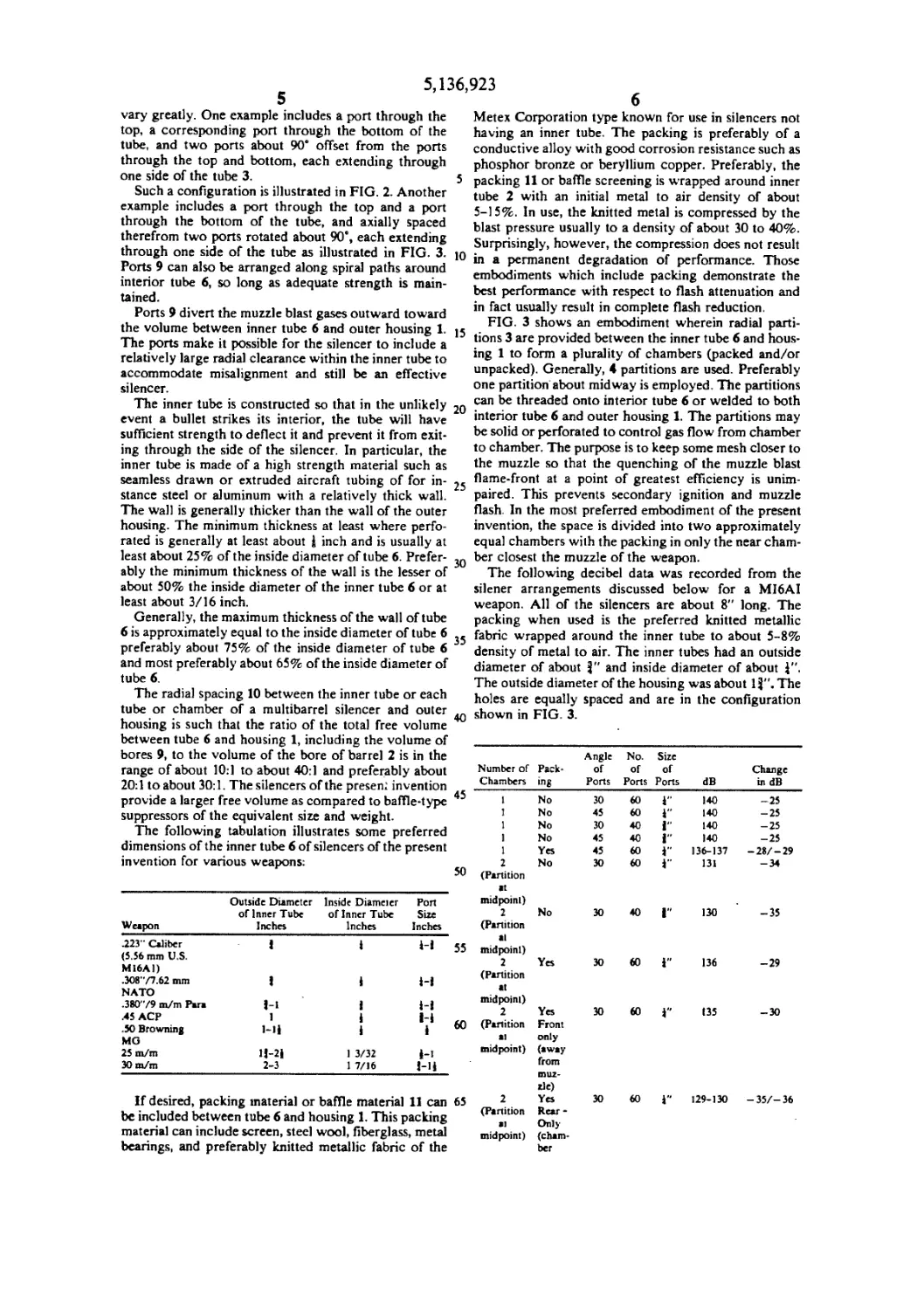
The following decibel data was recorded from the
silener arrangements discussed below for a MI6AI
weapon. All of the silencers are about 8" long. The
packing when used is the preferred knitted metallic
35 fabric wrapped around the inner tube to about 5-8%
density of metal to air. The inner tubes had an outside
diameter of about J" and inside diameter of about J".
The outside diameter of the housing was about 1J". The
holes are equally spaced and are in the configuration
40 shown in FIG. 3.
Number of Chambers Pack- ing Angle of Ports No. of Ports Size of Ports dB Change in dB
45 1 No 30 60 I" 140 -25
1 No 45 60 1" 140 -25
1 No 30 40 i 140 -25
1 No 45 40 i" 140 -25
1 Yes 45 60 i" 136-137 -28/-29
50 2 (Partition at midpoint) No 30 60 i" 131 -34
55 2 (Partition al midpoint) No 30 40 1 130 -35
2 (Partition at midpoint) Yes 30 «0 1" 136 -29
60 2 (Partition at midpoint) Yes Front only (away from tnuz- ric) 30 «0 I” 135 -30
65 2 (Partition at midpoint) Yes Rear - Only (cham- ber 30 60 1“ 129-130 -35/-36
5,136,923
8
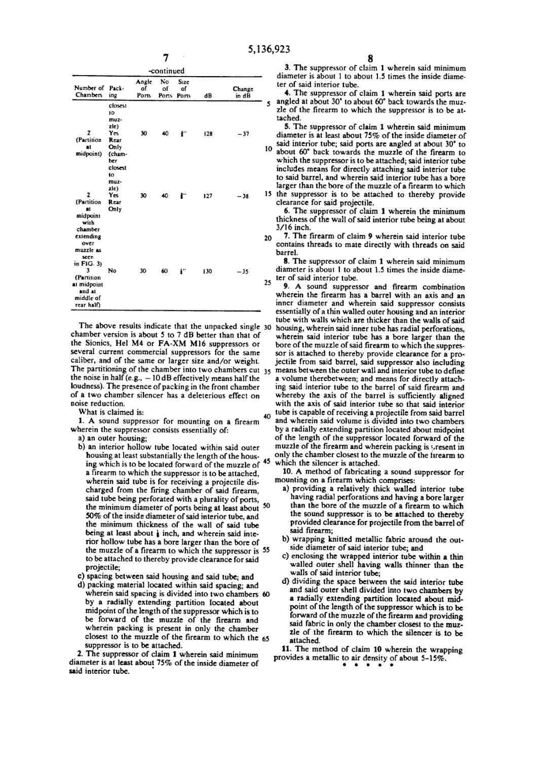
-continued
Angle No Size
Number of Pack* of of of Change
Chambers ing Pons Pons Pons dB in dB
closest
io
muz*
zle)
2 Yes 30 40 f' 128
(Partilion Rear
al Only
midpoint) (cham-
ber
closest
to
muz*
zle)
2 Yes 30 40 i 127
(Partition Rear
at Only
midpoint
with
chamber
extending
over
muzzle as
seen
in FIG. 3)
3 No 30 60 Г 130
(Partition
at midpoint
and al
middle of
rear half)
-37
10
-38 >5
20
-35
25
The above results indicate that the unpacked single 30
chamber version is about 5 to 7 dB better than that of
the Sionics, Hel M4 or FA-ХМ Ml6 suppressors or
several current commercial suppressors for the same
caliber, and of the same or larger size and/or weight.
The partitioning of the chamber into two chambers cut 35
the noise in half (e.g., —10 dB effectively means half the
loudness). The presence of packing in the front chamber
of a two chamber silencer has a deleterious effect on
noise reduction.
What is claimed is:
1. A sound suppressor for mounting on a firearm
wherein the suppressor consists essentially of:
a) an outer housing;
b) an interior hollow lube located within said outer
housing at least substantially the length of the hous-
ing which is to be located forward of the muzzle of ’
a firearm to which the suppressor is to be attached,
wherein said tube is for receiving a projectile dis-
charged from the firing chamber of said firearm,
said tube being perforated with a plurality of ports,
the minimum diameter of ports being at least about 50
50% of the inside diameter of said interior tube, and
the minimum thickness of the wall of said tube
being at least about } inch, and wherein said inte-
rior hollow tube has a bore larger than the bore of
the muzzle of a firearm to which the suppressor is 55
to be attached to thereby provide clearance for said
projectile;
c) spacing between said housing and said tube; and
d) packing material located within said spacing; and
wherein said spacing is divided into two chambers 60
by a radially extending partition located about
midpoint of the length of the suppressor which is to
be forward of the muzzle of the firearm and
wherein packing is present in only the chamber
closest to the muzzle of the firearm to which the 65
suppressor is to be attached.
2. The suppressor of claim 1 wherein said minimum
diameter is at least about 75% of the inside diameter of
said interior tube.
3. The suppressor of claim 1 wherein said minimum
diameter is about 1 to about 1.5 times the inside diame-
ter of said interior tube.
4. The suppressor of claim 1 wherein said ports are
angled at about 30° to about 60° back towards the muz-
zle of the firearm to which the suppressor is to be at-
tached.
5. The suppressor of claim 1 wherein said minimum
diameter is at least about 75% of the inside diameter of
said interior tube; said ports are angled at about 30° to
about 60° back towards the muzzle of the firearm to
which the suppressor is to be attached; said interior tube
includes means for directly attaching said interior tube
to said barrel, and wherein said interior tube has a bore
larger than the bore of the muzzle of a firearm to which
the suppressor is to be attached to thereby provide
clearance for said projectile.
6. The suppressor of claim 1 wherein the minimum
thickness of the wall of said interior tube being at about
3/16 inch.
7. The firearm of claim 9 wherein said interior tube
contains threads to mate directly with threads on said
barrel.
8. The suppressor of claim 1 wherein said minimum
diameter is about 1 to about 1.5 times the inside diame-
ter of said interior tube.
9. A sound suppressor and firearm combination
wherein the firearm has a barrel with an axis and an
inner diameter and wherein said suppressor consists
essentially of a thin walled outer housing and an interior
tube with walls which are thicker than the walls of said
housing, wherein said inner tube has radial perforations,
wherein said interior tube has a bore larger than the
bore of the muzzle of said firearm to which the suppres-
sor is attached to thereby provide clearance for a pro-
jectile from said barrel, said suppressor also including
means between the outer wall and interior tube to define
a volume therebetween; and means for directly attach-
ing said interior tube to the barrel of said firearm and
whereby the axis of the barrel is sufficiently aligned
with the axis of said interior tube so that said interior
tube is capable of receiving a projectile from said barrel
and wherein said volume is divided into two chambers
by a radially extending partition located about midpoint
of the length of the suppressor located forward of the
muzzle of the firearm and wherein packing is present in
only the chamber closest to the muzzle of the tirearm to
which the silencer is attached.
10. A method of fabricating a sound suppressor for
mounting on a firearm which comprises:
a) providing a relatively thick walled interior tube
having radial perforations and having a bore larger
than the bore of the muzzle of a firearm to which
the sound suppressor is to be attached to thereby
provided clearance for projectile from the barrel of
said firearm;
b) wrapping knitted metallic fabric around the out-
side diameter of said interior tube; and
c) enclosing the wrapped interior tube within a thin
walled outer shell having walls thinner than the
walls of said interior tube;
d) dividing the space between the said interior tube
and said outer shell divided into two chambers by
a radially extending partition located about mid-
point of the length of the suppressor which is to be
forward of the muzzle of the firearm and providing
said fabric in only the chamber closest to the muz-
zle of the firearm to which the silencer is to be
attached.
11. The method of claim 10 wherein the wrapping
provides a metallic to air density of about 5-15%.