/


Text
ART 73
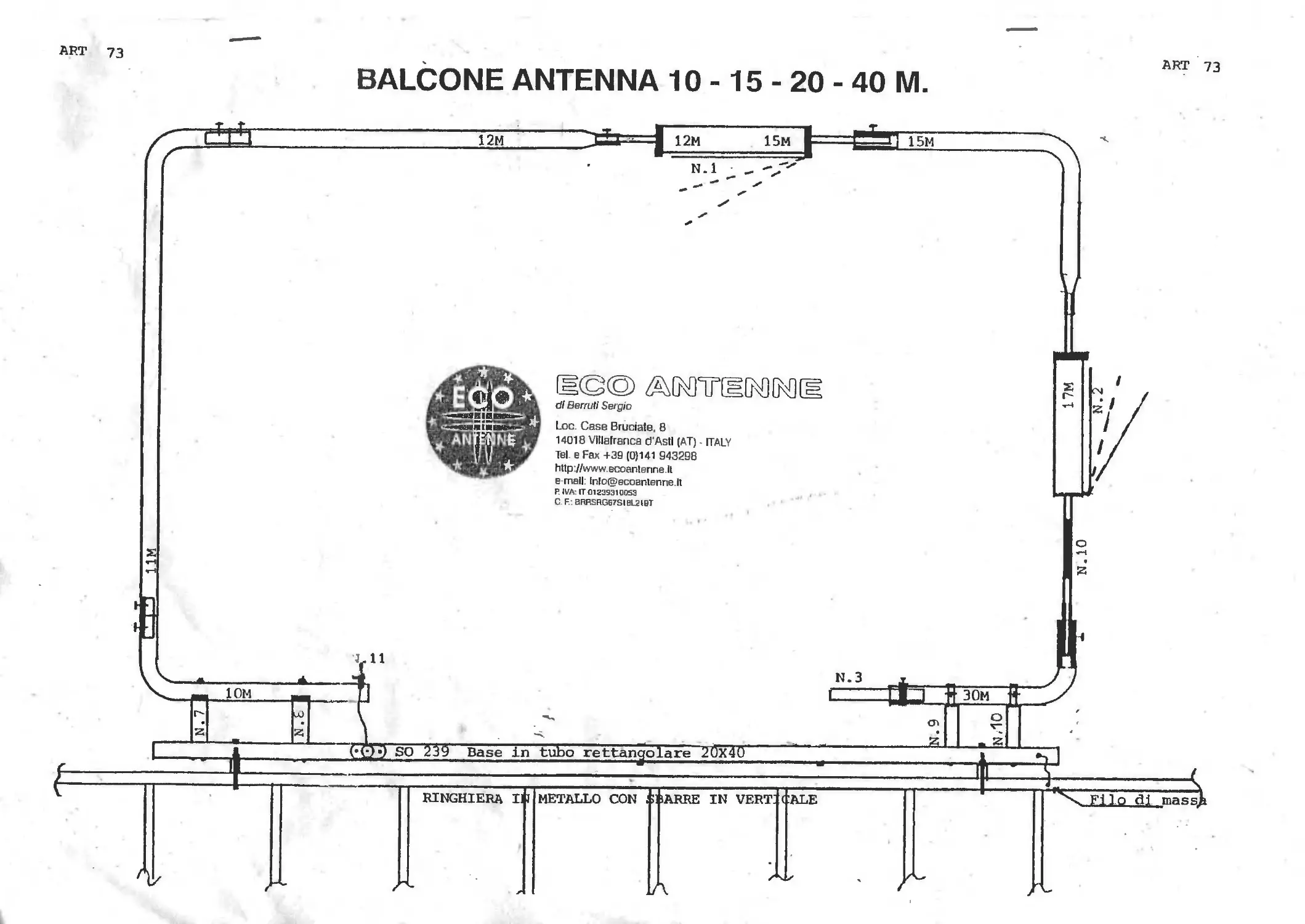
BALCONE ANTENNA 10 -15 - 20 - 40 M.
dl Berrutl Sergio
Loc. Case Bruciate, 8
14018 Vlllatranca d'Asti (AT) - ITALY
Tel e Fax +39 (0)141 943298
http //www ecoantenne II
e mall lnlo(H>ecoantenne It
P. IVA: IT012333100S3
C. F.: BRRERG67SIBL210T
wil
ГЕ©© ZWWCEDW
di Benvti Sergio
Loc. Case Bruciate, 8
14018 Villafranca d’Asti (AT) ITALY
Tel. e Fax +39 (0)141 943298
http://www.ecoantenne.it
e-mail: info@ecoentenne.it
p IVA' IT0ia3931D0S3
C. E. SRRSRGE7S1BL2I9T
ART. 73
n. 2
1. Screw on the plastic housings marked with the numbers 7 and 8 (that are
already assembled on the basis in a rectangular pipe 20 x 40 mm.) the mm. 19
long pipe marked with the label 10M, using 2 available 5 x 30 parker screws.
2. Join the pipe 11M, using an interior 16 mm. diameter x 10 cm long joint, using
2 equipped parker screws.
3. On the basis insulators n° 9 and 10 screw the pipe marked 30M, using 2
available parker screws.
4. Assembly on the pipe 30M the trap 17M (take care that the coil, detail n° 10, is
installed downwards), using 1 available 4,2 x 9,5 parker screw.
5. Assembly on the trap marked with the label 17 M the pipe 15M, using 1
available 4,2 x 9,5 parker screw.
6. Assembly on the pipe marked as 11M the pipe 12M, using a 16 mm. diameter
x 10 cm. long interior joint and 2 available 4,2 x 9,5 parker screws.
7. Connect both the pipes 12M and 15M with the trap 12 and 15M, using 2
available 4,2 x 9,5 parker screws (take care the piece marked with the 15M
label is turned to the 15M pipe).
8. Insert for approximately 7,5 cm. into the free extremity of the 30M pipe, the 16
mm. of diameter x 19 cm. long pipe, fixing by pressure with the aluminium
band, using 15x15 screw and the nut (as by detail n° 3 on the drawing).
9. Connect the SO239 wire to the 4 x 20 brass screw (detail n° 11).
10. Fix the antenna on the balcony railing and connect the ground conductivity.
'' /
CALIBRATION
1. For 15 meters, to lower the band centre pull down the copper stub n° 1 (more
you raise the stub from the trap more the frequency lowers).
2. For 20 meters, to lower the band centre adjust the copper stub n° 2.
3. For 40 meters, to tune up the band centre adjust the aluminium stub n° 3.
Sine? the plan reflecting is constituted by the balcc-nv railing л • vf.-'y important the
ground is perfect and as larger is possible.
2
ART. 73
10-15-20-40 M. BALCONY TRAPPED ANTENNA
If the floor ground was insufficient and the calibration on certain frequencies was impossible,
increase the plane reflecting with electric wires set both in horizontal line and in vertical line
downwards.
If this antenna is correctly installed, can produce very good performances, although his minimum .
dimensions.
With antenna in vertical position polarization will be horizontal. With antenna in horizontal
position polarization will come vertical.
S.W.R. 10 M 1:1,3
S.W.R. 15 M 1:1,3
S.W.R. 20 M 1:1,1
S.W.R. 40 M 1:1,1
IMPEDENZA 50 Ofim
FREQUENZA 7-14-21-28 MHz
DIMENSION! 170 X 120 CM.
POLARIZZAZIONE VERT. 0 ORIZZ.
FISSAGGIO A RINGHIERA
SISTEMA TRAPPOLATO
POTENZA 500 W
PESO 4,5 Kg.
di Beiruti Sergio
Loe. Case Bruciate, 8
14018 Villafranca d'Asti (AT) - ITALY
Tsl. e Fax +39 (0)141 943298
http://www. scoantenn e it
e-mail. In1o@ecoantenne it
R IVA: IT01Z293100S3
C.F BRRSRGE7S1BL21BT