/


Text
METALLURGY
FUELELEMENTDEVELOPMENT
FOR
PIQUA OMR
BY
M. H. BINSTOCK
A D I V I S I O N OF NORTH A M E R I C A N A V I A T I O N , I N C .
C A N O G A PARK, C A L I F O R N I A
P.O. BOX 3 0 9
CONTRACT: AT(ll-l)-GEN-8
ISSUED: JUNE 30, 1960
DISCLAIMER
This report was prepared as an account of work sponsored by an
agency of the United States Government. Neither the United States
Government nor any agency Thereof, nor any of their employees,
makes any warranty, express or implied, or assumes any legal
liability or responsibility for the accuracy, completeness, or
usefulness of any information, apparatus, product, or process
disclosed, or represents that its use would not infringe privately
owned rights. Reference herein to any specific commercial product,
process, or service by trade name, trademark, manufacturer, or
otherwise does not necessarily constitute or imply its endorsement,
recommendation, or favoring by the United States Government or any
agency thereof. The views and opinions of authors expressed herein
do not necessarily state or reflect those of the United States
Government or any agency thereof.
DISCLAIMER
Portions of this document may be illegible in
electronic image products. Images are produced
from the best available original document.
DISTRIBUTION
This r e p o r t h a s been distributed according t o the category "Metallurgy and
C e r a m i c s ' ' as given in "Standard Distribution L i s t s f o r Unclassified Scientific
and Technical Reports'' TID-4500 (15th Ed.), August 1, 1959.
A total of 600
copies was printed.
ACKNOWLEDGMENT
The author wishes t o thank the people l i s t e d below, whose guidance and h a r d
work helped complete t h i s project:
... .
_-_ ... ._
~
$ 1
<, y,
.~
..
.
L.
-
. ,_ j:,
.
._.._I./
-
'
, _
..
f
,...1.
,
.,
.
.
~
.
I
2
..
I-*
. .. . ,.
E. E. G a r r e t t
!.
I
,-
.r
.-
I
G. V. Alm
,
"
...
B. Gradle
J. L. Boyer
j i
-i..
.
.a
...',..'.
E. Weisner
C . Wheelock
E. B a u m e i s t e r
W. H. F r i s k e
In addition, s p e c i a l appreciation goes to all the l a b o r a t o r y mechanics who
p e r f o r m e d the n e c e s s a r y t a s k s and t e s t s t o develop the p r o g r a m .
ii
CONTENTS
Page
.....................................
...................................
vi
Abstract
I. Introduction
11. F u e l Alloy Development, Evaluation, and Selection
111. Melting and Casting
1
........
..............................
8
........................
Hot P r e s s u r e Bonding. . . . . . . . . . . . . . . . . . . . . . . . . . . . .
Bond Evaluation and Testing. . . . . . . . . . . . . . . . . . . . . . . . .
F i n a l Assembly . . . . . . . . . . . . . . . . . . . . . . . . . . . . . . . . .
Out- Of -Pile T e s t i n g . . . . . . . . . . . . . . . . . . . . . . . . . . . . . .
11
IV. Nickel P l a t i n g and Cladding
V.
VI.
VII.
20
23
27
30
VIII.
IX. In-Pile T e s t i n g
X.
4
.................................
Conclusions. . . . . . . . . . . . . . . . . . . . . . . . . . . . . . . . . . . .
45
References..
46
35
..................................
TABLES
I. R e s u l t s of T e n s i l e T e s t s at 9 0 0 ° F
....................
11. R e s u l t s of C r e e p T e s t s of Various A l l o y s .
111. Nickel P l a t i n g P r o c e d u r e s f o r Flat Plates.
6
...............
7
...............
12
...
16
..........
18
........
25
IV. Nickel P l a t i n g P r o c e d u r e s f o r U - 3.5 M o Cylindrical C o r e s .
V. Tubular Aluminum Cladding Surface P r e p a r a t i o n .
VI. Type 6061 Aluminum End P l u g Surface P r e p a r a t i o n
FIGURES
.............
Tubular OMR F u e l Element . . . . . . . . . . . . . . . . . . . . . . . . .
Typical U Alloy OMR F u e l Plates, C a s t to 0.130-in. T h i c k n e s s .
1. Eighty-Plate O M R F u e l E l e m e n t (7500-5144)
2
2.
3
3.
4. Top of Mold f o r Casting Six C y l i n d e r s of U - 3.5 Mo Alloy
(7508-4727G).
..................................
5. Mold f o r Casting Tubular Sections, Showing Graphite C o r e s
(7508-4727H)
..................................
8
'
9
9
\
iii
FIGURES
Page
..,........ ,
Plating Rack f o r F l a t P l a t e - Movable Contact T y p e . . . . . . . . . . .
Flat Plate Aluminum Cladding . . . . . . . . . . . . . . . . . . . . . . . . .
Hot-Knifing Apparatus. . . . . . . . . . . . . . . . . . . . . . . . . . . . . . .
c o m p o n e n t s of Flat P l a t e F u e l Section (7500-5112A). . . . . . . . . . .
P l a t i n g Rack f o r Tubular F u e l C o r e s - Movable Contact Type
(7519-5142A). . . . . . . . . . . . . . . . . . . . . . . . . . . . . . . . . . . . .
Tubular Aluminum Cladding (7515- 51267A). . . . . . . . . . . . . . . . .
Components of Tubular F u e l Section (7515-51349D) . . . . . . . . . . .
6. Eight Castings f o r Tubular E l e m e n t (7508-47146)
10
7.
1'1
8.
9.
10.
11.
12.
13.
14
15
15
16
17
17
14. End View of Welded End P l u g and Sealed Off Evacuation Tube
..
.. .. .
f o r Tubular Sections (7515-51349A) .
19
15. Hot P r e s s e d Tubular Sections (7515-51349B)
19
...
... . .. ....
. . .. ...........
16. Components of T u b u l a r Section, Showing Evacuation Tube Welded
to End P l u g (7515-513493)
. . .. . . . . . . . . . . . . . . . . . . . .. ..
21
17. W a t e r Cooled Copper Chill Blocks f o r Welding Tubular End
C l o s u r e s (7010- 5 103C) . .
.. ..
.
21
18. Typical Al-Ni-U Diffusion Bond Zone, I s o s t a t i c a l l y P r e s s e d at
1 0 0 0 ° F and 8000 psi f o r 10 m i n
. .
. .
24
19. Typical Bond Zone,
24
... .....
..
...... .. . . .. .
. .. . ...... . . . . . . ....
End P l u g Nickel P l a t e d to Cladding . . . . . . . .
20. Bond Zone of Hot P r e s s e d Type 6061 End P l u g to Type 1100
Cladding..
,
.
. . .
........... .... . . .... .. . .. .. . . . . .
Eighty P l a t e s , Assembled f o r Full-Size Flat Plate E l e m e n t
(7515-5110A) . . . . . . . . . . . . . . . . . . . . . . . . . . . . . . . . . . .
Complete Flat P l a t e Element (7515-5111C) . . . . . . . . . . . . . . . .
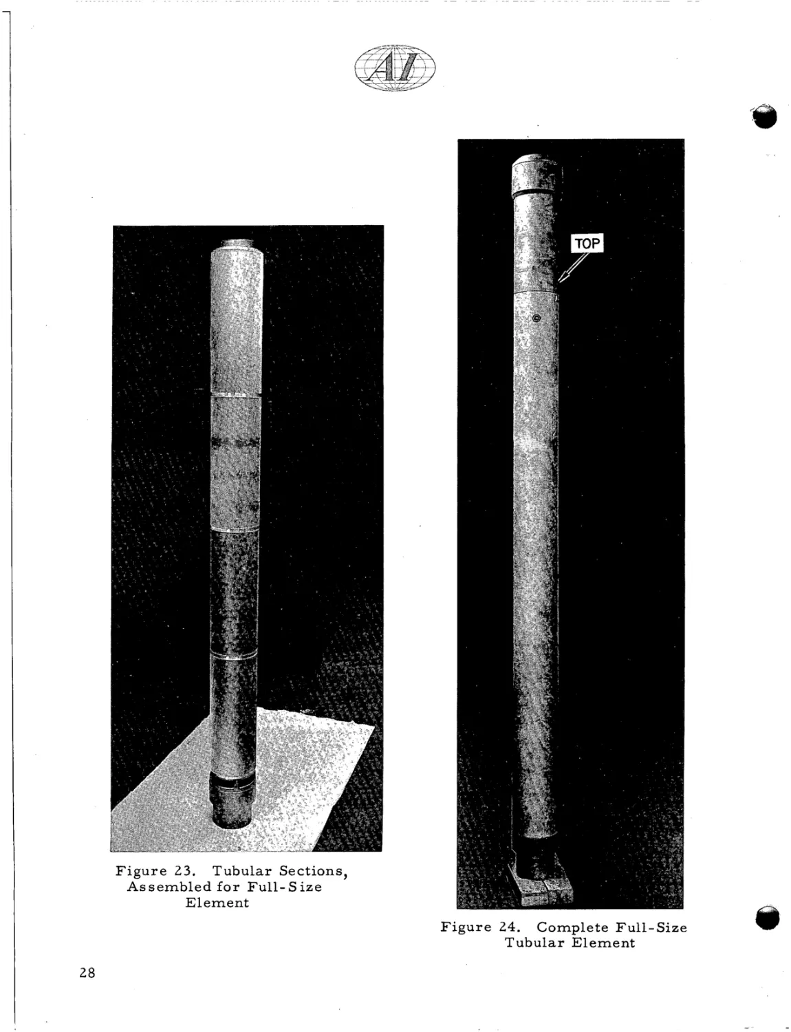
Tubular Sections, A s s e m b l e d f o r F u l l - Size E l e m e n t
(7515-47093) . . - .- .
. .
. . . - - .. . . . . . . . . . .
28
24. Complete Full-Size Tubular E l e m e n t (7515-4709F)
... . .......
28
25.
. ...... .. .
21.
22.
23.
T h r e e P l a t e s , After E x p o s u r e in Organic Loop a t 8 0 0 ° F
(7515-51319).
.
..
... .
..
. . ....
.. ......
24
26
26
30
26. P a r t i a l l y Decanned F l a t Plate Element, After E x p o s u r e in
.... . . . . . . . . . . . . . . . .
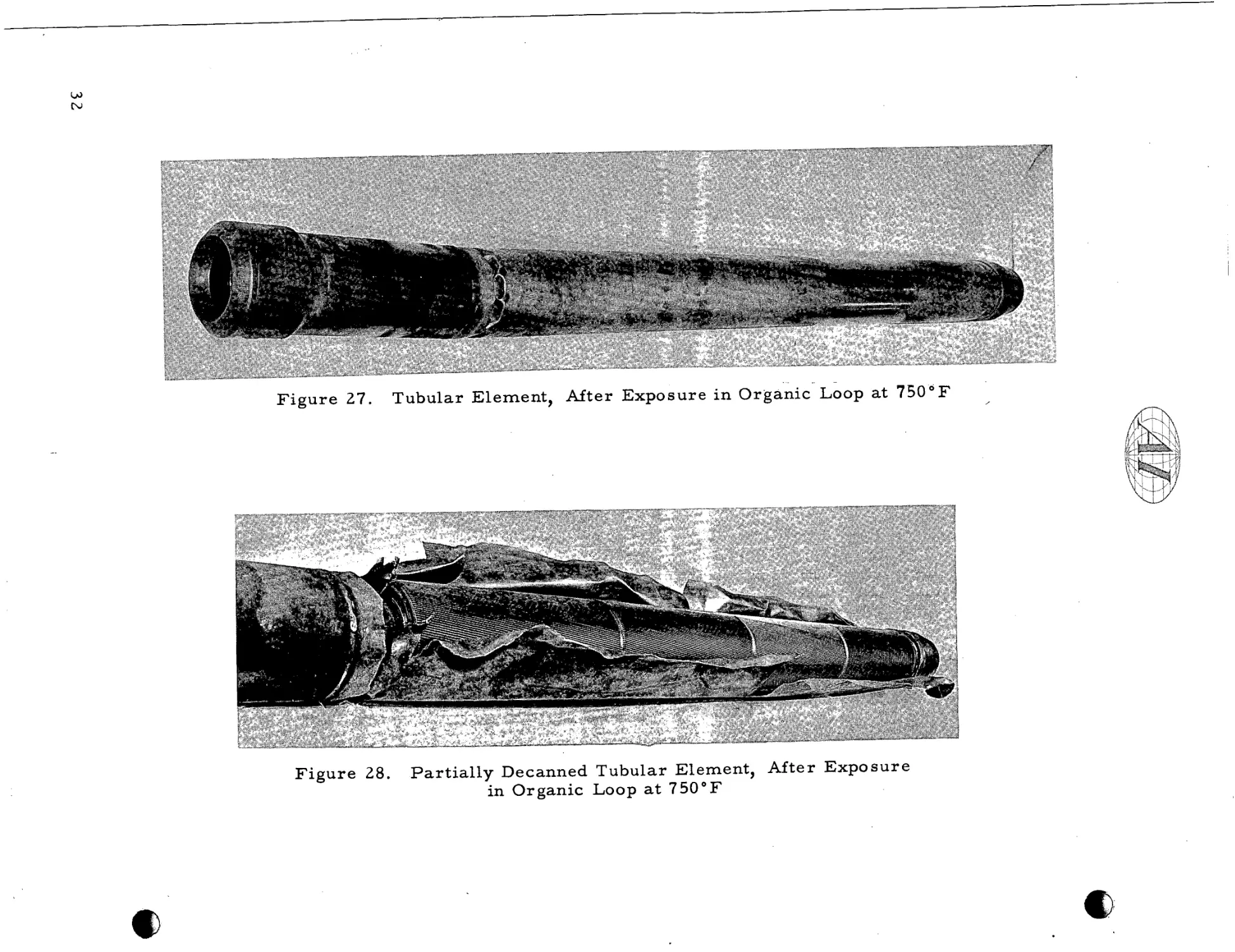
Tubular Element, A f t e r E x p o s u r e i n Organic Loop a t 7 5 0 ° F
(70 10- 5 102C) . . . . . . . . . . . . . . . . . . . . . . . . . . . . . . . . . . . . .
Organic Loop a t 8 0 0 ° F (7515-51302C)
27.
iv
31
32
V
Y
FIGURES
Page
28.
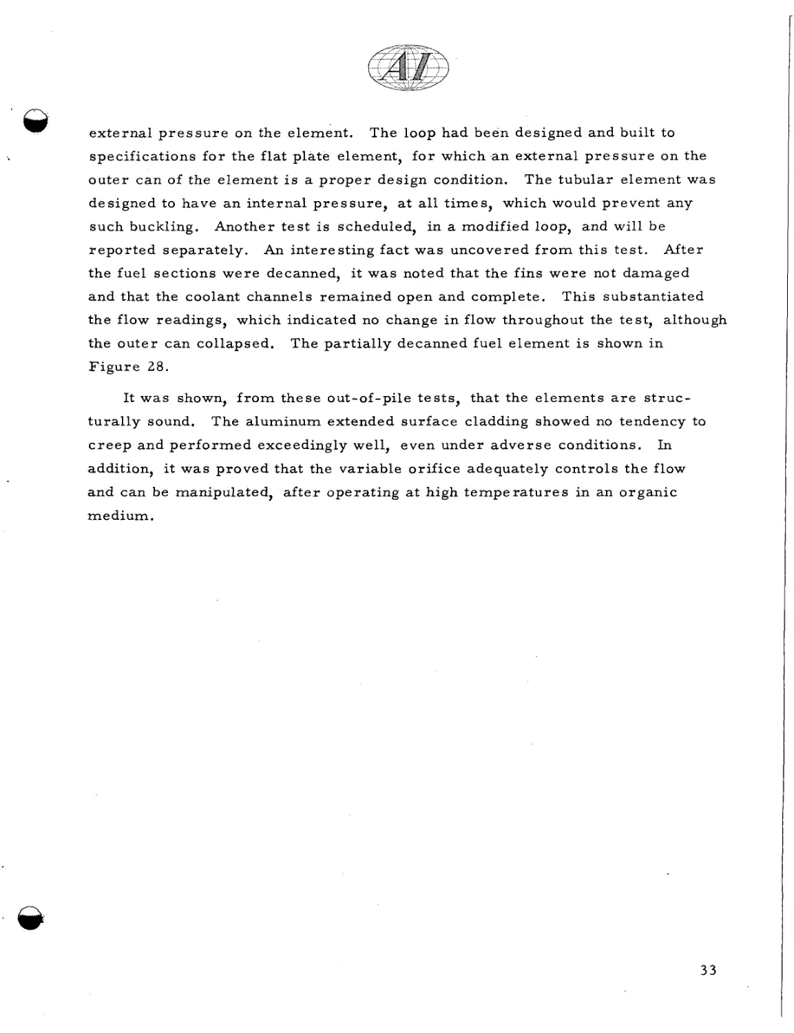
P a r t i a l l y Decanned Tubular Element, After Expo s u r e i n
Organic Loop at 7 5 0 ° F (7010-5101)
......................
32
29. F u e l Sections and Boron Steel Section f o r HB-1
(7500-5166B)
....................................
34
30. Two Bundles of Fuel, Showing Thermocouple A r r a n g e m e n t f o r
HT-1 (7515-5103A)
34
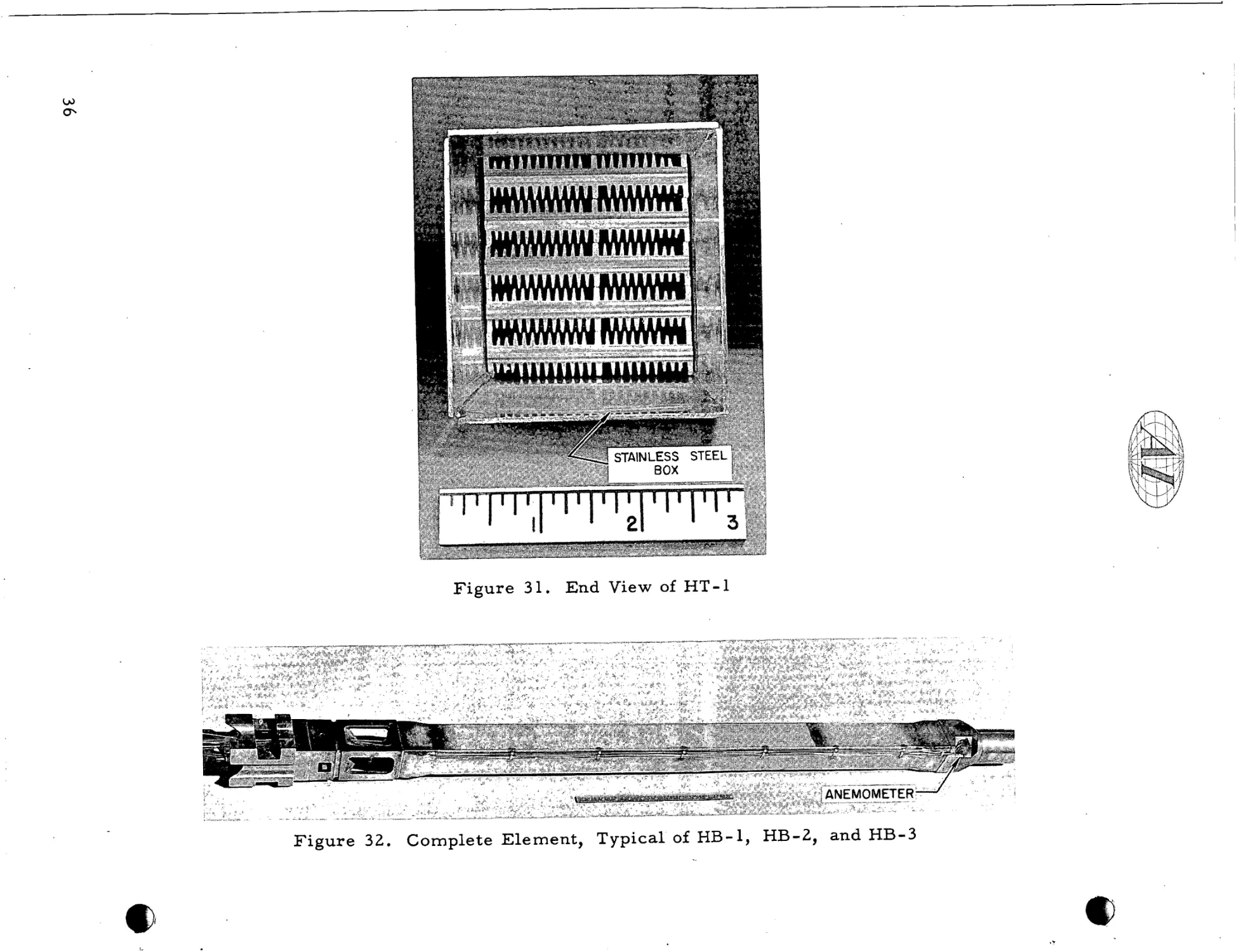
31. End View of HT-1
36
................................
(7500-1806A) . . . . . . . . . . . . . . . . . . . . . . . . .
32. Complete Element, Typical of HB- 1, HB- 2, and HB- 3
(7515-5121 1B)
36
33. Bottom End of F u e l Stack of HB-1, After Removal f r o m OMRE
(7515-5143-13)
37
34. HB- 1, After Irradiation, Showing Molten Cladding
(7515-5144-14)
37
....................................
...................................
...................................
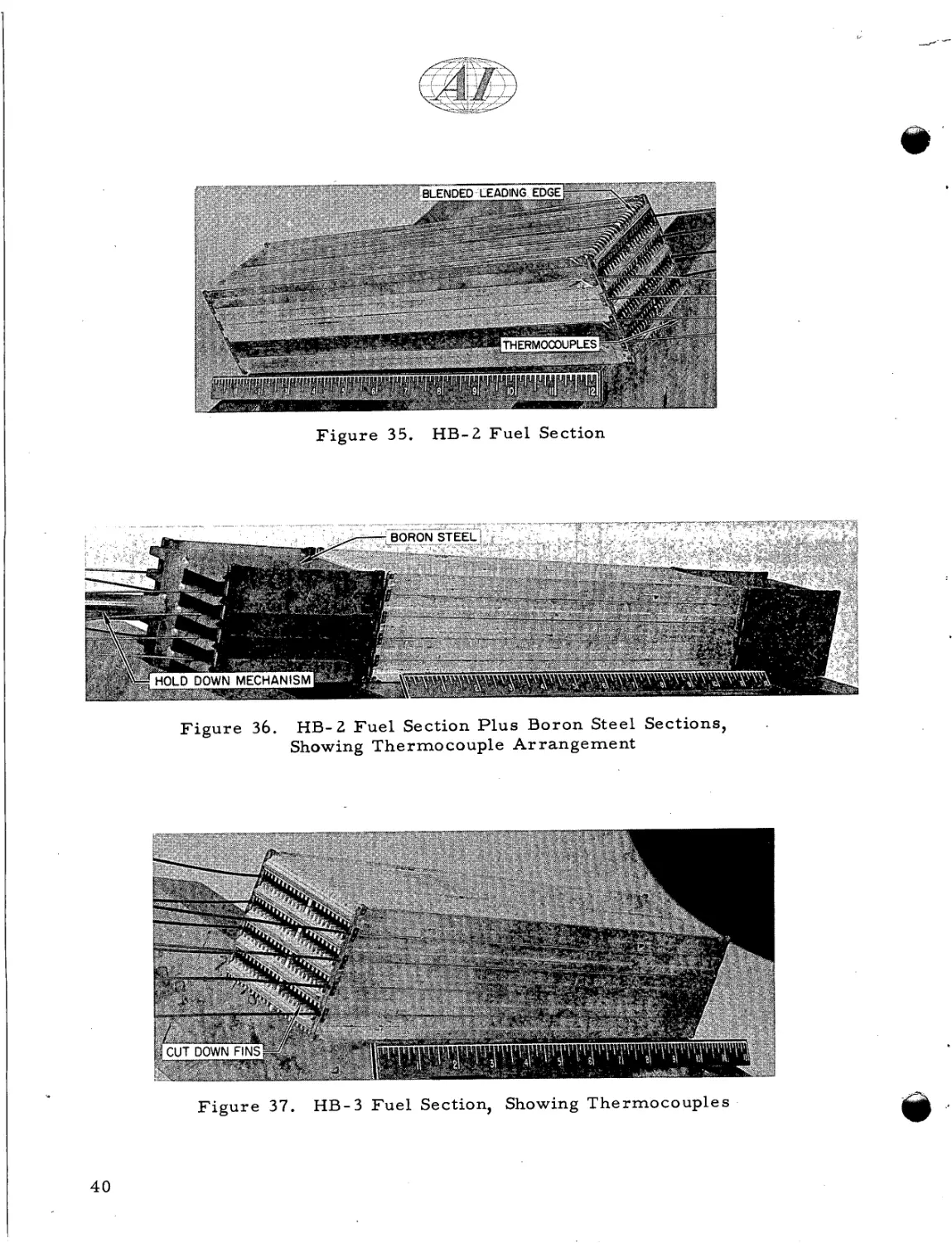
3 5. HB-2 F u e l Section (7515-51211A)
.......................
36. HB-2 F u e l Section P l u s Boron Steel Sections, Showing
Thermocouple A r r a n g e m e n t (7515-51179)
40
.................
40
.......
40
37. HB-3 F u e l Section, Showing Thermocouples (7515-51180)
38. HB-4 F u e l Section and Top Boron Steel Section, Showing
Thermocouple s (75 15- 5 133 1F)
41
39.
41
40.
41.
42.
43.
.........................
Components f o r HB-4 (7515-51331B) . . . . . . . . . . . . . . . . . . . . .
HB-4 F u e l Section (7515-51331C) . . . . . . . . . . . . . . . . . . . . . . .
Complete HB-4 (7515-51331K) . . . . . . . . . . . . . . . . . . . . . . . . .
Looking Through Fuel Section of HB-2, After Irradiation i n
OMRE (7519-51223-9). . . . . . . . . . . . . . . . . . . . . . . . . . . . . . .
Side View of F u e l Stack f r o m HB-2, After Exposure in
OMRE (7519 - 5 1 2 25 - 11)
..............................
44. Typical Flat P l a t e f r o m HB-2, After E x p o s u r e in OMRE
(7519-51227-13).
..................................
43
43
44
44
44
V
ABSTRACT
Fuel e l e m e n t s f o r the Organic Moderated R e a c t o r at Piqua, Ohio, (Piqua
OMR) consist of 1.94% e n r i c h e d U
-
3.5 Mo
- 0.1
Al alloy, nickel-bonded t o
extended surface Type 1100 aluminum cladding, in the f o r m of two c o n c e n t r i c
c i r c u l a r cylinders
.
The development p r o g r a m f o r these e l e m e n t s included:
1) The evaluation of fuel alloys having compositions n e a r U
s m a l l t e r n a r y additions of
- 3.5 Mo (with
Al and Si)
2) The casting of fuel c y l i n d e r s
3) The p r e p a r a t i o n of helically-finned e x t r u d e d cladding
4) The application of the nickel bond l a y e r and bonding by hot pneumatic
pressing
5) The establishing of p r o c e d u r e s f o r fuel mechanical a s s e m b l y .
The t e s t p r o g r a m involved the i r r a d i a t i o n of prototypes and out-of -pile testing
of full-scale mockups.
R e s u l t s show that s u c h e l e m e n t s a r e capable of s u c c e s s f u l p e r f o r m a n c e
under Piqua OMR conditions.
vi
1. INTRODUCTION
The Piqua OMR plant is designed t o produce a net power of 11,400 kwe.
The r e a c t o r c o n s i s t s of a heterogeneous a r r a n g e m e n t of slightly enriched u r a n i um alloy fuel, clad in and metallurgically bonded t o aluminum, i m m e r s e d in a n
organic medium which s e r v e s a s m o d e r a t o r - r e f l e c t o r and coolant.
E a r l y in the
development p r o g r a m f o r t h i s r e a c t o r , a p r o j e c t was established t o a c c o m p l i s h
two m a j o r goals:
a) To develop a f u e l e l e m e n t which will be stable under i r r a d i a t i o n t o
3000 Mwd/MTU, average, at 8 5 0 ° F peak, and compatible with organic
medium.
b) T o d e t e r m i n e p r o c e s s and product specifications f o r fuel e l e m e n t
f a b r i c at ion.
Both have been successfully accomplished.
During the development of the fuel e l e m e n t f o r Piqua OMR, two b a s i c designs w e r e considered.'
Initially, the design was a flat-plate extended-surface
configuration, a s shown i n F i g u r e 1 .
The final design includes two concentric,
extended-surface tubes, as shown in F i g u r e 2.
Much of the development of the
v a r i o u s p r o c e s s e s r e q u i r e d was done on the flat plate concept and, where p o s s i ble, extrapolated t o make the tubular shapes.
Many of the individual p r o c e s s
s t e p s had to be changed and f u r t h e r developed t o f a b r i c a t e the tubular element.
In t h i s r e p o r t , an attempt will be made t o t r a c e the development of the m a j o r
p r o c e s s s t e p s , including the n e c e s s a r y additional effort r e q u i r e d by the change
in shape.
The fuel element development p r o j e c t consisted of the following steps:
a ) F u e l alloy development, evaluation, and selection
b) Melting and casting fuel alloy
c ) Cleaning and plating
d) Bonding f u e l t o cladding
e ) Final assembly
P
E a c h of these will be d i s c u s s e d in detail in t h i s r e p o r t .
1
I
t
A
I
t
A
----UPPER
/ LOAD
CASTING
SPRING
/
ELEMENT BOX
/
EXTENDED SURFACE PLATES
.ELEMENT SECTION
/
/LOCATING BARS
LOWER END PLUG
13"
I
i
VIEW A-A
VIEW B-B
F i g u r e 1.
Eighty-Plate OMR F u e l E l e m e n t
I
54"
-
,--
FIN 0 108"
SECTION
GRID
-
SECTION B-B
OR1 FlCE
F i g u r e 2.
A-A
INNER
INNER
OUTER
OUTER
O.D. 3.816"
I D 3.396"
O.D. 4.842"
I . D. 4.422"
WTOF FUEL PER ELEMENT
I 8 4 K g
Tubular OMR F u e l E l e m e n t
1
II. FUEL DEVELOPMENT, EVALUATION, AND SELECTION
This development p r o g r a m was guided by two design requirements:
a ) A fuel life expectancy of 5000 Mwd/MTU peak (3000 Mwd/MTU
ave r a g e )
b) A fuel enrichment l e s s than 2 wt
I
70 U
235
.
T h e r e f o r e , the following c r i t e r i a w e r e established:
a) F u e l dimensional changes, under irradiation, should not exceed 5%
change in volume p e r atom p e r c e n t burnup, a t a maximum c e n t r a l
t e m p e r a t u r e of 8 5 0 ° F .
b) The fuel alloy must withstand s t r e s s e s induced b y t h e r m a l cycling.
c) The fuel should have sufficient s t r e n g t h and c r e e p r e s i s t a n c e t o be
mechanically stable at operating conditions.
I
d) Alloying additions should not exceed 5 wt
70, and
should be of low
absorption c r o s s section, consistent with the limitation on e n r i c h m e n t .
e ) The p r o c e s s should lend itself t o economic fabrication.
It was recognized that a complete evaluation of fuel alloy stability, under
irradiation, could only be accomplished in the environment of an operating r e a c tor.
As facilities f o r such testing w e r e very limited, t i m e consuming, and e x -
pensive, a n out-of -pile testing approach w a s attempted.
The m a j o r e m p h a s i s
was placed on developing an alloy which would r e s i s t p l a s t i c deformation at
1
8 5 0 ° F . Resistance t o p l a s t i c deformation r e q u i r e s a m a t e r i a l of high c r e e p
r e s i s t a n c e and yield s t r e n g t h at elevated t e m p e r a t u r e s .
Consideration was a l s o
given to eliminating phase changes, with t h e i r attendant volume changes; o r a t
l e a s t t o minimize s u c h changes.
The development of such fuels, by alloying, i s
d i s c u s s e d completely in R e f e r e n c e s 2 and 3.
F r o m these, we can d r a w the f o l -
lowing conclusions :
a ) An alloying addition of 3.5 wt
70 Mo
significantly i n c r e a s e s the stability
of a s - c a s t uranium during t h e r m a l cycling.
the
4
fi
This addition eliminates
phase; and, t h e r e f o r e , the CI phase t r a n s f o r m s t o )' phase only,
b) The addition of 3.5 wt
7'
Mo i n c r e a s e s the ultimate and yield s t r e n g t h s
of a s - c a s t uranium by a f a c t o r of five.
The addition of 0.1 wt % Al t o
the b i n a r y f u r t h e r i n c r e a s e s t h e s e p r o p e r t i e s , about seven t i m e s t h a t
of unalloyed u r a n i u m .
An addition of 0.1 t o 0.5 wt
70Si
did not i m -
prove the p r o p e r t i e s o v e r those of the b i n a r y alloy.
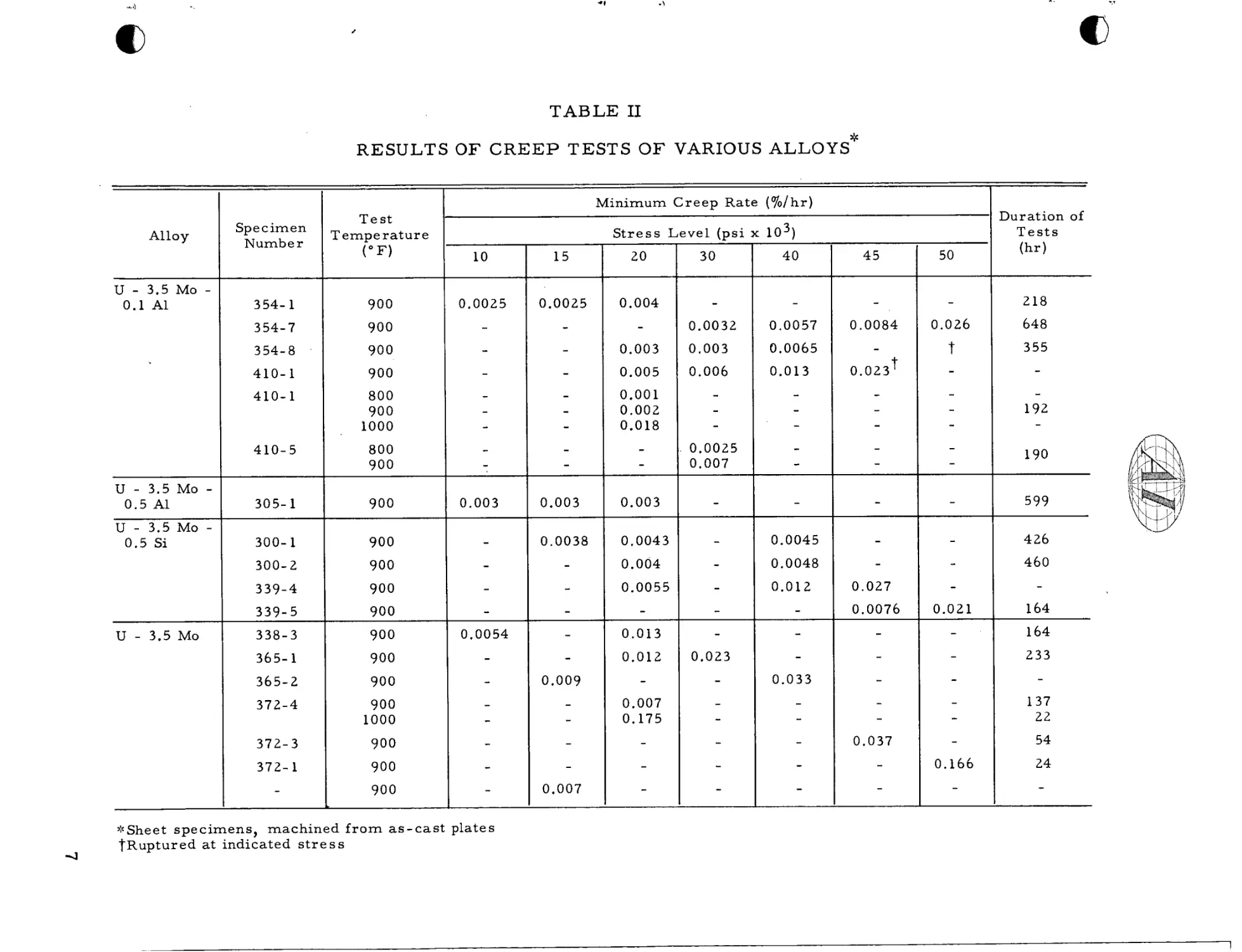
c) The c r e e p s t r e n g t h of U is significantly i n c r e a s e d by the addition of
3.5 wt
70 Mo.
T h i s improvement is enhanced by f u r t h e r addition of
e i t h e r aluminum o r silicon (0.1 t o 0.5 wt %).
The U
- 3.5
Mo
- 0.1
8
A1
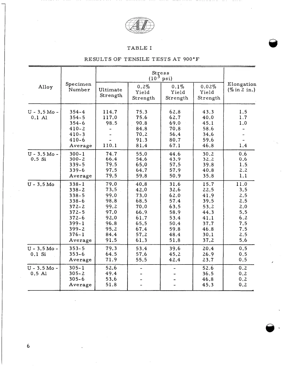
showed the highest c r e e p s t r e n g t h of all the low alloys t e s t e d . T a b l e 1
shows r e s u l t s of t e n s i l e t e s t s at 9 0 0 ° F , and Table I1 indicates c r e e p
t e s t s at v a r i o u s t e m p e r a t u r e s and s t r e s s l e v e l s . 2 F r o m the above
data, t h r e e alloys w e r e s e l e c t e d f o r in-pile evaluation, U
U
- 3.5
Mo
- 0.5
Si and U
-
3.5 Mo
- 0.1 Al.
-
3.5 Mo,
All t h r e e have been
i r r a d i a t e d , and the r e s u l t s a r e d i s c u s s e d in Section IX of t h i s r e p o r t .
4 3
* F i g u r e s denote weight p e r c e n t
5
TABLE I
RESULTS O F TENSILE TESTS AT 9 0 0 ° F
St? s s
(10- ? S i )
Spe c i m e n
Number
Alloy
I
U - 3.5 MO 0.1 A1
U - 3.5M0
0.5 Si
U
-
300- 1
300- 2
- 3.5 MO
U - 3.5M00.1 Si
U - 3.5M0
0.5 A1
3 54- 4
354-5
354-6
410-2
410-3
410-6
Average
-
Ultimate
Strength
114.7
117.0
98.5
-
-
110.1
74.7
66.4
0.2%
Yield
Strength
0.02yo
Y ie Id
Strength
Elongation
( % i n 2 in.)
75.3
75.6
90.8
84.8
70.2
91.3
81.4
62.8
62.7
69.0
70.8
56.4
80.7
67.1
43.3
40.0
45.1
58.6
34.6
59.6
46.8
1.5
1.7
1.o
1.4
55.0
54.6
65.0
64.7
59.8
44.6
43.9
57.5
57.9
50.9
30.2
39.8
40.8
35.8
0.6
0.6
1.5.
2.2
40.8
42.0
73.0
68.5
70.0
31.6
32.6
62.0
57.4
63.5
58.9
53.4
50.4
59.8
48.4
51.8
15.7
22.5
41.9
39.5
53.2
44.3
41.1
37.7
46.8
30.1
37.2
11.0
3.5
2.5
2.5
2.0
5.5
6.2
7.5
7.5
2.5
5.6
39.6
45.2
42.4
20.4
26.9
23.7
0.5
0.5
0.5
52.6
36.5
46.8
45.3
0.2
0.2
0.2
0.2
339-5
339-6
Average
79.5
338- 1
338-2
338-5
338-6
372-2
372- 5
372-6
399- 1
399-2
376- 1
Average
79.0
73.5
99.0
98.8
99.2
97.0
92.0
96.8
95.2
84.4
91.5
61.7
65.5
67.4
57.2
61.3
353-5
353-6
Average
79.3
64.5
71.9
53.4
57.6
55.5
305- 1
305-2
305-6
Average
52.6
49.4
53.6
51.8
97.5
79.5
0.1%
Yield
St'r e ng t h
66.9
32.2
1.1
,
,
TABLE I1
RESULTS OF CREEP TESTS OF VARIOUS ALLOYS*
Minimum C r e e p Rate ( % / h r )
Alloy
Specimen
Number
Test
r empe r a t ur e
(OF)
- 3.5 MO 0.1 A1
S t r e s s Level ( p s i x 1031
10
15
20
U
354- 1
900
0.004
-
354-7
900
-
0.0032
354- 8
U - 3.5 MO 0.5 A1
900
-I
0.0084
648
-
355
0.003
0.0065
0.006
0.013
900
0.005
800
900
1000
0.001
0.002
0.018
-
410-5
800
900
-
0.0025
0.007
305- 1
900
0.003
0.003
300- 1
900
0.0038
0.0043
0.0045
300- 2
900
0.004
0.0048
900
339- 5
900
338-3
900
365- 1
900
0.009
-
0.0055
-
50
0.0057
410-1
-
45
218
410- 1
339-4
U - 3.5 Mo
40
0.003
U - 3.5 MO 0.5 Si
30
h r a t i o n of
Tests
(hr)
0.023 t
-
-
190
599
0.012
-
-
426
460
0.027
-
0.0076
0.021
164
0.013
164
0.012
233
-
365-2
900
372-4
900
1000
372-3
900
-
-
54
372- 1
900
-
-
24
-
900
-
-
':'Sheet specimens, machined f r o m a s - c a s t plates
TRuptured a t indicated s t r e s s
0.007
0.007
0.175
137
22
111. MELTING AND CASTING
The shaping of enriched uranium alloys by casting eliminates e x t r a c o s t s
that a r e often a s s o c i a t e d with r e c o v e r y of the expensive U235 in nonrecyclable
s c r a p , when t h e s e alloys a r e shaped by wrought methods.
Another r e a s o n f o r
choosing a casting p r o c e s s was the necessity, in the Piqua OMR fuel design, of
making a l a r g e number of relatively short-length p i e c e s .
The p r o c e s s , which is
d e s c r i b e d i n Reference 4, essentially c o n s i s t s of vacuum induction melting
uranium derby, molybdenum pellets, and o t h e r alloying additions, and casting
into w a r m , magnesium-zirconate- coated graphite molds.
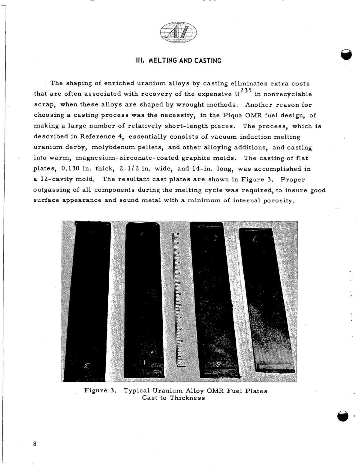
The casting of flat
plates, 0.130 in. thick, 2 - 1 / 2 in. wide, and 14-in. long, was accomplished i n
a 12-cavity mold.
The r e s u l t a n t c a s t p l a t e s a r e shown in F i g u r e 3.
Proper
outgassing of all components during the melting cycle was required, to i n s u r e good
s u r f a c e appearance and sound metal with a m i n i m u m of internal porosity.
F i g u r e 3.
8
Typical Uranium Alloy OMR F u e l P l a t e s
C a s t to Thickness
.. 5 .,. ..
.-
,
I.
,.-
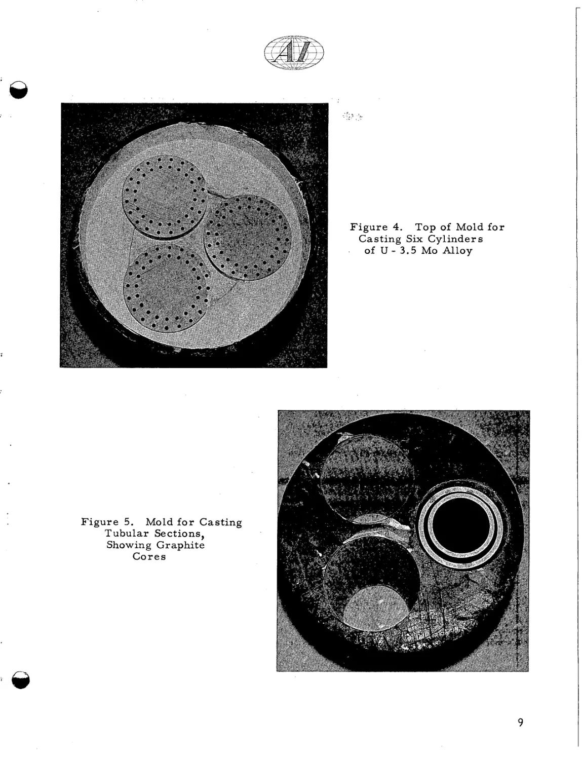
F i g u r e 4. Top of Mold f o r
Casting Six C y l i n d e r s
.
of U - 3.5 MO Alloy
F i g u r e 5. Mold f o r Casting
Tubular Sections,
Showing Graphite
Cores
9
-
The casting of the tubular sections involved s e v e r a l modifications of t h i s
process.
The s i z e s r e q u i r e d w e r e approximately 5-in. OD and 0.2-in. thick
wall, and 4-in. OD and 0.2-in. thick wall.
The mold t e m p e r a t u r e was a much
m o r e important variable i n controlling s u r f a c e and internal porosity.
In addi-
tion, it w a s n e c e s s a r y to outgas all graphite components, as a s e p a r a t e operation,
before casting and induction heating.
With these special precautions added, the
r e s u l t a n t castings w e r e sound and had good s u r f a c e appearance.
w e r e made simultaneously, a s shown in F i g u r e s 4 and 5.
Six castings
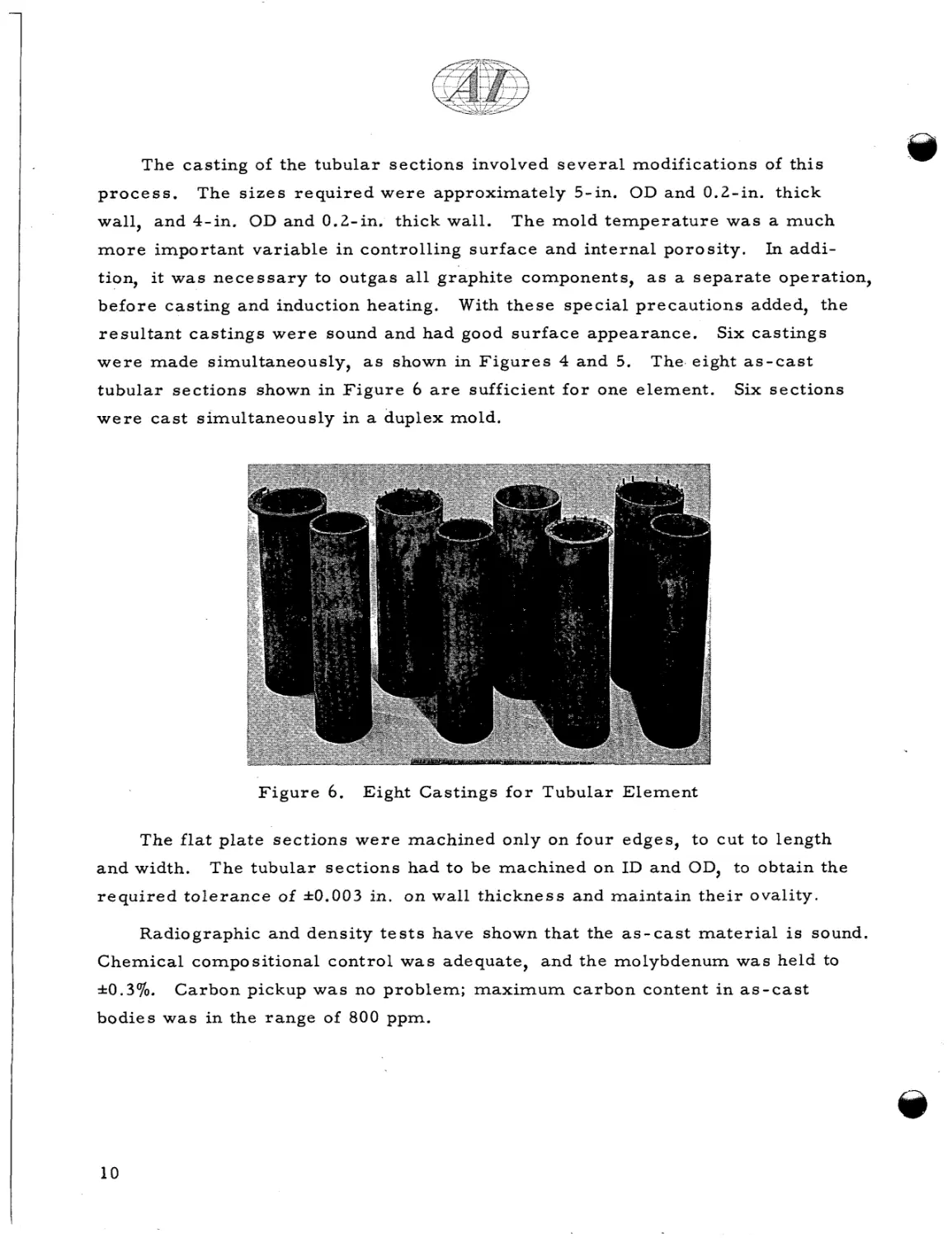
The eight a s - c a s t
tubular sections shown in F i g u r e 6 a r e sufficient f o r one element.
Six sections
w e r e c a s t simultaneously i n a duplex mold.
F i g u r e 6.
Eight Castings f o r Tubular Element
The f l a t plate sections w e r e machined only on four edges, to cut to length
a n d width.
The tubular sections had to be machined on ID and OD, to obtain the
r e q u i r e d t o l e r a n c e of *0.003 in. on wall thickness and maintain t h e i r ovality.
Radiographic and density t e s t s have shown that the a s - c a s t m a t e r i a l i s sound.
Chemical compositional control w a s adequate, and the molybdenum was held to
*0.3%.
Carbon pickup w a s no problem; maximum c a r b o n content i n a s - c a s t
bodies was in the range of 800 ppm.
10
I
,
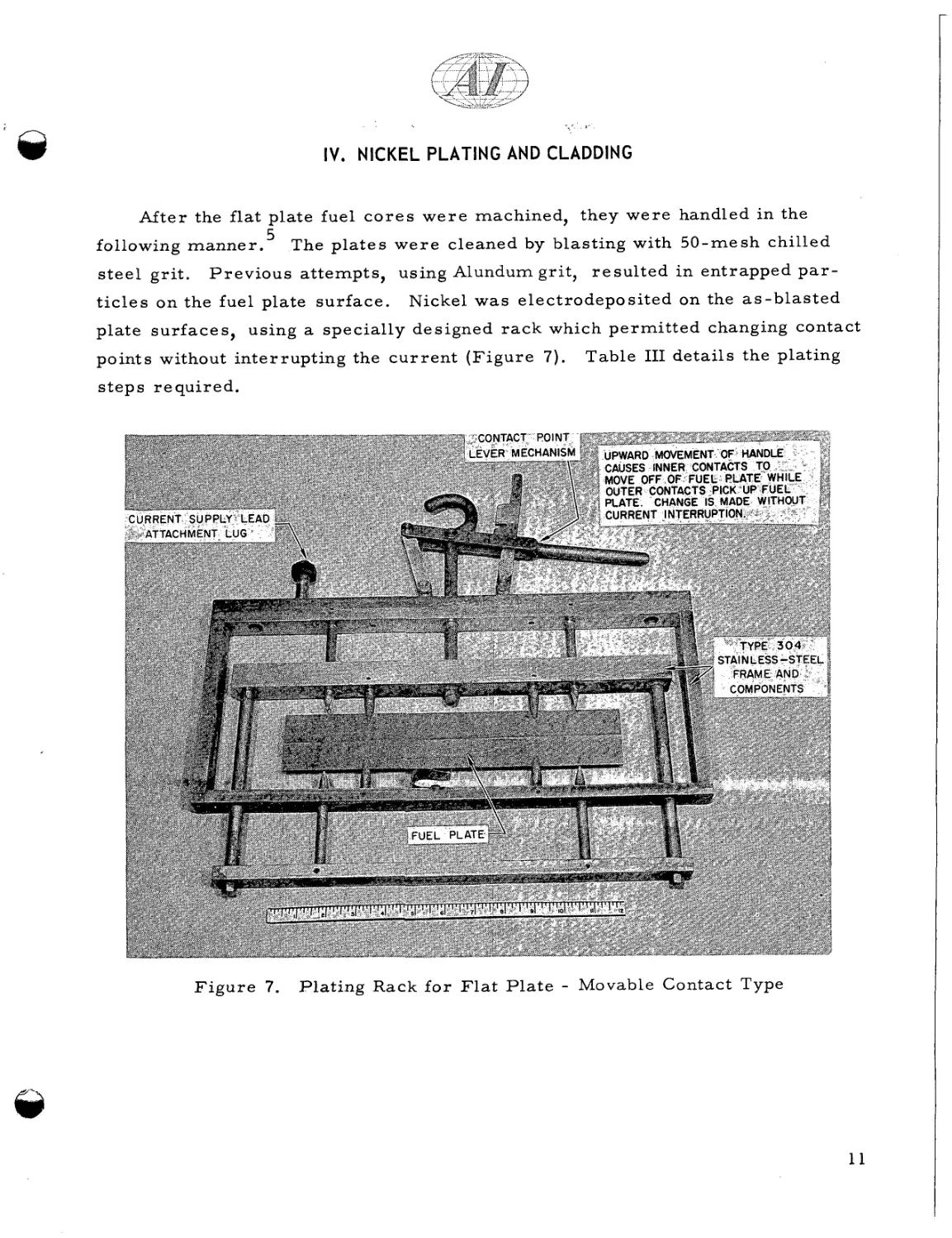
IV, NICKEL PLATING AND CLADDING
After the flat plate fuel c o r e s w e r e machined, they w e r e handled in the
5
The p l a t e s w e r e cleaned by blasting with 50-mesh chilled
following m a n n e r .
steel grit.
P r e v i o u s attempts, using Alundum grit, r e s u l t e d i n entrapped p a r -
t i c l e s on the fuel plate surface.
Nickel w a s electrodeposited on the a s - b l a s t e d
plate s u r f a c e s , using a specially designed r a c k which p e r m i t t e d changing contact
points without interrupting the c u r r e n t ( F i g u r e 7).
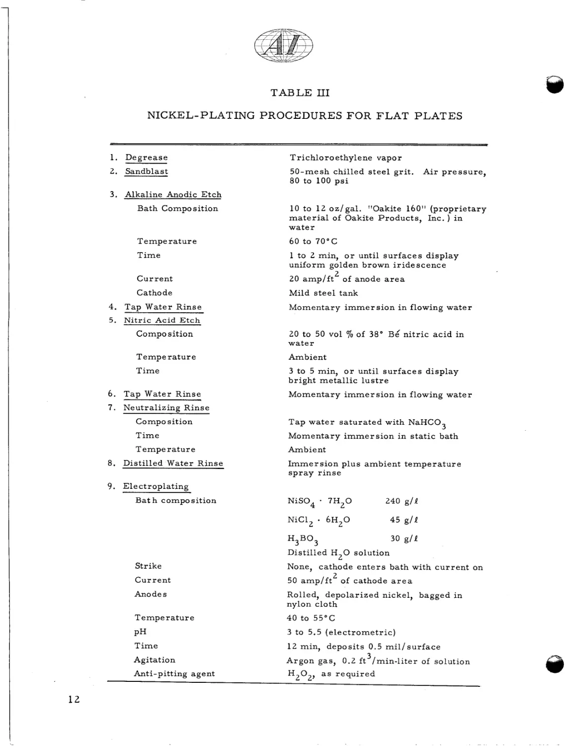
Table I11 details the plating
steps required.
F i g u r e 7.
Plating Rack f o r F l a t P l a t e - Movable Contact Type
TABLE I11
NICKEL-PLATING PROCEDURES FOR F L A T P L A T E S
1. Degrease
2.
Sandblast
T r ic hlo r o ethylene vapor
50-mesh chilled s t e e l g r i t .
80 to 100 p s i
Air p r e s s u r e ,
3 . Alkaline Anodic E t c h
Bath Composition
10 to 12 o z / g a l . "Oakite 160" ( p r o p r i e t a r y
m a t e r i a l of Oakite Products, Inc. ) in
water
Temperature
60 to 70°C
Time
Current
1 to 2 min, o r until s u r f a c e s display
uniform golden brown iridescence
2
20 a m p / f t of anode a r e a
Cathode
Mild s t e e l tank
4. Tap Water Rinse
Momentary i m m e r s i o n i n flowing water
5. N i t r i c Acid E t c h
70of
38" Be/ n i t r i c acid in
Composition
20 to 50 vol
water
Temperature
Ambient
Time
3 to 5 min, o r until s u r f a c e s display
bright metallic l u s t r e
6. Tap Water Rinse
Momentary i m m e r s i o n in flowing w a t e r
7 . Neutralizine Rinse
Compo sition
Tap w a t e r s a t u r a t e d with NaHC03
Time
Momentary i m m e r s i o n in s t a t i c bath
Temperature
Ambient
8. Distilled Water Rinse
I m m e r s i o n plus ambient t e m p e r a t u r e
spray rinse
9. Electroplating
B a t h composition
NiS04
NiCIZ
*
-
7H20
240 g / l
6H20
4 5 g/P
H3B03
30 g/P
Distilled H 2 0 solution
Strike
Current
12
None, cathode e n t e r s bath with c u r r e n t on
2
50 a m p / f t of cathode a r e a
Anodes
Rolled, depolarized nickel, bagged in
nylon cloth
Temperature
40 to 55°C
PH
3 to 5.5 ( e l e c t r o m e t r i c )
Time
Agitation
12 min, deposits 0.5 m i l / s u r f a c e
3
Argon gas, 0.2 f t / m i n - l i t e r of solution
Anti-pitting agent
HZ02, a s r e q u i r e d
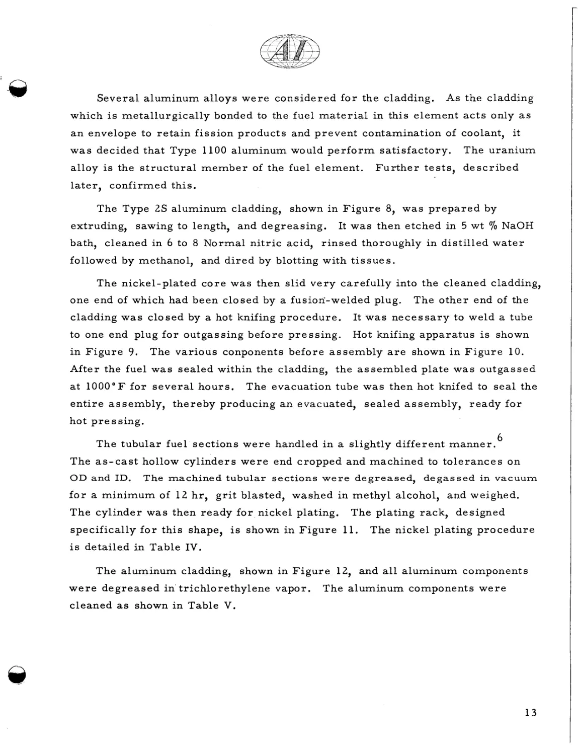
Several aluminum alloys w e r e considered f o r the cladding.
As the cladding
which is metallurgically bonded to the fuel m a t e r i a l in this element a c t s only a s
a n envelope to r e t a i n f i s s i o n products and prevent contamination of coolant, it
w a s decided that Type 1100 aluminum would p e r f o r m s a t i s f a c t o r y .
alloy is the s t r u c t u r a l m e m b e r of the fuel element.
The uranium
Further tests, described
later, confirmed this.
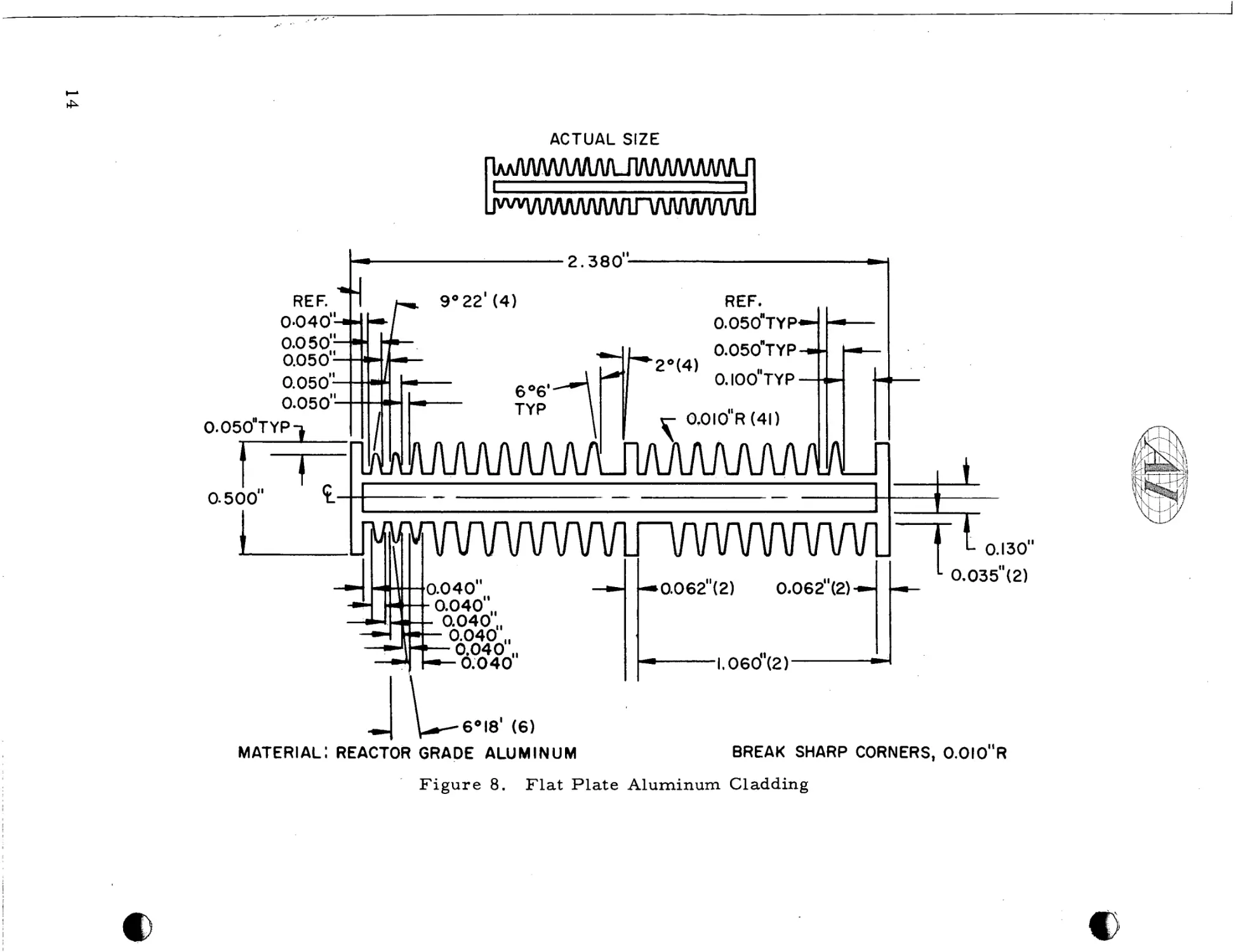
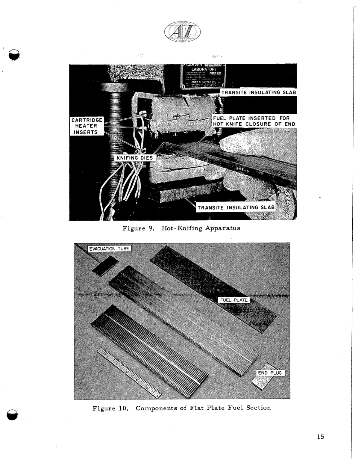
The Type 2s aluminum cladding, shown in F i g u r e 8, was p r e p a r e d by
extruding, sawing to length, and degreasing.
It w a s then etched in 5 wt
70 NaOH
bath, cleaned in 6 to 8 Normal n i t r i c acid, r i n s e d thoroughly in distilled w a t e r
followed by methanol, and d i r e d by blotting with t i s s u e s .
The nickel-plated c o r e was then slid v e r y carefully into the cleaned cladding,
one end of which had been closed by a fusion'-welded plug.
The o t h e r end of the
cladding w a s closed by a hot knifing procedure.
It w a s n e c e s s a r y to weld a tube
to one end plug f o r outgassing before p r e s s i n g .
Hot knifing a p p a r a t u s i s shown
i n F i g u r e 9.
The various conponents before a s s e m b l y a r e shown i n F i g u r e 10.
After the f u e l was sealed within the cladding, the a s s e m b l e d plate w a s outgassed
a t 1 0 0 0 ° F for s e v e r a l hours.
The evacuation tube was then hot knifed to s e a l the
e n t i r e assembly, t h e r e b y producing a n evacuated, s e a l e d assembly, r e a d y f o r
hot p r e s sing.
The tubular fuel sections w e r e handled i n a slightly different m a n n e r .
6
The a s - c a s t hollow cylinders w e r e end cropped and machined to t o l e r a n c e s on
OD and ID.
The machined tubular s e c t i o n s w e r e d e g r e a s e d , d e g a s s e d in vacuum
f o r a minimum of 12 h r , g r i t blasted, washed in methyl alcohol, and weighed.
The cylinder was then ready f o r nickel plating.
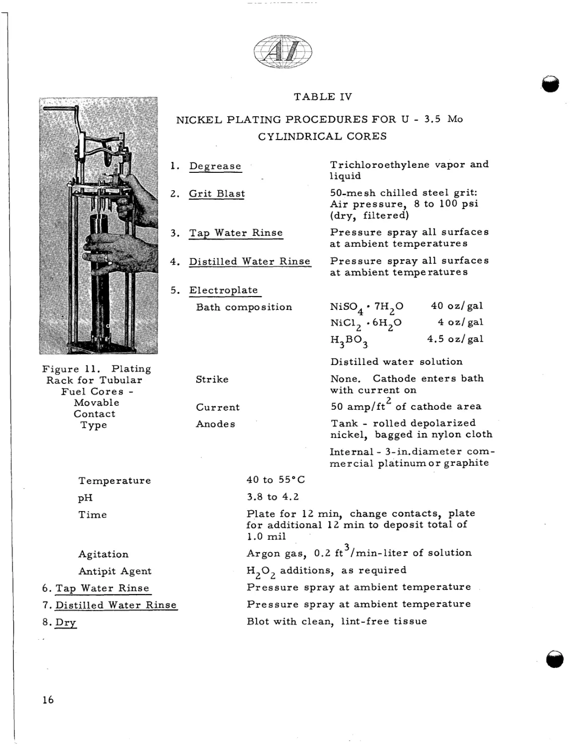
The plating rack, designed
specifically f o r t h i s shape, is shown i n F i g u r e 11.
The nickel plating p r o c e d u r e
is detailed in Table IV.
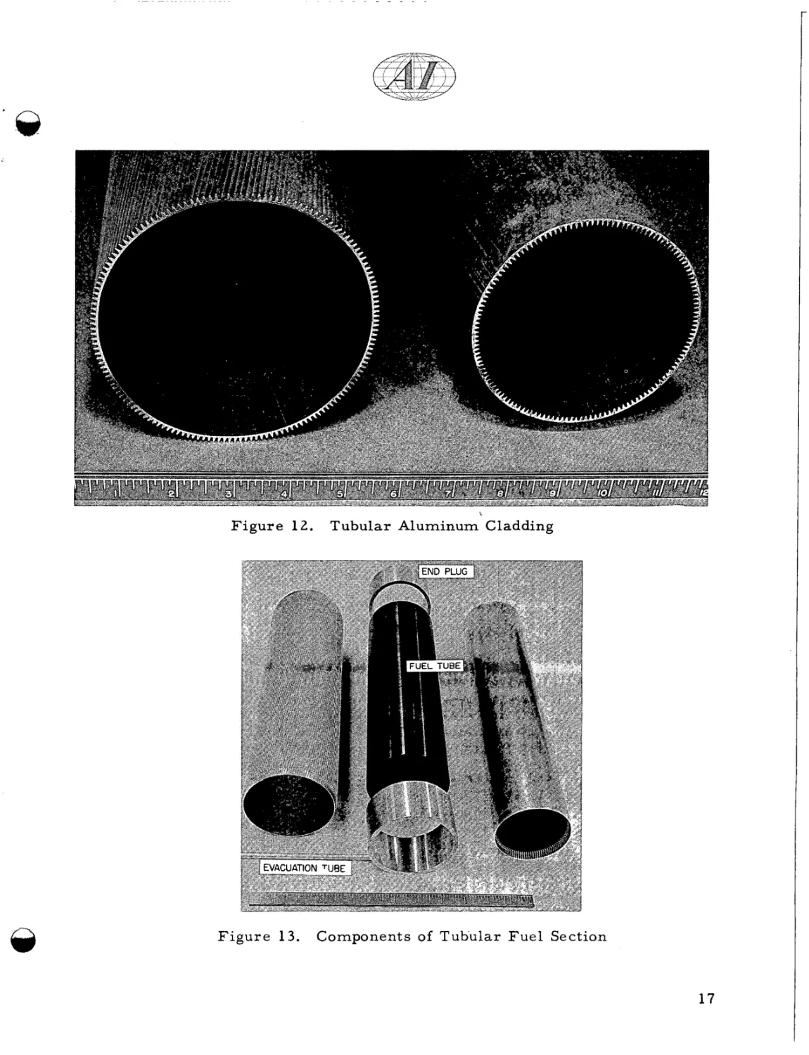
The aluminum cladding, shown in F i g u r e 12, and all aluminum components
w e r e d e g r e a s e d in' trichlorethylene vapor.
The aluminum components w e r e
cleaned as shown in Table V.
13
*
'
,
I
,,. .
ACTUAL SIZE
-k
-
2.380"
REF.
0.050"TY
Pd -I
1
-
1
I
0.062"( 2 1
it
0.06 2"(2)
I
0.035"(2)
L 6 ' 1 8 ' (6)
MATERIAL: REACTOR GRADE ALUMINUM
F i g u r e 8.
BREAK SHARP CORNERS, 0.010"R
F l a t P l a t e Aluminum Cladding
TRANSITE INSULATING SLAB
.’
F i g u r e 9.
F i g u r e 10.
Hot-Knifing A p p a r a t u s
Components of Flat Plate F u e l Section
:-
.: .
TABLE IV
NICKEL PLATING PROCEDURES FOR U
-
3.5 MO
CYLINDRICAL CORES
Trichloroethylene vapor and
liquid
1. D e g r e a s e
2.
50-mesh chilled s t e e l grit:
A i r p r e s s u r e , 8 to 100 p s i
(dry, f i l t e r e d )
G r i t Blast
3. T a p Water Rinse
4.
Distilled Water Rinse
P r e s s u r e s p r a y all s u r f a c e s
at ambient t e m p e r a t u r e s
P r e s s u r e s p r a y all s u r f a c e s
at a m b i e n t t e m p e r a t u r e s
5. E l e c t r o p l a t e
Bath compo s ition
NiS04
7H20
NiC12 . 6 H 2 0
H3B03
F i g u r e 11. Plating
Rack f o r Tubular
Fuel Cores Movable
Contact
Type
40 oz/gal
4 oz/gal
4.5 o z / g a l
Distilled w a t e r solution
None. Cathode e n t e r s bath
with c u r r e n t on
2
50 a m p / f t of cathode a r e a
Strike
Current
Tank - r o l l e d depolarized
nickel, bagged i n nylon cloth
Anodes
I n t e r n a l - 3-in.diameter c o m m e r c i a l p l a t i n u m o r graphite
Temperature
40 to 55°C
PH
Time
3.8 to 4 . 2
Agitation
P l a t e f o r 1 2 min, change contacts, plate
f o r additional 12 m i n to deposit total of
1.0 mil
3
Argon gas, 0 . 2 f t / m i n - l i t e r of solution
Antipit Agent
H 2 0 2 additions, a s r e q u i r e d
6. T a p Water Rinse
P r e s s u r e s p r a y a t ambient t e m p e r a t u r e
7. Distilled Water Rinse
P r e s s u r e s p r a y at ambient t e m p e r a t u r e
8. D r y
Blot with clean, l i n t - f r e e t i s s u e
16
i
F i g u r e 12.
Figure 13.
T u b u l a r Aluminum Cladding
Components of T u b u l a r F u e l Section
17
TABLE V
TUBULAR ALUMINUM CLADDING SURFACE PREPARATION
1. D e g r e a s e
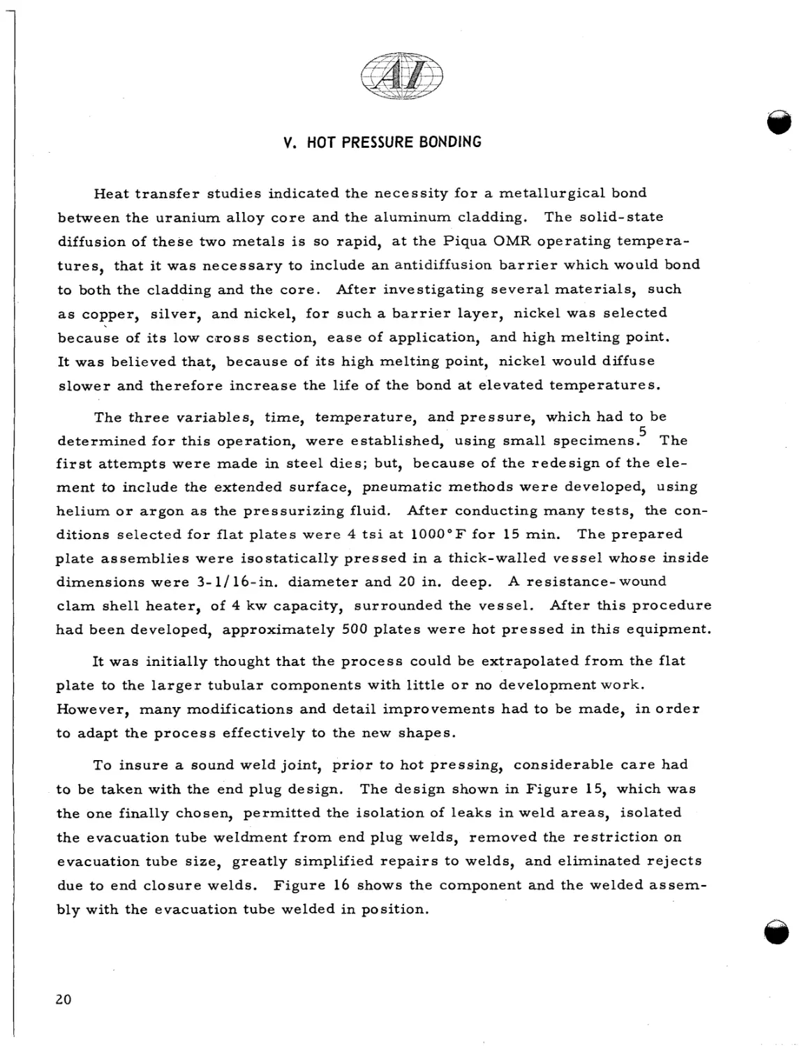
Trichlorethylene vap0.r and liquid
2. Alkaline E t c h
Bath Compo s ition
1 2 o z / g a l of "Oakite 160" ( p r o p r i e t a r y
m a t e r i a l of Oakite P r o d u c t s , Inc.) i n w a t e r
Temperature
60 to 70°C
Time
1 min
3. T a p Water Rinse
Momentary i m m e r s i o n
4. Nitric Acid Clean
Bath Compo sition
6 to 8 N o r m a l n i t r i c a c i d
Temperature
Amb i e nt
T ime
'
1 to 2 min
5. Tap Water Rinse
Momentary i m m e r s i o n
6. Distilled Water Rinse
Pressure spray
7. A i r D r y
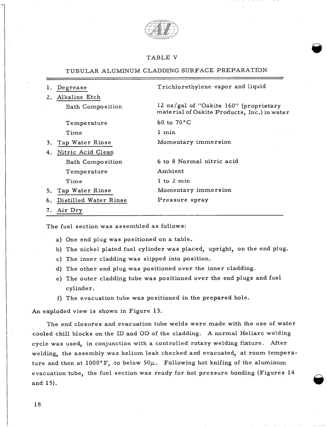
The fuel section w a s a s s e m b l e d a s follows:
I
a ) One end plug w a s positioned on a table.
b ) The nickel plated fuel cylinder w a s placed, upright, on the end plug.
c ) The i n n e r cladding w a s slipped into position.
d ) The o t h e r end plug w a s positioned o v e r the i n n e r cladding.
e ) The o u t e r cladding tube w a s positioned o v e r the end plugs and fuel
cylinder.
f ) The evacuation tube w a s positioned i n the p r e p a r e d hole.
An exploded view is shown i n F i g u r e 13.
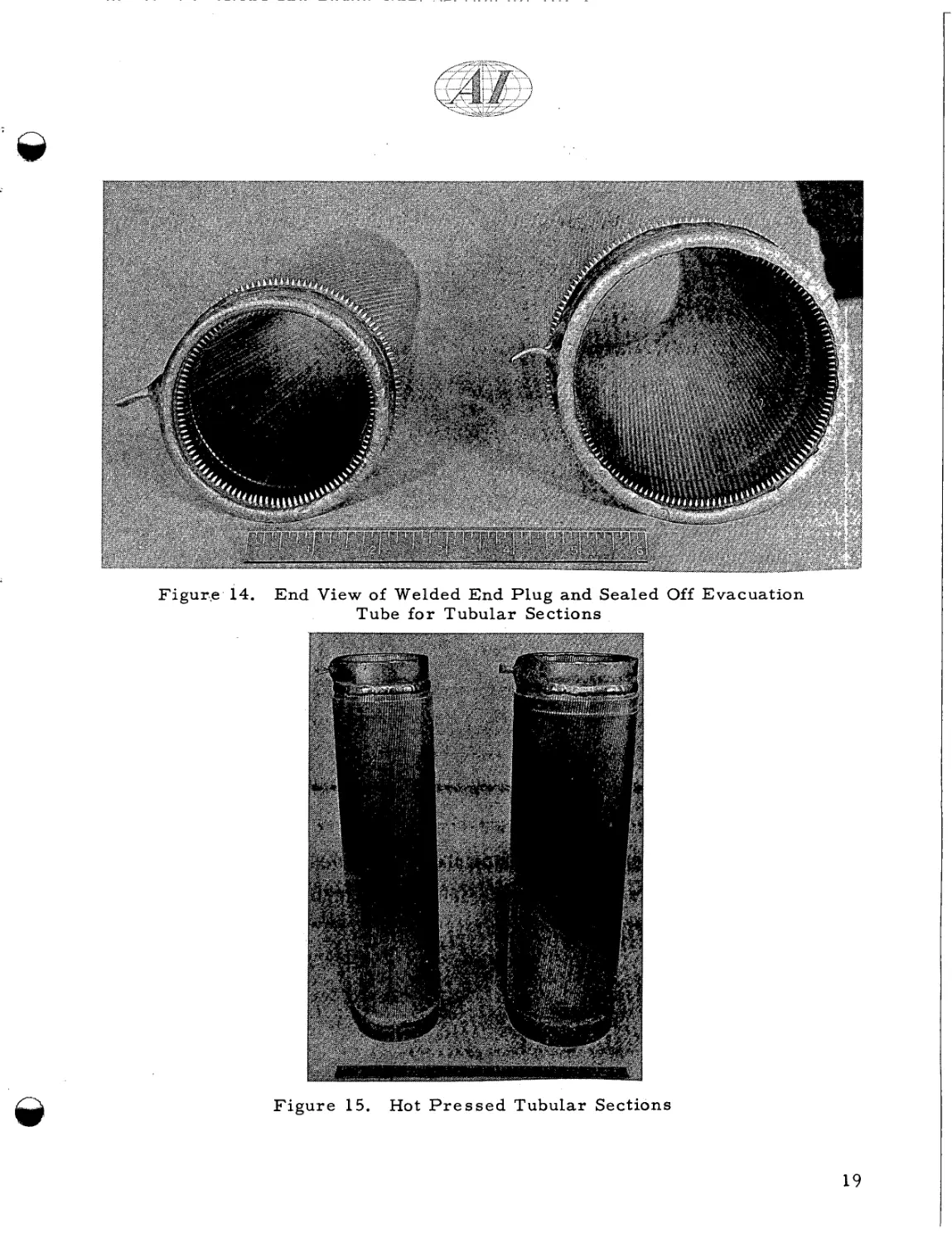
The end c l o s u r e s and evacuation tube welds w e r e m a d e with the u s e of w a t e r
cooled chill blocks on the ID and OD of the cladding.
A n o r m a l H e l i a r c welding
cycle w a s used, i n conjunction with a controlled r o t a r y welding f i x t u r e .
After
welding, the a s s e m b l y w a s h e l i u m l e a k checked and evacuated, at r o o m t e m p e r a t u r e and then at 1000°F, to below 5 0 ~ . Following hot knifing of the aluminum
evacuation tube, the fuel section was r e a d y f o r hot p r e s s u r e bonding ( F i g u r e s 14
and 15).
18
Figur.e 14. End View of Welded End P l u g and Sealed Off Evacuation
Tube f o r Tubular Sections
F i g u r e 15.
Hot P r e s s e d Tubular Sections
19
V. HOT PRESSURE BONDING
Heat t r a n s f e r studies indicated the n e c e s s i t y f o r a m e t a l l u r g i c a l bond
between the uranium alloy c o r e and the aluminum cladding.
The solid-state
diffusion of t h e s e two m e t a l s is so rapid, at the Piqua OMR operating t e m p e r a t u r e s , that it was n e c e s s a r y to include a n antidiffusion b a r r i e r which would bond
to both the cladding and the c o r e .
After investigating s e v e r a l materials, such
as copper, silver, and nickel, f o r s u c h a b a r r i e r l a y e r , nickel was selected
because of its low c r o s s section, e a s e of application, and high melting point.
It w a s believed that, because of its high melting point, nickel would diffuse
slower and t h e r e f o r e i n c r e a s e the life of the bond at elevated t e m p e r a t u r e s .
The t h r e e variables, time, t e m p e r a t u r e , and p r e s s u r e , which had to be
d e t e r m i n e d f o r t h i s operation, w e r e established, using small specimens?
The
first a t t e m p t s w e r e made in s t e e l d i e s ; but, because of the r e d e s i g n of t h e e l e m e n t to include the extended surface, pneumatic methods w e r e developed, using
helium o r a r g o n as the p r e s s u r i z i n g fluid.
After conducting many t e s t s , the con-
ditions s e l e c t e d f o r flat p l a t e s w e r e 4 t s i at 1 0 0 0 ° F f o r 15 min.
The p r e p a r e d
plate a s s e m b l i e s w e r e i s o s t a t i c a l l y p r e s s e d i n a thick-walled v e s s e l whose inside
dimensions w e r e 3- 1/ 16-in. d i a m e t e r and 20 in. deep.
A r e s i s t a n c e - wound
c l a m shell heater, of 4 kw capacity, surrounded the v e s s e l .
After t h i s p r o c e d u r e
had been developed, approximately 500 p l a t e s w e r e hot p r e s s e d in t h i s equipment.
It w a s initially thought that the p r o c e s s could be extrapolated f r o m the flat
plate to the l a r g e r tubular components with little o r no development work.
However, many modifications and detail i m p r o v e m e n t s had t o be made, i n o r d e r
to adapt the p r o c e s s effectively to the new shapes.
To i n s u r e a sound weld joint, p r i o r to hot p r e s s i n g , considerable c a r e had
t o be taken with the end plug design,
The design shown in F i g u r e 15, which was
t h e one finally chosen, p e r m i t t e d the isolation of l e a k s i n weld areas, isolated
the evacuation tube weldment f r o m end plug welds, r e m o v e d the r e s t r i c t i o n on
evacuation tube size, g r e a t l y simplified r e p a i r s to welds, and eliminated r e j e c t s
due to end c l o s u r e welds.
F i g u r e 16 shows the component and the welded a s s e m -
bly with the evacuation tube welded in position.
20
F i g u r e 16. Components of Tubular Section,
Showing Evacuation Tube Welded to End Plug
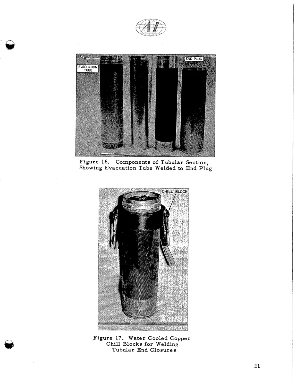
F i g u r e 17. Water Cooled Copper
Chill Blocks f o r Welding
Tubular End C l o s u r e s
21
Another problem, which was not evident with flat plates, was the effect that
the welding of end plugs had on the other components.
The amount of heat g e n e r a -
ted, during the welding cycle with tubular f u e l , oxidized the nickel-plated
uranium to a n extent which prevented complete diffusion during subsequent hot
pressing.
A w a t e r cooled copper chill block had to be designed; i t s u s e s u c c e s s -
fully prevented the cladding f r o m reaching a t e m p e r a t u r e higher than 1 5 0 ° F .
F i g u r e 1 7 depicts such an a r r a n g e m e n t .
Because the mass of the cylindrical sections w a s approximately 10 t i m e s
that of the flat plates, it soon became evident that it would be n e c e s s a r y to outgas
t h e individual c a s t sections, to r e m o v e the dissolved and absorbed g a s e s .
An
outgassing cycle, of 16 h r at 1 0 5 0 ° F in a vacuum of 5 p o r l e s s , was satisfactory;
but a n optimum cycle w a s not determined.
Hot isostatic bonding of t u b u l a r sections r e q u i r e d a much l a r g e r and complex
facility than previously r e p o r t e d .
5
The p r e s s u r e v e s s e l was 6 in. ID, 18 in.
effective depth, and w a s r a t e d at 15000 p s i at 1000°F.
r a t e d at 10,000 p s i f o r continuous delivery of argon.
The gas c o m p r e s s o r was
The f u r n a c e f o r heating was
a n air c i r c u l a t o r y type, r a t e d at 3 3 kw.
After completion of many o t h e r m i n o r modifications, which a r e detailed i n
Reference 6, the tubular sections w e r e successfully and repeatedly hot p r e s s u r e
bonded ( F i g u r e 15).
22
VI. BOND EVALUATION AND TESTING
The A1-Ni-U s y s t e m h a s been studied at many different s i t e s .
A good
s u m m a r y of the work is given in Reference 7.
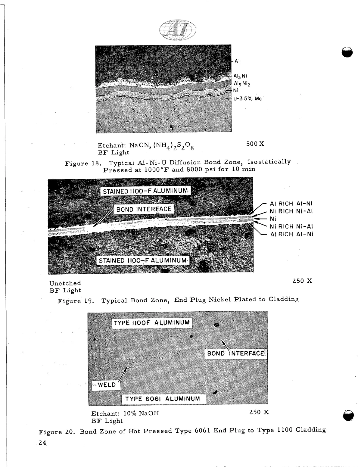
During the development of the flat plate element, a 0.001-in. thick nickel
deposit was applied to all s u r f a c e s .
A typical diffusion bond zone which r e s u l t e d
a f t e r hot p r e s s i n g is shown i n F i g u r e 18.
The aluminum end plugs w e r e a l s o
nickel plated, as it was thought that d i s s i m i l a r m e t a l s would promote b e t t e r
bonding.
F i g u r e 19 shows a typical bond a r e a in the aluminum end plug-to-
cladding region.
While developing the hot p r e s s i n g techniques f o r the tubular element, s e v e r a l
m i n o r changes w e r e included to improve the bonding.
An a l t e r n a t e cleaning cycle
w a s attempted, which used a nitric-hydrofluoric a c i d combination, in place of
n i t r i c acid, but t h i s t u r n e d out to have many disadvantages.
Finally, i t was
decided to nickel plate d i r e c t l y onto a s t e e l - g r i t blasted s u r f a c e .
shows the r e s u l t i n g Al-Ni-U interface.
F i g u r e 18
Good bonding was confirmed by c h i s e l
peel t e s t s and metallographic examination.
F o r aluminum end plug-to- cladding
bonds to be obtained without a nickel layer, it w a s found that p r o p e r s u r f a c e
p r e p a r a t i o n p e r m i t t e d good bonding.
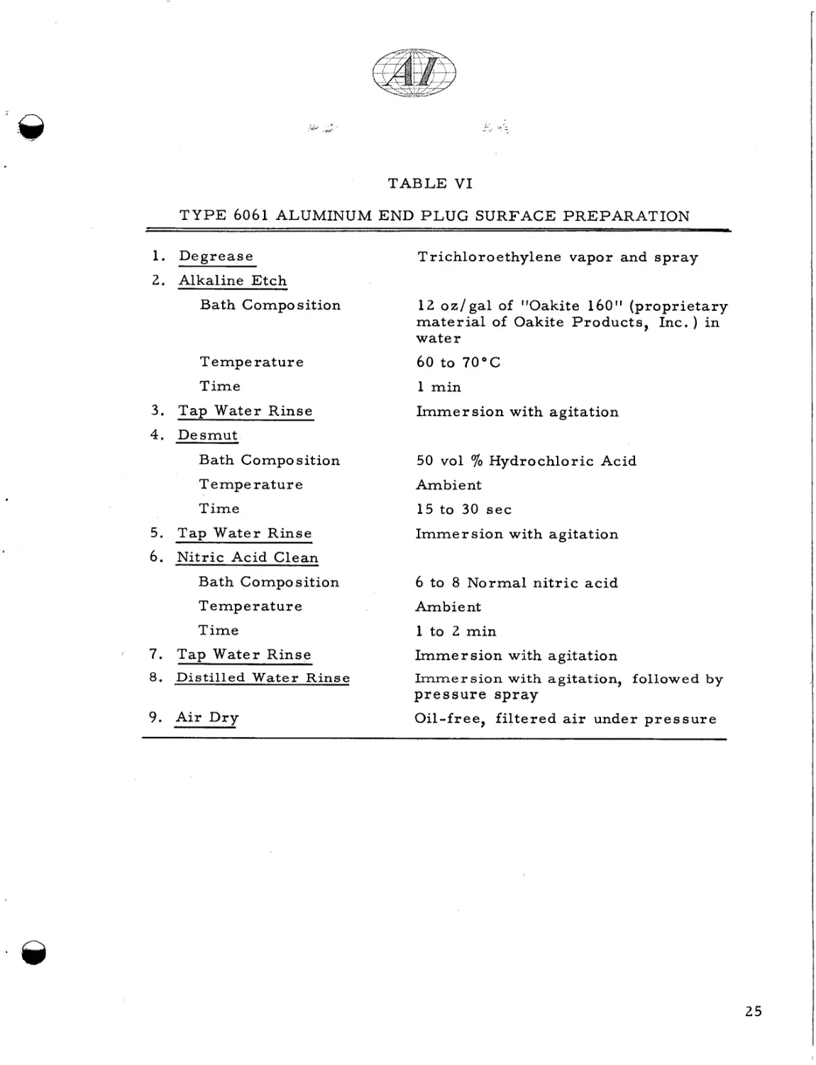
Table V I e n u m e r a t e s s t e p s f o r good
s u r f a c e p r e p r a t i o n of Type 6061 aluminum.
A typical photomicrograph of
Type 1100 cladding to Type 6061 end plug is shown in F i g u r e 20.
The testing of the m e t a l l u r g i c a l bond is a p r e r e q u i s i t e for good quality control.
P r o c e d u r e s used included metallographic examination, peel t e s t , and
m a c r o etching.
No s a t i s f a c t o r y nondestructive t e s t is known f o r evaluation of
the bond with the p a r t i c u l a r geometry p r e s e n t h e r e .
Most nondestructive t e s t s
m e a s u r e the change in thickness of m a t e r i a l s ; and, because of the extended
surface, the thickness of the bonded section is quite variable.
c u r r e n t , sonic, and i n f r a r e d methods w e r e t r i e d .
Ultrasonic, eddy
P r e l i m i n a r y evaluation
indicated that the m o s t p r o m i s i n g of t h e s e i s the transient-heating i n f r a r e d
scanning procedure, but m o r e development is r e q u i r e d to e s t a b l i s h it as a n
e n t i r e l y reliable t e s t .
23
AI
AI3 Ni
AI, Ni2
Ni
U-3.5O/o M O
Etchant: NaCN, (NH4)2S208
B F Light
F i g u r e 18.
500 X
Typical Al-Ni-U Diffusion Bond Zone, Isostatically
P r e s s e d a t 1000°F and 8000 p s i f o r 10 min
r AI R I C H AI-Ni
/INi
C
I
R I C H Ni-AI
- Ni
t.
Ni RICH
\ AI RICH
-
'
Ni-AI
AI-Ni
250 X
Une t ched
B F Light
F i g u r e 19.
Typical Bond Zone, End Plug Nickel P l a t e d to Cladding
Etchant: 1 0 % NaOH
B F Light
250 X
F i g u r e 20. Bond Zone of Hot P r e s s e d Type 6061 End P l u g to Type 1100 Cladding
24
TABLE V I
T Y P E 6061 ALUMINUM END P L U G SURFACE PREPARATION
1. D e g r e a s e
-
Trichloroethylene vapor and s p r a y
2. Alkaline E t c h
3.
Bath Compo sition
1 2 o z / g a l of "Oakite 160" ( p r o p r i e t a r y
m a t e r i a l of Oakite P r o d u c t s , Inc. ) i n
water
T e m p e rat u r e
60 to 70°C
Time
1 min
T a p Water Rinse
I m m e r s i o n with agitation
4. Desmut
70 Hydrochloric
Bath Composition
50 vol
T e mpe rat u r e
Ambient
Time
15 to 30 s e c
5. T a p Water Rinse
Acid
I m m e r s i o n with agitation
6. Nitric Acid Clean
I
Bath Composition
6 to 8 N o r m a l n i t r i c a c i d
T e m p e r at u r e
Ambient
Time
1 to 2 min
7. Tap Water Rinse
8. Distilled W a t e r Rinse
Irnmer sion with agitation
Immersion with agitation, followed by
pressure spray
9. A i r Dry
Oil-free, f i l t e r e d air under p r e s s u r e
26
d
c,
:
Q)
Q)
2
d
c,
E
d
c,
c
N
Q)
d
d
I
;;;
k
2
0
%I
a,
a
2
E
Q)
m
*
F
m
a,
d
c,
N
4
a,
M
3
k
.d
6(
r..
%
Gq%.,
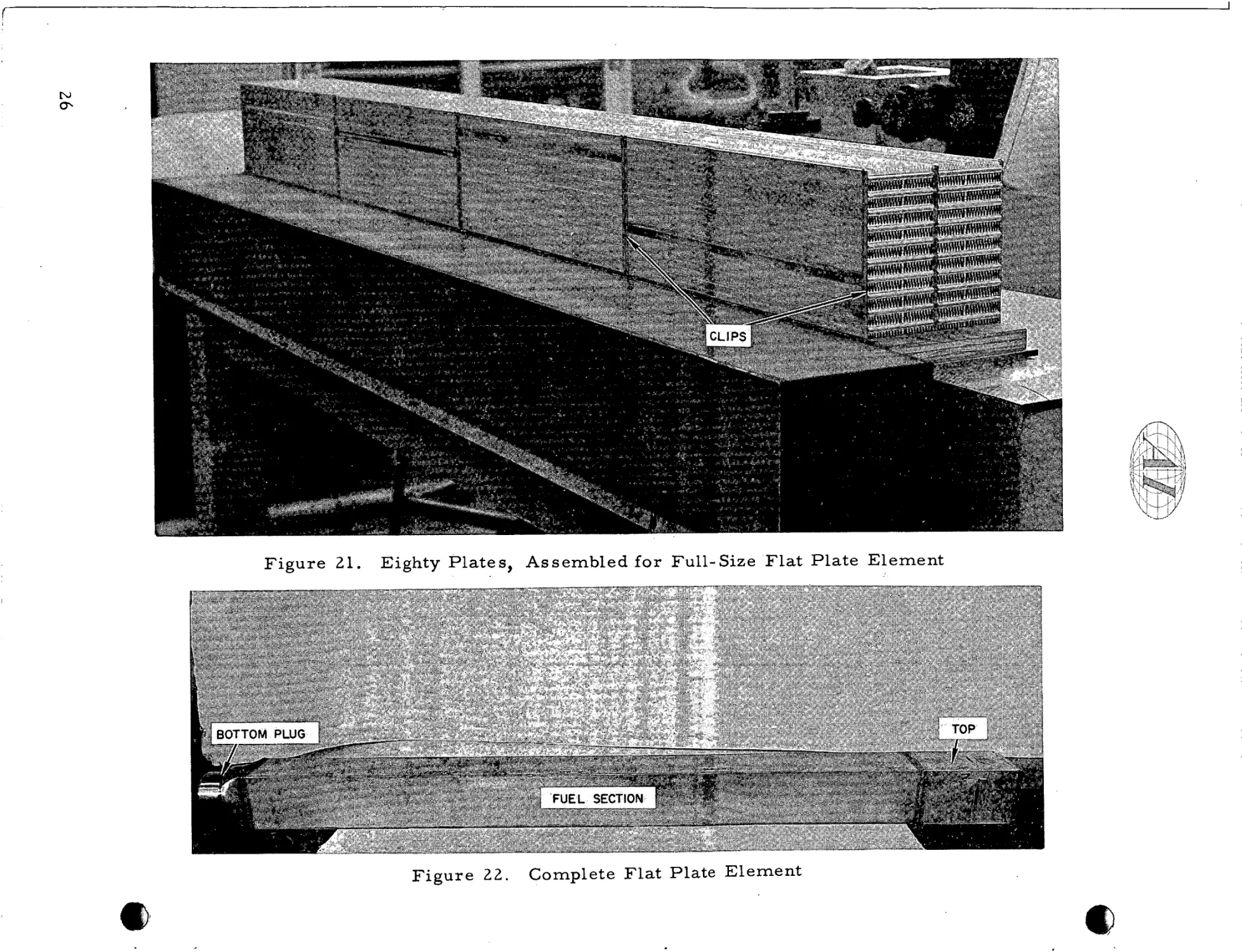
VII. FINAL ASSEMBLY
After the hot p r e s s e d components w e r e inspected, the fuel element was
assembled.
required.
T h i s step was accomplished with very little development work
During the p r o c e s s development, s e v e r a l f u l l - s i z e mockup e l e m e n t s
w e r e made, of both flat plate and tubular sections.
The flat plate element consisted of 80 fuel sections which w e r e a s s e m b l e d
into 4 bundles of 20 plates each.
The a s s e m b l y sequence f o r the flat plate e l e m e n t was:
a ) P l a c e 2 fuel-plate stacks, of 10 p l a t e s each, 2 plates wide, on a flat
surface.
b) Affix a p a i r of p a r a l l e l c l a m p s at each end of the fuel section.
Tighten the c l a m p s until all f u e l plate s p a c e r s a r e in intimate contact.
c ) P l a c e the fuel section on end and affix s t a i n l e s s s t e e l retaining clips
to the middle and o u t e r aluminum fuel plate s p a c e r s .
Use special
staking p l i e r s to s e c u r e the clips to the aluminum s p a c e r s .
( F i g u r e 21
shows such a n a r r a n g e m e n t . )
d) Repeat operation ( c ) on the opposite end of t h e fuel section, f o r all
4 fuel bundles.
e ) The s u b a s s e m b l i e s (20-plate bundles) a r e slid into a s t a i n l e s s s t e e l
o u t e r box. The 4 s u b a s s e m b l i e s a r e stacked and a s s e m b l e d , with
tongue and groove, to t h e i r p r e d e t e r m i n e d position.
f ) The head extension, o u t e r box, and lower plug a r e a s s e m b l e d in a
welding jig, and junctions between the components a r e welded.
g) The finished element is m e a s u r e d f o r Total Indicated Reading (TIR)
and length, and the welds a r e nondestructively examined.
F i g u r e 22
shows a completed element.
The a s s e m b l y p r o c e d u r e f o r the tubular element was:
a) P l a c e the lower plug in an upright position
b) P l a c e the inner s t a i n l e s s s t e e l can, upright, in i t s s e a t in the lower
Plug.
27
F i g u r e 23. Tubular Sections,
As s e m b l e d f o r F u l l - S i z e
Element
F i g u r e 24. Complete Full-Size
Tubular E l e m e n t
28
c ) Position the inner fuel sections on the inner sleeve (The bottom s e c tion r e s t s on i t s s e a t in the lower plug);=.
~
d ) Position the outer fuel section concentric with the inner section, and
.
4
:. :+.
c
s e a t it on the lower plug.
e ) Position the second inner section around the inner can and s e a t i t on
the bottom fuel section.
f ) Position the second o u t e r section on the bottom outer section.
g) Repeat these operations until all eight sections a r e loaded.
Figure 2 3
shows the stacked fuel sections.
h ) Position the outer s t a i n l e s s s t e e l c a n around the fuel s t a c k s and s e a t
it on the lower plug.
i) Position the upper plug, with its premachined s e a t r e s t i n g on the ID
of the o u t e r can.
j ) P l a c e the a s s e m b l y in a welding jig, and join all components by
welding.
k ) Measure the finished element f o r TIR and length, and nondestructively
examine all welds.
The completed element i s shown i n F i g u r e 24.
One of the m a j o r differences in design between flat plate and tubular e l e m e n t s was the addition, to the l a t t e r , of a variable o r i f i c e to control coolant
flow.
T h i s and the locking m e c h a n i s m , s c r e e n , and s u p p o r t b a r s a r e p r e -
f a b r i c a t e d and assembled, p r i o r to final a s s e m b l y .
29
?
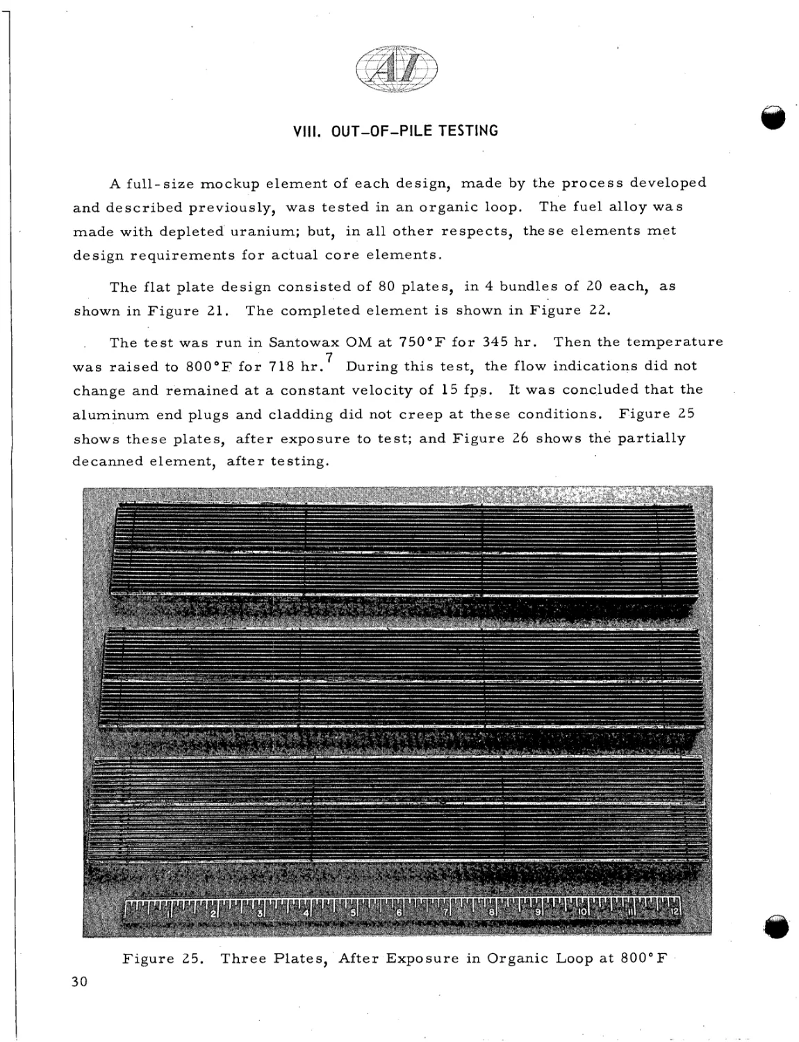
VIII. OUT-OF-PILE TESTING
A f u l l - s i z e mockup e l e m e n t of each design, made by the p r o c e s s developed
and d e s c r i b e d previously, w a s t e s t e d in a n o r g a n i c loop.
The fuel alloy w a s
m a d e with depleted uranium; but, in a l l o t h e r r e s p e c t s , t h e s e e l e m e n t s m e t
d e s i g n r e q u i r e m e n t s f o r actual c o r e e l e m e n t s .
The flat plate design consisted of 80 plates, in 4 bundles of 20 each, as
shown in F i g u r e 21.
The completed e l e m e n t i s shown i n F i g u r e 22.
The t e s t w a s r u n in Santowax OM at 7 5 0 ° F f o r 345 h r . Then the t e m p e r a t u r e
7
w a s r a i s e d to 8 0 0 ° F f o r 718 h r .
During t h i s t e s t , the flow indications did not
.
change and r e m a i n e d a t a constant velocity of 15 fp.s.
It w a s concluded that the
aluminum end plugs and cladding did not c r e e p at these conditions.
F i g u r e 25
shows t h e s e plates, a f t e r exposure to t e s t ; and F i g u r e 26 shows the partially
decanned element, a f t e r testing.
F i g u r e 25.
30
T h r e e P l a t e s , After E x p o s u r e in Organic Loop a t 8 0 0 ° F
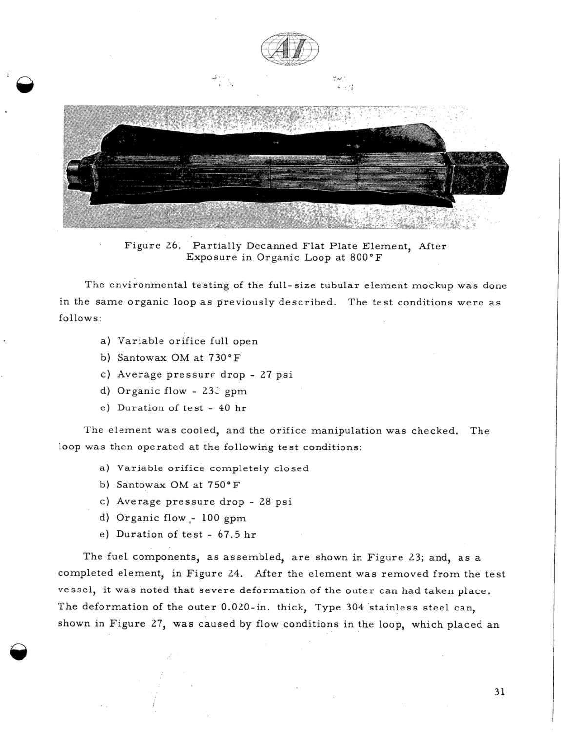
-0
F i g u r e 26.
P a r t i a l l y Decanned F l a t P l a t e Element, After
Exposure in Organic Loop a t 8 0 0 ° F
The environmental testing of the f u l l - s i z e tubular e l e m e n t mockup w a s done
in the s a m e o r g a n i c loop a s previously d e s c r i b e d .
The t e s t conditions w e r e a s
follows :
a ) Variable orifice full open
b) Santowax OM at 7 3 0 ° F
c ) Average p r e s s u r e d r o p
-
27 p s i
dj Organic flow - 23: gpm
e ) Duration of t e s t - 40 h r
The element w a s cooled, and the orifice manipulation was checked.
The
loop was then operated a t the following t e s t conditions:
a ) Variable o r i f i c e completely closed
b) Santowax OM a t 7 5 0 ° F
c ) Average p r e s s u r e d r o p
-
28 p s i
d ) Organic flowo- 100 gpm
e ) Duration of t e s t
-
67.5 h r
The fuel components, a s assembled, a r e shown in F i g u r e 23; and, a s a
completed element, in F i g u r e 24.
After the e l e m e n t w a s removed f r o m the t e s t
vessel, it w a s noted that s e v e r e deformation of the o u t e r c a n had taken place.
The deformation of the o u t e r 0.020-in. thick, Type 304 s t a i n l e s s s t e e l can,
shown in F i g u r e 27, w a s c a u s e d by flow conditions i n the loop, which placed an
31
32
0
6(
0
m
c,
tc.
rd
0
a
I O
4
0
.d
d
rd
M
d
6
a,
.PI
k
7
a
rn
0
4
Q)
k
3
N
[c
k
Q)
7
M
iz
7
k
Q)
a
rn
0
k
i
Q)
c1
2
Q)
Q)
N
M
7
k
iz
'
@
e x t e r n a l p r e s s u r e on the element.
The loop had been designed and built to
specifications f o r t h e flat plate element, f o r which a n e x t e r n a l p r e s s u r e on the
o u t e r c a n of the element i s a p r o p e r design condition.
The tubular element was
designed to have a n internal p r e s s u r e , at all t i m e s , which would prevent any
such buckling.
Another t e s t is scheduled, in a modified loop, and will be
reported separately.
After
An interesting f a c t w a s uncovered f r o m t h i s t e s t .
the fuel sections w e r e decanned, it w a s noted that the fins w e r e not damaged
and that the coolant channels r e m a i n e d open and complete.
This substantiated
the flow readings, which indicated no change i n flow throughout the test, although
the o u t e r can collapsed.
The p a r t i a l l y decanned fuel element i s shown i n
F i g u r e 28.
It w a s shown, f r o m these out-of-pile t e s t s , that the e l e m e n t s a r e s t r u c t u r a l l y sound.
The aluminum extended s u r f a c e cladding showed no tendency to
c r e e p and p e r f o r m e d exceedingly well, even under a d v e r s e conditions.
In
addition, it w a s proved that the variable o r i f i c e adequately controls t h e flow
and can be manipulated, a f t e r operating a t high t e m p e r a t u r e s in an o r g a n i c
medium.
33
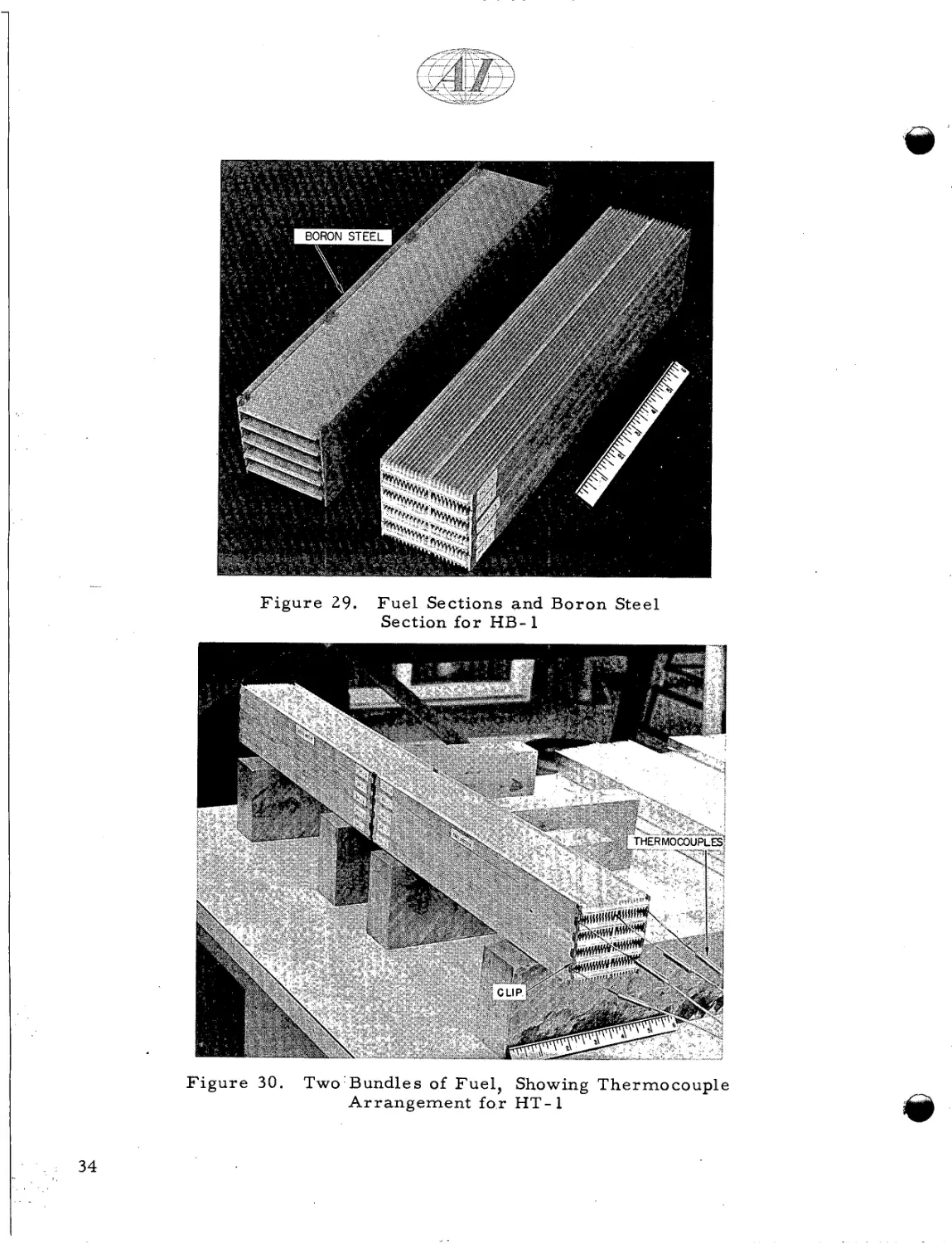
F i g u r e 29.
F i g u r e 30.
F u e l Sections and Boron Steel
Section f o r HB- 1
Two'Bundles of Fuel, Showing Thermocouple
A r r a n g e m e n t f o r HT- 1
During the development of the Piqua OMR element, five prototype e l e m e n t s
w e r e made and i n s e r t e d into OMRE f o r i r r a d i a t i o n proof testing. In July, 1958,
8
two elements, designated HB- 1 and HT- 1, w e r e i n s e r t e d . HB- 1 was f a b r i c a t e d f r o m flat plates consisting of t h r e e p l a t e s of 8 wt
alloy and two plates of U - 3.5 wt
a s shown in F i g u r e 29.
70 Mo -
7'0 enriched
U
-
3.5 wt
7'0 Mo
0.5 wt % - S ialloy, a l t e r n a t e l y spaced,
The top and bottom sections, which completed the
element, w e r e made f r o m 1 wt
7'0 boron
Type 304 s t a i n l e s s s t e e l (which a r e
a l s o shown in F i g u r e 2 9 ) , to m a t c h neutron absorption along the length of the
assembly.
sections.
The plates w e r e cast, plated, and bonded, a s d e s c r i b e d i n previous
The a s s e m b l y of a 5-plate fuel section consisted of simply stacking
the components on top of each o t h e r and fastening the group together by m e a n s
of a Type 304 s t a i n l e s s s t e e l clip which fitted o v e r the four c o r n e r s of the
bundle.
This a s s u r e d a rigid configuration f o r subsequent handling.8
The
thermocouples w e r e situated in a premachined groove i n the s p a c e r of the fuel
plate cladding.
Typical thermocouple installation and location is shown in
F i g u r e 30 (although this is f o r the HT-1 e l e m e n t ) .
The HT-1 element was identical t o HB-1, except that all t h r e e bundles contained fuel, and the e n r i c h m e n t was 4 wt
plates each, contained U
0.5 Si alloy plates.
-
%. The
top and bottom bundles, of five
3.5 Mo, while the c e n t e r section contained U
The top and c e n t e r sections a r e shown in F i g u r e 3 1 .
"hot-wire" a n e m o m e t e r was installed, to m e a s u r e coolant flow.
-
3.5 Mo
A
This consisted
of a nickel wire, of known e l e c t r i c a l r e s i s t a n c e , wrapped around a n i n s u l a t o r .
It operated by m e a s u r i n g the variations in r e s i s t a n c e with changes in t e m p e r a t u r e
caused by flow changes.
The final a s s e m b l e d element, showing a n e m o m e t e r
connection and location, i s shown in F i g u r e 32.
These two e l e m e n t s o p e r a t e d in OMRE f o r approximately four months.
At
t h i s time, a steady i n c r e a s e of outlet and s u r f a c e t e m p e r a t u r e readings, with a
corresponding d e c r e a s e in flow, was noted; and the e l e m e n t s w e r e removed f o r
hot cell examination.
After the end fittings w e r e removed, it w a s quite obvious
what had caused the elements to fail.
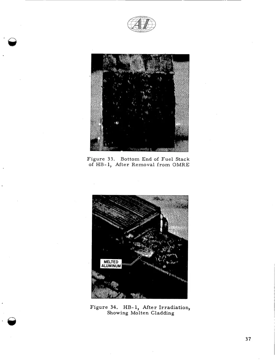
F i g u r e 33 shows how the inlet end of the
coolant channels of the fuel section f r o m HB-1 was completely blocked by solid
35
-
F i g u r e 3 3 . Bottom End of F u e l Stack
of HB-1, After Removal f r o m OMRE
F i g u r e 34. HB- 1, A f t e r Irradiation,
Showing Molten Cladding
37
m a t e r i a l s which w e r e f i l t e r e d out of the coolant s t r e a m by t h i s element,
After
the p l a t e s w e r e separated, it w a s a l s o noted that some melting of cladding
had o c c u r r e d , which w a s caused by overheating a f t e r the coolant channels w e r e
blocked.
F i g u r e 34 shows a chunk of aluminum which had apprently melted,
oozed out between the fuel plates, and f r o z e n on the cooler boron-steel p l a t e s .
The r e s u l t s of hot cell examination of HT-1 w e r e e s s e n t i a l l y the s a m e .
No
melting was observed, but a b l i s t e r e d a r e a was found on one plate, which w a s
a t t r i b u t e d to local overheating.
S e v e r a l of the p l a t e s w e r e m e a s u r e d , and the r e s u l t s w e r e compared with
p r e i r r a d i a t i o n data.
.Mean
Thickne s s
(in. )
Mean
Width
(in. )
Mean
Length
(in. )
Original Dimension
0.470
2.380
12.175
HB-1 Element ( U - 3.5 Mo)
Plate
0.469
2.382
12.245
-0.001
t0.002
t0.070
0.474
2.384
12.259
t0.004
t0.004
t0.084
Change
H T - 1 Element ( U
0.5 Si) P l a t e
-
Change
3.5 Mo
-
These m e a s u r e m e n t s w e r e taken a c r o s s the aluminum s u r f a c e s ; and some
uncertainty a r i s e s , due to a slight s u r f a c e coating of the plates.
Metallographic examination w a s done on s e v e r a l p l a t e s f r o m each element.
The Al-Ni-U bond w a s still intact, except w h e r e fuel p l a t e s w e r e definitely
overheated.
The following conclusions w e r e formulated, f r o m the examination of HB- 1
8
and HT-1:
a ) Both e l e m e n t s w e r e damaged by coolant flow r e s t r i c t i o n , caused by
the blocking of coolant channel e n t r a n c e s by e x t e r n a l m a t t e r .
b ) HB-1 showed signs of aluminum melting, i n c e r t a i n a r e a s , while
adjacent a r e a s still w e r e s t r u c t u r a l l y and metallurgically sound.
38
c ) Dimensional change data showed a n i n c r e a s e only i n length
(0.6 to 0.770)which m a y o r m a y not be significant.
T h e r e f o r e , both
compositions a p p e a r to be stable, up to 2300 M w ~ / M T U ,the
~ peak
burnup attained.
After t h e s e two e l e m e n t s w e r e evaluated, it w a s decided that another in-pile
In
t e s t was required, to prove the applicability of the design and m a t e r i a l s .
addition, at about this time, the design w a s changed f r o m the flat plate to the
tubular shape; and the U
-
3.5 wt %
' Mo
-
0.1 wt
70 A1
alloy was s e l e c t e d a s the
r e f e r e n c e fuel composition, because of i t s e x t r e m e l y high c r e e p strength.
elements, HB-2,
Three
HB-3, and HB-4, w e r e f a b r i c a t e d and i n s e r t e d into OMRE in
July, 1959.
HB-2 e s s e n t i a l l y w a s a duplication of HB-1, with c e r t a i n modifications.
To
d e c r e a s e the probability of coolant channels being blocked, the f i n s w e r e
"blended" with a r a d i u s to eliminate all s h a r p c o r n e r s .
f e a t u r e , and a l s o the thermocouple a r r a n g e m e n t .
F i g u r e 35 shows t h i s
It should be noted that e a c h
coolant channel t e m p e r a t u r e is monitored; and, i n addition, another thermocouple
m e a s u r e s the coolant
AT
between inlet and outlet t e m p e r a t u r e s .
The length of
the boron s t e e l section was reduced f r o m 12 to 4 in., as shown in F i g u r e 36.
To f u r t h e r i n s u r e that the blocking of coolant channels would not cause a f a i l u r e
of the element, a s c r e e n w a s placed inside the bottom end fittings of all t h r e e
elements.
U
-
3.5 wt
The fuel alloy chosen f o r all sections'of all t h r e e e l e m e n t s w a s
70 Mo -
0.1 wt
70 Al. The e n r i c h m e n t
of the u r a n i u m w a s 8 wt
70.
HB-3 w a s f a b r i c a t e d exactly like HB-2, except that the fins w e r e reduced
0.050 i n . , which c r e a t e d a 0.100-in. wide coolant channel between the fin t i p s .
F i g u r e 37 shows the bundle of fuel p l a t e s and the thermocouple a r r a n g e m e n t s ,
which a r e identical to those f o r HB-2.
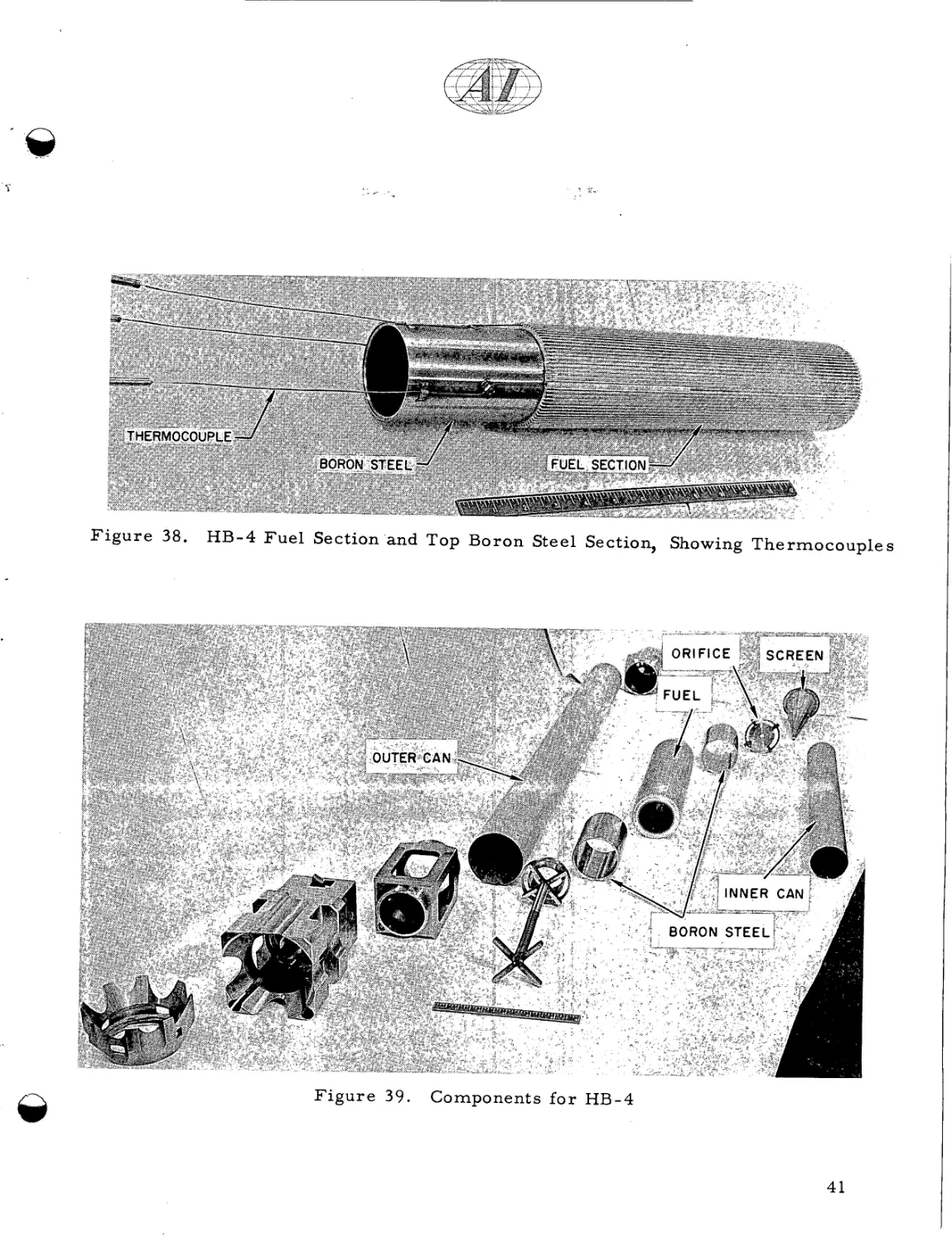
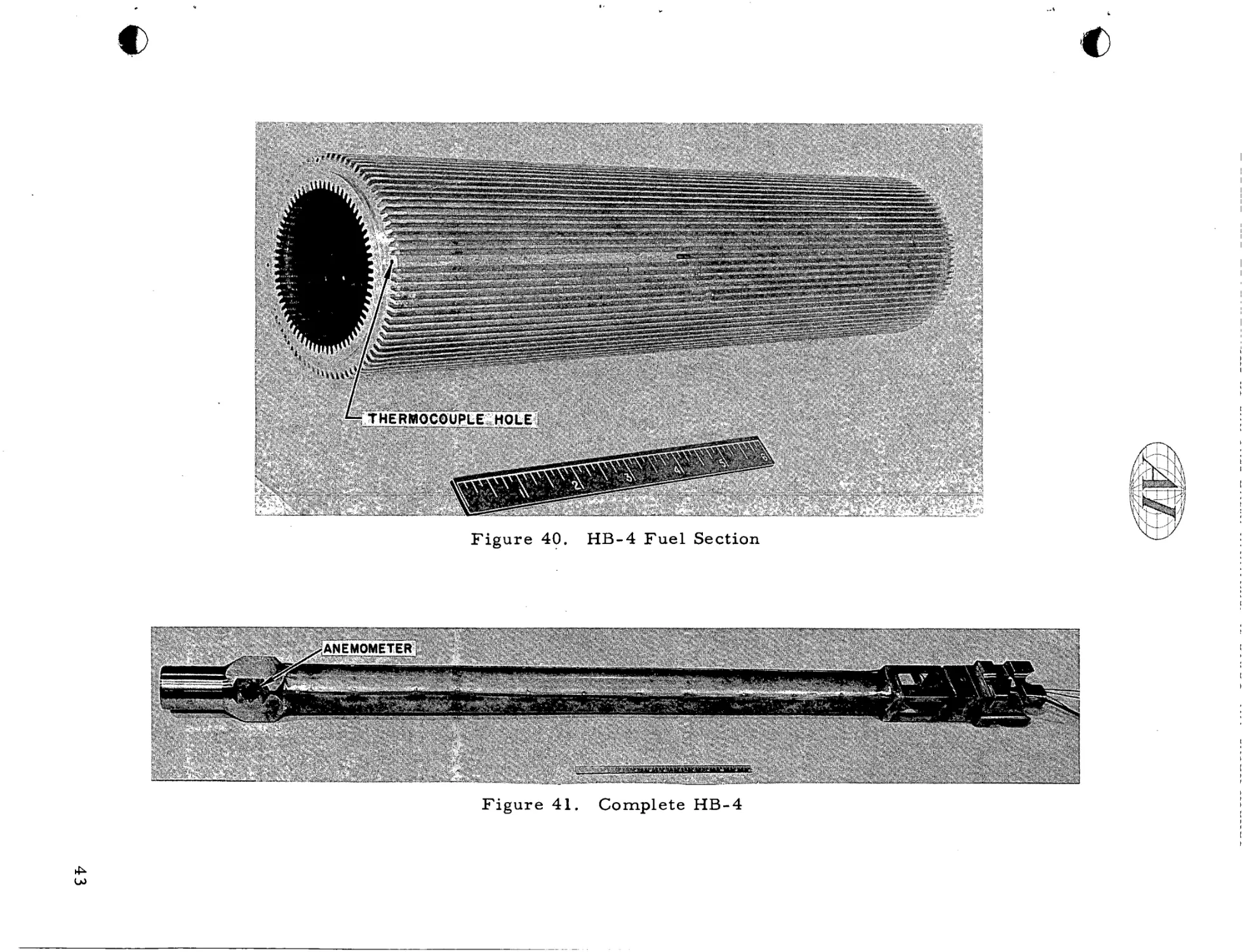
HB-4 consisted of a single tubular fuel section, clad i n extended-surface
aluminum, approximating the shape of the Piqua OMR elements.8
e n r i c h e d to 5.7 wt
70, and
The fuel w a s
w a s i n s t r u m e n t e d with t h r e e s u r f a c e t h e r m o c o u p l e s
( F i g u r e 38) and a thermocouple to m e a s u r e the inlet and outlet t e m p e r a t u r e
differential.
2.240-in. ID.
The fuel cylinder w a s c a s t and machined to 2.540-in. OD and
The processing, f r o m machining fuel to finished bonded section,
63
39
Y
-
1
-
F i g u r e 35.
HB-2 F u e l Section
.
-
F i g u r e 36.
..
-
..
..
HB-2 F u e l Section P l u s Boron Steel Sections,
Showing Thermocouple A r r a n g e m e n t
F i g u r e 37.
40
1
.
HB- 3 Fuel Section, Showing Thermocouples
-
.
F i g u r e 38.
HB-4 Fuel Section and Top Boron Steel Section, Showing Thermocouples
F i g u r e 39.
Components f o r HB-4
41
w a s p e r f o r m e d a s previously described.
final a s s e m b l y a r e shown in F i g u r e 39.
The various components r e q u i r e d f o r
A closeup of the machined hot p r e s s e d
fuel section, with holes f o r thermocouples, is shown in F i g u r e 40.
description of the a s s e m b l y p r o c e s s is included in Reference 9.
A complete
The completed
a s s e m b l y i s shown in F i g u r e 41.
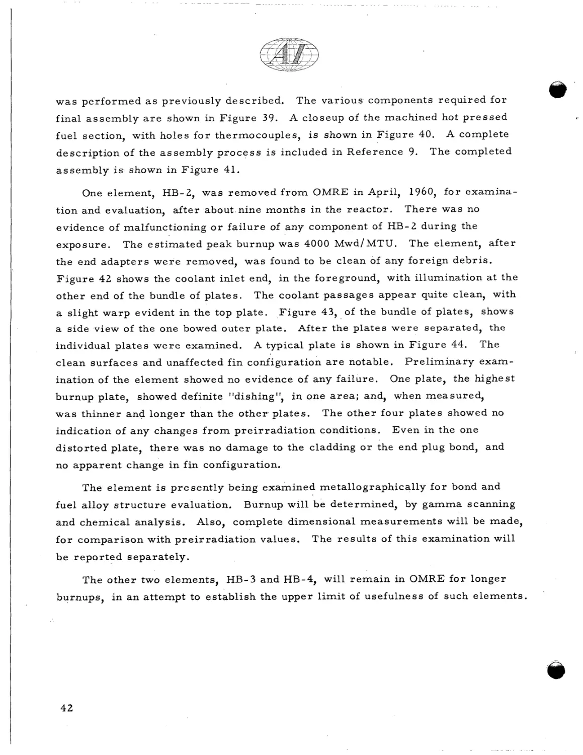
One element, HB-2, w a s removed f r o m OMRE in April, 1960, f o r examination and evaluation, a f t e r about nine months i n the r e a c t o r .
T h e r e was no
evidence of malfunctioning o r f a i l u r e of any component of HB-2 during the
exposure.
The e s t i m a t e d peak burnup was 4000 Mwd/MTU.
The element, a f t e r
the end a d a p t e r s w e r e removed, was found to be clean of any foreign d e b r i s .
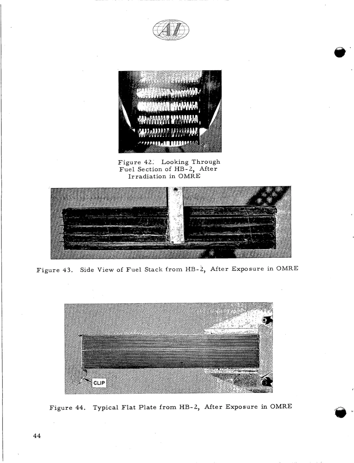
F i g u r e 4 2 shows the coolant inlet end, in the foreground, with illumination at t h e
other end of the bundle of p l a t e s .
The coolant p a s s a g e s a p p e a r quite clean, with
a slight w a r p evident in the top plate.
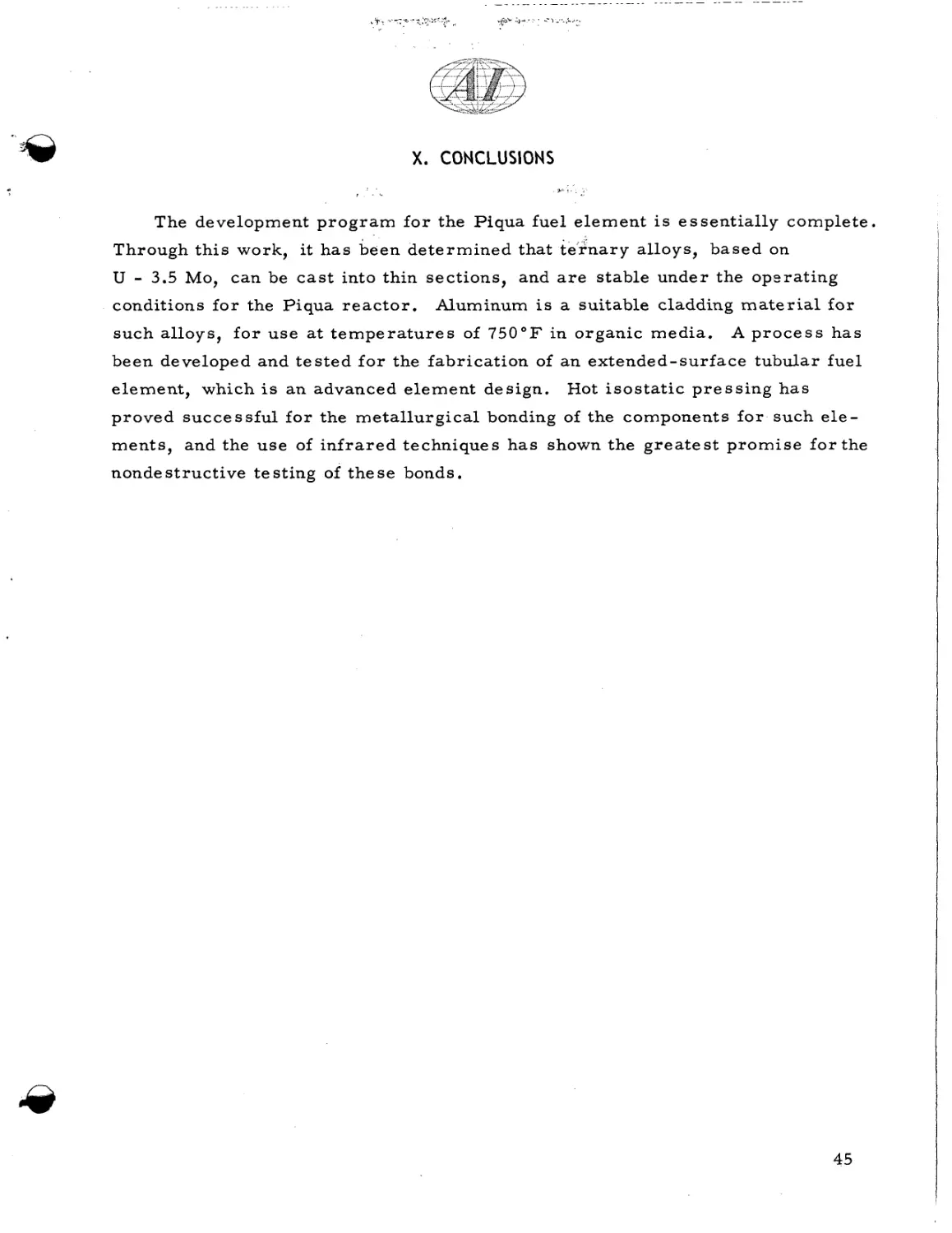
F i g u r e 43, of the bundle of plates, shows
a side view of the one bowed outer plate.
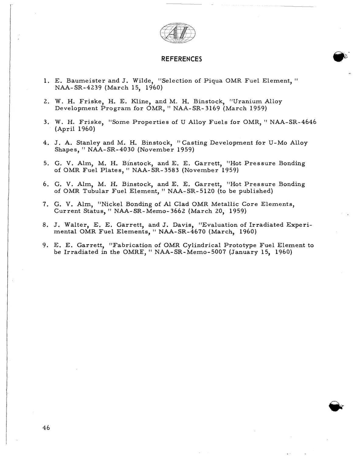
individual p l a t e s w e r e examined.
After the p l a t e s w e r e separated, the
A typical plate is shown in F i g u r e 44.
c l e a n s u r f a c e s and unaffected f i n configuration a r e notable.
ination of the element showed no evidence of any f a i l u r e .
burnup plate, showed definite "dishing",
The
P r e l i m i n a r y exam-
One plate, the highest
in one a r e a ; and, when m e a s u r e d ,
w a s thinner and longer than the o t h e r p l a t e s .
The o t h e r four p l a t e s showed no
indication of any changes f r o m p r e i r r a d i a t i o n conditions.
Even in the one
d i s t o r t e d plate, t h e r e was no damage to the cladding o r the end plug bond, and
no apparent change i n fin configuration.
The e l e m e n t is p r e s e n t l y being examined metallographically f o r bond and
fuel alloy s t r u c t u r e evaluation.
and chemical analysis.
Burnup will be determined, by g a m m a scanning
Also, complete dimensional m e a s u r e m e n t s will be made,
f o r c o m p a r i s o n with p r e i r r a d i a t i o n values.
The r e s u l t s of t h i s examination will
I
be r e p o r t e d s e p a r a t e l y .
The o t h e r two elements, HB-3 and HB-4, will r e m a i n in OMRE f o r longer
burnups, in a n attempt to establish the upper limit of usefulness of such e l e m e n t s .
42
I
L3
5
a,
k
M
.d
r4
l-4
+
k
a,
3
M
tz
43
F i g u r e 42; Looking Through
F u e l Section of HB-2, After
I r r a d i a t i o n in OMRE
Figure 4 3 .
Side View of F u e l Stack f r o m HB-2, After Exposure in OMRE
F i g u r e 44.
Typical Flat P l a t e f r o m HB-2, After Exposure in OMRE
X. CONCLUSIONS
I
9
i
.
The development p r o g r a m f o r the Piqua fuel e l e m e n t is e s s e n t i a l l y complete.
Through t h i s work, it h a s been d e t e r m i n e d that t e r n a r y alloys, b a s e d on
U
- 3.5
Mo, can be c a s t into thin sections, and a r e stable under the operating
conditions f o r the Piqua r e a c t o r .
Aluminum is a suitable cladding m a t e r i a l f o r
such alloys, f o r u s e at t e m p e r a t u r e s of 7 5 0 ° F in organic media.
A process has
been developed and t e s t e d f o r the fabrication of a n extended-surface tubular fuel
element, which is a n advanced e l e m e n t design.
Hot i s o s t a t i c p r e s s i n g has
proved s u c c e s s f u l f o r the m e t a l l u r g i c a l bonding of the components f o r such e l e ments, and the u s e of i n f r a r e d techniques h a s shown the g r e a t e s t p r o m i s e f o r the
nondestructive testing of t h e s e bonds.
45
REFERENCES
1. E. B a u m e i s t e r and J. Wilde, "Selection of P i q u a OMR F u e l Element,
NAA-SR-4239 ( M a r c h 15, 1960)
2. W . H. F r i s k e , H. E. Kline, and M. H. Binstock, "Uranium Alloy
Development P r o g r a m f o r OMR, NAA-SR-3169 ( M a r c h 1959)
3. W. H. F r i s k e , "Some P r o p e r t i e s of U Alloy F u e l s f o r OMR,
(April 1960)
NAA-SR-4646
4. J. A. Stanley and M. H. Binstock,
Casting Development f o r U-Mo Alloy
Shapes, I f NAA-SR-4030 (November 1959)
5. G. V. Alm, M. H. Binstock, and E. E. G a r r e t t , "Hot P r e s s u r e Bonding
of OMR F u e l Plates, ' I NAA-SR-3583 (November 1959)
6. G. V. Alm, M. H. Binstock, and E. E. Garrett, "Hot P r e s s u r e Bonding
of OMR Tubular F u e l Element,
NAA-SR-5120 (to be published)
7. G. V. Alm, "Nickel Bonding of A1 Clad OMR Metallic C o r e Elements,
C u r r e n t Status,
If
NAA-SR-Memo-3662 ( M a r c h 20, 1959)
8. J. W a l t e r , E. E. G a r r e t t , and J. Davis, "Evaluation of I r r a d i a t e d Experimental OMR F u e l Elements, I ' NAA-SR-4670 (March, 1960)
9. E. E. G a r r e t t , "Fabrication of OMR Cylindrical Prototype F u e l Element t o
be I r r a d i a t e d in the OMRE,
46
NAA-SR-Memo-5007 ( J a n u a r y 15, 1960)