/


Tags: military affairs mines
Year: 1964

Text
ТМ 9-1345-200
DEPARTMENT OF THE ARMY TECHNICAL M A N О A I
LAND MINES
HEADQUARTERS. DEPARTMENT OE THE ARMY
1964
TM 9-1345-200
Technical Manual
No. 9-1345-200
HEADQUARTERS,
DEPARTMENT OF THE ARMY
WASHINGTON 25, D. C. 8 June J96J.
LAND MINES
Paragraph Page
Chapter 1. GENERAL
Section I. INTRODUCTION
Scope................................................................... 1 з
Arrangement of text..................................................... 2 3
Forms and reports....................................................... 3 4
Errors and omissions.................................................... 4 4
II. General Discussion
Land mines................................................................... 5 4
Boobytraps.............................................................. 6 8
Mine complete round..................................................... 7 8
Classification.......................................................... 8 11
Identification ......................................................... 9 11
Care, handling, and preservation....................................... 10 13
Packing and marking for shipment....................................... 11 15
Transportation......................................................... 12 15
Chapter 2. ANTIPERSONNEL MINES
Section I. Service Antipersonnel Mines and Fuzes
General . . .*......................................................... 13 16
Mine, antipersonnel, M2A4 with fuze, mine, combination, M6A1........ 14 18
Fuze, mine, combination, M6A1.......................................... 15 21
Mine, antipersonnel, М3 with fuze, mine, combination, M7A1............. 16 21
Fuze, mine, combination, M7A1.......................................... 17 23
Mine, antipersonnel, M16A1 with fuze, mine, combination, M6O5....... 18 24
Fuze, mine, combination, M6O5.......................................... 19 29
Mine, antipersonnel, M18A1 and accesssories............................ 20 29
Mine, antipersonnel, M18 (T48) with carrying kit, M68 (T66)
or M69 (T67)........................................................... 21 42
Mine, antipersonnel, nonmetallic (NM), M14 with integral fuze.......... 22 45
П. Practice Antipersonnel Mines and Fuzes
General................................................................ 23 48
Mine, antipersonnel, М3 empty with fuze, mine, combination,
M7A1, inert............................................................ 24 50
Mine, antipersonnel, М2 (all mods) inert with fuze, mine,
combination, М2, M2A1 or M6A1 inert.................................... 25 50
Mine, antipersonnel, M16A1 inert with fuze, mine, combination,
M6O5 inert............................................................. 26 51
Mine, antipersonnel, practice, M8 and fuze, mine, combination,......... 27 51
Fuze, mine, combination, practice, M10 or M10A1 practice............... 28 54
Mine, antipersonnel, NM, M17 (T34) with integral fuze.................. 29 55
Chapter 3. ANTITANK MINES
Section I. Service Antitank Mines and Fuzes
General................................................................ 30 58
Mine, antitank, HE, heavy, M15 with fuze, mine, AT M603 and
activator, Ml.......................................................... 31 59
Fuze, mine, antitank, M603 ............................................ 32 63
‘This manual supersedes TM 9-1940, 17 May 1956, including Cl, 5 June 1957, C2, 7 October 1957, C4, 30 August
1961, and C5, 24 April 1962; ТВ 9-1940-13, 18 June 1956; ТВ 9-1345-200/1, 13 July 1960; ТВ 9-1345-200/3, 29 Sep-
tember 1960, including Cl, 18 June 1962; and ТВ 9-1345-200/4, 2 October 1961, including C2, 5 August 1963; that por-
tion of ТВ 3-300-2, 27 May 1959 which pertains to bursters for land mines, and so much of ТВ Cml 76, 2 September
1960, and TM 3-300, 14 August 1956, including C2, 5 May 1958, C3, 25 August 1959, and C5, 24 May 1962, as pertains
to land mines.
1
Paragraph Page
Mine, antitank, HE, heavy, M21 with fuze, mine, combination, M607 . . 33 64
Mine, antitank, NM, M19 (T18) with fuze, mine, combination M6O6 .... 34 71
Activator, antitank mine, Ml and М2 (T3E1)...'................... 35 8<>
П. Practice Antitank Mines and Fuzes
General.......................................................... 36 85
Heavy practice antitank mines.................................... 37 87
Light practice antitank mines.................................... 38 91
Mine, antitank, NM, M19, inert with fuze, M6O6, inert............ 39 96
Activator, antitank mine, practice, Ml........................... 40 96
Chapter 4. INCENDIARY BURSTER AND CHEMICAL MINES
Section I. Incendiary Burster
General.......................................................... 41 98
II. Chemical Mines
General ......................................................... 42 100
Mine, land, chemical, 1-gallon................................... 43 100
Mine, chemical agent, VX, M23 ................................... 44 102
Chapter 5. RELATED ITEMS
General.......................................................... 45 105
Demolition materials............................................. 46 105
Pyrotechnics..................................................... 47 107
Antipersonnel mine clearing devices.............................. 48 107
Antitank mine clearing devices................................... 49 109
Chapter 6. DESTRUCTION OF LAND MINES TO PREVENT ENEMY USE
General ......................................................... 50 116
Methods.......................................................... 51 116
Appendix I. REFERENCES............................................................... 118
П. COMPLETE ROUND DATA................................................ 121
III. INDEX OF FORMER NAMES............................................... 123
Index.................................................................................... 124
2
CHAPTER 1
GENERAL
Section I. INTRODUCTION
1. Scope
a. This manual provides technical in-
formation on the identification, care, hand-
ling, and use of land mines in Federal
supply classification (FSC) 1345 and their
components. It also provides general tech-
nical information on items from other FSC
classes which are used with these land
mines.
b. For information on doctrine and tech-
nique for the tactical employment of land
mines and related items, refer to FM
20-32.
c. This manual differs from TM 9-1940,
May 1956, as follows: •
(1) Adds information on:
(a) Mine, antipersonnel, M16Al,and
fuze, mine, combination, M605
(b) Mine, antipersonnel, M18 (T48)
w/carrying kit M68 (T66)
(c) Mine, antipersonnel, M18 (T48)
w/carrying kit M69 (T67)
(d) Mine, antipersonnel, M18A1
(T48E3), and accessories
(e) Mine, antipersonnel, М3, inert
(£) Mine, antitank, HE, NM, M19
(T18)
(g) Mine, antitank, practice, M20
(T38)
(h) Mine, antitank, heavy, HE, M21
(i) Fuze, mine, M606 (T1202E2)
(j) Fuze, mine, antitank, M607
(k) Burster, incendiary, M4
(1) Mine, land, chemical, HD, 1-gal-
lon
(m) Mine, chemical agent, VX, M23
(2) Changes the information on nomen-
clature, marking, and packaging
for a number of items.
(3) Deletes information on:
(a) Fuze, mine, chemical AT, NM,
M12, practice
(b) Mine, antitank, HE, heavy, M6A2
w/fuze, mine, M603
(c) Mine, antitank, HE, light, M7 w/o
fuze
(d) Mine, antitank, HE, light, M7A2
w/fuze, mine, AT, M603
(e) Mine, antitank, practice, NM, M9
w/ or w/o fuze, mine, AT, chem-
ical, M12, practice
(f) Some FSC class 1370 items
(demolition materials)
(g) Some FSC class 1375 items
(pyrotechnics)
2. Arrangement of Text
a. Chapter 1 outlines the manual and
provides general information on the types
of mines, complete rounds, explosive
trains, classification, identification, care,
handling and preservation, storage, pack-
ing and marking for shipment, and trans-
portation.
b. Chapter 2 contains physical descrip-
tions, data, and technical instructions for
the use of antipersonnel mines and relative
items.
c. Chapter 3 contains physical descrip-
tions, data, and technical instructions for
the use of antitank mines and related
items.
d. Chapter 4 contains physical descrip-
tions, data, and technical instructions for
the use of chemical mines and related
items.
e. Chapter 5 contains general technical
information on items from other FSC
classes which are used with land mines.
f. Chapter 6 contains instructions for
the destruction of land mines and compo-
nents to prevent enemy use.
g. Appendix I contains a list of refer-
ences to be used in conjuction with this
manual.
h. Appendix П contains complete round
data on land mines.
i. Appendix in contains a list of former
3
item names with their current Federal
item name.
3. Forms and Reports
a. Authorized Forms. The forms gen-
erally applicable to units using or main-
taining land mines and components are
listed in Appendix I. For a listing of all
forms refer to DA Pam 310-2. For in-
structions on the use of these forms, refer
to FM 9-6.
b. Field Report of Accidents. Accidents
or malfunctions involving the use of am-
munition which occur during training or
combat will be reported immediately to
the qualified ammunition representative
under whose supervision the ammunition
for the unit involved is maintained or
issued. The report will be made by the
officer in charge or by the senior non-
commissioned officer or enlisted man of
the unit involved. All available pertinent
facts will be included in the report. It is
the duty of the qualified ammunition rep-
resentative to investigate thoroughly all
cases of malfunction or accident observed
by him or reported to him and to report
all such cases as outlined in AR 700-
1300-8.
c. Fires. Fires or explosions followed
by fire involving loss of life or damage to
property in excess of fifty dollars will be
reported in accordance with AR 385-40.
Fires involving in-use vehicles are ex-
empt from this requirement.
d. Report of Hazardous Conditions In-
volving Military Explosives or Ammuni-
tion. Report actual or potentially hazard-
ous concentrations of ammunition or
explosives and hazardous conditions which
appear inadequately covered by existing
regulations to U.S. Army Materiel Com-
mand for review by Armed Services Ex-
plosive Safety Board. See AR 385-60 for
further instructions.
4. Errors and Omissions
Any errors in, or omissions from this
manual will be reported on DA Form2028
and forwarded direct to the Commanding
Officer, Picatinny Arsenal, Dover, New
Jersey, ATTN: SMpPA-DC5.
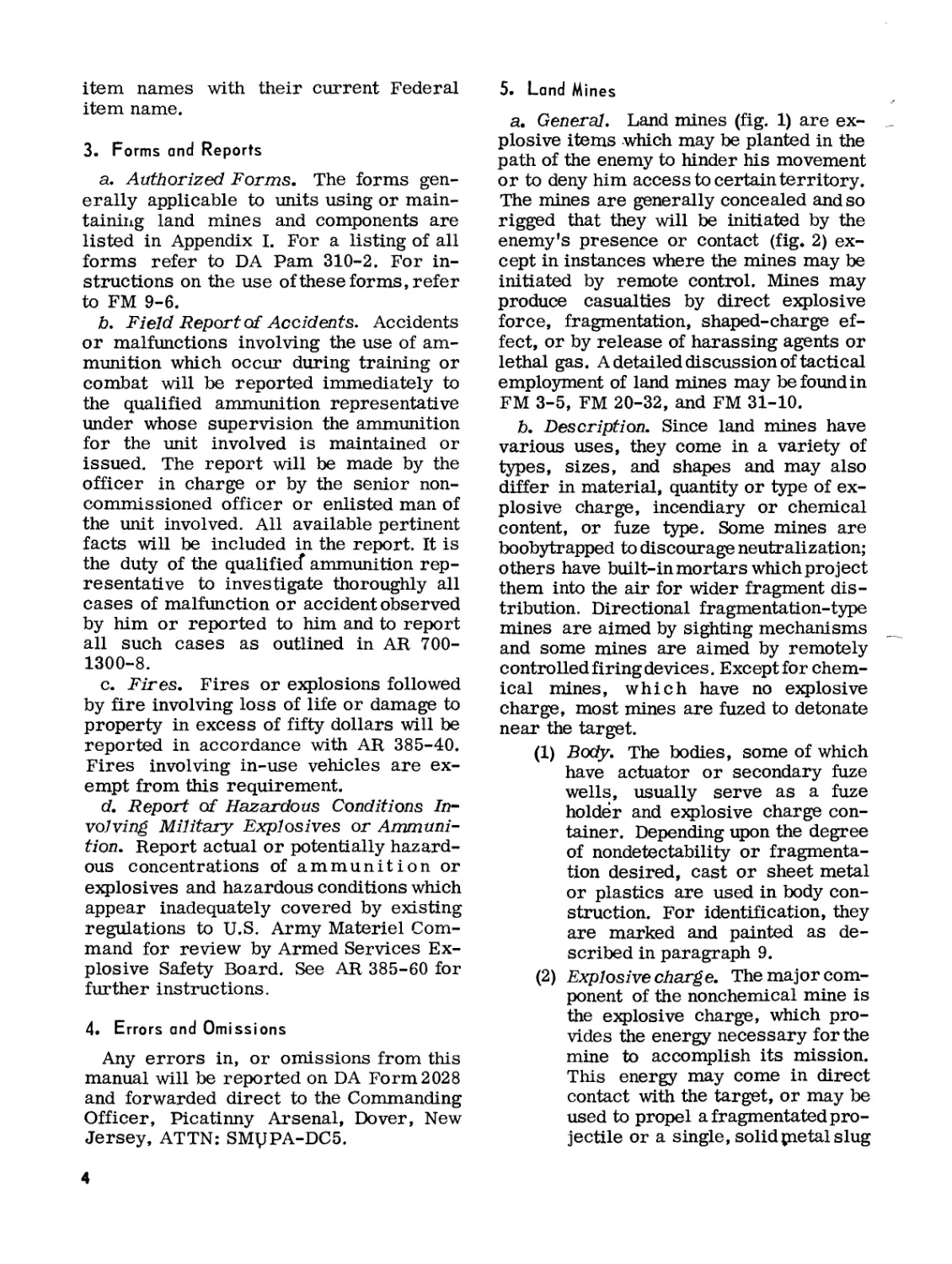
5. Land Mines
a. General. Land mines (fig. 1) are ex-
plosive items which may be planted in the
path of the enemy to hinder his movement
or to deny him access to certain territory.
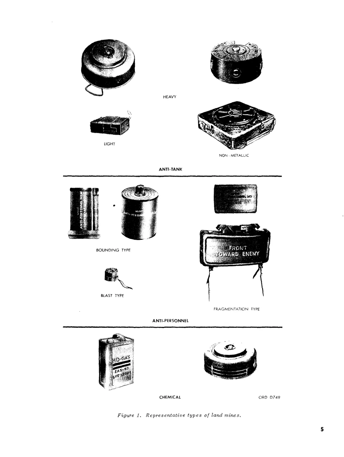
The mines are generally concealed and so
rigged that they will be initiated by the
enemy's presence or contact (fig. 2) ex-
cept in instances where the mines may be
initiated by remote control. Mines may
produce casualties by direct explosive
force, fragmentation, shaped-charge ef-
fect, or by release of harassing agents or
lethal gas. A detailed discussion of tactical
employment of land mines may be found in
FM 3-5, FM 20-32, and FM 31-10.
b. Description. Since land mines have
various uses, they come in a variety of
types, sizes, and shapes and may also
differ in material, quantity or type of ex-
plosive charge, incendiary or chemical
content, or fuze type. Some mines are
boobytrapped to discourage neutralization;
others have built-in mortars which project
them into the air for wider fragment dis-
tribution. Directional fragmentation-type
mines are aimed by sighting mechanisms
and some mines are aimed by remotely
controlled firing devices. Except for chem-
ical mines, which have no explosive
charge, most mines are fuzed to detonate
near the target.
(1) Body. The bodies, some of which
have actuator or secondary fuze
wells, usually serve as a fuze
holder and explosive charge con-
tainer. Depending upon the degree
of nondetectability or fragmenta-
tion desired, cast or sheet metal
or plastics are used in body con-
struction. For identification, they
are marked and painted as de-
scribed in paragraph 9.
(2) Explosive charge. The major com-
ponent of the nonchemical mine is
the explosive charge, which pro-
vides the energy necessary for the
mine to accomplish its mission.
This energy may come in direct
contact with the target, or may be
used to propel a fragmentated pro-
jectile or a single, solid pie tai slug
4
HEAVY
ANTI-TANK
BLAST TYPE
ANTI-PERSONNEL
NON - METALLIC
FRAGMENTATION TYPE
CHEMICAL
ORD D749
Figure 1. Representative types of land mines.
5
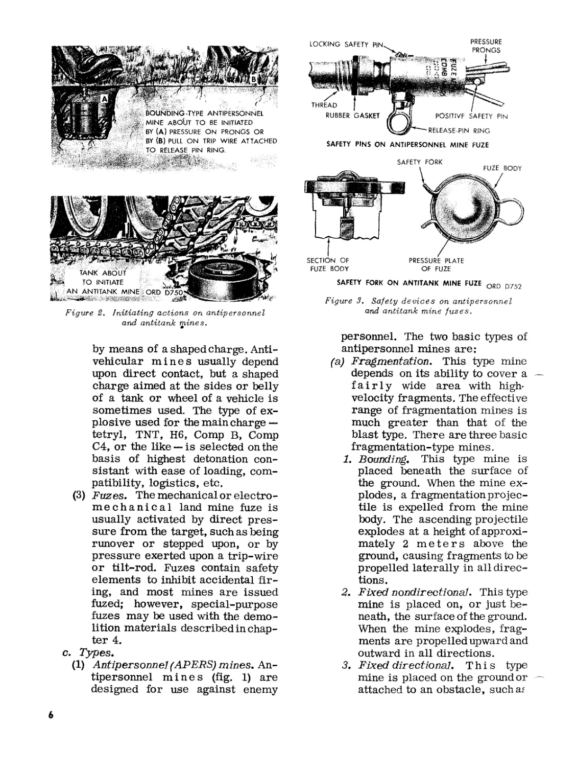
SAFETY PINS ON ANTIPERSONNEL MINE FUZE
Figure 2. Initiating actions on antipersonnel
and antitank tpines.
FUZE BODY
OF FUZE
SAFETY FORK ON ANTITANK MINE FUZE ORD D752
Figure 3, Safety devices on antipersonnel
and antitank mine fuzes.
by means of a shaped charge. Anti-
vehicular mines usually depend
upon direct contact, but a shaped
charge aimed at the sides or belly
of a tank or wheel of a vehicle is
sometimes used. The type of ex-
plosive used for the main charge —
tetryl, TNT, H6, Comp B, Comp
C4, or the like —is selected on the
basis of highest detonation con-
sistant with ease of loading, com-
patibility, logistics, etc.
(3) Fuzes. The mechanical or electro-
mechanical land mine fuze is
usually activated by direct pres-
sure from the target, such as being
runover or stepped upon, or by
pressure exerted upon a trip-wire
or tilt-rod. Fuzes contain safety
elements to inhibit accidental fir-
ing, and most mines are issued
fuzed; however, special-purpose
fuzes may be used with the demo-
lition materials described in chap-
ter 4.
c. Types.
(1) Antipersonnel (APERS) mines. An-
tipersonnel mines (fig. 1) are
designed for use against enemy
personnel. The two basic types of
antipersonnel mines are:
(a) Fragmentation. This type mine
depends on its ability to cover a
fairly wide area with high-
velocity fragments. The effective
range of fragmentation mines is
much greater than that of the
blast type. There are three basic
fragmentation-type mines.
1. Bounding. This type mine is
placed beneath the surface of
the ground. When the mine ex-
plodes, a fragmentation projec-
tile is expelled from the mine
body. The ascending projectile
explodes at a height of approxi-
mately 2 meters above the
ground, causing fragments to be
propelled laterally in all direc-
tions.
2. Fixed nondir ectional. This type
mine is placed on, or just be-
neath, the surface of the ground.
When the mine explodes, frag-
ments are propelled upward and
outward in all directions.
3. Fixed directional. This type
mine is placed on the ground or
attached to an obstacle, suchaf
6
a tree, pole, etc., and at the
expected path of the enemy.
When the mine explodes, frag-
ments are propelled outward in
a fanshaped pattern (60 degree
arc) above the ground. This type
mine may be initiated by the
approaching enemy or a remote
control device.
(b) Blast. This type mine (fig. 1)
depends for its effect on direct
force developed by its explosion.
The mine functions without delay
while still in contact with the
enemy who has initiated it.
(2) Antitank mines. Antitank mines are
used to immobilize or destroy
enemy tanks or other vehicles.
Blast type mines are generally
employed in minefields and are
usually laid on, or slightly below,
the surface of the ground. They
consist of a charge of high explo-
sive, usually 3 to.22 pounds in cur-
rent standard mines, in a metallic
or nonmetallic casing fitted with a
primary fuze, with provisions for
attachment of one or two secondary
fuzes. Ordinarily, antitank mines
require a pressure of 300 to 400
pounds for actuation, but they can
be exploded by being stepped on by
running troops. One of the newer
type antitank mines (par. 33) de-
rives its effectiveness to immo-
bilize or destroy enemy tanks from
its ability to project a mass of steel
upward at a high velocity. The two
general classes of antitank mines
are heavy and light.
(3) Chemical mines. These mines are
designed to disperse chemical
agents from fixed locations, and to
provide area contamination in bar-
rier and nuisance minefields. The
chemical agent may be in liquid or
vapor form. The chemical mine
may be used in anti-tank mine-
fields or elesewhere as an anti-
personnel mine. Composite mine-
fields containing chemical land
mines and HE antipersonnel anti-
tank mines are particularly effec-
tive. The presence of HE mines
reduces traversal speed, thereby
forcing greater exposure to chem-
ical contaminates. The presence of
chemical mines slows breaching
operations as it discourages rapid
mine-clearing techniques. Chem-
ical land mines may be initiated by
action of the enemy or by remote
control. Chemical mines are
shipped empty, with the exception
of the chemical mine M23. Refer
to TM 3-255 for filling instructions
and refer to FM 3-5, FM 20-32
and FM 31-10 for tactical employ-
ment of chemical land mines. All
chemical mines depend on blast
effect for dispersing the chemical
agent. The weather, type terrain,
and soil affect the period of time
for which these chemical agents
are effective. There are two rep-
rsentative types of chemical
mines, persistent and nonpersis-
tent.
(a) Persistent chemical mines are
those whose agents remain in
effect, at point of release, for 10
minutes or more.
(b) Nonpersistent chemical mines
are those remaining in effect for
less than 10 minutes.
(4) Improvised mines. An improvised
mine is one which is made of any
available material. Improvised
mines are used when standard
mines are not available or are in-
capable of producing the desired
results.
Warning: In view of the nature of
improvised mines, appropriate
precautions should be observed
in laying, marking, reporting,
and breaching of minefields.
(5) Phony mines. Phony mines, as the
name implies, are not real mines.
They usually consist of scrap ma-
terial or some disturbed earth
improvised in the field to simulate
an actual mine emplacement. Phony
minefields may be used to supple-
ment a live minefield. They are
laid principally to deceive, delay,
7
and confuse the enemy. Phony
mines should not be confused with
inert issue mines, which are used
for training in handling live issue
mines. For information on em-
ployment of phony mines, refer to
FM 20-32.
(6) Practice and training mines. Prac-
tice mines are of the same size,
weight, and shape as service mines
but contain a small smoke puff and
noise charge consisting of black
powder or pyrotechnic composition
instead of a high explosive. Inert
mines, which are usually the metal
or plastic parts of service mines,
either empty or filled with inert
materials such as sand, are pro-
vided for training in handling. Inert
mines contain no explosives or
pyrotechnic mixtures.
6. Boobytraps
A boobytrap is an explosive charge which
is exploded when an unsuspecting person
disturbs an apparently harmless object, or
performs a presumably safe act. A booby-
trapped mine is any mine having a supple-
mentary fuze or separate charge so ar-
ranged that it will detonate the mine when
the mine is disturbed, even though the
main fuze has been removed. Most anti-
tank mines have one or more secondary
fuze wells but current antipersonnel mines
do not. These wells are of two types .-those
adapted to receive firing devices with a
base coupling and those adapted to receive
an activator. (An activator is an explosive
item which is essentially a detonator-
booster acting as an adapter between the
firing device and the mine, through the
secondary fuze well.) Those mines which
do not contain secondary fuze wells may
be boobytrapped by connecting a firing
device to the mine so as to explode a
separate charge when the mine is dis-
turbed. There are three types of booby-
trapping devices — antilift, antipull, and
anti tilt — which are activated by firing
devices or by an improvised electrical
circuit connected to electrical blasting
caps. Boobytraps may also be improvised
from a nonelectrical blasting cap and ex-
plosive material such as demolition blocks
or coils of detonating cord. Several meth-
ods of boobytrapping mines are shown in
figures 4 and 5. For further information
on boobytrapping, see FM 5-31.
7. Mine Complete Round
a. Definition. A mine complete round
consists of all explosive and non-explosive
components of a mine necessary for it to
function. A complete round may be issued
with all components in the same packing
container or with components shipped
separately for assembly in the field. A
table of complete round data may be found
in appendix П.
b. Explosive Train. An explosive train
is a sequence of explosive elements be-
ginning with a small amount of highly
sensitive explosive, followed by other
elements of progressively larger amounts
and lesser sensitivity, until the large,
relatively insensitive main charge is
reached. This ratio of sensitivity to quan-
tity is maintained in the interest of greater
safety. To insure that the full potentiality
of the main high-explosive charge is
realized, a specific sequence must be fol-
lowed from the triggering of the fuze to
the detonation of the main charge. At min-
imum, a primer, a detonator having at
least two explosives, a booster, and a main
charge are required. At times, however,
the train becomes more complicated and
other elements are needed. The bounding
type mine (fig. 6) is a good example. The
explosive trains for antipersonnel and
antitank mines are described in (1) and
(2) below.
(1) Antipersonnel mines. The explo-
sive trains in the bounding type
antipersonnel mine are shown in
figure 6. This type mine has two
explosive trains: propelling charge
explosive train and high explosive
train. Operation of the propelling
charge explosive train causes ejec-
tion of the fragmentation shell or
body from the outer case. When
the shell or body reaches a pre-
determine height from the surface
8
Figure 4- Boobytrapped antipersonnel mine.
of the ground, the high explosive
train detonates, causing fragments
of the shell or body to be dispersed
in a circular pattern. The two ex-
plosive trains mentioned above are
described as follows:
(a) Prop ell ing charge explosive
train. The components of the
propelling charge explosive train
are shown in figure 6. This ex-
plosive train functions as de-
scribed in 1 through S below.
1. Percussion primer. The fuze
firing pin strikes the percus-
sion primer and initiates the
priming composition which is
very sensitive and capable of
being initiated by mechanical
shock. The percussion primer
emits a small, intense spit of
flame downward.
2. Delay charge. The flame from
the percussion primer ignites
the delay charge which burns for
a predetermined period.
3. Delay charge. The delay charge
ignites the relay charge which
activates the igniter charge.
4. Igniter charge. The relay
charge ignites the igniter charge
which burns with sufficient in-
tensity to set off the propelling
charge.
5. Propelling charge. The propel-
ling charge throws the high-
explosive-filled shell or body
Figure 5. Boobytrapped antitank mine.
9
PROPELLING
CHARGE
EXPLOSIVE
TRAIN
Figure 6. Explosive trains in bounding type antipersonnel mine.
into the air and also initiates
the delay charge of the high-
explosive .train.
(b) High-explosive train. The com-
ponents of the high-explosive
train are shown in figure 6. This
explosive train functions as de-
scribed in 1 through 5 below.
1. Delay charge. The propelling
charge ignites the delay charge
as it propels the high-explosive
projectile from the mine case.
The delay charge burns, delay-
ing detonation of the high explo-
sive until the projectile attains
sufficient height to produce an
effective fragmentation pattern
upon detonation.
2. Primer mixture. After the time
lag has elapsed, the delay charge
sets off the primer mixture.
3. Detonator charge. The flash
from the primer mixture sets
off the detonator charge.
4. Booster charge. The detona-
tion wave from the detonator
charge sets off the booster
charge. The booster charge re-
10
inforces and strengthens the
detonation wave, thus assuring
detonation of the main charge.
3. Fragmentation (bursting)
charge. The detonation wave
from the booster charge sets off
the fragmentation charge, which
ruptures the projectile case and
projects the fragments in all
directions at high velocity.
(2) Antitank mines. The explosive
trains in a typical antitank mine
are shown in figure 7. All antitank
mines have a main or primary ex-
plosive train which is initiated by
action of the weight of the vehicle
on the fuze. This explosive train is
essentially the same as the high-
explosive train described in (b)
above except that a delay charge is
not always included and the primer
mixture is set off directly by the
mechanical action of the fuze. De-
lay elements, however, may be
added to give the tank time to move
well over the mine before the ex-
plosiion takes place (fig. 45). The
mine may also have one or more
secondary explosive trains which
are substantially the same as the
primary explosive train, differing
principally in the mechanical ar-
rangement of the assembled fuzes.
The secondary explosive trains are
usually part of the boobytrapping
installations (par. 6).
8. Classification
a. Land mines are classified, according
to their use, as ’’antipersonnel” and "anti-
tank". Under very limited conditions, an
antitank mine might be used for antiper-
sonnel purposes, but if so used itwouldbe
very inefficient. Antipersonnel mines are
ineffective against tanks. Antitank mines
could be used under special conditions for
improvised demolition purposes, and some
demolition explosives could be used as
improvised mines.
b. Land mines are classified according
to purpose as "service" or "practice," and
according to filler as "high-explosive" or
"inert." In the case of service antitank
SIDE SECONDARY FUZE WELL (MAY ALSO HAVE
SECONDARY HIGH EXPLOSIVE TRAIN OR MAY BE PLUGGED)
.ACTIVATOR
SECONDARY
HIGH-EXPLOSIVE TRAIN
1. PRIMER FIRING DEVICE' I
2. ACTIVATOR DETONATOR
3. ACTIVATOR BOOSTER
4. MAIN CHARGE OF MINE
PRIMARY HIGH-EXPLOSIVE TRAIN
1. PRIMER FUZE
2. DETONATOR FUZE
3. BOOSTER
4. MAIN CHARGE OF MINE
ORD D754
Figure 7. Explosive trains in antitank mine.
mines, the designation "HE" appears in the
nomenclature. In the case of practice
mines, the word "practice" appears in
nomenclature. In the case of inert mines,
which are used for training in handling,
the word "inert" or "empty" appears in
the nomenclature.
9. Identification
a. General. Landmines are identified by
standard nomenclature, lot number, model,
painting, marking, and ammunition iden-
tification code symbol. Such means of
identification are used on all packing con-
tainers and, unless the item is too small,
on the item itself.
b. Standard Nomenclature. Standard no-
menclature is established so that each
item may be identified specifically by
name. The standard nomenclature for am-
munition and explosive items consists of
an item name and a colon (:) followed by
sufficient additional information about the
item of supply to differentiate between
items having the same item name. An ex-
ample of complete nomenclature for a mine
is: MINE, ANTITANK: HE, heavy, M15,
and fuze, mine, AT, M603 and activator,
Ml.
c. Ammunition Lot Number. When am-
munition is manufactured, an ammunition
lot number, which becomes an essential
part of the marking, is assigned in ac-
cordance with pertinent specifications.
The lot number for mines consists of the
11
loader’s initials or symbols, and the lot
number. This lot number is stamped or
marked on every mine and on all packing
containers. It is required for all purposes
of record, including reports on condition,
functioning, or accidents, in which the
ammunition may be involved. In any one
lot of ammunition, the components used in
the assembly are manufactured under as
nearly identical conditions as practicable,
d. Model. To identify a particular
design, a model designation is assigned at
the time the item is classified as an adopted
type. This model designation becomes an
essential part of the standard nomencla-
ture and is included in the marking on the
item. The present method of model desig-
nation consists of the letter M followed by
an Arabic numeral. Modifications are in-
dicated by adding the letter A and appro-
priate Arabic numerals. Thus, "M6A1"
indicated the first modification of an item
for which the original model designation
was M6. Modifications which are func-
tionally identical with the original model
but which have manufacturing differences
may be designated by the letter В and an
Arabic numeral. When a particular design
has been accepted for a limited procure-
ment and service test, only the model
designation is indicated by the letter T or
XM and an Arabic numeral, and modifica-
tions by the addition of E and an Arabic
numeral. In such cases, if the design sub-
sequently should be standardized, the M
designation is assigned; hence there may
be encountered some lots still carrying
the original T designation (not yet re-
marked to show the later standardized M
designation). There is no direct relation-
ship between the numerical designations
of a T item and that of the item when
standardized and assigned an M designa-
T able I A.
tion. Items of Navy design are designated
MK (abbreviation for "Mark") instead of
M, and Navy modifications are designated
"Mod" and appropriate Arabic numeral
instead of A and appropriate Arabic nu-
meral.
e. Painting and Marking.
(1) Painting. Ammunition is painted
to retard rusting of exposed metal
parts, to aid in identification of
type, and to indicate type of filler,
such as high or low explosive, or
toxic.
(a) HE mines and related items are
painted olive drab with yellow
markings. Some items may also
have yellow stripes or bands, or
have their closing plugs painted
yellow.
(b) Practice mines are painted blue
and marked in white. Under "new"
system, practice mines contain-
ing low explosives are tan
color — blue, white and brown.
(c) Inert mines are painted black
(old) or blue (new) with markings,
including the word "INERT", in
white. The М2 and М3 series
either have a 1/4-inch hole on
each side or have the filler cap
omitted, thus providing an 1-3/4-
inch hole on one side.
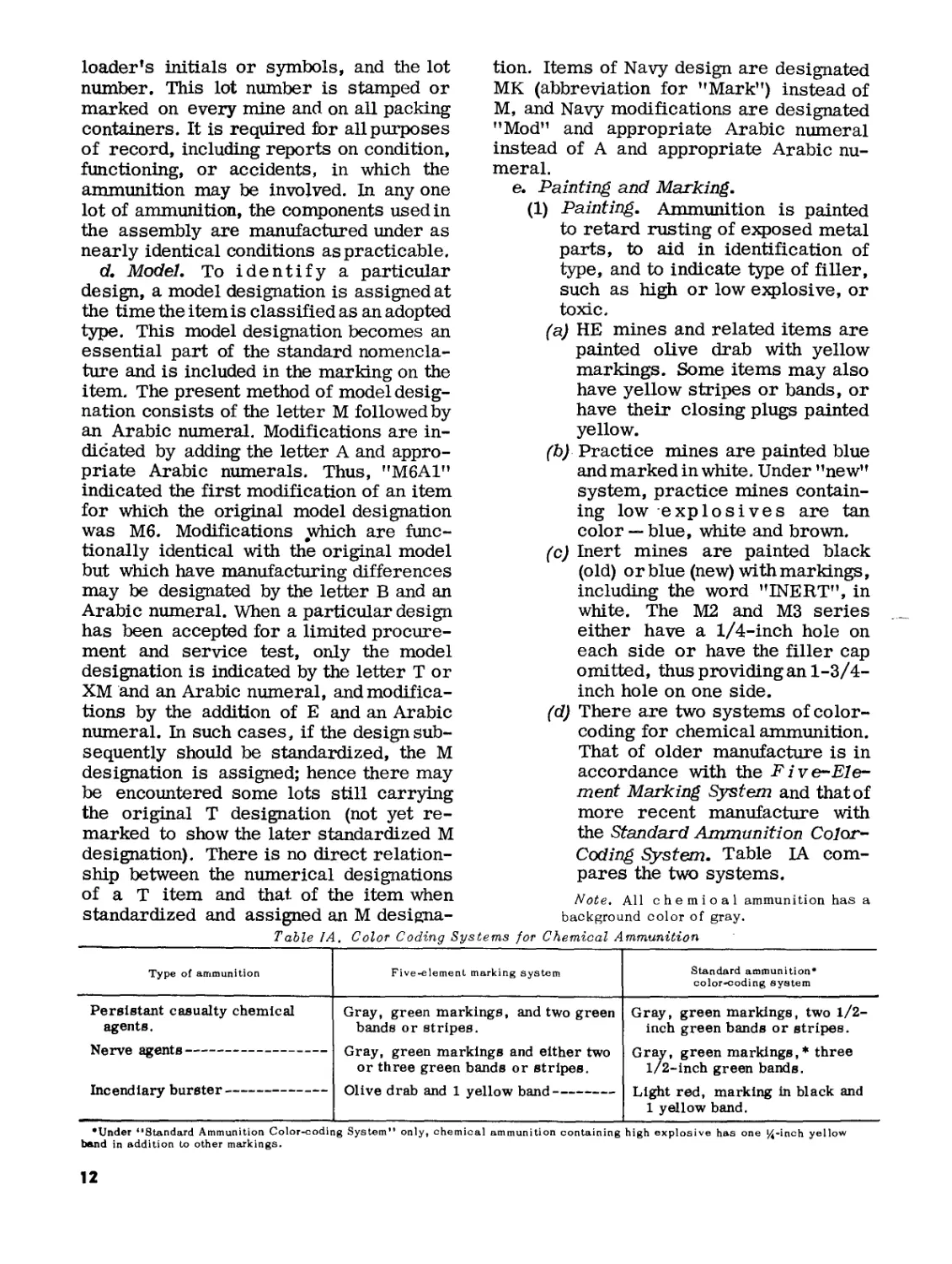
(d) There are two systems of color-
coding for chemical ammunition.
That of older manufacture is in
accordance with the Five-Ele-
ment Marking System and that of
more recent manufacture with
the Standard Ammunition Color-
Coding System. Table LA com-
pares the two systems.
Note. All chemical ammunition has a
background color of gray.
Color Coding Systems for Chemical Ammunition
Type of ammunition Five-element marking system Standard ammunition* color-coding system
Persistant casualty chemical agents. Gray, green markings, and two green bands or stripes. Gray, green markings, two 1/2- inch green bands or stripes.
Gray, green markings and either two or three green bands or stripes. Gray, green markings,* three 1/2-inch green bands.
lIClVv —————————— — — — — —
Olive drab and 1 yellow band Light red, marking in black and 1 yellow band.
lllLuilUШГу UUlolvl ———————— — ——— — —
•Under “Standard Ammunition Color-coding System” only, chemical ammunition containing high explosive has one 14-inch yellow
band in addition to other markings.
12
Caution: Ammunition which has been
color-coded and marked according to the
older system (TM 9-1900 and TM 3-300)
will be on hand for several years. There-
fore, special care should be taken to as-
sure that all ammunition, whether color-
coded according to the older or the newer
system, is properly and fully identified.
f. Data Card. An ammunition data card
prepared in accordance with pertinent
specifications for each lot of ammunition.
Copies are forwarded with each shipment
of ammunition. In addition to the ammuni-
tion lot number, the data card gives the lot
numbers of the components and other
pertinent information concerning the am-
munition.
g. Federal Stock Number and Depart-
ment of Defense Ammunition Code. The
Federal stock number (FSN) replaces the
Ammunition Identification Code (AIC) and
the Ordnance Stock Number (OSN). An FSN
is assigned to each end item of ammuni-
tion as packaged, and, ^unless there is a
difference in packaging or packing, no
two items bear the same FSN, nor is more
than one FSN assigned to the same item.
The Department of Defense Identification
Code (DODIC) is used in requirement
studies, worldwide reporting of stocks,
and to denote interchangeability between
items within FSC group 13. The FSN and
DODIC are used in conjuction (i.e., 1345-
096-3155 (C605)) as means of positive
identification in requisitioning. The FSN
consists of a 4-digit FSC class code num-
ber plus a 7-digit Federal item identifica-
tion number (FUN). For example, in FSN
1345-096-3155 the 1305 is the Federal
Supply Classification (FSC) class code and
the "-096-3155" is the FUN. The class
code indicates the commodity group (13)
and the class (45) to which the item be-
longs. The FUN is a group of nonsignificant
digits used to provide positive identifica-
tion to the item (a given FIIN is assigned
to one FSN only, and is never duplicated
or reused). The DODIC, composed of a
letter and three digits, denotes inter-
changeability between like items of am-
munition or explosive supply within group
13. This code is used in two ways: as a
parenthetical suffix to a FSN, such as
"1345-096-3155 (C605)," or as a hyphen-
ated suffix to a FSC classification code such
as "1345-C605." In the second form it is
known as a"DOD Ammunition Code". When
requisitioning ammunition, the using unit
will normally use the DOD ammunition
code. However, if a particular item, model,
or pack is desired, requisition by FSN and
DODIC is authorized, but justification for
such requests must be shown on the requi-
sition. FSN’s suffixed with identical
DODIC’s are functionally interchangeable
and are considered as suitable substitutes
for one another for supply purposes.
10. Care, Handling, and Preservation of Mines
Warning: Mines must be handled with
care at aU times. The explosive elements
in fuses, primers, detonators, and boost-
ers are particularly sensitive to mechan-
ical shock, friction, static electricity, and
high temperature. Boxes ofcrates contain-
ing mines should not be dropped, dragged,
tumbled, walked on the corners, or struck,
as in lining up a stack. The boxes should
be electricaUy grounded whenever prac-
ticable and protected from high tempera-
ture.
a. General.
(1) Mines are packed to withstand con-
ditions ordinarily encountered in
the field. Items that are not water-
proofed are packed in moisture-
resistant containers. Care must be
taken to keep containers and pack-
ing boxes from becomming broken
or damaged. All broken containers
and packing boxes must be repaired
immediately and careful attention
given to the transfer of all mark-
ings to the new parts. Such con-
tainers should not be opened until
the mines are about to be used or
prepared for use. Items unpacked
but not used should be repacked
and the containers sealed. Such
items should be used first in sub-
sequent operations in order that
stocks of opened containers and
packing boxes may be kept to a
minimum. When the ammunition
packing box contains a metal liner,
13
the liner should be sealed and air-
tested at 3 to 5 pounds per square
inch, if equipment is available.
(2) When it is necessary to leave mines
in the open, raise them, on dunnage,
at least 6 inches from the ground
and cover them with a double thick-
ness of paulin (tarpaulin), leaving
enough space for the circulation of
air. Drainage trenches should be
dug around the stacks to prevent
water from running under the pile.
(3) Mines and components in their
packings should be protected
against moisture.
(4) Boxes should not be opened in a
magazine or at an ammunition
dump, nor should they be opened
within 100 feet of any store of ex-
plosive. Safety tools, if available,
should be used in unpacking and
repacking operations. Safety tools
are those made of copper, wood, or
other material incapable of pro-
ducing sparks when struck.
(5) No attempt will be made to fuze a
mine closer than 100 feet to a mag-
azine or other such stores of ex-
plosives or ammunition.
(6) No disassembly of mines or com-
ponents thereof will be permitted
except as specifically authorized
by the Army Materiel Command.
(7) Safety pins, safety forks (clips),
and other safety devices are de-
signed to prevent accidental initia-
tion of the mine while being handled.
They should be left in place until
the last possible moment before
arming a mine, which should be
done as prescribed in arming pro-
cedures for the particular item.
Before removing (picking up)
mines, safety devices should be
replaced, that is, the mines should
be properly disarmed.
(8) Make certain that firing device
wells, cap wells, activator wells,
and fuze cavities are clear of ob-
struction and free of foreign mat-
ter before attempting to install the
fuze or detonator.
(9) Mines will usually function satis-
factorily at temperatures of-40° F.
to 160° F. Most mines are not
appreciably affected by tempera-
ture changes.
Caution: If the temperature fluc-
tuates around freezing, steps must
be taken to prevent moisture or
water from accumulating around
the mine and subsequently freezing.
The mine may become neutralized
by the formation of ice. See FM
20-32 for Information on laying
mines in winter weather.
(10) Mines may be reused (taken up
and relaid) any number of times
provided that proper procedures
as explained in this manual and
in FM 20-32 are observed and that
no components show evidence of
damage or deterioration.
b. Field Storage and Preservation. The
following conditions govern field storage
of mines, fuzes, and detonators.
(1) Mines are usually stored in iso-
lated buildings or abandoned pill
boxes which have been designated
for this purpose. When specially
constructed magazines are not
available, buildings used should af-
ford good protection against mois-
ture and dampness, have adequate
ventilation, and be on well-drained
ground. They must not be heated
with open fires or stoves.
(2) Mines that must be stored in the
open are stacked in small piles and
protected from dampness and
weather with tarpaper and paulins.
(3) Boxes, cases, and other mine con-
tainers must be clean and dry when
stored. Before storing, damaged
containers should be repaired or
replaced, but not within 100 feet of
magazines.
(4) No oily rags, paint, turpentine, or
other flammable material are to be
left in a magazine.
(5) Mines should be piled by type in
small piles so arranged that indi-
vidual containers are accessible
for inspection and air can circulate
freely. The tops of piles should be
below the level of the eaves to avoid
14
the heated space directly below the
roof. The bottom of the piles should
be raised off the floor or ground at
least 2 inches. Stacks must not be
so high that containers or mines
on the bottom will be crushed.
(6) Individual magazines, or stacks of
mines stored in the open, should be
separated by distances adequate to
prevent propagation of an explosion
from one to another. Refer to TM
9-1300-206 (TM 9-1903) for such
distances.
(7) Magazines or storage areas must
be kept free of dry leaves, grass,
trash, empty boxes, scrap, lumber,
and similar flammable material.
A 50-foot firebreak should sur-
round each magazine.
(8) Smoking, carrying matches, or
using lights other than approved
electric lights is forbidden in mag-
azines or mine-storage areas.
(9) Store mines in accordance with
prescribed procedures.
(10) Captured enemy mines and ex-
plosives should be stored in dumps
at least a quarter of a mile from
the nearest dump of "friendly" am-
munition. Mixed storage of enemy
and "friendly" ammunition is not
permitted. For further storage
precautions, see TM 9-1300-206
(TM 9-1903).
11. Packing and Marking for Shipment
a. Packing data for land mines and their
components are given in SM 9-5-1345
(Conventional) or SM 3-1-1345 (Chemical).
b. In addition to nomenclature and lot
number, packages offered for shipment are
marked with the Interstate Commerce
Commission shipping name of classifica-
tion of the article, the names and addresses
of consignor and consignee, volume, and
weight, and the Department of Defense
identification code which replace the am-
munition identification code symbol form-
erly used.
12. Transportation
Transportation of explosives by rail or
truck in the United States is regulated by
"Interstate Commerce Commission Reg-
ulations for Transportation of Explosives
and Other Dangerous Articles by Freight,"
published by the Bureau of Explosives, 30
Vesey Street, New York, N.Y. Refer also
to AR 55-155 and AR 55-228.
15
CHAPTER 2
ANTIPERSONNEL MINES
Section I. SERVICE ANTIPERSONNEL MINES AND FUZES
13. General
a. Uses. Antipersonnel (APERS) serv-
ice mines are used primarily as a hazard
to restrict or delay movement of enemy
foot troops by denying them access to
certain areas. For this reason the number
of casualties caused by these mines is of
secondary importance. Antipersonnel
mines are usually set off by enemy action
(fig. 2), but some are so rigged that they
may be initiated by a friendly observer
when enemy troops move within range.
Antipersonnel mines are not effective
against armored vehicles; however, light,
thin-skinned vehicles, such as trucks and
jeeps, may be damaged or their occupants
injured by a near by detonation. Special
care must be taken in camouflaging anti-
personnel mines because foot troops move
slower and can therefore more readily de-
tect poorly concealed installations. More
detailed information on uses and tactical
employment of the antipersonnel mines
may be found in FM 20-32.
b. Mines. Representative types of anti-
personnel mines are shown in figure 1.
There are two general types of land
mines — "fragmentation" and 'lalast ef-
fect". Fragmentation mines depend for
their effect upon high-velocity projection
of fragments of the metal case. Blast type
mines depend for their effect upon the
shock of the explosion. For a more detailed
general discussion of the types of antiper-
sonnel mines, see paragraph 5c.
c. Fuzes. Functioning of antipersonnel
mines is initiated by various types of fuzes.
The fuze serves to transform mechanical
action, such as pressure on the fuze or pull
on the trip cord, into an explosive force
which detonates the high-explosive charge
or into a burning action which ignites the
propelling charge of a bounding-type anti-
personnel mine. A fuze which provides ex-
plosive force is called a detonating fuze;
which provides burning action is called an
igniting fuze.
Note. Detonating fuzes and igniting fuzes are
functionally different and therefore are not inter-
changeable.
The initiating action for an APERS fuze
is normally either pressure directly on
the fuze or a pull on a trip wire attached
to the fuze (fig. 2).
d. Data. Tabulated data on antipersonnel
mines and fuzes may be found in table I.
Additional data may be found in paragraphs
14 and 22.
Table I. Service Antipersonnel Mines and Fuzes
Service Antipersonnel Mines
Nomenclature Packing description Weight as shipped (lb.) Shipping case dimensions (in.)
Length Width Height
MINE, ANTIPERSONNEL: М2 and fuze, mine, combina- tion M6A1. Packed 1 mine w/1 spool of four 26- ft length of steel wire/ctn, 10 ctn (10 mine w/accessories)/wdn bx. 93.4 32 13-1/4 9-1/2
MINE, ANTIPERSONNEL: М2 Al, and fuze, mine, com- bination M6A1. Packed 1 mine w/1 spool of four 26- ft length of steel wire/ctn, 10 ctn (10 mine w/accessories)/wdn bx. 93.4 32 13-1/4 9-1/2
MINE, ANTIPERSONNEL: M2A3 and fuze, mine, com- bination M6A1. Packed 1 mine w/1 spool of four 26- ft length of steel wire/ctn, 10 ctn (10 mine w/accessories)/wdn bx. 76.6 22-3/4 10-1/4 9-3/8
MINE, ANTIPERSONNEL: M2A4 and fuze, mine, com- bination M6A1. Packed 1 mine w/1 spool of four 26- ft length of steel wire/ctn, 6 ctn (6 mine w/accessories)/wdn bx. 45.3 15 10-1/4 9-3/8
16
Table I. Service Antipersonnel Mines and Fuzes — Continued
Service Antipersonnel Mines — Continued
Nomenclature Packing description Weight as shipped (lb.) Shipping case dimensions (in.)
Length Width Height
Packed 1 mine w/1 spool of four 26- ft length of steel wire/ctn, 10 ctn (10 mine w/accessories)/wdn bx. 76.6 22-3/4 10-1/4 9-3/8
MINE, ANTIPERSONNEL: М3 and fuze, mine, combina- tion M7A1. Packed 4 mine w/4 fuze and 4 spool of steel wire/wdn bx. Packed 6 mine w/6 fuze and 6 spool of steel wire/wdn bx. 75.6 17-7/8 8-3/4 9-1/2
MINE, ANTIPERSONNEL: M16 and fuze, mine, com- bination M605. Packed 4 mine w/4 fuze M605/mtl cntr and 4 spool trip wire & 1 wrench M25/wdn bx. 44.8 15-5/8 10-1/8 8-1/2
MINE, ANTIPERSONNEL: M16A1 and fuze, mine, com- bination M605. Packed 4 mine w/4 fuze M605/mtl cntr and 4 spool trip wire and 1 wrench M25/wdn bx. 44.8 15-5/8 10-1/8 8-1/2
MINE, ANTIPERSONNEL: M18 (T48) w/carrying kit M- 68 w/sights. Packed 1/kit, 6 kit/wtrprf wrppd ctn, 1 ctn (6 mine)/wdn bx. 32.0 23-3/4 10-1/8 9-3/8
MINE, ANTIPERSONNEL: M18 (T48) w/carrying kit M- 68 (T66). Packed 1 mine w/1 blasting cap and 1 battery holder assy in carrying kit M68, 6 kit (6 mine)/fbrbd ctn, 1 ctn/wdn bx. 41.0 23-3/4 10-1/8 9-3/8
MINE, ANTIPERSONNEL: • M18 (T48) w/carrying kit M- 69 (T67). Packed 5 mine w/5 electric blast- ing cap and 5 spool wire/carry- ing kit M69 (T67), 2 kit (10 mine)/ wdn bx. 45 14-1/8 11-1/2 15-1/2
MINE, ANTIPERSONNEL: M18A1 w/accessories. Packed 1 mine w/accessorles in M7 band (6 mine and 6 band)/wdn bx. — —————— ------ — — — —
MINE, ANTIPERSONNEL: NM, M14 w/integral fuze. Packed 90 mine/ctn (w/90 detona- tor M46 in set-up-box) and 6 wrench M22/wdn bx. Packed 90 mine/ctn (w/90 detona- tor M46 in set-up-box) and 9 wrench M22 wdn bx. 44.1 45. 70 19-3/4 19-3/4 17-1/4 17-1/4 8-3/4 8-3/4
Service Antipersonnel Mine Fuzes
Nomenclature Packing description Weight as shipped (lb.) Shipping case dimensions (in.)
Length Width Height
FUZE, MINE: combination M6A1. Packed 3/ctn, 16 ctn (48 fuze)/wdn bx. Packed 3/crdbd ctn, 4 ctn/strprf pkg, 4 pkg (48 fuze)/wdn bx. Packed 3/ctn, 30 ctn (90 fuze)/wdn bx. Packed 3/ctn, 2 ctn/wtrprf pkg, 15 pkg (90 fuze)/wdn bx. 32.3 32.8 56. 0 56.0 22-3/4 32-5/8 32 32 10-1/4 10-3/8 13-1/4 13-1/4 9-1/2 9-3/8 9-1/2 9-1/2
FUZE, MINE: combination M7A1. Packed 3/ctn, 16 ctn (48 fuzes)/ wdn bx. Packed c/crdbd ctn, 4 ctn/wtrprf pkg, 4 pkg (48 fuze)/wdn bx. Packed 3/ctn, 2 ctn/wtrprf pkg, 8 pkg (48 fuzes)/wdn bx. Packed 3/ctn, 30 ctn (90 fuze)/wdn bx. Packed 3/ctn, 2 ctn/strprf pkg, 15 pkg (90 fuze)/wdn bx. 30.1 33. 0 33.0 56. 0 56. 0 22-3/4 22-5/8 22-5/8 32 32 10-1/4 10-3/8 10-3/8 13-1/4 13-1/4 9-1/2 9-3/8 9-3/4 9-1/2 9-1/2
700-986 (224 ) О - 64 - 2
17
14. Mine, Antipersonnel, M2A4 with Fuze,
Mine, Combination, M6A1 (fig. 8)
a. General. The antipersonnel mine
M2A4 is of the "bounding type." To obtain
a more effective fragmentation pattern, the
main charge (bursting charge, contained in
a heavy steel tube) is projected several
feet into the air by a propelling charge be-
fore it is exploded. If the main charge were
exploded in the ground most of the frag-
ments would be imbedded in the earth and
the effective fragments would be few in
number and the effective radius very
small.
PRONGS (3)
LOCKING SAFETY PIN
CAP
PROJECTOR
TUBE
cw
’OSITIVE
SAFETY PIN
IGNITER
CHARGE
IGNITER
BURSTING
CHARGE
BOOSTER
DETONATOR
COUPLING
BASE
PERCUSSION
PRIMER
RELEASE
PIN RING
PULL SPRING
RELEASE
PIN
FIRING PIN
J PRESSURE
J SPRING
TRIGGER PIN
S
z~
о
PROJECTILE
Z
s
о
s
RELAY
( igniter CHARGE
DELAY CHARGE
PROPELLING
CHARGE
RAPD 89392B
Figure 8. Mine, antipersonnel, M2AJ/, with fuze,
mine, combination, M6A1.
b. Description. This mine consists of a
combination mine fuze M6A1 (par. 15), a
propelling charge and a projectile all con-
tained in a steel case as shown in figure
8. The fuze is screwed into the tube
attached to the base of the mine case. This
base also contains the propelling charge.
The projectile, which is a modified
60 — mm mortar shell, is contained in the
projector tube attached to the base. When
the mine is triggered, the projectile acts
as a mortar. Detailed data on this mine and
fuze are listed in (1) and (2) below. Several
earlier models of the М2 series are avail-
able, as shown in table I. Except for minor
improvements in design, the М2 A 4 is iden-
tical to earlier versions of the М2. The
information inc through h below applies to
all models of the М2 series.
(1) Mine.
Model number — М2 A4.
Type—bounding, fragmentation.
Weight, loaded and fuze —5.01
pounds.
Dimensions — height, fuzed, 9-5/8
inches; diameter plus portion of
base for fuze, 3-3/4 inches.
Material — steel.
Fuze well —capped (hex cap) as
shipped; located in the tube ex-
tending upward from base.
Relay— consists of delay and igni-
ter charges — located in base
plug of projectile.
Detonator — consists of primary
and secondary detonating char-
ges— located adjacent to relay in
base plug of projectile.
Booster (tetryl) — located adjacent
to detonator in base plug of pro-
jectile.
Weight of explosive charge (TNT)
— 0.34 pound.
Weight of expelling charge (black
powder)—40 grains, located in
base of mine near opening to de-
lay charge in base plug of pro-
jectile.
Painting — body, olive drab; base,
yellow.
Marking — nomenclature of mine,
month and year loaded, and lot
number (including loader's ini-
tials and symbol) — all in black.
Shipping cap — hexagonal shipping
cap is on coupling base which is
in fuze well as shipped. Coupling
base contains primer and is fitted
with crimped-on igniter.
18
(2) Fuze (par. 15).
Model — number M6A1.
Components — firing mechanism
and primed coupling base with
crimped-on igniter.
Type — combination.
Weight of igniter charge (black
powder) —10 grains.
Length —7.18 inches (approx.).
Thread size — 9/16 inch.
Material — zinc-base alloy.
Safeties — locking safety pin (cot-
ter pin type) in release pin at end
opposite release pin ring; posi-
tive safety pin (cotter pin type) in
end of firing pin between
pressure prongs.
Painting — olive drab.
c. Functioning.
(1) Pressure of 8 to 20 pounds acting
on one or more of the three prongs
of the fuze, or, pull of 3 to 10 pounds
on a trip wire attached to the re-
lease pin ring of. the fuze causes
release of firing pin which is then
forced downward by the firing pin
spring and strikes the primer.
(2) Primer projects a flame to igniter
charge.
(3) Igniter transmits flame to propel-
ling charge.
(4) Propelling charge transmits flame
to delay charge and projects the
shell (modified 60-mm mortar
shell) from mine.
(5) Delay charge then transmits flame
to ignite charge, which causes
detonator, booster, and bursting
charge to function bursting the
shell at a height of approximately
two to three meters.
d. Laying and Arming.
(1) Prepare a hole~in the ground with a
firm foundation at the bottom and a
depth such that the fuze prongs,
with the mine emplaced, extend
about 1/4-inch to 3/4-inch above
ground level.
(2) After unpacking a mine and a firing
mechanism (packed in the carton
with the mine) (fig. 9), test the lock-
ing safety pin and the positive
safety pin for freedom from bind-
ing. If either of these safety pins
binds when twisted in their holes,
turn in the mine to appropriate
technical personnel for inspection.
RAPO 116928
Figure 9. Packing box for antipersonnel mine
MZAJ), and fuse M6A1.
(3) Unscrew the hexagonal shipping
cap from the coupling base in the
mine, inspect the fuze well for
foreign matter, and screw the fir-
ing mechanism to the couplingbase
hand-tight.
(4) Place the mine upright in the hole
so that the trips of the prongs on
the fuze protrude above ground
level ((1) above). Pack dirt tightly
around and over the mine to just
below the release pin level. After
emplacement, check mine for sta-
bility by attempting to move the
mine laterally. If the mine moves,
pack dirt more solidly around the
mine.
(5) Install one or more trip wires by
attaching them first to firmly
driven stakes and then to the re-
lease pin ring, leaving enough slack
in the trip wires to allow the top of
the fuze to rotate to receive a direct
19
pull on the release pin ring from
any one of the trip wires. This is
necessary for proper functioning of
the fuze.
Caution: Be sure that there is no
tension on the trip wires.
(6) Remove the locking safety pin by
pulling on the cord to which it is
attached.
(7) Finish filling the hole with dirt up to
the tips of the prongs, making sure
that the dirt around the trip wire (s)
and around the cord attached to the
positive safety pin is loose enough
to permit free movement.
(8) The effective pressure area maybe
increased by installing a board,
fixed at one end, and in such aposi-
tion that pressure on the board
would bring pressure on the prongs
of the fuze. If a board is installed,
care must be exercised not to
allow the weight of the board to
exert any pressure on the fuze.
(9) Camouflage the whole installation.
(10) Remove the positive safety pin by
pulling on the end of the cord at-
tached to it, thus arming the fuze.
Warning: Do not disturb the trip
wires.
(11) Save the hexagonal shipping cap and
both safety pins for use in disarm-
ing the fuze.
e. Boobytrapping. This mine has no pro-
vision for a secondary boobytrapping fuze.
Boobytrapping will be done only by espe-
cially trained personnel. Refer to FM 5-
31.
f. Disarming and Removal (Neutral-
izing).
Warning: Do not attempt to disarm or
remove any mine that is frozen in or to the
ground.
(1) Carefully inspect the installation
for boobytraps and boobytrapping
devices before each of steps (2)
through (7) below.
(2) Carefully remove the camouflage
material and pressure board, if
any.
(3) Carefully remove the dirt from
around the top of the mine to ex-
pose both the positive safety pin
hole and the locking safety pin
hole.
(4) Insert the positive safety pin -
first, and then insert the locking
safety pin.
(5) Disconnect the trip wires.
(6) Remove the remaining dirt from
the hole and remove mine.
(7) Unscrew the firing mechanism
from the fuze, taking care not to
remove the coupling base contain-
ing the primer from the mine.
(8) Replace the hexagonal shipping cap
and return the mine and firing
mechanism to their original con-
dition and packing.
g. Effectiveness.
(1) Casualty radius, approximately 10
meters.
(2) Danger radius, approximately 150
meters.
(3) Ten percent more effective than
antipersonnel mine M16A1 (par.
18).
h. Special Precautions.
(1) No attempt will be made to disas-
semble the mine beyond unscrew-
ing the firing mechanism from the
base coupling when a mine is re-
moved from the emplaced posi-
tion.
(2) Mines with loose projector caps
or with a loose primer in the base
coupling will not be used until in-
spection by ordnance personnel
shows that the igniter charge and
propelling charge have not been
damaged by moisture, and the pro-
jector cap and the primed base
coupling with igniter charge (pri-
mer and igniter assembly) have
been resealed.
(3) Although the mine is water resist-
ant, it should not be expected to
function after prolonged submer-
gence in water.
Note 1. The mine may be laid and re-
moved any number of times if not damaged
or deteriorated, and if the above instruc-
tions are followed. Do not use mines if
either the mine projector cap or the coup-
ling base containing the primer are loose,
except as provided in (2) above.
Note 2. Hexagonal shipping and storage
20
cap is removed from base coupling in the
field and replaced with firing mechanism.
15. Fuze, Mine, Combination, M6A1
a. Description. This fuze (fig. 8), which
is used with all antipersonnel mines, М2
series, consists of a tripronged firing
mechanism, and a base coupling fitted with
a percussion cap primer and a black
powder igniter. This base coupling assem-
bly is assembled to the mine as issued
and the firing mechanism is packed sepa-
rately in the mine packing box. The base
coupling assembly is protected by a hex-
agonal shipping cap. Completely assem-
bled fuzes may also be requisitioned
separately (Table I). The firing mechanism
consists of a cylindrical head and body, the
head being slightly larger in diameter. The
head contains a spring-loaded trigger pin
to which the three pressure prongs are
attached. The head also contains a spring-
loaded release pin with the locking safety
pin and with a release pin ring for attach-
ment of a pull or trip wire. The head and
body of the firing mechanism contain a
firing pin which consists of al/8-inch steel
rod recessed near the center for engage-
ment of the release pin. The positive safety
pin is located near the top of the firing pin
between the prongs of the firing mechanism
head. See paragraph 14b(2) for additional
data on this fuze.
b. Functioning. The firing mechanism is
initiated by a pull on a trip wire attached
to the release pin ring, thus releasing the
firing pin, or by pressure on one or more
of the prongs of the head. Such pressure
depresses the trigger pin which operates
the release pin which, in turn, releases
the firing pin. A pull of 3 to 10 pounds on
the release pin ring or a force of 8 to 20
pounds on one or more of the prongs pro-
truding from the top of the head depresses
the head about 9/32-inch and causes the
fuze to function.
Warning: When the fuze is unpacked for
use, it should be inspected to insure that the
trigger pin in which the prongs are set
(fig. 8) is fully seated, and that the safety
pins doe not bind. If the fuze fails to meet
any of these requirements, it is unsafe and
should not be used.
16. Mine, Antipersonnel, М3 and Fuze, Mine,
Combination, M7A1
a. General. Antipersonnel mine М3 is а
fragmentation-type mine. It consists of a
high-explosive charge in a heavy cast iron
case. It is normally placed at the surface
of the ground, as shown in figure 4. How-
ever, its effective radius can be increased
if it is raised several feet off the ground.
Its effective radius is considerably re-
duced when the mine is buried. The mine
case has three fuze wells which permit
boobytrapping on a variety of fuzing ar-
rangements.
b. Description, (fig. 10).
(1) Body. The cast-iron body is filled
with 0.90 pound of flake TNT. There
are threaded fuze wells in two op-
posite sides and one end. The fuze
(M7A1), which consists of a firing
mechanism and a primed base
coupling to which a nonelectric
blasting cap is crimped, may be
inserted in any one of these wells.
As shipped, the holes are closed
with slotted plastic plugs. In one
end, opposite the end containing the
threaded well is a filling hole
which is closed with a metal disk.
Additional information maybe
found in table I.
(2) Fuze. The fuze M7A1 is described
in paragraph 17.
Note. Fuze M7A1 is not interchangeable
with the M6A1 (par. 15).
c. Functioning. A pressure of 8 to 20
pounds on any of the prongs of the fuze or a
pull of 3 to 10 pounds on the release pin
ring will release the firing pin. The firing
pin strikes the primer. A small, intense
spit of flame from the primer explodes the
nonelectric blasting cap crimped to the
base coupling of the fuze, which in turn
explodes the TNT bursting charge. The ex-
ploding charge fragments the cast iron
case and propels the fragments at high
speed in all directions away from the blast.
d. Installation and Arming. Remove a
mine from the packing case (fig. 12). Pre-
pare the mine for use by testing the safety
pins (cotter pins) on the fuze (fig. 13) for
freedom from binding. The mine may be
installed with any one or all of the fuzes
21
8 68 IN APRX
particular operation. Use wrench
packed with mines. Conceal the
plugs for possible future use in
disarming in accordance with
FM 20-32.
(c) Inspect the threaded well to in-
sure absence of foreign matter.
(d) Screw in the fuze or fuzes, mak-
ing sure that the nonelectric
blasting cap is attached.
(e) Attach the trip wires to anchor
stakes and then to the release pin
ring of the fuze, making certain
that most of the slack of the wire
is taken up but that the wire is not
tight enough to exert any pull on
the ring. If more than one trip
wire is attached to a single fuze,
leave enough slack in the trip
wire to allow the top of the fuze
to rotate just enough to receive a
direct pull on the release pin ring
by any one of the trip wires. This
is necessary for proper function-
ing of the fuze.
Figure 10. Mine, antipersonnel, М3 and fuze,
mine, combination, M7A1.
arranged for trip-wire operation, pres-
sure operation, or both.
(1) For trip-wire operation
(a) Anchor the mine firmly so that it
will not move when the trip wire
is pulled. The mine may be se-
cured by partially burying it and
packing it with earth, or by tying
or taping it to a tree, stakes, or
other immovable object.
(b) Remove one, two, or three of the
closing plugs depending upon how
many fuzes are to be used for the
Figure 11. Packing box for antipersonnel mine,
М3 and fuze, Ml Al.
HEAD PRONGS
RELEASE PIN RING'
RELEASE PIN-
SPECIAL BLASTING
CAP (TYPE 1)
f
SAFETY PIN
RELEASE PIN SAFETY PIN
REMOVE LAST
RAPD 15121C
Figure 12. Fuze, mine, combination, M7A1.
22
(f) Camouflage the installation in
accordance with FM 5-20.
(g) Arm the fuze or fuzes by first
pulling out the relase pin safety
pin and then pull ingout the safety
pin (positive) locatedbetweenthe
three prongs. Neither safety pin
may bind.
(h) Do not adjust or disturb the trip
wires.
(2) For pressure operation.
fa) Place the mine in a hole with top
of prongs of a fuze one-fourth of
an inch below ground level.
(b) A pressure board may be placed
to bear very lightly on prongs of
mine.
Warning: If a pressure board is
used, it must be so placed that it
exerts practically no pressure on
prongs.
(c) Cover and camouflage the mine.
(d) Arm the fuze or fuzes by first
pulling out the release pin safety
pin (locking safety pin) and then
pulling out the firing pin safety
pin (positive safety pin) located
between the three prongs.
Neither may bind.
e. Arming From a Distance. If desired,
a 10- to 18-inch piece of No. 16 wire at-
tached to a long cord may be inserted in
place of the locking and positive safety
pins (always remove the positive safety pin
last) so that the arming may be done from
a distance.
f. Boobytrapping. This mine may be
boobytrapped to prevent disturbance or re-
moval, by using the firing devices (with
nonelectric blasting caps) described in
paragraph 41. The firing devices with
blasting caps are‘screwed into the fuze
wells not occupiedbythe main fuze. Figure
4 shows a mine М3 with antilift and anti-
disturbance boobytrapping arrangements.
Before attempting to use the various firing
devices available, personnel should study
the instructions for their use contained in
TM 9-1375-200.
g. Disarming and Removal (Neutraliz-
ing) a Trip-Wire Installation.
(1) Inspect carefully for boobytraps.
(2) Insert the firing pin safety pin
(positive) first, and then insert the
release pin safety pin (locking).
(3) Disconnect the trip wires.
(4) Remove the mine.
(5) Remove the fuze or fuzes, including
base coupling with blasting cap
attached.
(6) Replace the closing plugs and re-
turn the mine and its components
to their original packings.
h. Disarming and Removal (Neutraliz-
ing) a Pressure Installation.
(1) Inspect carefully for boobytraps.
(2) Remove pressure board, if any.
(3) Insert the firing pin safety pin
('’positive” safety pin).
(4) Remove the mine.
(5) Remove the fuze or fuzes, including
base coupling with blasting cap
attached.
(6) Replace the closing plugs and
return the mine and its compo-
nents to their original packings.
Note. The mine may be laid and removed
according to the above instructions any
number of times if not deteriorated or
damaged,
i. Effectiveness.
(1) Effective radius, 10 meters when
detonated at surface of ground.
(2) Effective radius may be increased
by detonating above ground.
(3) Fragments may be thrown more
than 100 meters.
Warning: Make sure that friendly
troops within a radius of 100
meters of a laid mine are ade-
quately protected.
17. Fuze, Mine, Combination, M7A1
This fuze (figs. 12 and 13) consists of a
three-pronged firing mechanism of the
same type used with the fuze M6A1 (par. 15)
and a primed base coupling which is fitted
with a blasting cap. The base couplingused
with the fuze M7A1 is a 1/4-inch shorter
than the one used with fuze M6A1. A
blasting cap is employed by fuze M7A1
because it is used with the antipersonnel
mine М3 in which the high explosive is
directly exploded by the cap, whereas the
igniter of the fuze M6A1 used with М2
series mines ignites a propelling charge
in the bottom of the mine.
23
Warning: When the fuze is unpacked
for use, it should be inspected to insure
that the trigger pin is seated against the
crimping at the top of the head, that the
release pin is fully seated, and that the
safety pin (cotter pin) does not bind. If the
fuze falls to meet any of these require-
ments, it is unsafe and should not be used.
For information on installation, arming,
and neutralizing, refer to paragraph 16.
As shipped, the fuze M7A1 is a complete
assembly consisting of firing mechanism
and primed base coupling with crimped-
on blasting cap. This complete assembly
is packed separately but in the same pack-
ing box with the mine. The fuzes are also
packed for the separate issue, the method
of packing being identical to that for fuzes
M6A1. See table I for details.
Figure 13. Installing fuse M7A1 in anti-
personnel mine М3.
18. Mine, Antipersonnel, M16A1 with Fuze,
Mine, Combination, M605
a. General. This mine (fig. 14) is of the
bounding fragmentation type and functions
similarly to mine M2A4 described in par-
agraph 14. The M16A1 has an explosive
charge three times larger than the M2A4
and therefore has a more effective frag-
mentation pattern and a larger effective
radius.
b. Description. This mine consists of a
combination mine fuze M605 (par. 19), a
propelling charge, and a projectile, all
contained in a sheet steel case (fig. 15).
The fuze screws into the top of the case
and extends through the center of the pro-
jectile to the bottom of the case, where the
expelling (propelling) charge is located.
The remaining space inside the case is
occupied by the projectile. Detailed data
on this mine and fuze are listed in (1) and
(2) below. Additional data may be found in
table I. An earlier model, the Ml6, is also
available for issue as shown in table I. The
principal differences between the M16A1
and M16 are in the construction of the det-
onators and boosters. Figure 16 shows the
differences between the two models. The
information in e through i below pertains
to both models.
(1) Mine.
Model number — M16A1.
Type — bounding, fragmentation.
Weight, loaded and unfuzed —7-7/8
pounds (approx.)
Dimensions - height, shipping,
5-1/2 inches
(approx.)
height fuzed, 8
inches (approx.)
diameter, 4-1/16
inches.
Material - steel and cast iron.
Fuze well - in center of mine,
closed with hexagonal shipping
plug, as shipped.
Two delay charges.
Two detonators.
Two boosters (tetryl).
Weight of bursting charge (TNT) —
1 pound.
Weight of expelling charge (black
powder) - 75 grains (approx.).
24
GREEN WIRE
SAND-COLORED WIRE
0.775 IN.
ORD D757
Figure Ц. Items contained in antipersonnel mine M16A1 packing case —antipersonnel mine M16A1,
combination mine fuze M606, trip wire, and fuzing wrench, M£5.
25
Painting - olive drab.
Marking - nomenclature of mine,
month and year loaded, and lot
number (including loader's
initials and symbol) - all in
yellow.
Shipping plug - hexagonal shipping
APPROX 4-IN Ч ORD D758
plug is in place in the fuze well
(in center of mine) as shipped.
This plug is removed and
replaced with fuze in the field.
(2) Fuze. (par. 19).
Model number — M605.
Components - firing mechanism
and primed fuze body with
crimped-on igniter containing
a black powder charge.
Type — combination.
Dimensions — length, 7-1/8 inches;
diameter (overall), 1-3/4 inch.
Material - metal.
Safeties — locking safety pin (cotter
pin type) in release pin ring;
positive safety pin (cotter pin
type) in end of firing pin between
pressure prongs; interlocking
pin between safety pins.
Painting - olive drab.
Marking —nomenclature of fuze.
c. Functioning by Pressure
(fig. 16).
(1) Pressure of 8 to 2 0 pounds on either
of the three prongs of the fuze
compresses the pressure spring.
Figure 15. Mine, antipersonnel, M16A1 and /uze,
mine combination, M605.
PRESSURE PRONGS (3)
TRIGGER PIN
PRESSURE SPRIN
RELEASE PIN SPRING
RELEASE PIN RING
OUTER
CASING
FLASH
IGNITER
CHARGE
DELAY
CHARGE
INNER
CASING
LOCKING
SAFETY PIN
PERCUSSION
PRIMER
POSITIVE
SAFETY PIN
(REMOVE LAST)
RELAY I
CHARGE I
I FIRING PIN
[(STRIKER)
M16
МП
FIRING PIN SPRING
(STRIKER SPRING)
FRAGMENTATION
-SHELL (BODY) -
PRIMER MIXTURE
DELAY ELEMENT
EXPELLING CHARGE
FRAGMENTATION
CHARGE
(BURSTING CHARGE)
- BOOSTER CHARGE
-- DETONATOR
L.
ORD D759
M16A1
Figure 16. Comparison of antipersonnel mines M16 and M16A1.
26
(2) Pressiire spring forces the trigger
downward.
(3) Wedge-shaped tip of trigger forces
release pin outward to position
where firing pin (strike) is re-
leased.
(4) Firing pin spring forces firing pin
downward.
(5) Firing pin hits primer, which ig-
nites the fuze delay charge.
(6) Fuze delay charge while burning
allows time for person stepping on
prong(s) to move from directly
above mine.
(7) Fuze delay charge then ignites the
fuze relay charge, which ignites
the fuze igniter charge.
(8) Fuze igniter charge ignites the
mine propelling (expelling) charge.
(9) Mine propelling charge projects
cast-iron shell upward from mine
body and at the same time ignites
the two detonator delay charges.
(10) When shell is ajjproximately one
meter above the ground the deto-
nator delay charges have burned
through, initiating the detonators.
(11) Detonators explode boosters which
in turn explode bursting charge.
(12) Explosion of bursting charge shat-
ters shell, projecting metal frag-
ments in all directions.
(13) The mine will explode even if re-
strained by a weight or barrier,
from being projected upward.
e. Functioning by Pull.
(fig. 14).
(1) Pull of 3 to 10 pounds on a trip
wire attached to the release pin
ring of the fuze pulls release pin
outward to position where firing
pin (striker) is released.
(2) Functioning from this point on is
the same as described in d(4)
through d(13) above.
f. Installing and Arming.
(1) Unscrew the hexagonal shipping
plug from the fuze well of the mine,
using the closed end of fuzing
wrench M25 issued with the mine.
(2) Examine the fuze well and flash
tube for evidence of obstruction or
foreign matter. To remove ob-
structions or foreign matter, turn
the mine upside down and gently
tap its bottom. If any mines appear
to be damaged or in an unsatisfac-
tory condition, they should be car-
ried to a safe place and destroyed
with explosives by authorized per-
sonnel as prescribed in TM 9-
1300-206 (TM9-1903).
(3) Carefully examine the fuze assem-
bly, including the crimping at the
top of the fuze where it touches
the top of the trigger, for evidence
of damage. Check the safety pins
to see that they move freely in the
safety pin holes. Be sure the rub-
ber gasket is around the fuze case.
(4) Screw the fuze assembly into the
fuze well of the mine and tighten
it securely against the rubber
gasket, using the open end of the
combination wrench М25.
(5) Dig a hole about 6 inches deep and
about 5 inches in diameter.
Note. When buried so that the tops of the
pressure prongs are about even with the
surface of the ground, sympathetic detona-
tion will occur when mines M16 are laid
approximately 1.5 to 2 meters apart.
(6) Place the mine in the hole. It can
be installed so that it will detonate
by pressure alone; or it may be in-
stalled with trip wires, in which
case the mine can be detonated
either by pressure on the pressure
prongs or by pull on the trip wires,
as described in (a) and (b) below.
(a) For pressure actuation. Cover
the mine with spoil (dirt) from
the hole, pressing it firmly into
place around the sides of the
mine. Leave the release-pin ring
and pressure prongs exposed.
Arrange the pull cords on the
safety pins for easy withdrawal.
Camouflage the installation in
accordance with instructions in
FM 20-32. Remove the locking
safety pin. After the locking
safety pin is removed, the inter-
locking pin can be removed from
the positive safety pin, which is
located between the prongs.
Finally, remove the positive
safety pin, thus arming the fuze.
27
Warning: If the positive safety-
pin is hard to remove the fuze
should be replaced with a new
one.
(b) For trip-wire actuation. Cover
the mine with spoil (dirt), pres-
sing it firmly in place around the
sides of the mine. Leave the re-
lease-pin ring and pressure
prongs exposed. Drive two an-
chor stakes approximately 10
meters (approx. 33 feet) from the
mine. Locate the stakes so that
wires, when attached, will form
a wide "V." A third trip wire and
anchor stake may be installed,
if desired. This prevents any lat-
eral movement of the enemy.
Fasten a separate wire to each
anchor stake, then fasten the free
ends to the release pin ring of
the fuze. Follow the steps out-
lined in (a) above for removing
the safety pins»
Warning: Do not install the trip
wires so taut that they exert pull
on the release pin ring, as this
might cause the mine to deto-
nate accidentally when the safety
pins are removed.
g. Boobytrapping. No secondary fuze
wells for boobytrapping are provided in
the mine M16, and boobytrapping will be
done only by especially trained personnel.
Refer to FM 5-31.
h. Disarming and Removal.
(1) After locating the mine and check-
ing for boobytraps, carefully un-
cover the top and examine it for
evidence of malfunctioning or
damage from blast.
Warning: If the mine is damaged,
do not attempt to neutralize It.
Either destroy It in place with a
prepared charge, or attach a 50-
meter length of wire or rope to the
head of the fuze and, from a pro-
tected position, pull the mine from
the hole. Be sure to examine such
protected position for mines before
occupying it,
(2) If the mine does not appear to be
damaged, insert the original or a
like safety pin (cotter pin), a length
of steel wire, or a nail of proper
diameter through the positive
safety ' pin hole (located betweei
the prongs of the fuze).
(3) Insert the safety pin, a length of
steel wire, or a nail through the
locking safety pin hole (located in
the head of the fuze, opposite the
release pin ring).
Warning: The positive safety pin
must be inserted FIRST. In case
the fuze malfunctions, the positive
safety pin stops any action that
starts.
(4) Cut all slack trip wires attached to
the release pin ring.
Warning: Never cut a taut wire
until the other end has been ex-
amined to see that it is not anchored
to another mine.
(5) Carefully dig around the sides and
bottom of the mine and check for
boobytrapping devices. (Ifthemine
is boobytrapped, proceed as out-
lined in Warning in (1) above.)
(6) Lift the mine from the ground.
(7) Unscrew and remove the fuze as-
sembly from the mine.
(8) Replace the shipping plug.
(9) Restore mine to original condition
and packing.
i. Effectiveness.
(1) Casualty radius when exploded, ap-
proximately 30 meters.
(2) Danger radius 200 meters.
(3) The mine Ml6 is a highly effective
weapon, capable of killing or injur-
ing personnel in the vicinity of the
mine. It is more effective than the
М2 series bounding type antiper-
sonnel mine (para. 14). This mine
is primarily employed in mixed
mine fields to protect antitank
mines against enemy breaching
parties. However, it canbeusedby
itself in the preparation of am-
bushes or in the nuisance mining
of areas likely to be occupied by
enemy troops.
(4) Since both the pressure prongs and
trip wires will be exposed after
the mine is installed, the M16 is
28
best employed where at least 3
inches of natural cover is avail-
able. When installed for trip-wire
actuation, a maximum of front can
be covered with a single mine.
Normally, 2 trip wires are used
with each mine. The spool of trip
wire packed with each mine con-
tains 4 separate 12 meter lengths.
Two are green, and two are sand
colored. Always select the color
that blends best with the terrain or
vegetation. If it is necessary to in-
stall this mine in bare or sparsely-
covered ground, the use of trip
wires is undesirable; a soldier
walking erect is not likely to detect
the pressure prongs unless alerted
to the presence of the mines.
j. Special Precautions.
(1) No attempt will be made to disas-
semble the mine (except as re-
quired in e and g above), to un-
screw the shipping plug in prepa-
ration for fuzing, or to unscrew
and remove the fuze in neutralizing
operations.
(2) Mines withbroken or jammed outer
casing or fuzes from jammed or
dented metallic containers will not
be used until inspection by ammu-
nition personnel shows that neither
the propelling charge of the mine
nor the fuze has been damaged by
moisture or otherwise.
19. Fuze, Mine Combination, M605
a. General. This fuze consists of two
main assemblies, the head assembly and
the loading assembly (figs. 14,15, and 17).
Although somewhat similar in design, the
M605 and the M6A1 (par. 15) are not in-
terchangeable.
b. Head Assembly. The head assembly
contains the firing mechanism and safety
devices. It includes the three pressure
prongs projecting from the top of the fuze
case, the positive safety pin which passes
through the firingpin between the pressure
prongs, the interlocking pin located on the
side of the head and assembled to both the
positive and locking safety pins, and the
locking safetypinwhichpasses through one
side of the fuze case and through one end
of the release pin. Attached to the other end
of the release pin is the release-pin ring
to which trip wires may be attached.
Threads for assembling the fuze in the
fuze well of the mine are located about mid-
way on the head assembly. At this point
the fuze case is shaped to permit the use
of a wrench in tightening the fuze to the
mine. The interlocking pin is designed to
assure that the safety pins will be with-
drawn in the proper sequence, that is, the
locking safety pin first and the positive
safety pin last.
c. Loading Assembly. The loading as-
sembly, which is screwed to the head
assembly to complete the fuze assembly,
consists of the primer assembly and the
delay and relay charge assembly to which
the igniter is crimped.
d. Functioning. See paragraph 18 for
functioning.
e. Wrench, Fuzing, Antipersonnel Mine,
M25. This combination box and open-end
wrench (fig. 14) is stamped from apiece of
strip steel 6 inches long, 1-1/4 inches wide
and about 1/8-inch thick. The box end has
a hexagonal opening, 0.775-inch across
flats, to engage the shipping plug of anti-
personnel mine M16A1 (par. 18). The open-
end has an opening of 0.64-inch to engage
the shoulder on the combination mine fuze
M605, which is used with the M16A1 mine.
20. Mine, Antipersonnel, M18A1
and Accessories
a. General. The antipersonnel mine
M18A1 (fig. 18) is a directional, fixed frag-
mentation mine that is used primarily for
defense of bivouac areas, outposts, and
against infiltration tactics. This mine is
also effective against thin-skinned vehi-
cles such as jeeps, automobiles, trucks,
etc., readily perforating the outer body
and injuring or killing the occupants. The
fragments will also puncture tires, gas
tanks, crankcases, radiators, and engine
accessories. When detonated, afan-shaped
sheaf (pattern) of spherical steel frag-
ments is projected in a 60-degree hori-
zontal arc covering a casualty area of
50 meters to a height of 2 meters. Each
mine is issued in a bandoleer containing
29
one mine with accessories and instructions
for use (fig. 18 and 19). See table I for
detailed information on packing.
b. Description.
(1) Mine. Mine M18A1 (fig. 17) is a
curved, rectangular, olive-drab,
molded case of fiberglass filled
polystyrene (plastic). It is 8-1/2
inches long, 1-3/8 inches wide,
3-1/4 inches high, and weighs 3.5
pounds. In the front portion of the
case is a fragmentation face con-
taining 700 steel spheres (10.5
grains) embedded in a plastic
matrix. The back portion of the
case, behind the matrix, contains a
1.5-pound layer of composition C-4
explosive. The fragmentation face
is convex horizontally to direct the
fragments in a 60-degree arc and
concave vertically to control the
vertical dispersion of the frag-
ments. Additional components of
this mine are: t^o detonator wells
with shipping plug priming adapt-
ers, a molded slit-type peepsight,
and two pairs of scissor type fold-
ing legs. These components are de-
scribed in (a) through (c) below.
(a) Detonator wells. The two det-
onator wells, located in the top of
the mine, enable the mine to be
fired from two locations or to be
fired by nonelectric single or
dual priming. The wells are
sealed by the plug ends of the
shipping plug priming adapters
which prevent entry of foreign
materials into the detonator
wells. The slotted end of the ship-
ping plug priming adapter is used
to hold an electric or nonelectric
blasting cap in place when the
mine is armed.
Note. The shipping plug-priming
adapter is merely reversed when the
mine is to be armed.
(b) P eepsight and arrows. The
molded slit-type peepsight and
arrows (fig. 17), located on top of
the mine, are used to aim the
mine.
(c) Legs. The two pairs of scissor-
type folding legs, located on the
bottom of the mine, enable the
mine to be emplaced on all types
of surfaces. The mine canalsob
tied to posts, trees, etc.
(2) Accessories.
(a) Firing device Мб1/. The firing
device M57 (fig. 18) is handheld
pulse generator which, by a
single actuation of the handle,
produces a double (one positive,
one negative) electrical pulse.
This device is about 4 inches
long, 1-3/8 inches wide, 3-1/4
inches high, and weighs 3/4-
pound. At one end of the firing de-
vice is a rubber connector with
a dust cover.
(b) Test set M40. The test set M40
(fig. 18) is an instrument used for
checking the continuity of the
initiating circuit of this mine.
This test set is 3-1/2 inches long,
1-1/2 inches wide, 1-3/8 inches
high and weighs 1/2-pound. Rub-
ber connectors protrude from
each end, one with a combination
shorting plug and dust cover and
the other with a dust cover only..
A small window is provided fc
observing the flashes of an indi-
cating lamp.
(c) Electric blasting cap M4. The
electric blasting cap M4 (fig. 18)
consists of an electric blasting
blasting cap M6 attached to 100
feet (30 meters) of firing wire.
Attached to the firing wire con-
nector is a combination shorting
plug and dust cover. The short-
ing plug prevents accidental
functioning of the blasting cap by
static electricity and the dust
cover prevents dirt and moisture
from entering the connector. The
blasting cap assembly is wrapped
around a flat paper and then
rolled to form a package 6 inches
long, 4 inches wide, and 2 inches
high. This assembly should be
uncoiled without tangling or kink-
ing. A piece of insulating tape is
used to hold the package to-
gether.
30
Figure 7 7. Mine, antipersonnel, M18A1.
31
Figure 18, Antipersonnel mine M18A1 and accessories packed in bandoleer Ml.
32
Figure 19. Packing box fer antipersonnel
mine M18A1,
(3) Bandoleer M7. The bandoleer M7
(fig. 18) is constructed of water re-
sistant canvas (olive-drab color)
with snap fasteners to secure the
flaps. The bandoleer has two
pockets; one pocket contains the
mine and the other pocket con-
tains a firing device, a test set,
and an electric blasting cap as-
sembly. The packed bandoleer
measures 9-1/4 inches long,
11-1/2 inches wide, and 2 inches
high. A 2-inch wide web strap,
which is used as a shoulder carry-
ing strap, is sewn to the bag. An
olive-green water repellent in-
struction sheet is sewn to the
inside flap.
Note. Only one of the six bandoleers in
each packing box (fig. 20) contains a test
set. The bandoleer containing the test set
is identified by an identification tag on the
carrying strap (fig. 18).
c. Casualty Effect and Danger Area.
(1) Fragmentation. The mine M18A1
delivers 700 highly effective steel
fragments in a fan-shaped pattern
approximately 2 meters high and
60-degrees wide at a range of 50
meters (fig. 21). These fragments
are effective up to a range of 100
meters and can travel up to 250
meters forward of the mine.
(2) Backblast. Within an area of 16
meters (fig. 20) to the rear and
sides of the mine, backblast can
cause injury by concussion and
secondary missiles. Up to 100 me-
ters to the rear and sides of the
mine, all friendly personnel must
be under cover for protection from
secondary missiles.
(a) Radius of Oto 16 meters from the
mine. Friendly troops are pro-
hibited in this area.
(b) Radius of 16 to 100 meters from
the mine. The minimum safe op-
erating distance from the mine is
16 meters. At this distance, the
operator should be in a foxhole or
dugout (fig. 21) or lie prone, pre-
ferably in a depression. All
friendly troops, including the op-
erator, within 100 meters of the
mine should take cover behind a
boulder, a tree, or the like to pre-
vent being injured by flying sec-
ondary missiles, sticks, stones,
pebbles, etc.
d. Functioning. When the mine M18A1
has been armed, the actuation of the firing
device handle (safety bail in armed posi-
tion) will provide sufficient energy (elec-
trical) to detonate blasting cap M6. The
detonation of the blasting cap, in turn,
detonates the high explosive charge (comp.
C-4). Detonation of the high explosive
charge causes fragmentation of the plastic
matrix and projection of the spherical
fragments outward in afan-shapedpattern
(fig. 20). The mine functions effectively in
temperatures ranging from-40° to/ 12 5°F.
This mine is sufficiently waterproof to
function satisfactorily after having been
submerged in salt or fresh water for 2
hours.
e. Laying and Aiming.
Note. Remove the mine and accessories (fig. 18)
from the bandoleer. Read the instruction sheet at-
tached to the flap of the bandoleer before proceed-
ing with the following instructions.
33
700-986 (224) 0-64-3
ы
DIRECTION OF AIM OF MINE
V87-B
Figure 20. Casualty areas and da _ ,• areas of antipersonnel mine M18A1.
WITHIN IOOM TO REAR AND SIDES OF MINE .
ALL FRIENDLY PERSONNEL MUST TAKE COVER
I6M MINIMUM
50M
The mine should be sighted on a point 8 ft. high at a
distance of 150 ft., or one of the alternative points shown.
ORD D188-B
Figure 21. Emplacement of antipersonnel mine M18A1.
ы
1Л
Warning: Position the mine so that
friendly troops forward and to the side of
the mine (figs. 20 and 21) will not be en-
dangered. The firing position should be at
least 16 meters to the rear or to the sides
of the mine.
(1) Turn the legs downward and spread
about 45-degrees. Twist the legs so
that one leg protrudes ahead and
one behind the mine, and position
the mine with the surface marked
"FRONT TOWARD ENEMY" and
the arrows on top of the case
pointing in the direction of the
enemy or the desired area of fire.
On snow or extremely soft ground
(mud), the bandoleer maybe spread
beneath the mine as support. To
prevent tipping in windy areas or
when legs cannot be pressed into
the ground, carefully spread legs
to the maximum possible (approx-
imately 180-degrees), so that legs
will be fore and aft.
(2) Select an aiming object (tree, bush,
etc.) or use an aiming stake that
is approximately 50 meters from
the mine and projects approxi-
mately 1 meter above the ground
(fig. 21).
(3) Position the eye approximately 6
inches away from the mine and aim
the mine by sighting through the
slit-type peepsight. The groove of
the sight should be in line with the
aiming point. The aiming object
should be in the center of the de-
sired coverage area and the bot-
tom edge of the peepsight should be
parallel to the ground to be covered
with fragment spray.
f. Arming and Electrical Firing.
(1) Unscrew the shipping plug priming
adapter and retain for future use.
(2) Remove the insulation tape and un-
roll the paper form from the elec-
tric blasting cap assembly (fig. 18).
Retain paper form and tape for pos-
sible future use. Hold the blasting
cap while unwinding approximately
3 meters of the firing wire.
Warning: Make certain that the
combination shorting plug and dust
cover is assembled to the con-
nector of the blasting cap assembly
before placing the blasting cap in
the. detonator well.
(3) Wind the firing wre around the i
leg two or three times on the same
side of the mine as the detonator
well to be used (fig, 22).
(4) Slide the slotted end of the shipping
plug priming adapter on the firing
wires of the blasting cap between
the crimped connections and the
blasting cap. Pull the excess wire
through the slotted end of the ship-
ping plug priming adapter until the
top of the blasting cap is firmly
seated in the bottom portion of the
shipping plug priming adapter; then
screw the shipping plug priming
adapter and the blasting cap into
the detonator well.
Warning: Make certain the face
of the mine marked FRONT TO-
WARD ENEMY and the arrows on
top of the mine point in the direction
of the enemy.
(5) Unwind the remaining firing wire
to the firing position. If possible,
bury the firing wire to prote<'
from artillery fire and to pre
easy detection.
Note. Retain paper roll form for future
use during disarming.
Warning: The mine firing posi-
tion should be in a foxhole; or in a
shielded or protected position, at
least 16 meters behind or to the
side of the emplaced mine.
Note 1. If possible, perform tests in д
below before firing mine M18A1.
Note 2, If the area has been subject to
recent mortar or artillery bombardment, re-
testing of the blasting cap assembly is
required.
(6) Remove the dust cover from the
connector on the firing device;
also, remove the combination
shorting plug and dust cover from
the end of the firing wire. Assem-
ble (plug in) the two connectors.
Warning: Before connecting the
blasting cap assembly to the firing
device (fig. 22), the safety bail must
be in the "safe’' position. Make
sure that all personnel are under
36
PEEP SIGHT
BA'L
UNROLLED FiklNG
WIRE
SHimNG PLUG PRWIUS A0A"“
HANDLE
window
armed
OUST COVER
TO FIRE CIRCUIT
M18A1.
ARROW
0Г .мтонлтоа well
ARROWS
TO TEST
CIRCUIT
electric BLASTING
CAP M4
SHORTING PLUG
c0 and dust COVER
SAFE
189-B
„ »« Armm? an
Figure it-
37
cover at least 250 meters away
from the front and sides of the
mine and at least 100 meters to the
rear of the mine,
(7) After performing testing (g below)
the mine is ready for firing. To
fire the mine, position the firing
device bail in the "armed" position.
Note. When enemy troops approach with-
in 20 to 30 meters of the front of the mine,
fire the mine.
(8) Fire by actuating the firing device
handle with a firm quick squeeze
and release.
g. Testing.
Warning: Before and after completion
of firing device and blasting cap continuity
tests, ascertain that the firing device bail
is in the "safe" position.
(1) Remove the dust cover from the
connector of the firing device and
from the female connector of the
test set.
(2) Plug the test set into the firing de-
vice (fig. 22), Leave the combina-
tion shorting plug and dust cover
assembled on the other end of the
test set.
(3) Position the firing device bail to
the "fire" position and actuate the
handle of the firing device with a
firm quick squeeze, and observe
the flashing of the lamp through
the test set window.
Note. The window of the test set should
be held against the eye when checking the
firing device and the blasting cap assem-
bly. It minimizes the risk of enemy obser-
vation in the dark and improves the ability
of the operator to see the lamp flashing
even in the bright sunlight.
(4) Flashing of the lamp indicates that
the firing device is functioning
properly. If the lamp does not flash
(on and off), the firing device should
be discarded and replaced with
another firing device. After com-
pletion of the firing device test,
place the firing device bail in the
"safe" position.
Note. If the test set indicates that sev-
eral firing devices are faulty, retest with
another test set prior to discarding since
the test may be defective.
(5) Remove the shorting plug and dust
cover from the connector of the
blasting cap and from the end of the
test set. Plug the connector of the
blasting cap into the test set. Posi-
tion the firing device bail to
"armed" position. Actuate the h.
die of the firing device.
Warning: Before connecting the
blasting cap to the test set and fir-
ing device (fig. 22), the safety bail
must be in the "safe" position, and
all personnel will be under cover
at least 250 meters away from the
front and sides of the mine and un-
der cover at least 100 meters to
the rear of the mine.
(6) Flashing of the lamp in the window
of the test set indicates that the
blasting cap circuitry is satis-
factory. If defective, replace blast-
ing cap and test for serviceability
as indicated above.
h. Nonelectric Firing. Subparagraphs
(1) and (2) below provide instructions for
laying, aiming, and arming of the mine
using two nonelectric blasting cap M7 (par.
41), a piece of detonating cord approxi-
mately 25 feet long, a pull wire, and a
pull-type or pull-friction-type firing de-
vice, such as the Ml or the М2. Subpa-
graph (3) below provides instructions
laying, aiming, and arming of the mii±v;
using a dual firing or a dual priming sys-
tem.
Warning: To arm the mine by the
methods below, a thorough knowledge of
the utilization of explosives and demoli-
tion materials, the use and installation, of
land mines and boobytraps is required.
Refer to FM 5-31 and TM 9-1375-200,
Note: Waterproofing and periodic replacement of
detonating cord should be made in accordance with
instructions provided in FM 5-25.
(1) Pull-wire initia tion of mineM18A1.
(a) Laying and aiming the mine are
performed in the same manner
as that used for electric firing.
Refer to e above for laying and
aiming.
(b) Crimp a blasting cap M7 to a
pull-type device, using cap
crimping pliers (with fuse cutter)
М2 for this operation (par. 42).
(c) Fasten one end of the detonating
cord to the blasting cap that
38
attached to the firing device ((b)
above) by means of tape (A, fig.
23).
(d) Fasten the firing device securely
to a firmly emplaced stake (A,
fig. 23), by means of tape, wire,
twine, or anchor cord.
(e) Slip the slotted end of the ship-
ping plug priming adapter over
the other end of the detonating
cord.
(f) Insert the detonating cord end
fully into the second blasting cap.
Crimp the cap to the detonating
cord, using the cap crimping
pliers М2 for this operation.
(g) Seat the cap (with the detonating
cord) into the the shipping plug
priming adapter and carefully in-
sert the cap into the well.
(h) Secure the cap in the well by
carefully screwing the shipping
plug priming adapter into the
detonator well..
(i) Attach a pull wire securely to the
pull ring of the firing device. The
pull wire should be of sufficient
length to allow actuation of the
firing device from a protected
position at least 16 meters rear-
ward (minimum safe distance
protected position) from the em-
placed mine (A, fig. 23).
Warning: Care must be taken
during emplacement to secure
the firing device so that the mine
will not be dislodged by a pull of
the detonating cord or trip wire.
If the mine becomes dislodged, it
will be aimed in a direction other
than intended.
(2) Trip-wire in it i at ion of mine
M18A1.
(a) Laying and aiming of the mine
are performed in the same man-
ner as that used for electric fir-
ing. Refer to e above for laying
and aiming.
(b) The preliminary steps u s e d to
arm the mine are the same pro-
cedures used in (l)(a) through
(h) above.
(c) The trip wire, stretched across
a trail or other avenue of ap-
proach, and the firing device
must be securely attached to two
firmly emplaced stakes at a dis-
tance of approximately 20 meters
forward of the mine (B, fig. 23).
(3) Nonelectric method using dual fir-
ing or dual priming systems.
Note. Refer to FM 5-25 for details for
using dual firing or dual priming systems.
(a) Dual firing.
1. Obtain two 10-meter (33-feet)
lengths of detonating cord, four
nonelectric blasting caps M7,
and two pull-type firing devices.
Remove both shipping plug
priming adapters from the
mine. Push one end of each piece
of detonating cord through the
holes in the adapters.
Note. Push cord through holesIfar
enough to allow blasting capsto'be
crimped to the cord ends.
3. Crimp end of each piece of det-
onating cord to a blasting cap
M7, using cap crimper М2. Pull
access of detonating cord
through holes in the adapters
so that blasting caps seat
against the bottom of the adapt-
ers.
4. Screw shipping plug priming
adapters in the detonator wells.
Unwind detonating cord while
moving back to safe firing dis-
tance (fig. 21).
5. Emplace mine and detonating
cord as instructed inh(l) (a) to
($ above, and shown in figures
21 and 23.
6. Attach a pull-type firing device
(FM 5-25) to the free end of each
piece of detonating cord, and
attach a pull wire or trip wire
(Л(1) or (2) above).
(b) Dual priming.
1. Follow the instructions in (a)l
through S above.
2. Make a ring mine in accordance
with instructions contained in
FM 5-25.
3. When emplaced one behind the
other, the foremost one (nearest
the enemy) must be fired first.
39
40
Mines emplaced side-to-side in
a line may be fired in any order
or simultaneously.
Note. To prevent tipping in windy
areas or when the legs cannot be
pressed into the ground, carefully
spread legs to the maximum possible
(approximately 180-degrees), so that
the legs will be fore and aft.
4. The mine and the danger area
around the mine must be visible
from the firing position in order
that any friendly personnel in
the vicinity of the mine may be
seen.
Warning; A dislodged or
overturned mine is a potential
hazard to friendly personnel and
should not be fired.
i. Disarming and Destruction.
Warning 1; Render the firing device
safe by returning the safety bail to the
SAFE position (fig. 22) prior to performing
the steps below.
Warning 2: Duds or mines which ap-
pear to have been run oVer by a vehicle or
otherwise damaged after emplacement
should be considered as unsafe. Destroy
as in (2) below.
(1) Disarming.
(a) Mine with electrical components.
1. Disconnect the firing wire from
the firing device. Replace the
combination shorting plug and
dust cover on the blasting cap
assembly connector, and the
dust cover on the firing device
connector.
2. Unscrew and remove the ship-
ping plug priming adapter (fig.
18) containing the blasting cap
from the mine. Remove the
blasting cap and the firing wire
from the shipping plug priming
adapter.
3. Reverse the shipping plug prim-
ing adapter and screw the plug
end of the shipping plug priming
adapter into the mine.
4. Remove the firing wire from the
stake beneath the mine or
around the mine leg. Reroll the
blasting cap and firing wire on
the paper form and secure this
assembly with the piece of in-
sulation tape.
5. Remove the mine from its em-
placement and repack the mine
and its accessories in their re-
spective pockets in the bando-
leer.
Note. Check to assure that all ac-
cessories are removed from mine be-
fore repacking.
(b) Mine with nonelectric compo-
nents.
Warning 1: Check to assure the
firing device has not been fired or
the mine run over. If the firingde-
vioe has fired or the mine appears
to be a dud, destroy the mine.
Warning 2: Render the firing de-
vice safe by replacing all safety
pins prior to performing the steps
below.
Caution 1; Nonelectric blasting
caps and detonating cord crimped
together can be separated only by
cutting the blasting cap free of the
detonating cord, using a nonspark-
ing knife.
Caution 2: If facilities are not
available for cutting the blasting
cap free of the detonating cord, and
these components are not to be re-
used immediately, the crimped ex-
plosive components should be de-
stroyed in accordance with
instructions contained in TM 9-
1300-203 and TM 9-1375-200.
1. Disconnect the pull-wire or
trip-wire from the firing de-
vice.
2. Unscrew and remove shipping
plug priming adapters contain-
ing the blasting caps from the
mine. Cut the blasting cap free
of the detonating cord, using a
nonsparking knife.
3. Return the blasting cap to
storage container, and pull the
detonating cord end free of the
shipping plug priming adapters.
4. Reverse the shippingplugprim-
ing adapter and screw it in the
detonator well, plug end down.
S. Remove the mine from its em-
placement position and repack.
41
Store accessory items in origi-
nal or appropriate containers.
(2) Destruction. Any mine considered
a dud or otherwise in an unsafe
condition should not be handled or
jarred but should be destroyed as
instructed in TM 9-1300-203.
21. Mine, Antipersonnel, M18 (T48) with
Carrying Kit, M68 (T66) or M69 (T67)
a. General. This mine is an earlier
model of mine M18A1 which is described
in paragraph 20. The difference between
the two models may be seen by comparing
figure 24 with figures 17 and 22. The use
and functioning of the M18 is similar to
the use and functioning of M18A1, de-
scribed in paragraph 20.
b. Description.
(1) The antipersonnel mine M18 (T48)
comes in two versions, with or
without a peepsight, otherwise both
versions are identical. The mine
consists of a curved rectangular
plastic case containing high ex-
plosive and steel fragments. The
forward face contains the steel
fragments and is designed to pro-
duce a fan-shaped spray which can
be aimed at a prescribed target
area. The arrow marked on the top
of each mine indicates the direc-
tion of aiming. The mine has three
folding-type legs and cloth tabs on
each side. The legs of the mine are
used to emplace it above ground,
whereas the cloth tabs are used to
tie or nail the mine to trees "
posts. The mine is covered
green and brown fleck in а сапк „
flage pattern to reduce detection.
The mine is capable of causing a
severe or fatal wound within 35
meters and casualties at ranges up
to 50 meters. The principal dimen-
sions of the mine are as follows:
Length.................9-1/4 in.
Width..................3-1/4 in.
Thickness (approx) ... 1- in.
Length of outer legs ... 4-1/2 in.
Length of center legs
(approx).............6- in.
Weight (approx)........2-1/2 lb.
See table I for additional data.
(2) Carrying kit M68 (T66). This kit
is a bandoleer type (fig. 25) car-
rier for personnel and contains one
antipersonnel mine, battery holder
with protective wood block, blast-
cap with lead wire in a cardboard
tube, and instruction sheet in a
canvas carrying case. Dry cell
flashlight batteries are not pacb^
in the kit; however, they are
tainable.
(3) Carrying kit M69 (T67). This kit
is a haversack (fig. 26) for use by
armored and mechanized units and
contains five antipersonnel mines,
five blasting caps with lead wires
Figure 2J/,. Mine, antipersonnel, M18 (T ready for firing.
42
(each cap with wire in a cardboard
tube) packed in a protective box,
five spools of insulated electric
wire (100 feet per spool), one
utility belt, one box of electrical
tape, and five instruction sheets in
a canvas haversack.
c. Arming and Laying.
(1) Using the point of a caliber .30
cartridge or a similar shaped ob-
ject, puncture the tape at either
end of the mine and form a hole in
the explosive for insertion of the
blasting cap.
(2) Carefully remove special electric
blasting cap (type П, J2, PETN)
from the cardboard tube and insert
into the hole provided, making cer-
tain that firm or positive contact
between the explosive charge and
the blasting cap has been achieved.
(3) For emplacement above ground,
unfold the legs of the mine and
press them firmly into the ground.
Warning: The center leg of the
mine, when emplaced in the ground,
must be placed forward of the mine
to provide maximum stability.
Note. For installation on a tree or post,
the legs Should remain folded and the mine
secured by tying or nailing through the
holes provided in the cloth tabs of the
mine. For either method of installation , the
arrow on the top of the mine is pointed at
the center of the fragmentation pattern
(which is 0.83 meters high at a distance of
35 meters).
(4) After placement of the mine, com-
pletely unwind the 16 meters (50
feet) of lead wires and run them to
the firing position. The lead wires
may be laid on top of the ground,
but if time permits the wires should
be buried under soil to reduce the
possibility of being dislodged or
cut by artillery fragments.
d. Preparation and Firing.
Utilization of mine M18 (T48) with
carrying kit M68 (T66) (fig. 25).
(a) Remove the protective wood
blocks from battery holder.
(b) Insert two 1-1/2-volt flashlight
batteries into the battery holder,
making certain that forward end
BATTERY HOLDER
Figure 25. Mine, antipersonnel, M18 (TJ(,8) with carrying kit M68 (T66').
43
of each battery is facing the clip
of the holder.
Warning: The switch of the bat-
tery holder must be in the OFF
position.
(c) Carefully attach the lead wires
to the clips of the battery holder.
The mine is now ready to be
fired.
(d) The mine is fired by firmly push-
ing the switch to the ON (full
forward) position.
(e) If additional lead wire is re-
quired, add 3 volts (in series) for
each 16 meters (50 feet), utiliz-
ing additional batteries and bat-
tery holders.
(2) Utilization of Mine M18 (T48) with
carrying kit M69 (67) (fig. 26).
(a) The mine packed in this carrying
kit is fired by connecting the lead
wires to the battery of a tank or
other vehicle.
(b) If additional* lead wire is re-
quired, 3 volts must be available
at the power source for each 16
meters (50 feet) of lead wire
used.
(3) Utilization of mine M18 (T48) и
other firing devices. This mi.
may also be fired by using pull-
type firing devices and nonelectric
blasting caps with sufficient length
of detonating cord to bridge the
distance between the mine and the
firing device as described in para-
graph 20b.
e. Disarming.
(1) If dry cell batteries and battery
holder(s) were utilized, make cer-
tain that switches are in the OFF
(rearmost) position, and remove
lead wires from the clips of the
holder.
(2) Short the lead wires by twisting
the bare ends together.
(3) Carefully remove the blasting cap
from the mine.
(4) Rewind lead wires and return blast-
ing cap and wire to original card-
board tube.
(5) Remove the mine from its installed
Figure 26. Mine, antipersonnel, M18 (T$,8) with carrying kit, M69 (T67).
44
position, fold the legs if required,
and return it to its original pack-
ing.
Caution: Provided the original
packing is not available, care
should be taken to prevent water
from accumulating in the hole after
removal of the blasting cap.
£. Precautions in Use.
Warning: Stones or mine debris may
be thrown to the rear of sides at the time
of firing. Personnel within 100 meters to
the rear or sides of the mine must not be
exposed. The mine must be fired only from
protected or shielded positions no closer
than 16 meters from the mine.
(1) Follow the precautions contained in
paragraph 217.
(2) Keep batteries dry and warm in
cold weather so that the mine can
be successfully detonated.
(3) Use fresh or fully charged batter-
ies atrall times.
22. Mine, Antipersonnel, Nonmetallic (NM),
M14, with Integral Fuze
a. General. This mine (figs. 27 and 28)
is a nonmetallic, blast type, high-explosive
antipersonnel mine consisting of a main
charge of tetryl (1 ounce), and an all-
plastic body with an integral plastic fuze
having steel firing pin. Because it is small
it can be used in large numbers and may
readily be concealed. This mine is capable
of inflicting a serious casualty since it
explodes in direct contact with the enemy.
Being of practically all plastic construc-
tion, it is nondetectable by magnetic mine
detectors.
b. Description. The mine is cylindrical
in shape. Six ribs on the outside of the body
provide strength and serve as a means
for identifying the mine in darkness. For
safety, the plug-type plastic detonator
holder with detonator, is packaged sep-
arately within the same shipping container
as the mine. The detonator holder is to be
installed in the base of the mine (figs. 28
and 29). During shipment, the hole in the
base of the mine is closed by a shipping
plug. The shipping plug is similar in ex-
ternal shape to the detonator holder except
that the shipping plug has a circular head
while the detaonator holder has a hexagonal
head. The pressure plate has a yellow
indicating arrow and is indented to accom-
modate the mine and fuze wrench. Two
letters, "A" and "S", on the top of the fuze
body signify "armed" and "safe" respec-
tively. The slots in the pressure plate are
for insertion of the steel, U-shaped safety
clip (fig. 28). The pull cord is for use in
removing the safety clip from the mine
when testing and arming. Beneath the safety
Figure. 27. Mine, antipersonnel, NM, МЦ, with integral fuse.
45
PULL CORD-
LOCK KLY
PRESSURE PLATE
1-9/16 IN
LOCK RING
INDiCAT’NG ARROW
SPIDER
** S* л * 1
PARTITION
FIRING PIN
DETONATOR
DETONATOR HOL (AR '.HEXAGONAL BASE)
CARRYING CORO
!TETRYL
(CHARGE
I BELLEVILLE
(SPRING
(DETONATOR
(HOLDER
DETONATOR HOLDER
BASE GASKET
SLOT FOR)
SAFETY CLT>I
RUBBER GASKET
2-3/16 IN
Figure 28. Nonmetallzc antipersonnel mine MIJr with safety clip removed and detonator installed.
MINE BODY
RAPD 149687A
clip slots is a circular groove for a rubber
gasket which makes a watertight joint be-
tween the pressure plate and the fuze body.
A lock key is fastened to the center of the
under side of the pressure plate. The lock
key holds the lock ring firmly when the
arrow on the pressure plate is pointed to
"S". The lock ring prevents the mine from
firing prematurely. The spider spaces the
parts within the fuze and supports the pres-
sure plate when this plate is in the "safe"
position. The three projections on the in-
side of the center hole of the spider pre-
vent the lock ring, belleville spring, and
firing pin assembly from rotating when
the pressure plate is turned. The belle-
ville spring with the attached lock ring and
firing pin assembly is seated against the
spider and is held in place by a ridge on
the rim of the partition. The partition also
holds the main charge in place and pre-
vents any explosive from getting into the
firing mechanism of the fuze. Data on this
mine is listed in (1) and (2) below. Addi-
tional data may be found in table I.
(1) Mine data.
Model number - M14.
Type - blast.
Weight, loaded and fuzed (integral
fuze and detonator) - 3-1/3 ounce
(approx.).
Weight of explosive chai
(tetryl) - 1 ounce.
Dimensions - height, 1-9/16
inches; diameter, 2-3/16 inches.
Material - plastic.
Fuze - integral.
Detonator - M46, in plastic hex-
agonal-head detonator holder (in-
stalled in the field).
Booster - none required.
Color - olive drab.
Marking (on bottom) - nomencla-
ture, symbol of parts manufac-
ture, loader's lot number, month
and year loaded.
Shipping plug - circular-head par-
tially slottted shipping plug, in
place as shipped, to be replaced
in the field by detonator holder.
(2) Fuze data.
Model number - none.
Components - pressure plate, lock
key, spider, lock ring, belleville
spring, and firing pin.
Type - belleville spring - integer
46
о
•SAFE' POSITION
Figure 29. Mine, antipersonnel, NM, MUp—top, bottom and cross section.
Material - plastic (except steel
firing pin).
Safeties - clip (U-shaped) with pull
cord; provision for turningpres-
sure plate from safe position
(yellow pointer at S) to armed
position (yellow pointer at A).
Color - olive drab.
c. Functioning.
(1) A force of 20 to 35 pounds will de-
press pressure plate.
(2) Pressure plate depresses lock key.
(3) Lock key forces lock ring to slide
through notches in inner ring of
spider and depresses the belle-
ville spring.
(4) Belleville spring snaps into re-
verse, driving firing pin into det-
onator.
(5) Detonator explodes main charge.
(6) Mine will function satisfactorily in
temperature ranging from -40° to
+125° F.
d. Laying and Arming.
(1) Unscrew the shipping plug from the
bottom of the mine body using
wrench (fig. 30). Inspect detonator
well for foreign material. Remove
foreign material when found.
(2) Turn the pressure plate in a clock-
wise direction with the wrench
(arming tool), so the indicating
arrow points to "A" (fig. 28). This
places the pressure plate in the
armed position. Withdraw the
safety clip to determine if the mine
will malfunction. Replace the safety
clip.
(3) Screw the detonator holder with
Figure. 30. Wrench, mine and fuze, M22, for
antipersonnel mine MUp,
47
attached detonator gasket into the
detonator well. Use the wrench
(arming tool) to screw the detona-
tor holder down tightly against the
detonator gasket to obtain a water-
tight joint.
Warning: Do not exert anypres-
sure on the pressure plate.
(4) Place the mine in the ground so
that the pressure plate extends just
above ground level, otherwise a
shoe or boot may bridge the mine.
Be sure the ground beneath the
mine is sufficiently stable to sup-
port the mine when pressure is
applied to the pressure plate. If
the ground is not sufficiently stable,
place a block of wood or other
nonmetallic object in the bottom of
the hole to provide a firm surface
for the mine to rest upon.
(5) Remove the safety clip by pulling
the safety clip pull cord. Retain
the safety clip for possible future
use.
(6) Camouflage the mine and remove
any excess spoil from the immedi-
ate vicinity of the installation.
Warning: Use extreme care when
handling the detonators for this
mine. A severe shock, such as
dropping the detonator on a solid
surface, may cause it to function.
Detonators should never be car-
ried in pockets or otherwise on the
person. After the mine has been
armed it should be handled with
care. Do not drop or throw it.
Place it in position carefully.
Note. In camouflaging the mine, use mix-
ture of material such as dirt, clay, grass,
gravel, and fine twigs, arranged so that
they are not likely to be washed away by
e. Boobytrapping. No provision is made
for boobytrapping the mine. There are no
secondary fuze wells.
f. Disarming and Removal.
Caution: If there is evidence of dam-
age, boobytrapping, or malfunctioning, dp
not attempt to disarm the mine. Mark •'
spot for subsequent destruction in pla<
as prescribed in TM 9-1903.
(1) Remove camouflage material and
carefully uncover the concealed
mine. Do not exert pressure on the
pressure plate.
(2) Enlarge the hole carefully and ex-
amine the ground around and under-
neath the mine for evidence of
damage, malfunction, or impro-
vised boobytrapping.
(3) Before the mine is otherwise dis-
turbed, insert the safety clip in the
slots in the pressure plate. If the
safety clip cannot be inserted rel-
atively easily, it is an indication
that the mine has malfunctioned or
has been damaged. In such cases,
mark the spot and discontinue fur-
ther attempt to disarm the mine.
(4) Using the mine-and-fuze wrench,
turn the pressure plate in a coun-
terclockwise direction from "A" to
"S".
(5) Remove the mine from the grour '^
(6) Unscrew the detonator holder fr
the bottom of the mine body, usiiib
the mine-and-fuze wrench.
(7) Replace the shipping plug and gas-
ket.
(8) Restore the mine to its original
condition and packing.
g. Effectiveness.
(1) Not effective against armored ve-
hicles.
(2) When buried so that top of pressure
plate is flush with ground (normal
procedure), it will cause a non-
lethal casualty to any person who
steps on it.
Section II. PRACTICE ANTIPERSONNEL MINES AND COMPONENTS
23. General mines described in paragraphs 24through
28 simulate many of the service antiper-
a. Uses. The practice antipersonnel sonnel mines described in paragraphs 14_
48
through 22. The various types of practice
antipersonnel mines (empty, inert, prac-
tice) are used to train personnel in the
recognition, care, handling, and use of
antipersonnel mines.
b. Types. The antipersonnel mines and
fuzes which are designated "inert" or
"empty" have metal or plastic parts iden-
tical to those of service mines. These
inert mines may be filled with inert mate-
rial, such as sand, or they may be empty.
The inert mines and fuzes contain no ex-
plosive of any kind and are used only in
training for handling mines. Inert fuzes
are also provided for use with inert and
empty mines. These inert fuzes have no
explosive or pyrotechnic components. The
antipersonnel mines and fuzes which are
designated "practice" are of the same
size, shape, weight, and casing material
as the service mines and fuzes they sim-
ulate. These practice mines contain no
high explosive but they may contain small
smoke puff and noisemaking charges of low
explosive (black powder or pyrotechnic
composition) to simulate the explosion of
a service mine. These practice mines are
provided for practice and training in iden-
tification, care, handling, and use of anti-
personnel service mines. Practice fuzes
are provided for use with practice mines.
The firing mechanisms of these fuzes are
fitted with primers and igniters which,
when initiated, ignite the spotting or pro-
pelling charge in the mine.
c. Precautions. The following safety
precautions will be observed in the use of
practice and training mines.
(1) Do not mix service, practice, and
inert mines and fuzes. Practice
and inert mines should be painted
their proper color and have the
appropriate identifying terms
stencilled upon their bodies.
(2) Inert antipersonnel mines, since
they contain no explosive, are safer
to handle and therefore should be
given preference for training pur-
poses. Personnel should be trained
to handle all ammunition and am-
munition components as potentially
dangerous, even though the items
have been designated "inert" or
"empty."
(3) The rules, regulations, and pre-
cautions pertaining to service
mines and their components in AR
385-63 and this manual, pertain
also to practice antipersonnel
mines.
Table II. Practice Antipersonnel Mine, Fuzes, and Components
Practice Antipersonnel Mines
Nomenclature Packing description Weight as shi pped (lb.) Shipping case dimensions (in.)
Length Width Height
MINE, ANTIPERSONNEL: М3 empty and fuze, mine com- bination M7A1 inert. Packed as required — — — — — — — —
MINE, ANTIPERSONNEL: М2 (all mods) inert and fuze, mine, combination М2 or M- 2Al inert. Packed as required ——— — ———— —————— —————
MINE, ANTIPERSONNEL: М2 (all mods) inert and fuze, mine, combination M6A1 inert. Packed 1 mine, 1 fuze/ctn, 10 ctn (10 mine and 10 fuze)/wdn bx. 39.0 22-3/4 10-1/4 9-3/8
MINE, ANTIPERSONNEL: M- 16A1 inert and fuze, mine combination M605 inert. Packed 4 mine w/4 fuze М605/ strprf paper wrapper and 4 spool trip wire and 1 wrench M25/wdn bx. 40. 0 15-5/8 10-7/8 8-1/2
MINE, ANTIPERSONNEL PRACTICE: M8 and fuze, mine, combination M10 or M10A1 practice. Packed 2 mine w/2 fuze and 20 set of replacement parts/wdn bx. Packed 2 mine w/2 fuze and 20 set of replacement parts and 5 spool wire in ctn, 1 ctn/strprf pkg, 1 pkg/wdn bx. 31.0 37. 0 20-3/4 16-1/2 12-1/4 11-3/8 9 13-3/8
49
Table II. Practice Antipersonnel Mine, Fuzes, and Components-Continued
Practice Antipersonnel Mines — Continued
Nomenclature Packing description Weight as shipped (lb.) Shipping case dimension
Length Width h
MINE, ANTIPERSONNEL PRACTICE: NM, M17 (T34). Packed 125 mine/ctn, 1 ctn and 6 arming wrench M22/wdn bx. 41 16-3/4 14-1/4 11-3/8
Practice Antipersonnel Mine Fuzes
FUZE, MINE: combination MIO or M10A1 (w/o primer- igniter). Packed as required — — — —— —
FUZE, MINE: combination M10A1 (w/primer-igniter). Packed 4/mtl cntr, 60 cntr (240 fuze)/wdn bx. 125 22 17-1/8 18
Components for Practice Antipersonnel Mines
Nomenclature Packing description Weight as shipped (lb.) Shipping case dimensions (in.)
Length Width Height
BODY, ANTIPERSONNEL MINE: for practice APERS MINE M8. Packed as required — ———— — ———
CAP, ANTIPERSONNEL MINE: for mine, APER, practice M8. Packed as required — ———— — —
CHARGE, SPOTTING, MJNE: for mine, APER, practice M8. Packed as required — — — ————
PRIMER-IGNITER, MINE FUZE: for mine, combina- tion MIO or M10A1. Packed as required — — ——————
SIMULATOR, ANTIPERSON- NEL MINE, PROJECTILE: for mine, apers, practice M8. Packed as required — —————— ————— —-
24. Mine, Antipersonnel, М3 Empty with
Fuze, Mine, Combination, M7A1, Inert
This mine and fuze are similar to their
service counterparts described in para-
graphs 16 and 17, except that the mine
case is empty and the combination fuze is
loaded with inert material. The metal parts
of the empty mine are duplicates of those
used for the service mine, from which it
may be distinguished by its color (black),
and by the word "INERT" stencilled in
white. The mine and fuze are used for
training in the care, handling and use of
their service counterparts. The mine may
be ordered separately.
25. Mine, Antipersonnel, М2 (All Models)
Inert with Fuze, Mine, Combination
М2, M2A1 Inert
a. General. This mine (fig. 31) simu-
lates antipersonnel service mines of the
М2 series. Its metal parts are identical
to those of the service mine; however, it
is readily distinguished from them by four
holes drilled in the projector, its color
(black), and the word "INERT" stencilled
on it in white.
b. Description. The mine consists of a
base plate, a piece of sheet tubing attached
to the base plate, an inert shell contained
in the tube, and a 1/4-inch pipe nipple and-
50
Figure 31. Mine, antipersonnel, MZA3BZ, inert and
fuze, mine combination, M6A1, inert.
pipe coupling which serves as a fuze well
for the fuze. The inert base coupling of the
fuze is assembled to the pipe coupling and
is protected during shipment and handling
by a hexagonal cap. An inerted fuze M6A1
is used. For description of the service
fuze M6A1, refer to paragraph 15.
0. Functioning. A load of 8 to 20 pounds
applied on any one of the fuze pressure
prongs or a pull <?r 3 to 10 pounds on the
release pin will release the firing pin,
causing it to strike the inert primer in
the base coupling of the fuze. No other
action occurs, since the mine is completely
inert.
d. Laying and Arming. The same pro-
cedure will be used in laying and arming
this inert antipersonnel mine as is pre-
scribed in paragraph 14 for the antiper-
sonnel service mine.
e. Boobytrapping. Practice in booby-
trapping will be conducted under the
supervision of trained personnel. The
same procedure will be used in disarming
and removal of this inert antipersonnel
mine as is prescribed in paragraph 14 for
the antipersonnel service mine.
i. Precaution. No special precautions
are required in training with the inert
antipersonnel mine (par. 23). However,
personnel in training should become famil-
iar with all the general rules in care,
handling, and preservation on the mine
(par. 10) and the precautions applying to
the service counterpart of the mine (par.
14).
26. Mine, Antipersonnel, M16A1 Inert with
Fuze, Mine, Combination M605 Inert
The metal parts for this mine and fuze
are identical to those used for their serv-
ice counterparts (pars. 18 and 19). The
mine and fuze are loaded with inert mate-
rial and, except for the firing mechanism
of one fuze, will not function. This mine
and fuze are used for training in the care,
handling, and use of their service coun-
terparts.
27. Mine, Antipersonnel, Practice, M8 and
Fuze, Mine Combination, Practice,
MIO and M10A1
a. General. This practice mine, which
simulates the М2 series of antipersonnel
service mines, is shown, with fuze M10A1
installed, in figure 32. The metal parts
for this mine are identical to those of the
service mine M2A4 (par. 14) except for the
projectile. The projectile in the M8 is
made of cardboard and contains a spotting
charge assembly which resembles a blank-
loaded shotgun shell with a delay fuze ele-
ment instead of a primer. The M8 practice
mine may be usedmany times by replacing
the following separately requisitionable
components which are fired or damaged
in use: fuze igniter and primer assemblies
(primer coupling base with black powder
igniter crimped on), mine caps (covers),
cardboard projectiles, and spotting
charges. Firing mechanisms (tri-pronged)
and igniter and primer assemblies are in
separate containers in the same box (fig.
33) with the mine and are to be assembled
51
to the mine in the field. See table П for
information on packing and replacement
components. A firing mechanism and an
igniter and primer assembly constitutes
the fuze. Note that no propelling charge is
used in this mine although a propelling
charge is used in the М2 series antiper-
sonnel mines. The igniter charge in the
fuze expels the cardboard projectile. For
description of practice fuses MIO and
M10A1, refer to paragraph 28.
PRESSURE
SPRING
LOCKING
SAFETY PIN
POSITIVE
SAFETY PIN
PROJECTOR
TUBE
PRONGS (31
HEAD
FIRING PIN
PRIMER
TRIGGER
PIN
RELEASE
PIN RING
t5
RELEASE
PIN
PULL
SPRING
г
0
о
S.
О
COUPLING
BASE
SAFETY FUZE
TYPE 11
CARDBOARD
PROJECTILE
— IGNITER
•IGNITER CHARGE
5
SPOTTING CHARGE
ASSEMBLY
RELAY CHARGE
DELAY CHARGE
ORD 0835
Figure 32. Mine, antipersonnel, practice, M8
and fuse, mine combination, M10A1.
b. Description.
(1) Mine.
Model number — M8.
Weight, unfuzed —3.63 pounds.
Dimensions — height, fuzed, 9-3/4-
inches; diameter plus portion of
base for fuze, 3-3/4-inches.
Material —steel.
Fuze well — uncapped, located in
tube extending upward from base.
One delay charge.
One relay charge.
One spotting charge (black pow-
der — 0.38 ounce).
Painting — blue.
Marking — nomenclature of mine,
month, and year loaded, and lot
number (including loader’s in-
itials and symbol) all in white.
(2) Fuze.
Model number —M10A1 (or MIO).
Components — firing mechanism;
primed coupling base with safety
fuze delay and crimped-on black
powder igniter.
Type — combination.
Weight of igniter (black powder) —
15 grains.
Dimension — height (fuzed), 9-3/4-
inches; diameter including por-
tion of base for fuze well, 4
inches.
Thread size — 9/16-inch.
Material — zinc base alloy.
Safeties — locking safety pin (cot-
ter pin type) in release pin at
end opposite release pin r?
positive safety pin (cotter
type) in end of firing pin between
pressure prongs.
Painting — olive drab.
Marking — nomenclature of fuze.
Figure 33. Packing box for two antipersonnel
practice mine M8 and 20 of each replacement part“
52
c. Functioning. Actuation of the firing
mechanism by an applied load of 8 to 20
pounds on any of the prongs of the head,
or by a pull of 3 to 10 pounds on the re-
lease pin by means of a trip wire, causes
the firing pin to hit the primer. The primer
ignites a delay train which burns for 4 to
5 seconds before igniting the igniter
charge. The igniter charge ignites the
delay element in the spotting charge and
expels the cardboard projectile (canister)
from the projector, blowing off the mine
cap. After a short delay during which the
part of the projectile containing the spot-
ting charge rises aboout 6 feet in the air,
the flame from the delay element initiates
the spotting charge. The spotting charge
explodes with a loud report and emits
smoke.
d. Laying and Arming.
(1) Remove a mine, a firing mechan-
ism, and igniter-and-primer as-
sembly (an igniter-and-primer as-
sembly consists 6f a coupling base
fitted with both a primer and an
igniter), a spotting charge, and a
cardboard projectile from their
packings.
(2) Test both the locking safety pin
(located in end of the release pin
opposite to the release pin ring)
and the positive safety pin (located
in the firing pin between the pres-
sure prongs) for freedom from
binding, by twisting the safety pins
gently with the fingers.
Caution: If either of these safety
pins is not free enough to be re-
moved easily when arming the fuze,
a damaged firing mechanism is
indicated. Such a firing mechanism
should be replaced.
(3) Assemble the firing mechanism to
the igniter-and-primer assembly,
thus completing the fuze M10A1.
Note. Use only the black 4-!/2-second de-
lay flash igniter.
(4) Inspect the fuze well of the mine
and remove any foreign material.
(5) Screw the fuze into the fuze well of
the mine as shown in figure 34,
grasping the knurled edge of the
base coupling.
Note: If the base coupling has a hexa-
gonal edge, use antipersonnel mine fuzing
wrench M25.
(6) Fit the spotting charge into the
cardboard projectile (canister).
Note. The spotting charge does not al-
ways fit easily into the cardboard projec-
tile. Do not strike the spotting charge
when inserting it. Either enlarge the pro-
jectile hole, or twist and press the spot-
ting charge in with a steady pressure.
(7) Insert the cardboard projectile
with spotting charge into the pro-
jector tube and snap the mine cap
(cover) over the projector.
Caution: This should be done
after the fuze is installed.
(8) Lay the mine in a hole (about 10
inches deep) on a firm foundation
with the tips of the fuze propgs
extending just above ground Ibvel.
Pack dirt around mine up to the
mine cap until the mine is solidly
and firmly emplaced.
Note. Do not cover the projector with
dirt or rocks.
(9) Install one or more trip wires by
attaching them first to firmly-
driven anchor stakes and then to the
release-pin ring, leaving enough
slack to allow the top of the fuze
to rotate and thus receive a direct
pull on the release pin ring from
any one of the trip wires. This is
necessary for proper functioning
of the fuze.
(10) Remove the locking safety pin by
pulling on the cord to which it is
attached.
(11) Camouflage the installation in ac-
cordance with instructions in FM
20-32.
(12) Remove the positive safety pin (lo-
cated between the three prongs) by
pulling on the cord to which it is
attached, thus arming the fuze.
Caution: Do not disturb the trip
wires.
(13) Save the safety pin for subsequent
disarming of the fuze.
Note. The mine may be installed for
pressure and trip-wire operation or it may
be installed for pressure operation only by
omitting the trip wires.
e. Disarming and Removal (Neutraliz-
ing).
53
(1) Carefully inspect the installation
for boobytrapping devices.
(2) Carefully remove the camouflage
material.
(3) Insert the positive safety pin first,
then insert the locking safety pin.
(4) Disconnect trip wires.
(5) Remove the mine from the hole.
(6) Remove the fuze. Unscrew the fir-
ing mechanism from igniter and
primer assembly.
(7) Remove the mine cap from the
mine projector and remove the
cardboard projectile. Remove the
spotting charge from the cardboard
projectile.
(8) Restore mine, firing mechanism,
igniter and primer assembly, spot-
ting charge, cardboard projectile,
and mine cap to their original con-
dition and packings.
f. Functioned Mine and Fuze.
(1) The mine body and the firing mech-
anism of the £uze which have func-
tioned are reusable. The fired
igniter-a n d-primer assembly
(primed base coupling with
crimped-on igniter) should be
either replaced by a new one or
prepared for reuse by renewing the
primer and igniter.
(2) To be reused, the functioned firing
mechanism must be recocked and
its safety pins replaced. To recock,
place the end of a stick, pencil, or
nail against the firing pin and push
it back until it is held in place by
the release pin,
(3) After restoring the mine body and
fuze (firing mechanism, and ig-
niter-an d-primer assembly) to
their original condition, either
place them in their original pack-
ing or prepare them for immediate
reuse by following the procedure
in above, using replacement parts
as required.
g. Special Precautions.
(1 ) When this practice mine functions,
the mine cap and part of the card-
board projectile are projected up-
ward; hence, to prevent injury in
case of accidental functioning, the
hands or other parts of the body
should not be directly over the
mine at any time.
(2 ) If the spotting charge fails to
the cardboard projectile is pro-
pelled into the air. Personnel must
be alert to avoid the falling projec-
tile. The falling cardboard pro-
jectile must be recovered and the
unfired spotting charge removed.
(3 ) Do not open replacement part con-
tainers until ready for use.
(4 ) Protect spotting charges and ig-
niter-and-primer assemblies in
opened containers from exposure
to moisture.
28. Fuze, Mine, Combination, Practice
MIO orMlOAl
a. General. This fuze is a combination
fuze of the pull-pressure type, used to
ignite the spotting charge in antipersonnel
practice mine M8. It is shown in figure 32
assembled to the mine. The M10A1 fuze
can be used interchangeably with the MIO,
the principal difference being in the
primer. The difference between the М3 9A1
primer which is used with the fuze Mlr
and the MK 5 primer which is used л
fuze MIO is that the M39A1 has a sharper
pointed anvil and a flat bottom cup, thus
providing more reliable functioning.
b. Description. This fuze consists of a
tri-pronged firing mechanism and a base
to which an igniter containing 15 grains of
black powder is attached. The base also
contains a primer and a safety fuze which
provides a delay of 4 to 5 seconds. The
firing mechanism consists of a cylindrical
metal case containing a trigger pin, a re-
lease pin, and a firing pin, each pin being
fitted with a coil spring to provide the force
necessary to activate the fuze. Two safety
pins render the fuze safe during shipment
and handling. One safety pin (locking safety
pin) passes through the end of the release
pin and bears against the body of the fuze;
the other safety pin (positive safety pin)
passes through that part of the firing pin
which protrudes between the prongs and
above the top of the fuze (par. 27b.).
(1) The three prongs are assembled to
54
the hollow trigger pin which is held
against the top of the casing by
pressure of the trigger pin spring.
The wedge-shaped portion at the
base of the trigger pin bears on
the release pin.
(2) The release pin , has a keyhole-
shaped slot. The narrow portion
of the slot engages the notch in the
firing pin to hold the firing pin in
the cocked position.
(3) The firing pin is a steel rod ap-
proximately 1/8-inch in diameter
and has a circumferential groove
or 2 slots where it passes through
the release pin.
c. Functioning.
(1) When a sufficiently heavy load (8 to
20 pounds) is applied to any of the
prongs, the trigger pin is forced
downward and acts against the re-
lease pin to force the release pin
outward. This action disengages
the narrow portio/i of the keyhole-
slot from the notch or groove in the
firing pin, and the firing pin is
driven by its spring into the primer
and fires it.
(2) A pull of 3 to 10 pounds on the trip
wire attached to the release-pin
ring will pull the release pin out-
ward. This releases the firing pin,
which is then driven by its spring
into the primer, firing it.
(3) The functioning of the primer ig-
nites the safety fuze which,„after 1
to 2 seconds, ignites the blackpow-
der igniter charge.
d. Arming and Disarming. Refer to
paragraph 27 d and 27e.
29. Mine, Antipersonnel, NM, M17 (T34)
with Integral Fuze
a. General. This mine (fig. 34) is the
practice version of mine, antipersonnel,
NM, M14, with integral fuze (par. 22). The
M17 like the M14, is detectable by metal-
lic-type mine detectors, and is not re-
usable. Unlike the M14, the M17 provides
a 1 to 2 second delay between activation
and functioning. The mine cannot cause
injury to the person initiating it or per-
sonnel in the immediate vicinity. To pro-
vide the visible and audible signal re-
quired for the practice mine, the M17
contains an expelling charge, a smoke
charge and two small firecrackers. The
expelling charge blows the fuze portion of
the mine and the two firecrackers out of
the ground. The firecrackers function
either in the air or on top of the ground.
The smoke charge stays in the ground
and burns for approximately 5 seconds,
causing a smoke cloud to issue from the
hole made by the expelled fuze. The M17
practice mine has the following character-
istics: force of 20 to 35 pounds applied to
the pressure plate of the armed mine will
cause the mine to function. Aman’s weight
is sufficient to activate a mine M17 buried
to a depth of 1/2-inch or less. The M17
is designed to withstand exposure to alter-
nate freezing and thawing periods.
b. Description.
(1) Mine.
Model number —M17 (T34)
Type — practice (simulating blast
type)
Weight (with integral fuze) —4
ounces (approx.)
Weight of smoke tube charge
(smoke composition) — 200
grains
Weight of expelling charge (black
powder) — 60 grains (approx.)
Weight of firecracker detonator
charge — 1.75 grains (approx.)
Di me ns io ns — hei ght, 1-9/16
inches; diameter, 2-3/16 inches
Material — plastic
Fuze — integral
Color —blue (arming arrow in
white)
Marking (on bottom) — nomencla-
ture, symbol of parts, manufac-
turer, loader's lot number,
month and year loaded.
Plug (in bottom) — head of plug is
same size and shape (hexagonal)
as head of detonator holder of
M14 mine, which the M17 simu-
lates.
(2) Fuze.
Components — pressure plate, lock
key, spider, lock ring, belleville
spring, and firing pin.
55
A—Key lock (plastic)
B—Plate, pressure (plastic)
C—Clip, safety (steel)
D—Gasket (rubber)
E—Spider (plastic)
F—Body, fuze (plastic)
G—Firing pin assembly (consists
of plastic belleville spring,
plastic lock ring, and
firing pin assembly)
H—Partition (plastic)
J—Smoke tube assembly
K—Firecracker assembly
L—Body, mine (plastic)
M—Gasket, plug (rubber)
N—Plug (plastic)
P—Fuze, delay
Q—Charge, initiating
R—Igniter, prime charge
(quick match)
S—Igniter, firecracker
(quick match)
T—Charge container
U—Cord, carrying
V—Expelling charge
W—Igniter
Figwe 34. Mine, antipersonnel, practice, NM, МП (ТЗ^,) top, bottom, and cross section.
Type — belleville spring - integral
Material — plastic (except steel
firing pin)
Safeties — steel clip (U-shaped)
with pull cord; provision for
turning pressure plate from safe
position (white pointer at A)
Color — blue
c. Functioning. Until the mine is armed,
the safety clip prevents downward motion
of the pressure plate. If the safety clip is
removed, the mine remains safe until the
pressure plate is turned from the safe (S)
position to the armed (A) position (fig. 35).
This motion disengages the key lock from
the lock ring and turns the pressure plate
clear of the spider, permitting downward
motion of the pressure plate. Any weight
56
on the pressure plate will then be trans-
mitted to the firing pin spring assembly.
If a weight of 20 to 35 pounds is so applied,
the belleville spring will snap through
center, causing the firing pin to initiate
the primer charge. The initiating charge
then ignites the fuze delay which burns
for 1 to 2 seconds before initiating the
igniter. The igniter initiates the prime
charge igniters which in turn initiate the
smoke charge and the firecrackers. The
igniter also initiates the expelling charge
which blows the fuze assembly out of the
ground.
WRENCH, MINE AND FUZE, M22
PRESSURE PLATE IN UNARMED POSITION WITH SAFETY CLIP IN PLACE.
PRESSURE PLATE IN ARMED CONDITION WITH SAFETY CLIP REMOVED.
RAPD 212803
Figure 36. Mine, antipersonnel, practice, NM, M17
(T3Jr)—method of using arming wrench.
d. Preparation for Use, The mine is
assembled and shipped with the arrow on
the pressure plate turned to safe (S) and
with the safety clip in place. The plug in
base of the Ml 7 mine must not be removed.
Unlike the M14 mine, it is not necessary
to remove a shipping plug and insert a
detonator. The mine M17 is complete as
shipped.
e. Laying and Arming.
(1) Make certain that the safety clip
is in place.
(2) Using the arming wrench M22 (fig.
35) turn the pressure plate from
(S) in a clockwise direction, until
the arrow on the pressure plate
points to (A).
(3) Lay the mine in a small hole in the
ground so that pressure plate is
within 1/2-inch of the surface of
the ground. The ground beneath the
mine should be sufficiently firm to
support the mine when pressure is
applied to the pressure plate. The
mine should be anchored, using the
carrying cord, in such a manner
that the mine will not float above
ground level should there be a
heavy rainfall.
(4) Hold the mine firmly with one hand,
without touching the pressure plate.
With the other hand, remove the
safety clip by pulling the safety
clip pull cord. The mine is now
fully armed.
Caution: Do not touch pressure
plate of fuze while arming the mine.
Retain safety clip for possible
future use.
f. Disarming.
Caution: Check for boobytrapping be-
fore removing camouflage material.
(1) If there is any evidence of booby-
trapping, damage, or malfunction-
ing, or if the safety clip cannot be
replaced, discontinue any attempt
to disarm the mine.
(2) Carefully remove camouflage ma-
terial and insert the safety clip
into the slots in the pressure plate
before the mine is otherwise dis-
turbed.
(3) Turn the pressure plate from (A)
in a counterclockwise direction
with the arming wrench until the
arrow points to (S).
g. Precautions.
(1) In use. All precautions normally
followed in the storage, shipment,
handling, and use of military pyro-
technics should be followed. Refer
to TM 9-1370-200.
(2) In storage. The practice mine
should be stored in accordance
with instructions contained in TM
9-1903.
57
CHAPTER 3
ANTITANK MINES
Section I. SERVICE ANTITANK MINES, FUZES AND COMPONENTS
30. General
a. Uses. Antitank mines are used pri-
marily to restrict or delay movement of
enemy vehicles. An antitank mine is so
placed in the ground that it will be trig-
gered by movement of enemy tanks, vehi-
cles, or attempted removal by enemy
troops. Antitank mines will usually destroy
a small unarmored vehicle. Although they
may not always destroy an armored tank
they can be relied on to incapacitate it,
usually by damagingits tracks. Heavy anti-
tank mines are likely to be triggered by
foot troops unless they attempt to run
across or distrub them. Detailed informa-
tion on uses I and tactical employment of
antitank mines maybe found in FM20-32.
b. Mines. Representative types of anti-
tank mines are shown in figure 1. An ex-
ample of both a light and a heavy antitank
mine is shown in this illustration. Light
antitank mines are now obsolete; however,
inert, empty, and practice models of light
antitank mines are available (see table IV.
and par. 38). Most antitank mines are of
the blast type and depend on the explosive
force developed by the explosion for their
effect. For a more detailed general de-
scription of antitank mines see paragraph
5.
c. Fuzes and Other Components. Vari-
ous types of fuzes are used to activate
antitank mines. The fuze serves to trans-
form the mechanical initiating action
(pressure) on the fuze to an explosive force
which initiates the high-explosive train of
the mine. Antitank mines require a booster
which serves to amplify the explosive force
of the detonator in the fuze and to assure
initiation of the main charge in the mine.
Antitank mines are provided with sec-
ondary fuze wells for use in boobytrapping
the mine (par. 6). A secondary fuze usually
consists of a standard firing device (par.
42) screwed into an activator (par. 35),
which serves as an adapter-detonator
the firing device.
d. Data. Tabulated data on antitank
mine fuzes and components may be found
in table Ш. Additional data may be found
in paragraphs 31. through 35.
Table III. Service Antitank Mines, Fuzes, and Components.
Service Antitank Mines
Nomenclature Packing description Weight as shipped (tb.) Shipping case dimensions (in.)
Length Width Height
MINE, ANTITANK: HE, heavy M15 w/fuze, mine, AT M603 and activator Ml. Packed 1 mine (w/fuze and 1 acti- vator, ea in can M182)/wdn bx. 49. 0 18 15-1/8 7-1/2
MINE, ANTITANK: HE, heavy M21 and fuze, mine, com- bination M607 and booster M120. Packed 2/wtrprf barrier bag, 2 bag (4 mine w/2 wrench M26)/wrbnd bx. 90. 8 22-1/8 20-1/8 16
MINE, ANTITANK: HE, NM, M19 (T18). Packed 2 mines (w/2 fuze M606, 1 wrench M22 and 2 detonator hold- er assy in crdbd ctn, overpacked in barrier material bag and 2 activator М2 in indiv mtl cntr)/ wdn bx. 71.8 16-3/8 10-3/8 16
MINE, ANTITANK: HE, NM, M19 (T18E4) w/fuze mine M606 (T1202E2). Packed 2 mine (w/2 fuze and 1 wrench)/wdn bx. 71.8 16-3/8 10-3/8 16
58
Table III, Service Antitank Mines, Fuzes, and Components — Continued
Service Antitank Mines — Continued
Nomenclature Packing description Weight as shipped (lb.) Shipping case dimensions (in.)
Length Width Height
MINE, ANTITANK: HE, NM, M19 (w/fuze M606, w/acti- vator М2). Packed 2/support/bag, 2 bag (4 mine and 1 arming wrench M22)/ wrbnd bx. — — — ——
Service Antitank Mine Fuzes
FUZE, MINE: AT M603 Packed l/mtl cntr, 144 cntr (144 fuze)/wdn bx. Packed l/mtl cntr, 180 cntr (180 fuze)/wdn bx. 58.9 71.6 16-3/8 16-3/8 17-7/8 14-7/8 13-3/8 13-3/8
MINE, ANTITANK: HE, Heavy M6 w/fuze, mine, AT(M603) and activator Ml. Packed 2 mines (w/2 fuzes and 2 activators) in a wdn bx. 60 17-5/8 16-3/16 8-3/4
MINE, ANTITANK: HE, light M7 w/fuze, mine, AT M603. Packed 12 mines in rows of 3, w/12 fuzes and 12 activators all packed in a wdn bx. Packed 12 mines w/12 fuzes 71.5 77 18-3/8 23-3/8 10-1/2 11-3/4 7-1/4 9-1/2
Components of Service Antitank Mines
Nomenclature • Packing description Weight as shipped (lb.) Shipping case dimensions (in.)
Length Width Height
ACTIVATOR, ANTITANK MINE: Ml. Packed l/mtl cntr, 100 cntr (100 activator)/wdn bx. Packed l/mtl cntr, 132 cntr (132 activator)/wdn bx. Packed l/mtl cntr, 144 cntr (144 activator)/wdn bx. Packed l/mtl cntr, 168 cntr (168 activator)/wdn bx. 47. 9 65.3 54.4 22-1/4 26-7/8 IQ-3/8 9-3/4 15-3/4 14-7/8 14-1/2 9-3/8 13-3/8
ACTIVATOR, ANTITANK MINE: М2 (T3E1). Packed l/mtl cntr, 180 cntr (180 activator)/wdn bx. 54. 5 16-3/8 16-3/4 14-3/4
ARMING PLUG, ANTITANK MINE: M4 or M4B1 (w or w/o spring). Packed as required — — — ———
ARMING PLUG, ANTITANK MINE: M4 or M4B1. Packed 144/wdn bx 70. 0 15 13-3/8 11-1/2
BOOSTER, ANTITANK MINE: M120 (w/retainer). Packed 200/ctn, 6 ctn (1,200 boost- er and 1,200 retainer)/wdn bx. 63.11 16-1/8 13-3/4 13-1/2
RETAINER, ANTITANK MINE BOOSTER. Packed 25,000/fbrbd drum 93.0 16 16 18-1/2
31. Mine, Antitank, HE, Heavy, M15 with
Fuze, Mine, AT, M603 and
Activator, Ml
a. General. This is a high capacity
mine (figs. 36 and 37) intended for use
against heavy tanks. A minimum force of
565 ± 174 pounds on the fuze is required
to initiate this mine therefore it will not
ordinarily be initiated by foot troops.
However, it is possible that the mine could
be detonated by a running soldier.
Warning: Friendly troops should avoid
areas mined with antitank mine M15.
b. Description.
(1) Mine.
Model number — M15
59
Weight, unfuzed - 30 pounds
Weight of explosive charge
(Comp B) - 22 pounds
Dimensions - height, 4-7/8 inches;
diameter, 13-1/8 inches.
Material - steel
Fuze well —main (primary) fuze
well located in center of mine.
Fuze arming mechanism - arming
plug M4 or M4B1. This plug is in
place over main fuze well of mine
as shipped. This plug (fig. 31) has
a steel shutter which moves from
a side position as the setting knob
is moved from SAFE through
DANGER to ARMED position.
Arming plug M4 or M4B1 may
be used with HE antitank mines
of the M6 series or the M15
series. Arming plug M4 is used
with AT practice mine M12.
Caution: The setting knob should
never be left pointing to DANGER.
Secondary (boobytrapping) fuze
wells:
Number and location —two wells,
one located in side and one in
bottom; covered by tape, as
shipped.
Type of secondary (boobytrapping)
fuze for which threaded — any fir-
ing device (par. 42) and activator
Ml (par. 35).
MINE, AT, HEAVY M15
LOT NUMBER
RAPD 212800A
MONTH AND YEAR LOADED
Figure 36. Mine, antitank, HE, heavy, M15.
Booster - booster M120 in bottom
of main fuze well; no other
booster required.
Painting — olive drab.
Marking - nomenclature, lot nu
ber, month and year loaded, and
loader's initials —on bottom of
mine in yellow.
(2) Fuze (primary).
Model number - M603
Type — mechanical, belleville
spring
Weight — 1.56 ounces
Weight of explosive (primer deto-
nator, lead azide, and RDX) - 7
grains (approx.).
Dimensions - height, 1.17 inches;
diameter, 1.125 inches.
Material - steel
Safeties - safety clip (fork)
Painting - unpainted
Marking - nomenclature stamped
in metal
(3) Fuze (secondary) (boobytrapping).
Firing device type and model num-
ber-any regular type having
9/16-inch thread, usually pull-
type Ml. _
Activator name and model nun
- activator Ml.
c. Functioning.
(1) When the shutter of the arming plug
(fig. 38) is in the "ARMED" po-
sition, a force of 300 to 400 pounds
on pressure plate of mine de-
presses the belleville spring of the
mine, causing the shutter to de-
press the pressure plate of the
fuze.
(2) The fuze pressure plate depresses
the fuze belleville spring which
snaps into reverse, driving firing
pin into the detonator and exploding
it.
(3) Explosion of the detonator explodes
the booster (M120) which, in turn,
explodes the main charge.
d. Laying and Arming.
(1) Unscrew the arming plug from the
mine, using the arming wrench (fig.
39) as shown in figure 40.
(2) Inspect the fuze well and arminc
60
FUZE RETAINER SPRING
FUZE M603
Figure 37. Mine, antitank, HE, heavy, M15 (T27)—cross section with fuze M603 installed.
'SAFE' POSITION
SHUTTER IN SETTING KNOB IN
'ARMED' POSITION ’ARMED' POSITION
BOTTOM VIEWS TOP VIEWS
RAPD 116933
Figure 38. Arming plug Ml^, or MJf,Bl, for antitank
mines M15 servicepiMe empty and M12 practice.
4-INSERTING ARMING
PLUG WITH INDICATOR
AT ’SAFE' POSITION
INTO MINE BEFORE
5-INDICATOR TURNED
TO ’ARMED' POSITIONED
AFTER LAYING MINE
Figure 39- Wrench, arming plug, M20, for
arming plug M.) or M^Bl.
LAYING
RAPD 116934
Figure J^O. Five steps in method of fuzing and
arming antitank mine M15 with fuze,
mine, A T, M603.
plug threads to see that no foreign
material is present. Remove for-
eign material when found.
Warning: Ice in the fuze well
during fuzing operations can cause
a serious accident. During freezing
weather make sure none is present.
Note. Check to be sure booster retainer
is seated in fuze well. If booster retainer
is not present, replace mine.
61
(3) After removing it from its metal
shipping container, inspect fuze
M603 for serviceability. The green
end of the detonator must show in
the bottom of the fuze.
(4) Just before insertion of the fuze
into the mine, remove the safety
fork from the cover assembly of
the fuze, as shown in figure 40.
This may be done by hand by using
the hook-end of the arming wrench.
Save the safety fork (clip) for use
in disarming the fuze.
(5) Insert the fuze into the fuze well of
the mine, as shown in figure 40,
pushing it down gently until it seats.
Note. Always insert the main (primary)
fuze before installing secondary fuzes.
Warning: No pressure must be
put on the pressure plate of the fuze
when inserting it into the fuze well.
To assure proper clearance be-
tween the fuze pressure-plate but-
ton and the 'shutter of the arming
plug, it is essential that the fuze
be fully seated on the internal
shoulder of the mine fuze well. If
the fuze is not fully seated, the but-
ton on the fuze pressure plate will
interfere with the movement of the
shutter in arming the fuze. Hence,
if the fuze does not seat fully, it
must be removed and the cause in-
vestigated.
(6) Make sure that the setting knob and
shutter are in the SAFE position,
screw the arming plug with helical
spring fuze retainer into the mine
securely as shown in figure 40
using the arming wrench to assure
a watertight joint.
(7) Lay the mine on a firm foundation
with the top surface of the pres-
sure plate not more than 1-1/2
inches beneath the ground level.
(8) Just before the mine is covered,
arm the mine by turning the setting
knob with red pointer from "SAFE"
through "DANGER" to "ARMED"
as shown in figure 40. The arming
wrench may be used for this pur-
pose. The fuze will not function if
62
the pointer on the arming plug
points to SAFE.
Caution: Because of tolerances
permitted in manufacture, it
possible that in some cases t
pressure plate of the fuze M603
extends too high, making it diffi-
cult, if not impossible, to turn the
knob on the arming plug to the
ARMED position. Do not attempt
to force the knob but, if necessary ,
unscrew the arming plug just
enough to allow the knob to be
turned freely. The setting knob
should at no time be left pointed to
DANGER.
(9) Camouflage the mine in accordance
with instructions in FM 20-32.
e. Boobytrapping. Boobytrapping of the
mine M15 requires activator Ml (par. 35)
and a firing device of the pull, or pull-
release type (par. 46) and wire or trip wire
(fig. 5).
(1) Remove mine M15 from packing
and inspect for and remove foreign
material.
(2) Remove tape and shipping sleeve
from secondary fuze well (sW°
well, bottom well, or both).
(3) Inspect secondary fuze well ca.
fully to make certain it is free of
foreign material.
(4) Remove plug and its gasket from
head of activator (activator Ml),
and screw the activator hand-tight
into the secondary fuze well of the
mine. Retain plug and gasket for
future use.
(5) Check to assure that the small rub-
ber gasket is in place inside the
activator. Screw firing device
hand-tight into activator (the firing
device does not have a blasting
cap).
(6) Install trip wires as required,
fastening them to anchor posts
first and to the firing device of
mine last. Make sure there is no
tension on the wires, except on the
pull-release type firing device
(par. 46), which must be installed
by special troops only.
f. Disarming and Removal (Neutrali-
zing),
(1) Carefully uncover the concealed
mine and examine the side and bot-
tom secondary fuze wells for
boobytrapping devices (secondary
fuzes).
Warning: Trip wire may have
been installed that will initiate a
secondary fuze by either pull or
release.
(2) Do not cut taut trip wires, but cut
all slack trip wires.
Warning 1; If taut wires are en-
countered when attempting to neu-
tralize the mine, do not cut the
wires, under any circumstances.
The best procedure is to attach a
long rope or wire to the mine with-
out disturbing the taut trip wire and
then remove the mine from the
ground by pulling on the long rope
or wire from a protected position,
making sure that such protected
position is not mined. If this method
is not practicable, the matter
should be referred to specially
trained personnel.
Warning 2: When removing the
mine with a long rope or wire, use
extreme caution - the mine may
detonate.
(3) Replace all safety pins in the firing
devices, always replacing the
"positive" safety pin first then
remove the trip wire.
(4) Unscrew the activator. Replace
plug and gasket in head of acti-
vator.
(5) Turn the setting knob of the arming
plug to the "SAFE" position.
(6) Unscrew firing device from acti-
vator.
(7) Remove arming plug by unscrew-
ing it in a counterclockwise direc-
tion.
(8) Remove the fuze, grasping the fuze
pressure plate with the fingers,
and insert the safety fork (clip)
under the pressure plate. The fuze
should come out easily.
Warning: Do not attempt to re-
move the fuze if it is frozen in
place or difficult to remove.
(9) Unscrew the actuator from the
secondary fuzewell(s). Replace the
plug and gasket in the head of the
actuator.
(10) Screw arming plug with retainer
spring into place hand-tight, with
pointer on setting knob pointing to
"SAFE".
(11) Replace tape over secondary fuze
well.
(12) Pack the mine and fuze in its orig-
inal position in its packing con-
tainer.
Note. The mine may be laid and removed
any number of times, provided neither fuze
nor mines show evidence of damage or de-
terioration.
g. Effectiveness.
(1) If buried 3-inches deep, this mine
will disable a medium tank such
as the 90-mm gun tank M48 by
breaking the track.
(2) If laid flush with ground, it will
disable a medium tank such as the
90-mm gun tank M48 by breaking
the track and bogies (road wheels
or other parts of the suspension
system).
32. Fuze, Mine, AT, M603
a. General. Antitank mine fuze M603
(figs. 37, 41 and 42) is an instantaneous
mechanical-pressure type fuze. This fuze
is used and packed with (fig. 43) antitank
mine M15 (par. 31). Fuze M603 is also
available as a separately issued item. (See
table III.)
b. Description. The fuze consists of an
aluminum body 1-1/8 inches in diameter
and 1-3/16 inches high. The body contains
a firing pin assembly, a cover assembly,
a safety fork (clip), and a detonator. The
firing pin assembly consists ofafiringpin
and two steel belleville springs held to-
gether by a retainer which is crimped to
the firing pin. The cover assembly con-
sists of a metal cover for the top of the
fuze body and a pressure plate which is
attached to the cover in such a manner that
the safety fork may be inserted between
the fuze body and the pressure plate. The
detonator well contains a detonator
crimped to the body of the fuze. A projec-
tion at the bottom of the fuze body permits
63
ALUMINUM FUZE CASE
[inches 'I 1 z| SHOULDER OF BODY
ORD D836
Figure Jf,l. Fuze, mine, AT, M603-bottom,
top and cross section.
RAPD 131065
Figure Metal ammunition container for
fuze, mine, AT, M603.
the detonator (bottom end identified by its
green color), to come into close proximity
with the booster charge. All mines using
fuze M603 have a booster M120 inthebot-
tom of the fuze well.
c. Functioning. This fuze will function
when a load of 140 to 240 pounds depresses
its belleville spring, causing itto snap into
reverse and drive the firing pin into the
detonator. When this fuze is used in heavy
antitank mine Ml5, a minimum load of
565 ± 174 pounds is needed on the pres-
sure plate to overcome belleville spring
resistance and actuate the mine.
d. Precautions in Use.
(1) As the fuze contains a detonator,
all precautions prescribed for
Figure ^3. Packing box for mine, antitank
HE, heavy, M15. ’
handling high explosives should be
observed. Refer to paragraph 10.
(2) When used with heavy antitank mine
M15, the safety fork (clip) should
not be removed until immediately
before the mine is fuzed. The set-
ting knob of the arming plug of mine
M15 should not be turned to the
armed position until all other op-
erations except final covering of
the pressure plate of the mine with
earth or other camouflaging ma-
terial have been completed.
(3) For cautionary measures in i ?
and arming, disarming and re-
moval (neutralizing), in connection
with the use of this fuze in heavy
antitank mine Ml5, refer to para-
graph 31.
e. Temperature Limits. The fuze M603
operates normally at temperatures be-
tween -40°F. and 125°F.
33. Mine, Antitank, HE, Heavy, M21 with
Fuze, Mine, AT, M607
a. General. Antitank mine M21 with
antitank mine fuze M607 (fig. 44) is used
primarily for destroying tanks and other
types of tracked and wheeled vehicles. The
fuze M607, with extension rod adapter and
extension rod, can be actuated by contact
with any portion of the frontal width of a
tank or other vehicle. With the extension
rod adapter and extension rod removed,
the fuze may be used as a pressure-type
fuze. Mine M21 derives its effectiveness
against armor from the energy produced
by the high-explosive charge (Comr
64
700-986 (224) 0-64-5
NOTE
M21 mines manufactured before September 1963 have extension rod adapters
whereas the extension rods of M21 mines manufactured sifter that date thread directlj
into the M607 fuze. Descriptions of the mine and fuze bodies, and the operating
instructions for both types of mines are the same.
Figure 44- Mine, antitank, HE, M21 and fuze
mine, antitank M607.
propelling a mass of steel in an upward
direction at velocity sufficient to perforate
the tank belly armor.
b. Description.
(1) Antitank mine M21. Antitank mine
M21 (fig. 45) is 9 inches in diam-
eter, 4-1/2 inches in height, and
contains approximately 11 pounds
of high-explosive (Comp H6). The
mines are painted olive drab with
markings in yellow. The adjustable
carrying strap attached to tiie mine
is used for hand or shoulder
carrying of the mine. The strap
can also be used for lifting the
mine from an emplacement. The
approximate weight of the mine,
without fuze M607, is 17-1/4
pounds. The mine is composed of
a cover assembly and a body.
(a) The cover assembly of the mine
contains a shipping plug assem-
bly, a charge cap assembly, a
cover assembly, and a black
powder expelling charge. The
purpose of the threaded hole in
the charge cap assembly is to
receive fuze M607.
(b) The body of the mine consists of
the following components: mine
body with its concave steel plate,
firing pin assembly, and high-
explosive charge (Comp H6). The
delay assembly consists of a
primer M42, a delay element and
a relay assembly.
Note. Booster M120 is not shipped in
the booster cavity of mine M21. It is ship-
ped in the same packing support, but sep-
arate from the mine.
(2) Antitank mine fuze M607
(T1200E2). Antitank mine fuze
M607 (T1200E2) (fig. 46), is 4 in-
ches in length without the extension
rod- and extension rod adapter, and
approximately 2-3/4 inches in
diameter. The 3/4-inch external
threads at the base of the fuze are
protected during shipment by a
closure assembly and gasket. The
fuze assembly consists of the fol-
lowing components: pressure ring,
cap, body, tilt rod, band, stop,
pull-ring assembly, plastic collar,
seal, bearing cap, belleville
spring, retainer ring, О-ring, fir-
ing pin assembly, fork, detonator
M46, gasket, and closure assem-
bly. The band and the stop are held
together by the pull ring assembly
until the fuze is armed. The 24-
inch extension rod and the exten-
sion rod adapter are shipped un-
assembled (fig. 47).
Note. The fork of the closure assembly
(fig. 47) prevents the firing pin from acci<
dentally striking detonator M46 during ship-
ment or handling.
c. Functioning.
(1) Fuze, M607. The fuze will func-
tion with or without the extension
rod and the extension rod adapter.
(a) With the extension rod and the
extension rod adapter (fig. 48),
assembled to the fuze (after the
pull-ring assembly, stop, and
band have been removed), the
tilting of the extension rod with
a minimum horizontal force of
65
SHIPPING PLUG ASSEMBLY
CLOSING PLUG ASSEMBLY-
SCREWDRIVER SLOT-
ORD D55-B
i
Figure J/,6. Mine, antitank, HE, M21—sectional view.
3.75 pounds, acting through an
angle of approximately 20 de-
grees or more, will shatter or
break the plastic collar (fig. 46).
(b) When used without the extension
rod and the extension rod
adapter, a minimum force on the
pressure ring of 290 pounds
66
STOP
COTTER PIN
SECTION A—A
Figure ^,6. Fuze, mine, antitank, M 607—cross sectional view.
acting through a distance of 1/8-
inch, will shatter or break the
plastic collar.
(c) Once the plastic collar is shat-
tered or broken, the tilt rod
presses against the bearing cap,
forcing it downward, causing the
belleville spring (fig. 46) to snap
67
д
FILLER
MINE M21
(T29E3)
BOOSTER Ml20
BOOSTER
CONTAINER
PACKING SUPPORT
EXTENSION ROD ADAPTER
EXTENSION ROD
WIREBOUND PACKING BOX
ORD D59-A
PI ASTIC
BARRIER BA(
ARMING
WRENCH M-26
Figure J/,7. Packing for antitank mine M21 and components.
FUZE, ANTITANK
M607 (Ч1200Е2,
I t
into reverse position. The re-
versing action of the spring
drives the firing pin of the firing
pin assembly into detonator M46
and explodes the detonator,
which, in turn, fires the black
powder expelling charge of the
mine (fig. 45).
(2) Mine M21. The blast from the
black powder expelling charge (fig.
45) blows off the fuze assembly,
the cover assembly, and the dirt
or camouflage material which
covers the mine. The pressure
created by the burning of the black
powder expelling charge drives the
firing pin into the primer M42,
causing the primer to ignite. The
ignition of the primer, in turn, ig-
nites the delay assembly. Afte^ я
68
EXTENSION ROD
3/4 IN. THREAD ,
ORD D57
Figure Jf.8. Fuze, mine antitank, M607—before installation in mine M21.
0.15-second time delay, the relay
assembly is detonated. The deto-
nation of the relay assembly det-
onates booster M120, which then
detonates the high-explosive
charge (Comp H6). The detonation
of the high-explosive charge blows
the body of the mine apart and
causes the steel plate to be pro-
jected upward at a high velocity.
d. Laying and Arming.
Warning: Only the disassembly and
reassembly of components as authorized
herein may be performed. Unauthorized
disassembly of ammunition in the field is
dangerous and is prohibited except under
a specific directive.
(1) Remove mine and components from
packing support and packing box
(fig. 50), and inspect for service-
ability. Unserviceable items will
be replaced.
Note. Check fuze closure assembly (fig.
46) to make sure that it is firmly seated
against the fuze base. The fork of the clos-
ure assembly prevents acc idental movement
of the firing pin.
Warning: Make sure that the cot-
ter pin of the pull ring assembly
holds the stop and band securely
in place under the pressure ring.
(2) Using the screwdriver end of the
arming wrench М26 (fig. 49) re-
move the closing plug assembly
(fig. 45) from the bottom of the
mine and remove any foreign ma-
terial found in booster cavity. In-
sert the booster, either end first,
into the booster cavity, then reas-
semble the closing plug securely,
using the arming wrench.
(3) Using the shipping plug end of
arming wrench М26, remove the
shipping plug assembly. Remove
any foreign material found in the
fuze cavity.
(4) Using the closure assembly end
(fig. 52) of fuze wrench M26, re-
move closure assembly (fig. 49)
from the fuze and assemble fuze
69
Figure ^,9. Wrench, arming M26.
hand-tight into the threaded fuze
hole (fig. 48) of the mine.
(5) Prepare a hole in the ground 10 to
12 inches in diameter and 6 inches
deep.
Note. Make certain that the bottom of
the hole is firm and level so that the mine
will lie squarely on the ground. When the
extension rod adapterand extension rod are
assembled to the mine, the extension rod
shou.d be in a vertical position (not tilted
in any direction).
(6) Place the mine in the hole and press
the dirt firmly around the mine up
to the level of the top of the fuze
body, taking care not to cover any
part of the band.
Warning: Take care not to strike
the mine or fuze.
(7) Screw the extension rod into the
extension rod adapter. Screw this
assembly, hand-tight, to the pres-
sure ring of the fuze. If pressure
ring is to be used as a pressure-
firing device, retain extension rod
and extension rod adapter for fu-
ture use.
(8) Arm the mine by removing the pull
ring assembly, the band, and the
stop. Retain above items for future
use. Remove dirt from around the
plastic.
70
Warning 1: The mine should not
be armed until just before camou-
flaging.
Warning 2: After arming, e
else care not to tilt the extei
rod or the pressure ring as the fuze
may be initiated by a minimum
force of 3.75 pounds on the end of
the extension rod or a minimum
tilt force of 45 pounds on the side
of the pressure ring.
(9) Camouflaging material around the
extension rod should be placed in
such a manner as not to interfere
with its being tilted, thereby pre-
venting the fuze from functioning.
(10) Cover and camouflage the mine and
fuze in accordance with instruc-
tions contained in FM 20-32.
Note. Avoid use of the extension rod in
open areas where it may be easily detected.
e. Disarming and Removal.
Warning: If, during disarming, it is
noted that either the extension rod or the
pressure ring appear deformed or tilted,
or the plastic collar is shattered or broken,
keep personnel away from the mine and
notify an explosives disposal officer im-
mediately.
Note. Exercise care during disarming to pi
entry of dirt or other foreign matter into the fuz. л
mine openings.
(1) Carefully inspect mine for booby-
trapping devices before attempting
to uncover the mine.
(2) Remove the camouflage material,
taking care not to disturb the ex-
tension rod or the pressure ring
until the band, the stop, and the
pull-ring assembly have been re-
assembled to the fuze.
(3) Carefully disarm the fuze by re-
assembling the band, the stop, and
the pull-ring assembly to the fuze,
as shown in figure 50. Squeeze the
cotter pin ends together in order to
reinsert it easily. After inserting,
spread the ends of the cotter pin to
approximately 40 degrees.
(4) Unscrew extension rod and exten-
sion rod adapter, taking care not
to damage the rod or the adapter.
(5) Remove the mine from the hole.
Figure 60. Disarming antitank mine fuse M607.
The carrying strap maybe used for
lifting the mine.
(6) Unscrew the fuze from the mine.
Screw on the closure assembly,
using closure assembly end of
arming wrench (fig. 50), to the base
of the fuze.
(7) Replace and secure the shipping
plug assembly in the top of the
mine, using the shipping plug end
of the arming wrench.
(8) Unscrew the closingplug assembly
from the bottom of the mine, using
the screwdriver end of the arming
wrench.
(9) Remove the booster; replace and
secure the closing plug, using the
screwdriver end of arming wrench.
(10) Repack the mine and its compo-
nents in the packing support and
the packing box (fig. 47).
34. Mine, Antitank, HE, Nonmetallic (NM)
M19 (T18E4) with Fuze, Mine, M606
a. General. Antitank mine M19 (fig. 51)
is intended for use against heavy tanks and
other types of heavy-tracked and wheeled
vehicles. Being of nearly all plastic con-
struction, mine Ml 9 is nondetectable by
magnetic mine detectors. The mine uses
fuze M606, which is a mechanical-pres-
sure type fuze. This fuze is also con-
structed of plastic material. The fuze M606
will function effectively at temperatures
between -40°F to 125°F.
b. Description. The mine (fig. 51) is
box-shaped, 13.09 by 13.09 by2.95 inches,
and contains 21 pounds of Comp B. The
mine case is of olive drab plastic material
with both embossed and yellow markings.
It can easily be identified in the dark by
its box shape. The mine is packed with the
primary fuze assembled but with the deto-
nator removed.
c. Components.
(1) The mine body holds the high-ex-
plosive charge, the tetryl booster
pellet, and the fuze. It has two
activator wells, one located in the
side and the other in the bottom,
which are threaded to receive ac-
tivators if the mine is to be booby-
trapped. As shipped in mines of
earlier manufacture the activator
wells were closed with plugs and
gaskets; in those of more recent
manufacture, the wells are closed
with strips of adhesive tape.
(2) The fuze body contains the pres-
sure plate, belleville spring, set-
ting knob, step plate, firingpin as-
sembly and detonator.
71
ORD D583
Figure 51. Mine, antitank, NM, M19 and fuze, mine antitank, M606.
(3) The belleville spring supplies the
power to snap the firing pin assem-
bly into the detonator when the
pressure plate is forced downward.
(4) The setting knob is keyed with the
step plate so that the step plate is
rotated when the setting knob is
turned.
72
(5) The safety clip prevents the set-
ting knob from moving.
d. Functioning.
(1) When the setting knob on top of the
setting plate (fig. 51), is in the safe
position (S), the mine cannot func-
tion by actiog^of^he main fuze,
since the. dctOMitof' is out of line
with the firiagpm and the position
of the step plate prevents depres-
sion of the pressure plate. Turning
the setting knob to the armedposi-
tion (A), alines the detonator with
the firing-fun and rotates the step
plate to a position in which the
pressure plate can be depressed,
permitting functioning of the main
fuze. The mine is packed and
shipped with a safety clip (fig. 29)
in place to prevent accidental
movement of the setting knob.
(2) After the safety clip has been re-
moved and the setting knob turned
to the armed position (A), a mini-
mum force of 350 to 500 pounds on
the pressure plate depresses the
belleville spring of the fuze.
(3) The belleville spring snaps into
reverse, driving the firing pin into
the detonator and exploding it.
(4) Explosion of the detonator initiates
the booster pellet which, in turn,
explodes the main charge of the
mine.
e. Laying and Arming.
(1) Remove the fuze mine assembly
from packing.
(2) Remove the fuze from the mine,
using the arming wrench М22 inon-
(3) Check if in Safe (S) position and clip in
(J place. Reject defectives. lot—
(a) Remove shipping plug from fuze deto-
nator hole. Visually check position of firing pin. If
armed (firing pin centered in hole) reject fuze. If )6TL“
not armed (firing pin at edge of hole) continue to /
next operation. /
(b) Remove Safety Clip. .jtn©
(c) Turn to Armed position (A) with M22 J the
wrench. Do not use excessive force after striking 1.-,. e
stop. Force used should just be enough to
overcome the friction load that is felt during
( turning from S to A.
(d) Visually check position of firing pin. If ..
not armed (firing ptn ar'BCtge oftiole) reject fuze. If tUC
armed (firing pin centered in hole) continue to пЬ1у
next operation. and
(e) Turn to Safe (S) position with M22
wrench. Observe same precautions with regard to
excessive force after striking stop as indicated in
(c) above.
(f) Visually check position of firing pin. If
still in armed position (firing pin centered in hole)
reject fuze. If not armed (firing pin at edge of hole)
Continue with next operations.
(д') Replace safety clip.
NOTE
Purpose of inspection is to detect broken
stop lug that actuates the firing pin
hnlfier. „
(5) Insert fuze into mine and lay mine
on a firm foundation in hole with a
45-degree side slope and of suffi-
cient depth to cover the mine with
1-1/2 inches of dirt.
(6) Remove safety clip and turn setting
knob to armed position (A), using
arming wrench.
(7) Cover with dirt and camouflage in
accordance with FM 20-32, or
plant in water as described in par-
agraph 34 j below.
f. Boobytrapping. Boobytrapping of the
mine Ml 9 required antitank mine activator
М2 (par. 35), a firing device of the pull or
pull-release type and a trip wire(s).
(1) Remove closure from one or both
activator well(s).
(2) Make certain that each activator
well used is free of foreign mat-
ter.
(3) Remove activator plug and its
gasket from head of activator М2
and screw the activator hand-tight
into the activator well of the mine.
(4) Making sure that the small rubber
gasket is in place inside the acti-
vator, screw firing device hand-
tight into activator.
(5) Install trip wires, as required,
fastening them to anchor posts first
and to the firing device last.
(6) Arm the firing device by removing
safety pins, always removing the
"positive" safety pin last.
(7) Save and conceal all safety pins,
the activator plug and its gasket,
and the activator well closure for
future use in disarming and re-
moval.
g. Disarming and Removal (Neutraliz-
ing)-
(1) Carefully uncover the concealed
mine and examine the side and bot-
tom wells for boobytrapping de-
vices (secondary fuzes). Trip
wires may have been installed that
will initiate a secondary fuze by
either pull or release.
(2) Never cut taut wires, but cut all
slack trip wires.
Warning 1: If taut wires are en-
countered when attempting to neu-
73
ORD D591
Figure 62. Placement of detonator holder assembly into fuze M606 and of fuze M606 into mine Ml,
tralize the mine, do not cut the
wires under any circumstances.
The best procedure is to attach a
long rope or wire to the mine with-
out distrubing the taut trip wire,
then, from an unmined protected
position, remove the mine by
pulling the rope or wire. К this
method is not practicable, the mat-
ter should be referred to specially
trained personnel.
Warning 2: When removing the
mine with a long rope or wire, use
extreme oaution, because the mine
may detonate.
(3) Replace all safety pins in the firing
devices, always replacing the posi-
tive safety pin first. Refer to TM
9-1375-200 for instructions per-
taining to the particular firing de-
vice involved.
74
(4) Unscrew firing device from acti-
vator.
(5) Unscrew activator. Replace plug
and rubber gasket in head of acti-
vator. Replace the closure for the
activator well.
(6) Turn the setting knob to the SAFE
position.
(7) Remove the mine fuze, grasping the fuze
pressure plate with the fingers. The fuze should
come out easily. Remove detonator holder and
inspect to assure that firing pin is in the unarmec
position (firing pin at edge of hole). Reject fuze ii
firing pin is still in the armed position (firing pir
centered in hole). Assemble shipping plug to fuze
if available, or tape over hole.
(8) Remove the trip wire and replace plug(s) ii
activator well (s), if available, or tape over hole (s)
(9) Restore the mine and fuze to its origins
configuration and packing. The mine may be laic
and removed any number of times providec
neither fuzes nor mines show evidence of d
or deterioration.
inches deep, the mine will completely im-
mobilize light and heavy tanks by track
damage and will immobilize trucks of the
2-1/2 ton size.
/. Sympathetic Detonation.
(1) When buried 1-1/2 inches deep,
sympathetic detonation will occur
when mines axe49 feet apart.
(2) When buried 2-inches deep, sym-
pathetic detonation will occur when
mines are 15 feet apart.
(3) When laid on top of ground, sym-
pathetic detonation will occur when
mines are 25 feet apart.
(4) Satisfactory reliability of actuation
and elimination of sympathetic det-
onation is obtained when mines are
buried under 1-1/2 inches of dirt
cover, with 45-degree side slope
of holes, and six yards center-to-
center distance between adjacent
mines.
j. Amphibious Use.
(1) General. Mine Ml9'is two to three
times as effective in water as it is
on land in immobilizing tracked or
wheeled vehicles, because water
tends to amplify the shock waves.
Vehicles which strike mines em
planted in water not only have their
tracks or wheels destroyed as is
the case when striking mines
buried in the ground, but also have
their support members destroyed
as well. Smaller vehicles are
flipped over on their backs and al-
most completely destroyed. Be-
cause of this ability of water to am-
plify and transmit shock waves to
a much greater degree than does
land, mines equipped with pres-
sure-actuated fuzes are subject to
sympathetic detonation at greater
distance than is the case on land.
To avoid sympathetic detonation,
mines M19 with fuzes M606 planted
in water must be at least 14 feet
apart in two-foot water and at
least 24 feet in five-foot water
(fig. 53).
Figure 63. Emplacement of mine M19 in water so as to prevent sympathetic detonation.
75
(2) Equipment, (fig. 52).
(a) Outrigger. The materials needed
to construct and use the field-
improvised outrigger are: two
green limbs three feet long and
1 inch or less in diameter,
(barbed-wire stakes, signposts,
fence rails, or similar items
having the proper dimensions
may be used, but green limbs are
recommended because they are
stronger and less likely to float
than are those which are dried-
out or dead), and two pieces of
3-foot clothesline, twine, or sim-
ilar material.
(b) Two lensatic compasses mounted
upon individual plane tables.
(c) One 6-foot rod marked off in
one-foot increments and, prefer-
ably, in alternate colors.
(d) Two 100-foot lengths of clothes-
line, rope, twine, or similar ma-
terial, marked off in 1-foot
intervals.
(3) Use of stream characteristcs.
Note. Before beginning actual emplanta-
tion, prepare a “Minefield Plan” showing
essential features of the terrain, such as
those described below. Use this plan as a
guide in choosing the minefield site and to
record the location of emplanted mines.
Choose the area to be mined so as
to take the greatest advantage of
the characteristics of the stream
and adjacent area. Water depth
within the minefield should not ex-
ceed 3-1/2 feet, since deeper water
is difficult to work in and since
fuzes activated by direct contact
are usually ineffective against
floating vehicles in water deeper
than four feet. Because of diffi-
culty in maintaining footage and
balance in faster water, current
velocity should not exceed three
knots. Should the site chosen con-
tain a mud bottom, the mud depth
should not be greater than 18
inches, and there should be a hard
base underneath, since the enemy
is unlikely to choose a fording-
point in which his vehicles are
likely to become mired. Avoid
76
areas where gravel, rock, stumps,
and the like exceed mine size. If
such areas are used, so prepr
the' field that the mines and t
fuzes will be exposed to the whee^o
or tracks of passing vehicles. Since
sand in inland waters is con-
tinuously moving downstream, it
may be difficult to locate and re-
move mines planted on or down-
stream from sandbars. Be sure to
indicate such locations on the
minefield plan. Armored vehicles
are most likely to enter and exit
from streams at points where the
incline is 60-degrees or less. Af-
ter entering the stream, they often
travel up- or downstream for a
distance before leaving it. The trail
most likely to be followed by
vehicles fording the stream can be
predicted if careful examination is
made of the natural formation along
river banks and the location of un-
derwater obstacles if found.
(4) Emplacement of mine M19 in wa-
ter.
Note 1. Check the minefield plan to —-
sure that all information determin'
procedure outlined above has been com
entered, non-fordable ar e as crossed-^..,
and all minefield reference points recorded.
Note 2. If mines are to be planted along
its banks as well as in the stream, plans
should be similar, differing principally in
that water-implanted mines must be further
apart than are land-implanted ones, to min-
imize sympathetic detonation (par. j(l)).
Note 3. Preparation for firing (except for
arming) of mines and fuzes which are to be
planted in water should be done on land,
as near to the intended minefield as prac-
ticable.
Note If,. Coat all fuze threads and wells
with a waterproof lubricant, aheavy grease,
or some similar preparation, to minimize
chances of water leaking into the mine and
to ease fuze installation.
Caution 1: When planting mines
in streams and rivers, men should
always work in pairs.
Caution 2: When working in wa-
ter, watch for sudden drops in the
level of the bed.
(a) Remove the mine and the fuze
from their shipping container and
set the fuze aside, upsidedown.
Caution: Check to assure saf('*"
3 FT LONG LIMBS OR STICKS
ORD D587
Figure 5Jp. Equipment for amphibious emplacement of mine M19.
clip is attached to the setting
knob. If the setting knob is not in
the "S" position, rotate it into
that position. Should the safety
clip be missing, replace it be-
fore handling fuze.
(b) Using the arming wrench М22
provided, remove the white plas-
tic shipping plug from the bottom
of the fuze M606.
(c) Assemble the detonator holder
assembly containing the deto-
nator M50 to the fuze. Thread the
assembly into the well until it is
hand-tight, then complete the
tightening by using the arming
wrench M22 (fig. 52).
Caution: If arming wrench M22
is unavailable, be sure that the
substitute tool is nonmagnetic
and nonsparking.
(d) Spread a waterproof lubricant or
a heavy grease on the fuze seal-
ing gasket. Thread the fuze in the
mine fuze well, using the wrench
provided.
(e) To prepare the outrigger (par.
f(2) and fig. 54) fasten two 3-
foot green limbs to the underside
of the mine and secure with two
3-foot lengths of rope, as shown
in figure 55.
(f) With the fuze in a horizontal po-
sition, carry the mine to its em-
placement position.
Warning: Do not arm the fuze
Figure 55. Attachment of mine M19 to field outrigger.
until the mine is emplaced, and
approach the emplacement posi-
tion from the downstream side.
Note. To prevent dragging the outrig-
ger or contacting objects in the stream,
carry the mine by grasping its sides, not
by its carrying handle.
(5) Plotting, recording and reporting
mine emplacement.
(a) Emplacements should be re-
corded and reported as directed
by FM 5-31, FM 30-21, and FM
37-10. The mine laying proce-
dures presented in FM 20-
32 should be followed when plant-
ing mines in inland waters,
except that additional distance
between mines is required to
preclude sympathetic fuze initi-
ation (par. y(l) and fig. 53).
Mines planted in inland waters
are difficult to remove or re-
cover by conventional means
available to field personnel.
Therefore, it is recommended
that amphibious mines be re-
moved only be explosivebreach-
ing unless the tactical situation
dictates that these mines be re-
covered for reuse or removed
by other means. Accurate rec-
ords of amphibious mine em-
placement positions can be ob-
tained using one of the following
methods: triangulation, rope, о
grid.
Note. Scattered mines, laid without
any basic pattern, add to casualties and
to problems in breaching or clearing the
mine fields. Indiscriminate mining should
therefore be used only when the tactical
situation makes the need for removal ex-
tremely unlikely.
(b) Triangulation method.
Location of mines through the
use of "triangulation" may be
accomplished using plane tables
and compasses (fig. 56).
Note. When the mines are placed in the
“water, it is essential that they be cor-
rectly emplaced and positioned to pre-
clude any movement which would invali-
date the recordings made at the time of
the mine emplacement, and to eliminate
the possibility of sympathetic fuze initi-
ation.
1. Survey the stream or river to
determine characteristics of its
current velocities, depth, and
bottom characteristics (par. 34
j(3)).
2. Set up the two plane tables or
78
the same side of the stream,
about 5 feet from the edge of the
stream and from 20 to 40 yards
from each other. The tables are
located, and leveled, and the
compasses placed in position.
Note, Plotting points can also be es-
tablished across the stream if desired.
3. Open the cover of the lensatic
compass and set the compass
on top of the table inside of the
inscribed circle in the center of
the board to so orient the com-
pass that the arrow points to the
north.
Caution: Allow no metallic
objects, such as canteens and
rifles, near the compass.
4. Establish a base line by sighting
in each lensatic compass on the
opposite plotting point. Record
on the minefield record the dif-
ference (in degrees) between
north and the opposite plotting
point.
S. Use a six-foot rod to measure
the stream depth to mark the
point where the first mine is to
be planted. Sight-in both lensatic
compasses on man holding a 5
to 6-foot rod.
6. Have a second man bring the
mine with outrigger attached to
the emplacment position while
the sighting is being made.
7. Once the sightings are finished,
place the mine on the stream
bottom.
Warning: Do not arm the fuze
at this time.
Note. Have the man who brought the
mine from Shore remain at the firstem-
placement position or location.
8. Record the water depth, the type
of mine, the type of fuze used,
the location of antipersonnel
devices nearby, boobytrapping
employed, and the variation in
degrees between the base line
and the planting site.
9. To avoid sympathetic detona-
tion, plot the position for and
plant remaining mines in ac-
cordance with paragraph 34j(l)
and figure 53.
Caution: Do not try to gauge
distances or the positions of
mines already laid through th<
use of land marks, which can
be deceiving. One man should
stand at the position where a
mine has been planted until the
second man has paced off the
required distance to the next
position. The second man should
remain in the new location while
the first man goes ashore and
returns with a mine for planting.
Note. Determine placement of addi-
tional mines within the first two plot-
ting points in accordance with
information in paragraph 34/(1) and the
distance between the plotting points.
10. Remove the safety clip from the
setting knob, and, using arming
wrench М2 2, arm the fuze of the
first mine.
Caution: Always arm the fuze
from the downstream side of
the mine.
11. Remove the plane tables when
all of the mines are planted in
the area covered by the two plot
ting points. To ensure that the
exact positions for these points
will be found when recovering
the mines, it is necessary to
drive stakes intothe ground, or,
mark in some other suitable
manner the exact points where
plotting points No. 1 and No. 2,
etc., were located duringplant-
ing. A permanent physical land-
mark should always be used to
mark the upstream end of the
mine field plotting point No. 1.
Note. For ease in interpreting plot-
ting records used to locate mines to be
removed, number plotting points con-
secutively, in a downstream direction.
Thus, in a four-mine minefield, point
one is furthest upstream and point four
furthest downstream.
(c) Pope method (fig. 56).
Note. When the mines are placed in wa-
ter, it is essential that they be correctly
emplaced and positioned to preclude any
movement which would invalidate the re-
cordings made at the time of emplacement,
and to e 1 i m i n a t e the possibility of
sympathetic fuze initiation.
1. Survey the stream or river to
determine the general charac-
teristics of its current veloc-
ities, depth, and bottom charac-
teristics (paragraph 34j(3)).
Select two trees on the side of
the stream, about 5 feet from
its edge, and from 20 to 75
feet apart. If trees are not avail-
able, drive sticks or limbs into
the ground.
3. Tie one end of one of the two
100-foot lengths of rope (par.
34j(2)), to one of the two trees,
at a point 2 to 3 feet above
ground level and, pulling the
rope taut, tie the other end to
the second, at a point 2 to 3
feet above ground level.
4. Select an emplantation point for
the first mine which, as nearly
as conditions permit, is in line
with the upstream tree or stake.
Drive the six-foot rod (par.
34j(2)), into the stream bed at
this point.
5. Tie one end of the remaining
100-foot rope to the six-foot
rod at a point approximately 2
feet above the surface of the
water. Tie the other end of this
rope to the one stretched be-
tween the two trees (or stakes),
so that the two ropes are per-
pendicular to each other.
6. Record on the minefield plan the
distance from the point of inter-
section of the two ropes to the
upstream tree, and from the
same intersection to the six-
foot rod.
7. Place a mine with attached out-
rigger (par. 34j(4) and fig. 55),
at the point where the six-foot
rod is driven into the stream
bed. Record the stream depth
at this point, type of mine and
fuze used, location of any near-
by antipersonnel devices, and a
description of any boobytrap-
ping employed.
Warning: Do not arm the fuze
at this time.
Note. Have the person who plante
the mine remain with ituntil it is armed.
8. Select the second emplantation
point sothat its position relative
to the first such point is in
accord with the instructions
contained in paragraph 34j(l),
and illustrated by figure 53.
Move the six-foot rod with rope
attached, to the new position and
retie the ropes so that the rope
between the two trees (or
stakes) is perpendicular to the
one affixed to the six-foot rod.
9. Arm the first mine by remov-
ing the setting knob safety clip
and, using the arming wrench
M22, turning the knob to the "A"
position.
Caution: Always arm a mine
from the downstream side.
10. Repeat steps 1 through 9 above
for each mine until the down-
stream limit of the minefield^
is reached.
(d) Grid method.
(fig. 57).
Note. The grid method of locating and
recording amphibious mine emplacement is
reoommended for use where both banks of
a stream are accessible to friendly troops.
1. Determine and record the char-
acteristics of the stream and
adjacent territory as directed
in paragraph 34j (3).
2. Tie one end of a rope to an
object such as a tree, post or
driven stake located at the high-
water line on one side of the
stream, and, pulling the rope
taut, tie the other end to a sim-
ilar object at the high-water line
on the opposite bank. Recordon
the minefield plan the length of
that portion of the rope which
is between the two high-water
lines.
Note. Should the distance between
these two points be greater than 80
80
Figure 56. Triangulation and rope methods of emplacement.
TOO-906 (224 ) 0 - 64 -6
81
feet, use both 100-foot lengths of rope,
and should it become necessary to
affix the rope to trees or other objects
which are on the inland-side of the
high-water line, designate the high-
water line by tying a marker to the rope
above that point.
3. Select the spot where the first
mine is to be planted and mark
it by driving the six-foot rod
into the streambed atthatpoint.
Carry the mine-and-outrigger
assembly, holding it by placing
one hand on either side (never
by its handle) and in a horizontal
position, to the emplantation
point and carefully place it on
the stream bed.
Warning: Do not arm the mine
at this time.
4. Mark the spot where the mine
is planted by tying a rag or other
object to the overhead rope at
that point. Record on the mine-
field plan such data as: nature
and purpose of the marker, dis-
tance of the marker from the
nearest tree (or other object)
to which the rope is tied, and
other information which might
aid in relocating the mine.
Note. Have the person who brought it
from the shore remain with the first
mine until the second is planted and
marked.
5. Record on the minefield plan
the water depth at point of em-
plantation, type of mine and fuze
used, location of any nearby
antipersonnel mines, and infor-
mation on any boobytrapping
used.
6. To avoid sympathetic detona-
tion, locate second and all sub-
sequently planted mines in ac-
cordance with paragraph 34j(l)
and figure 53.
7. Mark the location of the second
mine by tying an identifying
object to the rope, record rel-
evant data, and then arm the
first mine.
Caution: Always arm fuzes of
water-emplanted mines from
the downstream side.
8. Repeat steps 1 through 8 until
width of stream has been
covered.
9. Move the rope to the next do
stream position and rex
steps 1 through 9, then repeat
steps 1 through 10 until down-
stream end of the minefield has
been reached.
Note. Retain rope, with markers attached,
as an aid in removal of minefield, should
this become desirable.
(6) Removal of amphibious minefields.
Warning: Removal of water-em-
planted mines by methods other
than explosive breaching (TM 9-
1375-200), is extremely hazardous
and is not recommended. If the
situation demands such removal,
proceed with utmost caution.
Minefields planted in accordance
with (1) through (5) above can, if
the minefield plan is available, be
removed by reversal of the proce-
dure by which it was laid. For
minefields established by the grid
method it is necessary to use the
same rope (with markers at-
tached), as was used to plant
field; for those planted by ei.
the rope or the triangulation
method, duplications of the original
equipment may be used to remove
the mines. To remove mines lain
in accordance with the rope or grid
method, consult the minefield plan
and set up ropes in same location
and manner as when field was
planted. For those laid by the tri-
angulation method, set up and level
the plane tables and lensatic com-
passes in the exact spots they oc-
cupied during emplantation, and
proceed as follows:
(a) Place the compass inside the
circle inscribed on the tabletop,
open its cover, and orient it by
turning it until the arrow points
north.
(b) Sight-in on the water at the angle
indicated on the minefield plan
for the last-planted mine. The
two sightings (one from each
82
compass), cross at the point
where the mine was planted.
(c) Have the two-man recovery team
proceed slowly and carefully to
a point two yards below (down-
stream) the point where the two
sightings cross and carefully feel
for the mine. (For probing in-
structions, see FM 20-32.)
(d) Remove foreign material from
its top and, using arming wrench
М22, disarm the mine by turning
the fuze-setting knob to the "S"
position.
(e) Take the mine ashore and repeat
the above procedure until the
field has been cleared.
Warning 1: In recovering
mines from water, enter the
stream at a point two to three
feet downstream from the point
indicated by the minefield plan
as the lower limit of the field,
remove the last-planted mine
first, and then work upstream
until the upper limit of the field
has been reached. Always ap-
proach and work from the down-
stream side of the mine.
Warning 2: Where the current
speed is in excess of three miles
per hour, recovery should be
attempted only if absolutely nec-
essary.
Warning 3: Mines may have
drifted slightly in a downstream
direction, and/or contain anti-
personnel devices (booby traps
or adjacent antipersonnel mines),
installed at the time of planting
(these will show on the minefield
plan), or have been added later.
Warning 4: Where evidence is
found which indicates that the
fuze is deformed or that the mine
is otherwise damaged, vacate the
area and notify EOD personnel.
83
35. Activator, Antitank Mine: Ml
and М2 (T3E1)
a. General. These activators are es-
sentially detonator-boosters. They maybe
used with any one of several kinds of
firing devices (usually the pull-type or
pull-release-type), to supply an antitank
mine with a secondary fuze for antilift or
boobytrapping purposes. Activator Ml is
used with antitank mine M15 (par. 31), and
activator М2 is used with nonmetallic
antitank mine Ml9 (par. 34). The activator
performs the function of an adapter for
the firing device to the mine. One end
of the activator is threaded externally
for insertion in the secondary fuze well
of the mine, the other end is threaded
internally to receive the primed base
coupling of the firing device.
b. Description.
(1) Activator Ml. This activator (fig.
58) is 2.1-inches long, is made of
a black (newer type, olive drab)
plastic material and has a threaded
closing plug and gasket. It contains
a detonator and has a cylindrical,
unthreaded cup which is cemented
to the opposite end of the body,
and contains a tetryl booster
charge. The thread, which screws
into the mine, is 3/4-inchin diam-
eter. Note that activator Ml will
tetryl booster
DETONATOR /
PLASTIC BODY
RAPD 1I6939A
Figure 58. Activator, antitank mine, Ml.
not fit the secondary fuze well of
antitank practice mine M12 (par.
38), and that practice activato’ ” '1
(par. 40) will not fit the an1
mine Ml 5.
(2) Activator М2. This activator (fig.
60) is similar to activator Ml ((1)
above), except that its overall
length is 1.9-inches and it is made
from olive drab plastic.
c. Precautions Against Activator Mis-
fires. Activator misfires resulting from
failure of the detonator or the booster to
fire may be due to cap-sealing compound
in the flash hole of the firing device. The
detonator may fail to ignite if an appreci-
able amount of the wax-like compound is
deposited on top of detonator. Therefore,
for proper functioning of activator Ml,
when used with a firing device, the follow-
ing precautions must be observed:
(1) After removing the plug and gasket
from the activator, examine the
cavity in body of the activator to
be sure that it is free of foreign
matter.
Figure 59. Metal ammunition container
for activator Ml.
84
0.5625-THREAD FOR
BOOBY TRAPPING
Figure 60. Activator, antitank mine, М2.
(2) The activator should be screwed
hand-tight into the secondary fuze
well.
(3) After removing the protective c&
from the nipple on the base coupling
of the firing device, examine the
tip, and, especially the flash hole
in the tip, to be sure they are free
of cap-sealing compound or other
foreign matter.
(4) The firing device should be
screwed hand-tight into the activa-
tor. Arm the firing device in ac-
cordance with method prescribed
for its particular type (see para-
graph 42 and TM 9-1375-200).
Section II. PRACTICE ANTITANK MINES AND FUZES
36. General
a. The all practice antitank mines and
fuzes are of the same size, shape, weight,
and casing material as the service mines
and fuzes they simulate. These practice
mines contain no high explosive, but they
do contain small smoke-puff and noise-
making charges of low explosive (black
powder or pyrotechnic composition), to
simulate the explosion of a service mine.
These practice mines are used for training
in identification, care, handling, and use
of antitank service mines.
b. The inert antitank mines and fuzes
have metal or plastic parts, identical to
those of service mines and fuzes. The
inert mines are filled with nonexplosive
material such as sand, or they may be
left empty. The inert mines and fuzes
contain no explosive of any kind and are
used only in practice and training in han-
dling mines.
c. Safety precautions governing the use
of practice and inert mines include:
(1) Make sure that all mines are
properly color-coded and marke
and that service, practice, a
inert mines are kept segregated
from each other.
(2) Although inert mines do not of
themselves require special safety
precaution, safety regulations
governing the use of service mines
should nonetheless be observed
when using inert mines to estab-
lish and maintain habits necessary
to the safe handling of explosives.
Note. Tanks unaccompanied by ground
troops need observe no special safety pre-
cautions when negotiating minefields con-
taining only practice or inert antitank
mines.
(3) All regulations found in this man-
ual, or in AR 385-65, which apply
to service or practice mines, will
be observed when using practice
antitank mines.
d. Data relating to various antitank
mines appear in table IV and paragraphs
37 through 40.
8o
Table IV. Practice Antitank Mines, Fuzes, and Components
Practice Antitank Mines
Nomenclature Packing description .Weight as shipped (lb.) Shipping case dimensions
Length Width Height
MINE, ANTITANK: heavy M6 empty w/inert fuze M600 and inert activator Ml. Packed 1/mtl cr Ml53 16.3 14 13-3/4 4-1/8
MINE, ANTITANK: light M7 empty (w/o fuze). Packed 8/mtl bx 45.0 18-3/4 10-1/2 7-1/4
MINE, ANTITANK: light M7 empty (w/o fuze). Packed 12/mtl bx 65.0 18-3/4 10-1/2 7-1/4
MINE, ANTITANK: light M7A1 empty and fuze, mine, AT, chemical, M600 or M601 inert. Packed 8 mine (w/8 fuze packed 1/ can M182, 4 can/ctn, 2 ctn) (8 fuze)/mtl bx Ml 56. 50.0 19-1/8 11 8-1/8
MINE, ANTITANK: light M7A2 empty and fuze mine, AT M603 inert. Packed 10/mtl bx M156 Packed 12 mine (w/12 fuze in indiv mtl cntr/wdn bx. 27.1 27. 0 19-1/8 23-3/8 11 11-3/4 8-1/8 9-1/2
MINE, ANTITANK: heavy M6 inert (w/o fuze and activa- tor). Packed 2/wdn bx 57.0 17-5/8 16-3/4 8-3/4
MINE, ANTITANK: light M7 inert w/fuze, mine, AT, chemical, M600 or M601 in- ert. • Packed 8 mine (w/8 fuze packed 1/ can M182, 4 can/ctn, 2 ctn) (8 fuze)/mtl bx M156. 50.0 19-1/8 11 8-1/8
MINE, ANTITANK: light M7A2 inert loaded, w/fuze, mine, AT M603 inert. Packed 10/mtl bx M156 58. 0 19-1/8 11 8-1/8
MINE, ANTITANK: NM, M19, inert loaded (w/fuze, M606, inert). Packed 2 mine (w/2 fuze M606, 1 wrench M22 and 2 detonator assy/ crdbd cntr, overpacked in barrier material bag and 2 activator in indiv mtl cntr)/wdn bx. 75. 0 16-1/4 10-5/8 16
MINE, ANTITANK, PRACTICE: heavy M12 or M12A1 (w/o fuze). Packed 1/mtl cr M153A1 Packed w/wdn bx 18. 5 38.8 14 17-1/2 13-3/4 16 4-1/8 9-3/4
MINE, ANTITANK, PRACTICE: heavy M20 (T38). Packed 3 mine w/arming wrench/ wdn bx. 50.4 16-3/4 14-7/8 17-1/2
MINE, ANTITANK, PRACTICE: light MIO (w/o fuze). Packed 12/mtl bx M156 Packed 12/wdn bx 70.3 76. 0 19-1/8 18-5/8 11 14-7/8 8-1/8 9-1/2
Practice Antitank Mine Fuzes
FUZE, MINE: AT, practice M604. Packed 1/mtl cntr, 180 cntr (180 fuze)/wdn bx. 77.4 16-1/2 14-7/8 12-7/8
Practice Antitank Mine Components
ACTIVATOR, ANTITANK MINE: practice Ml. Packed 1/mtl cntr, 100 cntr (100 activator)/wdn bx. Packed 1/mtl cntr, 180 cntr (180 activator)/wdn bx. 38. 5 54.5 25-3/4 16-3/8 7-1/8 16-3/4 13-1/2 14-3/4
COVER, ANTITANK MINE: for mine, HE, M7A2 and mine, practice MIO and M- 10A1. Packed 50/bndl, 40 bndl (2, 000 cover)/wrbnd bale. 92. 0 35 27 10
86
37. Heavy Practice Antitank Mines
a. General. Although there are only two
standard heavy service antitank mines
listed in table III, there are several types
of heavy practice antitank mines listed in
table IV. Some of these are inert or empty
practice models of a service mine which
is now obsolete, however, they may be
used in some phases of training personnel
in the care, handling and use of heavy
service antitank mines. The heavy practice
antitank mines available are described in
b through d below.
b. Mine, Antitank, Heavy, M6 Empty or
Inert. This mine (fig. 55), is available
either empty or inert-loaded and with or
without the inert fuze M603, and activator
Ml, practice or inert (par, 40). This mine
is made from metal parts identical to those
of obsolete service mine M6. The mine M6
is similar in appearance, use and function-
ing to mine M15 (par. 31). The principal
difference is that the M6 is only 3-3/8
inches high (thick) where as the M15 is
4-7/8 inches high. The inert fuze M603
is made from metal parts identical to those
of service fuze M603 (par. 32). The mine
is used for training in laying and arming,
boobytrapping (using a firing device with-
out primer), and disarming and removing
(neutralizing). In such training, exactly the
same procedure and observance of safety
precautions will be followed as in per-
forming those operations with their serv-
ice counterparts, which contain high
explosive. For instruction in those opera-
tions, refer to paragraph 34. Inert mines
are painted black with marking in white.
Note. If this mine is requisitioned packed without
fuze and without activator, an inert fuze M603 and
an inert activator Ml must also be requisitioned.
c. Mine, Antitank, Practice, Heavy M12
or M12A1 and Fuze, Mine, AT, Practice,
M604.
(1) General. This practice mine (figs.
62 and 63) is used for training
personnel in the precautions and
proper method to be observed in
the care, handling, and laying of
high-explosive heavy service anti-
tank mine M15 (par. 31). Except
for the smoke charge contained in
the main fuze, and, when secondary
(boobytrapping) fuzes are used, the
detonator and smoke charges in
practice activator Ml, and the
primer in the firing device whic’
is fitted to the practice activator,
this mine is inert. The mine is
shipped empty and is to be loaded
with sand (11-1/8-p ounds (ap-
prox,)) in the field. When so loaded,
its weight will be approximately
that of the now obsolete M6 series
high-explosive mine which it simu-
lates (see b above). The mine is so
laid that the weight of an inter-
mediate or heavy tank passing over
it causes the main fuze to function.
(2) Description of mine.
Model number — M12.
Weight, sand-loaded — 20 pounds.
Weight of smoke charge — none.
Dimensions — height, 3-1/2 inches;
diameter, 13-1/4 inches.
Material — steel.
Fuze well —main fuze well is in
center of mine underneath arm-
ing plug.
Arming mechanism — arming plug
M4 is in place over main fuze
well, as shipped. This plug (fig
38), has a. steel shutter whic.
moves from a side position to a
center position as the setting
knob is moved from "SAFE"
through "DANGER" to "ARMED"
position.
(3) Functioning.
(a) A minimum force of 565 ± 174
pounds depresses the pressure
plate and the belleville spring of
the fuze.
(b) Depression of the mine pressure
plate andbelleville spring causes
depression of the arming plug
shutter (armed position). De-
pression of the shutter in turn
depresses the pressure plate
and belleville spring of the fuze.
(c) Belleville spring of the fuze
snaps into reverse, driving the
firing pin into the charge of the
fuze.
(d) The igniter charge of the fuze
ignites the smoke composition
of the fuze.
12-1/2 IN
ARMING PLUG IN (SAFE POSITION)
TOP VIEW
carrying handle
CARRYING POSITION
BOTTOM SECONDARY FUZE WELL
SIDE SECONDARY FUZE WELL
BOTTOM VIEW
RAPD 116893 В
Figure 61. Mine, antitank, heavy, M6, empty.
(e) The smoke composition explodes,
emitting a cloud of smoke and
creating a noise.
(4) Laying and Arming.
Caution: Always insert the pri-
mary (main) fuze before installing
secondary (boobytrapping) fuzes.
(a) Using the arming plug wrench
M20 (fig. 39), unscrew the arming
plug from the mine.
RAPD 116896B
Figure 62. Mine, antitank, practice, heavy, M12
with practice fuze МбО^ and practice activator M1.
(b) Inspect the fuze well and arming
plug threads to see that no foreign
matter is present.
Warning: It is particularly im-
portant during freezing weather
to see that there is no ice in the
fuze well as the presence of ice
during fuzing may cause a
serious accident.
(c) Remove fuze M604 from its meta
shipping container and inspect it
for serviceability.
(d) Just before inserting the fuze
into the mine, use the hook end
of the arming wrench to remove
the safety fork from the cover
assembly of the fuze. Save and
conceal the safety fork (clip) for
use in disarming the fuze.
Caution: Mak© sure fuze well
is clear of foreign material.
(e) Insert the fuze gently into the
primary fuze well of the mine
until it seats firmly (fig. 63).
Warning: No pressure mustbe
put on the pressure plate of the
fuze when inserting it into the
fuze well.
Note. To assure proper clearance be-
tween the fuze pressure-plate button and
the shutter of the arming plug, it is essen-
tial that the fuze be fully seated on the
internal shoulder of the mine fuze well.
(f) Making sure that the setting knob
88
13.16 IN. MAX
Figure 63. Mine, antitank, heavy, practice, Ml%, and fuze, mine antitank,
practice, M60^—cross sectional view.
and shutter are in the SAFE
position, screw the arming plug
into the mine wrench tight to
assure a watertight joint.
(g) Lay the mine on a firm founda-
tion with the top surface of the
pressure plate not more than
three inches beneath the ground
level.
(h) Just before the mine is covered,
arm the mine by turning the set-
ting knob red pointer from SAFE
through DANGER to ARMED. The
arming wrench may be used for
this purpose. The fuze will not
function if the pointer on the
arming plug points to SAFE.
Caution: Because of tolerances
permitted in the manufacture of
antitank mines, the pressure
plate of the fuze M604 may be
too high, making it difficult, if not
impossible, to turn the knob on
the arming plug to the ARMED
position. Do not attempt to force
the knob but unscrew the arming
plug just enough to allow the knob
to be turned freely. The setting
knob should at no time be left
pointing to DANGER.
(i) Camouflage the mine in accord-
ance with instructions in FM20-
32.
(5) Boobytrapping. Boobytrapping of
the practice mine M12 requires a
practice activator (par. 40), the
correct primed firing device (par.
42), and one or more trip wires.
(a) Remove the tape and the shipping
sleeve from the secondary fuze
well (side well, bottom well, or
both).
(b) Inspect the secondary fuze well
carefully to make certain it i
free of foreign matter.
(c) Remove the plug and its gasket
from the head of practice activa-
tor Ml and screw the activator
hand-tight into the secondary
fuze well of the mine.
(d) Making sure that the small
rubber gasket is in place inside
the activator, screw the firing
device hand-tight into activator
(the firing device requires no
blasting cap when used with an
activator). Install trip wires as
required.
(e) Arm the firing device by remov-
ing its safety pins, always re-
moving the positive safety pin
last.
(f) Save and conceal the safety pins
and the activator plug and its
gasket for use in disarming and
removal.
(6) Disarming and removal (neutraliz-
ing)-
(a) Carefully uncover the concealed
mine and examine the side and
bottom secondary fuze wells for
boobytrapping devices (second-
ary fuzes). Trip wires may have
been installed which will initiate
a secondary fuze by either pull
or release.
(b) Do not cut any taut trip wires,
but cut all slack trip wires.
Warning 1: If taut trip wires
are encountered when attempting
to neutralize the mine, do not cut
the wires under any circum-
stances. The best procedure is
to attach a long rope or wire
to the mine without disturbing the
taut wire and then from a pro-
tected position remove the mine
from the ground by pulling on
the long rope or wire. If this
method is not practicable, the
matter should be referred to
EOD personnel.
Warning 2: When removing the
mine with a long rope or wire,
use extreme caution — mine may
detonate.
(c) Replace all safety pins in the
firing devices, always replacing
the positive safety pin first.
Refer to TM 9-1375-200 for in-
structions pertaining to the par-
ticular firing device involved.
(d) Unscrew the firing devices from
the activators.
(e) Unscrew the activator. Replace
the plug and its gasket in the
head of the activator.
(f) Turn the setting knob of the arm-
ing plug to the SAFE position.
(g) Remove the arming plug by un-
screwing it in a counterclockwise
direction.
(h) Remove the fuze by grasping the
fuze pressure plate with the
fingers. It should come out
easily. Do not attempt to remove
the fuze if it is frozen in place.
Insert the safety fork (clip) in
the fuze.
(i) After removing the fuze, screw
arming plug back into place hand-
tight with pointer on setting knob
pointing to SAFE.
(j) Remove the trip wire and repla<
tape over secondary fuze well.
(k) If required, remove sand from
mine.
(1) Restore the mine and fuze to its
original position and packing.
The mine may be laid and re-
moved any number of times pro-
vided neither fuzes nor mines
show evidence of damage or de-
terioration.
(7) Functioned mine and fuze. If mine
and fuzes have functioned and the
mine casing is undamaged, replace
the main fuze with a new fuze,
replace the practice activator with
a new one, and retain the firing
mechanism of the firing device.
The base coupling with fired
primer may be discarded or re-
primed, depending on its condition.
The firing mechanism may be re-
cocked by placing the end of a
stick, pencil, or nail against the
firing pin and pushing it back until
it is held in place by the releasfi-
pin. Install safety pin. Resto:
mine, new fuze, new practice acti
vator, and firing device to original
condition and packing.
d. Mine, Antitank, Practice, Heavy, M20
(T38) and Fuze, Mine, Antitank, Practice,
M604.
(1) General. This practice mine (figs.
64 and 65) is used for training in
the proper methods and precau-
tions to be observed in the care,
handling, laying and arming,
boobytrapping, and disarming of
high-explosive heavy antitank mine
M15. The mine is issued empty
with arming plug assembled but
without primary or secondary fuze.
It is to be loaded with sand (21.2
lbs.) and fuzed in the field. The
mine (fig. 58) is a flat cylindrical
steel casing (4.91-in. high by
13.13-in. diameter), similar ex-
ternally to the high-explosive mine
M15 (par. 31) which it simulates.
Similar to the service mine M15
90
the practice mine has a wire carry-
ing handle, which folds under the
mine when not in use, and uses
the arming plug M4. It differs from
the mine M15 chiefly in having
three filler holes in the side and
perforations in the top and around
the side secondary fuze well. The
mine is laid so that the weight of
an inter mediate or heavy tank
passing over it causes the primary
fuze to function. The mine may be
boobytrapped by installation of one
or two secondary fuzes, each con-
sisting of practice antitank mine
activator Ml and any regular type
firing device having 9/16-inch
threads. Depending upon the type
of firing device used, the mine can
be caused to function by pull or
release of either of two trip wires
attached to the firing device. Ex-
cept for the smoke charge and
primer M45 in fuze M604, and the
smoke charge anti igniting charge
in practice activator Ml, the mine
is inert.
(2) Use. The laying and arming,
boobytrapping, functioning, dis-
arming and removal (neutralizing),
and the recovery and refuzing for
re-use of practice mine M20 and
practice fuze M604 are similar
to those for practice mine Ml2
and practice fuze M604 (which
supersedes practice fuze M602).
(3) Wrench, arming plug, mine, M20.
Because of tolerances permitted in
the manufacture, the pressure
plate of the fuze M604 may inter-
fere with the movement of the arm-
ing plug shutter which is on the
bottom of the arming plug. The
shutter moves from an outside to a
center position as the arming knob
is turned from the SAFE to the
ARMED position. To predetermine
whether there will be proper clear-
ance, an arming wrench M20 of
recent manufacture is provided
with a depth gage consisting of a
lip projecting from its side. Use
the depth gage as follows:
(a) After insertion of the fuze into
the fuze well of the mine, and
before screwing the arming plug
into place, lay the arming wrench
on its side on top of the pressure
plate of the mine so that the depth
gage extends into the fuze well
towards the fuze.
(b) That the end of the gage touches
the pressure plate of the fuze
indicates improper clearance.
The lack of proper clearance can
be remedied by screwing the
arming plug into the mine slightly
less than its full normal distance
so that the arming plug shutter
can be moved freely to the
ARMED position.
(4) Painting and marking. The mine is
painted blue with marking which
includes the nomenclature, manu-
facturers number and symbol, and
month and year manufactured in
white.
38. Light Practice Antitank Mines
a. General. There are no standard serv-
ice counterparts to the light practice
antitank mines. Formerly there was an
M7 series of light service antitank mines.
Although these mines are now obsolete,
empty and inert models of the M7 series
and a practice mine MIO which simulates
the M7 series are available for use in
training in the care, handling, and use of
antitank mines.
b. Mine, Antitank, Light M7 Series,
Empty or Inert with Fuze, Mine, Antitank,
M603, Inert.
(1) General. The mine is constructed
of metal parts identical to those
of the M7 series service mines
and employs an inert fuze. The
mine is used for training in laying
and arming, boobytrapping (using
a firing device without primer and
without blasting cap) and disarming
and removal (neutralizing).
(2) Description (fig. 66).
(a) Mine.
Model number—M7 series,
empty or inert.
91
PRESSURE PLATE
(SLOTS COVERED BY
TAPE AS SHIPPED)
ARMING PLUG IN
SAFE POSITION
SECONDARY FUZE WELL (SHIPPING
SLEEVE INSERTED AND WELt COV-
ERED BY TAPE AS SHIPPED)
ORD D584
FILLER HOLE WITHOUT CAP CAP
TAPED IN BOTTOM SECONDARY FUZE
WELL. TWO OTHER FILLER HOLES
ON OPPOSITE SIDE OF MINE.
BLUE
MARKING ON BOTTOM—MINE,
PRACTICE, HEAVY, M20 LOT
NUMBER MONTH AND YEAR LOADED
Figure 6у Mine, antitank, practice, heavy, M20.
Weight, unfuzed —4-7/8 pounds
(inert models).
Weight of inert filler — 3-5/8
pounds.
Dimens ions — height, 2-1/2
inches; length, 7 inches; width,
4-1/2 inches.
Material — steel.
Fuze well —main (primary) fuze
located in center of top of mine.
Fuze arming mechanism — slid-
ing pressure plate.
Secondary fuze well (fitted with
carrying plug and cord as
shipped).
Number and location —one well
located in one end of mine.
Type of boobytrapping (second-
ary) fuze for which threaded
— inert firing device with inert
blasting cap.
(b) Fuze (primary) (fig. 66).
Model number —M603, inert.
Type — mechanical, belleville
spring.
Weight —1.56 ounces.
Dimensions — height, 1.17
inches; diameter, 1.125 inches.
Material — steel.
Safeties — safety clip (fork).
(c) Fuze (s econdary) (boobytrap-
Ping).
Inert firing device type and model
number —any regular type
having 9/16-inch thread.
Activator model number — no ac-
tivator used.
(3) Functioning.
(a) A minimum force of 140 to 240
pounds on the pressure plate of
the armed mine depresses pres-
sure plate of fuze.
92
13 16 IN
ORD D585
Figure 65. Mine, antitank, practice, heavy, MZO (T38) and fuze, mine, M бО^—cross sectional view.
(b) The belleville spring of the fuze
snaps into reverse and drives
the firing pin into the detonator.
(c) Since both mine and fuze are
inert-loaded, there is no further
action.
(4) Laying and arming.
(a) Slide the pressure plate of the
mine aside to expose the fuze
well.
(b) Inspect fuze well to see that no
foreign matter is present.
(c) Remove inert fuze M603 from its
container and inspect to see that
it is serviceable and that the end
of the detonator shows in the
bottom of the fuze.
(d) Just before inserting the fuze into
the mine, remove the safety fork
(clip) from the cover assembly
of the fuze. The fingers or the
hook end of the arming wrench
may be used for this purpose.
(e) Insert the fuze gently into main
(primary) fuze well of the mine
until it seats. To assure proper
clearance between the fuze pres-
sure plate button and the steel
pad on underside of pressure
plate of the mine, the fuze must
be fully seated on internal
shoulder in fuze well (fig. 66).
Caution: Always insert the
main fuze before installing sec-
ondary fuzes. No pressure must
be. put on the pressure plate of
fuze when inserting it into fuze
well.
(f) Slide the mine pressure plate
into position over fuze. Center
the pressure plate so that the
rivets in the sides of mine are
in the vertical slots of pressure
plate. The fuze is now armed.
(g) Lay the mine on a firm founda-
tion in a place not likely to be
flooded. The pressure plate side
may be up or down. Whichever
side is up should be flush with,
or not more than one inch below,
93
Figure 66. Mine, antitank, light, M7A2, inert and
fuze, mine, antitank, M603 inert.
ground level, with the longer axis
of the mine parallel to the prob-
able approach of the enemy.
(h) Camouflage in accordance with
instructions in FM 20-32.
(5) Boobytrapping.
(a) Unscrew the carrying plug with
the ring handle from the second-
ary (boobytrapping) fuze well and
inspect the secondary fuze well
to make certain it is free of
foreign material.
(b) Crimp an inert blasting cap to a
base coupling.
(c) Screw the base coupling with
crimped-on blasting cap to the
firing device. Insert the blasting
cap hand-tight into the secondary
fuze well.
Note. Use fuzing wrench М2 5 if the
edge of the base coupling is hexagonal.
(d) Install trip wire(s) as required
and arm the firing device by re-
moving safety pins, always re-
moving the positive safety pin
last.
Note. Save and conceal all safety pins
for future use in disarming and removal.
(6) Disarming and removal (neutraliz-
ing)-
(a) Carefully uncover the camou-
flaged mine and examine it for
any boobytrapping device (sec-
ondary fuze). Trip wires may
have been installed which will
initiate a secondary fuze by
either pull or release.
Caution: Great care must be.
taken with regard to antilift
boobytrapping devices (secoi.
ary fuzes).
(b) Do not cut taut wires but cut all
slack trip wires.
Warning.’ If taut trip wires are
encountered when attempting to
neutralize the mine, do not cut
the wires under any circum-
stances. The best procedure is
to attach a long rope or wire to
the mine without disturbing the
taut trip wire and then remove
the mine from the ground by
pulling on the long rope or wire
from a protected position,
making sure that such protected
position is not mined. If this
method is not practicable, neu-
tralize the secondary fuze ac-
cording to procedure prescribed
in FM 20-32.
Warning: When removing the
mine with a long rope or wire,
use extreme caution — mine may
detonate.
(c) If the secondary fuze has oni
slack trip wire attached to it,
it and replace safety pins in the
firing device, replacing the posi-
tive safety pin first.
(d) Unscrew secondary fuze well by
grasping the knurled edge of the
base coupling, or if the edge of
the base coupling is hexagonal,
by using fuzing wrench M25.
(e) Unscrewthe base-coupling-with-
blasting-cap attached from the
firing device. Restore the base
coupling and the firing device to
its packing.
(f) Slide pressure plate away from
its position over the fuze and
remove the fuze.
(g) Insert the safety fork (clip) into
the primary fuze.
(h) Restore the mine and the fuze
each to its original packing con-
tainer.
94
c. Mine, Antitank, Practice, Light MIO
and Fuze, Mine, Antitank, Practice, M604.
(1) General. This practice mine (fig.
67) is used for training personnel
in the precautions and methods to
be observed in the care, handling,
and laying of high-explosive serv-
ice antitank mines. Except for the
smoke charge contained in the
firing device (when used as second-
ary fuze), this practice mine is
inert. The mine is shipped empty
and is to be loaded with sand in
the field. When so loaded, its weight
will be approximately that of the
obsolete M7 series high-explosive
antitank mine which it simulates.
The mine is so laid that the weight
of a truck or light tank passing
over it will cause the main fuze
to function.
(2) Description.
(a) Mine.
Model number — MIO, simulates
the M7 series mines (b above).
Type —practice.
Weight, unfuzed — 4-7/16 pounds.
Dimensions — height, 2-1/2 inches;
length, 7 inches; width, 5 inches.
Material — steel.
Fuze well — main (primary) fuze
well located in top center of
mine.
Fuze arming mechanism — sliding
pressure plate.
Secondary (boobytrapping) fuze
well:
Number and location —one, lo-
cated in end of mine.
Type of secondary (boobytrap-
ping) fuze for which threaded
— any regular firing device
((c) below).
Painting—blue.
Marking — nomenclature, loader's
lot number and symbol, month
and year loaded — in white.
Carrying plug — mine is fitted with
carrying plug and cord, as
shipped.
Closing cap — as shipped, the clos-
ing cap is separate from the
mine. The mine is loaded with
Figure 67. Mine, antitank, light, practice, MIO and
fuse mine, antitank, practice, M6O4,.
sand in the field and the filling
hole is then closed with the clos-
ing cap.
(b) Fuze (primary).
Model number — M604.
Type — practice.
Weight —2-1/2 ounces.
Weight of smoke charge —17
grains.
Dimensions — height, 1-3/4
inches; diameter, 1-1/8 inches.
Material — steel.
Safeties — safety clip (fork).
Painting —none.
Marking — nomenclature,
stamped in metal.
(c) Fuze (s econdary) (boobytrap-
ping).
Firing device type and model
number - any regular type firing
device having 9/16-inch thread,
usually pull-type Ml or pull-
friction type М2.
Note: No igniter charge or blasting
cap should be used on the firing device.
(3) Functioning.
(a) A minimum force of 140 to 240
pounds on striker plate of the
armed mine depresses the pres-
sure plate of the fuze, causing
the belleville spring of the fuze
95
to snap into reverse, driving the
firing pin into the igniter of the
fuze, causing it to function.
(b) The igniter of the fuze ignites
the smoke charge of the fuze.
(c) Functioning of smoke charge
causes a cloud of smoke to rise
from mine, accompanied by a
noise.
(4) Laying and arming. This operation
is the same as that of the mine
M7A2 with the fuze M603 (b above).
After mine has functioned, it may
be taken up and, if in good condi-
tion, refitted with a new fuze M604
and a new or reprimed firing de-
vice, and reused.
(5) Boobytrapping. This operation is
the same as that of the M7 series
mines (b above) except that no
blasting cap or igniter is used on
the firing device.
(6) Disarming and removal (neutraliz-
ing). This operation is the same
as that of the M7 series mines
with the fuze M603 (b above) ex-
cept that if the firing mechanism
of the firing device has functioned,
it may be recocked by placing the
end of a stick, pencil or nail against
the firing pin and pushing it back
until it is held in place by the
release pin.
d. Fuze, Mine, Antitank, Practice, M604.
(1) General. This fuze (fig. 67) is used
with the light practice antitank
mine MIO (c above).
(2) Description. The fuze consists of
an aluminum body containing a
belleville spring, and fitted with a
firing pin, an igniter charge, and
a smoke composite charge weigh-
ing 17 grains.
(3) Functioning. A minimum force of
140 to 240 pounds on the pressure
plate of this fuze depresses the
belleville spring in the fuze, caus-
ing it to snap into reverse and
drive the firing pin into the igniter,
which then ignites the smoke com-
position charge. A cloud of smoke
issues from the top of the mine,
accompanied by a noise. Mines
which use this fuze have no booster.
The space occupied in the fuze well
by the fuze M604 equals the spa<~ ~
occupied by the fuze M603 and i
booster M120 together in the fuzv
well of service mines.
39. Mine, Antitank, NM, M19, Inert with
Fuze, M606 Inert
This mine and fuze are completely inert
(contain no explosive). It is used for train-
ing in handling the heavy-type nonmetallic
antitank mine M19. The mine is con-
structed of parts identical to those used
in the M19 service mines, and employs
an inert fuze. The mine is used for train-
ing in laying and arming, boobytrapping
(using a firing device without primer),
disarming and removing (neutralizing). In
training, follow exactly the same proce-
dure and observance of safety precautions
as if high-explosives containing service
mines were being used (par. 34).
40. Activator, Antitank Mine, Practice Ml
a. General. This activator (fig. 68) is-
used to adapt the heavy antitank pract:'
mine M12 to the use of a practice boobu
trapping firing device. It contains an ig-
niter, and a smoke charge for spotting
purposes.
Figure 68- Activator, antitank mine, practice, M1.
96
b. Description.
(1) The practice activator is made of
black (newer type, blue) plastic
parts and contains an igniting
charge of photographic flash
powder and a smoke charge of white
smoke composition. The booster
cup, which contains the smoke
charge, is blue. The body has eight
equally spaced longitudinal ribs
and is internally threaded to re-
ceive a firing device (9/16-inch
thread diameter); this end is closed
during shipment by a threaded plug.
The other end is externally
threaded (0.6875-inch thread
diameter) to fit the secondary fuze
well for practice activator in the
mine.
Note. The practice activator Ml has an
external thread that will not fit any mine
except the practice mine M12.
(2) The activator operates when the
action of a firing device initiates
the igniter charge which, in turn,
ignites the smoke charge, thus
releasing a puff of white smoke
with accompanying noise.
700-986 (224) 0-64-7
97
CHAPTER 4
INCENDIARY BURSTER AND CHEMICAL MINES
Section I. INCENDIARY BURSTER
41. General
a. Uses. The incendiary burster M4 is
used, primarily, with field-improvised in-
cendiary munitions. When immersed in a
container (5-gallon can, used shell case,
ammunition container, 55-gallon drum)
filled with thickened fuel, the M4 will burst
the container and scatter flaming fuel over
a large area. The number of bursters re-
quired is determined by the size of the
container and the amount of fuel it con-
tains. This type of munition can be used
to boobytrap flame-type mines.
b. Description.
(1) Incendiary burster M4. This in-
cendiary burster contains the fol-
lowing major components: steel
burster tube, shipping plug, plug
and cap, outer and inner plastic
tube, pyrotechnic-ignition mixture,
tetryl pellets, and burster cap. Two
or more bursters may be joined by
removing the plug from one
burster and the cap from another
and joining the two open ends by
means of the bayonet-type fitting.
(a) Burster tube. This tube is a
steel cylinder approximately 12-
inches long with a wall thickness
of 1/16-inch. Its outside diameter
is 1-3/4-inches. The tube is
closed at one end by a plug and
at the other end by a cap. A pre-
formed packing (О-ring) is seated
in a channel beneath a shoulder
near the plug end of the tube.
When the plug is inserted, the
preformed packing forms a tight
seal with the surface of the plug.
The plug end of the tube is slotted
to form a bayonet-type connec-
tion with the plug. Two steel pins
are provided near the cap end of
the tube for a bayonet-type con-
nection with the cap.
(b) Plug. This plug is a tight-fitting
steel closure for the detonator
end of the burster tube. A
threaded hole through the end of
the plug is built to accomodate
the fuze, blasting cap, or deton-
ating cord used to detonate the
filling. Two steel pins near the
end of the plug make possible a
bayonet-type connection between
tube and plug. A discardable
plastic shipping plug is inserted
in the detonator hole of the plug
during shipment and storage of
the burster, to protect the con-
tents from moisture and dirt. The
shipping plug is removable when
the burster is used.
(c) Cap. A tight-fitting steel cap is
the closure for the other end of
the burster tube. Preformed
packing is seated in a channel
inside the cap, beneath the cap
shoulder, to provide a tight seal
between tube and cap.
(d) Filler. The explosive-incendiary
filling is contained in two con-
centric cellulose nitrate plastic
tubes, each 10-1/2 inches long.
The inside diameter of the inner
tube is 3/4-inch; it is filled with
tetryl pellets having a slightly
smaller diameter, so that in ef-
fect the inner tube contains a
solid column of tetryl. The outer
plastic tube has an inside di-
ameter of about 1-3/16 inches.
The inner tube is held in correct
relative position in the middle of
the outer tube by a plastic burster
cup seated inside one end of the
inner tube. The lip of this cup is
cemented on its lower side to the
ends of both tubes, A plastic end
cap is cemented to the outer ends
98
of both tubes to hold the tubes in
their correct relative positions.
The space between inner and
outer tubes is filled with a pyro-
technic ignition mixture. The
burster is preassembled with
explosive-incendiary tubes ce-
mented in place inside the steel
burster.
(2) Accessories. The burster M4 can
be fired either electrically or
mechanically, by fuze, blasting
cap, detonating cord, or any stand-
ard boobytrap firing device. The
M206A2 detonating fuze may be
used to fire the burster provided
the mating between the fuze and
burster is improvised. Either
electric or nonelectric blasting
caps can be used. Detonating cord
may be used by passing it through
the hole in the burster plug and
extending well into the burster cup.
Any of the following firing devices
(TM 9-1375-200) may also be used
in boobytrapping the burster M4.
(a) Pressure firing device, M1A1.
(b) Pressure-release firing device,
M5.
(c) Pull-friction firing device, М2.
(d) Pull-release firing device, М3.
The threaded base coupling of any
of these devices can be screwed
into the hole in the plug of the
burster tube.
c. Fuzes and Other Components. The
functioning of bursters can be initiated by
a fuze, blasting cap, detonating cord, or
any standard boobytrap device.
d. Data. Tabulated data on the bursters
may be found in table V.
e. Functioning.
(1) Initiation of fuze, blasting cap,
detonating cord, or any standard
Figure 69. Burster, incendiary, Mif,.
99
boobytrap device will ignite the
explosive material in the burster
cup.
(2) Detonation of the burster cup ma-
terial ignites the tetryl pellets.
(3) The ignition of the tetryl pellets
ignites the pyrotechnic-ignition
mixture.
(4) Ignition of the pyrotechnic-ignition
mixture bursts the metal burster
tube.
f. Effectiveness. The size and shape of
the ground dispersion pattern depends
largely on wind speed and direction close
to the ground. Under calm conditions, the
coverage to be expected from the disper-
sion of a 5-gallon can of fuel in an upright
position is an area approximately 20 to S'"
yards wide. Detonation of two bursters .
a 55-gallon drum of fuel will cover an area
approximately 104 to 120 yards wide.
Note. Fuel composition in an upright position is
also a factor in the ground coverage pattern.
g. Boobytrapping. The burster M4 may
be boobytrapped to prevent disturbance or
removal by using any of the firing devices
listed in (2) above. See TM 9-1375-200 and
FM 5-31 for boobytrapping instructions.
Section II. CHEMICAL MINES
42. General
a. Uses. Chemical mines may be used
to disperse chemical agents from fixed
locations to provide area contamination
in barrier and nuisance mine-fields. The
chemical agent employed may be in liquid
or vapor form. The chemical mine, an
antipersonnel mine, may be used in anti-
tank minefields or elsewhere for triggering
by ground troops. The presence of chem-
ical mines in a minefield slows breaching
operations as it discourages rapid mine-
clearing techniques. Chemical land mines
may be initiated by action of the enemv or
by remote control. More detailed informa-
tion on use and tactical employment of
chemical land mines may be found in FM
3-5, FM 20-32, and FM 31-10.
b. Mines. Representative types of chem-
ical mines are shown in figure 1. For a
detailed general discussion of chemical
mines, see paragraph 5.
c. Fuzes and Other Components. The
functioning of chemical mines is initiated
by a fuze or burster, depending upon the
type of mine. The 1-gallon mine uses a
bursting charge made of detonating cord.
An electric blasting cap or detonating cord
is used to detonate the detonating cord
bursting charge. The 1-3/4-gallon mine
(M23) uses a fuze for primary fuzing.
When employed as an antipersonnel mine
an activator and firing device are actu-
ated by a trip wire.
d. Data. Tabulated data on chemical
land mines are given in table V. Additional
data may be found in paragraphs 43 through
44.
43. Mine, Land, Chemical, 1-Gallon
a. General. The chemical mine can be
used to disperse distilled mustard (HD)
or Levenstein mustard (H). It can be em-
ployed in combination with high-explosive
mines in minefields.
b. Description. The 1-gallon chemic'
mine (fig. 70) consists of an unpainb
but marked 1-gallon metal can with a
carrying handle and a threaded cap. The
cap is lined with a gasket made of cork or
rubber and faced with lead foil. Two short
copper wires are soldered to one side of
the mine for use when attaching a burster
Figure 70. Mine, land, chemical, 1-gallon.
100
Figure 71. Mine, land, chemical, 1-gallon.
charge (fig. 71). Detailed data on this mine
is listed below.
Description of mine.
Model number — none.
Type — bursting.
Weight, loaded —11 pounds (varnish-
can type HD mines’ are filled by de-
pots and supplied to the field in that
condition).
Capacity — 1.1 gallons.
Dimensions — height, 10-9/16 inches;
width, 6-9/16 inches; depth 4-1/8
inches.
Material — light gage metal.
Bursting charge —4 foot length of
detonating cord.
Weight of filler — 9.9 pounds (1-gallon)
(HD).
Painting — unpainted.
Marking — green with two green bands.
c. Functioning,
(1) Electrically,
Upon completion of the electrical
circuit, current is transmitted to
the electric blasting cap which
causes the electric blasting cap to
function and detonates the bursting
charge, the force of which bursts
the mine and disperses the chem-
ical agent over a wide area.
(2) Nonelectrically,
Burning safety fuse sets off the
flasting cap which causes the det-
onating cord to detonate, bursting
the mine and dispersing the chem-
ical agent over a wide area.
d. Laying and Arming,
Warning: A protective mask and pro-
tective clothing must be worn when pre-
paring and laying chemical land mines.
(1) Prepare a hole in the ground wit.
a firm foundation at the bottom and
of appropriate dimensions (b
above).
(2) Attach a 4-foot length of detonating
cord to the side of the mine with
the copper wires provided for that
purpose.
(3) Tape either an electric blasting
cap or a length of detonating cord
lengthwise along and in firm con-
tact with the detonating cord
burster charge.
(a) When using an electric blasting
cap, leave the ends of the blast-
ing cap wires connected to each
other until ready to connect them
to the electric firing circuit.
(b) When using detonating cord as a
detonator, use a square knot to
tie it to the bursting charge.
(4) Place the mine, bursting charge
down, in the hole leading the blast-
ing cap detonating cord or wires
out of the hole.
(5) Cover the mine with approximately
4-inches of earth.
(6) Camouflage as instructed in FM
20-32.
(7) If an electric firing circuit is used
for detonation, connect the blasting
cap wires to an electrical firing
circuit.
(8) If a nonelectric blasting cap is
used, attach a safety fuse of suf-
ficient length to allow time for
firing personnel to move to safety,
e. Disarming and Removal.
Warning: A protective mask and protec-
tive clothing must be worn when disarming
and removing chemical land mines.
(1) Carefully coil wires or detonating
cord.
(2) Remove camouflage material.
(3) Remove dirt covering the mine.
(4) Remove the mine from the hole and
return to its packing container.
Note. Filled mines should not be stored
for more than 30 days and should be vented
periodically to prevent pressure from build-
ing up and to minimize leaks.
101
f. Effectiveness. An exploding bursting
charge disperses the chemical filling of the
mine over a radius of approximately 5
yards. Such areas present a hazard to
personnel for a time varying from hours
to days. The effectiveness of the chemical
agent is dependent on the method of dis-
semination, the weather, and the condition
of the surface of the terrain in the target
area.
44. Mine, Chemical Agent, VX, M23
a. General. The chemical mine, M23
(fig. 66) is prefilled and is used to disperse
a nerve agent (VX). The mine M23 maybe
fuzed for contact or remote static deton-
ation and may be used as an antitank mine
or antipersonnel mine. When used as an
antitank mine, a fuze M603 (par. 32) is used
in the primary fuze well. When used as an
antipersonnel mine the M23 is booby-
trapped by using an activator Ml and a
firing device Ml Al, М2, М3, or M5 in
either the side or bottom secondary fuze
well.
b. Description. The chemical agent
mine M23, similar in size and shape to the
antitank mine M15 (par. 31), consists of a
mine body made of the same type steel
used in the mine M16A1. The chemical
land mine M23 can be distinguished vis-
ually and by touch from the AT mine M
by eight raised projections spaced in pa
around the periphery of the top of the
chemical mine (at 90-degree intervals). A
primary fuze well, a side fuze well, and
a bottom fuze well are proved for fuzing
the mine (fig. 73). The side fuze well is
part of a burster tube which contains a
tetryl burster held in place by a retaining
ring. The bottom fuze well is part of a
cover adapter plate which holds a Com-
position В burster cone in place. Both
the side and bottom fuze wells are closed
with removable caps. The pressure plate
assembly consists of a pressure plate, a
belleville spring, a fuze retainer spring,
and an arming plug. Later model mines
use a coil spring instead of a belleville
spring. The fuze retainer spring holds the
booster and fuze in the primary fuze well
when the arming plug is installed. Fuze
M603 (see par. 32) is used for primary
fuzing. An activator, Ml (see par. 35),
used with a firing device (see par. 46),
is used for secondary fuzing when the mine
is employed as an antipersonnel min«^
ORD D780
Figure 72. Mine, chemical agent, VX, M23.
102
Mine, chemical agent, VX, M23 is packed
and shipped three to a packing container
(fig. 74).
(1) Mine.
Model number — M23.
Type — bursting.
Weight (unfuzed) — 22-3/4 pounds.
Weight of filling—10-1/2 pounds.
Dimensions — height, 5 inches; di-
ameter, 13 inches.
Material — steel.
Primary fuze well — located in cen-
ter of mine top.
Secondary (boobytrapping) fuze
wells: Two fuze wells, one lo-
cated in side and one in the bot-
tom; covered with plastic caps.
Type of secondary (boobytrap-
ping) — fuze for which threaded;
firing device M1A1, М2, М3, or
M5 and activator Ml.
Booster — M120 in bottom of main
fuze well.
Painting — gray.
Marking — green ‘with three 1/2-
inch green bands and one 1/4-
inch yellow band.
Capacity —1-3/4 gallons.
(2) Fuze (par. 32).
Model number —M603.
Type —mechanical, belleville
spring or coil spring.
Weight —1.56 ounces.
Weight of explosive (primer mix-
ture, lead ozide, and RDX) — 7
grain (approx.).
Dimensions — height, 1.17 inches;
diameter, 1.125 inches.
Material — steel.
Safeties — safety fork (clip).
Painting—uncolored.
Marking — nomenclature stamped
in metal.
(3) Fuze (secondary) (boobytrapping).
Firing device:
Delay type, Ml.
Pull-friction type, М2.
Pull-release type, М3.
Pressure type, Ml Al.
Pressure-release type, M5.
Figure 73. Mine, chemical agent, VX, M23—cross section.
103
COMPARTMENTS
Figure Ц. Packing for mine, chemical agent, VX, M23.
c. Functioning. For functioning refer to
antitank mine M15 (par. 31).
d. Laying and Arming. For laying and
arming of the chemical mine M23 see
antitank mine M15 (par. 31).
Warning; A protective mask and pro-
tective clothing must be worn when pre-
paring and laying of chemical land mines.
e. Boobytrapping. Boobytrapping of the
mine M23 requires activator Ml (par. 35)
and a firing device (par. 46) with trip
wires. Refer to paragraph 31 for booby-
trapping procedures.
f. Disarming and Removal.
Warning; A protective mask and pro-
tective clothing must be worn when dis-
arming and removing chemical land mines.
For disarming and removal procedures
see paragraph 31.
g. Effectiveness. The effective burst
radius for the mine buried under 3 to 5
inches of earth is about 4 meters. By
bursting in the ground, the liquid con-
taminant mixes thoroughly with the dirt
cover. A burst from the buried position
thus gives a more lasting contamination
than one from a mine placed on the surface
of the ground. The liquid contamination
density is high at the point of burst and
decreased rapidly as the distance from
the burst point increases.
104
CHAPTER 5
RELATED ITEMS
45. General
The land mine fuzes and components de-
scribed in chapters 2, 3, and 4 all belong
to Federal Supply Classification (FSC)
class 1345. There are also a number of
other items belonging to other FSC
classes, which are used in conjunction
with, or in lieu of, the land mines, fuzes,
and components described in chapters 2,
3, and 4. These other materials belong
principally to FSC classes 1375, demoli-
tion materials, and 1370, pyrotechnics,
and are described in paragraph 46 through
49.
46. Demolition Materials
a. General. The term "demolition ma-
terials" refers to a variety of explosive
charges of different sizes and shapes, ex-
plosive-initiating devices designed for use
with such charges, explosive and nonex-
plosive mechanical devices, and apparatus
such as instruments, tools, and equipment
used with charges for performing various
military demolition functions. Repre-
sentative demolition materials are shown
in figure 75. All of these materials belong
to FSC class 1375. Most demolition ma-
terials can be used in one way or another
in land mine operations; however, in this
paragraph, only demolition charges which
may be substituted for land mines under
special conditions, and firing devices
which are used for secondary fuzing and
boobytrapping, will be discussed. Detailed
descriptions of demolition materials and
instructions for use may be found in TM
9-1375-200 and a complete list of all demo-
lition materials available may be found in
SM 9-5-1375. For more detailed informa-
tion on the field use of demolition ma-
terials, see FM 5-25. Antipersonnel and
antitank mine carrying devices also belong
to FSC class 1375. These devices are de-
scribed in paragraphs 49 and 50.
b. Demolition Charges. The various
types of demolition charges available are
shown in the upper portion of figure 75. As
a field expedient, any of these explosive
charges may be used as land mines. The
assembled fuze, consisting of a firing de-
vice with a blasting cap attached thereto,
is screwed into the fuze well of the demo-
lition charge. For plastic demolition
charges, which have no fuze well, the
blasting cap is inserted into the mass of
plastic explosive. The fuzed demolition
charge is then set into place and set
initiating action as in an ordinary land
mine. Demolition devices containing ex-
plosve charges weighing from 1/4 of a
pound to 40 pounds are available. The blast
effect of a particular land mine canbe ap-
proximated by assembling demolition
charges with weights equal to the explo-
sive weights of the land mine.
c. Firing Devices. A firing device is a
mechanism used to initiate a train of fire
for detonation of demolition charges,
boobytraps, or mines, usually but not nec-
essarily, as part of a nonelectric system
A firing device is a separate item of issue
and must be requisitioned separately from
land mines or demolition charges which
are used for making improvised land
mines. Firing devices are of two general
shapes, tubular and box (fig. 76). The tub-
ular types of firing devices consist of a
head, a case, which contains a firing pin,
and a base coupling which contains a
primer. They are arranged for actuation
by pressure, pull or release of pull ac-
cording to the design of the particular
model (fig. 76). The box-type firing de-
vices, consisting of a rectangular steel
body and base coupling, operate by the
pressure release method. The base cou-
pling fitted to all types contains a percus-
sion primer. All firing devices are physi-
cally interchangeable, as base couplings
have the same thread (9/16 of an inch) for
attachment to mines or explosive charges.
The base coupling of the pull-type and the
delay-type (which is seldom used with land
mines) firing devices are not removable.
105
1/4-LB. TNT
BLOCK
I-LB. TNT BLOCK
8ДИЧ
DYNAMITE
STICK
40-LB. SHAPED
CHARGE
15-LB. SHAPED
CHARGE
40-LB. CRATERING
CHARGE
BLOCK М3
BLOCK M5A1
DEMOLITION CHARGES AND DYNAMITE
RELEASE
FUSE IGNITER
(FRICTION TYPE)
FUSE IGNITER
(WEATHERPROOF)
BLASTING CAP
(NONELECTRIC)
BLASTING C
(ELECTRlf
PULL-RELEASE
DELAY
-------------Fl RING
PRESSURE-
RELEASE
DEVICES----------
DETONATING CORD
BLASTING
MACHINE
TIME BLASTING
FUSE
INITIATING AND PRIMING MATERIALS
PROJECTED CHARGE M3A1
OBSTACLE AND MINE FIELD CLEARING DEVICES
ORD D3I2
Figure 76. Representative types of demolition materials.
106
The base coupling on all other types of fir-
ing devices are removable. The various
initiating actions for firing devices are
shown in figure 76. When firing devices
are used with demolition charges, ablast-
ing cap is crimped to the end of the firing
device. When a firing device is used as a
secondary fuze for boobytrapping of heavy
antitank mines, a blasting cap is not used.
The base coupling of the firing device is
screwed directly into an activator which
is in turn screwed into a secondary fuze
well of the mine. When used with antiper-
sonnel mine М3 or light antitank mines a
blasting cap is used with the firing device.
Inert firing devices which contain an inert
percussion primer are provided for train-
ing. Inert firing devices used for training
purposes are to be employed in exactly the
same manner and with the care and pre-
cautions as the explosive items com-
prising the firing devices simulated.
Hence, it is essential that personnel in
training be fully conversed withall proce-
dures and instructions given in TM 9-
1375-200 pertaining thereto.
47. Pyrotechnics
a. General. Pyrotechnics are items of
ammunition used in military operations
for producing light for illumination,
smokes or lights for signalling or sound
to simulate battle noises and effects. The
pyrotechnic items described in this para-
graph are trip flares and boobytrap simu-
lators. Trip flares can be used as land
mines to be initiated by enemy troops to
provide a warning of approach. Boobytrap
simulators can be used for training in the
techniques of boobytrapping mines. These
devices are described in b and c below.
For detailed information on these pyro-
technic items see TM 9-1370-200.
b. Trip Flares.
(1) Flare, surface, trip, parachute,
M48. This flare (fig. 77) is used
primarily to give warning of enemy
marauders or infiltrating hostile
troops and for illumination of such
troops. The flare burns with a white
or yellowish light. It is in effect a
one shot mortar, fired by a trip
wire, which projects an illumi-
nating projectile into the air. The
projectile consists of an illuminant
charge and a parachute in a flare
case'which is projected vertically
to an altitude of 80 to 130 meters
where the parachute supported
candle is lighted and expelled from
the flare case. It effectively illumi-
nates exposed objects on the ground
to a distance of approximately 300
meters, depending upon the char-
acter of the terrain. The flare re-
sembles, and functions in a man-
ner similar to, the М2 series
antipersonnel mines described in
paragraph 14. For a detailed de-
scription of and instructions for
use, see TM 9-1370-200.
(2) Flare, surface, trip, M49. This
trip flare (fig. 78) resembles a
chemical hand grenade in size and
shape, except that it is provided
with brackets for attachment to a
tree or post, and a trigger mecha-
nism for firing. It is intended for
the same purposes as the parachute
trip flare M48 (see (1) above). The
flare burns with a yellowish light
and illuminates an area up to ap-
proximately 300 meter radius, de-
pending upon the character of the
terrain. The trip fuze M12 is sim-
ilar to fuzes used for cylindrical
hand grenades, but acts without de-
lay when released.
c. Simulators, Boobytrap, Flash, M117.
This flash simulator consists of a cylin-
drical body with a flat metal nailingbracket
protruding from one end. It is for use dur-
ing maneuvers and in troops training where
there is need for a small pyrotechnic de-
vice which can be installed as a safe
boobytrap. It functions with a loud report
and flash when a victim unwittingly trips
it. This device is intended to provide train-
ing in the installation and uses of booby-
traps as well as instill caution in troops
who may become exposed to traps set by
an enemy. For detailed description and
instructions in its use see TM9-1370-200.
48. Antipersonnel Mine Clearing Devices
a. General. Antipersonnel-mine clear-
107
ORD D336A
Figure 76. Representative methods о/ using firing devices
in boobytrap installations.
108
ing devices are called projected charge
demolition kits (figs. 74 and 75). A kit such
as the cable, detonating, antipersonnel-
mine-clearing Ml, consists of a flexible
linear explosive charge and the apparatus
for projecting it. This kit is used primarily
to clear narrow lanes in enemy antiper-
sonnel minefields. The explosive charge
of the mine-clearing device consists of a
special detonating cable which is projected
from a launcher, across the minefield, by
a jet propulsion unit. The cable is then ex-
ploded by a delay detonator.
b. Description. The major components
of the antipersonnel mine clearing device
Ml El are: a storage and carrying case,
a 170-foot length of detonating cable, a
propulsion unit, a launcher unit, and the
firing equipment. The cylindrical alumi-
num storage and carrying case (fig. 81),
which is 16-1/2 inches in diameter, 20
inches long, and weighs 92 pounds, con-
tains and houses the remaining major
components. The explosive charge con-
sists of 19 strands of nylon-covered deto-
nating cord, each containing 100 grams of
oil-soaked PE TN per foot. The total weight
of the explosive material (PETN) is ap-
proximately 46 pounds. The launcher unit
consists of a folding stand constructed of
aluminum angles with two connected legs.
The propulsion unit (assembly) consists of
a rocket unit, a length of wire rope attached
to the front end of the detonating cable, a
length of time fuse, and two weatherproof
fuze lighters М2. A 15-second delay deto-
nator is used to detonate the detonating
cable. An oak tent stake, used to anchor
one end of the detonating cable, is also
included in the carrying case. Simulated
cables of 1/2-inch wire rope, 1-1/8-inch
sisal rope, or inert loaded cables, with
live propulsion units, live fuze lighters,
and live 15-second delay detonators, may
be used for training. For further informa-
tion refer to TM 9-1375-200.
49. Antitank Mine Clearing Devices
a. General. Antitank mine and obstacle
clearing devices are issued as kits con-
taining all materials necessary for assem-
bly. The completely assembled devices
(fig. 75), called "demolition snakes,"
"projected charges," or "bangalore torpe-
does." The projected charge is usedprir '
cipally to breach antitank minefields, b\
it can also be used to breach bands of log
posts, steel rails, antitank ditches, or
small concrete obstacles. The bangalore
torpedo is used primarily to breach areas
of obstacles listed above. The demolition
snake M3A1 consists of sections made up
of two parallel linear explosive charges
encased in corrugated metal plates bolted
together to form a rigid assembly which
can be towed or pushed by a light or me-
dium tank (fig. 82). This demolition snake
is exploded by action of a bullet-impact
fuze that is actuated by fire from a ma-
chine gun mounted on a tank.
b. Description.
(1) Projected charge М3 Al. An as-
sembled projected charge (fig. 82)
consists of two parallel, linear,
c or rugate d-aluminum or steel
plates bolted together to form
a rigid assembly. It is flexible in
the vertical plane to permit it to
pass over rough ground and rigid
enough in the horizontal plane to
maintain a relatively true cours
when being pushed. The assembleu
projected charge, shown in a
cross-section in figure 83, is 14
inches wide, 5 inches high, and 400
feet long. Projected charges fab-
ricated from steel plates weigh
12,500 to 15,000 pounds; those fab-
ricated from aluminum plates
weigh 9,000 pounds. Each may con-
tain as much as 4,500 pounds of
explosives, For information on
tactical uses of projected charges
and their effects on minefields and
other obstacles, see FM 5-25, TM
5-220 and FM 20-32. For a detailed
description of the available anti-
tank projected charges and in-
structions for use, see TM 9-1375-
200.
(2) Torpedo, bangalore M1A1. This
demolition device (fig. 75), which
is made up of 5-foot lengths of
high-explosive-filled steel tubes
with connecting sleeves, may be
109
PROPELLING CHARGE
II
PRONGS
FIRING PIN
PARACHUTE
FLARE CASE
FELT PAD
SUSPENSION CABLE
QUICKMATCH
EXPELLING CHARGE
DELAY FUSE
FIRING PIN SAFETY PIN
(POSITIVE)—REMOVE LAST
ILLUMINANT
CHARGE
(CANDLE)
FIRST-FIRE CHARGE-
PRIMING CHARGE“
FELT PAD —
TRIGGER PIN
RELEASE PIN
COUPLING BASE
BASE PLATE
FIRING
MECHANISM
Figure 77. Flare, surface, trip, parachute,
RELEASE PIN SAFETY PIN
RELEASE
PIN RING
FIRING PIN
SPRING
FUZE, M6A1
PERCUSSION
PRIMER
IGNITER CHARGE
NIPPLE
RELAY CHARGE
RAPD 69071C
no
STRIKER SPRING
SAFETY PIN
PERCUSSION PRIMER
STRIKER
TAPED HOLE
«UPPER CAP
TRIP FUZE Ml2
QUICKMATCH
PRIMING CHARGE
LOWER CAP
HOLDER
TRIGGER PIVOT
TRIGGER SPRING
TRIP WIRE SLOT
SAFETY LEVER
TRIGGER
TRIGGER
SPRING
IFIRST-FIRE
ICHARGE
SAFETY LEVER
MOVING FROM COCKED1
TO RELEASE POSITION
SAFETY LEVERI
(COCKED):
TRIP
WIRE
SLOT
BRACKET
CLIP
TONGUE
TRIGGER PIVOT
ANCHOR CLIP
NAIL
ILLUMINANT
CHARGE
(CANDLE)
TONGUE
...
TRIGGER-AS COCKED
TRIGGER MECHANISM—FRONT VIEW BEFORE COCKING
RA PD 89353C
Figure 78. Flare, surface, trip, MJ/,9.
Ill
used for blasting a path through an
antipersonnel minefield, wire en-
tanglements or other obstructions.
The individual tubes, called "load-
ing assemblies", may also be used
as explosive charges in the demo-
lition snake (par. 1). The complete
item of issue consists of 10 loaded
assemblies, 10 connecting sleeves,
and 1 nose sleeve. Each loading
assembly (5 feet long by 2-1/8
inches in diameter) is filled with
amatol, with about 4-inches of TNT
at each end. Total weight of explo-
sive in each loaded assembly is
about 9 pounds. E ach end of the tube
contains a threaded well to ac-
commodate a firing device with
crimped-on nonelectric blasting
cap or a delay detonator. Six turns
of detonating cord wrapped around
one - end of a loading assembly, t<
which is connected an 8-15 secono
delay detonator, may be used as a
firing device. Detonation of one
loading assembly will result in
detonation of the entire series if
properly connected. The con-
necting sleeve is a short tube into
which the ends of the loading as-
semblies fit and are held by spring
clips. The nose sleeve, located at
the end of a loading assembly, has
a round point for ease in pushing
the torpedo past or through obsta-
cles.
B -SIMULTOR WITH CAP REMOVED AND CORD EXTENDED
ORD D17
Figure 79. Simulator, Boobytrap, Flash, M117.
112
700-986 (224) О - 64
Figure 80. Antipers onnel mine clearing devic
RA PD 131039
laying detonating cable across mine field.
PROPULSION UNIT
WIRE ROPE
ND OF CABLE
TAKE
LAUNCHER
TIME BLASTING FUSE
COILED DETONATING CABLE
LID
OAK
TENT
STAKE
15-SECOND DELAY
PERCUSSION
DETONATOR M1A2
THREADED CAP WELL
AND BOOSTER SLEEVE
BRAIDED WIRE CABLE GROUP
CLIP FOR DELAY DETONATOR
Figure 81. Projected charge demolition kit M1E1 emplaced for firing.
I TIME BLASTING
(FUSE IGNITERM60
ORD D357A
114
Figure 82. Antitank mine clearing device being
pushed into position by medium tank.
1st FUZE SHIELD
33d BOLT HOLE
FROM TAIL
FUZE
FUZE SHIELD
LINEAR DEMOLITION CHARGES
NOSE
CORRUGATED PLATES
6-IN OF COMP A-3
BOLT HOLE
2nd FUZE SHIELD
43d BOLT HOLE
FROM TAIL
ORD D363
Figure 83. Longitudinal section of projected charge M3A1 at fuze.
115
APPENDIX I
REFERENCES
1. Publication Indexes
The following indexes should be consulted frequently for latest changes or revision of
references given in this appendix and for new publications relating to material covered
in this technical manual.
Indexes of Army Motion Pictures, Film Strips, Slides, and DA Pam 108-1
Phono-Recordings.
Military Publications:
Index of Administrative Publications..............................DA Pam 310-1
Index of Blank: Forms.................................. ...........DA Pam 310-2
Index of Doctrinal, Training, and Organizational Publications......DA Pam 310-3
Index of Graphic Training Aids and Devices.........................DA Pam 310-5
Index of Supply Manuals; Ordnance Corps............................DA Pam 310-29
Index of Technical Manuals, Technical Bulletins, Supply Bulletins, DA Pam 310-4
Supply Manuals (types 4, 6, 7, 8, and 9) Lubrication Orders, and
Modification Work Orders.
Index of Ordnance Publications (Navy) .............................OPO
2. Supply Manuals
Ammunition and Explosives: Class 1305 — Ammunition, through SM 9-5-1305
30-Millimeter.
Ammunition and Explosives: Land Mines................................SM 9-5-1345
Ammunition and Explosives: Military Pyrotechnics, All Types....SM 9-5-1370
Ammunition and Explosives: Solid Propellants, and Explosive SM 9-5-1375
Devices.
Stock List of All Items, Price List.................................. SM 9-2-1
Index of Graphic Training Aids and Devices.............................DA Pam 310-5
3. Forms
The following forms pertain to the material covered in this manual:
DA Form 2415, Ammunition Condition Report
DD Form 6, Report of Damaged or Improper Shipment
The Army Equipment Record System and Procedures *........................TM 38-750
* For instructions on the use of DA Forms, refer to......................TM 38-750
4. Other Publications.
a. Ammunition, All Types.
Ammunition, General....................................................TM 9-1900
Ammunition: Federal Stock Number and Department of Defense ТВ 9-AMM-5
Ammunition Code.
Ammunition: Restricted or Suspended.................................. ТВ 9-AMM-2
Care, Handling,, Preservation, and Destruction of Ammunition...........TM 9-1300-206
Disposal of Supplies and Equipment: Ammunition.........................SR 755-140-1
Distribution of Ammunition for Training................................AR 710-1300-1
Explosives; Responsibilities and Procedures for Explosive AR 75-15
Ordinance Disposal.
to the
safety
j de-
The
эпсе,
У for
use.
iked
igh-
ips,
;ms
lem
yith
ves
ied
ive
JX-
ste
in—
1-
if-
ge
v-
ry
id
)e
i-
c
It
:)
,1
Y
9
J
ed
•»e
118
Military Explosives...........................................TM 9-1910
"ety: Identification of Inert Ammunition and Ammunition AR 385-65
Components
Safety: Regulations for Firing Ammunition for Training, Target AR 385-63
Practice, and Combat
Tables of Allowance: Training Allowances......................TA 23-100
b. Camouflage.
Camouflage, Basic Principles and Field Camouflage.............FM 5-20
c. Decontamination.
Decontamination...............................................TM 3-220
Small Unit Procedures in Nuclear, Biological, and Chemical FM 21-40
Warfare.
d. Destruction to Prevent Enemy Use.
Explosives and Demolitions....................................FM 5-25
Care, Handling, Preservation, and Destruction of Ammunition. . . TM 9-1300-206
e. General.
Army Safety Program...........................................SR 385-10
Chemical, Biological, and Radiological Operations.............FM 3-5
Chemical Corps Reference Handbook.............................FM 3-8
Department of Defense Ammunition Code.........................SB 708-100
Federal Supply Classification: Part I. Groups and Classes.....SB 708-401
Ground Chemical Munitions.....................................TM 3-300
Land Mine Warfare.............................................FM 20-32
Logistics (General): Malfunctions Involving Ammunition and AR 700-1300-8
Explosives.
Military Chemistry and Chemical Agents......................... TM 3-215
’Titary Security: Safeguarding Defense Information............AR 380-5
litary Symbols................................................FM 21-30/AFR 55-3
Military Terms, Abbreviations, and Symbols:
Authorized Abbreviations......................................AR 320-50
Dictionary of United States Army Terms..........................AR 320-5
Military Training............................................... FM 21-5
Ordnance Ammunition Service.......................................FM 9-5
Ordnance Corps Equipment Data Sheets..............................TM 9-500
Ordnance Maintenance and General Supply in the Field..............FM 9-10
Ordnance Service in the Field.....................................FM 9-1
Safety: Accident Reporting and Records............................AR 385-40
Techniques of Military Instruction................................FM 21-6
Ordnance Major Items and Major Combination and Pertinent SB 9-1
Publications.
Fire Report.......................................................AR 385-12
Supply and Service Installations and Activities:
Depots — Organization and Command Relationship..................AR 780-10
Expendable Property.............................................AR 735-4
Tactics and Techniques of Chemical, Biological, and FM 3-5
Radiological (CBR) Warfare.
f. Shipment and Limited Storage.
Logistics (General): Report of Damaged or Improper Shipment . . AR 700-58
Military Traffic Management Regulations...........................AR 55-355
Packaging and Shipping of Materiel: Army Shipping Document . . . TM 38-705
Transportation and Travel: Transportation by Water of AR 55-228
Explosives and Hazardous Cargo
^ministration.............. ....................................AR 210-10
119
g. Training Aids.
Index of Doctrinal, Training, and Organizational Publications . . . DA Pam 310-3
Index of Graphic Training Aids and Devices......................DA Pam 310-5
Targets, Target Material, and Training Course Lay Outs..........TM 9-855
Techniques of Military Instructions............................. FM 21-6
h. Maintenance and Repair.
Maintenance of Supplies and Equipment Spot Check Inspection AR 750-925
and Reports; Ordnance Corps Material.
Ordnance Maintenance: Materials Used for Cleaning, Pre- TM 9-247
serving, Abrading, and Cementing Ordnance Material, and
Related Materials Including Chemicals, Lubricants, Indi-
cators, and Hydraulic Fluids.
i. Shipment and Limited Storage.
General Packaging Instructions for Ordnance General Supplies . . TM 9-200
Issue of Supplies and Equipment Preparation, Processing, AR 725-5
and Documentation for Requisitioning, Shipping and Receiving.
Logistics (General): Report of Damaged or Improper Shipment . . AR 700-58
Marking and Packing of Supplies and Equipment: Marking of ТВ ORD 379
Supplies for Shipment.
Demolition Equipment Set, Explosive Initiating, Electric SM 9-4-4940-A09
and Nonelectric.
Demolition Equipment Set, Explosive Initiating, Nonelectric .... SM 9-4-4940-A10
Bureau of Explosives Pamphlets No. 6 and No. 6A,
Bureau of Explosive, 63 Vesey St.,
New York 7, N.Y.
Consolidation Freight Classification No. 22
Freight Classification Guide....................................CTB 42
120
APPENDIX II
COMPLETE ROUND DATA
1. Antipersonnel Mines
Mine and fuze Firing device
PRACTICE
MINE, ANTIPERSONNEL: М2 (all mods) inert and fuze mine combina- tion М2 or М2 Al inert. MINE, ANTIPERSONNEL: М2 (all mods) inert and fuze mine combina- tion M6A1 inert. FIRING DEVICE: M17.
MINE, ANTIPERSONNEL: M16A1 inert and fuze mine combination M605 inert. MINE, ANTIPERSONNEL, PRACTICE: M8 and fuze mine combination MIO or M10A1 practice, consists of: 1 mine body 1 antipersonnel mine cap (cover) 1 mine spotting charge 1 mine combination fuze MIO or M10A1 practice (consisting of Mechanism and 1 mine fuze primer-igniter including primed coupling base, delay element and igniter charge) 1 antipersonnel mine projectile similator MINE, ANTIPERSONNEL, PRACTICE: NM M17 (T34) w/integral fuze. None.
SERVICE
INE, ANTIPERSONNEL: М2 series and fuze mine combination M6A1. None.
MINE, ANTIPERSONNEL: М3 and fuze mine combination M7A1 FIRING DEVICE: w/nonelectric blasting cap.
MINE, ANTIPERSONNEL: M16 and M16A1 and fuze mine combination M605. MINE, ANTIPERSONNEL: M18 w/M68 and M69 Kits uses Type #2 blasting cap assy. MINE, ANTIPERSONNEL: M18A1 w/accessories used M4 blasting cap assy. MINE, ANTIPERSONNEL: NM, M14 w/integral fuze. None. •
2. Antitank Mines
Mine Fuze Acti vator Firing device
PRACTICE
MINE, ANTITANK: heavy, M6 empty or inert. FUZE MINE: AT, M- 600 inert. ACTIVATOR, AT MINE: Ml inert. FIRING DEVICE: w/ inert coupling base.
MINE, ANTITANK: light M7 empty or inert. MINE, ANTITANK: light M7A1 empty. FUZE MINE: AT, Chemical M600 or M- 601. None.
MINE, ANTITANK: light, M7A2 empty or inert. FUZE, MINE: AT, M- 603 inert. None.
INE, ANTITANK: NM, M- 19 inert. FUZE MINE: M606 in- ert. ACTIVATOR: М2.
121
APPENDIX Il-Continued
COMPLETE ROUND DATA-Continued
Mine Fuze Activator Firing device
PRACTICE — Continued
MINE, ANTITANK, PRAC- TICE: heavy M12 or M12A1 FUZE MINE: AT prac- tice M604. ACTIVATOR: AT, MINE Ml, practice. FIRING DEVICE: М2.
MINE, ANTITANK, PRAC- TICE: heavy M20 (T38). MINE, ANTITANK, PRAC- TICE: light, MIO. FIRING DEVICE: М3 Pull release.
MINE, ANTITANK, PRAC- TICE: NM M9. FUZE, MINE: AT Chemical NM M12 practice. None. None.
SERVICE
MINE, ANTITANK: HE, heavy M6A2. MINE, ANTITANK: HE, heavy M15. FUZE, MINE: AT M- 603. ACTIVATOR: AT MINE: Ml. FIRING DEVICE: w/ primed coupling base and w/o blasting cap.
MINE, ANTITANK: HE, heavy M21. FUZE, MINE: combin- ation M607. None. None.
MINE, ANTITANK: HE, light M7 and M7A2. FUZE, MINE: AT M- 603. FIRING DEVICE: M45.
MINE, ANTITANK: HE, NM M19 (T18). FUZE, MINE: M606. ACTIVATOR: М2. None.
122
APPENDIX III
INDEX OF FORMER ITEM NAMES
(1) (2)
Former item name Federal item name
ACTIVATOR BOOSTER CAP CHARGE COVER FUZE, mine IGNITER ASSEMBLY MINE, antipersonnel MINE, antipersonnel, practice MINE, antitank MINE, antitank, practice PLUG, arming, AT mine PROJECTILE, (simulated) (tube Assy) RETAINER, booster ACTIVATOR, ANTITANK MINE BOOSTER, ANTITANK MINE CAP, ANTIPERSONNEL MINE CHARGE, SPOTTING, MINE COVER, ANTITANK MINE FUZE, MINE PRIMER-IGNITER, MINE FUZE MINE, ANTIPERSONNEL MINE, ANTIPERSONNEL, PRACTICE MINE, ANTITANK MINE, ANTITANK, PRACTICE ARMING PLUG, ANTITANK MINE SIMULATOR, ANTIPERSONNEL MINE PROJECTILE RETAINER, ANTITANK MINE BOOSTER
123
INDEX
Paragraph Page
Paragraph Page
Accidents, report of............. 36 4
Activator, antitank mine, Ml ... . 356(1) 84
Activator, antitank mine, М2 .... 356(2) 84
Activator, antitank, practice, Ml 40 96
Ammunition Identification Code
(See Dept. Defense Ident Code)
Ammunition Lot Number.................... 9c 11
Antipersonnel mines: (See also
Mines, antipersonnel)
Fragmentation type.................. 5c(l) 6
Blast type........................ 5c(l) 6
Antipersonnel mine fuze (See
Mine, fuze, antipersonnel)
Antitank mines (See also Mines,
antitank)
Heavy type.......................... 37 87
Light type.......................... 38 91
Antitank mine fuze (See Mine,
fuze, antitank)
Bandoleer, M7........................ 20(3) 33
Boobytrapping mines............. 6 8
Boo by traps............................. 6 8
Care, handling and preservation . . 10 13
Classification........................... 8 11
Combination mine fuze (See Mine,
fuze, antipersonnel)
Complete round data (Appendix II) 7a 8
Complete round mine (See Mine
complete round)
Data card............................... 9/ 13
Demolition charges..................... 466 105
Demolition materials.................... 46 105
Department of Defense Identi-
fication Code........................ 9<? 13
Destruction of ammunition to pre-
vent enemy use:....................... 50 116
Methods of destruction....... 51 116
Electric blasting cap, M4......... 20(2)(c) 30
Errors and omissions..................... 4 4
Explosive train......................... 76 8
Federal Stock Number................... 9ff 13
Field storage and preservation
(See storage and preservation)
Fires................................... 3c 4
Firing device, M57 ................. 20(2) 30
Firing devices................... 416,c 98,99
Flare, trip:
Parachute trip surface flare,
M48 ........................... 476(1) 107
Trip surface flare, M49 ........ 476(2) 107
Former Item Names................. Арр. HI 123
'orins and reports:
Authorized forms.................... 3a 4
Accidents, field report...... 36 4
Fires............................... 3c 4
Hazardous conditions................ 3d 4
Fuze, mine antipersonnel, service:
Combination: M6A1.................. 15 21
M7A1.................. 17 23
M6O5.................. 18 24
Fuze, mine antipersonnel,
practice:
Combination: M7A1 inert ... 24 50
М2, M2A1, or M6A1 inert. . . 2 5 50
M6O5 inert........................ 26 51
M10 or M10A....................... 28 54
Fuze, mine antitank, service:
M6O3 ................................... 32 63
M6O7 ................................ 33 64
M6O6 ................................ 34 71
Fuze, mine antitank, practice:
M6O4............................. 37c,d 87,90
38c,d 95,96
M6O3 inert......................... 386 91
M6O6 inert.......................... 39 96
Handling and preservation care
(See Care, handling and preser-
vation)
Identification.......................... 9 11
Improvised mines....................... 5c 6
Lot Number, Ammunition................. 9c 11
Mine, antipersonnel, practice:
General................................ 23 48
М3 empty........................... 24 50
М2 inert.......*................... 25 50
M16A1 inert........................ 26 51
Mine, antipersonnel, service:
General................................ 13 16
M2A4............................... 14 18
М3................................. 16 21
M16A1.............................. 18 24
M18A1 w/accessories................ 20 29
Ml8 w/carrying kit................. 21 42
M14 nonmetallic.................... 22 45
Mine, antitank, practice:
General................................ 36 85
Heavy: M6 empty or inert ... 376 87
M12........................ 37c 87
M20 ...................... 37<f 90
Light: M7 series empty
or inert........................... 386 91
M10................... 38c,d 95,96
M19 inert................... 39 96
Mine, antitank, service:
General................................ 30 58
M15................................ 31 59
M21................................ 33 64
M19 noiimetallic................... 34 71
Mine-clearing devices:
Antipersonnel mine..................... 44 102
124
Paragraph Page
Paragraph Page
Antitank mine................
. complete round:
Data table...................
Explosive train..............
Mine fuze (See Fuze, mine)
Mines, land:
Description..................
Types .......................
Model............................
Nonmetallic mine (See Mine, anti-
personnel also, Mine, antitank)
Packing and marking for shipment
Painting and marking.............
Phony mines .....................
Practice activator, Ml (See
Activator, antitank)
Practice mines (See also Mine,
antipersonnel, practice and
Mine, antitank, practice)........
Practice antipersonnel mine fuze
(See Fuze, mine antipersonnel)
Practice antipersonnel mines,
fuzes, and components (table
П)...............................
Practice antitank mine fuze (See
Fuze, mine antitank)
Practice antitank mines, fuzes,
,- nnd components (table IV) . . . .
ice antipersonnel mine fuze
vSee Fuze, antipersonnel,
service)
45 105 Service antipersonnel mines and
fuzes (table I) 13d 16
la 8 Service antitank mine fuze (See
lb 8 Fuze, antitank, service) Service antitank mines, fuzes,
and components (table III) .... 3 0d 58
5b 4 Simulator, boobytrap, flash, Ml 17 47c 107
5c 6 Storage and preservation, field . . 106 14
9d 12 Tables:
Color Coding of Chemical Mines (table IA) Service antipersonnel mines 9d 12
11 15 and fuzes (table II) 13d 16
9e 12 Practice antipersonnel mines,
5c 6 fuzes, and components (table III) 23d 50
Service antitank mines, fuzes, and components (table IV). . Practice antitank mines, 30d 58
23,36 48, fuzes, and components
(table IV) Complete round data (appen- 36d 85
dix II) la 8
Test set, M40 20(2) 30
23d 50 Training mines (See Mine, anti-
personnel, practice also Mine, antitank, practice)
Transportation 12 15
36d 85 Trip flares (See Flares, trip)
125
By Order of Secretary of the Army:
Official:
J. C. LAMBERT,
Major General, United States Army,
The Adjutant General.
EARLE G. WHEELER,
General, United States Army,
Chief of Staff.
Distribution:
Active Army:
USASA (2)
DCSLOG (1)
CNGB (1)
CofEngrs (2)
CofT (1)
USCONARC (3)
USACDC (2)
USAWECOM (2)
USAMICOM (5)
USASMCOM (5)
USAECOM (2)
ARADCOM (2)
ARADCOM Rgn (2)
OS Maj Comd (2) except
USAREUR (5)
OS Base Comd (2)
LOGCOMD (2)
MDW (1)
Armies (3) except
First USA (5)
Corps (2)
USA Corps (2)
Div (2)
Instl (2)
Svc Colleges (2)
Br Svc Sch (2)
GENDEP (OS) (2)
Ord Sec, GENDEP (OS) (5)
Ord Dep (OS) (5)
Army Dep (2) except
Savanna (30)
Letterkenny (4)
USAADCDA (2)
USAARMCDA (2)
USAARTYCDA (2)
USAAVNCDA (1)
USACBRCDA (2)
USACARMSCDA (2)
USACECDA (1)
USAECDAA (2)
USAICDA (2)
USAINTCDA (1)
USAMPCDA (1)
USAOCDA (2)
USAQMCDA (1)
USASWCDA (2)
US AOS A (2)
PG (2) except
Ord PG (10)
Ord Arsenals (2) except
Picatinny (32)
Proc Dist (1) except
Chicago Proc Dist (None)
Svc Colleges (2)
Br Svc Sch (2)
USA Ammo Proc & Sup Agcy (3)
Fid Comd, DASA (1)
USA TrnJ Comd (2)
PMS Sr Div Ord Units (1)
POE (2)
Mil Man (1)
MAAG (2)
JBUSMC (2)
JUSMAGG (2)
Units org under fol TOE:
3-500 (KA) (2)
5-5 (2)
5-500 (2)
9-500 (BB,FA,IA,KA,KB,KC) (2)
NG: State AG (3); Units — Same as Active Army except allowance is one copy to each unit.
USAR: None.
For explanation of abbreviations used, see AR 320-50.
;f U. S, GOVERNMENT PRINTING OFFICE : 1964 О - T00-9B6 (224)
126