/


Text
AD
TECHNICAL REPORT ARLCB-TR-77031
EROSION IN 81MM MORTAR TUBES
V. Peter Greco
July 1977
US ARMY ARMAMENT RESEARCH AND. DEVELOPMENT COMMAND
LARGE CALIBER WEAPON SYSTEM LABORATORY
BENET WEAPONS LABORATORY
WATERVLIET. N. Y. 12189
AMCMS No. 3210.16.0008
PRON No. Ml-3-lK501-(03)-M7-M7
APPROVED FOR PUBLIC RELEASE; DISTRIBUTION UNLIMITED
DISCLAIMER
The findings in this report are not to be construed as an official
Department of the Army position unless so designated by other
authorized documents.
The use of trade namefs) and/or manufacturer(s) in this report does
not constitute an official indorsement or approval.
DISPOSITION
Destroy this report when it is no longer needed. Do not return it to
the originator.
SECURITY CLASSIFlCATlON OF THIS PACE (When Data Entered)
REPORT DOCUMENTATION PAGE READ INSTRUCTIONS BEFORE COMPLETING FORM
L jMtapRT N JMBER 2. GOVT ACCESSION NO. U’/ /aRLCB-TR-77031 / 3. RECIPIENT'S CATALOG NUMBER
4. TITLE (end Subtitle) ' EROSION IN 81MM MORTAR TUBES. / ~ -a ! ' ! 5. TYPE OF REPORT & PERIOD COVERED
6. PERFORMING ORG. REPORT NUMBER
7 AUTHOR(t) fV. Peter/Greco 8. CONTRACT OR GRANT NUMBERfa)
9 PERFORMING ORGANIZATION NAME ANO ADDRESS Jenet Weapons Laboratory Watervliet Arsenal, Watervliet, N.Y. 12189 DRDAR-LCB-TL 10. PROGRAM ELEMENT. PROJECT TASK AREA & WORK UNIT NUMBERS kMCMS No. 3210.16.0008 >ron No. М1-3-1К501-(03>>Г-М7
11. CONTROLLING OFFICE NAME AND ADDRESS US^Army Armament Research and Development Command i Large Caliber Weapon System Laboratory Dover, New Jersey 07801 REPORT DAT£ //) Julf 9111
NUMBER OF pages 36
14. MONITORING AGENCY NAME & ADDRESSflf different from Controlling Office) 15. SECURITY CLASS, (ot thia report) UNCLASSIFIED 15л OECL ASSI Fl CATION/DOWN GRADING SCHEDULE
16. DISTRIBUTION STATEMENT (of thio Report)
Approved for public release; distribution unlimited.
DISTRIBUTION STATEMENT (of the abstract entered tn Block 20, If different from Report)
18. supplementary notes
о
SV
Mortars
Particles
Propellants
Tubes
Wear
19 KEY WORDS (Continue on reverse elda if песоeeery and identify by block number)
Coatings
Erosion
Fins
Gases
Ignition
To' ABSTRACT (Continue on revarae aide If neceaeafy and Identity by block number)
A laboratory erosion tester has been designed and developed for predicting
the service performance of protective coating materials in the bores of mortar
systems using rounds with tail fins. Due to the use of newly designed ammuni-
tion, the service life of 81MM mortar tubes has been reduced to approximately one
third of its original life as the result of the formation of three rings on annu-
lar groove erosion formed in the bore. Preliminary efforts to apply wear resis-
tant bore coatings and test fire them in the field have been extremely costly and
(Continued on reverse sidej
DO 1473 EDITION OF t NOV SS IS OBSOLETE
oZ^THIS PAGE (9Nen Data
Entered^
SECURITY CLASSIFICATION
SECURITY CL ASSIFICA HON OF THIS PAGtfWhw Dfa BwtmdJ
Continued from Block 20.
a
time consuming because of the large number of rounds required (approximately
7500) .
The laboratory erosion tester has been designed to ignite the actual tail
fin assembly (which causes the erosion) in a chamber which holds eight test
.specimens to be evaluated, at,t.he.sajne. .time....The _erojs.ion..rate of the test, mater-.,
iai can be increased so that less rounds are required, by merely reducing the
distance of the jet stream an4 moving the specimens closer to the tail fin assem-
bly which upon ignition, radially discharges the mixture of hot gases and associ-
ated burning particles onto the specimen surface.
This progress report presents the erosive behtiV^or of eight candidate coat-
ings which have been tested in the laboratory erosiori tester. Laboratory results
have shown that a five mil thick cobalt or cobalt alloy deposit should be suit-
able to resist erosion and increase the service life of the 81MM mortar system.
An overlay of 2/10 of a mil of chromium over cobalt further increases the erosion
resistance. Further testing is necessary to specifically determine the best co-
balt system and chromium conbination. The next effort would be to field test the
coating in the actual mortar system to verify the laboratory results.
APfnWlTv Cl ASSIFICATION OF THIS РАСЕЛГЬен Fnferwrf)
ACKNOWLEDGEMENT
Credit is extended to Dr, J. A. Walden for nonitoring the firing
tests and obtaining the wear data. The author also wishes to thank
Messrs. W. Baldauf, P. Giordano, R. Messier, and W. Coughlin for their
assistance in obtaining the firing data.
TABLE OF CONTENTS
Page
Acknowledgement i
Historical Background 1
Objective 7
Theoretical Considerations in the Formation of Pitting Erosion 7
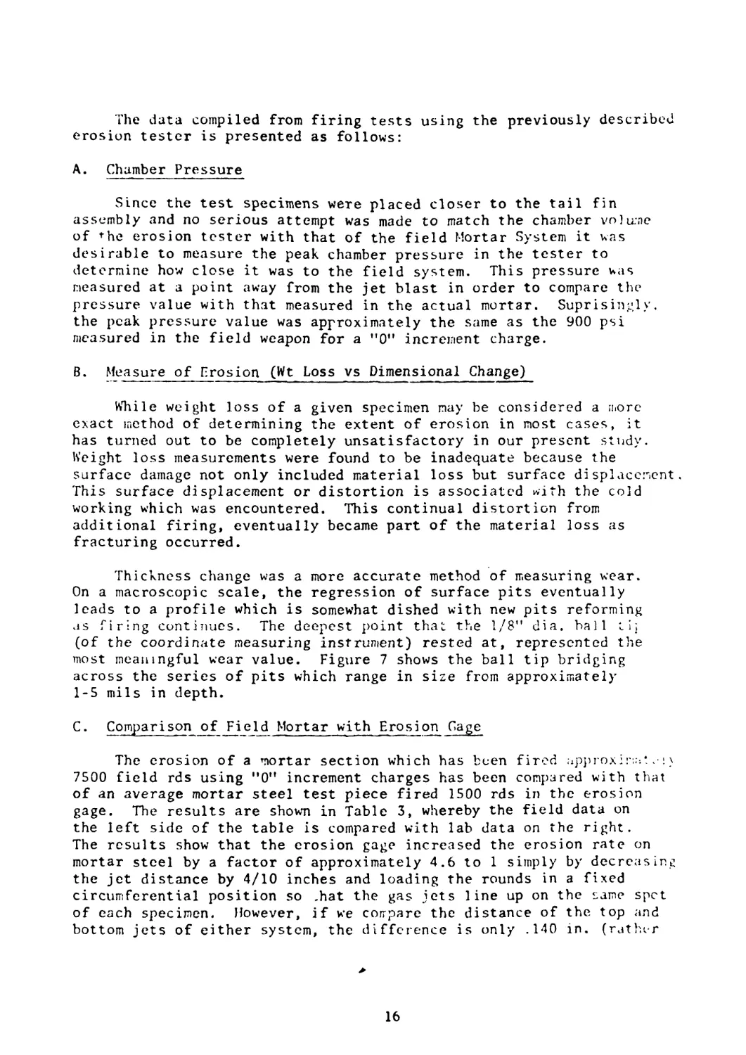
Field Testing 11
Experimental Details 11
Results and Discussion 15
Conclusions 29
References 30
LIST OF ILLUSTRATIONS
Figure
1. Comparison of Old and New Version of Ignition Cartridge 2
1A. 81mm Mortar Tube Cut Out to Reveal the Three Eroded Annular
Grooves 3
2. Overhead View of the Eight Jets of Igniting Gases Impinging
on the Bore Surface 4
3. Sectional View of Igniting Gas Jets Impinging on Test Specimens 4
4. Eroded Views of a Condemned 81mm Mortar Tube After Field Firing
of Approximately 7500 Rounds 6
5. Weight Removed by Erosion as Function of Angle of Impingement
for 1100-0 Aluminum and High Density Aluminum Oxide 9
6. 81mm Mortar Erosion Tester 12
7. Surface Wear Measurement - Maximum Depth Determined by a 1/8"
Diameter Ball Tip 17
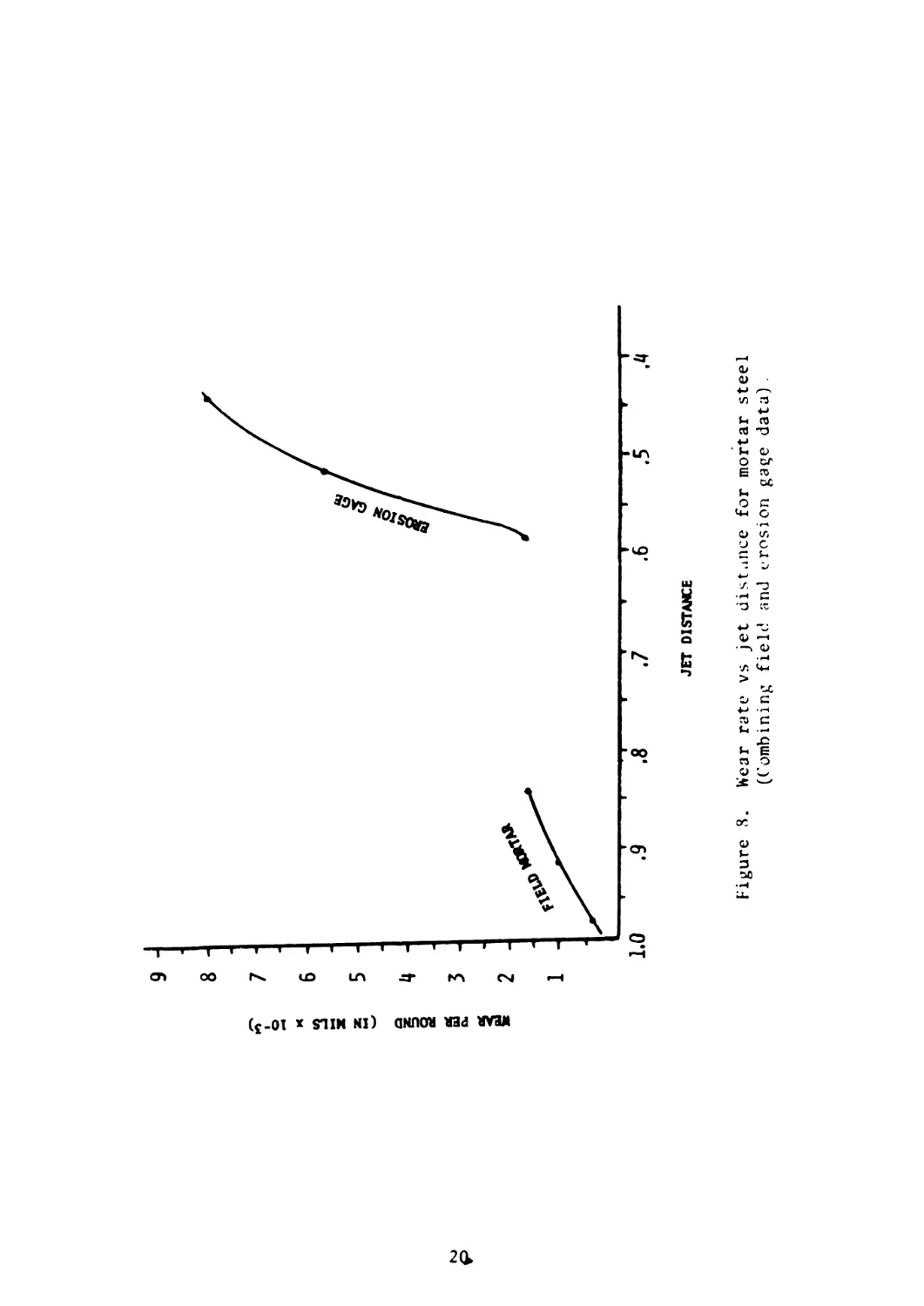
8. Wear Rate vs Jet Distance for Mortar Steel (Combining Field
and Erosion Gage Data) 2°
9. Microscopic Cross-Sectional View of a Pit in Two Steels 21
LIST OF ILLUSTRATIONS (cont)
Figure Page
10. Wear vs Round Curves Showing Relation of Steel Hardness 22
11. Wear vs Round Curves Comparing Various Coatings with Mortar
Steel 24
12. Cross Section of Chromium Deposit on Mortar Steel with "V"
Notch Sections Removed, Leading to Early Failure 26
13. Sectional Surface View of Pit Erosion in 81mm Bore After
Chromium has Flaked Away 2t>
14. Wear vs Round Curves Comparing Cobalt System Coatings with
Mortar Steel 27
LIST OF TABLES
Table
1. Plating Bath Formulations 13
2. Plating Conditions 14
3. Comparison of Gas Jet Distance - Wear Relation for Field
Mortar vs Lab Erosion Gage is
iii
HISTORICAL BACKGROUND
A. Annular Groove Erosion in 81MM Mortar Tubes
Erosion of cylinder bores is typically encountered in gun systems
and recoilless rifles. Erosion of bores in Mortar systems would not
normally be expected in view of the relatively low chamber pressures
and low projectile velocities associated with the weapon. However,
due to changes in the design of the tail fin assembly in the 81MM M29A1
Mortar System, excessive damage to the tube bore surface has been found
during its early firing life which has rendered the tube unserviceable
after approximately 7000 rds as compared to the normal service life of
20,000 rds before condemnation.*
B. Nature and General Cause of Erosion
The surface damage due to erosion occurs in the form of 3 annular
grooves presumably due to the jet impingement of hot gases and cartridge
material flowing from the vent holes of the tail fin assembly of the
mortar round. The major changes in the system which are suspected in
creating the erosion problem are:
a. A quantity of 20 vent holes having a .196" diameter were re-
placed with 24 holes having a .125” diameter which obviously increased
the velocity of the eroding gaseous atmosphere at the. point of contact
on the bore surface.
b. The use of an ignitor cartridge without a copper sleeve in the
center as shown in Figure 1.
Figure 1A shows a mortar tube with a section cut to reveal the three
annular grooves of erosion. Figure 2 shows an illustration of the eight
rows of three jets of igniting gases impinging on the bore surface as one
looks through the bore. Figure 3 attempts to illustrate the flow pattern
of the eroding gaseous atmosphere emanating from the 24 holes of the tail
fin assembly (apart from its projectile) onto a sectional view of the bore
surface.
*As a result of the annular groove erosion, a maximum wear limit of
.022" on the diameter of the bore has been established before con-
demnation of the mortar tube.
1
Figure 1. Comparison of old and new version of ignition cartridge.
1
Figure 1Л. 81 nun mortar tube cut out to reveal the three eroded annular grooves
(Inset is sketch of tail fin showing propellant bags (for higher
increment charges) that deflect gases which otherwise impinge ;on the
bore surface.I
TH FNI
Fi gure 2. Overhead view of the eight
jets of igniting gases im-
pinging on the bore surface.
TEST SHClMfN
Figure 3. Sectional view of igniting
gas jets impinging on test
specimens.
From a single round of firing a very slight degree of damage is
caused by the jet of hot gases and propellant particles streaming from
each of the 1/8” holes of the tail fin assembly. The bore damage
caused from a single jet of hot gas only covers a circular area of
approximately 1/2 inch diameter. However, with the firing of several
thousand of rounds which are loaded in the mortar tube in a random
position (circumferentially) the resulting accumulated surface damage
is formed in a pattern of 3 circumferential annular grooves spaced
opposite to the 3 rows of holes on the tail fin assembly.
The 81MM Mortar System is designed to fire rounds using various
increments of propellant (i.e. from 0 to 9). Increments from 1-9 require
a corresponding number of propellant bags which are physically placed
around the tail fin assembly (inset in Figure 1). The chamber pressures
increase with increasing increment (i.e. 900 psi with increment 0 and
S40D psi with increment 9). Along with burning time and flame
terr.perature, the amount of bore erosion in rifled gun systems is also
increased with increasing chamber pressures. Suprisingly, however, in
th.* case of the 81MM Mortar System damage to the bore surface is most
severe when a ”0” increment round is fired (i.e. low pressure) because
no bags are placed around the tail fin assembly to obstruct the jet
stream of gases from directly impinging on the bore surface. The low
pressure referred to, of course, is misleading since it is the peak chamber
pressure. The pressure value of importance is that which is pinpointed
on the bore surface from the gas jets.
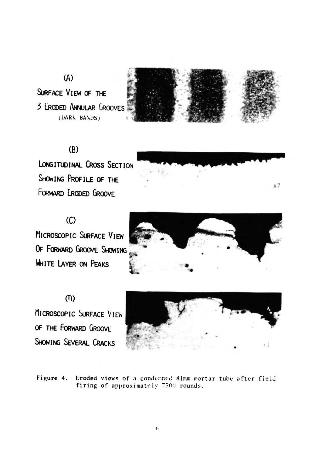
C. Erosion Characteristics in the 81MM M29A1 Mortar System
A severely eroded 81MM Mortar Tube (which was fired in the field)
was metallographically studied in an attempt to determine the signif-
icant factors leading to the annular groove erosion which form the 3
rings. Figure 4a shows a sectional surface view of the 3 annular
grooves. Figure 4b shows the longitudinal cross-sectional profile of
the forward eroded groove. While visual examination of the eroded
surface shows a severe pitted condition which appears to be caused by
purely mechanical forces, microscopic cross-sectional examination
(see Figures 4c and 4d) has revealed patches of the typical white
layer (presumably due to thermal cycling) normally found in large
caliber rifled gun tubes.
5
(A)
Surface View of the
3 Eroded Annular Grooves
(DARK BANOS)
(B)
Longitudinal Cross Section
Showing Profile of the
Forward Eroded Groove
(0
Microscopic Surface View
Of Forward Groove Showing
WhiTE Layer on Peaks
(П)
Microscopic Surface View
of the Forward Groove
Showing Several Cracks
Figure 4. Eroded views of a condemned 81mm mortar tube after field
firing of approximately 7500 rounds.
OBJECTIVE
The primary purpose of this investigation was to search for a
surface coating which could be economically applied to the mortar bore
to resist erosion and increase the service life up to its original
performance. In order to achieve such an objective, a number of coat-
ings had to be tested and evaluated.
THEORETICAL CONSIDERATIONS IN THE FORMATION OF PITTING EROSION
Unfortunately, a mechanism for such erosion was not easily obtain-
able, since we were dealing with a jet stream of hot gases and associated
propellant particles with various degrees of burning and trajectories
at point of impact. Furthermore, an exact analytical solution appeared
impossible, even if treated as a simple mechanism of erosion.
However, since it appeared that the particular pitted surface
damage encountered in the 81MM Mortar System was primarily formed by
abrasive or cutting forces, it was considered appropriate to review the
open literature as a guide in approaching a solution to the problem.
A review of the literature on gun bore erosion offered no help, even
though the grooved erosion was somewhat similar to the erosion sometimes
formed at the end of cartridge cases. By the same token, none of the
investigations reported in the open literature could be matched with
the combined factors existing in the Mortar System, but it was hoped
that some of the erosion studies could be of some help to us. As one
might expect, the studies reported in the literature on impact erosion
varied considerably.
For example, some investigators have studied the impingement of
abrasive particles on a metal surface, some looked at the effects of
steel or glass spheres striking a surface and some studied the collapse
of water droplets which causes cavitation erosion. Still others have
looked at striking abrasive particles in a fluid stream, while some
have studied the effects of hot turbine gases on a metal surface. Some
of these study areas revealed some similarities in the behavior and dam-
age characteristics of metal surfaces and warrant some discussion.
7
Finnic1’ et al appeared to be the first to analytically study the
manner in which abrasive particles erode the surface of a ductile metal
and was quick to point out that a general disadvantage of erosion data
in the literature is that particle velocities as distinct from fluid
velicities, had not previously been measured. He points out also that
ductile surfaces should be given separate attention from brittle
surfaces since their erosion behavior is significantly different.
In solving the equations of motion of a single abrasive particle
striking a ductile surface^, it was shown that the volume Q removed by
a given mass of abrasive grains with velocity V and angle a is estimated
to be
Q = С 1 Г (a)
4 4 p '
where p is the flow stress (relative to the surface). In Figure 5, the
dashed line shows^ (a), the predicted variation of erosion with angle
for a ductile material eroded by abrasive particles. The scale of (a)
was chosen arbitrarily so that its maximum value agrees with the experimental
data for aluminum. Finnie et al^ reported good correlation of wear with
experiments showing the greatest wear to be at angles 17e-20e (see Figure 5).
However, the equation does not hold very, well for angles nearer 90° which is
what we are dealing with in our present case. The three possible effects
which invalidate the simple theory for ductile surfaces at angle 90е is:
a) Not all particles will strike the surface at the same angle.
b) The analysis considers a smooth surface and after the surface
is roughened the particle-surface interaction is changed.
c) The surface becomes cold worked and embrittled and no longer
behaves in a predictable manner.
1. Finnie, I., ’’The Mechanism of Erosion of Ductile Metals,”
Proceedings of the 3rd National Congress of Applied Mechanics,
American Society of Mechanical Engineers, 1958, pp. 527-532.
2. Finnie, I., ’’Erosion of Surfaces by Solid Particles,” Wear,
Vol. 3, 1960, pp. 87-103.
3. Finnie, Iain, Wolak, Jan, and Kabil, Yehia, ’’Erosion of Metals
by Solid Particles,” Journal of Materials, Vol. 2, No. 3.
Sept. 1967, pp. 682-700.
4. Sheldon, G.L., Finnie, I., ”0n the Ductile Behavior of Nominally
Brittle Materials During Erosive Cutting” Journal of Engineering
for Industry, Nov. 1966, pp. 387-392.
5. Sheldon, G.L. and Finnie, I., ’’The Mechanism of Material Rcmova"
in the Erosive Cutting of Brittle Materials,” Transactions,
American Society of Mechanical Engineers, Vol. 88B, 1966,
pp. 387-392.
8
Figure 5. Weight removed by erosion as function of angle of
impingement for 1100-0 aluminum and high density
aluminum oxide (after Finnie ref 3).
9
One point of interest in the case of brittle surfaces (Figure 5),
is that 90е angle of impingement produces the greater amount of wear.
It will be shown later that some of our own results have shown similar
behavior.
Engel^"? reported that the development of a pit-depth vs velocity
equation for collision of rigid spheres on a surface does not hold in
every case where cold working of the surface occurs. This has also
been pointed out by Moore, et al® in their studies of worn metal
surfaces using a blunted tool.
As previously mentioned, the above studies cited from the literature
involve process conditions which are quite remote from the environmental
factors which exist in the Mortar System. To begin with the particles
are neither jagged abrasives, metal spheres or water droplets but
propellant platelets or discs which are at an indeterminate rate of
burning at the point of contact with the surface. Also, the propellant
particles are traveling in their associated hot gaseous atmosphere
when impinging on the surface. Thirdly, the time cycles involved are
in milliseconds and the particle velocities (although unknown) are
undoubtedly far greater than any of those cited in the literature.
Early attempts to measure the velocity of propellant particles in the
erosion gage by high speed photography techniques were unsuccessful.
In spite of these differences pointed out in the Mortar system
compared to the particle-surface actions cited in the literature, our
results will show that the behavior of Mortar steel surfaces and some
of the wear characteristics exhibit surprising similarities.
6. Olive Engel, ’’Pits in Metals Caused by Collision With Liquid Drops
and Soft Metal Spheres,” NBS Journal of Research 62, 229 (1959)
RP2958.
7. Olive G. Engel, "Pits in Metals Caused by Collision With Liquid
Drops and Rapid Steel Spheres,” Journal of Research of the
National Bureau of Standards-А Physics and Chemistry Vol. 64A,
No. 1, January-February 1960, pp. 61-72.
8. Moore, M.A., Richardson, R.C.D., Attwood, D.G. "The Limiting
Strength of Worn Metal Surfaces” Metallurgical Transactions (ASM),
Vol 3, Sept 1972, pp. 2485-2491.
10
FIELD TESTING
Early efforts in searching for a suitable coating to protect the
bore of the 81MM Mortar Tube from such erosion consisted of electro-
depositing various tube bores with candidate coatings which were then
scheduled for field testing using primarily ”0*' increment rounds
(i.e. the most damaging rounds). Since electrodeposited chromium was
presently being used as the acceptable erosion resistant coating in
high velocity production weapon systems, it was naturally selected as
a first choice for test in the Mortar System. Other selected coatings
were cobalt-alumina (A^Oj) and also a proprietary chromium coating
called "Armoloy".
These preliminary efforts to apply wear resistant bore coatings
and test firing mortar tubes in the field have been extremely costly
and time-consuming because of the large number of rounds required and
difficulties encountered with field firing schedules. In view of the
latter it was decided to devise a laboratory method of testing so that
a variety of coatings could be evaluated concurrently prior to field
testing.
EXPERIMENTAL DETAILS
Erosion gage - An erosion tester or gage was designed and
developed which utilizes the M285 tail fin assembly inside a chamber
holding eight test specimens at the same time to correspond to the 8
rows of holes. (See cut away illustration in Figure 6.) The actual
details of construction of the erosion gage will be reported under a
separate cover and will not be discussed here. The primary change
made in the firing action, is that the projectile has been removed from
the tail assembly which is secured to remain stationary during the
firing cycle.
The erosion rate of the test material can be increased, so that less
rounds are required, by moving the specimens closer to the tail fin assem-
bly which reduces the distance of the jet stream. Upon firing the ignitor
charge, the mixture of hot gases and associated burning particles are ra-
dially discharged upon the specimen surface through the .125" vent holes.
Fin Assembly - The M170 fin assembly (which was used in all of the
tests) houses the M285 ignition cartridge containing the M9 propellant
which has a charge weight of 108 grains (1 grain = .0648 gram).
Physical Properties of M9 Propellant - The propellant is in the form
of platelets measuring .059 in. in diameter and .010 in. thick. The bulk
density is 46 Ib/cu-ft.
11
81мм MORTAR EROSIO
НОЮ DOWN RING
НОЮ DOWN BAR
TEST CHAMBER
TEST SPECIMEN
SPECIMEN HOLDER
TEST PLUG
XM170 FIN
ASSEMBLY
FIRING PIN ASSEMBLY
Figure 6. 81mm mortar erosion tester.
12
Calculated Thermochemical Values for M9 Propellants (as per Spec
MIL-P-20306)
Isochoric flame temp, ° К..................... 3799
Force, ft-lbs/lb x 10’3..........................382
Unoxidized carbon, %...............................0
Combustibles, %..................................32.8
Heat of explosion, cal/gm.......................1295
Gas volume, moles/gm...............................0.03618
Ratio of specific heats............................1.2102
Isobaric flame temp, °K........................3139
Covolume, in.^/lb................................25.97
Plating Conditions - The bath formulas and plating conditions
employed for preparing the surface coatings selected for evaluations
are given in Tables 1 and 2, respectively.
TABLE 1. PLATING BATH FORMULATIONS
Bath No Coating Bath Formula Compound Cone, g/1
1 Cobalt (Co) Cobalt Sulfate (CoSO^’7H20) 300
Cobalt Chloride (СоС^’бН^О) 50.6
Boric Acid (HjBO^ 31.4
2 Cobalt Alumina Cobalt Sulfate 314
(Со-АЦО ) Boric Acid 31.4
Cobalt Chloride 50.6
Aluminum (A^O^) (.05u particle size) 25
3 Cobalt-Iron Cobalt Sulfate 314
(Co-Fe) Boric Acid 31.4
Cobalt Chloride 50.6
Ferrous Sulfate (Ре$Од-7Н2О) 25
4 Chromium (Cr) Chromic Anhydride (CrO^) 250 g/1
Sulfuric Acid (Н2$Од) 2.5 g/1
5 Armoloy Cr *Armoloy Salts 454 g/1
*Supplied by Armoloy Inc., Fort Worth, Texas
13
TABLE 2. PLATING CONDITIONS
Bath Current Density _£H Be' Bath Temp
Cobalt 5.4 amp/dm^ (50 amp/ft2) 2.0 30 60eC (140°F)
Cobalt-Alumina 50 g/1 (.05 micron) 5.4 amp/dm^ (50 amp/ft^) 2.0 30 60’C (140*F)
Cobalt-Iron (6 wt %) 2 5.4 amp/dm (50 amp/ft2) 3.0 30 60 °C (140eF)
Chromium 2 32 amp/dm (300 amp/ft2) 21-22 54°C (130°F)
Armoloy Cr 2 32 amp/dm (300 amp/ft2) 21-22 54eC (130eF)
Pc>st Heat Treatment - All coatings with the exception of Co-Fc
were thermal treated in an atmosphere furnace for hydrogen relief after
plating at 450eF (232°C) for 4 hrs to insure against embrittlement
The Co-Fe coatings were thermally treated at 675eF (357°C) for 4 hrs
for the purpose of attempting to impart some ductility to the relatively
brittle coatings in the as plated condition.
Nitride Surfaces - The 76-hour nitriding cycle for the 81mm
Mortar specimens consisted of treatment at 975eF for 15 hours at 24-
28% dissociation and 1020°F for 61 hours at 80-84% dissociation.
Coating Thickness and Wear Measurements - The deposit thickness of
iron group metals for this test were 6-8 mils. In the case of chromium
deposits, two thicknesses were tested, which were 0.2 mils and 2.0 mils.
The thickness of deposits were measured with micrometers and in some
cases later verified by measurements of the coatings using the micro-
scopic camera. Wear measurements of all specimens were taken every
125 rds and conducted with a ball micrometer and coordinate measuring
instrument (Sheffield Cordex 300 Coordinate Measuring Machine) which
had a 1/8" ball tip. The procedure was to slide the test specimen back
and forth across the worn depression of the surface until the tip
14
reached the lowest point which measured the greatest point of wear
due to firing.
Weight Measurements - Weight loss determinations, due to erosion
during firing, were conducted on a Mettler analytical balance.
Microhardness Measurements - These measurements were made on cross
sections of the specimens with a Wilson Tukon microhardness tester using
a 100g load and are reported on the Knoop scale. Measurements on the
soft steels were taken with a 25g load. Hardness measurements given are
those taken before firing unless otherwise stated.
Photomicrographs - Cross sections of specimens were mounted and pol-
ished using diamond abrasives. The polished specimens were etched with a
solution of 60 parts lactic acid, 30 parts HNO3 ♦ 5 parts HF, by swabbing
for 10-15 seconds. The photomicrographs were made with a Polaroid cam-
era using a Leitz MM5 Research Metallograph.
Test Specimens - The specimens consisted of SAE 4340 steel strips
Cl/8 inch thick) and cut sections of mortar tubes. The specimens mea-
sured 3/4 of an inch wide and five inches in length.
Laboratory Firing Tests - The firing tests were limited to 1500 rds
which produced over 10 mils of wear on the radius of unprotected mortar
steel. Mortar tubes in the field are condemned when any portion of the
bore shows a wear of 20 mils on the diameter (i.e., 10 mils on the side).
However, the 1500 rd test was selected to permit a suitable range of wear
values for evaluating the various candidate erosion resistant coatings.
Since the erosion tester held eight specimens during a firing test, one
of the specimens was always unplated mortar steel which, acted as the con-
trol specimen.
RESULTS AND DISCUSSION
In reviewing the literature, one will find that considerable doubt
and controversy exists on the validity of data from erosion vent studies
when comparing results with actual field behavior of eroded surfaces and
it is agreed that some of the doubts have considerable merit. However,
as previously mentioned, in this present laboratory study our erosion
gage consists of the actual field system (which includes the M170 Tail
Fin Assembly with the M285 Ignitor) with the absence of the mortar pro-
jectile. In spite of two primary changes made in the use of the ero-
sion gage for the purpose of accelerating the erosion process, micro-
scopic examination shows a close similarity in the erosion characteristics
produced by the two systems. One of these changes included a decrease in
the jet distance from the vent holes to the specimen surface which in-
creases the velocity at point of impact. The second change effectively
focuses the surface damage on the same circular location rather than dis-
persing the surface damage when the rounds are circumferentially loaded
at random which results in the formation of annular grooves which have
been shown previously.
15
The data compiled from firing tests using the previously described
erosion tester is presented as follows:
A. Chamber Pressure
Since the test specimens were placed closer to the tail fin
assembly and no serious attempt was made to match the chamber volume
of rhe erosion tester with that of the field Mortar System it was
desirable to measure the peak chamber pressure in the tester to
determine how close it was to the field system. This pressure was
measured at a point away from the jet blast in order to compare the
pressure value with that measured in the actual mortar. Suprisinglу,
the peak pressure value was approximately the same as the 900 psi
measured in the field weapon for a ”0” increment charge.
В. Measure of Erosion (Wt Loss vs Dimensional Change)
Wbile weight loss of a given specimen may be considered a more
exact method of determining the extent of erosion in most cases, it
has turned out to be completely unsatisfactory in our present study.
Weight loss measurements were found to be inadequate because the
surface damage not only included material loss but surface displacement.
This surface displacement or distortion is associated with the cold
working which was encountered. This continual distortion from
additional firing, eventually became part of the material loss as
fracturing occurred.
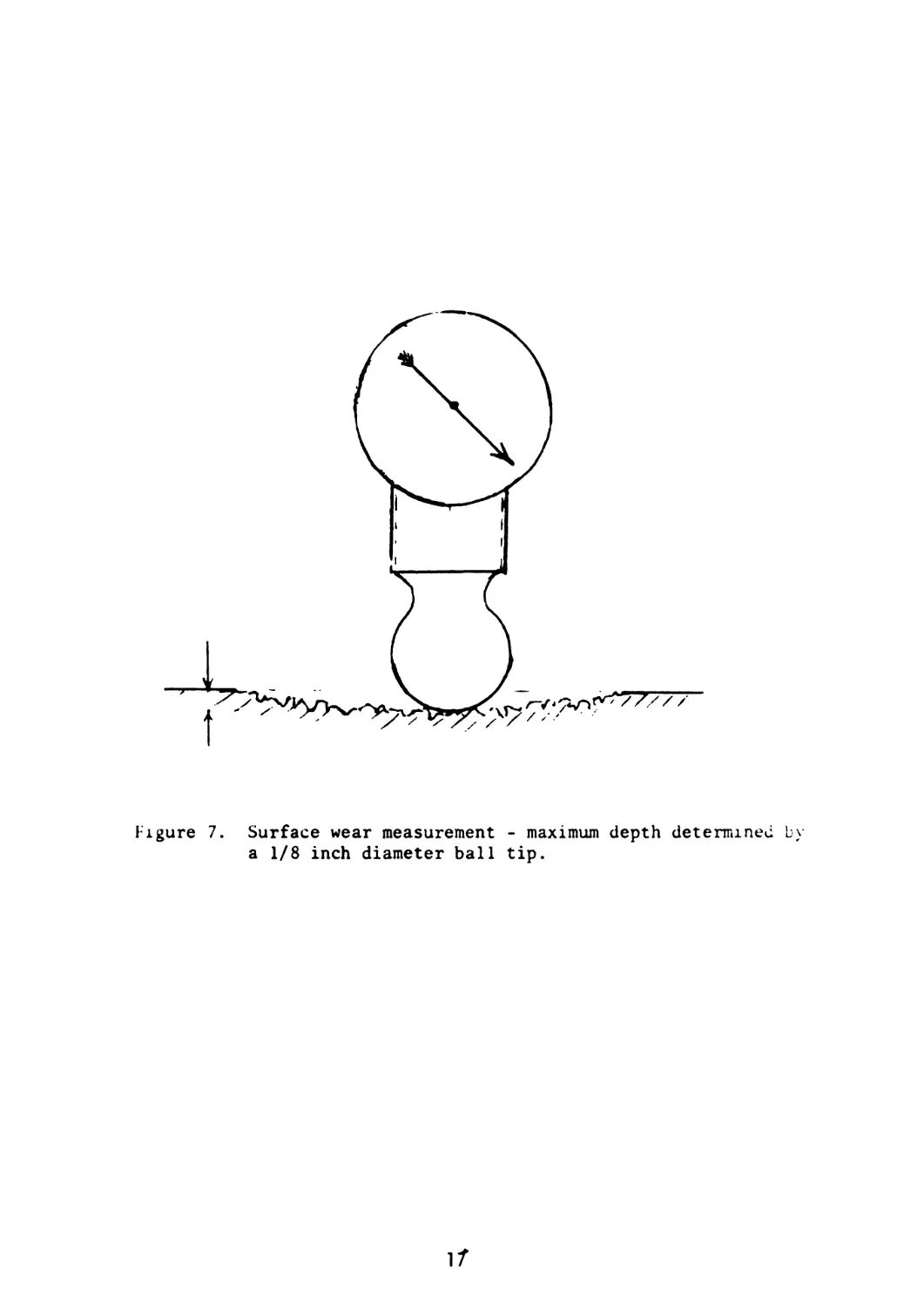
Thickness change was a more accurate method of measuring wear.
On a macroscopic scale, the regression of surface pits eventually
leads to a profile which is somewhat dished with new pits reforming
as firing continues. The deepest point that the 1/8” dia. ball tij
(of the coordinate measuring instrument) rested at, represented the
most meaningful wear value. Figure 7 shows the ball tip bridging
across the series of pits which range in size from approximately
1-5 mils in depth.
C. Comparison of Field Mortar with Erosion Gage
The erosion of a mortar section which has been fired approximat.••\
7500 field rds using "0" increment charges has been compared with that
of an average mortar steel test piece fired 1500 rds in the erosion
gage. The results are shown in Table 3, whereby the field data on
the left side of the table is compared with lab data on the right.
The results show that the erosion gage increased the erosion rate on
mortar steel by a factor of approximately 4.6 to 1 simply by decreasing
the jet distance by 4/10 inches and loading the rounds in a fixed
circumferential position so _hat the gas jets line up on the same spet
of each specimen. However, if we compare the distance of the top and
bottom jets of either system, the difference is only .140 in. (rather
16
Figure 7. Surface wear measurement - maximum depth determined by
a 1/8 inch diameter ball tip.
17
TABLE 3. COMPARISON OF GAS JET DISTANCE - WEAR RELATION FOR FIELD MORTAR VS LAL EROSION GAGE
TESTING ON MORTAR STEELS
FIELD MORTAR SYSTEM AFTER 7500 RDS У170 TAIL FIN EROSION GAGE AFTER 1500 RDS
SURFACE VD-W OF EROSION WEAR ON RADIUS (mils) WEAR PER RD xlO"bin DIST. OF JET TO BORE SURFACE (IN.) DIST. OF JET TO BORE SURFACE (1N.) WEAR PER RD xlO'bin i WEAR SURFACE ON , RADIUS (VIEW OF 1 (mils) erosion i
[ IGNITION CHAMBER
WITH .125 IN. DIAM VENT HOLES)
14 / 1.87 z *.850 -M - z дД — .450 -* J 8.07 1 12.1 i J
1* [ / / /s']
> - 9 i.2o : ^.920 .520—* ^5.8 8.7
4** /д
1 3 i 0.40 ' / ✓ *-.990 — ।/ zl — / / f z J -.590 —» ;1.8 27 'Я
than и.40 in.) and the erosion rate is still a factor of about 4.5 to 1.
In view of this observation, it was decided to combine the data and
plot wear rate vs jet distance which is shown in Figure 8. The bottom
or rear vent distance of the erosion gage is 0.260 in. closer than the
top vent of the field mortar system in addition to the fixed circum-
ferential loading of the rounds - but still the wear rate is the same
for the two systems. This indicates that length of bore travel through
the vent hole may be more effective than the jet distance in increasing
the impact velocity and subsequent erosion rate. However, the longer
bore length is still considered relatively short to significantly in-
crease the particle velocity. Another strong possibility is that more
solid particles pass through the forward vents compared to the rear
vents due to incomplete ignition which is discussed below. Dealing
with ignition systems is more complicated than dealing with propellants
in chamber systems. However, based on the observation in Figure 8, and
the collection of additional data, it appears that some empirical equa-
tion can be developed to calculate erosion in the present system.
D. Pit Formation
It was previously stated that erosion of mortars was due to the
impingement of hot gases and associated propellant particles. Obser-
vations in our laboratory indicated that the mechanical force contribution
to the surface damage was due to unburned as well as partially burned
propellant particles striking the surface. After certain intervals of
firing, some of these unburned propellant discs were found embedded in
th? pitted surfaces of the specimens. Some other unburhed discs were
scattered about the surrounding area of the erosion gage set-up. The
surface damage due to solid particles is also confirmed by the grain
refinement and subsequent microhardness increase observed along the
periphery of the pits during metallographic examination (see Figure 9).
It is obvious that severe plastic deformation takes place during the
impingement of these unburned and partially ignited propellant particles
apparently driven through vent holes by the expanding gases of the inner
propellant particles which are first ignited in the cartridge housing.
Problems with poor distribution of ignition gases and resultant sporatic
local pressures encountered in gun systems have been well documented in
the literature.
It is strongly suspected (on the basis of the similarity in surface
damage) that this behavior of unburned propellant particles impinging
on the surface also occurs in field mortars with "0” increment charges.
E. Relationship of Hardness to Erosion or Wear
Since it was found that mechanical forces played a major ro?e in
the present wear problem, the effect of hardness of a steel surface
vs erosion was examined. Figure 10 shows the behavior of three types of
steels tested on the erosion gage in which hardness is shown to be a sig-
nificant factor with nitrided surfaces providing the best wear resistance.
19
WEAK PER ROUND (IN MILS x 10" J)
Figure 8. Wear rate vs jet distance for mortar steel
(Combining field and erosion gage data).
Figure 9. Microscopic cross-sectional view of a pit in two steels
(Note fine grain structure along the periphery of the
pit due to cold working).
21
Ю
K)
MORTAR STEEL (fc 40)
Figure 10. Wear vs round curves showing relation of steel hardness.
The effectiveness of hardness is apparently also demonstrated by
the •’S’* shape of the curves which shows the wear rate to decrease for
a period and then increase again. This is attributed to the cold
working of the surface which occurs as the degree of pitting becomes
extensive. As firing continues, it is speculated that the distortion
and plastic deformation of the surface peaks or crests approach a
severity whereby fracturing occurs resulting in a sudden increase in
the rate of wear as shown by the curves.
The indication that hardness of a surface effectively increases
the erosion resistance would lead us to prematurely conclude that a
quick solution to the problem is to nitride the bore surface of mortar
tubes. Other considerations and findings, however, have ruled out
such a decision. These are as follows:
1. The process of nitriding was found to be expensive and time
consuming.
2. Surface cracks initiated at the surface, during firing, which
propagated through the substrate (i.e. non-nitrided portion
of the steel).
3. At the early stage of firing, the nitrided surface is very
resistant to wear; however, as firing continues, the brittle
casing quickly spalls and fragments leading to a rapid rate
of wear and surface regression.
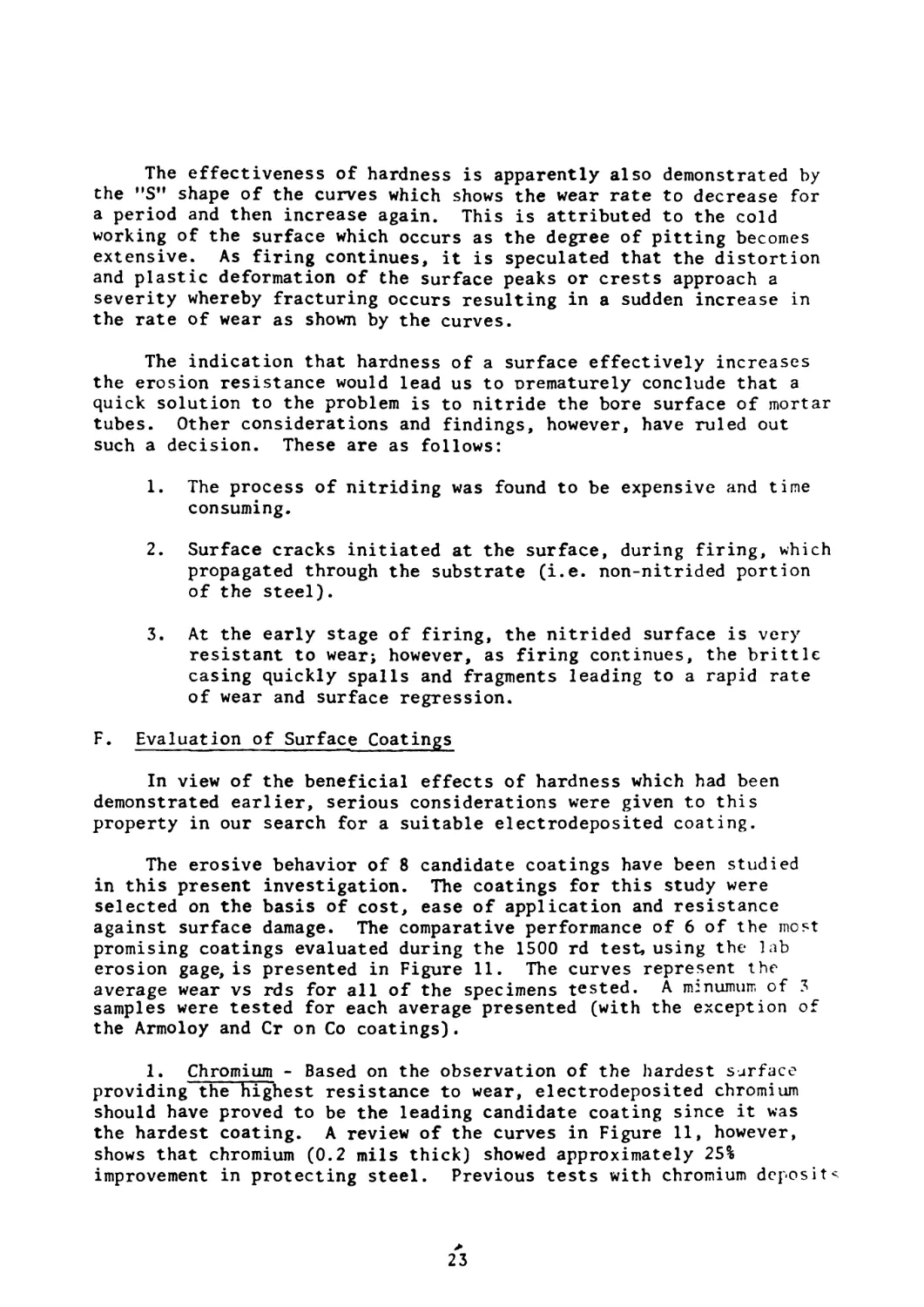
F. Evaluation of Surface Coatings
In view of the beneficial effects of hardness which had been
demonstrated earlier, serious considerations were given to this
property in our search for a suitable electrodeposited coating.
The erosive behavior of 8 candidate coatings have been studied
in this present investigation. The coatings for this study were
selected on the basis of cost, ease of application and resistance
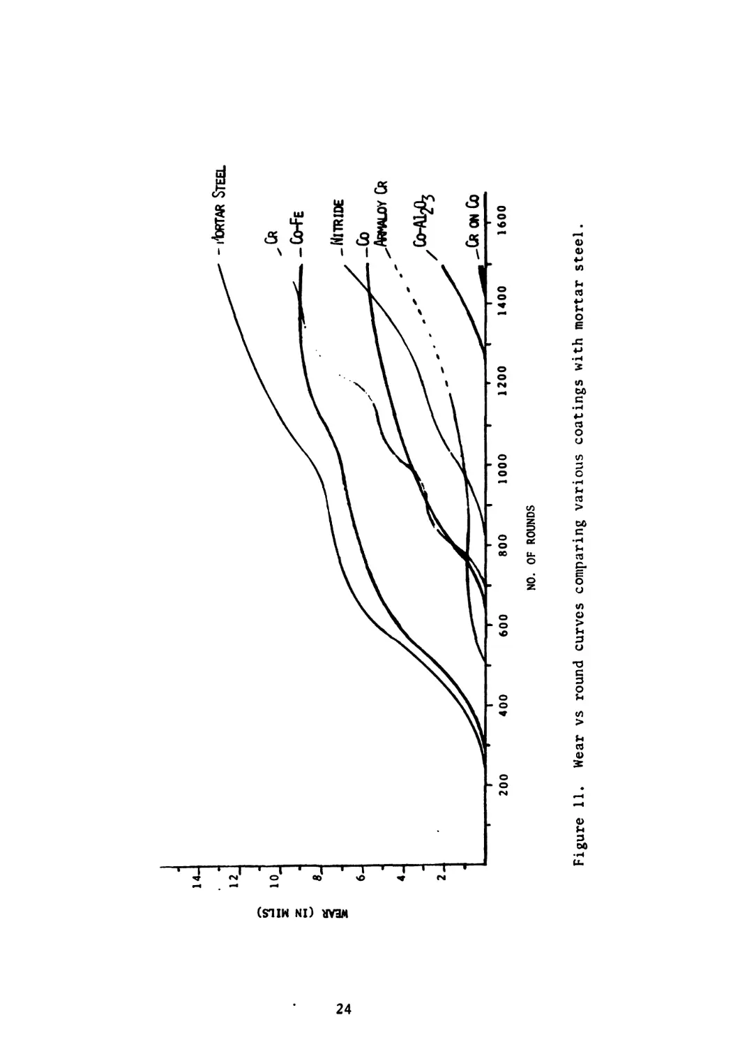
against surface damage. The comparative performance of 6 of the most
promising coatings evaluated during the 1500 rd test, using the lab
erosion gage, is presented in Figure 11. The curves represent the
average wear vs rds for all of the specimens tested. A mznumum of 3
samples were tested for each average presented (with the exception of
the Armoloy and Cr on Co coatings).
1. Chromium - Based on the observation of the hardest surface
providing the highest resistance to wear, electrodeposited chromium
should have proved to be the leading candidate coating since it was
the hardest coating. A review of the curves in Figure 11, however,
shows that chromium (0.2 mils thick) showed approximately 25%
improvement in protecting steel. Previous tests with chromium deposits
23
WEAR (IN MILS)
NO. OF ROUNDS
Figure 11. Wear vs round curves comparing various coatings with mortar steel.
wh’ch were 2 mils or greater in thickness failed prematurely by
excessive spalling and were withdrawn early during the 1500 rd test.
Field tests also showed chromium coatings (2-5 mils thick) to perform
poorly in a similar manner. An explanation for this behavior can be
offered if we look at the wear plot from Finnie et al in Figure 5,
which shows a brittle surface to result in greatest wear at a 90° angle
of impingement. In reality, electrodeposited chromium can be
classified as a brittle surface and therefore explains such a behavior.
Figure 12 shows a cross-section of chromium on mortar steel with
initial "V” notch segments of chromium progressively sheared away.
Figure 13 shows a surface view of a pitted mortar section. The
white patches represent the chromium still remaining.
2. Armoloy Chromium - Coatings of armoloy chromium (which were
deposited in a proprietary electrolyte) 1 mil thick were shown to be
very promising. However, only one specimen was available for test
firing above 1200 rds which is indicated by the dashed line. Other
specimens flaked prematurely, and it could not be determined whether
the failure was due to the material property or plating defects. In
view of the electrolyte being of a proprietary nature and inconsisten-
cies encountered in the deposition process, the study of these deposits
was temporarily suspended.
3. Cobalt System of Coatings - We have already discussed the
evaluation of nitrided steel, and conventional and armoloy chromium
deposits as candidate materials. The remaining materials for discussion
are referred to as the cobalt system and can be classified as ductile
coatings in contrast to chromium. The wear plots for these coatings
are shown separately with mortar steel (which includes their hardness)
in Figure 14 in order to simplify the discussion of their evaluation.
In studying the performance of these coatings, it was observed
that the erosion resistance generally increased with increasing
microhardness but the hardness was not the sole factor in controlling
their overall performance. Coatings had to be sound (i.e. free from
voids, stress, cracks, and be crystalline), possess high shear and
tensile properties and be highly adherent to their substrates in order
to be highly resistant to erosion.
a. Co-Fe - The process controls and mechanical properties of
Co-Fe alloys have been reported previously from this lab by Sadak and
Sautter^. In view of some of these properties it was decided to
include Co-Fe as one of the candidate coatings. However, a comparison
of the wear curves shows cobalt-iron to be the most inferior among the
cobalt system. However, this behavior has been attributed to plating
problems in which difficulties were encountered in achieving homogeneous
and sound deposits of the alloy. Recent improvements in the plating
process controls have indicated that Co-Fe (5-12 wt %) should prove to
9. Sadak, J.C., and Sautter, F.K., Vac. Sci. Technol. Vol 11,
No. 4 July/Aug 1974 pp. 771-776.
25
I igurv 1-. uros-. section of chromium deposit on mortar steel with
V” notch sections removed, leading to early failure.
Figure 15. Sectional surface view of pit erosion in 81mm bore after
chromium has flaked away (white patches are remaining
chromium).
26
WEAR (IN MILS)
NO. OF ROUNDS
Figure 14. Wear vs round curves comparing cobalt system coatings with mortar steel.
be a strong candidate as an erosion retardant coating in 81mm mortars.
b. Cobalt - The performance of pure cobalt was comparable
to nitrided steel and eroded approximately 1/2 the amount as mortar
steel. The influence of adhesion and soundness of the deposit on its
resistance tb erosion was clearly evident by the testing of an earlier
group of cobalt whereby the erosion resistance was only approximately
25% better than mortar steel. In this case the surface regressed by
the flaking of large chips of the deposit.
c. Cobalt-Alumina - (C0-AI2O3) - Dispersion strengthened
cobalt alloy was selected as a candidate coating on the basis of its
high temperature properties. The concept cf preparing dispersion
strengthened alloys by electrodeposition techniques was first reported
by Sautter^0 using nickel, and later by Greco and BaldaufH. The prop-
erties of electrodeposited Со-А120з alloys were reported by Sadak and
Sautterl2f and more recently by Chen and SautteriS.
Dispersion hardened cobalt deposits for the present test
consisted of approximately 2 v/o of finely dispersed alumina (having
a particle size of .05 microns) in a cobalt matrix. This alloy was
found to be one of the best erosion resistant materials for this test.
C0-AI2O3 alloys would be expected to perform better than pure cobalt,
since their hardness is higher both at room and high temperature and
their shear and yield strength are superior. The importance of
obtaining sound and homogeneous deposits cannot be overstressed, since
a large variation in the erosion rate results when the process controls
are not under close observation. Non-homogeneity frequently leads to
spalling of large fragments of the deposit rather than the fine micro-
scopic surface regression normally observed in unplated mortars.
d. Chromium on Cobalt - We have shown previously that
chromium deposits on steel (2-5 mils thick) showed poor performance in
mortars due to its inherent brittleness resulting in progressive
spalling of the coating. Thinner deposits (i.e. 0.2 mils) directly on
steel offered better protection but the decrease in wear was only
approximately 25%. Furthermore cobalt deposits by themselves were
classified as fair among the other coatings (i.e. the wear rate was
50% compared to mortar steel). Nevertheless, Figure 14 shows Cr on
10. Sautter, F.K., J. Electrochem. Soc. 110, 557 1953.
11. Greco, V.P. and Baldauf, W., Plating Journal, pp. 250-257, Mar 1968.
12. Sadak, J.C. and Sautter, F.K., J. Metals Eng. Qtrly, Aug 1974.
13. Chen, E.S., and Sautter, F.K., Plating and Surface Finishing, Sept.
1976.
28
cobalt to offer the highest resistance against erosion when compared
with all other coatings. This infers that by combining the 2 coatings
we have capitalized on their erosion resistance beyond their protective
quality as individual coatings. This means that some combined effect
must exist at the interface of Cr and Co. In addition, the chromium
deposit was only 2-5 tenths of a mil thick over 6 mils of cobalt.
Thin deposits of Cr are relatively strong compared to thick deposits
and do not shear or spall readily. However, thin deposits directly
on steel did not perform as well, probably because when the thin Cr
flaked away, the underlying steel pitted and the surface regressed at
a relatively high rate but thin Cr on cobalt appeared to shear away in
a gradual manner with the underlying cobalt still being very resistant
to the impinging gases. It must be pointed out ttox ' of
Cr on Co is limited and efforts in this area must be continued to
explain the combined effect of Cr on Co as an erosion resistant
material.
CONCLUSIONS
It should be apparent from the above tudy that the evaluation
and selection of a coating for the protection of mortar bores against
annular groove erosion, is incomplete. However, based on the present
data which has been evaluated, two coatings warrant further study.
These are:
a. C0-AI2O3 (5-7 mils thick)
b. Chromium (0.2-0.5 mils) on Cobalt (5 mils)
Continued firing in the erosion gage with these coatings should
provide sufficient data to determine the best coatings to be
recommended for field testing.
One can conclude from the present data, however, that:
a. The erosion gage has shown to be a useful tool for evaluating
erosion resistant coatings for mortar bores.
b. The comparison of the surface damage characteristics produced
by the gage and field mortar are very similar.
c. The major cause of pitting erosion in the present system is
the impingement of unburned ignitor propellant.
d. The gage accelerates the erosion rate compared to the field
system by a factor of approximately 4.5 to 1.
e. The cobalt system of coatings will significantly reduce the
annular groove erosion in mortar bores.
29
REFERENCES
1. Finnie, I., "The Mechanism of Erosion of Ductile Metals,"
Proceedings of the 3rd National Congress of Applied Mechanics,
American Society of Mechanical Engineers, 1958, pp. 527-532.
2. Finnie, I., "Erosion of Surfaces by Solid Particles," Wear,
Vol. 3, 1960, pp. 87-103.
5. Finnie, Iain, Wolak, Jan, and Kabil, Yehia, "Erosion of Metals
by Solid Particles," Journal of Materials, Vol. 2, No. 3.
Sep 1967, pp. 682-700.
4. Sheldon, G.L., Finnie, I., "On the Ductile Behavior of Nominally
Brittle Materials During Erosive Cutting" Journal of Engineering
for Industry, Nov 1966, pp. 387-392.
5. Sheldon, G.L. and Finnie, I., "The Mechanism of Material Removal
in the Erosive Cutting of Brittle Materials," Transactions,
American Society of Mechanical Engineers, Vol. 88B, 1966,
pp. 387-392.
6. Engel, Olive,’’Pits in Metals Caused by Collision With Liquid Drops
and Soft Metal Spheres," NBS Journal of Research 62, 229 (1959)
RP2958.
7. Engel, Olive G.,"Pits in Metals Caused by Collision With Liquid
Drops and Rapid Steel Spheres," Journal of Research of the
National Bureau of Standards-А Physics and Chemistry Vol. 64A,
No. 1, January-February 1960, pp. 61-72.
8. Moore, M.A., Richardson, R.C.D., Attwood, D.G. "The Limiting
Strength of Worn Metal Surfaces" Metallurgical Transactions (ASM),
Vol 3, Sep 1972, pp. 2485-2491.
9. Sadak, J.C., and Sautter, F.K., J. Vac. Sci. Technol. Vol 11,
No. 4 July/Aug 1974 pp. 771-776.
10. Sautter, F.K., J. Electrochenu Soc. 110, 557 1953.
11. Greco, V.P. and Baldauf, W., Plating Journal, pp. 250-257, Mar 196Я.
12. Sadak, J.C. and Sautter, F.K., J. Metals Eng. Qtrly, Aug 1974.
13. Chen, E.S. , and Sautter, F.K., Plating and Surface Finishing, Sop
1976.
30
WATERVLIET ARSENAL INTERNAL DISTRIBUTION LIST
May 19’6
No. of Copies
i OMMXNDf к I
DIRICIOR, BENI Г WEAPONS LABORATORY 1
DIRECTOR, DEVELOPMENT ENGINEERINC DIRECTORATE 1
ATTN: RD-А Г 1
RD-MR 1
RD-PE 1
RD-RM 1
RD-SE 1
RD-SP 1
DIRECTOR, ENGINEERING SUPPORT DIRECTORATE 1
DIRECTOR, RESEARCH DIRECTORATE 2
ATTN: RR-AM 1
RR-C 1
RR-ME 1
RR-PS 1
TECHNICAL LIBRARY 5
TECHNICAL PUBLICATIONS & EDITING BRANCH 2
DIRECTOR, OPERATIONS DIRECTORATE 1
DIRECTOR, PROCUREMENT DIRECTORATE 1
DIRECTOR, PRODUCT ASSURANCE DIRECTORATE 1
PATENT ADVISORS 1
EXTERNAL DISTRIBUTION LIST
1 copy to each
December 1976
oh: Ob ГН1 DIR. OF DEFENSE RGE
ATTN: ASSI DIRECTOR MATERIALS
ПН PENTAGON
WVSH1NGION. !!.(.. 20315
CUR
US ARMY F\NK-AUTMV COMD
ATTN: AMl'TA 1)1.
AMSГА REM MAT LAB
WARREN, MICHIGAN 48090
CDR
PiCATINNY ARSENAL
ATTN: SARPA-TS-S
SARPA-VP3 (PLASTICS
TECH EVAL CEN)
DOVER, N.J 07801
CDR
FRANKFORD ARSENAL
ATTN: SARFA
PHILADELPHIA, PA 19137
DIRECTOR
US ARMY BALLISTIC RSCH LABS
ATTN: AMXBR-LB
ABERDEEN PROVING GROUND
MARYLAND 21005
CDR
US ARMY RSCH OFC (DURHAM)
BOX CM, DUKE STATION
ATTN: RDRD-IPL
DURHAM, NC 27706
CDR
WEST POINT MIL ACADEMY
ATTN: CHW, MECH ENGR DEPT
WEST POINT, NY 10996
CDR
HQ, US ARMY AVN SCH
ATTN: OFC OF THE LIBRARIAN
FT RUCKER, ALABAMA 36362
CDR
US ARMY ARMF COMD
ATTN: AMSAR-PPW-IR
AMSAR-RD
AMSAR-RDG
ROCK ISLAND, IL 61201
CDR
US ARMY ARMT COMD
FED SVC DIV
ARMCOM ARMT SYS OFC
ATTN: AMSAR-ASF
ROCK ISLAND. IL 61201
CDR
US ARMY ELCT COMD
FT MONMOUTH, NJ 07703
CDR
REDSTONE ARSENAL
ATTN: AMSMI-RRS
AMSMI-RSM
ALABAMA 35809
CDR
ROCK ISLAND ARSENAL
ATTN: SARRI-RDD
ROCK ISLAND, IL 61202
CDR
US ARMY FGN SCIENCE G TECH CEN
ATTN: AMXST-SD
220 "TH STREET N.E.
CHARLOTTESVILLE, VA 22901
DIRECTOR
US ARMY PDN EQ. AGENCY
ATTN: АМХРЕ-МГ
ROCK ISLAND, IL 61201
EXTERNAL DISTRIBUTION LIST (Cont)
1 copy to each
CDR
US NAVAL hl’NS LAB
i HILL, MAT SCIENCE I)IV
Ъ TN MR D. MALYEVAC
D'HLGREN, VA 22448
it I R1 , I OR
\X\XI RSCH LAB
XI IV DIR. MECH DIV
W X>111 SGTON , D.C. 20375
I • I Ri CTOR
N\VXL RSCH LAB
iOi>! 2b-27 (DOCU LIB.)
WISHING ION, ICC. 20375
NASA SCIENTIFIC & TECH INFO FAC
PO BOX 8757, ATTN: ACQ BR
В XL ГIMORE/WASHINGTON INTL AIRPORT
MARYLAND 21240
DEFENSE METALS INFO CEN
BXTTEI.LE INSTITUTE
505 KING .AVE
COLUMBUS, OHIO 43201
MANUEL E. PRADO / G. STISSER
LAWRENCE LIVERMORE LAB
PO BOX 808
LIVERMORE, CA 94550
DR. ROBERT QUATTRONE
CHIEF, MAT BR
US ARMY R$S GROUP, EUR
BOX 65, FPO N.Y. 09510
2 copies to each
CDR
US ARMY MOB EQUIP RSCH & DEV COMD
ATTN: TECH DOCU CEN
FT BELVOIR, VA 22060
CDR
US ARMY MAT RSCH AGCY
ATTN: AMXMR - TECH INFO CEN
WATERTOWN, MASS 02172
CDR
WRIGHT-PATTERSON AFB
ATTN: AFML/MXA
OHIO 45433
CDR
REDSTONE ARSENAL
ATTN: DOCU & TECH INFO BR
ALABAMA 35809
12 copies
CDR
DEFENSE DOCU CEN
ATTN: DDC-TCA
CAMERON STATION
ALEXANDRIA, VA 22314
.NOTE: PLEASE NOTIFY CDR, WATERVLIET ARSENAL, ATTN: SARWV-RT-TP,
WATERVLIET, N.Y. 12189, IF ANY CHANGE IS REQUIRED TO THE ABOVE.