/


Tags: helicopter
Year: 1950
Similar


Text
RESTRICTED AN O1-25OHA-1
Pilot’s Handbook
for
NAVY MODEL
HRP-1
HELICOPTERS
THIS PUBLICATION SUPERSEDES AN 01-250HA-1
DATED 15 JUNE 1949 REVISED 1 OCTOBER 1949
PUBLISHED UNDER AUTHORITY OF THE SECRETARY OF THE AIR FORCE
AND THE CHIEF OF THE BUREAU OF AERONAUTICS
NOTICE—This document contains information affecting the national de-
fense of the United Sides within the meaning of the Espionage Act, 50
U. S. C., 31 and 32, as amended. Its transmission or the revelation of
its contents in any manner to an unauthorized person is prohibited by law.
RESTRICTED
RESTRICTED AN 01-250HA-1
Pilot’s Handbook
for
NAVY MODEL
HRP-1
HELICOPTERS
THIS PUBLICATION SUPERSEDES AN 01-250HA-1
DATED 15 JUNE 1949 REVISED 1 OCTOBER 1949
PUBLISHED UNDER AUTHORITY OF THE SECRETARY OF THE AIR FORCE
AND THE CHIEF OF THE BUREAU OF AERONAUTICS
NOTICE—This document contains information affecting the national de-
fense of the United States within the meaning of the Espionage Act, 50
U. S. C., 31 and 32, as amended. Its transmission or the revelation of
its contents in any manner to an unauthorized person is prohibited by law.
RESTRICTED
1 July 1950
RESTRICTED
AN 01-250HA-1
Reproduction for non-military use of the information or illustrations contained in this
publication is not permitted without specific approval of the issuing service (BuAer or
AMC). The policy for use of Classified Publications is established for the Air Force
in AFR 205-1 and for the Navy in Navy Regulations, Article 1509.
UfT OF REVISED PAGES ISSUED
IMSOTT LATSST ttVlSID FAMS. MSTftOY SUPMtSSMD PAMS.
NOTE: The portion of the text affected by the currtot rtriaho it indicated by a vertical line in the outer margina of
the ре<*
The asterisk indicates pages revised, added or deleted by the current reviaioe.
ADDITIONAL COPIBS OF THIS PUBLICATION MAY И OSTAINBD AS FOLLOWS!
BuAer
USAF ACTIVITIES.—In accordance with Technical Order No. 00-5-2.
NAVY ACTIVITIES.—Submit request to neareat supply point listed below, using form NavAer-WO; NAS, Alameda, Calif.;
ASD. Orotc. Guam; NAS, Jacksonville. Ha.; NAS, Norfolk, Va.; NASD, Pearl City, Oahu; NASD, Philadelphia. Pa.;
NAS. San Diego, Calif.; NAS, Seattle, Wash.
For listing of available material and details of distribution see Naval Atronautica Publications Index NavAer 00-500.
RESTRICTED
RESTRICTED
AN 01-250HA-1
Table of Cootoots
TABLE OF CONTENTS
SECTION I
DESCRIPTION
Page
1-1 General............................... 1
1-5 Fuel System .......................... 3
1-8 Oil System............................ 4
1-11 Engine Controls ...................... 4
1-18 Electrical System .................... 6
1-22 Radio ................................ 6
1-24 Lights ............................... 7
1-29 Pilot’s Flight Controls .............. 8
1-44 Wheel Brakes ........................ 11
1-48 Nose Wheel Lock...................... 12
1-50 Co-Pilot’s Flight Controls........... 12
1-55 Pilot Comfort........................ 13
1-57 Miscellaneous Equipment.............. 13
1-63 Operational Equipment ............... 13
SECTION II
NORMAL OPERATION INSTRUCTIONS
2-1 Before Entering the Pilot’s Compart-
ment ............................... 15
2-5 On Entering the Pilot’s Compartment.... 15
2-8 Fuel System Management................. 16
2-11 Starting Engine ...................... 16
2-12 Starting Rotors ...................... 16
2-15 Engine Warm-Up and Accessory Check ’7
2-16 Scramble Take-Off..................... 17
2-18 Engine and Accessories
Operation Ground Test with Rotors
Engaged ............................ 17
2-22 Taxiing Instructions ................ 18
2-25 Take-Off ............................ 18
2-30 Transition from Hovering to Forward,
Backward, Sideward Flight .. 18
2-35 Engine Failure During Take-Off.. 19
2-38 Climb ............................... 19
2-40 Cruising............................. 19
2-42 General Flying Characteristics...... 19
2-45 Stells .............................. 20
2-47 Spins ............................... 20
Page
2-49 Diving ........................... 20
2-50 Hovering ......................... 20
2-51 Downwind Turns at Low Altitude.... 20
2-54 Power-On Glide ................... 20
2-55 Power-Off Descent................. 20
2-65 Night Flying...................... 21
2-66 Approach and Landing.............. 21
2-71 Take-Off If Landing Is Not Completed 22
2-73 Stopping of Engine ............... 22
2-74 Before Leaving the Pilot’s Compartment 22
2-75 Tying Down ....................... 22
SECTION III
EMERGENCY OPERATING INSTRUCTIONS
3-1 Engine Failure .................... 23
3-6 Transmission Failure .............. 23
3-9 Emergency Exit or Entrance......... 23
3-15 Ditching ....................... 24
3-17 Fire ............................. 24
SECTION IV
OPERATIONAL EQUIPMENT
4-1 Remote Compartments................ 25
4-3 Communication Equipment ........... 25
4-12 Rescue Hoist ..................... 27
SECTION V
EXTREME WEATHER OPERATION
5-1 Various Conditions ................ 29
APPENDIX I
OPERATING CHARTS AND TABLES
A-l Air Speed Correction Table......... 31
A-2 Use of Charts ..................... 31
A-3 Flight Planning ................... 31
A-4 Sample Problem .................... 31
RESTRICTED
RESTRICTED
AN 01-250HA-1
List •< IIIvstrotiMs
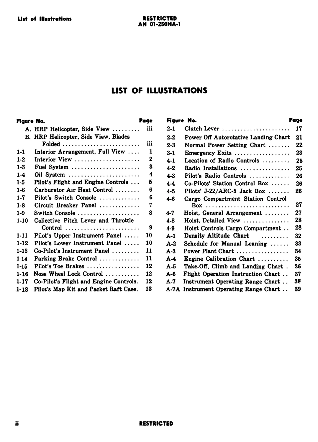
LIST OF ILLUSTRATIONS
Hgvre No. Page
A. HRP Helicopter, Side View........... iii
B. HRP Helicopter, Side View, Blades
Folded............................. iii
1-1 Interior Arrangement, Full View .... 1
1-2 Interior View..................... 2
1-3 Fuel System....................... 3
1-4 Oil System ............................ 4
1-5 Pilot’s Flight and Engine Controls ... 5
1-6 Carburetor Air Heat Control........ 6
1-7 Pilot’s Switch Console............ 6
1-8 Circuit Breaker Panel ................. 7
1-9 Switch Console.................... 8
1-10 Collective Pitch Lever and Throttle
Control ............................. 9
1-11 Pilot’s Upper Instrument Panel... 10
1-12 Pilot’s Lower Instrument Panel... 10
1-13 Co-Pilot’s Instrument Panel...... 11
1-14 Parking Brake Control............ 11
1-15 Pilot’s Toe Brakes ................... 12
1-16 Nose Wheel Lock Control.......... 12
1-17 Co-Pilot’s Flight and Engine Controls. 12
1-18 Pilot’s Map Kit and Packet Raft Case. 13
Rgvre No. Page
2-1 Clutch Lever.......................... 17
2-2 Power Off Autorotative Landing Chart 21
2-3 Normal Power Setting Chart........... 22
3-1 Emergency Exits....................... 23
4-1 Location of Radio Controls........... 25
4-2 Radio Installations .................. 25
4-3 Pilot’s Radio Controls ............... 26
4-4 Co-Pilots’ Station Control Box....... 26
4-5 Pilots’ J-22/ARC-5 Jack Box.......... 26
4-6 Cargo Compartment Station Control
Box ...................................... 27
4-7 Hoist, General Arrangement........... 27
4-8 Hoist, Detailed View.................. 28
4-9 Hoist Controls Cargo Compartment .. 28
A-l Density Altitude Chart ............... 32
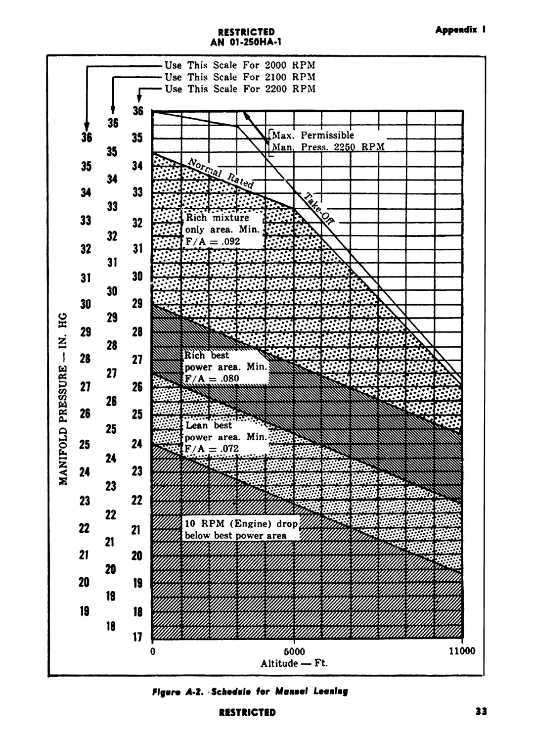
A-2 Schedule for Manual Leaning .......... 33
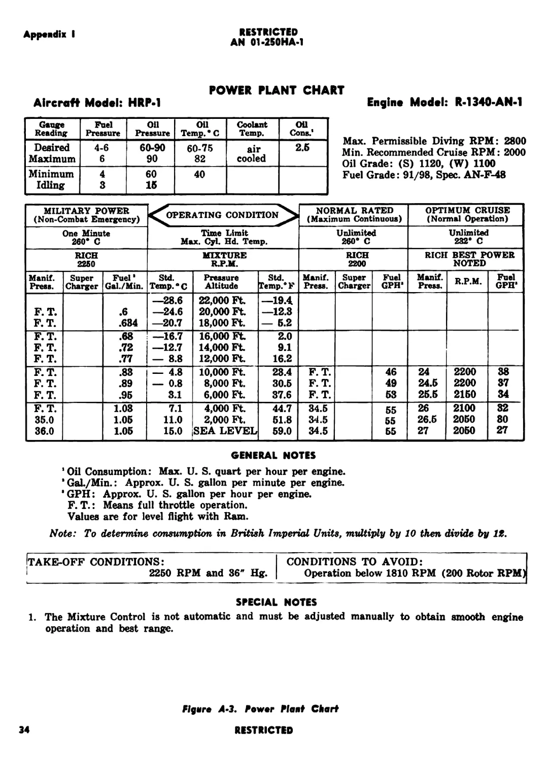
A-3 Power Plant Chart..................... 34
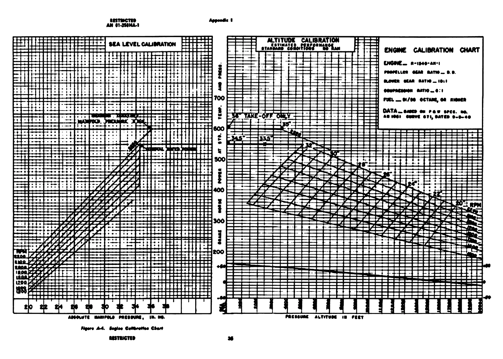
A-4 Engine Calibration Chart.............. 35
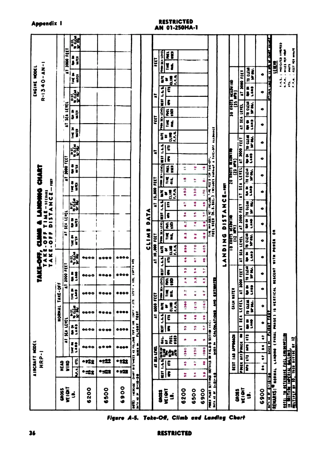
A-5 Take-Off, Climb and Landing Chart . 36
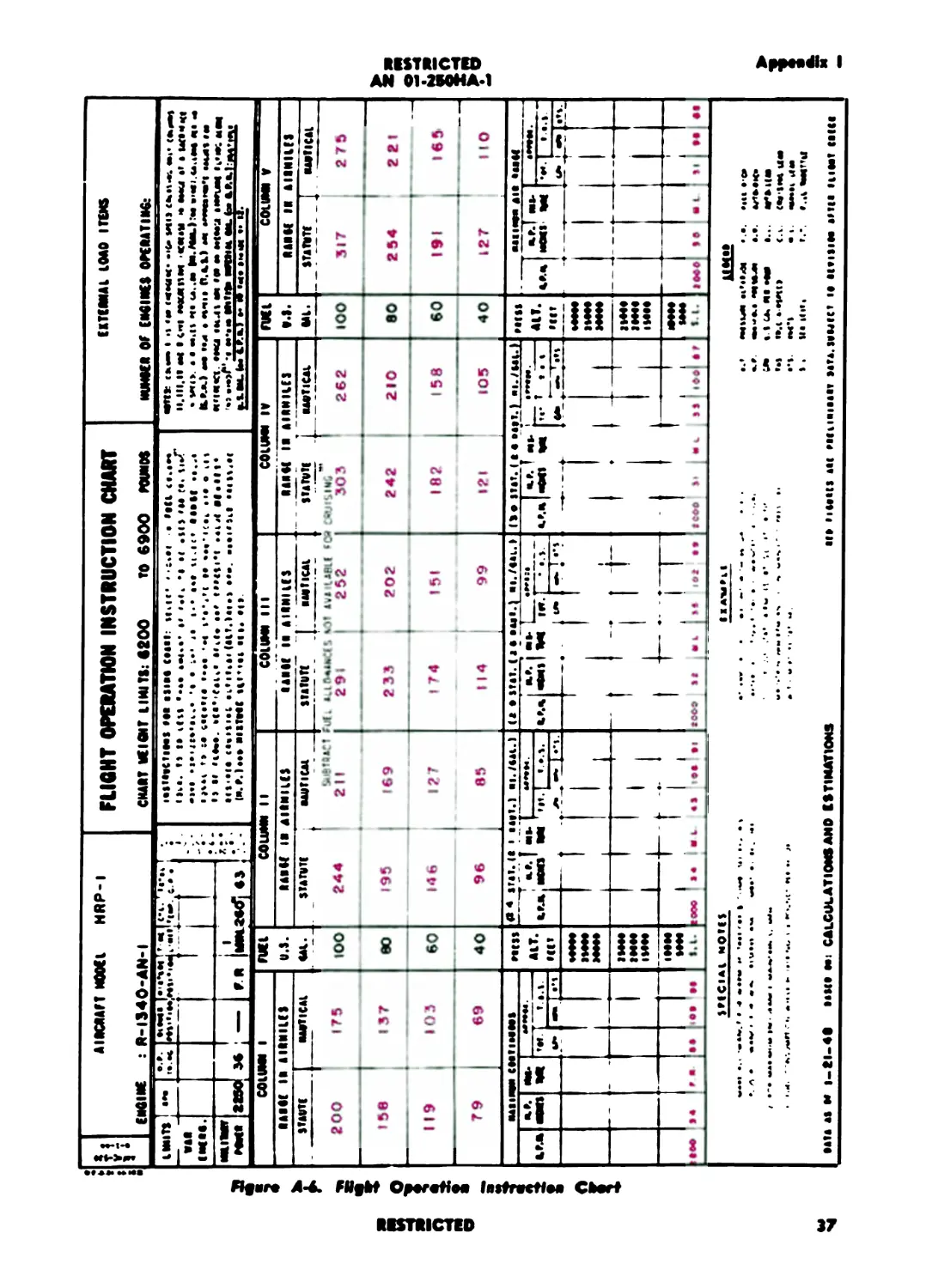
A-6 Flight Operation Instruction Chart .. 37
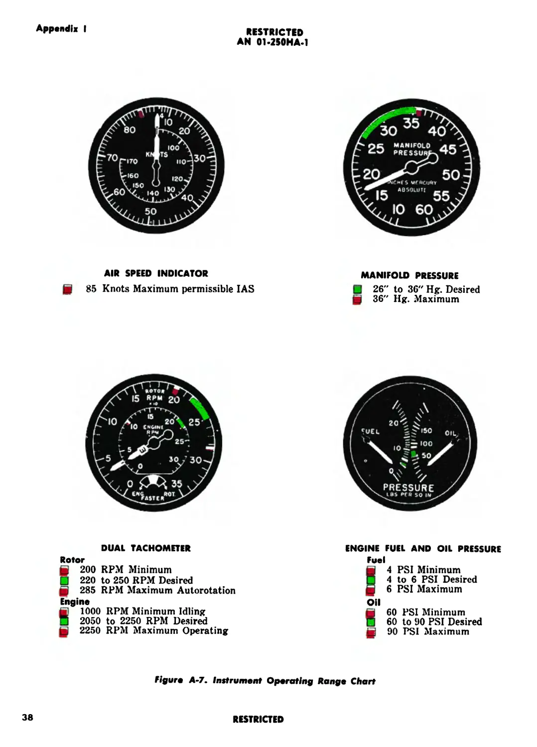
A-7 Instrument Operating Range Chart .. 38
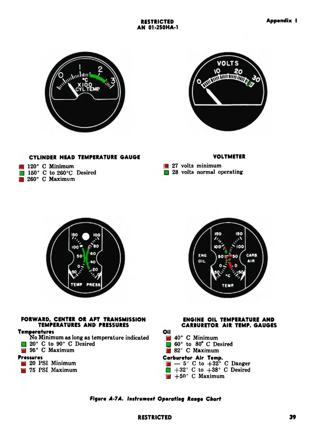
A-7A Instrument Operating Range Chart .. 39
H
RESTRICTED
RESTRICTED
AN 01-250HA-1
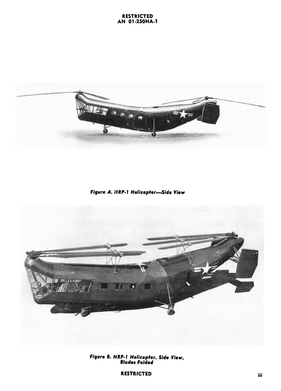
Figure A. HRP-1 Helicopter—Side View
Figure B. HRP-1 Helicopter, Side View,
Blades Folded
RESTRICTED
iii
RESTRICTED
RESTRICT»
Section I
Paragraphs 1*1 to 1*4
RESTRICTED
AN 01-250HA-1
SECTION 1
DESCRIPTION
1*1. GENERAL.
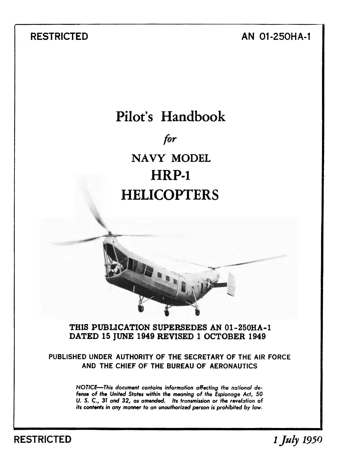
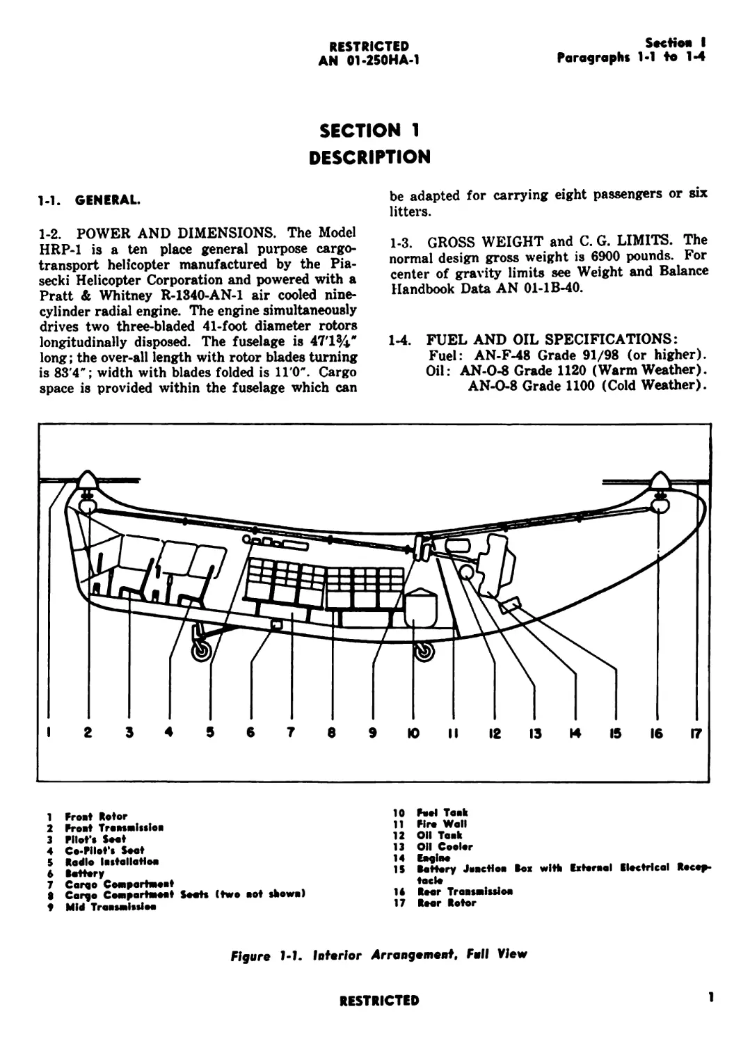
1-2. POWER AND DIMENSIONS. The Model
HRP-1 is a ten place general purpose cargo-
transport helicopter manufactured by the Pia-
secki Helicopter Corporation and powered with a
Pratt & Whitney R-1340-AN-1 air cooled nine-
cylinder radial engine. The engine simultaneously
drives two three-bladed 41-foot diameter rotors
longitudinally disposed. The fuselage is 4T1W
long; the over-all length with rotor blades turning
is 83’4"; width with blades folded is 11'0". Cargo
space is provided within the fuselage which can
be adapted for carrying eight passengers or six
litters.
1-3. GROSS WEIGHT and C. G. LIMITS. The
normal design gross weight is 6900 pounds. For
center of gravity limits see Weight and Balance
Handbook Data AN 01-1B-40.
1-4. FUEL AND OIL SPECIFICATIONS:
Fuel: AN-F-48 Grade 91/98 (or higher).
Oil: AN-0-8 Grade 1120 (Warm Weather).
AN-0-8 Grade 1100 (Cold Weather).
1 Frost Rotor
2 Front Tronsmlsslon
3 Fllot's Soot
4 Co-Fllot's Soot
5 Radio Installation
6 tottery
7 Coro© Comportment
8 Cor^o Comportment Soots (two not shown)
t Mid Transmission
10 Feel Tank
11 Fire Wall
12 OU Tank
13 011 Cooler
14 Engine
IS Battery Junction Box with External Electrical Recep-
tacle
14 Rear Transmission
17 Roar Rotor
Figure 1-1. Inferior Arrangement, Fall View
RESTRICTED
1
Section I
RESTRICTED
AN 01-250HA-1
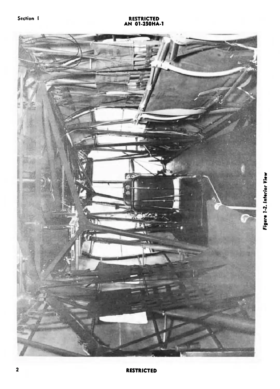
Figaro 1-2. Interior Viow
2
RESTRICTED
SecHon I
Paragraphs 1-5 to 1-7
RESTRICTED
AN 01-250HA-1
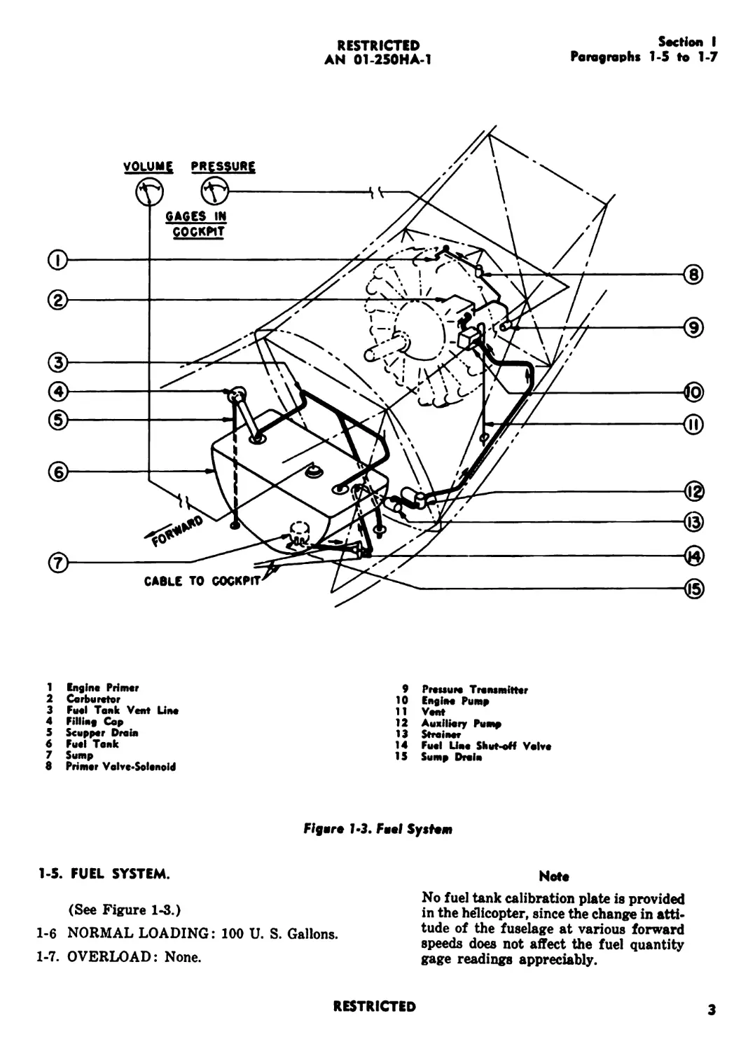
1 Engine Primer
2 Carburetor
3 Fuel Tank Vent Line
4 Filling Cop
5 Scupper Drain
6 Fuel Tank
7 Sump
8 Primer Valve-Solenoid
9 Pressure Transmitter
10 Engine Pump
11 Vent
12 Auxiliary Pump
13 Strainer
14 Fuel Line Shut-oH Valve
15 Sump Drain
Figere l«3. Feel System
1-5. FUEL SYSTEM.
(See Figure 1-3.)
1-6 NORMAL LOADING: 100 U. S. Gallons.
1-7. OVERLOAD: None.
Note
No fuel tank calibration plate is provided
in the helicopter, since the change in atti-
tude of the fuselage at various forward
speeds does not affect the fuel quantity
gage readings appreciably.
RESTRICTED
3
RESTRICTED
AN 01-250HA-1
Section I
Poragrophs 1-8 to 1-13
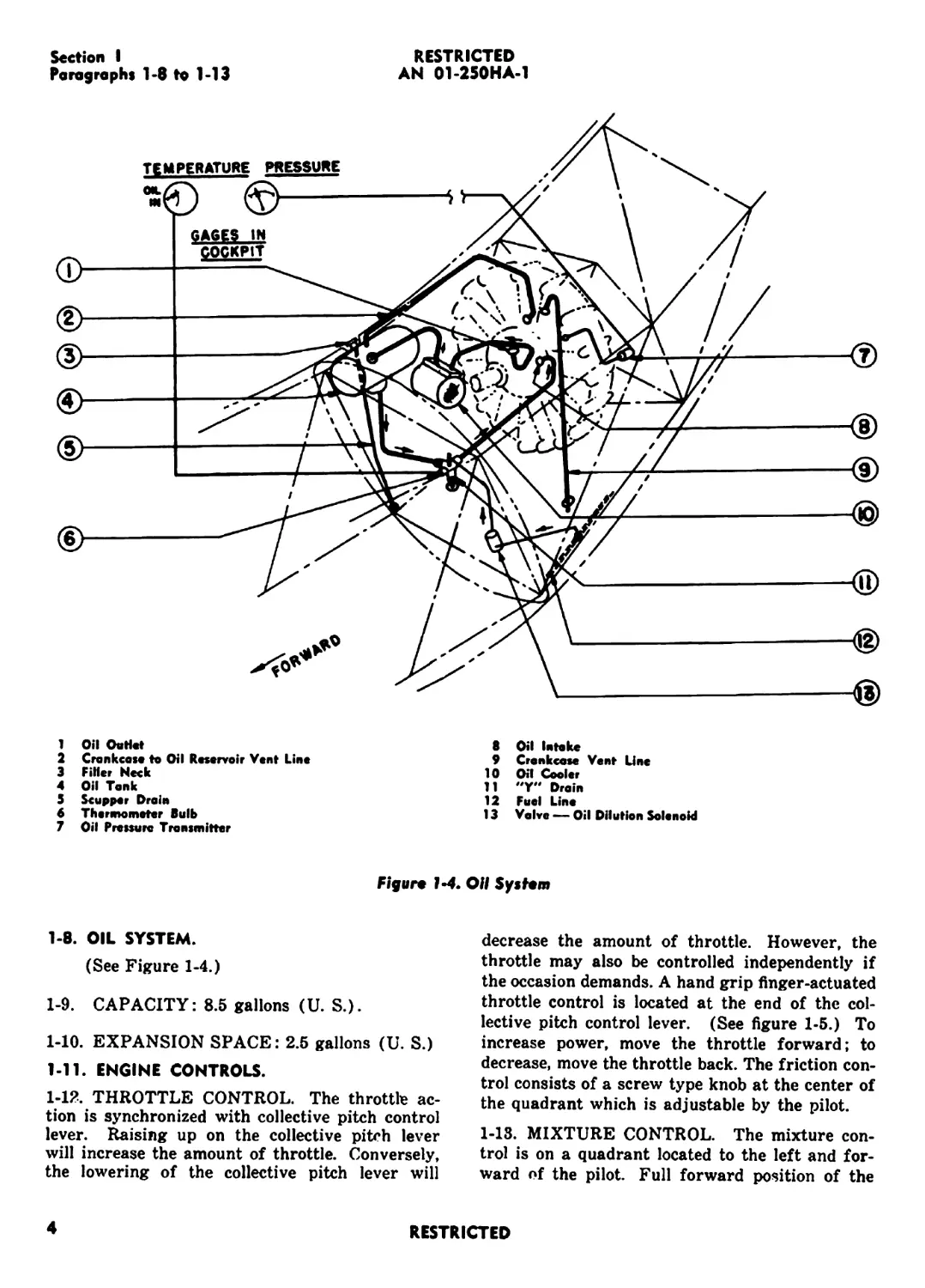
1 Oil OuH«t
2 Crankcase to Oil Reservoir Vent Line
3 Fitter Neck
4 Oil Tank
5 Scupper Drain
6 Thermometer Bulb
7 Oil Pressure Transmitter
8 Oil Intake
9 Crankcase Vent Unc
10 Oil Cooler
11 "Y** Drain
12 Fuel Line
13 Valve — Oil Dilution Solenoid
Figure 1-4. OH System
1-8. OIL SYSTEM.
(See Figure 1-4.)
1-9. CAPACITY: 8.5 gallons (U. S.).
1-10. EXPANSION SPACE: 2.5 gallons (U. S.)
1-11. ENGINE CONTROLS.
1-12. THROTTLE CONTROL. The throttle ac-
tion is synchronized with collective pitch control
lever. Raising up on the collective pitch lever
will increase the amount of throttle. Conversely,
the lowering of the collective pitch lever will
decrease the amount of throttle. However, the
throttle may also be controlled independently if
the occasion demands. A hand grip finger-actuated
throttle control is located at the end of the col-
lective pitch control lever. (See figure 1-5.) To
increase power, move the throttle forward; to
decrease, move the throttle back. The friction con-
trol consists of a screw type knob at the center of
the quadrant which is adjustable by the pilot.
1-13. MIXTURE CONTROL. The mixture con-
trol is on a quadrant located to the left and for-
ward of the pilot. Full forward position of the
4
RESTRICTED
RESTRICTED
AN 01-250HA-1
Section I
Paragraphs 1*14 to 1-17
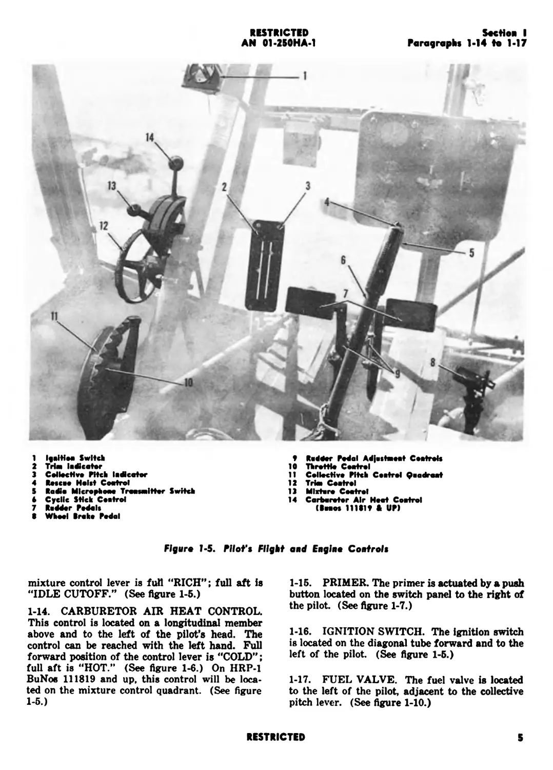
1 Ijaitiaa Switch
2 Trie ladkatar
3 Callactive Pitch la di cater
4 Reccae Heist Coatrol
5 Radle Mlcrophawe Traesaiitter Switch
6 Cyclic Stick Caetrol
7 Redder Pedals
8 Wheel Broke Pedal
9 Rodder Pedal Adjestaieat Ceetrok
10 Throttle Coetrol
11 Collective Pitch Ceetrol Qoadraet
12 Trie Cootrol
13 Mlxtoro Coatrol
14 Carbaretor Air Heat Coetrol
(8nos 111819 & UP)
Figure 1-5. Pilot’s Flight and Engine Controls
mixture control lever is full “RICH”; full aft is
“IDLE CUTOFF.” (See figure 1-5.)
1-14. CARBURETOR AIR HEAT CONTROL.
This control is located on a longitudinal member
above and to the left of the pilot’s head. The
control can be reached with the left hand. Full
forward position of the control lever is "COLD”;
full aft is “HOT.” (See figure 1-6.) On HRP-1
BuNos 111819 and up, this control will be loca-
ted on the mixture control quadrant. (See figure
1-5.)
1-15. PRIMER. The primer is actuated by a push
button located on the switch panel to the right of
the pilot (See figure 1-7.)
1-16. IGNITION SWITCH. The ignition switch
is located on the diagonal tube forward and to the
left of the pilot (See figure 1-5.)
1-17. FUEL VALVE. The fuel valve is located
to the left of the pilot, adjacent to the collective
pitch lever. (See figure 1-10.)
RESTRICTED
5
RESTRICTED
AN 01-250HA-1
Section I
Poragrophs 1-18 to 1-23
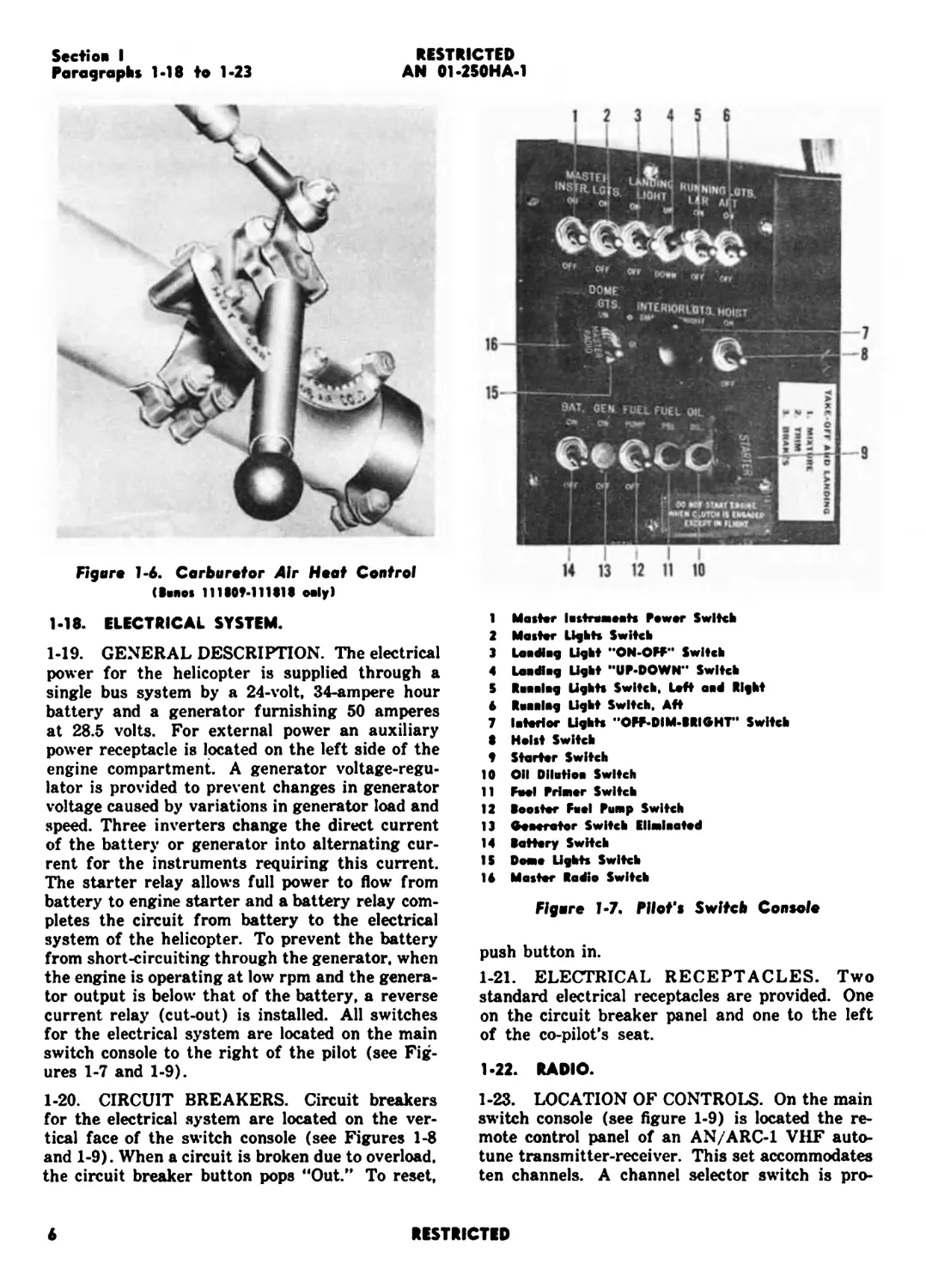
Figure 1-6. Carburetor Air Heat Control
(Banos 111Ш-111 BIB only!
II iI Г
14 13 12 11 10
1-18. ELECTRICAL SYSTEM.
1-19. GENERAL DESCRIPTION. The electrical
power for the helicopter is supplied through a
single bus system by a 24-volt, 34-ampere hour
battery and a generator furnishing 50 amperes
at 28.5 volts. For external power an auxiliary
power receptacle is located on the left side of the
engine compartment. A generator voltage-regu-
lator is provided to prevent changes in generator
voltage caused by variations in generator load and
speed. Three inverters change the direct current
of the battery or generator into alternating cur-
rent for the instruments requiring this current.
The starter relay allows full power to flow’ from
battery to engine starter and a battery relay com-
pletes the circuit from battery to the electrical
system of the helicopter. To prevent the battery
from short-circuiting through the generator, when
the engine is operating at low rpm and the genera-
tor output is below that of the battery, a reverse
current relay (cut-out) is installed. All switches
for the electrical system are located on the main
switch console to the right of the pilot (see Fig-
ures 1-7 and 1-9).
1-20. CIRCUIT BREAKERS. Circuit breakers
for the electrical system are located on the ver-
tical face of the switch console (see Figures 1-8
and 1-9). When a circuit is broken due to overload,
the circuit breaker button pops “Out.” To reset,
1 Master lustramoats Rawer Switch
2 Master Lights Switch
3 Laodiog Light “ON-OFF** Switch
4 Laodlog Light “UP-DOWN** Switch
S Reeeleg Lights Switch, Left aid Bight
6 Ruuulug Light Switch. Aft
7 Interior Lights “OFF-DIM-BRIGHT" Switch
В Heist Switch
4 Starter Switch
10 OH Dilution Switch
11 Feel Primer Switch
12 Boaster Feel Pump Switch
13 Generator Switch Eliminated
14 Battery Switch
IS Dome Lights Switch
16 Master Radio Switch
Figure J-7. Pilot’s Switch Console
push button in.
1-21. ELECTRICAL RECEPTACLES. Two
standard electrical receptacles are provided. One
on the circuit breaker panel and one to the left
of the co-pilot’s seat.
1-22. RADIO.
1-23. LOCATION OF CONTROLS. On the main
switch console (see figure 1-9) is located the re-
mote control panel of an AN/ARC-1 VHF auto-
tune transmitter-receiver. This set accommodates
ten channels. A channel selector switch is pro-
6
RESTRICTED
Section I
Paragraphs 1-24 to 1-26
RESTRICTED
AN 01-250HA-1
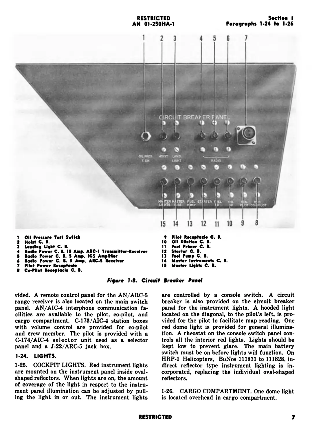
1 011 Prasura Test Switch
2 Hoist С. B.
3 Laodbf Ufht С. B.
4 Radio Power С. B. 15 Амр. ARC-1 TraesMitter-Receiver
5 Radio Power С. B. 5 Amp. ICS AmpIKor
4 Radio Power С. B. 5 Amp. ARC-5 Receiver
7 Pilot Power Receptacle
В Co-Pllot Receptacle С. B.
P Pilot Receptacle С. B.
10 011 Dllwtioa С. B.
11 Pool Primer С. B.
12 Starter С. B.
13 Fool Pomp С. B.
14 Master I astro meets С. B.
15 Master Lifbts С. B.
Figure 1-8. Circuit Breaker Panel
vided. A remote control panel for the AN/ARC-5
range receiver is also located on the main switch
panel. AN/AIC-4 interphone communication fa-
cilities are available to the pilot, co-pilot, and
cargo compartment. C-173/AIC-4 station boxes
with volume control are provided for co-pilot
and crew member. The pilot is provided with a
C-174/AIC-4 selector unit used as a selector
panel and a J-22/ARC-5 jack box.
1-24. LIGHTS.
1-25. COCKPIT LIGHTS. Red instrument lights
are mounted on the instrument panel inside oval-
shaped reflectors. When lights are on, the amount
of coverage of the light in respect to the instru-
ment panel illumination can be adjusted by pull-
ing the light in or out. The instrument lights
are controlled by a console switch. A circuit
breaker is also provided on the circuit breaker
panel for the instrument lights. A hooded light
located on the diagonal, to the pilot’s left, is pro-
vided for the pilot to facilitate map reading. One
red dome light is provided for general illumina-
tion. A rheostat on the console switch panel con-
trols all the interior red lights. Lights should be
kept low to prevent glare. The main battery
switch must be on before lights will function. On
HRP-1 Helicopters, BuNos 111811 to 111828, in-
direct reflector type instrument lighting is in-
corporated, replacing the individual oval-shaped
reflectors.
1-26. CARGO COMPARTMENT. One dome light
is located overhead in cargo compartment.
RESTRICTED
7
RESTRICTED
AN 01*2S0HA*1
Section I
Paragraphs 1*27 to 1*32
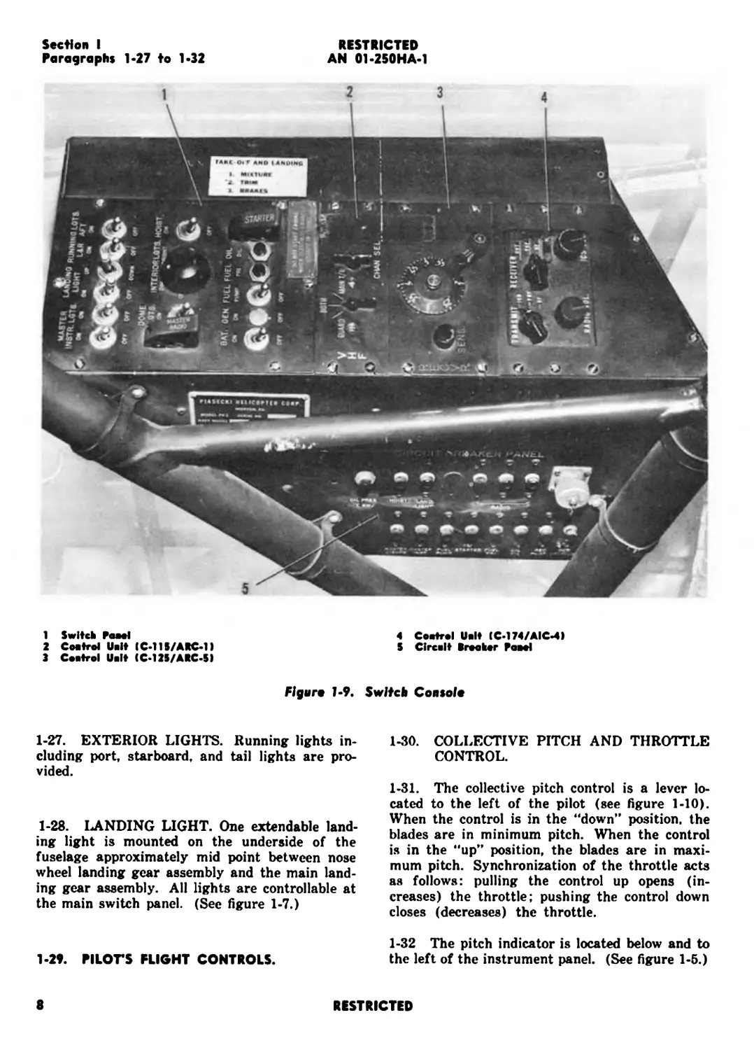
1 Switch Pawl
2 Coetrol Unit (C-l 15/ABC-1)
3 Cactrol Unit (C-125/ABC-5)
4 Coatral Uclt (C-174/AIC-4)
S Clrcclt Breaker Paeel
Figure 1-9. Switch Console
1-27. EXTERIOR LIGHTS. Running lights in-
cluding port, starboard, and tail lights are pro-
vided.
1-28. LANDING LIGHT. One extendable land-
ing light is mounted on the underside of the
fuselage approximately mid point between nose
wheel landing gear assembly and the main land-
ing gear assembly. All lights are controllable at
the main switch panel. (See figure 1-7.)
1-29. PILOTS FLIGHT CONTROLS.
1-30. COLLECTIVE PITCH AND THROTTLE
CONTROL.
1-31. The collective pitch control is a lever lo-
cated to the left of the pilot (see figure 1-10).
When the control is in the “down” position, the
blades are in minimum pitch. When the control
is in the “up” position, the blades are in maxi-
mum pitch. Synchronization of the throttle acts
as follows: pulling the control up opens (in-
creases) the throttle; pushing the control down
closes (decreases) the throttle.
1-32 The pitch indicator is located below and to
the left of the instrument panel. (See figure 1-5.)
8
RESTRICTED
Section I
Paragraphs 1-33 to 1-36
RESTRICTED
AN 01-25 OH A-1
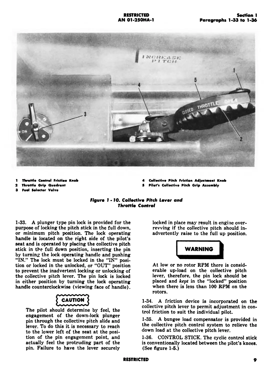
1 TbrofHa Control Friction Knob
2 Throttle Grip Quadrant
3 Fuel Selector Valve
4 Collective Pitch Friction Adjustment Knob
3 Pilot's Collective Pitch Grip Assembly
Figura 1-10. Collective Pitch Lever and
Throttle Control
1-33. A plunger type pin lock is provided for the
purpose of locking the pitch stick in the full down,
or minimum pitch position. The lock operating
handle is located on the right side of the pilot's
seat and is operated by placing the collective pitch
stick in the full down position, inserting the pin
by turning the lock operating handle and pushing
"IN.” The lock must be locked in the "IN” posi-
tion or locked in the unlocked, or "OUT” position
to prevent the inadvertent locking or unlocking of
the collective pitch lever. The pin lock is locked
in either position by turning the lock operating
handle counterclockwise (viewing face of handle).
locked in place may result in engine over-
revving if the collective pitch should in-
advertently raise to the full up position.
At low or no rotor RPM there is consid-
erable up-load on the collective pitch
lever, therefore, the pin lock should be
placed and kept in the "locked” position
when there is less than 100 RPM on the
rotors.
CAUTION
The pilot should determine by feel, the
engagement of the down-lock plunger
pin through the collective pitch slide and
lever. To do this it is necessary to reach
to the lower left of the seat at the posi-
tion of the pin engagement point, and
actually feel the protruding part of the
pin. Failure to have the lever securely
1-34. A friction device is incorporated on the
collective pitch lever to permit adjustment in con-
trol friction to suit the individual pilot.
1-35. A bungee load compensator is provided in
the collective pitch control system to relieve the
down load at the collective pitch lever.
1-36. CONTROL STICK. The cyclic control stick
is conventionally located between the pilot’s knees.
(See figure 1-5.)
RESTRICTED
9
RESTRICTED
AN 01-250HA-1
Section I
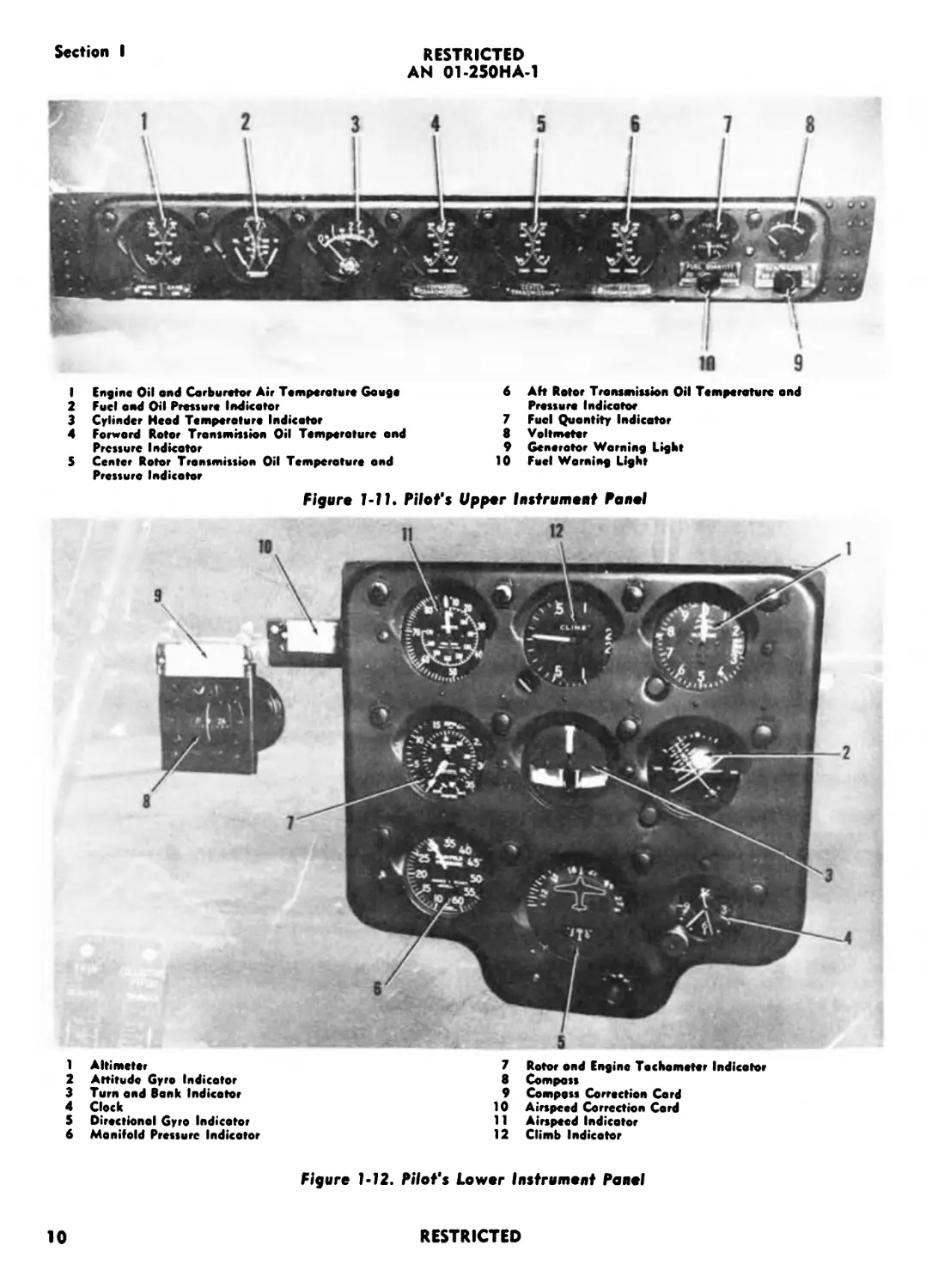
I Engine Oil and Carburetor Air Temperature Gauge
2 Fuel and Oil Pressure Indicator
3 Cylinder Head Temperature Indicator
4 Forward Rotor Transmission Oil Temperature and
Pressure Indicator
5 Center Rotor Transmission Oil Temperature and
Pressure Indicator
6 Aft Rotor Transmission Oil Temperature and
Pressure Indicator
7 Fuel Quantity Indicator
8 Voltmeter
9 Generator Warning Light
10 Fuel Warning Light
Figure 1-11. Pilot's Upper Instrument Panel
1 Altimeter
2 Attitude Gyro Indicator
3 Turn and Bonk Indicator
4 Clock
5 Diroctionol Gyro Indicator
6 Manifold Pressure Indicator
7 Rotor and Engine Tachometer Indicator
8 Compass
9 Compass Correction Card
10 Airspeed Correction Cord
11 Airspeed Indicator
12 Climb Indicator
Figure 1*12. Pilot's Lower Instrument Panel
10
RESTRICTED
Section I
Paroqraphs 1-48 to 1-54
RESTRICTED
AN 01-250HA-1
Flgare !• 16. Note Wkeel Lock Control
(BvNoi 111914 тЬгацЬ 111929 and 111924 oalyl
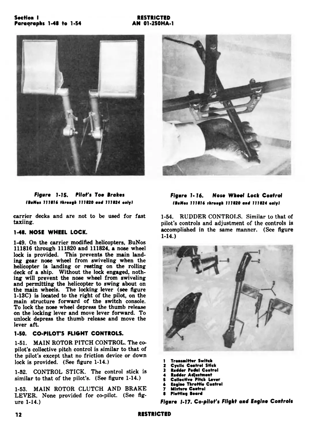
Figure LJ5. Pilot’s Too Brakes
IBaNos 111914 threayh 111820 aid 111924 only)
carrier decks and are not to be used for fast
taxiing.
1-48. NOSE WHEEL LOCK.
1-49. On the carrier modified helicopters, BuNos
111816 through 111820 and 111824, a nose wheel
lock is provided. This prevents the main land-
ing gear nose wheel from swiveling when the
helicopter is landing or resting on the rolling
deck of a ship. Without the lock engaged, noth-
ing will prevent the nose wheel from swiveling
and permitting the helicopter to swing about on
the main wheels. The locking lever (see figure
1-13C) is located to the right of the pilot, on the
main structure forward of the switch console.
To lock the nose wheel depress the thumb release
on the locking lever and move lever forward. To
unlock depress the thumb release and move the
lever aft.
1-50. CO-PILOTS FLIGHT CONTROLS.
1-51. MAIN ROTOR PITCH CONTROL. The co-
pilot’s collective pitch control is similar to that of
the pilot's except that no friction device or down
lock is provided. (See figure 1-14.)
1-52. CONTROL STICK. The control stick is
similar to that of the pilot’s. (See figure 1-14.)
1-53. MAIN ROTOR CLUTCH AND BRAKE
LEVER. None provided for co-pilot. (See fig-
ure 1-14.)
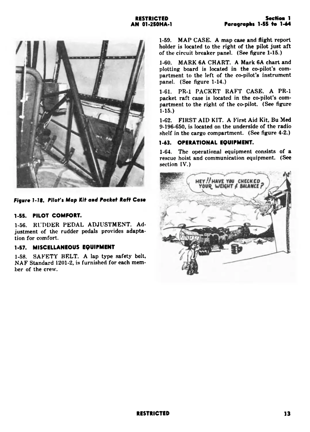
1-54. RUDDER CONTROLS. Similar to that of
pilot’s controls and adjustment of the controls is
accomplished in the same manner. (See figure
1-14.)
1 Troasailtter Switch
2 Cyclic Coatrol Stick
3 Rodder Pedal Coatrol
4 Rodder Ad|ostmoat
5 Collective Pitch Lever
6 Eifiee Throttle Coatrol
7 Mixture Coatrol
8 Plottlag Board
Figart 1-17. Co-pllot’s Flight and Engina Controls
12
RESTRICTED
RESTRICTED
AN 01-250HA-1
SecNo* 1
Paragraphs 1-55 to 1-64
Figure 1-18. Pilot’s Map Kit a*d Packet Raft Case
1-55. PILOT COMFORT.
1-56. RI DDER PEDAL ADJUSTMENT. Ad-
justment of the rudder pedals provides adapta-
tion for comfort.
1-57. MISCELLANEOUS EQUIPMENT
1-58. SAFETY BELT. A lap type safety belt,
NAF Standard 1201-2, is furnished for each mem-
ber of the crew.
1-59. MAP CASE. A map case and flight report
holder is located to the right of the pilot just aft
of the circuit breaker panel. (See figure 1-15.)
1-60. MARK 6A CHART. A Mark 6A chart and
plotting board is located in the co-pilot’s com-
partment to the left of the co-pilot’s instrument
panel. (See figure 1-14.)
1-61. PR-1 PACKET RAFT CASE. A PR-1
packet raft case is located in the co-pilot’s com-
partment to the right of the co-pilot. (See figure
1-15.)
1-62. FIRST AID KIT. A First Aid Kit, Bu Med
9-196-650, is located on the underside of the radio
shelf in the cargo compartment. (See figure 4-2.)
1-63. OPERATIONAL EQUIPMENT.
1-64. The operational equipment consists of a
rescue hoist and communication equipment. (See
section IV.)
RESTRICTED
13
RESTRICTED
RESTRICTED
Section II
Paragraphs 2-1 to 2-6
RESTRICTED
AN 01-250HA-1
SECTION II
NORMAL OPERATION INSTRUCTIONS
2-1. BEFORE ENTERING THE PILOT'S
^^^COMPARTMENT^^^^^^^^^^^^^^
2-2. FLIGHT LIMITATIONS AND RESTRIC-
TIONS. The following maneuvers are pro-
hibited :
Aerobatics. Practice autorotation.
Speed. Do not exceed 85 kts IAS in any
flight attitude.
Anything other than normal flight ma-
neuvers.
The maximum recommended gross
weight is 6900 pounds.
Those limitations and restrictions are
subject to change and latest service
_____directives and orders must be consulted.
2-3. CAUTIONS TO BE OBSERVED.
Do not engage in maneuvers which
require large and/or rapid lateral mo-
tions or reversals of the cyclic pitch con-
trol. The reason for this caution is to
avoid the possibility of the rotor blades
hitting the droop stops, resulting in pos-
sible injury to the blades.
A visual inspection of the aircraft
should be made to insure that all blade
tie down socks are removed from blades
and that all obstructions are well clear of
the rotors such as checkstands, ladders,
etc.
Obtain the take-off and landing gross
weights and center of gravity locations
for the contemplated flight. For normal
operation, do not exceed the maximum
gross weights and center of gravity lim-
its specified in the Handbook of Weight
and Balance Data, AN01-1B-40.
2-4. ACCESS TO PILOT’S COMPARTMENT.
Access to the pilot’s compartment is gained
through the cargo (or passenger) compartment.
2-5. ON ENTERING THE PILOT'S
COMPARTMENT.
2-6. STANDARD CHECK FOR ALL FLIGHTS.
a. Inspect interior of ship to determine that
no loose equipment, i.e., rags, etc., are lying about.
b. Fasten safety belt.
c. Adjust rudder pedals for proper length.
d. Check collective pitch lever: full down
position (low pitch) and locked with the pin lock.
e. Check controls for free and full movement.
f. Wheel brakes “ON.”
g. Main clutch. “DISENGAGED (clutch
lever full aft).
h. Ignition switch “OFF.”
i. Battery switch “ON.”
j. Main instrument switch “ON.”
k. Master radio switch “ON.” (See Section
IV for communication set up instructions.)
1. Check fuel quantity warning light by press-
ing.
m. Check fuel quantity gage for fuel loading.
n. Set altimeter.
o. Set trim at zero degrees.
CAUTION
Improper use of the trim could, under
certain flight conditions where maximum
longitudinal control is necessary, result
in insufficient longitudinal control under
certain center of gravity conditions. For
example, with the C.G. at its most for-
ward permissible condition and with the
trim set full nose down, it would be diffi-
cult to perform a quick stop or sharp au-
torotative flare due to the reduction of
aft longitudinal control caused by im-
proper use of the trim. The proper pro-
cedure would be to set trim at zero, then
take off to a hovering condition. The
cyclic stick would probably be slightly
aft of neutral position due to the forward
C.G. condition. Nose up trim would then
be applied to center the cyclic stick to
insure full longitudinal control in either
direction. Once the trim setting has been
established, do not re-trim unless a con-
siderable change in loading has been
made. Normal loading conditions do not
necessitate the use of the trim.
Note
All instruments with electrical connec-
tions are in a functional condition when
the battery and instrument switches are
“ON.”
RESTRICTED
15
RESTRICTED
AN 01-250HA-1
Section II
Paragraphs 2-7 to 2-13
2-7. SPECIAL CHECK FOR NIGHT FLIGHTS.
a. Check instrument lights.
b. Check landing light (with engine run-
ning only).
c. Check running lights.
2-3. FUEL SYSTEM MANAGEMENT.
2-9. NORMAL CONDITIONS.
a. Fuel valve: “ON.”
b. Auxiliary fuel pump: “ON”
c. When engine is firing evenly, turn the
auxiliary fuel pump “OFF.”
2-10. EMERGENCY CONDITIONS. In the
event the fuel pressure drops below four pounds
per square inch, turn the auxiliary fuel pump
“ON.”
2-11. STARTING ENGINE.
CAUTION
Before starting engine be sure clutch is
disengaged.
a. PITCH CONTROL: Minimum pitch posi-
tion and down lock pin “IN.”
b. USE OF BATTERY CART. If battery
cart is available, with the ignition switch in the
“OFF” position, turn the engine four or five revo-
lutions with the starter. If the battery cart is not
available, the engine should be turned over manu-
ally to clear the combustion chambers.
c. FUEL VALVE: “ON.”
d. MIXTURE: RICH.
e. CARBURETOR HEAT: COLD.
f. THROTTLE: Cracked open — equivalent
to approximately 1000 RPM.
g. AUXILIARY FUEL PUMP: “ON.”
h. IGNITION SWITCH: On “BOTH.”
i. PRIMER SWITCH: “ON,” as necessary.
< CAUTION
Avoid excessive priming which may flood
the engine causing difficulty in starting;
this is also an additional fire hazard.
j. STARTER: “ON.”
k. GENERATOR. Check generator output
on voltmeter. If generator is not functioning, the
red indicator will light.
1. A standard oil dilution switch is provided
to facilitate starting the engine in extremely cold
weather. A valve is located on the oil dilution
system in the engine compartment and must be
“ON” before the system will operate.
CAUTION
With the clutch disengaged, the throt-
tle is extremely sensitive. If held open,
it will cause excessive engine speed while
engine is still cold. Stop engine immedi-
ately if oil pressure is not indicated with-
in 30 seconds after starting.
2-12. STARTING ROTORS.
No minimum warm-up of the engine is required
before rotor engagement. A qualified pilot who
is fully instructed and authorized to warm up the
engine should be at the controls at the time the
rotors are engaged.
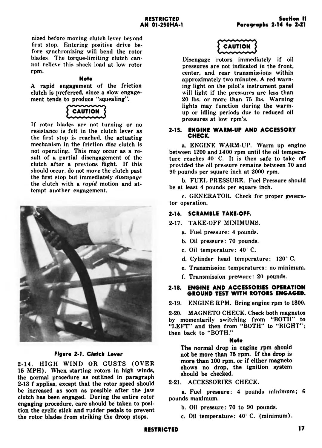
2-13. FOR NORMAL WIND. (Up to 15 MPH.)
a. The aircraft should be headed into the
wind if not already heading in that direction.
When the rotor is to be engaged, be sure
the blades are free and clear with no
tie-down socks on, or ladders or other
obstructions in the way.
b. Be sure the wheel brakes are on.
c. Throttle: 1200 rpm.
CAUTION
Do not engage rotors at over 1400 en-
gine rpm.
d. Main rotor pitch control: Minimum and
locked.
e. Cyclic stick and rudder pedals neutral.
f. To engage the rotors depress the thumb
release on the clutch lever and advance the lever
with a positive motion to the first stop. The en-
gagement of the friction discs during this oper-
ation will be recognized by a definite resistance
in the clutch lever. When the engine and rotor
rpm become synchronized, release the thumb but-
ton and allow the clutch lever to travel forward
to the second stop. Upon contacting the second
stop again depress the thumb release button and
allow the clutch lever to travel forward to the
fully engaged position.
CAUTION
Engine and rotor rpm must be synchro-
16
RESTRICTED
RESTRICTED
Section II
Paragraphs 2-14 to 2-21
AN 01-250HA-1
nized before moving clutch lever i>eyond
first stop. Entering positive drive be-
fore synchronizing will bend the rotor
blades. The torque-limiting clutch can-
not relieve this shock load at low rotor
rpm.
Note
A rapid engagement of the friction
clutch is preferred, since a slow engage-
ment tends to produce ’‘squealing”.
< CAUTION J
If rotor blades are not turning or no
resistance is felt in the clutch lever as
the first stop is reached, the actuating
mechanism in the friction disc clutch is
not operating. This may occur as a re-
sult of a partial disengagement of the
clutch after a previous flight. If this
should occur, do not move the clutch past
the first stop but immediately disengage
the clutch with a rapid motion and at-
tempt another engagement.
Figure 2-1. Clutch Lever
2-14. HIGH WIND OR GUSTS (OVER
15 MPH). When, starting rotors in high winds,
the normal procedure as outlined in paragraph
2-13 f applies, except that the rotor speed should
be increased as soon as possible after the jaw
clutch has been engaged. During the entire rotor
engaging procedure, care should be taken to posi-
tion the cyclic stick and rudder pedals to prevent
the rotor blades from striking the droop stops.
CAUTION
Disengage rotors immediately if oil
pressures are not indicated in the front,
center, and rear transmissions within
approximately two minutes. A red warn-
ing light on the pilot's instrument panel
will light if the pressures are less than
20 lbs. or more than 75 lbs. Warning
lights may function during the warm-
up or idling periods due to reduced oil
pressures at low rpm’s.
2-15. ENGINE WARM-UP AND ACCESSORY
CHECK.
a. ENGINE WARM-UP. Warm up engine
between 1200 and 1400 rpm until the oil tempera-
ture reaches 40 C. It is then safe to take off
provided the oil pressure remains between 70 and
90 pounds per square inch at 2000 rpm.
b. FUEL PRESSURE. Fuel Pressure should
be at least 4 pounds per square inch.
c. GENERATOR. Check for projjer genera-
tor operation.
2-16. SCRAMBLE TAKE-OFF.
2-17. TAKE-OFF MINIMUMS.
a. Fuel pressure: 4 pounds.
b. Oil pressure: 70 pounds.
c. Oil temperature: 40 'C.
d. Cylinder head temperature: 120е C.
e. Transmission temperatures: no minimum.
f. Transmission pressure: 20 pounds.
2-18. ENGINE AND ACCESSORIES OPERATION
GROUND TEST WITH ROTORS ENGAGED.
2-19. ENGINE RPM. Bring engine rpm to 1800.
2-20. MAGNETO CHECK. Check both magnetos
by momentarily switching from “BOTH” to
“LEFT” and then from “BOTH” to “RIGHT”;
then back to “BOTH.”
Note
The normal drop in engine rpm should
not be more than 75 rpm. If the drop is
more than 100 rpm, or if either magneto
shows no drop, the ignition system
should be checked.
2-21. ACCESSORIES CHECK.
a. Fuel pressure: 4 pounds minimum; 6
pounds maximum.
b. Oil pressure: 70 to 90 pounds.
c. Oil temperature: 40° C. (minimum).
RESTRICTED
17
RESTRICTED
AN 01-250HA-1
Section II
Paragraphs 2-22 to 2-31
d. Cylinder head temperature: 120 degrees
C (minimum).
e. Carburetor heat: “COLD."
f. Generator output: Voltmeter: 28 volts.
g. Dual tachometer: Engine and rotor nee-
dles should coincide. Rotation of the synchroscope
or spread of the needles indicates clutch slippage
and should be checked before take-off.
2-22. TAXIING INSTRUCTIONS.
2-23. GENERAL. The helicopter can be readily
taxied. The necessary thrust to move the helicop-
ter, forward or backward, is obtained from the
rotor system. The cyclic stick is used for fore,
aft and lateral control; the rudders for directional
control. It is not advisable to attempt taxiing
over rough terrain. Under such conditions, it is
more practical to fly the helicopter to the desired
position.
2-24. PROCEDURE
a. With nose wheel unlocked and wheel brakes
released, increase the collective pitch to approxi-
mately 5°, and the engine rpm to 1800.
b. Displace the cyclic stick in the direction it
is desired to taxi.
c. Use rudder to control the direction of the
fuselage.
d. Use throttle and amount of deflection of
the cyclic stick to control speed. (Care should be
taken to avoid hitting droop stops with the blades.
This can be readily recognized by a heavy thump-
ing.)
e. To slow or stop the helicopter, displace the
cyclic stick rearward and at the same time in-
crease collective pitch and rotor RPM. Here again
care should be taken to avoid hitting the droop
stops. Return cyclic stick to neutral and reduce
collective pitch and rotor RPM when helicopter
stops.
f. When taxiing or turning in strong cross
winds caution must be exercised to prevent the
wind from getting under the rotors and upsetting
the helicopter. Should a rolling-over tendency
appear the helicopter must be airborne immedi-
ately. The best practice is to keep the lateral
cyclic well into the wind and maintain a high
rotor rpm. Maintaining a high rpm will allow
take-off power to be more rapidly applied.
^CAUTIOI^
Do not use wheel brakes to slow or stop
the helicopter, (except Bunos 111816
through 111820 and 111824. These are
provided with toe brakes) as damage
may occur to the system due to pressure
overloading.
2-25. TAKE-OFF.
2-26. STARTING RUN-UP. Keeping the collec-
tive pitch control at a minimum pitch, i.e., full
down position, slowly open the throttle to about
1500 RPM. This RPM setting should be varied
according to the load, air temperature, and wind.
Conditions of high loading, no wind, and high
temperature will require higher RPM settings
since more power is required under these condi-
tions. The helicopter should be kept headed into
the wind by use of the rudders (cross wind and
down wind take-offs may be accomplished but
should be attempted only by experienced pilots).
The helicopter should be kept from rolling by use
of the cyclic control stick.
2-27. OPERATION OF COLLECTIVE PITCH
STICK. Release the pin lock on the collective
pitch lever. Keeping a firm grip on the lever,
increase the pitch moderately, watching the en-
gine tachometer. Due to the throttle-pitch syn-
chronization, the rotor RPM will increase to 250
at about 7° pitch. Increase the pitch until the
helicopter is airborne. Minor variations of the
hand throttle setting may be necessary to prevent
over or under “revving."
2-28. TAKE-OFF TO HOVERING POSITION.
Cafeful attention should be paid to keeping the
helicopter steady as it leaves the ground. Do not
hold the helicopter in “half-flight” condition, that
is, with the shock struts extended but with the
wheels still on the ground.
2-29. TRIM. Adjust trim for neutral or cen-
tered stick position while in hovering flight. It
is important that the cyclic stick be longitudinally
centered by the use of the trim device to allow
full longitudinal control in either direction. The
cyclic stick is centered when perpendicular to
the deck of the helicopter, this can be visually
checked by the pilot.
CAUTION
Do not operate at take-off power (2250
RPM, 36" Hg. manifold pressure) for
more than five minutes.
Note
Check engine fuel and oil pressures,
transmission pressures and tempera-
tures, while in hovering flight immedi-
ately after leaving the ground.
2-30. TRANSITION FROM HOVERING TO FOR-
WARD. BACKWARD. SIDEWARD FLIGHT.
2-31. TRANSITION TO FORWARD FLIGHT.
In order to prevent the slight loss in altitude
when moving off the ground cushion into for-
ward or sideward flight, it may be necessary to
RESTRICTED
Section II
Paragraphs 2-32 to 2-44
RESTRICTED
AN 01-250HA-1
increase the pitch slightly until translational lift
is attained.
2-32. FORWARD FLIGHT. The control stick
should be displaced slightly forward. As the ship
gains forward speed, and translational lift is at-
tained, the control stick should be neutralized or
positioned for climbing or cruising.
2-40. CRUISING.
2-41. SETTINGS FOR BEST CRUISE. For
smoothest cruise use 225 to 230 motor RPM.
Recommended engine settings for cruising are 29
inches of mercury with an engine RPM of 2050.
For maximum range, cruise at 75 knots. Cruise
at 56 knots for maximum duration.
DO NOT OPERATE ROTORS AT LESS
THAN 200 RPM. This figure represents
the minimum rpm necessary to main-
tain a safe coning angle of the rotor
blades.
2-33. BACKWARD AND SIDEWARD FLIGHT.
The HRP-1 helicopter can be readily flown in
rearward or sideward flight by proper deflection
of the control stick in the desired direction. How-
ever, flying in both of these directions should be
done at slow speeds (17 Kts-IAS) and only when
it is necessary.
CAUTION
Since the tip path of the rear rotor will
extend approximately 60 feet behind the
pilot, and because backward visibility is
limited, it is mandatory that the pilot
thoroughly check the area to be sure
there are no obstructions before at-
tempting rearward or sideward flight.
2-34. GENERAL. Only under extreme conditions
of load, no wind, and high air temperatures
should full power be necessary for hovering or
maneuvering close to the ground. Under average
conditions, the pilot should be able to maintain a
20 reserve of power for emergency operation.
2-35. ENGINE FAILURE DURING TAKE-OFF.
2-36. UNDER 10 FEET. If engine failure occurs
during hovering under 10 feet, the inertia of
the rotors will be sufficient to obviate an unreas-
onably hard landing. A rapid increase of collective
pitch should reduce the landing shock to a
minimum.
2-37. EMERGENCY OPERATING INSTRUC-
TIONS. See Emergency Operating Instructions
for procedure to be followed for engine failure
between 10 and 530 feet.
2-38. CLIMB.
2-39. SETTINGS FOR BEST CLIMB. The best
rate of climb at sea level is achieved at 47 knots,
2200 engine RPM and 34.5" Hg. manifold pres-
sure, mixture rich.
Normal operating oil pressures of the
front, center, and rear transmission are
35 pounds per square inch. However,
the pressure will vary with conditions
and it is permissible to operate within
the ranges of from 20 to 75 pounds per
square inch pressure. Normal operating
temperatures of the transmissions are
65-70° C. However, the operating tem-
peratures vary with the outside temper-
ature and it is permissible to operate at
a stabilized temperature as high as 95°
C. A red warning light indicator is incor-
porated in each transmission instrument.
If a red light goes on, it indicates that
either the oil pressure is too high or too
low, or tfie temperature is above maxi-
mum permissible operating limits for
that transmission. The indicator hands
of the instrument will determine whether
the difficulty is temperature or pressure.
Land immediately if transmission red
warning lights go on. It is also recom-
mended that a landing be effected if a
sudden raise in transmission tempera-
ture is noted or erratic pressures are
indicated.
A fuel quantity warning light is located
on the right side of the instrument
panel. When there is only a 20 minute
supply of fuel remaining the red warn-
ing light will function.
2-42. GENERAL FLYING CHARACTERISTICS
2-43. STABILITY. The HRP-1 helicopter cannot
be flown “Hands Off” for extended periods. For
norma] operation, the control stick should be held
for all rotor operation, both in the air and on
the ground.
2-44. TRIM. The trim wheel (see paragraph
1-37) enables the pilot to position the longitudinal
control stick into a neutral position to compensate
for variations in longitudinal balance. This trim
is not to be used to reduce or “trim out” control
forces that may be present.
RESTRICTED
19
RESTRICTED
AN 01-250HA-1
Section II
Paragraphs 2-45 to 2-59
2-45. STALLS.
2-46. FLIGHT CONDITIONS. If sufficient en-
gine RPM is maintained, the helicopter will not
stall under any conditions. However, considering
the possibility of engine failure, it is not good
practice to hover between 10 and 530 feet. When
the ship is hovering up to approximately 10 feet,
considerable lift will be evident due to “Ground
Cushion.” Considerable additional lift is also
evident when forward flight of approximately 15
knots is achieved (translational lift).
2-47. SPINS.
2-48. 360° TURNS. The HRP-1 helicopter is not
subject to uncontrolled conventional spins. In
fact, a controlled maneuver can be made while
hovering by applying rudder in either direction
causing the fuselage to rotate about the vertical
axis.
2-49. DIVING. During dives the HRP-1 helicop-
ter should not exceed 85 knots IAS.
2-50. HOVERING, the helicopter may be hov-
ered at zero airspeed under normal load.
CAUTION
Do not hover at zero airspeed between
10 and 530 feet altitude. In the event of
engine failure while at zero airspeed
between 10 and 580 feet exceptional
technique will be necessary to avoid a
hard landing.
2-51. DOWNWIND TURNS AT LOW ALTITUDE.
2-52. LOSS OF TRANSLATIONAL LIFT. While
the helicopter will not stall or spin, loss of air-
speed due to downwind turns will result in loss
or “translational lift?' When flying at low altitude,
the pilot tends to judge with reference to the
ground rather than to his true airspeed. There-
fore, when downwind turns are made at low alti-
tudes, the pilot should be certain to maintain
airspeeds above 17 Kts. (IAS) or be prepared to
apply pitch and power at a rapid rate to prevent
an unintentional landing.
2-53. RESERVE POWER. Under normal flying
conditions, the pilot should be able to conduct all
maneuvers, hovering, etc., close to the ground
with considerably less than full power. If this con-
dition is observed, reserve power will be available
in case of emergencies caused by turbulent air or
severe maneuvers.
2-54. POWER-ON-GLIDE. A power - on - glide is
accomplished by reducing pitch for the desired
rate of descent, being careful to maintain a safe
rotor RPM (between 220 and 250 RPM).
2-55. POWER OFF DESCENT.
2-56. EMERGENCY AUTOROTATIVE DE-
SCENT. In case of power failure it is of utmost
importance to reduce the collective pitch to auto-
rotative angles (3 to 4 degrees) immediately
upon power failure. This pitch should be deter-
mined by closely watching the rotor tachometer
maintaining the pitch that will obtain approxi-
mately 240 rotor RPM. The range of collective
pitch between powered flight and autorotative
flight must be passed through quickly to prevent
loss of rotor RPM, caused by high pitch and no
power.
CAUTION
Practice autorotative descent is not
permitted due to the possibility of
the free wheeling unit (over running
clutch) failing to operate properly.
Should this occur a sufficient surge of
power may be transmitted through the
drive system to damage the rotor blades.
2-57. POWER FAILURE AT HIGH SPEED.
Should a power failure occur at high forward
speeds of over 60 kts. IAS, the cyclic stick should
be moved rearward and a partial cyclic flare
effected simultaneously with a decrease in col-
lective pitch. This will aid in maintaining rotor
RPM and reduce the airspeed to the best auto-
rotative speed for opimum rate of descent and
control.
Note
Above 70 kts. IAS in autorotation, the
helicopter is difficult to turn. This is due
to reduced effective rudder control at
high autorotative speeds. The best ma-
neuvering speeds in autorotation are
from 40 to 70 kts. IAS. However, if high
speeds in autorotation are inadvertently
encountered and lack of rudder control
is present, reduce air speed to 40 to 70
kts. immediately by application of aft
cyclic control.
2-58. ALTITUDE LIMITS FOR AUTOROTA-
TION. For autorotative safety , the limits out-
lined in Figure 2-2 (Power Off Autorotative Land-
ing Chart) must be observed.
2-59. ROTOR RPM IN AUTOROTATION. The
best total pitch angle for autorotative descent is
20
RESTRICTS)
Settles II
Paragraphs 2-60 to 2-67
RESTRICTED
AN 01-250HA-1
Figure 2-2. Power Of Autorotatlve Landing Chart
that angle which will maintain a 240 rpm on the
rotors. Rotor RPM is affected by collective pitch,
airspeed, and weight of the ship. For minimum
rate of descent, the helicopter should be kept be-
tween 45 and 50 knots airspeed, with the rotors at
a minimum of 220 RPM and a maximum of 285
RPM. Best rate of descent is obtained at 47 kts.
IAS and 240 rotor rpm.
2-60. POWER OFF LANDING. Two major
types of power off landings may be accomplished:
2-61. RUNNING LANDING, WITH FORWARD
SPEEDS BETWEEN 17 AND 30 KTS. (IAS):
this type of landing should be attempted only on
smooth surfaced areas with adequate space for a
relatively long easy flare-out. The technique to
accomplish this type of landing should be as
follows:
Note
The nose wheel should be locked, on heli-
copter equipped with locking devices, to
prevent nose wheel shimmy when mak-
ing run on landings at high forward
speed.
2-62. As the ground is approached (approxi-
mately 75 to 100 feet), the cyclic control stick
should be brought rearward slowly, causing the
flight path to flatten. A gradual reduction in air-
speed will accompany this maneuver. At the same
time, collective pitch should be increased gradually
by raising the main pitch lever in order to lessen
the rate of descent. By the time the helicopter
has slowed down to between 17 and 34 Kts. (IAS),
the wheels should be on the ground and the land-
ing effected. The helicopter should be brought to
a stop by continued application of rearward cyclic
stick.
2-63. FLARED, STALL TYPE LANDING: the
second type of landing may be accomplished on
relatively rough terrain if necessary. In order to
accomplish this type of landing the technique to
be used should be as follows:
2-64. As the ground is approached (approxi-
mately 75 to 100 feet), a cyclic flare as in the
first case should be started. However, in this
case, the flare should be more positive so that the
forward speed will be reduced to less than 10
MPH at a point approximately ten feet above the
ground. In this case, the flare should be accom-
plished with cyclic stick only, maintaining maxi-
mum rotor RPM as long as possible. As the
helicopter arrives at the end of the flare, collective
pitch should be applied rapidly, but smoothly. At
the same time, the cyclic stick should be brought
forward to prevent a “tail low** landing.
CAUTION
When recovery from an emergency auto-
rotative descent is conducted, power, if
available, should be applied gradually
and smoothly until rotor and engine
RPM are synchronized. This will avoid
shock loads caused by sudden synchroni-
zation. Although a torque limiting device
is provided to prevent damage to the
drive system and rotor blades if power
is applied suddenly, shock loads to the
system should be avoided.
2-65. NIGHT FLYING. Instrument, running and
landing lights are provided for night flying. How-
ever, because it is difficult to maintain steady
flight condition without ground reference, night
flying under conditions of low visibility is not
recommended.
2-66. APPROACH AND LANDING.
2-67. APPROACH.
a. Mixture Control: “RICH.**
b. Engine RPM: 2250.
c. Airspeed: Airspeed should be reduced to
zero gradually.
d. Angle of Approach: Approaches to land-
ing areas may be made long and low or nearly
vertical as the terrain demands.
RESTRICTED
21
RESTRICTED
AN 01-250HA-1
Section II
Paragraphs 2-68 to 2-77
2-68. TRANSITION FROM APPROACH TO
HOVERING.
a. Stick: Ease the cyclic control stick rear-
ward until the helicopter slows down to the de-
sired rate and then neutralize it
b. Main Pitch Lever: Decrease collective pitch
to prevent climbing. The more abrupt the stop,
the more decrease of total pitch will be required.
c. The transition from approach to hover-
ing should be made at least 10 feet above the
ground.
2-69. DESCENT FROM HOVERING TO THE
GROUND.
a. Collective Pitch: Decrease slightly.
b. Engine: Maintain 2250 engine RPM.
c. Allow helicopter to become stabilized in
hovering position before contacting the ground.
d. As soon as the wheels are on the ground,
decrease collective pitch and throttle promptly. Do
not maintain a condition of “HALF FLIGHT.”
2-70. CROSS WIND AND DOWN WIND LAND-
INGS. Cross wind and down wind landings may
be effected if care is taken to prevent drift
2-71. TAKE-OFF IF LANDING IS NOT
COMPLETED.
2-72. TECHNIQUE. If excessive drift or swing-
ing is evident as the helicopter touches down,
power and pitch should be applied, the helicopter
lifted free of the ground, the aircraft stabilized
and a new landing made.
2-73. STOPPING OF ENGINE.
a. Wheel brakes: "ON.”
b. Main Pitch control: “MINIMUM” pitch
position and “LOCKED” with pin lock.
c. Throttle: “CLOSED.”
d. Mixture control: “IDLE CUTOFF.”
Note
Cylinder head temperature should be less
than 160 degrees C.
e. Ignition switch: “OFF” when the engine
has stopped.
f. Declutch to the “FULL AFT” position of
the clutch lever.
g. “DECELERATE” the rotor blades. The
clutch on the HRP-1 is used as a rotor brake. To
decelerate the rotors, partially re-engage the
clutch. This is accomplished by moving the clutch
lever forward, with the thumb button depressed,
as rapidly as desired. It is not advisable to en-
gage past the first stop.
Noto
In high winds it is desirable to stop the
rotors as soon as possible to prevent
excessive flapping and possible resultant
damage to the blades or rotor hub. To
accomplish this, declutch to the “FULL
AFT” position, then immediately engage
clutch to the first stop. The cyclic stick
and rudder pedals should be positioned
to prevent the blades from striking the
droop stops.
h. Fuel valve: “OFF.”
2-74. BEFORE LEAVING THE PILOT’S
COMPARTMENT.
a. All switches: “OFF.”
b. Radio: “OFF.”
2-75. TYING DOWN.
2-76. BRAKES. Set wheel brakes and chock the
main landing-gear wheels both fore and aft.
2-77. ROTORS “SECURED.” Put on blade socks
and tie to weights or stakes on ground. Lines
should be snug but blades should not be deflected
downward. Weights or stakes should be located
slightly inboard from rotor tips to keep the
socks on.
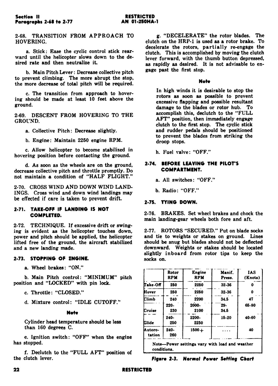
Rotor RPM Engine RPM Manif. Press. IAS (Knots)
Гаке-Off 250 2250 32-36 0
Hover 250 2250 ~~ 32-36 0
Climb 240 2200 34.5 47
— 220- 2000- 29- 65-80
Cruise 230 2100 34.5
240- 2200- 15-20 40-60
Clide 250 2250
Autoro- 240- 1500-i- .... 40
tation 260
Note—Power settings vary with load and weather
conditions.
Flger* 2-3. Normal Powr Sotting Chart
22
RESTRICTED
ENGINE FAILURE
TRANSMISSION FAILURE
EXIT
RESTRICTED
AN 01-2S0HA-1
Section III
Paragraphs 3-1 to 3-11
SECTION III
EMERGENCY OPERATING INSTRUCTIONS
3-1. ENGINE FAILURE.
3-2. PARTIAL FAILURE. If the engine is
missing or shows lack of power, the pilot must
decide whether or not a power-on landing can be
made. An attempt should be made to get over a
suitable landing area in any event.
3-3. COMPLETE FAILURE. Reduce collective
pitch to autorotative position and proceed with
autorotative descent and landing as described
under paragraphs 2-55 through 2-64.
If the situation warrants and sufficient altitude
permits, an attempt should be made to restart the
engine. After establishing autorotative flight the
following procedure should be used.
«. Check engine controls for proper position for
starting. (See paragraph 2-11.)
b. Auxiliary fuel pump: “ON”.
c. Starter: “ON”.
Note
When attempting to restart the engine
in the air do not disengage the clutch.
3-4. AT TAKE-OFF, HOVERING OR SLOW
FLIGHT UNDER 10 FEET ALTITUDE. In-
crease collective pitch as rapidly as possible and
keep ship level.
3-5. BETWEEN ALTITUDES 10 AND 530
FEET. Instantly reduce collective pitch to auto-
rotative angles and obtain forward speed. Turn
into the wind if altitude permits and perform a
normal autorotative landing. Vertical autorotation
is possible but forward speed will reduce the rate
of descent. The time available for making an
autorotative landing under the above conditions is
very short. Therefore all control motions must be
conducted with precision and rapidity.
3-6. TRANSMISSION FAILURE.
3-7. Incipient trouble in any one of the forward,
mid or rear transmissions can be identified by
excessively high temperatures or excessively high
or low pressures, as indicated on the gages and
warning lights. Should the indicators warn of
difficulty, a landing should be made immediately
with minimum use of power, autorotating if prac-
tical. Should a warning occur over water or un-
landable terrain, the pilot should attempt to reach
the closest landable area at minimum altitude (10*
to 25') and slow airspeed (20 to 40 knots). It
should be borne in mind that the use of minimum
power applied will relieve the failing part and
may considerably delay complete failure. If over
water with a helicopter equipped with floatation
gear a landing should be made immediately.
3-8. Failure of the rotor drive system resulting
in the severence of the interconnecting shafts
should be considered as an extreme emergency
condition. Failure of the drive system will be
noticeable to the pilot by either a runaway engine
or an unequal distribution of lift between the
rotors. If at altitudes sufficient for parachute
descent (over 500') immediate egress from the
helicopter should be made. If at low altitudes
immediately reduce the collective pitch to a mini-
mum pitch position, shut off engine and autorotate
to a landing.
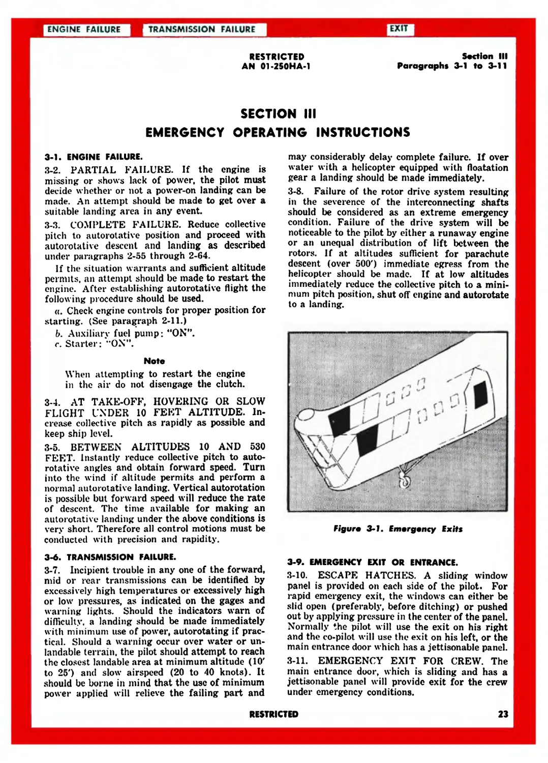
Figure 3-1. Emergency Exits
3-9. EMERGENCY EXIT OR ENTRANCE.
3-10. ESCAPE HATCHES. A sliding window
panel is provided on each side of the pilot. For
rapid emergency exit, the windows can either be
slid open (preferably, before ditching) or pushed
out by applying pressure in the center of the panel.
Normally the pilot will use the exit on his right
and the co-pilot will use the exit on his left, or the
main entrance door which has a jettison able panel.
3-11. EMERGENCY EXIT FOR CREW. The
main entrance door, which is sliding and has a
jettisonable panel will provide exit for the crew
under emergency conditions.
RESTRICTED
23
BAILOUT
DITCHING
IRE
Section III
Paragraphs 3-12 to 3-19
RESTRICTED
AN 01-250HA-1
3-12. BAILOUT.
3-13. ALTITUDES. The following altitudes and
speeds provide ample time for a parachute to
open: at 350' with 0 airspeed, at 300' with 20
kts forward speed, at 250' with 50 kts and 220'
with 80 kts. These figures do not include time for
the individual to react to the emergency, which
requires from 3 to 6 seconds, and bail out of the
helicopter. Therefore, for general conditions, 500
feet is the minimum safe altitude for bailout.
3-14. PROCEDURE. In the event the helicopter
is in a spiral, jump away from the turns if prac-
tical. to avoid the possibility of contact with the
falling helicopter. After bailout a short free fall
should be made before opening parachute, to pre-
vent it from fouling in the helicopter.
3-15. DITCHING.
3-16. Should a forced landing become necessary
at sea. a normal approach to the surface should be
made. During descent the pilots’ windows and
main entrance door should be completely opened to
expedite escape. Just prior to contact the heli-
copter should be “dumped” to the right so that
the rotor blades will be stopped by contact with
the water. Exit should be made quickly through
the main entrance door and pilots windows.
3-17. FIRE.
3-18. FIRE WHILE STARTING ENGINE.
Hold the starter switch “ON”. Leave the ignition
switch “ON”. Make every attempt to complete the
start. This procedure will normally draw the fire
into the engine and thereby extinguish it. If the
fire continues for a dangerous length of time turn
the ignition switch off and use a COz bottle.
3-19. FIRE DURING FLIGHT.
a. Reduce pitch.
b. Close throttle.
c. Mixture to idle cut off.
d. Close fuel valve.
e. Cut magnetos.
f. Autorotate to landing, if below 500'. Above
500' it is left to the pilot’s discretion whether
to bail out or autorotate to a landing.
24
RESTRICTED
Section IV
Paragraphs 4-1 to 4-6
RESTRICTED
AN 01-250HA-1
SECTION IV
OPERATIONAL EQUIPMENT
4-1. REMOTE COMPARTMENTS.
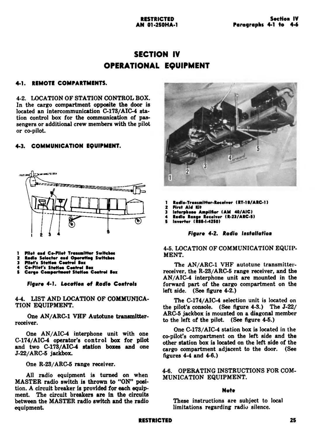
4-2. LOCATION OF STATION CONTROL BOX.
In the cargo compartment opposite the door is
located an intercommunication C-173/AIC-4 sta-
tion control box for the communication of pas-
sengers or additional crew members with the pilot
or co-pilot.
4-3. COMMUNICATION EQUIPMENT.
1 Pilot and C••Pilot TroasMlHtr SwHcboe
2 Radio Selector aod Operotlof Switches
3 Pilot's Stotloa Cootrel hi
4 Co-Pllot's Stotioo Cootrel Box
5 Corf • Compartmeat Stotloa Cootrol Bos
Figure 4-L Location of Radio Controls
4-4. LIST AND LOCATION OF COMMUNICA-
TION EQUIPMENT.
One AN/ARC-1 VHF Autotune transmitter-
receiver.
One AN/AIC-4 interphone unit with one
C-174/AIC-4 operator’s control box for pilot
and two C-173/AIC-4 station boxes and one
J-22/ARC-5 jackbox.
One R-23/ARC-5 range receiver.
All radio equipment is turned on when
MASTER radio switch is thrown to “ON" posi-
tion. A circuit breaker is provided for each equip-
ment. The circuit breakers are in the circuits
between the MASTER radio switch and the radio
equipment
1 Rodlo-Traosmitter-Recoivor (RT-1B/ARC-1)
2 First Aid Rlt
3 lotorphooo Amplifier (AM 40/AIC)
4 Radio Raafo Receiver (R-23/ARC-5)
5 Inverter (RSS-I.42S0)
Figure 4-2. Radio Inttallafion
4-5. LOCATION OF COMMUNICATION EQUIP-
MENT.
The AN/ARC-1 VHF autotune transmitter-
receiver, the R-23/ARC-5 range receiver, and the
AN/AIC-4 interphone unit are mounted in the
forward part of the cargo compartment on the
left side. (See figure 4-2.)
The C-174/AIC-4 selection unit is located on
the pilot's console. (See figure 4-3.) The J-22/
ARC-5 jackbox is mounted on a diagonal member
to the left of the pilot. (See figure 4-5.)
One C-173/AIC-4 station box is located in the
co-pilot’s compartment on the left side and the
other station box is located on the left side of the
cargo compartment adjacent to the door. (See
figures 4-4 and 4-6.)
4-6. OPERATING INSTRUCTIONS FOR COM-
MUNICATION EQUIPMENT.
Nott
These instructions are subject to local
limitations regarding radio silence.
RESTRICTED
25
RESTRICTED
AN 01-250HA-1
Section IV
Paragraphs 4-7 to 4-8
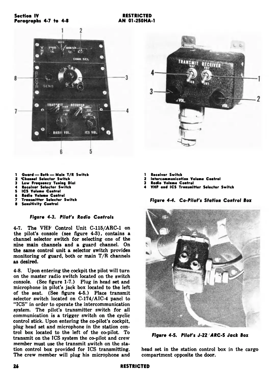
1 Guard — Both — Malo T/R Switch
2 Chaaaal Selector Switch
3 Low Froqooocy Tuuiaf Dial
4 Receiver Selector Switch
5 ICS Volume Coatrol
6 Radio Volume Coatrol
7 Traasmitter Selector Switch
В Seositivity Coatrol
Figure 4-3. Pilot's Hadio Controls
4-7. The VHP Control Unit C-115/ARC-1 on
the pilot's console (see figure 4-3), contains a
channel selector switch for selecting one of the
nine main channels and a guard channel. On
the same control unit a selector switch provides
monitoring of guard, both or main T/R channels
as desired.
4-8. Upon entering the cockpit the pilot will turn
on the master radio switch located on the switch
console. (See figure 1-7.) Plug in head set and
microphone in pilot's jack box located to the left
of the seat. (See figure 4-5.) Place transmit
selector switch located on C-174/AIC-4 panel to
“ICS” in order to operate the intercommunication
system. The pilot's transmitter switch for all
communication is a trigger switch on the cyclic
control stick. Upon entering the co-pilot's cockpit,
plug head set and microphone in the station con-
trol box located to the left of the co-pilot. To
transmit on the ICS system the co-pilot and crew
member must use the transmit switch on the sta-
tion control box provided for ICS transmitting.
The crew member will plug his microphone and
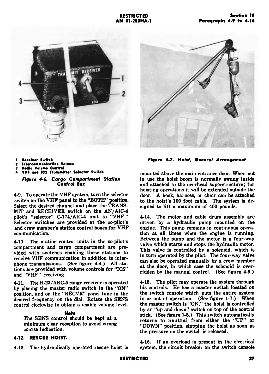
1 Receiver Switch
2 latorcommuaicatioa Volume Coatrol
3 Radio Volume Coatrol
4 VHF aad ICS Troosmltter Selector Switch
Figure 4-4. Co-Pilot's Station Control Box
Flgore 4-5. Mot's J-22 ДВС-5 Jock Box
head set in the station control box in the cargo
compartment opposite the door.
RESTRICTED
Section IV
Paragraphs 4-t to 4-16
RESTRICTED
AN 01-250HA-1
1 Receiver Switch
2 latcrccMnealcatioa Volva*
3 Radio Volamo Coatrol
4 VHF oad ICS Traasailttor Selector Switch
Figure 4-6. Cargo Compartment Station
Control Box
4-9. To operate the VHF system, turn the selector
switch on the VHF panel to the “BOTH” position.
Select the desired channel and place the TRANS-
MIT and RECEIVER switch on the AN/AIC-4
pilot’s “selector” C-174/AIC-4 unit to “VHF.”
Selector switches are provided at the co-pilot’s
and crew member’s station control boxes for VHF
communication.
4-10. The station control units in the co-pilot’s
compartment and cargo compartment are pro-
vided with switches enabling these stations to
receive VHF communication in addition to inter-
phone transmissions. (See figure 4-4.) All sta-
tions are provided with volume controls for “ICS”
and “VHF” receiving.
4-11. The R-23/ARC-5 range receiver is operated
by placing the master radio switch in the “ON”
position, and on the “RECVR” panel tune in the
desired frequency on the dial. Rotate the SENS
control clockwise to obtain a usable volume level.
Note
The SENS control should be kept at a
minimum clear reception to avoid wrong
course indication.
4-12. RESCUE HOIST.
4-13. The hydraulically operated rescue hoist is
Figure 4-7. Hoist, General Arrangement
mounted above the main entrance door. When not
in use the hoist boom is normally swung inside
and attached to the overhead superstructure; for
hoisting operations it will be extended outside the
door. A hook, harness, or chair can be attached
to the hoist’s 100 foot cable. The system is de-
signed to lift a maximum of 400 pounds.
4-14. The motor and cable drum assembly are
driven by a hydraulic pump mounted on the
engine. This pump remains in continuous opera-
tion at all times when the engine is running.
Between the pump and the motor is a four-way
valve which starts and stops the hydraulic motor.
This valve is controlled by a solenoid, which is
in turn operated by the pilot. The four-way valve
can also be operated manually by a crew member
at the door, in which case the solenoid is over-
ridden by the manual control. (See figure 4-9.)
4-15. The pilot may operate the system through
his controls. He has a master switch located on
the switch console which puts the entire system
in or out of operation. (See figure 1-7.) When
the master switch is “ON,” the hoist is controlled
by an “up and down” switch on top of the control
stick. (See figure 1-5.) This switch automatically
returns to neutral from either the “UP” or
“DOWN” position, stopping the hoist as soon as
the pressure on the switch is released.
4-16. If an overload is present in the electrical
system, the circuit breaker on the switch console
RESTRICTED
27
RESTRICTED
AN 01-250HA-1
Section IV
Paragraphs 4-17 to 4-18
1 Holst Cahlo
2 Up-Umlt Switch
3 Male Holst Boom
4 Hook ao4 Weight
I Bobbie
4 Removable Holst Boom
7 Up-Limlt Switch Acoetor
ating the hoist are removed. The hoist is oper-
ated by the co-pilot or crew member by using
the four-way valve manual control.
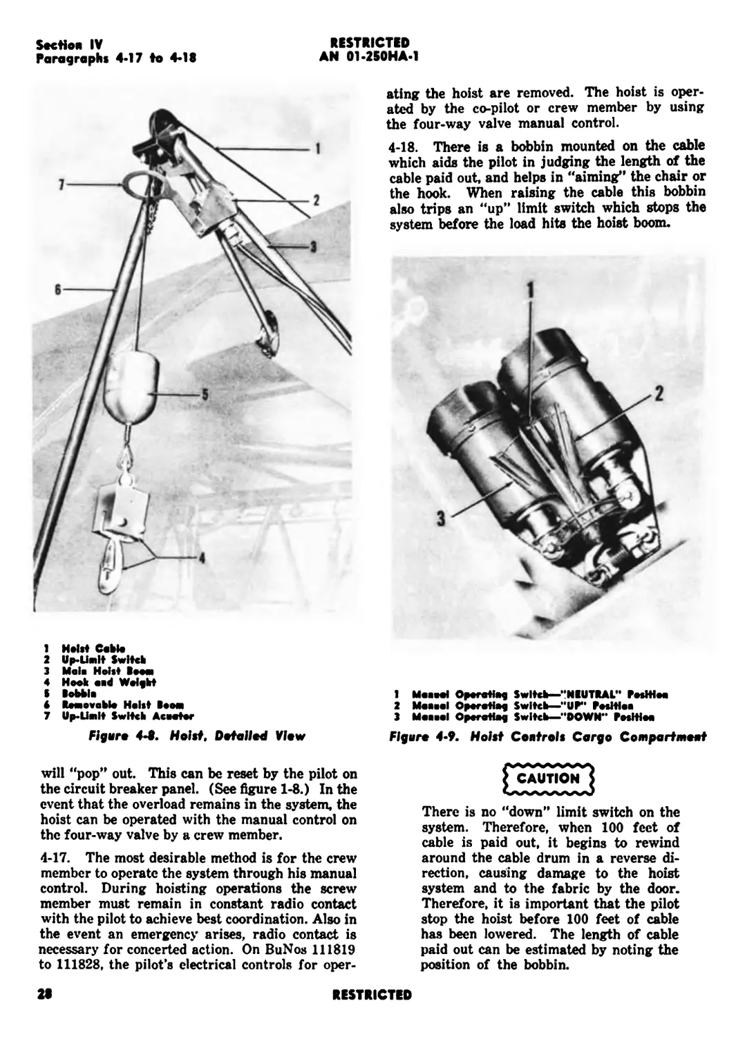
4-18. There is a bobbin mounted on the cable
which aids the pilot in judging the length of the
cable paid out. and helps in “aiming” the chair or
the hook. When raising the cable this bobbin
also trips an “up” limit switch which stops the
system before the load hits the hoist boom.
1 Mcaool Oporatlog Switch—“NEUTRAL” РиЖн
2 Maoael Operatteg Switch—“UP” Posltlao
3 Mesial Operating Switch—"DOWN" Posltioo
Figaro 4-8. Hoist. Dotaiiod View
Figure 4-9. Holst Controls Cargo Compartment
will “pop” out. This can be reset by the pilot on
the circuit breaker panel. (See figure 1-8.) In the
event that the overload remains in the system, the
hoist can be operated with the manual control on
the four-way valve by a crew member.
4-17. The most desirable method is for the crew
member to operate the system through his manual
control. During hoisting operations the screw
member must remain in constant radio contact
with the pilot to achieve best coordination. Also in
the event an emergency arises, radio contact is
necessary for concerted action. On BuNos 111819
to 111828. the pilot's electrical controls for oper-
CAUTION
There is no “down” limit switch on the
system. Therefore, when 100 feet of
cable is paid out. it begins to rewind
around the cable drum in a reverse di-
rection, causing damage to the hoist
system and to the fabric by the door.
Therefore, it is important that the pilot
stop the hoist before 100 feet of cable
has been lowered. The length of cable
paid out can be estimated by noting the
position of the bobbin.
28
RESTRICTED
RESTRICTED
AN 01-250HA-1
Section V
Paragraphs 5*1 to 5*5
SECTION V
EXTREME WEATHER OPERATION
5-1. VARIOUS CONDITIONS*
5-2. RAIN AND SNOW. It is permissible to fly
the HRP-1 in snow and rain, due to the steel lead-
ing edge protecting the blade. Flight in very heavy
rain or snow is not recommended unless necessary.
5-3. TURBULENCE. Thunder storms and ex-
treme turbulence are to be avoided. Flight in
moderate turbulence can be maintained, however,
less buffeting will be encountered if the IAS is
kept below 80 kts.
5-4. LOW CEILING AND VISIBILITY.
Because it is difficult to maintain steady flight
conditions without ground reference, flight under
conditions of very low ceiling and visibility is not
recommended.
5-5. ICING CONDITIONS. When icing condi-
tions are present the carburetor heat and pitot
heat must be applied. (See Carburetor Air
Temperature ranges Chart A7A.)
CAUTION
Since no blade de-icing equipment is pro-
vided, flights under icing conditions
should be avoided.
RESTRICTED
29
RESTRICTED
AN 01-250HA-1
Section V
10
RESTRICTED
Appendix I
Paragraph* A-l to A-4
RESTRICTED
AN 01-250HA-1
APPENDIX I
OPERATING CHARTS AND TABLES
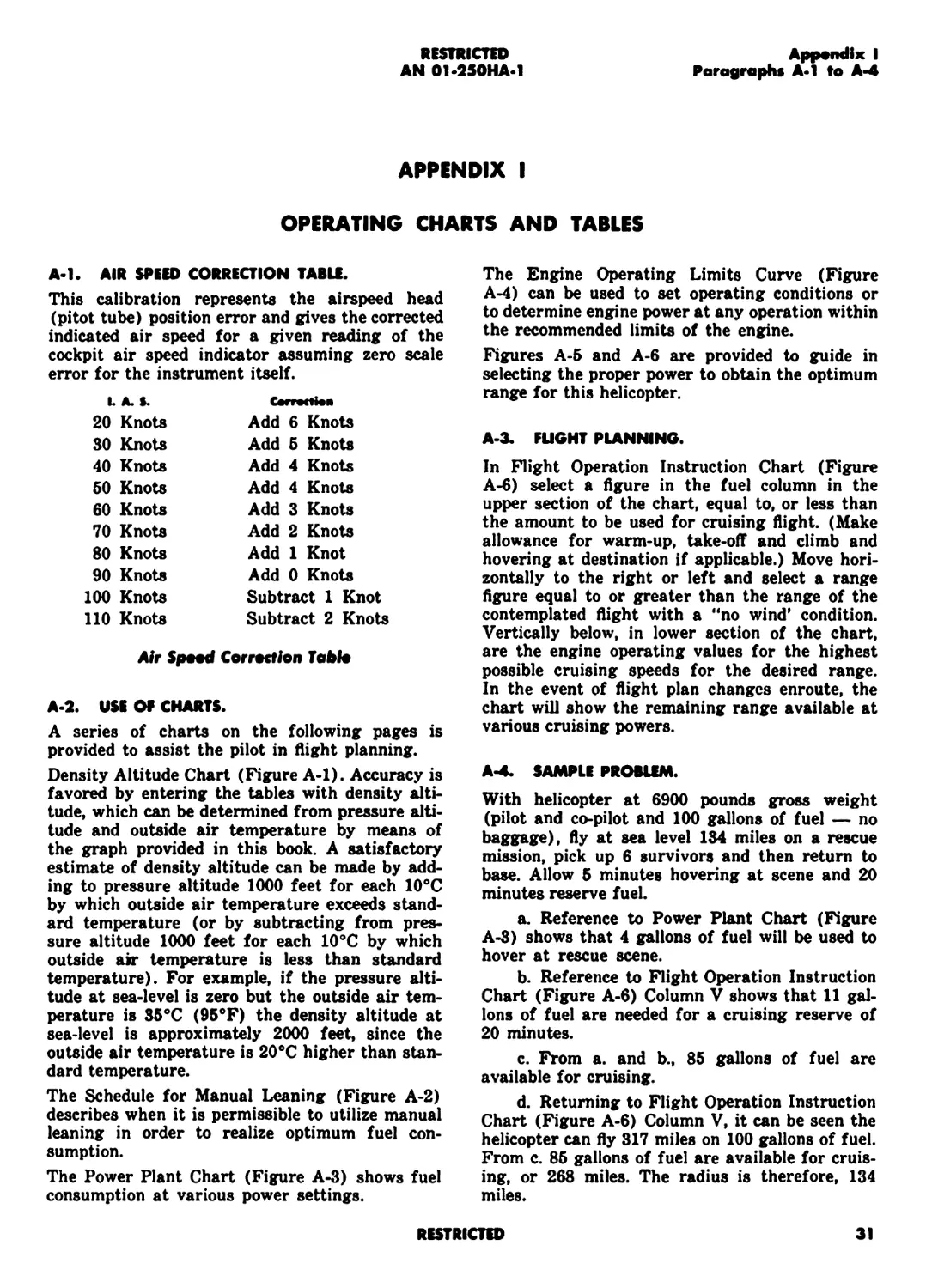
A-l. AIR SPEED CORRECTION TABLE.
This calibration represents the airspeed head
(pitot tube) position error and gives the corrected
indicated air speed for a given reading of the
cockpit air speed indicator assuming zero scale
error for the instrument itself.
LA.*. Cerrectien
20 Knots 30 Knots Add 6 Knots
Add 5 Knots
40 Knots Add 4 Knots
50 Knots Add 4 Knots
60 Knots Add 3 Knots
70 Knots Add 2 Knots
80 Knots Add 1 Knot
90 Knots Add 0 Knots
100 Knots Subtract 1 Knot
110 Knots Subtract 2 Knots
Air Spoad Correction Table
A-2. USE OF CHARTS.
A series of charts on the following pages is
provided to assist the pilot in flight planning.
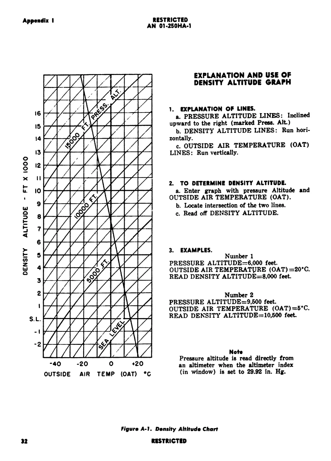
Density Altitude Chart (Figure A-l). Accuracy is
favored by entering the tables with density alti-
tude, which can be determined from pressure alti-
tude and outside air temperature by means of
the graph provided in this book. A satisfactory
estimate of density altitude can be made by add-
ing to pressure altitude 1000 feet for each 10°C
by which outside air temperature exceeds stand-
ard temperature (or by subtracting from pres-
sure altitude 1000 feet for each 10°C by which
outside air temperature is less than standard
temperature). For example, if the pressure alti-
tude at sea-level is zero but the outside air tem-
perature is 35°C (95°F) the density altitude at
sea-level is approximately 2000 feet, since the
outside air temperature is 20°C higher than stan-
dard temperature.
The Schedule for Manual Leaning (Figure A-2)
describes when it is permissible to utilize manual
leaning in order to realize optimum fuel con-
sumption.
The Power Plant Chart (Figure A-3) shows fuel
consumption at various power settings.
The Engine Operating Limits Curve (Figure
A-4) can be used to set operating conditions or
to determine engine power at any operation within
the recommended limits of the engine.
Figures A-5 and A-6 are provided to guide in
selecting the proper power to obtain the optimum
range for this helicopter.
A-3. FLIGHT PLANNING.
In Flight Operation Instruction Chart (Figure
A-6) select a figure in the fuel column in the
upper section of the chart, equal to, or less than
the amount to be used for cruising flight. (Make
allowance for warm-up, take-off and climb and
hovering at destination if applicable.) Move hori-
zontally to the right or left and select a range
figure equal to or greater than the range of the
contemplated flight with a “no wind’ condition.
Vertically below, in lower section of the chart,
are the engine operating values for the highest
possible cruising speeds for the desired range.
In the event of flight plan changes enroute, the
chart will show the remaining range available at
various cruising powers.
A-4. SAMPLE PROBLEM.
With helicopter at 6900 pounds gross weight
(pilot and co-pilot and 100 gallons of fuel — no
baggage), fly at sea level 134 miles on a rescue
mission, pick up 6 survivors and then return to
base. Allow 5 minutes hovering at scene and 20
minutes reserve fuel.
a. Reference to Power Plant Chart (Figure
A-3) shows that 4 gallons of fuel will be used to
hover at rescue scene.
b. Reference to Flight Operation Instruction
Chart (Figure A-6) Column V shows that 11 gal-
lons of fuel are needed for a cruising reserve of
20 minutes.
c. From a. and b., 85 gallons of fuel are
available for cruising.
d. Returning to Flight Operation Instruction
Chart (Figure A-6) Column V, it can be seen the
helicopter can fly 317 miles on 100 gallons of fuel.
From c. 85 gallons of fuel are available for cruis-
ing, or 268 miles. The radius is therefore, 134
miles.
RESTRICTED
31
RESTRICTED
AN 01-250HA-1
Appendix I
О
О
О
x
i-
u.
СП
z
ш
а
OUTSIDE AIR TEMP (OAT) °C
EXPLANATION AND USE OF
DENSITY ALTITUDE GRAPH
1. EXPLANATION OF LINKS.
a. PRESSURE ALTITUDE LINES: Inclined
upward to the right (marked Press. Alt)
b. DENSITY ALTITUDE LINES: Run hori-
zontally.
c. OUTSIDE AIR TEMPERATURE (OAT)
LINES: Run vertically.
2. TO DETERMINE DENSITY ALTITUDE.
a. Enter graph with pressure Altitude and
OUTSIDE AIR TEMPERATURE (OAT).
b. Locate intersection of the two lines.
c. Read off DENSITY ALTITUDE.
3. EXAMPLES.
Number 1
PRESSURE ALTITUDE=6,000 feet.
OUTSIDE AIR TEMPERATURE (OAT)=20*C.
READ DENSITY ALTITUDE=8,000 feet.
Number 2
PRESSURE ALTITUDE=9,500 feet.
OUTSIDE AIR TEMPERATURE (OAT) =5*0.
READ DENSITY ALTITUDE=10,500 feet
Note
Pressure altitude is read directly from
an altimeter when the altimeter index
(in window) is set to 29.92 in. Hg.
ш
a
э
figure A-1. Density Altitude Chart
32
RESTRICTED
Appendix I
RESTRICTED
AN 01-250HA-1
Use This Scale For 2000 RPM
Use This Scale For 2100 RPM
MANIFOLD PRESSURE — IN. HG
36
3$
34
33
32
31
30
29
28
27
26
25
24
23
22
21
20
19
36
35
34
33
32
31
30
29
28
27
26
25
24
23
22
21
20
19
18
36
35
34
33
32
31
30
29
28
27
26
25
24
23
22
21
20
19
18
17
Use This Scale For 2200 RPM
1 LJ 1 1 1
..Max. Permissibl) 1 ' е
Man. Press. 2250 RPM
e Л-
\
Ге 2^
, Rich only 'F/A FIIMIfiMSBBa» —
Й®9Й9® ass 88» 8&е
>»•.’••• J • • eu ж* • 1 .*• *Ге*е ' • •
Г-гЙ ’e • • «Г•*Ге" • • •-. ^ ♦ • • "ГХ.
'• •_ • •гГр*. •Г^’Г* Ч'*‘г Ге •*Ге’ •_*• е*е*
’••Г*** ’Г* • Т« * we • *Г* • • •> • *1 »• •>• •w е • * • • •г^. \
ЯИДГГ **J ?•*»•*' ’••Ге** ’• * *<"• * ‘Г’**- Г^?'^*е Ге •’Г» 1 *11* * ^’•^ч *Ге*Г. ’
sssssfcS • •.*• *Ге Ге • *- • • • ^е • w ~ Г^^е^ .‘^Jx
;Ricn powe ;F/A best n r area. Min =J)80 к K V • *"е • • ' Ге ••*• Га/Г^Ч ••••гС
’Ге *Ге•
•**»••**•
jagg?? .Lean •powe 'f/a best ’** ”••• r area. Min = .072 и
***** •-***•***< ny.’rw*" •••*• •*ж>
г^**7гп* •’-.••Л.» । • •
• *^е’е •*( 55&к2?в*«в* •". ?Г’ 7»
«&&& 10 RPM (Engine) below best power area Г»* " г» •.*.•• •? ***** *••'
и
в
ж| и
ж
5000
Altitude — Ft.
11000
Flgere A-2. Schedule fw Maewel Leeeleg
RESTRICTED
33
RESTRICTED
AN 01-250HA-1
Appendix I
POWER PLANT CHART
Engine Model: R-1340-AN-1
Aircraft Modal: HRP-1
Gauge Reading Fuel Pressure OU Pressure OU Temp. • C Coolant Temp. OU Cons.* 1
Desired Maximum 4-6 6 60-90 90 60-75 82 air cooled 2.5
Minimum Idling 4 3 60 15 40
Max. Permissible Diving RPM: 2800
Min. Recommended Cruise RPM: 2000
Oil Grade: (S) 1120, (W) 1100
Fuel Grade: 91/98, Spec. AN-F-48
MILITARY POWER (Non-Combat Emergency) ^OPERATING CONDITION^ NORMAL RATED (Maximum Continuous) OPTIMUM CRUISE (Normal Operation)
One Minute 260е C Time Limit Max. CyL Hd. Temp. Unlimited 260° C Unlimited 232е C
RICH 2250 MIXTURE R.P.M. RICH 2200 RICH BEST POWER NOTED
Manif. Press. Super Charger Fuel’ Gal./Min. Std. Temp. • C Pressure Altitude Std. Гетр/F Manif. Press. Super Charger Fuel GPH* Manif. Press. R.P.M. Fuel GPH’
F.T. F.T. .6 .684 —28.6 —24.6 —20.7 22,000 FL 20,000 FL 18,000 Ft. —19.4 —12.8 — 5.2
F.T. F.T. F.T. .68 .72 .77 —16.7 —12.7 — 8.8 16,000 FL 14,000 FL 12,000 FL 2.0 9.1 16.2
F.T. F.T. F.T. .88 .89 .95 — 4.8 — 0.8 8.1 10,000 Ft. 8,000 Ft. 6,000 FL 28.4 30.5 37.6 F.T. F.T. F.T. 46 49 53 24 24.5 25.5 2200 2200 2150 38 37 34
F.T. 35.0 36.0 1.08 1.05 1.05 7.1 11.0 15.0 4,000 FL 2,000 Ft. SEA LEVEL 44.7 51.8 59.0 34.5 34.5 34.5 55 55 55 26 26.5 27 2100 2050 2050 82 80 27
GENERAL NOTES
'Oil Consumption: Max. U. S. quart per hour per engine.
*GaL/Min.: Approx. U. S. gallon per minute per engine.
*GPH: Approx. U. S. gallon per hour per engine.
F. T.: Means full throttle operation.
Values are for level flight with Ram.
Note: To determine consumption in British Imperial Units, multiply by 10 then divide by It.
ITAKE-OFF CONDITIONS: CONDITIONS TO AVOID:
I 2250 RPM and 36" Hg. Operation below 1810 RPM (200 Rotor RPM)
SPECIAL NOTES
1. The Mixture Control is not automatic and must be adjusted manually to obtain smooth engine
operation and best range.
Figure Д-3. Fewer Plant Chart
RESTRICTED
34
•HTMcm
AN 914MMA.I
«Haunt mminu мсееим, in. nn. mcmmc аьтлгом in rtev
wt*>* e«Nto**M cbm*
М1ТШСТ1» M
RESTRICTED
Appendix I
AN 01-250HAU
Hfar* A-5. Tote-Off, Clhnb еяЛ 1ляЛя^ Cterf
МЭТШСТКО
1 1 f—It A : 1 1SCOAFT MOOCI R-I340-AN-I NRP-I FLIGHT OPERATION INSTRUCTION CHART emit Mtia<r нт:»: ааоо то eaoo rouaoa UTtMAl 10A0 ITCNS иииаса of wises opcaating:
UNITS J a t«.«4 а«ана |а<ачм T г м 1 Mt • • • HjNt i • i «4 l • «1 •’ ' »f04 1 Г 1 • a - k: • laSTHCHMS HIM (UH: ihic* ».uat MCI <».••• iba. H ta Uli »i i.h •• •( «SIS «88 fa. liaT .•• i.« ti.ic* tttSC • •HM ♦» ;• «a<ot(a »•••«»( •• ••«*icok .ia • ut • > 81 HH8. a<8*'Colia 8«u* »0lM llilll* aifaia ca«»tioi ai* iUa< (aiT.)at •> o««. ••«»%.•< (Я.Р.)оо» NI1TMC 8<t’*8l atu aoni: смет 1 •» «аа <<e«ac« •»> Wti> Cfea!***. oa*« (Oaa»t li.lll.lf aM 1 Ctl *М1Ш >««ам « 8a«4 at a MC8N«ct • $aai>. a a w.tt <л..8> |M.NM.>:«8 »’«•!.«аавм ма ам ааи о avno П.КК) at tauil tea a<riai«a. aaaca aoc^t ам aa aataaj a«a*iaa| tu***. atMf
vas (CM. _u
miser мио ttso 1 1 '* j INN. aadj •>
IT
200
ВАКС I» AIANIUS
inure
NAfTICAL
STATUTf
миг I CM
lUTVYl
ВАФТ1СМ
244
100
1OO
252
303
262
291
158
195
169
233
202
242
210
80
119
146
127
1 74
151
182
60
158
79
69
96
85
121
40
105
V
srifun
U.S
99
HUM
.A MT’U
HKI M: CALCULATIONS ANO SSTIMATIOHS
I» ниш aii Miiiaiiiii >iu,nui(f i« itviiito ihii hi мт ctici
ARA MS
— —
tM >8 a -
103
60
40
•All— CMfIMMS
ftARll IS AHNILtl lAHAt 10 AIINIU3 ПАЯЦ IS AIHNKC3
MflCAl
MHAC1 Fufi MltHAeCIl KOT AVAilAMI <C0 C«UtSINC
211
HIM
ALT.
HU
Mist
All.
Hit
1ИИ
I MM
1ИН
I MH
I Mil
I ни
ИЯ
HASSI IS AllNIltS
__*TAWf J Г Wf ICAl
317 1 27a
254 2 21
... - 165
127 1 10
*811— Alt 8—«
RESTRICTED АррмМж I
AN 01>2ИИА.1
Appendix I
RESTRICTED
AN 01-250HA-1
AIR SPEED INDICATOR
g 85 Knots Maximum permissible IAS
MANIFOLD PRESSURE
□ 26" to 36" Hg. Desired
gg 36" Hg. Maximum
DUAL TACHOMETER
Rotor
8 200 RPM Minimum
220 to 250 RPM Desired
g 285 RPM Maximum Autorotation
Engine
8 1000 RPM Minimum Idling
2050 to 2250 RPM Desired
g 2250 RPM Maximum Operating
ENGINE FUEL AND OIL PRESSURE
Fuel
S4 PSI Minimum
4 to 6 PSI Desired
6 PSI Maximum
on
В 60 PSI Minimum
60 to 90 PSI Desired
90 PSI Maximum
Figure A-7. Instrument Operating Range Chart
38
RESTRICTED
Appendix t
RESTRICTED
AN 01*250HA*1
CYLINDER HEAD TEMPERATURE GAUGE
И 120° C Minimum
150’ C to 260°C Desired
260° C Maximum
VOLTMETER
IH 27 volts minimum
28 volts normal operating
FORWARD. CENTER OR AFT TRANSMISSION
TEMPERATURES AND PRESSURES
Temperatures
No Minimum as long as temperature indicated
□ 20’ C to 90’ C Desired
В 95’ C Maximum
Pressures
20 PSI Minimum
В 75 PSI Maximum
ENGINE OIL TEMPERATURE AND
CARBURETOR AIR TEMP. GAUGES
Oil
В 40° C Minimum
□ 60’ to 80* C Desired
82° C Maximum
Carbureter Air Temp.
— 5’ C to 4-32’ C Danger
□ 4-32° C to 4-38’ C Desired
В 4-50° C Maximum
Figure Л-7Л. Inttrument Operating Range Chart
RESTRICTED
39
RESTRICTS)
RESTRICTED