/


Text
GENERAL
FOUNDRY PRACTICE.
13 Y
ANDREW MCWILLIAM, A.R.S.M.,
ASSISTANT PROFESSOR OF METALLURGY IN THE UNIVERSITY OF SHEFFIELD :
AND
PERCY LONGMUIR,
CARNEGIE MEDALLIST ; CONSULTING METALLURGIST ; SOMETIME FOUNDRY FOREMAN.
TWUtb IRumerous illustrations.
LONDON:
CHARLES GRIFFIN & COMPANY, LIMITED
EXETER STREET, STRAND
1907.
[All Rights Reserved.)
PKEFACE.
This work is designed to give a condensed and crystallised account of the
science and practice of iron, steel, and brass founding in such a way that
it may prove of the greatest benefit to all connected with the production
of castings. The field is an extensive one, but so far as possible the authors
have drawn from their combined experience gained under normal foundry
conditions and under the conditions of experimental laboratories and works.
Practically every operation described has been personally followed, and the
spirit of the book will be found to reflect the experience of actual workers
and not merely spectators.
Although primarily intended for foundry managers and foremen, or those
who aspire to such positions, the authors trust that their work may become
as much the literary companion of moulders and apprentices during the time
they devote to technical study as the tool-box is in their hours of moulding.
Much of the matter should also be of interest and value to the engineer and
designer as well as to the student of general metallurgy. ■
Reliability throughout has been striven for, and the intimation of even
seeming error detected by any thoughtful reader with a knowledge of foundry
practice will be welcomed ; whilst suggestions from a similar source tending
to increase the usefulness of a future edition will receive careful consideration.
Wherever possible, acknowledgments have been made in the text. Our
heartiest thanks are here tendered to Mr Arthur Simonson for his description
of the Tropenas process ; to the several manufacturers or their agents who
have supplied blocks for figures 8 to 12, 43 to 45, 123 to 125, 127 to 130,
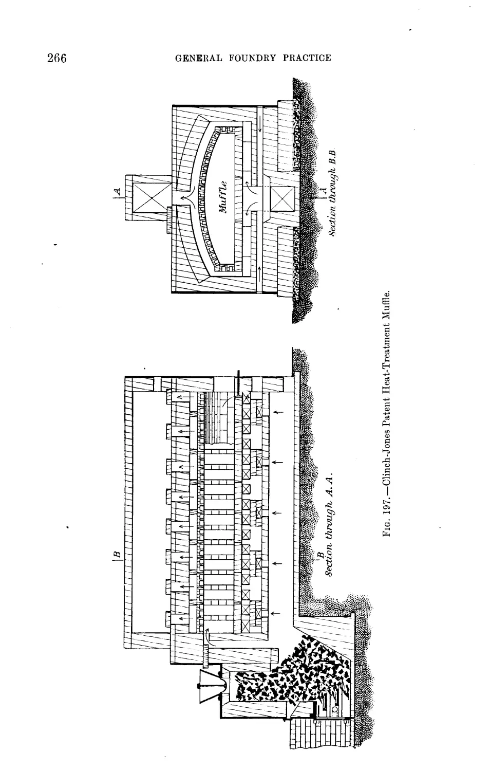
132, 136, 169, 190, 191, 193, 194, 197, 199, 201, 203, 204, and 217 ; to the
Iron and Steel Institute for 173, 175 to 177 ; to the West of Scotland Iron
and Steel Institute for 236, 238 to 240; and to the Editor of Page's Magazine
for 243, the last eleven being all from our own papers ; also to Mrs A.
M William for preparing the index.
A. M°W.
P. L.
Sheffield, April 1907.
V
20412v
/
CONTENTS.
CHAP. PAGE
I. Introduction, . . . r . . . 1-3
II. General Properties of Matter, ... 4-16
III. Moulding Sands, . . . . . . . 17-21
IV. Facing Sands and Facings, ..... 22-27
V. Foundry Tools, . . . . . . . 28-41
VI. Moulding Boxes, ....... 12-50
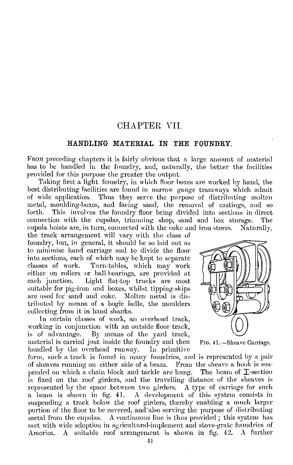
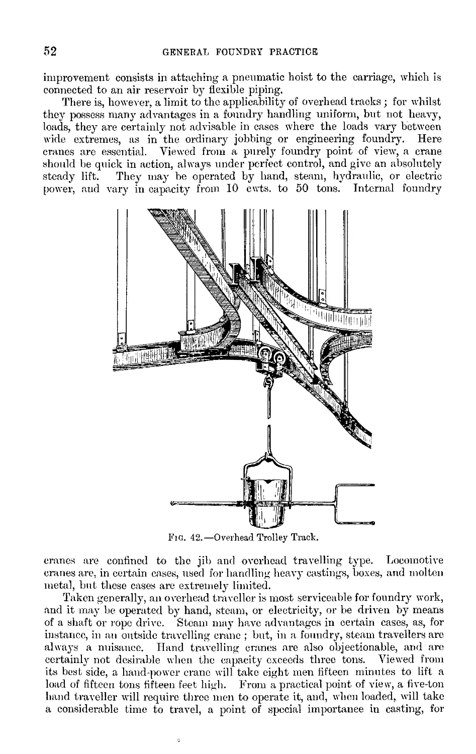
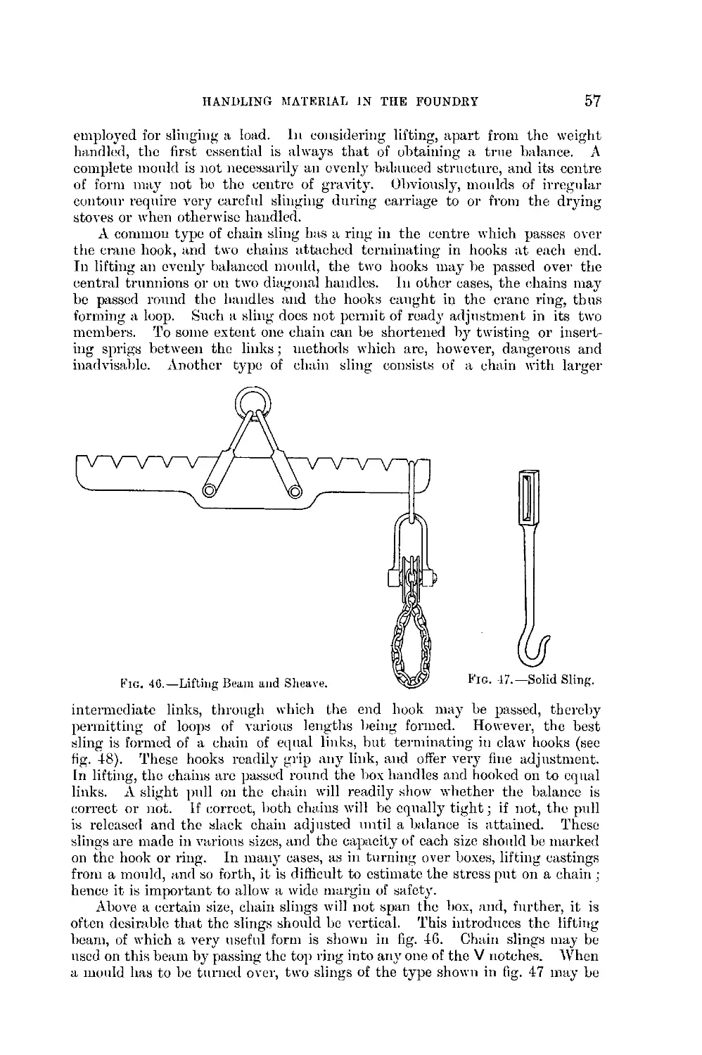
VII. Handling Material in the Foundry, .... 51-59
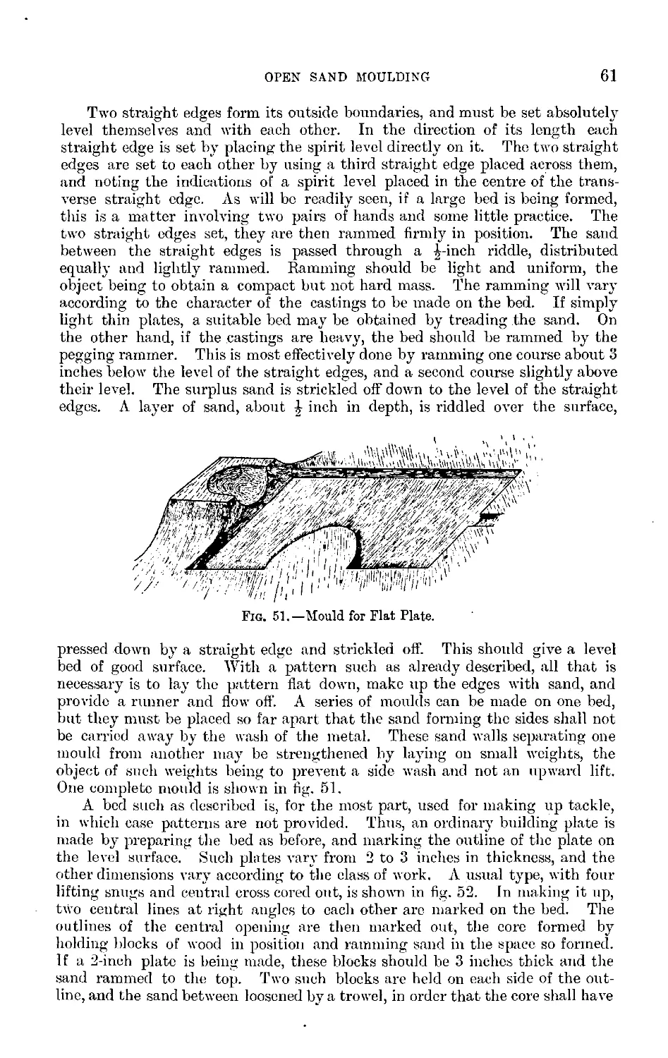
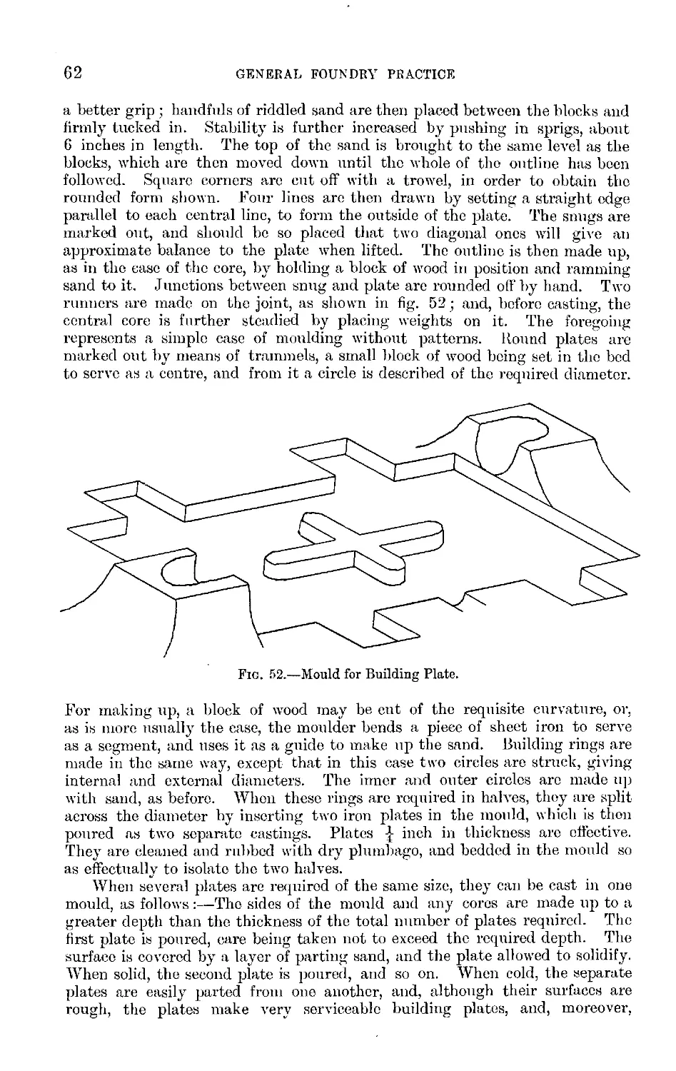
VIII. Open Sand Moulding, ...... 60-66
IX. Cores, ........ 67-78
X. Elementary Aspects of Moulding, .... 79-83
XI. Green Sand Moulding, ...... 84-91
XII. Green Sand Moulding-^-Loose Pieces and Subdivision of
Patterns—False Cores and Drawbacks—Moulding in
Three-part Boxes—Coke Beds—Additions to Top Parts—
Stopping Off or Extending Patterns, . . . 92-106
XIII. Securing Cores in Moulds, ..... 107-114
XIV. Moulding from Guides, ...... 115-121
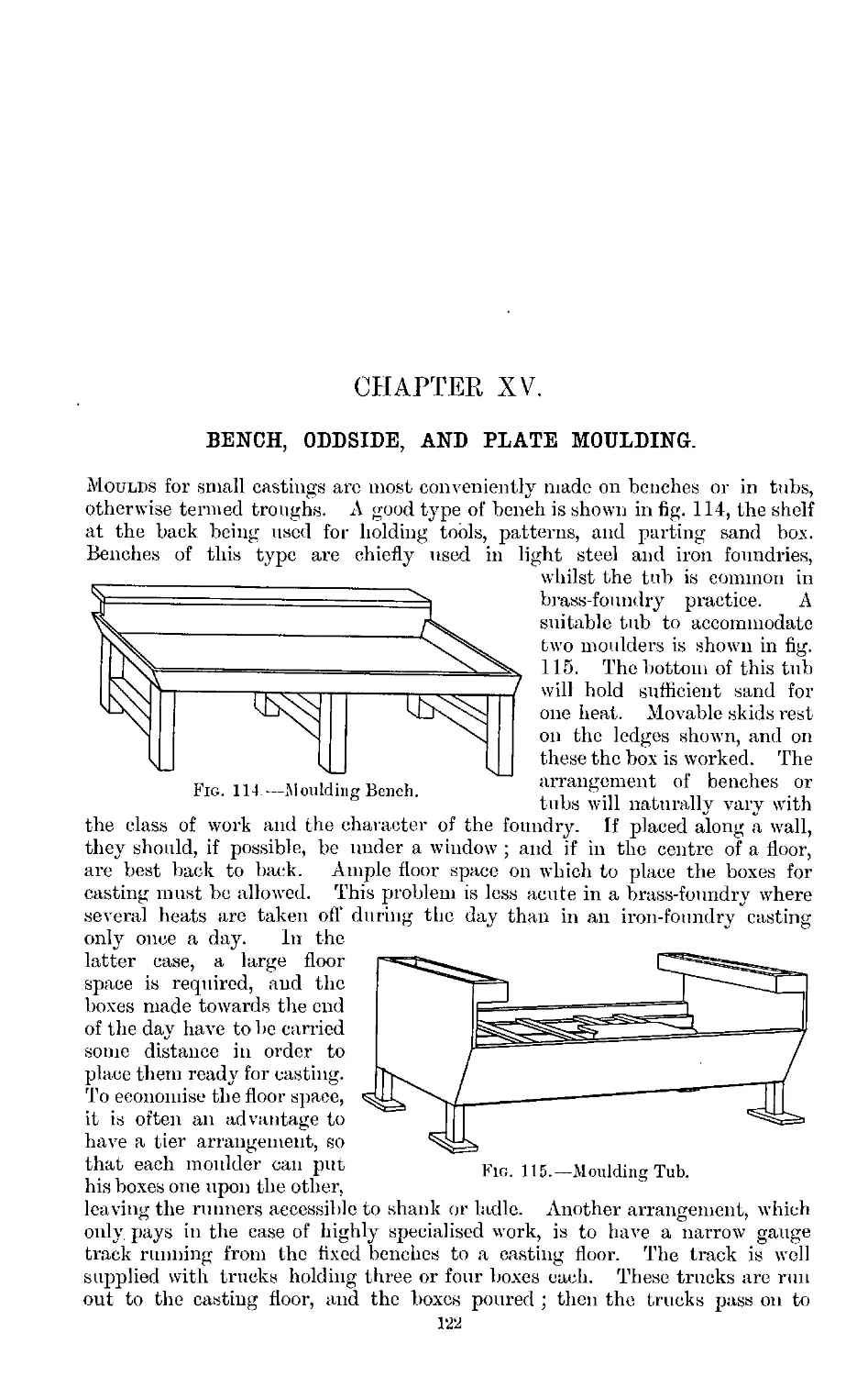
XV. Bench, Oddside, and Plate Moulding, .... 122-129
XVI. Machine Moulding, ...... 130-144
XVII. Dry Sand Moulding, ...... 145-153
XVIII. Loam Moulding, ....... 154-168
-^XIX. Chill Casting, ....... 169-175
XX. Casting on to Other Metals—Burning, . . . 176-182
XXI. Weighting and Binding Moulds, .... 183-186
_ XXII. Shrinkage, Contraction, and Warping, . . . 187-193
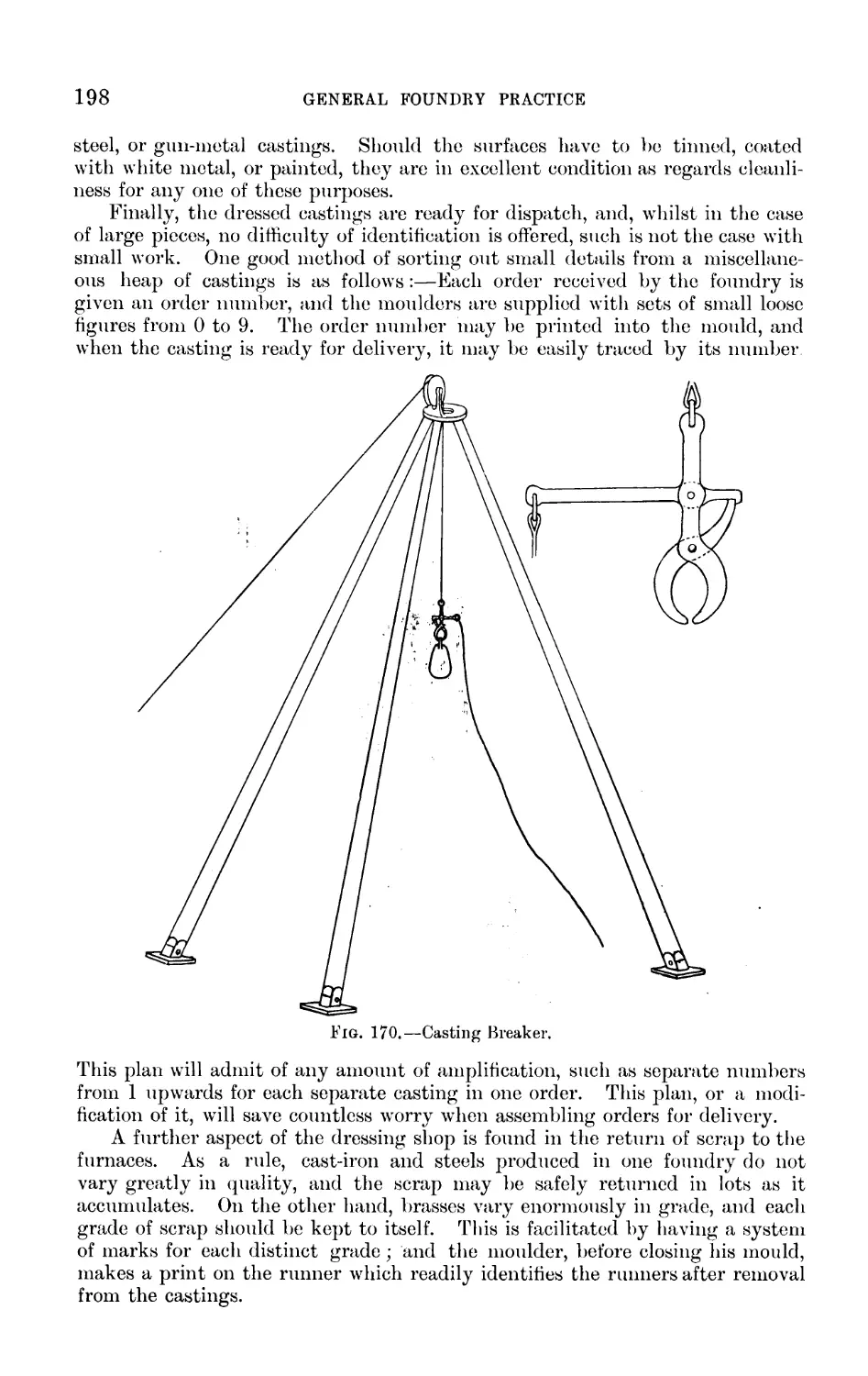
XXIII. Dressing Castings, ...... 194-199
■ ^CCXIV. Common Faults Due to Mould and Pattern, . . . 200-209
XXV. Malleable or Wbought Iron, Steel, Cast Iron, and Malleable
Cast Iron, ....... 210-213
KXXVI. Cast Iron, ........ 214-227
XXVII. Refractory Materials, ...... 228-234
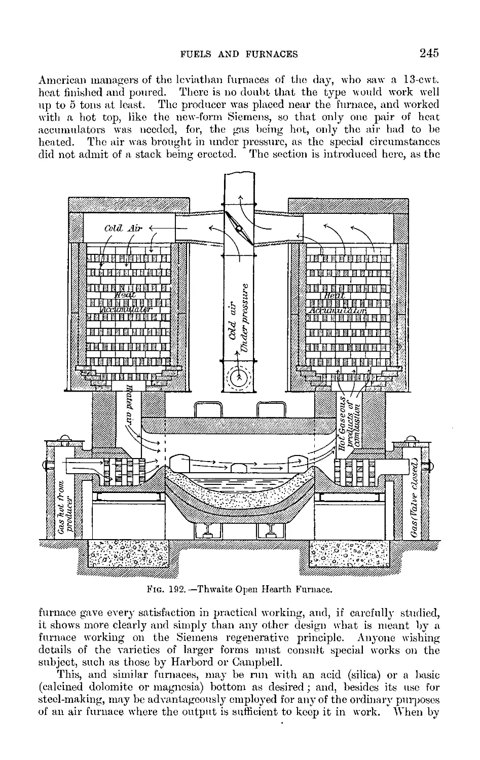
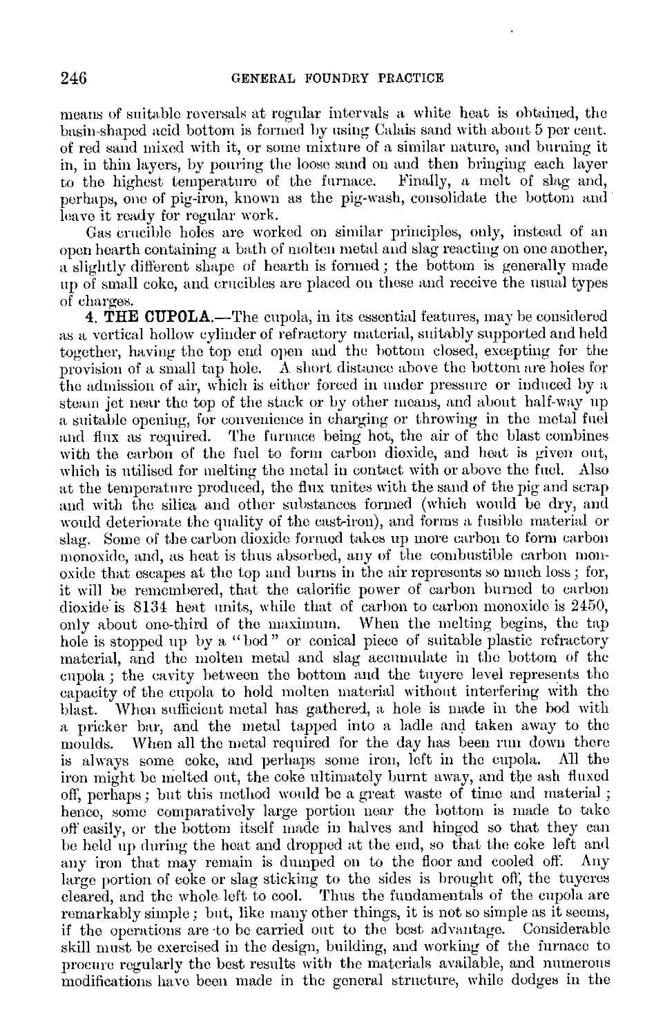
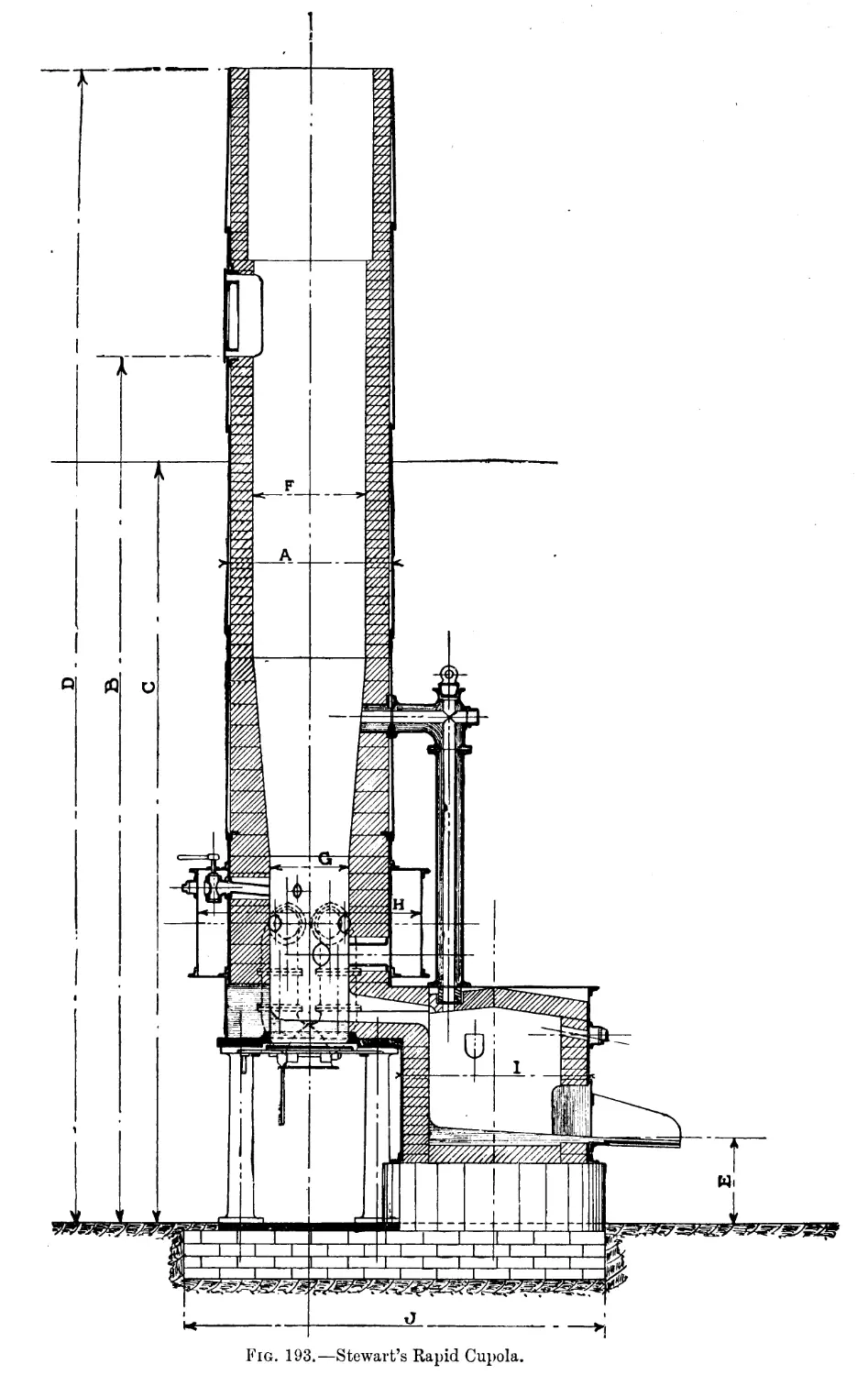
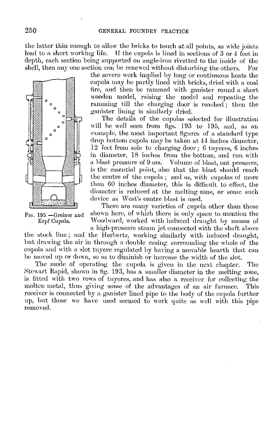
XXVIII. Fuels and Furnaces, ...... 235-250
2\'XXIX. Mixing by Analysis—Influence of Remelting—Working
the Cupola, ....... 251-262
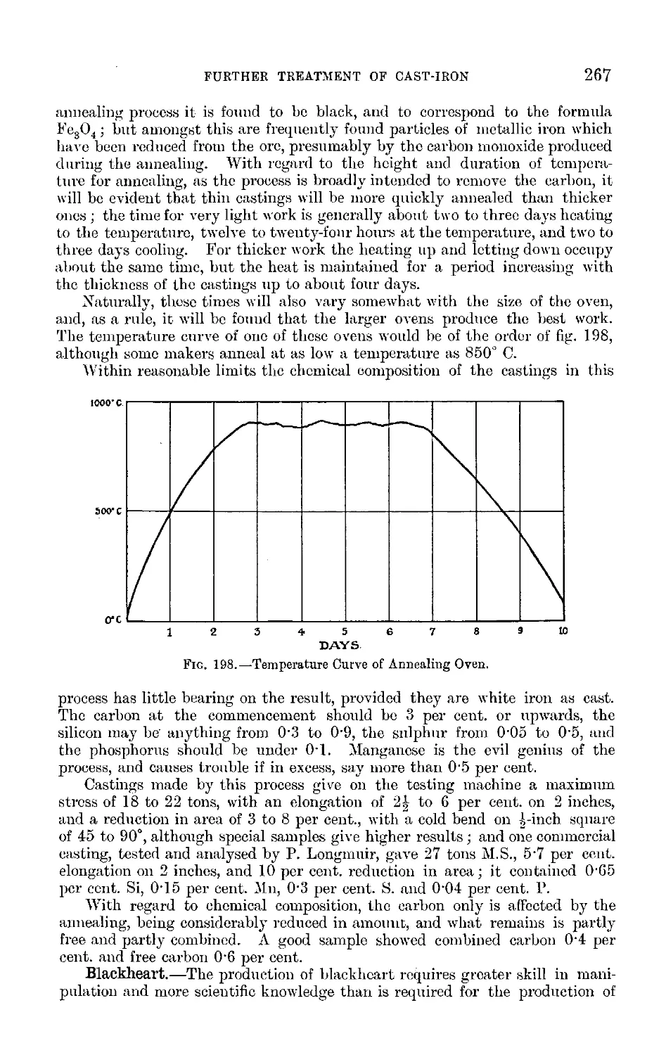
XXX. Further Treatment of Cast Iron, .... 263-270
XXXI. High Temperature Measurement, .... 271-286
XXXII. Steel, 287-309
XXXIII. Notes on Metals other than Iron—Introductory to Alloys, ' 310-316
XXXIV. Alloys, ........ 317-328
XXXV. Mechanical Testing, ...... 329-336
- XXXVI. Micrographic Analysis, ...... 337-354
XXXVII. Common Faults Due to the Metal, .... 355-368
XXXVIII. Notes on Foundry Management, .... 369-375
Index, ........ 376-383
vii
GENERAL FOUNDRY PRACTICE.
CHAPTER I. ■
INTRODUCTION.
The art of founding has been described as making a hole in the sand and
filling it with fluid metal. There is a simplicity and directness about the
definition which entitle it to respect, and leave it suitable for the general
reader; but for the practical moulder or founder looking for help in his work
it is lacking in detail. Before proceeding to a more particular consideration
of founding, it may be well to glance at its early history. Antiquaries con¬
sider that the art was known before the days of written history. Cold
working probably preceded melting and casting; for example, meteoric iron
and surface deposits of copper may have been utilised by roughly hammering
pieces to the desired shapes. This stage may have been followed by that of
liquefying the copper and casting it into baked clay moulds, for in many parts
of the world both cast and hammered weapons of copper have been found
which are probably of similar ages. The addition of tin to copper may have
been made purposely, or the presence of the tin may have been due to the
smelting of copper ores containing tin, but in either case the product is the
ancient metal bronze. The general composition of this bronze is about 90
parts of copper to 10 of tin, and in later examples lead has been detected.
Ancient Egyptian tools are reported to contain 12 per cent, of tin, whilst
Greek and Roman tools have a composition varying between 88 and 90 per
cent, of copper, 12 and 10 per cent, of tin, with traces of silver and zinc, the
last two probably accidental. An old writer, Theophilus, gives as a composi¬
tion of bell metal, copper containing one-fifth of its weight of tin, which, it is
interesting to note, is the British Admiralty specification for bell metal to-day.
In England, according to Sir John Evans, the bronze period extended over
several centuries, and in all probability it had merged into the iron age a
century before Ceesar’s invasion of Britain.
. The ancient Egyptians were essentially stone-workers, and it is claimed that
the tools employed were of hardened and tempered bronze ; it is further stated
that the method of hardening bronze to the same degree is now a lost art.
This requires further confirmation, for, considering the advanced state of
civilisation prevalent in early Egyptian times, it is not improbable that they
1 "
2
GENERAL FOUNDKY PRACTICE
may have been familiar with steel. Implements of bronze buried in the earth
are fairly permanent, whilst those of steel or iron in the presence of air and
moisture are rapidly rusted away; therefore the relative scarcity of the latter
in certain deposits is no criterion of the relative numbers in use during the
time these deposits were being formed. It is also of interest that the first
cores were of iron, namely, bronze liners cast round a small iron shaft. In
such a case the iron would be fairly permanent, and specimens so treated,
dating from about 880 B.C., are now in the British Museum. The birth of
cast-iron in Britain occurred between the years 1345 and 1355, and the first
home of the new industry was in Sussex. . Iron-founding was first practised in
this country about the year 1500, and the first cast-iron cannons were made in
1543, while by 1595 cannons weighing three tons each were made; a record
of progress illustrating alike the adaptability of cast-iron and the development
of iron-founding. So far as this country was concerned, further progress was
prevented by the limited supply of wood for conversion into charcoal, then the
only suitable fuel available. In the seventeenth century, Dud Dudlej7 success¬
fully prepared coke from the Staffordshire coal, and James I. granted a patent
for the invention. The coke was used as a fuel in the blast furnace, and cast-
iron obtained. Owing to certain troubles and misfortunes, Dudley relinquished
his process, and not much progress was made until in 1713 Darby revived
Dudley’s process at Coalbrookdale. This was put on a commercial footing, with
such success by the younger Darby that in 1790 there were 106 furnaces in
blast, 81 using coke and 25 charcoal, the weekly output of the coke furnaces
being 17 tons and of the charcoal furnaces 10 tons of pig-iron. The revolution¬
ary improvements in the steam-engine introduced by Watt in 1768 gave a
further impetus to iron-founding, and from this the record is one of steady
progress. The crucible process for the melting of steel (Huntsman of Sheffield,
1740), the introduction of the Bessemer process (1856), and of the Siemens
furnace (1867), all had their effect in the steady advance of the foundry, and
were each in their turn employed in the manufacture of steel castings, as is also
the basic process (Thomas and Gilchrist, 1878), at least when worked in the
Siemens furnace. In more modern progress in the founding of metals and
alloys, the improvement in green sand, dry sand, and loam moulding are note¬
worthy, castings of almost any size and form being made daily, although the
advances in machine moulding form the greater feature. Progress in founding
must not, however, be judged solely by the usual rule, “ the extent of the adop¬
tion of labour-saving devices,” and many writers err in this direction and label
the whole foundry industry as retrograde, simply because they may be
acquainted with a few foundries in which moulding machines are not extensively
adopted. In many foundries not controlled by foundrymen, moulding machines
have been installed under unsuitable conditions, and the result has been the
locking up of the capital involved. The whole question is considered in
Chapter XVI. ; but it may be mentioned here that the founder’s art seems
recentlv to have come in for more than its fair share of amateur advice and
sweeping adverse criticism from those who do not realise that each new form to
be cast is a new problem, that each new set of requirements necessitates a metal
of different properties, that the successful practical and technical founder must
be an ever-alert and living man of good judgment, and that the business cannot
be reduced to the employment of moulding machines, motors, and a card index.
The experience of the authors gained on the moulding floor, at the melting
furnace, and in the foundry and research laboratory, together with their
reading on the subject, leads them to the conclusion that advances have been,
INTRODUCTION
3
and are being, made of a magnitude commensurate with those of other
industries.
In the last twenty years information as to the properties and uses of metals
and alloys has greatly increased, as is testified by the high tension bronzes,
the better qualities of cast- and malleable cast-iron, and the great development
of steel castings. In the literature of the subject much valuable matter
relating to the scientific aspects of founding has been published, but much
also that is confusing and misleading, so that the founder must be on the
alert to winnow the chaff from the grain and absorb the latter. The young
moulder of to-day enters a splendid heritage, which, however, involves high
responsibilities, and his aim should be to continue the work of the past.
Every moulder may become a pioneer; and any real advance, however slight,
will bring its own reward.
Given an ambitious young moulder, what ought he to do in order to
become thoroughly conversant with foundry practice? Naturally, the first
essential is that of moulding, and the greater the amount of practice the
better. It need hardly be stated that practice in moulding must be acquired
in a foundry engaged in the production of commercial castings. Further,
moulding experience should include, if possible, the three branches of green
sand moulding, dry sand, and loam work. If, during his apprenticeship, the
young moulder can obtain experience of these three branches, he will be
fortunate, and should eagerly seize every opportunity for acquiring it. Whilst
undergoing this training his evenings will be free, and these, during the winter
months, should be devoted to study. Evening classes are now within reach
of all foundries, and the first classes taken should be elementary mathematics
and machine drawing. Some acquaintance with mathematics is necessary ;
and whilst the ability to make a working-drawing is useful, it is absolutely
essential that the student-moulder should acquire facility in reading working-
drawings. Following these classes, the next in importance would be elementary
stages of chemistry, mechanics, and heat. These subjects are essential for
their own sake and as a preliminary training previous to entering on the
study of metallurgy. In order that conditions may not he too severe, the
young moulder might devote the first three years of his apprenticeship to the
five subjects, and leave the winter evenings of the remaining four years for
the study of metallurgical science.
Once a habit of stud}7 is acquired, the learner will work out his own path,
and his training will have so increased his powers of observation that his
daily experience will call for wider knowledge ; when he has attained to this
stage he may safely be left alone. It must not be forgotten that even seven
years’ apprenticeship, with attendance at evening classes and home study, will
not make a complete foundryman. Knowledge is not easily gained, and
training is never complete. It may be thought that the outline here given is
too much for an apprentice after doing a full day’s work in the foundry.
Naturally, it involves considerable strain, hut the authors are advocating
no untested scheme.
CHAPTER II.
GENERAL PROPERTIES OF MATTER.
Those who have had the benefit of a good grounding in Natural Science may
pass this chapter over, unless in so far as it may refresh their memories
and perhaps be suggestive of application of their theoretical knowledge to
their practical work. It is intended for the beginner, not only to showr him
the least he must study, if he would attain to the fullest development of
scientific method in his present work and in the gradual attainment of his
practical experience, but also, incidentally perhaps, to encourage him to begin
the work by showing a few of the more obvious applications. In the future,
such a chapter may, and most probably will, be unnecessary; but the wide
experience of the authors leads them to insert it as at the present time
desirable for the end they have in view, namely, to attract and help all who
are thinkers and workers connected with the foundry.
The number of different kinds of materials dealt with daily, even in foundry
work, might well appal the beginner when he thinks of studying their properties
and chemical composition. The chemist has found, however, that all these
substances, and, indeed, all substances examined, are composed of a com¬
paratively small number (70 odd) of kinds of matter, each of which has so far
resisted all the applications of his skill and perseverance to break it up into
two or more dissimilar bodies. These he calls elements, and of these only a
small proportion need he considered by the beginner as necessary for the study
of everyday foundry work. Thus, slags and the non-metallic materials of
construction are practically all made up of oxides (elements combined with
the element oxygen), or combinations of oxides, mainly silica, alumina, oxides
of iron, lime, magnesia, potash, and soda. The metallic substances in the
widest practice mainly consist of the metals iron, manganese, copper, zinc, tin,
nickel, lead, aluminium, mercury, or alloys of these, with bismuth, antimony,
arsenic, generally in smaller proportion, and more or less of the non-metallic
substances carbon, silicon, sulphur, and phosphorus. The list of elements
that need he considered is thus not so formidable, and, although their combin¬
ations are practically infinite, this idea gives a foundation for studies on which
may he built up a useful structure of knowledge to any extent, and of any
degree of detail, embracing the whole range of metals, specialising in one
or more branches, but all on the same fundamental basis and with a remarkable
similarity of mental treatment. Thus, the beginner may look forward to
building to any extent his attainments and opportunities will permit, and, at
whatever stage he may arrive, feel sure of acquiring not only useful knowledge
but mental power to record and take advantage of his own experience and
GENERAL PROPERTIES OF MATTER
5
that of others, as expressed in conversation, in books, or in technical periodicals.
A little knowledge is only dangerous when it is viewed out of proper perspective
and assumed to be a complete knowledge to be recklessly acted upon ; and the
authors meet with oft-recurring evidence that all stages of well-arranged
knowledge, if used with discretion to throw light on practical experience, is
daily and increasingly helpful as the underlying science of the founder’s art
becomes more and more clear. The real theoretical knowledge of the scientist
is built on experiment, and his explanations or theories in all true scientific
work are tested by further experiment. The practical man constantly meets
with difficulties in his work, and he also must in some way group the results
of his former experience, seek in these for an explanation of the case, and,
after thinking the matter over, devise a remedy, and put it to the test,—truly
scientific work. The apparatus may often be cruder than that found in
laboratories, but frequently used with a more subtle judgment of the special
needs of the case. The man who combines a scientific training with a
sufficiency of real practical experience is gradually, but surely, becoming
the dominant type of industrial captain in the working departments
of the best equipped foundries. All youths looking forward to progress in
foundry work in the future should study at least the rudiments of mathematics,
particularly geometry and mensuration; physics, especially mechanics and
heat; and inorganic chemistry in some of the elementary classes so liberally
arranged in practically all towns having "foundries. They will then be able to
start their own special subject with the certainty of profitable work. It is
hoped, then, that this chapter, unnecessary for those who have had preliminarj'
training, will help those who have not, to understand what follows and lead
them to make a study of chemistry and physics, as many things must here
be merely stated, whereas, in special works on the subject, they would be
reasoned out. Reverting to the elements, it has been found that when these
combine with one another they always do so in definite proportions. Thus,
iron filings and sulphur may be mixed in any proportion; if heated to¬
gether they combine to form an entirely different substance, but always in
the proportion of 56 parts by weight of iron to 32 parts by weight of sulphur;
and, under these conditions, in no other proportion. A natural mineral known
as pyrites, the “ brasses ” of coal, is a compound of iron and sulphur, but in
the proportion of 56 of iron to 64 of sulphur, that is, double the proportion of
sulphur. So the elements are found to combine in definite and, generally,
also in multiple proportions. All this, and much more, led to the idea of the
atomic theory, namely, that elements are composed of atoms of a definite
weight, that all the atoms of the same element are of the same weight, but the
atoms of different elements have different weights; hence each element has its
own atomic weight. Also the smallest portion of an element, or of a compound
that can exist in the free state, is called a molecule. The elements are for
convenience represented by symbols, as iron Fe, from its Latin name ferrum ;
and the atomic weight of iron being 56, the symbol Fe not only means an atom
of iron but 56 parts by weight of iron ; and similarly S, the symbol for sulphur,
means an atom of sulphur and 32 parts by weight of sulphur. It will now
readily be seen that the first compound of iron with sulphur would be written
FeS; while the formula, as it is called, for pyrites would be FeS2, the small 2
indicating 2 atoms of sulphur. To represent what took place when the mixed
iron and sulphur was heated till they combined, combining in definite propor¬
tions and rejecting any portion in excess, an equation is written thus:—Fe + S =
FeS; this equation means not only that iron and sulphur have combined to
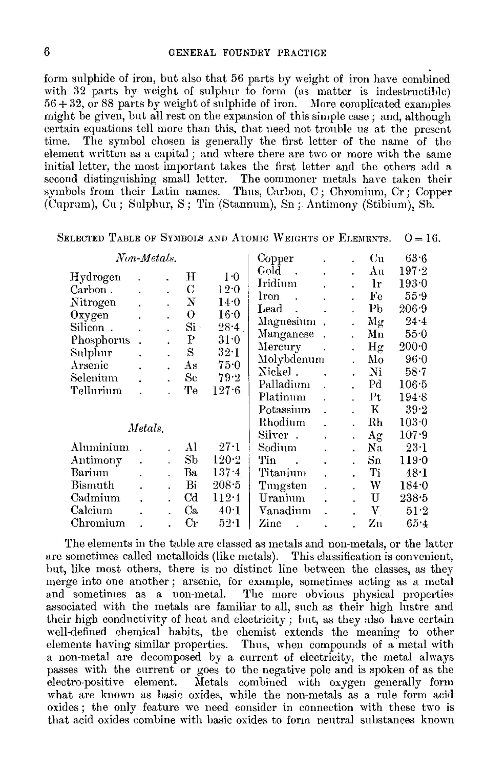
6
GENERAL FOUNDRY PRACTICE
form sulphide of iron, but also that 56 parts by weight of iron have combined
with 32 parts by weight of sulphur to form (as matter is indestructible)
56 + 32, or 88 parts by weight of sulphide of iron. More complicated examples
might be given, hut all rest on the expansion of this simple case ; and, although
certain equations toll more than this, that need not trouble us at the present
time. The symbol chosen is generally the first letter of the name of the
element written as a capital; and where there are two or more with the same
initial letter, the most important takes the first letter and the others add a
second distinguishing small letter. The commoner metals have taken their
symbols from their Latin names. Thus, Carbon, C; Chromium, Cr; Copper
(Cuprum), Cu ; Sulphur, S ; Tin (Stannum), Sn ; Antimony (Stibium), Sb.
Selected Table op Symbols and Atomic Weights of Elements. 0— 16.
Non-Metals.
Hydrogen .
. H
1-0
Carbon . .
. C
12-0
Nitrogen .
. N
14-0
Oxygen .
. 0
16-0
Silicon . .
. Si
28-4
Phosphorus .
. p
31-0
Sulphur .
. s
32-1
Arsenic .
. As
75-0
Selenium .
. Se
79-2
Tellurium .
. Te
127-6
Metals.
Aluminium .
. A1
27-1
Antimony .
. Sh
120-2
Barium .
. Ba
137-4
Bismuth .
. Bi
208-5
Cadmium .
. Cd
112-4
Calcium .
. Ca
40-1
Chromium .
. Cr
52-1
Copper .
. Cu
63-6
Gold . .
. An
197-2
Iridium .
. Ir
1930
Iron . .
. Fe
55-9
Lead . .
. Pb
206-9
Magnesium .
• Mg
24-4
Manganese .
. Mn
55-0
Mercury .
• Hg
200-0
Molybdenum
. Mo
96-0
Nickel . .
. Ni
58-7
Palladium .
. Pd
106-5
Platinum .
. Pt
194-8
Potassium .
. K
39-2
.Rhodium .
. Rh
103-0
Silver . .
■ Ag
107-9
Sodium .
. Na
23-1
Tin . .
. Sn
119-0
Titanium .
. Ti
48-1
Tungsten .
. W
184-0
Uranium .
. U
238-5
Vanadium .
. V
51-2
Zinc . .
. Zn
65-4
The elements in the table are classed as metals and non-metals, or the latter
are sometimes called metalloids (like metals). This classification is convenient,
but, like most others, there is no distinct line between the classes, as they
merge into one another; arsenic, for example, sometimes acting as a metal
and sometimes as a non-metal. The more obvious physical properties
associated with the metals are familiar to all, such as their high lustre and
their high conductivity of heat and electricity; but, as they also have certain
well-defined chemical habits, the chemist extends the meaning to other
elements having similar properties. Thus, when compounds of a metal with
a non-metal are decomposed by a current of electricity, the metal always
passes with the current or goes to the negative pole and is spoken of as the
electro-positive element. Metals combined with oxygen generally form
what are known as basic oxides, while the non-metals as a rule form acid
oxides; the only feature we need consider in connection with these two is
that acid oxides combine with basic oxides to form neutral substances known
GENERAL PROPERTIES OF MATTER
7
as salts. Thus, sulphur combines with oxygen in two ways; as sulphur
dioxide, S02, when sulphur burns in air, or, by special means, forms sulphur
trioxide, S03. These are acid oxides; and when combined with water, H20,
form sulphurous acid, H2S03, and sulphuric acid, H2S04, respectively. A metal
may replace the hydrogen in the acid, and form a salt; thus, iron
Fe + H2S03 = FeS03 + H2 or Fe + H2S04 = FeS04 + H2.
A metal combined with a non-metal lias a name ending in ide, with a non¬
metal and oxygen in fe, with the lower proportion of oxygen in ite, and with
the higher in ate. Thus, FeS, FeSOs, FeS04 are respectively sulphide of iron,
sulphite of iron, and sulphate of iron. The acids may be looked upon as a
combination of water and the oxide; thus, H2S03, or H20,S02, and H2S04, or
H20,S03; hence, the S02 and S03 being complete acids, minus the water, are
strictly not acids, but anhydrides (without water). In the high temperatures
of metallurgy, where the water seldom has any part to play in the combina¬
tions, a little more freedom is used; and, although H4Si04 or 2H20,Si02 is
silicic acid, we seldom speak of Si02 as silicic anhydride, unless to emphasise
some special point, and, as with other very common things, generally refer to
it by the older name of silica. Not only does the nature of the acid control one
part of the name of the salt, but the nature of the basic oxide may also decide
the termination of the other part. Thus there are two oxides of iron, FeO and
Fe203, either of which may he called oxide of iron, but, to distinguish between
them, the name of the one with the greater proportion of metal ends in ous
and the other in 7c; hence, FeO represents ferrous oxide and Fe203 ferric
oxide ; while a third, the black or magnetic oxide, is a combination of these two,
being Fe0,Fe203, or Fe304. In considering compositions of slags, bricks, etc., in
foundry work, it is usual to think of the bodies in the second way shown for
salts, namely, less as substitutions of metal for the hydrogen in acids than as
combinations of acid and basic oxides. Thus, H4Si04 represents silicic acid ;
substituting Fe2 for H4, we have Fe,Si04, which is one way of looking at the
composition of ferrous silicate; hut, as it is generally formed at high
temperatures, it is usually thought of as 2Fe0,Si02, that is, as two molecules
of ferrous oxide combined with one of silica, and hence is known as ferrous
silicate, a prominent constituent of the slags of the cupola furnace, the
Bessemer converter, and the Siemens furnace, also of the black scouring slags
of the ordinary blast furnace when producing white cast-iron. The chemical
affinity, or the firmness of the grip that these substances have on one another,
varies very much, some being much more stable than others; and, given
suitable conditions, a metal that would form a more stable compound with a
non-metal will replace it in the compound. Wo have spoken already of
ferrous sulphide, FeS, which, if present as an impurity, is retained by iron when
in the liquid state, and forms a very dangerous structure in the metal when
cold ; but if manganese be added, manganous sulphide, which is not nearly so
dangerous, will be formed, and iron liberated, thus:—FeS + Mn = MnS + Fe.
This reaction also forms the basis of the Massenez desulphurising process of
adding ferro-manganese to cast-iron in a metal mixer, for the sulphide of iron
is held by the molten cast-iron, whereas the sulphide of manganese thus
formed gradually rises to the surface of the metal. Similarly the metal bath
at the end of a Siemens heat or a Bessemer blow is charged with ferrous
oxide, which dissolves in the iron and makes it quite unforgeable; hut the
manganese added again evicts the iron from its oxide and forms manganous
oxide, FeO + Mn = MnO + Fe ; as the oxide is insoluble in the iron, it gradually
8
GENERAL FOUNDRY PRACTICE
floats to the top, where it is taken up by the slag, forming manganous
silicate, 2MnO + Si02 = 2Mn0,Si02.
The normal carbide of iron is represented by FesC, and is found in fine
plates in the pearlite of mild steels. If, however, these steels contain 1 per
cent, of manganese, the nature of the pearlite is changed, most probably by the
substitution of some carbide of manganese (Mn3C) for an equal number of
molecules of the iron carbide. “ Most probably ” may sound a strange phrase
to the beginner who has heard of science as exact knowledge, but science is
only organised knowledge as exact as we can get it, with continual striving
after more accuracy in what we know and the unfolding of new discoveries;
the former is illustrated by the enormous amount of work done since 1890 to
get more reliable fixed points for high temperature measurements; the latter
by the wonderful properties of Hadfield’s manganese steels, steels with high
nickel contents, and other special steels.
Chemistry, then, concerns itself with the composition of substances and
with their reactions on one another, the changes taking place being generally
very marked. Physics, on the other hand, although in its widest sense it
includes chemistry7, is generally restricted to the study of (I.) Dynamics, or the
laws of force and the relations which exist between force, mass, and velocity,
under the three heads Mechanics, Hydrodynamics, and Pneumatics, or the study
of those laws applied respectively to solids, liquids, and gases; (II.) Sound;
(III.) Light; (IV.) Heat; (V.) Magnetism and Electricity, under which heads
combined we may be said to study the general properties of matter.
Dymamics deals with force, mass, and velocity7, force being defined as that
which moves or tends to impart motion to a body at rest or change of motion
to a moving body. It is generally stated in terms of units of weight as lbs. or
kilograms. When a body7 free to move is acted on by forces which do not move
it, the forces are said to be in equilibrium; while, if the forces are not in
equilibrium, the body is moved. The division called Statics treats of the former
and Kinetics of the latter. One of the first points of importance that has con¬
stantly to be dealt with in practice is that there is never only one force but
that every7 action has a reaction equal and opposite. Any7 number of parallel
forces acting on a body can be replaced by one force known as the resultant, if
applied at a certain point; and in the cases of the parallel forces of gravity
acting on each particle of a body7, the resultant force is the weight of the body
and its point of application the centre of gravity of the body. This centre of
gravity is an important point, for it always tends to descend; that is, to
approach the centre of gravity of the attracting body ; if in any structure
the direction of gravitation falls outside the base, the structure tends to
fall; also, if the base be small compared with the height, instability may
arise with a small angle of movement; all of which may seem self-evident,
but the neglect to give it adequate consideration has resulted in many an
accident.
The principle of work is, perhaps, the most widely7 used in everyday
simple problems. Work is defined as the power exerted in overcoming a force
through a distance, as, for example, in lifting a weight against gravity7, and is
measured in foot-pounds, found by multiplying the number of pounds carried
by the number of feet they are raised. In any7 system, neglecting frictional
losses (where work is converted into heat and dissipated), the work put into
the system is equal to the work given out by the system. This simplifies the
consideration of all the mechanical powers, the lever, the wheel and axle, the
pulley, the inclined plane, the wedge and the screw. Thus, for example, a
GENERAL PROPERTIES OF MATTER
9
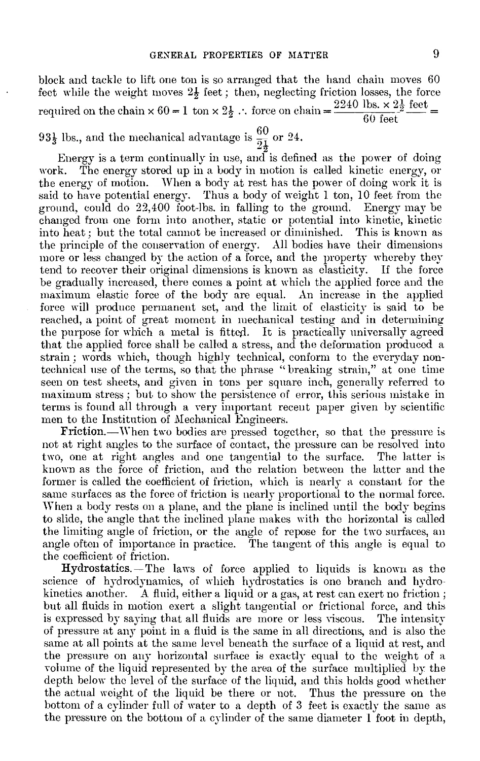
block and tackle to lift one ton is so arranged that the hand chain moves 60
feet while the weight moves 21 feet : then, neglecting friction losses, the force
, 2240 lbs x 24 feet
required on the chain x 60 = 1 ton x 24 force on chain = ! 2 =
H 2 60 feet
60
93^ lbs., and the mechanical advantage is or 24.
. "2. .
Energy is a term continually in use, and is defined as the power of doing
work. The energy stored up in a body in motion is called kinetic energy, or
the energy of motion. When a body at rest has the power of doing work it is
said to have potential energy. Thus a body of weight 1 ton, 10 feet from the
ground, could do 22,400 foot-lhs. in falling to the ground. Energy may he
changed from one form into another, static or potential into kinetic, kinetic
into heat; but the total cannot he increased or diminished. This is known as
the principle of the conservation of energy. All bodies have their dimensions
more or less changed by the action of a force, and the property whereby they
tend to recover their original dimensions is known as elasticity. If the force
he gradually increased, there comes a point at which the applied force and the
maximum elastic force of the body are equal. An increase in the applied
force will produce permanent set, and the limit of elasticity is said to be
reached, a point of great moment in mechanical testing and in determining
the purpose for which a metal is fitted. It is practically universally agreed
that the applied force shall he called a stress, and the deformation produced a
strain ; words which, though highly technical, conform to the everyday non¬
technical use of the terms, so that the phrase “breaking strain,” at one time
seen on test sheets, and given in tons per square inch, generally referred to
maximum stress ; hut to show the persistence of error, this serious mistake in
terms is found all through a very important recent paper given by scientific
men to the Institution of Mechanical Engineers.
Friction.—When two bodies are pressed together, so that the pressure is
not at right angles to the surface of contact, the pressure can be resolved into
two, one at right angles and one tangential to the surface. The latter is
known as the force of friction, and the relation between the latter and the
former is called the coefficient of friction, which is nearly a constant for the
same surfaces as the force of friction is nearly proportional to the normal force.
When a body rests on a plane, and the plane is inclined until the body begins
to slide, the angle that the inclined plane makes with the horizontal is called
the limiting angle of friction, or the angle of repose for the two surfaces, an
angle often of importance in practice. The tangent of this angle is equal to
the coefficient of friction.
Hydrostatics.—The laws of force applied to liquids is known as the
science of hydrodynamics, of which hydrostatics is one branch and hydro¬
kinetics another. A fluid, either a liquid or a gas, at rest can exert no friction ;
but all fluids in motion exert a slight tangential or frictional force, and this
is expressed by saying that all fluids are more or less viscous. The intensity
of pressure at any point in a fluid is the same in all directions, and is also the
same at all points at the same level beneath the surface of a liquid at rest, and
the pressure on any horizontal surface is exactly equal to the weight of a
volume of the liquid represented by the area of the surface multiplied by the
depth below the level of the surface of the liquid, and this holds good whether
the actual weight of the liquid be there or not. Thus the pressure on the
bottom of a cylinder full of water to a depth of 3 feet is exactly the same as
the pressure on the bottom of a cylinder of the same diameter 1 foot in depth,
10
GENERAL FOUNDRY PRACTICE
16
15
13
with a continuation pipe carried 2 feet higher up and the whole filled with
water, a fact taken advantage of in testing certain boilers.
This point requires careful consideration with regard to the weighting of
moulds, and is of interest in understanding the
FI „ usual ingenious pressure gauge for measuring
the pressure of the blast delivered to cupolas.
The instrument is shown in section in fig. 1.
The rubber tube connects the blast main to the
small brass cylinder, so that the pressure of the
14 blast is exerted on the surface of the water in
the cylinder, and forces the water up in the
glass tube till the difference in height between
the two levels balances and therefore produces
12 a pressure equal to the pressure of the blast.
1 cubic inch of water weighs 003612 lb., or
0578 oz.; 12 inches of water in height will
therefore produce a pressure of 12 x ’578, or
10 a 12 inches
— 6‘936 ozs. per square inch, and --, or
6‘936
1 "73 inch in height corresponds to a pressure
of 1 oz. per square inch. In the gauge, how-
8j ever, as the water rises in the glass tube it
falls in the brass cylinder; and as it would be
extremely inconvenient always to have to
measure the difference between the levels, the
diameter of the cylinder is so arranged with
regard to the diameter of the bore of the glass
tube that when the water falls 023 inch in the
cylinder it shall rise 1'5 inches in the gauge
glass, so that a scale of equal parts, each part
1^- inch long, shall represent ozs. per square
inch of blast pressure. For this to follow, the
area of the brass cylinder must be to the area
of the bore of the glass tube as 1'5 to 0’23,
or as 6‘5 to 1, and the diameters of the two
To Blast Main —* as to or as 2-55 to 1. Hence, if the
13 glass tube be of -j\-inch bore, the inside
diameter of the brass cylinder must be T5¥ inch
x 2-55, or practically y-f inch. As another
example of fluid pressure, take the case of a
steel casting, the top surface of which is 5 feet
9 inches long and 18 inches broad, and suppose
that the runner is to be filled to a level of
12 inches above the top of the casting, and
that there are two risers, each 6 inches square.
As there can be no upward pressure where the
risers are, the total upward pressure on the top
part of the mould will be equal to the weight
of molten metal that would be contained in the
space represented by the total area of the top of the casting, less the area of
the risers, and to a depth equal to the head of metal in the runner, or
(69 inches x 18 inches -2x6 inches x 6 inches) x 12 = (1242 - 72) x 12 =
I
Fig. 1.—Pressure Gauge.
GENERAL PROPERTIES OF MATTER
11
14,040 cubic inches of metal; and taking the hot metal roughly at 4 cubic
inches to the lb., then 14,040 cubic inches = 1or 3510 lbs., or 1 ton
11 cwts. and 38 lbs.; and at least this weight, including the weight of the
top part, will he required to hold the top part down.
When a body is immersed in a liquid it displaces its own volume of the
liquid; hence the weight of this liquid, by its tendency to regain its position,
may be considered to he pressing the body upwards; and then its loss in weight,
when immersed in the liquid, is exactly equal to the weight of its own hulk of
the liquid. A familiar example of the case where the body is lighter than
the liquid, and the upward pressure will therefore float it, is found in the case
of cores, which, unless held down, are raised by the liquid metal and float on
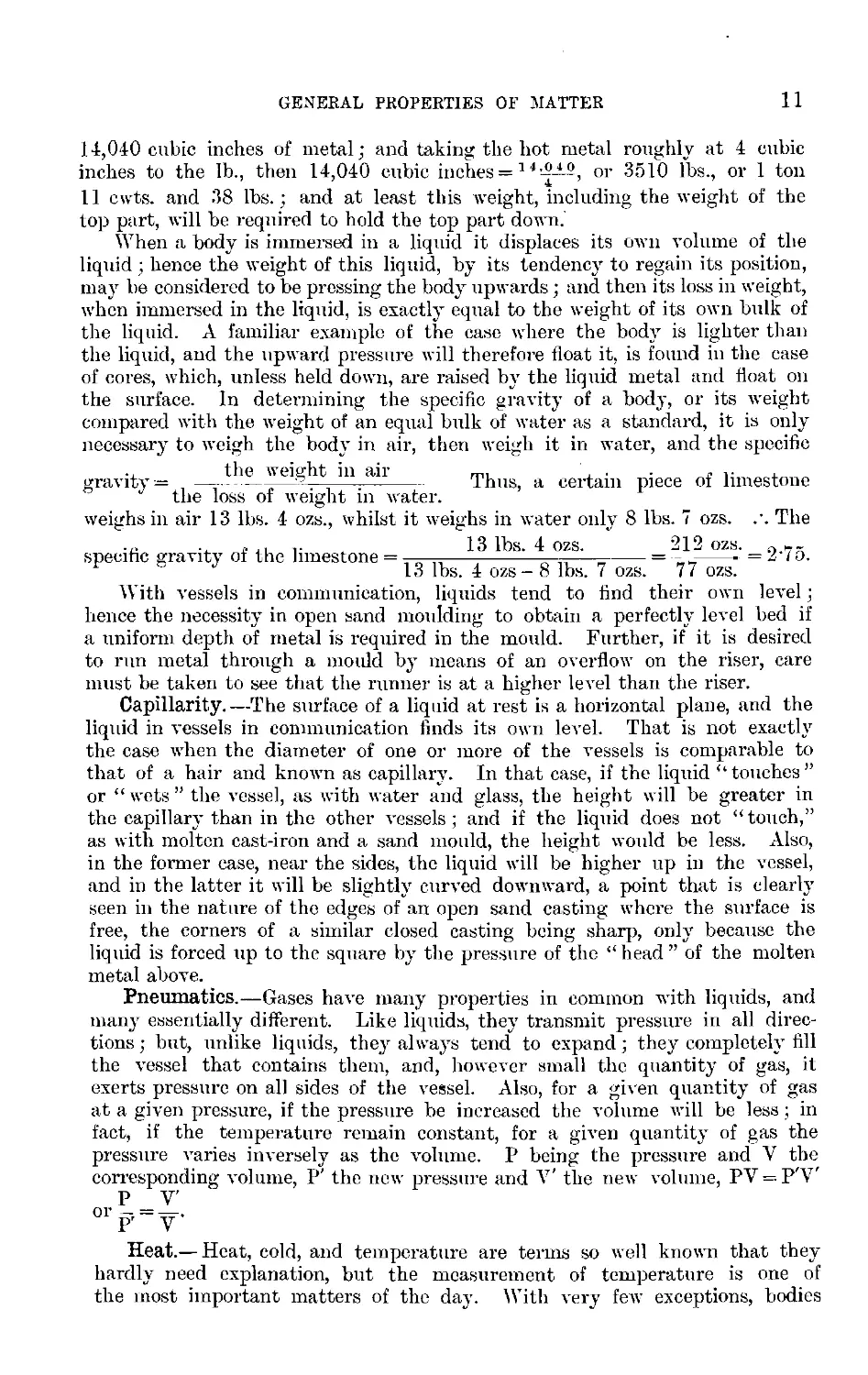
the surface. In determining the specific gravity of a body, or its weight
compared with the weight of an equal hulk of water as a standard, it is only
necessary to weigh the body in air, then weigh it in water, and the specific
gravity = — the^tteight in ail Thus, a certain piece of limestone
the loss of weight in water,
weighs in air 13 lbs. 4 ozs., whilst it weighs in water only 8 lbs. 7 ozs. .'. The
.j. r 13 lbs. 4 ozs. 212 ozs. 0
specific gravity of the limestone = —-^ = - _ =21 o.
F J 13 lbs. 4 ozs - 8 lbs. 7 ozs. 77 ozs.
With vessels in communication, liquids tend to find their own level;
lienee the necessity in open sand moulding to obtain a perfectly level bed if
a uniform depth of metal is required in the mould. Further, if it is desired
to run metal through a mould by means of an overflow on the riser, care
must he taken to see that the runner is at a higher level than the riser.
Capillarity.—The surface of a liquid at rest is a horizontal plane, and the
liquid in vessels in communication finds its own level. That is not exactly
the case when the diameter of one or more of the vessels is comparable to
that of a hair and known as capillary. In that case, if the liquid “touches”
or “ wets ” the vessel, as with water and glass, the height will he greater in
the capillary than in the other vessels; and if the liquid does not “touch,”
as with molten cast-iron and a sand mould, the height would be less. Also,
in the former case, near the sides, the liquid will he higher up in the vessel,
and in the latter it will be slightly curved downward, a point that is clearly
seen in the nature of the edges of an open sand casting where the surface is
free, the corners of a similar closed casting being sharp, only because the
liquid is forced up to the square by the pressure of the “head” of the molten
metal above.
Pneumatics.—Gases have many properties in common with liquids, and
many essentially different. Like liquids, they transmit pressure in all direc¬
tions ; hut, unlike liquids, they always tend to expand; they completely fill
the vessel that contains them, and, however small the quantity of gas, it
exerts pressure on all sides of the vessel. Also, for a given quantity of gas
at a given pressure, if the pressure he increased the volume will he less ; in
fact, if the temperature remain constant, for a given quantity of gas the
pressure varies inversely as the volume. P being the pressure and V the
corresponding volume, P’ the new pressure and V' the new volume, PV = P'V'
P V'
0r P' V'
Heat.— Heat, cold, and temperature are terms so well known that they
hardly need explanation, but the measurement of temperature is one of
the most important matters of the day. With very few exceptions, bodies
12
GENERAL FOUNDRY PRACTICE
expand as their temperature rises and contract as it falls; the expansion of
the liquid metal mercury in a glass vessel is one of the commonest means
used for measuring temperatures below the boiling-point of mercury. Two
fixed points are necessary for the formation of a scale, and these are the melt¬
ing-point of pure ice and the boiling-point of pure water at normal atmos¬
pheric pressure. In the Celsius or Centigrade scale, the former is indicated
by zero, or 0° C., and the latter by 100° C., and the space between is divided
into 100 equal parts; in the Fahrenheit scale, the melting-point of ice cor¬
responds with 32° F. on the scale, and the boiling-point with 212° F., the
intermediate portion being divided into 180 equal parts. The Fahrenheit
degree is therefore or f the size of the Centigrade, and thus :—
(T°C. x f) + 32 = °F. and (T°F. - 32) x § = °C.
For the measuring of temperatures higher than the mercurial thermometer
will hear, instruments called pyrometers are used; but, as this subject is of
such immense importance, a special chapter is devoted to it, and so the
matter will not be further discussed here. In a special table the coefficient
of linear expansion, that is, the expansion of unit length for 1° C. for several
metals is given, and the coefficient of superficial expansion may be taken as
double and the coefficient of cubical expansion as three times the linear. For
if the original length be 1 and the new length 1 +Z, (1 +Z)2 will be the new
area and (1 + Z)2 = 1 4- 21 + 1-. Now, I is always small, say hence Z2
or T^-’o or this again will be negligible, 1 + 2Z will he the area, and hence
the coefficient of superficial expansion is practically double the 1 inear. Similarly
as (1 + Z)3 = 1 + 3Z + 3Z2 + Z8 and 3Z2 + Is are negligible, the coefficient of cubical
expansion is practically three times the linear. Two curious exceptions to the
rule of contraction in volume on cooling wc find in bismuth, which expands on
solidifying; and water, which contracts from 100° C. to 4° C., then slowly
expands till 0° C. is reached, when it freezes with a considerable expansion, and
then below 0° C., as ice, it contracts like an ordinary solid, an important
exception in the economy of nature. Another exceptional case is the alloy
“Invar,” iron alloyed with 36 per cent, of nickel, which contracts and expands
so little with the extremes of temperature found on the surface of the globe
that a wire of it, 24 metres long, may be used in surveys of the surface of
the earth practically without temperature corrections.
A given quantity of gas at constant pressure expands about Trh-j- of its
volume at 0° C. for every degree rise in temperature, and also contracts
jyj for every degree fall in temperature. If this held good, absolutely,
then, at - 273° C. all gases would be reduced to no volume, and this
theoretical temperature is known as the absolute zero, so that absolute
temperatures are found by adding 273 to the number of degrees C. If P, V,
and T be the pressure volume and absolute temperature of a gas, and I’j, Vj,
and Tj a second series of the same quantity of gas, then all relationships
PV P V
between them can be worked out from the equation = -i,--1-
. 1 . .
Quantity of Heat.—The first essential in measuring a quantity is clearly
to define the unit. The scale for the measurement of temperature may be
somewhat arbitrary, but the unit of quantity is quite definite. There are
several units in general use, hut in Britain it is generally that quantity of
heat that would raise 1 lb. of cold water 1° F., which is known as the British
Thermal Unit, or B.T.U.; while the other units are the calorie, that is, the
quantity of heat required to raise 1 gram of water 1° C., and the large or
GENERAL PROPERTIES OF MATTER
13
kilogram calorie, where the kilogram is the unit instead of the gram. The
B.T.U. would raise 1 lh. of mercury about 30° F.; hence the specific heat, or,
more elaborately, the specific thermal capacity of mercury, is that of water,
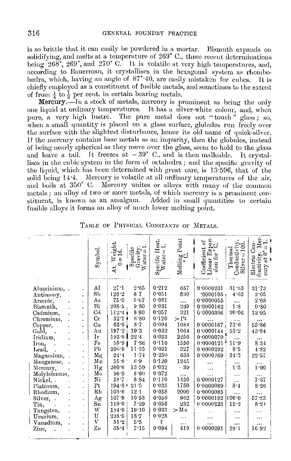
or, more accurately, 0'032, as in the table on p. 316, where it should be noted
that while aluminium stands at 0-212, iron is only 0-11.
Most solid bodies, including practically all the metals, when raised to a
sufficiently high temperture, become liquid ; and this change of state, spoken
of as melting or fusion, must be clearly distinguished from dissolving or a
change from solid to liquid produced by the action of a solvent, as when salt
dissolves in water. If a piece of solid metal, such as lead, be put under the
influence of a source of heat, as over a bunsen burner or in a small furnace, the
metal absorbs heat, and its temperature rises until at a temperature of 327° C.
the metal begins to melt; and if the solid and liquid portion be kept thoroughly
mixed, or sufficient time be given to maintain a heat equilibrium between the
various parts of the metal, the temperature will remain constant at 327° C.
until all the metal has melted, when the temperature will again begin to rise.
It is evident that heat is absorbed at 327° C. without raising the temperature
of the metal, but has been expended in changing the metal from the solid to
the liquid state. The amount of heat so absorbed is known as the latent heat
of fusion, and this fixed point at which the metal changes to liquid is known
as the melting-point. If the metal be allowed to cool by its heat being
radiated into the air, then when it cools to 327° C. again it begins to solidify,
and the temperature remains constant until the whole mass has become solid,
the latent heat gradually given out on solidification balances the radiation
of heat into the air. As very many seem to have rather a hazy idea as to the
length of time during which the temperature remains constant, this will be
about two or three minutes for 4 ozs. of lead in a room at about 15° C.
When all the metal has solidified, its temperature again commences to fall at
a regularly decreasing rate, until the temperature of the surrounding air is
reached. It is obvious that in melting, if the source of heat be pouring heat
into the metal at one point at a rapid rate, and if stirring be not possible, then
the metal may not conduct the heat away quickly enough for all parts of the
mass to keep a fairly uniform temperature ; hence, when such a fixed point is
used as a standard for pyrometric work, it is generally the freezing-point that
is taken as more easy to attain correct conditions. If the metal zinc be used
instead of lead, the melting takes place at 419° C.; and on still further heating,
preventing the oxidation of the metal by a layer of charcoal, the metal will
rise in temperature until it reaches about 920° 0., when it begins to boil, and
remains at this temperature until practically all the metal has been converted
into vapour. The heat absorbed in this case is called the latent heat of
vaporisation, and the fixed point is known as the boiling-point. These are the
two types of fixed point used in the standardisation of industrial pyrometers.
There is a curious phenomenon, known as surfusion, observed in the case of tin
cooling from the liquid state. It will generally cool a few degrees below its
true solidifying point, and yet remain liquid ; but when it does begin to solidify,
the temperature immediately rises to the true freezing-point, and remains
steady until the metal has all become solid.
Examples of the latent heats of fusion, using centigrade degrees, are ice,
79'25; tin, 14'25; bismuth, 12'64; lead, 5'37. Latent heat of vaporisation
of water at 100° C. = 537.
The change of volume in passing from the state of liquid to that of vapour
is very great. Thus the volume of steam at 100° C. to the volume of water
14
GENERAL FOUNDRY PRACTICE
at 4° C. is about 1700 to 1 ; so that, roughly, a cubic inch of water is converted
into a cubic foot of steam. The cause of the violent explosion when a mass
of molten metal runs over even a small volume of water is thus made plain,
even without allowing for the further expansion that takes place as the steam
is superheated. That water becomes an explosive is only in accord with
experience with general explosives which are practically all materials ready
under easy and suitable provocation suddenly to expand enormously.
Nitro-glyceriue is a liquid ready to decompose instantly and form over 1800
times its volume of gas, and most of the actions between water and the metals
have been imitated many times by the authors with explosives. A blasting
gelatine cartridge exploded in shallow water sends up a great fountain of
water, the particles moving with high velocity, the counterpart of the
violent explosion when a stream of molten metal strikes a comparatively small
quantity of water. A similar cartridge exploded in very deep water just
produces a great bubble which comes up to the surface, raises a quiet rounded
mass above the natural level of the water, and then, opening in the middle,
breaks over, the particles moving with comparatively slow velocity; a counter¬
part of this happened when the dry core sand dropped out into the bottom
of the mould for the large roll, the water of combination and the gases formed
at the high temperature most probably came off in a large bubble. A cart¬
ridge exploded in a mass of boiler flue dust just produced as light general
heaving of the surface, the gas seeming to come away at many points. This
seems almost typical of what happens when molten metal is poured in a fine
stream upon a large mass of water in making, say, shot copper or brazing solder
(by braziers called “spelter,” although mercantile zinc is also called spelter);
the steam comes off from many points, and the action is comparatively quiet.
Another fascinating study is the conversion of the various forms of energy
one into the other: heat into work, work into heat or into electricity,
electricity hack to work or to heat; but it may only be stated here that the
relations between these forms have been very accurately measured; thus, to
take one example, one B.T.U. = 778 ft. lbs. of work, or 774 according to some
investigators. An example of potential energy has already been given.
Another, all-important in metallurgy, is potential chemical energy. Carbon
combines with oxygen of the air to form carbon dioxide, and heat is given
out; thus the carbon is thought of as having latent within it the power
to combine chemically with oxygen, provided the action is properly started
by a suitable temperature, and the heat of the reaction keeps up the
necessary temperature and evolves great excess which can he used in the
various metallurgical operations, or converted into other forms of energy.
This is expressed by saying that the carbon has potential chemical energy.
The number of units of heat given out by the complete combustion of
one unit weight of a substance is known as its calorific power; and if all
the heat he supposed to he used in raising the temperature of the products
of combustion and their companion gases .under any given set of conditions,
the temperature to whicli these materials would theoretically be raised is
known as the calorific intensity of the original body under these conditions.
The calorific power of a fuel gives a measure of the quantity of heat to
he obtained from a unit weight of the. fuel, and the calorific intensity an
idea of the temperature or intensity of heat that might be obtained by the
complete combustion of the fuel under certain ideal conditions. For those
who would care to try a few of the calculations, it will he evident, on careful
study, that as the unit of heat is the amount of heat required to raise 1 gram
GENERAL PROPERTIES OF MATTER
15
of water 1° C., and the specific heat of a body measures the amount of heat
required to raise 1 gram of the body 1° C., that ■
„ . . Calorific power,
a on c intensity — severaj weigPt,s 0f products of combustion and
their companion gases x their respective specific heats.
Examples of Calorific Powers.
Hydrogen to water at 0° C.
34,180
Marsh gas (CH4) to C02,
Hydrogen to steam at
and steam at 100° C. .
11,970
100° C. . . .
28,450
Sulphur to S0.2 . .
2,220
Carbon to carbon dioxide .
8,134
Silicon to Si02 . . .
6,420
Carbon to carbon monoxide
2,450
Manganese to MnO . .
1,650
Carbon monoxide to carbon
Phosphorus to P2Ofl . .
5,800
dioxide . . .
2,436
Iron to FeO . . .
1,170
Marsh gas (CH4) to C02,
,, le304 . . .
1,560
and water at 0° C. .
13,400
,, Fe203 . . .
1,750
The calorific powers of hydrogen, carbon, carbon monoxide, and hydro¬
carbons are of value in the study of ordinary fuels, and those of silicon,
manganese, and phosphorus as special fuels of the Bessemer process.
Before leaving the subject of forms of energy, it is interesting to inquire
whence it all comes. Our fuels, natural or prepared, with the possible
exception of natural gas and petroleum, come directly or indirectly from
vegetable matter or its decomposition products. Even the special Bessemer
fuels, silicon, manganese, and phosphorus, have been reduced from their
oxides by the action of the ordinary fuels. Living vegetation has the power,
by the mysterious help of its chlorophyll or green colouring matter, to absorb
the energy of the sun’s ray7s, and to store it up- as potential energy7 by7
changing carbon dioxide and water ultimately, sometimes into cellulose or
woody7 tissue, at others into starch, somewhat in the following manner :—
C02 + H20 = CH20 + 02, that is, carbon dioxide and water produce a material
called an aldehyde, and oxygen is given off again into the air. 6CH20 =
CsH1206, C0HJ2O6 - H,0 = CaH10Os. Six molecules of the aldelryde have
combined to form 1 molecule, and in the organs of the plant dehydration
or a withdrawal of the substance of water takes place, forming (C6H10O5)
woody tissue, starch or other substance according to the way7 in which
the plant has built it up. In any case, here is the energy7 of the sun’s ray7s
stored ; and if as woody tissue, it may7 help the moulder to start his cupola
or other fire, if as starch, its potential energy may7 still be used in the
foundry, for the internal economy of the human being enables him to convert
this energy7 into muscular power, while the fossilised decomposition products
of woody tissue yield the bulk of all his fuels, and whether in the furnace
or in the man the material is oxidised into carbon dioxide and water again.
Thus, C6Hl0O5+120 = 6C02 q-5H20. The gradual change of condition in
the vegetable matter in a freshly7 made cutting of peat may7 be seen in various
stages at the present day from the living mosses through the brown “fog”
to the close-textured, almost black, substance which yields on drying the best
qualities of peat. In other places the vegetable matter, though it has not
necessarily passed through a peaty stage, has, at any rate, reached a more
advanced stage of decomposition by losing water, CH4 and C02, and the
residue is therefore proportionately richer in carbon and poorer in oxygen.
16
GENERAL FOUNDRY PRACTICE
As the oxygen in fuel is already combined, this portion of the fuel is useless
as a source of heat. If, as is generally assumed, this oxygen is combined with
hydrogen, then all the oxygen and one-eighth of its weight of the hydrogen
must be deducted. The hydrogen that remains, being oxidisable, is called the
available hydrogen. Thus the table shown below will give a rough idea of
the value of the fuel, which, as will he seen, increases, for equal weight, the
further the decomposition has proceeded. The following table has been
compiled by taking a rough average by the eye of hundreds of analyses,
omitting the ash and the sulphur, which are so variable, and calculating up to
100 again for comparison by percentages. That the figures tend to round
numbers may seem suspicious, but this circumstance may help to emphasise
the fact that fuels are found of every stage between those given, and they are
merely to act as guides. Thus, for anthracite the most anthracitic type is
chosen; coal may vary from the highest steam coal down to a type ligriitic in
its character, though black in colour, and so on. In the following table the
C.P.s. are calculated on the 8134 C +34180 (H--JO) formula, and the experi¬
mental results are selected from actual determinations of the samples in hand
nearest in composition to the types given in the table:—
Available
Hydrogen.
Calorific Power.
Carbon.
Hydrogen.
Oxygen.
Nitrogen.
By
Calcu¬
lation.
By
Experi¬
ment.
Cellulose (C6H]0O6),
Wood, . . .
Peat, . . .
Lignite or Brown j
Coal,. . j
Coal, . . .
Anthracite, . .
44-4
50
60
70
82
95
6-2
6
6
5
5
8
49-4
43
33
24
12
2
1
1
1
1
trace
0-6
1-9
2-0
3-5
2-7
3610
4-270
5530
6380
7870
8650
3600
8000
8530
Light.—A word must he said about light. White light, such as that from
the sun, is not a simple radiation ; for when passed through a prism and thus
refracted or bent in its course, it is found that different parts of it arc refracted
differently, and thus the white light is seen to be composed of violet, indigo, blue,
green, yellow, orange, and red rays, and by other means rays have been dis¬
covered above the violet and below the visible red. The radiation given out by
a black body as its temperature is raised are, first, heat only while still black
hot, then red rays, through orange to yellow, and, finally, white ; these colours
have for an unknown period been used to judge the temperatures of metals and
furnaces by the unaided eye. The relations between the radiations of different
bodies at different temperatures, the brightness and even the energy of certain
portions of their spectra and like matters, have been studied with increasing
care in recent years, with the result that numerous optical pyrometers have
been devised specially suitable for measuring the highest furnace temperatures.
The discussion of any of these relationships is not within the scope of this
work, so that reference must be made, by those interested, to standard works
of recent date, such as Le Chatelier and Boudouard’s work on High Tempera¬
ture Measurements. Meanwhile, this chapter will have attained its end, if it
has clearly grouped some of the more obviously useful results and indicated
the necessity for further study to those who would know their subject well.
CHAPTER III.
MOULDING SANDS.
Terms.—In foundry parlance, “ sand ” is a term of fairly wide acceptance ;
therefore, before examining types, it may be well to review briefly some of the
more general features. For instance, a handful of any type of moulding sand,
properly moistened, will, after squeezing, cohere, or retain the shape imparted
by the pressure of the hand. Herein lies one of the most important properties
of a moulding sand, namely, that of retaining a desired form. This property
of cohesion may he likened to the plasticity of a fire-clay, a quality largely
determined by the combined water present in the clay. Thus clays which are
more or less pure silicates of alumina chemically combined with water may bo
dried at a moderate heat without losing their property of becoming plastic, for
in this case they lose their uncombined water only, and, if again damped, the
clay will he found to knead well; it may be pressed into various shapes and
still retain the form on removal of the pressure. On the other hand, if the
clay has been heated to a high temperature, the chemically combined water
is driven off, and no amount of added water will restore the original plasticity,
as illustrated in the fact that “burnt ” bricks reduced to powder will not again
serve the purpose of unburnt clay. So, too, with moulding sand; it may be
dried at a moderate heat with no loss of cohesion; hut, if “ burnt,” its plasticity
cannot be afterwards restored by the addition of water.
The presence of alumina and combined water in the analysis of a sand
indicates the amount of clay present, and hence the cohering power, as
the clay acts as a binder. Generally, all moulding sands consist essentially of
silica, with more or less alumina, lime, magnesia, and certain metallic oxides.
Lime and metallic oxides, if in excess, make the sand more or less fusible ;
hence they impair its refractory qualities. Silica increases the refractoriness ;
but when in excess does so at the expense of plasticity. As already noted,
alumina, if present as clay, increases the cohesion ; but here, again, if in excess, an
essential property, that of porosity, is destroyed. Evidently, then, in selecting
a moulding sand, as indeed in all foundry operations, the happy mean must
be secured ; in other words, an effort must be made to obtain the best com¬
bination of dissimilar properties.
The essential requirements in a moulding sand are as follows:—
1. The sand of which the mould is formed must allow the free passage of
air and gases generated at the moment of casting.
2. It must be capable of withstanding a high temperature without fusing.
3. It should he readily removed from the cold casting, to which it should
give a clean and smooth skin.
17 2
18
GENERAL FOUNDRY PRACTICE
4. When rammed into shape, it should he firm and sufficiently compact to
resist the pressure of the liquid metal.
The following example will serve to illustrate these requirements. Fig. 2
sectionally shows the mould for a square block; it is formed in sand, held in
position by an iron frame. Connected with the space A is a cylindrical opening
B, funnel-shaped at the top. Now if A is filled with molten cast-iron by
pouring it down B, the conditions are such that the air filling the space must
escape through the sand; further, the increase in temperature generates a
certain amount of gas which must also find an outlet through the sand.
Supposing the sand was impervious to the passage of these gaseous currents,
then the gases would find a path to freedom by ejecting the fluid metal
through B. From the foregoing it will he evident that the sand in the
vicinity of A will be heated to a high temperature. When considering the
resistance of a sand at these temperatures, a sharp distinction must he drawn
between “burning” and “fusing.” The former, as already noted, represents
a driving off of the combined water, resulting in the sand losing its power of
cohesion. This being so, burnt sand may be readily removed from the faces
of the casting. If, however, a fusion is effected, then the resulting casting
will he extremely hard to clean, for fused sand will be as hard as the easting
itself, and every particle of it will
require chipping off before the cast¬
ing at all resembles its pattern. In
these properties of binding power,
porosity, and infusibility, lie the
primary essentials of a moulding
sand.
In the construction of a mould,
other factors come into play; for
instance, the sand must resist the
abrading action of a stream of fluid
metal, particularly in the case of
ornamental castings; for these the
sand must also he of such a texture as to take and retain the sharp and
delicate details of the pattern. In considering the washing action of the
fluid metal, it will be seen that the nature of the sand should vary according
to the character of the mould. If the surface is flat, a comparatively weak
sand may be used; if, on the other hand, it contains a tine detailed pattern,
a fairly strong one will he required, otherwise the small projections of sand
forming this detail will be carried away by the rush of metal. Also the finer
this detail the closer must he the texture of the sand, for, if too coarse, it
will not enter into the fine interspaces of the pattern; much of the pleasing
effect will thereby he lost, and the resulting castings will he lacking in
sharpness.
These preliminary remarks indicate to some extent the conditions mould¬
ing sands have to meet. Naturally, in practice one kind of sand is not used
for all purposes; but the necessary ehanges are made to adapt it for light
and heavy castings, plain and ornamental work, etc. The terms applied to
various sands indicate the purpose for which they are intended rather than
their particular property. For instance, “dry sand ” refers not to a moisture-
free type, but to sands used in the formation of moulds, which, previous to
casting, are dried in a stove. Green sand relates to moulds cast in the
green or undried condition. In working both green and dry sand, the
MOULDING SANDS
19
sand is rammed around a pattern, and must be sufficiently damp to hold
together; but not wet enough to stick to the pattern, or, in the case of green
work, to generate an excessive amount of steam when casting. A rough but
fairly reliable test of dampness is to squeeze a ball of sand in the hand ; on
releasing the pressure, the sand should retain its shape without adhering to
the hand. Should some of the sand stick to the hand, and the ball present a
rough appearance, it shows the sand is too wet; whilst if the ball readily
crumbles, it indicates sc lack of moisture.
The term “ loam ” applies to a clayey sand worked at about the consist¬
ency of stiff slime. As distinct from green or dry sand work, loam moulding
does not necessarily involve the use of a pattern. In the majority of eases,
loam moulds are built up roughly to the desired form, and finally swept by
means of strickles into the shape required.
“ Core sand ” usually means an open type of sand used in the formation
of cores, and is often represented bv a mixture of loam and sharp sand.
“ Parting sand,” as its name indicates, is used for parting the various divisions
of a mould. Thus in fig. 2 it will have been noted that a joint is formed at
C. In order to prevent the sand of the top half of the moulding-box sticking
to that of the bottom half, a layer of parting sand is spread on the joint C
before ramming the top box. It has already been shown that when sand is
burnt it will not again cohere even when damp. Evidently, then, a layer of
burnt sand serves for separating the various joints of a mould, and thus
constitutes a good parting sand.
In forming a mould, the sand in contact with the pattern is termed the
“facing sand”; that not in contact, but used as a backing and for filling up
the moulding-box, is known as “black” or “floor” sand. The purpose of the
former is to give the casting its desired appearance, such as a good skin ; that
of the latter to complete the mould by supplying the necessary rigidity and
a porous backing for the escape of gases. “ Black sands ” simply represent
the accumulation of used facing sands, and play only a secondary, but none
the less essential, part in the construction of a mould.
The terms “ open,” “ close,” “ weak,” “ strong,” etc., when applied to
sands are used in a physical sense ; thus, “ open ” indicates porosity, and such
a sand is often “ weak.” “ Close ” indicates a diminished porosity, but such a
sand usually binds well, and is therefore “ strong.” “ Sharpness ” indicates a
lack of cohesion, an example being found in river or shore sand, which, when
rammed, will not hold firmly in position.
Types of Moulding Sand.—A consideration of type is necessarily re¬
stricted to the most familiar varieties of moulding sands. Many foundries
are so situated as to have ready access to a local sand, which, whilst not in
general use, may still answer the required purpose. Obviously, black sands
cannot be dealt with ; for the black or floor sand of each foundry is necessarily
characterised by the varieties of facing sand used. Not only is this the case,
but the different sand heaps throughout one foundry may also vary in
composition. A black sand from the floor of a foundry making light eastings
contained: Si02, 78-5 per cent; A1.,03, 4-75 per cent.; Fe203, 6-00 per cent.;
CaO, 030 per cent. As black sand represents the accumulation of used facing
sand, questions naturally arise as to its original source. In starting a new
foundry, the moulding floor is formed by treading in an open variety of red sand,
such as Worksop; or a yellow variety, such as Erith. The desirable qualities
are that the sand shall possess moderate cohesion, be of an “ open ” character, and
not too costly. Not infrequently such a sand may be found in the neighbour¬
20
GENERAL FOUNDRY PRACTICE
hood of the foundry. Turning to facing sands on which the appearance of the
casting depends, it is not always good policy to secure the nearest at hand.
Facing sands are usually designated by the locality in which tljey are
found; thus, familiar ones arc—Belfast and Mansfield red sand; Erith
yellow sand ; Clyde rock sand, etc. The properties of any sand are largely
influenced by its chemical composition, and it will he well to note briefly the
more salient features. Free silica gives high heat-resisting properties to the
sand, hut it has no cohesive power. The latter can be overcome by the
addition of a binding material, commonly clay water. An examination of
many types of sand shows the contents of silica to vary somewhat after the
following order, but this cannot be given as a general ruie :—
Type of Casting.
Light Brass.
Light
Cast-iron.
Medium
Cast-iron.
Heavy
Cast-iron.
Steel.
Content of Silica,
per cent.
78 to 80
per cent,
80 to 82
per cent.
82 to 84
per cent.
84 to S8
per cent.
90 to 95
We have also seen that clay acts as a binder, hut when in excess it destroys
porosity. The latter feature is due to the fact that clay consists of extremely
fine particles ; and hence sands high in alumina (if present as raw clay) have
their pores clogged with this fine plastic material, and thus form a compact
and impervious mass; such a sand would, at high temperatures, bake hard
like clay. For light work the alumina may run up to 10 per cent, or
thereabouts.
The actual impurities of a sand are the alkalies—soda and potash—
which are usually present in insignificant quantities only; lime, which may
be present as an oxide or carbonate; and organic matter, roots, etc., seldom
exceeding 0'75 per cent., usually much lowrer, and when below 1 per cent,
organic matter is not injurious. As will be subsequently shown, organic sub¬
stances are frequently added to moulding sands for certain purposes.
Viewed broadly, the essential chemical features of moulding sands are found
in the amount of free silica, as representing refractoriness; and the amount
of silicate of alumina present as raw clay, representing binding quality.
Small amounts of oxide of iron present, and forming a rough coating on the
otherwise smooth particles of silica or quartz, materially affect the binding
quality of the sand, so that such sand binds well with a minimum of clay.
Oxide of iron, however, increases the fusibility of the sand, and excess must
be avoided. Chemically, other constituents are injurious so far as they
render the material too easily fusible, or give rise to the generation of
excessive amounts of gas at high temperatures.
The analyses given on the following page are those of typical sands from
various districts.
It will be noted that, chemically, the types of red sand given show com¬
paratively small variations, a feature which emphasises the fact that a sand
must be judged from a twofold point of view, viz., chemical and physical.
The physical condition of a sand is, in the present state of knowledge, a
matter to he judged by the moulder’s experience. Instinctively he associates
certain features with certain properties, and the greater his experience with
various sands the more reliable will his judgment be.
MOULDING SANDS
21
In testing dampness, a rough method has been indicated. Following the
same plan, if a ball of the sand is squeezed in the hand certain features are
noted. Thus, the slight force required to break the ball into halves will
indicate to some extent its lifting power, or coherence. The appearance of a
broken surface will indicate the compactness of the sand when rammed and
the facilities it will offer to the passage of gases. This may be readily tested
by taking a sample of open and one of close sand, and comparing the crystalline
arrangement, which is sufficiently large to be noted by the naked eye. The
lifting power may also be estimated by squeezing a sprig in the ball and
suspending it by the free end.
Mansfield
Red Sand.
Kidderminster
Red Sand.
S. Staffs
Red Sand.
; Building
Chips,
1 Glasgow.
Clyde
Rock
Sand.
Glenboig
Silica
Sand.
Silica
Sand.
Si02). .
83*40
' 83-69
85-52
92-75
85-32
88-9
95-22
F^Oa, .
7-47
6'26
5-47
2-56
7-10
7-43
2-66
A1203, .
3-14
4*10
3-72
2-50
3*74
4-17
1-04
CaO,. .
0-20 1
0-66
0-74
0 27
0-64
1-02
0-29
MgO, .
0-62
0-51
0-52
trace
0-31
0-86
trace
These tests, although rough and ready, are sufficient for the purpose; and
the young moulder will, by the application of similar simple tests, gain much
of value. The final test of a sand is naturally the character it imparts to
castings, but, as here experiment is costly, a method of judging suitability
before use is desirable. The best, and, in fact, the only method is that
indicated; judgment founded on experience.
Mr C. Scott1 has, however, devised a system of differential sieving in
which the grade of sand is classed according to its fineness (state of division).
1 Iron Age, Nov. 1, 1900.
CHAPTER IV.
FACING SANDS AND FACINGS.
It lias already been shown that the material of which a mould is constructed
must permit of the free passage of air and of gases generated at the moment
of easting. It must also be firm and sufficiently compact to withstand the
pressure of the liquid metal. Further, it must bear a high temperature
without fusing, and permit of ready removal from the casting to which it
should impart a clean and smooth skin.
Without entering into the details of moulding, it has also been shown that
the sand forming a mould may be divided into two portions : that forming the
face of the mould, known as facing sand ; and that forming the backing, known
as the floor or black sand.
In the selection and use of facing sand, the moulder is guided by his
experience, by the quality of sand available, and by the kind of work in hand.
As facing sands vary very considerably, the following notes are intended as
a guide only, in which form they will serve a better purpose than would bo
gained by detailing a series of mixtures.
Green Sand Facings for Grey Iron.—The majority of facing sands are
mechanically milled and sieved, apparatus for this purpose being illustrated
in Chapter V. The more intricate the detail of the pattern, the finer should
be the grade of facing sand used; for light ornamental work such sand is
milled very fine. Light work, but of plain surface, requires a weak sand;
black sand will answer here better than a milled facing. Hence a stove-grate
moulder in making a register front, part of which has detailed ornament, and
part plain surface, only uses facing sand on the figured part, floor sand being
used on the plain surface. Both facing and floor sand are mixed with coal
dust in the proportion of one shovelful to each riddle of sand. This applies
to work of comparatively thin section and large surface, such as is common in
stove grate foundries. Coal dust is used in all green sand facings for iron,
its object being to assist in peeling the sand from the castings. This object
is achieved by the fact that the heat developed by casting converts some
portion of the coal dust into gas, thereby preventing the molten metal reach¬
ing into the pores of the sand, and so retarding fusion of the sand or the
binding of its particles into a compact mass. The example of a register front
gives a key to the use of facing sands, namely, the more delicate the detail of
the pattern the stronger must be the sand; and, conversely, the plainer the
surface the more open should be the sand. Thus, for fine ornamental work,
for wheels with fine teeth, and for all cases where small isolated bodies of
sand have to resist the wash of a stream of metal, new sand is used. This is
22
FACING SANDS AND FACINGS
mixed with coal dust in the proportion indicated, and well milled. Less
detailed work, such as large fluting on columns, is faced with a mixture of
equal quantities of floor and new sand mixed with coal dust, and milled as
before. The new sand may be any of the red or yellow sands, as Belfast,
Mansfield, Staffordshire, or Erith, according to the locality. Mixtures of new
sands are occasionally employed, but no decided advantage is gained ; by far
the better plan in green sand work is the use of one type of new sand only,
diluting it to the required extent by means of floor sand. In jobbing iron
foundries all new sand is rarely used for facing purposes, floor sand being
added in amounts varying, according to the character of the work, from 25 to
75 per cent. In this class of work the amount of coal dust also varies, for
both coal dust and strength of facing have a decisive effect on the appearance
of the casting. Thus the teeth of heavy spur wheels require a stronger facing
than the rim, arms, or boss. Generally the amount of coal dust varies from
' one part to six parts of sand up to one part of dust to twenty of sand. With¬
out stating a definite rule, it may be taken that the heavier the casting, the
higher the proportion of coal dust permissible in the sand. Facings for
castings over three inches in thickness are usually mixed in the ratio of one
part of coal dust to eight or nine parts of sand. If too much coal dust is
present in a facing sand for light work, the castings will present a glazed and
shiny surface ; whilst an excess in sands for heavy work results in the castings
being pitted ( “ pock-marked ” ) and full of veins. The ideal colour for an
iron casting as it leaves the sand should be a dull grey, and this is very
largely determined by the coal dust present.
Dry Sand Facings for Iron.—Any sand which, in the rammed condition,
will permit of drying into a compact and coherent but porous mass, will answer
the purpose of a dry sand mixture. Many green sand facings dry into friable
masses; hence their unsuitability. Various mixtures, partaking somewhat of
the nature of loam, are employed; thus a close sand may be mixed with an
open one and tempered with clay water to give the necessary bond. Mansfield,
Staffordshire, or Erith may individually be used as dry sand facings, being, for
this purpose, mixed with horse-dung and milled. Rock sand, of the type
given in Chapter III., is exceptionally good for all classes of dry sand work.
This sand, without admixture, dries into a hard, but very porous, mass ; and
castings from it have a clear skin, and are remarkably free from scabs.
Where weak sands have to be used for dry sand work, the requisite bond
may be added in the form of clay, flour, or core gum. A clay-water pot is
common to all foundries, and is a tank or tub in which clay is soaked in water ;
the consistency of the resulting “ clay water ” ranges from that of cream to
that of treacle, according to requirements. A weak sand is tempered with
this clay water, which gives consistency and body to the sand; such addition
will often convert a weak sand into a passable one for dry sand work.
Green Facing Sand for Brass.—Although the alloys designated as brass
are cast at a much lower temperature than grey iron, there is nevertheless a
decisive action between the fluid alloy and the sand. Certain of the copper-
tin alloys, especially phosphor bronze, possess in a very distinct manner the
property of “ searching.” So much is this the case, that if two castings, one
of grey iron and the other of phosphor bronze, are poured into similar moulds,
the grey iron one will come out with the better skin, and this in spite of the
fact that there may be a difference of some 300° C. in favour of the bronze.
Another aspect of the same thing may be found by taking lead as an example.
This metal, poured into a mould at full red heat, will result in a casting of
24
GENERAL FOUNDRY PRACTICE
terribly rough skin and full of veins. Lead at a red heat represents a easting
temperature of from 500° to 800° C., which is comparatively low for sand.
None the less, the sand will adhere tenaciously to the casting, and in difficulty
of removal will resemble semi-fused sand. Therefore resistance to heat
alone does not always determine the suitability of a moulding sand, for it
must also offer resistance to the penetration of a thinly fluid metal or alloy.
All alloys containing tin possess this property of searching into the pores of
the mould and binding the particles of sand together. Although searching
does not necessarily indicate fusing, it will readily be seen that it has the
same effect, for in either case the same difficulty is experienced in trimming
the casting. This searching action imposes the following conditions:—
1. Coal dust cannot be used with green facing sands.
2. Sands for brass must be finer and drier than sands for grey iron.
3. The moulds must be rammed harder than similar ones for iron.
In certain cases, coal dust or plumbago may be mixed with facing sand;
but, as a general rule, such admixture results in veined or pock-marked
eastings. Owing to the searching action, the sand must be in a fine state of
division, and it must be rammed comparatively hard. Hard ramming neces¬
sarily involves a drier sand than one submitted to normal ramming.
The sands actually used are the finest qualities of Belfast, Mansfield, or
Birmingham cemetery. Floor or bench sand is frequently renewed by addi¬
tions of new sand, but it never reaches the black colour characteristic of an
iron-moulder’s floor sand. In grain it is comparatively fine, and this floor or
bench sand alone is sufficient for facing plain work, such as valve bodies.
With ornamental work new milled sand is used. Naturally between the
extremes of plain and detailed ornament various intermediate stages are
formed, and, as the pattern approaches either extreme, old, new, or mixtures
of old and now are used.
Dry Sand Facing for Brass.—As with iron, the authors have found no .
better facing than rock sand, which has answered admirably on all grades of
castings, varying in weight from 1 cwt. to 18 tons. Mansfield or Stafford¬
shire also gives good results, but not with the same regularity. Very heavy
castings may be made in moulds faced with steel moulding “ compo,” but the
appearance of the casting is not equal to those made in rock sand.
Loam.—A combination of dissimilar properties is essential to a good
loam mixture. This material is worked at about the consistency of stiff
slime, and an essential property is that it must admit of drying without
undergoing too great a contraction. It must also dry hard, and, in this
condition, admit of carding {i.e. rubbing) without being friable; and yet be
porous, in order that the molten metal will lie kindly on it. This involves
that a stream of metal shall not cut the surface of the mould, which it may
do if the loam is too compact. Mixtures of loam are infinite in number, each
foundry foreman having his own particular one. A mixture of close sand,
opened by the addition of sharp sand and brought to the required consistency
by means of clay water, is exceedingly serviceable. Staffordshire, Erith, or
Mansfield, opened by means of cow-hair or horse-dnng mixed with water or
clay water, make up into good loams. Finishing loam is simply a finer grade
of the loam used for backing, whilst building loam represents unmilled floor
sand mixed with water into a stiff sludge.
Green Sand Facings for Steel.—Only light castings are made in green
sand, and an ordinarj7 mixture as for iron is used. Any of the red sands
answer well, provided a suitable facing is dusted on.
FACING SANDS AND FACINGS
25
Dry Sand Facings for Steel.—The bulk of steel moulding represents dry
sand work. Sands employed must, owing to the high casting temperature,
be of a very refractory nature ; and to meet this, silica sands are largely
employed. The analysis of a silica sand given on p. 20 shows 95 per cent.
Si02, but such a sand is deficient in binding power. To obtain the requisite
cohesion, clay is added, as in loam. Various types of composition, technically
termed “ compo,” are in use, and for the most part consist of old crucibles,
fire-bricks, or similar- “burnt” refractory material ground to the required
fineness, and mixed with various binding agents. As a rule, it is better to
purchase compo from a supply house than to grind and mix it in the foundry.
Where home mixing is conducted, silica sands and clay may form the basis of
the compo. Ground burnt refractory materials have the advantage that they
reduce the contractibility of the mixture, and their use is not costly. The
following mixtures give an idea as to the ingredients employed1:—
For Castings
of 20-50 mm.
For Castings
over 50 mm. j
A.
B.
C.
D.
Old facing sand, . . .
4
12
1
Old crucibles, ....
1
10
Fire-brick
1
5
White clay
1
f
3
2
Coke dust, ....
i
1
Silica sand, ....
5
10 1
Graphite, ....
Litres.
2
Litres.
Litres.
Litres. |
Core Sands.—Owing to the fact that the majority of cores arc entirely
surrounded by metal, the sand of which they are made has more stringent
conditions to meet than facing sands, which form the external part of a
casting. Certain cores approach an S shape, and, except at the two ex¬
tremities, are entirely surrounded by metal. For the present, three conditions
should be noted : (1) the core has to stand much handling in fixing in the
mould ; (2) the gases generated on casting must find an egress through the
core and not through the metal ; and (3) the core has to be removed from
the casting.
All cores, before entering a mould, are dried, and in this condition must
be hard enough to permit handling, and porous enough to admit the free
escape of gases. Yet the sand must not be burnt or converted into a com¬
pact mass by the heat, for, if so, it will he exceedingly difficult to remove it
from the casting. Some of these conditions belong to core-making. Turning
to core sands, and looking at them from a purely chemical point of view, one
high in silica should yield the best results. To such a sand the necessary
bond may be added by means of flour, rosin, core gum, etc. In other words,
an ideal core sand is one in which silica is given bond by the addition of an
organic substance which produces a firm core capable of withstanding high
temperatures and resisting the penetrating action of fluid metal. Such a core
is friable in the cold casting, and therefore readily removed. If bond is given
to silica by clayey matter (hydrated silicate of alumina), then the metal bakes
1 Stahl und Eisen, vol. xxiv., No. 16.
26
GENERAL FOUNDRY PRACTICE
the cores hard (the clayey matter becoming hard burnt clay), and therefore
renders their removal a difficulty. 7
For ordinary small cores, red or yellow sands opened by means of horse-
dung, and hardened by core gum or rosin, are chiefly used. Small intricate
cores, surrounded by heavy masses of metal, should be made of rock sand, to
which a small quantity of dung and rosin has been added. Larger cores
are made from dry sand mixtures, or dry loam to which borse-dung or sawdust
and core gum are added.
It will have been noted that various substances are used in conjunction
with moulding or core sand. Thus the function of coal dust has been indi¬
cated ; for heavy and coarse work, coal dust may be replaced by coke dust.
Hair, horse-dung, and sawdust act as “openers,” i.e. they increase the porosity
of the sand or loam. Dung is dried and sieved for small cores, hut simply
riddled for dry sand or loam. The undigested hay of the dung, the hair or the
sawdust to some extent carbonise on drying, thereby leaving tiny interstices
in the sand. Core gum is a glutinous product derived from potatoes or other
starchy substance. Core gum, gluten, and kindred substances act as binders,
without increasing the fusibility of the sand. A hard surface imparted by
ramming is fatal to sand, for fluid metal will not lie on it; hut a hard surface
resulting from the presence of core gum or rosin does not necessarily
represent an impervious one, and fluid metal will usually lie quietly on it.
Heat, instead of fusing, tends to loosen a sand made hard in this manner. In
the ease of green sand facing for grey iron, the presence of coal dust was
indicated as tending to peel the sand from the eastings. To assist this peel¬
ing, the surfaces -of all moulds are lightly coated with either a refractory
material, or one which, by the formation of a thin stratum of gas, retards
searching by the fluid metal.
These facings in green sand work are dusted on the mould through a calico
bag or stocking-foot, care being taken to distribute an even coating. The
surplus is blown out by means of bellows, otherwise a collection of loose
facing would act in the same way as dirt, namely, leave holes in the casting.
Instead of blowing out, the facing may be sleeked, that is, smoothed on the
surface of the mould by means of a trowel, or brushed by moans of a camel-
hair brush, if its surface permits. Should the surface be inaccessible to
sleeking tools, then, after dusting on the facing, the pattern may be returned
to its place and lightly tapped to ensure uniform contact. Such a method,
termed “ printing,” ensures a very smooth easting, hut can only he applied to
facings which do not stick to the pattern.
In dry sand and loam work, facings are applied as a liquid, being painted
on the mould either before or after drying. In the latter case, the mould is
painted-whilst hot.
All facings are in a state of fine powder, and, chemically, may be divided
into either carbonaceous or siliceous materials. The former includes flour,
pease-meal, charcoal, coal, and plumbago; whilst the latter includes silica
flour, talc, and soapstone [both varieties are acid magnesium silicate, H2Mg3
(Si02)4, or H20,3Mg0,4Si02], and silicates sold under trade names. “ Plum¬
bago ” in foundry terminology is applied to the mineral graphite. “ Black¬
ings ” represent mixtures of charcoal dust, coal dust, and fire-clay; or plum¬
bago and fire-clay. Many of the white facings sold are silicates of magnesia,
as, for example, floured talc. As facings, these silicates are very serviceable.
The property of adhesion is of some moment in considering the use of a
facing, and this property is to some extent determined by the nature of the
FACING SANDS AND FACINGS
27
fluid entering the mould. Thus, with light green sand work in iron, charcoal
answers well, and the powder lightly dusted on will give a casting which
“ peels ” readily. For heavier work, plumbago blacking, and plumbago are
desirable, and in turn they effectually peel the sand from the casting. Char¬
coal, plumbago, or blacking mixture are entirely unsuitable for green sand
work in brass. If simply dusted on, these facings ball up in front of the
stream of metal, thus forming dross, which, in the cold casting, is equal to so
much dirt. These facings, if used on green sand moulds, must be carefully
sleeked on; and, when this is followed, the skin of the castings is of a more or
less black colour, which, from a brassfounder’s point of view, is a disadvantage.
For light brass castings, flour or pease-meal is decidedly preferable; these
facings adhere most tenaciously to the sand, and, if lightly dusted on to sand
of fine texture, very smooth castings of true brass colour result. For heavy
green sand work in brass, white facings such as terra flake (floured silicate of
magnesia) offers advantages greater than plumbago in that the same surface
or skin is obtained without a loss of the true brass colour. Carbon facings
are used to advantage on moulds for brass, if painted on in a liquid form and
the mould subsequently skin- or wholly dried. Thus, so far as dry sand
work is concerned, a facing suitable for iron will answer for brass; but such is
not the case with green sand work.
All facings applied as a liquid come under the term “ blacking,” which, as
noted, may represent mixtures of two or more of the following: charcoal,
coal, coke, plumbago, and clay. This mixture in a floured condition is mixed
with water to the required consistency, and applied to the surface of the
mould by means of a “swab,” a camel-hair brush being used for the finer
details. Blackings arc less costly than unadulterated plumbago. The latter
facing, however, always yields the best results for either iron or brass. Wet
blackings are sometimes sleeked, and in this case a light sprinkling of dry
plumbago on the wet blacking before sleeking will ensure an effective skin.
Unslecked blackings answer well, provided swab or brush marks do not show ;
and to such blackings, salt, sal ammoniac, or core gum is added in order to make
them set hard. Facings for steel moulds are either nearly pure silica or
carbon, or mixtures of these. Green sand moulds are dusted with floured
silica, whilst dry moulds are painted with plumbago. In some cases floured
“ compo ” is also added to the facing, as in the following :—
Compo, ..... 1 pail
Plumbago, . . . . . 2| lbs.
Silica flour, ..... 3 lbs.
Both compo and silica should pass through a 60-sievc, and the three ingredients
are mixed in water to the required consistency. Other washes for steel moulds
are :—
Plumbago, . .
. . 6J lbs.
15J lbs.
Silica flour, . .
• • io „
3 „
Sal ammoniac,. .
- • i „
Water, . .
. . 1 pail
2| pails.
Plumbago and water yield excellent results on work of medium weight.
CHAPTER V.
FOUNDRY TOOLS.
In this and the following two chapters moulding and foundry tools are
discussed in so far as they can be separated from actual foundry operations.
Commencing with a moulder’s tools, these will necessarily vary with the class
of work on which he is engaged, and for the greater part represent home-made
articles. Trowels, cleaners, sleekers, and gate knives are usually purchased
as required; but the remaining tools are made by the moulder, who either
casts them to shape or works them up from rod. In this case brass rod is
usually employed, whilst cast tools may be of brass, iron, or steel. Brass
tools answer admirably for brass or iron moulding; hut in steel moulding,
owing to the gritty nature of the compo, they are very rapidly worn
away, and for this work steel or cast-iron tools are more serviceable.
In passing, the authors may mention, as a matter of interest, that they
have been .watching the life of a trowel made from a 36 per cent, nickel-
steel, an alloy that takes a high polish, does not readily corrode, resists
abrasion well, and in other than foundry circles is known as “ Invar.”
In ironfounding it stood better than any one previously tested, but, used
regularly in a steel foundry on Sheffield compo moulds, it seems to he wear¬
ing more rapidly than an ordinary hardened and tempered steel one also in
regular use. '
Turning to the actual tools used, several steel cleaners are shown in
fig. 3 ; they represent tools absolutely essential in all jobbing work. The
lowest tool in this illustration represents a vent wire used for artificially
opening the sand and forming passages for the escape of mould gases. In
size, all tools vary according to the class of work. Small tools for a light
iron or brass moulder are shown in fig. 4. These represent spoon tools,
bead and button smoothers, and small trowels. Fig. 5 reproduces a few
“ sleekers,” that is, tools used for sleeking or smoothing the face of a mould.
These tools are used in places inaccessible to cleaner or trowel. The latter,
the most indispensable tool in the moulder’s kit, is shown in fig. 6. Trowels
vary from 1 to 2 inches in width, from 5 to 8 inches in length, and are
provided with a ball-form wooden handle. In working the trowel this hall
handle fits the palm of the hand, and the index finger is pressed on to the
blade. It may be well to note that the so-called Scotch trowel is provided
with an iron handle only, usually \ inch square and 3 inches long, but the
authors in this case prefer the English form of wooden handle. Turning
again to fig. 6, three “gate knives” will be noted. These have usually a
heart shape and an oblong blade. Two handy forms of “gate cutters” will he
23
FOUNDRY TOOLS
Fig. 3.—Moulder’s Steel Cleaners.
Fig. 4.—Moulder’s Small Tools.
30
GENERAL FOUNDRY PRACTICE
recognised in the teaspoon minus a nose, and in the strip of hrass immediately
to its left. A moulder’s kit should contain various sizes of camel-hair brushes,
one of which will be noticed in fig. 6. These are used for brushing dry
Fig. 6.—Moulder's Tools—Miscellaneous.
plumbago on the face of a mould or for applying liquid blacking. Two forms
of core pins will also be noticed, and these are used for picking up false cores
in light work. One of these core pins is formed from steel wire and the other
FOUNDRY TOOLS
31
made by fixing two sewing needles into a tab of wood. The
flat plate in the foreground is used for stopping off diaper
patterns, gratings, trellis work, and the like, when castings
of a different form to that of the pattern are required, and
where space will not permit of the introduction of a straight
edge. Amongst the miscellaneous items of fig. 6 will be
noticed a water brush and lifting screws for drawing patterns.
One with a T head is for wooden patterns, and is formed
by casting the head on an ordinar}7 wood screw. The spirit
level is essential in many foundry operations, but chief!}7 on
the sand bed for open cast work. A handy form of tool for
working on the sand bed is shown near the spirit level. It
consists of two tapering heads of different size, and is used for
making channels. Thus, after a core grid has been marked
out on the bed, channels are formed by pressing this tool to the
required depth along the marked lines. To the foregoing tools
should be added calipers for internal and external diameters,
and large compasses or trammels for marking out. The latter
may be replaced by a length of string and a nail driven into
a block of wood, but trammels are preferable.
The tools indicated are, or should be, the moulder’s own
property. Tools supplied by the shop comprise dry brushes,
bellows, shovels, riddles, sieves, hand lamps, rammers, etc.
Floor sand, before use, is passed through a i-inch-mesh riddle;
facing sand for large work is passed through a |--inch-mesh
riddle; whilst, for fine work, an ^-inch sieve is used. Parting
sand is passed through a sieve of JgAnch mesh. Nothing need
be said of the shovel, further than that it should bo treated and
used as a tool. Shovels are maintained in good condition by
cleaning them every night, and then daubing them with oil,
which is burnt off on the following morning. A clean and
bright shovel means sweet and light work.
Rammers are of various patterns, but are roughly of two
classes, known as “pegging” and “flat” rammers respectively,
the former being used for the preliminary and the latter for the
A
B
Fm. 7.—Rammers.
C
32
GENERAL FOUNDRY PRACTICE
final ramming. A in fig. 7 shows an ordinary pegging rammer formed by
casting a head on to an iron rod J inch in diameter by 14 inches long. The
head is about 2 inches in length by 1 inch in width, tapering down to
about £ inch at the nose. Owing to the short length of shaft, this is
known as a bench moulder’s rammer. Double-ended pegging rammers
may be used, the two ends being of different size. The purpose of the
wedge-shaped pegging rammer is to tuck or press the sand into the inter¬
stices of the patterns. Flat rammers, such as B in fig. 7, are employed
for the final ramming. The flat end of this rammer is about 2| inches
in diameter by 1 inch in thickness, with a shaft of similar length to
that of the pegging rammer. A combined pegging and flat rammer for
Fio. 9.—Sand Mill.
bench work is shown at C in fig. 7. This is turned from hard wood, and the
ramming faces may, in certain cases, be covered with a strip of gutta percha.
Floor rammers only differ from bench rammers in point of size. Thus' the
head of a pegging rammer is about 3 inches in length by 1J inch in width,
and tapers down to about £ inch at the nose. Flat rammers are about 4
inches in diameter, and the shafts of both are about 4 feet in length. Pit
rammers represent a heavier type of flat rammer, and have usually wooden
shafts fixed into a wrought-iron socket which is cast into the rammer head. In
the case of large work, pits and the like, ramming is laborious, and an effort to
lessen work in this direction is found in the introduction of rammers actuated
by compressed air. These rammers are not extensively used in this country,
FOUNDRY TOOLS
33
Fig. 10.—Rotary Sand Sifter.
but they undoubtedly have a future, and the authors have found them
exceedingly valuable when ramming up pits. Various styles of pneumatic
rammers are on the market; a '
typical one is shown in fig. 8.
Pegging, or flat heads, may be
introduced, and the length of
stroke varied to suit special
cases. As a rule, the number
of strokes per minute can be
varied from 200 to 400, and
the weight of the rammer
ranges from 14 to 18 lbs.
This practically comprises
all the sand-handling tools.
Turning to the sand-preparing
tools, these are mainly grinding
mills and mechanical sifters.
The most common form of
grinding apparatus is the
ordinary pan mill, slightly
modified to suit foundry re¬
quirements. Fig. 9 shows a
typical mill of this description.
Mills fitted with two plain
rollers tend to cake the sand, which) after delivery, requires riddling to break
it up again. For a universal mill the authors prefer a plain and a cogged
roller, as in this case the latter neutralises the caking action of the former.
Such a mill is suitable for either sand or loam, and water may be
led into the pan l>y means of a hose. Mills fitted with plain
rollers may be used for grinding coal dust; but when this is
attempted in the foundry, a ball mill is more convenient. It is,
however, far better for the foundry to purchase coal dust ready
for use, as in the end
this is more economi¬
cal than grinding it.
Mills with solid rollers
are also used for break¬
ing up brass foundry
slags, preparatory to
washing, for the re-
■: covery of metal from
r ; the slag,
j Mechanical sand
: sifters may be formed
of a rectangular riddle
suspended by slings
and given a to-and-
fro motion by means
of a cam actuating
the frame. A more
familiar type of sifter is a rotating one, shown in fig. 10. Sifters of this
description may be attached to a mixing trough in which a revolving worm
3
Fig. 11.—Battle Creek Sand Screen.
34
GENERAL FOUNDRY PRACTICE
mixes the material, breaks up lumps, and discharges into the rotating sieve.
The sifted sand is collected in a bin below the sifter. In capacity these sifters
vary from 30 to 50 cubic feet of sand per hour. They may be made portable
by attaching them to a waggon; they are then operated by a motor, with
flexible leads. Another type of portable sifter is the Battle Creek sand screen,
fig. 11, which is operated by steam or compressed air. Reference to the
illustration will readily show the action of this sifter. Portable screens are
of advantage in dealing quickly with large quantities of floor sand in that
the sand has not to be moved from the position in which it is required. Fixed
sifters are most suitable for facing sand.
A type of mixer which screens and tempers facing or core sand ready for
use is shown in fig. 12. This is known as the Standard sand mixer, and each
machine is provided with a water tank and graduated glass to measure the
water sprayed on the sand. The unrnixed sand is charged into the mixer
through a screen, water turned on, the charge effectually mixed and moistened
by the revolving paddles, and then discharged into a barrow.
Fig. 12.—Standard Sand Mixer.
Where no mechanical facilities exist for treating facing sand, it is sieved by
hand, coal dust is added and well mixed by repeated turning over. Water is
added until the sand is sufficiently damp, the heap is then well “trodden,” and
at each step the treader gives a twisting movement with heel and foot which
imparts toughness or grip to the sand. The toughening effect of this twisting
movement of the feet may be accentuated by hand in the following way :—
A sieveful of sand is placed on a board, and the operator, on his knees, rubs
it to and fro with a round toughening stick, a slight twisting movement being
imparted to each rub.
The remaining tools are essentially shop ones, and are used as accessories
to the mould, or in moulding operations, on the one hand ; and, on the other,
as accessories for handling molten metal. Excluding moulding-boxes and
handling facilities, the following general tools demand notice here :—
Any mould, previous to casting, must be so fastened down that its top
cannot be lifted by the pressure of the fluid metal, and one of the most
familiar methods of achieving this end is by piling weights on the top. These
weights sometimes take the form of pig-iron or heavy scrap, a method both
FOUNDRY TOOLS
35
unwieldy and inadvisable. It is far better to employ weights of suitable size,
which permit of ready handling and correctly serve their purpose. The
authors have found the two forms, shown in fig. 13, very serviceable for small
boxes. This form gives a flat bearing across the mould, effectually preventing
bursts when shallow top parts are used and the two recesses permit of handling
without trapping the lingers. A form of weight suitable for snap-flask work
is shown in fig. 14. The central cross, which is cored out, allows a fair
latitude for placing'runners, and at the same time, practically the whole
surface of sand is covered. This is essential in snap-flask work, for, when
casting, the moulds are not supported by a box; hence, weights of various
sizes are required to suit the flasks used. A form of crane weight, with
lifting hook cast in, is shown in fig. 15. Weights of this type are employed
on floor work, and vary from 5 cwts. up to 1 ton. These weights are exceed¬
ingly useful, and every foundry engaged in heavy work will find them of value.
As a general rule, the authors do not advocate weighting down; but where
this practice is followed, quite apart from neatness or convenience, it is better
to have weights, the sum of which can be readily reckoned, than to place on a
miscellaneous pile of pig-iron, moulding-boxos, etc., the total weight of which
can only be guessed at.
Where possible, moulding-boxes should be cramped ; this may be effected
by means of the box pins, or by cramps overlapping the full width of the box,
and tightened by a wedge. Cramps are of cast- or wrought-iron, with toes of
Fig. 14.—Snap Flask Weight. Fig. 15.—Crane Weight.
sufficient length to permit of a good grip on the box, whilst wedges are of
wood or wrought-iron. The latter are safer, and are usually about 3 inches
long by 1 inch broad, and taper from f inch downwards. The less packing
employed the better; hence a stock of cramps of varying size is essential.
Adjustable cramps have been devised, and one of these is shown in fig. 16.
Fig. 17 shows various methods of cramping, and it will be noted that in one
case cramps are passed over the full width of the box ; in another, the box
pin has a cotter hole, through which a small wedge or cotter is passed ; and
in the last a nut and holt pass through the box snugs parallel with the pin.
Cramps may also be wedged on to the snugs or handles. Properly tightened
cramps are effective up to rupture, but it should be remembered that a box of
large surface may spring; hence, if the box is of light section and largo size, it
36
GENERAL FOUNDRY PRACTICE
should be weighted in the centre in addition to cramping on the edges, in
order to prevent straining. In light work, particularly small brass work, the
moulds, after completion, arc turned on end to cast.
This involves the use of binding screws, which may
be of wood, having large butterfly nuts; or of iron
rod, with ordinary hexagon nuts. The usual style is
shown in fig. 18. Flat boards or plates are also
required, of a similar size to that of the boxes. A
pair of plates, one on the bottom and one on the top
of the mould, drawn firmly together by a pair of
screws, will permit the mould to be turned on end for
casting. In certain cases two or more moulds may
be placed within one set of screws for casting. Apart
from this, flat boards or plates have a wide use in
bench or tub moulding. In floor moulding, similar
boards are used for “ turning over,” or as bottom
boards, when the bottom half of the moulding-box is
not fitted with cross-bars. Large bottom boards of
this character are formed of 1-inch timber, well stayed
with cross battens. When nailing the planks on to
the battens, a space of \ inch or thereabouts is left
between each plank. If the planks butt one against
the other, a series of holes are drilled through, the
object of these spaces or holes being to permit of the
escape of gases from the sand. Turning boards .are
similarly built up, except that no provision for venting
is required, and the face should be planed. Lifters,
or “gaggers,” form a common, but most valuable,
accessory to moulding operations, and are used for the
purpose of strengthening the sand of a mould when
the cross-bars of the moulding-box are insufficient for
this purpose. They may be formed by bending an
iron rod, so that one end will rest on the cross-bar of
a moulding-box and the other carry or strengthen the sand. Fig. 19 shows a
cast- and a wrought-iron lifter. As the sizes naturally vary with requirements,
Fig. 16.—Adjustable
Cramp.
AJL
Fig. 17.-
H3 ' IJJI LELB
-Methods of Cramping
a large stock of assorted sizes should be kept in order to meet any particular
need. In addition to lifters, iron rods and sprigs are largely used for strengthen-
FOUNDRY TOOLS
37
ing moulds or cores. Sprigs vary in length up to 6 inches; whilst all sizes of
rod are required, the variety used being a cheap wrought-iron known as nail rod.
In some cases, lifters are replaced by pieces of wood, cut to size, and jammed in
the top part; when used in this fashion the pieces of wood are termed “chocks.”
Another type of miscellaneous tool is found in a portable iire-basket.
These are, as often as not, formed by punching holes in a pail for a small fire
or in a discarded oil-drum for a larger fire.
A more convenient type of fire-basket is
formed by making a cage of iron rod sup¬
ported by a framework of cast-iron, as illus¬
trated in Chapter VIII. Fire-baskets, or
“ devils,” are used for skin-drying sand moulds
or for stiffening loam.
Trestles are chiefly used for running up Fig. 19.—Lifters,
cores, as illustrated in Chapter IX. Fig. 20
shows a typical trestle for this purpose. It is made in open sand, the
two feet being cast on at a later operation. Small trestles may be used on
a core bench, and for this purpose bar-iron bent to the required form, with
the two ends let into suitable feet, offers a light, yet stable trestle. Turning
to accessories for dealing with molten metal, these for the most part include
carrying tongs, shanks, and ladles. Metals or alloys melted in crucibles are,
as a rule, cast from the crucible by means of either teeming or carrying tongs.
With teeming tongs the caster
grips the centre of the crucible
and supports some of the weight
by resting the tong shanks
on his knee during pouring.
In this way the caster stands
in line with the moulding-box.
Brass and German silver are
often poured by means of the
pulling-out tongs, and then the
caster stands in front of the
crucible, the lip of which is
rested on the moulding-box.
In other cases the load may be
supported by resting the tong
shanks on a weight laid across
the moulding-box. When the
contents of the crucible exceed
50 lbs., carrying tongs are
employed, and of these the
Fig. 20.—Trestle. three types shown in fig. 21
are the most representative.
A and B grip the pot by bringing together the two handles of the single
end, whilst the double end is used for turning up the crucible. Both
these types are familiar in crucible steel foundries; whilst C, which has
a solid ring, is chiefly used in brass foundries. In the case of brass
foundries, crucibles range in capacity from 20 to 400 lbs., and naturally
the diameter of the ring C is made to fit the particular size of crucible
employed. This diameter is such that the ring wedges at about the
centre of a new crucible; but as the latter lessens in diameter by use,
38
GENERAL FOUNDRY PRACTICE
wedges are employed to prevent the ring coming too high. The crucible is
placed in the ring of the carrying tongs, which are then lifted, and, just before
the centre is reached, a wedge inserted, which tightens on further lifting.
A hand shank for catching cast-iron from a cupola spout is shown in fig.
22. In capacity these shanks range up to 60 lbs. For larger capacities the
shanks have double ends, as shown in fig. 23. The sling shown on the shank
of fig. 24 is intended for crane lifting; but a shank of this description may be
Fig. 22.—Hand Shank.
Fig. 23.—Shank.
mounted on a carriage, as shown in fig. 25. In this case the shank is filled at
the cupola, and drawn along the track to the moulding floors, where the metal
is distributed to the moulders, each man filling his hand shank as required.
A small type of crane ladle is shown in fig. 26. This type of ladle is useful
up to a capacity of 10 cwts.; but for amounts exceeding this, every foundry
ladle should he fitted with gearing, otherwise unsteady pouring results, and
accidents are likely to occur. When the catch of fig. 26 is released, the stability
of the ladle is dependent on the man at the pouring end; and should he by
chance lose command, the ladle will invert. The authors have seen disasters
FOUNDRY TOOLS
39
due to this cause, and their personal experience is such that they would not
employ an ungeared crane ladle which has a capacity of more than 10 cwts.
Fig. 27 shows a geared ladle which, in capacity, may vary from 10 cwts.
to 15 tons. The pouring lips shown are now fitted on most of the newer type
40 GENERAL FOUNDRY PRACTICE
ladles, and give a much cleaner cast. These ladles are specially applicable to
cast-iron, brass, or bronze, or to surface-blown Bessemer steel. Open-hearth
steel is not so fluid as surface-blown steel, and will not, as a rule, admit of
pouring over the lip of a ladle; hence bottom pouring ladles are employed for
this type of steel. A typical bottom-casting ladle, fitted with swan neek and
stopper, is shown in fig. 28.
The shells of all ladles or shanks are built up of mild steel, and internally
lined with sand, loam, or compo. Loam is the best lining for iron or brass
ladles, and such a lining will give a comparatively long life. Hand shanks are
lined with red sand, and inverted over a fire to dry. When daubing up a
ladle, if the shell is not drilled with small vent holes, strings are laid in the
lining and withdrawn when it stiffens. The whole is thoroughly dried by
placing a fire on the bottom or suspending a fire-basket from bars laid across
the top. After drying, any cracks are filled in, the surface blackwashed and
again dried. The lining must he bone-dry before any metal enters the ladle,
as even a mere trace of moisture will cause the fluid metal to bubble, and only
a comparatively small volume of steam is required in order completely to
eject the contents of tlie ladle. As a case in point, the authors have a vivid
FOUNDRY TOOLS
41
recollection of tapping 25 cwts. of gun-metal into a ladle, which, owing to
carelessness on the part of the ladle man, had only been partially dried. A
brilliant pyrotechnic display followed, and the metal was subsequently recovered
in the form of fine shot scattered over a large area. Steel-casting ladles, if of
large size, are lined with fire-brick ; smaller ones are daubed with compo, and
when of bottom-casting type, the stopper is carefully fitted to the nozzle after
drying the lining. In exceptional eases, large ladles for cast-iron are lined
with fire-brick; but*for normal work and capacities up to 5 tons, a sand or
loam lining is sufficient. In brass-foundry practice the authors have found
a lining of rock sand very efficient in ladles up to 10 tons capacity. The
capacity of any ladle is readily determined as follows :—
Owing to the taper from top to bottom being uniform, the diameter at the
centre will represent the mean diameter of the ladle. Diameter squared and
multiplied by 0*7854, will give the superficial area. This area multiplied by
the depth of the ladle will give the volume or cubic capacity. This is,
practically, the method of finding the volume of a casting. Assuming the
ladle to have a mean diameter of 30 inches, and a depth of 54 inches, its
cubic capacity will be : —
Area of Section. x Depth. = Volume.
(30 ins. x 30 ins. x -7854) x 54 ins. = 706-86 x 54 = 38170A4 cub. ins.
For the moment, we may take it for granted that: —
The volume of the ladle multiplied by one of these factors will give the
weight of metal held by the ladle. Selecting cast-iron, this weight will he :—
When estimating the capacity of any ladle, the depth should be taken from
the level of the metal and not from the actual top.
A cubic inch of cast-iron weighs .
Or a cubic inch of steel weighs .
And a cubic inch of gun-metal weighs.
0-26 lb.
0-28 „
0-30 „
38170 x ,26 = 9924,2 lbs., or, roughly, 88 cwts.
CHAPTER VI.
MOULDIN'G-BOXES.
A moulding-box is essentially a frame for carrying sand ; its chief requirement
is therefore rigidity. Such a frame may he readily constructed of timber, a
method largely followed in the United States, but only to a limited extent in this
country, and then merely as a temporary expedient. Cast-iron frames, or
“boxes,” are not only more permanent, but, practically, also as cheap ; they arc
readily made in the foundry, and offer all that is required in the way of rigidity.
The simplest form of a complete moulding-box is represented by a top and
a bottom part (in American terminology a “ cope ” and a “ drag ”). One of these
parts is fitted with pins, which
correspond with guiding holes in
the other part, thus maintaining
the two parts always in a relative
position to each other. In form,
boxes may be square, rectangular,
round, or, in certain special cases,
designed to follow the contour of
the castings to he moulded in them.
The sizes vary greatly, and may he
taken to range from a tiny “jeweller’s
box,” three inches square up to any
extent within the lifting facilities of
the foundry in which they are
worked.
Fig. 29 gives the outlines of a
simple familiar type of bench mould¬
ing box. In this case the lifting handles are of wrought-iron, bent to shape, and
cast in the centre of the opposite sides. Apart from the greater convenience of
these handles, it is evident that a series of boxes, placed one on top of another,
can be slung in a crane. With snug bandies, which are often placed on this
type of box, lifting by means of crane slings is impossible. Lifting snugs
are usually |-ineh thick by 3 inches wide by 2 inches deep, and are cast in
the centres of the opposite ends. Lifting handles are formed of |-inch iron, bent
over, as shown in fig. 29, while the ends projecting into the bosses on the side of
the box are roughened in order that the metal shall take a better grip. The
method of mouldingsuch a box, and leaving the two ends of a handle projecting, so
that they may he surrounded by fluid metal, will be readily seen in later chapters.
Pin snugs are, in form, similar to lifting snugs. They are cast on the
42
MOULDING-BOXES
43
A
sides of each box part, and placed about J inch below the joint. In each box,
comprising top and bottom part, one set of snugs is drilled to take a box pin,
and the other set is drilled to pass over the pin. As a rule, pins are fixed in
the bottom part of each box. Whilst the purpose of a pin is to serve as a
guide in maintaining the two parts of the box always in the same relative position,
the style of pins varies greatly. In some cases they simply represent lengths of
rod iron rivotted into the snugs of the bottom part. This method is had, inas¬
much as a rivetted pin always works loose in course of time, and its chief function
that of a true guide is thereby lost. A better
form of pin is shown in A, fig. 30, in which it will p
be noted the end is reduced and tapped to take a
nut. The best form of pin is that of B, fig. 30, the
difference lying in the projecting shoulder giving
a truer bearing than that of A. The snugs of the
bottom part are recessed to take this shoulder A B C
and drilled for the screwed part. A nut readily Fig. 30.—Moulding-Box Pins,
tightens the pin, which, with the shoulder hearing,
renders it a perfectly upright and true guide. The snugs of the top part are
drilled to slide easily, but yet without play, over the pins of the bottom parts.
With this type of box, members of each size should be interchangeable ; that is,
any top part should fit any bottom part of the series, a feature of special moment
in plate and machine moulding. This uniformity is effected by drilling the
whole of the snugs to one jig or template. Joint faces should be planed, in
order that the top parts may lie evenly on the bottom parts without rocking.
The two pins, A and B, of fig. 30, have cotter holes cut through them.
This allows the box, when finally closed, to be cottered down, as shown at C
in fig. 30. Obviously, the two parts of a box wedged together in this manner
will not readily separate when stressed,
as in the case when pouring metal
into a mould ; hence cottcring, in many
cases, dispenses with the necessity of
weighting down the top part.
A two-part box offers only one joint,
and certain castings may require two or
three joints in order to mould them
successfully. A useful type of box for
this purpose is shown in fig. 31 ; each
part has two sets of pin snugs, and, by
the arrangement shown, any number
of parts can enter into a whole box.
Intermediate parts between top and
bottom are known as “ mid parts.”
Usually bench moulding-boxes are made with straight sides, but this need
not necessarily be the case in boxes which have much handling to stand, as in
machine-moulding, where cross-bars are not always desirable, the sides of each
part may be of ^ section. Each part of the box, therefore, has its greatest
width in the centre, which results, to some extent, in the sand being wedged
into V grooves, and thereby producing a more rigid mould.
The dimensions of bench moulding-boxes are naturally determined by the
class of work to be made in them ; common sizes are 12 inches by 12 inches,
12 inches by 14 inches, 14 inches by 16 inches, etc. The depth averages
44
GENERAL FOUNDRY PRACTICE
about 4 inches each part, but certain patterns may require an 8-inch bottom
and a 4-inch top, or vice versa. Hence, if the patterns are not of a standard
character, boxes are temporarily fixed together to serve as a complete box.
$
A
A
Y T
A
£
A
A
T
T
A
T
T
Floor moulding-boxes range from about 16 inches by 18 inches upwards, and
the first feature of note lies in the introduction of cross-bars for the purpose
of staying the sand. A typical floor box worked by hand is shown in fig. 32.
MOULDING-BOXES
45
l’ins are the same as in smaller boxes, hut of heavier build. As the
bottom part may have to ho lifted, hut not turned over, the cross-bars are
placed flatwise, in order to hold the sand in position when the part is lifted
vertically. On the other hand, the top part has to be lifted off from the
pattern and turned over ; hence, in order to carry the sand and stand handling,
the cross-bars must come down nearly to the joint. They are therefore
placed edgewise. Lifting handles may he of east-iron, forming part and parcel
of the box. Such handles, however, are extremely liable to break off, and
better ones are formed by casting pieces of bar-iron into the sides of the box,
the section round the handle being strengthened by a boss. Bar-iron of from
1 inch to 1J inch diameter, and projecting from the boss about 5 inches, is
most suitable.
Boxes for hand-working are cast of as light a section as is consistent with
rigidity, the usual thickness being f-inch for the sides and ^-inch for the
cross-bars. Actually, the sides will taper from f-inch to ^-inch, and the
cross-bars from f-inch to f-inch, the latter terminating in a rounded feather
edge. Weight is of moment when all operations arc by hand, as the authors
have realised by painful experience. Boxes handled by cranes come under
another category, for, as a rule, they have much severer conditions to meet.
Not only are the casting stres'ses greater, lont the boxes, in course of handling,
may also be subjected to sudden shock
or jar; hence the section of crane boxes
is always heavier than that demanded by
rigidity alone.
Apart from the heavier section, other
features of note are found in the replace¬
ment of the earlier type of lifting handles
by swivels, the ends of which are enlarged
by a collar to prevent the slings from
slipping. As with handles, these swivels
are cast in the box, the side of the box
being strengthened, as in fig. 35, where
the swivels enter. A specially strong typo Fig. 33.—Heavy Type of Box.
of box construction is shown in fig. 33, in
which a now form of lifting handle will be noted. These handles vary,
according to the weight of the box, from 1 to 2 inches in diameter; they
are forged to shape and cast in the side of the box, being strengthened
in the locality of the handle, as in preceding cases. A similar handle
will he noted on the box shown in fig. 34, and it will also be noted that
pin snugs are replaced by a flange running the full length of the joint.
This box shows a departure from the flat type hitherto considered ; it is
intended for moulding columns, liners, and articles of similar form. The end
is flanged similarly to the joint, and recessed in the centre. Thus, if a short
casting is required from a long pattern, during moulding, the pattern may
project through the ends of the box, which permits of the use of a short box
suitable to the casting, and unaffected by the pattern. On the other hand,
two or more lengths may be bolted together, end on, by means of the flanges
and holt holes shown. This permits of some elasticity, and dispenses with the
necessity of stocking long boxes which may only occasionally be required.
The joint flanges serve for the box pins, and also for bolting the two parts
together when finally closed. Another typo of flanged box is shown in fig. 35,
which has no cross-bars, and is lifted by means of swivels. This, again,
46
GENERAL FOUNDRY PRACTICE
represents an “elastic” type of box in that any number of parts may be fitted
together, a grid or grating being bolted 011 to the lowest one, and the upper¬
most one surmounted by an ordinary flat top part. The holes shown in the
sides of the box serve for the introduction of wrought-iron cross-bars, which
may he arranged to suit the pattern, and be wedged firmly into position.
Much ingenuity is exercised in jobbing foundries in fitting up stock boxes
to meet the requirements of a varying class of work. The object of a jobbing
founder is to make each box serve as wide a range of patterns as possible, in
order to keep the stock within reasonable limits. One aspect of this is found
in the built-up box. Thus, if the four plates forming fig. 35 are cast separately
instead of as a whole, and the corners fitted with flanges for bolting together,
then, by the introduction of two shorter end plates, a narrower box is obtained.
Obviously, a scries of pairs of plates,
differing in length and depth, will
offer any amount of latitude in size.
An ordinary top part may be formed
by bolting four plates together for
the frame, and bolting the necessary
eross-bars to opposite sides of the
frame. Bottom parts may be formed
in a similar manner, or, in certain
cases, they may be replaced by grids,
used as in the case of fig. 35.
This method of bolting up has a
Fig. 35.—Flanged Box. distinct value, but is only applicable
to the conditions cited, that is, to
the jobbing founder, whoso work is constantly changing in character.
Standard patterns are, or should be, made in standard boxes; in this ease
the keynote of standardisation is found in conformity of box to pattern.
Circular eastings, such as wheels, should bo made in round boxes, large
enough to take the patterns, but small enough to dispense with unnecessary
ramming. The object of the founder engaged on repetition work, or work of
standard character, is to produce a mould with the minimum amount of
MOULDING-BOXES
47
labour. The cost of boxes is in this case of less moment than in the case
of the jobbing founder, for the simple reason that they are continually
in use, and the economy effected in moulding more than covers the cost of
boxes.
Owing to the fact that, practically, any form of moulding-box can be
made, it is impossible to enumerate separately each particular shape in use.
The following leading examples will, however, serve to show the purpose and
design of special boxes, and they may be amplified by the reader to suit any
particular case. Thus, fig. 36 shows an ordinary flat box, with an enlarged
end for taking the head of a stanchion or other similar article. It also
illustrates a method of cramping the two half-boxes together by means of
hooks and eyes. In certain eases, as with columns or stanchions having
central projections, a box with an enlarged centre may be used. Fig. 37
shows a flat box, with a cut-out central portion, such as is used for moulding
flat register fronts. The economy in this case is readily apparent; for if, in
Fig. 36.—Box with Enlarged Ends.
moulding, the whole of the centre had to be rammed up, the day’s output
would be seriously curtailed. In fig. 37 the cross-bars come down to within
| inch of the joint, and the depth is usually about 4 inches for each part. In
the ease of a curved front, as, for example, the familiar tiled stove, the top
part of the moulding-box follows the contour of the pattern, as in fig. 38, a
portion of the centre being cut out, as in the preceding case. This form of
box gives in the top part an equal depth of sand, resulting in the minimum
amount of ramming, and, owing to the'curvature of the bars, entirely dispens¬
ing with lifters or other auxiliary aids for lifting.
In certain special cases, moulding-boxes are hinged, and the top, instead of
being lifted off, is simply turned up and propped in order to draw the pattern
and finish the mould. The hinges usually take the form of a hall and socket.
Evidently such a lift will not be vertical—a matter of little moment in flat
work, but of importance in other classes of work.
With some classes of work it may be necessary to make the middle part
of a moulding-box serve the purpose of a core-iron, and, in certain cases, this
method will permit of the use of a green sand core, and the one core-iron can
48
GENERAL FOUNDRY PRACTICE
be made to serve any number of cores. Without entering into details of
moulding, it is somewhat difficult to describe the use of a mid part as a core¬
iron ; however, the sketches shown in fig. 39 will illustrate one application of
/~°\ /Y\
W
Fig. 37.—Flat Register Front Box.
this principle. This box was designed to make a series of castings which
were practically square pipes about 3 feet 6 inches in length, one end of the
pipe being bent through an angle of about 45°. For reasons which need not
now be given, the bent portion of the pipe had to be made uppermost.
MOULDING-BOXES
49
the usual method of moulding with a dry sand core, fixing and maintaining
the core in position by means of chaplets would he a matter of some difficulty.
The box, as shown, removes this difficulty, incidentally reduces risk of wasters,
and increases the output by 75 per cent. An examination of the details of
the box will show that the middle part or core-iron consists of two pieces
\ — *
Fig. 39.—Special Box.
bolted together. The raised end of this middle part has the same width as
the bottom part, and fits the two side pins shown on the bottom part. The
actual core-iron enters into the bottom part, the end pins of which serve as
guides. When the middle part is in position, the top part, which is
provided with side handles, fits the four pins of the bottom part, and its upper
surface is level with the raised end of the middle part. When the box is
cramped, the middle part cannot possibly move ; and, on cleaning the castings,
4
50
GENERAL FOUNDRY PRACTICE
sand is first removed from the vicinity of the bolt heads, which may then be
loosened by means of a T-headed key. On removal of the holts, the halves of
the middle part may be withdrawn from opposite ends of the casting, and
bolted together again for further use.
Before leaving moulding-boxes, some reference is essential to an important
class known as “ Snap-Flasks.” Such a flask is shown in fig. 40. It is built
of wood, fitted with adjustable pins, hinged to open outwards, and provided
with locking apparatus, as shown. In reality, a snap-flask is a moulding-box
so constructed that on completion of the mould it can be removed, leaving
the mould ready for pouring. Usually these flasks are rectangular in form,
with flat joints; but, as with moulding-boxes, there is no limit to shape or
contour; round flasks, and flasks having irregular joints, are used when the
character of the pattern warrants such use.
CHAPTER VII.
HANDLING MATERIAL IN THE FOUNDRY.
From preceding chapters it is fairly obvious that a large amount of material
has to be handled in the foundry, and, naturally, the better the facilities
provided for this purpose the greater the output.
Taking first a light foundry, in which floor boxes are worked by hand, the
best distributing facilities are found in narrow gauge tramways which admit
of wide application. Thus they servo the purpose of distributing molten
metal, moulding-boxes, and facing sand, the removal of castings, and so
forth. This involves the foundry floor being divided into sections in direct
connection with the cupolas, trimming shop, sand and box storage. The
cupola hoists are, in turn, connected with the coke and iron stores. Naturally,
the track arrangement will vary with the class of
foundry, but, in general, it should be so laid out as
to minimise hand carriage and to divide the floor
into sections, each of which may be kept to separate
classes of work. Turn-tables, which may work
either on rollers or ball-bearings, are provided at
eacli junction. Light flat-top trucks are most
suitable for pig-iron and boxes, whilst tipping-skips
are used for sand and coke. Molten metal is dis¬
tributed by means of a bogie ladle, the moulders
collecting from it in hand shan'ks.
In certain classes of work, an overhead track,
working in conjunction with an outside floor track,
is of advantage. By means of the yard track,
material is carried just inside the foundry and then Fig. 41.—Sheave Carriage,
handled by the overhead runway. In primitive
form, such a track is found in many foundries, and is represented by a pair
of sheaves running on either side of a beam. From the sheave a hook is sus¬
pended on which a chain block and tackle are hung. The beam of I-section
is fixed on the roof girders, and the travelling distance of the sheaves is
represented by the space between two girders. A type of carriage for such
a beam is shown in fig. 41. A development of this system consists in
suspending a track below the roof girders, thereby enabling a much larger
portion of the floor to be covered, and'also serving the purpose of distributing
metal from the cupolas. A continuous line is thus provided ; this system has
met with wide adoption in agricultural-implement and stove-gratc foundries of
America.. A suitable roof arrangement is shown in fig. 42. A further
51
52
GENERAL FOUNDRY PRACTICE
improvement consists in attaching a pneumatic hoist to the carriage, which is
connected to an air reservoir by flexible piping.
There is, however, a limit to the applicability of overhead tracks ; for whilst
they possess many advantages in a foundry handling uniform, but not heavy,
loads, they are certainly not advisable in cases where the loads vary between
wide extremes, as in the ordinary jobbing or engineering foundry. Here
cranes are essential. Viewed from a purely foundry point of view, a crane
should be quick in action, always under perfect control, and give an absolutely
steady lift. They may be operated by hand, steam, hydraulic, or electric
power, and vary in capacity from 10 cwts. to 50 tons. Internal foundry
cranes are confined to tlic jib and overhead travelling type. Locomotive
cranes are, in certain cases, used for handling heavy castings, boxes, and molten
metal, but these cases are extremely limited.
Taken generally, an overhead traveller is most serviceable for foundry work,
and it may be operated by hand, steam, or electricity, or be driven by means
of a shaft or rope drive. Steam may have advantages in certain cases, as, for
instance, in an outside travelling crane ; but, in a foundry, steam travellers arc
always a nuisance. Hand travelling cranes are also objectionable, and are
certainly not desirable when the capacity exceeds three tons. Viewed from
its best side, a hand-power crane will take eight men fifteen minutes to lift a
load of fifteen tons fifteen feet high. From a practical point of view, a five-ton
hand traveller will require three men to operate it, and, when loaded, will take
a considerable time to travel, a point of special importance in casting, for
HANDLING MATERIAL IN THE FOUNDRY
53
molten metal should be handled quickly. One case within the authors’
experience is that of a five-ton traveller, operated by four men, taking twenty
minutes to distribute five tons of molten metal; whereas, under the same
circumstances, a modern crane operated by one man would do the same work
in eight minutes.
Therefore, apart from initial or operating costs, a vital point with all
foundry cranes is that of convenience, and, if largely used, the cranes must
actively respond to all demands. This response is obtained in the shaft-
driven traveller operated by a rope drive. In this the slow and heavy drive
of the shaft is replaced by a quick running rope, the crane being actuated
from a cage by means of open and crossed belts. The introduction of the
transmission of electric power has yielded a type of foundry crane exceedingly
satisfactory from the two-fold point of view of use and operating cost. A
modern electrically operated crane is capable of quick and steady work.
Hoisting or lowering can be performed with an absolute absence of jerkiness,
which is an essential feature in either drawing a pattern or closing a mould.
The authors have found cranes like that shown in fig. 43, and manufactured
by Messrs. Broadbent & Sons of Huddersfield, to be extremely serviceable in
foundry work. This crane is of the four-motor type, has a, maximum capacity
of 20 tons, and is provided with an auxiliary 5-ton hoist. The working speeds
are as follows :—
Motion.
Main hoist (20 tons),
Auxiliary hoist (5 tons),
Longitudinal travel, .
Cross travel, . .
Feet per
1 B.H.P. of |
Speed of
Rating of
Minute.
Motor. 1
Motor.
Motor.
8
’ 15
500
30 mills.
30
15
500
30 ,,
200
15
500
30 „
100
5
500
30 ,,
Lighter loads are lifted and moved at quicker speeds without change of
gear. The maximum capacity of a travelling crane should be such as amply'
to cover the heaviest work made under it; but in the majority of cases much
of the work will, in comparison with the maximum, be of a light character.
Hence, any traveller exceeding 20 tons total capacity should be provided with
an auxiliary hoist in order to cater more efficiently for the lighter work.
Whether this combination will effectually supply all requirements depends on
the number of moulders working in the bay traversed by the crane. Often in
closing a large mould the traveller may be tied up for several hours, and this
will, of course, retard the progress of work on other parts of the floor. Diffi¬
culties of this character may be overcome by having two. travellers running on
the one set of rails. However, the authors prefer supplementing the over¬
head traveller by means of jib cranes fixed to the wall columns. An ideal
arrangement is a foundry equipped with one traveller running the full length
of each bay and capable of handling the heaviest loads dealt with ; while to
facilitate routine work, jib cranes are arranged below the traveller to cover
practically the greater part of the moulding floor; these, by providing for
all the lighter lifts, contribute largely to continuous work. Jib cranes also
serve the purpose, when required, of connecting different bays of a foundry,
as by their means loads may be passed from one traveller to another. This
is a better plan than lowering the load on to a truck in one bay and running
54
GENERAL FOUNDRY PRACTICE
it through into the other bay in order to come within reach of the second
traveller. The motive power for these cranes may be hand, electric, or
hydraulic, the last being most suitable. The authors have found hydraulic
cranes, such as those shown in figs. 44 and 45, manufactured by Messrs-
Glenfield it Kennedy, of high service in the direction indicated. Fig. 44
gives the details of a 5-ton hydraulic crane by this firm. This type of
crane takes up very little floor space, the pillar being carried from one of the
shop columns, and the jib placed at a sufficient height to suit the class of work
HANDLING MATERIAL IN THE FOUNDRY
55
being made. The lifting cylinder is shown bolted to the front of a column.
The burden chain has one end fixed to the cylinder, then passes over the
various pulleys 011 the ram head and cylinder cover up to the guide pulleys on
the jib and along to the hook block, the other end of the chain being fixed at
the point of the jib. Turning or slewing is also effected by means of hydraulic
power. For this purpose there are two cylinders, one for turning in either
direction. One of these cylinders is shown bolted to the side of the column, and
the rams in this instance are inverted, working towards the floor. One end of
the slewing chain is fixed to the cylinder, then passes over the pulley on the
ram head and cylinder cover. The other end is secured to the slewing drum
shown round the mast above the bottom pivot bracket. Racking out and in
of the load is in this crane effected by hand power. The bogie runs 011 four
rollers along the jib, and the bogie frame carries two guide pulleys for the
burden chain. The hook block consists of heavy cheek blocks to overcome
the weight of the chain when lowering empty. Ball-bearings are arranged
under the neck of the hook, so that the load can be easily turned round. The
valves for lifting and slewing the load may be fixed at any desired place
56
GENERAL FOUNDRY PRACTICE
convenient for working, pipes being led from the valves to the various
cylinders.
Fig. 45 shows another type of crane by Messrs. Glenfield & Kennedy, in
which all motions, lifting, slewing, and racking, are performed by hydraulic
power. This type is suitable for shops having no great head room or height,
and is shown bolted to a wall. The cylinders are fixed to the crane structure,
and revolve with it. The valves are arranged 011 a platform under the strut
of the jib, so that the operator has full view of the load being manipulated.
When there is a space available between the crane and the wall, the valve
platform may be placed behind the mast, thus leaving all the floor area under
the jib clear for working purposes. The lifting cylinder is placed between the
mast uprights, the slewing cylinder behind the mast, and the racking cylinders
along the jib. Supply water is led into the crane through the top pivot pin,
and exhaust water is taken back to a return main through the same pin.
Whilst cranes have, as a rule, to be taken as they stand, and the foundry-
man must of necessity yield to the engineer, such is not the case with tackle
HANDLING MATERIAL IN THE FOUNDRY
57
employed for slinging a load. In considering lifting, apart from the weight
handled, the first essential is always that of obtaining a true balance. A
complete mould is not necessarily an evenly balanced structure, and its centre
of form may not ho the centre of gravity. Obviously, moulds of irregular
contour require very careful slinging during carriage to or from the drying
stoves or when otherwise handled.
A common type of chain sling has a ring in the centre which passes over
the crane hook, and two chains attached terminating in hooks at eacli end.
In lifting an evenly balanced mould, the two hooks may he passed over the
central trunnions or on two diagonal handles. In other cases, the chains may
be passed round the handles and the hooks caught in the crane ring, thus
forming a loop. Such a sling does not permit of ready adjustment in its two
members. To some extent one chain can be shortened by twisting or insert¬
ing sprigs between the links; methods which arc, however, dangerous and
inadvisable. Another typo of chain sling consists of a chain with larger
intermediate links, through which the end hook may he passed, thereby
permitting of loops of various lengths being formed. However, the best
sling is formed of a chain of equal links, but terminating in claw hooks (sec
fig. 48). These hooks readily grip any link, and offer very fine adjustment.
In lifting, the chains are passed round the box handles and hooked on to equal
links. A slight pull on the chain will readily show whether the balance is
correct or not. if correct, both chains will be equally tight; if not, the pull
is released and the slack chain adjusted until a balance is attained. Those
slings are made in various sizes, and the capacity of each size should be marked
on the hook or ring. In many cases, as in turning over boxes, lifting castings
from a mould, and so forth, it is difficult to estimate the stress put on a chain ;
hence it is important to allow a wide margin of safety.
Above a certain size, chain slings will not span the box, and, further, it is
often desirable that the slings should be vertical. This introduces the lifting
beam, of which a very useful form is shown in fig. 46. Chain slings may be
used on this beam by passing the top ring into any one of the V notches. When
a mould lias to be turned over, two slings of the type shown in fig. 47 may be
Fig. 46.—Lifting Beam and Sheave.
Fig. 47.—Solid Sling.
58
GENERAL FOUNDRY PRACTICE
placed in notches equidistant from the centre. With these slings only one
part can be turned over; hence their use is limited. The endless chain and
pulley shown on the beam in fig. 46 permit a full mould being turned over
whilst suspended. When three box parts form a mould, the chains are passed
over the two lower trunnions only, the mould is hoisted clear, and the whole
turned over. With care, little or 110 jerking occurs in turning over, and
slings of this type are of high utility in many foundry operations. The beam
Fig. 48. —Heavy Lifting Beam.
shown is preferably formed of mild steel or wrought-iron. Cast-iron and
wooden beams are sometimes used, hut are not very reliable.
A type of beam used in handling loam moulds is shown in fig. 48. This
is readily formed by planing off the two projecting flanges on one side of a
mild steel girder of I-section. Two lengths of from 6 to 12 feet, according
to likely requirements, so treated, give ] [-sections, which, bolted together,
give a double thickness in the centre and form a strong beam. Lifting
shackles are fitted as shown in fig. 48, and two wooden battens fixed 011 the
upper surface at either end. Chain slings fitted with claw hooks are used
with this beam and passed over the battens 011 which they grip. The degree
of adjustment offered is found in each chain member by means of the claw
HANDLING MATERIAL IN THE FOUNDRY
5!)
hooks and in the freedom of movement of the slings themselves to or from the
centre of the beam. The slings being vertical do not catch the sides of the mould,
and the adjustment offered allows an evenly balanced lift irrespective of the
distribution of the load. By means of this beam, practically any form of loam
mould can be handled, provided care is used in slinging it. Fig. 48 shows
the method of suspending a load. In certain cases, beams in the form of a
cross arc employed. In construction these are similar to the one described,
hut have four shackles instead of two. In the case of a lifting cross, shackles
arc far better than a central evebolt. Crosses arc, however, not very largely
used.
When handling large cores or drawbacks of irregular form, an adjustable
sling is useful. These slings arc composed of three chains attached to a
central ring for passing over the crane hook, and fitted with
ordinary hooks at each end. A shackle in the centre of each
chain is provided with right-and-left-hand screws, and the
chain can therefore be lengthened or shortened by means
of the shackle. A sling of this description permits of adjust¬
ment without releasing the load. When a load has to be
passed from one crane to another, a change hook, as shown pIG 49 Change
in fig. 49, is used on the crane hooks. The applicability of Hook.
such a hook is apparent, and, by its aid, ladles, etc., may
be passed from one crane to another without being set down 011 the floor.
All chains in foundry practice are subject to very severe service, and
therefore require frequent examination. Owing to the dusty atmosphere, the
wear is relatively rapid, and working temperatures vary within wide degrees.
Further, chains are often subjected to very severe stresses ; as, for example,
when hauling out a easting from a pit, and they are often permanently
deformed by such treatment. The danger is that after such deformation one
or more of the links of the chain are liable to fracture under a comparatively
low load. Without quoting the hackneyed “ weakest link,” frequent inspection
of chains is obviously demanded. This inspection should be more stringent
in frosty weather, or when the chains are used on hot castings. In addition to
inspection for apparent flaws, a good rule is to anneal the chains at least once
a year.
CHAPTER VIII.
OPEN SAND MOULDING.
As indicated by the name, an open mould represents one which has the upper
face uncovered, and can therefore only be followed when the top surfaces are
horizontal. This method is largely employed for making boxes, foundry tackle,
floor plates, and the like, where one rough surface is immaterial. Patterns
may be provided, but in the majority of cases the moulds are made up to size
by means of straight edges and templets. Pig. 50 shows the pattern of a
furnace top 1J 'n°h 'n thickness. In making the mould, part of the floor is
must be used in bedding down. When level, a weight is placed on the pattern
to prevent it moving, and sand firmly tucked round the edges. The surplus
sand is strickled off to bring it level with the top of the pattern, and then
smoothed over with a trowel. A small basin or “ runner ” is formed at one
end, and a channel inch deep cut at the other. The pattern is then drawn
and the mould ready for casting. The bottom of the runner is level with the
top of the pattern, and fluid metal poured into it runs over into the mould,
filling it, until at a height of 1 inch it flows out at the channel already
mentioned, when pouring is at once stopped.
All open sand moulds are made thicker than the desired castings, and over¬
flow channels are out to bring the mould to the required depth. These
channels at once indicate when sufficient metal has been poured in. If the
mould had to be filled right to the top, it would be almost an impossibility not to
overrun the edges, which in the cold casting would leave fins to be broken off.
The provision of a run-off at once secures the right depth and a easting with
clean top edges.
The foregoing method has been given, because it is often followed ; but it
is evident that by this method every separate mould has to be levelled by a
spirit level. When more than one easting is required, this is obviated by
“ striking ” a level bed, the surface of which will form the bottom of the mould.
Such a bed is formed as follows :—
Fig. 50.—Flat Plate.
dug over and riddled to a
depth of 4 inches. The pat¬
tern is then bedded down
until its upper surface is level
and the under layer of sand
uniformly solid. The top
surface must be level, other¬
wise the casting will vary in
thickness; hence a spirit level
60
OPEN SAND MOULDING
61
Two straight edges form its outside boundaries, and must be set absolutely
level themselves and with each other. In the direction of its length each
straight edge is set by placing the spirit level directly on it. The two straight
edges are set to each other by using a third straight edge placed across them,
and noting the indications of a spirit level placed in the centre of the trans¬
verse straight edge. As will be readily seen, if a large bed is being formed,
tills is a matter involving two pairs of hands and some little practice. The
two straight edges set, they are then rammed firmly in position. The sand
between the straight edges is passed through a j-inch riddle, distributed
equally and lightly rammed. Ramming should be light and uniform, the
object being to obtain a compact but not hard mass. The ramming will vary
according to the character of the castings to be made on the bed. If simply
light thin plates, a suitable bed may be obtained by treading the sand. On
the other hand, if the castings are heavy, the bed should be rammed by the
pegging rammer. This is most effectively done by ramming one course about 3
inches below the level of the straight edges, and a second course slightly above
their level. The surplus sand is strickled off down to the level of the straight
edges. A layer of sand, about I inch in depth, is riddled over the surface,
\
Fig. 51.—Mould for Flat Plate. '
pressed down by a straight edge and strickled off. This should give a level
bed of good surface. With a pattern such as already described, all that is
necessary is to lay the pattern flat down, make up the edges with sand, and
provide a runner and flow off. A series of moulds can be made on one bed,
but they must be placed so far apart that the sand forming the sides shall not
be carried away by the wasli of the metal. These sand walls separating one
mould from another may be strengthened by laying on small weights, the
object of such weights being to prevent a side wash and not an upward lift.
One complete mould is shown in tig. 51.
A bed such as described is, for the most part, used for making up tackle,
in which case patterns are not provided. Thus, an ordinary building plate is
made by preparing the bed as before, and marking the outline of the plate on
the level surface. Such plates vary from 2 to 3 inches in thickness, and the
other dimensions vary according to the class of work. A usual type, with four
lifting snugs and central cross cored out, is shown in fig. 52. In making it up,
two central lines at right angles to eacli other arc marked on the bed. The
outlines of the central opening are then marked out, the core formed by
holding blocks of wood in position and ramming sand in the space so formed.
If a 2-inch plate is being made, these blocks should be 3 inches thick and the
sand rammed to the top. Two such blocks are held on each side of the out¬
line, and the sand between loosened by a trowel, in order that the core shall have
62
GENERAL FOUNDRY PRACTICE
a better grip ; handfuls of riddled sand are then placed between the blocks and
firmly tucked in. Stability is further increased by pushing in sprigs, about
6 inches in length. The top of the sand is brought to the same level as the
blocks, which are then moved down until the whole of the outline lias been
followed. Square corners are cut off with a trowel, in order to obtain the
rounded form shown. Four linos are then drawn by setting a straight edge
parallel to each central lino, to form the outside of the plate. The smigs are
marked out, and should ho so placed that two diagonal ones will give an
approximate balance to the plate when lifted. The outline is then made up,
as in the case of the core, by holding a block of wood in position and ramming
sand to it. Junctions between snug and plate are rounded off by hand. Two
runners are made on the joint, as shown in fig. 52; and, before easting, the
central core is further steadied by placing weights on it. The foregoing
represents a simple case of moulding without patterns. Round plates are
marked out by means of trammels, a small block of wood being set in the bod
to servo as a centre, and from it a circle is described of the required diameter.
Fig. 52.—Mould for Building Plate.
For making up, a block of wood may be cut of the requisite curvature, or,
as is more usually the ease, the moulder bends a piece of sheet iron to serve
as a segment, and uses it as a guide to make up the sand. Building rings are
made in the same way, except that in this case two circles are struck, giving-
internal and external diameters. The inner and outer circles are made up
with sand, as before. When these rings arc required in halves, they are split
across the diameter by inserting two iron plates in the mould, whieli is then
poured as two separate castings. Plates -j- inch in thickness are effective.
They are cleaned and rubbed with dry plumbago, and bedded in the mould so
as effectually to isolate the two halves.
When several plates are required of the same size, they can be cast in one
mould, as follows:—The sides of the mould and any cores are made up to a
greater depth than the thickness of the total number of plates required. The
first plate is poured, care being taken not to exceed the required depth. The
surface is covered by a layer of parting sand, and tlie plate allowed to solidify.
When solid, the second plate is poured, and so on. When cold, the separate
plates are easily parted from one another, and, although their surfaces are
rough, the plates make very serviceable building plates, and, moreover,
OPEN SAND MOULDING
63
are very quickly made. Tt may be well to note that plates made in this
manner seldom exceed one inch in thickness.
Obviously, by the use of straight edge and trammel, quite a variety of
shapes can be readily marked out on the bed, and such shapes can he readily
made up by using strips of the required contour to follow the outline
marked.
A method introducing another principle is found in making core gratings
from a combination of wrought- and cast-iron. This subject really belongs to
core-making, but the method may be illustrated in the case of a fire-basket.
These baskets may be round or rectangular; taking the latter form, a frame
is made up, as shown in fig. 5.3, |-inch nail rod (a variety of cheap wrought-iron
largely used in foundries) cut to the required length, is spaced 1^ inch apart,
as shown. On casting this frame the rods are firmly fixed; a second and
similar mould is made, the first casting inverted, and the free ends of the rods
placed in the mould. Two eyes are sunk in the sand, with ends projecting.
On pouring in metal, the rods and eyes are fixed, and the complete casting
presents the appearance shown in fig. 54. A series of loose bars laid across
the bottom at once gives a convenient and portable fire grate.
Further examples of open sand work are found in making moulding-boxes.
In this case a full pattern may be provided, or simply an outer frame. As¬
suming a complete pattern is at hand, the first step is to dig a trench and set
the pattern level. It is then weighted to prevent displacement, and is ready
for ramming up, an operation requiring care. All moulding-boxes arc cast
joint-side down. Tims, in the case of a top part, the cross-bars do not reach
so far down as the outer frame. Sand must be carefully tucked under the
outer frame and the cross-bars, and the best tools for this purpose are the
fingers. Any soft places will result in swelling, and if these arc on the joint
their removal is necessary before the halves of a complete box will lie
truly. (liven a pattern set perfectly level, and the sand solid below the joint
edges and bottom of the cross-liars, the whole of the inside may lie rammed
up. Floor sand passed through a quarter riddle is sufficient, and in ramming,
the pegging rammer alone is used.
Ramming is not mere sand pounding, hut rather an operation requiring
skill and judgment. The ideal is to compress the sand into a compact but
not hard mass. Ignoring other conditions, it will be seen that if the sand
64
GENERAL FOUNDRY PRACTICE
between the cross bars is rammed into a dense hard mass, the pattern cannot
be removed without doing considerable damage to the mould. On the other
hand, if the sand is not rammed compact, the casting will swell; in other words,
there will be a lump on the casting corresponding to every soft place in the
mould. Uniformity is best obtained by lightly ramming thin layers of sand
between each bar. This is continued until the sand is level with the top;
it is then strieklcd off and smoothed over with a trowel. The pattern is then
tapped all round the outside with a mallet, in order to loosen it and facilitate
its later removal. The outside now remains to be rammed, and provision
made for the lifting handles and pin snugs. The position of the pin snugs is
marked on the pattern, and is usually slightly above the joint. Sand is
levelled off to the lower mark, and a loose snug pattern laid on. Sand is
rammed flush with the top, and the whole levelled off for 2 inches round
the snug, which is then withdrawn. On this level joint a piece of flat core
is laid hutting close up to the pattern. Instead of a core, a piece of flat cast-
iron, daubed with oil and sprinkled with parting sand, may he used. The
object of this covering is evident, and the ramming is continued above it until
the top is reached. The whole of the snugs arc formed, and the two sides
rammed np. The position of the handles is marked on each end of the box.
Occasionally, box handles are of cast-iron; in this case a round hush, 8 inches
long, is rammed up with sand, and a peg 1 inch in diameter driven down its
centre to a distance of 5 inches. On withdrawing the peg, the sand round
the top of the hole is sleeked away in order to form a fillet. The bush is
then laid in position flush against the pattern. Two conditions are of
moment: (1) in making the core for the handle the peg must be driven in
straight, and parallel with the sides of the bush ; (2) the hush must be placed
horizontal, and true to mark, otherwise the handles will be askew.
Cast-iron handles arc not safe for heavy boxes, and a piece of round bar
iron is far more effective. In this case cores are made to give an increased
OPEN SAND MOULDING
65
thickness on the side of the box, and a boss of metal to surround the handle.
The core shown in fig. 55 is placed in position, and a piece of bar iron 1 inch
in diameter by 6 inches long is pushed through the round liole.
Handle cores are rammed up with the two ends, the whole is strickled off
level with the top, and the pattern is ready for drawing. All loose sand is
swept off with a dry brush, and the surface of the sand slightly moistened by
sprinkling water with a “ water brush.” It will be remembered that the
inside lias already been loosened somewhat. Further loosening is effected by
jarring the four lifting pegs shown on the pattern, and tapping the sides.
The pattern must be drawn perfectly level, and, according to its size, will
require from one to four men. Daring drawing, the box is continually tapped
c?
Fig. 55.—Mould for Box.
by a boy on either side ; and if the ramming lias been properly done, this
jarring, assisted by the taper of sides and cross-bars, will result in a clean lift
without starting any of the sand. All loosened sand is replaced, using a strip
of wood as guide, and smoothing down with a trowel.
Handles and snugs arc already provided for, and, after the loosened sand
has been all replaced, the mould is ready for casting. Two runner bushes are
placed over two opposite corners, weights are placed on the sand between the
cross-bars to prevent a side wash, and over snug and handle cores to prevent
an upward lift. The mould is made J-inch deeper than required, and a flow-
off cut to this deptli indicates when the right height of metal has been
obtained, and gives a clean top by preventing an overflow.
Practically, the foregoing applies to any box having a horizontal top
surface. Bottom parts are made similarly, except that the cross-bars are
placed flat instead of crosswise. If trunnions are required, they are formed
5
66
GENERAL FOUNDRY PRACTICE
in cores, as in the case of handles. If flanges replace snugs, the flange is
moulded precisely as a snug, hut the bearing for the covering core is carried
further back.
Middle parts are often made with an inner projecting strip. On the
pattern this strip is loose, the inside is rammed up first, the pattern drawn,
and the strips removed by drawing them outwards. The pattern is then
replaced and the outside rammed up.
A full pattern is not always provided. Often an outer frame serves for
top and bottom parts. In this case two loose cross-bars are made, and, after
levelling the outer frame, the inside is formed by placing the loose bars in
position and ramming them up. The first bar is drawn, set in its next
position, rammed, and the process continued until the inside is completed.
As in all moulding operations, it will be seen that a certain elasticity is per¬
missible. From an outer frame with guide strips for cross-bars, any type of
box can be formed. In certain cases where the top surface is not a horizontal
one, or where flanges and inner strips are required, as in a middle part, on
both joints, open sand moulding cannot be followed.
CHAPTER IX.
CORES.
Cores are employed to cut out metal, as in the boss of a wheel; or to form
the internal portion of a casting, as in a valve body. In character they vary
infinitely, and may be of such a nature that a young boy will produce hundreds
in a day; or, on the other hand, so intricate that a skilled man will require
days of hard work to produce one.
The inherent requirements of cores are similar to those of moulds, i.e., the
core must resist the washing action of a stream of metal; it must admit of
the free escape of gases, and impart to the interior of the casting the required
contour. These determining conditions are, however, intensified by the fact
that cores are often almost wholly surrounded by molten metal, and therefore
offer more difficulty in the way of providing an escape for gases. For this
reason, and also to secure stability in handling, the majority of cores are dried
before they are fixed in the moulds.
Cores may be made from tubes, the internal diameter of which corresponds
to that required in the core. Such tubes are serviceable for odd sizes, and
the authors have found simple sheet-iron tubes made by a tinsmith, and
ranging in diameter from 3 to 12 inches, of use when standard core boxes
could not readily be obtained. Generally, boxes built of wood are employed,
and for round or square cores a series of standard sizes should be stocked.
Three simple core boxes are shown in fig. 56 ; it will lie noted that B and C
are fitted with pins, which servo the same purpose as the pins in a moulding-
box, viz., that of ensuring tlie two halves always being in the same relative
position to each other. A in fig. 56 represents a type of box for making flat
cores ; the box is laid on a flat plate, and core sand rammed flush with the top,
which is then strickled off and smoothed with a trowel. The hole shown in
the side is for the purpose of venting, and a vent wire may be placed through
the box before ramming the sand, or, as an alternative, the vent wire may be
pushed through after ramming. In the latter case, the trowel blade, or a flat
plate, is laid on the sand to prevent it starting upwards. Flat boxes of this
character are largely used for rectangular cores. Boxes such as B and C, if
of short length, are held together by one hand, and rammed and vented with
the other. The halves are then separated, and the core laid on a plate, which,
when filled, is transferred to the drying stove.
Long cores require strengthening by the insertion of a piece of wire or
iron rod. Such cores, when of small diameter, are made by packing sand in
the two halves of the box and strickling both level. On one half of the core
a stiffening wire is placed, and parallel with it a vent wire is laid, the sand of
67
68
GENERAL FOUNDRY PRACTICE
both halves is elaywashed, the two half boxes brought together, tapped, and
the vent wire withdrawn. The purpose of claywash is to stick the halves
together, and, when using it, a thin coating down the centre will be sufficient.
Should claywash get near the outer edge of the core, it is liable to make the
sand “clag” or stick to the core box, resulting in a rough core. Claywash
may be replaced by blacking, plumbago, core gum, or flour; any one of these
substances, when mixed with water, will successfully stick portions of cores
together. However, claywash will be found the cheapest, and, on the whole,
the most efficient.
Long cores of large diameter are made by fastening the two half boxes
together by means of cramps or dogs driven into the sides, placing an iron or
piece of wire in the centre, and ramming sand round it until the requisite
height is obtained. The core is then vented by means of a vent wire. The
B
Fig. 56.—Three Simple Core Boxes.
object in pasting a core of small diameter is simply to get a straight vent.
This may be readily appreciated by trying to pierce a core f-inch diameter by 12
inches long; the chances are that the vent wire will be sent into the box ;
hence the reason for laying the wire in and pasting. In a larger core this
difficulty vanishes, and it is fairly easy to drive the wire straight through the
core. Straight cores are easily vented by either of the methods given ; but
when the cores take a curved form, the difficulties of free venting increase with
the curvature. In a slightly curved core, a single string vent may be used,
and, when drawn from one end of the core box, will follow the bend of the
core without breaking through. An elbow core, the half box of which is
shown in fig. 57, should be vented by means of two strings so laid that their
ends slightly overlap at the bent portion. These strings admit of withdrawal
from each end of the core, thereby leaving two straight passages, which, meet¬
ing at the bend, give a continuous passage through the core. Elbow cores
CORES
69
exceeding 3 inches in diameter are most effectively vented by means of an
“ash vent.” To form this, the two halves of the core box are rammed up as
usual, and a strengthening iron, bent to the required contour, is bedded in
one half. Alongside this iron a channel is cut out, and loosely filled in with
small coke, about the size of a pea, but sieved free from dust or fine dirt.
The halves are pasted and closed as usual; after drying the core, such a
vent will otter a most effective route for the egress of gases. When the
diameter of the cores is sufficiently large, ash vents are not only the most
convenient, but also the most effective, and, no matter what the shape of the
core, channels can be readily cut to follow its windings. Asii vents cannot
be applied to cores of small diameters; strings must be used for these. In
the case of very small cores, as, for example, an elbow of the form shown in
fig. 57, but only \ inch in diameter, a string vent would be difficult to
manipulate. A material is therefore required which may be made up with
the core, and will, on drying, “char,” thereby leaving a passage through.
Strands of cotton soaked in tallow were used for this purpose ; but of late
years “ wax wire vents ” have been introduced, and serve the purpose better.
These vents are flexible, and will readily bend to follow the contour of any
core they are bedded in ; on subsequent drying, they melt, and the liquefied
wax is absorbed by the core,
thus leaving a clear channel.
In diameter, wax vents may
be obtained from one-sixteenth
of an inch upwards, and are
therefore suitable for a variety
of intricate cores.
Green cores arc fairly
tender, and will not admit
of much handling until dried.
A core of simple form may lie
turned out of the half box on Fig. 57.—Elbow Core Box.
to the hand, and then laid
on a plate for drying. When the core cannot lie handled, it is removed from
the box by bedding it on to a sand bed. Thus, on removing the top half of
the core box, a sprinkling of parting sand is thrown over the core, and
a layer of floor sand riddled on until a level bed is obtained. A plate is
then bedded on, and the whole turned over and the second half of the core
box removed. The core remains sitting in a sand bed, and need not lie
disturbed until the whole is dry ; it can then be handled. In certain cases the
sand bed may be replaced by a wooden cradle, the core being subsequently
removed from the cradle, by means of clips, on to a drying-plate.
So far, core boxes have been considered as consisting of two parts only,
but, under certain conditions, the boxes may require dividing into three or
more parts, in order to make the required core successfully. The joint
between the boxes B and C, fig. 56, is such that when one half is lifted
vertically it clears the core, and does not catch or tear the sand ; but when
seats or fitting strips are added to a core box, these would, if lifted vertically,
undercut or tear away the sand. Such pieces are therefore attached to the
core box as “ loose pieces,” so that, on removing the main portion of the box,
they remain in the core, and may be drawn away in a horizontal or other
direction which will not tear tlie sand. As an example, the ease of a round
core in which a series of longitudinal strips are required may be selected.
70
GENERAL FOUNDRY PRACTICE
Reference to fig. 58 will at once show that a vertical lift would tear away
certain portions of the sand. Therefore, the core box is so constructed that,
011 removing each half, the strips remain in the sand and can be removed
laterally. In order to keep the strips in place, they may be fitted on to the
main box with pins, which are removed during the process of ramming ; or
the strips may be jointed into the box in such a manner that they readily
fall out on a straight lift. This method of loose pieces is applied to core
boxes for asbestos-packed cocks. The strips forming recesses on the barrel
of the core are fitted loosely in order to permit of removal after the main part of
the box is lifted away. The core box for a two-way cock is divided across the
barrel; but, in the case of a three- or four-way cock, division of the box across
the barrel of the core would he attended with difficulties; hence a division
is made across the diameter of the “ ways.” In order to get a clean parting
on the barrel, this portion of the box is divided into segments. Thus, looking
on the top of a half box, fig. 59, the segments indicated by lines remain in
position on lifting the main part of the box, and are afterwards removed by
drawing them out in a horizontal direction. The whole is bedded on a plate
with floor sand, turned over, and the process repeated for the second half.
Such a box would, therefore, consist of ten pieces; and a limit for the sub¬
division of core boxes is only found when the loose pieces cannot be held
together for ramming. When this limit is reached, the core is made in
separate portions, and fitted together in the mould. This method often
involves that each separate piece of the core be held in position by means of
a chaplet. Whilst chaplets are very necessary in many cases, it is none the
less a fact that, when they can be safely dispensed with, better results follow.
To some extent, this may be achieved by constructing core boxes in such a
manner that when the various pieces come to lie fitted together in the mould
they all have a direct bearing in the main core. For example, if a body core
has a series of branches bending from it, a corresponding series of pockets in
the body core will offer a means of fixing one end of the branch cores, the
other end being carried by a pocket in the mould. Such pockets are termed
“ core prints,” and their use is shown in Chapter XIII.
On the other hand, separate pieces of a core may be pasted together
before placing in the mould as a complete core. This method often reduces
an intricate core to a series of simple ones, and, further, the fact of the core
entering the mould as a complete one may to some extent dispense with the
CORES
71
use of chaplets. Pasting mediums have already been given, and claywash
indicated as the best for sticking the halves of a green core together.
When pasting a series of dried cores together, core gum, boiled in water, will
be found the most efficient.
Fig. 60 shows a type of core usually employed to form the interior of a
valve body. This is made in two portions, and a hearing is made at X,
which is, however, insufficient for keeping the core in position, owing to the
thickness of metal between the two cores forming the valve seat. Hence,
used in this way, a chaplet is required to prevent the top portion of the core
floating from its seat. If the two portions could be stuck firmly together,
not only could the chaplet be dispensed with, but a joint is also saved in
making the mould. Fig. 61 shows one method of attaining this result, and
it will be noted that the core is made in three portions. This requires a box
for the main core, including the seat, and boxes for the smaller pieces which
complete the inlet and outlet portions of the valve. The pieces are dried
separately, and, before pasting, a channel is scraped down the centre to form
a vent. This method simplifies core-making and moulding, and readily lends
itself to a large output.
After drying, all cores are coated with black-wash or plumbago. Blacken¬
ing is usual for cast-iron and brass. Owing to the greater searching action of
bronze and gun-metal and the higher casting temperature of molten steel,
plumbago gives better results, i.e. cleaner skins. Small cores may be held
between the thumb and forefinger, so as to close up the vent hole, and dipped
bodily into the black-wash ; large cores are painted by means of a swab or
brush.
Gore irons are used for the purpose of strengthening the sand of a core,
and, naturally, vary in size and character with the size and form of the core.
They may, therefore, vary from wire one-sixteenth of an inch in diameter to
Fig. 60.—Yalve Gore.
72
GENERAL FOUNDRY PRACTICE
round or square rod of comparatively large size. Further, large cores may
require strengthening by the insertion of several' irons. When possible, rod is
always used, because it can be readily cut to size and bent to the required
shape. These rods are returned from the trimming shop, and may be
repeatedly used.
An iron, when bent to follow the outline of a core, should be free from
“ spring ” ; this is of special importance in the case of wire for small cores, as
otherwise the object of the strengthening wire will be lost. Examples of the
use of core irons are shown in fig. 62 ; it will be noted that branches are
attached to the main core by bending an iron to follow the shape, as in the T
and Y cores. A core with two branches, as in the cross, has two irons laid in
at right angles to each other. In fixing core irons, not only must they be
bent to shape without springing, but they must also be bedded solidly in the
sand of the core. Hence, where two rods overlap, as in the cross, it is usual
to bed one rod in each half of the core box. Obviously, above a certain weight
loose rods will not sustain a core and its branches. For stability, the core
iron must then be in one piece, and such pieces are most conveniently made of
cast-iron on the open sand bed. With cores up to 3 inches in diameter, an iron
such as A in fig. 63 is sufficient; but with larger cores projections are formed,
as shown in B and C. The method of moulding those irons has been sketched
CORES
73
in the previous chapter ; it consists in marking tiie required outline on a level
bed, and cutting channels to suit tire outline. In the case of standard core
irons, a pattern may lie made and stamped in the bed. This saves marking
out; or a chill mould may be used. Chill moulds are only advisable when
large numbers of core irons are required, owing to the cost of the preliminary
mould. The hardness induced by pouring molten iron in a metallic chill is
Fig, 63.—Cast Core Irons.
not a drawback in the ease of core irons, for, in trimming the castings, these
irons have, as a rule, to he broken in order to clean out the core.
Obviously, on a level bed only flat core irons or gratings may lie made,
but, whilst the upper surface is necessarily flat, the lower one may he of almost
any contour. Thus, after marking out the grating, a series of holes may be
made in order to form “dabbers,” as, for example, in fig. 64. The purpose of
these dabbers is to distribute the effect of tire grating into all parts of the
core ; they may be vertical or at any inclination required by the contour of
the core. The latter also determines the length of the dabbers. Therefore,
when making such a core iron, all requirements must be clearly realised ; for,
though bits may be broken off, none of the projections will admit of bending.
For this reason, sprigs or lengths of iron rod are often cast in a grating, since
they will admit of bending to shape. A composite core iron of this character
lias many applications. For example, a series of rods cast in the foundation
grating may be afterwards bent to follow the inclination of any core. This
method is specially applicable for supporting projections from the core, which,
74
GENERAL FOUNDRY PRACTICE
if oil a higher level than the grating, cannot otherwise be readily reached.
The method given for making a fire-basket in the previous chapter may also
lie taken as illustrating the making of a composite core iron. By this plan,
practically any form of cage may lie made, and the requisite internal support
for any type of core readily obtained. In addition to casting lengths of iron
rod in core gratings for the purpose indicated, nuts or hooks are also cast in.
The object in this case is that of offering a means of bolting two or more
gratings together, or of suspending the core in a crane. When a nut is
used, an eycbolt is screwed in for lifting ; or, if used for tying two gratings
together, the screw from the first grating is passed through a corresponding
hole in the second one, and tightened by means of a loose nut and washer.
Hooks, when cast in the grating, are connected together by means of eye
bolts ; when used for lifting, an S hook offers a means of connection with the
crane slings. According to the size and form of the grating, two or more
hooks may lie required to balance the core effectively when slung in a
crane. In making the core, tubes are placed over the hooks or nuts, as the
case may be, which, on withdrawal, leave a space for the insertion of a lifting
hook. Those spaces are filled in wdien the core readies its final position in the
mould, and are dried by means of a red-hot plate. It need hardly be added
that a sand core is not usually slung in a crane until dried, and then only for
the purpose of lowering into the mould.
So far, sand cores made from core boxes, core vents, and core irons have
been considered. Vents and irons are essential in any core, no matter how
made ; core boxes are, however, in certain cases dispensed with, and many
sand cores are made by processes technically known as “ sweeping ” or
“strickling.” Strickled cores are familiar in the case of curved pipes of odd
sizes, or where the number of castings does not warrant the outlay for a
complete pattern and core box. Swept cores are confined to round straight
pipes, and arc familiar in all classes of pipe moulding.
Strickling involves the use of a guide and strickle, as shown in A and B,
fig. 65. A is simply a flat board cut to the required curvature; it will be
noted that by sliding the strickle B along the length of A, the dotted outline
shown on A will lie traced. Therefore, sand roughly packed by the fingers to
this outline, and brought down to shape by passing the strickle over it, will in
final form give one half of the core. The sand should be solidly packed, and
strengthened by bedding in one or more irons bent to shape. On obtaining a
rough outline, the sand is examined for soft places, which are made good, and
the strickling continued until an exact half core is obtained. In using the
strickle B, it will be noted that the checks cut at C serve as a side guide only ;
therefore, the strickle must be pressed down on 'to the guide board ; if this is
not done, an irregular core will be the result. A layer of parting sand is
sprinkled over the half core, floor sand riddled on in order to lied a plate, and
the whole turned over. The second half of the core is then strickled, and for
this the opposite face of the guide board is required. After drying, the halves
will come together, forming the complete core ; hence the reason for strickling
one half from eacli face of the guide hoard. Before jointing, a channel is
scraped down the centre of each half, to serve as a vent, and the two are then
pasted together by clay wash or core gum. Simple pasting is sufficient for
small cores, but those of large size should lie tied together by means of wire.
This is effected by having the core irons slightly longer than required, and
looping them together by means of iron wire. If support is required in the
centre, a groove is cut down to the core irons, which are bound together by
CORES
75
iron wire, and the groove then filled in. The joint between the halves is
made good ; the core, after black-washing and drying, is then ready for the
mould.
This method of strickling is applicable to any core, the outline of which
may be obtained by means of a guide; further, these cores can be made to
serve the purpose of a pattern, as will
ire shown later. However, whilst
the method of strickling sand saves
pattern costs, it eiihances those, of
the foundry, and is therefore chiefly
applicable in the ease of castings
which are not of a standard character.
Swept cores arc usually run up in
loam. There are, however, various
cases in which swept sand cores arc
of advantage. The authors have
found swept green sand cores of
advantage in the case of castings in
which provision for contraction could
not otherwise be made. These cores
are placed in the mould in a green,
i.e. undried, condition, and are there- a
fore difficult to handle. Apart from FlG 65.-Strickling Board,
this, greater skill is required in
sweeping sand than loam, though essentially the two processes are similar, in
the case of sand, the method is as follows :—A core barrel, formed by drilling
holes in a tube of the required length, is set 011 trestles, then a winch handle
is fixed into one end and keyed by wedges. The barrel is tightly wrapped with
tow, or, in its absence, with frayed rope and then clay-washcd. Riddled green
sand is packed on as the barrel is rotated ; and when a uniform layer is obtained,
the strickle board is set 111 position across the strickles and weighted to prevent
movement. Sieved green sand, not too wet, is then packed 011 the rotating
barrel until the core assumes the form imparted by the stationary strickle. The
difficulty lies in getting such sand to hang whilst the barrel is being turned.
Practice in green sand sweeping is the only way to overcome it; as soon as
skill has been gained, cores are readily made by this method. When setting
the strickle, its position must be such as to give the exact size of core required.
Sizes are marked, or should be marked, on the strickle when it reaches the
foundry. Usually two recesses indicating the diameter arc made at each end
of the strickle, and the core-maker can set his calipers to these recesses. In
setting the strickle, allowance must also lie made for the diameter of the core
barrel. Green cores of this character are used without drying, and are of
service in the direction indicated, i.e. where contraction cannot otherwise be
met than by providing a yielding body of sand to meet it. In this respect it
may be noted that in intricate castings of zinc and aluminium the authors
have found the substitution of a green for a dry core the only possible
solution for the difficulty arising from contraction.
in running up loam cores a barrel is provided, as in the foregoing case,
and wound tightly with straw rope. Straw ropes are twisted strands of straw,
and were at one time spun in the foundry either by means of a hand winch or
a spinning machine. They are now more efficiently obtained from supply
houses, and any variety of size is offered. Wooden ropes have been intro
76
GENERAL FOUNDRY PRACTICE
duced as a substitute for straw, but they have not yielded any special
advantage, and general experience is in favour of straw. Having wrapped the
barrel with rope, it is clay-washed and daubed with loam, the latter being
pressed well into the interstices of the rope. A strickle is set across the trestles,
and weighted in a position for giving a slightly smaller diameter than that,
required by the finished core. Loam is pressed on the rotating barrel, which
acquires the form imparted by the strickle. The first coat of loam is then
stiffened by a few hours’ exposure in the core stove ; after which the finishing
coat is applied. Finishing loam is in a finer state and wetter condition than
that first applied. In running on the finishing loam, the strickle must be set
to the exact position required by the final size of the core. The core is then
finally dried ; after which the diameter is tested by calipers, and, if correct,
the core is black-washed. Should the diameter lie too large, the core is
“carded down” to size, that is, whilst rotating in the trestles the surplus
loam is rubbed off by means of sand-paper or card wires. The latter consists
of strips of leather belting pierced by a number of wires projecting about
\ inch, and are specially useful in all cases of carding. On the other hand,
if the diameter of the dried core is too small, a further coat of finishing
loam is given. Naturally, when applying the final coat the exact size should
he, and as a rule is, caught the first time.
The principle of sweeping cores is, therefore, that of applying sand or
loam to a revolving barrel, the desired form being obtained by rotating the
sand or loam against a fixed board with a bevelled edge. Tow or straw rope
serves as vents, and connects the whole of the core with the holes drilled in the
barrel. The fact that sand cores are more difficult to run up than loam is
due to the former containing less clay and thus having to be worked com¬
paratively dry ; it, therefore, does not “ hang ” well. Loam worked at about
the consistency of stiff sludge readily hangs, and easily takes the form im¬
parted by the strickle. An arrangement of core barrel, strickle, and trestles is
shown in fig. 66. This strickle will give a core of larger diameter in the centre
than at the ends, but strickles can be cut to give any form of circular core.
Obviously, core barrels should be of a suitable diameter, that is, large
enough to give the requisite support to the loam, but not too large to
hamper contraction of the castings. The barrels may be made from gas-pipe,
boiler tubes, or of cast-iron made specially to the required size. In the last
case, trunnions are. fitted to the ends. When a small barrel has, of necessity,
to be used for a large core, several layers of straw rope arc applied, in order to
increase its diameter. Each layer must be tightly wound, and its interstices
filled in by rubbing loam over the whole surface before winding 011 a second
layer. In repeat work, such as large pipes, loam is applied directly to the
core barrel. These barrels are some two inches less in diameter than the
core, the surfaces are covered with dabbers or small projections in order to
give a grip to the loam, and are penetrated by numerous small holes for
venting. To overcome contraction of the pipe, the barrels are made collaps¬
ible, and, after the casting has solidified, the barrel is “released” by removing
the keys which hold it in position. Thus, if the barrel is formed of three
segments, keyed together from the inside, when contraction commences,
these keys may be knocked away by passing a bar down the interior of the
barrel, thus permitting the casting, as it cools, to force the segments inwards.
The method of strickling sand, shown in fig. 65, is equally applicable to
loam, and in the case of large irregular pipe cores is widely used. The 'only
differences of note are that the guide plate should be of metal, as the half
CORES
77
core must be stiffened in the position in which it is swept, Stiffening may be,
and often is, effected on wooden guide plates; but there is always a tendency
for the plate to warp; hence, metal plates are better. These may be made on
the open sand bed, using the wooden guide as a pattern, in which case a
contraction allowance should he made on the pattern. In order to obtain two
smooth faces, the guide board is turned over to make the second plate. Two
suitable core grids are made, and, if the pipe is of large size, lengths of nail
rod are inserted in the grid. These are afterwards bent over to follow the
sweep of the core. On each end of the core grid a snug is made in order that
the two grids may be bolted together by passing a bolt through the snugs.
A layer of loam is spread on the face side of one plate, and the clay-washed
core grid bedded on to it. The right position is obtained by passing the
strickle along the full length of the plate. The grid is then partly filled in
with loam, and an asli vent laid along the centre of the half core. The filling
is completed, and the final form obtained by the use of the strickle. Plate
and core are carried bodily into the core stove and allowed to stiffen. The
process is repeated 011 the second plate ; and the two half cores, when stiffened,
are jointed and securely fastened by passing a holt through the end snugs of
the core grid.
Core Drying Stoves.—Drying stoves vary according to the style of cores,
from large brick structures down to small ovens, but little larger than those of
ordinary kitchen ranges. The larger type are more conveniently discussed
under the heading of stoves for drying moulds. The smaller type are, as a
rule, built of cast-iron, fitted with a series of shelves provided with iron doors,
and fired from a grate placed in the bottom. A sheet-iron flue leads from
the top to a convenient stack. One of these stoves, of a compact and
convenient type, is shown diagrammatically in fig. 67. It consists of four
compartments, and the products of combustion are drawn from the grate
between each compartment before finally entering the flue. Separate doors to
each compartment permit of access to any one without cooling off the other
78 GENERAL FOUNDRY PRACTICE
three. Small doors placed in the sides of the stove give access to the flues for
cleaning.
Various patent drying stoves are on the market, the Millett core stove being
probably the most typical. This stove may be built into a wall, or fixed in
Fig. 67.—Small Core Drying Stove.
any position convenient to the core bench. One of its best features is found
in the fact that each phelf is independent. Each shelf and door are so
attached that on opening any door the shelf conies with it, thus bringing the
cores into a readily accessible position. An iron plate fixed 011 the back of
the shelf effectually closes the stove when a shelf is drawn forward, thereby
preventing a loss of heat.
CHAPTER X.
ELEMENTARY ASPECTS OE MOULDING.
The Preparation of a Mould.—Some elementary notions of moulding have
been indicated in a previous chapter, but, as indicated, the method of open
sand moulding is limited (1) by the rough surface of the top face, and (2) by
the fact that this face must be a horizontal one. As a residt, only com¬
paratively few of the castings produced may be made in open moulds.
Turning to the more legitimate methods of moulding, it will be well, in the
first place, to consider a few of the more elementary principles involved
in the preparation of a simple mould.
As a first example, we shall take the case of a fiat plate 12 inches square
by £ inch thick, to lie moulded in a box II inches by 16 inches. The
pattern is laid on a flat “turning-over board,” and the bottom part of the
moulding-box is placed over it, joint side down. This should be so placed as
to leave 1 inch space between the pattern and the sides and one end, and a
space of 3 inches at the other end. For facing, a slight sprinkling of coal
dust is well mixed with a shovelful of floor sand and sieved on the pattern
to a depth of \ an inch. The box is filled with riddled floor sand, and the
edges immediately over the joint well rammed with the pegging rammer.
The sand overlying the pattern is not touched with the pegging rammer, but
more sand is spread on the box, and the whole lightly rammed with the flat
rammer or trodden with the feet, the object being to obtain the joint hard,
but the rest of the sand firm and compact only. Surplus sand is strickled
off level with the box edges, and the box is then ready for turning over. In
this class of work bottom parts are not provided witli cross-bars, hence a
bottom board is bedded on to prevent the sand falling out whilst turning over,
and also to permit of the complete mould being carried to a convenient place
for casting. After strickling off, a layer of sand is sprinkled on, and the
bottom board bedded by rubbing it to and fro until a level bearing is obtained
and the board rests on the box edges. The board is removed, and a series of
channels made by lightly striking the sand with a rammer shaft. The whole
of the sand is then pierced with a vent wire, the board returned, and the
whole thing turned over by gripping the two boards together. The turning
board is removed, and the joint of sand round the pattern sleeked with a
trowel. Any loose sand is removed by brush or bellows, and a sprinkling
of parting sand thrown on. After standing a moment, the surplus is blown
off and a further light dust of parting sand thrown evenly over the joint.
The top half of the moulding-box is fitted on the pins, and held “sun
79
80
GENERAL FOUNDRY PRACTICE
about”1; a runner peg is placed in the centre of the widest end of the joint, and
floor sand sieved on as before. The box is filled with floor sand, which is tucked
under the cross-bars by the fingers and rammed all over with the pegging
rammer. More sand is spread on, rammed compactly with the flat rammer,
and the surplus strickled off level to the cross-bars. The runner peg is with¬
drawn, and the top widened by scooping out a shallow head, which serves as a
pouring basin. The top part is vented by piercing with a vent wire, and then
lifted off, turned over and laid on a flat board. The sharp edge round the
runner is filleted, and the sand face forming the top of the casting dusted
over with charcoal or plumbago, and the surplus blown off. On the joint of
the bottom part a channel is cut parallel with the pattern, and connected with
it by means of light runners, as shown in fig. 68. These runners are most
conveniently cut by means of the spoon gate cutter. Loose sand is blown off,
and the joint round the pattern just touched with a water swab; the pattern
is then lightly tapped, to loosen it, and drawn out. Should the pattern be of
wood, its removal is effected by a sharp spike ; hut, if of metal, two holes are
previously drilled in it, and the pattern lifted by means of spikes placed in
these holes. This drawing should be effected so as not to start the edges of
the joint. If a very smooth face is required on the casting, charcoal dust or
plumbago is shaken on the sand, and “ sleeked ” or lightly smoothed with a
trowel. The mould is blown out, the top part returned, and the box eottorcd
or weighted ; it is then ready for casting.
As a second example, a pattern of the same size and thickness as the fore¬
going is selected; but the surface, instead of being plain, is covered with fine
detail, such as flowers, fruit, etc. The method of moulding is very similar to
that followed for the plain plate, except that strong facing sand is sieved over
the pattern, and, after filling with floor sand, the whole of the box is rammed
with the pegging rammer. The box is turned over, the joint made, the top
part rammed, and runners cut as before. A very fine skin is imparted to the
casting by “printing” the pattern, that is, after drawing out the pattern, the
surface of the mould is dusted over with plumbago, the pattern returned to
exactly its former position and pressed down, thereby pressing the plumbago
into the intricate details of the mould, and so securing an effect equivalent to
sleeking. Naturally, the pattern must be returned to the exact position from
which it was drawn, otherwise the mould will be spoilt. A small pattern of
this kind offers no difficulty in “ returning ” ; but larger ones are most con¬
1 In the case of a flat joint, twisting is not of grave moment, but “sun about” should
always be enforced when placing the top half of the'box on the bottom half; that is, the
right hand side of the box is pressed towards the moulder and the left hand pressed away.
ELEMENTARY ASPECTS OF MOULDING
81
veniently “ staked ” before the first removal, by fixing spikes at the corners,
which serve as guides on returning the pattern. After printing, the mould is
blown out and made ready for casting, as in the first case.
As a third example, the pattern of a block 12 inches square by 12 inches
deep may be taken. Here, owing to greater depth, the pressure of the liquid
metal on the bottom and sides of the mould comes into play, a condition not
so marked in the first two examples. The sides and bottom must, therefore,
be rammed sufficiently compact to resist this pressure. On plain work of
this kind, floor sand, to which coal dust is added, will answer as a facing, and
the more open its character the harder should be the ramming. Should the
floor sand be too weak, it may be bonded by the addition of from 10 to 25 per
cent, of new sand, but the mixture should be essentially open in nature. The
sides are rammed in courses of 4 inches, that is, after covering the pattern
with facing sand a layer of floor sand 4 inches in depth is spread round the
pattern, and evenly rammed with the pegging rammer. In ramming up the
sides, the rammer should not approach nearer than an inch and a half to the
pattern, and should not on any account strike the pattern. The courses
round the sides are repeated until a depth of 4 inches of sand on the bottom
of the mould is obtained, which is lightly and evenly rammed with the pegging
rammer. A further course is spread on, and the whole rammed harder
than the first course. The whole of the bottom of the mould may then be
rammed comparatively hard with the flat rammer, strickled off, and well
vented. Before venting, a series of channels are scraped by the point of the
vent wire from side to side and end to end of the box. After venting, the box
is turned over on to a level bed and the joint made. The top part is fitted on
the pins, and a runner peg fixed as before ; but in this case, owing to the large
volume of liquid metal, it is evident that there will be a fair amount of liquid
shrinkage. To meet this a “feeder” is placed in the centre of the top of the
pattern, and rammed up with the top part. After strickling off the top, the
runner peg and feeder are withdrawn, and the top part lifted off. The method
of gating differs from that adopted with the thin plates, and a deep runner
of y~~\ section will be sufficient here. Before drawing out the pattern
narrow channels, roughly, -J-ineh deep x 5-inch wide, are cut along tiie joint
and connected by branch channels leading to the box edges, as shown in
fig. 69. This channel is about II inch from the pattern, and is vented at
distances of an inch all round the mould, taking care to force the vent down
parallel with the sides of the pattern. The vent wire is also pushed beneath
the box and the bed on to which it was turned. The pattern is then drawn
out, and the mould finished and made ready for easting. On pouring fluid
metal down the gate and through the runner into the mould, it is obvious
that the metal will gradually fill the mould and rise in the feeder until it
reaches the same height as the runner. This feeding head will therefore act
as a reservoir, and, so long as it is fluid, will supply the shrinkage of the casting
below it. The position of gate and feeder on the casting as it leaves the
sand is shown in fig. 70, the diameter of the feeder being reduced at its
junction with the casting in order that it may be more readily broken off.
These three examples of moulding give rise to the following considerations
respecting ramming, venting, and gating :— .
Hamming is not an easy operation to describe, further than to state generally
that it is not mere sand pounding, but demands the exercise of some judgment.
Thus, in example one, the flat plate was not rammed with the pegging rammer,
6
82
GENERAL FOUNDRY PRACTICE
but simply consolidated by treading or lightly ramming with the flat rammer.
In the second and third examples, the pegging rammer was used on the face of
each mould and a fairly compact ramming given.
In making flat work of plain surface, all that is necessary is to get the sand
sufficiently compact to resist liquid pressure; provided this requirement is
met, the softer the ramming the better the result. If too soft, the casting will
swell; therefore, the greater the depth of the casting the more compact must
be the ramming. The question naturally arises, if compact ramming is
permitted in the case of a heavy block, what harm can it do, further than a
waste of physical effort, in the case of the thin plate? An answer is found in
the very fact of the plate being thin, for, if a fully run casting is required,
the metal must enter the mould quickly ; in other words, the air and gases of
the mould must escape rapidly. If they do not escape, the casting is
“ seamed ” or marked by more or less worm-like hollows, whicli are a source of
disfigurement. These streaks, due to the non-escape of gas, when present may
be traced to the use of too strong a facing sand or to the hard ramming. Com¬
pact ramming in the case of the block is required in order that the mould
shall not swell. Therefore, an open sand is used and venting assisted by the
vent wire, as indicated. Not only is there a greater pressure on the mould,
but there is also a greater depth of liquid metal to force the gases downwards
through the sand.
In the second example, strong facing sand was compactly rammed on a
figured surface. In this case the sand must lie squeezed into the finest intri¬
cacies of the pattern if a replica possessing the delicate detail of the original
is desired. A limit to hard ramming is, of course, found when the sand is so
wedged into the details of the pattern that the latter cannot be drawn out
without bringing the sand with it. Rammed within reason, such a casting
will seldom “seam,” and artificial venting is hardly necessary. In fact, large
numbers of panels, canopies, and the like, are moulded, and a vent wire never
used.
This gives rise to a feature of moment, in that the tiny projections of sand
forming the detail of the mould offer a route for the egress of gases. Molten
metal does not lie so kindly on a plain surface as on a figured one, hence the
greater precautions necessary in thin flat work. The foregoing refers only
to the bottom parts of a mould. Top parts are always rammed comparatively
hard, in order to withstand lifting off, turning over, and replacing. Whilst
Fig. 69. —Mould for Block.
Fig. 70.—Block Casting.
ELEMENTARY ASPECTS OF MOULDING
83
molten metal has to lie on the bottom face, it only lies against the top face.
Comparatively few remarks are necessary here as to the use of the vent wire.
As shown in the foregoing account, it is an artificial aid to the porosity of the
sand ; therefore, in heavy work, where compact ramming is required, venting
should be liberally practised. In venting, the wire should not touch the
pattern, for, if it does, metal will enter the vent, in which case it cannot serve
its intended purpose as a channel for the escape of gases. In thin work the
sides of the mould do not enter into consideration ; hut in deep work, as in the
third example, provision should be made for venting the sides of the mould.
In all cases the vent should be allowed a free escape, henee the cross channels
made on the bottom of the box before turning over. During casting, the gases
escaping through these channels are “ lit ” by applying a red-hot skimmer.
Gates or runners denote channels cut for the passage of metal from the ladle
into the mould, formed, as shown, by ramming up a peg with the top part and
cutting a channel communicating with the hole left by this peg. A typical
form of gate is shown in the block, fig. 70, representing a V-shaped channel,
whilst a sprue form of a gate is shown on the plate, fig. 68. In connection
with sprue gates it is well to remember that their area should not exceed that
of the down gate or runner. The authors have had much difficulty in getting
experienced moulders to recognise this, and one often sees a gate cut with a
dozen sprues, equal to an area of 2 square inches, supplied by a down gate of
an area equal to 1 square inch. Under such conditions, some of the sprues
cannot be effective, and it is always well to see that the source of supply is
equal to the demand. In fact, the area of the down gate should always exceed
that of the sprues. A series of sprue gates are always cut on a thin casting,
which must he filled quickly. Owing to its thinness, such a casting must be
supplied by several streams of metal from distinct points. A heavy easting
can be successfully run by one gate cut of such a size as to take the whole of
the metal supplied by the down gate. Here the metal will not chill so rapidly
as in the case of thin plates.
Risers, or “ whistlers,” are placed on portions of a casting which project
into a top part in order to ensure these portions being “run up” sharp. In
other cases, risers are placed on the opposite side to the runner, in order to
tell when the mould is full and to prevent straining. The purpose of a feeder
has been shown to lie that of a reservoir to supply liquid shrinkage. The size
of the feeder will, therefore, vary with that of the casting, and in certain cases
it may he necessary to place several on different portions of the casting. An
example of the latter is found in the rim of a heavy fly-wheel. In order to
make a feeder more effective, it is kept open by churning with an iron rod,
the object being to keep a passage between feeder and casting open, so that
at intervals further supplies of liquid metal can lie poured in, thus ensuring
a casting being “ fed up,” that is, solid to the top.
These notes, in conjunction with those given on open sand moulding, cover
the more elementary aspects of moulding. Practically, they may be summed
up by regarding a mould as a receptacle for liquid metal, which receptacle
must not be injured by the temperature or pressure, and be of such a nature
as to permit the removal of gases, and give a casting which in form shall be
an exact replica of the pattern.
CHAPTER XI.
GREEN SAND MOULDING.
Tiif. method of turning over has been described, but it is readily apparent
that few of the large range of patterns handled by any foundry can lie laid on
a flat board for the purpose of ramming up the bottom part. Patterns of
regular contour, but which do not, in the solid, permit of the use of a flat
turning-over board, may be divided through the centre, as, for example, the
flanged pipe, fig. 71.
The halves of such a pattern are maintained in true position by pins and
dowels, as in the case of core boxes. In moulding, one half is laid on a flat
board, and the bottom part and joint formed as before. The second half of the
pattern is placed in position on the first half, and the top part rammed up,
which, on .lifting off, brings with it the embedded half pattern. A light
wooden pattern will be readily lifted by the suction of the sand ; if there is
any danger of the pattern not lifting, a spike is driven into each flange, and
these are held by a boy, whilst the top part is being lifted off On turning
the box over, the spikes are drawn downwards. A metal pattern, evidently,
will not lift with the top part. Such patterns are therefore drilled and
tapped, usually f-inch thread, and a screw is inserted having an eye
projecting through the top part. After ramming, an iron rod is passed
through the eye and wedged on the sides of the box, as shown in fig. 72.
This device ensures lifting the pattern with the sand; but it may be noted
that, after lifting off' and turning the box over, the screw will not prevent a
side thrust on the sand. Hence, if the pattern is heavy, it must be held by
hand during the time of turning the top part over. _
Turning to the pipe again, after lifting off the top part, and turning it
over, the two half moulds are ready for finishing, that is, the two half patterns
are drawn out, gate cut, and any damaged part of the mould mended by tools.
Before drawing the pattern from the top half, the sand round both flanges is
“ sprigged.” Sprigs vary from 3 to 6 inches in length, according to the depth
of the flange, and are pressed in, as shown at fig. 7 3, with the object of holding
84
GREEN SAND MOULDING
85
the sand in position after removing the pattern. These sprigs are pressed in
about |-inch from the flange, but at an angle to it. The projecting boss
shown on the pattern, tig. 71, is termed the core print ; and reference to fig.
73 will show that by placing the core in these prints, a space will be left
between it and the mould, as shown by dotted lines. This core is placed in
the bottom half, and the top part closed over it. When closing a top part of
this character, namely, one from which a pattern has been drawn, it is
advisable to turn it over away from the bottom part and note if any sand falls
away. Should such he the case, the top part can he turned back again and
mended. If turned directly over the bottom part', any sand falling will enter
the mould; hence, in addition to patching the top part, the bottom will also
require cleaning.
Evidently, then, by splitting the pipe pattern, as in fig. 71, its moulding
is simplified into, practically, that of a flat object. However, as an illustration,
we will assume that the pattern is solid, as in fig. 74. Here a flat turning
board cannot possibly be used, and, for turning over, an “ odd side ” or false
top part is required. The top part of the box to be used is laid on the floor,
filled and trodden in with floor sand. After strickling off, a rough outline,
corresponding to the pattern, is cut out, and the latter sunk to half its depth.
The pattern is bedded by tucking in sand under any portions which spring,
until the whole lies solid. The bottom part is placed on, rammed-up, the two
parts cramped or cottercd, and turned over on to a level bed. The top part is
lifted off and knocked out. The pattern is jointed down to its centre, which
86
GENERAL FOUNDRY PRACTICE
must be faithfully followed ; for if the joint is out below the centre, the sand
of the top part will not lift; on the other hand, if the joint is cut above the
centre, the pattern will not give a clean draw, but will start the edges of the
joint. Having made the joint, examination will show that the body of the
pipe will readily lift, but such conditions will not hold in the case of the
flanges which are comparatively square, that is, in the direction of their
thickness they possess no taper. Two holes are burnt in the top of eacli
flange, in order to take a £-inch rapping bar drawn to a point where it enters the
holes. The top part is placed on, and over each hole in the flange a small
runner peg is placed. A layer of sand, approximately 1 inch in depth, is sieved
over the joint in this layer, and, following the contour of the pattern, lifters
are bedded. Before bedding, the lifters are dipped in clay-wash, and the top
of each lifter given a bearing on one of the cross-bars of the top part. The
latter is then rammed up, and the runner peg and the two pegs on the flanges
withdrawn. Through the latter a rapping bar is passed into the hole of the
flange, and the bar rapped equally in the direction of the length of the pipe ;
i.e. the untapered sides of the flange. This treatment is applied to the other
flange, and the two holes may then be filled up with sand, packing by means
of the fingers, or left open to serve as risers. The top part must he lifted
absolutely level until it clears the flanges, and, if the foregoing details have
been followed, a fairly clean lift will result. Any damaged places are mended
up, and for the flanges a strip of wood may be used as a guide. In working
from a solid pattern, it will lie seen that the “ odd side ” replaces a flat turning
board. As another example of moulding the same pipe, we will assume that
no bottom part is available, and that only a top part can be procured in which
to make the mould. For this example it is immaterial whether the pattern
is solid, as in fig. 74, or split, as in fig. 711; in either case, the method of
moulding is the same. A trench is dug in the floor, and filled in with riddled
sand, over which a layer of facing sand is sieved. The pattern is laid on and
pressed down until level with the floor line. Should the flanges be deep,
sand in their vicinity is scraped away by the hand, and the pattern then
bedded solid by laying a block of wood on it and tapping it down. When
approximately solid and level, the pattern is weighted and sand tucked round
and under by the fingers. The pegging rammer is then used until the sand
is compact to the joint line. A joint is made as usual, and top part placed
on. After ramming the top, and before lifting off, it is staked at the four
corners, these stakes taking the place of pins, and serving as a guide on
returning the top. The stake may be an iron bar, a flat file, or a piece of
wood ; but, in any case, it is driven into the joint parallel with and bearing on
the sides of the top part. Two such stakes at each corner serve as efficient
guides on returning the top. The only other feature calling for note is
1 It may be noted that when pipe patterns are solid the flanges are usually split so as
to lift with the top part. The example of a solid pipe with fixed flanges is given for purposes
of illustration.
GREEN SAND MOULDING
87
that before drawing the pattern from the bottom part, which in this case is
the foundry floor, being a “ bedded-in ” job, it should be vented from the
joint by means of a channel scraped round the pattern, and the vent wire
pierced under hut not catching the pattern, as in the case of fig. 69, noted in
Chapter X.
Pipes, such as those shown in fig. 74, are, for various reasons, often
required to lie cast on end. If a pattern, such as is represented in fig. 71 or
in fig. 74, has to be used, and the mould made in green sand, then the method
followed is that described in the first or second example, with the exception
that the runner is cut so as to drop the metal between the core and the body
of the pipe. Instead of turning the bottom half on to a sand bed, it is
turned over on a board ; after finishing and coring the mould, the top half
is closed on and a board bedded on it. Tire two boards are then either
cramped together or fastened by binding screws, and the complete mould
turned on end, with the pipe in a vertical position.
However, a slight alteration of the pattern will permit of it being moulded
directly in the vertical position. Tims, if the two
flanges are loose, so as to permit of their removal
in a vertical direction, the pipe may be moulded in
a square box by having a joint at each flange.
Thus, using a box of the type shown in fig. 75,
the method is somewhat as follows :—The bottom
flange of the pipe is laid on a flat board, and the
box part A placed over it, joint side down. This
part is rammed up, turned over, and jointed. The
body of the pipe is fitted into the flange, and the
box part B fitted on to the part A, and then
rammed in courses until level with the top of the
pipe. The top flange is then fitted on to the pipe,
sand tucked under and round it, and a joint made
level with the top of the flange. The box part C is
fitted on and rammed. For convenience in centring
the core, the print should be carried through this
part, and, if not long enough for this purpose, may be
cut through later. A wedge-shaped gate is rammed Pll>e
up with this part; the point of the wedge butts '
against the print, and is so fixed as to deliver a stream of metal directly down
the pipe. On lifting off C, the core print is cut through, which destroys part
of the gate. The top flange is drawn and then the body of the pipe. The
box part B is then lifted off and the bottom flange drawn. The three parts of
the mould are finished ready for closing, the part B returned, and the core
lowered down into the print in A. It is at once apparent that the core may
be fixed in this print before returning the part B. By following this plan
the core is easigr to centre, and the part B is then lowered over the core.
Further, if desired, an intermediate joint may be made by having B in two
portions. In such a case the joint is not parted until the pattern is
drawn. This further division of the mould offers greater facilities in finishing
and in centring the core. The core in position, and the mould closed up to
the joint of the top flange, the part C is then fitted on. As the core print of
this part has been carried through, it is evident that the core can be guided
into its print as the box is being lowered on. Thus, a hoy by means of a spike
in the vent of the core can move it in the direction required as the box is
88
GENERAL FOUNDRY PRACTICE
lowered down. It will be remembered that part of the gate has been de¬
stroyed in cutting the print through. The wedge gate is therefore returned
to its position, the spike left in the vent of the core, and both gate and print
made good by packing sand with the fingers. Before removing the gate a
small head is formed, and on removing the pin care is taken to see that 110
loose sand falls into the mould. On removing the spike which had been
inserted in the vent of the core, a passage is left connecting the vent with the
atmosphere, and offering a route for the escape of the core gases.
From the foregoing it is evident that any one pattern can be moulded in
various styles, and the particular method adopted should, of course, be that,
most suitable to the appliances at hand. It will be specially noted that three
methods, rolling over, bedding in, and
casting 011 end, have been introduced. The
last one gives an example of the use of a mid
part, and a little imagination will show that
by the aid of two or more joints very com¬
plicated patterns can be moulded in boxes.
In many cases the floor may he made
to serve the purpose of a bottom part in
a two-jointed mould, and, as ail example,
we may take the case of a valve body, the
core of which is in two portions, thus
necessitating the mould being made in the
position shown at fig. 76. Such a pattern
would he made in three portions, divided
in the centre, and with the bottom flange loose. This flange is bedded in
the floor and jointed, and the bottom half of the pattern fixed 011 the flange.
In these patterns the distance ire tween the lower side of the body and the
flange is comparatively narrow; hence the sand filling this space must he
strengthened, which may be effected by lifters, or, preferably, by wedging in
cross-bars. The bottom part, which really serves the purpose of a mid part,
is “ staked,” and the further details of moulding are practically those already
indicated. Another method of moulding is found in turning over. Tims,
the bottom half of the pattern is laid on a board and rammed up to the
flange joint, the flange is bedded 011, and the sides of the box rammed. A
fairly steep joint is made down to the flange, as in fig. 77. in order to
make the parting sand adhere 011 a steep joint of this character, it is first
damped and then smoothed round the joint. If thrown on dry it would
all roll to the bottom; hence, when parting, the two surfaces would stick
together or “.clag.” In place of damp parting sand, strips of paper may be
laid on the joint, and will effectually isolate the two surfaces. After making
the joint, sand is rammed over the flange, level with the rest of the box. A
board is then bedded on and the whole turned over. Further details are
GREEN SAND MOULDING
89
familiar. It may, however, he noted that the steep joint serves as a guide
when returning the mid part.
The joint shown in fig. 77 is the first one introduced which is not of a flat
character. It is, however, obvious that
the contour of many patterns is such
as to demand very irregular partings.
Turning again to fig. 77 it will be noted
that the joint before tapering off is
carried for a short distance level with the
flange. Supposing it had been jointed
straight down to the flange, then, on pIR 7g —Mould Joint,
turning over, and after removal of the
midpart and flange pattern, a feather edge of sand would lie left, as shown in
fig. 78. A thin body of sand of this character is exceedingly liable to crush;
hence the reason for making the joint as shown in fig. 77. Further illus¬
trations are shown in figs. 79 and 80. A semicircular pattern, such as 79,
should be jointed as shown at A ; the joint shown at ii does not give room
for lifters, and the thin body of sand will not lift well, henee necessitating
patching. Lifters can be readily placed along the joint A, and even- particle
of sand will come with the top part. Fig. 80 shows a joint which, for a
short distance, continues the lines of the pattern ; this type of joint will
not only lift well, but also give a casting with clean edges, and quite free
from “fins.”1
In drawing patterns from the mould, an absolutely vertical lift is usually
necessary. However, this does not apply in all cases. For example, the part
shown in fig. 80, drawn vertically, would bring with it the whole of the sand
undercutting at A, thus entirely spoiling the mould. If drawn in the direction
of the arrow, a clean parting of mould from sand results.
1 When two joints are strained by the fluid metal, or when they are not in perfect
contact, a fin of metal results along the edges of tire casting. .
90
GENERAL FOUNDRY PRACTICE
When speaking of moulding-boxes,
Chapter VI., it was shown that in the
ease of special or repeat castings the
cross-liars in the top part are arranged
to follow the contour of the pattern,
thus dispensing with lifters. But there
are many cases in which a flat top part
must bo used, and such cases involve
the exorcise of much ingenuity in
securing good lifts. In every case in
which a deep lift has to be obtained from
a flat top part, it must lie remembered
that the cross-liars carry the weight of
the sand, and therefore any artificial
support given to the sand must in turn'
have a direct hearing 011 these bars.
Thus, all lifters must hang from the
bars, if their purpose is to be efficiently
served. Not only so, but the side of the
lifter should bear directly against the
side of the liar. Lifters are of various
^ forms, and are made either of cast- or
| of wrought-iron. They help to deepen
^ the top part, as in the case of fig. 79,
<2 along the joint A. In place of lifters,
2 “ chocks ” may be used. Those are
*3 simply pieces of wood cut to size, and
j wedged in between the cross-liars. By
g this plan very deep lifts may be obtained,
and, the wooden chocks being wedged
£ in position, there is no danger of a side
slip when turning the top part over.
xVn example of chocking may he taken
from an old-fashioned range made in a
box having a flat top part, as in fig. 81.
After jointing, the chocks are wedged
in, as shown, and follow the contour of
the joint and pattern.
With certain deep lifts, pans for
instance, a grating may tie used. Such
a grating is made on the open sand bed,
and, if necessary, iron rods are cast in,
as in the case of a core grid. Eyes or
nuts for lifting are also cast in, and by
means of these the grating is hung or
bolted to the top part. Naturally, a
selection of lifters, chocks, or gratings
will permit of practically any top part
being lifted clean, and the choice will
lie determined by the most suitable
appliances at hand. A kindred subject
to lifting is that of strengthening
GREEN SAND MOULDING
91
isolated pieces of sand. Such protection is comprised in the use of sprigs and
rods of iron which rely for their support on a sand backing. One example of
sprigging has been given in fig. 73, the object in this case being to strengthen
the joint. The use of sprigs in holding projecting bodies of sand is found in
the teeth of spur wheels, and, according to the size, two or more sprigs are
bedded in during the ramming. It may be well to note that ramming 011
the teeth of such wheels is a delicate operation. If too soft, the teeth will
swell, and the wheel be useless. O11 the other hand, if too hard, the chances
are that in drawing out the pattern the sand in the teeth will be started, if
not actually drawn up with the pattern. Hence the practice is either to press
sand into the teeth with the fingers, bedding in sprigs during the process, or
to throw sand into the teeth. I11 the latter ease, a handful of sand is thrown,
the distance and sharpness of the throw depending on the size of the teeth.
Either method is good, but the authors prefer to press in the sand by the
fingers, for, in this ease, the sense of “ touch ” guides the moulder, and on the
whole ensures more reliable work. When the projecting body of sand is too
long to receive adequate support from sprigs, then rods of iron are cut to the
desired length and bedded in as the ramming progresses.
CHAPTER XIJ.
GREEN SAND MOULDING—continued.
Loose I’ieces and Subdivision of Patterns—False Gores and Drawbacks
—Moulding in Three Part Boxes—Coke Beds—Additions to Top
Parts—Stopping Off or Extending Patterns.
Up to the present only the more familiar aspects of moulding have been con¬
sidered, but essential principles have been introduced, and it has been shown
that a given pattern may be moulded by different methods. Thus, in the
case of the pipe, the methods applicable were (a) turning over, (b) bedding in,
and (c) moulding in a vertical position by means of loose flanges 011 the pattern
and mid parts in the moulding-box. Whilst the majority of patterns have to
be drawn vertically from the mould, it has been sliowu, in the case of fig. 80,
that a draw at an inclination to the vertical becomes necessary in order to
avoid tearing the sand. This practice is applicable to a large variety of
patterns, hut it lias its limitations. I11 macliinc-tool castings, recesses, bosses,
and the like are often required, and these may lie so situated as to fall
below the joint line of a pattern, which, of necessity, has to lie drawn
vertically from the sand. These requirements involve the provision of core
prints carried up to the joint line of the pattern or the attachment of “loose
pieces,” which, in effect, servo the same purpose as the loose pieces in a core
box. The most familiar examples of extended core prints are found in the
ease of castings requiring small round or .square holes in the sides at some
distance below the joint. In such cases the bottom part of the print serves
as a seat for the core, which, when in. position, follows the dotted lines of fig.
82. The upper part of the print is filled in with sand ; for this purpose a
stopping-off strip, fig. 82, is placed over the core, and held against the sides
of the mould. The core may lie made to fill its own print, as in fig. 83.
Here a recess is required along the side of a casting, and, in order to give a
flat joint, the core print is carried to the top of the pattern. O11 inserting a
core, of the section shown, into this print, the recess is formed, and the side of
the core also corresponds to the side of the casting.
The' core print of fig. 82, instead of being carried to the joint, may he
worked as a loose piece. Thus, 011 ramming up the pattern, immediately a
solid bearing of sand has been obtained under the print, the screw holding it
in position is removed and .the ramming continued. It therefore follows that
the print, being loose, remains in position 011 withdrawing the pattern, and
may be removed by drawing directly into the mould. This assumes that
the mould is of sufficient width to draw the print and insert the core. I11
92
GREEN SAND MOULDING 93
practice, loose prints are only used on patterns leaving sufficient working
space for the foregoing operations, and extended prints are used on patterns
of narrow cross-section, as, for example, flanges. Fig. 84 shows a type of
Fig. 82.—Extended Print.
recess common to slide castings, which obviously, owing to the taper, is such
as to prevent a clean parting of solid pattern from sand. The pattern is,
therefore, made in three pieces, and the loose pieces are temporarily hold in
position by wire pins, as shown. The inside is rammed with the strips held
in position by means of the pins, the latter are then withdrawn from the
outer edge of the pattern, and the ramming completed. The mould is turned
over and carried to the stage of withdrawing the main part of the pattern.
Tills will leave the two strips remaining in the sand : but the space provided
by the removal of the pattern will
permit of the strips being drawn
sideways until they safely clear the
overhanging sand.
Projecting bosses are similarly
moulded by means of loose pieces,
as in fig. 85. These two examples
sufficiently illustrate the applica¬
bility of loose pieces as a moans of
withdrawing projecting parts of a
pattern which do not fall on a
joint line. When ramming up any
pattern filled with loose pieces, care Flo. 85._Method 0f Moulding,
must be taken to see that each piece
is maintained in its proper position. Further, all pins or holding screws must
be withdrawn as the ramming proceeds, otherwise, when drawing the pattern,
the loose piece will belie its name and the mould be spoilt.
In certain cases loose pieces may be avoided by substituting a dry sand
GENERAL FOUNDRY PRACTICE
core. Thus, if a core print is fixed on to fig. 84 the pattern will, in section,
take the form shown in fig. 86. This renders moulding comparatively simple,
and the recess is formed by fitting
the core into the print. Similarly,
fig. 85 may be moulded in the way
shown in fig. 87. The substitution
of a dry sand core for what, in
reality, is a green sand one, may
increase pattern-making costs so
far as a core box is concerned, but
to some extent it simplifies mould¬
ing and lessens the risk of waster
castings.
Fig. 86.—Method of Moulding. Quite apart from the attachment
of fitting strips, bosses, etc., as loose
pieces, in certain cases it may become necessary to subdivide a whole pattern
into many distinct portions. For example, a fluted column, the half pattern of
which is shown in fig. 88, is divided
into six portions, dovetailing one
into the other, in order to facilitate
moulding. The column is moulded
with one joint across the centre, and
after drawing the central part of each
half pattern, two side pieces remain
in eacli half mould. These are
removed in a direction suitable to
the contour of the fluting. This
method of division is largely appli¬
cable to such work as ornamental
columns, gas or electric lamp
standards, and palisading. In „ n„
, h n , , Fig. 87.—Method of Moulding,
every case where the character of
the ornament is of such a nature as to prevent a vertical draw, that portion
of the pattern is dovetailed on to the main body in such a manner as to remain
Fig. 88.—Fluted Column.
behind on drawing the first part of the pattern. In place of dovetails, the
segments of a circular, hexagonal, octagonal, or like form of column may be
screwed together. In this case the screw heads must come to the inside of the
GREEN SAND MOULDING
95
pattern in order to permit of loosening after the halves of the pattern have
been separated. This is after the top part of the moulding-box lias been
lifted off and before the patterns are drawn. Some patterns met with in
engineering work have to be practically taken to pieces before they can be
removed from the mould. Hence it is of importance that all holding screws
should be accessible to the moulder from the position in which the mould is
parted or jointed.
False Cores and Drawbacks.—In certain cases the pattern may lie solid,
not fitted with core prints, and yet have projecting portions 011 the side faces
below the joint line. In order to draw such a pattern, some portion of the
mould must he removed horizontally from the pattern in order to admit of
its free removal. In light work these removable parts of a mould are termed
“ false cores,” and in heavy work “ drawbacks.” Examples of false coring are
often met with in iron and brass ornamental work, and intricate details below
the joint line of the pattern are successfully reproduced by these means.
Tims, in the ease of flowers or beading 011 the side of a pattern, after making
the joint and parting the halves of the moulding-box, sand overlying the
flowering is cut away, and a false joint formed, which widens as it leaves the
pattern. The whole of the projecting flower is thus exposed, and the joint is
made in such a fashion that a core may lie formed within it, permitting of
lateral movement from the pattern. After making the joint, parting sand is
applied as usual, and strips of paper laid on the sides, sieved facing sand is
tucked into the pattern and round the joint. A small hall of clay is pressed
into the centre of the core, and the core completed by tucking in sand to the
level of the mould joint already formed. After making the mould ready for
the removal of the pattern, the first step is to cut away the sand and the back
of the false core. A core pin is then inserted catching into the clay of the
core, the pattern is lightly loosened, and the core gently drawn away until
clear of the pattern, when it may be lifted up and laid on the joint. The
pattern is drawn and the core returned to its former position. The back of
the core, winch had been cut away, is made good by filling in with sand so that
there shall be a solid backing to maintain the core in position when the
pressure of the fluid metal comes on it. The purpose of the clay will readily
be seen to be that of giving body to the core and providing a material into
which a lifting pin may be inserted. Naturally, one easting may require
many false cores; hut the method thus outlined is, irrespective of the number
of cores required, applicable to any small casting.
Obviously, clay can only be employed as a lifting medium for false cores
of comparatively small size, and, when depth and width eacli exceed 2 inches,
a more solid stiffening becomes necessary. False cores lifted away by means
of supports other than clay are more legitimately known as “drawbacks.”
These supports may take the form of a piece of coke, a wooden chock, a cast-
iron frame, grid or plate, or a piece of sheet-iron. An example of the use of
a sheet-iron drawback plate is shown in fig. 89. These plates are cut to the
required contour, and bedded on the joint, the upper face being clay-washed.
The core is made up on the plate, and the mould carried to the stage of
drawing the pattern. The back of the drawback is cut away to allow of its
lateral movement. It will be noted that the operations are precisely the
same as in the making up of a false core, except that the central ball of clay
in the latter is replaced by a foundation plate of sheet-iron to carry the sand
of the drawback. Exceeding 8 inches in length, sheet-iron becomes too springy
for use as a drawback plate, and it is replaced by plates of cast-iron. These
96
GENERAL FOUNDRY PRACTICE
plates are made to the required size on the open sand bed, suitable lifting eyes
and strengthening rods being cast in.
Fig. 89 represents one of the smallest drawbacks. It is manipulated
entirely by means of the fingers, and removed from and into position by means
of the sheet-iron plate. Fig. 90 shows another type of drawback which
practically forms a complete side of the mould, and is treated as though it
were a box part and handled by means of a crane. The particular casting is
a gun-port door cast in gun-metal, but the actual casting is of less moment
than the features introduced in making the mould which are applicable to
various types of castings. The pattern is bedded in the floor and jointed, as
shown, the horizontal portion being levelled
by the aid of a spirit level, and the inclined
portion formed in a small pit about 4 feet
deep by 6 feet wide. The joints down the
side of this pit follow the inclination of the
pattern, which is such that the lowest part
projects some 6 inches beyond the highest
part. Obviously, a flat drawback plate would
not carry7 such a depth of overhanging sand ;
hence, two rows of strengthening rods are
cast in, the back row being perpendicular
and the front row inclined from the per¬
pendicular to follow the joint of the pattern.
Fig. 91 shows the arrangement of these
rods and the two lifting eyes for attaching
the plate to the slings of a crane. 1 Two
snugs are also shown at the back of the plate,
each one being cored out. This drawback,
when completed, will form a fairly heavy
mass of sand and metal ; therefore, in order
to ensure that it shall not sink, the bottom
joint of the pit must lie very firmly rammed,
flat weights are bedded in with their upper
giving a secure and unyielding support to
already been noted that dry parting sand
Flo. 90.—-Large Type of Drawback.
Fig. 91.—Drawback Plate.
As a further precaution, two
faces level with the joint, thus
the drawback plate. It lias
does not readily adhere on
GREEN SAND MOULDING
97
a sloping joint; hence the joints of the side of the pit are “papered,”
the paper being held in position by small tacks pressed into the joint.
The drawback plate is clay-washed, placed in position, and rammed up as
though it were a loose part. Here two features require notice. The
strengthening rods should show no tendency to spring; but if they do, they
may be tied together by wire and wedged by jamming small chocks of
wood between each bar. Frequently such a pattern has a recess which,
to obtain a good parting, will require nailing, that is, sprigs are bedded in
the recess as the ramming proceeds upwards. To give a solid backing for
ramming, boards are wedged against the sides and back of the drawback.
Ramming in courses is continued until the horizontal joint is reached,
and the top of the drawback is levelled off to form a continuous and level
joint. A top part covering the exposed part of the pattern and the top
of the drawback is then laid in position, runner pegs inserted, lifters, if
required, and the whole rammed up. Before removing the top part, it is
staked, in order to give guides for its return. After removing the top part
the pit is cleared, and the plate is staked by driving in iron bars at each end,
which serve as guides for the lower portion of the drawback, and V-grooves
are cut at its junction with the flat joint. These serve as guides for the
upper part of the drawback. The sand overlying the lifting eyes is cut out,
and the crane brought into position for lifting. However, before removing
the drawback, two points have to be considered: (1) if the aforementioned
recess is present, this will prevent a vertical lift; and (2) the overhanging part
of the drawback will throw it out of balance. These involve that the draw¬
back shall not be lifted vertically until it has been removed sufficiently far in
a horizontal direction to clear the recess. In order to balance the drawback,
the toe of a cramp is passed through the hole in each snug, two bars are laid
across these cramps and a weight placed on them. A trial by just taking the
weight of the drawback in the crane will at once tell how the balance is, and
the weight may be moved either in or out as required to effect a perfect
balance. This obtained, the full weight of the drawback is taken by the
crane, but no more, and the whole is drawn forward until the recess is
cleared.
The drawback may he then hoisted out of the pit and rested on battens
for finishing. The removal of the drawback permits the removal of the
pattern, as also the finishing of the bottom part of the mould. When the
mould is ready for closing, the drawback is returned in a similar manner to
that followed for effecting its removal, that is, it is lowered vertically down¬
wards at some distance from the lower part of the mould and returned to its
position in a horizontal direction. The two stakes at the bottom and the
notches at the top act as guides in returning the drawback. Evidently, when
casting this mould, there will be considerable pressure at the bottom of the
drawback, and the least possible movement will result in a casting thicker
than the pattern. Comparatively little movement will result in a waster
casting. It has been shown that in the case of false cores, or small drawbacks,
the sand cut away to allow of removal of the core must be made good in order
to give a solid backing to the core or drawback. So, in the present case, the
drawback must be firmly secured in order to resist movement due to the
pressure generated by filling the mould with liquid metal. However, owing
to the depth of the drawback and its inclination, the conditions are more
severe than in the comparatively simple cases already outlined, and a
backing of sand only will be insufficient. Therefore, an iron plate is solidly
98
GENERAL FOUNDRY PRACTICE
bedded against the side at the back of the pit, and from this plate
the bottom plate of the drawback is securely wedged by means of bars
and wedges. A course of sand is compactly rammed over these bars, and
a plate then bedded on the drawback corresponding to that at the back of
the pit, and the two plates wedged as before. The whole pit is then com¬
pactly rammed with sand, level to the top of the drawback. The top
part is returned to position, weighted down, and the mould made ready
for casting.
The procedure advocated for binding the drawback in position may seem
elaborate. As a matter of fact, it takes comparatively little time and avoids
a considerable amount of risk. It must he remembered that a drawback on a
bedded-in job receives no support from the sides of the bottom part. When
a bottom part is employed, a drawback can undoubtedly be maintained in
position by a solid backing of sand between the drawback and the side of the
box. Where a bottom part is not used, as in the case of a deep drawback,
the outward pressure must be resisted by supporting the drawback from a
solid and unyielding support. Rammed sand alone is insufficient for this;
hence the reason for solidifying the back of the pit by bedding a plate up
against it and wedging the drawback from it.
Sufficient has been given to show the applicability of drawbacks; they
are used on many forms of engineering castings, and more especially in
machine-tool work. For instance, the sides of a mould forming a lathe bed
are often made as drawbacks, which provides for any projecting portions and
at the same time allows easy access to the mould for finishing. The latter
aspect is of some moment, and certain castings of deep and narrow section are
often made with drawbacks simply to give access in finishing the mould and
fixing cores.
A further aspect of drawbacks is found in substituting them for deep lifts
in the top part. Thus fig. 81 may, alternatively, be made by means of two
drawbacks instead of the two deep lifts as shown. For drawbacks of this
character a long piece of cupola coke, roughly broken to the required form and
clay-washed, forms an admirable stiffening support and lifting medium. In
other cases, in order to avoid a deep lift, a oast-iron frame or pocket may be
used. Those frames are usually tapered, and the side coming against the
pattern is open. A good example of the use of such a frame is found in
fig. 92, representing a rectangular casting with an outlet pipe placed some
distance below the joint. If this mould,.jointed as shown, were lifted in
the top part, owing to the square sides of the pattern a bad lift would
inevitably follow. But if that portion of the mould overlying the top half
of the outlet pipe is made as a drawback, a clean parting is readily obtained.
To effect this the joint is made as shown, and a cast-iron pocket fitted in,
with the open side to the pattern. This is rammed and treated as a draw¬
back. As the flange on the pipe is loose and in halves, when the drawback
is lifted it may be eased by drawing it slightly away from the pattern.
This gives a clean parting, because, as the drawback moves from the
pattern, the square sides of the latter do not adversely affect the character
of the lift.
Moulding in Three-part Boxes.—The use of a mid part was indicated
when describing the moulding of a pipe on end. Where a mid part is em¬
ployed, a divided pattern is necessarily required. As an example, the two
flanges of the pipe were loose and the pattern therefore in three pieces. The
most familiar example of three-part moulding is found in sheave wheels or
GREEN SAND MOULDING
99
similar castings having the diameter of the rim loss at the centre than at the
outer edges. These patterns are divided through the centre, as in fig. 93, the
halves being doivelled together in order to ensure a true fit. When moulding, the
bottom half of the pattern is bedded on an oddside, rammed up, and turned over.
The flat joint is made down to the outer edge of the rim of the pattern, the top
half of which is then placed in position and weighted down. The mid part to
carry the groove of the sheave is clay-washed and placed on the bottom part.
As this mid part has to carry a certain
amount of sand, and has no central
support, it should be free from spring,
and its stability may be increased by
wedging in four bars parallel with the
sides, but as near to the pattern as
possible. Sieved sand is tucked into
the groove of the pattern, the weights
011 which prevent the top half from
being forced upwards. In the centre of
the groove a row of clay-washed sprigs
or pieces of nail rod are bedded, receiving
support from the bars fixed into the
mid part. Tucking is continued until
the upper edge of the sheave is reached, Fig. 92.—Pocket Drawback,
and the outer portion of the mid part
is rammed and jointed. The arms of the sheave are then jointed and made
ready for ramming the top part. After removing the top part, the upper half
of the pattern is drawn, which leaves the mid part free for removal. After
lifting the mid part, the lower half of the pattern is drawn, the mould
finished and closed by returning the mid part and the top part. Sheaves
are usually gated by means of a plump gate on the boss at the side of the
central core.
In jobbing foundries, patterns are not always available, and moulds have
at times to be made from old castings. Thus, if a mould has to be made from
an undivided slieave, it may be 'moulded in a two-part box, the groove being
cored out by a series of drawbacks, each of which forms the segment of a
complete core or drawback, or,
instead of this, the groove may
be filled in by a wooden core
print and dry sand cores made
in segments to fill the print.
This involves making a core box.
Fig. 93. —Divided Sheave Pattern. This method is often applied to
legitimate patterns; but as the
cores for sheaves of large diameter have necessarily to be made and placed
in the mould in segments, the groove is liable to be out of truth, and, at
the best, a joint will show at each division of the core. Only comparatively
small sheaves may he cored out by means of a complete circular core,
and the larger the diameter of the sheave the greater the division into
segments.
In moulding a sheave by the method first given, the purpose of the mid
part is to lift away the sand overlying the bottom half of the pattern, in order
to permit of its removal from the mould. If the halves of the pattern can lie
drawn away from each other, then the necessity for a mid part vanishes. In
100
GENERAL FOUNDRY PRACTICE
practice, this is achieved by moulding in a two-part box and regarding each
half as a top part for the time being. In other words, by means of a “double
turnover,” the mid part may be dispensed with. As before, the lower half of
the pattern is bedded on an oddside, and the bottom half of a moulding-box
placed over it. This part is temporarily converted into a top part by wedg¬
ing in cross-bars, in order that it will permit of its being lifted directly off the
pattern. A runner peg is placed on the boss of the pattern, and the part
rammed up and turned over. The joint is carried down to the bottom of the
groove, the upper part of the pattern placed in position, and the groove
tucked in with sand and stayed by means of sprigs. The second joint is
carried to the box edge, and the arms of the sheave jointed and made
ready for the top part. This part is rammed without a gate peg, lifted off,
turned over, and finished. The upper part of the pattern is drawn, and
the exposed parts of the mould finished. The top part is then returned,
the two boxes cramped together and turned over, thus bringing the part
with the gate uppermost. The gate is cleared from the loose sand, and
this part lifted off, thus giving access to the remaining half of the pattern.
This half is then drawn, care being taken to prevent any loose sand falling
into the lower part of the mould, the latter finished and closed ready
for casting.
This method, known as a double turnover, or a tumbling core, is applicable
to many split patterns in whicli the outside diameter is smallest in the middle.
A limitation is only found when the weight of the half pattern is such as to
crush the sand when turning over for the second time. This at once
negatives the use of heavy metal patterns, hut comparatively large wooden
patterns may be used in this maimer. The halves of the box being in perfect
contact when being turned over, the core forming the groove cannot move,
and it is thus maintained in its true position.
Other methods of eliminating the mid part, or at any rate lessening the
labour connected with it, are worth noting. Fig. 95 represents a type of
small castings often met with; in dividing the pattern, the upper part and
stem should be in one piece. The lower part is jointed level with the joint
of the bottom part of the box, the bulk of the pattern thus coming into the
top part. Sand is then tucked in between the two parts, and a second joint
formed, as shown in fig. 95. The top part is rammed and lifted off, leaving
the whole of the pattern in the bottom part. The upper part and stem are
drawn, taking care not to disturb the sand core. The joint of this core is
then clay-washed, and the top part returned and lightly pressed. On again
lifting the top part, the whole of the core will come with it, thus allowing
for the removal of the bottom part of the pattern. This particular method is
only applicable to comparatively light iron or brass castings, but it is largely
followed in moulding ornamental fruit dishes, stands, card and ash trays, and
similar articles.
Fig. 96 shows a type of pattern which, if moulded with the small flange
uppermost, may have a comparatively small top part, the mid part in reality
becoming the top part. Such a pattern would ordinarily be moulded in a
two-part box, the upper part taking the whole of the upper portion of the
pattern, and being of such a deptli as to reach the top of the small flange.
This flange is jointed and covered by a small box some two or three inches
larger than the flange. This box practically takes the place of a removable core,
and, although it does not avoid having a joint, it does save a certain amount
of ramming. Before removing it, marks are made to serve as guides for its
GREEN SAND MOULDING
101
return, or whitening may lie shaken on the four corners, which will serve the
same purpose.
After removing the loose flange, the remainder of the pattern should be
Fig. 94.—Sheave Mould.
casting, the lower boxes are
Fig.
95.—Two-joint Casting in
Two-joint Box.
lifted with the top part, as, owing to the straight boss, a good lift from the
pattern would be sufficient. On turning this part over, the pattern is readily
drawn from it. When closing the mould for
cramped together, and the small top part
must bo weighted down with loose weights
or cramped by passing two bars over it
and cramping from the ends of these bars
on to the main box.
Assuming that fig. 96 is moulded with
the small flange down, then a bottom
part deeper than the pattern and a shallow
top part are required. After bedding the
pattern on the top part as an oddside, the
bottom part is rammed up until level with the small flange, around which a
joint is made. Two flat pieces of dry sand core or loam cake are then fitted
to cover the flange and have a good bearing on the sand joint. Each of
these cores must be
recessed to take half the
core print; and when
the two are in position,
they should exactly fit
the print. After fitting
the cores, the flange is
drawn, leaving the print
in position. The cover¬
ing cores are returned,
care being exercised to
avoid the entrance of
loose sand into the
flange. Ramming is
continued over the cores
until the bottom part is
ready for turning over; the further treatment is the same as that of a
single-jointed casting. Other examples of covering cores, so as to avoid mid
parts, are afforded by patterns having L or T-shaped brackets. As a simple
Fig. 96.—Small Covering Top Part.
102
GENERAL FOUNDRY PRACTICE
case, a bracket on a flat plate is selected, and an examination of fig. 97 will
show the method of moulding. It may be noted that the sand pocket forming
the bracket will require stiffening with nail rod. The covering eoro is
applied ^precisely as in the former ease, that is, the flat part of the bracket
is drawn when ramming up the bottom part, and covered with a core, ramming
completed and the part turned over. It will also be remembered that covering
cores were used in the case of moulding a box part to form the snugs.
In examining figs. 95 and 96, the thought will naturally suggest itself—
why not divide the patterns along the length of the stem or the boss, and
mould them as single-jointed patterns ? This, of course, could be readily done
with fig. 95, assuming the lower face to he plain ; but, as noted, the method
given is chiefly applied to ornamental work which demands a vertical draw.
Castings of the type shown in fig. 96 often have ribs connecting the lower
plate with the boss, and, further, the plate itself may have to be cored in
several places.
Coke Beds.—Some reference to the practice of bedding-in has been made,
and it has been stated that such a job is vented from the joint. However,
when the size of the pattern is too large for effective venting from the joint,
recourse must be had to a coke bed. To some extent this is simply an
extension of the ash vent of a core, and the object is to provide a porous bed
Fig. 97.—Use of Covering Core on Bracket.
some distance below the mould into which the mould gases may he drawn.
Vent pipes leading from several points of the bed into the atmosphere offer
a means of igniting these gases, thereby drawing them from the bed under
the mould. Fig. 98 gives a section through a coke bed, showing vent pipes
at each end. In making the bed, a trench is dug out some 16 or 20
inches deeper than the pattern. The bottom of this trench must be rammed
hard with the flat rammer, in fact, it cannot be too solid. Over this a layer
of roughly broken coke is spread to a depth of 6 inches, and the flat rammer
passed over it. This is then roughly levelled off with smaller pieces of coke,
and the vent pipes (ordinary wrought-iron tubing of 2 inches internal
diameter) inserted in such a position that they will readily clear the top part
and yet draw the gases from the coke bed. On the smaller coke a thin
layer of straw is spread, and the bed is then ready for ramming with sand.
This is effected in courses, the lower ones being compactly rammed so as to
give a resisting backing of sand to meet the pressure of casting. It may be
here noted that a covered lied will admit of harder ramming than an open
one ; and in a way this is fortunate, since liquid pressure is greater with a
covered mould than would be the case if the mould were open. The actual
depth of sand over the coke bed varies according to the contour of the pattern,
hut is usually such as to leave about 12 inches between the straw covering
GREEN SAND MOULDING
103
and the lowest portion of the pattern. When a depth of 9 inches has been
reached, straight edges are bedded in, levelled, and set to give the requisite
depth of sand. Sand is rammed along the edges of these strips to maintain
them in position, and ramming is continued between them until a height
of about half an inch from the top has been reached. The whole surface of
the bed is then pierced with ^-inch vent wire, each vent reaching well
into the coke bed. This venting must be thorough, because the sand has been
rammed comparatively hard, and thereby rendered more or less impervious,
and must therefore, be artificially opened by the vent wire. ■ After venting, a
layer of facing sand is spread over the surface of the bed and solidified by as
light a ramming as the weight of the casting will admit. When strickled off
level with the straight edges, the bed is ready for setting the pattern in
position.
Instead of venting in the way described, ramming may be carried up to the
top of the straight edges, the bed strickled off and then vented. Each vent is
carefully closed by means of the fingers, a light layer of sand thrown on again
and strickled. The object in both cases is to close up the head of the vent so
Fig. 98.—Coke Bed.
as to prevent the entrance of metal into it. Just as in venting a turned-over
job the vent wire should not jab into the pattern, so, here, each vent should
serve as a channel for the escape of gases. It cannot be too strongly asserted
that this purpose is most effectually destroyed the moment any fluid metal
enters the vent. Hence, the ideal is to have a series of passages, separated by
a thin stratum of sand from the fluid metal, leading down to the porous coke
bed in which the gases may be collected and drawn off by means of the vent
pipe. To prevent loose sand falling down these pipes and thereby choking
the bottom, their tops are loosely plugged with tow or shavings, which, on
casting, may he ignited by a red-hot skimmer, and serve in turn to light the
escaping gases.
Whilst the coke bed provides a most effective means of venting the lower
surface of the mould, it does not directly affect the sides, and these, if of any
depth, are usually vented by sending the vent wire parallel with the pattern
at a distance from it of an inch or thereabouts. These vents are led off from
the joint by means of channels, as illustrated in fig. 69.
One coke bed will serve a series of similar castings but it is false economy
104
GENERAL FOUNDRY PRACTICE
to make one bed serve for dissimilar castings ; and it is always advisable, on
completing an order, to take up the bed, riddle out the whole of the coke, and
fill in the pit again.
Naturally, the coke bed must be laid on an unyielding foundation of sand ;
hence the reason for hard ramming the bottom of the dug-out trench. With
very heavy castings and a doubtful floor, it is always safer to lied a heavy loam
plate as a foundation on which to lay the coke bed. Such plates also offer
facilities in binding the moulds for casting. It is also obvious that a deep pit
must not act as a well for the accumulation of water, an important point in
foundries situated near the surface water level, since it must be remembered
that fluid metal and water never take kindly to each other.
Additions to Top Parts.—In green sand work by means of bedding in,
drawbacks, or covering cores, intricate castings can be made irrespective of the
boxes available. However, the top surface of these moulds must bo covered
by means of a top part, and it may be that in one direction or the other the
parts available are too short for the length or width of the pattern. Two or
more top parts may be employed to cover a bedded-in pattern. In this case
the parts butt against each other, if possible ; but it may be that lifting
handles, snugs, or even fitting strips prevent this. If so, the space between the
two boxes may, if the pattern has a flat upper surface, be covered with a flat
core after the two boxes are in position, rammed over with sand, and weighted
or wedged down from the ends of the boxes. In the event of the pattern
not being flat, a drawback is made between the two parts to take the place of
the covering core. When the boxes butt together, there will almost certainly
be a space of greater or less magnitude through which molten metal would
leak, on casting. This space is first of all filled in with tow, pressing it down
with a cleaner, but not into the mould. Sand may then be firmly tucked
between the boxes, the tow preventing its entrance into the mould. It may
be noted that when two or more boxes are used to cover a mould, the
junction of the boxes should not give a metal bearing on the pattern. This is
readily prevented by raising the joint so that the boxes clear the pattern.
Should snugs fall between the junction, they should be arranged to lie over
the joint, and not on the pattern. There will necessarily be more or less fin
between these junctions, but with care this may be kept within narrow limits.
Heavy fins are dangerous, as they retard contraction, and, by binding against
the top part, prevent freedom of movement in the casting. This, of course,
may be obviated by removing the top parts soon after the solidification of the
casting.
Complete moulding-boxes may be temporarily extended by cramping on
pockets of wood or cast-iron. For example, in stove-grate moulding the legs
of a register front may be carried through the box, and wooden frames of
sufficient size to cover this projection cramped on to top and bottom parts.
This involves breaking away some portion of the box joint in order to let the
pattern come through.
Stopping Off or Extending Patterns.—In work of a 11011-repeat character
alterations to existing patterns are frequently necessary, and these have in
many cases to he effected in the sand by the moulder. Taking the simplest
aspect of the case, if a 12-inch square plate is wanted, and only a 14-inch
square pattern is available, then, after completing the mould, by stopping off
2 inches from two sides the requisite size is obtained. Stopping off simply
implies carrying the joint forward to the required extent, and is effected by
laying in a straight edge and filling the intervening space with sand to the
GREEN SAND MOULDING
105
height of the joint. On the other hand, a 14-inch plate may be required from
a 12-inch pattern, and this is effected by laying 2-inch strips 011 two sides of
the pattern. These strips should have the same thickness as the pattern.
In the case of plain work, but of irregular contour, strips of lead arc bent to
the same form as the pattern, and serve for either extending it or making
up strips for stopping off. If a straight edge or bent strip cannot be laid
on the face of the mould, as 011 ornamental surfaces, a thin stopping-off
plate, practically a knife edge, is used. This will not disturb or disfigure the
details of the ornament. '
In many cases a sheet-iron frame may be used to give the outer edges of
a pattern, as in fig. 99, which
represents the sweep for a fire
grate. These grates, when of an
irregular size, are made from a
large standard grating. On com¬
pleting the actual moulding of this
grate, the position of the sweep is
marked, and it is then set back to
a distance corresponding with the
thickness of metal required on the
front edge. The curved part of
the sweep is then lightly marked
on the cores forming the bars, the
ends of which are cut away to these marks. The sweep is then returned to
the position marked and sunk down to the bottom of the grating, the cores are
cut away parallel with the sides and back to give the requisite thickness, which
has been already obtained for the front, and the mould is cleared of loose
sand. The outer edges of the sweep are made up to the level of the joint, the
sweep drawn, and a gate cut. The top part is tried 011 with tlic object of
noting if the thickness of the joint is correct, and also of noting the cores which
have been cut away. This is facilitated by shaking rosin or whitening on the
bottom part before trying 011; after lifting off the top part, distinct 'marks will
he shown where contact has been made. Thus, if the joint is correct, its outline
Fig. 100,—Stopping Oft'a Flange.
Fig. 101.—Stopping Oif One Side of a Casting.
will be shown on the top part; if too thick, the bottom part will be crushed ;
and, if too thin, no outline will show. Where the cores have been removed from
the bottom part will also ho indicated on the top part, and this portion should
be smoothed over so as to take away sand marks 011 the plain surface of the grate.
Fig. 100 shows a method of stopping off a part of the flange on a fiat
casting. In jointing, a strickle is cut so that when slid on the top of the
flange a joint is struck giving the height required in the flange. The tapered
side of the flange is then filled in, as shown, in order to obtain a good lift.
After lifting off the top part, the flat joint serves as a guide for filling in the
flange to the required depth. Fig. 101 is another illustration of the same
106
GENERAL FOUNDRY PRACTICE
principle applied to stopping off a portion of the side of a casting, as, for
instance, the inside of a fender curb, in order to fit over a tile hearth. This
is jointed, as before, down to the depth required to be cut off, and the flat
joint is used as a guide in filling up the top part.
When bosses, or cylindrical castings moulded 011 end, have to be cut in
the sand, a good plan is to mould the pattern as a three-part job, sinking it in
the lowest part to the depth required to be stopped off. This is facilitated by
marking the circumference of the pattern and using this mark as a guide for
Fig. 102.—Stopping Off Part of Boss. Fig. 103.—Filling-in Pieces.
jointing. In fig. 102 the portion of the pattern bedded in sand has to he
stopped of!'; 011 completing the mould, this is effected by filling in to the level
joint there shown. Before filling in, the core should be set in its print.
Circular castings moulded on the flat, when required of shorter length than
the pattern, need a filling-in piece in order to obtain a new print for the
core. These pieces, as in fig. 103, may be either flanged or not, and are made
exactly to fit the pipe. When set in position, a new flange and core print are
readily formed in both halves of the moulding-box.
CHAPTER XIII.
SECURING CORES IN MOULDS.
The irons and vents in a core, as has been indicated in Chapter IX., give
stability in the one ease and in the other act as a channel for the escape of
the gases contained in the core. It will also be remembered that when
discussing moulding sands in Chapter III. it was stated that molten metal
would not remain in an impervious mould, because the gases would find a
path to freedom by ejecting the metal through any available outlet, as, for
instance, through runner or riser. It has also been shown that the gases
generated in a mould on casting must be drawn through the sand, and that
the natural porosity of the sand must, in certain cases, be intensified by
artificial venting. Such conditions also hold good for cores, i.e. the porosity
of the sand must be further increased by vents or channels to draw away the
gases generated within the core. Practically, all cores are dried before use ;
they therefore contain no added or hygroscopic water which will generate
steam, as is the case with a green sand mould. The authors, however, have
met certain moulders who contend that a dry core will not, when heated, give
off any gas, and who further state that the reason for venting a core lies in the
fact that gases given off by the molten metal are drawn through the core; but
in justice it must be stated that these views are held by a few only.
In examining facts, the first feature of note is the almost complete
surrounding of the majority of cores by fluid metal. As a consequence, the
core is heated to a very high temperature ; thus, in the case of yellow brass,
the temperature reached will vary from 950° C. to 1100° C.; with gun-metal
or bronze it will vary from 1000° C. to 1200° C.; with normal cast-iron the
temperature will range from 1300° C, to 1400° C.; and in the case of steel from
1550° C. to 1650° C. The point, however, is not one of mere degrees of heat,
so much as the fact that the temperature is sufficient to bum the sand of the
core. It has been shown that burning, in the case of sands and clays, is
accompanied by an evolution of combined water, and at these temperatures
this evolved water is necessarily in the form of steam, which forms one source of
gas generation. Another source is the organic and carbonaceous matter
present in all sands, for example, horse dung, core gum, coal or coke dust, etc.
To the carbonaceous materials must be added the facing on the exterior
of the core, which, whether it be plumbago or a blacking of charcoal dust
or coal dust, will inevitably generate carbonaceous gases.
Dry cores must, therefore, be regarded as capable of generating gases at
temperatures exceeding a red beat; further, if this gas is not drawn through
the core it will pass through the fluid metal. In this respect it must be
107
108
GENERAL FOUNDRY PRACTICE
remembered that the generation of gas in the interior of a mould offering no
free passage for its escape is equivalent to an explosion, the intensity of which
varies according to the amount or volume of gas generated and to the
rapidity with which it is formed. Thus, in a mild case, the metal in runner or
feeding heads gives a slight “ kick ” and settles down. In an extreme case the
whole of the fluid metal above the source of gas generation is ejected. Such
an ejectment is the result of one discharge of gas, which, however, in ejecting
the metal, breaks it up into shot, thus extending the danger area, and, in
certain cases, giving the appearance of a series of explosions. In many cases
this ejectment of molten metal has been attended by fatal results, and, apart
from the loss of eastings, the risk of personal injury, or loss of life, is such as
to demand the utmost care in providing for a free escape of all gases
generated within the mould and its cores.
Turning to the second point, that fluid metal gives off gas, just sufficient
truth lies in this contention to make it dangerous when used as an argument.
However, the moulder need not trouble or try to eliminate any gases evolved
by fluid metal, for nothing he can do to the mould will achieve this end.
Gases contained in fluid metal, that is, occluded gases, cannot be drawn away
by core or mould vents. Further, properly melted, deoxidised, and well-killed
metal will not bo fiery or evolve gases. It need hardly be added that, after
taking the trouble to make a mould, only suitably melted metal should enter
it. In every case within the authors’ personal experience, the discharge of
molten metal from a sand or loam mould could be definitely traced to a fault
in the mould or its cores. The word “ fault” is used advisedly, for it is always
due to the generation of gas (a term including steam) for which no escape has
been provided, or the easy escape of which is prevented by the usual outlet
having become choked.
Fortunately for the moulder’s longevity, violent ejections are compara¬
tively rare; the milder forms, however, arc not so rare, and, if nothing more,
they tend to risk the loss of a casting. The kick previously described indicates
the passage of gas in the wrong direction, that is, into the metal instead of
through the mould or core. It may be thought that the gas having, by
means of the kick, found freedom, that the metal will settle quietly down
again. This, however, only occurs in a few fortunate cases. Generally a
casting which has kicked will contain a few or many blow-holes along the
path followed by the gas. Blow-holes not due to the nature of the metal are
simply trapped bubbles of gas or air, which may, or may not, be detected 011
machining the casting. If undetected, it constitutes a source of weakness,
and, to some extent, is always an element of danger to the working life of
the casting.
Fvidently, then, as cores give off gas when heated, and as, in the majority
of cases, all but the extremities of the cores are surrounded by fluid metal, it
follows that not only must the core be vented, but also that the gases gener¬
ated in the core and collected in the vent must be drawn away through the
mould. This practice is summed up in the term “ leading off the vent ” ; in
other words, leading the core vent through the moulding-box, so that, 011 cast¬
ing, the gases evolved by the core may be lit outside the box. With cores
run up on barrels, the latter often project through the box, tints communica¬
ting directly with the atmosphere; hence, no leading off is required. In such
a case, the end of the barrel is lightly packed with shavings, which are lit 011
casting, and serve to ignite the gases evolved. In the case of sand cores set
in a vertical position, the vent is most conveniently brought through the top
SECURING CORES IN MOULDS
109
part of the moulding-box, as illustrated in fig. 94. To lead off a vent in this
way usually means that, in moulding, the core print is carried through the
top part, as indicated when describing the moulding of a pipe on end. With
an open print of this character, a rod may be inserted in the vent of the core,
the edges of the core packed with tow, and the print filled in. On removing
the rod there is a clear communication between the core and the atmosphere.
Sand cores set horizontally in the mould have their vents led away through
the joint. Thus, assuming perfect contact between core and print, all that
is necessary is to scrape a channel along the joint, and to lead the vent of the
core to the box edges. Such an assumption is, as a rule, perfectly safe in
repetition work, in which patterns and core boxes correspond exactly to each
other. In jobbing work this correspondence does not always occur, and it is
quite possible that cores may be slightly smaller or fuller than the prints. If
small, metal will get between core and print, possibly < entering the vent,
thereby destroying its purpose as a channel for the escape of gases. A choked
vent is worse than no vent at all, and a blown casting will certainly be the
result. Not only so, but the metal will pass along the channel cut for leading
off the vent, and so cause a run out, which, of all foundry mishaps, is the
most vexing and the least excusable. On the other hand, if the core is full, the
moulder will have to card it down to fit the print, and the chances are that he
will card it slightly smaller than the print, in order to prevent a crush.
Therefore, in doubtful cases, the safest plan is, after fixing the core and cut¬
ting a channel, to place a string in the core vent, leading it along the channel
and over the box edge. The channel is filled in level with the joint, and the
string drawn after closing the top part. If this plan is followed, even if meta
does get between the core and print, it cannot enter the vent. With cores
having ash vents, a larger channel is cut in the joint, loosely filled with small
coke, and the joint made good as before, thus continuing the vent of the core
right to the edge of the box. In this respect, it may be noted that the joint
between two parts of a moulding-box is neither air- nor gas-tight, and the
gases evolved by a core will readily escape through the joint.
In certain eases it is necessary to lead the vent through the bottom part,
which, if level with the foundry floor, may be managed by means of the vent
wire. A series of vertical vents are made in the print before placing the
core; and these are in turn connected with a series of horizontal vents
pierced between the bottom of the box and its bed. When the casting is
bedded in the floor, such vent should be led down to a coke bed. Bottom
venting of cores should always be a last resort, as, wherever possible, all core
vents should be led through the top part, or, failing that, through the joint.
In a composite core, vents may have to be led from one core to another;
therefore, in fitting them in position, every care should be taken to see that the
vents are clear, and that contact between the two cores is such that no metal
can get between them so as to destroy the vent. If the separate cores fit into
one another by means of prints, a safe and continuous vent is easily achieved.
When two cores butt one against the other, it is safer to have separate vents,
the vent holes at the point of contact being closed, or filled in with a mixture
of plumbago and oil.
In all cases in which moulds are rammed in a pit before casting, care must
be taken to see that all core vents are brought to the surface by means of
tubes. Finally, although mail}7 examples cannot be considered in detail, it
will be seen that the whole secret of core venting lies in Inning a clear
passage right through the core to the atmosphere, and that precautions must
110
GENERAL FOUNDRY PRACTICE
be taken to avoid choking this passage during casting. Whatever method
will most readily secure this end must ho adopted; but the method will, of
necessity, vary according to the character of core and mould. When casting,
all core vents are lit by applying a red-hot skimmer at the place where the
vent issues from the mould.
Quite apart from venting, important points with cores are that when fixed
in the mould they must be true to position and perfectly rigid. Perfect
truth is readily obtained when prints and cores exactly correspond, and, in
such a case, all that is necessary is to maintain the core in position during
casting. Where such truth is not found, the cores must be centred in the,
mould; this can often be effected by means of calipers.
Practically, all cores set in a vertical position may be centred from the
sides of the mould; but when calipers cannot be used, as in cores set in a
horizontal position, the thickness of metal must be tested by means of small
balls of clay. Thus, balls of clay are placed in the bottom part of tlie mould
at all points of which the thickness of metal is desired, and the core placed in
position. Similar balls of soft clay are placed 011 the upper part of the core,
and the top part fitted on. On removing the top part, the thickness to which
the balls of clay have been squeezed will give an index as to the thickness of
metal, similar information being gained on removing the core from the bottom
part. Any locally thin parts are remedied by carding the core with a card
wire, or thickening the mould according to circumstances. If the prints are
too easy, the core must he raised in them by just half the amount of difference
between the print and the core. This naturally involves packing, and the
material so employed may be plumbago and oil mixed into a paste, a thin
layer of sand, or thicknesses of brown paper. If the print is smaller than the
core, the latter must be carded down to size, or a crush will follow. These
remarks apply to cores sitting in horizontal prints; vertical cores are tested
by calipers, and directly centred from the mould. It may he noted that clay
balls may be made to adhere on the sloping sides of a core by small tacks, or,
in certain cases, tacks may be used alone, the thickness being taken from the
length of tack projecting after fitting on.
Having attained the right thickness, or centred the core, the next point
lies in maintaining it in that position during casting. In other words, the
core must be so stayed as to resist flotation and the washing action of a stream
of fluid metal. Short cores in a vertical or horizontal position are sufficiently
stayed by top and bottom prints. A point worth noting is that horizontal
prints of green sand moulds must be of sufficient strength to carry the weight
of the core on one hand; and, on the other, of sufficient stability to resist any
upward.movement of the core when casting.
Hence, it is often advisable to strengthen a short print by bedding an iron
across it when ramming-up bottom and top parts. Some types of valve and
cock cores may be made with ball prints, thus giving a good bearing in the
print and a heavy body of sand to balance that in the mould.
Long cores carried by two opposite prints, when cast in a horizontal
position, tend to lift in the centre. This will occur in cores of length, no
matter how firmly the prints are secured; hence, the metal 011 the top of the
casting will ho thinner and that on the bottom thicker than desired. In an
extreme case all the thickness will be on the bottom, and the top at the
centre of the easting entirely cut through. This introduces the use of
chaplets, studs, and pipe nails. The last are simply iron nails, with large flat
heads, and tinned in order to prevent rusting. They are used in steel and
SECURING CORES IN MOULDS
111
iron moulding, whilst flat-headed copper nails are used in brass and bronze
moulding. Chaplets are formed from sheet-iron, brass, or copper, according to
the class of casting. They are formed of two plates, rivetted together by a
pin, the distance apart of the plates being varied to suit the thickness of
metal between core and mould. Pipe chaplets are circular discs of sheet-iron
into which a long stem is rivetted. Types of chaplets, etc., are shown in fig.
104, and their use will be indicated in a moment. Studs are chiefly used in
brass moulding. They may be either turned from rod, or cast in the form of
sprays. Before use, they should he thoroughly cleaned from adhering sand.
Sheet-iron chaplets of various sizes are stocked by all foundry supply houses,
but the authors have always had to make their own copper chaplets. Such a
one is shown with the pin carried through the plate, in order that the chaplet
may be nailed on to a sloping core or mould. Studs, when used on sloping
surfaces, are tacked in position by means of small tacks.
The purpose of a stud, chaplet, or flat-headed nail is to maintain the core
in position during casting, hut, obviously, the insertion of a chaplet between
a dry core and a green mould will not achieve this end; for, when pressure is
applied to the core, it will lift and force the chaplet into the yielding sand.
For similar reasons, a chaplet cannot be used alone on a green core. The
chaplet, to fulfil its function, must have direct contact with an unyielding
substance ; and, whilst a dried core may be regarded as firm, a green mould
cannot be so viewed. Herein lies a matter of great importance, second only
to that of venting. The authors find that, as a rule, far too much time is
V U u
a
b
c
d
e
/
Fig. 104.—Chaplets.
112
GENERAL FOUNDRY PRACTICE
given to placing chaplets in a mould and far too little to securing an adequate
support for them. As an axiom, it can be taken that the fewer the chaplets,
the bettor the result, provided each one is effective, and that an ineffective
chaplet should never be placed. To secure effectiveness, the golden rule is
metal to metal, that is, the chaplet is continued by metal to the top of the
box, where it may be either weighted or wedged into an immovable position.
In the case of bottom parts, a solid bearing is obtained by ramming-up or
bedding-in metallic packing in places where chaplets have to be placed. A
similar end is attained by bedding a block of wood in the bottom part into
which a pipe nail may be driven. This nail may be driven flush with the
face of the mould, and a chaplet laid on it, or it may be left projecting to the
extent of the thickness of the metal required. With cores cast in a horizontal
position, the greatest lifting pressure is below the core; hence, the top of the
core requires the most attention in securing. The position of studs or
chaplets placed on a core is noted by moans of whitening and trying on the
top part of the box. On removing the top part, the position of each stud is
shown by the whitening, and a hole is pierced through the centre of each
mark. When the top part is returned, a rod is passed down the hole previously
made and bedded on the chaplet. The top of this rod is packed with metal
packing, small plates, etc., to the same level as the top of the box, and a flat
weight bedded on. With metallic contact throughout, any pressure below the
core can only lift it when that pressure exceeds the weight placed on for
holding down.
Two important conditions must be observed here : (1) the lower side of
the core must bo so stayed as not to yield when its upper side is chapletted
down ; and (2) the skin of the core must not be broken, and the chaplet must
not penetrate the core. These two conditions demand recognition wheu
applying weights to the uppermost chaplets. Hence, the weight must be
bedded on the top surface of the box; in other words, the load must bo
carried by the box and not by the core; but from the lower side of the weight
right down to the core there must he a rigid support for the top of the core.
Also, for the same reason, green sand cores must have a metallic projection
from the core barrel to the surface of the core in all parts on which a chaplet
has to he placed.
Weighting down in the manner indicated is effective with the majority of
small and medium-sized cores, but in many cases wedging is preferable. This
is effected by wedging a cramp firmly across the top of the box. Between the
top of the iron leading from the chaplet and the underside of the cramp a
wedge is inserted and tightened. The latter requires care, for, if the wedge is
driven too tight, either the core is depressed or its skin broken. Weighting
and wedging are applicable in all cases in which cores are placed in a horizontal
or an inclined mould. It may be noted that the contour of the chaplet should
be bent to follow that of the core; that, in every case, the chaplet should be
dry; and that, in green sand moulds especially, chaplets should not lie too
long before casting. Busty chaplets are dangerous, chiefly because the rust
indicates the presence of water. Iron chaplets should always be tinned.
Wlien an untinned chaplet has to be used, it should be heated to a red heat,
and allowed to cool before placing it in the mould. Such a chaplet is also
better for a coat of oil previous to use, or chalk rubbed over the surface
will answer the same purpose as oil, namely, to retard to some extent the
deposition of water on the chaplet. However, notwithstanding precautions,
chaplets are often a source of blowholes or unsoundness, especially in the case
SECURING CORES IN MOULDS
113
of high-pressure steam or water castings. They are, however, a very necessary
evil; therefore, all possible care must be exercised when using them. A
chaplet may be replaced by a solid stud coated with loam, which is removed
from the casting, and the hole tapped, gas thread and plugged. Similarly,
brass castings may be chapletted down by passing an iron rod on to a brass
plate bedded on the core. The iron is removed from the casting, and the hole
plugged.
With moulds in which the cores are vertical, the necessity for side chaplets
vanishes. Castings, such as long liners, plungers, and cylinders in which the
main cores are vertical, require no chaplets, except on branch cores, such as,
for instance, those of the steam ways of a cylinder. However, other consider¬
ations arise, of vrhich the buoyancy of the core and the necessity of maintain¬
ing it in a central position are of chief moment. A built-up cylinder core,
when cast in a vertical position, is held down by the top plate; and as both
mould and core rest on one foundation plate, the two plates, when tied
together, effectually secure mould and core against vertical pressure. A
liner core in a sand mould differs in that its security must he obtained by
means of top and bottom prints. The bottom prints must, therefore, give an
unyielding bearing to the core, which is afforded by metallic packing or
distance pieces from the bottom of the box. If the liner is of equal section
throughout, that is, a simple pipe, then there will be no upward lift pn the
core, further than that induced by its buoyancy. The latter depends on the
weight of core and barrel and the thickness of surrounding metal. Thus a
4-inch core, placed vertically in a mould o inches in diameter, has less severe
conditions to meet than a core of the same diameter placed in a mould
36 inches in diameter. In one case the core is surrounded by J inch of
fluid metal, which quickly solidifies ; and, in the other, by 16 inches of metal,
which keeps fluid for a considerable time. Considerations of this kind
show that in all foundry operations judgment must be exercised; and in this
particular case, whilst the risk of movement in a vertical core surrounded by
half an inch of metal can be provided against by prints, these factors become
less safe as the thickness of surrounding metal increases. A long core having
a solid bearing in the bottom print may be weighted from the top print
somewhat after the style of weighting down a chaplet. If the core barrel does
not continue through the top part, it is lengthened by hollow distance pieces
and weighted down. In weighting, the vent must not be closed. If the
barrel projects above the top part, weights are laid on the edges of the box
for packing, and two bars laid across them bearing on the core barrel, but not
closing the bole for the vent. Weights are laid across the bars for holding
down. Assuming the weights to be effective, it will he noted that such a
core is practically immovable between the metal packing of the bottom print
and the holding down weights on the top, which naturally should be the case
for the purpose of casting. After casting, the temperature of the core
increases, with the result that the barrel expands in accordance with the rise
in temperature. Therefore, the weights holding the barrel down should 'be
removed on solidification of the casting, in order that the core barrel may
expand in the direction of its length. If the weights arc not removed, the
barrel will bnckle as it expands ; further, as the casting is contracting and the
barrel bending outward, at one part two opposing forces meet cacli other, and
such meetings are not good for castings. The point, however, is that, on
cooling, the barrel will not straighten itself, and will therefore be troublesome
for future cores.
114
GENERAL FOUNDRY PRACTICE
A better method than weighting is found in wedging bars across the top
of the box, and packing the core barrel to the under side of these bars, again
keeping the vent open. This packing
is released on solidification of the
casting.
The best method of all, and a per¬
fectly safe one for any class of vertical
core, is shown in fig. 105. The lower
end of the core barrel is reduced in
diameter, and threaded to take a nut.
A rigid support for the core is obtained
by using a flat washer, which is packed
by distance pieces from the bottom of
the box. This also prevents the core
from being drawn downwards when
the lower nut is tightened. On
tightening this nut from below the
box, the core becomes rigid; it can
neither fall nor rise; but, at the same
time, the barrel is free to expand in one
direction of its length. The method is
elastic, and it can be applied to any type of green sand, dry sand, or loam
mould cast on end, and it becomes of enhanced value in cores having inner
recesses which give rise to an upward lifting pressure distinct from flotation.
A simple expedient of this kind would, in many cases familiar to the authors,
have saved castings, and, in at least one case, human lives.
CHAPTER XIV.
MOULDING FROM GUIDES.
Moulding, as considered up to the present, involves a complete pattern as a
prime essential; and, whilst it has been shown that these patterns will admit
of cutting or extension in the sand, such alterations have not eliminated the
actual pattern. Practically speaking, sand moulding cannot he followed with¬
out a pattern of some kind, and in makeshift work the moulder makes his own
pattern by using guides. The latter may take the form of strickles, templates,
or frames, giving an outline of the required casting.
Skeleton or frame patterns are largely used in many classes of heavy work.
These patterns, instead of being built from the solid, are made up as frames ;
before moulding, the spaces of such a frame are filled in with sand, and
sleeked over to the pattern outline. Parting sand is spread over the sand
face, and the pattern then treated as a solid. As a rule, skeleton patterns are
more common in dry sand and loam moulding, though, to some extent, they
are used in green sand work.
Swept cores serve as good patterns for liners and similar cylindrical
castings. After sweeping the core to “ core size,” an additional thickness is
swept on, corresponding to the thickness of metal required in the easting.
The dry core is then treated as a pattern, for the time being; and, if flanges
or other projections are required, these are made of wood and treated as
“loose pieces.” On removing the “pattern” from the mould, its thickness is
stripped, and it is subsequently returned to the mould as a core. Strickled
cores are usually made and finished to core size ; such cores, when used as
patterns, arc thicknessed by means of clay thickness strips. The latter are
made up in open core boxes of the required thickness, and then fitted over the
core. Flanges or bosses are temporarily placed in position as loose pieces.
After completing the mould and removing the core pattern, removal of the
thickness strips leaves the necessary space between core and mould. A little
thought will show that these methods admit of very considerable extension ;
and that a combination of strips of varying thickness, with the necessary loose
pieces, will enable an intricate casting to be moulded from its own core. A
swept core rotating in a trestle may be regarded as a solid object in a lathe,
and therefore may bo turned to any required form. These two methods
admit of the moulding of various types of castings, and, although the skill
required from the moulder is high, pattern costs are correspondingly low.
In certain cases a mould may be built up by cores which are set in position
011 a level bed, and covered by means of a flat top part or by covering cores.
As an example, a lathe bed may be selected, the sides, ends, and centre of
115
116
GENERAL FOUNDRY PRACTICE
which are formed entirely of cores. These cores are made from frame core
boxes, and suitable grids provided with lifting eyes are placed in the cores,
thus permitting of ready handling after the cores are dried. A level bed is
struck off in a floor pit, and vented down into a coke bed. The cores for end
and sides are partly shown in fig. 106 ; these cores are set in position, as
shown in fig. 107, and backed with sand. Fig. 108 shows one of the covering
cores, which also form the interior of the bed, giving cross brackets and internal
lugs. The requisite number of these cores to cover the mould are placed
in position, and flat plates bedded on their upper surfaces to provide a
bearing for the holding-down weights. Moulds of this type may be gated
through the covering cores, or,
preferably, from the bottom of
one of the ends. In the latter
ease, ingates are provided in the
end cores, and connected with
vertical runner pegs, which are
rammed up in the sand backing.
Obviously, this sand backing must
be of sufficient stability to resist
outward pressure when the mould
is cast. The most effective manner
of securing this is by the use of a
curbing or a cast-iron frame larger
than the mould. As this frame
surrounds the cores, a solid ram¬
ming of sand between it and
the cores is readily obtained.
Naturally, no matter how solid
the sand at the back of the core is rammed, unless this backing lias an
unyielding support, it will fail when tlie liquid pressure in the mould readies
its maximum. Hence, in this class of work, in which the comparatively deep
sides of a mould are formed of cores only, the use of surrounding frames is
most advisable. Such a frame is readily set in position, dispenses with a
considerable amount of ramming, and renders the mould safe.
MOULDING FROM GUIDES
117
Although only one example of the use of cores to form a mould can be
given, others will readily occur to the reader; and it will be seen that this
method, as in the ease in which cores are used as patterns, will admit of much
extension. Circular castings may be made by scribing the diameter required
011 a level bed, and setting cores, made as a segment of the circle, to the line
so scribed, A flat top part would complete such a mould. However, with
circular eastings the more usual plan is to form the mould by sweeping or
strickling. So far as moulds are concerned, sweeping is simply an extension
of the methods already given for circular cores, the only difference lying in
the fact that the mould is stationary and the strickle movable. Thus, a level
bed may be struck from a strickle attached to an upright spindle working in
a central socket. Assuming a horizontal
straight edge attached to a vertical spindle,
then rotation of the straight edge over a
bed of rammed sand will sweep a level
surface precisely in the same manner as
by means of a strickle working on two
previously levelled straight edges. The
tackle required when sweeping a green
sand mould comprises strickles cut to the
required shape, spindle and socket. The
last two are illustrated in fig. 109, and,
with the top of the socket in a horizontal
position, the spindle should be truly
vortical. In fitting up, the socket is first
set at some distance below the face of the
required bed, and levelled by means of a
spirit level. This socket remains in position
until the mould is cast. Strickles are
bolted to a wrought-iron arm having a
boss which fits the spindle and is secured
to it by means of a set screw. The end
of a strickle corresponds to the circum¬
ference and the lower edge to the bottom
surface of a mould. In setting the strickle,
the distance from its end to the centre of
the spindle should be carefully adjusted to
give the diameter of the mould. This is
regulated when bolting the strickle on to Fig. 109.-Spindle and Socket,
the arm of the spindle, and at the same
time the upper edge of the strickle is levelled by means of a spirit level, in
order to set it horizontally. Fig. 110 shows a mould swept up by means of a
strickle, the latter being so cut as to give the bottom, sides, and joint of the
mould. Whilst it is comparatively easy to sweep flat surfaces, as, for example,
the bottom and joint of fig. 110, it is not so easy to sweep the straight sides
of a mould. The usual plan is to pack the sand firmly by hand into a rough
outline of the required form, working the strickle repeatedly round until the
finished form is obtained. With very deep moulds the sides may he rammed
against a guide temporarily placed in position, and finished off with the strickle.
Fig. 110 shows the method of obtaining the bottom, sides, and joint only
of a circular mould. Assuming this mould to be for a fly-wheel, then, after
removing the arm and strickle, a print with a central hole fitting the spindle
118
GENERAL FOUNDRY PRACTICE
is passed over the latter and bedded in the bottom. This ensures a central
print for the boss core, and, after obtaining it, the spindle is removed. The
arms of the wheel are formed by means of dry sand cores, which also give the
inner walls of the rim and the outer walls of the boss. Those cores are readily
set in position by means of distance pieces cut to give the rim and arm
thicknesses. The boss core is set into the central print already formed,
which completes the bottom part of the mould; and a flat covering part
completes the whole mould.
A similar end may be gained by sweeping a flat lied, scribing on it from
the centra] spindle the circumference of the wheel, and, by moans of a segment,
ramming up the sides in stages. Dry sand cores are again employed to form
the central part of the mould. If flat top parts are employed, these may lie
rammed up by placing them 011 a hard and level bed ; if the joints arc not flat,
the top part must be rammed up from a reverse mould swept from the'same
centre as the bottom part. So far as wheels are concerned, the boss is often
deeper than the face of the wheel, and note will lie taken of this in the
following example. As an example of green sand sweeping in conjunction with
the use of dry sand cores, the ease of a spur wheel may be selected. The
spindle socket is set and
levelled, the spindle placed
in position, and the reverse
stricklelevellcd and bolted
011 the arm. A depth of
sand is rammed and swept
into shape by the strickle,
as shown in fig. 111. The
spindle is removed and the
hole plugged with tow, a
top part is placed over the
lied and staked for guid¬
ance in returning. Runner
pegs arc placed over the sand projection which forms the boss, and risers are
placed at intervals whore the rim of the wheel will finally come. The top
part is then rammed up, lifted off, and, after finishing, set 011 one side until
the bottom part is completed.
The tow filling the hole occupied by the spindle is removed, and the
spindle returned to its socket. The sand forming the reverse mould is cut
away, and a new lied swept at a depth equal to the width of the wheel face.
Fig. 112 shows this bed, and it will be noted that the depth is obtained
by setting the projecting part of the strickle level with the previous bed.
MOULDING FROM GUIDES
119
This strickle gives a level bed for setting the outer and inner cores, and also
forms a print for the boss core. After sweeping the bed, a circle is scribed
from the spindle corresponding to the circumference of the wheel at the
bottom of the teeth. The cores forming the teeth arc made in a core box,
each core forming a segment of the complete circle. These cores are dried
and black washed on the tooth faces. They are set in position to the line
already scribed, and, if the
core box is a correct segment,
a true circle is obtained. The
truth of the circle is readily
tested from the spindle; if
correct, the latter is removed,
and the hole left filled in with
sand to the bottom of the
print. The outer cores are
backed with sand, which
should be compactly rammed
in order to prevent outward
movement. The arm cores
are set in position by the aid
of distance pieces, which are Fig 112.—Sweeping Bottom Part,
cut to give the width of
rim and arm respectively. The boss core is set in the print struck when
sweeping the bottom, which completes the bottom part. The appearance at
this stage is shown in fig. 113, and all that now remains is to try on the top
part in order to test its bearing on the bottom part. If the sweeping has been
true, there should be perfect contact -without crushing. On lifting off the top
part, the position of the vents in the arm cores will be shown, and holes are
pierced through in order to lead the vent through the top part.
This method of sweeping gives very true wheels at comparatively low
pattern cost. As regards moulding costs, swept wheels may, in certain cases,
be produced at a lower labour cost than when working from full patterns ;
this, however, is a question solely determined by the foundry equipment and
the skill of its personnel.
120
GENERAL FOUNDRY PRACTICE
As regards the applicability of sweeping, practically any object, the outer
form of which may be struck from a central spindle, can be made. Although
few examples are given, the applicability of the method will be readily seen,
the only disadvantage is the non-coherenee of green sand, a feature chiefly
shown 011 vertical surfaces. Hence, in the case of castings having deep sides,
sweeping up in loam becomes a more profitable occupation. For flat work,
and where the sides may be formed by means of cores, green sand sweeping is
certainly a decided advantage in cutting down pattern costs.
The limits of space preclude more than a passing reference to many
methods of moulding, which, though interesting in themselves, to some extent
lack interest to the general foundry worker. Of these methods we note first
“ reverse moulding,” which is practically confined to foundries engaged in
ornamental work. When introducing a new design for a canopy, stove front,
or similar article, a solid plaster block, which gives the face of what is required
in the casting, is modelled by tlie designer. This block is set on a turning
board, and maintained in position by guide strips. A suitable box is selected,
and the bottom part laid on the turning board, centred to the block, and
maintained in position by means of blocks nailed to the turning board. This
half of the box is raised from the face of the board by “thickness strips,”
which are of the same thickness as that required in the casting, usually about
| inch. The box is rammed up, and turned over on to a level bed. The
plaster block is drawn, and the mould is carefully jointed. The joint is carried
down to the face of the ornament, and all square corners are tapered a little
to allow clearance. Parting sand is thrown over the surface, the excess blown
off, and a dust of resin shaken on. The top part of the box is placed in
position, and rammed up with the necessary lifters. The top part is lifted off,
finished as usual, and set 011 one side. . The plaster block is again placed 011
the turning hoard in exactly the same position as before. The bottom part of
the box, from which the top part has been rammed, is knocked out and
returned to its former position on the turning board. This time the bottom
part is placed flush on the board, and is not raised by thickness strips as before.
The part is rammed up, turned over again, and the block drawn. A joint is
made and raised from the face of the mould to the extent of the thickness
strips previously used. The rest of the joint is made to correspond to the top
part. 1 All loose sand is removed, and a dust of resin given to one part and a
dust of blacking to the other, which, when the two parts arc fitted together, will
readily show how the joints correspond. After fitting 011, any thick parts of
the joint are, sleeked down, and thin parts are made good. Gates are cut in
the bottom part, and runners to suit cut through the top part, and the mould
made ready for casting. It will be seen that the thickness of the easting is
that of the strips which were placed between the bottom part and turning
board on first ramming up, and also that the contour of the hack of the
casting will exactly follow that of the face; in other words, no matter how
intricate the ornament, the thickness throughout will be equal. The first
eastings are intended for permanent patterns, and are finished up accordingly.
In the case of a very intricate casting, it is modelled in sections, moulds of
each section being made by reversing, and cast in lead. These lead sections
are then worked up into form, and soldered together for the complete pattern.
In other branches of ornamental work, castings may be made from
“ destructible ” patterns, methods in this ease relying for their success on
destroying and removing the pattern by means of heat. For example, if a
dead insect, say a large beetle, be taken, and surrounded by a pasty material
MOULDING FROM GUIDES
121
which, whilst entering into all the fine interstices of the insect, will withstand
a higli temperature, then on baking such a mould the insect will be charred
and a space left corresponding to the form of the beetle. Plaster of Paris
may be used as the plastic material; tire only difficulty in this type of
moulding lies in removing the charred ashes from the mould, as the latter is
not accessible. Should any reader desire to experiment in this direction, he
may, by placing small round sticks (lead pencils) 011 the object when forming
the mould, provide channels through which the ashes may to some extent be
blown out after the mould has been baked. One of these channels will then
serve as a runner. Generally the material selected as a pattern medium is one
which can be melted out of the mould, as, for example, wax. This has given
rise to the “lost wax” process common in statuary founding. In a sense,
this is beyond the scope of ordinary foundry practice, but a few words may
be given to the leading principles. Methods vary with different designers,
but, as a rule, the core is built up by hand to the outline required. This
core is built up in much the same fashion as a loam core, that is, vented as
usual, and strengthened by suitable irons; but the core material is a mixture
of plaster of Paris, loam, and cow hair, and pieces of wire-netting may be
interspersed for strengthening. On acquiring a rough outline, the core is
stiffened by drying, and a coat of wax evenly distributed over its surface.
This wax is modelled into final form by the designer of the figure, and, when
completed, the outer mould is made. The wax model is covered by a stout
frame of iron, and the whole filled in by spreading the plaster over the surface.
To maintain the plaster in position, cross-bars are placed in the frame, which
also increase its stability. The requisite runners, risers, and openings for
draining the wax from the mould are made as the work progresses. After the
plaster has “ set,” the mould is fired by building fires around it and keeping
them going until all the wax has been melted out and the mould itself has been
thoroughly baked. This baking gives the necessary porosity for venting.
The draining holes are then filled in, the mould surrounded by an iron
curbing, and firmly rammed by a backing of sand, heads made on runners and
risers and casting effected from a ladle or by means of a basin built 011 the top
of the mould. In the latter ease, the runners are closed by plugs, and the
basin connected by means of a channel to an air furnace and filled with
molten bronze before lifting the plugs. This, of course, implies that the top
of the mould is below the furnace level. Should a waster result, the whole of
the work on the wax model is lost. As an alternative, the figure may be
modelled in clay, and a master mould made from this clay pattern. This is
effected by using the clay figure as a pattern, and building around a plaster
mould constructed in a series of drawbacks. After setting, these drawbacks
are removed and assembled, sheet wax may lie then pressed into the mould
and a wax pattern obtained, which may be laid directly 011 the core in
suitable sections. The joints at the sections are touched up by the designer,
and the whole prepared for the outer mould, as before.
This is possibly one of the most ancient methods of moulding, since it was
evidently known in early historic, if not in prehistoric, times. Another
historic method of moulding is that of bell-founding, which, though practised
to-day, is of little interest to the average founder, as bells are now generally
moulded in loam by methods similar to those indicated in a later chapter.
CHAPTER XV.
BENCH, ODDSIDE, AND PLATE MOULDING.
Moulds for small castings are most conveniently made on benches or in tubs,
otherwise termed troughs. A good type of bench is shown in fig. 114, the shelf
at the hack being used for holding tools, patterns, and parting sand box.
Benches of this type are chiefly used in light steel and iron foundries,
whilst the tub is common in
brass-foundry practice. A
suitable tub to accommodate
two moulders is shown in fig.
115. The bottom of this tub
will hold sufficient sand for
one heat. Movable skids rest
on the ledges shown, and on
these the box is worked. The
Fig. 114—Moulding Bench. arrangement of benches or
tubs will naturally vary with
the class of work and the character of the foundry. If placed along a wall,
they should, if possible, be under a window; and if in the centre of a floor,
are best hack to back. Ample floor space on which to place the boxes for
casting must be allowed. This problem is less acute in a brass-foundry where
several heats arc taken off during the day than in an iron-foundry casting
only once a day. in the
latter case, a large floor
space is required, and the
boxes made towards the end
of the day have to he carried
some distance in order to
place them ready for casting.
To economise the floor space,
it is often an advantage to
have a tier arrangement, so
that each moulder can put Fig 115.-Moulding Tub.
his boxes one upon the other, "
leaving the runners accessible to shank or ladle. Another arrangement, which
only pays in the case of highly specialised work, is to have a narrow gauge
track running from the fixed benches to a casting floor. The track is well
supplied with trucks holding three or four boxes each. These trucks arc run
out to the casting floor, and the boxes poured ; then the trucks pass on to
122
BENCH, ODDSIDE, AND PLATE MOULDING
123
a sand mixing shop, the boxes are emptied and returned to the moulders with
sand ready for use again. In other cases, a light movable bench may be used,
which is made to travel with the work. Such a bench is worked the length
of a sand heap in the day, working hack in the opposite direction on the
following day.
Turning to the methods of moulding adopted in this class of work, these
are in principle exactly the same as those already described in green sand
moulding. Either moulding boxes or snap-flasks may be used, and the former
should be accurately fitted and interchangeable. In using snap-flasks for
deep work, trouble has arisen in many foundries through the moulds bursting.
This may be entirely avoided by the use of sheet- or east-iron binders and flat
weights. Well-fitting boxes or flasks lend themselves to large outputs, pro¬
vided the patterns are also equally suitable. To this end, patterns, if of wood,
should be made from a hard variety, and suitably divided along the centre.
To save tool work on the mould, all fillets, etc., should he on the pattern.
Shoidd the patterns not be filleted, temporary fillets of clay, beeswax, or red
lead may be put on, which will serve until the order is completed, and will
save much cutting and sleeking of the moulds. All patterns, whether of wood
or metal, should, whilst in use by the moulder, be kept in good order, an end
attained by brushing them over, after each day’s work, with a stiff brush and
beeswax, or washing with naphtha. In the case of finely-toothed wheels, a
wash over with naphtha before each mould is made will materially assist in
obtaining a clean draw.
Elat or divided patterns are worked 011 a turning-over board, which is laid
011 the bench or across the skids of the tub. When the quantity required
from one set of patterns will warrant it, a pattern of the runner and gate
should be made. Thus, in setting the patterns 011 the board the runner is
first placed in position, and the various patterns placed in contact with each
gate. After ramming up and turning over, the joint should only require
sleeking. A runner peg is placed 011 the pattern gate, and, after ramming up
and lifting off the top part, the patterns are drawn. Assuming these patterns
to be in good condition, the mould should require no further work, as it is
already gated. In this class of work, when a bad draw is obtained, it is always
quicker to knock out the box and ram up again than to attempt mending or
patching. A plan often adopted with light brass castings, such as plumbers’
work, cock and valve mountings, etc., is to attach as many metal patterns as
the box will hold to a cast gate, the whole forming one pattern, and involving-
only one draw. Twenty or thirty separate pieces may be thus moulded as one
pattern, and, if the latter is well finished, a large output will result.
More intricate forms of moulding are practically those already described,
though practised 011 a smaller scale. Thus, intricate patterns are sub-divided
in order to admit of drawing without tearing the mould, loose pieces are
attached by dovetails or pins, and, in the case of solid patterns, small draw¬
backs or false cores are employed. A two-jointed casting may, in many cases,
be made in a two-part box by moans of a “double turnover.”
The more specialised forms of moulding followed in the production of
small repeat castings may be summed up in the two terms, oddside and plate
moulding. An oddside is, of course, necessary for any irregularly shaped
pattern moulded by turning over, but in repeat work an effort is made to
give the oddside a permanent character. Thus, the fiat turning-over board
may be replaced by a built-up one constructed to follow the joint lines of
the patterns. However, such boards are somewhat costly and difficult to make.
124
GENERAL FOUNDRY PRACTICE
The more usual plan is for the moulder to make his own oddside, which,
according to the number of eastings required, may lie of sand or plaster. A
green sand oddside is formed by ramming up a top part, sinking in the
patterns to the required depth, and cutting the joint to suit. Such an oddside
will give fairly good joints for several sets of boxes; and it is used in
precisely the same manner as the turning-over board which it replaces.
An oddside rammed up in dry sand, carefully jointed, blaokwaslied, and dried,
will give a longer working life than a green sand one. The best type of sand
oddside is that known as the oil-side, and the authors have found this to be of
a fairly permanent character. To make this, one part of litharge is added to
twenty parts of fairly dry new sand, and the two are thoroughly mixed and
passed through a fine sieve. The mixture is brought to the consistency of
moulding sand by means of linseed oil, and in this condition is rammed up to
form the oddside. After jointing, the side is allowed to harden in air for a
period varying from twelve to twenty hours. These oddsides keep in good
condition for a long time, and give true joints in the moulds. Should the
edges become damaged, they may ho made good by means of beeswax.
As permanent oddsides, those of plaster are the most extensively used. In
making these oddsides the pattern is first bedded face downwards in the exact
position required, and the joint carefully made. As the oddside will be an
exact reverse of this joint, every care must he taken to see that it is accurately
made, that is, the joint must neither be full nor yet undercutting. To prevent
the plaster adhering, the pattern is greased or oiled. A second box part is
placed on the one containing the jointed pattern, and, if necessary, strength¬
ened by cross-bars. The joint between the two boxes is seamed up with
slurry, a mixture of black sand and water, which is rubbed well into the
joint to prevent leakage. The requisite amount of plaster of Paris is mixed
with water to a cream-liko consistency, and then poured over the pattern until
the box is filled. This is allowed to harden, then turned over, the sand part
lifted off, any adhering sand removed, and the pattern drawn. The face of the
plaster side may be varnished over, and, when dry, the side is ready for use.
The necessity of making a true joint in the first instance is at once shown
by the fact that any inequality on the oddside is necessarily reflected 011 the
mould, thus involving tool work to make the mould joint good. The most
essential property of any oddside is that of giving a sharp clear joint without
the use of tools, and, unless the original joint lines of the pattern are followed,
this essential is not realised. At the same time, if, during use, the joint edges
of the oddside become chipped or broken, the good qualities are destroyed to
the extent of the breakage. In this respect it may be noted that isolated
portions may be strengthened by inserting sprigs previous to pouring in the
plaster in much the same way that isolated pockets are strengthened in a
sand mould.
Naturally, the most that can be effected with a permanent oddside is the
elimination of joint-making, as patterns have to be drawn and the mould
finished as usual. None the less, the method is capable of yielding good results,
and is largely followed in cast-iron, malleable east-iron, steel, and brass
foundries. The next advance 011 oddside moulding is that of plate moulding.
A plate may be of metal or wood, having mounted 011 it the patterns and
gates necessary to form a complete mould. If for hand moulding, snugs
project from the plate, and holes are drilled in them corresponding to the
pins of the moulding-boxes. In this way the box pins act as a guide in
drawing the plate and its attachod patterns. The method is capable of
BENCH, ODDSIDE, AND PLATE MOULDING
125
quick and accurate results, and may be carried out by strong boys or trained
labourers.
In mounting plate patterns various methods are adopted, the exact pro¬
cedure being determined by the number of castings required. Wooden plates
have been mentioned, and, though these are not usual in British practice, the
authors have found them of high service in quickly executing small repeat
orders. The plates arc of seasoned wood, about f-inch thick, but, provided the
thickness throughout is uniform and sufficient for stability, the actual thick¬
ness is immaterial. Both faces of the plate are planed, snugs corresponding
to the boxes are provided and drilled with holes to fit the box pins. To
minimise wear, these holes are lined with metal, for which purpose brass or
iron tubing will be found convenient. If the patterns are flat, they are
attached to one face of the plate by moans of wood screws from the other
face. The heads of these screws arc driven flush with the face, and smoothed
over with red lead in order that no marks shall be left on the casting.
Wooden patterns forming runner and gates arc attached to the plate and
connected with the patterns. On the plain face of the plate which corresponds
to the top part of the mould, a small boss is fixed in the position where the
runner peg should come, which serves as a guide for placing the peg when
ramming the top part.
In moulding, the plate is placed between two box parts, with the pattern
side of the plate and the bottom part of box uppermost. The bottom part
is rammed, and the whole turned over; a runner tube is placed over the boss
indicating its position, and the top part rammed up and lifted off. The plate
is tapped round its edges and drawn, the pins of the box serving as a guide.
It will be seen that, whilst ramming up, the two parts of the box are separated
to the extent of the plate thickness, but, after removing the plate and closing
the box for casting, the parts come together. Hence, whilst the actual thick¬
ness of the plate is immaterial, it is essential that the thickness throughout be
uniform.
Patterns not having a flat upper surface, but permitting of division along
their centres, are mounted in halves, one on either side of the plate. Here
again, for small orders, wooden plates are effective. In mounting such
patterns the halves must exactly correspond with each other, so that when
the half moulds finally come together no overlapping occurs. This is most
readily effected by means of dowel pins in the pattern, which, if lengthened to
allow for the thickness of the plate, offer an accurate and simple method of
adjusting the halves to each other with the plate intervening. A pair of
divided patterns, as in fig. 116, are quickly mounted on a plate by a pattern¬
maker, and on completion of the order they may be removed and replaced by
others. This method of fixing wooden patterns on plates is only adopted
when the order is not likely to be repeated at some future time. The authors
have found this plan economical in cases where only thirty sets of castings
were required. As in any case the patterns should lie divided, there is very
little further trouble in mounting them on a plate. If a stock of suitable
plates is kept in the pattern shop, comparatively little pattern expense is in¬
volved in mounting, and the gain to the foundry consists in reducing intricate
moulding to straightforward simple work, which may bo readily executed by
plate moulders.
The chief difficulty with wooden plates arises from their tendency to warp,
which may be partly overcome by forming the plate of two hoards witli the
grain of one crossing that of the other. Another method consists in roughing
126
GENERAL FOUNDRY PRACTICE
the boards down to within an eighth of an inch of the finished size, and then
soaking them for a period of 10 or 12 hours in molten crude paraffin. A
convenient apparatus for this purpose consists of two tanks, one within the
other, provided with steam pipes in the space between the two. However,
where treatment is involved, the process becomes relatively costly, and,
in this country at any rate, wood cannot compete with cast-iron under these
conditions. Wooden plates are only recommended under the conditions in¬
dicated, that is, when the pattern-maker can readily mount a series of patterns
and thereby assist the foundry in the rapid production of good work when
required in comparatively small quantities only. When the number of cast¬
ings required is larger, or when the patterns are of a standard character, then
both plates and patterns should be of metal.
Metal pattern plates may he fitted up in a somewhat similar fashion to
those of wood, or they may be cast with patterns attached in one piece. As a
first example, the case of a flat plate cast with pattern on may be selected.
Assuming the pattern to lie a standard 12-inch hand-wheel, the first essential
to note is that the pattern should be provided with a double contraction
allowance ; and the second that the pattern should be divided across its centre.
A 12-incli wheel would he worked in a 14-inch box ; the pattern plate will
therefore require to be 14| inches square. One half of the pattern is laid on a
flat turning board, and a bottom part, about 18 inches square, placed in position
with the pattern exactly in the centre. This part is rammed, turned over,
and jointed. The joint should be level witli the top of the pattern and tire
box edges, as this joint will form the lower surface of the plate. The upper
half of the pattern is placed in position, and the top part rammed up and
lifted off'. A frame is laid over the joint of the bottom part and centred by
the pattern. The thickness of the frame should lie that desired in the plate,
and its outer form should correspond in size and contour to the boxes in which
the plate will be worked. Therefore, snugs for the box pins and for lifting are
provided. Having centred the frame, the joint surrounding it is packed with
sand and strickled off level with the top. Loose sand is removed, and the
frame drawn. Patterns are drawn from the top and bottom parts and the
mould finished.
A wheel of this character would he run by a plump gate on the boss, but,
for illustration, it will be gated from the rim. A gate is cut, as shown in 117,
neatly tapered, and finished to serve as a pattern gate. The plate itself is
gated, as shown in fig. 117, and a runner to correspond is cut through the top
part. Before closing, iron packing of the same thickness as the frame used
for making the joint is placed at the four corners of the box in order to pre¬
vent the raised joint crushing when the box is cramped or weighted.
BENCH, ODDSIDE, AND PLATE MOULDING
127
Fig. 117 shows an alternative method in which the mould joint is kept
level with the box edges by sinking the half pattern below the level of the
box to an amount equal to the desired thickness of the plate. In the former
method, which in the opinion of the authors is decidedly the better, the joint
is raised above the box edges to a similar extent.
Practically, then, the feature involved in making a pattern plate lies in
separating the half moulds by a distance equivalent to the thickness desired in
the plate. It need not be added that this involves careful moulding, for,
unless the resulting plate is perfectly true as regards thickness and coincidence
of patterns on each side, it will be useless.
A solid pattern may be used instead of the divided one described, but such
a course increases the difficulty of making a true joint. With a divided
pattern, the face of the plate is formed by the turning-over board ; with a solid
pattern this face must be made by hand, using the box edges as a guide.
Therefore, if a solid pattern is used, it must he sunk in the top part, employed
as an oddside, exactly down to its centre line. Further, the pattern should lie
perfectly level. This may be reached by setting tire top part with a spirit
level, and levelling the pattern by the same means. After setting the pattern,
the bottom part is rammed and turned over. The joint is
strickled level with the box edges, and this will obviously
correspond with the centre of the pattern.
Asa second example, a plate having an irregular joint may
be selected ; such plates are practically always moulded and
cast with patterns attached. The rake head, fig. 118, repre¬
sents a type of steel casting which may be profitably put on a
plate, and it will be noted that the contour of the prongs Fig ng
demands a sloping joint, which must be repeated on the plate. ' jjea(]
The pattern is bedded on the top part, using it as an oddside ;
the bottom part rammed up, and the whole turned over. The joint is made
to suit the plate and not the box in which it is moulded; hence, it is given
the requisite slope down to the prongs, but ample allowance is made for a
flat surrounding portion on which the plate thickness is subsequently placed.
After removing the top part, a frame is placed on the flat part of the joint,
and the thickness made up, as in the first case. The completed plate is shown
in fig. 119, the only projecting portion on the upper side being that of the
core print, whilst the centre of this side is dished to follow the slope of the
prongs. The method of making is identical with that of the first plate ; but the
128
GENERAL FOUNDRY PRACTICE
joint, instead of being on one plane, has to follow the contour of the pattern.
Thus the centre of a plate may be dished out to any required extent, but the
edges must be horizontal in order that the plate may lie evenly between the
two parts of a moulding-box, separating them to an equal extent in all directions.
Cast plates cannot, as a rule, be finished by machining; they have, there¬
fore, to be filed and scraped by hand. Any slight defects are filled in with
solder, and finished off level with the surface. Holes are drilled in the snugs
to a jig or template corresponding with the pins in the boxes used, and the
plate, before use, is varnished over. Although tersely described, it will be seen
that hand-finishing involves considerable labour; hence, when possible, it is
advisable to cast the patterns in halves, temporarily fix them together, and
finish in a lathe, subsequently mounting the halves one on either side of a
planed iron plate. For instance, the hand wheel, fig. 117, if in halves may
be readily matched on either side of the plate. In this case, there being
only one pattern, mounting is resolved into a question of centre lines on either
side of the plate; but if twenty or thirty patterns have to be mounted on one
plate, their adjustment in perfect truth is not so
easy. A usual method is to arrange the half
patterns on a plate in the order required, marking
their outlines, and scribing the dowel holes of the
patterns. The latter are drilled through, and, as
the patterns have been fitted, pins passed through
the holes in patterns and plate ensure the halves
matching. An extension of this principle lies in
the use of a master plate or jig. This is a plate
marked in squares, each square being drilled by
several holes. Half patterns are arranged on the
master plate, and the required holes noted, and
these are used as guides in drilling the pattern
plates. Patterns are attached by passing pins
through the plate and matching the half patterns
as before. Runners and gates connecting each pattern are pinned on, and
the plate is ready for trial.
So far, plates have been considered as containing the whole of the pattern,
that is, both halves fastened together with the plate intervening. If we
imagine such a plate split into two portions by division through its centre,
then, obviously, one half may be used for ramming bottom parts and the
other for top parts. In other words, the patterns for one half of a mould may
be attached to one plate, whilst those for the second half are attached to
another plate, thus permitting two operators to work on one mould. One
man will thus ram up bottom parts and another top parts only. This plan
has certain good features, and, whilst not usual for hand moulding, may be
necessary for machine moulding.
In other cases a set of half patterns mounted on one side of a plate only
may be made to serve for the production of a complete mould. Thus, if a
scries of divided valve bodies are mounted 011 cither side of a central runner,
it is evident that opposite half patterns can be arranged to match each other
so as to give a complete casting. This may be illustrated by means of the
diagram, fig. 120, which is assumed to represent a plate with linos scribed as
shown. If A B is maintained in a constant position, and the plate turned
completely over, then C will occupy precisely the same position as D ; whilst
D will take up the position of 0. Therefore, if along the lines D and C
Fio, 119.—Plate for Rake Head.
BENCH, ODDSIDE, AND PLATE MOULDING 129
corresponding half patterns arc mounted equidistant from the centre line A B,
a complete mould can be produced by ramming up two half moulds; for, on
ramming up the bottom parts, and lifting them off the plate, they have
necessarily to be turned over, but, while following the same course, the top
parts are not turned over; hence, the patterns being equidistant from a centre
line, and relative to each other,
the necessary rotation of one half
mould, to complete a full mould, is
obtained. This aspect of plates, as
with the last one, is more familiar
in machine than in hand moulding.^
Oil tanks for boiling stoves are
good examples of specialised plate-
moulding. These castings are prac¬
tically square boxes enclosed on all
sides, except the print shown in fig.121. Two patterns are provided Fig. 120.— Diagram to Illustrate Turning,
on each plate, which is fitted with
snugs corresponding to the square pins of a moulding-box. These castings
are extremely thin, and, after placing the core in its print, the proper top
thickness is assured by pressing down the thickness plate shown in fig. 122,
until it bears on the box edges. A round disc of tinned iron is placed on the
top of each core, on to which a nail is passed through the top part and
weighted down to serve as a chaplet, in one foundry familiar to the authors
the daily output per man by this method is 25 boxes, that is, 50 castings;
each man makes his own cores, casts, and knocks out his own work.
The Possibilities of Plate Moulding.—Plate moulding is practised in the
majority of foundries, but in only a few of the more specialised shops is it
worked to full advantage. The authors are strongly of the opinion that
machine moulding only pays when the possibilities of plate moulding have
been exhausted. As a matter of fact, they have, on certain classes of castings,
obtained far more economical residts from plate than from machine work.
It has been shown that, in the case of comparatively small orders, plate mould¬
ing can he readily adopted; and, in work of a standard character, permanent plates
can be constructed which practically only involve ramming to produce a mould.
9
Fig. 120.—Diagram to Illustrate Turning.
CHAPTER XVI.
MACHINE MOULDING.
The term “ machine moulding ” should be interpreted with tolerance, for
comparatively few moulding machines are, in the full sense of the word,
mechanical. As illustrations, a hand press, which simply squeezes sand in a
box, is often termed a machine; similarly an apparatus which, by means of
a lever, draws a pattern plate from a box rammed by hand is also termed a
machine.
Many ingenious mechanical ideas have been developed in order to facilitate
one or more of the stages followed in moulding, and the sum total of those
constitute machine moulding. A combination of these ideas has resulted in
the development of an automatic ramming machine, which also draws the
patterns, and, in at least one case, closes the mould ready for casting. Whilst
on one of these machines a complete mould can be produced in something
under a minute, the end is by no means yet in sight, and, notwithstanding
the number of years that moulding machines of one type or another have
been in use, machine practice is still in an experimental stage. One or two
establishments have travelled beyond this stage, but these represent excep¬
tional cases. This has resulted in various accusations against foundrymen for
their conservatism and tardiness in not taking fuller advantage of mechanical
methods. Whilst these accusations contain a certain amount of truth, it must
also be remembered that the utility of mechanical aids in moulding cannot,
on any account, be judged from the usual mechanical standpoint. Primarily,
foundries are established to produce good castings at a profit; therefore, the
utility of any mechanical aid lies in the extent to which these conditions are
realised. It is well within the range of possibility that mechanical aids,
whilst actually increasing the cost of production, may, by an improvement
in the quality of the product, render their adoption desirable and advisable.
In other cases, these aids may, whilst lessening labour cost, actually increase
total cost of production, and the quality may, or may not, be adversely affected.
The whole question is therefore one requiring unbiassed judgment founded
on actual foundry experience. The authors have endeavoured to reach this
plane; and in the following notes, whilst certain machines are necessarily
referred to by name, such reference is drawn from actual experience and not
from the maker’s catalogue.
From a foundry point of view, no one type of machine is, or can he,
universal; each machine must be regarded as a tool specially adapted to
produce a particular class of work in which alone its full possibilities will be
realised. The variety of designs actually in use, each one giving satisfaction
130
MACHINE MOULDING
131
in a particular field, illustrate this. Each moulding machine, no matter how
perfect its mechanism, requires a certain amount of skill from the operator.
The statement so often made that any unskilled labourer can successfully
handle a machine is by no means true. Some skill on the operator’s part is
essential, and a very considerable demand in this direction is made on the
management, if full results are to be obtained. Machines are sometimes
advocated in that they save floor room, and contribute to neatness and cleanli¬
ness in the foundry. Now, if a machine is to be a profit-earner, considerably
more floor space for setting down boxes will be required than for hand
moulding; not only so, but a greater demand will be made on the casting
facilities. A foundry in active operation cannot be neat and clean, but it
should always be orderly ; and we have not found any special value in machines
arising from their cleanliness.
Once a machine has been installed, it should be given a full and fair trial.
This might seem an unnecessary statement, were it not for the fact that we
have known many cases in which machines have been bought, fixed, and
condemned after a very half-hearted trial. As a rule, we have found that
whilst the initial cost of a machine is not considered, the after-cost of
accessories is cut down to the narrowest possible margin. This is short¬
sighted, for, if mechanical aids are adopted, there must be no half-measures,
or failure will inevitably follow. It cannot be too strongly urged that the
cost of a machine represents only the beginning of expenditure. Quite apart
from accessories which facilitate moulding, good core-making facilities are
required. For example, a power machine operated by two men will turn out,
say, 200 complete moulds per day. If each mould contains 10 castings, each
of which requires a core, then 2000 cores are required per day. Should these
cores be intricate, then the capacity of that machine is entirely determined by
the output of cores. This example is on the safe side. As another, we may
quote a case recently brought under our notice, in which a power machine
was employed on a plate fitted with 20 l-inch valve bodies. This particular
machine, when worked at full capacity, will turn out 300 moulds per day.
Hence, 6000 cores of a fairly intricate character are required per day, if the full
capacity of the machine is to be obtained. Yet, in this particular case, the
costly pattern plates were provided with only one core box, and the output of
this one box determined the output of the machine. This is a telling example
of the vice of thrift, for the greatest possible output under the conditions was
100 dried and blackwashed cores per day, and 100 castings would he readily
moulded by hand without any expensive accessories.
Turning from the general to the particular, the first points demanding
notice are mechanical aids to core-making. The most simple form is found
in a plunger forcing a previously rammed core from a die. The core moulds
may be round or square internally ; each one is fitted with a ram, which may
be set to any depth in the core mould, and thus determine the length of the
core. Ramming and venting are done by hand; on completion of which, the
ram being forced upwards ejects the cores. Fig. 123 illustrates a machine
built on this principle- by J. W. and C. J. Phillips. In operating it, a
mould of the required size is placed on the table of the machine, and a ram
of the same size fixed to the end of the plunger. The sand is rammed and
the core vented and then ejected by pulling the hand lever forward and
depressing the treadle. The rack is brought down again for a new core by
turning the pivoted handle of the hand lever inwards, thus allowing it to pass
beyond the stop, and releasing the pawl from the ratchet w-heel. At the same.
132
GENERAL FOUNDRY PRACTICE
time, a brake device for cheeking the return of the rack also comes into
operation. The rack is balanced by means of a chain and balance weights.
These machines, operated by boys or girls in the case of cores of small
diameter, yield a large output of good cores. Wherever large quantities of
straight cores are desired, such a machine will prove a good investment.
It will be noted that the foregoing machine is limited to straight cores,
a remark also applicable to the various types of machines which admit of
grouping under the general heading of sausage machines. Fig. 121 illustrates
Fig. 123.—Phillips’ Core Making Machine.
one of these machines, the principle being that of compressing sand through
a die of the required size by means of a differential screw. At the same time,
a central vent hole is provided, and the cores produced in continuous lengths,
which are afterwards cut into desired sections. In the plunger type of
machine, a core iron can he rammed up with the core, hence ordinary core
sand is available ; with the sausage-machine type, core irons are not applicable,
hence special mixtures of sand are required. These mixtures take the form
of ordinary sands mixed up with linseed oil.
In considering swept cores, the most apparent mechanical aid lies in the
introduction of power for rotating the core barrel. This is largely adopted
MACHINE MOULDING
133
where long cylindrical cores are required, as, for example, in pipe foundries.
A machine for running up circular cores in sand is shown in fig. 125. The
cores are struck up on an ordinary barrel by means of a reciprocating steel
bar which presses the sand on the revolving barrel. The reciprocating bar
also acts as a strickle, and is therefore cut out to suit the type of core desired.
Fig. 124.—Wadsworth Core Making Machine.
The cores may be green or dried, according to requirements. No special
mixtures of sand are necessary, so that, in certain classes of work, this machine
will prove of high value
Each of the three machines illustrated has a good field in its own partic¬
ular direction ; the only criticism is that none of them admit of irregularlv-
Fig. 125.—W. Jones’ Pipe Core Making Machine.
shaped cores. Here the real difficulty of mechanical core-making is most
evident, and the more intricate the core the less the chance of success. One
or two British and German inventors have tackled the matter, and in general
the principles adopted are as follows :—
The machine employed may bo actuated by hand or by hydraulic power,
134
GENERAL FOUNDRY PRACTICE
the core being formed by squeezing sand between two half dies corresponding
in form to the halves of the required core box. These dies may, of course,
contain several cores, the actual number being determined by the size of the
cores and the capacity of the machine. The lower die is set hoi'izontally in the
machine, and a tilling frame laid over it, which serves as a guide for the amount
of sand required. This frame is filled with sand, strickled off, and removed,
leaving a cone-shaped heap of sand lying above the lower half of the core die.
The top half of the core die is placed in position, and the halves pressed
together by the machine. Surplus sand is squeezed into grooves cut at the
side of the cores in both top and bottom dies. The top die is removed,
a frame laid on and filled with sand, over which a plate is bedded. The
whole is turned over, and the bottom die lifted off, leaving the cores lying in
a bed of sand and ready for the drying stove. Fig. 126 gives the details of
this method : a shows the lower die and filling frame, b the lower die filled
with sand and ready for pressing. After pressing, the surplus sand is forced
into the side channels, as shown in c.; d represents the core ready for turning
over, an operation completed in e.
Just as a metallic form may be pressed into shape by passing it through a
series of dies, each one bringing it nearer to the final shape, so a mass of sand
may be pressed in stages, the first of which gives a rough outline of the
required form and the final stage the exact shape required. Machines have
been designed on this principle, and are stated to produce good results.
The authors’ experience is that, whilst cores of regular section can be
produced by any one of the three machines first described, a departure from
a regular section leaves hand core-making in possession of the field. Probably
the future will see an improvement in this direction; but at the time of
writing it must he admitted that the general run of irregularly-shaped cores
are most cheaply and efficiently produced by hand.
Passing from the core to the mould, innumerable mechanical aids are to
he found, and selection becomes a task of no little difficulty. Generally
speaking, these aids may be divided into two main groups:—
(a) As an aid to moulding rather than output; and
(b) As an aid to output.
The first group is typified by gear-moulding machines, which are chiefly
valuable for producing true wheels without using a pattern. The second
group includes any mechanical aid to general moulding.
Gear-moulding machines are most extensively adopted in iron and steel
foundries; they have been in use for many years, and are possibly more fully
understood and appreciated than any other of the mechanical adjuncts of
foundry work. In describing the sweeping of a spur wheel, it will be
remembered that the teeth were formed by segmental cores set to a circle
described from the spindle. Assuming that an arm carrying a pattern tooth
block could be attached to the spindle, and a device affixed to the latter for
withdrawing the block from the sand, then, obviously, the teeth of the wheel
could be rammed up in stages. The authors have seen many makeshifts
rigged up, based upon this crude idea, but its full development is realised in
the gear-moulding machine. Several types of this machine are sold, and one
or other of them is in common use in foundries. Generally, they may lie
divided into table and floor machines, although certain of the table machines
may be employed in the dual capacity. In the table machines, which are
employed for wheels moulded in boxes, the table carrying the box is revolved
MACHINE MOULDING
] 35
as the ramming progresses, the pillar of the machine remaining stationary.
In the floor-moulding type, employed for wheels of largo diameter, the pillar
of the machine fits into a bed plate in the floor, and the arm carrying the
tooth block pattern is rotated as the ramming progresses.
This type represents the earlier form of machine. It required a number
of bases to be set in the floor, so that, on completing the teeth of one mould,
the machine could be lifted into another base and a second one made. xV
further disadvantage lay in the fact that wheels of small diameter could not
be made. With the table machine, in which the box is rotated, comparatively
e
Fig. 126. —Mechanical Method of Making Cores.
small wheels may be made, and 011 completing the teeth of the mould the
box is lifted away and the machine left free for another mould. The arms
and boss are formed by dry sand cores, as in the case of a swept gear wheel.
Gears for casting in steel are of compo, and dried before fixing in the cores ;
if for cast-iron, they may be cast green or dried, according to the weight of
the wheel.
The essentially mechanical parts of these machines are the dividing mechan¬
ism and the method of withdrawing the tooth blocks. Withdrawal may be
effected, according to the type of machine and the character of the teeth,
vertically, horizontally, or at an angle. The dividing mechanism is compar¬
136
GENERAL FOUNDRY PRACTICE
able to that of the screw-cutting lathe, and almost any number of proportional
relationships may be established between the number of teeth in the dividing
wheel of the machine and the wheel to be moulded. Instructions for this
division are either attached to, or supplied with, each machine; but, as a
general rule, the following may be given :—
“ As the number of teeth in the dividing wheel is to the number of teeth
in the wheel to be moulded, so is the number of teeth in the wheel on the
handle shaft to the number of teeth in the wheel required on the worm shaft.”
Having set the dividing apparatus for the requisite number of teeth, the
moulding of the wheel is comparatively simple. A bed is strickled at a depth
equal to the wheel face, and the teeth are then rammed up. The pattern
tooth block has usually two teeth, and the space between the teeth is rammed,
that is, one tooth is rammed at a time. Sprigs for strengthening, venting,
and other arrangements, according to the character of the teeth, are carried out
in the usual manner. In the case of spur wheels, the tooth block is drawn
vertically, and, to prevent a tear, a strip of sheet-iron cut out to the form of
the intermediate tooth space is held and lightly pressed over the sand by the
left hand, whilst the right hand actuates the hand wheel for drawing the
block. The tooth block may, by means of universal joints, be set at any desired
angle on the slide, and adjusted to enter and leave the mould in any direction.
This is of special moment in the case of helical and bevel wheels.
Machine Moulding as an Aid to Output.—Quality of the product is
assumed to be equal or superior to hand moulding, and the distinction is that
mechanical aids are directed to an increased output at a decreased production
cost. Various forms of subdivision are permissible, the one most consistent
with our purpose is as follows :—
Hand-moulding Machines.
(a) Presses, actuated by a lever with the sole object of ramming or com¬
pressing the sand. Patterns are withdrawn by hand.
(h) Machines which, by means of a falling platform or lever, draw the
patterns from the mould. The moulds are hand rammed as usual.
Power-moulding Machines.
The various types of these machines are designed to ram the mould and
separate it from the patterns. They may be actuated by means of steam,
hydraulic power, or compressed air.
Hand presses or “ squeezers ” represent the most simple and adaptable of
any of the mechanical aids. Loose patterns bedded in a plaster or oil oddside,
or fixed patterns mounted on a plate, may be moulded in either boxes or
snap-flasks. The squeezer may be profitably employed on changing patterns,
and there is hardly a brass, iron or steel foundry in which one or more of
these presses may not be put to good use. Fig. 127 shows the “Farwell
Press,” made by The Adams Company, Dubuque. This press will squeeze the
sand in any box or snap up to 24 inches by 18 inches and up to a depth of
10 inches. Larger sizes are obtainable, but that illustrated represents one
of the most useful sizes. The action of the press is as follows:—
A bottom board and oddside are placed on the two cross-bars, forming a
table and bottom part of box or snap placed in position. Facing sand is
spread over the patterns, and tucked into any pockets : floor sand is filled in
and piled to about 2 inches above the bottom part. A stout flat board is then
MACHINE MOULDING
137
laid over the sand, the lever of the press pulled forward, which brings the
plate of the press over the box, and a further depression of the lever compresses
the plate, thereby squeezing the sand in the mould. A return of the lever
throws the plate clear of the box, which is vthen strickled, vented, and turned
over on to a board, and made ready for the top part. The latter is rammed
in the same way as the bottom part. A runner peg, the exact depth of the
top part, may be used, or the runner may be subsequently cut through by
means of a tube, the
latter plan being the
more convenient. The
box is parted, patterns
drawn, and the mould
finished as usual.
It will be seen that
one movement of the
lever rams one part of
the box, and even in
a comparatively small
box, say 12 inches by
12 inches, this means'
a considerable saving
of muscular effort.
Various types of
presses are made. The
one illustrated is
stationary, and the
moulds are carried
away from it on com¬
pletion. Other types
are mounted on wheels,
and are, therefore,
portable; but we have
never found any special
advantage due to this
feature. Another type
of press, known as
the Economic, is per¬
manently bolted to a
pillar, and is actuated
by means of a geared
eccentric in direct con¬
nection with a toggle
workinga plunger over FigA127.—Farwell Press,
the top of the mould.
With any type of press, boards may be cut to follow the outlines of the
patterns; and these, when placed between the plates and sand, to some extent
secure equal compression in all parts of the mould. In other cases, flat boards
may be cut to fit inside the box, which is then only filled to the top, so that,
after compression, the sand will be of less depth than the box. Personally,
we find the best and least troublesome plan to lie in tucking in any pockets
or irregular parts by means of the fingers, and in piling the sand to a deptli
which, after compression, will allow of strickling level with the box edges.
138
GENERAL FOUNDRY PRACTICE
The next class of machine, in which the object is to effect a mechanical
parting of patterns from box, is a large one. We can only select the most
typical examples, and these are confined to machines we have actually used.
Here the falling platform type is Ijy virtue of longer use the most familiar.
Briefly, the principle is that of fixing the patterns on a table which may be
turned completely over. On this table, with patterns uppermost, a half-box
is cramped and rammed up by hand as usual. The table is reversed, the
platform raised until it bears entirely on the box, cramps of which are then
released, and the platform gradually lowered, bringing with it the half mould
and leaving the patterns attached to the turnover table. On reaching its
lowest position, the platform can be drawn forward by sliding on two rails,
and ready access is thus given to the mould. Fig. 128 illustrates one of
these machines by Darling & Sellers of Keighley. Various types are made
by this firm, the one illustrated has a 30-inch turnover tabic, and will take
boxes up to, and including, 24 inches by 18 inches. The distance between
the table and platform can be 'varied from 4 to 28 inches. The falling gear
is controlled by the hand wheel shown on the left of the illustration, which
is spur geared to racks on the platform, and, as the latter is balanced with
adjustable weights, raising or lowering is performed with a minimum effort.
In another type of machine, made by the same firm, the falling platform is
controlled by means of a lever, but otherwise the general principle is the same.
The method of working has been roughly indicated. Patterns may be
attached to the tables in various ways, but in our experience the best results
are obtained by working from oddsides or plates, preferably the latter.
Interchangeable boxes are an essential, and, in the case of plate moulding, a
master box for the plate is desirable. This box is fitted as usual, hut, in
addition, is provided with fitting strips inside and just below the joint face.
These strips are machined out to such a depth that the pattern plate may
he sunk in the box, with its upper face dea'd level with the box edges. Plate
and box are then fixed to the table, and the requisite number of half moulds
rammed up, parted, and set in position on the floor. The plate is then
reversed, and a second set of half moulds to complete the first set, rammed
and parted as before. An ordinary plate lying between the two half boxes
may be used, but the method of sinking the plate into a half box until it is
flush with the joint is the best plan. Should the patterns all he on one side
of the plate, requiring only a flat top part, this may be rammed up directly
on the platform of the machine.
Hand machines which draw patterns directly from the sand introduce a
new feature, namely, the stripping plate, the function of which is to prevent
a tear when parting the pattern from the mould. The patterns are mounted
on a flat plate, and raised from the surface by a thickness equivalent to that
of the stripping plate. The centre of the stripping plate is cut out to corre¬
spond with the outline of the patterns, so that when the pattern plate is drawn
downwards the stripping plate holds the sand in position. It will be seen
that this method involves, in cases where a flat top part cannot be employed,
two pattern and two stripping plates, that is, one each for the top and the
bottom part of the mould. The respective half moulds are made separately, and
assembled for casting. In the case of small orders, both pattern and stripping
plates may be of wood ; but when large quantities are required, metal plates
are more effective. Stripping plates are cast with holes corresponding to the
outline of the patterns, but larger in all directions. Sprigs are cast in the
body of the plate, with heads projecting into the cored-out spaces. Both
MACHINE MOULDING 139
pattern and stripping plates are planed level, and, after mounting the patterns,
the stripping plate is laid over the pattern plate, its position accurately
adjusted, and the space remaining between the roughly-cored holes and
Fig. 128.—Darling and Sellers’ Moulding Machine.
patterns is filled in with a fusible white metal. Any type of low melting
alloy will answer, and the following is given as a guide :—
Tin, 62 per cent. Lead, 31 per cent. Bismuth, 7 per cent.
After filling in, the upper face is levelled with that of the plate, and the
lower edges are bevelled a little in order to lessen the friction when drawing
the pattern. Evidently, a stripping plate may he, and is, used with ordinary
hand moulding. When used in hand-machine moulding, the sole mechanical
device consists in an attachment for lowering the patterns through the strip¬
140
GENERAL FOUNDRY PRACTICE
ping plate. An exceedingly good device for this purpose is the Pridmore
machine, which is largely used in British and American foundries. In effect
the general principle of these machines is as follows :—
The machine consists of a stiff, but, in some cases, portable frame standing
on the floor. Adjustable guide ways are provided in and near the top of the
frame on which the stripping plate is supported, whilst in the base of the
machine there is a single centrally located guide. The construction gives, in
effect, a long rigid guide, in which the yoke carrying the patterns is raised and
lowered by means of a depending pitman, crank shaft, and lever. The crank
shaft is journalled in a brass bushed box, secured to the bottom of the upper
frame. The yoke is held in its highest position by the crank pin passing
slightly beyond the centre and striking a stop. Means are provided for regu¬
lating the amount of draw to suit different patterns. Adjustment is also
provided for taking up wear
on the guides and crank
pins. The machines are
ff built in various styles and
f sizes, and a choice is thus offered
for moulding practically any type
of casting on them. Fig. 129
shows a square stand machine; such
machines may be worked either singly
or in pairs, that is, one machine may
be employed on bottom parts and the
other on top parts. A plan of working
advised by the makers is that of
drawing the smaller machines forward
along the length of a working floor.
By this plan the boxes are set down
in position for casting without having
to be carried any distance, and, at the
same time, the machine follows the
sand supply. So far as our experience
goes, we have not found very much
advantage due to this plan, and, in
comparative tests, we have obtained
practically the same results with the
machine in a stationary position.
This, however, is a matter that will vary with individual cases.
As already noted, orders may be executed by mounting the patterns on
wooden plates, and providing wooden stripping plates; for large orders, metal
patterns and plates are essential to a full output. In addition, the requisite
number of interchangeable boxes fitting the size of machine are required.
With the larger sizes of machines, cross-bars in the boxes may be dispensed
with by making the sides of each half box in the form of which adds con¬
siderably to the rigidity of the rammed sand.
A combination of press and pattern drawer is found in the Farwell
universal moulding machine. This machine, illustrated in fig. 130, is
practically a press provided with lifting mechanism located below the sta¬
tionary press table, and operated by means of the lever shown. The elasticity
of this machine is shown in the fact that it may be worked with a stripping
Fig. 129.—Pridmore Single Stand
Moulding Machine.
MACHINE MOULDING
141
plate, or as a lifting machine, in which the mould is lifted off the patterns,
the latter being mechanically rapped whilst the box is being lifted.
When used with a stripping plate the pattern rests firmly on the stationary
press table, with the stripping plate lying over it. Studs from the lower side
of the stripping plate pass down and rest on the lifter table. These studs
engage with guides on the pattern plate, and guide the stripping plate in its
upward movement. On raising the lifter lever, stripping plate and mould are
lifted off the pattern plate.
When the machine is used as a lifting machine only, patterns are mounted
on one side of a wooden or metal plate, provided with holes near the front and
Fig. 130. —Fanvell Moulding Machine.
back edges, through which loose studs are passed down on to the lifting
table. When the lifter lever is raised, these studs engage with the edges of
the box, and so lift the mould clear of the pattern plate. At the same time a
rapping bar is vibrated, thus ensuring a clean lift. It will be seen from this
brief description that the Farwell is an exceedingly adaptable machine ; this,
added to the fact that all operations are conducted by hand, enhances its
value for the ordinary iron or brass foundry.
Power Machines.—Various types of power machines are on the market:
the majority are founded on one or other of the principles applied in hand
machines. Whilst power machines may be employed simply to compress a
mould, such a course is unusual and also unprofitable. The majority of
142
GENERAL FOUNDRY PRACTICE
machines will compress and draw the pattern from a half mould: a few of
them will conduct these operations on a complete mould. Stripping plates
may be employed, or, in their absence, a vibrator is attached, which automati¬
cally raps the pattern plate as the mould is being lifted off. Moulding-boxes
or snap-flasks may be used, according to the type of machine and character of
patterns. Operation may be by the aid of compressed air, hydraulic power,
or steam. This arrangement also gives the order of' merit of the respective
sources of power. Whilst steam is usually available, it is not by any means
an ideal source of power for operating moulding machines; at any rate, this
is our experience. Hydraulic power and compressed air arc equally applicable,
but, unless water under pressure is available, it will be found more convenient
to instal an air compressor.
.! Fig. 131 gives a type of hydraulic machine, the action of which is as
follows :—One half of a moulding-box F is placed on the pattern plate T and
the other half Fj on the trolley W.
Both half boxes are clamped to the
pattern plate by means of the
clamps h and h'. The top half
box is filled with sand, the plunger
K raised, and the whole pressed
against the stationary head G. On
returning, the plate is arrested b}7
ferrules S, is then turned over, and
the process repeated on the half
box Fj, which is now uppermost.
The method of parting mould and
pattern is shown in the illustra¬
tion ; and it will be noted that,
on lowering the plunger, the
trolley will engage the rails and so
permit of a forward withdrawal of
the mould.
Many types of hydraulic
machines are made, and an ex¬
amination of fig. 131 will suggest
to the moulder directions in whicli
modifications arc made to suit
special classes of work. For example, in the case of shallow work such a
machine can be made to ram top and bottom parts at one operation. Thus,
if the bottom box is filled with sand at the same time as the top box, then,
on raising the plunger and compressing the mould, the pattern will be forced
into the bottom box. In particular, one type of machine, patented by Leader,
will simultaneously ram top and bottom parts, withdraw the pattern, and
close the mould ready for casting. This is effected by having the patterns
mounted on both sides of a plate swinging to and from the machine, and at
the same time capable of vertical movement. Two circular frames, which serve
the purpose of boxes, and a plunger for ramming, constitute the machine. An
auxiliary plunger is constituted within the ramming plunger, and its purpose
will be indicated in the following explanation:—A flat cast-iron plate is laid in
the lower frame, which is then filled with sand and strickled off. The pattern
plate is swung into position, the upper frame lowered on to it and filled with
sand. The plunger is then raised, and the whole pressed against the stationary
MACHINE MOULDING
143
head of the machine. On reversing the valves and lowering the whole, the top
part is arrested first, the plate and bottom part descend a little, and then the
plate is arrested, the bottom part descending the full length of the return.
The pattern plate may then be swung clear of the machine, leaving access to
the bottom part for setting any cores that may be required. The top part is
lowered by hand on to the bottom part, thus closing the mould, and the latter is
then raised by means of the auxiliary plunger until clear of the two frames. By
means of the bottom plate it can then be lifted away from the machine and set
down for casting. Practically, a mould so produced is really a complete core ;
the only tackle req aired, so far as the moulds are concerned, being the bottom
plates. This machine represents the nearest approach to a mechanical moulder
we have yet seen, and on shallow
work is capable of an extremely
large output.
One of the most familiar
examples of a machine operated
by compressed air is the Tabor
pneumatic machine, which is
made in various styles to suit
special requirements. With the
type in which patterns are
mechanically drawn, fig. 132,
pattern plates containing half
patterns on one side only are
mounted as usual and filled with
sand, the ramming head is then
drawn forward, and air at a
pressure of about 70 lbs. per
square inch admitted to the
cylinder. This lifts the upper
portion of the machine forcibly
against the ramming head, and,
according to the depth of the
mould, one or more blows are
given. On exhausting the
cylinder, the machine returns to
its original position, and is then ready for the withdrawal of the plate. This
is effected by means of a lever worked by the right hand, whilst the left hand
presses a valve admitting air to a pneumatic vibrator. In one sense the action
of this vibrator is comparable to hand rapping, but with the distinction that
no actual movement occurs in the pattern plate, which is more nearly akin to a
condition of shivering. A half mould is produced in an extremely short time,
so that these machines will turn out a large output per day. If the patterns
are such as admit of horizontal division along a centre line, then a series may
be mounted on one side of a plate, two moulds from which will give a set of
complete castings. Thus, on lifting a bottom part from the machine, it has to
be turned over in order to be set down for casting. A top part is lifted
straight off the machine, and in this position is ready for setting on the bottom
part (see fig. 120).
The Choice of a Moulding Machine.—Whilst it is quite out of the question
in a work of ordinary dimensions to refer to each individual machine at present
in use, it is even more difficult to give any cut and dried philosophy on the
Fig. 132.—Tabor Pneumatic Moulding Machine.
144
GENERAL FOUNDRY PRACTICE
choice of a machine. Whilst that choice is largely determined by the amount
of repetition work on hand, other determining conditions peculiar to each
individual foundry come into play, and naturally the limiting nature of these
conditions can only be determined by the individuals most directly concerned.
Apart from these we offer the following generalities, which may be useful if
supplemented by a perusal of manufacturers’ catalogues.
It has been shown that cheap, hut efficient, pattern plates can be readily
constructed by mounting divided patterns on a board. Such a board worked
in conjunction with a hand press will, under good supervision, leave very little
to be desired in the way of low production costs. This plan will admit of
small quantities being produced in competition with repetition work. Loose
patterns on oddsides may also be worked on the hand press.
With ordinary small work, such as is usually included in boxes up to 14 inches
by 16 inches, the greatest time consumers are (1) ramming, (2) jointing, and (3)
setting cores. J ointing is largely obviated with a good oddside, and altogether
so with a plate. Ramming by the aid of a press reduces the time occupied to
that required for the pulling forward of a lever. Obviously, then, the greatest
time consumers, with one exception, may be very considerably reduced by the
simple and inexpensive aid offered by plate moulding and the hand press. The
exception referred to is that of setting cores, and, whatever form of mechanical
moulding may be adopted, this exception will be found to hold good.
Pattern drawing does not take up so much time as is usually supposed, and
a moulder who cannot draw a small pattern without damaging the mould is
not worthy of the name of moulder. The advantage of hand-rammed pattern-
drawing machines is that the fully qualified man can be replaced by one of
less experience. With these machines, jointing and pattern drawing are
eliminated, and, in certain cases, the initial outlay is comparatively small. On
standard, but changing work, our best results in machine practice have been
obtained from the hand press supplemented, in the case of deep patterns, such
as flanged valve bodies, etc., by the hand-rammed pattern-drawing machine.
Accessories, in either case, are not costly, the output is high, and the quality
good. Our best results on standard work, in which one plate could be run
for at least 300 moulds, have been obtained from a pneumatic vibrator
machine. If the same plate could be run over a period of four or five days
without changing, then production costs fall very considerably, but such
conditions only hold good in foundries producing large quantities of repetition
work.
Whatever may be said to the contrary, stripping-plate machines involve
costly accessories; but this outlay is warranted, if the patterns are of a
sufficiently standard character. These machines are specially good on intricate
patterns, such as small spur wheels or others having little or no taper on the
sides.
Whilst hand machines of any type represent a low first cost, the cost of
subsequent accessories must not be forgotten. Power machines represent a
higher initial and maintenance cost; but, if they can be maintained in constant
operation, they give a low production cost. Finally, the chief drawback to
the further development of machine moulding of any type occurs in core¬
making and core-setting. An improvement in the mechanical production of
irregular cores will result in a very considerable advance in machine practice.
CHAPTER XVII.
DRY SAND MOULDING.
So far as actual moulding is concerned, the methods employed in dry sand are
practically those practised in green sand work. The only essential difference
is that the mould, after completion, is dried before being cast; hence, it follows
that the sand forming the mould must be of such a nature that it will dry
into a porous, but not friable, mould. This demands a strong sand of a similar
nature to a core sand, and such that, if the skin of the dry mould is started,
the sand below will not crumble away. Ordinary green sand can be dried,
but, should the face of the mould be broken, the sand is so friable that it
crumbles and washes before the metal. Practically every foundry centre has
a natural sand available for dry work, and the rotten rock of the Clyde valley
is an example of one of the best of these sands. In the event of a natural
sand not being available, an artificial one can be compounded by bonding a
weak sand with clay. Thus, a passably good dry sand is obtained by adding
clay to old floor sand and milling the mixture. The clay addition is solely to
bind an open and incoherent sand, and, for obvious reasons, an excess must not
be used. Mixtures of dry loam and green sand are also used, the loam being
added in sufficient quantity to give the requisite grip.
Sand mixtures are applicable to brass, bronze, and steel castings, and, whilst
the greater bulk of steel castings are made in dry moulds, the facing used is
an artificial “ compo,” made up for the most part of a mixture of burnt
refractories, such as old steel-melting crucibles, fire-bricks, and fire sand. All
heavy brass castings are made in dry sand, and the sand used is rock, Mans¬
field, Staffordshire, or Erith, and similar kinds, bonded, if necessary, by clay
and opened by horse-dung. Should none of these sands be available, a mixture
is made up as indicated. Iron castings of considerable weight may be made in
green sand, but, if the casting is at all intricate, as, for example, a steam cylinder,
a dry mould will give a better result.
The amount of drying given depends on the character of the mould and
the metal entering it. Thus, all moulds for steel castings should be bone dry,
and, owing to the high casting temperature, faced with refractory compo.
However, exceptions are met with, and the authors in several cases have found
a skin-dry sand mould preferable. As would be expected, a bone-dry mould
of compo which sets very hard is a comparatively unyielding thing, and, as
such, will retard the free contraction of a casting made in it. This obstacle
is readily removed in the case of a massive casting by releasing those parts of
the mould which bind, as, for example, by digging out the arm cores of a
large wheel. With a large intricate casting of light section, parts of the
145 10
146
GENERAL FOUNDRY PRACTICE
mould which bind cannot be loosened in sufficient time to allow face contrac¬
tion ; hence, in certain cases, a yielding mould is preferable. This is accom¬
plished by making the mould from a good red sand, and drying the skin
to a depth of half an inch or thereabouts. Skin drying may be effected In¬
laying fire-baskets over the mould, and burning in them either coke or charcoal :
or the moulds may be dried by means of red-hot ingots or plates. The most
convenient plan is to cover the mould with naphtha, by means of a small
watering-can, and to apply a lighted match. In storing and handling naphtha,
its dangerously inflammable character should be remembered. When lighting
a mould covered with naphtha, a match should be applied to the edge, and the
face held away, as the flame, instantaneously formed, shoots straight up.
Whilst skin-drying is only applicable to steel castings in the limited sense
indicated, it is very largely applicable to all types of iron and brass castings.
The whole, or a portion only, of the face of an ordinary green mould max7 be
readily dried by a hot plate or a little naphtha. This is of special advantage
in the case of projecting pockets of sand which may be readily stiffened to
resist the washing action of a stream of metal. Apart from this, any part of
a mould which has had to be patched and unduly swabbed may have the
surplus moisture readily driven off. In the case of large brass castings, such
as large step or tread plates, name plates, and the like, which are notoriously
thin, skin-drying is a considerable assistance in obtaining a fully-run casting.
It should be remembered that a skin-dry mould, after drying, cannot be
touched on the face; it should not be dried until nearly ready for casting, or
the damp will strike back, and it should not be closed until the last moment.
A bone-dry mould presents very different conditions to a skin-dry one;
in the first place, the whole of the added or hygroscopic water has been
expelled, and this fact allows considerable latitude in making the mould.
Thus, a comparatively close sand may he used with harder ramming and less
venting than in the case of a green mould. The expulsion of water by drying
is a most efficient substitute for the vent wire, and a compact sand in the
green state will dry comparatively open and porous. By the~same token the
risk of scabs, buckles, cold shots, etc., is considerably lessened; therefore, a
dry mould is always safer than a similar green one ; and wasters in dry sand
are less excusable than in green sand. This lessened risk is a good off-set
against the cost of drying; and, further, the actual moulding operations are
often more quickly performed in dry sand than in green sand ; hence, in
certain cases, total costs compare very favourably with green sand. This is,
however, a matter determined solely by the character of the patterns; for
example, a mould having several cores which require chapletting down would,
if made green, occupy a fair time in making the chaplets rigid ; whereas, if
made in dry sand, the surface of the mould offers, in the majority of cases,
sufficient support for the chaplets. Hence, in the case of an externally plain
casting, which could he readily made in green sand, internal cores may
actually make a dry sand mould the less costly of the two. As another
example, ship’s bollards of 30 cwts. or thereabouts may be made either green
or dry, but experience shows that comparatively little advantage is gained
by drying, and that actually green sand will produce the same quality of
casting at less cost. On the other hand, small steam-engine cylinders of 5
cwts. or so, which may be made green or dry, will, in the latter case, not only
give a better casting, hut also a less costly one.
The choice of method, therefore, depends largely on the type of casting,
and, in iron at any rate, not so much on its actual weight. As a rule,
DRY SAND MOULDING
147
hydraulic and steam castings give better results in dry sand; castings poured
in a vertical position, cylinders, liners, water-pipes, and so forth, are made in
dry moulds, because of the pressure exerted on the bottom of the moulds by
the depth of metal. Similar castings in green moulds would swell at the
bottom, and, if rammed hard enough to resist swelling, would very likely
scab.
As a general rule, all brass castings exceeding 1 cwt. should be made in
dry sand, owing to the fact that masses of brass or bronze have a very
searching effect 011 a green mould. Whilst heavy brass castings can be made
in green sand, the extra trouble involved in providing against both searching
and scabbing renders the method more costly than that of drying. As already
noted, practically all steel castings are made in dry moulds, the chief reason
lying in the high temperature of fluid steel and its tendency to unsoundness.
As stated in the opening sentence, methods of moulding are the same ;
thus, complete or skeleton patterns are used, moulds may be swept up and
the sides formed by means of cores, etc., by any of the methods already noted
for green sand. With some sands it may be necessary to sleek the joint down
a little before drying, in order to prevent a crush when closing the dry mould,
a plan always adopted in the case of moulds faced with compo. The facing
for a dry mould is alwaj's applied wet, and not shaken on as in the case of a
green mould. With skin-dry moulds either wet or dry facings may be used :
but, in the case of a bone-dry mould, the facing is always painted on wet.
Types of facings or blackings have been dealt with in Chapter IV.; it may,
however, again be noted that pure plumbago in the majority of cases is
decidedly the best; and though more costly than “ mineral blacking,’^that is,
very fine coal dust, the better skin of the castings is good warranty for its
use. Further, it may again be noted that although plumbago and blacking
destroy the trite brass colour of a brass casting made in a green mould, such
is not the case when these facings are applied wet to a dry sand mould.
According to the character of the mould, it may be painted before drying,
or after drying, so long as the mould has sufficient initial heat to dry the
facing. Plain moulds, such as propeller blades, arc painted green and stoved.
After drying, if any cracks are present on the face, they are touched up with
oil and plumbago, and on all dry moulds oil is used in the same way that the
water swab is used on a green mould. Pipe moulds are coated whilst green,
and, as hand painting is out of court, various devices have been applied for
distributing the liquid facing evenly over the surface of the mould. Thus, the
mould may be plugged at the bottom, filled with blackwash, and then drained
from the bottom. With large pipes a leather disc mounted on a long rod is
placed a short distance in the mould, and two or three buckets of blackwash
poured over the top, an up and down movement of the disc serving to dis¬
tribute the blackwash evenly over the surface of the mould.
Examples of moulds painted after drying are found in toothed wheels and
kindred moulds of uneven surface. Finally, it must be noted that, whatever
type of blackwash is used, the coating must be evenly applied and the sharp¬
ness of any angles must not be obliterated. Many moulders sleek a plain
mould, and, when this plan is followed, a good skin is obtained by painting the
mould with mineral blacking, shaking a dust of dry plumbago over the wet
surface, and sleeking down with tools. Personally, we have not found sleeking
of very great advantage on dry sand work, and an initial coating of unsleeked
plumbago will give as good a skin as can he desired. This remark is applic¬
able to dry sand castings in almost any metal or alloy.
148
GENERAL FOUNDRY PRACTICE
Methods of drying the moulds vary, but a strong tendency is exhibited
towards obtaining better value from the fuel consumption and shortening the
time of drying. A mould made in the floor must, of course, be dried in
position, but its top parts and drawbacks may be dried in a stove. Similarly,
all complete moulds made in boxes may be stoved.
When dried in the floor, fire-devils or fire-baskets are hung in the mould ;
but in the case of a large mould, fires are built directly over or surrounding
the mould. Thus, bearer bars are laid across the moidd and covered with
perforated plates on which fires are laid. In the absence of a stove, the top
part may be suspended over the fire, care being taken that the flame shall not
catch the sand and so bum it. Open firing of this kind is done during the
night or whilst the foundry is at rest. Obviously, the method is not economi¬
cal, for, apart from the setting of the fire, considerable time is occupied in
removing the ashes, plates, etc., and in cleaning the mould preparatory to
closing.
The ordinary drying stove is a brick chamber, supplied with fire grates
according to its size, and furnished with a set of rails and carriages on which
the boxes for drying may be loaded. The rails from the stove are continued
into the foundry in order to bring the carriages within reach of the cranes.
The grates may be fired with coal or coke, the latter being preferable, as it
does not leave a sooty deposit on the moulds, and the foundry atmosphere is
clearer should the stoves he at work through the day. The grates may be
fed from the inside, in which case they generally consist of large baskets
which are filled up before the carriages enter the stove. In other cases, they
may be externally fired, thus giving the advantage of continuous firing with¬
out opening the stove doors. The latter are constructed of plate and angle
iron, and, as a rule, slide up and down in guides, being assisted in this move¬
ment by means of counter weights. Where space in front of the stoves will
permit, doors divided in halves and opening outwards are more convenient.
The principle of all drying stoves is that of slow combustion, and the moulds
are dried by means of heated air, therefore the chambers should be built so as
to give the least loss by radiation. Not only so, but the current through the
stove should be such that whilst the watery vapour is carried off a minimum of
sensible heat is lost. This is attained by having flues at or near the floor level
and at the opposite ends to the grates. These flues may be connected to a
short stack, but will be found to be as effective if simply led into the open. In
any case, a brisk current through the stove should be avoided.
The usual method of getting the carriages into the stoves is by means of
a long bar used as a lever between the wheels and the rails ; and, in the case
of a carriage fully loaded with green moulds, this operation is sometimes
heavier than it need be. Assistance in this direction can be obtained by
giving the track a slight inclination towards the stoves ; for withdrawing the
carriage a chain is hooked on to the end, passed through a block imbedded at
the end of the track, and connected with a crane.
Many types of drying stoves could be given, but the simple view of a
heated chamber, as outlined, practically covers all the more ordinary types
of stoves. A stove introduced by Mr J. B. Thomas1 possesses many special
features. Practically, the stove consists of two chambers, both heated from
one grate. The temperature aimed at is 475° F., and a pyrometer is used for
indicating and thereby regulating the working temperature. Reference to figs.
1 The Foundry, vol. xiii., No. 73.
DRY SAND MOULDING
149
133 and 134 will at once show7 the construction and method of distributing
the products of combustion. The latter are drawn from the grate A over the
arch B, where they unite with cold air drawn through the opening C, the idea
being to pass a large volume of air through the ovens in order to carry aw7ay
the moisture from the moulds. From thence the gases pass along the flue D
Fig. 133.—Drying Stove (Cross Section).
and into the distributing box E, built into the partition wall
betw7een the two compartments. Openings are placed on either
side of this box, about three feet below7 the roof, through w7hich
the hot gases are distributed into the stoves. If desired, a damper
can be fitted, so that all the gases may be passed into one stove in
the event of the tw7o not being required. The current through
the stove is regulated by means of flues J. J., and the hot
Fig. 134.—Drying Stove (Longitudinal Section).
gases are drawn downwards through the openings shown and into the stack.
By this arrangement the hot gases are compelled to pass dow7nw7ards, and
contact with the green moulds will exchange heat for watery vapour w7hich
is drawn aw7ay. Thus an efficient current can be maintained and the
moulds quickly dried without burning.
150
GENERAL FOUNDRY PRACTICE
Although, in the foregoing case, the grate is not described as a gas pro¬
ducer, it could almost be regarded as one, since it is the source of a current
of heated air by which the moulds are dried. An external grate can be fitted
in the form of a small producer, and, working on the principle of incomplete
combustion, give rise to a stream of combustible gases which may he led into
the stove and by admixture with air he burnt in the actual drying chamber.
Reference to fig. 197 (p. 266) will show an annealing furnace worked on this
principle, that is, with a self-contained producer. Whilst a stove so heated
is a decided economical advance on one fired by solid fuel, a still further
advance is found in having a central generating station. In the case of large
foundries having several drying stoves, this plan is possible, hut hardly so in
the case of a small foundry having only one or two stoves. Any type of
producer gas is applicable ; thus, if a Mond plant is on the works, the mains
may be tapped and led to the foundry drying stoves. Steel foundries maj
draw their gas from the same source as that supplied to the open hearth
furnaces ; and, if a blast furnace is available, as is often the case with pipe
foundries, a portion of the waste gases can be put to good use in the foundry
stoves. Methods of combustion vary, but a simple and efficient plan is to
have a series of openings parallel with the carriage rails, and to burn the gas
in the form of jets at each opening. Methods of regulation lie in stopping
off one or more jets as required. More elaborate methods consist in having
regular combustion chambers, which, in a limited sense, are comparable with
the ports of an open hearth furnace. In such cases the amount of gas
emitted is regulated by a mushroom valve in the gas main, and the requisite
air for combustion is drawn through openings at or near the point where the
gases are burnt.
Oil as a foundry fuel is naturally of greater interest to American than
British foundries; however, when employed in drying stoves various devices
have been designed to attain full heat value from the fuel. A point of
moment lies in the fact that these devices all require compressed air, a
decided drawback from a foundry point of view, since drying is more con¬
veniently done during the night, when the mechanical plant is, as a rule, shut
down. The following ingenious device is, however, well worth attention. In
a paper read before the Philadelphia Foundrymen’s Association, Mr S. E.
Barnes described his method for heating drying stoves through the night
when compressed air was not available. Steam is substituted for air, and the
stove arranged to generate its own steam. The generator is a cast-iron
return pipe 3 feet long, placed in the fire grate with one end connected to the
town water-supply, and the other or steam end to the burner. The internal
diameter of this pipe is f-inch. When starting, all cold, oil is first sprayed by
means of compressed air : water is admitted to the return pipe ; and in a few
minutes a steam-raising heat is reached. The air is then shut off and the oil
sprayed by steam only. In order to attain the necessary oil pressure, town water
is led into the bottom of the oil tank, thus forcing the oil upwards. The flow
of oil is regulated by the steam pressure, which automatically opens or closes
the oil valve with a rise or fall in steam pressure. Should this pressure cease,
the oil valve is closed and locked. Fig. 135 gives a plan of the apparatus, and
from it the automatic character, after the first generation of steam, will he
noted. It is stated that two stoves, each 9 feet by 16 feet by 12 feet,
averaging 3 or 4 tons of sand per stove per night, give an oil consumption of
90 gallons per day, crude oil at 4 cents per gallon being employed.
Bedded-in moulds, as already noted, have to be dried in the floor; and the
DRY SAND MOULDING
151
method of open firing, apart from other objectionable features, is costly in both
labour and fuel. Drying by hot air is applicable to this and other classes of
work, the principle being that of forcing a current of heated air through the
closed mould. Fig. 136 gives an elevation and a sectional view of Sheddon’s
portable mould drier, and represents a type we have found of decided advantage
in drying iron, steel, and brass moulds. Briefly, the apparatus consists of a
rectangular steel chest, the angle irons of the corners being continued to form
legs. Internally the box is lined with fire-bricks set in fire-clay, and is divided
into two portions, as shown, the dividing wall being carried up to within 2
inches of the top. At the front of the chest a valve casing is fixed containing,
respectively, an admission valve and two inner valves, one at the bottom for
admitting air up through the fuel, and one at the top for mixing with the heated
air and rapidly forcing it over the dividing wall down through the second
chamber and into the mould. The discharge pipe of fig. 136 is fixed directly
over an opening in the mould for the admission of heated air. Blast may be
obtained from a small direct-coupled electric motor and fan ; or a stationary fan
feeding a service pipe laid in the foundry floor may be used. In the latter
case, suitable connections are provided, and these in turn are connected to the
valve box of the drier.
In drying by this plan we have found the following points of value :—In
the case of a deep mould, close the top part on to the joint, admit the air at one
end, and provide an outlet at the other end. In the case of a mould of thin
section, raise the top part a short distance from the bottom by means of
packing, but seam up the joint, except at three or four points which are used
as outlets. In every case it is better to start with cold or lukewarm air,
gradually raising the heat by means of the regulating valves until the desired
temperature is reached, as judged by peepholes placed in the second chamber.
The plan will prevent scorching or cracking. Should there be any danger in
GENERAL FOUNDRY PRACTICE
DRY SAND MOULDING
153
this direction, a further safeguard is found in laying a piece of sheet-iron or
asbestos immediately below the discharge pipe. Finally, although this
method of drying is now being largely adopted, many foundries in which the
method has not been adopted will find it of decided advantage. Personally,
we have found it of high value in every class of work, except loam moulds;
and for these our strong preference is, wherever possible, to stove the moulds,
although hot air, when applicable, is of service in rapidly stiffening up for
further sweeping.
CHAPTER XVIir.
LOAM MOULDING.
A current definition of loam moulding is that of moulding without patterns,
and, like many definitions, it has the doubtful virtue of not being applicable.
Whilst sand moulds can be made without patterns, loam moulds can be, and
are constantly being, made from patterns which may be solid or in skeleton
form. The general notion of loam moulding is that of sweeping up to shape,
and, in its simplest aspect, it is represented by a central spindle and suitable
strickles for the inner and outer portions of the mould. Obviously, this
confines the method to circular or semicircular castings, hut any geometrical
figure may be swept up by travelling strickles over guides cut to the required
shape; and where this method is inadmissible, as in the case of castings which
are not portions of a regular figure, then skeleton or outline patterns are
substituted and used as guides.
The requisites for loam moulding are foundation or building plates of
sufficient stability to carry the whole structure; building rings for strengthen¬
ing the brickwork; parting plates for separating parts of the mould ; building
loam ; coating loam; and finishing loam. Building loam is simply black sand
mixed up into slurry by the addition of water. Coating loam is used for
getting the form of the mould ; whilst finishing loam, to some extent compar¬
able with facing sand, is the same, except that it is in a finer state of division,
and is usually obtained by sieving the loam used for coating. The character¬
istic features of loam vary according to district, and have to some extent been
dealt with in an earlier chapter. We may, therefore, for convenience, here
regard loam as a strong type of moulding sand ground under edge runners,
and by the addition of water brought to the consistency of stiff sludge or
mortar. The backing of a loam mould is formed by building in red bricks,
which are strengthened where necessary by cast-iron plates or ties. Other
equally important essentials are the provision of drawings giving a clear con¬
ception of the casting to be made, strickles, pattern bosses, gauge sticks, and
outline patterns of parts which cannot be swept to shape. Gauge sticks
should be cut to mould size, that is, contraction allowed for. In many cases
a study of the drawing will enable the moulder to make the whole of the
tackle required for the job before actually starting it; but, in other cases,
the tackle may have to be made as the building progresses. At any rate, a
clear idea should be obtained of how the mould is to be made before starting
it, and preliminary thought will save arduous work and delays due to waiting
for metal to cast tackle.
As a simple example, the case of a plain cylinder may be selected, and the
154
LOAM MOULDING
155
first step is sweeping up the bottom plate. This plate has to carry the
complete mould, comprising core, cope, and top plate, and must also serve as a
guide for the cope. The top plate or top cake takes the place of the sand
top part, the cope is that portion of the mould lifted away, whilst the core
refers to the stationary part of the mould.
Bottom plates are cast with holes in the centre, thus allowing a socket to
lie bolted or cramped on the under side. A suitable plate with socket so fixed
is laid on a stove carriage, and a single course of brick set in building loam
laid on. For this course the bricks are set with about J-inch joints, and the
interstices filled in with cinders. The surface is daubed with coating loam,
and a second course of brick laid in a circle corresponding to the cylinder.
From the spindle, and by means of rotating the joint strickle, the form
shown in fig. 137 is obtained, which is simply a flat surface with a stepped
joint. The spindle is removed, and the carriage run into the stove in order to
stiffen this joint. After drying, the joint is blackwashed in order to obtain
a clean part at a later stage, hlackwash ill this case serving the purpose of
parting sand in sand moulding, as loam will not clag to a dried and black-
washed surface. The heat of the plate will dry the hlackwash, and it is then
ready for building the cope. The cope strickle is set in position, and a cope
ring is laid on the joint with its upper side clay washed. This ring'should be
provided with four equidistant lifting snugs. On it a circle of red brick is
built up, as in fig. 138, leaving a space of about 1 inch between the brick and
the strickle, the latter being worked round as the bricks are laid, in order to
gauge this distance. In bricking up loam moulds it must be remembered
that, although the bricks give stability, they do not give porosity ; hence, all
venting must be between their joints, therefore brick to brick is inadvisable,
and a good plan is to allow at least |-inch joints. In a more intricate mould
than the one under discussion, the joints would be varied thus, close building
being followed near the face and open building at the back. The joints filled
in with building loam are, when dry, practically self-venting. Having built a
ring of brick, the inner face is daubed with coarse loam and finished off with
fine loam to the contour loft by the strickle. The whole is then stcved until
the cope has stiffened sufficiently to admit of lifting, which is effected by
means of a beam and chain slings passed over the snugs of the cope ring.
The cope is then set on one side, and the strickle set for the core, as in fig.
139. This is bricked and swept up, as before, leaving a clear space in the
centre. A point of moment lies in the fact that cores of this character are,
when dry, exceedingly strong, and offer high resistance to liquid pressure; in
156
GENERAL FOUNDRY PRACTICE
reality, they are arches, and, within limits, the greater the pressure the greater
the resistance. This is a decided advantage so far as casting is concerned ;
but, when contraction commences, then the arch is a disadvantage. To make
such a core capable of compression by the contracting casting, each course of
red brick is broken by three or more loam bricks, which, owing to their softer
nature, admit of a certain amount of yield in the core. Loam bricks are, of
course, evenly distributed amongst the red bricks, the joints of which should
LOAM MOULDING
157
also be sufficiently wide to admit of the bricks being brought together by the
contracting casting. After bricking up the core, the face is coated with coarse
loam, finished off with fine loam and stovcd. The next requisite is a flat top
cake, which is usually a flat plate or ring with projecting dabbers on one side
and cored out in various parts so as to offer a series of holes for selecting
runners and risers. The dabber side is evenly coated with loam, either from
the central spindle or by means of a strickle worked over straight edges set
on cither side of the plate. The holes not required for runners, if they come
over the casting, are filled in with loam bricks. The various parts of the
mould are then stoved until bone-dry, and are then ready for finishing off.
Loam moulds are often surfaced by sandpaper, hut a simple mould of this
type should be ready for blacking just as it left the strickle, with, of course,
the intervention of drying. Blacking should be applied whilst the mould
contains sufficient heat to dry it. The bottom plate carrying the core is then
set in a level position, and the cope lowered over it, the bottom joint first
swept up acting as a guide for its return. Whitening is spread over the top
joint, and the top cake fitted on, and the position of runners and risers tested.
On lifting off, the whitening shows the character of the fit, which, with
proper sweeping, should he correct. The top cake is then returned and tied
to the bottom plate by means of binders or cramps and wedges. Runners
and risers are filled in with tow, to prevent any loose dirt falling in before the
heads are made up. in considering the question of securing the mould for
casting, it is obvious that the circular core entirely surrounded by metal is
comparatively safe, since any pressure put on it is distributed over the
circumference. Upward pressure is readily met by fastening top and bottom
plates together; so that there only remains the outward pressure on the cope,
in the majority of cases, this is met by lifting the complete mould into a pit,
which is hard rammed level with the top plate. An alternative method,
possessing many advantages, is to place an iron curbing over the mould, and
to ram the space between it and the outside of the mould with sand.
Curbings are extremely useful, as they save much labour in ramming pits.
Adjustable curbings are formed by segmental cast-iron plates which .fit one into
another, and may be made up into any required diameter. After ramming
the mould in a pit or inside a curbing, runner and riser heads are made up,
and the mould is then ready for casting.
The foregoing outline of the simplest kind of loam moulding is a good
illustration of the principles involved. More difficult cases are met by
applying the methods followed in sand moulding, so as to fit the particular
needs of loam moulding. For example, if, instead of a plain cylinder, a flange
is required on both ends, a slight alteration in the strickles is all that is
required. A rope drum or pulley would be made in the same way, save that
the strickles for the cope would be cut so as to form the required grooves.
If arms and hub had to he cast in the centre, these would be formed by means
of cores. Assuming that the plain cylinder required external brackets, feet
or other projections, these are provided for by using patterns of the shape
required, and bedding them in as the building progresses. Usually loose
pieces of this character are set in the position required by a patternmaker,
but the moulder must see that no movement occurs after setting. In the
majority of cases this pattern will require a drawback in order to effect its
withdrawal. In principle, loam drawbacks are similar to sand ones, save that
the pattern must always lie in the mould until the latter has stiffened, and the
drawback is therefore not disturbed until the mould has been whollv or
158
GENERAL FOUNDRY PRACTICE
partially dried. The utility of drawbacks is further increased by joints in the
mould. Thus, though it may be unnecessary, so far as the sweeping of a
mould is concerned, to have a joint, yet such may be necessary in order either
to draw the patterns used, or, when finishing the mould, to fix the cores in
position. Partings of this character are effected by rings similar to the
bottom cope ring, but the actual parting is not made until after stiffening.
As regards guides, for returning either drawbacks or parts of the mould, in
many cases the joint can be formed to give its own guide in returning, and the
efficiency of this may be increased by cutting V-shaped notches on the outside
of the mould.
Evidently, then, a combination of strickles, drawbacks, and loose pieces,
with the requisite partings, will allow considerable latitude in making castings,
chiefly of a cylindrical form, but embellished by additions which cannot be
obtained by sweeping. This sentence practically covers the making of a
steam cylinder, for, obviously, such a casting may be regarded as a simple
cylinder plus accessories, such as flanges, steam and exhaust ports, etc.
Flanges are provided for on the strickles, or, in the event of their not being
circular, by means of pattern frames. Steam and exhaust ports are made in
pattern form ; and access for placing cores, if not obtained through the draw¬
back, is obtained by suitable partings in the cope.
As a second type of loam moulding, the case of a large pan casting may be
taken. Here, if the complete mould is swept up, the core part would
necessarily have to be swept from a different centre to the body part of the
mould ; a plan which, though quite feasible, would entail more trouble than
the following one. The usual plan is to sweep, one part to size, thickness it,
and build the cope on top of the thickness. Fig. 140 shows the arrangement
adopted when the pans are cast inside down. The various stages are, first,
building the core and strickling to size. This is stiffened, either in the stove
or by building a fire inside, the products of combustion escaping through the
hole left by the spindle. By means of a thickness strickle, the core is coated
with a thickness of loam, giving the outer form required in the casting. This
is stiffened, and the cope then built directly on it, being carried from a cope
ring bedded on the joint; the face of the casting is loamed over by hand, and
backed by brick as usual. The further stages are parting, removing the
thickness, making good the hole left by the spindle, and closing ready for
casting. The complete mould is well rammed in a pit, and the core vent
brought away from the sides. Instead of building the cope on a ring, it may
be carried by means of irons somewhat akin to the saddles of a propeller
blade. These irons are simply open sand plates cast to the curvature, and
keyed together, thus offering a good support for the bricks and loam wedged
in between the irons. This method of casting pans, although at one time
commonly followed, is not a good one. The defects are found in the space
under the core permitting of an accumulation of gases, the difficulty of
satisfactorily binding, and the pressure of liquid metal on the top of the core
which nearly always leads to a more or less slight depression. In our own
practice we have always followed the plan of making the castings with the inside
of the pan up, thus permitting of more systematic binding, less pit ramming,
and, if more than one casting is required, of a very considerable saving in
building. Fig. 141 shows the method for the bottom part of a dynamite pan
casting made from a mixture of all hematite pig-iron. Details are briefly as
follows :—The outer building is comparatively open and well vented by ashes
between the brick joints. Near to the casting the building is closer and more
LOAM MOULDING
159
compact. A loam face is swept on, and, after stiffening, the pan thickness is
laid 011. In this case thin scone bricks are first laid on, and the thickness
brought up by means of loam and the thickness strickle. These bricks are
simply used because the thickness permits and because they offer a ready
means of stripping. Fig. 142 shows the cope arrangement, the lower part of
Fig. 140.—Mould for Pan.
the core being lifted by means of a box grating bolted on to the top plate or
ring. The lower part of the thickness is covered with loam, and the claywashed
grating bedded in, being built up first with loam brick and loam, and then
with hard brick and loam. The building ring shown in the core is split
across the diameter in order to allow for contraction, and the rest of the build¬
ing is carried on to the joint on this split ring. The joint is loamed over, and
Fig. 141.—Sweeping Dynamite Pan.
the top building ring, provided with dabbers to carry the loam over the joint,
is bedded on. Hook bolts are passed through the plate and hooked into the
lifters of the box grating. After stiffening, the cope is lifted off, and, as it
cannot readily be turned over, is finished whilst slung in the crane. It is
then set on stools carried up to the top plate, or, if a number of castings are
required, a “cup” may be built to rest it in, and this will be found useful for
160
GENERAL FOUNDRY PRACTICE
sitting the cope on the stove carriage. When preparing for casting, top and
bottom plates can be readily and firmly tied together; hence, there is only
outward pressure on the bottom building to consider. This is met by ramming
in a pit, and, generally speaking, all built up moulds should be so rammed.
However, the fact remains that all loam moulds are not pit rammed; and
although on paper one ought not to advocate any plan introducing an element
of risk, yet, obviously, a mould, such as shown in fig. 141, can, by strong
building and external binding, be made perfectly safe. Outside binding is
secured by having the top and bottom plates somewhat larger than required,
and cored out at intervals through which vertical bars may be passed, thus
admitting of horizontal plates being wedged against the outside of the building.
This, of course, implies that the mould is externally square, and, when so
bound, the mould may be cast on the floor, or, if deep, simply placed in an
open pit to dispense with staging from which to manipulate the ladles. Fig.
141 is shown bound by side plates in this manner; but, whilst we have cast
comparatively heavy weights in cast-iron by this plan, honestly we do not
Fig. 142, —Cope for Dynamite Pan.
recommend it, for, unless extremely careful work is followed, and a full
recognition given to the pressures exerted on all, and especially the weakest,
parts of the mould, a more or less serious run out or burst will follow. In
any case, loam moulds for the reception of alloys, such as gun-metal or bronze,
owing to higher density and greater fluidity, should always be rammed in a
pit in addition to external binding.
After pouring (fig. 142), and on solidification of the casting, the hook
bolts are loosened, and the top plate lifted off in order to allow of free
contraction. After the casting has cooled, to admit of removal, it will part
clean from the bottom, and, therefore, all that is necessary is to scrape out
the burnt loam and skin the mould up again for another casting. The top
part must, of course, be made up anew for each casting. As the bottom part
is only skinned over, it may be dried in position ; hence, if rammed in a pit,
the sand need not be disturbed, and one ramming will serve a series of
castings. In loam work it is always economy to save as much as possible of
the building for the next casting; and, particularly in pan castings, the bottom
part of the mould may in a sense be regarded as permanent for a run of
castings.
The two methods outlined only admit of tapering pans, that is, moulds
LOAM MOULDING
161
in which either outside or inside may be lifted away in the top part, and,
naturally, the method is inapplicable if the diameter of the pan is greater
towards the centre. In such a case the chief alteration in method lies in the
fact that all parts of the mould must be swept and a special allowance made
for closing the mould. The core is therefore built and swept entirely on the
top ring plate, but a joint is provided across the diameter so that at a later
stage the core may be split into two parts. The bottom part is swept as
usual, but a joint is made across the greatest diameter, allowing this part of
the mould to be lifted bodily away. Therefore, when ready for closing, the
stages are as follows The core is turned over into a cup, bolts unloosened,
and separated at the joint. The top half of the core is lifted on the removable
part of the bottom part of the mould, bolted to it, and then returned over the
lower part of the core, which is, in turn, again bolted to the top plate. Fig.
143 shows the arrangement at this stage with the core ready for lowering into
the bottom part of the mould. Fig. 144 shows the complete mould ready for
casting. Another method of binding the brick work is shown in figs. 143 and
144, and is found in long dabbers cast round the outside of each building plate.
This method is effective, and the only objection to it lies in the fact that the
dabbers are likely to break oft' when taking the mould to pieces or stacking
the plates.
The spindle has so far been considered as rotating in a central socket, but
in the case of tall moulds a top support will be required in order to maintain
the spindle in true position. In a somewhat rough and ready manner this is
11
162
GENERAL FOUNDRY PRACTICE
obtained by laying a board across trestles, or over a pit, if the job is being
built therein. This board is drilled out to fit the top of the spindle in order
Fio. 145.—Horse and Spindle.
to maintain it in a vertical position. A much better plan is to use a horse
permanently bolted on to a wall or column, as in fig. 145.
A third type of loam moulding is represented by sweeping, from a central
LOAM MOULDING
163
spindle* horizontal moulds of regular curvature, the commonest examples
being propeller blades and solid propellers. If, for a moment, we imagine a
sweep having freedom of movement in two directions (1) around the axis of
the spindle, and (2) vertical movement, then, if an external guide is placed on
a foundation plate, the surface swept by rotating the spindle will be that
imparted by the guide. Vertical movement is obtained by counterbalancing
the strickle, as in fig. 146, the three sheaves there shown being a better
arrangement than a single sheave at the top of the spindle. As a rule, only
small propellers, such as those for torpedo boats, are cast complete, that is,
blades and boss together. With larger ones the blades are cast separate 1}T
from the boss. Taking a solid propeller, the various stages are as follows :—
A circular bottom plate sufficiently rigid to carry the full weight of the
undried mould is levelled, a single course of brick built on, and a level bed
struck off. In the centre, a bed for the bottom of the boss is swept and the
whole stiffened. The boss pattern has a hole through the centre, in order to
admit of its passing over the spindle. Further, as the greatest diameter is at
the centre, the boss is divided into segments screwed together from the inside
in order that the screw heads may be readily reached and the segments with¬
drawn. The boss pattern is set in position, this and later setting out being
usually done by a patternmaker. Having centred the boss, the next step is
164
GENERAL FOUNDRY PRACTICE
setting guides or “gable seats” for the blades. Gable seats are wooden
frames built to sit on the level bed first struck off, and their top surfaces
serve as a guide for the strickle, thus giving one face of the blade. An
outline is bricked up from each gable seat to the boss, and the face finished
off by rotating the sweep over the gable. The three or four blades, as the
case may he, are completed and stiffened. The next step lies in forming a
guide for the thickness of the blade, and for this purpose a series of wooden
strips, each cut to give a section of the blade at varying points, are nailed in
position. The spaces between these guides are filled in with moulding sand,
and carefully smoothed over to the required shape. In this way a sand
pattern of each blade is formed. For the top part a plate similar to that
used for the foundation may be employed, each blade being lifted by means of
a box grating bolted on to the top plate. In the same way a box part may
be used; but, from personal experience, we find both plates and box parts
clumsy and cumbersome. These features will be realised by considering the
huge size of the top plate, or covering box, in comparison with the relatively
small area occupied by the blades. Hence, we prefer a separate covering for
each blade, which, in the case of standard work, may take the form of a
permanent grating, or, in work of varying pitch, may take the form of a
series of loose saddle bars per¬
forated by square holes, as in fig.
147. Any number of these bars
can he readily fixed together by
passing square bars through the
holes, and wedging each one in
position.
The surface of the sand pattern
is coated with loam, and the clay-
washed saddle, bedded in position,
is then built up with brick and
Fig. 147.-Saddle Bar. loam as usual. Each blade is so
covered, and a separate covering
part, made for the boss, which will contain runner and feeder. After stiffening,
V grooves are cut for guides, and each covering part lifted off, lifting being
effected by means of eye bolts in the two external bars of each saddle. The
sand pattern is removed, and the moidd finished, dried, and made ready for
casting. Only two features call for note here. First, the usual setting for the
boss core is found in prints placed on the pattern ; but if, for reasons of feeding,
it should be desired to continue the boss, the core must he lengthened to the
same extent. The usual method of feeding is by means of round feeders placed
directly on the boss, and kept open by means of feeding rods. The other
point is in binding the saddles down. When the mould is completely closed,
a ring plate is laid over the top, and supported on stools carried from the
bottom plate. This ring is then cramped down to the bottom plate, and the
top of each saddle is wedged securely down from the under side of the ring.
The whole is then lifted into a pit, and rammed up as usual. Practically
speaking, a single blade is moulded in the same way with the provision of a
wood pattern for the head, although, in the majority of cases, when blades
are made separately, full patterns are provided, and the mould is then made
in dry sand.
The propeller is a good example of a spindle and sweep working over a
guide ; but, with certain types of castings, guides have to be used alone. For
LOAM MOULDING
165
example, assuming an octagonal figure is required, then a wooden frame
giving an outline of the top and bottom are set up and used as guides in
building and strickling, and for the finishing coat straight edges are worked
over the guides. By the aid of thicknessing, cored castings may be produced,
and, with suitable guides set in line with each other, practically any form of
casting can be made. Generally, however, it will be found cheaper to make a
skeleton pattern of the required outline. This introduces the last aspect of
loam moulding, namely, that in which the form of the mould is obtained from
a more or less complete pattern.
Loam moulding from patterns is followed in many foundries, but more
especially in marine shops engaged on heavy work. From the description
given, it will have been noted that loam moulding implies no expensive
accessories, and the required tackle can all be made on the open sand bed.
Hence, under certain conditions, it may be cheaper to mould from a pattern
in loam than to make boxes or tackle for a sand mould. Further, loam
moulds are, generally speaking, safe, though, naturally, the choice of method
will depend on the equipment of the foundry, the type of pattern, and the
number of castings required. .
A propeller boss may be taken as an example of a complete pattern ; and
the first step lies in laying an open and well-vented course of brick on a stout
foundation plate. Two close courses are built on the top of this, and a level
bed struck oft. The pattern is bedded on, with the shaft core in a vertical
position, thus placing the recesses for the blade heads at the sides of the
mould. The contour of the pattern demands a central joint; accordingly, the
pattern is divided, but, if not, the prints for the blade heads are loose or are
loosened during the progress of building. The pattern is then bricked up to
the joint, a matter easier to do than to describe. However, the face of the
pattern is loamed over, and claywashed bricks are regularly pressed into the
loam. Regularity is essential, for the end of the brick must not press all the
loam out, thus coming into contact with the pattern, and yet it must be
pressed sufficiently hard against the pattern to consolidate the loam and
render it compact when dry. The external form of the building should be
square, and carried well back from the pattern for the sake of stability. The
latter is further increased by building rings, which should be bedded in every
three courses. On reaching the joint, this is made good, and, preferably,
stiffened before further work. A coat of blackwash ensures an effective part¬
ing, and on this a layer of loam is spread for the reception of the claywashed
building ring. Lifters are cast into the back of this ring, in order that it may
be bolted to the top plate. Building is continued with the intervention of
building plates, as in the lower part, until the top of the pattern is reached.
The whole top is then loamed over for the reception of the top plate, which is
provided with dabbers on its lower side, a central hole for the shaft core,
holes for the hook bolts, runners, feeders, etc. The hook bolts connected with
the lifters in the joint plate are cleared, and the top plate lowered over them
and bedded on the loam. Washers over the bolts and nuts admit of a firm
connection between the two plates. Other points calling for note are the fact
that, after stiffening the complete mould, the top part is lifted off as though
it were a box and turned over to finish. Turning over is not an easy task,
but is accomplished by setting the top part, as lifted off, on battens clear of
the floor. Slings are securely passed over the snugs on one side only, and the
crane brought into play. Practically, the battens are used as trunnions, and,
on the top part reaching a vertical position, the crane is travelled forward
166
GENERAL FOUNDRY PRACTICE
until the plate departs from the vertical, when it is lowered down and brought
into a horizontal position with the face of the mould uppermost. This is
another example of an operation easier to do than to describe, and we should
certainly not advise anyone to attempt it without very careful thought, and, if
possible, only after having actually witnessed the turning over of a loam top
part. Having turned it over, the top part is finished and dried. As the
joint will cut the blade head cores, these are conveniently split across the
diameter, one half being nailed in each half print. After closing, the mould
must be securely bound, and firmly rammed in a pit. Naturally, such a
mould could easily be made in dry sand; but, apart from the conditions
already noted, a solid boss of this character made in loam offers exceptionally
good resistance to the searching action of gun-metal, which represents the
type of alloy used for the better quality of bosses. Gun-metal boss and
manganese bronze blades represent the most costly type of propeller, whilst
the cast-iron boss and blades represent the least expensive type as regards
first cost.
When working from skeleton patterns, the inside of the pattern is usually
built up to serve as a core, from which external parts of the mould are formed.
Large-sized centrifugal pumps are made in loam by this plan, and, in such a
case, the mould is practically composed of three main parts : (1) the central
core carried on the foundation plate, (2 and 3) the two drawbacks on either
side of the core. Auxiliary parts are: drawbacks for brackets, covering
plates for discharge pipe, flange, etc. However, a more simple ease will give a
clearer illustration of the methods followed. Assuming there is a skeleton
pattern of the form shown in fig. 148, then the first requirement is a bottom
plate bricked with one course, and strickled level. The centre of this plate
should be cored out to admit of bolting the core irons down. On the fiat
joint already formed, another course of brick is laid corresponding in outline
to the flange of the pattern. The sides of this joint are tapered, and its
surface strickled level. After stiffening, the pattern is set on this bed with a
suitable core grating inside it. This grating must be of sufficient stability to
support the core, an effect increased by bolting it to the bottom plate by
means of hook bolts passed through the hole already mentioned. The core
grating whilst rigid should, however, be considerably smaller than the casting,
in order not to retard its contraction; for this is a type of core which cannot
be reached in order to loosen it after casting. The inside of the pattern is
built up with loam brick and loam, an ash centre being provided for venting.
The outside of the core is brought flush with the ribs of the pattern, and is
then strickled down to a depth equal to the thickness of metal required in
the casting. This is made good by clay thickness strips, the whole surface
being brought into even lines to form a good pattern, for the outside. After
the core has stiffened, the outer portion of the mould is commenced. For this,
two drawback plates are required, which should fit against the raised joint of
the core and butt against each other at the ends. In other words, each draw¬
back must carry one complete half of the outer part of the mould. The ends
of each plate are provided with lifting snugs, over which slings may be passed
from a lifting beam. One drawback is completed first, and, for stability,
building plates are laid every three courses. A glance at the pattern, fig. 148,
will show that the drawbacks have a considerable overhang from the drawback
plate, therefore the building plates must be carried well back into the draw¬
back in order to preserve the balance. The building is carried about throe,
courses above the pattern, brought over to the centre, and a top plate bedded
LOAM MOULDING
167
on in line with the centre line of the pattern. The second drawback is then
built up against the first, and to the same height, the two top plates butting
together, except for openings through which runners may be cut later.
Every part of the pattern is now covered, except the face of the round flange
on the discharge pipe. This is coated with loam, and a flat drawback plate
bedded on. The whole structure is then stiffened and made ready for parting,
guide lines being marked across the top, sides, and bottom of drawbacks.
The drawbacks are lifted away by means of beam and slings, the first step
being to balance carefully, then to take the weight in the crane without actually
lifting, and draw away until clear of the pattern. The drawback is then hoisted
up and set on the stove carriage to finish. After removing the second draw¬
back, the core is ready for attention. All the thickness strips are removed,
as also the screws holding the skeleton pattern together. Each separate
piece of the pattern is drawn out, and the space filled in with loam. Core and
drawbacks are then thoroughly dried, after which, the faces are dressed over
with sandpaper and the thickness tested. This is done by tucking small balls
of clay all over the core and then fitting the mould together. After opening
out again, each clay gives an index of the thickness in its own locality, and, if
thin, the core is dressed down with sandpaper, or, if too thick, the face is
brought up by a coating of fine loam, in castings of this character, even
thickness is an important point; hence the necessity for a careful test before
closing the mould. Having attained the right thickness, the mould is black-
washod, dried, and made ready for casting. After closing, the drawback plates
may bo cramped together by their lifting snugs, and the mould bound down
from the bottom plate. The pit should be firmly rammed, and the drawback
plate over the flange wedged from the sides of the pit as the ramming pro¬
gresses. Such a casting is usually run directly from the top; hence, before
closing, flat gates are cut through, and, after closing, a runner head made up
over them.
One objection often raised to loam moulding from patterns is that the
patterns are burnt when stiffening up the moulds, but this need not occur.
Actually, the mould only requires stiffening, not drying, and this is easily
effected without damage to the pattern. Drying is effected after parting the
mould and removing the pattern.
In this survey of loam moulding, many aspects have necessarily been
168
GENERAL FOUNDRY PRACTICE
omitted, but, in the space available, we have attempted to outline the various
methods followed. Finally, it may he noted that any loam mould, being
practically a brick structure, should be built somewhat on the lines followed
in ordinary bricklaying. One of the greatest aids to stability is found in
breaking the joints, the second in ties. The latter, in the case of a loam mould,
are represented by building rings or plates, and, although not essential in
every case, a good practical rule is a building ring every three courses. Let
it he noted that building rings in the case of internal cores should be split,
and so laid that they can he forced together by the contracting casting.
External stability has been discussed, and it is always advisable not to place
too much reliance on pit ramming, but to regard it as an adjunct to other
forms of binding. Loam brick should he plentifully used in pockets, under
flanges or other parts where contraction is most forcibly felt. Loam bricks
are also a valuable aid to venting. Generally the latter is effected through
the joints of the hard brick, and is assisted whenever possible by ashes. Vents
are led away, as in sand moulding, and vent pipes must he connected to all
vents below the floor level.
CHAPTER XIX.
CHILL CASTING.
Generally speaking, chills are used in conjunction with sand or loam moulds,
and it is only in very exceptional cases that an entirely metallic mould is
used. Such cases are common to the more fusible metals, as, for example,
alloys rich in tin or zinc, and the castings made include various types of
buttons, ornaments, and statuettes. In casting objects such as the last
mentioned, the chill mould is filled with molten alloy, and, on solidification of
the skin, the mould is inverted, thereby draining out the inside and producing
an effect somewhat akin to coring. The castings are subsequently bronzed,
and, as often as not, enter the market as “ Antique Bronze.” Such processes,
whilst of interest, hardly come within the scope of the general founder, who
practises chilling not because he wants a permanent mould so much as to
obtain one or other of the following conditions :—
(A) An equalisation of the rate of cooling in castings of varying section.
(B) To eliminate sand cores.
(C) To obtain from one grade of metal two distinct grades in the casting.
A and B are applicable to any metal or alloy which does not become
“ chilled ” by contact with a metallic surface, whilst C is limited to varieties
of cast-iron which possess the property of chilling, that is, of becoming
hardened to a greater or less depth by contact with a metallic surface.
The majority of writers regard chill moulds solely from the point of
producing hard surfaces; but there is a growing tendency to use chills with
many alloys and metals, the hardness of which is not affected, and in this
direction much greater developments are to be expected. Generally speaking,
any casting of unequal section tends to contract at different rates during
cooling. Thus, that portion of the casting which is most rapidly cooled
completes its contraction first, and it may be that a heavier portion with a
consequently slower fall in temperature is contracting after contraction has
ceased in the lighter portion. This condition of things results in stresses in
the castings which are greater as the differences in thickness of section arc
more pronounced. For the moment, liquid shrinkage and solid contraction
may be regarded as simple contraction only, and, further, it may be assumed
that castings in falling to the air temperature contract towards their own
centres. The latter is based on the assumption of a casting of equal section ;
hut, obviously, in a casting of the form shown in fig. 149, two different centres
of contraction will be formed. The light portion will cool rapidly, but the
massive part will cool slowly, and in this way the complete casting will behave
169
170
GENERAL FOUNDRY PRACTICE
as though it consisted of two distinct parts. The natural result is that the
contraction of the light part is directed towards its centre A, whilst that of
the heavy part is directed towards its centre B. Hence, in both portions of
the casting the metal is drawing away from the junction of the heavy and
light parts. This is often sufficient to develop a fracture along the junction ;
but, even if this effect is not produced, a
serious plane of weakness inevitably follows.
Whilst this is bad with regard to strength,
it is also equally bad as to soundness;
and it can be taken, as a general rule, that
a mechanically weak area developed in this
manner is also porous and open to admit
the passage of water or steam.
Ideal conditions are found in castings
of equal section; but, unfortunately, in
foundry work ideals are the exception and not the rule. Therefore, an
effort must be made to obtain in castings of unequal section as nearly an
equal rate of cooling as is possible under the conditions. This involves
hastening or retarding the cooling of certain parts of the casting, and, in the
case under discussion, this may be effected by the application of a chill to
the heavy part. Thus, if the lower surface of the heavy part of the mould for
fig. 149 is formed by a block of cast-iron, the light part being formed of sand
as usual, then, on casting, the metal block or chill will rapidly abstract heat
from the heavy part of the casting, thereby hastening its cooling and tending
to bring the rate more nearly to that of the light part. The more equal is
the rate of cooling the nearer do the centres of contraction A and B draw to
each other; and if the rate is equal throughout the casting, the two centres
merge into one ; thereby neutralising the opposing forces which resulted in
the development of a plane of weakness along the junction.
The heavier the chills employed the more rapid the abstraction of heat;
but even comparatively light chills may be used in certain cases, in order to
achieve the object of equalising the rate of cooling. Many intricate castings
met with in malleable iron moulding can be saved from distortion or rupture
by bedding a piece of plate, |-incli in thickness, against the thicker parts of the
pattern when ramming up the mould. As the white iron used for malleable
castings passes through a pasty stage of groat weakness between its liquid and
its solid state, a thin part of a casting comes to its strength so much more
quickly than a thick part, that the former sometimes actually pulls the latter
asunder; and the skilful use of chills in the mould, by bringing the two parts
to their strength about the same time, has many times enabled an order to he
fulfilled when it would have been worse than impolitic to have pointed out or
attempted to alter faults in design. Concerning the use of chills for these
purposes, it should be noted that their surfaces must be free from rust and
evenly coated with plumbago. The latter may be rubbed on dry, or the
plumbago may be mixed in water and painted on, the chill being dried before
use. As the moisture of a green sand mould tends to condense on the chills,
such moulds should not be closed until ready for casting.
Chills are bedded against the pattern, and rammed up with the mould. In
the case of plane surfaces, flat pieces of iron of smooth surface will answer,
but curved surfaces require chills specially made to fit the curvature. An
example is given in fig. 150 ; in this case the chills are rammed up with the
cores, and secured by the rods cast in the back of the chill being carried well
Fig. 149.—Diagram to Illustrate
Unequal Contraction.
UNIVERSITY
OF
J^LIFOfU^
CHILL CASTING
171
into the body of the core. This example illustrates a ready means of over¬
coming a difficulty of common occurrence in cast-iron cylinders, especially the
small intricate types common to motors. The double thickness, and, therefore,
slower rate of cooling, is provided for
by the introduction into the core of a
chill with the object of obtaining a
rate of cooling more nearly approach¬
ing that of the body of the casting.
Complete chills used as cores may
have as an object the purpose of
drawing away the heat from a mass
of metal, or simply that of replacing
sand cores. The latter is of limited
application only, but has none the
less certain advantages. A common
example occurs in a tire grate for a register front, fig. 151 ; where the print A
is desired to give two round holes through the foot of the grate for
subsequent bolting on to the stove front. Such a core is more conveniently
formed of metal, in that it is permanent, answers equally as well as sand,
and is therefore a time saver. The chill cores are readily removed from
the castings, and for further use only require rubbing over with plumbago.
In certain cases wheel centres may he cored out by metallic cores. True
holes arc thus obtained, into which a shaft or axle may be fitted without
boring out the hole. The authors have for this purpose used round steel,
cut to the desired length, and coated with plumbago. Certain patent coating
compositions are 011 the market, and, whilst good, have not in our hands
yielded better results than are
to be obtained from plumbago
coating. Turned cast-iron cores
may be used with equal advan¬
tage, and, irrespective of the
metal used, much better results
are obtained if a slight taper can
be given. In any case, metallic
cores, when completely sur¬
rounded by metal, should be
removed from the casting im¬
mediately after solidification.
The freedom ofachiii from rust
lias been emphasised ; it may be
further noted that, in gating any mould containing a chill, the gate should be
so cut as not to impinge directly 011 the chill. Further, the weight of the chill
should he such that it will not be melted by the easting; and, finally, when
using cast-iron chills as cores, it should be remembered that repeated reheating
of cast-iron results in an expansion or increase of volume. This only becomes
of moment when very exact sizes are required; hence, a cast-iron core for a
wheel centre should, after using for some time, be calipered, and the increase,
if any, in diameter turned off.
A further example of the use of metallic cores is found in using screws to give
an internal thread in brass castings. Before use, the screw is preferably coated
with oil, and sprinkled with parting sand. Somewhat rough, but still effective
threads, are obtained by this plan, and the method is useful in cases of emergency.
Fig. 151.—Fire Grate,
172
GENERAL FOUNDRY PRACTICE
The most familiar use of chills is found in the production of chilled cast-
iron, which represents castings having a comparatively soft grey centre and an
extremely hard exterior. The effect of chilling on the fracture is shown in
fig. 152. The bottom part was cast against a chill, the sides against sand,
and the top was open to the air. The bottom shows characteristic hard white
iron fracture passing gradually into soft grey. In a later chapter it is shown
that the hardness of a cast-iron is determined by the condition of the carbon
present; and reference to this chapter will show that white
irons which are extremely hard contain the greater part of
the carbon in the combined form; whilst, on the other hand,
a soft grey iron contains the greater part of the carbon in
the free form as graphite. Therefore, the relation of com¬
bined to free carbon determines in a large measure the
character of a cast-iron ; and, obviously, if in one casting
this relationship can be varied, a combination of properties
can be secured, and, with what are known as “chilling irons,”
the quicker the rate of cooling the whiter is the iron or the
deeper the chill. Therefore, by producing conditions in
which external faces cool rapidly, and internal parts
slowly, the tendency is to produce on the surface a white
iron and in the centre a grey one. The advantages of
Fig. 152.— Chill Test such combination lie in the fact of obtaining an extremely
Fracture. hard wearing surface, the brittleness of which is to some
extent minimised by the softer backing. Dies, for instance,
have a dead hard face modified by a backing of grey iron, which gives a
greater working life to the die. Car-whecls are chilled on the tread, which
gives a hard wearing surface; similarly, certain parts of grinding or crushing
machines, rolls for rolling mills, etc., are externally chilled in order more success¬
fully to resist wear by abrasion. It is worthy of note here that certain grades
of pig-iron give a deeper chill than others, the depth being also influenced by
the thickness and temperature of the metallic chill and by the temperature of
the molten metal. The five analyses given in the following table are of interest,
and should be studied again after reading the chapter on cast-iron. The first
Composition of Chilling Cast Irons and Chilled Rolls.
5
1-16
2-00
1-00
0*42
0-19
0'64
and second arc from chill samples that were taken at widely different dates,
and that each gave about |-inch chill. The third is from a sample of pig
sold for chilled roll making. The fourth and fifth are from chilled rolls
which were reported to have done good work, and the fifth had about a
£-inch chill.
The example given in fig. 149 of a chill used for equalising the rate of
1
2
3
4
Combined carbon, . .
0'80
0-91
0‘80
Graphitic carbon, . . .
2-54
2‘47
2‘22
Silicon, . . .
0-60
0‘80
0‘96
1‘07
Manganese, ....
0-61
0-76
0-57
0‘40
Sulphur, ....
0'05
0‘06
0‘21
Phosphorus, ....
0-46
0‘50
0-44
CHILL CASTING
173
cooling may be also used as an illustration of the making of a die with one
chilled face. The face of this chill is cut out to give the required contour to
the casting, that is, headed or fluted according to the character of the die. A
pattern is bedded on the chill, and the mould formed, the chill remaining in
position 011 removing the pattern. The method is shown in fig. 153, which is
gated, as shown, in order that the metal shall not have a clear drop on to the
surface of the chill. A feeding
head is placed, as shown; and
if the die is at all massive,
this head should be fed with
a rod.
Circular castings, such as
wheels, which are chilled on
the tread, are moulded in a
three-part box, the middle part
forming the chill. In repeat
work, this mid-part is turned
to size, and fitted with pins
and snugs corresponding to the
top and bottom parts of the
box. The arrangement shown
followed.
in fig. 154 gives a fair idea of the plan
Wheels of this character are largely made in the United States, and many
foundries have specialised exclusively in them. Under such conditions, large
outputs are the natural order of things, but a description of the particular
methods followed hardly comes within the scope of this work. However, one
or two points may he uoted :—The wheels are removed from the moulds at a
red heat, aud placed directly into annealing ovens or annealing pits, in order to
obtain a slow rate of cooling, aud thereby to minimise contraction stresses in
the central or unchillod portions. In addition to the usual mechanical tests,
these wheels have to pass a thermal test. This consists in surrounding the
chilled tread with a band of molten metal 1^ inch in thickness, and many
railway companies specify that a certain percentage of the wheels ordered shall
satisfactorily pass this test.
In British practice chilled rolls form an important class of chilled cast¬
ings. A chilled roll differs from a grain roll in that the wearing surface is
chilled ; hence, the mould is a composite one of sand or loam and metal. The
metallic portion consists of a cylinder, or series of cylinders, bored out to size,
whilst the neck and coupling are moulded in sand or loam. Fig. 155 gives
an idea of the arrangement usually adopted. These castings are gated from
174
GENERAL FOUNDRY PRACTICE
the bottom, and, as the moulds are rammed up inside a pit or curbing, the
down gate is taken outside the mould, the ingate being cut horizontally,
but at a tangent to the axis of the coupling. This gives the fluid metal a
rotary motion around the axis of the roll, thereby tending to concentrate any
sullage in the centre, and so assist in the production of a clean face. The
surface of the chill is coated with plumbago, and special care must he taken
to prevent the condensation of watery vapour. For this reason the chill is
heated, and, immediately before casting,
it should he uncomfortably warm to the
hand. The thickness of the chill should
be sufficient to resist cracking by ex¬
pansion on the one hand, and, 011 the
other, to conduct the heat away rapidly
from the casting, in order to give the
required deptli of chill, while the area
of its metallic cross-section should he
at least equal to the area of the cross¬
section of the hot metal in contact with
it. The feeding head of a chill roll
is formed by a continuation of the
coupling; and all rolls, chill, or grain
should be well fed by feeding rods,
frequent supplies of hot fluid metal
being added at necessary intervals. In
this sketch details of moulding have
been omitted, since these details have
already been covered under other forms.
It may, however, be noted that the complete mould, when placed in the
pit for casting, should, in the first place, give a good bearing for the chill;
the golden rule of “iron to iron” must be followed. The gates are formed in
cores, and the whole securely bound and rammed in order to withstand the
strain of casting. Naturally, the couplings must lie absolutely central with
.the cliill. F. Gorman of Pittsburg lias patented a method, the object of
which is to maintain the roll centrally within the chill during solidification
and cooling, so that all points may be equidistant from the face of the chill.
This is achieved by the projecting collars of sand, shown in fig. 156. It is
claimed that the thin rings of metal so formed cool quickly, and retain their
cylindrical form, thus serving as a guide for the roll during its solidification
and cooling. When turning the casting, these rings are cut off, and the chilled
face reduced to the proper length. Another patent by Gorman has as an
object an increase in the working life of the chills, and is attained by having
renewable liners, as illustrated in fig. 157.
Finally, chilling must always be regarded from the attitude outlined in
opening this chapter; and, although genuinely chilled eastings form a distinct
proportion of the total castings produced, yet the application of chills to
certain types of moulds without producing a hard surface, as, for example, in
steel, brass, and non-chilling cast-irons, forms a field capable of great extension.
This plan will in many cases cut down wasters due to porosity or contraction
stresses, and we have often found it the only solution when met with difficulties
in the way of hopelessly designed castings.
It lias been stated that complete metallic moulds hardly come within
general founding; however, as examples of time savers, metallic moulds for
CHILL CASTING
175
lifters and cere irons may be quoted. Chill moulds for these purposes are
readily made, and are practically permanent. Sash weights may bo also made
entirely in chills; and the moulds, if continuously used, are water cooled by having
wrought-iron pipes cast inside, through
which cooling water is circulated.
Ingots hardly come within chill
moulding; hut, none the less, a series of
ingot moulds is of service in both iron
and brass foundries. Special iron mix¬
tures are often passed through the cupola,
and cast into pigs before melting for the
production of a casting. Usually the
pig moulds are formed by drawing a
hand ladle over a bed of dry sand, thus
forming a rough open channel. A neat
and effective ingot mould is shown in
fig. 158, and a series of these may bo set
on a gantry, and used for the production
of clean pigs. ■
A similar method is followed in
brass foundries, with the addition that
every drop of spare metal should be
Fig. 156.—Chill Roll (Gorman’s Method).
Fig. 157.—Chill Mould with Renewable
Liners.
poured into an ingot mould and not on to a sand bed. The higher
intrinsic value of brass renders this not only advisable but also necessary.
Naturally, if the brass is melted in crucibles, the ingots must be of com¬
paratively small size. Generally,
the moulds used stand in a row
near to the furnaces, and the mould
and its contents have to he turned
completely over by hand to eject
the ingots. A series of moulds
similar to, hut smaller than, fig.
158 may, by the addition of a socket
Fig. 158.—Ingot Mould.
to the bottom, be set on an iron bar ;
a girder is fixed in such a position that on throwing over the mould it arrests
the fall at a point where the ingot will readily fall out. We have found
an arrangement of this kind effective and serviceable.
CHAPTER XX.
CASTING ON TO OTHER METALS. BURNING.
It has been shown in Chapter XIX. that, by the use of a composite mould of
metal and sand, two grades of metal are obtained in one casting. This practice
is limited to certain grades of cast-iron, since neither steels nor brasses “ chill ”
in the same sense as does cast-iron. In many cases composite castings are
required, and, though it is usual to make the castings separately, and bolt
them together, still, to a certain extent, two entirely distinct metals can be
united in one mould. A common example is that of a cast-iron wheel, the
spokes of which are formed of steel. In making such a wheel the full mould
is made, and the steel arms laid in position, the ends projecting into boss and
rim respectively. On closing the mould it is evident that boss and rim are
isolated from each other, and practically form two separate castings ; lienee
they are separately poured. It may be advisable to pour the two at distinct
intervals, in order that the contraction of one shall be complete before that
of the other commences. Other common examples are found in railings, gates,
and bedstead work, which represent wrought-iron rods or tubes hound together
and decorated by cast-iron ornaments. Obviously, the moulds in these cases
may he comparatively large, whilst the actual castings are small.
It must be remembered that in all cases in which steel or wrought-iron is
cast into other metals, no actual fusion of the two metals occurs; hence, the
resulting grip is solely duo to the contraction of the surrounding metal. For
this reason, it is advisable to flatten, taper, or indent any projecting heads
which have to be surrounded by molten metal. Tints, in stovo-grato moulding,
screws and staples are cast into the back of register fronts and the like,
whilst hooks are cast into ranges. The object of casting in is to save subse¬
quent fitting ; and, in order to make the screws hold, their heads are flattened,
tints obtaining a wedge form, as shown in fig. 159, the same form being also
given to the staple and hook. Screws and staples are simply packed in the
top part, leaving the head projecting to the necessary depth. Positions are
marked on the back of the pattern by a small boss, in the centre of which a
screw head is placed to serve as a print for the screw. Hooks are placed in
position by means of a core print, which is the full length of the head of the
Itook; sand is then filled in, and only the head left projecting. These cases
of composite castings simply represent an effort to save fitting, and herein lies
the chief reason for casting iron or steel into cast-iron. Another example is
found in heavy weights wliich have lifting eyes cast in, instead of being
drilled and tapped in. Hero, again, a good taper 011 the head buried in the
casting must he allowed, and the Lent over form shown in fig. 160 is often
176
CASTING ON TO OTHER METALS. BURNING
177
VI
Fig. 159.—Screw, Staple, and Hook.
adopted. An alternative form of lifting eye, which is easily made, is shown
in the same figure. Quite apart from taper or special bends, the rougher the
surface the better the grip of the surrounding metal; and, as with chills,
these surfaces should ho clean, free from
rust, and placed in the mould under con¬
ditions in which water will not condense
on them. Unlike chills, the surface must
not be protected by plumbago or other
substance used for a similar purpose.
Wrought-iron pipes are sometimes
required to he cast in a block of cast-
iron, and, in such cases, if the pipe is
straight, it is treated as a core, that is,
laid in prints and chapletted down along
its length. In order that it shall retain its shape when surrounded by fluid
metal, the interior of the tube may he rammed with sand, vented, and dried,
or simply filled with parting sand. The latter is preferable in the case of
return pipes, as the parting sand is
more readily removed when trimming
the casting. Return pipes, such as
are cast in steam heating plates,
present various difficulties when cast
on the flat. These are chiefly due to
unsoundness along the top of the pipe
and to the difficulty of retaining the
pipe in its exact position. Reference
to fig. 161 will show that if made on
the flat with the two ends supported
in prints, there will be a very con-
Evon if the bearing in the prints is
Fig. 160. —Lifting Eyes.
siderable upward lift at the U-bend.
absolutely rigid, the pipe, when heated by fluid metal, becomes flexible, and
will readily bend upwards by the pressure. Therefore, along the length of
each leg, and particularly at the
bend, the pipe would require firmly
binding down by moans of chaplets,
a matter of some little difficulty.
Chaplets may lie dispensed with,
and all risk of unsoundness elim¬
inated by making the mould to cast
on end, as in fig. 161. In this case
the top of the mould is formed by
a loam plate, and the pipe is held
firmly in position by a nut on either
side of the plate. The lower nuts
are covered over, and the surface
made good after tightening the pipe
in position. A green bottom part
will answer in most cases; but,
Fig. 161.—Return Pipe.
when the depth exceeds 2 feet, the bottom part should be dried in order to
eliminate any risk of swelling.
Other examples of casting steel in cast-iron are found in parts for printing
machines, and the like ; and in the majority of these cases the steel takes the
12
178
GENERAL FOUNDRY PRACTICE
form of rods cut to length and inserted with a view to act as journals. As a
rule, and provided ordinary care is exercised, the casting of steel pieces in
cast-iron, such as is indicated in the foregoing, and as found in the inclusion
of steel pole pieces in cast-iron field frames, etc., offers no difficulty that cannot
readily be overcome. Such is not the case with casting hrass liners on
shafts and plunger rods. Here difficulties arise, due to porosity in the brass,
which, as a rule, only shows when the liner reaches the machine shop and has
had its outer skin removed. Why this difficulty should arise is hard to say ;
none the less, the difficulty is there, and, as this is an important class of work
in many brass foundries, has of necessity to be overcome. Various “ fakes ”
are practised, and the authors have spent much valuable time in testing them
without obtaining any results of special value. These treasured and closel}’-
guarded fakes apply in different cases to (1) treating the shaft, (2) preparing
and method of gating the mould, and (3) the composition of the brass.
Whilst it is well known that certain alloys will run round an iron shaft, and give
a more solid liner than others, this is useless in view of the fact that the
composition of the liner is usually specified, the founder therefore having no
choice. The authors’ records for a number of years show that in a variety of
cases, varying from small spindles up to large tail shafts, composition in 95
per cent, of the shafts lined was specified by the purchaser or engineer in charge
of the work. Where a range of composition is permitted, a gun-metal of
approximately 5 per cent, tin and 8 per cent, zinc, touched with aluminium
just before casting, will give as good residts as any alloy applicable to lining,
softer brasses being useless for liners. The alloy most commonly specified is
that known as Admiralty gun-metal, which, containing 10 per cent, tin and
2 per cent, zinc, is considerably harder than the foregoing.
So far as moulding fakes go, the authors have found them to savour chiefly
of the nature of fads, and their experience is that the more simple and direct
the procedure the better the result. Directness lies in recognising the shaft,
for the time being, as a core which is non-porous and will expand as
the lining contracts. Whether such a core gives oft’ gas at the temperature of
casting is a question; but it is certain that if any gases are evolved they must
pass along with those of the mould through the mould itself. These conditions
are the reverse of those existing in an ordinary core. As the lining contracts,
the shaft expands : the latter should, therefore, be expanded as much as possible
before inserting it-,in the mould. This is effected by heating it to a didl red
heat; in other words, to a temperature at which the shaft will not bend by its
own weight when handled. In a green mould the best conditions for getting
away the air are found in having the shaft on end, which, under ordinary
conditions of equipment, limits the process to what are in reality little more
than spindles. Should a heavy shaft be lined on the flat, the prints, especially
with a green mould, should be packed with metal to make an unyielding
support for the shaft. However, when cast on the flat, a dry sand mould is
preferable, and the following procedure is the best the authors have yet
experienced:—
A pattern, as in fig. 162, is desirable, the prints of which should lie of
sufficient length to pass through each end of the moulding-box. These prints
may be packed up by moans of distance pieces from the bars of the box, hut
a better arrangement is to have stools at either end of the box, and use them
for the double purpose of supporting the shaft and binding it down. This
arrangement involves the use of a bottom plate projecting beyond the ends of
the box. The bottom part and bottom plate are bolted together, and the two
CASTING ON TO OTHER METALS. BURNING 179
half stools set to the projecting prints, and firmly bolted in position. The
mould is completed and gated from either end by means of plump gates,
risers being placed along the centre of the top. After thoroughly drying, the
bottom part and plate are set on a level bed, the shaft fitted in and thickness
tested by moans of clay strips; and, if the stools have been correctly set, this
IglffP
gggjggl
Fig. 162.—Liner Pattern.
thickness should be uniform. The shaft is then heated to what is technically
known as “ a blear red heat ”; and with the usual foundry equipment this can
only he effected by building a fire around it, extending to the length of the
lining. On attaining this temperature the shaft is slung, cleaned by brushing
off any adhering soot, etc., and returned to the mould, the latter being then
Fig. 163.—Lining a Propeller Sliaft.
closed and made ready for casting. A top half stool placed over eacli bottom
half and bolted to tire bottom plate gives an effective binding for holding the
shaft down. The final arrangement is shown in fig. 163, which gives a longi¬
tudinal section of the completed mould. A section through the gates is
shown in fig. 164, and through the stools in fig. 165. As already stated, this
is the best method the authors have experienced, and, as a rule, gives good
results. If any blowholes are found
along the top side of the liner, they
are filled in by “burning.” A
moderately thick liner may be cast
on in two portions, the first coating
being half the desired thickness.
This doubles the work, involves the
preparation of two moulds, and a
thorough cleaning of the first liner.
The object is, however, found in the
idea that the second liner effectually
fills in any bad places on the first. This idea is, however, not always realised.
Undoubtedly, the best practice is found in casting the liners separately, boring
them out to a tight fit on the shaft, on to which they are subsequently shrunk.
Liners up to 30 feet in length are so treated ; and the junction of two liners, as
in a propeller shaft, is subsequently “ burned ” in the foundry.
Burning is followed in foundry practice, for a variety of reasons, including
the obliteration of defects in castings or repairing broken ones and joining
Fig. 164.—Section
through Gatos.
Fig. 165.—Section
through Stools.
180
GENERAL FOUNDRY PRACTICE
separate pieces together. The principle of burning lies in flowing molten metal
over the parts to he joined until they have fused together. This is effected by
moulding a channel over the junction into which hot metal may be poured,
whilst an outlet is provided for the surplus metal. The mould for a burn may
bo either open or boxed, according to whether the upper surface is horizontal
or otherwise. Amongst the points to be noted in burning are, the surfaces
shoidd be perfectly clean; the metal or alloy used should in most cases be of
the same composition as the casting, and in every case must he hot and fluid.
In moulding, a sufficient head of metal shoidd be left in order to chip out to
the contour of the casting, but the smaller this head the better the result.
Sufficient metal must be run through the burn in order to effect a fusion ; but
here, again, no good results by passing this limit.
Sheet brass may be readily burnt in the brass foundry, as, for example,
in the case of a plain register front. Such fronts are fixed to a cast-iron one,
and thus, when in position, give the appearance of a solid brass front. The
sheet brass is cut to shape, and in three pieces, a cross piece and two legs. In
the brass foundry these three pieces are laid on a level sand bed, and the logs
set in line with the top piece by means of a straight edge. A piece of wood,
about ^-inch wide, is laid across the joint, and sand packed up to about 1 inch
in height, and, on withdrawing the wood, an open channel remains across the
joint of the two pieces. One end of this channel is cut down to half an inch in
height, and an open runner made from it to a small pig bed on a lower level.
On flowing brass through this channel, the surplus is taken away by the cut¬
out end, and in the course of a few moments the sheet brass will have fused.
If left at this stage to solidify, the two pieces will, when cold, be effectively
joined. Whilst pouring, the pot must be travelled up and down the channel,
and the stream of metal should he so manipulated as to strike the joint and
not splutter over the sand. This involves a pot having a clean lip. The pro¬
jecting lumps are ground or filed off, and the burnt joint will be found to be
stronger than a brazed joint; and, if the composition of the burning metal is
similar to the sheet metal, the colour will be uniform throughout, a point of
some importance in all artistic work. This principle is applied to any brass
casting which, owing to its intricacy, cannot lie moulded in one piece. The
pattern is made in segments, which, after casting, arc fitted together and then
burned. Intricate ornamental figures arc often made up in this way.
A box burn is essentially the' same as an open one, except that the channel
is covered over and a runner and flow-off provided. The latter must in every
case come off at a higher level than the casting, but also at a lower one than
the runner. An example of burning an irregular surface is found in the case
of a cast-iron fender curb. These curbs are made to standard sizes ; and, when
an odd size is required, it may be obtained by cutting the centre from a larger
one, and burning the two halves. These halves are levelled off' on a sand bed,
face side down, and, about the locality of the burn, sand is packed up level with
the outer edges and a joint made. A small top part is placed on this joint,
and centred to the part to lie burned. A wedge-shaped runner is placed over
the junction of the two pieces, and the box rammed up, a lifter being placed
in the centre to insure a clean parting. On lifting off, a lino will indicate
the junction of the two parts of the curb; a channel f-inch wide by |-incli
deep is cut along this line. This channel is continued to a hole in the side of
the box, and serves as a flow-off. Reference to fig. 166 will show a section
of the burn ready for pouring. It will be seen that the box, when returned,
leaves a channel directly over the junction of the halves, and, on pouring metal
CASTING ON TO OTHER METALS. BURNING
181
down the runner, it will flow down one side and up the other, passing away by
the flow-off into a small pig bed. The two foregoing examples are given to
illustrate an open and a box burn ; and, quite apart from the particular cases
quoted, the general applicability of the method will be noted. It must,
however, he observed that both cases represent the simplest aspects of burning,
as also that the articles burned are perfectly free to expand when heated by
the flowing metal, and equally free to contract when cooling. Reverting to
liners on steel shafts, it will be remembered that the method advised was that
of slirinking on, aud, in the event of two liners being necessary, to burn the
junctions. This only happens in the
case of long propeller shafts, and, owing
to the weight of sncli a shaft and the
difficulty in handling it, the most con¬
venient method of burning is by a series
of open bums. If the turning shop is
adjacent to the brass foundry, the shaft Fig_ _b0x Burn
may lie burnt whilst in a lathe, but
such a course is usually debarred by the distance which the molten brass lias
to lie carried. Failing the lathe, the shaft is left 011 the trucks which bring
it into the foundry, and rotated as required by means of an overhead crane.
Two open burns, about 4 inches long, may be made each rotation. The sand
necessary for the channels and pig beds is placed on staging packed up from
the truck, and the hums are so made that 110 metal projects over the liner.
In pouring, only sufficient metal to effect a fusion is flowed through the
channel, for, obviously, this is a case in which the article burned is not free
to expand or contract. However, by careful manipulation, the junction may
be followed round without the development of cracks ; and, should any occur,
they are burnt up again. It will be seen that this method involves a com¬
paratively largo number of burns and a fair amount of
subsequent chipping, but it is as good a method as can lie
found, and the risk is slight.
In ordinary eases, burning is followed in order to remedy
defects in castings, and is often the means of saving what
would otherwise he a waster. For instance, the flange of
a pipe, if poured short, may bo made good by burning a
piece 011, as in fig. 167. Similarly, if the gate is broken in,
IG 1 Burn or if blowholes or dirty places are present, the defect may
' lie remedied by means of an open burn. Burns, such as
the flange shown, involve very little risk ; but, when burns are required in
the centre of a cylindrical casting, then risk, due to cracking, becomes of
moment. In many eases this risk is lessened, if not obviated, by heating
the casting before burning, and, as the casting has thus expanded before the
molten metal is poured on, both burn and casting cool and contract at the
same time.
In preparing burns of this character, the inside of the casting is rammed
with sand and dried. The casting is then set in a pit in the position required
for burning, and the necessary channels made up in either sand or loam. The
latter may be in the form of loam cake, carded down to shape, or, if a close
bum, the box is lifted away and dried. A fire is built round the casting, and
the temperature raised to as near a red heat as possible. On attaining a higli
temperature, the mould for the burn is replaced and weighted in position, over¬
flow channel and pig beds made, and the burning metal flowed through. The
182
GENERAL FOUNDRY PRACTICE
whole is allowed to cool slowly with the dying fire, and is not disturbed till
contraction is complete.
Evidently, then, success in burning any part of a casting which has no
freedom of movement lies in having the whole of the casting as fully expanded
as possible before treatment, in order to eliminate as far as possible the risk
of cracking due to unequal expansion and contraction. Ill the case of cast-iron,
burning a hot casting with the resulting slow cooling lias a further advantage
in eliminating chill in the burned part.
If the defective part of a casting is large, it is better to cast a piece,
separately, of the required shape, loosely fit it into the aperture, and then
follow the joint by a scries of open burns. Apart from the difficulty of
contraction cracks, burning either east-iron or brass castings is effected with
comparative ease, and the process lias a legitimate position in any foundry.
As a means of removing unsightly, but otherwise unimportant defects, of
repairing broken castings or joining separate castings together, it lias a very
useful purpose, and from experience the authors can state that comparatively
few founders carry burning beyond its legitimate sphere.
Steel eastings, owing to the higher temperatures involved, otter greater
difficulties in burning than cast-iron or brass. This feature largely explains
the adoption of electric welding by steel founders. Where molten cast-iron is
available, as, for .instance, in a Bessemer steel foundry, effective burns are
made by washing out with cast-iron first and then immediately following on
with a stream of steel. Burning steel castings by moans of thermit possesses
advantages, chief of which is that the work can be effected away from or
independent of melting furnaces. Practically, the method is the same as
flowing molten steel through or over the part to be burned. The
difference consists not so much in making ready for burning as in readily
obtaining extremely hot and fluid metal. The latter depends 011 the thermit
reaction, viz., that when powdered aluminium and an oxide are in contact the
reaction started by an elevated temperature results in a rapid oxidation of the
aluminium. This oxidation develops a very high temperature, and the oxygen
of the oxide passing over to the aluminium leaves the metallic portion free,
with the consequent formation of alumina. The dual role of thermit lies in
reducing an oxide, and delivering from it the metal in a state of perfect fluidity
and of a temperature eminently suitable for burning.
CHAPTER XXI.
WEIGHTING AND BINDING MOULDS.
For the general run of work the usual methods of securing a mould are found
in (1) weights, (2) cramps, and (3) cotters through the box pins. These
methods have, to some extent, been discussed, and the only further points
calling for note are, first, the self-evident fact that in the case of loose weights
the weight employed should be ample for the purpose. As a rule, this is
obtained ; but it does not always follow that the weight is properly placed.
For example, the weight should he distributed evenly over the box edges, and
an equal bearing obtained on all parts of the joint. In cases where the
pattern comes relatively high in the top part, the weight should also bed
directly on the mould, in order to prevent a hurst through. This is of special
moment in the case of brass castings or alloys of high specific gravity, and a
good rule is always to bed the weight directly on the top of the box, thus
obtaining a bearing on the sand as well as on the sides of the box. The
weights shown in figs. 13 and 11 are very suitable for this purpose. Where
the top part is larger than can be covered by one weight, a turning board
may he bedded over it, on which the weights are laid, thus increasing their
effectiveness. With regard to cramps and cotters, a point of note lies in the
fact that they are chiefly effective round the joint of the box, and, if the latter
be of large area and light section, there may be a tendency to spring in the
centre when casting. In such a case the efficiency of the cramps should be
increased by weights placed over any parts likely to spring.
Whilst in many cases weights are essential, in the case of large work they
are, at the best, only a makeshift, and a tendency in many foundries is to rely
on weights and pit ramming to a greater extent than is safely permissible.
A dead weight, provided it has an effective bearing, cannot reasonably be
objected to, and it will be safe up to within its limit of resistance to the
pressure or movement below it. However, the difficulty with intricate or
built-up moulds lies in making a dead weight effective on all parts of the
mould. Tit ramming as a security for binding is of secondary value only, and
the net security is dependent entirely on the character of the backing beyond
the rammed part of the pit. Thus, an unyielding curbing surrounding the
mould offers a good and safe backing for ramming sand between mould and
curbing. A hole dug in the floor some three or four feet larger than the
mould, and, after the latter is placed in position, simply rammed up, can
only be regarded as a preventative of run-outs through bad joints. ■ The
resistance offered to pressure is entirely dependent on the character of the
floor backing the rammed part of the pit. In the case of tank or brick pits,
183
184
GENERAL FOUNDRY PRACTICE
if originally rammed in even courses to tlio top, then, on digging out to place
a mould, more or less compact sand surrounds the hole so formed, and a more
solid backing is thus obtained for the sand rammed between the mould aud
the sides of the hole dug out. It is absolutely necessary to regard these
limitations to both weights and pit ramming, and some recognition of them
in the past would have saved many wasters, and, in several cases, accidents
to members of the casting squad. At any rate, the lessons of these wasters
most forcibly show that pit ramming should never be regarded as a substitute
for binding, and that there is more in placing a weight on a mould than
actually meets the eye.
Complete boxes offer no difficulty in securing. When the mould is con¬
tained in several distinct parts, as, for example, a heavy bedded-in job with
several drawbacks, and covered by a top part in two or more pieces, the
difficulties increase; a remark also applicable to all classes of loam moulds.
Taking heavy bedded-in work first, if a plate is set below the coke bed, an
unyielding support for the sand of the mould is obtained. Not only so, but
bringing stools from the plate to the level of the joint gives a solid hearing
for the top part. Rings passed over the snugs of the plate may be caught in
a hook-ended bolt, the screwed end of which may be passed through a girder
placed over the top part. A washer and nut complete the outfit, and a mould
so bound down is “ iron to iron ” throughout; the top part cannot crush by
reason of the stools, it cannot lift by reason of its attachment to the bottom
plate. This method is followed in all modern foundries, and its virtues are
simplicity and security. The bottom plate may take the form of any con¬
venient loam building plate, and it takes no longer to bed than if the mould
were made without it. Fig. 168 gives details of useful binding tackle. The
stool shown at a is of cast-iron, and a scries of different sizes are handy.
Failing this, distance pieces must be used to give different heights. The
coupling ring, b, is made of metal 1^-inch in diameter, and the hook holt, c, is
cut with a 1^-inch thread at the top. The binding bar, d, may seem elaborate,
but actually it is not so, and we have found it of high value. It is made in open
sand, with two pieces of round iron, cast one in each side for convenience in
lifting.
The method of binding is as follows :—After the bottom plate lias been
bedded down, the requisite number of stools arc set to give a bearing for the
top part, and, if too low, the correct height is obtained by flat plates of packing.
Coupling rings arc passed over the snugs of the plate, and the moulding is then
proceeded with. When the sand sides of the mould reach the top of the
coupling rings, hook bolts are passed through and rammed up with the sides,
care being taken to keep them in a vertical position.
These bolts should be set to clear the top part, and come outside when the
latter is lowered in position. Should the top he of such a width that the bolts
come inside, then a space around them is left clear and not rammed. When
ready for binding down, the bar, d, is lowered over two opposite holts, a washer
passed over, and the bolts tightened by nuts. The actual number of holts and
binding bars used will depend on the character of the mould and on the
number of top parts covering it. Assuming that one side of the mould has
to be lifted away as a drawback, then the hook bolts on that side are not
placed in position until the drawback lias been returned. In such a case the
bolts serve a further purpose in that they can he used for supporting the back
of the drawback. Thus, a plate may lie bedded up against the drawback, and
after the bolts have been tightened over the top part, they are sufficiently rigid
WEIGHTING AND BINDING MOULDS
185
to admit of wedging from them to the plate. This plan considerably enhances
the value of the subsequent ramming at the back of the drawback.
Another aspect of binding in this fashion is found in the case of a large
top part, which may be of light section or subject to great stress in the centre.
The binding bars, of course, considerably stiffen the centre ; but, assuming
that only two are used and their effect is desired over the whole surface, then,
before placing the binding bars, flat bars of a similar length to the top part are
bedded on at right angles to the hinders. The latter, laid across these bars and
screwed down, convert the top part into an exceedingly rigid structure. This
effect is only obtained when the bars are bedded directly on the top part and
the hinders in turn bear directly on each bar; hence, it may be necessary to
wedge between certain of the bars and binder after the latter has been screwed
Loam moulds are bound down by very similar tackle,, though, in a simple
H
b
c
e
\
3C
3[
TT
cl
Fig. 168.—Binding Tackle.
down.
186
GENERAL FOUNDRY PRACTICE
case, the top and bottom plates may be directly tied together by means of
cramps and wedges. A loam mould is always more conveniently closed on
the floor than in the pit, and this plan is followed when circumstances allow
of it. Limiting conditions are found in the weight of the mould and its
relation to the lifting capacity of the crane, and also in the character of the
bottom plate. If the latter is liable to spring, then the mould should be closed
in the pit, but, assuming conditions favour closing on the floor, then the mould
may lie bound down ready for placing in a pit. Whilst a mould covered by a
flat top plate is comparatively easy to bind, this does not apply to a mould
consisting of several drawbacks and possibly an irregular top. So far as
irregularity on the top is concerned, this may, by means of metal packing and
cross-bars, be made to give a level surface on which to place binding bars
for connection with the snugs of the bottom plate. Drawbacks may, in
certain cases, bo wedged directly from the hook bolts, or, in other cases of
greater intricacy, top and bottom plates are made with projecting snugs
through which bars are passed and wedged, thus offering a means of packing
the drawback by means of horizontal bars, plates, wedges, etc. In other eases,
especially the covering plates of flanges and the like, the drawback plate is
necessarily set at such an inclination that wedging by these means is difficult.
Here the sides of the pit are useful, and a series of props may be carried hack
to the wall of the pit and firmly wedged. This, of course, should lie done as
the pit ramming proceeds, and care should be taken that the rammers do not
loosen the wedges. Practically, every loam mould built with drawbacks
should he rammed in a pit, hut simple rammed sand should not lie regarded
as sufficient security for maintaining the drawbacks in position ; hence, the
note on wedging either from the binding holts or from the solid and unyielding
sides of the pit. Finally, in concluding this short chapter the chief intention
of which is to he suggestive, we would emphasise the fact that, wherever
possible, a screw should replace cumbersome and uncertain weights. Tackle
of the type shown in fig. 168 is not costly, actually cheaper than weights,
takes up practically no valuable floor space, and lias the advantage of making
the most intricate mould, so that it can neither be crushed nor strained. As
noted, simplicity and security arc represented in a mould so tied down. If,
for any reason, the open girder shown in d, fig. 168, should he objected to, a
solid liar may be substituted, and screw bolts connected by a shackle of right
and left hand threads, used as in e.
CHAPTER XXII.
SHRINKAGE, CONTRACTION, AND WARPING.
These three headings are conveniently taken together, as they have a very
direct relationship to each other. Technically, “ shrinkage ” refers to the
gradual lessening in volume of fluid metal as it approaches the solidification
point at which shrinkage ceases and “ contraction ” commences, contraction
being understood to refer to the lessening in length or in volume of the solid
metal. Warping is simply unequal contraction induced by different thicknesses
of metal in the casting. Total contraction is found in the difference in size
between tire mould, or the pattern if only slightly rapped, and the casting;
this, under normal conditions, is fairly constant for a given grade of metal.
Variables which influence the amount of contraction are the contour of the
pattern, the temperature of the metal when poured, the presence of blowholes,
etc. As a case in point, mild steel castings should show a contraction of y^-inch
per foot, yet we have occasionally seen them come out of the mould at full
pattern size, probably owing to the presence of blowholes. In other cases,
contraction is influenced by the mass of the easting ; thus, the allowance in the
ease of light cast-iron is -J-incii per foot, whilst in the case of heavy cast-iron
it is y^-inch per foot. Variations of similar degree are also found between
light and heavy brass and light and heavy steel castings.
Whilst it is comparatively easy to measure total contraction, it is by 110
means easy to measure liquid shrinkage : but that shrinkage must be met if a
sound casting is to result. Generally speaking, a mass of fluid metal in
solidifying forms, first, a shell of solid metal; and then the liquid metal in
shrinking draws to the solid, leaving a depression in that part which solidifies
last. Contraction varies with the character of the metal; thus, with white
cast-iron and steel it takes place at a uniform and quick rate, but, with grey
cast-iron, the rate meets with one or more actual retardations, during which
the metal expands instead of shrinking. These expansions are more or less a
function of composition ; but, after completion, the casting steadily contracts
until atmospheric temperature is reached. Keep, and more recently, Turner
have done valuable work in investigating these expansions, but the chief
interest to the founder lies in the fact that expansion in the solid or semi-solid
state implies less apparent fluid shrinkage. In Prof. Turner’s experiments,
Iron and Steel Institute Journal, 1906, No. 1, copper, aluminium, lead, tin,
zinc, and alunnnium-zinc alloys contract evenly from the moment of solidifica¬
tion. White iron shows a pasty stage, and then contracts regularly till about
665° C. is reached, when there is a slight retardation. Non-phosphoric grey
iron shows two marked expansions, one immediately after the metal has become
187
188
GENERAL FOUNDRY PRACTICE
sufficiently solid to move the pointer of the measuring instrument used, and at
a temperature of about 1140° C., the second at 695° C. Phosphoric grey pig
(1'25 per cent. P.) lias three actual expansions, oue from the moment of
solidification, but reaching its maximum at 1060° C.; the second about 900°
C.; and the third very marked and long continued about 730° C. Combining
Turner’s and W. H. Hatfield’s experiments, given in the same volume of the Iron
and Steel Institute, it seems clear that these lowest changes are due to the forma¬
tion of amorphous free carbon produced by the decomposition of carbide of iron.
Shrinkage, whether groat or little, must be met by further supplies of
fluid metal until solidification of the casting is complete. This is obtained
either through the gate or the feeder, either of which is designed to.solidify at a
later period than the easting. This practice of feeding is one of the most
important aspects in the production of castings, and it is possibly the one to
which the least systematic attention is given. Whilst the first aim should bo
a solid casting, it should not be forgotten that gates and feeders have to be
removed from the casting, and that when removed their value is only that
of returned scrap. Taking grey cast-iron first: in light work, liquid shrinkage
is practically negligible, and the gates need only be cut of sufficient section to
run the casting. Heavy cylindrical castings are best fed by carrying the
mould two or three inches higher than the pattern, thus leaving a head of the
same size as the easting, which is subsequently cut off when machining the
casting. Solid cylindrical castings may also be fed by this plan; hut, if the
diameter and length arc large, the head will require continuing for a
considerable length. This plan has the advantage of collecting sullage or dirt
as well as supplying a reservoir of liquid metal to feed the shrinking casting
below it. Obviously, in the ease of circular castings, e.g. cannon halls,
rectangular blocks, etc., it is impossible to continue the casting upwards for
direct feeding, and the plan followed is to place a feeder on the highest or
heaviest part. These feeders vary in diameter according to the size of the
casting ; and whilst, in certain eases, a “ whistler ” the size of a lead-pencil
may act as a feeder, in other cases a reservoir some 8 or 10 inches in diameter
may he required. All feeders should he recessed at the junction of the
casting, and even a small recess is a very considerable aid to removing the
feeder. Naturally, even a large feeder, say 10 inches in diameter, if placed
on a massive casting, will solidify before the easting; hence the purport of
mechanical feeding, the sole object of which is to keep a channel open between
feeder and casting for the admission of further supplies of liquid metal. This
object is secured by means of the “feeding rod,” simply an iron rod worked
up and down the feeder, and passing well into the body of the casting at each
stroke, in order to maintain an open connection. New supplies of metal are
poured into the feeder as required, and thus pass directly into the casting. A
heavy grey iron casting will be taking metal in this fashion for a long time
after the actual pouring; hence, the feeder should be kept well open for its
admission. The feeding rod should be kept clean, any metal solidifying on it
being knocked off; and, further, the rod should not move up and down in one
spot only, or the feeder will soon choke, except for a small orifice the size of the
rod. By travelling the rod in its up and down movement round the feeder,
watching that no part of it chokes, a comparatively small feeder can be kept
open for a very long time, and the legitimate demands of the shrinking
casting fully met by periodical supplies of fluid metal. The object sought
should always he that of last solidification in the feeder, and, provided this is
attained, the smaller the feeder the better the practice.
SHRINKAGE, CONTRACTION, AND WARPING
189
As already noted, light grey iron castings do not require feeding in the
ordinary sense; but, in this class of work, “draws” are often met with, which
constitute another aspect of liquid shrinkage. For example, if the gate is
lighter than the casting, by solidifying early it may, under certain conditions,
draw metal from the casting during solidification. The result is that, on
breaking off the gate, a pin hole is shown in the casting. Even comparatively
small lumps on the back of a thin flat casting tend to draw the metal away
from the face. This, in the case of work that has to be ground and polished,
is often sufficient to condemn the casting, as the depression is not removed in
grinding. This defect does not occur if screws are cast in the lump, which
leads to the conclusion that the chilling influence of the screw head is sufficient
to cause the several portions of a casting of slightly varying section to solidify
more nearly at the same time, and thereby to eliminate the draw, in any
case, when screws are not cast in, a remedy lies in casting in either a sprig or
a small piece of cast-iron, so as to hasten the cooling of the lump. Another
interesting remedy lies in pricking the face of the mould immediately below
the lump, the pricking being effected by means of a needle, and the holes made
almost touching each other.
Steel, unlike grey iron, has a narrow range of fluidity, a feature which
almost excludes the feeding rod ; and, as liquid shrinkage has to be automatically
met from the head, necessitates the adoption in heavy work of much larger
feeders than would be employed on the. same casting if made in cast-iron.
As the heads, like the moulds, are faced with compo, which is a bad conductor
of heat, some benefit is obtained by heating the head mould to as high a
temperature as possible before placing it on the mould and then casting
immediately. Further protection is also obtained by covering the head with
charcoal dust immediately after filling, which, being also a non-conductor, to
some extent retains the heat. In any ease, with heavy steel castings, large
feeders are essential, and must he so placed as to provide a reservoir for the
casting during its limited interval in reaching the solidification stage. In the
case of small work, several castings may be fed from one feeder, the usual
plan being to arrange the feeder in the centre of the box, cutting a runner to
supply it, and gating each casting from the feeder. In such cases it is always
well to cut the runner into the feeder at a tangent, thus obtaining a circular
movement of metal in the feeder, which tends to drive any dirt or other light
material to the centre. We have used this method of feeding small castings,
and obtained good results by it, but it is inadmissible in the case of larger
work. Medium-sized work offers more difficulty in successful feeding than
either bulky, but compact, castings or small work. Plain rings, for example,
when of throe or four inches in width by similar thickness are almost
impossible to feed from one or two heavy feeders. In such cases, wo have
found the only solution to he in distributing a series of small feeders around
the ring, eacli one being effective on a comparatively small part, but assisting
its neighbours on cither side by meeting them half way. To sum up, as
regards steel, the feeding heads have necessarily to be large, and, in many
cases, their volume totals a third of that of the casting. Whilst in plain
bulky work one central feeder will lie effective, in other cases it may be more
effective to split the one feeder into several units, each having a local effect.
Finally, liquid shrinkage in the case of steel is high and quick acting, aud
must therefore be promptly met.
The majority of alloys coming under the common term brass have a
comparatively long range of fluidity, and may, therefore, be fed by kindred
190
GENERAL FOUNDRY PRACTICE
means to those followed with cast-iron, that is, feeding heads can be kept open
by means of iron rods, which should be coated with plumbago, and liquid
metal added as required. However, it may be well to take the alloys in detail,
and in the first place emphasis shonld be laid on the fact that almost any
weight of brass (copper-zinc alloys) or gun-metal (copper, tin, and zinc alloys)
may be successfully cast without the use of a feeding rod, as is illustrated in
every marine brass foundry daily, and it can he tested by simple experiment.
This feature is often a surprise to iron or steel moulders first taking up work
in a heavy brass foundry. Whilst the feeding rod is perfectly admissible,
practically the same or a better effect can be obtained without it. Generally
speaking, the whole of the feeding in ordinary brass work is done through the
gate, which should be so cut as to attain this end and not draw metal from the
casting. It therefore follows that the runner pegs and gates usual in brass-
founding are considerably heavier than would be used on a similar range of
iron castings, and effective feeding may he obtained by the gates only, supple¬
mented in special cases by risers, which may he either placed on the casting
or at the side and connected by a channel.
Special alloys offer somewhat different conditions, and experience shows
that certain of them yield better results when fed by the rod, the chief
examples of which are manganese bronze and phosphor bronze. Castings of
the latter are sometimes made up to 20 tons in weight, whilst castings in
manganese bronze often scale 4 or 5 tons. The method of feeding is practically
that followed with grey iron castings, the heads being kept open by rods, and
metal added as required. Unlike the grey iron foundry, a constant supply of
feeding metal is not available from the cupola, as these castings are made from
air furnace metal; therefore, a series of crucibles are charged in separate holes,
and so timed as to lie ready at suitable intervals for feeding purposes. Of
the special bronzes, manganese bronze is characteristic in its demand for good
feeding, and even small castings untouched by the rod should he plentifully
supplied with risers or effective feeding heads. These bronzes have the
advantage that chills induce no hardness in them ; therefore, when a feeder
is inapplicable, a chill may be used to obtain the same end, the object being
to hasten the solidification of a heavy part, and bring it into line with a lighter
part of the same casting. In other words, the chill is used for equalising
shrinkage in the same way that a chill is used for equalising the rate of
contraction.
The last aspect of shrinkage is found in white iron as used for the produc¬
tion of malleable castings. As a rule, these castings are comparatively small;
hence, the high shrinkage is efficiently met by gates supplemented by risers,
and, in special cases, chilis.
Shrinkage and contraction, although closely akin, have been differentiated
here since shrinkage must be met entirely by feeding, an operation which is
without effect on contraction. After assuming the solid state, most metals or
alloys contract regularly with a falling temperature. There are one or two
exceptions, but they must lie regarded as exceptions. These have, however,
led to our receiving inquiries from moulders, who have been troubled by
castings cracking during contraction, for a remedy based on the lines of a
noncontractible alloy. 11 cannot be too strongly stated that contraction is a
natural function, and, within the limits of tire particular metal used, the
more of it that takes place the bettor, for every casting should show its full
contraction, or there are certain to be either blowholes in the metal, or stresses
present which may or may not be removed by heat treatment, such as slow
SHRINKAGE, CONTRACTION, AND WARPING
191
cooling. The following table shows the usual contraction allowances; but
experience indicates that the actual amount of contraction is influenced by
several conditions, the chief of them being the contour of the casting and the
freedom it offers to movement:—
Metal.
Contraction.
Usual Allowance.
Yellow brass,. . .
4 to fV inch per foot.
4
inch per 10 inches.
Gun-metal, . . .
4 fu a a
TfT
,, foot.
Copper, ....
^ if a
i
i> t»
Zinc, ....
Aluminium, . . .
if to -5V ,, ,,
4
t5u to | ,, ,, •
5
TC
Grey cast-iron, . .
rVtoi ,, ,,
1
fi J J
White cast-iron, . .
i a a
1
H
Steel, ....
3
ITT jj a
3
J J Jf
Note.—White iron castings are annealed before use, and during this process
an expansion of -J-inch per foot takes place; hence, the same contraction
allowance as for grey iron is usual.
We confess to some hesitation in giving the foregoing table, for our
researches 011 contraction have shown the existence of several factors which
influence the amount, and practical experience conclusively shows that castings
of intricate form seldom absolutely conform to any given rule. However, the
point is that contraction not only does, but also must, occur if a sound casting
is to lie made. Taking the case of a steel liner, 20 feet long, with flanges at
each end, then, with a contraction of y3T-inch per foot of length, the total
contraction is 3J inches. Each flange must, therefore, travel towards the
centre of the liner a distance of 1§ inch, if the character of the mould will
not permit of this movement, then an inherent weakness or actual fracture
will develop in the casting. Actually, a fracture is the safer in that the casting
is at once condemned ; whereas, in the case of undetected stresses, the casting
may enter working life with a distinct risk of failing under a comparatively
low load or light shock.
in describing a vertically built loam core it was compared, from the point
of strength, to an arch. Assuming such a core built entirely of hard brick,
and faced with only a thin coating of loam, then the arch would lie too strong
for the' contracting casting, and fracture or a hidden flaw would inevitably
follow.
Therefore, as contraction must occur, the natural remedy lies in con¬
structing the mould to yield as the solid casting draws together. Green sand
moulds offer little difficulty in tins respect, and the usual run of dry sand
moulds for iron or brass are sufficiently yielding to be compressed by the
casting. However, in the case of intricate forms, provision should be made
either by placing asli beds in parts likely to resist contraction or by digging
out the mould in those parts, immediately 011 solidification. The latter method,
termed “relieving” or “releasing,” must he followed with all intricate steel
castings, since compo-faced moulds are very unyielding things. Relieving
must be quickly accomplished if it is to be effective, yet not too quickly, or the
metal may not be strong enough to keep its shape. All that is necessary is to
loosen any part of the mould likely to bind, thus giving the casting a free
path in its contraction. Cores, owing to their inaccessibility, offer greater
192
GENERAL FOUNDRY PRACTICE
difficulty, but in most cases a yielding body is provided when the interior of
the cores have ash beds. A point of note lies in the fact that it is useless
providing a body of sand which will yield if the core irons themselves bind;
and many a casting has been cracked by the irons being practically on the
metal, thus allowing no movement whatever. Collapsible core barrels in the
case of pipe castings are familiar, and in their absence straw ropes are the
great saving medium. In the case of cores almost completely surrounded by
metal, such as centrifugal pumps when cast on the side, a perfectly solid core
may be made by keeping the core gratings sufficiently far from the face to
allow of the contracting casting forcing the sand into ash vents in the centre.
Loam moulds and cores are, by their very nature, the most difficult to relieve ;
and here, as regards building, loam brick and ashes are the great remedies.
When sufficient freedom cannot bo obtained by these means, all binding parts
must be dug out, a laborious occupation, as it has to be quickly performed.
In many cases relieving bars can bo built in cope or core. These bars, being
provided with a ring or staple in the top, may be pulled out by the crane, and',
apart from the space left, will start the building sufficiently to allow of the
casting contracting.
Contraction can, therefore, be met, by providing yielding cores, or yielding
moulds, or by loosening all parts which retard movement in the casting.
There can he no excuse for a distorted or cracked casting when the fault is
due to the mould ; but in many cases distortion is solely due to the distribution
of metal in the casting, and, obviously, attention to the mould can only
partially remedy a defect due to design. ■
Warped or cracked castings, when due to unequal distribution of metal,
are not only extremely vexing, but also are hard to remedy. The cause of
such fault is found in the differing rates of contraction induced in one casting
by the different thicknesses of metal. Having stated the cause, the obvious
remedy lies in setting the pattern out of truth to the extent of the pull, so
that in cooling, the casting will straighten itself. Thus, long castings poured
on the flat tend to lift at the ends, and if the amount of lift is known, the
ends of the pattern can be set down, thus curving the face of the pattern, and
giving a chance of obtaining a straight casting. Lathe beds, according to
design, either lift at the ends, or the centre, usually the latter. With beds
that warp in this fashion, the common plan is to camber the pattern by
sotting the ends higher than the centre, an allowance of ^ inch per 6 feet of
length being usual. Should the casting warp in the other direction, then the
pattern is sot the reverse way. Register fronts often show a tendency to draw
in at the bottom, and these represent another type of pattern, which may be
set out of truth to the extent of the “pull.” However, no definite ride can
be given for setting patterns; existing knowledge is at the best empirical, and
one can only proceed by actual trial under the particular conditions in which
the casting has to lie made. This statement is made after attempting to
deduce a law from our own and other records. Failure lies in the fact that
so many variables enter into the question of retarded contraction, and no
general statement of a positive character could be made.
Assuming that the pattern has not been set, or, as often happens, that it
has been set in the wrong direction, then the only thing remaining is to
straighten or set the casting. With brass or bronze castings, this is effected
in the cold ; but, with cast-iron or steel, straightening should be effected only
on a hot casting. In a simple case the casting is heated to a red heat, laid on
a straightening plate, brought into shape by weights and allowed to cool down
SHRINKAGE, CONTRACTION, AND WARPING
193
with the weights in position. The weights should not be disturbed until
contraction is again complete. Another aspect of the same plan is to take a
casting red-hot from the mould, and weight it down, a plan more expedient
than advisable, although it is certainly successful from the one point of
preventing warping. Some castings cannot he reheated to a red heat and then
conveniently handled. For example, long lathe beds, when high in the centre,
are brought down by a simple but effective plan. The bed is levelled on two
stools, one at each end, a fire is built under the centre, and, as ttie casting gets
hot, it commences to sink by reason of its own weight and the influence of
heat. Evidently, then, if the sinking is arrested by drawing away the fire, any
desired amount of setting may he obtained; but the point is that, on again
cooling, contraction, and therefore warping, again commences, with the result
that ttie bed, if only brought down to the extent required, will, after cooling, be
again out of truth. If the bed is, say, f-inch up in the centre, then it should
be brought down by the fire a total distance of f inch, which allowance will
cover returning contraction on cooling. It need hardly be stated that
straightening by this plan requires very careful treatment, or more harm than
good will be done.
Finally, some reference is required to contraction cracks. If the casting
in cooling down cannot contract or relieve itself by warping, then a fracture
will follow, or, if not, dangerous internal stresses are developed. When this
is the fault of the mould, the remedy is apparent, but, when due to the design
of the casting, the remedy is not so apparent. Of all metals, steel and
aluminium are perhaps the worst in this respect; but, whatever the metal, the
best solution is found in equalising the rate of cooling throughout the casting.
The effect of chills in this direction has been noted, and practically the same
end is obtained if the thin parts of the casting can be thickened. This, of
course, is not always permissible ; but the thin parts may he indirectly thick¬
ened, and thereby strengthened, by means of fins about ^-ineh thick, 2 or 3
inches deep, and running the full length of the thin part. These fins are readily
chipped off the casting, and we have found them of distinct value in saving
castings. All junctions between light and heavy parts should he tapered by
the moulder, a remark also applicable to sharp corners, junctions between flanges
and bodies, etc., all of which should be well filleted. Flat plates, cast with large
square or rectangular cores, can often be saved by taking the corners off the
cores. In other cases, wrought-iron cramps are cast in. Another example
designed to reach the same end is found in the curved arms of a pulley, the
curvature admitting of a certain amount of straightening without bringing a
direct pull on to the rim of the pulley. An opposite method to thickening up
a thin part is found in lightening a heavy one, and, where permissible, as in
the bosses of wheels, this will give considerable relief.
13
CHAPTER XXIII.
DRESSING CASTINGS.
Having made the casting, its further treatment, in the event of n'o annealing
being required, lies in dressing it to shape by removing adhering sand, fins,
runners, feeders, etc. Naturally, the less dressing required the better for
the casting ; and the trite remark that “ Castings should Tie made on the
moulding floor, and not in the dressing shop,” is worth consideration by every
moulder.
Naturally, the tools required and conveniences for work vary with the
class of castings produced. Assuming these to be of a light and small type,
then the chief tools required will be convenient benches and vices, a good
supply of files and small coring tools, emery wheels and tumbling barrels.
The emery wheel is familiar, and is chiefly used for grinding off accessible fins,
removing projecting gates, etc. The tumbling barrel or rattler is simply a
revolving drum packed with eastings which rub against each other, thereby
removing adhering sand. The rubbing effect may be intensified by packing
the eastings with sharp pieces of iron ; convenient white iron stars are sold
for this purpose. Tumbling barrels vary in design, but all have the common
object of cleaning by rubbing. With brittle castings it is fairly obvious that
a barrel must not lie packed so that on each revolution the castings receive
a heavy bump, otherwise breakages will occur. Similarly, in the case of brass
castings a loosely packed barrel will result in bent or distorted castings.
Tumbling is applicable to all small iron, steel, or brass castings, save those
having sharp corners, which are apt to become slightly rounded, or those
having ornamented surfaces, the detail of which is likely to become dulled.
Practically, those limitations only apply to soft metal castings, such as brass,
and a method for tumbling these is given later.
Small iron or steel eastings, if properly moulded, should, after tumbling,
only require the cores cleaning out and the gates grinding off. Although
a side issue, it is wortli noting here that iron eastings are, after tumbling,
stronger than before. Small brass eastings, such as plumbers’ work, fire,
steam and water fittings, may easily be given a good appearance, whicli lends
much to the beauty of the easting. It is bettor to “blow” cored work of this
character, that is, to break the castings off the runner whilst hot, and dip them
in cold water. This, if caught at the right heat, lias the effect of blowing out
the core and leaving the casting without a particle of sand adhering to it.
Brass castings so treated do not require to lie tumbled, hut, after the gates are
ground off, to improve their appearance further, they may be put through one
of the following processes
194
DRESSING CASTINGS
195
(1) A water-tight rattler, constructed of hard wood, is used. The castings
are packed in this with coarse and sharp sand and a pailful of water added.
After closing up, the rattler is revolved at a slow speed for twenty minutes or
thereabouts. The castings are taken out, washed off in cold running water,
dipped into hot water, and left to dry. This treatment gives valve bodies and
similar castings, which are not afterwards machined, a dead bright and smooth
surface with comparatively little trouble.
(2) The second method is that of dipping in acids. In the ease of yellow
metal castings this is comparatively simple, and commercial aqua fortis
(nitric acid) can be employed with advantage. After treatment, all traces of
acid must be removed by washing in a stream of water. With triple alloys,
as, for instance, copper, tin, and zinc, acid treatment becomes more complex ;
in these cases the authors have found it advisable to use two separate acids, viz.,
nitric and hydrochloric. The castings are first dipped into nitric acid, then
into hydrochloric acid, well washed in water and dried off in sawdust.
Generally speaking, sand scrubbing is preferable, as it produces a good finish
at little cost. Aqua fortis is largely used for ornamental yellow metal castings,
and extensive treatment in this direction is practically a business beyond the
scope of the founder. It should, however, be noted that alloys for treatment
by aqua fortis should be free from lead, otherwise discoloured stains will result
after acid treatment. Hence the term “ dipping metal,” signifying dual alloys
of copper and zinc free from lead.
Personally, we have found the second form of acid treatment of use for
cleaning brass castings where sand blast was not available. It is of special
advantage in the case of brass bearings which have to be subsequently lined
with white metal. The reason for the second acid, hydrochloric, is duo to the
fact that, after dipping into the first, nitric, a white oxide of tin remains on
the surface. This is readily removed by the dip into the hydrochloric acid.
Naturally, all brass castings will not permit of blowing or breaking off gates
whilst hot. In such cases a hand saw is a decided advantage, as this saw will
cut through a large number of gates per day. Sawing is preferable to a gate
cutter, and is a distinct gain on the hand hammer and chisel. Apart from a
hand saw, the dressing shop should be equipped with pneumatic chipping
hammers for the larger castings. These hammers will quickly remove a fin or
core, and are exceedingly valuable tools.
So far as iron castings are concerned, saws are not required, but the
equipment should include pneumatic chippers, tumbling barrels, and emery
wheels, in addition to the usual run of hand tools. Dressing is simplified by
the fact that runners and feeders can be removed in the majority of cases by
hand or striking hammers. The acid treatment of iron castings lias for its
object the removal of the adhering sand, in order to facilitate machining, and
is only applied to those castings which cannot be tumbled. Dilute sulphuric
acid is a favourite pickling medium, and the castings are either soaked in it
for a short time, or the casting is laid on a wooden tray, and the acid ladled
over it at intervals, being finally soused with water from a hose.
Hydrofluoric acid is also used as a pickling medium, and in this case the
sand only is dissolved off. The effect of sulphuric acid is to eat into the skin
of the casting, thereby loosening adhering sand ; as a rule, machinists prefer a
casting pickled in this acid to one treated with hydrofluoric acid.
The equipment for dressing steel castings is practically the same as for
iron, with the addition of saws. Provided the castings are hard, runners and
feeders can be removed by nicking with a pneumatic chipper and then breaking
196
GENERAL FOUNDRY PRACTICE
off. To a certain extent this treatment is applicable to mild steel castings,
but, if there is danger of distortion, runners and feeders should be sawn off.
The band saw, so successful with brass castings, is not quite so successful with
steels. If, however, the eastings can be suitably packed, and regularly fed up
to the saw, fairly good results follow. Circular saws are also used, and, in
certain cases, with decided advantages. Large feeders are left on the castings,
and subsequently slotted off in the machine shop. Owing to the number and
comparatively large size of feeders required on steel castings, their removal is
a distinct drawback towards economical dressing. A proposal recently
brought forward for removing large heads is that of using the oxyhydrogen
flame for heating a spot of the steel to the burning point and then cutting a
slot through by means of compressed oxygen. In this case the blowpipe is
directed at a spot on the feeder until a melting heat is obtained, the hydrogen
is then cut off, and the pressure of the oxygen gradually increased until about
30 atmospheres is reached. Oxygen at this pressure causes the combustion of
the steel, and a narrow slot is rapidly burnt through the head. The oxygen
cuts the steel with astonishing rapidity, but the economical applicability of
the process has yet to be proved; hence, the idea is merely offered as a
suggestion.
Acid treatment is not advisable in the case of steel eastings. A good
method of removing burnt sand, scale after annealing, and generally improving
the surface is by means of the sand blast. This method is applicable to all
castings, and, where available, is decidedly preferable to any form of acid
treatment. In its simplest form the compressed sand blast is directed by
means of a flexible pipe on to the castings, the operator being protected by
a helmet which serves the purpose of protecting the face and providing pure
air for respiration. This involves a separate sand blast room in which to
treat the castings. The abrasive used is sharp sand, or chilled iron shot, in
certain cases a mixture of the two being employed; and the propelling
medium is compressed air. Various types of apparatus are in use, but
the latest development is Matthewson’s patent sand blast tumbling barrel,
which includes an automatic sand elevator, sand and dust separator, and
air sieve.
The principle is that of a slowly rotating cylinder, supported at its circum¬
ference on rollers. Sand blast is directed through one or both ends of the
cylinder, and impinges against the castings placed inside. By the rotation of
the cylinder fresh surfaces are constantly exposed to the action of the sand blast.
Sand and dust escape through perforations in the cylinder into the barrel
box, and are returned by means of an air current through a pipe to the sand
apparatus. The upper portion of the latter is a separator which allows the
heavy sand to fall into an air sieve ready for use again, whilst the dust is
carried away. A further improvement is found in Matthewson’s continuous
sand blast tumbling barrel, in which, whilst utilising the foregoing principle,
continuity of operation is given. Reference to fig. 169 will explain the details.
Castings are fed into the hopper A, and travel slowly through the barrel, being
exposed in the journey to the action of four or more sand blast jets, which are
equally divided along the length of the barrel. From thence the castings fall
on to a slanting grate, which is partially enclosed in the exhaust chamber B,
and slide into the lower hopper C. Sand, dust and scale are automatically
separated from the castings in the chamber B, and returned through the pipe
DD into the sand blast apparatus. The elevation of the sand and dust is
effected by a current of air from an exhaust fan, and in the sand blast apparatus,
DRESSING CASTINGS
197
dust is separated as before. Both forms of apparatus are made by the
Tilghman’s Patent Sand Blast Co.
In giving this outline many details are necessarily omitted, but sufficient
has been stated to show the applicability of sand blast cleaning. From personal
experience, we believe it to be the best method of effectively cleaning iron,
198
GENERAL FOUNDRY PRACTICE
steel, or gun-metal castings. Should the surfaces have to he tinned, coated
with white metal, or painted, they are in excellent condition as regards cleanli¬
ness for any one of these purposes.
Finally, the dressed castings are ready for dispatch, and, whilst in the case
of large pieces, no difficulty of identification is offered, such is not the case with
small work. One good method of sorting out small details from a miscellane¬
ous heap of castings is as follows :—Each order received hy the foundry is
given an order number, and the moulders are supplied with sets of small loose
figures from 0 to 9. The order number may he printed into the mould, and
when the casting is ready for delivery, it may he easily traced by its number.
This plan will admit of any amount of amplification, such as separate numbers
from 1 upwards for each separate casting in one order. This plan, or a modi¬
fication of it, will save countless worry when assembling orders for delivery.
A further aspect of the dressing shop is found in the return of scrap to the
furnaces. As a rule, cast-iron and steels produced in one foundry do not
vary greatly in quality, and the scrap may he safely returned in lots as it
accumulates. On the other hand, brasses vary enormously in grade, and each
grade of scrap should he kept to itself. This is facilitated hy having a system
of marks for each distinct grade ; and the moulder, before closing his mould,
makes a print on the runner which readily identifies the runners after removal
from the castings.
DRESSING CASTINGS
199
Before returning wasters from the dressing shop to the furnaces, core
irons, especially in the case of brass castings, should be removed. Concerning
the treatment of wasters to bring them into shape for remelting, if beyond
the hope of a striking hammer, a falling weight is effective with all iron and
most steel castings. A tripod arrangement, as in fig. 170, placed in a con¬
venient corner of the foundry yard, will prove useful. An arrangement for
releasing the weight is shown, and the height of drop and weight of ball will
be determined by the character of the casting to be broken. In the case of
heavy steel pieces it may be necessary to drill them, in order to assist fracture ;
and sometimes these and large waster rolls must be blown up by the help of
gelatine dynamite or other high explosive placed in drill holes.
Heavy brass castings are most effectively broken up by building a fire
round them, and, when at a red heat, applying a sledge.
Naturally, 110 casting should retpiire breaking up ; but, even in the best
regulated foundries, accidents sometimes occur, and, though we have often
heard of foundries which produce no wasters, we have not had the pleasure of
working in such an ideal establishment.
CHAPTER XXIV.
COMMON FAULTS DUE TO MOULD AND PATTERN.
It has been stated in an earlier chapter that each new casting constitutes a
fresh problem, and every moulder will recognise the truth of this statement.
In many occupations the effect of each stage of the work is shown at once;
therefore, any false step may be remedied before further work is put on the
article. These conditions do not hold in founding, and the only test of the
suitability of a mould is to fill it with metal and study the results. Should
the result be wrong, all the work put on the mould has to be repeated, and the
metal of the casting can only he regarded as of scrap value. This necessarily
demands that every stage followed in the production of a casting should
receive careful attention, and more especially the minor stages, for, as a rule,
when a casting is a waster it is due to the neglect of some small detail.
Naturally, the fewer wasters produced the better; but he would be an
irrational writer who dared say that no wasters need he produced. At any rate,
practical experience induces a feeling of humility, but it is certain that every
had casting is an inexcusable waster if its lesson is not wrested from it by a
determined effort made to lay bare the cause of the failure. Every waster
should be regarded as a subject for investigation, and, having once found the
cause, the same mistake should be avoided in the future. If this is faithfully
followed out, the experience gained becomes priceless; but, unfortunately, this
is not always the case, and wrasters from the same cause occur, at times, with
painful monotony.
A waster may bo due either to the condition of the mould or of the metal.
For the present, we propose to examine briefly some of the more common
faults due to the mould or to the pattern, leaving the condition of the metal
for a later chapter. This examination can only be general, for each waster
should be studied under the particular conditions of its production.
In the first place, wasters are often caused by run-outs, misruns, or short
pours. Run-outs, in the case of box castings, may be due to bad joints,
insufficient or unequal weighting, or to bad making up of the core vent. No
excuse can be offered for any waster due to a run-out, and the fault is simply
carelessness. When a run-out does occur, no earthly good is obtained by
throwing sand at it. A ball of sand should be taken in the hand, seamed into
the joint, and firmly held there until the run-out stops. If this is calmly done,
the hand will he well protected by the sand, and at the same time the pressure
behind the sand will stop the run-out. If the stream is too large for attention
in this way, the cupola bod stick will probably prove of use, and we have heard
a hose advocated as useful in chilling the metal and so stopping the run-out.
200
COMMON FAULTS DUE TO MOULD AND PATTERN
201
A still bettor plan is not to have a run-out at all, and this condition should he
easily reached by an apprentice of only a few months’ standing. Run-outs or
bursts, in the case of loam moulds, may be also classed as preventible, and,
with proper attention to the stability of the building, the fitting of cores and
joints, effective binding and solid ramming, they need never occur. In the
case of heavy bedded-in work, the floor, if at all risky, should be plated, and,
whilst attending to downward pressure, side pressure 011 the mould should not
be forgotten. Hence, under certain conditions, it may be necessary to bed in
side plates as well as bottom plates.
As with run-outs so with short pours, there is little or 110 excuse for
pouring a casting short. It is not a difficult task to estimate the weight of a
casting to within a few per cent., and, under normal conditions, wasters due to
scarcity of metal can he most easily avoided.
Misrun castings come under a slightly different heading, and, although
they should not occur in heavy work, still in light work of large surface it
may he difficult to obtain a fully run casting. Large castings of, say, (j. -inch
in thickness, demand a free running metal, which must bo sharply poiired into
the mould. Fluidity is a function of composition and temperature ; the latter
being of the greatest moment, it follows that dull metal should never enter a
mould of thin section. Hot metal and quick pouring are the chief remedies,
and these are aided by sotting the mould at an inclination or “casting on the
bank.” This is only applicable when one gate is used. Thin cast-iron
articles may be poured from many points, and the various streams on meeting
will unite. Thus, fenders are often poured from three hand ladles, whilst a
large mantel mould may require as many as eight hand ladles. The object
aimed at is to force hot metal into the mould from as many different points as
possible, and so quickly cover the surface. The down gates of such moulds
are connected with long sprues, thereby increasing the area of effective
entrance. However, the total area of the sprues should not exceed the area
of the down gate, or their effect will bo lost.
Whilst separate streams of brass meeting in a mould will unite, the union
is not so readily effected as with cast-iron. Further, in a cast-iron foundry it
is easy to place as many hand ladles as desired 011 any one mould ; whilst in a
brass foundry it is not always convenient to place a series of crucibles at the
disposal of one mould. Therefore, one crucible is made to cover as large an
area as possible, and this often involves long channels and sprues. The down
gates should, therefore, be proportionate to the area of the sprues, and a good
plan is to place two or more down gates about eight inches apart, making a
head on the top part to connect them. With large but thin tread plates, we
have found this plan very effective. The head should be made to hold slightly
more brass than is required to fill the mould, and the contents of the crucible
plumped without hesitation into the head. The same method is also useful
for large oil boxes, which, in point of thickness, scarcely exceed that of thin
sheet; at any rate, we have had them 24 inches long, 6 inches broad by 6
inches in depth, and scarcely |-inch thick. This, added to an intricate shape,
renders the production' of a fully run casting no easy task. A series of flat
gates on the top of an oil box, a head on the top part large enough to hold all
the metal required, and instantly filled, are the best aids to a sharp casting.
A little judgment will enable anyone to empty the right amount of metal into
the head, so that the casting and gates will about drain it; but, should a
surplus remain in the head, it should be loosened whilst pasty and before the
metal becomes too strong or ductile.
202
GENERAL FOUNDRY PRACTICE
With all classes of thin work sharp pouring is as essential as fluid metal,
and a dribbling or hesitating pour is fatal to sharp castings. Whilst a thin
casting may not be actually misrun, it may show the junction of two streams
of metal which, though possibly dovetailed one into the other, will still make
the casting a waster. Such defects arc termed cold shuts, and clearly indicate
that the metal has not entered the mould at a suitable heat and with sufficient
rapidity. It is often the fashion to blame the metal for eold shuts, but the
most practical remedy lies in attention to the method of casting, and a solution
will be found in quickly covering the surface of the mould with hot metal.
Cold shots represent solidified drops of hot metal, which have been trapped in
the mould and not fused hy the surrounding molten metal. If, when first
starting pouring, the stream of metal is broken, solid shots are formed and
injected into the mould. These shots are subsequently trapped by the molten
metal, but are not always melted again ; hence, 011 grinding the surface, a ring
round the embedded shot may he shown.
Other types of defects are found in cores out of truth and twisted castings.
It is evident that the core should be properly centred in its prints, and so
fixed that it cannot move from position. Twisted or shifted castings represent
an aggravating type of defect sufficiently self-evident to warrant a little atten¬
tion to the moulding-box pins.
Briefly, the foregoing defects represent the more usual types, and, with
the exception of misrun eastings, are easily provcntible. The exception re¬
ferred to requires some little thought and planning, hut in most cases can he
overcome without recourse to thickening, a practice not palatable to the
customer. Passing from these defects to a general examination of the pro¬
duction of sound eastings, we note, first, a few features applicable to the
mould, irrespective of the type of metal entering it. In the first place, dirty
castings, if not actual wasters, are, at any rate, displeasing to the eye. On
machined faces dirt is, of course, inadmissible; heuce the plan of casting these
parts face down; but the object should be to make the whole of the easting
as clean as possible. Naturally, this object is attained by pouring clean
metal into a clean mould. Not only should the mould be free from loose
sand, but the facing put on should also ho such that it will not shell off or
gather in the form of dross in front of the stream of metal. Much attention
is often given to the mould, and comparatively little to runners and risers.
Every particle of sand traversed by the metal is necessarily part of the mould,
and should, therefore, be treated as such. Runners must he clean, and, when
making up runner, riser, or feeder heads, care should lie taken to prevent
any loose sand falling into the mould. After a mould has been closed there
is not much inclination to open it again to remove any loose dirt; hence,
double eare should be taken to prevent the entrance of any. A good plan,
where practicable, lies in having cut-off risers, and in making heads over these
any dirt falling in does not enter the casting. Clean skimming is necessary,
and, whilst easily effected in the case of a hand ladle or shank, is hardly so
easy in the ease of a 10-ton ladle. With small ladles a length of flat iron
about 1^ inch broad, and turned over at one end to fit the lip, is effective.
Large ladles require special skimmers, whieli are usually formed by rivetting
a flat plate on the end of a length of iron rod. Such a ladle should, before
casting, be turned back and skimmed over the lip not used for pouring. A
layer of parting sand thrown over the surface will, under certain conditions,
tend to convert the cinder or slag into a more or less sticky covering, which
is not so liable to be carried over by the metal. Just before casting, the lip of
COMMON FAULTS DUE TO MOULD AND PATTERN
203
the ladle should be cleaned; an old dry brush will effect this better than a
few blows from the skimmer’s cap. Cylindrical castings are poured on end in
order that the bore shall be clean; and, in many cases, the mould is carried
higher than required, in order to provide a receptacle for any dirt floated up
by the metal. Points of note lie in the fact that the metal
rising in the mould must not he sluggish, or the dirt will
not be carried up. With moulds poured by plump gates
from the top, each gate tends to break up and liven the
rising metal; hence, there is every chance of the dirt being
brought up into the sullage head. Very long castings
cannot, however, be poured from the top, owing to the long
drop of the first metal and the risk of washing. A com¬
bination of top and bottom pouring is permissible in many
cases; or the mould maybe gated, as shown in fig. 171.
Here the first motai enters through the lowest gate, and
as the level rises in the mould the upper gates successively
come into play, each contributing their quota of hot metal
which livens that already in the mould.
Solid circular castings may be gated at a tangent, thus
imparting a rotary motion to the metal, which tends to
throw the heavy metal to the periphery, and to concentrate
the sullage in the centre. The same principle may be
utilised with various types of smaller castings by gating
them from a feeder of the type shown in fig. 172. An
ordinary gate peg is set in the top part, and a connecting
runner, of the form shown, cut in the top part. The
mould is gated in the bottom part from the feeder, and
the gate should be small enough to admit of the feeder
being kept full during pouring. Another type of skimming
gate for flat articles is found in cutting small sprues in
the bottom part and the connecting channel in the top
part, the idea being to retain light dirt in this channel and yl(j Bottom
allow only heavy metal to enter the sprues. In fact, all Pouring, with Side
types of skimming gates are based on the principle of Gates,
providing a receptacle through which the metal must pass
before entering the mould, which will also tend to retain all light matter,
while admitting of the egress of heavy matter.
Whilst filling the mould with metal, dirt may be formed by the washing
away of any part of the mould face, and, in this respect, thin projecting
pockets require special attention. Deep green sand
moulds are gated from as low a point as possible, in
order to have a gentle wash of metal; but should a deep
green mould of necessity have to he cast from the top,
then a dry core or loam cake may be bedded in the
mould to catch the first heavy fall of metal. Sprigging
is also useful for this purpose, and, quite apart from its
utility in the case of projecting pieces of sand or green cores, may be applied
to flat surfaces on which a heavy washing action may occur. The debatable
point of open or closed risers has a very direct connection with the disin¬
tegrating action of metal on a mould. Generally speaking, with closed risers
the air in the mould is under compression, so that it can only escape through
the pores of the mould. This compression tends to hold up the sides and top
Fig. 172.—Skimming
Gate.
204
GENERAL FOUNDRY PRACTICE
of the mould, thereby, to some extent, preventing the detachment of sand.
In a heavy type of mould this is an advantage, and therefore all risers should
be closed by clay balls, which keep their position until floated away by the
rising metal, lu a mould difficult to run, the risers should be open, as a rapid
escape of air favours a sharply run casting. When risers are left open they
should be of largo area, for the smaller the area the greater the compression
of the escaping air, and, naturally, the greater the tear on the mould. The
origin of the term “whistler” is due to the whistling noise made by the rush
of compressed air. Owing to the causes noted, it becomes necessary, with
some large green sand moulds, to cover them with a dry sand top part, for
a green top part “draws in,” that is, sand is detached, partly by the heat and
partly by the rush of air, before the level of metal reaches the top. Sand
detached in this manner, or by washing, is, of course, broken up and distri¬
buted as so much dirt in the higher parts of the casting. Further, sand so
loosened must be sharply distinguished from what is technically known as a
scab or buckle.
A scab on a green sand mould represents conditions which have retarded
the escape of air and mould gases; in other words, faulty venting, too hard
ramming, or too much moisture in the sand. Ramming and venting are the
usual causes, and, in considering the covering of the face of a mould, it is at
once apparent that the air displaced, as well as the gases of the moulding
sand, must escape downwards through the sand. This escape must be free
and uniform at all points of the sand below the metal. Assuming that this
is so, then the gases readily pass through the sand and the metal lies quietly
on the sand face; but if even one part of the face is impervious to the passage
of gases, then, as downward movement is forbidden, the gases must
necessarily bubble upwards through the metal. Local bubbling of this
character works on the sand and detaches a piece corresponding in size to
the hard or unvented area. The face of the casting is then disfigured to the
extent of the sand detached, and the loosened sand is distributed as dirt
through the casting. The remedy in such cases is self-evident. As the
metal has to lie on the bottom of a mould, this should always receive the
most care in venting and ramming; straight sides are usually comparatively
safe, but, if the sides contain any narrow projections, these should be specially
vented, or scabbing will occiir. It has been noted that projecting parts are
liable to wash; hence a tendency to make them harder than is desirable for
efficient venting. Over-anxiety in either direction will produce a bad result;
therefore, the happy mean must be chosen, and any part of the mould liable
to scab should be made sufficiently compact to resist wash or pressure of fluid
metal and yet kept sufficiently porous to admit of free and uniform escape of
gases. Scabs in dry sand or loam moulds can, in the majority of cases, be
traced to insufficient drying; in other words, to the presence of steam which
cannot escape. A difference between these and green sand scabs is often
found in the fact that the loam or sand face is just turned over and the
detached piece is not broken up. Such a defect constitutes a buckle, and, in
the cold casting, the dirt will all bo found together. The remedy is efficient
drying, but this should not be interpreted as a burnt mould; all that is
necessary is the expulsion of the whole of the steam present. Dry sand or
loam moulds should always be bone dry, although, by the very exigencies of
work, such moulds are often cast with steam freely escaping. The practice is
risky, and can only be successful when the steam or vapour present has an
uninterrupted escape through the mould and not through the metal. A
COMMON FAULTS DUE TO MOULD AND PATTERN
205
steaming mould should never he allowed to go cold before casting, or the
vapour will condense, and the mould will then be in a far worse state than a
green sand one, and the best plan of all is to give the mould another night’s
stoving.
Porosity in the mould or cores is the chief solution of many of the defects
met with, and this aspect has been fully noted in other sections of this work.
A porous mould will readily take care of the air displaced by the metal and of
the gases generated hy casting, but it will not remove any gases contained in
the metal before casting. Hence, blowholes are divided into two classes : (1)
those due to the mould; and (2) those due to the metal. In this chapter we
consider only those due to the mould. Practically, any source of disturbance
which leads to bubbling will result in the trapping of gas bubbles. The source
of a blowhole is, therefore, the same as that of a scab, but in the latter case the
disturbance is sufficiently violent to tear away the sand and thus offer a route
for the escape of gas. Blowholes, when present in grey cast-iron or brass, are,
in the majority of cases, due to the mould, not to the metal; and with green
sand moulds especially, a hard or too damp mould is morally certain to blow.
This applies to the mould as a whole, or to parts of
it; local hard or wet spots give the same effect.
Such a case is illustrated in fig. 173, where it will
be noted that the upper portion of the fracture is
honeycombed with blowholes, the lower portion being
comparatively solid. Here, sufficient moisture has
been present to cause bubbling from the bottom, the
gas bubbles and shots of metal having risen to the
top, where escape has been retarded by a solidified
outer crust. As a final result the bottom of the
casting, where the disturbance originated, is solid and
free from blowholes. The wet spot typified in fig.
173 represents excessive dampness in one portion of
the mould, and not wet in a literal sense of the word.
Naturally, had the mould been actually wet, the fluid IG' ing Bi0™holes S °W"
metal would have been violently ejected by the sudden
generation of steam. However, sufficient was present to cause the effect
shown. Local hard spots on the face of the mould have a very similar effect,
except that the disturbance is due to the non-escape of the gases of the
mould, and not to the formation of steam. Apart from the condition of
the sand, mould or core, blowholes may originate from the presence of
other metals, for example, chaplets in the mould. Fig. 174 shows an actual,
though somewhat unusual, type of such a blowhole. In this instance it
will be noted that a screw has been cast in by leaving the head projecting,
and this head must have been either damp or rusty, hence the blowhole.
Similarly, any metal forming part of the mould, for example, chills, spindles,
rods, etc., will, unless free from rust and moisture, give rise to blowholes.
Lining shafts is most commonly practised in brass foundries, but, quite
apart from the metal or alloy employed, the metallic core must not only be
perfectly dry but must also be free from rust, which is a chemical combina¬
tion of oxide of iron with water. Rust or scale, quite apart from preventing
metallic contact, will, under certain conditions, give rise to the formation
of gas, which, trapped witliin the metal, results in blowholes. The practice
of heating a clean metallic core or chill is therefore good, and in dry sand
moulds practically always leads to success. With a green sand mould the
206
GENERAL FOUNDRY PRACTICE
introduction of a warm core or chill should be quickly followed by casting,
otherwise moisture will condense and blowholes result. Practically, then,
blowholes in grey iron or brass castings are caused in the majority of cases
by (a) the formation of steam, or (6) the impervious nature of a part or the
whole of the mould to the passage of gases generated in the mould during
casting. Blowholes in steel and white iron castings may be duo to the con¬
dition of* the mould or to the condition of the metal, but it is always well
to be certain of the mould before blaming the metal. This can be readily
assured by the appearance of the blowholes themselves, as those due to
Fig. 174.—Blowhole.
the mould always show oxidation tints, the effect of which, from a colour
point of view, are very pretty, but from a moulder’s point of view are very
bad. Gases absorbed during melting, and liberated on solidification, give
bright blowholes free from oxidation tints.
Faults due to the pattern represent a practically inexhaustible topic, but
in the majority of cases may be simply expressed as due to a departure from
that canon of foundry faith, gradual change in thickness of section. Familiar
examples of abrupt changes in thickness of section are often found in the
junction of flange and bodies.
Hydraulic castings in gun-metal, steam and water castings in brass or
steel are especially guilty In this respect,
and it is no unusual thing to see flanges of
a thickness out of all proportion to that of
the body of the casting. Hence, unequal
shrinkage is bound to occur, and the weakest
part of such a casting will be the junction
_ indicated hy arrows in fig. 175. A valve
Fig. 175.—Flange and Body. body of'this type, in which the flange boars
a ratio to that of the body of 4 to 1, is very
likely to leak at the junction when tested by water or steam under
pressure. Similar conditions prevail when heavy bosses are cast on light
bodies, and the junction of boss and body offers a very favourable locality for
leakage when under pressure. When possible, a core through such a boss will
offer material assistance in unifying the shrinkage rates. All sharp comers
should he filleted, and junctions, such as fig. 175, if left on the pattern in that
form, would he filleted by the moulder. Suitable filleting is of assistance in
remedying faults of design, and when practised should be followed with the
one object of minimising abrupt changes. In experimenting with heavy
flanges, in which the ratio of flange to body was 8 to 1, we have obtained
COMMON FAULTS DUE TO MOULD AND PATTERN
207
castings in which the flange was completely severed from the body; this
occurred even in a green sand mould with a filleted junction. In other cases,
whilst an actual severance was not obtained, a scries of fine holes, technically
known as “draws,” were shown around the junction.
A further aspect of the same question is found in crystallisation ; if, during
cooling, conditions are present which affect the crystal growth or cause it to
take a particular direction, such retardation may give rise to planes of weak¬
ness, if not of actual fracture. As an instance, a rectangular casting
seetionally shown in fig. 176 may he cited. In cooling from a molten condi¬
tion, the four angles containing the greater mass of metal arc the last to
solidify. The crystals will take their direction from the cooling surface;
hence, a disturbance is naturally to be expected in the corners; not only so,
but each plate in process of contraction will tend to approach its own centre,
thereby further weakening the corners. Evidently, then, these angles, when
the casting is subjected to hydraulic pressure, will offer channels which,
though exceedingly minute, are none the less effective in permitting the
passage of water to the exterior. This is intensified by the fact that the
Fig. 176. - Rectangular Casting.
Fig. 177.—Diagram showing Expansion
by Water.
internal water pressure tends to force the plates outwards or away from eacli
other, thus exaggerating the structural weakness of tire angles, and imper¬
ceptibly widening the paths along which the penetrating water travels. This
is illustrated in fig. 177, the internal pressure, acting in the direction of the
arrows, tending to intensify the already porous structure of the corners.
The foregoing aspect lias been noted, since faulty design shows most in
the case of castings subjected to water or steam tests ; and it is often not
sufficiently realised that, when under such a test, the casting is temporarily
expanded by the internal pressure, an effect which intensifies any local
porosity. Generally speaking, it is harder to meet water or steam tests than
mechanical tests, because, in the one case, the whole of the casting is tested,
whilst in the other only a straight bar, which may or may not lie cast on the
casting. At any rate, when the complete casting is tested, any local defect
due to faulty design or moulding is at once shown up. When a casting fails
under water or steam, the leakage or sweating is due to inter-crystalline
porosity. Molecular porosity is a myth so far as commercial castings are
concerned. The ideal casting will, therefore, be one which passes from the
liquid to the solid state at a uniform rate in all parts, and one in which
solid contraction is fully shown without developing any stresses, the result of
contraction, or particular routes caused by crystallisation. The metallurgical
208
GENERAL FOUNDRY PRACTICE
aspect of this will he considered later; the moulding part of it is found in
obtaining an equal rate of cooling throughout. This sentence practically
covers all that the moulder can do, and various aspects have already been
noted, but, without repetition, the following features may be mentioned :—
So far as the general run of castings is concerned, the chief aid to equalising
the rate of cooling lies in the application of chills to the heaivy parts. The
converse of this method consists in keeping the thin part of the casting hot, and,
as an example, the following method may be quoted:—Pulley castings with
very light rims and heavy arms may, immediately on solidification, have the top
part removed and a trench dug round the rim, hut separated from it hy a
2-inch wall of sand, care being taken not to expose the rim. This trench,
filled with molten metal, acts as a heat reservoir for the thin walls of the rim,
and to some extent tends towards equalising the rate of cooling. Other
methods, having the same end in view, consist in exposing heavy parts of the
casting, and allowing air to play on them, whilst the lighter parts remain
covered hy sand. The sand round a heavy boss may, on completion of feeding,
he removed, and water sprinkled on the boss; for instance, the boss core of a
heavy fly-wheel may be dug out, and water used as above, and this method will
often prevent contraction stresses developing at the junction of boss and arm.
A wider application lies in the circulation of water through the core of a
heavy casting, as was customary in the days of cast-iron ordnance. By this
method the water does not come into actual contact with the casting, and, if
generally applicable, would have many advantages. Unfortunately, the method
is not applicable to varying classes of work ; the expense of fitting up piping
for each separate job, and the risk in the case of leaking joints, are its chief
drawbacks. However, whilst the circulation of water through the core of a
casting possesses certain possible advantages, the actual application of water
to a solid red-hot casting should only be adopted as a last resort to save a
hopelessly designed casting. Types of such castings are by no means un¬
familiar in many foundries. Whilst the properties of certain brasses and
bronzes are improved by water cooling, such treatment in the case of cast-iron
and steel is, owing to the sensitivity of iron and carbon at high temperatures,
not advisable except in the direction indicated. Under these conditions all
cooling water should be applied hy means of a water brush or swab, and the
outside of the casting should he allowed to become partly reheated by drawing
heat from the hotter centre between each application.
As a final word on patterns it may he noted that the balance of a pattern
should not he thrown out hy the gates. Thus, in the case of a symmetrical
casting, the gates, which are part and parcel of it, may he cut in such a fashion
as themselves to develop contraction stresses in the casting. The authors had
this fact very forcibly impressed upon them hy the loss of a large brass tread
plate which cracked across the width in cooling. As comparatively large
runners and sprues had to bo used, and as only one large crucible was avail¬
able, the contracting gates on one side simply pulled the casting in two.
Under the same condition a grey iron casting would have hopelessly warped.
The remedy lay in cutting dummy gates along the opposite side to that from
which the casting was run. Therefore, if the casting has to he thrown out of
balance hy the gates it should he brought in again by cutting dummies to
neutralise the effect of the gates.
In concluding tills chapter it may tie noted that wasters often arise from
no apparent causes ; there must, of course, bo a reason for every waster, but
the point is that the reasons may not he known. Whilst writing this chapter
COMMON FAULTS DUE TO MOULD AND PATTERN
209
we have had this truth forcibly demonstrated. An experiment in which three
eastings with heavy ends and light centres were made, and cast under normal
foundry conditions, showed contraction flaws in two of the castings, whilst
the third was entirely free from such flaws. Apparently, the three should
have behaved in the same way ; in point of fact, they did not; this is typical of
much that happens in foundry work. The moulder, having done his very best,
should, in the event of wasters occurring, use them as a means of research, and,
having found out the cause of failure, he has, in future work at any rate, one
stumbling-block removed. Care and thought will save much trouble, but
that care should never extend to over-anxiety or nervousness. In our own
experience we have found nervousness responsible for as many lost castings as
carelessness, and therefore that golden rule of the happy mean should be aimed
at in every case.
14
CHAPTER XXV.
MALLEABLE OR WROUGHT-IRON, STEEL, CAST-IRON, AND
MALLEABLE CAST-IRON.
The basis of all these materials is the metal iron, modified by the amount,
the combinations, and the distribution of the impurities, and by heat and
other treatment. The metal iron has been obtained in its greatest perfection
as to chemical purity by electrolytic deposition ; and, probably, the purest
sample known was that obtained by Dr Hicks and Mr L. T. O’Shea, in which
no trace of impurity of any kind could lie detected after heating the sample
to a red heat and cooling it in the air. The authors have had the privilege
of experimenting with a portion of this very pure iron. The sample was
bright and metallic, very brittle as taken off the cathode, owing to a strong
crystallisation at right angles to its surface; hut, on heating and cooling, it
became tough. It is soft, and can he easily cut with scissors. Both before
and after annealing, the iron easily scratches calcite and only scratches fluor
spar with difficulty, being scratched by fluor spar, so that its hardness is
certainly more than 3| and is just Barely 4 on Mohs’ scale of hardness.
The purest iron that can be obtained in quantity in commerce is Swedisli
wrought-iron, the best samples of which contain only 0'04 per cent, combined
carbon, 002 per cent, silicon, 0'07 per cent, manganese, 0‘02 per cent,
phosphorus, 002 per cent, sulphur; and are thus of over 99-8 per cent, purity.
It is extremely soft, malleable, and ductile. When tested in tension it
takes a permanent set when the stress reaches about 12 tons per square inch,
bears a maximum stress of about 20 tons per square inch of the original
section, and a test piece 2 inches long x ’564 inch diameter elongates 50 to 55
per cent, of its length, and contracts at the point of fracture 75 per cent, of
its original area. Professor Arnold, in experiments on the properties of steel
castings, has melted some of this pure material, and made it into castings of
almost equal purity (99’81 per cent. Fe, 0'07 per cent. C.C.), which gave the
following tests:—
Tons per Square Inch.
I Elongation
Reduction
Elastic
Limit.
Maximum
Stress.
■ per cent, on
1 2 Inches.
of Area
per cent.
As cast, .
10-7
19-8
30
39
Annealed, .
9-1
19-2
46
65
210
MALLEABLE OR WROUGHT-IRON, STEEL, CAST-IRON, ETC. 211
The corresponding figures for the forged samples were 14 "4 tons elastic
limit, 22 tons maximum stress, 47 per cent, elongation on 2 inches, and
76-5 per cent, reduction in area. Best Yorkshire iron, a wrought-iron made
from best native ores and special fuel, may he exemplified from a 1905 analysis
and test of Farnley iron. Its composition is C.C. 0‘05; Si, Ol; Mn, 0‘07 ;
P, 0'12; S, O'Ol ; under tensile test elastic limit 18 tons per square inch;
maximum stress 25J tons; elongation 39 per cent, on 2 inches; and reduction
in area 51 per cent. Best Staffordshire iron tested on 1 inch round stood 24
tons per square inch maximum stress, with 30 per cent, elongation on 8 inches,
and 45 per cent, reduction in area. While very common or poor quality
wrought-iron may contain 0’3 or even 0‘5 per cent, of phosphorus, and break
so short that, while its tenacity may be lower than that of the purest iron,
the elongation and reduction of area may be under 5 per cent.
These are examples of wrought-iron, which, as a general rule, contains
more phosphorus than a similar steel, although Swedish wrought-iron is an
exception ; generally, also, less manganese than in mild steel, the only material
with which it may he confounded; and may have the same amounts of com¬
bined carbon, silicon, or sulphur. ' Hence, chemical composition, though a fair
guide, cannot be relied upon for a definition of wrought-iron.
Pig-iron is generally defined as the crude product of the blast furnace,
but, as the phrase does not seem to give sufficient credit to the very high order
of skill and care at present bestowed on the blast furnace to obtain materials
of well-designed composition, it would perhaps be better to define pig-iron as
the metallic product of the blast furnace, as cast for convenience in handling
in the form of a sow and pigs. When this material is subject to remelting
and casting only, with merely the changes that may inevitably take place
during the process, it is called cast-iron. Cast-iron, of all the commercial
forms of iron used in comparatively large quantities, has the greatest amount
of impurities, containing generally from 2 to over' 4 per cent, of carbon, 0T
to over 3 per cent, of silicon, with very varying amounts of manganese,
sulphur, and phosphorus, an average pig or cast-iron containing from 4^ to
nearly 10 per cent, of impurity, and therefore is an iron of 95£ to 90 per cent,
purity.
Wrought-iron is the type of the purest commercial iron, cast-iron of the
least pure, but the most characteristic difference between the two is that
masses of wrought-iron of practically any size may he hammered or rolled at
suitable temperatures down to the smallest sections, while cast-iron can neither
ho hammered nor rolled at any heat; in fact, it is said to be not malleable.
The tenacity of cast-iron varies from about 5 to 15 tons per square inch, or
in exceptional cases even up to 18 tons, with practically no elongation or
reduction of area.
Steel is something intermediate between these two. The amount of
carbon it may contain varies from even less than Ol per cent, up to at least
2 "25 per cent. Again, it is seen that the amount of carbon present will not
distinguish between steel and wrought-iron on the one hand and between
steel and cast-iron on the other. Steel, however, should be malleable, and so
malleable that comparatively large masses of it may be worked down into
small sections. Thus, a true application of the malleability test separates
cast-iron from wrought-iron and steel. In early days any iron material that
could he forged, hardened, and tempered was called steel; but, when the
structural products from the Siemens furnace and the Bessemer converter
arrived, they also were called steels, although they will not sensibly harden or
212
GENERAL FOUNDRY PRACTICE
temper. An attempt has been made to call these and similar products ingot
iron, but the name steel for these is too widespread, convenient, and well known
to be easily changed. Another attempt lias been made to classify according
to the percentage of carbon contained. This also seems doomed to failure
by reason of its non-compliance with the usages of commonsense among
those handling the materials. Thus, it was suggested that all materials con¬
taining over 2 per cent, carbon he called cast-iron, while the authors and
many others have made tons of steel for the open market that was freely
malleable, being hammered from 3-inch square ingots to bars, say, 2J inches x
J-incli, could be hardened, tempered, and softened by annealing without the
production of free carbon as amorphous or annealing carbon, and yet contained
over 2 per cent, of combined carbon. That this material should be classed
as cast-iron is manifestly absurd. Malleability of this degree is the character¬
istic feature dividing cast-iron from wrought-iron and steel. Nothing has
yet been stated that will distinguish between wrought-iron and some steels.
Dead mild steels may have even less than OT per cent, of carbon, while
ordinary commercial wrought-irons often contain up to 02 or even 0'3 per
cent, carbon. Wrought-iron, however, as such, has never been in a molten
condition. It is produced by the puddling process; and, although the pig-
iron from which it is made has by certain processes been molten, still the
iron “ comes to nature ” as small particles in a pasty condition, is gathered
into balls, and the particles welded together by hammering or by pressure.
Thus, there always remains some slag or cinder, which, even in the purest of
Swedish wrought-irons, is a characteristic feature, and plainly visible under
the microscope with suitably prepared sections. Mild steels may, occasionally,
contain involved cinder; and sulphides, under certain special conditions, are
difficult to distinguish from cinder, but with care may bo so distinguished;
while in the case of wrought-irons undoubted cinder is always present. When
wrought-iron has been heated in charcoal for several days it becomes blister
steel. It still contains the cinder, but has taken up sufficient carbon to enable
it to be hardened and tempered, and is malleable to the degree already indi¬
cated. There yet remains malleable cast-iron to be considered. Malleable
east-iron has been cast as a hard white cast-iron, and either the combined
carbon partly or wholly changed to free carbon, or a large proportion of the
carbon actually removed by annealing processes; the resulting comparatively
small casting being in many eases sufficiently malleable to be drawn out under
the hammer, but not sufficiently so to lie worked down from large masses to
small sections. Some of these malleable castings are made of such a composi¬
tion, and with such treatment, that they can he forged, as mentioned, and also
hardened and tempered; still, having been cast as white cast-iron, and the
result obtained by heat treatment, the general verdict of the trade would be
that such articles are special malleable castings, and do not come under the
heading of steel. Such materials might have been aptly called semi-steel, if
the Americans had not already applied the term to cupola metal obtained by
melting cast-iron and steel scrap. Good steel should never contain any free
carbon, either as graphite or amorphous carbon ; while free carbon is a char¬
acteristic feature of malleable castings. It will readily be seen that the
classification is no easy one, and that, as in all cases of one substance merging
into another, boundaries are the subject of much disputation; but the
matter has been given with a fair amount of detail, as free from bias as pos¬
sible ; and with an endeavour to represent the meanings of the names as they
are understood by the vast majority of makers and users of iron and its
MALLEABLE OR WROUGHT-IRON, STEEL, CAST-IRON, ETC.
213
modifications. The above points must not be passed lightly over with the
idea that names matter little, for these very names must be used in writing
and speaking of the materials, and should he capable of giving clear ideas
when used. It would he inconvenient to enter into an elaborate specification
each time, and a careful study of the difficulties of the case will result in a
better knowledge of the types of materials available. Withal, many will
expect a specifically worded definition for each of the varieties, and this will
now he attempted.
Steel consists mainly of iron, with varying quantities of combined carbon
(0*05 to at least 2*25 per cent.), silicon, manganese, sulphur, phosphorus, and,
in many eases, other elements; it can he forged from comparatively large
masses into the smallest sections, and either it can be hardened and tempered,
or it has been poured direct from the fluid state into a malleable mass.
Malleable or wrought-iron consists of the same materials (combined carbon
generally less than 0*3 per cent.), always contains involved cinder, is eminently
malleable, has never, as such, been in the molten condition, and is not sensibly
hardened when heated to a good red heat and quenched in cold water.
Cast-iron also consists of the same materials (total carbon generally
between 2 and 4 per cent.), but it* is not malleable.
Malleable cast-iron has been cast in the form of a hard white iron, and
given a degree of malleability and toughness hy subsequent annealing, during
which either the carbon is partially eliminated and the remainder partly
combined carbon and partly amorphous or free carbon ; or, the amount of the
carbon is scarcely altered, but the condition of the hulk of it is changed to
amorphous or free carbon, and the remainder left as combined carbon.
CHAPTER XXVI.
CAST-IRON.
Pig-iron.—Pig-iron has already deen defined as the metallic product of the
blast-furnace roughly cast for convenience into masses known as pigs, and
cast-iron the same after being merely remelted and poured into castings
without necessarily any intentional alteration in composition, the actual
alterations being, as a rule, only those that inevitably accompany the
particular process of remelting used.
When pig-iron is melted under oxidising conditions to decrease, or oven
almost to remove, certain constituents, as, for instance, silicon, it is known
as refined cast-iron or sometimes merely refined iron. In certain cases the
purification or oxidising action is carried so far and under such conditions as to
remove practically all the silicon, manganese, sulphur, and phosphorus, leaving
only the carbon, and this product is known as washed metal. To give an idea
of the extraordinary degree of purity attained, the following experience with
one of the earliest samples of the special American washed metal received from
Mr E. L. Ford is worthy of record. It was drilled, and the drillings distributed
in the laboratory so as to give, in the end, at least duplicate determinations of
each element. Silicon and manganese could not he detected, the yellow precip¬
itate indicating the presence of phosphorus was not weighablc, sulphur showed
about 0'012 per cent., and the combined carbon was returned at 3'25 per cent.
Two qualities were at that time offered for sale, and samples of the better
quality bought in the ordinary way of commerce differed but little from the
results given, namely, combined carbon 3^ per cent., sulphur 0015 per cent.,
manganese, silicon, and phosphorus a mere trace. Cast-iron generally contains
more carbon than steels; although, in a very small minority of cases, steels
are made containing more carbon than an exceptionally small quantity of
cast-iron. Although these cases are exceptional and insignificant in quantity
yet they serve to emphasise the fact that the amount of carbon present is not
the essential difference between cast-iron and steel; hut that the essential
difference is that cast-iron is not malleable, while steel is malleable. Although
the American washed metal is practically pure iron, with about 3J per cent,
of carbon, the purest example of cast-iron untreated from the blast furnace
is the Swedish white iron, a characteristic sample of which contains about
4 per cent, of carbon and small amounts of silicon, manganese, sulphur, and
phosphorus, a typical analysis of one of the purest brands being combined
carbon, 4 per cent.; silicon, 02 per cent.; manganese, 03 per cent.; sulphur,
0-02 per cent.; phosphorus, 002 per cent. Practically, ail the carbon is
in the combined form, and, neglecting the small amounts of silicon, manganese,
214
CAST-IRON
215
sulphur, and phosphorus present, the material consists of about 53 per cent,
of the carbide of iron Fe3C as cementite, containing 6‘7 per cent, of carbon, and
having practically a hardness of 7, equal to that of quartz (grains of silica sand)
or of flint; and 43 percent, of the constituent pcarlite, the latter practically of
the nature of a best quality steel for cold setts unhardened. These constituents
are very evenly distributed, and so fine that they can only he properly seen by
the aid of a microscope (see fig. 235). A consideration of the nature of its con¬
stituents will, however, make clear the position of this material as the hardest
among cast-irons, as also the fact that with skill and care it can be drilled by a
properly hardened steel drill of special quality, as the hardened steel drill is
entirely composed of constituents of hardness, 7, or equal to that of flint.
Probably the next in point of purity that has come within the practical experience
of the authors was also a specially pure Swedish brand, extensively used for some
particular commercial work not connected with the foundry. This iron was soft
to the file, difficult to break with the sledge hammer, and, when broken,
showed a fine grey fracture ; whereas, we have seen that the other was hard,
brittle, and had a white fracture. On analysis this pig proved to be of a very
pure nature, but the carbon was mainly in the form of graphite, the manganese
was only OT per cent., the sulphur and phosphorus as before, and the silicon
O'GO per cent. Another Swedish iron, containing practically the same amounts
of sulphur and phosphorus, but with '3 per cent, of manganese and 1 per cent,
of silicon, was also soft and grey, with a fracture almost exactly the same
as the other, and had most of its carbon in the free or graphitic form. As
with the white iron, consider the constitution of the grey iron as revealed hy
the microscope. Plates or crystals of graphite exactly similar to the ordinary
plumbago or black lead of commerce, with a hardness of about 1 to 2, that is,
easily scratched by the thumb nail. The main mass of the material is ferrite,
which contains most of the iron and of the silicon, and is as soft as ordinary
wrought-iron. A small portion, the pearlite, mentioned in discussing the
white pig, practically completes the series, and the whole constitution shows
how it is that the grey iron is so typically soft.
All these pig-irons, having been cooled at substantially the same rates, run
at about the same temperature, and been made by the same process under
similar conditions, it will be evident, on thinking well over this simple case,
that a pure iron and 3J to 4 per cent, carbon form hard white iron; that the
presence of silicon determines the liberation of free carbon as graphite, as
witness the 0’6 per cent, silicon grey pig ; while the series at least suggests
that manganese has an opposite effect to that of silicon in this matter, and
tends to keep the carbon in the combined form. Taking, for the moment, the
more ordinary amount of 0'3 per cent, manganese, if the 0'2 per cent, silicon
gives a white iron and the 1 per cent, silicon gives a grey iron, then about a 0‘5
per cent, silicon pig of this series has a curious fracture, small portions of grey
fracture alternating with small portions of white fracture forming what is
very graphically called a mottled pig-iron. As with the Swedish charcoal pig-
iron series, so with the coke series of this country. Some pig-irons have an
entirely grey fracture, others are completely white, while others intermediate
between these have a mottled fracture. The corresponding compositions,
even with regard to silicon content, are not the same; for in an English
hematite series the grey of a similar fracture would generally contain over
1J per cent., the mottled about J per cent., and the white about J per cent,
of silicon.
There are other important differences, which will be taken in detail later
216
GENERAL FOUNDRY PRACTICE
in tills chapter; blit, at present, it is advisable to remember those three types
of pig-iron—grey, mottled, and white.
Although the members of the series of pure Swedish pigs chosen to
introduce certain fundamental principles are seldom used in the foundry as
cast-iron, yet, by reason of their purity, these very principles are less difficult
to follow than when results are modified by other elements present. Taking
the hematite as the next example, we have an illustration of the general run of
things in other series of pigs. We see the usual alterations in the amounts of
the various elements as we descend the series ; and, altogether, the table of
figures given is worthy of very careful study by those who would become
familiar with what to expect from different grades and qualities of pig-iron
available. The following table was supplied by the makers of the Carnforth
brand of hematite as representing typical compositions of their various
numbers
Hematite Pig-Iron.
No.
Graphitic
G.
Combined
C.
Silicon.
Manganese.
Sulphur.
Phos¬
phorus.
1. Bessemer, .
2. „ .
3. ,, .
3. Foundry, .
4. Forge, . .
5. ,, . .
Mottled, . .
White, . .
3'50
3-30
3-10
2-80
2'50
2-JO
1-40
Trace
0-50
0-60
0-80
0-80
1-10
1-30
1-80
3-00
2-0 to 3-0
2-0 to 2-5
1-5 to 2-0
2-0 to 2-5
1-50
1-20
0-70
0-30
0-1 to 0-3
> I
) 5
f >
Trace
0-02
0-04
0-05
0-08
0-11
0-15
0-20
•02 to -05
5 J
,,
It will be noticed that the silicon content of the pig-iron diminishes in a
fairly regular manner from No. 1 grey to white, that the manganese and
phosphorus are almost steady throughout the series, that the sulphur tends to
rise and is at '2 and often 03 in the white iron, while the C.C. also increases
from No. 1 grey to white. For eoke blast-furnace practice these results are
fairly typical, and perhaps a few words of explanation on the causes of these
differences would help the memory and aid in avoiding pitfalls. With normal
amounts of phosphorus and manganese in the ore, practically all the phosphorus
and a large proportion of the manganese in the blast furnace charge pass into
the pig. Taking a slag that would produce a No. 4 pig, if more lime be used
a more basic and less fusible slag will be formed, more coke and a higher
temperature will be required. The higher temperature tends to reduce more
silicon into the pig, and the more basic slag, more completely to prevent
sulphur passing into the pig by holding it bound in the slag. Similarly, the
conditions which produce a low silicon white iron also admit of a high sulphur
content in the pig. The Swedish series shows no such rise in sulphur in their
white irons, but it must be remembered that their ore as it reaches the blast
furnace is almost free ; and their fuel, charcoal, may be said to lie quite free
from sulphur, so that none can pass into the pig-iron, as compared with English
blast furnace coke, which is difficult to procure regularly with less than 1
per cent, of sulphur. Hence, to obtain a white iron low in sulphur in the
ordinary practice of this country it is necessary to refine a grey iron. Wc
have still, however, one native charcoal cold blast pig-iron produced in
CAST-IRON 217
Cumberland, brand “The Lorn,” and its grey and white irons have been
specially analysed for insertion here.
“Lorn” English Charcoal Cold Blast Pig.
c.c.
1
Gr.
Si.
Mu.
S.
P.
Grey, . . i ’88
3-35
0-84
0-12
0-015
0-08
White, . . 1 3-35
!
0-25
0-09
0 055
0-112
Although in pigs of small section, this grey iron had a beautifully regular
fine grey fracture, with no sign of mottle in it.
In all the different brands of pig-iron made from different types of ores
or charges there are certain general principles which must be remembered in
order to get a fair idea of the material available. The percentages of silicon,
of sulphur, of graphite, and of combined carbon, vary after the same fashion,
and with a similar kind of intorpendcnce, as is the case in the hematite series.
As nearly all the phosphorus in the charge passes into the pig-iron, the
percentage of phosphorus in the various numbers of pigs is fairly constant.
Thus, the phosphorus in Staffordshire All Mine pig (that is all ore, 110 admixture
of puddler’s cinder in the iron producing part of the burden) is about 0-6 per
cent., in Yorkshire about 0-7 per cent., in Scotch 07 per cent., in the pigs
from the Northampton and Lincolnshire ores about 1'2 to 1’4 per cent., in
pigs from Cleveland ore 1'4 to 1'6 per cent., in pigs for stove grates and similar
work up to 2 per cent., and in pigs from burdens with varying proportions
of puddler’s cinder and phosphoric ores anything up to, say, 3| per cent, of
phosphorus. Bart of the manganese is found in the slag and part in the iron,
but the result is that in any one series from the same ores the manganese is
fairly constant. Thus, in special West Coast irons from Cumberland ore
manganese will run to about 0'3 per cent. ; while hematites from Spanish ore
have about l'O per cent.; from Northampton, Leicester, and Lincolnshire ores,
say, 0-4 to over 1 per cent.; from Cleveland ores about 0'5 per cent.; and
special Scotch, 1 j to 2.
The following table of analyses of a set of pig-iron samples, chosen to
illustrate the appearances of the fractures of the various numbers, will also
serve well to illustrate how, under certain conditions of management and
driving, not known to the founder who uses the pigs, the fractures give but
little indication of the compositions of the pigs :—
Hematite Pig-Irons.
No.
Gr. G.
C.C.
Si.
Mn.
S.
P.
1
3 28
0-39
1-44
0-70
0-011
0-016
2
3-92
0-33
1-31
0-69
0-012
0-052
3
3-80
0-33
2-10
0-72
0-043
0-042
4
2-95
0-52
0-S3
072
0-122
0-054
5
3-33
0-49
1-27
0-58
0-141
0-042
Mottled
2-05
1-60
0-75
0-60
0-086
0-041
White
traces
3-80
0-46
0-55
0-320
0-040
218
GENERAL FOUNDRY PRACTICE
The percentages of silicon vary in a most erratic manner, the phosphorus
content is fairly regular, as also the manganese, but mixing hy fracture from
this assortment of pigs would be expected to give a very unsatisfactory result;
and such has been the experience of the authors and that of two other users
known to them. In mixing pig-irons for the manufacture of steel and also
for the manufacture of cast-iron castings, composition is the guide, and, where
the appearance of the fracture docs not indicate the composition, it is at the
best misleading. Such a series of compositions attached to the numbers shown
in the above table should compel those who have not already done so to give
their most serious consideration to the subject of mixing by analysis, which is
so very widespread in America, where, perhaps, the conditions of blast-furnace
working make its use more imperative, hut which, nevertheless, should ho much
more widely used in this country than it seems to bo at present. For mixing by
analysis some knowledge of the influence of the various impurities in cast-iron
on its properties is requisite, and, after considering the following brief account
of the several influences separately, their combined effect must be sought after.
Combined carbon is the material which, within the limits generally
found in castings, increases the strength, the hardness, and, ultimately, also
the brittleness of the iron. In ordinary castings to be used as cooled from
the mould without further heat treatment, the combined carbon varies from
about OT per cent, to about 1 per cent.; the carbide of iron, therefore, from
1'5 per cent, to 15 per cent.; the amount of this constituent and the nature
of its distribution have probably the most powerful influence on the
properties of the iron. It is not practicable, however, to calculate a
mixture on the combined carbon in the materials used in the mixture, as the
amount in the final casting has no definite relation to this, and varies not
solely according to the rate of cooling, hut, assuming the same rate of cooling,
is mainly determined by the influence of the other elements present. Hence,
the rate of cooling generally being roughly fixed by the size of the casting, the
amount of the combined carbon is mainly determined by the nature and
amount of the other impurities present.
Graphitic Carbon.—-In a cast-iron the total carbon is generally fairly
constant somewhere about 3 or 4 per cent.; and, as all the carbon not combined
is graphitic in an ordinary cast-iron, the conditions tending to decrease the
amount of combined carbon tend to increase the graphitic carbon and vice versa.
The extreme softness and weakness of graphite have been noted, and, as it is
merely mechanically mixed in the substance of the cast-iron, it merely tends
to weaken the metal as a whole in tensile stress; and, for any one grade of
graphitic carbon, the more so the greater its amount; while, generally, the
coarser its crystallisation the greater is the weakening effect in tenacity of a
given amount. It is obvious that in crushing tests this weakening will not
hold to the same extent, and the general effect will he to increase rigidity.
Silicon.—Of all the elements usually present in cast-iron, silicon plays
probably the most important role, not that its own influence on the nature of
the material is so great within the amounts generally present in the finished
material, say, up to 3J per cent., but because of its effect on the condition of
the carbon. For an ordinary rate of cooling, the simplest cast-iron, iron with
about 3 to 4 per cent, of carbon, is a white iron, while the presence of silicon
tends to throw the carbon out of the combined form and to make it appear in
the metal as free or graphitic; and, as a general rule, within the usual limits,
the rate of cooling being kept constant, the higher the percentage of silicon
the lower the percentage of combined carbon in the casting; and, also, the
CAST-IRON
219
more rapid the ceding, the greater is the amount of silicon required to prevent
more than the desired amount of carbon remaining as combined carbon. It
will thus be obvious that, in cast-iron castings, to produce a given type of
fracture, the thinner the section the quicker the rate of cooling and the
higher the silicon must he. This is well exemplified in the subjoined table
of the percentages of silicon, which the authors have found serviceable as a
guide in the manufacture of the given types of castings, the other elements
being present in normal amounts.
Silicon Standards as Used by the Authors.
Type of Casting.
Silicon
per cent.
Malleable cast-iron, .......
Chilled grey iron casting, ......
High-pressure cylinders, valve bodies, etc., . .
General machine and engine details, gearing, etc., .
Soft engineering and millwright castings, pulleys, etc.,
Soft thin castings, stove grate and similar work, . .
Hollow ware, ........
0'6 to 0*8
0-75 to 1*0
1-3
1*5
2*5
2*5 to 3*0
3*0 to 3'5
Silicon not only tends to change carbon from the combined to the graphitic
form, hut, when present in increasing amounts, seems more and more to pre¬
vent the absorption of carbon or to drive it out, if present. Thus, a forro-
silicon of about 14 per cent, silicon generally only contains about 1] per cent,
of carbon, practically all in the graphitic form, and at this stage the silicon
has shown its own influence, for the material is comparatively hard and brittle ;
just as, to a less degree lower down in the scale, are the glazed or silvery pigs
of about 5 per cent, silicon.
Manganese.—When manganese is present in a pig-iron the simple carbide
of iron of the pure iron and carbon material is probably, partly at least, re¬
placed by a double carbide of iron and manganese, which is generally of a
finer structure and stronger nature than the ordinary carbide, and also seems
to resist decomposition by silicon better ; so that while silicon has a tendency
to increase the graphitic carbon, manganese has the tendency to keep more of
the carbon in the combined form. Hence, silicon is often spoken of as a
softener for cast-iron, and manganese as having a hardening tendency.
Sulphur.—In the absence of manganese, sulphur is present in iron as
sulphide of iron, while, with a sufficiency of manganese, it is present as sulphide
of manganese. Sulphur, like manganese, has in some way the tendency to
make castings harder, and particularly so if present as sulphide of iron.
Sulphide of manganese will separate out from the iron, and, if given a chance,
will float to the top. Hence, if these two hardeners are brought together,
they may combine and partly remove one another, and thus have a softening
effect, an action which explains the occasional and apparently anomalous result
of manganese acting as a softener. Sulphur, besides its hardening effect
(which may be counteracted), has a deteriorating influence on the properties of
cast-iron tending to make it brittle; excess should be carefully avoided, and,
undoubtedly, in general foundry work as little as possible, less than Ol (if
feasible), and never more than 0‘2 for material not to be given some further
treatment. Still, with material of great purity, such as the iron of the
220
GENERAL FOUNDRY PRACTICE
Swedes, with its 0'02 per cent, content, it has been stated that it was found
necessary by the Swedes themselves to add a small amount of pyrites to get
the requisite strength, in the old days, when they used it for casting cannon.
This might be explained by assuming their lack of knowledge of silicon manip¬
ulation ; but the authors wore informed by a celebrated maker of chilled rolls,
who had not only long practical but deep scientific knowledge of his subject,
that he had endeavoured to use Swedish iron, and found that, although he
could obtain the necessary chill, he could .not make his rolls to wear without
the normal amount of sulphur present. Assuming the truth of these two
cases, might it not he that, as in the case of steel castings with a few blow¬
holes, it is easy to avoid hot cracks and shrinkages owing to the formation
of the blowholes preventing strain at a critical time, the small amount of
sulphide might have .some similar effect? Be that as it may, the vast
majority of founders need have no heart-searchings over such matters, for
the general rule is that there is sulphur enough and to spare, and the founder
has to watch carefully to keep it at a low enough limit.
Phosphorus.—Unless in greater amounts than is generally met with in
foundry practice, phosphorus seems to have little effect on the conditions of
the carbon. Mr J. E. Stead, F.R.S., in a classical research, has proved that
the phosphorus is present as FegP, and is present in pig-irons as a eutectic
in striped patches containing 102 per cent, of phosphorus. Phosphorus
increases the fluidity of cast-iron, and gives it a very fine skin, so that a
phosphoric mixture runs into the fine details of art work, such as ornamental
designs on stove grates, and faithfully reproduces the beauties of the pattern
in the casting. Mixtures for some work of this kind may contain as much as
2 per cent, phosphorus. Phosphorus has, however, a weakening effect on
the iron, so that where strength is required the phosphorus is kept as low as
the price will allow. In thick castings also, the phosphide remaining liquid to
the last has the tendency to liquate away from thicker parts and thus leave'
them spongy. Hence, for castings of uneven section, like valves to stand
hydraulic pressure, the phosphorus should he as low as possible, and should
not be over 1 per cent., or the castings are likely to fail under hydraulic
test. Phosphorus also makes the iron more easily fusible ; hence, for ingot
moulds for receiving molten steel, hematite mixtures should be used, keeping
the phosphorus as low as 0'06 per cent., which has the further advantage
that, when the ingot mould is worn out or has an ingot stuck in it, the mould
(with the sticker, if it contains one) can be used as part of the charge in a
Siemens furnace, instead of being resold to the mould-maker as scrap.
Nickel.—In 1892 A. M‘William, experimenting with ferro-nickels for the
Martino Steel Co., noticed that a 50 per cent, ferro-nickel made from the
purest Swedish white iron and the best refined nickel formed a beautifully
soft, fine grey metal, even when cast in from 1-inch to 3-inch sections in
chills. At that time no elements other than silicon and perhaps aluminium
were known to him which had the same effect; and, although there was no
prospect of the commercial application of nickel as a softener of cast-iron, the
result was of scientific interest, and would have been followed up had other
work allowed. As the result was not published, no claim of priority is made,
and the incident is mentioned to impress the influence of nickel. In 1899 Mr
Hadfield, in his paper on “Nickel and Iron,” mentions that a steel with-0'74
per cent, nickel and 1'3 per cent, combined carbon, on annealing, had 1'2 per
cent; of its carbon precipitated as graphite; and Prof. Arnold, in his contribu¬
tion to the discussion, stated that a steel containing 1'3 per cent, carbon and
CAST-IRON
221
34 per cent, nickel, after rolling, had all hut 0'05 per cent, precipitated as
graphitic carbon, and that annealing produced a similar result.
Titanium.—Recently titanium has been recommended by the. American
expert, Dr Moldenke, as well worthy of a trial as a remover of oxygen when
very special qualities of cast-iron are required.
Vanadium.—Vanadium, which has been so much before the metallurgist
recently by reason of its wonderful effects in vanadium-chrome and vanadium-
niokcl steels, originally worked out by Prof. Arnold and later by Messrs Satikcy
and Kent Smith, and in the less useful limits by Dr Guillet, has also been tried
in cast-irons in some preliminary experiments at the Sheffield University, in
which it produced a finer grain and showed a distinct, but, so far as tried,
unimportant improvement in the tensile, transverse, and crushing tests.
Grading by Fracture.—The system of numbering the pig-irons of a series
varies widely in different districts, hut, as examples, the hematites are generally
called Nos. 1, 2, 3, 4, 5, mottled and white reckoning from the most open
grey No. 1. The first three are generally spoken of as Bessemer numbers, for
obvious reasons ; and sometimes, instead of 4 and 5, the terms 4 foundry and
4 forge are used. The Holwell pig, again, is numbered 1, 2, 3, 4 foundry,
4 forge, mottled and white. Photographs of characteristic fractures of Nos. 1,
5, mottled, and white, of the purer hematite series, are shown in figs. 178 to
181; whilst similarly characteristic fractures of Nos. 1, 4 foundry, mottled,
and white, of the more phosphoric Holwell series are shown in figs. 182 to 185.
Selecting Pig-Irons for the Making of Cast-Iron Castings.—If for
malleable iron for chill-casting or for steel-making purposes, the reader is
referred to the chapters on these subjects (XIX. and XXXIT). The first point
will generally be the amount of phosphorus to be allowed in the finished castings.
Perhaps a fair average for general castings is about 1 per cent., although, as
we have seen, some, such as ingot moulds for steel, contain 0‘06 per cent., whilst
others may he suitable for ornamental work from 1 per cent, even up to 2 per
cent. It will be clear that, as the different brands give plenty of choice from
0'04 up to 2 per cent., while the several numbers of each brand vary little in
phosphorus, the choice is a simple one. The governing feature is that the lower
the phosphorus content the higher the price, as a rule. Having decided on
the final phosphorus, the next element that varies but little with different
numbers is manganese; and, as manganese has in most eases a fining and
strengthening influence on cast-iron by its effect on the structure, by its
mastery over the sulphur (keeping that element in its less dangerous form of
sulphide of manganese), by its tendency even to eliminate some of the sulphur
under suitable conditions, and to prevent the iron taking up more from the
coke, a content of up to 1 per cent, manganese is aimed at where sulphur
may be high. It is probably the high manganese and comparatively low phos¬
phorus that has given the special Scotch brands their renown as constituents
of mixtures. The sulphur, as has already been seen, is chosen as low as
practicable, and now only the silicon and carbon remain. By this time we
have decided on the particular brands, and in all eases there should he a
mixture of brands, for, with the best management, a blast furnace is subject to
bouts of internal derangement; if the result of this is sent out and reaches the
founder, with a mixture of three brands the effect on the casting will be
reduced to one-third, not more than one out of the throe furnaces being likely
to he out of order at one time. Each brand has its series of numbers or com¬
positions, and, as we have seen that for a given thickness of casting or rate of
cooling the percentage of silicon present particularly controls the amount of
222 GENERAL FOUNDRY PRACTICE
Fig. 178.—Hematite, No. 1.
Fio, 179.—Hematite, No. 5.
CAST-IRON
223
Fig. 181.—Hematite (White).
224
GENERAL FOUNDRY PRACTICE
Fig. 183.—Holwell, No. 4, Foundry.
CAST-IRON
225
Fig. 185.—Hohvell (White).
15
226
GENERAL FOUNDRY PRACTICE
combined carbon, the numbers required must be chosen to give the required
silicon and result in the final casting, in a way that will be shown in the next
chapter. Finally, the total amount of carbon will be seen not to be under
control in this way; but, if too great for the purpose desired, it may be varied
by allowing a suitable proportion of steel scrap which (in most cases where the
total mixture, steel scrap included, has been calculated on the above lines) will
be found to have a good influence on the result, and in many districts to he a
powerful help in endeavouring to arrive at a certain strength, grade, or purity.
Typical Analyses of Pig-Irons.
Name.
No.
C.C.
Gr. G.
Si.
Mn.
S.
P.
Holwell, . .
> > • ■
:: : :
J > • •
> > • •
1
2
3
4 Foundr}-
4 Forge
5
Mottled
White
0-14
o-io
o-io
0T4
0-25
0-80
1-30
3-10
3-43
3-70
3-71
3-61
■3-29
2-93
2-90
0-67
2-80
3-47
3-05
3-15
2-70
1-50
0-70
1-12
0 60
0-54
0 64
0-60
0-65
0-60
0-55
0-55
0-027
0-025
0-023
0-048
0-051
0-145
0-175
0 "240
115
1-26
1-22
1-11
1-16
1-17
1-14
1-10
Pig - iron from '
Leicester ore only ,
3
0-33
3-30
2-74
0-70
0-073
0-90
Average composi¬
tions of a well-
known Derby¬
shire brand, .
1
2
3
4 Foundry
4 Forge
4 Grey forge
Close forge
Mottled
White
0-22
0-14
0-05
0'50
0-25
0-44
0'67
1-08
3-10
3-32
3-54
3-38
2-98
3-16
3-05
2-85
2-18
0-90
2-80
2-75
2-70
2-30
2 20
1-90
1-75
0-80
0-50
0 80
0-75
0-80
0-85
0-73
0-58
1-05
1-33
1-33
0-030
0-040
0-060
0-090
0-105
0-115
0-145
0-165
0-180
1-37
1-38
1-44
1-43
1-30
1-40
1-50
1-44
1-36
Redbourne series, .
... | ...
about
1-30
Clarence series, .
... | ...
about
1-5
Renishaw, . .
Parkgate, . .
Staveley, . .
Bestwood, . .
Sheepbridge, . .
Stanton, . .
Frodingham, . .
Scotch, . . .
Carron,. . .
Blienavon, . .
Staffordshire. .
Staffordshire Dud |
Cold Blast, j
Siliceous pig, .
i
Siliceous
Ordinary
Phosphoric
0-08
0-40
0-06
0T4
0-12
0-07
0-08
0'30
0-20
0-20
0-40
079
(0-72
J 0-45
I 0 72
Nil
3-30
3-20
3-40
3-00
3-30
3-31
3-50
3-20
3-60
3-60
1-75
3-65
2-04
2-80
3-30
2-15
2-60
3-10
2-50
2-50
3-60
2-90
3-10
3-01
2-06
3-00
4-00
9-25
3-31
1-62
1-61
1-26
1-10
4-60
0-31
0-80
1-10
1-25
0-50
1-05
0-40
1-00
1-30
2 00
0-45
1-47
0-97
0-76
1-12
1-08
1-39
0-040
0-020
0-065
0-048
0-085
0-055
0-050
0-061
0-020
0-012
0-108
0-065
0-030
0-120
0 070
0 110
0-030
1-60
1-50
1-30
1-25
1-25
1-25
1-22
1 20
0-71
0 64
0-09
0-84
1-45
0-47
0-56
0-63
1-12
CAST-IRON
227
Steel-makixg Hematite Troxs.
Name.
No.
C.C.
o
p
Si.
Mu.
S.
P.
East Coast.
! Ayresome, . .
1 Bessemei
0-43
3-40
3-38
1-40
0-030
0'045
5 5 . .
•2 j5
3*50
1-42
0-024
0-050
Seaton Carew, .
3 ”,
0-30
3*60
3-10
1-38
0-023
0*048
1 „
3T8
0-70
0-014
0-038
>> •
2 ,,
3-35
0-70
0-0-20
0-035
55 •
3 >,
:::
3-20
0-70
0-030
0-034
Thornaby, . .
Bessemer
2-47
1*32
0-035
0-050
West Coast.
Carnforth, . .
Bessemer
...
3-03
0-72
0-025
0-035
Lowther, . .
3-03
0-36
0-050
0-050
Harrington, . .
...
2-84
0-18
0 -030
0-048
Millom, . .
n
3-03
072
0-040
0-052
Ulverston, . .
3*19
0-32
0-025
0-040
CHAPTER XXVII.
REFRACTORY MATERIALS.
The materials of construction for furnaces consist of those which are used
primarily to take the weight of the erection, to establish its form, to hold it
together or to a certain shape, but not necessarily to withstand the effects of
ordinary furnace operations ; and, secondly, those which, while they may take
certain weights and help in any or all of the functions mentioned, are
primarily required not to give way under the conditions of furnace work, and
hence are called refractory materials. The former are such as the ordinary
builder uses with an eye to the comparatively high temperatures that even
the outside portions of furnaces may attain, thus debarring, as a rule, the use
of any easily combustible substance, and originally consisting mainly of
masses of red bricks ; but for many years past these have been more and more
replaced hy iron work, cast-iron, wrought-iron, or mild steel, bolted or rivetted
together. The ideal refractory material would withstand the high temperatures
incident to the process without undue softening, the more or less great and
rapid alternations of temperature without cracking, crumbling, or flaking off,
the mechanical wearing action of fluids and solids in motion, the alteration in
composition produced hy oxidising or by reducing atmospheres, and the
chemically scouring action of basic oxides, or of highly basic or highly acid
slags. Refractory materials well known and much used in furnaces are fire¬
clay : silica in its various forms, such as ganister, Dinas stone, flints or silica
sand; lime, and, more largely, calcined dolomite (lime and magnesia), and
calcined magnesite (magnesia); carbon in various forms, such as charcoal,
coke dust, plumbago (graphite or black load); chromite (chrome iron ore) ;
alumina; oxides of iron; and even metallic iron itself. All these materials
may he grouped under the three heads of acid, basic, and neutral. Silica
being the important acid in nature, all the acid group are more or less pure
silica. The basic arc more varied, as, for example, lime, calcined dolomite,
magnesia, alumina, oxides of iron. The neutral group may be neutral, either
because of their indifference to acid or to bases; or because they consist of
acid an.d base combined in normal and satisfying quantities; the latter are
generally liable to be acted upon hy another acid or another basic material.
Thus, “ burnt ” fire-clay is more or less pure silicate of alumina or a combina¬
tion of the acid silica with the base alumina. Chromite is a compound of
chromic acid with the base ferrous oxide ; while the various forms of carbon are
neutral because they have no affinity for either acid or base.
Although refractoriness is a question of degree, in most cases it will be
found that there is an essential standard of the process and then a standard
228
REFRACTORY MATERIALS
229
representing the highest attainment to date. Thus, a mixture of clays, such
that they will not allow of one heat of a certain steel being properly melted
and poured, is not a refractory mixture for that steel and process; while if
even one heat could be successfully negotiated the mixture would for that
process be a refractory material; further, the authors have known cases where,
with machine-mixed clay and machine-made crucibles, this was considered
sufficient for the rich alloys made. Again, crucibles of the Sheffield hand-and-
foot worked mixture will withstand three, and sometimes four, heats of steel,
provided the crucibles are not allowed to cool between the heats, and here the
question of ideal and practical may he considered. In ideal definitions of
refractories one of the points mentioned is that they must withstand sudden
and considerable alternations of temperature without cracking or flaking off.
In practice, the best compromise must be chosen, for this same Sheffield
crucible worked up to stand severe handling at high temperatures, and to turn
out the maximum number of rounds with the smallest percentage of runners
(that is, heats that run through the crucible), and to have the minimum of evil
effect on the steel, will not stand cooling to a black heat without cracking ;
hence, the work is so arranged that it shall always be at a temperature above
the cracking point. The materials mentioned generally have a higher
softening or melting point the freer they are from impurities. Any substance
added to an acid or a basic refractory which would tend to form a new
silicate will make it more fusible, and, where mixed silicates are formed, the
fusibility is still further increased for a given amount of impurity. Thus,
silica present in magnesia is bad for the highest temperatures, and in dolomite
is still worse, forming some silicate of magnesia in the one case and double
silicate of lime and magnesia in the other. The presence of ferrous oxide in
fire-clay is very injurious, for then a ferrous silicate is formed, and silicate of
alumina is present; while ferric oxide is not nearly so bad, for, unless converted
to ferrous oxide, it does not combine with silica, and there is only the effect
of its own fusibility.
Similarly, lime is injurious to fire-clays, and potash and soda most
injurious, owing to the great fusibility of the silicates of potash and soda.
Lime added to siliceous refractories increases their fusibility, and more so in
the presence of clay; yet lime is purposely added to pure ganister in the
making of silica bricks ; for infusibility, though of great importance, is not the
only point; since the bricks must hold together until they are built into the
furnace, and bind, not crumble, when put under the furnace temperature ;
hence the addition of lime to frit the particles together. In the ease of fire¬
clays, the clay- itself (hydrated silicate of alumina) is plastic when moistened,
and a strong binding material, but very close in texture; therefore, in the
making of fire-bricks, in many cases, good sand or ganister is added to prevent
cracking in drying while increasing the refractoriness. In the case of a
moulding sand, which is an important refractory material (generally mainly
silica sand), a certain amount of clay is necessary for binding; but excess will
injure the sand with regard to porosity ; and generally a “ red ” sand, that is,
one in which each particle of quartz is roughened by a coating of red or brown
oxide of iron, will take a good bind with a minimum of clay present. These
general principles must be kept in view when examining each group in detail,
and, particularly, when studying the different tables of figures to give them a
living interest.
Acid Refractories.—The acid group are mainly composed of silica, and
are, in fact, more or less pure silica. According to Boudouard, pure silica
230
GENERAL FOUNDRY PRACTICE
softens or practically fuses at 1830° C. As silica is the most important and
most abundant constituent in the crust of the earth, it would seem that
there should he no shortage of good acid refractories. Nor does any shortage
appear likely. The accumulations of siliceous materials are, however, of
very varying degrees of purity; and as, in practice, it is found that in
many cases the shapes of the particles and the character of their surfaces
are also important, the deposits of the very highest order are more
limited. Typical examples of the finest for all very high temperature needs
are found in the ganister of the Sheffield district or the Dinas stone of Wales,
personally selected samples of the former from the best beds having been
tested in several cases and given over 98 per cent, of Si02. Near to these
beds there arc others of almost every grade of admixture with clayey
material down to an argillaceous or clayey sandstone. The purest ganister,
when viewed under the microscope, is seen to be composed of exceedingly
small particles of quartz, cemented together by silica, which has itself
crystallised as quartz, making a fine-grained pure and compact rock. This
very feature is important in many of its applications, for it is the cause of the
rock breaking up into sharp angular fragments, instead of pulverising into
its constituent rounder grains, as in an ordinary sandstone. These sharp
angular fragments of varying sizes, from the largest used for the particular
purpose to the finest powder when mixed with a small amount of clay and
moistened, may he rammed round a pattern (as in rebuilding crucible holes or
in lining a Bessemer converter) in a state almost like a liquid under the
rammer; so that no hole or joint is left, and still such that when the mould
is drawn the sides keep their shape in a way that no rounded particles would
do when moistened to the same consistency. In other circumstances the
angular pieces of silica, however pure, would not suit the purpose ; and a white
silica sand, such as Calais sand, almost entirely composed of rounded grains of
quartz, must be used. For example, in forming the bottom or basin-shaped
receptacle for the bath of an acid Siemens furnace many layers of sand are burnt
on, one after the other, with the furnace at full heat; and here the rounded
particles arc necessary, for by running down the sides in a way that the
angular particles would not do, they give a solid bed with hanks of the proper
slope. In this case, also, the pure white sand is considered by many melters
to be too infusible, and is mixed with 5 per cent, or so of red sand, in order
that the particles may he so fritted together as to stand the wash of the metal,
and the rubbing of the tools, and, by binding more firmly, reduce the rising
of portions of the bottom through the steel to a minimum. Calais sand is
merely pure quartz particles not bound in any way. It has been seen that
ganister consists of particles of quartz, cemented together by silica that lias
crystallised from one particle to the other. Other sandstones are found
consisting of quartz particles bound together by more or less clay, and these
are ground and made into grades of silica bricks, which gradually approach
fire-bricks in appearance and in properties; and, the percentage of injurious
oxides being allowed for, may lie said to he less refractory as the proportion
of clay increases and they approach the composition of ordinary fire-bricks.
Moulding sands, which have been already dealt witli in detail, are but acid
refractories of a special kind, being grains of quartz, eacli of which is coated
usually with a thin layer of the brown oxide of iron, an excellent binding material
itself, and giving a rough surface, so that a minimum of clay will give a good
binding sand, and, for a given size of particles, thus give a maximum of porosity,
clay being of such a close nature. In certain places, such as parts of Scotland,
REFRACTORY MATERIALS
231
flints are the purest available siliceous material, and, as flints are composed of
silica only partially crystalline, the material is so strong that it is too difficult
to break or grind to the required fineness. The difficulty is overcome hy
heating the flints to a high temperature and slacking them out in water, when
the typical waxy appearance of the flint is destroyed and the material becomes
white and brittle, and is easily ground for making into silica bricks.
Basic.—Refractory materials being used in such large quantities it is
naturally expected that they will he drawn from the common constituents
of the earth’s crust. We have already seen that the most abundant
is silica, the acid of the metallurgist. The next in quantity are alumina,
oxides of iron, lime and magnesia, potash and soda, all basic oxides found
either free or in combination with silica or some other acid. Of these,
alumina in a very impure form, as bauxite, oxides of iron in various forms,
lime and magnesia as calcined dolomite or calcined magnesite are most important
basic refractories; alumina combined with silica and water forming clay is of
world-wide distribution, while potash and soda are but dreaded impurities.
The natural minerals magnesite (magnesium carbonate, MgC03) and
dolomite (magnesium carbonate and calcium carbonate in varying proportions,
but tending to the formula MgC03,CaC03) are calcined or heated to a high
temperature to drive off the carbon dioxide, and yield respectively magnesia
(MgO) and calcined dolomite (MgO,CaO), which are extensively used as basic
refractory materials for the making of open hearth furnace bottoms and for
the ramming up of Bessemer vessels for the basic process of steel manufacture.
As these materials combine with water, and are thereby reduced to a powder,
not only must they not be made into bricks by mixing with water, but they
must he prevented, as far as possible, from absorbing water from the air.
They are, therefore, mixed with anhydrous tar, and ground in a mill while
hot, pressed or rammed into the desired shapes, and consolidated by heating
in as reducing an atmosphere as possible. This process leaves a carbonaceous
binding material, which acts as a fairly efficient protection from the influence
of moisture for a convenient period ; and the high temperature produces all the
contraction and admits of the bricks or other forms being fitted into place.
As might be expected, the magnesia wears longer in the furnace ; but being,
in Great Britain at least, much more expensive, the dolomite is more
extensively used, although the authors have recently been informed by some
founders that they find the greater durability of the magnesia in their work
more than compensates them for its extra price. Quite recently magnesia
has been treated at high temperatures, principally by electrical means, until
it has become highly crystalline, and the authors have been much interested
in experimenting with a sample presented to them for the purpose by
Mr H. G. Turner. Kept in water for several months it showed no sign of
change, and it has also boon successfully used in the Sheffield University
Metallurgical Department for lining plumbago crucibles so as to manufacture
low carbon and silicon, but high manganese, alloys with iron for research
purposes.
Neutral.—Of the refractory materials which may be considered as neutral,
because of their consisting of base satisfied with acid, the greatest example,
whether as to quantity, universal distribution, or importance, is clay. Clay is
a combination of alumina with silica and with water, forming a hydrated
silicate of alumina, and the insistance of the term hydrated to indicate its
chemical nature has no pedantic origin, for the presence of water of hydra¬
tion is, in some way, the cause of the valuable plastic property of clay.
232
GENERAL FOUNDRY PRACTICE
Plastic clay, when dried, may be easily reduced to an impalpable powder,
and, when dried so carefully that all moisture or uncombined water is driven
off, it absorbs water again on mixing and becomes once more plastic; while, if
once it be heated to a red heat, so that all the combined water or water of
hydration is driven off, then it becomes “ burnt clay ” ; and, although reduced
to an impalpable powder and mixed with water, it will not again become
plastic ; moreover, there is no known means of making it combine with water
again. Pure silicate of alumina of the formula Al203,2Si02, representing 51
per cent. Si02 and 46 per cent. Al2Og, has a melting point of 1830" C., according
to Boudouard, and, although this is the same number as he gives for pure
silica, the latter is more easily obtained in a state of purity ; and the impurities
in the former, as acting on a silicate, have greater effect in lowering the fusion
point. Recent researches are tending to make more exact our general practical
knowledge of the effects of the different impurities in varying amounts on the
fusibility of burnt clay, and the practical fact remains that the fire-clays obtain¬
able will not withstand steel-molting temperatures in the open hearth furnace,
and that for the roofs of all, and for the bed in acid work, nearly pure silica is
used. The influence of the alkalies potash and soda is probably the most
potent for evil, since, unlike the acid materials, in no case do we require the
clay to be more fusible for practical work, excluding, of course, the making
of more and more fusible mixtures in the manufacture of the useful Seger
cones for pyromctric work. But the fear of the influence of potash and soda
has led some to overstate the case, and say that quantities almost unattainably
low are necessary, and should bo specified, or bad bricks will result. The
Glenboig bricks, which are generally acknowledged to be among the finest
fire-bricks in the country, arc known to contain about 0‘7 per cent, of potash
and soda; while in a series of preliminary tests made by an old student for
the selection of one from three of the best natural clays procurable, Stour¬
bridge, the lowest of the series, gave 065 per cent, of the alkalies, and samples
heated in a crucible in the coke holes, and containing 2 per cent., stood well
up to 1200° C., without sign of forming porcelain, and not till 3 per cent, was
reached did the test entirely break down at this temperature. A minimum of
these materials is desired ; but as what is wanted cannot always be obtained at
the price available for its purchase, it is always well to know at least the order
of the quantities that would be injurious in ordinary work. Lime, and ferrous
oxide, are also objectionable because of their forming fusible double silicates;
but their exact influence in certain quantities is not yet sufficiently well known
to enable definite pronouncements to be made, and we must obtain general
ideas from the known tendencies of these materials as given here, carefully
study the amounts found in clays known to give excellent results, and then set
aside and rigidly investigate any case of failure or extra specially good wear.
An interesting case came under notice recently of good and bad stoppers and
nozzles used in a 2-ton ladle for distributing mild open hearth steel. The
stopper and nozzle were found to soften sufficiently during the teeming just
to stick together; consequently, before the end of the pouring, the stopper had
changed in shape so much that it would no longer fit the nozzle or a piece
actually pulled off the stopper end. Stopper ends from another firm were tried,
but they pressed into the nozzles, and, finally, this second firm supplied nozzles
also, and excellent results followed. The bad stopper was carefully analysed,
and it was shown to contain Si02, 52'7 ; A1203, 35'2 ; Fo203, 4'4 ; FeO, 1'8 ; CaO,
l-2 ; MgO, 03 ; Na20 + K20, 2'5 ; MnO, 0T ; P2Os, 05 ; loss on ignition, 03 ;
showing nothing so very bad in any one item, but each deleterious impurity
REFRACTORY MATERIALS
233
high, so that the total reaches 103 per cent. The good stopper was examined
sufficiently to show that it was fairly normal with Si02, 54'0 ; A1203, 40 ; Fe2Og,
2 G ■ FcO, 0’5; CaO + MgO, 0-8 ; and, assuming the Na20 + K20 to be 1 per
cent., there is a total of deleterious matter of 5 per cent. These two examples
arc sufficiently interesting in themselves, as the bad were only sufficiently so
to give a dribbling stopper, and they are also good examples of the kind of
thing that should he thoroughly investigated when it arises.
It will be obvious that fire-bricks must be set in fire-clay, for, with ordinary
mortar of lime and sand a fusible double silicate of lime and alumina would
be formed, and their life would thus he short; the ordinary life has been
known to be much reduced by the too liberal use of mortar in the red brick
course behind the fire-brick lining. Common red bricks used in too hot a part
of an air furnace flue were found (on inspection to find the cause of unsatis¬
factory working) to have formed a hanging curtain of beautiful, but draught-
destroying, stalactites.
In making clay crucibles, as the plastic clay contracts very considerably on
drying, generally some 11011-plastic material is mixed with the clay. For
experimental purposes the old two-thirds burnt one-third raw formula of the
Royal School of Mines answers well, but for the manufacture of crucibles to
stand the highest temperatures of coke steel melting (a temperature whicli
just softens all ordinary clays) an admixture of another of the neutral
materials, carbon in the form of best quality coke dust is used; and while the
clay portion of the crucible is soft, the coke being quite hard acts as a
kind of framework or skeleton, and enables the crucible to keep its shape
throughout the day. This is very beautifully shown, if either accidentally, or
purposely, for an experiment, a little air is allowed to strike the mouth of the
pot during the 12 or 14 hours annealing, so that the coke is burnt out, then
that portion gets all out of shape during the working, and, if the air has
entered the annealing furnace fairly freely, the usually beautifully shaped pot
becomes a wretched looking object, and these shapeless portions, when broken
cold, are always found to be white and porcellanous, showing that the carbon
has been burnt out; while the shapely parts give a black fracture, indicating
that the coke dust, the skeleton, still remains. The other neutral material of
this class, namely, acid and base combined, known as chromite, or chrome iron
ore, is essentially a ferrous chromate (Fe0,Cr203), and, all things considered, is
probably the most refractory material known. It withstands a very high
temperature, is not affected by an oxidising, and not much by a reducing,
atmosphere under ordinary furnace conditions ; it withstands the wash of acid
slags or basic oxides. Its high price and the fact that it has no binding
properties are against its extended adoption ; but, as an example of its special
utility, it is often used as a parting between the basic hearth and the acid roof
of a basic Siemens furnace.
Of carbon in its various forms as a neutral refractory material much might
be said. A typical use of coke dust has already been given. Coke bricks are
being used for the hearths of blast furnaces. Charcoal is made into a brasque
or inside coating for experimental crucibles; and in one of its crystallised
forms, plumbago, it is used in admixture with about an equal weight of good
fire-clay in the manufacture of graphite or plumbago crucibles.
Plumbago in powder, or as the familiar black lead, appears as a facing for
moulds. So far as its refractory properties are concerned, its melting or even
softening point is outside the range of ordinary furnace operations. In the
case of coke it is hard, and will stand abrasion; hut, either as charcoal or
234
GENERAL FOUNDRY PRACTICE
plumbago, it is exceedingly soft, and, as in experimental brasques, must
scarcely be touched, or, as in the plumbago crucibles, must be supported by
fire-clay; and even then any necessary stirring should be done with caution.
Seldom in works experience need complaint be made of articles being too
good, but in their practice the authors have met something like it at least.
For the making of a very special alloy, vigorous stirring was deemed necessary
after the mixture was melted. Two firms were asked to quote for crucibles,
and several lots ordered from each; but the crucibles of the firm with the
greater name never anything like equalled those of the other in numbers of
heats turned out. This curious result led us to examine the two carefully, and,
while they wore much the same in texture and in the nature of clay used, those
which lasted the better only differed (so far as was determined) by having more
than the usual 50 per cent, or so of clayey material, which is much the cheaper
substance; this is another example of the fact that not the dearest, but the
material best suited for its work is the best, while it also shows the saving
that even firms of the highest repute may make by careful experiment.
O
in
aj
o
in
.
.5''a
©
-3
°o
.2 <B
r;
<D '
Ferrous Oxide
(FeO).
Lime (CaO).
’m -—k
20
B>“
O
.2 rf"
-ca
£ +
<40
Combined
Water.
Carbon Dioxid*
(C02).
Best Sheffield ganister
(Rock), ....
98
1
0-5
...
White sand, . . .
96-5
2
1
0-5
Moulding sand, . . .
855
5-5
3-7
0-7
0-5
Steel Moulders’ “ Compo ” 1
(Rarbord), f
59-8
‘25-2
5-4
1-1
0-8
3-0
f water and
-[ carbonaceous
4-7
Chemically pure china |
47-1
39-2
13-7
clay, A1203. 2Si02. 2H20 i
Best Stourbridge fire-clay, .
62-0
23 -3
3-0
0-7
0-7
Glenboig calcined or burnt
clay, ....
64-0
32-0
2-0
0-7
0-6
0-7
...
Inferior fire-clay stopper, .
52-7
35-2
4-4
'i:8
1-2
0-2
2-5
Superior fire-clay stopper, .
54-5
41-0
2-5
0-3
0'2
0-5
1-0
Raw dolomite (Anston
Crags), ....
2-0
0-9
31-0
20-4
45-5
Calcined Steetly dolomite 1
2-1
5-4
54-0
37-5
(S.)
(P-)
(J. C, S. Armitage), j
... |
0-02
0-03
Magnesite j Calcined,'
1
2
1
1
1
1
2
4
45
92
50-0
Arkansas Bauxite, calcined j
(A. J. Aubrey), |
6-4
TiO-j
4-0
87-3
1-4
0-9
Graphite
3-9
3-0
2-3
0-2
1-7
1
.Carbon)
86-6
Chromite
7-0
12-0
15-0
10-0
f
-\
(Cr203)
56-0
Common red brick, . .
78-5
13-3
4-7
0-4
1-1
2-0
Porcelaine de Sevres
(Gruner), . . .
58-0
34-5
4-5
3-0
i u
The last two are given for comparison with really refractory materials.
As showing how electrical products are coming into use, carborundum fire sand,
an amorphous form of carbide of silicon, is being sold for patching and even
for lining cupolas, ladles, etc.
CHAPTER XXVIII.
FUELS AND FURNACES.
Various forms of furnaces are used for preparing the metals or alloys and for
raising them to a temperature sufficiently above their melting points to make
it practicable to transfer them to the moulds and pour them at a temperature
to permit of the making of good castings. The crucible, the reverberatory
or air furnace, and the Siemens regenerative open hearth, the cupola and
the Bessemer converter with its modifications the Robert and Tropcnas, are
the principal types of furnaces used in the foundry for the production of the
molten metal. Cast-iron in its molten state, taken direct from the blast furnace
or from a mixer to the foundry in a ladle, and known as direct metal, is
now much used where the two plants can he placed conveniently near to one
another; but the blast furnace is not yet generally claimed to belong to the
foundry, and will not be considered in this work, especially as it is dealt with
in detail in Prof. Turner’s volume on iron in this series.
Also this chapter is only general, dealing mainly with principles, to enable
those in the foundry to understand the methods by which the metals they use
are produced; and varieties of each type of furnace, with elaborate details and in
most cases working drawings to scale, may be found in Harbord’s volume on
steel in this series.
It is helpful to consider these furnaces as falling under four types :—
1. Those in which the metal or mixture of metallic substances is enclosed
in a refractory vessel, as in the various kinds of crucible furnaces, the
enclosing vessel or crucible being surrounded by the fuel in the coke-fired
furnaces, but only by the products of combustion in the gas- or oil-fired
furnaces.
2. Those furnaces in which the metals are heated on a separate hearth and
only the products of combustion reach the metal or the slag floating on its
surface, as in the ordinary reverberatory or air-furnace of the brass or iron
foundry; or in the Siemens open hearth, used either in the place of an air
furnace merely to melt the charge, with, generally, a minimum of alteration in
its composition; or, as in the manufacture of steel, for melting followed by
alterations in composition purposely made by the oxidising or purifying
influence of additions, generally of oxide (ore) to the slag, and continued until
the desired composition has been reached.
3. The cupola type, where the fuel and the metal are in contact.
4. Those furnaces in which, starting from a fairly high initial temperature,
the composition of the charge is altered and the necessary additional heat is
obtained by the oxidation or burning of one or more of the constituents of the
235
236
GENERAL FOUNDRY PRACTICE
metal itself, by means of a blast of air forced through the molten metal or
impinged upon its surface. This is the underlying principle of the Bessemer
and such modifications as the Robert converter for side blowing and the
Tropenas for surface blowing.
1. CRUCIBLE FURNACES.—Sections and a plan of different kinds of solid
fuel crucible furnaces arc shown. They all act on substantially the same general
principles, and, in construction and working, differ only in details. In nearly
all cases the draught is obtained by means of a chimney stack, only rarely
supplemented by forced draught underneath the grate. The small assay
furnace, fig. 186, and the one-pot hole for brass aud German silver molting, fig.
187, are shown in section, while
the two-pot hole for steel melting,
fig. 188, is shown in section and
in plan. The air drawn in by
moans of the chimney draught
is admitted under the fire bars.
This air is cold, and when it
impinges on the hot fuel over
the bars, although by its com¬
bination with the carbon of the
coke a great quantity of heat is
produced, naturally the maxi¬
mum temperature is not im¬
mediately reached, and hence
the first point in all crucible
work is to raise the crucible
above the level of the bars so
that metal when melted may be
within the region of maximum
heat. It will also be obvious
that as the air drawn in moves
along the path of least resistance,
the actual burning away of the
fuel tends to produce vacant
places and natural arches, and
these again would admit com¬
paratively cold air, which, im¬
pinging on the crucible, would
lower the temperature; hence,
these spaces must be broken
up by poking the fuel down
from above. Judgment must be gained and used in this matter, as the
steady rise of temperature would be interfered with by the too frequent
removal of the cover of the furnace. Another point follows from this, that
the best qualities of crucible cokes for the highest temperatures, although
of a considerable hardness and of a quality by analysis equal or even superior
to cupola or blast furnace coke, must be more brittle and break more easily
when struck with the poker. This important point may best be seen by
comparing two cokes of columnar structure, one suitable for blast furnace
or for cupola work and the other for crucible steel melting; the smallest
columns of the former are very much larger than those of the latter. The
authors have used cupola coke for crucible work during a strike, but
FUELS AND FURNACES
237
great care must be exercised with it, as, not only does it require more
labour to break it to suitable sizes for charging, but when in the furnaces,
instead of breaking when poked down and filling up the spaces, it has
a tendency, owing to its great strength, to go through the side of the
crucible.
In a small assay or experimental furnace, fig. 186, the draught is regulated
by a damper in the flue above the furnace and by a door in the ashpit. In
one-pot holes for brass, German silver, malleable cast-iron, etc., fig. 187, the
draught, as a rule, is only regulated by the general design of the furnace, and,
if too keen, eased off by having the cover of the furnace more or less open at
the top by tilting by means of a fire-brick or more often a piece of coke; the
loss of power thus caused by drawing air through this opening direct to the
chimney through the small flue leaving less power to pull the air from below
the fire bars through the cokes. As cold coke must be added on the top to
replenish loss by burning, for melting processes requiring high temperatures
Fig. 187.—One-Pot Hole for Brass or Herman Silver.
the coke is added to several inches above the lids of the pots or crucibles, in
order that it may be partly heated by the ascending gases before it reaches
any metal level in the crucibles. A series of crucible furnaces may be joined
up to a large stack at one end, say twelve holes in one stack, but naturally
the furnace nearest the stack draws best, and the one at the tail end worst, and
it is not always convenient to arrange the melting points or the weights of the
charges to suit. The arrangement may thus be convenient for college assay
or experimental furnaces, where different strengths of draught are desirable ;
but, at the best, for commercial work it is troublesome. Sometimes four or
six holes have flues leading to a stack on the centre line, in plan like a runner
and sprues, and this gives a more even range. The best method is, however,
to have an independent flue and chimney for each hole, the several stacks
being built in a general wall for say twelve or any convenient number of
holes; the authors, having at different times worked holes for brass, German
silver, cast-iron, and steel on all three plans, unhesitatingly recommend the
last plan for particular work as the one in which the individual care necessary
for the special character of crucible melting can be given to each pot with the
238
GENERAL FOUNDRY PRACTICE
least anxiety and the greatest certainty of success. The influence of the
process of molting on the quality of the metal, as distinct from the influence
of the chemical composition as ordinarily determined, is one of those matters
of a type already mentioned that science is endeavouring to solve satisfactorily,
and there is much difference of opinion, neither theoretical nor practical men
being agreed among themselves. When all the processes have been considered,
it will be seen that the coke crucible furnace is the only remelting furnace
in which the operation is conducted under reducing conditions. As oxygen
in most metal is dreaded because of its evil effect, and because of the diffi¬
culties involved in the estimation and therefore in the watching of it, the coke
crucible furnace lias a great advantage. This very advantage brings in its
train a disadvantage, for, as all crucibles exhibit a considerable degree of por¬
osity, if the sulphur in the coke he high, there is a decided increase of sulphur
in the metal. The changes in steel in the crucibles will he dealt with in the
chapter on steel, but even in German silver the same trouble is experienced.
Keeping a strict watch on the sulphur in the coke, the crucible process is
capable of producing metal unsurpassed where its extra cost does not debar
its use ; and, for special work, it is still used, as it has the further advantage
that with the small charges, special compositions for series of castings can be
melted and poured at their most suitable temperatures, a difficult matter
to arrange for small work where a 2- to 5-ton charge is ready at one time.
Crucibles for brass in one-pot holes vary from 30 lbs. to 600 lbs. per round,
the larger sizes being drawn by hydraulic cranes.
The question naturally arises, “ Why use coke for crucible work 1 ”
A trial in ail experimental furnace with a charge requiring a high temperature
to melt it, is convincing enough. Some ordinary coals, when heated, become
almost semifluid and weld into one mass, and are thus known as caking coals,
the variety most generally used for making coke by heating them until all
volatile matter is driven off. Other coals again, when heated, have a large
quantity of volatile matter driven off, but the particles do not coalesce; they
remain as separate pieces. These are spoken of as dry, free burning, or non¬
caking coals. The caking coals are obviously unfit for crucible furnaces, as
they would at once choke up the draught. Consider even the non-caking
coals, and their unsuitability will he seen. When charged on the top of the
fire not only must they be heated up to the required temperature, hut also a
certain amount of heat is used in driving off the volatile matters, and these
precious volatile matters are merely sent up the flue. This very fact means
also that a greater weight of coal than of coke must be used, and the simple
cooling effect of this larger weight is greater. In the case of the coke, volatile
matter has already been driven off, and in modern plants turned to account,
and the coke only needs to be simply heated up to become active in giving
out heat by combustion. The table of natural fuels indicates that anthracite
might almost bo looked upon as Nature’s slowly formed coke, for the volatile
matter is often as low as 5 per cent., and this fuel is, as a matter of experience,
very useful under some circumstances for certain high temperature crucible
work, and is much used in America for cupola melting. The authors have,
however, used Scotch splint coal with success in the melting of such compara¬
tively low temperature alloys as yellow brasses, because, although the cost of
fuel was increased, the crucibles lasted longer with the coal than witli the
local coke, and the balance was found to be slightly on the right side. With
the above guiding principles eacli case can be considered on its merits with
the economic and other conditions prevailing, hut it may be assumed that the
FUELS AND FURNACES
239
highest temperatures cannot be obtained in solid fuel crucible melting with
much volatile matter in the fuel.
In the assay and square built one-pot holes for brass, malleable iron, etc.,
the refractory lining is fire-brick set in fire-clay, with as close joints as possible.
The two-pot steel melting crucible hole, fig. 188, lias the outer rectangular
space built in with 9-inch
firestones, and then the hole
is shaped round a ramming
block about 2 feet x 1 foot
6 inches x 3 feet deep. The
draught is regulated by taking
out one or more of the loose
bricks in the stack under the
level of the bars, if the draught
is too keen ; or putting them
in, if too slow; and, if the
very keenest is required, then
a piece of paper is quickly
thrust over the loose bricks
and the pull of the stack
holds it there firmly. Both
these last forms are shown
with the top of the holes
level with the floor, and this,
nearly always the best and
safest arrangement, is always
adopted for steel melting.
In the case of the other form
sometimes the holes are built
so that the top comes about
a foot above the floor level,
perhaps to save a little ex¬
cavation and to enable the
men more easily to lift up
the grating and got down to
the bars. We have, however,
a very decided preference for
" on a level
the tops being
with the floor.
2. THE AIR FURNACE.
—The general structure of
the air furnace will be seen
from the drawing, fig. 189.
It is a reverberatory furnace,
generally with a curiously Fig_ ]gg
double-arched roof, so that
the roof dips very much in the centre. This throws the flame down on the
pig and scrap, and probably tends thus to minimise the amount of oxidation
in the metal. Some of the heat of the waste gases is utilised for heating the
cold pig, which is placed oil the gentle slope of the bed between the melting
hearth and the bottom of the stack; thus the iron as it melts trickles down
and forms a bath. The most suitable fuel is coal, giving a long flame and a
brzcAus1
SECTIONAL ELEVATION.
SECTIONAL PLAN
240
GENERAL FOUNDRY PRACTICE
dry ash which docs not clinker the bars. It is burnt on the fire grate, and
the bridge between the grate and the melting chamber enables a fairly deep
fire to bo kept, which prevents the entrance of excess of air to cool the
melting chamber. This forms a rudimentary gas producer, the principle of
which will be explained later in this chapter; and the combustible gases
formed, together with the volatile matters, give a flame of almost any desired
length, "which, taking its direction from the roof, reverberates on or near to
the surface of the charge before making its way to the base of the stack.
Air furnaces vary in capacity from | cwt. upwards. As a rule, the bed,
sides, bridge, and roof are built in of good fire-brick, which may be repaired
with ganister or fire-clay as the furnace wears. In certain cases the bod may
be formed by ramming a layer of refractory sand on the bricks. In every
case the bed must drain to the tap hole.
As a melting furnace, the reverberatory is slow, and has a high fuel con¬
sumption, varying from 10 to 20 cwts. of coal per ton of iron molted ; but these
features are of secondary moment, for those furnaces are only used for special
qualities of metal, as for the production of special quality cylinder iron, chilled
rolls, and iron for malleable castings. In the brass foundry these furnaces
arc extensively employed for the production of larger quantities of alloys, and
for this purpose are extremely satisfactory.
In British practice air furnaces are usually worked hy natural draught,
but forced draught or induced (steam jet) draught may be used, a plan
followed in American malleable foundries.
With natural draught or intermittent work it follows that, as a “ melter,”
the air furnace cannot compete with the cupola in cost, but it can and does
exceed it in point of quality of product. This is due to the fact that the
atmosphere of the cupola is under less control than that of the air furnace.
In the latter, a neutral, oxidising, and, with careful work, even a reducing
flame may be maintained, that is, from a bright, clear, and cutting flame to a
smoky flame. With the former, every portion of the furnace is visible, and it
indicates an excess of air which means an oxidising atmosphere. If, under
those conditions, the furnace contains a bath of brass, the oxygen will actively
attack the alloy, uniting in the first place with the volatile zinc, to form oxide
of zinc, which is carried on with the products of combustion, and, in the second
place, with copper, to form oxide of copper, which remains in solution in the
bath of metal on which it has a decisive effect.
If, on the other hand, the furnace contains a bath of molten cast-iron, the
effect of an oxidising flame would be in the main to oxidise silicon and
FUELS AND FURNACES
241
manganese. The direct value of this is that the flame may be varied at will,
and, in the case of iron, samples are taken, cast in chill or sand moulds, and
from an examination of the fractures, further treatment is decided. Thus, if
the bath is intended for a chill, and the chill on the test sample is too deep,
then grey pig or ferro-silicon may lie added to reduce the depth of the chill.
If, as is more probable, the sample shows too little chill, the hath is held in
hand until some of its silicon has been oxidised out. Similar control is offered
in the case of iron for malleable castings.
With gun-metals, brasses, or bronzes the furnaces must, of necessity, he
worked with a smoky flame, which means high fuel consumption. As an
illustration, a charge of yellow brass can he completely “ dezincified ” by means
of a clear flame, a hath of molten copper collecting, and the zinc being drawn
up the stack, as oxide, unless means are taken to collect the white oxide in
the flues. Therefore, excessive fuel economies with this class of alloys mean
metal losses in the furnace, and coal is cheaper than zinc. This does not imply
that one need be necessarily extravagant in the matter of fuel, hut simply
indicates that the atmosphere must lie maintained in a condition suitable to
the material being melted.
The average consumption in a series of air furnaces, varying from 2 tons
up to 20 tons, is about | cwt. of coal per cwt. of alloy melted under the most
suitable conditions of melting. The average metallic loss cannot lie exactly
stated, but it is in the neighbourhood of 5 per cent. This loss is chiefly zinc,
and will be referred to in detail in the chapter on alloys.
Taking the smaller furnace, 2 tons, an average of two years’ intermittent
working gave 81'7 lbs. of coal per cwt. of alloy, and during the period the
alloys were melted at an average rate of 1 cwt, in 111 minutes. Coke-fired
crucible furnaces inciting similar grades of alloys, in crucibles varying from
100 to 300 lbs. capacity, consumed 86‘3 lbs. of coke per cwt. of alloy melted.
Both these figures could lie reduced if one type of alloy only wore melted, and
then always in uniform weights ; but it will be noted that the crucible furnaces
take 100 to 300 lb. pots, which, in the lower weight, means excess of fuel.
Similarly, in the period under observation, the air furnace charges varied from
10 cwts. up to 40 cwts., the latter giving a lower ratio than the average and
the former a higher one. It must also lie noted that the authors’ practice has
always been to melt “hot,” their experience leading to the conclusion that it
is cheaper to regard the quality of the alloy than the amount of fuel consumed
in melting it.
Under ordinary conditions, the air furnace cannot lie worked continuously,
for heavy chill rolls or large brass castings are only produced at intervals of
days, or weeks, as the case may lie. In malleable foundries, whore throe or
four heats may lie taken off each day, advantage is taken of the accumulated
heat in the furnace from first heats onward, and the fuel costs correspondingly
decrease. Similarly, brass foundries, working with small air furnaces of f to
2 cwts. capacity, with natural draught, give fuel ratios much lower than the
crucible furnace, and, in addition, there is the saving which results from the
elimination of the crucibles. In this case, immediately after tapping, the
furnace is recharged, and the heat of the previous charge thereby utilised.
The lines of the ordinary air furnace reduced to the small capacity required
give an exceedingly good melting furnace. It should, however, be noted that
the shanks must he exceedingly hot.
Regulating the Draught.—Owing to the fact that an air furnace is
worked with a long flame, sliding metal dampers in the flues are useless, as
16
242
GENERAL FOUNDRY PRACTICE
they inevitably warp and jam. The best method is to fit the ash-pit with
doors which open outwards and can thus be readily adjusted to regulate the
current of air. When working with a smoky flame, on opening the fire doors
the atmosphere of the melting chamber clears, and the metal may be examined
through the sight hole, a convenient sight hole being formed by a small hole
through the side, plugged with a loose brick, and the joints seamed with wet
sand.
The top of an air furnace may be removable in sections for introducing
large waster castings or scrap difficult to break.
Charging Hot or Cold.—The authors’ experience on furnaces inter¬
mittently worked is that the result for any one heat, starting with the
furnace cold, is the same in either case, and it is much more convenient to
charge the furnace when cold. In melting to composition, copper and any
scrap are charged first, and, when nearly melted, the requisite amount of tin
is added, which will quickly take the mass down to a liquid state. Zinc
should never be added until the other constituents are molten, as it can
then be plunged below the surface, and oxidation losses to some extent
reduced.
3. THE SIEMENS FURNACE.—The Siemens open hearth furnace em¬
bodies a new principle on those already considered. It is obvious that the
gaseous products of combustion leaving a furnace must be as hot as or hotter
than the place they are heating up. In the crucible furnace, during a small
fraction of the time of melting, a small portion of the heat of the gases is
given to the cold coke added ; in the air furnace the hot gases from the
melting chamber are partly used to heat up cold pigs; in the cupola tlie
hot gases from the melting zone give up some of their heat to the cold charge
above before they escape'; but in all those cases the gases leave the furnace
at high temperatures. In the original form of the Siemens furnace used
principally for steel-melting temperatures, a systematic arrangement is made
for storing the heat of the furnace gases for use, in two pairs of separate
chambers of refractory brick checker work, which are so built that the
extremely hot gases from the melting chamber may leave their excess heat in
one chamber of each pair before passing to the chimney at a temperature
merely high enough to keep up the necessary draught; while from the other
member of one of the pairs the eold air absorbs heat previously left by the
products of combustion, and from the other member of the second pair the
producer gas also absorbs heat, so that air and producer gases both enter the
furnace at a high temperature. One set of checkers will thus be gradually
rising in temperature, while the other is falling. By suitable valves the
whole direction of those currents is reversed, and the cooler chambers are now
ready to absorb heat easily from the gases, while the hotter ones are ready to
heat the incoming air and gas. The most suitable length of time between
reversals for a given typo of work is found by experience, and for steel-melting
is about twenty minutes. This is known as the Siemens regenerative principle,
and the chambers of checker work are known as regenerators or recuperators,
although it will be fairly clear from their action that heat accumulators would
be the best, as it is certainly the most accurately descriptive term to use, for
they merely act by storing tip or accumulating the excess of heat between
that necessarily in the gases as they come from the furnace and that required
for producing the pull in the stack. Having accumulated this heat they give
it up again to the comparatively cold air and gas before they enter the
furnace; and thus, when these combine and convert their potential chemical
FUELS AND FURNACES
243
energy into the heat form, the heat is not required to raise the whole of the
gases from a low temperature, but only from, say, a bright orange or yellow;
so that there is evidently more heat to spare for raising the charge and the
furnace to the desired temperature and maintaining them at the degrees of
heat required during the working of the charge. The uninitiated seem to have
no difficulty in understanding the manufacture of ordinary illuminating gas
where the coal is subjected to a high temperature in a closed vessel and the
volatile gases driven off, cleaned, and used for illumination, while a residue of
coke or “ Fixed Carbon ” is left, but find it not so easy to see how in a gas
producer the whole of the combustible part of the fuel, volatile and fixed,
may be converted into gaseous fuel. The simplest way to consider the action
is to think of gas producers as being merely deep fires with more or less
elaborate details for convenience and economy in working. In the Duff
producer, shown in figs. 190
and 191, the draught (as is
generally the case), is obtained
by a high-pressure steam in¬
jector, the high-pressure steam
issuing from a fine nozzle,
drawing air with it; hence, it
is spoken of as an induced
draught. The oxygen of the
air meeting the hot solid carbon
above the grate combines with
it to form the gas carbon di¬
oxide, and much heat is evolved
(C + 02 = C02). This gas is not
combustible, but at the high
temperature produced it com¬
bines with more solid carbon
to form carbon monoxide and
heat is absorbed, but a com¬
bustible gas is produced which is
still very hot, C02 + C=2C0.
Besides oxygen passing _ in we Fig. 190,-The Duff Gas Producer,
have nitrogen of the air, and
the steam used for giving the pressure of air. The nitrogen is merely a
carrier, and takes no part in the chemical action, but it shares the result, as
the heat evolved must heat up all the gases present. The steam, however,
does act on the carbon of the hot coke, and there is again an absorption of
heat, but two combustible gases, carbon monoxide and hydrogen, are formed,
C + II20 = CO + H2. Thus, there are carbon monoxide, hydrogen, and nitrogen
still at a fairly high temperature, and these hot gases now pass through the
upper layers of the fire, and meeting the undecomposed coal drive off its
volatile matter, mainly complicated series of hydrocarbons, which, for
simplicity, we have put down as marsh gas (CH4). The distillation absorbs
some more heat, but, again, we gain more combustible gas. Among these
hydrocarbons are some which, if cooled, would produce ordinary tarry matter.
In the original Siemens design the gases were purposely cooled down, and hy
that means the sensible heat was lost, together with the tarry matters, which,
to the present day, give some little trouble by condensing in the flues and
valves. In the new form, the producer gas, consisting of CO, H, N, CH4, and
244
GENERAL FOUNDRY PRACTICE
other hydrocarbons, and a small proportion of C02 (as the conversion to CO
is never perfect), passes direct into the furnace with all its sensible heat, and
holding the tarry matters in a state of vapour. It is evident that only one
pair of checkers as accumulators is needed, because the gas is taken direct
into the furnace, and, the steam supply being regulated to give the desired
flame, -the depth of the fire is so regulated that the top of the producer is kept
at a nice even red (about 800° C.), as seen through the potter holes at the top;
while in the old form,
as the sensible heat is
lost, the top of the
producer is kept com¬
paratively cool. As in
crucible work, so here,
the air in making its way
through the fire tends
to burn out cavities
and form natural
arches, which must be
broken up by working
a potter or long poker
bar from above and in
some cases from side
potter holes also. It
will thus be seen that
practically all the com¬
bustible material may
be converted into gas,
but the ash or mineral
Fig. 191.—The Duff Gas Producer. matter remains either
loose or partly fused
into clinker. In some forms of producer, in which the fire rests on fire bars,
the ash or clinker is removed every 24 hours or so. This is managed by
stopping the blast, opening the air-tight doors near the bars, driving in flat
false bars a few inches above the ordinary bars till they rest on a ledge at the
back. The ordinary bars are then taken out, the ashes or clinker raked out,
the ordinary bars replaced, the false bars withdrawn, the doors closed and
wedged tight, the fire poked down, and the blast turned on again. The Duff
producer shown in figs. 190 and 191 is what is known as a continuous form, in
which the bottom of the producer is closed by a water seal formed by the water
in the trough, and the ashes or clinker may he raked out from the water at
any time without stopping the making of gas. The special feature of the Duff
is the peculiar form of the grid used as a grate, which distributes the air and
steam evenly through the mass of the fuel. Gas producers not only yield gas
for melting purposes, hut also for almost any other operation requiring heat,
such as drying ladles and the heating of drying stoves for moulds. The section
of the Siemens open hearth furnace, shown in fig. 192, is the old Sheffield
Technical School furnace, designed by Mr. B. H. Til waite, C.E., according to
Prof. Arnold’s general instructions, and used for the training of students.
Although 20-ton charges for castings and 50 tons for ingots are common
enough to-day, it will show the adaptability of the process that charges of 13 to
25 cwts. of all kinds of open hearth steel were made in it with complete
success, and the three most interested spectators of its working were throe
FUELS AND FURNACES
245
American managers of the leviathan furnaces of the day, who saw a 13-cwt.
heat finished and poured. There is no doubt that the type would work well
up to 5 tons at least. The producer was placed near the furnace, and worked
with a hot top, like the ucw-form Siemens, so that only one pair of heat
accumulators was needed, for, the gas being hot, only the air had to he
heated. The air was brought in under pressure, as the special circumstances
did not admit of a stack being erected. The section is introduced here, as the
Fig. 192.—Thwaite Open Hearth Furnace.
furnace gave every satisfaction in practical working, and, if carefully studied,
it shows more clearly and simply than any other design what is meant by a
furnace working on the Siemens regenerative principle. Anyone wishing
details of the varieties of larger forms must consult special works on the
subject, such as those hy Harbord or Campbell.
This, and similar furnaces, may be run with an acid (silica) or a basic
(calcined dolomite or magnesia) bottom as desired; and, besides its use for
steel-making, may be advantageously employed for any of the ordinary purposes
of an air furnace where the output is sufficient to keep it in work. When by
246
GENERAL FOUNDRY PRACTICE
means of suitable reversals at regular intervals a white heat is obtained, the
basin-shaped acid bottom is formed by using Calais sand with about 5 per cent,
of red sand mixed with it, or some mixture of a similar nature, and burning it
in, in thin layers, hy pouring the loose sand on and then bringing each layer
to the highest temperature of the furnace. Finally, a melt of slag and,
perhaps, one of pig-iron, known as the pig-wash, consolidate the bottom aud
leave it ready for regular work.
Gas crucible holes are worked on similar principles, only, instead of an
open hearth containing a hath of molten metal and slag reacting on one another,
a slightly different shape of hearth is formed; the bottom is generally made
up of small coke, and crucibles are placed oil these and receive the usual types
of charges.
4. THE CUPOLA.—The cupola, in its essential features, may be considered
as a vertical hollow cylinder of refractory material, suitably supported and held
together, having the top end open and the bottom closed, excepting for the
provision of a small tap hole. A short distance above the bottom are holes for
the admission of air, which is either forced in under pressure or induced by a
steam jot near the top of the stack or by other moans, and about half-way up
a suitable opening, for convenience in charging or throwing in the metal fuel
and flux as required. The furnace being hot, the air of the blast combines
with the carbon of the fuel to form carbon dioxide, aud heat is given out,
which is utilised for melting the metal in contact with or above the fuel. Also
at the temperature produced, the flux unites with the sand of the pig and scrap
and with the silica and other substances formed (which would be dry, and
would deteriorate the quality of the casffiron), and forms a fusible material or
slag. Some of the carbon dioxide formed takes up more carbon to form carbon
monoxide, and, as heat is thus absorbed, any of the combustible carbon mon¬
oxide that escapes at the top and burns in the air represents so much loss : for,
it will be remembered, that the calorific power of carbon burned to carbon
dioxide is 8134 heat units, while that of carbon to carbon monoxide is 2450,
only about one-third of the maximum. AVhen the melting begins, the tap
hole is stopped up by a “bod” or conical piece of suitable plastic refractory
material, and the molten metal and slag accumulate in the bottom of the
cupola ; the cavity between the bottom and the tuyere level represents the
capacity of the cupola to hold molten material without interfering with the
blast. When sufficient metal has gathered, a hole is made in the bod with
a pricker bar, and the metal tapped into a ladle and taken away to the
moulds. When all the metal required for the day has been run down there
is always some coke, and perhaps some iron, loft in the cupola. All the
iron might bo melted out, the coke ultimately burnt away, and the ash fluxed
off, perhaps; but this method would be a great waste of time and material;
hence, some comparatively large portion near the bottom is made to take
off easily, or the bottom itself made in halves and hinged so that they can
he held up during the heat and dropped at the end, so that the coke left and
any iron that may remain is dumped on to the floor and cooled off. Any
large portion of coke or slag sticking to the sides is brought off', the tuyeres
cleared, and the whole left to cool. Thus the fundamentals of the cupola are
remarkably simple ; but, like many other things, it is not so simple as it seems,
if the operations are to be carried out to the best advantage. Considerable
skill must be exercised in the design, building, and working of the furnace to
procure regularly the best results with the materials available, and numerous
modifications have been made in the general structure, while dodges in the
FUELS AND FURNACES
247
working are almost as many. Much has been written on cupola practice in
recent years, and one excellent work of 360 large pages is entirely devoted to
it (Kirk on The Cupola Furnace). It is well to study the above simple prin¬
ciples with care, and then the idea of the various modifications will be clear,
although just the measure of success to be expected, and the type of furnace
or details of working to get the best results with the greatest economy, will be
found quite worthy the careful thought of even the most skilful managers ;
for, although some claim to melt with less than 2 cwts. of coke to the ton of
iron, many use 4 or even 6 cwts., and some have been known to use 10 cwts.
to the ton. Many a cupola has been made by lining up an old boiler shell
with fire-brick, after cutting out suitable holes for doors, etc., and many such
are no doubt at work to-day; hut supply firms now make a great feature of
their own special design of cupola, and these arc delivered all ready for erection,
so that the user gains the advantage of the specialised experience in design of
the particular firm with whom lie elects to deal. With our primitive cupola
in mind, with all its bare essentials, it will be well in a few sentences to review
some of the special features of designs, illustrating only the Stewart’s Rapid
as a good British example, fig. 193, the Whiting cupola, fig. 194, as perhaps
the best of the American designs, and fig. 195, the Greiner and Frpf, special
arrangement of subsidiary tuyeres, in every cupola a space of | inch should
lie left between the fire-briek and the shell, to allow for expansion and contrac¬
tion, and the space may be loosely filled with parting sand. No definite
relation can be given as to tuyere area, but, roughly, the tuyere area should
be one-tenth the eross-seetion of the cupola in small and one-seventh in large
examples. Tuyeres are, as a rule, circular, and where two only are employed
are supplied directly from the blast main, but, where more than two are used,
an air belt or wind chest is fitted to the cupola. The majority of tuyeres
point straight in to the cupola, hut the Doherty tuyeres are placed at an
angle to give special motion to the blast, without, apparently, any advantage,
in the Colliau design there is a double row of tuyeres, one above the other;
those in the first row are from 2 inches x 6 inches to. 4 inches x 14 inches
horizontal, those in the second row round, 2 inches to 4 inches diameter, and
entering at 45°, pointing downwards towards the centre. The Whiting tuyeres
are an improvement, both rows being of similar shape and horizontal. The
MacKenzie tuyere consists of a continuous opening round the circumference of
the cupola, and the blast thus enters as a sheet. When a second row of tuyeres
is added, as described above, the idea is to burn any carbon monoxide formed
to carbon dioxide; but Greiner and Erpf claim that, only too often, with a
second row of comparatively large tuyeres the burning is so concentrated, and
thus the temperature maintained is so high that the carbon dioxide formed is
sufficiently hot to react on hot coke -and form carbon monoxide again; their
cupola, therefore, has one main row of tuyeres and then a series of small tuyeres
in a spiral form for a considerable distance up the cupola. They claim that,
by supplying the extra air needed in small doses, they burn all the carbon
monoxide to carbon dioxide without raising the temperature higli enough to
be followed by the reaction of the carbon dioxide on the coke again.
Blast pressure varies up to 14 or even 16 ozs. per square inch, and is
generally higher the greater the diameter of the cupola; a fair average would
be about 6 ozs. for small cupolas to 10 or 12 ozs. for large ones.
For raising materials to the stage, hydraulic hoists are generally used
in this country.
Linings.—The lining generally consists of good fire-bricks set in fire-clay,
FUELS AND FURNACES
249
Fig. 194.—The Whiting Cupola.
250
GENERAL FOUNDRY PRACTICE
the latter thin enough to allow the brieks to touch at all points, as wide joints
lead to a short working life, if the cupola is lined in sections of 3 or 4 feet in
depth, each section being supported on angle-iron rivetted to the inside of the
shell, then any one section can be renewed without disturbing the others. For
the severe work implied by long or continuous heats the
cupola may be partly lined with bricks, dried with a coal
fire, and then be rammed with ganister round a short
wooden model, raising tire model and repeating the
ramming till the charging door is reached; then the
ganister lining is similarly dried.
The details of the cupolas selected for illustration
will he well seen from figs. 193 to 195, and, as an
example, the most important figures of a standard type
drop bottom cupola may he taken at 44 inches diameter,
12 feet from sole to charging door; 6 tuyeres, 6 inches
in diameter, 18 inches from the bottom, and run with
a blast pressure of 9 ozs. Volume of blast, not pressure,
is the essential point, also that the blast should reach
the centre of the cupola ; and as, with cupolas of more
than 60 inches diameter, this is difficult to effect, the
diameter is reduced at the melting zone, or some such
device as West’s centre blast is used.
There are many varieties of cupola other than those
Fig. 195.—Greiner and shown here, of which there is only space to mention the
Erpf Cupola. Woodward, worked with induced draught by means of
a high-pressure steam jet connected with the shaft above
the stock line; and the Herbertz, working similarly with induced draught,
hut drawing the air in through a double easing surrounding the whole of the
cupola and with a slot tuyere regulated by having a movable hearth that can
ho moved up or down, so as to diminish or increase the width of the slot.
The mode of operating the cupola is given in the next chapter. The
Stewart Rapid, shown in fig. 193, has a smaller diameter in the melting zone,
is fitted with two rows of tuyeres, and has also a receiver for collecting the
molten metal, thus giving some of the advantages of an air furnace. This
receiver is connected by a ganister lined pipe to the body of the cupola further
up, but those wc have used seemed to work quite as well with this pipe
removed.
CHAPTER XXIX.
MIXING BY ANALYSIS. INFLUENCE OF EEMELTING.
WORKING THE CUPOLA.
Mixing by analysis, tempered with judgment based oil past experience, is
steadily replacing mixing hy fracture, by guesswork, or by trial. The calcu¬
lation of mixtures by analysis, given the compositions of the pig-iron and scrap
available, and of the castings required and the changes that take place in
melting, becomes merely a question of arithmetic. A. M'William, in 1889,
at the Sheffield Technical School, being faced hy a class of students from works
who had to be taught how to calculate more or less complicated mixtures for
the manufacture of steel, found some members of that class not sufficiently
adept in juggling with figures to make the necessary calculations, set himself to
simplify the problems, and designed what has become known to more than half
a generation of students as the “pound per cent.” method, with its “platform ”
modification, a method that is still in practice at the Sheffield University, and
is daily employed by many in the works. It has been found the easiest also
in carat calculations for students of dental metallurgy and for other similar
purposes. It should be obvious that the influence of a material in a mixture
with regard to any one element is proportional to the weight of that material
in the mixture and to the percentage of the particular element it contains.
Also, that the combined influence is obtained hy multiplying the weight of the
material by the percentage of the element. Thus, if 1 lb. of a material con¬
taining 1 per cent, of silicon is used in a mixture, 2 lbs. at 1 por cent, silicon
would give twice the amount of silicon to the mixture, and 3 lbs. at 1 per cent.
3 times; while 1 lb. at 2 per cent, would give twice, 2 lbs. at 2 per cent. 4
times, and, generally, the number of lbs. multiplied hy the percentage they
contain gives a measure of their influence on the total; for, indeed, it repre¬
sents the actual amount of silicon added in hundredths of a pound. This
unit is given the name of lb. per cent., to act as a guide in remembering
that if the amount be spread over so many pounds, divide by the number of
pounds, and the result is the percentage; or divide by the percentage
required, and the number of lbs. in which it would produce that percentage
is obtained, or :— '
lbs. x per cent. = lbs. per cent. lbs. per cent. _ ^ eenk lbs^per cent. _
lbs. per cent.
Any other unit of weight may be used as cwts. per cent, or tons per cent.,
and any fraction other than hundredths ; thus, using carats or twenty-fourths
as in jewellery; the unit carat oz. is employed. The problem that has to he
faced in the foundry is not the composition of the material as charged, but what
the composition will be in the casting; and in cupola work, as in all other
melting operations, we are thus at once brought to consider the influence of
rcmelting on the composition of the metal. Everyone must test this under
his own conditions, but examples will show the general type of changes to
expect. In remelting an ordinary grey iron mixture there is, as a rule, a loss
of about 02 to 03 per cent, of silicon. Unless the total carbon be abnormal,
251
252
GENERAL FOUNDRY PRACTICE
this will not change much; hut, if abnormally low, it will tend to increase to
a normal amount by reason of contact with the coke, and hence very low carbon
mixtures cannot be successfully melted in the cupola; a good reason why the
melting of steel-casting mixtures in the cupola, as has boon attempted by
more than one firm, has not met with success. The manganese will decrease
to a variable extent, 0'2 to 03 representing a typical loss if about 1 per cent,
is present in the charge, while with a low manganese content (like 0'3 per cent.)
the loss may be almost nil. The phosphorus comes out practically according
to calculation ; while the sulphur, again, owing to contact with the fuel, will
he found to have increased, an increase seldom less than 0-02 per cent., unless
with exceptionally pure coke or with a charge initially high in manganese, the
manganese in the latter case apparently combining with the sulphur in the
metal and taking it into the slag. An interesting article in the Iron Age,
19th November 1903, by J. Wangler, St Louis, summarises the experiments that
have been published on the influence of the use of manganese ore as a
preventive of the absorption of sulphur in cupola melting, the results being
mainly those of P. Reusch and of F. AVuest, published in Stahl und Eisen.
The latter used a 32-inch Herbertz cupola with coke from the Ruhr district,
containing 0"7 to 1*3 per cent. S, and added 11 lbs. of manganese ore (91 per
cent. Mn02) and 13 lbs. of limestone to each charge of 80 lbs. of coke and 12
cwts. of pig-iron. The average of 33 tests showed Si, 2’ 18 ; Mu, 075 ; S. 006
per cent.; the average of 10 tests, with i)L lbs. of ore, gave Si, l-75 ; Mil, 0'65 ;
S. 0-09 per cent.; the slag showed Si02, 55 ; A1203, 7 ; FeO, 15 ; MnO, 12 ; CaO,
10 ; MgO, 0‘03 ; S, 0-25 per cent.; whilst during the same period (1901-3) 185
castings, made by 27 different firms, with similar coke, averaged Si, 1'66;
Mn, 062 ; S, 0*11 per cent. Spiegel or ferro-manganese added to the charge
has a similar effect; and Messrs. Dugald Rennie & Sons, always ready to repeat
promising scientific experiments on a commercial scale, ran some special heats
to test the matter for this work, and their results generally corroborate the
trend of the figures given. There are obvious disadvantages for some cases,
such as the scouring nature of the slag or the increase of manganese in the
metal; but when the principle is established, these can be weighed up by each
one for his own particular commercial conditions.
A special case of a general mixture for light foundry work is given as an
example of the kind of test that should be made by the founder to obtain a
measure of the changes that take place under his own conditions of working.
Analyses were made of the actual consignment of each brand and of the scrap
to bo used, and, as the charge consisted of equal parts of these, the calculated
composition is the simple mean of the results :—
Wt.
C.C.
Gr. C.
Si.
Mn.
S.
P.
Bestwood No. 3, . .
1
0T2
3'34
2-78
0-50
0-08
1-20
Renishaw, . . .
1
0*06
3'28
3-34
0'35
0-05
1-51
Parkgate, . . .
1
0-55
2-96
1-84
1*10
0-056
1-34
Staveley,....
1
0-14
3*20
3 40
1-20
0-043
1-20
Scrap, . . .
1
0 60
2-85
2-in
0-80
0-094
1-36
Total, . . .
5
1*47
15-63
13G6
3-95
0-323
6-61
Calculated composition, .
0'29
3-13
2-69
0-79
0-065
1-32
Actual composition, .
0*68
2-70
2-40
0-54
0-098
1-40
MIXING BY ANALYSIS. INFLUENCE OF KEMELTING, ETC.
253
The above shows losses of 0-29 per cent. Si, 0-22 per cent. Mn, and a gain of
0033 per cent. S, whilst phosphorus and total carbon remain practically as
charged.
The Calculation of Mixtures.—Problem 1.—Take first an example of the
simplest case in the calculation of mixtures, namely, given the weights which
make up the charge and the percentage of any one element, such as silicon,
that each item contains, what is the calculated percentage of silicon in the
charge ? Let the mixture he 5 cwts. of pig containing l-92 per cent. Si, 2 cwts.
at 2-g per cent. Si, and 3 cwts. of scrap at 1"8 per cent. Si. Multiply each
weight of pig or scrap by the percentage of silicon it contains; this gives the
cwts. per cent, of silicon added by each. The sum of these numbers represents
the total cwts. per cent, of silicon in the charge. Divide by the total weight
of the charge, and the result is the percentage of silicon in the mixture, thus :—
Those who do not care for calculations will find that this example,
representing only the simplest multiplication, addition and division, contains
all that is necessary for testing mixtures to find out what their calculated
composition is; and, with the mere extension to other elements and entered
in the tabular form shown later, the most complicated mixtures may be
calculated without confusion. Thus, a man with good judgment in making
mixtures may, with the tabular form shown and by means of the simplest
calculations in the whole range of arithmetic, check his judgment by figures,
and confirm his mixture or modify it if found desirable.
Problem 2.—When the compositions of the materials are given, and the
weights necessary to produce a given composition of charge are required, the
problem is of a more confusing type, particularly when several elements are
specified, although this also may be converted into the first type by judging
what would give the desired result, testing this and modifying according to
the result obtained. The authors have found that in even the most complicated
cases a third trial is nearly always successful in the hands of the average man.
Omitting the judging method, which can he tried by anyone, calculate the
weights of the above materials whicli would make a charge containing 2'0 per
cent, of silicon. Look at these materials, not as to their actual content of
silicon, hut as to their positions above a percentage platform equal in height
to the lowest of the three. This, obviously, eliminates the lowest from the
calculation, and shows that the weight of the other pig x its height in Si above
the platform must equal the weight of the mixture x its height above the same
platform. Thus, D92 is the lowest and 2-5 is 0-58 above and 2-0 is 0'08 above
the 1’92 platform. Hence, weight of 2-5 pig x 0-58 = 7 cwts. x 0'08, and weight
required is .'.7-1=6 cwts ; and the reader on checking this charge, as in
problem 1, will find that it comes to 2'0 per cent.
Problem. 3.—Assume that the exact reverse of No. 1 is required, namely,
that 30 per cent, of 1'8 Si scrap must be used in a 10 cwts. charge. 10 cwts.
Cwts.
5
2
3
x
x
X
X
Per cent, of Si.
1-92
2-50
1-80
Cwts. per cent, of Si.
5-00
5'40
9-60
10 x Per cent. Si in mix. —
20-00
and
= 2 per cent, silicon,
254
GENERAL FOUNDRY PRACTICE
at 2 per cent, require 20 cwts. per cent. Si, but 3 cwts. at 1'8 per cent, will
add 5'4 cwts. per cent. Si, leaving 20-5'4, or 14‘6, to be found in the
remaining 7 cwts., an average of = 2‘09 per cent. The lowest of the
three remaining is the 1*92 pig and the other is 0’58 above, whilst the 7 cwts.
will be 0’17 above; hence
cwts. of 2-5 pig x 0-58 = 7 x 0-17 = 1-19,
1 -19
and cwts. of 2'5 pig = —— = 2-05 cwts.,
U‘Oo
or, practically, 2 cwts., and the weight of the other = 7-2 = 5 cwts.
Problem 4.—Passing to some examples of the type of No. 1, all taken
from actual cases extensively used in the foundry, charges for castings which
had hydraulic tests to pass, such as those applied to high-pressure valves,
consisted of 6 cwts. of Stanton No. IV., 3 cwts. of Gartsherrie No. III., 1 cwt.
of Warner’s C.B.lb No. IV., and 5 cwts. of foundry scrap.
Percentage Composition.
Cwts. per cent.
Material.
Cwts.
Si.
Mn.
S.
P.
Si.
Mn.
S.
P.
Stanton IV., . .
6
2-0
0-4
0'06
1-2
120
2-4
0-36
7-2
Gartsherrie III., .
3
2-5
1-3
0'03
0-6
7'5
3*9
0'09
1-8
Warner C. B.R. IV.,
1
1-3
0-4
0-05
0-2
1-3
0-4
0-05
0-2
Foundry scrap, . .
5
1-4
0-6
0'08
0-8
7-0
3-0
0-40
4-0
Mixture, . . .
15
1'85
0-65
0-06
0-88
27-8
9'7
0-90
13-2
Rule out a form, as shown above, leaving a column for names of materials,
one for weights used, one for each element to be considered, and one for a
cwts. per cent, column for each of the same elements. Leave a number of
lines equal to the items in the mixture and one extra for the mixture itself.
Under the composition columns enter the corresponding results of analyses.
Figures are given that will show the types of the pigs named; but these
numbers should, wherever possible, be taken from the compositions of the
actual consignments used. Taking the Stanton first, multiply the 6 cwts. in
column 2 by the 2 per cent. Si in column 3, and place the result in the 7th
column, representing cwts. per cent. Si. Multiply the 6 by the 04 Mn in
column 4, and record the result in column 8 as cwts. per cent. Mn, the 6
cwts. x 0'06 per cent. S in 5, and record in 9, and the 6 cwts. x 1'2 percent. P
in 6, and enter the result 7'2 in 10 under cwts. per cent, of P. Do the same
for all the other constituent parts of the mixture, add up the totals of the
several cwts. per cent, columns, divide eacli by the total number of cwts. in
the mixture, and enter in the proper composition column. Thus, the total
of column 7 is 27‘8 cwts. per cent. Si, and ^ ^ percent. Si _ j.gg _
^ ’ 15 cwts. ^
cent. Si, which is entered in column 3 under Si per cent. Thus, in line with,
and immediately following, the total weight of the mixture is found the
composition as charged. This form has been tried with success by the
authors on many people who are easily confused with calculations.
MIXING BY ANALYSIS. INFLUENCE OF REMELTING, ETC. 255
Problem 5.—Another example of the type of No. 1 may be given without
further explanation. The mixture is used extensively for heavy marine
cylinders, and consists of 1 cwt. of No. 1 Staffordshire cold blast, 2 cwts. of
No. HI. West Coast hematite, 2 cwts. of Coltness No. III., and 5 cwts. of good
engine scrap, averaging 2'0 per cent. Si; and it will be seen that, with the
compositions given, this would calculate to Si 2'14, Mu 0-67, S 006, P 0'59,
as charged.
Percentage Composition.
Cwts. per cent.
Material.
Cwts.
Si.
Mn.
S.
P.
Si.
Mn.
S.
P.
Staffs Cold Blast I., .
1
1-8
1-1
0'02
0'6
1-8
1-1
0'02
0-6
West Coast Hem. III.,
2
2 3
0-3
0-05
0'05
4'6
0'6
O'lO
0'1
Coltness III., . .
2
2'5
1-0
0-03
0-6
5'0
2-0
0-06
1-2
Good engine scrap, .
5
2'0
0'6
0'08
0'8
lO'O
3'0
0'40
4'0
Mixture, . . .
10
2-14
0'67
0'06
0-59
21'4
6'7
0'58
5'9
This would represent about 1'9 Si, 0'5 Mn, 0'08 S, 0'6 P in the castings.
We shall now attempt a few of the more difficult type, such as Nos. 2 and
3 ; all these problems have been presented from foundry sources, so that tliey
eould not, even unconsciously, have been made to suit the method of
calculation.
Problem 6.—Wanted a cheap mixture for stove grate work, the limits
being Si 2-4 to 2'7, P l'O to 1 *3, S less than 0'15. The phosphorus so easily
fits the pigs given, the silicon also is a common foundry one, the sulphur is
easy, and the limits for a calculation are so wide that we shall not work this
out, but leave it to the student for practice.
Problem 7.—The castings are required to contain 2'5 per cent, of silicon,
not more than 0’6 of manganese, 008 of sulphur, and l'O of phosphorus.
Previous experience shows that with our conditions of design of cupola, coke
used, pressure of blast, and rate of melting, a loss of 0'2 silicon, a loss of 0'2
manganese, and a gain of 0'02 per cent, of sulphur is experienced. The
mixture must, therefore, calculate as nearly as possible to 2'5 + 0'2 = 2'7 per
cent. Si, 0'6 + 0'2 = 0'8 per cent. Mn, and 0'08 - 0'02 = 0'06 per cent. S.
It lias already been pointed out that the first element to consider is
phosphorus, as, in any one series of pigs, that element is fairly constant, and
we find Holwell witli over 1 per cent. P, hematite with 0'05 per cent, or so,
and Scotcli with 0'7 per cent I' ; it is obvious, then, that with the pigs shown
in Chapter XXVI., either hematite or Scotcli maybe mixed with the foundry of
the district, wbicli we assume to lie Holwell. Taking the Holwell at 1'2 per
cent. P and the hematite at 0'05 per cent., and assuming that 40 per cent, of
scrap from similar work and therefore of the composition desired is used, how
much hematite must be added 1 600 lbs. of pig are required for each 1000 lbs.
charge : working from a 0'05 per cent. P platform
lbs. of Holwell x 1'15 = 600 lbs. x 0'95 per cent. P.
lbs. of Holwell = 570l1!JS‘ P01',06111' ^ =496 lbs.
1*15 per cent. P
256
GENERAL FOUNDRY PRACTICE
and the remainder 600 — 496 = 104 lbs. of hematite. The mixture would
thus be 496 lbs. of Holwell, 104 lbs. of hematite, and 400 lbs. of scrap.
Proof.— 496 lbs. Holwell x 12 per cent. P= 595-2 lbs. per cent. P.
104 lbs. hematite x 0-05 per cent. P = 5-2 ,, ,,
400 lbs. scrap x 1-0 per cent. P= 400-0 ,, „ ,,
1000 lbs. mixture xi per cent. P= 1000-4 ,, ,, ,,
.-. *=1-0 per cent. P.
This platform method can be amplified to almost any extent; the conditions
of the work or of the district will generally fix some part of the charge. In
the case thought of here the problem was:—using a 1'25 pig of the
neighbourhood and our own scrap at 1 '0 per cent. P, what is the amount of
hematite necessary (minimum amount was the phrase used) to produce cast¬
ings containing 1 -0 per cent, of P ?
Similarly, how much Scotch at 0'7 per cent. P would be necessary? As
0-7 is the lowest percentage, we view the others from this platform. Holwell
is 0'5 above it, and the mixture must be 0'3 above that; hence
lbs. of Holwell x 0-5 = 600 lbs. of the charge x 0-3.
lbs. of Holwell = 180Ib^pcr_ocnt. P=36Q ^
0'5 per cent. P
The mixture, then, is 360 lbs. of Holwell, 240 lbs. of Scotch, and 400 lbs.
of scrap, and the result can be checked, as in the other cases. Next, suppose
that a charge made up of three different kinds of pig is desired ; the problem
is indefinite in this case, because it is evident, from the above, that either 24
per cent, of Scotch or 10 per cent, of hematite may he used, each to the ex¬
clusion of the other. Now, test the mixture with Scotch for manganese,
240 lbs. @ 1'3 per cent. Mn = 312 lbs. per cent. Mn; 360 lbs. @ 0'6 = 216;
and 400 lbs. @ 0-6 = 240; a total of 768 lbs. per cent. Mn, which, divided by
1000 lbs. = 0-768 per cent. Mn. So that if you really must have 0-6 per cent,
of manganese in the casting, of the two you must use this mixture, or the
hematite one with ferro-manganese or spiegol added ; or choose a hematite
higher in manganese.
Thus, the fundamentals of the nature of the charge arc chosen, and, having
settled, for simplicity, on the last shown, the Holwell, Scotch, and scrap (and
this part of the choosing may he done once for all, to settle the character of
the mixture), then the element most changeable, and yet, prohably, most
important of all, comes to he dealt with, namely, the silicon. Assume the
scrap at 2-5 per cent. Si, the Scotch at 3 per cent., what Si Holwell must be
chosen to complete the mixture 1
400 lbs. of Scrap @2-5 per cent. Si= 1000 lbs. per cent. Si.
240 lbs. of Scotch @ 3 per cent. Si= 720 lbs. per cent. Si.
This makes a total of 1720 lbs. per cent. Si, but 1000 lbs. must contain
2-7 per cent. Si= 2700 lbs. per cent. Si. There is .-. a deficiency of 2700 — 1720
= 980 lbs. per cent. Si. This must be supplied hy 360 lbs. Holwell; hence, the
Holwell must contain PCr = 2-72 per cent. Si; and this is
360 lbs. F
found in your stock as Holwell No. 1 foundry. It happens that there is a pig
that exactly fits ; hut if there did not happen to he one, then it becomes a
MIXING BY ANALYSIS. INFLUENCE OF REMELTING. ETC.
257
problem of finding, say, two of these pigs that would make up a mixture of
360 lbs. containing 2*72 per cent, silicon.
This is practically the most complicated problem that can occur, and it is
seen how it resolves itself into simple ones, always tempered with judgment
to select from the materials those that will possibly fit the case. There is no
use setting oneself the task of calculating how much mottled hematite should
be added to a No. 5 ordinary foundry pig to give a 3 per cent. Si metal for
small cylinders. By whatever method you may have arrived at your mixture,
whether by trial, by general judgment, or by calculation, as shown here, the
result should always be checked by the tabular form, a recommendation worth
much when you have made out calculations for steel mixtures containing 5
special elements, as was required of the authors at one time.
Materials.
lbs.
Percentage
Composition.
lbs. per cent.
Si.
Mn.
S.
P.
Si.
Mn.
S.
P.
Holwell No. I,, .
360
2-80
0-6
1
1 0-03
1-15
1008-0
216-0
10-8
414-0
Scotch, . .
240
3-00
1-3
0 02
0-71
720-0
31-2-0
4-8
170-4
Scrap, . .
400
2 50
0-6
0-08
1-00
1000-0
240-0
32-0
400-0
Mixture, . .
1000
2-73
077
0-05
0-98
2728-0
1
768-0
47-6
984-4
Although these figures are as the problem was presented to us, the Holwell
pig fits absolutely ; hut suppose that we had nothing nearer in stock than
the one shown as Staveley 2-5 Si, 0'065 S, 1-1 Mn, and 1-30 P, let us see how
near this would come to requirements. Form the table as before.
Percentage Composition.
lbs. per cent.
Materials.
Ibs.
Si.
Jin.
S.
P.
Si.
Mn.
S.
P.
Staveley, .
360
2-50
1-1
0-065
„
900
396
23-4
468-0
Scotch,. .
240
3-00
1-3
0-02
0-71
720
312
4-8
170-4
Scrap, . .
400
2-50
0 6
0 08
1-00
1000
240
3-2-0
400-0
Mixture, .
1000
2-62
0-95
0-06
1-04
2620
948
60-2
1038-4
It is seen that this change gives us a mixture of 2'62 per cent. Si, 0'95
per cent. Ain, 0'06 per cent. S, and 1'0I per cent. P; the use of this tabular
form for trying mixtures, either those in use now, or new ones just calculated,
or for trying (as we have just done) what difference would he produced hy
the insertion of so much of some other pig perhaps offered at a favourable price,
is very strongly recommended, as it almost prevents error hy keeping the
necessary figures in a compact form and very clearly defined; it shows the
result of any change at once, and in the lbs. per cent, columns shows the
actual influence of each item on the mixture as a whole with regard to each
element in turn.
Problem 8.—Required a mixture for hydraulic castings giving in the
' 17
258
GENERAL FOUNDRY PRACTICE
castings 1"4 per cent. Si, 0"75 Mn, 0-6 P, and S not more than 008 per
cent., which would mean about l-6 per cent. Si, 0'9 Mn, 0-6 P, and not much
more than 0'06 per cent. S. This constitutes a difficult problem if one must
keep to cast-iron materials, for, in practically all the pigs shown and in all
ordinary makes with silicon at l-6 per cent., the sulphur is generally above
the amount specified, and Swedish pig or American washed iron would he
prohibitive, owing to price. One of the low silicon and low sulphur pigs
shown in the table of erratic hematites and a type like the Derby brand
might suit, hut if the use of steel scrap is allowed then it becomes easier.
Take the hematite shown as 1-4 per cent. Si, and O’Ol S, 0‘02 per cent. P,
a rather unusual composition, but the whole series is from careful
personal analyses, doubly cheeked; and Derby at 1-30 per cent. P.
Calculating as before, lbs. of Derby xl'28 per cent. P = 1000 lbs. x 0-58
percent. P. lbs. of Derby =^^, = 453 lbs., and .-. 1000-453 = 547 lbs. of
1 '2b
hematite. The hematite choice in the tables is rather restricted, so 547 lbs.
of this hematite is assumed. This adds 547 x 14 per cent. Si = 765*8 lbs.
per cent. Si; hut there are 1000 lbs. x 1‘6 per cent. Si= 1600 IDs. per cent.
Si required; hence, the 453 Derby must provide 1600 - 765-8 = 834-2 lbs. per
cent. Si, and should contain cen^~ ^ = 1 '84 per cent. Si, and
4o3 lbs.
the nearest to this contains about 1'9 per cent. Si. Test the mixture by the
form as usual:—
Material.
lbs.
Percentage Composition.
lbs. per cent.
Si.
Mn.
S.
P.
Si.
Mn.
S.
P-
Hematite, . .
547
1-4
0-7
o-oi
0'02
765-8
382-9
5-47
10-94
Derby, . .
453
1 9
0-6
0-12
1-3
860-7
2718
54-36
588-9
Mixture, . .
1000
1-63
0-65
0-060
0'60
1626-5
654-7
59-83
599-84
1
This would come very close to the requirements, only the Mn would be rather
low; and should this be rigidly required up to specification, if a suitable pig
low in Si, S, and P could not he found, it would lie easy to add a small pro¬
portion of ferro-mangauese to the charge, the amount of which the student
could now easily calculate.
Problem 9.—Take the same case as last, only allow the use of 20 per cent,
of steel scrap from ship plates and 30 per cent, foundry scrap from a similar
mixture, the steel scrap being taken at C 0'2, Si 0'02, Mn 0'5, S 0'05, P 0'05.
This assists in lowering the silicon without raising the sulphur content; and
it is evident that, roughly, we may take this as a normal hematite phosphorus,
taking the first table of hematites at 0-05 per cent. P. As before, Derby
700 x 0-55
required = — = 308 lbs. We shall try to use the Staveley shown, to
1‘jO
help up our Mn, and first take stock of lbs. per cent. Si so far, namely, 200
steel at 0’02 = 4 (what a boon we have here at once for a low silicon mixture !),
300 scrap at 14 = 420, 308 Staveley at 2-5 = 770; total, 1194 out of a total
required of 1600; so that the hematite must add 1600- 1194 = 406 lbs. per
MIXING BY ANALYSIS. INFLUENCE OF REMELTING, ETC.
259
cent. Si; and this from 192 lbs. hematite means that it must contain
406 lbs, pei cent. = 1 [ pCr cent. Si; thus we have our 2‘1 Si, 042 Mn,
192 lbs.
0’04 S, 0'04 P. What a difference this 20 per cent, steel scrap makes to a
low silicon, low sulphur mixture, for, after bringing it in, wo can select among
the pigs containing over 2 per cent. Si for the remainder, and thus find it
easier to get low sulphurs. Test as before.
Material.
lbs.
Percentage Composition.
lbs. per cent.
Si.
Mn.
S. , P.
I
Si.
Mn,
S.
P.
Staveley, . .
Hematite III., .
Steel, . . .
Home scrap, .
Mixture, . .
308
192
200
300
2-5
21
0-02
1-4
1-1
072
0'6
0-75
0-06 1 '30
0-05 0'05
0'05 O'OO
0-08 0-6
770-0
403-2
4-0
420-0
338-8
138-2
120-0
225-0
18-48
9-60
10-0
24-00
400-4
9-6
10-0
180-0
1000
1-60
0-82
0 062 0-60
1594-2
822-0
62-08
600-0
This should melt out as close to the specification as need bo desired; which
specification, from being an awkward one to fulfil with ordinary pig and
cast-iron scrap, becomes easy with the use of 20 per cent, of steel scrap; the
calculation also shows the nature, as to composition at any rate, of the
beneficial effect of steel scrap in cupola charges.
Operating the Cupola.—Previous to a heat the cupola is chipped out,
projecting knobs of slag, etc., removed, and all worn places patched with fire-clay
or ganister, preferably the latter. In an iron foundry running daily heats, this
is usually done the first thing in the morning. The next stage is to fix the
bottom doors in position. Cupolas of small sizes have the bottom doors
supported hy means of a bolt, with a ring head, into which a hooked bar can
be inserted for withdrawing the bolt and dropping the bottom. Cupolas of
larger size, however, must have the additional support of props between the
foundation plate and the under side of the door. The necessity for this will
bo seen when it is recognised that the bottom doors have to carry the full
weight of the charge. After hooking and propping the bottom doors, the
sand bottom is put in. For this purpose the foundry floor sand or black sand
is used. It should he passed through a ^-inch riddle, and be of the same
degree of dampness as is usual for moulding, that is, the sand should bo
sufficiently damp to cohere when pressed together, but not actually wet. The
doors are brushed over with water or clay-wator, the sand spread on them
and evenly rammed. The best plan is to ram, in courses of 2 inches deep,
and tuck the sand into the interspaces between the fire-brick lining and the
doors, by means of the fingers. The whole of this bottom must be perfectly
solid without being dead hard. If too hard or wet, the molten iron will blister
or scab the sand, thereby leading to leakage. In this respect precisely similar
conditions hold as in the case of a sand mould. The requisite slope to the
bottom is given, and should be such as completely to drain the metal to the
tap hole. The surface of the bottom is then carefully traversed by the fingers
in order to detect any soft places, which should he made good. The face of
the sand bottom may then he brushed over with clay-water or blackwash. In
260
GENERAL FOUNDRY PRACTICE
the case of a cupola not fitted with a drop bottom, the foregoing procedure is,
of course, omitted. Such a bottom may be put in to last over a number of
heats, but the breast and tap hole have to be made up each heat. To effect
this, a piece of round iron of the diameter required in the tap hole is laid in
position and a wall of coke built level with the inside of the cupola lining.
The front of this coke is rammed with sand level with the casing ; the breast
plate placed in position over the sand, and wedged between snugs fixed in the
casing. The tap hole and spout leading from it are then made up with
moulding sand. The spout should have a fall of about 1 inch per foot in
order to drain. On completing the heat the breast plate is removed, the Sand
broken away, and the cupola raked out by moans of a long-handled rake.
Solid bottoms, though largely used in Britain, are not nearly so convenient
as drop bottoms. The latter are in general use in the United States of
America, and within the last few years have boon largely adopted in
Britain. Generally, drop bottom cupolas have a fettling door opposite the
spout; therefore, after the bottom is put in, the door must be made up. A
wall of coke is built in level with the lining, and the fire kindled in the cupola.
Air is drawn through the fettling door until the fire is well started, the door
is then made up precisely as in the case of a draw front cupola, except that no
tap hole is required in it. One tap hole is ample for any cupola, but, in certain
cases, two are provided, one being fixed for crane ladles. The size of a tap
varies with the size of the cupola. In some instances the tap hole is left open
throughout the heat, while in others the hole is plugged and opened again when
the required quantity of the metal has accumulated. When stopping a tap hole
a mixture of clay and sand is pressed in the form of a cone on to an iron bar,
termed a bod stick, and this forced into the tap hole. If clay is used alone, it
is apt to bake hard, and the next tap will be difficult. A mixture of one-third
sand and two-thirds clay will not bake hard, and is easily opened out again by
a tapping bar. Slag holes, when fitted to a cupola, arc made up in similar
manner to the tap holes. These holes arc placed just below the tuyeres, and,
when it is required to draw off the slag, metal is accumulated in the cupola
until it reaches the bottom of the slag hole, which is then opened by a tapping
bar and the slag runs out.
In charging a cupola it is always advisable to weigh all materials entering
the furnace. This practice is now almost universal, and the plan of mixing by
analysis is also being adopted by the more progressive firms. The first step
is to determine the height of the coke bed, which can only be done by actual
trial. In starting a new furnace it is well to start with a comparatively high
bed, and gradually to decrease it until the right height is found. With the
bed too high melting is slow, and with the bed too low the iron is dull and
lifeless. J ust as 110 rule can be given for the amount of the bed coke, neither
can 0110 he given for the subsequent charges of iron and coke. These features
can only he determined in practice ; but, as with the bed so with the charges,
it is better to err on the safe side by commencing with comparatively light
charges of iron to rather heavier charges of coke, until the conditions most
suitable to the cupola arc found. Special attention is drawn to this aspect of
trial, because experience with many types of cupola is convincing that no set
of advantageous rules can be given. At the best, the cupola is an empirical
apparatus, and the conditions most suitable to each particular furnace must be
ascertained by trial and then rigidly adhered to. Similar remarks hold good
for the fuel ratio, and many published figures are truly misleading. O11 paper,
pig-iron may be melted with very little coke. I11 practice, 2 cwts. per ton, 01-
MIXING BY ANALYSIS. INFLUENCE OF REMELTING, ETC.
261
a 1 to 10 ratio, represents excellent work. The ratio will, however, vary
according to the class of casting. Thus, while 1 to 10 represents excellent
practice for large work, 1 to 8 may he necessary for light or thin castings.
Melting ratios are expressed in two ways : in Britain, usually as so many cwts.
of coke per ton of iron melted ; and in the United States, more generally as 1
to some number, thus 1 to 8, meaning that one part by weight of coke has
been used in melting 8 parts by weight of metal. There arc many difficulties
in the way of settling what is good practice with regard to coke consumption,
and this cannot he done by merely stating the melting ratio, for, not only
must due consideration lie given to the types of castings made, hut also to
the total weight melted at each run and its duration in time for the cupola in
use. In West’s moulder’s text-book details are recorded of 47 different heats
from 46 firms, and the average consumption of coke works out at 2‘7, or,
practically, 2f- cwts. per ton, a 1 to 7^ ratio; although for one run, in which
70,000 lbs., or a little over 31 tons, were melted, a ratio of 1 to 11 is shown.
Kirk says that a 1 to 8 ratio with Comielsville coke is good melting.
R. Buchanan, in a paper on “The Foundry Cupola and How to Manage it,”
read before the Staffs LS.I. in 1901, gives his ratio, over 1 month, when with
Messrs. W. & T. Avery, as 1 to 10 for heavy castings, 1 to 7'87 for light castings,
with an average of 1 to 8'49 for the month; and sets out details of a typical
run as under :—
Inside diameter of cupola 36 inches, contracted to 19 inches at bottom ;
two rows of tuyeres 78 square inches total area; melts over 4 tons per hour,
and 20J tons have been melted in one afternoon ; height from bottom plate to
charging door 15 feet, cupola full to charging door when 50 cwts. of iron in;
blast pressure 8 to 10 ozs., and 24 to 28 lbs. limestone put on top of each
charge of coke.
System of
Charging.
1. Bed coke, .
. 5 cwts.
7. Coke, .
• 1*
2. Iron, . .
■ io „
8. Iron, .
. 10
3. Coke, . .
■ 1* „
9. Coke, .
• 1|
4. Iron, . .
• 10 „
10. Iron, .
. 10
5, Coke, . .
• H II
11. Coke, .
. 1
6. Iron, . .
. 10 „
12. Iron, .
. 10
and so on; until after the second last charge, when only 56 lbs. of coke is put
on. Metal appears in about eight minutes after the blast is put on, and is hot
enough to run castings sometimes under |-iiich in thickness.
It is well worth while making a few calculations on this record, for it is
obvious that, if stopped at 3 tons, it gives 3’83 cwts. per ton, or a 1 to 5'2
ratio ; if at 10 tons, then 2'55 cwts., or a 1 to 7’8 ratio; if at 15 tons, 2'37 cwts.,
or a 1 to 8'4 ratio (practically Mr. Buchanan’s mean); and, taking the afternoon
on which the cupola melted 20 tons, it is 2'28 cwts. per ton, or a 1 to 8'7 ratio.
Another series of heats before us is worked on a system of 7 ewts. of lied
coke and charges of 10 cwts. of iron to 1 cwt. of coke; but, after every third
ewt. of coke, a double weight of iron is charged, and generally a 1^ weight of
iron for the final charge of the run, the metal being used for light work. Owing
to the necessities of the melting, as a rule this system has to be stopped after
running down about 3J tons, and hence shows a consumption of 3 "38 cwts. per
ton, a ratio of 1 to 6 ; whilst, when it is possible to run on to 71 tons, the same
262
GENERAL FOUNDRY PRACTICE
system shows 2*34 cwts., or a 1 to 8*53 ratio. A careful consideration of the
essentials indicated in these or any similar reliable records, from the points of
view given here, will enable anyone to make a just comparison between them
and his own practice ; but melting ratios obtained by experiment should at least
occasionally be checked by comparison with a half-yearly or other balance sheet,
the only true judge; and in all contemplated change in practice it must ever
be kept in mind that not melting ratios, but the providing of metal in its best
state for pouring into the moulds prepared, is the aim and object of the cupola,
and that a small saving in coke, which produced an increase in wasters, would
be but doubtful economy.
CHAPTER XXX.
FURTHER TREATMENT OF CAST-IRON.
ANNEALED METAL—BLACKHEART AND MALLEABLE CAST-IRON.
The varieties of cast-iron have already been dealt with, and there remains
the further treatment of cast-iron castings as distinct from castings in general.
This further treatment is a heat treatment, and it may be necessitated either
by the casting being harder than desired, or it may be an essential part of the
process designed from the start, as in the making of malleable cast-iron. There
are thus two distinct classes—(A) Cast-irons pure and simple, made and sold as
such ; (B) Malleable cast-irons.
Annealed Metal.—The material coming under section A consists of ordinary
grey or mottled iron castings, some of which, owing to their configuration, are
liable to have serious internal stresses, which arc apt at any time to cause the
fracture of the casting. Again, these castings may be hard to machine, and
particularly so on the skin, owing to the chilling action of the sand on metal
within certain limits of composition. Judicious heat treatment will not only
render the hard places soft, but will also diminish or remove the internal
stresses. The treatment is simple, for, by heating to a good red heat and
cooling slowly, a new crystalline formation is given to the iron, which relieves
the stress; and the carbides of iron, which were the cause of the hardness,
are decomposed into free carbon and iron.
Certain small intricate castings also, such as are used for textile machinery,
table forks, harness fittings, etc. (which are so thin that they are apt to be
chilled), are subjected to this simple annealing to soften them, aud they are
then sometimes called black metal castings.
It must, however, he remembered that annealing grey iron greatly reduces
its strength, often to about half of what it was before annealing. Tests carried
out by P. Longmuir showed that a cast-iron, with its carbon mainly graphitic,
and of 11'I tons tenacity, stood only 6'7 tons after annealing for four days; a
loss in strength of 4'7 tons per square inch. W. H. Hatfield, in his memoir,
cited later, shows three cast-irons (Si 2'5, Gr.C. 2‘4, C.C. 0'8) which stood an
average of 8'5 tons per square inch as cast; but, when annealed, had Gr.C.
3'24, C.C. 0’06, and only stood 4-5 tons per square inch. It is also worth noting
that annealed grey irons have a coarse open grain.
Blackheart and Malleable Cast-Iron.—Witli regard to section B, malleable
castings, there are two distinct varieties, namely, blackheart and ordinary
malleable. Both these varieties are malleable, and possessed of considerable
strength when properly made. The fracture of the blackheart consists of a
263
264
GENERAL FOUNDRY PRACTICE
black inside and a silvery outside, and in a good specimen the black “ heart ”
lias a silky lustre. The fracture of ordinary malleable is similar to a close-
grained mild steel, and has a distinctly steely appearance. The difference
between the two varieties is due to the different principle involved in their
manufacture. In each case, before annealing, the castings consist of hard
white iron, containing 3 to 4 per cent, of carbon as hard carbide of iron. In
the blackheart process, the object of the manufacturer is to decompose the
carbide of iron into free carbon (amorphous or annealing carbon) and iron,
thus obtaining a soft malleable product, which still contains practically the
whole of the initial carbon, only as free carbon merely intermixed with the iron,
instead of as combined carbon, hard carbide of iron. In the ordinary malleable
(Reaumur) process, the idea is to eliminate the carbon by packing the hard
white castings in some oxidising substance, thus producing material similar to
wrought-iron ; in fact, where pure iron is used, a well-made malleable casting
is similar ill analysis to wrought-iron. The Reaumur malleable is the variety
which, up to the present, has been principally made in this country, whilst
blackheart is almost the only product of the American malleable foundries.
This seems mainly due to the local conditions and to the composition of the
irons at the disposal of the manufacturers in the respective countries. It is
well known that sulphur is not injurious to the typical malleable castings of
this country, the authors having come across a sample containing 0'5 per cent,
which still bent double. It has already been pointed out that white irons
produced by the English hematite blast furnaces are high in sulphur, but
they are suitable for the manufacture of Reaumur malleable. In blackheart
malleable, sulphur has a deadly influence, in some way preventing the pre¬
cipitation of the free or annealing carbon. The low silicon irons of America,
being generally lower in sulphur, it seemed a natural consequence that black¬
heart should be manufactured there, as the operation of changing the condition
of the carbon requires much less time than the elimination of the carbon.
The Production of Ordinary (Reaumur) Malleable Cast-Iron.—The iron
used is generally a mottled white of the following composition :—Total carbon,
31 per cent.; manganese, OT to 0-2 ; silicon, 05 to 0’9 ; sulphur, 0-25 to 0'35 ;
and phosphorus, 005 to 0-08.
This iron is melted in the crucible, in the cupola, in the air furnace, or, in
rare cases, in the Siemens furnace, but the cupola is the furnace most generally
used in this country. Below is appended an interesting series of analyses,
showing approximately the influence of remelting by the several processes.
The rather large increase in sulphur by the crucible process is due to the fact
that for producing malleable cast-iron the crucible is not a closed vessel, no
lid being used, the charge when put in coming above the top of the crucible,
and thus being in contact with coke.
Original Pig-iron.
Crucible.
Cupola.
Reverb.
Siemens.
C 3-5
3-4
3-4
3-2
3-2
Si 0-85
0-82
0-75
0-65
0-70
Mn 0-20
o-io
0-10
0-10
o-io
S 0-25
0-30
0-31
0-27
0-26
P 0-05
005
0-054
0-052
0-05
Whatever furnace is used, it is necessary to have the metal fluid enough to
FURTHER TREATMENT OF CAST-IRON
265
fill the most intricate parts of the moulds to he poured in any one hatch.
Moulding operations are similar to those of the grey iron foundry, provision
being made for the narrow range of fluidity and the high contraction of white
iron, about I inch to the foot, although as the blackheart castings during
annealing expand -J inch per foot, for these the same shrinkage allowance on
the pattern as for ordinary grey iron is given. The castings arc allowed to
set, and then the runners are either knocked off when the casting has just set,
or, after it lias gone cold, according to the nature of the casting, remembering
always that this type of iron, when just set, is more than ordinarily weak. The
amount of feeder necessary to make a solid casting is very variable, and may
range from 25 per cent, to 125 per cent, of the weight of the casting. One
strong feature of the skill of the moulder is brought out in being able to make
a solid casting with a minimum weight of metal.
Having obtained the castings as hard brittle white iron, they are next
barrelled or otherwise dressed
to remove the sand, and they
are then ready for annealing.
The annealing ovens, of whicli
a simple type is shown in fig.
196, are built to contain one
to eight tons of malleable cast¬
ings, and are generally heated
with coal, although many are
now to he found gas-fired. A
common type of oven consists
of a rectangular chamber, with
fire grates at each corner placed
below the floor level. The
flames enter the chamber at
the floor level, pass towards
the middle, and are drawn out
at the roof hy means of a flue
running down the centre.
In many cases the pro¬
ducts of combustion from the ]rIG. 196.—Annealing Oven,
fires are conducted through
series of flues somewhat analogous to the most modern coke ovens, or to
the Clinch-Jones furnace, shown in fig. 197, the object being, in each case,
to give a uniform heat to the whole of the oven. The dimensions of ovens
vary with the output; an oven capable of holding a large number of pots
would measure internally 12 feet x 15 feet x 6 feet in height. The castings
are packed in “ pots ” or pans with iron ore, stacked in the ovens, and raised
to the necessary heat. The pans, which may be round, square, or rectangular,
as most suited to the forms of the castings, arc generally made of cast-iron, and
are used over and over again. An average size of pot for small castings would
be 15 inches diameter x 23 inches in depth. The ore used is rod hematite,
broken up finely, but never used all new, as it seems to act too energetically
as an oxidiser, and, generally, one part new ore is added to several parts of
ore that has been used before, the two thoroughly mixed, and the castings
carefully packed so that no two castings are in contact. The oxygen from this
ore oxidises the carbon in the castings, and thus gradually eliminates that
element. The ore previous to use is red oxide of iron (Fe203), but after the
266 GENERAL FOUNDRY PRACTICE
Fig. 197.—Clinch-Jones Patent Heat-Treatment Muffle.
FURTHER TREATMENT OF CAST-IRON
267
annealing process it is found to bo black, and to correspond to the formula
Fc804 ; but amongst this are frequently found particles of metallic iron which
have been reduced from the ore, presumably by the carbon monoxide produced
during the annealing. With regard to the height and duration of tempera¬
ture for annealing, as the process is broadly intended to remove the carbon, it
will be evident that thin castings will be more quickly annealed than thicker
ones ; the time for very light work is generally about two to three days heating
to the temperature, twelve to twenty-four hours at the temperature, and two to
three days cooling. For thicker work the heating up and letting down occupy
about the same time, but the heat is maintained for a period increasing with
the thickness of tho castings up to about four days.
Naturally, these times will also vary somewhat with the size of the oven,
and, as a rule, it will be found that the larger ovens produce the best work.
The temperature curve of one of these ovens would be of the order of fig. 198,
although some makers anneal at as low a temperature as 850° C.
Within reasonable limits the chemical composition of the castings in this
DAYS.
Fig. 198.—Temperature Curve of Annealing Oven.
process has little hearing on the result, provided they are white iron as cast.
The carbon at the commencement should be 3 per cent, or upwards, the
silicon may be' anything from 0-3 to 0-9, the sulphur from 0'05 to 0‘5, and
the phosphorus should be under 0-1. Manganese is the evil genius of the
process, and causes trouble if in excess, say more than 0'5 per cent.
Castings made by this process give on the testing machine a maximum
stress of 18 to 22 tons, with an elongation of 2 £ to 6 per cent, on 2 inches,
and a reduction in area of 3 to 8 per cent., with a cold bend on 1-inch square
of 45 to 90°, although special samples give higher results ; and one commercial
casting, tested and analysed by P. Longmuir, gave 27 tons M.S., 5'7 per cent,
elongation on 2 inches, and 10 per cent, reduction in area; it contained 0'65
per cent. Si, 0T5 per cent. Mn, 03 per cent. S. and 0’04 per cent. P.
With regard to chemical composition, the carbon only is affected by the
annealing, being considerably reduced in amount, and what remains is partly
free and partly combined. A good sample showed combined carbon 04 per
cent, and free carbon 0'6 per cent.
Blackheart.—The production of blackheart requires greater skill in mani¬
pulation and more scientific knowledge than is required for the production of
268
GENERAL FOUNDRY PRACTICE
Reaumur metal. The iron used is of a somewhat different type. It must be
low in silicon, but need not necessarily be a white iron, its chemical composi¬
tion being the necessary feature. The analysis should approximate to carbon
3 per cent., silicon 0'5 to 1 per cent., sulphur 0'05 as a maximum, phosphorus
O'l as a maximum, and manganese not exceeding 0'5 per cent. The principle
involved is the making of a white iron casting of a suitable composition, heat¬
ing it to a high temperature, and thus converting the iron to the malleable
condition by precipitating the carbon in a fine state of division as annealing
carbon. The higher the temperature, the shorter the anneal; hut it has been
found in practice more reliable to use a lower heat and a longer anneal, as
the change can thus be made more certain. The process is similar to the
other in its general aspects, excepting that it is usual to pack in scale instead
of in ore ; and, as an oxidising medium is not necessary in this case, hone dust,
sand, and even fire-clay are sometimes used.
The composition of the casting after annealing is only altered in the carbon,
the total content being somewhat lower and practically all present in the free
state ; the composition and tests of a sample by one of the largest makers in
the kingdom being Si 0'50, Mn 04, S 0‘04, PO07, Gr.C. 2'5, C.C., 0’05 per
cent. ; a test piece of section J-inch square, bent through 180° cold, and the
tensile test registered M.S. 20 tons per square inch, elongation 6 per cent, on
2 inches, and reduction in area 9 per cent.
Blackheart is not so reliable for heavy work as for light; and, to avoid the
introduction of sulphur, it is usual to melt the pig-iron in the air furnace.
An important point to remember is that the shrinkage in the finished
casting is only half that in the Reaumur process, owing to the expansion pro¬
duced by the precipitation of the annealing carbon.
Those who wish to go further into detail with regard to the changes
underlying these processes are recommended to digest the following papers:—
G. P. Royston on “ Malleable Cast-Iron ” and on “ The Relation of Carbon
to Iron at High Temperatures” (Iron and Steel Inst. Journ., 1897, I., pp.
154-190); G. Charpy and L. Grenet on “The Equilibrium of Iron-Carbon
Systems” (Bull. Soc. d’Enc. VIndustrie Nat., Mar. 1902); P. Longmuir on
“The Influence of Varying Casting Temperature on the Properties of Steel
and Iron Castings” (Iron and Steel Inst. Journ., 1904, I., pp. 420-436,
which is summarised with other matter in Chap. XXXVII.; and W. H.
Hatfield on “ The Influence of the Condition of the Carbon on the Strength
of Cast-Iron as Cast aud Heat-Treated” (Iron and Steel Inst. Journ., 1906,
II., pp. 157-188).
Special attention should be paid to some of Charpy and Grenet’s con¬
clusions, noting well, before attempting to apply them, the particular condi¬
tions under which the experiments were made. The compositions of the irons
used are shown in the following table; practically the only element which
was varied in amount was the silicon :—
No.
Carbon.
Silicon.
Manganese.
Sulphur.
Phosphorus.
1
3-60
0-07
0-03
o-oi
traces
2
3-40
0-27
traces
0'02
0-02
3
3’25
0-80
traces
0'02
0-03
4
3-20
1-25
0-12
o-oi
o-oi
5
3-30
2-10
0'12
0-02
o-oi
FURTHER TREATMENT OF CAST-IRON
269
These irons were poured into cold water, and (excepting the last, which had
020 per cent.) contained no appreciable amount of graphite. Samples of
these were subjected to various reheatings; and, to ascertain as nearly as
practicable the condition at any one temperature, the samples were quenched
at that temperature and then analysed. Some of their conclusions are as
follows :—
1. The temperature at which the separation of graphite begins is lower
the higher the silicon content. Thus, No. 1 heated to 1100° C. or any
lower temperature for long periods gave no graphitic carbon, but at
1150° C. the separation of graphitic carbon was produced. No. 2, heated
for four hours each at 700°, 800°, 900°, and 1000° C., showed no free
carbon; but it appeared on heating to 1100° C. No. 3 showed traces at
800°, Nos. 4 and 5 at 650°; and in the case of No. 5, after heating at 650°
for six hours, the content of graphitic carbon had increased from O'lO to
2-83 per cent.
2. The separation of graphite, once commenced, continues at temperatures
inferior to those at which the action begins. Thus, a sample of No. 1, heated
to 1170° and quenched, contained only 0’50 Gr.C. and 2'6 C.C. ; while another
sample of the same cast-iron, heated at the same time to 1170°, cooled slowly
to 700°, and then quenched, contained 1-87 Gr.C. and 0-43 C.C. Again, a
fragment of No. 3, heated to 1170° and quenched, contained 1'42 Gr.C. and
1 *69 C.C.; while another fragment, heated to 1170°, cooled slowly to 700°,
and then quenched, contained 2-56 Gr.C. and 0'38 C.C.
3. At a constant temperature the separation of the graphite is effected
progressively at a rate that is the more gradual the lower the temperature or
the less the silicon content.
These authors also show, with regard to critical points, that their cast-irons
have the usual carbon change point about 700°, but that there is another well-
marked arrest in heating at 1140°, 1165°, 1137°, 1165°, and 1165° C. for Nos.
1, 2, 3, 4, and 5 respectively, and similarly in cooling at 1120°, 1145°, 1130°,
1137°, and 1145° C.
In IV. H. Hatfield’s important memoir there are many points of interest,
but specially noteworthy are the results on the 6 bars, all of composition C.C.
0-08, Gr.C. 2-83, Mn 0’22, Si 1-0, S 0-04, P 0-04 per cent., which were all
white irons as cast, but were variously heat-treated, so as to give the same
composition to analysis, but to have the free carbon in all states of division
from fine in No. 1 to coarse in No. 6. Bars 1 inch square x 18 inches long
were tested transversely on knife edges 12 inches apart, and gave No. 1, 2|
inches; No. 2, l|inch; No. 3, lT°g inch ; No. 4, lj% inch ; No. 5, inch ;
No. 6, | inch deflection before fracture, the gradually decreasing deflections
given being due entirely to the increasing coarseness of the free carbon.
Another sot of 4 test bars, containing 045, 0‘90, 1-10, and 1-88 per cent, of
silicon, but otherwise similar in composition to the above, and then heat-
treated, so that all should have the same type of free or annealing carbon, gave
practically the same numbers, namely, 95°, 98°, 94°, and 89° respectively, when
subjected to the ordinary bending test. The microstructure of these liars
consisted of ferrite, or silicon ferrite, speckled with annealing carbon, which,
if kept of suitable structure, affects the malleability little more than does the
slag in the case of wrought-iron. He also shows that pearlite, when present,
after heat-treating white irons, greatly increases the tenacity; one sample
had a tenacity of 32-6 tons per square iucli, with an elongation of 6’0 per
cent, on 2 inches and a bending angle of 90° when treated so as to leave 0‘35
270
GENERAL FOUNDRY PRACTICE
per cent, of carbon in the combined form and present as pearlite in the
structure; while another sample, of the same general composition, hut
treated to leave only 0*06 per cent, as combined carbon, had a tenacity of
21*2 tons per square inch, with an elongation of 11 per cent, on 2 inches
and a bending angle of 180° unbroken. These results have been obtained
at Messrs. Crowley & Co.’s, under works conditions, by Mr. W. H. Hatfield,
an old student of the Sheffield University, and they show what can be done
hy the application of the methods of science to ordinary works practice.
CHAPTER XXXI.
HIGH TEMPERATURE MEASUREMENT.
One of the most noticeable features of recent years is the way in which pyro¬
meters, or instruments for measuring comparatively high temperatures, have
won their way into the most conservative works. For every inquiry about
pyrometers and their application to metallurgical manufacturing purposes
received fifteen years ago, there are fifty such to-day, and a like proportion
seems to exist with regard to the numbers of actual applications of pyrometers
to manufacturing processes. The history of the development of apparatus
for measuring temperatures higher than those that can bo conveniently
registered by the mercurial thermometer is one of absorbing interest, but to
deal with it fairly would require too much space, and demand a very consider¬
able degree of attainment in mathematics and physics. Happily, no more
than a short summary need be given here, because the subject is very thor¬
oughly treated in High Temperature Measurement, by Le Chatelier and
Boudouard, translated into English, with additions, hy Burgess; and all
interested in the more theoretical points are advised to study that work.
In this chapter only such expositions will be given of the underlying
principles on which the different pyrometers are based, as seem desirable for
the intelligent application of the various types to industrial work. Also,
only those examples that have come within the authors’ own experience,
and that seem to give promise of being of practical use in the foundry, will
lie described.
It can hardly be doubted that the oldest pyrometer of all is an optical one,
namely, the human eye, and one can have very little notion of the antiquity
of its use to measure the temperatures of bodies hy the colour of the light
they emit; and probably, at the present day, it? is the pyrometer that is most
extensively used. How early such precautions to attain a greater degree of
accuracy as doing work in a semi-dark place, or at least taking care that the
tell-tale light from the article is not asked to compete with direct sunlight,
cannot even he surmised. The errors of this instrument, apart from any
inherent structural defects, come mainly from lack of the training of experience
or of temporary aberration in the brain to which it is attached, or from the
variation of the surrounding or competing light, so that on a dull or foggy
day the light at one temperature seems much brighter than it would appear
on a clear and sunny day and of a different colour; and an important draw¬
back also lies in the fact that no permanent numerical record of temperatures
can be made from its observations. A fairly good judgment of temperatures
271
272
GENERAL FOUNDRY PRACTICE
by colour to the eye is attained, especially when one is constantly experiment¬
ing with pyrometers. The following shows the colours as observed in a dull
light, and as given by different authorities ; they may lie taken as a rough
guide, until opportunity arises for comparing the colours observed with the
readings of a pyrometer. We have often tested several different people on
the same furnace, and it is rather surprising to find how much they differ in
naming the colour—much more so than in estimating the temperature in °C. :—
Temperature.
Pouillet.
Otto Thallner.
Authors (with a
Le Chatelier
Pyrometer).
1500 to 1600° C., . .
1400, . . •
1300, . . .
1200, . . •
1100, . . .
1000, . .
900, . . .
800, . . .
700, . •
Dazzling white
Welding white
White
Clear orange
Orange
Bright cherry red
Cherry red
First cherry red
Dark red
First red (525°)
Bright white
Dull white
Bright yellow
Yellow
Yellow red
Bright red
Cherry red (750°)
Brown red (550°)
Moonlight white
Clear yellow
Orange yellow
Orange
Bright cherry red
Dark red
About 1782 Josiah Wedgwood, the famous potter, evidently felt the
need of some apparatus that would yield a measure of the temperature his
kilns had reached, and lie conceived the idea of making standard pieces of clay
mixture in a mould, drying them, and burning them at the temperature of
the kiln. Then, as the higher the temperature reached, the greater was the
contraction of the standard piece, by fitting the burnt piece into a sloping
scale, he had a measure of the temperature which could be recorded. The
temptation to mention this simple historical instrument cannot lie resisted,
although the authors have never used it.
The Murric pyrometer had a vessel of mercury which, as the temperature
of the furnace in whicli it was placed was higher, gave a higher reading on an
ordinary pressure gauge. The Bailey gave direct readings on a scale by
means of the relative expansions of metal rods.
The Siemens water pyrometer, familiarly known as the copper bail
pyrometer, is shown in cross-section in the accompanying sketches (fig. 199),
and relies for its indications on the method of mixtures which seems to have
been used first by T. Wilson and the present form designed by Mr. Cowper.
It consists of a cylindrical copper vessel, provided with a handle, and containing
a second smaller copper vessel. An air space («) separates the two vessels,
and a layer of felt surrounds the inner one, in order to retard the exchange of
temperature with the surroundings. The capacity of the inner vessel is a
little more than a pint. A mercury thermometer (b) is fixed close to the
wall of the inner vessel, its lower part being protected by a perforated brass
tube, whilst the upper projects above the vessel and is divided as usual on the
stem into degrees, Fahrenheit or Centigrade, as desired. At the side of the
thermometer there is a small brass scale (c), which slides up and down, on
which the high temperatures are marked in the same degrees as those in
which the mercury thermometer is divided; on a level with the zero division
of the brass scale a small pointer is fixed, which traverses the scale of the
HIGH TEMPERATURE MEASUREMENT
273
thermometer. Short cxdinders (d) of copper, iron, nickel, or platinum, which
are so adjusted that their heat capacity at ordinary temperature is equal to
one-fiftieth of that of the copper vessel filled with
one pint of water, are supplied with the pyrometer.
The water pyrometer is used as follows :—
Exactly 1 pint (0'568 litre) of clean water,
preferably distilled or rain water, is poured into
the copper vessel, and the pyrometer is left for
a few minutes, to allow the thermometer to
attain the temperature of the water. The brass
scale (c) is then set with its pointer opposite the
temperature of the water, as shown by the ther¬
mometer. Meanwhile, one of the metal cylinders
has been exposed to the high temperature which
is to be measured, and, after allowing sufficient
time for it to acquire that temperature, it is
rapidly withdrawn and dropped into the pyro¬
meter vessel without splashing any water over.
The temperature of the water then rises, and
when the mercury of the thermometer has become
stationary, the degrees are read off, as well as
those on the brass scale opposite the top of the
mercury. The sum of these last two gives the
temperature required.
With the copper ball, temperatures up to 1000°
C. may be measured, and this simple instrument
holds its own in some works for special purposes.
In the determination of the correct temperature
for the quenching of armour plates, it is still in
favour with some of the largest producers.
Thermo-Electric Pyrometers.
After the discovery of thermo-electricity many
kinds of thermo-couples were tried, but the germ
of a great advance was given life when, in 1873,
Professor Tait of Edinburgh made the suggestion
that the current from a thermo-couple, using
metals of high melting points (such as platinum
and an alloy of platinum and iridium), might be
used for the measurement of high tempera¬
tures. This idea awaited the introduction of the
D’Arsonval deadbeat galvanometer, and, after
various trials, Mr. H. Le Chatelier of Paris brought
the matter to a successful issue for scientific and ,nn .
. , , . , , ,, i . ,ric. 199.—Siemens Water
industrial purposes, and the peculiar adaptability Pyrometer.
of this most successful instrument gave the in¬
vestigation of the properties) of metals and alloys a new and very powerful
impetus. So important in itself, and because it is the parent of many of the
best-known pyrometers of to-day (the Robcrts-Austen, the Baird and Tatloek,
the It. W. Paul, etc.), we shall consider in some detail the principles underlying
its construction and use, and then, merely alluding to the special points of
274
GENERAL FOUNDRY PRACTICE
difference in the other three mentioned, endeavour to indicate how they may
he made useful in foundry practice.
First, the facts about a thermo-couple must be noted, and those are that
if two dissimilar metals are joined so as to make a complete circuit, there must
he two junctions; and if one junction is made hotter than the other, a current
of electricity, due to the electromotive force produced by the difference in tem¬
perature, will pass round the circuit. This current is called a thermo-electric
current, and the two dissimilar metal wires thus used are called a thermo¬
couple, short for thermo-electric couple. For every difference in temperature
between the two junctions there is a corresponding difference in electromotive
force (E.M.F.), and as the current in a circuit = the E.M.F-=-the resistance of
' . . E .
the circuit, or1 C = — then, if the same couple and circuit be used, for each
difference in temperature there is a corresponding strength of current passing
round the circuit. It is evident that if we measure either the E.M.F., or the
strength of the current, under known conditions which can be repeated, we
have a measure of the temperature required. The current is conveniently
measured on a D’Arsonval dead-beat galvanometer, which will give a steady
reading from zero in about five seconds.
Suitable dissimilar metals for pyromctry are platinum and platinum alloyed
with 10 per cent, of rhodium ; or platinum alloyed witli 10 per cent, of iridium.
If it were necessary to have the galvanometer in the Pt, Pt-Rd, or in the
Pt, Pt-Ir circuit, the cost would be prohibitive for general purposes; hut it is
found that if the ends of the wires forming the cold junction, instead of being
joined together, be each soldered to a copper wire, these two junctions kept
at the same temperature, and the circuit completed, then the two junctions
become the cold junction, and sufficient copper wire may he used to form
leading lines from any required number of furnaces to one galvanometer,
which, by the aid of a switch placed near the scale, may bo used for any of
these furnaces in turn, provided that wherever dissimilar metals touch, as at
terminals, etc., the two junctions be kept at the same temperature. It is
therefore advisable to have such junctions near together and enclosed in a
wooden box. To form the hot junction the wires need not be either fused
or soldered together, but only closely twisted round each other as at b, fig. 200 ;
not one round the other as at c ; when they are twisted in this manner they
are apt to come apart on heating. This point must be carefully watched, as
the platinum-rhodium wire being stronger than the pure platinum wire, there
is a tendency for the latter to twist round the former, and this tendency
should he counteracted by handicapping the platinum-rliodium wire by bending
it back before eacli twist is made. Two or, at most, three twists will generally
lie enough. When properly done, this will he quite efficient for laboratory
experiments; but, where a couple is to be left in a furnace for an indefinite
period, it will be safer just to fuse the ends of the wires together by placing
them for an instant in an oxyhydrogen flame (see a, fig. 200).
The wires should be protected from contact with metals which would alloy
with the platinum, and from such substances as hot magnetic oxide, or reducing
gases, which render them brittle.
The pyrometer may be installed to read the temperatures of two or indeed
almost any number of furnaces in succession on the same scale with only one
galvanometer. A wire joins the + or platinum-rhodium terminal of the
galvanometer to the centre of a switchboard placed under the scale. The
movable contact arm is in electrical contact with the centre, and several brass
HIGH TEMPERATURE MEASUREMENT
275
pieces are insulated from the arm and from one another, but joined to the wires
from their respective furnaces. A common wire is carried from the—or Pt
terminal of the galvanometer, and is connected to the—terminals throughout
the system. The direction of the current is from Pt to Pt-Rd, through tire
hot junctions. It will be seen, by making a diagram and following the wires
round the only possible circuit, that if the arm he turned to No. 1 brass, the
reading will he that of No. i furnace ; if to No. 2, that of No. 2 furnace ; and so
on. In ordinary furnace work the cold junction is
contained in a hinged wooden casing, preferably with
a thermometer bulb inside and the scale outside to
read the temperature of the cold junction, as in the
Baird and Tatlock form.
For experimental work the cold junction is better
to be kept in cold water, which can he maintained at
a fairly constant and easily determined temperature.
For very special research the cold junction is often kept
at one of the fixed points, as when immersed in melting
ice or even boiling water, as used by Dr. Stansfield.
Calibration of the Pyrometer.—It must be care¬
fully noted that as it is the F.M.F. produced that, for a given thermo-couple,
corresponds with any given difference of temperature between the junctions,
the current will only give a true measure of temperature when the resistance
of the circuit is kept constant or within the limits of accuracy required. The
next point is, that having obtained a measure of the temperature it will be
desirable to convert that into degrees Centigrade or Fahrenheit, as the most
convenient way of expressing temperatures. This is done by calibrating the
instrument, using, as standards, known fixed points, generally the melting
points or boiling points of pure substances which have been determined with
great care by comparison with the great standard of temperatures, the air or
the nitrogen thermometer. Such are the melting points of tin (232° C.), lead
(327° C.), silver (962° C.),and copper (1084° C.), or potassium sulphate (1060° C.),
and the boiling points of water (100° C.), sulphur (445° C.), and selenium
(680° C.). The hot junction is placed so that it may attain to each of these
in turn. The current due to these temperatures, minus the temperature of
the cold junction, is passed through the galvanometer, and the reading on the
scale (of millimetres with the Be Chatclier) is taken. There is no necessity to
consider the strength of current that the reading represents, for by taking
these observations through the required range of temperature, plotting tem¬
peratures as ordinates, millimetres or other readings of the galvanometer as
abscissa), and drawing a fair curve through the points obtained, a calibration
curve is made from which an unknown difference of temperature between the
hot and the cold junctions is obtained.
The zero of the instrument is noted by bringing the two junctions to the
same temperature : generally, for furnace work, by leaving the encased couple
in the air in such a position that the two junctions will reach as nearly as
possible the same temperature and taking the reading on tlxe scale when
constant. If this is not easy, the zero may he obtained by breaking the
circuit, hut, whenever possible, should be checked by the other method in case
of any small current being in the circuit. In all experiments it is necessary
to arrange that the wires shall not touch unless at the hot junction, and they
must therefore always be suitably insulated, as by running one or both through
quill glass, or porcelain tubing, or thin pipe stems, or two-hole pipe-clay or
Fin. 200.—Thermo-
Couple Twists.
276
GENERAL FOUNDRY PRACTICE
porcelain tubing manufactured for the purpose. The reading for boiling
water can be taken with an ordinary wash bottle, the jet tube being replaced
by a closed glass tube and the water allowed to boil till the reading is constant,
as in all the other boiling-point determinations. To ensure a correct reading
for boiling points, the couple should not be in the liquid but in the vapour
immediately above the liquid. For lead and tin small fireclay crucibles
holding a few ounces are used; and after melting the metal over a Bunsen
burner, and inserting the couple (protected by a closed hard glass tube,
closed as thin as possible) into the molten metal, the flame is removed and
the spot of light on the scale is watched. It generally rises a little, owing
to the excess heat in the bottom of the crucible, then turns and begins to fall
steadily, becomes stationary when the metal begins to solidify, remains so till
the metal is solid, and then begins to move steadily down again. The exact
point is thus easily determined. Similarly, the point for pure copper is obtained,
only the copper is melted in a coke crucible furnace in a plumbago crucible, with
a good covering of charcoal or borax on the top, and the protecting tube must
be porcelain or a similar refractory material as thin as possible. If the copper be
melted in an oxidising atmosphere, it may solidify at as low a temperature as
1065° C. instead of at 1084° C., when proper precautions are taken to keep the
conditions reducing. We have recently been using pure silver under similar
conditions with very satisfactory results when the melting is done under
glass and the wires are protected with thin hard glass tubing. One oz.
of this silver, which can bo obtained for 3s. or 4s., is sufficient, and lasts
indefinitely. The sulphur point is most conveniently taken in a 6-inch x f-inch
test tube, with an asbestos jacket which may he made hy wetting thin asbestos
millboard, rolling it on the tube, and tying it on till thoroughly dry. This
jacket, which will last out many test tubes, shoidd come to within about
1 inch of the bottom of the tube, and is necessary in order to obtain the true
reading from the sulphur vapour, by preventing th'e cooling effects of currents
of air on the one hand and the superheating effect of the flame on the other.
A Bunsen burner answers admirably as a source of heat. Similarly, the
boiling point of selenium may be taken as a calibration point, using a hard
glass or “oxygen” test tube as the containing vessel and an ordinary gas and
air blowpipe as the source of heat. In the last two cases (for a stopper) the
protecting tube and two open tubes are packed in the mouth of the vessel
witli asbestos, which is soon bound into a solid mass by the condensation of
vapour among the fibres.
For rough practical purposes a near approximation is obtained for the
temperatures included by taking the reading for sulphur and for silver and
joining these hy a straight line, which may he produced even up to 1200° C.
without being more than 15° or 20° from the true line at any one point.
The above details, if carefully studied, will make clear the principles on
which thermo-couple pyrometers are based, and enable them to he more
efficiently handled. Thus, the Koberts-Austen is practically a Lc Chatelier,
with a spot of light recording the temperature on a sheet of bromide paper
stretched on a revolving drum driven hy clockwork, while part of the light
is also reflected on to a scale so that it can be read at any instant. It
is made hy Mr. ,T. Pitkin, 36 Red Lion Street, Clcrkenwell, London, E.G.
Pattern 1, at about £33, giving a record from any one of six furnaces by
means of a switch. Pattern 2, about £35, giving two continuous and
simultaneous records. Pattern 3, about £38, taking three continuous and
simultaneous records.
HIGH TEMPERATURE MEASUREMENT
277
The Baird and Tatloek portable pyrometer is also on a similar principle,
only the galvanometer readings are given by a pointer, and the scale is marked off
in degrees. It is obvious that the cold junction temperature must be added
to the reading on the scale for accurate work. There is one stationary form,
for which a fairly level surface must be found ; and another set on-gimbals like a
mariner’s compass. This firm also supply a direct reading form, with
photographic recorder attachment, which they call a pyrograph (see fig. 201).
In this instrument a hand of photographic paper is drawn at a suitable rate
under a very fine slit in the dial, the record running for 24 hours. The face
being illuminated by ail 8-volt electric lamp, the needle of the pyrometer moving
over the dial casts a shadow through the slit on to the photographic paper,
and when this is developed the record is seen as a white line. The same
clockwork which draws the paper also switches off the lamp for one minute
Fig. 201.—Baird and Tatlock’s Pyrograph.
every hour, and this marks white hour lines across the record. The scale can
be seen while the diagram is being made, the records can be inserted and
withdrawn in daylight, and the temperature lines are ruled off by means of a
gauge supplied. The portable form costs about £12, mounted on gimbals
about £14, and the pyrograph form about £24.
R. 4V. Paul has elected to use the platinum and platinum with 10 per
cent, iridium couple, and has attached these to his well-known single pivot
portable galvanometer, with scale marked in degrees and in millivolts. This
is an extremely convenient and portable instrument, and the mere act
of lifting the galvanometer fixes the bearing ready for carrying about,
while the placing of it down pushes in a little pin which frees it again
for taking readings. it is also wound with special wire of low tempera¬
ture coefficient, so that the variation in the readings due to change of
resistance in the galvanometer as its temperature varies, is reduced to
a minimum.
278
GENERAL FOUNDRY PRACTICE
The R. W. Paul single pivot moving coil galvanometer, 230 ohms re¬
sistance, with wall plate for wall, shelf, or tables, costs about £7 ; it is graduated
to read in degrees and also in millivolts if required. Thermo-couples, etc., cost
about £3. It is one of the cheapest and remarkably portable and efficient. •
Electric Resistance Pyrometers.
In these the increase in the resistance of a platinum wire with increase
of temperature is the feature used for measuring temperatures, a principle
first proposed by Sir Wm. Siemens in 1871. The Callendar and Griffiths
is a well-known pyrometer of this type in which a fine platinum wire is
wound on a mica frame, in section that of a cross with equal arms, which
gives perfect insulation without causing any alteration in resistance of the
wire, the principal defect in the Siemens form with the platinum wire
wound on porcelain. The platinum wire is connected by means of stout
copper or platinum leads to terminals in the head of the pyrometer. Two
similar leads, but unconnected with the coil, pass through the whole
length of the pyrometer and act as compensating leads. By this means
no error is introduced by the variation of the temperature of the wires
connecting the thermometer with the indicator or the recorder. For
recording temperatures by moans of an electric resistance pyrometer a
Callendar recorder is employed. This instrument consists of a Wheatstone
bridge or potentiometer, in which the movements of the slider along the
bridge wire is automatically effected by relays worked by the current passing
through the galvanometer between the bridge arms. According as the moving
coil of this galvanometer is deflected in one direction or the other, a relay
circuit is connected through one or the other of two electro magnets. Each
of these magnets is mounted ou a clock, the movement of which is prevented
by a brake. When a current passes through a magnet this brake is lifted,
allowing the clockwork to revolve. Those clocks are connected by differential
gearing with a recording pen, which is pulled in one direction or the other
when the brake is lifted from the corresponding clock. The bridge slider
moves with the pen, and tends to restore the balance. Cambridge Scientific
Instrument Co.’s pyrometer costs about £8 to £10; the Whipple indicator for
taking readings, £20; or the Callendar recorder for continuous readings for
one week, £43 ; the record is made in ink, and can be read at any time.
The Seger Cones are made of mixtures of silicates which melt at certain
fixed points. The temperatures at which the several cones will melt begin
with cone No. 022, melting at 590° C., to No. 010, melting at 950° C., with
intervals of 30° C.; and from No. 09, melting at 970° C., to No. 36, melting at
1850° C., with increments of 20° C.
In fig. 202, cones 9, 8, 7 and 6 are shown protected from the action of
live flame by a little fire-brick erection, and as they would appear after being
withdrawn from a furnace of approximately temperature 7 or 1270° C., No. 6
having practically melted, while 7 comes nearest to the condition under whicli
they have been made to indicate the temperatures in the tabic, namely, that
the cone has bent over until the apex lias nearly touched the base, Nos. 8 and
9 are as sharp on the edges as when put in, so the furnace reached over 1250°
C., did not reach 1290° C., and was somewhere very near 1270° C. The
applications of these, with their advantages and disadvantages, are obvious.
HIGH TEMPERATURE MEASUREMENT
279
The cones are imported and sold at about 13s. 6d. per 100 by Messrs. S. G.
Bailey & Co., Ltd., Stroud, Glos.
Melting Points of Seger Cones.
Cone
No.
Cent.
Fahr.
Cone
No.
Cent.
Fahr.
Cone
No.
Cent.
Fahr.
Cone
No.
Cent.
Fahr.
022
590
1094
07
1010
1850
9
13)0
2390
24
1610
2930
021
620
1148
06
1030
1886
10
1330
2426
25
1630
2966
020
650
1302
05
1050
1922
11
1350
2462
26
1650
3002
01 <J
680
1256
04
1070
1958
12
1370
2498
27
1670
303S
018
710
1310
03
1090
1994
13
1390
2534
28
1690
3074
017
740
1364
02
1110
2030
14
1410
2570
29
1710
3110
016
773
1423
01
1130
2066
15
14.30
2606
30
1730
3146
015
800
1472
1
1150
2102
16
1450
2642
31
1750
3182
014
830
1526
2
1170
2138
17
1470
2678
32
1770
3218
013
860
1580
3
1190
2174
18
1490
2714
33
1790
3254
012
890
1634
4
1210
2210
19
1510
2750
34
1810
3290
011
920
1688
5
1230
2246
20
1530
2786
35
1830
3326
010
950
1742
6
1250
2282
21
1550
2822
36
1850
3362
Oil
970
1778
7
1270
2318
22
1570
2858
08
990
1814
8
1290
2354
23
1590
2894
The Wiborgh Thermophones consist of small calcined cylinders, enclos¬
ing some explosive material. When placed in a furnace or space, the
temperature of which is required, after an interval corresponding with the
temperature of the blast, molten metal, or hot space, as the ease may he, the
cylinder explodes with a sharp crack. They must he deposited in the place
where the temperature is to he measured, and at the exact moment a stop
watch started. The watch is stopped at the moment the thermophone explodes,
the reading taken to the
fifth of a second, and the
corresponding temperature
is found by reference to
a table supplied with each
box of cylinders. AYith
proper care and a little
practice it is really surpris¬
ing how nearly the results
agree with the readings of
a standard Lo Chatelicr
pyrometer.
” The Sentinel Pyro¬
meters have just been put Fig. 202.—Seger Cones, and Method of Protecting,
on the market, and, from
preliminary tests made, they hid fair to take a prominent place amongst
this class. They consist of ctdinders about |-ineh long x |~inch diameter,
and are made of mixtures of oxy-salts, protected from the moisture in the
air by a thin coating of paraffin wax. These salts are so compounded
that the cylinders melt sharply at certain intervals in a wide range of
temperature; their uses will easily be gathered from what has already
been said.
280
GENERAL FOUNDRY PRACTICE
Optical Pyrometers.
For the daily determination of very high temperatures with the methods
given, and particularly in those cases where the manipulation of molten
metal is included, difficulties increase until the methods become impractic¬
able. Consider two typical eases. It would be of great interest, and no
doubt ultimately of great value in open hearth steel making, to be able to
give, with some fair degree of reliability, the temperatures of the furnace,
the slag, and the metal at different stages of the heat, and the temperature
of the metal as tapped from the furnace or as run into the moulds ; but
thermo-couples need efficient protection, such as it is almost impossible at
present to find for them for application to this ease industrially, and resistance
pyrometers break down before this temperature is reached. Again, there are
eases where, owing to the necessities of output, etc., the reader of temperatures
must not disturb the rhythm of the work, even for short periods, and his
instrument must not stop, say, the pouring of castings. For these and similar
reasons, advantage has been taken of the radiation from the hot body whose
temperature is to be measured. These radiations will come through space to
the instrument without the aid of wires, and the observer may take his readings
without disturbing the ordinary routine of the foundry. The eye has already
been given as an example of an optical pyrometer which is used for determining
temperatures by judging of the colour and brightness of the light given off by
the body. Even here, when very high temperatures are reached, artificial
help is called in, as, in open hearth practice, the judging of the heat of the
furnace through blue glasses of a standard tint, the colour of the bubbles as
they break, or the thickness (viscosity) of a slag judged to he of a given com¬
position, or, again, the appearance of some part of the furnace as seen through
the glasses.
The Mesure & Nouel Pyrometer.—One of the simplest optical pyro¬
meters is that of Mesure & Nouel, the principle of which will he sketched
as simply as possible, as, although optical pyrometers have been so much
Fig. 203.—Mesure & Nouel Optica] Pyrometer.
improved recently, this one is still much used, and serves well as an
introduction to the others. The pyrometer is in the form of a telescope,
and consists, essentially (fig. 203), of a polariser, P, and an analyser, A, of
which the position of extinction is the zero of the graduation on the divided
circle, C.C. This circle is divided into degrees, and is movable in front of
the fixed index, I. Between the two Nieols, P and A, is a quartz plate, Q,
of convenient thickness and rotation, carefully calibrated. The lens L faces
the opening U, which is furnished with plate-glass, or, if required, with
ground glass of very fine grain, and, in certain cases, with a special additional
lens system in order to gather in a greater amount of light when observing
HIGH TEMPERATURE MEASUREMENT
281
temperatures below 900° 0. The light emitted by incandescent bodies is not
homogeneous. Tts spectrum contains, for the temperature corresponding to
dark red, only the least refrangible rays. In proportion as the temperature
rises,. the series of more and more refrangible rays appear and augment in
intensity until all the colours of the spectrum of white light arc represented.
Applied to composite light the preceding system cannot, in any position of the
analyser, determine the extinction of the emergent pencil; hut the rotation
of the analyser causes a series of tints of varying colours and intensities to
appear. In the case of white light one of the tints is specially noticeable. It
is called the “ Sensitive Tint,” because it changes more quickly than any of
the others. It is greyish-violet, and turns to blue or to red for a very small
rotation of the analyser in one or the other direction. The light from
Flu. 204. — Mesure & Nouel Optical Pyrometer.
incandescent bodies also gives a sensitive tint, and the angle of rotation which
causes it to appear varies with the composition of the light and therefore with
the temperature of the bodies. It is so much less as the temperature is lower,
and hence the measure of the angle serves to define the temperature.
For extremely high temperatures the sensitive tint approaches that of
sunlight, is of a greyish-purple, and turns from red to blue. For lower
temperatures, the blue rays being feebler or wanting in the spectrum,
the sensitive tint passes from red to green, and is of a greyish - yellow
colour. For still lower temperatures only the passage of the red to the
greenish-yellow is obtained, and, finally, merely the simple extinction of the
red rays. The reading on the circle when this sensitive or transition tint is
observed defines the temperature of the incandescent body, and, although there
is no standard for comparison, considerable skill in obtaining concordant
282
GENERAL FOUNDRY PRACTICE
results is acquired by. practice. Particularly for repeating a certain tempera¬
ture day after day it is used with success, and its easy portability is greatly in
its favour for positions not easily accessible. For metals giving off coloured
vapours while fused, a tube of iron closed at one end may be forced into the
hath or into the hearth to he observed and the reading obtained by looking
into the open end of the tube with the pyrometer. This is made by Ducretet,
Paris, and costs about 130 francs; the lens system for temperatures below
900° C. is 45 francs extra; and the very useful stand shown (fig. 204) is
another 32 francs.
The Wanner Optical Pyrometer serves for measuring temperatures from
900° C. upwards. It is very convenient for the measurement of the tempera¬
tures of molten iron or steel, of other very high temperatures, and of the
temperatures of places that are inaccessible or where machinery or workmen
would be interrupted by the use of instruments, part of which must touch the
sample or be in the actual space, the temperature of which is to bo measured.
The light from the hot body or place enters the apparatus through a slit, and,
after traversing a direct vision prism, forms a spectrum from which, hy means
of a screen, light of definite wave length is cut off and the intensity of the light
measured hy polarisation. The part of the apparatus facing the radiation to
be measured is fitted with a small 6-volt electric incandescent lamp, the light
from which also passes through the apparatus and is used as a standard for
comparison with the intensity to be measured, the lamp being worked by an
accumulator which must be kept at a fairly constant voltage. On looking
through the apparatus, the circular field of view is seen to he divided into
two semi-circles, one of which is illuminated hy the little electric light and
the other by the body under observation, the colour being red, as the light
selected is that corresponding to the Frauenhofer line C. By adjusting a
rotating eyepiece containing a Nicol prism, the halves of the field of view
can easily be brought to equal intensity, as, when they are even slightly
different, there is a distinct line across the diameter, which just disappears
when they are equalised. The angle of rotation is measured on a circular
scale, and, by reading the angle, the temperature corresponding to it is
found in the table sent out with each instrument. The method simply
consists in comparing the rays of a known temperature emitted hy the
electric lamp with the rays of an unknown temperature, and the operation
is a very simple one. The whole apparatus is about 12 inches long, and
is made in the form of a telescope. Consequently, it can be manipulated
with ease, and the distance from the object to he measured is of little
importance, so long as the field of vision is fairly filled with the light to he
measured; and, with practice, when this is not feasible, as in taking the tem¬
perature of a thin stream of metal, fairly concordant results can he attained.
It is essential that the filament of the little electric lamp should always have
the same temperature, and as this may vary as the accumulator runs down, or
as the lamp deteriorates with use, the electric light is periodically compared with
a standard light, namely, the flame of a standard amyl acetate lamp, burning
steadily, protected from draught, and with its flame of definite height as
measured hy the metal gauge supplied with the instrument (see fig. 205)'.
The underlying principle is, that if the light from a hot body is passed
through a prism, and light of certain wave length selected from its spectrum
(in this case the red) as the temperature of the hot body increases, the in¬
tensity of any portion, and, therefore, of this red portion of the spectrum
increases, and herein is obtained a measure of the temperature of the hot body.
HIGH TEMPERATURE MEASUREMENT
283
This is only strictly true, however, for the theoretically black body (like lamp¬
black) which absorbs all rays that fall on it, and hence can radiate light of any
colour or wave length. Lampblack is almost perfect; iron and black slags
are nearly so, while bright platinum is far removed ; copper also, owing to its
own red colour, appearing hotter in a muffle side by side with iron and brick.
According to Kirehhoff, a hollow space, surrounded hy walls that are impervious
to heat and perfect reflectors, is a theoretically black body ; and practically the
same effect would be attained if the walls, instead of being reflecting, have
the same constant temperature as the hollow space. Closed furnaces at high
temperatures thus approximate to this condition, and it is encouraging to he
told by the physicist that any deviation from perfection decreases as the
temperature increases.
284
GENERAL FOUNDRY PRACTICE
At S, there are two vertical slits, a and b, vertically above one another,
the lower, a, illuminated by the little electric lamp through a right-angled or
totally reflecting prism, ground 011 the face next the lamp to diffuse the light
from the lamp filament. The upper slit, b, is illuminated by the light from
the furnace walls or other hot body. Oj is a lens which, placed at its focal
length from Sj, transmits the two sets of rays as parallel beams. K is a direct
vision prism which forms the continuous spectra of the beams. Through the
polariscr W, each pencil from a and b is resolved into two polarised parts,
called the ordinary and extraordinary rays, vibrating in directions at right
angles to cacli other, and having different directions. There are now four scries
of spectra, and the lens 02 would focus these four spectra over the surface of S2,
hut the pencils have to pass through the double prism Z, which deviates them
towards the axis, meanwhile making eight spectra. Z is so proportioned that
only one from a (ordinary rays) and one from b (extraordinary rays) are
focussed in one plane exactly in front of the slit S2, the diaphragm of which
cuts off all the others, and all hut the red rays of these two, so that there is
now in the field of view of the analyser N, two half fields, whicli are polarised in
directions at right angles to one another, the lower illuminated from b alone and
the upper from a alone. If the slits lie equally illuminated, and the plane
of the analyser midway between or at 45° to the plane of the polarisation of
cacli beam, the two semi-circles will he equally illuminated and appear as one
complete circular field; if they do not, then, by turning the analyser, one will
become brighter and the other darker, so that they may lie equalised. The
angle may bo read from a scale, and the temperature calculated or taken from
a table made by calculation or by calibration. This table is supplied with each
instrument. Townson and Mercer are the agents, and the price is about £22.
With these optical pyrometers strong reflected light from an external
source must lie avoided where possible, and the atmosphere between the body
at the required temperature and the observer must he reasonably clear, that is,
free from much smoke, or coloured fumes, or clouds of dust or steam.
The Fery Radiation Pyrometer.—1'This recently introduced and convenient,
form of pyrometer uses the heat radiation from the furnace or hot body to
measure the temperature, and is thus suitable for dealing with very high
temperatures. The complete outfit consists of a short telescope on a tripod
stand and a Mcyian-D’Arsonval galvanometer graduated in millivolts and
° C. The radiation from the hot body falls on a concave mirror within the
telescope and is brought to a focus oil a coppcr-constantan thermo-couple.
The hotter the body the greater the rise in temperature of the couple, and
the stronger the current produced ; thus a measure of the temperature of the
body is obtained.
The Uehling Pneumatic Pyrometer and Steinbart Automatic Recorder
form one complete instrument, the former registering the temperatures attained,
and the latter, at the same moment, legibly recording them in ink. The
pyrometer is based upon the laws governing the flow of air through small
apertures, and, although the instrument is wonderfully ingenious, and has so
far given satisfactory results for annealing furnace temperature, wo cannot
afford the space to describe it in detail. It has been carefully described by
its inventors before the Cleveland engineers and later by Mr. J. II. Harrison,
M.Inst.C.K., before the Iron and Steel Institute (Journ., 1904, I.). Suction is
maintained by a steam aspirator, and is kept constant by drawing air in through
a tube in a deep water vessel. Specially purified air which has attained the
HIGH TEMPERATURE MEASUREMENT
285
temperature of the space enters one small aperture in a platinum tube, is
drawn along to a second, where it is also reduced to a constant temperature
(100° C). As there is a constant suction behind the second aperture, and all
air passing in at the first is reduced to a constant temperature, if the air passing
in at the first is of a high temperature and a given volume passes through
the first aperture the amount that reaches the second will bo less than if the
temperature were lower; hence, the pressure will he less the higher the tem¬
perature, and the water in a manometer tube attached will rise, while, when the
temperature is less, the water will fall; hence, the height of this water gives
a measure of the temperature. This varying pressure is transmitted to a float,
so that as the pressure varies the float has a corresponding movement, and,
by means of a special pen attached, records the temperature 011 paper moved
hy clockwork. The price is about £100 for each furnace.
Choosing a Pyrometer,—The starting point is, the purpose for which the
instrument is required, whether merely to take the temperature of a space or
to record the delicate changes in the rate of cooling of a piece of iron, steel,
or alloy; to determine the temperature of an oven or an annealing furnace ;
or to take that of a mass of metal at any given moment; to regulate the per¬
formance of a given operation, such as quenching, so that it shall always he
done at the same temperature; or merely to ensure that a kiln shall have
attained to a certain high temperature before it is allowed to cool down again.
Next must be settled whether a reading at any desired moment will do, or a
continuous record must he kept; if the latter, whether the record need ho
visible while being made, or if it will suffice to be traced photographically so that
one day’s record can only be examined when it is completed and the plate or
paper developed. Then comes the price that would give a reasonable expectation
of return ; or what smaller amount is the maximum those in authority may be
induced to expend; and, lastly, what instruments are available, at what price,
and where they may be purchased. For taking the temperature of a space,
such as an oven or a muffle, almost any of the pyrometers are available when
used with knowledge and care. To read off the heat at a certain spot quickly,
or to obtain the temperature of a piece of metal for experimental purposes,
or to follow the faintest of the changes in the rate of cooling of, say, a piece
of pure iron, the thermo-couple stands easily first, and, with regard to its indica¬
tion changing with use, thermo-couples have been in use for two and three
years at a time for experimental work from 0° to 1000° C., gradually becoming
shorter and shorter through small pieces being cut off': hut their calibration
curve has hardly altered; if protected with double-glazed porcelain tubes (as
resistance pyrometers must he), their life would probably have been much
further prolonged, although their indications would not be so promptly defined.
Such pyrometers as thermophones, Seger cones and sentinels, arc cheap at first,
and are convenient as checks, where others cannot be bought; but it must be
remembered that each time a reading is required one thcrmophono is gone or
several cones are destroyed ; if few readings are required, these may do ; but if
many are needed the cost mounts up. The simple ball pyrometer still holds
in certain large furnaces where the length of the thermo-couple, always exposed
to a considerable temperature, is an objection, and, as in the case of a large
plate, the small hall attached to asbestos-covered wires can he laid on the plate
and covered with asbestos or sand, thus taking the temperature of the face ; the
instrument, though cheap, is also capable of giving many readings at a small
cost; lmt it is mainly used for such work as taking a large plate or furnace
to a given temperature. With a nickel cylinder this may be dipped into
286
GENERAL FOUNDRY PRACTICE
metals or alloys of low melting point, such as white metals or antifriction alloys,
and thus their best casting temperature arrived at. Where the length of
couplc-wirc required is not excessive, and the wires can be protected from oxide
of iron or reducing gases, then the thermo-couple gives readings at any moment
and will take the temperature of the place where the couple is, in a few seconds.
They are thus in constant use for steel casting and other annealing furnaces,
for malleable annealing ovens, for taking the temperatures of chimney gases,
etc. These arc of the Le Chatelicr type ; the R. W. Paid is one of the cheapest
and most portable, but does not record ; the Baird and Tatlock is another,
their pyrograph records photographically, and the record can only be seen
after development, as is tlie case with the Roberts-Austen. With the platinum
resistance type the platinum must he protected by a double-glazed porcelain
tube, which is ratlier tender and causes lag, a matter of little importance in re¬
cording a temperature for twenty-four hours, and with proper precautions the re¬
liability of the indications is a great point, and the record made hy the Callendar
& Griffiths type is in ink and can be seen at any time. If in either of these
types, thermo-couple or resistance, the poker has to be thrust into a furnace
above a dark red, the metal tube is soon eaten through, and, for continu¬
ous work, must either bo replaced by a kind of fire-clay tube now being made,
or the tube must be wTater-cooled up to the part that is recording the
temperature. The Uehling is a good example of a water-cooled tube arrange¬
ment with a visible record in ink, the last six or seven hours of which can be
read without disturbing anything, and, on the whole, it is a marvel of ingenuity ;
the only points against it are its price, the fact that it cannot be moved from
one part of a works to another, and that, practically, a new pyrometer is re¬
quired for every furnace. Finally, as the authors have found by experience that
they are as often asked for prices and name of maker or supply-houso as for
the principle on which that pyrometer acts, the names of the makers and
approximate prices have been given, merely as a guide; and when some idea
has been formed of the most suitable kind available, the firms mentioned, or
almost any of the usual houses who supply chemicals and apparatus, will give
a proper quotation for specified wants. Thermo-couples may be used for tem¬
peratures near to the melting point of platinum, but if required for extended
periods to read above 1100° C., the wires soon deteriorate and recourse must be
had to an optical form : for cheapness, the Mesure and Nouel is with practice
good for deciding when a certain fixed temperature is reached, as it needs no
standard and storage battery, and is easy to take to places difficult of access;
but only with long practice is it of much use in varying temperatures, as the
sensitive tint is different for every temperature. The Wanner optical is much
dearer; hut since it has been available as a matter of personal experience, even
the l|-lb. Wanner, witli its 18-lb. accumulator to haul about instead of the
Mesure and Nouel weighing 2 lbs. in all, the Wanner is the one now used for
taking the temperature of Siemens bath, tapping the Siemens, hot end of the
checkers, molten cast-iron, special experimental steels, and the like. Then, it
must he remembered, that several others of importance have not been de¬
scribed ; but as the authors have not yet used them, the reader will obtain as
reliable information as they could get here from their respective catalogues.
It should be observed that it is not so much an instrument that is said to
read to a fraction of a degree, and may not be giving the real temperature at all,
as one that will give, with reasonable accuracy, the actual temperature of the
space or metal required, with the greatest facility and the least interference
with work, that contains the essentials of a pyrometer for practical purposes.
CHAPTER XXXII.
STEEL.
There is a wealth of information on the influence of composition on steel
generally, both in the form of the tests given by many varied compositions
and by tables of results of special experiments, showing the effect of gradually
increasing the amount of one element present, keeping the others in fairly
constant proportions. The great majority of these tests have, unfortunately
for our present purpose, been made on forged materials, and, probably because
the composition of the great bulk of steel castings came, until recently, within
comparatively narrow limits, the tests on materials as cast or annealed, but
without work 011 them, have been by comparison but few. Another reason
for the paucity of results 011 castings of varying compositions may be that with
castings there are so many influences, other than composition, that affect the
tests, the effect of which is nearly eliminated by always casting in an ingot
mould and subsequently forging ; hence, probably, the greater attraction of
forged material for experimenters.
Influence of Carbon.—The influence of .carbon on iron, whether in cast
or in forged material, is of such immense importance that, in this case, wc
shall consider, briefly, both the cast and the forged materials. Fortunately
for the purposes of comparison, the best results on the purest materials are,
in both cases, hy the same experimenter, Prof. Arnold. In all these results
N' means normalised, that is, heated up to about 950° C. to 1000° C., and cooled
in air ; A (annealed) means that the specimen was maintained for about 70 hours
near 950° C., and cooled in the furnace in about 100 hours; and U means
unbroken.
The table on page 288 is worthy of careful study, as it shows the influence
of carbon 011 steel in castings, and it also shows that, although the pure iron
and carbon steels may be ideal for certain forged or hardened materials, they
are not suitable for the general run of commercial steel castings; as, when
the tenacity has been sufficiently raised, the ductility has fallen off to an extent
that would ensure their rejection, a common specification being 28 to 30 tons
maximum stress, 20 per cent, elongation on 2 inches, and 90° bend on l-inch
square bar over a radius of not more than 1| inch. It may be mentioned here
that, although the drastic or long annealing improves the quality of the steel
castings, it injures forgings of a similar composition, and one is often asked
why this should he so. The answer seems fairly clear, for a casting, as cast,
is in its least reliable state for its composition, and it requires long annealing
to give it the opportunity not merely to eliminate internal stresses, but also to
repack itself and remodel its whole constitution, as will be seen from the
287
288
GENERAL FOUNDRY PRACTICE
photo-micrographs shown; while a forging has already had a compulsory
remodelling with a very severe artificial closing up of its ranks, until distances
Treatment.
£
>
03
5
o
IS
Cl
03
P.
a>
! =.g-
§ 6*
hJ ?
o S
•.£ a
c§ M
3 §
’J1 •
tfl s
CD .-I
CT1
& ST
a s
s &
& W
g o
S Cfi
Gh G
g tN
‘-3 c
o3 O
bp .
O G
3 o
Cfl
CD
< .
W-H -1-3
0 G
C2 ®
1 °
OJ Q0
s ”
<V
as
Bending Angle
1 in. sq, round
J-inch radius.
Compression per
cent, at 100 tons
per square inch.
O
-O
S-i .
c3 -(J
O G
T3 §
V .
.2 S3
-O p-t
a
o
O
Crucible Casting, FeB, Si '02, Mn ’05, S '02, P ’01, Al '02.
Forging, Si "03, Mn '02, P ’02, S '03, Al ’02.
As cast . . .
Annealed A .
Forged N .
Forged A .
7-916
7-925
10-7
9-1
12-2
8-8
19-8
19-2
21-4
18-3
30-0
46-0
46-6
52-7
38-7
65-1
74-8
76-7
180° U
180°U
62-3
63'0
61-9
64-4
0-07
0-07
0-08
0-08
Casting, Si ’01, Mn '09, S '03, P ’01, Al ’02. Forging, Si "05, Mn ’05, S '03, P '02, Al ’02.
As cast . . .
Annealed A .
Forged N .
Forged A .
7-887
8-014
11-9 19-9
9-4 j 19-5
17-1 ' 25-4
9-0 21-3
19-5
31-0
42-1
423
29T
47-0
67-8
65-7
180° U
180° U
61-8
61-9
57-5
61-5
0-18
0-16
0-21
0-21
Casting, Si '04, Mn -06, S '02, P -01, Al . Forging, Si -03, Mn -08, S 02, P -02, Al -03.
As cast . . .
Annealed A .
Forged N .
Forged A .
7-851
7-865
...
17-2
10-1
18-0
9-6 ■
2-3-4
24-0
30-0
-25-0
6-5 1 8-4
24-5 29-0
34-5 56-3
35-0 , 50-6
90°
180° U
45-7
500
53-4
58 "4
0'42
0-40
0-38
0-38
Casting, Si -06, Mn "03
S -025, P -02, Al -03. Forging, Si '03, Mn -09, S '02, P '02, Al ‘03.
As cast . . .
Annealed A .
Forged N .
Forged A .
7-905
7-960
22-3 3-2-4
18-5 , 29-0
24-8 ! 5-2-4
16-8 36-7
2 0
4-0
13-0
4-5
1-8
1-7
15-4
4-2
r|
1
50°
Sheared
at 90 -4
tons per
sq. in.
50-7
28-9
41-4
0-97
0-83
0-89
0-89
Casting, Si "1, Mn ’28, S ’02, P "02, Al '04. Forging, Si *07, Mn '15, S -02, P '02, Al '03.
As cast . . .
Annealed A .
Forged N .
Forged A .
J 7'879
) 7-854
22-3
16-6
35-7
16-2
22-3
29-9
61-7
32-9
o-o
2-5
8-0
6-0
o-o
3-5
7-8
4-9
0°
20"
33-1
40-7
28-4
46-3 j
1-29
1-10
1-20
0-92
Or. '28
between crystals must have been brought down very nearly to ordinary
molecular distances, and a long annealing only allows these to become greater
again where they have that tendency.
STEEL
289
The following tests on carbon-silicon, carbon-manganose, and the remark¬
ably high tensile crucible-melted carbon-, silicon-, manganese-steel castings
respectively are selected from an unpublished research of Prof. Arnold’s, and
given hero by his special permission. They should be compared with the
pure iron and carbon series, and with the several tests of carbon-, silicon-, and
manganese-steel castings given in the tabic and in the text, and also with the
curious nickel steel casting result and with the one marked W and B, made by
Messrs. A. B. Winder and J. D. Brunton, in 1892, in the small open hearth
furnace, fig. 192.
Mark.
Treat¬
ment.
Chemical Composition.
1
j Elastic Limit.
Tons per square inch.
Maximum Stress.
Tons per square inch.
Elongation per cent,
on 2 inches.
i Reduction of Area
wo
per cent.
i
A
03 .
03
s' .2
HD
r-t cS
© Ph
*3) -•
-u
c3
+£ ri
5
o &
u M
pH S
C3 ^
C.C.
Si.
Mn.
S.
P.
>QX
fcfhS
.2 s
T3 S
M
© cr
’« 2
cn o
2^
P-l®
o
O
Si 3
Si 3A
As cast,
Annealed,
0-35
0-51
:::
...
6-4
16-5
6'4
23 1
0
4
0
137°
50 2
54-1
" '
Si 1
As cast,
0'41
0-23
0-13
0'02
o-oi
16-6
16-6
0
2
0
50*7
Si 1A
Annealed,
11-9
28-9
16
173
3-3°
Mn 1
As cast,
0-35
0-08
1-34 1 0'03
0-02
22-7
39-0
4
4
13°
42*3
Mn 1A
Annealed,
23-6
37’9
18
25
3505
52-4
i
403
As cast,
0-34
0T5
1-58
0'06
0-06
23'1
35-8
8
9
33°
41*7
403 A
Annealed,
17-3
32-1
21
28
180°
Annealed,
0-27
0-20
0-90
0-04
0 04
300
32-0
50-0 i ...
As cast,
0-39
0'58
1-42
0 03
0-02
29-6
39-1
3
2
10°
41*7
Annealed,
... -
22-6
39-1
16
20'5
135°
44T
W. & B.
As cast,
Cr
31-5
13'0
13-8
f.0a
W. & B. A
Annealed,
0-3
o-i
0-53
0-05
0'07
0T9
32'7
15'0
22'5
120°
Forged,
...
34-2
29 0
46'7
1180°U
Ni B.
As cast,
Ni
18-0
23T
24-4
62-2
180°
Ni B. A
Annealed,
Nil
0-95
13-9
21-6
17-5
33-2
180°
The Annealing of Steel Castings.—Steel castings are still sometimes
annealed in ordinary reverberatory furnaces of the coal-fired type designed
with the proportion of grate area to that of the bed to give a temperature
of 1000° C. with comparative ease. They are, however, more frequently
19
290
GENERAL FOUNDRY PRACTICE
annealed in a reverberatory type of furnace, but gas-fired with gas from the
ordinary producers. The annealing recommended by l’rof. Arnold for general
work, in his paper already quoted, is to heat the castings up to about 950" C.,
keep them there for about 70 hours, and (lilting up the furnace) cool as slowly
as practicable, generally taking about another 100 hours.
One objection to the long annealing is the very considerable scaling of the
castings, and, for small experimental work, to minimise this Prof. Arnold
recommends that the castings should be packed in lime in covered casUiron
boxes. The old annealing furnace of tlie Sheffield University is a coal-fired
reverberatory type ; but recently aClinch-Jones patent heat treatment furnace,
embodying a simple but ingenious feature, has been installed witti an idea of
AS CAST
anne^g
Fig. 206.—Structure of Steel Casting, x 66.
testing its capabilities for several types of heat treatment. Pressure of
organisation and other experimental work has prevented its being thoroughly
tested, but preliminary trials, and the experience of Mr. Clinch-Jones himself,
show that sealing is reduced to a minimum. Fig. 197 is from a drawing
the patentee has specially prepared for this work, and represents his latest
type, excepting that sloping wrought-iron fire-bars have been substituted
for the rather troublesome step grate, and a water bosh now forms the bottom
of the ash-pit. The fundamental idea is that while the materials are heated in
a nmfflo by keen flames outside the walls of the muffle, virgin gas from the
producer is allowed to come into the muffle and combine with all the oxygen
that may enter, thus preventing it getting to the castings to scale them by
oxidising them at their surfaces.
STEEL
291
Tlio principal constitutional changes that take place during annealing may
be illustrated by the following micrographs :—Fig. 206, representing an un¬
usually perfect example of the triangular structure of this type of steel as
cast, was first published by Arnold & M‘William in Nature, 10th November
1904, page 32, to show that the triangular markings found in meteorites, and
known as Widmannstatten figures, may also be found in many castings, and, in
this case, they are very perfectly exhibited. The microstructurc of the same
casting, after annealing, is shown in the lower half circle, and the great change
Fig. 207.—Structure of Steel Casting (Insufficiently Annealed), x 45.
produced by this treatment is obvious. The straight-line triangular structure is
generally typical of one kind of brittle casting, and the fact that a f-inch round
bar bent over a |-inch radius broke at 43° when of the upper pattern, and, when
of the lower, bent double without fracture, shows clearly how this change in
structure lias produced a very marked change in the mechanical properties.
Fig. 207 shows the structure of a portion of a large commercial open hearth
casting, which had originally a similar structure to the above, and was in¬
sufficiently annealed, part of the had structure being retained and part altered,
witli the result that a 1-inch square test-piece from this casting (C.C. 0-24,
292
GENERAL FOUNDRY PRACTICE
Si 0'15, Mn 0’8, P 004, S 0'05) gave only a 40° bend and broke; while, after
thorough annealing, its structure was represented by fig. 208, and it gave a
bend of 101° without fracture, with a tensile test of 33 tons per square inch
maximum stress, 30 per cent, elongation on 2 inches, and a reduction in area
of 41 per cent. Sometimes the original brittle casting has a structure like
fig. 209 (also from a large commercial open hearth casting of C.C. 03, Si 0'28,
Mn 0'8, P 0'04, S 0'04), which gave a very poor bend, due, in this case, to
the weakening influence of the sulpho-films in the ferrite rivers. Fig. 210,
Fig. 208.—Same Specimen as shown in fig. 207 after Thorough Annealing, x 45.
again, is from a similar casting (C.C. 0'27, Si 0'2, Mn 0'9, P 0'04, S 0'04),
giving in tension a maximum stress of 30 tons, 32 per cent, elongation on 2
inches, 50 per cent, reduction in area, and a bend of 100° without sign of
fracture. In this case it is important to notice that all trace of the triangular
structure has gone, and the sulpho-films are balled up into the practically
harmless form of little blebs. Unfortunately, with this type also, annealing
does not always hall up these films, and fig. 211 represents the structure of a
casting of general composition, C.C. O'2.3, Si 0'2, Mn 1'0, P 0'04, S 0'05, which
very stubbornly resisted balling up by ordinary annealing; for, after the
usual process, the sidpho-filins can be seen to retain their continuity in some
STEEL
293
cases, while in others they are balled up, and in yet other cases, all in the
same field, they have merely segregated sufficiently to break the continuity by
forming little elliptical masses with, however, their longer axes still in line, so
that the bend was only 49°. Fig. 212, C.C. 0'6, Si 0'27, Mn 07, S 0'06, P 006,
shows large groupings of ferrite and pearlite individually small, with large
divisions of ferrite between ; but with an evil-looking sulphide villain at the cross
roads resulting in the inferior tensile test of elastic limit 20 tons, maximum stress
31 tons, elongation 6 per cent, on 2 inches, reduction in area 7 per cent., and
a bend not even worthy of being recorded. Fig. 213 is also of interest, as
Fig. 209.—Structure of Steel Casting with Rivers of Ferrite and Sulpho-films. x 45.
showing a similar case in a high carbon easting of C.C. 0’5, Si 0'25, Mn l'O,
P 006, S 0'05, with an elastic limit of 25 tons, a maximum stress of 43 tons,
elongation and reduction in area each 10 per cent, and a bend of 25°. Only
three examples of the good to several of the diseased have been given, as,
although the former might he multiplied indefinitely from everyday work, it
is when the latter are found that a study of their present state, and the
conditions under which they have been formed, are of the greatest value to
those who would produce the best, and it is a necessary study, for it is only
in works in fairy-tales that such examples never occur in connection with the
extremely difficult but fascinating art of producing first-class steel castings.
Not only is there this general change in the form and grouping of the
constituents, but the pearlite is different in itself, long annealing generally
294
GENERAL FOUNDRY PRACTICE
causing its strise to become better defined. This change is in many cases
beneficial, hut in others it may be harmful, as in castings of saturated steel,
and therefore entirely composed of pearlite. While eliminating internal
stresses, and readjusting crystallisation, it may cause a new brittleness due to
the lamination of the constituents of the pearlite (see fig. 232), but tlris may
lie removed, without reintroducing the other evils, by heating the casting to a
fair red heat above Ael (about 730° C.) and cooling in the air, as, usually,
they are not large castings (see fig. 233).
Fig. 210.—Structure of Steel Casting with Suipho-fUms Balled up. x 45.
The authors have made castings for the market of an ordinary turning
tool mixture, free from blowholes, by the use of aluminium; these were used
without annealing, as, having only to stand being pressed through thin
material, annealing would have deteriorated them for their work. Also eastings
of self-liard mixtures, such as the Martino steol eastings, will obviously not
require the customary treatment of ordinary steel casting's which arc annealed
to give them ductility, but must be treated according to the usual well-known
needs of self-hard stools. If such castings arc to he tooled, they must he annealed
to soften them, as they are dead hard when they cool from the mould ; but a
STEEL
295
twelve hours’ annealing should generally suffice, remembering never to draw the
eastings until they are cold enough to handle quite comfortably, or they will
sensibly harden to the tool. After tooling, they may be re-hardened by suitably
heating the cutting parts, or the parts required hard, to a temperature depend¬
ing on the nature of the steel, and cooling again as directed hy the makers,
say, in a blast of air, in hot water, or in a moderately thick (viscous) oil.
Crucible Process.—In the manufacture of steel for castings hy the
Fig. 211.—Structure of Steel Casting with Sulpho-films partly Continuous, partly
Elliptical with long axes in line, and partly Balled up. x 45.
crucible process, roughly, the resulting steel (as poured into the mould) has
the mean composition of the material charged. There are, however, certain
small changes during the process, which are important when making to a
specification between narrow limits, and, without doubt, important also in
their influence on the steel itself. There may he either an increase or a
decrease in the percentage of carbon over the calculated composition, and the
amount of this variation must he found for the particular circumstances. If
melting is effected in a plumbago crucible, the carbon will increase, and the
296
GENERAL FOUNDRY PRACTICE
probability is that the increase will he less from tho new crucible onwards
during successive meltings. With the ordinary Sheffield pot, and materials
free from rust, the carbon comes practically to calculation, with, perhaps, a
slight increase in the first round and decrease in the third, but for the general
run of casting specifications practically negligible. The silicon and manganese
are subject to important variations. As an example, a mixture calculating to
•06 per cent, silicon and 0'6 per cent, manganese as charged, when melted
Fig. 212.—Structure of Steel Casting showing Ferrite, Pearlite, and Sulpho-fhms and
masses, x 45.
with care by a good melter and killed by fire, that is, left in the hole for 30
minutes or so after being thoroughly fluid, will analyse in the casting about
0‘12 per cent, of silicon and about 0'35 per cent, of manganese, taking actual
figures. The manganese most probably decomposes some silica, in the form of
a silicate borrowed from the crucible round the ring at the surface of the
molten metal, aud throws silicon into the steel, while the manganese itself
suffers oxidation. Thus,
2Si02 + Mn,2 = 2MnO, Si02 + Si.
110 28
STEEL
297
If this he the reaction, then the '06 of silicon added must have been the
cause of 0‘24 per cent, of manganese being oxidised, and it will be seen that
060 - 035 = 025 per cent. Mn has gone. Any oxygen that may be present
in the steel, or that has been admitted while the lid was off for inspection,
mav be taken up either by the silicon or the manganese; hut it will be seen
later that, even in the open hearth, Si and Mn may be reduced from the
Fig. 213.—Structure of Steel Casting showing Ferrite and Pearlite. x 45.
slag by carbon from the molten steel. Another explanation is that the
Mn is oxidised to MnO, which attacks the crucible, forming manganous silicate,
and that the carbon of the steel reduces silicon from this slag. Whichever
be the true explanation, the facts are clear, for the longer the molten steel is
kept in the crucible the more manganese is eliminated and the higher the
silicon becomes. During the process of melting, the sulphur invariably
increases, with ordinary commercial cokes containing from '75 to over 1 per
cent, of sulphur, and, as a guide, with coke about 1 per cent., the increase in
sulphur will run to something like 0'015 per cent., while a particularly bad
298
GENERAL FOUNDRY PRACTICE
coke of 1*75 per cent, sulphur has given an increase of over 0'02 per cent,
sulphur. Also, when inferior coke dust high in sulphur is used in making the
crucibles some of its sulphur is taken up by the charge. The phosphorus
in the casting will be practically the same as by calculation from the mixture.
To sum up, under normal conditions, with a clay crucible, the carbon shows
little and the phosphorus no variation from the calculation, the sulphur and
silicon an increase and the manganese a decrease. While the figures give
an idea of the respective magnitudes of the differences and an insight into
the nature of the changes in crucible melting sufficient to make a very good
first trial for a casting to specification, they should be taken mainly as a
warning of the changes that do take place; and as the amounts vary
with the varying conditions of melting, and, for the same conditions of
melting, with charges of varying compositions, the alterations for. the
special ease in hand should be determined by trial charges.
The crucibles for steel melting are made of a mixture of the best firc-clays,
with a small proportion of coke dust from the best quality melting coke ;
after the required amount of water is added, they are well mixed, and, finally,
systematically trodden hy the hare feet in a way that produces a quality of
crucible that has not yet been produced at the same cost by any mechanical
process. The clay is then divided with the spade into lumps suitable for
one pot each, and these are carefully adjusted to weight, so that the exact
amount necessary for one pot may be worked on a table until the potmakcr
satisfies himself that he has released all entrapped air. The ball is then
thrown into a well-oiled flask, oiled with a kind of crude petroleum, and the
plug is forced down into the clay until the guide pin of the plug enters the
hole in the bottom of the flask, when the plug is driven home by blows from
a heavy wooden mallet. The plug is withdrawn, the top of the crucible
shaped with a hand tool, the flask lifted on to a stand, eased and then
dropped, leaving the crucible standing clear. The crucible is lifted 011 to a
board holding two, and these are taken away to air-dry. They should be
allowed to dry for several weeks, and then, the night before they are required,
they are placed mouth down in an annealing grate, a rectangular cavity of
suitable grate area to pack the desired number of pots side by side with a
slight clearance between them and a few inches deeper than the pot, while the
bars are set as close as rough-cut 1 [-inch square wrought-iron bars will go.
This grate is started with a thin layer of small cold coke on the bars, a thin
layer of hot on that, a thin layer of cold, the pots laid on mouth down, filled up
with small coke to a few inches above the pots and left, when it will be at a red
heat in about twenty hours or so. It is obvious that the pots made by the plug
and flask worked by hand have a hole in the bottom ; but sometimes, although
the refractory mixture is trodden by foot, it is shaped by machines, and then
there is no hole in the bottom. This latter is the type used for gas crucible
holes.
In the morning a coal fire is made on a special grate, two stands carefully
placed 011 the bars in each hole, some red-hot fuel from the grate put in, and
coal on the top. When the fires have fairly started, the stands are cleared
with a scrajier, a sprinkling of sand thrown on, the crucibles drawn from the
annealing furnace and placed on the stands, the lid put on, a little more coal
added, the fire allowed to burn up for about five minutes, and then steel-melting
coke thrown in till level with the lids. If the pots have a hole in the
bottom, when they have attained a good heat, a generous double handful of a
fairly refractory red sand is thrown in to make a solid bottom to the crucible,
STEEL
299
while the sprinkling on the stand cements the crucible and the stand together.
A firing of coke is put on, and when the sand is set hard and the crucibles
have attained a good heat the mixture is charged into them, the lid put on,
and cokes added to well above the lids. If the steel is to be killed by fire,
one firing will be required after the mixture is clear melted; hut if by
aluminium, then about 0'03 per cent. Al, or j oz. to 50 lbs., may he added
to the charge whenever it is clear melted, and the charge poured as soon
as possible. By this process about 2J to 3 tons of coke are required to
melt 1 ton of steel, but the steel is the whole time surrounded by a
reducing atmosphere. An ordinary' casting mixture will take about four
hours in the first round and three-and-a-half in the second. In the gas
crucible process, the ordinary Siemens regenerative principle is adopted, and,
instead of an open hearth, crucibles are used to hold the charges. The
temperatures of individual charges are not under such good control as with
the coke crucible, and the melting is done in a distinctly oxidising atmosphere,
as seen from the extra slag produced in melting and the fact that crucibles
from the same mixture arc black through in fracture after use in the coke
holes, while the fracture is partly white when they are used in the. gas holes.
Whether this has any deleterious influence on the properties of the castings is
not yet known. The frrel consumption with gas holes is about 22 cwts. of
coal per ton of steel melted.
The crucible is always cut away at the surface of the liquid metal, and
hence the desirability of reducing the weights for each successive charge by
4 to 6 lbs. Thus, if 56 lbs. be the weight for the first round, 52 lbs. would he
advisable for the second and 48 for the third, so as to have the cutting action
on the crucible at a different level in each round. The life of a plumbago
crucible is very variable, but the Sheffield crucible cracks in cooling, and lasts
the three rounds of one day’s work, or occasionally, in times of stress, even four
rounds. The kind of materials suitable for steel easting mixtures is obvious.
They must calculate out to the carbon required, to not more than the
phosphorus, and rather less than the sulphur in the specification. The silicon
is generally added by using high silicon pig or fcrro-silicon, the manganese by
the use of fcrro-manganese or spiegel, and the charges are calculated as already
shown in the case of cupola charges.
Acid Open Hearth Process.—For the acid open hearth process of steel
making in the Siemens regenerative furnace, Siemens originally proposed
melting on the hearth of the furnace pig-iron of suitable composition, having
a covering of slag and gradually eliminating the carbon, silicon, and manganese
by the oxidising action of ore (Fe203) added to the slag. Martin used a
mixture of pig-iron and scrap, and the method almost universally employed to¬
day is a combination of these, the Siemens-Martin or pig, scrap, and ore pro¬
cess, in which a mixture of pig and scrap, in proportions generally somewhere
between 65 per cent, pig to 35 per cent, scrap and 30 per cent, pig to 70 per
cent, scrap, is charged, melted with a covering of slag, and purified by the
addition of ore to the slag.
The general features of the process are, that, after melting down, the hath
being well covered with slag, if not from materials formed during the melting,
then by the addition of some slag from a former heat, the slag is brought into
a fluid and (for the acid process) a basic condition by the addition of a compara¬
tively large proportion of ore. The fining of the charge takes place at this
stage ; and the silicon and with it the manganese are oxidised into silica (Si02)
and manganous oxide (MnO) which pass into the slag, while but a little of the
300
GENERAL FOUNDRY PRACTICE
carbon is removed. Then continuing suitable additions of ore to keep the slag
in a thin or limpid and basic condition, the carbon begins to be attacked, and,
coming off in the form of carbon monoxide, produces a bubbling action
in the slag, when the bath is said to have come “ 011 the boil.” The carbon
monoxide gas may often he seen burning to carbon dioxide as the bubbles
break. At a stage of the boil dictated by experience, or, if there has been 110
experience, early enough in the process, after well rabbling, spoon samples
well covered with slag are taken out, cooled slowly to below the carbon change
point, then cooled off more rapidly, and either broken to judge the carbon hy
the fracture, or drilled for its estimation by the colour test. If the last few
samples showed that the carbon is going down at the rate of, say, 0'15 per
cent. C. per hour, and a carbon report 0'35 per cent, is handed in 15 minutes
after the sample was taken, allowing another 5 minutes before the ferro¬
manganese could be added, making 20 minutes or one-third of the hour, the
bath would now probably he one-third of 0‘15, or 0‘05 lower in carbon, or
0'35 - 0'05 = 0‘30 per cent. The ferro will, however, add some carbon to the
hath, and the amount should he calculated as already shown. Say it comes to
about 0'1 percent., this would make the bath 0'30 + 0 ■ 1, or 0'4 percent. C., as
tapped. Again, taking the problem the usual way it occurs, required the
carbon the last sample should show if the bath is to be tapped at 0'45 per
cent. It is obvious that the carbon in the deciding sample should be equal to
the carbon desired in the castings - the carbon added by the ferro + the probable
fall during the time from taking the sample to reporting and adding the
ferro. The ferro may be added either in the furnace or in the ladle. If in
the furnace a. loss of 40 per cent, may he allowed for, and finishing with a good
quiet acid slag the loss to a great extent depends 011 the time between adding
the ferro and tapping. If the ferro be added to the ladle as the stream runs
in, the loss of manganese may he even less than 20 per cent.; hut here,
again, only a general idea from one’s own experience can be given, and for
striking a particular composition in the casting each one should determine the
amount of the loss under his own working conditions.
The steel is then tapped hy breaking through the tap hole in the fixed form
or by partly rotating the hearth in the tilting form ; it runs down the spout or
lander into the ladle, from which it is transferred to the moulds by bottom pour¬
ing by means of the swan neck and stopper, as shown in fig. 27. A mean normal
loss in the process may be taken at about 5 per cent, on the metallic charge.
In considering the reactions in the acid process it must be remembered that
a quiet slag is mainly ferrous and manganous oxides, with something like 50
per cent, silica, and the ore added will soon dissolve in the slag, probably as
magnetic oxide (Fe304). This may attack silicon in the bath; thus,
. Si2 + Fe304 = Fe3 + 2Si02
28 x 2 = 56 56 x3
in which case it is evident that the removal of one part of silicon from
the hath would add three of iron to it, and thus he a good exchange. The
reaction may also stop thus, however, Si + 2Fe304 = Si02 + 6F0O, and
silicon, from the bath may merely reduce the magnetic to ferrous oxide,
when the ferrous oxide will join with the silica formed and some from the
furnace or in the slag and give rise to ferrous silicate. The 0110 reaction
obviously tends to make the slag more acid, while the other leaves it basic, and
it is probable that both reactions actually take place. Generally, the carbon
is very little attacked until the silicon and manganese are much reduced in
STEEL
301
amount; while, after this, the carbon is also gradually eliminated, although
sometimes it was found that the steel at the end was much higher in silicon
than in others. This point was very fully investigated by A. MAVilliam and
W. H. Hatfield, who gave some of their results in their paper, “ The Elimination
of Silicon in the Acid Open Hearth,” Iron and Steel Inst. Journ., 1902, No. 1,
pp. 54 to 78, in which they show that, although the above generally accepted
explanation is true when the slag is kept sufficiently basic, if the slag be
allowed to become acid the carbon may still continue to be removed ; but that,
instead of being removed by reduction of oxide of iron, part of it at least
reduces not only silica but also manganous oxide from the slag ; so that, while
the carbon still continues to fall, silicon, and even manganese, are thrown hack
into the bath, a discovery sufficiently startling to draw from Prof. Ledebur of
Freiberg the remark “ that manganese could be reduced from a slag so rich
in silica was scarcely to be imagined, especially under the oxidising influences
of the open hearth.” The result, however, was hilly confirmed by Mr. Lange
of Gorton, after receipt of the usual advance copy of the paper mentioned, and
lias since been many times repeated. Full details are given in the paper ; but it
may he said that, after the fining stage was over and under their conditions
of working, a slag containing 51 per cent, of silica was thin and active and
kept the silicon and manganese low ; while with 57 per cent, of silica it was
thick, and silicon and manganese were both increasing in the bath, while
somewhere near 54 per cent, of silica was about the balance point between
the two. The following table and curves, taken from the same paper, are worth}'
of careful study, and in connection with it the authors remark: “ Tt is interesting
to note that, about an hour after melting, the carbon is 1'55 per cent., the
manganese 0T, and the silicon 0'05. At 1.30, when the thinnest slag has
had a short time to act, and is just beginning to thicken again, the analvsis is
C.C. 0'86, Mil 0'04, Si 0'02. The slag is now allowed to thicken for two and a
half hours quietly and steadily from reduction of base, and the analysis of the
sample then shows C.C. 0'38, Mil 0T, and Si 0'09 per cent. ; then, with the
suitable thinning of the slag again, ail three elements arc steadily eliminated
until the final sample, just before adding the manganese, contains C.C. 0'14,
Mn 0-0(35, Si 0'025 per cent. The percentages of silica in the slags corre¬
sponding to the last three samples are 53, 57, and 53 respectively.”
Details of Special Charge No. 1.
Time. Composition of Bath.
Additions. _ Consistency Composition of Slag, j
Hr. Min. C.C. Si. Mn.
11 10
11 12
11 30
11 15
12 15
12 20
12 15
12 50
1 0
1 15
P. cent. P. cent. 1’. cent.
1'tiO 078 0'4S (Melted) ...
... ... ... Ore 10
Thin
P.cent. P.eent. P.cent.
1-54 0'35 0'20 (Boil)
1-55 0 047 O'll ...
4
Thin
30'8 7'1 1 45'0 >
... .. ... ,, i i2
0'94 0-028 . 0-042 ... i ...
‘ ) Ore 1 j
"■ j Lime f)
0-86 0-018 I 0-018
. ... ... Ore 2
1-22 | 0-045 ! 0-09 ... I ..
j ... Ore ‘ 3
„ . H
Thin
Very thin 24'1 2'5 1 52'8
1 16
1 30
Thin
302
GENERAL FOUNDRY PRACTICE
Details of Special Charge No. 1—continued.
Time.
Composition of Bath.
Additions.
Hr.
Min.
C.C.
Si.
Mn.
Material.
Cwts.
P. cent.
P. cent.
P. cent.
2
0
0*73
0-022
)
... j
2
30
0*65
0*034
0*056
3
0
0*55
0-061
0*068
3
30
0*40
0-078
0*08
3
50
0*38
0*088
0*095
3
55
Ore
1
a
i Ore
n
| Lime
hi
4
25
0"26
0*031
0-072
-{
4
30
Ore
i
4
35
Lime
i
4
45
Ore
*
4
50
0*16
0*024
0-065
4
55
• • •
Ore
4
5
13
0*14
0*025
0*065
Consistency
of Sla<'.
Becoming
thicker
Fairly thick
Thick
Thickest
Becoming
thinner
Fairly thin
Fairly thin
Composition of Slag.
FeO.
Fe203.
Si02.
P. cent.
\
J ••
P. cent.
P. cent.
2 o'8
ri
56*8
I
21*9
0*57
53 4
Finished steel, C.C. 0*31 ; Si 0*045 ; Mn 0*58.
Tensile Test. ■—Maximum stress, 35 tons per square inch ; elongation, 28 per
inches ; reduction in area, 49 per cent, on the forged sample.
Specification.—Maximum stress, 33 tons per square inch ; elongation, 25 per
inches ; reduction in area, 40 to 45 per cent.
16
cent, in 2
cent, in 2
Fig. 214.
STEEL
303
Steel of almost any desired carbon content for castings may be made by
running down to dead mild and bringing the carbon up by adding a calculated
quantity of pig of known composition, a process known as pigging back; but
to stop the process at any desired percentage of carbon, a slowing down of
the elimination process is necessary to obtain a quiet metal with the carbon
within fine limits. The slag is thus allowed to exhaust itself of ore sufficiently,
and thus to become comparatively acid, which, if the balance point be passed,
results in a slight gradual increase in silicon ; this, although it must be kept
low for some forged material specifications, is not at all undesirable for metal
for the great majority of steel castings, as it helps to give a quiet metal and
to prevent the formation of blowholes in the castings.
Mr. Brinell, the great Swedish metallurgist, has published the results of
his extended researches on “ The Influence of Chemical Composition on
Soundness of Steel Ingots,” which ingots arc, after all, steel castings cast in
chills. He showed that in his practice, as a preventive of blowholes, taking
the elements as found in the steel, and using manganese as his standard,
silicon is 5-2 times, and aluminium, if any present, is 90 times as
powerful. Hence, multiplying the percentage of silicon by 5-2, and that of
aluminium in the steel hy 90, and adding the results to the manganese present,
ho obtained a number which he called the density quotient, of such a nature
that for the same density quotient he obtained the same type of ingot; for a
lower quotient one with more blowholes; for a higher, one with fewer blow¬
holes. A. M‘William and W. II. Hatfield, in a paper given to the Iron and Steel
Inst. Journ., 1904, No. II., pp. 206 to 220, on “Acid Open Hearth Manipulation,”
state that their “general experience had corroborated that of Brinell; but during
the progress of their research they made the interesting discovery that those
charges treated to one hour’s thickening of the slag required a lower density
quotient than that for normal heats to give a certain type of ingot; charges
treated to two hours’ thickening required a lower number still; while in a
heat run specially fast, and finished with a much higher density quotient, the
ingots corresponded to a lower number. The following figures are given
tentatively as a matter of interest, for they appeal to the writers as being of
considerable importance, and they arc engaged in following the matter up
through this and other channels :—
Treatment of Charge.
Density Quotient.
Type of Ingots.
Thickening, 2J hours, .
0-814
good
Thickening, 1J hours, .
1-000
good
Ordinary, . . .
1-35
good !
The matter is quoted hero, as it seems to give another point in the clearing
of open hearth practice, and shows that all does not depend on the final
composition as given in a ‘ complete ordinary ’ analysis, but that there is
importance in the history of the charge before it has attained to that composi¬
tion. Also it might perhaps become of interest if sound castings wore wanted
with smaller amounts of silicon and manganese and without the use of
aluminium.”
It is evident that, as the nearer the bath of metal comes to pure iron
the higher is its melting point, the temperature must be kept up to suit
304
GENERAL FOUNDRY PRACTICE
the composition of the bath. The fuel consumption runs from about 7 to 12J
cwts. of coal per ton of steel melted, and the average loss is about 3 to 5 per
cent, on tire metallic charge; for, although a suitable pig may only contain 93
per cent, of iron, or a 2 to 1 mixture 95 per cent, of iron, and some must be
oxidised during • melting down, there is undoubtedly some exchange of iron
from the slag for silicon or manganese or carbon, when the molten material is
under its covering of slag. When considering suitable metal for the process,
the mixture of pig and scrap must be as low in sulphur and phosphorus as
the requirements of the specification; hut otherwise there is a great freedom
of choice, although, if the sulphur be low, this generally means fairly
high silicon in the pig, which will then carry a good proportion of scrap.
The ordinary English Siemens pig is generally mixed Bessemer numbers
(see table on p. 227), running over 2 per cent. Si, under 1 per cent, manganese,
with sulphur and phosphorus, say, about 0'06, but depending on the specification
for the eastings.
Basic Open Hearth Process.—The basic open hearth process is worked in
a similar furnace to the acid, only the bottom is made of some basic material,
as already described. Suitable pig and scrap are melted, or, in some cases,
direct metal is charged on to the hearth, and lime and ore are added, for in
this case a highly basic slag is maintained, and ultimately the carbon, silicon,
manganese, and phosphorus are oxidised, and sometimes also a proportion of
the sulphur is removed. As before, there is a fining, stage, and then the boil,
when practically all the carbon and phosphorus are eliminated by additions of
ore and lime ; and, during the process, if the ore bo low in sulphur, and fluor
spar lie used to thin the slag, a proportion of the sulphur may be removed.
20,000 tons of fluor are said to have been used for steel-making purposes in
U.S.A. in 1905. It will be seen that as the phosphorus must be brought
low, and, if present in quantity, it is the last to go, ail the elements, carbon,
silicon, manganese, sulphur, and phosphorus, must be brought low, and if
carburising material be added in presence of the slag, some of the phosphorus
is apt to return to the metal; hence, the steel must ho tapped to separate
the slag, 0)', in the tilting form, the slag is poured off and the carbon raised to
the desired extent by adding ferro or spiegel or by the Darby process of
passing into the metal a known weight of charcoal.
For the basic process it is obvious that the charge should be low in silicon,
for this forms the acid oxide, silica, which would cither attack the lied or
banks or require a large amount of added lime to keep the slag sufficiently
basic. Sulphur, nearly as low as specified for the eastings, is also required, as
sulphur elimination is not very reliable, is expensive, and bad for the hanks.
The phosphorus may be almost anything in reason, only the higher the
phosphorus, the longer the purifying process is said to take. Manganese is
usually high in the real basic pigs, owing to the needs of the blast furnace in
making low silicon pig, with low sulphur and coke as fuel; but the manganese
helps the elimination of sulphur, although excess is wasteful, as it is oxidised
and passes into the slag, the amount present generally being I 4 to 2 per cent.
As an example, a common specification is silicon less than 0'9, and sulphur not
more than 0'06. Talbot, in his basic continuous process, claims a yield of 105
per cent, on the metallic charge.
The Bessemer Process and its Modifications.—There only remains the
Bessemer process in which pig-iron is purified by a blast of air, and, with an
acid or a basic lining respectively, the same elements are eliminated as in the
corresponding open hearth processes. Molten pig-iron, either direct from the
STEEL
305
blast furnace, or after remelting in a cupola, is delivered into the hot vessel,
hot from a previous blow or heated hy a fire or by a gas or an oil flame. Air
is made to act upon the liquid pig-iron hy being blown from underneath
(ordinary Bessemer), from the side (Robert), or along the surface (Tropenas) ;
and the air in oxidising carbon, silicon, and manganese with an acid, and
carbon, silicon, manganese, and phosphorus with a basic lining, at one and the
same time purifies the metal and raises its temperature to the desired extent.
In the acid process, the sulphur and the phosphorus in the pig must he slightly
less than in the specification, for as, in this case, the oxygen in the air merely
combines with the impurities and carries them off or leaves them in the slag,
there is no exchange of iron for impurity, as in the open hearth process; and,
although the impurities oxidised supply the necessary heat, they are a dead
loss in weight, the loss amounting in some cases to as much as 20 per cent.
Hence, as there is no elimination of sulphur and phosphorus, and the amount
present is concentrated in a smaller total, the sulphur and phosphorus in the
pig must he less than required in the casting. The skill in the working of
this process, then, is addressed to charging a composition of metal, which,
under the special circumstances, shall bring the bath to the temperature re¬
quired for the sizes, number, and types of castings to be made, when the proper
degree of purification is reached. Ledebur has calculated that the rise in
temperature of the bath, due to the combustion of 1 per cent, of each of the
constituents, is as under:—silicon, 300° C. ; phosphorus, 183° C.; manganese,
69° C. ; iron, 44° C. ; carbon, 6° C. Tt will be seen that silicon is of the chief
importance ; and generally, in the aeid process, it is mainly to the alteration
of this element, the others remaining approximately constant, that change
of composition for different conditions is directed, except in Swedish
practice, in which a considerable proportion of the heat is supplied by the
oxidation of manganese. In ordinary English Bessemer practice, 2j per cent,
silicon is a fair average with ^ to 1 per cent, manganese ; in American, with
very Hot fluid metal and quick working, 1J per cent, silicon would he nearer
the average ; while in Sweden, for many purposes, as much as 2 per cent,
manganese is used with a comparatively low silicon.
In the basic process, a minimum of silicon is desirable, because of the
slagging effect of the acid oxide, silica, on the basic lining, and therefore only
sufficient is used, with the manganese also present, to keep the bath in good
condition until the carbon has all gone, when, during the after-blow, the
period of the blow after the flame has dropped, the phosphorus is oxidised,
and, if the right amount he present, the bath is thus brought to a temperature
suitable for finishing the heat and pouring the necessary castings.
The authors are fortunate in obtaining from the well-known American
Tropenas expert, Mr. Arthur Simonson, the following detailed description of
the Tropenas process. Mr. Simonson is a son of Sheffield, was trained in its
Technical College, and took his first practical steps in its works :—
The Tropenas Process. By Arthur Simonson, Philadelphia, U.S.A.—
Historical.—The Tropenas process was patented by Alexandre Tropenas
of Paris, France, in the beginning of 1891 ; and the first converter, having a
capacity of 800 pounds, was erected at the works of Edgar Allen cfc Co., Ltd.,
in Sheffield. Results obtained from this baby converter, under the most trying
circumstances of inexperience, smallness of the apparatus, etc., were so
encouraging that a larger vessel, of two tons capacity, was very shortly erected,
and the process at once became a commercial success. Since that time, hy
virtue of its intrinsic merits, it has progressed, until, at the present time, out-
20
306
GENERAL FOUNDRY PRACTICE
side of the open hearth and Standard Bessemer processes, it is, probably, the
largest producer of steel. About 1898 it was introduced into the United
States, where it has met with great success, having been adopted by the
Government, and used in two navy yards and one arsenal. Altogether, in the
United States at this time there are over twenty converters in use in about
fifteen plants.
Object and Scope of the Process—The object of the Tropenas process is
to fill a field left vacant by the other processes in use. To ascertain what this
field is it will be necessary to look at the other processes and see what are
their limitations. First, we have the open hearth process, supreme for the
manufacture of large castings and heavy tonnage, but, needing to he kept
going continuously night and day; the plant is very costly, and it is but ill
suited to the fluctuations of trade. On the other hand, it is probably the
cheapest process to operate when installed on a large scale and operated to its
full capacity. The crucible process, while it makes the very highest grade of
steel, has a very small capacity and very great cost of production. The
Tropenas process occupies an intermediate position, and while it necessarily
has its limitations it fills a wide and increasingly large field. Tt is exceedingly
elastic, accommodating itself to changes in the volume of business with great
economy. It produces hotter steel than any other process, gives great facility
in handling, and produces small quantities at a time—two tons being the
standard capacity—making it unnecessary to have a groat quantity of moulds
ready at one time, and thus reducing the amount of floor space required. The
steel may be carried long distances in hand ladles or shanks, and poured
into small and complicated castings, which replace forgings, malleable and
grey iron castings. The development of automobiles, motor boats, and other
enterprises calling for immense power to he developed in engines of small size
and weight, has largely been made possible by the aid given to the designer by
the Tropenas process.
Description of Plant and Process.—The Tropenas process consists, essen¬
tially, in the melting of a chemically calculated mixture of pig-iron and scrap
in a cupola, the transference of the molten material to a special type of con¬
verter and its conversion to steel therein. The reactions of the process are
identical with those of the Bessemer and open hearth processes ; it is only in
the manner of producing the reactions that there is any difference. The object
being to produce very hot steel, as nearly free from occluded gases as possible,
the convertor is designed to conserve and increase the heat as much as possible,
and, by preventing ebullition of the bath, to keep out any gases not necessary
for or not caused by the decarburisation. In this, in particular, lies the
fundamental difference between the Tropenas and all other pneumatic processes ;
mechanical disturbance, gyration or ebullition of the hath is reduced to the
minimum. In all the other processes the aim is to cause as much disturbance
of the bath as possible, allowing the air to penetrate to every part of the mass.
TropenaS found this was not necessary, and that hotter steel was produced by
its omittance. The converter in general shape is similar to a Bessemer con¬
vertor, the main difference being in the location and description of the tuyeres.
A good general idea of the shape of the converter is given by the illustrations,
figs. 215 and 216. Fig. 215 is a photograph of the converter, and fig. 216
shows a horizontal and vortical section, giving the disposition of the tuyeres
and the approximate angle at which blowing takes place. The operation is
somewhat as follows :—
The cupola practice is exactly the same as grey iron foundry practice, except
STEEL
307
that the slag hole is fixed at such a height that the necessary amount of iron
is contained in the cupola when melted up to that height; this is found by
one or two experiments. The requisite amount of iron being melted, it is
transferred to the converter and skimmed clean of slag. The position of the
converter is then adjusted so that on looking through the tuyeres the metal
is seen to reach exactly to the lower edge of the circular bottom tuyeres. It
must not run into the tuyeres ever so slightly, but must at the same time be
well up, so that the blast entering will skim along the exact surface. At this
stage the vertical axis of the converter should make an angle of from five to
eiglit degrees with the vertical. A little iron should be put in, or taken out,
Fig. 215.—Tropenas Plant.
till this angle is reached. Blast from a blowing engine or rotary positive
pressure blower is then turned on through the lower tuyeres only, the upper
ones remaining closed at this time. The pressure is about three pounds. At
the commencement, sparks and smoke are omitted from the mouth of the con¬
verter for about four minutes, if the composition of the iron is correct and it
has been melted hot in the cupola. At the end of this time, the temperature
having risen, a flame appears, which gradually increases in size and brilliance
until, after about ten minutes’ blowing, we have what is known as the boil.
After a few minutes this dies down considerably, and the blow remains quiescent
for a time. Then the flame increases in size once more, attains the maximum
brilliance, and, finally, dies down for the last time. This is the end of the blow,
the carbon, silicon, and manganese being reduced to their lowest limit. The
converter is turned down, the blast shut off, and a weighed amount of ferro-
308
GENERAL FOUNDRY PRACTICE
silicon, ferro-mangancse, or silicon-spiegel added to recarburisc the steel to the
desired point. This is, properly speaking, the end of the Tropenas process.
Handling of the Product.—On account of the High temperature of
Tropenas steel there is great latitude in its manipulation. Its freedom from
thin, watery slag, and its great fluidity, enable it to be poured over the lip of
the ladle, instead of having to use bottom pouring ladles. This gives great
control over casting temperatures and speed j of
pouring. It may be carried around in shanks or
hand ladles, and a great number of moulds poured
with one ladle. There is no excuse for running a
mould short, as the operator can always see the
amount of steel he has in the ladle.
Important Claims made for the Process.—
1. The form of the bottom of the converter gives a
greater depth in proportion to the surface area and
cubic contents than in any other pneumatic process,
preventing the disturbance of the bath when blowing.
2. The symmotrical position of the tuyeres from
the centre tuyere prevents any gyrating or churning
of the bath. This is directly opposed to all other
processes.
3. The special position of the bottom tuyeres
during blowing, so that they are never below the
surface of the hath, reduces the power necessary for
blowing, as only enough air is introduced to make
the combustion and not to support or agitate the
hath.
4. The oxidation of the metalloids takes place at
the surface only, the reaction being transmitted
from molecule to molecule without any mechanical
disturbance.
5. The addition of a second row of tuyeres
Fro. 216. Tropenas Con- completely burns the CO and H produced by the
verter for Surface Blowing, partial combustion of carbon and the decomposition
of moisture introduced with the blast, and this
increases the temperature of the hath by radiation.
6. Very pure steel is obtained, as the slag and iron are not mixed
together.
7. There is a minimum of waste on account of the hath being kept com¬
paratively quiet. .
8. Less final addition is needed on account of the purity of the steel and
its freedom from oxides.
Chemistry of the Process.—No fuel is needed in the converter, the metal
being introduced in a liquid state and the subsequent increase of heat being
brought about by the combustion of the metalloids which it is desired to
remove. These elements are silicon, manganese, and carbon, of which silicon
is the most important, .contributing by far the greatest part of the useful
heat. It is therefore necessary that the composition of the hath before blowing
should he that which has been found to give the best results. No particular
mention is made of sulphur and phosphorus, except to say that they are as
unaffected here as in any other acid-lined furnace, and the content of those
elements in the finished steel will depend on how much the melting stock
STEEL
309
contains. The cupola mixture generally consists of low phosphorus pig-iron
and steel scrap, consisting of runners, risers, and waste from previous heats,
and as much as 50 per cent, of scrap may be carried successfully. They must
be mixed in proportions such that the analysis, after melting, will be :—
Silicon, . . . . . 1*90 to 2"25 per cent.
Manganese, . . . . "60 to 1"00 ,,
Carbon, about, ... 3 ,,
The result of low silicon is to make the blows colder, and of high silicon
to make the blows unduly long and increase the wear on the lining. Man¬
ganese shoidd be kept within the limits specified, low manganese tending to
make the slag thick, and high manganese making the blow sloppy and corroding
the lining.
During the first period of the blow the silicon chiefly is oxidised and the
carbon changed from graphitic to combined. The manganese is the most
active element in the middle of the blow, being most rapidly eliminated at the
boil. The last period is the carbon flame, and the indications are so plain
that it is feasible to stop the blow before all the carbon is burned out, thus
reducing the amount of carburiser needed. In addition to these elements
a certain amount of iron is unavoidably oxidised, and the total loss of all
elements included is about 12 per ceut.
Converter Linings.—The converter is generally lined with an acid, that
is, a silica lining. Successful experiments have been made with a basic or
dolomite lining, but it has never been developed commercially. The lining may
he made in a variety of ways. Special shaped blocks made to fit the converter
may be used, or the regular standard brick shapes. This is a matter of choice,
but the material must be of the highest grade silica stock, burnt at the
highest possible kiln temperature. They usually contain from 95 to 97 per
cent, of Si09, and are practically free from lime and magnesia.
Another method frequently used is to ram ground ganister around a
collapsible form. This is probably the cheapest method. Before making the
first blow the converter is made white hot by means of coke or fuel oil.
CHAPTER XXXIII.
NOTES ON METALS OTHER THAN IRON, INTRODUCTORY
TO ALLOYS.
The metals themselves in a state of purity, even of commercial purity, are
seldom used for the making of castings. That the influence of impurities or
admixture on metals is great is a fact brought prominently forward at every
turn of experiment and hy every memory of experience. Still, the changes,
though in many cases profound, are seldom revolutionary ; and as they are, of
whatever magnitude, still changes in the properties of the main constituent,
it is well to consider the properties of at least the commercially pure samples
as preparatory to the study of alloys. In the case of iron it has already
been indicated what a very large amount of skill and patience has been
expended 011 that metal, most difficult to prepare in the pure state, to obtain
the values for its mechanical and physical properties as a foundation for
comparison with those of its varieties, wrought-iron, steel, cast-iron, and
malleable cast-iron. From this point of view the properties of such metals as
copper, zinc, tin, lead, nickel, aluminium, and silver are of interest as the
bases of various alloys used in the cast state. A word also may be said about
antimony, bismuth, and mercury, used to some extent in modifying alloys, if
only for the purpose of recognising them among other metals. A11 extensive
experience in determining various properties of the varieties of iron and steel
convinces one that exact figures cannot be given even for wrought
materials; and, where determinations must he made 011 the cast material, still
greater variations will occur in results obtained on different samples, not only
owing to slight differences in impurities and in structure which may happen
in the wrought condition, blit also in the number and disposition of small
blowholes, and shrinkage places (even in apparently sound material) in the
cast state. The numbers given may, however, he taken as approximately
correct, and more than accurate enough for general use in the foundry.
Bands of skilled experimenters have recently been redetermining many of the
numbers required for the table at the end of this chapter, aud, wherever
available, the latest work lias been examined and incorporated. The enormous
amount of work that lias been expended 011 the determination of the figures
in this small table can hardly lie estimated. The atomic weights determined
and redetermined, ever necessary for all analyses, are also required for the
study of the compounds formed in alloys. The value of specific gravity or
weight compared with volume need hardly he pointed out to the founder who
so frequently uses it in calculations of weights required for given castings.
Specific heat, though less prominently useful, is interesting, say, in the
310
NOTES ON METALS OTHER THAN IRON, INTRODUCTORY TO ALLOYS 311
comparatively long time it takes to melt aluminium, considering its melting
point. Melting points come forward at every turn, and memory recalls a
case where wo asked a good melter accustomed to hard steel to melt one
heat of lead-antimony alloy, with the passing remark, “ now, keep it cool ” ;
coming in later we found the place filled with antimonial fumes, and the alloy
at a bright cherry red, while, as a matter of fact, a hot crucible on the floor
melted the required charge thoroughly. The coefficient of linear expansion
gives a measure of contraction after solidification, the electric and thermal
conductivities being obviously useful in many special cases.
The conductivities for heat have the least corroboration, and those for
electricity are varied so much by small quantities of impurities and changes
of structure that the figures given must only be taken to refer to pure metals,
and for accurate work must be determined on the samples used.
Copper has a very characteristic feature in its peculiar red. colour,
which, on the fibrous fracture of a sample of best tough pitch, nicked and bent
double without breaking off, is a beautiful salmon pink. In similar samples
containing increasing amounts of cuprous oxide, brittleness develops, and the
fracture approaches a brick-red colour. The colour of pure copper, as
ordinarily seen, may be said to be the real coloured rays, as sifted out by the
metal, mixed with a large proportion of white light reflected without change;
and the real colour is seen when the light has been reflected many times from
the copper, as in a deep and narrow copper cup or a deep hole bored in an ingot,
both of which show quite a bright scarlet; just as the ordinary yellow colour
of gold becomes a bright orange under similar conditions, as in a deep goblet,
gold-plated 011 the inside. The specific gravity of copper determined by
various workers on different samples varies from 8'6 to 8'95, but for best
wrought copper 8'9 may he taken as the most probable number; aud in the
cast state, probably, the best samples would not be more than 8'8, and in
some cases as low as 8'2. The melting point of copper has been the subject
of much research, and, quite recently, by the most skilled investigators with the
finest of apparatus. For many years the question of whether gold or copper
had the higher melting point was doubtful, and gold was given at 1045° C. and
copper at 1050“ C. Gradually pyromctric methods were improved, and it was
also found that copper which had been melted in the air, and had thus taken
up its full dose of cuprous oxide, solidified at 1065° C.; but when pure, and
melted in a plumbago crucible with a layer of carbonaceous matter on the top
to prevent oxidation, it registered a melting point of 1084° C. Copper is very
malleable, and can he rolled or beaten into the thinnest- sheet. Being also of
high tenacity it can be drawn into very fine wire. It becomes hardened hy this
cold work, but can be softened by annealing at about 800° C. It is only feebly
weldable, and becomes brittle at a temperature near its melting point. It is
not appreciably volatile at ordinary alloy-making temperatures, but is said to
be volatile at such high temperatures as those of the electric arc or of the
oxyhydrogen blowpipe. Copper crystallises in the cubic system, and it must
be borne in mind that even the toughest sample is crystalline, although it
may not break with a crystalline fracture. Good copper having great ductility
breaks with a fibrous fracture, the crystals holding together and drawing out so
that the fibres seen at or near the fracture have really been formed out of groups
of crystals drawn out in one direction, the material of the individual crystal
being highly ductile, and the different crystals holding together at their junc¬
tions. Copper is susceptible to the deteriorating influence of small quantities
of certain impurities, such as bismuth, arsenic, antimony, and sulphur;
312
GENERAL FOUNDRY PRACTICE
while other substances, such as gold, silver, zinc, and tin affeot its properties,
but in such a way that they form valuable series of alloys for industrial uses.
The tenacity of cast copper is given as about 8 tons, of wrought bolts 17 tons,
and of wire 26 tons per square inch. Samples of commercial wrought copper
turned to '564 diameter, or | square inch in area, and 1 inch parallel, and
tested for this work, gave a maximum stress of 21'4 tons per square inch, an
elongation of 21 per cent., and a reduction of area of 59 per cent. Results
obtained by Kirkaldy from test-pieces cut from a cast ingot are as follows :—
, Elastic Limit.
Tons per sq. in.
Maximum Stress.
Tons per sq. in.
Elongation per
cent, on 10 inches.
Reduction of
Area per cent.
Top, . .
1*6
5‘1
5'0
13-4
Bottom. .
2'0
10-7
30*6
20'1
The average of three copper castings from commercial copper remelted,
worked out at 8‘1 tons per square inch maximum stress, with an elongation of
9’2 per cent, on 2 inches. Copper is used in a nearly pure state for electrical
castings, and also as a constituent of brasses, bronzes, German silver, brazing
solders, and hearing metals (antifriction alloys).
Zinc is a white metal, with a pale bluish-grey tint, with a high lustre on
a fresh fracture, which is not affected in dry air, hut in ordinary damp air
becomes coated over with a layer of hydrated basic carbonate of zinc, which
helps to protect the zinc underneath from further action.
its specific gravity is about 7'15 as cast, taking the mean of the results of
various experimenters ; a sample east and determined by 1’. Longmuir gave 7'3.
The melting and boiling points of zinc have also been the subject of several recent
investigations, the former being a point strongly recommended for pyromctric
calibrations, recent results done with great care giving 418°, 419°, 419°, 421°,
leaving 419° C. as the most probable result; the greatest variations being only
2° C. from this number. The determinations of the boiling point, not so reliable,
vary from 918° C. to 930° C.; the mean, 925° C., may be taken as not more than
a few degrees from the true boiling point. At or above this temperature
then, zinc, whether covered with a layer of charcoal or not, will give off vapour
of zinc which burns with a brilliant greenish flame where it comes into contact
with the air, forming the floccnlcnt oxide of zinc, yellow when hot, but white
when cold, as always seen in the brass and in the German silver melting
shop. Thus, in melting for alloys of a given zinc content, allowance must
be made for this loss in calculating the mixture to be used, the loss in the
quickest crucible-melting amounting to at least 2 lbs. of zinc in the 100 lbs.
charge. At ordinary temperatures zinc is brittle, and the ordinary commercial
cakes can be broken for use with a hammer. Zinc can he rolled into sheet
or drawn into wire between 100° C. and 150° C., but at higher temperatures,
over 200° C., it again becomes brittle. Brassfoundcrs will often have noted
that if a cake of zinc has been laid on the furnace covers, and warmed through,
that it will bend considerably before breaking, while, if thoroughly hot, it is
as brittle as at ordinary temperatures. The tenacity of zinc may be taken
at about 1 '5 tons per square inch, a result representing the mean of three tests
made on the east material. Zinc is used for galvanising, and to a small extent,
in a nearly pure state, for under water fittings, such as propeller sheathing,
NOTES ON METALS OTHER THAN IRON, INTRODUCTORY TO ALLOYS 313
etc., the object being to lessen corrosion, as zinc, being one of the most highly
electro-negative of the common metals, protects any metal with which it is
in contact; that its protective influence does not depend merely on the
perfection of the coating is well in evidence 011 comparing the appearance of
sheet iron or steel vessels coated respectively with zinc (galvanised bucket),
tin (a tin can), and nickel (bicycle handle bars), after being exposed to damp
for some days, which makes one wish to try the highly polished zinc coating
of the low temperature Shcrardising process, in which the zinc is applied hy
allowing commercial zinc dust to alloy with the surface of the iron at a very
low temperature (about 300° C.), which gives a fine structure instead of
the rather violent appearance of the ordinary galvanised article produced
by dipping into the molten zinc. Zinc is used for the manufacture of
imitation bronzes, and as a constituent, with copper, in brasses, bronzes,
German silver, etc.
Tin, when of great purity, has a beautiful white colour, with the faintest
yellowish tinge, being only surpassed in the purity of its white hy the metal
silver. It is soft, hut cannot be scratched hy the thumb nail, and has a
peculiar odour when held in the hand till warm. The specific gravity of tin
is 7'29 as cast, and, like lead, is practically the same in the rolled or hammered
state. Its melting point has been the subject of much recent work, as this
is taken as one of the standard temperatures for pyrometer calibration, and
the results are most concordant at 232° C., which is most probably within 1°
of the truth. Tin is highly malleable, and can be rolled into very thin sheets
(tin foil), but, owing to its low tenacity, cannot be drawn into wire. It is
flexible, as cast, but not elastic ; and, if nearly pure and subjected to bending,
it emits a curious grating noise known as the “ cry ” of tin, which is supposed
to be due to its crystals rubbing 011 0110 another. The cry is also plainly
hoard when tin is being pulled in the testing machine. Tin is said to be
dimorphous, that is, to crystallise, sometimes in one system, the cubic ; and,
under different conditions, in a second system, the tetragonal. Tin plate is
merely sheet iron or mild steel covered with a thin layer of tin, which
may almost be said to be in the cast state. Its crystalline condition may he
brought out very beautifully by etching the surface with hydrochloric acid,
and the fcrn-liko appearance produced may he preserved by varnishing.
The bright surface of tin is only slightly affected hy exposure to the air,
and on account of its unalterability it is used in many domestic utensils,
as in the so-called tin vessels and for tinning the inside of cast-iron pots
and pans. The tenacity of cast tin is about 2 tons, two special tests averaging
2'0 tons per square inch maximum stress, with an elongation of 30 per cent.
011 2 inches.
Tin, besides the uses already mentioned, is a constituent of bronzes, type
metals, fusible alloys, and antifriction metals.
Lead has a pale bluish-grey colour, and, when pure, is so soft that it can
he scratched hy the thumb nail, a fact which gives a rough idea of its purity,
for, when alloyed with, say, a small proportion of antimony, it becomes harder
than the thumb nail. The specific gravity of lead in its cast state is about
11'35, and it seems to he increased very little by rolling or hammering. The
melting point of lead has received much attention in recent years, and from
1895 to 1901 the numbers found hy different methods have lain between 326°
and 329°, and, all points considered, 327° C. may he taken as the most probable
value within 2° C. of the truth. Lead is highly malleable, and can he rolled
into very thin sheets, but, owing to its low tenacity, cannot be drawn into wire.
314
GENERAL FOUNDRY PRACTICE
Clean surfaces of lead weld perfectly when hammered together or when
pressed together, as by passing the lead through rolls.
Lead crystallises in the cubic system, and has the curious property that
the distorted crystals of rolled or hammered lead rearrange themselves at
ordinary atmospheric temperatures, adjacent crystals even altering their
orientation or direction of crystallisation so as to become one larger crystal.
Thus, old sheet lead on roofs has always large crystals, while freshly rolled
lead has distorted crystals similar to those in rolled iron. Three test pieces,
cast at decreasing temperatures, gave 011 testing 1' 1 3 tons, 1'43 tons, l-30 tons
maximum stress, with elongations of 18, 35, and 42 per cent, on 2 inches
respectively; while duplicates from the same cast, laid away and tested three
months later, all gave practically the same test, viz., 1'7 tons per square inch
and 40 per cent, of elongation. The tenacity of lead, as cast, may be taken
at 1 ’5 tons per square inch, with an elongation of 36 per cent, on 2 inches, the
average of twelve tests specially made. Lead is easily flexible, but is not elastic.
Lead in a nearly pure state is used for certain castings. The authors have
lively recollections of trouble with a furnace air valve, the “ brasses ” of which
were ultimately discovered to he of this metal! It is also used as a minor
constituent of brasses and bronzes and as a major constituent of certain anti¬
friction alloys and type metals.
Nickel is a white metal, with a slight steel-grey tinge, but takes a very
brilliant polish, owing to its colour and hardness. It is highly malleable, and,
with its groat tenacity, can be drawn into the finest wire. Its specific gravity,
as cast, is given by Mr It. A. Hadfield (Proc. G.E., vol. oxxxviii. part iv.) as
about 8'84 and forged 8'83. He also records the followiug test of a sample as
cast, unannoaled, and of about 99 per cent, purity, as elastic limit 11 tons;
maximum stress, 16J tons; elongation per cent, on 2 inches, 41 ; reduction in
area, 9| per cent. Its melting point is given at about 1450° C., but more work
is required on this point, although the latest determination hy Ilarker is
1427° C. As a metal, nickel is sold in commerce in two principal forms, (1)
malleable rods, etc., of nickel, with the characteristic colour and high metallic
lustre; (2) in small dull cubes about |-inch side or in cylinders about If
inches diameter by 1 inch deep, which have been formed by pressing oxide,
mixed with charcoal or other suitable reducing agent, into these shapes in
moulds, and .then boating them in furnaces to such a temperature that the
oxide is reduced to metal. The former is nearly pure nickel, but, being much
more expensive, is not used for alloy-making; the best qualities of the latter
yield over 98 per cent. Ni, although the pieces are brittle and may he crushed
with a sledge. If either malleable nickel or superior alloys are to be made,
steps must he taken for the removal of the small residue of oxygen in the
nickel, as by the use of manganese in non-iron alloys or of forro-manganese in
iron alloys, or of magnesium in the manufacture of malleable nickel. This
last must he used with caution, as, at least on addition to a molten steel
casting mixture, it explodes on reaching the surface, unless care is taken to
plunge the magnesium beneath the surface of the bath of metal, say, with
tongs. Nickel castings are occasionally made for the supply of anodes, but
the chief use of nickel in the foundry is as a constituent of German silver and
of certain special nickel steels.
Aluminium is a white metal, with a very slight bluish-grey tinge,
not so white as tin or silver, hut whiter than zinc. Its specific gravity is
about 2‘65, as cast, and this is slightly increased hy hammering or rolling.
Aluminium is another of the metals, the melting point of which has been
NOTES ON METALS OTHER THAN IRON, INTRODUCTORY TO ALLOYS 315
redetermined by many experimenters recently, and its melting point may be
taken at about 657° C. It can be melted with little oxidation. It removes
oxygen from most metallic oxides, but, at the temperature of molten steel,
oxidises very rapidly, and even reduces that prince of reducing agents,
carbon monoxide, to carbon, the aluminium oxidising to alumina, Alo + 3C0 =
A1208 +-3C. The oxide formed is “dry,” and, if in large quantities, would
injure the metal and must he fluxed off. The tenacity of aluminium, as cast,
may he taken at 5 to 7 tons per square inch, with hut slight elongation ; the
average of three special tests for this work giving maximum stress 5T tons,
with 5‘3 per cent, of elongation on 2 inches. Aluminium is largely used in
a state of commercial purity, and also as a constituent of aluminium bronze
and brasses. It is hardened by alloying with small quantities of copper, zinc,
or magnesium. Considerable quantities arc also consumed for adding, in
small percentages, to molten steel, to prevent the formation of blowholes.
Antimony is a white metal, with a pale greyish tinge. It is so brittle
that it can easily he powdered in a mortar. For the specific gravity of
antimony recorded results vary from 6'6 to 6"8, and 6’7 may he taken as a fair
average. Recent accurate work puts the melting point at 630° C., probably
within a few degrees of the truth, the best results being 629°-5 and 630°’6 C.
When a mass of antimony of a certain degree of purity solidifies, the upper
surface shows a very marked and coarse crystalline pattern, known as the
antimony star. The metal is not affected by exposure to air at ordinary tem¬
peratures, hut above its melting point oxidises rapidly. It crystallises in the
hexagonal system, its rhombohedra having an angle of 87°'35, according
to Bauerman. It is only of use as a constituent of alloys, chiefly type
metal and hearing or antifriction metals. Antimony is often added to a
common easting brass, in order to enable it to carry a larger “dose” of lead,
and it is also a constituent of hard lead castings.
Silver, the whitest of metals, takes a vcrj7 high polish. In malleability,
and capability of being drawn into wire, it is only inferior to gold. Its specific
gravity is 10'5, and its melting point, which has been recently thoroughlv
investigated, may be taken at 962° C., within a very few degrees, recent
results being 962'7, 962, 961, 961 ‘5, 96P5- Where circumstances permit, its
freezing point is strongly recommended as a standard point for pyrometric
calibration. It must be noted, however, that in contact with air it absorbs
oxygen, and its melting point falls to 955° C.; hence, if used as a standard, it
should he melted in a plumbago crucible, and its surface kept covered with a
layer of charcoal or other reducing or protecting covering.
Silver crystallises in the cubic system. At a high temperature it is
volatile, yielding a green vapour, and it may be distilled by the oxyhydrogcn
blowpipe. When molten silver has absorbed oxygen it gives it off a"ain
suddenly on solidifying, which causes the familiar spitting of silver after a
crust has been formed on the surface. The silver solidifies quite quietly when
alloyed with copper, as in standard silver, or when oxygen is kept away, as by
melting it under charcoal or under a layer of salt or carbonate of soda. It is
unchanged by any agents in the air, excepting sulphuretted hydrogen, H2S,
which tarnishes and ultimately blackens it by the formation of the black
sulphide of silver, Ag2S. Pure silver is soft; but standard silver, which
consists of 925 of pure silver alloyed with 75 parts of copper, is much harder
and more durable. Silver is a constituent of hard silver solders, and, with
copper, it is alloyed with gold to form the various carats.
Bismuth has a characteristic greyish-white colour, with a tinge of red, and
316
GENERAL FOUNDRY PRACTICE
is so brittle that it can easily be powdered in a mortar. Bismuth expands on
solidifying, and melts at a temperature of 269° C., throe recent determinations
being 268°, 269°, and 270° C. It is volatile at very high temperatures, and,
according to Bauerman, it crystallises in the hexagonal system as rhombo-
hedra, which, having an angle of 87°'40, are easily mistaken for cubes. It is
chiefly employed as a constituent of fusible metals, and sometimes to the extent
of from 5 to ^ per cent, in certain bearing metals.
Mercury.—In a stock of metals, mercury is prominent as being the only
one liquid at ordinary temperatures. It has a silver-white colour, and, when
pure, a very high lustre. The pure metal does uot “ touch ” glass; so,
when a small quantity is placed on a glass surface, globules run freely over
the surface with the slightest disturbance, hence its old name of quick-silver.
If the mercury contains base metals as an impurity, then the globules, instead
of being nearly spherical as they move over the glass, seem to hold to the glass
and leave a tail. It freezes at - 39° C., and is then malleable. It crystal¬
lises in the cubic system in the form of octahodra ; and the specific gravity of
the liquid, which has been determined with great oarc, is 13’596, that of the
solid being 14'4. Mercury is volatile at all ordinary temperatures of the air,
and boils at 350° C. Mercury unites or alloys with many of the common
metals; an alloy of two or more metals, of which mercury is a prominent con¬
stituent, is known as an amalgam. Added in small quantities to certain
fusible alloys it forms an alloy of much lower melting point.
Taisle of Physical Constants of Metals.
Symbol.
At. Weight.
0 = 16.
' Specific
Gravity.
"Water = 1.
Specific Heat.
Water = 1.
1 Melting Point
° C.
Coefficient of
Linear Expan¬
sion for0 C.
Thermal
Conductivity.
Silver=100.
Electric Con¬
ductivity. Mer¬
cury at 0°=1.
Aluminium, . .
A1
271
2-65
0-212
657
0-0000-231
31-33
31-73
Antimony, . .
Sb
120-2
6 7
0-051
630
•0000105
4-03
'2-05
Arsenic, . .
As
75-0
5-67
0-081
0-0000055
2-68
Bismuth, . .
Bi
208-5
980
0-031
269
0-0000162
1-8
0-80
Cadmium, . .
C4
112-4
8-60
0-057
3-21
0-0000306
20-06
13-95
Chromium, . .
Cr
52-1
6-80
0T20
>Pt
Conner. . ■
Cu
63-6
8-7
0-094
1084
0-0000167
73-6
55-86
Cold, . . .
Au
197-2
19-3
0-032
1064
0-0000144
53-2
43-84
Iridium, . .
Ir
193-0
22-4
0-033
2250
0-0000070
Iron, . . .
Fe
55-9
7-86
0-110
1550
0-0000121
11-9
8 *34
Lead, . . .
Pb
206-9
11-35
0-031
327
0-0000292
8-5
4-82
Magnesium, . .
Mg
24-4
1-74
0-250
633
0-0000269
34-3
22-57
Manganese, . .
Mn
55 0
6-9
0-120
1245
Mercury, . •
Hg
200-0
13-59
0-032
-39
1 "3
1-00
Molybdenum j .
Mo
96-0
8-60
0-072
Nickel, . . .
Ni
58-7
8-84
0-110
1450
0-0000127
7;37
Platinum, . .
Pt
194-8
21-5
0-033
1750
0-0000089
8’4
8-26
Rhodium, . •
Rh
103-0
12-1
0-058
2000
0-0000085
Silver, . . .
Ag
107-9
10-53
0-056
962
0-0000192
100-0
57-23
Tin, . . ■
Sn
119-0
7-29
0-056
232
0-0000223
15-2
8-21
Tungsten, . .
\V
184-0
19-10
0-033
>Mn
Uranium, . .
U
238-5
18-7
0-028
Vanadium, . .
V
51-2
5-5
2
...
Zinc, . . .
Zn
65-4
7-15
0-094
419
0-0000291
28 :i
16-92
CHAPTER XXXIV.
ALLOYS.
Metals, other than iron, have been dealt with in the preceding chapter, and
the properties there given form a necessary foundation for a study of alloys.
At the outset some definition of a metallic alloy ought to lie given, and the
nearest to our purpose is that included in the “Nomenclature of Metallo¬
graphy,” which reads as follows
“ An alloy is a substance possessing the general physical properties of a
metal, but consisting of two or more metals or of metals with non-mctallic
bodies in intimate mixture, solution, or combination with one another, forming,
when melted, a homogeneous fluid.”
Foundry alloys are produced by fusion of the constituent metals either in
crucible or reverberatory furnaces.
Having decided the composition, the first essential is that of accurate
weighing of the constituents entering the alloy: the second essential is that
undue oxidation must be prevented ; whilst the third lies in the fact that any
changes taking place during melting must be allowed for, if exact compositions
arc required. General!}' speaking, industrial alloys in which copper is an
essential constituent may be divided into three groups — (1) brasses, (2) gun-
mctals, (3) bronzes.
Ordinary Brasses.—The term brass is applied, in foundry practice, to
those alloys in which copper and zinc are the essential constituents. In
composition, brasses range from 90 to 35 per cent, copper and from 10 to 65
per cent. zinc. Between these proportions a range of colour from coppery red
to light yellow is obtained and also wide ranges of mechanical properties and of
cost of production. Thus, the higher the content of copper the greater the
cost of production, and there is therefore a natural tendency to keep the con¬
tent of zinc at the highest possible limit consistent with the colour, or the
mechanical properties required. The following tests by the authors illustrate
the range in mechanical properties :—
Condition.
Content of
Copper,
Content of
Zinc.
i
Maximum
Stress. Tons
per sq. in.
Elongation
per cent, on
2 inches.
Reduction
of Area
per cent.
Specific
Gravity.
Copper, . , .
As east i ...
9-0
11-0
... 8-80
Zinc, . . .
„ ...
1-5
... 7-30
Red brass, . .
,, 1 89-6
10-2
12-6
26-0
30'0 8-55
Yellow brass, . .
,, 73-0
26-0
13-0
43-0
35-0 8-10
Muntz metal, . .
,, 59-0
400
19-0
15'0
16-0 8-03
The foregoing tests each represent the mean of several determinations
from bars east in sand under normal foundry conditions. The value of alloy¬
ing is shown by comparing the results obtained from metallic copper and metallic
317
318
GENERAL FOUNDRY PRACTICE
zinc with those from the three brasses. Thus, the brittle metal zinc which,
alone, has a tenacity of 1J tons per square inch, yields, when added to copper
to the extent of 40 per cent., an alloy of high tensile strength and at the same
time possessing a fair degree of ductility. It will he noted that from 26 to
40 per cent, zinc, an increase in maximum stress is associated with a distinct
fall in extensibility. Exceeding 40 per cent, zinc, maximum stress and
extensibility fall together. Common casting brasses may contain 50 per cent,
zinc, but the resulting alloy is decidedly light or pale yellow in colour, and its
mechanical properties are low. As the content of zinc exceeds 50 per cent.,
decisive brittleness is evidenced, and with further increase of zinc the yellow
tint is replaced by grey or white. Still, keeping to the legitimate brasses of
red or yellow colour, the following compositions show the variations found
in practice :—
Ormolu or
Red Metal.
Brazing Metal.
English
Standard Brass.
Muntz Metal.
Per cent.
Per cent.
Per cent.
Per cent.
90
90 to 80
70
60
10
10 to 20
30
40
These are essentially sand-casting alloys, although sheet and wire brasses
verge on that described as English standard brass. Ormolu is largely em¬
ployed for artistic castings, which, after huffing or burnishing, yield a rich
copper red colour. A typical yellow colour is obtained from the standard
brass, whilst a lighter yellow is obtained from the Muntz alloy. From an orna¬
mental point of view, these colours are of some importance, and permit of good
contrasts being obtained in composite figures. Brazing metal is chiefly cast into
the form of flanges and connections which have to he brazed on to copper pipes.
The term brazing metal should not he confused with that of brazing solder.
The latter, otherwise known as hard solder, is a copper-zinc alloy of compara¬
tively low melting point, or, in other words, a high content of zinc. These
solders, whilst forming an important class of copper-zinc alloys, are only rarely
made in brass foundries. Composition ranges from 60 to 34 per cent, copper and
from 40 to 66 per cent, zinc ; they are granulated by pouring through a sieve
into water, a fall of 10 feet before reaching the water giving very uniform shot.
Special brasses are coppcr-zinc alloys, the properties of which are modified
by the presence of a third or fourth element. Of these elements the most
noteworthy are lead, tin, iron, aluminium, and manganese. Lead added to a
brass makes it “sweeter” to machine, that is, the turnings chip off, instead of
curling round and clogging up the tool. With an ordinary yellow metal a
limit is found at about 6 per cent, of lead; and even with this amount, if the
castings are heavy, the load will tend to liquate, that is, during cooling the
lead will collect in the heavier portions of the casting, or, if of equal section,
it will gather at the bottom of the easting. A trace of antimony added to a
yellow brass will enable it to “ carry ” lead with less fear of liquation.
Lead, as noted, is of much assistance in enabling the alloys to he machined
at a higher speed; it also lessens the cost of production, but lowers the
mechanical properties, and, when exceeding 1 per cent., has a marked
deleterious effect on maximum stress and elongation. Lead should never he
present in varieties of brass known as dipping metal, that is, ornamental
ALLOYS
319
castings which are treated in “aqua fortis.” If present under such conditions
disfiguring black stains result after dipping.
Of the remaining elements, tin, iron, aluminium, and manganese, when
individually or collectively present in small amounts, have the effect of
considerably raising the mechanical properties. Taking their individual effect
first, it will he necessary to examine them in conjunction with the influence
of zinc on copper, as shown in the tests already given. These tests show that a
content of 26 per cent, zinc gives a maximum stress of 13 tons per square inch,
and an elongation of 43 per cent, on 2 inches : whilst 40 per cent, zinc gives
a maximum stress of 19 tons and an elongation of 15 per cent. The latter
alloy is, therefore, a good base on which to test the effect of other elements
in that it yields the highest maximum stress of the copper-zinc series. If to
the alloy 1-J per cent, iron he added, zinc being reduced accordingly, maximum
stress will increase from 19 to 23 tons and elongation from 15 to between 20
and 24 per cent. It may be noted that the iron must be alloyed with the
copper and zinc and not be present as free iron. The effect of aluminium on
high zinc alloys is at the best erratic ; but ignoring variations so far as possible,
average results obtained by adding 05 per cent, aluminium to an alloy of
60 per cent, copper and 39‘5 per cent, zinc, are as follows :—
Maximum stress, 20 tons per square inch ; elongation, 22 per cent, on 2
inches. Average tests of an alloy containing 1'5 per cent, manganese, 60
per cent, copper, and 38'5 per cent, zinc, are, maximum stress 22 to 24 tons
per square inch, and elongation from 25 to 30 per cent, on 2 inches. Tin
in contents up to 1 per cent, increases tensile strength, but beyond this limit
mechanical properties begin to fall. An average test for an alloy containing
0'8 per cent, tin, 60 per cent, copper, and 39-2 per cent, zinc is maximum
stress 20 tons, and elongation 25 per cent, on 2 inches.
In other words, the foregoing may be given as follows :—Iron and tin
stiffen a brass when present in small amounts ; aluminium and manganese
have a similar effect, hut, further than this, possess the virtue of acting as
powerful deoxidising agents. In this respect it must he noted that zinc is in
itself a deoxidising agent, hut its activity is considerably less than that of
aluminium or manganese.
The following compositions show a series of copper-zinc alloys embodying
some of the features noted :—
Common
Sterro
Naval
Aluminium
Manganese
Casting Brass.
Metal.
Brass.
Brass.
Bronze.
Per cent.
Per cent.
Per cent.
Per cent.
Per cent.
Copper, . .
60-0
60-0
61-0
60-0
57-0 60-0
Zinc, . . .
34-0
38-0
38'0
39'0
40-0 37'3
Iron, . . .
2-0
1 -5 1 '5
Lead, . . .
6-0
Aluminium, .
1-0
0-3 0-5
Manganese, . .
0-‘2 ...
Tin, . . .
1-0
1-0 0'7
Of these compositions the common casting brass is typical of the ordinary
yellow metal casting ; sterro metal shows a type of alloy with iron as an
essential constituent, whilst the naval brass represents a genuine brass with a
small amount of tin present. Both sterro and naval brass are extremely
320
GENERAL FOUNDRY PRACTICE
tenacious, and, as they resist corrosion remarkably well, are largely used in
marine work for under-water fittings. However, chief interest is found in
the manganese bronze, which would he more correctly termed manganese
brass, though by trade usage wo are compelled to adopt the word bronze. As
will be seen, this alloy is in one sense a combination of sterro, naval, and
aluminium brass plus manganese. Tn many ways manganese bronzes are
remarkable alloys, for a maximum stress of 28 tons per square inch, with an
elongation of 30 per cent, on 2 inches, is an average commercial test.
For sand castings, and absolutely untreated, it will be readily granted that
the foregoing figures are good, and their value is further emphasised by the
fact that they are typical of many tons of commercial castings. Notwith¬
standing this, we have met with many founders who have failed to obtain
tests at all approaching these values, a failure due entirely to the non¬
recognition of chemical changes taking place during melting and also to the
alloy being cast under unsuitable conditions. In glancing over the two
compositions of manganese bronze, it will be noted that one of them contains
no manganese, and this represents an alloy which, in our hands, yielded
excellent mechanical properties. In point of fact, we have examined many
manganese bronzes absolutely destitute of manganese and yet excellent alloys.
So long as the manganese does its work efficient!}7 it is immaterial whether any
remains in the final alloy. The particular work of manganese is of a two-fold
character ; first, as a cleansing or scavenging agent; and, second, as an aid in
promoting the alloying of the iron with the remaining constituents. Aluminium
should not fall below 0-3 per cent. ; iron should he in the near vicinity of 1'5
per cent; tin between 0'7 and l'O per cent.; with zinc not less than 38 per cent,
in the final alloy for casting in sand moulds. Forging alloys are slightly
different, but with these we have, at present, no concern.
Iron and manganese may bo added by means of ferro-manganese, which is
the usual plan ; or they may he introduced separately, as metallic iron and
metallic manganese, or eupro-manganese may be used. In calculating a
charge it is necessary to know the analyses of the available materials, and then
proceed by the method already given for calculating mixtures.
Before leaving brasses a brief reference must be made to what are known
as “ white brasses.” These alloys, containing over 60 per cent, zinc, are far
too brittle for ordinary commercial work; but, where brittleness is immaterial,
they find an industrial application in the casting of ornaments, statuettes,
fancy buttons, and so forth. Such castings may be in sand or chill moulds,
and, owing to the repetitive character of the work, the latter type of moulds
is usually employed.
Compositions range as follows :—
1
2 . 3
Copper, . . ,
Zinc, ....
Per cent.
40
60
Per cent. Per cent.
20 10
80 90
The castings are artificially bronzed, and a series of tints, varying from
olive green to chocolate, may he readily obtained.
Gun-Metals.—Under this general heading are included eopper-tin and
copper-tin-zinc alloys, all known as gun-metals, a term the origin of which is
ALLOYS
321
familiar, but copper alloys have long been superseded by steel for ordnance,
and the only guns now made of them are small decorative cannon for yachts.
As a matter of passing interest, it may be noted that one of the authors at one
time worked in a brass foundry in which a series of moulding-boxes, known
even then as gun-boxes, had survived.
In writing of alloys, it is the usual custom to give considerable space to
the copper-tin series, which would be of value if this series had any application.
As a matter of fact, copper-tin alloys are hardly used in practice, the nearest
approach being found in phosphor bronze, which, however, represents copper-
tin plus traces of phosphorus. In an extensive practice the only genuine
copper-tin alloy we have used is found in hell metal, an alloy in which “tone”
is the chief requirement. The Admiralty requirements for ships’ bells are 5
of copper to 1 of tin, or copper 83'3 per cent., tin 16'7 per cent.
This alloy casts well, presents a good appearance when turned up, and
gives a good clear tone. A trace of phosphorus in the form of phosphor tin
may be added just before casting ; or the alloy may be made up from copper
82 per cent., tin 17 per cent., yellow brass 1 per cent.
Under such conditions the zinc of the yellow brass will, to some extent,
act as a deoxidiser. Gong metal approximates 80 per cent, copper and 20 per
cent, tin, a composition which represents the highest content of tin in the bell-
metal series. Speculum metal is white in colour, brittle in properties, and
admits of a very high polish. Its application is, however, exceedingly limited,
and for the greater part these alloys have been replaced by glass. A general
composition is 67 per cent, copper and 33 per cent, tin ; Ross’s alloy con¬
tained 68-21 per cent, copper and 3U79 per cent. tin. Whilst the copper-tin
series are, in a foundry sense, of limited application, this by no means applies
to the coppcr-tin-zinc series, which find an application in, practically, every
branch of engineering. All modern gun-metals contain zinc in amounts
varying from 11 per cent, upwards, the addition of this zinc not onty giving
sharpness or life to the fluid alloy, hut also, by virtue of its deoxidising
properties, leading to the production of sounder castings.
Three types of high quality gun-metals are as follows:—
1
2
3
Copper, . . .
Per cent.
88
Per cent.
86
Per cent.
87
Tin, ....
Zinc, ....
10
10
8
2
4
5
In the form of castings these alloys are used for high-pressure steam
fittings, air- and water-pumps, engine and machine details, boiler mountings,
and the like. Typical tests obtained by the authors are as follows :— .
No.
Maximum Stress.
Tons per square inch.
Elongation per cent,
on 2 inches. 1
1
18-0
11-0
2
17-0
10-5 1
3
15-0
9-0
21
322
GENERAL FOUNDRY PRACTICE
The Admiralty specification for No. 1 is a maximum stress of 14 tons per
square inch and an extension of at least 7 per cent, on 2 inches. The fore-
■going tests, which represent an average of many, show very little difference,
and it is a fact that with careful casting No. 3 can be made to give very
similar tension results to those obtained from No. 1, a remark also applicable
to steam or hydraulic tests. No. 3 is the least costly of the series, and is
decidedly easier to treat in machine or finishing shop than the comparatively
hard alloy No. 1. The highest and lowest tests obtained by the authors from
some hundreds of experiments on composition No. 1 are as follows :—
Maximum Stress.
Elongation on
Tons per square inch.
2 inches.
Highest
20-0
16-0
Lowest, ....
6-5
3’7
This wide range of variation emphasises the care necessary when the best
results are required, for though only obtained from one type of alloy, similar
variations have been obtained from most of the industrial alloys.
The gun-metals given represent high quality, and, therefore, costly types.
Typical compositions of ordinary commercial gun-metals are included in the
following table. Nos. 1 and 2 represent the usual run of alloys for valve bodies,
engine and boiler fittings, but not fittings used in conjunction with high-
pressure boilers or high-speed engines. Nos. 3 and 4 represent cheaper types
of gun-metal in which outside scrap enters largely into the composition.
No.
Copper.
Tin.
Zinc.
Lead.
Merchant
Scrap.
Per cent.
Per cent.
Per cent.
Per cent.
Per cent.
1
80
4
10
6
2
80
6
8
6
3
70
4
4
4
18
4
55
5
40
As with brasses, the addition of lead to a gun-metal facilitates free
turning. Merchant scrap is a variable factor, and previous to use it should
be sorted so far as possible into uniform grades.
Bearing Brasses.—Solid bearings are being largely replaced by shells
lined with antifriction metal. When a copper-tin alloy is used as a bearing
brass, its composition will vary between the following limits :—
Copper from 88 to 82 per cent.
Tin „ 10 to 14 „
Zinc ,, 2 to 4 ,,
An intermediate alloy, copper 84 per cent., tin 12 per cent., and zinc 4
per cent., represents an alloy which has successfully met severe service condi¬
tions. A cheap and hard bearing may be made from copper 52 per cent.,
tin 8 per cent., and merchant scrap 40 per cent. However, on the whole,
ALLOYS
323
bearing brasses of phosphor bronze yield better results than are obtained
from copper-tin alloys.
The increase in hardness, following an increase in the content of tin,
is also associated with a decisive increase in brittleness. Only in the case of
bearing brasses is it advisable to exceed a content of 10 per cent, tin, a
feature illustrated in the following table : —
Analysis.
Maximum Stress.
Tons per square inch.
Elongation per cent,
on 2 inches.
Copper. Tin.
Zinc.
85 1 13
2
11-9
1-5
These results, representing the average of six specially conducted tests,
are of importance in view of the fact that gun-metals are often stated to
contain 16 per cent. tin. Such a composition would he far too brittle for
the purpose to which gun-metal is usually applied ; it is, in fact, a bell
metal.
Bronzes.—Manganese bronze, so called, has already been dealt with. The
next most familiar member of this group is phosphor bronze, an alloy which
may be produced in various grades, possessing many valuable properties.
Two typical grades are as follows:—
Ordinary.
Hard.
Copper, ....
Tin
Phosphorus, . . .
Per cent.
90-0
9-6
0-4
Per cent.
88-5
10-5
1-0
The hard grade is used, in foundry practice, for casting pinions, spur and
bevel wheels, slide valves and bearing brasses. The ordinary grade is ex¬
tensively used for various machine and engine details, and also for heavy
castings, such as the ram and stern fittings of a cruiser. A large series of tests
of the ordinary grade have yielded results varying between the following
limits:—Maximum stress, lowest, 12'5 tons; highest, 26'2 tons per square
inch ; elongation per cent, on 6 inches—lowest, 5-0 ; highest, 510.
The usual specification for castings of this grade is a maximum stress of
17 tons per square inch and an elongation of 15 per cent, on 6 inches. A
comparison of the lowest and highest tests obtained by the authors is of much
interest in showing the range of properties in an alloy of constant chemical
composition, and, incidentally, as illustrating the importance of careful melt¬
ing and casting. It may he added that the series for which the foregoing-
extreme tests were taken represent sand castings tested in the condition
“ as cast.”
As the amount of phosphorus increases beyond 0'5 per cent., ductility
decreases, whilst hardness and brittleness increase. For a hard type of
bronze 1 per cent, phosphorus is a suitable limit, but where extreme hardness
is required 1| per cent, may be added. Exceeding 2 per cent, phosphorus,
the alloys, owing to their brittleness, become useless for castings. It will be
324
GENERAL FOUNDRY PRACTICE
noted that the foregoing alloys approximate 90 per cent, copper and 10 per
cent, tin, corresponding to the old gun-metal formula. Sound copper-tin
alloys may be produced by the aid of phosphorus, sufficient being added to
remove the oxygen absorbed by the copper and tin, and leaving only a trace
of phosphorus in the final alloy.
Another type of phosphor bronze represents one in which lead is present
in considerable quantity. Such alloys are used for bearing brasses in this
country and in America. In the latter case the alloys are chiefly used in the
form of car brasses. A typical percentage composition is:—Copper, 79’7 ;
tin, 10'0; lead, 9'5; phosphorus, 0-8.
The addition of phosphorus is made by means of phosphor-copper or
phosphor-tin, containing respectively 15 per cent, and 5 per cent, phosphorus.
Stick phosphorus is extremely difficult, and somewhat dangerous to handle,
owing to its inflammability in air.
Aluminium Bronzes.— The most general composition is copper 90 per
cent, and aluminium 10 per cent., an alloy discovered and investigated by
Dr. Percy. For some reason these alloys have not met with a very wide
industrial application, probably owing to the fact that their properties have
not been systematically investigated. From the composition given, we have
obtained results varying as follows:—Maximum stress, 18 to 26 tons per
square inch; elongation, 2 to 18 per cent, on 2 inches.
These represent untreated sand castings, hut we hope in the future to
supplement them by others obtained from a more exhaustive investigation.
Finally, although there are many special casting bronzes on the market, it
will be found that the majority of them approximate to 60 copper and 40 zinc,
specially deoxidised and stiffened up in a similar manner to that of the
manganese bronze. This type of bronze is certainly the best we have handled,
and, provided careful treatment is given, the resulting castings may he made
to yield excellent mechanical properties.
German Silver.—Of remaining alloys only two groups call for note in a
work devoted to foundry practice, and the first group is found in the copper-
nickel-zinc alloys, commercially known as German silver. Essentially they arc
copper-zinc alloys whitened by the addition of nickel, and the range in
composition is as follows :—
No.
Copper.
Zinc.
Nickel.
Per cent.
Per cent.
Per cent.
1
63
32
5
2
66
26
8
3
62
28
10
4
50
32
18
5
62
23
15
6
65
20
15
7
67
14
19
8
60
20
20
Of these compositions No. 8 is recommended for colour and lustre.
Generally speaking, the higher the content of nickel the better the appearance,
as also the greater the cost of the alloy. Lead and iron are sometimes
present, though not advisable, in German silver castings. Types of such
alloys are as follows :—
ALLOYS 325
No.
Copper.
Zinc.
Nickel.
Lead.
Iron.
Per cent.
Per cent.
Per cent.
Per cent.
Per cent.
1
48
32
15
5
2
57
30
10
3
3
60
28
10
2
4
56
32
11
1
In making up German silver, cost and colour are the ruling factors, and the
content of nickel is regulated by these factors. Apart from these, a feature
not shown in the foregoing compositions lies in the fact that the nickel must
be deoxidised, and this is effected by manganese either in the ferro or cupro
form. Zinc will deoxidise copper, hut it will not remove the oxygen present
in nickel; hence the necessity for manganese.
White or Antifriction Metals.—The second group of alloys consists of the
white or antifriction, metals which have often to be made up in the brass-
foundry. These alloys are extensively used for lining the bearing surfaces
of brass, steel, or iron bushes. Before lining, the inner surfaces of the bushes
are cleaned by sand blast or acid pickle, and then tinned in order to ensure a
better contact of the lining metal. The thickness of the lining varies from
^ inch to | inch, and lining is effected by running the metal into the space
left by the insertion of a sheet iron core into the bush. The diameter of this
core or mandril is less than that of the finished bearing, in order to allow
material for machining up to size. The white metal is maintained in a molten
condition in a cast-iron pot fired from the bottom, and is ladled out as
required. Three types of high quality white metal are found in the following
table :—
No.
Copper.
Tin.
Antimony.
Per cent.
Per cent.
Per cent.
1
5-5
86'0
8-5
2
7'0
85-0
8-0
3
8-5
83-0
8-5
These compositions vary only slightly, but they may be taken as represent¬
ing the highest quality Babbit metals. The following compositions represent
less costly types of white metals, the content of tin being the governing factor
as regards cost:—
No.
Copper.
Tin.
Antimony.
Lead.
Zinc.
Per cent.
Per cent.
Per cent.
Per cent.
Per cent.
4
9
73
18
5
3
53
10
33
1
6
40
6
54
7
5
10
85
8
4
19
3
5
69
9
16
84
326
GENERAL FOUNDRY PRACTICE
These compositions are simply given to show the range, and are not
necessarily recommended. Where Nos. 1, 2, or 3 arc too costly, then the best
substitute is found in lead-antimony alloy of the type shown in No. 9, which is
sometimes made with the addition of 4 to 5 per cent, of tin, and even a few
tenths per cent, of bismuth, in place of an equal amount of the lead.
It is well known that lead and copper alone will not alloy, yet if the two
metals can he made to alloy an antifriction metal results, which for certain
purposes is ideal. In our own efforts in this direction, we have taken advantage
of the carrying power of antimony, and achieved successful results. An anti-
monial lead, containing 7 per cent, antimony, is first made; 28 per cent, of
this is added to 72 per cent, copper, and the resulting castings show no segrega¬
tion. It is advisable to remelt the alloy before pouring into a sand mould.
An alloy used in the form of cast rings for piston-rod packing is as
follows :—
Tin.
Lead.
Antimony.
Arsenic.
Per cent.
21
Per cent.
69
Per cent.
9-5
Per cent.
0-5
The arsenic is added in the form of white oxide mixed with charcoal.
Some types of antifriction metals contain graphite, and we have heard
theorists gravely discuss the extraordinary phenomenon of the presence of free
carbon in tin-lead alloy, but the fact is that the graphite is added to the alloy
after its production. Thus, an alloy of 43 per cent, tin, 56 per cent, lead, and
1 per cent, antimony is made and cast into blocks. These blocks are machined
into thin shavings, and the shavings, when mechanically mixed with vaseline
and graphite, are used for packing purposes.
Many of the metals considered in the foregoing as constituents of alloys
are at times required in the form of castings. Thus, lead and antimony in the
form of castings are used for certain purposes in chemical works. Making
moulds, and melting the metal for snch castings, offers no difficulty, but
subsequent handling does. Thus, lead is easily distorted, and antimony is
exceedingly fragile. Acid pumps of metallic antimony, even though the bodies
are 1 inch thick and the flanges 3 inches, are difficult to dross without break¬
age, and the greatest care is therefore required after casting. Copper castings
are often required, and the majority of them represent copper plus 3 or 4 per
cent, of zinc. Sound castings of metallic copper can be made by control¬
ling the absorption of copper oxide. Nickel castings are also required at
times, and - here the problem is entirely one of eliminating oxygen. This
aspect of oxidation is hardly germane to this chapter, hut is fully discussed
later.
Castings of tin do not call for special comment; but, when the metal zinc
is used, then the moulds must readily admit of free contraction. The latter
remark is also applicable to aluminium castings. With metallic aluminium,
manganese bronze, and phosphor bronze, fairly large gates are necessary in
order to obtain castings free from pin holes or draws. If the castings are at
all massive these runners shoidd he supplemented by feeding heads placed on
the heavy portions. With metallic aluminium, aluminium alloy or bronze,
and manganese bronze, much cleaner castings are obtained by the use of plug
ALLOYS
327
heads, which consist of a dry sand or loam reservoir with a cast-iron plug fitted
into the runner. The head is filled with metal, the plug withdrawn, and a
constant level maintained by the ladle until the mould is filled. By this
precaution no dirt or oxide enters the mould, and extremely clean castings
result.
It may be noted that alloying in the case of aluminium is chiefly followed
with a view to raising its tensile strength, but, if carried too far, the special
virtue of low specific gravity is lost. These stiffening agents are found in
copper in contents up to 5 per cent., or in zinc in amounts up to 10 per cent.
Method of Making Alloys.—As already noted, foundry alloys are produced
by fusion of the constituent metals. Many foundries purchase alloys in ingot
form, and in such cases the process of melting for castings is one of simple
fusion either in crucible or air furnace, when any loss taking place during
melting must be made good before drawing or tapping. This loss is chiefly
confined to zinc, and in everyday practice we have found an allowance of 25
per cent, fairly safe ; that is, 25 per cent, of the zinc contents of the alloy, and
not 25 per cent, of the weight of the alloy. Brass castings are sometimes
produced by simply melting outside, or merchant scrap. In this case the
scrap as it comes in is carefully sorted into grades, and examined for iron or
steel holts, studs, etc., which must be removed before melting. Merchant
scrap is necessarily of a varied character, and, even with the best of care, is
likely to lead to erratic results. By far the best plan is to melt it in large
weights in an air furnace and cast into ingots. An analysis will then give the
exact composition, and, when remelting for casting, any desired alteration can
be made. This plan is also a good one for dealing with borings and turnings.
When using new metals, a plan we personally prefer, the usual practice is
to charge the metal of highest melting point first, and, on its partial fusion, to
add the remaining constituents in their order of fusibility, any volatile one,
such as zinc, being left to the last. The heat is then raised to a good casting
heat, the alloy well stirred and cast. When large quantities of an alloy are
required, and an air furnace is not available, the. cupola furnace may be used.
Under such conditions the copper only is passed through the cupola, which
must be blown with a soft blast, that is, from 4 to 6 ounces (according to
diameter). The molten copper is collected in a ladle, and the weighed
amounts of zinc and tin added in the solid form. The contents of the ladle
should be well stirred, but in a 5- or 10-ton ladle this is easier said than
done. A plan we have found of value lies in sticking a small potato on a
forked iron rod, and holding it for a minute at the bottom of the ladle.
The resulting agitation efficiently mixes the contents of the ladle.
When melting in either crucible or air furnace, liberal coverings of charcoal
should he used as a measure of protection from oxidation. It may be noted
that in brass or gun-metal melting lids are rarefy used on the crucibles, hence
the greater need for a charcoal covering. The best qualify of alloys are
always produced without fluxes, and extensive experiments in this direction
are not at all favourable to the use of any type of flux during melting. A
small amount of phosphor copper, phosphor tin, or cupro-manganese may with
advantage he added to all copper alloys of low zinc content immediately before
casting. Such additions should not exceed (H per cent, phosphorus, or 0'2
per cent, manganese.
A distinction has already been drawn between iron present in a free state
and iron alloyed with the constituents of an alloy. Free iron simply represents
iron mechanically trapped in the alloy, that is, it has accidentally entered the
328
GENERAL FOUNDRY PRACTICE
crucible, and never been liquefied. As these specks of iron are objectionable
and sufficient to condemn a casting, every care should be taken to prevent
their presence. This necessitates careful use of stirring bars and skimmers,
and a point of interest is found in the fact that iron bars or skimmers are
better than steel ones. A coat of hlackwash is always good in preventing the
taking up of iron. After black-washing, the bar should, of course, be dried.
All borings or turnings before melting should be passed through a magnetic
separator in order to remove iron. If a crucible of brass containing free iron
is allowed to stand, it will be noticed that the iron floats to the surface and
sparks; advantage may be taken of this by squeezing a swab over the surface,
and then skimming, a treatment which will remove some of the iron.
CHAPTER XXXV.
MECHANICAL TESTING.
Mechanical tests are applied to eastings for a variety of reasons, but always
as an attempt to obtain a measure of their qualities. The ideal test must
surely be behaviour in the work for which they are intended ; hut again, in
the foundry, as, indeed, in most other places, the ideal is but seldom attainable,
although that is no reason why the educative effect of viewing it should be
missed. This is strikingly enforced in those rare cases where even mild forged
steel, such as boiler plate, has passed ordinary mechanical tests to prove its
ductility, and yet has broken in an exceedingly brittle fashion in use. Some
hold that the mechanical tests showed the steel to he good, and yet, having
failed to show any faults in the design of the boiler, they can hardly hope to
succeed in convincing the owner of the burst boiler that their ideas are correct.
With forged steels these eases are comparatively rare, but in castings the
difficulty often arises of a sample standing the tensile, and failing under the
drop test, or passing a satisfactory drop test, blit not reaching requirements
under the tensile. These matters are mentioned to impress the point that
blindly following the apparent teachings of the results of ordinary mechanical
tests may readily lead to dangerous practices; and that, if possible, these tests
should always he supplemented by the results of trials in use before very
radical changes are made in situations where failure would produce disastrous
results. Castings are sometimes produced which give tensile tests almost equal
to forgings, and the claim has been made that this proves their equal suit¬
ability for almost any and every purpose ; but as he who recommends either
man or casting for work in which either is likely to fail is their enemy, it is
well to remember that, although such tests may point to new uses, it is advis¬
able to have the results of actual behaviour in work before embarking largely
on a new scheme; for, frequently, the different internal architecture of the
casting has prevented it confirming in use what the static tensile test had
appeared to indicate. Nevertheless, in the great majority of cases, mechanical
tests, supplemented for special service, hy chemical and even micrographic
analyses, are successfully relied upon in the making and in the selecting of
castings for given purposes.
Castings are sometimes divided into test and non-test castings, the latter
term being somewhat of a misnomer; for, under this head are generally in¬
cluded those which are subjected only to some rough test, such as dropping
from a certain height 011 to an iron plate.
Steam and Water Tests.—Apart from the drop test, the only test which
tries the behaviour of the easting as a whole is the steam or the water test.
329
330
GENERAL FOUNDRY PRACTICE
In its simplest aspect this test consists in closing all outlets and filling the
casting with steam or water under pressure. Pressures vary according to
specification. Thus, cast-iron has often to meet 300 lbs. water pressure, and
steam and boiler fittings in gun-metal may have to pass a test of 1700
lbs. water pressure. Any leakage or sweating at the specified pressure con¬
demns the casting. AVhere a steam or water test is specified, the whole of the
castings undergo the test. In the case of mechanical tests, only selected parts
of certain castings are tested, or even special test pieces cast from the same
material as the castings.
The transverse test, probably the simplest type, is the one most
generally applied to casfriron. In this country the standard test piece is a
casting 3 feet 6 inches long x 2 inches deep x 1 inch broad, which is evenly
laid on two knife edges 3 feet apart, a third knife edge being brought down
midway between the other two and a gradually increasing pressure brought
to bear until the specimen breaks. The result is generally recorded in cwts.,
Fig. 217.—Transverse Testing Machine.
and a refinement of the test is to measure the deflection for given pressures,
or, more usually, the total deflection before fracture. It would be easy to give
numerous actual results of such tests, but it is much more useful to remember
the three numbers 18, 28, and 38 cwts., of which 18 represents a distinctly
poor, or, even bad, result; 28 cwts. a fair average; and 38 cwts. a very good
test. These tests are easily made on the more elaborate testing machines, such
as the Buckton single lever, but fig. 217 shows an efficient apparatus by W. &
T. Avery, specially designed for transverse testing only.
It is important to note that the dimensions of the section in this test
should be correct or carefully measured, a fact sometimes ignored, as these
cbd2 . .
pieces are tested as cast. Take the formula W = — ■ —, representing the resist¬
ance to fracture of a beam of this form, and, therefore, the relationships between
W, the weight required to break the test bar; c, a constant for any one material;
b, the breadth of the section ; d, its depth ; and I the length between the knife-
edge supports. Assuming I and b to he true to standard, and 36 cwts.
recorded, but d found afterwards to be 2'1 inches instead of 2 inches, then
MECHANICAL TESTING
331
(1) 36 cwts. =
^_«xlx (2)2 .
x 1 j
This not only serves as a warning’, but shows how to arrive by calculation
at the correct result for the true standard size from a result obtained from
another size. For cast-iron the calculation should only be used when the
sizes are something near the standard ; as, even assuming a constant composi¬
tion, the structure of this material varies so much with different sizes of castings.
In some cases in this country, and more so in America, the transverse test is
made on 1-inch square section on supports 12 inches apart.
The compression, or crushing test, is another that is sometimes applied
to cast-iron, and, although the transverse test is most generally relied on to
judge of the quality of cast-iron, its resistance to crushing is very commonly
the property that is used. The name sufficiently describes the test, and the
form of the piece and results obtained are all that need be given. In fig. 218,
7 is an unused test piece, 6, 5, 4 are grey irons, 3, 2, 1 are white irons (all
after testing), in which the shattering of the white iron should be noted. The
test piece for crushing is generally a cylinder of which the length is about
twice the diameter. The results are read in tons and calculated to tons per
square inch; and, as in technical work calculation must be reduced to a
minimum in order to save time in doing a series of tests, the diameter is
arranged so that the area of the circle shall be 1 square inch or some simple
fraction, generally 4, h, or 1 square inch, represented by 0'564 inch, 0-798
inch, and 1 -128 inch respectively, and hence 1128 inch, 1-596 inch, or 2-256
inches in length. The cylinder chosen is set between two parallel plates of
hardened steel, and the crushing pressure applied in the special manner
designed for the particular machine in use. With regard to results : for cast-
iron the three numbers 30, 40, 50 may bo remembered; 30 tons per square
inch being a had result, 40 a good average, and 50 tons a very good result. In
the case of steel castings, the test pieces, as a rule, do not break, but merely
Fig. "218.—Crushing Test Pieces.
332
GENERAL FOUNDRY PRACTICE
assume a cheese shape, and the result is expressed as a compression of, say,
41 per cent, at 100 tons per square inch ; several are given in the proper
chapter. The test, unless for cast-iron, is seldom used in commercial work,
and is principally reserved for scientific investigations, in which it is desired to
throw every available light on the subject. Fig. 220, C, shows the appearance
of a 0'35 per cent, carbon steel crushing piece after testing.
The Drop Test.—Many castings, such as wheel centres, are required to
stand a drop test. This is somewhat similar to the transverse test, only,
instead of a pressure gradually applied, a specified weight, say 1 ton, is lifted
so many feet above the casting between guides and then dropped on it, so as
to gauge how it would behave under severe shock. The method of raising
and releasing the weight is practically that shown in fig. 169 for breaking up
castings, only the weight is raised and falls between guides, and it has a part
underneath, V-shaped in one view and rectangular in the other, with the
object of striking the casting on a definite line or place.
The Bending Test.—In this test the section of the piece is specified as
Fig. 219.—Bending Test Pieces.
round or square, and dimensions are given; while one part is held firmly, the
other is bent either by hammering or by pressure over a specified radius, for
the smaller the radius the more severe the test. The bending is continued
until either the specimen breaks or the required angle is reached, when, in
commercial work, it is usually not bent further, although, in experimental
work, the bending is continued until fracture is produced or until the sample
bends double. Fig. 219 shows two pieces after testing, the upper having
broken at 89° and the lower bent double without sign of distress.
The Tensile Test.—The tenacity of a metal is the resistance it offers to
rupture by a tensile stress, a force which tends to pull its particles asunder,
and it is generally expressed here in tons per square inch ; in America, in lbs.
per square inch ; and, on the continent, as kilos, per square millimetre. In fig.
220, 4 represents a common form of tensile test piece for 2 inches parallel,
before testing; 1, a gun-metal; 2, a yellow brass; 3, a steel casting; 5, a
forged steel; 6, a lead; and 7, a cast-iron test piece after breaking in the
MECHANICAL TESTING
333
testing machine. With substances such as grey cast-iron, white cast-iron,
and certain hard steels, the test piece resists the force up to a certain point,
and then suddenly gives way. With mild steel castings and many alloys the
behaviour is different, for, up to a certain point, there is the same resistance
and only a very slight elongation and consequent reduction in area of the
piece, which are proportional to the force applied; and, when the force is
removed, the piece practically regains its original dimensions, as is the case
with the other materials mentioned above. With these, however, a point is
reached where the conditions no longer hold, for the elongation suddenly
becomes much greater than proportional to the stress, the beam of the
machine drops, and the lengthening of the piece is now sufficient to be clearly
seen by measuring with finely-pointed dividers held during testing in fine
12 3 4 <J 5 6 7
Fig. 220.—One Crushing (C) and Seven Tensile Test Pieces.
centre punch marks. Before this stage, if the stress be removed, the piece
will return to its original dimensions. The force which enables the piece to
do this is called elasticity. When the stress is equal to the maximum elastic
force, it is known as the elastic limit. The slightest increase in the stress
now produces permanent set. The sudden drop of the beam of the testing
machine, or the very decided lengthening of the piece as shown by the
dividers, is taken, perhaps somewhat loosely, as the elastic limit, but is styled
by some the yield point. It will readily be seen that it must be a delicate
matter to obtain the true elastic limit according to the definition, that perfect
elasticity is measured by the exact return to original dimensions after removal
of the stress. It is also held that exact proportionality between the stress and
the elongation does not cease at exactly the same point as perfect return, and
that neither is exactly at the yield point as measured by the drop of the beam,
334
GENERAL FOUNDRY PRACTICE
and the more delicate the measuring instrument the sooner is disagreement
shown. It is not therefore to be wondered at, that, in ordinary practical
commercial testing, the settling of these fine points is left to specialists, who
are very much at variance among themselves, and that the drop of the beam
or the sudden lengthening already described is generally taken as the
elastic limit, if, on running the weight back, there is found to be a distinct
permanent set.
On further increasing the stress, the piece continues to elongate, at first
fairly regularly throughout the parallel part; and, finally, at one point & special
“ waist ” is formed. Soon after, the piece fails to lift the beam, and the maxi¬
mum stress has been reached. Generally, the piece is then allowed to break
by continuation of a force'which is not measured ; as, the beam having dropped,
and the strength of the piece being unequal to lifting it, the real stress acting
now must be less than that recorded on the beam, and the real stress required
generally continues to decrease until fracture takes place. Hence, when the
maximum stress that the piece will stand is meant, it is obvious that breaking
stress, and, much more so, breaking strain are not terms that should be used.
In some special work, when the maximum stress is reached, arrangements are
made for measuring the then gradually decreasing stress, which can be done
by a pressure gauge, or by running back the weight so that the beam is kept
floating, and obtaining the result from an automatic recorder. It may seem
strange that the breaking stress should be less than the maximum stress ; but,
when the continuous decrease in diameter is allowed for by calculating the
stress per square inch of the smallest section at each stage, it is found that
this number increases to the end of the test. The readings 011 the beam give
the elastic limit (E.L.) and the maximum stress (M.S.) in units of weight on
section; and these are calculated and reported as units of weight per unit
area of the original section, as, for example, in tons per square inch of the
original section. The ductility of the material is represented by the amount
the test piece elongates or draws out after the elastic limit is reached. This
is the definition of the user of such material, the engineer, and is the best.
The old metallurgical definition of ductility as the property which enables a
metal to be drawn into wire is founded on a confusion of ideas. A metal is not
merely drawn out into wire, but its tenacity is taken advantage of to draw it
through a hole, smaller than its own diameter, in a steel wortle or wire drawer’s
plate, and the fact that it yields at this point is due to its malleability; hence,
the properties that enable a metal to be drawn into wire are its tenacity and its
malleability combined. The amount, then, that the test piece elongates after
the elastic limit is passed, determined as the total permanent elongation when
broken, is a measure of the ductility of the material, and is expressed as so
much per cent, on so many inches. One is often asked why trouble to say
on 2 inches or 4 inches (as the case may be), for is that factor not eliminated
by stating the result in percentages ? This is necessary, however, as there are
two distinct permanent elongations, one fairly regular over the whole parallel
part and one relatively great, but restricted generally within about an inch of
the length and constituting the waist, where the piece decreases in diameter
comparatively rapidly. Thus, the general elongation would be the same per
inch on a 2-inch as on a 4-inch piece, but there would be only one elongation
for each due to the waist; hence the elongation per cent, is greater on 2 inches
than on 4 inches, and, in general terms, it is less the greater the length of the
test piece. It is interesting to note that, given the elongations of two test
pieces differing only in length, the two separate kinds of elongation can he
MECHANICAL TESTING
335
calculated from these ; and, hence, also the elongation per cent, for any other
length of test piece of the same diameter and made of the same material; this
result is often desired for comparing specifications or experimental results.
The authors have tested this by several experiments, but the following should
be interesting, and make the matter clear:—
Let fj represent the regular elongation per inch, and lw the special elon¬
gation due to the waste. Take the elongation on 3 inches and on twice that
length, namely, 6 inches, which it is seen are 0*94 inch and 1*46 inch
respectively. The former contains three times the general elongation pqr
inch and once that specially due to the waist; hence, twice this, or:—
2 x 094 inch = 6f] + 2lm and 1*46 inch = 6Zj + lm
l -4.fi _ n-40
hence 1*88- 1*46 = lw =0*42, and L = „ =0*173 inch.
6
It is obvious from the sketch that the actual measured elongation on the
first inch from the left is 0*17 inch and on the next 0*18 inch. Of the others
only the last is marked and clear of the waist, and it measures 0*17 inch, an
average of 0*173 inch. From these it is easy to calculate the elongation
on 4 inches, for, assuming a homogeneous material, it must be 4 x 0*173 inch
-4-
<- -1*17- 4- - 2*35 - 4 4*-87 4-1^. 6*-29- A 7"-46- 4
< - - 3” 94 - 5* 11-5-
Fig. 2*21.—Tensile Test Piece before and after Fracture.
+ *42 = 1*112, or 27*8 per cent.; whereas, it will be seen from the figure that
the measured elongation is 5*11 - 40 = 1 *11, or 27*7 per cent.; this is an
exceptionally close agreement, obtained by using an exceedingly homogeneous
piece of forged material, Farnley iron, and having the different lengths of test
pieces all on the same piece. Disagreements obtained from similar calcula¬
tions, using non-homogeneous materials and different test pieces, are only
such as are obtained in the actual testing of the same. It will further be seen
hy measurement, where possible, or otherwise hy calculations similar to the
above, that the elongation is 38*3 per cent, on 2 inches, 31*3 per cent, on 3
inches, 27*7 per cent, on 4 inches, 26*0 per cent, on 5 inches, 24*3 per cent,
on 6 inches, and would be 22*5 per cent, on 8 inches.
According to the Law of Similitude of M. Barba, not only do different
lengths give different elongations, but also the same lengths only give the
same elongations on pieces of the same diameter, and, in general terms, for
the same material only, similar figures give the same elongations. Thus, a
test piece 0*564 inch diameter by 2 inches long (as we have already shown)
would not give the same elongation as a test piece 0*564 inch diameter by
4 inches long, nor would one 0*798 inch diameter by 2 inches long give the
same elongation per cent, as one 0*564 inch by 2 inches long ; hut one 0*798
inch diameter hy ^ ^ lllclies 0r 2*83 inches long, gives the same elonga-
0*564 inches
336
GENERAL FOUNDRY PRACTICE
tion as the first. These points are well worthy of careful thought, for,
although complications can be avoided in most cases in one’s own testing by
keeping to standard dimensions, it is impossible to compel others to do the
same; yet it is often necessary to compare one’s own results with those of
other workers. Hence, some engineers ask for the figure —j= to be always
v Ct
given, so that a fair comparison between elongations may be made ; for those
test pieces in which —j= are equal are obviously similar figures, I representing
the length between centre punch marks and a representing the area of the
section, Ja is proportional to the diameter. Several people to whom these
matters have been mentioned have doubted their accuracy, whether from
prejudice or experiment is not known to us; but it is well to state that we
have made several experiments as occasion arose in ordinary testing work on
all these points, and all have corroborated M. Barba’s statements. As an
example, a test piece of one steel 0‘564 inch diameter by 2 inches long gave
an elongation of 23'0 per cent.; whilst one 0'712 inch diameter by
0*71 9 y 9 lKltf'liPS!
0"“^Q4 1 or 'nc6es long, gave an elongation of 233 per cent. In
case it might be thought that the difference in length was too small to make
any difference in the elongation per cent., a test piece of another steel was
tested later to meet the objection, when 0'564 inch diameter by 2 inches
long gave 32 per cent, elongation and on the same diameter, hut 2’53 inches
long showed 27'7 per cent, elongation.
Alternating Stress Test.—The fact already mentioned that tensile testing
sometimes fails to give all the information desired has led engineers to specify
other or added tests for certain work, as in the case of the drop and the bending
tests. Behaviour under rapid alternations of stress below the elastic limit has
been much to the fore among experimenters recently; but Prof. Arnold has
designed an alternating stress test which, unlike most of the others, can he
made in a very short time, and the peculiar feature of which is that the sample
is stressed above the elastic limit, a piece §-inch square or round being held
firmly in a hardened steel die and struck 3 inches above the surface of the die,
so that it is moved to and fro §-inch on each side of the centre about 670
times per minute. The method has given some interesting and important
preliminary results in studying the treatment of castings, but it is too soon
to make any special pronouncement, and there is not space to discuss the
detailed results.
CHAPTER XXXVI.
MICROGRAPHIC ANALYSIS.
To many the microscope may seem an unnecessary refinement, and not at all
in keeping with the work of a foundry. Experience proves, however, that
its use has a commercial value, as has been distinctly shown in Chapter XXXII.,
the micrographs there given illustrating one method of attacking problems
not open to solution by other means. Not only must the founder know the
constituents present in his metals, but he should also know how those
constituents are distributed in the mass of the metal. This involves a study
of structure, and, at the outset, structure must not he confused with the
appearance presented by a fractured surface. A fracture reveals only the
appearance after breaking hy a force, such as a blow or a pull, and even the
nature of the force used to effect rupture and its manner of application have
a considerable effect on the appearance of the fracture. In breaking pig-iron
the greater portion of the fracture follows the plates of graphite, and, as a
result, the broken surface may suggest a preponderance of graphite incon¬
sistent with the actual composition of the mass. A crystalline fracture, one
having a brilliant or sparkling appearance, generally indicates a crystalline
material, the crystals of which are only loosely held together, or are separated
hy some brittle cement, or even the individual crystals, which are so
perfectly developed that they show real crystal cleavage, definite planes of
weakness within the crystal. A fibrous fracture may also be given by
highly crystalline bodies, such as lead, copper, or pure iron, for in that case the
crystals are soft and ductile, and cling together, so that the fracture is fibrous
because these crystals have been pulled out in the direction of the stress.
Structure, then, may be described as the internal architecture ; and whilst,
under certain conditions, the architectural arrangement may be visible to the
naked eye, in the majority of cases aided and magnified vision is essential.
This study of the structures of metals is known as metallography. Amongst
early workers in the science the name of Henry Clifton Sorby will always
stand pre-eminent as the father of the introduction of the microscope to the
study of the structure of rocks, as he also, some years later, was the first to
apply the microscope to the examination of the minute structure of metals.
Professor Wm. Nicol of Edinburgh had prepared thin transparent sections of
fossil wood which revealed the structure of the original wood. Dr Sorby saw
these, and applied the methods to rocks, thereby revealing their internal
structure. He also carried the work on to the examination of the opaque
bodies, metals, and thus laid the foundation of metallography. For a long
time Sorby’s work lay dormant, and we have heard him tell how geologists
337 22
338
GENERAL FOUNDRY PRACTICE
ridiculed the idea of- examining mountains under the microscope, and metal¬
lurgical applications were ignored for years. Although, as Sorby showed,
there are remarkable similarities between the structure of igneous rocks and
metals cast or forged, a rock section when ground down to a thin slice can be
examined hy transmitted light; whilst a metal section is opaque, and can only
be examined hy reflected light. This deprives the metallurgist of some of
the most valuable tests open to the petrographer.
Martens in Germany did a vast amount of microscopical work on the
structure of metals, but the renaissance and extension of Sorby’s pioneering
work in the true spirit is largely due to Arnold, Osmond, and Stead. Since
then the field seems to have become almost fashionable; but, unfortunately,
although much valuable material is to be found scattered through various
publications, much ill-digested matter has been contributed by careless or
incompetent workers, which must sorely try the student.
Fig. 22‘2.—Structure of Pure Metal.
Only a general survey of metallography is given here from a purely
foundry point of view, drawing all examples from our joint experience and
avoiding the technics of the microscope as an instrument and the preparation
of sections. No attempt is made to discuss conflicting theories, or to enlarge
on theoretical niceties, and the views given are those deemed suitable for
practical men. Practically speaking, all metals arc crystalline. Assuming
tbe metal to be chemically pure, then in mass it will be built up of a series
of crystals, each bounded by its contact with its neighbours and not necessarily
by crystal faces. A plane section cut from a pure metal, when polished and
etched, shows under suitable magnification a series of lines which mark the
crystal boundaries, as in fig. 222. Whilst representing the general appearance
of most pure metals when viewed under the microscope, this illustration does
not define the size of the crystals. Actual size varies with the metal, and,
for any one metal, with the rate of cooling from a high temperature, the
slower the cooling the larger are the crystals and the more geometrical are their
boundaries ; conversely, rapid cooling results in a finer type of crystallisation.
MICROGRAPHIC ANALYSIS
339
Deeper or more prolonged etching will generally show not only crystal
boundaries, but also a little of the internal structure of the individual crystals.
Certain lines appear, which, consisting of parallel series in each crystal, have
different directions in different crystals. This is expressed by saying that the
orientation is constant within one crystal, but varies from one crystal to
another. Comparatively few metals are met with in a state of perfect purity,
hut the foregoing is essential as a basis for the study of the nature and
distribution of impurities or other constituents.
When a foreign substance is added, or is present, it may he isomorphous
with the metal, that is, it may crystallise in the same form and solidify as one
substance with the metal; or, on the other hand, it may of itself, or when
combined or alloyed with a portion of the metal, form a substance that will
not crystallise with the metal, and in this case the crystals separate in a state
of purity and reject the impurity, which is found on solidification as a separate
constituent. AVith the former type of impurity the structure is, practically,
Fig. 223. —Structure of Pure Metal, with Trace of Impurity.
as shown in fig. 222, whilst with the latter type the impurity may show in
section as a network embracing pure crystals, as in fig. 223, or as small rounded
particles, as in fig. 210.
One of the most troublesome problems of metallurgy is that of determining
the particular form of this thrown-off material when it is a brittle substance,
and the importance of this form has already been discussed in connection with
steel castings (Chapter XXXII.).
Obviously, the properties of a metal possessing a structure like that shown
in fig. 223 are represented by the character of the network. Assuming the
network to he brittle, then, no matter how ductile the individual crystals may
be, the mass will be brittle, for the ductile crystals are completely isolated from
each other. The rejected material may also have a lower melting point and a
different contraction coefficient to that of the pure metal. Thus, the contraction
of the pure crystals may he well advanced before the rejected compound
solidifies and commences to contract. The nett result is that the cohesive
force acting between the crystals and the network is weakened, or, in aggravated
340
GENERAL FOUNDRY PRACTICE
cases, a minute space may be developed. This is of some moment in the case
of water or steam-tests, and, for the sake of clearness, a narrow space is shown
traversing one of the lines of network in fig. 223. Translating such a structure
into the solid, the metal would he traversed by minute intercrystalline spaces,
and thus tiny routes are offered for the percolation of water under pressure.
A result of this kind may be actually obtained by adding small amounts of
sulphur to pure iron, the result being that the leakage takes place along
the interspaces between the crystals of pure iron and the meshwork of iron
sulphide.
Mere optical effects, in the case of sections which have necessarily to be
examined by reflected light, must be allowed for, and fig. 224 shows a typical
example representing an actual photograph of perfectly pure copper. The
crystal junctions will he readily seen, and it will also be. noted that some of the
FiG. 224.—Structure of Pure Copper, x 58.
crystals are much darker than others. The white junctions might he mistaken
in a photograph for brittle or other cements, hut when examined hy suiting
the focus to each point in turn, it is plain that they only represent reflection
off a sloping portion of one crystal leading up to the other. That the dark
crystal is only due to an effect of lighting may be proved by revolving the
section, when the dark one becomes light and some of the lighter crystals
change to dark.
Fig. 225 represents the same copper as is shown in fig. 224, but alloyed
with 0*2 per cent, of antimony. This impurity is an exceedingly objectionable
one, and the meshwork shown in fig. 225 gives a very clear reason for the
adverse influence of antimony on the mechanical and electrical properties of
copper. Figs. 224 and 225 are from the authors’ photographs from sections
expressly prepared by Arnold & Jefferson to illustrate the influence of small
MICROGRAPHIC ANALYSIS
341
amounts of impurity. Obviously, when the addition combines with a certain
amount of the excess metal to form an alloy, then its effect is intensified.
Fig. 225.—Structure of pure Copper, with 0-2 per cent, of Sb. x 58.
Fig. 226.—Stucture of Pure Copper, with Oxygen, x 58.
Whilst it is unlikely that less than I lb. of antimony, evenly disseminated in a
free state through 99'8 lbs. of pure copper, would have any marked effect on
its properties, it is easy to realise that, when the antimony separates out as
342
GENERAL FOUNDRY PRACTICE
an alloy and forms thin walls, effectually isolating each ductile crystal, the
strength of the mass will be that of the investing membrane.
Fig. 226 is an interesting structure to compare with that of the pure copper
shown in fig. 224. It represents copper, melted without any special pre¬
caution ala to oxidation; the result is a composite structure of apparently two
distinct constituents. We have obtained many and various types of structures
from sand cast copper melted under different conditions of oxidation, but fig.
226 is sufficiently far removed from fig. 224 to give an interesting comparison
and to convey a moral to the student.
Good examples of these two types may also be drawn from gold and
from iron. Fig. 222 might represent a microsection of either gold or iron at
different magnifications. Add a few tenths per cent, of silver to the gold,
the structure is unaffected, the silver crystallising out as one with the gold.
Silicon added to the iron gives the same result, probably dissolving as a silicide
of iron; similar substances, in which the added material crystallises out
with the other as a homogeneous mass, are called solid solutions. It must
not be assumed that in these cases there are no changes in properties, for the
additions have a subtle influence, the silver stiffening the crystals of gold
slightly and the silicon most probably helping to perfect the crystallisation
of the iron and giving some tendency to the formation of cleavage planes.
Add 0*2 per cent, of sulphur to the iron, the sulphur combines with the iron
to form sulphide of iron, which, on cooling, is rejected hy the crystals of the
metal. Add 0*2 per cent, of lead to the gold, the lead forms an easily fusible
alloy with a small quantity of the gold, and this alloy is also rejected by the
crystals in such a way that the structure in either case is very much like fig.
223, and the metal is more or less brittle. A term very much used in speaking
of the constitution of. metals is Eutectic. The eutectic is the alloy of lowest
melting point in a series of alloys. Thus, lead melts at 327° C., tin at 232° C.;
but an alloy of 2 of lead to 1 of tin begins to solidify at about 230° C., when
the lead crystallises out until a composition of 31 per cent, lead to 69 per cent,
tin (nearly PbSn4) is reached, which solidifies as a whole at 180° C. This alloy of
lowest melting point or mother liquor of the lead-tin series is known as the lead-
tin eutectic. It is of a definite composition, has a definite solidifying point;
and a usual feature of eutectics is that, on solidification, they split up into two
constituents, and on etching a polished section they show generally a more or
less definitely striped appearance, as in the case of Stead’s phosphide of iron
eutectic containing 10*2 per cent, phosphorus (see figs. 241 and 242).
We have seen that sulphur combines with some of the iron, and the
disposition of the sulphide may make the iron brittle, but sometimes the
added material may combine with a portion of the metal, and the compound
may have the effect of giving us alloys of great importance. Take the case of
the copper-zinc alloys. The exact theoretical changes that take place are much
discussed ; but we give only one view, with the warning that there are others-
(which do not, however, affect the practical results). Copper alloyed with
10 per cent, zinc presents the structure shown in fig. 227, which is a network
of a definite yellow compound or alloy of copper and zinc nearly corresponding to
the formula Cu2Zn (66 per cent, copper, 34 per cent, zinc), distributed through
a groundwork of copper. The yellow portion of this alloy may be called true
brass. As the content of zinc is increased, the area of the true brass is
increased, until, when about 34 per cent, zinc is reached, the whole of the
structure is just one yellow field of true brass. When the content of zinc is
still further increased, the compound Zn2Cu appears and increases in amount
MICROGRAPHIC ANALYSIS
343
Fig. 228. —Structure of Muntz Metal. x 360.
344
GENERAL FOUNDRY PRACTICE
as the content of zinc is increased, and thus, pure Muntz metal alloys consist
of two constituents Cu2Zn and Zn2Cu. There is some difference of opinion
as to the former being a real chemical combination, many workers holding it
to be an alloy of CuZn with copper, hut we think that Laurie has proved his
point with regard to the Zn2Cu being a true chemical compound, even in the
solid metal. An average cast Muntz metal structure is shown in fig. 228, in
which the light portions represent true brass and the dark areas the compound
Zn2Cu. Fig. 229 shows a more attenuated arrangement of the dark con¬
stituent in the yellow ground of true brass, and this represents a type of
structure common in high-tension bronzes.
The copper-zinc series of alloys give a good illustration of the gain in
properties due to a composite structure. Thus, ductile true brass is stiffened
by the distribution through it of the harder compound Zn2Cu ; but when the
compound is present in excess, as when 40 per cent, zinc is exceeded, then by
virtue of its own brittleness, and owing to the decreasing amount of the ductile
Cu2Zn, decisive hardness and brittleness in the alloy is manifested.
Another example of the beneficial effect of dissimilar crystals side by side
is found in the case of gun-metal, for, as in fig. 230, we have ductile copper
modified by the distribution of hard SnCu4. This compound is extremely
hard and brittle, it possesses a silver white colour, and to it is due the hardness
of gun-metal. Here, again, an increase in tin results in an increase in the
amount of hard SnCu4, and, as noted in the chapter on alloys, experience has
shown that a limit of 10 per cent, tin is sufficiently high for ordinary gun-
metals. Exceeding this amount there is not sufficient ductile copper to temper
the brittleness and hardness of the compound. Fig. 231 shows another type
of gun-metal structure induced by casting at a very low heat. The differences
in mechanical properties are worth noting, and the very perfect type of
Fig. 229.—Structure of Muntz Metal, x 230.
MICROGRAPHIC ANALYSIS
345
Fig. 230.—Structure of Pure Gun Metal, x 58.
Maximum Stress, 20'0 tons per square inch. Elongation, 16 per cent, on 2 inches.
Fig. 231.—Structure of Pure Gun Metal, x 58.
Maximum Stress, 9'5 tons per square inch. Elongation, 2'8 per cent, on 2 inches.
346
GENERAL FOUNDRY PRACTICE
crystallisation of fig. 231 forms a strong contrast to the interlocked and broken
up appearance of fig. 230. These two structures represent the two extremes
met with in the examination of many gun-metals of identical composition.
They show* that, when two dissimilar constituents are present, each constituent
should be merged w*ell into the other, in order that the properties of the whole
may be a blending of their separate properties. With crystallisation exhibiting
a pronounced straight line structure, lines of weakness are evidently introduced.
Iron-carbon alloys have received a much greater share of attention than
has been given to the copper alloys. Here metallography owes a very con¬
siderable debt to Arnold, w*ho published “ The Influence of Carbon on Iron ”
(Proc. I. G.E., 1895), in which he clearly showTed the influence of carbon, not
only on the mechanical properties of iron, but also its influence on the micro-
Fig. 232.—Laminated Pearlite. x 1000.
structure. The structure of ^mre iron may be taken to be as shown in fig. 222.
Crystals of pure iron, as seen under the microscope, are called ferrite. When
carbon is added to iron it most probably diffuses evenly through the molten
mass, but on cooling from a high temperature it segregates into areas con¬
taining about 0*9 per cent. C.; while above about 700° C. it forms a homogeneous
constituent corresponding to the formula Fe24C. If quenched above this
temperature these areas remain homogeneous and form hardenite, a flint
hard constituent. If cooled, at a normal rate, to the temperature of the air,
then a little below 700° C., these homogeneous areas break up into iron and
Fe3C (Fe24C = Fe21 + Fe3C), and, still occupying practically the same areas,
they now consist of alternate plates of carbide of iron (Fe8C) and of iron
varying in coarseness according to the rate of cooling and known as pearlite.
Evidently, if a sample contains less than 0*9 per cent, carbon, its microstructure
will consist of pearlite and ferrite (see fig. 207), and as the carbon is increased
MICROGRAPHIC ANALYSIS
347
so does the pearlite increase and the ferrite decrease until 0*9 per cent, is
reached, when the whole area is pearlite. Fig. 232 represents such a casting
Fig. 233. Granular Pearlite. x 11)00.
after long annealing ; and, as it shows the striped character of a eutectic, pear¬
lite has been called by some the carbon-iron eutectic : but, as it is formed
Fig. 234.—Supersaturated Steel, x 1000.
long after the most fusible constituent of iron and steel has solidified, the
unsuitability of the term need hardly be pointed out. Some of the advocates
of the term, having tardily seen the true position, propose now the term
348
GENERAL FOUNDRY PRACTICE
eutectoid (like eutectic) ; but to commonsense practical men, Prof. Arnold’s
seems to be the best, namely, saturated steel, or true steel as a descriptive
term. Until the whole field is pearlite, the steel is an unsaturated one, con¬
taining areas of pearlite or true steel and ferrite. When more than 0'9 per
cent, carbon is present, the excess is simply thrown off as Fe3C structurally
free, when it is known as cementite, so that this would he called a super¬
saturated steel, consisting of pearlite and cementite (fig. 234). Among all the
controversies, the only views with much support are Arnold’s view of pearlite
becoming an attenuated compound Fe24C and the solution theory of FesC dis¬
solving in Fe21, and, although important theoretical matters are involved, practi¬
cally, there is little to worry about. In either case, if we think of Fe3C com-
Fig. 235.—White Cast-iron. x 150.
bined with or dissolved in iron below 0-9 per cent, carbon, unsaturated is a correct
term, and above 0'9, as the hardenite rejects the excess carbide, supersaturated
steel is not only a correct but a good descriptive term. Some saturated steel-
castings were comparatively brittle, and their structure was represented by
striped or laminated pearlite (fig. 232). They wore heated to about 950° C.,
and cooled in air, with the result that their pearlite is of the type represented
in fig. 233, and their quality was greatly improved. The harmless little bleb of
manganese sulphide may be noted in the photograph.
As the amount of carbon is increased, so the cementite increases until the
composition of a pure white iron is reached. The microstructure of such an
iron is shown in fig. 235, in which it is seen to consist of pearlite and cementite ;
the effect of these on the nature of the mass has already been discussed under
MICROGRAPHIC ANALYSIS
349
cast-iron. When other elements are added, the problem becomes increasingly
complex, and, instead of a few pages, a treatise would be required to give an
Fig. 236—Grey Cast-iron, x 150.
Fig. 237.—Grey Cast-iron. (Section prepared by Dr. Sorby in 1864.) x 460.
adequate idea of the subject. A few points may be mentioned to show tend¬
encies. If manganese he present, it tends to prevent the pearlite becoming
350
GENERAL FOUNDRY PRACTICE
laminated, but a slow enough cooling neutralises this tendency. Also, with
manganese, the saturation point is sooner reached than with pure iron and
carbon; thus, with 0*4 per cent, of manganese the saturation point would
be somewhere about 0*85 per cent, carbon. When silicon is added to the
high carbon series it probably dissolves as silicide in the iron, and seems to
decompose or prevent the formation of carbide, so that, on cooling, a portion
of the carbon is present in the free state, and crystallises out, as graphite ;
and the whole structure is made up of graphite, ferrite, and more or less pearlite,
with, sometimes, comentite (depending on the amount of carbon retained in
the free state). The bearing of this on the properties of grey iron have also
been discussed under cast-iron. Fig. 236 shows a pure grey iron made by
adding 24 per cent, silicon to the washed metal shown in fig. 235. Small
Fig. 238.—Fine Graphite, x 150.
groups of ferrite crystals are very plainly seen, together with graphite and
some pearlite. Fig. 237 is of interest as being a micrograph from one of
Sorby’s sections of No. 3 Rcnishaw grey iron, polished and etched in 1864,
and showing pearlite, graphite, and phosphide eutectic. Figs. 238, 239, and
240 show how the size of the plates of graphite varies, and the important
bearing of this on the strength of the metal should not need to he further
impressed. 238 is from a casting of \ inch diameter x 150 diamaters, 239 from
a casting 2 inches in thickness x 58 diameters, whilst 240 is a section of IS o. 1
pig x 58 diameters. _ _ _ _ .
When phosphorus is also present in grey pig-iron it exists as Fe3r, and
separates as a brittle phosphide eutectic, as shown in figs. 241 and 242, and
those who would study this question in detail should digest Mr Stead s classical
paper on the subject, “ Iron and Phosphorus,” Jour. I.S.I., 1900. II., pp. 60-15o.
MICROGRAPHIC ANALYSIS
351
Fm. '240.—Coarse Graphite. 58.
352
GENERAL FOUNDRY PRACTICE
Fig. 243 represents the structure of an American blackheart casting. Here
a white iron has first been formed, and a varying quantity of the carbide
Fig. 241.—Phosphide Eutectic, x 1000.
subsequently decomposed by heat treatment. Under these circumstances the
carbon separates in a free, but, apparently, in an amorphous form, so that, in
Fig. 242.—Phosphide Eutectic, x 1000.
the present state of our knowledge, it may he called simply amorphous carbon.
There arc also pearlite, ferrite, and some manganese sulphide blebs present.
MICROGRAPHIC ANALYSIS
353
Fig. 244.—Alloy of 50 Copper, 50 Nickel, x 1000.
23
354
GENERAL FOUNDRY PRACTICE
As a final word, let it be remembered that this is but an introduction to
metallography, and that not only variations of the types given are met with
on every hand, but that two dissimilar types may bo found in the same piece
of metal. Fig. 244 shows the structure of a 50 copper, 50 nickel alloy, and
fig. 245 shows a portion of a very mild steel with large crystals on the outside
Fig. 245.—Example of Fine and Coarse Crystallisation. x 150.
and small on the inside ; and as the figure represents about one-fiftieth of an
inch across, the endeavour to picture the conditions under which snob a
structure was formed will he an interesting puzzle for the student, and tend
to foster that modesty of thought which comes when one has attained
sufficient knowledge to reach the stage of seeing how great is the field yet
unexplored.
CHAPTER XXXVII.
COMMON FAULTS DUE TO THE METAL.
It is obvious that a waster casting may be due to faidty moulding, or to faulty
metal, or even to a combination of the two causes. These sources admit of
much discussion, but for the present we are concerned with inherent faults
in the metal. Should the fracture of the metal show blowholes, these may
be due to either of the causes. In the case of steel, if from the mould, they
are coloured or oxidised, whilst those for which the metal must be blamed
are clear and bright, unless with very badly blown metal, when some, next
the skin, seem to break through, and admitting air, are consequently dis¬
coloured. Blowholes are generally an effect of composition, although it has
recently been shown that it is not enough to consider only composition as
ordinarily determined, but that the manner of working the heat in making
the metal has a considerable influence (see p. 303). One good point about
deep-seated blowholes is that they minimise contraction stresses, but their
use for this purpose is not generally available, as they are apt also to appear
at surfaces which are required to be solid. Drawn holes represent faulty
feeding, and the line of attack to remove the fault should be clear. In this
work, due prominence has been given to the importance of chemical composi¬
tion ; and in a case of failure requiring investigation, the first step is to
ascertain, by analysis, the constituents present in the metal. Should impurity
be in excess, or the general composition prove to he one known to be unsuit¬
able for the purpose, then a necessary alteration is at once revealed. The
composition being favourable, then the condition of the metal is of importance,
and here a microscopical examination will often indicate whether the treat¬
ment has been correct. In this way, faulty annealing in the case of steel or
of malleable iron castings may be detected. Apart from any of these features,
troubles may arise in the form of wasters, the causes of which are extremely
hard to locate.
Of matters not already dealt with, the problem of the influence of oxygen,
principally in its character of dissolved oxygen or oxide, is of the first
importance, and has to be faced daily in every steel and brass foundry. An
oxidised metal does not necessarily imply a blown metal, for, though steel
castings made of metal from which the oxide has not been properly removed,
are generally much blown, copper castings may be perfectly free from blow¬
holes and yet he so saturated with oxide as to be harsh and dry. Behaviour
under forging is a characteristic test for iron containing oxide, and such an
iron will crumble or work dry under the hammer. Excess of oxygen in metals
induces red shortness, a point possibly in itself of little moment to the
355
356
GENERAL FOUNDRY PRACTICE
founder, only that at atmospheric temperatures excess of oxygen is' distinctly
shown in dry fractures and low elongations under tests.
Pure iron is not a commercial foundry product, although castings as low
as 0’08 per cent, carbon are produced by the surface-blown Bessemer process.
Before casting such a metal, additions of manganese and aluminium must be
made in order to remove oxygen and bring the metal into a condition to make
sound castings. Herein lies a point of moment, for the more intensely oxidis¬
ing the conditions of manufacture, the greater the amount of deoxidising
agents required not only to be added, but to be left in the steel as excess, in
order adequately to remove the oxygen in the time available. Thus, bottom-
blown Bessemer castings, to ensure a sound and oxide-free product, must
generally contain 0*8 to l’O per cent, manganese in the finished casting.
Castings from the surface-blown Bessemer process, in which apparently the
oxidation of the iron is not so pronounced, are successfully produced when
required so pure, by adding sufficient manganese to leave a content of 0*3 per
cent, plug the addition of 0*05 per cent, aluminium just before casting, to pre¬
vent the formation of blowholes. With carbon under 0*1 per cent, this con¬
stitutes a nearly pure iron casting, and as such is specially applicable to
electrical purposes. Given a high temperature coke crucible furnace, pure
iron can be melted, and, by the aid of aluminium alone, sound and tough
castings obtained. Here, however, the oxidising influence is at a minimum,
the surroundings being often actually reducing. Prof. Arnold was the first
to produce successfully sound castings of practically pure iron in sand, and
typical results are as follows :—
C.C.
Si.
Mn.
S.
P.
Al.
Elastic Limit.
i Tons per sq. in.
Maximum Stress.
Tons per sq. in.
Elongation per
cent, on 2 inches. 1
1
Reduction of
Area per cent.
Arnold, . .
Authors, . .
0-07
0*08
0-023
0*04
0*05
0*06
0-0-2
0-03
o-oi
0-01
0-018
0'02
9-1
7-2
19-2
18-5
460
350
651
52-2
These tests have a two-fold interest, as illustrating the mechanical pro¬
perties of sand-cast pure iron, and as exemplifying the activity of traces of
aluminium in preventing the formation of blowholes and enabling sound castings
of such purity to be made. One of the best examples of oxygenated iron is
found in overblown Bessemer metal, a condition brought about by the fact
that although, when considerable amounts of carbon, silicon, and manganese
are present in the bath, the oxidation is preferential, and the iron is not
vigorously attacked, those elements are nearly eliminated when the oxygen
of the blast combines with the iron to form oxide of iron which is retained by
the metal. P. Longmuir, in conjunction with Dr. Carpenter, as a preliminary
to determining the solidification ranges of a series of nickel steels, molted
some pure iron in an injector gas crucible furnace under conditions which
proved to be strongly oxidising. The particular object in view was to ascer¬
tain if any difference existed between the readings given by a protected and
a bare thermo-couple. This object was not realised, for the oxide of iron on
the surface of the molten metal immediately attacked the platinum wires of
COMMON FAULTS DUE TO THE METAL
357
the couple, and, on again heating up for another test, the crucible broke down.
Exactly 3 lbs. of iron had been charged into the crucible, and, after the
furnace had cooled, every particle of metallic iron was recovered, this being
assured by the fact that the solid bottom of the furnace was thoroughly
chipped out. The exact weight of metallic iron recovered was 36 ozs., represent¬
ing a loss of 12 ozs., or 25 per cent, of the charge. The value of the experi¬
ment lies in giving in a tangible form the influence of oxygen on molten iron,
even when the melting is done in a crucible, but surrounded by a strongly
oxidising atmosphere, and as showing- that, although at first the oxide formed
may be absorbed by the iron, on reaching saturation the excess oxide attacks
the walls of the containing vessel. The metallic iron remaining was dry,
indicating its saturation with oxide.
A simple and easily conducted experiment consists in heating iron turnings
in a dry but oxidising atmosphere, when, even at a dull red heat, the whole
of the turnings are converted into oxide. This, in the solid ; hence, in melting
furnaces with their higher ranges of temperature and the consequently in¬
creased chemical activity, the matter demands every attention from the
founder.
With grey cast-irons, owing to the very appreciable amounts of silicon and
manganese present, the oxide problem during melting is of less moment.
That a slightly oxidising atmosphere exists is shown by the silicon and man¬
ganese losses and the slight change in carbon. In our personal experience
we have not in any instance been convinced of the absorption of iron oxide by
passing grey cast-iron through a normally worked cupola, nor have we had
trouble with grey iron castings that we had cause to think was due to oxide.
However, Dr. Moldenke, the weight of whose authority none would dispute,
advances a strong plea for the view that, under certain conditions, oxides are
present in cast-iron and advises the use of titanium as a deoxidiser. As a
side light, certain irons have the reputation of being of a stronger nature
than others of a similar composition, and our observations point to this special
nature or body as being coincident with conditions which would favour the
absence of oxide. It is also singular that pig-iron from a rapidly driven fur¬
nace does not seem to possess the same body as do similar grades of iron from
a normally worked furnace. If oxygen is present in cast-iron, in all probability
it is there before that cast-iron has been through the cupola. Dr. Moldenke’s
views may therefore simply reflect one result of the rapid driving of American
blast furnaces. The question of oxygen in cast-irons is, however, a very open
one, and calls for much further investigation.
The relations between copper and oxygen are perhaps more fully appre¬
ciated than those between iron and oxygen. Sheet copper heated to a good
red heat in the oxidising temperature of a muffle furnace is completely
converted into oxide, a process used in laboratories for preparing pure
oxide for use in carbon estimations by combustion. One characteristic
feature is the influence of cuprous oxide on the melting point of copper.
Heyn and Bauer have shown that, although pure oxygen-free copper solidified
at a temperature of 1084° C., as the content of oxygen increases, the tem¬
perature of solidification steadily falls, until, when 3-5 per cent, of cuprous
oxide is reached, the mass solidifies at 1065° C. ; in a sense this lower
limit of 1065° C. marks a saturation point, for, with further increments
of oxygen, the cuprous oxide appears structurally free in the solid metal,
and the temperature of solidification rises as the amount of oxide present is
further increased.
358
GENERAL FOUNDRY PRACTICE
Various methods are followed in order to prevent the retention of oxide by
copper during melting. The usual text-book advice is to cover with a layer
of charcoal; but this method, under foundry conditions and using commercial
copper, will not regularly produce good copper castings. It should be
remembered that, in the case of ordinary copper, a small amount of oxide
must be retained in the metal to obtain the best effect, as this, in some way,
neutralises the evil influence of the impurities present. Thus, in the refining of
copper, which is carried out in a reverberatory furnace, when the metal has
too much oxide left in it, the ingots are sunk on the top, are dry and brittle,
and break with a curiously dark red granular fracture. After the greater
proportion of the oxide has been removed by a layer of anthracite or of char¬
coal thrown on the surface of the bath, the process is hastened and perfected
by stirring with a pole of green wood, an operation known as poling. The
gases given off hy the wood bubble up through the metal, and not only mix it
well hut help to reduce oxide. When this has gone far enough, a spoon
sample will forge well, and a nicked bend test on the forged sample bends
double, showing a beautiful salmon coloured fibrous bend ; and ingots cast
from the bath now set almost level. If poling is carried too far, then the
metal in the ingot is blown, and the surface of the ingot is raised in the middle
or convex, and the metal has again become brittle. The first metal is said to
he under-poled, the second is called tough pitch, and the third is over-poled
metal. These points are readily tested hy experiments in a small crucible,
and we have often repeated them with commercial copper on as small a charge
as 8 ounces of copper. Percy says that pure electrolytic copper cannot
he overpoled, and this lends support to the view that the function of the
oxide in ordinary copper is to neutralise the effect of the impurities therein.
It will thus be clear why it is no easy task to make copper castings hy
removing the oxide by means of some carbonaceous material. In making
commercial copper castings we have found a modification of the poling method
successful. The copper was melted, as usual, with a charcoal covering, and,
immediately before casting, was stirred with a small piece of wood stuck on
the end of an iron rod. The operation requires considerable judgment,
for, if carried too far, the results will he bad, owing to the formation of over¬
poled copper.
The more easily handled methods of deoxidation lie in the use of agents,
such as zinc, phosphorus, manganese, etc. Not a few commercial copper
castings contain appreciable quantities of zinc. So-called copper hammers, for
example, are made by adding 5 per cent, of zinc to the molten copper. A
more sparing use of zinc can be made to yield exceptionally good castings of
high copper content (99'5 per cent.) and high electrical conductivity. The
method is, after melting under charcoal, to “ flare ” the copper, that is, for
a 50-lbs. crucible charge, to push a piece of zinc the size of a peach to the
bottom of the crucible. The oxygen of the cuprous oxide will pass over
to the zinc, and, as the temperature of the molten copper is above the
boiling point of zinc, the vapour of the zinc coming up through the copper
will carry any oxide formed to the surface. Practically, no zinc remains
in the copper, and by this plan we have made electrical castings in which
high electrical conductivity was an essential. The favourite deoxidiser is
phosphorus, preferably in the form of phosphor-copper containing 15 per
cent, phosphorus. An addition of J lb. to 50 lbs. of copper will give
a theoretical phosphorus content of O'15 per cent. Contrary to what is the
case for steel, the actual amount of phosphorus remaining in the metal is
COMMON FAULTS DUE TO THE METAL
359
less than that added, and will depend on the amount of oxygen present in
the copper.
Assuming a loss of about 50 per cent., which is not excessive, there would
be about 0‘07 per cent, phosphorus in the castings, an amount which, under
ordinary conditions, is beneficial rather than injurious.
Manganese and silicon act in a similar manner to phosphorus, and may be
procured in either the ferro- or the cupro- form, the latter being used for
copper, the former for alloys in which the introduction of iron is not a
disadvantage.
In the case of nickel, oxide is most tenaciously retained by the metal.
When making nickel castings the metal must be deoxidised before pouring,
and the most suitable agent is manganese added as 80 per cent, ferro-manganese ;
but, if the iron introduced is objectionable, then magnesium or metallic man¬
ganese, such as the Goldschmidt metal, should he substituted. Not only must
nickel, when used alone, be deoxidised, hut also when employed as a constituent
of alloys, such as German silver and nickel steels.
Of the metals already dealt with, iron, copper, and nickel, the chief
feature lies in the fact that they are readily oxidised, and the oxides formed
remain in the metal, affecting its properties. Metallic tin will unite with
oxygen at high temperatures, and will also reduce copper oxide, thus:—
2Cu20 + Sn = 4Cu + Sn02, the resulting oxide of tin being retained by
the alloy.
On remelting an alloy containing zinc, a certain amount of the zinc is lost,
mainly by volatilisation or boiling off, the vapour burning into oxide (ZnO)
when it reaches the air, forming the beautiful “ yellow when hot, white when
cold,” material familiar in blowpipe tests. The following example, in which a
mixed alloy of manganese bronze was simply remelted in a crucible furnace, is
instructive :—
Original Alloy.
Ingot Metal.
After Remelting.
Sand Casting.
Copper, ....
Per cent.
59-00
Per cent.
68-88
Tin, ...
0-58
0-86
Zinc, ....
Iron, ....
37-92
23-13
1-40
1-45
Manganese, . . .
Aluminium, . . .
0-42
0-23
0-48
0-20
The most striking features are the loss of zinc, which approaches 26 per
cent, of the zinc present in the original alloy, and the loss of manganese, which
is nearly 50 per cent. The increase in copper is simply the result of con¬
centration. A change similar to the foregoing always takes place on melting
a zinc alloy, and this change should meet with greater recognition than is
usually accorded it.
Taking, first, a financial view, a glance at the analysis of the remelted
metal will show that its constituents have a greater money value than the
ingot metal, owing to the higher content of the costly metal copper. But,
although of greater value in a monetary sense, its properties are decidedly
inferior to those of the original metal. The original metal would yield a
360
GENERAL FOUNDRY PRACTICE
maximum stress of 25 to 28 tons per square inch, whilst the remelted metal
would not exceed 15 tons per square inch. This illustrates the point,
noted when describing alloys, that all high-tension bronzes for sand castings
should approximate 60 per cent, copper and 40 per cent. zinc. Therefore,
before any zinc alloy is cast, the amount of zinc lost during melting must he
allowed for, if exact compositions are required.
Brassfoundry losses are usually estimated on the total weight of the alloys
handled, and figures in the neighbourhood of from 6 to 8 per cent, result.
This is misleading, and a much better plan is to ascertain which constituents
of the alloys are lost, in order that the loss may be covered. Necessarily these
losses must be determined for individual furnaces, but the following figures
obtained from a typical crucible furnace are of interest. In conducting the
experiments the authors followed the usual plan of melting the copper under
charcoal and adding the zinc when the copper was sufficiently fluid to take it.
The crucible was then heated up to the requisite temperature, drawn, and
cast. The highest temperature reached is recorded in the following table:—
Alloy.
Highest
Temperature.
Zinc present in
the Casting.
Loss of Zinc.
p i J
rer cent.
Per cent.
Red brass, ....
1308° C.
10-2 |
28-6
Yellow brass, ....
1182° C.
26-0
26-1
Gun metal, ....
1173° C.
1-8 |
277
Muntz metal, ....
1038° C.
40-5
19-0
i
The loss of zinc is calculated from the difference between the amount
charged and that found in the castings, and is expressed in terms per cent, of
the original amount of zinc present. The total weight of alloy melted was in
each case 50 lbs. The results clearly show that a standard loss of zinc cannot
bo given, and also that the percentage loss of zinc is unaffected by the amount
present. A glance down the temperature column will show that the deter¬
mining factor is, under normal conditions, the highest temperature reached
during fusion, but, if the charge is kept an abnormally long time at a high
temperature, the loss will he greater. Whilst casting a scries of moulds from
a crucible of yellow brass, zinc oxide fumes are constantly emitted, from which
it would appear that the content of metallic zinc would be steadily lessened.
This, however, is not the case, and a wide series of tests have shown that the
loss of zinc at this stage is practically negligible.
Taking a composition of the following order, copper 60 per cent., nickel 3
per cent., tin 1 per cent., and zinc 36 per cent., an application of the
principles noted would involve treatment as follows:—First melt the copper
and nickel under charcoal, and deoxidise by the addition of 05 per cent,
metallic manganese, draw the crucible, add the tin, stir, and cast into ingot
moulds. These ingots are remelted under charcoal, zinc added plus the
necessary allowance for loss, and, when at the right heat, the crucible is
drawn and its contents poured into sand moulds. It will he obvious that
all scrap of whatever nature should, on remelting, have the necessary addi¬
tions made to cover zinc loss. Although it may seem that a little too much
space has been given to the questions of oxide and oxidation, still their
importance is such that every founder must perforce give them attention,
COMMON FAULTS DUE TO THE METAL
361
and only in this way can the full properties of alloys, especially high-tension
bronzes, be reached.
Given the right composition, correct treatment in melting, with due
reference to oxidation and a properly formed mould, then one would naturally
expect the fullest properties the composition is capable of yielding. This
expectation is not always realised, as witness the following results:—
1
2
Maximum stress, tons per square inch, .
19
21
Elongation per cent, on 6 inches, . .
19
25
21
33
These tests are all from ordinary grade phosphor bronze, and the composi¬
tion throughout is identical. The fact that from one alloy, melted and cast
under normal foundry conditions, a range in elongation of from 19 to 50 per¬
cent. is obtainable is sufficiently startling; but, in addition to this, we can
definitely state that, with one exception, the conditions of melting and casting
were identical throughout the series. Variations, such as the foregoing, have
led P. Longmuir to make a special study of the matter which, commenced in
1897, is by no means complete yet. However, in broadly viewing the case
one must recognise that each of the stages adopted in the production of a cast¬
ing contributes its quota to the success, or otherwise, of the final product, and
also that one stage cannot be specially watched to the exclusion of others.
Taking the more general of these stages it will be found that the chief determin¬
ing conditions are:—
1. Composition of the metal or alloy.
2. Method of melting, including the problems of change of composition,
absorption of oxide, and influence of gases.
3. Initial casting temperature.
4. Preparation of the mould.
5. The presence of blowholes and mechanically-held foreign matter, such
as sand, slag, etc.
6. Shrinkage faults, due to inefficient feeding.
7. Contraction cracks and stresses.
8. After-treatment, in the case of white iron and steel.
With the exception of No. 3, these determining conditions have been fully
considered, and, in this exception, initial casting temperature will be found
the only variable in the phosphor bronze tests just quoted. It is only fair to
add that these tests are selected from a large number, and that No. 5 is an
abnormally high value. -
In modern foundry practice the governing conditions indicated are readily
controlled by the exercise of suitable care. The greatest variable in a well-
organised foundry operated under efficient chemical supervision is the factor of
casting temperature. To it many mysterious failures may be attributed, and
it may be that in the case of cast-iron the transverse test is a few hundredweights
short: or with steel that the elongations and bending angles are too low.
With brasses mysterious failures are chiefly shown under water or steam tests,
and an apparently perfect casting will leak or sweat under pressure. Such
failures are exceedingly vexing in the case of boiler mountings, and frequently,
in a series of castings poured from one crucible under apparently identical
362
GENERAL FOUNDRY PRACTICE
conditions, one or two will leak, whilst the majority are sound. This appealed
powerfully when making high-pressure steam and hydraulic fittings, and
attention to casting temperature led to a very considerable reduction in the
wasters on testing. Some years ago, when conducting experiments on this
question, we also observed that the temperature of the metal, in the case of
chill castings, had an effect on the depth of chill, but subsequent experience
clearly showed this aspect to he of very much less importance than that of the
effect on mechanical and water-resisting properties. Some exact figures have
been given by Longmuir in the Journal of the Iron awl Steel Institute, No. 1,
1903, and No. 1, 1904. The results there given were obtained by studying a
series of alloys and the effect of varying casting temperatures on their
mechanical properties. The temperatures were measured hy means of a
thermo-couple passing directly into the moulds. Fig. 246 shows the plan
followed ; and the use of cold junction, switchboard, etc., will be understood
after a study of Chapter XXXI.
The results obtained from a few typical alloys are embodied in the follow¬
ing table :—
Alloy.
Cu.
Eu.
Sn.
No.
Casting
Temperature ° C.
Maximum Stress.
Tons per
square inch.
Elongation per
cent, on 2 inches.
Reduction of
Area per cent. 1
r i
1173
8-38
5-5
4-2
Gun metal, . .
87-5
1-80
10-20
\ 2
1069
14-84
14-5
16-7
I 3
965
11-02
5-0
6-4
( 4
1182
11-48
37-7
31-4
Yellow brass, . .
73-0
26-0
1 5
1020
12-71
43-0
35-7
I 6
850
7-45
15-0
15-2
( 7
1308
6-85
13-2
12 6
Red brass, . .
89'6
10-2
\ 8
1073
12-65
26-0
30 3
I 9
1058
5-67
5-5
6-6
M0
1038
12-45
6-0
10-6
Muntz metal, . .
58'6
40-5
1 11
I 12
973
18-89
15-0
16-1
943
16-29
9-5
14-8
In each case every condition, other than casting temperature, was identical,
special efforts being made to obtain uniform moulds and uniform rates of
pouring. Pattern runners and gates were used in order to minimise any
variation due to hand-cut gates.
In considering these results it may he well to recall specification for gun-
metal castings, viz., maximum stress 14 tons per square inch, elongation 7^
per cent, on 2 inches. These requirements are met by No. 2 ; but No. 1,
cast only two minutes before, and No. 3, cast two minutes later than No. 2,
would most certainly meet with rejection. The elongations in each ease from
COMMON FAULTS DUE TO THE METAL
363
1 to 12 are worth special notice, and it must be remembered that the only
variable is that of initial temperature.
Obviously, in the case of a misrun casting, if it is not due to the mould or
to the method of pouring, the casting temperature is at fault; hut the
Fig. 246.—Method of Measuring Casting Temperature.
results given, and those to follow, all represent variations within the range of
perfect fluidity.
For comparison with Nos. 1, 2, and 3, we extract the following results
from a large series of commercial experiments :—
Maximum Stress, j
Tons per j
square inch. J
i
Elongation per
cent, on 2 inches.
Maximum Stress.
Tons per
square inch.
Elongation per |
cent, on 2 inches, j
Poured at inter¬
a 13 "2
5-0
7-2 1 1-0
vals from one
b 17-0
11-0
lO'l ' 4'0
crucible.
e 15-0
8-5
9-5 2-0
Cast at intervals within
the range of fluidity
from one crucible.
These represent Admiralty grade gun-metal, melted and east under the
best conditions of foundry practice, the first set showing high, fair, and low
heats, as judged by the eye of an independent observer, and the second set
representing temperatures as judged visually to give erratic results.
Some results obtained from commercially pure metals are embodied in the
following table :—
GENERAL FOUNDRY PRACTICE
Metal.
No.
Costing
Temperature 0 C.
Maximum Stress.
Tons per
square inch. j
Elongation per
cent, on 2 inches.
Remarks.
Zinc, . . |
118
119
120
580
528
491
1-30
1-81
1-37
Poured at intervals from
one crucible.
Aluminium, . -j
121
122
123
725
691
662
4-48
5-62
5T2
2'5
8'5
5-0
Poured at intervals from
one crucible.
Copper, . . |
124
125
126
1500
1446
1141
6-60
7'80
8-80
8-5
11-0
8*0
All from one crucible.
|
124A
4'52
8-0
Companion bars of Nos. 124
Copper, . . -!
125A
6-86
10-0
to 126 heated to 646° 0.,
1
126A
8-51
8-0
and cooled in air.
I
124B
5-80
9'0
Companion bars of 124 to
Copper, . . I
125B
8-36
15-5
126 heated to 543° C.,
I
126B
9-04
10'0
and quenched in water.
The particular feature of this table is, that, in the case of copper, com¬
panion bars submitted to equal after-treatment are not brought to one level.
In the case of lead the variations due to casting temperature do not survive,
for it was accidentally discovered that by the lapse of time an apparent re¬
crystallisation obliterates the variations. The following results are typical of
the work done on commercial lead :—
No.
Casting
Temperature ° C.
Maximum Stress.
Tons per
square inch.
Elongation per
cent, on 2 inches.
40-0
40'0
35-0
Remarks.
127
128
129
566
426
356
170
1-71
1-64
Tested some time after
casting.
130
131
132
580
430
360
1-13
1’43
1'30
18-0
35-0
42-0
Tested the day follow¬
ing casting.
133
134
135
580
430
360
1-44
1-46
1-46
30-0
37'5
46-5
Companion bars of
130-132 tested three
months after casting.
136
137
138
575
450
370
1-41
1-47
1-51
20’0
35-0
50'0
Tested six days after
casting.
The work carried forward to cast-iron has shown very similar variations to
those obtained in the case of alloys. The following results are typical of grey
iron castings:—
COMMON FAULTS DUE TO THE METAL
365
No.
C.C.
Gr.
Si.
Mn.
s.
p.
Casting
Temperature
Maximum
Stress. Tons
per square inch.
37
0-52
3-40
1-78
0-28
0-04
0-27
1400
9-7
38
> J
i y
1 J
y y
1350
14-1
39
> J
> )
y y
iy
y y
y y
1245
10-6
These particular results are from grey cast-iron melted in a crucible. We
have obtained similar variations from cupola metal, and, in particular, recall a
series of transverse test bars, poured from one ladle, the highest result being
35 cwts., and the lowest 23 cwts., on a standard test piece 3 feet 6 inches x 2
inches x 1 inch, placed on supports 3 feet apart.
Results obtained from white cast-iron may be typified by the following
examples : —
As Cast.
Maximum Stress.
Tons per sq. in.
Annealed in Ore.
Heated to above
1000° C., and
slowly cooled.
Maximum Stress.
Tons per sq. in.
Casting
Temperature.
Maximum Stress.
Tons per sq. in.
Elongation on
2 inches.
1320° C.
10'7
20-6
1-0
18-6
1230° C.
15-9
29-2
3-5
24-0
1120° C.
12-1
26-5
2-0
21-6
The analysis of the iron “ as cast ” was as follows :—
C.C. 3-40, Si 0-39, Mn 0-05, S 0-02, P 0-02.
The improvement in properties due to treatment will be noted, neverthe¬
less the treated castings have not reached one level. Thus, in spite of the
chemical changes induced by annealing in ore, and the complete structural
rearrangement, the influence of casting temperature still holds good. It will
also be noted that the castings treated by the short anneal also remain a
relative distance apart in properties. American blackheart castings, poured
at different temperatures, hut otherwise treated alike, have shown similar
variations to those of the foregoing heat-treated metal.
In the case of alloys, the comparatively low fusibility gives an exceedingly
wide range of casting temperature, but as the melting points rise the practical
range of fluidity is narrowed. Thus, steel with its higher melting point does
not in most furnaces offer the same range of variation as is to be found with
cast-iron and alloys. Taking crucible steel first, it is well within the range of
possibility to cast a hard tool steel at too high a temperature, but, under
ordinary conditions, mild steel by the same process can hardly be overheated.
Fairly similar conditions hold good in the case of open hearth steel, for the
milder the steel, the less the danger of obtaining excessively high casting
temperatures. The surface-blown Bessemer converter gives, of the three
methods, the greatest range of fluidity, and, therefore, the widest range of
casting temperature. If, in the case of mild steels, the probability of exceeding
a fair casting heal is remote, it would appear that casting temperature, as a
governing condition, is of comparatively little moment. For example, the
366
GENERAL FOUNDRY PRACTICE
following tests do not differentiate between the properties of two sets of cast¬
ings poured from one crucible at two distinct temperatures:—
Condition.
Analysis.
d
As Cast.
Annealed.
to £
•S-3
& a 1
© .s
. ®
-t-S
03 •
g.S
• »
° -C
4-a
c.
Si.
Mn.
S.
P.
“ S
o H,
g
©
£-|
Maximum Sti
Tons per sq.
Elongation ]
cent, on 2 inc
R. A. per cei
“ s
n
x 5
|e2
.5
o
05
c3
fee o
a
o ^
w S
V
R. A per cei
0'29
0-14
0-92
...
006
...
0-0-2
1611
ir.60
30 "9
30-1
7'5
7*0
13-1
12 1
29-1
234
19-5
18-5
CO 00 |
These results are practically identical, and might bo duplicates of the
same steel. Bending angles of the two stools, as cast, were identical. After
annealing, the first steel bent through an angle of 180°, and. in doing so de¬
veloped no flaw. The second one, annealed simultaneously with the first one,
fractured on reaching an angle of 105°. Other tests on similar low-carbon
crucible steels, whore the fair casting heat can hardly lie exceeded, show that
differences in casting temperature do not result in any marked differences in
properties, as shown by the tensile tests. Harder types of crucible steel show
differences under tension-tests, but such types are beyond the range of ordinary
foundry products. Generally speaking, open hearth steels follow the same
order as crucible steels ; but when the range of fluidity can be widened by
obtaining higher initial temperatures, then the influence of varying casting
temperature is decisively shown on the tensile properties of the resulting steels.
The perfect fluidity of low-carbon steels from a surface-blown converter lias
been shown in another chapter, and this fluidity necessarily involves high initial
temperatures. In order to investigate this wider range, Messrs. I), Ronnie A
Co., Glasgow, have conducted many experiments for the authors, employing
for the purpose a 2-ton Robert converter. All conditions, other than casting
temperature, were identical, the analyses of the cold castings agreed exactly, and
annealing conditions were perfectly comparative for eaqh series of eastings. The
following results represent four sets of castings poured from one ladle within
a few minutes of each other. The eastings are in the annealed condition :—
Analysis.
r, .. _ Maximum
Temperature. Stress' Tons
1 per sq. in.
Elongation
per cent, on
2 inches.
Reduction
of Area
per cent.
G.
Si.
Mu.
S.
P.
029
0-07
0-16
0-07
0-06
(High , 24 -2
J Fair 1 27'2
j Medium 27 '0
VLow , 25-5
9-5
24-0
12-5
8-0
18-0
32-3
17-5
12-0
The fact that castings poured within a few minutes of each other and
from the same ladle yield elongations rising from 9J per cent, to 24 per cent.,
and falling again to S per cent., is of some moment to steel founders working to
COMMON FAULTS DUE TO THE METAL 367
a specification. As a further example the following results are given, the values
being obtained from annealed castings -
C.C.
Si.
Mn.
S.
P.
Casting
Temperature.
Maximum
Stress. Tons
per sq. in.
Elongation
per cent,
on 2 inches.
Reduction
of Area
per cent.
1 High
30-9
15-5
16'4
0-28
075
0-29
0-06
0'05
< Fair
28’0
33-5
45-6
( Medium
30-3
27'5
39'2
It is hardly necessary to quote further results; the two sets given are typical,
and should be studied in conjunction with those yielded by the crucible steels.
Such comparisons as we have made between crucible and surface-blown steels
show that, with a low-carbon and light castings, surface-blown metal always
gives the best elongation and bending angles. This is suggestive, and, so far as
steel castings are concerned, would indicate that the best results are obtained by
having a high initial temperature and cooling down in the ladle until the right
casting heat is reached. This is certainly the case with cast-irons, brasses, and
bronzes, and we have found in practice that the best results were always obtained
by melting hot, drawing, or tapping, and allowing to cool to a suitable heat.
A recognition of the fact that there are high, fair, and low casting heats
within the range of fluidity for the majority of foundry alloys and metals will
remove many of the vexations associated with specification work. The fair
heat of any metal or alloy necessarily varies with the contour and weight of
the casting, but by associating a certain appearance of the molten metal with
a given type of casting and its resultant mechanical properties, invaluable
data as to the influence of varying casting temperature is obtained. The know¬
ledge is necessarily intuitive, but it is a comparatively reliable guide, and its
exercise will lead to more regular results. It should be noted that in visually
judging the heat of alloys containing aluminium, the deceptive appearance of
the sluggish skin, graphically described by one melter as “ like mutton fat,” must
be allowed for. Such alloys often appear much colder than is actually the case.
Finally, one word on brittle steels. It will be remembered that, in the
case of the mild crucible steel, tensile tests did not distinguish between the
two heats, although some difference in behaviour under bending test was
registered. This steel was not overheated, a statement also applicable to the
following results obtained from crucible steel of slightly higher carbon : —
No.
C.
Si.
Mn.
S.
P.
Casting
Temperature. °C. !
i
i
cs
©
o
Maximum Stress.
Tons per sq. in.
Elongation per
cent, on 2 inches.
Bending
Angle.
Arnold Test.*
Reversals to com¬
plete Fracture.
97
0-36
0'22
0-89
0-02
0 02
1550-1600
As cast
35-8
12-5
75 broken
68
98
1470-1500
34-2
11-5
80 ,,
48
97 A
Annealed
270
17-5
180 unbroken
122
98A
j j
28-2
18-5
160 broken
62
* 270 reversals per min., T\-inch each side of vertical. Test piece, g-inch square x 4
inches from top of die to striker.
368
GENERAL FOUNDRY PRACTICE
In the alternating-stress results it will be noted that No. 98, even after
annealing, does not quite reach the value obtained from 97 in the cast
condition. Here, again, tension tests do not differentiate between the two
conditions, either as cast or annealed. In this fact lies the significance of the
results, for, if with mild steel not overheated, but cast at too low a temperature,
the usually accepted tests do not select the brittle samples, there may be risk
of a dangerous steel going into service. This aspect is extremely suggestive
and well worth farther inquiry.
It is hy no means intended to advance faulty casting temperatures as a
source of all mysterious wasters, for, in view of the many influences at work
during the production of a casting, such a procedure would be absurd. When
studying variables, every condition, other than the one under investigation,
must be as nearly constant as possible. For example, when investigating the
tensile properties of a series of alloys, every mould, each gate and height of
runner must he uniform throughout the series, and the fluid pressure on each
casting, due to the depth of molten metal, should be the same. Further, the
moulds should be rammed to a uniform degree of hardness in order that
contraction stresses shall be approximately equal in each case. W. H. Hatfield,
in a recent communication to the l.S.l. Journ., 1906, II-. pp. 157-188,
has shown that, experimenting with a series of extremely pure cast-
irons, he does not obtain similar variations to those of P. Longmuir. The
reasons for the differences in mechanical properties produced by varying
casting temperature are not yet properly understood; and as both these
investigators are continuing their experiments in this direction, but on different
lines, a careful comparison of their future results may help towards the
discovery of the fundamental cause. In conclusion, so far as any given grade
of metal is concerned, if, in the first place, the composition is right; in the
second place, oxidising influences are avoided or neutralised; in the third, it
has been brought into a suitable condition with regard to gases; and, in the
fourth, a suitable casting heat is chosen, then, under normal conditions, any
resulting failure will not be due to the metal, but must be traced to the
mould.
CHAPTER XXXVIII.
NOTES ON FOUNDRY MANAGEMENT
Generally speaking, the production of good castings at an economical rate
demands good equipment. in the foundry : but, however necessary good tools
may be, they are useless if mated with bad management and correspondingly
poor organisation. In this respect an old-fashioned or even antiquated
foundry, if managed by a good head, will compete with the most up to date
plant, if that plant is under the charge of an inefficient manager. This is
only another way of saying that each tool, whether new or old, should be so
managed as to produce its maximum amount of work. Amongst the tools
so-called, none are more important than the skilled men of the foundry, and
it is manifest that any valuable tool is only profitable when engaged on the
work for which it is specially fitted. Moulders do not make good labourers,
and a moulder is only profitable when actually moulding. Therefore, any
scheme of organisation will endeavour, in the first place, to relieve all skilled
labour of work which can be done by unskilled labour; in the second place,
it will endeavour to obtain from each unit or tool its fullest output; and, in
the third place, will arrange a definite sequence of operations by which no
unnecessary ground is covered in the progress of the work.
Successful foundry management is largely a human question, and the
temperament of the individual exercises a considerable effect on the result.
However, excluding personal idiosyncrasies, we may examine some of the
broad aspects of the matter, and the first question arising is that of dual
control or divided responsibility between chemist and manager. Under certain
conditions this plan may prove successful, but in the majority of cases it will
fail, and fail hopelessly. Under, normal foundry conditions no one of the
various stages followed in the production of castings can be neglected. Each
stage must be given its due share of attention, and it naturally follows that
the head of the concern must he familiar with these stages and their relative
importance. As faults may arise from mould or metal, it also follows that the
chemist, if he be responsible for the metal, ought to possess a good knowledge
of furnace working and of moulding, in order to apply his chemical knowledge
to the particular needs of the case. On the other hand, a foundryman should
have a knowledge of the metals he handles, which implies that he is able to
interpret and use results supplied by the chemist. Therefore, if it is essential
that the chemist be familiar with foundry practice, and that the foundryman
be familiar with the metallurgy of the particular metals handled, it is obvious
that two such heads with equal, but divided, responsibility would not lead to
harmonious organisation. There must he one, and only one, responsible head,
and experience shows that the best results follow when that head is a practical
foundryman equipped with the requisite metallurgical knowledge. Such a
369 24
370
GENERAL FOUNDRY PRACTICE
man will readily avail himself of the chemist’s results, and, with the aid of his
melting and moulding experiences, translate them into efficient castings.
Given a large foundry, following the three branches of moulding, we find
a good scheme of organisation in the following :—
Foundry Manager.
I " 'I. I .
i Works chemist or Clerical staff,
outside chemist.
Foremen.
Green sand. Dry sand. Loam. Mel ter. Labourer. Dresser.
This subdivision removes detail from the hands of the manager, but at the
same time leaves him responsible for the efficient supervision of the whole.
The duties of the foremen in the moulding sections are fairly obvious, but, in
the case of smaller foundries, dry sand and loam would ho combined and
placed under the charge of one man. The foreman dresser supervises the
effective cleaning of the castings and grouping them into their respective
orders for delivery. If a series of furnaces are employed, then a charge
hand becomes necessary; and his duties lie in keeping furnacemen and
furnaces in efficient working.
The term unskilled labour has been mentioned, but, as regards foundry
work, this term is relative only; for every operation demands some skill.
Hence, where a number of labourers are employed it will be found advisable
to have them under the supervision of a charge hand. This is of special
value where gangs are employed in knocking out boxes, digging and ramming
pits, etc. Under such a system a raw recruit is soon brought into line with
the rest, and the nett effect is shown in the systematic assistance rendered to
moulders and coromakers.
The duties of the clerical staff vary, according to whether the foundry is
a constituent part of a works or an isolated unit. Generally, they comprise
the ascertaining of labour and material costs and recording them in duo form.
The duties of dispatch clerk are : weighing and forwarding completed orders,
with due attention to the clerical work involved.
Under this scheme it is- the chemist’s duty to provide the manager with
analyses of raw materials entering the foundry. Here it may be noted that,
with the exception of steel, comparatively few foundries handle a sufficient
volume of work to warrant the retention of a qualified chemist. An unqualified
chemist is worse than useless; therefore, unless the volume of work is very
large, the analyses required are obtained from private laboratories.
The foregoing scheme is essentially simple in character, and is based on the
well-proved system of having one head solely responsible for his department, but
providing him with the requisite assistance for the conduct of that department.
This assistance will naturally vary with the volume of work handled, and
in a small foundry will be nil. The following details are worthy of note:—
Foundry Stores.—Given plenty of yard space and good handling facilities,
systematic storage is an easy problem. Pig-iron should be stacked in grades
Pattern stores.
Metal stores.
Foundry stores.
NOTES ON FOUNDRY MANAGEMENT
371
arranged with a view to feeding the cupola hoist. Sand stocks may be
planned so as to be almost self-feeding to the sand mills. Moulding-boxes
and loam plates are more difficult to arrange systematically, but, provided
the yard space is ample, they can he stacked according to size or type and
each group arranged to be accessible from at least two sides. The systematic
storage of pig-iron, coke, sand, and boxes, is, as a rule, well recognised, and
therefore no further comment is necessary. The systematic storage of
sundries, such as sprigs, chaplets, facings, etc., is not recognised, and usually
these materials are distributed at haphazard in odd corners of the foundry.
With a large foundry an internal foundry stores will not only lessen the
wastage of material, but will also contribute to the smoother working of the
foundry as a whole. In such a case, the storekeeper is held responsible for
all small tools, special slings, etc., not regularly in use. All moulders’ tools,
shovels, riddles, etc., are issued by the storekeeper, and a new man on
starting can be at once supplied with a full kit and immediately started to
work. The wages of this storekeeper may seem an unnecessary expense, hut
in a foundry employing a large number of moulders this expense is easily met
by the more legitimate use of sundries, and is far more than offset by the
smoother working of the foundry.
In the case of alloys, lock-up stores are an essential, owing to the higher
intrinsic value of the metals, such as copper, tin, etc. Here the system of
storekeeping must be such as to show at once any illegitimate leakage.
Pattern stores are usual to all classes of foundries, and no difficulty should
be found in methodically arranging the patterns in easily accessible positions.
Foundry Costs. —Methods of costing have now been developed to such a
pitch that one is almost afraid to venture into a field so ably filled by that
prolific writer, the foundry accountant. However, the man in the shop is
often anxious to test his work by the cost of its production, and usually the
factor of greatest moment is the labour cost. This is, of course, distinct from
prime cost, that is to say, the cost of individual orders, for such work very
properly belongs to the accounting side of the management, and details are
seldom worked out until too late to he of service to the foundry'manager.
Further, prime cost details are often worked out from the time-records kept by
the man working on the orders so treated, records which are not always reliable
guides. The following notes give a plan personally found to he of value, and
are drawn from an article by P. Longmuir in The Engineering Magazine for
September 1902. A form of labour cost analysis often adopted is as follows :—
Week Ending 16th February. Output of Good Castings, 38\ Tons.
Items.
Class of Labour.
Wages.
Cost per cwt.
1
1
Furnacemen,....
£9 8 8
£0
0 2-94
2
I Labourers, ....
25 0 10
0
0 7'80
3
J Dressers, ....
14 8 8
0
0 4-49
4
Moulders, ....
73 10 0
0
1 ll'OO
5
Clerks, timekeeper, etc., .
10 4 0
0
0 3-17
6
Foundry management, . .
11 17 0
0
0 3-70
| Total, . . .
£144 10 0
£0
3 9-10
Labour cost per ton, £3, 15s. 2d.
372
GENERAL FOUNDRY PRACTICE
From a foundry manager’s point of view this form is defective, as it does
not indicate the cost of various classes of moulding nor the apportionment of
the charges due to labourers. The output given is that of a foundry doing no
machine or plate moulding, hut engaged on a general class of work in green
sand, dry sand and loam, none of which, however, is of an exceptionally heavy
character. Dividing the work into representative classes and apportioning
the unskilled labour as employed by each class, we get the hundredweight
cost, as in the following table. Owing to inherent difficulties, coremaking could
not be distributed in this manner, and is, therefore, regarded as a factor of the
whole output. General labouring No. 6 includes such labour as is not directly
chargeable to one class of moulding; of this there is always a fair amount in
every foundry, and it is essentially labour from which all classes of moulding
benefit, but not necessarily proportionately.
Item.
Class of Work.
Mould)
Wages.
Weight
Produced.
Cost per Cwt.
rs.
Labourers.
Tons.
Cwts.
Moulding.
Labouring.
1
Loam, . .
£7
10
0
£3
12
0
5
8
£0
1
4-6
£0
0 8
2
Dry sand. . .
20
0
0
4
10
0
13
7
0
1
6-0
0
0 4
3
Green sand, .
32
6
0
5
8
0
16
3
0
2
o-o
0
0 4
4
Apprentices, .
3
10
0
0
18
0
3
12
0
0
11-7
0
0 3
Totals, . .
£63
6
0
£14
8
0
•38
10
£0
1
7'7
£0
0 4’5
5
Coremakers, .
£10
4
0
£0
18
0
38
10
£0
0
3 3
£0
0 0-3
6
General labour¬
ing, . .
9
14
10
38
10
0
0 3'0
Totals, . .
£73
10
0 £25
0
10
38
10
£0
1
11-0
£0
0 7 8
The value of this analysis lies in the fact that it at once shows any depart¬
ment in which costs are abnormal. The chief disadvantage of the average
factor shown in the first table is that, by it, the good features of one section
may he neutralised by the bad features of another section. The good work of
the profit-making section is thus lost sight of or swallowed by the non-profit
producers, and, assuming that the profit made by the former be such as when
distributed over the whole to show fair working, then the backwardness of the
latter may escape detection for a considerable period.
Weekly cost factors may be plotted in the form of curves which graphically
show the progress week by week of each item of labour cost. The success of
detailed cost analysis and graphic representation lies in the fact that it instantly
and almost automatically directs the attention of the responsible man to the
weak places of his department.
Where the wages books are not made up in the foundry office, or where
they are not accessible to the foreman or his clerk, then weekly output charts
may be plotted, which to some extent show the conduct of the department.
It should be recognised that the capital invested in any foundry demands a
definite return, and in this case the return may be very conveniently regarded
as the production of a certain weight of castings each week. The weight
necessary to yield this return may he arrived at hy careful survey of past
NOTES ON FOUNDRY MANAGEMENT
373
working for as long a period as possible. A higher output is recognised as
good working, and a lower one is fixed which represents the amount necessary
to meet all charges and keep just on the margin of profitable production.
These three figures once estimated may be regarded as comparative standards,
and distinguished on the charts as “good working,” “caution,” and “danger”
lines. Such charts are easily plotted with ordinates and abscissae of time
(weeks) and output in tons or cwts. The £hree standard lines are ruled across
in red ink, and the proximity of the output line to any of the standards is an
index of the progress of the foundry.
Viewing the matter in the light of output only, it is readily apparent that
a foundry may he producing castings at a very low labour cost, and yet be work¬
ing at a decided loss. Thus, if the output is constantly below the danger line,
no matter how low the cost of production may be, the establishment is working
at a disadvantage in that capital costs are not being met. Taking an
extreme view, an establishment fitted to produce 50 tons of castings per week,
and only turning out one ton, will be working at a loss, even if that single ton
is produced for nothing. Material costs may be detailed out in the manner
advocated for labour costs, but these are usually worked out by the accounting
department. The foundry manager or foreman is chiefly concerned with
his labour costs, and, at regular periods, he should ascertain the exact cost of
each class of labour in order that the comparisons so obtained shall form a
guide to future working.
Having mentioned costs it may be well to state that low production costs
do not necessarily imply economical castings. The condition of a metal in a
casting, the method adopted in its prodiiction, and its requirement of the
maximum or minimum of machining are strong factors in determining
economy. Taking the last factor, that of machining, if a slight increase in
foundry costs results in a large decrease in finishing costs, such an outla}7
obviously contributes towards economy. The majority of castings form parts
only of a complete structure, and the work put on each part, after leaving the
foundry, is often of a costly character. Therefore, a low cost of production in
the foundry shotild not be at the expense of a high finishing cost in the
machine shop. This is another example in which trained judgment must be
exercised, for, in certain cases, although foundry costs may be high, ultimate
costs may be low and the foundry working on a really economical basis. This
true economy can only be obtained by a combination of good moulding and
metallurgical practice, both of which have in their various aspects been fully
dealt with in preceding sections. However, in conjunction with the foregoing,
we may specially note an aspect of the question of economy having a more
direct bearing on brassfoundry practice. Here, owing to the high cost of
the constituent metals entering the alloys, greater and more stringent super¬
vision is required than in the case of iron or steel. Losses by volatilisation
have been treated of, and have been shown to have a twofold importance, with
regard to (a) the properties of the alloys, and (b) the cost of the alloys. As these
losses are usually confined to zinc, and as this metal is comparatively cheap,
it is obviously more economical to make good the zinc loss than to allow the
comparatively costly metal copper to increase hy concentration. Other
metallic losses in the brassfoundry are found in the form of shot metal, spilled
when casting, or in the ashes of a crucible furnace. The latter are a fairly
valuable commodity, and may be sold at from 15 to 18 shillings per ton. If
carefully picked over and washed by hand, the refuse will still sell at from 7
to 10 shillings per ton. Shoidd the volume of ashes he large, it will pay to
374
GENERAL FOUNDRY PRACTICE
put down a grinding and washing plant, thereby recovering the whole, or
practically the whole, of the metallic value. Sweepings from the dressing
shop are treated as ashes.
Losses due to unsteady pouring, filling a gate too full, or careless skimming,
can be largely avoided by effective supervision during casting. The general
treatment given to borings and turnings from the machine shop is to pass
them through a magnetic separator and deposit them all in one bin. When a
sufficient quantity has accumulated, they are melted down, together with the
metal recovered from the washing plant, and cast into ingots. The ingots
are generally used for the lowest quality of brass castings, or, at the best, only
in admixture to give second or third quality alloy. As the intrinsic value of
borings may vary from 5 pence to 10 pence per lb., this method of indiscrim¬
inate mixing does not take full advantage of the more valuable parts. The
following system of classification has been proved to be a good one, and was
advocated by P. Longmuir in The Engineering Review for October 1901.
Let it be assumed that the output is such as to give a return to the
foundry of 15 cwts. of borings per week, that the value of these is 10d., 8d.,
and 6d. per lb. respectively, and, for convenience, that equal quantities of
each quality are produced. Under the usual conditions of indiscriminate
mixing, these borings would, of necessity, take their value from that of the
cheapest grade present, that is, fid. per lb., or a total of £42.
If classified into their respective qualities
or a difference of £14.
The melting down, in either case, will he the same, and against the £14
there is the cost of classification, which should not, in any case, exceed £2 ;
thus leaving a clear gain of £12 on 15 cwts. of borings. One handy man
stationed in the machine shop can collect the borings or turnings from each
machine before a change of work or different quality metal is put on.
Copper and white metal borings or turnings are in the same manner taken
away from each machine before changing work. The same man passes the
borings through a magnetic separator, and delivers them to the foundry
storage bins. In the foundry the borings are melted down as occasion serves,
say in two or three ton lots in the air furnace, zinc losses are made good, and
the ingots are equal to the original alloy.
Many white metals used for lining up hearings contain a minimum of 85
per cent. tin. These turnings, when separated, can be used as a means of
adding tin to a non-specification alloy, and alloys so made up will he found to
give very fair results. The dross and skimmings from the white metal shop
may he reduced by charcoal and sodium carbonate, and will yield as much as
70 per cent, metal, consisting chiefly of tin with small amounts of copper and
antimony. If antifriction alloys containing lead are used, more or less lead
will be present in the recovered metal. The dross is better when worked
down in fairly large quantities in order to obtain uniform batches, which are
analysed and subsequently alloyed according to the analysis.
These examples indicate the opportunities for intelligent and profitable
application of metallurgical knowledge as connected with alloys. Borings,
5 cwts. at lOd. per lb.
5 ,, 8d. „
5 ,, 6d. „
£23 6 8
18 13 4
14 0 0
£56 0 0
NOTES ON FOUNDRY MANAGEMENT
375
slags, oxides, ashes, and, at times, even the very sand heaps of a foundry, offer
problems that will yield profitable solutions.
As a final word on foundry management, we would say, that whilst the
organisation should be as near perfection as possible, it must also be re¬
membered that foundries are intended to produce profitable castings, a feature
which demands certain elasticity. Red tape and mere officialism must be
rigorously avoided ; and, whilst at all times strict discipline must be main¬
tained, that discipline should he tempered with judgment. Sympathetic man¬
agement is the most successful; sympathy including firmness and justice for
the men, sympathetic treatment of plant and tools, and a full appreciation of
the metals handled.
INDEX.
“Acid open hearth manipulation,”
303.
Acid open heartli process, 299-304.
refractories, 229-231.
treatment, 195.
Additions to top parts of moulds, 104.
Admiralty requirements for bells, 321.
specification for gun-metal, 178, 322.
Air belt or wind chest on cupola, 247.
Air furnace, 239-242.
fuel consumption and regulating draught
in, 241.
Allen, Edgar, & Co., Ltd., 305.
Allov, definition of, 317.
Alloys, 317-328.
Alternating stress test, 336.
Aluminium bronzes, 324.
properties of, 314, 315.
American blackheart, 352, 353.
Amorphous carbon, 264, 352.
Analysis of cast-iron mixtures after melting,
252.
Annealed metal, 263.
Annealing carbon, 264.
of steel castings, 289-295.
oven, 265.
Antimony, properties of, 315.
Antique bronze, 169.
“Aqua fortis,” 319.
Arnold, Prof. J. 0., 210, 221, 244, 287, 289,
290, 338, 340, 346, 348, 356.
Arnold & M'William, 291.
Assay or experimental furnace, 237.
Automatic ramming machine, 130.
stove using oil fuel, 151.
Babbit metals, 325.
Band saw, 195.
Barba’s law of similitude, 335, 336.
Barnes, S. E., on drying stoves, 150.
Basic open hearth process, 304.
refractories, 231.
Bauerman, Prof. H., on the crystallisations
of antimony and bismuth, 315, 316.
Beam, heavy lifting, 58.
Bearing brasses, 322.
Bedded-in moulds, 150.
Bench moulding, 122, 123.
Bending test, 332.
Bessemer converter, 235.
Tropenas, 307, 308.
Bessemer process and its modifications, 236,
304-309.
Best Staffordshire iron, 211.
Binding bar, 184.
core, 114.
outside, of loam mould, 160.
methods of, and tackle, 184, 185.
Bismuth, properties of, 316.
Blackheart, 263, 267, 352, 353.
Blackheart and malleable cast-iron, 263-270.
Blacking, 27.
Black metal castings, 263.
-wash on cores, 71, 119.
Blast main, 247.
pressure for cupola, 247.
for Tropenas process, 307.
Blear red heat, 179.
Block casting, 82.
Blowing cored brass castings, 194.
Blow-holes, 108, 205, 206, 355.
Blown casting, 109.
Bod, 246.
stick, 260.
Bone dry mould, 146. .
Boss pattern, 16-3.
Bottom-blown Bessemer castings, 356.
Bottom plates, 155, 166.
pouring, 300.
ladle, 40.
with side gates, 203.
Box burn, 180, 181.
BOXES—
Box with enlarged end, 47.
Column box, 46.
Flanged box, 46.
Floor moulding boxes, 44.
Heavy type of box, 45.
Hinged box, 47.
Moulding box pins, 43.
boxes, 42, 123.
Nest of boxes, 43.
Register front box, 48.
Snap flask, 50, 123.
Special box, 49.
Brass castings, 171, 198, 199.
Brasses, 317, 318.
white, 320.
INDEX
377
Brazing metal, 318.
Breaking pig-iron, 337.
“ Breaking strain,” 9.
Breast plate of cupola, 260.
Brinell on soundness of steel, 303.
Brittle steels, 367.
Bronzes, 319, 320, 323, 324.
Brunton, J. D., Winder, A. B., and, 289.
Bubbling, 204, 205.
Buchanan on cupola management, 261
Buckle, 204.
Building plate and rings, 62.
Burgess on pyrometry, 271.
Burned, 179.
Burning, 179-182.
Burns, 181.
Burnt clay, 228, 232.
Calculation of mixtures fob cast-iron,
251-259.
Calibration o( pyrometer, 275, 276.
Calorific intensity, 15.
power, 15, 16.
Campbell, H. H., book on steel, 215.
Capillarity, 11.
Carbides of iron, 8, 215, 218, 263.
Carbon, amorphous, 264, 352.
annealing, 264.
combined. 218.
fixed, 243.
graphitic, 218.
influence of, on iron and steel, 287, 288,
346.
“ Carbon-iron eutectic,” 347.
Carnforth hematite, 216.
Carpenter and Longmuir on melting pure
iron, 356.
Carrying tongs, 38.
Cast core irons with dabbers, 73.
plates for plate moulding, 126-129.
Casting breaker, 198.
conditions necessary for success in. 361.
on the bank, 201.
temperatures, 361-368.
Castings of unequal section, 170, 171, 206¬
208.
application ofchills for, 170, 171, 208.
Cast-iron, 211-227.
castings, 263.
chills, 169-175.
grey, mottled, and white, 214-217, 348,
349.
mixtures, influence of remeltiug on grey,
252 ; on white, 264.
mixing by analysis, 251-259.
Cementite, 215, 348.
Centres of contraction, 170.
Chain sling, 57.
Change hook, 59.
Chaplets, 111, 112, 113, 177, 205.
Charge of yellow brass, 241.
Charging, hot or cold, 242.
Charpy and Grenet’s conclusions, 268, 269.
Chemistry, 8.
Chill moulds, 73, 160, 175.
tread, 173.
Chilled rolls, 172-175.
Chilling, 169, 172.
irons, 172.
Chills, 169, 172, 175, 176, 190.
application of, for castings of unequal
section, 170, 171, 208.
Chocking, chocks, 36, 90.
Choice of moulding machine, 143.
Choked vent, 109.
Choosing a pyrometer, 285.
Chrome iron ore, chromite, 228, 233.
Circular saws, 196.
Claw hooks, 57.
Clay, plastic properties of, 231, 232.
crucibles, 233.
wash, 86.
-washed core joint, 100.
water, 23.
Clean skimming, 202.
| Cleaner, 104.
Cliuch-jones patent heat treatment muffle,
265, 266, 290.
Coarse graphite, 351.
Coating compositions, 171.
Coke bed, 102, 103, 116.
bricks, 233.
for crucible melting, 238
Cold shots and cold shuts, 202.
Collapsible core barrels, 192.
Colliau cupola design, 247.
Colour test, 300.
Combined carbon, 218.
Commercial copper castings, 358.
Composite castings, 176.
Composition of brass liner, 178.
Compounds, 6, 7.
Compression or crushing test, 331.
Conservation of energy, 9.
Contractions, 187.
cracks, 192.
stresses, 173, 174, 208.
Conversion of energy, 14.
Cope, 42.
for dynamite pan, 160.
ring, 155.
Copper and oxygen, 357-359.
properties of, 311.
-tin alloys, 319-325, 342-344.
-zinc alloys, 317-325.
Core barrel, strickle and trestles, 77.
barrels, 76, 77.
collapsible, 192.
boxes, 68-70.
drying stoves, 77, 78.
grating, 166.
irons, 71, 72, 73, 199.
cast with dabbers, 73.
print, 92, 93.
size, 115.
Cores, 25, 26, 65, 67-78, 87, 91, 95, 101,
106-110, 112, 114, 115-121, 191.
mechanical method of making, 135.
378
INDEX
Cores, ramming, jointing, setting, 144.
Cottars, 183.
Cottered, 36, 85, 87.
Counterbalancing the strickle, 163.
Coupling rings, 184.
Covering core, 116.
Cowper’s water pyrometer, 272.
Cramps, cramping, cramped, 35, 36, 85, 87,
183.
Crane ladle, 39.
weight, 35.
CRANES—
Hand travelling, 52, 53.
Hydraulic jib, 55, 56.
Jib, 53.
Overhead travelling, 54.
Crucible furnaces, 235-239.
process, 295-299.
Crucibles for steel melting, 298.
Crushing and tensile test pieces, 331, 333.
Crystalline formation, 263.
fracture, 337.
Crystallisation, 207.
example of, 354.
Crystals of pure iron, 346.
Cupola, 235, 246-250, 259-262.
Cupro-manganese, 320.
Curbing, chill roll mould in, 174.
Dabbers, 73.
Darling & Sellers’ moulding machine, 138,
139.
D’Arsonval deadbeat galvanometer, 273.
Dead mild steels, 212.
Deep green sand moulds, 203.
Dezincified, 241.
Die mould, 173.
Dinas stone of Wales, 230.
Dipping in acids, 195.
metal, 195.
Direct metal, 235.
Dirty castings, 202.
Distorted or cracked easting, 192
Divided sheave pattern, 99.
Doherty tuyeres, 247.
Double turnover or tumbling core, 100.
Dowels, 89.
“ Draw in,” 204.
Drawback plate, 96, 97, 98.
Drawbacks, 59, 95, 96, 97, 99, 121, 158,
166.
Drawn holes, 355.
Draws, 189, 207.
Dressed castings, 198.
Dressing, 194, 195.
Drop bottom cupolas, 260.
test, 329, 332.
Dry cores, 107.
sand moulding, 145, 147.
Drying, faults due to insufficient, 204.
stoves, 148-153.
Ductility, 334.
Duff gas producer, 243, 244.
Dynamics, 8.
Efficient drying, 204.
Elastic limit, 234.
Elbow core box, 69.
Elements, 4-6.
“ Elimination of silicon ill the acid open
hearth,” 301.
Elongation, 334, 335.
Energy, 9, 14.
Eutectic, 342, 347.
“ carbon-iron,” 347.
phosphide of iron, 352.
Eutectoid, 348.
Explosion, cause of, when molten metal
touches water, 14.
Extended prints, 93.
Facing sands, 19, 22-25, 82.
Facings, 20-27.
False cores and drawbacks, 95.
Farwell moulding machine, 141.
press, 137.
Faults due to mould and pattern 200-209.
due to the metal, 353-358.
Feeding head, 173, 174, 189.
rod, 174, 189, 190.
Ferrite, 292, 346.
Ferro-manganese, 320.
Fettling door, 260.
Fibrous fracture, 337.
Filleting, 206.
Filling-in pieces, 106.
Fin, 104.
Fine graphite, 350.
Fire basket, 37, 63, 64, 148.
bricks, 232, 233.
grate, 171.
Fitting strips, 70.
Fixed carbon, 243.
Flange and body, 206.
burn, 181,
Flanged box, 46.
Flare, 358.
Flask, 35, 50
Flat patterns, 123.
plate, 60.
Flow off', 180, 181.
Fluidity, 20.
range of, 189.
Fluted column, 94.
Fluxes, 327.
Ford’s, E. L., American washed metal, 215.
Founding, art of, 1.
Foundry costs, 371.
losses, 374.
stores, 370.
tools, 28-41.
Fracture under pressure, 207.
Fractures of pig-irons, 222-225.
Free iron trapped in alloy, 327.
Friction, 9.
Fuel ratio, 260, 261.
Fuels and furnaces, 235-250. .
Full patterns, 164.
Fusing, 18.
INDEX.
379
Gable seats, 164.
Ganister of the Sheffield district, 230.
Gas crucible holes, 246.
Gate cutter, 195.
peg, 100,
Gates or runners, 83.
Gating, methods of. 178, 179, 203.
Gear-moulding machines, 134.
German silver, 324.
Glenboig bricks, 232.
Gong metal, 321.
Gorman’s method for chill rolls, 175.
Grading by fracture, 221.
Granular pearlite. 347.
Graphite, fine, 350.
medium and coarse, 351.
Graphitic carbon, 218.
Green cores, 69.
mould, 178.
sand moulding, 84-106, 145.
Greiner and Erpf cupola, 247, 250.
Grey cast-iron, 215, 216, 222, 224, 349-351,
357.
Guides, 158.
Gun-metal boss and manganese-bronzeblades,
166.
Gun-metals, 320.
Hadfield, R. A., on nickel and iron, 220,
314.
Half pipe mould, 85.
Hand-moulding machines, 136. 144.
-rammed pattern-drawing machines, 144.
Handle cores, 65.
Harbord, F. AV., book on steel, 235, 245.
Hard spots, 205.
Hardenite, 346, 348.
Hardness of cementite, 215.
of flint, 215.
of graphite, 215.
of hardenite, 346,
of pure iron, 210.
of quartz, 215.
Harker, Dr. J. H., on melting point of
nickel, 314.
Harrison, J. H., on Uehling pyrometer, 284.
Hatfield, W. H., 188, 263. 268, 269, 301,
303, 368.
Heat, 11.
latent, 13.
quantity of, 12.
Hematite pig irons, 216, 217, 224, 225.
227.
Herbertz cupola, 250.
Heyn and Bauer on copper and oxygen, 357.
High temperature measurement, 271-286.
by Le Chatelier and Boudouard, 271.
Horse and spindle, 162.
Hot metal and quick pouring, 201.
Hydraulic castings, 206.
hoists, 247.
moulding machine, 142.
pressure, 207.
Hydrofluoric acid, 195.
Hydrostatics, 9.
Hygroscopic water, 116.
“Influence of carbon on iron”
(Arnold), 346.
of carbon on steel in castings, 287, 288.
of chemical composition on soundness of
steel, 303.
of oxygen on castings, 355.
of re-melting on grey cast-iron, 252.
on white, 264.
of varying casting temperatures, 268.
Ingot iron, 212.
Ingot mould, 175.
cast-iron for, 220, 221.
Intercrystalline porosity, 207.
Internal chills in cylinder, 171.
stresses, 263.
water pressure, 207.
Iron, free, trapped in alloy, 327.
Iron, Profs. Hicks and O’Shea’s pure electro¬
lytic, 210.
“ Iron to iron,” 184.
Invar, 28.
Jefferson, Arnold and, 340.
Joint flanges, 45.
Jointing, 144.
Jones’, W\, pipe core making machine, 133.
Keep, \V. J., 187.
Kent-Smith on vanadium, 221.
Kick, 108.
Kinetics, 8.
Kirchhoff, 283.
Kirk on the cupola furnace, 247.
Kirkaldy on strength of cast copper, 312.
Ladle, 40, 300.
Laminated pearlite, 346.
Lange, E. F., 301.
Laurie on Zn2Cu, 344.
Leading off the vent, 108.
Lead in brass, 318.
properties of, 313, 314.
Lead-antimony alloys, 325, 326.
Le Chatelier, pyrometry, 271, 273.
Ledebur, Prof., 301.
Lifters, 86, 89.
Lifting eyes, 177.
snugs, 42.
Light, 16.
Liner pattern, 179.
Lining a propeller shaft, 179.
Linings, cupola, 247.
Loam, 19, 24, 76.
bricks, 156, 178.
moulding, 154-168.
Long cores, chaplets for, 110.
Longmuir, P., 263, 267, 268, 361, 362, 371,
374.
“ Lorn” English charcoal cold blast pig, 217.
Losses, metallic, 241, 304, 305, 309, 360.
Lost wax process, 121.
380
INDEX
Machine moulding, 130-144.
as an aid to output, 136.
Mackenzie tuyere, 247.
M°William. Prof. A., 220, 251,291, 301, 303.
Malleable cast-iron, 213, 263-270, 352, 353.
or wrought-iron, 213.
Malleability, 212.
Manganese bronze, 190, 319, 320.
Manganese in cast-iron, 219, 252.
ore in cupola charges, 252.
sulphide, 7, 352.
Martens, 338.
Martin, 299.
Matter, general properties of, 4.
Matthewson’s continuous sand blast tumb¬
ling barrel, 196, 197.
patent sand blast tumbling barrel, 196.
Maximum stress, 319, 334
Mechanical method of making cores, 135.
moulder, 143.
tests, 329-336.
Melting point of pure silica, 230.
of pure silicate of alumina, 232. '
Melting points of metals, 13, 316.
of Seger cones, 279.
Mercury, properties of, 316.
Metallic mould, 169, 174.
Metallography, 337-354. '
Metalloids. 6.
Metals, 6, 7.
are crystalline, 338.
commercially pure in the form of castings,
326.
physical constants of, 316.
properties of, 310-316.
Method of binding, 184, 185.
of binding core, 114.
of feeding, 173, 174, 189-190.
of gating for liner, 178, 179.
of making alloys, -327.
of measuring casting temperatures, 363.
Method of combustion and regulation in
drying stoves, 148-150.
of drying moulds, 148.
of moulding, 93, 94, 120.
Micrographic analysis, 3-37-354.
Microstructures of metals and alloys, 290¬
297, 337-354.
Mid parts, 43.
Misrun castings, 201, 363.
Mixing by analysis, 218, 251-262.
Moldenke, Dr. R., 221, 357.
Molecular porosity, 207.
Mottled pig-iron, 215, 216, 223, 225.
Mould, construction of, 18.
for block, 82.
for box, 65.
for building plate, 62.
for fire basket, 63.
for flat plate, 61, 80.
for pan, 159.
for pattern plate, 127. .
for range, 90.
joints, 88, 89.
Moulding, 17, 115, 122-128.
bench, 122.
box pins, 43.
in three-part boxes, 98.
MOULDING MACHINES, 130-144.
Darling & Sellers’, 138, 139.
Farwell, 141.
Hand, 136, 144.
Hand-rainmed pattern-drawing, 144.
Hydraulic, 142.
Pridmore, 140.
Sand, 17-21, 229.
Tabor pneumatic, 143.
Tub, 122.
Moulds, open sand, 60-66.
additions to top parts, 104.
Muntz metal, 318.
Natural science, 4.
Nest of boxes, 43.
Neutral refractories, 231.
Nickel castings, 314, 359.
Nickel in cast-iron, 220.
properties of, 314.
steel casting, 289.
Nicol, Prof. Win., 337.
Oddside, 86,124.
Oil fuel for drying stoves, 150.
“ On the boil,” 300.
One-pot hole, 237-239.
Open burns, 181.
sand moulding, 60-66.
Operating the cupola, 259-262.
Optical pyrometers, 280-284.
Ordinary brasses, 317, 318.
Ormolu, 318.
Osmond, M. F., 338.
Outside binding of loam mould, 160.
Overpoled copper, 358.
Oxygen, oxide, 6.
in cast-iron, 221, 357.
influence of, on metals, 238, 355-361.
Pan with core largest at centre, 161,
162.
Parting sand, 19, 120.
Pattern plates, 127, 138.
Paul, R. W., galvanometer, 278.
Pearlite, 293.
granular, 347.
laminated, 346.
Pegging rammer, 80, 81, 86.
Percy, Dr. J., on aluminium bronze, 324.
on electrolytic copper. 358.
Phillips’core making machine, 131, 132.
I Phosphide of iron eutectic, 220, 342, 352.
j Phosphor bronze, 190, 323, 324, 361.
Phosphorus in cast-iron, 220.
Physical constants of metals, 316.
1 Pig-iron, 211, 214-218, 221-227.
I grey, mottled, and white, 216.
I Pig irons, typical analyses of, 216, 217, 226,
227.
INDEX
381
Pigging back, 303.
Pin snugs, 42.
Pipe, methods of moulding, 84-88.
moulds, painting of, 147.
Pit ramming, 183.
Plain moulds, painting of, 147.
Planes of weakness, 207.
Plastic property of clay, 231-232.
Plate for rake head, 128.
moulding, 124-129.
possibilities of, 129.
with patterns, 126.
“Platform” method of calculation, 251.
Plumbago, 27, 233, 234.
facing for moulds, 233.
Plump gates, 203.
Pneumatic moulding machine, Tabor, 143.
Pneumatics, 11.
Pocket drawback, 99.
Porosity, 178, 205, 207.
Portable mould drying stove, 152.
Possibilities of plate moulding, 129.
Potential chemical energy, 14.
Power moulding machines, 131, 136, 141,
144.
Preparation of a mould, 79, 178.
Pressure gauge for cupola, 10.
Pricker bar, 246.
Pridmore single hand moulding machine,
140.
Printing, 80.
Producer gas, 243.
Propeller moulding, 163-166.
Pull, 192.
Pure iron, 356.
PYROMETERS—
Bailey, 272.
Baird and Tatlock, 273.
Callendar and Griffiths’ electric
resistance, 278.
Fery radiation, 284.
Le Chatelier, 273.
llesure & Nouel, 280-282.
Murrie, 272.
Optica], 280-284.
Paul, R. W., 273.
Roberts-Austen, 273.
Seger cones, 278.
Sentinel, 279.
Uehling and Steinbart, 284.
Wanner optical, 280-283.
Water (Siemens), 272, 273.
Wedgwood, 272.
Wiborgh, 279.
Quality of product, 238, 240.
Rabbling, 300.
Rake head, 127.
Ramming, 61, 63, 81, 82, 97, 118, 204.
Rapping, 86.
Reactions in the acid Siemens, 300.
Reaumur malleable cast-iron, 264.
Red moulding sands, 19-21, 229.
Refractory materials, 228-234.
Releasing, relieving, 191.
Rennie, Dugald, & Sons’ experiments, 252,
366.
Results from commercially pure metals, 364,
365.
Return pipes, 177.
Returning, 80.
Reush and Wuest’s results, 252.
Reverberatory or air furnace, 235, 239-242.
Reverse moulding, 120.
Risers, 83, 118, 202, 204.
Robert converter, 235, 305.
Rosse’s alloy, 321.
Run up, 83.
Runner, 60, 107, 202.
pegs, 118.
Run outs, 200, 201.
Rust or scale, 205.
Rusty chaplets, 112.
Saddle bap., 164.
Sand blast, 196.
core, 100.
projection, 118.
SANDS—
Mansfield, Staffordshire, Erith, or
rock, 20, 145.
Black or floor sand, 19.
Core sand, 19, 25.
■ Dry sand, 18, 19.
facing for brass, 24.
facings for iron, 23.
facings for steel, 25.
Facing sands, 22-27.
Green facing sand for brass, 24.
Green sand, 18.
facings for grey iron. 22.
facings for steel, 24.
! Moulding sand, types of, 19.
| sands, 17-21.
: Parting sand, 19.
| Sankey, Capt. R. E , on vanadium, 221.
Saturated steel, 348.
Scab, 204.
Scotch pig, 217.
splint coal, 238.
j Screw and staple hook, 177.
Selecting pig irons for cast-iron castings,
221-226.
' Sensitive tint, 280.
Sharp pouring, 205.
Sheave, 99.
carriage, 51.
lifting beam and, 57.
mould, 101.
Sheddon’s portable mould drier, 151.
Sheet brass burning, 180.
Short cores, 110.
pours, 201.
Shrinkage, 187, 190.
j Side and end cores for lathe bed, 116.
Siemens, Siemens-Martin, 299.
regenerative furnace, 235, 242-246.
382
INDEX
Siemens, special charge No. 1, 301, 302.
Silica bricks, 231, 232.
Silica most abundant constituent, 230.
Silicon in cast-iron, 218, 219.
standards (table), 219.
Silver, properties of, 315.
Simonson, Arthur, 305.
Skeleton or frame patterns, 115, 166, 167.
Skimming gate, 203.
Skin-drying, 146.
Slag holes in cupolas, 260.
Snugs, 42, 104.
Solid circular castings, gating in, 203.
pipe pattern, 86.
propellers, 163.
sling, 57.
Sorby, Dr. H. C., 337, 338, 349.
Special alloys, 190.
brasses, 318.
bronzes, 190.
Specialised plate moulding, 129.
Specification for steel castings, 287.
for gun metal, 362.
Speculum metal, 321.
Spelter, 14.
Spindle, 161, 162.
and socket, 117, 118.
Spoon gate cutter, 80.
Spout or lander, 300.
Sprigs, 36, 84, 85.
Sprigging, 203.
Sprues, 201, 203.
Spnr wheel cores in position, 119.
Squeezers, 136.
Staffordshire All Mine pig, 217.
Staked, 88.
Statics, 8.
Stead, J. E., F.R.S., 220, 338, 342, 350.
Stead's “iron and phosphorus,” 350.
Steam and water tests, 329.
Steel, definition of, 211, 213.
manufacture of, 287-309.
structure of, 290-297, 346-348.
Steel-making hematite irons, 216, 217,
227.
Stewart’s rapid cupola, 247, 248, 250.
Stoppers and nozzles, 232.
Stopping-oif or extending patterns, 104-106.
Strain, 9.
Stress, 9.
internal, 263.
maximum, 319, 334.
tensile, 332.
Strickle, 77, 118.
Strickling, 74, 85.
board, 75.
Stripping-plate machines, 144.
plates, 138.
Structures of several steel castings, 290-297.
of various metals and alloys, 337-354.
Studs or chaplets, 112.
Success in casting, conditions necessary7 for,
361.
Sullage, 174.
Sulpho-films, 292-297.
balled up, 294.
Sulphur, 5-7.
in cast-iron, 219.
Supersaturated steel, 347.
Surface-blown Bessemer (Tropenas) process,
356.
Surfusion, 14.
Swan neck and stopper, 300.
Swedish wrought-iron, 210, 212.
Sweeping, 74, 118,119.
bottom plate, cope and core, 155, 156.
dynamite pan, 159.
System of charging cupola, 261.
Table machine, 134, 135.
Table of refractories, 234.
Tabor pneumatic moulding machine, 143.
Tait, Prof., 273.
Talbot on basic continuous process, 304.
Tapering pans, 160.
Tapping, 300.
Temperature, 12.
measurement of. See High Temperature
Measurement and Pyrometers.
curve of annealing oven, 267.
Template, 105.
Tensile test, 332.
piece before and after fracture, 335.
TERMS, FOUNDRY—
Bedded, 85.
in, 87, 102.
Blacking, 27.
Black-washed, 76.
Burning, 18.
Carded down, 76.
Char, 69.
Clag, 68, 88.
Close, 19.
Cope 42.
Drag, 42.
Fed up, 83.
Feeder, 81.
Fusing, 19.
Kick, 108.
Lit, 83.
Open, 19.
Openers, 26.
Papered, 97.
Peels, 27.
Pull, 192.
Seamed, 82.
Sleeked, 80.
Sprigged, 84.
Strong, 19.
Turning, 84.
Weak, 19.
Testing, mechanical, 329-336.
Tests on special steel castings, 289.
Thermo-couple twists, 275.
Thermo-couples, 273, 274.
Thickness strickle, 158.
strips, 167.
Thwaite open hearth furnace, 245.
INDEX
383
Tilghmann’s Patent Sand Blast Co., 197.
Tin, properties of, 313.
Titanium in cast-iron, 2*21.
TOOLS, FOUNDRY -
Battle Creek sand screen, 33.
Bottom pouring ladle, 40.
Carrying tongs, 38.
Chocks, 36.
Cramps, 35, 36.
Crane ladle, 39.
weight, 35.
Fire basket, 37.
Flat rammers, 31.
weight, 35.
Gaggers, 36.
Geared ladle, 39.
Hand shank, 38.
Lifters, 37.
Mould screws, 36.
Moulder’s sleekers, 30.
Pegging rammers, 31.
Rammers, 31.
Rotary sand sifter, 33.
Sand mill, 32.
mixer, 34.
Shank with sling, 38.
Snap flask weight, 35.
Sprigs, 36.
Trestles, 37, 77.
Top pouring, 203.
Tough pitch copper, 358.
Transverse test and testing machine, 330.
Treating the shaft for lining, 178.
Trestles, 37.
Triple alloys, 195.
Trolly track, overhead, 52.
Tropenas, 235, 305.
process and plant, 305-309.
Trunnions, 165.
Tumbling, tumbling barrels, 194, 196, 197.
core or double turnover, 100.
Turner, Prof. T., 187, 235.
Tuyeres, 247.
Twisted or shifted castings, 202.
Two-joint casting in two-part box, 101.
Types of moulding sand, 19.
Unequal contraction, 170.
shrinkage, 206.
Underpoled copper, 358.
Valve body, 88.
core, 71, 72.
seat, 71.
Vanadium, 221.
Vent in cores, 109.
pipes, 102.
wire, 81.
Venting, 204.
Wadsworth core-making machine, 133.
“ Waist ” in test piece, 334.
Warped castings, 192.
Warping, 187.
Waster casting, 200, 355.
Water brush, 65, 207, 208.
cooling, 208.
and steam test, 207.
-tight rattler, 195.
Wedge gate, 88.
Weights, 183.
West Coast hematite irons, 217.
West’s centre blast cupola, 250.
moulder’s text-book, 261.
Wet spot, 205.
Whistler, 83, 204.
“ White ” brasses, 320.
White cast-iron, 348.
or antifriction metals, 325.
pig-iron, 215.
Whiting cupola, 247, 249.
Widmannstatten figures, 292.
Winder, A.B., and Brunton, J.D., 289.
Wilson, T., water pyrometer, 272.
Woodward cupola, 250.
Wrought-iron, 211, 212.
I Yielding cores and moulds, 192.
' Yorkshire pig-iron, 217.
Zinc, alloys of, 317-328
Zinc, loss of, in melting, 312, 327.
Zinc, properties of, 312, 313.
OF THE
UNIVERSITY
OF
s£dLlFORHiS*
PRINTED BY NEILL AND CO., LTD , EDINBURGH.