/


Tags: military affairs engineering design handbook
Year: 1964
Similar


Text
AMC PAMPHLET
This Document
Reproduced From
Best Available Copy
AMCP 706-247
ENGINEERING DESIGN HANDBOOK
AMMUNITION SERIES
SECTION 4, DESIGN FOR PROJECTION
STATEMENT #2 UNCLASSIFIED
This document is subject to special export
controls and each transmittal to foreign
governments or foreign nationals may be made
only with prior approval of: Army Materiel
Command, Attn: AMCRD-TV, Washington, D.C.
20315
HEADQUARTERS, U. S. ARMY MATERIEl COMMAND
JULY 1964
This Document
PREFACE
Reproduced From
Best Available Copy
This handbook, is the fourth of six handbooks on artillery ammu-
nition and forms a part of the Engineering Design Handbook Series of
the Army Materiel Command. Information concerning the other hand-
books on artillery ammunition, together with the Table of Contents,
Glossary and Index, will be found in AMCP 706-244, Section 1, Artil-
lery Ammunition--General.
The material for this series was prepared by the Technical Writ-
ing Service of the McGraw-Hill Book Co. , based on technical informa-
tion and data furnished principally by Picatinny Arsenal. Final prepa-
ration for publication was accomplished by the Engineering Handbook
Office of Duke University, Prime Contractor to the Army Research
Office-Durham for the Engineering Design Handbook Series.
Agencies of the Department of Defense, having need for Handbooks,
may submit requisitions or official requests directly to Publications
and Reproduction Agency, Letterkenny Army Depot, Chambersburg,
Pennsylvania 17201. Contractors should submit such requisitions or
requests to their contracting officers.
Comments and suggestions on this handbook are welcome and
should be addressed to Army Research Office-Durham, Box CM, Duke
Station, Durham, North Carolina 27706.
HEADQUARTERS
UNITED STATES ARMY MATERIEL COMMAND
WASHINGTON, D. C. 20315
31 July 1964
AMCP 706-247, Section 4, Design for Projection, forming
part of the Ammunition Series of the Army Materiel Command
Engineering Design Handbook Series, is published for the informa-
tion and guidance of all concerned.
(AMCRD)
FOR THE COMMANDER:
SELWYN D. SMITH, JR.
Major General, USA
Chief of Staff
DISTRIBUTION: Special
TABLE OF CONTENTS
Section 4 - Design for Projection
Page Paragraphs
Propellants and Interior Ballistics 4-1
Propellants, General 4-1 4-1 to 4-2
Propellant Composition 4-2 4-3
References and Bibliography 4-5
Manufacture of Propellants 4-6 4-4 to 4-6
References and Bibliography 4-8
Determination of Grain Design for a Specific
Weapon 4-9 4-7 to 4-8
References and Bibliography 4-12
Design of Dies and Pin Plates 4-13 4-9
List of Symbols 4-13
Control of Burning Surface 4-16 4-10 to 4-20
References and Bibliography 4-29
Theoretical Methods of Interior Ballistics 4-30 4-21 to 4-48
Tables of Symbols 4-30,-31,-32
LeDuc System 4-80 4-49 to 4-51
References and Bibliography 4-83
General Problems of Propellant Ignition 4-84 4-52
References and Bibliography 4-86
Calculation of Thermodynamic Properties of
Propellants 4-87 4-53 to 4-64
References and Bibliography 4-91,-92
Propellant Characteristics and Test Methods 4-93 4-65 to 4-75
References and Bibliography 4-94
Tables 4-95 to 4-116
Hi
TABLE OF CONTENTS
Section 4 - Design for Projection (continued)
Page Paragraphs
Cartridge Case and Gun Chamber Design 4-117
Introduction 4-117 4-76
British Practice 4-117 4-77 to 4-93
Notes on American Practice 4-129 4-94 to 4-100
Dimensioning of Cartridge Case and Chamber 4-133 4-101 to 4-113
Wraparound Cartridge Cases 4-135 4-114 to 4-116
References and Bibliography 4-137
Figures and Table 4-138 to 4-148
Rotating Band and Rifling Design 4-149
Rotating Band Design 4-149 4-117 to 4-143
Erosion of Rifling 4-162 4-144 to 4-148
Rifling Design 4-169 4-149 to 4-154
References and Bibliography 4-176
Stress in Shell 4-177
List of Symbols 4-177
Introduction 4-178 4-155 to 4-156
Forces Acting on Shell 4-178 4-157 to 4-164
Stresses Resulting from Forces 4-181 4-165 to 4-171
Yield Criteria 4-185 4-172 to 4-177
References and Bibliography 4-190
iv
SECTION
DESIGN FOR PROJECTION
PROPELLANTS AND INTERIOR BALLISTICS
PROPELLANTS, GENERAL
4-1. Introduction. The purpose of propellant
design is to select the correct formulation and
granulation to satisfy a given set of conditions.
The limitations imposed by these conditions
constitute the design problems. To achieve the
desired results from a given propellant, it is
necessary to consider such factors as cartridge
case volume, rate of bore erosion, reduction
of flash and smoke, ballistic uniformity, and
high-velocity requirements balanced against
pressure limitations. It may not be possible to
satisfy all of these considerations; therefore,
a certain amount of compromise is necessary.
From practical considerations, propellants
should be made from relatively cheap, non-
strategic materials which are available in
large quantity. The rate of burning of the pro-
pellant should be controlled so that the rate of
gas evolution does not develop pressure peaks
within the gun tube in excess of the gun stress
limits. The burnt propellant should leave little
or no residue, since unburned material cor-
rodes bores, creates srnoke, and reduces gun
efficiency. It is also desirable that the explo-
sion gases be as cool as possible at the muzzle
to reduce flash and so prevent exposure of the
gun position by night. By the same token, it is
desirable that the explosion be smokeless to
prevent obscuration of the target or revealing
the gun position by day. Cooler-burning pro-
pellants decrease the tendency to erode bores.
WhiL* nitrocellulose has a certain amount of
inherent instability, it has retained its position
as a general ingredient of propellants because
it can be made satisfactorily stable by the
addition of stabilizing materials and because
of the lack of a large supply of more stable
materials possessing its advantageous char-
acteristics.
The black powder* originally used as a military
propellant has been completely displaced by
propellant compositions at one time referred to
as "smokeless powders,” which invariably con-
tain nitrocellulose. Smokeless powder is a
misnomer, because these propellants are not
used in the form d powder, and do liberate
varying amounts of smoke.
On a composition basis, propellants are divided
into the following three groups.
a. Single-Base Propellants. Nitrocellulose
is the principal active ingredient of single-base
propellant (see table 4-23). It may contain a
stabilizer (usually possessing plasticizing prop-
erties) or any other material in a low state of
oxidation, in addition to nitro compounds, and
inhibiting or accelerating materials such as
metals or metallic salts. Ml propellant is an
example of a single-base propellant.
b. Double-Base Propellants. "Double-base"
generally defines propellant compositions con-
taining nitrocellulose and nitroglycerin. A bet-
ter definition describes adouble-base propellant
as one containing nitrocellulose and a liquid
organic nitrate which gelatinizes the nitrocel-
lulose. It may also contain additi'.es similar
to the single-base compositions. Nitroglycerin
propellants have not been used extensively in
♦Black powder la the generic name originally applied
to a mixture of charcoal, sulfur, and potas-dum
nitrate and now also applied to compositions . >-
taining bituminous coal and sodium nitrate in ;
of the charcoal and potassium nitrate. The 7' :0
ratio of the components of the potassium
charcoal-sulfur has remained essentially - ne
for over 400 years, since any modification
ratio has been fo'ind to produce adverse resu.;
Although black powder is no longer used as a or
pellant, it is still used as an igniting material > .r
propellants, time fuzes, base-ejecting shells, and
the like. Black powder is coated with graphite to
increase its loading density and to reduce the build-
up of static charge.
4-1
the United States as standard propellants
because their high explosion temperature makes
them quite corrosive, reducing the service life
of the gun; furthermore, they may possibly be
in short supply in an emergency. М2 propellant
is an example of double-base propellant.
c. Triple-Base Propellants. These pro-
pellants have three basic active ingredients:
nitrocellulose, nitroglycerin, and nitroguani-
dine, in addition to such other additives as
may be necessary. M15 propellant is an ex-
ample of a triple-base propellant.
Table 4-23 is a breakdown of compositions
of standard propellants. In these compositions,
the dinitrotoluene and nitroglycerin act as
gelatinizing and moistureproofing agents which
contribute to the ballistic potential; diphenyla-
mine and ethyl centralite are used as stabi-
lizers; dibutylphthalate and triacetin are non-
explosive gelatinizing agents which also con-
tribute to flashlessness; nitroguanidine is dis-
persed throughout the nitrocellulose-nitro-
glycerin colloid as a finely divided crystalline
powder which contributes to ballistic potential
and flashlessness; potassium sulfate and cryo-
lite are used as chemical flash reducers; while
tin is used as a decoppering agent.
4-2. Forms of Nitrocellulose. Some types of
nitrocellulose are distinguished by name, in-
cluding the following (see table 4-2).
te Pyroxylin, or collodion, is soluble in a
mixture of ether and ethanol and contains
from about 8 to about 12 percent of nitrogen.
Pyroxylin is distinguished from other types of
nitrocellulose by its partial solubility in ethanoL
The pyroxylin used for military purposes con-
tains 12.20 ± 0.10 percent of nitrogen, while that
used in the manufacture of blasting explosives
has a nitrogen content of 11.5 to 12.0 percent.
b. Pyrocellulose has a nitrogen content of
12.60 ± 0.10 percent, and is completely soluble
in a mixture of 2 parts of ether and 1 part of
ethanol. Pyrocellulose for military use is
manufactured from cotton linters or wood cel-
lulose obtained commercially from wood pulp.
c. Guncotton contains 13 percent or more of
nitrogen, that used for military purposes con-
taining a minimum of 13.35 percent. Only 6 to
11 percent of this type of nitrocellulose is
soluble in ether-ethanol mixture, but it is
completely soluble in acetone, as are prac-
tically all types of nitrocellulose.
d.’ Blended Nitrocelluloses are mixtures of
pyrocellulose and guncotton. These are designed
to have desirable solubility and viscosity char-
acteristics as well as a specified nitrogen
conte nt.
PROPELLANT COMPOSITION
4-3. Criteria for Selection of Propellant Mate-
rials. In the manufacture ci propellants it may
be desirable to incorporate with the nitro-
cellulose other materials in order to modify
the properties of the nitrocellulose. These
materials may be either incorporated or coated
on the surface, and are used to (1) increase
stability, (2) decrease hygroscopicity, (3) change
heat of explosion, (4) control burning, (5) re-
duce muzzle flash, (6) reduce smoke, (7) in-
crease electrical conductivity, and (8) reduce
bore residue. Table 4-1 lists some of the ma-
terials used to achieve these ends, with spe-
cific applications.
a. Stability. Since propellants must be stored
for lo.ig periods and then must function re-
liably when used, they must not decompose in
storage. Of primary concern is the fact that
nitrocellulose by itself is not stable. In com-
mon with other nitrate esters, nitrocellulose
breaks down autocatalytically to yield acid de-
composition products which accelerate the
decomposition rate once decomposition has
started. Stabilizers are added to the propellant
colloid to reduce the decomposition rate.l
Stabilizers react with the acid decomposition
products, as they are formed, to neutralize
them and thus prevent acceleration of the de-
composition. When deter ioration has progressed
to a point where the neutralizing action of the
stabilizer is no longer significant, the de-
composition rate accelerates. The appearance of
an acid odor and subsequently visible red
fumes indicate that the propellant has become
unsafe for further storage or use. (See para-
graphs 4-65 through 4-75.)
b. Hygroscopicity. Hygroscopic propellants
are undesirable both because absorption of
moisture reduces the ballistic power, and ren-
ders the propellant unstable chemically and
physically, and because variations in moisture
content alter the ballistic characteristics un-
predictably. Propellants are made as non-
hygroscopic as possible by including moisture-
resisting materials in the colloid or by coating
the surface of the propellant grain with mois-
ture-resisting materials.
4-2
c. Heat of Explosion. The heat of explosion
is controlled to reduce muzzle flash and bore
erosion, since high heats of explosion produce
muz'.le flash and high rates of bore erosion,
especially at high rates of fire. 1’or discussion
of flash from guns see references 2, 3, 4, 5-,
6, 7, and 8. The heat cf explosion is governed
by the material included in the propellant
composition. A high oxygen content produces
a high heat of explosion; therefore, it is ad-
visable to formulate propellant compositions
with low oxygen balance to lower the heat of
explosion.
d. Control of Burning. The rate of burning
is controlled to govern the pressure within the
gun tube and to reduce flash. In addition to
being controlled by proper grain geometry
(paragraphs 4-10 through 4-20), the rate of
burning may be further modified by coating
the propellant grain with a deterrent material
that diffuses into the grain and makes the
outside surface burn slower than the main
body of the propellant. The depth to which the
deterrent diffuses into the surface is con-
trolled by the temperate* э and duration of the
coating process.
e. Flash and Smoke. The importance of the
elimination (or at least reduction) of muzzle
flash and smoke lies in the elimination of a
source of detection of the gun battery and in
the pi evention of target obscuration. The goal
in design for flash reduction is a propellant
that will be consumed close to the breech,
thereby allowing the combustion products to
cool before they exit from the muzzle. This
goal is opposed to the high muzzle pressure
necessary to produce high projectile velocities.
Muzzle flash may be resolved into two com-
ponents. The first flash is due to the burning
of incandescent propellant gases, occurring
at the muzzle, immediately after the emer-
gence of the projectile. The second flash, due
tc the combustion of H2 and CO in the pro-
pellant gases with atmospheric oxygen, occurs
a fraction of a second later some distance in
front of the muzzle. Its illumination intensity
is far greater than the first flash.2 Alkali
metal salts have been found effective in re-
ducing secondary flash, as they prevent the
chain reactions which occur in oxidation of
hydrogen to water; they also form nuclei in the
emergent gases on which the explosion-pro-
duced water vapor may condense, thereby cre-
ating smoke. 3
An alternative method of reducing flash is to
incorporate large amounts of nitrogen into the
propellant composition thereby diluting the
amounts of inflammable H2 and CO in the
muzzle gases. Oxygen balance is important in
the reduction of flash and smoke because an
adequate supply of oxygen reduces smoke by
converting all of the carbon in an explosive to
gaseous form.
f. Electrical Conductivity. Graphite is coated
on the grains to increase their surface elec-
trical conductivity in order to reduce the danger
arising from an accumulation of a static charge
during propellant hand ling..-The graphite also
serves to lubricate the grains and so increases
packing density.
g. Residues. Propellant formulations are
compounded so that unoxidized carbon remains
low, since unburned carbon produces bore res-
idue and smoke. Lead carbonate and tin are
materials that may be added to reduce copper-
ing.
Table 4-1 lists some of the more commonly
used materials that are added to propellants
and indicates their functions. It should be
noted that some items are multipurpose.
4-3
Table 4-1
Substitutes and additives
X, Function Material \ Reduce hygroscopicity Stabilizer 1 Plasticizer I Deterrent Reduce flame temperature Reduce flash Reduce bore erosion Increase electrical conductivity Control burning rate Source of oxygen
Nitroglycerin (NG) X X X
Nitroguanidine X X
Dinitrotoluene (DNT) X X X X X
Methyl centralite (Sym- dimethyldiphenylurea) X X X X X
Ethyl centralite (Sym- diethyldiphenylurea) X X X X X X X X
Diethyleneglycoldinitrate (DEGN) X* X X
Diphenylamine (DPA) xt
Dibutylphthalate (DBT) X X X X X X X
Diethylphthalate (DET) X X X
Trinitronaphthalene X X
Mineral jelly X X X X
Barium nitrate X
Potassium nitrate X
Potassium perchlorate X X
Potassium sulfate X
Tin (powdered)
Graphite X
Carbon black
Cryolite X
♦ Thermally more stable than NG.
t Stabilizer for single-base propellants only.
4-4
REFERENCES AND BIBLIOGRAPHY
1. Davis, T. L., "Chemistry of Powder and Explosives," John Wiley and Sons, New York,
1943, p. 266 If.
2. "Internal Ballistics," The Philosophical Library, New York, 1951, pp. 3, 4, 80, 81.
3. Chemical Suppression cf Gun Muzzle Flash, Franklin Institute Report, 15 January 1Э34,
ASTIA No. AD-31197 (CONFIDENTIAL).
4. Laidler, K. J., "Chemical Kinetics," McGraw-Hill Book Co., New York, 1950, pp. 318-323.
5. Cocke et al, Study of Physical Mechanism of Muzzle Flash, CARDE Report No. 210/45.
6. Report on Muzzle Flash, BRL Report No. 426, 19 November 1943 (CONFIDENTIAL).
7. Muzzle Flash and Its Suppression, BRL Report Nc. 618, 10 February 1947.
8. Midwest Research Institute, Contractor's Reports on W-323-072-ORD-2163-27-4.
4-5
MANUFACTURE OF PROPELLANTS
4-4. Description of Propellant Manufacture.
The basic propellant material- is nitrocellulose,
Which is made by nitrating cellulase derived
from cotton linters or wood pulp. The manu-
facture of nitrocellulose propellants consists
of two distinct processes: (1) manufacture of
the nitrocellulose, and (2) manufacture of the
propellant from the nitrocellulose. Nitrocellu-
lose is a nitrate formed by esterification of
cellulose. The wood pulp is purified at a pulp
mill by either the sulfite or sulfate process to
yield a high alpha cellulose content, and sent
to the nitrating plant in continuous rolls. Linters
cellulose is bleached and sent to the nitrating
plant in bales. At the nitrating plant the wood
cellulose is shredded, and the linters are
picked to expose the fibers, and then dried.
Nitration is accomplished by the du Pont me-
chanical dipper process. The proper degree of
nitration results by adjustment of the nitric
acid-sulfuric acid-water ratio. When nitration
is complete, the contents of the nitrating vessel
are centrifuged, and the acid fortified for re-
use. The nitrocellulose is submitted to a
lengthy series of acid and neutral atmospheric
pressure boils to remove occluded acids. This
comprises the stabilization process. This pro-
cess also accomplishes a certain amount of
viscosity reduction. At the conclusion of stabi-
lization the nitrocellulose must meet the sta-
bility, physical, and chemical requirements of
Specification JAN-N-244.
Table 4-2
Military grades of nitrocellulose
(Per Specification JAN-N-244)
Grade Class Nitrogen, percent
Grade A Pyrocellulose
Type I 12.GO ± 0.10
Type II 12.60 ± 0.15
Grade В Guncotton 13.35 minimum
Grade C Blended (guncotton) .
Type I 13.15 ,t 0.05
Type II 13.25 ± 0.05
Grade D Pyroxylin (collodion) 12.20 ± 0.10
The grade of nitrocellulose in widest military
use contains 13.15 percent nitrogen. This grade
is blended from pyrocellulose (12.60 percent
nitrogen) and high grade guncotton (13.35 per-
cent nitrogen). See paragraph 4-5. The pyro-
cellulose is soluble in the ether-ethanol solvent
while the guncotton is soluble only to a limited
degree, so that the pyrocellulose acts as a
binder.
Nitrocellulose is softened or gelatinized by
various volatile and nonvolatile solvents, in-
cluding ether-alcohol mixtures, acetone, nitro-
glycerine and other nitrate esters, and di-
butylphthalate and other phthalates. In the gela-
tinized state, it may be formed by extrusion or
rolling.
4-5. Cclloiding. The product obtained by dis-
solving nitrocellulose in a mixture of ether and
ethyl alcohol is called the colloid. Since water-
wet nitrocellulose will not dissolve in the ether
alcohol solvent, it is centrifuged to approxi-
mately 30-percent moisture content and then
dehydrated by forcing alcohol through the nitro-
cellulose under pressure. The alcohol-saturated
blocks of nitrocellulose, as they are received
from the dehydrating press, are put into a
dough mixer, to which, afte- the blocks are
broken up, the additional solvent is added. This
step in the process is continued until a satis-
factory colloid is obtained.* Diphenylamine cr
other stabilizer (dissolved in the solvent) is
also added at this stage. From the mixer, the
crumbly mass is blocked under pressure, and
is worked until it is freed from lumps.
In their colloided form, the constituents of the
propellant are packed together so densely that
the hot gases d<. not travel through the mass
as they would if the propellant grain were
porous, but instead, the gases travel across the
grain surface. Burning is stabilized by the
transfer of energy from the burning zone into
the body of the grain. The burning surface re-
cedes into the solid at a relatively low velocity.
The linear rate is independent of the grain
shape. The result is that the propellant burns
in layers at a rate that can be controlled by
varying the pressure. The mass rate is a
function of shape in addition to other things.
Proper rate of conversion cf propellant to gas
*The determination of "satisfactory" colloid is still
an art.
4-6
is brought about by dimensioning of the grain
to give the proper surface area. The proper
grain shape is produced in the final manu-
facturing operation by forcing the colloid
through dies. (See paragraphs 4-7 through
4-9.) As the propellant comes from the grain-
ing dies, it contains almost 50 percent solvent,
whose recovery is an important consideration.
The "green” grains shrink as they are dried
and this shrinkage must be allowed for in the
design of the graining dies. Purposeful solvent
recovery is carried on until the concentration
is reduced to about 12 to 15 percent, after
which it is no longer economically feasible.
The remaining solvent, down to 0.2 to 3 per-
cent, depending on grain size, is removed
either by air drying or water drying. Double-
base propellants are not subjected to solvent
recovery or water drying.
The process just described is the conventional
method of manufacturing artillery propellants,
which may vary in web from 0.014 to 0.100
inch. When dimensions get larger than this,
solvent recovery is such a difficult problem
that solventless methods are used. These
methods will not be covered here, since they
find very little application in artillery pro-
pellant manufacture.
For an alternative method of propellant manu-
facture that has been successfully applied to
small arms propellant manufacture, see ref-
erence 3. This is the Ball Powder Process
used by the Olin Mathieson Chemical Corpora-
tion. Although apparently competitive with the
conventional solvent-extrusion process for
small arms propellants, it does not seem
suited for production of larger granulations.
4-6. Relative Costs of Propellant Manufacture.
It is not economically feasible for commercial
manufacturers of explosives to maintain plants
for production of military explosives in peace-
time. For this reason, the Ordnance Depart-
ment has established contractor-operated sys-
tems at Ordnance plants to handle wartime
military requirements and standby or reduced
production in peacetime. Table 4-3, prepared
by the Ordnance Ammunition Command, gives
some indication of the relative costs of buying
propellant materials commercially (where
available) and manufacturing in government
plants.
Table 4-3
Ammunition component cost for the quarter ended 31 December 1954,
propellants, explosives, and chemicals
: Nomenclature Purch. or Gov'tPlt Mfg. Cost or Purch. Price Indirect Cost-3% Total Cost Unit
Barium titrate, Class D, Granulation 140 i Purchased $0.168 $0.005 $0.173 Lb
Dinitro toluene Gov't Pit. 0.119 0.004 0.123 Lb
Diphenylamine Gov't Pit. 0.387 0.011 0.398 Lb
Diphenylamine-Grained for Powder Gov't Pit. 0.366 0.011 0.377 Lb
Ethyl Centralite (Carbamite) Class П1 Purchased 0.928 0.028 0.956 Lb
Mortar, 4.2", M8 (Increment Charge M6 and Increment Charge M8) Gov't Pit. 1.49 0.045 1.535 Lb
Mortar, 60-mrn and 81-mm, Increment Packaging (Increment М1Л1, M2A1, and M3A1) Gov't Pit. 3.18 0.10 3.28 Lb
Nitroglycerin Gov'tPlt. 0.204 0.006 0.210 Lb
Nitroguanidine Class A or В Purchased 0.26 0.008 0.268 Lb
Powder, Black, Grade A4 Purchased 0.33 0.01 0.34 Lb
4-7
Table 4-3
Ammunition component cost for the quarter ended 31 December 1954,
propellants, explosives, and chemicals (cont)
Nomenclature Purch. or Gov't. Pit. Mfg. Cost or Purch. Price Indirect Cost-3% Total Cost Unit
Powder, Black, Meal Grade Purchased 0.32 0.01 0.33 Lb
Powder, Black, Grade FFFG Purchased 0.316 0.009 0.325 Lb
Powder, Black, Grade Al Purchased 0.311 0.009 0.320 Lb
Powder, Black, Sodium Nitrate, Class A Purchased 0.11 0.003 0.113 Lb
Propellant, М2 Purchased 0.67 0.02 0.69 Lb
Powder, Black, Potassium Nitrate, Cannon Grade Purchased 0.33 0.01 0.34 Lb
Propellant, M6 Purchased 0.574 0.017 0.591 Lb
Powder, M9, for Ignition Cartridge M4 and M5 (60-mm Mortar) Purchased 1.03 0.03 1.06 Lb
Powder, M9, for Ignition Cartridge М3 and M6 (81-mm Mortar) Purchased 0.82 0.025 0.845 Lb
Propellant, IMR 4895 Purchased 0.70 0.021 0.721 Lb
Propellant, IMR 4996 Purchased 0.70 0.021 0.721 Lb
Propellant, IMR 7005 Purchased 0.75 0.023 0.773 Lb
Propellant, M12, IMR 7013 Purchased 0.70 0.021 0.721 Lb
Propellant, Western Ball, Type П, WC 820 Purchased 0.799 0.024 0.823 Lb
RDX Gov't. Pit. 0.382 0.01 0.392 Lb
Solvent, Double Base Multiperforated Propellant (М2) Gov't Pit. 0.783 0.023 0.806 Lb
Solvent, Single Base Moltiperforated Cannon Powder (Propellant Ml, M6, and MIO) Gov't Pit. 0.42 0.012 0.432 Lb
Solvent, Single Base Single Perforated Propellant Gov't Pit. 0.474 0.014 0.488 Lb
Solvent, Triple Base Single Perforated Propellant Gov't. Pit. 0.597 0.018 0.615 Lb
Trinitrotoluene Gov't. Pit. 0.145 0.004 0.149 Lb
REFERENCES AND BIBLIOGRAPHY
1. Tschappat, W. H., "Textbook of Ordnance and Gunnery," John Wiley and Sons, New York,
1917, ch. I.
2. Hayes, T. J., "Elements of Ordnance," John Wiley and Sons, New York, 1938, ch. I.
3. Chemical Engineering, McGraw-Hill Book Co., New York, December 1946, pp. 92-96, 136-139.
4-8
DETERMINATION OF GRAIN DESIGN FOR A
SPECIFIC WEAPON
4-7. Fitting the Web to the Gun. The potential
thermal energy of a propellant when fired in a
gun is partially converted into the kinetic energy
of the projectile. The proportion of the total
available energy that can be communicated to
the projectile is limited by the length of travel
of the projectile in the gun tube, maximum
pressure, expansion ratio, friction and heat-
conduction energy losses, and so on. The re-
quired maximum pressure is controlled by the
ball;"*:cian through the proper choice of pro-
pel granulation web. The web and propellant
weig.*i combination which produces maximum
velocity at a specified pressure is the optimum
charge.
Propellant grains are commonly designated as
either degressive or progressive. A degressive
grain burns with a continually decreasing sur-
face until the grain is completely consumed,
while a progressive grain burns with a con-
tinually increasing surface. The burning rates
are functions of the grain geometry (form).
(See paragraphs 4-10 through 4-20.) Because
of nonsimultaneity of ignition, end-burning,
nonuniformity of web, and nonhomogeneities of
various types, all propellants are somewhat
degressive. In general, it is not practical to
manufacture grains that are wholly degressive,
or wholly progressive.
A propellant designed to fit a given set of bal-
listic conditions must have its burning rate
closely controlled, which is accomplished
within close limits by proper design of the web
dimensions. Burning may also be controlled by'
diffusing a material, which decreases the rate
of burning of the propellant, into the surface of
the propellant grain. In this discussion, it is
assumed that the selected composition is com-
patible with the several general requirements,
such as hygroscopicity, stability, and so on
(see paragraph 4-3) which are prerequisites
for any propellant composition. Based on this
assumption, the proper design ar.d subsequent
acceptance of a particular composition for a
given weapon is made as follows.
At least three sma’l lots of propellant are
made for the particular weapon to which the
improved composition is to be fitted or for
which a propelling charge is required.* With
a knowledge of the weapon characteristics and
of the functioning of other propellant com-
positions in the weapon, an attempt is made
to manufacture these three propellants over a
fairly wide web range; one lot will have a web
that burns slightly too slowly, one will burn at
nearly the correct rate, and one will burn a
little too fast for the weapon.t
Each of the three lots of propellant is test-
fired in the weapon for which it is being de-
signed, in order to establish the charge-veloc-
ity and charge-pressure relationships. This is
done by slowly building up the amount of charge
used until a quantity of charge is reached that
will produce the service velocity of the weapon,
or to a point where the firings must be dis-
continued either because the pressure limit has
been exceeded or because the chamber capacity
has been reached. Since further calculations
are based on the results of these test firings,
they should be conducted with care.
The following is an application of the principle
described above: Figure 4-1 represents the
charge-velocity and charge-pressure curves
for three experimental lots of propellant plotted
on the same ordinate. Examining these curves,
it can be determined that Lot 1 does not meet
the ballistic requirements oi the weapon be-
cause the rated maximum pressure (48,000
psi)t will be exceeded before the desired
muzzle velocity of 3,500 ft per sec is attained;
the medium web propellant (Lot 2) also fails
to meet requirements for the same reason;
*From preliminary interior ballistic calculations
there probably is available an estimate of the web
required. However, it is usually considered ad-
visable to test-fire webs slightly larger and slightly
smaller (±10 percent) than the estimated web, in
addition to the one indicated, because of the lack
of specific data providing an accurate value of the
burning rate.
tThe relative quickness of a propellant is defined as
the ratio of dP/dt of a test propellant to dP/dt of a
standard propellant of the same composition taken
at the same initial temperature and loading density
of a closed chamber (bomb). (See paragraphs 4-10
through 4-20.)
tThe rated maximum pressure for any type of gun
is that value of the maximum pressure which U
specified in the propellant specification as the
upper limit of average pressure which may be de-
veloped by an acceptable propellant in the form of
propelling charges which will impart the specified
muzzle velocity to the specified projectile.
4-9
the slowest propellant (Lot 3) can meet the re-
quirements. The completion of propellant selec-
tion depends on the interpretation of these
curves.
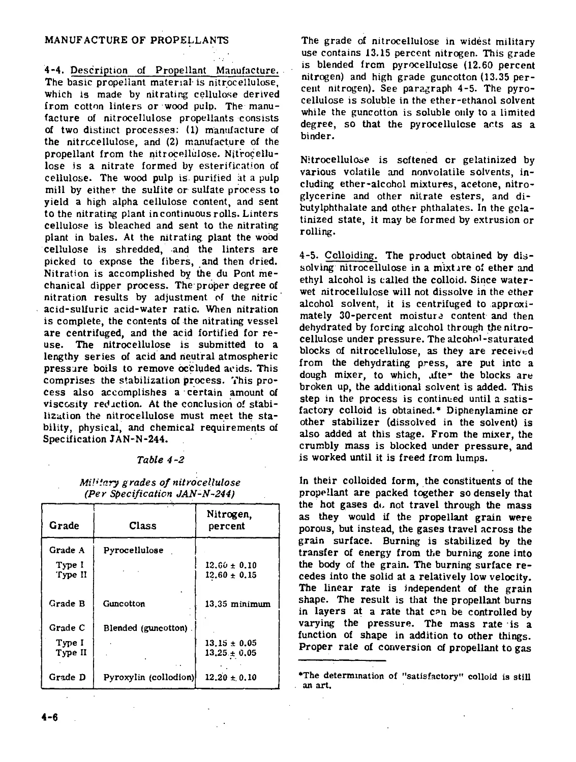
Figures 4-2 and 4-3 are constructed from data
taken from the curves of figure 4-1. Figures
4-2 and 4-3 are called "design curves." Figure
4-2 represents the relationship between web
size and velocity at 95 percent of the rated
maximum pressure. Figure 4-3 is a web-charge
curve, at service velocity (3,500 ft per sec),
plotted from values taken from the charge-
velocity curves. The values used for plotting
curve 2 are obtained by tracing, on the charge-
pressure curve of figure 4-1, the abscissa
which represents 95 percent of the rated maxi-
mum pressure (46,000 psi). Wherever this trace
intersects a pressure curve, the ordinate of the
intersection is traced to the right to where it
intersects the corresponding charge-velocity
curve. From this latter intersection, the cor-
responding velocity is obtained. This value is
plotted against the web of the propellant in
figure 4-2. Having obtained the web-velocity
curve (figure 4-2), the ordinate representing
the service velocity (3,500 ft per sec) can be
traced to the point of intersection with the
curve, and the corresponding abscissa deter-
mined. This value represents the web that
will give a service velocity at 95 percent of
the rated maximum pressure. In this example,
the most desirable web to meet the ballistic
requirements is found to be 0.099 inch. Pro-
jecting this web value vertically to figure 4-3,
it is found that approximately 409 ounces of
propellant will be required.
While the determination of the optimum web
was successful in this particular example, it
may not be so successful under all conditions.
For instance, it may be that the normal bal-
listic requirements of a certain weapon are
too severe for a given.propellant composition.
4-8. Determination of Web Range. Once the
optimum web for a given composition has been
determined, it may not be feasible to manu-
facture a grain with exactly the prescribed
dimensions. To meet this difficulty, a web
4-10
WEB SIZE (IN)
range of thickness must be established. The
lower limit of web thickness is set by pressure
limitations, while the upper limit depends on
such things as flashlessness and chamber ca-
pacity. To establish the web range, it is neces-
sary to fire several propellant lots with web
thicknesses approaching the maximum and mini-
mum web limits in the particular gun for which
the grain is intended. To indicate any tendency
to produce erratic pressures, the charge weights
of these firings should be somewhat in excess
of those required to give service velocity. The
web range established should be as wide as
possible fur manufacturing feasibility when the
gun-ammunition combination is desired to de-
liver a velocity close to the maximum attain-
able. Under this condition, the web range that
will satisfy the requirements is very narrow
and requires tight control of manufacturing
processes.
Since the optimum web was determined by
assuming 95 percent of the rated maximum
pressure, it is therefore the thinnest web that
can be used. Any material reduction of the web
will tend to develop a service pressure in ex-
cess of the allowable maximum. However, thin
webs (which tend to produce high pressures)
are somewhat desirable since they require
less charge to meet a given set of ballistic
conditions.
Large webs tend to leave unburnt propellant
at the muzzle and to increase the muzzle
pressure. Both factors inc-ease the tendency
to flash. If the web is too thick, the chamber
capacity may be exceeded before the velocity
level is attained. In certain large-chamber,
high-/elocity guns the velocity at a constant
pressure may begin to decrease as the web
exceeds a certain value (this is not a common
occurrence with normal guns).
Figures 4-2 and 4-3. Figure 4-2 (above) rep-
resents the relationship between web size
and velocity at 95 percent of the rated max-
imum pressure, and figure 4-3 (below) is a
web-charge curve
4-11
REFERENCES AND BIBLIOGRAPHY
1. Alexander, Jerome, "Colloid Chemistry,” D. Van Nostrand, New York, 1919, vol. 4, pp.
117-120.
2. McFarland, "Textbook of Ordnance ar.d Gunnery," John Wiley and Sons, New York, 1929.
3. Marshall, "Explosives," Blakiston, New York, 1919, vol. 1, pp. 312-313.
4. Picatinny Arsenal Technical Report No. 165.
5. Proof Officer's Manual, Aberdeen Proving Grounds, February 1929, pp. 158-162.
4-12
DESIGN OF DIES AND PIN PLATES
LIST OF SYMBOLS*
D = maximum outer grain diameter
Dg = die diameter, or external diameter of
green grain
Dq = dry grain diameter
d = inner diameter of grain perforation
dg = pin diameter, or green perforation di-
ameter
dD = dry perforation diameter
L * grain length (usually 2 to 3 times the
maximum diameter)
W = web, or minimum distance between
two directly opposing surfaces
Wj = inner web, or minimum distance be-
tween two directly opposite interior
surfaces of the grain
Wig » green inner web
WjD « dry inner web
Wo = outer web, or - minimum distance be-
tween an interior surface and a di-
rectly opposing exterior surface
wog = green outer web
WqD dry outer web
Wa * average of the inner and outer webs
WaD 3 average dry web
P a pin circle diameter
Swo - percent shrinkage of outer web
Swi 3 percent shrinkage of inner web
$d - percent shrinkage of perforation
in the grain design. As stated in the preceding
paragraphs, a major factor in the control of
burning rate is the control of the web dimen-
sions. Once the dry grain dimensions and per-
centage shrinkage for a given composition have
been established, the propellant can be made
with reasonable assurance that its dry dimen-
sions will be close to expectation. The follow-
ing formulas are used.
Sw3 = W-VW?Pxl°° (1)
wog
Wie - W1D
Swi = 100 (2)
Wig
Sd = J'fo-x 100 (3)
dg
4-9. In paragraphs 4-7 and 4-8, the procedure
for establishing web size was described. In
this section, the procedure for designing the
proper-sized die to manufacture a grain of
desired web size will be described.
Propellants are shaped into their final form in
a plastic condition. This plasticity is the re-
sult of the use of volatile solvents to disperse
the nitrocellulose among the other ingredients
ui the colloid. Subsequent evaporation of the
solvents during the drying process causes a
shrinkage of the grain that i iust be allowed for
*See figure 4-4 for application of symbols.
Do = 3d]j + 4W3d (for multiperforated grain)(4)
dn
(pin size) ------x 100
100 - Sd
WaD = Wid|Wod
(5)
(6)
«777- = 1.00 to 1.15 (for multiperforatcd (7)
.,”,4 grains)
Dg (bore) ’ 3ug + 2Wog + 2Wig (8)
P (pin diameter circle) = 2dg ♦ 2W(g (9)
4-13
w°* 100 (10)
w‘« 100
For example, to design the die and pin plate
necessary for the manufacture of a propellant
with an average web of 0.0220 inch and a per-
foration diameter of 0.0127 inch, assume the
shrinkages for this composition for this web
are Sa - 21.0 percent, Swo = 36 0 percent,
WoD
Swj = 25.0 percent, and the ratio —— = 1.04.
wiD
The solution is as follows.
0.0127
dg (pin size) = 2i x 100 = 0 0161 (5)
WqD = 0.0229 in. and = 0.0211 in.
... _ WiD +WOD л no- ie\
WaD = ----g~ in- (®)
w<* ioSrV. ’100 <10>
= X 100 = 0.0352 in.
100 - 35
wig =
Wjp
100 - Swi
x 100
(ID
0.0211
ГББТГ5 x 100 = 0 0281 in-
Dg (bore) = 3dg + 2Wog + 2Wjg (8)
Dg = 3(0.0161; + 2(0.0352) + 2(0.0281) = 0,175
P (pin circle diameter) = 2dg + 7.Wjg
P = 2(0.0161) + 2(0.0281) = 0.0883
This completes all the data required for multi -
perforated propellant except the length, which
is usually about 2.1 times the dry diameter (D).
The dimensions of the die, pin plate, and length
of cut are:
dg = (pin diameter) = 0.0161 in.
Dg = (bore diameter) = 0.175 in.
P = (pin circle diameter) = 0.0883 in.
L = (grain length) = 0.110 in.
This example is typical for web calculations.
The shrinkage values actually vary widely for
different propellant compositions. Representa-
tive shrinkage data for some common pro-
pellants are given in table 4-4.
4-14
Table 4-4
Representative shrinkage data (percentages)
Composition Type Web (dry) L sd sWi sWo Wa
Ml MP .03 7 25 40 27 33
SP .02 3 40 ... ... 20
М2 MP .035 3 14 20 20 20
SP .03 4 33.5 ... ... 7
.09 1.3 14 ... ... 25.5
M6 MP .103 3.5 27 32 24.5 28.5
MIO MP .04 6 38 40 29 34
SP .024 9.5 40.5 ... ... 34.5
.018 5.2 49 ... ... 30.5
M15 MP .055 2 13 7.5 7.5 7.5
M17 MP .098 1 10 13 1 7.5
4-15
CONTROL OF BURNING SURFACE
4-10. Notation. Each of the authors of the
various ballistics systems which we are about
to consider has used his own set of symbols to
define the parameters involved. Because this
condition exists in the literature, it has been
difficult to standardize on any one set of sym-
bols. However, where possible, an attempt has
been made to use consistent notation here. In
the instances where different notation has been
used by different authors to define the same
quantity, the symbols have been changed to read
alike. Where apparently similar, but not iden-
tical, quantities have been encountered, it has
been impossible to identify such parameters by
uniform notation, and, in such cases, the sym-
bols from the original treatises have been re-
tained. Tables of the original notation found in
the references are given in table 4-7.
4-11. Burning of Propellants. The burning of
propellants is a surface phenomenon. A pro-
pellant grain burns in parallel layers, in di-
rections perpendicular to its ignited surfaces,
at a rate dependent on the initial temperature
and pressure. Under constant pressure, a pro-
pellant burns with uniform velocity. An in-
crease in initial temperature or pressure
causes an increase in the characteristic burn-
ing rate of a composition, so that a rapid
acceleration of burning rate results from burn-
ing a propellant under confinement. Under
variable pressures, as in a gun, a grain will
burn at a variable rate.
4-12. Linear Burning Rate. The linear burning
rate is the distance (in inches) normal to any
surface that the propellant burns in unit time
(say, one second). Theoretically, this property
is a function of the chemical composition of the
propellant and is not a function oi propellant
geometry. At present, there are two methods
used to determine burning rates, the strand
burner and the closed bomb.
a. Strand Burner. This method is applicable
only if the propellant is in the shape of a
strand, or a strip, such as in rocket pro-
pellants (in which it has its most pertinent
application). This device measures the time
required for a propellant strand to burn a
predetermined distance (five inches between
fixed electric probes). W'ith this method, it is
possible to measure burning rates at any tem-
perature. However, burning rates are usually
measured at -40°C, +21°C, and +71°C, at pres-
sures varying from atmospheric up to 50,000
psi at any specified pressure intervals.
b. Closed Bomb.2 This method is used for
most gun propellants, which are not usually
manufactured in the form of strands. The
closed bomb is a thick-walled, steel-alloy cyl-
inder with removable threaded plugs in front
and rear which permit access to its interior.
The front plug contains the ignition mechanism,
and the rear plug contains a piezoelectric gage.
The bomb is cooled by a water jacket.
The closed bomb test is used to obtain data,
under varying conditions of temperature and
pressure, for use in determining the interior
ballistic properties of propellants, such as the
linear burning rate, relative quickness, and
relative force. This test allows a prediction
to be made of the behavior of any given pro-
pellant in any gun, serves as a manufacturing
control test, and may serve as a substitute for
proving ground tests. Usually, the output of the
gage is recorded as time-rate of pressure rise
as a function of the pressure.
When the closed bomb test is used, a com-
parison is made between closed bomb results of
a propellant under test and of previous lots cf
propellants of the same composition of known
ballistic value. Mathematical treatment of
closed bomb results, dP/dt as a function of p,
together with propellant granulation form func-
tions (paragraph 4-20), yields the linear burn-
ing rate dX/dt. The actual method of obtaining
the data may vary at different establishments,
but at Picatinny Arsenal an oscillographic
method is used, which measures the pressure
developed in the bomb by means of a quartz
piezoelectric gage. The circuitry used enables
the charge generated by the gage to cause the
horizontal deflection (Vx) cf an oscilloscope
trace to be proportional to the pressure (P) in
the bomb, while vertical deflection (Vy) is
proportional to the rate of change of pressure
(dP/dt) at the same instant. The maximum
pressure developed in the bomb is measured
as the maximum horizontal deflection of the
trace.
In this method, the data are obtained as oscillo-
grams superposed on rows of calibration dots.
(See figure 4-5, which illustrates a typical
4-16
trace.) The dots are set 0.25 volt apart (cor-
responding to approximately 5,uOG-lb pressure
increments) and distances between dots are
measured by use of a transparent interpolator,
shown in figure 4-6. The complete description
of the apparatus and test procedure may be
found in reference 1. Interpretation of the data
obtained from the oscillograms enables a de-
termination of the ballistic properties of the
propellant under test.
Figure 4-5. Pressure (P) versus rate of
change of pressure (dP/dt)
' Figure 4-6. Transparent interpolator
This description is confined to methods of cal-
culation and interpretation of the data obtained.
The values of Vx and Vy may be converted
respectively to values of pressure and rate of
change of pressure by equations (12) and (13),
which are derived in appendix I cf references.*
P = K(CxVx) <12>
dt/dt. JK-
(13)
where
P = pressure developed by the burning
propellant
dP/dt = time-rate of change of pressure of
the burning propellant
К - gage constant of tne piezoelectric
gage
Vx = voltage across the capacitance Cx
Vy = voltage across resistance R
Cx = capacitance of the pressure-meas-
uring circuit
Cy - capacitance of the rate-of-change
measuring circuit
R = resistance in the rate-of-change
measuring circuit
Am = slope = zsV7/aVx at any point on
the curve.
The expression
1 - дт
is a correction factor due to the capacitor Cy
in the rate-measuring circuit. A nomograph has
been devised which enables this correction
factor to be read directly from the dP/dt
curve with a minimum of mathematical
computation.
*For the sake of consistency within this section, the
symbols of the original reference have been substi-
tuted as follows;
Original reference^
a = covoluiuc nt propellant
aj = covolume of igi.iUr
В = shortened notation for
equation (15)
C = shortened notation for
equation (16)
h = propellant web
mo = weight of unburned propellant
mi = weight of Igniter
w' = grain width
Z = fraction of web burned
This handbook
= N/C
= Am
= H
= W
= c
4-17
To calculate a linear burning rate from the
oscillographic data obtained, a method used at
Picatinny, considered to be the best-balanced
between accuracy and speed, uses equation (14).
dX _ dZ/dt
dt Sx7 V о
(14)
where
P and dP/dt are obtained as described above
Pi is the pressure due to the burning of
igniter alone, which is obtained empirically.
About 300 psi are developed by two grams of
black powder in a 174-cc bomb. For rough
approximation, Pi in equation (14) may be taken
equal to zero.
G is calculated from equation (15).
<₽max - pl) f1 *'£’’1 >Dq|
О-------------------------------- <15'
in which
C = weight of propellant
Ci = weight of igniter
q = propellant covolume by the method of
reference 4. For sample calculation,
see reference 3, AppendixII-F, p. 19ff.
^i = igniter covolume, assumed to be 0.37
cmVgm. (See reference 5.)
Do = leading density of propellant, alone,
C/VB
b = specific volume of propellant; the re-
ciprocal density before combustion.
(For sample computation, see refer-
ence 3, Appendix Il-G, p. 20.)
H is calculated from equation (16).
Z - = fraction of powder burned
L(1 * p - ₽?.
dZ/dt = rate of burning of fraction of powder
Sx/V0 = ratio of surface area to original volume
when grain has burned a distance x,
normal to grain surface.
Form functions of Z and Sx/Vo in terms of X
may be calculated for each grain geometry. The
form functions for the most common geom-
etries are included in paragraph 4-20, where
they are correlated with their equivalent ex-
pressions in the Hirschfelder interior ballistic
system.
A consideration of dP/dt versus P, plus the
appropriate form function, equation (14), yields
the linear burning rate, dX/dt with respect to
P, for a particular grain geometry.
= linear burning rate (14)
°x/vo
After the linear burning rates have been cal-
culated from equation (14), the procedure is to
plot these values against pressure on appropri-
ate graph paper (figure 4-7) to determine a
burning equation. The burning of most pro-
pellants seems to follow one of three general
laws:
dx/dt = a + BP (18)
dx/dt = BPn (19)
dx/dt = a + BPn (20)
where a, B, and n are constants. (See para-
graph 4-15.)
H =
(n- b)D0
(16)
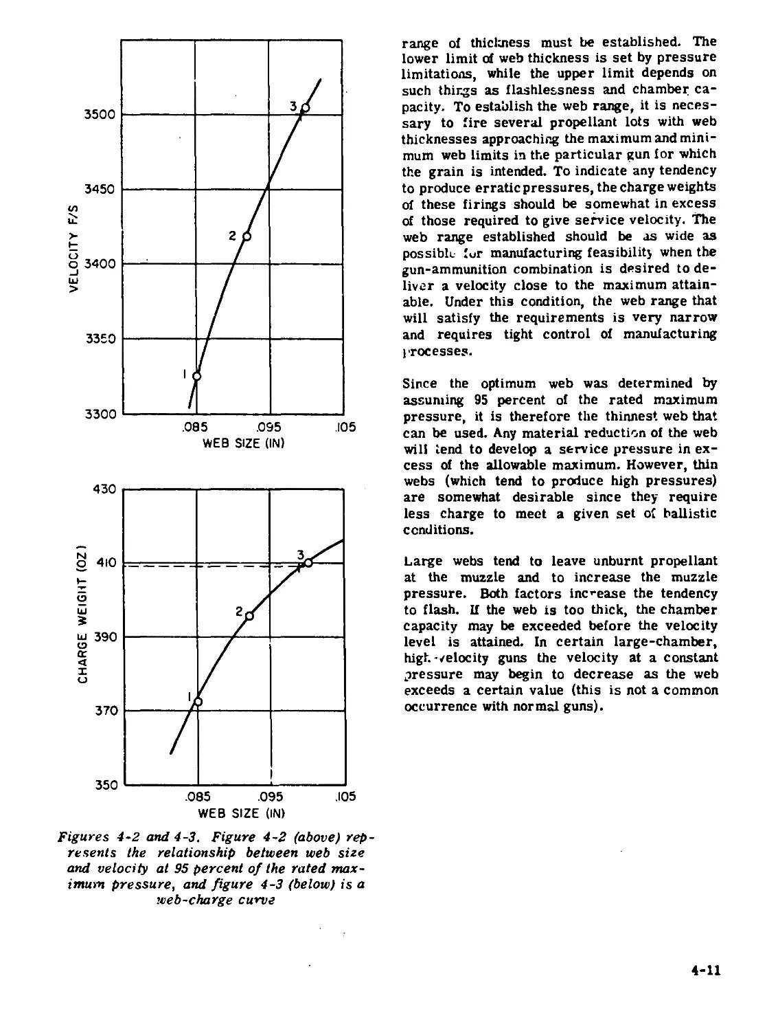
4-13. Relative Quickness. Relative quickness
is defined as the ratio of the average rate of
P sure rise of a propellant lot under test to
the average rate of pressure rise of a standard
4-18
Figure 4-7. Linear burning rate versus
pressure
propellant of the same formulation at the same
specified pressures when each is fired in the
same bomb under the same loading density and
test conditions. When the test sample and
standard propellant are similar in quickness,
the relative quickness can be taken as the ratio
of the Vy values without making any corrections
for the circuit capacitance. When the quickness
of the test propellant and standard differ widely,
equations (12) and (13) must be used to obtain
the correction for Vy before comparison can
be made. The values of dP/dt are plotted as
functions of P (calculated from the 0.25-volt
intervals of Vx). The values of dP/dt at 5, 10,
15, 20, and 25 thousand psi are taken from the
graph (figure 4-7) and the relative quickness
is calculated as Ln the example below. (See
table 4-5.)
4-14. Relative Force. In interior ballistics
use, the term "force" is related to the energy
released by a given propellant; that is, Force =
(PV)r = nRTv, where (in closed bomb work) P
is the maximum pressure developed and V is
the volume of the bomb. Since the bomb volume
is constant, relative force is defined as the
ratio d the observed maximum pressure de-
veloped by a lot of propellant under test, to the
maximum pressure developed by a standard
propellant, when each is fired in the same
bomb under the same test conditions. Since
pressure is measured as P = KCXVX [equation
(1)], if Cx is constant the relative force re-
duces to the ratio of the maximum x-voltages
Table 4-5
Relative quickness and relative force
p dP/dt x 10“6 Rel. quickness, ratio test/std. (%) Rel. force, ratio test/std. (%)
Prop. #1 (std.). #2 #3 #2 #3 #2 #3
*5,000 1.03 1.32 1.27 123 123
6,000 1.18 1.55 1.46 132 124
10,000 1.82 2.44 2.27 134 125
15,000 2.73 3.50 3.35 128 123 1.77 1.76
• 1.81 Lei "
20,000 3.67 4.70 4.55 128 124 98.0 97.2
25,000 4.66 6.09 5.82 131 126
Avg Max 130 124
Vx 1-81 1.77 1.76
•Value of dP/dt used, extrapolated.
4-19
recorded on the oscillograms. Values of maxi-
mum Vx are obtained by measuring a vertical
tangent to the trace at the point of maximum
pressure, using the 0.25-vclt interpolator. A
sample calculation of relative force is included
above.
For a complete description of cler.ed bomb
technique as used at Picatinny Arsenal, see
reference 3. Another application of closed
bomb information as used by the Navy is
described in reference 7.
4-15. The Proportional Law of Burning Rate.**
The minimum distance between ar.y two ad-
jacent surfaces of a propellant gr?in is called
the web. The rate at which the web decreases
is a function of the gas pressure produced in a
gen due to the burning of propellant grains.
It is assumed that burning proc eeds only On the
inner and outer grain surfaces, that is, burn-
ing of the ends of the grains is neglected. The
type of burning most usually encountered fol-
lows equation (19), dx/dt = BPn (in. per sec).
For MIO propellant this equation would be
4.53 x IO"3 P0-7 (21)
For ease of computation, it is desirable to ex-
press burning rate as proportional to pressure
ar = ri = BP (22)
or, to make equation (19) more useful in the
Hirschfelder system, an attempt is made to
make n equal to unity, in which we consider
what should be the value of the coefficient В to
make n = 1, while the value of r^ remains con-
stant. The value of В used in equation (22) is
an effective value. This effective value is ob-
tained from a plot of the curve of equation (21).
(See figure 4-8.) A curve of this nature allows
a person desiring to use a proportional law to
obtain a value of В that best represents the
actual burning law over a desired pressure
range.
The abscissa is first divided into arbitrary
intervals. Then, for each of these intervals,
the portion of the curve (from the start of the
interval to the maximum point of the curve in-
cluded in the interval) is replaced by a line of
least-square fit. The least squares are obtained
Figure 4-8. Proportional law to determine
value of В for n*l
at three-, six-, and nine-tenths of the maximum
value of an interval. The maximum value for
the intervals is called the peak pressure (Pp),
distinguishing it from all other values, which
are average pressure values. The slope of
each of the straight lines thus obtained is B.
ft can be seen from figure 4-8 that, as the
peak pressure increases, the slope decreases;
thus, the maximum value of В occurs at the
minimum peak pressure. Values of В are
plotted against peak pressures in figure 4-9.
4-16. Effect cf Grain Shape cn Burning Rate.
Although the linear burning rate of a propellant
is characteristic of the formulation and the
pressure, the granulation affects the overall
rate at which the propellant is transformed to
gas, since the surface exposed is determined
by the granulation. The best form of propellant
grain from a ballistic viewpoint is one which,
with the smallest weight of charge,will impart
a prescribed velocity to a projectile without
developing a pressure in excess of the per-
mitted maximum. In this connection, uniformity
of ballistic effect must also be considered.
Figure 4-10 illustrates the relation between
grain shape and ballistic effect. It should be
noted that, for equal weights of identical pro-
pellant composition, the position of the pressure
peak in the gun is very weakly dependent on
the grain shape, while projectile velocity de-
pends only on charge weight. The criterion
for the selection of a particular granulation is
the maximum pressure. .
4-20
Figure 4-9. Values of В determined by least-squares fit
The most important dimension of the propellant
grain is the web thickness. The web size of
a multiperforated grain refers to its average
web. Relatively slight changes in the average
web of a propellant result in appreciable
changes in the required weight of propellant
charge and maximum pressure produced, for a
given muzzle velocity of the projectile. Figure
4-11 illustrates the relation between surface
area and weight percentage burned for various
grain shapes. Ю When z (or N/C, the fraction
burned), is zero, the ratio S/So must be unity
for all grain shapes.
4-17. The Form Function. It is assumed that
all of the exposed surfaces recede at the same
rate when propellant burns. Thus, there is a
simple relation between the fraction of pro-
pellant burned and the distance that each sur-
face has regressed. The mathematical ex-
pression of this relationship, for any par-
ticular propellant granulation, is called the
form function for that granulation. In the fol-
lowing paragraphs we present two approaches
to the solution of workable form functions, and
show how the different systems may be cor-
related. Corner* s9 treatment is similar to the
HirschfeldeH treatment, except that the former
uses a form coefficient e, based on experiment,
whereas the latter uses a set of k's based on
geometry.
4-18. Corner Form Coefficient, gj If a long
cord of propellant, of initial diameter D, burns
under a pressure P, the rate of recession is
uniform over the surface of the cord, and is
expressed аз 1/2B(P). The amount of gas
generated up to time t is C^(t), where C is the
initial weight of the cord and ф goes from 0 to 1.
The diameter of the cord remaining at the time
t is fD.
Neglecting the small contribution from the burn-
ing of the ends of the cord, we have the geo-
metrical relation
Ф = 1 - f2 (23)
4-21
TRAVEL (IN.)
Figure 4-10. Pressure-travel and velocity-travel curves
Figure 4-11. Surface area versus weight-
percent burned for various grain shapes
and the expression of our definition of the rate
of burning is
DgJ-=-B(P) (24)
In the solution of the equations of interior
ballistics, f is a convenient variable, but as
it appears only in these two equations and not
in the other fundamental equations, we may
eliminate f, giving
8»
These equations are true for any number of
long cords. The web size (D) is the minimum
distance between any two adjacent burning
surfaces; for cord propellant, the web is equal
to the diameter.
Analogous relations may be written down for
other shapes. Sirgle perforated grains of initial
external and internal diameters di and d2,
respectively, have D = I (d^ - d2>, and fD as the
annulus remaining at time t. The geometrical
relation is
Ф = 1 - f
(26)
and the burning rate is still the same as in
equation (24), leading to
d/ в
dt " D
(27)
4-22
This assumes that the rate of burning is the
same on all surfaces of the propellant, ar.d that
the inner and outer surfaces are coaxial.
Both cord and single-perforated grains may be
brought into the same scheme bv choosing the
dimension of the grain along a direction normal
to the surface at two points of intersection,
where the direction is in one instance passing
into, and at the other instance passing out of,
the propellant. The smallest such diameter is
called the web size.
Next, we define fD as the remaining web when
a fraction Ф of the propellant has been turned
into gas. From the definition of the rate of
burning, given in equation (24),
Dg|.= -B(P) (24)
For certain shapes, ф - 1, when i = 0. For a
still more restricted class of shapes, Ф and f
are related geometrically by
Ф = (1 - 0(1 * 0f) (28)
where 9 is a constant for a given shape. For
example, 9=0 for single perforated grains,
and 9=1 for long cords.
final surfaces is (1 +• 9)/(l -9). Thus, the
larger the 9, the faster the decrease in surface
and the faster the drop in the rate of evolution
of gas at constant pressure. Shapes of positive
9 are said to be "degressive," and those of
negative 9 to be "progressive." Shapes, such
as tubes, with 9 > 0, are sometimes said to be
"neutral."
The possible range of 9 is restricted. 9 cannot
be less than -1, for otherwise Ф would be nega-
tive for f near unity. Nor can 9 be greater than
unity, for then Ф would be greater than unity
for some accessible range of f. This does not
mean that the cord, with its 9 = 1, is the most
degressive shape passible. The sphere has a
surface which decreases even more rapidly
(figure 4-12). In this case, D comes out, by our
prescription, as the diameter, and<# * 1 when
the remaining diameter is zero. Equation (28)
cannot express precisely the relation between f
and Ф for every geometric shape, although a
satisfactory approximation can often be made
by a proper choice of 9. The true geometric
form function is Ф = 1 - P for a sphere. Al-
though almost all grain shapes could be covered
by writing Ф as a cubic in f, this is not done
because the analytical solutions of the ballistic
equations would be much more difficult.
It is seen that D is defined by reference to a
direction which will not exist for a shape
chosen at random. For shapes of fairly high
symmetry, D will have a meaning. The defi-
nitions of f and equation (24) then follow with-
out exception. There is, however, no guarantee
that when this dimension has been eaten away
all Ле solid propellant will have turned into
gas; only for simple shapes does this occur.
Finally, equation (28) is a very special form.
We shall discuss the most common shapes to
illustrate the various possibilities.
With long cords and single perforated grains,
there is no difficulty. The web is easily found,
and equation (28) holds when 9=1 and 0,
respectively. Equation (28) may be referred to
as the "form function," with 9 as the "form
factor" or "form coefficient." 9 is a measure
of the change in the area of the burning surface
as burning proceeds. The burning surface of a
long tube remains constant (9 = 0), and the sur-
face area of a card decreases to zero as the
burning proceeds. The ratio of the initial and
Figure 4-12. Relationship of form factor
to rate of change of area of
burning surface
4-23
4-19. Form Coefficient for CSRD 6468. Let N
be the weight cf propellant burned up to any
time t, so that N/C is the fraction of propellant
burned. Let W be the web thickness, which in
the case of multiper'orated grains is the mini-
mum thickness before the grains splinter. Let f
be the fraction of tne web that remains un-
burned at any particular time. The OS RD 6468
ballistics are based on a form function that
expresses N/C as a quadratic function in f;
thus
N/C . ко - kxf > k2f2 (29)
where kg, kx, and k2 are all constants that
depend on the granulation and grain shape. The
form functions for all grain shapes, except the
seven-perforated, can be expressed rigorously
as cubic equations. However, since this would
unnecessarily complicate the ballistics, and
since the f^-term is always quite small com-
pared to the other terms, the quadratic ap-
proximation is used in practice. This approxi-
mation never differs from the exact expression
by more than 0.05.
a. Constant Burning Surface. The form func-
tion for a grain with a constant burning sur-
face is
N/C = 1 - f • (30)
which is a simplification of equation (29). This
is the simplest of all the form functions. Its use
greatly simplifies our ballistic computations.
It is derived from a consideration of a grain
such as a sheet, whose web is so very small,
compared to its length and width, that W/D and
W/L can be considered equal to zero.
^o = 1
kx a 1
k2 = 0
b. Strip Propellant. The web of this grain is
its thickness and the к-coefficients are:
k0 = 1
k, i W W w2
1 " 1 ‘ L ‘ D 2LD
W W w2
k2 = ’ L ‘ D 2LD
c. Cord Propellant. Cord propellant is not
used very much in the U. S. but is used ex-
tensively in Britain. The exact form function is
N/C= 1 - (1 - W)f2_(W)f3 (30a)
but replacing P by its approximate equivalent
(3/2)f2 - (l/2)f gives the approximate form
function
N/C = 1 + (^)f - (1 * ^)f2 (30b)
For cord propellant
k0 = 1
W
kl " ‘ 2L
k2 = - (1 + ^)
For a very long cord, neglecting the burning
of the ends of the cord, where W/4L is nearly
zero, we can use
N/C = 1 - f2 (31)
where
k2 = -1.
d. Single-Perforated Grain. This granula-
tion is in common use in the U. S. for small-
caliber weapons. The web of this grain is one-
half the difference between the outer and inner
diameters. The form coefficients are
ко = 1
kl s 1 - L
. w
k2 = --
No approximation was made here, but if W/L
is quite small the form icr constant burning
surface may be used, and is recoqimended
except for very accurate work.
e. Multiperforated Grain (Seven-Perforated).
Form functions for the burning of this granula-
tion, which is the most common in use in the
U. S. for large-caliber weapons, are more
complicated than those described above. The
burning is considered to occur in two stages,
a progressive stage, before the web burns
4-24
through to the formation of unburned splinters;
and a regressive stage during the burning of
the splinters. The burning in each stage is
approximated by a separate quadratic form
function.
1. Progressive Burning. The burning of
the grain before splinter formation may be
treated analytically. Values of ko, Iq, and
1<2. to be used in equation (29) for various
values of the ratios D/d (grain diameter to
web diameter) and L/D (grain length to
diameter), are given in table 4-6. The curve
of figure 4-13 (obtained from reference 4,
based on reference 6) is a plot of the burning
of a grain with D/d = 10, and L/D = 2.5. It
will be noticed that the slope increases up to
f = 0, where the splinters form.
2. Regressive Burning. Al‘er splintering,
shown by the flex in the graph at f = 0, the
slope decreases. This part of the curve is
represented by another quadratic of theform
N/C = ко - k’jf ♦ kfcf2 (32)
This is actually a continuation .of the cu.-ve
to the left of f - 0. It is shown in reference
4 that if the curve is made to pass through
the points (I = f0> N/C = 0), (f = 0, N/C = k^,
and (f = -0.5, N/C я 1), the resulting ex-
pression is a satisfactory approximation
to the form function in the regressive in-
terval. Accordingly, the form function to use
in the interval after splintering is given by
the following equations.
Table 4-6
Form functions for seven-perforated propellant
D/d L/D 1.5 2.0 2.5 ' 1 3.0 3.5
k«j 0.8409 0.8362 0.8335 0.8316 0.8303
8 kl 0.9111 0.9300 0.9414 0.9490 0.9544
k2 0.0702 0.0938 0.1079 0.1174 0.1241
Kj 0.8498 0.8451 0.8423 0.8405 0.8191
. 9 kl 0.9298 0.9507 0.9633 0.9717 0.9776
k2 0.0800 0.1056 0.1210 0.1312 0.1385
ko 0.8563 0.8516 0.8487 0.8468 0.8455
10 kl 0.9447 0.9673 0.9808 0.9898 0.9963
k2 0.0884 0.1157 0.1321 0.1430 0.1508
ko 0.8612 0.8565 0.8536 0.8517 0.8503
11 kl 0.9569 0.9809 0.9952 1.0048 1.0116
k2 0.0957 0.1244 0.1416 0.1531 0.1613
ko 0.8652 0.8603 0.85’4 0.8554 0.8541
12 kl 0.9673 0.9923 1.0073 1.0173 1.0245
k2 0.1021 0.1320 e.1499 0.1619 0.1704
0.8682 0.8633 0.8604 0.8585 0.8571
13 kl 0.9760 1.0020 1.0177 1.0281 1.0356
k2 0.1078 0.1387 0.1573 0.1696 0.1785
4-25
(.0
Figure 4-13. Actual versus theoretical burning curves
ко = k0
thickness. With this adjusted web and the
corresponding f,
k'i =
4f0 (1 - ko) (kp/fp)
2f0* 1
. 4 (1 - kp) - 2 (kp/fp)
2=-----------------------
3. Simplified Form Function for Seven-
Perforated Propellant. It is often convenient
for the purpose of rough calculations to con-
sider the seven-perforated grains as having
a constant burning surface throughout their
entire burning. This approximation cor-
responds to replacing the true form function
by the dotted line in figure 4-13, which is
a graph of N/C = 1 - f with specific values.
Since it is desired to vary f between unity
at the beginning and zero when all of the
propellant is burned, instead of between 1.0
and -0.25, as indicated by the dotted line in
figure 4-13, we must define an adjusted
web equal tc 1.25 times the actual web
Stating this another way, we may say that a
seven-perforated propellant is ballistically
equivalent to a single-perforated propellant ot
1.25 times its web thickness. The factor 1.25
may vary somewhat between 1.23 end 1.28,
depending on the conditions of firing, and on
whether the ballistic equivalence of the two
propellants is based on the same muzzle veloc -
ities or the same maximum pressures.
4-20. General Form Functions. The particular
equations (form functions) used to describe the
change in grain geometry during burning as a
function of web or linear distance burned are
determined by the ballist*? method used. Para-
graphs 4-18 and 4-19 have described the form
functions used in the Corner and Hirschfelder
systems. The form functions of the most com-
mon granulations, as used in the method of
4-26
subparagraph 4-12b, are included here along
with their exact equivalents, since their deri-
vation is time-consuming. 11 The symbols used
in the various equations are listed below.
= fraction of charge burned
N = amount of charge burned
C = initial amount of charge
Vq = initial volume of grain
Vx = volume burned at any linear dis-
tance (X)
Sq = initial surface of grain
Sx = surface cf grain burned at any linear
distance (X)
V„
x = fraction of propellant remaining
Vo (N/C = 1 - Vx/V0)
X = linear distance burned to flame front,
perpendicular to burning surface
f = fract on of web remaining
sx
— = progressivity
so
R, r = larger and smaller radii, respec-
tively, of grain geometry
W = web, or thickness
L = length
D = width
(Note that Z = 1 - Vx/V0)
a. Equations for Strip Propellant. The exact
formula for fraction of charge burned is
N , (LW + DW - LD - W2) .
c - 14- П5
(2W2 - LW - DW) л
+----------------- i
W2 3
' LD f
L and D are both assumed to be much greater
than W, and the f3 term is assumed negligible.
With these assumptions, the Hirschfelder form
can be shown to be
N
C
1 - f
Sx 2(LD + DW + LW) - 8(L + D + W)X + 24X2
Vo = Lwh
2(LD + DW + LW)X - 4(L + D + W)X2 + 8X3
Z " Lwh
b. Equations for Cord Propellant. The exact
equation for fraction of charge burned is
N = i + 2R - L {2 _ 2L f3
where R is the radius of the cross section of
the cord. The Hirschfelder approximation for
this is
g =(1-f) (1 -s- f) = 1 - f2
on the basis that L is much greater than R, so
that R becomes negligible by comparison. Since
f is a decimal, it becomes insignificant when it
is cubed, and the f3 term drops cut. The other
equations, given without derivation, are as
follows.
Vx . 2(R2 + RL) 4R + L v2 2 v3
V ~'йГх
Sx 2(R2 + RL) - 2(4R * L)X + 6X2
so ” R2L
2(R ♦ RL)X - (4R + L)X2 + 2X3
Z= —
c. Equations for Single-Perforated Propel-
lant. The exact formula for N/C is
N _ i + R - r - L f_ R - r {2
C" L " L
where the web (R - r) is assumed much less
than the length (L), so that N/C becomes equal
to (1 - f). This again is the Hirschfelder
equation for a constant burning surface. The
Hirschfelder equivalent, before simplification,
is
which is the Hirschfelder form function for a
constant burning surface. The other equations
are as follows.
= 1 - '-V ♦ k2f2
4-27
where
(See subparagraph 4-19c.) The other equations
are given below.
Sv 2(R - r + L) - 8X
Vo “ L(R - rj
2(R - r + L)X - 4X2
Z ” L(R -r)
Vx 1 - 2(R - r ♦ L) 4 2
Vo= L(R-r) L(R-r)
d. Equations for Multiperforated Grain. The
exact formula for N/C is
N R3 - R2r - 5R2r - 3r3
C 16(R2 - 7r2)
14R2L - 4RL- 114r2L
16(R2 - 7r2)
In the Hirschfelder system, the equivalent form
function is represented by a cubic equation
[see reference 4, p. 129, equations (14) and
(15)] that is simplified to a pair of quadratics
of the form
N/C = k -kJ 114f2
U A
where the coefficients k0, kp and k2 are ex-
pressed in terms of grain diameter, grain
length, and web. (See subparagraph 4-19ci.) The
other equations are
Sx 2 [(R + 7r)L + (R2 - 7r2)]
Vo ” L(R2 - 7r2)
- 4 [2(R 7r) - 3L]X- 36X2
*" L(R2 - 7r2)
2 [(R + 7r)L + (R2 - 7r2)]x
Z = ----------------------
L(R2 - 7r2)
- 2[2(R+ 7r) - 3L]X2- 12X3
L(R2 - 7r2)
9R3 - 49R2r + 35Rr2 + 93r3 - 20R2L
16(R2 . 7r2)
40 RrL + 60r2L f
16(R2 - 7r2)
-i3R3 + 77R2r - HlRr2 - 9r3 + 6R2L
16(R2 - 7r2)
- 36RrL + 54r2L
+---------------- f2
16(R2 . 7r2)
3R3 - 27R2r ♦ 81Rr2 - 81 r3 {3
+ 16(R2 - 7r2)
4-28
REFERENCES AND BIBLIOGRAPHY
1. Jackson, W. F., "Closed Bomb Method of Powder Testing," E. I. Du Pont de Nemours &
Co., Explosives Dept., Carney's Point Works, 1941.
2. Proof Directive-12, Rev. 3, Supplement to U. S. Army Specification 50-12-3, Powder,
Cannon, Propellant.
3. Pallingston, A. O., and M. Weinstein, Methodcf Calculation of Interior Ballistic Properties
of Propellants from Closed Bomb Data, Picatinny Arsenal Technical Report No. 2005, June
1954.
4. Interior Ballistics, A Consolidation and Revision of Previous Reports, Office of Scientific
Research and Development Report No. 6468. July 1945.
5. Closed Bomb Burning of Propellants and High Explosives, Office of Scientific Research
and Development Report No. 6329, January 1946.
6. Tschappat, W. H., "Textbook of Ordnance and Gunnery," John Wiley and Soi.s, New York,
1917.
7. Atlas, K., A Method for Computing Webs for Gun Propellant Grains from Closed-Vessel
Burning Rates, Naval Powder Factory, R. and D. Dept., Indian Head, Md., Memorandum
Report No. 73, January 1954.
3. Hughes, S. G., Summary of Interior Ballistics Theory for Conventional Recoilless Rifles,
Frankford Arsenal, Report No. R-1140, September 1953.
9. Corner, J., "Theory of Interior Ballistics of Guns," John Wiley and Sons, Inc., New York,
1953, p. 30ff
10. Hunt, CoL F. R. W., et al, "Internal Ballistics," Philosophical Library, New York, 1951,
p. 52.
11. Julier, В. H., Form Functions for Use in Interior Ballistics and Closed Chamber Calcula-
tions, Naval Powder Factory, Indian Head, Md., Memorandum Report No. 3, February 1951.
4-29
THEORETICAL METHODS OF INTERIOR
BALLISTICS
Table 4-7
Table of symbols
Symbol Unit Definition
A in.2 . Cross-sectional area of bore
a in.3 per lb. 1 ’’"T
a° ... 23,969 (j)
В (in. per sec) (lb per in.2) Burning constant
b 2 2 ft per sec 2CF
m'(y - 1)
C lb Charge weight
Cv ... Specific heat (constant volume)
°2 ft per sec hCF(B/W) A
e3 ft-lb per in.2 0 f eg" m VC
F ft Powder impetus
f ... Fraction of web remaining unburned
... Initial value of f
g j Jo ft per sec2 Acceleration due to gravity fz z dz exp 1 x JQ q + z - uz— No
... C
Jl ... kl * 2k2fo
J2 ... kl " 2k2
ko' kl’ k2 ... Form-function constants
L in. Travel of the projectile
M lb Weight of projectile
m slug Effective mass of projectile
mr slug Modification of m
N lb Weight of powder burned
No ib Weight of powder burned when projectile begins to move
P lb per in.2 Space-average pressure
4-30
Table 4-7
Table of symbols (cont)
Symbol Unit Definition
Po lb. per in. Initial value of P
P° О lb. per in. a°P
Pr lb. per in.2 Pressure resisting projectile motion (friction)
px lb. per ln.2 Pressure on base of projectile
Q ... (‘-V'AS)
q io Zb
J A
R energy Gas constant
(gm-mole°K)
^oJ2fo
zb
s ...
T °k Absolute temperature of gas
To °k Isochoric flame temperature
t sec Time from beginning of motion of projectile
u ... 2 7 } JlZb
V ft per sec Velocity of projectile
Vc in.3 Chamber volume
w in. Web of powder
X in. Distance from the base of the projectile tn a . point fixed with respect to the gun
*o in. vc Effective length of chamber 3 д
X ... <rl* 1 * о
У ... X ^"e
У' ... у - rZ
z ... V . e2 ’ •
Zb ... Value of Z at the time the powder is all burned
4-31
Table 4-7
Table of symbols (cont)
Symbol Unit Definition
a ... Geometric density of loading
г ... Function of Zb (or Zs) and Pp°
у Ratio of specific heats
У ... Pseudoratio of specific heats
д lb per in-.3 Average density of gas
a gm per cm3 Density of loading, Д = 27.68 До
s ... Constant depending on ratio of charge weight C to projectile weight M
n in.3 per lb Covolume of gas
lb per in.3 100M AX m
**1 ••• jo " k2fo (fo *
аДр
£ ... (xL " ^До)
p lb per in.3 Density of solid powder
a
Ф ••• №
Table 4-8
Symbols proper to the RD38 method only
Symbol Unit Definition
D in.2 Initial web size
E in.3 Al (initial free space behind shot)
ID in. Remaining web
M' ... Central ballistic parameter
RTo ft-lb Force constant
Л ft-lb per lb Effective mean force constant
4-32
4-21. Introduction. When a gun is fired, the
primer delivers energy in the form of hot
gases to the individual propellant grains in the
propelling charge, and initiates the decomposi-
tion reactions of the propellant. It is known
that in many artillery rounds deficiencies of the
ignition system cause nonuniform distribution
of primer energy and, consequently, time dif-
ferences in initiation of various parts of the
charge. For ease of mathematical treatment,
however, it is assumed that all grains are ig-
nited on all surfaces instantaneously. The rate
at which the solid propellant is transformed to
gas depends on total exposed surface and on
the pressure surrounding the grains. If there
were no mechanism serving to increase the
volume available for gas (chamber volume
minus the volume taken up by the solid, un-
consumed propellant), the pressure would rise
at an Increasingly high rate until the propellant
was all transformed to gas. This is the action
in a closed bomb, where the loading density
(propellant weight divided by chamber volume)
seldom exceeds 0.2 g/cc, and the pressure
may be as high as 45,000 psi. At the loading
densities usual in guns, however, if the volume
did not increase during propellant burning the
pressure would become excessively high. This
increase in volume is provided by the forward
motion of the projectile with an acceleration
proportional to the force exerted by the cham-
ber pressure on the projectile base. The pro-
jectile begins to move as soon as the force on
its base is high enough to overcome the crimp
and to inscribe the rotating band in the forcing
cone. As the volume increases, the bulk gas
temperature decreases, and the internal energy
change of the gas is mostly accounted for by
the I kinetic energy acquired by the projectile.
In tjhe beginning, when the projectile is moving
slowly, the pressure increases as a result of
propellant burning. A proper balance of the
factors that influence propellant burning and
projectile motion determines the maximum at-
tainable pressure. After this, the rate of vol-
ume increase more than compensates for the
rate of gas production, and the pressure be-
gins to drop. The point of maximum pressure
occurs when the original volume has about
doubled. After the propellant is completely
transformed to gas, the pressure drops more
rapidly. The projectile continues to increase
in velocity, at an acceleration proportional to
the pressure until it emerges from the muzzle
of the gun. (Sec figure 4-14.)
4-22. Fundamental Equations of interior Bal-
listics. Interior ballistics attempts to predict
mathematically the effects described quali-
tatively above. The fundamental mathematical
relations are: (a) equation (43), representing
the rate of burning; (b) equation (33), repre-
senting the motion of the projectile; (c) equation
(42), the energy balance equation; (d) equation
(34), the equation of state of the powder gas;
and (e) equation (47), an equation expressing
the variation of weight fraction of propellant
remaining with fraction of web burned.
Interior ballistics is concerned with the simul-
taneous solution of these equations, which are
correctly modified to take into account pro-
jectile friction, the distribution of the gas, the
heat lost to the bore, and other second-order
effects.
The variety of systems of interior ballistics
that have been proposed differ in the number
of simplifying assumptions made in order to
obtain a solution of these equations. If time is
no object, or if automatic computing machines
are available, it is possible to solve these
equations by maintaining a strict analogy to
the physical phenomena. A quick hand com-
putational technique, nowever, requires some
simplification. Two excellent compromises be-
tween exactness and ease of calculation are
outlined in references 1 and 2. We reproduce
below the method of reference 2, and two very
much simpler techniques, one in use in the
United Kingdom (RD38) and the other in con-
siderable use by the U. S. Navy (Le Due).
4-23. Basic Problems. The basic problems to
which solutions are desired are of the follow-
ing two general types.
a. Given the type, web (essentially a mea-
sure of available burning surface), and weight
cd the propellant; the weight of projectile; and
the characteristics of the weapon, calculate
the expected maximum pressure and muzzle
velocity.
b. Given the characteristics of the weapon;
the weight of the projectile; and the muzzle
velocity and maximum permissible pressure,
find the weight and web of propellant required
(to this problem, there may be no practical
solution).
In each of these cases it may be necessary to
establish the point-to-point relationship among
4-33
Figure 4-14. Pressure versus time and pressure versus travel curves
time, position of the projectile, velocity and
pressure; or the muzzle velocity, maximum
pressure, charge, and web may be the only
values desired.
4-24. Development of the Fundamental Equa-
tions. The equation of motion of a projectile
is one of Newton's laws. This equation states
that the force is equal to the product of the
mass and the acceleration. In the case of a
gun, the force causing the acceleration of the
projectile is the product of the pressure and
the area on which it acts. Thus,
a „ M d2x M „ dV
APx ------— = — V —
g dt2 g dX
(33)
Px is the pressure on the base of the projectile,
and t the time measured from the beginning of
motion of the projectile. Normally, the cross-
sectional area of the chamber is larger than
that of the bore. It is convenient to define the
zero point of X so that AX is the total volume
behind the projectile available to gas and
solid powder. However, the zero point may also
be the position of the projectile base before
motion occurs. In that case the distance trav-
eled is denoted as X and the equation of motion
is
Md2x
APX=--------
g dt2 (33)
where A is the cross-sectional area of the base
at the beginning of motion of the projectile, and
X is the distance the projectile has moved. M is
the weight of the projectile, so that M/g is its
mass (g is the acceleration due to gravity).
4-25. Equation of State. The equation of state
of the powder gas is the relation among the
pressure, the density, and the temperature of
the gas. This equation is to some extent em-
pirical. The virial equation of state is the most
general form. This equation gives the pressure
4-34
in terms of a power series in the density. How-
ever, it is apparent that such an equation would
considerably complicate the equations of in-
terior ballistics. It can be shown that the Abel
equation of state applies with sufficient ac-
curacy under the conditions of the gas in the
gun tube. The Abel equation of state is the
van der Waals equation with the constant a
omitted because it is negligible at the high
temperature prevailing in guns. The Abel equa-
tion of state is
P(- - r)) 3 nRT (34)
д
where a is the average gas density; -n the co-
volume of the gas; P the space-average pres-
sure; T the absolute temperature; n the number
of moles of gas per unit weight; and R the usual
gas constant.
The volume available to the propellant and the
propellant gas is Vc > Ax, where Vc is the
original volume (the volume of the cartridge
case corrected for the volume occupied by the
projectile extending into the case before firing).
If p is the density of the solid propellant, then,
since C - N is the amount of propellant remain-
ed - N
ing unburned, —-— is the volume occupied by
the solid propellant remaining. The volume
available to the gas is
Vc + Ax -
and the gas density is given by
Simplifying, we get
Г c 1 T
P Vr ♦ Ax- — - aN = NF —
L J To
(39)
4-26. Energy-Balance Equation. The energy-
balance equation simply states that the loss of
internal energy of the gas is equal to the kinetic
energy cf the projectile. Thus
ы/’Т°СтйТ= 1/2—v2
4 8
(40)
Where V is the velocity of the projectile, N the
amount of powder that has been burned, To the
flame temperature, and Cy the specific heat of
the gas at constant density. We assume that CV
is constant in the region of temperatures in-
volved, so that
NCy (lb - T) = 1/2 “ V2 (41)
Then the equation of energy balance becomes
-^(l-V-V—V2 («)
>-1 V To/ 2 g
4-27. Burning Rate Equation. The equation of
the rate of burning is the equation that gives
the rate of regression of the surfaces. It has
been found empirically that the rate of burning
of the powder depends primarily on the pres-
sure of the gas surrounding the burning grains.
Other factors apparently affect the rate to only
a small extent It has been found that the de-
pendence of the rate on the pressure can be
given by an equation either of the form
Vc *Ax-^_N
(35)
Let us define two constants characteristic of
the powder.
a = - 7 (36)
F = n RT (37)
The equation of state becomes
rvc .Ax-<C- N)/p I _ T (38)
pl------5------’J"FT?
dt = a + bp (43)
or
dr _
df=BP (44)
where r is the distance the surface has re-
gressed. It has been found that both forms fit
the experimental data equally well. In the case
of equation (43) it has been found that the con-
stant a is small; and in the case of equation
(44) the exponent n is near unity. An equation
of the form
S-BP
(45)
4-35
therefore fits the existing data with reasonable
accuracy over the range of high pressures ex-
isting in guns. In addition, the use of an equa-
tion of tiiis type permits an analytic solution cf
the ballistic differential equation. For these
reasons, we adapt the approximate equation for
the rate of burning, equation (45). The web of
the powder grain is defined to be the minimum
distance between the surfaces of the grain, that
is, the distance which must be burned before
the grain is completely consumed (or in the
case of seven-perforated grains, before the
grain splinters). The equation of the rate of
burning to be used in this ballistic system is
-W = BP (46)
where В is' the burning constant (a constant
characteristic of the type of powder); W the
web of the powder; and f the fraction of the web
which remains unburned. The quantity f is re-
lated to the fraction of the powder burned by
purely geometric relations based on the geom-
etry of the grain. It is shown in section 52 of
reference 2 that this relationship can usually
be represented satisfactorily by a quadratic
equation of the form
N/C = k0 - kif + k2f2 (47)
The values of coefficients k0, kj, and k2 depend
only on the shape of the grain.
Equation (47) is expressed in the RD38 method
as
N
-= (1 - f) (1+ef) (48)
= 1 + (в - l)f -t?f2 (49)
4-28. The Second-Order Effects. In the previous
section a necessary distinction was made be-
tween the pressure on the base of the projectile,
and the space-average pressure. The gas must
follow along behind the projectile, yet the
breech element must remain stationary. This
motion of the powder gas causes a pressure
gradient to develop, in which the pressure on
the base of the projectile is lower than that at
the breech. The kinetic energy of the gas mu:',
be included in the energy-balance equation,
and the existence of the pressure gradient must
be taken into account in relating the motion of
the projectile to the space-average pressure.
4-29. .Equations of Motion and Energy Balance.
The motion of the powder gas is represented by
the usual partial differential equations of fluid
flow. A solution of these equations applying to
the motion of a gas in a gun tube with the pow-
der burning has not been found. A solution
under certain restricted conditions was de-
veloped by Love and Pidduck. 1 However, this
solution involves the motion of waves of finite
amplitude, and is entirely too cumbersome to
use in the . equations of interior ballistics. A
solution developed by Kent represents a limit-
ing condition, that is, a stable equilibrium
situation. The development of this solution is
described in section 57, reference 2.
According to this solution, the pressure cn the
base of the projectile is related to the average
gas pressure by
[m + —1
p = Px~sr (50)
and the projectile base pressure is related to
the breech pressure by Рьгеесь =
Px LM+F
L__& j
M
(51)
where 5 is a constant depending cn the ratio of
the charge weight (C) to the projectile weight
p
(M). In the usual cases, when the ratio tt is
м
about 1/3, 8 is about 3.1. (In RD38, the value
of 8 is talcen as 3.) It is also shown in section
57 of reference 2 that the kinetic energy of the
CV2
powder gas is given by -x—-
2g5
It becomes convenient to define an effective
mass of the projectile,
(M+C/8)
m =---------- (52)
In terms of this quantity the equation of motion,
equation (1), becomes
d2x
APav.= mT7 (53>
and the equation of energy balance, equation
(33) becomes
NCV (To- T) = 1/2 mV2 (54)
4-36
4-30. Energy Equation Including Heat Loss.
The heat lost to the bore surface up to any
instant is taken to be proportional to the square
of the velocity. Thus if h is the amount of
energy lost to the bore of the gun, then
h = 1/2 (mV2B) (55)
where В is a constant. Some justification for
this form is given in section 55 of reference 2.
This term is now included in the energy equa-
tion, equation (54) so that
— (1 - T ) - ( 1 + В) 1 mv2 (56)
у - 1 To 2
4-31. Energy Equation Allowing for Friction.
We take the friction of the projectile to be
equivalent to a resisting pressure on the base
of the projectile equal to a constant fraction of
the actual average pressure. The resisting
pressure is taken to be
_ c _
Pr = z---P
1 + c
(57)
Because of this friction, the equation of motion,
equation (53) must be modified. Pressure caus-
ing acceleration is no longer P, but rather
P - Pr. Thus
' А<ГГс’₽-"$ (58)
or
d2x
АРзт''^' <59)
where
m’ = (1 ♦ c)m (60)
The work done against friction must be in-
cluded in the energy-balance equation. This
work is
divided by the cross-sectional area A. From
equation (59) and V > ^this term becomes
1/2 mV2C
This correction term must be added to the right
hand side of the energy-balance equation, equa-
tion (56), to give
J!L(i-^)
7 - 1 To (62)
= (1 + B) 1/2 mV2 + 1/2 mV2c
Equation (62) can be written in terms of m* as
-^-(1-Л
7-1 To (63)
- (1 + B) 1/2 m’V2 - 1/2 C£ mv2
The final term is dropped as negligible, to give
as the modified equation at energy balance
NF T
------ (1- —)- (1 + B) 1/2 m'V2 (64)
7-1 To
4-32. Solution ot Equations by the Scheme
RD38. The simplifying assumptions are as
follows.
a. There is no initial resistance to motion
by cartridge-case crimp, or the need for en-
graving the rotating band.
b. The temperature of the gas during burn-
ing is constant, thereby reducing the simul-
taneous equations to be solved.
c. The covolume is assumed to be equal to
the specific volume of the solid propellant.
These assumptions permit an algebraic solu-
tion at the remaining simultaneous equations.
By assumption b the right hand side at equa-
tion (39) becomes A.N, and by assumption c,
a = o. The equation of state, equation (39), then
becomes
[cl
Vc+Ax-----ON (65)
** p I
or, in terms of breech pressure (P). See equa-
tions (50) and (51).
-X X
A I Pr dX = —— Al P dX
1 + c
Ao aq
(61)
where Xo is the effective length of the cham-
ber, defined as the volume of the chamber
(66)
4-37
The assumption c introduces an error that may
be considerable at high densities of loading,
since v is about 1 g/cc, and 1/p is 0.6 g/cc.
The result is that the peak pressure is higher
than the calculations would predict. This can
be compensated for by increasing either В or
K, which then becomes dependent on peak
pressure. It is more convenient to hold x
constant, and to vary В as required to cor-
respond with ballistics.
, ₽v AN (1 ♦ C/2MP
P(x ♦ Z) -------—i-
A (1 ♦ C/3Mj)
dV
(Mi ♦ C/2) др - AP
(74)
(75)
with the initial conditions x = 0 at f = 1.
Eliminating P from equations (73) and (75) and
integrating, we get
We can write
r
Vc — = E = AZ
v = B(Mf?c72j(1"° <76)
If we use equation (76) in equation (75), and
eliminate P by using equation (74), then
where E is the initial free space behind the
shot. The length Z is a convenient measure.
Hence, equation (66) becomes
I . C
\ Л N 1 * 2M
p(x>n = -y----eV
\ *3M/
where
(68)
A2p2(i < C/3Mj)32,2
B2M1CX(1 ♦ C/2M1)2
The equation of motion of the shot is
Integrating equation (46) with 6 / 0,
dV AP
M— = ’
dt C (69)
1 * 2W1
neglecting resistances to motion, the recoil of
the gun, and the rotational inertia of the shot.
To include these we replace equation (40) by
dV AP
1 dt = , C (70)
1 +2Кц
where = niM and
m = 1.02 (approximately) (71)
The fundamental equations are thus:
£ = (1 - f) (1 ♦ ef) = 1 - (9- l)f - df2 (72)
D — = - BP (73)
dt
/1 «. «AM’/?
X*Z = * U +ef/
(79)
whereas, if в = 0,
x + Z=ZeM’(1 ‘ 0 (80)
The pressure P can now be obtained from
equations (39) and (48) as
6/0: («)
XC(1 +C/2Mj) (1 - f) (1 + Sf) /1 + t?f\M’/<?
P = E(1 * C/3M1) \ 1 + 6 /
6 =О-Р=хса*с/2М1) -МЧ1-П
E(1 + C/3M1)
(82)
This completes the determination of x, V, and
P as functions of the parameter f.
X is an energy per unit mass, the square of a
velocity; AD/BMi is a velocity. Hence M1 is
dimensionless, as it should be in order to be
consistent with equation (77). M1 is the "central
ballistic parameter" of this method. m' or an
equivalent can be identified in nearly all of the
ballistic theories that lead to explicit solutions.
4-38
M can be thought of as a dimensionless param-
eter showing the importance of the shot motion
in reducing the pressure from th? va'-c that
would be attained in a closed vessel.
4-33. Values at "All Burnt." The suffix В will
be used to denote quantities at the instant at
which the propellant is just burnt, f = 0. From
equation (76),
,, AD
Vb = B(Mj + C/2) №3)
Integrating equation (77),
xB ♦-t =Z(1 ♦e)M'/6 (*/0) (84)
= ZeM' (0 = 0) (85)
The last equation (91) is simplified as
xC(l 4- C/2Mj) (1 4- 0)2
p„ --------------i--------- (93)
m E(14-C/3Mi)(eM'4-4fl)
This is exact tor 5 • 0.
4-35. Solution After "Burnt."
Let _ x 4- I (94)
г = х£Т7
At any travel x greater than xB, the pressure is
P = PBr->
(95)
The velocity is given by
From equation (74),
y2 _ *C(M + Ф)
' Ml 4- C/3
(96)
X C(1 ♦ C/2Mi) ........
pB = E(1 C/3M1) (1 + fl)M</0 W / 0) (86)
_ XC(1 1- C/2M1) ,-M‘
_ E(1 + C/3M1) e
(fl = 0) (87)
4-34. Values at "Maximum Pressure." Quanti-
ties here are denoted by the suffix m. Differ-
entiating equations (48) and (49) gives
M* 4- fl - 1
fm = M’ + 2fl
(88)
for all в. Also
N, . (1 4-5)2 (M’4-fl)
— (m) =---------------
С (M* + 29)2 (89)
\ M'/fl
v , , M’ + 2 A
Xm * ~wTT) M o)
= Ze (fl = 0) (90)
and
Pm = OU
xC(l 4- C/2Mt) (1 + fl)2 (M14- 9)1*(M>/^) ^0)
E(1 4- С/Змр (M’ 4- 2 )2 + (M’/6)
(92)
XC(1 4- C/2Mi)
=----- --------- (fl = 0)
E(14 С/ЗМреМ'
where ,
^~(1-Г1->) (97]
7-1
where у is the equivalent specific heat ratio,
defined by equation (44).
For details on the derivations of the equations
for the last three conditions, refer to reference
1, pages 138 and 139.
4-36. Summary of the Working Formulas. A
solution of the equations given above leads to
the expressions given below.
If M' > (1 -fl),
хСа + С/гмр (l+fl)2
p_ =------------—________— (98)
E(l + C/3Mi)(eM'+ 4fl)
Otherwise, the maximum pressure is
xC(l 4- C/2M1) , ,
PB =------------------------- (°/0) (86)
E(1 4- С/ЭМ1) (1 4- fl)M’/9
_ * C/281!) (fl= 0) (87)
" Е(14-С/ЗМх)еМ’
The position of "all burnt” is given by
xB 4- Z = Z(1 4- fl)M’/e (fl 0) (84)
= Ze1®' . ’ (5 = 0) (85)
4-39
If the muzzle is at travel x, and
x + r
(94)
and
ф = _L (1 . r1 - У) (97)
у - 1
, хс(мЧф)
У* 3 ------
Mi + C/3
(96)
4-37. Sample Solution by Use of the RD38
System. The equations developed include two
constants whose value cannot easily be found
except with experience obtained through the use
of this scheme in the analysis of past firings.
Since X/RTO is equivalent to ~, where T* is
1 о
the correctly averaged temperature assumed
to exist during propellant burning, x/RT0 should
be a fraction, probably between 0.8 and 1.0.
e can be assigned from considerations of
geometry of the grain alone, but there are other
factors .such as nonideality of ignition and im-
perfect piopellant grains that make a better
value at 6 to be 0.2 greater than the geometric
value. The actual values have to be fitted in a
particular problem to match the observed prop-
erties to calculated ones. When no results of
firings are available for the particular case
desired, it is necessary to obtain values of в
and X from an analysis of a similar case where
ballistic firings are available.
The burning constant В is of prime importance
in determining the maximum pressure, as is
clear from various equations. However, it is
difficult to correlate values of В determined
from closed-chamber firings (with these ob-
tained in guns. Hence, whenever possible, В
should be determined from the observed max-
imum pressure or muzzle velocity in a bal-
listic firing of a similar case to the one under
consideration. This can be done once values are
assigned to X and в.
An illustrative example, of the manner in which
this scheme may be used, follows. Table 4-22
contains the ballisticsof reference propellants
used in assessing charge for production lots
of propellant for various weapons. In the prob-
lem worked out below, we will take item 21
(from table 4-22) as the one for which a solu-
tion is known. Then we will try to find the max-
imum pressure and muzzle velocity for items
10 and 14.
Knowing the value of the maximum pressure as
given for item 21, we find the value of M for
item 21. We check this value of M* with the &
and x/RTo used to see if the correct velocity
will be obtained. The final value of 6 and
x/RTq that we will use will be the one that will
give us the correct velocity. Then, with the
correct value of M1 for item 21, we can calcu-
late M* for items 10 and 14.
In the first set of calculations, we shall assume
that в = 0, and then take various values for
x/RTo to see whi^h of these will be correct for
our problem.
In the standard calibration chart (table 4-22) it
will be noticed that the maximum pressure is
given as 39,500 psi, whereas the value used in
this example, as well as for Hirschfelder and
Le Due is 45,400 psi. This is so as the pres-
sure given in the charts is the copper gage
pressure, which is a lower reading. To con-
vert to the actual pressure, we must multiply
the copper pressure by 1.15.
Using the basic formula for pressure, we have
XC(1 + C/2M.) (1 + 6)2
p ----------------i---------- (98)
E(1 ♦ C/3Mj) (eM1 + 46)
However, since в = 0, the formula can be slightly
simplified.
Assuming 6=0, and x/RTc = 0.9, we have
45 400 - (0-9) (ЗЛ8) (ЗЛ2> (1Л5> <12> <105)
45’400 ----------(Е5&)Г1.1)еМ'---------
M* = 1.50
Checking the velocity with this value, we find
that the- velocity is 2,680 ft/sec, which is too
low.
4-40
We then try a higher value of x/RT0. Trying
f = 0 and x/RT0 = 0.93, we have
M* = 1.54
This value of M yields V as 2,710 ft/sec. Hence
we raise the value of x/RTq to 0.96, and obtain
a velocity of 2,780. We try.x/RT0 = 0.98, and
obtain a velocity of 2,800. The value of M' that
we choose for item 21 is 1.69. Using this value
of M we can calculate the burning rate, using
the formula
A2D2 [1 ♦ C/3Mj] 32.2
B2MtCx [1 + C/2M* ] 2
(78)
B2 _ 102 (2.97 x IO"3) (1.1) (32.2)
” (1.69) (26.5) (8.12) (0.98) (3.18) (1.32)
„ -8
B“ = 7." x 10
Using this value of B, we can find M1 for items
10 and 14.
(49.3) (1.76 x IO"3) (1.08) (32.2)
Mio=--------------------------------------
(7.55) (16.9) (3.82) (0.98) (3.18) (1.21)
Mjq = 1.59
MU - <49-3) (I-35) (i-07) (32.2)
(7.55) (16.5) (3.39) (0.98) (3.18) (1.23)
Mu = 1.57
Calculating the pressure for items 10 and 14,
we get
(0.98) (3.18) (3.82) (1.12) (12)
₽ml0 = (73) (1.08) (3.94)
Pml0 ~ 49»400 lb ₽er in-2
(0.98) (3.18) (1.11) (12) (3.39;
₽ml4 = (130) (1.07) (3.40)
Pml4 = 26,400 lb per in.2
To calculate the velocities for both of these
items, we have to obtain the values of ф.
Ф for item 10 = 2.31
Ф for item 14 = 1.62
„ , (0.98) (3.82) (3.18) (3.76) (32.2)
10 ' 18.2
VjO = 2,560 ft per sec
,, 9 (0.98) (3.39) (3.18) (2.87) (32.2)
”14 = --------------------------------
17.6
Vi4 = 2,180 ft per sec
We now assume a value of в as 0.15, and then
try various values of x/RT0 to see which is
correct. We again use the formula for max-
imum pressure
p xC(l » C/2Mj) (1+*)2
“ E(1 + C/3M1) (eM‘ + 46)
Trying successively the values of x/RT0 as
0.85, 0.87, 0.90, and 0.92, we find that
x/RTo = 0.88 will yield the correct velocity
for item 21. The correct value of M for
item 21, using 6 =0.15 and X /RT0 = 0.88, is
1.79.
B2 is obtained as 7.19 x 10"8
М’ю 3 1-83
M14 = 1.61
₽mi0 = 44,400 lb per in.2
Pml4 ж 23,100 lb P®r in-2
Checking the velocities in these, we obtain
*10 3 1.65
ф 14 = 1.24
v10 = 2,610 ft per sec
Vi4 = 2,230 ft per sec
We again repeat the problem, but assume
в = 0.30, and in the first case, thatx/RT0= 0.95.
Usi -g the formula
> ">2 („
E(1 + C/3M1) (eM* ♦ 46)
we get
« ann (0-95)(8.12)(3.18)105(1.15)(1.69)(12)
45’400 ---------(15ЙК1.1)(еЯТ1.2)---------
M* = 2.10
4-41
Trying this value of M for velocity, we obtain
V = 2,950
which is too high.
We then try t1 = 0.30 and \/RT0 = 0.90. With
these values we obtain M' = 2.06 and the veloc-
ity V = 2,850, which is still too high.
Then we try в =0.30, and \/RTo=0.88. With
these values M* = 2.03 and V = 2,800. This
value of M is then correct for our в and
x/RTq. With this value of M' we can calculate
В for M6 propellant. We can then use the value
of В obtained for item 21, and use it for items
10 and 14 to obtain M* for thece.
_ (0.88) (3.18) (3.39) (1.11) (1.69) (12)
pml4=--------(ТПГЩПГТПГ 70)
pml4 = 25,300 psi
2 \C(M' + <*)
10 + C/3
v .2 (0.88)(3.18)(3.82)(1.79 » 2.57)(32.2)
10 ° 18.2
Vio = 2,590 fps
2 (0.88)(3.18)(3.39)(1.29 > 2.08)(32.2)
V142 -----------------------------------
V14 = 2,300 fps
We obtain В from the formula for M*
, A2D2 Г1 + C/3Mi] 32.2
M = --------1---------J------ (78)
B^jC- [1 + C/2mJ2
2 (102)(2.97 x 10~3)(l.l)(32.2)
= (2.03)(26.5)(8.12)(0.u8)(3.18)(1.32)
B2 = 6.75 x IO"8
Hence, we obtain Мщ from
4-38. Derivation of Equations by Method Out-
lined in OSRD 6468. For the tabular solution
we assume that у = 1.3; and that the starting
pressure is what is developed when one pei -
cent of the charge has burnt when the projectile
begins to move. The covolume of the propellant
is considered.
Equation of State. The equation of state (34),
as derived in paragraph 4-25, is transformed
by taking Vc = AX0 and AX = Vc + Ax. The
equation of state (34) then becomes
M' = (49.3)(1.76)(l,08)(32.2)
10 (6,75)(16,9)(3.'-’2)(0.88)(3.18)(1.28)
Mj0 = 1.995
We obtain Mu from
M’ - (49.3)(1.35)(10.7)(32.2)
14 (6.75)(16.5)(3.39)(0.88)(3.18)(1.25)
M'14 = 1.795
We can now use these values of M to calculate
the pressure and velocity for both items 10
and 14.
хса + с/гмра.бэш2) /Q_X
Hmio ;-------------------------- (93>
E'l + C/3Mj)(eM ♦ 1.2)
_ (0.88) (3.18)(3.82) (1.11) (1.69) (12)
ml° ” (73)(108)(5.12)
pml0 = 46-400
Г C I T
P AX+7- aN = NFv-
L P I To
(99)
Multiplying this equation by Vc, dividing by
its equivalent AX0, and remembering that
C/Vc = we get
Pvc^-r-aAou = NF,T7 <10°)
Equation of Motion. By equation (52), equa-
tion (33) can be expressed in terms of the
average gas pressure as
др — M/M + С/ S j у dV g\ M / dX (101)
or dV AP = mV — dX (102)
where 1C <Л (103)
4-42
To account for frictional resistance, engraving
resistance, etc., m' is substituted for m, the
relation being m' = 1.02m. The qu;.”tity m' is
defined as an effective mass.
The three equations, the energy of motion (33),
the equation of state (34), and thr energy bal-
ance equation (40), derived previously in para-
graph 4-26, are combined to give one equation
valid before and after the powder is all burned.
The rate of burning will then be used to obtain
a differential equation applicable only during
the interval of burning of the powder.
First eliminate T/To between equation (34) and
equation (40), and then eliminate P between this
equation and equation (45). This gives
lm.v2 = (104)
2 > - 1
vc / X Л0 N \ m* „ dV
1\XO ' a °C/ 4 VdX
The equation for the rate of burning (43) may
be rewritten in terms of velocity to give
df _ m' В dV
dt A W dt
(105)
This equation is integrated to give
l(--l) m'V2*—Vc
2 A
’ X ”0 1 m* В
+ --------аДо(»Ч -Tk2) — - V-
,Xq p 2 A W
dV [n0 tn* В
+ VdT = CF lc + (kl - 2k2fo) T wv
(109)
Here, in the term ад© N/C, which is a small
correction term, we have approximated the
value of N by replacing f2 by jf. Thus
N 1
k0 - <kl - 2k2>f <110>
and, correspondingly, we have introduced
~ = k0 - (kJ - _k2)f0
4-39. The Solution of the Differential Equation.
Let us define the following:
m' В
«o-f = 7wv <106>
. No
o = ^
(HD
where f0 is the value of f when the velocity is
zero, that is, fo is the fraction of the web that
is unburned when the projectile begins to move.
It is convenient to let No be the weight of the
powder burned when the projectile begins to
move (equation (47) evaluated at f = f0). Equa-
tion (106) can be used to eliminate f from the
form-function equation, equation (47), to give
(107)
N Nq m’ В /т' в\2 о
С ” С + к1 + 2к2Г°)-д w V * к2\~А W/ V
The value of No is related to the starting pres-
sure Po by the equation of state, equation (48),
evaluated at the start of motion, that is, when
P = Po, N = No, T/To = 1, and X/Xo = 1, gives
Nq _ Pp(l - Дс/о ) QQg,
C ’ A0(F > aP0)
Eliminating N in equation (104) by means of
equation (107) gives the fundamental ballistic
equation for the interval of burning
)1 kt - 2k2l0 (112)
)2 . к, - |k2 (ИЭ)
c =^+аД0(к0- j^ (114)
and
fo a2
Zb =----------------- (115)
i! C F m’ (B/W)2
In terms of these quantities, equation (109)
becomes
-aM2^v|v
A ri
dV_ C F jo
dX m’
CF В 11
2(7-D-
(116)
J^!o) v2
iizt >
4-43
(127)
This is an equation relating the length of
travel (X) of the projectile to its velocity (V).
It now becomes convenient to define dimen-
sionless variables related to the travel and
velocity:
X
y = "c (U7)
and
Z = ^ (118)
where
jjC F (B/W)
e2=-------A-----
In terms of these variables, equation (116)
becomes
(120)
CFj0 (1 k2fo| 9
= -x-Г* Z -j- (У - 1) --7-ZZ2
e2zm' (2 Jlzb)
Let us define the following:
and
a Ao 12 fo
r= zb
Jo Zb
h 1q
(121)
(122)
(123)
In terms of these quantities, equation (120)
becomes
(y - rZ)Z^ = q (124)
which may be arranged to give
аУ z (У - dZ * q + Z - uZ2 (125)
We define у' = у - rZ (126)
so that equation (125) becomes
dy’ = Zy’
dZ q + Z - uZ2
Thus wc obtain a linear first-order differential
equation, with a solution as follows
y' = j/k - r f (128)
Where к is the constant of integration,
J = exp /" --Z--Z- (129)
Jo q+Z-uZ2
and
f zdZ
S = J I — (130)
Jo 3
Then by using the definition of у from equation
(126) and of у from equation (117)
X/Xo = kJ + a - r(S - Z) (131)
The function J is elementary, but the expres-
sions developed by the explicit integration are
rather cumbersome from a computational point
of view. The function S is, in general, not
elementary, and must be calculated either by
numerical integration or by some type of series
expansion.
The integration constant к is obtained by use
of the initial situation, X/Xo = 1 when Z = 0,
J = 1, and S = 0.
This gives the following equation for X/Xo as
a function of Z.
X/Xo = J - ° (J - 1) - r(S - Z) (132)
This is the relation between the travel and the
velocity of the projectile. It will be noted that
in this equation the velocity is the independent
variable and the travel is the dependent vari-
able. This is not the choice that would have
been desired. However, it is not possible togive
a simple equation for the velocity in terms of
the travel.
4-44
The pressure may be obtained as a function of
the velocity as follows. From equation (45) and
the definitions of Z and у in equations (117)
and (118)
dP
(136), and the setting of -^ = 0, leads [see
uA
equation (117)] to
P = ез Z
(133)
q + Zp - u Zp^
(13Э)
where
e22 m'
” - --
(134)
If a position of true maximum pressure (that
dP
is, — = 0) occurs during the range of the eoua-
tion (that is, during the burning of the powder),
equation (137) may be combined with equation
(125) to give
The constant e<j may be written in terms of
more fundamental quantities as fellows:
e3 =
FJi fc *o
Zb
(135)
Equations (124) and (133) may be combined to
give
on re-
(141)
q + Z - uZ2
P = e3 X/Xo - ? - rZ (136)
The relation between position and time can be
obtained only by means cf numerical integrals.
This can be carried out by use of either of
two equations
t =
( 137)
or
m’ fV dV
“‘X T
(138)
The first equation leads to an improper integral.
For this reason, it is always convenient to
begin the integration by use of equation (137).
This equation leads to infinite times in the case
Po = 0. This is true because the ballistic equa-
tions give solutions for the case Po = 0 only in
a limiting sense. If the pressure is initially
zero, the powder (according to the rate-of-
burning equation used) will not burn. Therefore,
the pressure will not rise, and the situation
will remain unchanged.
4-40. The Maximum Pressure. The position of
the maximum pressure is found by setting
dP
-- a 0. Let a subscript p indicate that the
dX
quantity has been evaluated at the time of maxi-
mum pressure. The differentiation of equation
q+ Zp - uZp2 (1 + 2u)Zp- 1
yp-rZp ” r
Thus, from equation (136) we obtain
arrangement r
1 + ?5PP
Zp -
1 + 2u
This is a relation between the value of Z, and
the value of P at the time of maximum pressure.
The numerical value of the term (r/ej)Pp is
of the order of 0.1, so that the numerical value
of Zp is only slightly dependent c . the value of
Pp. This fact is made use of in a recursive
method of obtaining Zp and‘Pp numerically.
4-41. The Point at Which the Powder Is All
Burned. The velocity at the time the powder is
all burned is o' lined from equation (106) by
letting f, the fraction of the web left unburned,
equal zero. Thus
Af0
vb = -7Tv (142)
It is convenient to let the subscript b indicate
that the quantity has been evaluated at the time
that the powder is all burned. From the defi-
nition of Z equations (117) and (118)
jjC F m* (B/W)2
( 143)
Thus the quantity previously denoted by Zb is
seen to be simply the value of Z at the time the
powder is all burned [equation (120)] .
4-42. The Equations for the Period After All
the Powder Is Burned. In the derivation (para-
graph 4-38), it was stated that equation (104) is
4-45
applicable both before and after the powder is
all burned. After the powder is all burned,
N = C and equation (104) becomes
The pressure is found by combining equations
(34), (146), and (147). Thus
|m'V2 =
FC
(7 - 1)
vc m' / x
A<>- - 1)(
(142;
dV
VdX
. (Ь-.У2)
2VC (X/Xo-
Let
It is convenient to introduce 4, as defined in
equation (150), into this equation to give
2CF
m’(y- .1)
(144)
(145)
Then, since
y dV V_dV _ 1 dV2
dx" Xodx” 2X0 dX
equation (143) becomes
dV2 (y - 1) , by - 1
---+ ----- v2 = -------
dX X X
(147)
This differential equation can be solved to give
V2 = kX-(r ' 15 ♦ b (148)
where к is the constant of integration.
This constant is evaluated so that V = Vb when
X = Xb. Thus,
V2 = (vb2 - b)(^) * b
(149)
It is convenient to define
Q - (1 Jlf0Zb) (Xb/X0- ni0>(7" n (150)
it
Then, by use of equations (142), (144), (145),
and (149),
(151)
v2 - elx/x°- ’У4’’1’]
P = До FQ (X/Xo - ^o) (153)
4-43. Summary of Equations. The equations of
interior ballistics developed previously can be
summarized and rewritten in a form more
suitable for use in the solution of problems..
The equations are given in an order consistent
with their use. The constants are expressed
in a somewhat different manner, that is, in a
manner which permits more direct calculation
of their numerical values. Equations for the-
gas temperature and for the fraction of the
powder burned are included. These equations
are derived directly from equations (34) and
(107). First we have the subsidiary quantities —
functions of the form function constants kg,
ki, and k2, and the fraction of the powder
burned to create the starting pressure, jQ:
Г 9 „ „ ..11/2 (154)
U = [kj2 . 4k2 (k0 - Jo)j
^2 = kl ~ "2 k2 (155)
(kl - 11)
f° ° 2k2 U k2 / °
(156)
(ко - jo)
i0 = - if k2 = 0
*1
Ml = j0- к2Г0(Г0 ~ ,(157)
One of the important parameters is Zb. This
quantity introduces the burning rate, and is de-
fined as
Zb = foA2/ilCFm’ (B/W)2 (158)
The quantity a, which is essentially the geo-
metric density of loading, that is, the ratio of
4-46
the density of loading Л 0 = C/Vc to the density
of the powder P, is defined by
Д Л
□ =—+aanMl (159)
p ° 1
The quantity r introduces the covolume of the
powder gas (n) through
a = n - - (36)
p
so that
ajofnAo
г = >°-° (160)
zb
The gas temperature <s given by
Г 1/2 (7 - 1) Z2 I
T ” T° t ’ (q<- Z - uZ2) ♦ l/2(y- 1) zd (168’
The fraction of the powder burned N/C is
given by (169)
f=t44 + z-uz2*1/2 (7“ !) z2]
c zbL
The point of maximum pressure is given by
Zp, vrtiere
The two parameters that enter into the functions
J and S are q (related to the starting condi-
tions) and u (related to the pseudo-ratio of
specific heats, >):
Zp._L.L±12_p
₽ 1 ♦ 2u \ 12FJ1 P
(170)
•oZb
iifo
(161)
1 K2fo . .
" 2 ' Ж 11621
The physical quantities for the interval before
all the powder is burned (that is, Z = Zb) are
given in terms of the parameter Z. The travel
of the projectile is given by
L = (X/Xo - 1) (163)
where
A = J(1 - a) - rs + a + TZ (164)
X0
The pressure is given by
q + Z - uZ2
J(1 - a) - rs
(165)
The velocity is
'CFMcV72 z
m'Zb/
(166)
The time since the beginning
of motion is
given by
t
fo fz
Zb \y) °
dZ
P
(167)
unless Zp > Zjj. If this is true, all the powder
is burned before the pressure has risen to a
point of aero slope. The maximum pressure
then occurs at the time the powder is all burned,
that is, at Z > Zb- It will be noticed that Zp
depends on Pp. However, this is a weak de-
pendence, so that a method of successive ap-
proximations converges quite rapidly.
4-44. Tables for the Calculation of Muzzle
Velocity and Maximum Pressure. Tables 4-9
through 4-15 show the interdependence of the
four functions Г (a function related to the
muzzle velocity, Pp° (a function related to the
maximum pressure), i (a function related to the
density of loading), and Zb (a function related to
the burning rate or web). These tables permit
the rapid solution of problems involving only
the maximum pressure and muzzle velocity.
The tables cannot be used to obtain the complete
curves. The use of the tables is restricted
somewhat by the fact that certain of the minor
parameters are fixed; In general, this is not a
serious restriction.
A new constant, dependent only upon the char-
acteristics of the powder, is
„ /a\
a0 = 23,969 I —l (171)
\F/
The numerical constant was chosen to make
a0» 1, for M-l powder. A new pressure
function defined as
P° = a°P (172)
4-47
The travel function is
аЛо
(173)
and the density of loading function
A2 /B\2
Zb = 0.99 — ml—)
D CF \W/
for seven-perforated grains
A2 /B\2
ZS = 1.369 - m(-J
(176)
(177)
(174)
As in the case cf the other variables, a sub-
script p, b, or m on P° or f indicates that the
quantity is evaluated at the time of maximum
pressure, when the powder is all burned, or
when the projectile reaches the muzzle, respec-
tively. In the case cf seven-perforated grains,
the subscript s refers to the instant the powder
splinters. The use of twc of these tables is
shown in the solution of the problem worked out.
A function Г has been defined so that
Vm2 = —?££_ A . Г5
(y - 1) m' \ >
(175)
provided that
f (> - 1) < ~ ^o^b)
m _ p
or, in the case of the seven-perforated grain
tables, provided that
(7 - 1) < П - 0.2420Zs)
4m p-
(These conditions are necessary to ascertain
that the powder is all burned when the projectile
reaches the muzzle.)
Reference 2 has two sets of tables showing the
interrelations of Г, Pp°, <t, and Zb (or Zs). One
set applies to the problems involving the burn-
ing of ccnstant-burning-surface grains. The
other applies to the burning of seven-perforated
grains. In this latter case, Zs replaces Zb as
the variable in the tables.
b. The pressure function
/F\ a a
Po = I”) ~ P = 2.3969 x 10⁴ - P (178)
xa/m' F F
c. The velocity function for the period after
burning is complete is
P(Zb Pp°) = (l - 0.14852^ £b'°’3 (179)
Two of the minor parameters have been fixed
by the tables. The starting pressure has been
fixed by taking j = 0.01. The heat loss and ratio
of specific heats has been fixed by taking
v = 1.30. Provided that these quantities are
not changed, the results obtained by use of
these tables are numerically identical with
those obtained by the cumbersome fundamental
equations.
4-45. Solution by the Hirschfelder System. The
example worked out by the RD38 System will
new be worked out by the OSRD 6468 System,
and the results will be compared in table 4-20.
We again assume that item 21 is known, and
will calculate the maximum pressure and muzzle
velocity for items 10 and 14.
Knowledge of C, Pmax, and type of propellant
permits calculation of Pp° and ф. Table 4-11
provides i..e value of Zs for the calculated
values of Pp° and Ф. From Zs, B/W and
therefore В can be calculated. В is dependent
on the propellant formulation only, and may be
used to estimate B/W for any other round (that
is, items 10 and 14) using the same formula-
tion. Zs and Ф may then be calculated for items
10 and 14, which чге used to obtain values of
Pp° and Г. From Pp° and г the maximum
pressure and muzzle velocity for items 10 and
14 are obtained.
There are three other fundamental parameters
or auxiliary variables that enter into the simpli-
fied tables. They are:
a. The reduced velocity at the completion of
burning, for constant-burning grains
The maximum pressure for item 21 is given
as:
₽max ~ 45,400
4-48
From this we determine Pp by:
PP
M + C/3
from table 4-11, we get Pp° = 46,000 lb per
in.2. The value was obtained with a value cf
<t as 0.679.
₽max
P
M + C/2 max
= 43,100 lb per in.2
The value
4-15. The
0.991.
12.98, is obtained from table
of a,
value cf a0, also from table 4-15, is
46,000 _
Pp = = 46,400 lb per in.2
Г 15.4 ♦ 3.82/2'
pm,v = 46,400 ---------------
max L15.4 + 3.82/3.
= 48,100 lb per in.2
For item 14:
Pp°= acPp = 0.991 (43,100) = 42,700
В 0.0003455 „„„„ ,
- =----------= 0.00941
W 0.0367
a 12.98
л = ----------- =------ = 0.665
(1/л0- 1Л) 19.5
= 8.85 x IO'5
8.12
До = -T—= 0.027
° 300
Zg = 1.5890 (from table 4-11)
Zs = 1.48
♦ * 0.313
. (1.02) (24.1 ♦ 8.12/3.1)
m = 32.17
m* = 0.8467
(1.369) (102.1)
B______________________________________
w (8 12) (3.18)105(0.8467) (1.5890)
hence, from table 4-11,
Pp° = 19,010 lb per m.2
Pp = 19,200 lb per in.2
pmax = 19.800 lb per in.2
Checking the velocity, we use the basic formula
= 0.00634
Therefore, В = 0.0003455.
Using this value of B, we may now calculate the
ratio of B/W for items 10 and 14, since web
sizes are known.
For item 10:
Vm =
[1-(1.3379) (0.3955)]
(6,667) (3,82) (3,18) ip5
0.528
For item 10:
The value of г is obtained from table 4-13.
B^
W
°-^0-034-55 = 0.00825
0.0419
(1.369) A2
Zs = CFm' (B/W)2 = 1,54
i m is obtained from the formula
e - ________a^o_____
m - tAq)
Hence
12.98 (G.0273)
f " 8.63 - (30.49) (0.0273)
f m0-3 = 0.3955 (table 4-14)
4-49
The value Xm/X0 is obtained from the formula
Xm Vc + AL
Xo Vc
Hence
Xm 140 + (6.82) (156)
x?= но = 863
Vm 3 2,680 ft per sec
The actual velocity is 2,600 ft per sec.
Checking for velocity in item 14:
Г- 1,7813
m= 0.0336
m°'3= 0.3613
= 7.19
Xo
1 - (1.7813) (0.361У
0.509
(7.19) 106
V = 2,340 ft per sec
4-46. The Optimum Conditions
a. Optimum Loading Density. Given a gun
with its maximum rated pressure and the
weight of the projectile to be fired from it,
the question often is asked what is the maxi-
mum velocity that can be obtained. In most
cases of guns encountered it turns out that the
maximum velocity occurs at maximum loading
density, that is, at the maximum charge that
the case will hold. To avoid ignition diffi-
culties, and as a consequence of the packing
characteristics of propellants, this maximum
loading density should seldom exceed 0.75 g/cc
of chamber volume. The optimum loading den-
sity in the general case, is dependent on pres-
sure, however, and at low pressures, or with
very light projectiles, the optimum loading
density may leave a void in the cartridge can.
b. Optimum Gun. If the gun is in the design
stage, with the required velocity and weight of
the projectile known, the method of solution for
the optimum gun corresponds to a trial and
error solution for several assumed values of
chamber volume and travel. A calculation is
made for each of these values to determine
optimum loading density (subparagraph 4-46a
above) and velocity. The selection of these
assumed values for chamber volume and travel
is based upon the characteristics which are
desired for the gun; for exampie, in tank guns
it is desirable to keep gun length as short as
possible. The desired characteristic could also
be a light gun. The design should be a coopera-
tive effort among the interior ballistician, the
gun designer, and the man familiar with tactical
requirements. As an example, if there is a
maximum length limitation that cannot be ex-
ceeded, the initial calculation may be based on
this maximum barrel length, and the velocity
calculated for several assumed values of cham-
ber volume. If the chamber volume at which
the desired muzzle velocity is obtained is low
enough, and it is desired to shorten the gun
length at the expense of a larger chamber vol-
ume, the calculation may be repeated for a
shorter barrel length. This relationship of
chamber volume versus barrel length to obtain
a given velocity at a given pressure is asymp-
totic to both axes, and there is a smallest
practical chamber and shortest practical gun
as shown in figure 4-15. Pressure enters into
this problem by its effect on gun weight, and if
the lightest gun is desired, the method outlined
above has to be repeated for several pressure
levels, and at each pressure level the lightest
gun is selected. For tank guns, weight is not
too important, and considerations of short
length prescribe using the shortest possible
gun, which implies working at the maximum
pressure level permitted by practical con-
siderations, such as cartridge case design.
Table XVII of OSRD 6468 has approximate
solutions of velocity and loading density versus
gun dimensions and pressure which may be used
to restrict the number of trial calculations to
be made as outlined above.
4-47. Example for Optimum Loading Density.
In the example worked out below, there is a
fixed gun-projectile combination, with one type
of propellant. The loading density and quick-
ness (B/W) are varied in order to attain max-
imum velocity at the required pressure.
In this example, we again use a 90-mm gun,
but of different type. Also, we change the
4-50
Table 4-9 (OSRD 6468)
Table of as a function of f> and P^> single -perforated grains
/ О / Ct / °* 0.05 0.1 0.15 0.20 0.25 0.30
2000 4000 6000 8000 10000 ! 2.4588 i. 1,1748 0.7767 0.5448 0.3591 2.4914 1.6185 2.5242 1.204? 1.8626 2.5574 .3.2903 0.9636 1.4819 2.0242 2.5906 3.1818
12000 14000 16000 18000 20000 0.2034 0.0691 0.8058 0.6849 0.5783 0.4830 0.3966 1.2349 1.6810 2.1439 2.6241 1.0618 1.4417 1.834 2 2.2395 0.9338 1.2655 1.6071 1.958G 0.8354 1.1304 1.4334 1.7444 0.7543 ! 1.0236 1.2964 1.5758
22«no 24000 26000 28000 30000 0.3176 0.6803 | 0.9370 0.2448 0.6121 ] 0.8654 0.1771 0.5488 9.8045 0.1139 0.4897 0.7482 0.054 7 0.4343 0.6956 1.1856 1.4398 1.0941 ’.3276 1.0174 1.2337 0.9520 1.1538 0.8958 1.0851
32000 34000 36000 38 000 40000 0.382 1 0.6460 0.8468 0.3329 0.5991 G.8018 0.286 1 0 554 7 0.7592 0.2417 0.5124 0.7187 0.1993 0.4722 0.6800 1.0253 0.9730 0.9266 0.8854 0.8480 1
42000 44000 46000 48000 50000 0.1588 0.4337 0.6432 0.8124 0.1201 0.3969 0.6078 0.7783 0;0829 0.3616 0.5740 0.7457 0.047 1 0.3277 0.54 15 0.7143 0.0127 0.2950 0.5102 0.6841
52000 54000 56000 58000 60000 0.2635 0.4800 0.6551 0.2332 0.4509 0.6270 0.2038 0.4228 0.5999 0.1754 0.3956 0.5737 0.1479 0.3693 0.5484
62000 64000 66000 68000 70000 0.1213 0.3438 0.5238 0.0954 0.3190 0.4999 0.0703 0.2950 0.4768 0.0458 0.2716 0.4543 0.0221 0.2489 0.4324
72000 74000 76000 78000 80000 0.2268 0.4111 0.2052 0.3904 0.1842 0.3702 0.1637 0.3504 0.1437 0.3312
82000 84000 86000 88000 90000 0.1242 0.3124 0.1051 0.2941 0.0864 0.2761 0.0682 0.2586 0.0503 0.2414
95000 100000 0.0073 0.2001 0.1608
4-51
Table 1-9 (OSRD 6-ltlS)
Table of Zj, as a function of : and P^0, sin^le-f>erfo>ated i'rains (cont)
/ О / Q. / °* 0.35 0.40 0.45 0.50 0.55 0.60
12000 3.1218
11000 2.6578 3.0892
16000 2.3201 2.6917 3.0737
18000 2.0634 2.3905 2.7258 3.0694
20000 1.8619 2.1515 2.4539 2.7601 3.0731
22000 1.6995 1.9648 2.2357 2.5123 2.7946 3.0827
21000 1.5659 1.8089 2.0567 2.3094 2.5669 2.8293
26000 1.4541 1.6786 1.9073 2.1402 2.3773 2.6186
28000 1.3591 1.5681 1.7808 1.9971 2.2171 2.4107
30000 1.2776 1.4733 1.6722 1.8744 2.0799 2.2886
32000 1.2067 1.3910 1.5 7.81 1.7682 1.9612 2.1570 .
34O00 1.1446 1.3189 1.4958 1.6753 1.8574 2.0422
36000 1.0898 1.2553 1.4231 1.5934 1.7660 1.9410
38000 1.0409 1.1987 1.3586 1.5206 1.6848 1.8513
10000 0.9973 1.1480 1.3008 1.4556 1.6123 1.7711
12000 0.9579 1.1025 1.2489 1.3971 1.5472 1.6991
14000 0.9223 1.0612 1.2019 1.3443 1.4883 1.6341
16000 0.8899 1.0238 1.1592 1.2963 1.4349 1.5752
18000 0.8595 0.9896 1.1203 1.2525 1.3862 1.5214
50000 0.8303 0.9583 1.0846 1.2124 1.3416 1.4722
520C0 0.8022 0.9295 1.0519 1.1756 1.3007 1.4271
54000 0.7750 0.9028 1.0217 1.1417 1.2530 1.3855
56000 0.7488 0.8774 0.9937 1.1103 1.2281 1.3470
58000 0.7234 0.8528 0.9678 1.0812 1.1957 1.3114
60000 0.6989 0.8239 0.9437 1.0542 1.1657 1.2783
62000 0.6751 0.8058 0.9211 1.0289 1.1377 1.2474
64 000 0.6520 0.7835 0.8994 1.0054 1.1115 1.2186
66000 0.6296 0.7617 0.8782 0.9834 1.0870 1.1917
68000 0.6079 0.7406 0.8577 0.9627 1.0641 1.1664 1
0 0.5867 0.7201 0.8377 0.9-432 1.0425 1.1427
. 00 0.5661 0.7001 0.8183 0.9243 1.0222 1.1203
74000 0.5461 0.6807 0.7994 0.9059 1.0031 1.0993
76u00 0.5265 0.6617 0.7810 0.8879 0.985.’ 1.0794
78000 0.5075 0.6433 0.7631 0.8704 0.9679 1.0606
80000 0.4889 0.6252 0.7455 0.8534 0.9513 1.0428
82000 0.4708 0.6077 0.7285 0.8368 0.9351 1.0260
84000 0.4530 0.5905 0.7118 0.8205 0.9193 1.0100
86000 0.4357 0.5737 0.5955 0.8046 0.9038 0.9947
88000 0.4188 0.5573 0.6795 0.7891 0.8887 0.9800
90000 0.4022 0.5412 0.6639 0.7740 0.8739 0.9656
95000 0.3623 0.5026 9.6264 0.7375 0.8383 0.9309
100000 0.3244 0.4659 0.5908 0.7028 0.8046 0.8980
4-52
Table 1-9 (OSRD 616b)
Table of Zft as a function of ; and Pp°, single-perforated grains fcont/
/ О / CU / CU ; 0.65 0.70 0.75 0.80 0.85 0.90 I
2-4OOO 3.0967
26000 2.8642 3.1142
28000 2.6682 2.8293 3.1343
.10000 2.5006 2.7160 2.934 7 3.1568
’2000 2.3559 2.5576 2,7624 2.9702
34 0 00 2.2295 2.4 196 2.6123 2.8078 3.0059
36000 2.1184 2.29Я2 2.1804 2.6651 2.8522 3.0418
38000 2.0198 2.1906 2.36.36 2.5388 2.7163 2.8960
40000 1.9319 2.094 7 2.2595 2.4263 2.5952 2.7662
42000 1.8529 2.0086 2.1661 2 3255 2.4867 2.6499
41000 1 7816 1.9309 2.0818 2.23-15 2.3889 2.5451
46000 1.7170 1.8604 2.0055 2.1521 2.3004 2.4503
48000 1.6581 1.7963 1.9360 2.0772 2.2199 2.56-41
50000 1.6042 1.7376 1.8724 2.0087 2.1463 2.2853
52000 1.554 b ’.6838 1.814 1 1.9-458 2.0788 2.2132
54000 1.5092 1.6342 1.7605 1.8880 2.0167 2.1468
56000 1.4671 1.5885 1.7109 1.834 6 1.9595 2.0855
58000 1.4281 1.5460 1.6650 1.7852 1.9064 2.0288
60000 1.3919 1.5066 1.6224 1.7393 1.8572 1.9762
62000 1.3582 1.4700 1.5828 1.6966 1.8114 1.9272
6-1000 1.3267 1.43э7 1.54 57 1.6567 1.7687 1.8816
66000 1.2972 1.4037 1.5111 1.6.94 1.7287 1.8389
68000 1.2696 1.3737 1.4787 1.5845 1.6913 1.7989
70000 1.2437 1.3455 1.4482 1.5518 1.6562 1.7614
72000 1.2193 1.3190 1.4196 1.5209 1.6231 1.7262
74000 1.1963 1.2940 1.3926 1.4919 1.5920 1.6929
76000 1.1745 1.270-1 1.3671 1.4645 1.5627 1.6616
78000 1.1540 1.2482 1.34 30 1.4386 1.5350 1.6320
80000 1.1346 1.2271 1.3202 1.4141 1.5087 1.6040
82000 1.1162 1.2071 1.2986 1.3909 1.4839 1.5775
84000 1.0987 1.1881 1.2782 1.3689 1.4603 1.5524
86000 1.0821 1.1701 1.2587 1.34 8 0 1.4379 1.5285
83000 1.0663 1.1529 1.2402 1.3281 1.4166 1.5057
90000 1.0512 1.1366 1.2225 1.3091 1.3963 1.4841
95000 1.0166 1.0990 1.1820 1.2655 1.34 96 1.4343
100000 0.9844 1.0654 1.1458 1.2266 1.3080 1.3900
4-53
T ihle 4-9 (OSRD 6468)
Table of Zb as a function of f and Pp°, single-perforated grains (cont)
* p- \ 0.95 1.00 1.10 1.20 1.30
38000 3.0780
40000 2.9392 3.1143
12000 2.8149 2.9319
44000 2.7031 2.8628
46000 2.6018 2.7550 3.0663
48000 2.5098 2.6571 2.9563
50000 2.4258 2.5677 2.8559
52000 2.34 8 8 2.4858 2.7639 3.0475
54000 2.2780 2.4106 2.6795 2.9535
56000 2.2127 2.3412 2.6016 2.8669
58000 2.1523 2.2769 2.5296 2.7869 3.04Я8
60000 2.0962 2.2174 2.4629 2.7127 2.9699
62000 2.0441 2.1620 2.4008 2.6438 2.8910
64000 1.9955 2.1103 2.3430 2.5796 2.8202
66000 1.9500 2.0621 2.2890 2.5197 2.7541
68000 1.9075 2.0169 2.2384 2.4636 2.6923
70000 1.8675 1.9745 2.1910 2.4110 2.6.344
72000 1.8300 1.9347 2.1465 2.3616 2.5800
74000 1.7947 1.8972 2.1045 2.3151 2.5289
76000 1.7613 1.8618 2.0650 2.2713 2.4807
78000 1.7298 1.8284 Й.0277 2.2300 2.4352
80000 1.7001 1.7968 1.9924 2.1909 2.3922
82000 1 6718 1.7669 1.9590. 2.1539 2.3515
84000 1.6451 1.7385 1.9273 2.1188 2.3129
86000 1.6197 1.7115 1.8972 2.0855 2.2763
88000 1.5955 1.6859 1.8686 2.0538 2.2415
90000 1.5725 1.6615 1.8414 2.6237 2.2085
95000 1.5196 1.6054 1.7788 1.9545 2.1324
100000 1.4724 1.5554 1.7231 - 1.8928 2.0647
4-54
Table 4-10 (OSRD 6468)
Table of Г as a function of p and Pp°,
single-perforated grains
i- P p 0.05 0.10 0.15 0.20 0.25 0.30
2000 3.7334
4000 2.9089 3.0370
6000 2.7228 : 2.5375 2.6935
8000 2.6248 i 2.3530 2.3380 2.4751 2.7762
10000 2.5510 ' 2.2567 2.1716 2.2007 2.3191 2.5382
12000 2.4922 I 2.1976 2.0745 10525 iaw 2.2000 ~
140C0 2.4434 2.1541 1 2.0115 1.9595 1.9639 2.0128
16000 2.1170 1 1.9667 1.8955 1.8758 1.8935
18COO 2.0847 U9334 1.8487 1.8128 1.8104
20000 2.0562 1.9067 1 1.8130 1.7655 1.7492
iiOod 2.0307 1.8828 I 1.7849 1.7286 1.7021
24000 2.0076 1.8612 1,7622 1.6991 1.6648
26000 1.9866 1.8415 1.7431 1.6748 1.6344
28000 1.9673 1.8234 1.7258 1.6545 1.6091
30000 1.9494 1.8067 1.7099 W.74 1.5879
32000 1.7911 1.6950 1.622,’ . 1.5697
34000 1.7766 1.6811 1.8093 1 1.5539
36000 1.7630 1.6681 1.5967 ! 1.5402
38000 1.7502 1.6559 1.5849 ' 1.5281
40000 1.7381 1.6443 1.5737 T.5T71*;
42000 1.7266 1.6334 1.5431 1.30W г
44000 1.7157 1.6230 1.5531 1.4972 J
46000 1.7054 1.6131 1.5436 1.4879 “
48000 1.6956 1.6037 1.5345 1.4790
50000 1.6861 1.5947 L5257 1.4705
52000 1.5860 M174 1.4824
54000 1.5777 1.5094 1.4546
56000 1.5690 L5017 1.4471
58000 1.5621 L4M3 1.4399
60000 1.5548 M872 1.4330
62000 1.5477 L480.3 Uifc»
64000 1.5408 1.4736 1.4198
66000 1.5341 L4672 1.4138
68000 1.5277 M610 1.4076
__ ’OOOC 1.5215 1.4550 1.4017
72600 L4491 1.3960
74000 1.4435 1.3905
76000 M380 1.3851
78090 1.4328 1.3799
80000 1.4274 1.3748
82000 1.4223 1.3699
84000 M174 1.3651
86000 1.4126 1.3604
88000 1.4079 1.3558
90000 M033 1.3513
95000 L3923 1.3406
100000 1.3305
4-55
Table 4-10 (OSRD 6468)
Table of Г as a function of ? and P^0, single-perforated grains (cont)
* 0.35 0.40 0.45 0.50 0.55 0.60
12000 2.3718
14000 2.1050 2.2466
16000 1.9437 2.0268 2.1477
18000 1.8352 1.8850 1.9608 2.0670
20000 1.7569 1.7856 1.8345 1.9048 1.9994
22000 1.6978 1.7118 1.7428 1.7904 1.8559 1.9417
24000 1.6514 1.6548 1.6730 1.7051 1.7515 1.8131
26000 1.6140 1.6093 1.6180 1.6390 1.6718 1.7169
28000 1.5831 1.5721 1.5735 1.5860 1.6089 1.64 20
30000 1.5573 1.5411 1.5368 1...426 1.5578 1.5820
32000 1.5353 1.5149 1.5058 1.50C3 1.5155 1.5327
34000 1.5163 1.4924 1.4794 1.4755 1.4798 1.4914
36000 1.4998 1.4729 1.4566 1.4491 1.4492 1.4563
38000 1.4853 1 «558 1.4366 1.4260 1.4227 1.4260
“ 1.4725 1 4407 1.4191 1.4058 1.3995 1.3996
42000 | 1.4610 1.4272 1.4035 1.3878 1.3791 1.3764
44000 L 1,4507 1.4151 1.3895 1.3718 1.3609 1.3558
46000 1.4415 | 1.4143 1.3770 1.3575 1.3446 1.3374
48000 1.4328 I 1.3945 1.3656 1.3445 1.3299 1.3208
50000 1.4245 1 1.3855 1.3553 1.3327 1.3165 1.3058
52000 1.4166 ; 1,3773 1.34 59 1.3220 1.3044 1.2922
54000 1.4090 1.3698 • 1.3372 1.3122 1.2933 1.2797
56000 1.4017 1.3626 ! 1.3293 1.3031 1.2831 1.2683
58000 1.3946 1.3557 ! 1.3220 1.2948 1.2737 1.2578
60000 1.3873 1.3491 L 1.3152 1.2871 1.2651 1.248’
G2000 1.3813 1.34 27 1.3088 j 1.2799 1.2570 1.2391
64000 1.3750 1.3365 1.3027 ; 1.2733 1.2495 1.2308
66000 1.3689 1.3305 1.2968 : 1.2671 1.2426 1.2230
68000 1.3630 1.3247 1.2911 1 1.2613 1.2361 1.2157
70000 1.3572 1.3191 1.2856 1.2558 ! 1.2299 1.2089
72000 1.3517 1.3136 1.2803 1.2505 1 1.2242 1.2025
74000 1.3463 1.3083 1.2751 1.2454 1 1.2188 1.1965
76000 1.3410 1.3033 1.2700 1.2404 ! .’.2138 1.1909
78000 1.3359 1.2982 1.2651 1.2356 " "1.2089 ; 1.1856
80000 1.3310 1.2933 1.2603 1.2309 2043 | 1.1805
82000 1.3261 1.2886 1.2557 1.2263 1.1998 ‘ 1.1757
84000 1.3214 1.2840 1.2511 1.2218 1.1954 1J712
86000 1.3168 1.2795 1.2467 1.2174 1.1911 i.1670 ;
88000 1.3124 1.2751 1.2424 1.3132 1.1869 1.1628 1
90000 1.3080 1.2708 1.2382 1.2091 1.1828 1.1588 1
95000 1.2975 1.2605 1.2280 1.1991 1.1729 1.1490
100000 1.2876 1.2508 1.2185 1.1897 1.1636 1.1398
4-56
Table 4-10 (OSRD 646;')
Table of V as a function of ; and P&°
single -perforated grains (cont)
0.65 0.70 0.75 0.80 0.85 0.90
24000 1.8921
2600'1 1.7752 1.8486
28000 1.6859 1.7415 1.8102
30000 1.6153 1.6581 1.7113 1.7762
32U00 1.5578 1.5911 1.6329 1.6841
34000 1.5101 1.5360 1.5692 1.6101 1.6595
36000 1.4699 1.4898 1.5162 1.5492 1.5893 1.6373
38000 1.4354 1.4505 1.4714 1.4981 1.5310 1.5704
40000 1.4054 1.4166 1.4330 1.4546 1.4817 1.5144
42000 1.3791 1.3869 1.3996 1.4171 1 4394 1.4667
44000 1.3559 1.3608 1.3703 1.3843 U026 1.4254
46000 1.335? 1.3376 1.3444 1.3553 1.3703 1.3894
48000 1.3166 1.3169 1.3213 1.3296 1.3417 1.3577
50000 1.29^8 1.2982 1.3005 1.3G66 1.3162 1 3294
52000 1.2846 1.2813 1.2818 1.2858 1.2933 1.3041
54000 1.2707 1.2659 1.2647 1.2670 1.2725 1.2812
56000 1.2580 1.251& Г.2491 1.2498 1.2536 1.2605
58000 1.2463 1.2388 1.2348 1.2341 1.2364 1.2416
60000 1.2356 1.2268 1.2217 1.2196 1.2206 1.2243
62000 1.2256 1.2158 1.2095 1.2063 1.2060 1.2084
64000 1.2163 1.2056 1.1983 1.1940 1.1925 1.1937
66000 1.2077 1.1961 1.1878 1.1825 1.1800 1.1801
68000 1.1996 1.1872 1.1780 1.1718 1.1684 1.1674
7000Э 1.1921 1.1789 1.1689 1.1618 1.1575 1.1556
72000 1.1850 1.1711 1.1604 1.1525 1.1473 1.1445
74000 1.1784 1.1638 1.1523 1.1438 1.1378 1.1342
76000 1.1721 1.1569 1.1448 1.1355 1.1288 1.1245
78000 1.1662 1.1504 1.1377 1.1278 1.1204 1.1154
80000 1.1600 1.1443 1.1310 1.1205 1.1125 1.1068
82000 1.1554 1.1385 1.1246 1.1135 1.1050 1.0986
84000 1.1504 1.1330 1.1186 1.1070 1.0978 1.0909
86000 ! 1.1457 1.1278 1.1129 1.1008 1.0911 1.0S36
88000 ; 1.1412 1.1228 1.1075 1.0919 1.0847 1.0767
90000 i„XJ3j5.9 1.1181 1.1024 1.0893 1.0'86 1.0701
9. 000 i.i27i ; 1.1073 1.0906 1.0764 1.0647 1.0550
100000 1.1180 I 1.0977 1.0800 1.0650 1.C522 1.0416
4-57
Table 4-10 (OSRD 6468)
Table of res a function of p and PpU, single-perforated grains (cont/
p 0.95 1.00 1.10 1.20 1.30
38000 1.6171
40000 1.5532 1.5987
42000 1.4992 1.5375
44000 1.4529 1.4854
46000 1.4127 1.4404 1.5101
48000 1.3774 1.4011 1.4612
50000 1.3461 1.3664 1.4185
52000 1.3162 1.3356 1.3808 1.4411
54 000 1.2931 1.3080 1.3473 1.4003
56000 1.2703 1.2831 1.3173 1.3640
58000 1.2496 1.2604 1.2903 1.3315 1.3854
60000 1.2307 1.2398 1.2657 1.3023 1.3503
62000 1.2134 1.2209 1.2433 1.2757 1.3187
64000 1.1974 1.2035 1.2228 1.2515 1.2901
66000 1.1826 1.1874 1.2039 1.2293 1.2640
68000 1.1688 1.1725 1.1864 1.2089 1.2401
70000 1.1560 1.1586 1.1702 1.1900 1.2181
72000 1.1440 1.1457 1.1552 1.1725 1.1977
74000 1.1328 1.1336 1.1411 1.1562 1.1789
76000 1.1223 1.1223 1.1280 1.1410 1.1614
78000 1.1125 1.1116 1.1156 1.1268 1.1450
80000 1.1032 1.1016 1.1040 1.1135 1.1297
62000 1.0944 1.0921 1.0931 1.1009 1.1153
84000 1.0861 1.0832 1.0828 1.0891 1.1018
86000 - 1.0782 1.0748 1.0730 1.0780 1.0891
88000 -1.0707 1.0667 1.0638 1.0674 1.0771
90000 1.0636 1.0590 1.0550 1.0574 1.0657
95000 1.0474 1.0416 1.0349 1.0345 1.0397
100000 1.0329 1.0260 1.0171 1.0142 1.0167
BEST AVAILABLE COPY
4.58
Table *-11 (OSRD 6468)
Table of Zs as a function of ;
and Pp°,
s^ven -perforated grains
4 pp>X 0.05 0.10 0.15 0.20 0.25 0.30
2000 1 1.9949
4000 1,0725 2.01'7
6000 0.’143 I 1.3927 2.0406
8000 0.4493 : 1.0960 1.5684 2.0636
10000 0.9038 1 1.2965 1.6344 2.0866 2.5031
12000 0.7432 1.1198 1.4400 1.7700 2.1096
14060 0.6048 0.9a90 ! 1.2695 1.5503 1.8380
16000 0.4329 0.8714 ; 1.1438 1.3889 1.6394
18000 0 7721 1.0448 ! 1.2655 1.4878
20000 0.6794 0.9564 : 1.1680 1.3684
22000 0.5947 0.8754 1.0834 “! 1.2719
21000 0.5166 0.8010 1.0166 1 1.1923
2'000 0.4442 0.7319 0.9501 1.1255
28000 0.6675 0.8880 1.0655
30000 0.6071 0.8299 1 0092
32000 0.5503 0.7753 0.9563
34000 0.4967 0.7236 0.9063
36000 0.1459 0.6748 0.85'0
38000 0.3976 0.6283 О.ЗнО
40000 0.5841 0.7712
42000 0.5418 0.7303
44000 0.5014 0.6912
46000 0.4626 C.6538
48000 0.4254 0.6178
50000 0.5832
52000 0.5498
54000 0.5177
56000 0.4867
58000 0.4566
60000 0.4275
62000 0.3993
4-59
Table 4-11 (OSRD 6468!
Taole of Zs as a function of ) and seven-perforated grains (cont)
"7“ 0.35 0.40 0.45 0.50 0.55 0.60
120C0 2.4591
HOOD 2.1328 2.4344
16000 1.8950 2.1559 2.4220
18000 1.7142 1.9447 2.1791 2.4176
20000 1.5720 1.7790 1.9891 2.2024 2.4188
22000 1.4574 1.64 56 1.8364 2.0297 2.2257 2.4241
2400C ’..3630 1.5360 1.711’. 1.8883 2.0676 2.2490
2G000 ; 1.2840 1.4443 1.6064 1.7702 1.9359 2.1032
28000 1.2169 1.3665 1.5176 1.6703 1.8244 1.9801
30000 1.1591 1.2996 1.4414 1.5846 1.7290 1.8747
32000 ' 1.1076 ' " 1.2416 1.3754 1.5103 1.6464 1.7835
34000 1.0590 ; 1.1907 1.3175 1.4453 1.5741 1.7038
36000 1.0130 1.1454 ; 1.2664 1.3880 1.5104 1.6336
38000 0.9693 1.1028 1.2210 1.3370 1.4538 1.5713
40000 0.9278 1.0623 ' 1.1803 1.2914 1.4032 1.5156
12000 0.8881 1.0236 u" 1.1426 . 1.2505 1.3577 1.4656
44000 0.8501 0.9867 1.1065 ; lt2134 1.3166 1.4204
46000 0.8136 0.9512 1.0719 1.1794 ) 1.2793 1.3794
48000 0.7788 0.9172 1.0387 1.1469 1 1.2452 1.3420
50000 0.7452 0.3845 1.0067 1.1157 1.2141 I 1.3077
52000 0.7128 0.8530 0.9760 1.6857 1.1847 ] 1.27ЙГ
54000 0.6817 0.8227 0.9464 1.0567 1.1563 1 1.2472
56000 0.6515 0.7934 0.9178 1.0288 1.1289 1.2203 ;
53000 0.6224 0.7650 0.8902 1.0018 1.1025 1.1944 1
60000 0.5943 0.7376 0.8634 0.9756 1.0769 1.1694 :
62000 0.5670 0.7110 0.8375 0.9503 1.0522 1.1451
64000 0 5405 0.6353 0.8124 0.9258 1.0282 1.1216
66000 0.5148 0.6603 0.7881 0.9020 1.0049 1.0988
68000 0.4899 0.6360 0.7644 0.8789 0.9823 1.0767
70000 0.1656 0.6125 . 0.7414 2.8565 0.9604 1.0552
72000 0.4419 0.5895 0.7191 0.8347 0.9390 1.0343
74000 0.4189 . 0.5672 . 0.6973 0.8134 0.9182 1.0139
76000 0.3964 0.5454 0.6761 0.7927 0.8980 0.9941
78000 0.5242 0.6554 0.7725 0.8783 0.9748
80000 0.5035 0.6353 0.7529 0.8591 0.9560
82000 0.4833 0.6156 0.7337 0.8403 0.9377
84000 0.4636 0.5965 0.7.49 0.8220 0.9197
86000 0.4443 0.5777 0.6966 0.3041 0.9022
88000 0.4255 0.5594 0.6788 0.7867 0.8852
9C000 0.4070 0.5414 G.6613 0.7696 0.8684
95000 0.4983 0.6192 0.7285 0.8283
100000 0.4573 0.5793 0.6S95 0.7901
4-CO
Table 4-11 (OSl 168)
Table of Zs as a function of ;
and P°
P
seven-perforated grains (cont)
v / •o / ° / 6.65 0.70 0.75 0.80 0.85 0.90
21000 2.4325
2C.000 2.2723 2.4432
28000 2.1372 2.2957 2.4558
30000 2.0216 2.1698 2.3192 2.4698
32000 1.9217 2.0610 2.2013 2.3427 2.4850
34000 1.8345 1.9661 2.0986 2.2319 2.3662 2.5013
36000 1.7577 J.8825 2.0082 2.1346 2.2618 2.3897
38000 1.6895 .1.8085 1.9281 2.0484 2.1694 2.2910
40C00 1.6287 1.7424 1.8567 1.9716 2.0870 2.2031
42000 1.5740 1.6830 1.7926 1.9026 2.0132 2.1243
44000 1.5247 1.6295 1.7347 1.8404 1.9466 2.0533
46000 1.4799 1.5809 1 6823 1.7841 . 1.8863 1.9890
48000 1.4391 1.5366- 1.6345 1.7328 1.8315 1.9305
50000 1.1017 1.4961 1.5909 1.6859 1.7813 1.8770
52000 1.3674 1.4589 1.5508 1.642 9 1.7353 1.8280
... 54000 1.3358 1.4247 1.5139 1.6033 1.6930 1.7829
56000 1.3066 1.3931 1.4798 1.5667 1.6539 1.7413
58000 1.2796 ' 1.3638 1.4482 1.5328 1.6177 1.7028
60000 1.2544 1.3365 1.4188 1.5014 1.5841 1.6670
62000 1.2306 1.3111 1.3915 1.4721 1.5528 1.6337
64 000 1.-2076 : 1.2875 1.3660 1.4448 1.5236 1.6027
66000 1.1852 1.2653 1.3422 1.4192 1.4964 1.5737
68000 1.1635 1.2,40 1 1.3198 1.3952 1.4708 1.5465
70000 1.1424 1 2233 L-L2988. 1.3727 1.4468 1.5210
72000 1.1219 1.2032 1.2790 : 1.3516 1.4242 1.4970
74000 1.1020 1.1836 1.2598 1.3316 1.4030 1.4743
76000 1.0826 1.1646 1.2411 _ 1.3128 1.3829 1.4530
78000 1.0637 1.1460 1.2229 1.2949 1.3639 1.4329
80000 1.04 52 1.1279 1.2051 1.2775 I 1.34 60 1.4138
82000 1.0272 1.1103 1.1878 1.2605 ; 1.3290 1.3958
84000 1.0097 1.0931 1.1709 1.2439 1.3127 ; 1.3786
86000 0.9926 Г.0763 1.1545 1.2277 1.2968 : 1.3624
88000 0.9758 1.0599 1.1383 1.2119 1.2813 ! 1.3469
90000 .0.9595 1.04 39 1.1226 1.1965 1.2661 1.3320 .
95000 0.9201 1.0053 1.0848 1.1593 1.2296 1.2961 j
100000 0.8828 0.9687 1.048 9 1.1242 1.1951 1.2622
4-61
Table 4-11 (О SRЦ 6468)
Table of Zs as a function of : and seven-perforated grains (cont)
f 0.95 1.0 1.1 1.2 1.3
о cu a
36000 2.5185
38000 2.4133 2.5363
40000 2.3197 2.4369
42000 2.2359 2.3480
44000 2.1604 2.2679 2.4842
46000 2.0920 2.1954 2.4034
48000 2.0298 2.1295 2.3299
50000 1.9731 2.0694 2,2629 2.4 576
52000 1.9210 2.0143 2.2016 2.38 99
.34000 1.3731 1.9636 2Л452 2.3276
56000 1.8289 1.9168 2.0931 2.2703 2.4481
58000 1.7880 1.8735 2.0450 2.2172 2.3901
60000 1.7501 1.8334 2,0004 2.1681 2.3363
62003 1.7148 1.7960 . l.'>589 2.1224 2.2863
64000 1.6819 1.7612 1.9203 2.0798 2.239г
66000 1.6511 1.7287 1.8841 2.0400 2.1964
68000 1.6223 1.6982 1.8503 2.0028 2.1557
70000 1.5952 1.6696 1.8186 1.9680 2.1176
72000 1.5698 1.64 27 1.7388 1.9352 2.0818
74000 1.5458 1.6174 1.7607 1.9043 2.0482
76000 1.5233 1.5935 1.7343 1.8753 2.0164
78000 1.5019 1.5710 1.7093 1.8478 1.9865
80000 1.4817 1.54 97 1.6857 1.8219 1.9582
82000 1.4626 1.5295 1.6333 1.7973 1.9314
84000 1.4445 1.5103 1.6421 1.7740 1.9060
86000 1.4272 1.4921 1.6220 1.7519 1.8819
88000 1.4108 1.4748 1.6028 1.7309 1.8590
Эоо'оо ; 1.3952 1.4584 1.5346 1.7109 1.8373
95000 ) 3593 [ 1.4205 1.5427 1.6S50 1.7872
100000 1.3259 . 1.3867 1.5054 . 1.6241 1.7427
BESl AVAILABLE COPY
4-62
Table 4-12 (OSRD 6468)
Table of Г as a function of Zs and P^°,
seven-perforated grains
p ₽p 0,5 0.6 0.7 0.8 0.9
2000 3.9415 3.8859 3.8306 3.7758 3. 213
40«0 3.2004 3.1552 3.1103 3.0658 4.3215
600(1 2.8328 2.7928 2.7531 2.7137 2.6745
80Cr 2.5976 2.5609 2.5245 2.4884 2.4525
10000 2.4285 2.3942 2.3602 2.3264 2.2929
12000 2.2984 2.2660 2.2338 2.2018 2.1700
14000 2.1937 2.1628 2.1320 2.1015 2.0712
16000 2.1008 2.0771 2.04 76 2.0183 1.9892
18000 2.0329 2.0042 1.9758 1.9475 1.9194
20000 1.9639 1.9412 1.9136 1.8862 l.f-' >0
22000 1.9127 1.8857 1.8590 1.8324 . 1.8060
24000 1.8627 1.8365 1.8104 1.7845 1.7588
26000 1.8179 1.7922 1.7668 i.7415 1.7164
28000 1.7772 1.7522 1.7273 1.7026 1.6781
30000 1.7402 1.7157 1.6913 1.6671 1.6431
32000 1.7062 1.6821 1.6583 1.6345 1.6110
34000 1.6748 1.6512 1.6278 1.6045 1.5814
36000 1.6457 1.6225 1.5995 1.5766 1.5539
38000 1.6186 1.5958 1.5732 1.5507 1.5284
40000 1.5933 1.5709 1.548 6 1.5265 1.5045
42000 1.5696 1.54 75 1.5255 1.5037 1.4821
44000 1.54 72 1.5255 1.5038 1.4823 1.4610
46000 1.5262 1.5047 1.4833 1.4622 1.4411
48000 1.5062 1.4850 1.4640 1.4431 1.4773
50000 1.4873 1.4664 1.4456 1.4250 1.4045
52000 1.1694 1.4487 1.4282 1.4078 1.38 /5
54000 1.4523 1.4319 1.4116 1.3914 1.3714
56000 1.4360 1.4158 1.3957 1.3758 1.3560
58000 1.4204 1.4004 1.3806 1.3609 1.3413
60000 1.4055 1.3857 1.3661 1.34 66 1.3273
62000 1.3912 1.3717 1.3522 1.3329 1.3136
64000 1.3775 1.3581 1.3389 1.3198 1.3008
66000 1.3643 1.3452 1.3261 1.3072 1.2884
68000 1.3517 1.3327 1.3138 1.2950 1.2764
70000 1.3394 1.3206 1.3019 1.2834 1.2649
72000 1.3277 “1.5630 1.2005 "1.2721 “1.2583
74000 1.3163 1.2978 1.2794 1.2612 1.2431
76000 1.3053 1.2870 1.2687 1.2507 1.2327
78000 1.2947 1.2765 1.2584 1.2405 1.2227
80000 1.2844 1.2663 1.2184 1.2306 1.2130
82000 1.2744 1.2565 1.2387 1.2211 1.2036
84000 1.2647 1.2470 1.2293 1.2118 1.1945
86U00 1.255* 1.2377 1.2202 1.2029 1.1856
88000 1.2463 1.2288 1.2114 1.1941 1.1770
90000 1.2374 1.2200 1.2028 1.1857 1.1687
1 95000 1.2163 1.1992 1.1823 1.1655 1.1483
1 100000 1.1966 1.1798 1.1631 1.1466 1.1301
4-63
Table 4-12 (OSRD 6468)
Table of " us a function of Zs and Pp°, seven-perforated grains (cont)
u / •c / ° / / N / v 1.0 1.1 1.2 1.3 1.4
2000 3.5672 ’ 3.6154 3,5771 3.5520 3,5379
4 COO 2.9776 ! 2.9351 2.9032 2.8821 2.8700
6000 2.C357 ' 2.5978 2.5688 2.5494 2.5381
4 000 2.4169 ; 2.3819 2.3546 2.3363 2.3254
10000 2.2596 2.2267 2.2006 2.1829 2.1722
12000 2.1385 2.1073 2.0820 2.064'> 2.0541
14000 2.0412 ; 2,oii3 1.9865 1.9695 1.9589
16O00 1.9603 1.9317 1.9073 1.8904 1.8798
В 000 1.8916 1.8639 1.8399 1.8231 1.8125
20000 1.8320 1.8053 1.7815 1.7648 1.7541
22000 1.7798 1.7538 1.7303 1.7136 1.7028
24000 1 7333 1.7080 1.6847 1.6680 1.6571
26000 1.6915 1.6668 1.6438 1.6271 1.6160
28000 1.6537 1.6296 1.6068 1.5900 1.5788
30000 1.6193 1.5956 1.5731 1.5562 1.5-149
32000 1.5877 1.5645 1.5422 1.5252 1.5137
34000 1.5585 1.5357 1.5136 1.4966 1.4849
36000 1.5314 1.5091 1.4872 1.4701 1.4583
38000 1.5062 1.4843 1.4627 1.4454 1.4334
40000 1.4827 1.4611 1.4397 1.4223 1.4102
42000 1.4506 1.4393 1.4182 1.4007 1.3884
44000 1.4398 1.4189 1.3980 1.3804 1.3679
46000 1.4203 1.3996 1.3790 1.3612 1.3486
48000 1.4017 1.3813 1.3610 1.3431 1.3303
50000 1.3842 1.3640 1.3440 1.3260 1.3130
52000 1.3675 1.3475 1.3278 1.3097 1.2966
M000 1.3516 1.3319 1.3124 1.2943 1.2809
56000 1.3364 1.3169 1.2976 1.2795 1.2660
58 000 1.3219 1.3027 1.2836 1.2655 1.2518
60000 1.3081 1.2890 1.2701 1.2520 1.2382
62000 1.2948 1.2759 1.2572 1.2392 1.2251
64000 1.2820 1.2634 1.2449 1.2268 1.2126
66000 1.2638 1.2513 1.2330 1.2150 1.2006
68000 1.2580 1.2397 1.2215 1.2037 1.1891
70000 1.2466 1.2285 1.2105 1.1928 1.1780
72000 1.2257 1.2177 1.1999 1.1822 1.1674
74000 1.2251 1.2073 1.1896 1.1721 1.1571
76000 1.2149 1.1972 1.1797 " f. 1624 1.1471
78000 1.2050 1.1875 1.1701 1.1529 1.1375
80000 1.1955 1.1781 1.1609 1.1438 1.1283
82000 1.1862 1.1690 1.1519 1.1349 1.1193
84000 1.1772 1.1601 1.1431 1.1263 1.1106
86000 1.1685 1.1515 1.1347 1.1180 1.1022
88000 1.1600 1.1432 1.1265 1.1099 1.0941
90000 1.1518 1.1351 1.1185 1.1020 1.0862
95000 1.1322 1.1158 1.0995 1.0833 1.0675
100000 1.1138 1.0977 1.0817 1.0658 1.0501
4-64
Table 4-12 fOSRD 6468)
Table of Г at a function of Zs and Pp°, seven-perforated graine (cont)
•0 / •a / ° / / N / W 1.5 1.6 1.7 1.8 1.9
2000 3.5333 3.5371 3.5483 3.5666 3.5816
4000 2.9657 2.8682 2.8769 2.8914 2.9112
6000 2 5338 2.5356 2.5429 2.5553 2.5725
8000 2.3209 2.3221 2.3284 2.3395 2.3550
10000 2.1G76 2.1683 2.1738 2.1838 2.1980
12000 2.04 93 2.0496 2.0545 2.0636 2.0?68
14000 1.9540 1.9539 1.9582 1.9666 1.9789
16000 1.8746 1.8742 1.8781 1.8859 1.8974
18000 1.8071 1.8063 1.8098 1.8 ITO 1.8279
20000 1.7485 1.7475 1.7505 1.7572 1.7675
22000 1.6970 1.6956 1.6982 1.7045 1.7143
24000 1.6511 1.6494 1.6517 1.6576 1.6668
26000 1.6098 1.6079 1.6098 1.6153 1.6241
28000 1.5724 1.5702 1.5718 1.5769 1.5853
30000 1.5383 1.5358 1.5371 1.5418 1.5498
32000 1.5069 1.5042 1.5052 1.5096 1.5172
34000 1.4779 1.4750 1.4757 1.4798 L4870
36000 1.4510 1.4479 1.4483 1.4520 1.4589
38000 1.4260 1.4226 1.4227 1.4262 1.4327
40000 1.4026 1.3989 1.3988 1.4020 1.4082
42000 1.3806 1.3767 1.3764 1.3792 1.3851
44000 1.3599 1.3558 1.3552 L3578 1.3634
46000 1.3404 1.3361 1.3352 1.3375 1.3429
48000 1.3219 1.3174 1.3163 1.3184 1.3234
50000 1.3044 1.2996 1.2983 1.3001 1.3049
52000 1.2878 1.2828 1.2812 1.2828 1.2873
54000 1.2719 1.2667 1.2650 1.2663 1.2705
56000 1.2568 1.2514 1.2494 1.2505 12545
58000 1.2424 1.2368 1.2346 1.2354 1.2392
60000 1.2286 1.2228 1.2203 1.2210 1.2245
62000 1.2154 1.2094 1.2067 1.2071 1.2104
64000 1.2027 1.1965 1.1936 1.1938 1.1968
66000 1.1905 1.1841 1.1810 1.1810 1.1838 :
68000 1.1788 1.1722 1.1689 1.1686 1.1712 '
70000 1.1675 1.1607 1.1572 1.1567 1.1591
72000 1.1567 £1496 ' 1.1460 1.1453 1.1474 “
74000 1.1462 1.1390 1.1351 1.1342 1.1361
76000 1.1361 1.1287 1.1246 1.1235 1.1252
78000 1.1263 1.1187 1.1144 1.1131 1.1146
80000 1.7168 1.1091 1.1046 1.1031 1.1044
84666 1.16)? 1.0997 - 1.0961 LOOM 1.6944 '
84000 1.0989 1.0907 1.0858 1.0839 1.0848
86000 1.0903 1.0819 1.0769 1.0748
88000 1.0820 1.0735 1.0682 1.0659
90000 1.0739 1.0652 1.0598 1.0573
95666 1.0547 1.0456 ' "1.635? 1.0367
100000 1.0369 1.0273 1.0210
4-65
Table 4-12 (OSRD 6468)
Table of Г аз a function of Zs and Pp°, seven-perforated grains (cont)
м / TJ / ° / / N / * 2 0 2.1 2.2 2.3 2.4
2000 3.6229 3.6605 3.7044 3.7546 3.8115
4000 2.9363 2.9665 3.0018 3.0424 ' 0883
IM 2.5944 2.6208 2.6518 2.6874 2.7278
8000 2.3747 2.3987 2.4269 2.4593 2.4961
10000 2.2162 2.2384 2.2645 2.2945 2.3287
12000 2.0937 2.1145 2.1390 2.1672 2.1994
14000 1.9949 2.0144 2.0376 2.0643 2.0948
16000 1.9125 1.9310 1.9530 1.9786 2.0076
18000 1.8422 1.8599 1.8809 1.9053 1.9332
20000 1.7811 1.7980 1.8182 1.8417 1.8685
“iioM 1.7273 1.7435 1.7629 1.7855 1.8114
24000 1.6793 1.6949 1.7136 1.7354 1.7604
26000 1.6360 1.6510 1.6691 1.6902 1.7145
28000 1.5967 1.6112 1.6287 1.6492 1.6727
30000 1.5608 1.5748 1.5917 1.6116 1.6345
32000 1.5277 1.5413 1.5577 1.5770 1.5993
34000 1.4972 1.5102 1.5262 1.5450 1.5667
36000 1.4687 1.4814 1.4969 1.5152 1.5384
38000 1.4422 1.4544 1.4695 1.4873 1.5080
40000 1.4173 1.4292 1.4438 1.4612 1.4814
42000 L3939 1.4054 1.4197 1.4367 1.4564
44000 1.3718 1.3830 1.3969 1.4135 1.4328
46000 1.3510 1.3619 1.3754 1.3916 1.4105
48000 1.3312 1.3418 1.3550 1.3708 1.3893
50000 1.3125 1.3227 1.3355 1.3510 1.3691
52664 1.2946 1.3045 1.3170 L3322 1.3499
54000 1.2775 1.2872 1.2994 1.3142 1.3316
56000 1.2612 1.2706 1.2825 1.2970 1.3140
58000 1.2456 1.2547 1.2663 1.2805 1.2972
60000 1.2307 1.2395 1.2508 1.2647
62000 1.2163 1.2249 1.2359 1.2495
64000 1.2025 1.2108 1.2216
66000 1.1892 1.1973 1.2078
68000 1.1764 1.1815
70000 1.1641 1.1716
22666 1.1522
74000 1.1407
76000 1.1295
4-66
Table 4-13 (OSRD 6468}
Table of Г (is a function of p and P°, seven -perforated grains
X. * 0.05 0.10 0.15 0.20 0.25 0.30
о a a.
2000 4000 3.6211 2.9461 2.9413
6000 8000 2.7474 2.6162 1 2.5387 2.3832 2.6046 2.3213 2.3895
10000 2.2916 1 2.1833 2.1726 2.2351 2.3685
12000 2.2199 ; 2.1016 2.0515 2.0605 2.1167
14000 16000 2.1613 2.1119 2.0144 1.9966 ! 1.9739 ! 1,9200 „ 1.9533 1.8807 1.9709 L8752
18000 20000 1.9554 1.9193 1.8791 : 1.8438 1.8282 1.7883 1.8075 1.7569
22000 24000 26000 28000 30000 1.8872 1.8584 1.8322 1.8124 1.7842 1.7587 1.7354 1.7139 1.7566 1.7291 1.7039 1.6810 1.6599 П " 1ЛН< 1.6606 ; 1.6379 : i.ei7i:
32000 34000 36000 38000 40000 1.6941 1.6756 1.6583 1.6421 1.6404 1.6223 1.6053 1.5894 1.5744 1.5978 1.57M 1.5632 1.5476 1.5328
42000 44000 46000 48000 50000 1.5603 1.5469 1.5342 1.5221 1.51M 1.5057 1.4932 1.4813 1.4 6M
52000 54000 56000 58000 60000 1.4591 1.4487 1.4387 1.4291 1.4 IM
62000 1.4111
4-87
Table 4-13 (OSRD 6464)
Table of Г as a function of f and Pp°, seven-perforated grains (cont)
* p p \ 0.35 0.40 0.45 0.50 0.55 0.80
12000 2.22ЭЗ
14000 2.0216 2.1062
16000 1.8967 1.9429 2.0145
18000 1.8106 1.8338 1.8762 1.9385
20000 1.7473 1.7555 1.7794 1.8187 1.8739
22000 1.6989 1.6963 1.7077 1.7318 1.7684 1.8181
24000 1.6605 1.6500 1.6522 1.6655 1.6895 1.7239
26000 ; 1.6294 1.6127 1.6079 1.6133 1.6280 1.6516
28000 ! 1.6036 1.5820 1.5717 1.5710 1.5787 1.5942
30000 ! 1.5818 1.5563 1.5416 1.5359 1.5382 1.5475 _
32000 1.5627 ; 1.5344 1.5161 1.5064 1.5042 1.5086
34000 1.5450 1.5155 1.4942 1.4812 1.4754 1.4758
36000 1.5285 1.4990 ; 1.4752 1.4594 1.45C5 1.4476
38000 1.5130 1.4836 • 1.4585 1.4404 1.4289 1.4232
40000 1.4984 1.4692 :___.1Л438.„ 1.4236 1.4099 1.4018
42000 1.4847 1.4556 1.4303 1 1.4087 1.3930 1.3828
44000 1.4717 1.4427 1.4175 ! 1.3954 1.3780 1.3660
46000 1.4593 1.4304 1.4054 1.3832 ; 1.3645 1.3506
48000 1.4475 1.4188 1.3938 1.3718 I 1,3523 1.3372
50000 1.4363 1.4077 1.3828 1.3608 1.3412 1.3248
' ШоО 1.4256 i.3i7'i 1.3723 1.3504 1.4568 1.4146
54000 1.4153 1.3869 1.3622 1.3404 1.3209 1,3033
56000 1.4054 1.3771 1.3525 1.3308 1.3113 1.2937 !
58000 1.3960 1.3678 1.3432 1.3216 1.3022 1.2847 1
60000 1.3869 1.3588 1.3343 1.3127 1.2934 1.2759 !
62000 1.3781 1.3501 1.3257 1.3042 1.2849 1.2675
64000 1.3697 1.3417 1.3174 1.2960 1.2768 1.2594
86000 1.3615 1.3336 1.3094 1.2881 1.2689 1.2515
68000 1.3536 1.3258 1.3017 1.2804 1.2613 1.2439
70000 1.3459 1.3183 1.2942 1.2729 1.2539 1.2366
72000 1.3385 1.3109 1.2869 1.2657 1.2467 1.2295
74000 1.3314 1.3038 1.2799 1.2587 1.2398 1.2226
76000 1.3244 1.2970 1.2731 1.2520 1.2331 1.2159
78000 1.2903 1.2665 1.2454 1.2266 1.2095
60000 1.2837 1.2600 1.2390 1.2202 1.2032
82000 1.2774 1.2537 1.2328 1.2140 1.1970
84000 1.2712 1.2476 1.2267 1.2080 1.1910
66000 1.2652 1.2417 1.2208 1.2021 1.1852
88000 1.2594 1.2359 1.2151 1.1964 1.1795
90000 1.2537 1.2302 1.2094 1.1909 1.1740
95000 1.2166 1.1960 1.1775 1.1607
100000 1.2038 1.1833 1.1649 1.1482
BEST AVAILABLE COPY
4-63
Table 4-13 (OSRD 6468)
table of Г as a function of ; and Pp°, seven-perforated grains (cont)
Pp'^x 0.65 0.70 0.75 0.80 0.85 0.90
24000 1.7693
26000 1.6841 1.7260
28000 1.6174 1.6483 1.6872
30000 1.5636 1.5863 1.6158 1.6o23
32000 1.5192 1.5357 1.5579 1.5862 1.6200
34000 1.4819 1.4934 1.5100 1.5319 1.5590 L5918
3COOO 1.4501 1.4575 1.4696 1.4864 1.5078 1.5341
38000 1.4226 1.4266 1.4351 1;4477 1.4646 1.4856
40000 1.3985 1.3998 1.4051 1.4144 1.4275 1.4443
42000 1.3762 1.3789 1.3853 1.3953 1.4087
4’000 1.3586 1.3553 1.3558 1.3597 1.3870 1.3775
46000 1.3417 1.3366 1.3351 1.3370 1.3420 1.3500
48000 1.3266 1.3198 1.3166 1.3168 1.3196 1.3255
50000 1.3128 1.3047 1.2999 1.2983 1.2996 1.3036
52000 1.3003 1.2909 1.2848 1.2817 1.2815 1.2838
54000 1.2889 1.2783 1.2710 1.2666 1.2650 1.2659
56000 1 1.2784 1.2668 1.2584 1.2528 1.2499 1.24 Э5
58000 I 1.2688 1.2562 1.2468 1.2402 1.2362 1.2345
60000 ! 1.2599 1.2464 1.2361 1.2285 1.2235 1.2208
62000 1.2514 1 1.2374 1.2262 1.2177 1.2118 1.2081
64000 1.2435 1.2290 1.2170 1.2077 . 1.2009 1.1963
66000 1.2357 1.2211 1.2084 1.1984 1.1908 1.1854
68000 1.2282 1.2136 1.2004 1.1897 1.1814 1.1733
70000 1.2209 1.2063 I 1.1930 1.1816 1.1728 1.1658
‘ Jiiio 1.2138 1.1993 1.1859 1.1740 1.1644 1.1569
74000 1.2069 1.1925 1.1791 1.1669 1.1567 1.1486
76000 1.2003 1.1859 1.1726 1.1602 1.1494 1.1408
78000 1.1939 1.1795 1.1662 1.1538 ! 1.1426 1.1334
80000 1.1876 1.1733 1.1600 1.1476 1 1.1361 1.1265
82000 1.1815 1.1672 1.1539 1.1416 ; 1.1300 1Д1Ы
84000 1.1’55 1.1611 1.1480 1.1357 1.1242 ! 1.1137
86000 1.1697 1.155b 1.1423 1.1300 1.1185 I 1.1078
88003 1.1641 1.1499 1.1367 1.1245 1.1130 ! 1.1022
90000 1.1586 1.1444 1.1313 1.1191 1.1076 1.09681
95000 1.1454 1.1313 1.1183 1.1061 1.0947 1.0839
100000 1.1330 1.1189 1.1059 1.0938 1.0824 1.0718
4-69
Table 4-13 (OSRD 6468)
Table of Г аз a function of <t and Pp, seven-perforated grains (cont)
Ф pp° 0.95 1.00 1.10 1.20 1.30
34000 1.5653
38000 1.5110 1.5410
40000 1.4650 1.4896
42000 1.4255 1.4458
44000 1.3911 1.4079 1.4513
48000 1.3809 1.3747 1.4112
48000 1.3341 1.3454 1.3760
50000 1.3102 1.3193 1.3450 1.3808
52W>0 1.2Ш 1.2554 1.3172 1.3480
54000 1.2691 1.2746 1.2923 1.3187
56000 1.2514 1.2554 1.2698 1.2924 1.3232
58000 1.2352 1.2379 1.2494 1.2686 1.2954
60000 1.2203 1.2218 1.2307 1.2469 1.2703
62000 1.2554 1.2070 1.2130 1.2271 1.2475
64000 1.1939 1.1934 1.1978 1.2089 1.2266
86000 1.1821 1.1807 1.1831 1.1921 1.2074
68000 1.1712 1.1689 1.1696 1.1766 1.1896
70000 1.1610 1.1579 1.1570 1.1622 1.1732
72000 1.1514 1.1477 1.1452 1.1488 1.1586
74000 1.1424 1.1381 1.1342 1.1362 1.1438
76000 1.1340 1.1291 1.1239 1.1245 1.1305
78000 1.1261 1.1208 1.1142 1.1135 1.1180
80000 1.1187 1.1126 1.1050 1.1031 1.1063
82000 1.1116 1.1050 1.0964 1.0934 1.0953
84000 1.1049 1.0979 1.0883 1.0842 1.0850
86000 1.0986 1.091’ 1.0806 1.0755 1.0752
88000 1.0926 1.0647 1.0733 1.0672 1.0659
90000 LLQ8.69— . . 1.0786 1.0663 1.0593 1.0571
95000 1.0738 ; 1.0646 1.0504 1.0414 1.0370
100000 1.0617 1.0522 ; 1.0363 1.0255 1.0192
4-70
Table 4-14 (OSRD 6468)
Values of N0-3
N 0 2 4 в 8 Arg. Diff.
0.010 0.25119 0.25269 0.25416 0.25562 0.25706 146
0.011 0.25847 0.25988 0.26126 0.26263 0.26398 137
0.012 0.26531 0.26663 0.26793 0.26922 0.27050 129
0.013 0.27176 0.27301 0.27424 0.27546 0.27667 122
0.014 0.27787 0.27905 0.28023 0.28139 0.28254 116
0.015 0.28368 0.28481 0.28593 0.28704 0.28814 111
0.016 0.28923 0.29030 0.29138 0.29244 0.29349 106
0.017 0.29453 0.29557 0.29660 0.29761 0.29862 102
0.018 0.29963 0.30062 0.**0161 0.30259 0.30356 98
0.019 0.30453 0.36549 0.30644 0.30738 0.30832 94
0.020 0.30925 0.31017 0.31109 0.31200 0.31291 91
0.U21 0.31381 0.31470 0.31559 0.31647 0.31735 88
0.022 0.31822 0.31908 0.31994 0.32080 0.32165 85
0.023 0.32249 0.32333 0.32416 0.32499 0.32582 83
Э.024 0.32664 0.32745 0.32826 0.32908 0.32986 80
0.025 0.33066 0.33145 0.33224 0.33302 0.33380 78
0.026 0.33457 0.33534 0.33611 0.33687 0.33763 76
0.027 0.33838 0.33913 0.33986 0.34062 0.34136 74
0.028 0.34210 0.34283 0.34355 0.34428 0.34500 72
0.029 0.34572 .0.34643 0.34714 0.34785 0.34855 71
0.030 0.34925 0.34995 0.35064 0.35133 0.35202 вГ“
0.031 0.35270 0.35338 0.35406 0.35474 0.35541 68
0.032 0.35608 0.35674 0.35741 0.35807 0.35873 66
0.033 0.35938 0.36003 0.36068 0.38133 0.38197 65
0.034 0.36261 0.36325 0.36389 0.36452 0.36515 63
0.035 0.36578 0.36641 0.36703 0.36765 0.36827 61
0.036 0.36888 0.36950 0.37011 0.37072 0.37133 81
0.031 0.37193 0.37255 0.37313 0.37373 0.37432 60
0.038 0.37492 0.37551 0.37610 0.37668 0.37727 59
0.039 0.37785 0.37843 0.37901 0.37958 0.38016 58
0.040 0.38073 0.38130 0.38187 0.38244 0.38300 57
0.041 0.38356 0.38412 0.38468 0.38524 0.38579 56
0.042 0.38634 0.38690 0.38744 0.38799 0.38854 55
0.043 0.38908 0.38962 0.39016 0.39070 0.39124 54
0.044 0.39177 0.39231 0.39284 0.39337 0.39390 53
0.045 0.39442 0.39495 0.39547 0.39599 0.39652 52
0.046 0.39703 0.39755 0.39807 0.39858 0.39909 51
0.047 0.39960 0.40011 0.40062 0.40113 0.40163 51
0.048 0.40214 0.40264 0.40314 0.40364 0.40413 50
0.049 0.40463 0.40513 0.40562 0.40611 0.40860 49
0.050 0.40709 0.40758 0.40806 0.40855 0.40903 49
0.051 0.40952 0.41000 0.41048 0.41096 0.41143 48
0.052 0.41191 0.41238 0.41286 0.41333 0.41380 47
0.053 0.41427 0.41474 0.41520 0.41567 0.41814 47
0.054 0.41660 0.41706 0.41752 0.41798 0.41844 46
0.055 0.41890 0.41935 0.41981 0.42026 0.42072 45
0.056 0.42117 0.42162 0.42207 0.42252 0.42297 45
0.057 0.42341 0.42386 0.42430 0.42474 0.42519 44
0.058 0.42563 0.42607 0.42650 0.42694 0.42738 44
0.059 0.42781 0.42825 0.42868 0.42912 0.42955 43
0.060 0.42998 0.43041 0.43084 0.43126 0.43169 43
0.061 0.43211 0.43254 0.43296 0.43339 0.43381 42
0.062 0.42423 0.43465 0.43507 0.43549 0.43590 42
0.063 0.43632 0.43673 0.43715 0.43756 0.43797 41
0.064 0.43838 0.43879 0.43920 0.43961 0.44002 41
4-71
Table 4-14 (OSRD 6468)
Values of №'3 (coni)
N 0 2 4 6 8 Avg. Dtff.
G.06G 0.44043 0.44083 0.44124 0.44164 0.44205 40
0.066 0.44245 0.44285 0.44325 0.44365 0.44405 40
0.067 0.44445 0.44485 0.44524 0.44564 0.44603 40
0.068 0.44643 0.44682 0.44722 0.44761 0.44800 39
0.069 0.44839 0.44878 0.44917 0.44955 0.44994 39
0.45033 0.45071 0.45110 0.45148 0/.5187 38
0.071 0.45225 0.45263 0.45301 0.45339 0.45377 38
0.072 0.45415 0.45453 0.45191 0.45528 0.45566 38
0.073 0.45603 0.45641 0.45678 0.45715 3.45753 37
0.074 0.45790 0.45827 0.45'64 0.45901 0.45938 37
0.075 0.45975 0.46011 0.46048 0.46085 0.46121 37
0.076 0.46158 0.46194 0.46230 0.46267 0.46303 36
0.077 0.46339 0.46375 0.46411 0.46447 0.46483 36
0.078 0.46519 0.46555 0.46590 0.46626 0.46661 36
0.079 0.46697 0.46732 0.46768 0.46803 0.46838 35
0.080 0.46873 0.46909 0.46944 0.46979 0.47014 35
0.081 0.47048 0.47083 0.47118 0.47153 0.47187 35
0.082 0.47222 0.47256 0.47291 0.47325 0.47360 34
0.083 0.47394 0.47428 0.47462 0.47497 0.47531 34
0.084 0.47565 0.47599 0.47632 0.47666 0.47700 34
0.085 0.47734 0.47767 0.47801 0.47835 0.47868 34
0.086 0.47902 0.47935 0.47968 0.48002 0.48035 33
0.087 0.48068 0.48101 0.48134 0.48167 0.48200 33
0.088 0.48233 0.48266 0.48299 0.48331 0.48364 33
0.089 0.48397 0.48429 0.48462 0.48494 0.48527 32
0.090 0.48559 0.48592 0.48624 0.48656 0.48688 32
0.091 0.48721 0.48753 0.48785 0.48817 0.48849 32
0.092 0.48881 0.48912 0.48944 0.46976 0.49008 32
0.093 0.49039 0.49071 0.49103 0.49134 0.49166 32
0.094 0.49197 0.49228 0.492C0 0.49291 0.49322 31
6.095 0.49353 6.49Й5 6.49416 6.4944? 0.49478 91
0.096 0.49509 0.49540 0.49570 0.49601 0.49632 31
0.097 0.49663 0.49694 0.49724 0.49755 0.49785 31
0.098 0.49816 0.49846 0.49877 0.49907 0.49938 30
0.099 0.49968 0.49998 0.50028 0.50058 0.50089 30
N N0.3
10 1.995262
102 3.981072
IO3 7.943282
104 15.84893
105 31.62278
106 63.09573
107 125.8925
10е 251.1886
io9 501.1872
4-72
Table 4-15 (OSRD 6468)
Nominal constants for typical American powders
Powder TO(°K) С» n F У n fi a 8°
Pyro 2550 ♦ 7/W 0.3710 - 0.00045/W 0.04178 298000 ♦ 800/W 1.228 28.12 0.0580 12.14 0.930
FNH (85/10/5) 2480 0.3458 0.04482 310000 1.258 30.57 0.0587 12.93 1.000
NH (87/10/3) 2425 * 10/W 0.3520 - 0.00025/W 0.0481 - 0.0001/W 309000 ♦ 500/W 1.258 30.49 0.0571 12.98 0.991
FNH-M1 (20% N.G.) 3580 0.3438 0.03873 384000 1.223 28.95 0.0598 10.17 0.835
ШЯ (email arms) 2800 0.3480 0.04301 334000 1.248 29.32 0.0578 12.02 0.883
4-73
powder to М2. The constants that we use in
this evaluation are listed .-low.
M > 11 lbs
Vc 457 in.3
L - 185.2 In.
A >10.1 in.2
Pm> 59,60°
Propellant Composition: М2
Г) > 26.95 in.3/lb
p - 0.0596 Ib/in.3
F . 384,000 ft-lbs/lb
a > 10.17 in.3/lb
a° > 0.635
В > 0.5 x 10⁻³ (in./sec)/(lb/in.2)
Figure 4-15. Optimum conditions
To start, we select three values for Ф'.
— Ф > 0.40 0.50 0.60
ho - l/U/* * l/₽) loading density, lbs /in.3
а/Ф > 25.4 20.33 16.94
1/p > 16.78 16.78 16.78
l/ho - 42.18 37.11 33.72
ho ж 0.02372 0.02695 0.2968
Д > 27.68ДО loading density, gms/cc
Д > 0.657 0.746 0.822
c - до*с charge, lbs
Vc - 457 45? 457
С > 10.84 12.33 13.56
pmax ’ 59,800 59,600 59,800
₽p° -
M . 11 11 11
5 > 3.275 3.300 3.320
C/S = 3.31 3.74 4.09
M > c/s > 14.31 14.74 15.09
M > 11 11 11
C/2 - 5.42 6.16 6.78
M > C/2 = 16.42 17.16 17.78
M> C/5 M > C/2 “ 0.872 . 0.858 0.849
p (M*c/5V *maxlM «. С/2/ 52,200 51,300 50,800
p о Fp « 33,200 32,600 32,200
Xm/XQ > (Vc ♦ AL)/VC > 1 + AL/VC
vc > 457 457 457
AL > 1852 1852 1852
Vc > AL > 2309 2309 2309
w 5.05 5.05 5.05
4-74
*3 *V(Xn/x0 - ’’M
Хц/^о3 5.05 5.05 5.05
3 0.640 0.726 0.800
Xjn/X0 - v&Q 3 4.41 4.32 4.25
аЛо = 0.2412 0.2740 0.3015
fm a 0.0545 0.0632 0.071
Use table 4-14 for values of №‘3
fm0,3 a 0.41775 0.43673 0.45225
Use table 4-9 or 4-11 for Z and tables 4- 10 and 4-13 for Г as indicated.
Г a 1.5250 1.4988 1.5043
zs or zb 3 1.2110 1.4908 1 7755
’m V<I’r{”°'3)02S’
. 1.02(M ♦ C/3.1) “ 3 31.174 '
M a 11 11 11 11
C/3.1 3 3.31 3.74 4.09 3.88
M 4- C/3.1 = 14.31 14.74 15.09 14.88
m’ = 0.454 0.467 0.478 0.472
0.3m' a 0.1361 0.1385 0.1434
2CF a 8330000 9470000 10420000
2CF/0.3m' = 6120000 6840000 7260000
CF a 4665000 4732000 5210000
r£m0-3 = 0.636 0.654 0.681
1 - rfm0-3 a 0.364 0.346 0.319
Vm2 = 22.2 x 10⁶ 23.68 x 10⁶ 23.18 x 10⁶
Vm3 4710 4865 4810
When using a multiperforated propellant, follow this method:
f m0-3 (i - 0.242Zs)/T G.?42Zg = 0.293 0.361 0.43
1 - 0.242Zs a 0.707 0.639 0.57
(1 - 0.242Zg)/r = 0.464 0.426 0.379
The point of optimum efficiency is when fnA3 and (1 - 0.242Zs)/t' are equal, hence we use
b/w 3 VcfS^~
A2 - 100
1.36ЭА2 = 136.9
CFm’Zs » (12.05) (384,000) (0.472) (1.4315) 3 3.19 x 10+6
(B/W)2 = 43.7 x 10“6
B/W - 6.61 x IO-3
4-75
Now. having all the values, we plot the curve
for ;m0-3 and for (1 - 0.242 Zs)/r. The value
of * (and therefore C and Vm) selected should
be the one corresponding to the point of inter-
section of these curves, or the one corres-
ponding to the highest velocity, whichever occurs
Fif^tre 4-16. Optimum value of
The constants calculated are listed below.
C = 12.05 lbs
Д = 0.725 gms/cc f
Vma 4,855 ft/sec
Zs a 1.4315
4-48. The Complete Solution for a Pressure-
Time Trace. Utilizing the formulas of the pre-
ceding derivation for the OSRD 6488 System,
we shall make a complete solution, and plot the
resultant pressure-time curve. Our gunis again
-the 90-mm, WTV-F1951, the same as in the
example lor the optimum conditions.
From the example for the optimum loading
density, we found B/W to be
8.61 x 10*3
We shall use this value of B/W for our calcu-
lations below. As explained previously, the
pressure-time trace Is divided into three in-
tervals — before splintering, after splintering,
and after burnt. There are different formulas
for each interval; accordingly the problem
worked out below is done in three sections.
We know the value of Zs to be 1.4315, and 4 to
be 0.462. We break our interval before splinter-
ing into increments of Z of 0.2, starting with
0.2,. and going up to 1.4315, omitting 1.40. The
form function constants for this first interval
are
ko = 0.8487
kt = 0.9808
k2 = 0.1321
Also, we have
Joa 0.01
у = 1.30
Jl = 0.72028
J2 = 0.91475
f0 = 0.98607
Ml a -0.53315
Aq/p = 0.439
a -0.01422
a a 0.42478
aWo= °-2405
r a 0.1679
JOZ_ a 0.014315
Jlf0= 0.711
q = 0.02014
i (7 - 1) = 0.15
k,fna 0.1302
J1Z°= 1.03
k2*(/JlZss 0.1264
Using the formula
u 3 ify - 1) - lC2fo/Jlzs
we get u * «• 0.0236.
With our values of q, u, and Z we can get the
vailues of J and S from tables. These values are
given here in table 4-16.
4-76
Table 4-16
Values of J and Sfor values of Z
z 0.2 0.4 0.6 0.8 1.0 1.2 1.4315
J 1.1647 1.4065 1.7082 2.0812 2.542 7 3.1131 3.9327
s 0.2180 0.4834 0.8082 1.2064 1.6945 2.2951 3.1633
We then find the pressure for each interval
from the formula
12F j(f0 До q + Z - uZ2
Zs J(l-o)-rs
The steps in the calculation are tabulated below.
z 0.2 0.4 0.6 0.8
12FJiV0/Zb 59,900 59,900 59,900 59,900
Z2 0.04 0.16 0.36 0.64
uZ2 0.000936 0.00374 0.00842 0.01497
q + Z - uZ2 0.2192 0.41640 0.61172 0.80517
J(1 - a) 0.669 0.809 0Л82 1.195
ww I 1 0.6324 0.7273 0.8463 0.990
q + Z- uZ2 J(1 - a) - ra 0.3405 0,573 0.723 0.813
P j 20,700 34.3G0 43,300 48.700
z 1.0 1.2 1.4315
UFJjf^/Zb 59,900 59.900 59,900
z2 1.0 1.44 2.043
uZ2 0.023 0.0337 0.0478
4 + N i c N 0.99S74 1.1864 1.4038
J(l- c) 1.462 1.789 2.260
J(1 - a) - r'j 1.1775 1.404 1.7297
q + z - uZ2 J(1 - a) - rS 0.846 0.845 0.812
. p 1 50,700 50,600 48,600
This is the space average pressure. To con-
vert to maximum pressure, we multiply by
M » C/2
M - C/5
We get
20,900 34,700 43,800 49,300
51,500 51,400 49,200
We find the time before splintering by the
equation
io «
’ ZS(B/W) Jo P
To solve this integral, we plot Z versus 1/P,
and find the areas under the curve for the
various intervals. These values of the area
give us the value of the time. The curve is
shown in figure 4-17. The outline of the calcu-
lations for the curve is given below.
z 0.2 0.4 C.6
f0/Zs(B/W) 104.2 104.2 104.2
1/P x 10* 0.483 0.292 0.231
rz Г dZ P 1.2 x 10*5 0.744 x IO’5 0.512 x 10"5
t 1.648 2.022 2.554
z 0.8 1.0 1.2 1.4315
f0/Zs(B/W) 104.2 104.2 104.2 104.2
1/P x 10* 0.2052 0.1972 0.1976 0.2060
f ? 0.432 x 10"5 0.400 0.392 0.460
t 3.003 3.419 3.827 4.300
The plot of the P - t curve for the interval
from t = 0, to t > 4.306 (splintering), can be
seen on figure 4-18 as part of the complete
curve.
The equations used in the solutions for the
Interval before splintering no longer apply.
From the point of splintering to the point when
all the powder is burned, the following values
Figure 4-17. Evaluation of time integral in
interval before splintering
apply. The form function constants for the
burning of splinters are
kj » 0.49037
kj - -0.3755
Jl - 1.231
jj - 0.39648
» 0.45774
m3 - 0.66817
- 0.24197
Aq/p » 0.439
ah^ug » 0.122
a1 > 0.561
aA^yij « 0.179
r* > 0.125
i(y - 1) > 0.15
k^fo » -0.370
JlZs - I-03
>&<Azs - -0.359
Figure 4-18. Pressure-time curve
Using the formula
u‘ * - 1) - kifo/JxZg - 0.68751
The physical quantities for the Interval of
burning of the splinters are given in terms of
the parameter Z1 in the region
zs 5 z‘ 5 4
where Z3 > jiZg/j'x > 0.837, and Z^ = «о - $
Zg/f0 = 1.262.
9 U
In addition, we use the following two quantities:
J* =. (1 - u'z')’1/u'= 2.9d
3 s
1ГХ= r' 1
K - rlsr -a' - (1 + ZP ж 0 62299
•s I "О 1 ♦ U J
where Xg/X0 is the value of X/Xo at the end
of the previous interval (2.3848).
We take our interval during burning from
Zg £ Z* S Z^. Hence, wa break this interval
into four parts, as shown in the calculations
below. To calculate J*, we use the formula
4-78
J* » (1 - u*z’)-l/u The values for the various
Intervals are given in table 4*17.
Table 4-17
Values of J'
z 0.837 0.900 1.000 1.100 1.262
u’Z’ 0.426 0.458 0.509 0.560 0.632
1 - u'Z' 0.574 0.542 0.491 0.440 0.367
I/J' 0.336 0.3095 0.247 0.199 0.140
J' 2.973 3.230 4.050 5.020 7.140
For this interval, S is absorbed In the equa-
tions. To calculate the pressure, we use the
formula
л 12F ft fo h0 Z’ (1 - u’ Z’)
8 k r * i~(1 •u'z,)
The outline of the values for the increments is
given in table 4-18.
The value of the time from the beginning of
motion is given by
Л»
% (B/W) 4; p
We again solve this integral by plotting Z*
versus 1/P, and finding the area under the
curve for the Increments. The values are given
in table 4-19.
The equations for the Interval after all the
powder is burned are in general the same as
those for the Interval after splintering. First,
we find Q, as
The values that we have are
- 0.24197
Z, . 1.4315
m<Zs > 0.346
(1 . 0.654
пДо ж °-70в
jj" - 3.992
Q - 0.991
The physical quantities for the interval after all
the powder is burned are given in terms of
X/XQ as the parameter. The pressure is given
by
P - 12 FA0 Q (X/Xg -
Table 4-18
Maximum pressure in interval after splintering
z 0.8o7 0.900 1.000 1.100 1.244
KJ' 1.67 1.814 2.270 2.820 4.01
r*/l 4-U’ 0.0829 0.0829 0.0829 0,0829 0.0829
12FJ'j f^/Zg 175.000 175.000 175,000 175,000 175,000
Z'(l - u'Z’) 0.4805 0.4880 0.4910 0.484 0.458
Г Г1 1 0.0476 С.044Э 0.0407 0.0365 0.0305
Ц1 + u') (1 - u'Z’U
P space av. 49.000 46,000 37,100 29,650 19,840
Pmax 49.700 46,800 37,700 30,200 20,100
4-79
Table 4-19
Time in interval after splintering
z’ 0.837 0.9 1.00 1.10 1.244
(o/ZgiB/W) 178.2 178.2 178.2 178.2 178.2
1/V X to4 0.204 0.2175 0.2695 0.338 0.503
If 0.136X10'e 0.245 0.300 0.597
f— 4.306 4.548 4.984 5.518 6.578
For our X/Xo values, we take the value X^/Xo,
and Xm/X0. We have Хь/Хо » 4.698, Pm >
19,740; and Xm/Xo « 5.05, Pm - 17,700.
The time is found from the integral
/>Xm/X0
t VC / °d(X/Xo)
t » tb + —- I -------------
12a •'Xb/Xo v
To find the value of V, we use the formula
v2 ’ НтЬ? I1 - Q • пДо)1
Vb2 > 2.754 x 10е [1 - 0.991 (4.698 - 0.706)"0-3]
Vb « 976 ft/sec
Vm2 . 2.754 x ln6[l - 0.991 (4.344)4’-3]
Vm = 1,012 ft/sec
«J Л05 .
12 J V
4.698
-? (103) - 1.025
*b
(103) . 0.988
*m
t - 6.578 0.352 = 6.930
LE DUC SYSTEM
4-49. Introduction. The Le Due System is al-
most completely empirical, deriving little sup-
port from theory. The system depends on as-
suming a simple algebraic relation between
velocity and shot travel.
The basic assumption of the Le Due System is
that the velocity space curve for the travel of
the projectile up the bore of any gun can be
represented by the hyperbolic function
v » — (180)
b ♦ x
This curve passes through the origin, rises
steeply at first, and gradually flattens out.
This curve resembles the velocity-space curve
in general form, but the equation is not always
accurate.
To determine the significance of a, it will be
noticed that as x tends to infinity, tends
to unity, and. v thus tends to a. Therefore, a is
the theoretical velocity of a projectile fired
from a gun with the given loading conditions,
but from a gun of infinite length. Under these
conditions the kinetic energy of the projectile
1 wa.2
is expected to be - However, by con-
sideration of the energy equation
FC7 PCz(v - b) rx
Psto <181>
it is seen that the energy released by the
burning propellant is FC/ у - 1. Neglecting
losses, and equating the two energy expressions,
we get
or
FC 1 ws2
(> - 1) ' 2 ~
Г 2gF Cl 1/2
1 - 1) w]
(182)
(183)
Adapted for American naval pyro powder, the
formula becomes
a - 6823(C/w)i (27.68C/KQ) (184)
with ?
C and w are in lb, Kq Is in cubic inches.
4-8C
For other propellants, the constant term Is
Г F 1*
lb - 1)J ’
modified in the ratio of
By consideration of the equation of motion of a
projectile, the formula for maximum pressure
is derived as
P« = (ld5)
It can be shown that b is travel to maximum
pressure.
It is assumed that the shot travel to maximum
pressure is proportional to some function of
the quickness of the propellant, to Initial air
space, and to some power, positive or negative,
of the chamber volume and of the weight cf the
projectile, that is
b . q(KQ - СЛ)Коа ' Ч-к
-q(l - C/S w-lc (18П)
where q is a constant depending on the com*
position and ballistic size of the propellant. For
American pyro powders, a and к have been de*
termined as approximately 2/3. Hence the for-
mula becomes
b.q(l -C/JKJ (K^w)2/3 (187)
4-50. Example by Le Due System. The four
basic equations that are used in our calcula-
tions are given below.
ax
_ 4.48 wa2
27Agb
v
(188)
(189)
(190)
(191)
By the Le Due system, we first calculate the
value of a, directly from equation (189). With
this value cf a, and by use of equation (190),
with the known maximum pressure of item 21,
we can calculate the value of the constant b.
We can use the computed value of a in either
the formula for pressure or the formula for
velocity. With the constant b, however, we caa
only use the b value calculated from maximum
pressure in the formula for maximum pres-
sure. The b value which Is calculated from the
velocity formula can be used only In computing
velocity. This is explained by the fact b takes
somewhat different values in each case, in our
example, we will first calculate the value of a
for item 21. With this, we will calculate the
values of b from the pressure formula and from
the velocity formula. We then calculate the value
of a for itema 10 and 14, and by changes in
equation (191), we can calculate the b value for
velocity for items 10 and 14. Then, with our
values of b and a for Items 10 and 14 a simple
calculation yields the velocity.
To calculate the maximum pressure in items 10
and 14, we use the a values computed for 10
and 14 and make the proper changes in the b
from pressure in item 21 to obtain the b value
for pressure in Items 10 and 14. With these
values, the maximum pressure can be calcu-
lated directly.
For item 21
„ (64.4) 1318,000) (8.12)
аж—впялил)—
a « 5,189
Finding the b value for maximum pressure, we
obtain
« ann (0.1659) (24.1) (2.692) 107
45,400-------ffO.f)(32.2)b--
b - 7.126 ft
bailor pressure) •
(1 - C/1 KohO (Ko»102/3
(1 -СЛ Kq)21 (Vw)2!2/3
Г 3.82 j /140 \ 2/3
I1 ~ (0?0571) (140)] \15Л/
b10 ’ Г 8.12 1 /300 X
’ (0.0571) (300)] \24.1/
b10 - 5.74 ft
4-81
To get the value of b for item 14 that is needed
for pressure, we solve in the same manner,
and obtain
Checking for velocity in items 10 and 14, we
first have to obtain the b value for velocity in
item 21.
1 -
*>14
3.39 ~| /200'
(0.0571) (200)1 \ 15;
28.2
ь14 . 10.1
(7.126)
- 156.133 in.
2,800
Applying this value o( b to find the values al
b in 10 and 14, we obtain
ТЫ a value for item 10 is
b (0.522)(4.36)(133)
10 " (0.526) (5.36)
. 107 in.
Г(64.4) (3.18 X IO5) 3.821 1/2
*’ I 0.256 15.4J
- 4,455
. (0.703)(5.61)(133) lge
b14 ----------Тяг------- ж 188 ln-
i2 19.85 x 10е
v (4,455X136) . , ion ft oer sec
¥юж iot; 134 2,490 n
The a value for item 14 is
[(64.4) (3.18) 105 3.39p/2
(L256 ГбТо J
4,250
a2 > 18.08 x 10⁶
p (0.166)(15.4)(19.85)10e
10 " (7.02)(32.2)(5.74)
39,100 lb per in.2
p (0.166)(15)(18.1) 10ЯПП ,bn.wln2
₽*< ° (одадмГ19,800 1“'
„ (4f25g) (158) M j geo ft
1* 186 * 158 ’
4-51. Comparison of Results. Since the same
problems have been worked out by the three
systems, a comparison of the results may be
made. This is done in table 4-20. Since only two
problems have been worked out, a general com-
ment cannot be made as to the relative accuracy
of the three systems, although it seems that
both the RD38 (Corner system) and Hirsch-
felder (OSRD 6468) systems give results which
are about the same in value.
Table 4-20
Coruparison of results
Value RD38 method OSRD 6468 Le Due Firing values
0 . 0 0.15 e • 0.30
43,600 44.400 48,400 48,100 39,100 48,640
V10 3,560 2,610 2,590 2,680 2.490 2,600
P14 21.800 23,100 25,300 19300 19,800 33,000
V14 2,180 2.280 . 2,300 2,340 1,980 2,400
4-82
REFERENCES AND BIBLIOGRAPHY
1. Corner, J., "Theory of Interior Ballistics of Guns," John Wiley and Sons, New York, 1850.
2. Curtiss, C. F., and J. W. Wrench, Jr., Interior Ballistics, Division 1, OSRD, NDRC Report
No. A-397, Washington, D. C.
3. Hypervelocity Guns and the Control of Gun Erosion, Summary ct Technical Report of
Division 1, NDRC, Vol. 1, Washir^ton, D. C., 1946.
4. Hayes, T. J., "Elements of Ordnance," John Wiley and Sons, New York, 1938.
5. "Internal Ballistics," Philosophical Library, New York, 1951.
4-83
GENERAL PROBLEMS OF PROPELLANT
IGNITION
4-52. The standard method of igniting fixed
and semifixed rounds of ammunition is by the
long artillery primer; usually the longest
primer allowed by the cartridge case and
round lengths is used, in the hope of distribu-
ting the igniter gases uniformly in the pro-
pelling Charge. Few conventional primers jus-
tify this intent (see references 1, 2, and 3),
because the black powder charge within the
narrow primer tube imposes a resistance to
rapid flow of gases within the tube. For a
simplified analysis of the action of the primer
gases, see reference 4; for design information
regarding standard primers, see reference 7.
Manifestations of improper ignition vary from
misfires and hangfires to sporadic high pres-
sures and poor velocity uniformity. Theoretical
analysis indicates, and experience confirms,
that problems of ignition are more severe under
the following conditions:
1. High propellant loading density (over 0.7
gm/cc)
2. Long cartridge cases
3. Small granulations of propellant
4. Low flame temperature propellants
5. Low ambient temperatures
6. Low projectile sectional densities and
starting forces.
These conditions are met more frequently in
modern ammunition, because there is a need
to attain high velocities and to extend gun life.
There is still much to be learned about ignition
of propellants and there may be disagreement
among workers in the field on the principles
to follow. There appears to be no difference
of opinion, however, that in artillery rounds
the index of satisfactory ignition is a pressure-
time record of the firing that exhibits no dis-
continuities. There has been general acceptance
of this rule, which was first proposed by
British workers in 1943, and most proving
grounds are equipped to record the pressure-
time relationship in experimental firings.
It is obvious that the ignition interval is com-
plete when the pressure in the gun has reached
some high value. It follows that the primer
must have discharged its igniter gases by that
time. If the primer used does not accomplish
this, only part of its black powder charge is
effective. This is the explanation of why some
primers with a smalt black powder charge
perform better than larger primers in certain
rounds.
As a consequence of the nonunifornidistribution
of black powder gases along the axis of the
primer or the time delay which exists in mam
primers before any g-ses emerge from the
forward vent holes, some parts of the propellant
bed start burning, and increase the pressure
locally, earlier than others. This is believed tc
be conducive to sporadic high pressures under
the several conditions listed earlier. For an
alternate hypothesis, see reference 5.
During the past few years there have been
several proposals made lor overcoming the
deficiencies of the conventional long artillery
primers.
a. The fraction ot the black powder charge
emitted from each section of the primer can
more nearly be equalized by using small vents
where the pressure normally is highest and
large vents where pressure is low. An example
of this is the T88E1 primer.
b. An empty channel can be built into the
primer, so that the percussion element flash
is transmitted rapidly along the whole primer
axis.
c. Some correction is effected if the black
powder charge is positioned forward, rather
than in close contact with the percussion ele-
ment. The distance forward has to be precisely
determined in order to prevent hangfires.
d. The igniter charge may be placed in a
closed magazine at the rear, from which the
gases then issue into a highly vented, empty
forward section. Since room for the igniter
material is limited in such an arrangement,
something with a higher heat of reaction than
black powder must be used. In a practical de-
vice designed by the Canadians, a propellant
with high nitroglycerine content is used.6
e. The resistance to flow along the axis,
characteristic of haphazardly packed black pow-
der granules, can be drastically reduced by
using an igniter material in the form of long
sticks. A proper rate of burning is provided by
inducing porosity in the igniter sticks during
manufacture.?
Practical considerations often dictate the de-
sign of the ignition system on terms directly
4-84
opposed to the requirement for optimum ignition.
As an example, there was one experimental,
fin-stabilized round whose tin extended within
a few inches of the cartridge-case base, leav-
ing no room for a primer. Fortunately for the
engineers responsible for the ignition system,
the project was cancelled. The problem is
present to a varying extent in other finned
ammunition.
In separate-loading ammunition (no cartridge
case), no primer is used. The ignition system
consists of pancake bags loaded with black
powder and positioned along the charge. An
attempt is made to allow a free channel for
passage of igniter gases by using propelling
charges of smaller diameter than the chamber.
There is evidence to indicate that the loading
density must be very low to prevent sporadic
high pressures.
4-85
REFERENCES AND BIBLIOGRAPHY
1. Ekstedt, E. E., and D. L. Wann, The Discharge Characteristics of Certain Artillery Primers,
BRL Report No. 972, November 1955.
2. Vest, D. C., et al, On the Performance of Primers for Artillery Weapons, BRL Report
No. 852.
3. Unpublished experimental data available at Picatinny Arsenal on several standard and special
primers.
4. Hicks, B. L., Some Characteristics of the Practical Ignition of Propellants, BRL Memo*
randum Report No. 640, December 1952.
5. Frazer, J. d., et al, One View of the Ignition Process for Nitrocellulose Propellants, Bulle-
tin of the First Symposium on Solid Propellant Ignition.
6. McLennan, D. E., Studies in Ignition, Part VIII: Further Experiments with the "Hot Gas”
Primer, CARDE Report No. 296/54, April 1954.
7. Vest, D. C., A General Discussion of Extruded Igniter Compositions, BRL Memorandum
Report No. 894.
8. Price, J. R., Experiments on the Ignition of Cool Granular Propellants in the Q. F. 3" 70 cal
Gun, CARDE Memorandum (P) 14/55.
4-86
CALCULATION OF THERMODYNAMIC
PROPERTIES OF PROPELLANTS
4-53. Introduction. From a knowledge of the
composition of propellants, the thermochemical
properties of their constituents, and of the
products ot explosion, it is possible tocalculate
the ballistic properties of propellants. Because
the propellant is a colloid rather than a com-
pound, the individual contributions of the con-
stituents are additive. The following methods
of calculation, based on reference 1, use the
summation of tabulated values of these additive
properties.* Gun performance depends, es-
sentially, on three properties of the propellant
gas: n, the number of moles of gas formed per
gram of propellant burned (reciprocal of the
mean molecular weight of the gas); C, the mean
heat capacity of the combustion gases in the
range of temperatures and densities attained in
the gun; Tv, the adiabatic (constant volume)
ilame temperature (the temperature a gas
would attain if all thr energy cf the propellant
were used to heat the gas, without energy loss
to surroundings). Auxiliary quantities are de-
fined in terms of these three. The constituent
properties of propellants that are calculated
by these methods are:
Heat of explosion
Gas volume
Relative energy
in gas
Mean heat capacity
Force
Unoxidized
carbon
Density
Q cal per gm
n moles per unit mass
E cal per gm
C cal per gm per deg
F 't-lbs/lb
UC percent in „as
D gms per cc
4-54. Heat of Explosion. Calculations are based
on the assumption that the carbon, hydrogen,
nitrogen, and oxygen of the solid propellant are
transformed into CO or CO2, H2 or H2O, and
N2; and that no free oxygen or dissociation
results.
a. The heat of explosion (Q) is calculated for
an organic chemical constituent by the iormula
4 = ~S7,421 <2C * iH ~ °)
molecular weight
where ДНС = heat of combustion, in cal per mole.
Example. Ethylene diamine dinitrate
(C2HioN406):
377,580 - 67,421 (4 * 5 - 6)
186
» 945 cal per gm
b. The heat of explosion (Q) is calculated
for a propellant composition (the colloid) by
obtaining the algebraic sum of weighted values
for all constituents.
Example. Calculation for a propellant con-
taining 20 percent nitrocellulose (J3.15 N), 30
percent triethylene glycol dinitrate, and 50 per-
cent ethylene diamine dinitrate is as follows:
1033* x 0.20 = 206.2
619 x 0.30 a 186.
945 x 0.50 a 473.
Q = 865.2 cal per gm
4-55. Gas Volume (Volume of Products of Ex-
plosion). Calculations are based on the assumed
complete reaction to yield maximum volume.
Below 3,000°K, n is additive (by this method;
values are given in table I of reference 1).
Above 3,000°K, dissociative equilibrium be-
comes important, but does not affect values
of n at densities encountered in guns.
a. The gas volume (n) is calculated for an
organic chemical constituent by the formula
C > jH ► iN
П — — '
molecular weight
Example. Triethylene glycol dinitrate
^C6H12N2°8^:
n = в--4 S * 1 _ 0.0542 moles per gm
240
b. The gas volume (n) is calculated for a pro-
pellant composition by obtaining the sum of
weighted values for all constituents.
Example. For composition as in subpara-
graph 4-54b, above:
0.0392 x 0.20 = 0.00784
0.0542 x 0.30 = 0.01625
0.0484 x 0.50 = 0.02420
n = 0.04829 moles
per gm
‘These are simplified equations. For more detailed
methods, see paragraph 4-64 and associated ref-
erences.
•The Q value for nitrocellulose is obtained fi-un
reference 19, p. 276.
4-87
4-56. Energy Released (Relat.ve Energy) is the
change in internal energy of the propellantgases
when they cool from the adiabatic flame tem-
perature to the temperature at which «he relative
energy is being calculated (in this case, 2,эОО’К).
(See paragraph 4-50.)
a. The relative energy, in the gas is cal-
culated for an organic chemical constituent
by the formula:
E , ~ I32,771 c ~ 40,026 H
molecular weight
♦ 51,819 О - 6,724 N
molecuar weight
where -\E is the heat of combustion.
Example. Ethylene diamine - dinitrate
(C2HiaN4O6):
-132,771 x 2 = -265,542
- 40.026 x 10 = -400,260
AE = 377,580
- 6,724 x 4 = - 26,896
6 x 0 = 310,914 -692,698
*688,494 *-688,494
- 4,204
E ’ * 22.59 cai P®r em
b. The relative energy is calculated for a
propellant composition by obtaining the algebraic
sum of weighted values for all constituents.
Example. For composition as in subpara-
graph 4-54b, above:
283.1 x 0.20 = *-56.6
-169 x 0.30 = -50.3
- 22.6 x 0.50 = -JT3
- 5.2 cal per gm
4-57. Mean Heat Capacity (see reference 2,
p.19 ff).
a. The mean heat capacity is calculated for
an organic chemical constituent by the formula:
1.62 C *- 3.265 H *- 5.193 О * 3.384 N
molecular weight
b. The mean heat capacity is calculated for
a propellant composition by obtaining the sum of
weighted values for all constituents.
4-58. The Ratio of Specific Heats.
Sp. Ht. Constant Pressure _ Cp
' y 3 Sp. Ht. Constant Volume " Uv
where
у = 1 - ♦ 1.987??-
where the units of R are BTU per Ib-mole per
eR, or cal per gm-mole per °K.
4-59. Isochoric Adiabatic Flame Temperature.
(See reference 2, pp. 19-22.) This value (Tv)
= 2,500 * E/Cv. If Tv is found to be over
3,000’K, a better approximation can be obtained
from the formula:
Tv = 3000 * 6046 {-(Cv * 0.01185)
*• [(Cv * 0.01185)2 * 3.308 x 10-4(E-500CV)]
4-60. Isobaric Adiabatic Flame Temperature.
This value (Tp) = Tv/>.
4-61. Force. This term is a property of a
propellant composition that is convenient for
use in interior ballistic systems. It is defined
as
F = nRTv
For the composition given in subparagraph
4-54b above,
F = (0.0482Э) (1543) (2490) (1.8) ft-lbs/lb
where 1.8 x 1543 is the gas constant.
Experimental values of force for a new compo-
sition relative to a known composition may be
obtained as the ratio of maximum pressures
obtained in the closed bomb upon firing equal
weights of propellant. This is justified as
follows.
The equation of state of satisfactory assuracy
under closed bomb conditions is
P(V - -) = nRTv = F
where л is the covolume and Tv (neglecting
cooling) is the adiabatic flame temperature.
For equal covolumes,
₽! (nRTv)1
P2 ’ (nRTy)2
4-88
Note that the cooling of the system affects the
results, if widely different granulations (see
paragraphs 4*7 and 4*8) are tested.
4-62. Unoxidized Carbon.
a. This value is determined for the purpose
cl estimatin' by calculation the amount of car-
bonaceous smoke produced from propellants in
ballistic tests. For the purpose of simplicity
in calculations, the following assumptions are
made:
1. Propellant gases consist only of CO2,
CO, H2O, H2, and N2.
2. N2 is not involved in smoke and re-
lated oxidations.
3. All CO2 and H2 which are formed can
be considered as equivalent amounts of ad-
ditional CO and H2O formed, without affect-
ing fuel-oxygen balance.
4. All H2 burns to H2O; all remaining O2
burns some C to CO; remaining unoxidized C
represents carbonaceous smoke.
b. The excess (or deficiency) of oxygen in an
organic chemical compound, for rearrangement
of the atoms to CO and H2O, can be calculated
by the formula.
Oxygen deficiency percent
* deficient no. atoms oxygen x 16
molecular weight
Example. Ethylene diamine dinitrate:
16
Oxvgen deficiency » 757 x 100 » -8.6 percent
Igo
The value of this estimation is that it allows a
comparison to be made between a new formula-
tion and a known formulation whose smoke
characteristics are favorable.
c. The percentage oxygen deficiency of the
products of combustion of a propellant compo-
sition can be calculated by obtaining the alge-
braic sum cf weighted values for all constituents.
Example. For the composition (given in sub-
paragraph 4-54b, above:
>0.81 x 0.20 «
-26.7 x 0.30 =
- 8.6 x 0.50 =
Oxygen deficiency =
0.162 (20% NC;
13.15% N)
- 8.01 (30% TEGN)
- 4.30 (50% EDDN)
-12.15%
d. Unaxidized Carbon. This value can be ob-
tained by multiplying the oxygen deficiency by
12/16. In the example in subparagraph 4-62c,
above:
9.12% unaxidized
4-63. Density. The density of a propellant com-
position can be calculated by obtaining the sum
of weighted values for all constituents. This is
the density of the solid propellant.
4-64. Alternate Methods of Calculation. Some
important quantities used to determine the
thermochemical characteristics of propellants
and explosives are heat of combustion (дНс),
heat of explosion (Q), heat of formation (дН(),
and heat of reaction UHr). These quantities
are all interrelated and are usually determined
by some form of calorimetric test. The de-
tailed descriptions of the many methods of cal-
culating these quantities are given in the ref-
erences (see bibliography at end of this section).
The exact definition of each term is given in
the glossary.
The calorimetric quantities are related by the
formula:
ДН = IHf(products) - liHj(reactant) (192)
where
AH > heat (energy) evolved
л Hf(products) > heat of formation of the pro-
ducts of the reaction
AHj(reactant) > heat of formation of the re-
actant (explosive).
The principal methods of calculating these
properties are described in references 4, 5, 6,
7, and 10.
To calculate the heat of explosion (Q) for any
explosive or propellant, it is necessary to know
the heat of formation (aHj), or the heat of com-
bustion (aHc), of the substance, as well as the
products of explosion.
a. Methods for Calculating дН{. Based on
chemical structure of the molecue, it is pos-
sible to estimate the heats of formation of com-
P'xmds by the following methods:
1. Kharasch method, references 4 and 8;
2. Bond, group, and atomization energies,
references 5, 6, ami 9;
3. Group contribution method, reference
7.
4-89
A simpler, but generally satisfactory, method
(for heat of combustion) consists of adding the
contribution of the various structural groups,
as given in table 4-21. Special experimental
studies have been made on heats of formation
of nitrocellulose, reference 11, and nitrogly-
cerin, reference 12.
b. Calculation of &HC. Heat of combustion,
Hc, may be calculated by (1) a modification of
formula (192),
ДНС laHj(products) - ^AHf(reactant)
or (2) by direct summation of heats of com-
bustion of the molecular structural units (if
the values are known). Substituting the known
values from table 4-21 for TNT (C^HgOgNj),
AHC may be calculated thus:
Structural feature Heat liberated (kcal per mole)
3 c«c 3 x 116.43
4 C-C 4 x 49.79
5 C-H 5 x 52.44
3 C—NO2 (Aromatic) 3x 16.66
Resonance of benzene nucleus -40.00
Hc calculated 820.6 kcal per mole
Hc experimental 820.7 kcal per mole
c. Calculation of Q. The heat of explosion
cannot be predicted as accurately as the heat
of combustion because the products of explosion
are uncertain. Various procedures have been
advanced for estimating the products of ex-
plosion. See subparagraph4-54band references
2, 13, 14, 15, 16, 17, and 18.
Table 4-21
Heat of combustion values from
structural features
(H^O is calculated as a liquid; see reference 6.)
C-H 52.44
C-C 49.79
С—О (Aliphatic) 13.96
С—О (Aromatic) 4.16
C—N (Al'nhatic) 27.91
C—N (Aromatic» 33.70
O-H -14.28
N-H 21.34
C=C 116.43
C-O (Ketone) 11.25
C-O (Amide) 16.15
C=O (Aldehyde) 19.09
o-no2 12.90
C—NOj (Aliphatic) 10.76
C—NOj (Aromatic) 16.66
n-no2 6.55
Resonance of benzene nucleus -40.00
Resonance of naphthalene nucleus -77.00
Resonance of amide -27.00
4-90
references and bibliography
1. Illr^chfelder, J. O., and J. Sherman, Simple Calculation of Thermochemical Properties for
Use in Ballistics, Office of Scientific Research and Development Report No. 935, October
1942.
2. "Internal Ballistics," Philosophical Library, New York, 1951.
3. Hirschfelder, J. O., et al., Interior Ballistics, Office of Scientific Research and Development
Report No. 8468, July 1945.
4. Kharasch, S., Heats of Combustion of Organic Compounds, Bu. Std. Jr. Res., RP41, vol.
2, p. 359, 1929. This paper gives determined and calculated values for hundreds of com-
pounds.
5. Springall and Roberts, ARD Explosives Report No. 614/44, Bristol Research Report No.
12b, July 1944.
6. Report on Study of Pure Explosive Compounds, Arthur D. Little, Inc., 2 April 1947.
7. Anderson, Beyer, and Watson, National Petroleum News, vol. 36, May-August 1944.
8. Selected Values of Physical and Thermodynamic Properties of Hydrocarbons and Related
Compounds, American Petroleum Institute Research Project 44, 1963, Carnegie Press.
9. Pauling, "Nature of Chemical Bond,” Cornell University Press, 1948.
10. Laidler, K. J., Progress Report, Catholic University of America, NORD 10260. December
19s9.
11. Jessup and Prosser, National Bureau of Standards Report RP 2086, vol. 44, April 1950.
12. Taylor and Hall, Journal of Physical Chemistry, p. 593, 1947.
13. Kistiakowsky and Wilson, NDRC Report No. 1352.
I
14. Robinson, C. S., "Thermodynamics of Firearms," McGraw-Hill Book Co., New York, p.
41 f* i
15. Corner, J., "Theory of interior Ballistics of Guns," John Wiley and Sons, New York, 1950,
p. 89 ff.
16. "Handbook of Chemistry and Physics,” 34th ed., Chemical Rubber Pub. Co., Cleveland,
Ohio, pp. 1631-1640, 1952-53. I
17. Perry, J. H., ed., Chemical Engineer's Handbook,” 3rd ed., McGraw-Hill Book Co., New
York, 1950, pp. 236-246, 344, 345.
18. Gilman, Henry, ed., "Organic Chemistry," John Wiley and Sons, New York, 1953, vol.
IV, p. 953 ff.
19. Hickman, С. M., Rocket Fundamentals, Office of Scientific Research and Development Re-
port No. 3992, 29 December 1944 (CONFIDENTIAL).
20. Tomlinson, W. R., Properties of Explosives of Military Interest, Picatinny Arsenal Tech-
nical Report No. 1740, 20 June 1949 (CONFIDENTIAL).
4-91
REFERENCES AND BIBLIOGRAPHY (cont)
21. Gamer, W. E., and C. L. Abernathy, Heats of Combustion and Formation of Nitro Com-
pounds (Benzene, Toluene, Phenol and Methylaniline Series), Chemical Abstracts, vol.
15, 3748, 1921.
22. Blatt, A. H., Compilation of Data on Organic Explosives, Office of Scientific Research and
Development Report No. 2014, 29 February 1944 (CONFIDENTIAL). .
23. Stegeman, G., Heat of Combustion of Explosive Substances, Office of Scientific Research
and Development Report No. 5308, 4 July 1945 (CONFIDENTIAL).
24. Sheffield, О. E., Long range Basic Research Leading to the Development of Ideal Pro-
pellants—Compounds of High Nitrogen Content in Propellant Powders, Picatinny Arsenal
Technical Report No. 1694, 26 May 1948 (CONFIDENTIAL).
25. Taylor, J., C. R. Hall, and H. Thomas, Then.ioc’.emistry of ' . pellant Explosives, Г
Phys, fc Colloid Chem., vol. 51, 580-592, 1947.
26. Helf, S., Long Range Research Leading to the. Development of Ideal Propellants— Com-
pounds of High Nitrogen Content in Propellant Powders, Picatinny Arsenal Technical Re-
port No. 1752, 7 November 1949 (CONFIDENTIAL).
27. Castarina, T. C., Long Range Research Leading to the Development of ideal Propellants
— Explosives Plasticizers for Nitrocellulose, Picatinny Arsenal Technical Report No.
1755, 30 December 1949 (CONFIDENTIAL).
28. Second Report on Synthesis and Testing of High Explosives to Office of the Chief of Ord-
nance, Arthur D. Little, Inc., 1 March 1951 (CONFIDENTIAL).
29. Picatinny Arsenal Technical Report No. 1841.
30. Jessup, R. H., and E. J. Prosen, Heats of Combustion and Formation of Cellulose and Nitro-
cellulose, National Bureau ol Standards Research Paper, Report No. 2086, vol. 44, 3
January 1950.
31. J. Soc. Chem. Ind., vol. 55, 291-2T, 1936.
32. Stohmann, F., Colorimetrische Untersuchungen, Journal Praktische Chemie (2), vol. 55,
263, 1897.
33. Karrer, P., and W. Fioroni, Heats of Combustion of Carbohydrates, Chemical Abstracts,
vol. 17, 2416, 1923.
34. Picatinny Arsenal Physical Chemistry Laboratory reports.
4-92
PROPELLANT CHARACTERISTICS AND TEST*
METHODSl
4-65. Sensitivity is a measure of the ease with
which an explosive material can be made to
bum or explode. Propellants, as manufactured,
are relatively insensitive to shock and friction.
However, they are required to be sufficiently
sensitive to ignition by flame so that initiation
may be positive and burning may be uniform
(see paragraph 4-52).
4-66. Stability is a measure of the period of
time that an explosive material can be safely
stored before it begina to decompose. Pro-
pellant stability is concerned primarily with
the stability of nitrocellulose, which, being hy-
groscopic, is the most vulnerable component of
propellant compositions. Tests for stability
are made during the manufacture of the pro-
pellant, immediately after the completion of
each lot, and as long as the lot remains in
service. After propellants are issued for serv-
ice use, it is not possible to subject them to
the heat tests described here; therefore, visual
checks, such as the methyl violet test, are used.
4-67. Methyl Violet Test. This test is used as
an acceptance test for both nitrocellulose and
finished propellant. The test prevents accept-
ance of improperly stabilised nitrocellulose and
detects deterioration of the propellant in serv-
ice. It consists of heating the sample with
methyl violet test paper in a glass tube while
the temperature is maintained at a constant
134.5±0.5*C, or 120*C, and noting the time re-
quired for the test paper to turn salmon pink,
and for the onset of NO2 fumes; in addition, the
sample must not explode in less than five hours.
Actual minimum time requirements of individual
propellants are given in the propellant specifi-
cations. This test is run at 135‘C for single-
base propellants, and at 120*C for double-base
propellants. A related test (for nitrocellulose)
is the Bergmann-Junk test, in which a quanti-
tative determination is made of the amount of
gas liberated.
4-68. M-Starch Test. This test is used as an
acceptance test to prevent acceptance of nitro-
cellulose containing traces of oxidizing im-
purities that tend to accelerate the decomposi-
tion. It is a test for traces of impurities that
•See Section 2 for teals applicable to high explosives.
might cause deterioration, rather than a test
of inherent Instability. After being properly
prepared and dried, the sample *s heated (nitro-
cellulose to 65.5*C, nitroglycerin to 82.2*0) in
a glass tube maintained at constant temperature,
into which is suspended a potassium iodide*
and starch-impregnated paper. The test is
continued until the paper becomes discolored.
The minimum time required for discoloration
of the paper is considered to be the test value
of the sample. This test is gradually being
eliminated from general use.
4-69. 65*C Surveillance Test. This test is
applied only to finished propellants. It consists
of placing the samples in sealed bottles in a
magazine kept at a constant temperature cf
65*C. The end point is reached when red fumes
of nitrous oxide appear in the bottles. Minimum
times of appearance of the fumes are stated
for each size of granulation.
4-70. 115*C Heat Test. This test applies only
to finished propellant. It consists of exposing
whole graina of the propellant to a temperature
of U5’C for six 8-hour days and noting the
weight loss. The loss in weight must be less
than a specified limit for each size of granu-
lation. This test is not in general use.
4-71. Compression Test. Propellant grains
should be designed to withstand the stresses to
which they may be subjected during the firing
of a gun. Little has been done to determine
what theoretical factors are involved, but it is
known that the chamber pressure builds up too
sharply if the grains fracture (exposing more
burning surface). Therefore, it is desired that
the grains do not fracture during firing. The
compression test is a routine test for measuring
the percent compression to failure under static
load. It is a very simple test, and unsatis-
factory as a measure of the propellant's ability
to withstand stresses Imposed by the gun. In
the test, the grains are cut to form cylinders
whose lengths are equal to their diameters,
and are then compressed between parallel sur-
faces until the first crack appears on the
cylindrical surface. Specification JAN-P-270
requires that the average compression of a
grain at the point of cracking be not less than
30 percent. Nitroguanidine propellants are
excepted.
4-93
4-72. Maximum Pressure (see Glossary, under
"PERMISSIBLE INDIVIDUAL MAXIMUM PRES-
SURE"). Prod firings are made to determine
the pressure developed by a propellant. The
easiest way to measure this pressure is by the
use of a device called a crusher gage, which is
Inserted in the gun chamber. In this type of
gage the gas pressure developed is transmitted,
by means of a piston, to a copper cylinder con-
tained within the body of the gage, and the
amount of deformation of the copper cylinder is
used as a measure of the maximum gas pres-
sure to which the gage has been subjected.
The crusher gage is used in two forms: a fixed
gage, which is threaded into the breech block,
and a loose gage, which is loaded loosely with
the propellant charge. Because of the high
strain rate of the gage, the deformation of the
copper cylinder is smaller than the deformation
that would be obtained for the same stress under
static conditions. Accurate piezoelectric meas-
urements indicate that the true pressure stres-
sing the gage is approximately 1.2 times the
static pressure required to produce the meas-
ured strain of the copper cylinder. Although
the crusher gage does not record true pressure
levels, it is still of value as an indicator of
relative pressure.
Crusher gages can only measure the maximum
pressure developed at the position of the gage
in the gun. The piezoelectric gage is used to
obtain a history of the way pressure builds up.
This device operates on the principle that
pressure applied to certain types of crystals
will produce a charge which is proportional to
that pressure. A piezoelectric gage can be
used in conjunction with an oscilloscope and
sweep generator to measure, as the projectile
travels through gun, the variation of pressure
with time, producing a photographic time-pres-
sure record.
4-73. Hygroscopicity is the tendency of the pro-
pellant composition to absorb moisture, thereby
decreasing its effectiveness. It is determined
by routine chemical analysis.
4-74. Total volatiles is a measure of the in-
corporated solvents. The tests and require-
ments for specific propellants are as per speci-
fications.
Vacuum .stability tests have been found suitable
for determining the compatibility of propellants
or explosives with each other. (See table 4-27
and Section 2.) This is accomplished by testing
the stability of the proposed mixture of ma-
terials under vacuum and determining whether
the volume of gas liberated is significantly
greater than the sum of the gas volumes lib-
erated by the materials when tested separately.
When used for this purpose, the test generally
is made at 100*C, 120'C, or 150*C. or any other
desired temperature, but 100* or 120*C are most
commonly used. Vacuum stability tests yield
reproducible values; and when a material is
subjected tc this test at two or more tempera-
tures, a rather complete picture of its chemi-
cal stability is obtained. In some cases, tests
at two or more temperatures are required to
bring out significant differences with respect
to stability between explosives, but a test at
1GO*C is sufficient to establish the order of
stability of an explosive.
4-75. Taliani Test (110*C). One gram of finely
ground propellant is placed in a sample tube-
helix combination with constant volume of 6 ml.
This assembly is placed in an aluminum block
heater maintained at 100 t 0.ГС and attached
to a mercury manometer equipped with a level-
ing device. The system is evacuated and then
infused with nitrogen or oxygen. The mercury
is leveled to a fiducial mark on the helix, and
at progressive readings at 30-minute intervals,
the mercury is leveled to this mark. With
temperature and volume constant, the evolution
of gas is reflected as increased pressure. The
series of readings is plotted as pressure versus
time and the resulting curve is examined for
slope.
REFERENCES AND BIBLIOGRAPHY
1. Purchase Description and General Specification for Methods of Inspection, Sampling and
Testing, MIL-P-11960, 24 April 1952.
2. "Internal Ballistics," Philosophical Library, New York, 1951, pp. 98, 99.
4-94
Table 4-22
Standard propellant calibration data chart
(TANKS AND ARTILLERY WEAPONS)
Rwisi<in J. dated:
April 1954
Calibration
Cun
rated
Projectile Cart case Standard charge values тая. Press
Item Weight Primer Pul] Propellant Lcudinu Weight Vol Press press gages Last check Valid STDZ
Cannon No, Type (pounds) Fuze type Type Grains Type Ibs Lot Type Web Desig. Zone (ounces) fps P»1 psi used fired date data FR NO
76mm G, M1A2. MIAIC 9 HF.M42AI WP. M312 12.80 Dummy. M73 M28D2 300 M26 Min at 1800 17636*R M6 ,0419-MP Loose 60.40 2700 36600 43000 2-М3 To be std w. .440AI primer, Jan 45 Cheek due wz Shell Lot LOP-500- 2 Yes (R) JP0I09261
10 APC-T, M62At 15.40 BD. M66AI M40AI 270 M26 17636-H M6 .0419* MP Loose w, 1. 2 oz. pure lead foil on top of prop 61.17 2600 42300 4Э000 2-M3 Feb 53 Lot LM-3 (a) Check Firing due Yes (Я) JP0124(47
tl АГ-Т. T166F2. TP-T304 14.60 None M49B2 400 M26 2000 to 8500 35’t8-tf M17 .0547-MP Loose 57.84 2700 39500 43000 2-М3 Estb. Aug 53 Yes (S3 P57020
12 HVAP-T, M93 9.30 None M28B2 300 M26 2000 Io 8500 18891-R М2 0596- MP Loose 61.73 3400 39800 43000 .2- М3 June 52 Lot CM-73 CHK w,GP- l-3a(a) Yes (R) P37413
t3 HVTP-T, M315A1 9.30 None M2BD2 300 M26 2000 to 8500 18B91 R М2 ,0598-MP Loose 61.98 3400 39500 43000 2-М3 June 52 Yes (R) P51796 P51797
76mm G. T91. T124 14 ; HE, T64 15.00 PD. M5tA5 M58 400 Т19Е1Ш 5000 lo 11000 35036-S 12479-R M6 M6 ,0367-MP ,0377-MP Bag, Sleeve Gr. ”E" silk П9’ x 3” Loose 54.21 55.94 2400 2400 28700 28109 46000 Shell RMP 30000 2-М3 2-М3 Sid-Aug 52 To be Re- Stdz wz Disl. Wad * T7C Primer. Prop Lot 60105 No (S) Yes (R) P52483 P49108
15 1 [ WP.TI40E2 i i 1 15.71 Pl >. M51A5 T70 300 T19E1BI 5000 to 11000 35036-S M6 ,0367-MP tSist Wad 2400 46000 Shell RMP 30000 2-М3 To be Sldz w/Dist. Wad. ♦ T70 Primer, Prop Lol 60105, Web .0365-
If AP-T. T128F6 TP-T.T212 14.50 Nt ine M5B 400 T19EIBI 2000 lo 8500 3B313-R Mi’ 0615-MP tMise 89 43 3200 44200 46000 2-М3 Estb. Jan 53 Incom- plete. Pdr. To be std'z. JPG conducted Temp. Ref. Yes (R) JPG172685
17 HVAP- T, T66E4, HVTP-T, T74E1 7.0 Nt »ne M62 300 T19E1B1 2000 to 8500 16050 M6 0Э4-МР 84.64 4135 44700 46000 2-М3 Eslb. Mai 52 No (A) P48982
IB HVAP-DS-T, M331A2 B.22 None T8BEI 300 T19EIB1 5000 to 11000 344B2-R M17 0495-MP Loose 91.05 4125 43800 46000 2-М3 Estb. Jan. 54 Prop Lot to be std’z. Yes (R) P5BS83
Item No. 9 - Data valid in issessmenl tor Shell. WP. M312. test round- M42A1 loaded Io 12.80 lbs., std rds. Haded to 12.80 ibs.
12 - Std. rds. loaded to 9.30 lbs, and test rds. loaded Io 9 38 ibs. Assessment of prop, to be made tor M93A1 shot weighing 9.38 "is
14 - Prop. Io be std'z. with distance wadding if .i-’horized by 000.
- Prop, tot 34700. M17, MP. web size ^0448 la be std’z. in the near future.
Bullet pull requirements have not been established, a minimum of 5000 lbs. is recommended, however, the maximum < f
11000 Ibs. wilt need further investigation
(S) - Valid Standard
(R) - Valid Reference
(A) - Not valid, limited reference
(a) - Pro|. lol used in latest check
4-95
Table 4-22
Standard propellant calibration data chart (cont)
(TANKS AND ARTILLERY WEAPONS) Fuse type Primer Cart case Propellant Loading Standard charge Calibration values Gun rated max. press Press gages used Revision 3 Last check fired date dated: Valid data 1 April 1954 STDZ Г» NO. P-41910 P-8429
Cannon Projectile
Item No. Type Weight (pounds) Type Putl lbs Design Zone weicht Vel. 2700 2700 Prate pat 26900 36200
Type Grains Lot •frpe Web iOS uss 3.13 1.7
90mm G, Ml, M1A1, М2, М3, T9 19 HE. M71 TP, M71 WP, M313 23.40 PD, M51A5 M28B2 300 M19 Mia at 5000 17365-S 979». 3 М3 M6 K2-O4 .0496-MP .0491-MP Loose Loose 7 7 380C0 38000 2-М3 2-М3 Oct 31 Lot DOW-7» СЯК «/EGS-1-13 (a) To be replaced w/Prop. Lot 33215 Tes (Я Tee (81
20 HE, M71 TP. M71 WP. М31Э 23.40 PD, M51A5 M49 400 M19 33422-3 M15 .0550-MP Loose 7 1.91 2700 38200 38000 2-М3 Estb. Aug 1953 Tee (SI P-56830
21 APC-T M92 24.10 BD, M68 M49 400 M19 10332-R M6 .0545. MP Dtst. Wad 2 oa. Ign. on top of chg. t . 2.1 2900 39300 41500 2-М3 June 48 BS-33 (a) Tes (R) P32409
22 HVAP-T M304 13.75 None Man Al 270 M19 5000 to 11000 14677-R MS .046». MP Diet. Wad. 2 oa. Ign. on top of chg. 9 5.22 3350 .0600 41500 2-М3 June 52 Lot H CO-7 andCAA-1- 8(a) Yes (R) P37523
22 HVTP-T M317A1 13.75 None M40A1 270 M19 5000 to 11000 14677-R MS .0469-MP •• 9 3.10 3350 41100 41500 2-М3 Yes (R) P51784
24 HVAP-T, M332A1 HVTP-T, M333A1 12.44 None M49 400 M19 5000 to 11000 3571B Ml 7 .0547-MP Diat. Wad. 3 0.27 3875 41400 41500 2 М3 Chg. Est. conducted March 1954 Yes (R) P58912
25 HEAT T108E45 T108E40 H.60 13.20 PI-BD. T209 T39 400 approx, in boom. T27 Not Est. 35258 K2SO4 Ml .0344-MP Loose 5 3 9.58 13.34 2800 ’400 22700 28700 41500 41500 3-M1 2-Ml No (A) Yei (R) P47615 P58913
26 Canister M333 23.29 None M49 400 M19 5000 to 11000 33840-R М2 .0924- MP approx. Loose 7 11.2 8.59 2870 39200 41500 Shell RMP 41500 2-M3 Estb. Mar. 1954 Tes (Pi P59136
90ms Gun, TH», T136 27 RE.T91 WP.T92 18.60 PD, M51A5 T70 300 T24B1 5000 to 10000 38740-S Ml .0267-MP Dlst. Wad. 4 8.46 2400 28500 47000 Shell RMP 30000 3-M3 Stds. Sept. 1953 Yes (S) P57202
28 ЛР-Т, T33E7 TP-T T225 24.10 None M58 400 T24 5000 to 11000 34478 M17 .073-MP Loose 3 os. Ign. on top of chg. 9 4.21 3000 47400 47000 3-M3 Prop. Gran. Tests to be continued No (A) P53277
29 HVAP-DS- T, T137 47000 3-M3 Dev. incom- plete
30 HEAT T108E40 13.20 Pl-BD, T209 T6U 400 T27 Not Eat. 35258-R K2SO4 Ml .0344-MP Loose 5 13.34 2800 28700 47000 3-M1 Estb. Dec. 1953 Yes (R) P58913
Item No. 22 and 23 - Differences la band materials result in different prop, charges for M3O4 and M317A1 Shell.
25 - Present production round la T108E40.
2$ - Shell, HE, M71 loaded to 23.22 lbs. used to simulate Canister, M333. Chg. based on tube have 2 prev. rds.
27 - Standardised with M28B2, screw head primer (T70 primer was not available at the time of test).
Fired also with various lots modified T10 Brass cases. Comparisoa te-t with T24B1 cases were
conducted. 12 fps less vel. with steel case.
23 - Standard rounds loaded to 13.75 lbs., test rounds (M317A2) fired at 13.31 lbs.
(9) - Valid standard
(R) - Valid Reference
(A) - Not valid, liui’ed reference
(a) - Pro). lot used in latest chet к
4- /7
Table 4-2.
Slandar propellant calibration data chart (cont-
(TASKS AND ARTILLERY WEAPONS) Calibration rated
Cannon No. Prciiectile Cart case S’?!’ .’З Г.Ь.-‘ГХГ . ,..val^ ">»«• Press
' Weight Primer "Puil Propellant _ „ Wright Vei Press press gages U't check Valid STDZ
Type (pounds) Fuze type fvpe firaiw Type lbs Lot Type Web Loading Design -’one lbs ozs fps psi рм used fired date daia FR NO
105mm How. М2. M2A1. M4, 31 HF Ml 33 00 PD M5IA5 М28Л2 300 M14B1 None 610SO-S Ml ,0143-SP Dualgrin Zone 1 8 55 65C f600 Stdt Mar Yes (S) P58846 31080-5 Ml .0143-SP Rayon 1 » 2 2 9.98 710 6200 1954 «1180-5 Ml .0262-MP Big 1,3 SPPdr. 3 12.51 780 9000 61180-5 Ml .0262-MP oz. 60, MP>1! 4 18.31 875 11000 61180-5 Ml ,0262-MP 40 leid other 5 22.98 1020 14300 61180-3 Ml ,0262-MP fotl zones. 6 30.85 1235 19800 61I8O-S Ml ,0262-MP sewed to 7 45.24 1550 31000 32500 2-M3 Zone 5 _ Big
32 HEAT-T 28.80 BD M91 M1B1A2 100 MI4 None 6658-5 Ml ,014fc3P Big Single 24.42 1250 23500 32500 2-M3 Jan 48 Lot Yes (5) M14542 Ms— Sect. Sb'll RA-3-6 (a) Gr. "E" RV.P Chk firing Silk 26000 due Bag
33 HEAT 24.00 Pt-BD (Mod) 700 (Mod) Not 3328 M6 0140-MP Loose 60.50 1750 20600 32500 2-M1 To be stdz No (A) P49276 T131E31 T2O8 M23A2 M14 Estb. Shell U requlre- RMP ments exist, approx. 25000
105mm How. М3. 34 HE. Ml 33.00 PD, M51A5 M28B2 300 M14(I) None 9525-S Ml ,0154-SP Bag Gr. "E” 9,75 850 7800 25000 2-M3 Apr 47 Yes (S) M23114 Silk 11.36 710 9100 13.34 780 10800 16.23 875 13800 21.24 1020 19900
35 HEAT, M67 28.80 BD, M91 M28B2 300 М14(П) None 9525-S Ml ,0154-SP Bag Gr E 24.42 1020 17400 25000 2-M3 Apr 47 Yes (S) M22294 ' Silk 1 pc sleeve
105mm Gun, T140 36 AP-T- 35.0 None T48 400 T6 None EXA- M17 .0852-MP 5 uZ. 274.90 3500 45500 480C0 2-М3 Cont. dev. No (A) P4935O TI82, 6905 ign. on Chg. TP-T, on top to be done- T79 cf cbg.
120mm Gun, Ml 37 HE, M73 50.000 MT, M61 M1R1A2 100 M24 None 38470-5 M6 0474-MP g oz. ign. M15E1 23S-S.97 3100 37200 3800O 2-M3 Stdz. Nov. 53 Yes (R) P577168 Dist. Wad. M2E2 closing plug, no reta ine r
120 mm. Cun, T123 38 HE, T15E2 50.40 PD, M51A5 M57 1000 M54 None 38723-S M15 ,034-SP T23 Plug. T21E1 12 3.82 2500 38500 48000 2-M3 Additional Yes (R) P58630 WP, TI6E2 or or Bag Silk Chg. firings to M67 Т25ЕЭ "E" 25 x 5" be conducted
» Dist. Wad. to establish ’
Prop, as
Standard
I 3» AP-T, 50 0 None
T116E5
TP-T,
T147F3
M67 1000 T25E1 None EXA
7069
«0 HEAT 32.0
T153E8
M57 800 M34 Mod None
Mod 18 12"
Length
МП ,1123-MP Loose 4
Approx. oi. on
ign. top
o( chg.
M6 .0469. MP Loose,
Plastic
Plug
T38E1
Chg.
T41
Chg.
29 5.0 3500 45600 48000 2-M3 Dev Prop. No (A) P55152
incomplete
18 8.0 3450 33000 48000 2-М3 Dev.
incomplete
Item No. 33 - Charge weight in primer includes the amount of black powder obtained in primer and shell bcorn.
32 - Standardization conducted with prop, loose in case and crimped. Test rounds should be fired in bag and standard
loose in case when firing for calibration. New values will be set for standard using Gr. "E" silk bag if requirement exists.
31 - Propellants recently made the new standard by matching the velocity levels of propellant lots 36172/17395.
40 Data shown is approximate.
(S) - Valid Standard
(R) - Valid Reference
(A) ..Not valid, limited reference
(a) - Pro), lot used in latest check
.4-99
fable 4-22
Standard propellant ^libration data chart (cont)
(TANKS AND ARTILLERY WEAPONS)
I April I9M
Calibration
Press
U«ra
Primer
Loading
Design
Zone
ots
Vel.
fps
Press
P»t
Valid
data
FTDZ
FR NO.
max
press
P»1
Last check
fired date
Item
No.
Standard charge______
Weight
lbs
Propellant
Cart case
---------POT
rpe lbs
Projectile
---- Weight
pe (pounds) Fuse
155mm Cun. Ml. М2Л1 and М2 41 HE, M101 •5.0 PD. M51A5 МКПА4 17 None None 3280k-S M6 .0153- MP Cr. "C" Cotton Normal Super MI9 Chg. 20 4.4 30 10.8 2100 2800 17300 38400 40000 40000 2-М3 2-М3 fuse 48 Let OBW- 1-32 (a) to be fired with Lot JBC-l 82 Check due Yes (9 РЭ4ООЗ
155mm How. Ml and Ml 42 HE. M107 95 00 PD. M51A5 MK UA4 17 None None 3743-S Ml 0J85-SP Cr. "B" Cotton М3 (; 2 3 4 5 1 II - 2 7 13 3 1 40 3 15 70 5 8 0 6 3U 7’0 840 1020 1220 4800 «200 8400 12000 18900 32000 2-М3 fas 52. Aide- 1 and NCC-15 (a) Chk. firing due w/Lot U3K-1-20 Yes® М3 1Ю
42 HE. M107 95.0 PD. M51A5 МКПА4 17 None None 38250-3 ♦ KjSO, Ml .0334-MP Gr. "A" Cotion M4A1 Chg 3 4 5 6 4 4.00 5 7 04 7 3 .20 1 0*4 t3 * de 860 1020 1220 t >?' If'5 5200 7000 10100 17000 29700 32000 2- М3 Est. Mar 53 Yes (S3 P55450
8" Cun, Ml 44 HE. M103 340.0 PD. M51A5 MK ПА4 17 None None 8501-S MS 0S9I- »* M9 Chg RedKrd Sjrmal Gr. ЧГ VMtun 538 00 74» 80 2100 2600 18700 33500 38000 38)00 4-М3 4-М3 Apr 46 HC- 2-4 (s) Check due w/LR-9 Yes® M26448
45 "E, MI03 240.0 PD, M51A5 MK OA4 17 None None 16697-R MS 0839-MP M10 Chg. Normal $"Ocr - ТГ Cot.on 80» 14.25 92» 425 2600 2850 29300 37600 38000 38000 4-М3 4-М3 Mar 4* ПС- 2-9 (a) Check due w/LR-9 Yes (R) P37233
8” How.. Ml 46 HE. M106 2Gu U ' Г M51A5 MK 11A4 17 None None 8295-S 111 ,0181-SP Ml Chg Green Bsf Cr. "B” Cotton 1 2 3 4 5 5» 5 3 6* 4.5 7» 8 3 9» 8.6 13» 2.5 SiO 900 1000 1150 1360 7600 9600 12400 t710O 27000 33000 33000 4-М3 Aug 47 OW3-1- 49(a) Check due Yes (9 P318Q0
47 4F. M106 200.0 PD, M51A5 MK ЧА4 17 None None 10567-S Ml 04 It-MP М2 Ch< White Bag Gr. "E” Silk 5 8 7 16» 10.0 21» 13.4 28» 0.8 1380 1(40 1050 12900 19600 32000 33000 4-М3 Aug 47 OWS- 1-49 (a) Check due Yes (9 P318Q0
240mm How., Ml 48 HE, M114 360.0 PD, M51 A5 MK 1Л4 17 None None 17014-S Mb ic.J.-MP M23 Chg Gr. "D" Cotton I 2 3 4 42» 2.0 52» 10 0 651 7.0 78» lO.i) 1500 1740 2020 2300 10900 15100 23100 34600 36000 4-М3 fuse 48 ACF-55- 23145 (a) Check due Yes (9 M31889
280mm Gun, T131 4» HE, T122 600.0 VT, T27 PD. M51A5 MK 15- Mod. 1 Elec 30 None KCNa? 38834-R 30271-R 30371-R 30271-R M6 * 1 M6 M6 M6 V.03-MP .0993-MP T44 Chg. Sila Class "B” 1 2 3 4 53.781 90.05» 118.28» 156.78» 1380 1780 2100 2500 8700 16000 22700 35200 36000 4-М3 Est. Noe 1952 Yes (R) P53814
Item No. 44 and 45 - Check firings due, however, no firings will be conducted due to propellant being <rf limited standard.
(3) - Valid Standard
(R) * Valid Reference
(a) - Proj. lot used is latest check
4-101
Tabic 4-23
Calculated thermochemical tallies ft>r standard propellants
(including residual tolahlcs)
Use Artillery’ Rccoihe.ss I"1 —— - " Mortar 1 Srr arms
Propellant Ml М2 M5 M6 M14 Ml 5 Ml 7 c > M13 T’S 1 — M7 М» 1 M° 1 IMR *1» M18
JAN-P- JAN-P- JAN-P- JAN-P- JAN-P- PA-P0- ! pa-pd- PA-PD- PA-PD- PA-PD- PA-PD- JAN-P- JAN-P- !mil-p- I JAN-P- JAN-P- FA-PD-
Specification 309 323 323 309 309 26 26 L„,„_ 123 329 329 329 659 381 20306 1 733 528 26A
Nitt.x.clluloee 85 0 77.45 81.95 87.0 90.0 20.0 22.0 20.0 98.0 72.0 73.25 67.25 54 6 52.15 57.75 100.0 97.7 80.0
‘I Nitration 13.15 13.25 13.25 13.15 13.15 13. IS 13.15 13.15 13.15 13.15 13.15 13.15 13.15 13.25 •3.:j ‘ 13.15 13.15 13 15
Nitroglycerin 19.50 15.00 ... ... 19.0 21.5 13.0 19.75 20.00 25.00 35.5 43.00 40.00 > ... tn о
Barium nitrate ... 1.40 1.40 ... ... ... ... 0.75 0.75 0.75 ! •*• ...
Potassium nitrate ... 0.75 0.75 ... ... 0.70 0.70 0.70 1.25 1.50 1 ... ... ...
Potassium perchlorate Nitro guanidine ••• ... ... ... 54.7 54 7 60.0 ... ... ... ... 7.80 ... ::: 1 8.0 t
Din it rotolucne 10.0 10.0 8.0 ... ... ... ...
Dibutylphthalale Dicthylphthalate 5.0 ... ... 3.0 2.0 5.U • ... 3.00 ... ... 9.0
Potassium sulfate ... ... ... ... 1.0 ... ... 1.0* 0.75 ...
Tin ... ... • •a ... ... ... ... ... ... ... ... ... 0.75
Diphenylamine 1.0» ... ... 1.0» 1.0» ... 1.0 ... ... ... 0.75 0.7» 0.80 1.0
Ethyl centrahte ... 0.60 0.60 ... ... 6.0 1.5 2.0 0.10* 6.50 5.00 6.00 0.90 0.60 ...
Graphite ... 0.30 0.30 ... ... 0.1T ... 0.30 0.30 0.30 ... ... ... ... ...
Carbon black ... ... ... ... ... ... ... ... ... 1.20 ...
Cryolite ... ... ... ... ... 0.3 0.3 ... ... ... ...
Ethyl alcohol (Residual) 0.75 2.30 2.30 0.90 1.00 0.30 0.30 0.30 1.50 1.20 1.20 1.20 0,80 0.40 0.50 0.60 1.50 0.50
Water (residual) 0.50 0.70 0.70 0.50 0.25 0.00 0.00 0.00 0 50 0.30 0.30 0.30 0.00 0.00 0.00 1.00 1.00 0.00
Lead carbonate ... ... ... ... ... ... 1.0* ... ... ... ... ... ... ... ...
Isochoric flame temp. °K 2417 3319 3245 2570 2710 2594 3017 2388 3000 2938 3071 3081 3734 3695 3799 2827 2996 2577
Force, ft-lbs/lb. x 10*3 305 350 355 317 327 336 364 314 339 346 353 356 368 382 382 325 336 31»
Cnoxidized carbon, % 9.6 0 0 6.8 5 9.5 3.9 11.6 4 3.4 1.8 2.2 0 0 0 1.9 6 6.9
Combustibles. % 65.3 47.2 47.4 62.4 58.9 51.0 38.7 53.1 54.5 59.1 uj.4 37.2 32.8 59.2 53.66 66.6
Heat of explosion, cal/gm 700 1080 1047 758 809 796 962 712 936 910 962 966 >255 1244 1295 866 933 772
Gas volume, moles/gm 0.04533 0.03900 0.03935 0.04432 0.04338 0.04645 0.04336 0.04 7 94 0.04 068 0.04219 0.04133 0.04157 0.03543 0.03711 0.03618 0.04137 0.04 037 0.04457
Ratio of specific heats 1.2593 1.2238 1.2258 1.2543 1.2496 1.2557 1.2402 1.2591 1.2342 1.2421 1.2373 1.2383 1.2Ю0 1.2148 1.2102 1.2400 1.2326 1.2523
Isobaric flame temp, °K 1919 2712 2647 2050 2168 2066 2433 1897 2431 2365 2482 2488 3085 3042 3139 2280 2431 2058
Density, lbs/ix3 0.0567 0.0597 0.0596 0.0571 0.0582 0.0600 0.0603 0.0602 1.0583 0.0585 0.0585 ...
Covolume. in.3/lb 30.57 27.91 27.52 29.92 29.54 31.17 29.50 30.41 27.76 29.13 28.66 28.77 ... 26.63 25.97 28.87 27.91 30.21
•Added
^Glazed
tCuating Added
4-103
Table 4-24
Characteristics* of propellant compositions
Composition Heat of combust ion (cal per gm) Products! of explosion Burning rate* (at 25°C) Force (1,000 It-lb per lb)
Heat (cal per gm) Gas (ml per gm)
Ml 2.975 744 658 15 314
М2 2.275 1.138 685 29 368
М3 2.830 820 804 12 310
M4 2.945 797 783 ... 325
M5 2.389 1.032 729 ... 362
M6 2.780 796 842 14 328
M7 1.262 587 59 370
MM 1,225 671 67 380
M9 ... ... 43 384
MIO 949 762 38 352
M12 950 760 38 356
M13 1.244 640 55 390
M14 879 ... ... 337
M15 800 836 18 337
T2 935 821 31 353
T3 798 874 ... ...
T5 1.259 610 ... ...
T6 873 842 28 338
TH 752 864 20 306
T9 ... 65 ...
Pyrocellulose 861 792 19 339
Cordite MO 1.025 910 ...
* For units, meaning, anil methods of determination sec paragraphs 4-53 through 4-64.
t At constant volume.
t Water produced in liquid form. _
5 In. per sec per lb per sq i.i.x 10''*
4-105
Table 4-25
Thermochemical characteristics of ritrocellulose
Cha racteristics Nitrogen content. ent
12.60 13.15 1 1 i 13.35 16.0
Heat of combustion (cal per gm)
At constant volume 2.115 2.. Я 5 2.320 2.237
At constant pressure 2,409 2.33o 2,313 2.224
Hear, of formation ical per gm)
At constant volume 616.7 575.5 560.8 512.5
I Heat of explosion (cal per gm)
» 1 At constant volume, with
f Water, liquid 936 1,017 1.046 1.140
Water, gaseous 855 935.5 965 1.058
। Gas produced (ml per gm) 1
At constant volume, with
Water, liquid 741 721.0 713.5 GM 7
Water, gaseous 913.5 392.7 .4*3.2 S53
4-106
Table 4-26
Thermochemical properties of propellant constituents
Constituent Formula Molecular weight Heat of combustion (cal/mole) N (moles/gm) c (cal/gm/deg) E (cal/gm) Q (cal/gm) Oxygen balance N at».3/i>: Density ' Heat of combustion reference
Acetone C3H6° 58 J'•6,800 .10345 .5111 -2756 -1911 -138 4
5-Amino Tetryl C«3NS 85 254,500 .05882 .3333 -376 360 -47.1 28
Aeid Ammonium Tartrate W°6 167 341,700 .05389 .4216 -1470 -578 4
Ammonium Alum (Anhyd) A1H.NSO 4 « о 237 .020 .2400 -600
Ammonium Nitrate NIL NO, NH NO. *• «1 4 J 80 49,200 .03750 .4426 365 1458 20 22.83 1.725 17
Ammonium Picrate C6H6N4°7 246 677,130 .04472 .3219 -97 560 -13 23
Ammonium Thiocyanate NH^SCN 76 340,100 .05260 .2830 445 926 -42.1 1.30 35
Barium Nitrate Ba(No3)2 BA(NO3)2 261 .00765 .1574 131 1139 15.34 3.240
Barium Sulfate Ba SO, BaSO. 4 4 233 .004 30 234
N-Bcnsoylalanine C10HllNO3 193 1,168,100 .08390 .3683 -2338 -1808 -104 4
Butane Triol Trinitrate C4H7N3°9 241 522,480 .03734 .3578 653 1469 10 1.52 20
Butyl Malonate CllH20°4 216 1.484,400 .09722 .4810 -2635 -1867 -126
Butyl Stearate ^22^44^2 340 3,342,330 .12941 .5579 -3636 -2861 -198 58.91 .855 6
Camphor C10H16° 152 1.411,000 .11842 .4844 -3324 -2693 -179 4
Carbon Black CB c 12 .0*333 .1350 -3330 -133
Cellulose Acetate C10H14°7 246 1,106,000 .06911 .3994 -1704 -985 -65 42.10 34
Cyanuric Trihydrazide C3H9N3 171 623.979 .07018 .3784 -1141 -491 -70.2 24
Cvclohexane Hexanone -811^0 C6H16°14 312 366,000 .04487 .3718 -1117 -123 0 6
Cyclotet ramethylene Tetranitramine hmx Wso8 296 666,610 .04054 .3419 595 1341 0 . 1.92 23
Diamylphthalate C18H26°4 306 2,359.000 .10131 .4406 -2824 -2206 -141 58.81 1.022 31
Dibutylphthalate DBP C16H22°4 278 2,056,000 .09712 .4263 -2667 -2063 -132 56.97 1.05 31
Dibutyltartrate C12,*22°6 262 1,533,000 .08779 .4673 -2404 -1611 -104 6
Diethanolnitraminediniti ate DINA C4H8N4O3 240 576,060 .04167 .36- t 469 1277 0 23
Diethyldiphenylurea EC C17H,0N2O 268 2.266,700 .10448 .3910 -2808 -2360 -155 62.60 1.11 25
Diethylcncglycoldinitrate DEGN C|H3NnO7 196 548,400 .0159 .3862 237 1078 -8.2 22
|[ Diethvlphthalate DEP C12H14°4 222 1,432,000 .08559 .3870 -2315 -1749 -108 4
Divthylmalonam ide C7H14N2°2 158 994,800 .09491 .4696 -2561 -1811 -122 4
Dimcthyldiphenylurea C15H16N2° 240 1,950.000 .10000 .3688 -2682 -2269 — A -147 25
4-107
Table 4-26
Thermochemical properties of propellant constituents (cont)
Constituent Formula Molec- ular weight Heat ol combustion (cal/mole) N (moles/gm) c ^cal/gm/deg E (cal/gm) Q (731/gr..' Oxygen balance In^/lb) Density Heat of combustion reference
Dimethylphthalate DMP C10H10O4 I'M 1,119,700 .07732 .3589 -2067 -1527 -91 4
Dlnitrodlmethyl Oxamide DD Oxam C. H.N.O, 4 6 4 6 206 511,910 .043G9 .34 35 120 849 -7,76 21!
Dim 1 roethy Ibcnzene DNEB СЯНЯН,О, 196 1,011,800 .06633 .3399 -911 -342 -65.3 43.0 1.32 6
Dlnitrotoluene DNT C.H-N-O, 7 6 2 4 182 855,200 .06043 .3213 -662 -117 -52.7 40.44 1.27 21
Diphenylamine DPA Ci2HnN 169 1,536,200 .10651 .34 76 -29*3 -2679 -166 65.41 1.16 20
Diphenylurea C13H12N2° 212 1,614,500 .09434 .3406 -2610 -2243 -136 4
Dtphenylurethane C15H15NO2 241 1,866,090 .09544 .3612 -2609 -218.3 -136 6
Ether (Dimethyl) C2H6° 46 347,600 .10870 .6092 -2310 -l:;i8 -139 4
Ether (Diethyl) Г4Н10° 84 660.300 -26 Lt 1141 4
Ethyl Alcohol ETOH C2H6O 46 327,600 .10870 • 609Z -2715 -1672 -139 56.35 .789 4
Ethylene Diamine Dinitr.tte EDDN C2H10N4O6 196 374,700 .04 8 39 .4332 -38.1 u27 -8.6 1.59 23
Ethylenedinitramine НЛ LEITE C-H.N.O. 2 6 4 4 ISO 371,690 .04 667 .3809 30S ИЗО -10.G 33.90 1.71 22
Food Meal .067*5 .4215 - 1 •')
Glucose C6H12°6 180 673,000 .06Й67 .4148 -162° -756 -53.3 4
Glucose Pentaacetate (Insol,) C16H22°11 390 1,726,300 .06923 .3971 -1817 -1105 -66 4
Glycine C2H5NO2 75 233,400 .06667 .4445 1801 -933 -55.3 1.60 . 4
Graphite G C 12 94,272 .0*333 .1350 -3208 2370 -133 60.53 2.10
Guantdini Sitrate CHcN.O., О 4 J 122 209,230 .04 918 .4125 -288 610 -13.1 22
Guany '.nil ,-uurea (Stab. Insol.) C2H5N5°3 147 288,900 .04080 .3540 -374 360 -16.3 1.93 26
Guanylun anitrate (Stab. Soluble) c2h7n.°4 165 296,500 .04840 .3860 -457 367 -14 1.54 20
H.-xanitroethane HEXANE C-N,O,- 2 6 12 300 130,000 .01666 .2862 I486 2231 53.3 4
Hexani'ro uxanii'de UNO C14H6N8Oh 510 1.421.030 .04118 .2785 -12 339 -9.4
Hydrazine Nitraie H5N3°3 95 112,200 .04210 .4427 499 1536 -13 1 29
Hydrazine H .'-lr 'gen Oxah’- С2"б\°4 122 189,100 .04920 .4120 -1007 -108 -13.1 27
Hydroxylamine Nitrate HYDROX N Nli2OH.HNO3 96 49,740 .03125 .4229 855 1923 33.3 17
I i-.iri C ..lunate рьсо2 pbCn3 '•67 .00374 .0644 618 .315
Melamine C3«6N6 126 478,926 .07143 .3552 -1587 -1015 -76.2 1.57 24
Metriol Trim’ i I’e C5H9N3°9 255 673,710 .04314 .3701 375 1188 -3.1 1 17 20
4-109
Table 4-26
Thermochemical properties of propellant ccnstituents (cont)
Constituent Formula Molec- ular weight Heat of combustion (cal/mole) N (moles/gm) C (cal/gm/deg) E (cal/gm) Q (cal/gm) Oxygen balance (In.^-lb) Density Heat of combus- tion re- ference
Mineral Jelly (Vistanex) C30H62 423 4,695.000 .14421 .5935 -4184 -34 05 -231 (3.64 0.92 6
Nitrocellulose 11.1%N NC CeH3N2U9 252 657,000 .04390 .3545 -27.4 734 -6.3 29.61 11
Nitrocellulose 11.2%N NC .04129 .3478 28.51 11
Nitrocellulose 11.6%N NC C6H7.5504 N2.4496°9.8992 272 651.800 .04041 .3454 183 941 0.77 28.11 11
'Nitrocellulose 13.15%N C6H7.3645N2.6700°10.2710 281 651.700 .03920 .3421 268.4 1024 3.4 27.56 1.68 11
Nitrocellulose 13.25N NC C6H7.3300N2.6726°’0.3400 282 650,000 .03898 .3415 278.5 1034 3.95 27.46 11
Nitrocellulose W.SS'JN NC .03876 .3409 291 4.4 27.36 11
Nitrocellulose 13.451N NC C6H7.2604N2.7396°10.4792 285 649,000 .03854 .34 03 305 1061 4.8 27.26 11
Nitrocellulose 14.14%N NC CeH7N3On 297 647.000 .03704 .3362 407.2 1160 8.3 26.57 11
Nltrodicyanodiatnidine .04761 .3541 -252
2-Nitrodiphenylamine 2NDPA ci2H10N2°2 214 .08400 .3240 -1960 -1575 -112 53.73
Nitroglycerin NG C3H5N3O9 227 370,237 .03084 .3439 960 17'э 24.7 22.78 1.601 22
Nitroguan «dine NGua CH4N4O2 104 211,300 .04808 .3712 -46.5 735 -15.4 31.77 1.50 22
4-Nitro-N-Met>.ylanallne 4NNMA C7H8N2O2 152 925.200 .07887 .3560 -1671 -1141 -94.6 21
Oxalic Acid C2«2°4 90 60200 .03333 .3393 -868 -80 17.8 1.65 4
Oxamic Acid W°3 89 128,600 .04 50 .3600 -1222 -449 -9 4
Oxamide C2H4N2°2 88 203,280 .05682 .3801 -1502 -755 -30. • 36.26 1.67 24
Paracyanogen <c2n2ix (52)X . 250,000 .05769 .1925 -5575 -3785 -81.5 4
Pentaerythritol Tetranitrate PETN C5H8N4O12 316 619,360 .03481 .3483 729 1533 15.2 24.88 22
Potassium Aluminum Flouride CRYOLITE KjALFg 258
Pclassium Nitrate KNO, KNO, 101 .00989 .2158 ?5 1434 23.61 2.109
Potassium Sulfate W w 174 .00574 .1250 -800 300 9.38 2.662
Potassium Perchlorate КС 10. КС 10 A 4 4 139 .00722 .2467 891 1903 48.1
Sodium Aluminum Flouride CRYOLITE NajALFg 210
Starch .08785 .4215 -1608
Sucrose C12H22°11 342 1,349.600 .08725 .4339 -1620 -785 -58 1.59 4
* The values for nitrocellulose depend linearly on the degree of nitration.
X = A + В (13.15 - %N_); N_ = % Nitrogen of component В
D D
NC-B N = .00218 C = .0060 E = -153 Q » -140
4-111
Table 4-2t>
thermochemical properties of propellant constituents (cont)
Constituent Formula Molec- ular weight Heat of combustion (cal/mole) N (moles/gm) C (cal/gm/'deg) E cal/gm) Q (cal/gm) Oxygen balance N (In.3/lb) Density Heat ct combus- tion ref- erence
Tetranitro Diphenyleneimtne * TNC C12H5N5O8 347 1,332.250 .048 99 .2716 -231 245 -30.0 •
Tetranitro Oxanillde TNO cuWio 420 1,492.590 .05000 .2882 -497 22 -30.5 •
Triacctin C9H14°6 218 1,100,620 .07339 .4195 -1577 -827 -73 43.77 1.161 6
Tricresyl Phosphate TCP С^.Щ.РО, "1214 368 2,539.568
Triethyleneglycol TEG CcH,,O, о 11 4 ISO 857,800 .08667 .4427 -1146 349 -96 32
Triethyleneglycol Dtnltrate TEGN CR H NO„ 0 IX i о 240 822,270 .05417 .4051 -223 -617 -26.7 33.60 1.33 20
T tmethylenetrinitramine RDX C,H,N.Oc •3000 222 507,270 .04 054 .3419 628 1374 9 28.51 1.816 22
Trinitrotoluene TNT C.H.N-O. < Э U D 227 816,990 .0484 6 .3039 -96 480 -24.6 34.31 1.654 22
Urea CH4N2O 60 151,500 .06667 .4440 -1715 -844 -53.3 4
Water hoh KjO 18 .05556 .6513 -1568 0 0 24.60 1.00
4-113
Table 4-27
Propellant stability test talues
Composition Surveillance test (Days to rod fumes) 120°C heat test 134.5°C heat test Vacuum stability test (Ml gas per 5 grams per 40 hours) Taliant test (110°C)
Medium Slope at 100 .nm Min to 100 mm Slope at 100 min
At 65.5°C At 80°C SP, min Expl, min SP. min Expl, min A t S0«C At 100°C
1MR SSO 150 3004 50 300+ 0.M 2.5 Nitrogen 0.30 400 0.25
WC Ball 1.000 85 300+ 25 .300+ 1.2 6.5 Nitrogen 0.90 175 0.35
Ml 1,700 400 . . . . . . 50 300+ 0.2 .3.5 Nitrogen 0.25 500 0.10
М2 SOO 90 105 300+ • . . 1.0 2.0 Nitrogen 0.95 145 0,70
MS 600 100 110 300+ . . « 2.0 Nitrogen 1.54 139 0.85
M6 1,700 400 . . . . . . 55 300+ 0.5 5.0 Nitrogen 0.31 324 0.25
M7 (DPA)* 400 75 85 300+ . . . 7.5 . . . Nitrogen 2.22 52 1,95
M7 (EC)* 800 200 115 300+ 4 . . 2.0 Nitrogen 0.60 200 0.60
M8 (DPA)* 200 40 50 300+ 15 90 7.0 Nitrogen .3.45 44 2.50
M8 (EC)* .370 75 60 300+ . . . 4.0 Nitrogen 0.80 250 0.65 |
M9 210 . . . 50 300+ 20 .85 6,5 Nitrogen 2.38 76 2.50
MIO SOO 150 * * » . . . 90 300+ 1.0 5.0 Nitrogen 1.47 43 0.95
M12 800 . . . SO 300+ . . . 2.5 Nitrogen 0.30 360 0.25
MIS i.ooot . . . 100 300+ 35 300+ 2.0 Nitrogen 0.75 170 0.80
M17 1,000^ . . . ISO 300+ 35 100 1.3 6.0 Nitrogen (>.55 245 0.50
T18 . . . 60 300+ 25 300+ 6,5 . . . Nitrogen ' i.4 1 74 1.33
T20 95 300+ Nitrogen ! . . .
ECBF 800 150 300+ 40 240+ 6.0 i + . .
•Stabilizers: diphenylamine (DPA); ethyl ccniralite (EC).
t Surveillance Test of nitroguanidine propellants Joes not
produce red tumes by normal procedure. Fumes appear on
opening of te-it bottle after approximately 1,000 days.
4-115
CARTRIDGE CASE AND GUN CHAMBER DESIGN
4-76. Introduction. The primary function of a
cartridge case is to facilitate the handling of the
propellant charge. When the projectile and
charge are short enough and light enough to be
handled as a unit, and when adjustment of the
charge is not required, fixed ammunition is
used. When provision for adjustment of the
charge is required, semifixed ammunition is
used. When the combined overall length or
total weight of a case and projectile is too great
to permit both to be handled as a unit, and there
is no need for adjustment of the charge, sepa-
rated ammunition is used. In very large guns,
where the weight of a case for the propellant
charge would be a liability, separate loading
ammunition is used. (See paragraphs 1-1
through 1-12, "Types and Classification of
Complete Rounds," for a description of these
types of ammunition.)
In a separate loading gun, the chamber must
be designea for a volume determined by the in-
terior ballistician. This volume must be suf-
ficient to hold the propellant charge and provide
the desired loading density (see paragraphs
4-21 through 4-51, "Theoretical Methods of In-
terior Ballistics"). The shape of the chamber
is determined, within the limitations of this
volume, by the gun designer. From the latter's
standpoint, the diameter of the chamber should
be kept low to reduce the diameter and weight
of the breech of the gun. A further limitation
is set, however, by the fact that the diameter
must not be so small as to cause the breech of
the gun to be excessively long or to require
the use of powder bags that are difficult to
handle.
In separated, fixed, and semifixed ammunition,
the propellant charge is not loaded directly into
the gun, but is contained in a cartridge case
which may or may not be attached to the pro-
jectile. This cartridge case must be designed
so that it has the volume desired by the propel-
lant designer. The shape of the case is subject
to the same limitations as the shape of the
chamber, in addition to the limitation that it
must be capable of being extracted from the
chamber of the gun. Moreover, the case is
expected to protect the propellant charge dur-
ing storage and handling, and to provide ef-
fective obturation during the firing of the gun.
BRITISH PRACTICE
4-77. Design of Drawn Cartridge Cases — Brit-
ish Practice. The report by the British Arma-
ments Design Department of the Ministry of
Supply on the design of drawn cartridge cases
is acknowledged by both the Picatinny and Frank-
ford Arsenals to be the best assemblage of
design material available for this type of car-
tridge case. Paragraphs 4-78 to 4-93 are
taken directly from this report. The only
changes that have been made are changes in
nomenclature, where British nomenclature dif-
fers from American, and the insertion of a few
parenthetical remarks to indicate some points
where American practice is at variance with
the British.
It <s highly probable that other variations than
those indicated exist between American and
British practice. This must be borne in mind
when making use of this information.
4-78. Requirements in Design. The require-
ments for the production of a cartridge case
are that:
1. It shall be easy and cheap to manufacture.
2. It shall effectively protect the propellant
charge against flash and moisture during the
storage.
3. It shall not be corroded by moisture.
4. It must not develop cracks or split during
storage or undergo dimensional changes.
5. It must be strong enough to withstand
rough usage and the force of the gun extractors
after firing, and in the instance of fixed ammuni-
tion rigid enough to carry the projectile without
distortion in handling.
6. it shall withstand the high temperatures
and pressures encountered during firing.
7. It shall be of suitable hardness to ensure
that it will expand to the chamber and obturate
satisfactorily during firing, but will be resilient
enough to recover after firing to allow free ex-
traction.
8. It shall preferably be capable of being re-
formed to size a number of times after firing.
The following paragraphs (4-79 to 4-93) con-
sider the above requirements and attempt to
cover those points in cartridge case design,
whicli can, to some degree, be standardized. It
is emphasized, however, that successful case
design involves experience and a knowledge of
the methods of manufacture and of the function-
ing of the case during firing.
4-79. Theory of Functioning. Figure 4-19
shows a typical cartridge case with the names
of the various parts. The closed end of the
case is known as the ’Ъазе" or the "head” but
the term "base" is mo: e consistent with the
names of the other parts.
When firing a cartridge case in a gun, the case
is supported by the gun «u.dtf.e nicialot the case
is subject to plastic flow; therefore, strength
calculations by elastic theories do not apply.
When a gun is fired, the propellant charge is
ignited and the resultant internal gas pressure
causes the case to expand to the diameter of the
chamber, after which case and gun expand to-
gether. The gun expands elastically; the metal
of the case will be stretched beyond its yield
point and plastic strain will occur. For the case
to extract freely, the recovery of the case from
firing strain must exceed that of the gun, or in
other words, the permanent expansion of the
case after firing must not exceed the initial
clearance in the chamber. This is illustrated
in figure 4-20, which shows a stress-strain
curve for the material (brass) of the case wall.
AB represents the initial clearance between the
case and chamber, and BC represents the elastic
expansion of the gun on firing. Stress and
strain are proportional up to the yield point Y,
and hence the graph follows a straight line,
whose slope is a measure of Young's modulus
for the material. Beyond the yield point, plas-
tic extension takes place up to a point E; on re-
lease of the pressure, elastic recovery takes
place along line ED (which may be assumed to
be parallel to YA).
AD then represents the permanent expansion of
the case. Provided that the expansion of the
gun is completely elastic, the chamber will re-
turn to В after firing; the distance BD thus
-epresents the clearance between chamber and
case after firing. The dotted line AF repre-
sents a case made from material of the same
modulus but lower yield. It will be seen that
this case would, on recovery, follow the line
FG, which would result in an interference
between case and chamber (represented byBG),
causing stiff extraction.
The factors, then, influencing the freedom of
extraction represented by distance BD in figure
4-20 are:
1. Yield stress of material, indicated by
point Y;
2. Young's modulus of elasticity for the ma-
terial (given by the slope of the straight portion
AY of the stress-strain curve and assumed to
be also the slope of the recovery line (ED);
4-118
MOO* STRESS IN CASE WALL
Figure 4-20. Functioning of cartridge case
3. Elastic expansion of the gun (BC),
4. Initial clearance of the case in the cham-
ber (AB).
With brass, there is a good correlation between
hardness and yield stress, so in cartridge case
manufacture great importance is attached to the
hardness. It is emphasized, however, that the
factor influencing extraction is yield stress and
not hardness, the latter being merely a con-
venient method of measuring the former.
The elastic expansion of the gun for a given
pressure will depend on the materials and de-
sign of the gun. Higher gun pressures or guns
with a reduced factor of safety will lead to
higher elastic expansion, with accompanying
extraction difficulties. It will be seen from
figure 4-20 that the initial clearance of the
case in the chamber has little influence on ex-
traction conditions.
Figure 4-21 gives two further diagrams to am-
plify the theory of extraction. Figure 4-21a
shows the effect of an increased elastic expan-
sion of the gun, due to raising the pressure or
reducing the factor of safety. It will be seen
that a case which extracts freely on the normal
chamber expansion will be hard to extract with
increased expansion. Figure 4-21b shows a
comparison of steel and brass cases. It will
be seen that the steel case, owing to its higher
modulus, will require a much higher yield stress
than the brass to give the same recovery. With
steel cases, a small increase in the elastic ex-
pansion of the gun would necessitate a relatively
large increase in the yield stress of the case,
and a condition is eventually reached when the
necessary yield stress is unobtainable by work-
hardening during manufacture, and a heat-
treated steel becomes necessary.
4-80. Effect of Gun on Extraction The pre-
ceding theory is based only on the oehavior of
the case across a plane perpendicular to the
axis, and would be true for a chamber with a
very smooth surface finish, no extractor pock-
ets, and no longitudinal expansion. In these
circumstances, a case made as thin as manu-
facturing considerations permit would be ex-
pected to extract freely. In British practice,
however, the gun usually has extractor pockets,
and during the war the surface finish of cham-
bers was permitted to deteriorate. This has
resulted, on occasions, in stiff extraction of
cartridge cases. The precise reason for this
is a little obscure, but is probably due to the
internal gas pressure expanding the mouth of
the case to the chamber. The chamber expands
longitudinally, and the pressure forces back
the base of the case, together with the breech.
Owing to the roughness of the gun chamber, the
mouth of the case will not slide, and the case
is thus stretched. In this condition the case ex-
pands into the extractor pockets, and when the
gun recovers after firing the bulged portion of
the case is longer than the extractor pocket and
the edge becomes jammed in the chamber. Sim-
ilar trouble will be experienced if the radius at
the junction of chambei and brccch face is too
small. Shots striking this edge during loading
will bruise it and form small projections in
front of it, which the case will upset on firing,
causing stiff extraction. A further possible
cause cf stiff extraction occurs when the gun is
recovering after firing and the breech travels
forward relative to the barrel, pushing the
cartridge case in front of it. The gas pressure
may be sufficient to hold the mouth of the case
against the rough chamber, preventing sliding.
In these circumstances the case will be sub-
jected to a longitudinal compressive force,
which may cause "barrelling" and stiff extrac-
tion. If the breech-block face is rough or if the
firing-hold bushing sets back on firing, the
pressure of the expanded case thereon will make
operation of the sliding block very difficult.
The Ordnance Board has now recommended the
adoption ol the following design policy:
1. To provide full support for the cartridge
cases (no breakthrough extractor pockets).
2. The provision of breech blocks without
firing-hole bushings when possible.
3. The specification of a smooth finish tothe
chamber and front face ol the breech block.
4-119
ELASTIC EXPANSION
OF GUN
-------V--------'
(A)
Figure 4-21. Functioning of cartridge case
If pressures in new designs of guns are raised
appreciably, with a corresponding increase in
elastic chamber expansion, it is unlikely that a
brass case or work-hardened, low-carbon steel
case will have sufficient elastic recovery to
extract freely. In that case the only solution
(for a solid-drawn metal case) would probably
be a case made of alloy steel of high yield ob-
tained by a combination of work-hardening and
heat treatment.
4-81. Effect of Case Manufacture on Extraction.
A further cause of stiff extraction is the use of
different length cases in thte same gun. With
the shorter cases, constant firing will cause
an annular depression to be eroded in the
chamber near tne mouth of the case. When a
longer case is fired in the same gun, the mouth
of the case will expand into the depression and
stiff extraction will Result.
4-82. Summary of Causes of Case Failure. The
causes of "case iaili’res" can be summarised
as follows:
a. Failures Due to Case.
1. Cases too soft (yield stress too low),
resulting in hard cxtraction(seefigure4-20).
2. Cases too hard, resulting in splitting
caused by the low percentage elongation of
the material.
3. Cases with inherent metal faults or
folds, causing "blow-throughs" and gas wash.
4. The use of cases of different lengths
in the same gun, causing stiff extraction.
b. Failures Due to Gun Causing Hard Ex-
traction.
1. Extractor pockets.
2. Rough chamber and/or breech-block
face.
3. Setback of firing-hole bushing.
4. Burrs at junction of chamber and
breech face, caused by the shot striking on
an insufficient radius.
4-83. Data Required to Design a Cartridge
Case. Before a design era be initiated, the
following data will be required:
1. Details of gun chamber
4-120
2. Details of projectile and rotating band
3. Gun pressure.
With regard to the details of the gun chamber,
dimensions of lhe gun chamber should not be
finalized until the cartridge-case designer has
confirmed that a case to suit the chamber is a
manufacturing proposition.
The gun designer is not always permitted afree
hand in the shape of chamber. Often there is a
complete round length restriction to suit stow-
age or other special conditions. For a speci-
fied chamber capacity, then, it may become
necessary to design a chamber with a large
back end; but this is objectionable from the
gun designer's point of view, as it results in
a large breech and heavy gun. Such a design
also causes difficulties, in cartridge-case
manufacture; it is difficult to taper the case
from the large back end to the comparatively
small emergent caliber.
To ensure ease of extraction, it is desirable
that the main body taper should not be less
than 0.02 inch per inch on diameter. The
tapered portion of the case, between shoulder
and parallel, should not have a taper in excess
of 0.3 inch per inch on diameter, or manufac-
turing difficulties will be encountered.
When designing new equipment, a "basic de-
sign," showing the chamber and rifling with the
cartridge case and projectile in position, en-
sures close cooperation between the various
design sections, which is obviously very de-
sirable.
4-84. Length of Cartridge Case. On fixed am-
munition the mouth of the cartridge case should
be in contact with a projection on the projectile
known as the "case stop," controlling the over-
all length of the round. On conventional pro-
jectiles, the rear lace of, or a step on, the
rotating band forms the case stop.
The length of case should be calculated by as-
suming a minimum run-up of 0.015 in. in a new
gun; that is, with a high length of case and high
rotating band ia a low chamber the projectile
should have a travel of 0.015 in. before the ro-
tating band contacts the taper portion (known as
the forcing cone) at the front of the chamber.
The tolerance of the length of the case, lor
fixed or semifixed ammunition, may be taken
approximately as 0.01 inch per inch of caliber,
but this tolerance can be reduced, if necessary,
without causing serious manufacturing prob-
lem ;.
For separated ammunition, the length of the
case should be calculated so that after ramming
the projectile there is a minimum clearance of
0.075 in. between the base of the projectile
and the closing plug of the case.
4-85. Clearance in Case in Chamber, with
fixed ammunition, and separated ammunition
(closed v ith plastic plug), the clearance should
be constant along the body taper and the tapered
portion in .ront of the shoulder. An exception
to this :ule occurs with fixed ammunition, when
it is necessary to increase the length of paral-
lel to improve shot attachment, which may be
done, for a given length of case, by increasing
the taper of the portion of the case in front cf
the shoulder. The clearance has hitherto been
obtained by assuming minimum clearance of
0.004 in. on diameter per inch of caliber. This
is excessive for the larger calibers; figure 4-22
shows a suggested clearance curve. (Ameri-
can practice for 37-mm to 120-mm calibers is
to allow 0.006 in. clearance on diameter for
brass cases, and 0.008 in. on diameter for
steel cases. The larger clearance for steel is
specified to allow 0.002 in. for the varnish
coat.)
When estimating the clearance at the parallel
portion of fixed-ammunition cases, it must be
borne in mind that the projectile is an inter-
ference fit in the case, and hence the mouth
oi the case expands upon assembly.
Toe parallel portion of the gun chamber must
be designed to give the correct clearance over
the rotating band. Once the case mouth thick-
ness has been fixed, therefore, the case de-
signer has no means oi controlling the clearance
in the chamber at the mouth of the case. The
clearance between the gun chamber and the
parallel portion of the case (after insertion of
the projectile) should not be lessthanO.Ol in. on
diameter per inch of caliber; if this cannot te
achieved, the chamber and projectile dimen-
sions should be reconsidered. At this point it
is better to err on the side of too much rather
than too little clearance, as maltreatment of a
4-121
.025
Figure 4-22. Clearance of cartridge case in chamber
fixed round will sometimes cause a slight boil-
ing of the mouth cf the case, and if the clear-
ance is too small troubles in loading may be
experienced.
In separated ammunition closed with a white
metal plug, the clearance at the "under head"
position should be on the lines outlined above.
The clearance should then decrease uniformly
along the taper toward the mouth, so that the
high mouth diameter of the case is equal to the
low chamber diameter at that point.
With a plastic plug, however, the mouth of the
cartridge case after closing is very rigid and
will not "give" to the chamber, as would a case
closed with a white metal plug, should slight
discrepancies (due, for instance, to ovality) be
present. Therefore, with a plastic plug it is
necessary to allow clearances of the case with-
in the chamber in the same manner as for fixed
ammunition, except that the clearance at the
short parallel portion should be approximately
the same as at the taper.
4-86. Crimping Groove Design. With separated
ammunition, where the projectile is rammed
before the loading of the cartridge (as is the
case in howitzers), the cartridge case is. nor-
mally closed with a simple glazed-board cup.
When the projectile is rammed by means of the
cartridge, however, ле latter is closed with a
white metal or plastic plug. In such cases it is
now common practice to strengthen the mouth
of the case, and to increase the support for the
plug, by rolling a crimping groove into the
mouth of the case (see figure 4-19). For the
3.25-in. case the radius (R) is 0.2 inch, and for
other sizes the radius should be adjusted in the
ratio of the calibers.
For white metal plugs, the empty case is slotted
at the mouth to form tangs which may be bent
over ine recesses in the plug to secure the
latter.
The present tendency is to close with a plastic
plug, this being secured by "coining," no tangs
being required.
4-87. Flange Design. The flange (figure 4-19)
performs the dual function of acting as a stop
when loading the round, and providing a projec-
tion on the case against which the gun extractors
operate to eject the case after firing. The
force exerted by the extractors when a case is
tight may be considerable, and flange strength
is therefore of importance.
Figure 4-23 shows several types of flanges.
With any type of flange the cartridge head space
(the clearance between the base of the case and
4-122
_H 255
L.24 5
(A) 20 PR
VI0 62 41 l£ SH
STEPPED FLANGES
note: BRITISH PRACTICE USES HIGH JHI
TO INDICATE MAXIMUM PERMISSIBLE
DIMENSION ANO LOW (LI TO INDICATE
MINIMUM PERMISSIBLE DIMENSION.
IE) ARRANGEMENT OF GERMAN CHAMBER
SHOWING LIP AT MOUTH OF CHAMBER TO
OBVIATE EXTRACTOR POCKETS.
Figure 4-23. Flange design
the face of the breech block when the case is
pushed right home into the chamber) should be
low* 0.005 in. - highf 0.015 in. with a high
thickness flange. When designing ammunition
for a new gun, the case designer is usually
permitted a free hand on flange thickness, and
the breech is then designed to give the correct
cartridge head space.
•Low refers to the minimum dimension.
{High refers to the minimum dimension.
With a simple flange without step ('igure 4- ‘3,
a and b) the extractors are usually located in
recesses at the mouth of the chamber. These
pockets leave small areas of cartridge case
unsupported; when there is insufficient thick-
ness under the head, the case is likely to expand
into the pockets, causing hard extraction. (See
paragraphs 4-79 through 4-82.) German de-
signs for Q.F. guns incorporate a lip at the rear
cf the chamber (see figure 4-23e), which ob-
viates extractor pockets; it is understood that
extraction troubles with German cases are very
rare.
With a stepped flange (figure 4-23c), the step
acts as a stop in loading, and positions the
flange proper at a fixed distance from the
chamber face. The extractors are located In
the space so formed, leaving a portion of the
case unsupported and necessitating a rather
heavier base. A few early case designs have a
step located in the chamber. This step appears
to serve no useful purpose, and the design is
not likely to be repeated.
4-88. Design of Mouth cf Cartridge Case. From
a functional aspect, the internal surface of the
mouth of the case is quite satisfactory "as
drawn." In production, however, forming the
meuth within the specified tolerances, par-
ticularly with fixed ammunition, could only be
effected at the expense of repeated tool re-
placements.
It is usually considered more economical to
thicken the cases at the mouth when tapering
and necking, and to bore on a lathe to within
the specified tolerances. (In American practice,
this is not usually done; instead, the case is
used "as drawn.")
To obtain a rigid fixed round, there must be
adequate interference between the cartridge
case and the projectile. Excessive interference
is objectionable as it causes stretching of the
cartridge-case mouth in the plastic range with-
out giving additional strength of attachment, and
increases the work necessary to insert the
projectile.
The interference depends on the diameters and
tolerances of both the case mouth and the base
of the projectile; it is often necessary to com-
promise. Figure 4-24 shows recommended
maximum and minimum interferences. The
4-123
Figure 4-^4. Interference of cartridge case
and projectile
dotted curves show the maximum and minimum
interferences for selected existing ammunition.
The thickness of the case mouth is governed
by .‘wo considerations:
1. Strength of attachment of the cartridge
case to the projectile
2. Sealing in the chamber upon firing.
For a given hardness, a thin mouth would be
expected to seal better than a thick mouth, but
the thickness must be adequate for the strength
of attachment. It should be borne in mind that
once the dimensions of the chamber have been
fixed, the mouth thickness car. only be increas-
ed at the cost of reduced clearance in the
chamber.
The length of the parallel mouth of the cartridge
case is controlled by the shape of the chamber
and the width cf the rotating band. However, to
give the maximum possible strength of attach-
ment, it is desirable that the case parallel be
at least as long as the portion of projectile to
the rear of the rotating band.
For conventional projectiles, the surface finish
after mouth boring is unimportant, but for
skirt-banded projectiles (for example, discard-
ing-sabot shot) and for projectiles where the
case is attached over the rotating b'uid a smooth
case mouth is essential; the case design should
carry a note to the effect that the "mouth of case
may be bored, but a smooth finish is essential."
Reference should be made here to the method
of dimensioning the mouth of the case. With
separate-loading ammunition, the internal di-
ameter of the mouth of the case is not critical,
and the mouth is usually controlled by an ex-
ternal hi' h and low diameter and a high and low
wall thickness. The wall thickness toierance
also ‘rols the eccentricity of the mouth
boring.
Assuming a. internal diameter tolerance of
0.005 in. and a wall thickness tolerance of
0.01 in. the above method of dimensioning would
permit a tolerance on vac internal dia.neter of
0.025 in., which would :• general be acceptable
for separate-loading ammunition.
With fixed ammunition, however, the internal
mouth diameter is critical s it controls the
interference of the case on the projectile; and
the wall thickness is critical because it con-
trols the strength of attachment as well as the
clearance of the assembled round in the gun
chamber.
Having fixed these two dimensions, one cannot
logically add external high and low dimensions,
but the manufacturing and inspection depart-
ments insist on a control at this point. A
rather unsatisfactory compromise has there-
fore been agreed, of giving a high (only) external
diameter calculated from the additions of two
high wall thicknesses to the low internal mouth
diameter.
4-89. Internal Contour of Case. After drawing
and before tapering, a cartridge case is parallel
externally, but to facilitate stripping the case
from the punch the inside of the case will have
a constant taper from th", mouth to a point
where the thickening for fae base commences.
The internal contour in the base must be con-
sidered in conjunction with the gun design and
working conditions, but the general trend is
indicated in figure 4-25. The contour of figure
4-25a is favored for the smaller sizes of case,
but in the latger sizes (over about 3 in.) the
contour of figure 4-25b is preferred.
The distance to points x and у is stated on the
design. The radius (R) is invariably left open,
but is virtually fixed by being centered on a
line through x parallel to the base and drawn
tangential to xy and to the base thickness line.
4-124
Figure 4-25. Internal contour cj tar* ridge
cases
Radius R can be fixed, but as it i« :.jt critical
it is usually left to ths manufacturer's discre-
tion. These radii will affect the flow of metal,
and hence the hardness under the flange, and it
is undesirable to restrict the manufacturer un-
necessarily.
The question of a blending radius at point у or
of a large radius joining point у to radius R has
caused some controversy. Each manufacturer
usually has a definite opinion on what he con-
siders the best contour to avoid a hard spot at
the junction of the wall and base (point y). It
is usual therefore to allow, as an alternative to
contour figure 4 -25a, a blending radius at point
у equal approximately to 2 1/2 times the inside
diameter of the case at that point.
Early assigns d the case showed a radius
approximately equal to the internal diameter
of the case, connecting point у to radius R.
This contour, while possibly permitting a bet-
ter flow of metal in drawing, gave a very (hick
wall in the region of point x. The contour has
been replaced in new designs bv the contour
shown in figure 4-25a or b, except for an oc-
casional case design for medium- or low-pres-
sure guns.
The base thickness and wall thickness at points
у and x are at present controlled by low dimen-
sions only. The high dimensions have pre-
viously been controlled by specifying the maxi-
mum weight of the case.
In estimating the minimum chamber capacity,
it may be assumed that the base thickness will
be low* +10 percent and the high wall thick-
ness low >20 percent for sizes up to and in-
cluding 6 pounder, and the low +40 percent for
sizes larger than 6 pounder. The high figures
are not, however, specified at present.
4-90. Additional Notes on Cartridge Case De-
signs.
a. Number of Draws. The minimum number
of draws and anneals required during manu-
facture used to be stated on the design with the
object of controlling, to some extent, the work
hardening of the final product, but this practice
has been discontinued as unsatisfactory since
the case is now fully annealed between draws.
An insufficient number of draws may result in
overworking the brass and producing a case
which would split upon firing, but this would
be brought to light at proof.
b. Hardness of Cartridge Case. The hard-
ness figures of the finished case are quoted in
the relevant inspection1 department specifica-
tions, but as a rough guide, the hardness of tne
mouth for fixed ammunition should be 60 to 75
D.P.N., and the "underhead” approximately
160 D.P.N. Between these two points the hard-
ness should approximate to a straight line
gradient.
The hardness of the case (see pr ragraphs 4-79
to 4-82) is particularly critical for certain high-
pressure guns having a large elastic setback of
the breech bloc'.; the gas pressure tends to hold
the mouth of the case to the chamber while the
*See notes to paragraph 4-87.
4-125
base of the case is being forced back. The
case then must stretch, and if the metal will
not stretch sufficiently separation will occur.
This type of failure is more common in small
arms than in larger calibers. Too high a
hardness will result in a high yield stress but
low ductility. To insure correct functioning in
such guns, it is desirable to work to both high
and low hardness figures on the case.
c. Notes on Experimental Case Design
Drawings. On experimental cartridge-case de-
signs, the following information should be given,
in order that a complete history of the design
can be referred to:
1. Chamber design number and date
2. Projectile design number and date
3. Rotating band design number and date
4. Diagram showing clearance of car-
tridge case in chamber
5. Volume of projectile to the rear of the
rotating band (case stop)
6. Effective chamber capacity with pro-
jectile in position. (In the case of
separate-loading or separated ammu-
nition this will include the space around
the base of the projectile.)
d. Control of Flatness of Base. Inaccuracies
and wear in the lathes may produce concavity
or convexity of the base in machining. Con-
cavity will reduce the thickness of the base
toward the center and will increase the distance
between the primer and the breech block, thus
reducingthe effective striker blow when per-
cussion firing is being used. Convexity will
result in a reduced cartridge head space to-
ward the center cf the base, which if excessive
may cause difficulty in closing the breech.
4-91. Marking on Bases of Cartridge Cases.
Marking is one of the last operations in manu-
facture, and is usually carried out with a group
stamp on a light power press. During stamping
the case must be supported on a bolster which
is small enough to pass through the mouth of
the case. It is therefore very desirable (though
not always practical) that all stamping should be
within the diameter of the bolster (that is, the
diameter of the mouth); otherwise, tilting of the
case and distortion of the base may occur
during stamping.
4-92. Effective Chamber Capacity. For a given
weight of propellant, the resultant ballistics are
influenced by the volume of the chamber; an
accurate estimation of this volume is therefore
necessary. The effective chamber capacity for
fixed ammunition is the volume contained by the
cartridge case, up to the base of the shot, less
the volume of the empty primer (American
practice considers the filled primer). The
volume cf an empty rather than a filled primer
is subtracted, as the primer magazine contains
gunpowder which may be considered part of the
propellant charge. The internal volume of the
primer thus becomes part of the effective cham-
ber capacity.
The effective chamber capacity for separated
ammunition is the same as for fixed ammunition,
except that the volume of the gun chamber
around the base of the projectile to the rear
of the rotating band must be added, and the
volume of the plug with which the cartridge case
is closed must be deducted.
To determine the internal volume of the car-
tridge case, 'the case is drawn accurately to
scale and divided up into frustums cf cones, and
an irregular portion in the base of the case. The
volume of the frustums may be calculated by the
usual formulas. The volume of the irregular
portion in the base of the case may be obtained
by the use of an integrator or by mensuration.
In capacity calculations it is necessary to as-
sume a thickness for the tapered portions of
the wall to the rear cf the mouth parallel, and
for this purpose the thickness at the junction cf
the taper and the parallel is taken as being equal
to the high mouth thickness.
When a new gun is designed, the effective cham-
ber capacity (E.C.C.) is first obtained by the
gun designer, who calculates the gross capacity
cf the chamber and subtracts an estimated
amount for the volume of the cartridge case.
This preliminary E.C.C. can only be regarded
as an approximate figure that is subject to cor-
rection after the cartridge case has actually
been designed. A small variation in the final
figure from the original estimate of chamber
capacity is not serious, as the charge is de-
termined with the cartridge case to give the
required ballistics. Once the charge has been
determined, however, it is important that the
case-to-case variation of the actual volume
cf metal shall be within a defined percentage
tolerance.
4 -93. Typical Calculations for a Cartridge Case
Design to Suit a Given Chamber.* Figure 4-26
•See notes to paragraph 4-87.
4-126
H.255
L.245
.06,
ROOr
RACIC-
18.5
25.68 * .05
24.0 4-.05
22.17 +.05
18 5 -4- 05
DIMENSIONS OF CHAMBER
TAPER .02 INCHES PER INCH
ON DIAMETER
°!
Z/ZZZ/ZZ/ZZZ//Z////////zzzzzzzA
ю
ф
no. в
zztz^zzzzzz.
lzz<
PARALLEL
H 24,09 L 24,04
EXTERNAL DIMENSIONS OF CASE
DETAIL OF DRIVING BAND
Figure 4-26. Typical chamber and details of rotating band
ENLARGED VIEW OF
SHOT SEATING
ю
о ij}
shows ч typical chamber together with details
of the rotating band.
Assuming a minimum run-up to be 0.015 inches
and supposing D to be the point at which the
front edge E of the rotating band first meets the
forcing cone,
Then
D'stance from mouth of case to point E
= high 0.35 (193)
(See detail of rotating band in figure 4-26.)
High length of case (from chamber face)
f 0.35 ♦- 0.015 = low distance of D from
chamber face (AD) (194)
Axial length of forcing cone BC
= 25.68 - 24.0 = 1.68 (195)
(Note that subtracting high AB from low AC
would give a shorter length for BC, but we re-
quire the shortest length AD to ensure that a
high length cise will not foul. See figure 4-27.)
LowBB' 1/2 (3.465 - 0.005) - 3.3 = 0.08 (196)
DD' = 1/2 (3.44 - 3.3) = C.07 (197)
Then by ratio we get that
. , 1.68 x 0.01 „
B D---------O8~ = 0 21 <198)
Low distance of D from chamber face (AD)
= 24.0 4- 0.21 = 24.21 (199)
Substituting in equation (194) gives
High length of case from chamber face
23.845
A FOR D TO BE NEAREST TO A
I USE LOW В ANO LOW C
U------MIN------------M
Figure 4-27. Slope of forcing cone
4-127
•Assuming low thickness of flange = 0.245
High overall length of сазе = 24.09 (200)
Allowing a tolerance of 0.05 gives
Low overall length of сазе = 24.04 (201)
Clearance on Main Taper. This should be a
parallel clearance (see figure 4-22) of low0.013
on diameter = low 0.0065 on radius.
Diameter of chamber at rear face
= 5.35 i 0.005
Taper of chamber = 0.02 inches per inch
on diameter
Diameter of chamber at 0.07 inches
from chamber face
= 5 35 - (0.02 x 0.07) ± 0.005 = 5.349 ± 0.005
= H.5.354 L.5.344
High diameter of case under head
= low chamber - low clearance
= 5.344 - 0.013 = H.5.331 (202)
Allowing a tolerance of 0.01 gives the low di-.
ameter of case = L.5.321 (203)
(For calibers less than 3-inch, tolerance should
be reduced to 0.005 inch.)
Then
High clearance = high chamber - low case
= 5.354 - 5.321
= H.033 on diameter
= H.0165 on radius '204)
•The length of a cartridge case is invariably
taken from the base to the mouth, that is, in-
cluding the flange. Had the high thickness of
the flange been used in the above calculation,
then in manufacture it would be possible to
obtain a high length cf case from the chamber
face in excess of 23.845.
Length from flange to shoulder of case
= low length of chamber = 18.5
(As the precise position of the shoulder is
somewhat indeterminate, tolerances are not
given for this dimension.)
Diameter of chamber at shoulder
= H.4.985 L.4.975
High case diameter at shoulder
= low chamber - low clearance
= 4.975 - 0.013
= H.4.962 (205)
Low case diameter at shoulder
= high chamber - high clearance
= 4.985 - 0.003
= L.4.952 (206)
Assume mouth thickness of case after
boring = H.06 L.05
Diameter of rear end of projectile
H.3.29 L.3.28
External diameter of neck of case after pro-
jectile is inserted:
High = 3.29 4- 0.12 = II.3.41
Low = 3.28 > 0.10 = L.3.38
Diameter of chamber parallel = 3.465 ± 0.005
= H.3.47 L.3.46
Low clearance on diameter = 3.46 - 3.41
= L.0.05
High clearance on diameter = 3.47 - 3.38
= H.0.09
Assume interference of L.0.01 H 0.025 (See
figure 4-24.)
Mouth bore diameter (high) = 3.28 - 0.01
= 3.27H
Mouth bore diameter (low) = 3.29 - 0.025
= 3.265L
High external diameter of mouth
= low mouth bore diameter 4- 2
(high mouth thickness)
= 3.265 4- 0.12 = H.3.385 (209)
(See paragraph 4-88.)
4-128
To Obtain Length of Parallel Mouth. The
clearance of the conical portion of the case
above the shoulder within the chamber should
be constant and equal to the clearance on the
main body taper.
Using mean dimensions
Taper of coned portion of chamber
4.98 - 3.465
= 3767
= 0.4128 in. per in. on diameter (210)
Mean diameter of shoulder of case = 4.957
Mean diameter of neck case after
insertion of shot = 3.395
Length of coned portion of case
4.957 - 3.395
= 0.4128
= 3.783 (211)
Theoretical length of parallel mouth of case
= High overall length of case
- (low flange thickness ± length to shoulder
i- length of coned portion case)
= 24.09 - (0.245 > 18.5 3.783) =* 1.56
To obviate fouling in the chamber this must be
regarded as a low dimension; allowing a tol-
erance of ±0.02 inch gives a dimension of
1.58 ±0.02 (212)
NOTES ON AMERICAN PRACTICE
4-94. Design Procedure for Cartridge Cases.
In order to design a cartridge case, the re-
quired internal volume and the maximum length
of the case must be specified. The external
volume of the case is determined by adding to
the required interior volume the volume of the
metal in the case, the volume occupied by the
portion of the projectile that projects into the
case, and the volume of the primer. (The
primer charge is not considered to add to the
effectiveness of the propellant, hence the volume
of the primer tube is considered as if it were
a solid rod ) When'determining the length of the
case, the maximum length permissible is usual-
ly used in order to obtain minimum body di-
ameter.
The volume cf metal contained in the case is
ordinarily obtained by using the volume of a
similar, previously designed, case for an ap-
proximation. When possible, Frankford Ar-
senal solves the design problem by finding a
case already manufactured and having approxi-
mately the same volume as the required case,
but which takes a larger caliber projectile. By
necking this case down to the required size, a
satisfactory new design can be established. This
procedure not only simplifies the design prob-
lem, but also expedites manufacture, since,
with the exception cf the tapering dies, existing
dies may be used.
4-95. Trend in Specifications for Cartridge
Cases. Frankford Arsenal recommends that
the major reliance cf quality in the production
of cartridge cases be placed upon functional
tests. They feel that the fewer the restrictions
placed upon a manufacturer, the more likely
he is to find it possible to reduce the cost of
producing a satisfactory product. It is recog-
nized that in seme instances the effect of
changes in accepted methods may net be im-
mediately perceptible. One example of this
type was the high notch sensitivity of the bases
of non-heat-treated steel cartridge cases at
low temperatures. This high notch-sensitivity
was not predictable, and did not show up until
low-temperature firing tests were performed.
In instances cf this sort, it is necessary, cf
course, to make definite specifications for heat
treating.
Figure 4-28 shows the format used for draw-
ings of steel cartridge cases. Figure 4-29
shows the format for brass cases.
4-96. Bullet Pull. Bullet pull refers to the
straight pull necessary to remove the pro-
jectile from the crimped case in a round of
fixed ammunition. Correct bullet pull is re-
quired in order tc obtain proper internal bal-
listic characteristics. Propellant pressure
must be allowed to build up to a minimum value
before the projectile leaves the case. Exces-
sive variations in bullet pull from round to
r< *ind may cause the muzzle velocity of the pro-
jei tile to vary accordingly, and consequently
ma.’ result in excessive dispersion of the
rounds. Bullet pull is also highly important
in rounds used in automatic weapons. If in-
sufficient cullet pu.’l exists, the case may be-
come detached from the projectile during the
loading cycle.
4-129
Figure 4 -28. Steel cartridge case.
Figure 4-29. Brass cartridge case
4-97. Methods of Achieving Desired Bullet
Pull. The desired bullet pull may be obtained
by means of (1) press fitting of the projectile
in the cartridge case and (2) by machining a
crimping groove into the projectile and crimp-
ing the case into this groove.
a. Press Fit. The amount of bullet pull
that may be obtained by means of the press
fit is limited by two considerations. Both
considerations ire dependent on the fact that,
for a metal o.' a given modulus of elasticity,
th? tangential force that can be applied by the
press fit is determined by the thickness of
the neck of the cartridge case. These limita-
tions are:
1. The absolute limit is set by the fact
that the outside diameter of the case at the
neck must be loss than the outside diameter
of the rotating band.
2. The manufacuring process (drawing)
imposes a practical limit on the thickness
of the neck; this practical limit is usually
well below the absolute limit.
b. Crimping. The amount of bullet pull re-
quired, beyond that obtained by means of the
press fit, must be obtained by crimping th?
case to the projectile. The amount of pull
obtained depends upon (1) the physicals of the
metal of the case, (2) the length of the crimp-
ing groove, (3) the depth of the crimp, (4) the
width of the crimping groove, and (5) the num-
ber of crimping grooves.
1. The physicals of the metal are not
ordinarily controlled in order to affect the
bullet pull. In the case of steel cases, how-
ever, the mouth must be soft enough to per-
mit the crimp to be made without cracking
the metal. For that reason, cases that have
been overall heat-treated must be mouth-
annealed before crimping.
2. The length of the crimp may vary from
a full crimp, around the entire periphery of
the case, to an interrupted crimp that makes
use of only a small portion of the available
circumferential length. An interrupted crimp
can be used only when press-type crimping
is employed.
3. The depth of the crimpi.ig groove is
limited, for any given width of groove, by
the physicals of the metal. Depth is further
limited by the requirement that the crimping
groove must not be so deep that it weakens
the wall of the projectile.
4. Excessively wide crimping grooves
have been found to cause extraction diffi-
culties. Under the action of the propellant
gases, the metal in the crimp expands to the
wall of the chamber and, due to the highly
strained condition of this metal, sufficient
recovery does not take place.
4-98. Effect of Method of Crimping. Two
methods of crimping are in use: (1) press-
type crimping, and (2) rubber-die crimping.
a. In press-type crimping, the case is
crimped to the shell by means of a form tool
in a mechanical or hydraulic press. This
method has an inherent difficulty in that the
tool must be properly alined with the crimp-
ing groove. Since the projectile is inside the
case, the alinement cannot be done visually but
must be done by means of an alining jig. Var-
iations in the position of the crimping groove
may result in the tool's not falling at the exact
position required. This results in the metal of
the case being excessively strained in the area
where the crimping tool forces it against the
edge of the crimping groove. This effect is not
easily noticed during inspection, but has given
rise to extraction difficulties during firing.
b. In rubber-die crimping, the projectile is
placed inside the case and a closed rubber bag
or a solid rubber ring is fitted over the neck of
the case. In the use of the rubber bag, hydraulic
pressure applied on the inside of the bag forces
the metal of the case into the crimping groove.
In the use of the solid rubber ring, compressing
the ring by a mechanical or hydraulic press
forces the case into the groove. Rubber-die
crimping does not present the alinement diffi-
culties that press-type crimping does. It is
difficult, however, to make an interrupted
crimp by this process.
4-99. Materials for Cartridge Cases. Brass
strips or disks of 70/30 composition were used
almost exclusively in the manufacture of car-
tridge cases prior to World War II. Present
specifications allow:
68.5 to 71.5 percent copper
0.07 percent maximum of lead
0.05 percent maximum of iron
0.15 percent other materials but
not over 0.006 percent bis-
muth and 0.0001 percent mer-
cury; remainder, zinc.
In the annealed state, the minimum tensile
strength may vary between 40,000 and 45,000
pounds per sq in. (depending upon the thickness
4-132
of the sheet or disk) with corresponding mini-
mum elongation of from 60 to 40 percent. In
the cold-worked state, the tensile strength may
vary from about 50,000 to about 100,000 pounds
per sq in. Cold work produces plastic de-
formation which not only increases the tensile
strength, but also increases the yield strength
while decreasing the percent of elongation.
Cold working sets up stresses whose magnitude
depends upon the amount of plastic deforma-
tion. these stresses may cause surface cracks
or, in the case of thin sections, complete
cracks in the finished cartridge case. The
stresses are relieved by low-temperature an-
nealing.
Steel had long been considered as a substitute
for brass in the manufacture of cartridge
cases; not until World War U, however, did the
shortage of copper and zinc force an accelera-
tion of the development of steel cartridge cases.
Present specifications (1955) advise the use of
MIL-5-3289, generally in the spheroidized an-
nealed condition. This steel has a carbon con-
tent of 0.25 to 0.35 percent. It may contain a
maximum of 0.045 percent phosphorous and
0.055 percent sulfur. Steels with lower carbon
or manganese content cannot be properly heat
treated.
4-100. Base Rupture of Steel Cartridge Cases.
It has been found that base rupturing cf steel
cases at low temperatures is almost always
the result of small folds or discontinuities
produced on the inside of the base during the
beating process. Discontinuities, which under
ordinary conditions would cause no trouble, may
cause trouble when the notch sensitivity of the
steel is increased at lower temperatures. It has
been found that this increased notch sensitivity
at low temperatures is a property of non-heat-
treated steels. The notch sensitivity of heat-
treated steels is relatively un'affected by tem-
peratui e. Frankford Arsenal heat treats the in-
ner section of the base and sidewall of the case
at a temperature of 1,650’F, followed by aquench
in brine and a 750’F draw, to prevent these low-
temperature base ruptures.
DIMENSIONING OF CARTRIDGE CASE AND
CHAMBER
4-101. Head Thickness. In table 4-29 the col-
umn headed R shows the nominal head thickness
for certain representative service cartridge
cases. The height of the primer boss is shown
in column P; P - R is the height of the primer
boss above the bottom of the cavity of the case.
This dimension (P - R) is determined entirely
by the dimensions of the heading mandrel. To
allow for wear and recovery of the metal after
pressing, a rather generous tolerance is usually
allowed. But, because the outside of the head is
machined, the tolerance of the head thickness
may, if necessary, be held quite close. How-
ever, 0.01 in. is usually allowed for the smaller
calibers, while as much as 0.05 in. may be
allowed for the larger ones.
4-102. Flange Thickness affects the seating of
the complete round when it is loaded into the
gun. This thickness is obtained by machining,
so that a fairly close tolerance is practicable.
It rarely exceeds 0.01 in.
4-103. Primer Hole. In cases designed for use
at chamber pressures in excess of 40,000 psi,
a screwed-in primer is used; for pressures
below 40,000 psi a forced fit is used to hold the
primer in place.
4-104. Thickness at Mouth. In the taper draw-
ing operations, the walls of the case will thick-
en; the amount cf thickening depending on the
amount of taper: the greater the taper, the
greater the thickening will be. Usually, the
friction of the die will prevent any appreciable
increase in the overall length of the case. This
thickening of the wall cannot be directly con-
trolled, and the final wall thickness at the mouth
depends on (1) thickness of the walls before the
taper draw, (2) diameter of the final taper draw
die at the mouth of the case, and (3) recovery
or spring of the walls after leaving the die.
Experience indicates that a tolerance of 0.01
in. is necessary for mass production.
The thickening of the mouth that takes place
during taper drawing is the primary factor
limiting the amount cf necking the case may
undergo. The body of the case is rarely made
more than 1.5 calibers in diameter.
4-105. Chamber Dimensions. Once the car-
tridge case has been designed, the gun chamber
may readily be laid out by adding the clearance
to the outside dimensions of the cartridge case.
The length of the chamber is determined by
adding to the length of the case contained in the
chamber (1) the width of the rotating band, and
(2) the allowable travel necessary for the
4-133
rotating band to engage the rifling. As smooth a
finish as is consistent with production is neces-
sary if obturation and extraction difficulties are
to be avoided.
4-106. Chamber Tapers. In guns using car-
tridge cases the taper of the chamber is made
the same as that of the cartridge case. In
some chambers, the part that accommodates
the straight portion of the case is given a
taper of 0.005 in. per in. on diameter. This
taper has been found to facilitate the extraction
of drawn steel cases. In guns using bagged
charges, the chamber is not tapered.
4-107. Protective Coating must be controlled,
and tests must be prescribed by the designer
of the steel cartridge case to ensure the ability
of the coating to resist corrosion and abrasion.
Thickness of the coating should not exceed
0.001 in.
4-108. Neck of Case and Obturation. Obtura-
tion, as well as ease of extraction, tends to
dictate the physical properties of the metal at
the neck of the cartridge case. Capability
of holding projectile firmly is also important
in the case of fixed ammunition.
Hot propellant gases must not escape between
the walls of the neck of the cartridge case and
the walls of the chamber. To prevent escape,
the walls of the neck of the case must expand
outward and begin to press firmly against the
walls of the chamber before there is any ap-
preciable forward movement of the projectile.
This desired expansion is possible because of
the impact nature of the propellant pressure.
The inertia of the projectile causes the im-
mediate initial action of the propellant gases
to stress the base of the projectile and the
walls of the case. If the yield strength of the
metal in the neck of the case is not too high,
this metal in the neck will be strained suf-
ficiently to press firmly against the walls of the
chamber during the short interval of time when
the base of the projectile is elastically de-
forming and before the projectile moves for-
ward out of the neck of the case.
If the yield strength of the neck metal is too
high, the straining of the walls of the case will
lag behind the propellant pressure. In this
instance, the projectile will have begun to move
out of the case before the walls of the neck are
pressed firmly enough against the walls of the
chamber to prevent escape of hot gases. Sim-
ilarly, if the build-up of propellant pressure is
too slow, there also may be escape of gases.
If the yield strength of the neck metal is too
low, satisfactory recovery will riot take place
and extraction will be difficult.
Compromise between the conflicting require-
ments for extraction and obturation is there-
fore necessary in specifying the physical prop-
erties of the metal in the neck of the cartridge
case. Brass cases (modulus of elasticity,
15,000,000 psi), according to experience, should
have tensile strength at the mouth up to a
maximum of about 55,000 psi. Steel cases
(modulus of elasticity, 30,000,000 psi), accord-
ing to experience, may have a Rockwell hard-
ness up to a maximum of B85 at the mouth.
This corresponds to a tensile strength of
82,000 psi.
4-109. The Obturating Problem in Howitzers.
The use of zoned charges in howitzers creates
a unique problem in obturation. A cartridge
case, designёd (and heat-treated) to obturate
successfully when the greatest powder charge
is used, may not obturate at the lower zone
charge. Two methods have been tried by
Frankford Arsenal to eliminate this difficulty.
The first of these (figure 4-20a) was to use an
inverted bead placed in the straight portion cf
the case at a point slightly below the base of
the shell. It was hoped that this inverted bead
would act as a labyrinth seal and permit ef-
fective obturation. Tests of cases modified in
this manner revealed that, although obturation
was improved, extraction difficulties were ex-
perienced. The second method involved the
use of two obturating beads in the straight
portion of the case (figure 4-30b). These beads
filled up most of the clearance space between
the case and the chamber. Successful obtura-
tion was achieved with this design and no ex-
traction difficulty was experienced.
4-110. Hardness Requirements. Hardness val-
ues of various parts of the case for certain
representative steel cartridge cases are shown
in table 4-28. In general, it has been found
by Frankford Arsenal that extraction diffi-
culties can be minimized by overall heat treat-
ing.
4-134
specified to assure sufficient ductility to per-
mit expansion without rupture. Experience in-
dicates that the minimum elongation in the C
section should be not less than 6 percent in one
inch; in the D section, 4 percent in one inch.
Hardness requirements, except at the mouth,
are furnished by the designer to the manu-
facturer for the latter's guidance in controlling
manufacture. Hardness requirement at the
mouth is mandatory for acceptance.
4-112. Tensile Strength, Brass. Required ten-
sile strength of walls cf brass cartridge cases
at the important sections are given in the
specifications for manufacture of brass car-
tridge cases.
a. Head. At the head, the minimum tensile
strength varies from 57,000 psi to 60,000 psi,
depending upon the particular cartridge case.
b. Mouth. At the mouth, the maximum values
range from 44,000 psi to 54,000 psi, depending
on the particular cartridge case.
c. Shoulder. At the shoulder, the minimum
values range from 47,000 psi to 50,000 psi.
d. Body. At the body, the minimum values
range from 62,000 psi to 67,000 psi.
4-113. Stress-Relief Anneal, Steel Cases. The
final taper draw gives the walls their "as
drawn" hardness and sets up stresses in the
steel that, if not relieved, may result in split-
ting or rupturing of the cases. These stresses
are relieved by a stress-relieving anneal. The
temperature of the anneal varies from 600s to
800SF, depending on the composition cf the
steel. Fortunately, the anneal raises the yield
strength and, at the same time, increases the
elongation slightly.
WRAPAROUND CARTRIDGE CASES
4-114. Wraparound Steel Cartridge Case. The
wraparound process for forming a steel car-
tridge case has been studied along two lines,
one a spiral wrap (not too satisfactory) and the
other (more successful) a trapezoidal wrap.
The spiral-wrapped design employs a strip of
sheet steel wound helically around a mandrel.
In the more successful design, a steel sheet in
the shape of a trapezoid is wrapped around a
mandrel and firmly pressed.
A double thickness of metal is usually provided
at the neck and a triple thickness at the head.
The end of the case toward the head is spun
over and joined to the head (a seoarate piece).
The wraparound design is to be preferred for
cartridge cases that have a relatively small
shoulder taper, that is, whose body diameter
is not much greater than the mouth diameter.
4-115. Trapezoidal-Wrapped Steel Case. This
type of case has several advantages over the
4-135
Table 4-28
tiutdness requirements, steel cartridge cases
B-*
2
D
A
Cartridge case Dimension Rockwell hardness
75mm T6B1 A 21.30 in. max. В 0.05 in. approx. C 3.5 in. approx. B-92 min. C-35 to C-42
76mm T19E1B1 D 16 in. approx. E 1 in. apprjx. Zi* 3/8 in. max. Z2* 1/4 in. max. A 22.830 max. B-95 to B-102 B-78 max.
90mm T24B1 В 0.40 in. approx. C 4.5 in. approx. D 13 in. approx. E 1.3 in. approx. Z]* 0.125 in. max. Z2* 0.25 in. plus 0.25 in. A 23.30 in. max. В 0.40 in. approx. C 6 in. approx. D 15 in. approx. E 1.2 in. approx. Zi* 0.125 in. max. Z2* 0.25 in. plus 0.25 in. B-92 min. C-35 to C-42 B-95 to B-102 B-85 max. B-95 min. C-36 to C-44 B-95 to B-102 B-85 max.
*Z| and Zj represent transition zone.
drawn case: it may be mad? by using com-
mercial materials; no large-capacity presses
are required; and the body may be formed by
conventional pyramid rolls available in com-
mercial sheet-metal shops. Extraction diffi-
culties and obturation difficulties are mini-
mized.
The body may be rolled from 1010 to 1020
steels with a Rockwell В hardness of 65 to 80.
Softer steels also have been found to perform
satisfactorily. The minimum percentage elon-
gation required is 8 percent, but 15 percent is
ordinarily specified. The base may be forged
from steels having a yield stress as low as
30,000 psi, with 35,000 psi the recommended
minimum. Free-machining steels have also
been used successfully for manufacture of bases.
4-136
Rigid specifications have not been found neces-
sary. All physicals are advisory, and all
dimensions other than those directly affecting
fit or interchangeability are advisory. For the
most part, functional tests can be relied upon
to indicate the acceptability of these cases.
The interior edges of the sheets are ordinarily
chamfered so that an extremely sharp bend is
not formed where the sheet overlaps. In order
to prevent the overlap at the mouth from
causing eccentricity of the projectile in the
case, the upper edges of the trapezoid, which
form the mouth, are scarfed where overlap
takes place. Additional information on this type
of case may be found in Section 6.
,4-116. Characteristics of Present Cartridge
Case and Chamber Designs. Table 4-29 and
figures 4-31 to 4-47 are taken from a Franklin
Institute report. 1 The portion of the report
from which this material was abstracted was
an attempt to extrapolate the dimensions of
existing cartridge cases to obtain advisory
dimensions for future designs.
Flange diameter, case diameter at the breech,
outside diameter at the neck of the case,
length of the case, maximum thickness at the
base of the case, thickness of the base flange,
wall thickness of the case near the base, wall
thickness of the case at start of forward slope,
thickness of the case at throat diameter, out-
side diameter at the start cf forward slope,
volume of the case, length of chamber slope,
length of forward slope, length of the case
neck, length of the base reinforcement, curve
of chamber slope, and curve of forward slope
were plotted separately against the caliber of
the projectile for each of the current designs.
In each instance, a straight line or curve was
fitted to the data by eye. Where a large
amount of dispersion was present in the data,
the slopes were drawn in such a manner as to
favor the conservative values. The equations
of these curves were then determined, and the
suggestion was made that future designs could
be based on these equations.
It is felt by both Picatinny Arsenal and Frank-
ford Arsenal that these equations may have
some value in indicating trends. Inspection of
many of the curves, however, reveals that the
dispersion of the data is so great as to pre-
clude reasonable extrapolation. In several
cases, correlations have been drawn between
projectile diameter and design parameters that
can have no real relationship to the size of the
projectile. One example of this is the volume
curve cf the case versus the projectile diameter.
The volume of the case is determined by the
internal ballistician, and is obtained from a
consideration of the type of propellant to be
used, the allowable pressure in the gun, and
the required muzzle velocity. Given a series
of guns with similar muzzle velocities, some
correlation with projectile diameter might be
expected, and actually was obtained in this
case. It will be noted, however, that the
greatest deviation from the mean takes place
for the three howitzers that have the lower
muzzle velocities.
REFERENCES AND BIBLIOGRAPHY
1. Cartridge Case and Chamber Design, Report No. 307 Part II, Franklin Institute.
2. Notes on the Design of Solid Drawn Q.F. Cartridge Cases, Technical Report Na R5030-48,
Armaments Design Department, Ministry of Supply, Fort Halstead, Kent, December 1946.
4-137
Figure 4-31. Flange diameter
4-138
BLANK PAGE
Table 4-29
Characteristics of present cartridge case and chamber design
Some os type-A
except for changes
noted.
Some as type-A
except for changes
noted.
- N —
Same os type-A
except for chonges
noted.
NOTES'
I* Taper computed on basic dimensions.
2* Max. and min. diameter of rotating
bond used in computing allowance.
Rotating band assumed to strike
chamber at crest of bevel.
J------------------- к |-L-
— м -----------------------
Cose Type-A Type-В Type C Type-0
NO CALIBER Case 4 Chamber Type Case А В С D Е F G Н J к L М N — Р R S 1 и V W X Y 7 ' ’ 1 Z2 ДА Case Volixne Си. In. Proj. WeifM folds Std. Muzzle Velocity Oim.-A Taper-B Oim.-C Taper-0 Oim.-E Oim.-F Taper-G Travel-H
Max. Min. Gin Case Taper Mai. ' Min. Gun Case Л0 Max. Min. Max. Min. Gun E.A.I. Max. Min.
1 20MM, M21AI 71-2-119 A .976 .980 .328 .135 .766 816 - .886 3.732 .250 .360 4.342 .846 .378 .233 .098 .118 - .049 .034 .025 .025 .00878 .5359 .950 2.40 28 2850 .00393 .00439 00046 .26795 .018 .009 .013 .006 .08393
2 ЗТММ. MARK 3 A2 AKO MARK 4 A?R1 71-2-48 C 1.775 1.60 .630 .549 1.430 1.470 .670 - 4.352 .430 .908 5.69 .770 .320 .160 .082 .079 - .050 .023 .020 .020 .01148 .1884 1.551 930 Lie 2900 .0085 .005 .00642 .00571 .00063 .007 .002 .05235 .0942 .04185 .019 .011 .0115 .0075 .04206 .261 .093
3 ЗЛИ. MARK 1 A2 AND MARK I A2B1 71-2-73 C 1.735 1.565 .630 .549 1.430 1.4/0 .670 - 2.922 .120 .598 3.640 .600 .320 .160 .082 .079 - .050 .020 .020 .020 .00496 .6841 1.551 5.60 191 2050 .0105 .005 .00355 .00248 .00107 .009 .002 .0924 .34205 .24965 .<1225 .0115 .0125 .0065 .03615 .532 .290
4 37MM, MI6& M16B1 71-2-96 C 2.190 1.970 .630 .549 1.430 1.490 .718 - 5.960 1.28 1.51 8.75 1.010 .390 .250 .100 .079 - .055 .032 .030 .030 .00681 .3438 1.930 20.90 191 1276 .010 .015 .00341 .00341 - .0125 .005 .16795 .1718 .00385 .015 .0045 .014 .003 .0757 .1375 .004
5 37MM, M17 4M17B1 71-2-100 В 2.035 1.970 .630 .549 1.430 1.490 .718 1.870 _5,960 1.28 1.51 8.75 1.010 .390 .250 .100 .079 - .055 .032 .030 .030 .00681 .3438 1.930 202 134 1276 .010 .005 .00341 .00341 - .0125 .005 16795 .1718 .00385 .115 .0045 .010 .0045 .0757 .1375 .000
Zf 40MM, M25 71-2-122 В 2.441 2.196 .630 .549 1.541 1.615 780 1.983 9.74 1.770 .730 1224 1378 .600 .380 .240 .079 - .067 .037 .037 .037 .03485 .1452 1.874 31.98 1JJ JUUL 2870 .01752 .01742 .0001 .0689 .0726 .0037 .0178 .0075 .010 .001 .10325 .0U .024
7 40ЫМ, M25BI 71-2-130 3 2.441 2.196 .630 .549 1.541 1.615 .750 2.008 9.74 1.770 .730 12.24 1.378 .750 .240 .240 .079 - .070 .037 .037 .037 .03485 .1452 1.874 31.98 737 1\P.C. 2870 .01752 .01742 .0001 .0689 .0726 .0337 .0178 .0075 .010 .001 .10325 .OU .024
8 57MM, M23A2 /1-2-120 с 3.540 3.230 .630 .540 2.229 2.319 .787 - 14.20 1.950 1.250 17.40 1.250 .490 .320 .200 .079 - .070 .045 .045 .045 .03000 .2518 2.810 104.0 L953 JLL- 2970 .01500 .01500 - .11975 .1259 .00615 .047 .027 .0U .031 .1515 .0602 .0472
9 75MM, M18 l Ч1ВВ1 71-2-71 0 3.426 3.193 .630 .549 2.918 2.998 .787 3.237 11504 .590 1.726 13.82 1.811 .490 .315 .115 .079 .229 .057 .040 .040 .040 .00975 .1449 3.083 94.2 12.44 1778 .014 .008 .00493 .00487 .00005 .0138 .0075 .0661 .07245 .00635 .023 .006 .0095 .0045 .06835 .188 .0065
Ю 75MM. M5AI. TYPE 1-2 HOWITZER 71-2-91 0 3.426 3.193 .630 .549 2.958 2.913 3.018 2.993 .787 3.237 7259 .750 2.681 10.69 1.811 .490 .315 .115 .079 .229 .057 .040 .040 .040 .00967 .1427 ,17» 3.125 97.56 18.76 705 1270 .014 .008 .00512 .00483 .00801 .0095 .0025 .0600 .07135 .0880 .01135 .02» .033 .016 .0195 .0145 .0750 .172 .0075
1 1 751*1, MSAIbl. TYPE 1-2 HOWITZER 71-2-129 0 3.426 з.ьз .630 .'49 2.998 2.918 1013 2.293 .787 3.237 7259 .750 2.681 10.69 1.811 .490 .315 .115 .079 .229 .057 .040 040 .040 .00967 .1427 .1760 3.125 72.56 1176 705 1270 .00512 .00483 .00801 .0600 .07135 .0880 .01135 .02» .050 .075 .026 .051 .039 .029 .0750 .157 .013
i2 76MM, M261 M26BI 71-2-123 с 3.566 3.266 .630 .549 2.970 3.086 .787 • 21И - 1.186 21.30 1.750 .600 .380 .225 .079 - .070 .058 - .058 .00900 - 3.068 149.0 I2J7 2800 .00395 .00450 .00055 - - - .013 .022 .1000 .348 .298
i3 3 INCH. MARK 2M2 71-2-95 0 4.270 3.900 .630 .549 2.970 3.080 .820 4.020 2127 1.000 1.810 23.08 1.780 .450 .320 .150 .079 .280 .080 .055 .055 .055 .02521 2.000 Radius - 212.0 12.87 2800 .008 .012 .01239 .012605 .00021 .”105 .006 .0225 .605 .0065 .001 .1000 .136 .004
14 MW, MI9 8M19BI 71-2-112 0 5.150 4.700 .630 .549 3.534 1654 1.000 4.850 17.97 3.50 2.23 23.70 2.200 .700 .390 .200 .079 .350 .130 .060 .060 .060 .01703 .2131 4.40 322.0 23.4 2700 ,»95 .003 .00825 .008515 .00026 .014 .0075 .10545 .10605 .0006 .0245 .010 .022 .017 .1340 .III .0168
15 105МЫ. M6 71-2-97 0 6.25 5.80 .630 .549 4.115 4.235 .875 .595 24.37 3.75 2.25 30.37 2.51 .790 .560 .300 .079 .450 .120 .060 .060 .060 .01672 .3107 5.40 638.0 32.77 2800 .0105 .003 .00806 .00836 .00029 .Ob-5 .010 .02027 .022 .00173 .0245 .010 ,017 .012 .1675 .170 .042
16 I05MM. MU 4 M14B1 HOWITZER 1-2-101 с 4.70 4.35 .630 .549 4.143 4.223 .850 - 13.29 - 1.35 14.64 1.77 .560 .360 .180 .079 - .090 .040 - .040 .00968 - 4.223 191.0 3100 650 .0105 .003 .00450 .00484 .00033 - - - .028 .0135 .011 .006 .12625 .125 .013
17 120MM, M24 71-2-113 0 7.55 7.05 .630 .549 5.434 5.546 1.10 720 17.60 12.17 3.03 32.8 2.55 .800 .550 .300 .079 .450 .100 .080 .056 .056 .01283 .1120 6.830 1014.5 4153 .00612 .006415 .00029 .05612 .ь5600 .00012 * .0666
DIMENSION FORMULA FOR APPARENT PRESENT STD; А.1.5Х U CD Я Ц_ II X я 1 ж 3 в -j I» Я N-P-.38V । S <д O'tXJlO'-A 3 & а» оо ЬнГ J §
FIGURE NO. 4 31 32 33 | 1_Л_ 43 44 5 45 1 35 36 37 38 39 46 47 40 41 - ,,J L ,
4-139
Figure 4-34. Length of case
4-141
Figure 4-36. Thickness of base flange
4-142
Figure 4-38. Wall thickness at start of forward slope
4-143
4-144
4-145
Figure 4 -41. Volume of case
4-146
Figure 4 -45. Length of base reinforcement
Figure 4 -44. Length of case neck
CALIBER X (IN.)
Figure 4 -4 7. Curve of forward slope
4-148
ROTATING BAND AND RIFLING DESIGN
ROTATING BAND DESIGN
4-117. Rotating Band. The rotating band is a
ring cf easily engraved material, whose pri-
mary purpose is to engage the rifling in the
gun tube in order to* impart spin to the pro-
jectile. Materials used for rotating bands in-
clude gilding met;!, copper, sintered iron,
soft (Armco) iron, nylon, and other plastics.
Rotating bands either may be pressed into a
seat machined in the shell body or, in the
case cf the welded overlay type cf baind, they
may be welded or brazed to the body. When
the band is pressed on, the seat is knurled or
machined with wavy grooves to prevent the
band from slipping on the body. The seat may
be straight-sided or undercut. The undercut
assists in preventing the band from flying off
when subjected to the centrifugal stresses in-
duced after the projectile leaves the gun. The
use cf the welded overlay band obviates the
need for concern with either fly-off or slip-
ping of the band.
4-118. Function of Rotating Band. In addition
to its primary function of imparting spin to
the projectile, the rotating band is also re-
quired (1) to provide obturation; (2) to center
the projectile in the bore in order to limit yaw
of the projectile inside the gun (initial yaw of
the projectile as it leaves the muzzle is a func-
tion of the yaw inside the gun); (3) in the case
of separate-loading ammunition, to hold the
projectile in the rammed position when the
gun is elevated; (4) to provide a uniform initial
(shot start) pressure at which the projectile
will begin its travel through tne tube. This
characteristic enables consistent performance
of the propelling charge to be obtained. A
successful rotating band will perform all of
these functions adequately in either a new or
a worn gun tube.
4-119. Other Methods cf Imparting Rotation.
In some special types of ammunition, use has
been made cf canted fins or jets to provide spin
in lieu of the rotating band and rifling.
4-120. Properties Required of Materials Used
in Rotating Bands.
a. The material must have a yield stress
sufficiently low to permit it to be engraved
easily by the rifling and yet high enough to
prevent fly-off. Ideally, this would require an
anisotropic material. An anisotropic rotating-
band material should have a lbw yield strength
in the radial direction and a high yield strength
in the tangential if the band is long, in the axial
direction if the band is short, or in both axial
and tangential directions if the band is of inter-
mediate length.
b. It must be soft enough to obturate ef-
fectively without wearing the gun tube excessive-
ly; at the same time, it must not be so soft
that particles will adhere to the rifling and
cause excessive metal fouling.
c. The material should not be subject to
age-hardening, nor should its properties be
greatly affected by changes in temperature.
4-121. Rotating Band Design. After selection
cf the material, the design of a rotating band
may be broken down into the following pro-
cedures.
1. Determination of band outside diameter.
2. Determination cf band inside diameter
3. Determination of equivalent width of band
4. Determination of profile of rotating bands,
including cannelures and front and rear
chamfers, and true width
5. Check the design for a possibility of fly-
off under centrifugal strasses, which may
dir‘ate the necessity for an undercut band
seat, or the use of welded overlay
6. Determine location of the rotating band
with respect to the base of the projectile.
4-122. Band Outside Diameter. Experience
seems to indicate that a good seal is provided
if the diameter of the band is made 0.02 inch
greater than the diameter of the grooves. How-
ever, recent experiments i- ' cate that the high
radial band pressure (paragraph 4-126) that may
be induced as a result of excessive positive
interference between band and groove diameter
tends to cause rapid wear of the rifling.
During engagement of the band with the rifling,
some elastic deformation occurs in the radial,
tangential, and axial directions. A properly de-
4-148
signed band would utilize the elastic deforma-
tion to provide continuously a new band surface
to replace the one that wears away. Thus, if
one could predict the amount of wear that wil.'
occur, the amount of elastic deformation that
will exist in the band, and the axial flow of the
band material, then it would be possible to de-
sign a band that would obturate perfectly.
These factors, however, defy theoretical pre-
diction at present. In the absence of the ideal
solution, Watertown Arsenal suggests that best
results might be achieved by designing the band
so that the volume of the material in the un-
engraved band is just sufficient to flow into and
completely fill the rifling grooves after engrav-
ing. Such practice could result in poor obtura-
tion, and the Watertown Arsenal further suggests
that a short sealing lip, with a diameter greater
than that of the rifling-groove diameter, be in-
cluded in the band to provide the necessary ob-
turation.
Another practice that shows considerable pro-
mise is the use of expanding cups attached to
the base of the projectile. These cups, which
may be made of metal, rubber, or plastics,
expand into the rifling under the pressure of the
propellant gases and provide effective obtura-
tion. They may be used either as a supplement
to the rotating band, in which case the cup pro-
vides obturation and the band provides spin, or
as a substitute for the rotating band, in which
case the cup must perform both functions. This
type cf rubber cup has been applied experi-
mentally to several models of canister round
(see paragraphs 2-266 through 2-278) and has
been found very effective.
4-123. Determination of Band-Seat Diameter.
Past practice indicates that the depth of the
band seat should always be greater than the
height of the band above the body or, if pre-
sent, the rear bourrelet of the projectile. Table
4-30 lists these dimensions for several repre-
sentative projectiles.
Plasticity theory indicates that the minimum
thickness of band material below the lands
should be no less than 0.354Wp, where W/ is the
width of the land. This will ensure that the en-
graving pressure, before the grooves are filled,
will be no greater than 1/2(2 )K, where К is
the yield strength, in pure shear, cf the band
material. As the thickness of band material de-
creases oelow the given value, the radial band
pressure (paragraph 4-126) rises very rapidly,
even before the grooves have filled.
4-124. Determination of Effective Width of
Band. The effective width of the rotating band
is defined as the bearing area of the band di-
vided by the average bearing height. The width
selected must be sufficient to ensure that (1)
the band will not wear excessively during its
travel through the bore of the gun, (2) the band
will not fail in shear, and (3) the band will not
fail in bearing.
The following procedure is suggested:
1. Determine the effective band width on
the basis of the British wear factor (paragraph
4-125).
2. Determine the radial band pressure for
this width (paragraph 4-126).
3. Using the radial band pressure and the
width determined above, compute the force on
the driving edge cf the band (paragraph 4-128).
4. From the driving edge force and the band
and rifling geometry, determine the bearing
stress (paragraph 4-129) and the shear stress
(paragraph 4-130). If these stresses are below
the yield strengths in bearing and in shear of
the material, the width is great enough; if
these stresses are above the appropriate yield
strengths, choose a greater band width and re-
peat steps 2 through 4.
5. Using the radial band pressure deter-
mined for the final band, check to be sure that
excessive stresses are not developed in the
shell wall or the gun tube.
4-125. British Wear Factor. The British wear
factor method for computing band width as-
sumes that wear of the rotating band is pro-
portional tv the rotational muzzle energy of the
projectile.! It is a wholly empirical method and
requires a value for the wear factor that has
been previously computed for a rotating band
for use in a weapon similar to that under de-
sign. The wear factor (Fw) is defined as
F - E
w “ Nhb^
where
E & rotational muzzle energy of the pro-
jectile, ft-tons
N a number of lands
h a groove depth
b = groove width
>. = effective width of band.
4-150
Table 4-30
Rotating band characteristics
Caliber Pro- jectile Shape of band Width of band width tol. Diam- eter of band Diam- eter of body Diam- eter til band seat Width of band seat Canne- lure Dist. to base
37-mm MSI 0.74 -0.02 1.507 -0.006 1.441 -0.008 1.320 -0.008 0.72 40.02 none 0.58 +0.02
40-mm Mk 2 0.345 -0.02 1.630 -0.004 1.547 -0.005 1.45 -0.01 0.342 +0.02 1 0.618 +0.015 (to nose)
75-mm M48 к > 0.49 -0.02 3.011 -0.006 2.933 -0.015 2.75 -0.02 0.47 +0.02 none 2.26 -0.03
76-mm APC M62A1 CSXZi 1.02 -0.02 3.098 -0.006 2.980 -0.01 2.76 -0.02 1.00 +0.02 2 0.79 -0.02
90-mm M71 1.20 -0.02 3.64 -0.006 3.520 -0 015 3.28 -0.02 1.18 +0.02 2 2.65 -0.03
105-mm Ml i 0.81 -0.02 4.223 -0.006 4.10 -0.02 3.94 -0.02 0.79 +0.02 none 3.08 -0.03
120-mm M73 2.2S -0.04 4.980 -0.006 4.67 -0.02 4.49 -0.02 2.29 +0.04 2 3.53 +0.02
155-mm M101 2.02 -0.04 6.320 -0.008 6.07 -0.02 5.80 •0.02 1.98 +0.04 1 3.48 -0.03
8-in. M106 2.02 -0.04 8.254 -0.008 7.98 -0.02 7.53 -0.02 1.98 +0.04 3 6.06 -0.06
240-mm М114 ... 2.52 -0.04 9.820 -0.008 9.39 -0.02 9.00 -0.02 2.48 +0.04 ... 6.64 -0.06
j _ _ 2 v 2
E = 2,000 Mk
where
n a twist of the rifling, calibers per turn
V a muzzle velocity of the projectile, ft per
sec
d a caliber of the projectile, ft
M a mass of the projectile, lbs
к a radius of gyration of the projectile, ft
(The approximations of paragraph 4-128
may be used to determine k+; the value
of d used must be in feet.)
For most guns, the wear factor should be kept
in the range of 20 to 25 ft-tons per cu. in.; for
howitzers, it may be as high as 30. These
values are for gilding metal. Values for other
materials are not available at this time.
4-126. Theoretical Prediction of Radial Band
Pressure. An approximate theoretical esti-
mate of the radial band pressure at the instant
of complete engraving has been made by Water-
town Arsenal. 1
4-151
Case I: Interference Ratio (IR) < 0 (that is, in-
complete obturation after engraving)
where
Pb a radial band pressure (averaged over
the lands and grooves of the rifling)
Y = yield stress of the band material
(refer to "Discussion of Equations"
following)
IR = interference ratio
band dia, before engraving - aver, bore dia.
average bore diameter
.j . _ rifling diameter - average bore dia.
' '° average bore diameter
(The rifling diameter is measured
from groove to groove of the gun.
The average bore diameter may be
obtained by dividing the entire bore
area — including grooves — by v/4
and taking the .square root .of the
result.) • -
W£, = land width
Wg в groove width.
The formula was arrived at from the following
considerations: the first bracketed factor cor-
responds to the indentation pressure on the
tops of the lands, assuming the rifling is a
rigid material pressing into an ideal plastic
(rotating band) material.2 The second bracketed
factor averages the pressure acting on the
lands over the entire bore surface. The final
bracketed term is inserted to compensate for
the flexibility of the gun tube and shell wall
and incomplete bottoming of the band. It is
assumed that the band pressure is linear with
respect to IR up until the time of complete ob-
turation.
Case II: Interference Ratio (IR) - 0 (that is,
complete obturation)
Pb Г_2_ A +’\ * WL + _L_
Y “ LV"3 V 7/ WL + WgJ 2V3 t
where
L = final band width = the width of the band,
with an IR of zero, having the same
volume of band material as the original
band. For instance, "L" can be readily
derived if one considers the projectile
to be completely pushed through a
smooth-bore cylinder having the same
inside cross-sectional area at the rifled
tube. As a result, the band material
will flow to the rear, increasing its
length. The new length is defined as
"L."
t = band thickness = average band diameter
after engraving, minus band-seat di-
ameter, all divided by two.
For complete obturation, the band pressure is
assumed to be due to the pressure required to
fill the grooves, plus additional pressure caus-
ing the backward flow of the excess band ma-
terial. The bracketed portion of the formula
represents the first effect (see case I) and the
additional term corresponds to the average
pressure exerted by two rigid plates squeezing
an ideal plastic material.2
Discussion cf Equations
a. Since these equations are derived for an
ideal plastic material, they do not take into ac-
count the effects cf strain-hardening. In other
words, they are applicable to a material that
has a flow stress which, at any portion of the
plastic deformation region of the true stress-
strain curve, is equal to the yield stress. En-
gineering materials do not behave in this man-
ner. The strain-hardening effect causes the
flow stress, which may be defined as that
stress at which plastic flow will take place, to
increase with increase in strain. If the yield
stress for a nonideal material is used in these
equations, the band pressure obtained will err
on the low side. This effect may be compen-
sated for by choosing as the yield stress the
value of the flow stress for the average strain
under the land. The strain may be computed
from consideration of the band and rifling
geometry. It is equal to the band outside di-
ameter minus the rifling land diameter, all
divided by the band diameter minus the band
seat diameter. The flow stress may then be
found by reference to the true stress-strain
curve in compression.
b. These formulas should be used with cau-
tion until sufficient experimental evidence at-
tests to their validity. Several factors, such as
4-152
strain-hardening, strain rate effect, tempera-
ture, and effect of gas pressure, have not been
taken into account in these approximations. In
particular, though the formula for band pres-
sure for IR < 0 was based upon the best infor-
mation available at the time, current investi-
gations would appear to indicate that the last
bracketed term should be taken as unity.
c. These equations apply to an uncannelured
band. Recent investigations indicate that band
pressures may be considerably reduced by the
use of cannelures.* In effect, if the cannelure
is sufficiently wide, so that it will not fill up
during engraving, the results obtained will be
equivalent to those that could be expected if the
band were actually made as several smaller
bands, rather than merely being dividea by
the cannelures.
4-127. Driving Face Force—No Friction. The
force on the driving face of each land of the
engraved rifling may be closely approximated
for a tube with uniform twist rifling by the fol-
lowing expression.! This equation does not
take into account the effect cf friction between
the rotating band and the rifling as the projectile
passes through the gun. It is, however, quite
satisfactory for the range of accuracy present-
ly required in rotating band design.
where
R = driving face force ,
к = radius of gyration of the projectile about
its longitudinal axis
n = rifling twist, calibers per turn
N = number of lands.
The following approximate values of k2 may be
used.
For HVAP projectiles, k2 = O.lOOd2
For AP shot, k^ = 0.115d2
For HE shell, k2 = 0.140d2
4-128. Driving Face Force — With Friction. The
force on the driving face of each land of the en-
graved rifling may be closely approximated for
a tube with uniform twist rifling by the follow-
ing expression, which, in addition to the force
required to cause rotation of the projectile, also
takes into consideration the force needed to
overcome friction on the driving edge and on the
top- ul the land and the bottom cf the groove.!
Values for coefficients of -friction under the
conditions experienced during the firing of a
gun are not available at present. Until £ is-
factory values are obtained, the simpler for-
mula given in the preceding paragraph may be
used.
2rr |k2G(l » tan ff)i + Mtan d Fb(r2 - k2)|
= [hr(tan ff - д) 4. 2^k2(M tan ff 4- 1)] N<
where 4
G = propellant force on the projectilh
[maximum pressure (psi) x area of
Die bore, in.2]
к = radius cf gyration about the longi-
tudinal axis, in.
м = coefficient of friction between band
and rifling
tan f = tangent oi angle made by rifling with
plane perpendicular to bore
r = radius of projectile, in.
h = distance along bore for one com-
plete turn of rifling (twist in calibers
per turn x caliber in in.)
F^ = force resulting from the radial band
pressure (radial band pressure x
effective band length x band circum-
ference)
N = number of lands.
The following approximate values k2 may be
used.
For HVAP projectiles, k2 = u.lOOd2
For AP shot, k2 = O.115d2
For HE shell, k2 = 0.140d2
The term k2G(l « tan ff)!/2 in the numerator
represents the portion of the force which re-
sults from consideration of the driving face;
the term tan ff Fb(r2 - k2) results from con-
sideration of the friction acting at the top cf
the lands and the bottom of the grooves.
4-129. Bearing Stress. The bearing stress
(S^) on the driving face of the rotating band is
where is the effective width of the band (in.)
and h is the average height of the band land (in.).
4-130. Shear Stress. The shear stress across
the base of the land of the rotating band is
4-153
where I is the effective width of the band and b
is the transverse width of tne rotating band
land.
4-131. Profile. Table 4-3V illustrates the
shapes of finish-machined rotating bands used
on certain representative projectiles. The fol-
lowing characteristics merit special notice.
a. Most bands are tapered toward the front
to match the taper of the forcing cone.
b. In order to allow space for part cf the
metal displaced by the lands during engraving,
cannelures are provided. The cannelures are
circumferential grooves cut in the band, into
which part of the excess metal ahead of th?
cannelure may flow. Theoretically, the can-
nelure should provide sufficient space to ac-
commodate the metal displaced to the rear
during engraving; the purpose is to avoid an
objectionable fringe and to lower radial band
pressure (paragraph 4-126). Actually, the
width, depth, and profile, of the cannelure are
determined empirically or experimentally. As
a general rule, the depth of a cannelure meas-
ured below the top of the metal immediately to
its rear should not be greater than the depth
of the band metal beneath the cannelure. Can-
nelure root diameter should not be less than
rifling land diameter, to minimize possibility
of band f lyoff.
c. Approximately the maximum metal dis-
placed ahead cf a cannelure during engraving
VE is / 2 \
VE Dba - AbTl
where
» maximum band diameter
Ab = maximum bore area
Zj a width of a band, ahead of a cannelure,
the volume of which is equal to the
actual band but which has rectangular
cross section.
4-132. Band Retention. Band retention refers
to the ability of the rotating band to remain at-
tached to the projectile throughout its flight.
During flight, the centrifugal forces caused by
the rotation cf the projectile tend to cause it to
leave its seat, rupture, and fly off. This tend-
ency is opposed by the strength properties of
the material itself. In addition, the method of
attaching the band to the projectile may aid re-
tention. In a projectile that has a nonundercut
seat, the friction at the ends aids retention. In
one that has an undercut seat, the undercut it-
self constrains the band. Special methods have
been used to prevent fly-ofi. One of these,
which has been used in connection with plastic
bands that are cast into place on the projectile,
is to machine ridges into the seat. These
ridges are rolled, so that their tops mushroom
and provide dovetails, which hold the band in
place. Another is the use of the welded over-
lay band, which is applied primarily to very
thin-walled shell that either are too thin to take
an effective seat or that might collapse under
the pressure applied in a banding press or "tire-
setter." Paragraphs 4-134 to 4-140. following,
deal only with the problem rf calculating for re-
tention of the rotating band by the straight-
sided and by the undercut band seat.
4-133. Calculation for Band Retention. The
following method may he used to determine
whether or not a given band will be retained in
flight. It may also be used to determine whether
a long band, which calculations indicate will not
be retained, may be retained by dividing it into
two shorter bands.
The rotating band is analyzed as a shell acted
upon by centrifugal forces. The action of end
friction or undercut is considered to impose
simple constraint on the ends of the band. This
analysis is then compared to two simpler anal-
yses: one for short bands on the basis cf a
simple beam formula; and one for long bands on
the basis of a "boiler" formula, which considers
the band to be a simple unconstrained shell. A
length parameter (7) is developed, and values
cf у are determined such that the value of > may
be used to predict whether the simpler beam
or boiler formulas may be satisfactorily used
to determine the retention of the band. Limit-
ing values of are chosen to pejuiil calcula-
tion by either of the simpler methods when the
error introduced by so doing is no greater
than 10 percent.
4-134. Suggested Procedure for Calculation.
1. Determine geometry cf equivalent rotat-
ing band for analysis (paragraph 4-135).
2. Calculate length parameter у (paragraph
4-136).
3. If у is less than 0.63, use the beam anal-
ysis (paragraph 4-137).
4. If у is greater than 3.03, use the boiler
analy s (paragraph 4-138).
5. И у has an intermediate value, use the
constrained shell analysis (paragraph 4-139).
4-154
6. И calculations indicate that the band will
not be retained, consideration may be given to
dividing the band into two shorter bands equiv-
alent to the single long band. This procedure
ordinarily will be found effective only foi long
(7 greater than 3.03) or intermediate length
bands. In any case, the redesigned band should
be checked. (See paragraph 4-126 for effect
of this procedure on radial band pressure.)
4-135. Equivalent Rotating Band Geometry. The
equivalent rotating band geometry for band re-
tention computation may be determined as fol-
lows:
1. The band will be considered to have been
engraved by the rifling.
2. The outside, band land, radius will be
equal to the radius of the rifling grooves.
3. The band groove radius will be equal to
the rifling land diameter.
4. The inside, band seat, radius will not take
into consideration the depth of the band that is
penetrated by the knurling on the seat. That is,
it will be equal to the radius over the knurling.
5. The band width will not take into account
front and rear chamfers. It will be considered
that the band extends radially from the outer
edge of the band seat.
6. Where the long or intermediate band length
analyses are used, the section of band con-
sidered will extend from the center of one band
groove to the center of the next.
7. The profile of the rifling will be consid-
ered to be straight-sided in the analysis of the
intermediate length band. Appropriate stress
concentration factor to account for the true
fillet radius will be used > calculating the
stress at the root of the band land.
4-136. Calculation of Length Parameter.
4/12tl (1 - v2) I
» D2H 2
where
Ц = thickness of equivalent band from seat
to band groove, in.
v a Poisson's ratio (about 0.3 for most
materials)
D a mean bsnu diameter, in.
a 1/2 (seat diameter * band groove di-
ameter)
x shell diameter
ti< ♦ 4kti3t2 - 6kti2t22 + 4ktit23 ♦ k2t24
_____
3 11 » 4kT - 6kT2 » 4kT3 » k2T*
a tl L (1 ♦ k) (1 + kT)
where
T 3 <1
t2 a thickness of equivalent band from seat to
band land, in.
к a в*1** land width д a2 ZinA
band groove width “ aj \iny
Z a band width, in.
For the case where к a 1 (land width equals
groove width) the value of 9 may be obtained
from the plot at the center of figures 4-46 and
4-49. Curves are given for values of & ranging
from -0.2 to +0.5447.
4-137. Beam Analysis. The beam analysis is
made by means of the following equation. The
maximum permissible velocity or minimum per-
missible yield stress may be solved for
M2 3 ЛцЛ /Dr\
\nJ 1 3 «2144 \ p J
where ' *
V a velocity, fps
n a rifling twist, calibers per turn
a longitudinal stress at outer fiber, lb
per in.2
g a acceleration of gravity, in. per sec2
p a density of band material, lb per in.3
D a mean band diameter, ir.
a 1/2 (seat diameter ♦ band groove di-
ameter)
% shell diameter
Z a band width, in.
T a quasi-equivalent rotating band thick-
ness parameter
2(tj4 + 4kti3t2 - 6ktj2t22 ♦ 4ktjt23 + k2t24)
(ti ♦ t2) (2tit2 ♦ kt22 - Ц2) (1 + k)
where
ti a thickness of equivalent band from seat
to band grc?ve, in.
t2 a thickness of equivalent band from seat
to band land, in.
a2 a band land width, in.
ai a band groove width, in.
4-155
Figure 4-48. Relation between beam and boiler theory versus shell theory
For the case where к = 1 and setting
1 + 4T - 6T2 + 4T3 ♦ T4 S
T + 3T^ + T$ - 1
This analysis will give the solution for initial
yielding of the band. The graph (figure 4-50)
may be used to solve this equation in terms cf
the following parameters.
G a geometry characteristic
_ Dt/—Y
S = velocity characteristic
4-138. Boiler Analysis. Using the boiler anal-
ysis, the maximum permissible velocity or
minimum permissible yield stress may be
solved for. The following equation is used.
144^2 g) 2
where
V a velocity, fps
n = twist of rifling, calibers per turn
<rT = tangential stress in material lb per
in.2
g = acceleration of gravity, in. per sec2
P = density of band material, lb per in.1 * 3
Figure 4-51 may be used to solve this equation
graphically.
Ql a material or stress characteristic
4-139. Thin-Walled Theory — Constrained Ends.
The constrained shell analysis assumes that
failure may occur at any one of three areas.
AU of these must be checked. They are:
1. The band land surface
2. The band land-groove fiUet
p
4-156
Figure 4-49. Relation between beam and boiler theory versus shell theory:
special case of figure 4-50
3. The inner surface of the band.
The following equations are used.
1. Band land surface
2. Band land-groove fillet
cyp = S.C.F.
3. The inner surface of the band
[st (^-SL (?£;)]
where
cvp = yield stress cf band material, lb per
in. 2
p a density of band material, lb per in.3
g a acceleration of gravity, in. per sec^
S в velocity characteristic
V
3 ——
П
V a velocity, fps |
n > rifling twist, calibers per turn
f = band width, in.!
D a mean band diameter, in.
a 1/2 (seat diameter + band-groove
diameter)
% shell diameter
r a thickness of original band (not the
equivalent) from inside diameter of
equivalent band to outside diameter
of original band, in.
ti = thickness of equivalent band from
seat to band groove, in.
t2 a thickness of equivalent band from
seat to band land, in.
S.C.F. a band land-groove fillet stress con-
centration factor
<7<T shell
T ’ с т hoop
4-157
Figure 4 -50. Beam analysis
<7. shell
St a i ------------
b <7 l beam
< 7 beam a maximum longitudinal stress in
beam having same applicable di-
mensions as band
a- shell a maximum longitudinal stress in
rotationally sy.ametric band
< 7<P hoop a maximum tangential stress in ro-
tationally symmetric band, assum-
ing no end constraint
< 7^. shell a maximum tanger ial stress in ro-
tationally symmetric band
Given the value cf у (paragraph 4-136), the
values cf S*p and Sl may be obtained graphically
from figures 4-48 and 4-49.
ria Ц
T2 ’ -tl
1 + 4kT - 6kT1 2 + 4kT3 + k2T4'
(1 + kT) (2T +kT2- 1) ь
1 ♦ 4kT - 6kT2 + 4kT3 + к2т<
(1 + kT) (1 + kT2)
аг
к а --
а2 3 band land width, in.
ai = band groove width, in.
в
4-140. Position of Band Seat. Position of the
rotating band, and hence the band seat, affects
the chamber capacity. The location is, there-
fore, usually stated with reference to the base
cf the projectile. From the standpoint cf ob-
taining minimum stress in the shell wall, the
rotating band should be located as close to the
base of the shell as possible The position of
the rotating band also has an effect upon the
initial yaw jf the shell, as well as upon the drag
in flight. All of these factors must be con-
sidered when determining the position cf the
rotating band. Location is different for (1) flat-
base and (2) boat-tail artillery projectiles and,
in both instances, depends on whether the am-
munition is (1) fixed, (2) semifixed, or (3)
separate loading.
4-158
4-159
4-141. Flat-Вазе Projectiles.
a. Fix?d Ammunition. The rotating band acts
as the stop for the projectile when it is inserted
into the cartridge case. The length of the body
behind the rotating band should be sufficient to
provide ample bearing surface along the wall of
the cartridge case. The location cf the band
seat usually is from 1/4 to 1/3 cf a caliber from
the base.
b. Semifixed and Separate-Loading Ammuni-
tion. In these cases the projectile is not pres-
sed into the case, and the provision of adequate
bearing surface is obviated. The location of the
band seat usually is from 0.1 to 0.2 of a caliber
from the base.
4-142. Boat-Tail Projectiles.
a. Fixed Ammunition. As in the case cf the
flat-base projectile, sufficient cylindrical sur-
face must be available in front cf the boat-tail
to provide a good bearing on the walls cf the
cartridge case. The location of the band seat
usually allows about 1/4 of a caliber of cylin-
drical surface between the band seat and the
beginning of the boat-tail.
b. Semifixed and Separate-Loading Ammuni-
tion. Location of the band seat is usually such
as io provide from 0.2 to 0.25 of a caliber of
cylindrical surface between the band seat and
the beginning of the boat-tail. Table 4-30, in
the column headed "Distance to base," shows
the location cf the band seat with reference to
the base for certain representative projectiles.
4-143. Properties of Rotating Band Materials.
a. Gilding Metal:
1. Composition.
Copper 89 to 91 percent
Zinc 9 to 11 percent
Lead 0.05 percent max.
Iron 0.05 percent max.
Other
impurities 0.13 percent max.
2. Mechanical Properties.
Ten- sile strength (₽si) Yield strength (psi) Elon- gation in 2 in. (per- cent) Rock- well hard- ness Shear strength (psO
1/2 hard 52,000 45,000 15 B58 35,000
As hot roll- ed 37,000 10,000 45 F53 28,000
b. Copper and Alpha Brasses. Tests per-
i or med at Frankford Arsenal1 yielded the true
stress-natural strain curves shown in figures
4-52 and 4-53.
Compositions of the materials used are given
in table 4-31.
Table 4-31
Element Material
OFHC copper Commercial bronze Low brass Cartridge brass
Cu 99.92 89.39 80.16 70.04
Pb < 0.003 (ND) ND ND 0.01
Fe < 0.003 0.01 0.01 0.01
Zn ... 10.60 19.83 29.93
Ni < 0.005 • •• ...
Mn < 0.003 (ND) ... ... < 0.001
Ag < 0.002 ... ... < 0.02 (ND)
Sn < 0.002 (ND) ... ... < 0.01
Bi < 0.0005 • •• • •• < 0.0005 (ND)
Al < 0.005 (ND) ... • •• < 0.01
P < 0.005 • •• • •• ...
Sb ... ... ... < 0.005 (ND)
Si ••• ... ... < 0.01
ND - none detected
OFHC = oxygen-free high-conductivity
4-160
Figure 4-52. Compression test data for OFHC
copper and three alpha brasses, grain size
range 0.015 to 0.025 mm
c. Sintered Iron. Tests performed by Purdue
University to determine the properties of sin-
tered iron yielded the curves shown in figures
4-54 through 4-65. The curves in the figures
include:
Figure No. Title
4-54 through 4-59 True stress-true strain curves in compression
4-60 Variation of modulus of elasticity with density
4-61 Variation of ultimate ten- sile strength with density
4-62 Variation of yield point with density
4-63 Variation of yield strength with density
4-64 Variation of elongation with density
4-65 Variation of density with final stress in compression
Figure 4-53. Compression test data for OFHC
copper and three alpha brasses, grain size
range 0.030 to 0.045 mm
The iron powder was compacted in a double-
acting die (free-floating), the faces of which
were lubricated with oleic acid and moly-sulf ide
powder. The compacts of densities 4.4 and 5.5
grams per cc were sintered at 1,100’C for one
hour, while the compacts of density 6.4 grams
per cc were sintered at l,150sC for one hour.
The compacts were unimpregnated.
The sintered-iron compacts that were tested
were pressed from a hydrogen-reduced mill
scale powder produced by the Pyron Corpora-
tion. The characteristics of this iron powder
were as follows.
Apparent Density Specific Density
2.33 grams per cc 0.416 cc per gram
Compacting Pressures
Nominal density (g^auis per cc)
4.4 5.5 6.4
Compacting pressure (10,000 psi)
16-17 37-38 67-71
4-161
IN/lN
Figure 4-54. True stress-true strain curves in compression, density - 4.4
Chemical Analysis Percent by Screen Analysis
Mesh Percent by weight
Element weight
C 0.018 on 100 0.34
Mn 0.39 pass 100 6.0
Si 0.22 on 140
s 0.014 pass 140 23.7
p 0.012 on 200
Ni 0.07 pass 200 14.7
Cr 0.05 on 270
Mo 0.02 pass 270 18.4
Cu 0.06 on 325
V nil pass 325 36.5
Fe remainder
EROSION OF RIFLING
4-144. Failure of the Gun Tube. Failure of the
gun tube may take two forms. The tube may
either fail completely or wear to a point at
which satisfactory accuracy and muzzle velocity
can no longer be obtained. The complete fail-
ure may be caused by excessive pressures de-
veloped inside the tube as a result cf the pre-
ence of foreign material, the development of
progressive stress cracks, or premature func-
tioning of the fuze cf the projectile. Premature
functioning may be caused by sudden changes
in rotation cf the projectile that result from
worn rifling. Failure by loss cf accuracy or
velocity, which is by far the more common
mode, usually is caused by erosion of the rifling.
4-145. Erosion. Erosion may be defined as the
gradual wearing away of the material cf the bore
as a result cf ths firing of the weapon. Erosion
takes place throughout the length of the tube,
but is most severe in the region of the forcing
cone (nomenclature of rifling and cartridge
4-162
8
LONGITUDINAL TRUE STRAIN AND TRUE REDUCTION OF AREA-IN/1N
Figure 4-55. True stress-true strain curves in compression, density - 5.5
cases is given in figure 4-66). Figures 4-6T
and 4-68 illustrate the effect of erosion and
progressive stress cracking on the 105-mm
howitzer, muzzle velocity 1,550 feet per second,
and on the 76-mm gun Ml, muzzle velocity
3,400 feet per second. Note that erosion is
much more rapid at the higher muzzle velocity.
Erosion usually is specified in terms of the ad-
vance cf the forcing cone, which is measured by
means of a pull-over gage.
4-146. Effects of Erosion. Erosion of the ri-
fling (wear of the lands and advancing of the
forcing cone) may have the following effects.
1. Loss in obturation, resulting in drop in
muzzle velocity.
2. Loss in shot-stm t pressure, resulting in
slower burning of the propellant and erratic
internal ballistics.
3. In separate-leading ammunition, which is
rammed into place against the forcing cone, ad-
4-163
10
LONGITUDINAL STRAIN AND REDUCTION OF AREA - IN/IN
Figure 4-56. True stress-true strain curves in compression, density - 6.4
vance of the forcing cone causes an increase in
the chamber volume and a corresponding de-
crease in the loading density of the propellant.
This affects interior ballistics.
4. Wear cf the lands may permit a consider-
able amount cf projectile free run. That is, the
projectile may travel (or some distance in the
tube before there is obtained a sufficient depth
of engraving cf the rotating band to impart spin.
This may result in wiping off of the band lands,
with attendant failure to attain full spin. In ex-
treme cases, sudden erratic imparting cf spin
may cause premature functioning of the fuze.
5. Excessive wear permits too much clear-
ance between bourrelet and rifling. This may
result in balloting of the projectile and in ex-
cessive initial yaw, which in extreme cases can
result in tumbling of the projectile.
4-147. Causes of Erosion. The causes cf ero-
sion are (1) the scouring action cf the hot pow-
der gases, and (2) the interaction between the
gun tube and the rotating band. Factors affect-
ing the rate of erosion are:
1. The type cf metal used in the bore of the
gun
2. The quantity cf propellant used
3. The type of propellant used (combustion
temperature, products cf combustion)
4. The material of the rotating band
5. The radial band pressure
6. Rate of wear of the rotating band. (Ex-
cessive "wiping off" of the band lands may per-
mit escape of combustion gases, with attendant
scouring cf the rifling. This band wear is a
function of the band width.)
7. Muzzle velocity
4-164
figure 4-57. True stress-true strain curves in compressiont density — 4.4
о»
Figure 4-58. True stress-true strain curves in compression, density — 5.5
50
Figure 4-59. True slress-t/ue strain curves in compression, density — 6.4
Figure 4-60. Variation of modulus of
elasticity with density
DENSITY-GRAMS PER CC
Figure 4-61. Variation of ultimate tensile
strength with density
DENSITY - G.'CC
Figure 4-62. Variation of yield point with
density
Figure 4-63. Variation of yield strength .
with density
4-168
DENSITY - GRAMS PER CC
Figure 4-64. Variation of elongation
with density
8. Size and number of unburned propellant
particles.
4-148. Methods Used to Control Erosion. The
most common method used to combat erosion
is to use a liner or plating in the tube of the
gun. Chromium, or some other material more
resistant to erosion by the propellant gases than
steel, is used. Another area that is being in-
vestigated is the development of cool propel-
lants, which have less erosive effect than those
in use at present.
From the standpoint of the rotating band design-
er, the most important method is the reduction
of the radial band pressure and the supplying
of sufficient band width to withstand the driving-
edge load without wearing excessively. This
may be accomplished by designing for minimum
or zero interference between band diameter and
rifling groove diameter and by the use of can-
neluring. It is also known that the type of ma-
terial used for the band affects the rate of
erosion. However, the precise nature of this
effect is not yet known.
RIFLING DESIGN
In the design of a new gun and its ammunition,
two important determinations must be made:
(1) profile cf rifling, and (2) twist of rifling.
4-149. Profile of Rifling. Design of the profile
cf rifling involves determination of
1. Number of grooves
2. Depth of groove
3. Width of land
4. Width of groove
5. Radii, slopes, and chamfers.
4-150. Dimensioning of Rifling. Figure 4-69
shows the method used to dimension rifling.
The four reference circles (bore circle, groove
circle, land base circle, and groove base circle)
are drawn in first. In this figure
a = bore diameter (land diameter)
b = groove diameter
c = groove chord
d - land chord
e = slope of side of land
f = angle of chamfer cf land
g = width of chamfer of land
h = radius at root at land
i a central angle of land
j a central angle of groove.
The arc intercepted by the groove chord on the
bore circle is the length of groove. The arc
intercepted by the land chord on the bore circle
is the length cf land. The depth cf rifling is the
groove diameter minus the bore diameter.
4-151. Rifling Standard Forms. The rifling
standard forms cf drawings 15 OKD 2 and 15
OKD 2A (figures 4-70 and 4-71) have been used
by the Ordnance Department since shortly after
World War I. The trend in modification of
these forms is toward a deepening of the
grooves on some newer guns. This is being
done by Frankford Arsenal, in an effort to re-
duce excessive erosion caused by the high
radial band pressures resulting from "over-
fill" of the grooves. Frankford reports it to
have been successful.
The design cf rifling of semielliptical and of
pseudo-elliptical forms in order to reduce
stress concentrations at the land root fillets
4-169
FINAL COMPRESSIVE STRESS — IOOO PSI
Figure 4-65. Variation of density with final stress in compression
has been contemplated, but no guns with this
form of rifling have been made as yet.
4-152. Twist of Rifling. Two types of rifling
have been used: (1) uniform twist, and (2) in-
creasing twist (gain twist). Twist usually is
specified as n, the number of calibers for one
complete turn cf the rifling, and is determined
by the requirements for the stability in flight
of the projectile. Most guns and howitzers in
army service have uniform twist.
Both advantages and disadvantages have been
claimed for increasing twist.
a. Advantages.
1. Torques on the driving side of the
lands and on the driving side of the band
engraving are supplied more uniformly
throughout the travel of the projectile.
4-170
gum cw in*™ " rm
крютм 9f ИЧЖ
CNAMIO fMNT non
.«wffqucvm
LMffw m
CfttiMM
OMMYCff OF САМО»
M TUU
FOOOF ПП
ОМЙГП» or OOOOVCS
otioc* одето* аг ояссся
iqoamo гошде идепс
kk— CtWTtOMO MM
foocmo сон oo
ЙА0 MM
or ormino
mTCRMCA 04
KM SUOFMl
SONC MUULf RMKMS
— 'URTUM noK
*--CHAMOCi OCAO
MOOK
— CAM UMAMt МКМЙ
FIGURE F RIFLING ио
SMALL GUNS
FIGURE C RCLATlVt POSITION OF MOUTH OF CARTRIOOC CASS AKO
OMIN OF MFUNO M 0ШП UtM FUCO AMMUNiTtOW
figure x artillery
" туэе wajEgTiLf
Figure 4-66. Nomenclature of rifling and cartridge cases
4-171
Figure 4-67. Erosion-stress damage,
105-mm howitzer M2A1
Figure 4-68. Erosion-stress damage,
76-mm gun tube Ml
2. Since the torque is applied more uni-
formly, the maximum shearing stress, acting
to rupture the engraving, is lower.
3. Some work has been done on the de-
sign of guns with zero twist for the first five
inches or so of the rifling, and increasing
twist for the remainder. It is thought that
this type of design will help eliminate the
shearing of rotating bands by worn tubes in
guns using fixed ammunition. In these guns,
the projectile is not rammed, and erosion at
the origin of the rifling leaves an unrifled
gap, across which the projectile jumps when
the gun is fired.-The projectile, when it en-
counters the rifling in present- designs, is
subjected to very high rotational accelera-
tion, and shearing of the band often results,
b. The Major Disadvantage is that the con-
tour of the engraving changes as the projectile
moves forward. This results in shearing of the
metal of the band in the grooves of the rifling.
The wider the band, the greater the changes of
contour of the engraved band.
4-153. Typical Values of Twist. These are
shown in table 4-32 for representative guns
and howitzers (marked H).
Table 4-32
Values of twist
Caliber Twist calibers (uniform)
75-mm Ml 1 to 20
76-mm M1A1 1 to 40
90-mm М2 1 to 20
105-mm H М3 1 to 20
120-mm Ml 1 to 30
155-mm Ml 1 to 25
155-mm H Ml 1 to 25
8-in. Ml 1 to 25
240-mm H Ml 1 to 25
4-172
Figure 4-69. Dimensioning of rifling
4-154. Determination of Rifting Twist. Muzzle
velocity and twist determine the spin, the sole
purpose of which is to stabilize the projectile
in flight. Il spin rate is too low, the projectile
is unstable; if too great, the projectile may be
overstable when fired at high angles cl quadrant
elevation. For a discussion of the twist neces-
sary to assure the stability of a given projec-
tile, refer to paragraphs 3-1 through 3-22.
For uniform twist rifling, the slope of the ri-
fling is constant and is expressed by
tan* «к
The developed curve of gain twist rifling usually
takes the form of the semicubical parabola
x2/2 » 2 py
where x represents the travel through the bore,
у represents the distance through which a point
on the outside cf the projectile has rotated,
and p is a constant. This equation assumes
zero twist at the origin of the rifling.
The slope of the rifling at any point may be
obtained by differentiating:
where n varies with the distance along the tube.
The rotational velocity of the projectile ш at
any point in its travel is
2v tan S
where
v = velocity of translation of the projectile
at any point in the bore, fps
в = angle of twist of the rifling at the same
point
ш = angular velocity of the projectile, radians
per second
d - bore diameter, ft.
4-173
Figure 4-70. Standard rifling forms
.787 (20ММ) RIFLING
NO. OF GROOVES
DEPTH OF GROOVES
WIDTH OF GROOVES
WIDTH OF LANDS
9
.015
.205
.068
NO. OF GROOVES
DEPTH OF GROOVES
WIDTH OF GROOVES
WIDTH OF LANDS
32
04
.1978
.190
.220
.089
WIDTH OF GROOVES
WIDTH OF LANDS
WIDTH OF GROOVES
WIDTH OF LANDS
.2949
.1473
2.244 (57MM) RIFLING
NO. OF GROOVES 24
DEPTH OF GROOVES 02
WIDTH OF GROOVES .1736
WIDTH OF LANDS .120
THE WIDTHS, SHOWN, FOR LANDS
AND GROOVES ARE NORMAL TO THE AXIS
OF THE GUN AND ARE ON THE ARC.
ALLOWED VARIATIONS IN THE WIDTH
OF LANDS AND GROOVES ±.004. UNLESS
OTHERWISE SPECIFIED.
DIMENSIONS SHOWN FOR WIDTH OF
CHAMFERS ON LANDS ARE MAXIMUM AND
MAY VARY FROM THESE DIMENSIONS TO
SHARP CORNER WITHOUT BURRS.
0015 ECCENTRICITY, BETWEEN BORE
AND OUTSIDE DIAMETER OF RIFLING, IS
ALLOWED FOR RIFLING DEPTHS UPTO
AND INCLUDING 049 AND 0025 FOR
RIFLING DEPTHS OVER .045
TOLERANCES ON RADU IN BOTTOM
OF RIFLING .OIR-005^0I5R-008~02R-OL
.024R-OI.
Figure 4-71. Standard rifling forms
4-1*75
REFERENCES AND BIBLIOGRAPHY
1. Rifling and Rotating Band Design, Report No. WAL 760/410, Watertown Arsenal, Watertown,
Mass.
2. Lee, E. H., and B. W. Schaffer, Some Problems of Plastic Flow Arising in the Operation of
Engraving Bands on Projectiles, Report No. WAL 893/81-84.
3. Nadal, A., "Plasticity," McGraw-Hill, 1931, pp. 221-225.
4. Ross, E. W., Jr., Theoretical Investigation of Identation Pressures on Rotating Bands, Re-
port No. WAL 760/525, Watertown Arsenal, Watertown, Mass.
5. Bluhm, J. I., On the Influence cf End Friction of Undercut Angle on the Failure of a Rotating
Band Under Centrifugal Forces, Report No. WAL 760/520, Watertown Arsenal, Watertown,
Mass.
6. Deformation Characteristics of Copper and Alpha Brasses, Frankford Arsenal Report No.
R-1021.
7. Salmassey, О. K., An Investigation of Properties of Sintered Iron. Purdue University, June
1953.
4-176
STRESS IN SHELL
LIST OF SYMBOLS
Symbol Definition Unit
A a Area of bore of gun Linear acceleration sq in. ft per sec*
d Diameter of bore of gun (across lands) in.
dl Inside diameter cf projectile in.
d2 Outside diameter of projectile in.
do Diameter of assumed shear circle in base of shell in.
F Maximum force or. base of projectile and rotating band lb
FT Maximum tangential force on projectile wall lb
Fw Hoop tension (force) in wall cf projectile resulting from
rotation of shell lb
FT Tangential force at section of shell lb
r Setback force lb
r Acceleration due to gravity ft per sec^
nl Total depth of filler from nose (head) in.
h2 Depth of filler from nose end of cavity to section under
consideration in.
I Polar moment of inertia lb-in.2
I' Polar moment of inertia cf metal parts forward of section
when section is at front of rotating band, or rearward of
section when section is behind rotating band lb-in.2
n Twist of rifling calibers per turn
p Maximum propellant pressure (usually taken as 1.2 times
max. allowable pressure for gun) lb per sq in.
₽oh Filler pressure due to setback lb per sq in.
Por Filler pressure due to rotation lb per sq in.
Ro its ide radius of projectile in.
R1 Outside radius of projectile in.
r Bourrelet radius in.
S Compressive strength of band lb per sq in.
STp ST2» etc" Tangential stresses lb per sq in.
sLp SL2> etc- Longitudinal stresses lb per sq in.
SRi. Sr2, etc. Radial stresses lb per sq in.
sSi, SS2, etc. Shear stresses lb per sq in.
So Static yield stress in tension lb per jq in.
SR Combined or resultant stress lb per sq in.
T Torque applied to projectile Ib-in.
fb Base thickness in.
V Muzzle velocity ft per sec
w Total projectile weight lb
w* Weight of metal parts forward of section considered lb
Wf Weight of filler forward of section considered lb
и Angular acceleration radians per sec2
Д Density of metal in walls cf projectile lb per cu in.
s Density of filler charge lb per cu in.
a Angular velocity radians per sec
4-177
INTRODUCTION
4-155. Failure of the Shell Under Stress may
be s"*ld to occur when stresses are sufficient
to cause enough deformation of ’he shell com-
ponents to prevent proper functioning of the
shell or cause damage to the gun. A certain
amount of deformation can and will take place
when the shell is fired. However, if the de-
formation is not great enough to cause pre-
mature detonation cf the explosive filler, the
shell is considered to be successful, stress-
wise at least. This criterion is much less
stringent than that used for machine parts,
which allows only elastic deformation. How-
ever, it is based on the fact that a shell is
designed to be used only once, and hence this
limited amount of permanent deformation may
be permitted.
4-156. The Problem of Stress Analysis in the
shell resolves itself into the following three
phases.
a. The determination oi the maximum
forces acting on the shell during firing, that
is, of the loading conditions on the shell, in
the gun.
b. The determination, for critical points in
the body of the shell, of the principal stresses
resulting from each of these forces.
c. The utilization of yield criteria to deter-
mine if the stress state at critical points of the
shell body is in an elastic or plastic state of
deformation.
FORCES ACTING ON SHELL
4-157. Forces During Loading for Firing. Dur-
ing loading, the following forces must be con-
sidered.
a. Forces caused by eccentric loading cf
the shell can cause bending stresses in the
nose of the shell, which might tend to loosen
the bond between the armor-piercing cap and
the body cf the APC shell, or between the
windshield and body of the projectile.
b. Excessively hard or eccentric ramming
of the separate-loading shell can cause flatten-
ing of the lands near the origin of the rifling.
c. Eccentric ramming may cause cocking of
the proj’ctile in the chamber. If the projectile
is cocked, a transverse moment will be pro-
duced by the gas pressure when the gun is
fired. This moment, together with the forces
induced by the spinning of the projectile, can
cause the projectile to ballot (move from side
to side) in the bore. If excessive clearance
between bourrelet and bore exists, the balloting
forces developed may be sufficient to flatten
the lands of the rifling. A secondary effect cf
excessive bourrelet clearance is to induce
large values of Initial yaw when the projectile
leaves the gun (see, in paragraphs 3-23 to 3-48.
the discussion of initial yaw). Balloting may
be minimized by designing the shell for mini-
mum bourrelet clearance. Present practice
defines minimum bourrelet clearance as 0.002
in. plus 0.001 times the caliber in inches, with
a minimum of 0.004 in. for 37-mm and smaller
projectiles. A tolerance cf plus zero minus
0 005 in. is specified for all projectiles. Thus,
projectiles may be designed for a maximum
clearance cf 0.007 in. plus 0.001 times the
caliber in inches or, for 37-mm and smaller,
0.009 in.
d. In loading mortar shell there is some
possibility of damage to the fins as a result
of dropping the projectile into the bore. How-
ever, the magnitude cf these forces is so small
compared to those applied by the pressure of
the propellant gases that it can be discounted.
A greater possibility of damage to mortar shell
is that from rough handling and the uneven
pressures resulting from turbulence cf the
propellant gases. The effect of both of these
can be minimized by enclosing the fins in a
shroud.
4-158. Forces During Firing. When the gun
is fired the following forces are normally con-
sidered in deriving shell stress formulas.
a. The force from the pressure cf the pro-
pellant gases against the base of the projectile,
the rear of the rotating band, and the projectile
wall to the rear cf the rotating band.
b. The inertial or setback forces induced
in the shell filler and the shell wall by the
forward acceleration cf the projectile.
c. The tangential inertia forces in the wall
cf the shell arising from the angular accelera-
tion imparted to the shell by the rifling.
d. The centrifugal forces induced in the wall
of the shell and in the filler by the rotation
imparted by the rifling.
e. A radially compressive force applied at
the seat of the rotating band when the band is
engraved by the rifling in the forcing cone of
the gun. A considerable amount of experimental
work must be done before this force can be
precisely evaluated. Although it is known to be
4-178
of relatively large magnitude, in computations
of total stress on shell it has been disregarded
without apparent bad effect on the design prob-
lem. For further information, see paragraphs
4-117 through 4-154.
4-159. Force Resulting from Propellant Gas
Pressure. The maximum force (F) on the base
of the projectile, the rear of the rotating band,
and tht> shell wall behind the rotating band, is
equal to the maximum pressure of the pro-
pellant (P) multiplied by the area of the bore
(A). For design purposes, the maximum pres-
sure is usually taken as the maximum rated
copper pressure for the projectile.
F > Рл (213)
4-160. Setback Forces.
a. Setback Forces are caused by the accel-
eration (a) of the projectile.
a = w7g (214)
where W is the total weight of the projectile
in pounds, and g is the acceleration cf gravity
in ft per sec^. Combining equations (213) and
(214).
a »
PAg
*W—
(215)
b. Setback cf Shell Walls. At any transverse
section cf the projectile the inertia cf the mass
of the metal parts of the projectile ahead of
that Section will exert a compressive force (f*)
in the projectile wall.
. w'
f = Y a (216)
where W' is the weight cf metal forward of the
section and a is the common acceleration cf all
parts cf the projectile, assumirg the projectile
acts as a rigid body. Combining equations (215)
and (216)
w’
f^^PA
(217)
subparagraph 4-177d). For the purpose of
stress analysis it is convenient to compute the
pressures in the charge, rather than the
forces. This pressure, acting normal to the
walls of the shell, produces both a longitudinal
tensile stress and a tangential, or hoop, stress
in the shell walls. The pressure poh at any
section of the shell is
poh = 5h2| (218)
Combining equations (218) and (215).
. 5 h, PA
Poh’ (219)
4-161. Tangential Force. The tangential force,
induced in the rotating band and transmitted to
the wall of the shell, is caused by the angular
acceleration. This angular acceleration (a)
may be computed from the linear acceleration,
the twist of the rifling, and the diameter of
the projectile.
2-a 24-a
° 3 n(d/12) 3 nd
(220)
where n is the rifling twist in calibers per
turn, ^.id d is the caliber of the projectile in
inches.
The torque (T), in Ib-in., applied to the pro-
jectile to give the angular acceleration (a) is
(221)
where I is the polar moment of inertia of the
projectile in lb-in.2, and T is in Ib-in. The
tangential force is
FT-^f (222)
Combining equations (222), (221), (220), and
(215).
c. Setback of Filler. The filler charge of a
projectile is considered to act as a liquid (sec
4-179
As a simplification, assume
Combining equations (226) and (227)
por = 1.23 8
(228)
FT*
12-21P
nW
(224)
since Ft is directly proportional to propellant
pressure, maximum Fj will occur when pro-
pellant ’ pressure is a maximum. This force
is of interest primarily in the design of rota-
ting bands. For shell design the average force
acting at a given cross section of the shell is
pertinent. If in equation (223) (d^2 > d22)/2 is
substituted for d2, we obtain
4-163. Tension . n Wail Resulting from Rota-
tion. The stress in the shell wall, resulting
from the rotation of the projectile, Is small
compared to the stress caused by the setback
of the filler. Therefore, in order to avoid the
complex calculation required to find stress
distribution by a thick-cylinder formula, it is
permissible to approximate the stress by con-
sidering the shell to be a thin cylinder. See
figure 4-72.
F’ = 96-Г PA
T nW(dj2 + d22)
(225)
where I’ is the. polar moment of inertia of the
metal parts forward of the section if it is to the
front of the rotating band, or rearward of the
section if it is behind the rotating band.
4-162. Pressure on Shell Wall Resulting from
Rotation of Filler. When the filler is regarded
as a liquid, the maximum pressure (por) re-
sulting from the rotation of the projectile will
occur at the periphery of the cylindrical
charge. This pressure will act directly on the
inner wall of the shell.
Figure 4-72. Hoop tension force diagram
Por =
8 dj2 u 2
144g
(226)
Assuming a thin shell, r may be taken as the
mean radius. The elemental mass is then de-
fined as
where 5 is the density of the filler in lb per
in.2, dj is the inside diameter of the shell in
inches, ы is the angulaY velocity of the shell in
radians per second, and g is the acceleration of
gravity in ft per sec2. The factor oi 12 is in-
troduced in the denominator in order to convert
g into units of in. per sec2.
. ' rd^Lta
dm =-------
g
(229)
where a is the density of the metal. Consider-
ing the semicylinder as a free body and equating
the forces
The angular velocity (ш) may be expressed in
terms of the linear velocity (V) and the twist
of the rifling (n) and the diameter of the pro-
jectile (d).
2F^ = A2 sin в d e
O) —
24 nV
nd
(227)
aLt
g
2rV
4-180
but since r, average radius, equals
Rj * M 1
2 /12
d. Tangential Force on Rotating Band.
where Rj and Ro are the inner and outer
radii (in inches)
_ 48nIPA
тЯ nd2W
(223)
Fw-^(R1*R0)2(aY“2
12»2ip
nW
(224)
substituting the value of ш in equrtion (227).
₽ ALt in \ n \2 I Л2 (24nv\2
Fw “ -g- (Ri + Ro) \^j
e. Tangential Force at Given Section of
Shell.
96nl’PA
T’nW (d^ > dj2)
(225)
f. Pressure on Shell Wall Resulting from
Rotation cf Filler.
As expressed originally, g is in in. per sec2.
Expressing g in ft per sec2
Fw «1 * ад2 $2 (230)
For steel, Д» 0.283 lb per in.2. We get
/R1>RO\2/V\2
FW- 1.04 - -) (Lt) (231)
4-1C4. Summary of Forces and Pressures Act-
ing on Projectile During Firing.
a* Force Resulting from Propellant Gas
Pressure.
F = PA b. Setback cf Metal Parts. (213)
f* > — PA w A (217)
c. Setback of Filler.
Dh po - w (219)
(228)
g. Tension Force in Wall Resulting from
Rotation.
F* (R1 * “o*2 (J/ (230)
STRESSES RESULTING FROM FORCES
4-165. Signs cf Stresses. It is important to
note that the algebraic sign of a stress in-
dicates whether the stress is compressive or
tensile. It is arbitrary but standard practice to
assign a plus sign to indicate a tensile stress
and a minus sign to denote compressive stress.
Thus, for example, in aquation (232) the plus
sign indicates tension and in equation (233) the
minus sign indicates compression. The matter
of stress signs becomes especially important
when the various yield criteria (see paragraphs
4-172 to 4-177) are employed.
Signs are normally attached only to normal
stresses acting oa an elemental volume of ma-
terial; the signs of the shear stresses usually
are not considered in practice. It should be
noted that the tangential, radial, and longi-
tudinal (axial) stresses herein calculated are
all normal stresses acting perpendicular to the
faces cf an elemental volume of shell material
4-181
at the section under consideration. These
stresses, called principal stresses, are the
maximum normal stresses possible under the
given loading conditions in the gun —that is,
such would be the case il the formulas herein
were exact. (See paragraph 4-177.)
4-166. Tangential Stresses. The present prac-
tice cf Picatinny Arsenal is to base the deter-
mination cf t ress (resulting from internal or
external pressure) in the shell walls upon the
equations developed by L«un£ for open-ended
cylinders.
a. Internal Pressure. Maximum tangential
stress (S?) for this case is
Co, 2 . r 2\
Л- A (232)
Rp - Roz/
b. External Pressure. Maximum tangential
stress for this case is
/ 2R,2 \
st23 -p (233)
\R1 * Ro /
c. Stress Resulting from Rotation of Wall.
The tension in the shell wall (F\y) resulting
from its rotation is
FW ж (231)
The resultant stress (S-jj) is
4-167. Radial Stresses.
a. The radial stress in the inner fiber Oi
the wall cf the shell results from the internal
pressure acting on that section.
b. The stress in the walls resulting from
filler setback Sr is
Sr =-P0h
c. The stress in the walls resulting from
filler rotation Sr is
Sr = - Por
d. The total radial stress is
-₽oh “ РоГ
Sri -(Poh + РоГ)
(235)
e. The radial stress at the inner fiber of
the base results from the moment applied by
the wall, in the case cf a flat base, or from
the moments applied to the base and the wall,
in the case cf a round base. The pressures
producing these moments are:
1. Pressure resulting from setback of
the filler, po\ where h = h«;
2. Chamber pressure, P;
3. Pressure resulting from rotation cf
the filler, por. Since por is low compared
to the other pressures (in fact, it Is zero
at the center cf rotation), and since the
stress formulas used are conservative,
por usually is disregarded.
For a Flat Base, the stress Sr, is
R 2
Sr2 = A (p - Po”) <236>
4)
where t^ is the minimum base thickness.
For a Round Base (internally), separate equa-
tions are used to compute stress resulting
from chamber pressure and from filler set-
back.
Stress resulting from chamber
(Sr3) is
Г 3Ri3 1
SR3 ’ -P ------x-i---x-
3 L2(Ri3 - R03)J
pressure
(237)
Stress resulting from setback pressure
(Sr4) is
+Poh
4
Rl3 + 2RO31
2(R13 - Ro3)J
(238)
The total stress on the base is the sum cf the
two.
4-168. Longitudinal Stresses. Longitudinal
stress in the shell wall is produced by ihe
difference between the setback of the metal
parts forward of the section under considera-
tion, and the filler setback and rotational
pressure acting on the base and wall cf the
shell to the rear cf the section.
4-182
Longitudinal stress in the base results from
the filler setback and rotational pressure.
a. Stress in Shell Wall Resulting from Set-
back of Filler.
о h
-----z^----— nh2Ro2 * *
h2<Rl2 - Ro2)
- (vol. filler forward of section)
This may be written
Poh Rp2 h2 s PA/W
JR12 - Ro2) -h2(Rl2 - Ro2)
(vol. filler forward of section) (239)
Poh Rp2 _ PAWf
Rj2 - Rq2 7r(Rj2 . r02)W
b. Stress in Shell Wall Resulting from Rota-
tion cf Filler. This stress results from the
average rotational pressure acting on the base.
The average pressure may be shown to be
..I r
equal to por-
SL_ - +1 p if R°2 ~1 (240)
SL2 +2₽0[r12-R02J
Since maximum rotation does not occur until
near the gun muzzle, the stress S^ is small
in comparison with S^ calculated at peak
pressure. It is therefore expedient to neglect
S^ in stress calculations.
c. Stress in Wall Resulting from Setback
of Metal Parts.
W'/WPA
SL3 = " T(Ri2- Ro2)
(241)
A simplification can be arrived at by adding
S4 * SL3-
PA(W’ ♦ Wf)
SL4 = ‘ w(R{2_ r02)w
(242)
к Ho2
* ₽o (Rl2 - Ro2)
d. Stress in Base Resulting from Setback of
Filler. This stress is numerically equal topn"
SL- - -Poh (243)
3
e. Stress in Base Resulting from Rotation of
Filler. Tliis stress varies from zero, at the
center of rotation, to por at Ro in accordance
with the equation
/o»\ 2
SL6 = -₽or(-)
\Ho/
(244)
where R* is the radius of the element under
consideration. Since por is small compared to
poh, and since the element usually considered
is at the rotational center, this stress may be
disregarded.
4-169. Shear Stresses.
a. In Base. For a flat-bottomed shel1 with
small radius fillets, the shear stress on the
area *dotb should be computed. The pressure
producing this shear is the algebraic sum of
the chamber pressure (p), the filler setback
pressure (p0^), and the average filler rotation-
al pressure — por. Because it is extremely
£
small compared with the other pressures, the
filler rotational pressure usually is omitted
from calculations.
SS1=(p‘₽oh)f^;
4 я doth
8»! a (₽ - Po*1* (245)
b. At Any Siection cf Shell Wall. The tan-
gential force resulting from the angular accel-
eration of the metal parts forward of the sec-
tion if it is ih front cf the rotating band, or
rearward of tlie section if it is behind the
rotating band, is
ЭбггГРА
F’T a nW(di2 + d22) (225)
The annular area of the shell wall is
; Hd22 - di2)
4
! 4-183
The stress produced is
SS2
96п1'рд
nW(dj2 + d22)
384ГРА
882 nW(d24 - dl4)
4
w (d22 - diZ)
(246)
4-170. Summary of Stress in Shell. Table 4-33
summarizes the results obtained in paragraphs
4-166 through 4-169.
4-171. Stresses In Shell. On a new design,
several critical elements and sections are
chosen for stress analysis. If the design checks
for these, it is considered good. The elements
and sections ordinarily used are:
a. The inside fiber at the center of the base
b. The inside fiber just under the rear of
the rotating band
c. The inside fiber just under the front of
the rotating band
d. The inside fiber just to the rear of the
bourrelet
e. Shear in the base i
f. Shear at the section just to the rear of
the rotating band
g. Shear at the section just to the front of
the rotating band
h. Shear at the section just to the rear of
the bourrelet. These elements and sections
are shown in table 4-34, along with a tabulation
cf the appropriate stresses to be considered
at each point.
Table 4-33
Summary of stress formulas *
Stress Equation number Symbol Formula
Tangential stresses
Internal pressure (232) /2 2\ / R, + R \ , h r. [ 1 0 |
External pressure (233) % 1 о
Rotation of wall (234) 4 2 / \ 2 1.04 (R^R/ДЛ d2 \7
Radial stresses
Filler pressure on sidewall (235) 4 4h>Pr1 1 Ho *0 I
Flat base (236) 4 . 1 •0 0^
Round base — chamber pressure (237) 4 -p зи^ 2(Ri3 - Ro)3
Round base — filler pressure (238) 4 + o4 ar C4 . Я 3’ О о W CJ **
4-184
Table 4-33
Summary of stress formulas* (cant)
Stress Equation number Symbol Formula
Longitudinal stresses
Filler setback pressure — In wall (239) 34
Filler rotational pressure — in wallt (240) 4 К i 1 u a° -101
Setback of metal parts forward of element — In wall (242) % W'/W PA "22 n(R/ - RqZ)
Filler setback pressure — on base (243) % h -₽o
Shear stresses
Shear in base (245) \ . d
Acceleration of metal parts — in wall t (246) 4 384l’pA nWtd/ - dx4)
* Tensile stresses are defined as positive; compressive stresses are defined as negative.
t Considered expedient to ignore this stress, as it is relatively small.
t If section is in front of rotating band, use moment of inertia of metal parts forward of section; if sec-
tion is in back of rotating band, use moment of inertia of metal parts rearward of section.
YIELD CRITERIA
4-172. Yield Criteria Theories. The maximum
or principal stresses in three mutually or-
thogonal directions on each element having
been obtained, it is necessary to determine
whether they produce elastic or plastic de-
formation at the points in question. Several
theories to permit this have been advanced.
Three widely used theories are:
1. Maximum shear (Tresca’s rule of flow)
2. Maximum energy
3. Constant distortion (Hencky-Von Mises).
4-173. Maximum Shear Theory. This theory
slates that in a complex system of stresses
permanent deformation begins when the
greatest of the principal shearing stresses
reaches the value of shear stress at yielding
in a simple tension test. According to this
theory, a material should fail in transverse
planes that are inclined 45° to the direction
of largest and smallest principal stresses. If
algebraically Sj is the greatest and S3 is the
least of the principal stresses, then the maxi-
mum shear stress is 11 Sj - S31, and perma-
nent deformation occurs when |Sj - Sj^S^
where So is equal to static yield stress in ten-
sion. Ductile materials, including most metals,
do faii in this maimer, but brittle materials
behave otherwise. The critical value for yield-
ing for a given state of stress given by this
theory differs from that given by me Von Mises
4-185
Table 4‘34
Stresses in shell
Stress Type Equation
S1 Setback %
(flat bottom) Setback (flexural) 4
Sj (round bottom) Setback (flexural cc* W + W
S3 Hoop of tangential CA 4 ♦ CA 4 to ♦ CA 4 co 1
О Radial 3”1
CA СЛ w 0» CA <0 Setback %
S8 S11 Hoop or tangential CA 4 + CA H co
Shear at base — thickness t ss
Shear at any cross section ss “2
theory below by 15 percent at most, and is in
general smaller. Empirical data plots some-
where between the values predicted by both
theories.
4-174. Maximum Energy Theory. According to
this theory, failure begins to take place when
the energy per unit volume reaches some
definite amount equal to the energy per unit
volume at which a bar of the material will
fail in tension. Results of computations using
this theory, however, are frequently difficult
to correlate with experimental observations.
4-175. The Constant Distortion or Hencky-Von
Mises Theory essays to bring the maximum
energy theory into agreement with the fact
that materials can sustain large hydrostatic
pressure without plastic deformation. The
strain energy associated with volume changes
does not produce plastic flow. Therefore, this
theory states in one form (due to Hencky) that
incipient plastic flow occurs when the strain
energy per unit volume, which changes the
shape of a small cube of the material, reaches
a critical value, namely, J/2G (where G is the
modulus of rigidity of the material). J is the
Von Mises yield function defined below. '
4-186
Experiments indicate that in general the yield
point of pure shear is about 0.6 of the yield
point in pure tension for thin specimens, but a
limiting value of 0.5 is obtained as the thick-
ness of the test specimen is increased. This is
in close agreement with values derived from
the Hencky-Von Mises theory, which gives a
value ol 1/VT. (The maximum shear theory
above predicts a value of 0.5.) It is common
practice to use this theory to predict when
plastic flow begins, but there is no objection
to using the maximum shear yield criterion
if desired. The Hencky-Von Mises criterion is
a more expedient one in the mathematical
development of plasticity theory.
4-176. Mathematical Statement of Von Mises
Ttield Condition. If the principal stresses Sj,
S2, S3 at the point of the material are given,
where tensile stresses have pos tive signs and
compressive stresses negative signs, then
plastic flow or yielding begins when (form due
to Von Mises)
J = S12 «. s22 + S32
(247)
- (S1S2 * S2s3 + S3S j) = So2
where So is equal to static yield stress in
tension.
If the value of the expression J on the left,
called the "Von Mises yield function," ob-
tained by substituting values for Si, S2, S3,
has a value less then So2, then the material is
still in an elastic state of stress and no yield-
ing occurs. This is the state of stress gener-
ally desired in ordnance projectiles.
In the case of two-dimensional stress, one of
the three principal stresses is zero, and those
terms in the Von Mises yield function contain-
ing this principal stress drop out. Thus, if
S3 = О for initial plastic flow, Sj and S2 must
be such that
S12 > S22 - Si S2 = So2 * * (248)
The simplicity of the mathematical expression
stating the Hencky-Von Mises yield criteria
makes it unnecessary to use charts and nomo-
grams, which are often found in the literature
on the subject: these graphical methods are
more of academic interest than practical aids
to computation.
Example 1
Given: Sj = -40,000 psi
S2 = 80,000 psi
S3 = 50,000 psi
So = 100,000 psi
So2 = 100 x 108 psi
Ven Mises Yield Function.
= Si2 S22 ♦ S32 - (Si S2 < S2 S3 * S3 sp
- 16 x 108 64 x 108 * 25 x 108
- (-32 x 108 + 40 x 108 -20 x 108)
= 105 x Ю8 12 x 108
= 117 x 108 psi
117 x 108 > So2; therefore, material is in
plastic stress state.
Maximum Shear Criterion Solution.
s2 * S3 > s * *i
|S2 - S3| = |80,000 - (-40,000)| = 120,000 > So
Therefore, material is in plastic state.
4-187
Example 2
5j = -40,000 psi
S2 - 60,000 psi
So = 100,000 psi
SQ2 = 100 x 1C8 psi
Von Mises Yield Function.
= Sj2 * S22 - S1S2
= 16 x 108 /36 x IO8 + 24 x 108
= 76 x 108 psi
76 x 108 < So2; therefore, material is indicated
to be in elastic stress state.
Maximum Shear Criterion Solution.
|S2 - Si I = |60,000 - (-40,000) | = 100,000 = So
Therefore, an incipient plastic stress state is
indicated.
Since empirical data on yielding plots between
the Von Mises and maximum shear values, we
can be reasonably assured that the stress state
is an elastic one. !
4-177. Discussion of Formulas and Methods.
a. Effect of Free-Body Analysis. It is to be
noted that the stress formulas u;ed herein are
calculated by isolating the shell sections and
treating them as free bodies. It is therefore
evident that the resti'aints imposed by joining
contiguous sections, that is, considering the
shell body as an integral unit, will set up shear
stress and bending moments at these junctions.
These shear stresses and bending moments,
which are caused by the effects of one section
01 shell on another, are ignored— and assumed
(without justification) to be negligible. On the
other hand, the mathematical treatment of
these additional stresses—or in fact the exact
analysis of shell stresses—is a formidable
task, analytically and numerically; research on
this subject is still in a state of flux.
b. Effect of Base. Presence of the bise of
the projectile materially increases the strength
of the walls to the rear of the rotating band
through beam action. The shorter the distance
from the base to the band, the more important
this reinforcement factor becomes.
c. Maximum Stresses. The forces that pro-
duce the linear acceleration are greatest at
the point of maximum propellant pressure.
(See figure 4-73.) This point is well behind the
muzzle. The resultant stresses of these forces
are greatest at this point. On the other hand,
the forces that result from rotational velocity
are greatest at the muzzle. Consequently, at
this point, the stresses in the projectile result-
ing from these forces are greatest.
In the foregoing formulas the propellant pres-
sure (P) usually is taken as 1.12 times the
maximum allowable pressure for the projectile.
Figure 4-73. Pressure and velocity
versus travel
4-183
The linear and angular accelerations are maxi-
mum when P is maximum. The value for - (the
angular velocity) is derived from the twist of
rifling and the muzzle velocity. Using the value
of P at maximum pressure and the values de-
pendent upon V at muzzle velocity will give
maximum calculated stresses in excess of
those which would result from using the values
dependent upon V at the point of maximum
pressure. The difference is small and usually
is on the side of safety. Therefore, it is not
ordinarily objectionable.
d. Behavior of Filler. The analysis of
stress in shell assumes that the filler acts as
a liquid, that is, the setback pressure is as-
sumed to act hydrostatically. This assumption,
while it has proved a usable one, has not been
substantiated. It is thought, therefore, that the
filler may behave as an anisotropic plastic
substance, the rheological properties of which
have yet to be determined.
e. Weight Distribution. Distribution of metal
in the projectile has a substantial effect on its
stability. Any change made in weight distribu-
tion in order t * attain greater strength must be
checked to determine the corresponding effect
on stability in flight.
f. Fin-Stabilized Projectiles. When a fin-
stabilized projectile is fired there is little or
no rotation. The stresses therefore are merely
those attributable to the propellant pressure
and the setback. Formulas, for these two ef-
fects, given in preceding paragraphs, are ap-
plicable to the fin-stabilized projectile. It is
customary to check the stresses in the walls
of the projectile just forward of the fin as-
sembly. At that point the stresses are at-
tributable to (1) propellant pressure, (2) set-
back of filler charge, and (3) setback of the
walls ahead of the section and its attached
parts.
g. Projectiles with Tapered Backs. Many
mortar shells are made with tapered backs
and they use no gas check or rotating band.
The chamber pressure acts, therefore, on all
sections to the rear cf the bourrelet. This
produces a longitudinal stress on the tapered
section which must be considered in design.
Consider the portion of such a shell forward
of a section through the base. At the section,
the outer radius is Rj and the inner radius is
Ro. The bourrelet radius is r, and the pro-
pellant pressure is P. The pressure acts on
the projected area, n (r2 - R^2), forward of the
section, and is distributed over the area of the
shell wall, ” (Rj2 - Ro2). The stress produced,
SL6, is:
% = P
»(r2 . R|2)
"(Rl2 - Ro2)
(249)
The total longitudinal stress at the element
under consideration is therefore:
Sl3 * s4 + Sl6
(See equations (241) and (242) for S^j and
Sl4-)
BEST AVAILABLE COPY
4-189
REFERENCES AND BIBLIOGRAPHY
E Ordnarice Engineering Notebook, Ammunition Section, Ordnance School.
2. Memorandum Report MR 51, Picatinny Arsenal Technical Division, 7 January 1954.
3. Schwartz, Picatinny Arsenal Notes.
4. Tschappat, W, H., "Textbook of Ordnance and Gunneiy," John Wiley & Sons, New York,
1917.
5. Symposium on Shell Stresses, Picatinny Arsenal, September 1951.
6. Geldmacher, Little, and Roach, Review . Shell Stress Relationships, Physical Research
Section Memorandum No. 9, Picatinny Arsenal, April 1955.
* V. S. GOVERNMENT PRINTING OFFICE i960 О - 211*203 13МП
4-190
ENGINEERING DESIGN HANDBOOK SERIES
Listed below are (tie Handbooks which have been published or submitted foe publication. Handbooks with publica-
tion dates prior to I August 1962 were published as 20-eenes Ordnance Corps pamphlets, AMC Circular 310- IS. 19
July 1963, redesignated those publications as 706-series AMC pamphlets (I«e., ORD? 20-138 was redesignated AMCP
706-1381. All new, reprinted, or revised Handbooks are being published as 706-series AMC pamphlets.
General and Miscellaneous Subjects
No.
106
107
10S
110
111
112
113
114
121
134
135
136
137
138
139
170(C)
250
252
270
290(C)
331
355
Title
Elements of Armament Engineering. Part One.
Sources of Energy
Elements of Armament Engineering. Part T*o,
Ballistics
Elements of Armament Engineering, Part
Three, Weapon Systems and Components
Experimental Statistics. Section 1. Basic Con-
cepts and Analysis of Measurement Data
Experimental Statistics. Section 2. Analysis of
Enumerator* and Classificatory Data
Experimental Statistics. Section 3, Planning
and Analysis of Comparative Experiments
Experimental Statistics, Section 4, Special
Topics
Experimental Statistics. Section 5, Tables
Packaging and Pack Engineering
Maintenance Engineering Guide for Ordnance
Design
Inventions. Patents, and Related Matters
(Revised)
Servomechanisms, Section 1, Theory
Servomechanisms, Section 2. Measurement
and Signal Converters
Servomechanisms. Section 3, Amplification
Servomechanisms, Section 4, Power Elements
and System Design
Armor and Its Application to Vehicles (U)
Gun «--General (Guns Series)
Gun Tubes (Guns Series)
Propellant Actuated Devices
Warheade--General (U)
Compensating Elements (Fire Control Series)
The Automotive Assembly (Automotive Series).
(Revised)
Ammunition and Explosives Series
175 Solid Propellants. PartOne
176(C) Solid Propellants, Part Two (U)
177 Properties of Explosives of Military Interest,
Section 1
178(C) Properties of Explosives of Military Interest,
Section 2 (U)
179 Explosive Trains
210 Fusee, General and Mechanical
211(C) Fuaes. Proximity, Electrical, Part One (U)
21 ’4S) Fuaes, Proximity, Electrical, Part Two (U)
213(S) Fuses, Proximity. Electrical. Part Three (U)
214(S) Fuses, Proximity. Electrical. Part Four (U)
215(C) Fuses. Proximity, Electrical. Part Five (V)
244 Section 1. Artillery Ammunition--General.
with Table of Contents, Glossary and
Index for Series
245(C) Section 2, Design for Terminal Effects (U)
246 Section 3, Design for Control of Flight
Characteristics
247 Section 4, Design for Projection
248 Section 5, Inspection Aspects of Artillery
Ammunition Design
249 Section 6. Manufacture of Metallic Components
of Artillery Ammunition
Ballistic Missile Series
No. Title
281(S-RD) Weapon System Ef'ectiveness (U)
282 Propulsion and Propellants
283 Aerodynamics
214(C) Trajectories (U)
286 Structures
Ballistic s Series
140 Trajectories, Differential Effects, and Data for Projectiles
150 Interior Ballistics of Gune
I6O(S) Elements of Terminal Ballistics, Part One. Introduction, Kill Mechanisms, and Vulnerability (U)
16I(S) Elements of Terminal Ballistics, Part Two. Collection and Analysis of Data Concerning Targets (U)
162(S-RD) Elements of Terminal Ballistics, Part Three. Application to Missile and Space Targe's (U)
Carriages and Mounts Series
340 Carriages and Mounts--General
341 Cradles
342 Recoil Systems
343 Top Carriages
344 Bottom Carriages
345 Equilibrators
346 Elevating Mechanisms
34? Traversing Mechanisms
Military Pyrotechnics Series
186 Part Two, Safety, Procedures and Glossary
18? Part Three, Properties of Materials Used in Pyrotechnic Compositions
Surface- to-Air Missile Series
291 Part One, System Integration
292 Part Two, Weapon Control
29 3 Part Three. Computers
294(S) Part Four, Missile Armament (U)
W5(S) Part Five, Countermeasures (U)
296 Part Six, Structures and Power Sourcsa
29?(S) Part Seven, Sample Problem (U)
Materials Series*
149 Rubber and Rubber-Like Materials
212 Gasket Materials (Nonmetallic)
691 Adhesives
692 Guide to Selection of Rubber O-Rings
693 Magnesium and Magnesium Alloys
694 Aluminum and Aluminum Alloys
697 Titanium and Titanium Alloys
698 Coppsr and Copper Alloys
699 Guide to Specifications for Flexibis Rubbor
Products
700 Plastics
721 Corrosion and Corrosion Protection of
Metals
722 Glass
•Vhe Materials Series is being published as Military Handbooks (MIL-HDBK-) which are available to Department of
Defense Agencies from the Naval Supply Depot, 5801 Tabor Avenue, Philadelphia. Pennsylvania 19120.