/


Tags: astronomy space cosmonautics rocketry
Year: 1969


Text
P
R
E
S
S
K
I
T
APOLLO 11
LUNAR LANDING MISSION
NATIONAL AERONAUTICS AND SPACE ADMINISTRATION
NATIONAL AERONAUTICS AND SPACE ADMINISTRATION WO 2-4155
WASHINGTON,D.C. 20546 " WO 3-6925
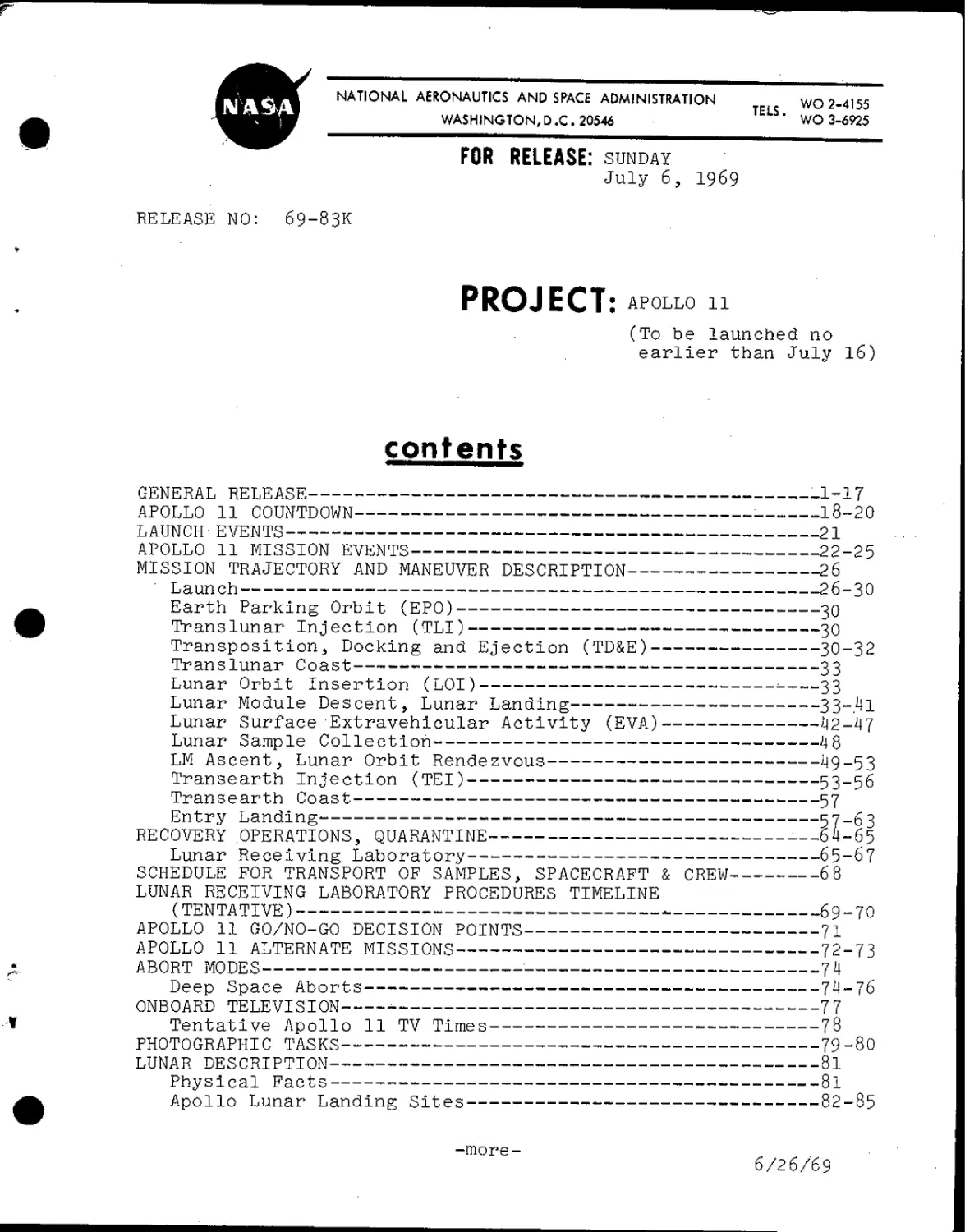
FOR RELEASE: Sunday
July 6, 1969
RELEASE NO: 69-83K
PROJECT:
11
(To be launched no
earlier than July 16)
contents
GENERAL RELEASE 1q1L
APOLLO 11 COUNTDOWN : 10-20
LAUNCH EVENTS 21
APOLLO 11 MISSION EVENTS 22-25
MISSION TRAJECTORY AND MANEUVER DESCRIPTION 26
¦ Launch 26-30
Earth Parking Orbit (EPO) 30
Translunar Injection (TLI) 30
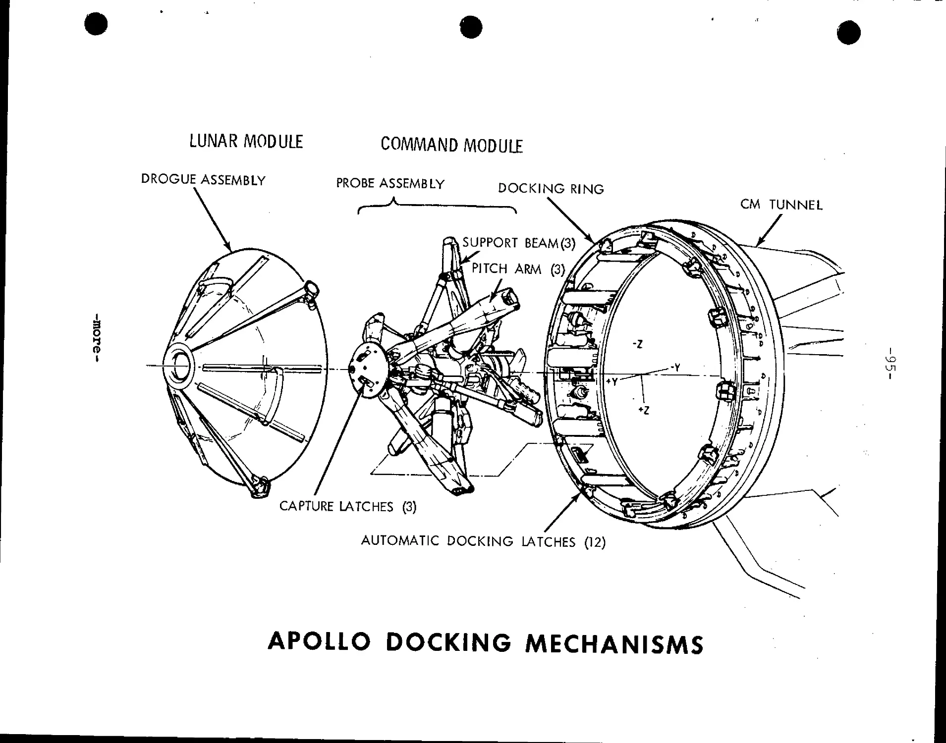
Transposition, Docking and Ejection (TD&E) 30-32
Translunar Coast 33
Lunar Orbit Insertion (LOI) ; 33
Lunar Module Descent, Lunar Landing 33~.4l
Lunar Surface Extravehicular Activity (EVA) 42-47
Lunar Sample Collection 48
LM Ascent, Lunar Orbit Rendezvous 49-53
Transearth Injection (TEI) 53-56
Trans earth Coast 57
Entry Landing P7~^
RECOVERY OPERATIONS, QUARANTINE —64-65
Lunar Receiving Laboratory rcT
SCHEDULE FOR TRANSPORT OF SAMPLES, SPACECRAFT & CREW 6 8
LUNAR RECEIVING LABORATORY PROCEDURES TIMELINE
(TENTATIVE) 69-70
APOLLO 11 GO/NO-GO DECISION POINTS 71
APOLLO 11 ALTERNATE MISSIONS 72-73
ABORT MODES 7J1
Deep Space Aborts 74-76
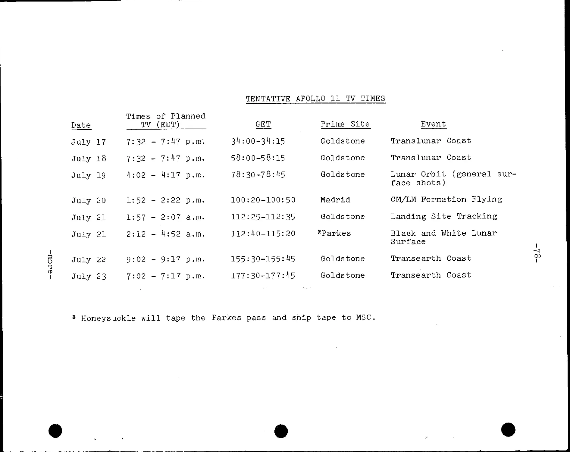
ONBOARD TELEVISION 77
Tentative Apollo 11 TV Times 7o
PHOTOGRAPHIC TASKS 79-80
LUNAR DESCRIPTION °x
Physical Facts °1
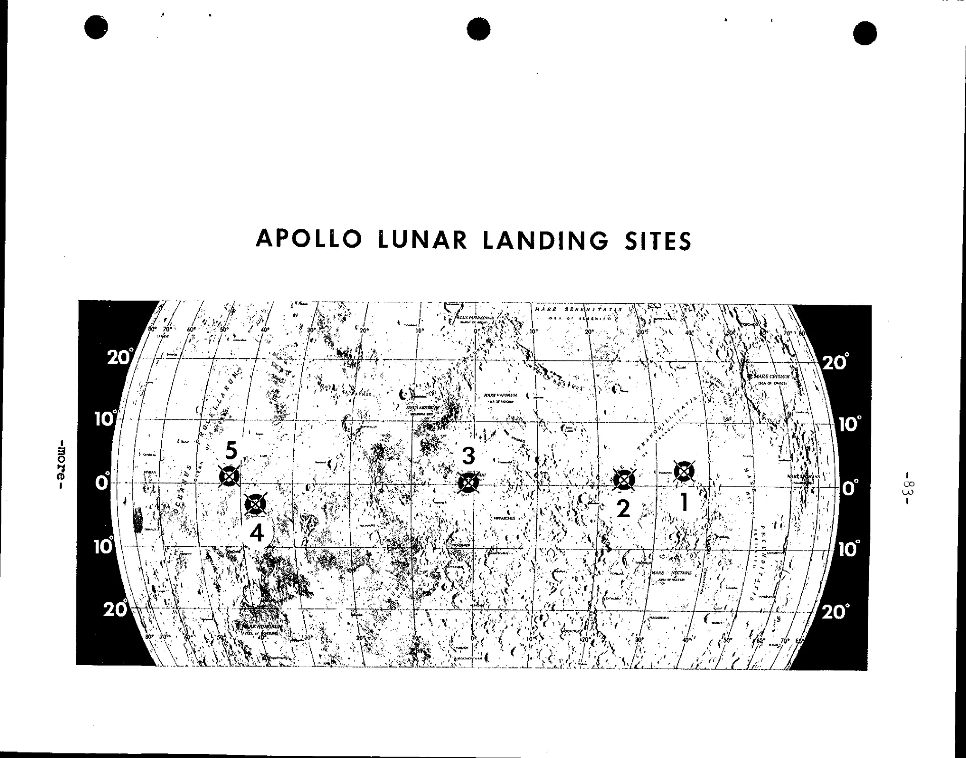
Apollo Lunar Landing Sites o2-o5
-more- . . ,,
6/26/69
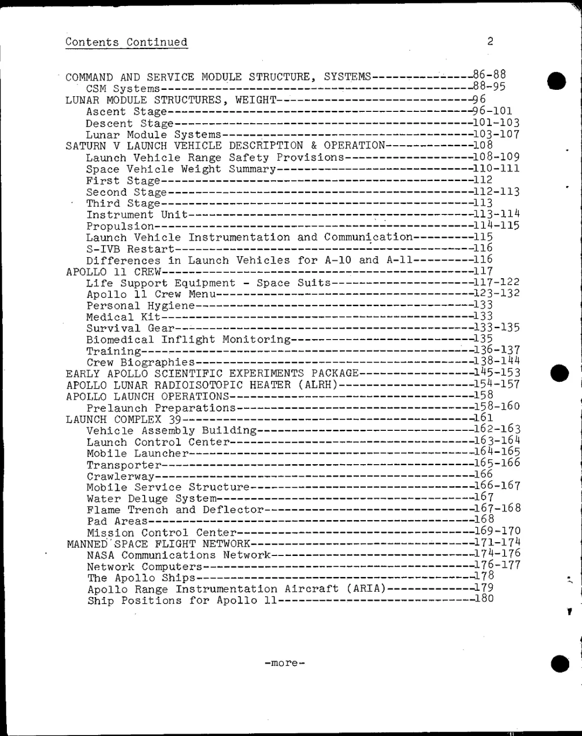
Contents Continued 2
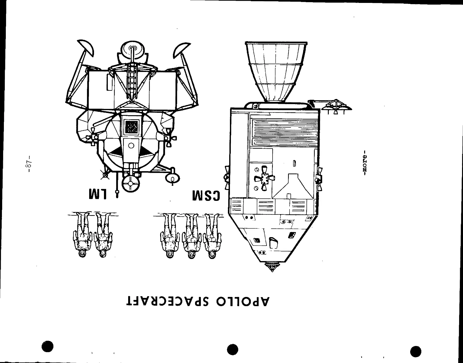
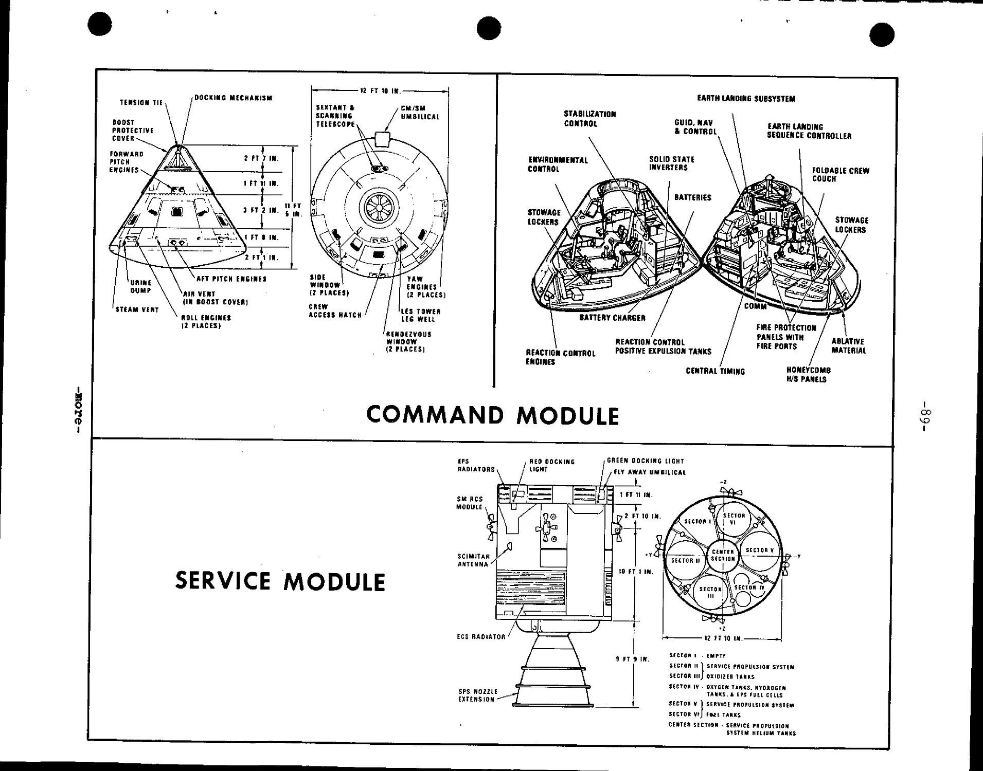
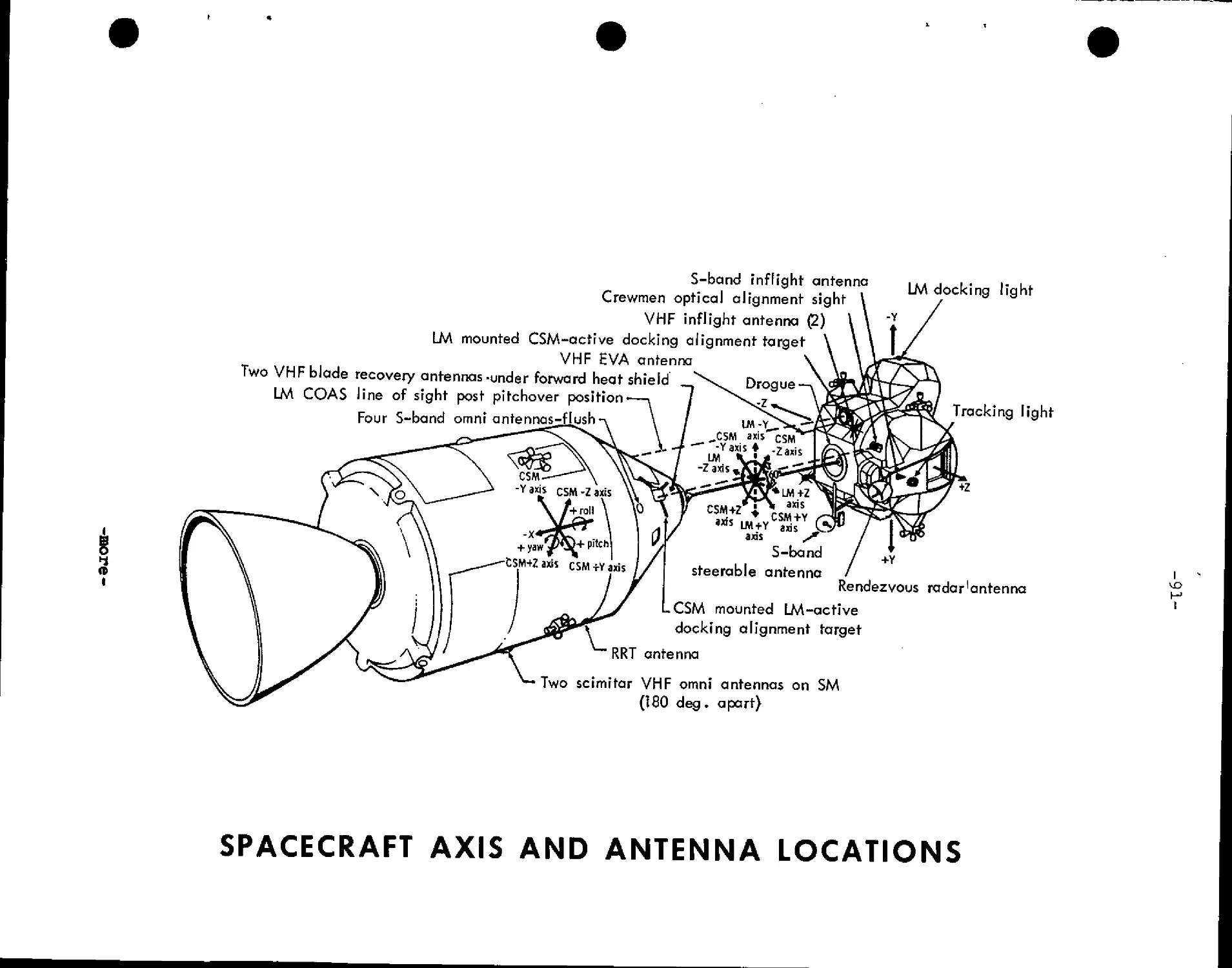
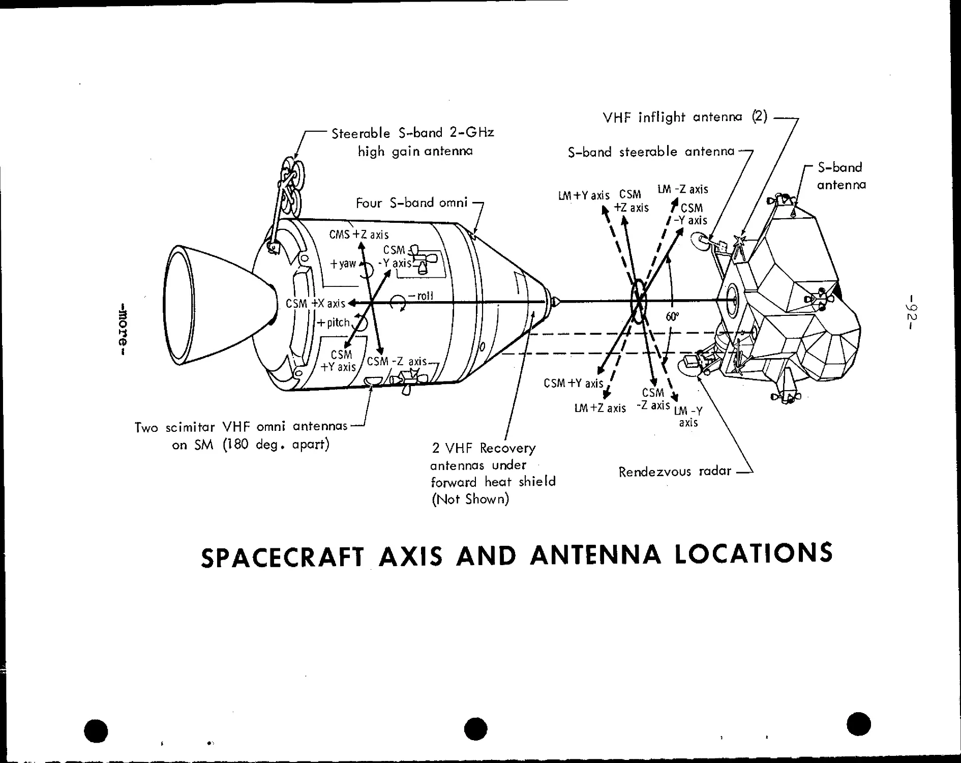
COMMAND AND SERVICE MODULE STRUCTURE, SYSTEMS - 86-88
' CSM Systems • • 88-95
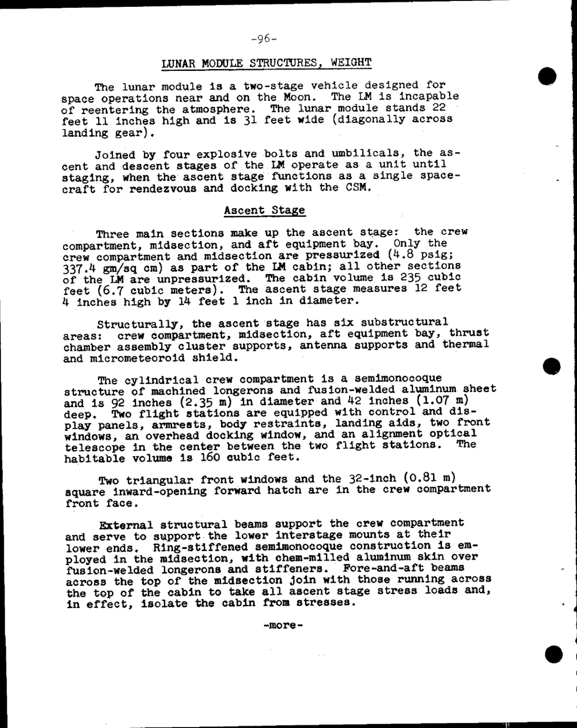
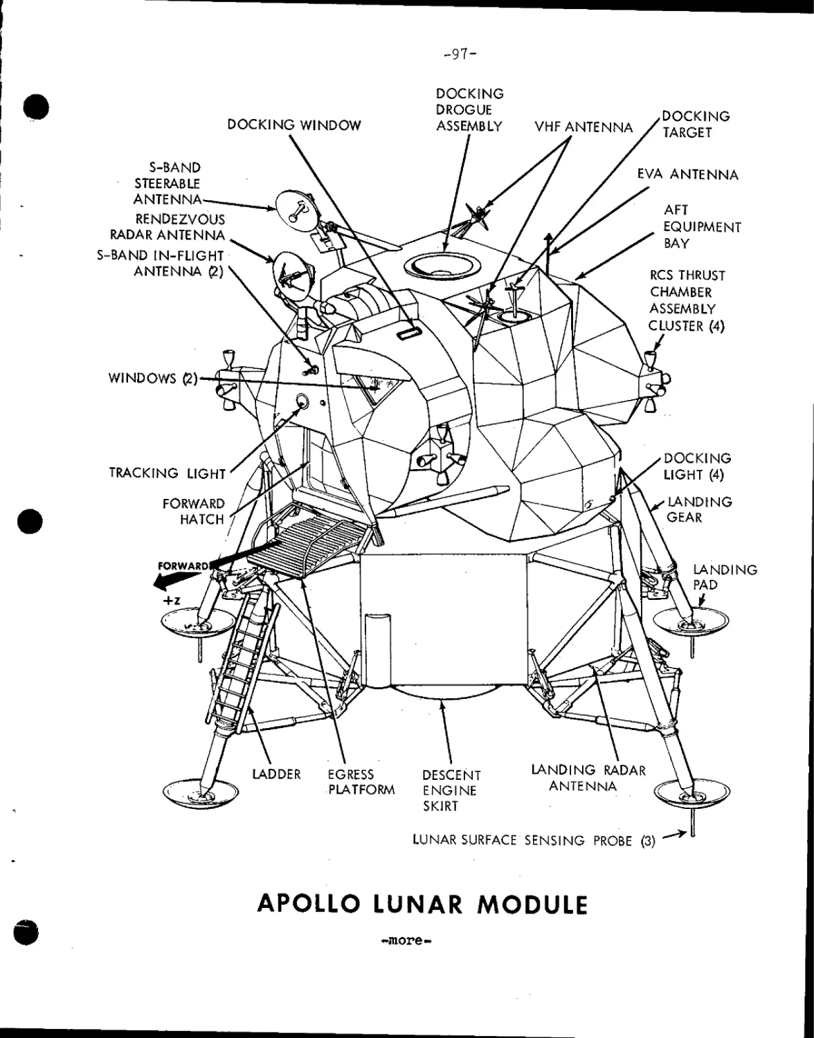
LUNAR MODULE STRUCTURES, WEIGHT— 96
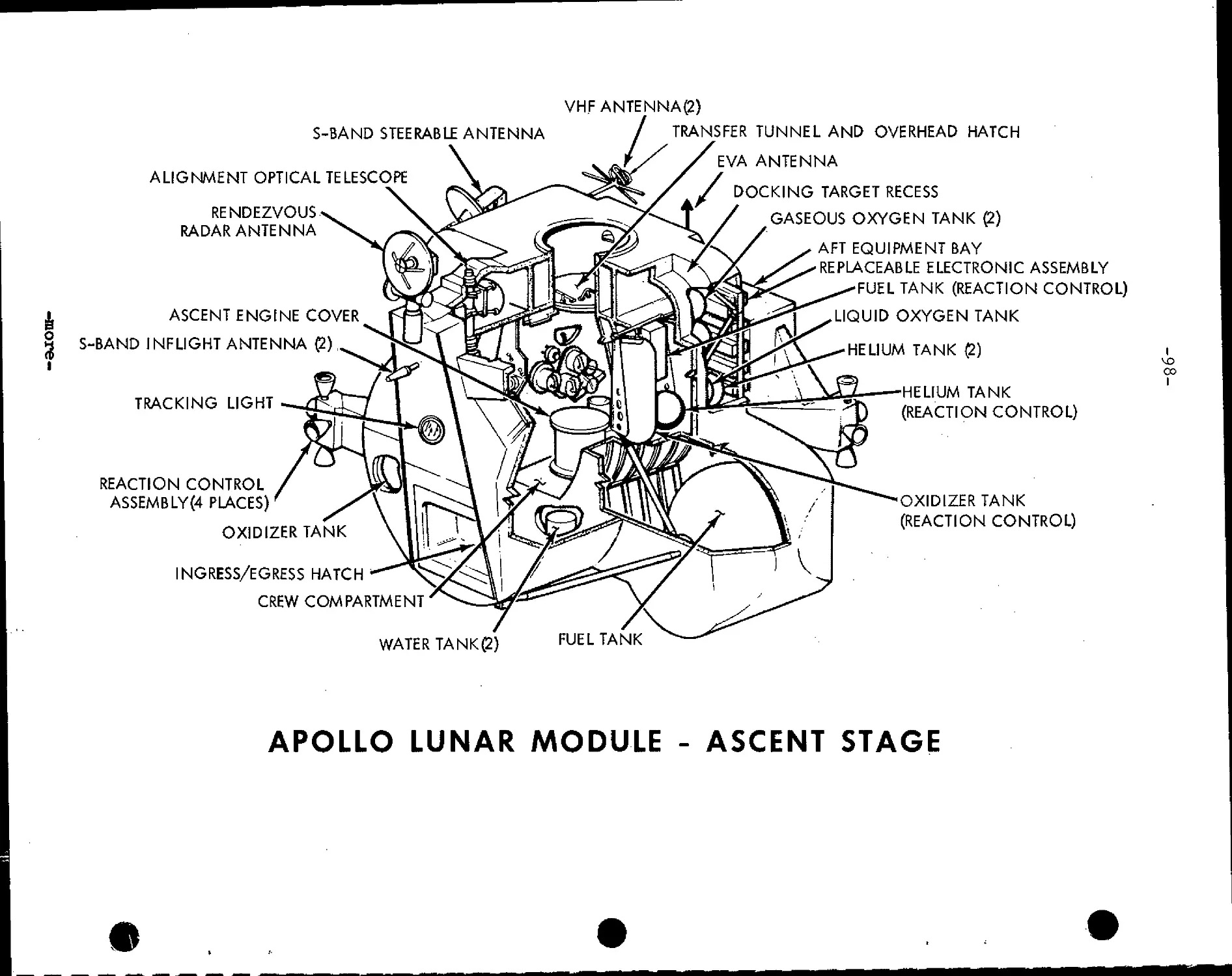
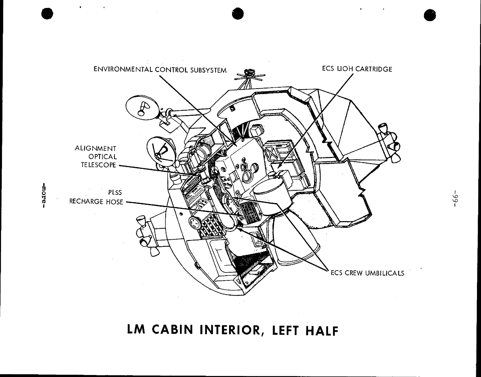
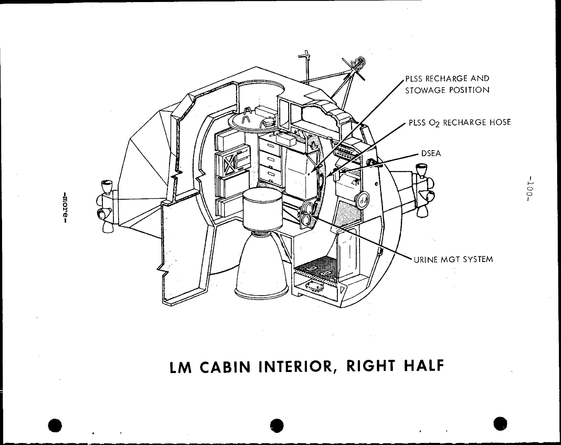
Ascent Stage 96-101
Descent Stage 101-103
Lunar Module Systems 103-107
SATURN V LAUNCH VEHICLE DESCRIPTION & OPERATION 108
Launch Vehicle Range Safety Provisions 108-109
Space Vehicle Weight Summary 110-111
First Stage 112
Second Stage 112-113
- Third Stage 113
Instrument Unit — 113-114
Propulsion 114-115
Launch Vehicle Instrumentation and Communication 115
S-IVB Restart 116
Differences in Launch Vehicles for A-10 and A-ll 116
APOLLO 11 CREW ¦ 117
Life Support Equipment - Space Suits 117-122
Apollo 11 Crew Menu 123-132
Personal Hygiene 133
Medical Kit 133
Survival Gear— 133-135
Biomedical Inflight Monitoring 135
Training : '—136-137
Crew Biographies 138-144
EARLY APOLLO SCIENTIFIC EXPERIMENTS PACKAGE 145-153
APOLLO LUNAR RADIOISOTOPIC HEATER (ALRH) 154-157
APOLLO LAUNCH OPERATIONS 158
Prelaunch Preparations 158-160
LAUNCH COMPLEX 39 l61
Vehicle Assembly Building 162-163
Launch Control Center 163-164
Mobile Launcher 164-165
Transporter 165-166
Crawlerway 166
Mobile Service Structure 166-167
Water Deluge System • 167
Flame Trench and Deflector 167-168
Pad Areas 168
Mission Control Center 169-170
MANNED'SPACE FLIGHT NETWORK 171-174
NASA Communications Network 174-176
Network Computers 176-177
The Apollo Ships ¦¦ 178
Apollo Range Instrumentation Aircraft (ARIA) 179
Ship Positions for Apollo 11 : 180
-more-
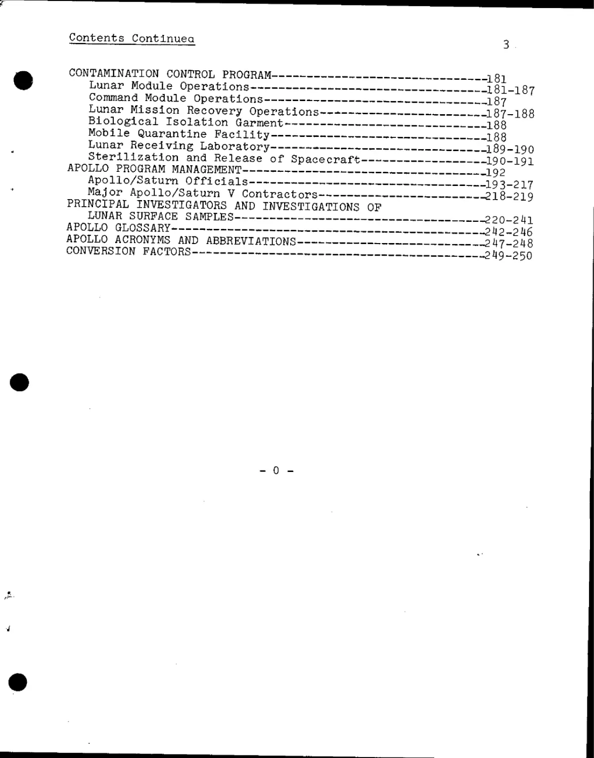
Contents Continued 3
CONTAMINATION CONTROL PROGRAM 181
Lunar Module Operations 18l-l87
Command Module Operations ¦ 187
Lunar Mission Recovery Operations 187-188
Biological Isolation Garment 188
Mobile Quarantine Facility 188
Lunar Receiving Laboratory 189-190
Sterilization and Release of Spacecraft 190-191
APOLLO PROGRAM MANAGEMENT 192
Apollo/Saturn Officials 193-217
Major Apollo/Saturn V Contractors 218-219
PRINCIPAL INVESTIGATORS AND INVESTIGATIONS OP
LUNAR SURFACE SAMPLES 220-2 41
APOLLO GLOSSARY 242-246
APOLLO ACRONYMS AND ABBREVIATIONS 2 47-248
CONVERSION FACTORS 249-250
- 0 -
NEWS
NATIONAL AERONAUTICS AND SPACE ADMINISTRATION
WASHINGTON,D.C. 20546
TELS.
WO 2-4155
WO 2-6925
FOR RELEASE:
SUNDAY
July 6, 1969
RELEASE NO: 69-83K
APOLLO 11
The United States will launch a three-man spacecraft
toward the Moon on July 16 with the goal of landing two astronaut-
explorers on the lunar surface four days later.
If the mission—called Apollo 11—is successful, man will
accomplish his long-time dream of walking on another celestial
body.
The first astronaut on the Moon's surface will be 38-year-old
Neil A. Armstrong of Wapakoneta, Ohio, and his initial act will be
to unveil a plaque whose message symbolizes the nature of the
journey.
Affixed to the leg of the lunar landing vehicle, the plaque
is signed by President Nixon, Armstrong and his Apollo 11 compan-
ions, Michael Collins and Edwin E. Aldrin, Jr.
-more-
6/26/69
It bears a map of the Earth and this inscription:
HERE MEN FROM THE PLANET EARTH
FIRST SET FOOT UPON THE MOON.
JULY 1969 A.D.
WE CAME IN PEACE FOR ALL MANKIND
The plaque is fastened to the descent stage of the lunar
module and thus becomes a permanent artifact on the lunar sur-
face.
Later Armstrong and Aldrin will emplant an American flag
on the surface of the Moon.
The Apollo 11 crew will also carry to the Moon and return
two large American flags, flags of the 50 states, District of
Columbia and U.S. Territories, flags of other nations and that
of the United Nations Organization.
During their 22-hour stay on the lunar surface, Armstrong
and Aldrin will spend up to 2 hours and 40 minutes outside the
lunar module, also gathering samples of lunar surface material
and deploying scientific experiments which will transmit back
to Earth valuable data on the lunar environment.
Apollo 11 is scheduled for launch at 9:32 a.m. EDT July 16
from the National Aeronautics and Space Administration's Kennedy
Space Center Launch Complex 39-A. The mission will be the fifth
manned Apollo flight and the third to the Moon.
-more-
— 3 —
The prime mission objective of Apollo 11 is stated simply:
"Perform a manned lunar landing and return". Successful fulfill-
ment of this objective will meet a national goal of this decade,
as set by President Kennedy May 25, 1961.
Apollo 11 Commander Armstrong and Command Module Pilot
Collins 38, and Lunar Module Pilot Aldrin, 39, will each be
making his second space flight. Armstrong was Gemini 8 commander,
and backup Apollo 8 commander; Collins was Gemini 10 pilot and
was command module pilot on the Apollo 8 crew until spinal
surgery forced him to leave the crew for recuperation; and Aldrin
was Gemini 12 pilot and Apollo 8 backup lunar module pilot.
Armstrong is a civilian, Collins a USAP lieutenant colonel and
Aldrin a USAP colonel.
Apollo 11 backup crewmen are Commander James A. Lovell,
Command Module Pilot William A. Anders, both of whom were on the
Apollo 8 first lunar orbit mission crew, and Lunar Module Pilot
Fred W. Haise.
-more-
-4-
The backup crew functions in three significant categories.
They help the prime crew with mission preparation and hardware
checkout activities. They receive nearly complete mission
training which becomes a valuable foundation for later assignment
as a prime crew and finally, should the prime crew become unavail-
able, they are prepared to fly as prime crew on schedule up until
the last few weeks at which time full duplicate training becomes
too costly and time consuming to be practical.
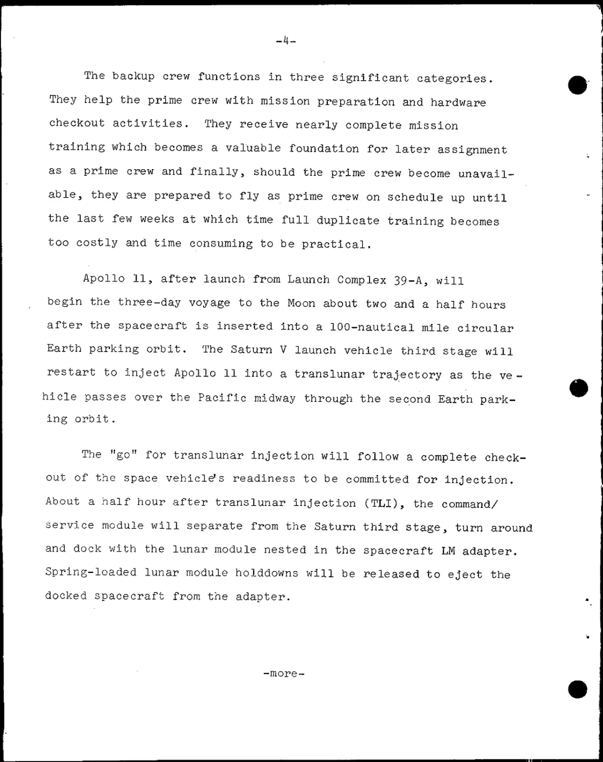
Apollo 11, after launch from Launch Complex 39-A, will
begin the three-day voyage to the Moon about two and a half hours
after the spacecraft is inserted into a 100-nautical mile circular
Earth parking orbit. The Saturn V launch vehicle third stage will
restart to inject Apollo 11 into a translunar trajectory as the ve-
hicle passes over the Pacific midway through the second Earth park-
ing orbit.
The "go" for translunar injection will follow a complete check-
out of the space vehicle's readiness to be committed for injection.
About a half hour after translunar injection (TLI), the command/
service module will separate from the Saturn third stage, turn around
and dock with the lunar module nested in the spacecraft LM adapter.
Spring-loaded lunar module holddowns will be released to eject the
docked spacecraft from the adapter.
-more-
APOLLO 11 Launch And Translunar Injection
3
O
4
W/d
yw \'
Astronaut Insertion
Check Of Systems
i
I
Saturn Staging
Translunar Injection
-6-
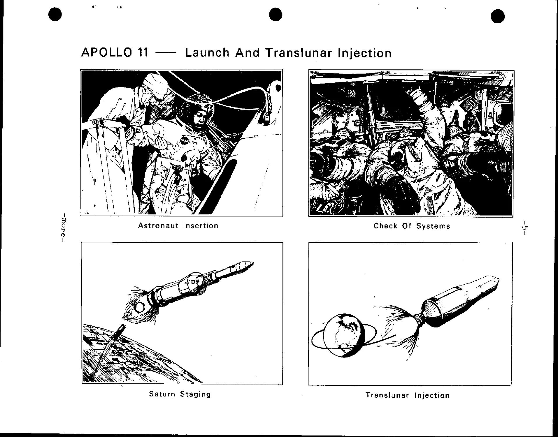
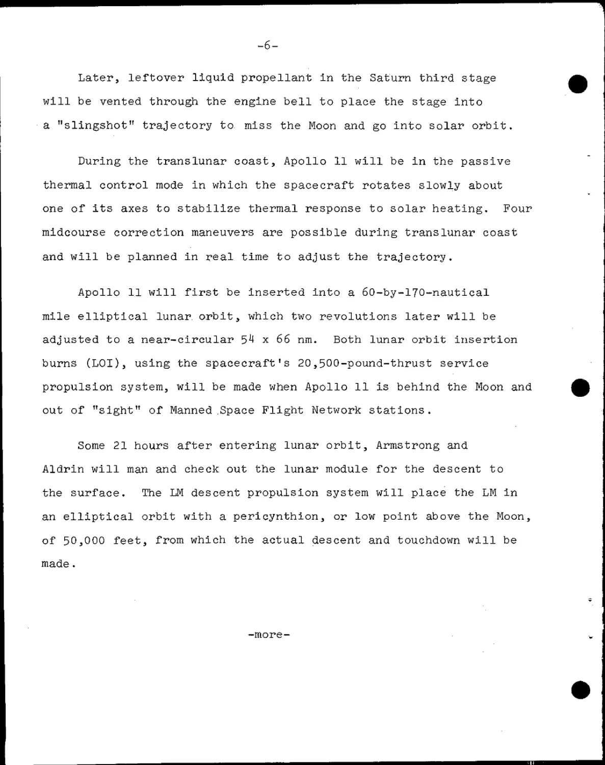
Later, leftover liquid propellant in the Saturn third stage
will be vented through the engine bell to place the stage into
a "slingshot" trajectory to. miss the Moon and go into solar orbit.
During the translunar coast, Apollo 11 will be in the passive
thermal control mode in which the spacecraft rotates slowly about
one of its axes to stabilize thermal response to solar heating. Four
midcourse correction maneuvers are possible during translunar coast
and will be planned in real time to adjust the trajectory.
Apollo 11 will first be inserted into a 6O-by-17O-nautical
mile elliptical lunar, orbit, which two revolutions later will be
adjusted to a near-circular 54 x 66 nm. Both lunar orbit insertion
burns (LOI), using the spacecraft's 20,500-pound-thrust service
propulsion system, will be made when Apollo 11 is behind the Moon and
out of "sight" of Manned .Space Flight Network stations.
Some 21 hours after entering lunar orbit, Armstrong and
Aldrin will man and check out the lunar module for the descent to
the surface. The LM descent propulsion system will place the LM in
an elliptical orbit with a pericynthion, or low point above the Moon,
of 50,000 feet, from which the actual descent and touchdown will be
made.
-more-
4 >¦>,,
APOLLO 11 Translunar Flight
i
o
4
CD
I
Transposition Maneuver
Extraction Of Lunar Module
i
—a
i
Navigation Check
Lunar Orbit Insertion
-8-
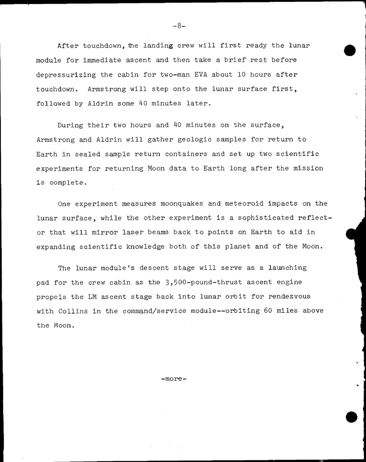
After touchdown, the landing crew will first ready the lunar
module for immediate ascent and then take a brief rest before
depressurizing the cabin for two-man EVA about 10 hours after
touchdown. Armstrong will step onto the lunar surface first,
followed by Aldrin some 40 minutes later.
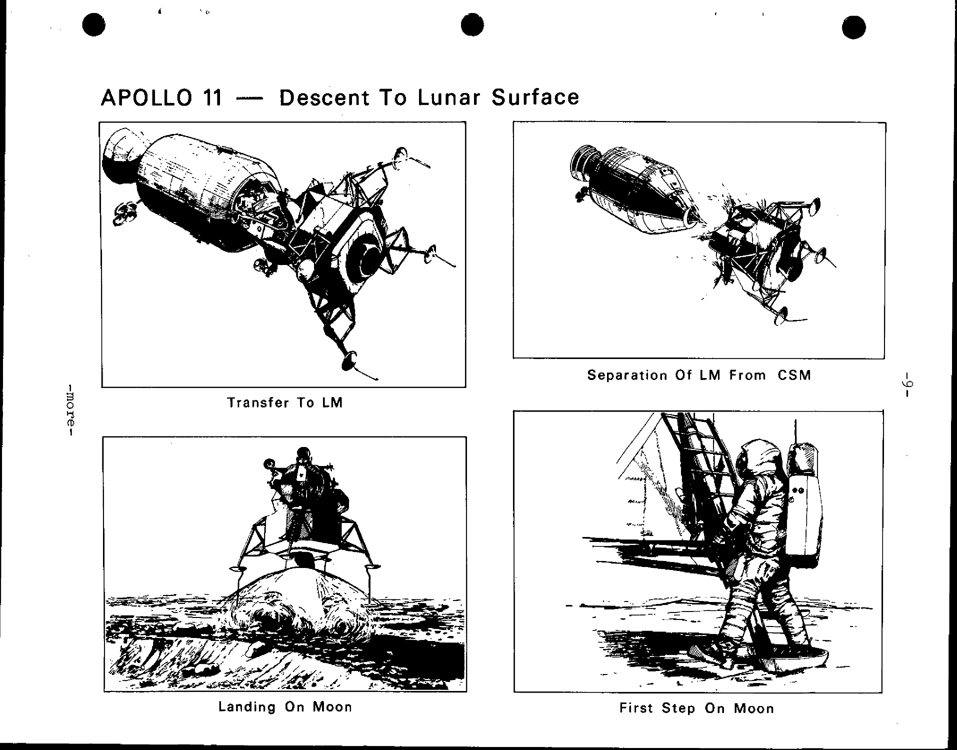
During their two hours and kO minutes on the surface,
Armstrong and Aldrin will gather geologic samples for return to
Earth in sealed sample return containers and set up two scientific
experiments for returning Moon data to Earth long after the mission
is complete.
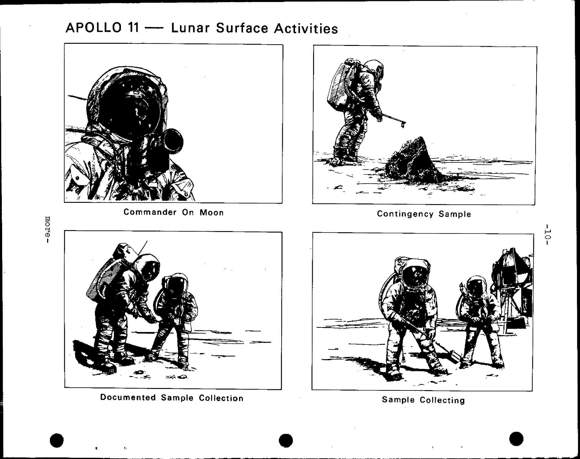
One experiment measures moonquakes and meteoroid impacts on the
lunar surface, while the other experiment is a sophisticated reflect-
or that will mirror laser beams back to points on Earth to aid in
expanding scientific knowledge both of this planet and of the Moon.
The lunar module's descent stage will serve as a launching
pad for the crew cabin as the 3,500-pound-thrust ascent engine
propels the LM ascent stage back into lunar orbit for rendezvous
with Collins in the command/service module—orbiting 60 miles above
the Moon.
-more-
APOLLO 11 — Descent To Lunar Surface
i
o
CD
i
Transfer To LM
Separation Of LM From CSM
Landing On Moon
First Step On Moon
APOLLO 11 — Lunar Surface Activities
w. ¦•<& if
Cdmmander On Moon
3
o
Contingency Sample
¦1
> - •^r)
IP
\flfeft
IS
» ^_ *. *¦ ..,,a
O
I
Documented Sample Collection
Sample Collecting
APOLLO 11
Lunar Surface Activities
Experiment Placements
i
3
o
i
TV Camera
Alignment Of Passive
Seismometer
Bulk Sample Collection
-12-
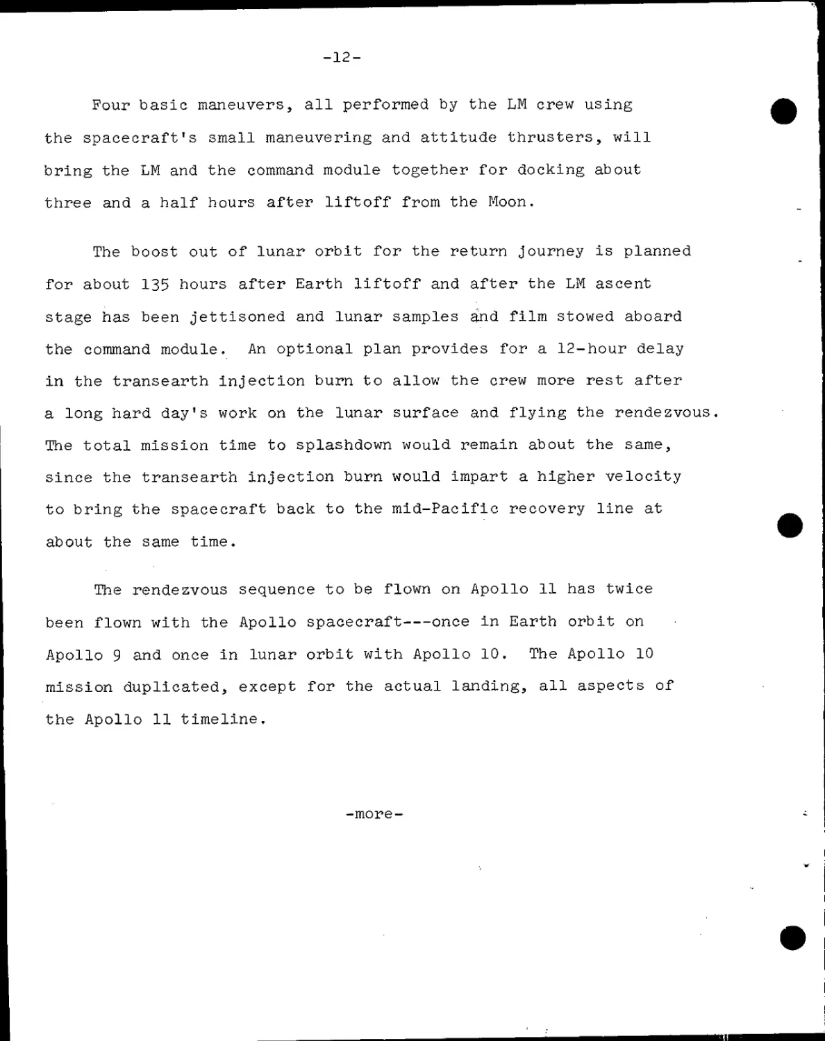
Four basic maneuvers, all performed by the LM crew using
the spacecraft's small maneuvering and attitude thrusters, will
bring the LM and the command module together for docking about
three and a half hours after liftoff from the Moon.
The boost out of lunar orbit for the return journey is planned
for about 135 hours after Earth liftoff and after the LM ascent
stage has been jettisoned and lunar samples and film stowed aboard
the command module. An optional plan provides for a 12-hour delay
in the transearth injection burn to allow the crew more rest after
a long hard day's work on the lunar surface and flying the rendezvous.
The total mission time to splashdown would remain about the same,
since the transearth injection burn would impart a higher velocity
to bring the spacecraft back to the mid-Pacific recovery line at
about the same time.
The rendezvous sequence to be flown on Apollo 11 has twice
been flown with the Apollo spacecraft once in Earth orbit on
Apollo 9 and once in lunar orbit with Apollo 10. The Apollo 10
mission duplicated, except for the actual landing, all aspects of
the Apollo 11 timeline.
-more-
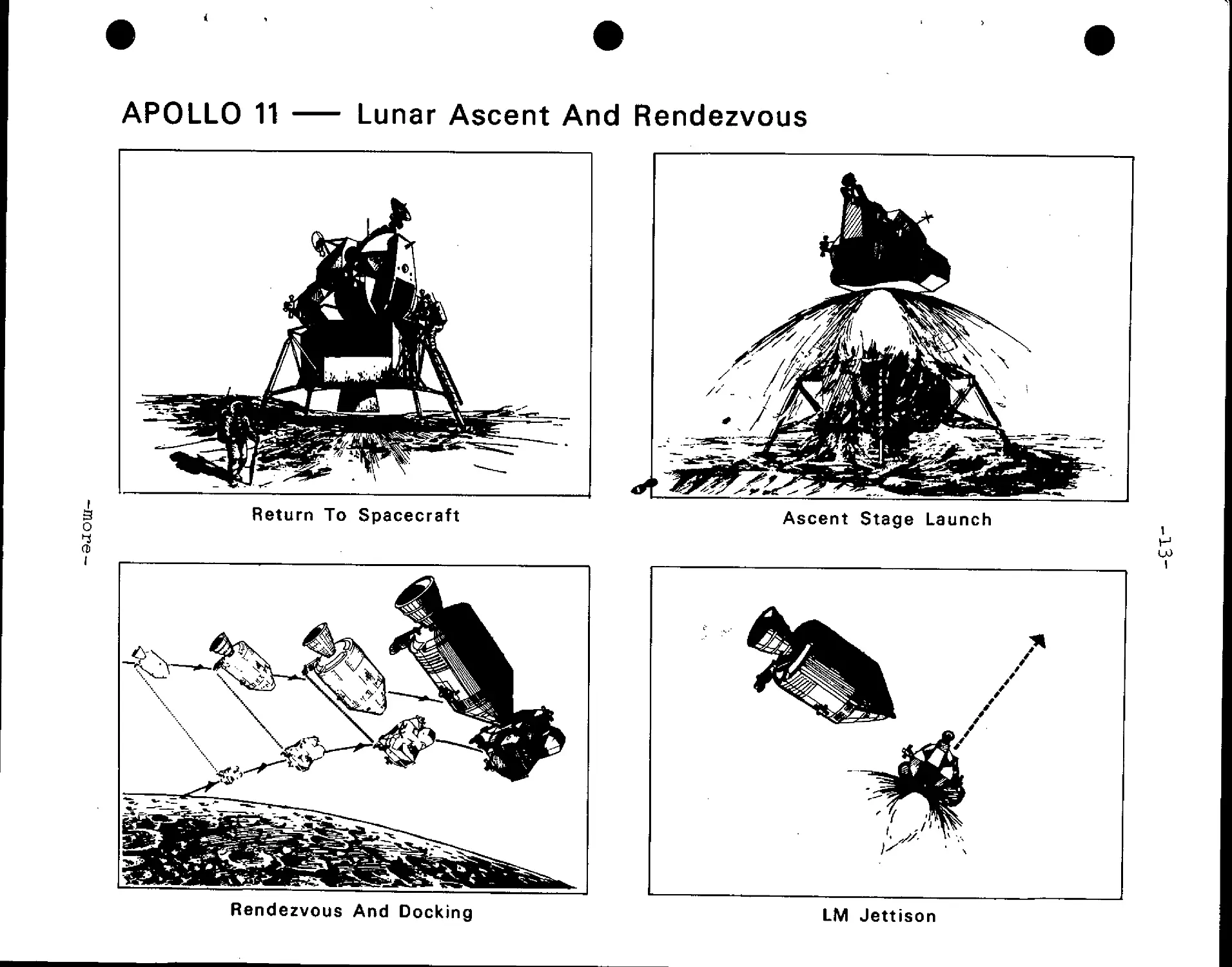
APOLLO 11
Lunar Ascent And Rendezvous
o
CD
I
Return To Spacecraft
Ascent Stage Launch
i
H
Rendezvous And Docking
LM Jettison
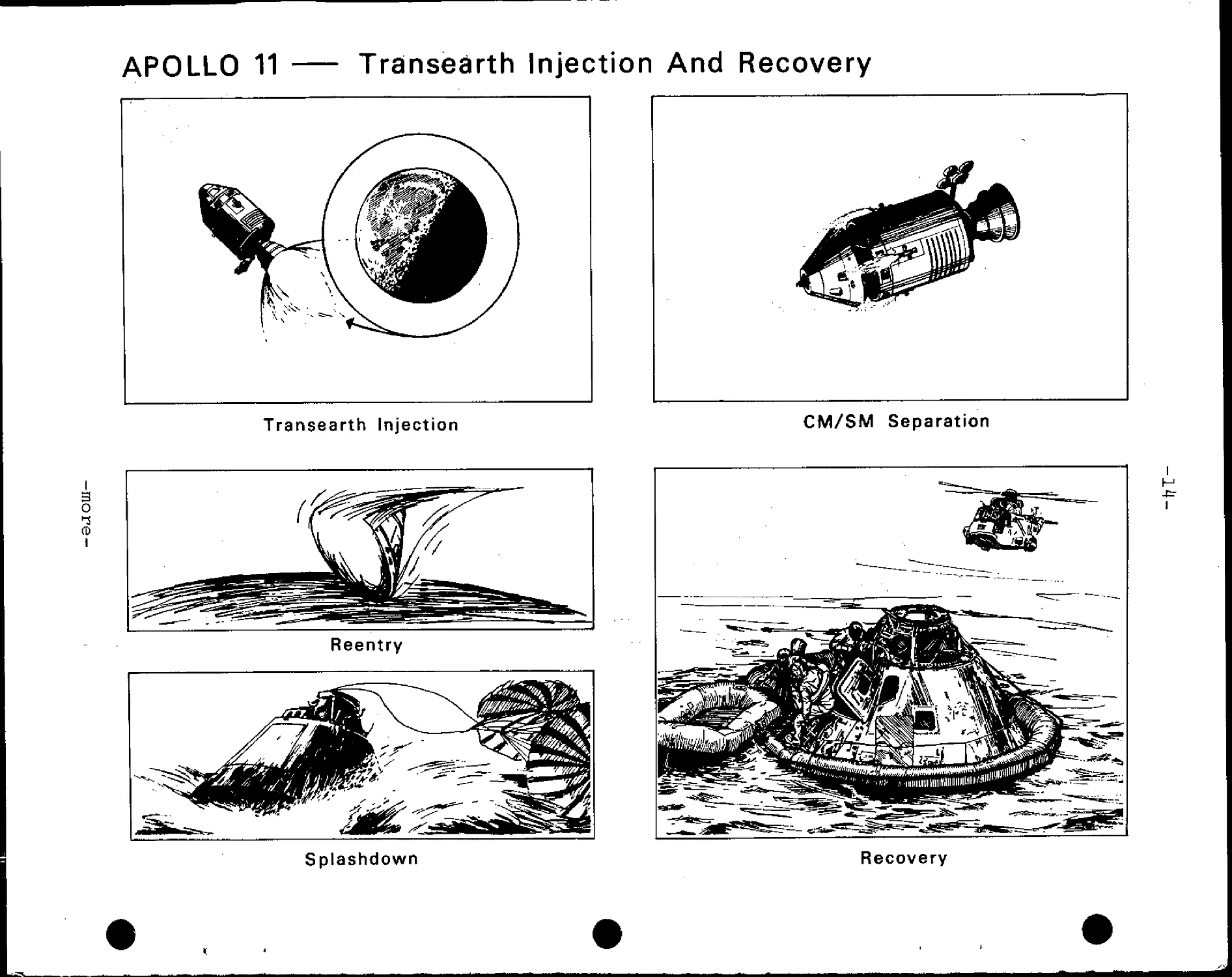
APOLLO 11
Transecirth Injection And Recovery
Transearth Injection
CM/SM Separation
I
Reentry
Splashdown
Recovery
-15-
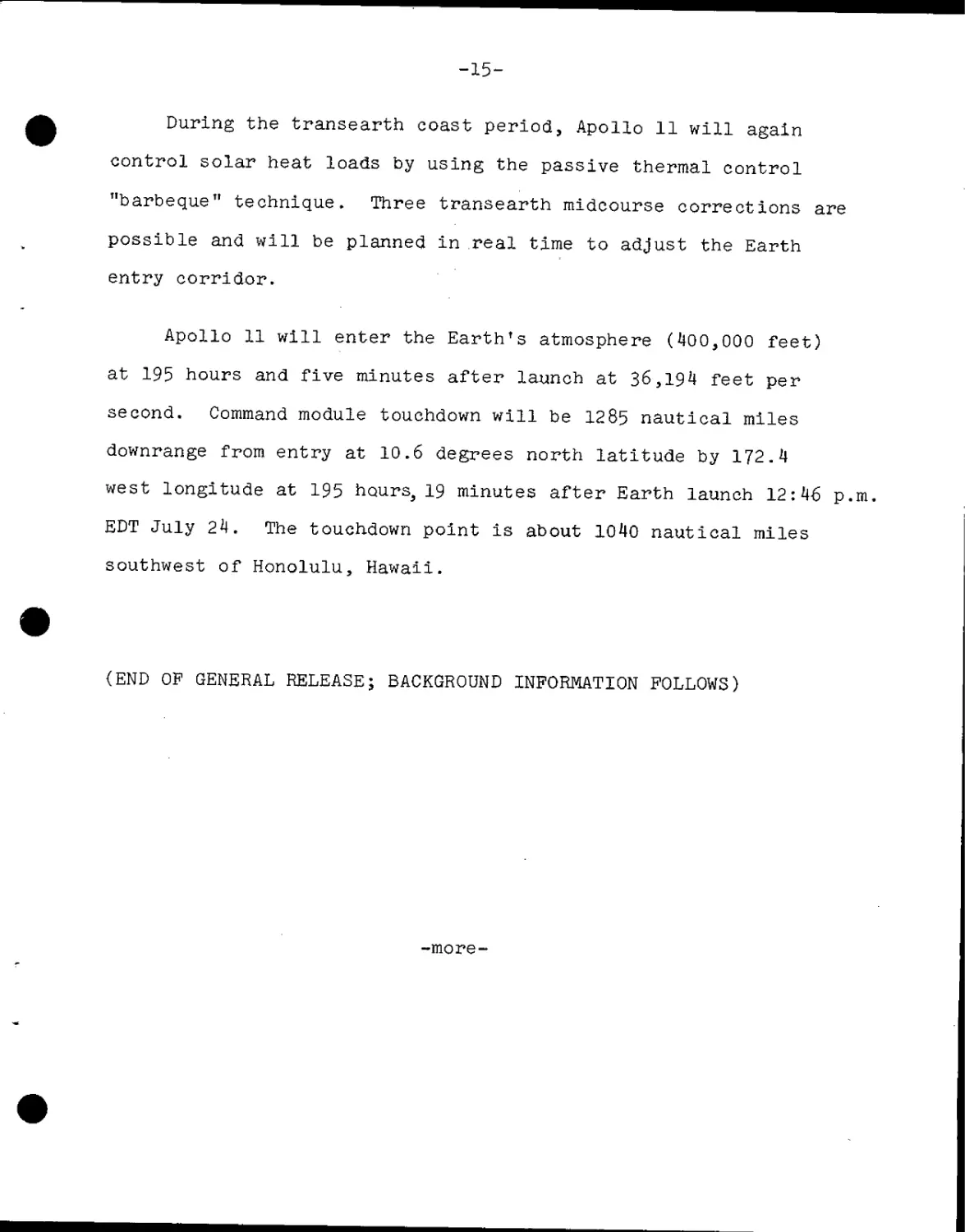
During the transearth coast period, Apollo 11 will again
control solar heat loads by using the passive thermal control
"barbeque" technique. Three transearth midcourse corrections are
possible and will be planned in real time to adjust the Earth
entry corridor.
Apollo 11 will enter the Earth's atmosphere D00,000 feet)
at 195 hours and five minutes after launch at 36,194 feet per
second. Command module touchdown will be 1285 nautical miles
downrange from entry at 10.6 degrees north latitude by 172.4
west longitude at 195 hours^ 19 minutes after Earth launch 12:46 p.m.
EDT July 24. The touchdown point is about 1040 nautical miles
southwest of Honolulu, Hawaii.
(END OP GENERAL RELEASE; BACKGROUND INFORMATION FOLLOWS)
-more-
-16-
Official Apollo 11 Insignia
This photograph not for release
before Saturday, July 5, 19&9
-more-
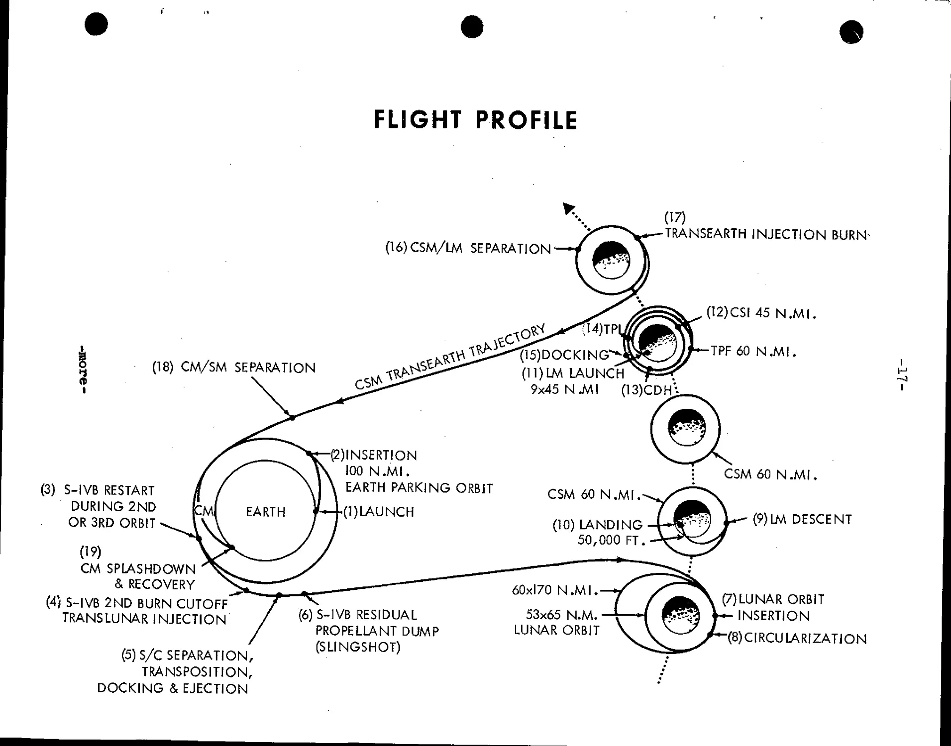
FLIGHT PROFILE
A6)CSM/LM SEPARATION'
A8) CM/SM SEPARATION
C) S-IVB RESTART
DURING 2ND
OR 3RD ORBIT
A9)
CM SPLASHDOWN
& RECOVERY
D) S-IVB 2ND BURN CUTOFF'
TRANSLUNAR INJECTION
E) S/C SEPARATION,
TRANSPOSITION,
DOCKING & EJECTION
A5)DOCKING
(ll)LM LAUNCH
9x45 N.Ml A3)CDH"
)INSERTION
100 N.MI.
EARTH PARKING ORBIT
CSM 60 N.MI.
(l)LAUNCH
A0) LANDING
50,000 FT.
60x170 N.MI.
53x65 N.M.
LUNAR ORBIT
TRANSEARTH INJECTION BURN-
A2)CSI 45 N.MI,
TPF60 N.MI
CSM 60 N.MI.
(9)LM DESCENT
F) S-IVB RESIDUAL
PROPELLANT DUMP
(SLINGSHOT)
G)LUNAR ORBIT
INSERTION
(8)C[RCULARIZATION
H
I
-18-
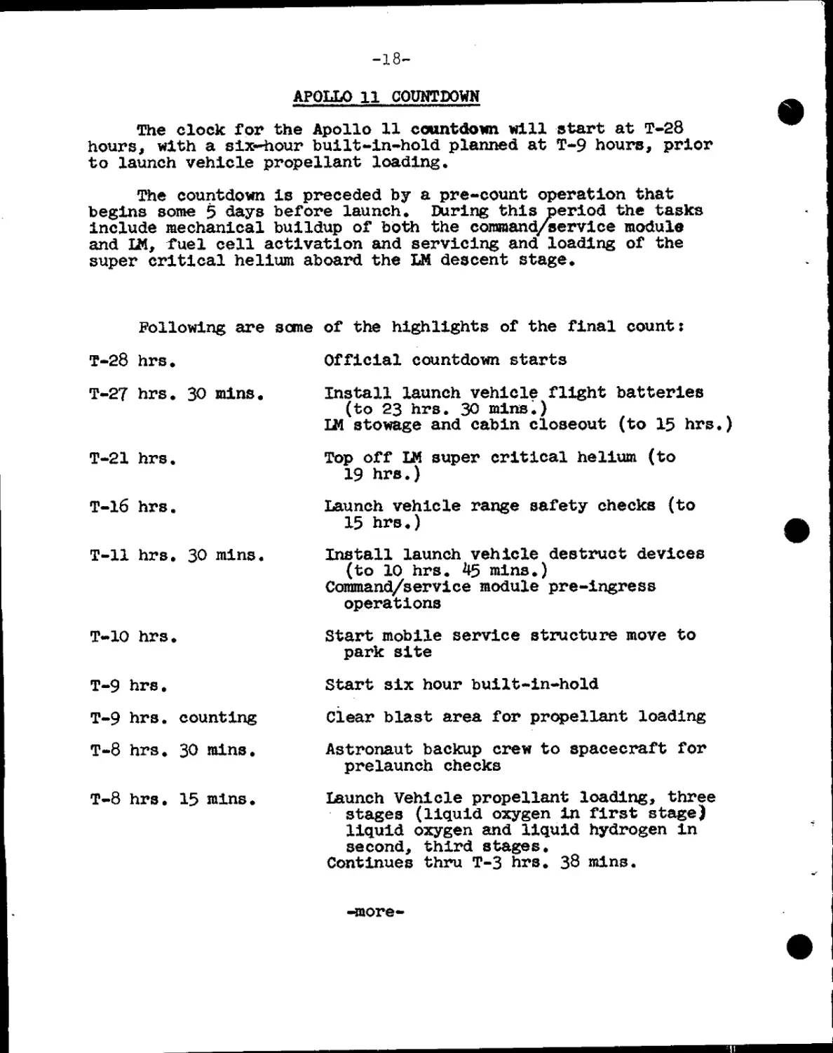
APQLLO 11 COUNTDOWN
The clock for the Apollo 11 countdown will start at T-28
hours, with a six-hour built-in-hold planned at T-9 hours, prior
to launch vehicle propellant loading.
The countdown is preceded by a pre-count operation that
begins some 5 days before launch. During this period the tasks
include mechanical buildup of both the command/service module
and LM, fuel cell activation and servicing and loading of the
super critical helium aboard the LM descent stage.
Following are
T-28 hrs.
T-27 hrs. 30 mins.
T-21 hrs.
T-16 hrs.
T-ll hrs. 30 mins.
T-10 hrs.
T-9 hrs.
T-9 hrs. counting
T-8 hrs. 30 rains.
T-8 hrs. 15 mins.
some of the highlights of the final count:
Official countdown starts
Install launch vehicle flight batteries
(to 23 hrs. 30 mins.)
LM stowage and cabin closeout (to 15 hrs.)
Top off LM super critical helium (to
19 hrs.)
Launch vehicle range safety checks (to
15 hrs.)
Install launch vehicle destruct devices
(to 10 hrs. 45 mins.)
Command/service module pre-ingress
operations
Start mobile service structure move to
park site
Start six hour built-in-hold
clear blast area for propellant loading
Astronaut backup crew to spacecraft for
prelaunch checks
Launch Vehicle propellant loading, three
stages (liquid oxygen in first stage)
liquid oxygen and liquid hydrogen in
second, third stages.
Continues thru T-3 hrs. 38 mins.
-more-
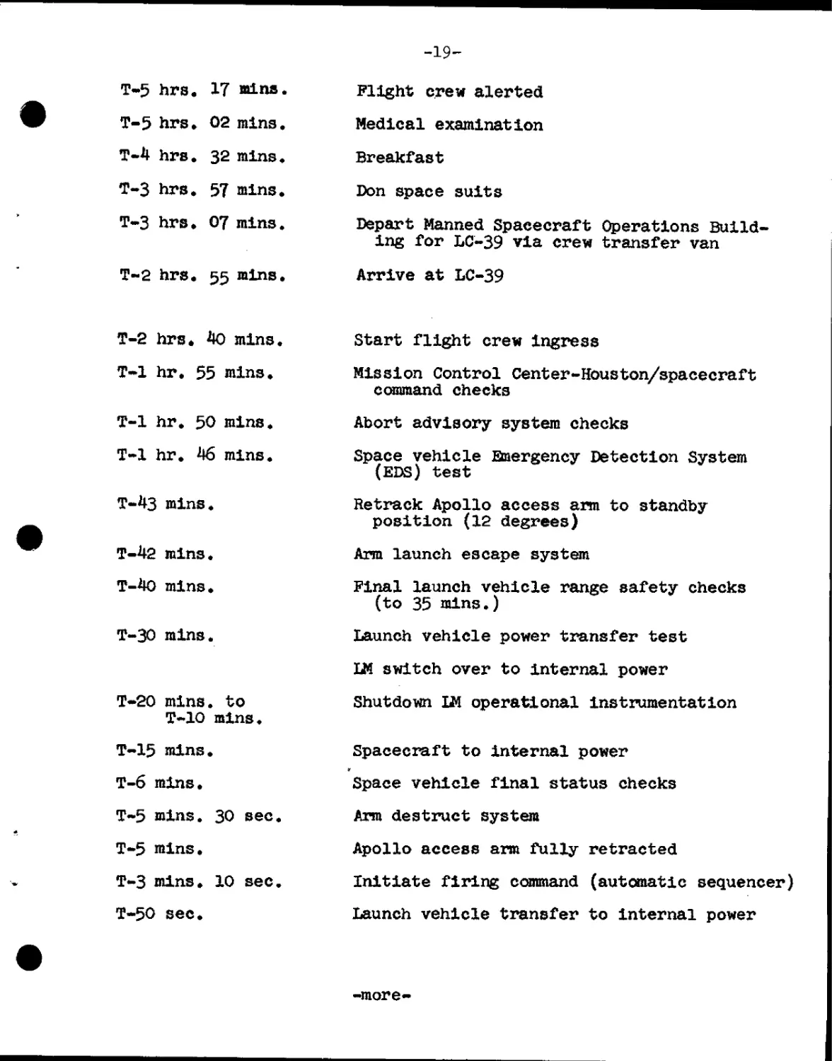
-19-
T-5 hrs. 17 mlns.
T-5 hrs. 02 mlns.
T-4 hrs. 32 mlns.
T-3 hrs. 57 mlns.
T-3 hrs. 07 mlns.
T-2 hrs. 55 mlns.
Plight crew alerted
Medical examination
Breakfast
Don space suits
Depart Manned Spacecraft Operations Build-
ing for LC-39 via crew transfer van
Arrive at LC-39
T-2 hrs. 40 mlns.
T-l hr. 55 mins.
T-l hr. 50 mins.
T-l hr. H6 mlns.
T-43 mins.
T-42 mlns.
T-40 mins.
T-30 mlns.
T-20 mins. to
T-10 mlns.
T-15 mlns.
T-6 mins.
T-5 mins. 30 sec.
T-5 mins.
T-3 mins. 10 sec.
T-50 sec.
Start flight crew ingress
Mission Control Center-Houston/spacecraft
command checks
Abort advisory system checks
Space vehicle Emergency Detection System
(EDS) test
Retrack Apollo access arm to standby
position A2 degrees)
Arm launch escape system
Final launch vehicle range safety checks
(to 35 mins.)
Launch vehicle power transfer test
LM switch over to internal power
Shutdown LM operational instrumentation
Spacecraft to internal power
Space vehicle final status checks
Arm destruct system
Apollo access arm fully retracted
Initiate firing command (automatic sequencer)
Launch vehicle transfer to internal power
-more-
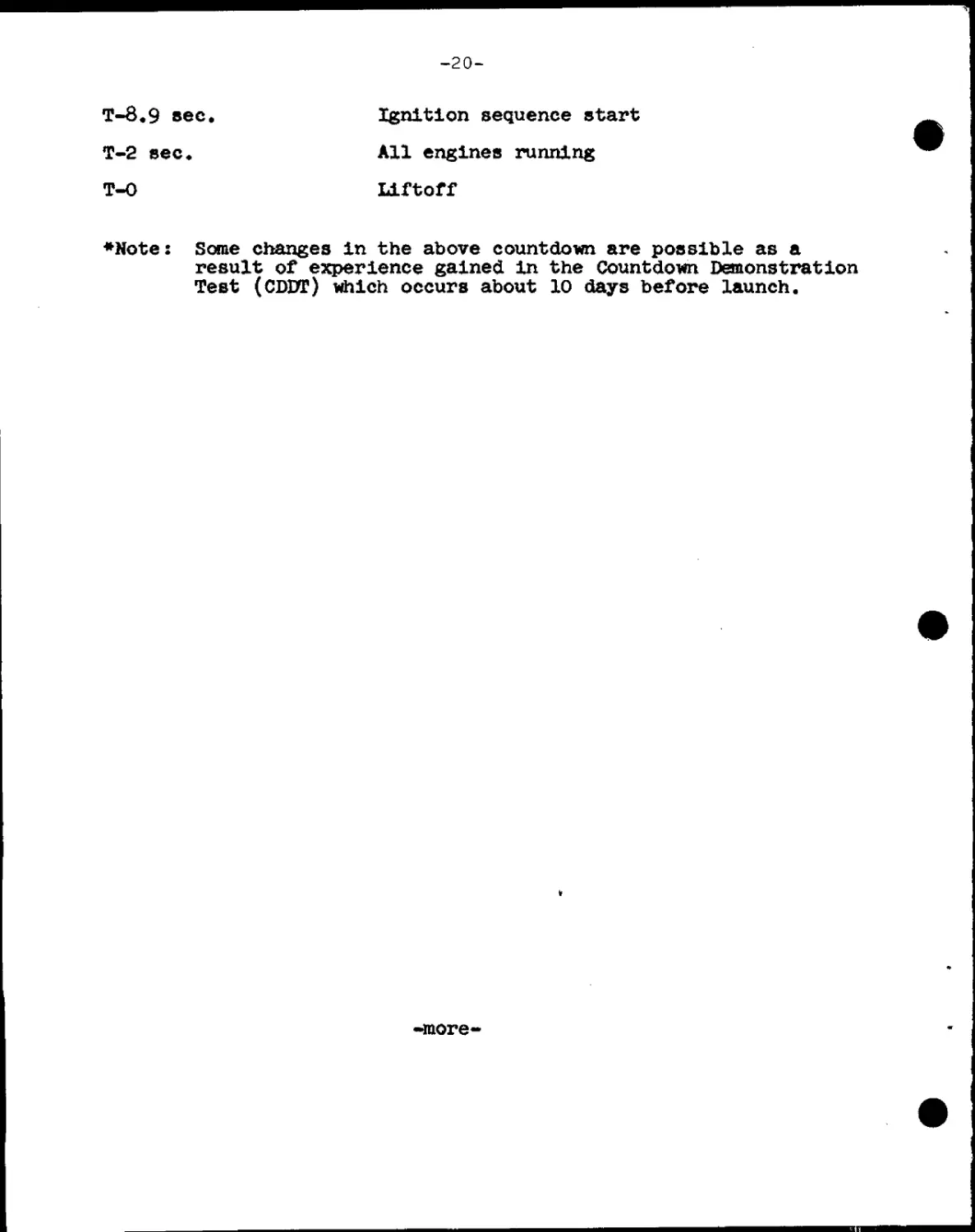
-20-
T-8.9 sec. Ignition sequence start
T-2 sec. All engines running
T-0 Liftoff
¦Note: Some changes in the above countdown are possible as a
result of experience gained in the Countdowi Demonstration
Test (CDDT) Which occurs about 10 days before launch.
-more-
-21-
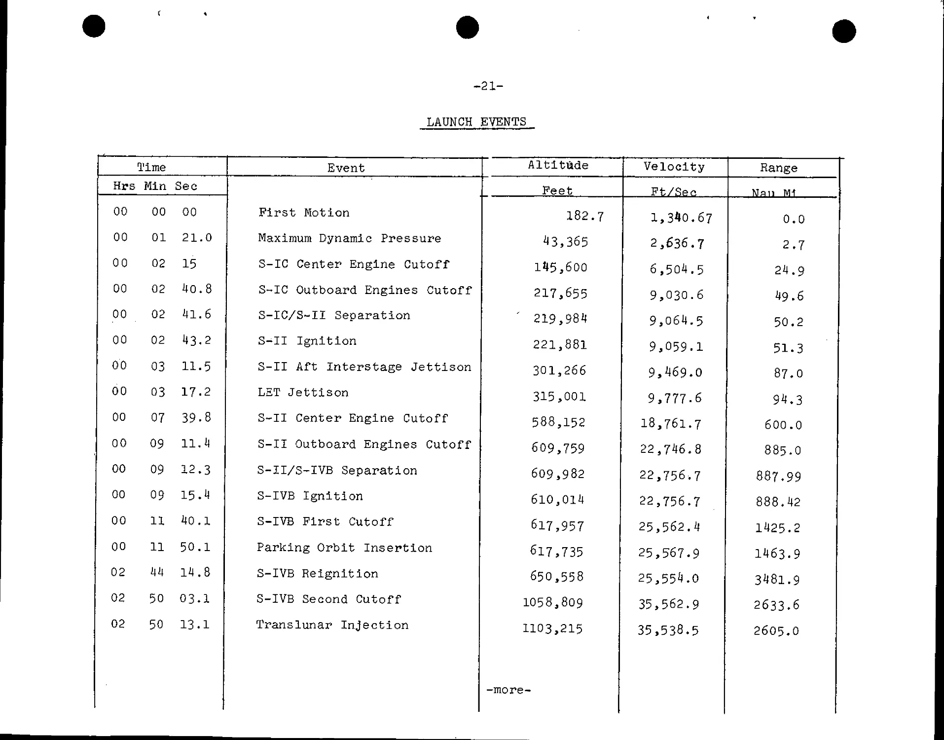
LAUNCH EVENTS
Hrs
00
00
00
00
00
00
00
00
00
00
00
00
00
oo
02
02
02
Time
Min
00
01
02
02
02
02
03
03
07
09
09
09
11
11
44
50
50
Sec
00
21.0
15
40.8
41.6
43.2
11.5
17.2
39-8
11.4
12.3
15.4
40.1
50.1
14.8
03.1
13.1
Event
First Motion
Maximum Dynamic Pressure
S-IC Center Engine Cutoff
S-IC Outboard Engines Cutoff
S-IC/S-II Separation
S-II Ignition
S-II Aft Interstage Jettison
LET Jettison
S-II Center Engine Cutoff
S-II Outboard Engines Cutoff
S-II/S-IVB Separation
S-IVB Ignition
S-IVB First Cutoff
Parking Orbit Insertion
S-IVB Reignition
S-IVB Second Cutoff
Translunar Injection
Altitude
Peet
182.7
43,365
11*5,600
217,655
' 219,984
221,881
301,266
315,001
588,152
609,759
609,982
610,014
617,957
617,735
650,558
1058,809
1103,215
-more-
Velocity
Ft/Ren
1,340.67
2,636.7
6,504.5
9,030.6
9,064.5
9,059.1
9,469.0
9,777.6
18,761.7
22,746.8
22,756.7
22,756.7
25,562.4
25,567.9
25,554.0
35,562.9
35,538.5
Range
Nan NH
0.0
2.7
24.9
49.6
50.2
51.3
87.O
94.3
600.0
885.O
887.99
888.42
1425-2
1463.9
3481.9
2633.6
2605.0
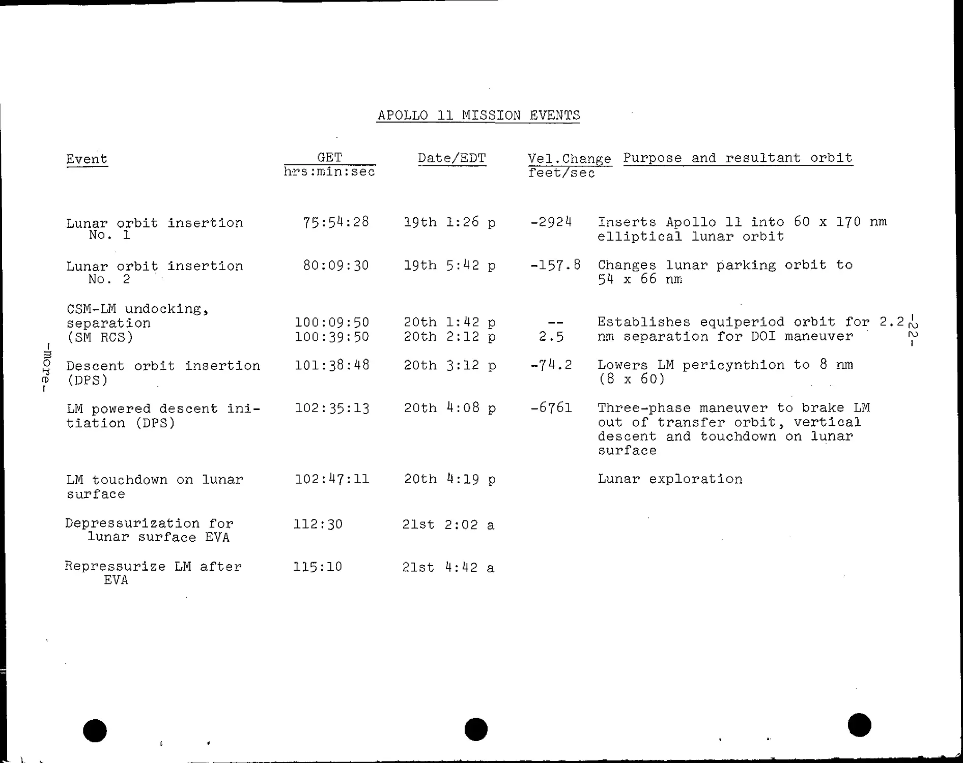
APOLLO 11 MISSION EVENTS
Event
GET
h-rs :min: sec
Date/EDT Vel.Change Purpose and resultant orbit
feet/sec
Lunar orbit insertion
No. 1
Lunar orbit insertion
No. 2
CSM-LM undocking,
separation
(SM RCS)
3
2 Descent orbit insertion
o> (DPS)
LM powered descent ini-
tiation (DPS)
LM touchdown on lunar
surface
75:54:28
80:09:30
100:09:50
100:39:50
Depressurization for 112:30
lunar surface EVA
Repressurize LM after 115:10
EVA
19th 1:26 p
19th 5:42 p
20th 1:42 p
20th 2:12 p
101:38:48 20th 3:12 p
21st 2:02 a
21st 4:42 a
-2924 Inserts Apollo 11 into 60 x 170 nm
elliptical lunar orbit
-157.8 Changes lunar parking orbit to
54 x 66 nm
2.5
-74.2
102:35:13 20th 4:08 p -6761
102:47:11 20th 4:19 P
Establishes equiperiod orbit for 2.2
nm separation for DOI maneuver
Lowers LM pericynthion to 8 nm
(8 x 60)
Three-phase maneuver to brake LM
out of transfer orbit, vertical
descent and touchdown on lunar
surface
Lunar exploration
L I
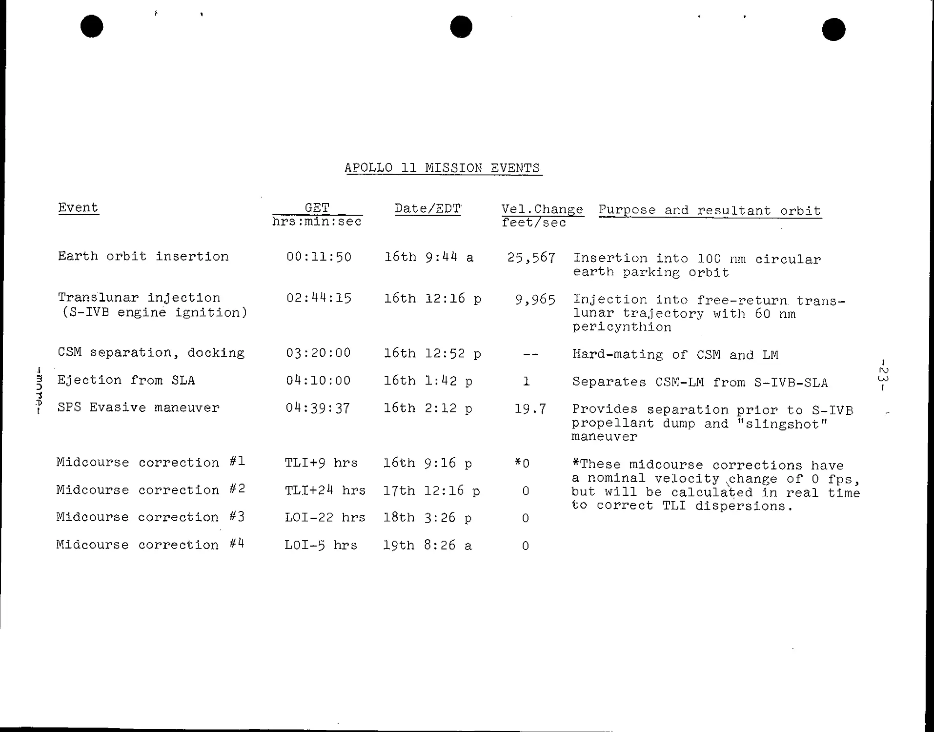
APOLLO 11 MISSION EVENTS
Event
Earth orbit insertion
Translunar injection
(S-IVB engine ignition)
CSM separation, docking
i
3 Ejection from SLA
-i
? SPS Evasive maneuver
Midcourse correction #1
Midcourse correction #2
Midcourse correction #3
Midcourse correction #^
GET
Date/EDT'
hrs:min:sec
00:11:50 l6th 9:41 a
03:20:00
04:10:00
04:39=37
Vel.Change Purpose and resultant orbit
feet/sec
25,567 Insertion into 100 nm circular
earth parking orbit
02:44:15 l6th 12:16 p 9,965 Injection into free-return, trans-
16th 12:52 p
16th 1:42 p
16th 2:12 p
TLI+9 hrs 16th 9:16 p
TLI+24 hrs 17th 12:16 p
LOI-22 hrs 18th 3:26 p
LOI-5 hrs 19th 8:26 a
1
19.7
*0
0
0
0
lunar trajectory with 60 nm
pericynthion
Hard-mating of CSM and LM
Separates CSM-LM from S-IVB-SLA
Provides separation prior to S-IVB
propellant dump and "slingshot"
maneuver
*These midcourse corrections have
a nominal velocity vchange of 0 fps,
but will be calculated in real time
to correct TLI dispersions.
1
CO
I
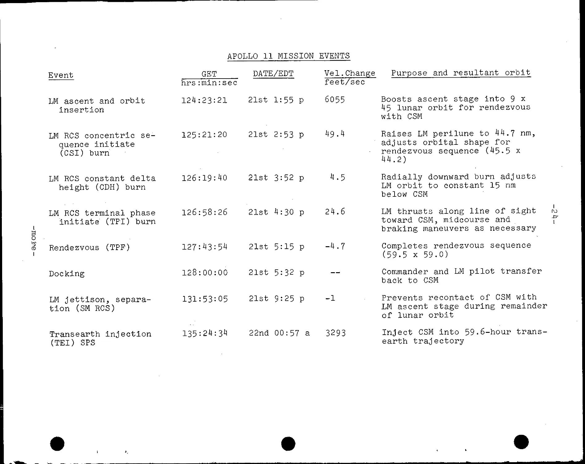
APOLLO 11 MISSION EVENTS
i
o
Event
LM ascent and orbit
Insertion
LM RCS concentric se-
quence initiate
(CSI) burn
LM RCS constant delta
height (CDH) burn
LM RCS terminal phase
initiate (TPI) burn
GET
DATE/EDT
ci> Rendezvous (TPF)
Docking
LM jettison, separa-
tion (SM RCS)
Transearth injection
(TEI) SPS
hrs:min:sec
124:23:21 21st 1:55 p
125:21:20 21st 2:53 P 49-4
126:19:40 21st 3:52 p H.5
126:58:26 21st 4:30 p 24.6
127:43:54 21st 5:15 p -4.7
128:00:00 21st 5:32 p
131:53:05 21st 9:25 p
Vel.Change
feet/sec
6055
Purpose and resultant orbit
-1
135:24:3^ 22nd 00:57 a 3293
Boosts ascent stage into 9 x
45 lunar orbit for rendezvous
with CSM
Raises LM perilune to 44.7 nm,
adjusts orbital shape for
rendezvous sequence D5-5 x
44.2)
Radially downward burn adjusts
LM orbit to constant 15 nm
below CSM
LM thrusts along line of sight
toward CSM, midcourse and
braking maneuvers as necessary
Completes rendezvous sequence
E9-5 x 59.0)
Commander and LM pilot transfer
back to CSM
Prevents recontact of CSM with
LM ascent stage during remainder
of lunar orbit
Inject CSM into 59.6-hour trans-
earth trajectory
1
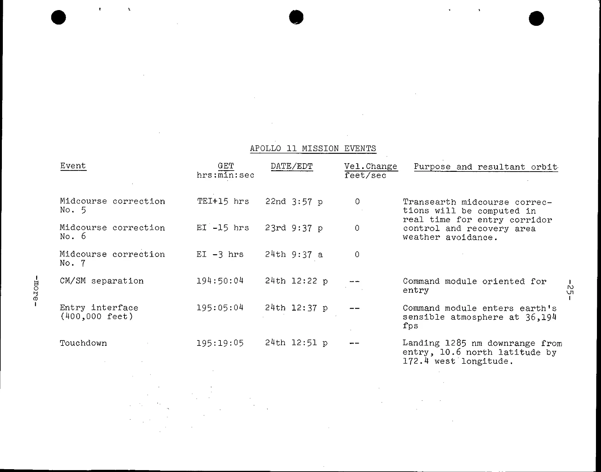
APOLLO 11 MISSION EVENTS
1
B
o
^re-
Event
Midcourse correction
No. 5
Midcourse correction
No. 6
Midcourse correction
No. 7
CM/SM separation
Entry interface
D00,000 feet)
Touchdown
GET
hrs:min
TEI+15
El -15
: sec
hrs
hrs
El -3 hrs
194:50:
195:05:
195:19:
04
04
05
DATE/EDT
22nd
23rd
24th
24th
24th
24th
3:57 P
9:37 P
9:37 a
12:22 p
12:37 P
12:51 P
Vel.Change
feet/sec
0
0
0
—
Transearth midcourse correc-
tions will be computed in
real time for entry corridor
control and recovery area
weather avoidance.
Command module oriented for i
entry ^
i
Command module enters earth's
sensible atmosphere at 36,194
fps
Landing 12 85 nm downrange from
entry, 10.6 north latitude by
172.4 west'longitude.
-26-
MISSIQN TRAJECTORY AND MANEUVER DESCRIPTION
Information presented herein is based upon a July 16 launch
and is subject to change prior to the mission or in real time
during the mission to meet changing conditions.
Launch
Apollo 11 will be launched from Kennedy Space Center Launch
Complex 39A on a launch azimuth that can vary from 72 degrees to
106 degrees, depending upon the time of day of launch. The azimuth
changes with time of day to permit a fuel-optimum injection from
Earth parking orbit into a free-return circumlunar trajectory.
Other factors influencing the launch windows are a daylight launch
and proper Sun angles on the lunar landing sites.
The planned Apollo 11 launch date of July 16 will call for
liftoff at 9:32 a.m. EDT on a launch azimuth of 72 degrees. The
7.6-million-pound thrust Saturn V first stage boosts the space
vehicle to an altitude of 36.3 nm at 50.6 nm downrange and increases
the vehicle's velocity to 9030.6 fps in 2 minutes 4o. 8 seconds
of powered flight. First stage thrust builds to 9,088,419 pounds
before center engine shutdown. Following out-board engine shutdown,
the first stage separates and falls into the Atlantic Ocean about
340 nm downrange C0.3 degrees North latitude and 73-5 degrees West
longitude) some 9 minutes after liftoff.
The 1-million-pound thrust second stage (S-II) carries the
space vehicle to an altitude of 101.4 nm and a distance of 885 nm
downrange. Before engine burnout, the vehicle will be moving at a
speed of 22,7^6.8 fps. The outer J-2 engines will burn 6 minutes
29 seconds during this powered phase, but the center engine will be
cut off at 4 minutes 56 seconds after S-II ignition.
At outboard engine cutoff, the S-II separates and, following
a ballistic trajectory, plunges into the Atlantic Ocean about
2,300 nm downrange from the Kennedy Space Center C1 degrees North
latitude and 33-6 degrees West longitude) some 20 minutes after
liftoff.
The first burn of the Saturn V third stage (S-IVB) occurs
immediately after S-II stage separation. It will last long enough
A45 seconds) to insert the space vehicle into a circular Earth park-
ing orbit beginning at about 4,8l8 nm downrange. Velocity at Earth
orbital insertion will be 25,567 fps at 11 minutes 50 seconds ground
elapsed time (GET). Inclination will be 32.6 degrees.
-more-
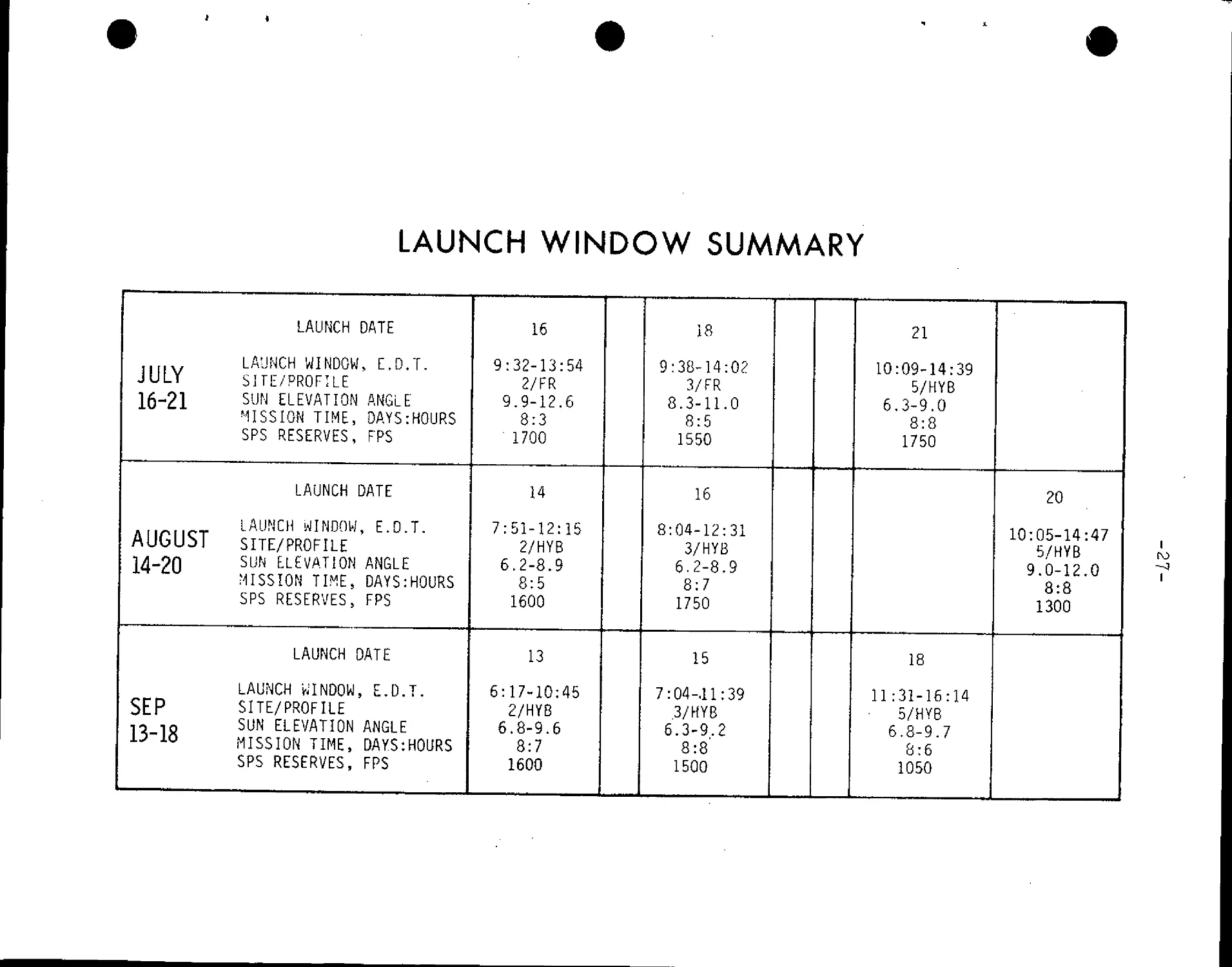
LAUNCH WINDOW SUMMARY
LAUNCH DATE
LAUNCH WINDOW, E.D.T.
JULY SITE/PROFILE
16-21 SUN ELEVATION ANGLE
MISSION TIME, DAYS:HOURS
SPS RESERVES, FPS
LAUNCH DATE
LAUNCH WINDOW, E.D.T.
AUGUST SITE/PROFILE
14-20 SUN E.LEVATION ANGLE
MISSION TIME, DAYS:HOURS
SPS RESERVES, FPS
LAUNCH DATE
LAUNCH WINDOW, E.D.T.
SEP SITE/PROFILE
7o 1Q SUN ELEVATION ANGLE
15"A0 MISSION TIME, DAYS:HOURS
SPS RESERVES, FPS
16
9:32-13:54
2/FR
9.9-12.6
8:3
1700
14
7:51-12:15
2/HYB
6.2-8.9
8:5
1600
13
6:17-10:45
2/HYB
6.8-9.6
8:7
1600
18
9:38-14:02
3/FR
8.3-11.0
8:5
1550
16
8:04-12:31
3/HYB
6.2-8.9
8:7
1750
15
7:04-.ll:39
3/HYB
6.3-9.2
8:8
1500
21
10:09-14:39
5/HYB
6.3-9.0
8:8
1750
18
11:31-16:14
¦ 5/HYB
6.8-9.7
8:6
1050
20
10:05-14:47
5/HYB
9.0-12.0
8:8
1300
I
MISSION DURATIONS
i
3
o
I
8d8h
8d6h
TOTAL
MISSION TIME,
DAY:HR.
8d0h
LAUNCH
ON TIME,
1ST TLI
¦OPPORTUNITY
¦LAUNCH AT CLOSE OF
WINDOW, 2ND TLI OPPORTUNITY
16 T8 21
JULY 1969 LAUNCH DATE
i
oo
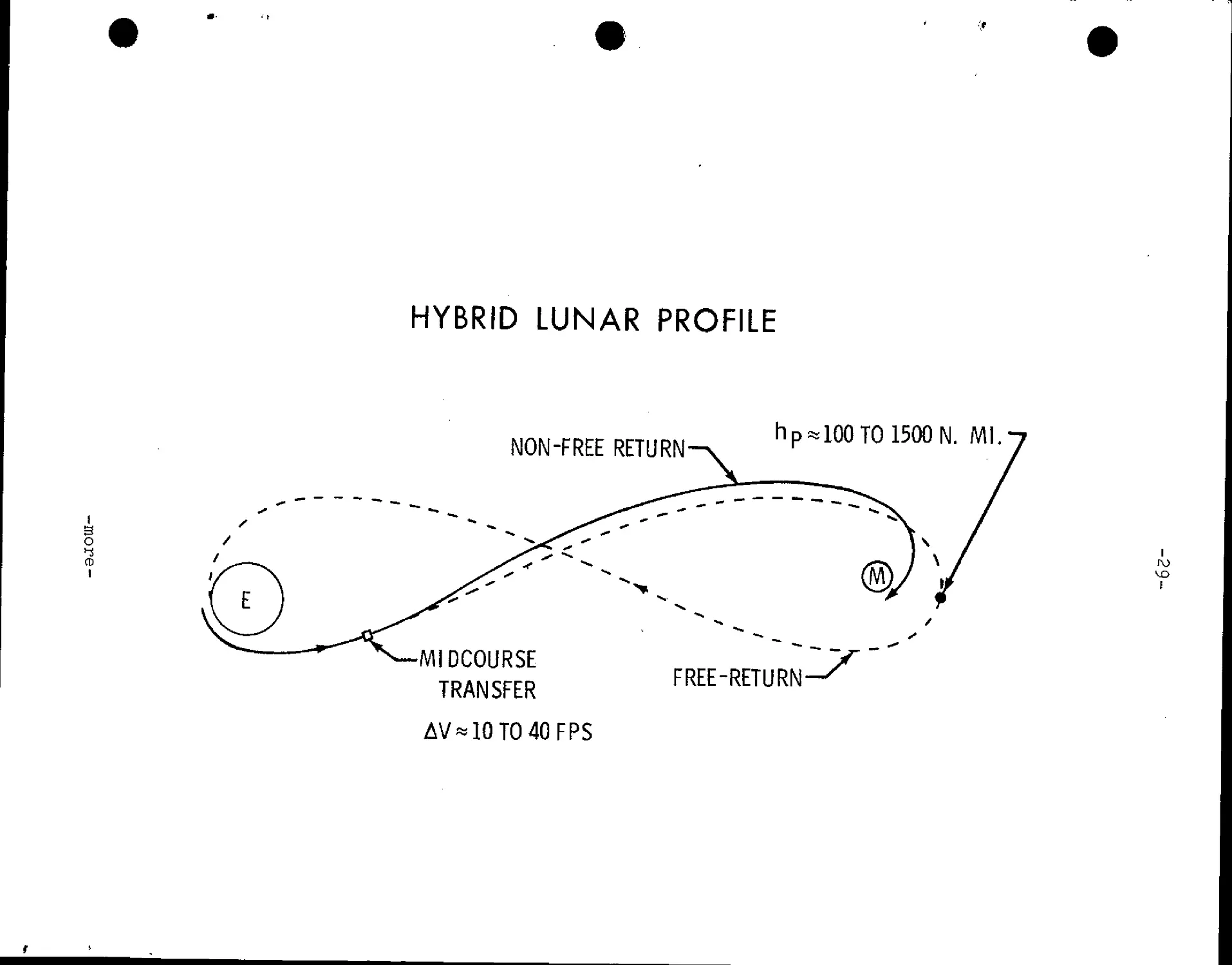
HYBRID LUNAR PROFILE
B
O
CD
I
NON-FREE RETURN-
hp*100T01500N. Ml
•MIDCOURSE
TRANSFER
FREE-RETURN
AV*10TO40FPS
-30-
'¦The crew v/ill have a backup to launch vehicle guidance during
powe.red flight. If the Saturn instrument unit inertial platform
fails, the crew can switch guidance to the command module systems
for first-stage powered flight automatic control. Second and third
stage backup guidance is through manual takeover in which crew hand
controller inputs are fed through the command module computer to the
Saturn instrument unit.
Earth Parking Orbit (EPO)
Apollo 11 will remain in Earth parking orbit for one-and-one-
half revolutions after insertion and will hold a local horizontal
attitude during the entire period. The crew will perform spacecraft
systems checks in preparation for the translunar injection (TLI)
burn. The final "go" for the TLI burn will be given to the crew
through the Carnarvon, Australia, Manned Space Flight Network
station.
Translunar Injection (TLI)
Midway through the second revolution in Earth parking orbit,
the S-IVB third-stage engine will restart at 2:44:15 GET over the
mid-Pacific just south of the equator to inject Apollo 11 toward
the Moon. The velocity will increase from 25,567 fps to 35,533 fps
at TLI cutoff—a velocity increase of 9971 fps. The TLI burn is
targeted for about 6 fps overspeed to compensate for the later SPS
evasive maneuver after LM extraction. TLI will place Apollo 11 on
a free-return circumlunar trajectory from which midcourse corrections
if necessary could be made with the SM RCS thrusters. Entry from a
free-return trajectory would be at 10:37 a.m. EDT July 22 at 14.9
degrees south latitude by 17^.9 east longitude after a flight time
of 145 hrs 04 min.
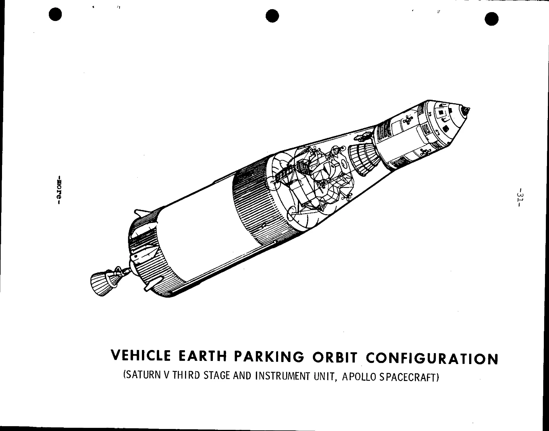
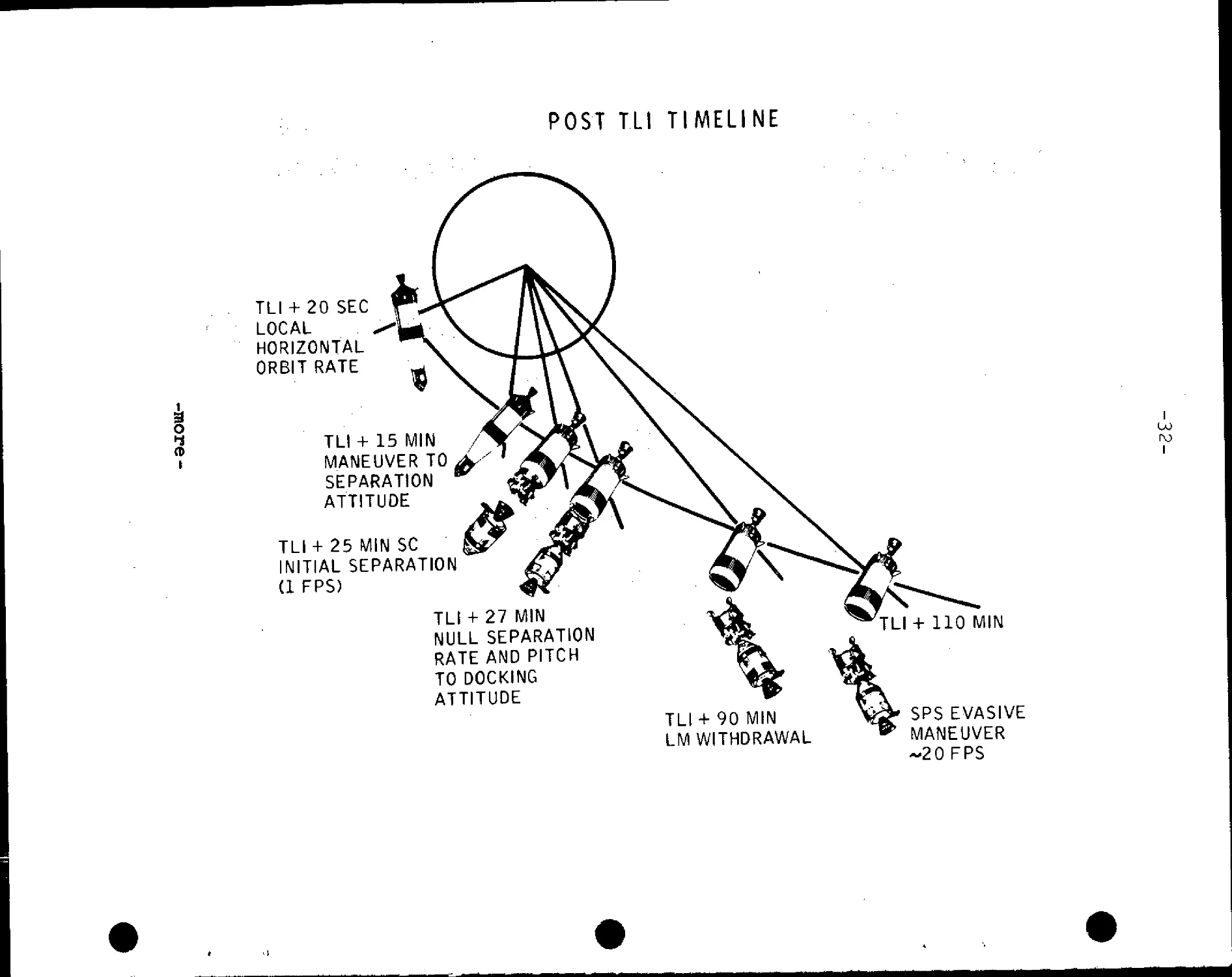
Transposition, Docking and Ejection (TD&E)
At about three hours after liftoff and 25 minutes after the
TLI burn, the Apollo 11 crew will separate the command/service
module from the spacecraft lunar module adapter (SLA), thrust out
away, from the S-IVB, turn around and move back in for docking with
the lunar module. Docking should take place at about three hours
and 21 minutes GET, and after the crew confirms all docking latches
solidly engaged, they will connect the CSM-to-LM umbilicals and
pressurize the LM with the command module surge tank. At about 4:09
GST, the spacecraft will be ejected from the spacecraft LM adapter
by spring devices at the four LM landing gear "knee" attach points.
The ejection springs will Impart about one fps velocity to the
spacecraft. A 19-7 fps service propulsion system (SPS) evasive
maneuver in plane at U:39 GET will separate the spacecraft to a safe
distance for the S-IVB "slingshot" maneuver in which residual launch
vehicle liquid propellants will be dumped through the J-2 engine bell
to propell the stage into a trajectory passing behind the Moon's
trailing edge and on into solar orbit.
-more-
I
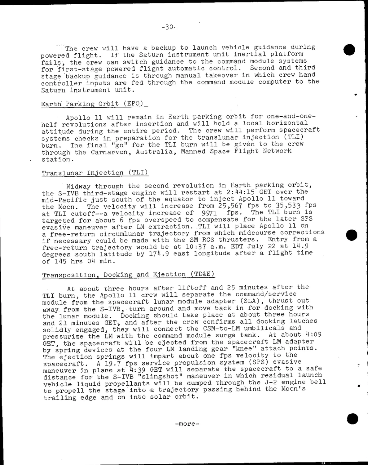
VEHICLE EARTH PARKING ORBIT CONFIGURATION
(SATURN V THIRD STAGE AND INSTRUMENT UNIT, APOLLO SPACECRAFT)
POST T.LI TIMELINE
TLI + 20 SEC
LOCAL . .
HORIZONTAL
ORBIT RATE
TLI + 15 MIN
MANEUVER TO
SEPARATION
ATTITUDE
TLI + 25MINSC
INITIAL SEPARATION
A FPS)
i
U)
I
TLI + 27 MIN
NULL SEPARATION
RATE AND PITCH
TO DOCKING
ATTITUDE
TLI + 90 MIN
LM WITHDRAWAL
TLI + 110 MIN
SPS EVASIVE
MANEUVER
~20 FPS
-33-
Translunar Coast
Up to four midcourse correction burns are planned during the
translunar coast phase, depending upon the accuracy of the trajectory
resu-lting from the TLI maneuver. If required, the midcourse
correction burns are planned at TLI +9 hours, TLI +2 4 hours, lunar
orbit insertion (LOI) -22 hours and LOI -5 hours.
During coast periods between midcourse corrections, the
spacecraft will be in the passive thermal control (PTC) or "barbecue"
mode in which the spacecraft will rotate slowly about one axis to
stabilize spacecraft thermal response to the continuous solar
exposure.
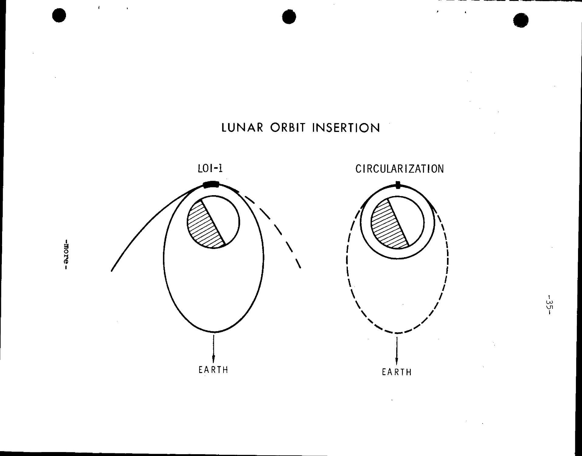
Lunar Orbit Insertion (LOI)
The first of two lunar orbit insertion burns' will be made at
75:54';28 GET at an altitude of about 80 nm above the Moon. LOI-1
will have a nominal retrograde velocity change of 2,924 fps and will
insert Apollo 11 into a 60xl70-nm elliptical lunar orbit. LOI-2
two orbits later at 80:09=30 GET will adjust the orbit to a 54x65-nm
orbit, which because of perturbations of the lunar gravitational
potential, will become circular at 60 nm at the time of rendezvous
with the LM. The burn will be 157.8 fps retrograde. Both LOI man-
euvers will be with the SPS engine near pericynthion when the space-
craft is behind the Moon and out of contact with MSFN stations.
After LOI-2 (circularization), the lunar module pilot will enter
the lunar module for a brief checkout and return to the command
module.
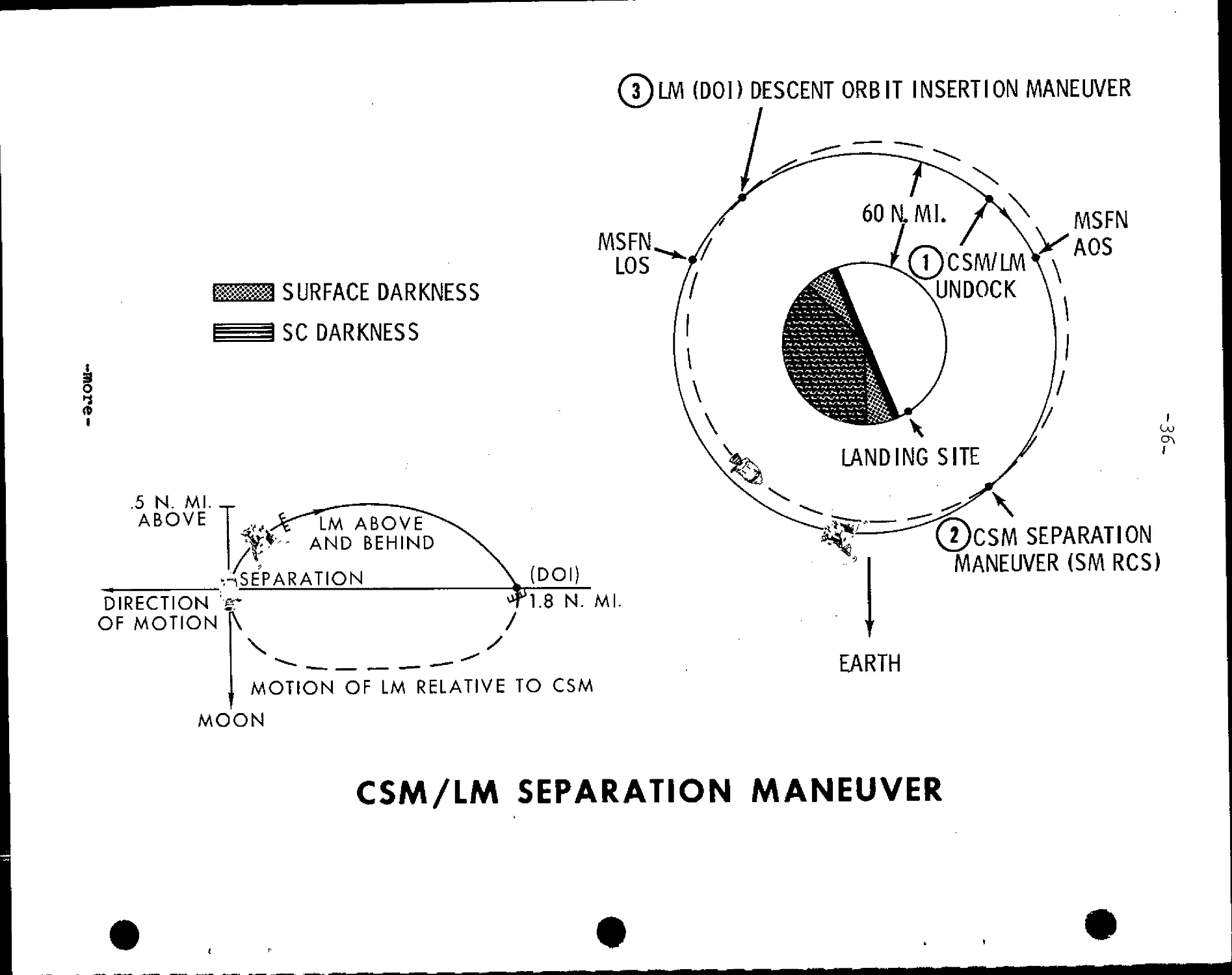
Lunar Modulepescent,_Lunar Landing.
The lunar module will be manned and checked out for undock-
ing and subsequent landing on the lunar surface at Apollo site 2.
Undocking will take place at 100:09=50 GET prior to the MSFN
acquisition of signal. A readially downward service module RCS
burn of 2.5 fps will place the CSM on an equiperiod orbit with
a maximum separation of 2.2 nm one half revolution after the
separation maneuver. At this point, on lunar farside, the descent
orbit insertion burn (DOI) will be made with the lunar module
descent engine firing retrograde 74.2 fps at 101:38:48 GET. The
burn will start at 10 per cent throttle for 15 seconds and the
remainder at 40 per cent throttle.
The DOI maneuver lowers LM pericynthion to 50,000 feet at
a point about 14 degrees uprange of landing site 2.
-more-
-34-
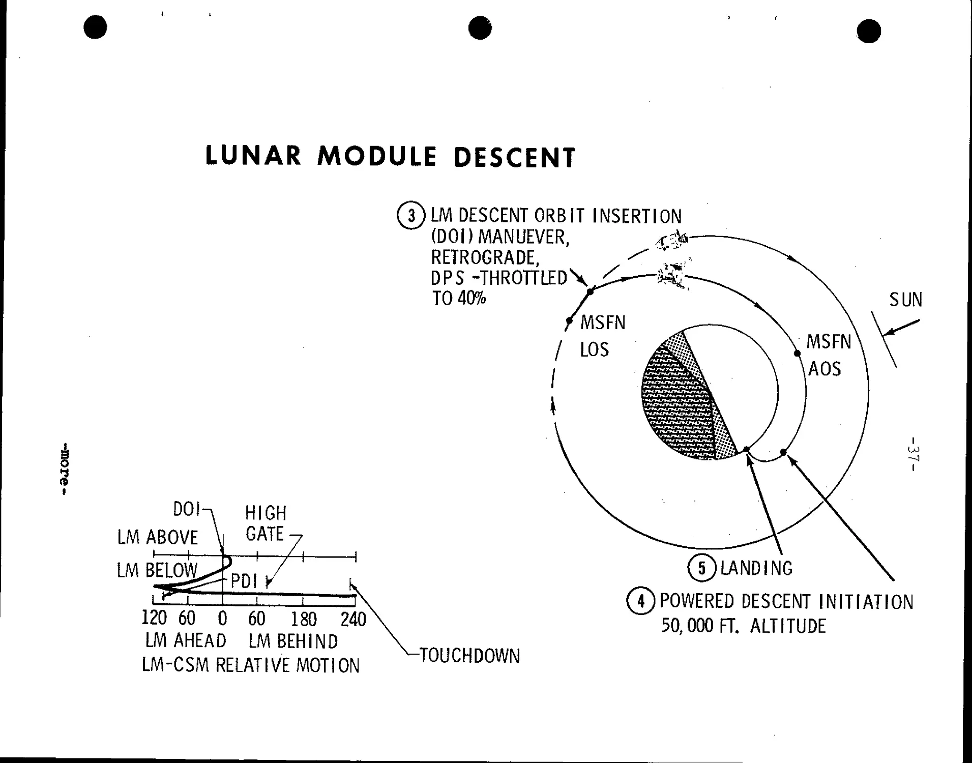
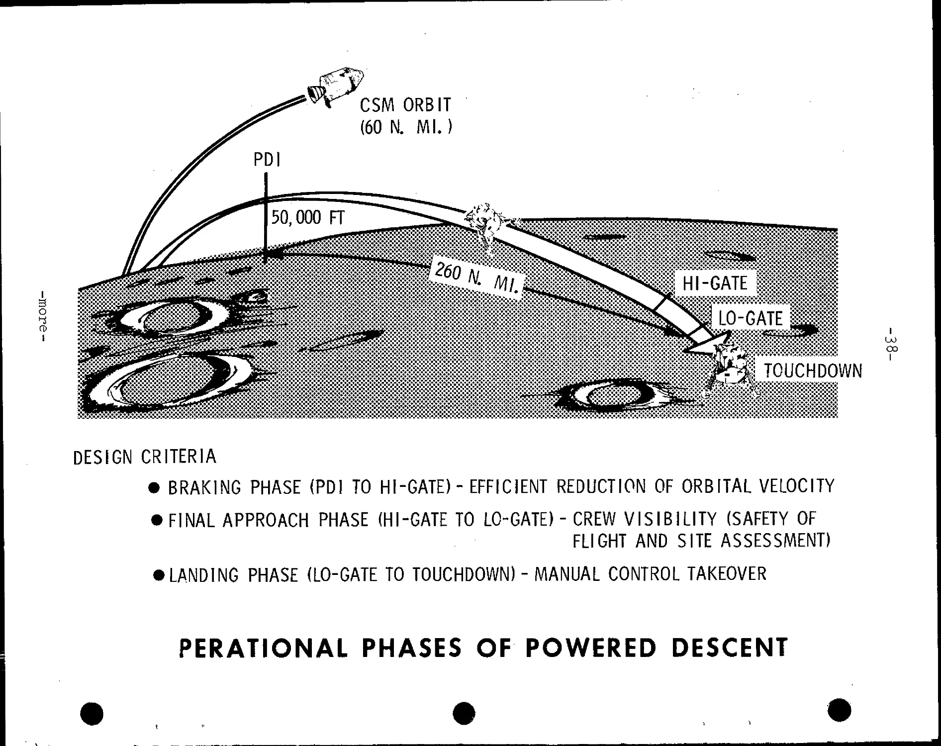
A three-phase powered descent initiation (PDI) maneuver
begins at pericynthion at 102:53:13 GET using the LM descent engine
to brake the vehicle out of the descent transfer orbit. The guid-
ance-controlled PDI maneuver starts about 260 nm prior to touchdown,
and is in retrograde attitude to reduce velocity to essentially zero
at the time vertical descent begins. Spacecraft attitudes range from
windows down at the start of PDI, to windows up as the spacecraft
reaches 45,000 feet above the lunar surface and LM landing radar
data can be integrated by the LM guidance computer. The braking
phase ends at about 7a000 feet above the surface and the spacecraft
is rotated to an upright windows-forward attitude. The start of the
approach phase is called high gate, and the start of the landing
phase at 500 feet is called low gate.
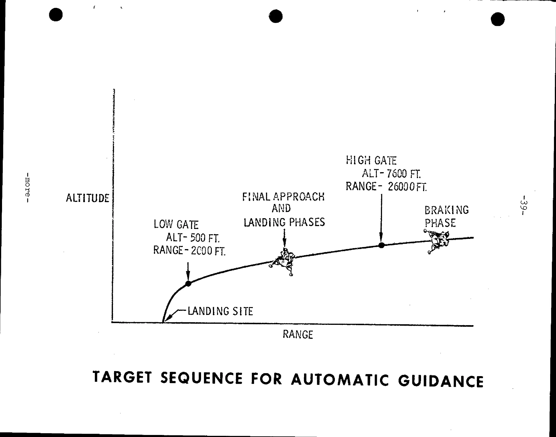
Both the approach phase and landing phase allow pilot take-
over from guidance control as well as visual evaluation of the land-
ing site. The final vertical descent to touchdown begins at about
150 feet when all forward velocity is nulled out. Vertical descent
rate will be three fps. Touchdown will take place at 102:47:11 GET.
-more-
LUNAR ORBIT INSERTION
LOI-1
CIRCULARIZATION
3
o
I
EARTH
EARTH
^M SURFACE DARKNESS
SC DARKNESS
4
i
.5 N. Ml. _
ABOVE
%* -- and behind
-./separation
DIRECTION ¦¦?"
OF MOTION |\
7)LM (DOI) DESCENT ORBIT INSERTION MANEUVER
MSFN.
LOS
(DOI)
'1.8 N. Ml.
MOTION OF LM RELATIVE TO CSM
MOON
1)CSM/IAU\
UNDOCK X
MSFN
AOS
UJ
2JCSM SEPARATION
MANEUVER (SM RCS)
EARTH
CSM/LM SEPARATION MANEUVER
LUNAR MODULE DESCENT
3
t
DOI-
LM ABOVE
LM BELOW
HIGH
GATEy
PDI
7
LM DESCENT ORB IT INSERTION
(DOI)MANUEVER,
RETROGRADE,
DPS -THROTTL?D\
TO 40%
'MSFN
SUN
120 60 0 60 180 240
LM AHEAD LM BEHIND
LM-CSM RELATIVE MOTION
-TOUCHDOWN
5)LANDING
4)POWERED DESCENT INITIATION
50,000 FT. ALTITUDE
3
o
I
CSM ORBIT
F0 N. Ml.)
TOUCHDOWN
DESIGN CRITERIA
• BRAKING PHASE (PD! TO HI-GATE) - EFFICIENT REDUCTION OF ORBITAL VELOCITY
• FINAL APPROACH PHASE (HI-GATE TO LO-GATE) - CREW VISIBILITY (SAFETY OF
FLIGHT AND SITE ASSESSMENT)
• LANDING PHASE (LO-GATE TO TOUCHDOWN) - MANUAL CONTROL TAKEOVER
co
I
PERATIONAL PHASES OF POWERED DESCENT
I
g
o
ALTITUDE
LOW GATE
ALT- 500 FT
RANGE- 2C00FI
FSNALAPPROACH
AND
LAND! MG PHASES
I
HIGH GATE
ALT- 7600 FT.
RANGE- 26000FT
-¦-'
BRAKING
PHASE
i —SP5
1
U)
U3
1
LANDING SITE
RANGE
TARGET SEQUENCE FOR AUTOMATIC GUIDANCE
E
CD
1
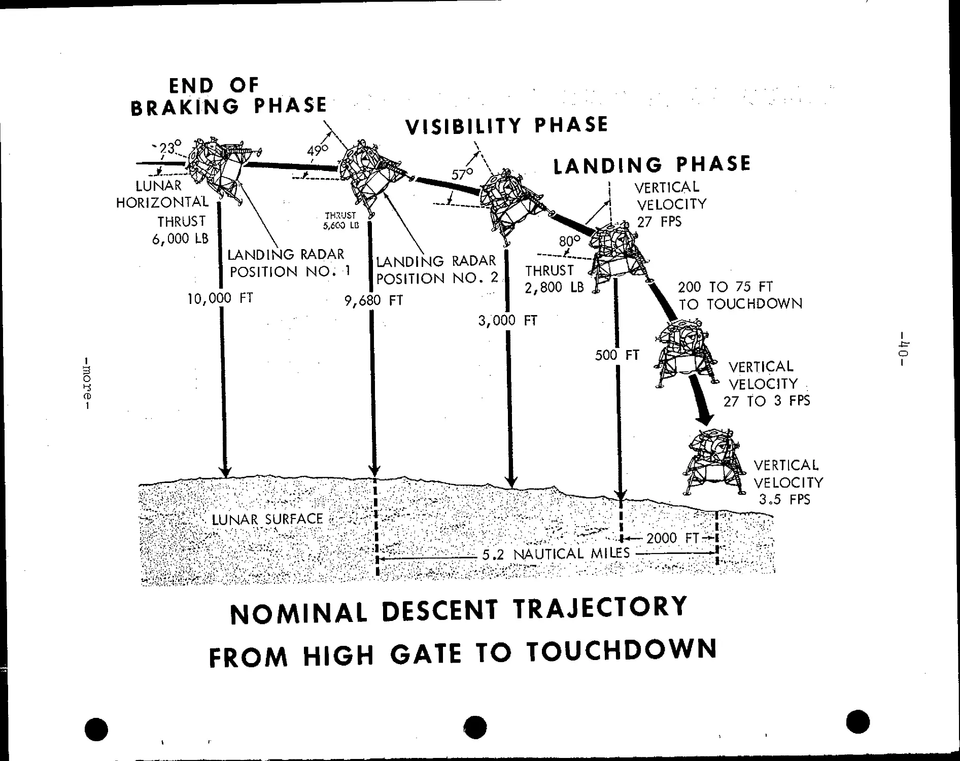
END OF
BRAKING PHASE
VISIBILITY PHASE
LUNAR
HORIZONTAL
THRUST
6,000 LB
LANDING RADAR
POSITION NO. 1
10,000 FT
LANDING PHASE
VERTICAL
VELOCITY
27 FPS
LANDING RADAR
POSITION NO. 2
9,680 FT
2,800 LB
3,000 FT
LUNAR SURFACE - - ,.
500' FT
200 TO 75 FT
TO TOUCHDOWN
VERTICAL
VELOCITY
27 tO 3 FPS
VERTICAL
VELOCITY
3.5 FPS
5.2 NAUTICAL MILES
I
2000 FT-I
J
NOMINAL DESCENT TRAJECTORY
FROM HIGH GATE TO TOUCHDOWN
i
-fcr
O
I
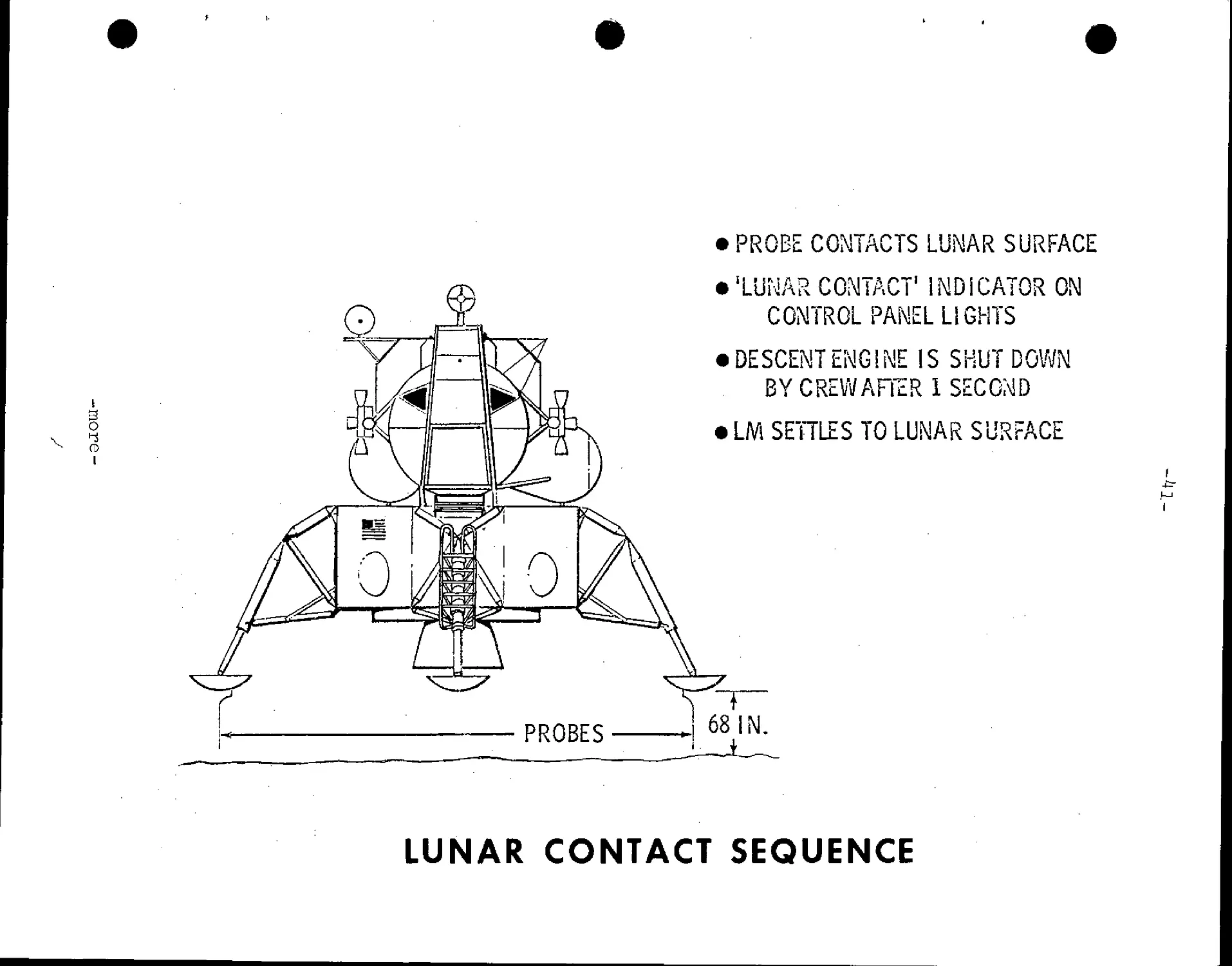
PROBE CONTACTS LUNAR SURFACE
CD
I
'LUNAR CGMTACT1 INDICATOR ON
CONTROL PANEL LIGHTS
DESCENT ENGINE IS SHUT DOWN
BY CREWAFTER1 SECOND
LM SETTLES TO LUNAR SURFACE
-fcr
I
LUNAR CONTACT SEQUENCE
-42-
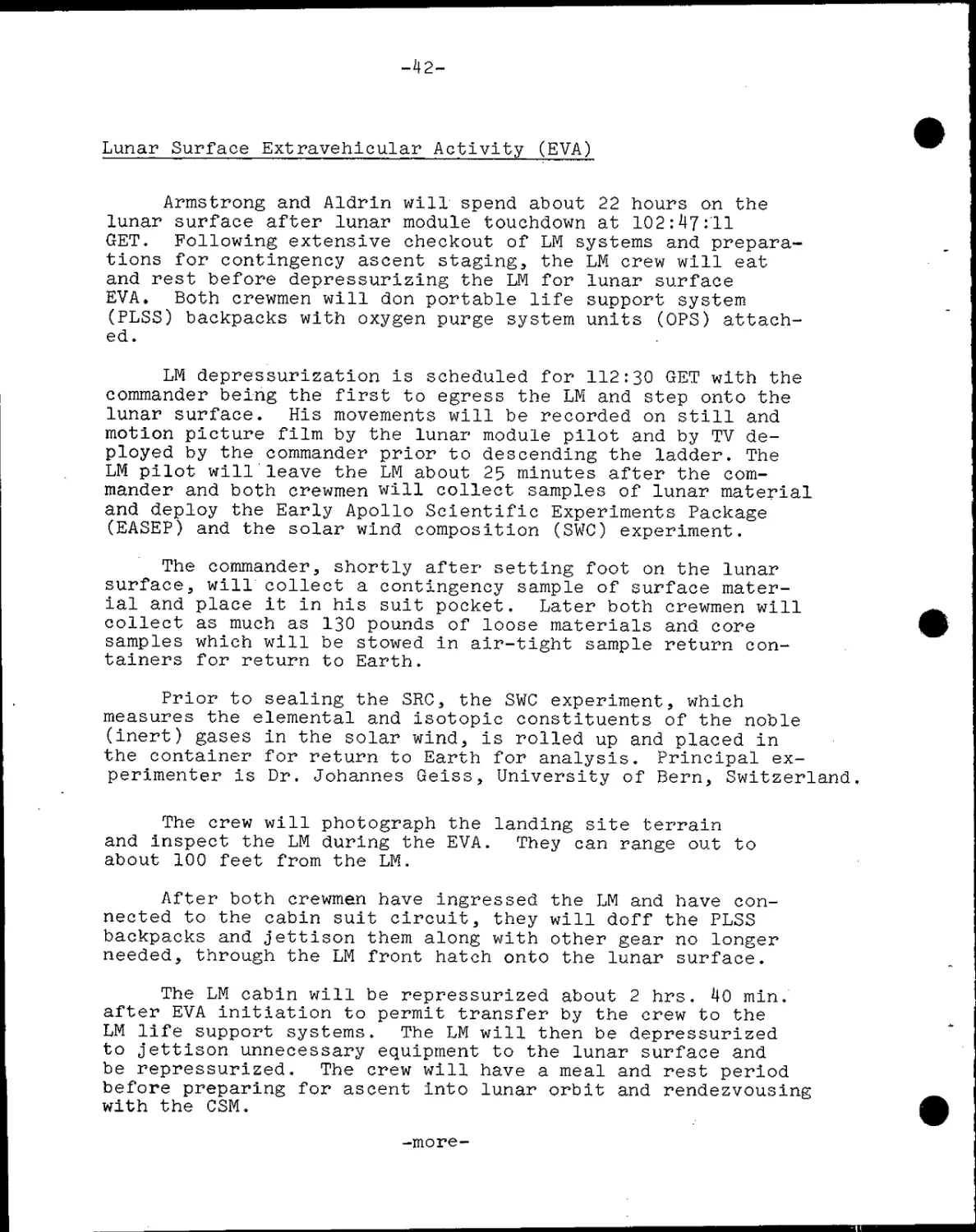
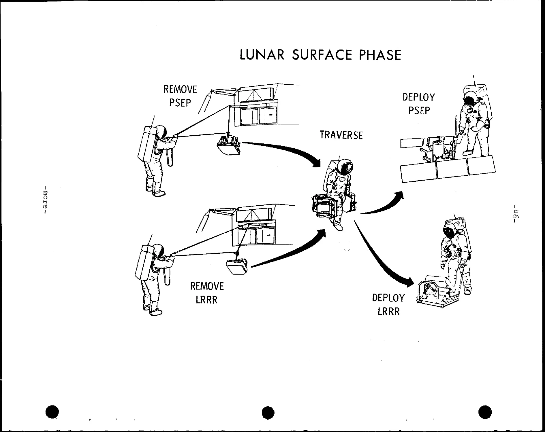
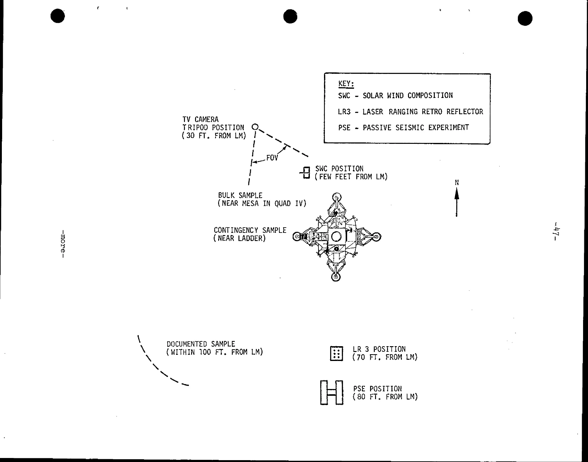
Lunar Surface Extravehicular Activity (EVA)
Armstrong and Aldrin will spend about 22 hours on the
lunar surface after lunar module touchdown at 102:47:11
GET. Following extensive checkout of LM systems and prepara-
tions for contingency ascent staging, the LM crew will eat
and rest before depressurizing the LM for lunar surface
EVA. Both crewmen will don portable life support system
(PLSS) backpacks with oxygen purge system units (OPS) attach-
ed.
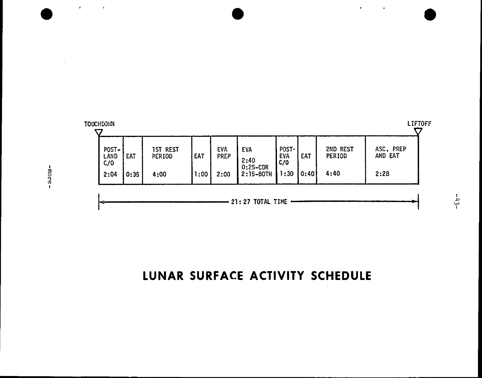
LM depressurization is scheduled for 112:30 GET with the
commander being the first to egress the LM and step onto the
lunar surface. His movements will be recorded on still and
motion picture film by the lunar module pilot and by TV de-
ployed by the commander prior to descending the ladder. The
LM pilot will leave the LM about 25 minutes after the com-
mander and both crewmen will collect samples of lunar material
and deploy the Early Apollo Scientific Experiments Package
(EASEP) and the solar wind composition (SWC) experiment.
The commander;, shortly after setting foot on the lunar
surface, will collect a contingency sample of surface mater-
ial and place it in his suit pocket. Later both crewmen will
collect as much as 130 pounds of loose materials and core
samples which will be stowed in air-tight sample return con-
tainers for return to Earth.
Prior to sealing the SRC, the SWC experiment, which
measures the elemental and isotopic constituents of the noble
(inert) gases in the solar wind, is rolled up and placed in
the container for return to Earth for analysis. Principal ex-
perimenter is Dr. Johannes Geiss, University of Bern, Switzerland,
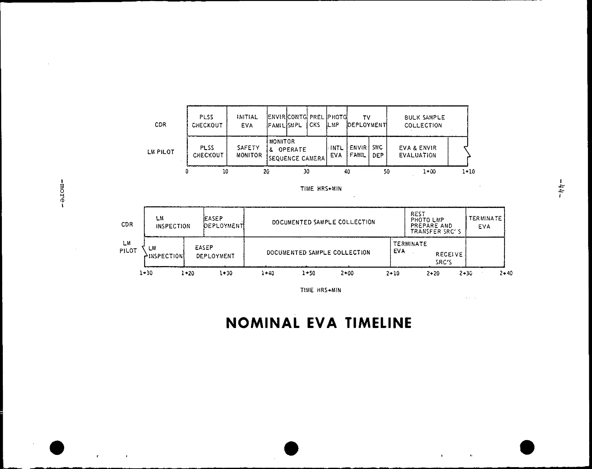
The crew will photograph the landing site terrain
and inspect the LM during the EVA. They can range out to
about 100 feet from the LM.
After both crewmen have ingressed the LM and have con-
nected to the cabin suit circuit, they will doff the PLSS
backpacks and jettison them along with other gear no longer
needed, through the LM front hatch onto the lunar surface.
The LM cabin will be repressurized about 2 hrs. 40 min.
after EVA initiation to permit transfer by the crew to the
LM life support systems. The LM will then be depressurized
to jettison unnecessary equipment to the lunar surface and
be repressurized. The crew will have a meal and rest period
before preparing for ascent into lunar orbit and rendezvousing
with the CSM.
-more-
I
o
4
TOUCHDOWN
LIFTOFF
POST-
LAND
C/0
2:04
EAT
0:35
1ST REST
PERIOD
4:00
EAT
1:00
EVA
PREP
2:00
EVA
2:40
0:25-CDR
2:15-B0TH
POST-
EVA
C/0
1:30
EAT
0:40
2ND REST
PERIOD
4:40
ASC. PREP
AND EAT
2:28
21: 27 TOTAL TIME
i
LUNAR SURFACE ACTIVITY SCHEDULE
I
o
I
COR
LM PILOT
PLSS
CHECKOUT
PLSS
CHECKOUT
INITIAL
EVA
SAFETY
MONITOR
ENVIR
FAMIL
CONTG
SMPL
PREL
CKS
MONITOR
4 OPERATE
SEQUENCE CAMERA
PHOTO
LMP
¦INTL.
EVA
TV
DEPLOYMENT
ENVIR
FAMIL
SWC
DEP
BULK SAMPLE
COLLECTION
EVA & ENVIR
EVALUATION
[
10
20
30 40
TIME HRS+MIN
50
1+00
CDR
LM
INSPECTION
LM
PILOT \LM
f INSPECTION
EASEP
DEPLOYMENT
EASEP
DEPLOYMENT
DOCUMENTED SAMPLE COLLECTION
DOCUMENTED SAMPLE COLLECTION
1*10
REST
PHOTO LMP
PREPARE AND
TRANSFER SRC S
TERMINATE
EVA
RECEIVE
SRC'S
TERMINATE
EVA
1+10 1+20 1+30 1+40 1+50 2+00
TIME HRS+MIN
2+10
2+20
2+30
-fcr
I
2+40
NOMINAL EVA TIMELINE
VIEW THRU OPTICAL CENTER OF TV LENS IN DIRECTION OF "Z"-PLANE
i
o
CD
I
VIEW OBSTRUCTED BY
EDGE OF STRUCTURE
VIEW OBSTRUCTED
BY EDGE OF MESA
INTERSECTION OF "Z"
PLANE AND LUNAR SURFACE•
LUNAR SURFACE PHASE
REMOVE
PSEP
3
o
REMOVE
LRRR
TRAVERSE
DEPLOY
PSEP
DEPLOY
LRRR
I
?
a>
i
TV CAMERA
TRIPOD POSITION C
C0 FT. FROM LM) /
I
j
/
FOV
KEY:
SWC -
LR3 -
PSE -
SOLAR
LASER
WIND COMPOSITION
RANGING RETRO REFLECTOR
PASSIVE SEISMIC EXPERIMENT
-B
SWC POSITION
(FEW FEET FROM LM)
BULK SAMPLE
(NEAR MESA IN QUAD IV)
CONTINGENCY SAMPLE
(NEAR LADDER)
N
DOCUMENTED SAMPLE
(WITHIN 100 FT. FROM LM)
\
LR 3 POSITION
LLLJ G0 FT. FROM LM)
PSE POSITION
(80 FT. FROM LM)
-4 8-
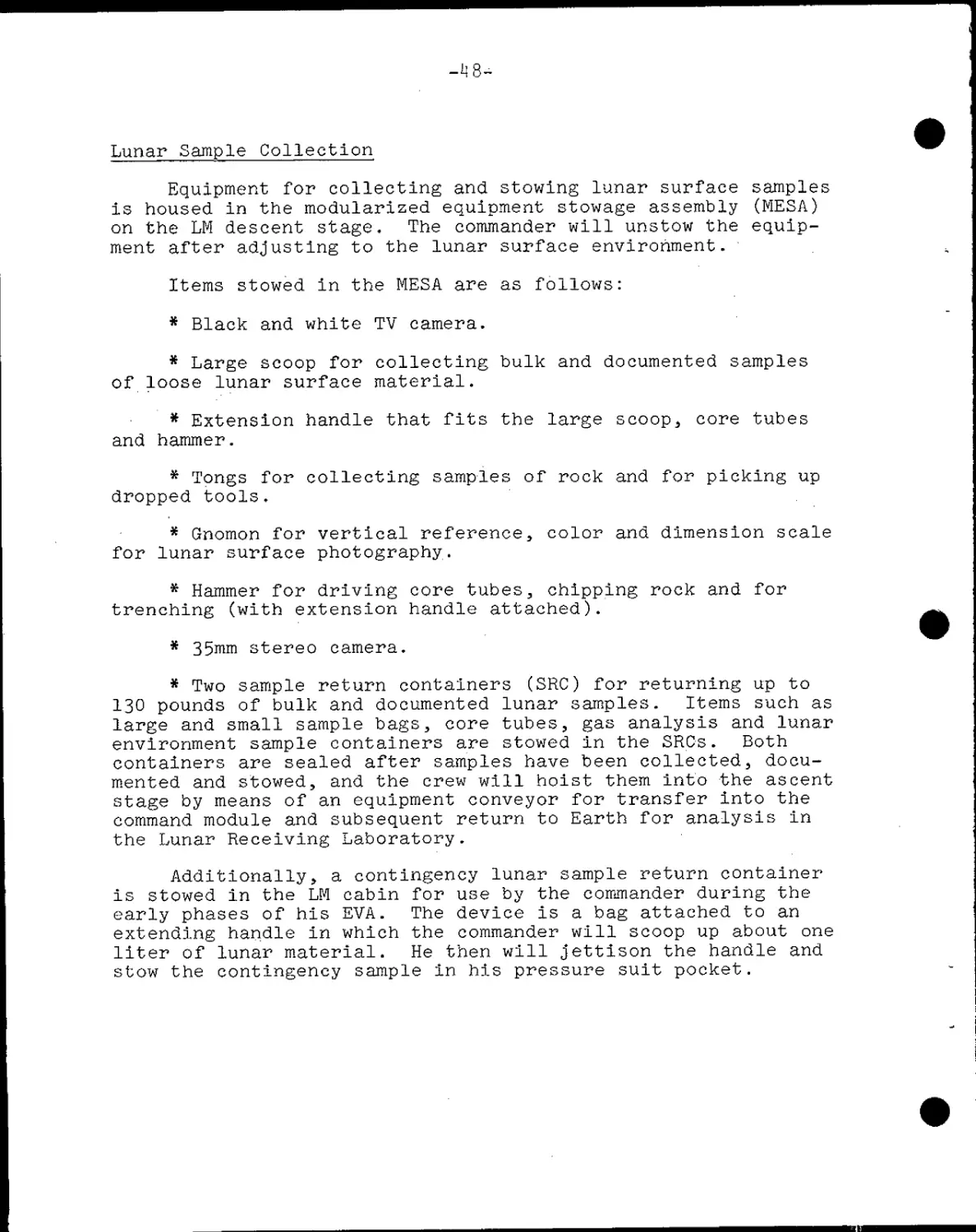
Lunar Sample Collection
Equipment for collecting and stowing lunar surface samples
is housed in the modularized equipment stowage assembly (MESA)
on the LM descent stage. The commander will unstow the equip-
ment after adjusting to the lunar surface environment.
Items stowed in the MESA are as follows:
* Black and white TV camera.
* Large scoop for collecting bulk and documented samples
of loose lunar surface material.
* Extension handle that fits the large scoop, core tubes
and hammer.
* Tongs for collecting samples of rock and for picking up
dropped tools.
* Gnomon for vertical reference, color and dimension scale
for lunar surface photography.
* Hammer for driving core tubes, chipping rock and for
trenching (with extension handle attached).
* 35mm stereo camera.
* Two sample return containers (SRC) for returning up to
130 pounds of bulk and documented lunar samples. Items such as
large and small sample bags, core tubes, gas analysis and lunar
environment sample containers are stowed in the SRCs. Both
containers are sealed after samples have been collected, docu-
mented and stowed, and the crew will hoist them into the ascent
stage by means of an equipment conveyor for transfer into the
command module and subsequent return to Earth for analysis in
the Lunar Receiving Laboratory.
Additionally, a contingency lunar sample return container
is stowed in the LM cabin for use by the commander during the
early phases of his EVA. The device is a bag attached to an
extending handle in which the commander will scoop up about one
liter of lunar material. He then will jettison the handle and
stow the contingency sample in his pressure suit pocket.
-49-
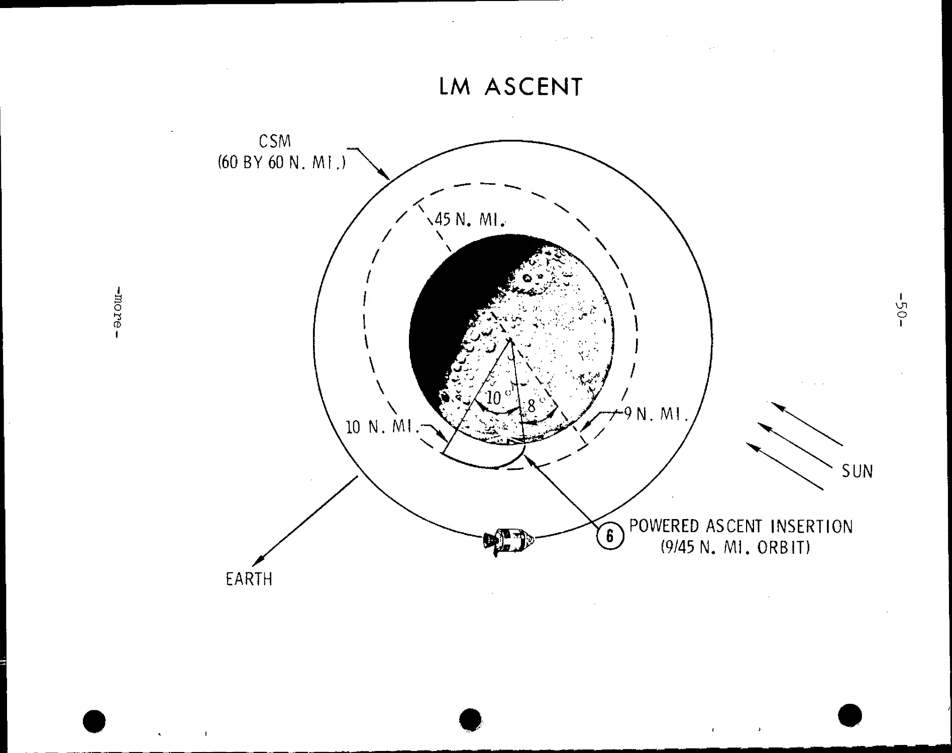
LM Ascent, Lunar Orbit Rendezvous
Following the 22-hour lunar stay time during which the
commander and lunar module pilot will deploy the Early Apollo
Scientific Experiments Package (EASEP), the Solar Wind Composition
(SWC) experiment, and gather lunar soil samples, the LM ascent
stage will lift off the lunar surface to begin the rendezvous sequence
with the orbiting CSM. Ignition of the LM ascent engine will be at
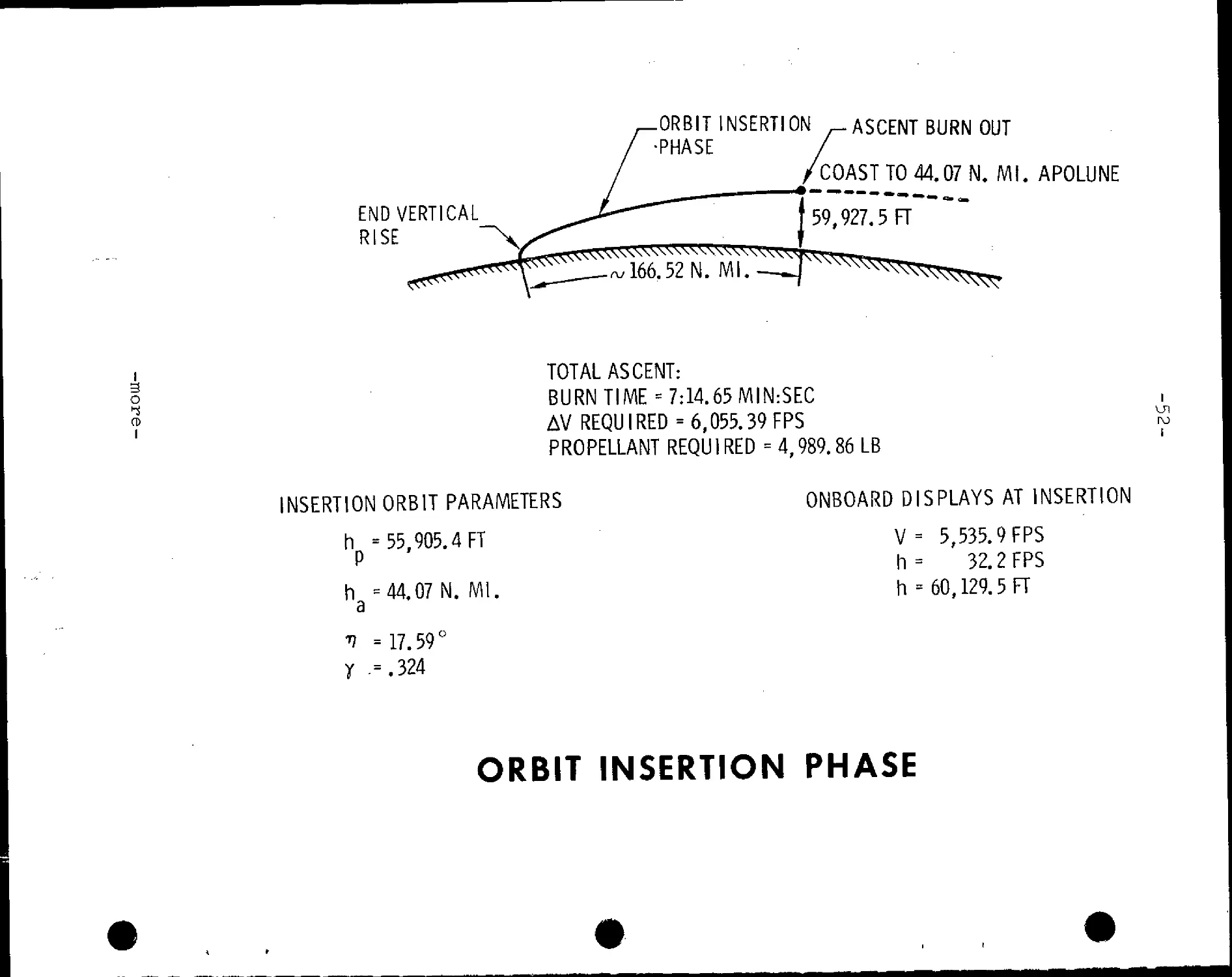
124:23:21 for a 7 min 14 sec burn with a total velocity of 6,055 fps.
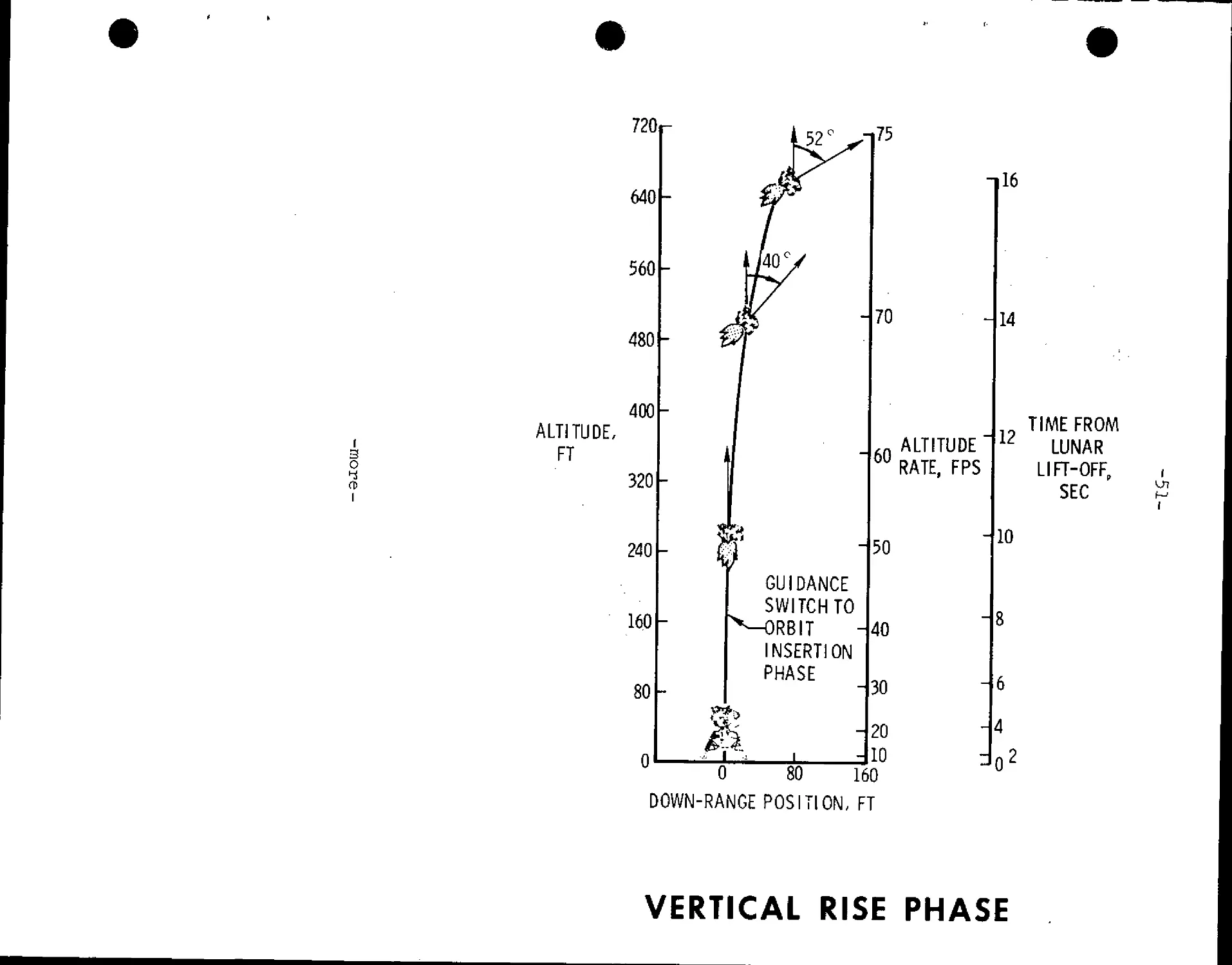
Powered ascent is in two phases: vertical ascent for terrain clear-
ance and the orbital insertion phase. Pitchover along the desired
launch azimuth begins as the vertical ascent rate reached 50 fps
about 10 seconds after liftoff at about 250 feet in altitude.
Insertion into a 9 x 45-nm lunar orbit will take place about 166
nm west of the landing site.
Following LM insertion into lunar orbit, the LM crew will
compute onboard the four major maneuvers for rendezvous with the
CSM which is about 255 nm ahead of the LM at this point. All
maneuvers in the sequence will be made with the LM RCS thrusters.
The premission rendezvous sequence maneuvers, times and velocities
which likely will differ slightly in real time, are as follows:
-more-
LM ASCENT
CSM
F0 BY 60 N. Ml.)
3
o
I
i
vn
o
I
SUN
POWERED ASCENT INSERTION
(9/45 N. Ml. ORBIT)
EARTH
I
o
<-i
a>
i
720r
640 -
560
480
ALTITUDE,
FT
400
320
240
160
80
0
75
GUIDANCE
SWITCH TO
INSERTION
PHASE
116
70
60
ALTITUDE '
RATE, FPS
50
40
30
20
10
14
12
TIME FROM
LUNAR
LIFT-OFFP
SEC
10
0 80 160
DOWN-RANGE POSITION, FT
VERTICAL RISE PHASE
END VERTICAL
RISE
ORBIT INSERTION
PHASE
ASCENT BURN OUT
COAST TO 44.07 N. Ml. APOLUNE
59,927.5 FT
B
o
CD
I
TOTAL ASCENT:
BURN TIME = 7:14.65 MINrSEC
AV REQUIRED = 6,055.39 FPS
PROPELLANT REQUIRED = 4,989.86 LB
INSERTION ORBIT PARAMETERS
h =55,905.4 FT
h = 44.07 N. Ml.
17 =17.59°
y =.324
ONBOARD DISPLAYS AT INSERTION
V= 5,535.9 FPS
h= 32.2 FPS
h = 60,129.5 FT
ORBIT INSERTION PHASE
-53-
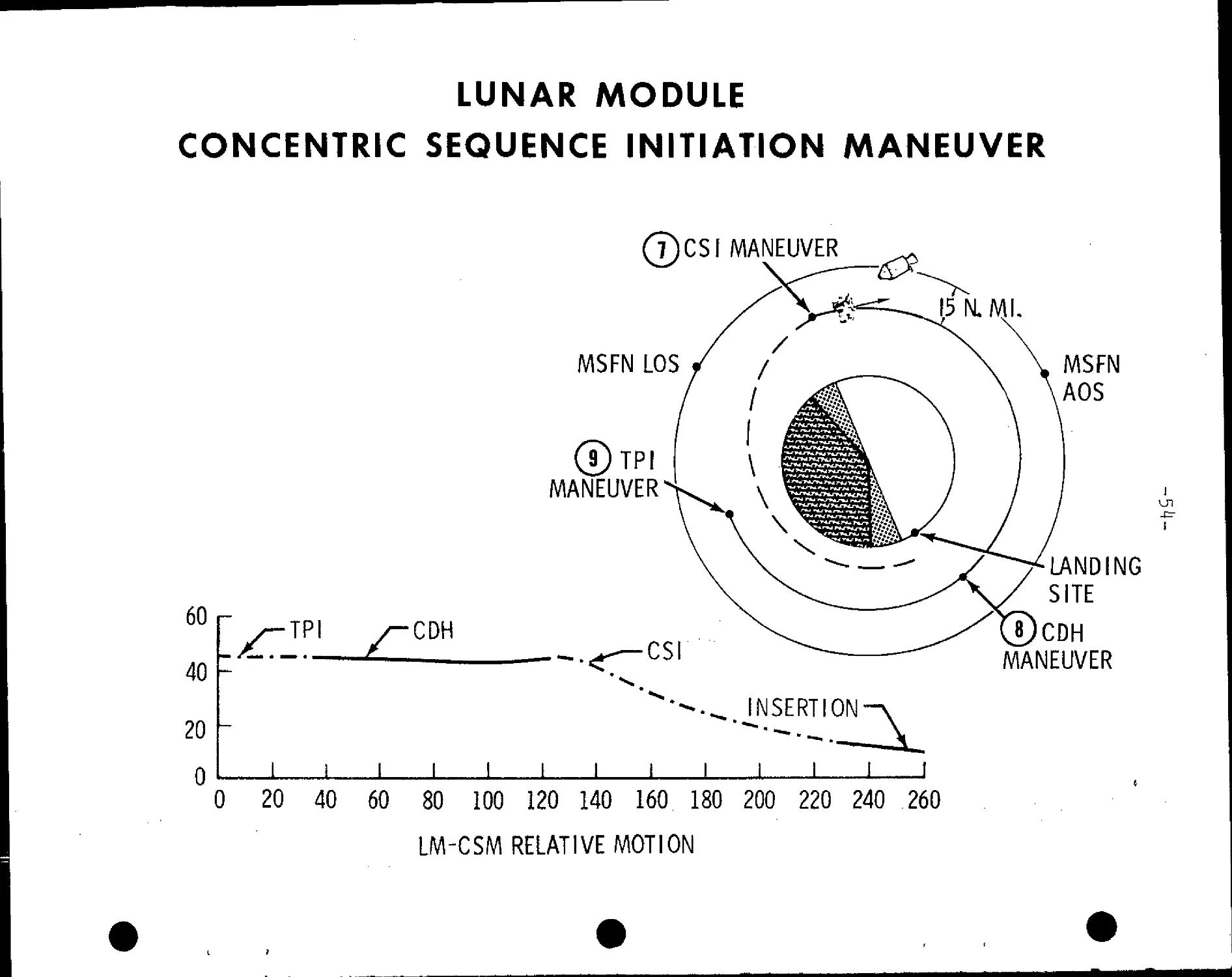
Concentric sequence initiate (CSI): At first LM apolune after
insertion 125:21:20 GET, 49 fps posigrade ,, following some 20 minutes
of LM rendezvous radar tracking and.CSM sextant/VHF ranging navi-
gation. CSI will be targeted to place the LM in an orbit 15 nm
below the CSM at the time of the later constant delta height (CDH)
maneuver. The CSI burn may also initiate corrections for any out-of-
plane dispersions resulting from insertion azimuth errors. Resulting
LM orbit after CSI will be 45.5 x 44.2 nm and will have a catchup
rate to the CSM of .072 degrees per minute.
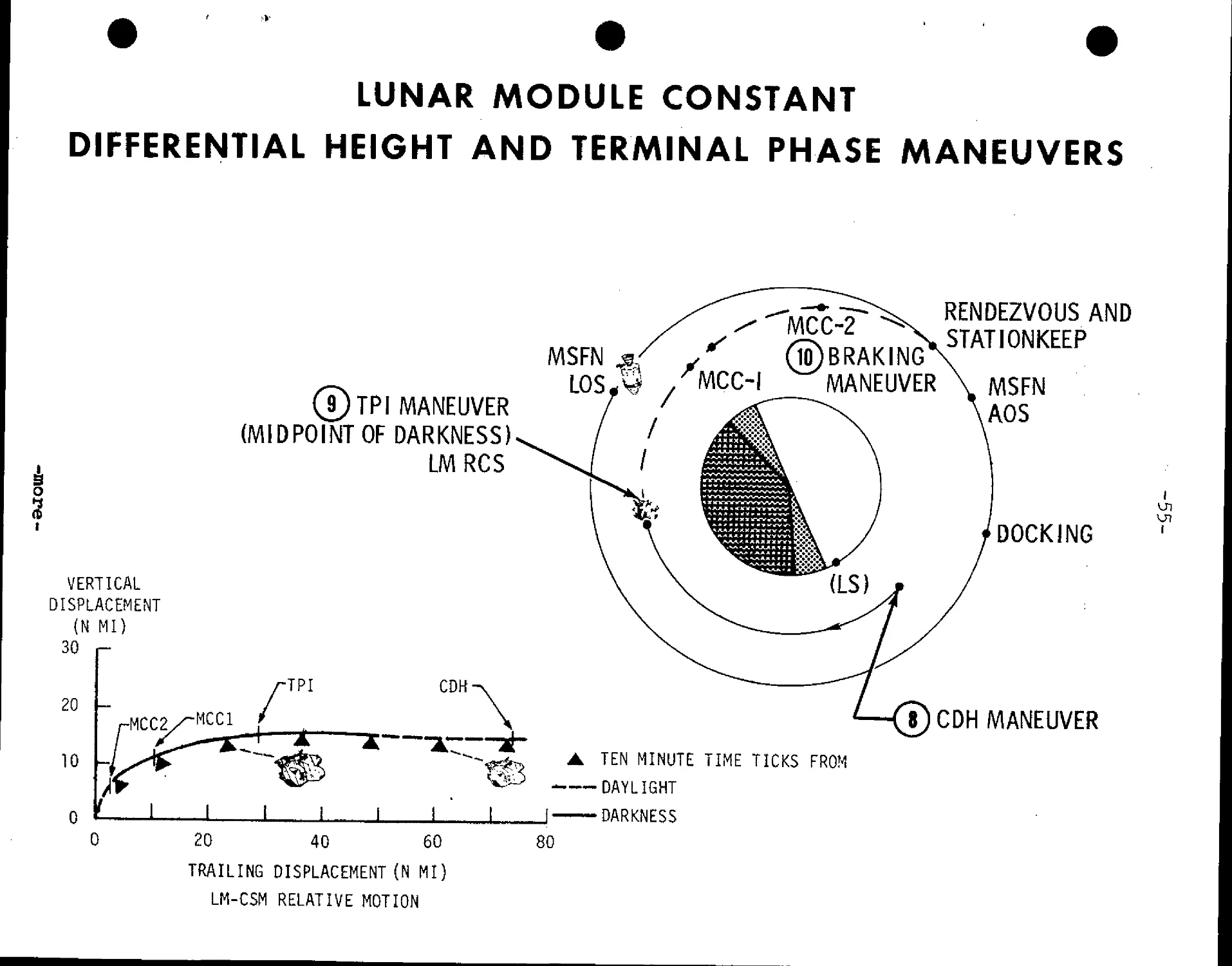
¦ Another plane correction is possible about 29 minutes after CSI
at the nodal crossing of the CSM and LM orbits to place both vehicles
at a common node at the time, of the CDH maneuver at 126 :19:40. GET.
Terminal phase initiate (TPI): This maneuver occurs at 126:58:26
and adds 24.6.fps along the line of sight toward the CSM when the
elevation angle to the CSM reaches 26.6 degrees. The LM orbit becomes
61.2 x 43.2 nm and the catchup rate to the CSM decreases to .032
degrees per second, or a closing rate of 131 fps.
Two midcourse correction maneuvers will be made if needed,
followed by four braking maneuvers at: 127:39:43 GET, 11.5 fps;
127:40:56, 9-8 fps; 127:42:35 GET, 4.8 fps; and at 127:43:54 GET,
4.7 fps. Docking nominally will take place at 128 hrs GET to end
three and one-half hours of the rendezvous sequence.
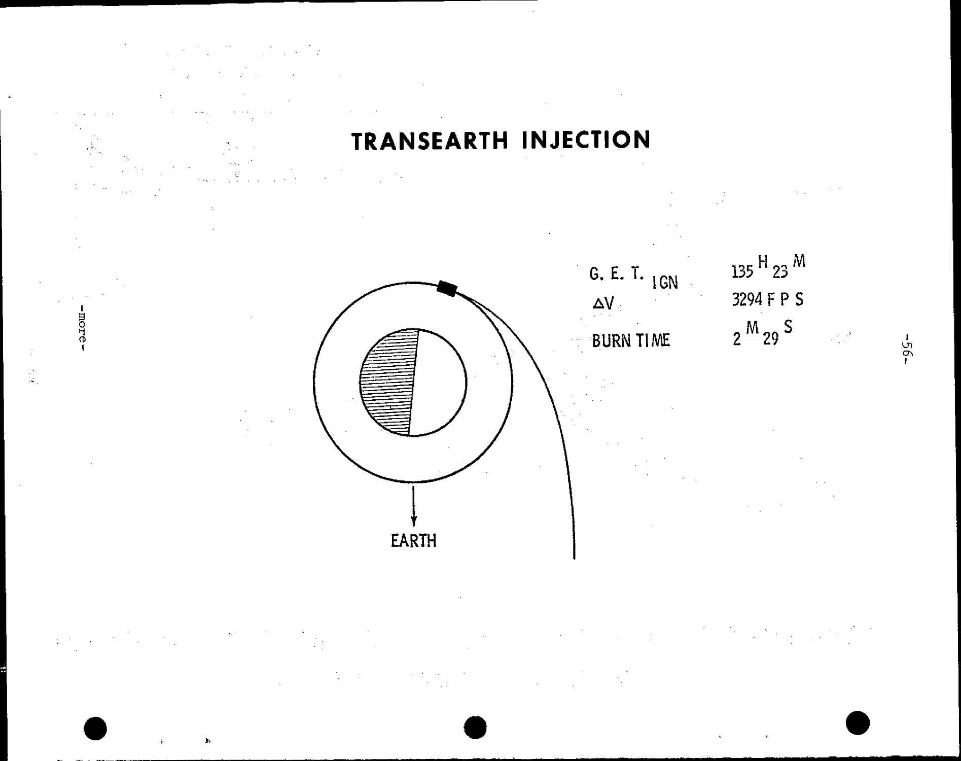
Transearth Injection (TEI)
The LM ascent stage will be jettisoned about four hours after
hard docking and the CSM will make a 1 fps retrograde separation
maneuver.
The nominal transearth injection burn will be at 135:24 GET
following 59.5 hours in lunar orbit. TEI will take place on the
lunar farside and will be a 3,293 fps posigrade SPS burn of 2 min
29 sec duration and will produce an entry velocity of 36,194 fps
after a 59.6 hr transearth flight time.
An optional TEI plan for five revolutions later would allow
a crew rest period before making the maneuver. TEI Ignition under
the optional plan would take place at 145:23=45 GET with a 3,698 fps
posigrade SPS burn producing an entry velocity of 36,296 fps and a
transearth flight time of 51.8 hrs.
-more-
LUNAR MODULE
CONCENTRIC SEQUENCE INITIATION MANEUVER
60
40
20
0
TPI
CDH
I I
7)CSI MANEUVER
MSFN LOS
MANEUVER
INSERTION
l I i I
.1 L
0 20 40 60 80 100 120 140 160 180 200 220 240 260
LM-CSM RELATIVE MOTION
MSFN
AOS
LANDING
SITE
CDH
MANEUVER
LUNAR MODULE CONSTANT
DIFFERENTIAL HEIGHT AND TERMINAL PHASE MANEUVERS
*
3
t
VERTICAL
DISPLACEMENT
{N MI)
30 r-
20
10
J[)TPI MANEUVER
(MIDPOINT OF DARKNESS)
LMRCS
CDH-
j
I
MSFN
LOS-M*
20 40 60
TRAILING DISPLACEMENT (N MI)
LM-CSM RELATIVE MOTION
10)BRAKING
MANEUVER
TEN MINUTE TIME TICKS FROM
¦DAYLIGHT
•DARKNESS
80
RENDEZVOUS AND
STAT1ONKEEP
MSFN
AOS
DOCKING
8)CDH MANEUVER
U7
TRANSEARTH INJECTION
i
o
I
G. E. T.
IGN
AV
BURN TIME
135 H 23 M
3294 F P S
2M29S
U1
I
EARTH
-57-
Transearth coast
Three corridor-control transearth midcourse correction
burns will be made if needed: MCC-5 at TEI +15 hrs, MCC-6 at
entry interface (EI=400,000 feet) -15 hrs. and MCC-7 at El -3 hrs.
Entry, Landing
Apollo 11 will encounter the Earth's atmosphere D00,000 feet)
at 195:05:04 GET at a velocity of 36,19^ fps and will land some
1,285 nm downrange from the entry-interface point using the space-
craft's lifting characteristics to reach the landing point. Touch-
down will be at 195:19:05 at 10.6 degrees north latitude by 172.4
west longitude.
-more-
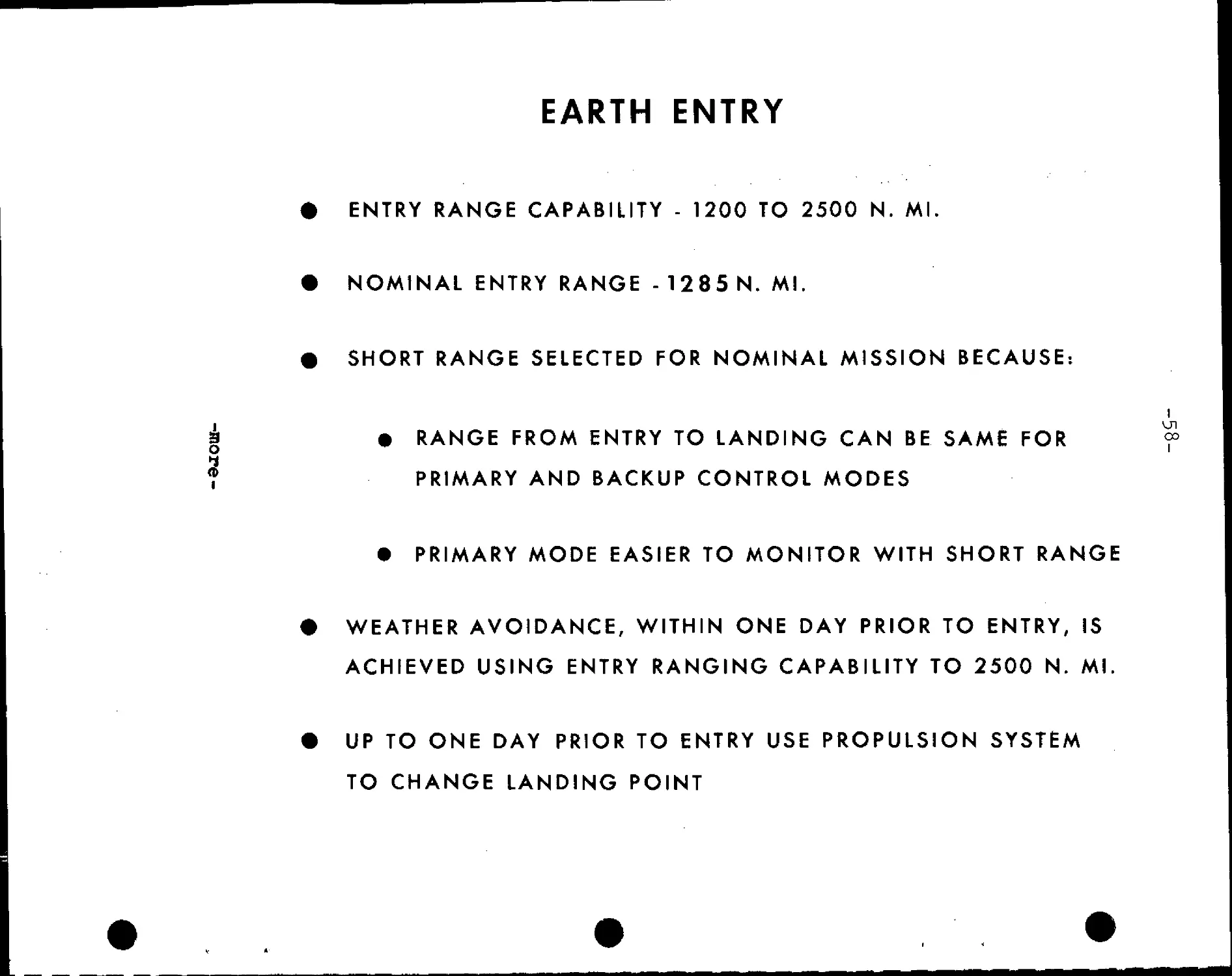
EARTH ENTRY
ENTRY RANGE CAPABILITY - 1200 TO 2500 N. Ml.
NOMINAL ENTRY RANGE - 1285 N. Ml.
SHORT RANGE SELECTED FOR NOMINAL MISSION BECAUSE:
i m
3 • RANGE FROM ENTRY TO LANDING CAN BE SAME FOR <=
? PRIMARY AND BACKUP CONTROL MODES
• PRIMARY MODE EASIER TO MONITOR WITH SHORT RANGE
WEATHER AVOIDANCE, WITHIN ONE DAY PRIOR TO ENTRY, IS
ACHIEVED USING ENTRY RANGING CAPABILITY TO 2500 N. Ml.
UP TO ONE DAY PRIOR TO ENTRY USE PROPULSION SYSTEM
TO CHANGE LANDING POINT
60
CD
1
40
¦¦¦/¦>¦-X
Entry interface
Altitudes 400,341 ft
-Longitudes 171.37"E
Geodetic latilude = 3.53*5
touchdown target
Longitude = 172.5* W
Geodetic latitude = 10.65" N
Nominal groundtrack
120 140 160 ?asl 180 Wesl 160 140
Longitude, deg
120
100
80
MANEUVER FOOTPRINT AND NOMINAL GROUNDTRACK
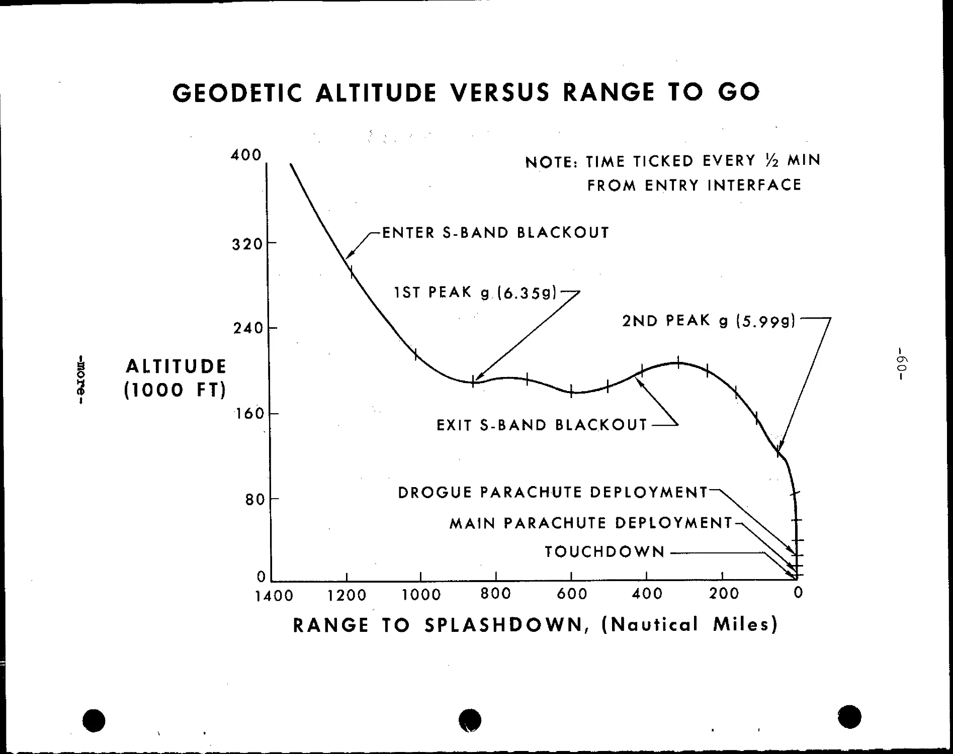
GEODETIC ALTITUDE VERSUS RANGE TO GO
400
320
240
ALTITUDE
A000 FT)
160
80
NOTE: TIME TICKED EVERY Y2 MIN
FROM ENTRY INTERFACE
¦ENTER S-BAND BLACKOUT
1ST PEAK g.F.359)
EXIT S-BAND BLACKOUT
DROGUE PARACHUTE DEPLOYMENT
MAIN PARACHUTE DEPLOYME
TOUCHDOWN
NT
0
1400 1200 1000 800 600 400 200 0
RANGE TO SPLASHDOWN, (Nautical Miles)
O
I
i
I
20° N
10° N
. *
_
-
*
r
t.
4
•
#
IJLACKOU
IIMTRY
\
\
>
1
¦ft
1
H
P
JJ
¦
•
20-
*
i
1.
•o
m
W////M
n
ev
w
! —
2
*
—
L
i
I
-
I
¦to*
c ^
•¦
/
H
y
^>
— -r-
• —.
^*
/
,/
-4vH
204.
A
*N
1
\
[h
V—
1 '
TJT
*
o
.__
TARGE
[POINT
IORNE1
g
r
"V
)
170° E
180
170° W
H
I
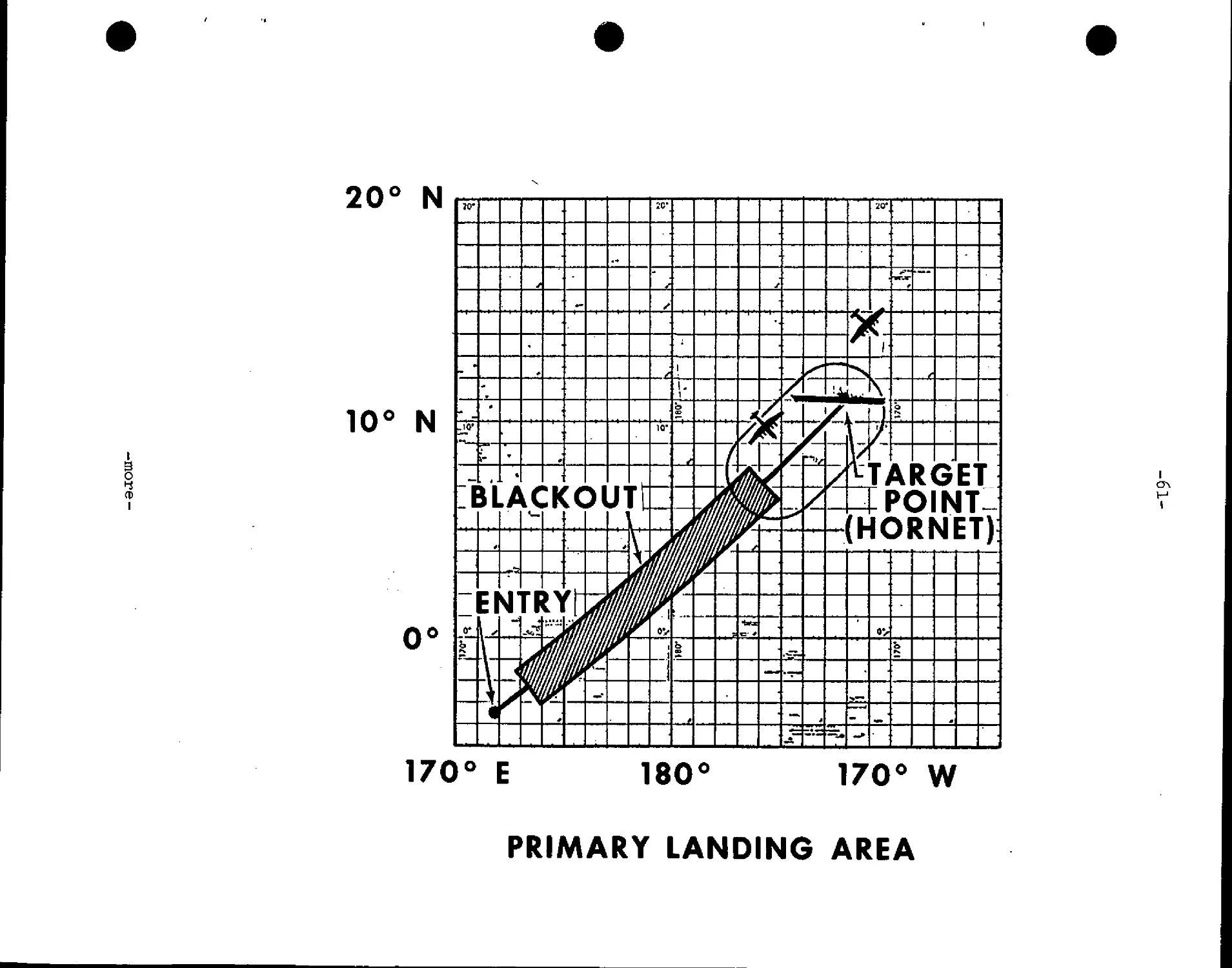
PRIMARY LANDING AREA
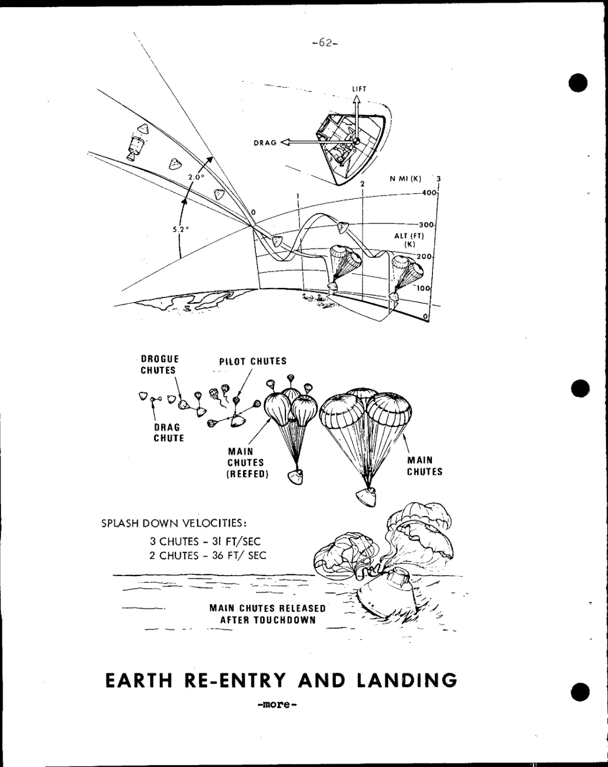
-62-
LIFT
DROGUE
CHUTES
PILOT CHUTES
DRAG
CHUTE
MAIN
CHUTES
(REEFED)
SPLASH DOWN VELOCITIES:
3 CHUTES - 31 FT/SEC
2 CHUTES - 36 FT/ SEC
MAIN CHUTES RELEASED
AFTER TOUCHDOWN
\
MAIN
CHUTES
EARTH RE-ENTRY AND LANDING
-more-
I
LAUNCH LANDING
DATE DATE
JULY 1969 JULY 1969
16 h
18
21
A
1/2 HOUR BEFORE SUNRISE
6 7 8 9
LOCAL LANDING TIME, HR
10
(-0
I
11
LOCAL LANDING TIMES
-64-
RECOVERY OPERATIONS, QUARANTINE
The prime recovery line for Apollo 11 is the mid-Pacific along
the 175th west meridian of longitude above 15 degrees north latitude,
and jogging to 165 degrees west longitude below the equator. The
aircraft carrier USS Hornet, Apollo 11 prime recovery ship, will be
stationed near the end-of-mission aiming point prior to entry.
Splashdown for a full-duration lunar landing mission launched
on time July 16 will be at 10.6 degrees north by 172.5 degrees west
at a ground elapsed time of 195 hrs 15 min.
The latitude of splashdown depends upon the time of the trans-
earth injection burn and the declination of the Moon at the time of
the burn. A spacecraft returning from a lunar mission will enter the
Earth's atmosphere and splash down at a point on the Earth's farside
directly opposite the Moon. This point, called the antipode, is a
projection of a line from the center of the Moon through the center
of the Earth to the surface opposite the Moon. The mid-Pacific
recovery line rotates through the antipode once each 24 hours, and
the transearth injection burn will be targeted for splashdown along
the primary recovery line.
Other planned recovery lines for lunar missions are the East
Pacific line extending roughly parallel to the coastlines of North
and South America; the Atlantic Ocean line running along the 30th
west meridian in the northern hemisphere and along the 25th west
meridian in the southern hemisphere, and the Indian Ocean along the
65th east meridian.
Secondary landing areas for a possible Earth orbital alternate
mission are in three zones one in the Pacific and two in the
Atlantic.
Launch abort landing areas extend downrange 3*200 nautical
miles from Kennedy Space Center, fanwise 50 nm above and below
the limits of the variable launch azimuth G2-106 degrees). Ships
on station in the launch abort area will be the destroyer USS New,
the insertion tracking ship USNS Vanguard and the minesweeper-
countermeasures ship USS Ozark.
In addition to the primary recovery ship located on the mid-
Pacific recovery line and surface vessels on the Atlantic Ocean
recovery line and in the launch abort area, 13 HC-130 aircraft
will be on standby at seven staging bases around the Eartn: Guam;
Hawaii; Bermuda; Lajes, Azores; Ascension Island; Mauritius and
the Panama Canal Zone.
-more-
-65-
Apollo 11 recovery operations will be directed from the
Recovery Operations Control Room in the Mission Control Center and
will be supported by the Atlantic Recovery Control Center, Norfolk,
Va., and the Pacific Recovery Control Center, Kunia, Hawaii.
After splashdown, the Apollo 11 crew will don biological isola-
tion garments passed to them through the spacecraft hatch by a
recovery swimmer. The crew will be carried by helicopter to the
Hornet where they will enter a Mobile Quarantine Facility (MQF)
about 90 minutes after landing. The MQF, with crew aboard, will be
offloaded at Ford Island, Hawaii and loaded on a C-l4l aircraft
for the flight to Ellington AFB, Texas, and thence trucked to the
Lunar Receiving Laboratory (LRL).
The crew will arrive at the LRL on July 27 following a nominal
lunar landing mission and will-go into the LRL Crew Reception area
for a total of 21 days quarantine starting from the time they lifted
off the lunar surface. The command module will arrive at the LRL
two or three days later to undergo a similar quarantine. Lunar
material samples will undergo a concurrent analysis in the LRL
Sample Operations area during the quarantine period.
Lunar Receiving Laboratory ¦
The Manned Spacecraft Center Lunar Receiving Laboratory . has
as its main function the quarantine and testing of lunar samples,
spacecraft and flight crews for possible harmful organisms brought
back from the lunar surface.
Detailed analysis of returned lunar samples will be done in two
phases time-critical investigations within the quarantine period
and post-quarantine scientific studies of lunar samples repackaged and
distributed to participating scientists •
There are 36 scientists and scientific groups selected
in open world-wide competition on the scientific merits of
their proposed experiments. They represent some 20 institu-
tions in Australia, Belgium, Canada, Finland, Federal Republic
of Germany, Japan, Switzerland and the United Kingdom. Major
fields of investigation will be mineralogy and petrology,
chemical and isotope analysis, physical properties, and bio-
chemical and organic analysis.
The crew reception area serves as quarters for the flight
crew and attendant technicians for the quarantine period in
which the pilots will be debriefed and examined. The other
crew reception area occupants are physicians, medical tech-
nicians, housekeepers and cooks. The CRA is also a contingency
quarantine area for sample operations area people exposed to
spills or vacuum system breaks.
Both the crew reception area and the sample operations
area are contained within biological barrier systems that pro-
tect lunar materials from Earth contamination as well as pro-
tect the outside world from possible contamination by lunar
materials. ¦ '
-more-
BIOLOGICAL ISOLATION GARMENT
-more-
-67-
Analysis of lunar sampj.es will be done in the sample operations
area, and v;ill include vacuum, magnetics, gas analysis, biological
test, radiation counting and physical-chemical test laboratories.
Lunar sair.ple return containers', or "rock boxes", will first be
brought to the vacuum laboratory -and opened in the ultra-clean
vacuum system. After preliminary examination, the samples will be
repackaged for transfer, still under vacuum, to the gas analysis,
biological preparation, physical-chemical test and radiation count-
ing laboratories.
The gas analysis lab will measure amounts and types of gases
produced by lunar samples, and geochemists in the physical-chemical
test lab will test the samples for their reactions to atmospheric
gases and water vapor. Additionally, the physical-chemical test
lab will make detailed studies of the mineralogic, petrologic,
geochemical and physical properties of the samples..
Other portions of lunar samples will travel through the LRL
vacuum system to the biological test lab where they will undergo
tests to determine if there is life in the material that may
replicate. These tests will involve introduction of lunar samples
into small germ-free animals and plants. The biological test
laboratory is made up of. several smaller labs bioprep, bio-
analysis, germ-free, histology, normal animals (amphibia and
invertebrates), incubation, anaerobic and tissue culture, crew
microbiology and plants.
Some 50 feet below the LRL ground floor, the radiation counting
lab will conduct low-background radioactive assay of lunar samples
using gamma ray spectrometry techniques.
(See Contamination Control Program section for more details
on LRL, BIGs, and the Mobile Quarantine Facility.)
-more-
-68-
SCHEDULE FOR TRANSPORT OF SAMPLES, SPACECRAFT, CREW
Two helicopters will carry lunar samples from the
recovery ship to Johnston Island where they will be put aboard
a C-l^l and flown directly to Houston and the Lunar Receiving
Laboratory (LRL). The samples should arrive at Ellington Air
Force Base at about 27 hours after recovery and received in
the LRL at about 9 or 10 a.m. COT, July 25.
Spacecraft
The spacecraft is scheduled to be brought aboard the
recovery ship about two hours after recovery. About 55 hours
after recovery the ship is expected to arrive in Hawaii. The
spacecraft will be deactivated in Hawaii (Ford Island) between
55 and 127 hours after recovery. At 130 hours it is scheduled
to be loaded on a C-133 for return to Ellington AFB. Estimated
time of arrival at the LRL is on July 29, 1^0 hours after
recovery.
Crew
The flight crew is expected to enter the Mobile Quarantine
Facility (MQF) on the recovery ship about 90 minutes after splash-
down. The ship is expected to arrive in Hawaii at recovery plus
55 hours and the Mobile Quarantine Facility will be transferred
to a C-l^l aircraft at recovery plus 51 hours. The aircraft
will land at Ellington AFB at recovery plus 65 hours and the
MQF will arrive at the LRL about two hours later (July 27).
-more-
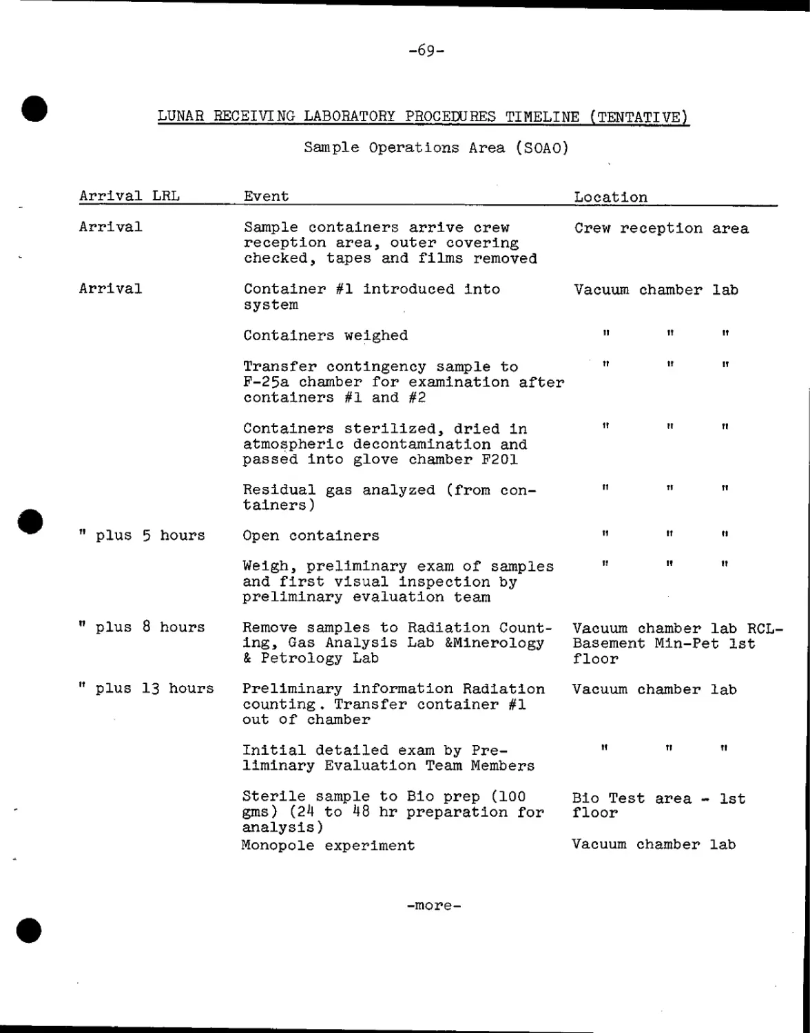
-69-
LUNAR RECEIVING LABORATORY PROCEDURES TIMELINE (TENTATIVE)
Sample Operations Area (SOAO)
Arrival LRL
Event
Location
Arrival
Arrival
Sample containers arrive crew
reception area, outer covering
checked, tapes and films removed
Container #1 introduced into
system
Containers weighed
Transfer contingency sample to
P-25a chamber for examination after
containers #1 and #2
Containers sterilized, dried in
atmospheric decontamination and
passed into glove chamber F201
Residual gas analyzed (from con-
tainers)
Crew reception area
Vacuum chamber lab
" plus 5 hours Open containers
" plus 8 hours
" plus 13 hours
Weigh, preliminary exam of samples
and first visual inspection by
preliminary evaluation team
Remove samples to Radiation Count-
ing, Gas Analysis Lab &Minerology
& Petrology Lab
Preliminary information Radiation
counting. Transfer container #1
out of chamber
Initial detailed exam by Pre-
liminary Evaluation Team Members
Sterile sample to Bio prep A00
gins) B4 to 48 hr preparation for
analysis)
Monopole experiment
Vacuum chamber lab RCL-
Basement Min-Pet 1st
floor
Vacuum chamber lab
Bio Test area - 1st
floor
Vacuum chamber lab
-more-
-70-
Arrival LRL
Event
Location
11 plus 13 hours Transfer samples to Phys-Chem Lab Phys-Chem - 1st floor
" plus 24 hours
" plus 1-2 days
Detailed photography of samples and Vacuum chamber lab
microscopic work
All samples canned and remain in " " "
chamber
" plus 4-5 days
11 plus about 7
15 days
" plus 15 days
" plus 17 days
"plus 30 days
Preparations of samples in bioprep
lab for distribution to bio test
labs. (Bacteriology, Virology,
Germ-free mice) through TEI plus
21 days
Early release of phys-chem analy-
sis
Detailed bio analysis & further
phys-chem analysis
Conventional samples transferred
to bio test area B4-48 hours
preparation for analysis)
Bio test begins on additional
bacteriological, virological,
microbiological invertebrates,
(fish, shrimp,oysters), birds,
mice, lower invertebrates (house-
fly, moth, german cockroach, etc),
plants (about 20) (through
approximately arrival plus 30 days)
Bio test info released on pre-
liminary findings
Samples go to thin section lab
(first time outside barrier) for
preparation and shipment to
principal investigators
Bio test labs
floor
- 1st
Phys-Chem labs - 1st
floor
Bio test & min-pet
1st floor
1st floor
1st floor
1st floor
1st floor
-more-
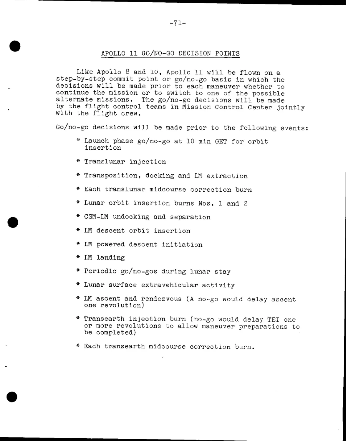
-71-
APQLLQ 11 GO/NO-GO DECISION POINTS
Like Apollo 8 and 10, Apollo 11 will be flown on a
step-by-step commit point or go/no-go basis in which the
decisions will be made prior to each maneuver whether to
continue the mission or to switch to one of the possible
alternate missions. The go/no-go decisions will be made
by the flight control teams in Mission Control Center jointly
with the flight crew.
Go/no-go decisions will be made prior to the following events:
* Launch phase go/no-go at 10 min GET for orbit
insertion
* Translunar injection
* Transposition, docking and LM extraction
* Each translunar midcourse correction burn
* Lunar orbit insertion burns Nos. 1 and 2
* CSM-LM undocking and separation
* LM descent orbit insertion
* LM powered descent initiation
* LM landing
* Periodic go/no-gos during lunar stay
* Lunar surface extravehicular activity
* LM ascent and rendezvous (A no-go would delay ascent
one revolution)
* Transearth injection burn (no-go would delay TEI one
or more revolutions to allow maneuver preparations to
be completed)
* Each transearth midcourse correction burn.
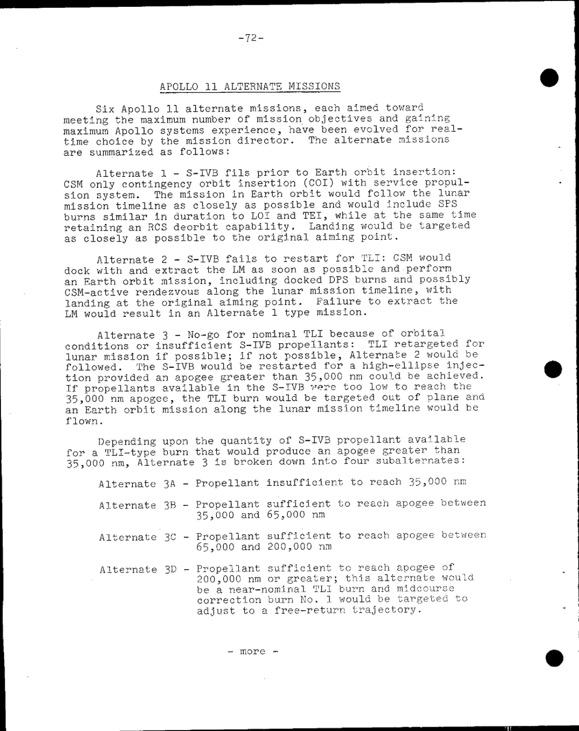
-72-
APOLLO 11 ALTERNATE MISSIONS
Six Apollo 11 alternate missions, each aimed toward
meeting the maximum number of mission objectives and gaining
maximum Apollo systems experience, have been evolved for real-
time choice by the mission director. The alternate missions
are summarized as follows:
Alternate 1 - S-IVB fils prior to Earth orbit insertion:
CSM only contingency orbit insertion (COI) with service propul-
sion system. The mission In Earth orbit would follow the lunar
mission timeline as closely as possible and would include SPS
burns similar in duration to LOI and TEI, while at the same time
retaining an RCS deorbit capability. Landing would be targeted
as closely as possible to the original aiming point.
Alternate 2 - S-IVB fails to restart for TLI: CSM would
dock with and extract the LM as soon as possible and perform
an Earth orbit mission, Including docked DPS burns and possibly
CSM-actlve rendezvous along the lunar mission timeline, with
landing at the original aiming point. Failure to extract the
LM would result In an Alternate 1 type mission.
Alternate
conditions or
lunar mission
followed. The
tion provided
If propellants
35,000 nm apog
an Earth orbit
flown.
3 - No-go for nominal TLI because of orbital
insufficient S-IYB propellants: TLI retargeted for
if possible; If not possible, Alternate 2 would be
S-IVB would be restarted for a high-ellipse injec-
an apogee greater than 35,000 nm could be achieved.
available In the S-IVB 7Tere too low to reach the
ee, the TLI burn would be targeted out of plane and
mission along the lunar mission timeline would be
Depending upon the quantity of S-IVB propellant available
for a TLI-type burn that would produce an apogee greater than
35,000 nm, Alternate 3 is broken down Into four subalternates:
Alternate 3A - Propellant insufficient to reach 35,000 nm
Alternate 3B
Alternate 3C
Alternate 3D
Propellant sufficient to reach apogee between
35,000 and 65,000 nm
Propellant sufficient to reach apogee between
65,000 and 200,000 nm
Propellant sufficient to reach apogee of
200,000 nm or greater; this alternate would
be a near-nominal TLI burn and midcourse
correction burn No. 1 would be targeted to
adjust to a free-return trajectory.
- more -
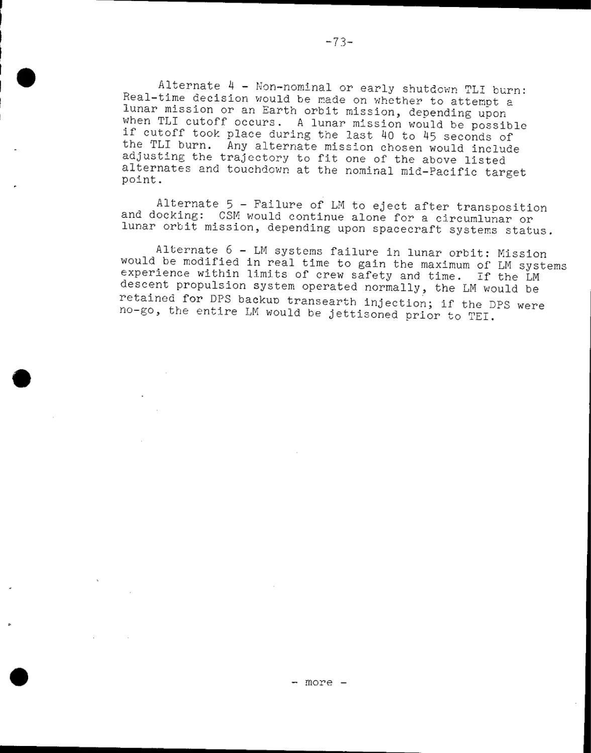
-73-
Alternate 4 - Non-nominal or early shutdown TLI burn:
Real-time decision would be made on whether to attempt a
lunar mission or an Earth orbit mission, depending upon
when TLI cutoff occurs. A lunar mission would be possible
if cutoff took place during the last 40 to 45 seconds of
the TLI burn. Any alternate mission chosen would include
adjusting the trajectory to fit one of the above listed
alternates and touchdown at the nominal mid-Pacific target
point-
Alternate 5 - Failure of LM to eject after transposition
and docking: CSM would continue alone for a circumlunar or
lunar orbit mission, depending upon spacecraft systems status.
Alternate 6 - LM systems failure in lunar orbitr Mission
would be modified in real time to gain the maximum of LM systems
experience within limits of crew safety and time. If the LM
descent propulsion system operated normally, the LM would be
retained for DPS backus transearth injection; if the DPS were
no-go, the entire LM would be jettisoned prior to TEI.
- more -
-7H-
ABORT MODES
The Apollo 11 mission can be aborted at any time
during the launch phase or terminated during later phases
after a successful insertion into Earth orbit.
Abort modes can be summarized as follows:
Launch phase —
Mode I - Launch escape system (LES) tower propels
command module away from launch vehicle. This mode is in
effect from about T-45 minutes when LES is armed until LES
tower jettison at 3:07 GET and command module landing point
can range from the Launch Complex 39A area to 400 nm downrange.
Mode II - Begins when LES tower is jettisoned and runs
until the SPS can be used to insert the CSM into a safe Earth
orbit (9"-22 GET) or until landing points approach the African
coast. Mode II requires manual separation, entry orientation and
full-lift entry with landing between 350 and 3,200 nm downrange.
Mode III - Begins when full-lift landing point reached
3,200 nm C,560 sm, 5,931 km) and extends through Earth orbital
insertion. The CSM would separate from the launch vehicle, and
if necessary, an SPS retrograde burn would be made, and the com-
mand module would be flown half-lift to entry and landing at
approximately 3,350 nm C,852 sm, 6,197 km) downrange.
Mode IV and Apogee Kick - Begins after the point the SPS
could be used to insert the CSM into an Earth parking orbit --
from about 9:22 GET. The SPS burn into orbit would be made
two minutes after separation from the S-IVB and the mission
would continue as an Earth orbit alternate. Mode IV is pre-
ferred over Mode III. A variation of Mode IV is the apogee
kick in which the SPS would be ignited at first apogee to raise
perigee for a safe orbit.
Deep Space Aborts
Translunar Injection Phase —
Aborts during the translunar injection phase are only
a remote possibly, but if an abort became necessary during the
TLI maneuver, an SPS retrograde burn could be made to produce
spacecraft entry. This mode of abort would be used only in the
event of an extreme emergency that affected crew safety. The
spacecraft landing point would vary with launch azimuth and length
of the TLI burn. Another TLI abort situation would be used if a
malfunction cropped up after injection. A retrograde SPS burn
at about 90 minutes after TLI shutoff would allow targeting to land
on the Atlantic Ocean recovery line.
-more-
-75-
Translunar Coast phase —
Aborts arising during the three-day translunar coast
phase would be similar in nature to the 90-minute TLI abort.
Aborts from deep space bring into the play the Moon's anti-
pode (line projected from Moon's center through Earth's Center
to the surface opposite the Moon) and the effect of the Earth's
rotation upon the geographical location of the antipode. Abort
times would be selected for landing when the 165 degree west
longitude line crosses the antipode. The mid-Pacific recovery
line crosses the antipode once each 2k hours, and if a time-
critical situation forces an abort earlier than the selected
fixed abort times, landings would be targeted for the Atlantic
Ocean, West Pacific or Indian Ocean recovery lines in that order
of preference. When the spacecraft enters the Moon's sphere
of influence, a circumlunar abort becomes faster than an attempt
to return directly to Earth.
Lunar Orbit Insertion phase --
Early SPS shutdowns during the lunar orbit insertion
burn (LOI) are covered by three modes in the Apollo 11 mission.
All three modes would result in the CM landing at the Earth
latitude of the Moon antipode at the time the abort was per-
formed.
Mode I would be a LM DPS posigrade burn into an Earth-
return trajectory about two hours (at next pericynthion)
after an LOI shutdown during the first two minutes of the LOI
burn.
Mode II, for SPS shutdown between two and three minutes
after ignition, would use the LM DPS engine to adjust the orbit
to a safe, non-lunar impact trajectory followed by a second
DPS posigrade burn at next pericynthion targeted for the mid-
Pacific recovery line.
Mode III, from three minutes after LOI ignition until
normal cutoff, would allow the spacecraft to coast through one
or two lunar orbits before doing a DPS posigrade burn at peri-
cynthion targeted for the mid-Pacific recovery line.
Lunar Orbit Phase —
If during lunar parking orbit it became necessary to
abort, the transearth injection (TEI) burn would be made early
and would target spacecraft landing to the mid-Pacific
recovery line.
-more-
-76-
Transearth Injection phase —
Early shutdown of the TEI burn between ignition and
two minutes would cause a Mode III abort and a SPS posigrade
TEI burn would be made at a later pericynthion. Cutoffs
after two minutes TEI burn time would call for a Mode I
abort--restart of SPS as soon as possible for Earth-return
trajectory. Both modes produce mid-Pacific recovery line
landings near the latitude of the antipode at the time of
the TEI burn.
Transearth Coast phase —
Adjustments of the landing point are possible during
the transearth coast through burns with the SPS or the service
module RCS thrusters, but In general, these are covered in the
discussion of transearth midcourse corrections. No abort burns
will be made later than 24 hours prior to entry to avoid effects
upon CM entry velocity and flight path angle.
-more-
-77-
APOLLO 11.ONBOARD TELEVISION
Two television cameras will be carried aboard Apollo 11.
A color camera of the type used on Apollo 10 will be stowed
for use aboard the command module, and the black-and-white
Apollo lunar television camera will be stowed in the LM des-
cent stage for televising back to Earth a real-time record
of man's first step onto the Moon.
The lunar television camera weighs 7.25 pounds and draws
6.5 watts of 24-32 volts DC power. Scan rate Is 10 frames-per-
second at 320 lines-per-frame. The camera body is 10.6 inches
long, 6.5 inches wide and 3-4 inches deep. The bayonet lens
mount permits lens changes by a crewman in a pressurized suit.
Two lenses, a wideangle lens for close-ups and large areas,
and a lunar day lens for viewing lunar surface features and
activities In the near field of view with sunlight illumination,
will be provided for the lunar TV camera.
The black-and-white lunar television camera is stowed in
the MESA (Modular Equipment Stowage Assembly) in the LM descent
stage and will be powered up before Armstrong starts down the
LM ladder. When he pulls the lanyard to deploy the MESA, the
TV camera will also swing down on the MESA to the left of the
ladder (as viewed from LM front) and relay a TV picture of his
initial steps on the Moon. Armstrong later will mount the TV
camera on a tripod some distance away from the LM after Aldrin
has descended to the surface. The camera will be left untended
to cover the crew's activities during the remainder of the EVA.
The Apollo lunar television camera is built by Westinghouse
Electric Corp., Aerospace Division, Baltimore, Md.
The color TV camera is a 12-pound Westinghouse camera
with a zoom lens for wideangle or close-up use, and has a three-
inch monitor which can be mounted on the camera or in the
command module. The color camera outputs a standard 525-line,
30 frame-per-second signal In color by use of a rotating color
wheel. The black-and-white signal from the spacecraft will
be converted to color at the Mission Control Center.
upon
The following is a preliminary plan for TV passes based
a 9:32 a.m. EDT, July 16 launch.
-more-
TENTATIVE APOLLO 11 TV TIMES
JOUt-
i
Date
July
July
July
July
July
July
July
July
17
18
19
20
21
21
22
23
Times of Planned
TV (EDT)
7:32 - 7:47
7:32 - 7:47
4:02 - 4:17
1:52 - 2:22
1:57 - 2:07
2:12 - 4:52
9:02 - 9:17
7:02 - 7:17
p.m.
p .m.
p .m.
p .m.
a.m.
a.m.
p . m.
p.m.
GET
34:00-34:15
58:00-58:15
78:30-78:45
100:20-100:50
112:25-112:35
112:40-115:20
155:30-155:45
177=30-177:45
Prime Site
Goldstone
Goldstone
Goldstone
Madrid
Goldstone
*Parkes
Goldstone
Goldstone
Event
Translunar Coast
Translunar Coast
Lunar Orbit (general sur-
face shots)
CM/LM Formation Plying
Landing Site Tracking
Black and White Lunar
Surface
Transearth Coast
Transearth Coast
co
I
* Honeysuckle will tape the Parkes pass and ship tape to MSC,
-79-
APOLLO 11 PHOTOGRAPHIC TASKS
Still and motion pictures will be made of most spacecraft
maneuvers as well as of the lunar surface and of crew activities
in the Apollo 11 cabin. During lunar surface activities after
lunar module touchdown and the two hour ^4-0 minute EVA, emphasis
will be on photographic documentation of crew mobility, lunar
surface features and lunar material sample collection.
Camera equipment carried on Apollo 11 consists of one 70mm
Hasselblad electric camera stowed aboard the command module,
two Hasselblad 70mm lunar surface superwide angle cameras stowed
aboard the LM and a 35mm stereo close-up camera in the LM MESA.
The 2.3 pound Hasselblad superwide angle camera in the LM
is fitted with a 38mm f/4.5 Zeiss Biogon lens with a focusing
range from 12 inches to infinity. Shutter speeds range from
time exposure and one second to 1/500 second. The angular field
of view with the 38mm lens is 71 degrees vertical and horizontal
on the square-format film frame.
The command module Hasselblad electric camera is normally
fitted with an 80mm f/2.8 Zeiss Planar lens, but bayonet-mount
60mm and 250mm lens may be substituted for special tasks. The
80mm lens has a focusing range from three feet to infinity and
has a field of view of 38 degrees vertical and horizontal.
Stowed with the Hasselblads are such associated items as
a spotmeter, ringsight, polarizing filter, and film magazines.
Both versions of the Hasselblad accept the same type film
magazine.
For motion pictures, two Maurer l6mm data acquisition
cameras (one in the GSM, one in the LM) with variable frame
speed A, 6, 12 and 24- frames per second) will be used. The
cameras each weigh 2.8 pounds with a 130-foot film magazine
attached. The command module l6mm camera will have lenses of
5, 18 and 75*™ focal length available, while the LM camera will
be fitted with the l8nm wideangle lens. Motion picture camera
accessories include a right-angle mirror, a power cable and a
command module boresight window bracket.
-more-
-80-
During the lunar surface extravehicular activity, the
commander will be filmed by the LM pilot with the LM 16mm
camera at normal or near-normal frame rates B4 and 12 fps),
but when he leaves the LM to join the commander, he will switch
to a one frame-per-seeond rate. The camera will be mounted
inside the LM looking through the right-hand window. The l8mm
lens has a horizontal field of view of 32 degrees and a vertical
field of view of 23 degrees. At one fps, a 130-foot 16mm maga-
zine will run out in 87 minutes in real time; projected at the
standard 2*i fps, the film would compress the 87 minutes to 3.6
minutes.
Armstrong and Aldrin will use the Hasselblad lunar surface
camera extensively during their surface EVA to document each of
their major tasks. Additionally, they will make a 360-degree
overlapping panorama sequence of still photos of the lunar hori-
zon, photograph surface features in the immediate area, make
close-ups of geological samples and the area from which they
were collected and record on film the appearance and condition
of the lunar module after landing.
Stowed in the MESA is a 35mm stereo close-up camera which
shoots 24!™! square color stereo pairs with an image scale of one-
half actual size. The camera is fixed focus and is equipped
with a stand-off hood to position the camera at the proper focus
distance. A long handle permits an EVA crewman to position the
camera without stooping for surface object photography. Detail
as small as 40 microns can be recorded.
A battery-powered electronic flash provides illumination.
Film capacity is a minimum of 100 stereo pairs.
The stereo close-up camera will permit the Apollo 11 landing
crew to photograph significant surface structure phenomena which
would remain intact only in the lunar environment, such as fine
powdery deposits, cracks or holes and adhesion of particles.
Near the end of EVA, the film casette will be removed and
stowed in the commander's contingency sample container pocket
and the camera body will be left on the lunar surface.
-more-
-81-
LUNAR DESCRIPTION
Terrain - Mountainous and crater-pitted, the former
rising thousands of feet and the latter ranging from a few
inches to 180 miles in diameter. The craters are thought
to be formed by the impact of meteorites. The surface is
covered with a layer of fine-grained material resembling
silt or sand, as well as small rocks and boulders.
Environment - No air, no wind, and no moisture. The
temperature ranges from 243 degrees in the two—week lunar
day to 279 degrees below zero in the two-week lunar night.
Gravity is one-sixth that of Earth. Micrometeoroids pelt the
Moon (there is no atmosphere to burn them up). Radiation
might present a problem during periods of unusual solar activity.
Dark Side - The dark or hidden side of the Moon no longer
is a complete mystery. It was fi*rst photographed by a Russian
craft and since then has been photographed many times, particu-
larly by NASA's Lunar Orbiter spacecraft and Apollo 8.
Origin - There is still no agreement among scientists
on the origin of the Moon. The three theories; A) the Moon
once was part of Earth and split off into its own orbit, B)
it evolved as a separate body at the same time as Earth, and
C) it formed elsewhere in space and wandered until it was
captured by Earth's gravitational field.
Diameter
Circumference
Distance from Earth
Surface temperature
Surface gravity
Mass
Volume
Lunar day and night
Mean velocity in orbit
Escape velocity
Physical Facts
2,160 miles (about ? that of Earth)
6,790 ailes (about ? that of Earth)
238,857 miles (mean; 221,463 minimum
to 252,710 maximum)
+243°F (Sun at zenith) -279°P (night)
1/6 that of Earth
l/100th that of Earth
l/50th that of Earth
14 Earth days each
2,287 miles per hour
1.48 miles per second
Month (period of rotation
around Earth)
27 days, 7 hours, 43 minutes
-more-
-82-
Apollo Lunar landing Sites
Possible landing sites for the Apollo lunar module have
been under study by NASA's Apollo Site Selection Board for more
than two years. Thirty sites originally were considered. These
have been narrowed down to three for the first lunar landing.
(Site 1 currently not considered for first landing.)
Selection of the final sites was based on high resolution
photographs by Lunar Orbiter spacecraft, plus close-up photos
and surface data provided by the Surveyor spacecraft which soft -
landed on the Moon.
The original sites are located on the visible side of the
Moon within 45 degrees east and west of the Moon's center and
5 degrees north and south of its equator.
m
The final site choices were based on these factors:
•Smoothness (relatively few craters and boulders)
¦Approach (no large hills, high cliffs, or deep craters
that could cause incorrect altitude signals to the lunar
module landing radar)
¦Propellant requirements (selected sites require the least
expenditure of spacecraft propellants) Ml
•Recycle (selected sites allow effective launch preparation
recycling if the Apollo Saturn V countdown is delayed)
¦Free return (sites are within reach of the spacecraft
launched on a free return translunar trajectory)
¦Slope (there is little slope — less than 2 degrees in
the approach path and landing area)
APOLLO LUNAR LANDING SITES
g
3
4',^ -f #U •fcM^- ^,Vr- ?( ' i ¦/"¦f!1'v''«-' ^7' A r" ¦• / ¦ V ¦¦IF"-*//
I
I
I
o
4
I
I
CO
-tr
I
-85-
The Apollo 11 Landing Sites Are:
Site 2 latitude 0° 42' 50" North
longitude 23° 42' 28" East
1 . Site 2 is located on the east
central part of the Moon in south-
western Mar Tranquillitatis. The
site is approximately 62 miles
A00 kilometers) east of the rim
of Crater Sabine and approximately
118 miles A90 kilometers) south-
west of the Crater Maskelyne.
Site 3 latitude 0° 21' 10" North
longitude 1° 17' 57" West
Site 3 is located near the center
of the visible face of the Moon
in the southwestern part of Sinus
Medii. The site is approximately
25 miles D0 kilometers) west of
the center of the face' and 21 miles
E0 kilometers) southwest of the
Crater Bruce.
Site 5 latitude 1° 40' 41"' North
longitude 41° 53' 57" West
Site 5 is located on the west
central part of the visible face
in southeastern Oceanus Procel-
larum. The site is approximately
130 miles B10 kilometers) south-
west of the rim of Crater Kepler
and 118 miles A90 kilometers)
north northeast of the rim of
Crater Flamsteed.
-more-
-86-
COMMAND AND SERVICE MODULE STRUCTURE, SYSTEMS
The Apollo spacecraft for the Apollo 11 mission is comprised
of Command Module 10 7, Service Module 107, Lunar Module 5, a
spacecraft-lunar module adapter (SLA) and a launch escape system.
The SLA serves as a mating structure between the instrument unit
atop the S-IVB stage of the Saturn V launch vehicle and as a
housing for the lunar module.
Launch Escape System (LES) — Propels command module to
safety in an aborted launch. It is made up of an open-frame tower
structure, mounted to the command module by four frangible bolts, and
three solid-propellant rocket motors: a 147,000 pound-thrust launch
excape system motor, a 2 ,400-pound-thrust pitch control motor, and
a 31,500-pound-thrust tower jettison motor. Two canard vanes near
the top deploy to turn the command module aerodynamically to an
attitude with the heat-fhield forward. Attached to the base of
the launch escape tower is a boost protective cover composed of
resin impregnated fiberglass covered with cork, that protects the
command module from aerodynamic heating during boost and rocket
exhaust gases from the main and the jettison motors. The system
is 33 feet tall, four feet in diameter at the base, and weighs
8,910 pounds.
Command Module (CM) Structure — The basic structure of the
command-module is a pressure vessel encased in heat shields, cone-
shaped 11 feet 5 inches high, base diameter of 12 feet 10 inches, and
launch weight 12,250 pounds.
The command module consists of the forward compartment which
contains two reaction control engines and components of the Earth
landing system; the crew compartment or inner pressure vessel
containing crew accomodations, controls and displays, and many
of the spacecraft systems; and the aft compartment housing ten
reaction control engines, propellant tankage, helium tanks, water
tanks, and the CSM umbilical cable. The crew compartment contains
210 cubic feet of habitable volume.
Heat-shields around the three compartments are made of
brazed stainless steel honeycomb with an outer layer of phenolic
epoxy resin as an ablative material. Shield thickness, varying
according to heat loads, ranges from 0.7 inch at the apex to 2.7
inches at the aft end.
The spacecraft inner structure is of sheet-aluminum honey-
comb bonded sandwhich ranging in thickness from 0.25 inch thick
at forward access tunnel to 1.5 inches thick at base.
-more-
APOLLO SPACECRAFT
i
3
I
-88-
CSW 10 7 and LM-5 are equipped with the probe-and-drogue
docking hardware. The probe assembly is a powered folding
coupling and impact attentuating device mounted on the CM tunnel
that mates with a conical drogue mounted in the LM docking tunnel.
After the 12 automatic docking latches are checked following a
docking maneuver, both the probe and drogue assemblies are removed
from the vehicle tunnels and stowed to allow free crew transfer
between the CSM and LM.
Service Module (SM) Strucutre — The service module is a
cylinder 12 feet 10 inches in diameter by 2H feet 7 inches high.
For the Apollo 11 mission, it will weigh, 51,243 pounds at launc>,,
Aluminum honeycomb panels one inch thick form the outer skin, and
milled aluminum radial beams separate the interior into six sections
around a central cylinder containing two helium spheres, four sections,
containing service propulsion system fuel-oxidizer tankage, another
containing fuel cells, cryogenic oxygen and hydrogen, and one
sector essentially empty.
Spacecraft-LM Adapter (SLA) Structure — The spacecraft LM
adapter is a truncated cone 2b feet long tapering from 260 inches
diameter at the base to 15h inches at the forward end at the
service module mating line. Aluminum honeycomb 1.75 inches thick
is the stressed-sxm structure for the spacecraft adapter. The
SLA weighs *l,000 pounds.
CSM Systems
Guidance, Navigation and Control System (GNCS) — Measures
and controls spacecraft position, attitude, and velocity, calculates
trajectory, controls spacecraft propulsion system thrust vector,
and displays abort data. The guidance system consists of three
subsystems: inertial, made up of an inertial measurement unit and :
associated power and data components; computer which processes
information to or from other components; and optics, including
scanning tel'ecope and sextant for celestial and/or landmark
spacecraft navigation. CSM 107 and subsequent modules are equipped
with a VHP ranging device as a backup to the LM rendezvous radar.
Stabilization and Control Systems (SCS) — Controls space-
craft rotation, translation, and thrust vector and provides displays
for crew-initiated maneuvers; backs up the guidance system. It
has three subsystems; attitude reference, attitude control, and
thrust vector control.
Service Propulsion System (SPS) — Provides thrust for large
spacecraft velocity changes through a gimbal-mounted 20,5Q0-pound-
thrust hypergolic engine using a nitrogen tetroxide oxidizer and a
50-50 mixture of unsymmetrical dimethyl hydrazine and hydrazine fuel.
This system is in the service module. The system responds to auto-
matic firing commands from the guidance and navigation system or to
manual commands from the crew. The engine provides a constant
thrust level. The stabilization and control system gimbals the
engine to direct the thrust vector through the spacecraft center of
gravity.
-more-
TENSION TIE
,D0CKIN6 MECHANISM
i IN.
-12 FT 10 IK-
SEXTANT t
SCANNING
TELESCOPE
STEAM VINT
NJMR VENT
(IN BOOST COVER!
¦ ROLL ENGINES
|Z PLACES)
>5
SIDE
WINDOW
(Z PLACES)
CREW
ACCESS HATCH
EARTH LANDING SUBSYSTEM
EARTH LANDING
SEQUENCE CONTROLLER
FOLD ABLE CREW
COUCH
REACTION CONTROL
ENGINES
CENTRAL TIMING
COMMAND MODULE
SERVICE MODULE
IPS
RADIATORS.
DEO DOCKING
LIGHT
GREEN DOCKING LIGHT
FLV AWAY UMBILICAL
SM DCS
MODULE.
SCIMITAR
ANTENNA'
ECS HAOlATOft
SPS NOZZLE
EXTENSION
SECTOR II 1 SERVICE fBOPUlSIOH SYSTEM
SECTOR lit] OXIDIZE! TIKIS
StCTOfl IV ¦ OKTGEN TA«KS.
T«»«S.l EPS I
SECTOI V 1 SERVICE PROPU
SECTOR VlJ FIML TAKKS
StCTOA IV ¦ OKTGEN TADtKS. HtOJLOGEN
T<««S.l EPS FUEL CELIS
IPULSIDN STSIEM
cehkh sictioii
SERVICt PR0PU1SIOH
-90-
Telecommunications System — Provides voice, television, tele-
metry, and command data and tracking and ranging between the space-
craft and Earth, between the command module and the lunar module
and between the spacecraft and the extravehicular astronaut. It
also provides intercommunications between astronauts. The tele-
communications system consists of pulse code modulated telemetry
for relaying to Manned Space Plight Network stations data on space-
craft systems and crew condition, VHP/AM voice, and unified S-Band
tracking transponder, air-to-ground voice communications, onboard
television, and a VHF recovery beacon. Network stations can transmit
to the spacecraft such items as updates to the Apollo guidance
computer and central timing equipment, and real-time commands for
certain onboard functions.
The high-gain steerable S-Band antenna consists of four,
31-inch-diameter parabolic dishes mounted on a folding boom at
the aft end of the service module. Nested alongside the service
propulsion system engine nozzle until deployment, the antenna .
swings out at right angles to the spacecraft longitudinal axis,
with the boom pointing 52 degrees below the heads-up horizontal.
Signals from the ground stations can be tracked either automatically
or manually with the antenna's gimballing system. Normal S-Band
voice and uplink/downlink communications will be handled by the
omni and high-gain antennas.
Sequential System -- Interfaces with other spacecraft systems
and subsystems to initiate time critical functions during launch,
docking maneuvers, sub-orbital aborts, and entry portions of a
mission. The system also controls routine spacecraft sequencing
such as service module separation and deployment of the Earth land-
ing system.
Emergency Detection System (EDS) — Detects and displays to
the crew launch vehicle emergency conditions, such as excessive
pitch or roll rates or two engines out, and automatically or
manually shuts down the booster and activates the launch escape
system; functions until the spacecraft is in orbit.
Earth Landing System (ELS) — Includes the drogue and main
parachute system as well as post-landing recovery aids. In a
normal entry descent, the command module forward heat shield
is jettisoned at 24,000 feet, permitting mortar deployment of
two reefed 16.5-foot diameter drogue parachutes for orienting
and decelerating the spacecraft. After disreef and drogue release,
three mortar deployed pilot chutes pull out the three main 83.3-
foot diameter parachutes with two-stage reefing to provide gradual
inflation in three steps. Two main parachutes out of three can
provide a safe landing.
-more-
S-band inflight antenna
Crewmen optical alignment sight
VHF inflight antenna B)
LM mounted CSM-actrve docking alignment target
VHF EVA antenna
Two VHF blade recovery antennas-under forward heat shield
LM COAS line of sight post plrchover position-
Four S-band omni antennas-
T
LM docking light
Tracking light
+z
Rendezvous radar'antenna
-CSM mounted LM-active
docking alignment target
RRT antenna
¦Two scimitar VHF omni antennas on SM
A80 deg. apart)
SPACECRAFT AXIS AND ANTENNA LOCATIONS
Steerable S-band 2-GHz
high gain antenna
o
Two scimitar VHF omni antennas
on SM A80 deg. apart)
VHF inflight antenna B)
S-band steerable antenna
LM+Yaxis CSM
IM -Z axis
+Z axis fCSM
/-Yaxis
\
60°
/ CSM+Y axis/ * \
2 VHF Recovery
antennas under
forward heat shield
(Not Shown)
LM+Zaxis ~ZaxisLM-Y
axis
Rendezvous radar
S-band
antenna
I
ro
I
SPACECRAFT AXIS AND ANTENNA LOCATIONS
-93-
Reaction Control System (RCS) — The command module and the
service module each has its own independent system. The SM RCS
has four identical RCS "quads" mounted around the SM 90 degrees
apart. Each quad has four 100 pound-thrust engines, two fuel and
two oxidizer tanks and a helium pressurization sphere. The SM
RCS provides redundant spacecraft attitude control through cross-
coupling logic inputs from the stabilization and guidance systems.
Small velocity change maneuvers can also be made with the SM RCS.
The CM RCS consists of two independent six-engine subsystems
of six 93 pound-thrust engines each. Both subsystems are activated
just prior to CM separation from the SM: one is used for spacecraft
attitude control during entry. The other serves in standby as a
backup. PropeHants for both CM and SM RCS are monomethyl hydrazine
fuel and nitrogen tetroxide oxidizer with helium pressurization.
These propellants are hypergolic, i.e., they burn spontaneously
when combined without an igniter.
Electrical Power System (EPS) — Provides electrical energy
sources, power generation and control, power conversion and condition-
ing, and power distribution to the spacecraft throughout the mission.
The EPS also furnishes drinking water to the astronauts as a by-
product of the fuel cells. The primary source of electrical power
is the fuel cells mounted in the SM. Each cell consists of a hydrogen
compartment, an oxygen compartment, and two electrodes. The cryogenic
gas storage system, also located in the SM, supplies the hydrogen
and oxygen used in the fuel cell power plants, as well as the oxygen
used in the ECS.
Three silver-zinc oxide storage batteries supply power to the
CM during entry and after landing, provide power for sequence con-
trollers, and supplement the fuel cells during periods of peak
power demand. These batteries are located in the CM lower equip-
ment bay. A battery charger is located in the same bay to assure
a full charge prior to entry.
Two other silver-zinc oxide batteries, independent of and
completely isolated from the rest of the dc power system, are used
to supply power for explosive devices for CM/SM separation,
parachute deployment and separation, third-stage separation, launch
excape system tower separation, and other pyrotechnic uses.
Environmental Control System (ECS) — Controls spacecraft
atmosphere, pressure, and temperature and manages water. In
addition to regulating cabin and suit gas pressure, temperature
and humidity, the system removes carbon dioxide, odors and
particles, and ventilates the cabin after landing. It collects and
stores fuel cell potable water for crew use, supplies water to the
glycol evaporators for cooling, and dumps surplus water overboard
through the urine dump valve. Proper operating temperature of
electronics and electrical equipment is maintained by this system
through the use of the cabin heat exchangers, the space radiators,
and the glycol evaporators.
-more-
Recovery aids include the uprighting system, swimmer inter-
phone connections, sea dye marker, flashing beacon, VHF recovery
beacon, and VHP transceiver. The uprighting system consists of
three compressor-inflated bags to upright the spacecraft if it
should land in the water apex down (stable II position).
Caution and Warning System — Monitors spacecraft systems for
out-of-tolerance conditions and alerts crew by visual and audible
alarms so that crewmen may trouble-shoot the problem.
Controls and Displays — Provide readouts and control functions
of all other spacecraft systems in the command and service modules.
All controls are designed to be operated by crewmen in pressurized
suits. Displays are grouped by system and located according to the
frequency the crew refers to them.
-more-
* .1
LUNAR MODULE
DROGUE ASSEMBLY
COMMAND MODULE
PROBE ASSEMBLY
i
SUPPORT BEAMC)
PITCH ARM C)
DOCKING RING
CM TUNNEL
CAPTURE LATCHES C)
AUTOMATIC DOCKING LATCHES A2)
APOLLO DOCKING MECHANISMS
-96-
LUNAR MODULE STRUCTURES, WEIGHT
The lunar module is a two-stage vehicle designed for
space operations near and on the Moon. The LM is incapable
of reenterlng the atmosphere. The lunar module stands 22
feet 11 inches high and is 31 feet wide (diagonally across
landing gear).
Joined by four explosive bolts and umbilicals, the as-
cent and descent stages of the LM operate as a unit until
staging, when the ascent stage functions a3 a single space-
craft for rendezvous and docking with the CSM.
Ascent Stage
Three main sections make up the ascent stage: the crew
compartment, midsection, and aft equipment bay. Only the
crew compartment and midsection are pressurized D.8 psig;
337.4 gm/sq cm) as part of the IJ4 cabin; all other sections
of the JM are unpressurized. The cabin volume is 235 cubic
feet F.7 cubic meters). The ascent stage measures 12 feet
4 inches high by 14 feet 1 inch in diameter.
Structurally, the ascent stage has six substructural
areas: crew compartment, midsection, aft equipment bay, thrust
chamber assembly cluster supports, antenna supports and thermal
and micrometeoroid shield.
The cylindrical crew compartment is a semimonocoque
structure of machined longerons and fusion-welded aluminum sheet
and is 92 inches B.35 m) in diameter and 42 inches A.07 m)
deep. Two flight stations are equipped with control and dis-
play panels, armrests, body restraints, landing aids, two front
windows, an overhead docking window, and an alignment optical
telescope in the center between the two flight stations. The
habitable volume is l6o cubic feet.
Two triangular front windows and the 32-inch @.81 m)
square inward-opening forward hatch are In the crew compartment
front face.
External structural beams support the crew compartment
and serve to support the lower interstage mounts at their
lower ends. Ring-stiffened semimonocoque construction is em-
ployed in the midsection, with chem-milled aluminum skin over
fusion-welded longerons and stlffeners. Fore-and-aft beams
across the top of the midsection join with those running across
the top of the cabin to take all ascent stage stress loads and,
In effect, isolate the cabin from stresses.
-more-
i
i
-97-
DOCKING WINDOW
DOCKING
DROGUE
ASSEMBLY
VHF ANTENNA
, DOCKING
TARGET
S-BAND
STEERABLE
ANTENNA
RENDEZVOUS
RADAR ANTENNA
S-BAND IN-FLIGHT
ANTENNA
WINDOWS
TRACKING LIGHT
EVA ANTENNA
AFT
EQUIPMENT
BAY
RCS THRUST
CHAMBER
ASSEMBLY
CLUSTER D)
LANDING RADAR
ANTENNA
DESCENT
ENGINE
SKIRT
DOCKING
LIGHT D)
LANDING
PAD
LUNAR SURFACE SENSING PROBE C)
APOLLO LUNAR MODULE
-more-
VH.F ANTENNAB)
S-BAND STEERABLE ANTENNA
ALIGNMENT OPTICAL TELESCOPE
RENDEZVOUS
RADAR ANTENNA
ASCENT ENGINE COVER
S-BAND INFLIGHT ANTENNA B)
TRACKING LIGHT
REACTION CONTROL
ASSEMBLYD PLACES)
OX1DIZERTANK
INGRESS/EGRESS HATCH
CREW COMPARTMENT
TRANSFER TUNNEL AND OVERHEAD HATCH
EVA ANTENNA
DOCKING TARGET RECESS
GASEOUS OXYGEN TANK B)
AFT EQUIPMENT BAY
REPLACEABLE ELECTRONIC ASSEMBLY
FUEL TANK (REACTION CONTROL)
LIQUID OXYGEN TANK
HELIUM TANK ?)
HELIUM TANK
(REACTION CONTROL)
OXIDIZER TANK
(REACTION CONTROL)
00
I
WATER TANKB)
FUEL TANK
APOLLO LUNAR MODULE - ASCENT STAGE
ENVIRONMENTAL CONTROL SUBSYSTEM
ECS LI OH CARTRIDGE
o
@
ALIGNMENT
OPTICAL
TELESCOPE
PLSS
RECHARGE HOSE
ECS CREW UMBILICALS
LM CABIN INTERIOR, LEFT HALF
8
PLSS RECHARGE AND
STOWAGE POSITION
PLSS O2 RECHARGE HOSE
DSEA
URINE MGT SYSTEM
o
o
LM CABIN INTERIOR, RIGHT HALF