/


Tags: weapons military affairs machine gun
Year: 1983
Similar


Text
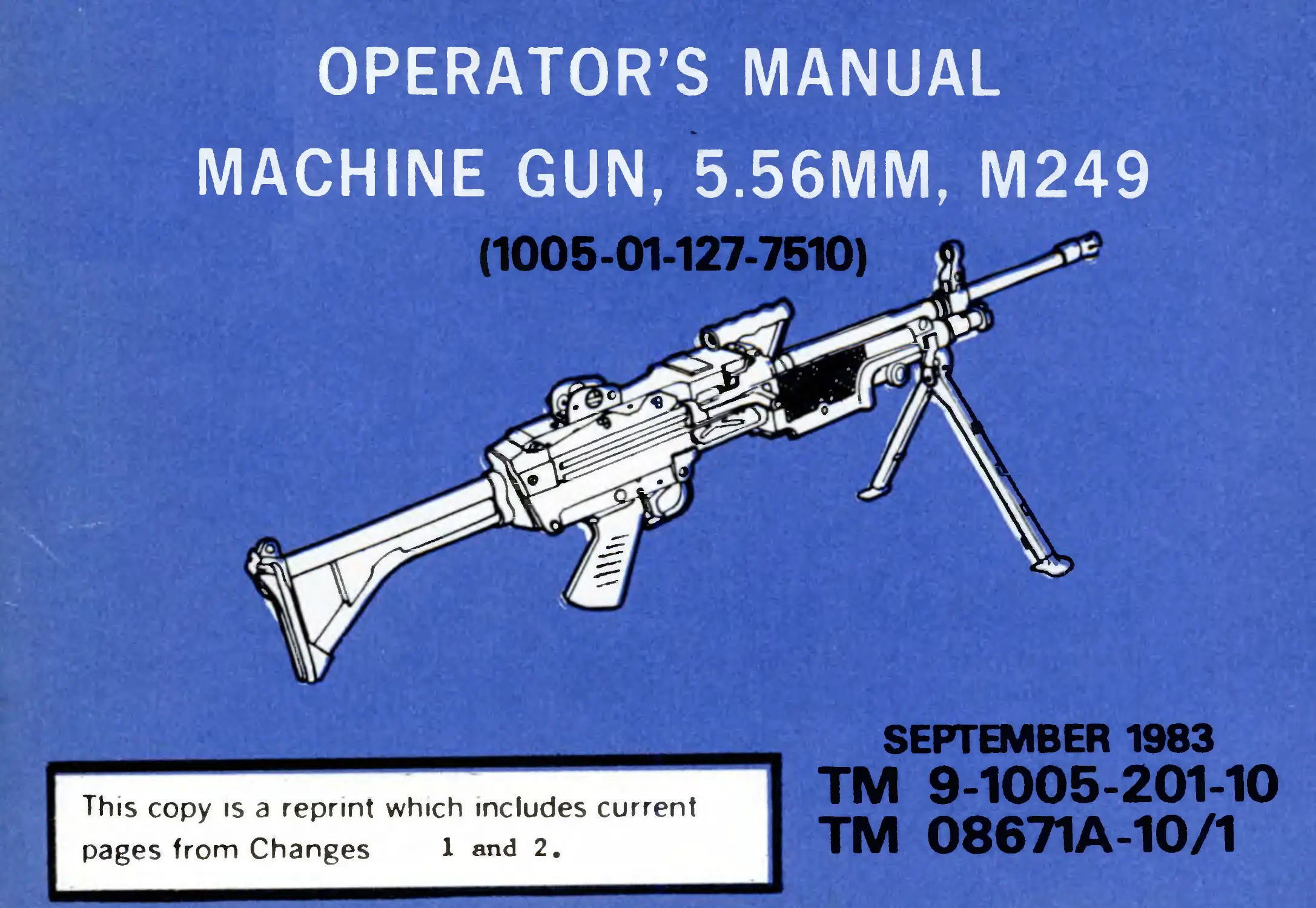
OPERATOR’S MANUAL
MACHINE GUN, 5.56MM, M249
да!
This copy is a reprint which includes current
pages from Changes 1 and 2.
SEPTEMBER 1983
TM 9-1005-201-10
TM 08671A10/1
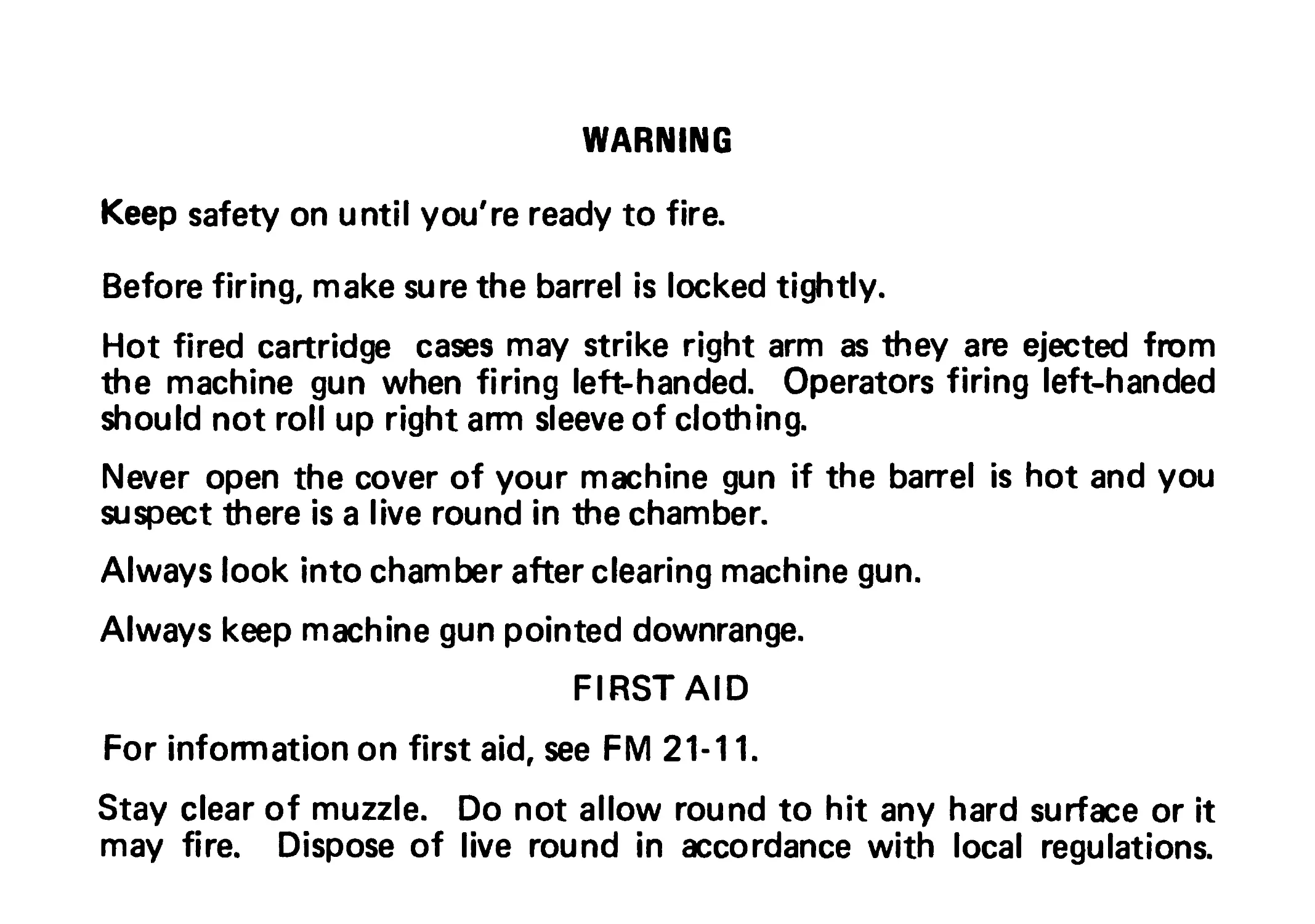
WARNING
Keep safety on until you're ready to fire.
Before firing, make sure the barrel is locked tightly.
Hot fired cartridge cases may strike right arm as they are ejected from
the machine gun when firing left-handed. Operators firing left-handed
should not roll up right arm sleeve of clothing.
Never open the cover of your machine gun if the barrel is hot and you
suspect there is a live round in the chamber.
Always look into chamber after clearing machine gun.
Always keep machine gun pointed downrange.
FIRST AID
For information on first aid, see FM 21-11.
Stay clear of muzzle. Do not allow round to hit any hard surface or it
may fire. Dispose of live round in accordance with local regulations.
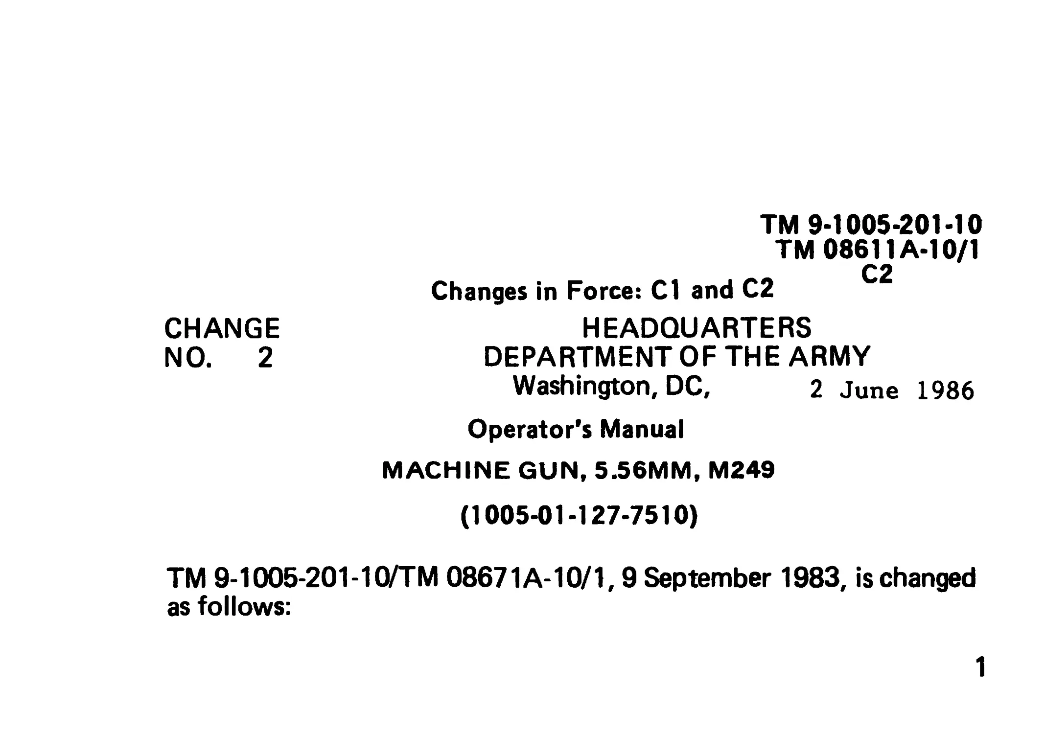
ТМ 9-1005-201-10
ТМ 08611А-10/1
С2
Changes in Force: Cl and C2
CHANGE HEADQUARTERS
NO. 2 DEPARTMENT OF THE ARMY
Washington, DC, 2 June 1986
Operator’s Manual
MACHINE GUN, 5.56MM, M249
(1005-01-127-7510)
TM 9-1005-201-10/TM 08671A-10/1,9 September 1983, is changed
as follows:
1
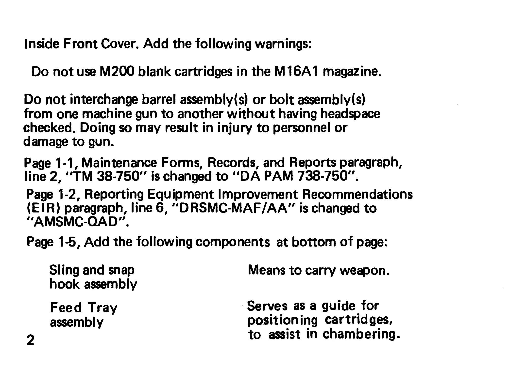
Inside Front Cover. Add the following warnings:
Do not use M200 blank cartridges in the M16A1 magazine.
Do not interchange barrel assembly(s) or bolt assembly(s)
from one machine gun to another without having headspace
checked. Doing so may result in injury to personnel or
damage to gun.
Page 1-1, Maintenance Forms, Records, and Reports paragraph,
line 2, "TM 38-750" is changed to "DA PAM 738-750".
Page 1-2, Reporting Equipment Improvement Recommendations
(EIR) paragraph, line 6, "DRSMC-MAF/AA" is changed to
"AMSMC-QAD".
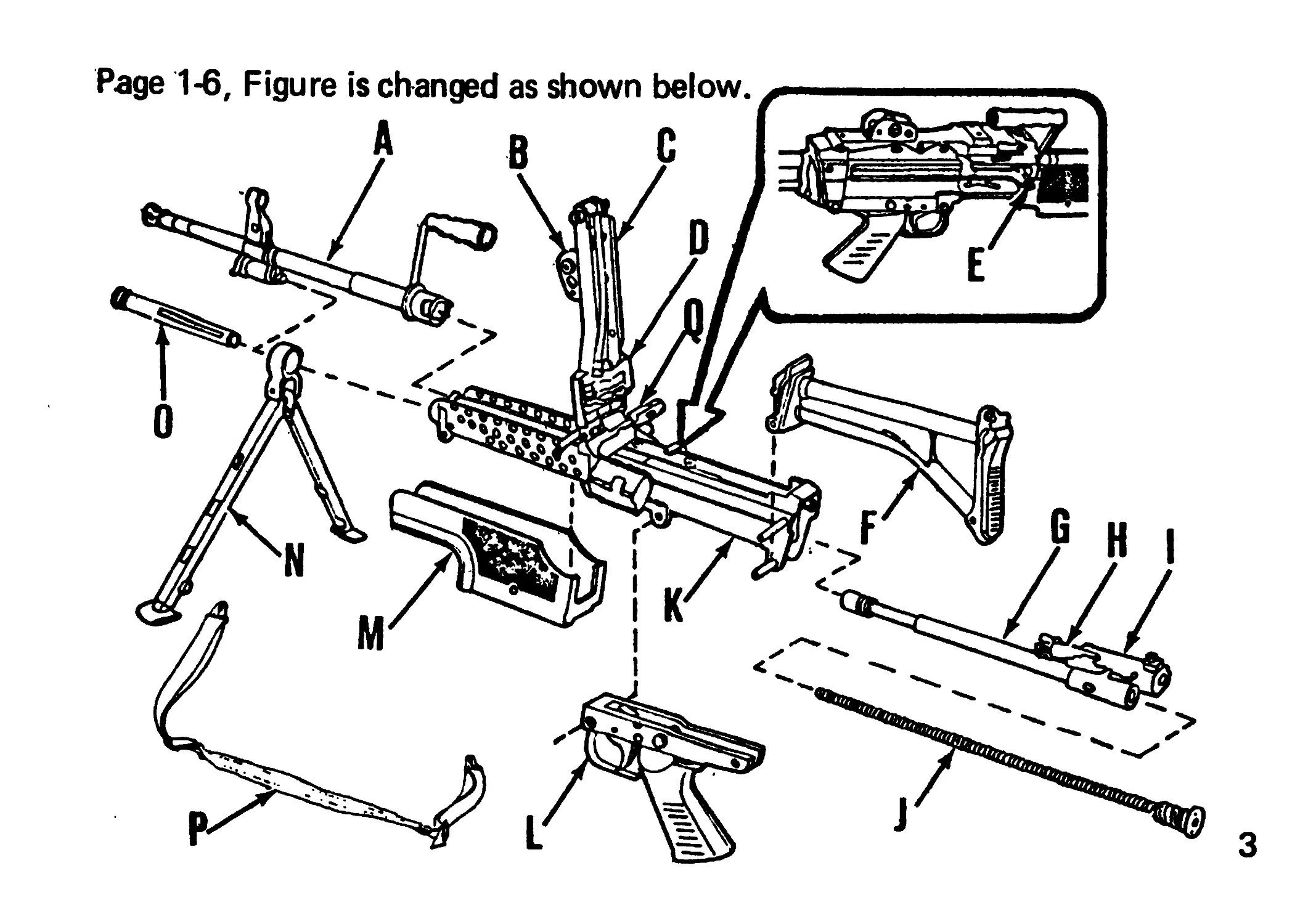
Page 1-5, Add the following components at bottom of page:
Sling and snap
hook assembly
Feed Tray
assembly
Means to carry weapon.
Serves as a guide for
positioning cartridges,
to assist in chambering.
2
3
Page 1-7, Add the following statement at bottom of page:
P- SLING AND SNAP HOOK ASSEMBLY.
Q-FEED TRAY ASSEMBLY
Page 1-8, "SLING ASSEMBLY" is changed to "SLING AND SNAP
HOOK ASSEMBLY".
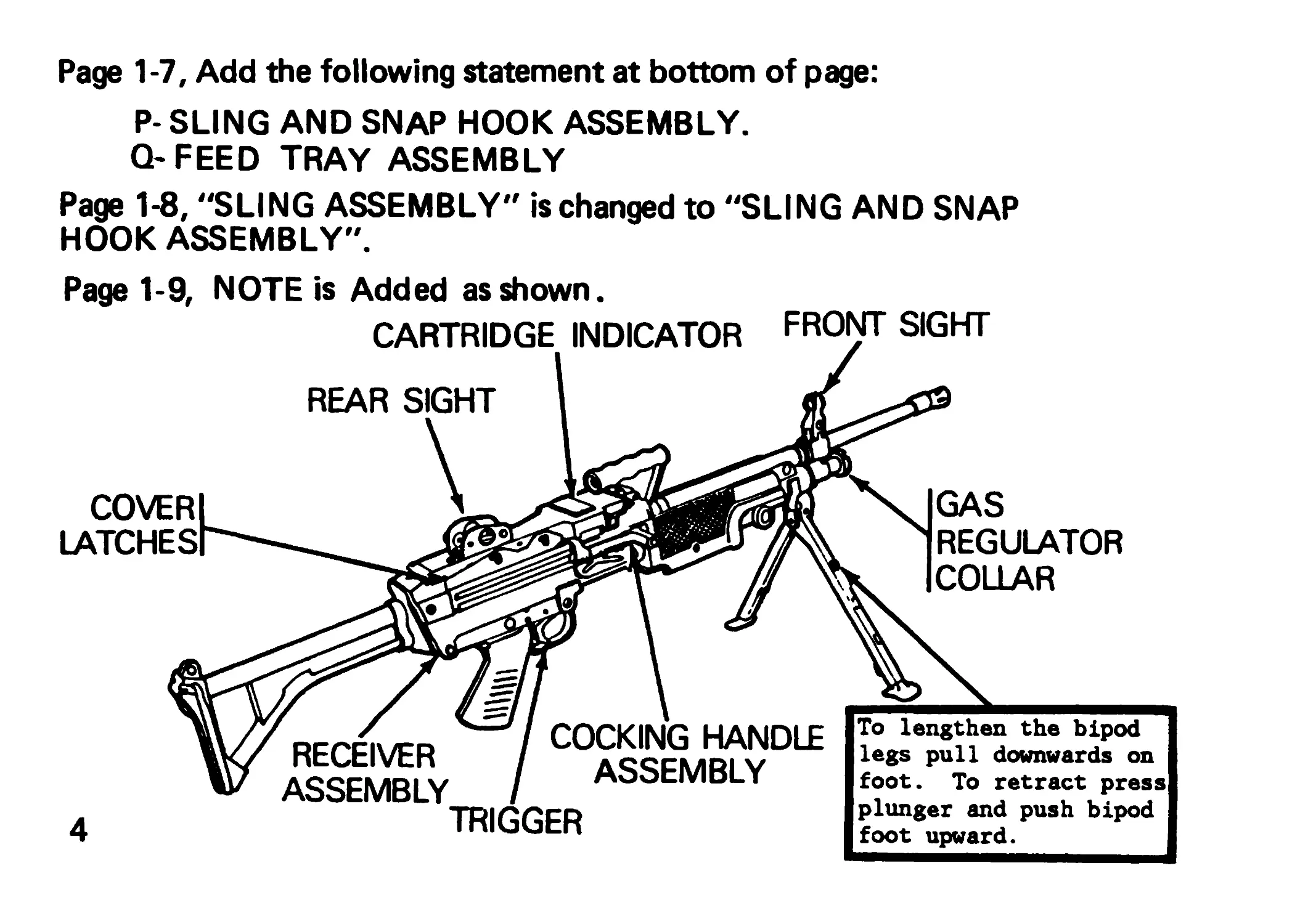
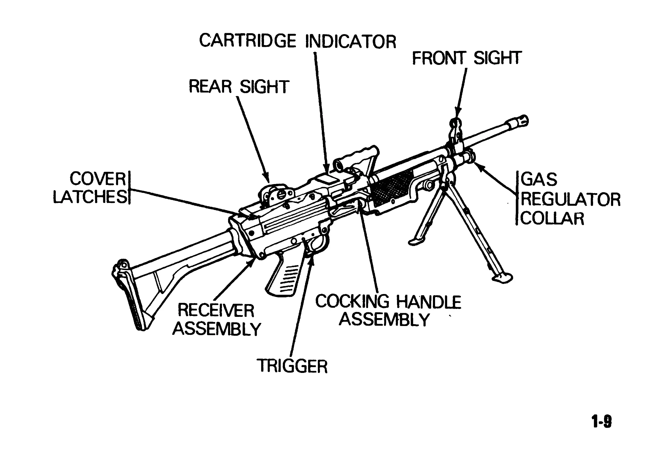
Page 1-9, NOTE is Added as shown.
CARTRIDGE INDICATOR FRONT SIGHT
REAR SIGHT
COVER
LATCHES
GAS
REGULATOR
COLLAR
ocrcix/Eo COCKING HANDLE
ntutlvtn ARRFMRI V
ASSEMBLY AootMBLY
TRIGGER
4
To lengthen the bipod
legs pull downwards on
foot. To retract press
plunger and push bipod
foot upward.
Page 1-10, under “Rate of Fire", "max setting" is changed to
"adverse setting".
Page 1-10, "Cyclic rated at 70°F (21°C) when set at MAX position."
is changed to "Cylic rated at 70°F (21°C) when set at ADVERSE
position."
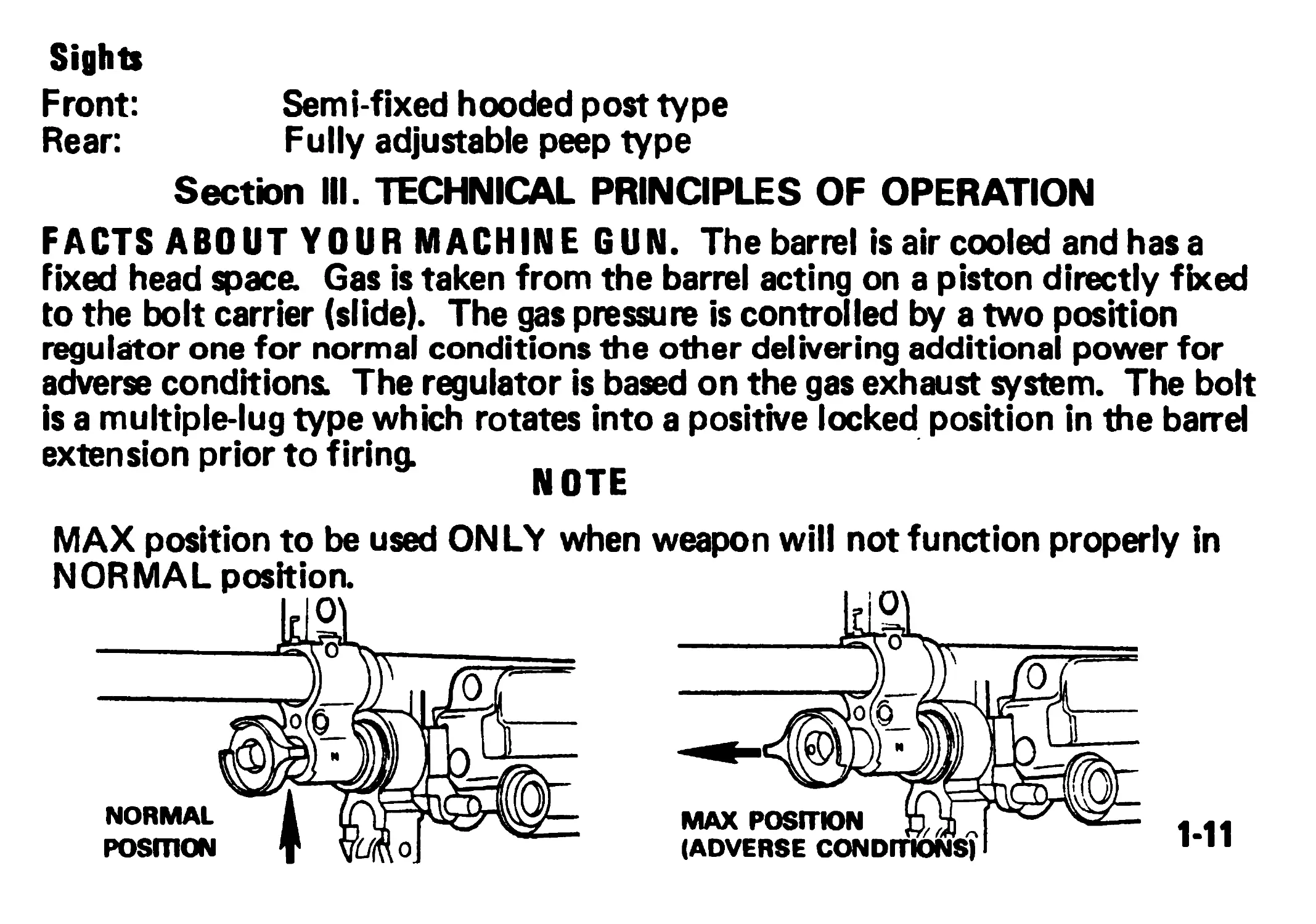
Page 1-11, under NOTE, change to read "ADVERSE position to be
used ONLY when weapon will not function properly in NORMAL
position.
Page 1-11, figure in bottom right corner, change "MAX POSITION"
to "ADVERSE POSITION."
5
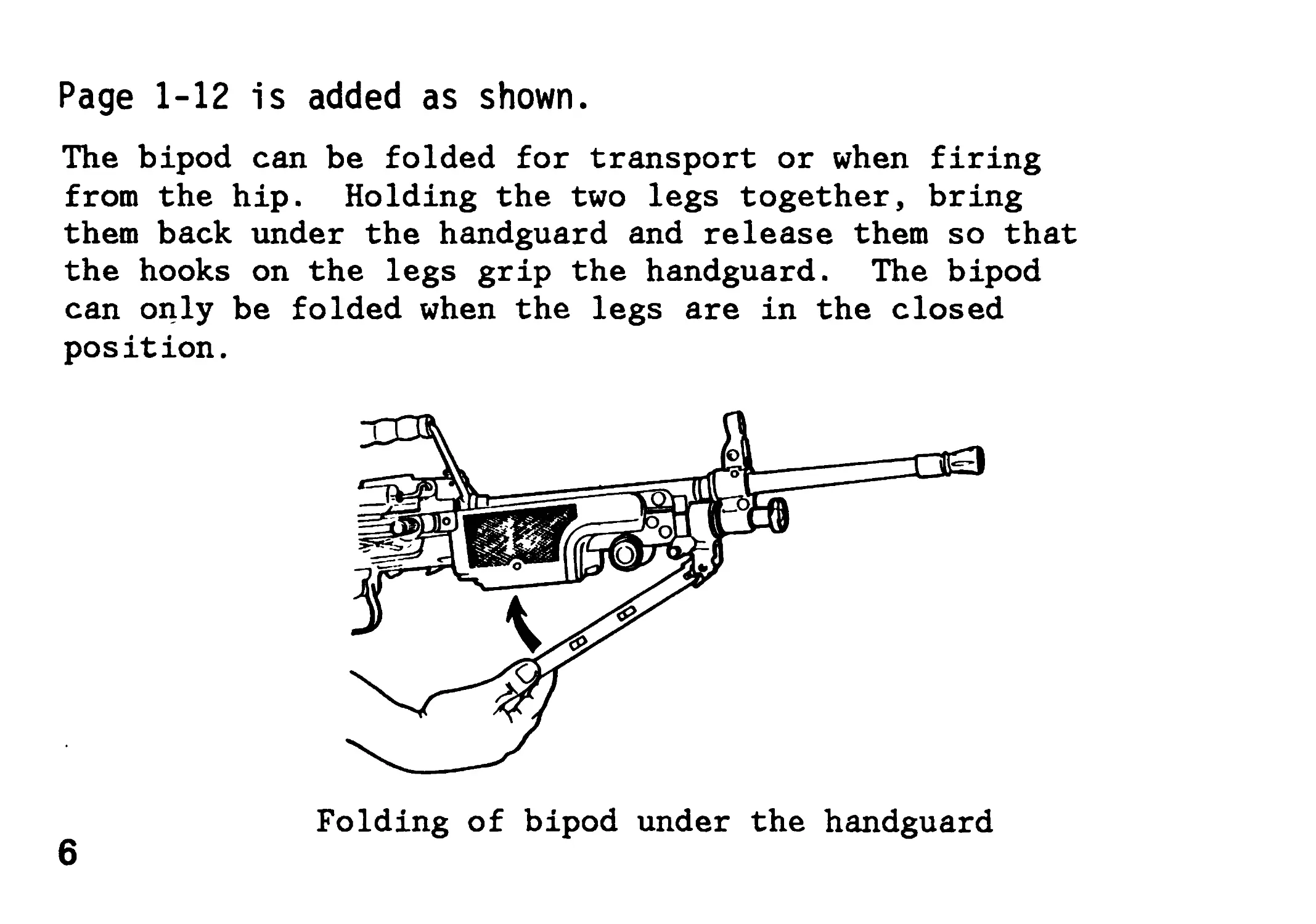
Page 1-12 is added as shown.
The bipod can be folded for transport or when firing
from the hip. Holding the two legs together, bring
them back under the handguard and release them so that
the hooks on the legs grip the handguard. The bipod
can only be folded when the legs are in the closed
position.
Folding of bipod under the handguard
6
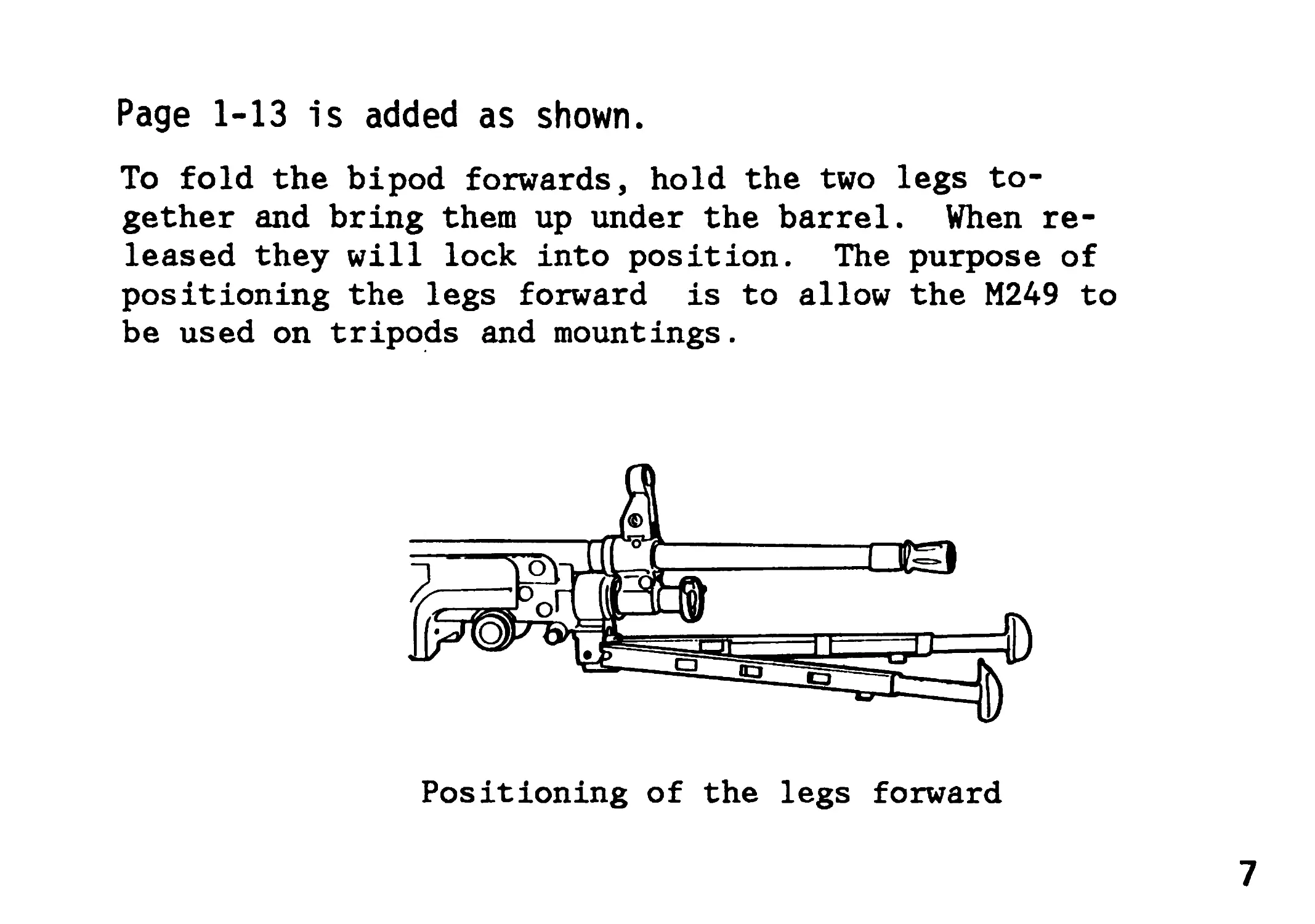
Page 1-13 is added as shown.
To fold the bipod forwards, hold the two legs to-
gether and bring them up under the barrel. When re-
leased they will lock into position. The purpose of
positioning the legs forward is to allow the M249 to
be used on tripods and mountings.
Positioning of the legs forward
7
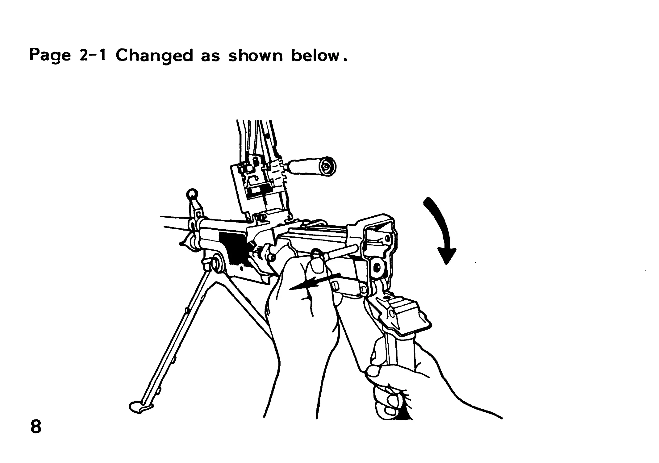
Page 2-1 Changed as shown below.
8
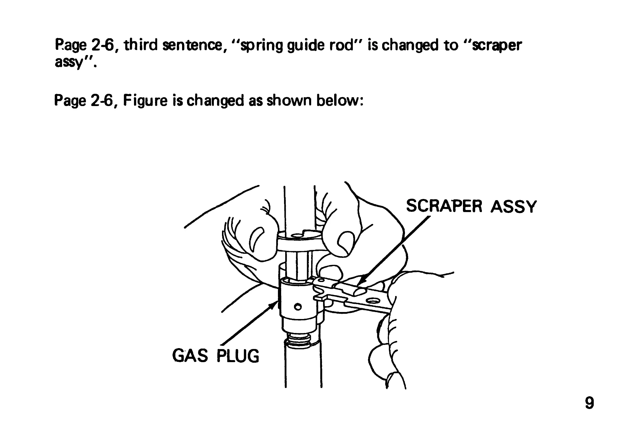
Page 2-6, third sentence, "spring guide rod" is changed to "scraper
assy".
Page 2-6, Figure is changed as shown below:
9
Page 2-7, first sentence, "guide rod" is changed to "scraper
assembly".
Page 2-13, before the NOTE, add the following warning:
WARNING
Do not interchange barrel assembly(s) or bolt assembly(s)
from one machine gun to another without having headspace
checked. Doing so may result in injury to personnel or
damage to gun.
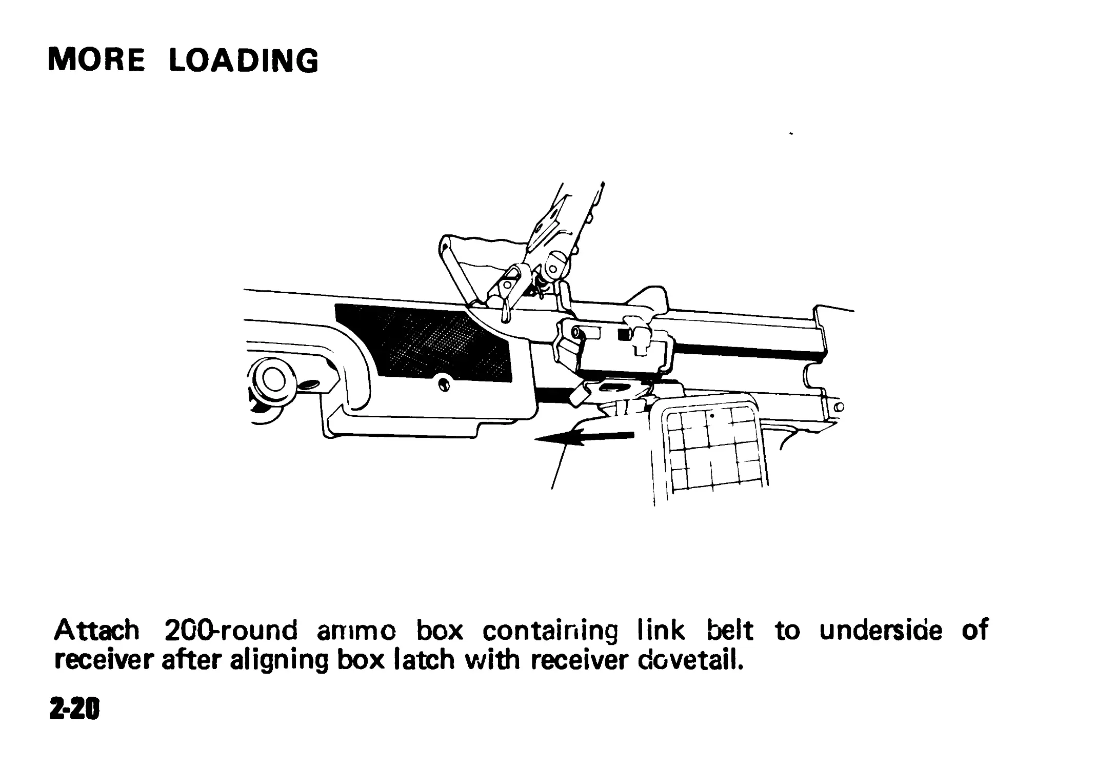
Page 2-20, after sentence, add following sentence
"Pull outward on ammo box to ensure that the
aligning box latch is engaged."
10
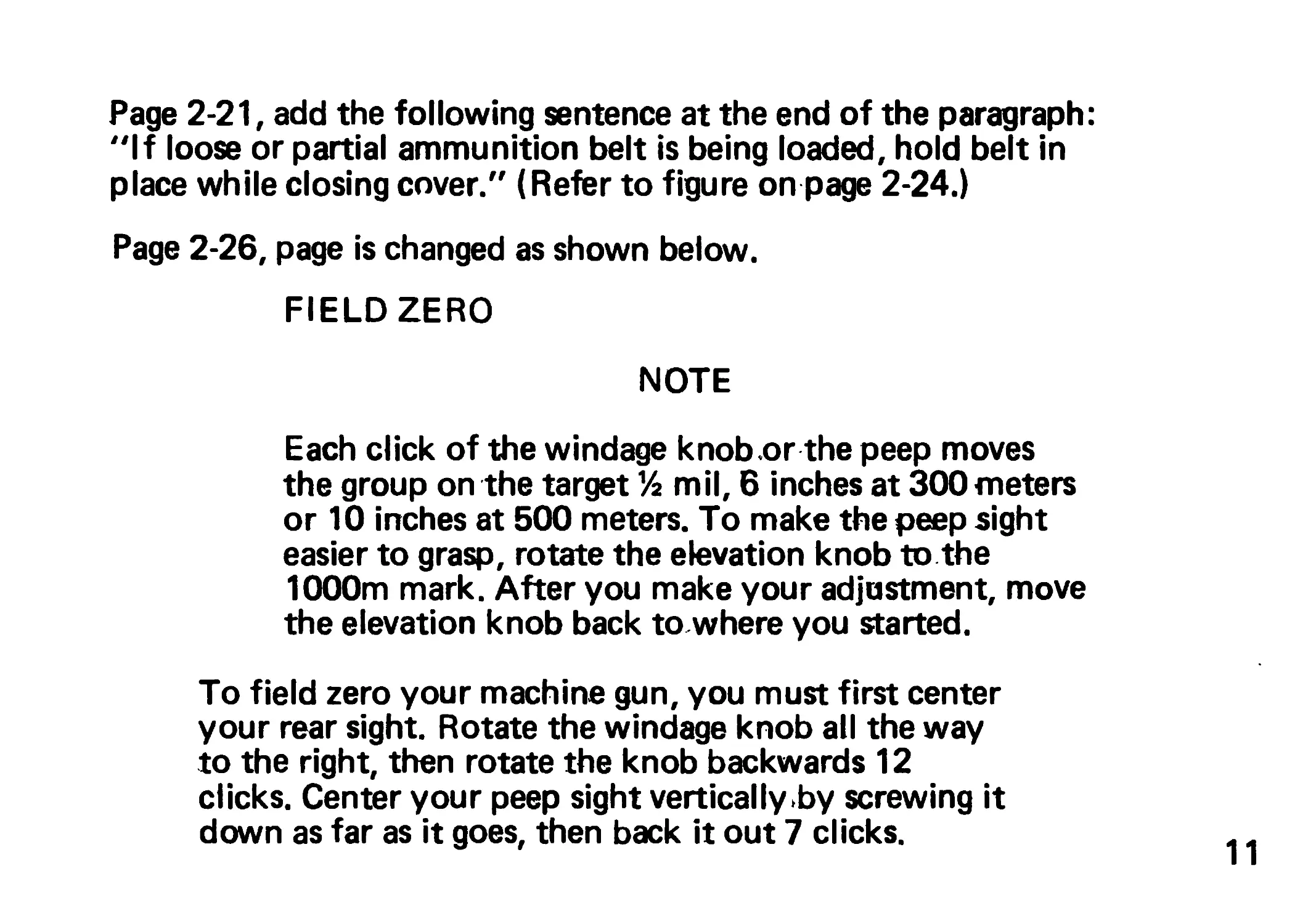
Page 2-21, add the following sentence at the end of the paragraph:
"If loose or partial ammunition belt is being loaded, hold belt in
place while closing cover." (Refer to figure on page 2-24.)
Page 2-26, page is changed as shown below.
FIELD ZERO
NOTE
Each click of the windage knob .or the peep moves
the group on the target 1/z mil, 6 inches at 300meters
or 10 inches at 500 meters. To make the peep sight
easier to grasp, rotate the elevation knob to the
1000m mark. After you make your adjustment, move
the elevation knob back towhere you started.
To field zero your machine gun, you must first center
your rear sight. Rotate the windage knob all the way
to the right, then rotate the knob backwards 12
clicks. Center your peep sight vertically by screwing it
down as far as it goes, then back it out 7 clicks.
11
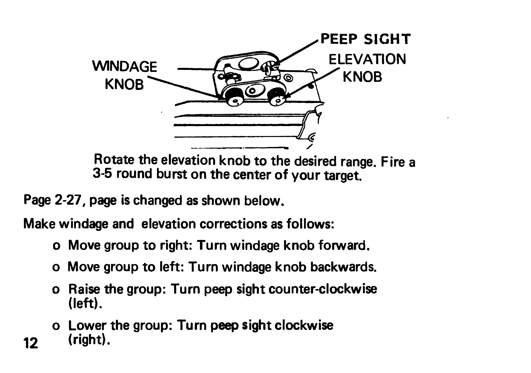
WINDAGE
KNOB**
PEEP SIGHT
ELEVATION
x^KNOB
Rotate the elevation knob to the desired range. Fire a
3-5 round burst on the center of your target.
Page 2-27, page is changed as shown below.
Make windage and elevation corrections as follows:
о Move group to right: Turn windage knob forward,
о Move group to left: Turn windage knob backwards,
о Raise the group: Turn peep sight counter-clockwise
(left).
о Lower the group: Turn peep sight clockwise
12 (right).
Fire another group. Repeat above procedures until
zeroed.
NOTE
If the weapon cannot be zeroed, and the peep sight is
screwed all the way in or out notify your unit
armorer for a front sight post adjustment. Center
your rear peep sight and fire a burst of 3-5 rounds for
a shot group. Tell your unit armorer the estimated
adjustment required to bring the weapon on target.
Unit armorers have a special wrench that will screw
the front sight post down to raise the group or
unscrew the sight post to lower the group.-One half
-turn of the sight post will move the group 1 mil on
the target, about T2 inches at 300 meters or 20 inches
at 500 meters.
Page 2-40, add after last sentence, "Pull lightly on magazine to
ensure it is locked in weapon."
Add, NOTE: Avoid magazines with defects.
13
Page 3-5, page is changed as shown below.
MALFUNCTION TEST OR INSPECTION
FAILURE TO EXTRACT Inspect and thor- oughly clean weapon as soon as possible. Dirty chamber/bolt and slide assy.
Carbon buildup in gas system Damaged extractor/ spring SPRING-.^ EXTRACTOR*
14
CORRECTIVE
ACTION_______________
FOR EMERGENCY USE ONLY:
Switch gas regulator to
ADVERSE setting and con-
tinue to fire.
Clean chamber and/or clean
bolt and slide assembly. If
problem still exists notify
organizational maintenance.
Clean gas regulator,
cylinder, and piston
Notify organizational
maintenance
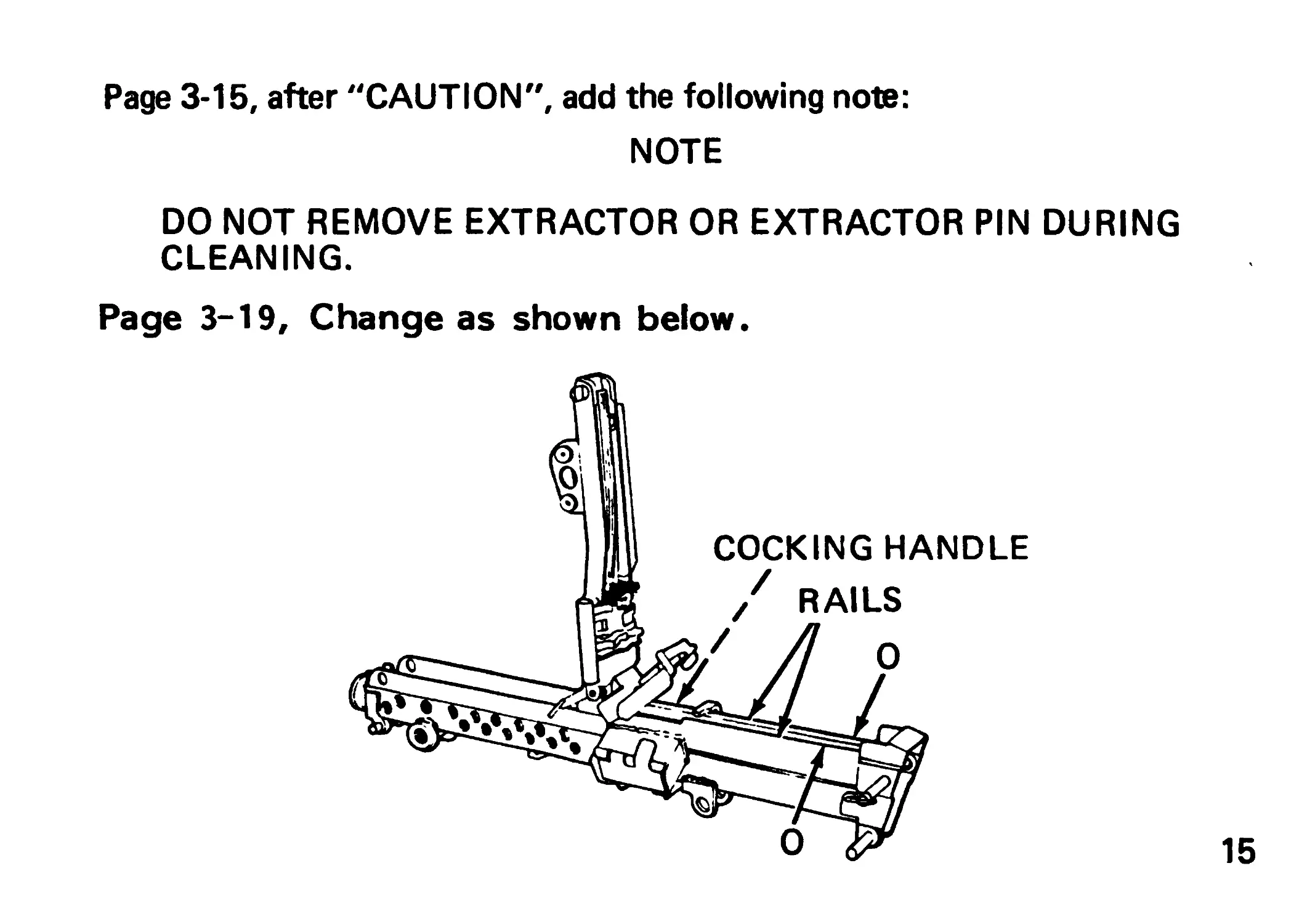
Page 3-15, after "CAUTION", add the following note:
NOTE
DO NOT REMOVE EXTRACTOR OR EXTRACTOR PIN DURING
CLEANING.
Page 3-19, Change as shown below.
15
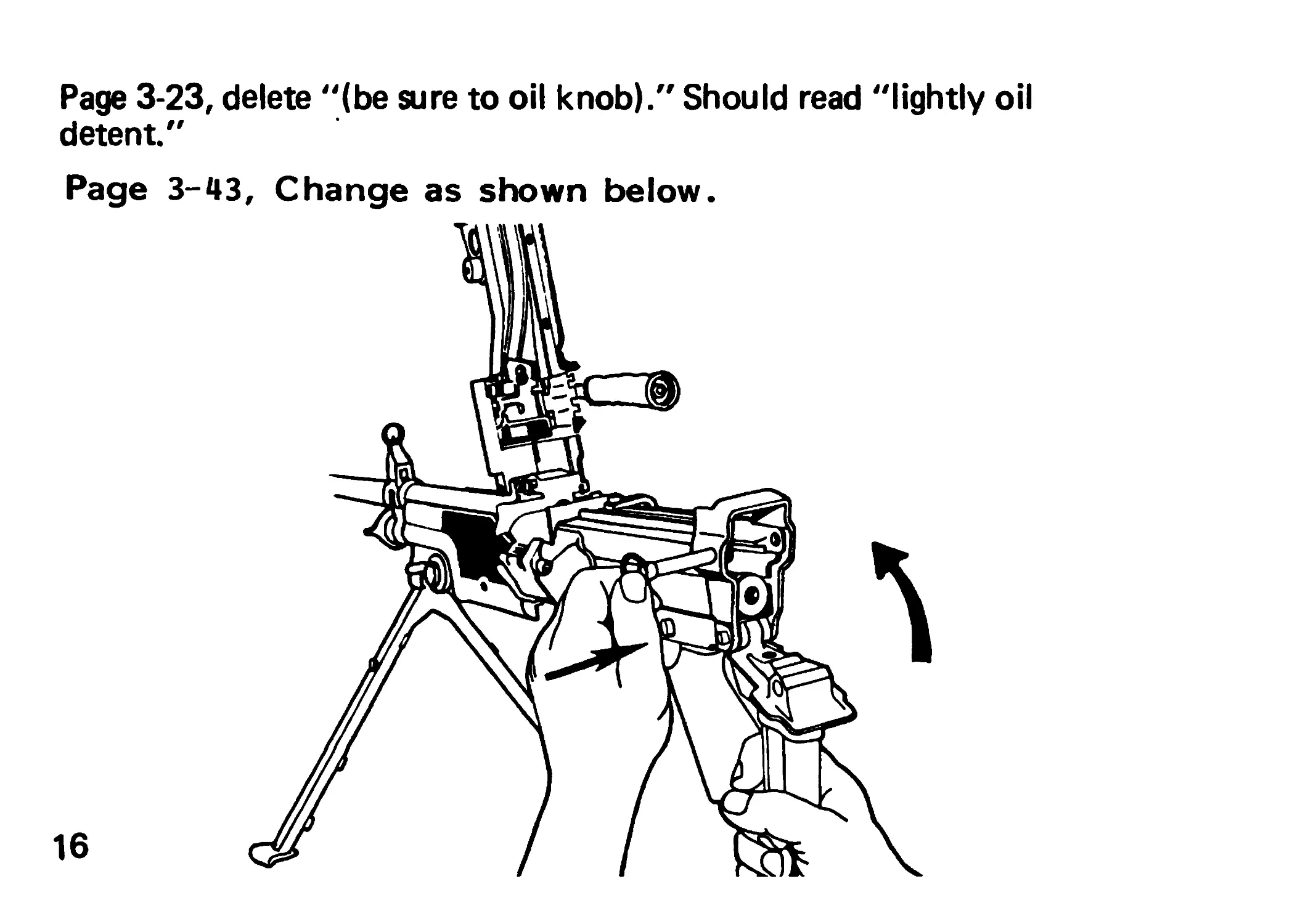
Page 3-23, delete “(be sure to oil knob)." Should read "lightly oil
detent."
Page 3-43, Change as shown below.
16
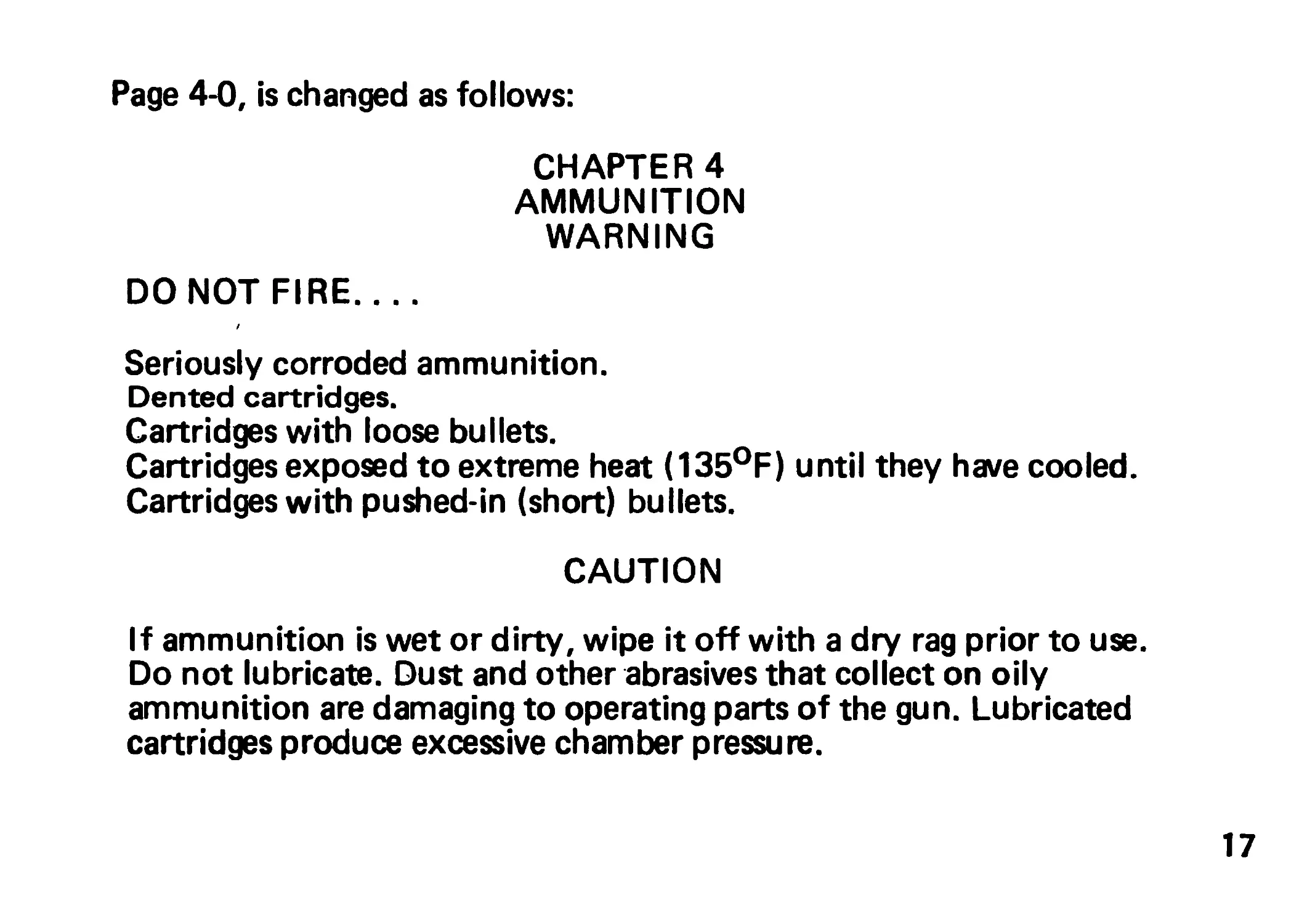
Page 4-0, is changed as follows:
CHAPTER 4
AMMUNITION
WARNING
DO NOT FIRE....
Seriously corroded ammunition.
Dented cartridges.
Cartridges with loose bullets.
Cartridges exposed to extreme heat (135°F) until they have cooled.
Cartridges with pushed-in (short) bullets.
CAUTION
If ammunition is wet or dirty, wipe it off with a dry rag prior to use.
Do not lubricate. Dust and other abrasives that collect on oily
ammunition are damaging to operating parts of the gun. Lubricated
cartridges produce excessive chamber pressure.
17
Page 4-1, "M199" is changed to "M199/M232".
Page B-3/B-4 Blank is changed as follows:
Section II. COMPONENTS OF END ITEM
(1) IL LUS No. (2) NATIONAL Stock No. (3) DESCRIPTION FSCM & Part No. (4) U/M (5) QTY RQR
1 1005-00-312-7177 SLING SMALL ARMS (19204) 12002983 EA 1
2 1005-01-138-0134 HOOK, SNAP (19200) 9348468 EA 2
18
By Order of the Secretary of the Army and the Navy:
JOHN A. WICKHAM, JR.
General, United States Anny
Chief of Staff
Official:
R. L. DILWORTH
Brigadier General, United States Army
The Adjutant General
J.J. WENT
Lieutenant General, USMC
Deputy Chief of Staff for Installations and Logistics
DISTRIBUTION:
To be distributed in accordance with DA Form 12-40,
Operator maintenance requirements for Machine Gun, 5.56-MM,
M249.
Marine Corps:
MARCORPS CODE: Bl/BN
Changes in force: Cl
TM 9-1005-201-10
TM 08671A-10/1
Cl
CHANGE HEADQUARTERS
NO. 1 DEPARTMENTOF THE ARMY
Washington, DC, 14 February 1985
Operator’s Manual
MACHINE GUN, 5.56MM, M249
(1005-01 -127-7510)
TM 9-1005-201-1 (УТМ 08671A-10/1, 9 September 1983, is changed
as follows:
1
Inside Front Cover. Ado the following warnings:
Do not interchange barrel assembly(s) or bolt assembly(s) from one
machine gun to another without having headspace checked.
Use only blank M200 with the BFA and do not fire directly at any-
one less than 20 feet away.
2
Page 3-45. Add the following paragraph:
OPERATION OF AUXILIARY EQUIPMENT
M15A2 BLANK FIRING ATTACHMENT (BFA)
WARNING
Use only blank M200 with the BFA and do not fire directly at any-
one less than 20 feet away.
3
CAUTION
Do not use tools to tighten attachment; HANDS ONLY.
NOTE
After 50 rounds, check to see if BFA is still tight. Make sure to
clean carbon buildup after each training exercise.
4
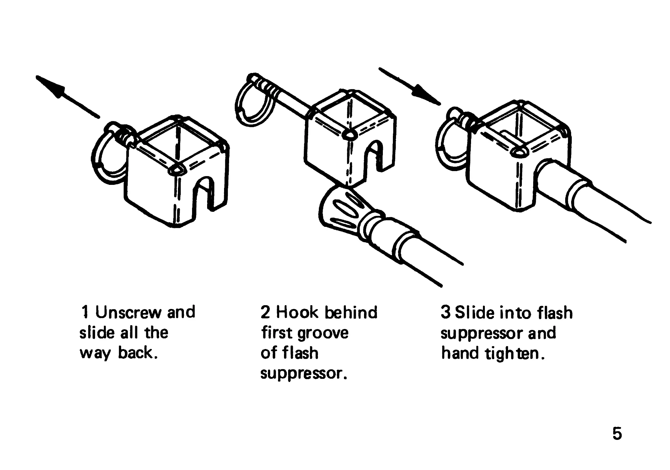
1 Unscrew and
slide all the
way back.
2 Hook behind
first groove
of flash
suppressor.
3 Slide into flash
suppressor and
hand tighten.
5
By Order of the Secretary of the Army:
JOHN A. WICKHAM, JR.
General, United States Army
Official: Chief of Staff
DONALD J. DELANDRO
Brigadier General, United States Army
The Adjutant General
H.A. HATCH
Lieutenant General, Marine Corps
Deputy Chief of Staff, Installation and Logistics Command
Distribution:
Army: To be distributed in accordance with DA Form 12-40A, Operator and Crew
Maintenance requirements for Gun, Machine, 5.56MM, M249.
Marine Corps: BI/BN
ТМ 9-1005-201-10
Th/r 00671А-10/1
TECHNICAL MANUAL
No. 9-1005-201-10
No. 08671A-10/1
HEADQUARTERS
Department of the Army
US MARINE CORPS.
WASHINGTON, DC,
Operator's Manual SEPTEMBER 83
MACHINE GUN, 5.56MM, M249
(1005-01-127-7510)
REPORTING ERRORSAND RECOMMENDING IMPROVEMENTS
You can help improve this manual. If you find any mistakes or if
you know of a way to improve the procedures, please let us know.
Mail your DA Form 2028 (Recommended Changes to Publications
and Blank Forms) direct to: Commander, US Army Armament,
Munitionsand Chemical Command, ATTN: DRSMC-MAS, Rock
Island, IL 61299. A reply will be furnished to you.
USMC users submit NAvMC Form 10722 to:
Commandant of Marine Corps, ATTN: Code LMA-1, Washington,
DC 20380.
i
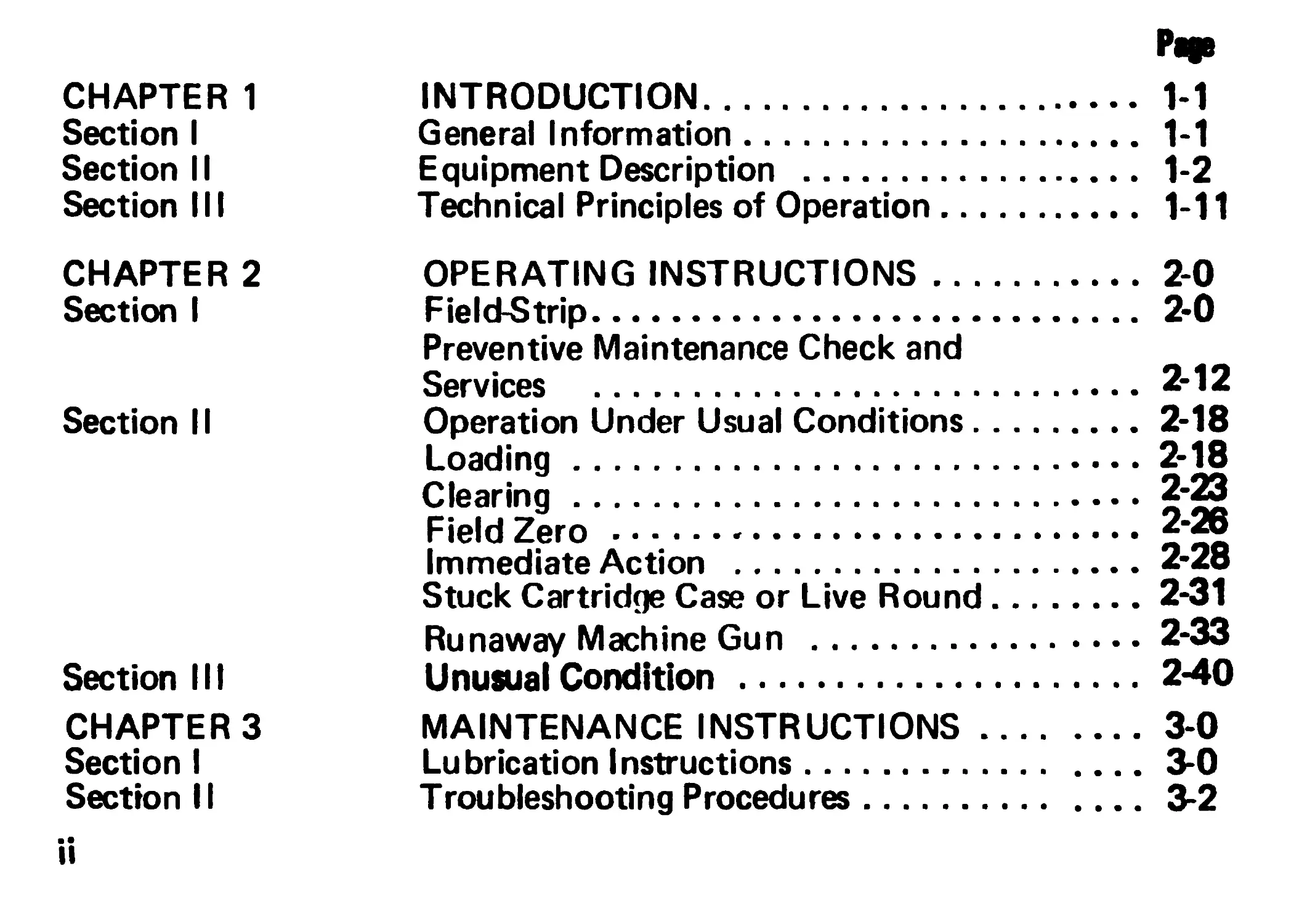
CHAPTER 1 INTRODUCTION............................. 1-1
Section I General Information...................... 1-1
Section II Equipment Description ................... 1-2
Section III Technical Principles of Operation....... 1-11
CHAPTER 2 OPERATING INSTRUCTIONS..................2-0
Section I Field-Strip............................ 2-0
Preventive Maintenance Check and
Services ..................................2'12
Section II Operation Under Usual Conditions...........2-18
Loading....................................2-18
Clearing....................................2-g
Field Zero.................................
Immediate Action ..........................2-28
Stuck Cartridge Case or Live Round.........2-31
Runaway Machine Gun ...................2-33
Section III Unusual Condition ....................2-40
CHAPTERS MAINTENANCE INSTRUCTIONS.................3-0
Section I Lubrication Instructions.................3-0
Section 11 Troubleshooting Procedures...............3-2
Page
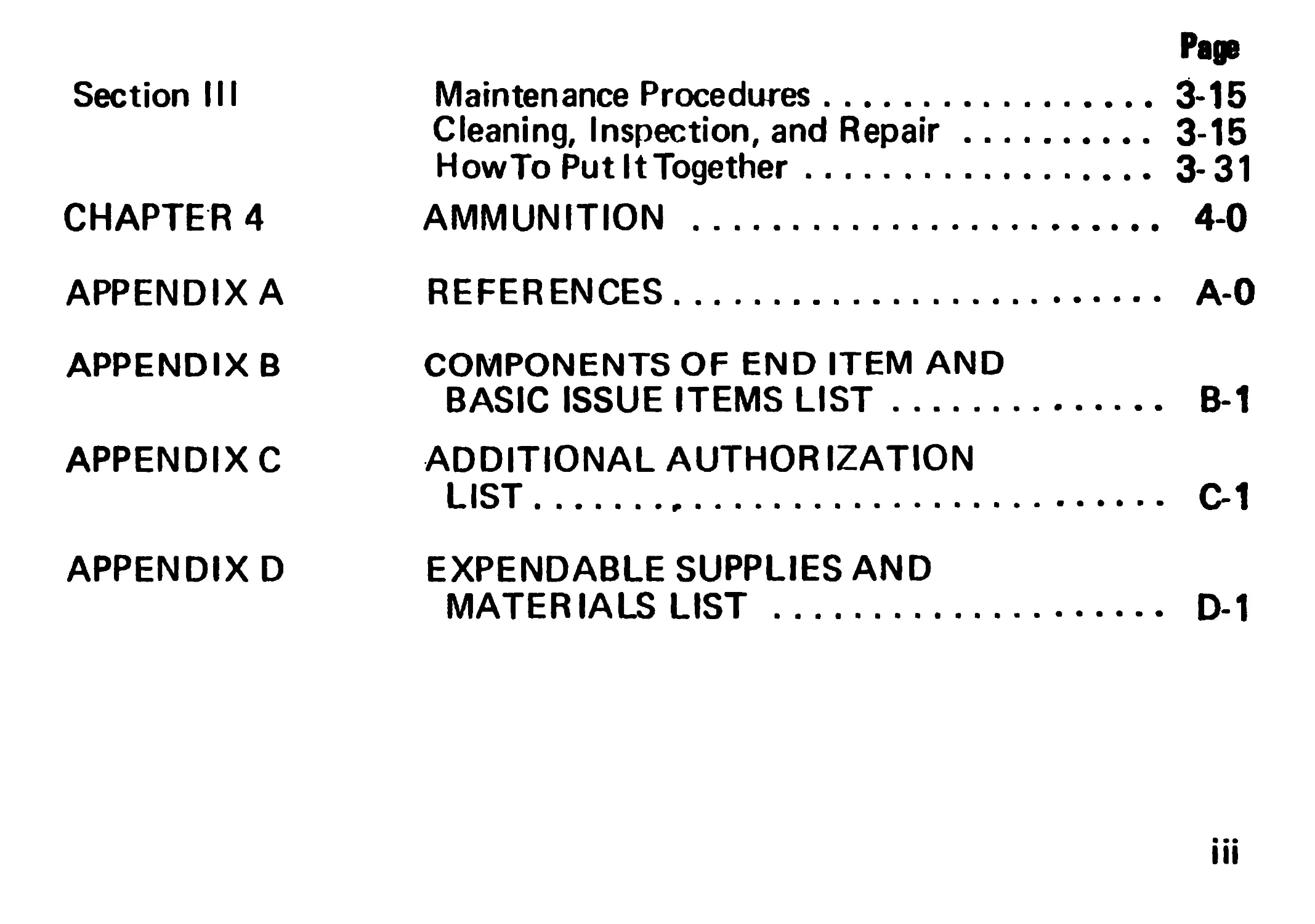
Section III Maintenance Procedures.............3-15
Cleaning, Inspection, and Repair. 3-15
HowTo Put It Together............ 3-31
CHAPTER 4 AMMUNITION ........................ 4-0
APPENDIX A REFERENCES......................... A-0
APPENDIX В COMPONENTS OF END ITEM AND
BASIC ISSUE ITEMS LIST............ B-1
APPENDIX C ADDITIONAL AUTHOR IZATION
LIST.............................. C-1
APPENDIX D EXPENDABLE SUPPLIES AND
MATERIALS LIST ................... D-1
iii
CHAPTER 1
INTRODUCTION
Section I. GENERAL INFORMATION
SCOPE.
Type of Manual: Operator's manual
Model Number and Equipment Name: M249 5.56mm Machine Gun.
Purpose of Equipment: Designed as a fire team automatic weapon; for
rear area security/special missions.
Maintenance Forms, Records, and Reports.
Department of the Army forms and procedures used for equipment main-
tenance will be those prescribed by TM 38-750, The Army Maintenance
Management System (TAMMS).
USMC users will refer to TM 4700-15/1 for applicable forms and records.
REPORTING EQUIPMENT IMPROVEMENT RECOMMENDATIONS (EIR)
If your machine gun needs improvement, let us know. Send us an El R.
You, the user, are the only one who can tell us what you don't like about
your equipment. Let us know why you don't like the design. Tell us why
a procedure is hard to perform. Put it on an SF 368 (Quality Deficiency
Report). Mail it to us at Commander, US Army Armament Munitions and
Chemical Command, ATTN: DRSMC-MAF/AA Rock Island, IL 61299. A
reply will be furnished directly to you.
USMC users should submit SF 368 to: Marine Corps Logistics Base Albany,
ATTN: Code P840 Albany, GA. 31704.
Section II. EQUIPMENT DECRIPTION
Equipment Purpose, Capabilities^and Features.
Purpose of Equipment: Designed as a fire team automatic weapon; for rear
area security/special missions.
1-2
Capabilities and Features:
The machine gun is gas-operated, air-cooled and fires from the open bolt
position. It has a regulator for selecting normal or max rate of fire. Use
of the max rate is authorized only in the event that the weapon firing
rate stows down (weapon becomes sluggish). It also has an alternative
30-round magazine feeding provision. Use of the 30-round magazine
is authorized only in an emergency situation. Use of the magazine re-
duces performance.
The major components of the machine gun are:
Barrel assembly Houses cartridge for firing, directs projectile, and supports fixed front sight
Rear sight assembly Rear sight is adjustable for both windage and eleva- tion.
Cover/feed mechanism assembly Provides support for rear sight and means for gaining access to feed tray. By means of cam and lever action, feeds linked belt ammo and holds cartridges in position for stripping, feeding, and chambering
1-3
Feed pawl assembly Feeds linked belt ammo, positions and holds cartridges in position for stripping, feeding and chambering.
Cocking handle assembly Pulls the moving parts rearwarcLMoves in a guide rail fixed to the right side of the receiver.
Butt stock and shoulder assembly Serves as a shoulder support for aiming and firing machine gun. Contains a folding shoulder rest
Piston assembly Transfers power from propelling gases to bolt and slide assemblies to function the machine gun (move recoiling-parts rearward).
Bolt assembly Provides feeding, stripping, chambering, firing, and extraction, using the propellant gases and recoil spring for power.
Slide assembly 1-4 Houses firing pin and roller assembly.
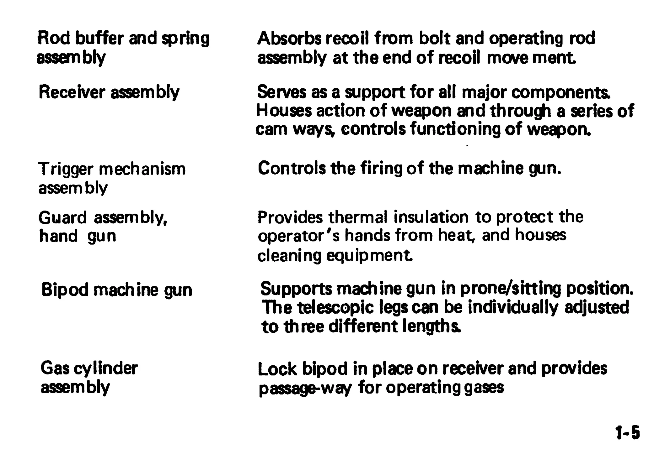
Hod buffer and spring assembly Absorbs recoil from bolt and operating rod assembly at the end of recoil move ment
Receiver assembly Serves as a support for all major components. Houses action of weapon and through a series of cam ways, controls functioning of weapon.
Trigger mechanism assembly Guard assembly, hand gun Controls the firing of the machine gun. Provides thermal insulation to protect the operator's hands from heat, and houses cleaning equipment
Bipod machine gun Supports machine gun in prone/sitting position. The telescopic legscan be individually adjusted to three different lengths.
Gas cylinder assembly Lock bipod in place on receiver and provides passage-way for operating gases
1-5
1-6
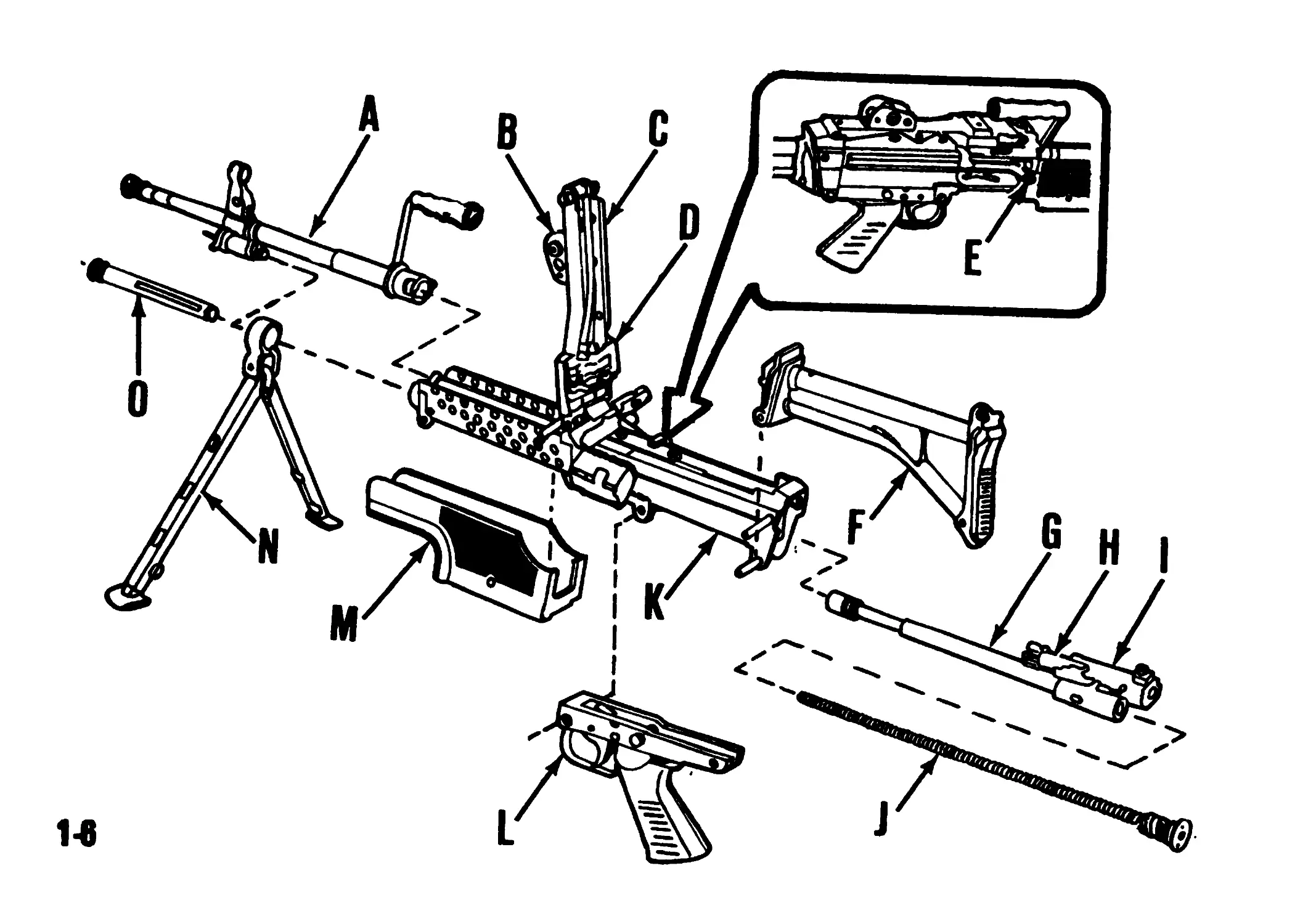
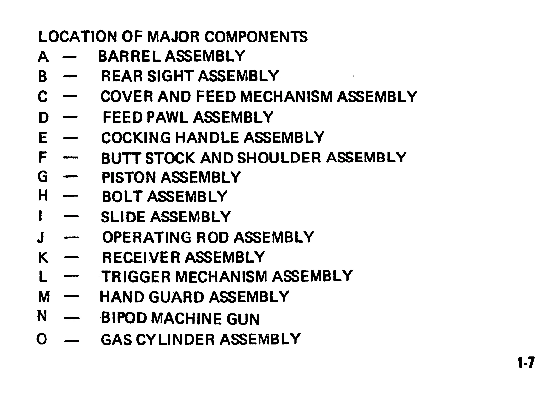
LOCATION OF MAJOR COMPONENTS
A — BARREL ASSEMBLY
В — REAR SIGHT ASSEMBLY
C - COVER AND FEED MECHANISM ASSEMBLY
D — FEED PAWL ASSEMBLY
E — COCKING HANDLE ASSEMBLY
F — BUTT STOCK AND SHOULDER ASSEMBLY
G — PISTON ASSEMBLY
H — BOLT ASSEMBLY
I — SLIDE ASSEMBLY
J — OPERATING ROD ASSEMBLY
К — RECEIVER ASSEMBLY
L — TRIGGER MECHANISM ASSEMBLY
M — HAND GUARD ASSEMBLY
N — BIPOD MACHINE GUN
О — GAS CYLINDER ASSEMBLY
1-7
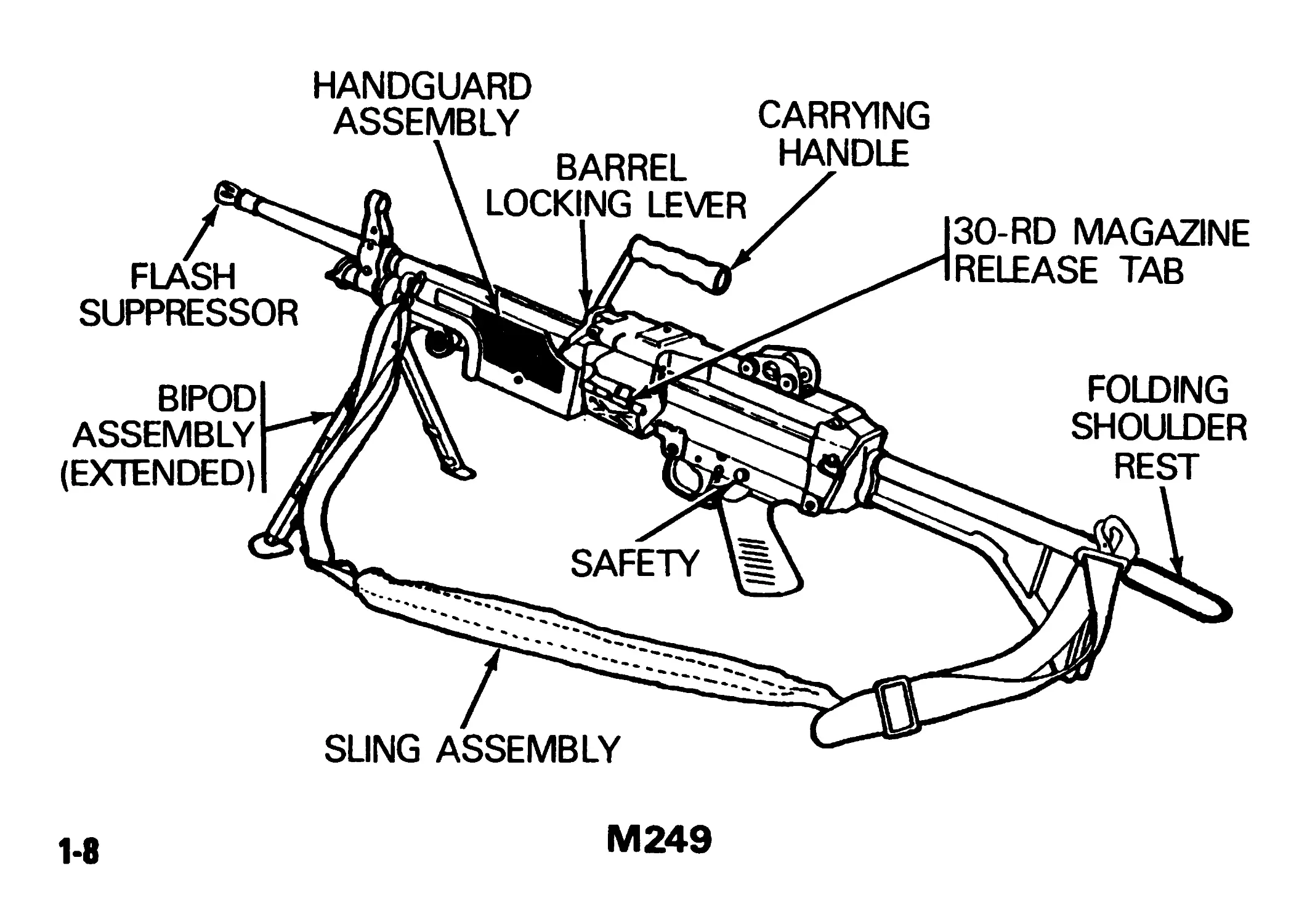
HANDGUARD
ASSEMBLY
CARRYING
1-8
M249
REAR SIGHT
COVER
LATCHES
CARTRIDGE INDICATOR
FRONT SIGHT
TRIGGER
RECEIVER
ASSEMBLY
COCKING HANDLE
ASSEMBLY
GAS
REGULATOR
COLLAR
1-9
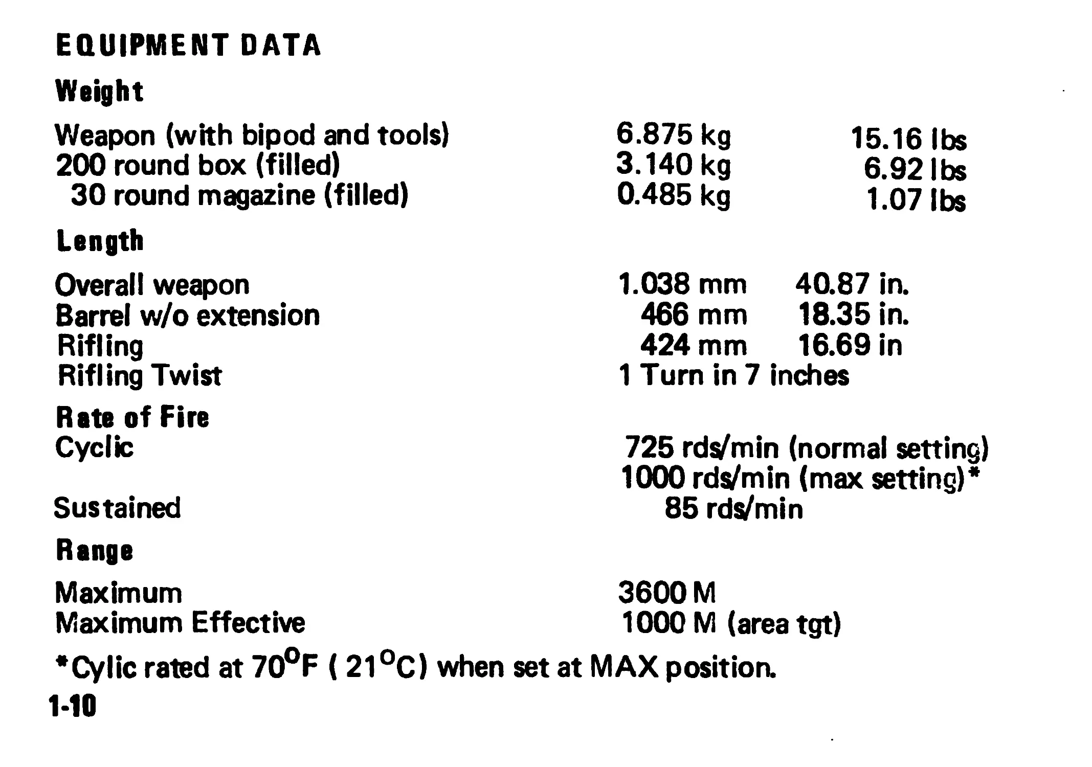
EQUIPMENT DATA
Weight
Weapon (with bipod and tools)
200 round box (filled)
30 round magazine (filled)
Length
Overall weapon
Barrel w/o extension
Rifling
Rifling Twist
Rate of Fire
Cyclic
Sustained
Range
Maximum
Maximum Effective
6.875 kg 15.16 lbs
3.140 kg 6.92 lbs
0.485 kg 1.07 lbs
1.038 mm 40.87 in.
466 mm 18.35 in.
424 mm 16.69 in
1 Turn in 7 inches
725 rds/min (normal setting)
1000 rds/min (max setting)*
85 rds/min
3600 M
1000 M (areatgt)
*Cylic rated at 70°F (21 °C) when set at MAX position.
1-10
Sights
Front: Semi-fixed hooded post type
Rear: Fully adjustable peep type
Section III. TECHNICAL PRINCIPLES OF OPERATION
FACTS ABOUT YOUR MACHINE GUN. The barrel is air cooled and has a
fixed head space Gas is taken from the barrel acting on a piston directly fixed
to the bolt carrier (slide). The gas pressure is controlled by a two position
regulator one for normal conditions the other delivering additional power for
adverse conditions. The regulator is based on the gas exhaust system. The bolt
is a multiple-lug type which rotates into a positive locked position in the barrel
extension prior to firing.
NOTE
MAX position to be used ONLY when weapon will not function properly in
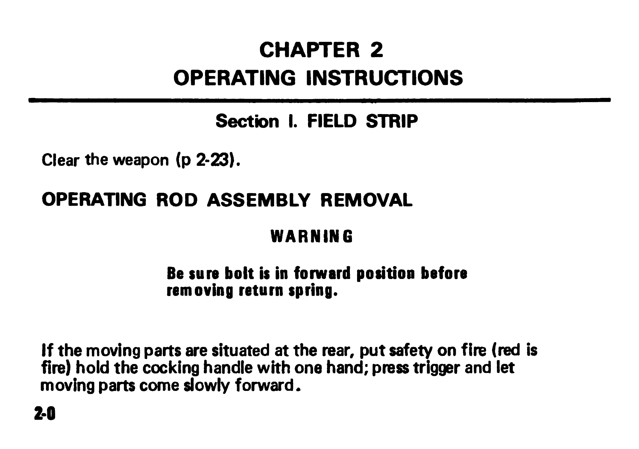
CHAPTER 2
OPERATING INSTRUCTIONS
Section I. FIELD STRIP
Clear the weapon (p 2-23).
OPERATING ROD ASSEMBLY REMOVAL
WARNING
Be sure bolt is in forward position before
removing return spring.
If the moving parts are situated at the rear, put safety on fire (red is
fire) hold the cocking handle with one hand; press trigger and let
moving parts come slowly forward.
2-0
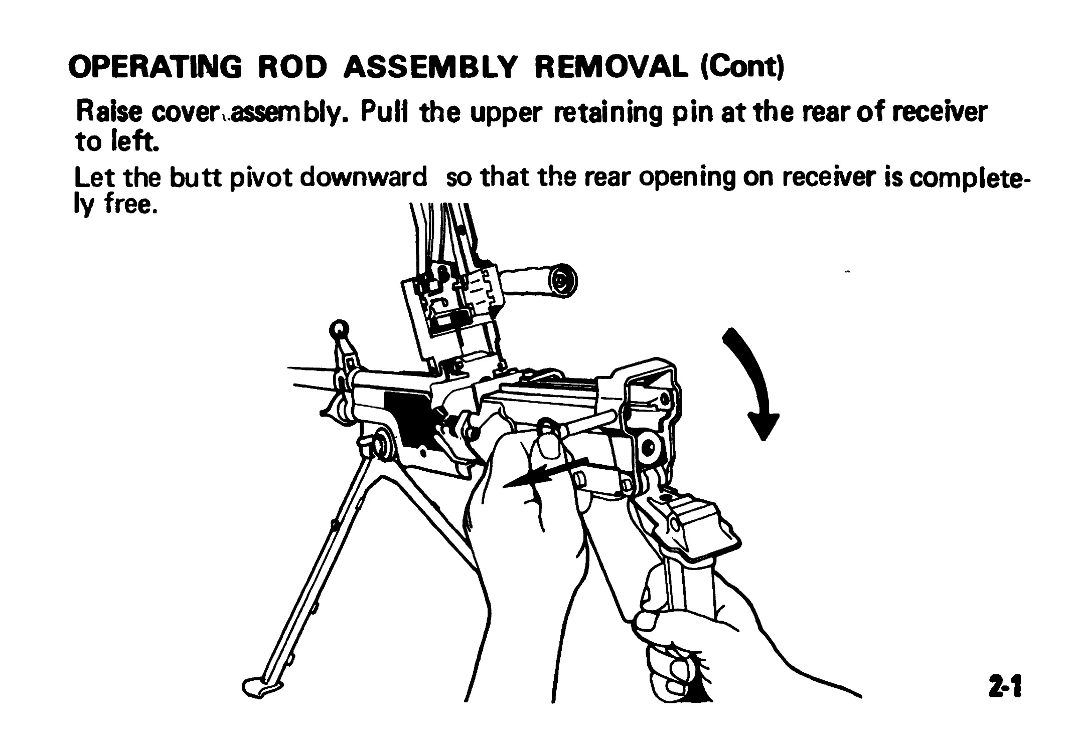
OPERATING ROD ASSEMBLY REMOVAL (Cont)
Raise cover assembly. Pull the upper retaining pin at the rear of receiver
to left
Let the butt pivot downward so that the rear opening on receiver is complete-
ly free.
2*1
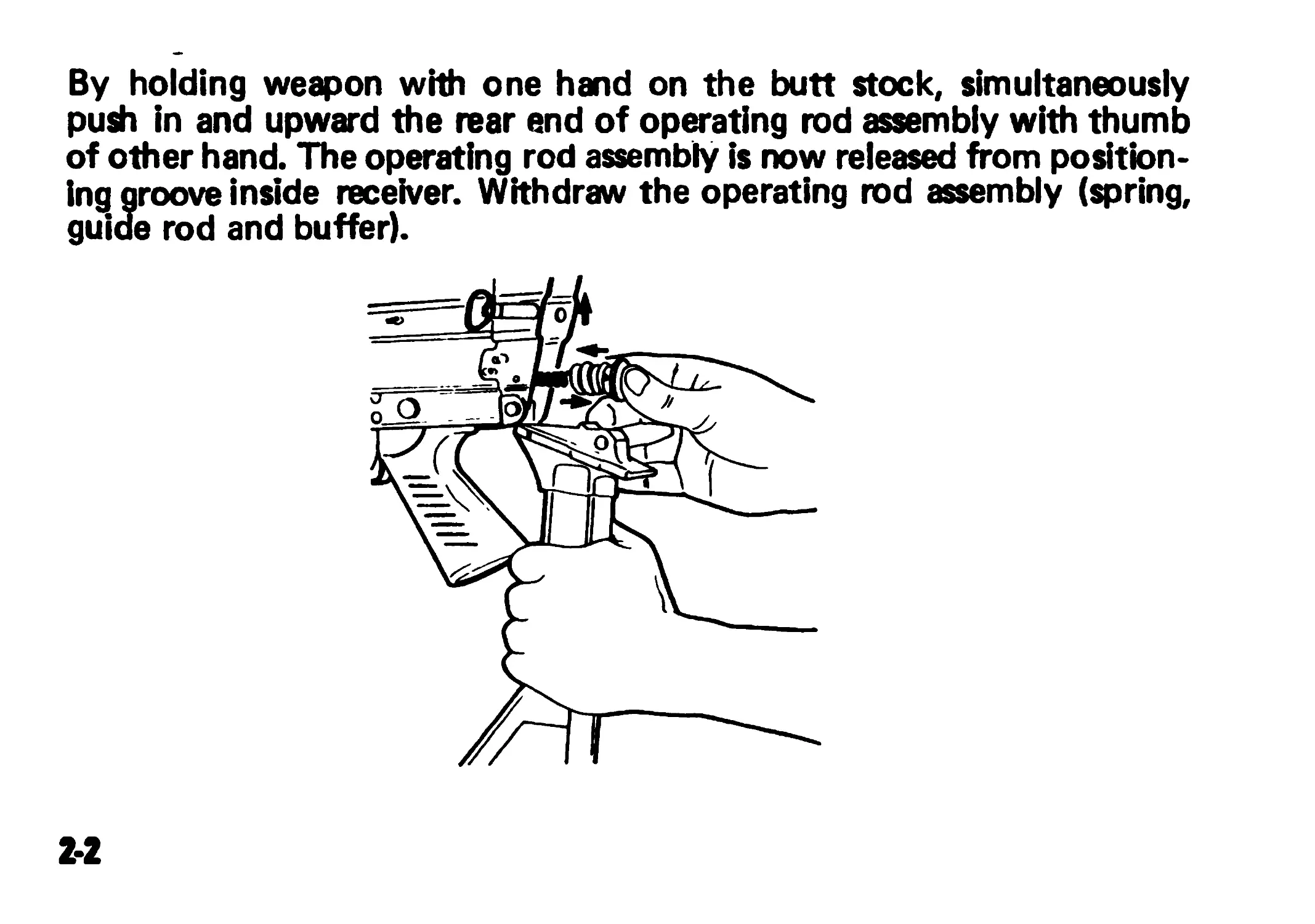
By holding weapon with one hand on the butt stock, simultaneously
push in and upward the rear end of operating rod assembly with thumb
of other hand. The operating rod assembly is now released from position-
ing groove inside receiver. Withdraw the operating rod assembly (spring,
guide rod and buffer).
2-2
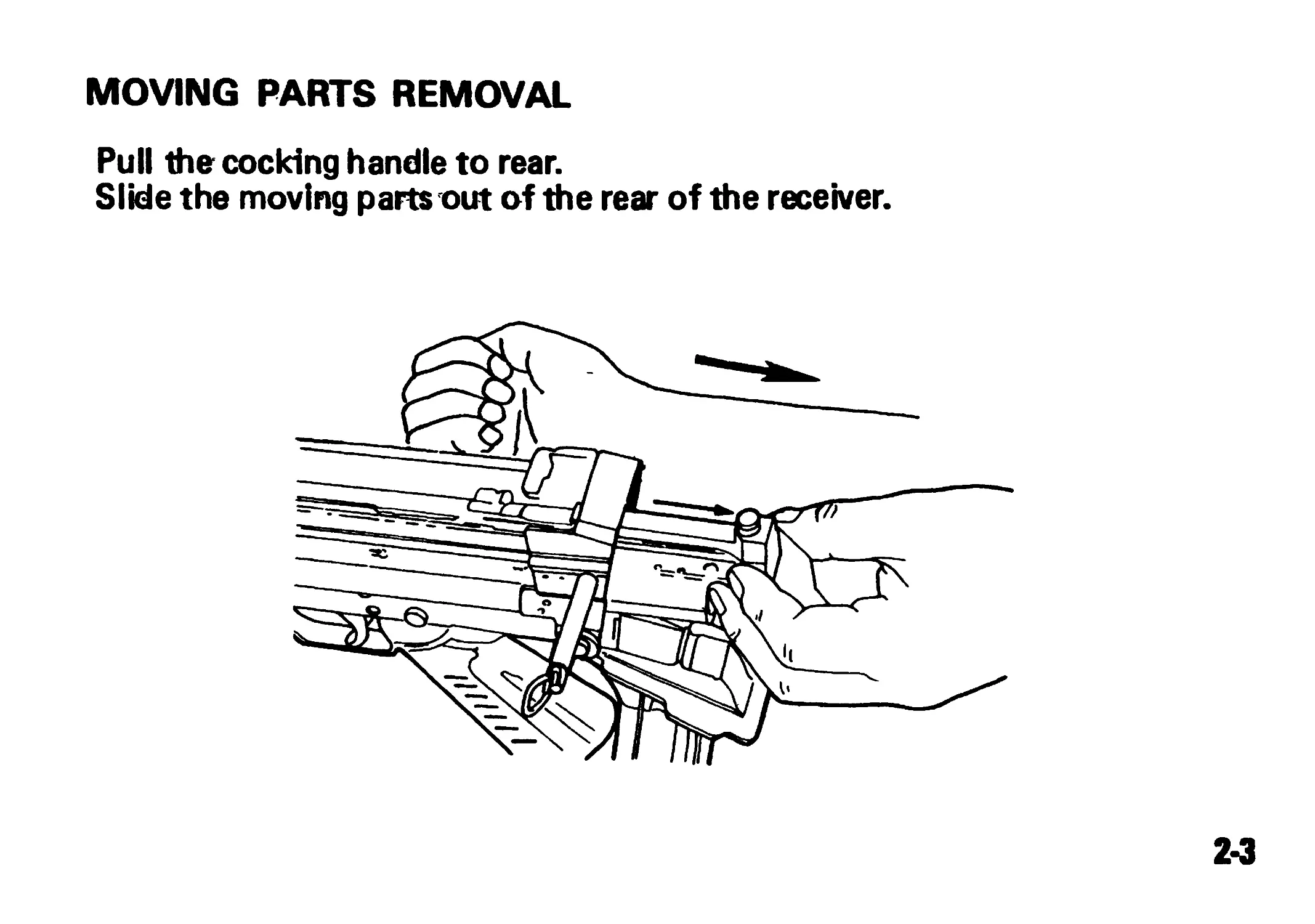
MOVING PARTS REMOVAL
Pull the cocking handle to rear.
Slide the moving parts out of the rear of the receiver.
2-3
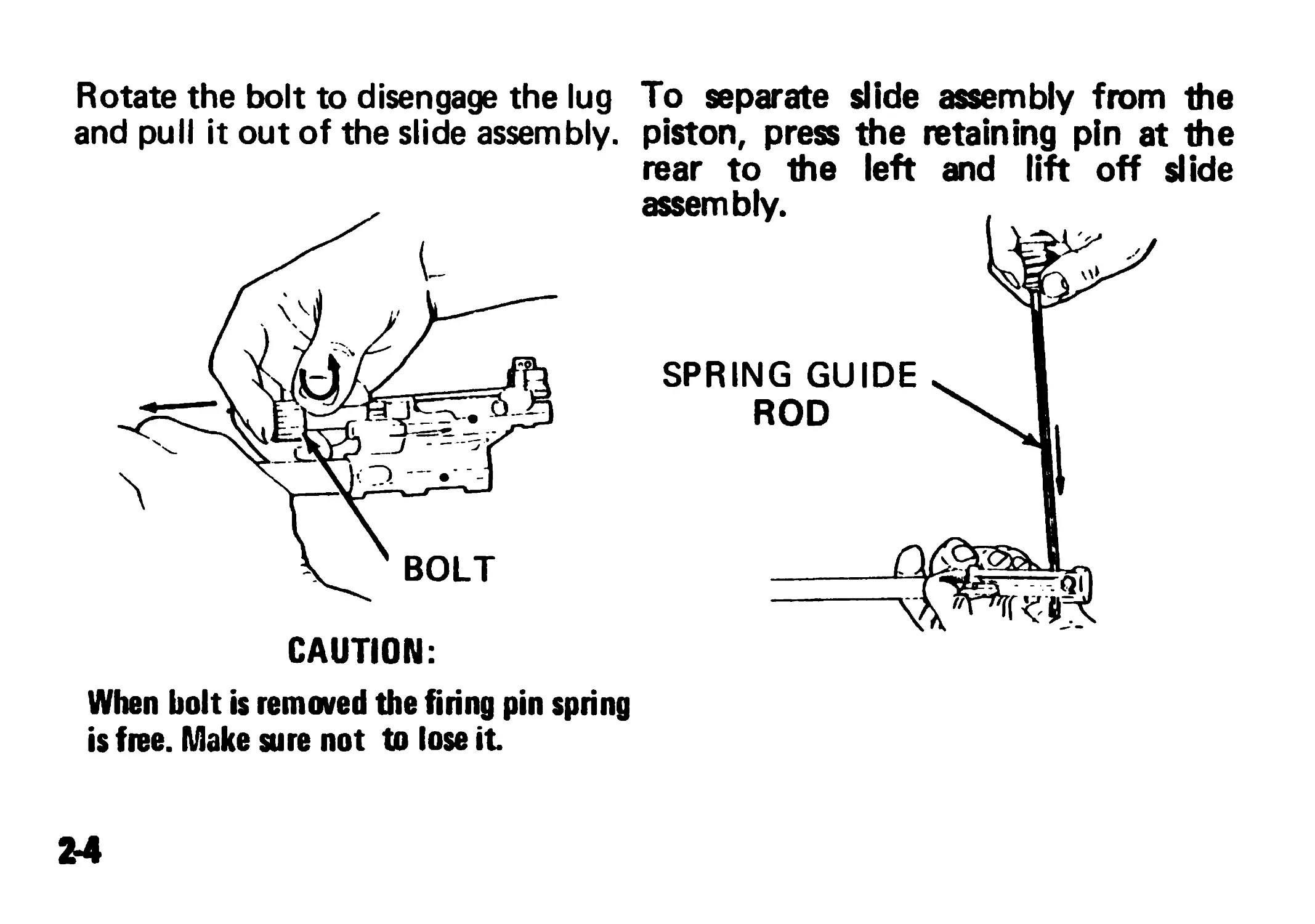
Rotate the bolt to disengage the lug To separate slide assembly from the
and pull it out of the slide assembly, piston, press the retaining pin at the
rear to the left and lift off slide
CAUTION:
When bolt is removed the firing pin spring
is free. Make sure not to lose it
24
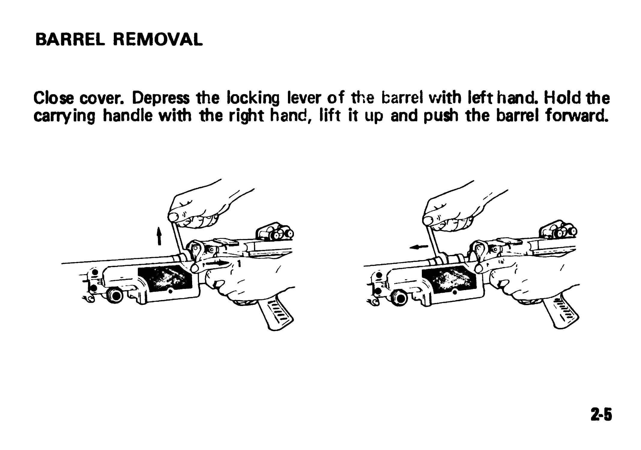
BARREL REMOVAL
Close cover. Depress the locking lever of the barrel with left hand. Hold the
carrying handle with the right hand, lift it up and push the barrel forward.
2-5
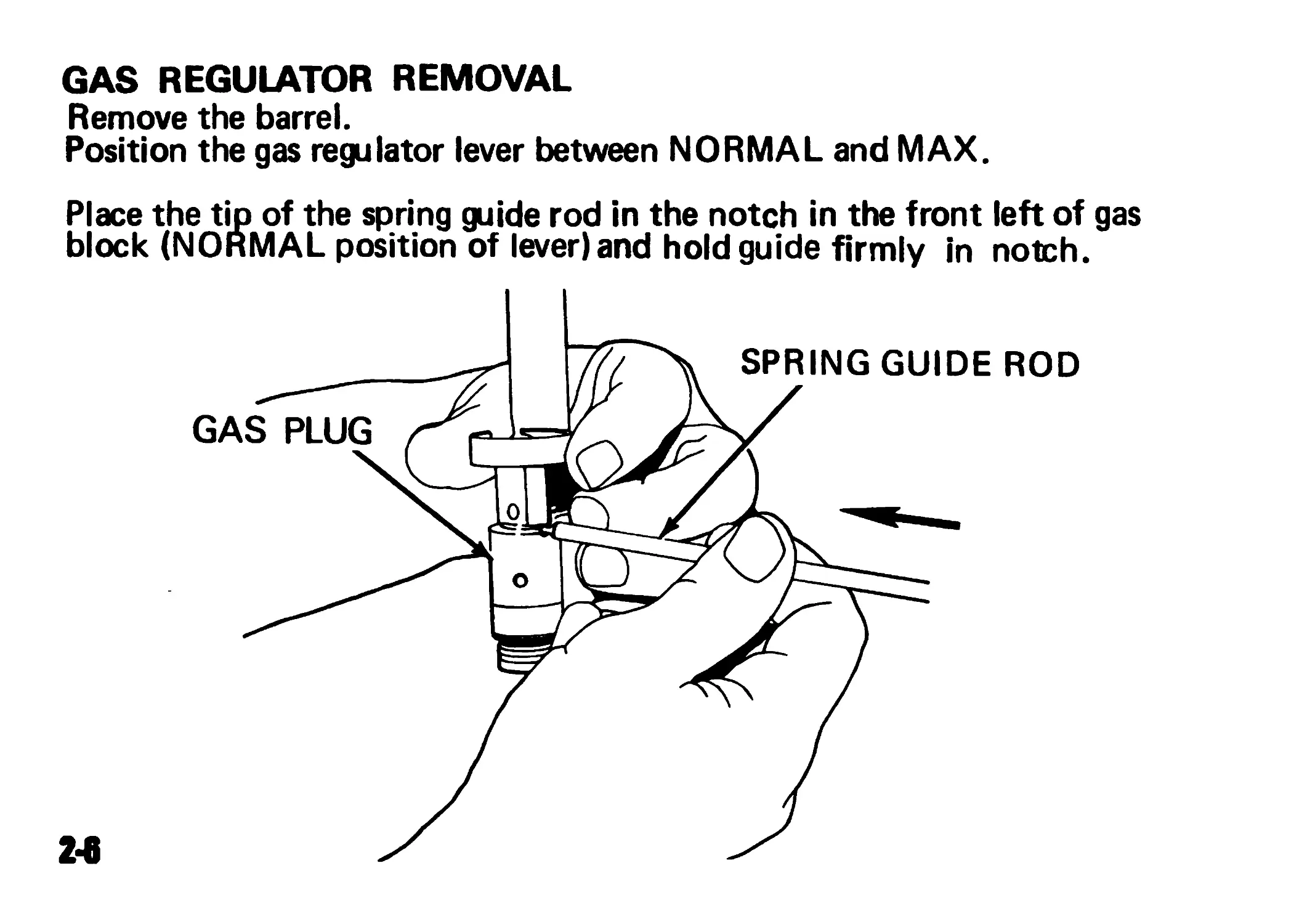
GAS REGULATOR REMOVAL
Remove the barrel.
Position the gas regulator lever between NORMAL and MAX.
Place the tip of the spring guide rod in the notch in the front left of gas
block (NORMAL position of lever) and hold guide firmly in notch.
2*6
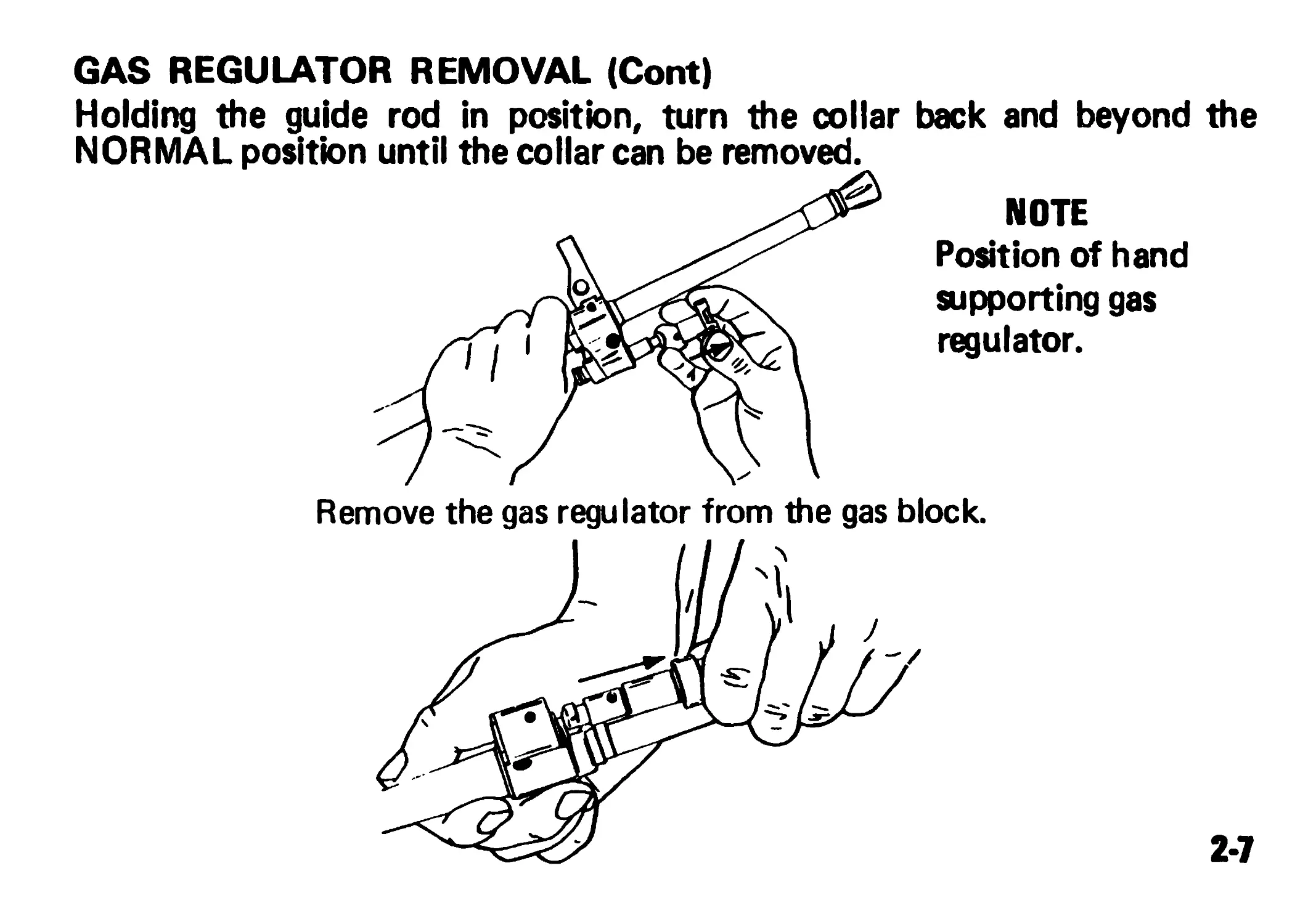
GAS REGULATOR REMOVAL (Cont)
Holding the guide rod in position, turn the collar back and beyond the
NOTE
Position of hand
supporting gas
regulator.
Remove the gas regulator from the gas block.
2-7
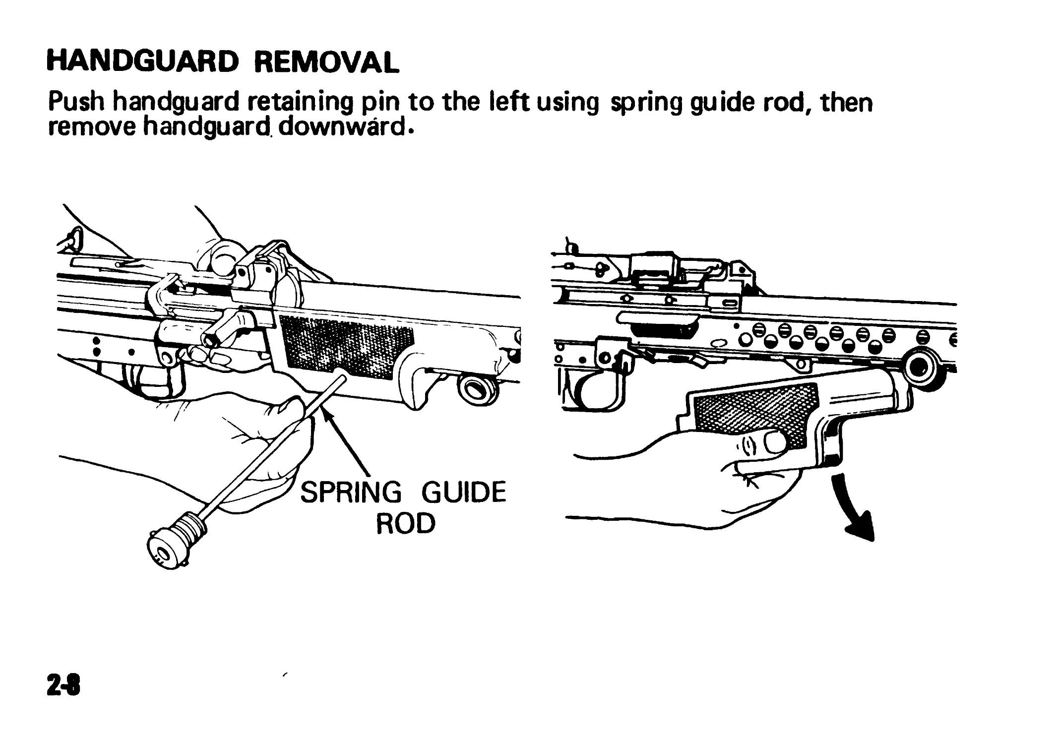
HANDGUARD REMOVAL
Push handguard retaining pin to the left using spring guide rod, then
remove handguard downward.
24
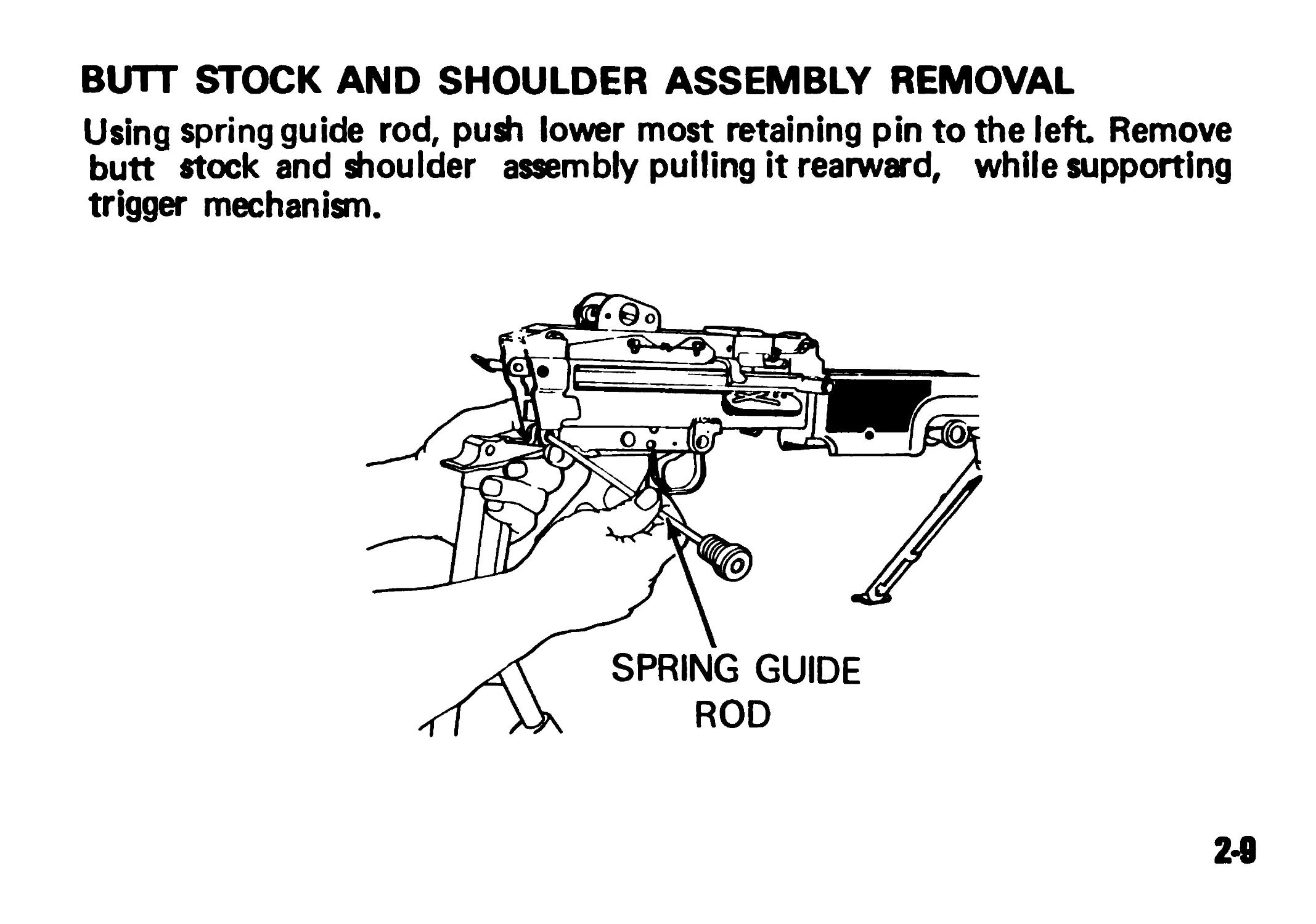
BUTT STOCK AND SHOULDER ASSEMBLY REMOVAL
Using spring guide rod, push lower most retaining pin to the left Remove
butt stock and shoulder assembly pulling it rearward, while supporting
trigger mechanism.
2-9
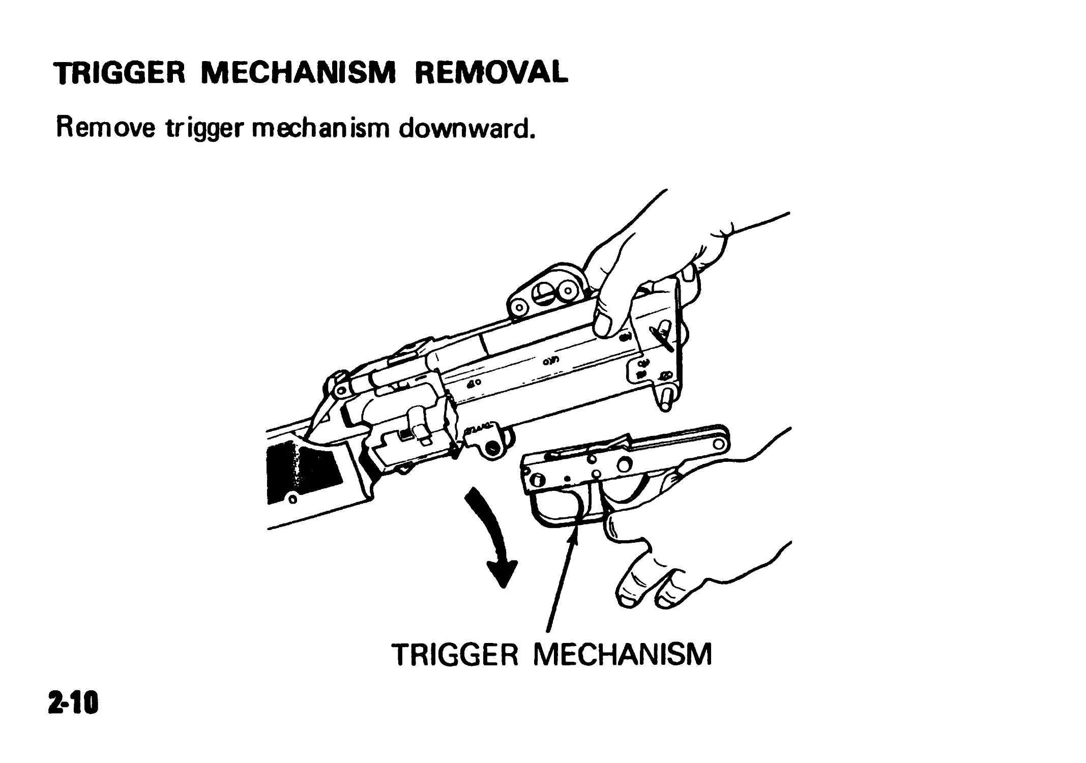
TRIGGER MECHANISM REMOVAL
Remove trigger mechanism downward.
TRIGGER MECHANISM
2*10
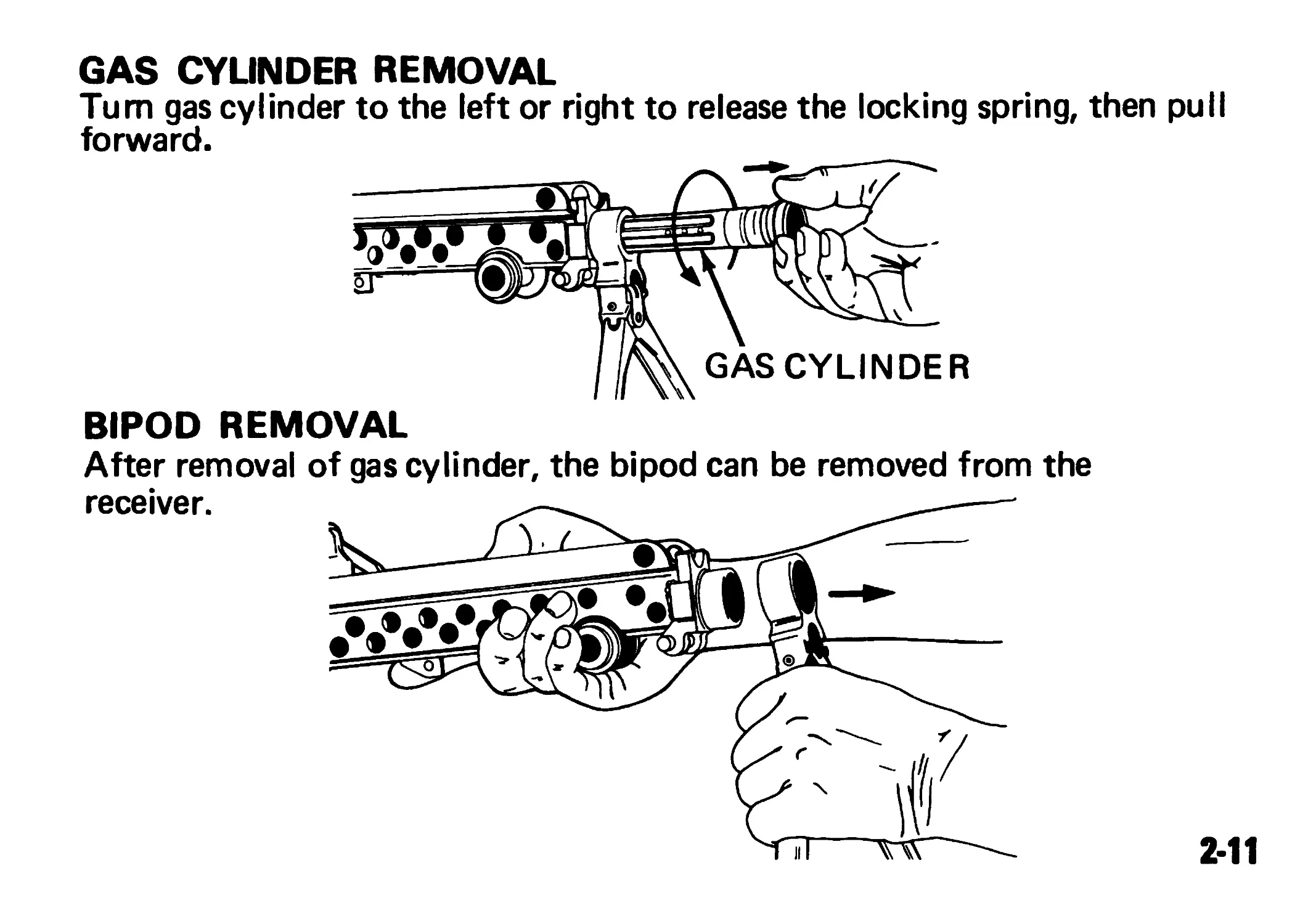
GAS CYUNDER REMOVAL
Turn gas cylinder to the left or right to release the locking spring, then pull
forward.
GAS CYLINDER
BIPOD REMOVAL
After removal of gas cylinder, the bipod can be removed from the
receiver.
2-11
PREVENTIVE MAINTENANCE CHECKS AND SERVICES (PMCS)
Always keep in mind the CAUTIONS and WARNINGS. The numbers in
the item number column shall be used for the "TM Number" column on
DA FORM 2404, Equipment Inspection and Maintenance Worksheet, in
recording results of PMCS.
Perform PMCS if; (1) you are the assigned operator and the machine
gun has been stored and not used for a period of 90 days, or (2) you
have been issued the machine gun for the first time.
2-12
EQUIPMENT IS NOT
READY/AVAILABLE IF:
ITEM
No
ITEMS TO BE INSPECTED
PROCEDURES
1
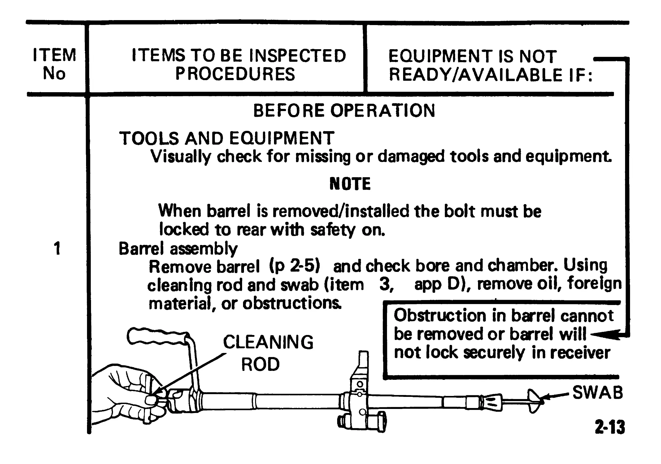
BEFORE OPERATION
TOOLS AND EQUIPMENT
Visually check for missing or damaged tools and equipment
NOTE
When barrel is removed/installed the bolt must be
locked to rear with safety on.
Barrel assembly
Remove barrel (p 2-5) and check bore and chamber. Using
cleaning rod and swab (item
material, or obstructions:
3, app D), remove oil, foreign
CLEANING
ROD
Obstruction in barrel cannot
be removed or barrel will
not lock securely in receiver
голе
SWAB
2-13
PREVENTIVE MAINTENANCE CHECKS AND SERVICES (Cont)
ITEM
No.
ITEMS TO BE INSPECTED
PROCEDURES
EQUIPMENT IS NOT -
READY/AVAILABLE IF:
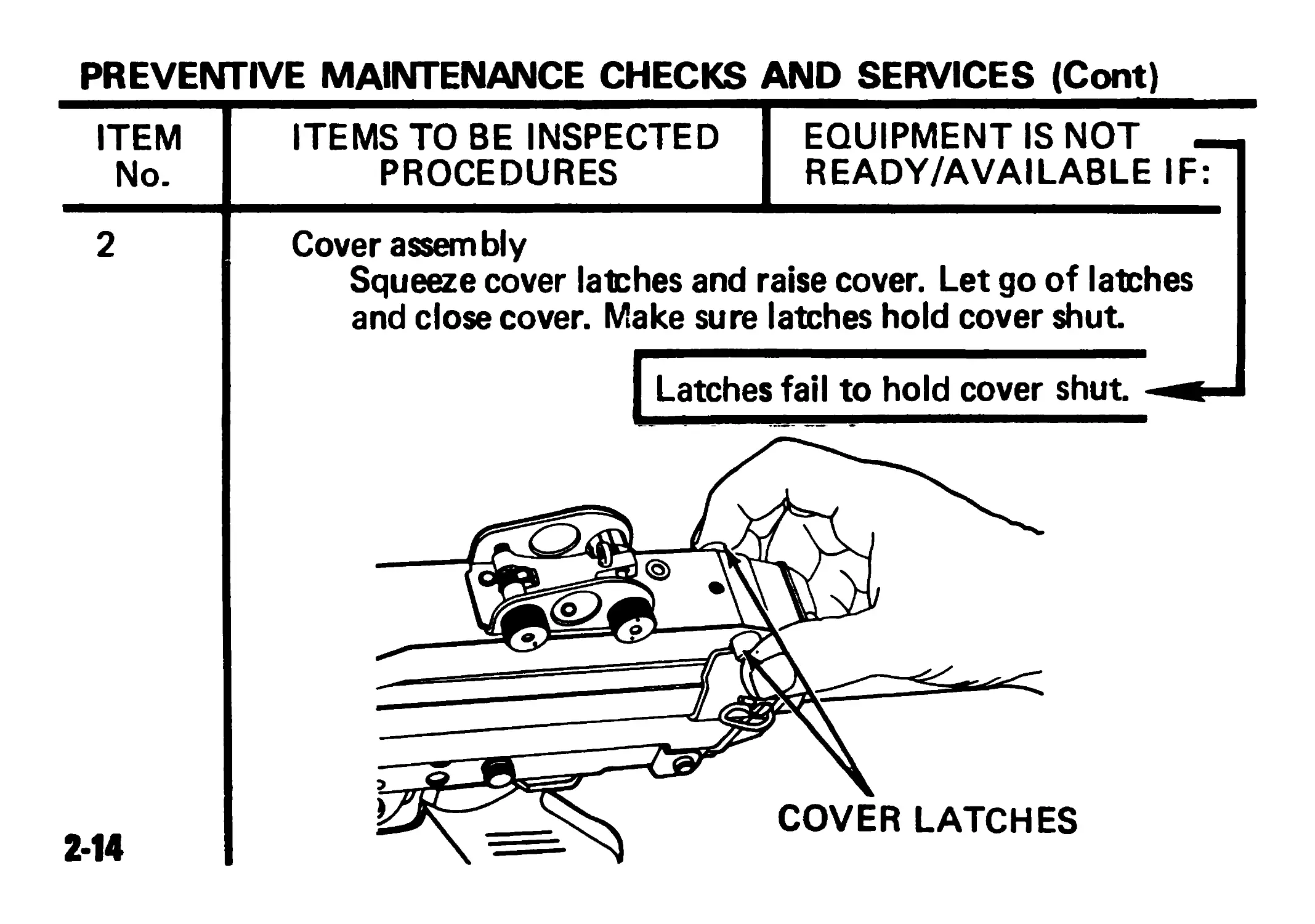
2
Cover assembly
Squeeze cover latches and raise cover. Let go of latches
and close cover. Make sure latches hold cover shut
| Latches fail to hold cover shut
2-14
EQUIPMENT IS NOT
READY/AVAILABLE IF:
ITEM
No.
ITEMS TO BE INSPECTED
PROCEDURES
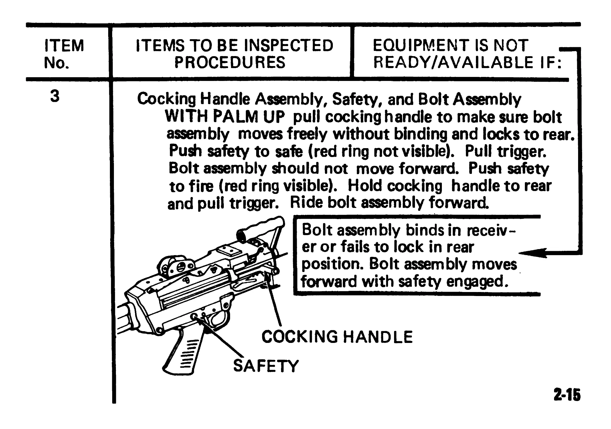
Cocking Handle Assembly, Safety, and Bolt Assembly
WITH PALM UP pull cocking handle to make sure bolt
assembly moves freely without binding and locks to rear.
Push safety to safe (red ring not visible). Pull trigger.
Bolt assembly should not move forward. Push safety
to fire (red ring visible). Hold cocking handle to rear
and pull trigger. Ride bolt assembly forward.
Bolt assembly binds in receiv-
er or fails to lock in rear
position. Bolt assembly moves
forward with safety engaged.
COCKING HANDLE
SAFETY
2-15
PREVENTIVE MAINTENANCE CHECKS AND SERVICES (Cont)
ITEM ITEMS TO BE INSPECTED EQUIPMENT IS NOT
No PROCEDURES READY/AVAILABLE IF:
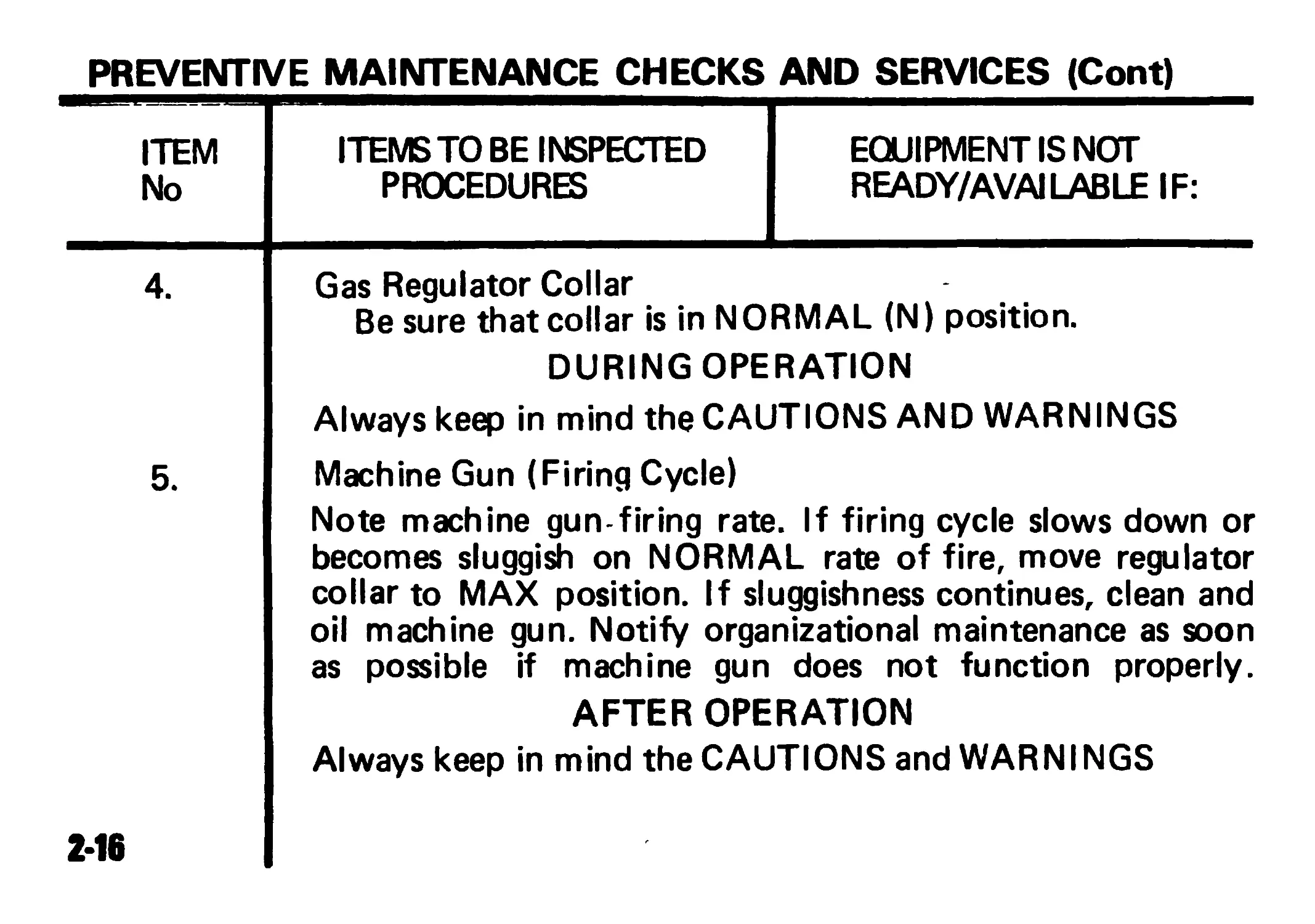
5.
Gas Regulator Collar
Be sure that collar is in NORMAL (N) position.
DURING OPERATION
Always keep in mind the CAUTIONS AND WARNINGS
Machine Gun (Firing Cycle)
Note machine gun-firing rate. If firing cycle slows down or
becomes sluggish on NORMAL rate of fire, move regulator
collar to MAX position. If sluggishness continues, clean and
oil machine gun. Notify organizational maintenance as soon
as possible if machine gun does not function properly.
AFTER OPERATION
Always keep in mind the CAUTIONS and WARNINGS
2-16
EQUIPMENT IS NOT
READY/AVAILABLE IF:
ITEM
No.
ITEMS TO BE INSPECTED
PROCEDURES
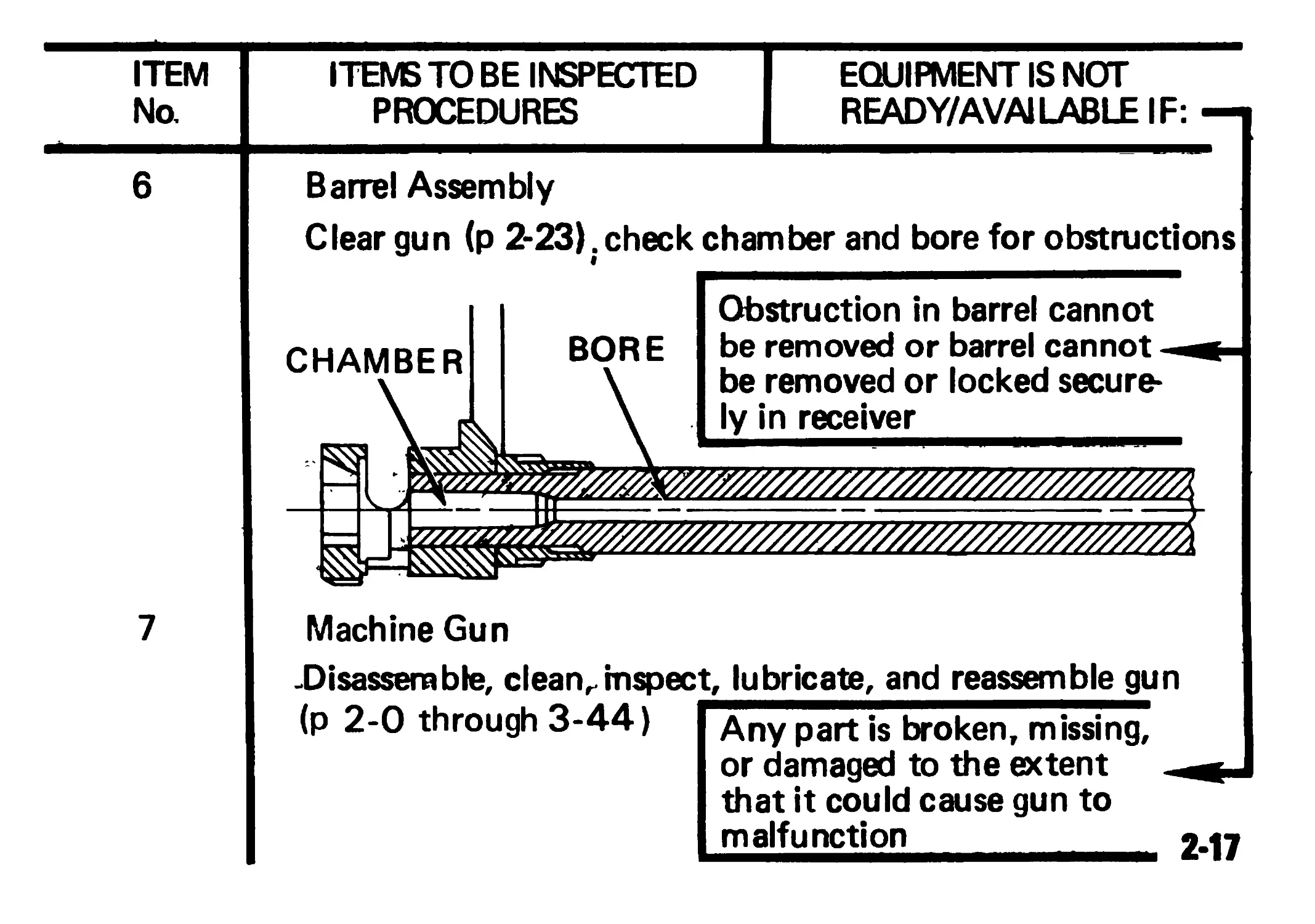
6
Barrel Assembly
Clear gun (p 2-23) . check chamber and bore for obstructions
BORE
CHAMBER
Obstruction in barrel cannot
be removed or barrel cannot -
be removed or locked secure-
ly in receiver
7
Machine Gun
.Disassemble, clean, inspect, lubricate, and reassemble gun
(p 2-0 through 3-44)
Any part is broken, missing,
or damaged to the extent -<
that it could cause gun to
malfunction 2-17
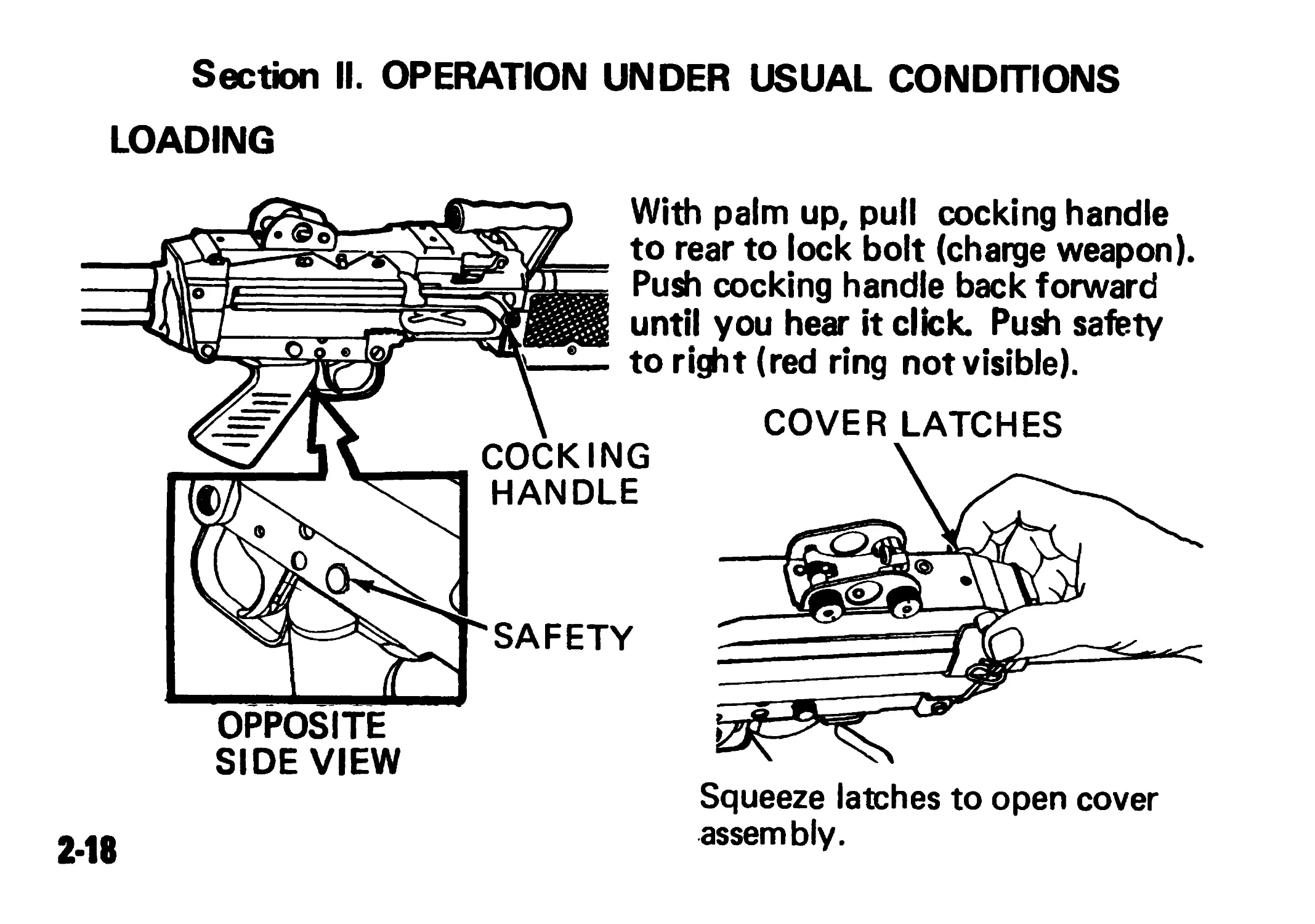
Section II. OPERATION UNDER USUAL CONDITIONS
LOADING V\ if \xo X OPPOSITE SIDE VIEW 2-18 With palm up, pull cocking handle to rear to lock bolt (charge weapon). Z Push cocking handle back forward until you hear it click. Push safety д—— to right (red ring not visible). \ COVER LATCHES COCKING \ 1 HANDLE j SAFETY < Squeeze latches to open cover assembly.
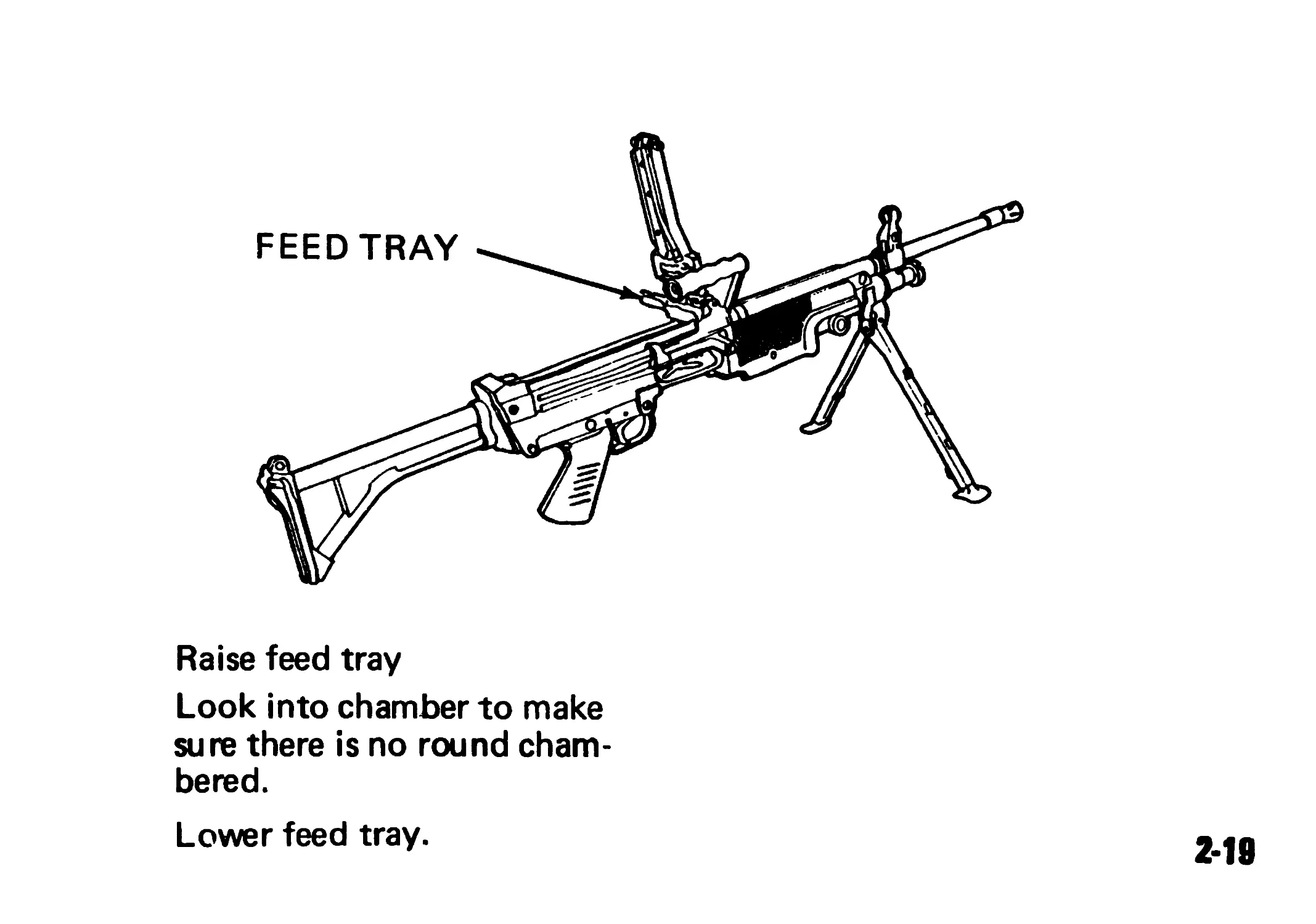
Raise feed tray
Look into chamber to make
sure there is no round cham-
bered.
Lower feed tray.
2-19
MORE LOADING
Attach 2GO-round ammo box containing link belt to underside of
receiver after aligning box latch with receiver dovetail.
2-20
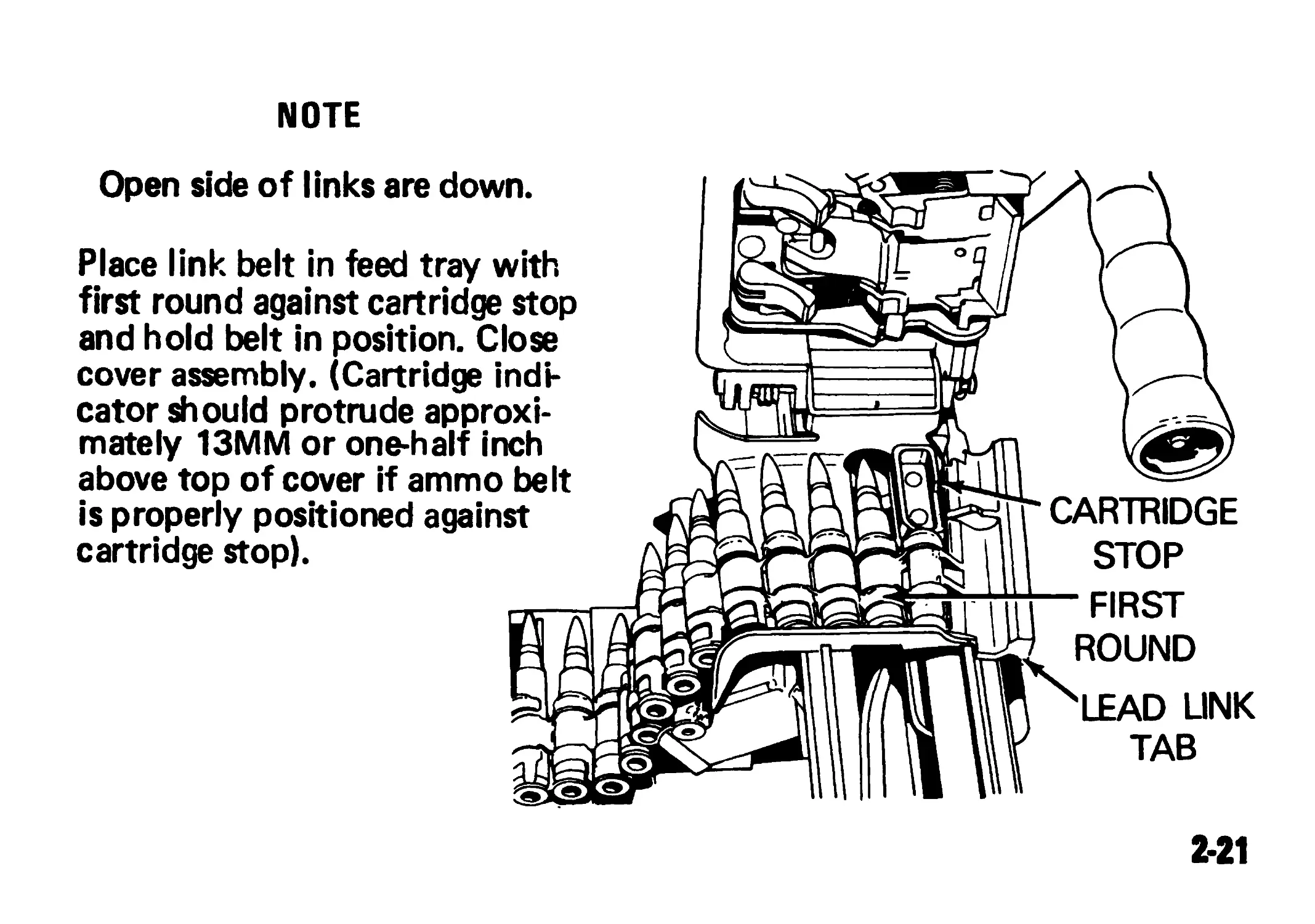
NOTE
Open side of links are down.
Place link belt in feed tray with
first round against cartridge stop
and hold belt in position. Close
cover assembly. (Cartridge indi-
cator should protrude approxi-
mately 13MM or one-half inch
above top of cover if ammo belt
is properly positioned against
cartridge stop).
о
CARTRIDGE
STOP
— FIRST
ROUND
LEAD UNK
TAB
2-21
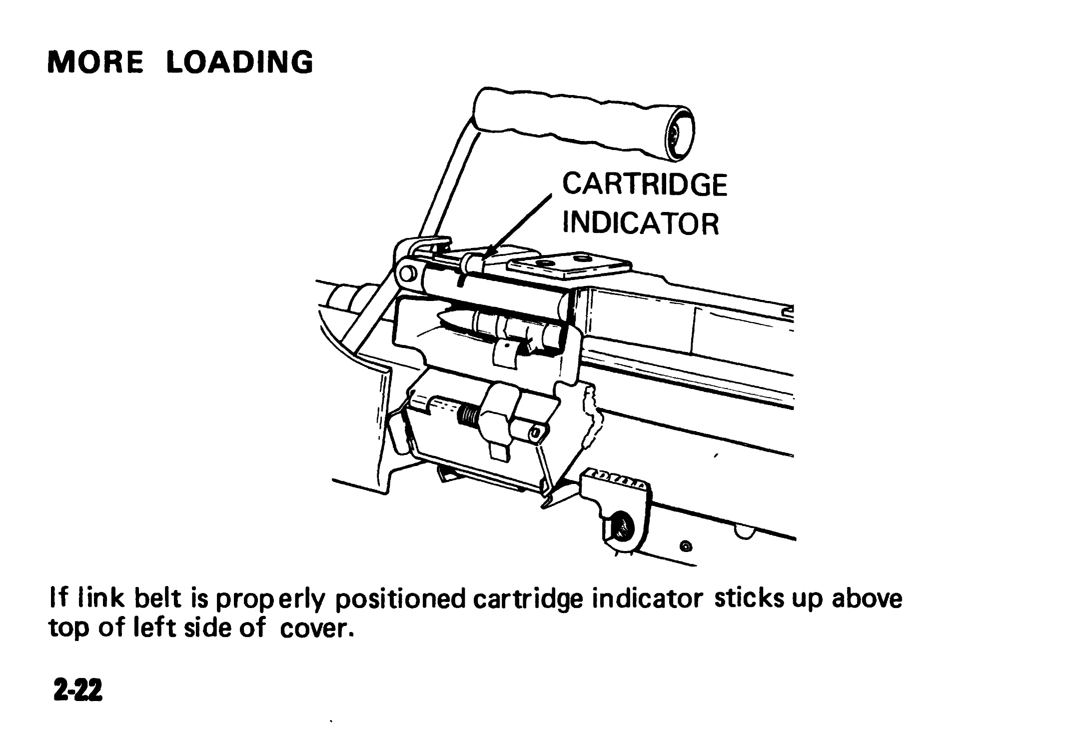
MORE LOADING
If link belt is properly positioned cartridge indicator sticks up above
top of left side of cover.
2*22
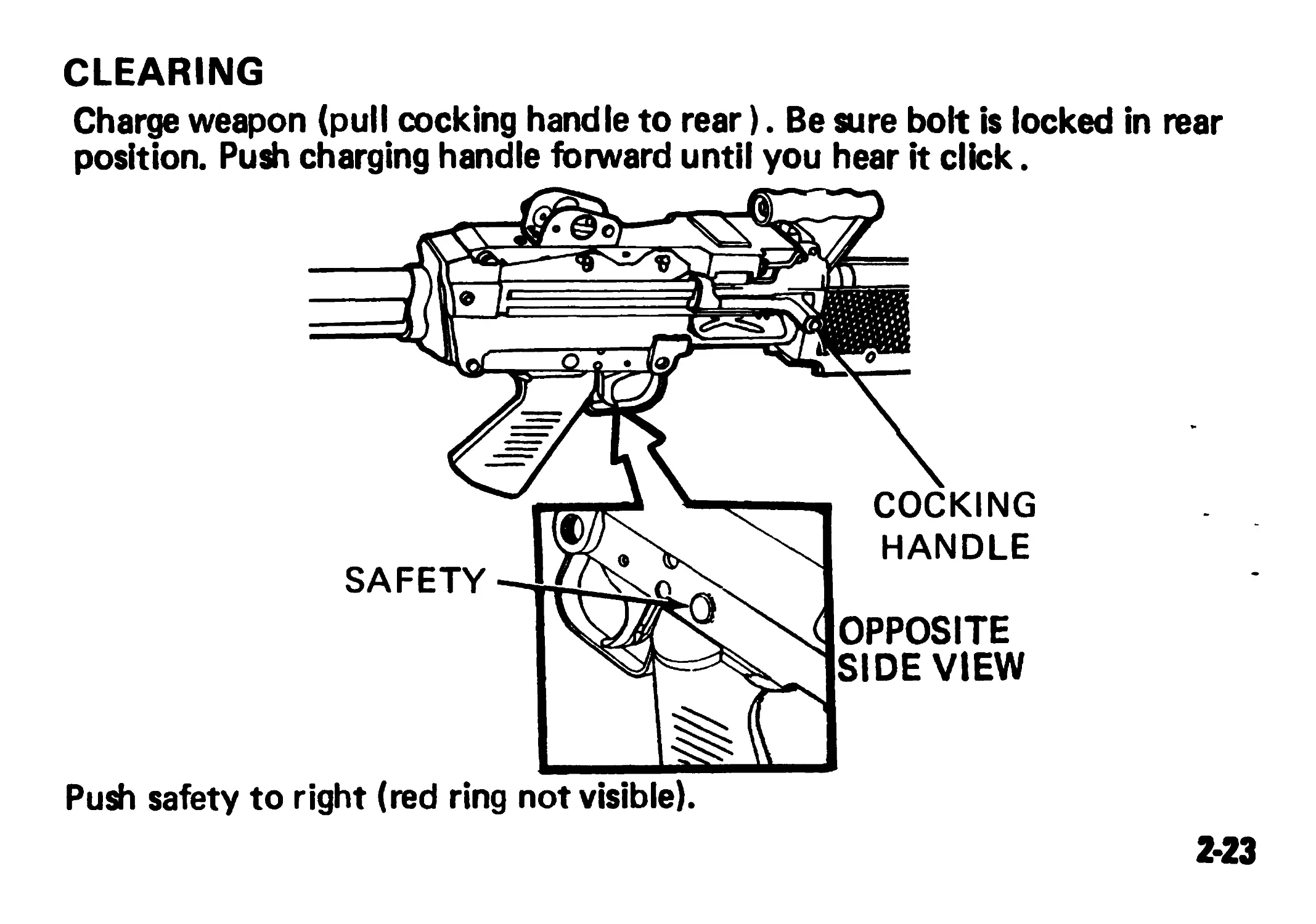
CLEARING
Charge weapon (pull cocking handle to rear). Be sure bolt is locked in rear
position. Push charging handle forward until you hear it click.
SAFETY
Push safety to right (red ring not visible).
OPPOSITE
SIDE VIEW
COCKING
HANDLE
2-23
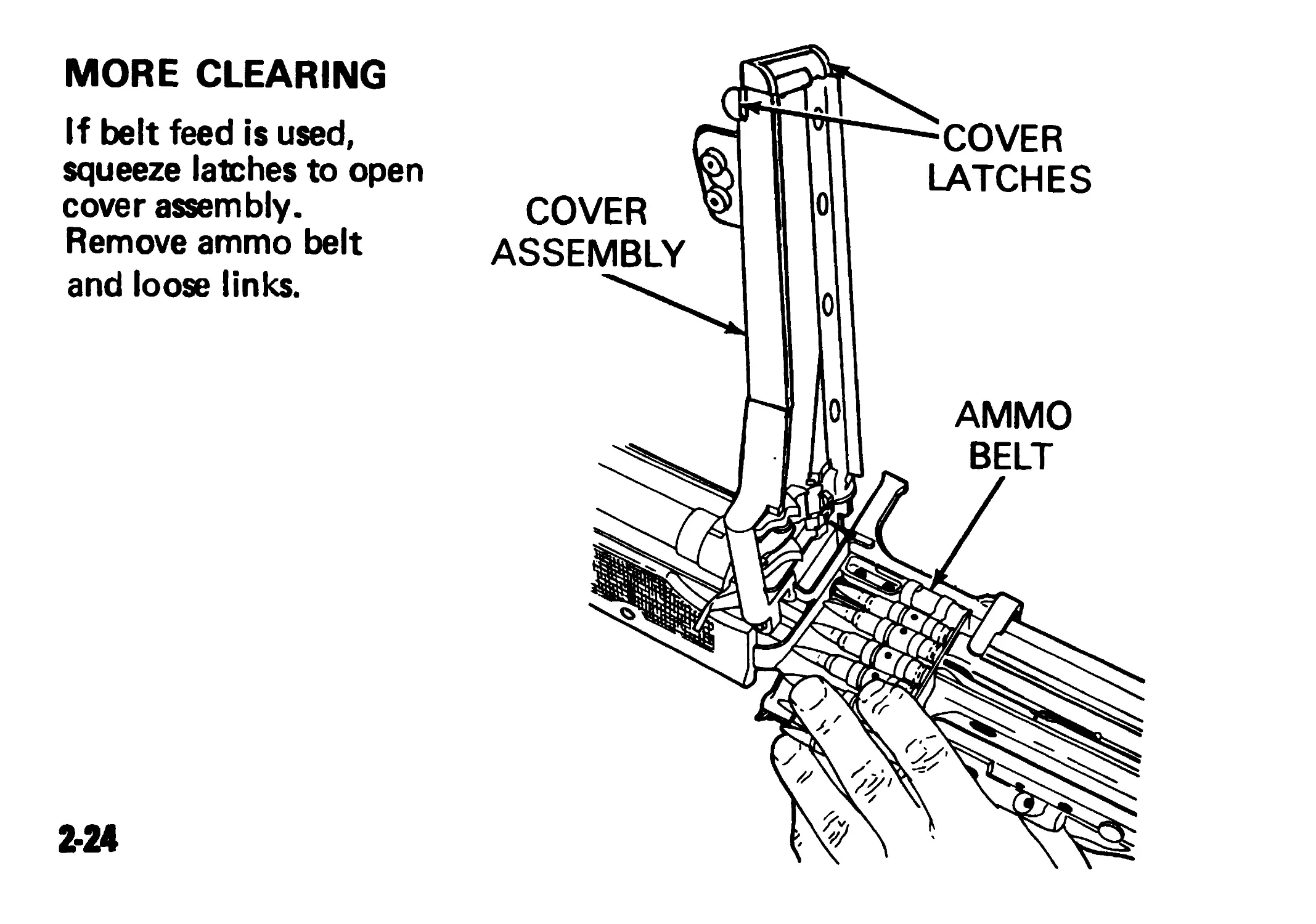
MORE CLEARING
If belt feed is used,
squeeze latches to open
cover assembly.
Remove ammo belt
and loose links.
2-24
'COVER
latches
AMMO
BELT
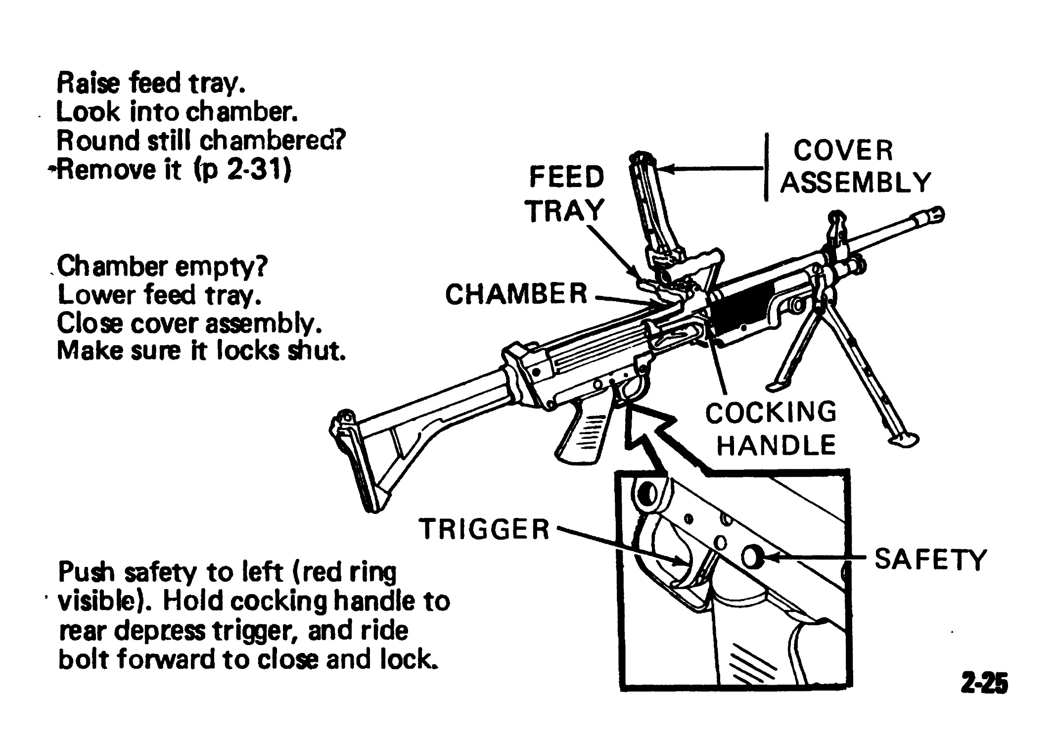
Raise feed tray.
Look into chamber.
Round still chambered?
•Remove it (p 2-31)
CHAMBER
FEED
TRAY
COVER
ASSEMBLY
TRIGGER
SAFETY
COCKING
HANDLE
Chamber empty?
Lower feed tray.
Close cover assembly.
Make sure it locks shut.
Push safety to left (red ring
visible). Hold cocking handle to
rear depress trigger, and ride
bolt forward to close and lock.
2*25
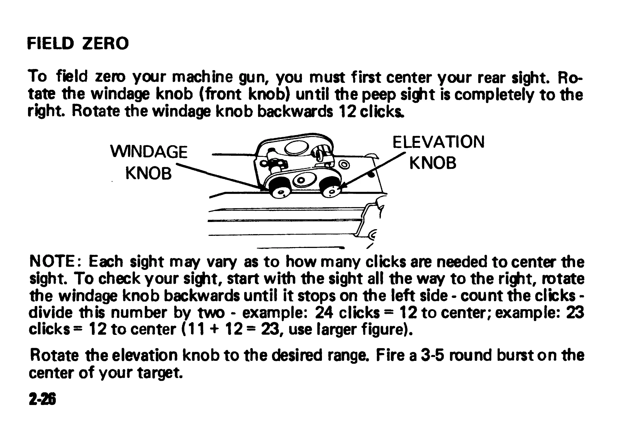
FIELD ZERO
To field zero your machine gun, you must first center your rear sight. Ro-
tate the windage knob (front knob) until the peep sight is completely to the
right Rotate the windage knob backwards 12 clicks;
WINDAGE
KNOB"
ELEVATION
^KNOB
NOTE: Each sight may vary as to how many clicks are needed to center the
sight. To check your sight, start with the sight all the way to the right, rotate
the windage knob backwards until it stops on the left side - count the clicks -
divide this number by two - example: 24 clicks = 12 to center; example: 23
clicks = 12 to center (11 + 12 = 23, use larger figure).
Rotate the elevation knob to the desired range. Fire a 3-5 round burst on the
center of your target.
2-26
аке tine windage changes as follows:
0 Forward moves the impact to the right
0 Backward moves the impact to the left
NOTE: Each click = 1/2 mil which moves the impact 1/2 meter at 1000
meters. To change the elevation of the Impact:
° Rotate the peep sight clockwise to lower the impact
0 Rotate the peep sight counter-clockwise to raise the impact
NOTE: Each click of the peep sight = 1/2 mil change in elevation. To make
the peep sight easier to grasp, rotate the elevation knob to the 1000m mark.
After you make your fine adjustment, move the elevation knob back to
where you started.
2-27
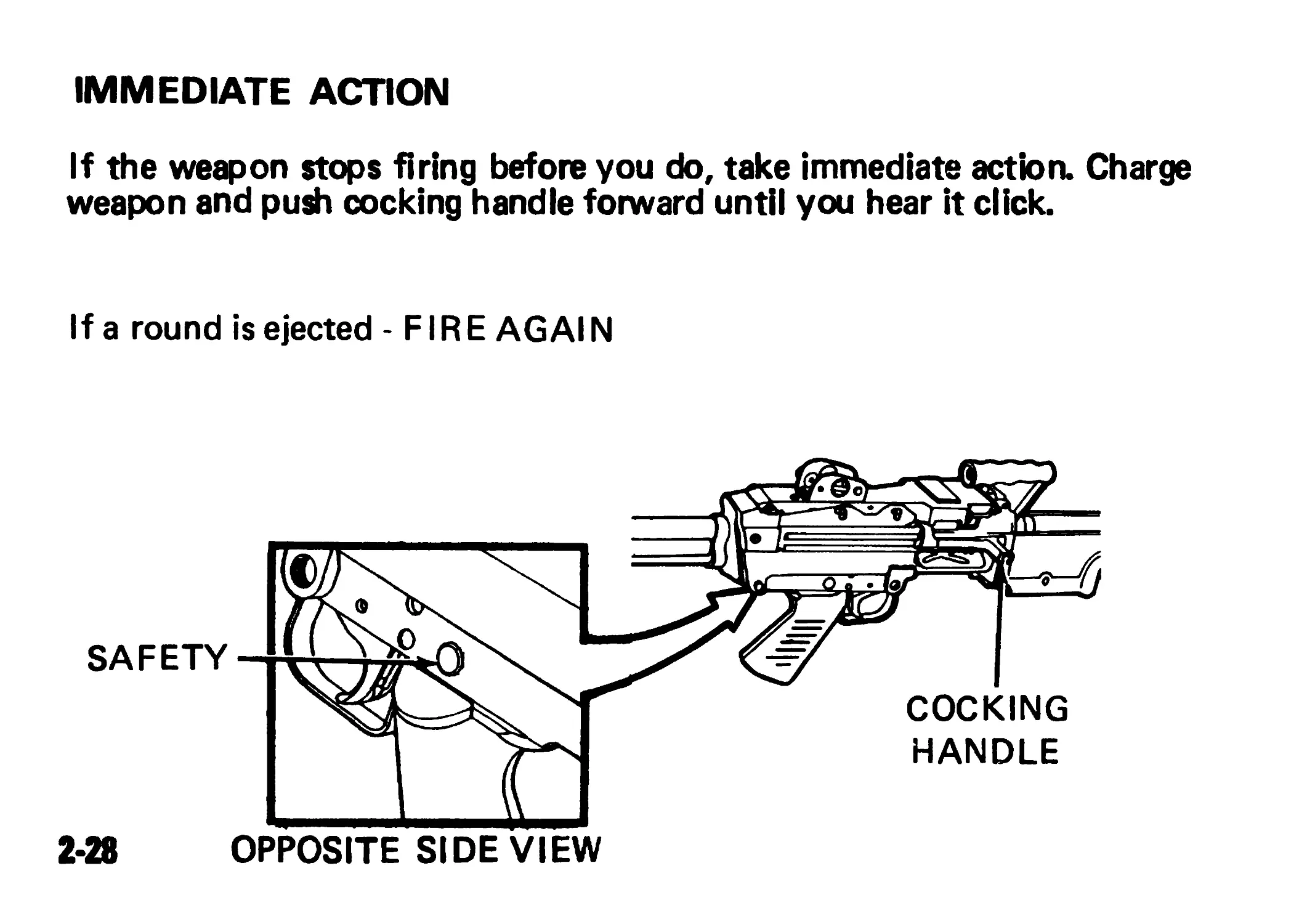
IMMEDIATE ACTION
If the weapon stops firing before you do, take immediate action. Charge
weapon and push cocking handle forward until you hear it click.
If a round is ejected -FIRE AG Al N
2*28 OPPOSITE SIDE VIEW
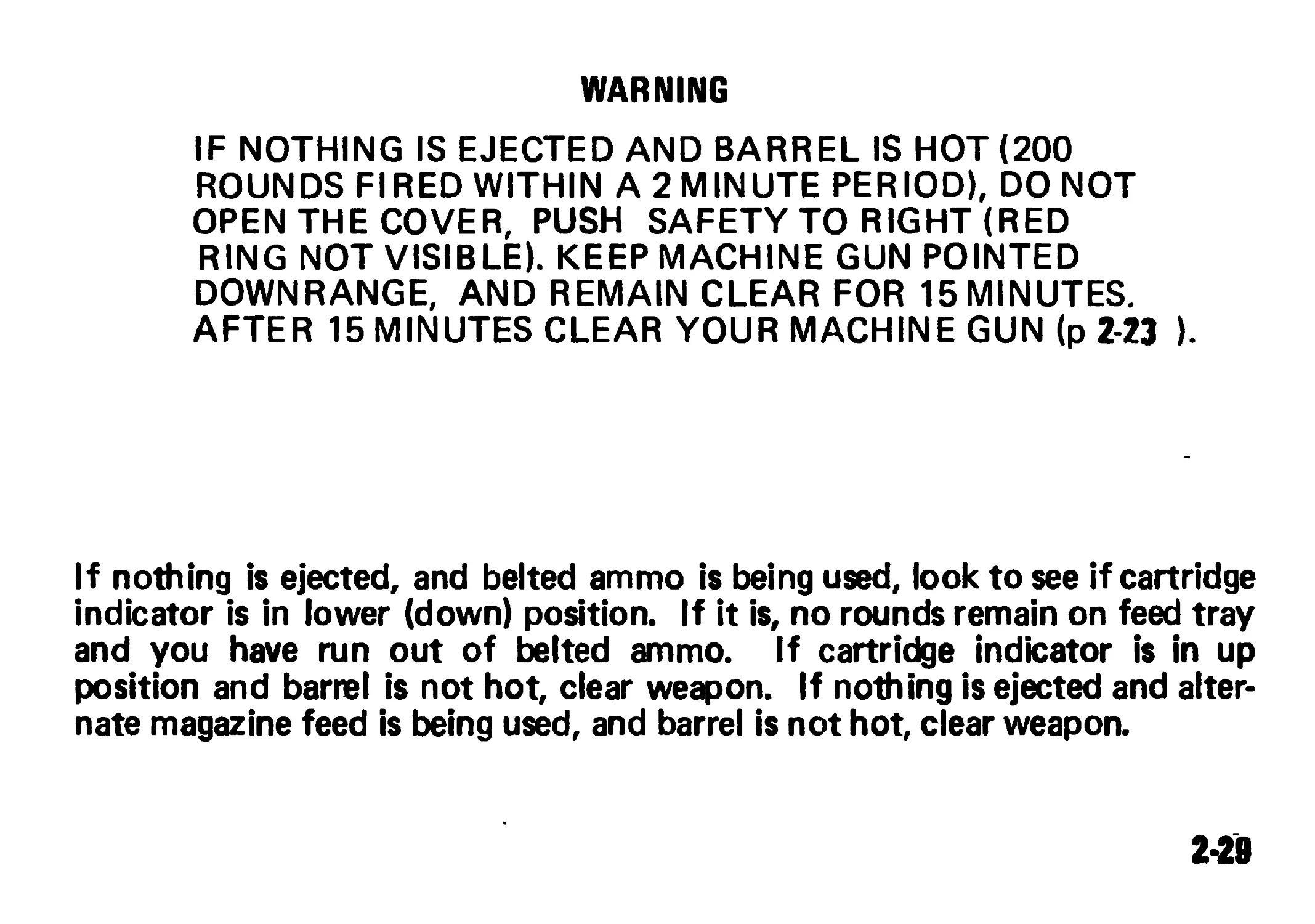
WARNING
IF NOTHING IS EJECTED AND BARREL IS HOT (200
ROUNDS FIRED WITHIN A 2 MINUTE PERIOD), DO NOT
OPEN THE COVER, PUSH SAFETY TO RIGHT (RED
RING NOT VISIBLE). KEEP MACHINE GUN POINTED
DOWNRANGE, AND REMAIN CLEAR FOR 15 MINUTES.
AFTER 15 MINUTES CLEAR YOUR MACHINE GUN (p 2-23 ).
If nothing is ejected, and belted ammo is being used, look to see if cartridge
indicator is in lower (down) position. If it is, no rounds remain on feed tray
and you have run out of belted ammo. If cartridge indicator is in up
position and barrel is not hot, clear weapon. If nothing is ejected and alter-
nate magazine feed is being used, and barrel is not hot, clear weapon.
2-28
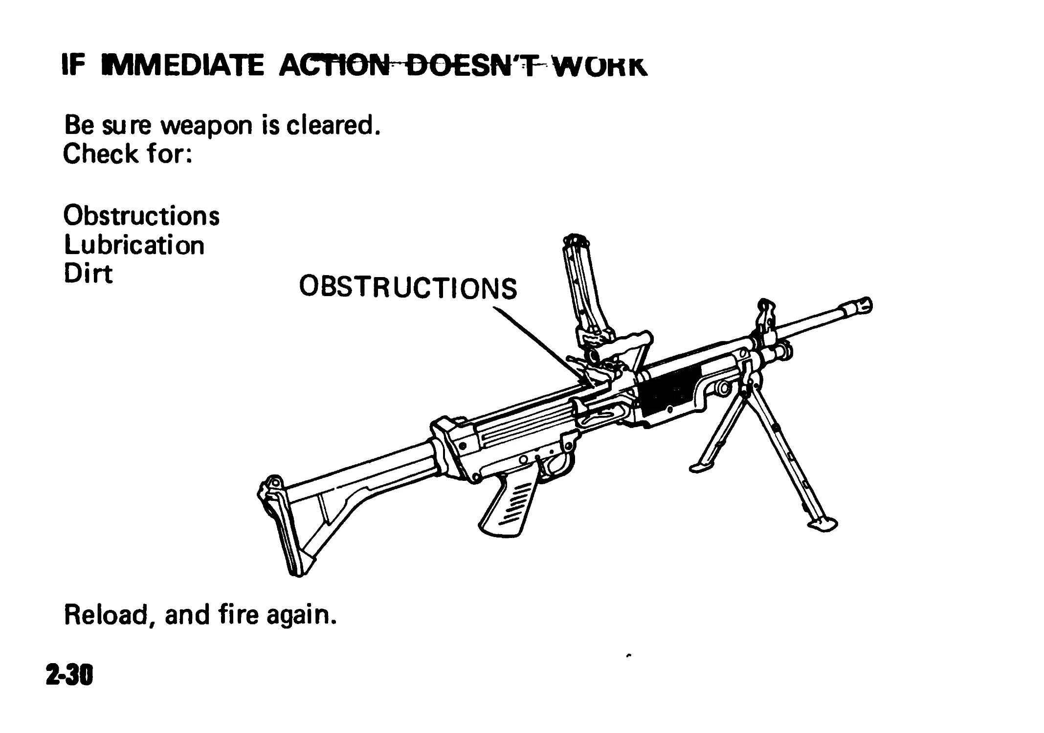
IF IMMEDIATE ACnON^DOESN'T WOKK
Be sure weapon is cleared.
Check for:
Obstructions
Lubrication
Dirt
Reload, and fire again.
2-30
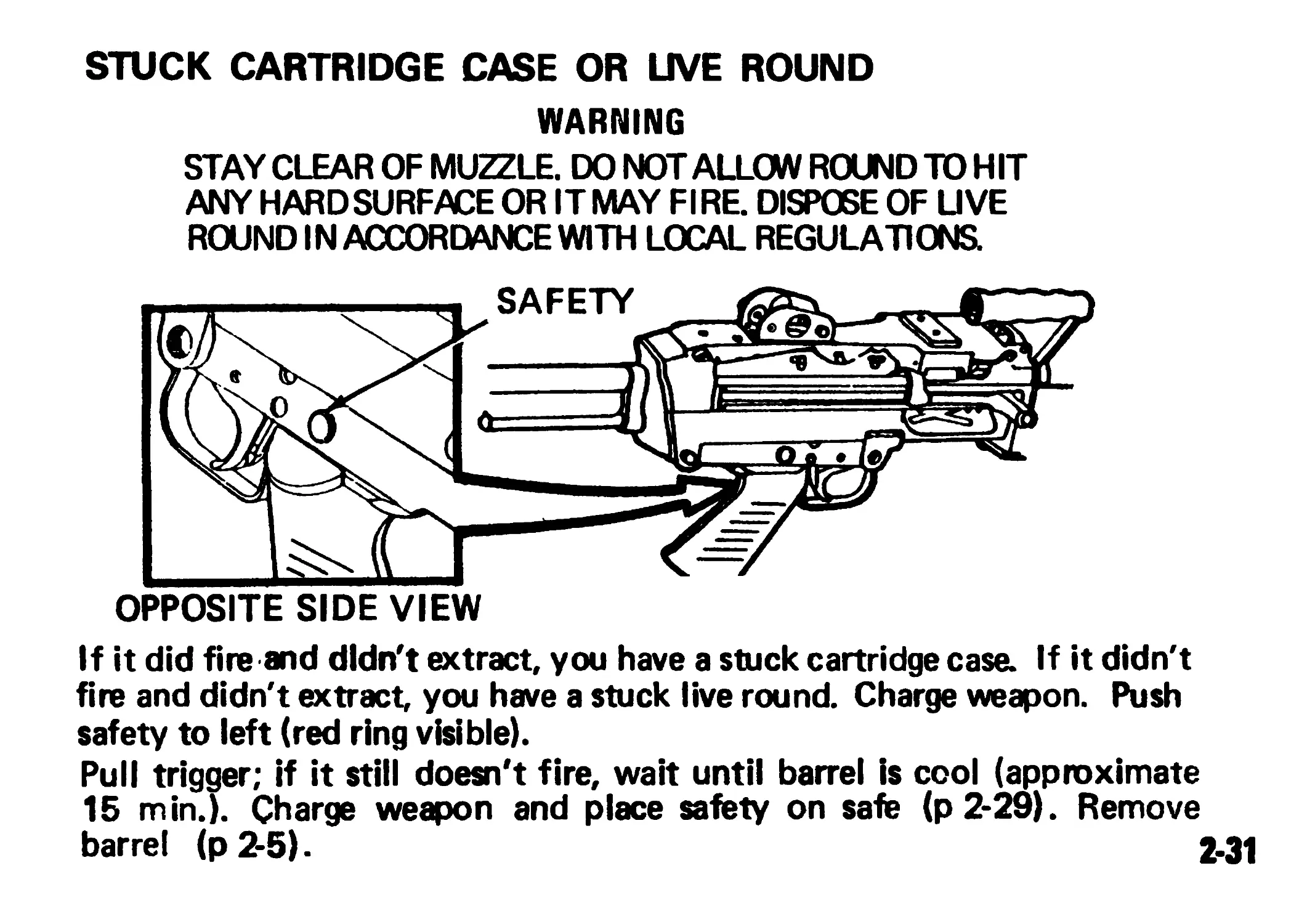
STUCK CARTRIDGE CASE OR UVE ROUND
WARNING
STAY CLEAR OF MUZZLE. DO NOTALLOW ROUND TO HIT
ANY HARD SURFACE OR ITMAY FIRE. DISPOSE OF UVE
ROUND IN ACCORDANCE WITH LOCAL REGULATIONS
OPPOSITE SIDE VIEW
If it did fire and didn't extract, you have a stuck cartridge case. If it didn't
fire and didn't extract, you have a stuck live round. Charge weapon. Push
safety to left (red ring visible).
Pull trigger; if it still doesn't fire, wait until barrel is cool (approximate
15 min.). Charge weapon and place safety on safe (p2*29). Remove
barrel (p2-5). 2-31
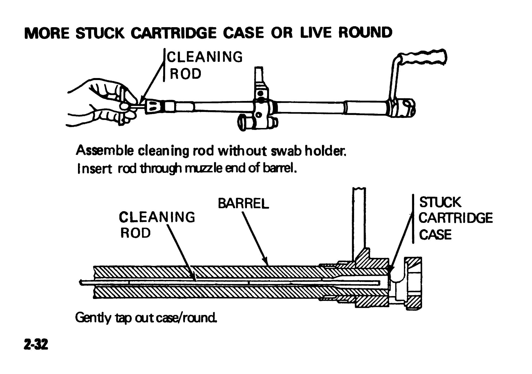
MORE STUCK CARTRIDGE CASE OR LIVE ROUND
Assemble cleaning rod without swab holder.
I nsert rod through muzzle end of barrel.
Gently tap out case/round.
2-32
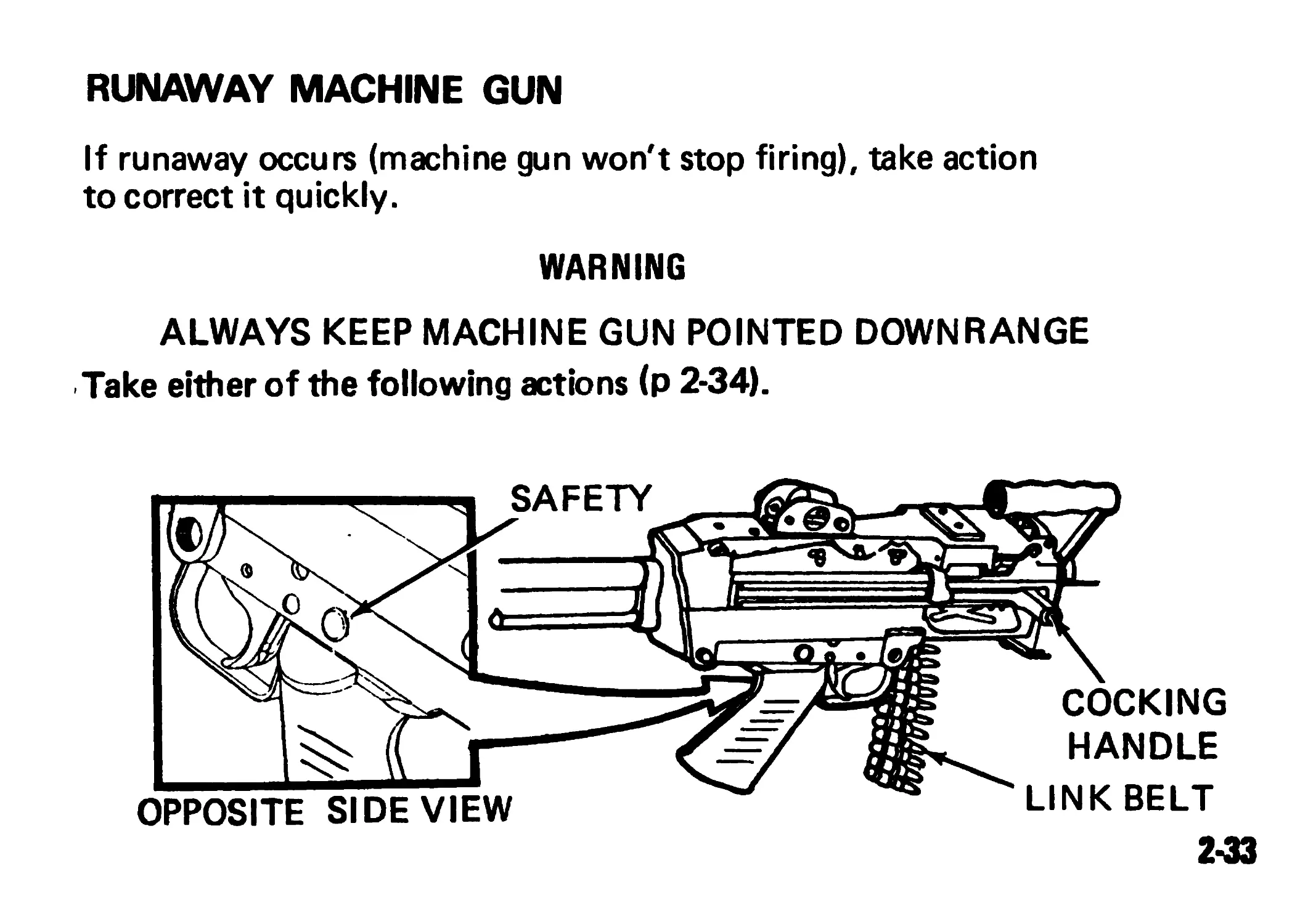
RUNAWAY MACHINE GUN
If runaway occurs (machine gun won't stop firing), take action
to correct it quickly.
WARNING
ALWAYS KEEP MACHINE GUN POINTED DOWNRANGE
Take either of the following actions (p 2-34).
SAFETY
COCKING
HANDLE
OPPOSITE SIDEVIEW
LINK BELT
2-33
MORE RUNAWAY MACHINE GUN
1- Let machine gun fire if near end of link belt or magazine capacity.
2. Grab cocking handle (palm up), pull all the way back and
hold. Push safety to ric^t (red ring not visible); raise cover,
remove link belt or magazine.
WARNING
NEVER RELOAD A RUNAWAY MACHINE GUN UNTIL IT IS
REPAIRED. BE SURE MACHINE GUN IS CLEARED.
Notify organizational maintenance for repairs.
2-34
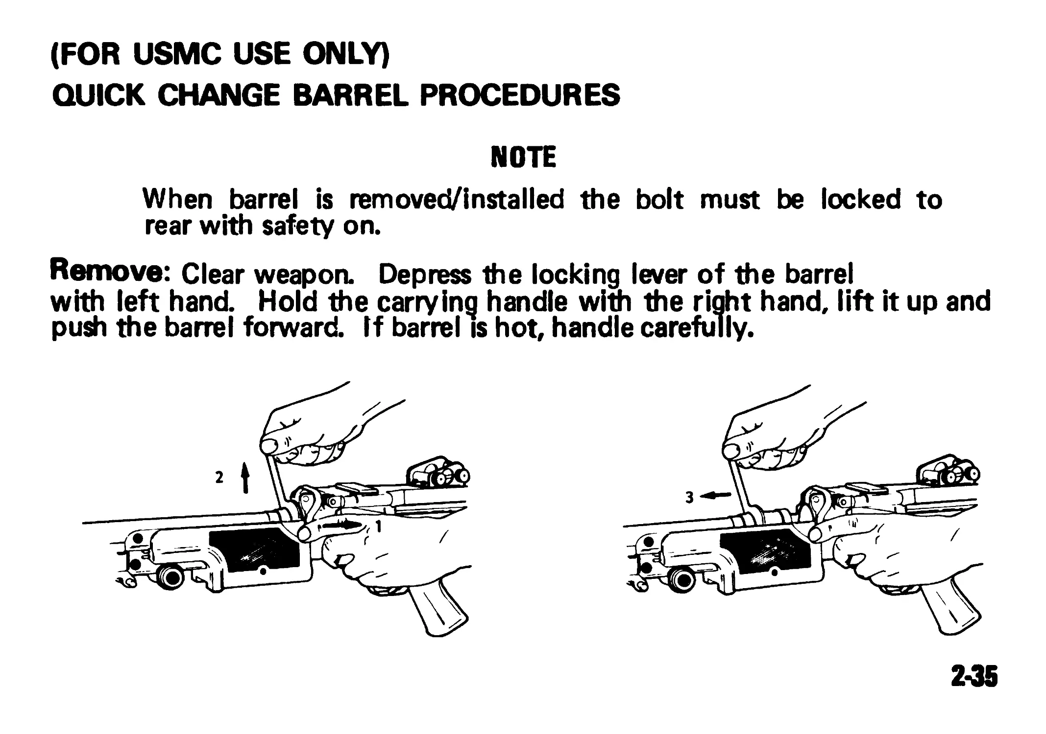
(FOR USMC USE ONLY)
QUICK CHANGE BARREL PROCEDURES
NOTE
When barrel is removed/installed the bolt must be locked to
rear with safety on.
Remove: Clear weapon. Depress the locking lever of the barrel
with left hand. Hold the carrying handle with the right hand, lift it up and
push the barrel forward. If barrel is hot, handle carefully.
2-35
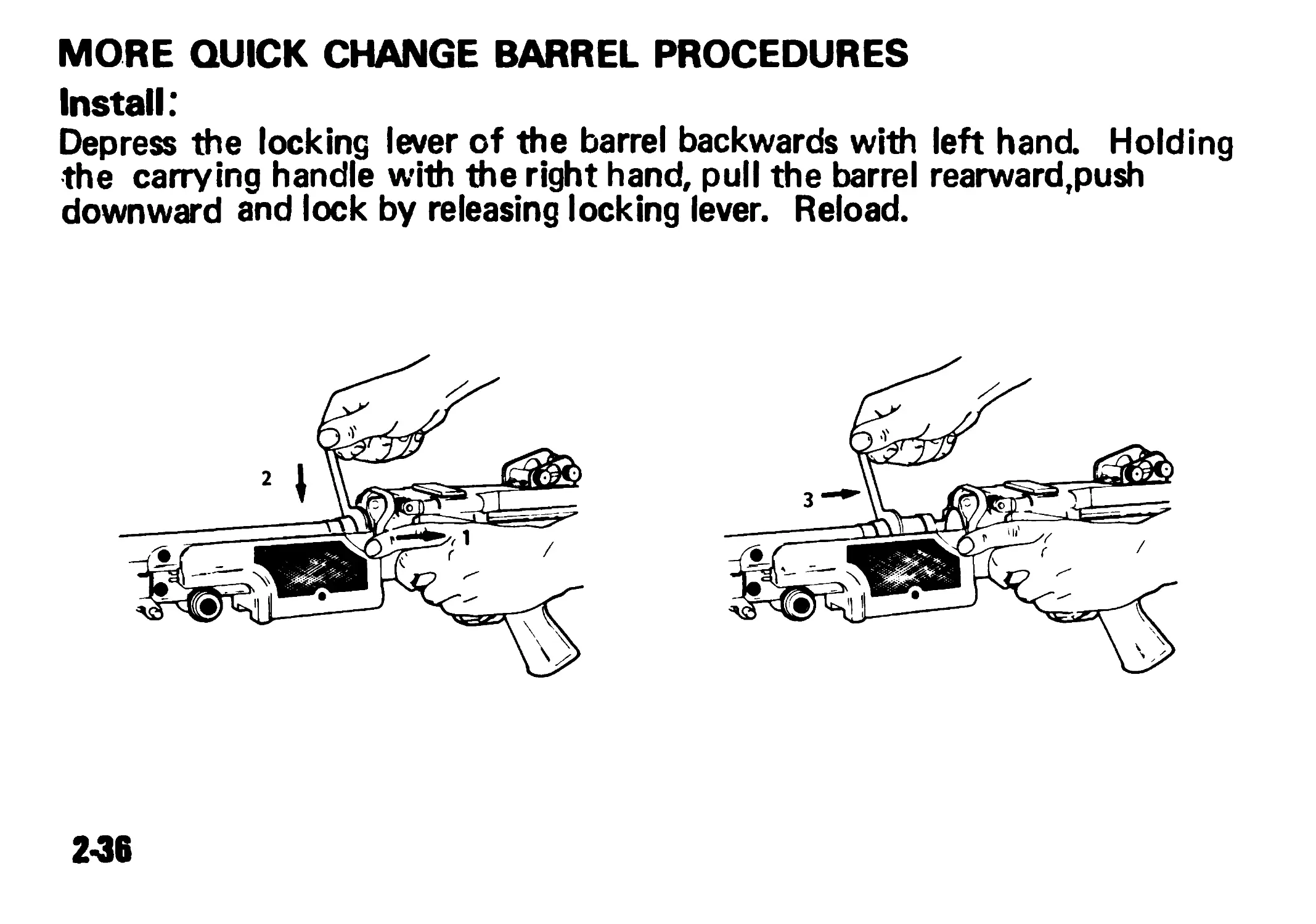
MORE QUICK CHANGE BARREL PROCEDURES
Install:
Depress the locking lever of the barrel backwards with left hand. Holding
the carrying handle with the right hand, pull the barrel rearward,push
downward and lock by releasing locking lever. Reload.
2-36
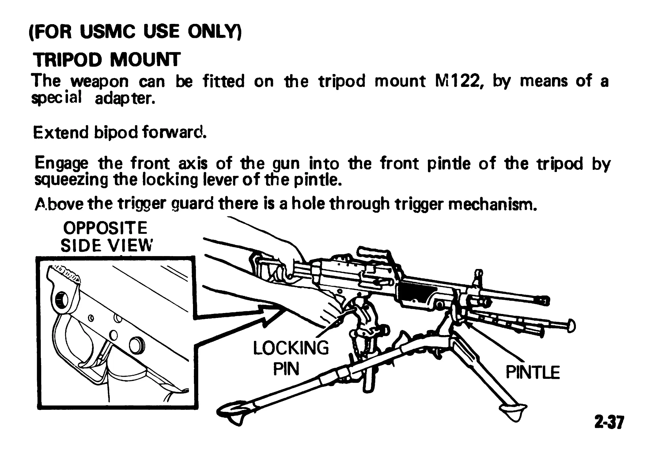
(FOR USMC USE ONLY)
TRIPOD MOUNT
The weapon can be fitted on the tripod mount M122, by means of a
special adapter.
Extend bipod forward.
Engage the front axis of the gun into the front pintle of the tripod by
squeezing the locking lever of the pintle.
Above the trigger guard there is a hole through trigger mechanism.
OPPOSITE SIDEVIEW - LOCKING \\ pintle
2-37
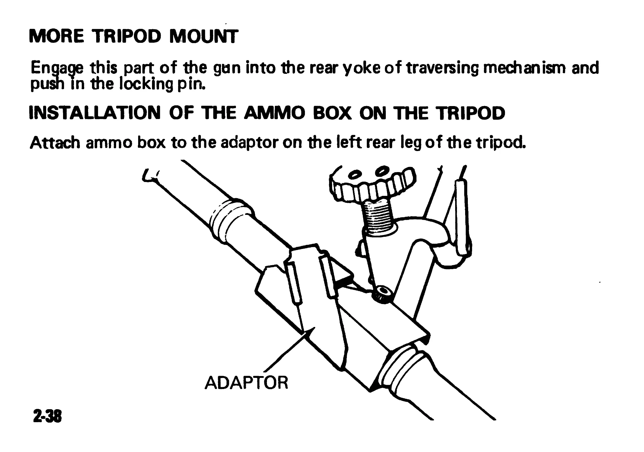
MORE TRIPOD MOUNT
Engage this part of the gun into the rear yoke of traversing mechanism and
push in the locking pin.
INSTALLATION OF THE AMMO BOX ON THE TRIPOD
Attach ammo box to the adaptor on the left rear leg of the tripod.
ADAPTOR
2-38
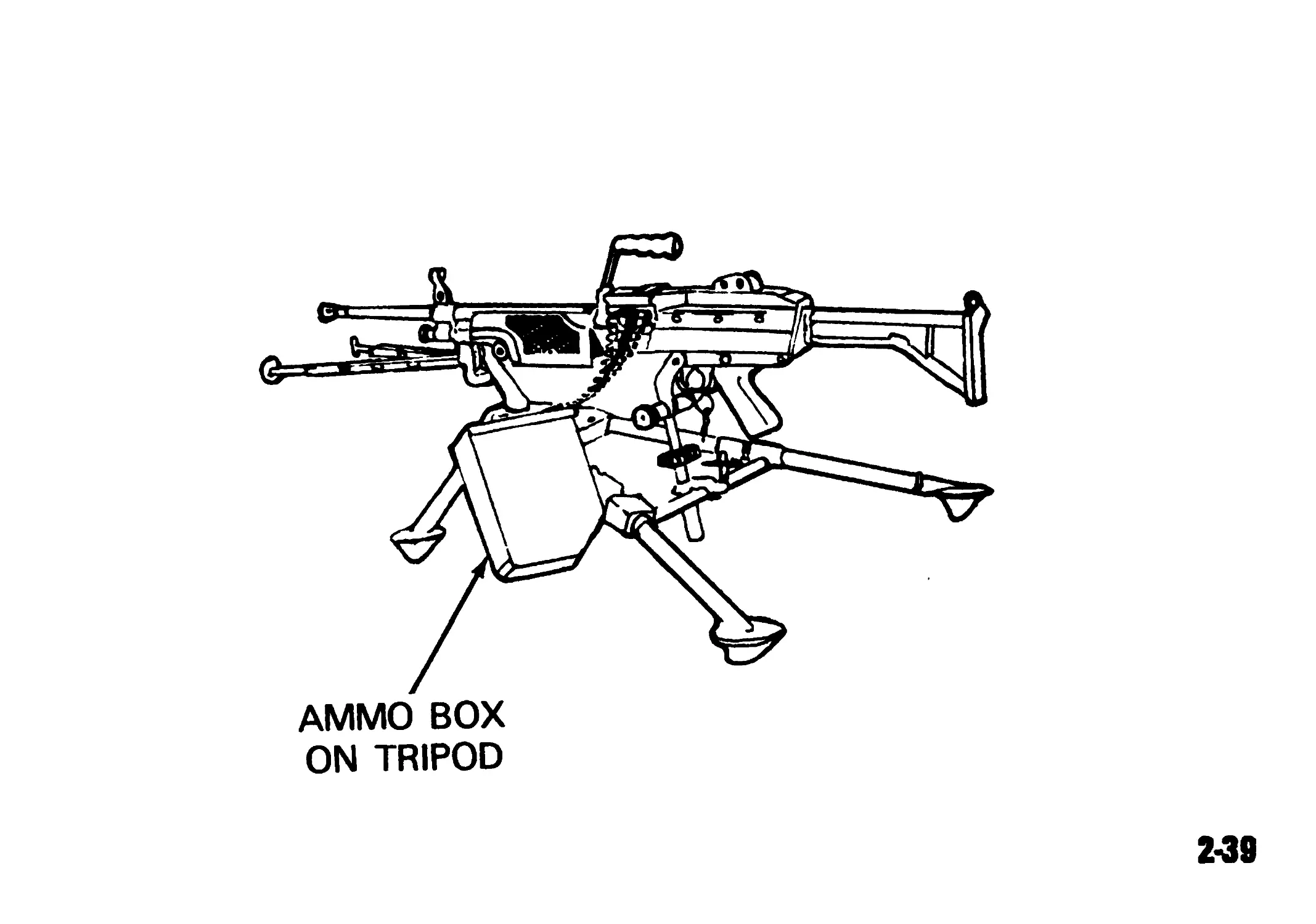
AMMO BOX
ON TRIPOD
2*39
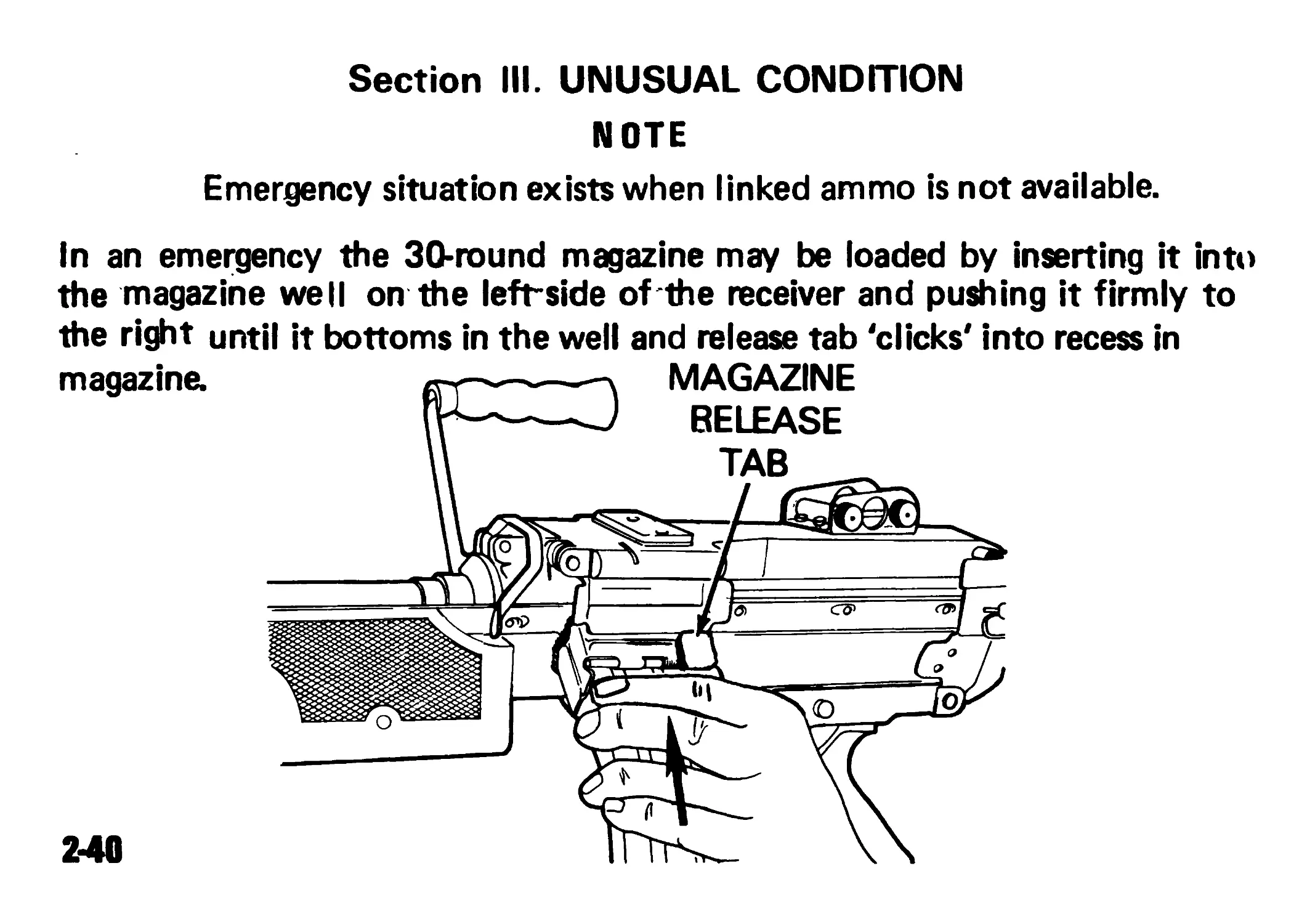
Section III. UNUSUAL CONDITION
NOTE
Emergency situation exists when linked ammo is not available.
In an emergency the 30-round magazine may be loaded by inserting it into
the magazine well on the left-side of the receiver and pushing it firmly to
the right until it bottoms in the well and release tab 'clicks' into recess in
magazine. «-p.---MAGAZINE
---------1 RELEASE
U--------TAB
1
240
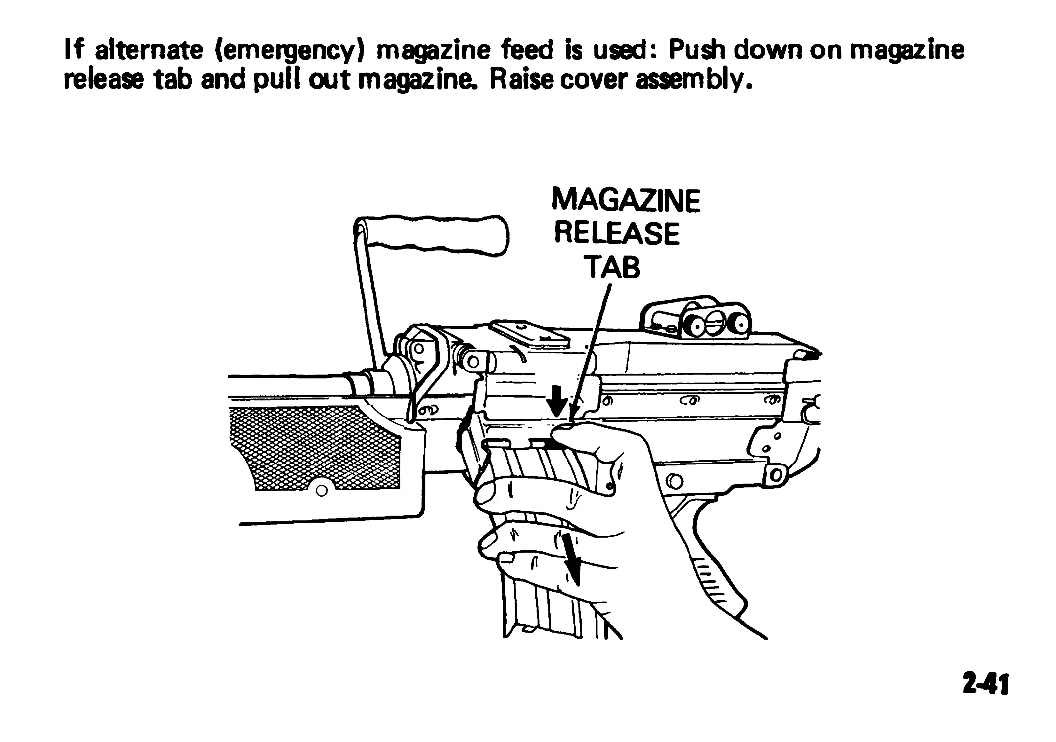
If alternate (emergency) magazine feed is used: Push down on magazine
release tab and pull out magazine. Raise cover assembly.
241
CHAPTER 3
MAINTENANCE INSTRUCTIONS
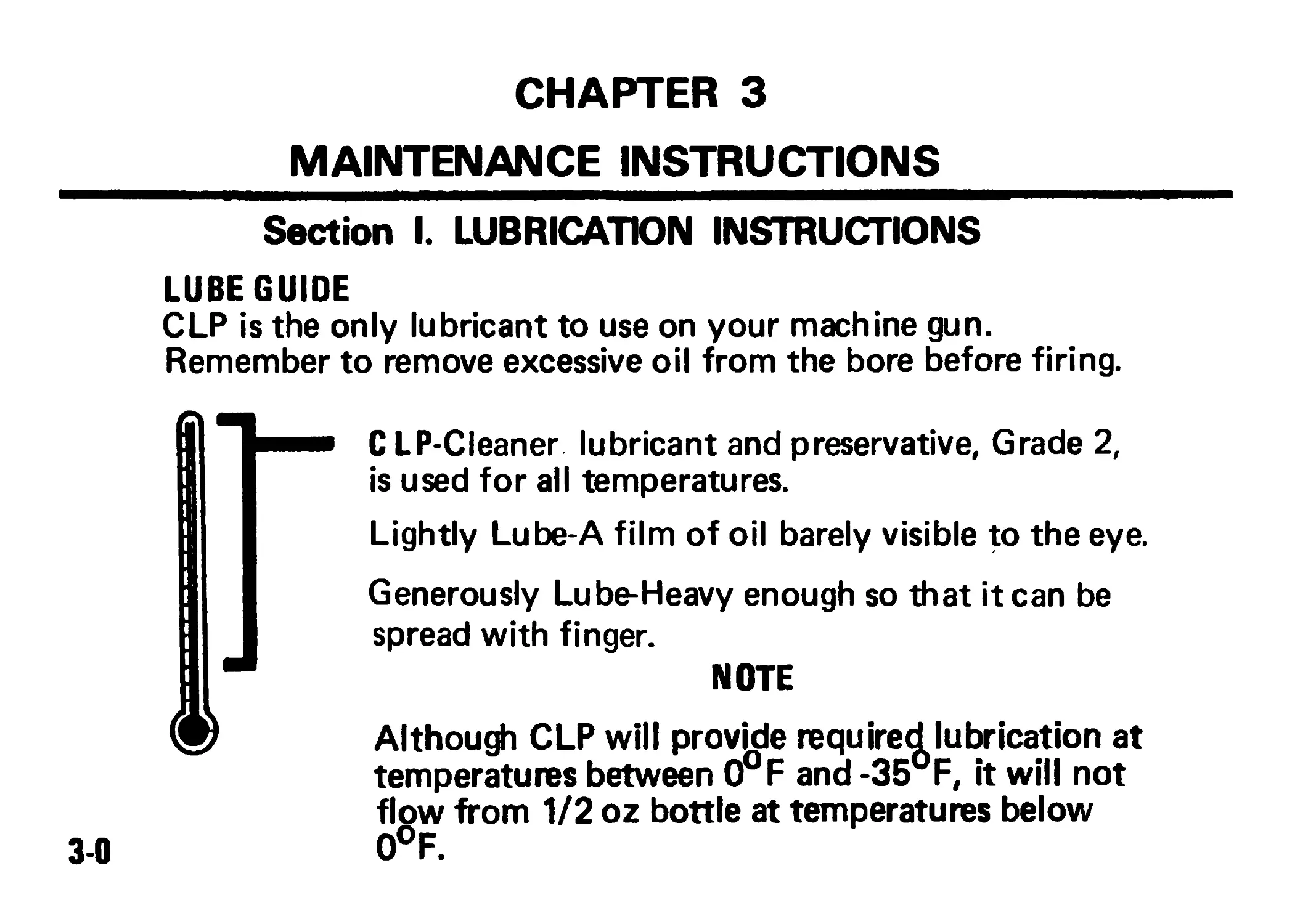
Section I. LUBRICATION INSTRUCTIONS
LUBE GUIDE
CLP is the only lubricant to use on your machine gun.
Remember to remove excessive oil from the bore before firing.
C LP-Cleaner lubricant and preservative, Grade 2,
is used for all temperatures.
Lightly Lube-A film of oil barely visible to the eye.
Generously Lube-Heavy enough so that it can be
spread with finger.
NOTE
Although CLP will provide required lubrication at
temperatures between 0°F and -35°F, it will not
flow from 1/2 oz bottle at temperatures below
0°F.
3-0
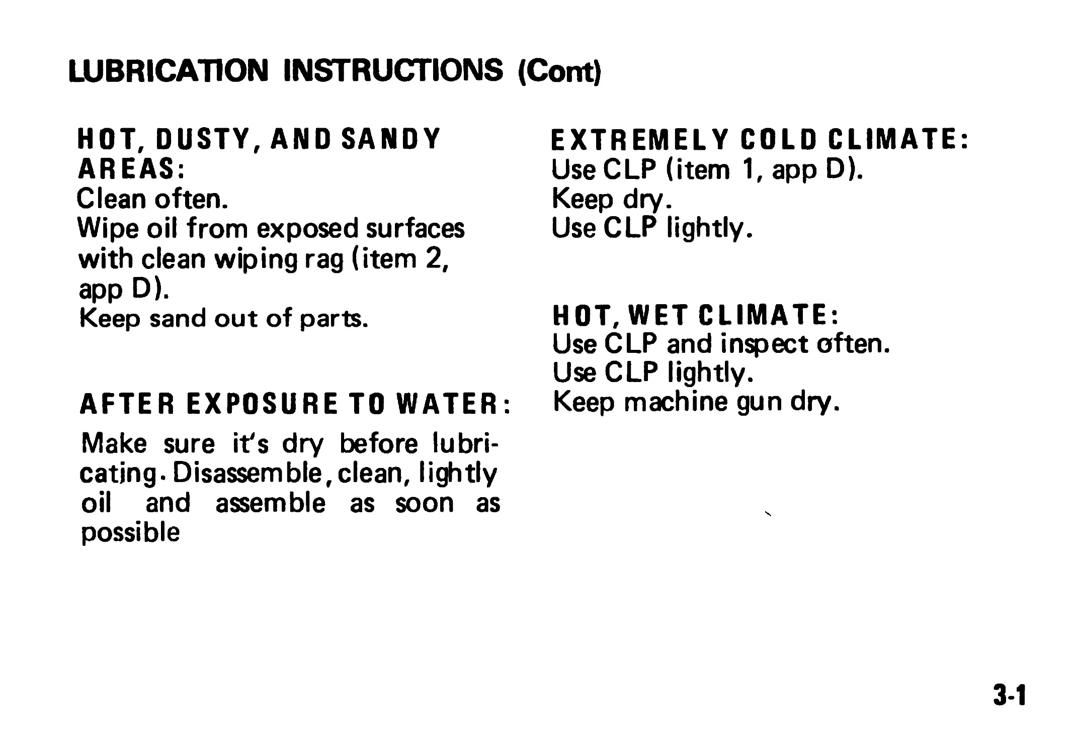
LUBRICATION INSTRUCTIONS (Cont)
HOT, DUSTY, AND SANDY
AREAS:
Clean often.
Wipe oil from exposed surfaces
with clean wiping rag (item 2,
app D).
Keep sand out of parts.
AFTER EXPOSURE TO WATER
Make sure it's dry before lubri-
cating. Disassemble, clean, lightly
oil and assemble as soon as
possible
EXTREMELY COLD CLIMATE:
Use CLP (item 1, app D).
Keep dry.
Use CLP lightly.
HOT, WET CLIMATE:
Use CLP and inspect often.
Use CLP lightly.
Keep machine gun dry.
3-1
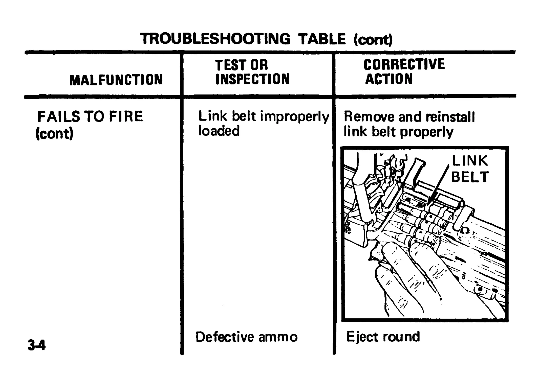
Section II. TROUBLESHOOTING PROCEDURES
The table lists the common malfunctions which you may find
during the operation or maintenance of the machine gun or its
components. You should perform the tests/inspections and correc-
tive actions in the order listed.
This manual can not list all malfunctions that may occur, nor all
tests or inspections and corrective actions. If a malfunction is not
listed or is not corrected by listed corrective actions, notify
organizational maintenance.
3-2
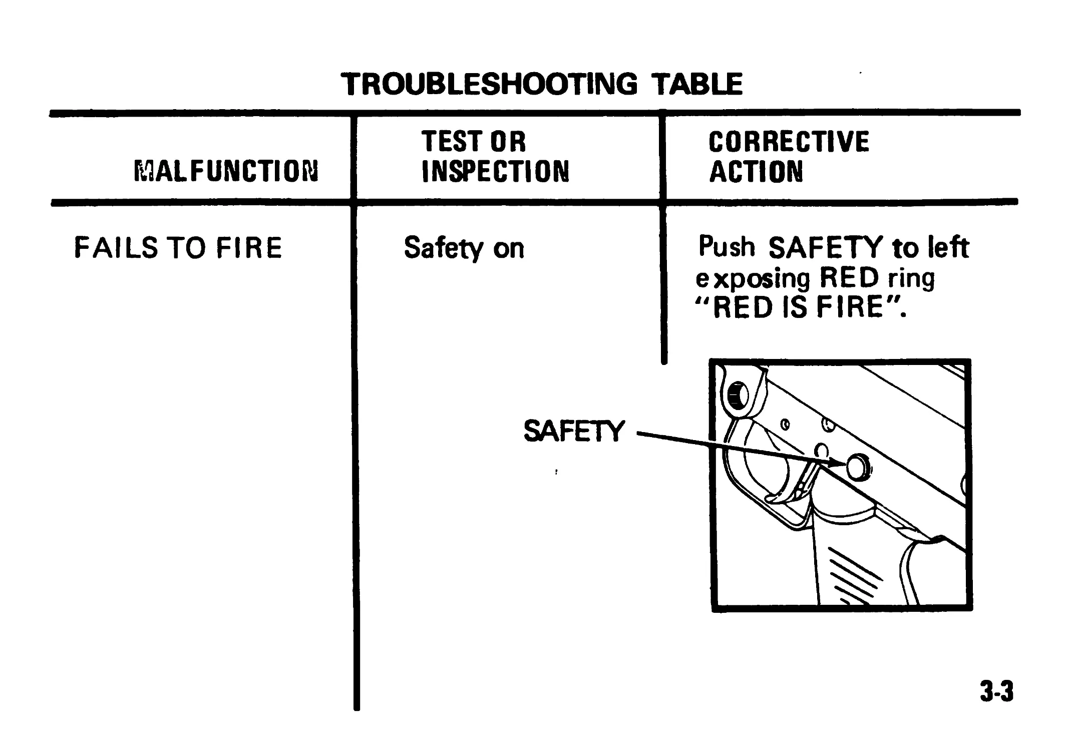
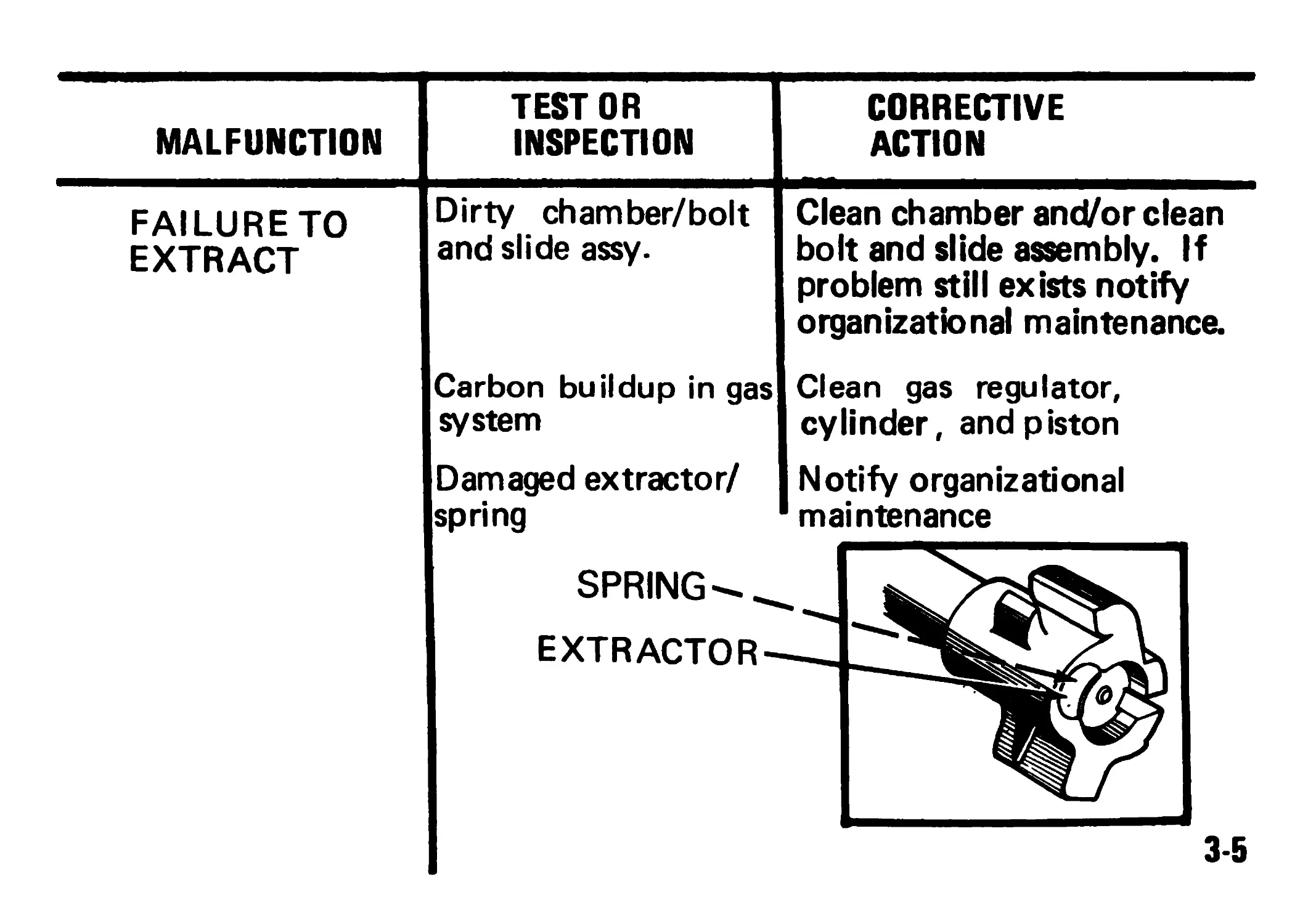
TROUBLESHOOTING TABLE
TROUBLESHOOTING TABLE (cont)
MALFUNCTION TEST OR INSPECTION CORRECTIVE ACTION
FAILURE TO EXTRACT Dirty chamber/bolt and slide assy. Carbon buildup in gas system Damaged extractor/ spring Clean chamber and/or clean bolt and slide assembly. If problem still exists notify organizational maintenance. Clean gas regulator, cylinder, and piston Notify organizational maintenance
3-5
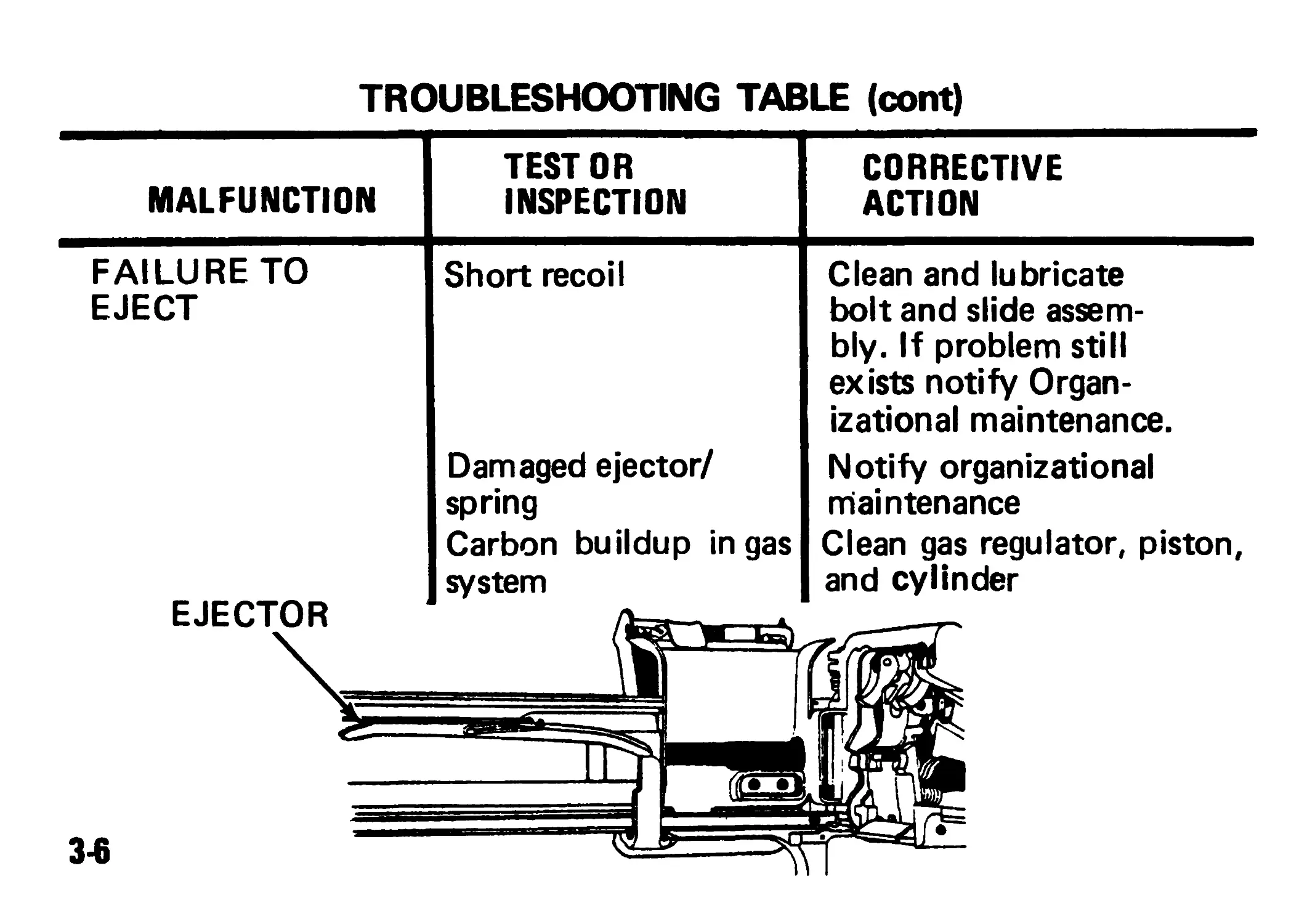
TROUBLESHOOTING TABLE (cont)
MALFUNCTION TEST OR INSPECTION CORRECTIVE ACTION
FAILURE TO EJECT Short recoil Damaged ejector/ spring Carbon buildup in gas system Clean and lubricate bolt and slide assem- bly. If problem still exists notify Organ- izational maintenance. Notify organizational maintenance Clean gas regulator, piston, and cylinder
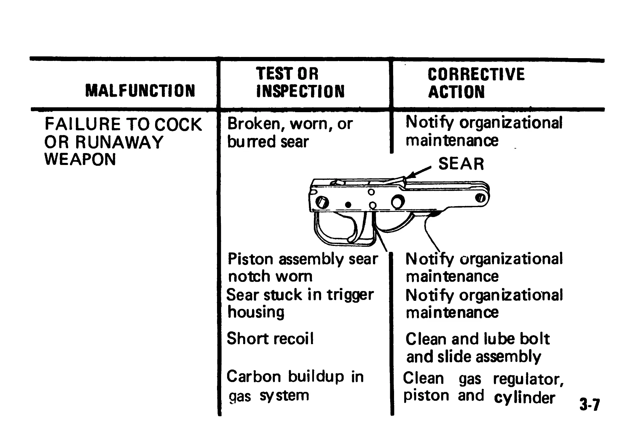
MALFUNCTION TEST OR INSPECTION
FAILURE TO COCK OR RUNAWAY WEAPON Broken, worn, or burred sear Piston assembly sear notch worn Sear stuck in trigger housing Short recoil Carbon buildup in gas system
CORRECTIVE
ACTION
Notify organizational
maintenance
SEAR
©'
Notify organizational
maintenance
Notify organizational
maintenance
Clean and lube bolt
and slide assembly
Clean gas regulator,
piston and cylinder 3.7
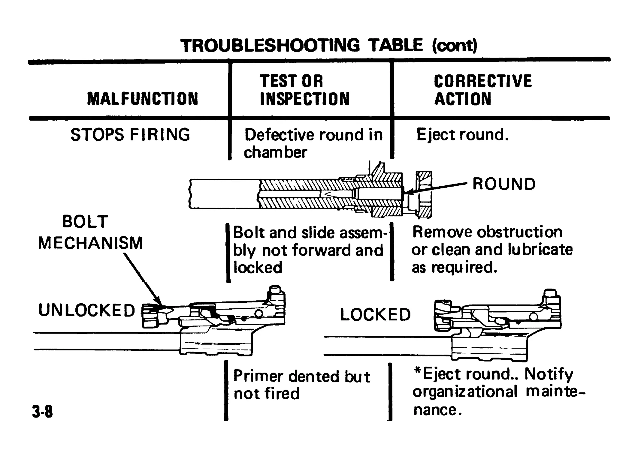
TROUBLESHOOTING TABLE (cont)
MALFUNCTION TEST OR INSPECTION CORRECTIVE ACTION
STOPS FIRING Defective round in chamber Eject round.
ROUND
BOLT
MECHANISM
Bolt and slide assem-
bly not forward and
locked
UNLOCKED
Remove obstruction
orclean and lubricate
as required.
LOCKED
Primer dented but
not fired
* Eject round.. Notify
organizational mainte-
nance.
3-8
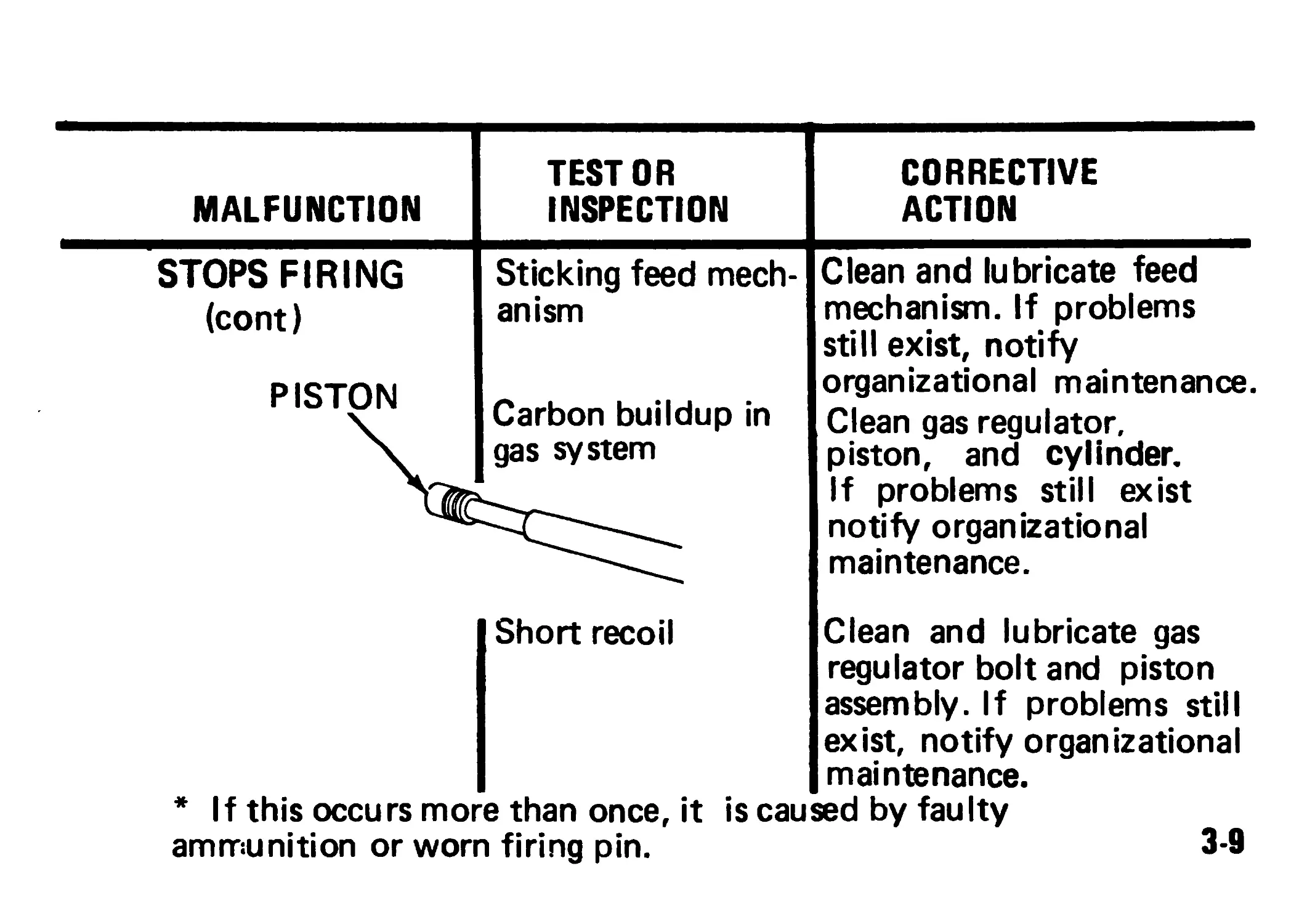
MALFUNCTION TEST OR INSPECTION CORRECTIVE ACTION
STOPS FIRING (cont) PISTON Sticking feed mech- anism Carbon buildup in gas system Clean and lubricate feed mechanism. If problems still exist, notify organizational maintenance. Clean gas regulator, piston, and cylinder. If problems still exist notify organizational maintenance.
Short recoil Clean and lubricate gas regulator bolt and piston assembly. If problems still exist, notify organizational maintenance.
* If this occurs more than once, it is caused by faulty
ammunition or worn firing pin. 3-9
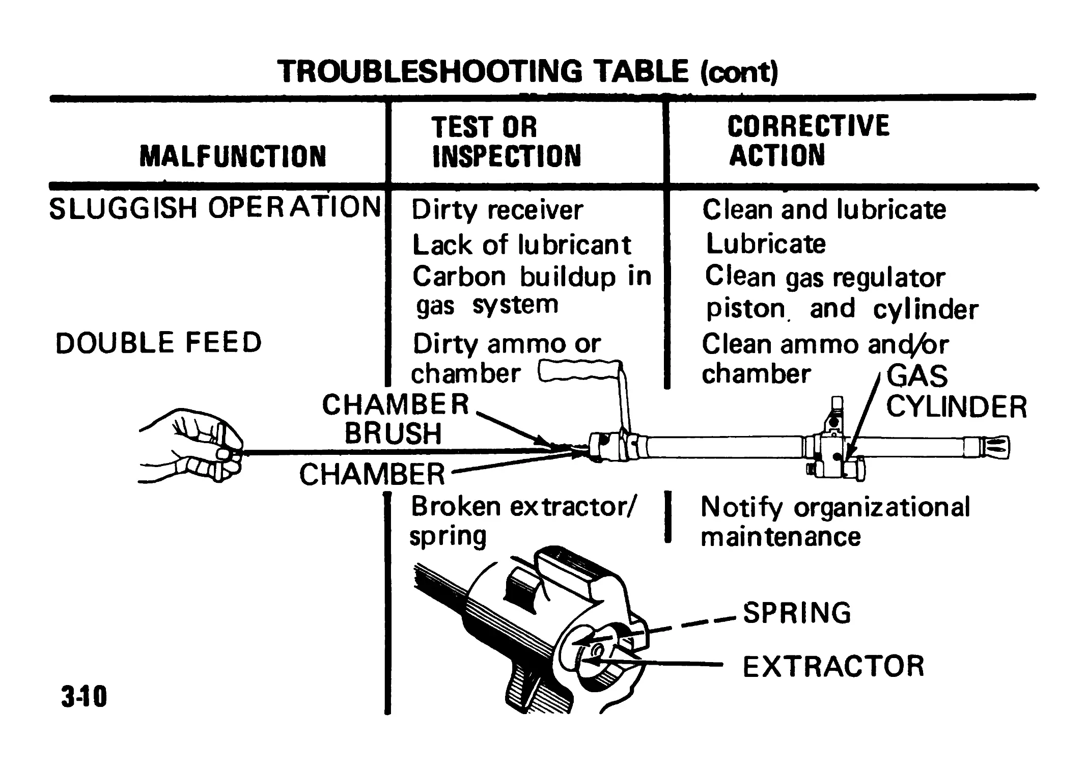
TROUBLESHOOTING TABLE (cont)
MALFUNCTION TEST OR INSPECTION CORRECTIVE ACTION
SLUGGISH OPERATION DOUBLE FEED . CHA Dirty receiver Lack of lubricant Carbon buildup in gas system Dirty ammo or Clean and lubricate Lubricate Clean gas regulator piston, and cylinder Clean ammo апфЬг chamber /GAS Jj / CYLINDER
chamber I——A MBER. ICL1 ,L
111 П1=1
CHAIV BER- Broken extractor/ 1 spring 1 I Notify organizational 1 maintenance
SPRING
EXTRACTOR
3-10
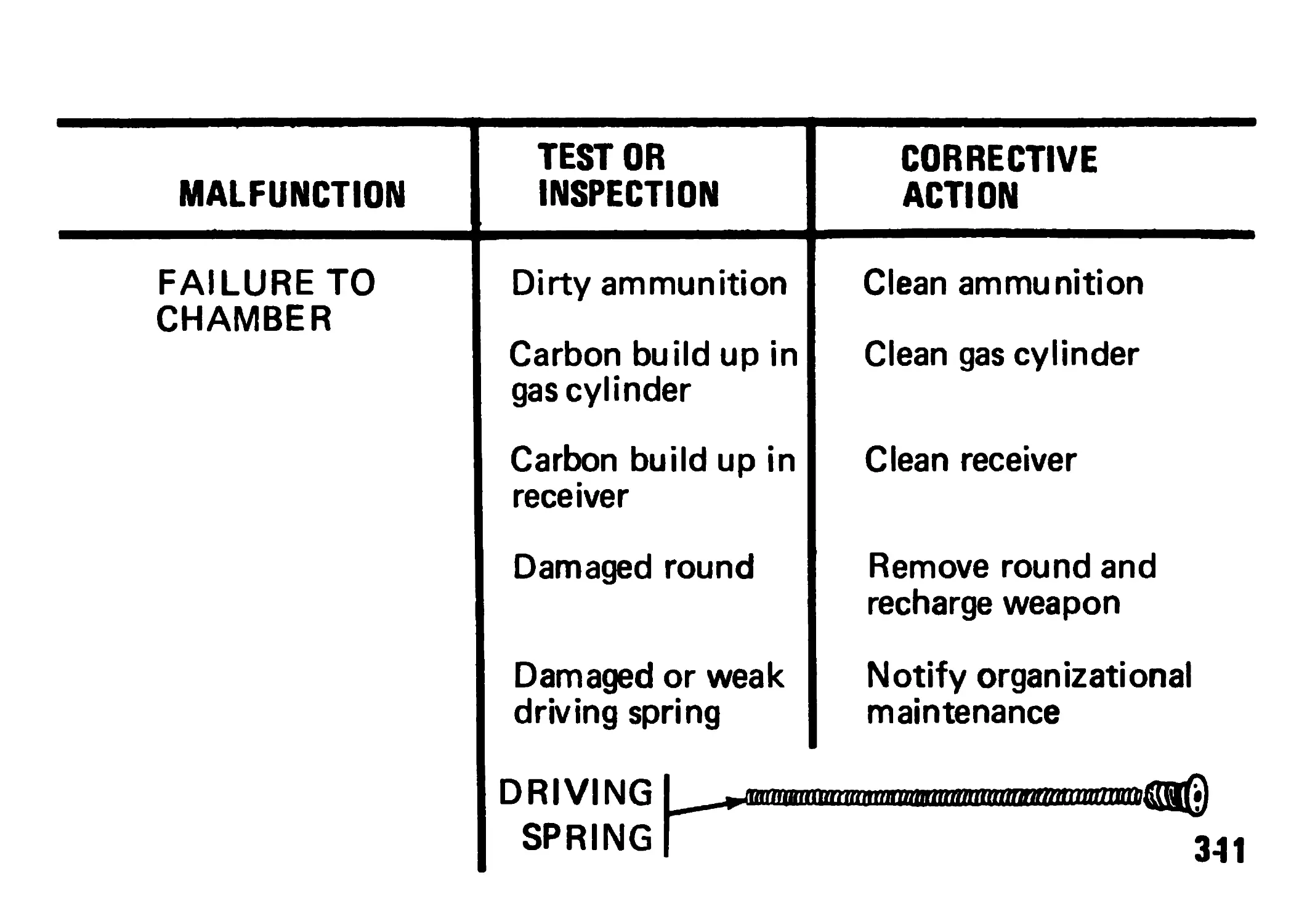
MALFUNCTION TEST OR INSPECTION
FAILURE TO CHAMBER Dirty ammunition Carbon build up in gas cylinder
Carbon build up in receiver
Damaged round
Damaged or weak driving spring
DRIVING SPRING |
CORRECTIVE
ACTION
Clean ammunition
Clean gas cylinder
Clean receiver
Remove round and
recharge weapon
Notify organizational
maintenance
341
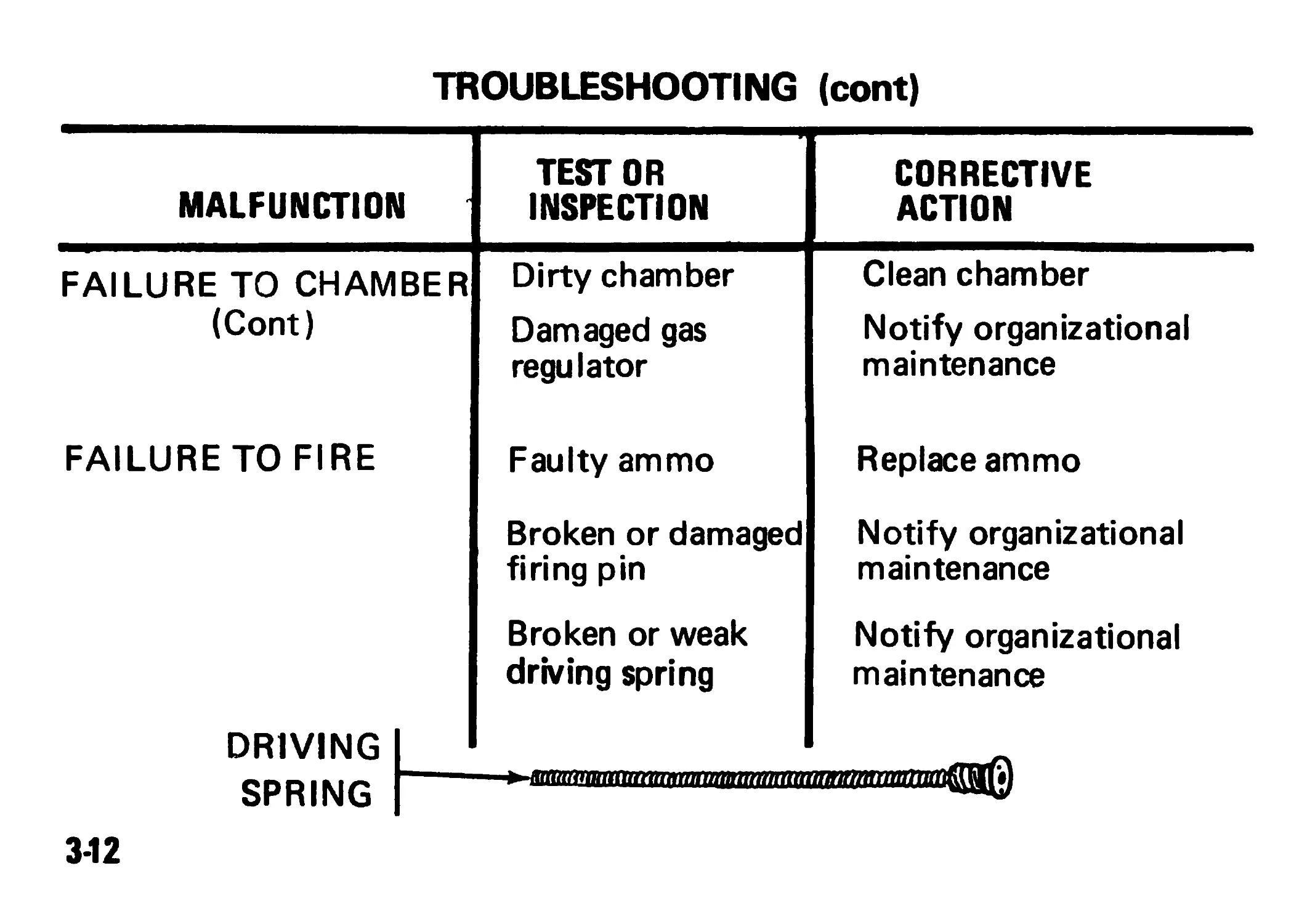
TROUBLESHOOTING (cont)
MALFUNCTION TEST OR INSPECTION CORRECTIVE ACTION
FAILURE TO CHAMBER Dirty chamber Clean chamber
(Cont) Damaged gas regulator Notify organizational maintenance
FAILURE TO FIRE Faulty ammo Replace ammo
Broken or damaged firing pin Notify organizational maintenance
Broken or weak driving spring Notify organizational maintenance
DRIVING I
SPRING
3-12
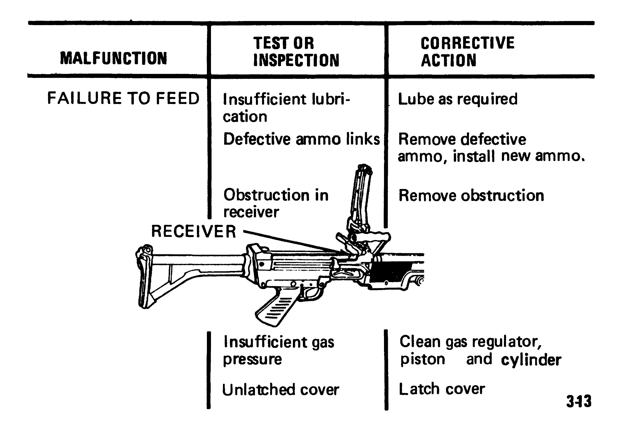
TEST OR
MALFUNCTION INSPECTION
FAILURE TO FEED Insufficient lubri-
cation
Defective ammo links
Insufficient gas
pressure
Unlatched cover
CORRECTIVE
ACTION
Lube as required
Remove defective
ammo, install new ammo.
Remove obstruction
)
Clean gas regulator,
piston and cylinder
Latch cover
343
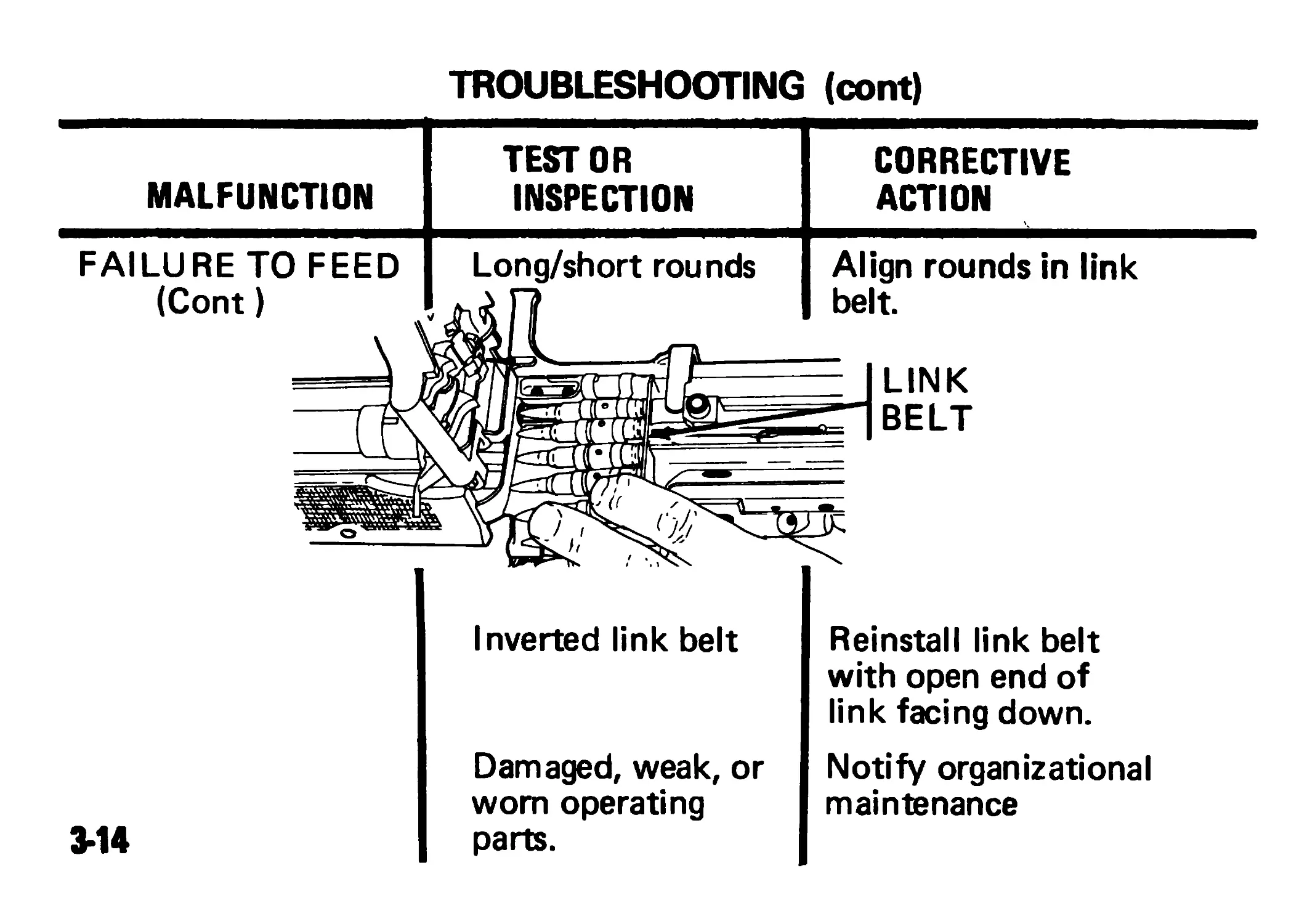
TROUBLESHOOTING (cont)
MALFUNCTION
TEST OR
INSPECTION
CORRECTIVE
ACTION
Inverted link belt
Damaged, weak, or
worn operating
parts.
Reinstall link belt
with open end of
link facing down.
Notify organizational
maintenance
3-14
Section III MAINTENANCE PROCEDURES
CLEANING, INSPECTION, AND REPAIR
WARNING
USING GASOLINE, KEROSENE, HYDRAULIC OIL, BENZENE, BEN-
SOL, HIGH-PRESSURE WATER, STEAM, OR COMPRESSED AIR
FOR CLEANING IS PROHIBITED.
CAUTION
DO NOT USE ABRASIVES TO CLEAN THE BORE, PISTON, GAS
CYLINDER, OR GAS REGULATOR PLUG.
3-15
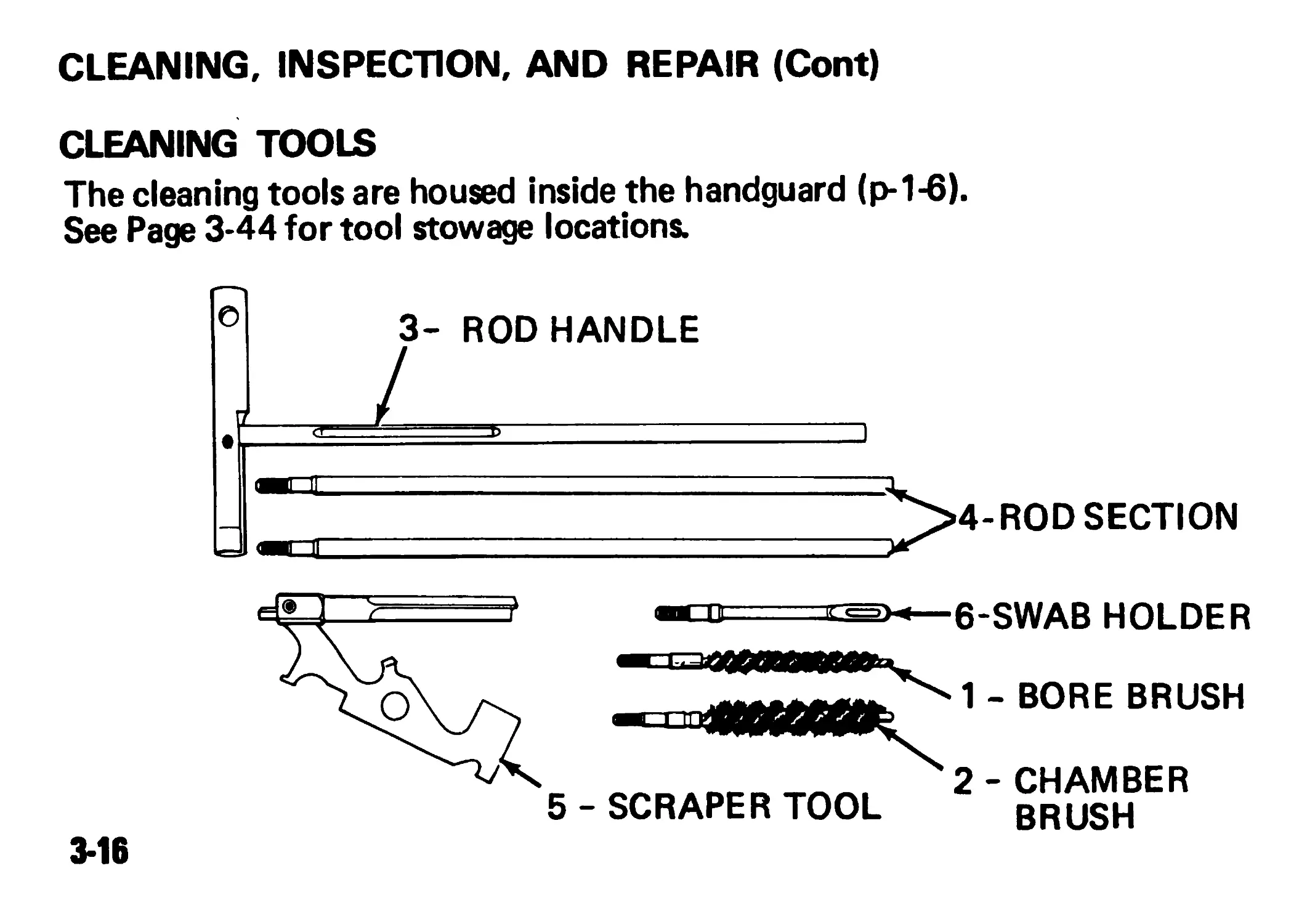
CLEANING, INSPECTION, AND REPAIR (Cont)
CLEANING TOOLS
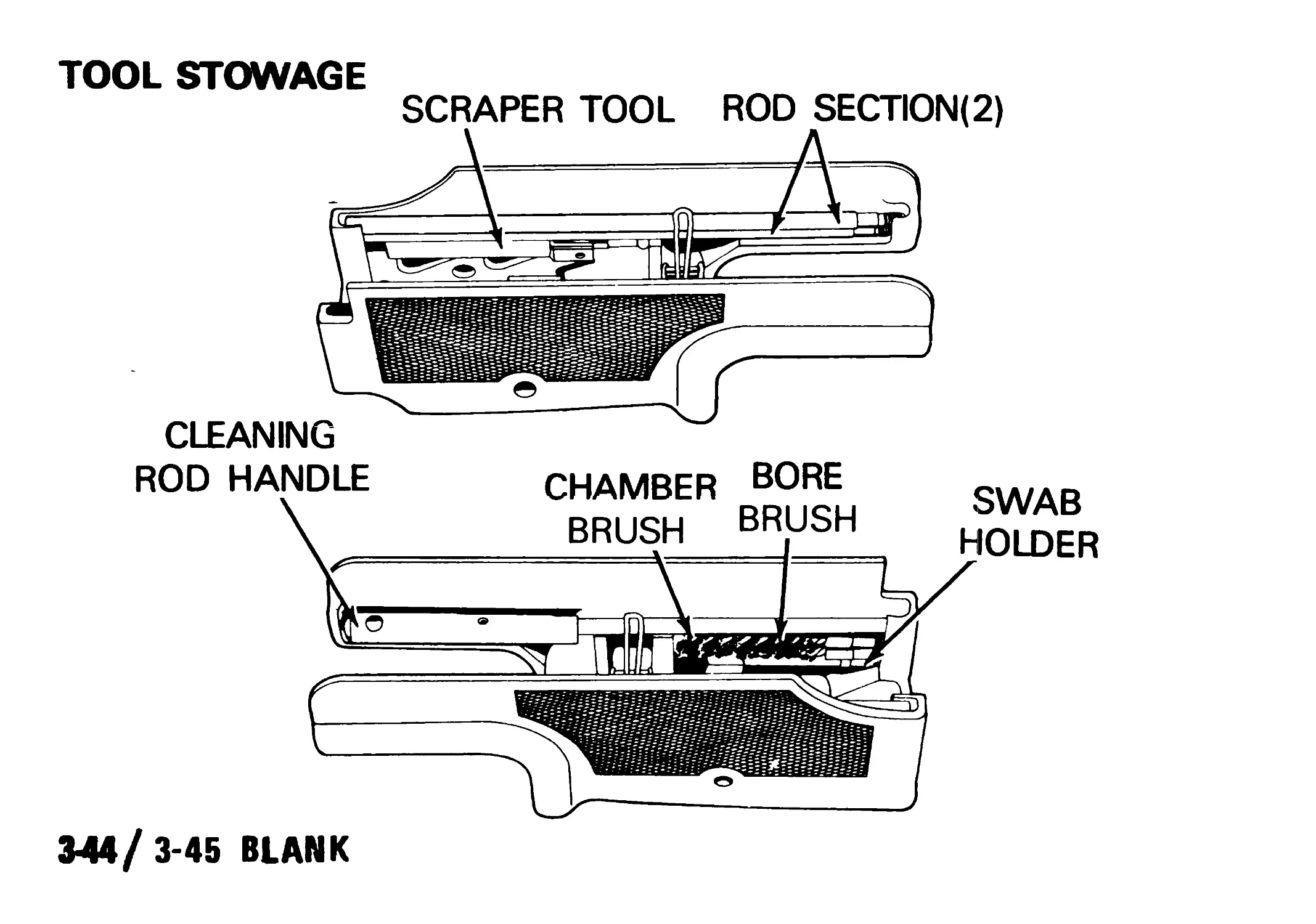
The cleaning tools are housed inside the handguard (p-1-6).
See Page 3-44 for tool stowage locations.
3-16
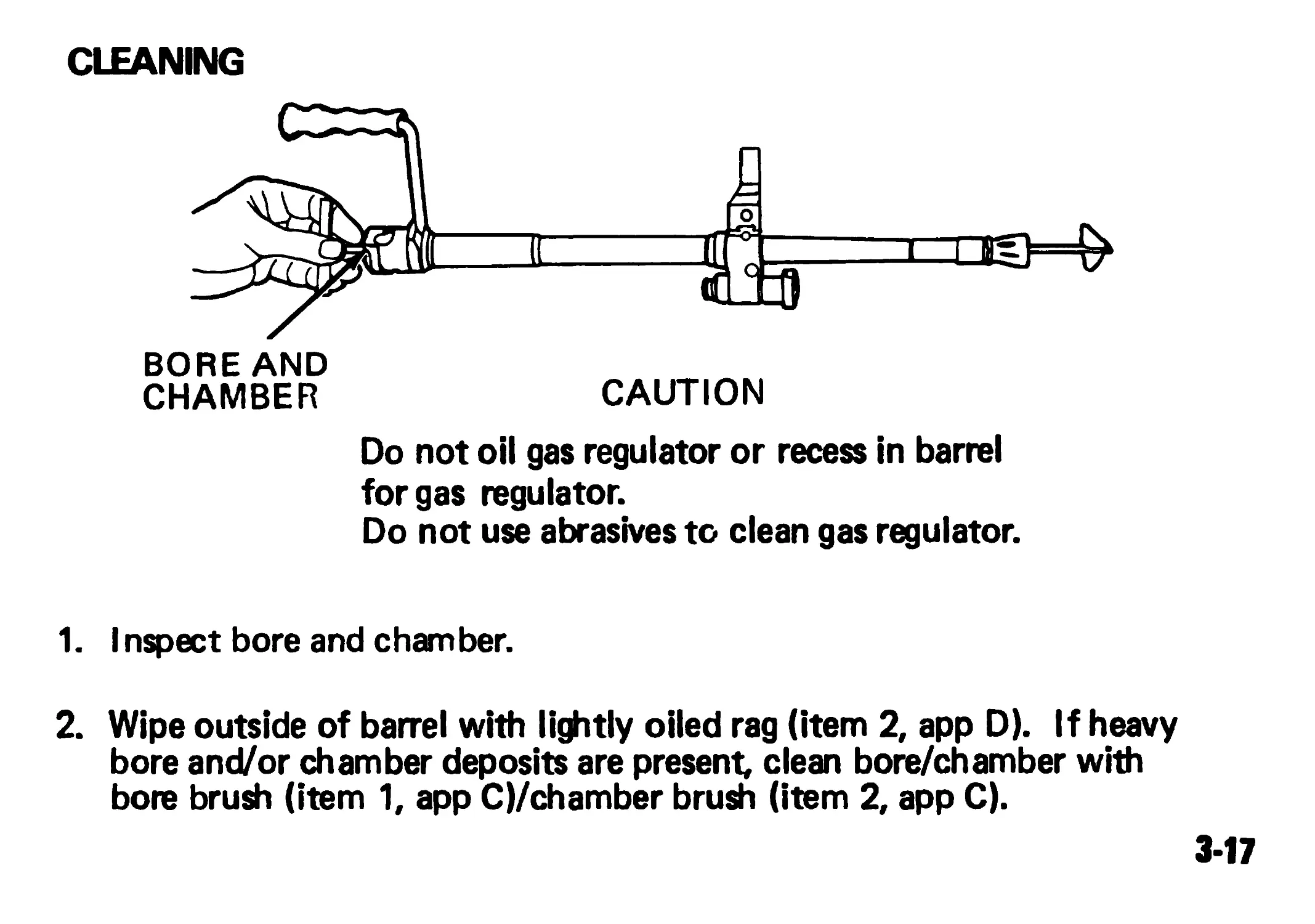
CLEANING
Do not oil gas regulator or recess in barrel
for gas regulator.
Do not use abrasives to clean gas regulator.
1. I nspect bore and chamber.
2. Wipe outside of barrel with lightly oiled rag (item 2, app D). If heavy
bore and/or chamber deposits are present, clean bore/chamber with
bore brush (item 1, app C)/chamber brush (item 2, app C).
3*17
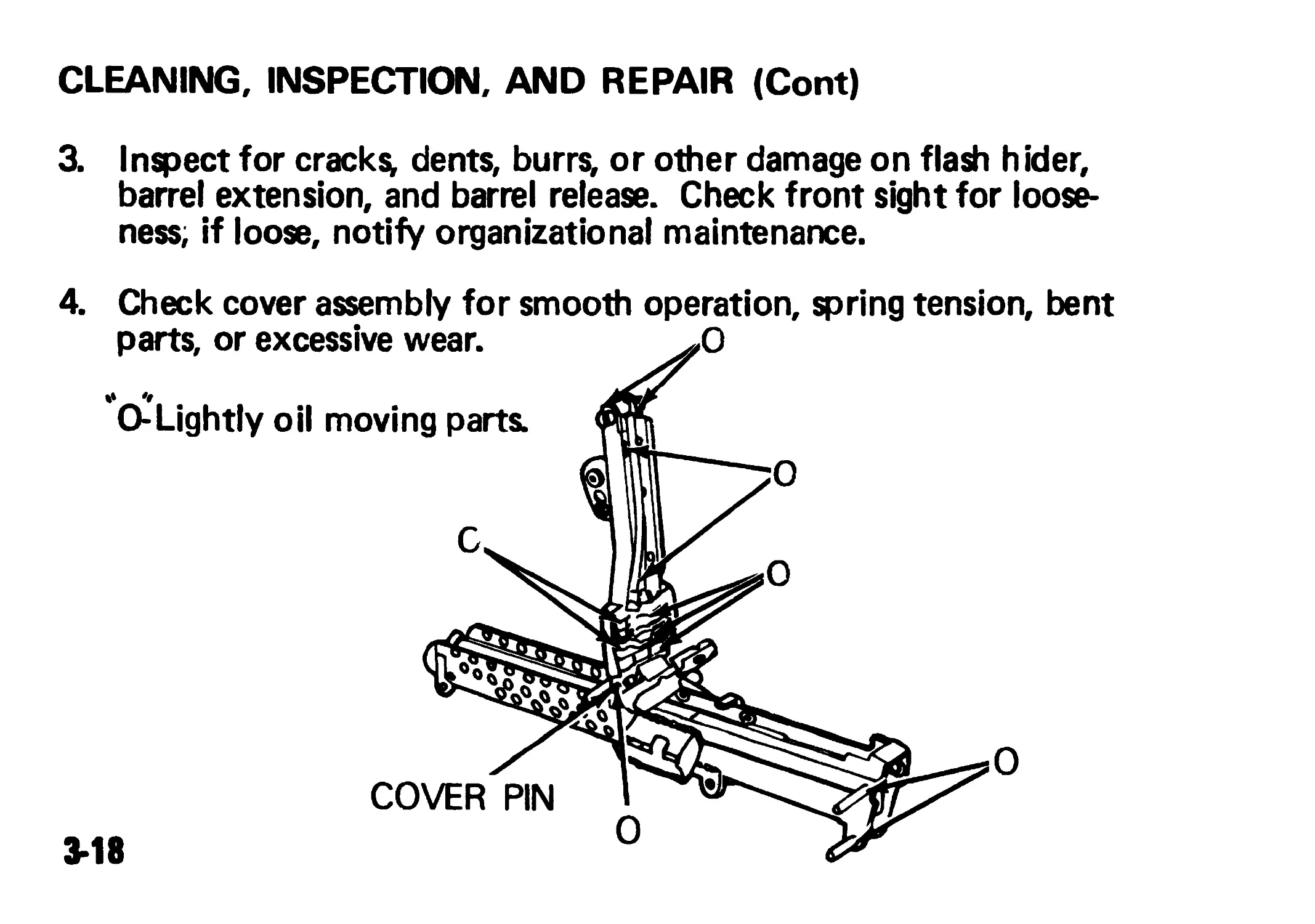
CLEANING, INSPECTION, AND REPAIR (Cont)
3. Inspect for cracks, dents, burrs, or other damage on flash hider,
barrel extension, and barrel release. Check front sight for loose-
ness, if loose, notify organizational maintenance.
4. Check cover assembly for smooth operation, spring tension, bent
parts, or excessive wear.
О
О
О
COVER PIN
O-Lightly oil moving parts.
3-18
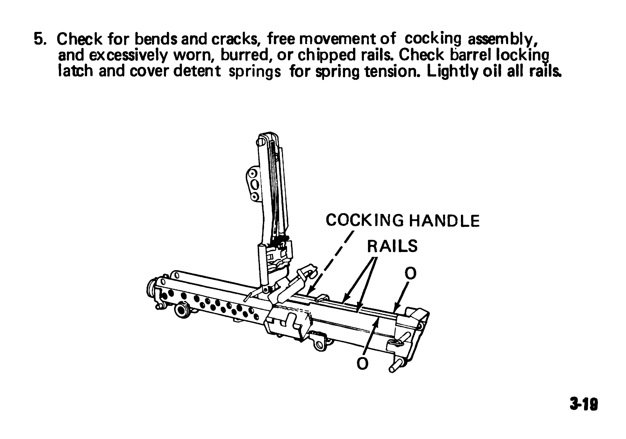
5. Check for bends and cracks, free movement of cocking assembly,
and excessively worn, burred, or chipped rails. Check barrel locking
latch and cover detent springs for spring tension. Lightly oil all rails.
3-19
CLEANING, INSPECTION, AND REPAIR (Cont)
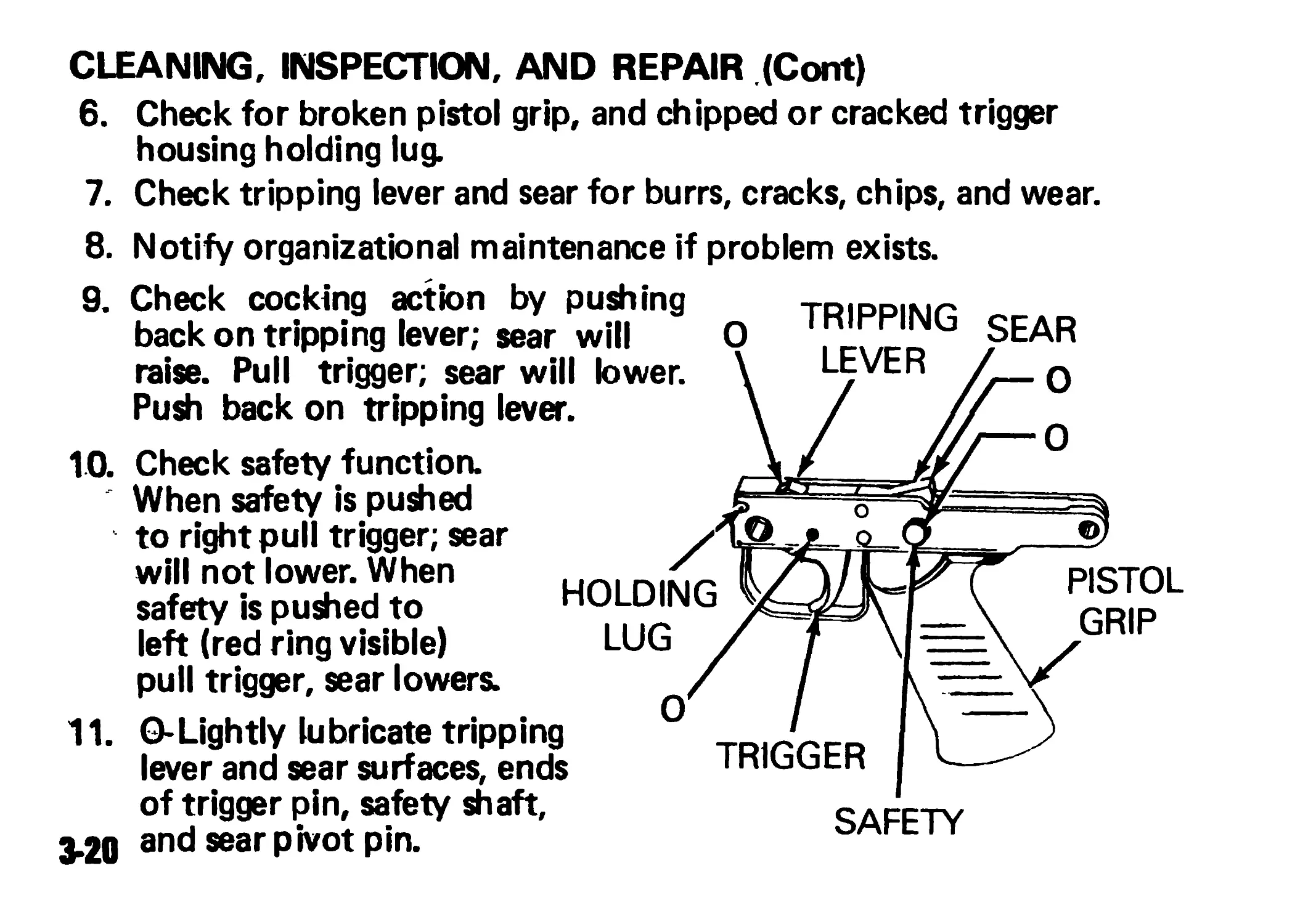
6. Check for broken pistol grip, and chipped or cracked trigger
housing holding lug.
7. Check tripping lever and sear for burrs, cracks, chips, and wear.
8.
9.
10.
Notify organizational maintenance if problem exists.
Check cocking action by pushing
back on tripping lever; sear will
raise. Pull trigger; sear will lower.
Push back on tripping lever.
Check safety function.
When safety is pushed
to right pull trigger; sear
will not lower. When
safety is pushed to
left (red ring visible)
pull trigger, sear lowers.
О-Lightly lubricate tripping
lever and sear surfaces, ends
of trigger pin, safety shaft,
and sear pivot pin.
HOLDING
LUG
11.
О TRIPPING SEAR
LEVER
О
О
SAFETY
PISTOL
GRIP
О
TRIGGER
3-20
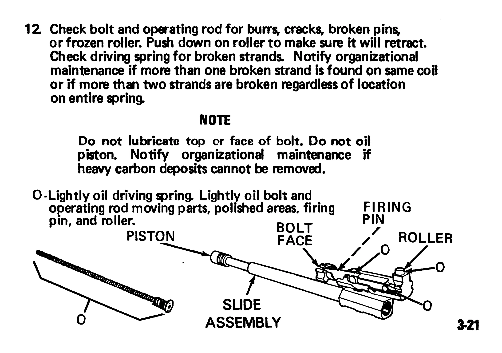
12. Check bolt and operating rod for burrs* cracks* broken pins*
or frozen roller. Push down on roller to make sure it will retract.
Check driving spring for broken strands. Notify organizational
maintenance if more than one broken strand is found pn same coil
or if more than two strands are broken regardless of location
on entire spring.
NOTE
Do not lubricate top or face of bolt. Do not oil
piston. Notify organizational maintenance if
heavy carbon deposits cannot be removed.
О-Lightly oil driving spring. Lightly oil bolt and
operating rod moving parts, polished areas, firing FIRING
CLEANING, INSPECTION, AND REPAIR (Cont)
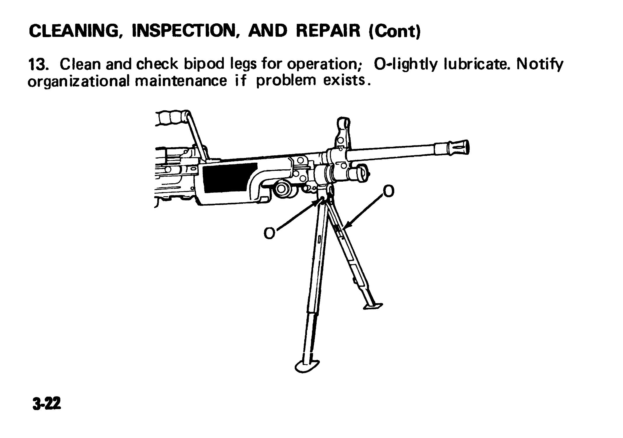
13. Clean and check bipod legs for operation; O-lightly lubricate. Notify
organizational maintenance if problem exists.
3-22
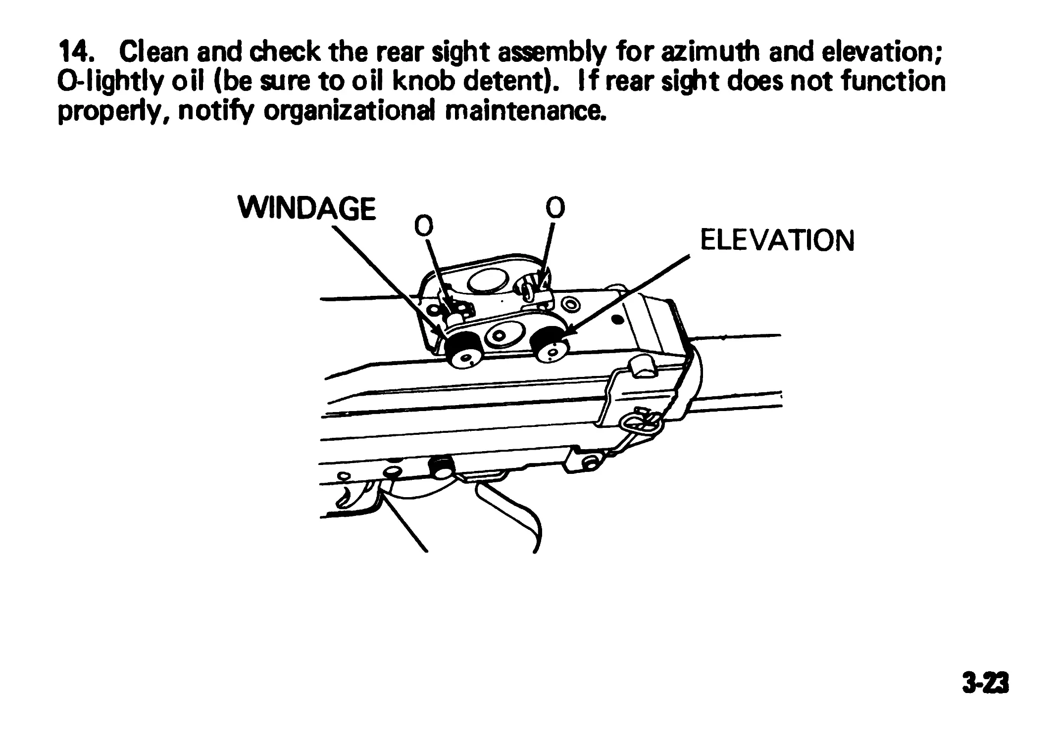
14. Clean and check the rear sight assembly for azimuth and elevation;
O-lightly oil (be sure to oil knob detent). If rear sight does not function
properly, notify organizational maintenance.
3-23
CLEANING, INSPECTION, AND REPAIR (Cont)
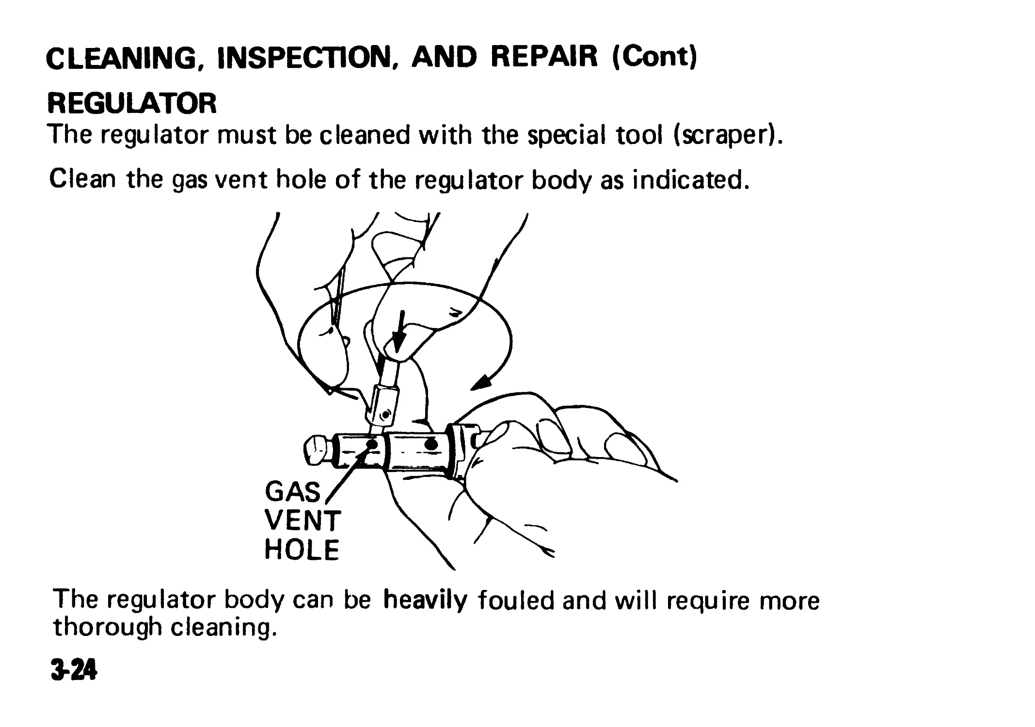
REGULATOR
The regulator must be cleaned with the special tool (scraper).
Clean the gas vent hole of the regulator body as indicated.
The regulator body can be heavily fouled and will require more
thorough cleaning.
3-24
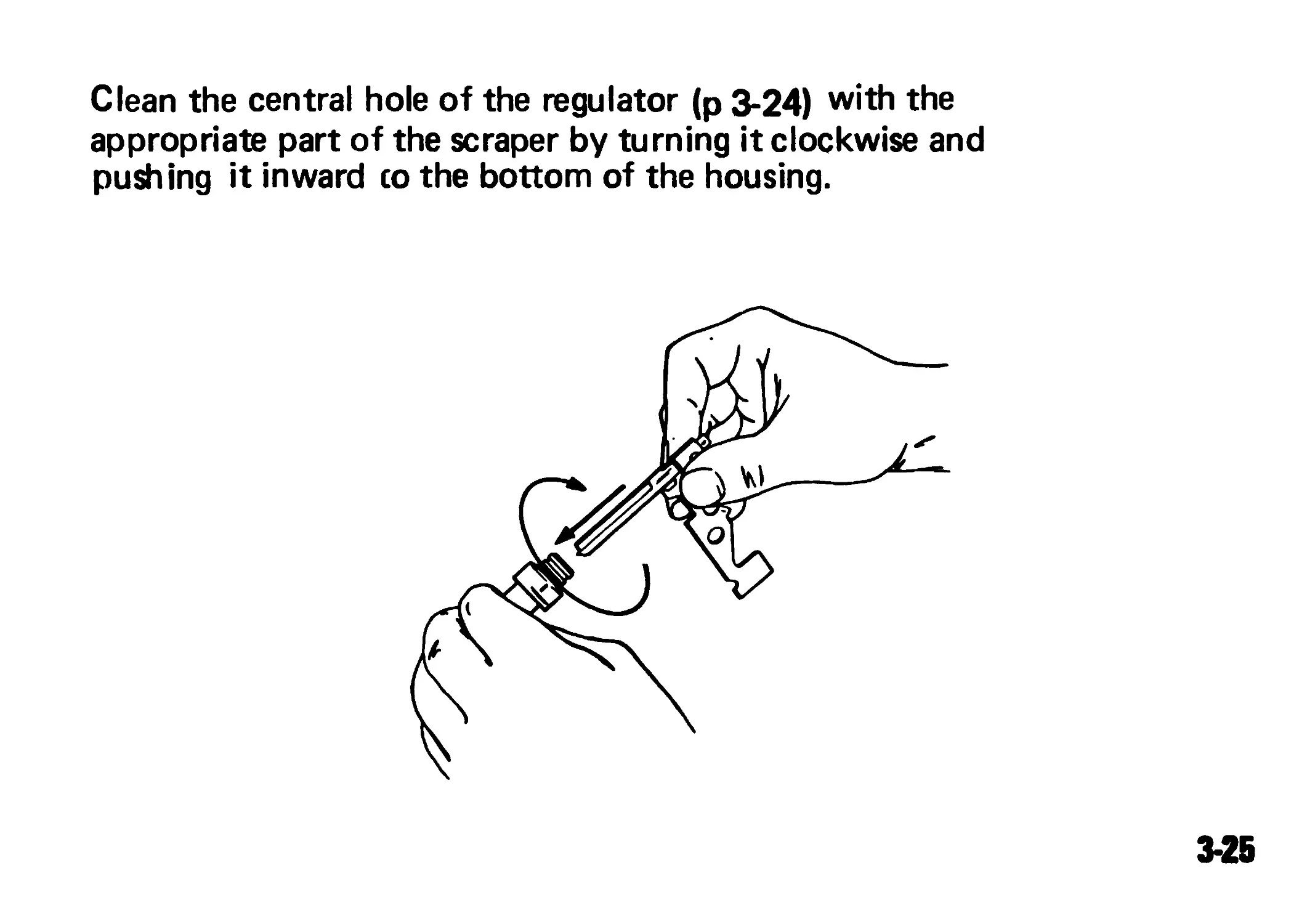
Clean the central hole of the regulator (p 3-24) with the
appropriate part of the scraper by turning it clockwise and
pushing it inward co the bottom of the housing.
3-25
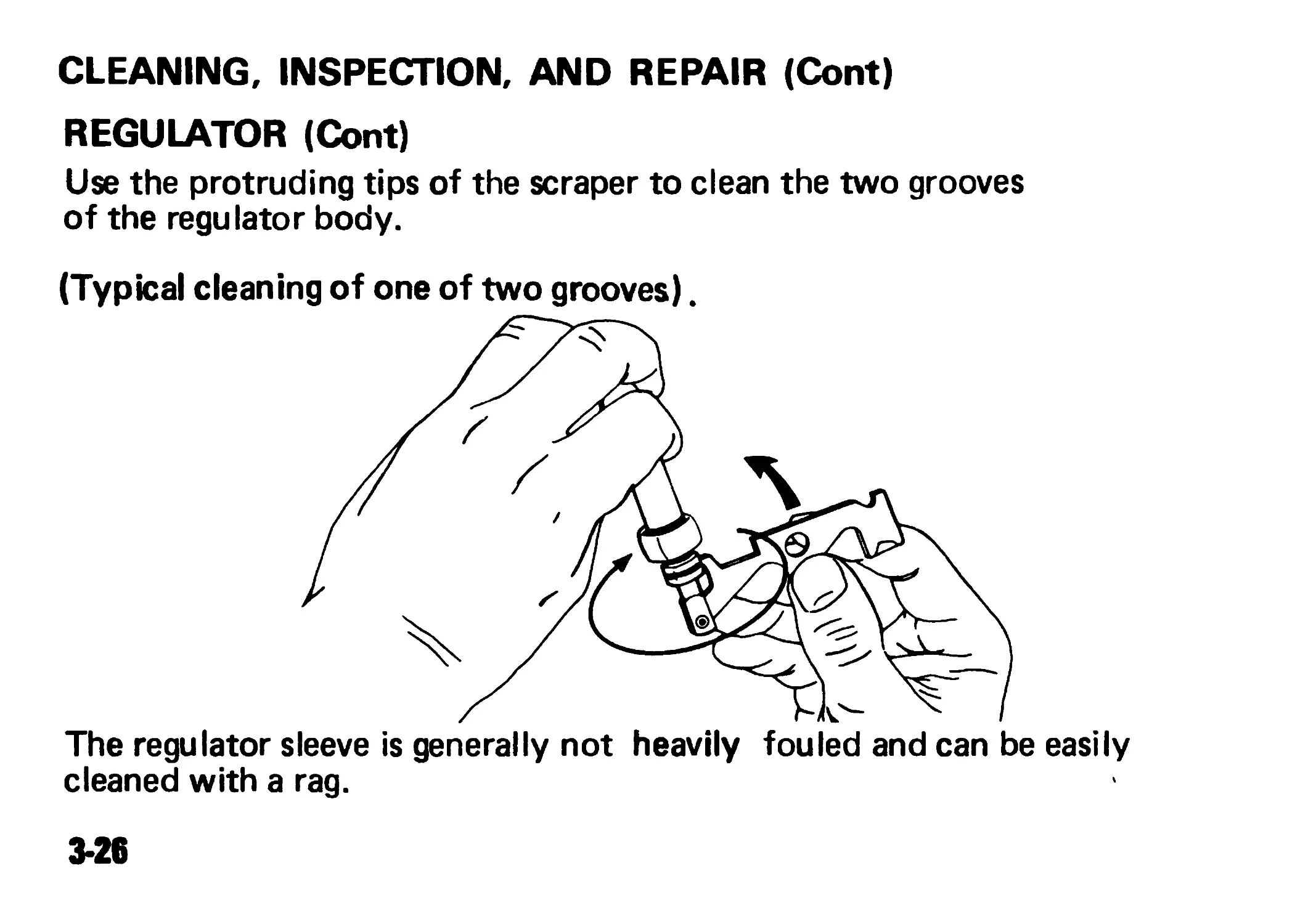
CLEANING, INSPECTION, AND REPAIR (Cont)
REGULATOR (Cont)
Use the protruding tips of the scraper to clean the two grooves
of the regulator body.
(Typical cleaning of one of two grooves).
The regulator sleeve is generally not heavily fouled and can be easily
cleaned with a rag.
3*26
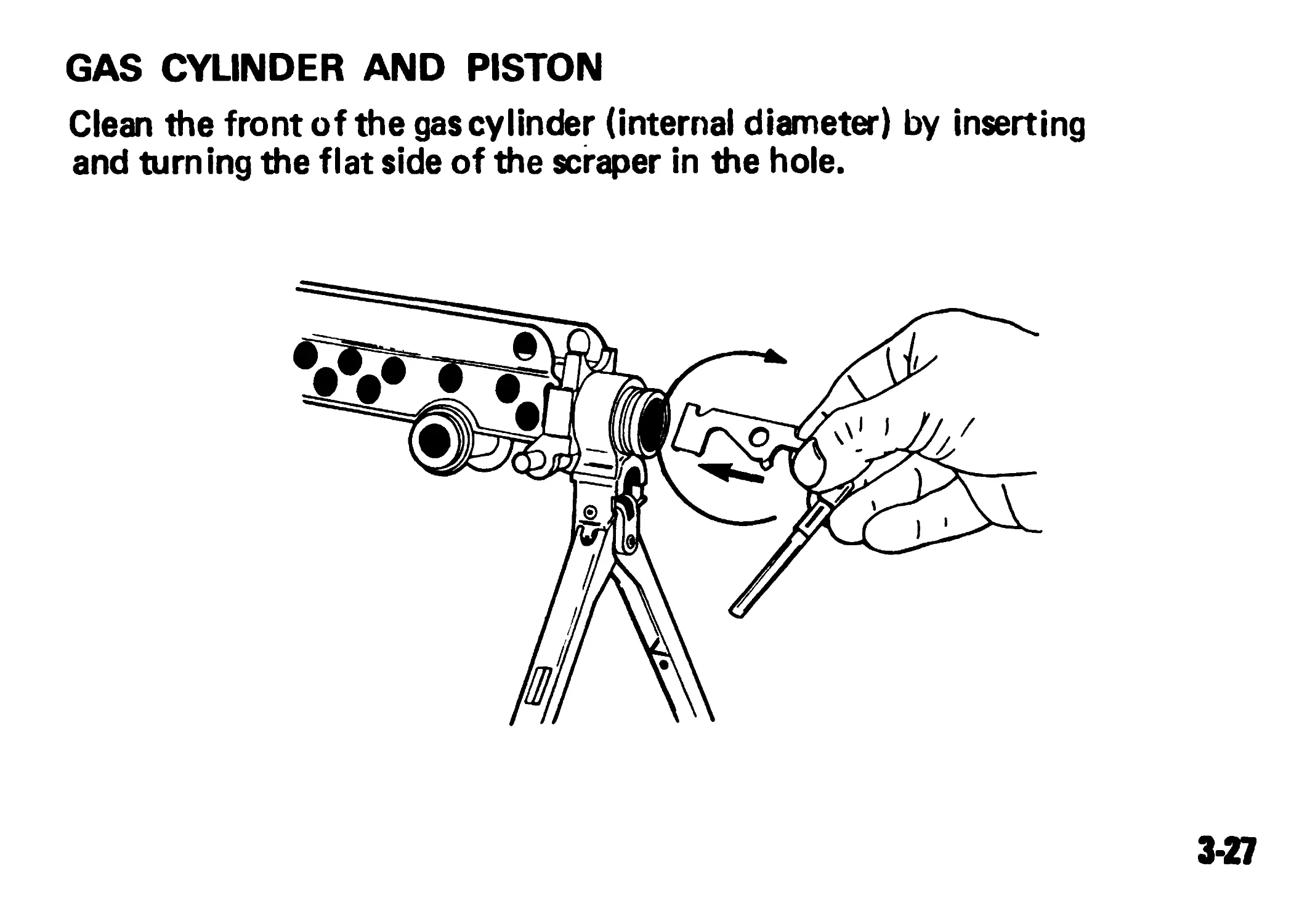
GAS CYLINDER AND PISTON
Clean the front of the gas cylinder (internal diameter) by inserting
and turning the flat side of the scraper in the hole.
3-27
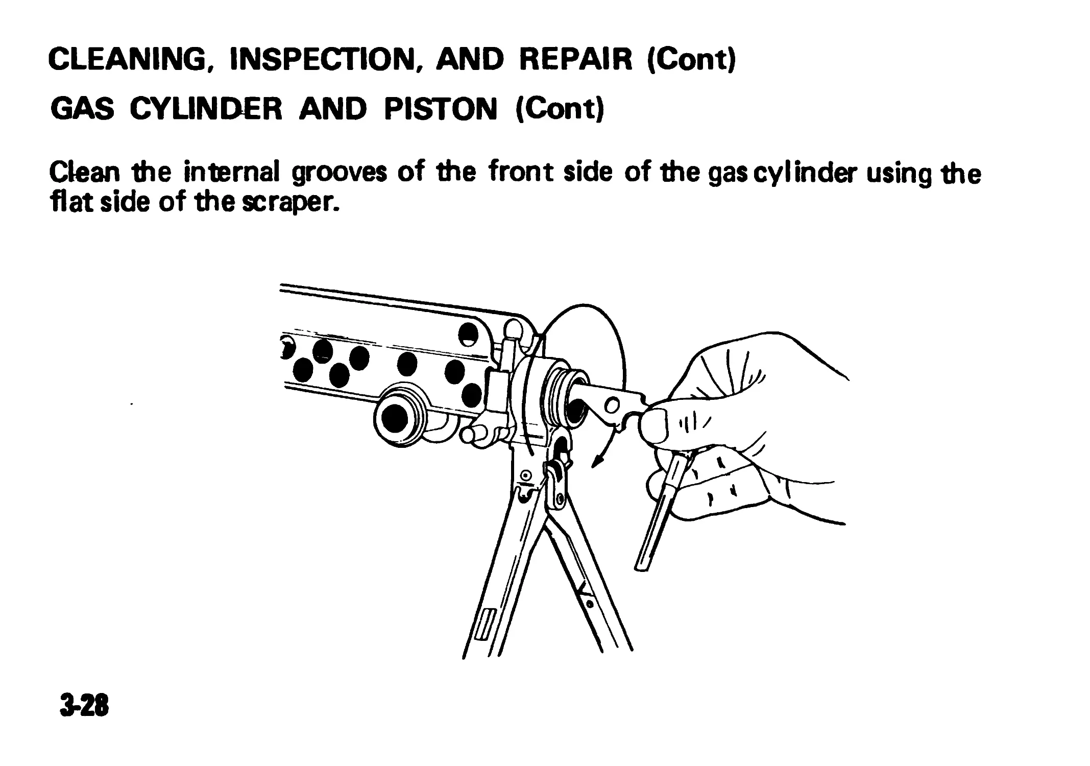
CLEANING, INSPECTION, AND REPAIR (Cont)
GAS CYLINDER AND PISTON (Cont)
Clean the internal grooves of the front side of the gas cylinder using the
flat side of the scraper.
3*28
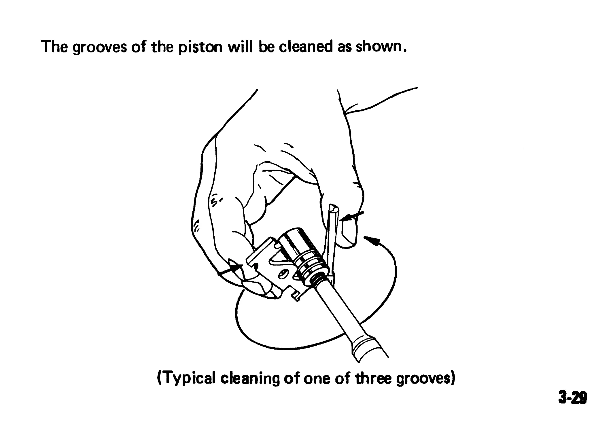
The grooves of the piston will be cleaned as shown.
(Typical cleaning of one of three grooves)
3-29
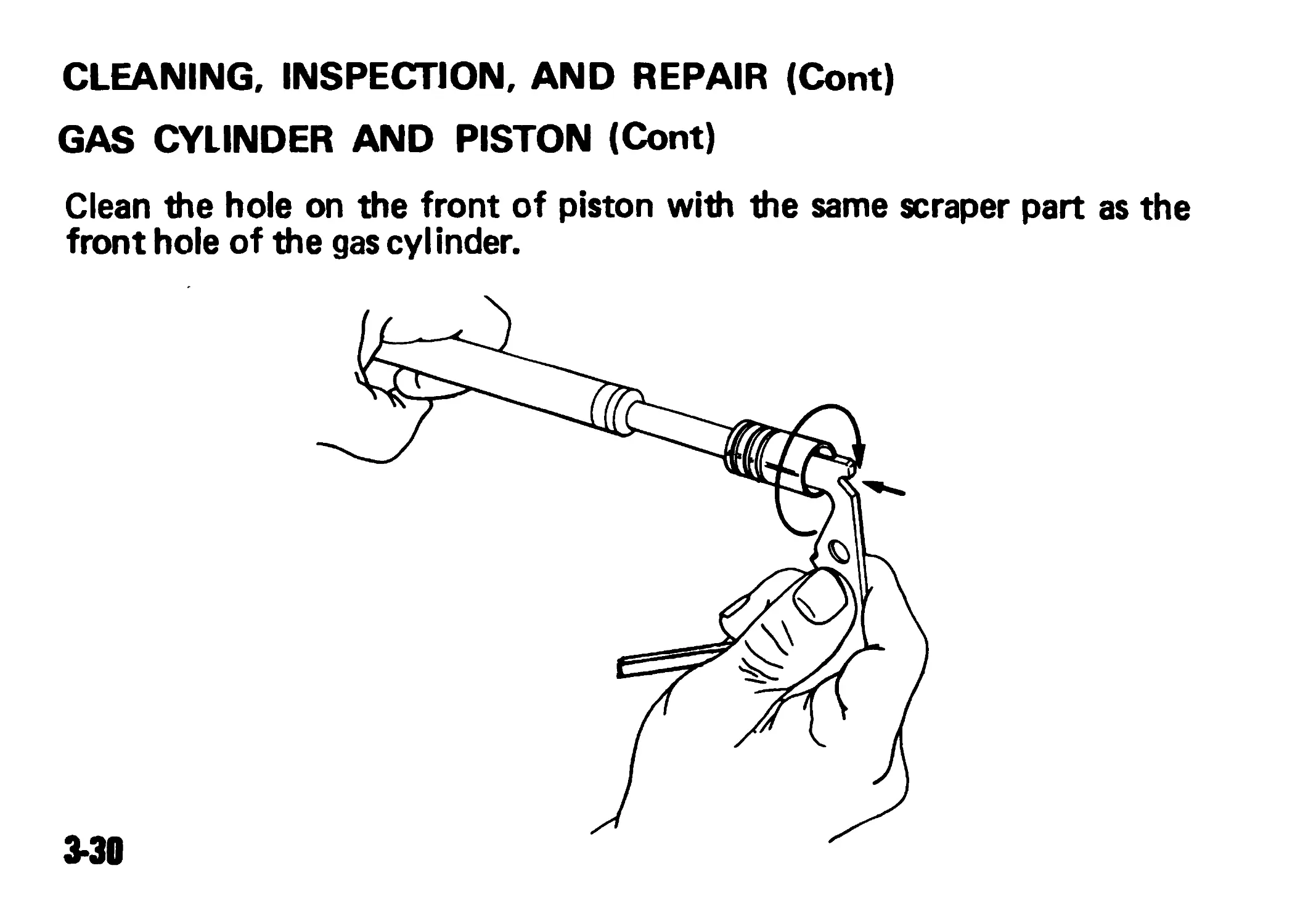
CLEANING, INSPECTION, AND REPAIR (Cont)
GAS CYLINDER AND PISTON (Cont)
Clean the hole on the front of piston with the same scraper part as the
front hole of the gas cylinder.
3-30
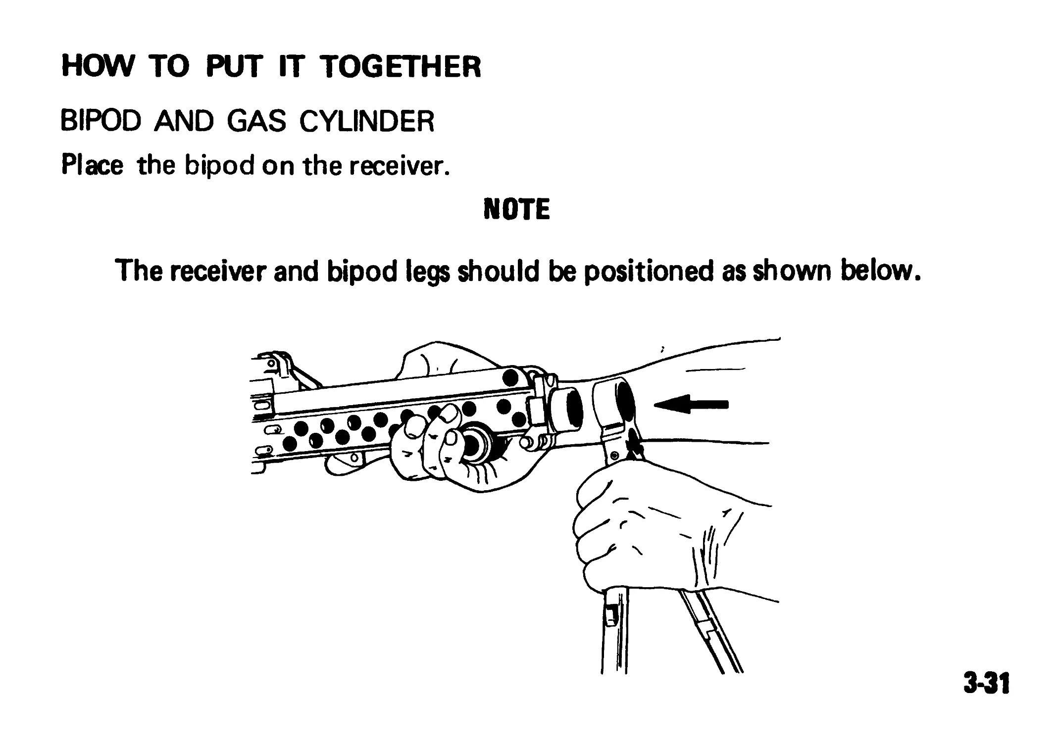
HOW TO PUT IT TOGETHER
BIPOD AND GAS CYLINDER
Place the bipod on the receiver.
NOTE
The receiver and bipod legs should be positioned as shown below.
3-31
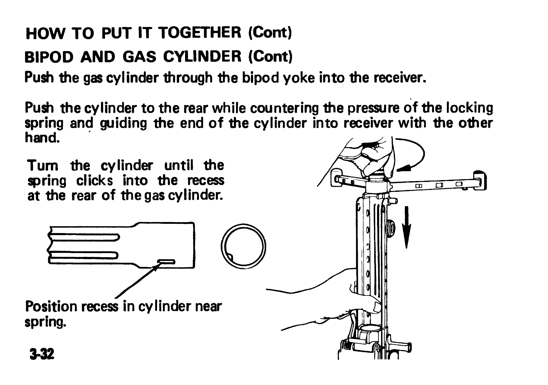
HOW TO PUT IT TOGETHER (Cont)
BIPOD AND GAS CYLINDER (Cont)
Push the gas cylinder through the bipod yoke into the receiver.
Push the cylinder to the rear while countering the pressure of the locking
spring and guiding the end of the cylinder into receiver with the other
hand.
Position recess in cylinder near
spring.
Tum the cylinder until the
spring clicks into the recess
at the rear of the gas cylinder.
3-32
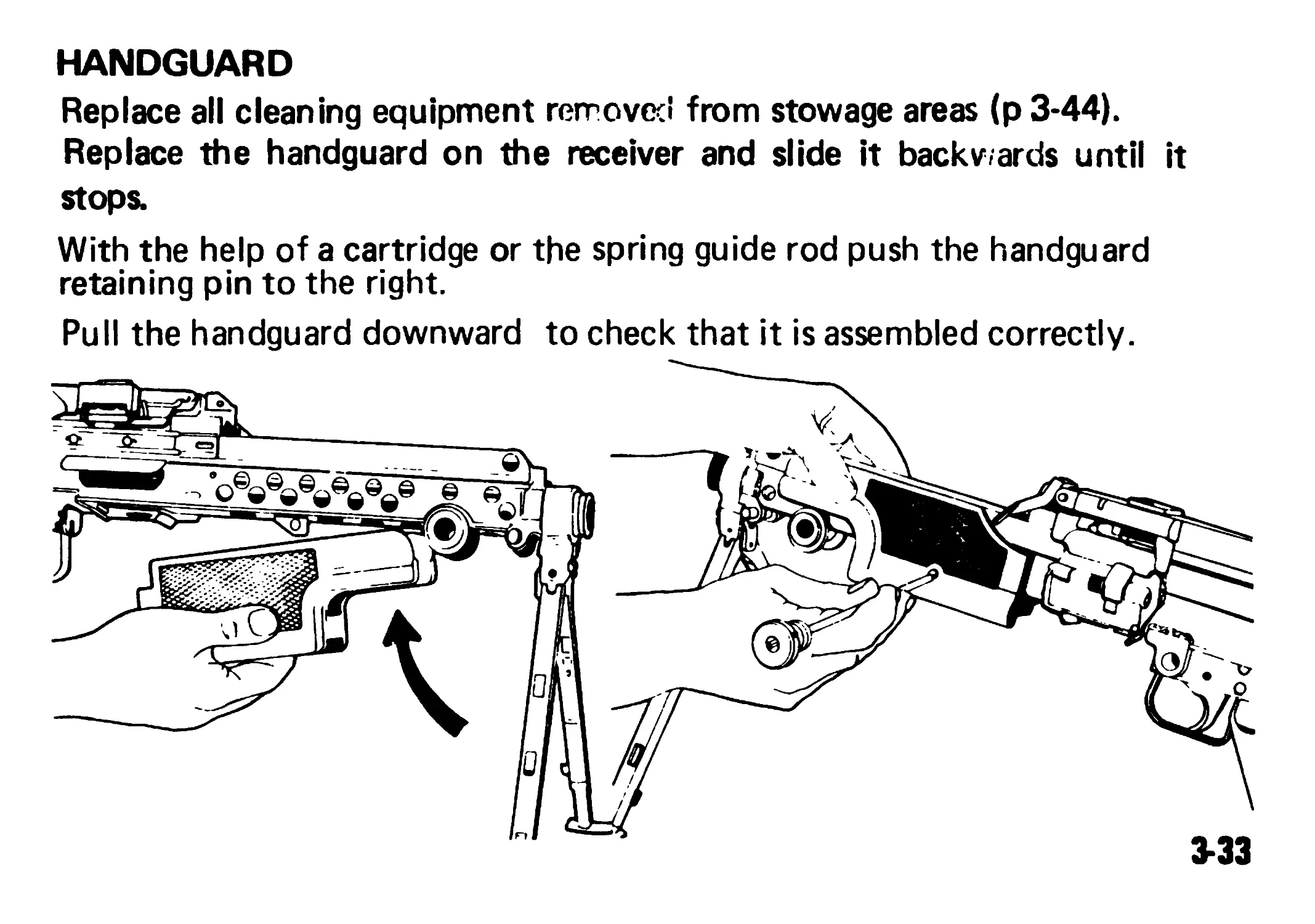
HANDGUARD
Replace all cleaning equipment removed from stowage areas (p 3-44).
Replace the handguard on the receiver and slide it backwards until it
stops.
With the help of a cartridge or the spring guide rod push the handguard
retaining pin to the right.
Pull the handguard downward to check that it is assembled correctly.
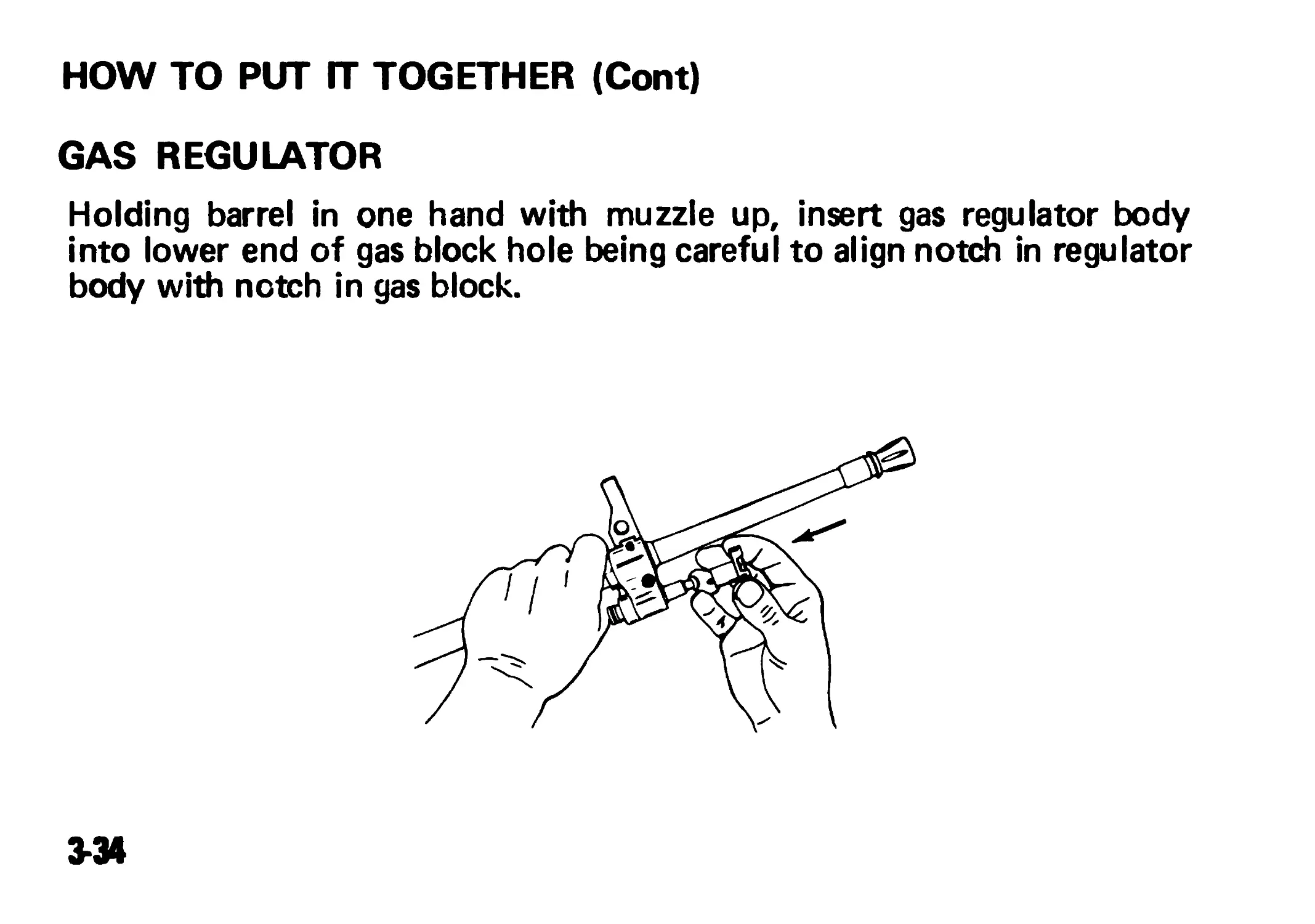
HOW TO PUT ГТ TOGETHER (Cont)
GAS REGULATOR
Holding barrel in one hand with muzzle up, insert gas regulator body
into lower end of gas block hole being careful to align notch in regulator
body with notch in gas block.
3-34
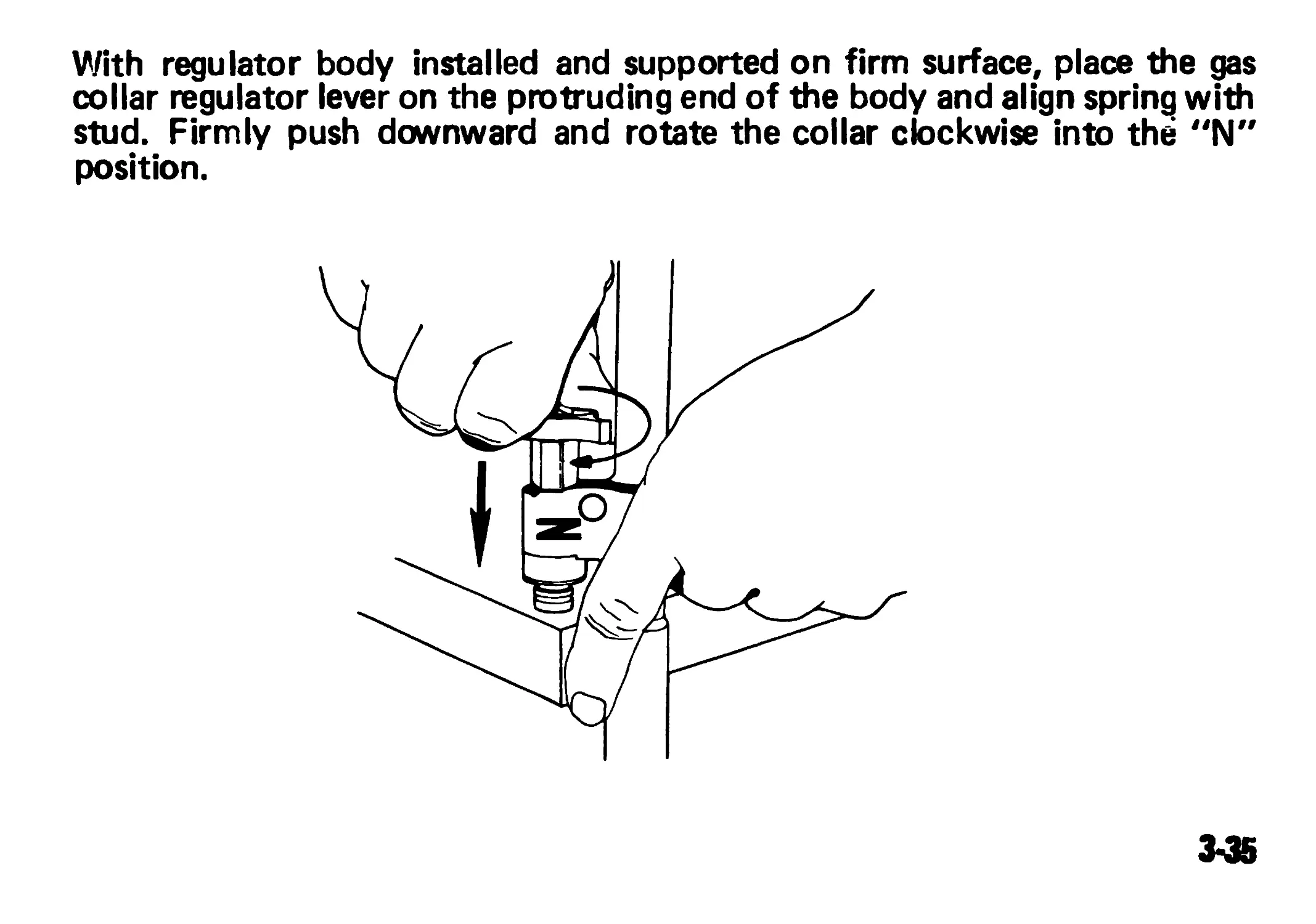
With regulator body installed and supported on firm surface, place the gas
collar regulator lever on the protruding end of the body and align spring with
stud. Firmly push downward and rotate the collar clockwise into the "N"
position.
3-35
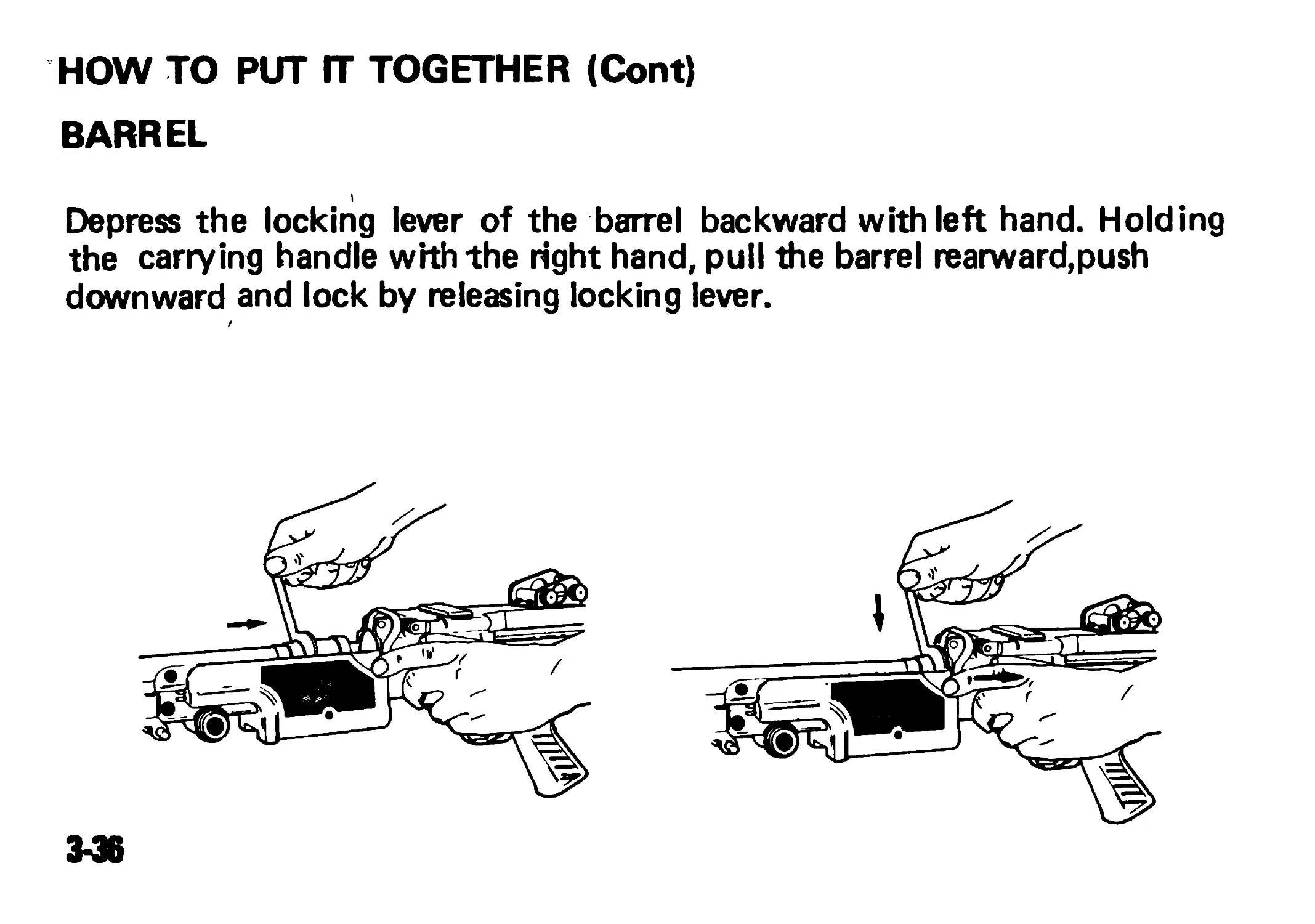
HOW TO PUT ГТ TOGETHER (Cont)
BARREL
Depress the locking lever of the barrel backward with left hand. Holding
the carrying handle with the right hand, pull the barrel rearward,push
downward and lock by releasing locking lever.
3-36
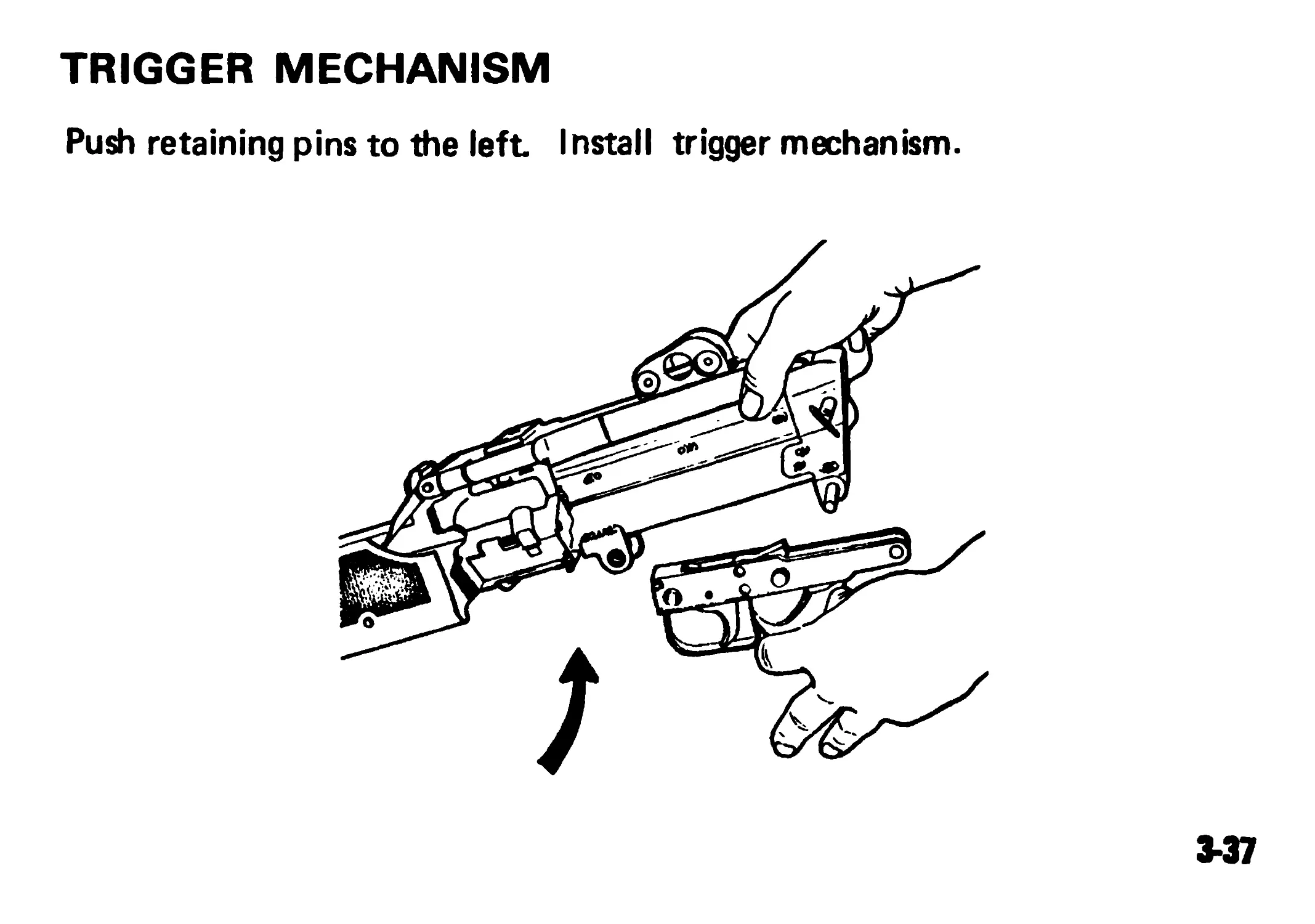
TRIGGER MECHANISM
Push retaining pins to the left Install trigger mechanism.
137
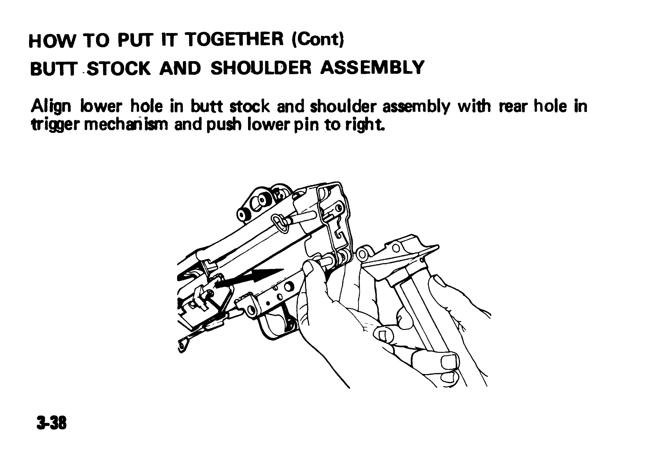
HOW TO PUT IT TOGETHER (Cont)
BUTT STOCK AND SHOULDER ASSEMBLY
Align lower hole in butt stock and shoulder assembly with rear hole in
trigger mechanism and push lower pin to right
3-38
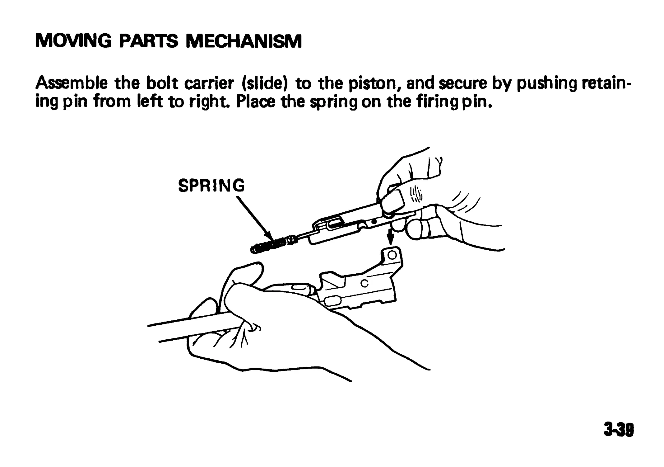
MOVING PARTS MECHANISM
Assemble the bolt carrier (slide) to the piston, and secure by pushing retain-
ing pin from left to right Place the spring on the firing pin.
M8
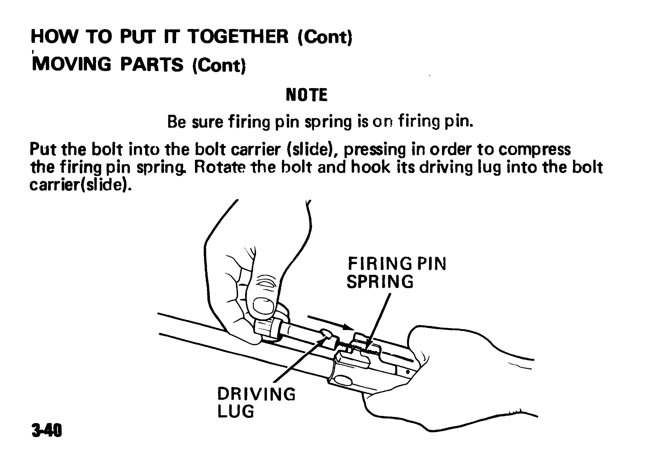
HOW TO PUT ГТ TOGETHER (Cont)
MOVING PARTS (Cont)
NOTE
Be sure firing pin spring is on firing pin.
Put the bolt into the bolt carrier (slide), pressing in order to compress
the firing pin spring. Rotate the bolt and hook its driving lug into the bolt
carried si ide).
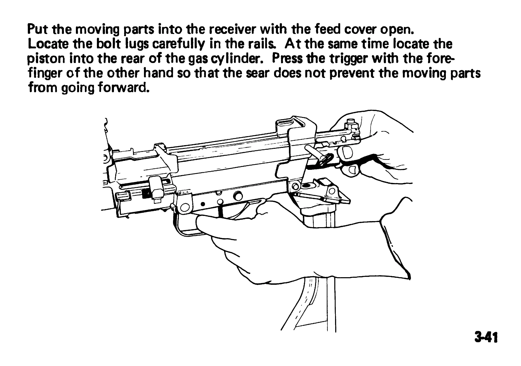
Put the moving parts into the receiver with the feed cover open.
Locate the bolt lugs carefully in the rails. At the same time locate the
piston into the rear of the gas cylinder. Press the trigger with the fore-
finger of the other hand so that the sear does not prevent the moving parts
from going forward.
341
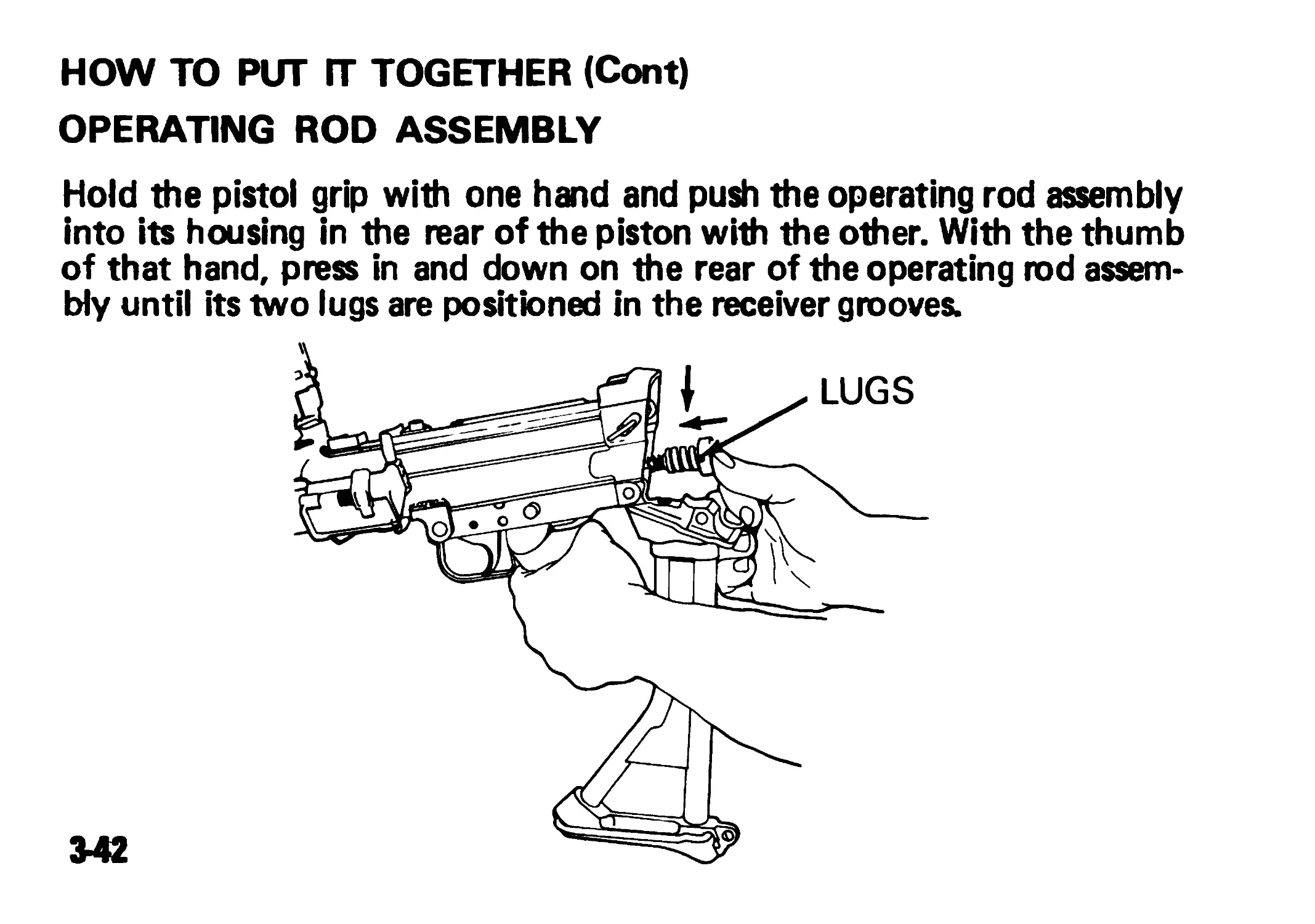
HOW TO PUT ГГ TOGETHER (Cont)
OPERATING ROD ASSEMBLY
Hold the pistol grip with one hand and push the operating rod assembly
into its housing in the rear of the piston with the other. With the thumb
of that hand, press in and down on the rear of the operating rod assem-
bly until its two lugs are positioned in the receiver grooves.
LUGS
342
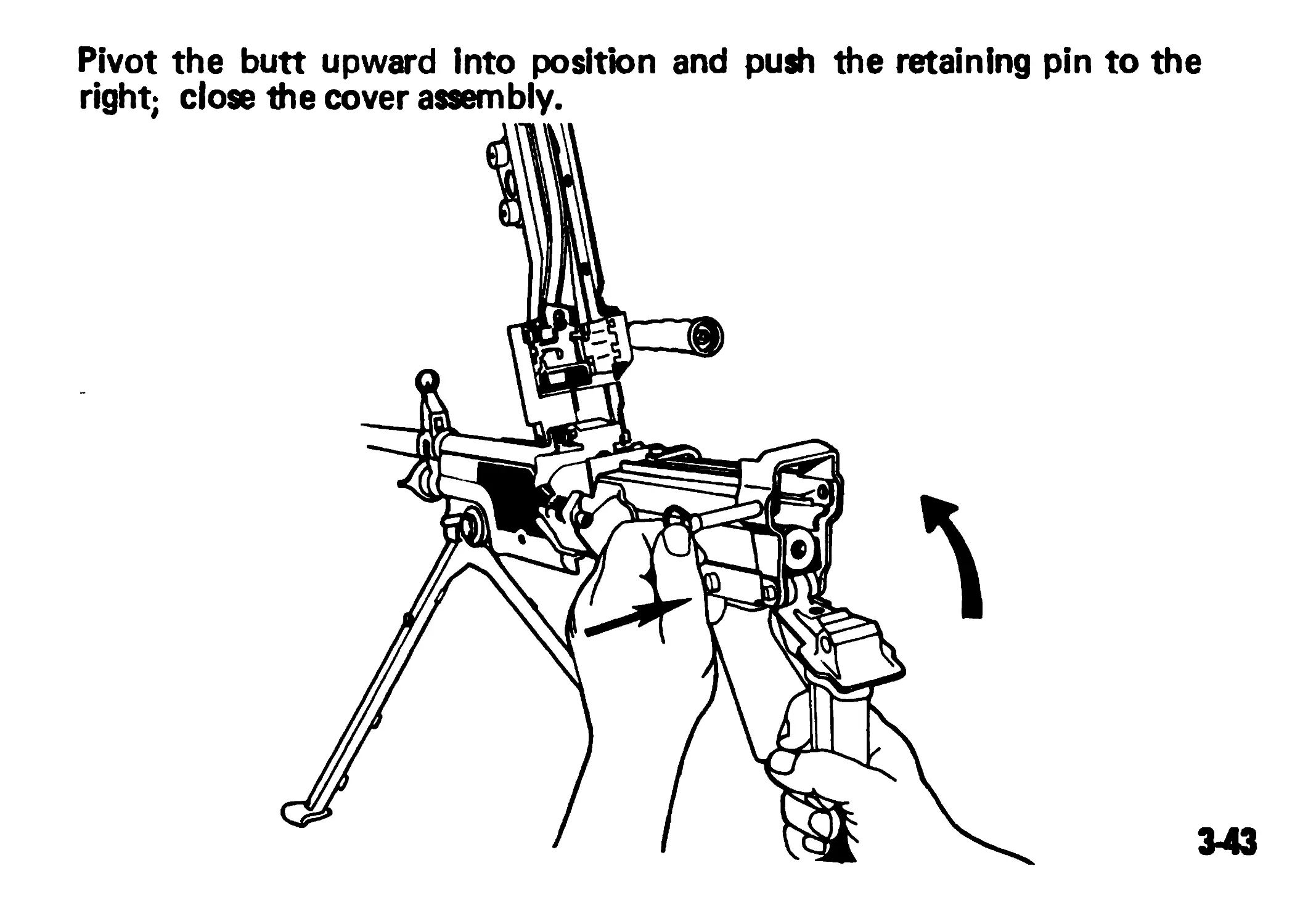
Pivot the butt upward Into position and push the retaining pin to the
right; close the cover assembly.
3-43
TOOL STOWAGE
SCRAPER TOOL ROD SECTIONS)
344/ 3-45 BLANK
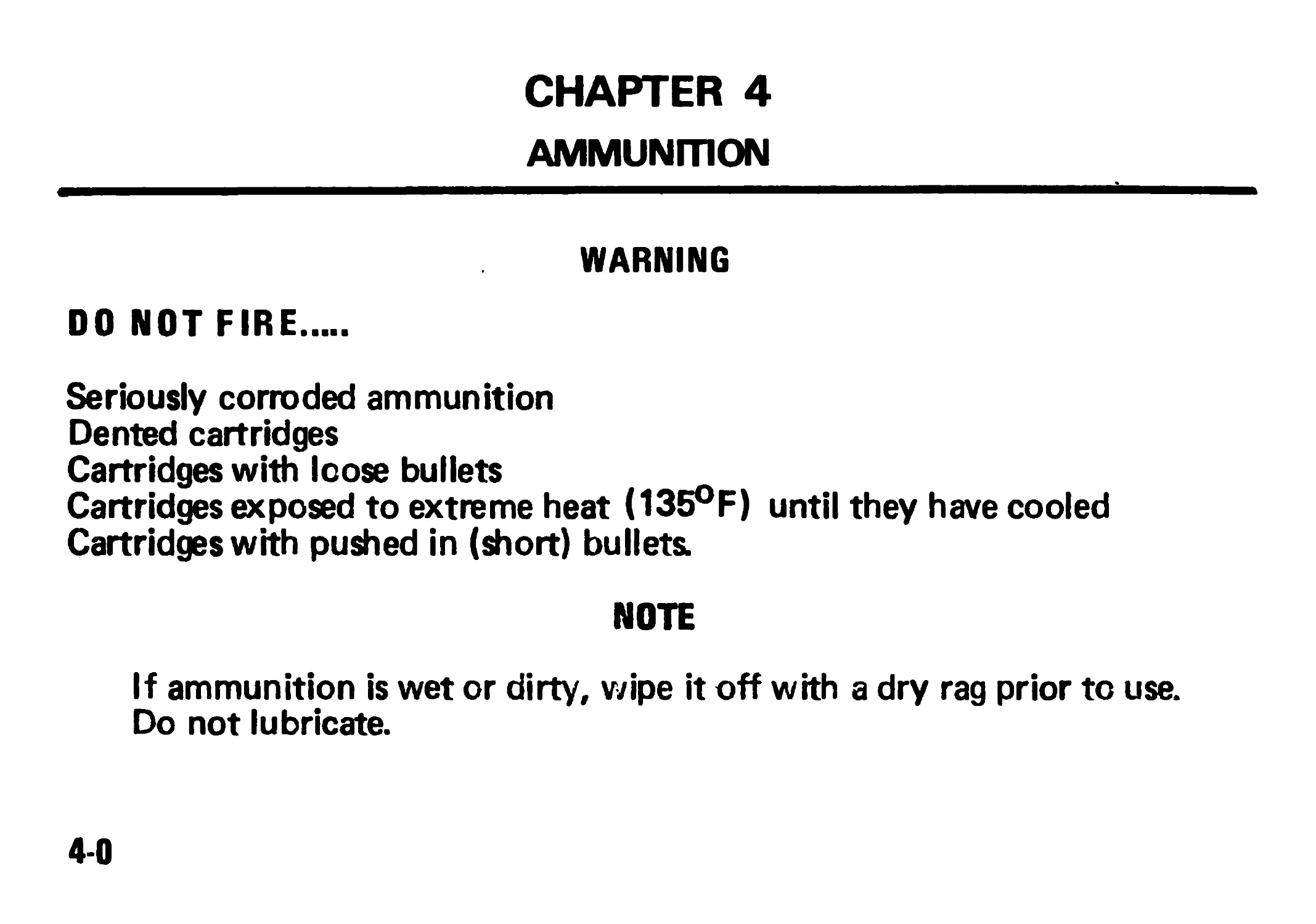
CHAPTER 4
AMMUNITION
WARNING
DO NOT FIRE.....
Seriously corroded ammunition
Dented cartridges
Cartridges with loose bullets
Cartridges exposed to extreme heat (135°F) until they have cooled
Cartridges with pushed in (short) bullets.
NOTE
If ammunition is wet or dirty, wipe it off with a dry rag prior to use.
Do not lubricate.
4-0
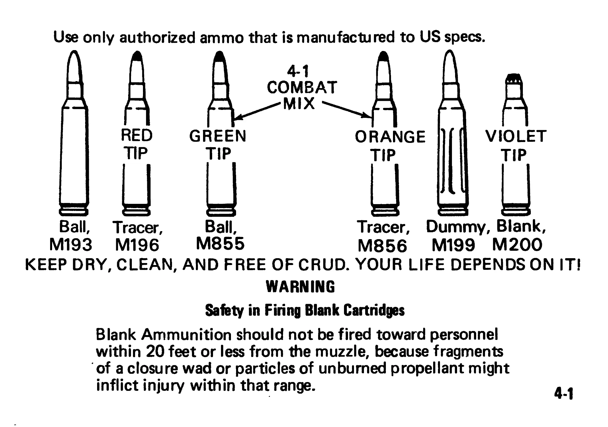
RED
Ball, Tracer,
M193 M196
Use only authorized ammo that is manufactured to US specs.
Ball,
M855
Tracer, Dummy, Blank,
M856 M199 M200
KEEP DRY, CLEAN, AND FREE OF CRUD. YOUR LIFE DEPENDS ON IT!
WARNING
Safety in Firing Blank Cartridges
Blank Ammunition should not be fired toward personnel
within 20 feet or less from the muzzle, because fragments
of a closure wad or particles of unbumed propellant might
inflict injury within that range.
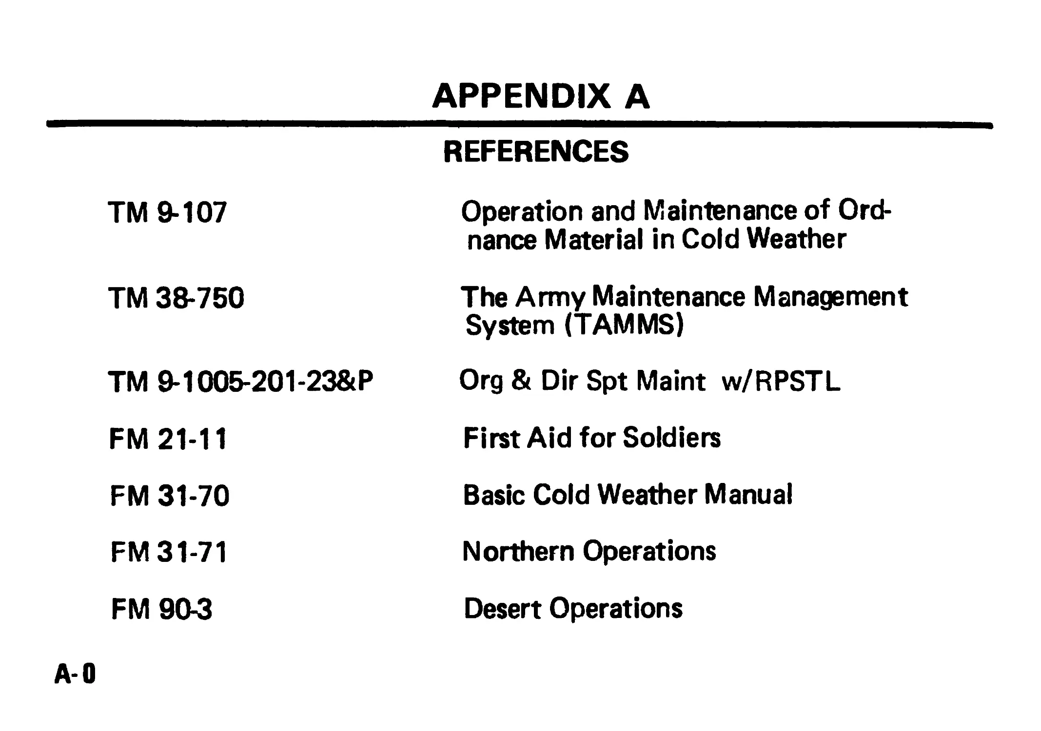
APPENDIX A
REFERENCES
TM 9-107 Operation and Maintenance of Ord- nance Material in Cold Weather
TM 38-750 The Army Maintenance Management System (TAMMS)
ТМ 9-1005-201-23&P Org & Dir Spt Maint w/RPSTL
FM 21-11 First Aid for Soldiers
FM 31-70 Basic Cold Weather Manual
FM 31-71 Northern Operations
FM 90-3 Desert Operations
A-0
APPENDIX В
COMPONENTS OF END ITEM AND
BASIC ISSUE ITEMS LIST
Section 1. INTRODUCTION
SCOPE. This appendix lists components of end item for the machine
gun to help you inventory items required for safe and effective
operation.
GENERAL The components of the End Item and Basic Issue Items List are
divided into the following sections:
Section I Components of End Item. This listing is for informational purposes
only and is not authority to requisition replacements. These items are part of
the end item, but are removed and separately packaged for transportation or
shipment. As part of the end item, these items must be with the end item,
whenever it is issued or transferred between property accounts. The illustra-
tion will assist you in identifying the item.
B-1
Section II. Basic Issue Items. There are no basic issue items.
EXPLANATION OF COLUMNS
The following, provides an explanation of columns found in the
tabular listing:
Column (1) - Illustration Number (Ulus No.). This column
indicates the number of the illustration in which the item is shown.
Column (2) - National Stock Number. Indicates the National stock
number assigned to the item and will be used for requisitioning
purposes.
Column (3) - Description. Indicates the Federal item name and, if
required, a minimum description to identify and locate the item.
The last line for each item indicates the FSCM ( in parentheses)
followed by the part number.
Column (4) - Unit of Measure (U/M). Indicates the measure used
in performing the actual operational/maintenance function. This
measure is expressed by л two-character alphabetical abbreviation
(e.g., ea, in., pr).
Column (5) - Quantity required (Qty rqr). Indicates the quantity
of the item authorized to be used with/on the equipment.
B-2
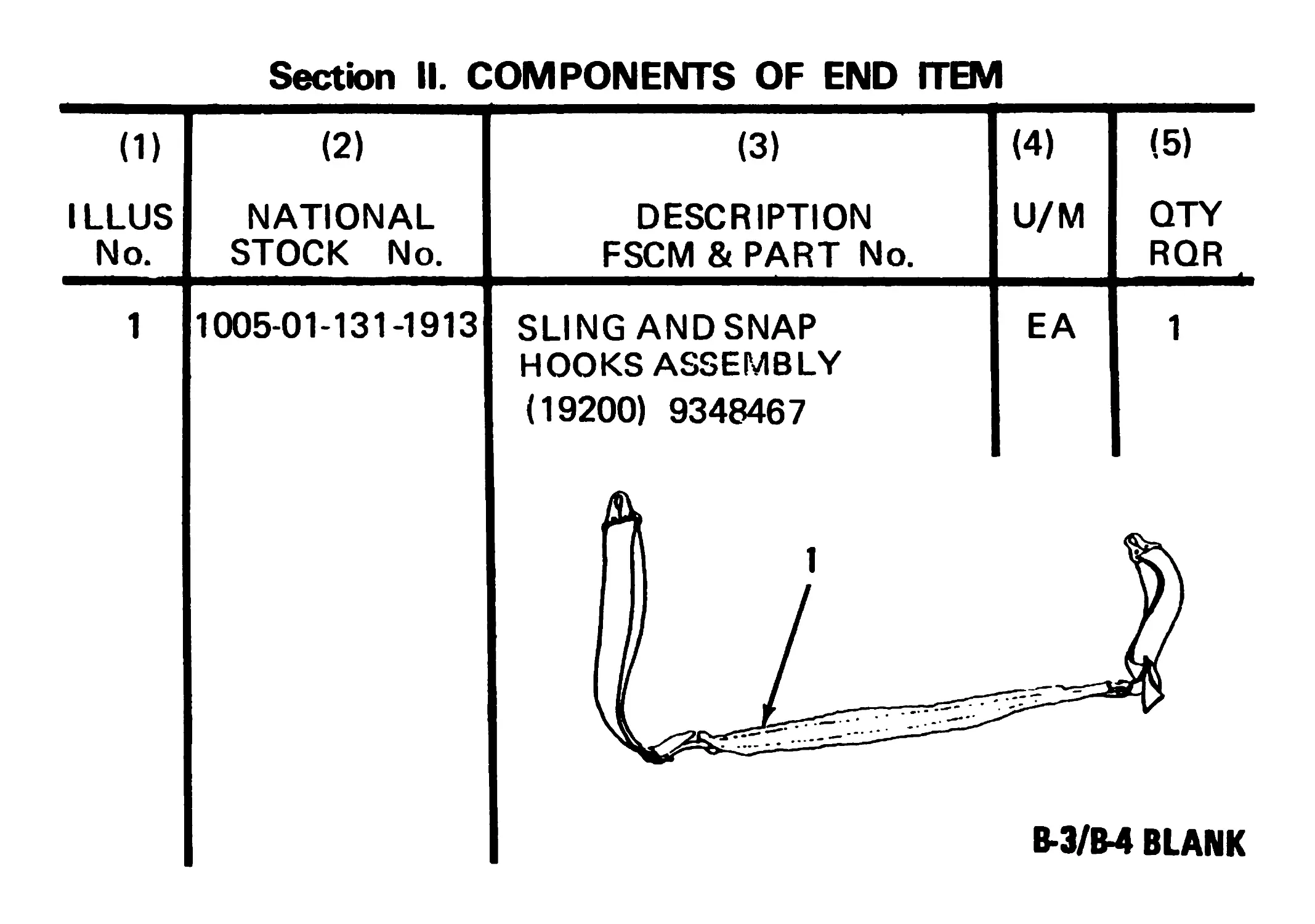
Section II. COMPONENTS OF END ITEM
(1) (2) (3) (4) (5)
ILLUS No. NATIONAL STOCK No. DESCRIPTION FSCM & PART No. U/M QTY RQR
1 1005-01-131-1913 SLING AND SNAP HOOKS ASSEMBLY (19200) 9348467 EA 1
APPENDIX С
ADDITIONAL AUTHORIZATION LIST
Section I. INTRODUCTION
SCOPE. This appendix lists additional items you are authorized for
the support of the machine gun.
GENERAL. This list identifies items that do not have to accompany the
machine gun and that do not have to be turned in with it. These items
are all authorized to you by СТА, MTOE, TDA, or JTA.
EXPLANATION OF LISTING. National stock numbers, descriptions,
and quantities are provided to help you identify and request the addi-
tional items you require to support this equipment The items are listed
in alphabetical sequence by item name under the type document
(i.e., СТА, MTOE, TDA, or JTA) which authorizes the item(s) to you.
C-1
С-2
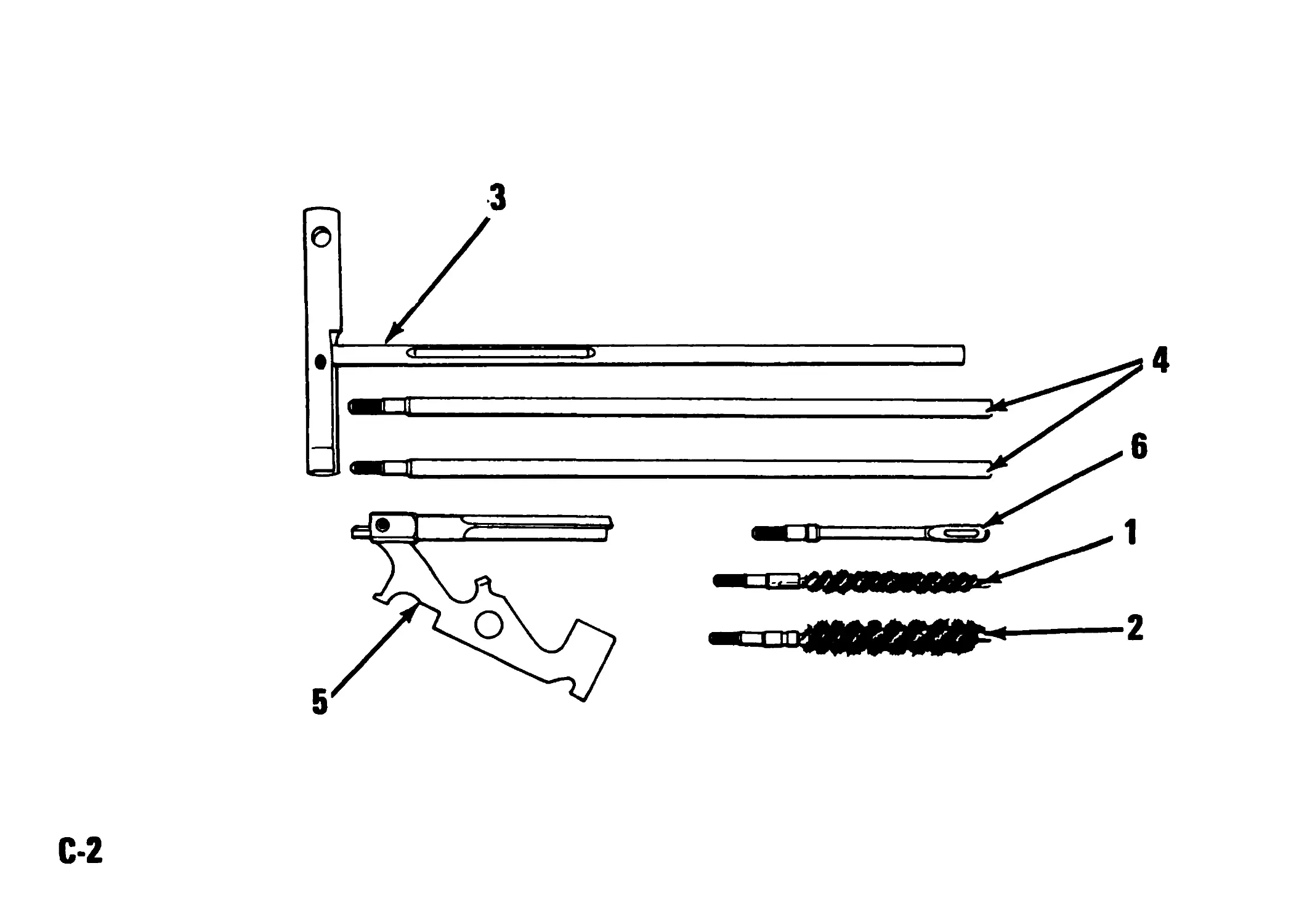
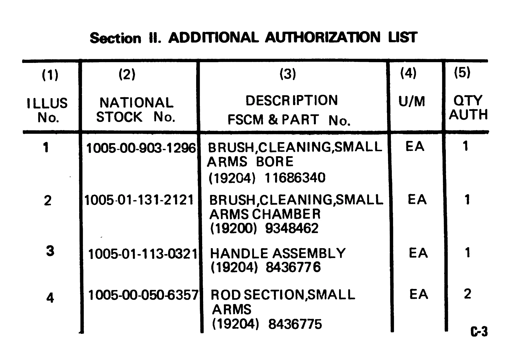
Section II. ADDITIONAL AUTHORIZATION LIST
(1) (2) (3) (4) (5)
ILLUS No. NATIONAL STOCK No. DESCRIPTION FSCM & PART No. U/M QTY AUTH
1 1005-00-903-1296 BRUSH,CLEANING,SMALL ARMS BORE (19204) 11686340 EA 1
2 1005 01-131-2121 BRUSH,CLEANING,SMALL ARMS CHAMBER (19200) 9348462 EA 1
3 1005-01-113-0321 HANDLE ASSEMBLY (19204) 8436776 EA 1
4 1005-00-050-6357 ROD SECTION,SMALL ARMS (19204) 8436775 EA 2 C-3
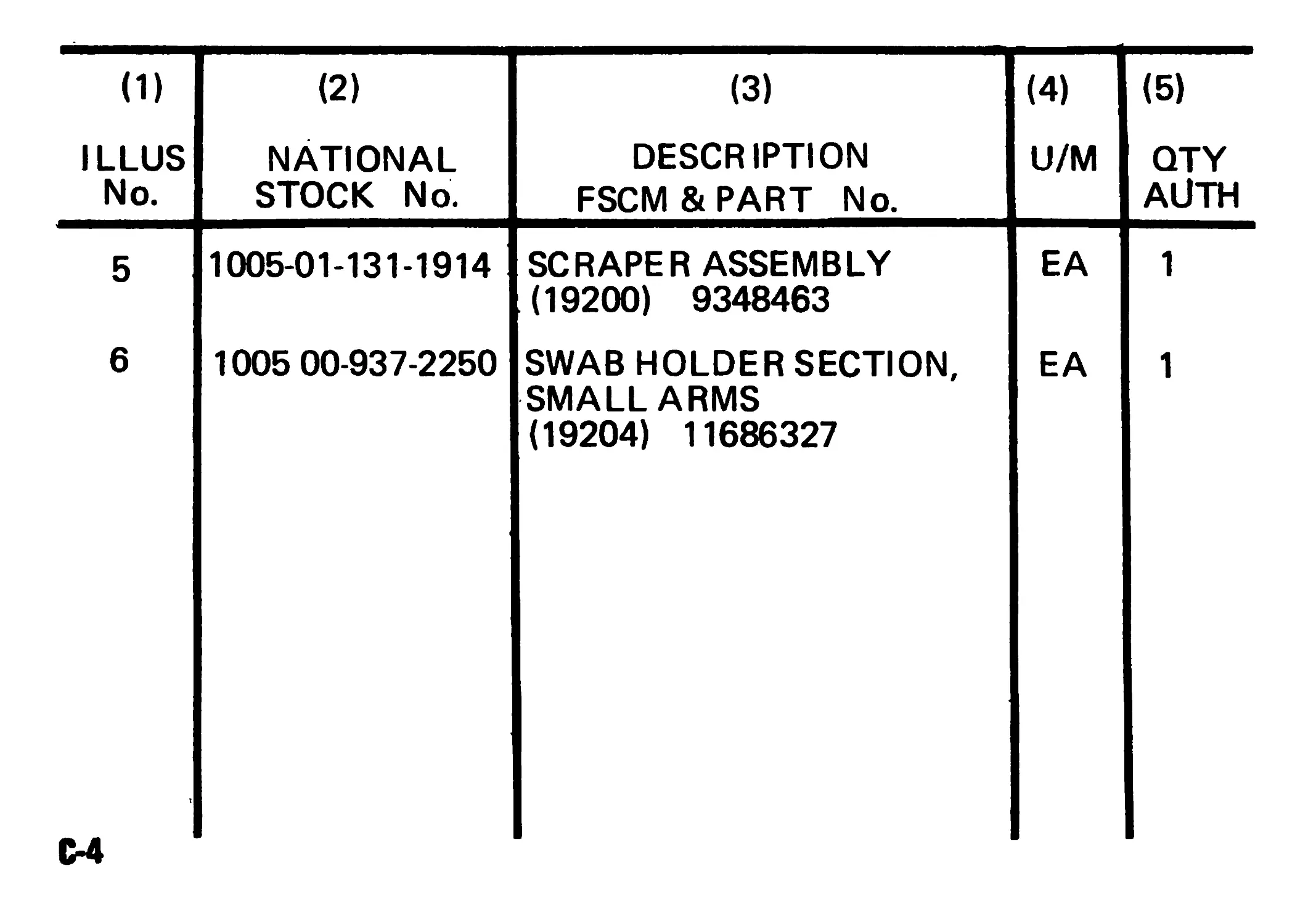
(1) (2)
ILLUS No. NATIONAL STOCK No.
5 1005-01-131-1914
6 1005 00-937-2250
С-4
(3) DESCRIPTION FSCM & PART No. (4) U/M (5) QTY All TH
SCRAPER ASSEMBLY (19200) 9348463 EA 1
SWAB HOLDER SECTION, SMALL ARMS (19204) 11686327 EA 1
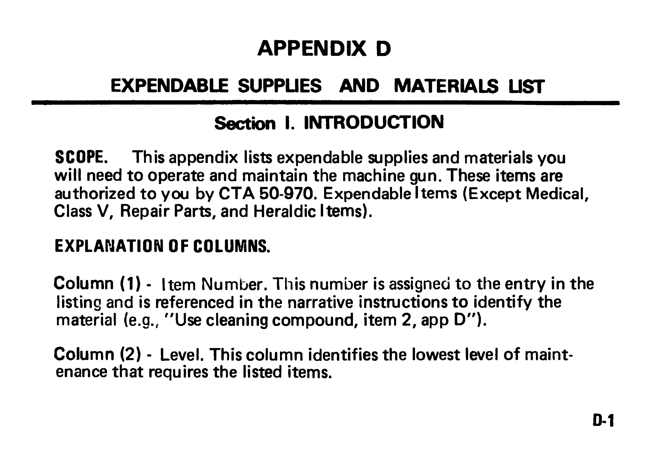
APPENDIX D
EXPENDABLE SUPPUES AND MATERIALS LIST
Section I. INTRODUCTION
SCOPE. This appendix lists expendable supplies and materials you
will need to operate and maintain the machine gun. These items are
authorized to you by СТА 50-970. Expendable Items (Except Medical,
Class V, Repair Parts, and Heraldic Items).
EXPLANATION OF COLUMNS.
Column (1) - Item Number. This number is assigned to the entry in the
listing and is referenced in the narrative instructions to identify the
material (e.g., "Use cleaning compound, item 2, app D").
Column (2) - Level. This column identifies the lowest level of maint-
enance that requires the listed items.
0-1
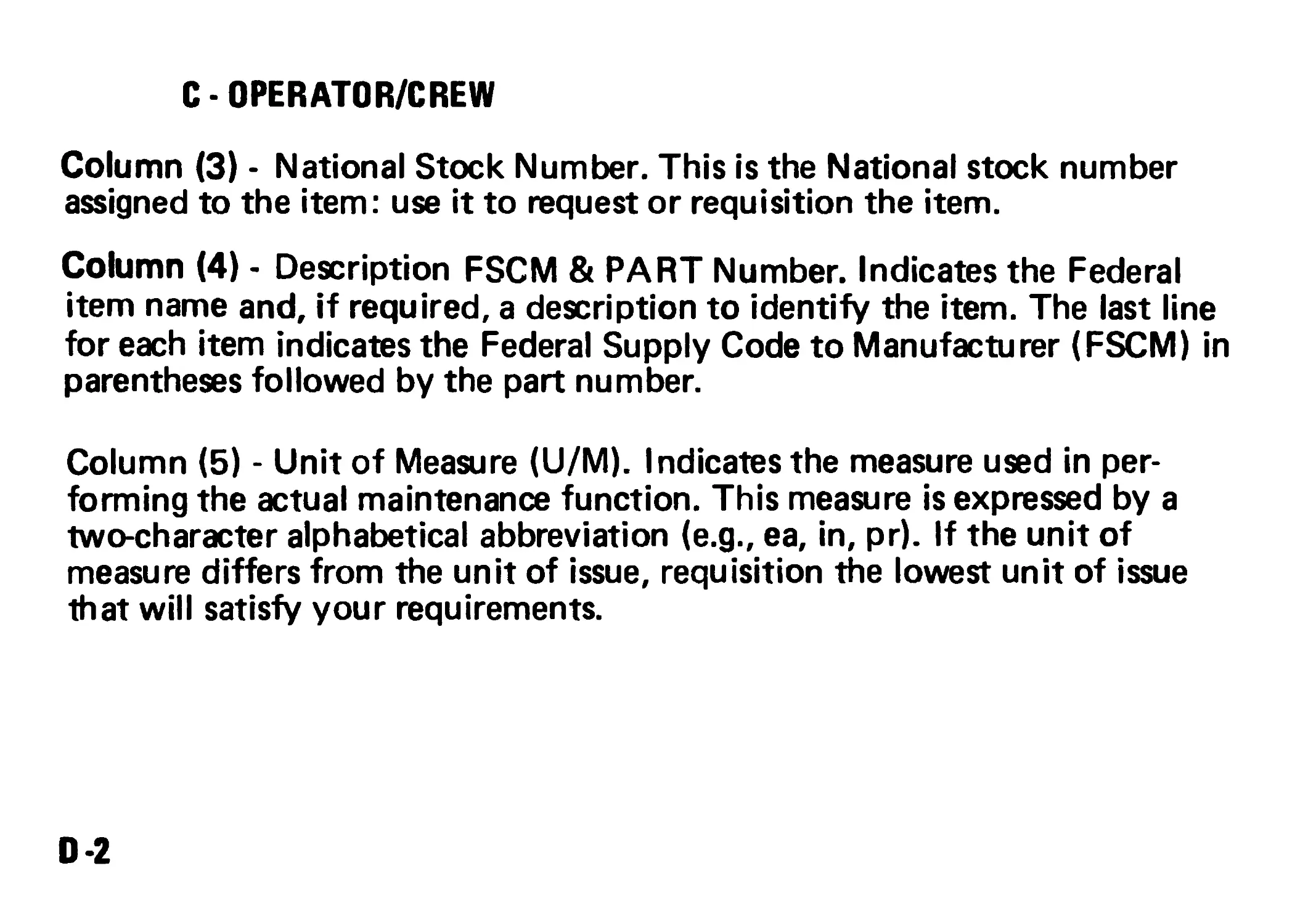
С - OPERATOR/CREW
Column (3) - National Stock Number. This is the National stock number
assigned to the item: use it to request or requisition the item.
Column (4) - Description FSCM & PART Number. Indicates the Federal
item name and, if required, a description to identify the item. The last line
for each item indicates the Federal Supply Code to Manufacturer (FSCM) in
parentheses followed by the part number.
Column (5) - Unit of Measure (U/M). Indicates the measure used in per-
forming the actual maintenance function. This measure is expressed by a
two-character alphabetical abbreviation (e.g., ea, in, pr). If the unit of
measure differs from the unit of issue, requisition the lowest unit of issue
that will satisfy your requirements.
0*2
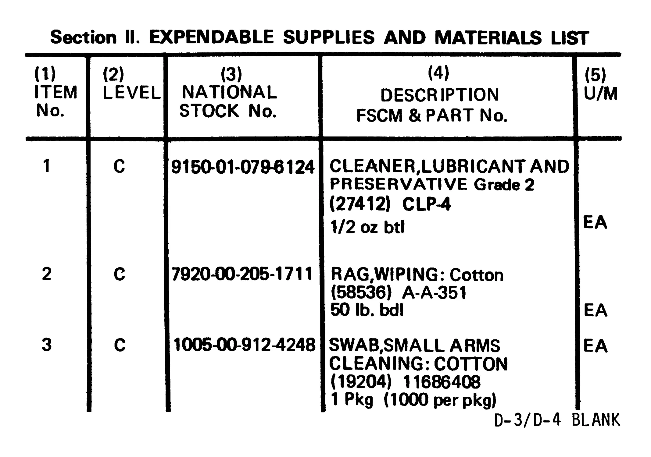
Section II. EXPENDABLE SUPPLIES AND MATERIALS LIST
(1) ITEM No. (2) LEVEL (3) NATIONAL STOCK No. (4) DESCRIPTION FSCM & PART No. (5) U/M
1 C 9150-01-07943124 CLEANER,LUBRICANT AND PRESERVATIVE Grade 2 (27412) CLP4 1/2 oz btl EA
2 C 7920-00-205-1711 RAG,WIPING: Cotton (58536) A-A-351 50 lb. bdl EA
3 C 1005-00-9124248 SWAB,SMALL ARMS CLEANING: COTTON (19204) 11686408 1 Pkg (1000 per pkg) EA
D-3/D-4 BLANK
By Order of the Secretary of the Army:
Official:
JOHN A. WICKHAM, JR.
General, United States Army
Chief of Staff
ROBERT M. JOYCE
Major General, United States Army
The Adjutant General
H. A. HATCH
Lieutenant General, USMC
Deputy Chief of Staff for Installations and Logistics
Distribution:
To be distributed in accordance with DA Form 12-40A, Operator Maintenance requirements
for Gun, Machine, 5.56MM, M249.
U.S. GOVERNMENT PRINTING OFFICE : 1987 0 - 193-678 : QL 3