/


Text
WARNING!
This manual is intended to be a 'first stop' manual to assist in the understanding of AURORA's
systems and equipment. It does not supersede manufacturer's publications, Fleet Regulations
or Standing Orders, all of which take precedence over this technical operating manual.
P&O Aurora
Technical Operating Manual
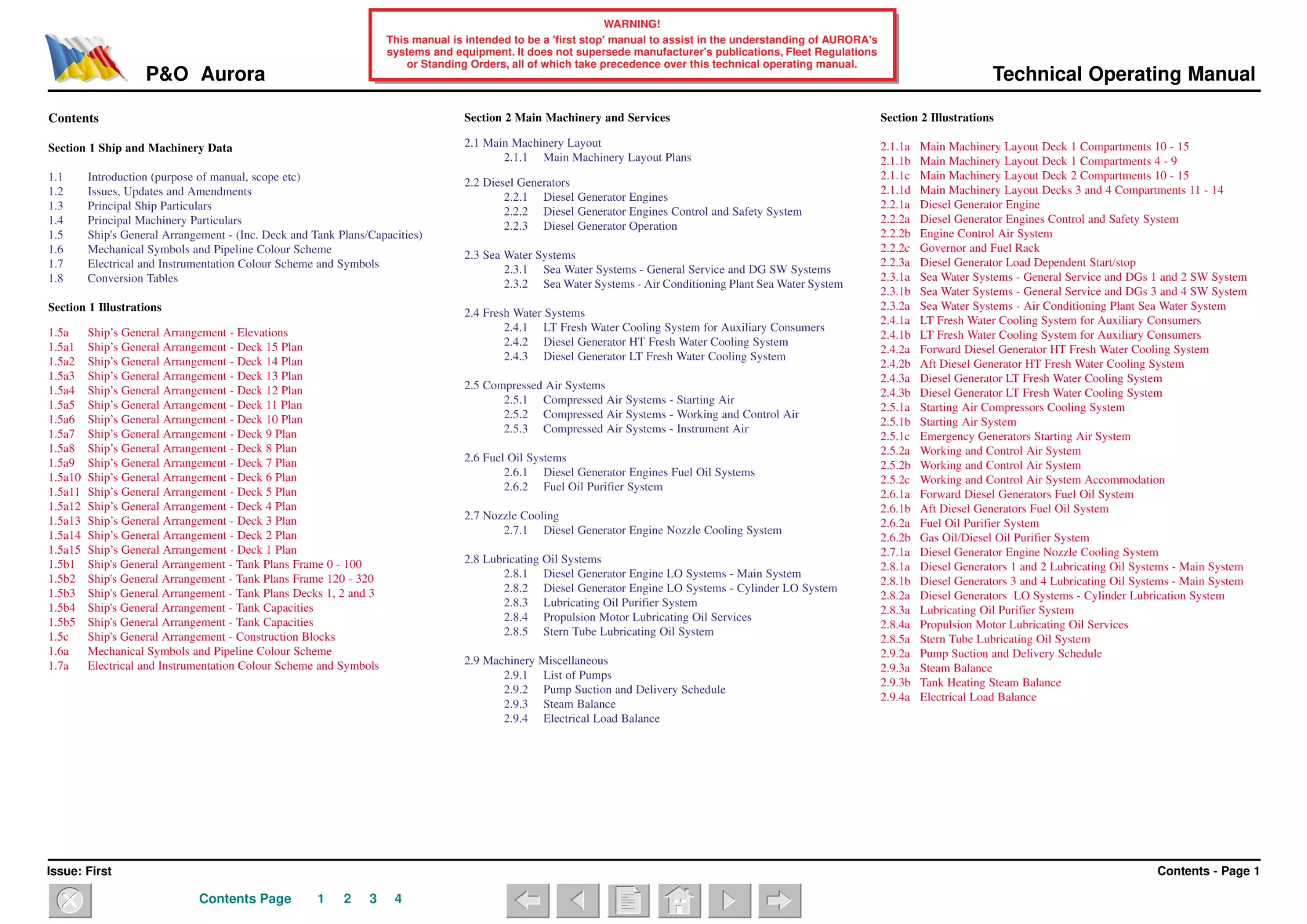
Contents
Section 2 Main Machinery and Services
Section 2 Illustrations
Section 1 Ship and Machinery Data
2.1 Main Machinery Layout
2.1.1 Main Machinery Layout Plans
1.1
1.2
1.3
1.4
1.5
1.6
1.7
1.8
2.2 Diesel Generators
2.2.1 Diesel Generator Engines
2.2.2 Diesel Generator Engines Control and Safety System
2.2.3 Diesel Generator Operation
2.1.1a
2.1.1b
2.1.1c
2.1.1d
2.2.1a
2.2.2a
2.2.2b
2.2.2c
2.2.3a
2.3.1a
2.3.1b
2.3.2a
2.4.1a
2.4.1b
2.4.2a
2.4.2b
2.4.3a
2.4.3b
2.5.1a
2.5.1b
2.5.1c
2.5.2a
2.5.2b
2.5.2c
2.6.1a
2.6.1b
2.6.2a
2.6.2b
2.7.1a
2.8.1a
2.8.1b
2.8.2a
2.8.3a
2.8.4a
2.8.5a
2.9.2a
2.9.3a
2.9.3b
2.9.4a
Introduction (purpose of manual, scope etc)
Issues, Updates and Amendments
Principal Ship Particulars
Principal Machinery Particulars
Ship's General Arrangement - (Inc. Deck and Tank Plans/Capacities)
Mechanical Symbols and Pipeline Colour Scheme
Electrical and Instrumentation Colour Scheme and Symbols
Conversion Tables
Section 1 Illustrations
1.5a
1.5a1
1.5a2
1.5a3
1.5a4
1.5a5
1.5a6
1.5a7
1.5a8
1.5a9
1.5a10
1.5a11
1.5a12
1.5a13
1.5a14
1.5a15
1.5b1
1.5b2
1.5b3
1.5b4
1.5b5
1.5c
1.6a
1.7a
2.3 Sea Water Systems
2.3.1 Sea Water Systems - General Service and DG SW Systems
2.3.2 Sea Water Systems - Air Conditioning Plant Sea Water System
2.4 Fresh Water Systems
2.4.1 LT Fresh Water Cooling System for Auxiliary Consumers
2.4.2 Diesel Generator HT Fresh Water Cooling System
2.4.3 Diesel Generator LT Fresh Water Cooling System
Ship’s General Arrangement - Elevations
Ship’s General Arrangement - Deck 15 Plan
Ship’s General Arrangement - Deck 14 Plan
Ship’s General Arrangement - Deck 13 Plan
Ship’s General Arrangement - Deck 12 Plan
Ship’s General Arrangement - Deck 11 Plan
Ship’s General Arrangement - Deck 10 Plan
Ship’s General Arrangement - Deck 9 Plan
Ship’s General Arrangement - Deck 8 Plan
Ship’s General Arrangement - Deck 7 Plan
Ship’s General Arrangement - Deck 6 Plan
Ship’s General Arrangement - Deck 5 Plan
Ship’s General Arrangement - Deck 4 Plan
Ship’s General Arrangement - Deck 3 Plan
Ship’s General Arrangement - Deck 2 Plan
Ship’s General Arrangement - Deck 1 Plan
Ship's General Arrangement - Tank Plans Frame 0 - 100
Ship's General Arrangement - Tank Plans Frame 120 - 320
Ship's General Arrangement - Tank Plans Decks 1, 2 and 3
Ship's General Arrangement - Tank Capacities
Ship's General Arrangement - Tank Capacities
Ship's General Arrangement - Construction Blocks
Mechanical Symbols and Pipeline Colour Scheme
Electrical and Instrumentation Colour Scheme and Symbols
2.5 Compressed Air Systems
2.5.1 Compressed Air Systems - Starting Air
2.5.2 Compressed Air Systems - Working and Control Air
2.5.3 Compressed Air Systems - Instrument Air
2.6 Fuel Oil Systems
2.6.1 Diesel Generator Engines Fuel Oil Systems
2.6.2 Fuel Oil Purifier System
2.7 Nozzle Cooling
2.7.1 Diesel Generator Engine Nozzle Cooling System
2.8 Lubricating Oil Systems
2.8.1 Diesel Generator Engine LO Systems - Main System
2.8.2 Diesel Generator Engine LO Systems - Cylinder LO System
2.8.3 Lubricating Oil Purifier System
2.8.4 Propulsion Motor Lubricating Oil Services
2.8.5 Stern Tube Lubricating Oil System
2.9 Machinery Miscellaneous
2.9.1 List of Pumps
2.9.2 Pump Suction and Delivery Schedule
2.9.3 Steam Balance
2.9.4 Electrical Load Balance
Main Machinery Layout Deck 1 Compartments 10 - 15
Main Machinery Layout Deck 1 Compartments 4 - 9
Main Machinery Layout Deck 2 Compartments 10 - 15
Main Machinery Layout Decks 3 and 4 Compartments 11 - 14
Diesel Generator Engine
Diesel Generator Engines Control and Safety System
Engine Control Air System
Governor and Fuel Rack
Diesel Generator Load Dependent Start/stop
Sea Water Systems - General Service and DGs 1 and 2 SW System
Sea Water Systems - General Service and DGs 3 and 4 SW System
Sea Water Systems - Air Conditioning Plant Sea Water System
LT Fresh Water Cooling System for Auxiliary Consumers
LT Fresh Water Cooling System for Auxiliary Consumers
Forward Diesel Generator HT Fresh Water Cooling System
Aft Diesel Generator HT Fresh Water Cooling System
Diesel Generator LT Fresh Water Cooling System
Diesel Generator LT Fresh Water Cooling System
Starting Air Compressors Cooling System
Starting Air System
Emergency Generators Starting Air System
Working and Control Air System
Working and Control Air System
Working and Control Air System Accommodation
Forward Diesel Generators Fuel Oil System
Aft Diesel Generators Fuel Oil System
Fuel Oil Purifier System
Gas Oil/Diesel Oil Purifier System
Diesel Generator Engine Nozzle Cooling System
Diesel Generators 1 and 2 Lubricating Oil Systems - Main System
Diesel Generators 3 and 4 Lubricating Oil Systems - Main System
Diesel Generators LO Systems - Cylinder Lubrication System
Lubricating Oil Purifier System
Propulsion Motor Lubricating Oil Services
Stern Tube Lubricating Oil System
Pump Suction and Delivery Schedule
Steam Balance
Tank Heating Steam Balance
Electrical Load Balance
Contents - Page 1
Issue: First
Contents Page
1
2
3
4
WARNING!
This manual is intended to be a 'first stop' manual to assist in the understanding of AURORA's
systems and equipment. It does not supersede manufacturer's publications, Fleet Regulations
or Standing Orders, all of which take precedence over this technical operating manual.
P&O Aurora
Section 3 Electrical Systems
3.1
3.2
3.3
3.4
3.5
3.6
3.7
3.8
3.9
3.10
3.11
3.12
3.13
3.14
3.15
3.16
3.17
3.18
3.19
3.14a
3.15a
3.15b
3.15c
3.16a
3.18a
3.19a
Main Electrical Network
Main Switchboards and Distribution
Main Switchboard Control and Operation
Electrical Switchboard Rooms and Sub Stations
Electrical Safety and the Permit to Work System
Main Alternators
Woodward Governors
Accommodation Distribution
Engine Room Distribution
Galley Distribution
Laundry Distribution
Miscellaneous Distribution
Air Conditioning/Ventilation Distribution
Battery and UPS Power Supplies
Emergency Switchboard and Distribution
Emergency Alternators
Trace Heating System
Shore Supply
Cathodic Protection System
Section 4 Propulsion System
4.1
4.2
4.3
4.4
4.5
4.6
4.7
4.8
4.9
Propulsion Control Stations
Propulsion PMS
Propulsion Control System
Propulsion Converters
Propulsion Transformers
Excitation System
Propulsion Motors
Shafting, Stern Tubes and Propeller Systems
Lips System
Section 4 Illustrations
Section 3 Illustrations
3.1a
3.2a
3.4a
3.5a
3.6a
3.6b
3.7a
3.8a
3.8b
3.8c
3.8d
3.8e
3.8f
3.8g
3.9a
3.9b
3.9c
3.10a
3.10b
3.11a
3.12a
3.12b
3.13a
3.13b
3.13c
3.13d
3.13e
Emergency Lighting UPS Unit
Emergency Switchboard
Emergency Switchboard 690V Distribution
Emergency Switchboard 230V Distribution
Emergency Alternators
Shore Supply
Cathodic Protection System
Main Electrical Network
Main Switchboards and Distribution
Electrical Switchboard Rooms and Sub Stations
Electrical Safety and the Permit to Work System
Main Alternators
Main Alternators
Woodward Governors
Accommodation Electrical Distribution Overview
Accommodation Distribution Zone 1 and 2 MD20
Accommodation Distribution Zone 3 MD30
Accommodation Distribution Zone 4 MD40
Accommodation Distribution Zone 5 MD50
Accommodation Distribution Zone 6 MD60
Accommodation Distribution Zone 7 MD70
Engine Room Distribution ME10.1 ME10.2 ME20.1 ME20.2
Engine Room Distribution ME21.1 ME21.2 ME11 ME12 ME22
Engine Room Distribution ME23 ME24
Galley Distribution GD10
Galley Distribution GD11 GD12 GD13 GD14 GD15 GD16
Laundry Distribution LD10
ECR Bridge Communication Centre UPS Distribution
Miscellaneous Distribution
Air Conditioning/Ventilation Distribution Zones 1 and 2
Air Conditioning/Ventilation Distribution Zones 3 and 4
Air Conditioning/Ventilation Distribution Zone 5
Air Conditioning/Ventilation Distribution Zone 6
Air Conditioning/Ventilation Distribution Zone 7
4.1a
4.1b
4.2a
4.3a
4.4a
4.4b
4.5a
4.6a
4.7a
4.8a
4.9a
Propulsion Control Stations
Propulsion Control Stations
Propulsion PMS
Propulsion Control System
Propulsion Converters
Propulsion Converters Power Circuits
Propulsion Transformers
Excitation System
Propulsion Motor
Shafting, Stern Tubes and Propeller Systems
Lips System
Section 5 Monitoring, Alarm and Control Systems
5.1
5.2
5.3
5.4
5.5
5.6
Integrated Monitoring Alarm and Control System (IMACs)
Power Management System
Screen Displays
General Alarm System (Ship)
Engine Control Room and Safety Centre
Engine Room Alarm and Call Systems
Section 5 Illustrations
5.1a
5.2a
5.3a
5.4a
5.5a
5.6a
Technical Operating Manual
Section 6 Auxiliary Plant Services
6.1 Emergency Diesel Generators
6.2 Steam Generating Systems
6.2.1 Boilers
6.2.2 Economisers
6.2.3 Boiler Feed and Condensate System
6.2.4 Boiler Fuel Oil System
6.2.5 Boiler Control System
6.2.6 Sludge System
6.2.7 Steam System
6.2.8 Accommodation Steam System
6.2.9 Tank Heating System
6.3 Water Systems
6.3.1 Fresh Water Evaporator Plant
6.3.2 Distilled Water Transfer System
6.3.3 Water Treatment Systems
6.3.4 Potable Hot Fresh Water System in Machinery Spaces
6.3.5 Potable Cold Fresh Water System in Machinery Spaces
6.3.6 Non-Potable Water System in Machinery Spaces
6.4 Sewage Systems
6.4.1 Grey Water System
6.4.2 Sewage (Black Water) Vacuum Units
6.4.3 Sewage (Black Water) Treatment Plants
6.5 High Pressure Washing System
6.6 Bilge and Ballast Systems
6.6.1 Oily Bilge System
6.6.2 Oily Water Separator
6.6.3 Main Bilge System
6.6.4 Ballast Water and Heeling System
6.6.5 Remote Valve Control System
6.7 Fuel Oil and Lubricating Oil Transfer and Bunkering Systems
6.7.1 Fuel Oil Transfer and Bunkering System - Fuel Oil
6.7.2 Fuel Oil Transfer and Bunkering System - Diesel Oil
6.7.3 Tank Vents and Overflow Systems
6.7.4 Lubricating Oil Transfer and Bunkering System
6.7.5 Lubricating Oil and Fuel Oil Drain System
6.7.6 Quick Closing Valves
Integrated Monitoring Alarm and Control System (IMACs)
Power Management System
Screen Displays
General Alarm System (Ship)
Engine Control Room and Safety Centre
Engine Room Alarm and Call Systems
Contents - Page 2
Issue: First
Contents Page
1
2
3
4
WARNING!
This manual is intended to be a 'first stop' manual to assist in the understanding of AURORA's
systems and equipment. It does not supersede manufacturer's publications, Fleet Regulations
or Standing Orders, all of which take precedence over this technical operating manual.
P&O Aurora
6.8 Air Conditioning, Refrigeration and Ventilation Systems
6.8.1 Accommodation Air Conditioning Plant
6.8.2 Accommodation Air Conditioning - Services
6.8.3 Machinery Space Ventilation System
6.8.4 Provision Refrigeration System
6.7.5a
6.8.1a
6.8.1b
6.8.2a
6.8.3a
6.8.4a
6.8.4b
6.9a
6.10a
6.9 Engine Room Cranes, Hoists and Lifting Arrangements
6.10 Dry Dock Services
Section 6 Illustrations
6.1a
6.1b
6.2.1a
6.2.2a
6.2.3a
6.2.4a
6.2.5a
6.2.5b
6.2.6a
6.2.7a
6.2.7b
6.2.8a
6.2.8b
6.2.9a
6.3.1a
6.3.2a
6.3.3a
6.3.4a
6.3.5a
6.3.5b
6.3.6a
6.3.6b
6.4.1a
6.4.1b
6.4.2a
6.4.3a
6.5a
6.5b
6.6.1a
6.6.2a
6.6.3a
6.6.4a
6.6.4b
6.7.1a
6.7.2a
6.7.3a
6.7.4a
Lubricating Oil and Fuel Oil Drain System
Accommodation Air Conditioning Plant Chilled Water System
Accommodation Air Conditioning Plant Heating Water System
Accommodation Air Conditioning - Services
Machinery Space Ventilation System
Provision Refrigeration Normal Cooling System
Provision Refrigeration Deep Cooling System
Engine Room Cranes, Hoists and Lifting Arrangements
Dry Dock Services
Section 7 Deck Equipment and Services
Emergency Diesel Generator Engine
Emergency Diesel Generator Engine Services
Boilers
Economisers
Boiler Feed and Condensate System
Boiler Fuel Oil System
Boiler Control System
Boiler Control System
Sludge System
Steam System
Steam System
Accommodation Steam System
Accommodation Steam System
Tank Heating System
Fresh Water Evaporator Plant
Distilled Water Transfer System
Water Treatment Systems
Potable Hot Fresh Water System in Machinery Spaces
Potable Cold Fresh Water System in Machinery Spaces
Potable Cold Fresh Water System in Machinery Spaces
Non-Potable Water System in Machinery Spaces
Non-Potable Water System in Machinery Spaces
Grey Water System
Grey Water System
Sewage (Black Water) Vacuum Unit
Sewage (Black Water) Treatment Unit
High Pressure Washing System
High Pressure Washing System
Oily Bilge System
Oily Water Separator
Main Bilge System
Ballast Water System
Ballast Water and Heeling System
Fuel Oil Transfer and Bunkering System - Fuel Oil
Fuel Oil Transfer and Bunkering System - Diesel Oil
Tank Vents and Overflow Systems
Lubricating Oil Transfer and Bunkering System
7.1
7.2
7.3
7.4
7.5
7.6
7.7
7.8
7.9
7.10
7.11
7.12
7.13
7.14
Safety Management System (SMS)
Anchor and Mooring Arrangements
Windlass and Winches
Deck Cranes
Thrusters
Steering Gear
Stabilisers
Accommodation Ladders
Tender Embarkation Platforms
Shell Doors
Davits
Lifeboats and Tenders
Liferafts
Window Washing Systems
Section 7 Illustrations
7.1a
7.2a
7.2b
7.3a
7.3b
7.4a
7.5a
7.6a
7.6b
7.7a
7.7b
7.7c
7.8a
7.9a
7.10a
7.11a
7.11b
7.12a
7.12b
7.12c
7.12d
Safety Management System (SMS)
Anchor and Mooring Arrangements
Aft Mooring Arrangements
Windlass and Winches
Windlass Portable Console
Deck Cranes
Thrusters
Steering Gear Control
Steering Gear
Stabilisers
Stabilisers Control
Stabilisers - Hydraulic System
Accommodation Ladders
Tender Embarkation Platforms
Shell Doors
Davits
Davits
Lifeboats and Tenders
Lifeboats and Tenders
Lifeboats and Tenders
Lifeboats and Tenders
Technical Operating Manual
7.13a
7.14a
7.14b
Liferafts
Window Washing Systems
Window Washing Systems
Section 8 Hotel Equipment and Services
8.1
8.2
8.3
8.4
8.5
8.6
8.7
8.8
8.9
8.10
8.11
8.12
8.13
8.14
8.15
8.16
Galleys, Pantries and Bars
Garbage Disposal Equipment
Incinerator
Fresh Water Systems
Sewage Treatment and Collection
Laundry and Dry Cleaning Equipment
Swimming Pool and Spa Water Systems
Lifts
Storing Platforms
Automatic Sliding Doors
Ving Card System
Burglar Alarms
Dimmer Systems
Entertainment Systems
Scandisplay System
TV System
Section 8 Illustrations
8.1a
8.3a
8.4a
8.4b
8.4c
8.4d
8.7a
8.7b
8.7c
8.8a
8.9a
8.9b
8.11a
8.12a
8.13a
8.13b
8.13c
8.14a
8.14b
8.14c
8.15a
8.16a
Galleys
Incinerator
Potable Cold Water Accommodation System
Potable Cold Water Accommodation System
Potable Hot Water Accommodation System
Potable Hot Water Accommodation System
Swimming Pool Water Systems
Swimming Pool Water Systems
Spa Water Systems
Lifts
Storing Platforms
Storing Platforms
Ving Card System
Burglar Alarms
Dimmer Systems Decks 5 and 6
Dimmer Systems Decks 7 and 8
Dimmer Systems Decks 11, 12 and 13
Entertainment Systems
Entertainment Systems
Entertainment Systems
Scandisplay System
TV System
Contents - Page 3
Issue: First
Contents Page
1
2
3
4
WARNING!
This manual is intended to be a 'first stop' manual to assist in the understanding of AURORA's
systems and equipment. It does not supersede manufacturer's publications, Fleet Regulations
or Standing Orders, all of which take precedence over this technical operating manual.
P&O Aurora
Technical Operating Manual
Section 9 Navigation and Communication Equipment
Section 10 Safety Systems and Equipment
Section 11 Emergency Procedures
9.1
Bridge Layout
9.2
Navigation Equipment
9.2.1 NACOS System
9.2.2 Bridge equipment
11.1
11.2
11.3
11.4
11.5
9.3
9.4
Navigation and Signal Lighting
Communication Centre
9.5
External Communication Systems
9.5.1 GMDSS
9.5.2 SAT B System
9.6
9.7
9.8
9.9
9.10
9.11
9.12
9.13
9.14
Internal Communication Systems
Propulsion Control
Steering Control
Bridge Alarm System
Lips Joystick System Control
External Sound Equipment
Manoeuvring Information
Crash Stop Manoeuvre
Surveillance TV System
10.1
10.2
10.3
10.4
10.5
10.6
10.7
10.8
10.9
10.10
10.11
10.12
10.13
10.14
10.15
10.16
Blackout
Failure of One Diesel Engine
Failure of One Half Propulsion Motor
Failure of One Propulsion System Component
Watertight Doors Emergency Procedures
Appendix
Machinery Item Photographs
Section 10 Illustrations
10.1a
10.2a
10.3a
10.3b
10.4a
10.5a
10.5b
10.6a
10.6b
10.7a
10.9a
10.9b
10.10a
10.11a
10.13a
10.13b
10.13c
10.16a
10.16b
10.16c
10.16d
10.16e
Section 9 Illustrations
9.1a
9.1b
9.1c
9.2a
9.3a
9.3b
9.4a
9.5.1a
9.5.1b
9.5.1c
9.5.2a
9.6.a
9.6.b
9.6.c
9.7a
9.8a
9.10a
9.11a
9.12a
9.13a
9.14a
Emergency Shutdown (ESD) System
Low Location Lighting
Fire Detection and Alarm System
Fire and Washdeck System
Sprinkler System
CO2 Systems
Fire Fighting Stations
Fire Dampers and Fire Doors
Machinery Space Firefighting Arrangements
Machinery Space Hi-Fog System
Galley Firefighting Arrangements
Smoke Control Strategy
Watertight and Splashtight Doors
Flood Water Removal Systems
Trim and Stability Data
Life Saving Equipment
Bridge Layout: Overhead Consoles
Bridge Layout: Main Console
Bridge Layout: Conning, Steering and Wing Consoles
Navigation Equipment NACOS System
Navigation and Signal Lighting Panels
Navigation and Signal Lighting Layout
Communication Centre
GMDSS Equipment
GMDSS Distress Reactions
Antenna Location
Satcom B System
Automatic Telephone System
Sound Powered Telephone System
Public Address Operating Panel
Propulsion Control
Steering Control
Lips Joystick System Control
External Sound Equipment
Manoeuvring Information
Crash Stop Manoeuvre
Surveillance TV System
Emergency Shutdown (ESD) System
Low Location Lighting
Fire Detection Panel
Fire Detection System
Fire and Washdeck System
Sprinkler System
Sprinkler System
CO2 Main System
CO2 Local Systems
Fire Fighting Stations
Machinery Space Firefighting Arrangements
Machinery Space Firefighting Arrangements
Machinery Space Hi-Fog System
Galley Firefighting Arrangements
Watertight and Splashtight Doors
Watertight and Splashtight Doors
Watertight Doors Control System
Life Saving Equipment Decks 3 and 4
Life Saving Equipment Decks 5 and 6
Life Saving Equipment Decks 7 and 8
Life Saving Equipment Decks 9, 10, 11 and 12
Life Saving Equipment Deck 14 and Elevation
Contents - Page 4
Issue: First
Contents Page
1
2
3
4
P&O Aurora
Section 1 Ship and Machinery Data
1.1 Introduction
General
Although Aurora is supplied with shipbuilder’s plans and manufacturer’s
instruction books, there is no single handbook which gives guidance on
operating complete systems as installed on board, as distinct from individual
items of machinery.
The purpose of this manual is to fill some of the gaps and to provide the ship’s
officers with additional information not otherwise available on board. It is
intended to be used in conjunction with the other plans and instruction books
already on board and in no way replaces or supersedes them.
Information pertinent to the operation of Aurora has been carefully collated in
relation to the systems of the vessel and is presented in one volume: ‘The
Technical Operating Manual’.
In many cases the best operating practice can only be learned by experience.
Where the information in this manual is found to be inadequate or incorrect,
details should be sent to the P&O Cruises Technical department, so that
revisions may be made.
The concept of this Operating Manual is to provide information to technically
competent ship’s officers who are unfamiliar to the vessel, in a form that is
readily comprehensible, thus aiding their understanding and knowledge of the
specific vessel. Special attention is drawn to emergency procedures and fire
fighting systems.
The manual also consists of a number of parts and sections which describe the
systems and equipment fitted and their method of operation related to a
schematic diagram where applicable.
Technical Operating Manual
Illustrations
All illustrations are referred to in the text and are located either in the text page
where they are sufficiently small, or on the page above the text so that both the
text and illustration are accessible when the manual is laid face down. When
text concerning an illustration covers several pages the illustration is
duplicated above each page of text.
Where flows are detailed in an illustration these are shown in colour. A key of
all colours and line styles used in an illustration is provided on the illustration.
Details of the colour coding used in the illustrations is given in the colour
schemes in sections 1.9 and 1.10.
Symbols given in the manual adhere to international standards. Keys to the
symbols used throughout the manual are also provided in sections 1.9 and 1.10.
Notices
The following notices appear throughout this manual:
WARNING!
Warnings are given to draw the reader’s attention to operation where
DANGER TO LIFE OR LIMB MAY OCCUR!
Safe Operation
The safety of the ship depends on the care and attention of all on board.
Most safety precautions are a matter of common sense and good housekeeping
and are detailed in the various manuals available onboard. However, records
show that even experienced operators sometimes neglect safety precautions
through over-familiarity and the following basic rules must be remembered at
all times.
1. Never continue to operate any machine or equipment which
appears to be potentially unsafe or dangerous and always report
such a condition immediately.
2. Make a point of testing all safety equipment and devices
regularly. Always test safety trips before starting any
equipment.
3. Never ignore any unusual or suspicious circumstances, no
matter how trivial. Small symptoms often appear before a major
failure occurs.
4. Never underestimate the fire hazard of petroleum products,
whether fuel oil or vapour.
CAUTION!
Cautions are given to draw reader’s attention to operations where
DAMAGE TO EQUIPMENT MAY OCCUR.
5. Never start a machine remotely from the control room without
checking visually (if practical) that the machine is ready for
operation.
(Note! Notes are given to draw reader’s attention to points of interest or to
supply supplementary information.)
In the design of equipment and machinery, devices are included to ensure that
as far as possible in the event of a fault occurring, whether on the part of the
equipment or the operator, the equipment concerned will cease to function
without danger to personnel or damage to the machine. If these safety devices
are neglected, the operation of any machine is potentially dangerous.
The manual also details the ship’s systems, providing a technical description,
system capacities and ratings, control and alarm settings (where practicable)
and operating details.
The valves’ and fittings’ identifications used in this manual are the same as
those used by the shipbuilder.
Issue: First
1.1 Introduction - Page 1
P&O Aurora
Technical Operating Manual
1.2 Issues, Updates and Amendments
This manual is provided with a system of issue and update control. Controlling
documents ensures that:
• Documents conform to a standard format
• Amendments are carried out by relevant personnel
• Each document or update to a document is approved before issue
1.1 Introduction
1.2 Issues Updates and Amendments
1.3 Principal Ship Particulars
1.4 Principal Machinery Particulars
1.5 Ship’s G.A.
1.6 Mech./Pipeline Symbols/Colours
1.7 Elec./Instr. Symbols/Colours
1.8 Conversion Tables
Issue 1
July 2001
July 2001
July 2001
July 2001
July 2001
July 2001
July 2001
July 2001
Illustrations
1.5a
1.5a1
1.5a2
1.5a3
1.5a4
1.5a5
1.5a6
1.5a7
1.5a8
1.5a9
1.5a10
1.5a11
1.5a12
1.5a13
1.5a14
1.5a15
1.5b1
1.5b2
1.5b3
1.5b4
1.5b5
1.5c
1.6a
1.7a
July 2001
July 2001
July 2001
July 2001
July 2001
July 2001
July 2001
July 2001
July 2001
July 2001
July 2001
July 2001
July 2001
July 2001
July 2001
July 2001
July 2001
July 2001
July 2001
July 2001
July 2001
July 2001
July 2001
July 2001
Text
2.1.1
2.2.1
2.2.2
2.2.3
2.3.1
2.3.2
2.4.1
2.4.2
2.4.3
2.5.1
2.5.2
2.5.3
July 2001
July 2001
July 2001
July 2001
July 2001
July 2001
July 2001
July 2001
July 2001
July 2001
July 2001
July 2001
Issue 2
Issue 3
Issue 4
• A history of updates is maintained
• Updates are issued to all registered holders of documents
• Sections are removed from circulation when obsolete
Document control is achieved by the use of the footer provided on every page
and the issue and update table below.
In the right hand corner of each footer are details of the page’s section number
and title followed by the page number of the section. In the left hand corner of
each footer is the issue number.
Details of each section are given in the first column of the issue and update
control table. The table thus forms a matrix into which the dates of issue of the
original document and any subsequent updated sections are located.
The information and guidance contained herein is produced for the assistance
of certificated officers who, by virtue of such certification, are deemed
competent to operate the vessel to which such information and guidance refers.
Any conflict arising between the information and guidance provided herein
and the professional judgement of such competent officers, must be
immediately resolved by reference to P&O Technical Department.
This manual was produced by:
WORLDWIDE MARINE TECHNOLOGY LTD.
For any new issue or update contact:
The Technical Director
WMT Technical Office
The Court House
15 Glynne Way
Hawarden
Deeside, Flintshire
CH5 3NS, UK
E-Mail: admin@wmtmarine.com
Issue: First
1.2 Issues, Updates and Amendments - Page 1
P&O Aurora
2.6.1
2.6.2
2.7.1
2.8.1
2.8.2
2.8.3
2.8.4
2.8.5
2.8.6
2.9.1
2.9.2
2.9.3
2.9.4
Issue 1
July 2001
July 2001
July 2001
July 2001
July 2001
July 2001
July 2001
July 2001
July 2001
July 2001
July 2001
July 2001
July 2001
Illustrations
2.1.1a
2.1.1b
2.1.1c
2.1.1d
2.2.1a
2.2.2a
2.2.2b
2.2.2c
2.2.3a
2.3.1a
2.3.1b
2.3.2a
2.4.1a
2.4.1b
2.4.2a
2.4.2b
2.4.3a
2.4.3b
2.5.1a
2.5.1b
2.5.1c
2.5.2a
2.5.2b
2.5.2c
2.6.1a
2.6.1b
2.6.2a
2.6.2b
2.7.1a
2.8.1a
2.8.1b
July 2001
July 2001
July 2001
July 2001
July 2001
July 2001
July 2001
July 2001
July 2001
July 2001
July 2001
July 2001
July 2001
July 2001
July 2001
July 2001
July 2001
July 2001
July 2001
July 2001
July 2001
July 2001
July 2001
July 2001
July 2001
July 2001
July 2001
July 2001
July 2001
July 2001
July 2001
Issue: First
Technical Operating Manual
Issue 2
Issue 3
Issue 4
2.8.2a
2.8.3a
2.8.4a
2.8.5a
2.9.2a
2.9.3a
2.9.3b
2.9.4a
Issue 1
July 2001
July 2001
July 2001
July 2001
July 2001
July 2001
July 2001
July 2001
Text
3.1
3.2
3.3
3.4
3.5
3.6
3.7
3.8
3.9
3.10
3.11
3.12
3.13
3.14
3.15
3.16
3.17
3.18
3.19
July 2001
July 2001
July 2001
July 2001
July 2001
July 2001
July 2001
July 2001
July 2001
July 2001
July 2001
July 2001
July 2001
July 2001
July 2001
July 2001
July 2001
July 2001
July 2001
Illustrations
3.1a
3.2a
3.4a
3.5a
3.6a
3.6b
3.7a
3.8a
3.8b
3.8c
3.8d
3.8e
3.8f
3.8g
3.9a
3.9b
3.9c
July 2001
July 2001
July 2001
July 2001
July 2001
July 2001
July 2001
July 2001
July 2001
July 2001
July 2001
July 2001
July 2001
July 2001
July 2001
July 2001
July 2001
Issue 2
Issue 3
Issue 4
1.2 Issues, Updates and Amendments Page 2
P&O Aurora
3.10a
3.10b
3.11a
3.12a
3.12b
3.13a
3.13b
3.13c
3.13d
3.13e
3.14a
3.15a
3.15b
3.15c
3.16a
3.18a
3.19a
Issue 1
July 2001
July 2001
July 2001
July 2001
July 2001
July 2001
July 2001
July 2001
July 2001
July 2001
July 2001
July 2001
July 2001
July 2001
July 2001
July 2001
July 2001
Text
4.1
4.2
4.3
4.4
4.5
4.6
4.7
4.8
4.9
July 2001
July 2001
July 2001
July 2001
July 2001
July 2001
July 2001
July 2001
July 2001
Illustrations
4.1a
4.1b
4.2a
4.3a
4.4a
4.4b
4.5a
4.6a
4.7a
4.8a
4.9a
July 2001
July 2001
July 2001
July 2001
July 2001
July 2001
July 2001
July 2001
July 2001
July 2001
July 2001
Text
5.1
5.2
5.3
5.4
5.5
July 2001
July 2001
July 2001
July 2001
July 2001
Issue: First
Technical Operating Manual
Issue 2
Issue 3
Issue 4
5.6
Issue 1
July 2001
Illustrations
5.1a
5.2a
5.3a
5.4a
5.5a
5.6a
July 2001
July 2001
July 2001
July 2001
July 2001
July 2001
Text
6.1
6.2.1
6.2.2
6.2.3
6.2.4
6.2.5
6.2.6
6.2.7
6.2.8
6.2.9
6.3.1
6.3.2
6.3.3
6.3.4
6.3.5
6.3.6
6.4.1
6.4.2
6.4.3
6.5
6.6.1
6.6.2
6.6.3
6.6.4
6.6.5
6.7.1
6.7.2
6.7.3
6.7.4
6.7.5
6.7.6
6.8.1
6.8.2
6.8.3
6.8.4
6.9
6.10
July 2001
July 2001
July 2001
July 2001
July 2001
July 2001
July 2001
July 2001
July 2001
July 2001
July 2001
July 2001
July 2001
July 2001
July 2001
July 2001
July 2001
July 2001
July 2001
July 2001
July 2001
July 2001
July 2001
July 2001
July 2001
July 2001
July 2001
July 2001
July 2001
July 2001
July 2001
July 2001
July 2001
July 2001
July 2001
July 2001
July 2001
Issue 2
Issue 3
Issue 4
1.2 Issues, Updates and Amendments - Page 3
P&O Aurora
Technical Operating Manual
Issue 1
Illustrations
6.1a
6.1b
6.2.1a
6.2.2a
6.2.3a
6.2.4a
6.2.5a
6.2.5b
6.2.6a
6.2.7a
6.2.7b
6.2.8a
6.2.8b
6.2.9a
6.3.1a
6.3.2a
6.3.3a
6.3.4a
6.3.5a
6.3.5b
6.3.6a
6.3.6b
6.4.1a
6.4.1b
6.4.2a
6.4.3a
6.5a
6.5b
6.6.1a
6.6.2a
6.6.3a
6.6.4a
6.6.4b
6.6.5a
6.7.1a
6.7.2a
6.7.3a
6.7.4a
6.7.5a
6.8.1a
6.8.1b
6.8.2a
6.8.3a
6.8.4a
6.8.4b
6.9a
6.10a
Issue: First
July 2001
July 2001
July 2001
July 2001
July 2001
July 2001
July 2001
July 2001
July 2001
July 2001
July 2001
July 2001
July 2001
July 2001
July 2001
July 2001
July 2001
July 2001
July 2001
July 2001
July 2001
July 2001
July 2001
July 2001
July 2001
July 2001
July 2001
July 2001
July 2001
July 2001
July 2001
July 2001
July 2001
July 2001
July 2001
July 2001
July 2001
July 2001
July 2001
July 2001
July 2001
July 2001
July 2001
July 2001
July 2001
July 2001
July 2001
Issue 2
Issue 3
Issue 4
Issue 1
Text
7.1
7.2
7.3
7.4
7.5
7.6
7.7
7.8
7.9
7.10
7.11
7.12
7.13
7.14
July 2001
July 2001
July 2001
July 2001
July 2001
July 2001
July 2001
July 2001
July 2001
July 2001
July 2001
July 2001
July 2001
July 2001
Illustrations
7.1a
7.2a
7.2b
7.3a
7.3b
7.4a
7.5a
7.6a
7.6b
7.7a
7.7b
7.7c
7.8a
7.9a
7.10a
7.11a
7.11b
7.12a
7.12b
7.12c
7.12d
7.13a
7.14a
7.14b
July 2001
July 2001
July 2001
July 2001
July 2001
July 2001
July 2001
July 2001
July 2001
July 2001
July 2001
July 2001
July 2001
July 2001
July 2001
July 2001
July 2001
July 2001
July 2001
July 2001
July 2001
July 2001
July 2001
July 2001
Text
8.1
8.2
8.3
8.4
8.5
July 2001
July 2001
July 2001
July 2001
July 2001
Issue 2
Issue 3
Issue 4
1.2 Issues, Updates and Amendments - Page 4
P&O Aurora
8.6
8.7
8.8
8.9
8.10
8.11
8.12
8.13
8.14
8.15
8.16
Issue 1
July 2001
July 2001
July 2001
July 2001
July 2001
July 2001
July 2001
July 2001
July 2001
July 2001
July 2001
Illustrations
8.1a
8.3a
8.4a
8.4b
8.4c
8.4d
8.7a
8.7b
8.7c
8.8a
8.9a
8.9b
8.11a
8.12a
8.13a
8.13b
8.13c
8.14a
8.14b
8.14c
8.15a
8.16a
July 2001
July 2001
July 2001
July 2001
July 2001
July 2001
July 2001
July 2001
July 2001
July 2001
July 2001
July 2001
July 2001
July 2001
July 2001
July 2001
July 2001
July 2001
July 2001
July 2001
July 2001
July 2001
Text
9.1
9.2.1
9.2.2
9.3
9.4
9.5.1
9.5.2
9.6
9.7
9.8
9.9
July 2001
July 2001
July 2001
July 2001
July 2001
July 2001
July 2001
July 2001
July 2001
July 2001
July 2001
Issue: First
Technical Operating Manual
Issue 2
Issue 3
9.10
9.11
9.12
9.13
9.14
Issue 1
July 2001
July 2001
July 2001
July 2001
July 2001
Illustrations
9.1a
9.1b
9.1c
9.2a
9.3a
9.3b
9.4a
9.5.1a
9.5.1b
9.5.1c
9.5.2a
9.6a
9.6b
9.6c
9.7a
9.8a
9.10a
9.11a
9.12a
9.13a
9.14a
July 2001
July 2001
July 2001
July 2001
July 2001
July 2001
July 2001
July 2001
July 2001
July 2001
July 2001
July 2001
July 2001
July 2001
July 2001
July 2001
July 2001
July 2001
July 2001
July 2001
July 2001
Text
10.1
10.2
10.3
10.4
10.5
10.6
10.7
10.8
10.9
10.10
10.11
10.12
10.13
10.14
10.15
10.16
July 2001
July 2001
July 2001
July 2001
July 2001
July 2001
July 2001
July 2001
July 2001
July 2001
July 2001
July 2001
July 2001
July 2001
July 2001
July 2001
Issue 4
Issue 2
Issue 3
Issue 4
1.2 Issues, Updates and Amendments - Page 5
P&O Aurora
Technical Operating Manual
Issue 1
Illustrations
10.1a
10.2a
10.3a
10.3b
10.4a
10.5a
10.5b
10.6a
10.6b
10.7a
10.9a
10.9b
10.10a
10.11a
10.13a
10.13b
10.13c
10.16a
10.16b
10.16c
10.16d
10.16e
July 2001
July 2001
July 2001
July 2001
July 2001
July 2001
July 2001
July 2001
July 2001
July 2001
July 2001
July 2001
July 2001
July 2001
July 2001
July 2001
July 2001
July 2001
July 2001
July 2001
July 2001
July 2001
Text
11.1
11.2
11.3
11.4
11.5
July 2001
July 2001
July 2001
July 2001
July 2001
Issue 2
Issue 3
Issue 4
z
Issue: First
1.2 Issues, Updates and Amendments - Page 6
P&O Aurora
1.3 Principal Ship Particulars
Builders:
Jos. L. Meyer GmbH & Co.
Papenburg,
Germany
Building Number:
S640
Keel laid:
11th May 1998
IMO Number:
9169524
Classification:
Lloyds Register of Shipping
+ 100 A1, passenger Ship
LMC, CCS
Call Sign:
GUSS
Flag:
British
Registered Owner:
P&O Cruises
Ship Manager:
P&O Cruises UK Ltd
Richmond House
Terminus Terrace
Southampton SO14 3PN
United Kingdom
Complement:
Passengers:
Crew:
Total:
Weight:
Light Ship Weight at Delivery:34919 tonnes
Deadweight at 8.09m draught: 6450 tonnes
Deadweight at 8.40m draught: 8486 tonnes
Tonnage:
International:
76, 000
Displacement:
42,036.6t
Max Service Speed:
24 knots
Max 1950
Max 850
2,800
Technical Operating Manual
Dimensions
Length Overall:
Length BP:
Breadth Moulded:
Breadth at Bridge:
Breadth at Deck 9:
Depth to Deck 14:
Depth to Deck 4:
Design Draught:
Freeboard Draught:
Max. Air Draught:
272.10 m
242.60 m
32.20 m (up to deck 9)
36.80 m
33.60 m
42.15 m
11.4 m
8.09 m
8.40 m
54.0 m
Rudders:
2
Thrusters:
3 Forward, 1 Aft
Lifesaving Equipment
Tenders:
Motor Lifeboats:
Fast Rescue Boats:
Lifebouys:
Immersion Suits:
Lifejackets:
Lifejackets on Deck:
Supplementary Lifejackets:
Children’s Lifejackets:
Passenger Accommodation
Penthouses:
Suites with balcony:
Deluxe Cabins with Balcony:
Staterooms with Balcony:
Std Outside Cabin with Balcony:
Std Outside Cabin with Window:
Special Outside Cabin:
Std Inside Cabin:
Special Inside Cabin:
Outside Disabled with Balcony:
Outside Disabled with Window:
Inside Disabled Cabin:
Total Passenger Cabins:
Crew Accommodation
Captain’s Suites:
Officers’ Suites
Special Officers’ Cabins
Officers’ Cabin One Berth:
Officers’ Cabin Two Berth:
Staff Cabin Four Berth:
Leading Hand Two Berth:
Issue: First
4
10
2
2
8
20
96
272
225
16
266
12
8
8
6
939
Rating Cabin Two Berth:
Total Crew Cabins:
248
498
Public Rooms Seating Capacity
Deck 5
Atrium Area
20
Deck 6
Shops
Atrium Area:
Dining Room Forward:
Dining Room Aft:
20
50
525
525
Deck 7
Champions:
Masquerade:
Monte Carlo Club:
Andersons:
Atrium Area:
Shops:
Carmens Lounge:
Curzon Theatre:
220
220
(35)
150
60
5
440
674
Deck 8
Atrium Area:
Vanderbilts:
Library:
The Playhouse:
Teenagers’ Room:
Childrens’ Room:
Business Centre:
Conference Room:
Writing Room:
Cafe Bordeaux:
140
100
10
250
60
60
6
16
12
72
Deck 12
Beauty Salon/Health Club:
Orangery:
56
420
Deck 13
Crow’s Nest etc:
430
2
7
2
75
20
13
131
1.3 Principal Ship Particulars - Page 1
P&O Aurora
Technical Operating Manual
1.4 Principal Machinery Particulars
Economisers
Principal Machinery
Make:
Type:
Model:
Capacity:
No. of Sets:
Main Diesel Generators
Make:
Type:
Serial No.s:
Max. Power:
Speed:
No. of Sets:
MAN B&W
14V 48/60
AEG
S5E1600M54-14SE+WK
99-402071/72/73/74
17,500kVA
1531A at 6,600V, 0.8pf
4
Propulsion Motors
Make:
Type:
Max. Power:
Voltage:
Current:
Speed:
No. of Sets:
AEG
AC Synchronous
20MW
2 x 3,900V
2 x 1624A
0 - 140 RPM
2 (4 Half Motors)
Propulsion Synchroconverters
Make:
Supply Voltage:
Supply Frequency:
Output Voltage:
Output Frequency:
Output Current:
STN Atlas
2 x 2,000V 3-Phase
60Hz
3900V 3-Phase
0-18.67Hz
1,624A
Boilers
Make:
Burners:
Type:
Operating Pressure:
Capacity:
No. of Sets:
Issue: First
Aalborg Industries
Finned tube
AV-6N
3,500kg/h at 9.5bar
4
Evaporators
13,650kW (nominal)
514RPM
4
Main Alternators
Make:
Type:
Serial No.s:
Max. Rated Power:
Max. Current:
No. of Sets:
Emergency Alternators
Aalborg
Saacke DZ 8-355
CPH+4XAV-6N(E)
9 bar
10,000 kg/h
2
Make:
Type:
Capacity:
No. of Sets:
Make:
Type:
Rated:
Speed:
No. of Sets:
STN Atlas
AC, 3 phase 60Hz
1250kVA 1MW 690V 1046A
2
Air Compressors (Starting and Control)
Serck Como
MSF 640 6
640 t/day
2
Make:
Type:
Max. Power:
Capacity:
No. of Sets:
Hamworthy Marine
2TM6
185m3/h at 30 bar
2
Air Conditioning Machinery
Stabilisers
Make:
Unit Type:
Compressor Type:
Motors:
Refrigerant:
Capacity:
No. of Sets:
York
MWCC
Centrifugal YDHA-90 SD EC
DKKSX 4519-2WE 6.6kV 1.35MW 3,570rpm
R134a
6,100 kW
3
Make:
Makers Ref. No.:
Control System Make:
Fin Length:
Fin Width:
No. of Sets:
Provision Refrigeration Machinery
Steering Gear
Make:
Unit Type:
Compressor Type:
Refrigerant:
System Capacity Norm
System Capacity Deep:
Motors Norm:
Motors Deep:
No. of Sets:
Make:
Type:
Model:
No. of Sets:
Range:
Noske-kaeser
MWCC
Screw YDHA-90 SD EC
R404a
:150 kW
35 kW
690V 90kW 98A
690V 75kW 82A
2 Normal, 2 Deep
Emergency Diesel Generators
Make:
Type:
Model:
Max. Power:
Speed:
No. of Sets:
Serial No.s
Mitsubishi
V12 Watercooled 4 stroke Diesel
S12R
Fincantieri
22/1473/665000
Atlas STN
6.37m
3.00m
2
Porsgrunn Steering Gear AS
Rotary Vane
550-165/2
2
45ºP - 45ºS
Thrusters
Make:
Type:
Motor Type:
Power:
Voltage:
Speed:
No. of Sets:
Lips
Electrically Driven, Variable Pitch, Constant Speed
DKKJK 5023-6WF
1.5MW
6.6kV
1,190RPM
3 Forward, 1 Aft
Oily Water Separator
2
Make:
Type:
Capacity:
RWO Water Technology
SKIT S
10m3/h
1.4 Principal Machinery Particulars Page 1
P&O Aurora
Technical Operating Manual
Illustration 1.5a General Arrangement: Elevations
Ship In Contact With The Lock
Ship In Centre Of The Lock
Deck 13
Deck 12
2625
2295
Deck 11
1025
Deck 13
Deck 10
1025
38500
3780
1200
Outside
Balcony
2121
Deck 9
2683
Standard
Outside
Deck 8
Stateroom
Balcony
Deck 7
Outside
Balcony
638
3780
Standard
Outside
Deck 6
19406
228
Deck 5
13043
19406
Inside
Cabin
Deck 11
Inside
Cabin
Inside
Cabin
Inside
Cabin
Inside
Cabin
Inside
Cabin
Inside
Cabin
Inside
Cabin
Standard
Outside
Outside
Balcony
Stateroom
Balcony
Inside
Cabin
Inside
Cabin
Deck 12 Lido Deck
35650 mm
Deck 11 Arcadia Deck
32900 mm
Deck 10 Brittania Deck
30150 mm
Outside
Balcony
Deck 9 Canberra Deck
27400 mm
Standard
Outside
Deck 8 Devanha Deck
23900 mm
Deck 7 Promenade Deck 20400 mm
13043
Deck 4
Standard
Outside
Inside
Cabin
Deck 6
Inside
Cabin
Standard
Outside
Deck 6 Ellora Deck
17000 mm
Deck 3
Standard
Outside
Inside
Cabin
AC
Inside
Cabin
Standard
Outside
Deck 5 Formosa Deck
14250 mm
Deck 4 Granada Deck
11500 mm
Deck 3
8800 mm
Deck 2
6100 mm
Deck 1
1500/2000 mm
Deck 4
32200
Deck 3
8200
12649
12649
16662
Inside
Cabin
Deck 12
38750 mm
Deck 7
Deck 2
8200
Inside
Cabin
Deck 13 Sun Deck
Deck 2
16662
Panama Canal Cross Section
Issue: First
Illustration 1.5a Ship’s General Arrangement - Elevations
P&O Aurora
Technical Operating Manual
Illustration 1.5a1 General Arrangement Deck 15
Deck 15
Funnel
Issue: First
Foremast
Illustration 1.5a1 Ship’s General Arrangement - Deck 15 Plan
P&O Aurora
Technical Operating Manual
Illustration1.5a2 General Arrangement Deck 14
Deck 14
DN
Radio
Equipment
AC
Conv.
Room
DN
Lift
AC
Lift
DN
Issue: First
Illustration 1.5a2 Ship’s General Arrangement - Deck 14 Plan
P&O Aurora
Technical Operating Manual
Illustration 1.5a3 General Arrangement Deck 13
Deck 13 - Sun Deck
Crows Nest
DN
Himalaya
AC
UP
Eng.
Vent/
Air
Intake
WC
Ladies
WC Dis.
DN
UP
DN
Lift
Lift
Mach.
Pantry
Bar
DN
Cold
Store
DN
WC
Gents
AC
Store
Store
UP
Uganda
AC
DN
Dance
Floor
DN
Band
Stand
DN
Deck
Store
Switchboard Rm.
Air Intake
Eng.
Vent/
Air
Intake
DN
Lift
Mach.
Lift
AC
Magrodome
Casing
AC
Store
Golf
Simulator
DN
Air Intake
Deck
Store
Switchboard Rm.
DN
Issue: First
Illustration 1.5a3 Ship’s General Arrangement - Deck 13 Plan
P&O Aurora
Technical Operating Manual
Illustration 1.5a4 General Arrangement Deck 12
Deck 12 - Lido Deck
Pass. Cabins
Showers
Hair Beauty
Salon
Chief
Technical
Officer
Sauna
WC Steam
Fem.
Change
WC
Male
Change
UP
Skylight
Atrium
UP
Hydro.
Oasis
Reception
Laundry
DN
UP
DN
Beauty
DN
Stage
Control
DN
UP
UP
Riviera
Bar
Riviera Pool
DN
UP
WC
Dis.
Gents
Cold
Store
Ladies
Change
&
WC
Fast Food
Gents
Change UP
&
WC
Gen.
Sec.
WC
Dis.
Ladies
Safety
Centre
UP
Deck
Office
AC
DN
DN
Pantry
Crystal Bar
Pantry
Cold
Store
Relaxation
Bridge
E-LKR
Bridge
E-LKR
Pantry
DN
UP
Store
Captain
Office
DN
Chart
Room
Staff Capt. WC
Off.
Pantry UPS
DN
DN
UP
UP
LKR
UP
Bridge
Sidewalk Cafe
Captain
DN
UP
Pantry
Dance
Floor
WC
Dis.
Pennant Bar
UP
Band
Store
WC
Gents
DN
Casing
DN
DN
WC
Ladies
C
F
F
F
Store
Crystal Pool
Galley
Cold
Store
Store
The Orangery
UP
UP
DN
Issue: First
Illustration 1.5a4 Ship’s General Arrangement - Deck 12 Plan
P&O Aurora
Technical Operating Manual
Illustration 1.5a5 General Arrangement Deck 11
Deck 11 - Arcadia Deck
Pass. Cabins
Penthouse
2
Jacuzzi
UP
UP
Pantry
UP
UP
DN
UP
Aerobics
DN
UP
Pass.
Launderette
UP
DN
UP
UP
DN
UP
UP
DN
DN
Beach
Pantry
UP
UP
Store
Penthouse
1
Pass. Cabins
UP
DN
Store
Store
Guarantee
Store
Off.
DN
Pool
Trunk
UP
UP
DN
DN
UP
Pantry
LKR
Hoist
LKR
Casing
Fire
LKR
Store
UP
DN
Issue: First
Illustration 1.5a5 Ship’s General Arrangement - Deck 11 Plan
P&O Aurora
Technical Operating Manual
Illustration 1.5a6 General Arrangement Deck 10
Deck 10 - Britannia Deck
Pass. Cabins
Penthouse
2
Trolley
Park
Store
Store
DN
UP
DN
UP
Pool
Equip.
UP
DN
Store
DN
UP
DN
UP
Fire
LKR
LKR
Store
Store
Fire
LKR
Trolley
Park
DN
UP
Fire
LKR
Pantry
LKR
LKR
Penthouse
1
Pass. Cabins
UP
DN
LKR
Store
Trolley
Cold
Store
DN
UP
UP
DN
AC
DN
UP
WC
UP
Issue: First
AC
Casing
Blast Dry
Chiller Store
Trolley
DN
Illustration 1.5a6 Ship’s General Arrangement - Deck 10 Plan
P&O Aurora
Technical Operating Manual
Illustration 1.5a7 General Arrangement Deck 9
Tel/
Central
Deck 9 - Canberra Deck
Store
Store
Pantry
DN
DN
UP
DN
UP
AC
UP
UP
UP
UP
AC
DN
DN
DN
PA/
Central
Pass. Cabins
Pantry
PA/Tel
Central
Pass. Cabins
DN
UP
Pantry
Launderette
Store
Store
DN
UP
AC
UP
DN
Fire
LKR
DN
Issue: First
AC
DN
UP
Casing
PA/TEL
HPP
Store
Store
UP
Illustration 1.5a7 Ship’s General Arrangement - Deck 9 Plan
P&O Aurora
Technical Operating Manual
Illustration 1.5a8 General Arrangement Deck 8
UP
Deck 8 - Devanha Deck
Soft
Play
Toybox
Monkey
Cage
DN
Pool
Monkey
Cage
Terrace Pool
HPP
Video
Game
Area
Night
Nurse
Cafe Bordeaux
WC
WC
Dis.
Baby
Change
Jumping Jacks
LKR
WC
Ladies
WC
Gents
WC WC
WC
Gents Dis. Ladies
DN
DN
Atrium
Finishing
Galley
UP
Pool
Photo Gallery
UP
Soft Play
WC
Casing
UP
DN
Pantry
Internet
Chill Out
Quarterdeck
Stage
Terrace
Bar
Conference Room
Dance
Floor
Intergalactica
The Playhouse
Dance Floor
Pantry
Vanderbilts
Vanderbilts
DN
Bar
DN
Decibels
UP
HPP
Pass. Cabins
Store
DN
UP
Raffles Court
AC
Theatre
Store
Store
Raffles
Bar
DN
DN
UP
UP
AC
UP
DN
DN
UP
Vanderbilts
Stage
Loft
DN
Theatre
Store
Pantry
Library
Store
Issue: First
Illustration 1.5a8 Ship’s General Arrangement - Deck 8 Plan
P&O Aurora
Technical Operating Manual
Illustration 1.5a9 General Arrangement Deck 7
Deck 7 - Promenade Deck
Life Jackets
UP
DN
AC
UP
Dress
Room
Andersons
Charlies
UP
DN
Bar
DN
UP
Theatre
Sub
Station
UP
Raised
Area
Crew
Pool
DN
Deck
Store
Mayfair Court
Pantry
Cold
Store
UP
Perfume
Dress
Room
AC
DN
Carmens
Control
Booth
Cold Hotel
Bar
Store Store
WC
Gents
Store
Pantry
Dressing
Room
WC Dis.
DN
Art Gallery
Champions
DN
Fashion Forum
DN
Slot
Maint.
UP
Mayfair
WC
Ladies
DN
DN
AC
UP
Pool
Equip. LKR
Band
Stand
Stage
UP
Bar
Masquerade
Bar
UP
Pool
Equip.
Deck
Store Store
DN
Lift Pantry
Mach.
Cold
Store
UP
Bar
UP
Monte Carlo
DN
Dance
Floor
DN
DN
UP
Band
Stand
AC
Pantry
Cold
Store
WC
Gents
WC
Dis.
Jewellery
Ceramics
WC
Ladies
Issue: First
Illustration 1.5a9 Ship’s General Arrangement - Deck 7 Plan
P&O Aurora
Technical Operating Manual
Deck 6 - Ellora Deck
Illustration 1.5a10 General Arrangement Deck 6
Pass. Cabins
Chlorine
Store
UP
Staff
Off.
Explorers
Electrical
Station
Store
DN
UP
DN
UP
AC
Deck
Store
Painter/
Polisher
Spray
Room
Elect.
Station
LH
AC
Orchestra Pit
Crane
UP
LH
DN
Breath.
App.
Recharg.
Stat.
HPP
Stat.
Oxy.
Piccadilly Court
Pantry
Electronic Goods
Empor.
Off.
Staff
Forward
Mooring
Deck
Acet.
UP
Starter Room
Winches/
Windlasses
Pass. Cabins
Store
UP
Cold
Store
Cold
Store
Cold
Store
Alexandria Restaurant
Medina Restaurant
Store
WC
Ladies
Main Galley
LKR
Wine Bar
UP
AC
UP UP
DN
UP
UP
Casing
UP
UP
UP
Casing
DN
AC
Wine
Bar
DN
WC
WC
Gents
UP
Issue: First
Coffee
Station
Cold
Store
Chef
Office
DN
UP
UP
Coffee
Station
WC
Gents
WC
Ladies
WC
Dis.
Piccadilly
Cold
Store
Blast
Chiller
Illustration 1.5a10 Ship’s General Arrangement - Deck 6 Plan
P&O Aurora
Technical Operating Manual
Illustration 1.5a11 General Arrangement Deck 5
Deck 5 - Formosa Deck
Pass. Cabins
HPP
Baggage
Store
Purser
Passenger
Services
Meet. Dep.
Communic. Rm. Purse.
Room
Acc.
Off.
AC
Pursers
Private
Office
Pool
DN
UP
DN
AC
UP
AC
UP
Safe
Carpenters Equipment Room
Workshop
Cru.
Dir.
Off.
Chain
Store
Hotel
Store
TV
Centre
Palm
Court
Exting.
Rech.
Station
DN
DN
Ship
Secretar.
Strong
Room
IT
Off.
UP
Computer
Room
UP
Bar Ass.
Serv. Purse.
Man.
AC
Pantry
Paint
Bosuns
Workshop
Store
Locked
deck
Store
Pass. Coxswains Store
Laundry Workshop
HPP
Pass. Cabins
Aft
Mooring
Deck
Emergency
Generator
2
Officer Cabins
Officer Cabins
CO2 Bottle Store
Gents
Toilets
Battery Room
Crew Cabins
DN
Ladies
Toilets
Officers
Officers Mess Wardroom
Room
Pantry
Emergency
Station
Store
DN
Photo
Copy
UP
DN
AC
Emergency
Switchboard
Butane/
Barbecue
Fuel Store
Issue: First
Crew
Office
Pantry
Emergency
Generator
1
Rope
Store
DN
Electrical
Station
LH
UP
AC
Trunk
DN
AC
UP
Crew
Galley
UP
DN
Cold
Store
Electrical
Station
Casing
DN
Casing
Pantry
UP
Emer.
Station
Crew Mess Room
Crew Recreation Room
Crew Mess Room
Pass. Cabins
Illustration 1.5a11 Ship’s General Arrangement - Deck 5 Plan
P&O Aurora
Technical Operating Manual
Illustration 1.5a12 General Arrangement Deck 4
Deck 4 - Granada Deck
Off. Cabins
Off. Cabins
Bunker Station
ICU
1
Nursing Pantry
Stat.
Store
Pax Waiting
Dispens.
2B
Ward
DN
1B
Ward
Shop
Store
Deputy Accom.
Purser
(Accom.) Office
AC
Consultation
Room
Pax
Toilet
Med.
Centre
HPP
3B
Ward
ICU
2
DN
UP
DN
UP
Treatment
Room
Lab.
Hotel
Stationary
Store
Printer
Shop
&
Store
Bathroom
DN
UP
UP
Emergency
Station
Pantry
Deck
Store
DN
Plumbers
Workshop
AC
Perfume
Store
Emergency Station
Emporium
Store
Off. Cabins
HPP
Bunker Station
C.T.O.
HPP
Room
Root
Vegetables
&
Potatoes
Frozen
Fish
Dairy
Dry Store
Dairy
Steering
Gear
Bone
Crusher
Room
Loading
Platform
UP
DN
Flour
&
Pulses
DN
Ice Cream
AC
Dry Store
Issue: First
Tech.
Office
Ice
Cream
Rm.
UP
Fresh Meat
DN
Stores
Handling
Area
Fish
Thawing
Lifting
Platform
Frozen
Meat
White
Meat
Ice
Blocks
Store
Office
Frozen
Meat
HPP
Room
DN
CO2
Meat
Prep.
Room
HVAC
MSSC
Workroom Room
Veg. Cold
Store
Pot Wash
Room
Poultry
Prep.
Room
DN
UP
Store
Baggage
Store
AC
UP
UP
UP
Casing
Meat
Thawing
EM Inc.
Store Trunk
Pantry
UP
Frozen
Poultry
&
Game
Baggage
Platform
Engine Control
Room
Bunk.
Stat.
DN
UP
Frozen
Vegetables
Decant
Room
Off. Cabins
Lab
DN
DN
Steering
Gear
S.E.O.
DN
Dry Store
Electrical
Room
Vegetable
Prep.
Room
UP
Dairy
Dry Store
Fish
Prep.
Room
S.E.T.O.
Loading
Platform
Garbage
Officers
Laundry
Emergency
Station
DN
DN
HPP
Baggage
Platform Bunk.
Hotel
Main Eng. Security
Maintenance Fire Fire
Stat.
Off.
Workshop Stat. Stat.
DN
Illustration 1.5a12 Ship’s General Arrangement - Deck 4 Plan
P&O Aurora
Technical Operating Manual
Illustration 1.5a13 General Arrangement Deck 3
Deck 3 - Himalaya Deck
LH Cabins
R Cabins
DN
DN
UP
UP
UP
DN
Crew
Laundrette
DN
UP
UP
UP
UP
UP
UP
AC
DN
Technical Store
DN
Photo
Laboratory
LH Cabins
Tender
Embarkation
Nozzle
Weld. Test Rm.
Shop
Filters
Fresh
Fruit
&
Salad
Hotel Store
Fresh
Veg.
Garbage
Cold
Store
Chem.
Store
Hotel
Store
Store
Trafo
Trafo
UP
Trolley
Wash
Wine & Beer
Office
UP
DN
Oil
Wine & Spirits
DN
UP
Trafo
Minerals
Fat & Butter
M20 Main
Switchboard
Room
Crew
Library
Trafo Trafo
Trafo
Converter
Uniform
Store
Tech.
Learning
Centre
Crew
Laund.
M10 Main
Switchboard
Room
M10
DN
UP
Trafo Garbage Plant
Soft
Fruit
Store
Converter
Minerals
Lifting
Platform
Workshop
DN
Trafo
Decant
Room
Office
Trafo
Converter
UP
DN
Tobacco
UP
Store
UP
Hotel Store
Trafo
Converter
Store
Crew
Gymnasium
UP
Tender
Embarkation
Issue: First
Illustration 1.5a13 Ship’s General Arrangement - Deck 3 Plan
P&O Aurora
Technical Operating Manual
Illustration 1.5a14 General Arrangement Deck 2
Deck 2
Rating's Cabins
UP
UP
DN
PW Tank
DN
UP
UP
UP
BW
Tank
DN
BW
Tank
PW Tank
Bow
Thruster
DN
Heeling Tank
Electrical
Workshop
PW
DN
UP
UP
UP
DN
DN
UP
PW
Stern
Thruster
Room
PW
Lift
Trunk
HFO Day
Tank
LKR
HFO Sett.
Tank
DN
LKR
HFO Sett.
Tank
Lift
Trunk
Grease
Trap
DN
PW
R Cabins
UP
UP
HFO
Day
TK
LKR
Prov.
Cooler
Prov.
Cooler
Heeling Tank
Garbage
Issue: First
Illustration 1.5a14 Ship’s General Arrangement - Deck 2 Plan
P&O Aurora
Technical Operating Manual
Illustration 1.5a15 General Arrangement Deck 1
Deck 1
Heeling Tank
GW
TK
Vacuum Unit
GW
TK
Laundry
AC Unit
Linen Store
HFO Tank
GW
TK
PW Tank
GW TK
Up
PW Tank
PW Tank
Up
Up
BW Tank
AC Unit
HFO Tank
GW
TK
Linen
Keeper
Office
PW Tank
Valet
Room
PW Tank
PW Tank
Bow
Thruster
Dirty Linen
AC Unit
Vacuum Unit
Heeling Tank
GW
TK
GW
TK
Heeling Tank
GW TK
GW TK
Sewage
Unit
Up
Workshop
For
Heavy
Parts
HFO Day Tank
Up
HFO Settling Tank
Vacuum
Unit
PW Tank
PW Tank
Sewage Unit
HFO Settling Tank
GW TK
Sewage Unit
HFO Day Tank
Vacuum
Unit
Sewage
Unit
Heeling Tank
Issue: First
Garbage
Illustration 1.5a15 Ship’s General Arrangement - Deck 1 Plan
P&O Aurora
Technical Operating Manual
Illustration 1.5b1 Tank Plans Frame 0 - 100
Cross Sections
Through Tanks
A. B.
0
C. D.
20
E.
40
F.
60
G.
80
H.
100
120
140
160
180
200
220
240
B. Frame 020
A. Frame 014
Deck 4
Stern Thruster Room
BW/GW Tank 17 (Port)
Stern Thruster Room
BW Tank 18 (Port)
BW Tank 18 (Starboard)
BW DB 18/19 Skeg
Void Space
Deck 2
Stern Thruster
Room
BW DB 18/19 Skeg
380
Deck 4
BW/GW Tank 17 (Starboard)
Deck 3
Void Space
H.F.O. Tank 17
(Centre)
Shaft Tunnel
Deck 1
Basis Line
Deck 1
360
Void Space Tank 17
Deck 3
Deck 3
340
C. Frame 040
BW Tk 18 (Starboard)
Stern Thruster
Room
320
300
Deck 4
BW Tk 18 (Port)
Deck 2
280
Deck 5
Deck 5
EDG Go Service Tank
260
Deck 2
Shaft Tunnel
BW DB 16/17 Skeg
Stern Thruster Room
Deck 1
Basis Line
Basis Line
E. Frame 060
D. Frame 045
PW Tank 16 Outer (Starboard)
Void Space Tank 16 (Port)
Deck 4
Deck 3
PW Tank 16 Inner (Port)
F. Frame 076
PW Tank 16 Inner (Starboard)
PW Tank 16 Outer
(Port)
Deck 4
PW Tank 16 Outer
(Starboard)
Waste Oil Store
Tank 15 (Port)
Deck 3
Waste Oil Store
Tank 15 (Starboard)
Go Service Tank 15
(Starboard)
Deck 4
Deck 3
Void Space Tank 16
Void Space
Tank 17
Void Space
Tank 17
Shaft Tunnel
PW Tank 16 Outer (Port)
Deck 2
Deck 2
Deck 1
Void Space
Tank 16
Deck 1
Basis Line
PW Tank 16 Inner (Port)
PW Tank 16 Inner (Starboard)
BW DB 16/17 Skeg
Void Space Tank 16
Shaft Tunnel
Deck 2
Go Tank 15 (Port)
Well
Basis Line
Shaft Tunnel
Well
BW DB 16/17 Skeg
D.O. Overflow D.B. (Port)
G. Frame 084
Heeling Tank 14 (Port)
H. Frame 100
H.F.O. DB 15 (Centre)
Heeling Tank 14 (Starboard)
Deck 4
Deck 4
D.O. Service Tank 13 (Port)
C/D D.B. 14
C/D D.B. 14
Bilge Water D.B. 14 Bilge Water D.B. 14
(Port)
(Starboard)
Deck 3
Deck 3
Deck 2
Deck 2
D.O. D.B. 13/14 (Centre)
C/D D.B 13
C/D D.B. 13
Basis Line
Issue: First
D.O. D.B. 14 (Starboard)
Oily Bilge Deep
Tank 15
(Starboard)
Waste Oil Collection
Tank 15
Sludge Storage Deep
Tank 15 (Starboard)
C/D D.B. 5(Starboard)
Deck 1
D.O. D.B. 14 (Port)
Deck 1
Basis Line
Leak Oil D.B. 15(Starboard)
Deck 1
Basis Line
D.O. D.B. 13/14 (Port)
D.O. D.B. 13/14 (Starboard)
Illustration 1.5b1 Ship’s General Arrangement - Tank Plans Frame 0-100
P&O Aurora
Technical Operating Manual
Illustration 1.5b2 Tank Plans Frame 120 - 320
Cross Sections
Through Tanks
0
20
40
60
100
80
A.
B.
C.
120
140
160
D.
180
200
E.
F.
220
240
G.
260
280
H.
300
I.
340
320
360
380
C. Frame 160
H.F.O. Settling Tank 10 (port) H.F.O. Settling Tank 10 (Starboard)
B. Frame 140
A. Frame 120
Deck 4
Deck 4
Feedwater Store D.B. 12 (Port)
L.O. D.B. 12 (Centre)
L.O. D.B. 12 (Starboard)
B.W. D.B. 12 (Port)
Deck 2
D.G. 4 Circ. D.B. 12
(Starboard)
D.G. 3 Circ. D.B. 12
(Port)
D.G. 1 Circ. D.B. 11 (Port)
Deck 1
Basis Line
C/D D.B. 11
C/D D.B. 11
Sea Chest (Starboard)
Leak Oil D.B. 10
(Starboard)
H.F.O. D.B. 10 (Starboard)
Deck 4
P.W. Tank 7 Inner (Port)
Deck 4
Pipetunnel Fr. 232-316
Deck 3
Heeling Tank 8 (Starboard)
Deck 2
Deck 2
C/D B.D. 7
Basis Line
P.W. Tank 7 Outer (Port)
Deck 3
Non Potable Water D.B. 6
(Port)
Deck 2
Deck 1
Basis Line
Basis Line
P.W. Tank 7 Outer (Starboard)
B.W./G.W. D.B. 6 (Port)
G. Frame 300
Laundry Water D.B. 6
(Starboard)
Deck 1
Deck 1
H. Frame 315
B.W./G.W. D.B. 6 (Starboard)
I. Frame 320
Deck 4
Deck 4
Deck 4
Deck 3
Deck 3
Emergency Exit
For Pipetunnel Deck 2
Deck 3
Deck 2
P.W. Tank 3-2 (Port)
H.F.O. D.B. 10 (Port)
P.W. Tank 7 Inner (Starboard)
Deck 3
P.W. Tank 3-2
(Starboard)
Leak Oil D.B. 10
(Port)
B.W. D.B. 10
(Starboard)
H.F.O. Overflow D.B. 10
(Centre)
F. Frame 240
Deck 4
Void Space Tk 3
B.W. D.B. 10
(Port)
E. Frame 220
B.W. D.B. 8 (Starboard)
H.F.O. D.B. 8 (Starboard)
Deck 2
Deck 1
Renovated Oil D.B. 11 (Centre)
B.W. D.B. 8 (Port)
H.F.O. D.B. 8 (Port)
Deck 3
Basis Line
Deck 1
D. Frame 204
Heeling Tank 8 (Port)
Separation Drain
Tank 10 (port)
B.W. D.B. 11 (Starboard)
Basis Line
Sea Chest (Port)
Deck 4
H.F.O. Service Tank 10
(Starboard)
Separation Drain
Tank 10 (Starboard)
Deck 2
D.G. 2 Circ. D.B. 11 (Starboard)
B.W. D.B. 11 (Port)
B.W. D.B. 12 (Starboard)
C/D D.B. 12
Deck 3
Deck 3
H.F.O. Service Tank 10
(port)
Void Space Tank 3
Deck 1
Basis Line
Void Space Tank 3
Deck 1
Deck 2
B.W. Tank 2
Deck 1
Pipetunnel Fr. 232-316
Basis Line
Basis Line
Pipetunnel Fr. 232-316
Issue: First
Illustration 1.5b2 Ship’s General Arrangement - Tank Plans Frame 120-320
P&O Aurora
Technical Operating Manual
Illustration 1.5b3 Tank Plans Decks 1, 2, & 3
Below Deck 3
B.W. Tank 19
(Port) Aft. Peak
Void Space
Tank 19
B.W. Tank 18
(Port)
Lift
Trunk
B.W. Tank 18
(Stb'd)
Void Space
Tank 19
Void Space
Tank 17
Stern Thruster
Room
P.W. Tank 16
Outer (Port)
B.W./G.W. Tank
17 (Port)
H.F.O. Tank 17
(Centre)
B.W./G.W.
Tank 17 (Stb'd)
Stern Thruster
Room
Heeling Tank 14
(Port)
Void Space
Tank 16
Void Space
Tank 17
B.W. Tank 19
(Stb'd) Aft. Peak
H.F.O. Settling
Tank 10 (Port)
P.W. Tank 16
Inner (Stb'd)
H.F.O. Settling
Tank 10 (Stb'd)
Waste Oil Store
Tank 15 (Stb'd)
B.W. Tank 2
B.W. Tank 1
Fore Peak
P.W. Tank
3-1 (Port)
P.W. Tank
3-2 (Port)
Bow Thruster
Room
P.W. Tank
3-2 (Stb'd)
H.F.O. Service
Tank 10 (Stb'd)
P.W. Tank
3-1 (Stb'd)
Pipetunnel Fr. 232-316
Separation Drain
Tank 10 (Stb'd)
Heeling Tank 14
(Stb'd)
Sludge Storage Deep
Tank 15 (Stb'd)
Void Space Tank
3 (Port)
H.F.O. Service
Tank 10 (Port)
P.W. Tank 16
Inner (Port)
Void Space
Tank 16
Down Flooding
Duct
Separation Drain
Tank 10 (Port)
Waste Oil Store
Tank 15 (Port)
P.W. Tank 16
Outer (Stb'd)
Down Flooding
Ducts
Down Flooding
Duct
Oily Bilge Deep
Tank 15 (Stb'd)
Down Flooding
Duct
Down Flooding
Duct
Down Flooding
Ducts
Below Deck 2
Stern Thruster B.W./G.W. Tank 17
(Port)
Room
B.W. Tank 18
(Port)
Void Space
Tank 17
B.W. D.B.
16/17 Skeg
Separation Drain Tank 10
(Port)
D.O. Service
Tank 13 (Port)
Heeling Tank
14 (Port)
Void Space
Tank 16
H.F.O. D.B.
10(Port)
P.W. Tank 16
Inner (Port)
H.F.O. Settling
Tank 10 (Port)
H.F.O. Settling
Tank 10 (Stb'd)
H.F.O. D.B.
10(Stb'd)
B.W. D.B.
16/17 Skeg
Void Space
Tank 17
B.W. Tank 18
(Stb'd)
Stern Thruster
Room
Void Space
Tank 16
B.W./G.W. Tank 17
(Stb'd)
H.F.O. D.B. 8
(Port)
P.W. Tank 7
Inner (Port)
P.W. Tank 7
Inner (Stb'd)
H.F.O. D.B. 8
(Stb'd)
P.W. Tank 7
Outer (Stb'd)
H.F.O. Service
Tank 10 (Stb'd)
Separation Drain Tank 10
(Stb'd)
P.W. Tank 3-2
(Port)
Pipetunnel Fr. 232-316
B.W. Tank 2
P.W. Tank 3-1
(Stb'd)
Heeling Tank
8 (Stb'd)
Waste Oil Collection
& Oily Bilge Deep
Tank 15 (Stb'd)
Void Space
Tank 3
P.W. Tank 7
Outer (Port)
Heeling Tank
14 (Stb'd)
Sludge Storage Deep
Tank 15 (Stb'd)
P.W. Tank 3-1
(Port)
H.F.O. Service
Tank 10 (Port)
H.F.O. Overflow
D.B. 10 (Centre)
G.O. Service
Tank 15
(Stb'd)
P.W. Tank 16
Inner (Stb'd)
Stern Thruster
Room
Down Flooding Ducts
Heeling Tank
8 (Port)
G.O. Tank 15
(Port)
B.W. D.B.
18/19 Skeg
Sea Chest
Void Space
Tank 3
B.W. Tank 1
Fore Peak
P.W. Tank 3-2
(Stb'd)
Down Flooding Ducts
Sea Chest
Below Deck 1
Cool Water D.B.
B.W. D.B. 12
12 (Port)
Dirty Oil D.B. 11
(Port)
Bilge Water
L.O. D.B.
H.F.O. Overflow
(Centre)
Feed Water
C/D D.B. 15 (Port)
D.B. 14 (Port)
11
D.G. 3 Circ D.B.
D.B. 10 (Centre)
Leak Oil
Renovated Oil
Storage
12
(Port)
D.B. 11/12
Sea
Stern Tube Oil Store
D.O. Overflow
D.O. D.B.
Leak Oil
D.B. 11
D.B. 12 (Port)
(Stb'd)
Chest
D.B. 15 (Port)
D.B. 15 (Port)
14 (Port)
D.B. 10 (Port)
(Centre)
Void Space
Tank 16
B.W. D.B. 18/19 Skeg
Port Stabiliser
Plant
B.W. D.B. 11
(Port)
C/D D.B.
C/D D.B. 13
14
Shaft Tunnel
H.F.O. D.B.
13/14 (Port)
H.F.O. D.B.
10 (Port)
H.F.O. D.B.
13/14 (Centre)
B.W. D.B. 16/17 Skeg
H.F.O. D.B.
13/14 (Stb'd)
Shaft Tunnel
Void Space
Tank 16
C/D D.B. C/D D.B. 13
14
Stern Tube Oil Store
D.B. 15 (Stb'd)
Leak Oil D.B.
15 (Stb'd)
C/D D.B. 15 (Port)
Issue: First
D.O. D.B.
14 (Stb'd)
Bilge Water
D.B. 14 (Stb'd)
Sea
Chest
B.W. D.B.
10 (Port)
C/D D.B. 12
L.O. D.B. 12
(Centre)
L.O. D.B. 12
(Stb'd)
B.W. D.B. 12
(Stb'd)
H.F.O. D.B.
10 (Centre)
C/D D.B. 11
B.W. D.B. 11
(Stb'd)
Stb'd Stabiliser
Plant
H.F.O. D.B.
10 (Stb'd)
B.W. D.B.
10 (Stb'd)
B/W G.W. D.B.
5 (Port)
B.W. G/W
9 (Port)
H.F.O. D.B.
9 (Port)
H.F.O. D.B.
9 (Centre)
H.F.O. D.B.
9 (Stb'd)
PipeTunnel Fr. 232-316
B.W. Tank 2
B.W Tank 1 Fore Peak
B.W. D.B.
8 (Port)
H.F.O. D.B.
8 (Port)
H.F.O. D.B.
8 (Stb'd)
B.W. D.B.
8 (Stb'd)
Non Potable Water
D.B. 6 (Port)
B/W D.B.
4 (Port)
C/D D.B. 7
B/W D.B.
4 (Stb'd)
Non Potable Water
D.B. 6 (Stb'd)
B.W. G/W
9 (Stb'd)
D.G. 2 Circ D.B.
Leak Oil
Leak Oil
11 (Stb'd)
D.B. 10 (Stb'd)
D.B. 11/12 (Stb'd)
D.G. 1 Circ D.B.
L.O. Overflow
11 (Port)
D.B. 12 (Stb'd)
D.G. 4 Circ D.B.
12 (Stb'd)
B/W G.W. D.B.
6 (Port)
B/W G.W. D.B.
6 (Stb'd)
B/W G.W. D.B.
5 (Stb'd)
Illustration 1.5b3 Ship’s General Arrangement - Tank Plans Decks 1, 2 and 3
P&O Aurora
Technical Operating Manual
Illustration 1.5b4 Tank Capacities
BALLAST WATER
Issue: First
DIESEL OIL
TANK
Identification
No.
BW TK 1 FORE PEAK
6011
BW TK 2
Volume (m3)
GAS OIL
TANK
Identification
No.
418.23
DO DB 14 P
0214
6012
378.63
DO DB 14 S
BW DB 4 P
6214
101.26
BW DB 4 S
6114
101.26
BW/GW DB 5 P
6215
116.72
BW/GW DB 5 S
6115
131.86
BW/GW DB 6 P
6216
131.86
BW/GW DB 6 S
6116
96.30
BW DB 8 P
6218
BW DB 8 S
Volume (m3)
Volume (m3)
TANK
Identification
No.
63.57
GO TK 15 P
7215
22.27
0114
63.57
GO SERVICE TK 15 S
7115
22.27
DO SERVICE TANK 13 P
0213
32.02
EDG GO SERVICE TK
7218
10.64
DO OVERFLOW DB 15 P
0215
20.72
HEAVY FUEL OIL
VOID SPACES
Volume (m3)
TANK
Identification
No.
Volume (m3)
TANK
Identification
No.
145.78
VOID SPACE TK 3
9013
630.99
HFO DB 8 P
1218
346.95
6118
145.72
PIPE TUNNEL Fr 232-316
9023
401.88
HFO DB 8 S
1118
346.95
BW/GW DB 9 P
6219
145.78
C/D DB 7
9017
257.13
HFO DB 9 P
1219
101.40
BW/GW DB 9 S
6119
142.69
C/D DB 8
9018
9.19
HFO DB 9 S
1119
101.40
BW DB 10 P
6210
54.45
C/D DB 9
9019
18.39
HFO DB 9 C
1019
116.72
BW DB 10 S
6110
223.26
C/D DB 10
9010
37.43
HFO DB 10 P
1210
141.87
BW DB 11 S
6111
142.76
C/D DB 11
9011
222.98
HFO DB 10 S
1110
141.87
BW DB 11 P
6211
142.76
C/D DB 12
9012
187.44
HFO DB 10 C
1010
96.30
BW DB 12 P
6212
20
C/D DB 13
9033
135.95
HFO SERVICE TANK 10 P
1220
149.79
BW DB 12 S
6112
20
C/D DB 14
9014
145.82
HFO SERVICE TANK 10 S
1120
142.29
BW/GW TK 17 P
6217
20
C/D DB 15 P
9215
7.19
HFO SETTLING TANK 10 P
1230
149.79
BW/GW TK 17 S
6117
21.17
C/D DB 15 S
9115
28.21
HFO SETTLING TANK 10 S
1130
138.38
BW DB 16/17 SKEG
6016
21.17
VOID SPACE TK 16
9016
849.27
HFO OVERFLOW DB 10C
1020
60.10
BW TK 18 P
6228
25.42
VOID SPACE TK 17
9027
782.78
HFO DB 13/14 C
1013
136.07
BW TK 18 S
6128
25.64
VOID SPACE TK 19
9029
919.54
HFO DB 13/14 P
1213
103.07
BW DB 18 SKEG
6018
25.64
SW CROSSOVER COMP 9
9039
36.60
HFO DB 13/14 S
1113
103.07
BW TK 19 P AFTPEAK
6229
21.79
SW CROSSOVER COMP 11
9021
42.19
HFO DB 15 C
1015
133.21
BW TK 19 S AFTPEAK
6129
12.62
SW CROSSOVER COMP 12
9022
64.36
HFO DB 17 C
1017
265.37
Illustration 1.5b4 Ship’s General Arrangement - Tank Capacities
P&O Aurora
Technical Operating Manual
Illustration 1.5b5 Tank Capacities
POTABLE WATER
HEELING TANKS
TANK
Identification
No.
PW TK 3-1 P
5213
PW TK 3-1 S
Volume (m3)
SPECIAL WATER
TANK
Identification
No.
192.18
HEELING TK 8 P
2218
5113
192.18
HEELING TK 8 S
PW TK 3-2 P
5223
141.20
PW TK 3-2 S
5123
141.20
PW TK 7 OUTER P
5217
138.14
PW TK 7 OUTER S
5117
138.14
PW TK 7 INNER P
5227
118.90
Volume (m3)
Volume (m3)
TANK
Identification
No.
142.88
SEPARATOR DRAIN TK 10 P
8210
22.28
2118
142.88
SEPARATOR DRAIN TK 10 S
8110
22.28
HEELING TK 14 P
2214
185.40
COOLING WATER DB 12 P
8222
8.52
HEELING TK 14 S
2114
185.40
SPECIAL OIL
LUBRICATING OIL
TANK
Identification
No.
TANK
Volume (m3)
Identification
No.
Volume (m3)
PW TK 7 INNER S
5127
118.90
PW TK 16 OUTER P
5216
157.52
DG 1 CIRC DB 11 P
3211
20
LEAK OIL DB 10 P
8220
2.86
PW TK 16 OUTER S
5116
141.47
DG 2 CIRC DB 11 S
3111
20
LEAK OIL DB 10 S
8120
2.86
PW TK 16 INNER P
5226
298.11
DG 3 CIRC DB 12 P
3212
21.5
DIRTY OIL DB 11 C
8011
23.95
PW TK 16 INNER S
5126
298.11
DG 4 CIRC DB 12 S
3112
21.5
RENOVATED OIL DB 11 C
8021
20.53
LO DB 11
3011
23.95
LEAK OIL DB 11/12 P
8211
5.18
LO DB 12 S
3122
71.93
LEAK OIL DB 11/12 S
8111
3.89
LO DB 12 C
3022
51.3
WASTE OIL STORAGE TK 15 P
8225
26.51
LO OVERFLOW DB 12 C
9012
6.81
WASTE OIL STORAGE TK 15 S
8135
24.24
STERN TUBE OIL DRAIN DB 15 S
8145
10.09
STERN TUBE OIL STOR. DB 15 P
8215
15.33
SLUDGE STORAGE DEEP TK 15
8165
9.17
OILY BILGE DEEP TK 15 S
8125
23.93
WASTE OIL COLLECTION TK 15 S
8115
7.14
LEAK OIL DB 15 S
8155
4.95
TECHNICAL WATER
Volume (m3)
TANK
Identification
No.
LAUNDRY WATER DB 4 S
8114
0.79
LAUNDRY WATER DB 6 S
8116
100.81
NON-POTABLE WATER DB 6 P
8216
99.04
FEEDWATER STORE DB 12 S
8212
63.41
BILGE WATER DB 14 P
8214
44.55
BILGE WATER DB 14 S
8124
44.55
FIRST DIGIT: PURPOSE
0: DIESEL OIL
1: HEAVY FUEL OIL
2: FRESH WATER
3: LUBRICATING OIL
5: POTABLE WATER
6: BALLAST WATER
7: GAS OIL
8: SPECIAL TANKS
9: VOID SPACES
THIRD DIGIT:
ORDER NUMBER
3122
FOURTH DIGIT: SLICE NUMBER
SECOND DIGIT:
TRANSVERSE LOCATION
0: AXIS COMPARTMENT
1: STBD COMPARTMENT
2: PORT COMPARTMENT
3: STBD & PORT COMPARTMENT
Issue: First
1: Fr. 344 TO FORE
2: Fr. 316 - 344
3: Fr. 290 - 316
4: Fr. 270 - 290
5: Fr. 254 - 270
6: Fr. 234 - 254
7: Fr. 218 - 234
8: Fr. 201 - 218
9: Fr. 178 - 201
0: Fr. 154 - 178
1: Fr. 128 - 154
2: Fr. 110 - 128
3: Fr. 94 - 110
4: Fr. 78 - 94
5: Fr. 62 - 78
6: Fr. 46 - 62
7: Fr. 26 - 46
8: Fr. 10 - 26
9: Aft - 10
Illustration 1.5b5 Ship’s General Arrangement - Tank Capacities
P&O Aurora
Technical Operating Manual
Illustration 1.5c Construction Blocks
62
61
19
60
56
55
54
53
51
52
15
50
17
16
18
57
48
49
46
47
44
43
42
11
10
39
13
12
59
14
40
45
36
35
34
28
27
33
32
31
25
24
06
08
07
09
29
41
0
20
30
37
38
40
60
29 80
100 23
120
26
140
22 160
21 180
200
02
01
20
220
03
240
260
04
280
300
05
58
340
320
360
380
Arrangement of Construction Blocks
Deck 13
Standard
Outside
Outside
Balcony
Many items of equipment onboard Aurora are
often labelled or designated as within blocks.
This description refers to the construction blocks
used to construct Aurora in the shipyard.
This construction block arrangement shows the
location of the blocks in the final construction.
Stateroom
Balcony
Outside
Balcony
Standard
Outside
Inside
Cabin
Inside
Cabin
Deck 13 Sun Deck
Deck 12
Inside
Cabin
Deck 11
Inside
Cabin
Inside
Cabin
Inside
Cabin
Inside
Cabin
Inside
Cabin
Inside
Cabin
Inside
Cabin
Standard
Outside
Outside
Balcony
Stateroom
Balcony
Inside
Cabin
Inside
Cabin
Deck 12 Lido Deck
Deck 11 Arcadia Deck
Deck 10 Brittania Deck
Outside
Balcony
Deck 9 Canberra Deck
Standard
Outside
Deck 8 Devanha Deck
Deck 7
Deck 7 Promenade Deck
Standard
Outside
Inside
Cabin
Deck 6
Inside
Cabin
Standard
Outside
Deck 6 Ellora Deck
Standard
Outside
Inside
Cabin
AC
Inside
Cabin
Standard
Outside
Deck 5 Formosa Deck
Deck 4
Deck 3
Deck 2
Deck 4 Grenada Deck
Deck 3
Deck 2
Deck 1
Issue: First
Illustration 1.5c Ship’s General Arrangement - Construction Blocks
P&O Aurora
Technical Operating Manual
Illustration 1.6a Mechanical Symbols and Pipeline Colour Scheme
Nozzle Cooling
Stop Valve
Angled Safety Valve
Suction Bellmouth/Foot
Foot Valve with Strainer
Hand Pump
H.T. Cooling Water
Stop Valve Pneum. Operated
Angled Safety Valve
Spring Loaded
Filler
Shore Connection
Mixing Device
L.T. Cooling Water
Stop Valve Screwed
El. Mag. Operated
3 Way Check Valve
with Automatic Bypass
Vent Pipe
Not Connected
Crossing Pipe
Helical Screw Pump
Aux. Consumer's L.T. Cooling Water
Straight Check Valve
3 Way Valve
Elec-Mag Operated
Hose
Connected Crossing Pipe
Diaphragm Pump
Non Return Valve Screwed
Angled Sea Inlet Valve
Penetration Socket
T Piece
Pulsation Damper
Straight Stop Non Ret. Valve
Branch Regulating Valve
Screwed
Penetration (Decks)
Orifice
Automatic Filter
Dom. Fresh Water
/Distillate
Wedge Gate Valve
Branch Regulating Valve
Flanged
Hose Connection
Accumulator
Condensate
Needle Valve
Butterfly Valve Mono
Hydr. Operated
Sounding Head with
Filling Cap
Feed Water
Temp. Valve Regulating
2 Way. Hydr. Operated
Non Return Valve
Sandwich Type
Spectacle Flange
Variable Pump
Temp. Valve Regulating
2 Way Elec. Operated
Non Return Disc Valve
Flanged Strainer
Hydraulic Pressure
Relief Valve
Cock Straight Valve
Butterfly Valve Mono
Hand Operated
Strainer Screwed
Back Flow Preventer
Straight Stop Valve Screwed
Dual Plate Check Valve
Mud Box
Butterfly Valve. Ring
Type. El. Op.
Straight Stop Valve
Elec. Operated
Straight Stop Valve
with Regulating Cone
Oil / Water Seperator
Breather and Vacuum
Breaker Valve
Straight Stop Non Ret. Valve
Screwed
Pressure Reducing Valve
Straight Sea Valve Cock
Pressure Reducing Valve
and Filter Unit
Spindle Pump
Straight Quick Closing Valve
Spring Loaded
Temp. Valve Regulating
3 Way Pneum. Operated
Centrifugal Pump
Oil/Water-Heat Exchanger
Straight Self Closing Valve
Spring Loaded
3 Way Cock
Straight Single Filter
Fan
Pressure Relief Valve
3 Way L Cock
Condensate Trap
Float Type
Chest With Level Switch
Sea Water
Ballast Water
Hydraulic Oil
Fire/Deck Water
CO2 Piping
Refrigeration
M
Marine Diesel Oil
Lubricating Oil
Saturated Steam
M
Air
Bilges
Sewage Discharge
S
Refrigeration Gas
Issue: First
Restrictor
M
Fuel Oil
F
Sounding Cock
Self Closing with Test Cock
Centrifugal Pump
Self-Priming
Ejector
FM
Flow Meter
Illustration 1.6a Mechanical Symbols and Pipeline Colour Scheme
P&O Aurora
Technical Operating Manual
Illustration 1.7a Electrical and Instrumentation Symbols and Colour Scheme
Electrical Signals (Pipeline Drawings)
Electrical Control/Instrumentation
(Electrical Drawings)
XX
Locally Mounted
Instrument (2 letters)
Temperature Indicator
XXX
Locally Mounted
Instrument (3 letters)
Pressure Indicator
XXX
Transformer
PS
Pressure Switch
Circuit Breaker (HV)
TI
Motor
PI
TI
6600 V
M
G
Generator
LAH
Level Alarm High
400 V
LAL
Level Alarm Low
450 V
Thyristor
LI
Level Indicator
230V
690V 400V
24V
Transformer
(Two Sec. Tappings)
PI
Delta Wound
Configuration
PI
Pressure Gauge
with Cock
+ PI
Manometer Gauge
with Cock
Bus Reactor
DPI
Differential Pressure
Indicator
Limit Switch
LS
Level Switch
Triac
Counter Function
Rectifier
FM
Flow Meter
Inverter
Variable Speed Drive
30A
Remote Quantity Indic.
with High/Low Alarm
Star Wound
Configuration
Speaker
R
IAHL
M
6.6kv
Issue: First
XXX
XXXX
Circuit Breaker (MV)
115V
Remotely Mounted
Instrument
XXXX
690 V
Fuse
Remote Pressure Indic.
HH
Letters outside the circle
of an instrument symbol
indicate whether high (H),
high-high (HH), low (L)
or low-low (LL) function
is involved
O = Open
C = Closed
CP
DPI
DPS
DPT
FD
FS
FM
FT
IL
LAH
LAL
LI
LIC
LS
LT
PAH
PAL
PI
PIC
PIAH
PIAL
PIAHL
PS
PT
SAH
TAH
TAL
TI
TIC
TIAH
TIAL
TIAHL
TS
TT
VAH
VAL
VCA
VCI
VCT
VI
VT
XS
ZI
ZS
Compound Gauge
Differential Pressure Indicator
Differential Pressure Switch
Differential Pressure Transmitter
Flow Detector
Flow Switch
Flow Meter
Flow Transmitter
Indication Lamp
Level Alarm High
Level Alarm Low
Level Indicator
Level Indicating Controller
Level Switch
Level Transmitter
Pressure Alarm High
Pressure Alarm Low
Pressure Indicator
Pressure Indicating Controller
Pressure Indicator Alarm High
Pressure Indicator Alarm Low
Pressure Indicator Alarm High Low
Pressure Switch
Pressure Transmitter
Salinity Alarm High
Temperature Alarm High
Temperature Alarm Low
Temperature Indicator
Temperature Indicating Controller
Temperature Indicator Alarm High
Temperature Indicator Alarm Low
Temperature Indicator Alarm High Low
Temperature Switch
Temperature Transmitter
Viscosity Alarm High
Viscosity Alarm Low
Vacuum Alarm
Vacuum Indicator
Vacuum Transmitter
Viscosity Indicator
Viscosity Transmitter
Auxillary Unspecified Switch
Position Indicator
Limit Switch
Illustration 1.7a Electrical and Instrumentation Symbols and Colour Scheme
P&O Aurora
Technical Operating Manual
1.8 Conversion Tables
LENGTH
Multiply
1 metre
1 metre
1 metre
1 metre
1 kilometre
1 inch
1 foot
l yard
1 fathom
1 nautical mile
(symbol)
m
m
m
m
km
in
ft
yd
fm
n mile
By
39.37
3.281
1.094
0.5468
0.5397
0.0254
0.3048
0.9144
1.829
1.853
To obtain value in
Inch
Foot
Yard
Fathom
Nautical mile
Metre
Metre
Metre
Metre
Kilometre
(symbol)
in
ft
yd
fm
n mile
m
m
m
m
km
AREA
Multiply
1 square metre
1 square metre
1 square metre
1 square inch
1 square foot
1 square yard
(symbol)
m2
m2
m2
in2
ft2
yd2
By
1550.0
10.76
1.196
6.452
929.0
0.8361
To obtain value in
Square inch
Square foot
Square yard
Square centimetre
Square centimetre
Square metre
(symbol)
in2
ft2
yd2
cm2
cm2
m2
VOLUME AND CAPACITY
Multiply
1 litre/cubic decimetre
1 cubic metre
1 cubic metre
1 cubic metre
1 cubic metre
1 cubic foot
1 cubic yard
1 UK gallon
1 US gallon
(symbol)
l or dm3
m3
m3
m3
m3
ft3
yd3
UK gal
US gal
By
61.02
35.31
1.308
220.0
264.2
28.32
0.7646
4.546
3.785
To obtain value in
Cubic inch
Cubic foot
Cubic yard
UK gallon
US gallon
Litre or cubic decimetre
Cubic metre
Litre or cubic decimetre
Litre or cubic decimetre
(symbol)
in3
ft3
yd3
UK gal
US gal
l/dm3
m3
l/dm3
l/dm3
MASS
Multiply
1 kilogram
1 tonne(metric ton)
1 tonne (metric ton)
1 tonne (metric ton)
1 pound
1 UK ton (US long ton)
1 UK ton (US long ton)
1 US short ton
1 US short ton
Issue: First
(symbol)
kg
t
t
t
lb
ton
ton
sh ton
sh ton
By
2.205
2205.0
0.9842
1.102
0.4535
2240.0
1016.0
2000.0
907.2
To obtain value in
Pound
Pound
UK ton (US long ton)
US short ton
Kilogram
Pound
Kilogram
Pound
Kilogram
(symbol)
lb
lb
ton
sh ton
kg
lb
kg
lb
kg
FORCE
Multiply
1 Newton
1 Newton
1 kilogram-force
1 pound-force
(symbol)
N
N
kgf or kp
lbf
By
0.1020
0.2248
9.807
4.448
To obtain value in
Kilogram-force
Pound-force
Newton
Newton
(symbol)
kgf/kp
lbf
N
N
PRESSURE
Multiply
1 bar
1 bar
1 pound-force per sq. inch
1 pound-force per sq. inch
(symbol)
bar
bar
lbf/in2 or psi
lbf/in2 or psi
By
105
14.50
6895.0
0.06895
To obtain value in
Pascal/Newton per sq. metre
Pound-force per square inch
Pascal
Bar
(symbol)
Pa or N/m2
lbf/in2 or psi
Pa
bar
POWER: MECHANICAL AND ELECTRICAL
Multiply
(symbol)
By
1 watt
W
0.7376
1 kilowatt
kW
1.360
1 kilowatt
kW
1,341
1 metric horsepower
PS, ch, CV
75.0
1 metric horsepower
PS, ch, CV
735.5
1 horsepower (imperial)
hp
550.0
1 horsepower (imperial)
hp
745.7
To obtain value in
(symbol)
Foot-pound-force per second ft lbf/s
Metric horsepower
PS, ch, CV
Horsepower (Imperial)
hp
Kilogram-force metre per sec. kgf-m/s
Watt
W
Foot-pound-force per second ft lbf/s
Watt
W
POWER: HEAT FLOW
Multiply
1 watt
1 watt
1 calorie per second
1 British thermal unit per hour
1 ‘ton of refrigeration’
1 ‘ton of refrigeration’
(symbol)
W
W
cal/s
Btu/h
By
0.2388
3.412
4.1868
0.2931
12,000.0
3,517
To obtain value in
(symbol)
Calorie per second
Cal/s
British Thermal Unit per Hour Btu/h
Watt
W
Watt
W
British Thermal Unit per Hour Btu/h
Kilowatt
kW
MOMENTS
Multiply
1 foot pound-force
1 foot pound-force
1 metre to the power 4
(symbol)
ft lbf
ft lbf
m4
By
0.138
1.44
115,86
To obtain value in
Kilogram-force metre
Tonne metre
Feet to the power 4
LIGHT INTENSITY
Multiply
1 lux (lumen per sq. metre)
(symbol)
lx=lm/m2
By
0.0929
1 foot-candle
ft-candle
10.76
To obtain value in
(symbol)
Foot-candle
ft-candle
(lumens per square foot)
lm/ft2
Lux
lx
TEMPERATURE
Temperature Kelvin (K)
1
C+273,15
5/9 (F+459.67)
Temperature Celsius (ºC)
K-273.15
1
5/9 (F-32)
(symbol)
kgf-m
t-m
ft4
Temperature Fahrenheit (ºF)
9/5K-459.67
9/5C+32
1
1.8 Conversion Tables
Page Left Intentionally Blank
Section 2: Main Machinery and Services
2.1 Main Machinery Layout
2.2 Diesel Generators
2.3 Sea Water Systems
2.4 Fresh Water Systems
2.5 Compressed Air Systems
2.6 Fuel Oil Systems
2.7 Nozzle Cooling
2.8 Lubricating Oil Systems
2.9 Machinery Miscellaneous
P&O Aurora
Technical Operating Manual
Illustration 2.1.1a Main Machinery Layout Deck 1 Compartments 10 - 15
Non Potable
Water Storage
Terrace
Pool
Water
Stbd Stern
Tube Header Treatment
Unit
Tank
Terrace
Jacuzzi
Water
Treatment
Unit
Grey Water
Tank 10
Non Potable
Hot Water Storage
Stern Tube L.O. Pool Cartridge
Fill/Prim. Pump Cleaning Pump
Grey Water
Tank 9
Alt 3
Earth/
Resistance
Box
Oily Bilge
Reciprocating Pumps
LO Auto
Filter
Feed Water
Transfer Pump
Electric
Hacksaw
Switch Board
ME 21.2
Valve
Control
Cab.
Fire Pump 2
Coolers D/G
3+4
Heeling Pump 2
Incinerator
Sludge
Tank
Incinerator
D.O. Pumps
Auxiliary
S.W. Pump
D.G. 3+4
H.T. Coolers
Bilge Ballast
Pumps & Prim.
Sewage Unit 3
Emergency
Fire Pump
Economiser Circ. Pumps Dirty/Clean
LO Transfer
Pumps
Sludge Pump 1
Alt 4
Alt 2
Vacuum
Unit 3
L.T. Cooling Pump 2 L.T. Cooling Pump 1
D.G. 1+2
L.T. F.W. Coolers
Pre Lube
Pump
L.O. Cooler
Waste Oil Pump
Grey Water
Tank 7
D.G. 2 Pre
L.O. Pump
Diesel Generator No. 4
Reservoir
Tank
Sludge Pump 2
Diesel Generator No. 2
562.1320
LO Auto Filter
Oily Water
Separator
Stbd Stern
Tube Header
Tank
Alt 1
F.O. Separator
Pump
Alt 4
Earth/
Resistance
Box
Pulper
Drain
Tank
G.O./D.O. Purifier
Diesel Generator No. 1
Cooling
S.W. Pumps
Wet Silos
Vacuum
Unit 4
S.W.
Cooling
Pumps
Aux Cons 1
CSW Pump
F.O. Supply
Pumps
D.G. 1+2
H.T. Coolers
H.F.O.
Auto
Filter
L.O. Filters
Stbd Stabiliser
Compartment 13
Compartment 12
Compartment 11
D.G. 3+4 F.O.
Booster Pumps
DG preheater
Hotwell
Compartment 14
Sewage
Treatment
Unit 2
H.F.O. Separator
Pumps 3+4
Grey
Water
D.G. 2
Tank 8 L.O. Cooler
Incinerators
Compartment 15
Sewage
Treatment
Unit 1
H.F.O. Separator
Pumps
Evaporator No. 2
ME 21.1
Switch Board
Stbd
P.E.M.
Grey Water
Pumps
Emergency E.O
Fill Pumps
Process
Station
Bilge
Ballast
Pump 1
LO Cooler
D.G. 3+4
L.T. CFW
Pumps
Bilge & Ballast
+ 2 Primers
D.O. Priming
D.O. Supply
Pumps
Lathe
Switch
Board
ME 22
F.O. Supply
Pumps
Process
Station
Diesel Generator No. 3
Alt. 3
D.O./G.O.
Separation
Pumps
Shaft Thrust
Bearing
Evaporator No. 1
H.F.O. Transfer
Pumps
D.G. 1+2 F.O.
Booster Pumps
L.O. Filters
G.O. Transfer
Pumps
Emergency
Bilge Pump
L.O. Cooler
Grinder
Port
P.E.M.
H.F.O.
Auto
Filter
Pre Lube
Pump
Process
Station
Milling
Grey Water
Tank 11
DG preheater
Port Stabiliser
Paddling
Pool
Water
Treatment
Unit
Process
Station
Boiler F.O.
Pumps
Boiler F.O.
Heater
Boiler Feed
Pumps
Under
Compartment 10
Deck 1
Issue: First
Illustration 2.1.1a Main Machinery Layout Deck 1 Compartments 10 - 15
P&O Aurora
Technical Operating Manual
Illustration 2.1.1b Main Machinery Layout Deck 1 Compartments 4 - 9 and Deck 5 Aft
Riviera
Pool Water
Treatment
Crystal
Unit
Pool Water
Treatment
Unit
Crystal
Jacuzzi
Treatment
Unit
Riviera
Jacuzzi
Treatment
Unit
Grey
Water
Tank 4.1
A/C HTG
Water Hydrophore
Non Potable
Water Hydrophores
Jacuzzi 3
Treatment
Unit
Fire Main Exp. Tank
H.P. Washer
Pool Cleaning Tk
C.W. Pump 1
Riviera Pool Fill Pump
Crew Pool Fill Pump
Non Potable
Water Calorifier
Tank 1
A/C Reheat
Pump
CO2 Bottle Store (Systems)
Vacuum
Unit 1
Emergency Fire Pump
Non Potable Water
Pumps 1+2
Flat Bed
Ironer
Emergency Fire Pump Starter
Battery Room
A/C S.W. Pump 1 Starter
A/C Comp. 1
Grey Water
Tank 6
Hi Fog
Unit
A/C S.W. Pump 1
Sprinkler
F.W. T/U
Potable Water
Pumps
Sprinkler Starter Pump 1
Sprinkler Starter Pump 2
Switchboard
ME11
Valve Control Cab.
A/C S.W. Pump 2
Main Tumble
Driers
Heeling Pump
Sprinkler Pumps &
Hydrophore
Switchboard
ME12
Emergency
Generator 2
Topping Up Fire Pump
A/C Reheater
Terrace Pool Fill Pump
Crystal Pool Fill Pump
Aft
Mooring
Deck
Potable Water
Service Chlorine Analyser
Hot Potable Water
Circulation Tank
Grey
Water
Tank 5
Hot Potable Water
Circulation Pumps
A/C Comp. 2
Laundry
Equipment
Emergency
Switchboard
Main Washing
Machines
C.W. Pump 2
A/C S.W. Pump 3
Evaporator/
Bunkering
Water
Treatment
Emergency
Generator 1
Vacuum
Unit 2
A/C Comp. 3
Crew
Recreation
Room
C.W. Pump 3
Soft
Water
Plant
PW Backflush Tank
A.C.
Service
Comp.
A/C Preheaters 1&2
Grey
Water
Tank 4.2
Chilled Water
Hydrophore
Potable Water
Heaters
Grey
Water
Tank 3
No.1
No.2
Min. Neutraliser
Filters
Deck 5 Zone 7
Compartment 9
Compartment 8
Compartment 7
Compartment 6
Deck 1
Issue: First
Illustration 2.1.1b Main Machinery Layout Deck 1 Compartments 4 - 9
P&O Aurora
Technical Operating Manual
Illustration 2.1.1c Main Machinery Layout Deck 2 Compartments 10 - 15
Mixing Tank
No. 2 Start
Air Compressor
F.O. Table
Starting Air
Compressor Receiver
D.O./G.O.
Separator
L.O. Separator
Electrical
Workshop
F.O. Separator
L.O. Heaters
F.O. Heater
F.O. Heater
Process
Station
Diesel Engine No.3
F.O. Separator
L.O. Separator
Evaporator 1
Process
Station
Evaporator 1 H.T.
Circulation Pump
D.G 3/4
H.T. C.F.W.
Pump 1+2
Port PEM Top
Alt. No.1
Earth/Resistor
Box
Diesel Engine No.1
Evap 2
H.T. Circulation
Diesel Engine No.2
Sewage
Unit 3
Evaporator 2
Alt. No.2
Earth/Resistor
Box
Miscellaneous Oil Tanks
Working
Air Driers
Working
Air Compressors
F.O. Separator
Wet Waste
Silos
F.O. Heater
Diesel Engine No.4
L.T. Cons.
Cooling
Stbd PEM Top
Working Air
Reciever
Cooling
Water
Dosing
Reservoir
Tank
Incinerator
Compartment 14
Process
Station
D.G. 1+2
H.T. C.F.W.
Pumps
Aux Consumers Aux Consumers
2 LT Cooler
LT CFW Pump 2
Compartment 13
Compartment 12
Surplus
Condensors
F.O. Heater
F.O. Separator
Dirty Drain
Coolers
543.5130
Auxiliary Cons.
L.T. Cooling Pumps
Clean Drain
Coolers
Starting Air
Compressor 1
Incinerator
Provision Refrigeration
Compressors
Compartment 15
L.O. Separator
L.O. Heaters
Starting Air
Compressor Receiver
Compartment 11
L.O. Separator
L.O. + F.O.
Separators
F.O. Table
Mixing Tank
Compartment 10
Deck 2
Issue: First
Illustration 2.1.1c Main Machinery Layout Deck 2 Compartments 10 - 15
P&O Aurora
Technical Operating Manual
Illustration 2.1.1d Main Machinery Layout Decks 3 and 4 Compartments 11 - 14
Port PEM
Excitation
Transformers
Oven
Harmonic Filters
Port
Converter
No.2
Propulsion
Transformer
Welding
Shop
502.9220 502.9210 502.9120
502.9110
Fuel pp Ups
Port
Converter
No.1
Ring
Mn Bd Ups Reactor
DG3
Control
Propulsion
Local
Control
Console
Stbd
Converter
No.2
M20.1
Engine Control Room
DG1/2
HT Exp
Tank
HP Air
Fan
TRS
3
TRS
4
HP Air
Blowers
No.1 Start
Air Comp
Clg Tank
Stbd
Converter
No.1
DG1/2
Nozz Clg
Pumps
TRS
1
HP Air
Fan
Garbage
Water
Press
Incinerator
DG1/2
LT Exp
Tank
M20.2
DG 3/4
Nozzle
Clg Pumps
Propulsion
Transformer
Store
Machine
Shop
Boiler/Econ
Cleaning Water
Collection Tank
Ring
Reactor
Technical
Library
Air Comp
CW Header
Tank
Propulsion
Transformer
Propulsion
Transformer
Store
DG2
Control
Process
Station
P5.0
Main
Switch
Board
M10
Main
Switch
Board
M20
Aft
Boiler
TRS
2
Densifier
Shredders
Process/control
DG3/4
HT Exp
Tank
Ash
Bagger
Sorting
Table
Incinerator Control Panels
Compartment 14
Ash Chute
Incinerator
Compartment 13
Compartment 12
Deck 3
Issue: First
Forward
Boiler
Economiser
Wash Water
DrainTank
M10.1
Switchboards
M10.2
DG3/4
LT Exp
Tank
Propulsion
Transformer
Stbd PEM
Excitation
Transformers
SEO
Office
DG1 Control
DG4
Control
Process
Station
P6.0
Propulsion
Transformer
Propulsion
Transformer
SETO
Office
Technical
Office
Grinder
Lathe
Mn Bd Ups
Propulsion
Transformer
CTO
Office
Compartment 11
Compartment 14
Glass
Crusher
Garbage
Lift
Compartment 13
Compartment 12
Deck 4
Illustration 2.1.1d Main Machinery Layout Decks 3 and 4 Compartments 11 - 14
P&O Aurora
Technical Operating Manual
Illustration 2.2.1a Diesel Generator Engine
Exhaust Pipe Outlet
Blow-off Pipe
Fuel Injection
Pump
H.T.
Circulation
Turbocharger Air
Inlets
Charge Air
Manifold
Cooling
Water
Inlet
Cooling
Water
Outlet
Starting
Valve Air
Inlet
Charge Air
Cooler
Drain
Oil Inlet
Charge Air
Cooler
Engine Driven
Cooling Water
Pumps
Engine Driven
Lube Oil
Pumps
Crankcase
Doors
Camshaft
Covers
Side Elevation
*Note: Turbochargers Are Fitted
to Drive End on DGs 3 and 4
N.D.E. Elevation
MAN B&W 14V 48/60 Four Stroke Diesel Engine
Issue: First
Illustration 2.2.1a Diesel Generator Engine
P&O Aurora
Technical Operating Manual
2.2 Diesel Generators
General Engine Description
Lubricating Oil System
2.2.1 Diesel Generator Engines
There are four identical engines, each driving an alternator. The engines are of
the four-stroke, trunk piston type and are unidirectional. Constant pressure
turbocharging is applied, there is one turbocharger to each bank of cylinders.
The temperature of the charge air is reduced in a two stage intercooler.
Lubricating oil for the bearings, cylinders and turbochargers is stored in the
circulating DB and is circulated through the system by two engine driven
pumps. An electrically driven prelubrication pump operates during engine
starting and ensures that there is sufficient oil at all bearing surfaces until the
engine driven pumps are operating. The engine driven LO pumps draw oil
from the circulating DB via magnetic filters and pass it through an automatic
backflush filter. The oil then passes to a cooler and then to the engine LO
distributor pipe via an indicator filter; the distributor pipe is situated between
the two banks of cylinders. A pressure regulating valve at the end of the
distributor pipe regulates pressure in the pipe and excess oil flows back to the
DB. From the distributor pipe, oil is directed to the main bearings, then to the
bottom end and top end bearings and also to the pistons, where it serves as a
coolant. Oil also flows to the camshaft bearings and the cam boxes, the
governor drive and rocker boxes. The cylinder lubricating pump takes from the
LO distributor pipe.
Make:
No. of Sets:
Model:
Type:
Serial No.s (1 to 4):
Max. Power:
Speed:
Direction of rotation:
Cylinder bore:
Piston stroke:
No. of Cylinders:
Fuel consumption:
LO consumption:
Cylinder mep:
Ignition pressure:
Mean piston speed:
Compression ratio:
MAN/B&W
4
14V/48/60
Four-stroke, trunk piston, Vee-form.
Constant pressure turbocharged
13,650kW (nominal)
514rpm
Clockwise
480mm
600mm
14; 7 in each bank
177 g/kWh (based upon 14,700 kW output under ISO
3046/1 reference conditions)
14.7kg/h
22.6bar
180bar
10.3m/s
14.4:1
Timing
Inlet valve opens:
52º before TDC
Inlet valve closes:
38º after BDC
Exhaust valve opens: 63º before BDC
Exhaust valve closes: 44º after TDC
Valve overlap:
96º
Starting air valve open: 2-3º after TDC
Starting air valve close: 116º after TDC
Turbochargers
Make:
No. of sets:
Model:
ABB
Two per engine
NA 48/S
Coupling:
Vulkan RATO-S Series 2300 Rigid Membrane
Pistons are of the composite type with forged steel crowns and modular cast
iron skirts. Cooling of the pistons is provided by oil from the crankcase. Oil
passes up the hollow connecting rod from the main bearing and bottom end
bearing. This oil is then directed to the cooling space in the piston crown by
means of a spring loaded funnel which contacts the upper end of the
connecting rod. Oil falls back to the crankcase through holes in the piston skirt.
Piston crowns are fitted with four piston rings, the upper three being
compression rings and the lower ring acting as a seal between the piston and
cylinder liner. Pistons are of differential form, which means that the crown has
a slightly smaller diameter than the skirt.
The cylinder liners are of a special cast iron which has high mechanical
strength and good self lubricating properties. The liners have a thick wall
section, in order to resist deformation during firing and they are water cooled
at the upper part only. A top land ring (or fire ring) is fitted at the top of the
liner, being held in place by the cylinder cover. This top land ring has a slightly
smaller diameter than the liner itself and this is designed to suit the differential
piston. Any coke or carbon which forms on the edge of the piston crown is
scraped off by the top land ring, thus preventing the build-up of a large coke
layer. Coke layers on the piston crown which come into contact with the liner,
have a polishing effect on the liner surface and a highly polished surface
impedes the formation of an effective oil film on the liner surface. The top land
ring is cooled by water passing up from the top of the liner.
Cylinder liners are splash lubricated from the crankcase and by a forced
lubrication system. Splash oil lubricates the lower part and the upper part of the
liner is lubricated by a pressure pump and quills. Electrical oil pumps supply
pressure oil to a distributor which then supplies the individual lubrication
points at the cylinder liners. Oil scraped off the liner returns to the crankcase.
Cylinder heads are provided with bore cooling at the lower face. There are two
exhaust valves and two air inlet valves in each cylinder head. Exhaust valves
are of the caged type, the cages being water cooled. Exhaust valves are fitted
with valve rotators on the valve stems to provide rotation through the action of
the exhaust gas flowing past. A thrust bearing at the upper end of the valve
stem allows the valve to rotate. This rotation counters the local high thermal
stress and prevents the build-up of deposits on the seat. The air inlet valves are
fitted with mechanical valve rotators. The inlet valve stems and seats are
lubricated at low engine loads from a scavenge air oil injection system.
A single fuel injector is fitted centrally in the cylinder head. The cylinder heads
are also provided with a starting air inlet valve. The engine is started with
compressed air at 30bar, the supply of air to the cylinders being controlled by
a starting air distributor.
Issue: First
Separate oil supply pipes lead from the distributor pipe to the turbochargers.
The engine speed governor has its own LO system.
Main bearing temperatures are monitored by means of temperature probes in
the bearing covers, Pt 100 resistance temperature probes are used. The cables
from the probes run in the crankcase to the height of the cable channel at the
A side of the engine and then run outside the crankcase. The crankcase is
provided with an oil vapour detector in order to safeguard against the risk of
crankcase explosion. It is essential that this detector device be checked
frequently and its alarm operation tested. Splash oil monitoring is fitted to
monitor the main bearing oil outlet temperature and provide early warning of
high temperatures and overloading. Alarms and engine shutdowns will be
initiated when set parameters are exceeded. See the manufacturer’s
documentation for further in-depth information.
Cooling Water System
The engine cylinders and cylinder covers are water cooled in order to keep
temperatures reasonable and so maintain material strength; the cooling system
is designed to prevent high temperature gradients within the engine, these high
temperature gradients result in thermal stress. Fresh water is used for cooling
and this is chemically treated to inhibit corrosion.
Water from the HT CFW system circulates around the cylinder liners and
through the cylinder heads, it also acts as a primary coolant for the combustion
charge air. Water from the LT CFW system acts as the secondary coolant for
the combustion charge air and also as the coolant for the LO circulating in the
system. At the charge air coolers, moisture in the air condenses and this is
removed from the charge air system via condensate traps.
The engine cooling system may be drained in order to allow for maintenance.
2.2.1 Diesel Generator Engines Page 1
P&O Aurora
The turbochargers have non-cooled bearing casings and so no cooling water
supply is required.
Fuel injector nozzles are cooled by circulating FW from a separate system. The
system is separate in order to prevent the risk of contamination of the main
cooling system by fuel oil should leakage occur at one of the injectors.
Fuel Oil System
The DG engines normally operate on HFO which is supplied to them under
pressure by electrically driven pumps. The supply pressure is 1bar above the
evaporation pressure of water, at the temperatures involved in the fuel system;
this prevents gassing up of the fuel injection pumps during their suction
periods, due to evaporation of any water in the fuel. There is a separate fuel oil
supply system for the forward pair of engines, No.s 1 and 2, and another for
the after pair, No.s 3 and 4. The HFO is heated to a temperature which will
provide optimum atomisation at the fuel injectors. Fuel supply pipes are lagged
and trace heated in order to reduce heat loss. There are filters in the fuel supply
system from the HFO service tanks and a final set at the entry to the individual
engines. The fuel supply to the engine is kept at a constant pressure by means
of the pressure control valve located at the end of the engine fuel supply
manifold. Buffer pistons connect with the fuel manifold and these dampen the
shock pressure which can occur in the fuel line.
Each engine cylinder is provided with a cam actuated fuel injection pump of
the helical control type; pipes carrying the fuel to, as well as the return from
the individual fuel injection pumps, are provided with cocks so that individual
pumps can be isolated for removal and replacement. The quantity of fuel
supplied by the fuel injection pump is varied by movement of the fuel rack and
that is under control of the governor system.
Camshaft Drive
The camshafts are rotated by the crankshaft through a system of gears, the gear
drive arrangement being located at the coupling end of the engine. The
flywheel is arranged on the coupling flange. The engine turning gear is situated
at the coupling end of the engine. A torsional vibration damper is fitted to the
crankshaft at its free end. A blocking system prevents the engine from being
started when the turning gear is engaged. LO pumps are driven by the
crankshaft at its free end, a gear wheel being located at the end of the torsional
vibration damper for this purpose.
Issue: First
Technical Operating Manual
Camshaft
Fuel Pump and Fuel Oil High Pressure Pipes
The camshaft sections are joined by means of conical sleeves. Apart from the
starting air cam, the cams are hydraulically shrunk onto the camshaft. For each
unit of the camshaft, there is one fuel injection cam, one air inlet valve cam,
one exhaust valve cam and one starting air cam. All shrunk-on cams have
smooth profiles to allow for controlled lifting and falling of the cam followers.
The starting air cam is split and is bolted to the camshaft; it has a raised section
which contacts the pulse pipe of the starting air pilot valve and prevents
venting during that period of contact.
Fuel injection pumps are of the helical control type and are driven by means of
cams. There is one fuel injection pump and one fuel injector per cylinder. High
pressure fuel from the pump is delivered to the injector by means of a high
pressure fuel pipe surrounded by a protective hose. Any leakage from the high
pressure pipe is contained by the protective hose and directed to an alarmed
collecting tank. Fuel injectors are cooled by circulating water in the nozzle
cooling system. This prevents overheating of nozzle tips which could have an
adverse effect on performance. During periods of low load running, the nozzle
cooling system has the effect of keeping the nozzle temperatures near that
which is required for optimum performance.
Starting Air System
The engines are started using compressed air which is injected into the
cylinders in a timed sequence which causes the crankshaft to turn. In order to
allow for starting at all times, when an engine is designated for starting by the
power management system, the compressed air valves to the engine must
remain open. Starting air pressure is 30bar and for the control equipment, the
pressure is reduced to 8bar. During starting compressed air flows through
engine line 7171 to the main starting valve and then into each cylinder in
sequence via a pneumatically controlled cylinder starting valve. The control air
can come from the same line 7171, but may also be taken from a separate air
receiver and enters the control system via line 7172. When the compressed air
supply valve to the engine is opened, air flows to the main starting valve and
also to the control valve. At the same time air will flow, as control air, through
the air filter to the pilot valve provided that the turning gear blocking valve is
clear and the emergency stop system is not activated. When a start is activated
by the control system or automatic system, air is directed to the starting air
pilot valves and the control valve. The control valve opens the main starting
valve, allowing compressed air to the cylinder valves. The starting air pilot
valves then send pilot air to open the cylinder valves. As the engine rotates, the
starting air pilot valves control the opening and closing of the cylinder starting
valves. The starting signal also sends air to the governor booster servomotor.
When operating on automatic start, there is no opportunity for prior blowing
through the cylinders to check for water or oil. The slow turning device is
activated and turns the engine over slowly for about 2.5 revolutions. When the
2.5 revolutions have been completed, the main air starting system is activated.
Slow turning uses the same system as main starting but air is supplied at a
reduced pressure of 8 bar by throttling in the main supply. If there is a
hydraulic lock, this pressure is insufficient for the engine to turn over against
it, the 2.5 revolutions are not completed in the set time and an alarm sounds.
Governor
The DG engines are provided with a Woodward electronic governor linked to
a Woodward Digital Synchroniser and Load Control (DSLC) system. The
DSLC is a microprocessor based generator load control which operates with
the DG engine Woodward speed control and the automatic voltage regulator to
provide synchronising, parallelling, loading and unloading of the alternators.
The system adjusts the engine fuel rack in order to maintain the required speed
and allows for equal load sharing during multiple engine operation. Digital
signals allow for improved accuracy compared with analogue signal systems.
The load control can be selected as either a proportional or integrating
controller, proportional control providing for smooth load change whilst
integrating load control provides for accurate load sharing when operating in
parallel. The engines have proximity switch speed sensing transducers and an
electro-hydraulic fuel regulating governor (Woodward PG-300). The governor
is provided with a booster servomotor which is activated when starting air is
supplied to the engine. The booster is used to help the DG engine start quickly
as it moves the governor output fuel control linkage towards the maximum fuel
position at engine start. This booster is necessary as it takes time for the
hydraulic part of the electro-hydraulic governor to react at starting speed and
this would result in low fuel injection rates, causing the engine to start slowly.
Turbocharger
There are two turbochargers fitted to each DG engine, one for each bank of
cylinders. The turbochargers operate on the constant pressure system where
exhaust gas from all the cylinders in that bank flow into the large volume
exhaust manifold which then supplies gas to the turbocharger. The turbine is a
single stage radial unit.
2.2.1 Diesel Generator Engines Page 2
P&O Aurora
Technical Operating Manual
Turbocharger Jet Assist System
Exhaust Gas Waste Gate (Blow-off Flap)
Charge Air Bypass System
The NA type turbocharger fitted to the main engine has a short, low mass rotor
which has good acceleration response when the engine load changes. Rapid
response is important as the air supply to the engine is critical to cylinder
combustion and engine performance. Even with the good response of the
turbocharger, there are times when even shorter response times are
advantageous, such as during periods of rapid load change when manoeuvring.
It should be remembered that the main engines are used to drive generators
which supply power to the propulsion motors, the ship’s electrical machinery
and to meet the hotel load. If the engine cannot respond rapidly to the change
in load it can have a detrimental effect on the propulsion motors and the
electrical equipment throughout the ship. Additionally the poor cylinder
combustion can result in soot being emitted from the funnel and soot deposits
on the turbocharger, the uptakes and the economiser surfaces.
The turbochargers are matched to the engine in order to provide for optimum
performance at part load rather than maximum load. This means that at higher
loads there may be more exhaust gas energy than the turbocharger requires to
meet the demand for combustion air. In the upper load ranges, turbocharger
overspeed may occur due to the exhaust gas supply to the turbine being in
excess of that which is required to drive the impeller. In order to prevent
turbocharger rotor overspeed, an exhaust gas waste gate is fitted before the
entry to each turbocharger. The waste gate (or blow-off flap) is a pneumatic
flap valve which diverts some of the exhaust gas around the turbocharger thus
reducing the driving energy directed to the turbocharger and therefore reducing
the rotor speed.
During part load operations of between 25% and 60% of the full load, the
volume of air available for the engine in the charge air manifold may be
insufficient for optimum engine performance. The air pressure in the manifold
will also be low and because of this low pressure, the load increase
characteristics of the engine may be impaired, resulting in exhaust smoke.
An exhaust pipe is fitted between the waste gate and the exhaust gas uptake
after the turbocharger so that exhaust gas, which flows through the waste gate,
may rejoin the main flow to the economiser and funnel uptake. The electropneumatically controlled waste gate is located conveniently on top of the
engine exhaust ducting just before the turbocharger. Indicator handles show the
position of the waste gate.
The throttle valve and ducting are located at the drive end of the engine on
generators 1 and 2 and at the non-drive end of the engine on generators 3 and
4. Control of the throttle valve is by means of a pneumatic actuator and this is
regulated as a function of engine speed from the fuel pump rack setting.
The pneumatic valve which operates the waste gate is supplied with air from
the control air supply to the engine and the air supply is controlled by solenoid
valve M367. The turbocharger speed is used as the criterion for activation of
the waste gate, but if the speed sensing unit becomes inoperative, activation is
governed by fuel admission to the engine.
Exhaust gas leaves the cylinder heads on the opposite side from the charge air
inlet, the exhaust manifolds running the length of the engine in the centre of
the Vee. Temperature monitoring sensors are located at each cylinder exhaust
and at the turbocharger turbine inlet and outlet.
The jet assist system provides a means whereby the turbocharger can be
accelerated when additional air supply is required, in order to meet transient
sudden demand. Compressed air, from the starting air reservoirs, is used to
accelerate the turbocharger rotor. The air is taken from the starting air supply
line after the starting air inlet valve to the engine and is directed to the engine
turbochargers via a pressure reducing valve which is activated by solenoid
valve M307. This solenoid valve is operated by the control system when it
senses that the turbocharger response to a sudden load increase is not rapid
enough to meet the combustion air supply requirement. At the pressure
reducing valve, the starting air supply pressure of 30bar is reduced to 5bar and
this is directed to the compressor casings of the turbochargers. Inclined bored
passageways in the compressor casing direct the air onto the turbocharger
compressor wheel (the impeller) and the effect is to rapidly increase the
rotational speed of the turbocharger rotor. This increase in rotational speed
draws more air into the impeller and so the turbocharger delivers an increased
mass flow of air to the engine. The air injected into the compressor casing to
increase the rotational speed contributes to that increase in air mass delivery.
As soon as the control system senses that the sudden load increase period has
ceased, the solenoid valve is closed and air supply to the jet assist unit ceases.
Operation of the jet assist system is limited to a fixed load range and it is
restricted in operation in order to ensure that there is sufficient starting air
available for engine starting procedures. In order to allow for operation of the
jet assist system, the starting air supply to all operating engines must remain
open.
Charge Air Blow-off
The mass of air delivered to the cylinders for optimum combustion is governed
by the air pressure and its temperature. Depending upon climatic conditions,
particularly with low ambient air temperatures, an excessive air mass may be
delivered at a particular delivery pressure. This high air mass can result in
abnormal engine operation and the pressure must be reduced. The air pressure
limit is set for the engine and if it is exceeded, air must be released from the
air supply manifold after the cooler.
In order to increase the air available to the engine cylinders during low load
operation, some of the charge air from the air manifold is blown into the
exhaust manifold through a throttle valve and ducting. The resultant pressure
increase in the exhaust manifold leads to a higher turbine speed and a
subsequent higher charge air pressure.
Exhaust Gas System
The exhaust manifold is made up of cylinder length sections clamped to the
cylinder heads and joined to each other by means of flexible connection pieces
to allow for thermal movement. The exhaust pipes, from each of the two
turbochargers on an engine, join about 2m above the engine and the single pipe
then proceeds to a water trap and then the exhaust gas economiser associated
with that engine.
After the exhaust gas economiser, there is a silencer and then it finally exits at
the funnel top. Sections of exhaust pipe are joined using bellows pieces to
compensate for thermal movement. All parts of the exhaust pipe system are
lagged with mineral wool.
Reduction in air pressure delivered to the engine air manifold is achieved by
releasing air from that manifold via a flap valve fitted to the blow-off pipe. The
flap valve is electro-pneumatically controlled. Air is released into the engine
room. Air pressure in the charge air manifold serves as the criterion which
controls the opening of the blow-off flap valve. A secondary condition is that
of the air temperature. If the air pressure is below the limit value, the flap valve
remains closed but if it is higher than the limit value and the air temperature is
lower than the limit value, the flap valve is opened to release air.
The system only operates under certain climatic conditions when the suction
air temperature in the engine room is abnormally low.
Issue: First
2.2.1 Diesel Generator Engines Page 3
P&O Aurora
Scavenge Air System
Air intake to the turbocharger is directly from the engine room via a filter and
sound damper. The turbocharger impeller imparts high velocity to the air
which then flows to the volute casing and diffuser where the velocity energy is
converted into pressure energy. Compression increases the air temperature and
from the volute and diffuser, the air then flows to a cooler which reduces the
air temperature, in order to increase its density.
A two stage air cooler reduces the air temperature, the cooler being located in
the air outlet casing from the turbocharger. The cooling process can result in
condensation of water vapour in the air and these condensed water droplets can
remove the oil film from the cylinder walls if they enter the cylinder, thus
increasing cylinder wear. Condensation water pipes in the air discharge casing
allow for the removal of condensed water from the charge air. Air flows into
the charge pipe which runs the length of the cylinders and from there flows to
the individual cylinders in that bank through air inlet valves.
Sections of the charge air pipe are connected elastically to allow for movement
due to temperature variations.
Technical Operating Manual
Procedure for Cleaning the Compressor Side of the Turbocharger
a) Fill the cleaning tank with fresh water to the correct level.
b) Open the air valve to the cleaning tank, in order to pressurise the
tank using the charge air pressure developed by the turbocharger.
c) Ensure that the pipe connections to the cleaning nozzles on the air
system are tightly connected.
d) Note the pressure change across the turbocharger compressor.
e) Open the valve(s) from the cleaning tank to the cleaning nozzles
and discharge the contents of the tank to the cleaning nozzles.
f) Note the pressure change across the turbocharger compressor and
repeat the cleaning procedure if necessary.
(Note! If turbocharger vibration is noticed after the cleaning procedure the
engine must be slowed immediately to prevent damage.)
Procedure for Cleaning the Turbine Side of the Turbocharger
Turbocharger Cleaning
Regular and frequent cleaning of the turbocharger system is essential to
maintain optimum performance. The effectiveness of the cleaning process
should be checked immediately it is completed and cleaning repeated if it has
not improved performance sufficiently.
The charge air cooler is cleaned by injecting special cleaning fluids with the
engine stopped and the cooler isolated, by means of blind discs inserted after
the compressor outlet and before the charge air pipe inlet.
The compressor side of the turbocharger is cleaned by injecting a quantity of
water into the inlet air stream, the water removing the light oily/carbon
deposits for the impeller and air casing surfaces.
The turbine side of the turbocharger is cleaned by injecting pure fresh water
into the exhaust gas flow before the turbine nozzle, using the water lance.
Cleaning should be carried out at about 250 hour intervals, but the interval
between cleaning depends upon the level of fouling on nozzles and blades.
This fouling depends upon the quality of fuel being burned and the quality of
combustion in the cylinders of the engine. Although an interval between
cleaning may be arrived at after a period of time in operation, that interval can
change for the reasons outlined above.
Engine operation should be monitored for signs that the turbochargers are
suffering from fouling on the gas side. Indications of this are a change in
charge air pressure, a change in turbine speed and reduction in exhaust
temperature drop across the turbine at a particular engine output. Turbine
deposits can result in surging and the engine load must be reduced immediately
if surging is experienced and the actual cause determined.
If vibration is experienced this may also be indicative of heavy fouling but it
is unlikely to be cured effectively by in-service cleaning. If turbocharger
vibration is experienced the turbocharger should be inspected to determine the
cause. Cleaning at frequent intervals is easier as the deposits are lighter and
more readily removed.
It is essential that MAN B&W’s instructions regarding turbocharger cleaning
are observed in order to avoid turbine damage. The engine load should be
reduced to a maximum of 10% and more preferably 0%. The conditions should
be allowed to stabilise before starting cleaning. Water is injected using the
washing lance inserted into an opening in the exhaust gas supply duct to the
turbocharger.
Issue: First
Procedure for Water Washing the Turbocharger Turbines
a) Reduce engine load to 10%, or preferably 0% and allow the
engine conditions to stabilise for 15 minutes.
b) Open the drain cocks from the turbocharger turbine casing and
check that the line is clear by the flow of exhaust gas out. If
necessary clear the line.
c) Open the flap on the injection pipe lead-in and insert the injection
lance and clamp in place.
d) Connect the cleaning hose to the fresh water supply pipe located
at the bulkhead, at the turbocharger end of the engine (there are
two connections, one for each turbocharger).
e) Open the stopcock at the injection point and the supply valve at
the hose connection. The valve numbering is in the following
table:
Description
Valve
No.1/2 DG turbocharger turbine cleaning water supply valve
721A1070
No.3 DG turbocharger turbine cleaning water supply valve
721A1075
No.4 DG turbocharger turbine cleaning water supply valve
721A1077
f) Allow water to flow to the turbine cleaning lance for about 10 to
15 minutes until clear water flows from the drain. The time taken
for the water to clear is indicative of the degree of fouling.
g) On completion, close the supply valve and the stopcock at the
turbine injection point.
h) Remove the injection lance and close the injection pipe lead-in
with the flap. Disconnect the supply hose from the supply valve
connection.
i) Drain the injection lance and supply pipe and store them safely.
j) Close the turbine casing drain cocks.
k) Allow the engine to run at low load for 10 minutes to allow the
turbine to dry and then gradually increase engine load.
l) Check for vibration as the engine load is increased. If any
vibration is experienced, immediately remove the load and repeat
the cleaning operation. If vibration is still experienced, the turbine
must be manually cleaned.
2.2.1 Diesel Generator Engines Page 4
P&O Aurora
Technical Operating Manual
Engine Operation
Routine Engine System Checks
Preparation for Starting the Engine after a Prolonged Downtime or an
Overhaul
Checks are as required by MMS, but will include the following:
a) Ensure that the fuel system is fully primed and that all fuel filters
have been cleaned.
b) If an engine has been shut down on HFO, the fuel heating system
must be operated and fuel circulated, so that all parts of the
system are at the required temperature.
c) Circulate the nozzle cooling water, heat the water to
approximately 55ºC and maintain this temperature.
d) Remove sludge from the cooling water system and vent the
system of air.
e) Take a sample of the cooling water and replenish inhibitor
chemicals if necessary.
f) Circulate the cooling water system and bring all the parts to the
same temperature gradually. A temperature of 60ºC must be
achieved and maintained.
a) Fuel should be sampled as bunkers are taken and the samples
should be analysed. The results of the analysis will indicate if any
additional treatment or procedures are necessary before the fuel is
burned in the engines.
b) The LO should be sampled and analysed at recommended
intervals. The results of the analysis will indicate whether any LO
treatment is required or if the charge needs to be replaced.
c) Sample the cooling fresh water (CFW) for the concentration of
corrosion inhibitor and replenish as necessary.
d) During engine operation, the LO and CFW temperatures and
pressures should be checked. Abnormal changes in pressure or
temperature will indicate defective operation or failure of
components. High or low temperatures and pressures will initiate
alarm conditions, but changes in temperature and pressure across
components such as coolers and filters will indicate a need for
cleaning which may be undertaken before an alarm condition is
reached.
g) Take a sample of the system LO and analyse.
e) Check for LO, CFW and fuel oil leaks; rectify as soon as possible.
h) Clean all LO system filters.
i) Switch on the prelubrication pump and turn the engine using the
turning gear for 2 revolutions. Check the freedom of movement of
the engine by noting the turning gear load (particularly important
if engine maintenance work has been carried out). The LO
temperature should be about 40ºC.
j) Check the tightness of cylinder head starting air valves and
injectors
f) Check cylinder performance and balance cylinder power as
required.
g) Check the operation of the crankcase oil mist detector and test the
alarm at least once each day.
h) Check bearing temperatures; even though an alarm trigger
temperature may not have been reached, the gradual increase in
bearing temperature can indicate problems which require
investigation.
Preparation for Starting the Engine after a Short Downtime
Follow the same procedure as above, except that the sampling of LO and
cooling water will not be necessary, nor will the removal of sludge or venting
of the jacket water system. Where engines are shut down for short periods and
remain under the control of the power management system they must always
be ready for restarting, with the cooling water and fuel system kept warm and
circulating.
Issue: First
i) Check engine shutdowns as required by MMS for exhaust
temperatures, bearing temperatures, high lubricating oil
temperature, exhaust scatter etc.
Preparation for Shutting Down an Engine in Local/Remote Control
a) The engine load should be reduced gradually until the engine is
operating on no load.
b) Activate the engine stop in the ECR and the control system will
move the fuel rack to the zero fuel position and stop the engine.
c) The CFW circulation must be maintained and if the engine is to
be taken out of service for maintenance, the temperature can be
allowed to reduce gradually.
d) If maintenance is to be carried out on the fuel system, it should be
changed to DO circulation before stopping if the trace heating or
steam heating have to be shut down during the required
maintenance.
e) If the engine is being shut down because of low load demand but
is to remain on standby duty, the cooling fresh water, nozzle
cooling water and the fuel system must be kept circulating at the
required temperature.
Local Starting and Stopping of the Engine
Although engines would normally be started and stopped from the ECR via the
IMACs system, it is possible, and sometimes necessary, to start and stop an
engine locally from the engine. In the event of an emergency such as
lubricating oil pump failure or failure of the cooling system the control system
will automatically unload and stop the engine.
Procedure for Stopping the Engine Locally
Depending upon the circumstances, the fuel system may be changed over to
diesel fuel oil operation. The load must be removed from the engine before it
is stopped.
a) Check that the engine is unloaded.
b) Press the emergency stop button at the engine control stand. This
activates a pneumatic stop piston which moves all fuel injection
pumps to zero admission.
j) Splash oil monitor alarms and shutdowns in accordance with
MMS.
2.2.1 Diesel Generator Engines Page 5
P&O Aurora
Procedure for Starting the Engine Locally
a) The engine prelubrication system must be operated and the fuel
system heated, if the engine is to start on HFO.
b) Check that the engine is warmed through and that the cooling
system is operational.
c) Check that the turbocharger lubricating system is functioning.
d) Check that there is sufficient compressed air in the starting air
receiver and that all the valves are open.
e) At the local control panel, set the actuating lever to the LOCAL
position.
f) At the local panel, adjust the nominal speed to approximately
30% using the fine regulating valve.
g) Check that the system blocked (do not start) indicator is not
illuminated.
h) Press the START button until the engine starts running.
i) Adjust the nominal speed to that required.
j) Check the operation of the engine and if satisfactory for operation
on load, transfer control to the management system.
Technical Operating Manual
Engine Operation under Emergency Conditions
CAUTION!
If any engine malfunction occurs the engine should ideally, be stopped, the
matter investigated and the fault rectified before the engine is restarted. Under
some circumstances, it may not be possible to stop the engine as it has to be
kept operational. It should be emphasised, however, that if there is a serious
mechanical failure of main components, the engine must be stopped, because
to continue operation under such conditions will inevitably result in major
engine damage and the rapid shutdown of the engine anyway. If a cylinder is
cut-out by stopping the fuel system on that cylinder or by removal of the piston
and connecting rod there may be balance problems. The engine builder should
be consulted regarding critical speeds when cylinders are cut-out. The engine
should not be operated if there is a critical speed close to the engine operating
speed. There may be a risk of the turbochargers surging with particular
cylinders cut-out and the engine must not be operated under turbocharger surge
conditions.
Procedure for Operating the Engine in the Event of Failure of the Fuel
Injection Equipment of One Cylinder
If the fuel injection equipment of one cylinder fails, the engine may still be
operated with that cylinder put out of operation. A check must be made that the
cutting out of that particular cylinder will not result in a critical speed at the
engine operating speed. (Details of the work to be undertaken are to be found
on the engine work card 200.01.)
a) Reduce the engine load as far as possible.
b) Move the stop piston of that cylinder’s fuel injection pump to the
zero admission position in order to shut fuel off that cylinder.
c) The engine governor will adjust the fuel settings of the remaining
fuel injection pumps to maintain engine speed and load.
d) The engine load must not exceed the limit set by the manufacturer
for operation with that particular cylinder cut-out. Engine
operating parameters must be carefully monitored from the
engine room rather than the control room. Limits of exhaust
temperature and turbocharger speed must not be exceeded.
e) As soon as possible, shut down the engine for permanent repair.
Issue: First
Procedure for Operation of the Engine in the Event of Failure of a
Cylinder Cover
(i.e. Exhaust or air inlet valve systems.) (Details of the work required in
removing the rocker arms and push rods is to be found on work cards 111.01
and 112.01.)
a) The engine must be stopped and the exhaust valve and air inlet
valve systems disabled, by removing the valve push rods. Blanks
must be used to seal openings from the cam box. The work to be
undertaken depends upon the nature of the failure and is covered
in the engine maintenance manual.
b) Disable the fuel injection system for the cylinder concerned.
c) Check that there will be no vibration and critical speed problems
with that particular cylinder cut-out.
d) Check the engine operational systems and start the engine locally.
e) Put the engine on load and closely monitor the operating
conditions for the engine room as in the procedure for a cylinder
fuel system failure.
f) As soon as possible, shut down the engine for permanent repair.
Emergency Engine Operation on Failure of One Turbocharger
The main diesel generator engines are of the Vee form with two banks of
cylinders, the exhaust gas from each bank of cylinders supplying a
turbocharger. In the event of one turbocharger failing it is possible to run the
engine, on reduced load, with only one turbocharger operating.
Details of the mechanical work required are to be found in the turbocharger
maintenance manual. The rotor of the failed turbocharger should be removed
so that it does not impede the flow of exhaust gas or air. With the rotor and
bearings removed, the opening between the air side and gas side of the casing
must be blanked on the air and gas sides by means of the special blanks
available for this purpose. The exhaust gas inlet side of the defective
turbocharger must be separated from the gas flow of the second turbocharger
by fitting a blind flange in the exhaust manifold. (Details of the work to be
undertaken are to be found on the turbocharger work card 500.05.)
2.2.1 Diesel Generator Engines Page 6
P&O Aurora
Procedure for Operating the Engine with One Turbocharger
a) Observe the procedures for starting the engine with respect to
cooling, fuel circulation, prelubrication and starting air supply.
Technical Operating Manual
Crankcase Oil Mist Detector
Maker:
Model:
Type:
Visatron
VN215/87 EMC
Light obscuring
b) Start the engine locally and monitor the operation.
Measuring Unit
c) When the engine operation has stabilised without any problems,
increase the engine load to a maximum of 50% full load. Observe
exhaust temperatures and reduce load if any temperature exceeds
the maximum for the engine.
Maker:
Model:
Schaller Automation
10 801
Detector Valve Box
d) Monitor the operating turbocharger and if surging occurs, reduce
the engine load until the surging stops.
e) As soon as possible, shut down the engine for permanent repair to
the turbocharger.
Maker:
Model:
Schaller Automation
10 402
The presence of oil mist in a crankcase poses a hazard as the mist can explode
should its concentration reach a high enough level. The primary explosion may
be mild or severe depending upon the amount of mist present, but a mild
explosion can result in a much more severe secondary explosion.
Visatron Oil Mist Detector.
Any crankcase explosion can be fatal to personnel in the vicinity and it may
trigger fires in the engine room. Explosion doors are fitted to each crankcase
unit and these lift to release the pressure resulting from an explosion In the
event of a severe crankcase explosion they may be insufficient to release the
pressure quickly enough and the crankcase sides may fracture. Crankcase
explosion doors are fitted with a gauze screen which is intended to reduce the
flame temperature, however, under severe cases flames may still enter the
engine room and ignite any combustible material in the vicinity. Combustible
material must never be left in the engine room nor must the gas escape path
from the explosion doors be restricted.
The oil mist detector draws a sample from all units of the crankcase
simultaneously and passes it through a mist detecting chamber, having
extracted larger oil droplets from the sample in a separator. The greater the
amount of mist in the sample, the lower will be the level of light falling on a
receiving photodiode in the detecting chamber. If the light level falls below a
certain value it indicates that the oil mist has exceeded a threshold level and an
alarm is triggered. The mist detector must be checked daily and the test alarm
button activated in order to check that the alarm system is functioning.
(Note! Testing the unit will result in the engine shutting down if on load. The
unit should only be tested with the engine in the standby condition.)
Issue: First
2.2.1 Diesel Generator Engines Page 7
P&O Aurora
Technical Operating Manual
Illustration 2.2.2a Diesel Generator Engines Control and Safety System
Key
IMACs / PMS SYSTEM
Unbalanced
Load Sharing
On/Off
Unbalanced
Load Sharing
Value
DG Remote DG Start
DG Automatic DG Stop
ABC Remote ABC Close
ABC Automatic ABC Open
(SL-H1)
Operator Station Imacs
DG Start Sequence Closed MSWB
DG Start Sequence Port MSWB
DG Start Sequence STBD MSWB
DG Closed/Port MSWB Stop Blocked
DG STBD MSBD Stop Blocked
Software Link H1
(SL)
Software Link
(HW)
Hard Wired
(SL-H1)
Hardware Switch
PMS AS/P5.0 - P6.0
Software Switch
POWER MANAGEMENT
CONTROL
<DG Remote>
<DG Automatic>
(SL-H1)
<DG Start>
<DG Stop>
(SL-H1)
<ABC Remote>
<ABC Automatic>
(SL-H1)
<ABC Close>
<ABC Open>
(SL-H1)
DG Signals MSWB
Engine Signals (SL-H1)
DIESEL CONTROL AS/P1.0-P4.0
DG Start
DG Stop
(SL-H1)
MAIN SWITCHBOARD
PMS
Automatic
Remote
Safety
Signals
DG Start
DG Stop
ACB Close
ACB Open
Remote
Automatic
ACB Open
ACB Close
DG Signals
MSWB (SL)
ACB Open
ACB Close (HW)
DG Start
DG Stop
ACB
Open
GENERATOR
ACB
CONTROL
GENERATOR
PROTECTION
Remote
Unbalance Load
Sharing On/Off (SL)
DG
Emergency
Stop
Local
LOAD
SHARING
Local
Remote
Unbalance Load
Sharing Value (SL)
ACB Open
(HW)
SAFETY SYSTEM
Speed Higher
Speed Lower
(HW)
ACB Open (HW)
DG De-Excitation (HW)
DG De-Excitation (HW)
DG
Emergency
Stop
(HW)
DG Start
DG Stop
(HW)
DG Start
DG Stop
(HW)
Remote
Local
Local Control
Stand
Woodward Governor
Diesel Generator Engine
Issue: First
Illustration 2.2.2a Diesel Generator Engines Control and Safety System
P&O Aurora
2.2.2 Diesel Generator Engines Control and Safety Systems
Introduction
The four main engines drive electrical generators and these provide electrical
power for propulsion, machinery and hotel services throughout the ship.
Depending upon the electrical load one, two, three or even four engines may
be operating at the same time with the total load shared between the engines.
The control system is responsible for ensuring that the engines take an equal
share of the load, if there is more than one engine running. The power
management system is responsible for starting and stopping engines in order to
meet the electrical requirements and ensure that no single engine is overloaded
or more engines are running than the electrical load requires.
Technical Operating Manual
As far as the engine control system is concerned, any manoeuvring is simply a
change in electrical loading and the control system must adjust the fuel setting
of the engine in order to satisfy that requirement. This is done via the engine
governor and the demand for increased electrical power adjusts the governor
spring setting so that the governor increases the output of the fuel injection
pumps.
Other parts of the control system are automatically regulated so that the engine
support systems, such as cooling water, can meet the change in loading and
maintain the engine operating at the required condition. Changes in engine
loading may require changes in the combustion air supply and turbocharger
systems; this may involve operation of the jet assist, the waste gate, charge air
blow off or charge air bypass systems.
Engine Control Cabinet
Under normal circumstances, the ship is manoeuvred from the bridge and the
electrical propulsion load is dictated by the speed of the ship. During
manoeuvring, additional electrical generating power is made available by the
PMS as and when the power demand and reserve calculation requires.
Whenever an engine is operating, its systems are constantly monitored in order
to ensure that the engine operates in a safe manner. The control system ensures
that corrective action is taken which will prevent any possible engine damage
in the case of any failure. The control system can make adjustments to various
engine supply systems, such as cooling water temperature and LO temperature,
to ensure that these engine conditions remain within the defined limits even
during load changes. The control system also monitors engine parameters and
reports on defects such as high or low pressures in cooling and lubricating
systems. Alarms may be triggered when operating parameters drift outside the
set limits. The control system may take corrective action to bring the
parameters back within limits or the alarm may signal the need for manual
intervention.
Manoeuvring does not have any direct impact on the engines apart from
changing the load and that is dealt with by the engine governors. The electrical
propulsion system is the main power user whilst at sea or when manoeuvring,
but the hotel load is also high, particularly when full air conditioning is
required. The engines run at a constant speed of 514rpm to keep the electrical
supply frequency stable at 60Hz.
The engine systems have back-up facilities, so that a failure of the operating
system, such as an LT cooling water pump, triggers an alarm and also activates
the start procedure for the standby pump unit.
Each engine has its own engine and governor control cabinet located within the
main switchboard rooms. DG 1 and 2 cabinets are in M10 main switchboard
room and DG 3 and 4 cabinets are in M20 main switchboard room. The engine
control cabinet is a microprocessor operated unit which takes electronic signals
from various parts of the engine and processes the information before sending
signals to activate the control units. The cabinets control the following
functions:
Starting, stopping and fuel control of the engine
Engine speed sensing
Electronic governor setting
Overspeed protection
Start blocking
Slow turning prior to starting
Turbocharger speed
Cylinder lubrication
Main lubrication
Valve seat lubrication
Turbocharger jet assist
Turbocharger air blow off
Turbocharger waste gate
Turbocharger air bypassing
Charge air pressure
Charge air preheating
Engine temperature and pressure monitoring
Oil mist detection
Safety system
Alarm system
The engine side local control panel has an emergency stop pushbutton which
is used should the engine fail to stop under normal shut down procedures. This
push button activates the fuel pump linkage shut down.
The control system monitors engine systems and activates alarms and
shutdowns (if necessary) should the operating values move from the upper and
lower set limits. The control system also prevents an engine from being started
should any of the system pressures and temperatures not be within
predetermined limits. The engine can not be started should the control system
detect that an interlock or blocking device is engaged (such as the turning
gear).
Governor System
Digital Control Unit
Maker:
Woodward Governor Company
Type:
Electronic
Model:
723 Digital Control with Digital Synchroniser and Load
Control
Governor Actuator
Maker:
Woodward Governor Company
Type:
Hydraulic
Model:
PGG-EG200
There are two arrangements for governing the engine speed, one is an
electronic arrangement and the other is a mechanical system. Both employ the
same hydraulic actuator for moving the fuel pump linkage, the basic difference
is the way in which the speed setting signal is defined. With the electronic
governor operating, the speed setting signal is electronically processed in the
governor control unit and converted into a pneumatic signal by the control
station. The pneumatic signal is then used to load the speed setting spring of
the hydraulic actuator.
For emergency operation, the mechanical-hydraulic governor system is
activated by moving the change-over handle at the control station. This applies
a designated air pressure to the speed setting spring which gives a defined
engine speed. The system is for use in emergencies only. During normal
service the electronic system is used but in the event of failure of the electronic
control system, or some other abnormality in the electronic system, the
mechanical-hydraulic arrangement can be employed.
Fuel system supply
Issue: First
2.2.2 Diesel Generator Engines Control and Safety Systems Page 1
P&O Aurora
Technical Operating Manual
Illustration 2.2.2b Engine Control Air System
Slow
Turn
Starting Engine
Speed Governing
1SSV
1075
M470
M329/1
1SSV
1011
B
3
1
A
C
Main Starting Valve
M359
7171
In
Out
Fuel Admission
Transmitters
2
1GOS
1070
1GT
1022
B
1SSV
1080
C
A
Emergency
Stop
3GT
1022
2 4
E
1SZ
1010
M745/1
Jet Assist
2GT
1022
Fuel Admission
Linkage
Cylinder
Starting
Air Valve
D
1 3
1SC
1010
4
Stop Valve
Shut Down
Solenoid
Woodward
Governor
M307
M409/2
Fuel Injection Pump
1SSV
1070
M317
Turning Gear
4
M470
From Compressed
Air 30 - Bar
M371/1
30 - Bar
4.5 - Bar
1SZV
1012
2SSV
1075
1
7172
Stop
3
M306
M462
2
M329/2
Key
3
Booster
1OTIA
2870
Manual Start
On Engine
Max.
5 - Bar
To Turbocharger
1
2
Air
Oil Mist
Detector
3170
Electrical Signal
From Monitoring Transducers
3470 4170 2170 2570 5070
From Charging Air Pipe
Engine
1SSV
1080
1SZV
1012
M307 Energised
At Jet Assist
M329/2 Energised
At Manual Emerg.
Stop & Autom. Stop
2SSV
1075
1GOS
1070
M371/1 Energised
At Slow Turn
M745/1 Limit Switch Operated
When Turning Gear Engaged
Start
Emergency
Operation With
Mech. Governor
366
1SSV
1011
1SSV
1075
M329/1 Energised
At Start & Slow Turn
M359 Energised
At Slow Turn
1SSV
1070
1-3GT
1022
M306 Operated When
Turning Gear Engaged
M388/1
Inductive Position Sensing
Device 4-20mA
M409
Set Point
8 - Bar
1HS
1016
Engine Speed
Normal
Operation With
Electric Governor
1SI
1000
1Hz
1012
Emergency
Stop
1SH
1010
Machinery Speed
Set Point Max.
1GO
1011
None
Start
1SL
1010
Machinery Speed
Set Point Min.
1GO
1070
Turning
Gear On
Reserve
Reserve
1HS
1014
PI
PI
1PT
7180
1PT
7170
1PT
7170
PI
PI
1PT
7180
PI
1PT
7170
1PT
7170
1PT
7180
PI
1PT
7180
1PT
7170
Starting 0-6 Bar
Air
Cylinder
Cooling Water
0-40 Bar
Starting Air
Emergency
Cut Off
PI
PI
1PT
7180
1PT
7170
1PT
7170
1PT
7170
PI
1PT
7180
1PT
7170
1PT
7170
0-6 Bar
Charging Air
Cooling Water
0-6 Bar
Needle Valve
Cooling Water
PI
PI
PI
1PT
7180
1PT
7180
1PT
7170
0-6 Bar
Turbo Charger
Lubrication Oil
0-10 Bar
Engine
Lubrication Oil
PI
1PT
7180
1PT
7170
1PT
7170
0-6 Bar
Charging
Air
0-10 Bar
Fuel
0-10 Bar
Control
Air
Control Station
Issue: First
Illustration 2.2.2b Engine Control Air System
P&O Aurora
The electronic engine governor consists of two parts:
The digital control unit
The hydraulic actuator unit
The 723 digital control unit (DCU) is located in the engine control panel and
takes speed signals from two digital transducers. These measure the engine
speed at the main output shaft. The DCU also takes signals from engine major
and minor alarms and has a generated power input. Because the engine is
driving an electrical generator (which has to be synchronised with the
electrical supply) the DCU utilises a signal from the digital synchroniser and
load control (DSLC) unit. This is a microprocessor based generator load
control unit which is designed for use with the Woodward speed control unit
in order to provide synchronising, parallelling, loading and unloading of threephase generator sets.
The DSLC unit monitors the following features of the main busbar supply and
the incoming generator:
The number of phases in each system
The direction of rotation of the phases
The voltage amplitudes of the phases
The frequencies of the two systems
The phase angle of the voltage of the two systems
The first two are specified when the system is installed but the remaining three
vary during operation and must be matched before the parallelling generator
circuit breakers are closed. The DSLC unit will adjust the signal sent to the
governor DCU in accordance with the requirements of the incoming generator
for parallelling. The governor will then adjust the engine fuel supply so that the
correct conditions are obtained for parallelling generators. When the busbar
and incoming engine conditions are matched (synchronised), parallelling takes
place automatically under the direction of the engine management system.
The DSLC is programmable, but once set for the engine should not require
reprogramming, unless it has become defective.
The 723 DCU processes the signals from the speed transducers, output load
transducer and the DSLC (together with other engine operating information)
and produces an output signal to the governor actuator unit. The DCU can be
configured using a hand help programmer, but care must be taken in
reconfiguring as an improperly calibrated control can result in engine
overspeed or damage to the engine.
CAUTION!
Do not attempt to programme the DCU unless it is absolutely necessary
and the programming procedure is thoroughly understood.
Issue: First
Technical Operating Manual
The use of two digital speed sensors allows for continued operation should one
of the sensors fail. The two sensors are positioned some distance apart
allowing them to be used to determine the twist in the output shaft and hence
the torque in the shaft can be computed. The control system operates to limit
engine torque by reducing the engine fuel supply. If both speed sensors fail, the
control system will shut down the engine and in no circumstances should the
engine be restarted until the speed sensors have been replaced and checked as
operational.
The governor has an integral oil sump and an integral pump which circulates
the oil through the hydraulic system. Movement of the pilot valve from the
closed position indicates an engine speed increase or reduction from the set
value and this allows oil to flow to or from the governor power cylinder, in
order to increase or reduce the fuel pump settings. Actual engine fuel pump
adjustment takes place via a pneumatic booster cylinder in order to avoid the
governor having to develop the necessary high forces, which would require a
larger hydraulic system which would, in turn, have higher friction losses.
The governor digital control system commences operation when the engine is
started in speed control mode. When the start is initiated, the speed reference
is instantly set to ‘idle speed’ and the engine will commence on fuel and run to
this speed until the rated/idle contactor is closed. This happens as soon as the
control system verifies that the engine has started and is running correctly. The
control system will then accelerate to the rated speed at a predetermined
acceleration rate. The control system software is programmed for the fuel
change to give the required acceleration (and deceleration) rate. When the
engine is operating at the rated speed, the governor’s characteristic must be
selected for operation when the output generator is synchronised and sharing
the load with other machines. There are two possible operating modes; droop
and isochronous/droop. As the engine is to share load with other machines and
is required to operate at a set stable speed for the correct electrical frequency,
the governor must be in isochronous/droop mode. This will have been selected
at commissioning and should not be changed. Load changes between engines
are handled by the control systems according to preprogrammed loading and
unloading rates (ramps), the rates are stored in the system software.
The description of the governor internal hydraulic system can be found in the
Woodward governor manual.
When an engine stop is signalled (after the load has been removed), the control
system instantly sets the speed reference to the ‘idle speed’ and the engine
speed will reduce to that value. The fuel is then shut off and the engine will
stop. When the emergency stop button is pressed at the engine side control
station, the governor control system is bypassed and pneumatic cylinders at the
fuel pumps immediately move the fuel racks to the zero delivery position.
At the local engine control station, there is a switch which can be changed from
the NORMAL OPERATION WITH EL GOVERNOR position to the
EMERGENCY OPERATION WITH MECH GOVERNOR position. This
switch should only be used in the emergency operating position if the
electronic control system or the electronic governor system fails. The hydraulic
part of the governor actuator will function in the same way as for the electronic
governor, but the speed setting arrangement will be under manual control and
will be set at a definite speed value. The governor will only respond to changes
in engine speed which in turn produce movement in the ballhead flyweights.
Great care will be required to adjust the engine speed in order to synchronise
a generator with the main electrical supply.
The hydraulic actuator unit is located at the side of the engine and is connected
to the fuel pump control linkage. The electronic governor system produces an
output signal (the strength of which relates to the required engine speed) which
is converted into an air pressure. The pneumatic signal is then transmitted to
the speed setting cylinder, located above the governor speeder spring in the
ballhead assembly. The ballhead assembly comprises rotating flyweights,
driven from the engine. These flyweights can move outwards under the action
of centrifugal force. Movement of the flyweights causes the pilot valve to
move upwards or downwards depending upon whether the flyweights move
inwards as the engine speed reduces or outwards as the engine speed increases.
The speeder spring exerts a downwards force on the pilot valve and at the
required operating speed the outwards centrifugal force of the flyweights,
which tend to lift the pilot valve, is balanced by the downwards force of the
speeder spring and the pilot valve is closed.
CAUTION!
Governor settings for speed droop, speed control and load limiting can be
changed by means of dials on the governor panel but these must not be
changed without specific reason otherwise the governor could fail to exert
correct control over the engine.
(Note! The governor’s hydraulic oil should be sampled periodically and the
samples analysed. Oil deterioration can result in governor malfunction.
Governor linkages should also be checked periodically for slackness, as lost
motion in linkages has a serious impact on engine performance. Governor oil
sampling and the checking of linkages should only undertaken when the
engine is stopped and the starting system locked out.)
The Emergency Mechanical Governor
Control Systems
Starting and Stopping
Starting and stopping can be initiated by the engine management system or it
can be accomplished manually in the ECR or locally at the engine side. The
actual engine and control procedures involved are the same, but the engine
management system initiates the process automatically whilst manual control
requires positive moves on the part of the operator. At the local engine side
position, starting is initiated by pressing the start button.
2.2.2 Diesel Generator Engines Control and Safety Systems Page 2
P&O Aurora
Technical Operating Manual
Illustration 2.2.2c Governor and Fuel Rack
1
2
3
4
5
6
7
8
9
10
11
12
13
Key
1
-
Articulated Lever
16 -
Scale Ring
2
-
Connecting Rod
17 -
Nut
3
-
Control Rod
18 -
4
-
Pointer
Twist Angle Measuring
Transducer
5
-
Injection Pump
19 -
Connecting Rod
6
-
Shut Down Piston
20 -
Connecting Rod
Fuel Rack Position Transmitter
7
-
Fuel Rack Control Shaft
21 -
8
-
Operating Lever: 'A' Bank Rack
22 -
Fuel Rack Position Transmitter
9
-
Connecting Rod
23 -
Lever
10 -
Lever: 'A' Bank
24 -
Governor
11 -
Bearing Block
25 -
Scale
12 -
Shaft: 'A' Bank
26 -
Control Lever
13 -
Cardan Shaft
27 -
Connecting Rod
Adjusting Device
For Injection Moment
28 -
Lever
29 -
Rocking Lever
Brake
30 -
Eccentric Shaft
14 15 -
30
29
14
15
16
17
28
18
27
19
26
25
20
24
23
21
Drive End
MAN/B&W 14V 48/60
22
Issue: First
Illustration 2.2.2c Governor and Fuel Rack
P&O Aurora
The control and monitoring system monitors the engine systems and will only
release the engine for starting if these systems are within preset limits. Cooling
water temperature and pressure must be correct and there must be lubricating
oil available at the correct temperature and pressure. This oil is supplied by the
prelubricating oil pump which stops when the engine reaches a specific speed.
When a start is initiated, the control system checks that interlocks and blocking
devices are released and that starting air is available. Slow turning is operated
initially with the slow turning system allowing the engine to turn on reduced
air pressure for two complete revolutions. When these have been completed
successfully, indicating that all cylinders are free from fluids, which would
cause a hydraulic lock, the main starting air system is activated.
When the engine attains the correct speed on starting air, control air passes to
the governor booster and the fuel pumps are enabled so that fuel is injected into
the cylinders. The starting air is shut off when fuel is injected. When the
cylinders fire there will be a speed increase which the control system
recognises as indicating a successful start. The governor system then operates
to regulate the engine speed in order to synchronise the generator with the
electrical supply already on the main switchboard.
For stopping, the engine must be unloaded. This is also initiated by the engine
management system. Load change takes place at a predetermined rate (ramp),
the rate of change being held in the controller software. The unloading and
stopping are described in the governor section above.
Should an engine fail to start when the start system is activated, the control
system detects this through the speed sensors and it will immediately trigger
an alarm condition. Failure to start will initiate a shutdown of that engine
system in preparation for investigation before a further starting attempt. A
‘failed to start’ alarm is raised.
Technical Operating Manual
Turbocharger and Charge Air System
Engine Safety Systems
The control unit is also charged with optimising engine performance through
control of the turbocharger and charge air system. Features such as jet assist,
exhaust gas bypass via the waste gate, charge air blow off or charge air bypass
(see section 2.1) are activated and regulated by the control unit according to
predetermined conditions. Activation of such systems is automatic and does
not require any intervention by the operator.
The engine control unit constantly monitors the engine for abnormal
conditions and initiates alarms and even shutdowns, should circumstances
dictate. The individual engine control systems are concerned with one engine
but the units for all four engines communicate with the power management
system. Each control unit is concerned with the safe operation of its engine and
it will initiate action to safeguard the engine and personnel.
Cylinder and Valve Seat Lubrication
The oil mist detector not only triggers an alarm but will initiate an engine shut
down for safety reasons. The control system will give a warning before the
shutdown is initiated. The splash oil monitor is a highly sensitive instrument
and will closely monitor the main bearing oil exit temperature and initiate the
warning alarm and subsequent shutdown of the engine if the preset limits are
exceeded.
The engine cylinders are lubricated by means of injection points around the
cylinder liner, oil being supplied to these injection points by means of an
electrically driven cylinder lubricator pump. When starting and at low load less
cylinder oil is required than at normal speed and high load. At engine start the
cylinder lubricator pump is started and delivers oil at a low rate to the
cylinders. The control system increases the speed of the lubricator pump and
therefore increases the supply of cylinder lubricating oil when the engine is
operating at normal speed on high load, compared with the idle condition.
Valve seat lubrication is also provided by electric motor driven lubricator
pumps, the lubricating oil being sprayed into the intake channels. The
lubrication is load-dependent and is started at 50% load and stopped at 46%
load.
A shutdown would be initiated by the failure of the main lubrication system but
failure of the cylinder or valve seat lubrication system would only raise an
alarm, allowing the watchkeeper to decide upon the action to be taken.
Alarm conditions are raised to warn the watchkeeper of potentially serious
situations and it is left to the watchkeeper to initiate corrective action. If the
watchkeeper is unable to correct the problem within a short period of time, the
engine should be shut down in order to prevent damage and also to allow time
for rectifying action.
(Note! Engines not operating should always be kept in a state of readiness for
operation with starting air, coolant and fuel systems operational. The control
and alarm system should also be in an operational state and the power
management system aware that the engine is ready for operation. If an engine
is not to be operated it should be locked out so that the control system cannot
activate a start.)
Monitoring Systems
During starting and running, engine systems are monitored for performance
and failure. The control system receives signals from transducers on the fuel,
cooling, lubrication, exhaust, turbocharger and charge air systems as well as
the speed and power systems. If the reading from any function moves outside
preset limits, for a particular operating load, the control system will try to
rectify the situation if it can. In the case of cooling, it may open or close the
coolant flow valve.
Issue: First
2.2.2 Diesel Generator Engines Control and Safety Systems Page 3
P&O Aurora
Technical Operating Manual
Illustration 2.2.3a Diesel Generator Load Dependent Start/Stop
60
REMARKS
56 MW
6124A
1. Summary of active power:
Actual power of the running generators.
Power difference between the requested propulsion power and the
actual load if the PEMs are running.
Power difference of the thrusters and AC compressor's
between nominal and actual load if they are running.
50
2. To start a generator, the active power or current limit must be
exceeded for 15 seconds.
4th DG Starts
3. To stop a generator the active power and current must be below
42 MW
4593A
the limits for 3 minutes.
> 38.64 MW Total
OR
> 4227A
40
Stop < 36.40 MW
AND
< 3980A
3rd DG Starts
Active
Power/MW
28 MW
3062A
30
> 25.76 MW Total
OR
> 2818A
Stop < 23.94 MW
AND
< 2618A
20
2nd DG Starts
14 MW
1531A
10
> 12.88 MW
OR
> 1409A
Stop < 11.76 MW
AND
< 1286A
0.00
1
2
3
4
Number Of Diesel Generators
Issue: First
Illustration 2.2.3a Diesel Generator Load Dependent Start/Stop
P&O Aurora
2.2.3 Diesel Generator Operation
Diesel Generator Start Sequence
The setting of the diesel generator automatic start sequence is carried out from
an operator station. As there are two different main switchboard
configurations, which may change over automatically, there are two different
sequences to be preset. One for the CLOSED MSWB and one for P/S MSWB
configuration.
By double clicking in the start sequence window (in Power Management
Control Level 1 Mimic) a sequence parameter window opens. The required
sequence number is entered for each generator.
The operator should note that the P/S MSWB configuration will only allow the
numbers 1 - 2 to be used. Whilst in CLOSED MSWB configuration, numbers
1 - 4 may be used.
Generator Availability
The vessel is designed to run with one diesel generator in port, with no
propulsion in operation. When at sea, with propulsion on, the vessel must run
on a minimum of two generators. These generators will be set with sequence
numbers 1 and 2 in the CLOSED MSWB configuration.
If propulsion is on, or if there is a request for the start of a heavy consumer
(such as a thrusters or AC compressor), the number of generators will depend
on the required power. In case of a standby start signal, the generator with the
next highest number will be started, if ready. Otherwise the start signal is
passed on to the next generator in the sequence.
If there is no stand-by generator available a PMS ‘No stand-by generator
available’ alarm will be raised. The alarm stops automatically when a stand-by
generator becomes available.
Load Down and Stop Sequence
The start sequence also defines the stop sequence which works in the same
manner as the start sequence, only from the other direction. The generator with
the highest start number in the sequence will be the first generator to unload
and stop in the case of low load.
If the main switchboard is in the open configuration (P/S MSWB), the diesel
generators with the start number 1 in each single network will be kept running.
If the generator selected as number 1 fails, the next highest numbered
generator will keep running.
Issue: First
Technical Operating Manual
If the main switchboard is in the closed configuration (CLOSED MSWB), the
diesel generators with start numbers 1 and 2 will not stop on low load if the
propulsion system is in operation. If the propulsion system is not in operation
the diesel generator selected as number 2 will be stopped.
If the automatic load down sequence is not required, the operator selects
‘Blocked’ from the load down sequence window. By selecting ‘Active’ the
load down sequence is active again. The state of the blocking is indicated by a
white background on the icon which is presently enabled.
Starting Preconditions
The preconditions listed are:
CB AUTOMATIC:
The circuit breaker has to be switched to Automatic
CB READY:
Circuit breaker is ready for switching
(Main switchboard signal to IMACS)
CB NOT READY:
This signal is a group signal caused by any of the
following circuit breaker alarms:
The load down and stop sequence is blocked automatically by the PMS if the
main switchboard configuration is switched over by PMS using the main
switchboard configuration icons, or if EMERGENCY MANOEUVRE is
selected in the propulsion system.
Circuit breaker not inserted
Circuit breaker watch dog alarm
Circuit breaker earth switch closed
Automatic Diesel Generator Start from the Power Management System
Circuit breaker tripped
The automatic start of a diesel generator follows a defined start procedure
programmed as a step sequence. Each step in the sequence is carried out by
subroutines within the start program of the diesel generator’s PLC/process
station.
Circuit breaker common alarm
Circuit breaker short circuit trip
Circuit breaker earth fault 6.6kV network
The start sequence is initiated by the operator or by the PMS when in full
automatic mode.
Circuit breaker earth fault
When a diesel generator is ready to start, the icon is black. The diesel generator
icon is blue when on standby. A double click on the ‘info’ icon opens the
preconditions window and the operator can see which start preconditions are
missing (if any).
If the breaker is not ready, this is indicated with a red
circuit breaker icon
Circuit breaker SF6 alarm
DG AUTOMATIC:
The diesel engine must be switched to automatic
A precondition which has been met is indicated by a cross. If one or more
conditions are missing, the icon indicates in red and the message ‘Not Ready
For Start’ is displayed.
DG READY:
The diesel engine must be ‘Ready To Start’
DG STOP:
The diesel engine must be in the stop position
When a step in starting is initiated, for example the prelubrication of the
engine, a specific monitoring time is started (these times are adjustable). A
failure signal is released in the case of a timeout or a failure signal from the
subroutine. If a failure occurs during the start procedure an alarm is raised, the
start is interrupted and the next standby diesel generator is started.
DG LINK OK:
The PMS H1 bus connection to the diesel generator’s
process station is proven
LINK TO MSWB
PANEL OK:
The bus connection from the diesel generator’s
process station to the corresponding diesel generator’s
panel in the main switchboard is proven.
DG NO FAILURE:
This message indicates a fault has cleared but the
failure alarm has not been reset in the diesel
generator’s icon
The diesel generator icon indicates a failure by changing the background
colour to red for alarm. In the window, which indicates the diesel generator
state, the step which caused the failure is indicated.
2.2.3 Diesel Generator Operation Page 1
P&O Aurora
Technical Operating Manual
Diesel Generator Ready for PMS Automatic Connection
Diesel Generator Excitation
Standby Diesel Generator Start
A diesel generator will be ready for PMS automatic connection to the main
switchboard under the following conditions:
After reaching the nominal speed, the PMS monitors the alternator voltage
which must be more than 90%. If the voltage at this time is less than 90%, an
‘Excitation’ alarm is raised and the sequence is stopped.
The following circumstances will initiate a standby diesel generator start.
Diesel engine running at nominal speed
Generator voltage and frequency correct
Diesel engine: no failures
Diesel engine in automatic mode
Generator circuit breaker ready for switching
Diesel generator ready for automatic start
Generator circuit breaker OFF
High active power
Diesel Generator Automatic Synchronising and Connection
If the alternator voltage is correct the PMS sends a circuit breaker close signal
to the main switchboard. The main switchboard control will automatically
synchronise the generator and close the circuit breaker.
The bus connection from the diesel generator’s
process station to the corresponding diesel generator’s
panel in the main switchboard is proven.
The PMS must receive the feedback signal ‘Circuit breaker closed’ from the
main switchboard. On receiving the feedback message ‘Circuit breaker
closed’, the diesel generator start step sequence is complete.
Diesel Generator Loading and Load Sharing
The diesel engine icon is steady green, indicating that the engine is running at
nominal speed. The icon flashes in green when the engine is running with an
excited alternator but not connected to the main switchboard.
After the diesel generator is connected to the network, the STN main
switchboard control system loads the generator according to an MAN B&W
loading ramp. The STN control system then achieves equal load sharing
between all the parallel running generators.
Diesel Engine Emergency Start
Diesel Generator Load Dependant Start
An emergency start can only be carried out in the case of a blackout. The PMS
sends an emergency start command to the diesel engine start step sequence.
The diesel engine start step sequence carries out all necessary steps to start the
diesel engine with the emergency start procedure.
The PMS continuously monitors:
After an emergency start and voltage rise, the PMS sends a ‘Circuit Breaker
Close’ command to the main switchboard. The main switchboard control is in
a blackout condition and so will close the circuit breaker directly without
synchronisation. The PMS must then receive the circuit breaker closed
feedback signal. If the monitoring time for this step is exceeded, the sequence
is stopped with a ‘circuit breaker’ failure message.
On receiving the breaker close feedback signal, the diesel generator start step
sequence is complete.
Diesel Engine Running Up
After a successful start of the engine, the Woodward governor increases the
engine speed according to a defined acceleration ramp to the nominal speed.
The time taken to reach the nominal speed is monitored by the PMS. If the time
taken to run up is too long, a ‘Running Up’ alarm is raised and the sequence is
stopped.
Issue: First
Overcurrent
Underfrequency
Blackout
Engine failure
If a failure occurs or the monitoring time for the synchronisation step is
exceeded, the sequence is stopped and the failure message ‘Synchronisation’
is given.
Generator circuit breaker set to AUTOMATIC
The PMS H1 bus connection to the diesel generator’s
process station is proven.
Load dependant start
Alternator failure
Load demand
Switching of main switchboard configurations
Switching of start sequences
Emergency manoeuvring of propulsion motors
The reason for starting the standby generator is indicated in a window (mimic
3.9). If the PMS tries to start a generator unsuccessfully the next standby
generator starts.
Standby Diesel Generator Starting due to Expected Load Down
In the case of a ‘Load down expected’ or ‘Load down’ signal from the safety
system of a running generator, the standby generator is started in that actual
main switchboard configuration.
Active thruster power
When the standby generator is on load, the PMS sends a ‘Circuit breaker open
command’ to the STN main switchboard control system. The STN control
loads the other generators to 8MW each and then the circuit breaker opens.
When the circuit breaker opens, PMS immediately stops the diesel engine.
Active A.C. compressor power
Standby Diesel Generator Starting due to Expected shut Down
The active power of the generators
The propulsion power and the requested propulsion power
If the load increases (or is expected to increase):
The first standby generator is started if the power on any on-load
generator exceeds 12.88MW or 1409A for a period of 10 seconds.
If two generators are on load and the total load exceeds 25.76MW
or 2818A for a period of 10 seconds, the next standby generator
is started, etc.
In the case of a ‘Shut down expected’ or ‘Shut Down’ signal from the safety
system of one running generator, the standby generator is started in that actual
main switchboard configuration.
PMS tries to connect the standby generator before the abnormal generator
disconnects. However, a safety system ‘Shutdown’ signal means an immediate
and independent stop. If the other (if any) generators then go into overload, the
PMS will firstly limit propulsion power or, if necessary, release non-essential
consumers.
2.2.3 Diesel Generator Operation Page 2
P&O Aurora
Standby Diesel Generator Starting due to Woodward Governor Failure
In the case of a critical failure, the Woodward governor will automatically
switch from electronic governor operation into mechanical governor operation.
The generator can then only be operated locally. The PMS starts the standby
generator after receiving the Woodward failure signal. The standby generator
then connects itself as previously described.
Standby generator starts due to electrical failures are described in section 3.7,
‘Main Switchboard and Generator Control and Operation’
If the mechanical governor fails in operation, the fuel rack moves to the full
admission position. In this case the engine will then stop on overspeed. The
engine can not be started until the governor is repaired.
Technical Operating Manual
The configuration of the main switchboard will remain in the same
configuration as before the blackout. However, if the blackout is caused by a
short circuit then the STN main switchboard control system will open the tie
breaker(s) for protection.
Depending on the configuration and blackout signal, the PMS will start the
standby generator in the corresponding main switchboard. In the case of an
open configuration total blackout, the PMS will start both standby generators
on each main switchboard.
All Diesel Generator Starting due to Emergency Manoeuvre Request
Emergency Operation can be selected in the control panel of the propulsion
system. This signal is sent from the propulsion system independently to all four
generator process stations. All available generators will be started, connected
and loaded.
Standby Diesel Generator Starting due to Large Consumer Start Request
Stop Procedure
The load demand system is a separate function block within the PMS. If the
load demand system receives a start request from a large consumer, such as
thrusters, A.C. compressors and propulsion electrical motors (PEMs), it makes
a load calculation. If there is not enough power available, the load demand
system gives a start signal to the standby generator. After the generator is
connected and loaded, a new calculation is performed. If satisfactory, the load
demand system will release the start signal to the large consumer.
The automatic stopping of a generator follows a definite stop procedure
sequence. The principle of the step sequence is the same as the start step
sequence. Each step in the sequence is a particular subroutine, with the
sequence monitored by the PMS.
Standby Diesel Generator Starting due to Main Switchboard
Configuration Change
For switching between the different main switchboard configurations it may be
necessary to start generators (mainly if the ‘Open’ configuration is required).
Stop Sequence:
1)
Unload and disconnect circuit breaker: 120 seconds
2)
Generator running on no load:
330 seconds
3)
Generator stop:
60 seconds
The stop sequence is complete when the PMS receives a signal that the
generator speed is below firing speed.
An immediate stop with no off load running time is carried out if a generator
receives any of the following signals:
Load down signal
The sequence which changes to the new main switchboard configuration starts
and loads the specific standby generator which will provide a running
generator on each main switchboard before opening the tie breakers.
Standby Diesel Generator Starting due to Blackout
Shut down signal
Woodward governor critical failure
De-excitation
Stopping a Diesel Generator in the case of Underload
The blackout conditions will be monitored separately for the port and starboard
main switchboards. A blackout in part of the main switchboard will be
recognised by the PMS when the busbar voltage is lower than 300V and no
generator is connected to this part of the main switchboard.
Issue: First
4 generators on load - 30% power availability on each - one released
3 generators on load - 40% power availability on each - one released
2 generators on load - 60% power availability on each - one released
Stopping a Diesel Generator by Remote Operation
In the case of a total blackout, the emergency generators will start
automatically and independently by emergency switchboard control.
If the electronic governor fails in operation, the fuel rack moves to the low
admission position. In this case the engine will then stop. The engine can now
be restarted using the mechanical governor if required. The engine can not be
restarted electrically until electrical repairs are carried out.
If the required power is higher than that which is available, or there is no
standby generator available, then the alarm ‘No power available’ is signalled.
The large consumer is not released for starting by the PMS.
time is halted. The time is re-started when the load reduces again. The
underload limit setpoint depends on the number of generators running on load.
The three limits are:
In the case of a generator underload situation, the PMS automatically stops the
diesel generator with the highest start number in the start sequence, after a
delay time of 3 minutes. If the load rises during the delay time, the delay count
Remote control of a diesel generator is possible when the LOCAL/REMOTE
switch at the engine local control stand is in the REMOTE position and the
LOCAL/REMOTE switch at the main switchboard generator cubicle is also in
the REMOTE position. When both selector switches are in the REMOTE
position, the operator then has to select between remote and automatic control
modes in the diesel engine icon and also in the generator circuit breaker icon.
Remote control is indicated by an ‘R’ next to the diesel engine and generator
circuit breaker icons. When the diesel generator is in automatic control, there
are no icons visible.
By switching from remote or automatic control to local control and back, the
previous control level, remote or automatic, is active again.
The remote operation of the diesel engines, and also of the generator circuit
breakers, is carried out for all diesel generators independently in their own
process stations: AS/P1.0 - AS/P4.0.
Remote control from the operator station actually means manual control of the
process from the operator. The operator must check all preconditions before
the process command. preconditions to complete before starting the diesel
engines are indicated in the diesel window. The generator circuit breakers must
be ready for switching, with no alarms indicated in the circuit breaker mimics.
The diesel engine and circuit breaker icons will indicate blue when the diesel
engines and circuit breakers are ready.
If the diesel engine is selected for remote operation, the operator can start and
stop the diesel engine directly. The start and stop commands are direct from the
operator station to the diesel generator process station, where the start and stop
procedures are carried out. The valves at the engine are controlled from this
process station and the start and stop signals are sent to the Woodward
Governor.
CAUTION!
As this is a REMOTE operation, the operator must check that all the
conditions to stop a diesel engine are correct. The operator must ensure
that the number of remaining diesel generators are able to handle the
remaining load.
2.2.3 Diesel Generator Operation Page 3
P&O Aurora
Generator Group Start and Stop Function
The fans and pumps associated with the running of a generator are grouped
together and started automatically in the correct sequence when the start
sequence for a generator is initiated.
Technical Operating Manual
The HT water Cooling Pump and Nozzle Cooling Water Pump are omitted
from the stop sequence, as they are used for standstill heating. The HFO pump
is also omitted from the stop sequence.The HFO pump is required for fuel
circulation.
The group stop sequence for a generator is as follows:
All the pump’s and fan’s starters must be set to the remote control mode. The
master and standby configuration for a pair will be maintained from the last
running condition. If the master is not available , the standby pump/fan is run
up. If, for operational reasons , a pump is in use on local control, this will be
regarded as the master.
The group start facility can be both initiated and blocked from the IMACs
screen mimic.
Delay
Item
All items ten minutes after generator stop plus:
0
Prelubricating Oil Pump
2
Nozzle Cooling Water Pump
4
HT water Cooling Pump
10
Combustion Air Fan
Generator Pump Groups
There is one group for each generator pair (forward or aft).
When the start command is given to a generator, from an operator or from the
PMS, the group start is initiated. The group start sequences are numbered from
one to four, for generators one to four respectively.
The group start sequence for a generator is as follows:
Delay
(Seconds)
Item
0
Prelubricating Oil Pump
0
HFO Booster Pump
2
HFO Supply Pump (If not already running)
4
Sea Water Cooling Pump
6
HT water Cooling Pump (If not already running)
8
LT water Cooling Pump
10
Nozzle Cooling Water Pump (If not already running)
12
Combustion Air Fan
When the stop command is given to a generator, from an operator or from the
PMS, the group stop sequence is initiated. The group stop sequence is delayed
for ten minutes after the engine actually stops, for cooling down purposes. If
the generator is restarted within this ten minute time the stop sequence is
cancelled until the generator stops again.
Issue: First
2.2.3 Diesel Generator Operation Page 4
Page Left Intentionally Blank
P&O Aurora
Technical Operating Manual
Illustration 2.3.1a Sea Water Systems - GS and DGs 1 & 2 Sea Water System
Key
Bunker Station Stbd
In Compartment 11
Deck 4
Dry Dock Connection
MGPS
Control Panel
Sea Water
All Valve No.s
Prefixed At 701A
Unless Stated Otherwise
H.T. Cooling Water
200
To Aux. Cond. 2
1031
L.T. Cooling Water
1200
Electrical Signal
450
300
65
PI
IAHL
300
1070
H.T.
Cooling
DG 1+2
H.T. Fresh Water Cooler 1
6808kW
H.T.
300
Cooling
712A
1318
TI
300
711A
1117
1068
L.T.
Cooling
Ballast System
300
300
100
1072
300
PI
IAHL
PI
300
711A
1118
711A
1104
1043
1047
DG 1+2
L.T. Fresh Water Cooler 2
6696kW
PI
1042
TI
Drain
300
Ballast System
25
1017
15
PI
300
1092
1041
1016
1040
1015
DG 1&2
CSW
Pump 2
1450m3/h
DG 1&2
CSW
Pump 1
1450m3/h
DPI
1197
Auxiliary
Consumers 1
CSW Pump
140m3/h
DPI
15
1011
100
1010
Sewage
Treatment
Unit 1
Sewage
Treatment
Unit 2
Compartment
10
Compartment
10
1198
50
50
1008
DPI
Anodes
+ PI
1088
1034
1087
50
1002
1003
1033
1012
Sea Water Cross over 11
1091
1005
TI
1089
Drain To
Bilge Well
+ PI
Junction
Box
Anodes
1039
1090
+ PI
65
1009
500
1093
To Ballast
System
225m3/h
Working Air
200
To Fire
System
200m3/h
Sea Water
For Fresh Water
Evaporator
526m3/h
450
Working Air
1094
Sea Chest
(Port)
1046
L.T.
Cooling
500
1095
50
450
450
65
150
PI
IAHL
PIAL
50
65
1099
125
PI
IAHL
L.T.
Cooling
1067
50
1098
1021
1051
Drain
1123
TI
PI
PIAL
1048
1097
Auxiliary Consumers 1
L.T. Cooler
1666kW
PI
Drain
300
1071
DG 1+2
H.T. Fresh Water Cooler 2
6808kW
TI
1096
150
L.T.
Cooling
1020
Drain
TI
150
1030
1049
300
PI
L.T.
Cooling
300
TI
H.T.
Cooling
150
300
711A
1103
TI
L.T.
Cooling
H.T.
Cooling
712A
1326
712A
1320
450
1073
PI
450
PI
IAHL
Drain
TI
Issue: First
TI
1069
PI
1022
1199
DG 1+2
L.T. Fresh Water Cooler 1
6696kW
1050
450
Junction
Box
1201
1032
300
712A
1317
Sea Level
125
IMACS
TI
1065
150
1066
1007
1004
Sea Chest
(Starboard)
Drain To
Bilge Well
Illustration 2.3.1a Sea Water Systems - GS and DGs 1 and 2 Sea Water System
P&O Aurora
2.3 Sea Water Systems
2.3.1 General Service and Diesel Generator Sea Water Systems
Sea Water Pumps
Diesel Generator Cooling Sea Water Pump
Make:
Model:
Capacity:
Pompe Garbarino
MU 300/315L
1,450m3/h at 2.8bar
Technical Operating Manual
A dry dock SW connection is located at the starboard bunker station on deck
four. This enables SW to be supplied from ashore to the ship’s forward engines
only.
Open
No.2 CSW pump discharge
valve
701A1041
701A1137
Open
Cooling main inlet valve
701A1046
701A1142
The pipework system enables the cooling SW pumps to discharge to the LT
coolers and then to the HT coolers, but there are facilities which enable the LT
and the HT coolers to be bypassed as a group or individually.
Open
No.1 LT FW cooler inlet valve 701A1049
701A1149
Open
No.1 LT FW cooler outlet valve 701A1050
701A1150
Open
No.2 LT FW cooler inlet valve 701A1047
701A1151
There are two separate auxiliary consumer LT fresh water coolers, one being
located in compartment 11 and another in compartment 12. Each cooler is
served by an auxiliary consumer cooling SW pump, which also supplies SW
to a pair of sewage treatment units.
Open
No.2 LT FW cooler outlet valve 701A1048
701A1152
Open
No.1 HT FW cooler inlet valve 701A1069
701A1167
Open
No.1 HT FW cooler outlet valve 701A1070
701A1168
The two evaporators, one located in compartment 11 and the other in
compartment 12, are served by two pumps, which have SW connections.
Pumps supplying the forward evaporator in compartment 11 take suction from
SW crossover 11 and those serving the after evaporator use SW crossover 13.
The evaporator SW pump supplies water to the low pressure flash evaporator,
where it first serves to cool the vapour in each of the evaporator stages and then
passes to a heater before entering the evaporator. The brine pump removes
brine from the evaporator and pumps it overboard.
Open
No.2 HT FW cooler inlet valve 701A1071
701A1169
Open
No.2 HT FW cooler outlet valve 701A1072
701A1170
Closed
LT FW cooler bypass valve
701A1051
701A1147
Closed
HT FW cooler bypass valve
701A1073
701A1165
Closed
Cooling circuit bypass valve
701A1067
701A1145
Closed
LT cooling circuit recirculation
valve
701A1065
701A1143
HT Cooling circuit bypass
valve
701A1066
701A1144
Open
Cooling circuit outlet valve
701A1068
701A1146
Flap valve
NR overboard discharge valve 701A1096
701A1191
Open
Hydraulic operated overboard
discharge valve
701A1192
Auxiliary Consumers Cooling Sea Water Pump
Make:
Model:
Capacity:
Pompe Garbarino
MU 100/250L
145m3/h at 2.0bar
Evaporator Ejector Pump
Make:
Model:
Capacity:
Serck Como
CLT 50-315 U3-17D W20
100m3/h at 7.5bar
Evaporator SW Pump
Make:
Model:
Capacity:
Pompe Garbarino
MU 200/315
431m3/h at 4.0bar
Evaporator Brine Pump
Make:
Model:
Capacity:
Serck Como
NT 200 400/370 U3-12F W84 B5
420m3/h at 2.3bar
The evaporator ejector pump passes SW through the condensate cooler and
this water then flows through the evaporator ejectors, before passing to an
overboard discharge.
Procedure for the Operation of the Cooling Sea Water System
a) Ensure that all strainers are clear.
b) Ensure that all pressure gauge and instrumentation valves/cocks
are open and that the instruments are reading correctly.
c) Set up the valves as shown in the following table:
The diesel generator cooling sea water pumps circulate SW through the LT and
HT fresh water coolers. There are four cooling SW pumps.
The generator engines are grouped in pairs, No.1 and 2 (the forward pair of
engines in compartment 11) and No.3 and 4 (the after pair of engines in
compartment 12), each pair has two LT and two HT fresh water coolers. The
SW pumps take suction from sea water crossovers at the bottom of the hull,
there being one situated in compartment 11 for the forward engine system and
another, designated SW crossover 13, in compartment 13 for the after engines.
The forward system SW overboard discharge is located below the waterline,
on the starboard side of the ship. The after SW system overboard discharge is
located below the waterline, on the port side of the ship.
Description
Valve
Compt. 11
Valve
Compt. 12
Open
No.1 CSW pump suction valve 701A1034
701A1131
Closed
No.1 CSW pump emergency
bilge suction valve
701A1039
701A1202
Open
No.2 CSW pump suction valve 701A1033
701A1130
Flap valve
No.1 CSW pump discharge
non-return valve
701A1042
701A1138
No.1 CSW pump discharge
valve
701A1043
701A1139
No.2 CSW pump discharge
non-return valve
701A1040
701A1136
Issue: First
Open
Flap valve
701A1097
Flap valve
Inlet N/R valve from shore SW supply 701A1199
Closed
Inlet valve from shore SW supply
701A1032
d) Set one of the CSW pumps to operate and the other to standby.
Position
Introduction
Closed
e) Start the CSW pump and check the pressures and flow throughout
the system. Check for system leaks.
2.3.1 General Service and Diesel Generator Sea Water Systems Page 1
P&O Aurora
Technical Operating Manual
Illustration 2.3.1b Sea Water Systems - GS and DGs 3 & 4 Sea Water System
Key
PI
Sea Level
Sea Water
65
Emergency A.C.
Compressor
For ECR &
Switchboard Room
30m3/h
Ballast System
IAHL
TI
1229
PI
PI
MGPS
Control Panel
1237
TI
IAHL
H.T. Cooling Water
From Dry Dock
Connection
65
L.T. Cooling Water
Electrical Signal
65
150
1123
150
All Valve No.s
Prefixed At 701A
Unless Stated
Otherwise
1122
300
300
100
300
1168
H.T.
Cooling
1143
125
1119
DG 3+4
L.T. Fresh Water Cooler 1
6696kW
300
TI
300
712A
1160
300
TI
Drain
1146
1191
L.T.
Cooling
300
TI
PI
IAHL
1170
300
H.T.
Cooling
200
Drain
1149
PI
PI
100
125
65
TI
1121
Auxiliary Consumers 2
L.T. Cooler
1600kW
1120
PI
PIAL
TI
PI
IAHL
50
1114
PIAL
300
PI
IAHL
25
450
1147
300
TI
1152
711A
1311
711A
1297
1145
15
1142
PI
L.T.
Cooling
300
L.T.
Cooling
Drain
50
1139
1151
DG 3+4
L.T. Fresh Water Cooler 2
6696kW
PI
1138
TI
Drain
50
300
1195
1137
1112
1136
1111
Auxiliary
Consumers 2
CSW Pump
140m3/h
DG 3&4
CSW
Pump 2
1450m3/h
DG 3&4
CSW
Pump 1
1450m3/h
15
1115
1116
Sewage
Treatment
Unit 4
Sewage
Treatment
Unit 3
Compartment
15
Compartment
13
1202
1185
1184
500
1187
1131
1130
+ PI
65
Working Air
To Ballast
System
225m3/h
Sea Water Cross over 13
65
Junction
Box
1100
1101
1103
Anodes
1108
1106
1104
1105
1186
Drain To
Bilge Well
+ PI
DPI
200
+ PI
450
Sea Water
For Fresh Water
Evaporator
526m3/h
DPI
500
1183
To Ballast
System
225m3/h
DPI
450
To Fire
System
200m3/h
Anodes
Sea Chest
(Port)
50
1102
Working Air
1188
1196
50
1190
1189
Issue: First
TI
Drain
1169
DG 3+4
H.T. Fresh Water Cooler 2
6808kW
65
711A
1296
L.T.
Cooling
1118
300
300
PI
Junction
Box
711A
1310
L.T.
Cooling
H.T.
Cooling
712A
1110
712A
1161
150
150
450
1165
300
TI
Ballast System
1167
PI
PI
L.T.
Cooling
PI
IAHL
1150
450
1192
1144
DG 3+4
HT Fresh Water Cooler 1
6808kW
H.T.
Cooling
712A
1170
150
PI
IAHL
IMACS
TI
1107
Sea Chest
(Starboard)
Drain To
Bilge Well
Illustration 2.3.1b Sea Water Systems - GS and DGs 3 and 4 Sea Water System
P&O Aurora
Technical Operating Manual
Procedure for the Operation of the Auxiliary Consumer Cooling Sea
Water System
Closed
Closed
a) Ensure that all strainers are clear.
b) Ensure that all pressure gauge and instrumentation valves and
cocks are open and that the instruments are reading correctly.
Position
Description
Open
Auxiliary consumers CSW pump
suction valve
701A1012
701A1108
Auxiliary consumers CSW pump
non-return discharge valve
701A1015
701A1111
Auxiliary consumers CSW pump
discharge valve
701A1016
701A1112
Auxiliary consumers LT cooler
inlet valve
701A1020
Open
Open
Open
Open
Closed
Closed
Open
Open
Open
Open
701A1031
701A1200
d) Start the auxiliary consumer CSW pump and check for flows and
leaks.
Procedure for the Operation of the Evaporator Sea Water System
c) Set up the valves as shown in the following table:
Valve
Compt. 11
Auxiliary consumers LT cooler shore
connection inlet valve
701A1030
Auxiliary consumers LT cooler shore
connection non-return valve
701A1201
Valve
Compt. 12
a) Ensure that all strainers are clear.
b) Ensure that all pressure gauge and instrumentation valves/cocks
are open and that the instruments are reading correctly.
c) Set the valves as shown in the following table: No.1 evaporator in
compartment 11 and No.2 evaporator in compartment 12
Position
Description
Valve
Compt. 11
Valve
Compt. 12
701A1118
Open
Auxiliary consumers LT cooler
outlet valve
701A1023
Evaporator hydraulic operated
sea suction valve
701A3805
701A3809
701A1121
Open
Auxiliary consumers LT cooler
No.1 bypass valve
701A1021
Evaporator SW pump suction
valve
701A3013
701A3015
701A1120
Open
Auxiliary consumers LT cooler
No.2 bypass valve
701A1022
Evaporator SW pump
discharge valve
701A3807
701A3813
701A1119
Open
Auxiliary consumers LT cooler
non-return overboard discharge valve 701A1098
Evaporator ejector pump
suction valve
701A3014
701A3016
701A1122
Open
Auxiliary consumers LT cooler
overboard discharge valve
701A1099
Evaporator condensate cooler
inlet valve
701A1123
Open
Sewage treatment units
inlet valve
Evaporator condensate cooler
outlet valve
701A1114
Open
Evaporator ejector outlet valve
Flap valve
Evaporator ejector and brine
overboard discharge N/R valve 701A3002
701A3010
Evaporator ejector and brine
overboard discharge valve
701A3003
701A3011
701A1017
No.1 sewage treatment unit
inlet valve
701A1011
Open
No.1 sewage treatment unit line test valve
701A1097
Open
No.2 sewage treatment unit inlet valve
701A1010
Operational
Brine pump discharge valve
701A3803
701A3811
Open
No.2 sewage treatment unit line test valve
701A1098
Operational
Brine pump recirculation valve 701A3821
701A3823
Open
No.3 sewage treatment unit inlet valve
701A1116
Open
No.3 sewage treatment unit line test valve
701A1196
Open
No.4 sewage treatment unit inlet valve
701A1115
Open
No.4 sewage treatment unit line test valve
701A1195
Issue: First
Open
Operation of the evaporator control system activates the brine pump discharge
valves and recirculation valves, so that brine may be discharged overboard or
back to the evaporator SW pump suction upon starting up the unit.
Distillate produced by the evaporator may be returned to the SW pump suction
if its salinity is too high.
2.3.1 General Service and Diesel Generator Sea Water Systems Page 2
P&O Aurora
Technical Operating Manual
llustration 2.3.2a Air Conditioning Plant Sea Water System
Dry Dock Emergency Sea Water
Overboard Discharge And Dry
Dock Connection
Key
Sea Water
Removable
Connection
Pipe
Air
To
Ballast
System
Shell
Discharge
Connection
Note* All valve numbers are
prefixed by 701A unless stated
otherwise.
To
Ballast
System
4
Brackets
Deck 2
Deck 4
Deck 3
Vent
TI
2052
A.C. Unit 1
2033
400
A.C. Unit 2
2034
A.C. Unit 3
Condenser
Pressure
Condenser
Pressure
PI
Condenser
Pressure
PI
PI
Vent
Vent
TI
TI
2051
2053
TI
M
2022
400
TI
TI
TI
M
450
2050
2018
250
Cooling
Sea Water
Pump
1
(1155 m3/h)
Dry Dock
Connection
TI
M
400
400
450
2811
2023
2013
TI
450
450
2031
PDI
+PI
Dry Dock
Connection
2012
2056
250
250
2014
Working
Air
To
Ballast
System
To
Sprinkler
System
To
Fire
System
2024
2006
+PI
50
2011
2045
250
250
65
2809
2042
Cooling
Sea Water
Pump
3
PDI
(1155 m3/h)
PDI
+PI
450
2039
2028
Cooling
Sea Water
Pump
2
(1155 m3/h)
450
2810
2044
To
Swimming
Pools
To
Sprinkler
System
2004
2035
Working
Air
2005
2055
450
450
Sea Chest
(Port)
2003
2008
2007
2059
2009
Drain To
Bilge Well
Issue: First
450
2010
2001
2002
Sea Water Cross Over 9
Sea Chest
(STBD)
Drain To
Bilge Well
Illustration 2.3.2a Sea Water Systems - Air Conditioning Plant Sea Water System
P&O Aurora
Technical Operating Manual
Procedure for the Operation of the Air Conditioning Plant Sea Water
System in Dry Dock
2.3.2 Air Conditioning Plant Sea Water System
A.C. Plant Cooling SW Pump
Make:
Model:
Capacity:
(Note! Only air conditioning machines 1 and 3 can be operated with shore sea
water supply.)
Pompe Garbarino
MU 30/315L
1,155m3/h at 1.2bar
a) Ensure that all instrument valves are open and that instruments
are reading correctly.
Introduction
b) Set up the valves as in the following table:
There are three separate air conditioning units and each has its own cooling
SW pump. All CSW pumps take suction from sea water crossover No.9. The
CSW pump discharges to the air conditioning unit, the SW then passing
overboard or being recirculated back to the pump suction via a three-way
valve. The three way valve is controlled by the air conditioning unit. Two of
the air conditioning plants, No.1 and No.3 have a dry dock connection which
allows water to be supplied to the circulating system, after the pump discharge.
This enables the air conditioning units to remain operational when the ship is
in dry dock.
Procedure for the Operation of the Air Conditioning Plant Sea Water
System
a) Ensure that all instrument valves are open and that instruments
are reading correctly.
Position
Description
Valve
M/C
No.1
Valve
M/C
No.3
Closed
Sea suction valve
701A2014
2035
Open
CSW pump discharge valve
701A2018
2039
Open
Dry dock connection inlet valve 701A2013
2006
Open
Three-way valve inlet valve
701A2050
2042
Operational
Three-way valve
701A2811
2809
Open
Overboard discharge N/R valve 701A2022
2044
Open
Overboard discharge
hydraulically operated valve
2045
701A2023
b) Set the valves as shown in the following table.
Position
Description
Valve
M/C
No.1
Valve
M/C
No.2
Valve
M/C
No.3
Open
Sea suction valve
701A2014
2024
2035
Open
CSW pump discharge
valve
701A2018
2028
2039
Dry dock connection
inlet valve
701A2013
Three-way valve
inlet valve
701A2050
2031
2042
Operational
Three-way valve
701A2811
2810
2809
Open
Overboard discharge
non-return valve
701A2022
2033
2044
Overboard discharge
hydr. operated valve
701A2023
2034
2045
Closed
Open
Open
2006
c) Start the CSW pump and check that the instrumentation is
functioning. Check for leaks.
Issue: First
2.3.2
Air Conditioning Plant Sea Water System Page 1
P&O Aurora
Technical Operating Manual
Illustration 2.4.1a LT Fresh Water Cooling System for Auxiliary Consumers
No.3
TI
No.2
PI
TI
TI
PI
TI
2610
PI
TI
Aux. Consumers
LT Exp. 2 TK
Waste Disposal Equipment
PI
TI
LI
TI
TI
TI
Shredder
2
2767
No.1
2751
2758
Densifier
Shredder
1
TI
2774
PI
TI
Coolers
1,2,3 & 4
TI
TI
2712
2707
2759
2471
2480
2715
Air Comp. 2
Header TK
LI
LI
TI
TI
TI
2479
DECK 3
20 20 20 20
40
40
40
50
50
PI
PI
50
150
2614
15
150
125
125
125
15
15
125
25
25
25
25
2071
50
15
2072
TI
DECK 2
TI
2435
Control
Air Dryer 2
Stern
Thruster
TI
PI
2440
Control
Air Dryer 1
65
100
PI
TI
TI
100
PI
PI
TI
TI
15
15
TI
15
TI
TI
Condensers
1
2502
PI
TI
100
TI
Issue: First
TI
TI
20 20
100
100
TI
Minus
Circuit
Prov.
Comp.s
1&2
2633
150
2
Work/Control
Air
Compressors
2049
2054
2050
2045
Aux. Consumer's
L.T. Fresh Water
Aux.
Cons. 1 LT
Cooler
200
2056
No.1 Aux. Cons.
LT CFW Pump PDI
183 m3/h
2047
2035
Chemical
Dosing
Connection for
Analysing Equipment
2802
2526
150
Sea Water
2509
100
TI
M
200
15
TI
80
150
L.T. Fresh Water
PI
TI
1
20 20
2344
TI
PDI
PIAL
Key
2339
Filling/Drain
DB 12
IMACS
2523
2445
PI
100
200
2065
2340
2
Oil Coolers
2444
150
150
TI
2335
150
150
2777
2778
2077
2079
PI
TI
40
D.O. Cooler100
2776
2076
2078
2495
2488
TI
40
2726
TI
100
2464
PI
PI
2616
2775
150
TI
2066
2343
100
Hydr.
Unit
Incinerator
1
TI
Plus Circuit
Provision
Compressors
1&2
65
Stern Thruster
Motor Cooler
FZ 7
Hydr.
Unit
Incinerator
2
2725
50
TI
PI
PI
TI
PI
TI
150
150
2694
2697
80
Starting Air
Comp. 2
TI
Stern Thruster
Hydraulic Unit
TI
2604
2644
DECK 2
TI
2613
PI
TI
2643
DECK 4
2766
40
50
TI
PI
TI
Steering Gear
Hydraulic
Coolers (P)
Steering Gear
Hydraulic
Coolers (S)
TI
LAL
TI
2704
PI
2750
Sample
Cooler 1
2711
2708
TI
PI
TI
2474
PI
TI
PI
2743
TI
2473
PI
TI
No.4
Sample
Cooler 2
Diesel Oil
40
200
All Valves Prefixed By 711A
Unless Stated
FZ 6
FZ 5
Illustration 2.4.1a LT Fresh Water Cooling System for Auxiliary Consumers
P&O Aurora
Technical Operating Manual
No.2 bow thruster hydraulic unit cooling
inlet valve
711A2687
No.2 bow thruster hydraulic unit cooling
outlet valve
711A2690
Open
Starboard fin unit cooler inlet valve
711A2238
711A2270
Open
Starboard fin unit cooler outlet valve
711A2245
711A2275
Open
No.1 starting air compressor cooling
inlet valve
711A2617
No.1 starting air compressor cooling
outlet valve
711A2618
Open
No.1 sample cooler inlet valve
711A2644
Open
No.1 sample cooler outlet valve
711A2643
Open
No.1 auxiliary consumer LT cooling
system aft line valve
711A2777
No.1 auxiliary consumer LT cooling
system aft line return valve
711A2778
No.1 incinerator hydraulic unit cooling
inlet valve
711A2065
No.1 incinerator hydraulic unit cooling
outlet valve
711A2072
Open
No.1 shredder cooling inlet valve
711A2712
Open
No.1 shredder cooling outlet valve
711A2715
Open
No.1 working air compressor cooling
inlet valve
711A2344
No.1 working air compressor cooling
outlet valve
711A2340
Open
No.1 control air dryer cooling inlet valve
711A2076
Open
No.1 control air dryer cooling outlet valve
711A2077
Open
No.1 plus circuit cooling compressor
cooling inlet valve
711A2443
No.1 plus circuit cooling compressor cooling
outlet valve
711A2495
2.4.1 Low Temperature Fresh Water Cooling System for Auxiliary
Consumers
Open
No.1 clean drain cooler inlet valve
711A2540
Open
No.1 clean drain cooler outlet valve
711A2549
Auxiliary Consumers LT CFW Pump
Open
Separator cooler unit (533.1530) inlet valve
711A2267
Make:
Type:
Capacity:
Open
Separator cooler unit (533.1530) outlet valve
711A2278
Open
Separator cooler unit (533.1540) inlet valve
Open
Separator cooler unit (533.1540) outlet valve
Open
No.1 auxiliary consumer LT cooling system
fore line valve
Pompe Garbarino
MU 100/250L
140m3/h at 3bar
Introduction
This system provides fresh cooling water to the engine room auxiliary services.
There are essentially two separate systems, each with its own pump, header
tank and cooler. The coolers are circulated with SW in order to reduce the
temperature of the FW, the SW being supplied by an auxiliary consumer CSW
pump.
Open
Open
Open
Procedure for Operating No.1 Auxiliary Consumers LT CFW System
a) Check that all instrumentation valves are open and that the
instruments are reading correctly.
Open
Open
b) Set up the valves as in the following table. All other valves are
closed unless stated.
Position
Description
Valve
Open
Pump suction valve
711A2624
Open
Pump non-return discharge valve
711A2623
Open
Operational
Pump discharge valve
No.1 auxiliary consumers LT cooler
three-way valve
Open
Open
711A2622
Open
711A2634
Open
No.1 auxiliary consumers LT cooler inlet valve 711A2633
Open
No.1 auxiliary consumers LT cooler inlet valve 711A2625
Closed
Pump and cooler bypass valve
711A2527
Open
System overflow valve to expansion tank
711A2532
Open
Open
Open
Open
No.1 auxiliary consumer LT cooling system
fore line return valve
Electrical motor AC chiller unit No.2
inlet valve
AC chiller unit No.2 bearing cooling
supply valve
711A2657
AC chiller unit No.2 bearing (a) cooling
outlet valve
711A2658
AC chiller unit No.2 bearing (b) cooling
outlet valve
711A2659
Electrical motor AC chiller unit No.3
inlet valve
711A2591
Electrical motor AC chiller unit No.3
outlet valve
711A2590
AC chiller unit No.3 bearing cooling
supply valve
711A2660
AC chiller unit No.3 bearing (a) cooling
outlet valve
711A2661
AC chiller unit No.3 bearing (b) cooling
outlet valve
711A2652
Open
AC service compressor inlet valve
711A2228
Open
AC service compressor outlet valve
711A2229
Open
No.1 bow thruster motor cooling inlet valve
711A2001
Open
No.1 bow thruster motor cooling outlet valve
711A2004
Open
No.2 bow thruster motor cooling inlet valve
711A2579
711A2577
No.1 auxiliary consumers LT cooler
expansion tank drain valve
711A2605
No.1 auxiliary consumers LT cooler
expansion tank filling valve
711A2611
Open
No.2 bow thruster motor cooling outlet valve
Open
No.1 dirty drain cooler inlet valve
711A2531
Open
No.1 bow thruster hydraulic unit cooling
inlet valve
Open
No.1 dirty drain cooler outlet valve
711A2538
Issue: First
711A2599
711A2598
711A2612
Closed
711A2782
Electrical motor AC chiller unit No.2
outlet valve
No.1 auxiliary consumers LT cooler
expansion tank valve
Closed
711A2781
Open
No.1 bow thruster hydraulic unit cooling
outlet valve
711A2688
Open
Open
Open
Open
Open
Open
Open
Open
Open
No.1 minus circuit cooling compressor cooling
inlet valve
711A2445
Open
No.1 minus circuit cooling compressor cooling
outlet valve
711A2509
Open
Port side steering gear cooler No.1 inlet valve
Open
Port side steering gear cooler No.1 outlet valve 711A2759
Open
Port side steering gear cooler No.2 inlet valve
Open
Port side steering gear cooler No.2 outlet valve 711A2767
711A2766
711A2774
711A2691
2.4.1 LT Fresh Water Cooling System for Auxiliary Consumers Page 1
P&O Aurora
Technical Operating Manual
Illustration 2.4.1b LT Fresh Water Cooling System for Auxiliary Consumers
2611
DECK 4
Aux. Con. 1
LT Exp. 1 TK
LI
TI
LAL
TI
DECK 5
2612
TI
TI
LO Sep. Cooler Unit
Fin Unit
Cooler (P)
2605
2654
PI
DECK 2
TI
PI
TI
20
PI
2655
2690
80
2472
LI
TI
TI
PI
TI
2163
Air
Comp. No.2
Header TK
2575
Starting
Air Comp.
No. 2
2263
TI
TI
PI
TI
TI
PI
PI
20
2656
PI
TI
TI
TI
PI
PI
40
20
TI
2779
100
2618
50
80
PI
PI
TI
50
50
2245
PI
2781
65
65
TI
50
M
2623 2622
TI
125 2549
TI
TI
2633
2632
150
2566
125
40
TI
TI
2574
PI
PI
TI
50
PI
50
40
TI
PI
2577
2004
50
20
50
65
PI
Key
Aux. Consumer's
L.T. Fresh Water
AC Chiller
Unit 3
Motor
Cooler
40
L.T. Fresh Water
Sea Water
PI
2
TI
TI
2558
2561
PI
TI
PI
200
TI
E-Motor Bow
Thruster 1
TI
20
1
2557
2590
2587
TI
2583
TI
TI
PI
PI
E-Motor Bow
Thruster 2
50
200
TI
PI
E-Motor Bow
Thruster 3
50
2591
PI
20
PI
2533
40
2228
TI
20
All Valves Prefixed By 711A
Unless Stated
50
2229
15
2552
2662
20
2661
50
2551
PI
2550
FZ 5
Issue: First
TI
2001
PI
20
2531
200
150
2659
2658
2626
Dirty
Drain Coolers
1&2
PI
20
PI
2543
2540
2625
150
2538
PI
200
PI
50
PI
AC Chiller 80
Unit 2
Motor
Cooler
PI
2532
PIAL
Clean Drain Cooler
125
50
20
15
2634
200
200
2579
TI
TI
PDI
Aux.
Cons. 1 LT
Cooler 150
2545
200
50
PI
2527
100
2530
150
2580
TI
200
IMACS
PI
Clean Drain
Cooler PI
PI
25
TI
100
80
2801
125
25
2657
No.1 Aux. Cons.
LT CFW Pump
183 m3/h
PDI
PI
20
2688
65
2598
TI
LO Sep. Cooler Unit
150
100
2624
2599
50
TI
40
100
100
200
100
2782
2275
PI
Analysis
Equip.
Conn.
TI
2687
65
2780
50
TI
2238
40
Chem.
Dosing
50
2270
2617
80
1
20
TI
50
PI
20
50
65
PI
PI
PI
PI
20
2025
2267
PI
TI
2683
2032
TI
2278
40
TI
PI
TI
Bow
Thruster
Hydr. Units
1,2 & 3
2255
Fin Unit
Cooler (S)
50
2
3
20
TI
20
2686
2170
2266
TI
20
AC Chiller
Unit 1
Motor
Cooler
2258
2691
20
PI
20
2567
LI
PI
FZ 4
TI
AC Service
Compr.
TI
PI
FZ 3
FZ 2
FZ 1
Illustration 2.4.1b LT Fresh Water Cooling System for Auxiliary Consumers
P&O Aurora
Technical Operating Manual
c) Check that power is available at the cooler three-way valve and
that the valve is set for automatic control.
Open
Separator cooler unit (533.1520) inlet valve
711A2258
Open
No.2 working air compressor cooling outlet valve 711A2335
Open
Separator cooler unit (533.1520) outlet valve
711A2263
Open
No.2 control air dryer cooling inlet valve
711A2078
d) Ensure that cooling SW is available at the LT FW cooler.
Open
No.2 auxiliary consumer LT cooling system
fore line valve
Open
No.2 control air dryer cooling outlet valve
711A2079
711A2779
Open
No.2 auxiliary consumer LT cooling system
fore line return valve
No.2 plus circuit cooling compressor
cooling inlet valve
711A2464
711A2780
Elect. motor AC chiller unit No.1 inlet valve
711A2025
e) Start No.1 auxiliary consumer LT CFW pump from the ECR.
Open
f) Operate the individual systems as required.
Open
g) Periodically check for leaks throughout the systems. Ensure that
the expansion tank is maintained at the correct level.
Procedure for Operating No.2 Auxiliary Consumers LT CFW System
a) Check that all instrumentation valves are open and all instruments
are reading correctly.
b) Set up the valves as in the following table. All other valves are
closed unless stated.
Open
Elect. motor AC chiller unit No.1 outlet valve
711A2032
Open
AC machine No.1 bearing cooling supply valve 711A2656
Open
AC machine No.1 bearing (a) cooling
outlet valve
711A2654
AC machine No.1 bearing (b) cooling
outlet valve
Open
Open
Open
Open
No.2 plus circuit cooling compressor
cooling outlet valve
No.2 minus circuit cooling compressor
cooling inlet valve
No.2 minus circuit cooling compressor
cooling outlet valve
711A2488
711A2444
711A2502
Open
Stbd side steering gear cooler No.3 inlet valve 711A2750
711A2654
Open
Stbd side steering gear cooler No.3 outlet valve 711A2743
No.3 bow thruster motor cooling inlet valve
711A2580
Open
Stbd side steering gear cooler No.4 inlet valve 711A2758
Open
No.3 bow thruster motor cooling outlet valve
711A2583
Open
Stbd side steering gear cooler No.4 outlet valve 711A2751
Open
Position
Description
Valve
Open
No.3 bow thruster hydraulic unit cooling inlet valve 711A2683
Open
Stern thruster hydraulic unit cooling inlet valve 711A2694
Open
Pump suction valve
711A2050
Open
No.3 bow thruster hydraulic unit cooling outlet valve711A2686
Open
Stern thruster hydraulic unit cooling outlet valve 711A2697
Open
Pump non-return discharge valve
711A2054
Open
Starboard fin unit cooler inlet valve
711A2263
Open
Stern thruster motor cooling inlet valve
711A2435
Open
Pump discharge valve
711A2056
Open
Starboard fin unit cooler outlet valve
711A2270
Open
Stern thruster motor cooling outlet valve
711A2440
Operational
No.2 auxiliary consumers LT cooler 3-way valve
711A2049
Open
No.2 start air compressor cooling inlet valve
711A2616
Open
No.2 auxiliary consumers LT cooler inlet valve 711A2033
Open
No.2 start air compressor cooling outlet valve
711A2614
c) Check that power is available at the cooler three-way valve and
that the valve is set for automatic control.
Open
No.2 auxiliary consumers LT cooler inlet valve 711A2047
Open
No.1 sample cooler inlet valve
711A2474
d) Ensure that cooling sea water is available at the LT FW cooler.
Closed
Pump and cooler bypass valve
711A2523
Open
No.1 sample cooler outlet valve
711A2473
711A2550
Open
D.O. cooler inlet valve
711A2725
Open
D.O. cooler outlet valve
711A2726
f) Operate the individual systems as required.
711A2613
Open
No.2 auxiliary consumer LT cooling system
aft line valve
711A2775
Closed
No.2 auxiliary consumers LT cooler expansion
tank drain valve
711A2604
g) Periodically check for leaks throughout the systems. Ensure that
the expansion tank is maintained at the correct level.
Open
No.2 auxiliary consumer LT cooling system
aft line return valve
711A2776
Closed
No.2 auxiliary consumers LT cooler
expansion tank filling valve
711A2610
Open
No.2 incinerator hydraulic unit cooling inlet valve 711A2066
Open
No.2 dirty drain cooler inlet valve
711A2551
Open
No.2 incinerator hydraulic unit cooling outlet valve 711A2071
Open
No.2 dirty drain cooler outlet valve
711A2556
Open
No.2 shredder cooling inlet valve
711A2704
Open
No.2 clean drain cooler inlet valve
711A2558
Open
No.2 shredder cooling outlet valve
711A2707
Open
No.2 clean drain cooler outlet valve
711A2566
Open
Densifier cooling inlet valve
711A2708
Open
Separator cooler unit (533.1510) inlet valve
711A2256
Open
Densifier cooling outlet valve
711A2711
Open
Separator cooler unit (533.1510) outlet valve
711A2266
Open
No.2 working air compressor cooling inlet valve 711A2339
Open
System overflow valve to expansion tank
Open
No.2 auxiliary consumers LT cooler expansion
tank valve
Issue: First
e) Start No.1 auxiliary consumer LT CFW pump from the IMACs.
2.4.1 LT Fresh Water Cooling System for Auxiliary Consumers Page 2
P&O Aurora
Technical Operating Manual
Illustration 2.4.2a Forward Diesel Generator HT Fresh Water Cooling System
Key
H.T. Cooling Water
15
Steam
15
Condensate
1068
LI
DG 1 & 2
HT Exp. Tank
2.2 m3
TI
Nozzle Cooling
System
PI
1338
Evaporator 1
LAL
PI
1293
TI
Steam
M
1040
Electrical Signal
M
TI
1069
Sea Water
TIAL
250
65
TIAL
TI
M
TI
65
1298
Diesel Generator
Engine 1
LT Out
M
TI
PIAL
PIAL
200
PI
TI
1291 1290
SW
Heater
M
Evap 1 HT
Circ Pump
300 m3/h
PDI
Condensate
1866
LT In
1299
1891
FIAHL
Drains
4 bar
80
Booster
Heater
250
TIAH
1288
1867
TIAL
200
15
1302
200
TI
1867
TIAHL
DG 1 & 2
HT System
TIAHL
100
1244
TI
LT Vent
32
1314
Diesel Generator
Engine 2
M
PIAL
1309
PIAL
PI
TIAH
701A
1070
1867
1320
TIAHL
1321
TI
LT Vent
PI
PI
TIAH
PI
TI
PI
250
250
PDI
150
Drain
Connection
for Analysing
No.1
701A
DG 1 & 2 HT 1072
Coolers 169 m3
Charge Air Cooling
Regulation Valve
No.2 Cooler
Vent
1866
200
PI
250
1326
701A
1071
TI
1312
TI
125
150
200
200
250
TIAHL
100
1336
1318
1226
200
TI
PI
1317
15
PIAL
TI
200
1230
PI
1238
Drain
1867
TIAL
TI
DG
Preheater
31 m3/h
TI
Fwd SW
Cooling System
Vent
1866
32
1892
200
701A
1069
TI
200
TI
LT In
250
200
LT Out
1307
No.1 Cooler
PI
Steam
Cond.
4 bar
1306
200
TI
1237 1235
M
250
In Combustion
TI
Air Duct
Charge Air Cooling
Regulation Valve
PI
Compt. 12
200
To/From
Diesel Engines
3&4
PI
1263
TI In Combustion
Air Duct
250
TI
1214
1328
PI
1217
250
DG 1 & 2 HT CFW
Pumps 340 m3/h
250
250
1868
No.2 1219
Chemical
Dosing
250
250
1221 1220
IMACS
250
TI
Note* All valve numbers are
prefixed by 712A unless stated otherwise.
PDI
M
TI
1319
PDI
250
200
TI
15
DG 1 & 2 / 3 & 4
Heat Exchanger
65
200
IMACS
1287
TI
PI
1305
1243
1866
TIAH
PIAL
200
PI
250
1231
32
TI
200
1301
PI
125
250
250
1224 1223
1222
80
Issue: First
Illustration 2.4.2a Forward Diesel Generator HT Fresh Water Cooling System
P&O Aurora
2.4.2 Diesel Generator High Temperature Fresh Water Cooling System
Technical Operating Manual
Position
Description
HT CFW Pump
Make:
Model:
Capacity:
Motor:
Pompe Garbarino
MU 150/250L
340m3/h at 2.7bar
32.4kW 1750rpm
Introduction
The high temperature cooling system is used for cooling the diesel generator
cylinder jackets and fuel injector nozzles. Each engine has its own internal
cooling circuit, with water supplied by means of external pumps. There are two
separate HT cooling systems, one for the forward pair of engines and the other
for the after pair of engines.
Each system comprises two CFW circulating pumps, two HT coolers, a nozzle
cooling water cooler, an expansion tank and a multi-stage flash evaporator. The
system for the forward pair of engines is provided with a preheater which is
supplied with steam heating. This preheater enables the HT jacket water
system to be maintained at the correct temperature, when only one engine is
operating under light load. The preheater is also used for warming through the
system when starting from cold. The aft HT cooling system can be warmed
through via a heat exchanger, through which hot water is circulated from the
forward system. The two systems are completely separate and there is no
provision for cross connection.
Procedure for Setting Up and Operating the Diesel Generator Engine
HT FW Cooling System
a) Check that the valves to all the instruments are open and the
instruments are operating correctly.
b) Check that power is available at the temperature control bypass
valves and that the valves are set to operate automatically.
c) Check that the cooling FW is correctly treated to prevent
corrosion, by taking a sample and analysing, if necessary.
d) Set up the system valves as in the following table. Valves are to
be set for all engines, unless an engine has been shut down for
maintenance. In this case, the PMS must be configured so that the
engine cannot be started.
Unless specified all other valves must be closed.
Issue: First
Forward
System
Valve
Aft
System
Valve
Open
No.1 and 2 DG nozzle cooler HT
supply valve No.1
712A1302
No.1 and 2 DG nozzle cooler HT supply
valve No.2
712A1306
Open
No1 and 2 DG nozzle cooler HT inlet valve
712A1298
Open
No.1 and 2 DG nozzle cooler HT outlet valve
712A1293
Closed
Heat exchanger bypass valve
712A1252
Open
No.3 DG engine cooling supply valve
712A1113
712A1283
Open
Open
No.1 CFW pump suction valve 712A1219
712A1266
Open
No.1 CFW pump discharge
non-return valve
712A1220
712A1268
Open
No.1 CFW pump suction valve 712A1221
712A1269
Open
No.2 CFW pump suction valve 712A1222
712A1270
Open
No.2 CFW pump discharge
non-return valve
712A1223
712A1272
Open
No.3 DG engine direct cooling supply valve
Open
No.2 CFW pump suction valve 712A1224
712A1273
Operational
No.3 DG engine three-way temp. control valve 712A1841
Closed
Engine HT bypass valve
712A1217
712A1275
Open
No.3 DG engine cooling inlet valve
712A1116
Operational
HT cooler three-way
temperature control valve
Open
No.3 DG engine cooling outlet valve
712A1118
712A1319
712A1156
Open
No.4 DG engine cooling supply valve
712A1145
Open
No.1 HT cooler inlet valve
712A1218
712A1160
Open
No.4 DG engine direct cooling supply valve
712A1279
Open
No.1 HT cooler outlet valve
712A1217
712A1170
Operational
No.4 DG engine three-way temp. control valve 712A1861
Open
No.2 HT cooler inlet valve
712A1326
712A1161
Open
No.4 DG engine cooling inlet valve
712A1143
Open
No.2 HT cooler outlet valve
712A1320
712A1110
Open
HT expansion tank
connection valve
Open
No.4 DG engine cooling outlet valve
712A1148
712A1040
712A1138
Open
Closed
HT expansion tank drain valve 712A1069
712A1111
No.3 and 4 DG nozzle cooler HT
supply valve No.1
712A1188
Closed
HT expansion tank filling valve
from LT system
712A1068
712A1108
No.1 and 2 DG nozzle cooler HT
supply valve No.2
712A1192
Open
Preheater FW inlet valve
712A1243
Open
No.3 and 4 DG nozzle cooler HT inlet valve
712A1210
Open
No.3 and 4 DG nozzle cooler HT outlet valve
712A1129
Open
Preheater FW outlet valve
712A1238
Closed
Preheater bypass valve
712A1237
All engines are now ready for starting.
Open
No.1 DG engine HT cooling supply valve
712A1301
Open
No.1 DG engine direct cooling supply valve
712A1231
Operational
No.1 DG engine three-way temp. control valve 712A1891
Open
No.1 DG engine cooling inlet valve
712A1301
(Note! The charge air intercoolers are supplied with fresh cooling water from
the HT and LT diesel generator systems. Both of these systems must be in
operation when an engine is started. Pneumatically actuated valves at the
intercoolers provide for connection between the HT and LT diesel generator
cooling systems.)
Open
No.1 DG engine cooling outlet valve
712A1305
Open
No.2 DG engine cooling supply valve
712A1307
Open
No.2 DG engine direct cooling supply valve
712A1230
Operational
No.2 DG engine three-way temp. control valve 712A1892
Open
No.2 DG engine cooling inlet valve
712A1309
Open
No.2 DG engine cooling outlet valve
712A1312
Open
e) With the valves set, select one pump as operational and the other
as standby from the IMACS mimic. Start the operational pump.
f) Check for the correct operation of the system and ensure that the
correct temperature is maintained.
2.4.2 Diesel Generator HT Fresh Water Cooling System Page 1
P&O Aurora
Technical Operating Manual
Illustration 2.4.2b Aft Diesel Generator HT Fresh Water Cooling System
15
DG 3 & 4 Nozzle Cooler
TI
15
PI
Deck 3
65
1210
65
80
1129
Nozzle Cooling System
PI
1108
TI
1339
Evaporator 2
15
LI
15
Deck 2
Steam
1111
Drains
1847
TIAL
M
4 bar
TI
LT In
M
200
200
PIAL
1116
1188
PIAL
PI
80
TI
250
Booster
Heater
FIAHL
Key
1846
TIAL
TI
TI
TIAH
H.T. Cooling Water
SW
Heater
M
Cond.
Electrical Signal
15
200
TI
TI
TIAHL
Steam
1846
Condensate
TIAHL
250
1113 1283
PI
TI
LT Vent
PI
PI
TI
PIAL
Sea Water
250
1847
TIAH
Note* All valve numbers are
prefixed by 712A unless stated otherwise.
PI
Charge Air Cooling
Regulation Valve
1118
No.1 Cooler 701A
1167
TI
TI
PI
SW Cooling
System
200
1105
Vent
65
Diesel Generator
Engine 4
200
1192
LT Out
1145
M
LT In
PIAL
1143
200
4 bar
PIAL
PI
TI
TI
701A
1168
250
Drains
TI
TI
250
701A
1169
PI
1161
TIAH
Vent
701A
1170
TI
1248
Drain
200
1846
TIAL
TI
1158
PI
1247
TI
PI
1244
80
No.2 Cooler
1251 100
From
DGs 1 & 2
Preheater
100
80
1846
TI
200
PI
15
1861
TI
TIAHL
250
TIAHL
1260
250
PI
TI
LT Vent
TI
1847
No.1
1275
1266
PDI
TI
In Combustion
Air Duct
1264
1269
PDI
M
1156
250
1263
250
TI
1273
To
DGs 1 & 2
Preheater
100
1255
Deck 2
IMACS
TI
TI
No.2
1268
Charge Air Cooling
Regulation Valve
PI
PI
DG 3 & 4 HT
CFW Pumps
340 m3
200
250
250
250
200
250
Vent
DGs 1, 2, 3 & 4
HT Heat
Exchanger
31 m3
1254
PI
1148
1259
Vent
1252
150
PDI
TIAH
250
PIAL
PI
PI
80
TI
1273 1272
250
1270
1869
250
Conn. for
Analysis Point
Chemical
Dosing Unit 5
Evap. 2 HT Circ.
Pump 300 m3
PDI
80
250
250
From Diesel
Engines 1 & 2
1160
150
1109
To Cooling Water
Drain DB 12.5
1159
Drain
PI
1277
1110
1847
DG 3 & 4 HT
Coolers 169 m3
200
1170
32
NC
1279
DG 3 & 4
HT Exp. Tank
2.2 m3
1138
M
Diesel Generator
Engine 3
LT Out
1841
LAL
M
TI
NC
LT
CFW
System
250
TIAL
1331 1332
200
250
1330
200
200
80
Issue: First
Illustration 2.4.2b Aft Diesel Generator HT Fresh Water Cooling System
P&O Aurora
Procedure for Warming Through an Engine Prior to Starting
If an engine in the system is currently operating, the other engine is maintained
in a heated condition by cooling water circulating in the HT system, provided
that the engine valves are open and the three-way temperature control valve is
operational.
Technical Operating Manual
d) Open the heat exchanger inlet valve (712A1251), from the aft HT
system.
e) Open the heat exchanger outlet valve (712A1255), from the aft
HT system.
If neither engine in a system is operating, the heating must be supplied by an
external means.
f) Start one of the aft HT system FW circulating pumps and put the
other on standby. Water passing through the heat exchanger will
be heated by the water from the forward HT system.
Forward HT Cooling FW System
g) When the engine is up to the correct temperature, start the engine.
a) Set the valves as in the procedure described above. Start the
circulating pump. The coolers are bypassed as the temperature is
too low for cooling.
h) When the aft HT system is stable, shut the heat exchanger valves.
b) Check that the preheater FW inlet valve (712A1243) and outlet
valve (712A1238) are open.
c) Open the preheater condensate discharge valve (732A1189).
d) Open the steam supply valve to the preheater (731A1252) and
from the ECR open the motorised preheater steam inlet valve
(731A1250).
e) FW will be drawn through the heater and the temperature
gradually increased. Note that the rate of temperature increase in
the HT system must be within the limits set by MAN B&W in
order to reduce the risk of differential expansion problems in the
engine system.
f) When the engine has been started and is on load, the steam supply
can be shut off and the coolers allowed to control the FW
temperature in the HT system.
Aft HT Cooling FW System
This system has no steam preheater, but has a heat exchanger utilising heat
from the forward HT system. In this case the forward system is warm.
a) Set the valves as in the main operating procedure and start a
circulating pump.
b) Open the heat exchanger inlet valve (712A1244), from the
forward HT system.
c) Open the heat exchanger outlet valve (712A1263), from the
forward HT system.
Issue: First
2.4.2 Diesel Generator HT Fresh Water Cooling System Page 2
P&O Aurora
Technical Operating Manual
Illustration 2.4.3a Diesel Generator LT Fresh Water Cooling System
15
15
PI
TI
TI
1769
TI
Synchro Conv.
2 PEM 1 Thyristor
Cooling (15 m3/h)
TI
1679
1685
PI
TI
PI
TI
TI
1478
PI
TI
Propulsion Transf.
TRS. 1 PEM 1
(7 m3/h)
TI
1540
1618
TI
Coolers
PI
TI
Fresh Water
1659
1732
TI
1619
Shaft
Bearing
P
(0.5 m3/h)
Shaft
Bearing
P
(0.5 m3/h)
TI
TI
TI
TIAH
TIAH
TIAH
TIAH
TIAH
Propulsion Transf.
TRS. 2 PEM 1
(7 m3/h)
1656
1622
1590
1589
1591
TI
PI
TI
PI
25
25
1425
1424
1422
1423
1421
1420
1419
80
32
TI
TI
PI
80
TI
PI
1585
32
32
150
150
150
32
200
1433
1432
1431
1430
1429
1428
TI
100
1586
150
80
1730
80
100
1582
TI
TI
125
125
1588
200
1262
125
25
80
Starboard
Propulsion
Electric
Motor
Shaft
Bearing
S
(0.5 m3/h)
TIAH
Shaft
Bearing
S
(0.5 m3/h)
Shaft
Bearing
S
(0.5 m3/h)
Thrust
Bearing
S
(1.5 m3/h)
TI
PI
TI
1577
TI
25
1579
PI
TI
1578
TI
TI
TI
PI
TI
PI
40
32
TI
Propulsion Transf.
TRS. 7 PEM 2
(7 m3/h)
32
80
TI
PI
Coolers
Note* All valve
numbers are
prefixed by
711A unless stated
otherwise.
32
TI
Propulsion Transf.
TRS. 8 PEM 2
(7 m3/h)
32
TI
PI
1691
65
1771
TI
TI
PI
65
40
1724
TI
TI
TI
80
TI
TI
PI
Propulsion Transf.
TRS. 5 PEM 2
(7 m3/h)
32
Coolers
1646
40
TI
TI
PI
65
1697
1770
1696
1719 25
80
1550
TI
PI
TI
15
TI
PI
65
1717
25
125
250
300
TI
I
1327
1652
Synchro Conv.
3 PEM 2 Thyristor
Cooling (15 m3/h)
PDI
TI
PI
TI
Propulsion Transf.
TRS. 6 PEM 2
(7 m3/h)
32
65
TI
TI
40
32
40
1645
Synchro Conv.
4 PEM 2 Thyristor
Cooling (15 m3/h)
H
TI
25
1638
32
1632
40
TI
PI
TI
1575
Deck 3
TI
40
1639
TI
0.6m3/h
25
TI
PI
1625
1723
80
TI
100
100
1631
200
Main
Altern.
DG 4
1580
Deck 3
25
1718
1716
TIAH
G
PI
TI
65
F
300
25
1584
E
200
200
250
150
150
150
200
100
1583
D
200
1194
TI
TIAH
200
PI
TI
TIAH
TIAH
0.6m3/h
25
100
TIAH
C
1729
1751
25
TI
PI
100
1576
TI
TI
TI
PI
1587
65
1581
100
1727
25
25
1427
80
25
25
TI
Main
Alternator
DG 3
150
25
1434
TI
25
TI
1426
TI
125
1725
TI
80
TI
PI
1543
80
25
100
Port
Propulsion
Electric
Motor
TIAH
25
TI
TI
TI
PI
25
PI
1663
1592
TI
TI
Deck 2
TI
Deck 3
80
Thrust
Bearing
P
(1.5 m3/h)
Shaft
Bearing
P
(0.5 m3/h)
PI
TI
TI
Deck 3
Deck 3
PI
TI
TI
Propulsion Transf.
TRS. 4 PEM 2
(7 m3/h)
15
Electrical Signal
TI
PI
TI
TI
B
L.T. Cooling Water
1690
TI
PI
TI
TI
Propulsion Transf.
TRS. 3 PEM 1
(7 m3/h)
A
Key
1753
PI
TI
TI
Synchro Conv.
1 PEM 1 Thyristor
Cooling (15 m3/h)
1684
PI
TI
PI
TI
150
40
300
TI
PI
J
TI
TI
1702
TI
PI
1755
15
65
Comp. 17
Issue: First
Comp. 16
15
Comp. 14
Comp. 13
Comp. 12
Illustration 2.4.3a Diesel Generator Low Temperature Fresh Water Cooling System
P&O Aurora
2.4.3 Diesel Generator Low Temperature Fresh Water Cooling System
Technical Operating Manual
Position
Description
a) Check that the valves to all instruments are open and that the
instruments are operating correctly.
Closed
b) Check that power is available at the temperature control bypass
valves and that the valves are set to operate automatically.
c) Check that the cooling FW is correctly treated to prevent
corrosion, by taking a sample and analysing if necessary.
Procedure for Setting up and Operating the Diesel Generator Engine LT
CFW System
Forward
System
Valve
Aft
System
Valve
Chemical dosing plant supply
valve
711A1819
711A1820
Open
Exp. tank connection valve
711A1147
711A1148
Closed
Expansion tank drain valve
711A1143
711A1142
Closed
Expansion tank filling valve
711A1141
711A1140
Open
LT CFW No.1 D/G engine
supply valve
LT CFW Pump
Make:
Model:
Capacity:
Motor:
Pompe Garbarino
MU 200/250L
685m3/h at 2.8bar
75kW 1800rpm
CFW Transfer Pump
Make:
Model:
Capacity:
Motor:
Pompe Garbarino
MU 32/250 MA
6.5m3/h at 2.5bar
4kW 1800rpm
Introduction
The diesel generator engine LT fresh water cooling system provides cooling
for the engine systems that are not subjected to the high temperatures found in
the engine jacket system.
The charge air is cooled in two stages, the second stage is the LT cooling
system. The LT system also provides cooling for the engine lubricating oil,
main alternators and bearings, propulsion motors and bearings, thrust bearings,
propeller shaft bearings and the propulsion motor transformers. Cooling water
is also supplied to the surplus steam condensers.
There are two separate LT CFW systems, each with two pumps and two
coolers. A chemical dosing unit is also provided to allow for the introduction
of corrosion inhibiting chemicals; a connection is available for drawing water
samples for analysis. An expansion tank allows for thermal expansion of the
water in the system and maintains a pressure head.
Water level in the header tanks is maintained by pumping water to the tanks
from the cooling water drain double bottom. This is achieved using the CFW
transfer pump, which has a local stop and start.
d) Set up the system valves as in the following table; valves are to be
set for all engines, unless an engine has been shut down for
maintenance. In this case the PMS must be configured so that the
engine cannot be started.
Unless specified all other valves must be closed.
Position
Open
Open
Open
Open
Open
Open
Open
(Note! It is important not to shut down the DG LT system if the boilers could
dump steam to the dump condensers, which are cooled by the LT system.)
Issue: First
Operational
Description
No.1 LT CFW pump suction
valve
Forward
System
Valve
Aft
System
Valve
711A1121
711A1315
No.1 LT CFW pump discharge
N/R valve
711A1125
711A1319
No.1 LT CFW pump discharge
valve
711A1129
711A1323
No.2 LT CFW pump suction
valve
711A1122
711A1316
No.2 LT CFW pump discharge
N/R valve
711A1126
711A1320
No.2 LT CFW pump discharge
valve
711A1130
711A1324
Branch regulating valve
engine bypass
711A1327
711A1133
711A1561
Operational
No.1 D/G temperature control three-way valve 711A1827
Open
LT CFW No.1 D/G engine inlet valve
711A1033
Open
LT CFW No.1 D/G engine outlet valve
711A1035
Closed
LT CFW No.1 D/G engine overflow valve A
711A1469
Closed
LT CFW No.1 D/G engine overflow valve B
711A1468
Open
No.1 D/G governor oil cooler inlet valve
711A1456
Open
No.1 D/G governor oil cooler outlet valve
711A1457
Open
No.1 D/G alternator cooling supply valve
711A1044
Open
No.1 D/G alternator oil cooler inlet valve
711A1739
Open
No.1 D/G alternator oil cooler outlet valve
711A1733
Open
No.1 D/G alternator bearing (a) inlet valve
711A1740
Open
No.1 D/G alternator bearing (a) outlet valve
711A1734
Open
No.1 D/G alternator bearing (b) inlet valve
711A1741
Open
No.1 D/G alternator bearing (b) outlet valve
711A1735
Open
No.1 D/G alternator cooling discharge valve
711A1056
Open
No.1 D/G engine L.O. cooler inlet valve
711A1036
Open
No.1 D/G engine L.O. cooler outlet valve
711A1005
Closed
No.1 D/G L.O. cooler outlet cross-connection valve 711A1756
CFW system temperature
control three-way valve
711A1119
711A1312
Open
LT CFW No.2 D/G engine supply valve
Open
Cooler bypass valve
711A1568
711A1569
Operational
No.2 D/G temperature control three-way valve 711A1828
Open
No.1 LT cooler inlet valve
711A1103
711A1296
Open
LT CFW No.2 D/G engine inlet valve
711A1060
Open
No.1 LT cooler outlet valve
711A1117
711A1310
Open
LT CFW No.2 D/G engine outlet valve
711A1062
Open
No.2 LT cooler inlet valve
711A1104
711A1297
Closed
LT CFW No.2 D/G engine overflow valve A
711A1465
Open
No.2 LT cooler outlet valve
711A1118
711A1311
Closed
LT CFW No.2 D/G engine overflow valve B
711A1464
711A1562
2.4.3 Diesel Generator Low Temperature Fresh Water Cooling System Page 1
P&O Aurora
Technical Operating Manual
Illustration 2.4.3b Diesel Generator LT Fresh Water Cooling System
32
15
1140
DG 3&4 LT
Expansion
Tank
1.5m3
LAL
Nozzle Cooling
1763
200
PIAL
C
PIAL
1180
15
200
1182
TI
TI
15
Diesel
Generator 3
TIAHL
PI
PI
TI
TIAH
TIAL
TI
Governor
Oil Cooler
1461
15
D
1184
TI TIPI
DG 3 LO Cooler
200
PI
TI
TI
1190
1774
32
32
PIAL
TI
TI
15
1559
PI
PI
TI
TIAHL
To CFW LT Aux. Con. 2&3
To CFW HT DG 3&4
1761
To CFW HT DG 1&2
TI
0.6m3/h
TIAH
TI
Governor
Oil Cooler
1457
1739
15
1456
15
200
1036
1037
PI
TI
TI
1252
G
300
OIL
PI
TI
TI
200
1760
1463
80
PI
TI
1756
PIAL
1250
1830
PI
TI
TI
TIAL
150
TI
Diesel
Generator 4
PI
PI
TI
TI
TIAHL
1562
TIAH
1044
PI
Charge
Air Cooler
Stage 2
15
M
1248
TI
15
15
I
300
No.1
No.1
300
1308
1315
DG 3&4 LT CFW
Pumps 1& 2
(665 m3/h)
J
1324
1320
PDI
300
No.2
1316
1820
TI
PI
1311
PDI
PI
TI
DG 3&4 LT FW
1296
Coolers 1& 2 250
1298
PI
TI
1312
No.2
1309
TIAL
TI
TIAH
25
PI
Comp. 12
Nozzle Cooling
Charge
Air
Cooler
Stage 2
1060 TI
PI
TI
M
300
1297
Main
Alternator
DG 2
TIAH
1749
Governor
Oil Cooler
TI
1745
TI
80
25
15 15
PI
80
1299
TI
PI
TI
250
DG 1&2 LT FW
Coolers 1& 2
1121
PDI
1126
No.2
1117
1122
1516
300
1116
1118
PDI
80
200
Aux. Consumers 2 CFW LT
200
200
Chemical Dosing
Plant 1
No.1
PI
PI
1104
PI
200
TI
1169
TI
200
1103
1105
1568
1106
TI
No.2
1671
PI
PI
TI
200
250
250
1672
TI
Comp. 11
TI
1670
150
Nozzle Cooling
10
1083
250
1115
300
TI
300
300
1819
80
300
1119
No.1
1125
TI
1750
TI
TI
DG 1&2 LT CFW
Pumps 1& 2
(665 m3/h)
1130
250
TI
1744
80
25
0.6m3/h
TIAHH
150
IMACS
1129
25
80
1743
TI
TIAHL
M
DGs 3&4 CFW HT
Chemical
Dosing
Plant 2
1742
1459
PIAL
PI
Aux. Consumers 1 CFW LT
DGs 1&2 CFW HT
15
Issue: First
TI
PI
200
1310
300
M
300
1571
TI
TI
PI
1133
1462
PI
TI
PI
TI
150
Governor
Oil Cooler
15
15
1319
PIAL
TI
150
1465
TI
1323
PIAL
15
TIAH
150
IMACS
1071
150
PDI
TI
125
PI
125
1070
PI
TI
TI
Diesel
Generator 4
TI
150
H
PI
TI
300
OIL
1062
TI
TIAHH
TI
125
1043
1828
PIAL
200
TI
150
1464
200
200
PIAL
1474
1064
DG 2 LO Cooler
15
150
1757
15
1258
TI
1741
OIL
200
125
15
TI
1063
200
200
1251 TI
80
25
200
PI
TI
TI
DG 1 LO Cooler
200
DG 4 LO Cooler
80
1740
125
15
125
Cool Water
Drain DB 12
(9.47 m3)
TI
Main
Alternator
DG 1
25
32
200
1735
80
TIAH
TIAHH
150
150
TI
1469
32
1762
1734
200
200
F
80
TIAL
TI
TI
1558
1733
1035
200
50
CFW Transfer
Pump 6.5m3/h
32
32 1758
32
200
E
S
Local
Start/
Stop
OIL
1759
PIAL
1033
15
Diesel Generator 1
Charge Air Cooler
Stage 2
TI
TI
150
15
To CFW LT Aux. Con.
1&3
200
200
1552
TI
1458
150
150
M
200
1555
TIAH
TI
1183
Deck 4
PIAL
PI
TI
1827
1561
TIAHH
TI
80
1553
Non
Potable
Water
System 4
Charge
Air Cooler
Stage 2
150
150
1470
TI
1460
TI
80
1056
300
M
200
PI
25
To Oily Bilge
TI
150 1471
150
PIAL
PI
TI
1147
200
15
1829
Electrical Signal
To/From
HT CFW
System for
Diesel
Generators
LAL
1143
80
15
32
LI
1142
1148
Sea Water
15
1144
DG 1&2 LT
Expansion
Tank
1.5m3
200
LI
15
15
L.T. Cooling Water
200
To/From
HT CFW
System for
Diesel
Generators
15
200
B
Key
Note* All valve numbers are
prefixed by 711A
unless stated otherwise.
200
A
To LT CFW System
for Aux. Consumers
32
15
1
200
PI
1676
200
1168
PI
200
2
1677
150
1675
200
TI
PI
Surplus
Condensers
1&2
(200 m3/h)
Illustration 2.4.3b Diesel Generator Low Temperature Fresh Water Cooling System
P&O Aurora
Technical Operating Manual
Position
Description
Valve
Position
Description
Valve
Position
Description
Open
No.2 D/G governor oil cooler inlet valve
711A1458
Open
LT CFW No.4 D/G engine supply valve
711A1575
Open
No.1 PEM forward bearing cooling outlet valve 711A1592
Open
No.2 D/G governor oil cooler outlet valve
711A1457
Operational
No.4 D/G temperature control three-way valve 711A1830
Open
No.1 PEM aft bearing cooling inlet valve
711A1585
Open
No.2 D/G alternator cooling supply valve
711A
Open
LT CFW No.4 D/G engine inlet valve
711A1248
Open
No.1 PEM aft bearing cooling outlet valve
711A1589
Open
No.2 D/G alternator oil cooler inlet valve
711A1742
Open
LT CFW No.4 D/G engine outlet valve
711A1250
Open
Port thrust bearing cooling inlet valve
711A1419
Open
No.2 D/G alternator oil cooler outlet valve
711A1749
Closed
LT CFW No.4 D/G engine overflow valve A
711A1473
Open
Port thrust bearing cooling outlet valve
711A1420
Open
No.2 D/G alternator bearing (a) inlet valve
711A1743
Closed
LT CFW No.4 D/G engine overflow valve B
711A1474
Open
Port No.1 shaft bearing cooling inlet valve
711A1421
Open
No.2 D/G alternator bearing (a) outlet valve
711A1745
Open
No.4 D/G governor oil cooler inlet valve
711A1462
Open
Port No.1 shaft bearing cooling outlet valve
711A1422
Open
No.2 D/G alternator bearing (b) inlet valve
711A1744
Open
No.4 D/G governor oil cooler outlet valve
711A1461
Open
Port No.2 shaft bearing cooling inlet valve
711A1423
Open
No.2 D/G alternator bearing (b) outlet valve
711A1750
Open
No.4 D/G alternator cooling supply valve
711A1262
Open
Port No.2 shaft bearing cooling outlet valve
711A1424
Open
No.2 D/G alternator cooling discharge valve
711A1083
Open
No.4 D/G alternator oil cooler inlet valve
711A1723
Open
Port No.3 shaft bearing cooling inlet valve
711A1425
Open
No.2 D/G engine LO cooler inlet valve
711A1063
Open
No.4 D/G alternator oil cooler outlet valve
711A1724
Open
Port No.3 shaft bearing cooling outlet valve
711A1426
Open
No.2 D/G engine LO cooler outlet valve
711A1070
Open
No.4 D/G alternator bearing (a) inlet valve
711A1718
Open
No.1 PEM transformer No.1 cooling inlet valve 711A1618
Closed
No.2 D/G LO cooler outlet cross-connection valve 711A1757
Open
No.4 D/G alternator bearing (a) outlet valve
711A1719
Open
No.1 PEM transf. No.1 cooling outlet valve
Open
LT CFW No.3 D/G engine supply valve
711A1576
Open
No.4 D/G alternator bearing (b) inlet valve
711A1716
Open
No.1 PEM transformer No.2 cooling inlet valve 711A1622
Operational
No.3 D/G temperature control three-way valve 711A1829
Open
No.4 D/G alternator bearing (b) outlet valve
711A1717
Open
No.1 PEM transf. No.2 cooling outlet valve
Open
LT CFW No.3 D/G engine inlet valve
711A1080
Open
No.4 D/G alternator cooling discharge valve
711A1550
Open
No.1 PEM transformer No.3 cooling inlet valve 711A1478
Open
LT CFW No.3 D/G engine outlet valve
711A1082
Open
No.4 D/G engine LO cooler inlet valve
711A125x
Open
No.1 PEM transf. No.3 cooling outlet valve
Closed
LT CFW No.3 D/G engine overflow valve A
711A1470
Open
No.4 D/G engine LO cooler outlet valve
711A1258
Open
No.1 PEM transformer No.4 cooling inlet valve 711A1619
Closed
LT CFW No.3 D/G engine overflow valve B
711A1471
Closed
No.4 D/G LO cooler outlet cross-connection valve 711A1760
Open
No.1 PEM transf. No.4 cooling outlet valve
711A1656
Open
No.3 D/G governor oil cooler inlet valve
711A1460
Surplus Steam Condenser
Open
No.1 PEM converter No.1 cooling inlet valve
711A1685
Open
No.3 D/G governor oil cooler outlet valve
711A1461
Open
No.1 surplus steam condenser CFW inlet valve 711A1671
Open
No.1 PEM converter No.1 cooling outlet valve 711A1690
Open
No.3 D/G alternator cooling supply valve
711A1194
Open
No.1 surplus steam condenser CFW outlet valve 711A1672
Open
No.1 PEM converter No.2 cooling inlet valve
Open
No.3 D/G alternator oil cooler inlet valve
711A1729
Open
No.1 surplus steam cond. CFW bypass valve
711A1670
Open
No.1 PEM converter No.2 cooling outlet valve 711A1684
Open
No.3 D/G alternator oil cooler outlet valve
711A1727
Open
No.2 surplus steam cond. CFW inlet valve
711A1676
Closed
No.1 PEM vent valve 1
711A1772
Open
No.3 D/G alternator bearing (a) inlet valve
711A1751
Open
No.2 surplus steam cond. CFW outlet valve
711A1677
Closed
No.1 PEM vent valve 2
711A1769
Open
No.3 D/G alternator bearing (a) outlet valve
711A1725
Open
No.2 surplus steam cond. CFW bypass valve
711A1675
Closed
No.1 PEM system vent valve
711A1753
Open
No.3 D/G alternator bearing (b) inlet valve
711A1730
Open
No.3 D/G alternator bearing (b) outlet valve
711A1732
Open
No.3 D/G alternator cooling discharge valve
711A1543
Open
No.3 D/G engine LO cooler inlet valve
711A1183
Open
No.3 D/G engine LO cooler outlet valve
711A1190
Closed
No.3 D/G LO cooler outlet cross-connection valve 711A1759
Issue: First
Valve
711A1659
711A1663
711A1540
711A1679
No.2 Propulsion Electric Motor and Shaft System
No.1 Propulsion Electric Motor and Shaft System
Open
No.1 PEM forward cooling inlet valve
711A1587
Open
No.2 PEM forward cooling inlet valve
711A1583
Open
No.1 PEM for cooling outlet valve
711A1591
Open
No.2 PEM forward cooling outlet valve
711A1579
Open
No.1 PEM aft cooling inlet valve
711A1586
Open
No.2 PEM aft cooling inlet valve
711A1582
Open
No.1 PEM aft cooling outlet valve
711A1590
Open
No.2 PEM aft cooling outlet valve
711A1578
Open
No.1 PEM forward bearing cooling inlet valve 711A1588
Open
No.2 PEM forward bearing cooling inlet valve 711A1767
2.4.3 Diesel Generator Low Temperature Fresh Water Cooling System Page 2
P&O Aurora
Technical Operating Manual
Illustration 2.4.3b Diesel Generator LT Fresh Water Cooling System
32
15
1140
DG 3&4 LT
Expansion
Tank
1.5m3
LAL
Nozzle Cooling
1763
200
PIAL
C
PIAL
1180
15
200
1182
TI
TI
15
Diesel
Generator 3
TIAHL
PI
PI
TI
TIAH
TIAL
TI
Governor
Oil Cooler
1461
15
D
1184
TI TIPI
DG 3 LO Cooler
200
PI
TI
TI
1190
1774
32
32
PIAL
TI
TI
15
1559
PI
PI
TI
TIAHL
To CFW LT Aux. Con. 2&3
To CFW HT DG 3&4
1761
To CFW HT DG 1&2
TI
0.6m3/h
TIAH
TI
Governor
Oil Cooler
1457
1739
15
1456
15
200
1036
1037
PI
TI
TI
1252
G
300
OIL
PI
TI
TI
200
1760
1463
80
PI
TI
1756
PIAL
1250
1830
PI
TI
TI
TIAL
150
TI
Diesel
Generator 4
PI
PI
TI
TI
TIAHL
1562
TIAH
1044
PI
Charge
Air Cooler
Stage 2
15
M
1248
TI
15
15
I
300
No.1
No.1
300
1308
1315
DG 3&4 LT CFW
Pumps 1& 2
(665 m3/h)
J
1324
1320
PDI
300
No.2
1316
1820
TI
PI
1311
PDI
PI
TI
DG 3&4 LT FW
1296
Coolers 1& 2 250
1298
PI
TI
1312
No.2
1309
TIAL
TI
TIAH
25
PI
Comp. 12
Nozzle Cooling
Charge
Air
Cooler
Stage 2
1060 TI
PI
TI
M
300
1297
Main
Alternator
DG 2
TIAH
1749
Governor
Oil Cooler
TI
1745
TI
80
25
15 15
PI
80
1299
TI
PI
TI
250
DG 1&2 LT FW
Coolers 1& 2
1121
PDI
1126
No.2
1117
1122
1516
300
1116
1118
PDI
80
200
Aux. Consumers 2 CFW LT
200
200
Chemical Dosing
Plant 1
No.1
PI
PI
1104
PI
200
TI
1169
TI
200
1103
1105
1568
1106
TI
No.2
1671
PI
PI
TI
200
250
250
1672
TI
Comp. 11
TI
1670
150
Nozzle Cooling
10
1083
250
1115
300
TI
300
300
1819
80
300
1119
No.1
1125
TI
1750
TI
TI
DG 1&2 LT CFW
Pumps 1& 2
(665 m3/h)
1130
250
TI
1744
80
25
0.6m3/h
TIAHH
150
IMACS
1129
25
80
1743
TI
TIAHL
M
DGs 3&4 CFW HT
Chemical
Dosing
Plant 2
1742
1459
PIAL
PI
Aux. Consumers 1 CFW LT
DGs 1&2 CFW HT
15
Issue: First
TI
PI
200
1310
300
M
300
1571
TI
TI
PI
1133
1462
PI
TI
PI
TI
150
Governor
Oil Cooler
15
15
1319
PIAL
TI
150
1465
TI
1323
PIAL
15
TIAH
150
IMACS
1071
150
PDI
TI
125
PI
125
1070
PI
TI
TI
Diesel
Generator 4
TI
150
H
PI
TI
300
OIL
1062
TI
TIAHH
TI
125
1043
1828
PIAL
200
TI
150
1464
200
200
PIAL
1474
1064
DG 2 LO Cooler
15
150
1757
15
1258
TI
1741
OIL
200
125
15
TI
1063
200
200
1251 TI
80
25
200
PI
TI
TI
DG 1 LO Cooler
200
DG 4 LO Cooler
80
1740
125
15
125
Cool Water
Drain DB 12
(9.47 m3)
TI
Main
Alternator
DG 1
25
32
200
1735
80
TIAH
TIAHH
150
150
TI
1469
32
1762
1734
200
200
F
80
TIAL
TI
TI
1558
1733
1035
200
50
CFW Transfer
Pump 6.5m3/h
32
32 1758
32
200
E
S
Local
Start/
Stop
OIL
1759
PIAL
1033
15
Diesel Generator 1
Charge Air Cooler
Stage 2
TI
TI
150
15
To CFW LT Aux. Con.
1&3
200
200
1552
TI
1458
150
150
M
200
1555
TIAH
TI
1183
Deck 4
PIAL
PI
TI
1827
1561
TIAHH
TI
80
1553
Non
Potable
Water
System 4
Charge
Air Cooler
Stage 2
150
150
1470
TI
1460
TI
80
1056
300
M
200
PI
25
To Oily Bilge
TI
150 1471
150
PIAL
PI
TI
1147
200
15
1829
Electrical Signal
To/From
HT CFW
System for
Diesel
Generators
LAL
1143
80
15
32
LI
1142
1148
Sea Water
15
1144
DG 1&2 LT
Expansion
Tank
1.5m3
200
LI
15
15
L.T. Cooling Water
200
To/From
HT CFW
System for
Diesel
Generators
15
200
B
Key
Note* All valve numbers are
prefixed by 711A
unless stated otherwise.
200
A
To LT CFW System
for Aux. Consumers
32
15
1
200
PI
1676
200
1168
PI
200
2
1677
150
1675
200
TI
PI
Surplus
Condensers
1&2
(200 m3/h)
Illustration 2.4.3b Diesel Generator Low Temperature Fresh Water Cooling System
P&O Aurora
Technical Operating Manual
Position
Description
Valve
Open
No.2 PEM forward bearing cooling outlet valve 711A1580
Open
No.2 PEM aft bearing cooling inlet valve
711A1581
Open
No.2 PEM aft bearing cooling outlet valve
711A1577
Open
Stbd thrust bearing cooling inlet valve
711A1428
Open
Stbd thrust bearing cooling outlet valve
711A1427
Open
Stbd No.1 shaft bearing cooling inlet valve
711A1430
Open
Stbd No.1 shaft bearing cooling outlet valve
711A1429
Open
Stbd No.2 shaft bearing cooling inlet valve
711A1432
Open
Stbd No.2 shaft bearing cooling outlet valve
711A1431
Open
Stbd No.3 shaft bearing cooling inlet valve
711A1434
Open
Stbd No.3 shaft bearing cooling outlet valve
711A1433
Open
No.2 PEM transformer No.5 cooling inlet valve 711A1632
Open
No.2 PEM transformer No.5 cooling outlet valve 711A1638
Open
No.2 PEM transformer No.6 cooling inlet valve 711A1646
Open
No.2 PEM transformer No.6 cooling outlet valve 711A1652
Open
No.2 PEM transformer No.7 cooling inlet valve 711A1625
Open
No.2 PEM transformer No.7 cooling outlet valve 711A1631
Open
No.2 PEM transformer No.8 cooling inlet valve 711A1639
Open
No.2 PEM transformer No.8 cooling outlet valve 711A1645
Open
No.2 PEM converter No.3 cooling inlet valve
Open
No.2 PEM converter No.3 cooling outlet valve 711A1697
Open
No.2 PEM converter No.4 cooling inlet valve
Open
No.2 PEM converter No.4 cooling outlet valve 711A1696
Closed
No.2 PEM vent valve No.1
711A1771
Closed
No.2 PEM vent valve No.2
711A1770
Closed
No.2 PEM system vent valve
711A1756
f) When the LT system temperature is at the correct level, the engine
may be started and loaded. As the engines must be available for
duty at most times, it is normal for the cross connection valves to
be open when both engines in that particular LT system are shut
down. This ensures that the cooling system is at the correct
temperature.
g) Operate each system as required. Check that water is flowing and
that the correct temperature is being maintained.
Procedure for Replenishing the Expansion Tanks
a) Open the CFW transfer pump suction valve from the cooling
water double bottom drain tank (711A1774). Open the transfer
pump discharge valve (711A1552).
b) Open the expansion tank filling valve (711A1141 for the forward
system tank, 711A1140 for the aft system tank).
c) Start the CFW transfer pump locally and fill the tank to the correct
working level.
d) When the working level is reached, stop the pump and close all
valves.
711A1702
711A1691
e) At the ECR console, set one of the CFW pumps to operate and the
other to standby. Start the operational pump. The cross connection
valves between the forward and aft systems at the L.O. cooler
may be opened to enable one system to warm through the other
system.
Issue: First
2.4.3 Diesel Generator Low Temperature Fresh Water Cooling System Page 3
P&O Aurora
Technical Operating Manual
2.5.1a Starting Air Compressors Cooling System
2472
2471
LI
Normally
Closed
2480
Air Compressor No.2
Cooling Water Header Tank
0.5m3
TI
LI
TI
Air Compressor No.1
Cooling Water Header Tank
0.5m3
32
Normally
Closed
2479
2567
2575
32
25
TI
PI
TI
TI
PI
TI
40
Plate
Cooler
Plate
Cooler
40
25
2618
2614
4.0 m3h
4.0 m3h
PI
TI
PI
TI
PI
PI
2617
2616
Starting Air Compressor No.1
27kW / 8.52m3/h
Starting Air Compressor No.2
27kW / 8.52m3/h
From Aux. L.T.
Consumer System
50
Drain To
Bilge Well
To Aux. L.T.
Consumer System
Key
From Aux. L.T.
Consumer System
50
Drain To
Bilge Well
To Aux. L.T.
Consumer System
Auxiliary Consumer's L.T. Cooling
Compressor L.T. Cooling Circuit
All Valve No.s
Prefixed At 711A
Unless Stated
Issue: First
Illustration 2.5.1a - Starting Air Compressors Cooling System
P&O Aurora
2.5 Compressed Air Systems
2.5.1 Starting Air
Technical Operating Manual
The starting air compressors are provided with automatic solenoid-operated
unloading and cooler drain valves. The compressors will start off load and stop
with the cooler drain valves open. The cooler drain valves are also opened
automatically and periodically whilst the compressors are in operation.
Starting Air Compressors
Make:
Type:
Capacity:
Pressure:
Hamworthy Marine
2TM6
185m3/h
30bar
Introduction
Starting air for the main diesel generator engines is provided by two
Hamworthy starting air compressors which are of the reciprocating, twocylinder, two-stage, single-acting, water-cooled, electrically driven type.
Compressors have their own cooling circuit for cylinder jackets, air intercooler
and air aftercooler. A compressor driven water pump circulates the cooling
water through the circuit which includes an external heat exchanger. The heat
exchangers are cooled by water circulating in the low temperature auxiliary
consumers fresh water system. Each compressor has its own cooling water
header tank; these tanks have a capacity of 0.5m3. Make-up water comes from
the distilled water system.
The starting air compressors discharge to two starting air receivers. No.1
compressor discharges directly to No.1 receiver and No.2 compressor
discharges directly to No.2 receiver. Each starting air receiver has a capacity of
5,500 litres and a maximum operating pressure of 30bar. Air flows to the
starting air receivers via an oil/water separator. It is possible to use either
compressor to fill either, or both, starting air receivers, crossover valves
(751A1041 and 751A1004) being provided for this purpose.
In addition to supplying starting air to the main diesel generator engines, the
system also supplies the following:
Working air system (via a 30/10bar reducer, but normally
supplied by dedicated compressors)
Control air system
No.1 emergency diesel generator starting air receiver
No.2 emergency diesel generator starting air receiver
One of the two starting air compressors is selected for duty and the other for
standby by means of a selector switch located on the ECR console. Each
compressor may be used to fill the receiver to which it is directly connected,
or they may be used to fill both receivers at the same time, one being the duty
compressor and the other the standby.
Starting and stopping the starting air compressors is controlled through
pressure switches mounted on the air receivers. Normally the air compressor
will cut in at 26bar and cut out at 30bar. If the selected duty air compressor
does not start, or if the air pressure continues to decrease, the standby starting
air compressor starts at 25bar and stops at 30bar. If the pressure continues to
fall, an alarm is raised.
Each starting air compressor starter is provided with the following means for
control and monitoring:
Heater on light
Local/remote stop switch
On pushbutton/running light
Off pushbutton
Ammeter
Local panel for:
High air/water temperature alarm
Diesel Generator Starting Air System
Starting air is supplied to each diesel generator main starting air control valve
and, via pneumatically controlled cylinder starting valves, to the cylinders.
Individual starting valves on each cylinder are opened in the correct sequence
by pilot air from cam-operated starting pilot valves. The main starting valves
open in sequence, each admitting air to the cylinder, forcing the piston down
and turning the engine. Mains air also acts as pilot air, but can only function as
such to open the cylinder starting air valves if the stop control valves and
interlocking valves are clear. The main control valve, which sends starting air
to the cylinder valves and air to the starting pilot valves, will only open after it
receives a starting signal from the automatic power management system or
from the local control stand.
Interlocking valves prevent the engine from starting when the turning gear is
engaged or other starting interlocks are present. The stop control valves are
actuated by emergency stop signals and supply air to shift the fuel racks on
individual fuel pumps to the ‘No Fuel’ position.
The engines have a slow turning facility in order to reduce the risk of engine
damage should oil or water be present in one or more of the cylinders when the
engine is started. When operating on automatic start, the slow turning system
is activated before full pressure main air is sent to the cylinder valves. Air at a
reduced pressure of 8 bar is directed to the starting air system which functions
as normal but, because of the reduced air pressure, there is insufficient force
on the pistons to turn the crankshaft over against a hydraulic lock caused by oil
or water in one of the cylinders. The system functions until the engine has
completed about 2.5 revolutions and when this has been achieved, full starting
air pressure is allowed into the starting air system and the engine starts
normally. If the 2.5 revolutions are not completed in the designated time
interval, the engine will not start and the alarm is sounded.
Low oil pressure alarm
Fault reset and auto start pushbuttons
At the ECR console each compressor is provided with a REMOTE/AUTO
selector switch with START/STOP facility in remote. When remote is selected,
the compressor will not run under the control of the pressure switches as stated
above.
The two starting air compressors are connected by means of two air ring mains,
which means that either of the two receivers can supply starting air to all four
engines. Under normal conditions isolating valves in the ring mains are closed
so that No.1 starting air compressor and receiver supply air to DGs 3 and 4,
whilst No.2 starting air compressor and receiver supply air to DGs 1 and 2.
On restoration of power supplies following a blackout and after resetting the
restarting sequence, the selected duty starting air compressor will start
automatically after a time delay.
Sprinkler system pressure tank
Each starting air compressor is provided with the following alarms:
Should a prolonged power failure occur, compressed air for starting the
emergency generators may be provided by the emergency diesel engine driven
starting air compressor located in the emergency generator room on deck 5 aft.
Low oil pressure
High air outlet temperature
Voltage failure
Issue: First
2.5.1 Compressed Air Systems - Starting Air Page 1
P&O Aurora
Technical Operating Manual
PI
Illustration 2.5.1b Starting Air System
Set Point 11 Bar
To Open Deck
Emergency Diesel
Generator No.1
PI
30 - 10 Bar
20
PI
Pipe
To Funnel
15
PIAL
PI
1041
Starting Air Receiver
3,500 litres / 30 Bar
1824
1045
F
1038
1037
25
To Sprinkler
System
25 25 25
20
100
1001
20
1809
25
706A1009
1018
1042
1031
1024
1012
1013
F
Sprinkler
Pressure
Tank
PIAHL
Emergency Start
Air Receiver
250 litres / 30 Bar
1032
PI
25
Drain
PI
PI
Start Air Compressor No.1
185m3/h 30 Bar
Fed From Emergency Switch Board
25
Drain To Bilge
1816
Oil Water
Trap
1030 1818
25
Drain
40
1070
1046
1823
Set Point
31 Bar
40
1043
Emergency Start
Air Compressor
Hand Starting
30 Bar / 20m3/h
1,400 litres
Capacity
Vol. 2.979m3
9.8 Bar
25
1044
1036
1048
IMACS
25
100
1017
20
1811
25
100
1016
Diesel Engine No.1
MAN 14V 48/60
100
25
To Open
Deck
1025
Diesel Engine No.3
MAN 14V 48/60
1019
1020
2002
1026
1015
2001
Drain
1071
Drain
PI
TI
Drain
50
1014
PI
1072
25
Emergency Diesel
Generator No.2
1009
20
1027
1810
1047
1065
15
20
100
1021
1033
1068
25
1812
Set Point
31 Bar
Drain
Diesel Engine No.2
MAN 14V 48/60
100
1028
PI
PIAHL
Emergency Start
Air Receiver
250 litres / 30 Bar
100
1050
25
1040
50
1073
1049
1039
Drain
1074
Drain
25
1010
PI
PIAL
PI
100
25
1006
1003
1815
1813
Oil Water
Trap
PI
IMACS
40
25
PI
1825
1057
1002
1008
25
1034
F
1035
1007
25
25
Air
L.T. Cooling
40
Starting Air Receiver
5,500 litres / 30 Bar
Drain To Bilge
Issue: First
1004
1005
1011
25
To Working & Control
Air System
Key
40
Pipe
To Funnel
Drain
1059
25
1029
1023
20
F
Diesel Engine No.4
MAN 14V 48/60
1022
20
40 25
Electrical Signal
Start Air Compressor No.2
185m3/h 30 Bar
Fed From Emergency
Switch Board
All Valve No.s
Prefixed At 751A
Unless Stated
Illustration 2.5.1b Starting Air System
P&O Aurora
Technical Operating Manual
charge the air receivers to a working pressure of 30 bar. Each
compressor will react to the pressure in its connected air receiver.
Procedure for Filling the Starting Air Receiver
For this procedure starting air compressor No.1 is filling air receiver No.1
(No.2 starting air compressor is filling No.2 receiver).
Normally the air compressors will be arranged with one as the duty compressor
and the other as standby, both receivers being filled at the same time.
a) Check the level of oil in the air compressor.
b) Ensure that the air compressor cooling water header tanks are
filled to working level. Replenish as necessary from the distilled
water system.
i) As air pressure becomes available in the receivers, open the
discharge valves to the services as required. Ensure that the air
supply valve to the ship's air whistle is locked open.
Procedure for Supplying Starting Air to the Diesel Generator Engines
k) Whilst the compressors are running, check the oil pressure and
cooling temperature.
a) Check the air receiver pressure and ensure that the automatic
drain trap is functioning.
Procedure for Recharging Both Air Receivers from Both Compressors
b) Open the following valves: This arrangement has No.1 starting air
receiver supplying air to diesel generator engines No.s 3 & 4 and
No.2 starting air receiver supplying diesel generator engines No.s
1 & 2. The correct actual receiver valves must also be opened;
these are on the air receiver and are not numbered.
For this procedure No.1 compressor is duty and No.2 is on standby.
Position
Description
Valve
No.1 Comp.
No.2 Comp.
Open
Header tank outlet valve
711A2575
711A2479
Closed
Header tank return valve
711A2567
711A2480
Open
CW inlet valve from LT
auxiliary cooling system
711A2617
711A2616
CW outlet valve from LT
auxiliary cooling system
711A2618
711A2614
Set
Open
e) Check that the air receiver automatic drain traps are functioning
and that the compressor L.O. pressure and cooling temperatures
are within set limits.
j) Ensure that the compressors stop in sequence at the pressures set
by the pressure switches.
c) All system valves are to be initially closed.
d) Open the following valves. The correct actual receiver valves
must also be opened; these are on the air receiver and are not
numbered.
charge the air receivers automatically, when the working pressure
of 30 bar is reached the compressor will stop. If the pressure in the
receivers falls below 26 bar the standby compressor will start.
a) Set up the compressor cooling system and make the checks as for
a single compressor supplying a single air receiver as described
previously.
b) Open the following valves. The correct actual receiver valves
must also be opened; these are on the air receiver and are not
numbered.
Position
Description
Valve
Open
No.1 DG engine inlet valve (7171 connection) 751A1025
Open
No.1 DG engine inlet valve (7172 connection) 751A1024
Open
No.2 DG engine inlet valve (7171 connection) 751A1028
Position
Description
Valve
Open
No.2 DG engine inlet valve (7172 connection) 751A1027
Open
Air outlet valve from No.1 starting air comp.
751A1030
Open
No.3 DG engine inlet valve (7171 connection) 751A1019
Open
Air outlet valve from No.2 starting air comp.
751A1003
Open
No.3 DG engine inlet valve (7172 connection) 751A1018
Open
Crossover filling valve at No.1 compressor
751A1041
Open
No.4 DG engine inlet valve (7171 connection) 751A1021
Air outlet valve from
starting air compressor
751A1030
751A1003
Open
Crossover filling valve at No.2 compressor
751A1004
Open
No.4 DG engine inlet valve (7172 connection) 751A1022
Closed
Crossover filling valve
751A1041
751A1004
Open
Compressor line valve to No.1 receiver
751A1070
Open
7171 Ring air main link valve No.s 1 & 2 DGs 751A1014
Open
Compressor line valve
to receiver
751A1070
751A1002
Open
Compressor line valve to No.2 receiver
751A1002
Open
7172 Ring air main link valve No.s 1 & 2 DGs 751A1015
Open
Receiver filling valve
751A1824
751A1825
Open
No.1 air receiver filling valve
751A1824
Closed
7171 Ring air main link valve No.s 1 & 3 DGs 751A1013
Open
Receiver drain valves to
drain traps
Open
No.2 air receiver filling valve
751A1825
Closed
7172 Ring air main link valve No.s 1 & 3 DGs 751A1012
Open
No.1 air receiver drain valve to drain trap
751A1036
Closed
7171 Ring air main link valve No.s 2 & 4 DGs 751A1010
Open
No.1 air receiver drain valve to drain trap
751A1034
Closed
7172 Ring air main link valve No.s 2 & 4 DGs 751A1011
Open
No.1 air receiver outlet valve to 7171 air line
751A1044
Open
No.1 air receiver outlet valve to 7172 air line
751A1043
Open
No.2 air receiver outlet valve to 7171 air line
751A1006
Open
No.2 air receiver outlet valve to 7172 air line
751A1005
751A1036
751A1034
e) Ensure that water is available at the compressor. Check that the
receiver drain trap is functioning
f) Ensure that electrical supplies are available and position the
LOCAL/REMOTE/STOP selector switches on each starter to
REMOTE. Press the alarm reset pushbuttons.
g) At the ECR console, set each compressor AUTO/REMOTE
switch to AUTO. The compressors will start automatically to
Issue: First
c) Ensure that electrical supplies are available and position the
LOCAL/REMOTE/STOP selector switches on each starter to
REMOTE. Press the alarm reset push buttons.
d) At the ECR console select the duty air compressor (No.1) and
standby starting air compressor (No.2). Set each compressor
AUTO/REMOTE switch to AUTO. The compressor will start and
2.5.1 Compressed Air Systems - Starting Air Page 2
P&O Aurora
Technical Operating Manual
Illustration 2.5.1c Emergency Generators Starting Air System
Starboard Emergency Generator Room
To Open
Deck
Set Point 11 Bar
PI
20
30 - 10 Bar
Emergency Diesel
Generator No.1
15
20
1823
1038
1048
Set Point
31 Bar
Drain
Drain
Emergency Start
Air Compressor
Hand Starting
30 Bar / 20m3/h
PIAHL
PI
Emergency Start
Air Receiver
250 litres / 30 Bar
20
1032
1042
F
20
1031
1001
25
25
Port Emergency Generator Room
To Open
Deck
Set Point 11 Bar
PI
20
30 - 10 Bar
Emergency Diesel
Generator No.2
15
25
From Starting Air System
(see Illustration 2.5.1b)
20
1033
Set Point
31 Bar
Drain
PI
PIAHL
Key
Emergency Start
Air Receiver
250 litres / 30 Bar
Air
20
1039
1050
F
1040
Drain
Issue: First
1049
All Valve No.s
Prefixed At 751A
Unless Stated
25
25
Illustration 2.5.1c Emergency Generators Starting Air System
P&O Aurora
Emergency Starting Air Compressor
Make:
Type:
Capacity:
Pressure:
Hamworthy Marine
2SM10A44
20m3/h
30bar
Introduction
Starting air for the emergency diesel generators is provided by one Hamworthy
air compressor which supplies two emergency diesel engine starting air
receivers. The emergency diesel generator receivers each have a capacity of
250 litres at a pressure of 30 bar and they can also be pressed up by the main
air compressors. The emergency diesel generators, emergency starting air
receivers and emergency compressor are located on Deck 5 aft.
The emergency starting air compressor is a reciprocating, two-cylinder, twostage, double-acting, air-cooled, diesel engine driven machine with an output
capacity of 20m3/h at a pressure of 30 bar. The diesel engine driving the
emergency compressor is started by hand.
Technical Operating Manual
Procedure for Filling the Emergency Diesel Engine Starting Air Receivers
Using the Emergency Starting Air Compressor
a) Check the oil level in the emergency air compressor and the diesel
engine.
a) Check that the air pressure in the main starting air receiver, from
which air is to be taken, is at the correct level.
b) Check the fuel level in emergency air compressor diesel engine
fuel tank and ensure that fuel flows to the engine.
b) Check that the automatic drains on the main and emergency
starting air receivers are functioning.
c) Check the operation of the automatic drains on the emergency
diesel starting air receivers.
c) Open the following valves: The correct actual receiver valves
must also be opened.
d) Open the following valves: The correct actual receiver valves
must also be opened.
Position
Description
Open
c
Open
Emergency starting air compressor outlet valve 751A1823
Open
Air from the emergency compressor is directed to both emergency air receivers
via an oil/water separator and discharge valve 751A1823. Filling valves on
both emergency air receivers are of the screw down stop type and each filling
line has a non-return valve. The emergency air receivers can be filled from the
main starting air receivers via valves 751A1001 or 751A1045 on No.1 and
No.2 main receivers respectively.
In the event of a blackout due to complete main engine shutdown, the
emergency diesel generators will start and supply power to the emergency
switchboard automatically. The air start system must be set so that air is
available to allow the engines to start and the engines must also be in a
condition that allows the duty engine to be started immediately. The starting air
line drains should be operated periodically to ensure that any water in the line
from the receiver to the engine is drained. Drain valves on the receivers
(751A1032 and 751A1039) should be open and the receiver drain traps
(751A1031 and 751A1040) should also be checked periodically for
satisfactory operation
Procedure for Filling the Emergency Diesel Engine Starting Air Receivers
from the Main Starting Air Receivers
Open
Emergency starting air compressor outlet
drain valve
Valve
751A1038
Filling valve to emergency starting air
receiver (581.3100)
751A1001
Filling valve to emergency starting air
receiver (581.3200)
751A1049
Position
Description
Valve
Open
Filling valve to emergency starting air
receiver (581.3100) from main air receiver
751A1042
Filling valve to emergency starting air
receiver (581.3200) from main air receiver
751A1049
Open
Outlet valve on No.1 starting air receiver
751A1045
Open
Outlet valve on No.2 starting air receiver
751A1007
Open
d) The emergency starting air receivers will be raised to the pressure
in the main starting air receiver which has been opened.
e) When the emergency starting air receivers have reached the
required pressure, close the filling valve and then close all other
valves.
d) Start the emergency air compressor diesel engine and supply air
to the receivers.
e) Shut outlet drain 10 seconds after compressor has started.
(Note! The emergency receivers are normally kept topped up from the main
bottles; valves 1050 and 1042 being left OPEN for this purpose.)
f) When the receivers are at the correct pressure, stop the emergency
air compressor diesel engine and close all valves.
s
The emergency diesel generator starting air receivers have a low pressure
alarm set at 20bar. The set value of the relief valves is 31bar.
Starting air pressure for the emergency diesel generator engines is 10bar and
there is a reducing valve fitted at the starting air supply inlet to the each engine.
Issue: First
2.5.1 Compressed Air Systems - Starting Air Page 3
P&O Aurora
Technical Operating Manual
Illustration 2.5.2a Working and Control Air System
Control Air Pressure
Reducing Station
1182
20
1075
1183
1074
1175
Elec.
25 Workshop
Separators
1176
1181
1177
25
20
Stern Thruster
Room
1028
32
40
Controller Air To
Boiler Burner
1029
To
Accommodation
1261
F
1178
1180
Separators
1179
To Sludge Burner
No.1.1 & 1.2
Deck 2
1076
20
To Sludge Burner
No.2.1 & 2.2
1077
1184
Compartments
19
18
17
16
15
14
13
12
11
Deck 3
10
Deck 4 FZ 6
To Funnel
1251
1187
11786
1189
1188
PIAL
IMACS
PI
15
10 bar
PI
40
40
32
1002
1190
1005
From
32
Starting
1011
Air System
1003
1001
32
Working & Control
Air Receiver
3000L 10 Bar
20
Workshop
F
1018
32
1010
1009
32
753A
3029
32
Drain To
Bilge
1197
Working &
Control Air
1016
Compressor No.2
252m3/h
To
Accommodation
1008
32
FZ 6
1006
Collecting
Pipe In Funnel
1007
32
753A
3028
1.5 bar
1124
1012
1185
1121 1122
L.T.
Cooling
1123
1017
40
1126
Discharge
Chute
1013
Garbage
20
1273
32
Working &
Control Air
Compressor No.1
252m3/h
PC
F
13
12
11
F
1129
T
40
Control Air
Dryer 1
15
1015
Aux.
Cons. L.T.
System Cooling
F
T
32
Compartments
PC
15
Drain To
Bilge
L.T.
Cooling
Aux. Cons.
System
Control Air
Dryer 2
1014
Drain To
Bilge
L.T.
Cooling
Aux. Cons.
System
1127
Garbage
1198
Key
Air
Electrical Signal
Note* All valve numbers are
prefixed by 752A unless stated
otherwise.
L.T. Cooling Water
Issue: First
Illustration 2.5.2a Working and Control Air System
P&O Aurora
2.5.2 Compressed Air Systems -Working and Control Air
Working and Control Air Compressors
Technical Operating Manual
The principal air consumers within the machinery spaces are as follows:
Sea chest for weed clearing
Charging chilled water expansion tank (632.7110)
Make:
Type:
Capacity:
Pressure:
Tamrotor Enduro Marine
EM 44-10 EWNA
252m3/h
10bar
Working and Control Air Dryers
Make:
Type:
Pressure:
Ultratroc
5D0630 W/314
Max. 16/20bar
Charging heating water expansion tank (633.3110)
Charging hot potable water circulating tank (602.2310)
Charging non-potable water hydrophore tanks (602.2110/20)
Hull services
Risers for compressed air system within the accommodation
Hose connections for general service
Laundry
Introduction
Workshop services
The working/control air at 10bar is supplied from the dedicated
dryer/compressor system, however, an emergency supply can be provided
from the the starting air system through a 30/10bar reduction valve
(751A1059). This cross connection is normally kept SHUT.
Sludge burner atomising air
Air at 10 bar is discharged into the working and control air main which is also
connected to the working and control air receiver. This receiver has a capacity
of 3m3. The receiver provides a buffer in the event of any loss of air from the
main starting air system and can be filled from that system through the stop
valve on the receiver valve block. The working and control air receiver,
compressors and dryers are located on Deck 2, compartment 11.
The working and control air receiver can also be supplied with air from one or
both of the two working and control air compressors. The compressors are
electrically driven and of the single stage screw type. They are water cooled
with the water supply fed from the LT FW system for auxiliary consumers.
One compressor is set as the working compressor and the other as the standby
to cut in if the air pressure falls below 7bar or if the main compressor fails to
start. The compressors have a cut-out pressure of 10bar and the main (lead)
compressor cuts in at 7.5bar whilst the standby (lag) compressor cuts in at 7bar.
Changeover and control is carried out via the IMACs mimic.
Hose connections for general service
Garbage room
Boiler burner atomising air
Infrasonic system
Procedure for Filling the Working and Control Air Reservoir and
Supplying Air to the Working and Control Air Systems
a) Open the following system valves:
Position
Description
Valve
Open
No.1 control air dryer cooling water inlet valve
711A2076
Open
No.1 control air dryer cooling water outlet valve 711A2077
Open
No.2 control air dryer cooling water inlet valve
Open
No.2 control air dryer cooling water outlet valve 711A2079
Open
Control and working air receiver outlet valve
Open
No.1 control air dryer inlet valve from working
air receiver
752A1002
No.2 control air dryer inlet valve from working
air receiver
752A1001
Open
No.1 control air dryer drain valve
752A1015
Open
No.2 control air dryer drain valve
752A1014
Open
No.1 control air filter drain valve
752A1012
752A1013
Open
Open
No.2 control air filter drain valve
The working air and control air systems use the same receiver and the same
supply from the starting air system via the 30/10bar reduction valve. The
control air dryers ensure that moisture is removed from the air in the combined
system.
Closed
No.1 air dryer inlet valve from starting air system 752A1005
Closed
No.1 air dryer inlet valve from starting air system 752A1006
Open
Control air dryer No.1 outlet valve
752A1006
Supply to the hull services is taken from the working compressed air system
main within the machinery spaces. Some items of equipment have fixed
connections, but most have socket and quick coupling connections which
incorporate a valve in the connector. This allows items of equipment to be
disconnected and reconnected readily; care must always be exercised when
handling such items and leaking connections should be rectified as quickly as
possible in order to avoid wastage of air.
Open
Control air dryer No.2 outlet valve
752A1007
Open
Working and control Air Receiver drain valve
751A1018
Open
Working air supply valve to system A
752A1010
Open
Working air supply valve to system A
752A1009
Closed
Crossover valve from cooler 2 to outlet line B
752A1008
Open
No.1 control air compressor cooling water
inlet valve
711A2344
No.1 control air compressor cooling water
outlet valve
711A2340
No.2 control air compressor cooling water
inlet valve
711A2339
No.2 control air compressor cooling water
outlet valve
711A2335
Open
No.1 control air compressor air outlet valve
752A1017
Open
No.2 control air compressor air outlet valve
752A1016
Open
Air from the air receiver is directed to the control air dryers which are
refrigeration type units cooled by water from the LT FW system for auxiliary
consumers. Both dryers operate together and each supplies a working air
distribution main. No.1 dryer supplies the main on the port side of the ship
whilst No.2 dryer supplies the main on the starboard side of the ship. Crossover
valves in the system allow one of the dryers to supply all of the working air if
necessary. The working air distribution main runs along Deck 1.
Issue: First
711A2078
Open
Open
2.5.2 Compressed Air Systems - Working and Control Air Page 1
P&O Aurora
Technical Operating Manual
2.2 bar
Illustration 2.5.2b Working and Control Air System
Sea
Chest
Stern
Tube
Timer Control
Box
2.2 bar
1041 PI
1214
15
753A3018
1043
Sea
Chest
PI
1064
1063
1811
Workshop
1810
1812
Stern Tube Air Space Drain Pump
1209
1168
8
1216
753A3009 15
20
1211
1206
1166
F
20
1051
1213
1203
20
1199
1200
1215
20
40
40
1201
1167
20
1169
8
Stern Tube Air Space Drain Pump
20
Oily Bilge
Sep.
Oily Bilge
Sep.
To Evap. 2
Dest. Module
1262
Deck 1
Stern
Tube
753A
3005
To Evap. 2
Vacuum Break
Coalescer
753A
3013
7 bar
753A
3016
753A
3015
753A
3006
25
753A
3012
753A
3010
40
15
753A
3004
25
1219
753A
3007
15
1034
1217
2.2 bar
1048
F
Timer Control
Box
753A
3003
20
1221
1056 753A
3017
Evap. 1
Vacuum
Break
1218
Evap. 1
Dest.
Module
20 32
8.5 bar
753A
32 3001
1806
1220
40
40
1205
1807
1808
Drain To
Bilge
1050
1204
1202
Evap.1
Inlet
Valve
Garbage
1208
Sea
Chest
1062
To Evap. 2
Inlet Valve
1222
753A3014
1061
2.2 bar
PI
PI 1046
Sea
Chest
753A3008
Compartments
19
18
17
16
15
14
13
12
11
Key
1000
1224
Sea
Chest
PI
1223
Non Potable Water
Pressure Tanks
1110
1109
1112
1111
Air
1090
1149
1230
1089
20
1272
25
40
1236
1234
1271
1102
Pot Water Pump 1
Pot Water Pump 2
Pot Water Pump 3
1225
Pressure Tank
0.3m3
20
Note* All valve numbers are
prefixed by 752A unless stated
otherwise.
1260
2.2 bar
1107
40
1239
1106
1113
To Consumers In
Laundry Area
753A
3035
7 bar
1174
1079
40
1105
1233
20
F
1103
40
1080
20
753A
3021
1229
A.C. and Final Preheaters
753A
3033
753A
3034
753A
3059
753A
3020
753A3031
1269
1226
1087
1148
753A3032
1263
1096
F
1081
2.2 bar
1083
Issue: First
753A3038
753A
3022
753A3037
1231
1117
1246
20
1237
F
1240
Drain
From
Accommodation
1116
1238
Drain To
Bilge
Pot Water
1232
753A
3025
753A
3024
7 bar
1268
PI
1086
Sea
Chest
9
Deck 1
753A3027
2
753A3026
Chilled Water
Expansion Tanks
10
1235
To
Accommodation
1264 32
1228
Compartments
1095
Bow
Thruster
To
Accommodation
8
7
6
5
4
Illustration 2.5.2b Working and Control Air System
P&O Aurora
Open
No.1 control air compressor air receiver
filling valve
Open
No.2 control air compressor air receiver
filling valve
Technical Operating Manual
Procedure for the Supply of Working and Control Air from the Main
Starting Air System
a) Open the following system valves:
b) Check the lubricant levels in the working and control air
compressors and check that the cooling water is flowing.
Position
Description
Valve
Open
No.1 control air dryer cooling water inlet valve
711A2076
c) Ensure that the control air dryer and control air filter are prepared
and brought into service in accordance with the manufacturer`s
instructions with the dryer cooling water inlet and outlet valves
open to allow the supply of water from the LT FW cooling for the
auxiliary consumers’ system.
d) Check that the working and control air receiver drain valve is
open and that the receiver automatic drain trap is functioning.
Open
No.1 control air dryer cooling water outlet valve 711A2077
Open
No.2 control air dryer cooling water inlet valve
Open
No.2 control air dryer cooling water outlet valve 711A2079
Open
Control and working air receiver outlet valve
Open
Air supply valve from starting air system to
No.1 air dryer
e) Ensure that electrical supplies are available and position the
LOCAL/REMOTE/STOP selector switches on each starter to
REMOTE. Press the alarm reset push buttons.
Open
No.1 control air dryer inlet valve from
working air receiver
752A1002
No.2 control air dryer inlet valve from
working air receiver
752A1001
Open
No.1 control air dryer drain valve
752A1015
Open
No.2 control air dryer drain valve
752A1014
Open
No.1 control air filter drain valve
752A1012
Open
No.2 control air filter drain valve
752A1013
Closed
No.1 air dryer inlet valve from starting
air system
752A1005
No.1 air dryer inlet valve from starting
air system
752A1006
Open
Control air dryer No.1 outlet valve
752A1006
Open
Control air dryer No.2 outlet valve
752A1007
Open
Working and control air receiver drain valve
751A1018
Open
Working air supply valve to system A
752A1010
Open
Working air supply valve to system A
752A1009
Closed
Crossover valve from cooler 2 to outlet line B
752A1008
Open
Air supply valve from starting air system
751A1057
Closed
Issue: First
The working and control air receiver and system should charge to a pressure of
10 bar via the reducing valve, 751A1059, located immediately after the air
supply valve from starting air system, 751A1057.
752A1005
752A1003
Open
c) Open the in-line valves to supply the service air locations as
required.
Procedure for Supplying Air to the Working and Control Air Systems
From the Receiver
Air supply valve from starting air system to
No.2 air dryer
Open
f) Set each compressor AUTO/MAN switch to AUTO and position
the STOP/RUN TPL to RUN. The compressors will start
automatically to charge the air receivers to a working pressure of
10 bar. The main compressor cutting in at 7.5 bar and the standby
compressor cutting in if the pressure falls to 7.0 bar.
711A2078
b) Ensure that the control air dryer and control air filter are prepared
and brought into service in accordance with the manufacturer`s
instructions, with the dryer cooling water inlet and outlet valves
open, to allow the supply of water from the LT FW cooling for
auxiliary consumers’ system.
The receiver has a limited capacity and is not intended to work in isolation.
The receiver acts as a reservoir and maintains pressure in the system if there is
any fluctuation in the supply pressure from the working and control air
compressors or the main starting air system. If there is a failure of the working
and control air compressors and the starting air supply, the use of working air
should be reduced in order to conserve the supply in the working and control
air receiver until the compressed air supply can be restored.
2.5.2 Compressed Air Systems - Working and Control Air Page 2
P&O Aurora
Technical Operating Manual
Illustration 2.5.2c Working and Control Air System Accommodation
(Port)
AC Room
2110
(Port)
2115
2121
(Stbd)
2201
(Port)
2117
(Port)
AC Room
2205
(Stbd) 2114
2111
(Port)
2116
AC Room
2112
2208
(Stbd)
2266
2207
2122
2119
2118
2124
(Stbd)
(Stbd)
2123
(Port)
21XX
2134
2125
AC Room
2127
(Port)
2202
(Port)
2136
2204
2135
2129
Deck 13
2200
2126
(Stbd)
2130
(Stbd)
(Port)
(Port)
(Stbd)
2120
AC Room
Deck 14
2113
2158
2108
Deck 12
(Stbd)
(Stbd)
2137
AC Room
Deck 11
2140
AC Room
2138
AC Room
Deck 10
(Port)
2148
2147
AC Room
2143
(Stbd)
2145
AC Room
2146
2149
2144
AC Room
(Port)
2142
AC Room
Deck 9
2151
(Port)
(Stbd)
2150
2155
2154
AC Room
2152
(Port)
(Port)
Deck 8
(Port)
2211
(Port)
2167
(Stbd)
2210
(Stbd)
(Stbd)
2212
2168
(Port)
2162
(Port)
2165
2209
(Stbd)
40
40
40
(Stbd)
2163
(Stbd)
AC Room
40
2177
2179
2180
2181
2171
2184
AC Room
2185
AC Room
2309
AC Room
2174
2172
(Port)
2186
AC Room
2189
Deck 6
2173
2195
(Stbd)
2192
2190
2193
Deck 5
(Port)
2303
2308
(Stbd)
25
2170
2187
2183
AC Room
(Port)
2307
(Port)
(Port)
(Stbd)
2178
2182
AC Room
Deck 7
2161
2175
AC Room
40
(Stbd)
2157
2159
(Stbd)
(Port)
2176
2158
2166
(Port)
2164
(Port)
2160
2169
40
2156
2306
F
2301
2302
2300
2199
(Stbd)
(Stbd)
2304
2305
2198
AC Room
40
2203
2096
Deck 4
40
Bunker
Station
Connections
From Machinery Space Distribution (See Illustration 2.5.2a)
Issue: First
2310
2311
AC Room
2214
Deck 3
From Machinery Space Distribution (See Illustration 2.5.2a)
Illustration 2.5.2c Working and Control Air System Accommodation
P&O Aurora
Technical Operating Manual
2.5.3 Compressed Air Systems - Instrument Air
Introduction
The control air system is supplied from the working and control air system.
Dry control air at 10bar is used by the following machinery:
L.O. purifier units
F.O. purifier units
Diesel generator L.O. autofilters
Steam dump control valves
Drain valves on drop lines are located throughout the system. The drain valves
are to be opened periodically to remove any moisture which may have
accumulated.
Procedure for Supplying Control and Instrument Air
These are the same as for the working air system supplying service air
throughout the ship as described in section 2.5.2., Compressed Air Systems Working and Control Air.
Issue: First
2.5.3 Compressed Air Systems - Instrument Air Page 1
P&O Aurora
Technical Operating Manual
Illustration 2.6.1a Forward Diesel Generators Fuel Oil System
Leakage Oil
From Auto-Filter
50
5 bar
32
D.G. 1 & 2
F.O. Supply Pumps
10.2m3/h
1220
65
743A3024
65
50
743A
3027
TI
Aux LT
Cons. System
50
65
PI
PDLAH
PI
PDI
H.F.O. Settling Tank 10
(Port) 149.79m3
1010
80
65 1019
H.F.O. Settling Tank 10
(Stb'd) 138m3
1011
D.G. 1 & 2 F.O.
Booster Pump 2
10.2m3/h
1023
PI
PI
65
80
1020
Tube Radiators
80
1192
5 bar
PI
743A3018
D.O. Supply Pump 1
10.2m3/h
+ PI
PI
65
65
1101
1126 65
Leakage Oil
Automatic Filter
65
PDI
1134
F.O. Final Heater 1130
1131
20
1133
To D.G.s 3 & 4
System
TI
PDI
Viscometer
Control
Air
65
20
32
1135
65
1041
65
65
Leakage Oil
To DB 10P
65
1037
65
1089
1219
743A3021
65
To D.G.s
3&4
System
65
65
65
1217
32
1136
1138
65
65
To D.G.s 3 & 4
System
50
1148
PI
65
1042
1221
32
743A
3031
PDLAH
PDLAH
65
65
1036
1040
1096
5 bar
65
743A
3010
65
IMACS
32
From D.G.s 3 & 4
System
1102
1118
TI
1128 D.G. 1 & 2
80
1103
65
1129
TI
1004
1005 100
1006
LAL
VI
To Boiler F.O.
Supply Pumps
50
65
1021
5 bar
1105
D.G.s
1&2
Mixing
Tube
25
PI
80
65
1106
65
743A
3009
80
743A
3002
PI
65
1107
1112
65
1124
1087
65
80
TI
1116
5 bar
D.O. Supply Pump 2
10.2m3/h
1117
M
80
Leak Oil
D.B. 10
(Stb'd)
H.F.O. Service Tank 10
(Stb'd) 142m3
80
1003
From
D.G.s
3&4
System
743A
3012
PI
1108
65
80
1009
100
1085
65
1123
80
PI
H.F.O. Overflow D.B.
(Centre)
50
Diesel Oil
Service
Tank 13
(Port)
37.36m3
+ PI
25
1110
PI
65
1008
Leak Oil
D.B. 10
(Port)
60
1025
743A
3001
1111
PI
80
Leakage
Oil
65
1002
1088
743A
3030
Diesel
Oil Cooler
1001
25
PI
743A
3022
TI
100
H.F.O. Service Tank 10
(Port) 149.79m3
32
743A
3026
D.G. 1 & 2 F.O.
Booster Pump 1
10.2m3/h
M
50
50
50
1807
5 bar
65
1046
65
PAL
65
PDLAH
65
Leakage
Oil
PDI
1224
65
1223
To DGs 3&4
System
50
1139
1140 1141
To D.O.
Transfer Pump
D.Gs. 1 & 2
50
Leakage Oil
1159
+ PI
From
Service
Tank
PI
32
1230
32
PI
PAL
1231
PDLAH
Key
PDI
D.G. 1&2 Cold Start Fuel Pump
0.6m3/h
(UPS Supply)
50
Fuel Oil
1150
1151 1152
Note* All valve numbers are
prefixed by 745A unless stated
otherwise.
Steam
Diesel Oil
Leakage Oil
Issue: First
Illustration 2.6.1a Forward Diesel Generator Engines Fuel Oil System
P&O Aurora
2.6 Fuel Oil Systems
Technical Operating Manual
(Note! All tank drain valves should be opened regularly to check for the
presence of water and should remain open until all water has drained.)
Open
No.2 FO BST pump outlet valve
745A1124
Open
HFO heater inlet valve
745A1126
Procedure for Setting Up the Diesel Generator Engine HFO System From
Cold
Closed
HFO heater bypass valve
745A1128
Open
HFO heater relief valve
745A1129
Port system supplying engine No.1 and No.2.
Closed
HFO heater drain valve
745A1130
Open
Viscometer inlet valve
745A1134
Open
Viscometer outlet valve
745A1135
Closed
Viscometer bypass valve
745A1133
Open
No.1 and No.2 DG engines HFO manifold
inlet valve
745A1221
No.1 and No.2 DG engines HFO manifold
bypass valve
745A1236
2.6.1 Diesel Generator Engines Fuel Oil Systems
DG FO Booster Pumps
Make:
Type:
Model:
Capacity:
Motor:
Imo
Self Priming IMO Screw Pump
ACG 060N6 NTBP
10.2m3/h 7bar
F265 5.5kW 690V 1140rpm
a) Supply steam to HFO service tank 10P and raise the temperature
to the required value. The maximum temperature depends upon
the HFO in the tank and the safety precautions with respect to the
heating of fuels must be observed.
DG FO Supply Pumps
Make:
Type:
Model:
Capacity:
Motor:
Imo
Self Priming IMO Screw Pump
ACG 060N6 NTBP
10.2m3/h 7bar
F265 5.5kW 690V 1150rpm
b) Set up the system valves as follows (all valves are presumed to be
closed prior to this procedure):
Position
Description
Valve
Open
No.10P HFO service tank quick closing valve
745A1001
Open
No.10P HFO service tank N/R line valve
Open
Open
No.1 and No.2 DG engines HFO 2nd manifold
bypass valve
745A1238
745A1002
Open
No.1 DG engine fuel line inlet valve
745A1139
Closed
No.10P and No.10S HFO tank crossover valve 745A1003
Open
No.1 DG engine fuel line outlet valve
745A1148
Open
No.1 HFO supply pump suction valve
745A1010
Open
No.2 DG engine fuel line inlet valve
745A1150
Open
No.2 HFO supply pump suction valve
745A1011
Open
No.2 DG engine fuel line outlet valve
745A1159
Open
No.1 HFO supply pump discharge valve
745A1019
Open
Open
No.2 HFO supply pump discharge valve
745A1020
No.1 and No.2 DG fuel return line pressure
relief valve
745A1807
Open
HFO supply pump discharge line relief valve
745A1021
Open
No.1 and No.2 DG fuel return line valve
745A1217
Open
HFO supply pump discharge line valve
745A1023
Open
Return fuel to mixing tube three-way cock
745A1107
Open
HFO supply pump discharge line 3 way cock
745A1042
Closed
Mixing tube top drain valve
745A1108
Open
HFO supply line filter inlet valve
745A1041
Closed
Mixing tube bottom drain valve
745A1116
Open
HFO supply line filter outlet valve
745A1040
c) Supply heat tracing to all HFO lines.
Closed
HFO supply line filter bypass valve
745A1096
Radiator
Open
HFO flowmeter inlet valve
745A1102
d) Open the viscometer bypass valve and supply steam to the HFO
heater.
Fuel flowmeter
Open
HFO flowmeter outlet valve
745A1105
e) Put one FO supply pump on standby and start the other pump.
FO mixing tube
Closed
HFO flowmeter bypass valve
745A1103
Viscometer
Open
Mixing tube inlet valve
745A1106
Heater
Open
Mixing tube quick closing outlet valve
745A1112
f) Circulate HFO through the engine system and when the
temperature approaches that which gives the required fuel
viscosity, close the viscometer bypass valve and allow the
viscometer to regulate the steam supply to the FO heater.
Two electrically driven FO booster pumps, one with
a power supply from the emergency system
Open
No.1 FO BST pump inlet valve
745A1117
Open
No.1 FO BST pump outlet valve
745A1123
Automatic back-flushing filter, straight single filter
and duplex fuel filter
Open
No.2 FO BST pump inlet valve
745A1118
The four diesel generator engines operate on HFO (Heavy Fuel Oil) at all
times, including stopping and starting. There are two fuel systems, one
supplying the forward pair of engines (engines No.1 and No.2) and the other
supplying the after pair (engines No.3 and No.4). These systems are totally
separate and they cannot be cross-connected for safety reasons.
HFO service tanks are heated and all fuel lines are lagged and provided with
electric trace heating.
Each fuel system has the following main components:
Two electrically driven fuel oil pumps which take suction from the
HFO service tank. One pump is fed from the emergency system.
The starboard pumps normally take suction from the starboard
HFO service tank and the port pumps from the port tank. Manual
crossover valves allow suction to be taken from either HFO
service tank
Issue: First
g) The fuel passing to the engine will be a mixture of recirculated FO
and fuel from the service tank but the actual amount of fuel used
will be indicated on the flowmeter as this is positioned before the
mixing tube.
2.6.1 Diesel Generator Fuel Oil Systems Page 1
P&O Aurora
Technical Operating Manual
Illustration 2.6.1b Diesel Generator Aft Engines Fuel Oil System
50
743A3024
50
50
Aux LT
Cons. System
D.O. Supply Pump 2
10.2m3/h
+ PI
PI
65
743A
3001
80
+ PI
From
D.G.s 1 & 2
System
50
H.F.O. Overflow D.B.
(Centre)
To Boiler F.O.
Supply Pumps
1192
32
1085
Auxiliary Consumers
LT Cooling Water
Note* All ValveNumbers are
prefixed by 745A unless
stated otherwise
PI
80
65
1028
1034
D.G. 3 & 4
F.O. Supply Pump No.2
10.2m3/h
PDLAH
1004
50
1025
PDI
65
80
Leak Oil
D.B. 10
(Stb'd)
H.F.O. Settling Tank 10
(Stb'd) 138m3
1184
PI
PI
80
65
1029
80
1005
1027
To DGs 1&2
System
5 bar
80
65
1188
Tube Radiators
1042
1087
65
1046
Leakage Oil
743A
1224
65
1006
1035
1026
100
H.F.O. Service Tank 10
(Stb'd) 142m3
To D.G.s
1&2
System
PI
743A3031
50
50
65
65
65
65
PI
10 bar
5 bar
50
743A
3002
D.G. 3 & 4
F.O. Supply Pump No.1
10.2m3/h
1003
50
743A
3009
D.O. Supply Pump 1
10.2m3/h
Diesel Oil
To DGs 1 & 2
System
743A
5 bar
3012
65
80
80
Leak Oil
D.B. 10
(Port)
PI
Leakage
Oil
Diesel Oil
Service
Tank 13
(Port)
37.36m3
80
Steam
1002
H.F.O. Settling Tank 10
(Port) 149.79m3
743A
3030
Diesel
Oil Cooler
1001
1088
743A
3022
TI
100
H.F.O. Service Tank 10
(Port) 149.79m3
65
TI
Fuel Oil
1173
743A
3010
PI
743A
3021
PAL
Leakage Oil
D.G. 3 & 4 F.O.
Booster Pump 1
10.2m3/h
From
D.G.s 1 & 2
System
1060
PI
PI
TI
PI
PDI
65
50
D.G. 3 & 4 F.O.
Booster Pump 2
10.2m3/h
32
D.G.s 3&4
PI
1061
PI
PI
50
1180 1182
1172
PI
1049
1050
1062
65
1071
Leakage Oil
65
65
1065
80
1052
D.G.s
3&4
Mixing
Tube
LAL
80
1064
65
1055
PDLAH
1070
65
1054
25
80
To D.O.
Transfer Pump
65
IMACS
M
PAL
1048
65
65
PDI
5 bar
50
65
743A
3018
65
1223
1160
1183
32
65
1815 5 bar
Leakage Oil
65
1222
+ PI
1232
Issue: First
65
1227
D.G.s 3 & 4
Cold Start Fuel Pump
0.6m3/h (UPS Supply)
From
Service Tank
PDLAH
32
1079
PDI
PDLAH
Control
Air
Viscometer
1080
65
TI
1081
32
65
32
32
Automatic Filter
PDI
VI
1072
65
PI
32
65
1218
1216
1043
65
TI
D.G. 3 & 4
1082
F.O. Final Heater 15 1076 1077
1163
1164 1165
20
TI
65
1181
1039
1044
1075
PDLAH
65
25
1053
65
65
M
743A
3027
50
1220
100
743A
3026
Key
From D.G.s 1&2
System
1045
65
65
1185
1038
50
Illustration 2.6.1b Aft Diesel Generator Engines Fuel Oil System
P&O Aurora
Technical Operating Manual
Diesel generator engines No.1 and No.2 are now operating on HFO and the
fuel system is charged with HFO.
i) Turn the three-way cock 745A1042, so that DO is supplied to the
HFO BST pumps.
The procedure for starting the fuel system supplying diesel generator engines
No.3 and No.4 is the same except for different valve numbering.
Procedure for Running the Port Engine System (DG1 and DG2) on Diesel
Oil
j) Shut down the HFO supply pump, ensuring that the standby HFO
supply pump does not start. The engine is now being supplied
with DO and the HFO in the system will gradually be used up, the
DO replacing it. Overflow oil from the mixing tube will pass to
the HFO service tank.
Under normal circumstances the engines will be shut down and started on HFO
but it can be advantageous to shut down the system with DO in the lines in
order to ease maintenance.
k) After about 15 minutes of operation, the fuel system of the engine
should be fully charged with DO and the engine can be shut down.
This can be confirmed by the viscosimeter reading.
Two diesel generator engines are supplied by the same fuel supply system and
it is necessary to put both engines on DO supply if both are running. If one of
the engine has already been shut down, its system will be charged with HFO
unless it has already been charged with DO.
There are two DO supply pumps and one of these has an electrical supply taken
from the emergency system. The DO supply pumps take suction from the DO
Service Tank.
The procedure described below assumes that only one engine on the fuel
system is actually running and that is to be charged with DO before being shut
down.
a) Unload the engine which is to be shut down (with its fuel system
charged with DO).
b) Ensure that there is sufficient fuel in the DO service tank and
sludge the tank to remove any water.
c) Confirm that the quick closing suction/filling valve on the DO
service tank, 743A2026, is open.
d) Ensure that the relief valve, 743A3012, on the DO supply pump
discharge line is open and able to release pressure back to the DO
service tank. The valve is set to a pressure of 5bar.
e) Open No.1 DO supply pump suction valve, 743A3002, and
discharge valve, 743A3010. If No.2 DO supply pump is to be
used, the valves are 743A3001 and 743A3009 respectively.
f) Open the DO supply valve, 745A1224, to the HFO BST pump
suction.
k) Turn three way cocks, 745A1042 and 745A1046 in order to
supply DO to the HFO BST pumps of both systems and isolate the
HFO supply pumps.
l) Shut off steam to the heaters.
m) Shut down the HFO supply pumps ensuring that the standby
pumps do not cut-in.
DO is now being supplied to the engines from the DO service tank by means
of the DO supply pump and the HFO BST pumps. The HFO in the systems will
be used and the fuel systems will eventually be completely charged with DO
The heater, mixing tube, filter unit and BST pumps will be charged with DO
and this will be purged when the system is restarted using HFO as described
above for starting the system from cold.
For prolonged engine operation on DO, the HFO part of the system should be
isolated. DO is supplied to the engines from the DO service tank and returned
to the DO tank via the DO cooler.
The procedure for charging the fuel system of diesel generator engines No.3
and No.4 is the same except that the valve numbering is different.
The following additional procedures are used:
Procedure for Emergency Operation of All DG Engines on Diesel Oil
a) Ensure that there is sufficient DO in the DO service tank and
sludge the tank to remove any water.
b) Remove the blanks 743A3020 isolating the HFO return oil system
from the DO return oil system.
c) Ensure that the pressure release valve, 743A3021 is open and
operational.
d) Open DO cooler inlet valve, 743A3022, and outlet valve,
743A3026.
e) Open the DO cooler water supply inlet valve, 711A2725, and
outlet valve, 711A2733, from the LT cooling system for auxiliary
consumers.
f) Open the DO service tank quick closing valve, 743A2026.
n) Open the DO return valve to the DO service tank, 743A3027.
o) Open the DO return line outlet valves from the engine fuel
systems, 745A1219 and 745A1218.
p) Open the DO engine fuel system inlet valves 745A1224 and
745A1223.
q) Close the DO supply pump outlet valve to the HFO BST pumps,
743A3031.
r) Close the fuel return valves to mixing tubes 743A1217 and
743A1216.
s) Shut down the HFO booster pumps.
The engines are now operating on DO which is supplied directly to the fuel
lines by the DO supply pump. The HFO system is shut down and is charged
with DO.
g) Open No.1 DO supply pump suction valve, 743A3002, and
discharge valve, 743A3010. If No.2 DO supply pump is to be
used, the valves are 743A3001 and 743A3009 respectively.
h) Open the DO supply pump outlet valve to the HFO BST pumps,
743A3031.
g) Shut off heat tracing and steam supply to the HFO heater.
h) Start the selected DO supply pump.
i) Shut off the fuel line trace heating.
j) Start the DO supply pump and put the other on standby.
Issue: First
2.6.1 Diesel Generator Fuel Oil Systems Page 2
P&O Aurora
Technical Operating Manual
Illustration 2.6.2a Fuel Oil Purifier System
753A5001
40
753A5801
TI
50
TI
TAHL
3029
3013
3073
+ PI
PI
3005
3002
H.F.O. Service Tank 10
(Port) 149m3
3108
3806
Steam
PS
3018
3016
3076
40
3011
40
3805
3006
+ PI
PI
50
3007
40
TI
TI
40
40
TAHL
F
50
PS
3025
3812
3024
3026
H.F.O. Separator 2
TI
3808
40
TI
TI
+ PI
50
3050
40
F
Steam
PS
40
3057
3084
50
3045
3109
125
H.F.O. Separator 3
LAH
3817
1x
MDO Sep.
2x
HFO Sep.
FI
40
3083
TI
TI
TAHL
3058
3055
3823
Starboard side
Valves
3056
40
3086
3097
3098
3095
3110
H.F.O. Separator
Heater 4
40
3088
3053
3096 3099
3112 3115
To Leak oil Tank 10
(Port & Starboard)
PAL
QIAHL
753A
5812
50
80
753A
5814
125
3062
150
3824
H.F.O. Separator 4
TI
3114
3111
3059
TIAHL
3061
753A
5004
Steam
Deck 2
3113
Steaming Out
Connection
PS
3060
M
F
LAH
40
50
M
Port side
Valves
3094
753A
5810
3813
3085
Separator Drain Tank 10 etc
(P/S) 21m3
50
3052
TI
40
Sludge
System
Separator Drain Tank 10
(Port)
PAL
3051
H.F.O. Separator
Heater 3
H.F.O. Separator Pump 4
3,700 l/h
150
50
M
3043
50
F
3048
3082
3044
PI
To Sludge
System
3816
3047
3049
3040
2x
LO Sep.
40
TAHL
3081
H.F.O. Separator Pump 3
3,700 l/h
To Bilge
System
FI
3039
3070
Vent
Pipe
3079
3021
PI
3036
125
3080
3035
Issue: First
50
3028
3811
Steam
40
Well
PAL
TIAHL
QIAHL
753A
5807
3027
3090
+ PI
To Sludge
System
Steaming Out
Connection
3023
M
H.F.O. Separator Pump 2
3,700 l/h
3093
LAH
3807
H.F.O.
Separator
Heater 2
3078
3010
65
H.F.O. Settling Tank 10
(Starboard) 138m3
125
H.F.O. Separator 1
3020
40
FI
3075
3077
To Oily
Bilge
System
50
TI
H.F.O. Separator Pump 1
3,700 l/h
65
3001
TIAHL
753A
5803
50
3069
Separator Drain Tank 10
(Port)
PAL
3017
3019
3014
3011
3092
H.F.O. Service Tank 10
(Starboard) 142m3
50
40
M
3015
50
H.F.O. Settling Tank 10
(Port) 149m3
F
40
40
H.F.O.
Separator
Heater 1
3074
3091
3030
FI
250
M
Compressed
Air
Top Of
Funnel
Port FO Sep.
Cleaning Tables
753A5002
3 bar
3820
3087
50
50
Compressed
Air
To Bilge
System
Key
753A
5003
Fuel Oil
Note* All valve numbers are
prefixed by 745A unless stated
otherwise.
3067
3068
To Sludge
System
Air
Steam
Stbd FO Sep.
Cleaning Tables
Illustration 2.6.2a Fuel Oil Purifier System
P&O Aurora
2.6.2 Fuel Oil Purifier System
HFO Separator Pumps
Make:
Type:
No. of sets:
Capacity:
IMO
ACG 045K6 IVBO
4
3.7m3/h 2bar
Introduction
Technical Operating Manual
(Note! Starting and stopping the purifiers and the setting up of system valves
for tanks etc must be carried out locally. The IMACs system only has
monitoring facilities for these systems. There is an emergency stop button
located outside the door of the separator room and this allows for immediate
action in the event of a problem.)
No.1 separator bypass valve to settling tank
745A3014
Open
No.1 separator outlet valve to service tank
745A3108
Open
Filling valve on HFO service tank
745A3091
Closed
Crossover filling valve between HFO
service tanks 10P and 10S
745A3092
Preparation for the Operation of the HFO Purifying System
To Operate the Separator
For this procedure the port HFO separators have a single separator operating.
In this example No.1 separator is operating alone.
There are separate systems for HFO and for DO For the centrifugal separation
of HFO there are two separate systems, one which takes fuel from the HFO
settling tank 10P and discharges it to the HFO service tank 10P, and the other
which deals with the starboard HFO settling and service tanks. Both HFO
purification systems are identical and comprise two centrifugal separators,
each with its own dedicated supply pump and heater. A drain tank is provided
for the port separator system and another for the starboard separator system.
a) Ensure that the settling tank contains HFO in sufficient quantity
to enable the separator to function correctly.
Each separator system normally draws from its own settling tank (although
when required, each can be cross connected via valve 745A3090) and can
discharge purified HFO to either service tank. The purified oil is pumped to the
service tank by the separator’s own pump. The separators have a maximum
throughput of 3.7m3/h.
d) All valves in the separator system are to be initially closed.
Separators are designed to operate continuously and excess filling of the
service tank, because the usage of HFO is less than the output of the separators,
flows from the service tank into the settling tank. The settling tanks are
replenished by the HFO transfer system when the tank level falls to a
predetermined value and the pump automatically stops when the maximum
tank level is reached.
Open
a) Open the instrument air supply to the separator to be used.
b) Ensure the separator brake is off and the separator is free to rotate.
c) Ensure that the correct gravity disc is fitted.
b) Check and record the level of oil in all fuel tanks.
d) Check the separator gear box oil level.
c) Open the self-closing test cock on the HFO settling tank, closing
it again when any water has drained.
e) Open the valves, as indicated in the table below, to take suction
from the HFO settling tank 10P and using HFO separator No.1
pump and No.1 separator, discharge to HFO service tank 10P.
(Note!: The port and starboard separator system have two separators with their
support pumps and heaters and they would normally be used as individual sets.
However, it is possible to use No.2 pump and heater to supply No.1 separator
and vice versa. For the situation considered, No.1 separator is used with No.1
pump and No.1 heater.)
e) Check that the strainers are clean.
f) Start the separator supply pump. Oil will bypass the separator,
returning to the settling tank through the three-way recirculating
control cock.
g) Slowly open the steam supply to the heater.
h) Set the steam temperature control valve to required set point.
i) HFO will now be circulating through the heater and returning to
the settling tank.
j) Open the technical water supply to separator.
Position
Description
Open
HFO settling tank 10P quick closing
suction valve
745A3001
Crossover valves between HFO service
tanks 10P and 10S
745A3090
Open
No.1 supply pump suction valve
745A3002
m) Start up the separator.
Open
No.1 supply pump discharge valve
745A3005
Closed
No.2 supply pump suction valve
745A3007
n) When the separator is up to speed, press the control panel start
button for automatic control of the unit.
Closed
No.2 supply pump discharge valve
745A3010
Operating water for the separators comes from the technical water system via
a pressure reducing valve which reduces the pressure from 6 bar to 2 bar.
Closed
No.s 1 and 2 supply pumps discharge
crossover valve
745A3006
The DO/GO (gas oil) separator is used to purify the DO and fill the DO service
tank from the DO DB tanks. It can also be used for purifying gas oil and
delivering it to the GO service tank from the GO tank 15P.
Open
No.1 heater inlet valve
745A3011
Active
No.1 separator valve to separator suction
recirculating cock
745A3806
Separators are of the self cleaning type and the bowls automatically open to
discharge sludge at timed intervals.
Centrifugal separation is improved when the difference in relative density
between the fuel, water and solids in the fuel are as great as possible and the
difference in relative densities can be increased if the temperature of the fuel
being treated is raised. Manufacturer’s recommendations with respect to
operating temperatures should always be followed. The temperature of the fuel
flowing to the separators can be adjusted by means of the thermostat control
on the heater control unit.
Issue: First
Closed
Valve
k) Open the flushing and operating water supplies to the separator.
l) Switch on the power to the control panel of No.1 separator (this is
the separator being used in this example.)
When the HFO has reached the correct temperature and the separator is at
operating speed, the automatic control system will change the position of the
three-way recirculating control cock and allow oil to flow to the separator.
The flow can be regulated by using the separator outlet valve.
o) Check that the separator is operating correctly with adequate
throughput.
2.6.2 Fuel Oil Purifier System Page 1
P&O Aurora
Technical Operating Manual
Illustration 2.6.2a Fuel Oil Purifier System
753A5001
40
753A5801
TI
50
TI
TAHL
3029
3013
3073
+ PI
PI
3005
3002
H.F.O. Service Tank 10
(Port) 149m3
3108
3806
Steam
PS
3018
3016
3076
40
3011
40
3805
3006
+ PI
PI
50
3007
40
TI
TI
40
40
TAHL
F
50
PS
3025
3812
3024
3026
H.F.O. Separator 2
TI
3808
40
TI
TI
+ PI
50
3050
40
F
Steam
PS
40
3057
3084
50
3045
3109
125
H.F.O. Separator 3
LAH
3817
1x
MDO Sep.
2x
HFO Sep.
FI
40
3083
TI
TI
TAHL
3058
3055
3823
Starboard side
Valves
3056
40
3086
3097
3098
3095
3110
H.F.O. Separator
Heater 4
40
3088
3053
3096 3099
3112 3115
To Leak oil Tank 10
(Port & Starboard)
PAL
QIAHL
753A
5812
50
80
753A
5814
125
3062
150
3824
H.F.O. Separator 4
TI
3114
3111
3059
TIAHL
3061
753A
5004
Steam
Deck 2
3113
Steaming Out
Connection
PS
3060
M
F
LAH
40
50
M
Port side
Valves
3094
753A
5810
3813
3085
Separator Drain Tank 10 etc
(P/S) 21m3
50
3052
TI
40
Sludge
System
Separator Drain Tank 10
(Port)
PAL
3051
H.F.O. Separator
Heater 3
H.F.O. Separator Pump 4
3,700 l/h
150
50
M
3043
50
F
3048
3082
3044
PI
To Sludge
System
3816
3047
3049
3040
2x
LO Sep.
40
TAHL
3081
H.F.O. Separator Pump 3
3,700 l/h
To Bilge
System
FI
3039
3070
Vent
Pipe
3079
3021
PI
3036
125
3080
3035
Issue: First
50
3028
3811
Steam
40
Well
PAL
TIAHL
QIAHL
753A
5807
3027
3090
+ PI
To Sludge
System
Steaming Out
Connection
3023
M
H.F.O. Separator Pump 2
3,700 l/h
3093
LAH
3807
H.F.O.
Separator
Heater 2
3078
3010
65
H.F.O. Settling Tank 10
(Starboard) 138m3
125
H.F.O. Separator 1
3020
40
FI
3075
3077
To Oily
Bilge
System
50
TI
H.F.O. Separator Pump 1
3,700 l/h
65
3001
TIAHL
753A
5803
50
3069
Separator Drain Tank 10
(Port)
PAL
3017
3019
3014
3011
3092
H.F.O. Service Tank 10
(Starboard) 142m3
50
40
M
3015
50
H.F.O. Settling Tank 10
(Port) 149m3
F
40
40
H.F.O.
Separator
Heater 1
3074
3091
3030
FI
250
M
Compressed
Air
Top Of
Funnel
Port FO Sep.
Cleaning Tables
753A5002
3 bar
3820
3087
50
50
Compressed
Air
To Bilge
System
Key
753A
5003
Fuel Oil
Note* All valve numbers are
prefixed by 745A unless stated
otherwise.
3067
3068
To Sludge
System
Air
Steam
Stbd FO Sep.
Cleaning Tables
Illustration 2.6.2a Fuel Oil Purifier System
P&O Aurora
p) Ensure there is no abnormal discharge from the water outlet or
sludge discharge.
Technical Operating Manual
Position
Description
Valve
g) Slowly open the steam supply to No.2 heater.
Open
HFO settling tank 10 P quick closing
suction valve
745A3001
h) Set the steam temperature control valve to required set point.
Crossover valves between HFO
service tanks 10 P and 10 S
745A3090
i) HFO will now be circulating through No.2 heater and returning to
the settling tank.
The separator will now operate on a timer, discharging sludge at preset
intervals.
Closed
To Stop the Separator
Closed
No.1 supply pump suction valve
745A3002
a) Shut off the steam to the heater, allowing the unit to continue to
operate for a short period.
Closed
No.1 supply pump discharge valve
745A3005
Open
No.2 supply pump suction valve
745A3007
k) Open the flushing and operating water supplies to separators.
b) Press the program stop button on the control panel. The automatic
control system will change the position of the three-way
recirculating control cock and oil will to flow to the settling tank.
Open
No.2 supply pump discharge valve
745A3010
Closed
No.s 1and 2 supply pumps discharge
crossover valve
l) Switch on the control panel for No.1 and No.2 separators.
m) Start up the separators.
745A3006
Open
No.2 heater inlet valve
745A3021
Active
No.1 separator valve to separator
suction recirculating cock
745A3806
No.2 separator valve to separator
suction recirculating cock
745A3811
Open
No.1 separator bypass valve to settling tank
745A3014
e) Stop the supply pump.
Open
No.1 separator outlet valve to service tank
745A3108
When the HFO has reached the correct temperature and the separators are at
operating speed, the automatic control system will change the position of the
three-way recirculating control cock and allow oil to flow to No.2 separator.
The outlet from No.2 separator will flow to No.1 separator HFO supply line
just before the three-way cock and the HFO will pass through No.1 separator
before being discharged to the service tank.
f) Shut off the water supplies.
Open
No.2 separator bypass valve to settling tank
745A3024
The flow can be regulated by using No.2 separator outlet valve.
Closed
No.2 separator outlet valve to service tank
745A3109
Closed
No.2 separator outlet valve to No.1 separator
three-way valve
745A3020
Open
Filling valve on HFO service tank
745A3091
Closed
Crossover filling valve between HFO
service tanks 10P and 10S
745A3092
j) Open the technical water supply to separators.
The separator will commence the shut down sequence. The pump will continue
to run for 20 minutes after the shutdown is initiated to cool the heater.
c) On completion of the sequence press the motor stop button.
d) Apply the brake during the run down period.
g) Shut all valves.
Preparation for the Operation of the HFO Purifying System with Two
Separators in Series
Port HFO separator system; No.2 separator operating in series with No.1
separator.
a) Ensure that the settling tank contains HFO in sufficient quantity
to enable the separator to function correctly.
b) Check and record the level of oil in all fuel tanks.
c) Open the self-closing test cock on the HFO settling tank, closing
it again when any water has drained.
Active
To Operate the Separator
o) Check that the separator is operating correctly with adequate
throughput.
p) Ensure that there is no abnormal discharge from the water outlet
or sludge discharge.
The separator will now operate on a timer, discharging sludge at preset
intervals.
a) Open the instrument air supply to the separators.
b) Ensure the separator brakes are off and that the separators are free
to rotate.
c) Ensure the correct gravity discs are fitted.
d) All valves in the separator system are to be initially closed.
d) Check the oil level in the separator gear boxes.
e) Open the valves, as indicated in the table below, to take suction
from the HFO settling tank 10 P, using HFO separator No.2 pump.
Passing HFO through No.2 heater, then No.2 separator, followed
by No.1 separator; discharge to HFO service tank 10P.
e) Check that the strainers are clean.
Issue: First
n) When the separators are up to speed, press the control panel start
button for automatic control of the units.
f) Start No.2 separator supply pump. Oil will bypass the separator,
returning to the settling tank through the three-way recirculating
control cock.
2.6.2 Fuel Oil Purifier System Page 2
P&O Aurora
Technical Operating Manual
Illustration 2.6.2b Gas Oil/Diesel Oil Purifier System
GO & DO
Separator Heater
(850 l/h)
1020
Control Air System
20
TI
TI
TAHL
20
1021
1806
Non-Potable Water System
1022
3001
32
20
1019
25
1023
M
Gas Oil and
Diesel Oil
Separator Pump
(850 l/h)
1017
1802
1028
PI
TI
TI
PS
1018
PI
TI
1015
1010
32
Heating
1807
32
40
1006
1005
1004
1025
1024
1014
GO Tank 15P
(22.27 m3)
1003
1007
DO
Service
Tank 13S
(32.02 m3)
32
PI
TI
Gas Oil and
Diesel Oil
Separator
(850 l/h)
40
1002
40
40
PAL
1013
40
32
DO DB Tank 14P
(64 m3)
25
1026
25
1012
1029
25
40
40
1011
DO DB Tank 14S
(64 m3)
32
25
Separator
Drain
Tank 10P
1001
GO
Service
Tank 15S
(22.27 m3)
Key
32
Note* All valve numbers are
prefixed by 743A unless stated
otherwise.
Marine Diesel Oil
Air
Dom. Fresh Water
Steam
Comp. 15
Issue: First
Comp. 14
Comp. 13
Comp. 12
Comp. 11
Comp. 10
Illustration 2.6.2b Gas Oil/Diesel Oil Purifier System
P&O Aurora
Diesel Oil Purifying System
Technical Operating Manual
Preparation for Purifying Gas Oils
Preparation for Purifying Diesel Oil
Diesel Oil/Gas Oil Separator Pump
a) Ensure that there is sufficient DO in the DO storage tank from
which the oil is to be taken.
Make:
Type:
Capacity:
b) Check and record the level of oil in all DO tanks.
IMO
ACE 032L1 IVBO
850l/h
There is one separator dedicated to Diesel Oil (DO) and Gas Oil (GO) and this
is used to transfer DO from one of the two DO storage tanks to the DO service
tank, and GO from the GO storage tank to the GO service tank.
The separator is provided with a heater and a supply pump. The integral pump
in the separator pumps the DO or GO to the storage tank.
Note! The heavy fuel oil purifiers are self-cleaning, however, the DO/GO
purifier is not self-cleaning.)
b) Check and record the level of oil in all the G.O tanks.
c) All valves in the separator system are to be closed.
c) All valves in the separator system are to be closed.
d) Open the valves, as indicated in the table below, to take suction
from the DO D.B. storage tank 14P, returning the purified oil to
the DO service tank.
Position
Description
Open
DO D.B tank 14P suction valve
to separator pump
743A1005
DO D.B tank 14S suction valve
to separator pump
743A1006
DO service tank suction valve
to separator pump
743A1003
GO storage tank 15S suction valve
to separator pump
743A1004
GO service tank 15S suction valve
to separator pump
743A1007
Open
DO and GO separator pump discharge valve
743A1010
Open
DO and GO separator heater inlet valve
743A1015
Open
DO and GO separator heater bypass valve
743A1028
Active
Three-way control recirculation cock
743A1806
Open
Three-way return cock to DO D.B. tanks
(set to return to the tank from which DO
suction is currently taken)
743A1029
Open
DO and GO separator discharge valve
743A1807
Open
DO service tank filling valve
743A1013
Closed
Closed
Closed
Closed
Valve
e) Operate the DO and GO separator in the same way as the HFO
separator except that, depending upon the oil temperature, the
heater may not be required. The need for the heater must be
checked with information relating to the oil to be purified and the
temperature of the DO in the storage tanks.
(Note! Regulations regarding the heating of oils and their flash points must be
observed.)
Issue: First
a) Ensure that there is sufficient GO in the GO storage tank 15P.
d) Open the valves as indicated below, taking suction from the GO
storage tank 15P and returning the purified oil to the GO service
tank.
Position
Description
Valve
Open
GO storage tank 15P suction valve
to separator pump
743A1004
DO D.B tank 14S suction valve
to separator pump
743A1006
DO D.B tank 14P suction valve
to separator pump
743A1005
DO service tank suction valve
to separator pump
743A1003
GO service tank 15S suction valve
to separator pump
743A1007
Open
DO and GO separator pump discharge valve
743A1010
Open
DO and GO separator heater inlet valve
743A1015
Open
DO and GO separator heater bypass valve
743A1028
Active
Three-way control recirculation cock
743A1806
Open
Three-way return cock to DO D.B. tanks
(set to discharge GO to one of the DO
storage tanks)
743A1029
Open
DO and GO separator discharge valve
743A1807
Open
GO service tank filling valve
743A1011
Closed
Closed
Closed
Closed
e) Operate the DO and GO separator in the same way as the HFO
separator except that, depending upon the oil temperature, the
heater may not be required. The need for the heater must be
checked with information relating to the oil to be purified and the
temperature of the DO in the storage tanks.
(Note! Regulations regarding the heating of oils and their flash points must be
observed.)
2.6.2 Fuel Oil Purifier System Page 3
P&O Aurora
Technical Operating Manual
Illustration 2.7.1a Diesel Generator Engine Nozzle Cooling System
50
HT Cooling
Water Inlet
Oil
Detector
2026
50
2912
HT Cooling
Water Inlet
PI
OIL
50
PI
32
Connection
For Analysing
Equipment
50
Heat
Exchanger
32
o
80-85 C
2909
2910
PI
32
PI
32
o
2908
80-85 C
HT Cooling
Water Outlet
IMACS
TI
50
IMACS
TI
Nozzle Water
Circulating
Pumps
8 m3/h
Nozzle Water
Circulating
Pumps
8 m3/h
32
32
32
32
32
LAHL
Insulation
25
TAH
TS
25
TAH
2906
Diesel Generator 3&4 Electric Heating
22.5kW
To Oily Bilge
Deep Tank
15S 3
Compartment 12, Deck 3
15
Chemical Dosing Unit 2
2902
25
25
32
LAHL
Insulation
TS
2907
PI
PI
50
2911
OIL
Connection
For Analysing
Equipment
HT Cooling
Water Outlet
Oil
Detector
2027
25
From
CFW
Transfer
Pump
2901
25
25
2904
2905
Diesel Generator 1&2 Electric Heating
22.5 kW
25
25
25
2903
Compartment 11, Deck 3
15
Deck 2
Chemical Dosing Unit 2
Deck 2
2812
2811
32
32
Diesel Generator Engine 3
50
Diesel Generator Engine 1
2002
2004
50
32
2003
o
1.5 bar
2005
o
3499
95 C
TIAH
32
2001
2012
3499
95 C
PIAL
1.5 bar
TIAH
32
PIAL
32
2011
2006
3471
3471
PI
TI
PI
TI
32
32
32
32
2015
Diesel Generator Engine 3
32
2014
2008
Key
2007
2013
2010
Nozzle Cooling
3499
o
95 C
H.T. Cooling Water
TIAH
Diesel Generator Engine 2
32
1.5 bar
PIAL
o
3499
95 C
TIAH
1.5 bar
PIAL
Electrical Signal
2017
3471
PI
TI
Engine Valves 3499 and 3471: No Prefix Number
Compartment 12, Deck 1
Issue: First
Note* All valve numbers are
prefixed by 712A unless stated
otherwise.
2009
3471
PI
TI
Compartment 11, Deck 1
Illustration 2.7.1a Diesel Generator Engine Nozzle Cooling System
P&O Aurora
2.7 Nozzle Cooling
2.7.1 Diesel Generator Engine Nozzle Cooling System
Nozzle Cooling Pumps
Maker:
Type:
Capacity:
Pompe Garbarino
8m3/h at 3.1 bar
Introduction
Fuel injector nozzles have an important effect upon fuel atomisation and
effective atomisation is essential to engine performance. During engine
operation, a fuel injector nozzle can become overheated and this leads to an
increase in fuel temperature in the nozzle fuel sac, with possible early ignition
and burning of the nozzle tip. Burning of the nozzle tip causes defective fuel
atomisation and subsequent poor combustion. Cooling of the fuel injector
nozzles minimises overheating problems and ensures optimum combustion.
During periods of reduced load, or when on standby, the nozzle temperature
may fall below the level required for good performance. This in turn can have
a detrimental effect upon fuel atomisation. In this case the nozzle temperature
has to be increased and the nozzle cooling system becomes a heating system.
Each pair of diesel generator engines has a nozzle cooling system comprising
a 500 litre coolant storage tank, two coolant circulating pumps, a plate type
heat exchanger and associated pipework and valves, including a three-way
temperature control cock. The coolant tank is provided with a 22.5kW electric
heater. Water from the diesel generator high temperature (HT) cooling system
is circulated through the plate heat exchanger in order to remove heat from the
nozzle cooling water before it flows to the engines. The circulating pumps
have a capacity of 8m3/h at 3.9 bar. The heat exchanger is rated at 66kW.
This system of nozzle cooling enables the temperature of the fuel injector
nozzles to be accurately controlled and this avoids contamination of the main
cooling system, as any leakage of fuel from the nozzles will only enter the
nozzle cooling flow. Pump suction is taken from the bottom of the storage tank
and any oil contamination remains at the top of the tank. A test cock is
provided on the coolant storage tank to test for the presence of oil.
Technical Operating Manual
Procedure for Setting Up the Nozzle Cooling System
a) At each nozzle cooling unit, check the level of water in the
storage tank and replenish from the cooling fresh water system if
required.
b) At each nozzle cooling unit, set up the valves as follows:
Position
Description
Open
No.1 pump suction valve
from storage tank
Issue: First
Valve
D/Gs 3&4
Description
Valve
Open
No.1 D/G engine nozzle cooling inlet valve
712A2006
Open
No.1 D/G engine nozzle cooling outlet valve
712A2005
Closed
No.1 D/G engine nozzle cooling bypass valve
712A2001
Open
No.1 D/G engine nozzle cooling return valve
712A2002
Open
No.2 D/G engine nozzle cooling inlet valve
712A2009
Open
No.2 D/G engine nozzle cooling outlet valve
712A2010
Closed
No.2 D/G engine nozzle cooling bypass valve
712A2007
Open
No.2 pump suction valve
from storage tank
Open
No.2 D/G engine nozzle cooling return valve
712A2008
Open
No.1 pump discharge valves
from storage tank
Open
No.3 D/G engine nozzle cooling inlet valve
712A2011
Open
No.3 D/G engine nozzle cooling outlet valve
712A2012
Closed
No.3 D/G engine nozzle cooling bypass valve
712A2003
Open
No.3 D/G engine nozzle cooling return valve
712A2004
Open
No.4 D/G engine nozzle cooling inlet valve
712A2017
Open
No.4 D/G engine nozzle cooling outlet valve
712A2013
Closed
No.4 D/G engine nozzle cooling bypass valve
712A2014
Open
No.4 D/G engine nozzle cooling return valve
712A2015
Open
No.2 pump discharge valves
from storage tank
Open
Heat exchanger coolant inlet
valve
Open
Heat exchanger coolant
outlet valve
Operational
Three-way temperature control
valve
Open
Cooling unit outlet valve
to D/G engines
2911
Coolant return valves from
No.1 engine
2907
Coolant return valves from
No.2 engine
2908
Open
Open
Open
Open
Closed
Water is drawn from the coolant storage tank by one of the circulating pumps,
one being operational and the other on standby, for automatic cut-in, should the
operational pump fail. The pump forces the water through the heat exchanger
where it is cooled by water from the HT engine cooling system. A three-way
temperature control valve at the cooler outlet allows uncooled water to mix
with the water passed through the heat exchanger, thus the temperature of the
water passing to the engine nozzles is controlled to suit the required nozzle
temperature. The outlet temperature from the temperature control valve is in
the range 80ºC to 85ºC. Cooling water leaving the unit is directed via an inline
oil detector to each of the two engines served and then returns to the coolant
storage tank.
Valve
D/Gs 1&2
Position
Closed
2912
2909
Coolant return valves from
No.4 engine
2910
712A2027
712A2026
Connection to chemical
dosing unit
712A2812
712A2811
Storage unit oil in water
test valve
2905
2906
Closed
Storage unit filling valve
2901
2902
Closed
Storage unit drain valve
2903
2904
Closed
Position
Description
Valve
Open
No.1 and No.2 D/G nozzle cooler heat
exchanger HT CW inlet valve
712A1298
No.1 and No.2 D/G nozzle cooler heat
exchanger HT CW outlet valve
712A1293
No.3 and No.4 D/G nozzle cooler heat
exchanger HT CW inlet valve
712A1210
No.3 and No.4 D/G nozzle cooler heat
exchanger HT CW outlet valve
712A1129
Open
Coolant return valves from
No.3 engine
Connection for analysing
equipment
d) At the unit heat exchangers set up the following HT cooling water
system valves:
c) At the diesel generator engines, set the nozzle cooling inlet and
outlet valves as follows:
Open
Open
e) At the ECR mimic select the engine nozzle cooling system for
generators 1 and 2 and select AUTO control, with one pump set as
duty and the other as standby. Switch the heater control to AUTO
and start the system. Repeat the operation for generators 3 and 4.
f) The nozzle cooling units will operate to keep the engine fuel
injector nozzle temperatures within the limits set for the system.
Heating is supplied by the thermostatically controlled electric
heater and the cooling is supplied by water circulating from the
diesel generator HT cooling system.
2.7.1 Diesel Generator Engine Nozzle Cooling System Page 1
P&O Aurora
Technical Operating Manual
Illustration 2.8.1a Diesel Generator Engines 1 and 2 Lubricating Oil Systems Main System
Funnel Top
200
200
150
Key
32
Emerg.
LO
Tank 2
(94L)
Lubricating
Oil
65
150
32
Emerg.
LO
Tank 1
(94L)
Emerg.
LO
Tank 2
(94L)
Dom. Fresh Water
65
2041
Air
32
32
32
32
125
125
50
Control
Air
M
50
Fresh
Water
2084
PDAH
200
H20
PDAH
200
2081
PDI
2036
Control
Air
PDAH
IT
PDAH
IT
2031
TI
250
250
2034
PDI
2087
H20
2040
100
2038
TI
Plate
Cooler
2030
2236
2027
PI
TI
2026
2022
2019
100
Engine
Driven
L.O.
Pumps
2020
2817
2225
TI
2240
+PI
-
PI
2248
150
(308 m3/h)
+PI
-
100
Pre-LO
Pump
(81 m3/h)
100
2247
100
2245
100
2246
100
100
100
TI
200
200
PI
2878
2007
125
2056
2882
125
100
100
150
150
300
40
2012
2880
2053
2009
2879
200
2881
TI
200
2877
PI
From/To
Separators
2
+PI
-
2067
2065
100
Pre-LO
Pump
(81 m3/h)
2835
2066
TI
TI
150
Engine
Driven
L.O.
Pumps
2069
2224
Auto
Filter
50
2017
2070
100
2238
Fresh
Water
PI
TI
IT
(308 m3/h)
2071
IT
+PI
-
2044
2018
PI
2239
250
2075
2079
Diesel Generator
2
2088
250
2076
2235
Auto
Filter
2086
TI
250
2237
Fresh
Water
PI
TI
100
Plate
Cooler
Diesel Generator
1
2037
250
2058
250
250
PI
TI
32
2857
PI
TI
M
Fresh
Water
32
32
TI
TI
32
32
2856
PI
TI
2060
32
Note* All valve numbers are
prefixed by 741A unless stated
otherwise.
32
Emerg.
LO
Tank 1
(94L)
100
From/To
Separators
2
300
2003
2002
300
40
2061
100
2051
300
2052
2043
200
Separate
Chamber
Issue: First
Circulating Deep
Ballast Tank 11
(P)
200
200
Separate
Chamber
200
2054
Circulating Deep
Ballast Tank 11
(S)
Illustration 2.8.1a Diesel Generator Engines 1 and 2 Lubricating Oil Systems - Main System
P&O Aurora
2.8 Lubricating Oil Systems
2.8.1 Diesel Generator Engine Lubricating Oil Systems - Main System
Prelubricating Pumps
Make:
Type:
Model:
Motor:
No. of Sets:
Capacity:
Imo
Self Priming IMO Screw Pump
BGR562 E2 NR01
690V 18kW 1185rpm
4
81m3/h
Lubricating Oil Circulating Pumps
Maker:
Type:
Capacity:
MAN B&W
Engine driven
308 m3/h at 8 bar
Introduction
Each diesel generator engine has its own self-contained lubrication system for
the lubrication of engine bearings, turbocharger bearings and cylinders.
The LO sump is the circulating DB tank immediately below the engine. This
serves as the LO reservoir from which the pumps draw suction and to which
the oil returns after serving the engine.
There are two main lubrication pumps and a prelubrication pump which also
draws suction from the circulating D.B. tank.
The electrically driven prelubrication pump runs before the engine starts and
ensures that there is oil at all the working surfaces. The pump stops when the
engine reaches operating speed and the main engine driven pumps are
supplying oil at pressure. The pump cuts in again when the engine slows at
shutdown.
The main pumps have a delivery rating of 308m3/h at a pressure of 8bar. A
pressure regulating valve at the end of the LO supply pipe to the engine
maintains the LO pressure in the engine system at a constant level.
The engine driven main LO pumps supply oil under pressure to the main
bearings, the bottom end bearings, top end bearings, camshaft bearings,
camshaft gear wheel drive system and turbocharger bearings. The circulating
oil also acts as a piston coolant, being supplied to the piston space by means of
a bore in the connecting rod. From the top of the oscillating connecting rod, oil
is transferred to the piston through a funnel on spring bearings which keep the
lower end of the funnel in contact with the outer face of the connecting rod
upper end.
Issue: First
Technical Operating Manual
The inlet valve stems are lubricated at high engine loads by two load controlled
oil pumps. The pumps use oil from the cylinder lubricating oil system and
inject the oil into the scavenge air. Each bank of seven cylinders has its own
pump. The pumps automatically start at 50% load and cut-out at 46% load.
Piston cooling is by a combination of shaker effect and bore cooling. After
extracting heat from the piston crown, the oil drains to the sump through return
holes in the piston skirt.
The turbocharger rotors are supported on two plain bearings, located between
the compressor wheel and the turbine rotor. The bearing at the compressor end
is used for axial location and to absorb axial thrust. Both bearings are supplied
with LO by two separate supply pipes, which are connected to both sides of the
bearing casing. The LO supply pressure to the turbocharger bearings should be
adjusted so that it is between 1.3 bar and 1.5 bar. The pressure reducing valve
in the supply pipe is used for this purpose.
Procedure for Setting Up the Engine Main Lubricating Oil System
a) Ensure that the LO level in the diesel generator engine circulating
D.B. tank (sump) is adequate. If necessary, supply clean LO from
the storage system (see section 6.7.4 LO Transfer and Bunkering
System).
b) If necessary, raise the temperature of the LO by opening the steam
supply to the sump heating coil (see section 6.2.7, Steam System).
c) With all valves initially closed, prepare the LO circulation system
by setting the valves as follows:
Position
Description
Open
Emergency LO header tanks are provided, two for each engine, in order to
supply oil to the turbochargers in the event of lubrication system failure. The
94 litre capacity of these tanks is sufficient to supply oil to the turbocharger
bearings during their run-down period after the engine has been stopped.
During normal operation, the engine driven pumps supply oil to the
turbocharger bearings with branches to the tanks. These branches keep the
tanks fully charged. There are no valves on the lines to and from these tanks.
During normal stopping periods, the pre-lubrication pump will maintain an oil
supply to the turbochargers after the engine has stopped.
Open
Valve
No.1 D/G
Valve
No.2 D/G
Prelubrication pump
discharge valve
741A2018
741A2066
Engine main LO pump
outlet valve
741A2019
741A2070
Operational
Auto backflush filter
three-way inlet cock
Operational
Auto backflush filter
three-way outlet cock
Open
LO cooler inlet valve
741A2027
741A2076
Open
LO cooler outlet valve
741A2034
741A2084
The lubrication of cylinder liner running surfaces is carried out via splash
lubrication and the cylinder lubrication system. The piston rings pick up oil
from the cylinder grooves which are supplied with oil from the bore holes in
the cylinder liner, these bore holes are supplied with oil by an electrically
driven pump. One pump supplies each bank of seven cylinders. These pumps
are two speed and operate according to the load on the engine. They draw oil
from the main LO distributing pipe and pass it to hydraulically controlled
block distributors which send the oil to individual cylinder lubrication points.
Operational
LO temperature control valve
741A2856
741A2857
Open
LO cooler LT FW inlet valve
711A1036
711A1063
Open
LO cooler LT FW outlet valve 711A1043
711A1070
Position
Description
Valve
No.3 D/G
Valve
No.4 D/G
Open
Prelubrication pump
discharge valve
741A2107
741A2066
Suction for the main LO pumps and the pre-lubrication pump is through nonreturn valves and magnetic filters in the suction pipelines. The oil then flows
through the automatic back-flush filter to the cooler, where it is cooled by fresh
water circulating in the LT diesel generator fresh water cooling system. The oil
flows to the engine through a final filter and is distributed to the various
locations by the engine`s internal LO pipework.
Open
Engine main LO pump
outlet valve
741A2110
741A2070
Remote temperature and pressure indicators, with alarms, are fitted to the LO
inlet line to the engine. A high LO temperature alarm is triggered if the inlet
temperature exceeds 60ºC and a low pressure alarm if the pressure falls to 3.5
bar. There is an oil temperature shutdown which is initiated at 64ºC.
The engine governor has its own lubrication system and is not part of the
engine system.
Operational
Auto backflush filter
three-way inlet cock
Operational
Auto backflush filter
three-way outlet cock
Open
LO cooler inlet valve
741A2119
741A2076
Open
LO cooler outlet valve
741A2126
741A2164
Operational
LO temperature control valve
741A28xx
741A2875
Open
LO cooler LT FW inlet valve
711A1183
711A1251
Open
LO cooler LT FW outlet valve 711A1190
711A1258
2.8.1 Diesel Generator Engine Lubricating Oil Systems - Main System Page 1
P&O Aurora
Technical Operating Manual
Illustration 2.8.1b Diesel Generator Engines 3 and 4 Lubricating Oil Systems Main System
Upper Deck
200
200
150
Key
Lubricating
Oil
32
Emerg.
LO
Tank 2
(94L)
65
150
32
Emerg.
LO
Tank 1
(94L)
32
Emerg.
LO
Tank 2
(94L)
65
32
Emerg.
LO
Tank 1
(94L)
Dom. Fresh Water
2128
Air
2170
32
32
32
32
32
125
Note* All valve numbers are
prefixed by 741A unless stated
otherwise.
125
250
Fresh
Water
2126
Control
Air
Fresh
Water
250
H20
250
2234
TI
2233
250
Plate
Cooler
2122
PI
TI
2118
2112
2111
2232
2854
2226
TI
2108
2107
(308 m3/h)
+PI
-
2229
2152
100
2242
2243
100
TI
200
200
2098
2140
2888
125
100
150
300
100
2095
From/To
Separators
2
300
2096
300
40
2141
100
2135
300
2136
2097
200
Separate
Chamber
Issue: First
100
150
40
XXXX
2886
2138
2100
125
200
2887
PI
2883
2885
100
2244
100
TI
200
+PI
-
50
100
2884
(308 m3/h)
150
Pre-LO
Pump
(81 m3/h)
100
PI
+PI
-
2148
2146
100
From/To
Separators
2
2876
2147
PI
2241
Diesel
Driven
L.O.
Pumps
2150
2227
Auto
Filter
100
Pre-LO
Pump
(81 m3/h)
2151
2228
2230
50
150
PI
TI
250
2157
TI
TI
PI
Diesel Generator
4
2166
250
Fresh
Water
2106
2169
IT
+PI
-
H20
2167
2156
IT
Auto
Filter
PDI
2165
TI
2160
Diesel
Driven
L.O.
Pumps
2110
2231
Fresh
Water
PI
TI
250
250
2119
PDAH
100
Plate
Cooler
Diesel Generator
3
2115
PDAH
250
100
PI
TI
Control
Air
200
2085
50
IT
2161
PDI
2116
M
2164
PDAH
PDAH
200
TI
250
50
IT
2123
32
2875
PI
TI
M
TI
TI
32
32
2855
PI
TI
32
32
Circulating Deep
Ballast Tank 12
(P)
2137
200
200
Separate
Chamber
200
Circulating Deep
Ballast Tank 12
(S)
Illustration 2.8.1b Diesel Generator Engines 3 and 4 Lubricating Oil Systems - Main System
P&O Aurora
d) Ensure that fresh water is flowing through the LO cooler.
e) Open the compressed air supply to the automatic backflush filter
and check that it is able to function. (See section 2.5.3.
Compressed Air Systems - Instrument Air.)
f) Ensure that the pre-lubrication pump is switched to automatic.
Technical Operating Manual
2.8.2 Diesel Generator Engine Lubricating Oil Systems - Cylinder
Lubricating Oil System
Illustration 2.8.2a Cylinder Lubrication
Running surfaces of the engine cylinders are lubricated by means of splash
from the crankcase. This arrangement provides a fresh film of oil on the liner
surface every time the lower part of the liners are uncovered by the piston skirt.
This is adequate for the lower liner lubrication, where temperatures and
pressures are not severe.
The engine is now ready to start.
g) Upon initiating the start procedure for the engine, the prelubrication pump starts and circulates oil around the system.
Check that the LO pressure rises to an acceptable level.
h) When the engine has started, check that the LO pressure is correct
and that the pre-lubrication pump has stopped.
i) Start the LO purifier for the engine and ensure that it runs
continuously whilst the engine is running.
Because of the higher pressures and temperatures existing at the top of the liner
additional cylinder lubrication is provided. Oil is injected into the cylinder by
means of bores, the piston ring pack then carries the oil upwards and
distributes it over the liner surfaces.
There are two electrically driven pumps, one for each bank of seven cylinders.
These pumps draw oil from the main LO distributing pipe and send it under
pressure to a hydraulically controlled distributor. These send the oil, at
regulated intervals, to the cylinders through small bore pipes. The distributors
operate by sending a measured quantity of oil to the lubrication bore holes at
the cylinders and this oil enters the cylinder through small radial bores. These
are located at a point where the ring pack will be when the piston is at the
bottom of its stroke, a location not readily reached by splash lubrication. The
piston rings carry the oil upwards and spread it over the liner surface to give
an effective lubricant film.
Cylinder Liner
Lubrication
Bore Hole
Cylinder
Crankcase
Lubrication Bore Hole
The pumps are two speed and operate according to the load on the engine.
There are no valves on the pressure cylinder lubrication system and the electric
pumps start automatically when the engine operates. It is important to ensure
that the pumps are set to automatic.
Proximity Switch
Inlet Pipe
Connection Pipes
Drainage
Pipe
Drainage Pipe
Block Distributor
Oil Pump
Drive
Motor
Drainage Pipe
Inlet Pipe
Issue: First
2.8.2 Diesel Generator Engine Lubricating Oil systems - Cylinder Lubricating Oil System Page 1
P&O Aurora
Technical Operating Manual
Illustration 2.8.3a Lubricating Oil Purifier System
P
Key
P
Comp.
Air
50
Lubricating Oil
Note* All valve numbers
are prefixed by 741
unless stated
otherwise.
Fresh
water
50
A3097
Electrical Signal
6-10 bar
JB
Steam
JB
A3022
A3034
Fresh Water
TI
TI
Air
TAHL
50
A3036
A3010
+ PI
L.O.
Separator
No.2
A3810
50
A3011
LO Separator
Pump 1
(4.800 l/h)
65
DG 1 Circ.
DB 11
(P)
A3070
IT
TI
50
A3032
50
TIT
I
TIP
50
50
50
I
TI
TI
TAHL
A3059
40
A3049
A3066
A3067
L.O.
Separator
No.4
40
I
6 bar
I
PAL
TI
PI
TI
A3054
Control
Unit
IMACS
A3055
A3845
50
I
TIP
50
A3053
A3051
I
TIP
PI
TI
A3048
I
L.O.
Separator
No.3 Heater
A3052
TIP
Control
Unit
A3061
A3008
TI
I
PAL
TI
TIP
TIP
50
TIP
40
A3084
TI
Oil Cooler
40
I
40
A3068
IMACS
A3073
A3065
50
A3060
50
A3063
I
TIP
LO
Separator
Pump 2
(4.800 l/h)
A3818
40
M
L.O.
Separator
No.4 Heater
+ PI
TAHL
A3047
A3064
50
PI
40
TIP
A3017
65
JB
TI
TI
A3823
40
M
DG 2 Circ.
DB 11
(S)
A3079
6-10 bar
A3046
65
LO Separator
Pump 4
(4.800 l/h)
50
JB
PI
A3020
Fresh
water
Comp.
Air
P
65
A3078
A3809
Separator Drain Tank 10
(P)
A3058
Renovated
Oil DB 11C
A3072
A3071
50
125
P
Oil Cooler
50
Dirty Oil
DB 11C
A3005
50
50
L.O.
Separator
No.1
A7534807
125
A3092
65
A3031
A3805
50
65
PI
IMACS
A3096
IT
50
A3015
+ PI
A3030
Control
Unit
50
PI
A3016
A3075
I
PI
TI
A3814
50
65
40
I
PAL
TI
753A4805
A3009
A3076
A3029
A3027
I
6 bar
A3043
A3044
DG 3 Circ. DB 12
(P)
50
A3024
A3026
Control
Unit
IMACS
L.O.
Separator
No.1 Heater
50
A3042
6 bar
65
PI
TI
40
I
A3037
LO Separator
Pump 3
(4.800 l/h)
I
TIP
50
TIP
PI
A3001
40
I
PAL
TI
I
TIP
A3004
50
A3041
A3028
TIP
A3014
Oil Cooler
A3039
40
TIP
L.O.
Separator
No.2 Heater
TIP
PI
I
TIP
TI
TI
40
M
50
PI
A3808
40
M
PI
TAHL
A3023
TIP
65
A3102
65
40
A3040
A3069
+ PI
50
TI
TI
A3813
40
A3035
50
A3056
50
L.O.
Separator
No.3
6 bar
PI
50
753A4812
A3820
50
125
DG 4 Circ. DB 12
(S)
A3074
PI
A3077
50
A3819
TI
PI
50
50
A3085
125
A3824
TI
50
A7534814
A3090
Separator Drain Tank 10
(S)
Oil Cooler
Issue: First
Illustration 2.8.3a Lubricating Oil Purifier System
P&O Aurora
2.8.3 Lubricating Oil Purifier System
Lubricating Oil Purifiers
Technical Operating Manual
Procedure for Purifying and Returning Lubricating Oil From a Diesel
Generator DB (Sump)
Open
All system valves initially closed.
Maker:
Type:
Model:
Capacity:
Westfalia
Self Cleaning Centrifugal
OSC 30-96-066
4,850 l/h
Lubricating Oil Purifier Supply Pumps
Maker:
Type:
No. of sets:
Capacity:
IMO
ACG 045N6 IVBO
4
4.8m3/h
a) Set the system valves as follows:
Position
Description
Valve
No.1 DG
Valve
No.2 DG
Open
DG sump suction valve
741A3011
741A3017
Closed
LO separator pump line
suction valve
741A3010
741A3072
Open
Open
Introduction
The purpose of the Lubricating Oil (LO) purifier system is to remove water and
solid impurities from the LO in the diesel generator engines. Each engine is
provided with its own purifier system, comprising a Westfalia OSC 30-96-066
centrifugal separator, a LO separator heater, a LO separator pump and a LO
cooler.
Operative
Open
LO separator pump
discharge valve
LO separator heater
inlet valve
Three-way temperature
control valve
LO separator bypass
non-return valve
Operative
741A3013
741A3051
741A3063
LO return line valve
741A3054
741A3068
Open
LO return cooler inlet valve
741A3084
741A3090
Open
LO return cooler outlet valve
741A3079
741A3085
Open
D/G LO sump inlet valve
741A3076
741A3077
Open
LO separator heater steam
1st inlet valve
731A1830
731A1827
LO separator heater steam
2nd inlet valve
731A1265
731A1263
LO separator heater electrical
steam inlet valve
731A1832
731A1829
Open
LO cooler LT FW inlet valve
711A2267
711A2270
Open
LO cooler LT FW outlet valve 711A2278
711A2275
741A3037
741A3813
741A3039
LO separator bypass
non-return valve
Open
741A3020
741A3027
741A3823
LO separator outlet valve
Operational
741A3808
741A3818
Open
Open
741A3026
Three-way temperature
control valve
Open
LO separator outlet valve
Although the purifier systems are arranged to serve a particular engine, a
system of crossover valves enables any of the four purifier systems to serve
any of the four engines.
Open
LO return line valve
741A3030
741A3042
Open
LO return cooler inlet valve
741A3097
741A3096
Open
LO return cooler outlet valve
741A3102
741A3092
For any system, the separator pump takes suction from the engine circulating
D.B. (sump), passing the oil through a heater and then to the separator. The
separator`s own pump returns the purified oil to the engine`s sump, via a cooler
if the temperature is too high. The separators discharge sludge into a separator
drain tank, there is one tank for two separators. A three-way temperature
control valve at the heater outlets allows the LO to be circulated back to the
sump when the purifier is on its sludge cycle, thus avoiding any system oil loss.
Open
DG LO sump inlet valve
741A3009
741A3078
Open
LO separator heater steam
1st inlet valve
731A1824
731A1821
LO separator heater steam
2nd inlet valve
731A1276
731A1292
LO separator heater electrical
steam inlet valve
731A1826
731A1823
Open
LO cooler LT FW inlet valve
711A2258
711A2255
Open
LO cooler LT FW outlet valve 711A2263
711A2266
f) Ensure that the correct gravity disc is fitted.
Position
Description
Valve
No.3 D/G
Valve
No.4 D/G
g) Ensure that the separator gear box oil level is correct.
Open
DG sump suction valve
741A3001
741A3005
Closed
LO separator pump line
suction valve
h) Switch on the separator control panel and check that the system is
functioning satisfactorily.
741A3069
741A3075
LO separator pump
discharge valve
741A3004
741A3008
LO separator heater
inlet valve
741A3049
741A3061
Any of the separators can take suction from the dirty oil tank and discharge to
any of the diesel generator engine sumps or the renovated oil tank. The
separators automatically discharge sludge from the bowl at timed intervals.
(Note! Care should be taken to prevent contamination of the oil in any of the
engine sumps, from contaminated oil in the dirty oil tank. Although water and
solids are removed from the LO during operation of the centrifugal separator,
this is not so for chemical contaminants or even bacteria. LO from the dirty oil
tank should be purified to the renovating tank and a test should then be carried
out on the LO in the renovating tank to ensure that it is safe to transfer to one
of the engine sumps.)
Purifier heaters are supplied with steam, the flow of which is regulated to
maintain the correct temperature.
Issue: First
Open
Operational
Open
Open
b) Ensure that the steam supply is available and that the LT FW
cooling system for auxiliary users is operational.
c) Open the instrument air supply to the separator room and ensure
that air is available at the separator(s) to be used. Check that the
air pressure reducing valve (753A4001) is functioning to supply
air at 3 bar to the temperature control valves.
d) Open the water supply valve from the technical water system and
check that the reducing valve (721A2001) is functioning and
supplying water at 3 bar to the separator bowls.
e) Ensure that the separator brake is off and that the purifier bowl is
free to rotate.
i) Start the separator supply pump. LO will bypass the separator via
the three-way temperature regulating valve.
2.8.3 Lubricating Oil Purifier System Page 1
P&O Aurora
Technical Operating Manual
Illustration 2.8.3a Lubricating Oil Purifier System
P
Key
P
Comp.
Air
50
Lubricating Oil
Note* All valve numbers
are prefixed by 741
unless stated
otherwise.
Fresh
water
50
A3097
Electrical Signal
6-10 bar
JB
Steam
JB
A3022
A3034
Fresh Water
TI
TI
Air
TAHL
50
A3036
A3010
+ PI
L.O.
Separator
No.2
A3810
50
A3011
LO Separator
Pump 1
(4.800 l/h)
65
DG 1 Circ.
DB 11
(P)
A3070
IT
TI
50
A3032
50
TIT
I
TIP
50
50
50
I
TI
TI
TAHL
A3059
40
A3049
A3066
A3067
L.O.
Separator
No.4
40
I
6 bar
I
PAL
TI
PI
TI
A3054
Control
Unit
IMACS
A3055
A3845
50
I
TIP
50
A3053
A3051
I
TIP
PI
TI
A3048
I
L.O.
Separator
No.3 Heater
A3052
TIP
Control
Unit
A3061
A3008
TI
I
PAL
TI
TIP
TIP
50
TIP
40
A3084
TI
Oil Cooler
40
I
40
A3068
IMACS
A3073
A3065
50
A3060
50
A3063
I
TIP
LO
Separator
Pump 2
(4.800 l/h)
A3818
40
M
L.O.
Separator
No.4 Heater
+ PI
TAHL
A3047
A3064
50
PI
40
TIP
A3017
65
JB
TI
TI
A3823
40
M
DG 2 Circ.
DB 11
(S)
A3079
6-10 bar
A3046
65
LO Separator
Pump 4
(4.800 l/h)
50
JB
PI
A3020
Fresh
water
Comp.
Air
P
65
A3078
A3809
Separator Drain Tank 10
(P)
A3058
Renovated
Oil DB 11C
A3072
A3071
50
125
P
Oil Cooler
50
Dirty Oil
DB 11C
A3005
50
50
L.O.
Separator
No.1
A7534807
125
A3092
65
A3031
A3805
50
65
PI
IMACS
A3096
IT
50
A3015
+ PI
A3030
Control
Unit
50
PI
A3016
A3075
I
PI
TI
A3814
50
65
40
I
PAL
TI
753A4805
A3009
A3076
A3029
A3027
I
6 bar
A3043
A3044
DG 3 Circ. DB 12
(P)
50
A3024
A3026
Control
Unit
IMACS
L.O.
Separator
No.1 Heater
50
A3042
6 bar
65
PI
TI
40
I
A3037
LO Separator
Pump 3
(4.800 l/h)
I
TIP
50
TIP
PI
A3001
40
I
PAL
TI
I
TIP
A3004
50
A3041
A3028
TIP
A3014
Oil Cooler
A3039
40
TIP
L.O.
Separator
No.2 Heater
TIP
PI
I
TIP
TI
TI
40
M
50
PI
A3808
40
M
PI
TAHL
A3023
TIP
65
A3102
65
40
A3040
A3069
+ PI
50
TI
TI
A3813
40
A3035
50
A3056
50
L.O.
Separator
No.3
6 bar
PI
50
753A4812
A3820
50
125
DG 4 Circ. DB 12
(S)
A3074
PI
A3077
50
A3819
TI
PI
50
50
A3085
125
A3824
TI
50
A7534814
A3090
Separator Drain Tank 10
(S)
Oil Cooler
Issue: First
Illustration 2.8.3a Lubricating Oil Purifier System
P&O Aurora
j) Operate the control to open the electrically activated heater steam
supply valve. LO will now circulate through the heater but will
still be returned to the engine sump.
Technical Operating Manual
To Stop the Separator
a) Press the stop button on the control panel; the separator will go
through the shutdown cycle including sludging of the bowl.
k) Start the separator.
Procedure for Purifying Oil from the Dirty Oil Tank and Returning it to
the Renovated Oil Tank
Any of the four LO separators can be used for this purpose. For the example
shown, No.1 LO separator system will be used.
b) Shut off the steam supply to the heater.
l) When the separator has reached operational speed, press the
separator control button. The separator will now function
automatically with the three-way valve directing LO to the
separator bowl and the heater steam supply controlled to give the
correct LO temperature at the separator.
m) Check the operation of the separator and if necessary, adjust the
LO flow.
n) Ensure that there is no abnormal discharge from the water outlet
or sludge discharge.
o) Check that all alarms are operational.
The separator will operate continuously with timed opening of the bowl to
discharge sludge.
c) When the LO temperature has fallen to an acceptable level stop
the separator LO supply pump.
a) Open the steam supply valve to the dirty oil tank in order to warm
the oil ready for purification.
b) Set up the valves as follows (No.1 separator system in use):
d) In the separator room, shut the water and air supply valves to the
separator.
e) Apply the separator bowl brake to stop the bowl rotating.
f) Shut all valves.
(Note! There is no start/stop control of the separators or pumps from the
IMACs system, only monitoring. The separators can be stopped locally or via
the SMS system in an emergency.)
Position
Description
Valve
Open
Dirty oil tank D.B. 11C suction valve
741A3015
Open
No.1 LO separator pump line suction valve
741A3010
Open
LO separator pump discharge valve
741A3013
Open
LO separator heater inlet valve
741A3026
Operative
Three-way temperature control valve
741A3808
Open
LO separator bypass non-return valve
741A3027
Open
LO separator outlet valve
Open
LO return line valve
741A3030
Open
LO return cooler inlet valve
741A3097
Open
LO return cooler outlet valve
741A3102
Open
Renovated oil return line valve
741A307
Open
Renovated oil DB 11C inlet valve
741A3016
Open
LO separator heater steam 1st inlet valve
731A1824
Open
LO separator heater steam 2nd inlet valve
731A1276
Operational
LO separator heater elec. steam inlet valve
731A1826
Open
LO cooler LT FW inlet valve
711A2258
Open
LO cooler LT FW outlet valve
711A2263
c) Operate the separator as for the diesel generator sump operation
described above.
Issue: First
2.8.3 Lubricating Oil Purifier System Page 2
P&O Aurora
Technical Operating Manual
Illustration2.8.4a Propulsion Motor Lubricating Oil Services
Non-Drive End
Bearing
TI
JOP-Unit NDE
Key
Hydraulic Oil
DPI
LI
Feed Water
Electrical Signal
M
Thrust
Bearing
Shaft Line
Locking
Device
M
PEM Non-Drive End Bearing Jack Up Hydraulic Circuit
Propulsion
Motor
Drive End
Bearing
TI
JOP-Unit DE
DPI
LI
Water Out
Water In
20 bar
M
IMACs Process Station
M
Propeller Shaft Thrust Bearing Oil Circuit
Issue: First
M
M
PEM Drive End Bearing Jack Up Hydraulic Circuit
Illustration 2.8.4a Propulsion Motor Lubricating Oil Services
P&O Aurora
2.8.4 Propulsion Motor Lubricating Oil Services
Bearing Maker:
Type:
Renk
Hydrostatic jack-up
Introduction
Each propulsion electric motor is provided with two pedestal bearings, one at
each end of the motor, to support the rotor. These pedestal bearings are of the
oil lubricated white metal type with labyrinth type seals at the ends of the
bearing unit to prevent the escape of oil.
During the normal operation of oil lubricated white metal bearings, an oil
wedge forms between the rotating shaft and the bearing due to the relative
movement between shaft and bearing. This is hydrodynamic lubrication and
the oil wedge is strong enough to keep the shaft and bearing apart thus
preventing metal to metal contact and possible bearing failure. The relative
speed between the two surfaces, caused by the rotational speed of the shaft, is
critical to the formation of the hydrodynamic oil wedge and if the speed is too
low an effective oil wedge does not form and contact can take place between
the shaft and the bearing.
The propulsion motor and the propeller shaft rotate at a relatively low speed
and the motor pedestal bearings are provided with a hydrostatic form of
lubrication, to ensure that the shaft and bearing are kept apart at all times. Oil
is supplied under pressure to the space between the bearing and the shaft and
that pressure, about 100bar, is sufficient to keep the bearing and shaft apart
even when the shaft is not turning. The bearing is specially designed with a
pocket to allow for effective support of the shaft in the bearing by means of the
pressurised oil.
Two electrically driven oil pumps, one operational and the other on standby if
the main pump fails, take suction from the sump of the pedestal bearing. The
sump is provided with a cooling coil, through which flows circulated water
from the cooling fresh water diesel generator’s LT system. This cooling
maintains the oil in the sump at a constant temperature. A pressure relief valve
connected to the pump discharge line maintains the oil delivery pressure at a
set value by discharging the excess back to the pump suction. Oil from the
operational pump flows through a filter unit and a flow sensor before entering
the bearing via a non-return valve.
Issue: First
Technical Operating Manual
The system is provided with a temperature and pressure sensor and the sump
has a level gauge and a low level sensor which raises an alarm if the sump level
falls below a set value.
In the case of a failure of more than one of the pumps per side or an IMACs
fault, it is still possible to operate the lubrication oil pumps manually from their
relevant motor control centre. The propulsion converter control system
requests operation of the pumps and then receives a running acknowledgement
signal that the pumps are in operation.
Procedure for Preparing the Propulsion Motor Bearings for Operation
a) Check that electrical power is available at the pump motor
switchboards and that all instrumentation is functioning correctly.
b) Check that the oil level in the sump is correct (at the top of the
indicator when the motor is not turning) and replenish the sump if
necessary.
c) Check that the pump pressure relief valve is set correctly.
Operation
The pumps are in operation during the motor speed range of zero to 30 rpm.
The pumps are automatically started at 30 rpm decreasing and are stopped at
35 rpm increasing.
The converter control system will generate a start command for the pumps if
the propulsion system is not switched on but the shaft is turning due to a
windmill effect. Therefore it is essential that the 690V for the pump control
circuits is provided continuously.
The pumps are also automatically started, if not already running, when the
shaft turning gear is started
If the supply is switched off for a particular reason, the shaft speed must be
monitored manually or the shaft must be blocked.
CAUTION!
Slow turning without lubrication will cause damage to the bearings.
d) Open the cooling water valves to the pedestal bearings as in the
following table:
Description
Valve
Port motor forward bearing cooling water inlet valve
711A1588
Port motor forward bearing cooling water outlet valve
711A1592
Port motor aft bearing cooling water inlet valve
711A1585
Port motor aft bearing cooling water outlet valve
711A1589
Starboard motor forward bearing cooling water inlet valve
711A
Starboard motor forward bearing cooling water outlet valve
711A1580
Starboard motor aft bearing cooling water inlet valve
711A1581
Starboard motor aft bearing cooling water outlet valve
711A1577
e) Select the operational pump and switch to AUTO; set the other
pump as the standby pump.
f) Start the pump and check that the oil is flowing in the system and
that the gauges are functioning.
g) The propulsion motor lubrication system is now ready and the
motor may be started when required.
2.8.4 Propulsion Motor Lubricating Oil Services
Page 1
P&O Aurora
Technical Operating Manual
Illustration 2.8.5a Stern Tube Lubricating Oil System
Key
Load Water Line
Load Water Line
Stern Tube Vent
40
Oil Stern Tube
Seal (FWD P)
Tank
20
Fore
Centre
Aft
Bearing Bearing Bearing
Lip Seal Oil Vent
TAH
TAH
Lubricating
Oil
32
20
20
30 L
2209
Air Space Vent
2313
Drip Feed
Rate Set
(P)
Note* All valve numbers are
prefixed by 741A unless stated
otherwise.
LI
2208
2192
2203
Air
20
Stern Tube
Header Tank
(P) 400 L
LI
TAH
Electrical Signal
2314
LAL
32
20
To Drip
Tray
40
12
40
Air Space Drain
12
15
Air Space
Drain Pump
(P)
To the Stern
Tube Deep Point
For Oil Test And
Stripping
15
2201
25
LAH
Air Space
Drain Tank
(P)
Stern Tube Oil
Supply And Drain
Stern Tube
Oil test
2202
2200
Working Air
(Max. 6 bar)
2312
30 L
Leakage
10
2198
15
Load Water Line
Load Water Line
2197
40
Oil Stern Tube
Seal (FWD S)
Tank
20
Stern Tube Vent
TAH
TAH
LI
2194
Fore
Centre
Aft
Bearing Bearing Bearing
Lip Seal Oil Vent
32
Stern Tube
Header Tank
(S) 400 L
30 L
2310
LI
TAH
2311
LAL
20
32
Air Space Vent
12
2191
2193
Drip Feed
Rate Set
(S)
40
12
Air Space
Drain Pump
(S)
To the Stern
Tube Deep Point
For Oil Test And
Stripping
2309
Stern Tube
Oil test
Issue: First
Stern Tube Oil 2182
Filling & Drain
Pump
32
(2.5 m3/h)
2190
2185
2184
25
25
2303
2302
15
2189
Leakage Tray
2306
Air Space
Drain Tank
(S)
2178
Working Air
(Max. 6 bar)
30 L
10
Leakage
2301
15
2186
15
15
32
2174
2307
32
2300
32
2175
2177
15
Located
Near
Pumps
Located
Near
Pumps
32
25
LAH
Stern Tube Oil
Supply And Drain
15
2183
2188
15
32
40
To Drip
Tray
40
Air Space Drain
32
2304
2176
40
Stern Tube
Oil Store
DB 15 C
17 m3
Stern Tube
Oil Drain
DB 15 C
17 m3
Illustration 2.8.5a Stern Tube Lubricating Oil System
P&O Aurora
2.8.5 Stern Tube Lubricating Oil System
Stern Tube Lubricating Oil Filling Pump
Make:
Type:
Model:
Motor:
Capacity:
Imo
Self Priming IMO Screw Pump
ACE 038K1 IVBO
F165 690V 0.75kW 1150rpm
2.5m3/h: 2.5bar
Air Space Drain Pump
Maker:
Type:
Capacity:
Pneumatically driven
Introduction
Each of the two stern tubes has its own lubricating oil (LO) system, which
operate independently.
The stern tube system is designed to provide support for the propeller shaft in
an oil lubricated bearing and prevent leakage of oil from the bearing into the
shaft tunnel. The system also prevents leakage of oil to the sea and prevents
leakage of water into the oil lubricated region. This would result in
contamination of the LO with the consequent risk of corrosion.
The provision of an oil lubricated bearing reduces the amount of heat generated
in the stern tube, but that which is generated has to be dissipated and this is
achieved by three methods:
Dissipation through the stern tube housing into the surrounding
space which is cooled by the sea water flowing past the stern area
Dissipation along the propeller shaft to the propeller and hence
into the sea water
Dissipation into the LO circulating in the stern tube bearing
Technical Operating Manual
The outer after seal prevents the ingress of sea water and the leakage of oil
outwards. This seal is of the lip type with the outer pair designed to prevent
ingress of water and the inner pair to prevent the escape of oil from the bearing
region. The seals are dry and the air space between the lips is constantly
drained by a pneumatic air pump. The pump discharges to an air space drain
tank which is fitted with a high level alarm. The top of the air space also vents
to this tank. Activation of the level alarm will indicate water or oil leakage at
the after seal. The space between the outboard and inboard pairs of lip seals is
supplied with oil from the bearing circulation system. Should the outboard
seals leak, the tendency will be for oil to flow outwards along the shaft rather
than water flowing inwards.
Open
The stern tube has its own LO circulation system, the oil being directed to the
bearing space between the stern tube forward and after seals. Oil circulation in
the stern tube is natural and not forced, oil being supplied by a header tank to
make up any loss from the system. The header tank capacity is 3.7 tonnes and
the level is maintained by means of a pump which draws oil from the stern tube
storage DB tank. In the event of pump failure, a hand pump allows the level in
the header tank to be maintained manually.
Closed
(Note! It can take up to 10 hours to fill the stern tube system in cold conditions.
Consideration should be given to preheating the oil to decrease its viscosity
when charging the system.)
Open
Stern tube pump discharge
valve to stbd header tank
741A2182
Stern tube pump discharge
valve to drain tank
741A2304
Normally
closed
Port hand LO pump
discharge valve
741A2185
Normally
closed
Starboard hand LO pump
discharge valve
Closed
Stern tube oil header tank
drain valve No.1
741A2313
741A2310
Stern tube oil header tank
drain valve No.2
741A2314
741A2311
Quick closing header tank
outlet valve
741A2208
741A2194
Three-way cock (directed
from tank to stern tube)
741A2202
741A2190
Open
Open
741A2304
741A2184
Open
Forward stern tube seal
header tank outlet valve
Closed
Forward stern tube seal
header tank drain valve
741A2192
741A2193
The stern tube forward seal is designed to prevent oil leakage into the tunnel
space and this is also of the lip seal type. It is supplied with oil under a static
pressure head from the header tank which is positioned lower than the
circulation system header tank. Therefore the pressure will be lower than in the
circulation system.
Open
Lip seal oil vent 3-way cock
741A2209
741A2197
Open
Air space vent valve
741A2203
741A2191
Open
Air space drain pump
discharge valve
741A2201
741A2189
Procedure for Setting Up the Stern Tube Lubrication System
Open
Air space drain 3-way cock
(to drain tank)
741A2200
741A2188
Stern tube oil test valve
741A2312
741A2309
Both port and starboard systems are identical and valves are shown for both.
a) Ensure that there is an adequate oil supply in the stern tube oil
storage DB 15C. The stern tube drain DB 15C normally only
contains oil if the system has been drained down for maintenance
and not as a clean storage tank.
Closed
d) Start the stern tube pump and check that oil returns through the
stern tube header tank drain line by viewing the sight glass.
Returning oil signifies that oil is filling the header tank.
e) Check that the inner seal is not leaking.
It is essential that an adequate LO supply is maintained to the stern tube in
order to reduce friction and cool the working surfaces. Oil in the stern tube
system should be sampled periodically and tested. The presence of water
indicates leakage at the after seal, whilst the presence of metal particles
indicate failure of the bearing.
b) Check the level of oil in the forward stern tube seal oil tank and
replenish if necessary.
Outer after seals
Stern tube, incorporating the bearing support for the propeller
shaft and the inner after seals
Forward seals
Issue: First
f) Check that the temperature sensors are reading normally.
c) Set up the valves as follows:
Position
Description
Open
Stern tube LO pump
suction valve
741A2178
Stern tube pump discharge
valve to port header tank
741A2183
The stern tube system is divided into three sections:
Open
The system is now operative.
Port
Valve
Starboard
Valve
g) During operation, periodically draw samples of oil from the oil
test valve for analysis.
741A2178
h) Periodically check if any oil or water is discharging from the after
seal pneumatic pump.
i) The air space vent valve (741A2203 or 741A2191) must always
be open to ensure that the after seal air space is correctly vented.
2.8.5 Stern Tube Lubricating Oil System Page 1
P&O Aurora
2.9.1 List of Pumps
Main and Emergency Fire Pumps
Manufacturer: Garbarino
Model/Type: MU 100/250 L
Rating:
67kw 9bar 200m3/h 3500rpm
Fire Top-Up Pump
Manufacturer: Garbarino
Model/Type: MU 32/200 L
Rating:
12m3/h
Sprinkler Top-Up Pump
Manufacturer: Garbarino
Model/Type: BT 304 (Four Stage)
Rating:
4Kw 9.5bar 4.5m3/h 1750rpm
Sprinkler Fire Pumps
Manufacturer: Garbarino
Model/Type: MU 50/250 L
Rating:
45Kw 90m3/h 9.5bar 3500rpm
Engine Room Hi-Fog System Supply Pump
Manufacturer: Asdesmit
Model/Type: PVLN 1050.22-017
Rating:
24.5m3/h 3430rpm
Passenger Swimming Pool Filling Pump
Manufacturer: Garbarino
Model/Type: MU 65/315 L
Rating:
60m3/h 14.5kW 1800rpm
Crew Swimming Pool Filling Pump
Manufacturer: Garbarino
Model/Type: MU 40/250 L
Rating:
15m3/h 2.5kW 1800rpm
Passenger Swimming/Paddle Pool Circulating Pump
Manufacturer: Speckpumen
Model/Type: Badu Block 32/200 FM
Rating:
15m3/h 2.5bar 1800rpm H=20mtr 2.2kW
Swimming Pool Circulating Pump
Manufacturer: Speckpumen
Model/Type: Badu Block 40/250 FM
Rating:
32m3/h 2.5bar 1800rpm H=25mtr 4kW
Issue: First
Technical Operating Manual
Paddle Pool Circulating Pump
Manufacturer: Speckpumen
Model/Type: Badu Block 32/200 FM
Rating:
10m3/h 2bar 1800rpm H=20mtr 2.2kW
Main Engine High Temperature Fresh Water Cooling Pump
Manufacturer: Garbarino
Model/Type: MU 150/250 L
Rating:
32.4kW 2.7bar 340m3/h 1750rpm
Crew Swimming Pool Circulating Pump
Manufacturer: Speckpumen
Model/Type: Badu Block 32/200 FM
Rating:
10m3/h 1.5bar 1800rpm H=15mtr 1.5kW
Main Engine Fresh Water Cooling Transfer Pump
Manufacturer: Garbarino
Model/Type: MU 32/250 MA
Rating:
2.3kW 2.5bar 6.5m3/h 1750rpm
Passenger Swimming Pool Effect Pump
Manufacturer: Speckpumen
Model/Type: Badu Block 32/200 FM
Rating:
20m3/h 2bar 1800rpm H=20mtr 3kW
Main Engine Fuel Oil Booster Pump
Manufacturer: Imo
Model/Type: ACG 060N6 NTBP
Rating:
10.2m3/h 7 bar 1180 RPM 5.5 kW
Pool and Spa Bromine Dosing Pump
Manufacturer: Speckpumen
Model/Type: NPY-2251.05/VA/MK
Rating:
0.55kW 400/690v 60hz
Main Engine Fuel Oil Supply Pump
Manufacturer: Imo
Model/Type: ACG 060N6 NTBP
Rating:
10.2m3/h 7 bar 1150 RPM 5.5 kW
Passenger Jacuzzi Circulation Pump
Manufacturer: Speckpumen
Model/Type: Badu Block 40/250 FM
Rating:
24m3/h 2bar 1800rpm H=25mtr 3kW
Stern Tube Lubricating Oil Filling Pump
Manufacturer: Imo A/B
Model/Type: ACE 038K1 IVBO
Rating:
2m3/h 2.5 bar 1150 RPM 0.75 kW
Jacuzzi Massage Pump
Manufacturer: Schmalen
Model/Type: Type NB 6516/4-2.2
Rating:
24m3/h 1.1bar 2.2kW
Boiler Fuel Oil Supply Pump
Manufacturer: Aalborg Industries
Model/Type: SPF 40R 54 U8.3-W8
Rating:
3320ltr/h 1670rpm 17bar
Air Conditioning Chilled Water Pump
Manufacturer: Klaus Union
Model/Type: SLM N 250-315-250 S4
Rating:
875m3/h 1750rpm 138Kw
Boiler Feed Water Pump
Manufacturer: K.S.B Pump Ltd
Model/Type: MULTITEC MTC A 65/8C-06.1 11-62
Rating:
43.7m3/h
Air Conditioning Reheat Circulating Pump
Manufacturer: Klaus Union
Model/Type: SLM N 150-315-220 S2
Rating:
355m3/h 38.8Kw 1750rpm
Exhaust Gas Economiser Circulating Pumps
Manufacturer: Klaus Union
Model/Type: SLM N 50-315-160 S1G
Rating:
28m3/h 7.3kW 1750rpm 3.5bar
Main Engine Pre-Lub Oil Pump
Manufacturer: Imo
Model/Type: ACF 110l4 IRBO
Rating:
81m3/h 3 BAR 1180 RPM 18.5 kW
Hotwell Pumps
Manufacturer: K.S.B Pump Ltd
Model/Type: MTC A 65/88-6.1-11.62
Rating:
1755rpm
Main Engine Low Temperature Fresh Water Cooling Pump
Manufacturer: Garbarino
Model/Type: MU 200/250 L
Rating:
65.3kW 2.8bar 665m3/h 1750rpm
Boiler Feed Water Transfer Pump
Manufacturer: Garbarino
Model/Type: MU 32/160 LA
Rating:
1.92kW 1.5bar 16m3/h 1750rpm
2.9.1 List Of Pumps Page 1
P&O Aurora
Technical Operating Manual
Heavy Fuel Oil Transfer Pump
Manufacturer: Imo A/B
Model/Type: ACF 110L4 IRBO
Rating:
50m3/h 5 BAR 1150 rpm 18.5 kW
Lubricating Oil Separator Pump
Manufacturer: Imo
Model/Type: ACG 045N6 IVBO
Rating:
4.8m3/h
Evaporator Ejector Pump
Manufacturer: Garbarino
Model/Type: MU 80/400
Rating:
100m3/h 28.6kW 1750rpm
Heavy Fuel Oil Separator Pump - ClockWise Rotation.
Manufacturer: Imo
Model/Type: ACG 045K6 IVBO (Stober gearbox)
Rating:
3.7m3/h
Pump, Water Softener Plant
Manufacturer: Allweiler
Model/Type: NT 25-160/159 U3D-W18
Rating:
3500rpm 1.9kW 5m3/h
Evaporator Distillate Pump
Manufacturer: Allweiler
Model/Type: CLT 50/315/320 GX W20
Rating:
29m3/h 8kW 1750rpm
Diesel Oil Transfer Pump
Manufacturer: Imo
Model/Type: ACG 070N6 IVBO
Rating:
1m3/h 5 BAR 1150 rpm 5.5 kW
Potable Water Circulating Pump
Manufacturer: Garbarino
Model/Type: MU 80/400 LE
Rating:
42.7kW 140m3/h 1750rpm
Evaporator Sea Water Pump
Manufacturer: Garbarino
Model/Type: MU 200/315
Rating:
445m3/h 60kW 1750rpm
Gas Oil Transfer Pump
Manufacturer: Imo A/B
Model/Type: ACG 052N6 IVBO
Rating:
5m3/h 3.5 BAR 1150 rpm 2.2 kW
Hot Potable Water Circulating Pump
Manufacturer: Garbarino
Model/Type: 50 G 5 V Multistage (5)
Rating:
7.1kW 7.5bar 22m3/h 1750rpm
Evaporator Brine Pump
Manufacturer: Allweiler
Model/Type: NT 200/400/01/370 U3.12D W84 V5
Rating:
420m3/h 37.3kW 1185rpm
Emergency Generator Diesel Filling Pump
Manufacturer: Imo
Model/Type: ACG 052N6 IVBO
Rating:
0.5m3/h 2.5 1200 rpm
Non Potable Water Circulating Pump
Manufacturer: Garbarino
Model/Type: 50 G 5 V Multistage (5)
RATING:
7.5kW 6bar 30m3/h 1750rpm
Evaporator High Temp. Circulating Pump
Manufacturer: Garbarino
Model/Type: MU 150/250 L
Rating:
17.5kW 1.5bar 300m3/h 1750rpm
Main Engine Black-Out Diesel Pump
Manufacturer: Allweiler
Model/Type: SPF 10R46 G8.3-W8
Rating:
0.7m3/h 5 bar
Non Potable Hot Water Circulating Pump
Manufacturer: Garbarino
Model/Type: MUR 32/160 M
Rating:
0.3kW 1bar 1m3/h 1770rpm
Evaporator Condensate Heating Pump
Manufacturer: Allweiler
Model/Type: NT 25/200
Rating:
9m3/h 3kW 3400 rpm
Diesel Oil Separator Pump - ClockWise Rotation.
Manufacturer: Imo
Model/Type: ACE 032L1 IVBO
Rating:
0.8m3/h
Laundry Water Pump
Manufacturer: Kuyl & Rottinghuis
Model/Type: B40BV GS+M+F
Rating:
15m3/h 2.2kW 2900 rpm
Main Engine Sea Water Cooling Pump
Manufacturer: Garbarino
Model/Type: MU 300/315 LDS
Rating:
160kW 2.8bar 1450m3/h 1750rpm
Diesel Oil Supply Pump
Manufacturer: Imo
Model/Type: ACG 060N6 NTBP
Rating:
10.2m3/h 7 bar 1150 rpm 5.5 kW
Laundry Water Pump
Manufacturer: Kuyl & Rottinghuis
Model/Type: B85BV GS+M+F
Rating:
58m3/h 5.5kW 1800 rpm
Air Conditioning Plant Sea Water Cooling Pump
Manufacturer: Garbarino
Model/Type: MU 300/315 LDS
Rating:
50.2kW 1.2bar 1155m3/h 1150rpm
Main Engine Clean Lubricating Oil Transfer Pump
Manufacturer: Imo
Model/Type: ACG 060K6 IVBO
Rating:
10m3/h 5 bar 1200 rpm 4 kW
Galley Water Pump
Manufacturer: Herboner Pumps
Model/Type: 5.5/QSH 101-2-160-F-W1 A1G-131
Rating:
60m3/h 0.8 bar 1800 rpm
Auxiliary Consumers Low Temperature Sea Water Cooling Pump
Manufacturer: Garbarino
Model/Type: MU 100/250 L
Rating:
10kW 2bar 145m3/h 1750rpm
Main Engine Dirty Lubricating Oil Transfer Pump
Manufacturer: Imo
Model/Type: ACG 060K6 IVBO
Rating:
10m3/h 5 bar 1200 rpm 4 kW
Auxiliary Consumers Low Temperature Fresh Water Cooling Pump
Manufacturer: Garbarino
Model/Type: MU 100/250 L
Rating:
14.13kW 3bar 140m3/h 1750rpm
Heeling Pump
Manufacturer: Frank Mohn
Model/Type: RBP 250-3ISO 10F350V28/18
Rating:
640m3/h-8 MWC 2270 rpm 24.6kW
Issue: First
2.9.1 List Of Pumps Page 2
P&O Aurora
Technical Operating Manual
Illustration 2.9.2a Pump Suction and Delivery Schedule
Pump Suction
or
s
Di
er
Se
r
at
or ect
G
p
s
ar
O
v
a
/D
ia
to
O
Fi
Bo
Se rs
lte
i le
rs
pa
rB
/H
ra
ea
to
ur
r
te
ne
rs
rs
HF
O
S
HF erv
ice
O
Ta
Se
nk
HF
ttl
s
i
n
O
St g Ta
or
ag nks
e
Ta
DO
nk
s
Se
DO rvic
DB e Ta
nk
s
G
s
O
St
or
ag
e
Ta
nk
DG
s
Ci
rc
ul
at
in
g
DB
W
as
s
te
O
Di
rty il St
o
O
il D rage
Sl
ud
B
Ta
ge
nk
s
O
il T
an
k
Sh
or
e
Co
nn
ec
tio
n
O
HF
el
G
en
en
G
es
el
Di
Di
DO
es
St
DO
DO
Se
rv
ice
er
at
Ta
or
nk
ag
DB e Ta
nk
s
G
O
Ta
HF nks
O
S
HF erv
ice
O
Ta
Se
n
HF
ttl
i
ng ks
O
S
Ta
HF tor
ag nks
O
e
D
Ta
DG ay
Ta nks
Ci
nk
rc
s
ul
Di
at
r ty
in
g
O
DB
il D
St
er
s
B
n
Tu
LO
be
O
DB
il D
Re s
ra
in
no
Ta
va
nk
BW ted
O
/G
il D
W
Se
B
Ta
pa
nk
ra
s
Le tor
Dr
ak
a
O
il D in T
Bs ank
s
Pump Discharge
Fuel Pumps
X
DG FO Supply Pumps
X
X
HFO Separator Pumps
Boiler FO Supply Pumps
X
HFO Transfer Pumps
X X X
X
X
X
X X
DO Transfer Pump
X
X X
GO/DO Separator Pump
X
X X
DO Supply Pumps
X
X
DO Blackout Pumps
X
X
X
X X
X
X
LO Pumps
Clean LO Transfer Pump
Dirty LO Transfer Pump
X X X
X
X X X
X
X
X
Misc. Pumps
Sludge Pumps
Grey Water Discharge
Pumps
Issue: First
X
X X
X
X
X
X
X
Illustration 2.9.2a Pump Suction and Delivery Schedule
P&O Aurora
Technical Operating Manual
Illustration 2.9.2b Pump Suction and Delivery Schedule
Fi
re
Fi
re
M
ai
n
M
a
in
Sp
Ex
r in
kle pa
ns
Sp
r
io
rin Ma
n
kle in
Ta
nk
rM
ai
n
Ex
Po
pa
ta
ns
bl
e
io
Po
W
n
a
Ta
ta
t
er
bl
nk
e
W Tan
No
a
k
nte
s
P
rD
Sw ota
i
s
tri
im ble
bu
m
W
tio
at
Ho ing
n
e
tw
Po r D
el
o
i
s
l
s/
t
Bo l
Sp ribu
ile
tio
as
rs
n
Bl
ac
k
W
G
re ate
rT
y
W
at ank
er
s
Ta
nk
O
s
ily
Bi
l
g
Bi
e
lg
De
e
wa ep
O
Ta
te
ve
n
rb r D
Bs k
oa
Sh
r
or d
e
Co
nn
ec
tio
n
s
se
r
er
en
nd
ol
AC
Co
ol
Co
HT
LT
DG
DG
Co
er
s
s
Pump Discharge
os
Cr
SW
SW
Cr
os
so
ve
r9
SW
so
v
er
Cr
os
11
so
ve
r1
No
3
nPo
No tab
le
nW
P
Po otab ater
ta
le
DB
bl
W
6
at
Po e W
e
at
rS
ta
er
bl
y
e
W Tan stem
at
ks
er
Dr
Ba
ai
n
lla
Ta
st
nk
M
Bi
ai
lg
n
e
M
ai
O
n
ily
Bi
lg
e
Sy
st
em
Ev
ap
o
Ho rato
rs
tw
el
l
Ta
Fe
nk
ed
wa
te
rS
to
ra
ge
Pump Suction
Sea Water Pumps
X
DG 1 and 2 CSW Pumps
X
DG 3 and 4 CSW Pumps
AC SW Pumps
X
X X
X
X X
X
X
X
X
X X
Bilge/Ballast Pumps
X
X
X
Oily Bilge Pumps
X
Emerg. Bilge Pump
X X
X
X X
Water Pumps
Note:
X
X
Potable Water Pumps
Potable Water Backflush
Pump
Non-Potable Water
Pumps
X
X
X* :
X
X
X
Via Sprinkler/Fire Main
Cross Connection
X
X
X
Evap. Distillate Pumps
Feed Water Transfer
Pumps
X
X
X
Boiler Feed Pumps
X
X
X
Fire Pumps
X
Emerg. Fire Pump 1
X
Emerg. Fire Pump 2
Fire Pump
X
Fire Topping Up Pump
X
Sprinkler Pumps
X
Sprinkler
Topping Up Pump
Issue: First
X
X*
X
X*
X
X*
X
X
X*
X
X
X
Illustration 2.9.2b Pump Suction and Delivery Schedule
P&O Aurora
Technical Operating Manual
Illustration 2.9.3a Steam Balance
Conditions At Sea:
Summer
In Port
Summer
At Sea
Winter
In Port
Winter
At Sea
70% MCR
85% MCR
50% MCR
85% MCR
TANK HEATING
400
750
950
1500
LO SEPARATOR HEATING
175
700
175
350
HFO SEPARATOR HEATING
82
246
82
164
HFO FINAL HEATING
225
840
225
420
GALLEY EQUIPMENT
600
600
600
600
SANITARY WATER HEATING
1800
1800
2000
2000
AIR CONDITIONING
3300
3300
13000
13000
SWIMMING POOLS
700
700
SUMMARY
7312
8966
17032
18034
STEAM PRODUCTION
EXHAUST GAS BOILER
3700
16400
3000
7000
STEAM PRODUCTION
OIL FIRED BOILER
3612
-7434
14032
11034
Capacity/Demand
25% of Entire Steam Demand
Winter: 2 Engines
Summer: 4 Engines
In Port: 1 Engine
25% of Entire Steam Demand
All values in kg/h
STEAM CONSUMPTION
EVAPORATOR
STEAM PRODUCTION
OIL FIRED BOILER
(Evaporator Consumption Taken into Account)
Issue: First
7300
3612
0
14032
Steam Demand: 2 X 7300 kg/h
18334
Illustration 2.9.3a Steam Balance
P&O Aurora
Technical Operating Manual
Illustration 2.9.3b Tank Heating Steam Balance
Summer Calculation (SW Temperature 32 degrees C)
TANK
Identification
No.
Volume (m3)
Steam
Consumption
Warming Up
Summer (kg/h)
Steam
Consumption
Heat Losses
Summer (kg/h)
Winter Calculation (SW Temperature 0 degrees C)
Summer
At Sea
Summer
In Port
TANK
Identification
No.
Volume (m3)
Steam
Consumption
Warming Up
Winter (kg/h)
Steam
Consumption
Heat Losses
Winter (kg/h)
Winter
At Sea
Winter
In Port
HFO DB 8 P
1218
378.63
204
39.4
204
204
HFO DB 8 P
1218
346.95
488.1
94.3
488.1
488.1
HFO DB 8 S
1118
378.63
204
39.4
39.4
39.4
HFO DB 8 S
1118
346.95
488.1
94.3
94.3
94.3
HFO DB 9 P
1219
101.26
HFO DB 9 P
1219
101.40
159.5
76.7
HFO DB 9 S
1119
101.26
HFO DB 9 S
1119
101.40
159.5
76.7
HFO DB 9 C
1019
116.72
HFO DB 9 C
1019
116.72
181.8
85
HFO DB 10 P
1210
131.86
HFO DB 10 P
1210
141.87
205.9
96.9
HFO DB 10 S
1110
131.86
HFO DB 10 S
1110
141.87
205.9
96.9
HFO DB 10 C
1010
96.30
HFO DB 10 C
1010
96.30
151.1
72
HFO DAY TANK 10 P
1220
145.78
HFO DAY TANK 10 P
1220
145.78
510.2
33.6
HFO DAY TANK 10 S
1120
143.72
HFO DAY TANK 10 S
1120
143.72
503.2
33.6
HFO SETTLING TANK 10 P
1230
145.78
241.6
3.3
241.6
3.3
HFO SETTLING TANK 10 P
1230
145.78
250.2
11.9
250.2
11.9
HFO SETTLING TANK 10 S
1130
142.69
236.4
3.3
3.3
3.3
HFO SETTLING TANK 10 S
1130
142.69
244.9
11.9
11.9
11.9
HFO OVERFLOW DB 10C
1020
54.45
HFO OVERFLOW DB 10C
1020
54.45
87.6
11.9
HFO DB 13/14 C
1013
223.26
HFO DB 13/14 C
1013
136.07
333.7
139
HFO DB 13/14 P
1213
142.76
HFO DB 13/14 P
1213
103.07
219.4
99
HFO DB 13/14 S
1113
142.76
HFO DB 13/14 S
1113
103.07
219.4
99
DG1 CIRC DB 11 P
3211
20
DG1 CIRC DB 11 P
3211
20
71.3
19.3
DG2 CIRC DB 11 S
3111
20
DG2 CIRC DB 11 S
3111
20
71.3
19.3
DG3 CIRC DB 11 P
3212
20
DG3 CIRC DB 11 P
3212
20
71.3
19.3
DG4 CIRC DB 11 S
3112
20
DG4 CIRC DB 11 S
3112
20
71.3
19.3
SEPARATOR DRAIN TANK 10 P
8210
21.17
28.4
10.7
10.7
10.7
SEPARATOR DRAIN TANK 10 P
8210
21.17
60.9
22.9
22.9
22.9
SEPARATOR DRAIN TANK 10 S
8110
21.17
28.4
10.7
10.7
10.7
SEPARATOR DRAIN TANK 10 S
8110
21.17
60.9
22.9
22.9
22.9
DIRTY OIL DB 11 C
8011
25.42
9.3
2.9
2.9
2.9
DIRTY OIL DB 11 C
8011
25.42
46.4
14.7
14.7
14.7
WASTE OIL STORAGE TANK 15 S
8135
25.64
34.2
12.6
12.6
12.6
WASTE OIL STORAGE TANK 15 S
8135
25.64
73.3
27
27
27
WASTE OIL STORAGE TANK 15 P
8225
25.64
34.2
12.6
12.6
12.6
WASTE OIL STORAGE TANK 15 P
8225
25.64
73.3
27
27
27
RENOVATED OIL DB 11 C
8021
21.79
RENOVATED OIL DB 11 C
8021
21.79
40.3
13.1
OILY BILGE DEEP TANK 15 S
8125
12.62
55.9
42.3
42.3
42.3
OILY BILGE DEEP TANK 15 S
8125
12.62
81.7
62.2
62.2
62.2
WASTE OIL COLLECT. TANK 15 S
8115
7.14
10.3
4.9
4.9
4.9
WASTE OIL COLLECT. TANK 15 S
8115
7.14
22.1
10.4
10.4
10.4
BILGE WATER DB 14 P
8214
38.54
43.1
28.7
28.7
28.7
BILGE WATER DB 14 P
8214
38.54
215.55
143.5
143.5
143.5
BILGE WATER DB 14 S
8114
38.54
BILGE WATER DB 14 S
8114
38.54
215.55
143.5
1508.8
936.8
139.5
58.1
SUMMARY
Issue: First
139.5
753.2
375.4
SUMMARY
333.7
Illustration 2.9.3b Tank Heating Steam Balance
P&O Aurora
Technical Operating Manual
Illustration 2.9.4a Electrical Load Balance
Notes:
A) Operating Factor 1: Otherwise factor is shown in Brackets
B) Deck Services include:
Steering Gear
Thrusters
Mooring Winches
Stabilisers
C) Safety equipment includes:
Fire Pumps
Lifeboat Winches
Watertight Doors etc
D) Accommodation services include:
Elevators
Pool Equipment
Laundry
Garbage Disposal Equipment
E) Propulsion Loads at Maximum Service Speed
When at Sea
Summary Data
Total Power
(kW)
At Sea Summer
(kW)
At Sea Winter
(kW)
Manoeuvring
(kW)
In Port Service
(kW)
Emergency Service
(kW)
Deck Services
7051
113 (0.8)
113 (0.8)
5611 (0.8)
113 (0.8)
80 (0.8)
Safety Equipment
872
34 (0.5)
34 (0.5)
34 (0.5)
34 (0.5)
363 (0.3)
Propulsion
43172
42726
42726
13256
100
0
Engine Services
2901
1393
1393
1393
905
0
Air Conditioning
8331
6838
4795
4795
4795
290
Galley Services
1200
600 (0.5)
600 (0.5)
600 (0.5)
600 (0.5)
0
Accomodation Services
1069
577 (0.5)
577 (0.5)
577 (0.5)
577 (0.5)
20 (0.2)
Lighting
1000
1000
1000
1000
1000
0
TOTAL POWER REQUIREMENT
65596
53281
51238
27266
8124
753
One Generator
Two Generators
Three Generators
Four Generators
Issue: First
Illustration 2.9.4a Electrical Load Balance
Page Left Intentionally Blank
Section 3: Electrical Systems
3.1
Main Electrical Network
3.2
Main Switchboard and Distribution
3.3
Main Switchboard Control and Operation
3.4
Electrical Switchboard Rooms and Sub Stations
3.5
Electrical Safety and the Permit to Work System
3.6
Main Alternators
3.7
Woodward Governors
3.8
Accommodation Distribution
3.9
Engine Room Distribution
3.10
Galley Distribution
3.11
Laundry Distribution
3.12
Miscellaneous Distribution
3.13
Air Conditioning/Ventilation Distribution
3.14
Battery and UPS Power Supplies
3.15
Emergency Switchboard and Distribution
3.16
Emergency Alternators
3.17
Trace Heating System
3.18
Shore Supply
3.19
Cathodic Protection System
P&O Aurora
Technical Operating Manual
Illustration 3.1a Main Electrical Network
Generator No.1
6.6kV 17.5mVA
514 RPM
G
Generator No.2
6.6kV 17.5mVA
514 RPM
G
Generator No.3
6.6kV 17.5mVA
514 RPM
G
Generator No.4
6.6kV 17.5mVA
514 RPM
G
Harmonic
Filters
Harmonic
Filters
M
M
Main Switchboard M10
6.6kV 60HZ
M
M
M
M
M
M
M
M
Neutral
Earthing
Resistor
M
M
M
M
M
TRS 3
TRS 1
M
M
M
M
M
M
M
R
Motor
Excitation
R
R
R
G
Propulsion
Converters
G
M
M
M
690 V
Excitation
Transformers
450 V
M
20MW
0-140 RPM
M
M
M
Port
Propulsion
Motor
TRS 2
TRS 4
Ring
Bus R
Reactor
Emergency
Generators
690V 1.25mVA
1800 RPM
Key
6600 V
M
A.C.
Bow
Stern
Comp. Thruster Thruster
No.3
No.3 1.5MW
1.4MW 1.5MW
A.C.
A.C.
Bow
Bow
Comp. Comp. Thruster Thruster
No.1
No.2
No.1
No.2
1.4MW 1.4MW 1.5MW 1.5MW
Ring
R Bus
Reactor
M
M
Emergency
6600/690V
Transformer
3MVA
Propulsion
Transformers
6600/2000V
8.8MVA
M
Main Switchboard M20
6.6kV 60HZ
M
M
Engine Room
Distribution
Transformers
1.8MVA
M
M
M
Starboard
Propulsion
Motor
Emergency
Switchboard
690V Section
Emergency
690/230V
Transformers
225kVA
230V
Emergency
Switchboard
230V Section
Engine Room Switchboard ME10.1
Engine Room Switchboard ME10.2
Engine Room Switchboard ME20.1
Engine Room Switchboard ME20.2
M
6600V
1.1MVA
690V
6600V
1.1MVA
230V
Substation MD20
Issue: First
M
690V
M
6600V
1.6MVA
230V
Substation MD30
690V
230V
Substation MD40
M
M
M
6600V
1.5MVA
6600V
1.5MVA
6600V
1.5MVA
450V
450V
690V
Galley Substation GD10
Galley Substation GD10
M
6600V
1.1MVA
230V
Substation MD50
690V
M
6600V
1.1MVA
230V
Substation MD60
690V
230V
Substation MD70
Illustration 3.1a Main Electrical Network
P&O Aurora
Technical Operating Manual
3.1 Main Electrical Network
Accommodation Electrical Network
Machinery Spaces Electrical Network
The electrical power and generation distribution system is designed according
to the ‘power station’ principle. The four diesel generators feed a common
6.6kV 60Hz busbar which then feeds the propulsion system and other high
voltage consumers.
The main accommodation load of the ship is supplied from the ring main
system.
The engine room 690 volt consumers are fed from engine room switchboards
ME10 and ME20. Each of these switchboards is divided into two physically
separate switchboards with a tie-connection.
There are also two 690V 1MW emergency generators which supply the
emergency switchboard. The emergency switchboard supplies essential
consumers in the event of loss of power at the main switchboards. The
generators are located in separate rooms in zone 7 on deck 5, forward of the aft
mooring deck. The emergency switchboard is located in a further separate
room between the two emergency generator rooms. The emergency
switchboard is normally fed via a 3MVA 6,600/690V transformer which can
be supplied from either of the main switchboard’s emergency switchboard
transfer lines.
The common busbar can, however, be split into two physically separate main
switchboards M10 and M20, by opening one of the tie breakers.The tie breaker
on each main board feeds a transfer line to the other main board’s transfer line
breaker. This can be carried out as one command via the IMACs system, which
will ensure that each switchboard has at least one generator supplying it, before
splitting the switchboards.
The network features a system of harmonic filters to provide a stable electrical
supply for the ship’s sensitive consumers.
The alternator’s star points are brought out and connected to earth, enabling
earth monitoring, via an earthing resistor arrangement. This resistor box is
mounted close to each alternator.
The propulsion load of the ship is fed from 8 transformers, 4 for each
propulsion system. The propulsion transformers lower the generated 6,600
volts to 2,000 volts, this is carried out for the supply to the synchroconverter.
One main board breaker feeds 2 transformers, one is a star/delta wound
transformer and the other is delta/delta wound. This arrangement gives a 30º
shift in the electrical supply to each synchroconverter, effectively supplying
each propulsion motor with a 6-phase feed. Each pair of transformers feed one
synchroconverter, these then supply one half motor of each propulsion motor.
Other high voltage consumers are the ring line, the transformers for the engine
room services and the high voltage motors of the air conditioning compressors
and the thrusters.
Issue: First
The ring line feeds 6 accommodation substations (MD20 - MD70) and the
galley substation (GD10). The accommodation substations feed all the general
accommodation domestic load for each zone. Substation MD20 in zone 2 also
feeds the supplies for zone 1, which is a much smaller zone than the others.
The ring can be opened at any of the substations and each substation on the
ring will then be fed radially, from the respective end of the ring. Each end of
the ring is fed from a breaker on the main board, MD20 end ring line feed is
from main switchboard M10 and MD70 end ring line feed is from main
switchboard M20. The ring system allows for several methods of feeding
consumers in the event of any failures. The rings have bus reactors fitted after
each feeding circuit breaker which suppress surging. The reactors are located
in each main switchboard room.
At each substation is a high voltage transformer which has a secondary
winding with two tappings, 690V and 400V. These tappings feed a vertical
busbar system rising and falling within each zone. At each substation is also a
690V to 115V transformer VT2-7 which feeds a vertical 115V busbar system.
The 115V transformers are fed from the 690V section of the substation.
ME10 is divided into ME10.1 and ME10.2, which are fed from transformers
TRS1 and TRS2 respectively. These switchboards and transformers are located
in a dedicated room in compartment 11 on deck 3. These switchboards feed the
propulsion auxiliaries. Switchboard ME10.2 contains a 120kvA 690/400 volt
transformer to feed 230 volt consumers and lighting in the machinery spaces.
ME20 is divided into ME20.1 and ME20.2, which are fed from transformers
TRS3 and TRS4 respectively. Switchboard M20.1 and TRS4 transformer are
situated in M20 main switchboard room and M20.2 and TRS3 transformer are
situated in M10 main switchboard room. Both main switchboard rooms are
located in compartment 13 on deck 3. Switchboard ME20.2 contains a 50kvA
690/440 volt transformer to feed 440 volt consumers in the machinery spaces.
Switchboard ME20.1 contains a 120kvA 690/400 volt transformer to feed 230
volt consumers and lighting in the machinery spaces.
The 690/400V transformers have a neutral point which is brought out and run
to the fourth conductor to provide the required voltage for the 230V
consumers.
In the middle of the ring line is the galley substation GD10. This is divided into
two switchboards. Each switchboard has a 1.5mVA 6,600/450V transformer
which supplies the 450V switchboard. These two switchboards have a
connecting link, the link is normally left open. There is also a network of
pantry distribution boards (GD11 - GD16) around the ship, for supplying the
forward and aft accommodation pantries.
Emergency Distribution
An unusual feature of Aurora’s electrical network is the provision of a neutral
system. The 6,600/400V transformers have a neutral point which is brought
out and run to the fourth conductor on the busbar systems. The 230V
accommodation distribution supply originates from a single 400V phase and
the neutral.
The UPS units utilise an inverter to provide AC power from a DC battery
source. The batteries are usually Nicad maintenance-free batteries fitted
locally, either in the cabinet or adjacent.
Each low voltage distribution system has it’s own earth monitoring system
which raises an alarm via the IMACs system when a circuit’s earth impedance
falls to a low level.
There are several uninterruptible power supply (UPS) units fitted to supply
power to specific essential consumers in the event of power loss from the
emergency switchboard or main switchboards. These UPS units provide a
seamless transition to a battery supplied power source.
The main UPS unit is fitted in the emergency switchboard room and can
provide power for the ship’s emergency lighting for at least 30 minutes in the
event of total power failure.
3.1 Main Electrical Network Page 1
P&O Aurora
Technical Operating Manual
Illustration 3.2a Main Switchboards and Distribution
1
0000
2
000
0000
GMM 10
3
000
0000
GMM 10
5
6
7
8
000
9
0000
GMM 10
Generator
4
Stbd
Propulsion
Converter 1
4
Bus
Riser
Engine
Rm TRS2
Bow
Thruster 2
Harmonic
Filter 3
Substation
MD70/MD20
10
000
TPM 10
Generator
3
Transfer
Line
M10
Emer.
TRS Feed 2
Engine
Rm TRS4
Stern
Thruster
0000
11
TPM 10 Unit 4B
0000
000
0000
000
0000
000
0000
000
MPM 10 Unit 6A
0000
000
MPM 10 Unit 6B
0000
000
TPM 10 Unit 7A
0000
000
MPM 10 Unit 7B
0000
000
0000
000
000
TPM 10
Port
Propulsion
Converter 1
Harmonic
Filter 4
A.C.
Comp. 3
Cubicle Number
TPM 10 Unit 5A
TPM 10 Unit 5B
TPM 10 Unit 8A
TPM 10 Unit 8B
Main Switchboard
STBD
M20
HA3 Circuit Breaker
Cubicle Number
TPM10 Unit 4A
1
2
0000
000
0000
000
TPM10 Unit 5A
0000
000
MPM10 Unit 6A
0000
000
MPM10 Unit 6B
0000
000
MPM10 Unit 7A
0000
000
0000
000
0000
000
TPM10 Unit 8B
0000
000
TPM10 Unit 9B
0000
000
0000
TPM10 Unit 4B
TPM10 Unit 7B
3
000
0000
4
5
6
7
8
9
000
TPM 10
GMM 10
Port
Propulsion
Converter 1
Generator
1
10
0000
Harmonic
Filter 1
Substation
MD20/MD70
A.C.
Comp. 1
Bow
Thruster 1
Engine
Rm TRS1
Bus
Riser
11
000
0000
12
000
0000
000
TPM 10
TPM 10
TPM 10
Transfer
Line M20
Generator
2
Stbd
Propulsion
Converter 2
TPM10 Unit 8A
Harmonic
Filter 2
Spare
A.C.
Comp. 2
Main Switchboard
PORT
M10
Issue: First
Bow
Thruster 3
Engine
Rm TRS3
Emer.
TRS Feed 1
Main Switchboard M10
Illustration 3.2a Main Switchboards and Distribution
P&O Aurora
Technical Operating Manual
SACE HA3/ZC
3.2 Main Switchboards and Distribution
9
E
SF6 CHARGING PRESSURE
D
Related Pressure In Bars
There are two main switchboards, M10 and M20. Each is fed from two of the
four main generators. M10 is fed from diesel generators 1 and 2 whilst M20 is
fed from diesel generators 3 and 4. These switchboards are each located in a
dedicated room in compartment 11 on deck 3.
C
ATTENZIONE:
See instruction manual
ATTENZIONE:
See instruction manual
ATTENZIONE:
See instruction manual
ATTENZIONE:
See instruction manual
8
7
6
5
4
3
2
1
10
-10 0
10 20
30 40
50
60
Temperature in oC
The usual mode of operation of these switchboards is when they are connected
together, via a transfer line, to form a common busbar. For operational
requirements, the boards may be split with one command via the IMACs
system, which will ensure that each switchboard has at least one generator
supplying it, before splitting the switchboards. For full automatic power
management the switchboards must be in the closed configuration. The
configurations are called CLOSED MSWB and P/S MSWB.
K
The opening and closing operation of the breaker is achieved using springs
which are normally charged by a spring charging motor. In the case of a failure
of this motor, the springs may be manually charged using a lever.
ALARM
low pressure
11
CHARGED
Opening
Spring
Closing
Spring
CHARGED
5
12
ATTENTION
red signalling;
insufficient pressure
99834
CIRCUIT BREAKER
SACE HA3/ZC-12-15-50
NR. ML043360
RATED VOLTAGE
LIGHTNING IMP. WITHSTAND VOLT.
RATED FREQUENCY
RATED THERMAL CURRENT
CLOSING TIME/OPENING TIME
ABSOLUTE PRESSURE
BREAKING CAPACITY
MAKING CAPACITY
AT THE VOLTAGE OF
OPERATING SEQUENCE
4
OPERATING MECHANISM
SACE GV3V/22
NR.MLO43360
YO
24
YO
24
YO
24
YO
24
YO
24
YO
24
V
V
V
V
V
V
-------------------------------
J
A
G
H
3
1
2
F
I
A:
B:
C:
D/E:
F:
G:
H:
I:
J:
K:
Circuit Breaker Truck
Front Protection Sheet
Control Connector Plug
Lock Strikers
Racking-in Lock Pivot
Earth Switch Lock Chute
Truck Cross Piece
Segregation Activation Lever
Segregation Shutter Chute
Tulip Contacts
Main Switchboard Circuit Breakers
The switchboard enclosure is explosion-proof and fully enclosed. No live parts
can be accessed without the safety isolation and earthing procedure being
correctly followed (see section 3.5).
6
B
When the Power Management System is in automatic control, it is possible to
switch over automatically between the two configurations from an operator
station by selecting the required mode from the IMACS system.
The switchboard consists of the main busbars with risers connecting the circuit
breaker housing to the main busbar. Breakers are of the withdrawable type,
using a special truck to withdraw the breaker when required. Each breaker has
an earthing switch to earth the outgoing circuit when required. The breaker
must be in the withdrawn position before the earthing switch can be applied.
7
OK
normal pressure
LOCKOUT
insufficient pressure
CLOSED MSWB configuration is when the two main switchboard
interconnecting tie-breakers are closed. The two main switchboards then
effectively act as a single main switchboard. This is the normal operating
mode. P/S MSWB configuration applies when one or both tie breakers are
open. The switchboards then act as two separate independent switchboards.
The switchboards contain the circuit breakers for the two incoming feeds from
the generators and the outgoing feed circuit breakers for the consumers.
8
SFG CONTROL
Manufacturer: ABB Sace
Type:
HA3
1:
2:
3:
4:
5:
6:
7:
8:
9:
10:
11:
12:
13:
Manual Charging Lever Receptacle
Manual Charge Close Operation Button
Manual Charge Open Operation Button
Key Lock
SF6 Gas Pressure Alarm/Indicator
SF6 Low Gas Pressure Indicator
SF6 Normal Pressure Indicator
Breaker Open (O) or Closed (I) Indication
SF6 Gas Pressure/Temperature Graph
SF6 Gas Fill/Drain Valve
Springs Charged (Yellow)
or discharged (White) Indication
Spring Charge Motor Protection/Reset
Indicator/Pushbutton
Operation Counter
Circuit Breaker Front Panel
The circuit breakers have the following alarms:
Each circuit breaker has a controlling PLC linked to the switchboard control
system, this in turn is linked to the PMS and IMACs systems.
Issue: First
The circuit breakers fitted to the main switchboards are of the SF6 type. SF6
is a gas called Sulphur Hexaflouride which fills the contact arcing chambers
during operation. There is a gas nozzle which is fully open when the circuit
breaker is in the fully open position. The nozzle is sealed by the moving arcing
contacts when the breaker is in the closed position and in the initial phase of
the opening operation.
CB NOT INSERTED
CB EARTH SWITCH CLOSED
CB COMMON ALARM
CB EARTH FAULT 6.6kV NET
CB SF6 ALARM
CB WATCH DOG ALARM
CB TRIPPED
CB SHORT CIRCUIT TRIP
CB EARTH FAULT
3.2 Main Switchboards and Distribution Page 1
P&O Aurora
Technical Operating Manual
3.3 Main Switchboard and Generator Control and Operation
Remote Control from an IMACS Operator Station
Diesel Generator Automatic Control by the Power Management System
Diesel Generator Control
Remote control of a diesel generator, from an IMACS operator station, is
possible when the LOCAL/REMOTE switch at the engine local control stand
is in the REMOTE position and the LOCAL/REMOTE switch at the main
switchboard generator cubicle is also in the REMOTE position.
For the full automatic control of a diesel generator the engine and circuit
breaker must be switched over using the automatic command available from
within the engine and circuit breaker icons. The indication of control level is
now not shown.
When both selector switches are in the REMOTE positions, the operator then
has to select between remote and automatic control modes in the diesel engine
icon and also in the generator circuit breaker icon.
Remote control is indicated by an ‘R’ icon next to the diesel engine and the
generator circuit breaker. When the diesel generator is in automatic control,
there are no icons visible.
The diesel generator and circuit breaker control PLCs will now only accept
start and stop commands from the PMS.
Control of the diesel generators is available at three levels:
Local control
Remote control from an IMACS operator station
Automatic control from the power management system
Generator protection is carried out from the corresponding generator panel.
The protection works independently in all three control levels.
The diesel engines are protected by the engine safety system which is located
in the corresponding process station of each diesel engine. The safety system
protects the diesel engine and works independently from the diesel control at
all three control levels.
By switching from remote or automatic control, to local control and back, the
previous control level, remote or automatic, is active again.
Local Control
The remote operation of the diesel engines and also of the generator circuit
breakers, is carried out for all diesel generators independently in their own
process stations: AS/P1.0 - AS/P4.0.
At the engine local control panel is a LOCAL/REMOTE switch. When
switched to the LOCAL position, the diesel engine can be started and stopped
from the local control stand.
In the generator’s respective main switchboard, a LOCAL/REMOTE switch is
located at the generator cubicle. When switched to the LOCAL position the
circuit breaker can be controlled from that generator cubicle panel in the main
switchboard. If the diesel engine has already been started locally, the speed of
the generator can be controlled with the SPEED HIGHER/LOWER switch at
the generator cubicle on this control panel. After synchronising the generator
the circuit breaker can then be closed using the CLOSE push button.
Remote control from the operator station actually means manual control of the
process from the operator. The operator must check all preconditions before
the process command. Preconditions to complete before starting the diesel
engines are indicated in the diesel window. The generator circuit breakers
must be ready for switching with no alarms indicated in the circuit breaker
mimics. The diesel engine and circuit breaker icons will indicate blue when the
diesel engines and circuit breakers are ready.
A generator on load can be unloaded using the SPEED LOWER switch and
disconnected from the switchboard using the circuit breaker OPEN
pushbutton.
If the diesel engine is selected for remote operation the operator can start and
stop the diesel engine directly. The start and stop commands are direct from the
operator station to the diesel generator process station where the start and stop
procedures are carried out. The valves at the engine are controlled from this
process station and the start and stop signals are sent to the Woodward
Governor.
Local operation is indicated at the operator station with an ‘L’ icon next to the
diesel engine icon and also with an ‘L’ icon next to the generator circuit
breaker icon.
If the engine is running, the operator can close the generator circuit breaker
with the ‘Close’ command. Synchronising, breaker closing and loading are all
carried out automatically.
If the engine safety system initiates an emergency stop, the safety system will
send a circuit breaker ‘Open’ command directly to the generator panel in the
main switchboard. The breaker trips immediately and the diesel engine is
stopped by activation of the shut down valve.
The power management system is described in section 5.2.
Generator Protection by Power Limitation
The PMS sends a load limitation signal to each propulsion converter at 95%
diesel generator load.
Generator Protection by the Release of Non-Essential Consumers
The release of non-essential consumers (preferential tripping), to protect the
diesel generators, is part of the function of the main switchboard and is
indicated on the IMACS for information only. Preferential tripping stages 1
and 2 are carried out directly by the main switchboard. Stages 3 and 4 are
carried out by a signal from the main switchboard to the ESD system which
releases the relevant consumers.
If the diesel generator is running on load, the operator can open the generator
circuit breaker with the ‘Open’ command. Unloading and breaker opening are
all carried out automatically.
It must be noted that the PMS will not consider a diesel generator in the remote
mode for use in an automatic standby start sequence/situation.
Issue: First
3.3 Main Switchboard and Generator Control and Operation Page 1
P&O Aurora
Technical Operating Manual
Primary Main Switchboard Generator Protection
Generator Short Circuit Trip
Generator Circuit Breaker Trip
Primary generator protection is an independent function of the STN main
switchboard control system. In the case of an active generator protection signal
the PMS receives signals from the main switchboard for alarm and control
only.
In the case of a main switchboard initiated generator short circuit trip, the
generator protection unit will:
In the case of a generator circuit breaker trip (not short circuit trip) the PMS
receives a signal from the generator protection unit. The PMS starts and
connects the standby diesel generator, leaving the abnormal generator running.
The operator must then:
A main switchboard command to trip a circuit breaker occurs independently of
the PMS. Operator stations will only show ‘Breaker Tripped’ indication. If the
circuit breaker was in automatic mode before the trip, the PMS switches to
REMOTE mode automatically. The operator must then:
a) Isolate the short circuit by firstly tripping the main switchboard
tie breaker.
b) After a small delay trip the generator circuit breaker.
a) Clarify the cause of the trip, attending to the fault as necessary.
b) Reset the fault at the generator protection unit at the main
switchboard.
c) Send a short circuit trip signal to the PMS.
c) Reset the failure in the icon of the circuit breaker.
a) Attend to the fault as necessary.
d) The diesel engine remains running.
d) Stop or run the generator as necessary.
b) Reset the fault in the main switchboard.
c) Reset the failure in the icon of the circuit breaker.
If, on the main switchboard with the short circuit, a standby generator is
available, the PMS will start it. However, the circuit breaker is not released for
switching unless the main switchboard short circuit is cleared.
Generator Winding High Temperature Protection
The temperature of the alternator windings are constantly monitored.
d) Switch the circuit breaker back to automatic mode to
use the generator in full automatic PMS control mode.
The circuit breaker tripping in the case of a short circuit is a function
independent of the PMS. The circuit breakers at the operator station show the
failure ‘Breaker tripped’. If the circuit breaker was in the automatic control
mode before the trip, the PMS switches to remote automatically. The operator
must then:
a) Attend to the fault as necessary.
A temperature higher than 130ºC initiates a pre-alarm and after reaching a
value higher than 140ºC the standby diesel generator is started. After the
standby diesel generator is connected and loaded, the diesel generator with the
high winding temperature is then disconnected from the network and remains
running. The operator must decide wether to use the generator again or stop it
manually.
b) Reset the fault in the main switchboard.
Alternator Protection by Diesel Engine Stop
c) Reset the failure in the icon of the circuit breaker.
If the circuit breaker of a generator is tripped by the STN main switchboard
generator protection system, the PMS receives a circuit breaker tripped signal.
The safety system of the diesel engine receives a ‘Diesel stop’ signal from the
generator protection system and executes an immediate stop by generator deexcitation.
d) Switch the circuit breaker back to automatic mode to
use the generator in full automatic PMS control mode.
The main switchboard tie breaker tripping changes the main switchboard
configuration from CLOSED MSWB configuration into P/S MSWB
configuration. The PMS will now automatically operate in single networks
PORT MSWB and STBD MSWB.
After elimination of the fault, it is possible to manually or automatically switch
back to the CLOSE MSWB configuration.
Issue: First
3.3 Main Switchboard and Generator Control and Operation Page 2
P&O Aurora
Technical Operating Manual
Illustration 3.4a Electrical Switchboard Rooms and Substations
ME20.1
ME20.2
Filters
Heeling Tank
GW
TK
Deck - 1
Electrical
Switchboard Rooms
and Substations
Deck - 3
Electrical
Switchboard Rooms
& Substations
GW
TK
Linen Store
AC Unit
DN
Trafo
Converter
Office
UP
Store
Trafo
PW Tank
GW TK
LD10
Up
ME12
Trafo
ME11
ME21.1
Trafo
Linen
Keeper
Office
PW Tank
AC Unit
M10
M20
Trafo
Dirty Linen
Converter
Vacuum
Unit
DN
UP
DN
ME22
ME21.2
Store
Trafo
Converter
M10.1
DN
Trafo Garbage Plant
AC Unit
M10.2
UP
GW
TK
Heeling Tank
Crew
Gymnasium
Trafo
Converter
Zone 2
Compt 15
Compt 14
Aft
Mooring
Deck
Deck - 5
Electrical
Switchboard Rooms
& Substations
Compt 9
Compt 7
Emergency
Generator
2
Officers
Officers Mess Wardroom
Room
CO2 Bottle Store
DN
Emergency
Switchboard
Deck - 6
Electrical
Substations
Pantry
Battery Room
MD50
LH
Crew
Office
Pantry
Emergency
Generator
1
Photo
Copy
Comm.s
Centre
DN
MD70
Zone 5
Zone 6
AC
UP
Trunk
MD20
MD30
Store
Meet.
Rm.
Telephone
Exchange
UP
DN
MD60
DN
GD10
TV
Centre
MD40
Pantry
Pantry
Crew Mess Room
Rope
Store
Zone 7
Zone 7
Zone 6
Zone 5
Zone 4
Zone 2
Zone 3
Zone 3
MD23
UP
Deck - 7
Electrical
Switchboard Rooms
Deck - 9
Electrical
Switchboard Rooms
UP
Tel.
Central
Zone 2
Pantry
DN
DN
UP
UP
Casing
UP
DN
UP
DN
PA/TEL
UP
Store
Zone 6
Air Intake
Store
DN
Theatre
Distrib.
MD29
Deck - 13
Electrical
Switchboard Rooms
Zone 5
PA/
Central
PA/
Central
DN
Zone 2
Zone 5
Air Intake
MD24
Issue: First
Illustration 3.4a Electrical Switchboard Rooms and Substations
P&O Aurora
Technical Operating Manual
3.4 Electrical Switchboard Rooms and Substations
Accommodation Distribution Substations
Accommodation Substation Switchgear
Manufacturer: STN Atlas
The electrical substations are located in their respective zones on deck 5 or 6.
In the substation rooms are the switchboards (MD20 - MD70) and the
6,600/690/400 transformers:
Make:
Type:
The accommodation ventilation and air conditioning switchboards are located
within the fan rooms.
Substation Transformers MD20 AND MD50
The switchboards have process stations fitted within for linking to the IMACs
system for monitoring and control.
At each switchboard is an incoming supply isolator/circuit breaker. This is of
the moulded case type and is fitted with an inverse current trip and an
instantaneous short circuit trip. This supply then feeds busbars mounted in the
top section of the panels which have a perspex cover over them for local
protection. The busbars then have dropper bars at intervals to feed the
individual cubicles.
In each cubicle there may be withdrawable motor starters, which have plug-in
main contacts enabling the starters to be removed for maintenance. For
distribution there are withdrawable moulded case circuit breakers fitted with
inverse current and instantaneous short circuit trips.
Groups of circuit breakers and starters may have a group section fuse for
protection and isolation if required. The arrangement of the individual
switchboards can be seen from the switchboard diagrams in sections 3.8.
The cables enter and leave the switchboards through the base. Each
switchboard has a control transformer to provide the control voltage for the
starters as well as the supply voltage for the fans and monitoring equipment.
This is fitted with primary and secondary protection and indication lamps.
Some of the air conditioning switchboards have UPS units fitted, these can be
seen on the air conditioning switchboard diagrams n section 3.8. The UPS
units supply a control and operating voltage for the dampers associated with
specific air conditioning and ventilation units, enabling them to controlled
from the safety management system in the event of a power failure.
Manufacturer's No.s
Specification:
Manufacturer:
Type:
Output Power:
Prim/Sec Voltage:
201465, 201466
Three phase, dry, air cooled
SGB Starkstrom
DTTHCG 1250/10
1500kVA
6,600/690V
Substation Transformers MD30, MD40, MD60, MD70
Manufacturer's No.s
Specification:
Manufacturer:
Type:
Output Power:
Prim/Sec Voltage:
201461, 20146, 201463, 201464
Three phase, dry, air cooled
SGB Starkstrom
DTTHCG 1000/10
1100kVA
6,600/690V
Galley Transformers GD TRS1 and GD TRS2
Manufacturer's No.s
Specification:
Manufacturer:
Type:
Output Power:
Primary Voltage:
201467, 201468
Three phase, dry, air cooled
SGB Starkstrom
DTTHC 1250/10
1500kVA
6,600/450V
Also in the substations are the 690/115V 60kVA transformers.
Merlin Gerin
RM6
The disconnector switch arrangement houses high voltage HRC fuses in the
supply to the transformers.
The two breakers at the ring ends, MD20 and MD70, are interlocked with M10
and M20 main switchboard breakers respectively. The MD breakers must be
open before the main switchboard breaker feeder earths can be applied.
Engine Room Distribution
The four engine room distribution switchboards M10.1 M10.2 M20.1 and
M20.2 each have a supply transformer:
Engine Room Transformers TRS1, TRS2, TRS3, TRS4
Manufacturer's No.s
Specification:
Manufacturer:
Type:
Output Power:
Primary Voltage:
Secondary Voltage:
201456, 201457, 201458, 201459
Three phase, dry, air cooled
SGB Starkstrom
DTTHC 1600/10
1800kVA
6,600V
690V
The transformers have temperature monitoring in the form of PT100 sensor
probes embedded within the windings of each low voltage (secondary) coil and
in the central core. There is also a spare probe embedded in the windings
should the first one fail. These sensors are connected to the IMACs system and
will raise an alarm should the temperature of the windings reach above 135ºC.
The switchboards have withdrawable motor starters and have ventilation fans
fitted.
Accommodation Ring Main Feeder System
The accommodation substations are fed via a ring system. The ring can be
broken at any substation to enable local maintenance. In this situation the
switchgear allows the substation transformer to be earthed using a built-in
earthing switch. The outgoing/incoming cables at each substation can also be
earthed according to the isolation required.
These switchboards feed the other switchboards fitted in the machinery spaces,
such as ME11, ME12, ME22, ME23 and ME24.
The electrical supply arrangements can be seen from the illustrations in section
3.8.
Local high voltage test points are also provided to prove the circuit dead before
the earth connections are applied and any maintenance is carried out.
Issue: First
3.4 Electrical Switchboard Rooms and Substations Page 1
P&O Aurora
Technical Operating Manual
3.5 Electrical Safety and the Permit to Work System
High Voltage
Filter Circuits Interlocking System
Electrical Safety
High voltage circuits are potentially more dangerous than low or medium
voltage circuits. This is not only due to the increased voltage, but also the
explosion risk and because, under certain circumstances, high voltage circuits
can retain a lethal charge even when switched off. In addition, dangerous
potentials exist some distance from the actual live high voltage conductors, the
distance being determined by the conductor voltage and the dielectric strength
of the insulating materials (including air) surrounding the conductor.
The filter circuits are located in a separate room on the port side of the two
main switchboards. This room is locked by a normal lock, so an additional
interlocking system is provided.
Before carrying out maintenance on any electrical systems the following
conditions are to be complied with:
a) The on-watch engineer should be informed of any maintenance
on any electrical equipment within the machinery spaces.
b) Approach to the maintenance should be fully discussed at the
work planning discussion.
c) Work on electrical systems should be carried out only by suitably
trained personnel.
d) The breaker for the apparatus under maintenance should be
opened.
e) Fuses should be removed.
f) The opened breaker should be locked and the key kept in the
possession of the person carrying out the maintenance.
g) When working in cubicles such as starter boxes, insulated shields
indicate live components and should not be tampered with. Work
in this area will require isolating at a more primary level.
h) A caution notice (Caution Men Working) should be attached to
the breaker isolating the circuit under maintenance.
i) The circuit should be tested to check that it is dead and that no
auxiliary supply is present.
j) All officers and technical staff should be competent in the
treatment of electric shock.
It is therefore essential that all persons who may be required to work on, or
operate high voltage apparatus are fully aware of the hazards and how to avoid
the associated danger.
Personnel carrying out high voltage isolation, earthing, maintenance and
inspection should have attended the company’s high voltage safety training
course.
High voltage apparatus is classified as any apparatus, equipment and
conductors which are normally operated at a voltage exceeding 690 volts.
A permit to work should be issued by the Staff Electrotechnical Officer or the
First Electrotechnical Officer to the authorised person in charge of work to be
carried out on the earthed high voltage apparatus, detailing exactly what
apparatus is dead, isolated from all live conductors, discharged, connected to
earth and on which it is safe to work.
A key interlocking system is provided for 6.6 kV parts, where access to live
electrical parts can be reached without using tools. This is applicable for the
propulsion converter and for the filter circuits. All other parts like generators,
motors or the ring main components are closed and can be opened only by
skilled personnel using tools.
The key interlocking system for the converters and harmonic filters allows for
safe access to the equipment for maintenance and repair. It ensures, that the
access to high voltage parts is prohibited in all cases, where the correct switch
off/down and earthing procedure of the main breaker is not performed
completely or in the wrong order. A specific step by step procedure is required
to gain access to the keys for the converter cubicles and filter rooms. The key
interlocking system ensures also the correct step by step procedure for
switching on the propulsion system, up to the closing of the HV breaker. The
interlocking system ensures, that the converter and filter room doors can only
be opened (and therefore access to live parts of the system is given) only if:
The 6.6kV supply breaker is off and the outgoing circuit
is earthed by the earth connector.
For the converters, the connection between the motor
and converter is interrupted by open isolator switches.
Issue: First
The condition to be fulfilled for entry is that both filter supply circuit breakers
are in an earthed condition, before access is possible to the filters. Here the
door is provided with two additional locks. Only if both of the keys are
available, can the door be opened. The keys are trapped in the switchboard,
until the output is grounded. When used, they are trapped in the filter door,
until the door is closed. The filter doors have to remain open, until the work is
complete and the filter rooms are vacated.
Generator Access
The generators are locked until the engine start air valve is locked closed and
the engine fuel valve is locked closed. These keys are then released and placed
in a lock which releases the access keys to enable the generator breaker to be
earthed down.
‘Permit to Work’ Procedure
If maintenance or inspection is required to be carried out on any high voltage
equipment, a permit to work certificate must be obtained and completed.
The permit to work certificate is to be signed by the Chief Technical Officer,
the Staff or the First Electrotechnical Officer and the Senior Watchkeeping
Engineer.
The permit to work certificate is in duplicate form. The duplicate copy must be
held by the person undertaking the work and the first copy is to be kept in the
engine control room.
‘Caution’ and ‘Danger Live’ notices are to be displayed at all points where the
work is being carried out and near parts that are live or may be made live.
Prior to any work being carried out, the item of equipment or circuit is to be
isolated from all sources of possible supply, earthed and tested to ensure that
the circuit or equipment is ‘dead’.
Cancellation of the permit to work certificate must be signed by the person
actually carrying out the work and the Staff or the First Electrotechnical
Officer.
Earthing
Earthing a circuit or item of equipment can be carried out using the earthing
device at the circuit breaker, or locally by the use of portable earthing leads.
3.5 Electrical Safety and the Permit to Work System Page 1
P&O Aurora
Earthing leads should always be connected to earth before attachment to the
conductors. At the end of the work the leads should be removed from the
conductors before removing the earth connection.
Technical Operating Manual
Illustration 3.5a Permit To Work
P&O Cruises
HIGH VOLTAGE ELECTRICAL
PERMIT TO WORK
If work is to carried out on an item of equipment remote from its circuit
breaker (a thruster motor for example), the earthing leads should be applied
locally at the motor as well as using the circuit breaker earthing device.
All items and parts of the circuit that have been earthed are to be identified on
the permit to work certificate.
Serial No..........................
Vessel...............................
1)
Issue
To................................................................Employed By.....................................................................................
2)
I hereby declare that:(I) It is safe to Work on the following apparatus....................................................................................................
which is Dead, Isolated from all points of supply,
connected to Earth and Caution Notices posted......................................................................................................
All fuses that have been removed and the points of isolation are to be identified
on the permit to work certificate.
ALL OTHER PARTS ARE DANGEROUS
The Staff or the First Electrotechnical Officer is responsible for the
disconnection of the earthing leads and the return of the circuit or item of
equipment to normal service.
(II) The apparatus Isolated at the following
points.
....................................................................................................................
............................................................................................................................................................................
(III) The apparatus if efficiently Earthed
with Circuit Main Earths at the following...............................................................................................................
Points.
Sanction for Test
The sanction for test is a document similar to a permit to work. The sanction
for test form identifies the responsibility for testing and ensures that the
necessary isolation and earthing procedures have been followed before a
responsible person performs a test (high voltage pressure test, insulation test
etc) on any high voltage apparatus.
............................................................................................................................................................................
(IV) Caution Notices have been posted at the
following points....................................................................................................................................................
............................................................................................................................................................................
(V) The following work is to be
carried out on the apparatus..................................................................................................................................
Signed.................................................................Time...............................Date.................................
Being authorised to issue this Permit to Work.
Permit to Work/Sanction for Test Procedure
a) Switch OFF the equipment on which the permit to work or
sanction for test is to be issued.
Issued with the Consent of:Signed.................................................................Time...............................Date.................................SETO/IETO.
Signed.................................................................Time...............................Date.................................CTO
b) Isolate from all sources of supply (including voltage transformers.
Where physical isolation of the primary is not possible, remove
secondary fuses and secure to prevent replacement.)
Signed.................................................................Time...............................Date.................................Senior Watchkeeper
3)
c) Prove the circuit dead.
d) Discharge to earth (wherever possible through a circuit breaker or
earth switch).
e) Apply CIRCUIT MAIN EARTHS and secure to prevent removal.
Signed.................................................................Time...............................Date.................................
4)
f) Prove the circuit dead at the point of work to the person who is to
receive the permit to work or sanction for test.
g) Issue the permit to work or sanction for test.
The named authorised person is responsible for carrying out the above steps in
a safe manner.
Issue: First
Receipt.
I Hereby declare that I have read the above and accept responsibility for carrying out the work detailed on this Permit
that no attempt will be made by me or by the men under my supervision to carry out work on any other apparatus.
Clearance.
I Hereby declare that the work for which this Permit was issued is now completed / suspended and that all men under
my supervision have been withdrawn and warned that it is no longer safe to Work on the apparatus specified on this
Permit and that all gear.tools and temporary earthing connections are clear.
Signed.................................................................Time...............................Date.................................
5)
Cancellation.
This Permit to Work and all copies of it are hereby cancelled.
Signed.................................................................Time...............................Date.................................
being authorised to cancel this Permit to Work.
3.5 Electrical Safety and the Permit to Work System Page 2
P&O Aurora
Technical Operating Manual
Illustration 3.6a Main Alternators
Cooling Water Inlet
Stator Core Centre Line
Emergency Air Openings
Cooling Water Inlet
Cooling Water Outlet
Leakage Detector
Emergency Air Openings
Cooling Water
Outlet
Lifting Jacks
Bearing
Cooling Water
JB3
JB1
Bearing
Cooling Water
JB5
Circulating
Pump
Unit
Bearing
Insulation
Bearing
Insulation
Space Heater 230V/600W
Issue: First
Illustration 3.6a Main Alternators
P&O Aurora
3.6 Main Alternators
Type:
Manufacturer:
Model type:
Serial No.s:
Rated power:
Voltage:
Current:
Max. load:
Speed:
Frequency:
Connection:
Power factor:
Excitation:
IP rating:
Thermal class:
Cooling:
Anti cond. Htg:
Total weight:
Rotor weight:
12/24 Pole
AEG Order No. 98-400401
S 5 E 1600 M 54-14 SE+WK
99-402071 (No.1) - 99-402074 (No.4)
17,500kVA
6,600V
1531A
14MW
514 rpm
60Hz
Star
0.8
73V 7.2A
IP54
F
Enclosed forced air, hydrocoolers
690V 2,400W
67,200 kg
33,700 kg
The four main synchronous alternators are driven by the MAN B&W 14V
48/60 diesel engines at a constant speed of 514rpm. These units make up four
independent generator sets.
Generators 1 and 2 are situated in compartment 11 and generators 3 and 4 are
in compartment 12. Each pair feed a separate main switchboard, M10 and M20
respectively. The main switchboards are, however, usually connected to form
one main switchboard. Each generator develops 17,500kVA at 6,600V, to give
14MW at a power factor of 0.8.
Technical Operating Manual
The coils are held in the stator grooves by retaining wedges. Separation of the
layers is achieved using laminated plastic layers. The coil connections and
main connections are hard soldered. After installation, the winding is
impregnated in a vacuum and hardened out whilst rotating. The beginnings and
ends of the phase windings are brought out to the connection junction box, at
the side of the stator.
The bearing at the drive end of the machine is also insulated but is normally
bridged. The bridge can be opened when required for measuring the insulation.
The bearing insulation resistance must be measured every two years. Refer to
the manufacturer's manual for detailed information.
There is an earthing terminal provided at a highly accessible and visible point
of the housing, for connection of the protective conductors and the earth
conductors. The star point of the stator is taken to an earthing resistor box
mounted close to the actual alternator.
The main connection box (JB1) is fitted with two doors. Inside the box are the
connection terminals, the neutral point, the three current converters and a
power transformer. There is a connection plan inside the cover.
Rotor Construction
The rotor consists of a shaft mounted rotor with individually mounted poles.
The poles consist of individual laminations which are stacked on a large bolt
in the centre of the pole core. They are pressed together by the pole end plates
and then bonded under pressure. The pole coils consist of several windings
wound next to, and above each other. They are made of insulated square
copper. The pole coil wound on the pole core is insulated against the core and
pole shoe by U-shaped insulators.
The rotor and poles are impregnated in a vacuum and hardened out whilst
rotating under heat. The rotor is then connected to the actual shaft by means of
a shrink fit. After impregnation, the pole coil terminals are connected together
by means of cable lugs. The damper winding is situated above the pole
winding and consists of several round copper bars which run axially just below
the pole shoe surface and the damper segments, to which the bars are
inductively hard soldered. The damper segments are connected to the closed
damper cage by jumpers, made out of laminated copper lugs.
Bearings
Stator Construction
The welded steel housing is made of solid steel plates and is used as a support
construction for the active part of the stator. The core assembly is made of
segmented laminations and is welded into the stator housing. The core is
pressed together by pressure rings and welded to bars at the back of the core.
The segmented laminations consist of low-loss electrical sheet steel, which is
coated with a heat-resistant insulating enamel on one side.
The rotor shaft runs in two sliding bearings. Both bearings are equipped with
an oil/water heat exchanger in the oil sump. A circulation pump unit with
additional heat exchangers is provided to assist the heat dissipation of the drive
end axial bearing. Oil temperature monitoring and flow control instruments are
fitted to monitor this pump unit. The bearing oil must be changed after 16,000
operating hours or two years.
Bearing insulation
The stator winding consists of two layer, former wound coils. The insulation
consists of glass filament as the carrier material, ground mica as an electrical
barrier and epoxy resins as bonding agents. The individual conductors are
enamel insulated and have glass filament braiding. These are covered by
polyester tape. The taping technique ensures a continuous taping of the whole
winding overhang, at the core ends.
Issue: First
Stray voltage may be induced in the shaft as a result of the magnetic circuits
within the alternator. Despite the insulating film of oil in the bearings, some
current can flow through the shaft, bearing and the base frame, which can lead
to damage to the bearing surfaces. In order to suppress these currents, the
bearing on the non-drive end of the machine is insulated from the hull. This
insulation must never be bridged and should be routinely checked.
Connections
JB3, the connection box for the monitoring and power supply equipment, is
fitted slightly behind the main connection box. The current converters,
although situated in the main connection box, also have their terminals (X200X203) in JB3, so all monitoring connections are in one junction box. There are
connections for heating, stator temperature monitoring, cooling air monitoring,
leak detection monitoring, bearing temperature monitoring, Lubricating oil
levels and temperature monitoring and the power supply to the drive end
lubricating oil pump motor. There is a connection plan inside the cover. Local
JBs 4, 5 and 6 (for the bearings equipment) are mounted close to the monitored
item.
Alternator Monitoring
The stator winding temperatures are monitored using 2 Pt100 resistance
thermometers per phase. They are evenly distributed on the circumference,
between the upper and lower layers of the stator windings in the stator grooves.
Voltage surge protectors are fitted to protect these sensors as they cannot be
replaced.
The temperature of every plain bearing is monitored using Pt100 resistance
thermometers and a local dial thermometer. Inspection glasses in the upper part
of the housing can be used to check the running of the lubrication rings and oil
supply. The oil level should be set between the minimum and maximum mark.
A level sensor is installed for each bearing to monitor the oil level.
Current and voltage is monitored using the current transformers T1.1 - T1.3,
achieving differential protection.
The cooling air circulating within the alternator is also monitored. The
temperature of the warm air entering the cooler and the cold air leaving the
cooler are monitored by Pt100 resistance thermometers.
The temperature of the cold air leaving the cooler is monitored via 2 Pt 100
resistance thermometers.
The temperature signals are monitored by the IMACs system. The system will
raise alarms and if necessary, shutdowns, if temperatures reach certain limits:
3.6 Main Alternators Page 1
P&O Aurora
Technical Operating Manual
Illustration 3.6b Main Alternators
S
T1
N
N
AVR
A
E
A
E
E
A
S
A
E
A2
S
Key
F1
A
E
6600 V
E
N
A
E
L1
A
E
A
A
E
V1
E
A
A
W2
E
E
A
S
6,600V
/450V
W1
Main
Switchboard
Control
and AVR
S
N
X203
W3
N
N
E
A
W1
S
Rotor Pole
Arrangement
S
G2
E
450 V
V21
G
AVR
Representative
Arrangement
Main 6.6kV
Circuit Breaker
A
690 V
N
F2
W1-3: Current Windings of T1.1
1600A:1A
V1
U1
Overvoltage
protection
Unit
T2
JB3
JB1
Rotor
Winding
Alternator
Stator
Winding
Exciter Rotor
Winding
A3
V4
V5
Exciter
Stator
Winding
V6
A1
G
A2
V20
R1
V21
R2
4x 600W
690V
Anti-Cond. PT100
Heaters
PT100
Float
Switch
PT100
Float
Switch
PT100
Flow
Switch
PT100
690V
0.44kW
Lube Oil
Pump
Float
Switch
PT100
M
G
V1
V2
V3
Rotating Diodes
Shaft Earth
Voltage and
Current
Sensing
Transformers
X1
X1
X1
JB4
JB6
JB5
T1.1
T1.2
T1.3
JB1
JB3
X203/
X200
1
2
X106
X302
X304
X304
X308
X303
X317
X317
X317
U1
JB1
V1
W1
X303
X317
Bearing
Lube Oil
Pump Supply
Earthing
Resistor Box
JB1
Starpoint
X117
Current Automatic Voltage
Sensing
Regulator
for AVR and
Protection Units
Heating
Cold Air
Monitoring
Stator
Temperature
Monitoring
Leak
Detection
Warm Air
Monitoring
D.E. Bearing
Lube Oil Level
Monitoring
D.E. Bearing
Temperature
Monitoring
D.E. Bearing
Lube Oil Flow
Monitoring
D.E. Bearing
Lube Oil
Temperature
Monitoring
N.D.E. Bearing
Lube Oil
Temperature
Monitoring
N.D.E.
Bearing Lube
Oil Level
Monitoring
Main Alternator Connections and Monitoring Arrangement
Issue: First
Illustration 3.6b Main Alternators
P&O Aurora
Technical Operating Manual
Stator temperature:
Warning:
Shutdown:
145ºC
150ºC
Bearing temperature:
Warning:
Shutdown:
80ºC
90ºC
Cooling air (outlet temperature):
Warning:
Shutdown:
47ºC
52ºC
The firing of the thyristors V20 and V21 is initiated by the overvoltage
protection units Al and A2, when the voltage of the pole winding exceeds
1000V. Resistors R1 and R2, connected in parallel with the thyristors, provide
thyristor protection in the event of uneven firing.
The excitation equipment should be cleaned thoroughly at least once a year.
The air gap between the rotor and stator must be measured periodically and
records kept.
a) The alternator should be isolated and earthed down.
Excitation System
The automatic voltage regulator (AVR) keeps the generator voltage constant
independent of the load. If the load changes suddenly then the AVR quickly
increases the excitation current to boost the rotor emf. The AVR senses the
voltage and current levels via the voltage and current transformers T1.1 - T1.3
and regulates the current sent to the exciter stator winding using thyristors.
b) Remove the three cover plates from each end shield.
c) Check the air gap between the stator bore and the rotor for
symmetry at three points 120º apart on the circumference, using
feeler gauges.
The maximum permitted deviation is +/- 5% from the mean value.
Alternator Excitation Equipment
Type: Thycom DEA 946 compound exciter
The excitation current is supplied by the exciter to the rotor pole windings of
the alternator using a rotating brushless system.
The exciter is a three-phase external pole generator with laminated individual
poles. The exciter coils are mounted on the pole cores and form-fitted. The
stator is screwed to the side of the housing. The excitation control equipment
is fitted in each generator’s respective control cabinet, mounted in the
respective main switchboard room.
The exciter rotor is a welded spider with a mounted core assembly. The threephase winding is located in the grooves of the core assembly. The rotating
diode assembly and exciter rotor are mounted on the shaft at the non-drive end,
inside the bearing and within the alternator enclosure.
The rotating diodes V1 - V6 are screwed onto two half-shells of different
polarity. These shells are also used for heat dissipation. The terminal leads of
the exciter rotor winding are run directly to the diodes. The diodes are overrated for reliability and are also connected to diode protection circuitry. This
circuitry ensures that the winding insulation and the rotating diodes are not
endangered during run-up or during any malfunctions. The high voltages
which may arise in the rotor windings (during any malfunctions) are shortcircuited via thyristors V20 and V21, protecting the diodes. The diodes are
connected in an anti-parallel arrangement to the rectifier jumper. The RC
module A3 also protects the diodes by blocking voltage peaks.
Issue: First
The exciter field is supplied with an excitation current via the air-gap reactor
L1, regulated by the signals received from the voltage and current transformers
T1.1 - T1.3. This current is kept slightly higher than that which is required to
maintain the voltage level constant. At no-load, such as when the generator has
just started, the reactor produces a voltage value of 120-140% of the nominal
voltage. The excess excitation current is shunted past the exciter field by the
action of the overvoltage protection unit. At the same time the current and
voltage transformers T1.1 - T1.3 are pre-magnetised and the voltage builds up.
The control unit compares the actual value to a preset setpoint value and
applies a setpoint deviation signal to an amplifier. The analogue to digital
conversion is then carried out to regulate the excitation thyristors accordingly.
The setpoint and therefore the output voltage can be adjusted via potentiometer
R9.
The generator is fitted with two air/water coolers within one cooling jacket. Air
is circulated via a fan impeller at both the drive end and the non-drive end of
the rotor. The air is taken from the heat exchanger and fed to the generator
where it flows axially through the pole gaps of the rotor as well as through the
air gap formed by the stator bore and the rotor. A partial air current circulates
via the winding overhangs at the drive end and non-drive end, through
openings in the sides of the housing into the ring space between the core
assembly and housing jacket. The individual partial air currents collect in this
ring space, leave the generator from the top and flow through the air/water heat
exchanger to cool down before flowing through the generator again. For
efficient cooling of the stator core assembly, the core is divided into individual
laminations with duct spacers, separated 10 mm from each other, providing
radial air ducts.
The generator is fitted with emergency air flaps. If the cooling system fails,
they must be removed. The air then enters the machine axially and flows
through the air gap and the pole gaps. It splits itself into several partial streams
in the pole gaps and escapes at the emergency air flap of the heat exchanger
hood. In the case of a heat exchanger failure, the flaps mounted on the heat
exchanger must be opened. The emergency air vents must then be opened.
The alternator is fitted with anti-condensation heaters, mounted in the lower
part of the stator. These heaters are rated at 2.4kW, 3 phase at 690V and are
switched on and off automatically when the alternator main circuit breaker is
opened and closed respectively.
The air/water heat exchangers are fitted with leak protection sensors,
consisting of a small metal tank containing a float and level switch. The
operation of this device should be tested periodically. The alarm will be raised
via the IMACs system.
Measuring the Insulation resistance
Alternator Protection
Measuring the insulation resistance evaluates the condition of the winding
insulation. A high DC voltage ge is applied to the windings and measured to
earth (e.g. using a motor-driven inductor), the current which flows is measured
and displayed as a resistance value. Before and after the measurement is taken,
any static charge in the windings must be discharged by grounding the
conductors several times for at least 10 seconds (windings with large copper
volumes store high static charges). All other circuit components and sensors
(Pt100s etc) must be grounded. Each winding should be tested against the other
phases and to the machine housing (ground).
The circuit breaker is controlled by the TPM unit and will trip the breaker to
protect the system and the alternator in the case of:
Reverse Power
Overcurrent
Overvoltage
Undervoltage
Short circuit
Cooling
Circulating Air/Water Cooler Data
Overfrequency
Underfrequency
Heat Quantity:
Water Quantity:
Water Inlet:
Water Outlet:
383kW
66m3/h
38ºC
43ºC
3.6 Main Alternators Page 2
P&O Aurora
Technical Operating Manual
Illustration 3.7a Woodward Governors
Woodward
Digital Speed Matching
Synchroniser
DSLC
Major/Minor
Alarm
Main Switchboard
Remote Speed
Setting Signal
Raise
Lower
IMACs
Other
Governors
Frequency Matching Commands/Communication
Load Sharing
Lines
Mode Selection
Main
Switchboard
IMACs
Breaker Open Command
Woodward
723 Digital Control Unit
kW Load Input
Actuator
Output
Charge
Air
Pressure
Actuator
Position
kW
Sensing
Fuel Rack
Position
Shutdown
Solenoid
Back-up
Governor Speed
Setting Switches
Main Bus
Speed
Pick-Up
Proximity
Probes
Governor
MAN B&W 14V48/60 Diesel Engine
Issue: First
kW
Sensing
Flexible
Coupling
Generator Bus
Breaker
Position
Feedback
Breaker
Closure
Command
Main Breaker
Alternator
Illustration 3.7a Woodward Governors
P&O Aurora
Technical Operating Manual
3.7 Woodward Governors
Digital Synchroniser and Load Control Unit
DSLC Features
Digital Control Unit
The digital synchroniser and load control (DSLC) unit is a microprocessor
based generator load control unit which is designed for use with a Woodward
speed control unit and an automatic voltage regulator in order to provide
synchronising, parallelling, loading and unloading of three-phase generator
sets. All transitions between the DSLC functions are co-ordinated to provide
smooth operation. The DSLC deals with the electrical part of the diesel
generator system and allows for connecting individual generators to the main
switchboards. It also provides signals to the 723 digital control unit which then
allows the Woodward governor to regulate the engine fuel supply.
Synchroniser
Maker:
Type:
Model:
Woodward Governor Company
Electronic
723 Digital Control with Digital Synchroniser and
Load Control
Governor Actuator
Maker:
Type:
Model:
Woodward Governor Company
Hydraulic
PGG-EG200
There are two arrangements for governing the engine speed, one is an
electronic arrangement and the other is a mechanical system. Both employ the
same hydraulic actuator for moving the fuel pump linkage, the basic difference
is the way in which the speed setting signal is defined. With the electronic
governor operating, the speed setting signal is electronically processed in the
governor control unit and converted into a pneumatic signal by the control
station. The pneumatic signal is then used to load the speed setting spring of
the hydraulic actuator.
For emergency operation, the mechanical-hydraulic governor system is
activated by moving the changeover handle at the control station. This applies
a designated air pressure to the speed setting spring which gives a defined
engine speed. The system is for use in emergencies only. During normal
service the electronic system is used but in the event of failure of the electronic
control system, or some other abnormality in the electronic system, the
mechanical-hydraulic arrangement can be employed.
The electronic engine governor consists of two parts:
The DSLC functions include:
A choice between phase matching or slip frequency synchronising
with voltage matching and automatic dead bus closing capability.
Automatic generator loading and unloading for smooth load transfer.
Droop, base load and isochronous (simultaneous) load control
capability.
VAR or power factor control.
Built in diagnostics.
Digital communications network to provide load sharing, VAR/power
factor sharing and other information exchange between individual
engine controls.
Under normal circumstances the system functions without any operator
intervention and should be left as initially set. The following is a brief
explanation as to the processes involved in the DSLC system and is not a guide
to procedures for adjustment
For synchronising, the voltages of the bus and the incoming system must be
measured as well as the frequencies and the phase angles between the two
systems. The root mean square (RMS) value of voltage gives the actual voltage
generated in an AC system over the cycle and so is used rather than an
instantaneous voltage (which will vary with time). The RMS voltage is
calculated by the processor, using the digital signals from the systems.
Synchronising may be achieved by means of phase matching or slip frequency.
If the slip reference frequency is set to zero, then phase matching is used,
otherwise slip frequency synchronising is used.
With phase matching synchronising, the controller senses a difference in
frequency between the bus and incoming machine and then sends a signal to
the engine governor to increase or reduce speed in order to change the
frequency to match the bus. Phase matching provides for rapid synchronising
but it can lead to problems with initial load sharing and possible reverse power
conditions.
Slip frequency synchronising ensures that power immediately flows out of the
incoming generator to the system as soon as the breaker is closed. This means
the generator immediately starts to take load. To achieve this, the incoming
generator frequency is slightly higher than the bus when the breaker is closed.
Slip frequency synchronising is selected when the slip frequency reference
point is set to a non-zero position.
The DSLC provides safe closing of the generator breaker when the bus is dead
as it only allows one machine breaker to be closed, even if two or more
machines are trying to connect with the dead bus. For the incoming generator
and the busbar to be synchronised and connected in parallel, five conditions
must be satisfied as follows:
The digital control unit
1) The number of phases in each system
The hydraulic actuator unit
2) The direction of rotation of the phases
The 723 digital control unit (DCU) is located in the engine control panel in the
respective generator’s main switchboard room and takes speed signals from
two digital transducers. These measure the engine speed at the main output
shaft. The DCU also takes signals from engine major and minor alarms and has
a generated power input. Because the engine is driving an electrical generator
(which has to be synchronised with the electrical supply) the DCU utilises a
signal from the digital synchroniser and load control (DSLC) unit.
Issue: First
3) The voltage amplitudes of the phases
4) The frequencies of the two systems
5) The phase angle of the voltage of the two systems
The first two are specified when the system is installed but the remaining three
vary during operation and must be matched before the parallelling breakers are
closed. The DSLC unit will adjust the signal sent to the governor DCU in
accordance with the requirements of the incoming generator for parallelling
and the governor will then adjust the engine fuel supply so that the correct
conditions are obtained for parallelling. When the busbar and incoming engine
conditions are matched, parallelling takes place automatically under the
directions of the engine management system.
3.7 Woodward Governors Page 1
P&O Aurora
The synchroniser may operate in one of four modes. These modes can be
selected using the mode switch. These modes are:
1) Off
2) Run
3) Check
Technical Operating Manual
Multiple Shot Reclosing
This function allows a number of attempts at closing the breaker. Failure to
obtain closing after the specified number of attempts locks out the
synchroniser by setting it to the auto-off mode and activating an alarm. The
synchroniser must then be reset. The multiple shot reclosing function is
disabled by setting the reclosing count to one.
Base load control is selectable as either a proportional or integrating controller.
When unloading, the adjustable unload ramp time controls unloading to the
unload trip level. When the load on the generator reaches the unload trip level
the control issues a breaker open command. The load and unload ramps
provide a smooth transition between base load, isochronous load sharing and
process control any time the operating mode is changed.
Automatic Generator Loading Functions
4) Permissive
Voltage Matching
When the switch is in the OFF position, the synchroniser is out of operation.
Run is the normal condition and allows the breaker to be closed with the speed
bias signal maintained. The synchroniser is disabled after the circuit breaker is
closed but is reset when the generator is disconnected from the bus.
The check mode allows for normal synchronising and voltage matching but
does not issue a breaker closure signal.
The permissive mode enables the synchronising check function, but
synchroniser operation does not affect engine speed or generator voltage. If the
phase, frequency and voltage are within limits, the breaker closure command
is issued.
Dead Bus Closing
When a dead bus is detected and the dead bus closing mode is enabled, the
synchroniser will operate an exclusive lock for breaker closure. This prevents
two or more units from closing their breakers at the same time. When the
DSLC receives a lock request, the following actions occur:
1) If a dead bus permission request is not currently being made by
another machine, a dead bus condition is indicated when there is
no power at the bus.
2) If another machine is also requesting dead bus permission and
that request precedes the received request, then the received
request is denied. If both machines make the request at the same
time, the unit with the lower assigned address is granted the
permission.
3) When all other units verify that they also indicate a dead bus
condition, the requesting unit then holds the lock condition and
may attempt to close its circuit breaker. The lock is automatically
released after issuing the circuit breaker closure command. This
allows the other machines to get permission to lock if the breaker
fails to close.
Issue: First
The voltages of the generators in parallel must be matched within a small
percentage in order to minimise reactive power flow in the system. If the
generator voltage is lower than the bus voltage, reactive power will be drawn
from the bus and used to excite the generator to the higher bus voltage. If the
generator voltage is very low, the reactive power flow could motorise the
generator resulting in possible damage to the generator windings. The voltage
matching circuits of the synchroniser compute the RMS values of the voltages
and the processor issues appropriate raise or lower commands to the voltage
regulator, in order to bring the generator voltage within the specified window
above the bus voltage.
Phase Matching Synchronising
The phase matching synchronising mode corrects the frequency and phase of
the generator to lock it to the bus frequency and phase. Phase matching is
automatically selected when the slip frequency reference set point is set to
zero. When a difference in phase voltage signals is detected between the
generator and the bus, the synchroniser sends a correction signal to the speed
control. The correction signal from the speed bias output increases or decreases
engine speed accordingly.
The automatic generator loading functions of the DSLC control are used with
the speed control to automatically control the loading and unloading of the
generator. This achieves a bumpless transfer when parallelling the generator to
the bus system or when removing the generator from the bus.
Soft Loading/Unloading
When the circuit breaker auxiliary contacts close, with the base load and
load/unload inputs open, isochronous load sharing mode is automatically
selected. When the load/unload contact is closed, the incoming machine will
be loaded according to the loading ramp programmed into the software. The
soft loading function compares the load on the incoming unit with the load on
the system and the load ramp linearly increases the load on the incoming unit
at a set rate. When the loads on all units match, the ramp is shut off. When
removing a generator from the system, the unloading sequence is initiated by
opening the load/unload contact and the DSLC control then ramps down the
load on the unit being removed. The load is taken to zero at a preset rate. When
the load reaches the unload trip level, the circuit breaker is opened.
Process Control
If the incoming generator speed is slightly higher than the bus when the
breaker is closed, power immediately flows from the generator to the system.
The slip frequency automatic synchronising function is enabled when the slip
frequency reference point is set to a non-zero position. The synchroniser
automatically controls the generator at the specified slip frequency.
The process control function will control any process where the controlled
parameter is determined by generator load and the controlled parameter can be
monitored as a 4-20 mA or 1-5V DC signal. The control function compares the
input signal to the process set point or to the external load reference signal and
adjusts the generator load to maintain the required set point. A cascade PID
process controller is provided for co-generation and import/export control.
Adjustable ramps allow for smooth entry to and from the process control
mode.
Load Control
VAR/PF Control
Digital signal processing is used in order to ensure true RMS values and hence
a true RMS power is calculated. Load control commences when the breaker is
closed and the load control function takes control of the DSLC speed bias
output directly from the synchroniser. Matching the synchroniser slip
frequency to the initial load results in a smooth transition to load control. The
adjustable ramp enables time controlled loading into base load, isochronous
load sharing or process control.
The VAR/PF function controls the reactive power component of the generator
when operating in parallel. The controller compares the kVAR load or power
factor on the generator with an adjustable internal reference and adjusts the
voltage regulator until the desired kVAR load or power factor is obtained. The
power factor control adjusts the generator voltage to maintain a constant power
angle throughout the kW operating range. Power factor sharing adjusts the
voltage regulators so that all generators carry the same proportion of reactive
load, by balancing the power factor on all units.
Slip Frequency Synchronising
3.7 Woodward Governors Page 2
P&O Aurora
Technical Operating Manual
Calibration and Adjustments
CAUTION!
The governors should only be adjusted or recalibrated under exceptional
circumstances. Once set there should be no need to make any adjustments
unless a system defect has occurred or components have been changed.
Calibration and adjustment takes place using a hand held programmer which is
connected to the DSLC and derives its power from the DSLC. When
connected, the programmer will perform a power-up self-test and when this is
complete the screen will go blank. The ID key is pressed and the screen will
show the part number and the revision level of the software being used. The
programmer has a four line LCD display and two separate functions or menu
items may be viewed at the same time.
The up/down arrow key allow the operator to toggle between the two
display items.
The up and down arrow keys allow movement through the menu
items.
Turtle up key allows the display set point to be increased slowly.
Turtle down key allows the display set point to be decreased slowly.
Rabbit up key allows the display set point to be increased quickly.
Rabbit down key allows the display set point to be decreased quickly.
R
Toggle Between Upper
And Lower Displays
Moves Backward Through
Each Menu, One Step At A Time
Advance Through
Configure Or Service
Advances Through Each Menu,
One Step At A Time.
Also Selects Service Mode
Moves Back Through
Configure Or Service
Turtle - (Slow) Keys
Increase Or Decrease The
Displayed Set Point Value Slowly
Number Keys for
Entering Exact Setpoint
Values
Rabbit - (Fast) Keys
Increase Or Decrease The
Displayed Set Point Quickly
1
The solid square key blanks the display.
The SAVE key saves entered set point values.
Numeric keys 1 to 0 selects menus 1 to 0.
4
Increase Or Decrease The
Displayed Set Point By One Step
At A Time
2
5
3
6
Select Configure Mode
-
7
8
9
=
0
.
(Note! The save key must be pressed after changing set point values otherwise
they will not be stored in the DSLC.)
Menu 1
Synchroniser
Menu 2
Load Control
Menu 3
Process Control
Menu 4
VAR/Power Factor Control
Menu 5
Configuration
Menu 6
Calibration
Menu 7
Generator Electrical Parameters
Menu 8
Control Status Monitor
Menu 9
Discrete Inputs/Outputs
Menu 0
Diagnostics
Displays 723 Part Number &
Software Revision Level
Returns To Menu Header
Or Main Screen
For Entering Exact Values
(Within 10%)
+
E
ID
S
S
C
A
E
N
V
E
T
For Scrolling Left And Right
Through Screen Display
For Accessing Configure
And Entering Set point Values
E
R
Saves Entered Values
(Set Points)
See the DSLC operation and calibration manual for the complete lists of items
within the individual menus.
Issue: First
3.7 Woodward Governors Page 3
P&O Aurora
Technical Operating Manual
Illustration 3.8a Accomodation Electrical Distribution Overview
G
Main Switchboard M10
6.6kV 60HZ
M
Generator No.1
6.6kV 17.5mVA
514 RPM
G
Neutral
Earthing
Resistor
M
Substation
Feeder
MD20/MD70
Generator No.2
6.6kV 17.5mVA
514 RPM
M
M
*Galley Distribution
See Illustration 3.9a
R
Substation
MD20
Substation Transformers Feed
Vertical Busbar Systems in
Each Fire Zone
Substation
MD30
M
6600V
1.1MVA
M
6600V
1.1MVA
G
M
M
Galley
Substation
GD10
M
Substation
MD40
M
Generator No.3
6.6kV 17.5mVA
514 RPM
G
Main Switchboard M20
6.6kV 60HZ
M
Substation
Feeder
MD70/MD20
Galley
Substation
GD10
M
R
M
Substation
MD50
M
6600V
1.5MVA
6600V
1.6MVA
Generator No.4
6.6kV 17.5mVA
514 RPM
Substation
MD60
M
6600V
1.1MVA
Substation
MD70
M
6600V
1.1MVA
690V Busbars: Telemecanique KS-80 - 800A
230V Busbars: Telemecanique KS-25 - 250A
690V
Zone 2
Distribution
230V
690V
230V
690V
230V
690V
230V
Zone 4
Distribution
Zone 3
Distribution
690V
230V
Zone 5
Distribution
690V
230V
Zone 6
Distribution
Zone 7
Distribution
Key
6600V
690V
230V
Deck 14
115V
Deck 14
Deck 13
Deck 13
Deck 12
Deck 12
Deck 11
Deck 11
Deck 10
Deck 9
Deck 8
Deck 10
Deck 9
Deck 8
Fire Zone 1
Issue: First
Deck 7
Deck 7
Deck 6
Deck 5
Deck 4
Deck 3
Deck 2
Deck 6
Deck 5
Deck 4
Deck 3
Deck 2
Fire Zone 2
Fire Zone 3
Fire Zone 4
Fire Zone 5
Fire Zone 6
Fire Zone 7
Illustration 3.8a Accommodation Electrical Distribution Overview
P&O Aurora
Technical Operating Manual
Illustration 3.8b Accomodation Distribution Zones 1 and 2 MD20
Substation MD20
VT2:
690/115V
60kVA
Key
6600V
1.1MVA
Substation MD 20
Located
Zone 2
Deck 6
L: Normal Feeds Lighting, sockets etc
B: Battery Feeding
G: Galley Consumer Feeds
R: Small Busbar System Feeds
690 V
230V
400V
Q3
Port Side Busbars
VT2
Q2
Q1
115V
Port Side Busbars
690V
SD2Q1
80A Zone 2 Lifts Second Feed
400V (230V)
160A MD25
80A Dimmer Rack L1302/10
80A Lighting Distribution L1302/02
Deck 13
400V (230V)
115V
80A Galley Distribution G1302/01
80A Lighting Distribution L1302/01
Deck 13
Feed Busbar R1202/01
Feed UPS Bridge L1202/07
Lighting Distribution L1202/05
Lighting Distribution L1202/03
Deck 12
Deck 12
80A Feed Busbar R 1202/02
80A Galley Distribution G1202/02
80A Lighting Distribution L1202/01
63A 115V Distribution H1202/02
80A
80A
80A
80A
Deck 11
80A Feed Busbar R 1102/01
63A 115V Distribution H1102/02
80A Feed Busbar R1102/01
80A Lighting Distribution L1102/01
Deck 11
Deck 10
80A Feed Busbar R 1002/02
80A Lighting Distribution L1002/01
63A 115V Distribution H1002/02
80A Feed Busbar R1002/01
80A Galley Distribution G1002/01
Deck 10
Deck 9
80A Feed P.A. Centre L0902/03
80A Feed Busbar R0902/02
63A 115V Distribution H0902/02
80A Feed Busbar R0902/01
80A Lighting Distribution L0902/01
Deck 9
63A 115V Distribution H0802/02
80A Feed Busbar R0802/01
80A Lighting Distribution L0802/01
Deck 8
80A MD24
200A MD23
Deck 8
100A Stage Equipment Transformer
16A Mooring Doors Fore
Deck 7
80A Feed Busbar R 0802/02
80A Galley Distribution L0602/02
320A 400V Theatre Feed 1 L0702/04
80A Lighting Distribution L0702/03
80A Lighting Distribution L0702/01
80A Dimmer Rack L0702/13
80A Lighting Distribution L0702/04
80A Lighting Distribution L0702/02
125A Dimmer Rack L0702/11
Deck 7
63A 115V Distribution H0602/02
80A Galley Distribution G0602/01
80A Feed Busbar R0602/01
80A Lighting Distribution L0602/01
Deck 6
63A 115V Distribution H0502/02
80A Feed Busbar R0502/01
80A Lighting Distribution L0502/03
80A Lighting Distribution L0502/01
Deck 5
16A Crew Pool Equipment
16A Fore Crane Moving
16A Fore Crane Hoisting
Deck 6
160A MD22t
160A Mooring Winch 3 Fore
80A Feed Busbar R 0602/02
80A Lighting Distribution L0602/02
100A MD21
80A Feed Busbar R 0502/02
80A Lighting Distribution L0501/02
Deck 5
160A Anchor and Mooring Winch Port
80A Feed Busbar R 0402/02
80A Lighting Distribution L0402/02
Deck 4
80A Feed Busbar R0402/01
80A Lighting Distribution L0402/01
Deck 4
Deck 3
16A Bow Thruster Room Exh. & Supply Fans
16A Fore Cathodiic Protection Unit
16A Bow Thruster 3 HPP Unit
16A Bow Thruster 1 HPP Unit
32A MD11
80A Lighting Distribution L0302/04
80A Lighting Distribution L0302/02
80A Lighting Distribution L0302/03
80A Lighting Distribution L0302/01
Deck 3
Deck 2
160A Laundry Distribution LD11
16A Laundry water Pump 1 & 2
16A Grey water Pumps 23 & 24
16A Grey water Pumps 3 & 4
16A Grey water Pumps 1 & 2
80A Lighting Distribution L0202/02
80A Lighting Distribution L0102/03
80A Lighting Distribution L0202/01
80A Lighting Distribution L0102/01
Deck 2
Issue: First
Illustration 3.8b Accommodation Distribution Zones 1 and 2 MD20
P&O Aurora
Technical Operating Manual
Illustration 3.8c Accomodation Distribution Zone 3 MD30
Substation MD30
6600V
1.1MVA
VT3: 690/115V
60kVA
Q3
Port Side Busbars
VT3
Q2
Substation MD 30
Located
Zone 3
Deck 6
400V (230V)
115V
Deck 13
80A Lighting Distribution L1403/01
Deck 12
80A Feed Busbar R1203/02
80A Lighting Distribution L1203/02
Deck 11
80A Feed Busbar R1103/02
80A Lighting Distribution L1103/02
Deck 10
80A Feed Busbar R1003/02
200A MD32
80A Feed Busbar R0903/02
80A Lighting Distribution L0903/02
Deck 8
80A Feed Busbar R0803/02
Deck 7
400A 400V Theatre Feed 2
80A Spare
80A Lighting Distribution L0703/02
250A MD31
80A Galley Distribution R0603/01
80A Feed Busbar R 0603/02
160A Mooring Winch 2
80A UPS Comm. Centre L503/04
80A Feed P.A. Centre 2 L0503/02
160A Anchor and Mooring Winch Stbd
Deck 4
16A Accomodation Ladder Stbd Short
16A Accomodation Ladder Port Short
16A Shell Doors Stbd
16A Shell Doors Port
Deck 3
16A Spare
16A Bow Thruster 2 HPP Unit
Issue: First
Stbd Side Busbars
SD3Q1
400V (230V)
Deck 5
230V
115V
100A Zone 3 Lifts Second Feed
Deck 6
L: Normal Feeds Lighting, sockets etc
B: Battery Feeding
G: Galley Consumer Feeds
R: Small Busbar System Feeds
690V
400V
Q1
690V
Deck 9
Key
80A Feed Busbar R 0503/02
80A Lighting Distribution L0403/04
80A Lighting Distribution L0403/02
80A Lighting Distribution L0303/04
80A Lighting Distribution L0303/02
80A Lighting Distribution L0203/02
Deck 13
80A Galley Distribution G1203/02
80A Feed Busbar R1203/01
Deck 12
80A 115V Distribution H1103/02
80A Feed Busbar R1103/01
80A Lighting Distribution L1103/01
Deck 11
80A 115V Distribution H1003/02
80A Feed Busbar R1003/01
80A Lighting Distribution L1003/01
Deck 10
80A 115V Distribution H0903/02
80A 115V Distribution H0803/02
80A Feed Busbar R0903/01
80A Feed Busbar R0803/01
80A Lighting Distribution L0803/01
80A Dimmer Rack L0703/11
Deck 9
Deck 8
Deck 7
63A 115V Distribution H0603/02
80A Feed Busbar R0603/01
80A Lighting Distribution L0603/01
Deck 6
63A 115V Distribution H0503/01
80A Lighting Distribution L0503/03
80A Feed Busbar R0503/01
80A Lighting Distribution L0503/01
Deck 5
63A 115V Distribution H0403/02
80A Feed Busbar R0403/01
80A Lighting Distribution L0403/01
80A Lighting Distribution L0203/01
80A Lighting Distribution L0103/02
Deck 4
Deck 3
Illustration 3.8c Accommodation Distribution Zone 3 MD30
P&O Aurora
Technical Operating Manual
Substation MD40
Illustration 3.8d Accomodation Distribution Zone 4 MD40
VT4:
690/115V
60kVA
Key
Substation MD 40
Located
Zone 4
Deck 5
6600V
1.1MVA
690V
Q1
Port Side Busbars
Q2
115V
115V
400V (230V)
SD4Q1
L: Normal Feeds Lighting, sockets etc
B: Battery Feeding
G: Galley Consumer Feeds
R: Small Busbar System Feeds
230V
400V
Q3
VT4
690V
Stbd Side Busbars
690V
Deck 13
80A Second Feed Lifts Zone 4
100A Dimmer Rack L1204/102
80A Lighting Distribution L1204/02
Deck 12
Deck 11
80A 115V Distribution H1104/02
Deck 10
80A 115V Distribution H1004/02
Deck 9
80A 115V Distribution H0904/02
80A
80A
80A
80A
Galley Distribution G1104/01
Feed Busbar R 1104/02
Spare
Spare
80A Lighting Distribution L1304/02
Spare
125A MD 43
Deck 12
125A Dimmer Rack L1104/10
80A Feed Busbar R1104/01
80A Lighting Distribution L1104/01
Deck 11
80A Feed Busbar R1004/02
80A Lighting Distribution L1004/01
80A Feed Busbar R1004/01
Deck 10
80A Feed Busbar R0904/02
80A Galley Distribution G0904/01
80A Feed Busbar R0904/01
80A Lighting Distribution L0904/01
125A MD 42
Deck 9
125A Dimmer Rack L0804/11
Deck 8
80A Lighting Distribution L0804/02
80A Lighting Distribution L0804/01
100A Dimmer Rack L0704/10
80A Lighting Distribution L0704/01
Deck 7
80A Lighting Distribution L0704/02
Deck 6
80A 115V Distribution H0604/02
80A Feed Busbar R 0604/02
80A Lighting Distribution L0604/04
80A Lighting Distribution L0604/02
80A 115V Distribution H0504/01
125A Dimmer Rack L0504/10
80A Feed Busbar R0504/02
80A Lighting Distribution L0504/02
Deck 5
Deck 4
80A Feed Busbar R0404/02
80A Lighting Distribution L0404/02
Deck 3
80A Lighting Distribution L0204/04
80A Lighting Distribution L0204/02
Issue: First
Deck 8
16A
16A
16A
16A
Man Rope System Stbd Aft
Man Rope System Port Aft
Man Rope System Stbd Fwd
Man Rope System Port Fwd
100A Dimmer Rack L0604/01
80A Feed Busbar R0604/01
80A Spare
80A Feed Busbar R0504/01
80A Lighting Distribution L0504/05
80A Lighting Distribution L0504/01
80A Feed Busbar R0404/01
80A Lighting Distribution L0304/03
80A Lighting Distribution L0304/01
Deck 7
Deck 6
16A Passenger Door Stbd
16A Passenger Door Port
160A MD 41
Deck 5
Deck 4
Deck 3
Illustration 3.8d Accommodation Distribution Zone 4 MD40
P&O Aurora
Technical Operating Manual
Illustration 3.8e Accomodation Distribution Zone 5 MD50
Substation MD50
6600V
1.1MVA
VT5:
690/115V
60kVA
Substation MD 50
Located
Zone 5
Deck 5
Q3
VT5
Port Side Busbars
Q2
Key
L: Normal Feeds Lighting, sockets etc
B: Battery Feeding
G: Galley Consumer Feeds
R: Small Busbar System Feeds
690V
230V
400V
Q1
115V
690V
Port Side Busbars
SD5Q1
400V (230V)
Deck 13
Deck 12
400V (230V)
Deck 13
115V
63A Feed Steam Bath
63A Feed Sauna
100A Zone 5 Lifts Second Feed
16A Spare
16A Sliding Cover
80A Spare
80A Lighting Distribution L1205/04
80A Feed Busbar R1105/02
80A Lighting Distribution L1105/02
Deck 11
Deck 10
250A MD53
Deck 9
160A MD52
Deck 8
80A Feed Busbar R1005/02
80A Feed Busbar R0905/02
80A Feed P.A. System L0905/03
80A Lighting Distribution L1205/02
80A 115V Distribution H1105/02
80A Feed Busbar R1105/01
80A Galley Distribution G1105/01
Deck 11
80A 115V Distribution H1005/02
80A Feed Busbar R1005/01
80A Lighting Distribution L1005/01
Deck 10
80A 115V Distribution H0905/02
80A Feed Busbar R0905/01
80A Lighting Distribution L0905/01
Deck 9
80A Effect Rack L0805/02
125A Dimmer Rack L0805/11
80A Lighting Distribution L0805/02
80A Effect Rack L0705/21
80A Lighting Distribution L0805/01
80A Contactor Rack L0705/31
80A Lighting Distribution L0705/03
80A Lighting Distribution L0705/01
80A Dimmer Rack L0705/10
Deck 7
80A Lighting Distribution L0705/02
Deck 6
125A Dimmer Rack L0605/10
80A Galley Distribution G0605/01
80A Light Distribution L0605/02
160A MD51
Deck 4
16A
16A
16A
16A
Crane Deck 4 Moving
Crane Deck 4 Hoisting
Fan: VE 04.5.02 Bunker Station Stbd
Fan: VE 04.5.01 Bunker Station Port
80A Feed Busbar R 0505/02
50A MD55
Issue: First
Deck 7
80A 115V Distribution H0505/01
80A Lighting Distribution L0605/01
Deck 6
80A Galley Distribution G0505/01
80A Feed Busbar R0505/01
80A Lighting Distribution L0505/01
Deck 5
80A Feed Busbar R0405/01
80A Feed Busbar R0405/02
80A Lighting Distribution L0405/02
50A MD56
Deck 3
Deck 8
125A Dimmer Rack L0605/11
50A MD57
Deck 5
Deck 12
80A Lighting Distribution L0305/07
80A Lighting Distribution L0205/05
80A Lighting Distribution L0405/03
80A Lighting Distribution L0405/01
80A Lighting Distribution L0305/03
80A Lighting Distribution L0305/01
80A Lighting Distribution L0205/01
Deck 4
Deck 3
Illustration 3.8e Accommodation Distribution Zone 5 MD50
P&O Aurora
Technical Operating Manual
Illustration 3.8f Accomodation Distribution Zone 6 MD60
Substation MD60
6600V
1.1MVA
VT6:
690/115V
60kVA
Substation MD 60
Located
Zone 6
Deck 5
690V
Q2
Port Side Busbars
Q1
VT6
Key
690V
Q3
400V
115V
115V
SD6Q1
L: Normal Feeds Lighting, sockets etc
B: Battery Feeding
G: Galley Consumer Feeds
R: Small Busbar System Feeds
230V
Stbd Side Busbars
690V
400V (230V)
Deck 13
125A Dimmer Rack L1206/10
80A Galley Distribution G1206/01
80A Lighting Distribution L1206/02
125A Dimmer Rack L1206/11
80A Lighting Distribution L1306/01
Spare
80A Lighting Distribution L1206/03
80A Lighting Distribution L1206/01
80A 115V Distribution H1106/02
80A Feed Busbar R1106/02
80A Feed Busbar R1106/01
80A Galley Distribution G1106/01
80A Lighting Distribution L1106/01
80A 115V Distribution H1006/02
80A Feed Busbar R1006/02
80A Galley Distribution G1006/04
80A Galley Distribution G1006/02
Deck 12
Deck 11
Deck 10
Deck 9
80A 115V Distribution H0906/02
80A Feed Busbar R0906/02
80A Lighting Distribution L0906/02
Deck 8
80A Lighting Distribution L0806/02
Deck 7
80A Lighting Distribution L0706/04
80A Lighting Distribution L0706/02
100A Galley Distribution G0606/04
Deck 6
Deck 5
Deck 4
Deck 3
Issue: First
80A 115V Distribution H0604/02
80A 115V Distribution H0504/01
80A Lighting Distribution L1006/01
80A Feed Busbar R1006/01
80A Feed Busbar 0906/01
80A Lighting Distribution L0906/03
80A Lighting Distribution L0906/01
100A Dimmer Rack L0806/11
80A Galley Distribution G0806/01
80A Lighting Distribution L0806/01
125A Dimmer Rack L0706/11
80A Galley Distribution G0706/01
80A Lighting Distribution L0706/01
100A Galley Distribution G0606/03
100A Galley Distribution G0606/02
100A Galley Distribution G0606/01
80A Lighting Distribution L0606/02
80A Lighting Distribution L0606/01
80A Lighting Distribution L0506/04
80A Lighting Distribution L0506/02
80A
80A
80A
80A
Galley Distribution G0406/02
Lighting Distribution L0406/04
Lighting Distribution L0406/02
Lighting Distribution L0306/01
80A Galley Distribution G0506/04
80A Galley Distribution G0506/02
200A MD 64
80A Second Feed Lifts Zone 6
16A Provision Crane Deck 13
16A Provision Crane Deck 13
Deck 12
Deck 11
160A MD 63 Second Feed
Deck 10
200A MD 63
Deck 9
40A HPP Unit 3 Starboard
40A HPP Unit 1 Port
80A Feed Lifts Zone 6
Deck 8
100A MD 62
100A MD 61
16A Spare
16A Lifting Device Deck 4
20A Storing Platform Port
20A Storing Platform Stbd
80A MD 67
80A MD 66
160A Aft Mooring Winch Port Fore
160A Aft Mooring Winch Stbd Aft
25A Glass Crusher
25A Densifier
Deck 7
Deck 6
Deck 5
Deck 4
Deck 3
Illustration 3.8f Accommodation Distribution Zone 6 MD60
P&O Aurora
Technical Operating Manual
Illustration 3.8g Accomodation Distribution Zone 7 MD70
Substation MD70
6600V
1.1MVA
VT7:
690/115V
60kVA
Q3
Port Side Busbars
VT7
Q2
Substation MD 70
Located
Zone 7
Deck 5
Key
L: Normal Feeds Lighting, sockets etc
B: Battery Feeding
G: Galley Consumer Feeds
R: Small Busbar System Feeds
690V
230V
400V
Q1
115V
690V
Port Side Busbars
SD7Q1
400V (230V)
400V (230V)
115V
Deck 13
Deck 12
Deck 13
Deck 12
100A Zone 7 Lifts Second Feed
Deck 11
80A Feed Busbar R1107/02
80A Galley Distribution G1107/02
80A 115V Distribution H1107/02
Deck 10
80A Feed Busbar R1007/02
80A Lighting Distribution L1007/02
80A 115V Distribution H1007/02
Deck 9
80A Feed Busbar R0907/02
80A Lighting Distribution L0907/02
80A 115V Distribution H0907/01
80A Feed Busbar R1107/01
80A Lighting Distribution L1107/01
Deck 11
80A Feed Busbar R1007/01
Deck 10
80A Feed Busbar R0907/01
Deck 9
125A Dimmer Rack L0807/11
63A HPP4 Port System
63A HPP3 Stbd System
Deck 8
80A Lighting Distribution L0807/02
160A Contactor Rack L0707/30
160A Effect Rack L0707/22
Deck 7
80A Lighting Distribution L0707/02
125A Dimmer Rack L0607/12
125A Dimmer Rack L0607/10
80A Galley Distribution G0607/02
80A Light Distribution L0607/02
Deck 6
160A Aft Mooring Winch Stbd Fore
160A Aft Mooring Winch Port Aft
Deck 5
16A Cathodic Protection Aft Unit
16A HPP Unit Stern Thruster
80A
80A
80A
80A
Feed Busbar R0507/02
Galley Distribution G0507/02
Lighting Distribution L0507/02
Lighting Distribution L0407/02
80A Galley Distribution G0807/01
80A Lighting Distribution L0807/03
80A Lighting Distribution L0807/01
160A Effect Rack L0707/24
160A Effect Rack L0707/20
125A Dimmer Rack L0707/11
80A Lighting Distribution L0707/03
80A Lighting Distribution L0707/01
Deck 8
Deck 7
80A Galley Distribution G0607/01
80A Lighting Distribution L0607/01
Deck 6
80A
80A
80A
80A
Deck 5
Lighting Distribution L0507/03
Lighting Distribution L0507/01
Lighting Distribution L0407/01
Lighting Distribution L0307/01
Deck 4
Deck 4
Deck 3
Deck 3
Issue: First
Illustration 3.8g Accommodation Distribution Zone 7 MD70
P&O Aurora
Technical Operating Manual
Illustration 3.9a Engine Room Distribution ME10.1 ME10.2 ME20.1 ME20.2
TRS 3
TRS 1
6600 V
Engine Room
Distribution
Transformers
1.8MVA
63A Premagnetisation Stbd PEM TRS 2.2
50A Stbd Propulsion Converter 2
125A Port Stabiliser
100A MCC Boiler Plant
100A MCC Port Separator Room
160A MCC ME12.1 Engine Room
100A Spare
200A MCC ME11.1 Engine Room
250A Stbd PEM Excitation TRS 2
48A Starter 4.1 AC Reheat Pump 1
79A Starter 4.2 AC CSW Pump 1
160A Starter 4.3 AC Chilled Water Pump 1
19.1A Starter 5.1 Aux. Cons. 1 CSW Pump
79A Starter 5.3 AC CSW Pump 2
160A Starter 5.4 AC Chilled Water Pump 2
21.4A Starter 7.1 HFO Transfer Pump 1
7A Starter 7.2 Boiler FO Supply Pump 1
7A Starter 7.3 Boiler Feedwater Pump 1
13A Starter 7.4 EGB 2 Circ. Pump
21.4A Starter 8.1 DG1 Pre LO Pump
7A Starter 8.2 DG 1&2 FO Supply Pump 1
7A Starter 8.3 DG 1&2 FO Booster Pump 1
1.5A Starter 8.4 DG 1DE Brg LO Pump
39.3A Starter 8.5 HP Fan VE 03.5.01 Compt 11
1.9A Starter 9.1 DG 1&2 Nozzle Clg Pump 2
19A Nozzle Unit Heater
39.3A Starter 9.2 DG 1&2 HT CFW Pump 1
77A Starter 9.3 DG 1&2 LT CFW Pump 1
Engine Room Switchboard ME20.1
1600A
400A MCC ME23 Engine Room
250A MCC Evaporator 2
100A Spare
200A MCC ME22.1 Engine Room
200A MCC ME21.1 Engine Room
125A Hi-Fog Unit
100A Sprinkler Pump 1
63A Start Air Compressor 1
63A Working/Control Air Compressor 1
100A Spare
300A Provision Cooling Plant 1
63A Premag. Port PEM TRS 2.2
250A Port PEM Excitation TRS 2
160A MCC Incinerator 1
125A Spare
100A Steering Gear Port
100A Spare
50A Port Propulsion Converter 2
1.9A Str. 5.1 DG 3&4 Noz. Clg Pump 1
19A Nozzle Unit Heater
Issue: First
39.3A Starter 5.2 DG 3&4 HT CFW Pump 1
77A Starter 5.3 DG 3&4 LT CFW Pump 1
185A Starter 5.4 DG 3&4 CSW Pump 1
21.4A starter 6.1 DG3 Pre LO Pump
7A Starter 6.2 DG 3&4 FO Supply Pump 1
7A Starter 6.3 DG 3&4 FO Booster Pump 1
7A Starter 6.4 DO Supply Pump 1
1.4A Starter 6.5 Gen 3 DE Brg LO Pump
16.2A Starter 8.1 Grey Water Disch. Pump 1
23A Starter 8.2 Bilge/Ballast Pump 2
8.4A B/B Pump 2 Priming Unit
23A Starter 8.3 Heeling Pump 2
39.3A Starter 9.1 HP Fan VE.03.5.03 Compt 12
19.1A Starter 9.2 Aux. Cons. 2 LT CFW Pump
16.2A Starter 9.3 Aux. Cons. 2 CSW Pump
19.1A Starter 10.1 Fan VE.05.5.01 Compt 10
33A Starter 10.2 Fan VE.07.5.01 Compt 11
33A Starter 10.3 Fan VE.07.5.03 Compt 13
19.1A Starter 10.4 Fan VE.05.5.03 Compt 13
25A Starter 10.5 Fan VE.05.5.05 Compt 14
690 V
400 V
230V
450 V
Transfer Line
To/From
ME 10.2
Engine Room Switchboard ME10.1
1600A
From Main Switchboards
Key
1600A
16A Turning Gear DG1
32A Vacuum Unit 3
16A DG1 Crane Plant
16A Stabiliser Central Panel
10A Spare
16A MCC DO Separator
16A Grey Water Pumps 13&14
25A Sewage Unit 1
16A Spare
10A Generator 1 Space Heater
16A Feed Water Transfer Pump
16A Clean LO Transfer Pump
16A Grey Water Pumps 17&18
16A Spare
10A Generator 3 Space Heater
230V Distribution
80A Lighting Dist. L0104/02
80A Lighting Dist. L0105/01
80A Lighting Dist. L0105/03
80A Lighting Dist. L0105/01
80A Lighting Dist. L0106/04
80A Lighting Dist. L0205/04
80A Lighting Dist. L0405/02
80A Spare
32A Trace Htg HFO System
32A Spare
100A
690/
400V
120kVA
TRS 4
Engine Room Switchboard ME10.2
1600A
63A Premagnetisation Port PEM TRS 1.2
50A Port Propulsion Converter 1
125A Stbd Stabiliser
100A Spare
100A MCC Stbd Separator Room
160A MCC ME12.2 Engine Room
100A Spare
200A MCC ME11.2 Engine Room
250A Port PEM Excitation TRS 1
250A MCC Evaporator 1
160A MCC ME12.2 Engine Room
48A Starter 4.1 AC Reheat Pump 2
79A Starter 4.2 AC CSW Pump 3
160A Starter 4.3 AC Chilled Water Pump 3
23A Starter 5.1 Bilge/Ballast Pump 1
8.4A B/B Pump 1 Priming Unit
88A Starter 5.2 Fire Pump
21.4A Starter 7.1 Pre LO Pump DG 2
7A Starter 7.2 DG 1&2 FO Supply Pump 2
7A Starter 7.3 DG 1&2 FO Booster Pump 2
1.5A Starter 7.3 DG 2 DE Brg LO Pump
33A Starter 7.4 HP Fan VE 03.5.02 Compt 11
1.9A Starter 8.1 DG 1&2 Nozzle Clg Pump 2
39.3A Starter 8.2 DG 1&2 HT CFW Pump 2
77A Starter 8.3 DG 1&2 LT CFW Pump 2
185A Starter 8.4 DG 1&2 CSW Pump 2
Transfer Line To/From
ME 20.2
1600A
16A Turning Gear DG3
16A Spare
16A DG3 Crane Plant
16A Spare
16A ECR Ups Unit
TRS 2
16A Turning Gear DG2
16A Spare
16A DG2 Crane Plant
16A Spare
10A Spare
16A Spare
16A Grey Water Pumps 15&16
25A Sewage Unit 2
10A Generator 2 Space Heater
100A
690/400V
120kVA
230V Distribution
80A Lighting Dist. L0103/04
80A Lighting Dist. L0104/04
80A Lighting Dist. L0105/04
80A Lighting Dist. L0105/02
80A Lighting Dist. L0106/02
80A Lighting Dist. L0205/02
80A Lighting Dist. L0206/02
80A Lighting Dist. L0306/02
32A Trace Htg HFO System
32A Main Bd. M20 Ups Unit
Engine Room Switchboard ME20.2
1600A
400A MCC ME24 Engine Room
250A MCC Inc. Aux System
200A MCC ME22.2 Engine Room
200A MCC ME21.2 Engine Room
125A Spare
100A Boiler Plant 2
100A Spare
63A Start Air Compressor 2
63A Working/Control Air Compressor 2
80A Sprinkler Pump 2
300A Provision Cooling Plant 2
63A Premag. Stbd PEM TRS 1.2
250A Stbd PEM Excitation TRS 1
160A MCC Incinerator 2
100A Em. AC Comp. ECR&MSB Rms
100A Steering Gear Stbd
100A Spare
63A Stbd Propulsion Converter 1
1.9A Str 5.1 DG 3&4 Noz. Clg Pump 2
39A Str 5.2 DG 3&4 HT CFW Pump 2
77A Str 5.3 DG 3&4 LT CFW Pump 2
185A Str 5.4 DG 3&4 CSW Pump 2
21.4A Starter 6.1 DG4 Pre LO Pump
7A Starter 6.2 DG 3&4 FO Supply Pump 2
7A Starter 6.3 DG 3&4 FO Booster Pump 2
7A Str 6.4 DO Supply Pump 2
(Em Feed)
7A Starter 6.5 DO Transfer Pump
1.4A Starter 6.6 Gen 4 DE Brg LO Pump
7A Starter 8.1 Boiler FO Supply Pump
48A Starter 8.2 Boiler Feedwater Pump 2
13A Starter 8.3 EGB 3 Circ. Pump
13A Starter 8.4 EGB 4 Circ. Pump
16.2A Starter 8.5 Grey Water Disch. Pump 2
23A Starter 8.6 Bilge/Ballast Pump 3
8.4A B/B Pump 3 Priming Unit
39A Str 9.1 HP Fan VE.03.5.04 Compt 12
21.4A HFO Transfer Pump 2
19.1A Str 10.1 Fan VE.05.5.02 Compt 10
33A Str 10.2 Fan VE.07.5.02 Compt 11
33A Str 10.3 Fan VE.07.5.04 Compt 12
9.4A Str 10.4 Fan VE.05.5.04 Compt 13
16A Turning Gear DG4
16A Crane Plant Compt. 12
50A
16A DG4 Crane Plant
16A Non-Pot Water Pump 2
16A Spare
690/440V
50kVA
16A CFW Transfer Pump
16A Dirty LO Transfer Pump
16A Grey Water Pumps 19&20
25A Sewage Unit 3
10A Generator 4 Space Heater
440V Distribution
25A Welding Skt MSB&Conv. Rm
25A Welding Skt Garbage Rm Dk3
25A Welding Skt Compt 12 Dk1-3
25A Welding Skt AC Wkshop Dk4
25A Welding Skt Wkshop Dk3 Z5
25A Welding Skt Hotel Workshop
25A Welding Skt Welding Shop Dk3
125A Workshop Distribution
125A Spare
125A Spare
Illustration 3.9a Engine Room Distribution ME10.1 ME10.2 ME20.1 ME20.2
P&O Aurora
Technical Operating Manual
Illustration 3.9b Engine Room Distribution ME21.1 ME21.2 ME11 ME12 ME22
Feed From
ME 20.1
Engine Room Switchboard ME21.1
Located: Centre Stbd PEM Room
Compartment 14
14A Starter 2.1 Port PEM Cooling Fan 1
14A Starter 2.2 Port PEM Cooling Fan 3
4.8A Starter 2.3 Port PEM TRS 2.1 Fan 1
4.8A Starter 2.4 Port PEM TRS 2.1 Fan 2
4.8A Starter 2.5 Port PEM TRS 2.2 Fan 1
4.8A Starter 2.6 Port PEM TRS 2.2 Fan 2
2.5A Starter 3.1 Port PEM DE Jack Up Pump 1
2.5A Starter 3.2 Port PEM NDE Jack Up Pump 3
2.5A Starter 3.3 Stbd PEM DE Jack Up Pump 2
2.5A Starter 3.4 Stbd PEM NDE Jack Up Pump 4
14A Starter 4.1 Stbd PEM Cooling Fan 2
14A Starter 4.2 Stbd PEM Cooling Fan 4
4.8A Starter 4.3 Stbd PEM TRS 2.1 Fan 1
4.8A Starter 4.4 Stbd PEM TRS 2.1 Fan 2
4.8A Starter 4.5 Stbd PEM TRS 2.2 Fan 1
4.8A Starter 4.6 Stbd PEM TRS 2.2 Fan 2
25A Port PEM Thrust Bearing Pump 1
25A Spare
Em. Feed
Em. Feed
10A Port PEM TRS 2.1 Heater
10A Port PEM TRS 2.2 Heater
10A Stbd PEM TRS 2.1 Heater
20A Spare
20A Spare
20A Spare
20A Spare
Shaft Turning Gear Port
Feed From
ME 10.2
Link
11.5A Starter 2.1 Non-Pot. Water Pump 1
11.5A Starter 2.2 Hot Pot. Water Pump 1
58A Starter 2.3 Potable Water Pump 1
58A Starter 2.4 Potable Water Pump 3
Feed From
ME 20.1
Engine Room Switchboard ME22
Located: Compartment 15
Link
8.4A Starter 2.1 Piston Oily Bilge Pump 1
8.4A Starter 2.2 Piston Oily Bilge Pump 2
8.4A Starter 2.3 Sludge Oil Pump 1
8.4A Starter 2.4 Sludge Oil Pump 2
8.4A Starter 2.5 Waste Oil Pump
40A Spare
20A Grey Water Pumps 21&22
20A Galley Water Pumps 1&2
10A Stern Tube LO Filling Pump
10A Spare
20A Spare
20A Spare
20A Spare
20A Coalescer Oily Bilge Separator
16A Shaft Turning Gear Stbd
Feed From
ME 10.2
Engine Room Switchboard ME12
Located: Compartment 9
Feed From
ME 10.1
Link
16A Grey Water Pumps 9&10
18A Passenger Pool 1 Control Panel
16A Spare
10A Spare
Feed From
ME 20.2
10A Stbd PEM TRS 1.1 Heater
10A Stbd PEM TRS 1.2 Heater
10A Port PEM TRS 1.1 Heater
Em. Feed
Em. Feed
19.1A Starter 2.1 Riviera Pool Fill Pump
8.4A Starter 2.2 Terrace Pool Fill Pump
15.6A Starter 2.3 Fire Topping Up Pump
23A Starter 2.4 Fan VE 01.4.01 Compt 9
40A Starter 2.5 Jacuzzi 1 Control Panel
40A Starter 2.6 Jacuzzi 3 Control Panel
40A Vacuum Unit 1
40A HP Pump Unit
18A Grey Water Pumps 7&8
18A Laundry Water Pumps 3&4
13A Spare
13A Spare
Feed From
ME 20.2
10A Port PEM TRS 1.2 Heater
10A Stbd PEM Space Heater
(12.1)
11.5A Starter 4.1 Non-Pot. Water Pump 2
11.5A Starter 4.2 Hot Pot. Water Pump 2
58A Starter 4.3 Potable Water Pump 2
2.1A Starter 4.4 Fan VS 01.3.01 Compt. 7
2.1A Starter 4.4 Fan VE 01.3.01 Compt. 7
18A Grey Water Pumps 5&6
18A Grey Water Pumps 25&26
13A Spare
13A Spare
14A Starter 2.1 Stbd PEM Cooling Fan 1
14A Starter 2.2 Stbd PEM Cooling Fan 3
4.8A Starter 2.3 Stbd PEM TRS 1.1 Fan 1
4.8A Starter 2.4 Stbd PEM TRS 1.1 Fan 2
4.8A Starter 2.5 Stbd PEM TRS 1.2 Fan 1
4.8A Starter 2.6 Stbd PEM TRS 1.2 Fan 2
2.5A Starter 3.1 Stbd PEM DE Jack Up Pump 1
2.5A Starter 3.2 Stbd PEM NDE Jack Up Pump 3
2.5A Starter 3.3 Port PEM DE Jack Up Pump 2
2.5A Starter 3.4 Port PEM NDE Jack Up Pump 4
14A Starter 4.1 Port PEM Cooling Fan 2
14A Starter 4.2 Port PEM Cooling Fan 4
4.8A Starter 4.3 Port PEM TRS 1.1 Fan 1
4.8A Starter 4.4 Port PEM TRS 1.1 Fan 2
4.8A Starter 4.5 Port PEM TRS 1.2 Fan 1
4.8A Starter 4.6 Port PEM TRS 1.2 Fan 2
25A Stbd PEM Thrust Bearing Pump 1
25A Spare
10A Stbd PEM TRS 2.2 Heater
10A Port PEM Space Heater
Engine Room Switchboard ME11
Located: Compartment 7
Feed From
ME 10.1
Engine Room Switchboard ME21.2
Located: Centre Port PEM Room
Compartment 14
Transfer Link
To/From
ME 21.2
(12.2)
19.1A Starter 4.1 Crystal Pool Fill Pump
8.4A Starter 4.2 Crew Pool Fill Pump
23A Starter 4.3 Heeling Pump 1
8.4A Starter 4.4 Sprinkler Topping Up Pump
6.2A Starter 4.5 Spare
40A Starter 4.6 Jacuzzi 2 Control Panel
16A Grey Water Pumps 11&12
18A Passenger Pool 2 Control Panel
16A Spare
10A Spare
25A AC Compressor 1 Control Panel
25A AC Compressor 2 Control Panel
25A AC Compressor Sequence Panel
10A Spare
25A AC Compressor 3 Control Panel
16A Refrigeration Leak Detection System
16A AC Service Compressor
10A Spare
40A Vacuum Unit 4
40A Jacuzzi 4 Control Panel
40A Spare
40A Spare
40A Spare
40A Spare
20A Pulper Water Pumps 1&2
20A Oily Bilge Separator Unit
10A Pool 3 Clean Water Pump
13A Socket Deck 2 Compt 15
Key
690 V
20A Paddling Pool Control Panel
20A Spare
10A Passenger Pool 3 Control Panel
10A Spare
Issue: First
Illustration 3.9b Engine Room Distribution ME21.1 ME21.2 ME11 ME12 ME22
P&O Aurora
Technical Operating Manual
Illustration 3.9c Engine Room Distribution ME23 ME24
Feed From
ME 20.1
Engine Room Switchboard ME23
Located: Deck 13 Zone 5
Port Side of Funnel Base
32A Starter 2.1 Fan VS 12.5.01 Compt 10
79A Starter 2.2 Fan VS 12.5.04 Compt 11
79A Starter 2.3 Fan VS 12.5.08 Compt 12
23A Starter 2.4 Fan VS 12.5.12 Compt 14
12.8A Starter 2.5 Fan VS 13.6.01 Compt 15
16A Spare
16A Spare
16A Spare
16A Spare
Engine Room Switchboard ME24
Located: Deck 13 Zone 5
Stbd Side of Funnel Base
Transfer Link
To/From
ME 23/24
25A Starter 2.1 Fan VS 13.4.01 Compt 9
79A Starter 2.2 Fan VS 12.5.05 Compt 11
79A Starter 2.3 Fan VS 12.5.09 Compt 12
19.1A Starter 2.4 Fan VS 12.5.10 Compt 13
12.8A Starter 2.5 Fan VE 13.6.01 Compt 15
16A Spare
16A Spare
16A Spare
16A Spare
690/440V
52A Fan VS 12.5.02 Compt 11
Feed From
ME 20.2
690/440V
52A Fan VS 12.5.03 Compt 11
52A Fan VS 12.5.07 Compt 12
52A Fan VS 12.5.06 Compt 12
34A Fan VS 12.5.11 Compt 13
Key
690 V
230V
400 V
Issue: First
Illustration 3.9c Engine Room Distribution ME23 ME24
P&O Aurora
Illustration 3.10a Galley Distribution GD10
Technical Operating Manual
Ring Line From MD40
Ring Line From MD50
M
Galley Substation GD10
Located Deck 5 Stbd Aft
Crew Mess
3A20 GD15 Feed 1 320A
2A20 GD13 Feed 1 160A
2Q5 GD15 Feed 2 100A
2Q4 GD13 Feed 2 160A
2Q3 GD11 160A
2F3
100A
2F2
100A
2A10 2F1
1000A 100A
1Q12 25A Spare
1Q11 25A Tilting Pan Elro
1Q10 32A Deep Fat Fryer
1Q9 32A Deep Fat Fryer
1Q8 25A Tilting Pan Elro
1Q7 32A Flat Griddle Elro
1Q6 32A Grooved Griddle Elro
1Q5 32A Deep Fat Fryer
1Q4 25A Tilting Pan Elro
1Q3 32A Flat Griddle Elro
1Q2 32A Grooved Griddle Elro
1Q1 32A Deep Fat Fryer
5F6
100A
5F5
100A
5F4
100A
3Q14 100A Deck Oven Sveba Dahlen
3Q13 2000A Port Shore Connection
3A10
250A
5F7
100A
Issue: First
3Q12 16A Spare
3Q11 100A Combi Oven Convostar
3Q10 16A Spare
3Q9 25A Spare
3Q8 25A Tilting Pan Elro
3Q7 32A Flat Griddle Elro
3Q6 32A Deep Fat Fryer
3Q5 40A Spare
3Q4 63A Spare
3Q3 63A Range: Elro
3Q2 100A Combi Oven Convostar
4Q58 16A Meat Grinder Hobart
4Q57 16A Coffee Machine Cafemat
4Q56 25A Pulper O2
4Q55 16A Dishwasher: Undercounter Hobart
4Q54 16A Spare
4Q53 25A Spare
4Q52 25A Coffee Machine
4Q51 25A Spare
TRS 1
6600V
1.5MVA
TRS 2
6600V
1.5MVA
450V
450V
Key
5F3
100A
5F2
100A
5F1
100A
4Q50 16A Water Boiler Animo
4Q49 16A Spare
4Q48 25A Pulper O4
4Q47 16A Dishwasher: Undercounter Hobart
4Q46 25A Pulper O2
4Q45 25A Flight Dishwasher Hobart
4Q44 25A Spare
4Q43 25A Dishwasher Hobart
4Q42 16A Water Boiler Animo
4Q41 16A Spare
4Q40 25A Pulper O5
4Q39 16A Dough Sheeter/Cutter
4Q38 16A Spare
4Q37 25A Flight Dishwasher Hobart
4Q36 25A Spare
4Q35 25A Dishwasher Hobart
4Q34 16A Water Boiler Animo
4Q33 16A Coffee Machine Vitality
4Q32 25A Pulper O6
4Q31 16A Spare
4Q30 V16A Roll-in Blast Chiller
4Q29 25A Spare
4Q28 25A Coffee Machine
4Q27 32A Spare
4Q26 16A Water Boiler Animo
4Q25 16A Spare
4Q24 16A Spare
4Q23 16A Roll-in Blast Chiller
4Q22 16A Roll-in Blast Chiller
4Q21 25A Spare
4Q20 25A Deck 4 450V Socket
4Q19 32A Spare
4Q18 16A Water Boiler Animo
4Q17 16A Spare
4Q16 16A Roll-in Blast Chiller
4Q15 16A Spare
4Q14 16A Spare
4Q13 25A Spare
4Q12 25A Deck 5 450V Socket
4Q11 32A Pulper O1
4Q10 16A Pot Washing Machine
4Q9 16A Pot Washing Machine: Metal
4Q8 16A Mixer Hobart
4Q7 16A Coffee Machine Cafemat
4Q6 16A Water Boiler Animo
4Q5 16A Roll-in Blast Chiller
4Q4 16A Espresso Machine
4Q3 16A Spare
4Q2 16A Spare
4Q1 16A Roll-in Blast Chiller
6.600V
Galley Substation GD10
Located Deck 5 Stbd Aft
Crew Mess
Link
Normally
Open
2Q7 100A Deck Oven Sveba Dahlen
2Q6 100A Spare
1Q24 40A Spare
1Q23 40A Spare
1Q22 40A Double Broiler Lang
1Q21 40A Double Broiler Lang
1Q20 63A Spare
1Q19 63A Range: Elro
1Q18 63A Range: Elro
1Q17 100A Spare
1Q16 100A Spare
1Q15 100A Combi Oven Convostar
1Q14 100A Combi Oven Convostar
1Q13 100A Combi Oven Convostar
M
5F8
100A
5F9
100A
5F10
100A
5F11
100A
5F12
100A
5F13
100A
5F14
100A
450 V
8Q3 GD12 200A
8Q4 GD16 Feed 1 160A
8Q5 GD14 Feed 1 125A
8Q6 100A Tempering system: Amana
8Q7 40A Range: Elro
7A20 GD14 Feed 2 160A
8A20 GD16 Feed 2 200A
6Q1 6A Spare
6Q2 25A Dishwasher Hobart
6Q3 16A Spare
6Q4 16A Spare
6Q5 16A Spare
6Q6 25A Pulper O7
6Q7 16A Bun Divider/Rounder
6Q8 16A Water Boiler Animo
6Q9 32A Spare
6Q10 25A Dishwasher Hobart
6Q11 16A Spare
6Q12 16A Veal Cutter Mixer Hobart
6Q13 16A Spare
6Q14 25A Pulper O3
6Q15 16A Spare
6Q16 16A Water Boiler Animo
6Q17 25A Spare
6Q18 25A Dishwasher Hobart
6Q19 16A Spare
6Q20 16A Veal Cutter Mixer Hobart
6Q21 16A Spare
6Q22 16A Espresso Machine
6Q23 16A Spare
6Q24 16A Coffee Machine Vitality
6Q25 25A 450V Sockets Deck 4
6Q26 25A Spare
6Q27 16A Mixer Hobart
6Q28 16A Spare
6Q29 16A Spare
6Q30 16A Espresso Machine
6Q31 16A Spare
6Q32 16A Automatic Rack Dishwasher
6Q33 25A 450V Sockets Deck 5
6Q34 25A Spare
6Q35 16A Dishwasher: Undercounter Hobart
6Q36 16A Spare
6Q37 16A Coffee Machine Vitality
6Q38 16A Espresso Machine
6Q39 16A Spare
6Q40 16A Automatic Rack Dishwasher
6Q41 25A Spare
6Q42 16A Spare
6Q43 16A Dishwasher: Undercounter Hobart
6Q44 16A Spare
6Q45 16A Water Boiler Animo
6Q46 16A Spare
6Q47 16A Dough Mixer Eberhardt
6Q48 16A Flight Dishwasher Hobart
6Q49 16A Spare
6Q50 16A Potwash Machine
6Q51 16A Butchers Meat Saw
6Q52 16A Spare
6Q53 16A Roll-in Blastchiller
L: Normal Feeds Lighting, sockets etc
B: Battery Feeding
G: Galley Consumer Feeds
R: Small Busbar System Feeds
6Q9
7A10
100A
7Q3 63A Range: Elro
7Q4 40A Doble Broiler Lang
7Q5 40A Spare
7Q6 32A Deep Fat Fryer
7Q7 32A Flat Griddle Elro
7Q8 25A Tilting pan Elro
7Q9 100A Combi Oven Convostar
7Q10 25A Spare
7Q11 16A Spare
7Q12 100A Deck Oven Sveba Dahlen
4Q9 2000A Shore Connection Stbd
8A10
100A
8F1
100A
9Q1 32A Deep Fat Fryer
9Q2 32A Deep Fat Fryer
9Q3 25A Tilting pan Elro
9Q4 25A Tilting pan Elro
9Q5 16A Spare
9Q6 16A Spare
8F2
100A
9Q7 32A Spare
9Q8 32A Deep Fat Fryer
9Q9 25A Tilting pan Elro
9Q10 25A Tilting pan Elro
9Q11 25A Spare
9Q12 16A Spare
8F3
100A
9Q13 32A Deep Fat Fryer
9Q14 32A Deep Fat Fryer
9Q15 25A Flat Griddle Elro
9Q16 25A GroovedGriddle Elro
9Q17 25A Spare
9Q18 100A Combi Oven Convostar
9Q19 100A Combi Oven Convostar
9Q20 100A Combi Oven Convostar
9Q21 100A Combi Oven Convostar
9Q22 100A Spare
9Q23 100A Spare
9Q24 63A Range: Elro
9Q25 63A Range: Elro
9Q26 40A Spare
9Q27 40A Spare
9Q28 40A Double Broiler Lang
9Q29 40A Double Broiler Lang
9Q30 40A Spare
9Q31 40A Spare
9Q32 63A Spare
Illustration 3.10a Galley Distribution GD10
P&O Aurora
Technical Operating Manual
Illustration 3.10b Galley Distribution GD11 GD12 GD13 GD 14 GD15 GD16
Fed
From
GD10
2Q3
GD11
Located Deck 4
Stbd of Forward Service Lifts
Fed
From
GD10
8Q3
25A Dishwasher Hobart Anderson's Pantry
25A Sockets
25A Sockets
25A Spare
22A Water Boiler Officer's Pantry
22A Undercounter Dishwasher Hobart
Officer's Pantry
22A Spare
22A Undercounter Dishwasher Hobart
Hospital Pantry
22A Water Boiler Cabin Service Pantry
22A Undercounter Dishwasher Hobart
Cabin Service Pantry
22A Water Boiler Cabin Service Pantry
22A Undercounter Dishwasher Hobart
Cabin Service Pantry
22A Water Boiler Anderson's Pantry
22A Spare
22A Spare
22A Spare
Fed
From
GD10
3A20
Fed
From
GD10
2Q5
25A Dishwasher Hobart Bell Box Galley
25A Sockets Deck 10 Zones 6-7
25A Spare
25A Spare
17A Coffee Machine Bell Box Galley
17A Water Boiler Bell Box Galley
17A Spare
17A Pot Wash Machine Bell Box Galley
17A Vertical Cutter/Mixer Machine Bell Box Galley
17A Pulper 09 Bell Box Galley
17A Spare
17A Spare
17A Spare
17A Spare
17A Spare
17A Holding Oven Bell Box Galley
17A Salamander Bell Box Galley
25A Spare
25A Spare
25A Spare
32A Tilting Pressure Pan Bell Box Galley
32A Tilting Pressure Pan Bell Box Galley
32A Grooved Griddle Elro Bell Box Galley
32A Flat Griddle Elro Bell Box Galley
32A Deep Fat Fryer Bell Box Galley
32A Deep Fat Fryer Bell Box Galley
40A Range Elro Bell Box Galley
40A Range Elro Bell Box Galley
100A Combi Oven Bell Box Galley
100A Combi Oven Bell Box Galley
Issue: First
Located Deck 4
Inside Substation MD30
25A Dishwasher Hobart Anderson's Pantry
25A Dishwasher Hobart Crows Nest Pantry
25A Sockets
25A Sockets
25A Spare
25A Spare
22A Water Boiler Cabin Service Pantry
22A Undercounter Dishwasher Hobart Cabin Service Pantry
22A Water Boiler Cabin Service Pantry
22A Undercounter Dishwasher Hobart Cabin Service Pantry
22A Water Boiler Cabin Service Pantry
22A Undercounter Dishwasher Hobart Cabin Service Pantry
22A Water Boiler Cabin Service Pantry
22A Water Boiler Cabin Service Pantry
22A Water Boiler Cabin Service Pantry
22A Spare
22A Undercounter Dishwasher Hobart Cabin Service Pantry
22A Undercounter Dishwasher Hobart Captain's Pantry
22A Water Boiler Riviera Bar Pantry
22A Coffee Machine Captain's Pantry
22A Spare
22A Spare
22A Spare
22A Spare
22A Spare
GD15
Located Deck 10
In Hotel Locker
Port Side of Aft Service Lifts
GD12
Fed
From
GD10
8A20
Fed
From
GD10
8Q4
GD16
Fed
From
GD10
2A20
Fed
From
GD10
2Q4
Fed
From
GD10
7A20
GD13
Located Deck 10
In Hotel Locker
Port Side of Mid Service Lifts
25A Dishwasher Hobart Sidewalk Cafe Pantry
25A Sockets
25A Sockets
25A Spare
17A Espresso Machine Raffles Bar Counter
17A Water Boiler Raffles Bar Pantry
17A Undercounter Dishwasher Hobart Raffles Bar Pantry
17A Water Boiler Cabin Service Pantry
17A Undercounter Dishwasher Hobart Cabin Service Pantry
17A Water Boiler Cabin Service Pantry
17A Undercounter Dishwasher Hobart Cabin Service Pantry
17A Pulper 11 Sidewalk Cafe Pantry
17A Spare
17A Spare
17A Spare
17A Spare
17A Spare
17A Spare
17A Spare
17A Spare
17A Salamander Sidewalk Cafe Counter
17A French Fry Heater Sidewalk Cafe Counter
17A French Fry Heater Sidewalk Cafe Counter
17A Spare
25A Conveyor Oven Sidewalk Cafe Counter
25A Flat Grill Sidewalk Cafe Counter
25A Flat Grill Sidewalk Cafe Counter
25A Fryer Rofry Sidewalk Cafe Counter
25A Fryer Rofry Sidewalk Cafe Counter
Fed
From
GD10
8Q5
GD14
Located Deck 9
In Hotel Locker
Port Side of Aft Service Lifts
25A Dishwasher Hobart Cafe Bordeaux Galley
25A Sockets Decks 8-9 Zones 6-7 Port
25A Sockets Decks 7-9 Zones 6-7 Stbd
25A Spare
25A Espresso Machine Cafe Bordeaux Counter
17A Espresso Machine Cafe Bordeaux Galley
17A Spare
17A Undercounter Dishwasher Cafe Bordeaux Galley
17A Coffee Machine Cafe Bordeaux Counter
17A Pulper 08 Cafe Bordeaux Galley
17A Water Boiler Terrace Bar Pantry
17A Water Boiler Cabin Service Pantry
17A Undercounter Dishwasher Hobart Cabin Service Pantry
17A Spare
17A Spare
17A Spare
17A Spare
17A Spare
17A Spare
17A Spare
17A Salamander Cafe Bordeaux Galley
17A Braising Pan Cafe Bordeaux Galley
25A Spare
25A Combi Oven Cafe Bordeaux Galley
32A Spare
32A Flat Grooved Grill Cafe Bordeaux Galley
32A Deep Fat Fryer Cafe Bordeaux Galley
32A Deep Fat Fryer Cafe Bordeaux Galley
40A Range Elro Cafe Bordeaux Galley
Located Deck 12 Zone 6
In Hotel Store Stbd Side
Opposite Orangery Cold Store
40A Coffee Machine Orangery Galley
40A Coffee Machine Orangery Galley
40A Coffee Machine Orangery Galley
40A Coffee Machine Orangery Galley
40A Spare
17A Undercounter Dishwasher Pennant Bar Pantry
25A Sockets Deck 12 Zones 4-7
17A Spare
17A Water Boiler Cabin Service Pantry
17A Undercounter Dishwasher Cabin Service Pantry
17A Flight Dishwasher Orangery Galley
17A Auto Rack Dishwasher Orangery Galley
17A Spare
17A Pulper 10 Orangery Galley
17A Spare
17A Water Boiler Pennant Bar Pantry
17A Salamander Orangery Galley
17A Spare
17A Induction Wok Orangery Galley
17A Induction Wok Orangery Galley
25A Spare
32A Flat Grill Elro Orangery Galley
32A Flat Grill Elro Orangery Galley
32A Spare
32A Deep Fat Fryer Orangery Galley
32A Deep Fat Fryer Orangery Galley
100A Combi Oven Orangery Galley
Key
450 V
Illustration 3.10b Galley Distribution GD11 GD12 GD13 GD14 GD15 GD16
P&O Aurora
Technical Operating Manual
Illustration 3.11a Laundry Distribution LD10
Feed From
MD20
690/440V
150kVA
Laundry Switchboard LD10
Located: Deck 1 Zone 2
Laundry Entrance
20A 35kG Primus Washer Extractor 2
20A Spare
20A Spare
20A Sockets
20A Sockets
20A Sockets
20A Sockets
20A Sockets
11A Rema Vacuum Unit
11A Camptel Rotary Cabinet
11A Cissel Ironing Table
11A Cissel Trouser Topper
11A Weir Foldmaker
11A Spare
11A Spare
11A Spare
45A Passat Setra Two Roll Ironer
45A Aquatex Washer
45A Aquatex Dryer
45A Spare
32A 135kG Washer Extractor 1
32A 135kG Washer Extractor 2
32A 135kG Washer Extractor 3
32A 135kG Washer Extractor 4
32A Spare
32A Spare
20A Kent Tumble Dryer 1
20A Kent Tumble Dryer 2
20A Kent Tumble Dryer 3
20A Kent Tumble Dryer 4
20A Kent Tumble Dryer 5
20A 35kG Primus Washer Extractor 1
Laundry Distribution board LD102.01
Located: Deck 1 Zone 2
01 Lighting, valet room
10 A
02 Lighting, valet room
10 A
03 Spare
10 A
04 Lighting, staircase & grey water room 10 A
05 Spare
10 A
06 Spare
10 A
07 Spare
10 A
08 Body press
10 A
09 C&Y press
10 A
10 Sleeve Press
10 A
11 Body former
10 A
12 Polybagger
10 A
13 Spare
10 A
14 Spare
10 A
15 Marking machine
16 A
16 Ironing table
16 A
17 Ironing table
18 Maytag washer
19 Spare
20 Spare
21 Spare
22 Maytag dryer
16 A
16 A
16 A
16 A
16 A
25 A
31 Socket: Drinking water dispenser
32 Sockets: Valet room
33 Sockets: Valet room
34 Spare
35 Spare
36 Spare
16 A
16 A
16 A
16 A
16 A
16 A
Key
690 V
450V
230 V
Issue: First
Illustration 3.11a Laundry Distribution LD10
P&O Aurora
Technical Operating Manual
Illustration 3.12a ECR Bridge Communication Centre UPS Distribution
Hotel Computer UPS Distriubution
Bridge Nautical Consumers 230V UPS Distriubution
Located: Comms Centre Deck 5 Zone 3
Located: UPS Locker Stbd Bridge Deck 12
Inverter
Unit
Emergency
Feed E10 10Q8
Backup
Battery
16A Least Cost Router
16A Inmarsat B, MF HF VHF Comm. Unit
16A Scandisplay System
16A Telephone System Manager
16A CCTV Rack
16A VHF Pager Rack
16A Satcom, Comm.s Centre
16A BCC Console
16A BCC Racks 11 and 12
16A BCC Racks 9 and 10
16A TV Antenna
16A BCC Racks 5 and 7
16A Computer Hub Zone 2
16A Computer Hub Zone 6
16A Sockets Secretariat
16A Sockets Secretariat, Accomm. , Safe Room
16A Sockets Reception
16A Sockets PS Purser, BSM
16A Sockets BSM, AP, IT Offices
16A Sockets Computer Racks 1 and 2
16A Sockets Computer Racks 1 and 2
16A Sockets Computer Racks 1 and 2
16A Sockets Computer Racks 3 and 4
16A Sockets Computer Racks 3 and 4
16A Sockets Computer Racks 3 and 4
16A Socket Computer Printer
16A Sockets, P.A. Centre
16A Sockets, P.A. Centre
16A Sockets Computer Printer Reception
16A Socket Telephone Paging
Engine Control Room E04/05/04 230V Distriubution
Engine Control Room S04/05/02 230V Distriubution
Located: ECR Deck 4 Zone 5
Located: ECR Deck 4 Zone 5
Main Emer.
Feed E10 9Q12
10A Multipilot 1 - Bridge Elec. Locker
10A DGPS 1- Stbd Console
10A DGPS 2 - Stbd Console
16A Chartpilot - Chart Room
16A Conning Pilot Monitors - Bridge Wings
10A Trackpilot Electronics Unit - Elec Lkr
16A Multipilot Monitors - Bridge
10A Multipilot II Electronics Unit - Elec Lkr
10A Multipilot III Electronics Unit - Elec Lkr
16A Watertight Door System - Safety Centre
16A Emer. WTD Rem. Control System - Elec Lkr
10A Rudder Angle Indicator System - Port
10A Rudder Angle Indicator System - Stbd
10A C Plath Autopilot - Steering Stand
16A Inmarsat B System - Safety Centre
20A GMDSS Console - Feed II
16A Scandisplay Computer - Chart Room
16A Master Clock - Chart Room
10A Fog Gyro Interface - Elec Lkr
10A Autopilot II Switchover Unit - Elec Lkr
Backup
Battery
10A SMS Workstation 4 - Stbd Console
10A SMS Workstation 1- Safety Centre
10A IMACs Monitor Switchbox
10A Spare
10A SMS Interface PC 2 - Safety Centre
10A IMACs Workstation 10 - Safety Centre
10A IMACs Server - Safety Centre
10A IMACs Workstation 12 - Stbd Console
16A Propulsion System - Elec Lkr
16A Propulsion System - Elec Lkr
10A CCTV System - Bridge Wings
10A CCTV System - Bridge
10A CCTV System Matrix - Elec Lkr
10A Spare
16A Fire Central Unit - Elec Lkr
16A Fire Doors Power Supply - Elec Lkr
Key
230V
400 V
400 V
ECR UPS Distribution
Located: ECR Deck 4
Inverter
Unit
Emergency
Feed E10 3Q2
Main Emer.
Feed E10 8Q3
1) 10A Emergency Lighting ECR
2) 10A Spare
3) 10A Spare
4) 10A Spare
5) 10A Spare
6) 10A Process Station ESD 5.1
7) 10A SMS Workstation 7
8) 10A Low Location Power Pack EK 0202
9) 16A IMACs UPS 1 ECR Console
10) 16A IMACs P2.0
11) 16A Spare
12) 10A IMACs P2.1
13) 16A IMACs P4.0
14) 16A ECR Console Sockets
15) 10A IMACs P15.3
16) 16A Spare
17) 10A Speed Control DG1
18) 10A Speed Control DG3
19) 16A Spare
20) 16A Spare
Issue: First
Inverter
Unit
Main Emer.
Feed E10 10Q6
1) 10A Safeguard Lighting ECR
2) 10A Safeguard Lighting ECR Corridor
3) 10A Lips Monitor ECR
4) 10A Workstation 1 Lifts
5) 10A Workstation 2 Lifts
6) 10A Safeguard Feed Lift Intercom System
7) 10A Safeguard Feed Lift Printer
8) 10A Safeguard Feed CCTV Monitors ECR
9) 10A IMACs Workstation 5 ECR
10) 10A IMACs Workstation 8 Eng Office
11) 10A IMACs Workstation 9 Mn Fire Station
12) 10A Safeguard Feed IMACs/SMS Printers
13) 10A Safeguard Feed SMS Workstation 5
14) 10A Safeguard Feed PCD Monitor ECR
15) 10A ECR Lock System
16) 16A ECR Console UPS 1
17) 10A Spare
18) 10A Spare
19) 10A Spare
20) 10A Telephone Relay Box Deck 3
Main Feed
20.1 4Q05
Backup
Battery
16A Local Control Panel
16A ECR Propulsion Panel
16A Remote Control MCC Station 5.1
16A Remote Control MCC Station 5.2
16A Remote Control MCC Station 6.1
16A Remote Control MCC Station 6.2
16A Remote Control MCC Station 7.0
16A Remote Control MCC Station 5.0
16A Remote Control MCC Station 6.0
16A Stabiliser System
10A Remote Control MCC Station 2.0
10A Remote Control MCC Station 2.1
10A Remote Control MCC Station 3.0
10A Remote Control MCC Station 3.1
10A Remote Control MCC Station 4.0
10A Remote Control MCC Station 4.1
20A Spare
20A Spare
20A Spare
20A Spare
Illustration 3.12a ECR Bridge Communication Centre UPS Distribution
P&O Aurora
Technical Operating Manual
Illustration 3.12b Miscellaneous Distribution
Power Distribution WD10
Engine Heavy Workshop
Power Distribution WD11
Plumbers Workshop Equipment
Power Distribution WD12
Carpenters Workshop
Power Distribution WD21
Trolley Charging
Power Distribution WD22
Trolley Charging
Located in Heavy Workshop
Compt 13 Deck 1
Located in Plumbers Workshop
Zone 1 Deck 4
Located in Carpenters Workshop
Located in Stores Area
Zone 6 Deck 3
Located in Stores Area
Zone 6 Deck 3
Feed From
GD11
Lathe
Welding Sockets Workshop
Welding Sockets Deck 1 Compt 13
Welding Sockets Deck 1 Compt 14
Welding Sockets Waste Room
Welding Sockets Deck 3 Compt 12
Drilling Machine Deck 3
Cylinder Head valve Seat Grinder
Electric Hacksaw
Pedestal Buffing Machine
Milling Machine
Head Drilling Machine
Electric Grinder
Lathe
Grinding Machine
Drilling Machine Elec workshop
Grinding Machine Elec workshop
Grinding Machine Deck 2 Compt 15
Feed From
MT10
Feed From
GD11
1Q1 10A Drilling Machine
1Q2 10A Band Saw
1Q3 10A Grinding Machine
Feed From
MT10
1Q1 16A Socket 1 Battery Charger
1Q2 16A Socket 2 Battery Charger
1Q3 16A Socket 3 Battery Charger
1Q4 16A Socket 4 Battery Charger
1Q5 16A Socket 5 Battery Charger
10A Drilling Machine
10A Milling Machine
10A Grinding Machine
10A Drilling Machine (Bosun wkshop)
10A Grinding Machine (Bosun wkshop)
10A Bandsaw
10A Socket for Vacuum Unit
1Q1 16A Socket 1 Battery Charger
1Q2 16A Socket 2 Battery Charger
1Q3 16A Socket 3 Battery Charger
1Q4 16A Socket 4 Battery Charger
Power Distribution MD55
Shell Doors Port Side
Power Distribution MD56
Shell Doors Starboard Side
Power Distribution MD57
Shell Doors
Power Distribution MD66
Loading Plant: Port
Power Distribution MD67
Loading Plant: Stbd
Located in Zone 5 Deck 4
Located in Zone 5 Deck 4
Located in Zone 5 Deck 4
Located in Zone 6 Port HPP Room
Aft of Tender Embarkation Platforms
Located in Zone 6 Stbd HPP Room
Aft of Tender Embarkation Platforms
Feed From
MD50
Feed From
MD50
1Q1 16A Tender Door
1Q2 16A Passenger Door
1Q3 16A Passenger Door
1Q4 16A Passenger Door
1Q5 16A Tender Door
1Q6 16A Tender Embark. Platform
1Q7 16A Tender Embark. Platform
Feed From
MD50
1Q1 16A Tender Door
1Q2 16A Passenger Door
1Q3 16A Passenger Door
1Q4 16A Passenger Door
1Q5 16A Tender Door
1Q6 16A Tender Embark. Platform
1Q7 16A Tender Embark. Platform
Feed From
MD30
Feed From
MD60
1Q1 16A Baggage Door Stbd
1Q2 16A Baggage Door Stbd
1Q3 16A Machinery Door
1Q4 16A Baggage Platform Stbd
15A Starter Baggage Door Port
25A Loading Plant Port
32A Loading Plant Port Starter 1
32A Loading Plant Port Starter 2
25A Loading Plant Port Starter 3
25A Spare
15A Starter Baggage Door Stbd
25A Loading Plant Stbd
32A Loading Plant Stbd Starter 1
32A Loading Plant Stbd Starter 2
25A Loading Plant Stbd Starter 3
25A Spare
Theatre Switchboard MD29
Located: Theatre Substation Deck 7 Zone 2
160A Effect Rack No.2 L0702/33
160A Spare
125A Indep. Contactor Rack 2 L0702/43
32A Amplifier Rack 2 L0702/43
32A Amplifier Rack 4 L0702/27
32A Spare
Issue: First
Feed From
MD60
Feed From
MD20
160A Effect Rack No.1 L0702/31
160A Effect Rack No.3 L0702/35
125A Indep. Contactor Rack 1 L0702/41
32A Amplifier Rack 1 L0702/21
32A Amplifier Rack 3 L0702/25
32A Spare
Illustration 3.12b Miscellaneous Distribution
P&O Aurora
Technical Operating Manual
Key
Illustration 3.13a Air Conditioning/Ventilation Distribution Zones 1 and 2
440V
Feed From
MD20
690 V
24V
Feed From
MD20
Air Conditioning Switchboard MD11
Located: AC Room 3.1
10A Spare
10A Spare
0.9A SS 03.1.01
0.9A ES 03.1.02
12A AS 03.1.01 (low)
12.8A AS 03.1.01 (high)
9A ES 03.1.01 (high)
3.3A ES 03.1.01 (low)
Air Conditioning Switchboard MD21
Located: AC Room 5.2
10A Spare
10A Spare
18A AS 05.2.01 (high)
3.6A AS 05.2.01 (low)
18A ES 05.2.01 (high)
3.6A ES 05.2.01 (low)
50A AC 05.2.01
4.1A EC 05.2.01
13.6A RC 05.2.01
UPS Unit
Feed From
MD20
690/440V
UPS Unit
Feed From
MD20
Air
AirConditioning
ConditioningSwitchboard
SwitchboardMD22
MD22
Located:
Located:AC
ACRoom
Room6.2
6.2
10A Spare
10A Spare
12.2A EC 06.2.01
5A EC 06.2.02
8.7A EC 06.2.03
5A AT 06.2.01 (high)
2.1A AT 06.2.01 (low)
2.6A ET 06.2.01 (high)
1.1A ET 06.2.01 (low)
4.2A AT 06.2.02 (high)
1.82A AT 06.2.02 (low)
1.6A ET 06.2.02 (high)
0.67A ET 06.2.02 (low)
AirConditioning
ConditioningSwitchboard
SwitchboardMD23
MD22
Air
Located:AC
ACRoom
Room8.2
6.2
Located:
10A Spare
10A Spare
29A AP 08.2.01 (high)
10A AP 08.2.01 (low)
12.2A EP 08.2.01 (high)
4A EP 08.2.01 (low)
12.2A EC 08.2.01
12.2A EC 08.2.02
690/440V
50A AC 06.2.01
19A RC 05.2.01
50A AP 06.2.01
690/440V
50A AC 08.2.01
19A RC 08.2.01
50A AC 08.2.08
19A EP 08.2.02
19A RC 08.2.02
6A Spare
6A Spare
UPS Unit
UPS Unit
Emer. Feed
E10
Feed From
MD20
Feed From
MD20
Air
AirConditioning
ConditioningSwitchboard
SwitchboardMD24
MD22
Located:
Located:AC
ACRoom
Room12.2
6.2
10A Spare
10A Spare
690/440V
8.7A EC 12.2.01
50A AC 12.2.01
19A RC 12.2.01
Air
AirConditioning
ConditioningSwitchboard
SwitchboardMD25
MD22
Located:
Located:AC
ACRoom
Room14.2
6.2
10A Spare
10A Spare
35A AP 14.2.01 (high)
9A AP 14.2.01 (low)
17A EP 14.2.01 (high)
7A EP 14.2.01 (low)
3.8A ES 14.2.01
4.1A EC 14.2.01
5A EC 14.2.02
2.9A EC 14.2.03
690/440V
50A AC 14.2.01
19A RC 14.2.01
UPS Unit
Issue: First
Illustration 3.13a Air Conditioning/Ventilation Distribution Zones 1 and 2
P&O Aurora
Technical Operating Manual
Illustration 3.13b Air Conditioning/Ventilation Distribution Zones 3 and 4
Feed From
MD30
Feed From
MD30
Air
AirConditioning
ConditioningSwitchboard
SwitchboardMD31
MD22
Located:
Located:AC
ACRoom
Room6.3
6.2
10A Spare
10A Spare
8.7A AC 06.3.03
5A EC 06.3.04
29A AS 05.3.01 (high)
6A AS 05.3.01 (low)
29A ES 14.3.01 (high)
6A ES 14.3.01 (low)
5A EC 06.3.01
8.7A AC 05.3.02
6.5A EC 05.3.01
Air
AirConditioning
ConditioningSwitchboard
SwitchboardMD32
MD22
Located:
Located:AC
ACRoom
Room9.3
6.2
10A Spare
10A Spare
19A AP 08.3.01 (high)
3.5A AP 08.3.01 (low)
6.3A EP 08.3.01 (high)
2A EP 08.3.01 (low)
2.1A VE 13.4.01
6.5A EC 08.3.01
690/440V
32A AC 06.3.01
13.6A RC 06.3.01
50A AC 06.3.02
690/440V
AC 08.3.01
RC 08.3.01
AC 09.3.01
8.7A EC 09.3.01
1.8A EC 09.3.02
2.9A EC 09.3.03
19A RC 06.3.02
RC 09.3.01
1.4A EC 05.3.02
29A AT 14.3.01
8.3A ET 14.3.01 (low)
11.6A ET 14.3.01 exh. (high)
4A ET 14.3.01 (low)
8.7A EC 06.3.02
5A EC 06.3.03
UPS Unit
Spare
Spare
UPS Unit
Air
Conditioning
Switchboard
MD41
Air
Conditioning
Switchboard
MD22
Located:
ACAC
Room
4.4
Located:
Room
6.2
Feed From
MD40
10A Spare
10A Spare
6.5A EC 04.4.01
5A EC 04.4.04
0.9A EC 04.4.05
Emer. Feed
From E10
690/440V
Feed From
MD40
Air Conditioning Switchboard MD42
Located: AC Room 9.4
50A AC 04.4.01
10A Spare
10A Spare
18.2A AP 09.4.01 (high)
5.5A AP 09.4.01 (low)
8.2A EP 09.4.01 (high)
2.8A EP 09.4.01 (low)
24A AP 09.4.02 (high)
7.7A AP 09.4.02 (low)
11.6A EP 09.4.02 (high)
4A EP 09.4.02 (low)
19A AP 09.4.03 (high)
3.5A AP 09.4.03 (low)
8.2A EP 09.4.03 (high)
2.8A EP 09.4.03 (low)
13A RC 04.4.01
8.7A EC 04.4.02
3.8A AT 04.4.01 (high)
1.33A AT 04.4.01 (low)
0.9A ET 04.4.01 (high)
0.46A ET 04.4.01 (low)
50A AC 04.4.02
19A RC 04.4.02
6A Spare
6A Spare
UPS Unit
Emer. Feed
From E10
Air Conditioning Switchboard MD43
Air Conditioning Switchboard MD22
Located: AC Room 13.4
Located: AC Room 6.2
Feed From
MD40
10A Spare
10A Spare
19A AP 13.4.01 (high)
3.5A AP 13.4.01 (low)
8.3A EP 13.4.01 (high)
2.8A EP 13.4.01 (low)
UPS Unit
690/440V
Emer. Feed
56A AC 13.4.01
19.3A RC 13.4.01
12.2A EC 13.4.01
1.8A EC 09.4.01
Emer. Feed
UPS Unit
Issue: First
Key
690 V
24V
230V
440V
Illustration 3.13b Air Conditioning/Ventilation Distribution Zones 3 and 4
P&O Aurora
Technical Operating Manual
Illustration 3.13c Air Conditioning/Ventilation Distribution Zone 5
Air
Conditioning
Switchboard
MD51
Air
Conditioning
Switchboard
MD22
Located:
ACAC
Room
5.5
Located:
Room
6.2
Feed From
MD50
10A Spare
10A Spare
5A AS 05.5.01 (high)
2.1A AS 05.5.01 (low)
0.64A ES 05.5.01 (high)
0.33A ES 05.5.01 (low)
Air
Conditioning
Switchboard
MD52
Air
Conditioning
Switchboard
MD22
Located:
ACAC
Room
9.5
Located:
Room
6.2
Feed From
MD50
10A Spare
10A Spare
29A AP 09.5.01 (high)
6A AP 09.5.01 (low)
15.5A EP 09.5.01 (high)
5.4A EP 09.5.01 (low)
690/440V
25A AC 05.5.01
690/440V
25A AP 09.5.03
5.8A RC 05.5.01
8.7A AS 05.5.03 (high)
3.3A AS 05.5.03 (low)
8.2A ES 05.5.03 (high)
2.8A ES 05.5.03 (low)
5.8A EP 09.5.03
24A AP 09.5.02 (high)
7.7A AP 09.5.02 (low)
11.64A EP 09.5.02 (high)
4A EP 09.5.02 (low)
1.8A EC 09.5.03
2.9A EC 09.5.02
39.1A AC 05.5.02
13.1A RC 05.5.02
29A AP 05.5.01 (high)
6A AP 05.5.01 (low)
8.7A EP 05.5.01 (high)
3.3A EP 05.5.01 (low)
6.5A EC 05.5.01
6.5A EC 05.5.02
5A AS 05.5.02 (high)
2.1A AP 05.5.02 (low)
0.64A EP 05.5.01 (high)
0.33A EP 05.5.01 (low)
Emer. Feed
UPS Unit
Emer. Feed
UPS Unit
Emer. Feed
From E10
Feed From
MD50
Air
Conditioning
Switchboard
MD53
Air
Conditioning
Switchboard
MD22
Located:
ACAC
Room
10.5
Located:
Room
6.2
10A Spare
10A Spare
0.8A VE 13.5.01
8.2A AP 10.5.01 (high)
2.8A AP 10.5.01 (low)
3.8A EP 10.5.01 (high)
1.33A EP 10.5.01 (low)
690/440V
39.1A AC 10.5.01
13.1A RC 10.5.01
Key
24A HV 10.5.01 (high)
7.7A HV 10.5.01 (low)
15.5A EV 13.5.01 (high)
5.4A EV 13.5.01 (low)
4.2A ES 13.6.06 (high)
1.82A ES 13.6.06 (low)
56A AC 10.5.02
690 V
25A RC 05.5.02
230V
24V
6.5A EC 10.5.01
12.2A EC 10.5.02
29A AT 13.5.01 (high)
6A AT 13.5.01 (low)
11.6A ET 10.5.01 (high)
4A ET 10.5.01 (low)
440V
6A Spare
6A Spare
Emer. Feed
UPS Unit
Emer. Feed
From E10
Issue: First
Illustration 3.13c Air Conditioning/Ventilation Distribution Zone 5
P&O Aurora
Technical Operating Manual
Key
Illustration 3.13d Air Conditioning/Ventilation Distribution Zone 6
690 V
24V
230V
440V
Air
Conditioning
Switchboard
MD61
Air
Conditioning
Switchboard
MD22
Located:
ACAC
Room
4.6
Located:
Room
6.2
Feed From
MD60
Air
Conditioning
Switchboard
MD64
Air
Conditioning
Switchboard
MD22
Located:
ACAC
Room
13.6
Located:
Room
6.2
Feed From
MD60
10A Spare
10A Spare
10A Spare
10A Spare
2.1A VE 13.06.01
24A AS 04.6.01 (high)
7.7A AS 04.6.01 (low)
15.5A ES 04.6.01 (high)
5.4A ES 04.6.01 (low)
1.33A ES 04.6.04 (high)
0.58A ES 04.6.04 (low)
690/440V
39.1A AC 13.6.01
8.7A EC 13.6.01
2.1A EC 13.6.03
4.1A EC 13.6.04
2.9A EC 13.6.05
13.1A RC 13.6.01
47A AC 13.6.02
8.7A EC 13.06.02
9.7A RC 13.6.02
15.5A AS 04.6.02 (high)
5.4A AS 04.6.02 (low)
1.33A ES 04.6.02 (high)
0.58A ES 04.6.02 (low)
5A ES 13.6.05 (high)
1.6A ES 13.6.05 (low)
39.1A AP 13.6.01
5.7A EP 13.6.01
25A AP 13.6.02
Emer. Feed
UPS Unit
15.5A AS 04.6.03 (high)
5.4A AS 04.6.03 (low)
1.33A ES 04.6.03 (high)
0.58A ES 04.6.03 (low)
5.7A EP 13.6.02
Emer. Feed
UPS Unit
Emer. Feed
From E10
Feed From
MD60
Air Conditioning Switchboard MD62
Located: AC Room 5.6
10A Spare
10A Spare
10A Spare
10A Spare
5A AT 09.6.01 (high)
2.1A AT 09.6.01 (low)
2.6A ET 09.6.01 (high)
1.16A ET 09.6.01 (low)
24A AS 05.6.01 (high)
7.7A AS 05.6.01 (low)
15.5A ES 05.6.01 (high)
5.4A ES 05.6.01 (low)
7A ES 05.6.02 (high)
2.5A ES 05.6.02 (low)
24A AS 09.6.01 (high)
7.7A AS 09.6.01 (low)
35A ES 09.6.01 (high)
10A ES 09.6.01 (low)
18.2A AP 05.6.01 (high)
5.5A AP 05.6.01 (low)
5A EP 05.6.01 (high)
2.1A EP 05.6.01 (low)
UPS Unit
15.5A AP 09.6.01 (high)
5.4A AP 09.6.01 (low)
7A EP 09.6.01 (high)
2.5A EP 09.6.01 (low)
11.6A AS 09.6.04 (high)
4A AS 09.6.04 (low)
11.6A ES 09.6.04 (high)
4A ES 09.6.04 (low)
24A AP 09.6.02 (high)
7.7A AP 09.6.02 (low)
8.7A EP 09.6.02 (high)
3.3A EP 09.6.02 (low)
35A AS 10.6.01 (high)
10A AS 10.6.01 (low)
19A ES 10.6.01 (high)
3.5A ES 10.6.01 (low)
7A ES 10.6.02 (high)
2.5A ES 10.6.02 (low)
Emer. Feed
UPS Unit
Emer. Feed
From E10
MD60
2nd Feed
19A AS 09.6.03 (high)
3.5A AS 09.6.03 (low)
18.2A ES 09.6.03 (high)
5.5A ES 09.6.03 (low)
19A AS 09.6.02 (high)
3.5A AS 09.6.02 (low)
11.6A ES 09.6.02 (high)
4A ES 09.6.02 (low)
Emer. Feed
Issue: First
Air Conditioning Switchboard MD63
Located: AC Room 9.6
Feed 1 From
MD60
6A Spare
6A Spare
Illustration 3.13d Air Conditioning/Ventilation Distribution Zone 6
P&O Aurora
Technical Operating Manual
Illustration 3.13e Air Conditioning/Ventilation Distribution Zone 7
Key
690 V
24V
230V
440V
Air Conditioning Switchboard MD71
Located AC Room 5.7
Main Feed
MD70
24A AP 05.7.02 (high)
7.7A AP 05.7.02 (low)
7A EP 05.7.02 (high)
2.5A EP 05.7.02 (low)
8.7A EP 05.7.03 (high)
3.3A EP 05.7.03 (low)
690/440V
13.6A AP 04.7.01
6.3A EP 04.7.01
2nd Feed
MD50
10A Spare
10A Spare
15.5A AS 04.7.01 (high)
5.4A AS 04.7.01 (low)
11.6A ES 04.7.01 (high)
4A ES 04.7.01 (low)
18.2A AP 05.7.01 (high)
5.5A AP 05.7.01 (low)
7A EP 05.7.01 (high)
2.5A EP 05.7.01 (low)
Emer. Feed
UPS Unit
5A ES 04.7.02
Emer. Feed
E10
Air Conditioning Switchboard MD73
Located AC Room 13.7
Air Conditioning Switchboard MD72
Located AC Room 10.7
Main Feed
MD70
Main Feed
MD70
10A Spare
10A Spare
39.1A AP 10.7.01
10A Spare
10A Spare
0.6A VE 13.7.01
12.2A EC 13.7.01
4.1A EC 13.7.02
10A Spare
19.3A EP 10.7.01
35A AT 13.7.01 (high)
690/440V
39.1A AP 10.7.02
690/440V
56A AC 13.7.01
19.3A RC 13.7.01
24V
10A AT 13.7.01 (low)
11.6A ET 13.7.01 (high)
4A ET 13.7.01 (low)
13.1A EP 10.7.02
39.1A AP 10.7.03
13.1A EP 10.7.03
Emer. Feed
E1007/02-01
Issue: First
UPS Unit
Emer. Feed
E1207/02-01
10A Spare
10A Spare
UPS Unit
Emer. Feed
E10
Illustration 3.13e Air Conditioning/Ventilation Distribution Zone 7
P&O Aurora
Technical Operating Manual
Illustration 3.14a Emergency Lighting UPS Unit
UPS Output
30kVA
3x400V
Static Switch
A
V
V
Rectifier 230V 100A
Main
Switchboard
Supply
P-MSB1B
AC 440V
3Ph 60Hz
Inverter 180kVA
Static Switch
A
V
UPS Output
150kVA
3x400V
1000A
Rectifier
On
Indication
A
Rectifier
Fault
Indication
Inverter
Fault
Indication
Local and
IMACs via
Process Station
17.1
Rectifier
Inverter
Static Switch
Inverter
On/Off
Indication
Static Switch
Fault
Indication
Local and
IMACs via
Process Station
17.1
DC Load
40kW 230V
(Boat Lights)
Battery
204 Cells
Key
400 V
230V
Issue: First
Illustration 3.14a Emergency Lighting UPS Unit
P&O Aurora
Technical Operating Manual
3.14 Battery and UPS Power Supplies
ECR UPS Unit
Aurora is fitted with a variety of uninterruptible power supplies (UPS) to
maintain the electrical supply to essential items of equipment and machinery
in the event of mains power failure. These power supplies ensure an
uninterrupted electrical supply to a consumer irrespective of whether or not the
main or emergency supply is available.
Make:
Type:
Output:
Supply:
The UPS units generally consist of a rectifier/charger, an inverter, a battery and
a bypass unit. In normal situations, the rectifier/charger supplies the load
(sometimes using an inverter at the output, if the load is AC) with the battery
receiving a trickle charge to maintain voltage. In the event of mains failure, the
battery will automatically supply the load (via the inverter if the load is AC).
The batteries have a limited capacity, but will generally be able to supply their
design load for a minimum of 30 minutes.
When the mains supply returns to normal, the batteries will automatically
receive a boost (equalising) charge to quickly return them to their fullycharged state. Some UPS units are fitted with a bypass facility to enable the
UPS unit to be isolated for maintenance whilst the load is supplied directly
from the mains.
Where possible, the UPS batteries should be tested once per month by
switching the mains supply to the UPS unit off and allowing the batteries to
supply the load. During this time the battery voltage should be closely
monitored.
Watertight Door and Emergency Station UPS Units
Jovyatlas
Jovystar BAX 1520E
24V DC 120A 130AH
Emergency and main supplies 690V
Make:
Output:
Supply:
SAE Elettronica
2.5kVA at 230V
690V
This UPS unit is fitted as back-up for the main generator and stabiliser control
circuits. The unit is situated in the engine control room on deck 4.
These UPS units are fitted in the emergency stations on deck 4. They supply
power for the emergency control boards fitted in these emergency stations to
control watertight doors, splashtight doors, cross-flooding valves etc.
Bridge Nautical Consumers UPS Unit
Public Address/Telephone System UPS Units
Make:
Type:
Output:
Supply:
Make:
Type:
Output:
Supply PA1:
Supply PA2:
Supply PA3:
Supply PA4:
Jovyatlas
Jovystar BAX 1842E
400/230V AC 36A 80AH
Main L12 02/07. Emerg. E12 02/01 230V
This UPS unit is fitted as back-up for important bridge consumers. The unit is
situated in a locker on the starboard side of the bridge.
Main Switchboard UPS Units
Make:
Type:
Output:
Supply:
Jovyatlas
Jovystar BAX 1731E
24V DC 160A 200AH
M10: E10 10Q9 230V M20: E10 10Q10 230V
Funa
Synthesis 10kVA
24V DC 160A
Main: L0902/01
Main: L0503/02
Main: L0905/03
Main: L0906/01
200AH
Emerg: E0902/01
Emerg: E0503/04
Emerg: E0905/01
Emerg: E0906/03
There are four UPS units fitted as back-up for the power supplies to the four
public address amplifier and distribution racks and telephone system nodes.
Units 1, 3 and 4 are situated in the PA/tel rooms on deck 9 and PA/tel unit 2 is
situated in the communications room on deck 5. The UPS units have both main
and emergency supplies.
Hotel Computer System UPS Unit
Further instruction on these loading procedures and the operation of these UPS
units can be found in the manufacturer’s manuals.
These UPS units are fitted as back-up for the main switchboard control
circuits. The units are situated in the main switchboard rooms.
Emergency Lighting UPS Unit
DG Cold Start Fuel Oil Pumps UPS Unit
Make:
Type:
Output:
Supply:
Make:
Type:
Output:
Supply:
Jovyatlas
BAX 1732E
180kVA at 400/230V
E10 1Q1 400/230V 220kVA AC
This UPS unit is fitted as back-up for the emergency lighting switchboard. The
unit is situated in the emergency generator room on deck 5 aft.
Jovyatlas
Jovytec 3000
13A at 230V
L0306/02-25
Make:
Type:
Output::
Supply:
Jovyatlas
Jovystar BAX 1842E
400/230V AC 36A 80AH
Emerg. E10 10Q8
This UPS unit is fitted in the hotel computer room on deck 5. The unit provides
back-up power for the hotel computer system.
This UPS unit is fitted to supply two small diesel oil pumps for the forward and
aft main generator fuel systems. The unit is situated in the M20 main
switchboard room.
Emergency Generator UPS Units
Air Conditioning MCC UPS Units
Make:
Type:
Output:
Supply:
Jovyatlas
D690 G24/50
50A at 27V max.h
E10 6Q17
These UPS units are rectifier/chargers for the emergency generator electric
starter motors. The units are situated in the emergency generator rooms on
deck 5
Issue: First
Make:
Type:
Output:
Supply:
Schneider E Technik
NBEC 24/10
10A at 24V
From E10: location dependent
These UPS units are fitted to the air conditioning switchboards to allow the
control of the fan unit’s fire dampers in the event of power failure.
3.14 Battery and UPS Power Supplies Page 1
P&O Aurora
GMDSS Equipment Power Supplies
Main power supply:
Emergency power supply:
L1202/3 F22
U1-1202/01 F116
A three position (mains, emergency and off) switch S1, located in the GMDSS
console, selects the supply for the fused distribution board which feeds the
GMDSS equipment as follows:
Technical Operating Manual
The MCBs feed a bank of fuses which supply the individual items as follows:
Fuse F1/F2
10A
Sat C No.1
Fuse F3/F4
10A
VHF DSC No.1
Fuse F5/F6
10A
Emergency light
Fuse F7/F8
10A
Sat C No.2
Fuse F9/F10
10A
Air band VHF
Fuse
Rated
Equipment
Fuse F11/F12
10A
VHF DSC No.2
FU1
16A
MF/HF transceiver
Fuse F13/F14 10A
Navtex receiver
FU2
6A
VHF No.1 DSC unit on GMDSS console
Fuse F15/F16 10A
Remote alarm panel
FU3
6A
VHF No.5 on joystick console
Fuse F17/F18 10A
Power failure alarm unit
FU4
6A
VHF No.4 on pilot console
Fuse F19/F20 10A
VHF DSC No.1 printer
FU5
6A
VHF No.7 on port bridge wing console
FU6
6A
VHF No.6 on starboard bridge wing console
FU7
6A
VHF No.8 on safety centre console
FU8
6A
Weather fax
FU9
6A
VHF No.2 on manoeuvring console
FU10
6A
VHF No.3 on GMDSS console
FU11
6A
Air band VHF on GMDSS console
FU12
6A
Sat C No.1
FU13
6A
Sat C No.2
FU14
10A
Battery charger
In the event of failure of the main and emergency supplies, the charger output
will fail and the batteries will take over the supply of the GMDSS equipment.
The GMDSS equipment mounted in the GMDSS console on the bridge is
backed up by a 24V battery and charger/rectifier system. The system will
automatically change over to battery supply if the main supplies fail. There are
two maintenance-free batteries located in the console, under the Sat C
Systems.
The output of the battery charger/rectifier supplies a group of miniature circuit
breakers (MCBs) located in the GMDSS console. This group of breakers
supply the following groups of equipment:
MCB 1:
MF/HF transceiver and DSC unit
MCB 2:
Sat C No.1, VHF DSC No.1, light
MCB 3:
Charger output to batteries
MCB 4:
Sat C No.2, air band VHF
MCB 5:
VHF DSC No.2, navtex receiver, remote alarm panel,
power failure alarm unit, VHF DSC No.1printer
Issue: First
3.14 Battery and UPS Power Supplies Page 2
Page Left Intentionally Blank
P&O Aurora
Technical Operating Manual
Illustration 3.15a Emergency Switchboard
Starboard
Forward
Panel 1
Motor Starter
Panel 2
Cons. 690V
Panel 3
TRS. 690V
& Cons.
Panel 4
Diesel Generator 2
Panel 5
Diesel Generator 1
Panel 4
Emergency Generator No.2
Panel 3
TRS Incomer
1
Panel 3
Panel 4
1.
2.
3.
4.
5.
6.
7.
8.
14.
15.
16.
17.
18.
19.
20.
21.
22.
23.
24.
25.
26.
27.
28.
Gen. 2 kW Meter
Gen. 2 Ammeter
Gen. 2 Voltmeter
Synchroscope
Frequency Meter
EDG2 Voltage Select Sw.
Sync. Mode Select Switch
Sync. Instrument On/Off
EM TRS Sync/On
EDG2 Current Select Sw.
Standstill Heating On
Operation Mode Select Switch
EDG2 Excited
CB On
Standstill Heating Switch
29.
30.
31.
32.
33.
Reset Siren
Gov. RPM-Adjust
Failure/Reset
CB Off
Generator
Management Module
9.
10.
11.
12.
13.
Voltmeter
Ammeter
INS. Monitor/Test
EM TRS Voltage Select Sw.
EM TRS Current Select Sw.
INS. Monitoring Sw.
Pilot Lamp
EM TRS Operation
Mode Switch
Transfer Line MV Via EM
TRS Live
EM TRS On Lamp
Management Module
Failure/Reset
EM TRS Off
2
Panel 6
Cons. 690V
3
14
Panel 7
Cons. 690V
15
34
6
18
7
8
9
10
24
11
12
13
28
19
20
29
21
22 23
Panel 5
36
38
39
40
41
42 43
25 26
27
44
45 46
47
30 31
32
48
49 50
51
33
Panel 10
Emergency Lights
TRS 2 400V
& Cons.
35
37
16
5
Panel 9
Emergency Lights
TRS 1 400V
& Cons.
Panel 5
Emergency Generator No.1
17
4
Panel 8
230V Ups
52
34.
35.
36.
37.
38.
39.
40.
41.
42.
43.
44.
45.
46.
47.
48.
49.
50.
Gen. 1 kW Meter
Gen. 1 Ammeter
Gen. 1 Voltmeter
Synchroscope
Frequency Meter
EDG1 Voltage Select Switch
Sync. Mode Select Switch
Sync. Instrument On/Off
EM TRS Sync/On
EDG1 Current
Standstill Heating On
Operation Mode Select Switch
EDG1 Excited
CB On
Standstill Heating Switch
Gov. RPM-Adjust
Failure/Reset
51.
52.
CB Off
Generator
Management Module
* Behind Generator Panel Doors
Generator Voltage Adjuster
Key Switch for Selection of Operation Feedback
Issue: First
Illustration 3.15a
Emergency Switchboard
P&O Aurora
Technical Operating Manual
3.15 Emergency Switchboard
Emergency Switchboard Automatic Operation
The emergency switchboard is located in a dedicated room forward of the aft
mooring deck on deck 5. The 690V switchboard is divided into 10 panels as
shown in illustration 3.15a. The switchboard panels are numbered forward to
aft from 1 to 10.
Normal Automatic Configuration
When the main network (M10 and M20 main switchboards) return to normal
power, the emergency switchboard and generators will operate as follows:
The emergency switchboard is fed from 6,600/690V transformer EM TRS.
a) The last emergency generator to connect to the switchboard
automatically unloads and disconnects itself from the
switchboard, ACB 5/4A10 opens. The generator shuts down.
The generator operation mode switches S8 are set to the following positions:
In normal supply conditions, the emergency switchboard is fed from either of
the main switchboards, M10 or M20. This supply feeds the emergency
transformer EM TRS at 6,600V which transforms the voltage down to 690V to
supply the emergency switchboard.
In the event of a power failure of the main switchboard, the emergency
transformer supply circuit breaker will open via its no-volt trip. The generator
management circuitry will sense the zero volts situation on the emergency
switchboard bus bars and start both emergency generators. The generators are
started from their respective Diesel Start Units (DSUs) by a signal sent from
the Generator Management Modules (GMMs).
The emergency generators will normally be started on compressed air but may
be started using the 24V DC electric starter motors. The choice of starting
method is elected at the generator local control panels mounted adjacent to
each engine.
In an automatic start situation, whichever generator runs up to speed and
voltage first will be connected to the emergency switchboard. The other
generator will then be synchronised to the first generator and both generators
will then run in parallel with automatic load sharing.
When power has been restored to the main switchboard(s), the emergency
transformer is synchronised automatically to the emergency switchboard and
the generators, after a time delay, will disconnect from the switchboard. The
second generator that connected to the switchboard will be the first to
disconnect.
Transformer EM TRS, panel 3:
AUTO
Emergency generator No.1, panel 5:
AUTO
Emergency generator No.2, panel 4:
AUTO
b) Transformer EM TRS ACB 3A10 automatically synchronises and
connects to the emergency switchboard, ACB 3A10 closes. The
first emergency generator and transformer EM TRS now supply
the emergency switchboard in parallel.
The main ACBs are in the following positions:
Transformer EM TRS, panel 3, ACB 3A10:
ON
Emergency generator No.1, panel 5, ACB 5A10:
OFF
Emergency generator No.2, panel 4, ACB 4A10:
OFF
If the main network (M10 and M20 main switchboards) blacks out, the
emergency switchboard and generators will operate as follows:
a) The emergency lighting UPS provides a seamless changeover to
battery power, supplying essential equipment such as the
safeguard distribution network.
c) After 30 seconds of parallel operation, the emergency generator
will disconnect itself from the switchboard. The generator ACB
opens. The emergency switchboard is now fed from the main
switchboards via EM TRS.
Automatic Operation Initiated via EM TRS Trip
If the emergency switchboard loses power because of the tripping of EM TRS
ACB 3A10, the automatic power restoration sequence is identical to the above
main switchboard blackout sequence, except that a manual reset at the EM
TRS GMM10 (the EM TRS ACB Management Module) is required before the
emergency switchboard can be resupplied by the main switchboards.
b) Transformer EM TRS ACB 3A10 drops out on no-volts.
c) The emergency generators start and when the first alternator
voltage builds up to 85%, ACB 5/4A10 closes, supplying the
emergency switchboard.
d) When the second emergency generator has run up to rated speed
and voltage, the generator automatically synchronises and
connects to the emergency switchboard, ACB 5/4A10 closes.
e) Both emergency generators now supply the emergency
switchboard in parallel. Load sharing is carried out automatically
by the GMM units.
Issue: First
3.15 Emergency Switchboard Page 1
P&O Aurora
Technical Operating Manual
Emergency Switchboard Manual Operation
Normal Manual Configuration
The following procedures apply if the emergency switchboard and generators
are to be operated manually:
The generator operation mode switches S8 are set to the following positions:
Transformer EM TRS, panel 3:
LOCAL
Emergency generator No.1, panel 5:
LOCAL
Emergency generator No.2, panel 4:
LOCAL
The main ACBs are in the following positions:
Transformer EM TRS, panel 3, ACB 3A10:
ON
Emergency generator No.1, panel 5, ACB 5A10:
OFF
Emergency generator No.2, panel 4, ACB 4A10:
OFF
If the main network (M10 and M20 main switchboards) blacks out or if TRS
ACB 3A10 trips, the emergency switchboard and generators should be
operated as follows:
a) The emergency lighting UPS provides a seamless changeover to
battery power, supplying essential equipment such as the
safeguard distribution network.
b) If the main network blacks out, transformer EM TRS ACB 3A10
drops out on no-volts.
c) The emergency generators start and the alternator voltages build
up to 690V. The chosen generator ACB 5/4A10 must be closed
manually by pressing EDG 1/2 ON pushbutton S12. When the
ACB is closed, emergency generator No.1/2 supplies the
emergency switchboard.
d) The other emergency generator must be manually synchronised
with the emergency switchboard as follows:
1. Set the synchronising mode selection switch S7 on panel 5/4 to
the incoming generator position.
2. Set the synchronising switch S6 on panel 5/4 to the No.1
position (On).
3. The red LEDs on the synchroscope will illuminate, revolving
in either the TOO FAST or TOO SLOW direction. Regulate the
speed of the generator using the generator speed
increase/decrease control switch S15.
Issue: First
4. Adjust the speed of the generator until the LEDs revolve slowly
in the clockwise TOO FAST direction. When the red LED
immediately before the green SYNC LED is illuminated, press
the green generator EDG1 ON button S12. The generator ACB
will close.
To Manually Supply a Dead Ship Using the Emergency Generators
5. Regulate the generator governors using the RPM ADJUST
control S15 to load share equally between the generators while
maintaining the supply frequency at 60Hz.
The generator operation mode switches S8 are in the following positions:
6. Turn synchronising switch S6 back to the OFF position.
e) Both emergency generators now supply the emergency
switchboard in parallel.
When the main network (M10 and M20 main switchboards) return to normal
power, the emergency switchboard and generators should be operated as
follows:
a) Reduce the load on the chosen generator until about 50KW
remain and trip the ACB by pressing EDG 1/2 OFF pushbutton
S11. The generator ACB will open.
It is assumed the emergency batteries are fully charged and the emergency
switchboard UPS is supplying essential consumers. In this instance it is
presumed emergency generator No.1 will be used.
Transformer EM TRS, panel 3:
LOCAL
Emergency generator No.1, panel 5:
LOCAL
Emergency generator No.2, panel 4:
OFF
The main ACBs are in the following positions:
Transformer EM TRS, panel 3, ACB 3A10:
OFF
Emergency generator No.1, panel 5, ACB 5A10:
OFF
Emergency generator No.2, panel 4, ACB 4A10:
OFF
Emergency generator No.1 must be set to local/manual and started as described
in section 3.16, Emergency Alternators or section 6.1, Emergency Diesel
Generators.
b) Switch synchronising selector switch S7 to the EM TRS position.
a) Manually start the generator.
c) When the illuminated LED passes the ‘five minutes to 12’
position, press the EM TRS ON pushbutton S22. The EM TRS
ACB 3A10 closes.
b) When the generator is up to speed and voltage, regulate the speed
by operation of the RPM ADJUST control S15 to set the supply
frequency to 60Hz. Observe the frequency meters.
d) Regulate the generator speed to shift the generator load to the EM
TRS incomer.
c) Press the EDG1 ON pushbutton S12. The generator ACB will
close to supply the switchboard. Supply consumers as necessary.
e) When the load remaining on the generator is approximately
50KW, trip ACB ACB 5/4A10 by pressing the EDG OFF
pushbutton S11.
f) The emergency TRS now feeds the emergency switchboard.
g) If the emergency switchboard and generators are to be set to the
normal automatic mode, return all mode selection switches back
to their normal automatic operating positions.
From this situation it should be possible to supply the required compressors
and pumps to start a main diesel generator. If, due to exceptional
circumstances, the main switchboards are to be fed from the emergency
switchboard the following applies:
To enable the EM TRS ACB 3A10 to be closed without synchronising (due to
the dead main switchboard network) there is a bypass key switch provided.
Key switch 3S20 is located behind the panel 3 door and its operation cancels
all interlocks.
The operation of this key switch acts as a ‘check synch override’ enabling the
EM TRS ACB to be closed onto the emergency switchboard bus.
a) Open panel 3 door and operate keyswitch 3S20. Indicator lamp
3H20 will flicker.
b) Turn the synchronising mode selector switch S7 to the EM TRS
position.
3.15 Emergency Switchboard Page 2
P&O Aurora
c) Press EM TRS ON pushbutton S22. The EM TRS ACB will
close, back-feeding the transformer and supplying the main
switchboard.
d) At the chosen main switchboard emergency TRS feeder circuit
breaker, switch the breaker to local control and close the breaker.
The main switchboard is now fed from the emergency
switchboard.
Technical Operating Manual
6.6kV Emergency Switchboard Supply Transformers
Main Circuit Breakers
Manufacturer’s No.s
Specification:
Manufacturer:
Type:
Output Power:
Primary Voltage:
Secondary Voltage:
Make:
Type:
Rated:
201460, 201572, 201573, 201577 (spare)
Three phase, dry, air cooled
SGB Starkstrom
ETTHG 630/10
1248kVA total (3x416kVA)
6,600V
690V
Merlin Gerin
M12NI
1250A at 690V
The above air circuit breakers (ACBs) are fitted to emergency generators No.1
and No.2 and the emergency transformer EM TRS incomer. The operation of
the ACBs is supervised by the management modules (GMM10).
This transformer consists of 3 separate transformers in a common housing, in
the emergency switchboard room. The spare transformer is inside this housing.
The transformers have temperature monitoring in the form of PT100 sensor
probes embedded within the windings of each low voltage (secondary) coil and
in the central core. There is also a spare probe embedded in the windings
should the first one fail. These sensors are connected to the IMACs system and
will raise an alarm should the temperature of the windings reach above preset
limits.
There are a further two 690/230V transformers which supply the emergency
switchboard 230V section and an uninterruptible power supply to supply
emergency lighting and essential consumers (see section 3.14).
Emergency Switchboard Panel 3 Showing Transfer Key Switch
Issue: First
Main Air Circuit Breakers
3.15 Emergency Switchboard Page 3
P&O Aurora
Technical Operating Manual
Illustration 3.15b Emergency Switchboard 690V Distribution
Emergency
Generator No.1
1250 KVA
Key
Feeding From Main
Switchboard 6,600V
G
Emergency
Transformer 6,600/690V
PANEL 2
Issue: First
G
Emergency
Generator No.2
1250 KVA
690 V
6600 V
PANEL 3
PANEL 6
2Q1 Service Lift 1
3Q1 Anchor Chain
System
3Q4 HPP. St. 2 lifeboat
Davit PT Aft
6Q9 Passenger Lift
16
2Q2 Service Lift 2
3Q2 UPS 24V
System
3Q5 HPP.
St.24V
2 lifeboat
UPS
Davit
PT FWD
System
6Q10 Passenger Lift
17
2Q3 Service Lift 7
3Q3 Raft Winch
PT
3Q8 Watertight
Bulkhead Doors FZ 2
6Q11 Emergency
Fans MD22
2Q4 Service Lift 15
2Q25 Emergency Ltg
Transformer 1
3Q9 Watertight
Bulkhead Doors FZ 4
6Q12 Emergency
Fans MD41
2Q5 Service Lift 19
2Q24Emergency Distr.
Engine Room E11
3Q10 Watertight
Bulkhead Doors FZ 6
6Q13 Emergency
Fans MD63
2Q6 Passenger Lift 4
2Q22 Emergency Fire
Pump 2
6Q1 Service Lift
8
6Q14 Emergency
Fans MD73
2Q7 Passenger Lift 5
2Q21 Rescue Boats
PT
6Q2 Service Lift
12
6Q15 Steering Gear PT
Emergency Starter
2Q8 Passenger Lift 6
2Q20 Sprinkler P/P
No. 2 Starter
6Q3 Service Lift
13
6Q16 Start Air
Compressor 1
2Q9 Passenger Lift 9
2Q19 Incinerator B
Auxiliary System
6Q4 Service Lift
14
6Q17 Battery Charger
Emergency DG 1
2Q10 Passenger Lift 18
2Q18 Battery Charger
Emergency DG 2
6Q6 Passenger Lift
3
6Q18 Incinerator A
Auxiliary System
MD32 Emergency
Fans
2Q17 Start Air
Compressor 2
6Q7 Passenger Lift
10
6Q19 Sprinkler P/P
No.1 Starter
MD52 Emergency
Fans
2Q16 Steering Gear SB
Emergency Starter
6Q8 Passenger Lift
11
Illustration 3.15b
Emergency Switchboard 690V Distribution
P&O Aurora
Technical Operating Manual
Illustration 3.15c Emergency Switchboard 230V Distribution
690V Section Contd.
Link Normally
Closed
Emergency Lighting
Section
9Q2
9Q7 Emergency
Busbar FZ6
10Q1 Inverter
9Q8 Emergency
Busbar FZ7
9Q3 Emergency
Busbar FZ2
690/230V
PANEL 9
Secondary Feed
Boats Area
9Q1 Secondary Feed
For Emergency Lights
From Panel 2Q25
690/230V
10Q2
PANEL 10
PANEL 7
10Q8 UPS Comm.
Centre and Computer
6Q20 Rescue Winch
SB
7Q3 Raft Winch
SB
6Q21 Emergency Fire
Pump 1
7Q4 HPP. St. 2 lifeboat
Davit SB AFT
6Q22 High Fog Pump
Unit 1
7Q5 HPP. St. 2 lifeboat
Davit SB FWD
6Q23 Breathing Air
Compressor
7Q6 Watertight
Bulkhead Doors FZ 3
6Q24 Emergency Bilge
Pump
7Q7 Watertight
Bulkhead Doors FZ 5
10Q9 UPS M10
9Q10 Emergency
DistrIbution E0205/01
10Q10 UPS M20
10Q20 PA System
1 FZ 2
9Q11 Emergency
DistrIbution E0306/02
9Q4 Emergency
Busbar FZ3
9Q12 Emergency
DistrIbution E0405/04
10Q21 PA System
2 FZ 3
9Q5 Emergency
Busbar FZ4
10Q6 UPS Bridge
Nautical Equipment
10Q22 PA System
3 FZ 5
9Q6 Emergency
Busbar FZ5
PANEL 6
7Q8 Watertight
Bulkhead Doors FZ 7
10Q23 PA System
4FZ 6
10Q7 UPS CCTV
INVERTER
Unit
7Q15 Emergency
Lighting Transformer 2
PANEL 8
690V Section Contd.
PANEL 1
8Q1 Safeguard
Distribution S 0205/02
In Case Of Battery Condition
Automatically Switched To DC
Boat Ltg Panel
9Q21 Flood Lights Boats
Area PT
9Q22 Flood Lights Boats
Area SB
Issue: First
Emergency
Lighting
Battery
7Q10 Emergency
Fans MD61
8Q18 Typhon
8Q2 Safeguard
Distribution S 0306/02
8Q12 Safeguard
Busbar FZ7
8Q3 Safeguard
Distribution S 0405/02
8Q11 Safeguard
Busbar FZ6
8Q4 Safeguard
Distribution S 1202/02
8Q7 Safeguard
Busbar FZ2
7Q9 Emergency
Fans MD71
8Q10 Safeguard
Busbar FZ5
8Q8 Safeguard
Busbar FZ3
8Q9 Safeguard
Busbar FZ4
1A30 Emergency
D. Room Fan 1
1A40 Emergency
D. Room Fan 2
Key
690 V
1A50 Cooling Emergency
Diesel 1
400 V
1A60 Cooling Emergency
Diesel 2
230 V
Illustration 3.15c
Control
Emergency Switchboard 230V Distribution
P&O Aurora
Technical Operating Manual
Illustration 3.16a Emergency Alternators
Emergency Cooling
Doors
(Forward and Aft)
Exh. Temp.
2710
Volt
2710
1
Oil Pressure
1
Oil Press. "2"
2
Oil Temperature
2
C/W Temp. "2"
3
C/W Pressure
3
Overspeed Stop
4
C/W Temperature
4
5
C/W Level
5
6
Fuel Pressure
6
7
Fuel Leakage
7
8
Start Failure
8
9
Fuse Fail ST/CI
9
Lamp Test
Cooling Unit
Exh. Temp.
Stop/start
Control Box
10
10
ACC TEST
ACC TEST
RPM
Water Temp.
Water Temp.
Emergency Alternator View
Emergency Switchboard
Hours
Oil Press.
0 0 0 0 2 5 0
Charging Air Press.
M
Cooling Fan Motor
M
Bearing Oil Pump Motor
h
'Cosimat' AVR
1. Manual Operation
Rotor
Winding
2. Test Operation
Start
3. Auto Operation
1
2
2
I
Main Switch
Reset
Stop
I
O
Diodes
Exciter
Rotor
Exciter
Stator
3
1
1. Std. Starter
Generator
2. Emergency Starter
Varistor
Alternator Stator
Emergency Generator Local Control Panel
Issue: First
Alternator Rotor
Alternator Stator
Emergency Alternator Electrical Circuit
Illustration 3.16a Emergency Alternators
P&O Aurora
3.16 Emergency Alternators
Manufacturer:
Type:
Rated:
Max. current:
Max. load:
Speed:
IP Rating:
AVK Deutschland
AC Synchronous
1250kVA at 690V
1,046A
1,000kW
1,800rpm
IP54
Two emergency alternators are fitted. Each alternator is rated at 1,000kW at
690 volts AC, 3ph, 60Hz. They are of the self-excited, brushless type and are
driven by a Mitsubishi S12R diesel engine. The load voltage is kept constant
by the automatic voltage regulator (AVR), which controls the excitation
current to the exciter. Output power from the stator is fed into a current/voltage
compound transformer and the thyristor regulated output of this is fed through
the exciter stator windings. The magnetic field in the exciter stator induces AC
into the exciter rotor, which is rectified by the rotating three phase bridge
connected rectifier set and passed to the main rotor DC windings. In this way
the excitation levels are boosted for heavy loads and reduced for light loads.
This provides a constant output voltage independent of load levels. Initial
voltage build-up is by residual magnetism in the rotor.
Alternator cooling is provided by a 6.6kW electric motor powered fan. The fan
runs as soon as the alternator produces sufficient voltage to energise the fan
control gear. This is controlled by the generator start/stop control circuits
mounted in a control panel adjacent to the alternator. The fan draws external
air through a controlled damper in the adjacent bulkhead. In the case of a
failure of the cooling fan, emergency cooling doors are fitted to the alternator.
There is also an electrically powered bearing oil pump which is supplied and
controlled in the same way as the cooling fan. They are both energised from
the alternator output when the generator is running, irrespective of whether the
alternator is connected to the emergency switchboard or not.
The alternator ACBs are normally operated by the generator management
system, but can be operated manually at the switchboard front. Embedded
sensors monitor the stator temperature in each phase, the two main bearings
also have temperature sensors and these temperatures are monitored by the
IMACs system.
The emergency electrical network protection is designed with discrimination
on the distribution system, so that the generator breaker is the last to open if
any abnormalities occur.
The operating procedures for the emergency alternators should be read in
conjunction with section 3.15, Emergency Switchboard and section 6.1,
Emergency Diesel Generators.
Technical Operating Manual
Procedure To Manually Air Start and Load Emergency Generator No.1
Procedure To Manually Unload Emergency Generator No.1
a) At the emergency switchboard, set the operation switch S8 on
panel 5 to the LOCAL position.
This procedure is to be used after automatic operation, ie: post blackout when
normal conditions have been restored at the main switchboards.
b) At the generator local start panel (adjacent to the engine), set the
operation keyswitch to the MANUAL OPERATION position.
When the appropriate instructions are received from the 1ETO or SETO that
the main switchboard(s) are back to normal supply, the emergency generator is
unloaded and stopped as follows:
c) Set the starter selection switch to the AIR START position. The
local alarm will sound at the emergency switchboard, press the
siren reset button on panel 4 of the emergency switchboard to
silence the siren.
d) Press the START button and hold the button depressed for
approximately 5 seconds until the generator runs up to speed.
e) At the emergency switchboard, set the synchronising mode
selection switch S7 on panel 5 to the No.1 generator position.
f) Set the synchronising switch S6 on panel 5 to the No.1 position
(On).
g) The red LEDs on the synchroscope will illuminate, revolving in
either the TOO FAST or TOO SLOW direction. Regulate the
speed of the generator using the governor increase/decrease
control switch S15 (RPM ADJUST). Adjust the speed of the
generator until the LEDs revolve slowly in the clockwise TOO
FAST direction. When the red LED immediately before the green
SYNC LED is illuminated, press the green generator EDG1 ON
button S12. The generator ACB will close.
h) The generator now supplies the emergency switchboard in
parallel with the main network and the load can be controlled
using the RPM ADJUST switch S15.
Procedure To Unload and Stop the Generator
a) At the emergency switchboard, set the synchronising mode
selection switch S7 on panel 5 to the emergency TRS position.
b) Set the synchronising switch S6 on panel 5 to the No.1 position
(On).
c) The red LEDs on the synchroscope will illuminate, revolving in
either the TOO FAST or TOO SLOW direction. Regulate the
speed of the generator using the governor increase/decrease
control switch 5S15. Adjust the speed of the generator until the
LEDs revolve slowly in the clockwise TOO FAST direction.
When the red LED immediately before the green SYNC LED is
illuminated, press the green emergency transformer ON button
S22. The transformer ACB will close.
d) After a short time delay the green EDG1 ON button will flash and
the generator ACB will open. The emergency switchboard is now
supplied from the main switchboard(s) via the emergency
6,600/690V transformer EM TRS.
e) If the generator ACB fails to open automatically, the ACB can be
manually opened by pressing the red EDG1 OFF button S11.
Confirm with the 1ETO/SETO that it is prudent to stop the emergency
generator. If permission is granted to stop the generator, there are two options
available:
a) Reduce the load until approximately 50kW remain on the
alternator and open the ACB by pressing the EDG OFF
pushbutton S11 on panel 5.
f) At the emergency switchboard, set the operation selection switch
S8 to the AUTO position. Press the red EDG1 OFF button and
keep the button depressed for approximately 5 seconds until the
generator stops.
b) In the emergency generator room, stop the generator by pressing
the STOP pushbutton on the local control panel.
g) The operator may also stop the generator at the local control panel
by pressing the STOP button.
c) Return the control switch settings to their automatic positions:
Start method switch to the STANDARD STARTER position
(Note! The supply and exhaust fans will stop automatically after a period of 5
minutes)
Operation selection keyswitch to the AUTOMATIC position
Operation switch S8 on panel 5 to the AUTOMATIC position
Issue: First
3.16 Emergency Alternators Page 1
P&O Aurora
Technical Operating Manual
3.17 Trace Heating System
Fuel Oil Service, Boiler and Other Consumers System
Circuit Piping Description
There is a requirement for the trace heating of pipework as some liquids, such
as fuel oil, become increasingly viscous and difficult to handle at low
temperatures. Fire mains and similar pipes may be subject to freezing and must
therefore be kept fluid at low temperatures. The pipes and valves in certain
systems must be maintained above a specified minimum temperature,
independent of the exterior temperature.
Circuit Piping Description
Length Deck
414
1
2F10
701
Boiler HFO service
lines, compt. 10
40m
1
DGs 1/2 FO supply and return 40m
lines, compt. 11
415
15m
1
2F11
701
Boiler HFO service
lines, compt. 11
40m
1
DG1 FO supply line,
compt. 11
416
1
1F10
701
Boiler HFO service lines
30m
and engine casings, compt. 12
1-4
DGs 3/4 FO supply and return 40m
lines, compt. 12
417
15m
1
1F11
701
Boiler HFO return
lines, compt. 10
35m
2
DG3 FO supply line,
compt. 12
418
DG4 FO supply line,
compt. 12
15m
1
1F12
The pipes and valves are heated by the laying of a special conductive cable
within their insulation jacket. The cable is flat in section and consists of two
parallel conductors with a semi-conductive material running continuously
between them. The material allows a current to flow between the conductors
along its length and in doing so heats up. The material has a large positive
temperature coefficient of resistance, meaning at low temperatures its
resistance is low and at higher temperatures its resistance is higher. This means
that the lower the temperature, the higher the current flow and the higher the
temperature of the material the lower the current flow. As the cable heats up,
the pipework and the fluid within the pipe also become warmer. Eventually the
current flowing across the material is self-regulated, maintaining the
temperature. This is called a self-limiting action. The cable has a power
consumption of 30 watts per metre.
Overcurrent or short circuit tripping failure of any of the circuit breakers
feeding a trace heating circuit is signalled to the IMACs system and an alarm
raised.
The heat tracing cabling may suffer insulation breakdowns. The supply
distribution boards are fitted with earth leakage detection and an alarm is raised
via the IMACs system if a low insulation resistance is measured on an
outgoing circuit.
The ship’s piping system shipyard diagrams indicate the application of trace
heating to a pipe by a dotted line against the pipe run.
Heavy fuel oil system
401
DGs 3/4 FO pump’s suction
and delivery lines, compt. 10
30m
1
1F3
402
DGs 3/4 FO autofilter
lines to drains, compt. 10
40m
1
1F6
403
DGs 3/4 HFO return to HFO
service tank 10P/S, compt. 10
25m
1
1F7
404
301
HFO transfer line, compt. 9
80m
1
L 0104/04-15
302
HFO overflow line, compt. 8/9 40m
1
L 0104/04-16
303
HFO overflow line, compt. 10 40m
1
L 0105/01-20
304
HFO transfer pump and lines,
compt. 10
80m
1
L 0105/04-15
305
HFO transfer lines HFO DB9
P/C, compt. 10
60m
1
L 0105/01-21
306
HFO transfer lines HFO DB10 80m
P/S, compt. 10
1
L 0105/04-16
307
HFO transfer lines HFO DB10S 80m
DB 9S, compt. 10
1
L 0105/01-22
308
HFO transfer lines, bunker line 75m
settling tank 10S, compt. 10
1
L 0105/04-17
1
405
DGs 3/4 FO booster pumps,
final heater suction and
delivery lines, compt. 10
40m
1
1F8
406
Crossover line, HFO service
tank 10P/S supply lines,
compt. 10
60m
1
1F5
407
DGs 1/2 FO pump’s suction
and delivery lines, compt. 10
30m
1
2F3
309
HFO transfer lines HFO service 70m
and settling tank 10S, compt. 10
1
L 0105/01-23
408
DGs 1/2 FO autofilter
lines to drains, compt. 10
40m
1
2F6
310
Bunker station port
10m
4
L 0205/02-15
311
Bunker station stbd
10m
4
L 0205/02-16
409
DGs 1/2 HFO return to HFO
service tank 10P/S, compt. 10
25m
1
2F7
312
Bunker station port supply and 25m
drain lines
3
L 0205/02-17
410
DGs 1/2 FO mixing and drain 30m
to HFO overflow DB10C lines,
compt. 10
1
2F5
313
Bunker station stbd supply and 25m
drain lines
3
L 0205/02-18
411
DGs 1/2 FO booster pumps,
final heater suction and
delivery lines, compt. 10
1
2F8
314
Bunker station port and stbd
70m
2
L 0205/02-19
315
HFO overflow lines, compt. 11 50m
1
L 0105/03-20
316
HFO transfer lines, compt. 11
80m
1
L 0105/03-21
317
HFO overflow lines, compt. 12 26m
1
L 0105/02-20
318
HFO transfer lines, compt. 12
55m
1
L 0105/02-21
319
HFO overflow lines, compt. 13 75m
1
L 0106/01-15
Separator plant system
Leakage oil lines system
Issue: First
Heavy Fuel Oil Transfer System
DGs 3/4 FO mixing and drain 30m
to HFO overflow DB 10C lines,
compt. 10
Heavy fuel oil transfer system
Sludge system
Elec. Feed
Heavy Fuel Oil System
The trace heating system is divided into six main systems:
Fuel oil service, boiler and other consumers’ system
Elec. Feed
Length Deck
40m
1F4
412
DGs 3/4 FO return and supply 30m
lines, compt. 11
1
2F9
413
DG2 FO supply line,
compt. 11
1
2F9
15m
3.17 Trace Heating System Page 1
P&O Aurora
Technical Operating Manual
Circuit Piping Description
Length Deck
Elec. Feed
Circuit Piping Description
320
HFO transfer lines, compt. 13
75m
1
L 0106/01-16
812
321
HFO overflow lines, compt. 14 25m
1
L 0106/02-15
322
HFO transfer lines, compt. 14
1
L 0106/02-16
323
HFO overflow lines, compt. 15 35m
1/2
L 0106/04-15
324
HFO transfer lines, compt. 15
55m
1
L 0106/04-16
325
HFO overflow lines, compt. 16 35m
2
L 0106/04-17
326
HFO transfer lines,
compt. 16/17
1
L 0106/04-18
50m
40m
Separator Plant System
501
HFO separators 1 and 2,
compt. 10
60m
1
L 0105/04-18
502
HFO separators 3 and 4,
compt. 10
60m
1
L 0105/01-24
503
HFO return lines to HFO
service tank 10P/S, compt. 14
40m
1
L 0105/04-19
Main sludge suction line,
compt. 10
30m
1
802
Sludge suction line, sep. drain 30m
tank 10P, compt. 10
1
803
Sludge suction line, sep. drain 30m
tank 10S, compt. 10
1
L 0105/01-29
804
Vent and overflow line,
leak oil DB 10P, compt. 10
20m
1
L 0105/04-22
805
Vent and overflow line,
leak oil DB 10S, compt. 10
20m
1
806
Vent and overflow line, sep.
30m
drain tank DB 10S, compt. 10
807
808
L 0105/01-28
35m
1
612
Leakage oil lines compt. 14
15m
1
613
Leakage oil lines compt. 15
30m
1
L 0106/01-17
816
Vent and overflow lines,
compt. 13/14
50m
2
L 0106/01-18
817
Vent and overflow lines,
compt. 13/14
50m
2
L 0106/01-19
818
Sludge settling tank test/
discharge lines compt. 15
40m
1
L 0106/04-19
819
Waste oil pump suction and
delivery lines compt. 15
60m
1
L 0106/04-20
820
Sludge oil pump 1/2 suction
and delivery lines compt. 15
40m
1
L 0106/04-21
821
Vent and overflow lines, sludge 40m
settling and leak oil tank 15S
compt. 15
2
L 0106/04-22
822
Vent and overflow lines, waste 30m
oil storage tank 15P/S
compt. 15
2
L 0106/04-23
L 0205/04-15
Elec. Feed
Leakage Oil Lines System
Vent and overflow line, sep.
35m
drain tank DB 10P/S, compt. 10
2
L 0105/04-23
604
1
Main sludge suction line,
compt. 11
1
Leakage oil lines, HFO settling 25m
/service tank 10P, compt. 10
605
Leakage oil lines, sep. drain
30m
tank 10P, DG 3/4 mixing tube,
compt. 10
1
606
Leakage oil lines, compt. 10S
30m
1
607
Leakage oil lines from DG2
compt. 11
20m
1
608
Leakage oil lines from DG1
compt. 11
20m
1
Issue: First
Leakage oil lines from DG4
compt. 12
1
1
1
611
44m
Leakage oil lines, sep. drain
30m
tank 10S, DG 1/2 mixing tube,
compt. 10
L 0105/03-25
50m
1
Main sludge suction line,
compt. 13/14
603
Main sludge suction line,
compt. 12
811
35m
815
L 0105/01-31
L 0205/02-21
Leakage oil lines from DG3
compt. 12
L 0205/04-16
2
2
610
2/3
1
50m
1
50m
Leakage oil lines, HFO settling 35m
/service tank 10S, compt. 10
Sludge shore connection line,
compt. 12
30m
Vent and overflow lines,
compt. 12
602
810
Leakage oil lines, compt. 10P
814
L 0105/01-30
L 0205/02-20
609
2
1
2
L 0105/02-25
40m
30m
Vent and overflow line, sep.
40m
drain tank DB 10P/S, compt. 11
Length Deck
Sludge shore connection line,
compt. 11
813
Leakage oil lines, compt. 9
809
Circuit Piping Description
1
601
40m
Elec. Feed
Vent and overflow line, leak oil 60m
DB 11/12S, compt. 12
Sludge System
801
Length Deck
L 0105/02-24
3.17 Trace Heating System Page 2
P&O Aurora
Technical Operating Manual
Illustration 3.18a Shore Power
G
Main Switchboard M10
6.6kV 60HZ
M
Generator No.1
6.6kV 17.5mVA
514 RPM
G
Neutral
Earthing
Resistor
M
M
Generator No.2
6.6kV 17.5mVA
514 RPM
M
G
M
Generator No.3
6.6kV 17.5mVA
514 RPM
M
Generator No.4
6.6kV 17.5mVA
514 RPM
G
Main Switchboard M20
6.6kV 60HZ
M
Substation
Feeder
MD20/MD70
Substation
Feeder
MD70/MD20
R
M
R
Substation
MD20
M
Substation
MD30
M
Substation
MD40
Substation
MD50
M
M
Substation
MD60
M
Substation
MD70
M
Key
6600V
6600V
1.1MVA
6600V
1.1MVA
6600V
1.5MVA
6600V
1.6MVA
6600V
1.1MVA
6600V
1.1MVA
690V
M
230V
690V
230V
690V
230V
690V
115V
690V
6600V
1.5MVA
6600V
1.5MVA
450V
450V
Galley Substation GD10
Shore Power Capacity
Voltage: 450V AC
Current: 2,000A max.
Port and Starboard
M
230V
230V
690V
230V
690V
230V
Galley Substation GD10
Port Shore Connection Box
Stbd Shore Connection Box
Located
Deck 4 Baggage Gunport
Door Port
Located
Deck 4 Baggage Gunport
Door Stbd
Phase Rotation
Test Meter
Port Shore
Connection Box
Issue: First
Illustration 3.18a Shore Supply
P&O Aurora
Technical Operating Manual
3.18 Shore Supply
Procedure to Supply to the Ship via Shore Supply
Rated:
450V 60Hz 3 phase
Max. Current: 2000A
The operator should make reference to the galley switchboard drawing, this
can be found in the STN manuals, volume 10.1.
There are 2 shore connection points on Aurora. They are situated port and
starboard in the midship baggage storing area on deck 4.
According to requirements, the emergency switchboard may be isolated and
the emergency consumers supplied from the emergency generators. This
enables emergency lighting etc during the changeover.
The boxes house busbar connections for the connection of the incoming
feeders, fuses and connections to the galley substation. A phase rotation meter
is provided on the front of the panels.
The ship’s consumer load should be reduced as much as possible before
changing over to shore supply.
The shore supply directly feeds the galley substation GD10. The port shore
connection feeds GD10 busbar section 1 (GD1) and the starboard shore
connection feeds GD10 busbar section 4 (GD2).
a) Ensure the 6.6kV ring is split at MD60(L3) MCB (motorised
circuit breaker). At an IMACs control station, select and open
MD70(L1) MCB. This will isolate GD1 and GD2.
The shore supply circuit breakers are interlocked with the main generator
breakers. The generator breakers must all be in the off position to allow either
or both shore breakers to close.
b) At GD1, open L1 circuit breaker manually. Lock the circuit
breaker in the open position.
Due to the high level of consumer demand, the preferred method of supplying
electrical power in a drydock situation is to run one of the ship’s main
generators utilising a shore cooling water connection. This allows operation of
the ship’s air conditioning compressors and accommodation fans, enabling a
large number of personnel to be accommodated on board.
To enable supply at the main switchboards, the galley transformers must be
backfed in order to energise the main switchboards at 6,600V. It is possible to
energise both the ring main and the engine room substations, although this will
have to be done carefully and sequentially, due to the large transformer inrush
currents. These inrush currents, depending on the reactance of the particular
transformer, may be as high as 20 times IN (nominal current). The time decay
before the normal current level is restored is in the order of 200ms.
To energise the transformers, it may be necessary to re-configure the circuit
breaker instantaneous trip protection (I3). This protection level can normally
be set up to 15 times the normal trip level (IN) or switched off completely.
Basic consumer requirements such as lighting, ventilation, hot and cold water
etc, may then be supplied up to the current limits of the shore connections.
m) Close breakers and supply consumers as required, mindful of
inrush and starting currents and the current limits of the shore
supply.
n) To return the ship’s electrical supply back to normal, reverse the
above procedure, ensuring the links between busbar sections 1
and 4 are removed before returning the normal supply to the
galley transformers.
c) At GD2, open L3 circuit breaker manually. Lock the circuit
breaker in the open position.
d) Links can be applied to connect both GD1 and GD2 together, if
required. The links to be used in this case are the transformer
supply links.
e) Connect the shore supply cables to either or both shore
connection boxes.
f) Confirm that the supply voltage is correct (450V).
g) Confirm that the phase rotation is correct.
h) Unload the galley consumers, by isolating the outgoing circuit
breakers.
i) Record the readings on the kilowatt/hour meters located on panels
3 and 7 of GD10.
The air conditioning compressors cannot be started when on shore power,
mainly due to the prolonged motor starting current.
j) At the main switchboards, unload the remaining consumers by
isolation of the outgoing circuit breakers. When the load is
minimal, trip the remaining main generator. All generator
breakers are now off.
Load management whilst on shore supply is basically a manual operation.
However, it is possible to set revised alarm limits via the IMACs.
k) Close circuit breaker 3Q13 on panel 3 for the port shore feeder
and/or circuit breaker 7Q13 for the starboard feeder.
Issue: First
l) Load the galley switchboards as required, monitor the load to
ensure the shore supply is not overloaded.
3.18 Shore Supply Page 1
P&O Aurora
Technical Operating Manual
Illustration 3.19a Cathodic Protection System
I.C.C.P. Power Unit for
Aft System, 300A/20V
Stern Thruster Room
I.C.C.P. Power Unit for
Bow System, 150A/20V
Bow Thruster Room
0
10
20
30
40
50
60
70
80
90
100
110
120
130
140
150
160
170
180
190
200
210
220
230
240
250
260
270
280
290
300
310
320
330
340
350
Anodes P3 and S3
Reference
Electrodes R1P and R1S
Anodes P1 and S1
Penetration Location:
BW Tank 18 Frame 12/13
Port and Stbd
Anodes P2 and S2
Penetration Location:
Void Space Tank 17 Frame 43/44
Port and Stbd
MONITOR
380
Penetration Location
Frame 363/364 Fore Peak
Port and Stbd
Propeller mV Monitoring Box
OFF
OFF
1888
DISPLAY
ON
PORT (P)
370
Reference Electrodes
R2P and R2S
Penetration Location
Frame 354/355 Fore Peak
Port and Stbd
Penetration Location:
Frame 76/77 Engine Room
Port and Stbd
360
POWER
ON
Pr. P
Pr. P
E
Pr. S
Pr. P
E
PROTECTION LEVELS
P or S
SET mV
PORT
VOLTS
2,5 mm2
STBD
AMPS
2,5 mm2
BOTH
UNDER
STBD (S)
BOTH
CONTROL SELECT
GOOD
OVER
SELECTOR
TEMPERATURE
CURRENT
SET
AUTO
SHUTDOWN
Corrintec
WINCHESTER.
Propeller
Shaft (P)
CONTROL
mV
RESET
MANUAL
PRESS
CL93-01 CONTROL MODULE
S023 7SF. UK
Propeller
Shaft (S)
Propeller Shaft
Earthing Assy.
Propeller Shaft
Earthing Assy.
Control Unit Panel
Issue: First
Illustration 3.19a Cathodic Protection System
P&O Aurora
Technical Operating Manual
3.19 Cathodic Protection System
Operation
Propeller, Rudder Stock and Stabiliser Shaft Earthing
Maker :
Type:
Power Supply:
Protection is achieved by passing low voltage DC current between the hull
metal and anodes, insulated from the hull, but in contact with the seawater. The
electrical potential of the hull is maintained more negative than the anodes, i.e.
cathodic. In this condition corrosion is minimised. Careful control is necessary
over the flow of impressed current, which will vary with the ship’s speed,
salinity and temperature of the seawater and the condition of the hull paint
work. If the potential of the hull is made too negative with respect to the anode,
then damage to the paint film can occur electrolytically or through the
evolution of hydrogen gas between hull steel and paint. The system on this
vessel controls the impressed electrical current automatically to ensure
optimum protection. Current is fed through 6 titanium electrodes situated
forward and aft of the ship. The titanium prevents the anodes themselves from
corroding and the anode surfaces are streamlined into the hull. Fixed zinc
reference electrodes forward and aft are used to compare the potential of the
hull with that normally found between unprotected steel and zinc electrodes.
Sufficient current is impressed via the anodes to reduce this to a level of
between 150 and 250 mV.
To avoid electrolytic corrosion of the propeller shafts and bearings, brushes are
fitted to the shafts and bonded to the ship's structure. In the case of the shafts,
a slip ring is clamped to the shaft and is earthed to the hull via brushes. A
second set of brushes, insulated from earth, monitors the shaft mV potential
and this signal is fed to a millivolt monitoring box, located in the shaft tunnels.
Corrintec
Impressed Current
AC 690V, 60Hz, 3ph
Aurora is fitted with an impressed current cathodic protection system. This
method of corrosion protection automatically controls electrochemical
corrosion of the ship’s hull structure below the water line. Cathodic protection
can be compared to a simple battery cell, consisting of two plates in an
electrolyte. One of the battery plates in the electrolyte will waste away through
the action of the flow of electrical current if the two battery electrodes are
connected electrically. The metal to be protected, in this case, the ship’s hull,
acts as the battery anode, the sea water being the electrolyte. If an external flow
of current is impressed to reverse the normal flow in the battery, then the anode
now acts as a cathode and ceases to waste away. In essence, this is how an
impressed current cathodic protection system functions. The hull steel is
maintained at an electrical potential more negative than the surrounding
seawater.
For this reason, terminals normally comply with the ISGOTT
Recommendation 20.6, Earthing, Bonding and Cathodic Protection, which
states, referring to IMO recommendations for the safe transport, handling and
storage of dangerous substances in port areas, that ship shore bonding cables
should be discouraged. High currents that can occur in earthing cables and
metallic connections are avoided. These are due to potential differences
between ship and terminal structure particularly due to the residual potential
difference that can exist for up to 24 hours after the shipboard I.C.C.P. has been
switched off. These terminals usually utilise insulating flanges on hose
connections to electrically isolate the ship and terminal structure.
Electrical Installation
Two sub-systems consisting of a power unit, control module, reference
electrodes and anodes are installed, one forward and one aft. System status
readings are available at the control module unit and these should be inspected
and logged each day.
To ensure efficient bonding, the slip ring should be cleaned on a regular basis.
Earth bonding of the rudder stocks and the stabiliser fin shafts consists of a
heavy bonding cable securely bolted to the ship’s hull at one end and the rudder
or stabiliser shaft at the other end.
Routine checks
a) Record the total current on a daily basis.
b) Record the reference electrode voltage on a daily basis.
c) Check and clean the propeller shaft slip ring and brushes every
month.
d) Inspect and clean the control unit cooling fans and grills every
three months.
These control units are also equipped with an alarm to give warning of any
system abnormalities.
Aft System
During preparations for berthing at terminals where such insulation is not
employed, or where earth connections are mandatory by local regulation, or
when bunker barges come alongside, the I.C.C.P. should be switched off at
least 24 hours in advance.
The aft system has a power supply and control unit fitted in the stern thruster
room which feeds four anodes, two port and two starboard. The control unit
receives reference levels from two reference cells, one port and one starboard.
Fresh water operation
The aft unit is supplied from the 690V MD70 busbars at deck 5.
When the vessel enters a river estuary the fresh or brackish water may limit the
spread of current from the anodes, due to the higher resistance of the water.
Normally this would cause the voltage output to increase to compensate for
this. This would be accompanied by very low current levels and the reference
electrode potentials may indicate under protection. However, in this system,
the output is taken care of by the computer and the system will automatically
return the hull to the optimum protective level when the vessel returns to sea
water.
Forward System
Issue: First
The forward system has a power supply and control unit fitted in the forward
thruster room which feeds two anodes, one port and one starboard. The control
unit receives reference levels from two reference cells, one port and one
starboard.
The forward unit is supplied from 690V MD20 busbars at deck 3.
3.19 Cathodic Protection System Page 1
Page Left Intentionally Blank
Section 4: Propulsion System
4.1
Propulsion Control Stations
4.2
Propulsion PMS
4.3
Propulsion Control System
4.4
Propulsion Converters
4.5
Propulsion Transformers
4.6
Excitation System
4.7
Propulsion Motors
4.8
Shafting, Stern Tube and Propeller Systems
4.9
Lips System
P&O Aurora
Technical Operating Manual
Illustration 4.1a Propulsion Control Stations
STN
ATLAS
STN
ATLAS
STBD
PEM
PORT
PEM
10
150
140
130
120
110
100
90
80
70
60
50
40
FULL
HALF
15
5
MW
SLOW
DEAD
SLOW
30
FULL
HALF
10
FULL
SLOW
HALF
15
5
MW
SLOW
DEAD
SLOW
DEAD
SLOW
20
10
10
20
0
-50
50
-100
DEAD
SLOW
100
-150
RPM
40
50
60
70
80
90
100
110
120
130
140
150
SLOW
HALF
FULL
PROPULSION
FAILURE
90% AVAIL.
POWER
POWER
LIMITATION
TELEGRAPH
FAILURE
REM CONTR.
FAILURE
EL. SHAFT
FAILURE
DEAD
SLOW
30
150
DEAD
SLOW
0
-50
50
-100
100
SLOW
-150
150
RPM
SLOW
HALF
FULL
HALF
FULL
PROPULSION
FAILURE
90% AVAIL.
POWER
POWER
LIMITATION
TELEGRAPH
FAILURE
REM CONTR.
FAILURE
EL. SHAFT
FAILURE
EMERGENCY
MANOEUVRE
PROPULSION
READY
PROPULSION
READY
PROPULSION
FAILURE
90% AVAIL.
POWER
POWER
LIMITATION
TELEGRAPH
FAILURE
REM CONTR.
FAILURE
EL. SHAFT
FAILURE
STOP
CONV 1
JOYSTICK
SPEEDPILOT
TAKE
CONTROL
STOP
CONV 2
30
FULL
FULL
HALF
HALF
SLOW
SLOW
DEAD
SLOW
DEAD
SLOW
STOP
CONV 1
20
10
10
20
30
40
50
60
70
80
90
100
110
120
130
140
150
DEAD
SLOW
DEAD
SLOW
SLOW
SLOW
HALF
HALF
FULL
FULL
PORT
PEM
EMERGENCY
MANOEUVRE
BRIDGE
WINGS
1
STOP
CONV 2
ALARM
ACKNOWL.
JOYSTICK
30
40
50
60
70
80
90
100
110
120
130
140
150
STBD
PEM
STOP
CONV 2
STOP
CONV 1
30
10
10
20
PROPULSION
READY
LAMP
TEST
150
140
130
120
110
100
90
80
70
60
50
40
20
STAND
BY
DIMMER
ALARM
ACKNOWL.
150
140
130
120
110
100
90
80
70
60
50
40
SPEEDPILOT
HALF
SLOW
DEAD
SLOW
DEAD
SLOW
SLOW
HALF
FULL
PROPULSION
FAILURE
90% AVAIL.
POWER
POWER
LIMITATION
TELEGRAPH
FAILURE
REM CONTR.
FAILURE
EL. SHAFT
FAILURE
FINISHED W.
ENGINE
PROPULSION
READY
ECR
2
FULL
3
LAMP
TEST
TAKE
CONTROL
STOP
CONV 1
STOP
CONV 2
DIMMER
Port/Starboard Wing Panel
Wheelhouse Central Panel
SWP
TS
CWP
CC
JS
ECR
PWP
SWP
TS
CWP
JS
PWP
CC
ECR
LCP
PEM
-
Starboard Wing Panel
Telegraph System
Central Wheelhouse Panel
Joystick System
Port Wing Panel
Converter Control
Engine Control Room Panel
Local Control Panel
Propulsion Electric Motors
LCP
S
PEM
Issue: First
P
PEM
Illustration 4.1a Propulsion Control Stations
P&O Aurora
Technical Operating Manual
Section 4 Propulsion System
4.1 Propulsion Control Stations
Introduction
The propulsion system may be controlled from four control positions:
Service position (which is located at the synchroconverter boards)
The propulsion system consists of four synchroconverters supplying a varying
frequency supply from the main electrical network to two synchronous electric
motors. The motors are rated at 20MW and are directly coupled to the
propeller shafts and fixed pitch propellers. Each motor is double wound with
two three-phase windings, each winding is known as a ‘half’ motor. The
synchroconverters allow a ‘four quadrant operation’ which means the motor
can be driven and braked in each direction.
The propulsion system for each shaft consists of:
Two or four transformers connected to the 6.6kV main
switchboard in order to achieve a 12 or 24 pulse drive system.
Two synchroconverters, each with a DC link reactor and
independent control system.
One brushless synchronous propulsion motor (PEM), divided into
two separate windings, each displaced 30º electrically.
One motor excitation circuit consisting of a mains transformer
supplying a thyristor regulating bridge. This bridge supplies a
varying excitation voltage to the rotor windings through a rotating
transformer and diode arrangement.
Four harmonic filters are connected to the main switchboards to provide a
stable mains supply. The harmonic filters remove the harmful distortion caused
by the thyristor network action.
Only the START pushbutton on the panel in service is active. However, the
OFF pushbutton at any control station is always active.
Local (converter room)
Engine control room
Bridge
With the propulsion system in the bridge control mode, there are three different
methods of controlling the ship’s speed:
The telegraph levers (wheelhouse or wings)
The joystick system
The speed pilot system.
Operation from the Control Stations
Local/ECR Propulsion Start-up
Before starting the propulsion system, assuming there is adequate electrical
power available (ie, two generators on the main switchboard) the
synchroconverters must be started.
After pressing the START CONVERTER pushbutton, the lamp within the
button starts flashing until the start-up sequence is complete. This is indicated
by the steady illumination of the READY lamp. If the start sequence is not
possible because of a start precondition which has not been met, the START
CONVERTER pushbutton will not flash.
If a start precondition such as ‘pumps running’ is not fulfilled, the converter
raises a ‘time out’ alarm after 3 minutes.
Propulsion System Start-Up Sequence
If all the preconditions are met, the start-up sequence is initiated by pressing
the START CONVERTER pushbutton. The start sequence runs as follows:
The 6.6kV circuit breaker is checked as ‘ready’
The motor oil pumps are started
The motor and transformer fans are started
Excitation is initiated, depending on which converter is master
Conditions Required for Switching On Propulsion
The start command will only be accepted if the following conditions are met:
Auxiliary electrical supplies switched on
Emergency stop buttons released
In the case of a converter failure or if one motor winding is damaged, the
operation of the remaining half motor is possible. Each half motor system is
rated to enable 70% nominal torque for that shaft. To achieve the increased
torque, the motor temperature rise increases to class ‘F’ levels.
The starting of the converters is achieved by pressing the relevant pushbutton
on the ECR or local panel.
Shaft turning gear disengaged
Shaft brake released
No ‘failure’ signals pending
Telegraph levers on the control stand in the STOP position
The 6.6kV main circuit breaker is closed
All relevant feedback signals are checked
The READY indicators illuminate at all control positions
The propulsion system is now ready for service. The propulsion motor and
propeller will rotate when the telegraph lever is moved out of its zero position.
The speed command is given by the telegraph lever. The drive will accelerate
the motor if the new command is higher than the previous one. The drive will
decelerate/brake the motor if the new speed command is lower than the
previous one.
‘Start allowed’ signal from IMACs available
No interlocks present (eg: ‘Cabinet fan fault’*, etc.)
(*An override of this precondition is available by switching the override
switch on the converter control cubicle to override position.)
If the telegraph lever is moved to the STOP position, the motor slows down
gradually without being braked. If the lever is changed from AHEAD to
ASTERN or vice versa, the motor speed is decreased by braking before being
started in the opposite direction to the original.
If all these conditions are met, the propulsion system is ready for switching on
and the relevant converter can be started.
The ‘ready’ condition for switching on is indicated by a lamp on the converter
control cubicle and is transferred to the IMACs system.
Issue: First
4.1 Propulsion Control Stations Page 1
P&O Aurora
Technical Operating Manual
Illustration 4.1b Propulsion Control Stations
STN
ATLAS
FULL
PORT
PEM
HALF
SLOW
DEAD
SLOW
FULL
SLOW
HALF
0
DEAD
SLOW
30
20
START
CONV 1
START
CONV 2
PROPULSION
FAILURE
STOP
CONV 1
90% AVAIL.
POWER
STOP
CONV 2
POWER
LIMITATION
40
50
60
70
80
90
100
110
120
130
140
150
HALF
FULL
TELEGRAPH
FAILURE
EMERGENCY
STOP
REM CONTR.
FAILURE
PROPULSION
READY
STAND BY
SLOW
2
START
CONV 2
PROPULSION
FAILURE
STOP
CONV 1
90% AVAIL.
POWER
STOP
CONV 2
DEAD
SLOW
150
POWER
LIMITATION
PROPULSION
FAILURE
STOP
CONV 1
POWER
LIMITATION
HALF
FULL
EMERGENCY
STOP
STOP
CONV 2
150
RPM
DEAD
SLOW
START
CONV 1
SLOW
START
CONV 2
PROPULSION
FAILURE
HALF
STOP
CONV 1
90% AVAIL.
POWER
STOP
CONV 2
POWER
LIMITATION
FULL
PROPULSION
READY
ECR
100
-150
PROPULSION
READY
STAND
BY
50
-100
DEAD
SLOW
40
50
60
70
80
90
100
110
120
130
140
150
STOP
CONV 2
REM CONTR.
FAILURE
STOP
CONV 1
PROPULSION
READY
90% AVAIL.
POWER
-50
30
FULL
TELEGRAPH
FAILURE
0
SLOW
10
10
20
DEAD
SLOW
START
CONV 2
HALF
20
RPM
START
CONV 1
MW
FULL
30
SLOW
ECR
1
START
CONV 1
100
-150
HALF
EMERGENCY FINISHED W.
MANOEUVRE
ENGINE
BRIDGE
WINGS
ALARM
ACKNOWL.
DEAD
SLOW
30
SLOW
50
-100
10
10
20
DEAD
SLOW
SLOW
-50
15
5
150
140
130
120
110
100
90
80
70
60
50
40
MW
STBD
PEM
HALF
10
15
5
FULL
STBD
PEM
STN
ATLAS
PORT
PEM
10
150
140
130
120
110
100
90
80
70
60
50
40
LOCAL
STOP
CONV 1
STOP
CONV 2
FINISHED W.
ENGINE
LOCAL
3
ALARM
ACKNOWL.
ALARM
ACKNOWL.
ECR Control Panel
1
2
EMERGENCY
MANOEUVRE
LAMP
TEST
Local (Converter Room) Control Panel
SWP
TS
CWP
JS
PWP
SWP
TS
CWP
JS
PWP
CC
ECR
LCP
PEM
CC
-
Starboard Wing Panel
Telegraph System
Central Wheelhouse Panel
Joystick System
Port Wing Panel
Converter Control
Engine Control Room Panel
Local Control Panel
Propulsion Electric Motors
ECR
LCP
S
PEM
Issue: First
P
PEM
Illustration 4.1b Propulsion Control Stations
P&O Aurora
Propulsion Shutdown Sequence
The system is usually switched off by the CONVERTER OFF pushbuttons on
the local or ECR panel. The converter will generate the OPEN command to the
main switchboard 6.6kV circuit breaker.
Technical Operating Manual
To Transfer Propulsion System Control from the Local to the Service
Position
To Transfer Propulsion System Control from the Bridge (Levers) to
Joystick System Control
The transfer from service to local control and vice versa is achieved by
operating a switch inside the synchroconverter (SCB) cabinet. This switch
overrides the changeover system with priority at the local control station.
The joystick system control is activated by pressing the JOYSTICK
COMMAND REQUEST pushbutton at the relevant joystick station. The
system can only be activated when bridge control is selected and the
propulsion system is on.
The shut down procedure is as follows:
Motor current is reduced to zero
To Transfer Propulsion System Control from the ECR to the Bridge
Position
Open command to the 6.6kV breaker
Excitation system current reduction and switch off
The transfer of control from the ECR to the bridge is initiated by the changeover system.
Oil pumps and fans off (fans delayed 20 minutes for cool down)
EMERGENCY OFF buttons are arranged on both bridgewings, the bridge
central console, the ECR panel, the local console and in the control cabinet of
the synchroconverter boards.
These buttons act independently of the converter control system, by directly
opening the M10 and M20 main board 6.6kV circuit breakers.
All the emergency switches are hard-wired, connected in parallel and protected
with a wire break monitoring system. The shutdown information is transferred
immediately to the converter in order to give the converter the possibility to
reduce the system current before the breaker opens.
The ESD system can also switch off the propulsion system in an emergency.
Automatic Failure Shutdowns
An automatic shutdown, by opening the converter supply 6.6kV breakers, is
initiated by the converter control system in all cases where any of the
propulsion components may be seriously damaged.
Switching on again is possible after correction of the failure and
acknowledging the fault on the converter control cubicle.
A direct switch-on after a shutdown may be possible depending on the fault.
For example, an overcurrent situation would be cleared after the breaker’s trip.
a) The selector switch at the bridge is turned to the
WHEELHOUSE/WINGS position, the indicator lamp flashes.
b) The ECR selector switch is turned to the
WHEELHOUSE/WINGS position, the ECR indicator lamp
flashes.
c) The bridge TAKE CONTROL button is pressed and the
indicator lamps illuminate steadily.
The transfer of control from the bridge to the ECR is achieved by reversing the
above procedure.
The transfer from ECR to local control is achieved directly without
acknowledgement, the local control station requests control, the ECR lamp
flashes and the buzzer sounds until the selector switch in the ECR is moved to
the local position.
The control system will only accept the transfer of control position if the
following conditions are met:
The service control mode is not selected
No lever fault (levers not lined up) exists at the requested station
If the propulsion system is already in operation, the telegraph
levers of the operation stands are both set to the same direction
(eg, both in AHEAD) or in the STOP position
When the telegraph has switched over to joystick control, the JOYSTICK
CONTROL indication is shown on the bridge mimic. The telegraph levers on
the bridge then follow the joystick system commands.
The joystick system can be switched off manually by pressing the TAKE
CONTROL button at one of the three lever positions on the bridge or one of
the TAKE pushbuttons at the relevant joystick control position.
To Transfer from Bridge (Levers) to Speed Pilot Control
The speed pilot function is activated by pressing the SPEED PILOT ON
pushbutton on the bridge console. If the speed pilot system is switched on, the
SPEED PILOT ON lamp illuminates and the telegraph levers at the bridge are
then controlled by the speed pilot system A feedback signal of the lever
positions is given to the speed pilot system.
The speed pilot system can be switched off manually by pressing the TAKE
CONTROL pushbutton at one of the three lever positions on the bridge.
The Telegraph System
The telegraph system consists of five stations in total:
Bridge wheelhouse
Bridge wing port
Bridge wing starboard
ECR
Local
If the control is moved to ECR or to local, the telegraph works as a normal
pointer type follow-up engine order telegraph, with commands given from the
bridge to the ECR or local positions, which then carry out the commands. A
subtelegraph system is incorporated in the telegraph system. This system
transfers the FINISHED WITH ENGINES and STANDBY commands from
the bridge to the ECR and local positions respectively.
The telegraph levers at the bridge central, bridge wing port and bridge wing
starboard positions are connected together via an electrical shaft. In case of any
failures with this system an alarm would be raised. If an alarm occurs, the
control must be transferred to the bridge central position or the ECR.
Issue: First
4.1 Propulsion Control Stations Page 2
P&O Aurora
Technical Operating Manual
Power Limitation Procedure
Electric Shaft Failure Indicator Lamp
Joystick Indicator Lamp
If the POWER LIMITATION alarm is raised, propulsion power has been
restricted and the available power does not match the requested power. This
condition may be initiated by one of the following:
This lamp indicates a failure in the telegraph electric shaft system. Remote
control from the wings, the speed pilot and joystick systems is not possible. An
audible alarm is given at the station in control and the lamp flashes. After
acknowledgment, the lamp becomes steady.
This lamp indicates that the joystick system is the active control position. The
signal is generated from the telegraph system. A take-over to joystick
operation is possible when:
Generator power available is too low
Converter current is too high
Emergency Stop Converter 1/2 Pushbutton
A high temperature has been monitored in the propulsion system
This pushbutton is of the arrestable type with a cover. A reset is possible by
pressing the pushbutton again. This emergency stop acts directly at the main
switchboard, tripping the circuit breakers feeding the converter. This
emergency stop is hardwired and is always active at all the control stands. The
lamp is illuminated if one of the pushbuttons is pressed.
Control Station Equipment
90% Available Power Indicator Lamp
The 90% AVAILABLE POWER indicator lamp is illuminated and an alarm is
raised when one of the main diesel generators has reached 90% of its
maximum load. The propulsion system is not affected by this signal, but
operators must be aware of the situation.
Control Selector Switch
Finished With Engines Pushbutton
This pushbutton transfers a finished with engines (FWE) command from the
bridge to the ECR and local positions. When the FWE pushbutton on the
bridge is pressed, all FWE lamps are illuminated. The command is accepted at
the ECR or the local stand by pressing the relevant pushbutton which then
switches off the lamps.
This switch activates a control command request.
Wheelhouse/Wings Indicator Lamp
Propulsion Ready Indicator Lamp
The lamp is illuminated when the start-up sequence is complete, all auxiliary
drives are operating and the main circuit breakers are closed. The propulsion
motor will now start, if the telegraph lever is moved from the zero position.
This lamp indicates that the bridge is the control station in command. The lamp
flashes during take-over and becomes steady when the control transfer is
completed.
ECR Indicator Lamp
Propulsion Failure Indicator Lamp
This lamp indicates a shut down of the propulsion system. An audible alarm
will be raised at the station in control and the lamp will flash. The alarm must
be acknowledged at the station in control. The alarm has to be acknowledged
locally at the converter.
Remote Control Failure Indicator Lamp
This lamp indicates a failure in the bridge control system which handles the
switching of control between the bridge/wings/speed pilot/joystick systems.
An audible alarm will be given at the station in control and the lamp flashes.
After acknowledgement, the audible signal is cancelled and the lamp becomes
steady.
Telegraph Failure Indicator Lamp
This lamp indicates a failure in the telegraph system. An audible alarm is given
at the station in control and the lamp flashes. After acknowledgment, the lamp
becomes steady.
Issue: First
This lamp indicates that the ECR is the control station in command. The lamp
flashes during take-over and becomes steady when the control transfer is
completed.
Local Indicator Lamp
This lamp indicates that the local control station is the station in command. The
lamp flashes during take-over and becomes steady when the control transfer is
completed.
The bridge is the selected control station
The relevant converter is ready (propulsion ready lamp on)
The electrical shaft system is fully functional
Speed-pilot Pushbutton
This pushbutton activates the speed pilot system. The telegraph system
switches over to speed-pilot and generates an output signal that the take-over
to the speed-pilot system has been performed successfully. The signal is
generated by the remote control system of the propulsion system. The button
is only active when:
The bridge is the selected control station
The wheelhouse (bridge central) is in control
The relevant converter is ready (propulsion ready lamp on)
The electrical shaft system is fully functional
Joystick/Speed-pilot Indicator Lamp
This lamp indicates that the take-over to the joystick or speed pilot system has
been successfully performed. This signal is generated by the telegraph system.
Emergency Manoeuvre Pushbutton
This pushbutton acts directly on the converter and the power management
system to enable the propulsion motors to respond faster to commands. The
standby generator is started and made available for more power. This button is
always active at all the control stations and is reset with a further push.
Buzzer Pushbutton
When the buzzer sounds, it can be reset by the pressing this acknowledgement
pushbutton. The button is always active at the station which is in control.
Take Control Pushbutton
This pushbutton transfers control from the wings, speed-pilot or joystick
systems to the bridge central position. The button must also be pressed as the
last step of bridge take-over from the ECR or local stations, to confirm the
take-over. The button is active when the wings, speed-pilot or joystick systems
are in control.
Acknowledge Pushbutton
This pushbutton resets any alarms if the alarm condition has cleared. The
button also silences the buzzer and switches a flashing indicator to a steady
light if the alarm condition has not cleared. The button is always active at the
control stand in control.
4.1 Propulsion Control Stations Page 3
P&O Aurora
Technical Operating Manual
Standby Pushbutton
Alarms and Shutdowns
This pushbutton transfers a standby request from the bridge to the ECR and
local control stations. When the STANDBY pushbutton on the bridge is
pressed all the STANDBY lamps are illuminated. If the command is accepted
either at the ECR or at the local control station, by pressing the relevant push
button, the lamps switch off and the command is transferred.
The protection and safety devices of the propulsion system monitor and protect
the complete propulsion system. In the case of a failure or a condition which
is out of the normal range of that equipment, an alarm or a shutdown will be
initiated.
Lamp Test Pushbutton
This pushbutton tests all the panel lamps by illumination.
(Note! An alarm requires attention and corrective action by the operator. If this
action is not performed, a dangerous situation for one or more items can occur.
The alarm will be transferred via bus connection from the propulsion system
to the IMACs system. The alarm is also indicated in parallel on the local
display in the converter control cubicle.)
The full list of propulsion system alarms and shut downs is described in the
manufacturer’s manuals.
In case of a blackout, some propulsion alarms are activated. In order to reduce
the time taken to restart the propulsion system after a blackout, a quick reset is
available from the ECR. The PROPULSION OFF pushbutton is pressed twice.
This function is also active during normal operation but the normal reset
procedure is from the converter control cubicle.
Start Converter 1/2 Pushbutton
These pushbuttons initiate the starting sequence of the propulsion converter up
to the closing of the main switchboard circuit breaker. The lamp flashes during
this sequence and illuminates steadily when the sequence is complete and
propulsion is ready.
Stop Converter 1/2 Pushbutton
These pushbuttons will initiate the stopping sequence of the corresponding
converter up to the opening of the main switchboard circuit breaker.
Issue: First
Most of the alarms are for indication and alert only. Most temperature alarms
have a second higher temperature level, which will lead to an automatic
reduction of current or power/speed. For the first level alarm the operator has
to monitor the temperature and decide on the corrective course of action to
ensure the second shutdown/reduction does not occur.
In the case of a serious failure, the propulsion safety system will act and
immediately shut down the equipment as necessary. The shutdown will be
indicated at all control stations by the flashing of the PROPULSION
FAILURE lamp and activation of the buzzer. The buzzer must be
acknowledged, the lamp will then be continuously illuminated. The propulsion
failure indication has to be reset at the service operation panel in the converter
room by pressing F16 RESET. If the failure still exists, the reset function is not
possible.
4.1 Propulsion Control Stations Page 4
P&O Aurora
Technical Operating Manual
Illustration4.2a Propulsion PMS
Bus Connection
Hardware Connections
0000
AS/P06
PMS
Starboard
Main
Switchboard
(M20)
AS/P05
PMS
Port Main
Switchboard
(M10)
000
PEM
PORT
Converter
No.2
Port
Propulsion
Motor
Stbd
Propulsion
Motor
STN PROPULSION SYSTEM
Bus Connection
20MW
0-140 RPM
Hardware Connections
Bus Connection GMM 5
PEM
STBD
Converter
No.2
Hardware Connections
STN PROPULSION SYSTEM
Bus Connection TPM 1
000
Bus Connection
PEM
PORT
Converter
No.1
Bus Connection
0000
PEM
STBD
Converter
No.1
20MW
0-140 RPM
Hardware Connections
STN Main Switchboard
PORT
(M10)
Bus Connection TPM 1
Bus Connection GMM 5
Bus Connection TPM 2
Bus Connection TPM 2
Hardware Connections
Hardware Connections
STN Main Switchboard
STARBOARD
(M20)
Bus A
H1
Bus B
Hardware
Connections
For PEM
Emergency
Manoeuvre
P01
CONTROL
DG1
0000
STN PROPULSION SYSTEM
CONTROL PANEL
P02
CONTROL
DG2
000
P03
CONTROL
DG3
P15
0000
000
Hardware
Connections
For PEM
Emergency
Manoeuvre
0000
0000
000
P04
CONTROL
DG4
000
0000
000
Bus
Connection
ET 200
P01S
SAFETY
SYSTEM
DG1
Issue: First
DG1
STN MSWB
PANEL DG1
P02S
SAFETY
SYSTEM
DG2
DG2
STN MSWB
PANEL DG2
P15.3
P03S
SAFETY
SYSTEM
DG3
DG3
STN MSWB
PANEL DG3
P04S
SAFETY
SYSTEM
DG4
DG4
STN MSWB
PANEL DG4
Illustration 4.2a Propulsion PMS
P&O Aurora
4.2 Propulsion PMS
PMS and the Propulsion System
The control functions from the PMS act in parallel to the control functions
from the STN propulsion panel. The control functions in the panel have
priority and in the case of a failure of the IMACs connection, the control can
be carried out independently from the STN propulsion panel.
Each PEM can be started and stopped separately by means of START and
STOP icon/buttons. To start and stop the PEMs from an IMACs station
requires a double action. Firstly the START or STOP icon/button is pressed.
The button indicates the ACTIVE state for 10 seconds, indicated by green
letters and a white background. During this time, the operator has to
acknowledge the command with the EXECUTE button. Only when the
EXECUTE command is entered will the START and STOP commands be
carried out. The commands are sent from AS/P5.O or AS/P6.O to AS/P15.3
process station. From AS/P15.3 to the propulsion control panel is hardwired,
the start and stop signals now run in parallel with the actual hardwired
propulsion start and stop pushbuttons. The start and stop procedures are carried
out from within the STN propulsion system.
In order to start the PEMs, the PMS receives a hardwired start request from the
PEMs. This is a signal for the load demand system to make the necessary
calculations regarding power availability. If the start or stop PEM procedures
are running, the corresponding icon/button will indicate ‘ACTIVE’ with green
letters and a white background. If the operator does not acknowledge the
START or STOP command with the EXECUTE function, the icon/buttons
revert to the ‘NOT ACTIVE’ state. This state is indicated with black lettering
on a grey background. The PEMs may be started or stopped again from this
situation by repeating the start procedure.
When the PMS receives a hardwired start request from the PEMs, it also
receives a 4-20mA SPEED SETPOINT signal, i.e. the initial speed required
after starting. Within the PMS are the propulsion curves for active power and
current over the speed available. The PMS program has the speed setpoints and
the required active power and current for that speed. The required active power
from the propulsion will be indicated as analogue values for each motor.
When PMS receives a start request from the PEMs, it starts a second generator.
The propulsion system requires at least the full power of one generator, over
the ship’s load already supplied, as a minimum value of power. Hence,
propulsion is not available until at least two generators are online.
Technical Operating Manual
If it is necessary to have more power under certain conditions, the operator has
the option to select a higher value of minimum available power. By pressing
the icon/button ‘MODIFY OPERATOR REQUEST’ a window with a
parameter table is opened. The operator can then enter a new minimum level
of required active propulsion power. If the entered value is lower than the PEM
power value, the PEM value remains valid. If the operator selects a value
higher than the PEM value, the PMS will take that new value as the propulsion
required power. The required power selected by the operator will also be
indicated as an analogue value.
In the mimic diagram there are three additional analogue power values
indicated. Each half motor and the active power of the PEM transformer is
indicated. Each shaft is indicated as the total motor output. The total motor
output is the summary of the active power of both half motors at the shaft.
The remaining power per shaft is a value calculated in the PMS. This value
indicates the remaining active power in the network which can be used from
the PEMs with the present number of running generators. This calculation of
the remaining power depends on the actual main switchboard configuration.
The remaining power is the difference between the available active power of
the generators and the required power. This available active power is the
connected capacity of the running generators, multiplied by the power as a
measured value in the main switchboard from the outgoing load limitation
factor.
‘READY FOR START’
‘START PUMPS’
‘STOP PUMPS’
‘START FANS’
‘STOP FANS’
‘START REQUEST’
‘STOP’
‘SPEED SETPOINT’ (O -140 rpm)
Control of Propulsion Auxiliaries
The PEM auxiliaries consist mainly of the lubrication pumps and cooling
fans. These are controlled from the PMS. Separate START and the STOP
commands for the pumps and fans, are used for each PEM converter. For a
normal PEM start the PMS receives in parallel, three start commands:
‘START PUMPS’
‘START FANS’
‘START REOUEST’
Communication Between PMS and the PEMs
The process station AS/P5.0 communicates by a serial link to the PEM PORT
converter 2 and another serial link to the PEM STBD converter 2. The process
station AS/P6.0 communicates by a serial link to the PEM PORT converter 1
and another serial link to the PEM STBD converter 1. The IMACs receives all
the indication and alarm signals from the propulsion system via these serial
links.
The hard-wired control signals for starting and stopping the propulsion and
auxiliaries, are connected in the same way as the process station serial links.
The links are connected from the converters to AS/P5.0 and AS/P6.0. All
signals to and from PEM PORT or PEM STBD are from converters 1 and 2.
The PMS sends its ‘START/STOP AUXILIARIES and START/STOP PEMs’
commands to each converter.
These signals are connected to the STN propulsion system in the same way as
the hard-wired buttons at the propulsion control panel.
The PMS may also send a ‘RELEASE FROM PMS’ and a ‘LOAD
LIMITATION DG POWER (100 - 75%) signal to each converter.
Issue: First
The PMS may receive from each converter, the following signals:
The pumps and fans are separately controlled from the PMS. Only the PEM
‘START’ signal involves a request to the load demand system.
When the propulsion system is not in use, it is still possible to start the pumps
if the shaft is turning. In this case, the PMS receives a ‘START PUMPS’ and
‘STOP PUMPS’ signal from that PEM.
In port it is possible to start and stop the propulsion auxiliaries using the
AUXILIARIES START/STOP icon/button on the IMACs propulsion
auxiliaries control mimic.
Starting Propulsion
On starting the propulsion system from either the propulsion control panel or
an IMACs operator station, the PMS receives the START signal from the PEM
independently for each shaft. The PMS also receives the required ‘SPEED
SETPOINT’ signal from the propulsion system.
The propulsion system start request, to the PMS load demand system, initiates
the start step sequence for the PEMs. In normal running both half motors per
shaft are in operation, so the load demand system receives a start demand from
PEM P or PEM S. If one converter is out of order it will be indicated as PEM
P CONV 1, PEM P CONV 2, PEM S CONV1 or PEM S CONV2.
4.2 Propulsion PMS Page 1
P&O Aurora
Technical Operating Manual
Illustration4.2a Propulsion PMS
Bus Connection
Hardware Connections
0000
AS/P06
PMS
Starboard
Main
Switchboard
(M20)
AS/P05
PMS
Port Main
Switchboard
(M10)
000
PEM
PORT
Converter
No.2
Port
Propulsion
Motor
Stbd
Propulsion
Motor
STN PROPULSION SYSTEM
Bus Connection
20MW
0-140 RPM
Hardware Connections
Bus Connection GMM 5
PEM
STBD
Converter
No.2
Hardware Connections
STN PROPULSION SYSTEM
Bus Connection TPM 1
000
Bus Connection
PEM
PORT
Converter
No.1
Bus Connection
0000
PEM
STBD
Converter
No.1
20MW
0-140 RPM
Hardware Connections
STN Main Switchboard
PORT
(M10)
Bus Connection TPM 1
Bus Connection GMM 5
Bus Connection TPM 2
Bus Connection TPM 2
Hardware Connections
Hardware Connections
STN Main Switchboard
STARBOARD
(M20)
Bus A
H1
Bus B
Hardware
Connections
For PEM
Emergency
Manoeuvre
P01
CONTROL
DG1
0000
STN PROPULSION SYSTEM
CONTROL PANEL
P02
CONTROL
DG2
000
P03
CONTROL
DG3
P15
0000
000
Hardware
Connections
For PEM
Emergency
Manoeuvre
0000
0000
000
P04
CONTROL
DG4
000
0000
000
Bus
Connection
ET 200
P01S
SAFETY
SYSTEM
DG1
Issue: First
DG1
STN MSWB
PANEL DG1
P02S
SAFETY
SYSTEM
DG2
DG2
STN MSWB
PANEL DG2
P15.3
P03S
SAFETY
SYSTEM
DG3
DG3
STN MSWB
PANEL DG3
P04S
SAFETY
SYSTEM
DG4
DG4
STN MSWB
PANEL DG4
Illustration 4.2a Propulsion PMS
P&O Aurora
Technical Operating Manual
The PEM start step sequence is also monitored by the PMS from process
stations AS/P5.0 and AS/P6.0:
1) Start auxiliary pumps and fans:
30 seconds
2) Load demand:
180 seconds
3) PEM Start:
180 seconds
The IMACs mimic motor icon indicates ‘READY FOR START’ in black, if all
the PEM starting preconditions are met.
If a precondition has not been met, the starting window will state: ‘NOT
READY FOR START’, double clicking on the motor ‘info’ icon, will show the
operator the list of starting preconditions. A starting precondition which has
been met will be indicated with a cross.
Starting Auxiliary Pumps and Fans
Before the PEM can be started, the PMS has to start the auxiliary pumps and
fans with direct signals to the motor starters. The PMS then receives the
feedback signals ‘PUMP/FAN RUNNING’. The PMS monitors the times
taken for this sequence and if there is a fault the step sequence is stopped, with
the failure message ‘START AUXILIARIES’.
In case of a failure message, the operator double clicks on the second motor
‘info’ icon, which will display the list of PEM auxiliaries. The failed auxiliary
will be indicated with a cross.
The PEM auxiliaries for one PEM (Port) are:
THRUST BEARING P/P PT
If one or more conditions are missing, the message ‘NOT READY FOR
START’ will be indicated, along with the motor icon turning red.
PT PEM NDE BRG P/P
The starting preconditions are:
PT PEM CLG FAN 1
Load Demand from Power Limitation
PT PEM CLG FAN 3
PEM no failure
PT PEM CLG FAN 4
AUXILIARIES IN AUTOMATIC
PEM NO FAILURE
If there is a fault indicated at the PEM icon, the fault has to be rectified and
reset, using the command ‘RESET FAILURE’ in the PEM icon.
If the PEM does not indicate ‘READY FOR START’ and the operator tries to
press the START button the step sequence will be stopped with the fault
message ‘START NOT POSSIBLE’ and the start request is deleted from the
load demand system program. The operator must then attend to the missing
preconditions.
Issue: First
In normal ‘at sea’ conditions, the propulsion system periodically sends the
SPEED SETPOINT to the PMS. The PMS monitors this value. If the SPEED
SETPOINT increases, the PMS sends a load calculation request to the load
demand system.
PT PEM TRS 1.1 FAN 2
Auxiliaries AUTO or RUN
LINK TO THE PEM CONVERTER PANEL IN THE MSWB IS OK
The bus connection, from the PMS process station AS/P5.0 or AS/P6.0
to the corresponding PEM converter panel in the STN main
switchboard, is functioning.
Load Demand from an Increase in Propulsion Power
PT PEM TRS 1.1 FAN 1
PT PEM CLG FAN 2
CB READY (covers all CB alarms)
If this precondition is not met, the operator must look in the diesel
generator’s and PEM’s circuit breaker mimic, for the single alarms.
The state ‘BREAKER NOT READY’ will be indicated with a red
CB icon.
After closing the 6.6 kV PEM circuit breakers and receiving a feedback signal
that the breakers are closed, the PEM start procedure in the propulsion control,
and in the PMS, is complete. The mimic motor icon is steady green and
indicates ‘RUNNING’.
Initially, the load calculation is to be carried out using the new increased power
and current values over-speed, corresponding to the propulsion curves. If
enough power is available, the increase signal is released. If not enough power
is available, the PMS starts the standby generator. The propulsion system does
not have to wait for the standby generator to go online, it will increase
propulsion power immediately, but only up to the power limitation of the
generators online at that time. If the standby generator is connected before the
load limit of the online generators is reached, the PEMs can run up without
delay.
PT PEM D.E. BRG P/P
PEM ready to start
The full list of items which make up the ‘READY FOR START’ main
precondition contains the following preconditions:
If there is a problem closing the breaker, or the monitoring time for the
RELEASE step in the PEM start step sequence is exceeded, the step sequence
is stopped. The ‘RELEASE’ signal to the STN propulsion control is cancelled.
PT PEM TRS 1.2 FAN 1
PT PEM TRS 1.2 FAN 2
Load Demand System PEM Start
When the auxiliaries are running, the start step sequence sends a request to the
load demand system which will carry out the power calculation for the PEM.
If the actual available power is not sufficient and a standby generator is
available, the generator is started.
The load demand system sends back a ‘RELEASE’ or ‘NO POWER
AVAILABLE’ signal to the PEM start step sequence. If there is not enough
power available to start the PEM, or if the monitoring time for the step LOAD
DEMAND runs off, the step sequence is stopped, with the failure message
‘LOAD DEMAND’.
If enough power is available and the auxiliaries are running, the PMS load
demand system releases the signal to allow the STN propulsion system to close
the PEM 6.6 kV main switchboard circuit breakers.
If an overload occurs in the electrical network, eg, if a generator trips, the
power plant protection, belonging to the propulsion control system, avoids
overloading the generators by immediately reducing the propulsion power to
the level of selected power limitation of the remaining online generators.
At the same time, the PMS detects that the requested power, corresponding to
the speed setpoint after a generator tripping, is higher than the available power.
The PMS then sends a request signal from the PEM to the load demand system
for a new load calculation. If necessary, the standby generator is started. After
connection to the network, the propulsion power is increased to its original
level.
Emergency Manoeuvring
At the STN propulsion system control panel, ‘Emergency Manoeuvre’ mode
can be selected. This hard-wired signal is sent from the propulsion system to
the diesel generator process stations AS/P1.0 - AS/P4.0. All generators which
are stopped and ‘ready for start’ are started and connected to the network to
guarantee that maximum power is available.
4.2 Propulsion PMS Page 2
P&O Aurora
Technical Operating Manual
PEM Stopping
Propulsion Power Requirements
70000
The PEMs can be stopped with a stop button, either in the propulsion panel or
from an IMACs operator station. The STN propulsion control sends a PEM
STOP signal to the PMS. The PMS stop step sequence which is carried out
contains the following steps:
4 Generators
Key
Total Gen. Apparent Power (kVA)
1) Circuit breaker open:
60 seconds
2) Auxiliaries running after service:
310 seconds
Apparent Power Hotel & Drive System (kVA)
3) Stop auxiliary pumps and fans:
30 seconds
Propulsion Power (kW)
60000
The stop step sequence running is indicated by a flashing yellow PEM icon.
50000
After the PMS receives a PEM STOP signal, the PEM is directly released for
stopping. The STN propulsion control system opens the PEM 6.6kV circuit
breaker directly. The PMS monitors the opening of the breaker. If the
monitoring time for that step is exceeded, the stop sequence is stopped and the
failure message ‘CB OPEN’ is displayed.
40000
Power (kVA)
After the opening of the circuit breaker, the PEM auxiliary pumps and fans run
for 10 minutes. This running time is adjustable via parameters in AS/P5.0 and
AS/P6.0. If the monitoring time for the ‘AUXILIARIES RUNNING AFTER
SERVICE’ step is exceeded, the step sequence is stopped and the failure
message ‘AUXILIARIES RUNNING AFTER SERVICE’ is displayed.
PMS receives a feedback signal that the fans have stopped. If the monitoring
time for the ‘STOP AUXILIARY PUMPS/FANS’ step is exceeded, the step
sequence is stopped and the failure message ‘STOP AUXILIARY
PUMPS/FANS’ is displayed.
After receiving signal that the auxiliary pumps and fans have stopped, the PEM
stop step sequence is complete and the PEM is either ‘READY FOR START’,
or in the case of a failure ‘NOT READY FOR START’.
3 Generators
2 Generators
30000
20000
1 Generator
10000
0
0,0
20,0
40,0
60,0
80,0
100,0
120,0
140,0
Shaft Speed (Rpm)
Issue: First
4.2 Propulsion PMS Page 3
P&O Aurora
4.3 Propulsion Control System
Introduction
As can be seen from the illustrations, several systems combine to control the
entire propulsion system. However, these systems, the telegraph/lever system,
joystick system, speed-pilot system, the IMACs system and the PMS system
all control, either directly or indirectly, the speed and direction demand signals
to the converters. This is mostly achieved by adjusting the required rpm signal
to the synchroconverters but can also carried out by the emergency stops and
the PMS, by opening the supply circuit breakers if required.
Technical Operating Manual
The control systems use signals transmitted by the shaft mounted resolvers to
establish the rotational position of the two shafts and therefore the position of
the propeller blades. This information is exchanged between the two shaft
converter control systems. The control of both converters act on this
information and one drive accelerates and the other decelerates until
synchronism is achieved.
In heavy seas the propellers may loose synchronism. If this is the case, the
lamps in the synchrophasing buttons will flash until the control equipment
achieves synchronism again.
Starting the Propulsion System
It is the control circuitry of the synchroconverters that converts the incoming
signals into the thyristor firing pulses. The output of these thyristors produce
the varying frequency supply to the propulsion motors. The action of the
converters is described in section 4.4.
To start up the propulsion system, the following conditions must be fulfilled:
1.* Two or more diesel generators on line.
Service/Maintenance Operation
2. Auxiliary 690V electrical supplies switched on.
The service/maintenance control station at the converters is provided only for
maintenance purposes and not for regular operation.
3. All EMERGENCY STOP switches are disengaged, ESD system included.
If the service control station is active, all control station’s (ECR etc) selector
switches are not active and the control indication lamps will be off. When
switching back the control to the previous control station, the control
indication lamps start to flash in order to signal that the take-over has to be
acknowledged. After acknowledgement of the take-over, they illuminate
steadily.
(Note! The service operation directly from the synchroconverter board is
provided for maintenance by skilled staff only.)
Synchrophasing
In order to reduce the noise and vibration of the rotating propellers, the
position of the blades passing the hull may be synchronised so the port and
starboard blades partially cancel the effects of each other. To initiate
synchrophasing, the pushbutton marked SYNCHROPHASING is pressed. The
button flashes while the propellers synchronise. When synchronism is
achieved, the button lamp illuminates steadily.
Issue: First
(Note! SERVICE control mode overrides the selected operation stand and is
selected by a switch at the converter control unit.)
When the ON pushbutton is pressed, the converter control will start the circuit
breaker closing sequence. At the end of this sequence the main switchboard
6.6kV breakers for the converters will be closed.
The READY FOR OPERATION light on the converter is switched off when
the starting command is accepted by the controls. During the starting sequence,
the ON indication at the IMACs mimics will flash, at the end of the sequence
the indication will be steady.
Turning gear disengaged
The propulsion motor can now be started by moving the telegraph lever to any
AHEAD or ASTERN position. It will stop if the lever is set to the central
STOP position. If the lever is moved from AHEAD to ASTERN or vice versa,
whilst the motor is still rotating in one direction, the motor is electrically
braked to zero speed and then started in the opposite direction.
Shaft blocking disengaged
Local Control of the Main Circuit Breakers
4. All interlocking devices clear, ie:
As the service control station has the highest priority, the control of one
converter is transferred immediately to the service control station by pressing
the SERVICE button at the synchroconverter board (SCB) display. The display
indicates the relevant status signals and, if applicable, the alarms and failures
as text. With the pushbuttons under the display, the converter can be switched
on and off as well as controlling the speed of the converter output.
The propulsion can now be started by pressing the pushbuttons at the selected
engine control room (ECR), local or service control station. To start the system
from the IMACS mimic diagram, ECR (or bridge) control MUST be selected.
If in LOCAL or SERVICE Control mode, the ON pushbutton at the relevant
operation panel is active.
*Circuit breakers for fans and excitation on
*Conductivity of the converter cooling water within low limits
Cooling water pump running
The main 6.6kV converter circuit breakers are controlled by the converter
control system when the LOCAL/REMOTE selector switch at the circuit
breaker is set to REMOTE. In an emergency, the propulsion system breakers
can be closed locally at the main switchboard using the following procedure:
No lever faults
No system shutdown faults
6.6kV switchboard ready
SFE (converter microprocessor unit) ready for operation
Selected control telegraph is in the zero (STOP) position
When all the start interlock conditions are met, the READY FOR
OPERATION indicator light on the converter control cubicle is illuminated.
This will indicate that the drive itself is ready to start.
a) Switch the LOCAL/REMOTE selector switch at the circuit
breaker to LOCAL. Safety interlocking with the propulsion
system is provided to avoid critical operations.
b) Switch the LOCAL/REMOTE selector switch at the required
converter to LOCAL.
c) Switch the circuit breaker control switch to the CLOSE position.
After a short premagnetisation sequence for the propulsion
transformer, the breaker will close.
(Note! This is a different function from the READY indication on the control
room and bridge operation panels.)
* The interlocks and conditions marked with an asterisk may be overridden
using the START BLOCKING OVERRIDE switch located in the converter
control cubicle. This facility should only be used when it is essential to start
the propulsion system and the operator is certain that the fault(s) are purely
sensor failures. This switch is provided for emergency operation only.
4.3 Propulsion Control System Page 1
P&O Aurora
Technical Operating Manual
Wheelhouse
Centre Overhead
Console
Illustration 4.3a Propulsion Control System
Wheelhouse Port
Wing Overhead
Console
Wheelhouse Starboard Wing Overhead Console
Wheelhouse
Centre
Console
Wheelhouse
Port Wing
Console
Telegraph
System
Wheelhouse
Starboard Wing
Console
Joystick
System
Speedpilot
System
ECR Overhead
Console
Converter Room
Local Control
Console
ECR
Console
0000
000
AS/P05
PMS
Port
Main
Switchboard
(M10)
IMACs
AS/P06
PMS
Starboard
Main
Switchboard
(M20)
0000
000
PEM
STBD
Converter
No.2
Display
MCU
Service
Operation
Panel
MCU
Digital
Analog
Inputs/
Outputs
Inputs/
Outputs
Rotor
Position/
Speed
Feedback
STN PROPULSION SYSTEM
STN Main Switchboard
PORT
(M10)
STN
STNMain
MainSwitchboard
Switchboard
STARBOARD
STARBOARD
(M20)
(M20)
Thyristor
Control
Stbd
Propulsion
Motor
PEM
STBD
Converter
No.1
20MW
0-140 RPM
Issue: First
Illustration 4.3a Propulsion Control System
P&O Aurora
Switching Off the Propulsion System
The propulsion system is stopped/switched off by pressing one of the OFF
pushbuttons at either the ECR panel, the local panel or at the converter unit. If
required, the circuit breaker OPEN/CLOSE switch may be switched to OPEN
to switch off the system by directly opening the circuit breaker.
At all the control stations, EMERGENCY STOP switches are fitted. These
stops will open the main circuit breaker in case of any control system failure.
These switches are protected against inadvertent operation by a protective lid.
It should be noted that these stops have to be re-pressed after operation to
release the stop command. The EMERGENCY STOP switch at the converter
is of the twistlock type which must be released by twisting after operation. The
ESD system is connected to the same circuit as the emergency stop switches.
Technical Operating Manual
5
Cooling fan M4 PEM1
6
Cooling fan M5 PEM1
7
Cooling fan M6 PEM1
8
Cooling fan M7 PEM1
9
Cooling fan M8 PEM1
10
Generators no.1 and no.2 sea water cooling pump
(If not already running)
12
Generators no.1 and no.2 LT cooling pump
(If not already running)
There is a manufacturer’s supplied matrix that states the reaction of the
propulsion system to every failure which may occur. This matrix is detailed
within the manufacturer’s handbook. The matrix states the effects on converter
No.1 with respect to failures in converter No.2. Generally, three different kinds
of failures can occur; alarm, slowdown and shutdown.
Alarm
An alarm indicates that a visual inspection of the related equipment must be
carried out in order to find the cause for the alarm. For a temperature alarm it
is also an indication that without any corrective action, an automatic power
reduction may occur as the next step.
The propulsion group start sequence for propulsion plant No.2 is as follows:
Slowdown
A slowdown will be activated if temperatures override a predefined level. This
is to protect the propulsion system in the case of dangerous temperatures and
to avoid a propulsion shutdown. During a slowdown, the relevant temperature
must be monitored permanently by the operator. A decision to reduce or switch
off the propulsion system, to avoid possible further damage, must be made if a
further increase of temperature occurs.
(Note! All the OFF and EMERGENCY STOP switches are active at all times
independent of which control position is selected.)
Delay (sec)
Item
0
Transformer room 4 fan no.1
Emergency Manoeuvre
0
Transformer room 4 fan no.2
0
Jacking pump M11/12
0
Jacking pump M13/14
0
Thrust bearing lubricating oil pump
Shutdown
1
Cooling fan L2
2
Cooling fan M1 PEM2
A shutdown is initiated in all cases, where an immediate switch off is necessary
for the protection of the plant. In this case the main switchboard breaker will
be opened.
3
Cooling fan M2 PEM2
4
Cooling fan M3 PEM2
5
Cooling fan M4 PEM2
6
Cooling fan M5 PEM2
7
Cooling fan M6 PEM2
8
Cooling fan M7 PEM2
9
Cooling fan M8 PEM2
10
Generators no.3 and no.4 sea water cooling pump (If not
already running)
12
Generators no.3 and no.4 LT cooling pump (If not already
running)
A switch marked EMERGENCY MANOEUVRE is located at each of the
bridge, ECR and local panels. Operation of this button causes the propulsion
system to operate from an alternative, faster set of acceleration and operation
parameters. The required value integrator is faster and the normal power
limitations are cancelled. At the same time a signal is sent to the diesel
generator PMS system to start and connect the standby generator.
Propulsion Group Start and Stop Function
If the port propulsion system is given a start command, start sequence No.1 is
initiated. The starboard propulsion system start sequence is No.2.
The propulsion group start sequence for propulsion plant No.1 is as follows:
Delay (sec)
Item
0
Transformer room 3 fan no.1
0
Transformer room 3 fan no.2
0
Jacking pump M11/12
0
Jacking pump M13/14
0
Thrust bearing lubricating oil pump
1
Cooling fan L1
Propulsion Cause and Effect Matrix
2
Cooling fan M1 PEM1
3
Cooling fan M2 PEM1
4
Cooling fan M3 PEM1
All the various sensors in the propulsion system are monitored by the converter
control system. This control system dictates the actions of the propulsion
system in the case of a monitored failure. The exceptions are the control and
monitoring of the auxiliary equipment of the propulsion motor and the
transformers from the IMACs system and the motor control centres.
Issue: First
The reactions of the system may be different due to the fact that two converters
supply one motor. In the case of a failure the effect on the system may differ,
dependent on wether the converter system is the master or slave. A master
converter will generate the torque command for the slave converter. If the
master is affected, the slave will also be regulated. If just the slave is affected,
the master will continue to operate without any reduction. If a shutdown of the
master converter does occur, the slave automatically takes over as the master.
The motor is equipped with two sets of monitoring sensors, one for each
converter, therefore both converters monitor and protect the motor. This
monitoring is independent at each converter. Only in the case of a power
limitation is there any interaction.
If any equipment in the motor exciter system indicates a high temperature,
there is a reduction in the exciter current to 90% of the nominal current. The
stator current will also be reduced to 50% of the nominal current.
4.3 Propulsion Control System Page 2
P&O Aurora
Technical Operating Manual
Illustration 4.4a Propulsion Converters
LCC
Network Bridge
Thyristor Cubicle
MCC
Machine Bridge
Thyristor Cubicle
DCC Reactor
PT PEM Converter 1
A7
MOTOR
A5
A6
Power (kW)
Speed (rpm)
Frequency (Hz)
Voltage (V)
Current (A)
Excit. Voltage
Excit. Current
Excit. Max.
TRS 1.1
3 Ph
From
Main
Switchboard
Power
Sensing
udd
Transformers
6600V
8.4MVA
3 Ph
Isolator
Cubicle
RATED
EMERGENCY RATED
20
140
18.7
3.867
1.64
400
250
320
12.8
129
17.2
3.78
2.165
320
250
320
PT PEM
M
6 AC
8pol
Resolver
A4
3 Ph
Converter
2
Current
Sensing
R<
TRS 1.2
Speed
Indication etc
Exc.
Current
Sensing
idd
Voltage
Controller
Speed
Controller
Remote
Control
Stations
Current
LCC
Controller Control
Excitation
Current
Controller
Exc.
Control
Speed and
Shaft Position
Feedback to
controller
Pulse
Amp.
Speed
Demand
Signal
A2
Pulse
Amp.
MCC
Control
#
TRS 1
#
n
P
Excitation
Transformer
n
AC 230V
Control Voltage
A
Cooler
Fans
Standstill
Heating
A6
A7
A5
A4
A2
Lighting
LCC/MCC
Impulses
Regulation
Key
A1
Signal/Control
6600 /2000 V
A3
3 AC Fans
AC 230V
690 V
AC 690V
A1
LCC
Choke
MCC
Isol.
Converter Cubicle Designation
Issue: First
Cooler
Exc.
230V
Loop Control
A1
CABINET Designation
Illustration 4.4a Propulsion Converters
P&O Aurora
Technical Operating Manual
4.4 Propulsion Converters
Operation
Manufacturer:
Rated:
Supply Voltage:
Supply Frequency:
Output Voltage:
Output Frequency:
Output Current:
Output Current in
Half Motor Operation:
LCC Thyristors:
MCC Thyristors:
Control Supply:
Excitation Supply:
Due to the different vector groups of the propulsion transformers, each
converter system operates as a single 12-pulse converter system, relative to the
main electrical network. The second converter operates identically as an
independent 12-pulse system. This means, that even with only one converter
system in use, the propulsion system operates as a 12-pulse system. This
reduces the harmonic distortion on the network.
STN Atlas Sam Electronics
10MW
2 x 2,000V 3-Phase
60Hz
3900V 3-Phase
0-18.67Hz
1,624A
2,190A (70% Torque)
12
24
690V
400V 320A
Introduction
The propulsion converters are situated in the converter room in compartment
14 on deck 3. There are 4 converters, 2 for each motor, 1 converter for each
half motor. The converters consist of:
The motor inverter bridge MCC is also arranged also as a 6-pulse bridge and
generates a 3-phase AC voltage at the required variable frequency. The inverter
consists of 24 thyristors, 4 connected in series in each phase (these are shown
in illustration 4.4b). The number of thyristors in series is defined as n+l, which
means, that although just 3 thyristors are necessary for a safe operation, the
fourth thyristor is provided to increase the levels of reliability, as operation
with one thyristor in a short circuit condition is possible.
A further improvement is the installation of the harmonic filters, these enable
a total harmonic distortion (THD) factor of <5%. As well as the harmonic
reduction, the power factor is also improved. The filters act independently
from the converter operation.
Each of the two LCC line rectifiers is arranged as 6-pulse bridge, consisting of
6 thyristors each. The two bridges are connected in series and these
controllable rectifiers generate a variable DC voltage. The LCC panel has a
damping unit to protect the thyristors against any overvoltage peaks. This
damping unit operates as an RC circuit and is connected to each rectifier via
fuses.
The network bridge (LCC)
The DC reactor (DCC)
The machine (motor) bridge (MCC)
Converter Cabinet A5: MCC Thyristors
The motor excitation equipment
Converter Drive System Layout
The control equipment
The converter cabinets are divided into two areas: the power section and the
control section.
The thyristor cooling equipment
The line converter bridge LCC rectifies the 6.6kV 3-phase supply into a DC
level which then passes through the DC link reactor (a large 4mH choke) to
damp out any surges and eliminate the worst of any current transients. The DC
level then feeds the machine (motor) bridge MCC. The thyristors in this bridge
act as a controlled inverter to reconstruct the AC motor supply at whichever
frequency corresponds to the speed required by the control system. The
converters cabinets also contain the field converter (FSR), which supplies the
propulsion motor excitation current for the rotor windings.
Converter Cabinet A7: LCC Thyristors
Whichever converter is switched on first, during the propulsion start-up
procedure, automatically becomes the ‘master’ converter and the excitation
equipment in this converter is used for excitation.
The DC smoothing reactor DCC ensures an almost constant DC current in the
intermediate circuit. The reactor smooths any differences between the rectified
line voltage and the motor voltage.
Power Section
The power cubicles contain the following equipment:
LCC and MCC thyristors
DCC, the DC link reactor
DC transformer for the detection of the DC link current (LEM shunt)
Voltage measuring unit for the measurement of the machine
voltage and the synchronisation of the machine converter
Insulation supervision/monitoring equipment for the power circuit
This high voltage (officially classed as medium voltage, MV) equipment
performs the actual supply shaping according to the converter control system
regulation.
Issue: First
4.4 Propulsion Converters Page 1
P&O Aurora
Technical Operating Manual
Illustration 4.4b Propulsion Converters Power Circuits
M20 Main Switchboard
M10 Main Switchboard
6.6kV 60Hz
P2
6.6kV 60Hz
P10
Premag. T/Fs
ER
TRS3
1800kVA
6,6kV
690V
PT PEM
TRS2. 1
PT PEM
TRS2. 2
8400kVA
6,6kV
2,0kV
PT PEM
TRS1. 2
8400kVA
6,6kV
2,0kV
PT PEM
TRS1. 1
1800kVA
6,6kV
690V
3 phase
3 phase
3 phase
PT PEM CONV2
3 phase
3 phase
LCC
CP
3 phase
30o
3 phase
LCC
0o
PT PEM CONV1
3 phase
0o
ER
TRS2
3 phase
3 phase
30o
CP
Control
Control
EXC
EXC
DCC
MCC
Isolator
MCC
Isolator
0o
DCC
30o
3 phase
Key
6600 V
PT PEM
Exciter
TRS2
Half Motor 2
V1
U1
0o
W1
Propulsion
Motor
(Port) PEM
30o
V2
U2
RPT2
RPT1
Xn2
Xn1
690 V
W2
450 V
Half Motor 1
PT PEM
Exciter
TRS1
3 phase
3 phase
3 phase
3 phase
ME 10.2 Engine Room
(690V/60Hz)
Issue: First
ME 20.1 Engine Room
(690V/60Hz)
Illustration 4.4b Propulsion Converters Power Circuits
P&O Aurora
Technical Operating Manual
DC Reactor
Control Software
The DC reactor is used for smoothing the current ripple and for decoupling the
LCC line rectifiers and the MCC motor converters. Each of the converters has
its own DC reactor. The reactors are water-cooled and this reduces the size and
the weight of the reactor. The cooling water flows directly through the square
hollow copper windings which have a stainless steel water carrying tube
inside.
The digital control and regulation functions are mostly implemented in the
software. The software includes the following functions:
Plant protection
Close (converter-near) control: ie, start/stop (on/off) control,
fault and error processing with identification and display
The converter control is designed as a multiple-loop system, integrating speed,
power, torque and current controllers.
The local control facility at the synchroconverter board (SCB) is for service
and maintenance. Local operation is possible by means of pushbuttons in the
control panel of the integrated display. Output speed adjustment can be
achieved via the pushbuttons.
Machine voltage control with secondary exciter current
control for the field converter (FSR)
Readouts of the actual speed and power are provided at the synchroconverter
board. Other data is available on the display at the operation panel.
Speed control
Key Interlock System
Control of parameters for the stator current controller
on the trigger equipment for the line converters (LCC)
Firing angle control characteristics for the adjustment
of the MCC network calculated over the machine frequency
The propulsion converter cabinets are fitted with a key interlock system to
allow safe access for maintenance and repair. The interlocking system ensures
that parts which may be subject to high voltage are isolated and earthed before
access is available.
Monitoring of machine frequency and the starting sequence
Presetting of setpoints, limitation
Diagnostics, fault detection, signal recording and event memory
Control Hardware
Monitoring functions and pulsing functions are implemented in the form of
digital and/or analogue hardware such as:
Converter Cabinet A6: DCC Reactor
The DC chokes are protected by Pt100 sensors in the windings and are
connected to the converter control system for monitoring via the IMACs
system.
The input and output of binary signals
The key interlocking system for the converters allows for safe access to the
converter equipment for maintenance and repair. It ensures that the access to
high voltage parts is prohibited in all cases, where the correct switch off/down
and earthing procedure of the main breaker is not performed completely or in
the wrong order. A certain step by step procedure is required to gain access to
the keys for the converter cubicles.
The key interlocking system also ensures the correct step-by-step procedure
for switch-on of the propulsion system up to the closing of the HV breaker. The
interlocking system ensures that the converter doors can only be opened if:
Stator current controller
Mains converter synchronous signals
The 6.6kV propulsion breaker is off and the outgoing circuit
is earthed by the earth connector.
Control of pulsing the DC link.
Control Section
High speed protective functions (pulse locking etc)
The control cubicles contain the following equipment:
Pulse amplifiers for the line, machine and field converters
3-phase AC transformer for the LCC synchronisation voltage
Field converter for the power section
3 DC transformers and one rectifier for exciter current measurement
Trigger circuitry for the line converter (LCC), machine converter
(MCC) and the field converter (FSR)
With these preconditions and proper visible earthing and short-circuiting by
the earthing device, a safe condition for maintenance or repair is reached.
Digital to analogue converters
The interlock system is designed as a mechanical system, no electrical power
is needed for safe operational conditions. Access to the converter cubicles is
also possible in the case of a blackout.
Adaptation/monitoring equipment for the control parameters/voltages
Transformers for the synchronisation of the field and line converters
Control and exciter contactors, insulation monitoring relays, fuse
disconnecting switches
Control PLCs and input/output cards
The connection between the motor and converter
is interrupted by open isolator switches in the isolator cubicle.
The control equipment regulates the line converter subject to secondary stator
current control. The machine converter is subjected to speed-dependent firingangle control and the excitation of the machine is subject to machine voltage
control with secondary exciter current control as well.
The system consists of door locks and key exchange boxes. The door locks are
used for the locking of the panel doors and the isolator switches. Where it is
necessary to gain access to more than one key, a key exchange box with a
master key and a number of further keys is provided.
The interface to the thyristors is the hardware based current controller. The
thyristor firing pulse drivers and pulse amplifiers are hardware based to ensure
protection in the case of a microprocessor control fault.
Issue: First
4.4 Propulsion Converters Page 2
P&O Aurora
Cooling Equipment
All the power thyristors as well as all the other main heat dissipating
components, such as the damping resistors, are water-cooled by de-ionised
water.
One cooler equipment panel for each converter is provided. There are two
circulation pumps and de-ionisation equipment, as well as their monitoring and
control equipment. One pump serves as a standby unit. The monitoring and
control of the cooling system is provided by a separate cooling PLC system,
although the converter control control circuitry controls some of the main
safety features in parallel with the cooler PLC.
Technical Operating Manual
The operation of each converter is independent from each other. Special
consideration of the half motor operation is not necessary.
g) Open the doors to the isolator cubicle A4 with the two keys.
h) Using the HV probe, prove dead each phase of the busbars.
It should be remembered that the low voltage circuits within the converter
cabinets are not controlled under the interlock system. They should be isolated
independently.
Procedure to Access the Converter Cubicles
This procedure starts with the propulsion system in operation and finishes with
the converters in the maintenance condition.
a) Switch off the relevant part of the propulsion system at the ECR
or local panel.
b) Select local control at the relevant circuit breaker of the
propulsion system and open the breaker.
c) Rack out the breaker to the isolated position.
d) Prove the circuit dead by testing with a voltmeter for O volts at
neon indicator test points K1, K2, K3; the nominal voltage will be
63V, when the breaker is in circuit.
e) Apply the circuit main earth and lock in the earthing position with
the Arel CME key. The CME key can now be removed. Note that
applying the circuit main earth also closes a relay contact to earth,
preventing excitation from the prime mover. Place caution boards
in the vicinity.
Converter Cabinet A3: Cooling Unit
The converter cabinets have roof-mounted fans to provide circulated air
cooling of the busbars etc. All cubicle temperatures and fans are monitored to
avoid any critical situations.
f) At the relevant converter (CONV 1 or 2), insert the CME key into
the key exchange box No.1 and unlock. Remove the two keys, K3
and K4 for the isolator cubicle door.
j) Remove the keys from the locked open isolator switches. Place
caution boards locally.
k) insert all 3 keys into exchange box No.2 and turn them to the
locked position. The master key can now released.
m) Using the HV probe, test for dead conditions at the point of work
and the secondary of the transformer.
n) Apply hand earths at the point of work and at the secondary of the
transformer. Place caution boards locally.
The same principle is used for the door locks, where the key is trapped in the
panel door. Only if the door is closed and the door key is turned to the closed
position, can the key be removed.
Issue: First
i) Open the 3 isolator switches and lock the handles in the isolated
position with the internal AREL locking arrangement. Note that
one isolator switch is at the rear.
l) Insert the box No.2 master key into exchange box No.3 and
release all six converter door keys. Open only the cubicle doors
required for maintenance access or repair.
The key exchange box allows one key to release a number of others. A
mechanical interlock in the keybox ensures that all keys are blocked in the
locks and can only be released by the master key. If one or more keys are
removed/used, then the master key is trapped in the keybox until their return.
All four converters are equipped with their own key interlocking system. The
key codes between the four converters are different and relevant to one
converter only. Any work on another converter, which is not switched off, is
prevented.
Converter Cabinet A4: Isolator Unit
The propulsion converter is now ready for maintenance. To put the converter
back into operation, the above sequence is reversed.
Converter Key Exchange Box
(Note! The low voltage circuits in the converter cubicles must be switched off
separately. A key interlocking system is not provided for the low voltage
circuits.)
4.4 Propulsion Converters Page 3
P&O Aurora
Harmonic Filters
Manufacturer:
Type:
Primary Voltage:
Cooling:
AEG
AF-6.6 F5.11/2850 E
6,600V
Natural air circulation
The switching action of the large thyristors gives rise to severe distortion of the
electrical network supply. Large spikes can appear as well as general distortion
of the waveforms at the different harmonic levels.
Whilst not affecting the propulsion plant directly, the distortion has a
detrimental effect on sensitive consumers such as computers and other
electronic consumers. It is therefore desirable to reduce the effects of this
distortion to a minimum.
Technical Operating Manual
The harmonic filters should always be connected to the main switchboard
when the propulsion system is on. The converter control system will
automatically connect and disconnect the filters according to the propulsion
system requirements.
Procedure to Access the Harmonic Filter Room
This procedure starts with the harmonic filters in operation and finishes with
the harmonic filters in the maintenance condition.
In the case of unforeseen circumstances, one pair of harmonic filters can be
disconnected from the main switchboard. However, the propulsion system load
must be reduced when operating in this condition. The load on the filters must
not exceed 250A. This current can be monitored via the IMACS mimic. There
is no automatic power reduction during operation on one main switchboard’s
filter network.
a) With the propulsion system off, switch the filter circuit breaker to
local control at the main switchboard.
The filter reactors are fitted with temperature monitoring Pt100 sensors. The
filter current is monitored by current transformers and a 24V current
transducer.
d) Prove the circuit dead by testing with a voltmeter for O volts at
neon indicator test points K1, K2, K3; the nominal voltage will be
63V when the breaker is in circuit.
b) Switch the circuit breaker to open.
c) Rack out the breaker to the isolated position.
The electrical spacing of 30º between the two propulsion half motors has the
effect of reducing the distortion by half. This is achieved by halving the current
levels switched on and off at any one time and removing the 5th and 7th
harmonics completely, as they cancel each other out on the primary side of the
propulsion transformers.
e) Apply the circuit main earth and lock in the earthing position with
the Arel CME key. The CME key can now be removed. Place
caution boards locally.
The harmonics that are left are reduced to approximately 5% of their original
levels by the harmonic filters. The filters consist of capacitors and reactors that
are tuned to resonate at the remaining harmonic frequencies, effectively
cancelling out the harmful harmonics and producing a ‘clean’ network supply.
Each filter is divided into top and bottom circuits, each circuit contains
different values of capacitors and reactors.
g) Insert both CME keys in the filter room door lock and unlock, the
keys are trapped within this lock until the door is closed again.
f) Repeat the procedure for the other filter.
h) Using the HV probe, test for dead conditions at each phase of both
filters.
i) Apply hand earths at the point of work. Place caution boards
locally.
The harmonic filters are divided into two groups. Each group consists of two
filters and these are both fed from one of the main switchboards. The forward
two are fed from main switchboard M10 unit 4, breakers HF1 and HF2. The
after two are fed from main switchboard M20 unit 8, breakers HF3 and HF4.
The filter circuits are now ready for maintenance. The harmonic filter’s
capacitors are completely discharged approximately 1 second after the breaker
opens, by voltage transformers.
Harmonic Filters
The harmonic filter circuits also comprise a 24V low voltage monitoring
circuit which should also be isolated before entry into the filter rooms. The
24V supply originates from the UPS of either M10 or M20 main switchboards.
To put the filters back into operation, the above sequence is reversed.
Issue: First
4.4 Propulsion Converters Page 4
P&O Aurora
Technical Operating Manual
Illustration 4.5a Propulsion Transformers
M
Main Switchboard M10
M
Secondary (L.V.)
Connections
Propulsion
Transformers
6600/1900V
8.8MVA
Laminated
Core
Port
PEM
T/F
2.1
Main Switchboard M20
M
Port
PEM
T/F
2.2
Port PEM
Converter
No.2
M
M
Port Port
PEM PEM
T/F
T/F
1.1
1.2
R
R
Stbd
PEM
T/F
2.1
M
Stbd
PEM
T/F
2.2
Stbd PEM
Converter
No.2
Port PEM
Converter
No.1
Stbd
PEM
T/F
1.1
R
R
Stbd
PEM
T/F
1.2
Stbd PEM
Converter
No.1
Primary (H.V.)
Winding
Primary (H.V.)
Connections
Secondary (L.V.)
Winding
20MW
0-140 RPM
Supporting
Stays
Port
Propulsion
Motor
20MW
0-140 RPM
Starboard
Propulsion
Motor
Premagnetising
Connections
Premagnetising
Transformer
Forward
Mounting
Frame
Main Switchboard M20
Propulsion
Transformers
Location
Propulsion
Transformer - End View
Deck 3
Zone 15
Port
T/F
2.1
Port
T/F
1.1
Port
T/F
1.2
Stbd
T/F
2.1
Stbd
T/F
2.2
Stbd
T/F
1.1
Stbd
T/F
1.2
Port
Starboard
Converter
Room
Converter Port 1
Converter Port 2
Chemical
Store
Issue: First
Port
T/F
2.2
Converter Stbd 2
Converter Stbd 1
Hotel Store
Illustration 4.5a Propulsion Transformers
P&O Aurora
4.5 Propulsion Transformers
Manufacturer:
Manufacturer’s No.s
Specification:
Type:
Output Power:
Primary Voltage:
Secondary Voltage:
Total Weight:
Protection Rating:
Cooling:
Insulation:
SGB Starkstrom
201444, 201445, 201446, 201447,
201448, 201449, 201450, 201451
Dry, cast resin. Prepeg secondary winding
DTTHCG 8000/10
8,400kVA
6,600V
2,000V
17,000kG
IP 44
Forced air, fresh water hydrocooled
Class F
Each drive motor’s two converters are supplied by four propulsion
transformers. Two transformers are connected in parallel and are supplied by a
common 6.6kV main switchboard breaker. The principle of these two
transformers is identical to a three winding transformer with a 30º shift
between the secondary windings.
The propulsion transformers adapt the network voltage (6.6kV) to the
requirements of the propulsion synchroconverters and motors. The
transformers act as commutation reactors and also reduce the short circuit
current in the case of any failures. The transformer requirements of a
synchroconverter are split into 2 separate transformers to enable a more
manageable and suitable installation.
The transformers are totally enclosed with integrated air/water coolers and
ventilation fans. Two fans per transformer provide the necessary air flow. The
air flow as well as the air temperature is monitored. Standstill heaters are fitted
to avoid any condensation when the transformer is switched off. There are
three 1000W heaters and they are fully automatic in operation.
Technical Operating Manual
The propulsion transformers have a premagnetising transformer fitted within
the housing:
The cooling fans and anti-condensation heaters are fed as follows:
Transformer
Manufacturer:
Manufacturer’s No.s
Specification:
Type:
Output Power:
Primary Voltage:
Secondary Voltage:
Secondary Current:
SGB Starkstrom
201452, 201453, 201454, 201455
Three phase, dry, air cooled
DTTHC40/10
40kVA
690V
470V
49.1A
The purpose of the premagnetising transformer is to raise the core flux before
the main primary voltage is applied. This prevents the huge current inrush
which would otherwise be required to ‘start’ these transformers. The
premagnetising transformer primary voltage is supplied from the engine room
substations under the control of the converter control equipment. The
premagnetising transformers apply a low voltage to the primary windings and
are energised for a few seconds before the main 6.6kV supply circuit breakers
are closed. There are current transformers mounted between the transformer
and the main transformer primary side to detect short circuits. If any are
detected, the control circuits switch off the supply to the premagnetising
transformer.
Port PEM TRS 1.1:
Port PEM TRS 1.2:
Port PEM TRS 2.1:
Port PEM TRS 2.2:
Stbd PEM TRS 1.1:
Stbd PEM TRS 1.2:
Stbd PEM TRS 2.1:
Stbd PEM TRS 2.2:
Fans/Heaters Premag T/F
Feed
Feed
ME 21.1
ME 20.1
ME 21.2
ME 20.2
ME 21.1
ME10.1
Monitoring
IMACs P6.0
IMACs P6.0
IMACs P5.0
IMACs P5.0
IMACs P6.0
IMACs P6.0
IMACs P5.0
IMACs P5.0
Construction
The transformers are of the cast resin type with a prepeg secondary winding.
The core sheets are insulated on both sides and made of grain-oriented low loss
laminations.
The coils of both the primary and secondary sides are split into two parts and
connected via screwed busbars to each other.
In the case of a failure involving the removal of a coil, the ceiling height above
each transformer is high enough to allow this repair.
The propulsion transformers have temperature monitoring in the form of
PT100 sensor probes embedded within the windings of each low voltage
(secondary) coil, in the central core and in the circulated airstream. There is
also a spare probe embedded in the windings should the first one fail. These
sensors are connected to the converter control circuits where they can be
monitored via the IMACs system. An alarm will be raised, should the
temperature of the windings or the air reach above 135ºC. The coolers are also
fitted with leakage detection units and these are connected to the IMACs
system.
The heat exchangers are fed with water from the LT auxiliary consumer’s
circuit. The internal circulating air fans draw hot air from the upper area of the
core and windings and circulate it through the cooler, before returning it to the
lower side of the windings and core. The cooling fan motors are 3.1 kW, 690V,
3.1A.
The propulsion transformers are also fitted with removable side shutters to
provide emergency cooling should the internal system fail. The temperatures
must be closely monitored when operating in this condition.
Issue: First
4.5 Propulsion Transformers Page 1
P&O Aurora
Technical Operating Manual
Converter No.1
Illustration 4.6a Excitation System
JB1
Converter No.2
1U1 3U1 5U1 2U1 4U1 6U1
JB2
Overvoltage
protection
Unit
Excitor Rotor
Winding
V4
Rotor
Winding
M
G
V20
Stator Core
V6
V21
Motor
Stator
Winding
Stator Winding
V5
Excitor
Stator
Winding
V1
V2
V3
U1 V1 W1
Rotor
Winding
Rotating Diodes
Upper Bearing
Housing
Shield D.E.
JB1
JB2
Starpoint
System No.1
Starpoint
System No.2
Excitor Stator
Frame
(removable)
JB3
Converter No.2
Propulsion Motor Excitation Electrical Diagram
Excitor Stator
Winding
Rotating
Diodes
Excitor Rotor
Winding
Upper Bearing
Housing
Rotor
Protection
Unit
Lower Bearing
Housing
Lower Bearing
Housing
Bearing-Block
Mounting D.E.
Issue: First
Wooden Bars
Bearing-Block
Mounting N.D.E
Illustration 4.6a Excitation System
P&O Aurora
4.6 Excitation System
Propulsion Motor Excitation Transformers
Specification:
Manufacturer:
Type:
Output Power:
Primary Voltage:
Secondary Voltage:
Secondary Current:
Total Weight:
Three phase, dry, air cooled
J Schneider
DLAB 250F-981116T7
250kVA
690V
690V
361A
990kG
The DC excitation for the motor is supplied by an asynchronous brushless
exciter machine with a rotating diode rectifier. The excitation power is
supplied via excitation transformers, which are fed from ME10 and ME20. The
transformers will allow operation to be sustained with an earth fault on the
690V supply.
Technical Operating Manual
Since the voltage transmission ratio of the asynchronous exciter changes with
the speed of rotation of the machine, the exciting current is controlled on the
excitation stator by the 3-phase controller. The exciting current is therefore
controlled so that the terminal voltage of the motor increases uniformly with
the speed of rotation.
Under single converter operation with one winding system, the motor flux is
increased by 5% from an increase in the exciter current and so the terminal
voltage of the motor will increase accordingly. This condition is uncritical
because the exciter current is lower than normal due to the absence of the
second stator. A temperature rise in the running winding will be noticeable
when running in this condition.
In order to generate a high starting torque, the exciter current is increased to
100% during motor starting. This reaches a maximum terminal voltage at low
speeds. The length of time spent in this condition is monitored by the control
circuitry which will only allow this high exciter current for a defined time.
Each motor has two complete excitation converter systems, one in converter
panel CONV1 and an identical excitation converter system in converter CONV
2, allowing full redundancy. The motor can be supplied from either of these
excitation systems. However, whichever converter is switched on first, during
the propulsion start-up procedure, automatically becomes the master converter
and the excitation converter in this converter is the one used for excitation. The
other excitation system is then interlocked from operation.
The exciter is incorporated within the frame of the propulsion motor and is an
asynchronous generator with a wound rotor. The rotor windings are connected
to the 3-phase rotating diode bridge. The transfer frequency and therefore the
power transfer capability, depends on the speed of the rotor. In order to provide
sufficient power in all operating conditions, the rotating field on the stator is
fed in the opposite direction, so that the frequency minimum occurs at zero
speed. If the direction of rotation is changed, the second exciter set is switched
on with a different phase sequence. The frequency increases with the speed in
both directions.
The 3-phase field converter (FSR) consists of two antiparallel thyristors per
phase. The excitation control equipment functions as an automatic voltage
regulator to boost or reduce the rotor magnetic field according to the required
motor output power. It does this by altering the firing angle of the thyristors
regulating the current applied to the rotor windings via the rotating
transformer.
The rotating part of the exciter system consists of a B6 rectifier bridge with an
overvoltage protection circuit. Two thyristors in series are connected to the DC
output of the diode bridge. These thyristors are controlled by means of a firing
unit, which generates a firing pulse in case of overvoltage. A moulded RC
circuit smooths out transient overvoltages.
Issue: First
4.6 Excitation System Page 1
P&O Aurora
Technical Operating Manual
Illustration 4.7a Propulsion Motor
Stator Core Centre Line
Cooling Water
Inlet
Cooling Water
Outlet
Cable
Entry
Box
Lifting
Jack
PT100
Air Temperature
Measurement
Measurement
Cable Entry
System 1
Supply
JB1
JB3
JB4
Cable Entry
System 2
JB2
PT100
Air Temperature
Measurement
Fan Motor
6kW/690/AC/60Hz
a t io n
R ot
Fan Motor
6kW/690/AC/60Hz
SB PEM
PT PEM
Speed
Resolver
Space
Heater
JOP
Space For
Feather
Element
Inspection
Opening
Bearing
Insulation
Bearing
Insulation
Cooling
Water
Space
Heater
Space
Heater
Leakage Detector
Issue: First
Drainage
Illustration 4.7a Propulsion Motor
P&O Aurora
Technical Operating Manual
4.7 Propulsion Motors
Stator
Resolver and Shaft Synchronisation
Manufacturer:
Type:
Model Type:
Serial No.s:
Rated:
Torque:
Torque, one winding:
Voltage:
Current:
Speed:
Frequency:
Connection:
Power Factor:
Excitation:
IP Rating:
Thermal Factor:
Cooling:
Anti Cond. Htg:
Insulation:
Total Weight:
Rotor Weight:
The stator frame is made of welded steel plates and cross members. The
laminations are made of bundles of overlapping layered metal segments
welded in open grooves within the housing. The segments are 0.5mm thick low
loss insulated sheet metal coated with heat resistant paint
Each motor is equipped with a resolver system on the shaft at the non-drive end
of the propulsion motor to monitor the speed of the rotor and its position in
respect to the stator field. This positional information is critical to the firing
sequence of the converter drive when starting the motor.
The windings consist of two separate 3-phase systems displaced by 30
electrical degrees. Each winding is made up of double-insulated copper bars
wedged in the slots of the magnetic core and retained by groove sealing
wedges. Fibreglass is used as as a support material, mica as an electrical barrier
and epoxy resin as a binding agent. The coils are electrically connected by hard
soldering. The winding is sprayed entirely with oil and creep-resistant enamel.
The stator winding is star connected and the star point is carried out to the
terminal box.
The resolver consists of a stator fed by a high frequency sinusoidal current of
10kHz and two sensor coils that have a 90º phase shift. Using the high
frequency supply, the resolver generates a voltage at zero rpm in the two coils.
The amplitude of the induced voltage corresponds with the angle of the coil in
respect to the fixed stator. As the second coil is 90º phase shifted to the first
one, this allows an indication of the direction of rotation. After elimination of
the high frequency supply voltage, the resolver electronics provide a sinusoidal
and a cosinusoidal output voltage. The frequency of this output signal is used
as a speed reference and the sine/cosine signal is used for definition of the rotor
position.
AEG Order No. 98-4003
Synchronous, 12/24 Pole
S 5 L 2000 M 66-16 SE+WK
99-402069 (S) 99-402070 (P)
20MW
1,365kNm
955kNm (70%)
2 x 3,900V
2 x 1624A
0 - 140rpm
0 - 18.67Hz
Star~Star
0.93
265V 60Hz
IP56 Up to Shaft, IP44 Above Shaft
F
Enclosed Forced Air, Hydrocoolers
690V 2050W
Class F
185,000 kg
84,000 kg
Circulating Air/Water Cooler Data
Heat Quantity:
500kW
Water Quantity:
100m3/h
Water Inlet:
38ºC
Water Outlet:
42.3ºC
Bearing Oil/Water Cooler Data
Heat Quantity:
3.5kW (aft) 2.5kW (fwd)
Water Quantity:
26l/min
Water Inlet:
38ºC
Water Outlet:
40ºC (aft) 39.5ºC (fwd)
Bearing Oil Data
Oil Quantity:
Oil Viscosity:
140l (aft) 105 (fwd)
ISO VG 100
The motors are of a conventional synchronous design. The stator carries two
star connected 3-phase winding systems with a 30º electrical shift. The two
windings are arranged to in different electrical angles to operate like a 12-pulse
motor with reduced air gap torque fluctuations. This guarantees a low vibration
and noise level. The rotor is of the salient pole type mounted on two pedestal
bearings.
Standstill anti-condensation heaters are provided within the propulsion motor.
Issue: First
Rotor
The shaft is made of forged steel with one end coupled to the propeller shaft
and the other, at the forward end, is utilised for the speed measuring and shaft
position measuring equipment. The rotating transformer and diodes are fitted
in a separate internal compartment with bolted inspection covers.
The rotor is of salient-pole type and is fitted with a DC excitation winding and
a damping cage. The cage is particularly important to the commutation
performance of the converter. The cage type damper windings are specifically
designed to reduce torque harmonics, which are generated by the harmonic
content of the stator current. Consequently the motors produce minimal stray
fields and a low sub-transient reactance.
Propulsion Motor Auxiliaries
Each propulsion motor is equipped with four cooling fans whose starters are
located in the propulsion motor room. If a cooling fan motor should fail, the
output power of the propulsion motor is reduced accordingly. The fans are also
included in the group emergency stop system and the CO2 system shutdowns.
The bearings are plain sleeve pedestal bearings provided with water cooling.
Each propulsion motor is also equipped with four jack-up pumps whose
starters are also located in the propulsion motor room. One pump feeds the oil
circuit in each of the motor’s bearings, one at the drive end and one at the nondrive end. The other pump in each case is a standby pump. One pump in each
pair is supplied from the emergency switchboard. The motors are controlled so
that when the speed of the propulsion motor rises above 60rpm the pumps are
stopped as the bearings can self-supply. When the speed of the propulsion
motor slows to 50rpm the pumps are started automatically. The pumps are also
included in the automatic blackout restart sequence and the group emergency
shutdown system. The jack-up pumps also start automatically if any rotation is
monitored on the propeller shaft (drag) or if the turning gear is engaged.
The resolver output signal is used to control the MCC drive thyristor firing
sequence during starting up to about 14rpm, to ensure the correct
commutation. Above 14rpm, the firing of the thyristors is derived from the
motor terminal voltage. The resolver signal is also used for the synchronisation
between the two shafts in the synchrophasing mode.
The lubricating system for the motor bearings is described in section 2.8.4.
Cooling System
The propulsion motors are cooled using a closed air circuit. Two double piped
fresh water coolers are mounted at the sides of the propulsion motors. The
leakage space between the inner and outer tubes is monitored by a leakage
sensor, which is directly connected to the IMACs system. The cooler is fitted
with drain outlets for the leakage compartment and the water chamber.
The air flow is provided by four radial fans, two at each end of the propulsion
motor, thus generating four air flow circuits. The cold air is monitored at all
corners of the motor, the warm air is measured at the centre on both sides. The
temperatures are monitored by each converter safety system.
There are emergency air flaps fitted which allow operation of the motor at
approximately 70% of the rated output in the event of a cooling system failure.
In this case, the winding temperatures must be continuously monitored.
The motor shaft is fitted with a slipring and earthing brush assembly at the
drive end to shunt to earth any stray induced voltages present in the shaft. Even
with this earthing arrangement, current may still flow through the shaft and
through the film of oil in the bearings to earth and damage the bearings. To
prevent this, the non-drive end bearing is insulated from the hull with a sheet
of insulation. This insulation must be kept clean.
4.7 Propulsion Motors Page 1
P&O Aurora
Technical Operating Manual
Illustration 4.8a Shafting, Stern Tubes and Propeller Systems
Key
Hydraulic Oil
Feed Water
Electrical Signal
Stern Tube Vent
Lip Seal Oil Feed
and Vent
Air Space Vent
Water Out
Water In
Twin Temp. Sensor Aft
Stern Tube Bush
A Detail A
20 bar
Stern Tube Oil
Test and Stripping
Twin Temperature
Sensor Forward
Stern Tube Bush
Stern Tube Oil
Supply and Drain
M
IMACs Process Station
Twin Temperature
Sensor Mid
Stern Tube Bush
M
Propeller Shaft Thrust Bearing Oil Circuit
Non-Drive End
Bearing
Drive End
Bearing
Air Space Drain
TI
TI
JOP-Unit NDE
JOP-Unit DE
B
Lip Seal Oil Feed
and Vent
DPI
LI
Detail B
DPI
LI
Stern Tube Vent Hole
Air Vent
Twin Temp. Sensor Aft
Stern Tube Bush
M
Stern Tube Oil
Test and Stripping
M
M
M
Mid Stern Tube
Bush
PEM Non-Drive End Bearing Jack Up Hydraulic Circuit
PEM Drive End Bearing Jack Up Hydraulic Circuit
Air Space Drain
Shaft Line
Locking
Device
Propeller
B
Propulsion
Motor
A
Stern Tube Assembly
Thrust
Bearing
Issue: First
Illustration 4.8a Shafting, Stern Tube and Propeller Systems
P&O Aurora
4.8 Shafting, Stern Tube and Propeller Systems
Thrust Bearing
Maker:
Type:
Model:
Renk
Tilting pad
DNZB 56-600
Technical Operating Manual
50% of the operating pressure, the standby pump is started. When the supply
pressure rises to 85% of the operating pressure the standby pump cuts out. If
the standby pump fails to bring the supply pressure to 85% of the operating
pressure, an alarm is triggered and the propulsion unit should be stopped as
soon as possible. If the oil supply pressure fails to reach 70% of the normal
operating pressure with both pumps working, the propulsion unit should be
stopped immediately to prevent damage to the thrust block. The maximum oil
operating pressure is 20bar
e) Select the operational pump and switch to AUTO, set the other
pump as the standby pump.
In addition to the pressure safety system, flow measurement also triggers
alarms. The propulsion system may be started when oil flow reaches about
70% of the normal flow, but must be stopped if the flow falls below 70% of the
normal flow.
h) The block lubrication system is now ready and the motor may be
started when required.
f) Start the pump and check that the oil is flowing in the system and
that the gauges are functioning.
g) Check that the oil supply pressure is correct and that the cooling
system is maintaining the correct temperature.
Introduction
The thrust from the propellers has to be transferred to the hull of the ship in
order to drive it through the water and this is achieved by the thrust blocks.
There are two propulsion units and each is identical, comprising of
intermediate shafts, propulsion motor, thrust bearing, shaft bearings, stern tube
and propeller attached to the propeller shaft. The thrust block is located after
the propulsion motor and before the first of the shaft bearings. Thrust acting
along the propeller shaft is transferred to the thrust block housing via a collar
on the first section of intermediate shaft and a number of tilting thrust pads
located in the thrust block housing. The pads are faced with white metal and
they tilt to allow an oil wedge to form between the white metal face of the pad
and the thrust collar; the thrust is transferred through the oil wedge and there
is no metal to metal contact between the pads and the collar. The six thrust pads
are held in the thrust block housing so that they cannot rotate with the thrust
collar but can pivot. Because the ship can run astern as well as ahead, the
propeller thrust will act in a forward and aft direction therefore two thrust
arrangements are provided, one ahead and one astern. The thrust block collar
has two faces and there are two sets of thrust pads within the same thrust block.
In order to enable a strong oil wedge to form between the thrust pads and the
thrust collar, a copious supply of oil must be provided. An independent
pumped oil system is provided for the thrust block, the oil being taken from the
sump within the thrust block and pumped back to the thrust block, via a cooler.
Two electrically driven gear type oil pumps supply oil to the thrust block, one
being designated the operational pump and the other the standby pump. The
cooler is circulated with water from the LT FW cooling system for the diesel
generators. A water bypass arrangement is used to maintain the oil temperature
within set limits. Filters ensure that the oil supplied to the thrust block does not
contain any solid particles which could damage the white metal surfaces.
The thrust block is fitted with a single split journal shell for supporting the
shaft. This is provided with a jacking-up pressure system which will be
described in the section covering shaft bearings.
Oil leakage from the thrust bearing along the shaft is prevented by labyrinth
seals located at the ends of the block.
The oil level in the thrust block sump must be at the top of the indicator gauge
when the propulsion shaft is not turning; the level will fall to the bottom of the
gauge when the shaft is turning.
Shaft Bearings
Maker:
Type:
Model:
Renk
Pedestal, hydrodynamically lubricated
SN
The three shaft bearings between the propulsion motor and the stern tube are
of the white metal oil lubricated type and are similar to the motor support
bearings. However, they do not have oil circulation pumps.
Procedure for Preparing the Propulsion Thrust Bearings for Operation
a) Check that electrical power is available at the pump motor
switchboard and that all instrumentation is functioning correctly.
b) Check that the oil level in the sump is correct (at the top of the
indicator when the motor is not turning), and replenish the sump
if necessary.
c) Check that the pump pressure relief valve and the pressure
switches are correctly set.
d) Open the cooling water valves to the thrust block oil cooler, as in
the following table:
A pressure relief valve, connected to the pump discharge piping, maintains a
constant pump pressure. Relief oil from the relief valve flows back to the thrust
block sump. There are three oil inlets to the thrust block and each is fitted with
a flow limiter to regulate the oil flow to that particular connection. The flow is
divided into one 10 and two 20, litre per minute flows.
Description
Valve
Port thrust block cooling water inlet valve
711A1419
Port thrust block cooling water outlet valve
711A1420
Starboard thrust block cooling water inlet valve
711A1428
A system of pressure switches is used to operate the pump control system. On
starting the oil pump, a main switch is unlatched when the pressure reaches
85% of the operating pressure. If, during operation, the supply pressure falls to
Starboard thrust block cooling water outlet valve
711A1427
Issue: First
i) During running, check that the oil pressure is being maintained,
that the oil level in the thrust block is at the correct level and that
the temperature of the oil is within the acceptable limits.
The pedestal bearings are lubricated by oil splashed from the sump at the
bottom of the bearing housing. Oil in that sump is cooled by water circulating
from the LT cooling system for auxiliary consumers. Labyrinth type seals are
fitted at the ends of the bearing unit to prevent the escape of oil.
The weight acting on the bearing shells is lower than at the propulsion motor
bearings and the hydrodynamic oil wedge which forms between the bearing
and the shaft, as the shaft rotates, is sufficient to keep the shaft and bearing
apart. The relatively low shaft weight will not cause adhesion between the
shaft and bearing when the shaft is stationary.
The bearing housing sump is provided with a level gauge and temperature
sensors which raise an alarm warning if the temperature rises to an abnormal
level. The level of oil in the sump should be checked frequently and oil added
as required.
The cooling water valves shown in the following table should be open at all
times unless work is taking place on the bearing.
4.8 Shafting, Stern Tube and Propeller Systems Page 1
P&O Aurora
Technical Operating Manual
Illustration 4.8a Shafting, Stern Tubes and Propeller Systems
Key
Hydraulic Oil
Feed Water
Electrical Signal
Stern Tube Vent
Lip Seal Oil Feed
and Vent
Air Space Vent
Water Out
Water In
Twin Temp. Sensor Aft
Stern Tube Bush
A Detail A
20 bar
Stern Tube Oil
Test and Stripping
Twin Temperature
Sensor Forward
Stern Tube Bush
Stern Tube Oil
Supply and Drain
M
IMACs Process Station
Twin Temperature
Sensor Mid
Stern Tube Bush
M
Propeller Shaft Thrust Bearing Oil Circuit
Non-Drive End
Bearing
Drive End
Bearing
Air Space Drain
TI
TI
JOP-Unit NDE
JOP-Unit DE
B
Lip Seal Oil Feed
and Vent
DPI
LI
Detail B
DPI
LI
Stern Tube Vent Hole
Air Vent
Twin Temp. Sensor Aft
Stern Tube Bush
M
Stern Tube Oil
Test and Stripping
M
M
M
Mid Stern Tube
Bush
PEM Non-Drive End Bearing Jack Up Hydraulic Circuit
PEM Drive End Bearing Jack Up Hydraulic Circuit
Air Space Drain
Shaft Line
Locking
Device
Propeller
B
Propulsion
Motor
A
Stern Tube Assembly
Thrust
Bearing
Issue: First
Illustration 4.8a Shafting, Stern Tube and Propeller Systems
P&O Aurora
Technical Operating Manual
Description
Valve
Port forward pedestal bearing cooling water inlet valve
711A1421
Port forward pedestal bearing cooling water outlet valve
711A1422
Port intermediate pedestal bearing cooling water inlet valve
711A1423
Port intermediate pedestal bearing cooling water outlet valve
711A1424
Port aft pedestal bearing cooling water inlet valve
711A1425
Port aft pedestal bearing cooling water outlet valve
Procedure for Fitting the Shaft Line Locking Device
a) Ensure that the ship is stopped and that there is no water effect on
the propeller causing it to rotate.
to this tank. Actuation of the level alarm will indicate water or oil leakage at
the after seal. The pump operates under the control of a programmable timer
which allows the interval between pump operation to be set, avoiding the pump
from working continuously and running dry.
b) Engage the turning gear so that the shaft cannot rotate.
Intermediate Propeller Shaft Bulkhead Seals
c) Mount the two support plates, one each side of the shaft.
Maker:
711A1426
d) Remove the shaft coupling bolts through which the keep bolts fit.
Stbd forward pedestal bearing cooling water inlet valve
711A1429
e) Mount the securing plates on their supports.
Stbd forward pedestal bearing cooling water outlet valve
711A1430
Stbd intermediate pedestal bearing cooling water inlet valve
711A1431
Stbd intermediate pedestal bearing cooling water outlet valve
711A1432
Where the propeller shaft passes through watertight bulkheads, watertight seals
must be provided. The seal housing is of the split type with upper and lower
halves bolted to an opening in the watertight bulkhead. The sealing ring is held
within the housing and makes contact with the intermediate shaft. No
lubrication or operating medium is required but the seal must be visually
inspected at monthly intervals to ensure that there is no sign of the seal
breaking up.
Stbd aft pedestal bearing cooling water inlet valve
711A1433
Stbd aft pedestal bearing cooling water outlet valve
711A1434
f) Fit the keep bolts through the securing plate and locate them in the
flange bolt holes.
g) Fit the securing caps and hold them in place with the hexagonal
head screws.
h) Set the limit switches with the correct clearance and ensure that
they are operational.
Shaft Line Locking System
Should the port or starboard propulsion system fail and could not be operated,
the propeller shaft has to be locked to prevent it from turning due to the action
of water on the propeller. With one propeller out of action and the other shaft
transmitting maximum power, it is possible for the ship to achieve 16 knots. At
this speed, the action of the water on the other propeller would cause it to rotate
and that could cause serious damage if the stern tube, thrust block or pedestal
bearings or their lubricating systems were defective. In order to prevent such
problems that shaft should be locked.
Each shaft is provided with a locking system located at the intermediate shaft
coupling flange, immediately forward of the thrust block. Two support plates
are bolted to the foundation plate, one each side of the shaft, these supports
being provided with a hole at the upper end, to which a securing plate attaches
by means of a keep plate. The keep plates have four holes through which keep
bolts fit, these keep bolts attach to the intermediate shaft flange. This
arrangement secures the intermediate shaft to the supports via the securing
plates and this locks the shaft. Limit switches are fitted at the supports and
these indicate if there is movement at the supports due to excessive thrust in
the shaft.
i) The shaft is now locked and the ship may proceed using the other
propeller shaft. The limit switches will give warning of any
movement in the locked shaft.
Stern Tube
John Crane
Propeller
Manufacturer:
Propeller diameter:
Hub diameter:
Material:
Pitch ratio:
No. of blades:
Weight:
Expanded area:
Kamewa
5,800mm
1,066mm
NiAl Bronze
1.175
5
21,257kG
20.4m2
Stern Tube Seal Drain Pump
Maker:
Type:
Model:
ARO
Diaphragm
66605X-XXX
Looking from aft, the port propeller rotates clockwise and the starboard
propeller rotates anti-clockwise.
The stern tube provides support for the propeller shaft using three white metal
lined bushes located at the forward, middle and after parts of the stern tube. A
slide pad is located between the middle and after bushes and provides support
for the propeller shaft between these bushes. The bushes are oil lubricated from
a separate supply. Surrounding sea water and the circulating lubricating oil
provide for cooling of the stern tube bushes and the propeller shaft.
Temperature probes are located in pockets at the bottom of the bushes.
The seal at the forward end of the stern tube is of the lip type and prevents
leakage of oil into the shaft tunnel. The after end seal is also of the lip type and
prevents sea water from entering the stern tube. It also prevents the escape of
oil from the after stern tube bush. The seal is ‘dry’, which means that there is
an air space between the part preventing water from leaking in and the part
preventing oil from leaking out. This air space between the lips is constantly
drained by a pneumatic air pump, the pump discharging to an air space drain
tank which is fitted with a high level alarm. The top of the air space also vents
Issue: First
4.8 Shafting, Stern Tube and Propeller Systems Page 2
P&O Aurora
Technical Operating Manual
Illustration 4.9a Lips System
Bridge
Telegraphs Stbd
Wing Panel
PORT
Bridge
Central Joystick
Panel
Bridge
Telegraphs Port
UPS Power
Supply
Wing Panel
STBD
230V AC
LIPS-STICK CENTRAL CONTROL CABINET
Bridge
Process
Station
P12.1
IMACs
Anemometer
EM-Log
(D) GPS
Rate Of Turn
Sensor
Gyro-compass
1
Gyro-compass
2
ECR Display
24V DC
UPS Power
Supply
Engine Control
Room
Rudder Control
(S)
Rudder Control
(P)
PEM Control
(P)
Thrust Control
(Stern)
PEM Control
(S)
STN Propulsion Control
Thrust Control
(Bow, Aft)
Thrust Control
(Bow, Mid)
Thrust Control
(Bow, FWD)
Thruster Lipstronic
Control Cabinets
Port
PEM
M
M
M
M
Stern
Bow
Aft
No.3
Bow
Mid
No.2
Bow
Forward
No.1
Stbd
PEM
Machinery
Spaces
Issue: First
Illustration 4.9a Lips System
P&O Aurora
4.9 Lips System
Make:
Type:
Lips, Drunen, the Netherlands
Lipstronic/C
Introduction
The Lips System simultaneously controls the three controllable pitch bow
thrusters and the single stern thruster, the two main fixed pitch propellers and
the two unlinked rudders. These items of manoeuvring machinery are referred
to as ‘devices’.
The control of the system is described in section 9.10 Lips Joystick System
Control.
For the above machinery there are two normal levels of control:
Individual device control using levers
Technical Operating Manual
This loading curve will load the diesel generators at a rate specified by the
engine manufacturers to avoid any stress which may be induced by
overloading.
The rudders are synchronised and are controlled by the rotation of the lever or
the automatic heading facility. There is a facility to enter a manual heading
using the RATE OF TURN control on the bridge panels.
The rudder angles are automatically reduced in proportion to the ship’s speed,
but this limitation can be manually controlled using the RUDDER LIMIT
control. This automatic rudder limitation may be overridden in an emergency
using the OVER R. button.
Transit mode is available when just one propulsion motor and one rudder are
available.
Manoeuvre mode
Anchor mode
Manoeuvring mode has the following configuration modes available:
Maintain position mode
Modes 7 - 9:
The Lips system has four main modes of operation:
Transit mode
Equipment
Uses:
The Lips equipment consists of the following items:
Main control cabinet
Maintain position mode can only be selected when:
There is no conflict between information received from the position
sensing equipment
The system is already in Manoeuvre mode
Stern Thruster
Bow thrusters 1, 2 or 3.
(Note! The DGPS must be using shore references when the system is in this
mode. If shore references are unavailable, the DGPS feedback signals are
unsuitable to allow maintenance of position.)
Port PEM
Stbd PEM
Port rudder
Stbd rudder
Device Load Control
Bow thrusters 1, 2 or 3.
The system will only ever request 100% load for each of the controlled
devices. If the load of a thruster or propulsion motor exceeds this limit, a load
reduction signal is given. The signal reduces the demanded transverse or
longitudinal forces.
Mode 19:
Port PEM
Stbd PEM
Technical Description
Port rudder held at midships
Stbd rudder held at midships
Transit Mode
Stern Thruster
Bow thrusters 1, 2 or 3.
Issue: First
This mode is a semi-dynamic positioning (DP) mode. Aurora will maintain her
position utilising positional information received from the two gyro
compasses, the Differential GPS and the EM speed log.
The speed of the vessel is less than 3 knots
Micro terminal, for parameter adjustment and fault-finding
Modes 20 and 21:
Uses:
Maintain Position Mode
Stbd rudder
Uses:
When the system is in Transit mode, the polar joystick is used in the ahead or
astern direction to provide forward or aft thrust in the ship’s longitudinal
direction. The lever gives a predefined load signal to the propulsion motor
control system of zero to 140 rpm ahead or astern. There is a predetermined
running up loading curve which the propulsion system will follow.
When in anchor mode, the vessels heading is maintained using the stern
thruster. Using the increase and decrease buttons, the heading required can be
adjusted. The system automatically takes into account the local wind
conditions. The dead band, around which the vessel may move without
correction, is adjustable using the DEAD BAND control.
Port rudder
Two bridge wing panels
Uses:
Anchor Mode
Stbd PEM
Modes 10 - 12:
The main control cabinet situated on bridge deck and the control cabinet
situated in the wheelhouse, have facilities to accept the Lips Micro terminal.
When in manoeuvre mode the rudder limit is inactive. Manoeuvre mode can
only be selected when the speed of the vessel is less than 6 knots.
Port PEM
Centre wheelhouse control panel
Four displays, one at each bridge position and one in the ECR.
Mode 7 will be the commonly used mode as this mode uses all the devices.
Anchor mode can only be selected when the speed of the vessel is zero and the
stern thruster is available.
Manoeuvre mode
When manoeuvring the polar joystick is used in the ahead or astern and port or
starboard directions (or a combination of these directions). These directions
provide transversal thrust or forward and aft longitudinal thrust. When
manoeuvring with a combination of transversal and longitudinal thrust, a
centre of rotation, around which the vessel will rotate, may be entered using
the RATE OF TURN control.
Lips stick control
The Lips system for Aurora does not use modes 1 to 6 or 13 to 18, due to
Aurora having only a single stern thruster.
Port PEM
or
Stbd PEM
Port rudder held at midships
Stbd rudder held at midships
Stern Thruster
Bow thrusters 1, 2 or 3.
Alarms
Each control or indication panel has an alarm lamp and buzzer. When the
system raises an alarm, a common alarm is sent to the IMACs system. Alarms
consist of wire break alarms, devices not-ready alarms, signal lost alarms, etc.
When more than one alarm is raised the alarm message is scrolled across the
display.
4.9 Lips System Page 1
Page Left Intentionally Blank
Section 5: Monitoring Alarm and Control Systems
5.1
Integrated Monitoring Alarm and Control System (IMACs)
5.2
Power Management System
5.3
Screen Displays
5.4
General Alarm System (Ship)
5.5
Engine Control Room and Safety Centre
5.6
Engine Room Alarm and Call Systems
P&O Aurora
Technical Operating Manual
Illustration 5.1a Integrated Monitoring Alarm and Control System
Safety Centre
Wheelhouse
Server
(STBD)
Engine Control Room
Server
(PT)
FZ7
FZ6
FZ5
FZ4
FZ3
Eng.
Off.
Main
Fire
St.
FZ2
L2 Profi Bus
P17
P16
P15
P14
P13
Main Switchboard (Port)
Ethernet Bus
(PT)
P05
Main Switchboard (Starboard)
P06
Master
Process Stations
DDG1
P01
DDG2
P02
DDG3
P03
P12
AC.05.2.01
Ethernet Bus
(STBD)
DDG4
P04
Process Stations
Process Stations
Issue: First
Illustration 5.1a Integrated Monitoring Alarm and Control System
P&O Aurora
Technical Operating Manual
5.1 Integrated Monitoring Alarm and Control System
Process Station Location
Type:
Station
B.P. 1
B.P. 2
CHU 1
CHU 2
CHU 3
CON 1 PT
CON 1 SB
CON 2 PT
CON 2 SB
ESD Panel
ESD 2.0
ESD 3.0
ESD 4.0
ESD 5.0
ESD 5.1
ESD 6.0
ESD 6.1
ESD 7.0
FWG 1
FWG 2
GMM 1
GMM 2
GMM 3
GMM 4
GMM 5
GMM 6
GMM 7
GMM 8
INC 1
INC 2
NAPA
P1.0,S1.0
P1.1
P12.0
P12.1
P12.2
P13.0
P13.1
P14.0
P14.1
P14.2
P15.0
P15.1
P15.2
P15.3
P16.0
Siemens IMAC 55s
Introduction
All the principal items of equipment and machinery are continuously and
automatically supervised by the Integrated Monitoring Alarm and Control
System (IMACS). The IMACS system consists of a network of process
stations and control stations, connected by two data buses, enabling the
operators to monitor and operate the majority of the ship’s machinery from a
single operator station.
The process stations are essentially input/output terminals receiving and
sending data from/to actuators, starters, sensors, etc.
The system is divided into two, each served by its own ethernet data bus. These
are called the Port and Starboard buses.
The main control station is the Engine Control Room (ECR) situated on deck
4 in compartment 12. There are also control stations on the Bridge, Safety
centre, Main Fire Station and Technical Office.
Three of the main operating stations in the ECR are served by the port server
and three by the starboard server. Each MCPU is totally independent of the
other, serving a dedicated dual highway ethernet bus.
The six ECR stations are capable of handling all control and monitoring
functions. The bridge station is mainly used for viewing displays only and
therefore has limited access to control functions.
Group Alarm Suppression
To avoid spurious alarms when an item of equipment is stopped or in repose,
the alarms of that item of equipment are grouped and suppressed by the IMACs
system. For example, the exhaust gas temperature deviation alarms for a
generator will be suppressed when the average exhaust gas temperature is
>250ºC. Another example would be the suppression of a substation’s consumer
alarms during a blackout situation.
Issue: First
Deck
4
4
1
1
1
3
3
3
3
12
6
6
5
5
4
4
5
5
2
2
3
3
3
3
3
3
5
5
3
3
12
2
3
6
12
1
6
1
5
1
1
5
1
1
4
5
Zone
5
5
4
4
4
6
6
6
6
2
2
3
4
5
5
6
6
7
5
5
6
6
6
6
6
6
7
7
6
6
2
5
5
2
2
1
3
3
4
4
5
5
5
5
5
6
Location
Boiler plant 1 (P5.0)
Boiler plant 2 (P6.0)
AC chilling Unit 1 (P14.0)
AC chilling Unit 2
AC chilling Unit 3
PEM converter 1 PT (STN-Interface P5.0)
PEM converter 1 SB (STN-Interface P6.0)
PEM converter 2 PT (STN-Interface P5.0)
PEM converter 2 SB (STN-Interface P6.0)
In Safety Centre
In substation, opposite cabin E130
Port, opposite cabin E142
Midships, aft of Bureau in substation
Port, opp. cabin F192 in substation MD50
Stbd, opposite hotel maintenance workshop
Opposite Technical Office
Stbd, fwd end of crew mess in substation
In substation next to crew office
FW evaporator 1 (P5.0)
FW evaporator 2 (P6.0)
Prot. unit generator 1 (STN-Interface P1.0)
Prot. unit generator 2 (STN-Interface P2.0)
Prot. unit generator 3 (STN-Interface P3.0)
Prot. unit generator 4 (STN-Interface P4.0)
Prot. unit transferline M20/M10 (P5.0)
Prot. unit transferline M10/M20 (P6.0)
Gen. prot. unit em. gen 1 (P17.0)
Gen. prot. unit em. gen 2 (P16.0)
Garbage system 1 (P16.0)
Garbage system 2 (P17.0)
Stability computer, bridge (P12.0)
Port, adj staircase, evaporator and DG1
Starboard midships, opp. crew gym/ME10.1
In Substation opposite cabin E130
Bridge Elec. Locker aft of safety centre, port
Bow thruster room
Port, opposite cabin E142
Midships, aft of laundry
Midships, aft of bureau in substation
Midships, between AC Units
Stbd fwd, between sewage unit and FO Rm
Port, opp. cabin F192 in substation MD50
Port fwd, between sewage unit and FO Rm
Midships port, next to evaporator and DG3
In ECR
Stbd, forward end of crew mess in substation
Station
P16.1
P16.2
P16.3
P16.4
P17.0
P17.1
P2.0,S2.0
P2.1
P3.0,S4.0
P3.1
P4.0
P4.1
P5.0
P5.1
P6.0
P6.1
PCP
SEP BLG
SEP PT
SEP SB
SMS
TPM 1
TPM 2
TPM 3
TPM 4
Transcvr Cab.
WCC 2.0
WCC 2.1
WCC 3.0
WCC 3.1
WCC 4.0
WCC 4.1
WCC 5.0
WCC 5.1
WCC 5.2
WCC 6.0
WCC 6.1
WCC 6.2
WCC 7.0
WTD 1
WTD 2
WTD 3
WTD 4
WTD 5
WTD 6
WTD 7
Deck
1
1
1
13
5
5
2
3
2
3
2
3
3
1
3
1
4
1
2
2
12
3
3
3
3
3
4
1
4
1
4
1
4
1
1
4
1
1
4
12
4
4
4
4
4
4
Zone
5
6
6
4
7
7
5
5
5
6
5
6
6
6
6
6
7
5
5
2
6
6
6
6
5
2
2
2
3
4
5
6
7
Location
Midships, stbd aft adj. evaporator and DG4
Port, in heavy workshop
Port, aft, next to staircase adj. pool treatment
Substation ME24, machine vent room
In Substation next to crew office
In emergency switchboard
Stbd, next to DG1
Stbd Midships, opp. crew gym - ME10
Aft, between DG3 and evaporator
Midships, forward in main switchboard
Aft of evaporator, next to DG4
Midships, aft in main switchboard
Port forward in main switchboard
Midships, between PEM port and starboard
Port aft in main switchboard
Midships, between PEM port and starboard
Provision cooling plant (P16.0)
Oily bilge separator (P16.0)
Separator plant PT (P14.0)
Separator plant SB (P14.0)
Safety Management System (P15.0)
Main switchboard 1P (STN-Interface P5.0)
Main switchboard 2P (STN-Interface P5.0)
Main switchboard 1S (STN-Interface P6.0)
Main switchboard 2S (STN-Interface P6.0)
Frame 128
Winners control cabinet FZ 2 (P16.0/P17.0)
Winners control cabinet FZ 2
Winners control cabinet FZ 3
Winners control cabinet FZ 3
Winners control cabinet FZ 4
Winners control cabinet FZ 4
Winners control cabinet FZ 5
Winners control cabinet FZ 5
Winners control cabinet FZ 5
Winners control cabinet FZ 6
Winners control cabinet FZ 6
Winners control cabinet FZ 6
Winners control cabinet FZ 7
WTD control cabinet Bridge (P12.2)
WTD control cabinet FZ 2
WTD control cabinet FZ 3
WTD control cabinet FZ 4
WTD control cabinet FZ 5
WTD control cabinet FZ 6
WTD control cabinet FZ 7
5.1 Integrated Monitoring Alarm and Control System Page 1
P&O Aurora
Technical Operating Manual
Illustration 5.2a Power Management System
STN PROPULSION SYSTEM
0000
AS/P05
PMS
Port Main
Switchboard
(M10)
000
PEM
PORT
CONV2
PEM
STBD
CONV2
STN PROPULSION SYSTEM
0000
STN Main Switchboard
PORT
(M10)
AS/P06
PMS
Starboard
Main
Switchboard
(M20)
000
Bus Connection
STN Main Switchboard
STARBOARD
(M20)
PEM
STBD
CONV1
PEM
PORT
CONV1
Bus Connection
Hardware Connections
Hardware Connections
Bus Connection
Bus Connection
Hardware Connections
Hardware Connections
Bus Connection TPM 1
Bus Connection TPM 3
Bus Connection GMM 5
Bus Connection GMM 6
Bus Connection TPM 2
Bus Connection TPM 4
Hardware Connections
Hardware Connections
Bus A
H1
Bus B
Hardware Connections
PEM Emergency Manoeuvre
P01
CONTROL
DG1
STN PROPULSION SYSTEM
CONTROL PANEL
Hardware Connections
PEM Emergency Manoeuvre
P02
CONTROL
DG2
0000
P03
CONTROL
DG3
000
0000
P01S
SAFETY
SYSTEM
DG1
Hardware
Connections
0000
000
Bus
Connection
GMM 2
P02S
SAFETY
SYSTEM
DG2
0000
DG1
Issue: First
0000
0000
STN MSWB
PANEL DG2
Hardware
Connections
PEM Start/Stop
From Imacs
DG2
Hardware
Connections
000
000
Bus
Connection
Bus
Connection
GMM 4
P04S
SAFETY
SYSTEM
DG4
Hardware
Connections
0000
000
STN MSWB
PANEL DG3
Bus
Connection
ET 200
P15.3
0000
Bus
Connection
GMM 3
000
P03S
SAFETY
SYSTEM
DG3
000
Hardware
Connections
000
Bus
Connection
Hardware
Connections
STN MSWB
PANEL DG1
Hardware
Connections
0000
P15
Bus
Connection
GMM 1
Bus
Connection
Bus Connection
000
Bus
Connection
P04
CONTROL
DG4
Hardware
Connections
STN MSWB
PANEL DG4
Hardware
Connections
DG3
DG4
Illustration 5.2a Power Management System
P&O Aurora
Technical Operating Manual
5.2 Power Management System
5) Starting and stopping control of the thruster motors.
The Power Management System (PMS) is integrated within the SIEMENS
IMAC 55 system. The PMS continuously checks the status of the power
generating plant and the consumer load. Its function is to balance the load to
the capacity of the diesel generators in service. PMS functions depend directly
on the configuration of the ship’s electrical network from the main switchboard
configuration.
6) Starting and stopping control of the AC compressor motors. The
6.6kV circuit breakers are controlled directly by the York A.C.
machine control equipment.
The available diesel generator power is measured by the PMS and, dependant
on the load, regulates or limits the propulsion motor’s torque and supply of
heavy consumers (A.C. machines etc) accordingly. In this way, continuity of
supply to essential consumers and passenger services is assured.
The limitation of consumer power prevents the overload of the diesel
generators. The specific levels of overload and corresponding generator
operation are explained in section 2.2.3 Diesel Generator Operation.
Power Management System General Functions
The main functions are:
1) Control of the electrical power supply and distribution of the
ship’s electrical network. This consists of two main switchboards
(MSWB), M10(P) and M20(S). The main switchboards can be
connected with two tie breakers and thus can be operated in two
different configurations:
CLOSED MSWB (Essentially acting as one main switchboard)
Port and starboard MSWB (Essentially two main switchboards)
(Note! The manufacturer refers to the main switchboards as Port (M10) and
Starboard (M20) due to M10’s position being more to the port side, with
respect to the centre line and M20.)
2) Control of the starting and stopping of the diesel driven
generators.
3) Control according to load demand of heavy consumers in the
individual parts of the ship’s electrical network according to the
actual selected configuration of the main switchboard for:
Propulsion Electrical Motors (PEMs)
Thrusters
AC compressors
4) Starting and stopping control of the propulsion motors. Starting
and stopping control of the propulsion auxiliaries (pumps and
fans etc). The PEM 6.6KV circuit breakers are controlled directly
by the Atlas STN Propulsion System.
Issue: First
process station AS/P6.0 is connected to the H1 bus and communicates with the
other primary PMS process station AS/P5.O and the secondary process stations
AS/P1.O, AS/P2.O, AS/P3.O, AS/P4.0 for start/stop control of the diesel
generators.
7) Control of circuit breakers in the ship’s electrical network.
The process station AS/P6.0 has serial links to converter 1 of the PORT PEM
and to converter 1 of the STBD PEM.
8) Control of the 6.6kV substation ringline.
Primary Process Station Functions
9) Automatic restoration of the ship’s electrical network after a
blackout.
All the PMS automatic functions are controlled and co-ordinated in process
stations AS/P5.0 and AS/P6.0.
10) Automatic switching between the two defined main
switchboard configurations after an operator command.
All power management control functions are divided between process stations
AS/P5.0 and AS/P6.0. The division of the control functions corresponds to the
actual main switchboard configuration.
11) Monitoring and display of all measuring values and alarms of
the MSWB, diesel generators and PEMs.
Process Stations
The hardware of the PMS consists of standard SIEMENS components utilising
the SIMATIC S5 Programmable Logic Controllers (PLCs).
The process stations are distributed around the vessel, mainly in machinery
spaces, electrical distribution stations and switchboards.
The configuration of the process stations, which includes the power
management functions, is shown in illustration 5.1a.
Primary Process Stations
Process station AS/P5.0 has master control of the diesel generator/main
switchboard configuration, electrical consumer control (when in CLOSED
MSWB configuration) and the port main switchboard (M10).
In both CLOSED and P/S configurations AS/P5.0 directly controls all diesel
generators and consumers in the port main switchboard and, through AS/P6.0,
the consumers in the starboard main switchboard.
AS/P5.0 also controls the switching over between CLOSED MSWB and P/S
MSWB configurations.
In case of a failure within AS/P5.0, AS/P6.0 takes over control of the most
important functions such as:
Control of all generators in the port and starboard main switchboards
The higher control functions of the PMS run in the primary process stations
AS/P5.0 and AS/P6.0.
Control of the tie breaker and main switchboard configurations
Process station AS/P5.0 is located in the M10-MSWB room. All the signals to
and from the port main switchboard and the starboard main switchboard tie
breaker (except DG1 and DG2 engine signals) run via this process station. The
process station AS/P5.0 is connected to the H1 bus and communicates with the
other primary PMS process station AS/P6.O and the secondary process stations
AS/P1.O, AS/P2.O, AS/P3.O and AS/P4.0 for start/stop control of the diesel
generators.
In the P/S MSWB configuration, the process stations AS/P5.0 and AS/P6.0
control (independently of each other) the diesel generators and electrical
consumers in the port main switchboard and in the starboard main switchboard
respectively.
The process station AS/P5.0 has serial links to converter 2 of the PORT PEM
and to converter 2 of the STBD PEM.
Process station AS/P6.0 is located in the M20-MSWB room. All the signals to
and from the starboard main switchboard and the port main switchboard tie
breaker (except DG3 and DG4 engine signals) run via this process station. The
Direct control of the consumers in the starboard main switchboard
Secondary Process Stations AS/P1.0, AS/P2.0, AS/P3.0, AS/P4.0.
Process stations AS/P1.0 to AS/P4.0 control all signals to and from the four
diesel generators respectively. They each have an S5-155U/CPU 948 PLC to
control the diesel generator and a 95U PLC (AS/S1.0 - AS/S4.0) as an engine
safety system.
5.2 Power Management System Page 1
P&O Aurora
The control PLCs (948) are connected to the H1 bus with an internal profibus
connection between the control PLCs and the safety system PLCs. All signals
to and from the diesel engines and the Woodward governors are hard-wired.
There is a bus connection (GMM1) between the process stations AS/P1.0 to
AS/P4.0 and the main switchboard panels for diesel generators 1 to 4
respectively.
Process Stations AS/P1.0, AS/P2.0, AS/P3.0, AS/P4.0 Main Functions
The process stations AS/P1.0 - AS/P4.0 work independently as a control unit
of their respective diesel engine and as a connecting medium between the
diesel engines, their Woodward governors and their corresponding generator
panels in the main switchboard.
Generally the PLCs in the process stations carry out all control functions of the
diesel engines and their auxiliary systems. The PLCs control all the start/stop
functions of the diesel engines and the corresponding pumps, fans and
systems. The PLCs also control the circuit breakers, engine controllers and
complete diesel engine and alternator monitoring.
The process stations connect all signals from the diesel engines and the
generator panels in the main switchboard. As such, the PLC operates as an
independent diesel generator control unit.
When operating in the REMOTE mode from the operator stations, the PLCs
control the diesel generator start, stop, circuit breaker close and circuit breaker
open functions directly. The PLCs detect and transfer the states and signals of
the diesel engines and the generators to the primary process stations AS/P5.0
and AS/P6.0.
Technical Operating Manual
control commands are sent to the respective circuit breaker control PLC in the
process stations AS/P12.0 - AS/P17.0.
Manoeuvre Mode: PMS Control of the Thrusters
To manoeuvre the ship using the thrusters, the PMS must be set to ‘Manoeuvre
Mode’. This can be selected at the ‘Manoeuvre’ window accessed from the
‘Propulsion Control’ mimic.
When ‘Manoeuvre’ is selected the thrusters are prepared for starting. The
indicator beside the manoeuvre icon flashes green during the starting up time.
When the mode is initialised, the PMS checks the available power and
calculates the power required to start two thrusters (in the closed MSWB
configuration). If enough generators are on load, manoeuvre mode is released.
The manoeuvre icon indicator illuminates steady green.
If there is not enough power available to start the thruster(s), or if the
monitoring time for the step is exceeded, the step sequence will be stopped and
the failure message LOAD DEMAND indicated.
The thrusters may now be started and stopped from the thruster control
windows within the ‘Propulsion Control’ mimic. If the thruster has all starting
preconditions met, it is ready to start and the icon is coloured black.
ACB ready
Hydraulic unit OK
Issue: First
2) Stop hydraulic power unit:
60 seconds
The thruster icon flashes yellow until the thruster stop step sequence is
complete. For the PMS to stop a thruster, the pitch must be at zero. The zero
pitch signal comes from the Lips system. For a manual stop, there are no
conditions which could inhibit a thruster stop.
After the stopping of the hydraulic power unit, the thruster stop step sequence
is complete and the thruster is READY FOR START again.
The MANOEUVRE operation is not complete until all the thrusters have been
stopped by the operator. If the thrusters are all in the stop position, manoeuvre
mode can be switched off by pressing the MANOEUVRE button. The
indicator icon beside the MANOEUVRE button then indicates OFF, in black.
The control of the AC compressors is carried out from the York control cabinet
at each of the AC machines. The PMS provides just the power and current to
start the compressor motors. The load demand of an AC compressor is also
supervised by the PMS as a step sequence.
ACB to automatic
The safety system PLCs in the AS/P1.0 - AS/P4.0 process stations control all
the safety functions of the diesel engines. They work as safety units
independently from the control PLC. Using the profibus connection they
transfer the signals of the safety units to the control PLCs AS/P1.0 - AS/P4.0
purely for indication on the IMACs system.
The remote control of a ringline circuit breaker in a certain fire zone is carried
out in the corresponding process station. The automatic control functions of the
ringline are co-ordinated in process stations AS/P5.0 and AS/P6.O and the
180 seconds
PMS Control of the AC Compressors
ACB open
The process stations AS/PI2.0 - AS/P17.0 each contain an S5-155U/CPU 948
PLC connected to the H1 bus. These PLCs directly control the 6.6kV ringline
circuit breakers via commands from the PMS.
1) Switch off thruster motor circuit breaker:
The starting preconditions are:
When the PMS is operating in full automatic mode, the PLCs receive the start
and stop commands for the diesel engines, from the primary process stations
AS/P5.0 and AS/P6.O, depending on which process station is the master. This
is dependent on the main switchboard operating configuration. These
commands are carried out as an internal process.
Process Stations AS/PI2.0 - AS/P17.0
The start sequence steps are also monitored by PMS. Any failures are indicated
with the appropriate alarms by PMS. The thruster start icon flashes green until
the sequence is complete. On completion, the icon turns to steady green. The
other thrusters then follow the same sequence, until all thrusters are running.
The operator can stop the thrusters by pressing the STOP icon button for each
thruster individually. However, the thrusters can be stopped as a group by the
PMS in a step sequence:
An AC compressor can be started manually at the York control cabinet
automatically by the AC compressor start sequence, or by the operator from an
operator station. However the compressor is started, the York controller sends
a hardwired START REQUEST signal to the PMS.
Thruster control ready to start
In manoeuvre mode
Link to main switchboard OK
The PMS load demand system outputs a signal to start the start step sequence
for the compressor. The start step sequence will be indicated by the A.C.
compressor icon flashing green. The following steps are carried out by the
PMS from process stations AS/P5.0 and AS/P6.0.: See section ..
No emergency stop
No thruster unit failures
If a precondition has not been met, the window will state: ‘Not ready for start’.
Double clicking on the thruster ‘info’ icon will show the operator the list of
starting preconditions.
1) Start auxiliary pumps:
30 seconds
2) Load demand:
180 seconds
3) Start release:
180 seconds
On activating the thruster start icon, the PMS starts a thruster start sequence:
1) Load demand check:
180 seconds
2) Start hydraulic power unit:
60 seconds
If the compressor has all starting preconditions met, it is ready to start and the
icon is coloured black.
3) Close thruster motor circuit breaker: 60 seconds
5.2 Power Management System Page 2
P&O Aurora
The starting preconditions are:
ACB to automatic
ACB ready
ACB open
No AC compressor failures
If a precondition has not been met, the starting window will state: ‘NOT
READY FOR START’. Double clicking on the compressor ‘info’ icon will
show the operator the list of starting preconditions. A starting precondition
which has been met will be indicated with a cross.
If one or more conditions are missing, the message ‘NOT READY FOR
START’ will be indicated, along with the AC compressor icon turning red.
If the AC compressor is not ready to start due to a York controller problem or
a compressor specific problem, the start step sequence is stopped and the
message; ‘START NOT POSSIBLE’ is indicated. The operator must attend to
the problem and reset the failure in the compressor icon with the command
‘RESET FAILURE’ before the compressor is again ‘READY FOR START’.
Before the compressor can be started, the PMS has to start the auxiliary pumps
by sending the start signal to the pump motor starters. The PMS monitors the
sequence time and any failures are indicated with an appropriate alarm.
If the compressor is now ready to start, the start step sequence sends a request
to the load demand system. The load demand system then carries out the power
calculation for the compressor. If the available power for starting the
compressor is not sufficient, the standby generator is started, if available.
The load demand system sends back the signal ‘RELEASE’ or ‘NO POWER
AVAILABLE’ to the AC compressor start step sequence. When sufficient
power is available, the load demand system sends a feedback signal to the PMS
compressor start sequence. The start sequence sends a ‘RELEASED‘ (for
starting) hardwired output to the York controller.
Technical Operating Manual
AC Compressor Stopping
The York controller stops the AC compressor independently if necessary, for
example in the case of an underload or emergency stop. The compressor stop
signal is sent to the PMS which will initiate the compressor stop step sequence:
1) Circuit breaker open:
60 seconds
2) Pumps running after service:
310 seconds
3) Stop auxiliary pumps:
30 seconds
The stop step sequence running will be indicated as a yellow flashing AC
compressor icon.
The PMS monitors the compressor stop sequence. When the auxiliary pumps
are stopped and the correct feedback signals are received, the compressor stop
step sequence is complete and the compressor window indicates ‘READY
FOR START’ or in case of a failure, ‘NOT READY FOR START’.
PMS Control of the Propulsion System
The propulsion system consists of two 20MW Propulsion Electric Motors
(PEMs) and their associated supply, control and monitoring equipment. Due to
the size of these electrical consumers, accurate control is required to ensure the
continuity and regulation of the supply to both the motors and the rest of the
ship’s electrical consumers.
Each PEM consists of two half motors. Each half motor has its own synchroconverter for control, starting, stopping and speed regulation The converters of
the PEMs are connected to the IMACs process stations AS/P5.O and ASIP6.O
by a serial link for the indication of alarms, states and analogue values.
Hardwired input and output signals enable some of the propulsion system
functions to be controlled from an IMACs operator station.
See section 4.2 Propulsion PMS for a detailed description of the Propulsion
Power Management System.
The York controller starts the remaining compressor auxiliary systems and
then sends the actual start signal, the breaker close signal, to the main
switchboard. The PMS now only receives the feedback signal from the main
switchboard that the AC compressor circuit breaker is closed.
When the circuit breaker closed signal ‘CB CLOSED’ is received by the PMS,
the compressor start step sequence is complete and the AC compressor icon
turns steady green and indicates ‘RUNNING’.
Issue: First
5.2 Power Management System Page 3
P&O Aurora
5.3 Screen Displays
Technical Operating Manual
Button 7A
HVAC Overview Mimic
Screen Display Hierarchy
Button 8A
Emergency &
Safety System
The IMACs system features several workstations, at each workstation is a
large visual display unit (VDU). The VDU will display one of the system
mimic diagrams for the monitoring and control of that system featured.
Along the top of the display are several system/group shortcut picture icons
which will take the operator straight to that system. The next page may then be
another system overview with shortcut icons for several sub-systems. Once at
a system diagram, there are always shortcut buttons on the bottom of the
display to take the operator to other related systems.
The icons on the mimics for pumps, motors, fans and circuit breakers conform
to the following schedule:
Black icon:
Equipment ready to run/close
Red icon:
Equipment stopped, not ready for starting/closing
Green icon:
Equipment running/closed
Icon flashing: Equipment starting/stopping/intermediate state
The group icon will flash red if there is an alarm anywhere in that system.
There is also an alarm list page which is accessed directly from the red alarm
icon in the top right of the display which also shows how many alarms are
present on the system at any one time.
There are certain grey function buttons on the mimics which will have an
operation description label on them, activation of this button will initiate that
specific operation via an access window.
Various
Safety
Systems
Fire Zone 1
Menu
Fire Zone 1
Overview
Fire Zone 2
Menu
Fire Zone 2
Overview
Fire Zone 3
Menu
Fire Zone 3
Overview
The mimics are set out in a hierarchy access layout. The shortcuts of the
available mimics are displayed at the bottom of the display.
Fire Zone 4
Menu
Fire Zone 4
Overview
Fire Zone 5
Menu
Fire Zone 5
Overview
Fan Units
Fan Units
Fan Units
Fan Units
Fan Units
Fan Units
Fan Units
Fan Units
Fan Units
Fan Units
Fan Units
Fan Units
Fan Units
Fan Units
Fan Units
Fan Units
Fan Units
Fan Units
Fan Units
Fan Units
Fan Units
Fan Units
Fan Units
Fan Units
Fan Units
Fan Units
Fan Units
Fan Units
Fan Units
Fan Units
Fan Units
Fan Units
Fan Units
Fan Units
Fan Units
Fan Units
Fan Units
Fan Units
Fan Units
Fan Units
Fan Units
Fan Units
Fan Units
Fan Units
Fan Units
Fan Units
Fan Units
Fan Units
Fan Units
Fan Units
Fan Units
Fan Units
Fan Units
Fan Units
Fan Units
Fire Zone 6
Menu
Fire Zone 6
Overview
PMS
Life Boats
Overview
Fire & Washdeck
Systems
PMS Control
Sprinkler
System
CO2
System
Low Location
Lighting System
Fire Zone 7
Menu
Fire Zone 7
Overview
Battery Chargers
& UPS's
Public Room
Menu 2
Return Links From
All AHU's To Their
Serving Fan Rooms
LIFTS
Lift Alarms
POOLS
Shell Doors
Watertight
Doors
Public Room
Menu 1
Propulsion
Control
Telephone &
P.A.
Damage
Control
Terrace Pools,
Jacuzzi & Paddle
Crystal Pool
& Jacuzzi
Riviera Pool
& Jacuzzi
Crew Pool
Various
Alarms
PUMPS
Fan Room A
Engine
Related
Fan Room B
General
Fan Room C
Fan Room D
RESETS
Engine Related
Shut Down Alarms
Fan Room E
Fan Room F
Fan Room Etc.
Issue: First
5.3 Screen Displays Page 1
P&O Aurora
Technical Operating Manual
Screen Display Hierarchy
Button 1
Main Overview
Button 2
Fwd DG Systems
Fwd Eng
Systems
Main Engine No.1
Main View
Main Engine No.2
Main View
Main Engine No.3
Main View
Main Engine No.4
Main View
Exhaust
Exhaust
Exhaust
DG No.1
DG No.2
DG No.3
DG No.4
Evaporator
No.1
Port Shaft Bearing
Evaporator
Overview
Evaporator
No.2
Starboard Shaft
Bearing
Compressor &
Pumping System
A.C. Machine
No.1
Port PEM
Overview
Exhaust
Port PEM
Port PEM
Transformer
A.C. Machine
No.2
Port PEM
Converters
A.C. Machine
No.3
Port PEM
Lubrication
Chilled
Water
Port PEM
Cooling System
Button 3
Aft DG Systems
Button 4
Common Engine &
General Systems
Button 5
Oil Bunkering
& Storage Systems
Button 6
Separators
Button 7
Freshwater
Systems
Oils
Aft Eng
Systems
Steam
Production
LT Cooling
System
LT Cooling
System
Valve Control
Cabinets
Fuel Oil
Fwd DG
FO Separators
Potable Water
Treatment
HT Cooling
System
HT Cooling
System
DG SW
Cooling
Diesel Oil
Aft DG
FO Separators
Cold Potable
Circulation
Nozzle Cooling
System
Nozzle Cooling
System
Auxiliary
SW Cooling
Gas Oil
DO/GO
Separators
Hot Potable
Circulation
Fuel
Lub Oil Cooling
Lub Oil Cooling
Starting Air
System
Lubricating Oil
Fwd DG
LO Separators
Non Potable
Water Circ.
Feed
Fuel
Fuel
Working Control
Air System
Aft DG
LO Separators
Button 1A
Manoeuvring
Equipment
Reheat
Water
Button 2A
Bilge Systems
Bilge
Button 3A
Ballast System
Button 4A
Sewage System
Button 5A
Garbage System
Ballast
Alarm List
As Required
Bow Thruster
Main Bilge
Forward
Ballast Main
Forward
Starboard PEM
Converters
Preference
Tripping
Stern Thruster
Main Bilge Mid.
Starboard PEM
Lubrication
Harmonic
Filters
Port
Steering Gear
Main Bilge Aft
Starboard PEM
Cooling System
Engine Room
Substation
Stbd
Steering Gear
Oily Water
Separator
Accommodation
& Galley Substation
Port Stabiliser
Oily Bilge Aft
ACB
Alarms
DGs and PEMs
Issue: First
Filters &
Transformers
E.R Distribution
Transformers
Aft Accommo.
Transformers
Emergency
Switchboard
Fwd Accommo.
Transformers
Economiser
Auxiliary
LT Cooling 2
Starboard PEM
Transformer
6.6kV
Switchboard
Boilers
Overview
Auxiliary
LT Cooling 1
Garbage
Processing
Starboard PEM
Starboard PEM
Overview
Button 8
Boilers
Stbd Stabiliser
Oily Bilge Fwd
Fwd Machinery
Ventilation
Sludge
Black Sewage
System Overview
Button 6A
Provisions Cooling
Systems
-25
Black Sewage
Collection
Incinerator A
Freeze
Compressors
Ballast Main
Centre
Black Sewage
Treatment
Incinerator B
Chill
Compressors
Ballast Main
Aft
Convention
Valves
Pulper Systems
Refrigerated
Rooms Deck 3
Heeling System
Grey Sewage
System - Fwd
Grey Sewage
System - Aft
Refrigerated
Rooms Deck 4
Convention
Valves
Refrigerated
Rooms Deck 5-13
Aft Machinery
Ventilation
Thrusters
A.C. Machines
Tie Breakers
5.3 Screen Displays Page 2
P&O Aurora
Technical Operating Manual
Illustration 5.3a Screen Displays
Fwd Eng
Systems
Short Cuts To
System Menus
Bilge
Oils
Aft Eng
Systems
Ballast
PMS
LIFTS
PUMPS
POOLS
Steam
Production
Garbage
Processing
Safety
Systems
-25
SIMOS IMA C 55
Time
08:36
Date
32
RESETS
63.08.12
CLOSE 6.6 kV Ring
6600V
690V
450V
400V
M10
M20
Number of
Alarms
and Shortcut
to Alarm List
RCTR1
MD20
MD30
M
Circuit Breaker
Icon
Q3
M
0v
0v
Q2
MD40
Q1
Q3
M
0v
0v
Q2
MD50
Q1
M
0v
0v
Q3
Q2
Q1
Q3
Q2
GD1
M
0v
0v
Q1
Q3
Q2
M
0v
0v
Q1
Galley2
Q1
Q1
Q1
Q1
Q2
Q2
Q2
Q2
Q2
Q2
Q3
Q3
Q3
Q3
Q3
Q3
SHORE
CONNECTION
CLOSE
0v
0v
Q3
Galley1
RCTR2
MD70
M
0v
0v
GD2
Q1
TEMPORARY RING CLOSURE
Function Button
MD60
Q2
Q1
Q1
SHORE
CONNECTION
Tie Breaker In
Time Out Warning
Ring Closure TimedOut
Short Cuts To
Related Systems
Issue: First
Main Switchboard
Supply Failures
Ring Transformers
LD&SD Transformers
Illustration 5.3a Screen Displays
P&O Aurora
Technical Operating Manual
Illustration 5.4a General Alarm System (Ship)
UPS-Rack
PA-Rack
Fire Zone 5-6-7
PA-Rack
Fire Zone 1-2-3-4
UPS-Rack
PA-Rack
PA-Rack
UPS-Rack
PA Station 4
Central Unit 4
'B' Amplifiers
PA Station 3
Central Unit 3
'A' Amplifiers
PA-Rack
PA-Rack
UPS-Rack
PA Station 2
Central Unit 2
'B' Amplifiers
PA-Rack
PA-Rack
PA Station 1
Central Unit 1
'A' Amplifiers
Seil Seres K o r e a F r a n c e
Korea France
Se i l
Korea
Se i l Se r e s K o r e a F r a n c e
Korea France
Se i l
Korea
Se il S er es K o r e a F r a n c e
Korea France
Se il
Korea
Seil Seres K o r e a F r a n c e
Korea France
Seil
Korea
Seil Seres K o r e a F r a n c e
Korea France
Se i l
Korea
Se i l Se r e s K o r e a F r a n c e
Korea France
Se i l
Korea
Se il S er es K o r e a F r a n c e
Korea France
Se il
Korea
Seil Seres K o r e a F r a n c e
Korea France
Seil
Korea
Seil Seres K o r e a F r a n c e
Korea France
Se i l
Korea
Se i l Se r e s K o r e a F r a n c e
Korea France
Se i l
Korea
Se il S er es K o r e a F r a n c e
Korea France
Se il
Korea
Seil Seres K o r e a F r a n c e
Korea France
Seil
Korea
Location: Deck 9 FZ 2
Location: Deck 9 FZ 6
Location: Deck 9 FZ 5
To Local
Sound System
Location: Com. Centre
Deck 5 FZ 3
To Local
To Local
Sound System Sound System
To Telephone
Exchange
To Local
Sound System
From TV-Rack
AF-SourceMusic Program
To Typhone
system
To TV-Rack
Alarm & Ann.
Floating Contacts
To Telephone
Exchange
From Fire
Detection System
Officer, Crew,
Guest Entertainer Cabins
Crew Corridors, Pantries,
Mess & Working Area
1
2
Officer, Crew,
Guest Entertainer Cabins
Crew Corridors, Pantries,
Mess & Working Area
1
2
Alarm
& Announcement
1
Must-/Lifeboat
Station
2
CREW
5
Officers Corridors & Mess
3
Officers Corridors & Mess
Officer, Crew,
Guest Entertainer Cabins
3
9
13
MESSAGE 1
2
Engine Rooms, Fan Rooms
& Technical Spaces
4
Engine Rooms, Fan Rooms
& Technical Spaces
4
Passenger Cabins
5
Passenger Cabins
5
17
MESSAGE 5
3
PASSENGERS
6
10
14
MESSAGE 2
18
MESSAGE 6
7
Officer, Crew,
Guest Entertainer Cabins
1
2
Crew Corridors, Pantries,
Mess & Working Area
2
Officers Corridors & Mess
3
Engine Rooms, Fan Rooms
& Technical Spaces
4
Passenger Cabins
5
1
8
11
12
LC-DISPLAY 2x16 CHARACTERS
16
MESSAGE 4
19
MESSAGE 7
1
4
ALL
15
MESSAGE 3
Crew Corridors, Pantries,
Mess & Working Area
INERT ALARM
TEST
20
MESSAGE
STOP
CREW
ALERT
GEN. EMERG.
STATION
ESC
MAN
OVER BOARD
BUSY
MANUAL
ALARM
RESET
Main
Fire Station
Must-/Lifeboat
Station
2
CREW
5
3
Officers Corridors & Mess
9
13
MESSAGE 1
3
TALK
Digital Station
Engine Rooms, Fan Rooms
& Technical Spaces
4
Passenger Cabins
5
17
MESSAGE 5
6
10
14
18
MESSAGE 6
2
CREW
5
9
13
MESSAGE 1
4
6
Passenger Areas
(Corridors, Lifts, Stairs & Shops)
6
Alarm
Horn
7
Alarm
Lamps
Passenger Areas
(Corridors, Lifts, Stairs & Shops)
17
MESSAGE 5
Lifeboat Station
7
8
Outer Deck (Including Pool Decks)
Lifeboat Station
8
18
MESSAGE 6
5
Restaurants (Alexandria & Medina)
10
Restaurants (Alexandria & Medina)
10
Aft Lounge (Carmen's)
11
Aft Lounge (Carmen's)
11
Cinema (The Playhouse)
12
Cinema (The Playhouse)
Bistro, Sports bar, Casino
(Cafe Bordeaux D8,
Champions & Monte Carlo D7)
15
Night Club (Masquerade)
17
Children's Facilities
(Youth Area & Decibels)
19
Conservatory (The Orangery)
20
CREW
3
PASSENGERS
6
7
12
16
MESSAGE 5
MESSAGE 6
MESSAGE 3
19
MESSAGE 7
5
1
2
3
4
5
6
7
1
Issue: First
2
3
4
5
6
7
9
13
MESSAGE 1
5
Lifeboat Station
8
Theatre (Curzon Theatre)
9
17
MESSAGE 5
2
CREW
4
1
8
12
LC-DISPLAY 2x16 CHARACTERS
16
MESSAGE 4
19
INERT ALARM
TEST
20
MESSAGE
STOP
3
PASSENGERS
6
10
14
MESSAGE 2
18
MESSAGE 6
7
11
15
MESSAGE 3
19
MESSAGE 7
CREW
ALERT
GEN. EMERG.
STATION
ESC
BUSY
MANUAL
ALARM
RESET
MAN
OVER BOARD
Cruise
Director
Must-/Lifeboat
Station
MESSAGE 4
9
1
TALK
Passenger Areas
(Corridors, Lifts, Stairs & Shops)
6
Outer Deck (Including Pool Decks)
7
Lifeboat Stations
8
Theatre (Curzon Theatre)
9
17
MESSAGE 5
CREW
ALERT
GEN. EMERG.
STATION
ESC
18
MESSAGE 6
RESET
LC-DISPLAY 2x16 CHARACTERS
INERT ALARM
TEST
20
MESSAGE
STOP
CREW
ALERT
GEN. EMERG.
STATION
ESC
RESET
Com.
Centre
Pre-Amp MD/Tape
Recorder
14
Anderson's
16
Anderson's
16
Oasis
(Weights & Measures, Aerobics)
18
15
Oasis
(Weight & Measures, Aerobics)
18
Medical Centre
A0
Night Club (Masquerade)
17
Medical Centre
A0
Children's Facilities
(Youth Area & Decibels)
19
Conservatory (The Orangery)
20
14
GEN. EMERG.
STATION
ESC
MAN
OVER BOARD
BUSY
MANUAL
ALARM
Safety
Centre
TALK
TALK
13
Card Room, Business Centre,
Library, Conf. Room (Vanderbilt's)
CREW
ALERT
RESET
MAN
OVER BOARD
1
12
LC-DISPLAY 2x16 CHARACTERS
INERT ALARM
TEST
20
MESSAGE
STOP
BUSY
MANUAL
ALARM
TALK
Digital Paging Station
19
MESSAGE 7
8
12
16
MESSAGE 4
2
CREW
3
PASSENGERS
6
7
4
ALL
8
9
10
11
12
13
14
15
16
MESSAGE 1
13
8
12
16
MESSAGE 4
Digital Station
MAN
OVER BOARD
Observation Lounge (Crow's Nest)
4
ALL
7
11
15
MESSAGE 3
4
BUSY
MANUAL
ALARM
3
PASSENGERS
6
10
14
MESSAGE 2
ALL
5
20
MESSAGE
STOP
2
CREW
5
13
MESSAGE 1
Observation Lounge (Crow's Nest)
Card Room, Business Centre,
Library, Conf. Room (Vanderbilt's)
Bistro, Sports bar, Casino
(Cafe Bordeaux D8,
Champions & Monte Carlo D7)
Alarm
& Announcement
1
LC-DISPLAY 2x16 CHARACTERS
INERT ALARM
TEST
17
MESSAGE 5
MESSAGE 2
18
MESSAGE 6
MESSAGE 3
19
MESSAGE 7
MESSAGE 4
LC-DISPLAY 2x16 CHARACTERS
INERT ALARM
TEST
20
MESSAGE
STOP
CREW
ALERT
GEN. EMERG.
STATION
ESC
RESET
MAN
OVER BOARD
BUSY
MANUAL
ALARM
TALK
Digital Paging Station
WheelHouse
Pre-Amp MD/Tape
Recorder
Man Overboard
8
9 10 11 12 13 14 15 16 17 18 19 20 21 22 23 24 25 26 27 28 29 30 31 32 33 34 35 36 37 38 39
T/Sec
Crew Alert
0
7
Outer Deck (Including Pool Decks)
General Emergency Stations
0
Hotel
Reception
TALK
Must-/Lifeboat
Station
11
15
18
MAN
OVER BOARD
BUSY
MANUAL
ALARM
8
10
14
MESSAGE 2
GEN. EMERG.
STATION
ESC
ALL
7
15
MESSAGE 7
CREW
ALERT
RESET
ALL
9
17
3
11
MESSAGE 3
LC-DISPLAY 2x16 CHARACTERS
INERT ALARM
TEST
20
MESSAGE
STOP
4
13
MESSAGE 1
2
2
8
12
16
MESSAGE 4
6
Must-/Lifeboat
Station
ECR
1
Must-/Lifeboat
Station
7
15
19
MESSAGE 7
To Local
Sound System
4
ALL
11
MESSAGE 3
PASSENGERS
6
10
14
MESSAGE 2
1
Outer Deck (Including Pool Decks)
3
PASSENGERS
MESSAGE 2
1
Must-/Lifeboat
Station
Passenger Areas
(Corridors, Lifts, Stairs & Shops)
To IMACs
System
8
9 10 11 12 13 14 15 16 17 18 19 20 21 22 23 24 25 26 27 28 29 30 31 32 33 34 35 36 37 38 39
T/Sec
Alarm
Signals
0
1
2
3
4
5
6
7
8
9 10 11 12 13 14 15 16 17 18 19 20 21 22 23 24 25 26 27 28 29 30 31 32 33 34 35 36 37 38 39
T/Sec
Manual Alarm - Morse Key Function - (Depent On Pushing 'Spring' Return Manual Alarm Button)
0
1
2
3
4
5
6
7
8
9 10 11 12 13 14 15 16 17 18 19 20 21 22 23 24 25 26 27 28 29 30 31 32 33 34 35 36 37 38 39
T/Sec
Illustration 5.4a General Alarm System (Ship)
P&O Aurora
Technical Operating Manual
Illustration 5.5a Engine Control Room and Safety Centre
Lips
Monitor
Int. Nav. System
Monitor
Hi-Fog
Panel
Master
Clock
CCTV
Monitors
and Control
Panel
ECR Ups
Distribution
ME Gov
Control Unit
ECR 230V
Distribution
ECR Console
Automatic
Telephone
IMACS
Monitor 1
IMACS
Monitor 2
IMACS
Monitor 3
Generator
Emergency Stop
Engineer';s
Emergency Call
Automatic
Telephone
IMACS
Monitor 4
IMACS
Monitor 5
UHF Base
Station
IMACS
Monitor 6
Engine Control
Room
CO2
DN
DN
HVAC
Workroom
SMS
Monitor
Bunk.
Stat.
Tech
Office
Port/Stbd Power/Speed/Rudder Angle Indication
UP
DN
MSSC
Room
ECR Location
Deck 4
Zone 5
Forward
AC
IMACS
Keyboard 1
& Track Ball
Baggage
Store
Casing
EM
Store
UP
Garbage
Paging
Panel
IMACS
Keyboard 2
& Track Ball
IMACS
Keyboard 3
& Track Ball
IMACS
Keyboard 5
& Track Ball
Bunk.
Stat.
ECR Console
Stbd
Autom.
Telephone
NAPA
Printer
NAPA
Monitor
15"
IMACS
Monitor 3
21"
SMS
Monitor 3
21"
SMS Monitor 29"
Automatic
Telephone
Column
Place
Maintenance
Keyboard
& Track Ball
UHF Base
Station
Fire Detection
Monitor 29"
IMACS
Monitor 7
IMACS
Keyboard 6
& Track Ball
IMACS
Keyboard 7
& Track Ball
Paging
Panel
DN
Hotel
Main Emg. Security
Maintenance Fire Fire
Off.
Workshop Stat. Stat.
IMACS
Keyboard 4
& Track Ball
Sound
Propulsion
Powered
Panel
Telephone
Maintenance
Monitor
Maintenance
Printer
Salwico
Fire Control Unit
Sprinkler Control Unit
Handset CU
Handset
Automatic Telephone
Telefax
Crew Tracking
Monitor
15"
NAPA
SMS Keyboard
Keyboard
& Track Ball
& Track Ball
Fire Detection
Keyboard
Crew Tracking
Keyboard
SMS Keyboard
& Track Ball
SMS Keyboard
& Track Ball
SMS Printer
SMS Monitor 21"
SMS Keyboard
& Track Ball
Automatic Telephone
Pal Panel
Safety Centre Console
Issue: First
Illustration 5.5a Engine Control Room and Safety Centre
Page Left Intentionally Blank
P&O Aurora
Technical Operating Manual
Illustration 5.6a Engine Room Alarm and Call Systems
Key
P16.2
842.0023
842.0024
842.0025
842.0026
842.0027
842.0036
842.0028
842.0029
842.0031
Light Column
P4.1
842.0033
842.0035
842.0032
842.0034
842.0022
842.0021
P16.1
842.0030
P3.1
842.0018
842.0019
842.0017
842.0016
842.0015
842.0014
842.0004
842.0007
842.0009
842.0008
842.0006
842.0010
842.0005
842.0003
842.0002
842.0001
P14.2
P15.3
842.0011
842.0012
842.0013
P14.1
842.0020
842.0014
842.0006
Deck - 1
842.0026
842.0028
842.0036
842.0023
842.0016
842.0029
842.0010
842.0004
842.0003
842.0002
842.0001
842.0024
842.0027
842.0012
842.0011
'Vingtor'
Machinery Spaces Communication Panel
842.0005
842.0025
842.0015
842.0007
Deck - 2
842.0030
Deck - 3
Deck - 4
842.0032
842.0022
842.0018
842.0008
842.0033
Electrical
Workshop
842.0035
842.0017
842.0021
842.0013
842.0020
842.0019
842.0031
Issue: First
842.0009
842.0034
Illustration 5.6a Engine Room Alarm and Call Systems
P&O Aurora
Technical Operating Manual
5.6 Engine Room Alarm and Call Systems
Vingtor Communication System
Technical Department ‘Panic’ Alarm
The machinery spaces, workshops and stores are fitted with an audible and
visual alarm system. Alarms which are raised via the IMACs system are
grouped according to priority and equipment. The relevant symbol for each
group is illuminated and an audible alarm sounds on indicator columns situated
throughout the machinery spaces.
The machinery spaces, workshops, stores and auxiliary machinery
compartments such as the thruster spaces, are fitted with an integrated
communication system. There are panels fitted throughout the machinery
spaces enabling two-way communication to be carried out between any two
locations. Panels mounted in noisy compartments are fitted with headset plugs
which enable communication via headphones and microphones.
The ECR has a technical department group call alarm which sounds an audible
alarm in each of the technical department’s officers’ cabins. This is for the use
of the control room personnel when it is deemed necessary that extra technical
personnel are required to avert a possible emergency or to help with a
machinery space or technical problem such as a blackout.
The columns are wired in groups as indicated on the above illustration.
A main station (the ECR) can make an all-station broadcast and follow on with
duplex conversation via the headsets if required. Individual locations can be
called by keying in the location number from the list which is provided at each
location. Simplex communication can be achieved without headsets by
pressing the M button at the stations. A call can be cancelled by pressing the
C button.
This group technical staff call can be initiated via the IMACs system or from
a hard pushbutton mounted on the ECR console. The system is also interfaced
with the paging system and will alert the technical personnel via their personal
pagers. The alarm also sounds as a constant tone on the machinery alarm
system in the workshops, on the bridge, officer’s wardroom, officer’s mess and
the machinery spaces.
The following cabins are included and where appropriate the officer’s pagers:
CTO
SETO
SEO
1EO
3 x 3EO Assistant Watchkeepers
3 x 2EO Senior Watchkeepers
2EO (V)
2EO (M)
2 x 1ETO
2 x 2ETO
2 x 3ETO
Issue: First
5.6 Engine Room Alarm and Call Systems Page 1
Section 6: Auxiliary Plant Services
6.1 Emergency Diesel Generator Engine Services
6.2 Steam Generating Systems
6.3 Water Systems
6.4 Sewage Systems
6.5 High Pressure Washing System
6.6 Bilge and Ballast Systems
6.7 Fuel Oil and Lubricating Oil Transfer and Bunkering Systems
6.8 Air Conditioning, Refrigeration and Ventilation Systems
6.9 Engine Room Lifting Equipment
6.10 Dry Dock Services
P&O Aurora
Technical Operating Manual
Illustration 6.1a Emergency Diesel Generator Engine
Left Side View (Without Radiator)
Right Side View (Without Radiator)
Turbocharger
Breather
Fuel Filter
Oil Cooler
Thermostat
Thermostat
Fuel
Injection
Pump
Alternator
Governor
Oil Cooler
Water
Pump
Service
Meter
Water
Drain
Cock
Vibration
Damper
Governor
Oil
Filter
Bypass Oil
Filter
Oil
Pump
Starters
Oil Filter
Issue: First
Water
Drain
Cock
Oil Level
Gauge
Fuel
Feed
Pump
Oil Filler
Turning
Gear
Oil Pan
Fuel
Feed
Pump
Fuel Filter
Illustration 6.1a Emergency Diesel Generator Engine
P&O Aurora
6.1 Emergency Diesel Generators
Engine
Manufacturer: Mitsubishi
Model:
S12R
Serial No.s:
Speed:
1,800rpm
Generator
Manufacturer:
Rated:
Max. current:
Max. load:
AVK Deutschland
1250kVA at 690V
1,046A
1,000kW
Introduction
There are two self-contained emergency diesel generators, each situated in its
own machinery room at the aft end of Formosa Deck (deck 5). No.2 is on the
port side and No.1is on the starboard side.
Both generators will start automatically on failure of the power supply to the
emergency switchboard. The generators will restore power to the essential
services supplied from the emergency switchboard. These generator sets will
also be used to get the ship under power from the ‘dead ship’ condition. They
will enable power to be supplied to essential services selectively, without the
need for external services such as starting air, fuel oil supply and cooling water.
Each engine is a V-type, 12 cylinder turbocharged engine with a self-contained
cooling water system. The cooling water is radiator cooled and circulated by
an engine driven pump. A thermostat maintains a water outlet temperature of
70ºC to 90ºC. Air is drawn across the radiator by an electrically driven fan.
The cooling water is circulated by an engine driven pump, which also supplies
cooling water to the lubricating oil cooler. An electric heater is fitted to keep
the cooling water at 40ºC to 50ºC when the engine is on automatic standby.
The engine running gear is force lubricated. The engine driven gear pump
draws oil from the integral sump, through the oil cooler and through a filter,
before supplying the lubricating oil rail. Each engine is fitted with two
independent means of starting.
Air Start
An air start motor is fitted, with air supplied from the generator’s own air start
receiver. During normal operation the start air is supplied from the main engine
system which maintains the pressure in the receivers at 30bar. An independent
diesel driven air compressor is fitted to supply the receivers in the event of a
failure of the main supply or starting from ‘dead ship’.
Technical Operating Manual
Procedure to Manually Start the Emergency Diesel Generator Engine
Two electric starter motors are fitted, close together on the flywheel housing.
A bank of 24V batteries, continually charged, supply these starter motors. A
switch on the local generator control panel selects the starting method.
Gas oil is supplied to the engines from an independent tank (capacity 10 tons)
located between the generator compartments. The tank is fitted with a quick
closing valve operated from the outside deck. The tank is supplied from the
main storage tank by a transfer pump, which is started and stopped as required.
Each generator compartment has automatically operated flaps over the air inlet
and exhaust trunkings. These are fitted to prevent the passage of air over the
radiator when the engine is on standby, thus losing some of the effect of the
preheater. They also function as fire dampers. It is important to ensure that the
dampers have opened when the engine has been started, in order to prevent
rapid overheating.
The engine should be started once a week and run up to full load monthly.
Whenever the engine has been started, the gas oil tank must be checked and
refilled if the level has dropped to or below the ‘24 hour operation’ level.
Procedure to Prepare the Emergency Generator Diesel Engine for
Automatic Starting
a) Ensure that the emergency generator control panel is switched on.
b) Check the level of oil in the engine sump and top up as necessary
with the correct grade of oil.
c) Check the level of water in the radiator and top up as necessary
with clean distilled water.
d) Check the level of gas oil in the emergency generator gas oil
service tank and top up as required.
e) Switch the cooling water heater on. (Normally on when engine is
stopped.)
f) Open the fuel oil supply to the diesel engine. (Normally open
when engine is stopped.)
g) Ensure that the three position switch, mounted on the local
generator panel, is turned to the AUTO OPERATION position.
h) Ensure that the control position selector switch on the emergency
switchboard is set to the AUTO position.
i) Check that the starting system is operational and that the batteries
are fully charged.
a) Ensure that the control position selector switch on the emergency
switchboard is set to the LOCAL position.
b) Ensure that the three position switch, mounted on the local
generator panel, is turned to the MANUAL OPERATION
position.
c) Check the level of oil in the engine sump and top up as necessary
with the correct grade of oil.
d) Check the level of water in the radiator and top up as necessary
with clean distilled water.
e) Check the level of gas oil in the emergency generator fuel oil
service tank and top up as required.
f) Select the required method of starting using the two position
switch mounted on the generator local control panel. Ensure that
there is sufficient starting air (if air starting is to be used) and that
the batteries are fully charged, if electric starting is to be used.
g) Press the green start button.
h) Check that the engine is firing smoothly.
i) Check the engine oil pressure, cooling water pressure and rpm.
Investigate any abnormalities.
j) Check that both the air inlet and exhaust dampers have fully
opened.
k) Check that the cooling water heater switches off as the engine
heats up and that the thermostat operates, allowing the cooling
water to flow to the radiator, as the engine heats further.
l) If required, load the engine, otherwise allow it to run idle or stop.
Ideally, the engine should run for at least 30 minutes in order to
ensure that all systems operate effectively and that the engine has
a chance to be thoroughly warmed through. The engine should be
run with the generator on load at least once per month in order to
check the electrical system and ensure that the engine cooling
system can cope with high loads.
m) When the engine has stopped, check that the heater switches on
automatically and restore the local control panel selector switch to
AUTO.
Electric Start
Issue: First
6.1 Emergency Diesel Generators Page 1
P&O Aurora
Technical Operating Manual
Illustration 6.1b Emergency Diesel Generator Engine Services
15
Engine Spill Return Lines
Funnel
Vents
15
743A
4015
Emergency
Generator
No.2
24V Battery Backed
UPS Unit
20
LS
743A
743A 4011
4012
32
742A
3037
LAL
EDG GO
Serv. TK
(11.73 m3)
65
Emergency
Generator Room
Local Start/
Stop
742A
3034
DECK 5
742A
3035
50
25
To GO Service
Tank 15 P (24.4 m3)
DECK 2
24V To Electric
Starter Motor
50
742A
3005
742A
3036
From Diesel Oil Transfer
and Bunkering System
(Illus. 6.7.2a)
EDG GO Transfer
Pump 5 m3/h
+ PI
PI
742A
3052
20
743A
4014
742A
3048
25
20
Key
To Open
Deck
Set Point
11 Bar
Marine Diesel Oil
Starting Air
PI
Fuel
Injection
Pump
30
30--10
10
Bar
Bar
Electrical: 24V DC
20
1048
Set Point
31 Bar
20
Air
Start
Motor
Drain
PI
PIAHL
Starboard Emergency
Generator Room
Emergency Start
Air Receiver
250 litres / 30 Bar
20
1032
1042
F
1031
25
20
1038
1001
25
Fuel Feed
Pump
Fuel Filter
Air
Filter
Air
Oiler
From Other
Emergency
Start Air Receiver
1823
From Main
Start Air
System
Drain
Emergency Start
Air Compressor
Hand Starting
30 Bar / 20m3/h
Solenoid
Valve
Issue: First
Illustration 6.1b Emergency Diesel Generator Engine Services
P&O Aurora
Technical Operating Manual
n) Ensure that control position switch on the emergency switchboard
panel is restored to the AUTO position.
k) Ensure that control position switch on the emergency switchboard
panel is restored to the AUTO position.
o) Ensure that the starter switch is correctly positioned for normal
starting.
l) Ensure that the starter switch is correctly positioned for normal
starting.
(Note! Both methods of starting should be tested alternatively during weekly
drills. After test running, the emergency starting method should be selected at
the control panel.)
Procedure to Start the Emergency Diesel Engine Using the TEST
OPERATION Facility
a) Ensure that the control position selector switch on the emergency
switchboard is set at LOCAL.
b) Check the level of oil in the engine sump and top up as necessary
with the correct grade of oil.
c) Check the level of water in the radiator and top up as necessary
with clean distilled water.
10. Open the fuel filters, clean and replace the elements.
11. Check the injection timing.
12. Replace the injection nozzles.
13. Check the fuel pump drive couplings.
14. Check the links and racks of the fuel injection pumps.
15. Check the turbocharger, dismantle and clean the compressor side.
Procedure for Stopping the Engine after Running on Load
Two Yearly
a) Shed load from the engine.
b) Allow the engine to idle for 3-5 minutes before shutting down, in
order to allow the cooling water and lubricating oil to cool the
combustion chambers, bearings, shafts etc. This is particularly
important for the turbocharger where a sudden stop can lead to a
40ºC temperature rise, which could damage the bearings and
seals. Long periods of idling will result in poor combustion and
build up of carbon deposits.
c) When the engine has stopped, ensure that the heater switches on
automatically.
1. Change the governor oil filter.
2. Change the zinc rods in the cooling system.
3. Air filter (air monitor starting): wash the element.
4. Air filter (air starting): wash the element.
5. Clean the lubricating oil cooler.
6. Change the lubricating oil automatic timers.
7. Cooling system pump drive: replace the V belts if necessary.
8. Clean the charge air coolers.
Three Yearly
1. Check the operation of the protective devices for the following:
d) Turn the operation selector switch to AUTO OPERATION.
d) Check the level of gas oil in the emergency generator fuel oil
service tank and top up as required.
e) Select the required method of starting, using the two position
switch mounted on the generator local control panel. Check that
there is sufficient starting air and that the batteries are fully
charged.
Engine Maintenance
Monthly
1. Sump: check for water or fuel in the oil.
2. Drain water off from the fuel tank.
3. Drain water off from the fuel filters.
4. Air filter (air monitor starting): drain water off.
5. Air filter (air starting): drain water off.
6. Drain water off from the air bottle.
7. Cooling system; check the tension and condition of the V belts.
8. Check the concentration of the ‘PERRY’ filter and antifreeze.
f) Turn the three position switch, mounted on the generator local
control panel, to the TEST OPERATION position. This simulates
a voltage failure condition to the emergency switchboard and
starts the engine.
g) Check that the engine is firing smoothly.
h) Check the engine oil pressure, cooling water pressure and rpm.
Investigate any abnormalities.
i) Check that the cooling water heater switches off as the engine
heats up, and that the thermostat operates, allowing cooling water
to flow to the radiator, as the engine heats further.
j) If required, load the engine, otherwise allow it to run idle or stop
it by pressing the stop button or operating the emergency stop
lever mounted on the engine. When the engine has stopped,
ensure that the heater is on and turn the switch to AUTO
OPERATION.
Issue: First
Water temperature rise: 98º±2ºC
Engine oil pressure drop: at rated speed - 4±0.2bar
at idle speed - 1.5±0.075bar
Overspeed: 112-115%
e) Restore the engine to automatic standby.
2. Replace the torsion vibration dampers if necessary.
Five Yearly
1. Flush the heat exchanger through.
2. Clean the air coolers.
3. Check the vibration dampers for cracks or flaws.
4. Overhaul the cylinder heads.
5. Overhaul the turbochargers.
6. Check the pistons and clean carbon deposits.
Weekly Test
Yearly
1.Change the sump oil.
2.Change the oil filters.
3. Change the bypass oil filter.
4. Clean and check the radiator fins.
5.Air cleaners (paper element type): change the filters.
6.Check the air bottle safety valve for correct operation.
7. Check the rubber bushings in the coupling.
8. Check the tension of the alternator drive belt.
9. Check and adjust the valve clearances.
Test run the generator engines weekly at ERO drills. Start the generators using
a different method each week. The engines are switched to manual and one is
started on air and the other via electric starter. The start methods are changed
the following week. Monitor the running generators for at least 10 minutes.
Three Monthly Test
Run the emergency generators on load for at least 30 minutes. (See section
3.16 Emergency Alternators).
6.1 Emergency Diesel Generators Page 2
P&O Aurora
Technical Operating Manual
Illustration 6.2.1a Boiler
Flue Gas
Receiver
Steam Outlet
Valve
Safety Relief Valves
Water Level
Cross Section
of Sunrod
Element
Sunrod Tube
Hot Furnace Gas
Pressure
Vessel
Sunrod Tube
Furnace
Roof
Furnace
Burner Equipment
Aalborg CPH Boiler
Risers
Downcomer
Issue: First
Distribution Header
Illustration 6.2.1a Boiler
P&O Aurora
6.2 Steam Systems
6.2.1 Boilers
Oil Fired Boiler
No. of Sets:
Make:
Model:
Type:
Capacity:
2
Aalborg Industries
CPH-10
Sunrod, Saacke steam atomising DDZ-10 burner,
cylindrical combined water and fire tube
10,000kg/h at 9bar
Introduction
The steam generating plant consists of two oil fired boilers and four waste heat
economisers, each taking exhaust gas from a designated diesel generator
engine. In port there will normally be one engine operating and that will allow
its associated waste heat economiser to generate steam. However, this is
unlikely to meet the demand for steam and so at least one of the main oil fired
boilers will have to be operated. At times of high steam demand, it may be
necessary to operate both oil fired boilers. At sea with two, three or four
engines running, steam demand may be satisfied by the waste heat
economisers.
The oil fired boilers and the waste heat economisers may be operated together
in any combination to meet the steam demand.
The oil fired boilers are operated as master and slave. When the load on the
master boiler exceeds 80%, the slave boiler receives a signal and will start to
generate steam. With both boilers firing simultaneously, they will share the
load equally. When the load on the master boiler falls below 20%, the slave
boiler cuts out. If the master boiler trips for any reason, the slave boiler starts
automatically and takes the master boiler status. It is possible to select both
boilers to act in master mode, in which case they act independently.
Each boiler has a single furnace, which is surrounded by a wall of water tubes.
These tubes connect the lower distribution header with the pressure vessel
upper water space, through which the fire tubes pass. The water wall consists
of two sets of tubes, the outer downcomers and the inner risers.
Water in the boiler is self circulating, due to the upward flow of the
steam/water emulsion in the riser tubes. Radiant heat from the furnace flame
generates steam bubbles in the riser tubes and these steam bubbles form an
emulsion with the water. The emulsion has a lower density than the water and
the emulsion rises to the pressure vessel. As the emulsion flows upwards in the
risers, water at the same temperature flows from the distribution header to take
its place. This encourages water from the outer part of the pressure vessel to
flow through the downcomers to the distribution header.
Issue: First
Technical Operating Manual
The fire tubes passing through the pressure vessel contain Sunrod elements.
These are water tubes with a connection to the water space of the pressure
vessel at the lower end and a connection with the steam space of the pressure
vessel at the upper end. The outer surface of the Sunrod element has a large
number of welded pins to increase heat transfer from the flue gas to the water
in the element. Baffles inside the element promote water turbulence.
With this type of boiler there are two different steam generating sections, the
furnace water wall risers and the Sunrod elements, each of which generates
about 50% of the steam.
A single fuel oil burner is located in the furnace, the floor of which is lined
with refractory. The Saacke burner employs steam atomising and is supplied
with heavy fuel oil from the main fuel system. Combustion air is supplied to a
windbox by the forced draught fan and the air flow to the furnace divided into
two separate flows; the core air, which mixes with the fuel and steam at the
burner tip and the main air flow, which enters via a swirl unit and mixes with
the fuel after the burner tip. The air supply is regulated by dampers in the
windbox, the air mass being determined by the fuel supply. The burner has a
control range of 1:4 and it is ignited by a diesel operated igniter which has its
own air supply.
The boiler control system (see section 6.2.5) regulates the fuel and combustion
air supply in order to maintain constant steam pressure. A flame monitoring
device is fitted to detect flame failure upon flash-up or during normal
operation. The water level in the boiler is controlled automatically by the feed
water control system, with alarms for high and low water levels. At the lowlow water level an alarm operates together with a burner trip. Water gauges are
fitted on the boiler shell for visual indication of water level and there are
remote water level indicators in the ECR.
The boilers are provided with a steam outlet valve of the shut-off/non-return
type which prevents steam from flowing back to the boiler should the pressure
in the line exceed the boiler pressure. There are two groups of feed water inlet
valves, each group consisting of a shut-off valve and a non-return valve. The
shut-off valve in the operating group must be open when the boiler is operating
or when it is acting as the steam drum for the economisers. There are two
valves which connect to the exhaust gas economisers, a water outlet valve to
the circulation pump and a steam inlet valve from the economisers.
Two safety valves are fitted to the upper part of the pressure vessel. Two sets
of blowdown valves are connected to the distribution header, the sets being
diametrically opposite each other. Each set comprises a shut-off/non-return
valve and a quick closing valve. A foam valve, of the shut-off/non-return type,
has a collection pan at the normal water level and allows foam to be removed
from the water surface. A ventilation valve is located at the top of the pressure
vessel and is normally closed, but is opened when the boiler is being filled or
drained. Two small furnace inspection windows allow for inspection of the
combustion flame, whilst manholes and inspection hatches allow for
inspection and cleaning of the water and flue gas spaces.
Procedure for Starting the Boiler from Cold
a) Check that the boiler is secure and that all instruments and fittings
are operational.
b) Fill the boiler with distilled water to a quarter of the glass. When
filling a boiler which is not under pressure, the shut-off valve after
the feed water pump must be throttled, otherwise the pump motor
will be overloaded.
c) Check that the water level control system is functioning.
d) Check the burner and the safety systems are operating in
accordance with their operating instructions.
e) Ensure that the fuel oil circulating system is set for operation.
Apply the trace heating and start the boiler fuel oil pump. The
boiler HFO system should be prepared and operated as described
in section 6.2.4. Steam will be available from the other oil fired
boiler, the exhaust gas economisers linked to the other boiler, or
from shore in a dry dock situation. This steam will provide for
HFO service tank heating and burner atomising steam.
f) Open the venting valve at the top of the boiler.
g) Start the burner on manual control and low load.
h) Check that the water level does not rise too high during the
pressure raising period.
i) Drain the boiler via the blow-down valves if the water level is too
high.
j) Shut the venting valve when the steam blows out.
k) Tighten the manhole cover and hand hole covers during the
pressure raising period, if required.
l) Check all flange joints at the plant for signs of leakage.
m) Switch the boiler to automatic control when the boiler pressure is
0.5 bar lower than the working pressure of the boiler.
n) Open the main steam valve slowly to supply steam to the steam
main line. The boiler is now operating on line and supplying
steam; the other oil fired boiler and/or the economisers may be
shut down as necessary.
6.2.1 Boilers Page 1
P&O Aurora
o) After about 3/4 weeks in operation, mud and deposits in the
piping system will have accumulated. These accumulations may
cause level variations which may disturb the steam generation
process. Daily blowing down of the boiler should minimise the
effect.
Procedure for Preparing the Boiler Saacke Burner System for Operation
The following description covers the basic procedures for operating the Saacke
DDZ oil burner with heavy fuel oil.
a) The boiler is prepared for operation as described above.
b) The HFO service tank heating system will be operational and fuel
in the tank will be at the appropriate temperature. The HFO
system should be prepared as described in section 6.2.4. and hot
HFO will be available at the burner unit.
c) Close the manual rapid shut-off valve upstream of the burner.
d) Ensure that the electric trace heating is switched on and under
automatic control. (This should have been done as part of the
preparation of the boiler HFO supply system.)
e) Ensure that the HFO heater is operating and that hot HFO is
available at the boiler burner unit.
f) Check that the HFO recirculating system is operating and monitor
the system until the fuel temperature reaches the operational
temperature.
g) Close the circulating valves in the return piping, closely watching
the pressure gauge, the heated fuel oil is now available upstream
of the burner. The fuel oil pressure controller is now operational
and will keep the preset fuel oil pressure constant after the
operating temperature has been reached.
Technical Operating Manual
k) Set the HFO operating pressure at 8 - 12 bar.
The plant is now ready to start
Procedure for Operating the Saacke Burner Unit
a) At the burner control box switch on the automatic sequence
control.
b) Press the RESET push-button, when the TROUBLE signal lamp
lights up. The OPERATION signal lamp should then light up,
indicating that the safety interlock circuit (ie, the pressure or
temperature limit controls, water level limit control, etc.) is closed
and the FD fan motors are in operation.
WARNING!
Unless the furnace is air-purged thoroughly and long enough, there is the
danger of an explosion.
d) Through the furnace observation window, observe the ignition
cycle. The pilot or ignition flame will ignite first. When the flame
scanner senses that the pilot burner is ignited, the main burner
ignition sequence commences.
If the shutdown is for a longer duration the fuel oil heating system, pump set
must be switched off and the atomising steam valve closed. The plant must be
restarted as described above.
Procedure for Shutting Down in Case of Trouble or Danger
b) Wait until the compound regulator has reached the LOW FIRE
position ‘1’, then switch off the automatic sequence control.
c) Trace and correct the cause of the trouble. (For help in tracing the
fault, consult the boiler burner troubleshooting manual.)
d) After the fault has been traced and corrected, restart the plant as
described above.
Procedure for Daily Boiler Inspection
e) When there is a steady furnace flame the COMBUSTION
CONTROL switch should be switched to the operational position
‘1’. The burner control system adjusts the fuel and air supply in
accordance with steam demand and steam pressure.
Procedure for Checking the Operation of the Flame Detector
a) Remove the flame sensing element (flame scanner) from its
mount.
i) Ensure that the selected boiler ignition pump is operating and
supplying DO to the burner unit for the ignition flame.
c) The fuel oil supply should be cut off within one second and the
TROUBLE signal lamp will be illuminated.
Issue: First
(Note! If the shutdown is to be of short duration, the fuel oil heating system
and pump set may remain switched on. The burner can be restarted at any
time.)
a) Actuate the emergency stop switch.
h) Open the manual rapid shut-off valve upstream of the burner.
j) Open the supply valve for the atomising steam.
d) The boiler burner has now been shut down.
c) Wait for the end of the purge period.
b) Obscure the flame scanner window with a piece of card or similar
in order to simulate flame failure.
(Note! The fuel oil pressure upstream of the burner should be 10 to 12bar.
Since the fuel oil pressure is of great importance for the operating conditions
and performance of the burner, it must be set very accurately during the initial
adjustments of the plant.)
c) Close the manual rapid shut-off valve if it is still open.
a) Blow down the boiler. Open the blowdown valves quickly for a
few seconds, shut and open again for 5-10 seconds. Repeat this
when required, according to the boiler water tests.
b) Drain each level glass for 10-15 seconds and check the level
readings.
c) Check the boiler water condition and take the necessary measures
with regard to the feed water treatment.
d) Check the operation of the fuel oil burner at different capacities
through the inspection glass on the boiler.
e) Check the fuel oil temperature, fuel oil pressure and the fuel oil
flow at a set, known rate.
Procedure for Shutting Down the Boiler Burner
a) Switch the COMBUSTION CONTROL switch to position ‘0’.
b) When the compound regulator has reached the LOW FIRE
position ‘1’, the automatic sequence control is switched off.
f) Check the flue gas temperature after the boiler. Too high a
temperature indicates fouling of the Sunrod tubes and the need for
cleaning.
g) Check and clean the flame scanner and the fuel oil filters.
6.2.1 Boilers Page 2
P&O Aurora
Technical Operating Manual
h) Check the boiler steam pressure and the water level.
Weekly Routine Checks
Sootblowing
i) Check the operation of the feed water control system.
Skimming (surface blowdown) according to analyses, but at least once per
week (2 minutes with the valve fully open).
After a certain time in operation, soot deposits are accumulated inside the flue
gas spaces of the boiler. The quantity of soot and the time of formation depends
upon factors such as oil quality, boiler load and burner adjustment. Therefore
it is not possible to specify exact intervals for sootblowing.
j) Every week, check the water level alarm system.
k) Every month, test the operation of the standby feed water pumps.
Blowdown (bottom blowdown) according to analyses, but at least once per
week (each blowdown valve 1 minute in low load condition).
There are three methods to cheek if soot cleaning is necessary:
l) Every month, check the operation of the high steam pressure trip,
by adjusting the setting slightly downwards. The burner should
trip. Ensure that the high pressure trip switch is reset after this
test.
Monthly Routine Checks
1) Inside inspection.
Check the operation of the salinity and oil detection systems.
Every Six Months
2) Checking of the exhaust gas temperature. (Clean if the
temperature is 10-20ºC above the figure for a clean boiler.)
The boiler water side (interior) must be carefully inspected at least twice a
year.
3) Checking the draught loss. (Clean if 10 - 20mm water gauge
above the figure for a clean boiler.)
Procedure for Cleaning the Boiler after Shutdown
a) Operate the sootblowers immediately before shutdown. Start the
burner and keep it in operation for at least 15 minutes after the
soot removal, in order to dry out the surfaces.
Yearly
The most effective way of soot cleaning is water washing, carried out when the
boiler is as hot as possible.
b) Check that the furnace and the pin tubes are clean and free from
soot and other deposits.
Check the water side of the boiler and hotwell for corrosion and scale
formation.
c) Empty the water from the boiler using the blowdown valve. Open
the venting valve when the pressure falls to 1.5 bar and let the
boiler cool. After cooling, open the inspection doors and check
the water space for deposits.
Check the feed treatment injection pump unit.
a) Shut down the burner.
Boiler BlowDown
b) Wait for the boiler to cool and the exhaust gases to disperse,
usually about 10-20 minutes.
d) Check and clean the external mountings.
Boiler blowdown is an essential requirement for complete control of the boiler
treatment. A reduction in the boiler water concentration of dissolved and
suspended salts is required to meet the limits set for control of treatment.
e) Clean the pin tubes thoroughly.
f) Change the inspection door joints as required.
g) Prepare the boiler for operation as described previously.
The frequency and duration of blowdown is indicated by the test results from
the boiler water conductivity. These tests show the total content of soluble salts
collected in the boiler from the feed water and the treatment. It is also equal to
the specific gravity, i.e. measurement of the total salt content may be done with
a specific gravity meter.
Boiler and Feed Water Maintenance
Daily Routine Checks
The feed and boiler water must be analysed daily. Samples are taken via the
sample coolers, through which cooling water must be circulated, before the
sample valve on the boiler (731A4824 for boiler No.1 and 731A4838 for boiler
No.2) and the sample cooler inlet valve (731A4821 and 731A4840
respectively) are opened.
Boiler water is tested and chemical treatment added to maintain the water in a
condition where scale will not form and corrosion will be prevented.
Issue: First
The conductivity is measured in microSiemens per centimetre (mS/cm) and the
approximate relationship between the salt content and the conductivity is as
follows:
S=KxC
Where: S = salt content, mg/l
K = 0.6 for boiler water and 0.7 for condensate
C = conductivity mS/cm.
Procedure for Cleaning the Tube Surfaces by Water Washing
c) Unlock the burner unit and swing it out of the furnace.
d) Open the soot water drain valve 724A1811 for boiler No.1 and
724A1812 for boiler No. 2. Check that the piping is not choked.
e) Unlock and remove the flue box inspection hatches, located on
top of the boiler.
f) Open the flushing water supply valve from the non-potable water
system.
g) Using a hand water lance, direct a jet of fresh water directly at
each of the vertical uptakes. Flush carefully over each tube for 20
- 30 seconds, with a flow of approximately 50 litres per minute.
The water pressure should be between 4 and 6bar. Care should be
taken not to let water get in contact with the burner throat
refractory.
h) Allow time for the water to drain and check that the soot water is
draining from the furnace floor. Also check that the drain outlet
has not become choked.
6.2.1 Boilers Page 3
P&O Aurora
Technical Operating Manual
Illustration 6.2.2a Economisers
Key
Note* All valve numbers are
prefixed by 724A unless stated
otherwise.
DG 4
Exhaust
Silencer
Bilges
731A4852 - 53 - 54 - 55 (4,3,2,1)
DG 3
Exhaust
Silencer
721A
1805
Dom. Fresh Water (Non Potable)
731A4848 - 49 - 50 - 51 (4,3,2,1)
Inside
Feedwater
DG 2
Exhaust
Silencer
65
Incinerator Flue
Fans Drain
40
1801
Outlet
Header
DG 1
Exhaust
Silencer
1803
1805
1806
1804
1802
1807
1808
Deck 10
Comp. 12
Deck 9
EGB
DG
4
EGB
DG
2
EGB
DG
3
EGB
DG
1
Tube Register
Connection
Tube
Deck 8
Deck 7
Deck 6
65
721A
5003
125
Inlet
Header
732A3848 - 46 - 44 - 35 (4,3,2,1)
Drain
732A3843 - 47 - 41 - 40 (4,3,2,1)
125
125
Boiler Lance
Waterwash
Outlets
732A3848 - 38 - 37 - 36 (4,3,2,1)
732A3849 - 47 - 45 - 34 (4,3,2,1)
721A
5002
Deck 5
Deck 5
125
DG Exhaust
Gas Pipes
721A5005 15
LAL
DG Exhaust
Gas Pipes
Deck 4
Deck 4
Overboard
With Removable
Key
Feedwater
From Exhaust Gas
Boiler Circulating
Pumps
737A
5073
737A
5071
737A
5070
Boiler Wash Drains
737A
5031
65
80
125
EGB Wash
Water
Filter Tank
80
200
Feed Water Store DB12 (Stb'd)
1022
125
End View
50
Economiser Washing Water
and Exhaust Gas Pipe
Drain System
Top
1020
125
Deck 3
50
Outlet
Header
1034
1033
Economiser
Wash Water Pump
(18 m3/h)
+ PI
PI
Inlet
Header
Oily Bilge
Deep
Tank 15 S
(23.93 m3)
Comp. 15
Issue: First
65
65
Deck 2
Comp. 14 Comp. 13
Economiser
Wash Water
Drain Tank
(2 m3)
1030
Deck 3
Deck 2
Non Potable
Water System
Comp. 12
Comp. 11
Illustration 6.2.2a Economisers
P&O Aurora
Technical Operating Manual
i) If necessary repeat steps ‘e’ and ‘f’.
6.2.2 Economisers
j) By looking into the furnace from the burner opening, ensure that
all soot water is drained away. Close the soot water drain valve.
Waste Heat Economisers
k) Refit the inspection hatches on the flue gas box and secure.
l) Swing the burner back into position and dry out the boiler by
restarting the ignition burner. It is essential that the boiler is dried
out in this manner since soot formations produced by an oil burner
contains sulphur compounds. Any residual soot and water will
therefore react chemically to form sulphuric acid which is highly
corrosive.
m) After running the burner for approximately 5 minutes, stop it and
open the soot water drain valve to release any residual water.
n) Close the soot water drain valve, restart the burner and run it for
a further 10 to 15 minutes. Check that the exhaust gas temperature
is now within the correct limits.
o) Stop the burner and open the soot water drain valve once more. If
any water is still present, allow it to drain and close the soot water
valve.
p) Check that all inspection hatches are clamped as tightly as
possible and that no gas leaks have occurred. If a hatch is
suspected of leaking, replace the gasket.
No. of Sets:
Make:
Model:
Type:
Capacity:
Working Pressure:
Max. Working Pressure:
Feed Water temperature:
Procedure for Operating an Exhaust Gas Economiser from Cold
a) Ensure that all the valves between the exhaust gas economiser and
the boiler are fully opened, to permit free flow conditions.
4
Aalborg Industries
AV-6N
Finned tube
3,500kg/h at 9.5 bar
9.5bar
12bar
50ºC
Economiser Circulation Pumps
Make:
Model:
Capacity:
Motor:
Klaus Union
SLMN 50 315 160S1G
28m3/h
1750rpm 12.1A 11kW
Introduction
The AV-6N boiler is a water tube exhaust gas economiser (EGE) with forced
water circulation. The economiser generates steam solely on the heat extracted
from the main diesel generator engine exhaust gases and they are used in
conjunction with the oil fired boilers. The boilers act as steam/water reservoirs
for the economisers.
Each of the boilers operates in conjunction with two economisers, No.1 boiler
with the economisers from No.s 1 and 2 generator engines and No.2 boiler with
the economisers supplied from No.s 3 and 4 generator engines.
The feed water is supplied to the boilers from the hotwell. Forced circulation
pumps, one for each economiser, take water from the boilers and supply it to
the economisers. The heated steam/water mixture is returned to the steam
space of the oil fired boiler where the steam is separated.
The economiser heating surfaces are built up of vertical registers carried out of
double steel tubes with steel gills welded on, the gills promote heat transfer
from the exhaust gas to the tubes. The tube registers, including tube bends and
tube supports, are placed in the exhaust gas flow. Tube supports are fixed to the
supporting beam at the side, where the inlet and outlet headers are placed, but
the other supports are not fixed to the respective supporting beams, in order to
allow for thermal expansion. The economisers are supplied with water from
the boilers and so the same water treatment conditions apply.
(Note! The safety valve of the exhaust gas economiser is usually set for an
opening pressure about 1bar higher than the safety valve of the associated
boiler. Under no circumstances should safety valves be adjusted or tampered
with.)
Issue: First
b) Ensure that all instrumentation is reading correctly.
c) Start the circulation pump.
(Note! If the boiler water is already heated (the boiler or the other economiser
in the pair is in operation), the circulating pump discharge valve should be
closed before starting the circulating pump and the flow to the boiler should be
slowly increased. This will avoid excessive thermal shock stress on the
economiser tubes.)
d) When full circulation conditions have been established in the
economiser and the temperature is at the correct level, the
generator engine may be started.
e) As steam is generated in the economiser, a steam/water mixture
will return to the oil fired boiler and steam will separate off for
use in the steam system.
f) When steam generation conditions are stable, set the economiser
to operate automatically.
Ideally the economiser should always be connected to the boiler even when the
associated diesel generator engine is shut down. This ensures that the
economiser is kept warm and is ready for immediate operation when required.
Prolonged Engine Shutdown
If required, the circulating pump can be stopped during prolonged stays in port,
however, not before 12 hours after diesel generator engine shutdown and
provided that no abnormal conditions have occurred during the cooling down
period, e.g. small soot fires.
If the pump must be stopped earlier than 12 hours after diesel generator engine
shutdown, a check must be made to ensure that no soot fires are in progress.
the circulation of water must be re-established prior to the next start of the
diesel generator engine.
If, for some reason, the boiler plant is out of operation, cooling down would
cause a vacuum in the system. This must be avoided, as air from outside is then
able to penetrate the system and cause oxygen corrosion. This oxygen
corrosion will especially appear in the tube system of the economiser.
6.2.2 Economisers Page 1
P&O Aurora
Technical Operating Manual
Economiser Emergency Dry Running
Economiser Gas Space Cleaning
It is possible to operate the economisers in a dry condition, i.e. with no water
circulating or present in the unit. However, this should only be under taken in
emergencies and extreme caution must then be observed to prevent soot fires.
Light soot deposits are removed from the flue gas side of the economiser heat
transfer surfaces using a sonic cleaning system. Each economiser has its own
sonic system. Each cleaning system is powered from the same switchboard and
each use compressed air from the single infrasonic air receiver. This receiver
is located on deck 6.
The economiser construction allows dry running at exhaust gas temperatures
not exceeding 450ºC, provided that the heating surface is clean. The risk of
soot fires is, however, increased during dry running because the tubes, which
are normally cooled by the water in the economiser, are then uncooled and the
temperature rise can be enough to ignite the soot, which is present on the tubes.
A soot fire under these circumstances would most likely cause major damage
to the tubes.
The sonic cleaner has two operating modes, insonating and pause. Insonating
is the mode when the sonic cleaner produces its low frequency sound and the
pause mode occurs during insonating periods. The sonic cleaner is normally set
to automatic (AUTO) operation. This means that it will operate according to a
prescribed sequence of insonating and pauses. In the manual (MAN) mode the
sonic cleaner will insonate continuously.
Procedure for the Emergency Dry Running of an Economiser
It is assumed that the economiser is in the dry condition and the associated
diesel generator engine is about to be started.
a) Inspect the heating surface prior to the dry running period.
b) Clean the economiser by water washing if any soot is present.
c) Start the generator engine and gradually increase the load in order
to raise the temperature of the economiser without causing
thermal expansion problems. Extended low load operation of the
main engine should be avoided as far as possible in order to
reduce soot formation on the economiser tube surfaces.
d) Inspect the economiser frequently and if any deposits are present,
remove them by water washing.
e) Make every effort to re-establish the water circulation to the
economiser, thereby reducing the dry running period to a
minimum.
f) If water circulation can be re-established, the economiser should
be allowed to cool down gradually before water circulation is
started in order to avoid excessive thermal shock stresses which
could result in tube damage.
g) After the diesel generator engine is shut down, allow the
economiser to cool down gradually. Inspect the economiser for
deposits and damage.
Issue: First
At the heart of the Infrafone sonic cleaner is the IC4990 insonating controller
which controls all four sonic cleaners and has three functions:
and sends a signal to the insonating controller causing it to adjust the pulsator
operation if the sound pressure is not correct. It is possible to adjust the sound
level.
Procedure for Operating the Sonic Cleaners
a) Open the service air inlet valve, 752A1152, to the infrasonic air
receiver.
b) Ensure that water is drained from the infrasonic air receiver by
opening the drain valve, 752A1153.
c) Open the infrasonic air receiver outlet valve, 752A1154.
d) Open the air supply valves, 752A1162/61/60/59, to the individual
infrasonic cleaners.
To open and close the solenoid valve for insonating and pause
modes when cleaning
e) Ensure that the pulsator supply pressure regulating valves,
752A1829/30/31/532, are operational.
To measure, via the transducer box TB1, the sound pressure
of the Infrafone sonic cleaner
f) Switch on the power supply to the Infrasonic switch board.
To trigger an alarm if the sound pressure is below a preset level
g) At the insonating controller 4990, set the power switch to ON; the
power light should illuminate indicating that power is being
supplied to all units.
Each exhaust pipe from the generator engines is fitted with a sonic cleaner, the
cleaner head being located below the inlet to the economiser associated with
that engine.
The sonic cleaner consists of a resonance chamber to which is attached a
pulsator and a transducer box. The sonic cleaner is attached to the exhaust pipe
via a resonance tube and diffuser. The sonic cleaner is tuned to produce a
defined frequency, corresponding to a fundamental longitudinal resonance
frequency of the gas column in the exhaust gas pipe to which it is attached.
The pulsator generates an oscillating air/gas sound pressure which is referred
to as the particle velocity. Sound generated in the pulsator, located at the top of
the cleaner head, is amplified, due to resonance, in the resonance chamber
located below the pulsator. This resonance creates a longitudinal standing
wave at intervals of 5 to 10 seconds and the particle velocity in the standing
wave has a cleaning effect on the soot and other solid particles in the gas flow.
The sound wave is omni-directional (it has no specific direction) and so the
entire uptake is cleaned, both upstream and downstream of the sonic cleaner.
h) The insonating lamp will illuminate for sonic cleaner No.1 and
that cleaner will insonate according to the time set with the
potentiometer P1 on the circuit board. After the time has elapsed
the pause sequence will begin. The duration of the pause sequence
is set by the potentiometer P5 on the circuit board.
i) The sequence is repeated for sonic cleaner No.2, then No.3 and
No.4. After all four sonic cleaners have operated, the cycle begins
again for sonic cleaner No.1 and the sequence repeats until the
unit switch is moved to the OFF position. The insonating lights
for each sonic cleaner will illuminate when that cleaner is
insonating and the pause light will illuminate when any of the
cleaners is in the pause mode.
The infrasonic air receiver supplies compressed air at 10bar to the pulsators.
Air for each insonating cycle is supplied to each sonic cleaner via a pressure
regulator, which is connected to the pulsator inlet via a rubber hose. An
electrically activated valve switches the pulsator on and off and it then acts as
a valve for the main air flow. It is this pulsating air flow which is amplified in
the resonating chamber. The transducer box TB1 measures the sound pressure
6.2.2 Economisers Page 2
P&O Aurora
Procedure for Changing the Sonic Cleaner Settings
The settings should only be adjusted if the system is failing to maintain the
engine uptakes in a clean condition. These switches are located within the
insonating controller 4990 cabinet.
a) Switch No.4 on switch panel S1 should be in the ON position
(indicating the last number of the sonic cleaners in the operating
sequence) and all other switches on switch panel S1 should be in
the OFF position.
b) All sonic cleaner switches (S2 - S5) should be set to AUTO for
automatic operation. If not required for operation, such as when
an engine is shut down for a prolonged period, the switch should
be set to the STB (standby) position. If the sonic cleaner is
required to operate continuously, the switch must be moved to the
manual position. However, this will disable the other sonic
cleaners as the insonating sequence will never be completed and
it should be used with caution.
c) The sound pressure alarm level for the sonic cleaners is set with
potentiometer P4. Switch S10 on the circuit board is moved to
position ALARM LEVEL and potentiometer P4 is adjusted; the
sound level is shown on the sound pressure meter. Switch S10 is
returned to the MEASURE position.
d) Time settings for insonating and pause intervals are adjusted
using potentiometers P1 and P5. The insonating interval is set to
between 5 and 15 seconds by adjusting potentiometer P1 to the
appropriate position; the time interval is increased by turning the
potentiometer clockwise. The pause interval is adjustable
between 50 and 300 seconds, by adjusting potentiometer P5. An
increase in pause interval is achieved by turning the potentiometer
clockwise.
Procedure for the Water Washing of the Economiser Tube Surfaces
a) The associated diesel generator engine must be stopped, but the
economiser must be hot enough for the water to evaporate so that
the tubes and fins will not remain wet after washing.
Technical Operating Manual
e) Open the water washing valves as in the following table:
High Temperature Fire
Economiser
Valve
Valve
Economiser DG No.1
724A1808
724A1807
Economiser DG No.2
724A1806
724A1805
Economiser DG No.3
724A1804
24A1803
Economiser DG No.4
724A1802
724A1801
f) Allow the water to spray over the economiser tube surfaces in
order to remove soot deposits.
(Note! Where deposits are highly corrosive or bonded, a soaking spray with a
10% soda ash solution is advisable before washing. If seawater is used for
cleaning, the economiser must be thoroughly washed afterwards with fresh
water in order to remove all salt deposits.)
g) Close the water supply valves. After all the water has drained
from the surfaces, inspect them to see that all deposits have been
removed. If necessary repeat the cleaning process.
h) Refit the inspection doors and close the drain valves.
i) When the generator engine associated with the economiser is to
be brought back into service, repeat the procedure for starting as
above. When the associated generator engine is started, check that
the inspection doors do not leak.
Exhaust Gas Economiser Fires
A fire in the exhaust gas economiser may develop in two stages. Firstly an
initial soot fire which, under certain conditions, may develop into a high
temperature fire.
Initial Soot Fire
c) Ensure that the drain from the bottom of the economiser is clear
and that drain water can flow to the economiser wash water filter
and drain tanks.
This type of fire arises when deposits of combustible materials burn in the
presence of sufficient oxygen. The main constituent of the deposit is soot but
there may be additional unburnt residues of fuel and lubricating oils present.
Such fuel and lubricating oil deposits may be due to faulty combustion
equipment, but they may also occur at starting and during prolonged low
power running of the diesel generator engine. The ignition temperature of the
soot layer is in the region of 300ºC - 400ºC, but the presence of unburnt fuel
or lubricating oil may lower the ignition temperature to approximately 150ºC.
This means that ignition may also take place after shutdown of the generator
engine.
d) Start the fire and wash deck pump system to ensure that pressure
is available for cleaning the economiser.
Even without an ignition temperature, the soot layer above the boiler tube wall
may be ignited by glowing particles (sparks) in the exhaust gas flow.
b) Remove the inspection door of the exhaust gas outlet box on top
of the economiser.
Issue: First
Under certain conditions, a soot fire may develop into a high temperature fire.
There are two forms of high temperature fire; hydrogen and iron.
A hydrogen fire occurs due to the fact that water (H2O) dissociates into
hydrogen and oxygen at high temperatures. Carbon monoxide may occur under
certain conditions when carbon is present. Hydrogen is a combustible gas and
a hydrogen fire may start if the temperature is above 1,000ºC.
An iron fire means that the oxidation of iron at high temperatures occurs at a
rate sufficiently high to make the amount of heat released from the reactions
sustain the process. Oxidation of iron at room temperature (rusting) is a slow
process but it still involves the liberation of heat. At high temperatures much
more heat is liberated, as can be seen when cutting steel with an oxy-acetylene
burner. An iron fire may take place at a temperature in excess of 1,100ºC.
Small soot fires in the economiser may occur especially during manoeuvring
with the diesel generator engine in low load operation. These fires do not cause
damage to the economiser but the fires should be carefully monitored. The heat
developed by the soot fire will increase the tube wall temperature until a state
of equilibrium is reached, i.e. the heat removed by the water in the economiser
tubes corresponds to the heat generated from the soot fire. In most cases the
situation gets no worse. However, if the soot fire is severe, heat removal may
be at a lower rate than generation and the temperature locally may increase to
a point where a hydrogen or iron fire can occur. A hydrogen fire will only
occur if water, or particularly steam, is present. The economisers are cleaned
of light soot deposits by means of a sonic cleaning system therefore steam is
not directed at the tubes at any time. However, in the event of tube failure
resulting in a steam/water mixture entering the exhaust gas pathway, a
hydrogen fire could result.
Procedure for Emergency Action in the Event of a Severe Soot Fire
a) Stop the engine.
b) Keep the circulating pump running.
c) Raise the alarm and inform the Chief Engineer and the bridge of
the situation.
d) Seal the air intakes and ensure that there is no access for air to the
seat of the fire.
e) Apply boundary cooling to the casing in order to lower the
temperature.
6.2.2 Economisers Page 3
P&O Aurora
Technical Operating Manual
Illustration 6.2.3a Boiler Feed and Condensate System
731A4808
731A4806
731A4852
TI
TI
731A4848
731A
4807
Exh. Gas
Economiser
3500kg/h
PI
732A3848
731A4803
Exh. Gas
Economiser
3500kg/h
PDI
150
732A3843
732A3849
40
TI
732A3838
732A3839
732A3842
Exh. Gas
Economiser
3500kg/h
732A3846
732A3844
732A3847
732A3845
40
80
80
80
80
731A4850
PI
40
737A5006
737A5002
731A4802
TI
731A
4804
PI
Bunker Station (Stbd)
731A4855
TI
Manual
Operation
Panel
731A
4805
731A4849
PDI
TI
731A4854
731A4853
Bunker Station (Port)
731A
4801
731A4851
PDI
Exh. Gas
Economiser
3500kg/h
PDI
150
TI
732A3837
TI
732A3836
732A3834
200
From Clean
Condensate
Surplus
Condensers
Clean Drain
Cooler
731A4023
731A
4822
732A3865
TI
732A
3866
731A4861
731A
4837
731A
4828
731A4863
25
731A
4835
731A
4830
731A
4829
25
Sample Cooler
731A4836
For
Sampling
Sample Cooler
731A4840
LIAH
731A4845
731A
For
4826
Sampling
731A4841
80
To Vent
731A
4823
731A
4824
732A3871
737A
5097
80
732A3826 732A3819
732A
3860
732A3818 732A3825
150
80
737A
5040
100
20
150
732A3830 732A3813
100
737A
5026
DIL
731A4838
TI
To Bilge
20
100
737A5027
50
To Bilge
Water
732A3816
25
Water Level
Transmitter
732A3817 732A3823
Simmer Coil
731A4839
731A4842
To
Bilge
Well
150
20 F
20
25
F
20
732A3824
40
40
80
20
E.G.B. 1
Circ. Pump
28m3/h 3.5 Bar
80
Hot Well
10m3
732A
3071
732A
3072
732A
3029
E.G.B. 2
Circ. Pump
28m3/h 3.5 Bar
PDI
732A
3079
732A
3075
PDI
PDIAH
TI
732A3025
732A
3073
20
125
PDIAH
732A
3069
PDIAH
732A
3080
TI
732A3024
732A3048
80
732A
3883
50
Chemical Dosing
Unit
737A
5037
E.G.B. 3
Circ. Pump
28m3/h 3.5 Bar
732A
3087
PDI
PDI
732A
3076
125
732A
3084
732A
3089
TI
732A3026
20
125
PDIAH
732A
3085
732A3009
TI
732A3027
737A
5016
TI
737A
5020
737A
5036
15
732A3010
80
732A
3052
732A
3051
732A
3802
737A
5012
PI
732A3007
732A3011
80
732A3006
737A
5031
+ PI
732A
3008
125
80
80
732A3056
PDI
PDIAH
Steam
LI
32
For
Sampling
32
732A
3055
732A
3054
732A
E.G.B. 4
Circ. Pump 3028
28m3/h 3.5 Bar
PDIAH
20
125
To Vent
80
50
150
Issue: First
TIAHL
150
732A
3030
PDI
732A
3061
LS
LAL
150
40
732A
3880
732A3031
732A
3064
737A
5018
732A3049
80
PDI
PDIAH
737A
5015
LS
40
80
PDIAH
40
737A
5074
80
732A
3874
PDI
732A
3058
20
732A 732A
3807 3811
40
737A5073
732A
3877
732A
3063
20
25
732A 732A
3810 3806
40
125
With
Removable
Key
40
732A3863
20
50
125
737A 40
5070
732A
3861
150
737A
5071
737A
5069
40
732A3831
732A 732A
3805 3809
150
737A
5072
732A 732A
3808 3804
Simmer Coil
731A4843
732A3013
Water
Level
Transmitter
732A3832 732A3812
20
737A5066
732A3833
150
25
737A
5028
TI
732A3012
732A3822
65
F
737A
5014
No.1
Oil Fired Boiler
10000 kg/h
50
Observation Tank
TI
737A
5060
Filling
M
732A3814 732A3829
737A
5099
TI
737A
5059
To Vent
732A
3870
LIAH
732A
3862
TI
737A
5041
150
TI
732A3815 732A3828
M
732A3821
731A4864
731A
4846
731A
4825
80
732A3827 732A3820
No.2
Oil Fired Boiler
10000 kg/h
731A
4844
731A
4827
732A
3016
Dirty Drain
Cooler
M
731A4862
To Vent
731A
4821
732A
3015
From Dirty
Condensate
Clean Drain Dirty Drain
Cooler Cooler
TI
40
50
50
To Steam
Consumer
80
80
737A5003
Filling
80
To Steam
Consumer
737A5004
50
25
40
737A5008
PI
732A3835
732A3840
732A3841
737A50007
S
737A
5010
Feed Water Pump 1
39.1m3/h 16 Bar
737A5017
Feed Water
Saturated Steam
732A 732A
3801 3004
50
50
To Bilge
Well
Key
PI
PI
732A
3005
125
737A
5019
732A
3003
+ PI
Feed Water
Transfer Pump
16m3/h 1.5 Bar
Bilge
Feed Water Pump 2
39.1m3/h 16 Bar
Vents
DPI
732A3053
Illustration 6.2.3a Boiler Feed and Condensate System
P&O Aurora
6.2.3 Boiler Feed and Condensate System
Feed Water Transfer Pump
No. of Sets:
Make:
Model:
Capacity:
Motor:
1
Pompe Garbarino
MU 32/160 LA
16 m3/h; 1.5 bar
1750rpm 1.9kW
Feed Water Pump
No. of Sets:
Make:
Model:
Capacity:
Motor:
2
KSB
n8DA 65 65/88/6.1-11.62
70 m3/h
1755rpm 34.5kW
Introduction
The main condensate system, as part of the steam generating cycle, is the
section concerned with the collection of condensed steam and its discharge to
the hot well. To obtain the maximum benefit from steam as a heating medium,
it condenses in the heating coils as it recovers the latent heat of evaporation in
the steam. Drain traps are fitted at the outlets from such heating coils, so that
only water is allowed to pass. This is the condensate which is returned to the
hot well. Depending upon the heating application, the returning condensate can
be very close to boiling temperature. This high temperature can cause the water
in the hot well to be of too high a temperature for the feed pumps to handle,
without the risk of ‘gassing-up’. Drain coolers are used to reduce the
temperature of the condensate returning to the hot well.
There are two pairs of drain coolers, the clean drain coolers and the dirty drain
coolers. The clean drain coolers take their condensate returns from locations
which are not likely to cause contamination, if there is a heating coil failure,
such as water heaters. The outlet from the clean drain coolers passes directly
to the hot well. The dirty drain coolers take their condensate returns from
locations such as fuel oil heaters, where any heating coil failure could
contaminate the returning condensate. Outlets from the dirty drain coolers pass
to an alarmed observation tank, allowing the presence of oil in the water to be
detected. Any oil or floating sediment is drained to the bilge well via a scum
line.
The clean drain coolers each have a cooling capacity of 800kW whilst the dirty
drain coolers have a 50kW capacity. Returns from both sets of coolers pass to
the cascade and filter side of the hot well, in order to ensure that any solid
matter, gathered in passage through the steam/condensate system, is removed.
When the vessel is at sea and steam is supplied by the waste heat economisers,
there may be times when excess steam is generated. In order to prevent the
lifting of economiser safety valves, the excess steam is dumped to the two
Issue: First
Technical Operating Manual
surplus condensers. Each of these has a steam flow capacity of 6,000kg/h with
39,53kW of heat extraction. Condensate from the surplus condensers flows to
the outlet side of the hot well. As it is condensed steam, directly taken from the
economisers, it will not contain any solid matter.
The cascade/filter section of the hot well is provided with an inspection or
observation compartment. The condensate flowing through the observation
tank is monitored for oil contamination and floating sediment. Any such
sediment found can be drained through a scum line to the bilge well.
Position
Description
Valve
Open
Dirty condensate line valve from forward
737A5049
Open
Dirty condensate line valve from midships
737A5050
Open
Open
Dirty condensate line valve from aft
Dirty condensate drain cooler (543.4040)
inlet valve
Dirty condensate drain cooler (543.4040)
inlet valve
Dirty condensate drain cooler (543.4050)
inlet valve
Dirty condensate drain cooler (543.4050)
inlet valve
737A5048
Open
The hot well has automatic filling. To allow for this there are level switches to
activate the feed water transfer pump start and stop. The feed water transfer
pump takes suction from the feed water storage double bottom (12 S) and will
automatically replenish the hot well, when the level falls to the pump start
level. In addition to the feed water transfer pump start and stop switches, there
is a low level alarm, a level indicator, a temperature indicator and a remote
temperature indicator with high and low level alarms.
Open
Open
737A5057
737A5059
737A5058
737A5060
Closed
Dirty condensate drain cooler bypass valve
737A5099
Closed
Observation tank entry side scum valve
737A5028
Water from the hot well provides the main feed pumps with a positive inlet
pressure head at the pump suctions.
Closed
Observation tank outlet side scum valve
737A5026
Open
Three-way valve from observation tank
737A5066
The drain coolers and surplus condensers should maintain the condensate inlet
temperature to the hot well at about 75°C.
Open
Clean condensate line valve from forward ship 737A5061
Open
Open
Closed
Clean condensate line valve from aft ship
Clean condensate drain cooler (543.4020)
inlet valve
Clean condensate drain cooler (543.4020)
outlet valve
Clean condensate drain cooler (543.4030)
inlet valve
Clean condensate drain cooler (543.4030)
inlet valve
Clean condensate drain cooler bypass valve
Open
Surplus steam line valve from No.1 boiler
731A4010
Open
Surplus steam line valve from No.2 boiler
731A4009
Open
Line valve to surplus condenser (543.4000)
731A4011
Operational
Auto-valve to surplus condenser (543.4000)
731A4831
Open
Outlet valve from surplus condenser (543.4000) 732A3015
Open
Vent valve from surplus condenser (543.4000) 732A3022
Open
Line valve to surplus condenser (543.4010)
731A4012
e) Ensure that cooling water is flowing to the drain coolers and
surplus condenser.
Operational
Auto-valve to surplus condenser (543.4010)
731A4832
Open
Outlet valve from surplus condenser (543.4010) 732A3016
f) Set up the valves as in the following table:
Open
Vent valve from surplus condenser (543.4010) 732A3023
Procedure for Preparing the Condensate System for Operation
a) Ensure that all pressure gauge and instrumentation valves are
open. Check that all instrumentation, including the salinometer, is
functional.
b) Set the valves for the feed water transfer pump as follows:
Open
Open
Open
Position
Description
Valve
Open
FW transfer pump suction valve
737A5010
Open
FW transfer pump discharge valve
737A5012
c) At the IMACs mimic, turn the feed water transfer pump control to
AUTO. Fill the hot well from the feed water storage double
bottom.
d) When the tank is at the correct level, zero the flowmeter reading,
or note the reading, so that the consumption of feed water can be
determined.
737A5062
737A5038
737A5040
737A5039
737A5041
737A5097
The feed pumps and boilers can now be put into operation.
6.2.3 Boiler Feed and Condensate System Page 1
P&O Aurora
Technical Operating Manual
The Boiler Feed System
The two oil fired boilers are supplied with feed water from the hot well by one
of the two boiler feed water pumps. One of these pumps is set for operation at
the IMACs mimic and the other for standby duty, ready to cut-in should the
operational pump fail. The exhaust gas economisers, when in service, are
circulated with water taken from the oil fired boilers by the EGB circulation
pumps. They do not receive feed water directly from the feed water pumps. A
minimum flow through the boiler water feed pumps is assured at all times,
even when the feed water inlet valve at the boiler is shut by the feed controller,
by means of the check valve with automatic bypass, located at each feed water
pump discharge. These valves allow a small quantity of water to return to the
hot well.
Chemical dosing units, one for each boiler, provide for the injection of water
treatment chemicals into the boiler by means of a pump. The treatment
chemicals are injected into the feed water supply line, immediately after the
motorised automatic feed water valve at the boiler, via a non-return stop valve
(732A3863 for No.1 boiler and 732A3861 for No.2 boiler).
Procedure for Preparing the Boiler Feed System for Operation
a) Ensure that the boilers and exhaust gas economisers, if required,
are ready for operation.
b) Ensure that the hot well is full, as described above.
c) Set up the valves as in the following table:
Position
Description
Valve
Open
Hot well suction valve for No.1 feed water
pump
737A5037
Open
No.2 boiler feed line valve
732A3006
The Exhaust Gas Economiser Feed Water Circulation System
Open
Feed water line cross over valve
732A3007
Exhaust Gas Economiser Circulating Pump
Operational
No.1 boiler automatic main feed check valve
732A3862
Open
No.1 boiler main feed check valve
732A3814
Open
No.1 boiler main feed inlet valve
732A3829
Make:
Model:
Capacity:
Motor:
Closed
No.1 boiler secondary feed check valve
732A3815
Open
No.1 boiler secondary feed inlet valve
732A3828
Operational
No.2 boiler automatic main feed check valve
732A3860
Open
No.2 boiler main feed check valve
732A3819
Open
No.2 boiler main feed inlet valve
732A3826
Closed
No.2 boiler secondary feed check valve
732A3820
Open
No.2 boiler secondary feed inlet valve
732A3827
d) At the IMACs mimic, select the operational boiler feed water
pump and switch it to AUTO operation; set the other boiler feed
water pump to standby.
The boiler feed system is now ready for operation. The feed water pumps will
automatically fill and maintain the boilers at the correct level. When filling the
cold boiler, the vent valve must be opened in order to expel air from the boiler
(valve 731A4833 on No.1 boiler and valve 731A4834 on No.2 boiler). The
vent valve must remain open until steam is generated and pressure begins to
rise. The steam expels the remaining air and the valve can be closed when
steam issues from it.
Connection valves to the boiler water level transmitter must be open.
No.1 boiler, water level transmitter connection valves:
Open
Hot well suction valve for No.2 feed water pump 737A5036
732A3816
Open
No.1 feed water pump check valve
with automatic bypass
732A3833
732A3802
732A3871
Open
No.1 feed water pump discharge valve
732A3003
Open
No.1 feed water pump discharge line valve
732A3008
Open
No.1 boiler feed line valve
732A3009
Open
No.2 feed water pump discharge valve
732A3004
Open
No.2 feed water pump check valve
with automatic bypass
732A3801
732A3865
Open
No.2 feed water pump discharge valve
732A3004
732A3866
Open
No.2 feed water pump discharge line valve
732A3005
Issue: First
732A3870
No.2 boiler, water level transmitter connection valves:
732A3821
732A3822
Klaus Union
SLMN 50 315 160S1G
28m3/h
1750rpm 12.1A 11kW
Hot water from the oil fired boilers is circulated through the exhaust gas
economisers and about 80% of that water is converted into steam. The mixture
of steam and water is returned to the oil fired boiler, where the steam collects
at the top of the boiler and is distributed to the steam consumers. At reduced
engine power, the oil fired boiler(s) may be intermittently fired in order to
provide additional heat for the steam generation requirement. The exhaust gas
economisers are located at deck 7 level and each has its own dedicated
circulating pump.
Water from the EGB circulating pump enters the economiser at the bottom and
passes upwards through the heat transfer elements. Here a proportion is
converted into steam. The mixture of steam and water leaves the economiser
at the top and flows to the oil fired boiler which is currently designated as the
steam reservoir. Both oil fired boilers may be used depending upon steam
demand. Flow from the economiser enters the boiler through a non-return
valve.
Procedure for Preparing the Economiser Circulation System for
Operation
a) Ensure that all valves to instruments and gauges are open and that
the instruments and gauges are functioning correctly.
b) Ensure that the oil fired boiler, which is to act as the steam and
water reservoir, is operating correctly.
c) The generator engine which is to supply exhaust gas to the
economiser, will be started after the economiser circulation
system is operating.
d) The economiser(s) and boiler(s) must be checked externally for
any signs of leakage before the units are put into service.
e) Set the valves as in the following table; valves not mentioned will
be closed. It is presumed that the oil fired boiler system is
functioning correctly.
(Note! Economisers No.1 and No.2 would normally be supplied with water
drawn from No.1 boiler, using their own dedicated EGB circulating pumps.
Economisers No.3 and No.4 would normally be supplied from No.2 boiler.
There are crossover valves which enable all EGB circulating pumps to draw
water from No.1.)
6.2.3 Boiler Feed and Condensate System Page 2
P&O Aurora
Position
Description
Open
No. 1 oil fired boiler water
circulating outlet valve
Open
Open
Open
Open
Open
Open
Technical Operating Manual
Economiser & EGB Pump
No.1
No.2
Valve
Valve
No. 1 oil fired boiler water
circulating check valve
732A3830
No. 1 oil fired boiler water filter
bypass valve
732A3051
EGB circulating pump
inlet valve
732A3025
732A3024
EGB circulating pump
filter (a) inlet valve
732A3061
732A3069
EGB circulating pump filter
(a) outlet valve
732A3058
732A3072
732A3073
EGB circulating pump filter
(b) outlet valve
732A3063
732A3071
EGB circulating pump
outlet valve
732A3031
732A3030
EGB circulating pump line
discharge valve
732A3874
732A3877
Economiser first feed
inlet valve
732A3834
732A3845
Economiser second feed
inlet valve
732A3835
732A3844
Open
Economiser first outlet valve
731A4851
731A4850
Open
Economiser second outlet valve 731A4855
731A4854
Open
No.1 boiler non-return inlet valve
from economiser
731A4864
No.1 boiler first inlet valve
from economiser
731A4846
No.1 boiler second inlet valve
from economiser
731A4825
Crossover valve from No.3 and No.4
economiser outlets
731A4023
Open
Open
Open
Open
Open
Closed
Open
No.2 oil fired boiler water
circulating outlet valve
No.2 oil fired boiler water
circulating check valve
No.2 oil fired boiler water
filter bypass valve
Open
732A3064
Open
Description
732A3813
EGB circulating pump filter
(b) inlet valve
Open
Position
Open
Open
Open
Open
Open
Open
Open
Open
Open
EGB circulating pump
inlet valve
732A3825
(Note! If necessary, any or all waste heat economisers may draw water from
either of the boilers and return the mixture of steam and water to that boiler.
This requires the boiler inlet valves from the economiser to be closed, on the
boiler which is not to operate, and the crossover valve (731A4023) to be
opened. The circulating water outlet valves from the boiler not in use must also
be closed and the circulating water crossover valve (732A3048) must be
opened.)
732A3054
Procedure for Filling the Feed Water Storage Double Bottom from Ashore
Economiser & EGB Pump
No.3
No.4
Valve
Valve
732A3818
732A3026
732A3027
EGB circulating pump filter (a)
inlet valve
732A3076
732A3085
732A3084
EGB circulating pump filter (b)
inlet valve
732A3080
732A3089
b) At the port bunker station, open the test valve (737A5008), to
ensure that fresh water is being supplied.
EGB circulating pump filter (b)
outlet valve
732A3079
732A3087
EGB circulating pump
outlet valve
c) Open the port bunker connection non-return valve (737A5006)
and fill the feed water storage DB.
732A3029
732A3028
EGB circulating pump line
discharge valve
732A3880
732A3883
732A3847
732A3849
Economiser second feed
inlet valve
732A3846
732A3848
Open
Economiser first outlet valve
731A4849
732A4848
Open
Economiser second outlet valve 731A4853
731A4852
Open
No.2 oil fired boiler non-return
inlet valve from economiser
731A4861
No.2 oil fired boiler first
inlet valve from economiser
731A4835
No.2 oil fired boiler second
inlet valve from economiser
731A4830
Crossover valve from No.1 and
No.2 economiser outlets
731A4023
Open
Open
Closed
a) Connect the shore water supply pipe to the bunker station
connection on the port or starboard side of the ship.
EGB circulating pump filter (a)
outlet valve
732A3075
Economiser first feed
inlet valve
Open
Normally the feed water DB would be replenished with water produced by the
evaporators. However, the DB can be replenished from a shore supply via a
connection at the bunker stations, should that be considered necessary.
d) If the starboard station is being used, open the starboard bunker
station test valve (737A5004) and check the fresh water supply.
e) Open the starboard bunker connection non-return valve
(737A5002) and fill the feed water storage DB.
f) With the valves set as above, any of the diesel generator engines
may be started and the exhaust gas will start to generate steam in
its exhaust gas economiser. The oil fired boiler may still be
operated until there is sufficient waste heat available from the
engine(s) to meet the steam demand.
Issue: First
6.2.3 Boiler Feed and Condensate System Page 3
P&O Aurora
Technical Operating Manual
Illustration 6.2.4a Boiler Fuel Oil System
Air
Air
From Boiler
Atomising
Steam System
M
731A
6810
20
M
20
731A
6808
10
Boiler 2
731A
6813
10
Boiler 1
631A
6811
From Boiler
Atomising
Steam System
15
20
20
Combination
Controller
F
Combination
Controller
2849
2848
20
20
F
2850
20
20
2022
2021
40
Boiler
Fuel Oil
Heater 1
Condensate
From Atomising
Steam System
15
20
20
40
PI
PI
TI
TI
PI
2009
Condensate
From Atomising
Steam System
TI
F
20
Boiler
Fuel Oil
Heater 2
HFO Service Tank 10
(Port)
149.79m3
20
To Diesel Generator
1&2 Fuel Oil Supply
Pumps
M
40
1001 1002
To Condensate
System
40
10
10
To Incinerator
DO Burners
743A
4009
743A
4008
PI
PI
PI
To
Condensate
System
40
2019
32
50
2006
40
To Leak
Oil DB10S
Boiler F.O.
Pumps
3.3m3/h
17 Bar
15
15
PI
20
2020
743A
4007
25
1003
40
PI
PI
HFO Service Tank 10
(Starboard)
147.73m3
1004
M
25
Incinerator
DO Pumps
260l/h
4bar
+ PI
743A
4002
20
25
743A
4010
DO Transfer
System
Issue: First
80
+ PI
+ PI
Key
2801
M
+ PI
Boiler
Ignition
Pumps
0.05m3/h
5.5/14bar
1006 1005
40
To Diesel Generator
3&4 Fuel Oil Supply
Pumps
HFO Fuel
743A
4001
DO Service
Tank 13
32.02m3
Aalborg Sunrod Unit
743A
2026
25
TI
743A
4013
50
Boiler FO Mixing Tube
0.160m3
2001
20
Saturated Steam
32
Note* All valve numbers are
prefixed by 745A unless stated
otherwise.
Condensate
Air
65
50
2802
1192
Diesel Oil
Illustration 6.2.4a Boiler Fuel Oil System
P&O Aurora
6.2.4 Boiler Fuel Oil System
Boiler Fuel Oil Supply Pump
No. of Sets:
Make:
Capacity:
Motor:
2
Allweiller
3.3 m3/h; 17 bar
1690rpm 2.2kW
Boiler Burner
No. of Sets:
Type:
Capacity:
2
Saacke DDZ 8-355
3.3 m3/h at 17 bar
Boiler Diesel Oil Ignition Pump
No. of Sets:
Make:
Model:
Capacity:
2
Saacke
DZ HD S30
0.05 m3/h at 7 - 14 bar
Introduction
The two oil fired boilers burn the same HFO as used for the generator engines,
the fuel being taken from the HFO service tanks. There are two boiler FO
pumps, one operational and the other set for standby duty. These supply the
boiler burners with heated fuel oil. Steam heaters heat the fuel oil on its way
from the pumps to the boiler burner units. The boiler firing rate is controlled
by a regulator at the boiler and any fuel not used by the boiler burners is
returned to the boiler FO mixing tube. The boiler FO pumps take suction from
the mixing tube and the HFO service tanks. Overflow from the mixing tube
flows to the HFO service tank 10S. The return fuel flow from the boilers may
also be directed to the HFO service tanks via an automatic three-way valve
(745A2801). If the pressure in the fuel supply line from the pumps exceeds a
set value, a pressure sensor activates an automatic valve which relieves the
supply pressure. The oil released flows to the mixing tube.
The boiler FO pumps can also take suction from the DO service tank via threeway cock 745A2802. DO supply would be used in an emergency, if HFO
could not be supplied to the boilers, or if it was considered necessary to flush
the boiler burner system and supply the system with DO prior to maintenance.
All fuel lines are provided with trace heating steam.
The boiler has DO igniters and there are two ignition pumps which draw DO
from the DO service tank and supply it to the boilers.
In normal operation, steam atomisation is used for the HFO and DO, but if no
steam supply is available, atomising air at a pressure of 7 bar is employed.
Issue: First
Technical Operating Manual
Procedure for Preparing the Boiler FO System for Operation
Open
Boiler FO pump No.1 discharge valve
Open
Boiler FO pump No.2 suction valve
Open
Boiler FO pump No.2 non-return discharge valve
Open
Boiler FO pump No.2 discharge valve
Operational
Automatic pressure relief valve
Open
Automatic pressure relief valve inlet valve
Open
Automatic pressure relief valve outlet valve
Open
No.1 boiler FO heater inlet valve
e) Open the steam supply and condensate drain valves for the boiler
FO heaters and check that the automatic steam supply valve is
operational. Check that the automatic steam supply valve bypass
valve is closed.
Open
No.1 boiler FO heater outlet valve
Open
No.2 boiler FO heater inlet valve
Open
No.2 boiler FO heater outlet valve
f) Check that the boiler forced draught fan is operational and that the
boiler furnace has been purged before any attempt is made to flash
the boiler.
Open
Quick closing FO supply valve to No.1 boiler
745A2021
Open
No.1 boiler FO inlet valve
745A2848
Open
No.1 boiler FO return valve
745A2850
g) Check that the boiler FO heater oil drain valves are closed.
Open
Quick closing FO supply valve to No.2 boiler
745A2022
h) Set the valves as in the following table. In this case fuel is being
taken from HFO service tank 10P. The fuel oil supply valves from
the tank may already be open if a generator engine is operating,
but this must be checked. The same tank will supply the boiler
system and the generator engines. The valve settings are such that
a steam supply is available for atomising purposes. If flashing the
boiler from cold, the atomising air supply valves must be opened.
Open
No.2 boiler FO inlet valve
745A2849
Open
No.2 boiler FO return valve
745A2851
Operational
Automatic three-way inlet valve to mixing tube 745A2801
Open
HFO service tank 10P inlet valve
745A2009
Open
HFO service tank 10P inlet valve
745A2006
Open
No.1 boiler atomising steam inlet valve
731A6811
Operational
No.1 boiler atomising steam motorised valve
731A6813
a) Ensure that the valves leading to all instruments and gauges are
open and that the instruments and gauges are reading correctly.
b) Check that the boiler burner is clean and operational.
c) Check that there is fuel in the HFO service tank to be used and
that the fuel is at the correct temperature.
d) Check that atomising steam is available at the boiler to be used.
Position
Description
Valve
Open
HFO service tank 10P quick closing
outlet valve
745A1001
Open
No.2 boiler atomising steam inlet valve
731A6810
Open
HFO service tank 10P line outlet valve
745A1002
Operational
No.2 boiler atomising steam motorised valve
731A6808
Open
HFO service tank 10P line crossover valve
745A1003
Open
HFO service tank boiler pump supply valve
745A1192
Closed
HFO service tank 10S outlet valve
745A1006
Closed
HFO service tank 10S line outlet valve
745A1005
Open
HFO service tank 10S line crossover valve
745A1004
Open
Three-way valve set for HFO suction
745A2802
Open
Mixing tube quick closing valve
745A2001
Open
Boiler FO pump No.1 suction valve
Open
Boiler FO pump No.1 non-return discharge valve
i) At the IMACs mimic, set one boiler FO pump to automatic
operation and the other to standby. Start the operational pump.
j) Set the DO pilot ignition system as described below and establish
a pilot light in the boiler(s).
k) HFO will be circulated around the system, flowing through the
heater(s) to the boiler burner(s) and back to the pump suction via
the mixing tube. When the FO temperature rises to the correct
temperature, the burner valves may be opened. Atomising steam
(or air) will produce the correct degree of atomisation and the
ignition pilot light will ignite the atomised FO spray. Excess FO
not passing through the burner will flow back to the mixing tube.
6.2.4 Boiler Fuel Oil System Page 1
P&O Aurora
Technical Operating Manual
Illustration 6.2.4a Boiler Fuel Oil System
Air
Air
From Boiler
Atomising
Steam System
M
731A
6810
20
M
20
731A
6808
10
Boiler 2
731A
6813
10
Boiler 1
631A
6811
From Boiler
Atomising
Steam System
15
20
20
Combination
Controller
F
Combination
Controller
2849
2848
20
20
F
2850
20
20
2022
2021
40
Boiler
Fuel Oil
Heater 1
Condensate
From Atomising
Steam System
15
20
20
40
PI
PI
TI
TI
PI
2009
Condensate
From Atomising
Steam System
TI
F
20
Boiler
Fuel Oil
Heater 2
HFO Service Tank 10
(Port)
149.79m3
20
To Diesel Generator
1&2 Fuel Oil Supply
Pumps
M
40
1001 1002
To Condensate
System
40
10
10
To Incinerator
DO Burners
743A
4009
743A
4008
PI
PI
PI
15
PI
20
2020
743A
4007
25
1003
40
To
Condensate
System
40
2019
32
50
2006
40
To Leak
Oil DB10S
Boiler F.O.
Pumps
3.3m3/h
17 Bar
15
PI
PI
HFO Service Tank 10
(Starboard)
147.73m3
1004
M
25
Incinerator
DO Pumps
260l/h
4bar
+ PI
743A
4002
20
25
743A
4010
DO Transfer
System
Issue: First
80
+ PI
+ PI
Key
2801
M
+ PI
Boiler
Ignition
Pumps
0.05m3/h
5.5/14bar
1006 1005
40
To Diesel Generator
3&4 Fuel Oil Supply
Pumps
HFO Fuel
743A
4001
DO Service
Tank 13
32.02m3
Aalborg Sunrod Unit
743A
2026
25
TI
743A
4013
50
2001
Boiler FO Mixing Tube
0.160m3
20
Saturated Steam
32
Note* All valve numbers are
prefixed by 745A unless stated
otherwise.
Condensate
Air
65
50
Diesel Oil
Illustration 6.2.4a Boiler Fuel Oil System
P&O Aurora
Technical Operating Manual
Procedure for Preparing the Boiler DO Ignition System for Operation
a) Check that there is an adequate DO supply in the DO service tank.
b) Check that the pump suction filters are clean.
c) Check that all instrumentation and gauge valves are open and that
the instruments and gauges are functioning correctly.
d) Set the valves as in the following table:
Position
Description
Valve
Open
DO service tank quick closing suction valve
743A2026
Open
No.1 boiler ignition pump suction valve
743A4001
Procedure for Flushing the Boiler Fuel System with Diesel Oil
(Note! As there is only one fuel supply system for both boilers the entire
operating system will be flushed through with DO unless the components are
isolated. The standby boiler FO pump will not be flushed through, nor will the
burner system of an oil fired boiler which may not be operating. One of the
boiler FO heaters can be isolated or both can be bypassed, but the description
given assumes that both heaters are open and both will be flushed through with
DO.)
a) The boiler system to be flushed through should be set to operate
on HFO, but will not be required to supply steam.
Open
No.1 boiler ignition pump discharge valve
743A4008
Open
No.2 boiler ignition pump suction valve
743A4002
Open
No.2 boiler ignition pump discharge valve
743A4007
d) Shut off the trace heating steam from the boiler FO heater(s), the
boiler FO supply lines and the boiler FO pump lines.
Open
Boiler ignition pump discharge crossover valve 743A4009
e) Open the inlet valve on the operating HFO service tank,
745A2009 (port tank) or 745A2006 (starboard tank).
f) Supply atomising air to the pilot ignition burner.
f) Activate the motorised three-way valve, 745A2801, so that fuel
oil returning from the boiler burner passes to the operating HFO
service tank.
g) Start the working boiler ignition pump and at the boiler, open the
pilot burner valve and ignite the atomised fuel jet. Check the pilot
flame.
g) Turn the three-way valve, 745A2802, so that the boiler FO pumps
take suction from the DO service tank and not the HFO service
tank.
The boiler now has a pilot light and the main fuel burner can be operated when
the fuel temperature reaches the correct level and the forced draught fan has
operated to purge the furnace.
a) Turn the three-way valve, 745A2802, so that the boiler FO pumps
take suction from the operating HFO service tank and not the DO
service tank.
b) Set one boiler FO pump to automatic operation and the other to
standby. Start the operating boiler FO pump and flash up the
operating boiler.
c) Operate the motorised three-way valve, 745A2801, so that fuel oil
returning from the boiler burner passes to the operating mixing
tube and not the HFO service tank.
b) Open the DO service tank quick closing valve 743A2026.
c) Open the DO supply valve to the boiler FO pumps 743A4013.
e) At the IMACs mimic set one boiler ignition pump to automatic
operation and the other to standby.
Procedure for Returning the Boiler System to HFO Operation
d) The boiler will operate on DO and the DO in the system will be
gradually used up.
e) Open the trace steam heating and steam supply to the boiler FO
heater(s). Monitor the boiler flame during this period for
instability which can arise as the temperature of the remaining
DO in the system increases. When the boiler is operating on HFO
at the correct temperature,s flame stability will return.
h) Start the boiler FO pump on manual if it has been stopped, or
switch to manual if it is already running.
The boiler FO pump now supplies DO to the boiler fuel system, the HFO being
forced from the system back to the HFO tank. After about 10 minutes the
boiler FO system will be charged with DO and the pump may be stopped.
Issue: First
6.2.4 Boiler Fuel Oil System Page 2
P&O Aurora
Technical Operating Manual
Illustration 6.2.5a Boiler Control System
ECR
Level
Indicator
Control Panel
ELS
Boiler Control Panel
IMACs
IT
ST
Level
Sensor
Electrode
WC
Level
Control
Valve
MS
M
C16
CO7B
C16
CC
SV
Local
Gauges
LC
W20
CO7A
AS
Level
Sensor
Proportional
Signal
M VM
SC
NV
FO
FV
FC
ME
ELS Emergency Level Switch
LC Level Controller
FP
DV
DO
MB
Water Level Control System
AF
IB
AC
FD
AIR
Air Flow
ME
IB
SC
IT
CC
FC
AC
FP
AS
FO
WC
Monitoring Photocell 'Eye'
Ignition Burner
Steam Control Valve
Ignition Transformer
Combustion Controller
Fuel Flow Controller
Air Flow Controller
Fuel Pump
Atomising Steam
Fuel Oil
Water Level Controller
MB
DV
SV
FV
VM
NV
FD
MS
DO
ST
AF
Main Burner
Diesel Shut Off Valve
Steam Shut Off Valve
Fuel Shut Off Valve
Vane Motor
Non Return Disc Valve
Forced Draught Fan
Manual Shut Off Overide
Diesel Oil
Steam Pressure Transducer
Air Flow Sensor
High Level Alarm
296mm
219mm
Normal Water Level
833mm
412mm
Key
Marine Diesel Oil
537mm
Low Level Alarm
95mm
Fuel Oil
Low Low Level Alarm Trip 1
Low Low Level Alarm Trip 2
Saturated Steam
Electrical/Data Signal
Level
Sensor
Electrode
Local
Gauges
Feed Water
Water Level Alarms and Trips
Issue: First
Illustration 6.2.5a Boiler Control System
P&O Aurora
6.2.5 Boiler Control System
Introduction
Technical Operating Manual
The common section of the boiler control panel with the PLC/PC units
contains the following:
Switches for changing operating modes (manual or automatic)
There are two oil fired Aalborg CPH-10 boilers and these burn heavy fuel oil
which is atomised using steam. At sea, the waste heat economisers generate
steam and the oil fired boilers act as steam and water reservoirs. In port, the
main boilers are oil fired. One of the boilers is designated the master and the
other boiler the slave. The master boiler will operate in accordance with the
steam demand, feed water and oil firing being applied to maintain the water in
the boiler at the correct level and generate steam at the rate to satisfy the
demand. The slave boiler works in conjunction with the master boiler and will
operate if the steam pressure falls below a set value when the master boiler is
operating. The slave boiler will stop firing when the steam pressure rises above
a set value. Automatic control is exercised in response to signals from
transmitters located in the steam lines.
Boiler System Set Pressures
Fuel oil temperature control
Fuel oil pressure control
Master steam pressure control
Steam dump valve control
Alarms for common section components
Emergency operation of common equipment
Each of the boiler control panel sections contains the following:
Burner mode selection with emergency local operation of the burner
Combustion air fan operation
Boiler water level control
12.0bar (gauge)
Economiser safety valves open
11.0bar (gauge)
Boiler safety valves open
10.5bar (gauge)
Maximum boiler working pressure: burner cuts out
(alarm)
Compound controller (burner load controller which regulates
the fuel and air supply to the boiler burner in order to keep the
common main line steam pressure steady at the required value)
10.1bar (gauge)
Main steam line alarm
Burner management control by means of PLC sequence control
9.3/9.6bar (gauge)
Steam dump valve opens
Boiler section alarms
9.0bar (gauge)
Burner stop signal
8.0bar (gauge)
Burner start signal
7.8bar (gauge)
Boiler pressure controller set point
7.5bar (gauge)
Slave burner stop signal high pressure
6.5bar (gauge)
Minimum steam pressure (alarm)
6.5bar (gauge)
Slave burner start signal
The boiler plant may operate under automatic control via the IMACs or the
local programme controller (PC) situated next to the boilers. The boilers may
also operate under manual control by selecting the manual positions on the
boiler controller switches at the local panel and at the burners.
The local control panel consists of three parts, one part for each of the boilers
and one for the common items. The common part is provided with a
programme logic controller (PLC) and a programme controller (PC). At each
of the burner units on the boilers is an emergency control box. The control
panel allows different parts of the plant to be run on manual (MAN) operation
without the PLC and PC units. All of the main pumps (boiler feed water,
economiser circulation and fuel oil) are controlled from the IMACs and not
from the boiler control panel.
Issue: First
Atomising steam pressure control
Systems for Emergency Operation of the Boiler Equipment
The burner sequence is handled by the programmable sequence controller in
the PLC and deals with aspects such as start/stop, purging, ignition, etc. The
sequences for start, operation and stop are carried out by means of program
steps and each step must be correctly carried out before the next step can take
place. This means that the PLC sends a signal to operate a particular function
and that function provides feedback to the PLC to indicate that the operation
was successful. If successful, the PLC signals the next step to take place. If,
however, the function was not performed successfully within a set time period,
the PLC signals the unit to stop safely and raises an alarm.
The two oil fired boilers may be operated as master and slave on automatic
control or they may be operated in manual mode, independently or
simultaneously.
The control system interlocks will not allow the boiler to be fired if the water
level is not within predetermined limits.
Automatic Operation
The boilers operate as a back-up system for the exhaust gas economisers and
will only start when the steam pressure falls below the set point. This is the
normal arrangement for the boiler plant which must always be kept in a state
of readiness. Control of the oil fired boiler plant is via the control panel apart
from the boiler feed pumps, water circulating pumps and fuel oil pumps which
are under the control of the IMACs.
If the steam pressure falls below the set value, the master boiler will start and
the burner will be kept on minimum load until the steam pressure has reached
the pressure of the main steam line. The burner load will then follow the main
steam demand. If, when firing on oil, the steam demand falls below the
minimum burner setting, the burner will continue firing and the steam pressure
will increase until it reaches the set point for the burner to stop. The rate of
firing is set to a predetermined ramp function in order to ensure correct boiler
temperature rise. The burner will remain off until the steam pressure falls
below the value set for automatic start, at which point the burner will ignite and
raise the boiler pressure to the set point.
The slave boiler control system allows the slave boiler burner to operate in
minimum load until the pressure transmitter reaches its stop point. This ensures
that the slave boiler is always ready to supply steam to the system if necessary
and avoids the slave boiler cooling down during long standby periods. The
slave boiler burner starts if the steam pressure falls below its minimum value
setting. The slave boiler will only operate in normal firing condition if the load
on the master boiler exceeds and remains above a predetermined value (about
75% load, but this is adjustable) for a period of time. When the slave boiler
burner is activated, the slave boiler pressure will rise until it matches the steam
supply pressure. The rate of firing during this period is set to a predetermined
ramp function. When the slave boiler is operating at the main steam pressure
the load will be shared equally between the two boilers. The slave boiler will
cut out when the steam load falls to the predetermined cut out load (about
30%).
(Note! The boilers may be operated in emergency firing mode if the key
operated switches on the burner control panels are turned to that position. This
bypasses the automatic sequence controllers and the burners are operated from
the local position.)
Burner Sequence Control
Each boiler has a single burner and each burner has its own sequence controller
(PLC) which deals with furnace purge time, ignition, flame supervision and all
aspects concerned with the operation of the burner. The burner compound
subcontroller deals with the setting of the air damper and fuel oil control valve
to match the steam demand. (If the steam demand falls below the minimum
firing rate, the burner will shut off when the maximum pressure is reached).
6.2.5 Boiler Control System Page 1
P&O Aurora
Technical Operating Manual
Illustration 6.2.5b Boiler Control System
Boiler 2 Section
Common Section
PLC
1.
2.
3.
4.
Boiler 1 Section
PLC
PLC
4a.
-X3
-X1
MMI Inter
Face
-X1
-X1
5.
-X3
5a.
Process Station P6.0 For
Boiler 2 + Common
RS422 Communication
Process Station P5.0 For
Boiler 1 + Common
RS422 Communication
Common
Components
6.
6a.
7.
-X9
-X7
-X8
Burner 2
-X9
Gauge Board Boiler 2
-X6
-X8
Burner 1
Gauge Board Boiler 1
12.
13.
14.
15.
Boiler Control Connections
Link
Coupler
Power
Supply
PLC:3
CPU
1601
1600
4AI
8.
9.
10.
11.
4AI
4AI
A1
PLC Common
Section
4AI
16.
17.
18.
Atomizing Steam
Water Level
Load Level Burner
Atomizing Steam Pressure
(Decrease & Increase)
Atomizing Steam Control
(Auto/Man)
Feed Water Control Valve
(Decrease & Increase)
Feed Water Control Valve
(Auto - Man)
Burner Load Main
(Decrease & Increase)
Burner Load Control
(Auto - Man)
Too Low Water Level
(Reset)
Combustion Air Fan
Combustion Air Fan Start
Combustion Air Fan Stop
Combustion Air Fan Control
(Auto & Man)
Smoke Density
Smoke Density Start
Control Voltage
Burner Mode Selector
Auto/Emerg. (Key Switch)
Lamp Test
Main Switch
Emergency Stop
1
2
1.
2.
3.
4.
3
Fuel Oil Pressure
Fuel Oil Temperature
Steam Pressure
Fuel Oil Pressure
(Decrease & Increase)
Fuel Oil Pressure
(Auto - Man)
Fuel Oil Temperature
(Decrease & Increase)
Fuel Oil Temperature
(Auto - Man)
Steam Dump Valve 1
(Decrease & Increase)
Steam Pressure
(Auto - Man)
Steam Dump Valve 2
(Decrease & Increase)
Ignition Burner Pump 1
Ignition Burner Pump
Selector 1,2&3
Ignition Burner Pump 1
Control Voltage
Supply On From
Boiler Section 1
Supply On From
Boiler Section 2
Lamp Test
Emergency Stop
4a.
5.
4
5
6
5a.
4a
5a
6a
6.
12
6a.
7
7.
14
15
9
10
16
8.
9.
13
10.
11.
12.
13.
11
8
14.
15.
18
1746-P2
1447L532
17461B16
17460B16
1746N14
1746N14
1746N14
1746N14
DSP
DSP
1746N14
PLC:2
CPU
Ignition Time +
Igniter Inserted
Burner Start
1600
4AI
4AI
4AI
A2
PLC Boiler 2
Section
Inter
Face
Link
Coupler
1746-P2
Power
Supply
1447L532
PLC:1
CPU
17461B16
1601
17460B16
1600
1746N14
4AI
1746N14
4AI
Process Station P6.0
Connection To IMACs
RS422
1746N14
4AI
A3
PLC Boiler 1
Section
Inter
Face
1764BASMBUS
1747AC
Boiler PLC Configuration
Issue: First
1746-P2
Chassis
Slot No.
1447L532
0
17461B16
1
17460B16
2
1746N14
3
1746N14
4
6
7
1
Air Fan Running
2
Purge Pos. Proven +
Time For Purge
Compound Servo To
Ignition Position
3
Compound Servo
Ignition Pos. Proven
Ignition Burner Pump
Start + V/V Open
4
SF
Stop
Safety Time
0
*
0
Min. Firing Position
Stop
0
*
*
6
Flame Stable Time
SF
Stop
7
Diff. Pressure OK +
Auto Operation Mode
Modulation Free
8
Stop
SF
Stop
*
Ignition Off
Stop
SF
Stop
*
5
Stop
SF
Stop
9
11
12
13
14
15
Stop Sequence
*
Compound Servo To
Steam Purge Position
Oil Supply V/V Open
Stop
0
*
Time
Oil Supply V/V Closed
Steam Purge V/V Open
Stop
SF
Stop
0
*
Steam Purge V/V Close
Compound Servo
To Closed Position
0
*
12
Steam Purge Time
Stop
SF
Stop
10
11
0
*
6
Time
Stop
SF
Stop
SF
Stop
0
: Burner Stop By Means Of
Safety Interlock Circuit Open.
The Sequence Will Return To Step
Process Station P5.0
Connection To IMACs
RS422
1746N14
5
Air Fan + Atomising
Steam V/V
Compound Servo To
Purge Position
1764BASMBUS
1747AC
10
5
Oil Supply V/V Open
1601
7
6a
8
*
Compound Servo
To Min. Position
Power
Supply
6
5a
Start/Stop Sequences
Interlock OK
Link
Coupler
4a
DSP
Safe Interlock Position
1746-P2
5
Boiler Common Section Control Panel Layout
Control Voltage On
4AI
4
3
Start Sequence
A4
Power
Supply
2
17
Boiler Section1/2 Control Panel Layout
1747AC
1
13
Cooling Time
7
8
SF
Stop
*
SF
Stop
*
SF
Stop
*
SF
Stop
*
Stop
0
0
: Normal Stop At Setpoint Or Burner Switch
Set To Stop. If Oil Valve Has Not Yet Been
Opened The Sequence Will Return To Step 0.
When Oil Is On, Sequence Will Jump To Step 10,
And The stop Sequence Will Be Executed, Before
0/10
Returning To Step 0.
: Condition To Be Fulfilled
For Leaving The Step Above
And Entering The Next Step
X
: Sequence Step Number, When
Active The Associated Outputs
Will Be Active, And The Described
Actions Will Be Executed
Illustration 6.2.5b Boiler Control System
P&O Aurora
The steam pressure transmitter is located in the main steam line for both boilers
(valve 731A4856 must be open) and this gives the measured variable for the
master steam controller. The set point for this controller can be adjusted. The
output signal from the master steam controller is the set point for the
compound controller at each boiler panel. When both the master and slave
boilers are operating, their set points are the same and they will operate
together in order to maintain the steam pressure, the load being shared equally.
When steam demand falls to the 30% set load point and both boilers have
dropped down to their cut-out position, the slave boiler burner is stopped. The
boiler will fire at the minimum rate in order to maintain its pressure at the
minimum condition ready for restart, should that be necessary.
The master boiler will remain operational until the exhaust gas boilers are
operating to maintain steam pressure. The boiler burner will shut down but will
operate at the minimum firing level to maintain minimum boiler set conditions.
The burner sequence is carried out in program steps executed in sequence. The
steps can be followed on the PC operator interface on the front of the local
control panel. Each step activates the necessary signal to a particular device
such as the air fan, the igniter or the fuel valve and it also signals the compound
controller to activate its parts of the sequence. Before and after a stop, the
sequence will always revert to step 0 and await a new start order. In the event
or failure of any interlock, the programme will be initialised but return to a set
point in the sequence activating an immediate burner stop. When the failure
has been corrected and the interlock has been reset, the burner sequence will
go to step 0 and commence the start sequence again. When the burner is ignited
successfully the compound controller takes over the regulation of the fuel and
air supply in accordance with steam demand. In the case of a normal stop, the
compound controller shuts off the oil supply to the burner and purges with
steam before shutting down. The fan is allowed to operate for a period in order
to cool the burner. The start sequence is shown in the illustration 6.2.5b.
Operation
The complete steam raising plant should be considered as a single entity, the
boilers are set to automatic operation and will function when the exhaust gas
economisers cannot meet the demand for steam. The boiler control system is
designed to operate the burner sequence, load control alarms and ancillary
systems. The system can be operated in automatic mode either locally from the
PC panel or from the engine control room via the IMACs. The complete plant
or parts of the plant can be operated manually should the need arise. This is
achieved at the PC panel by means of the AUTO/MAN selector for the boiler
components concerned.
Local operation selects the control panel at the boiler unit for each component
group and the groups can then be operated locally on automatic or switched to
manual operation. Local automatic operation is via the touch screen and/or the
numeric keys on the PC keyboard. Automatic control is via the IMACs system.
Issue: First
Technical Operating Manual
Procedures for Operating the Oil Fired Boiler Plant
Procedure for the Selection of Plant Operation Mode
Emergency Operation (Manual)
a) Turn the burner mode selector emergency key switch (52S7A) to
the EMERGENCY position.
a) At the PC panel in LOCAL mode or at the IMACs mimic, select
BURNER SYSTEM, to show the main burner system mimic.
b) Move the combustion air fan switch to the MAN position.
b) Select BOILER PLANT, to change the mimic to boiler control.
c) Press the combustion air START button.
c) Select the required boiler operation mode by pressing the
appropriate button; BOILER 1 MASTER/BOILER 2 SLAVE or
BOILER 2 MASTER/BOILER 1 SLAVE.
d) Select MAN on the burner load controller (compound controller).
d) For operation in manual mode, the boiler selector switch must be
turned to the MAN position.
f) Set the compound load selector to the ignition position by means
of the potentiometer.
e) Purge the furnace for at least 60 seconds.
Procedure for the Selection of the Burner Mode Operation
g) Press the button to open the atomising steam valve.
The controller gives the opportunity for operating the burner(s) in AUTO mode
(from the local PC unit) or EMERGENCY mode (from locally at the burner).
h) Press and hold the IGNITION button until the ignition burner is
on.
Automatic (AUTO) Operation
i) If the ignition burner is satisfactory, press the OPEN OIL VALVE
button and keep depressed for 5 seconds.
a) Check that the burner mode selector emergency key switch
(52S7A) is not activated and that the burner is in AUTO mode.
b) Switch the combustion air fan to AUTO at the combustion air fan
switch (53AS5B).
c) Press the BURNER SYSTEM button to show the main oil flow
picture.
d) Press the BOILER PLANT button to change the picture for boiler
plant control.
e) Toggle the AUTO START buttons in order to automatically start
the burners. Toggle the STOP buttons to stop the burners. This
starts and stops the burners in local mode only.
(Note! In automatic mode, the combustion air fans start automatically and run
for a minimum of 20 minutes in order to avoid more than 3 starts per hour. The
compound controller will automatically operate the air damper and oil control
valve during the purge and ignition cycles.)
j) Release the button and check the flame. If there is no flame,
repeat the furnace purge for 60 seconds and then attempt reignition.
k) When the flame is stable, the firing rate can be adjusted by
regulating the compound controller potentiometers on the control
panel to the required firing rate.
l) Firing is stopped by pressing the OIL VALVE CLOSE/STEAM
PURGE VALVE OPEN button on the local emergency box for at
least 15 seconds. When purging is completed the button is
released and the burner is stopped.
CAUTION!
When in emergency operating mode, only the low water level and flame
failure safety interlocks are operational. The boiler must be constantly
supervised.
f) The burner sequence steps can be followed on the PC display by
pressing the BURNER SYSTEM button to show the main oil
flow picture. The active steps for the selected burner (No.1 or
No.2 boiler) and the actions are indicated.
6.2.5 Boiler Control System Page 2
P&O Aurora
Technical Operating Manual
Boiler Control Loops
Fuel Pressure Control
Atomising Steam Pressure Control
The control system allows different parts of the boiler system to be operated
under automatic control from the PC interface, or the IMACs (AUTO) or under
manual control (MAN) from the local control panel on pushbuttons or
potentiometers.
AUTO Mode
a) Select AUTO on the fuel oil pressure switch on the local control
panel.
AUTO Mode
a) Select AUTO at the atomising steam pressure control
AUTO/MAN selector switch on the control panel for the boiler
concerned.
Selection of the operating mode of the individual controllers is achieved by
turning the controller operating switch on the local control panel.
AUTO Mode
The controllers are software based and the program is stored in the PLC. The
only action needed may be to change the set point and the PID gain. Different
pictures/mimics for the controllers can be called at the PC or at the IMACs.
Moving between input fields for set point (SP) and PID gain is accomplished
using the arrow keys and a new parameter value entered by overwriting the old
value. The new value is activated by pressing the CTRL-PAGE DOWN keys
together.
For each controller, there is a switch for selecting AUTO and MAN modes.
AUTO mode is normally used. In MAN mode, the PLC is inactive and the
operator manually controls the particular loop by activating the relevant push
buttons on the local control panel.
Procedures for Regulating Boiler Control Loops
b) Push the BURNER SYSTEM button to show the main oil flow
picture.
c) Select FUEL OIL PRESSURE CONTROL to change the picture
for FO pressure control. The operator can now change the set
point and PID gain for the controller.
MAN Mode
a) Push the AUTO/MAN button to change to MAN operating mode.
b) Push the INCREASE or DECREASE buttons to increase or
decrease the output signal to the FO control valve. The FO
pressure is displayed on the gauge above the buttons. The increase
or decrease is active whilst the button is pressed.
Feed Water Level Control
AUTO Mode
a) Select AUTO at the feed water control AUTO/MAN selector
switch on the control panel for the boiler concerned.
In the automatic mode, no action is required on the part of the operator except
to adjust the set point and PID gain if required.
b) At the local PC or IMACs display, select WATER SYSTEM to
show the main water flow picture.
Fuel Temperature Control
c) Select FEED WATER CONTROL to change the picture for feed
water control for No.1 boiler or No.2 boiler. The operator can now
change the set point or the PID gain.
AUTO Mode
a) Select AUTO on the fuel oil temperature switch on the local
control panel front.
b) Push the BURNER SYSTEM button to show the main oil flow
picture.
c) Select FUEL OIL PRESSURE CONTROL to change the picture
for fuel oil temperature control. The operator can now change the
set point and PID gain for the controller.
MAN Mode
a) Push the AUTO/MAN button to change to MAN operating mode.
b) Push the INCREASE or DECREASE buttons to increase or
decrease the output signal to the FO heater control valve. The FO
temperature is displayed on the gauge above the buttons. The
increase or decrease is active whilst the button is pressed.
Issue: First
d) The TOO LOW WATER LEVEL RESET button may be pressed
to override the low water level cut-out.
MAN Mode
a) Select the MAN position on the feed water control AUTO/MAN
switch.
b) Push the INCREASE or DECREASE buttons at the feed water
control valve switch, to increase or decrease the output signal to
the control valve. The increase or decrease is active whilst the
button is pressed. The water level indicator gauge is located above
the buttons
b) At the local PC or IMACs mimic select BURNER SYSTEM to
show the main oil flow picture.
c) Select ATOMISER STEAM PRESSURE CONTROLLER to
change the picture for atomising steam pressure for No.1 boiler or
No.2 boiler. The operator can now change the set point or the PID
gain.
MAN Mode
a) Select the MAN position on the atomising steam control
AUTO/MAN switch.
b) Push the INCREASE or DECREASE buttons at the atomising
steam control valve switch to increase or decrease the output
signal to the servo-motor control valve. The increase or decrease
is active whilst the button is pressed. The atomising steam
pressure gauge is located above the buttons
Master Steam Pressure Control
The boilers operate according to the master steam pressure set point and this
can be selected by the operator at the boiler control panel (or on the IMACs).
a) At the control panel, select the BURNER SYSTEM to show the
main oil flow picture.
b) Select the MASTER CONTROLLER, to change to the picture for
the master steam pressure control.
c) In AUTO mode the boiler control loop operates automatically.
The output from the master steam control is fed to the compound
combustion control in each boiler PLC.
d) For automatic/hand mode, AUTO/HAND must be selected at the
panel. The INCREASE or DECREASE buttons are pressed to
increase or decrease the output signal to the compound controller.
c) The TOO LOW WATER LEVEL RESET button may be pressed
to override the low water level cut-out.
6.2.5 Boiler Control System Page 3
P&O Aurora
Technical Operating Manual
Combustion Control, Compound Unit (Fuel and Air)
AUTO/HAND Operation
Smoke Density Monitor
AUTO Mode
The above boiler control loops can also be operated by hand whilst still in
AUTO mode. This would only be undertaken if there was a particular reason
for changing from the normal automatic operation without going to full manual
control of the particular loop operation.
Each boiler uptake is fitted with a flue gas monitoring system which detects
levels of smoke. The unit essentially comprises a detector (a lamp and a
receiving photocell in a housing), a blower and an amplifier. The blower
provides an air draught in the lamp and photocell housing which prevents soot
particles from adhering to the lenses and thereby influencing the accuracy of
the unit. The reduction in the amount of light falling on the detector photocell
is directly related to the amount of smoke in the flue exhaust. The amplified
output signal from the photocell is used to power a milli-ammeter which is
calibrated to read smoke density. If there is no light falling on the photocell
then no current is generated and this is the condition for black smoke.
a) At the air flow control switch, on the local boiler control panel,
select AUTO.
b) At the control panel select BURNER SYSTEM, to show the main
oil flow picture.
c) Select the combustion air fan for No.1 boiler or No.2 boiler. The
operator can now change the PID gain.
MAN Mode
a) At the air flow control switch on the local boiler control panel,
select MAN.
b) Turn the potentiometer (58R9a) air flow manual control to the
right to increase, or to the left to decrease, the output signal to the
air dampers.
Steam Dump Valve I and II Control
AUTO Mode
The control loop is operating and needs no action.
a) Select AUTO at the steam pressure switch below the valve push
buttons on the common panel.
b) At the control panel select the WATER SYSTEM, to show the
main water flow picture.
c) Select STEAM DUMP CONTROL on the picture. The operator
can now change the PID gain for the controller.
Procedure for Auto/Hand Operation of a Control Loop
a) With the AUTO switch selected for the particular control loop
select AUTO/HAND at the control panel. A flashing signal at the
panel will indicate that hand has been selected.
b) Push the INCREASE or DECREASE buttons on the control panel
to increase or decrease the output signal to the particular
controlled unit.
c) When the need for Auto/Hand operation has passed the
AUTO/HAND is deselected at the control panel.
(Note! Extreme care must be taken whenever changing any boiler control
parameter. The operating instructions and the new values must be checked
before any steps are made to alter the set values. Unless there is good cause,
set values and PID gains should not be altered.)
The strength of the light beam is set by means of the INTENSITY
potentiometer so that the instrument’s measuring range is adjusted to the actual
smoke channel width. The alarm point is set by pressing the ALARM LEVEL
ADJ button and rotating the adjusting knob to the required level. When THE
current falls to this level, the alarm is activated. The alarm function is
disconnected during this adjustment in order to prevent a false alarm which
would activate the automatic burner stop. The instrument may be calibrated
(when the glasses are clean and clear air is passing the detector heads) by
rotating the second knob in the adjustment panel until the maximum deflection,
to the ‘0’ position, is obtained on the instrument gauge. When adjustment to
both adjusting knobs has taken place, both must be locked by means of the
locking screws.
The system has a built in alarm delay of 20 seconds in order to discount any
transient readings which could be high when flashing up.
The instrument glasses should be checked weekly and cleaned as necessary. If
there are a number of frequent alarms indicating high smoke levels, the glasses
may require more frequent cleaning.
The smoke monitor must be switched on at all times when the boilers are in
operation or on standby for operation.
MAN Mode
a) Select MANUAL at the steam pressure switch on the common
panel.
b) For dump valve I and dump valve II, press the INCREASE or
DECREASE buttons to increase or decrease the output signal to
the servo motor control for the particular valve. The increase or
decrease is active whilst the button is pressed.
Issue: First
6.2.5 Boiler Control System Page 4
P&O Aurora
Technical Operating Manual
Illustration 6.2.6a Sludge System
Bunker
Stations
ESD
(P)
(S)
Sludge
Sludge
1050
1052
Deck 4
Deck 4
Transformer
Room
Deck 3
65
65
Incinerator
Burners
65
65
2
65
1038
65
TI
1
65
1037
LAH
Deck 3
Waste Oil
Waste Oil
Storage TK 15 (P) Storage TK 15 (S)
Deck 2
1033
1039
Deck 2
1032
TI
LI
LAH
65
TI
1040
LI
Oily Bilge
Deep
TK 15 (S)
Sludge
Settl.
TK
15 (S)
Oily Bilge
Sep.TK
Waste Oil Coll.
TK 15 (S)
80
80
1035
65
1042
18
1045
18
18
1046
18
1001
1002
Oily Bilge
System 1
1047
TI
Oily Bilge
System 1
65
LAH
80
65
LAH
1034
1028
1025
1020
1027
1048
80
1026
Sludge Oil
Pumps
(15 m3/h)
1023
LAH
80
Bilge
Water DB
14 (P)
80
Waste Oil
Pump
(15 m3/h)
No.2
Leak
Oil DB
11&12 (P)
1019
1024
80
Steaming Out
Connection
1029
Start
Stop
1003
LAL
Sludge Oil
TK 14 (P)
No.1
80
1010
LAH
1804
1006 1005
Incinerator
Sludge
Pumps
1011
80
80
80
1012
80
80 1015 1014
1004
80
Key
1017
Leak
Oil DB
10 (P)
80
1018
80
LAH
1013
LAH
80
LAH
80
Sludge
Stern Tube
Drain DB
15 (S)
Electrical Signal
Note* All valve numbers are
prefixed by 771A unless stated
otherwise.
Compartment 15
Issue: First
Sep.
Drain TK
10 (S)
Sep.
Drain TK
10 (P)
80
80
1030
1036
1041
1044
65
Leak
Oil DB
11&12 (S)
1016
Leak
Oil DB
15 (S)
Bilge Water DB
14 (S)
Compartment 14
Compartment 13
Compartment 12
Compartment
11
1008 1009
Leak
Oil DB
10 (S)
Compartment 10
Illustration 6.2.6a Sludge System
P&O Aurora
6.2.6 Sludge System
Technical Operating Manual
Procedure for Preparing the Waste Oil System for Pumping to the
Sludge Oil Tank
f) Start the waste oil pump and transfer the contents of the tank to
the sludge oil tank.
Sludge Oil Pump
No. of Sets:
Make:
Type:
Capacity:
2
Comet Marine Pumps
Vane
15m3/h; 6.0bar
Waste Oil Pump
No. of Sets:
Make:
Type:
Capacity:
1
Comet Marine Pumps
Vane
15m3/h; 6.0bar
Introduction
Sludge is produced by the purifiers and discharged to the separator drain tanks
of which there are two; separator drain tanks 10P (port) and 10S (starboard).
The leak oil tanks (DB 10P, DB 10S, DB 11/12P, DB 11/12S, and 15S) also
form part of the sludge system, as do the waste oil storage tanks (15P and 15S).
Oil from the stern tube drain tank supplies oil to the sludge system.
Water from the bilge double bottom tanks 14 port and starboard is processed
in the coalescer oily bilge separator and the oil collected is passed to the waste
oil collection tank, 15S. Additionally, oil from the oily bilge deep tank (15S) is
discharged to the waste oil collection tank. A Westfalia separator is also used
to centrifuge bilge water before it is discharged overboard and the oil
reclaimed from this unit is discharged to the waste oil collection tank 15S.
a) Steam heating is to be applied to any tank which is to be pumped
out and trace heating steam applied to the lines serving that tank.
Trace heating steam is to be applied to the waste oil pump
discharge lines to the sludge oil tank.
g) If waste oil is to be transferred ashore, rather than to the sludge
tank, the precautions described in the section covering the taking
of bunkers must be observed regarding communications and the
avoidance of spills.
b) Check the contents of the tank to be emptied and check that the
sludge oil tank has sufficient capacity for the oil being pumped.
Procedure for Preparing the Drain and Leak Oil Tanks for Pumping to
the Sludge Settling Tank
c) The waste oil pump has a discharge relief valve, set to 4.0 bar,
which sends oil back to the suction, thus controlling pump
discharge pressure.
a) Steam heating is to be applied to any tank which is to be pumped
out and trace heating steam applied to the lines serving that tank.
Trace heating steam is to be applied to the sludge oil pump
discharge lines to the sludge settling tank.
d) Open all instrument and gauge valves and ensure that the
instrumentation and gauges are working correctly.
e) Set the system valves as in the following table:
b) Check the contents of the tank to be emptied and check that the
sludge settling tank has sufficient capacity for the oil being
pumped.
c) The sludge oil pumps have discharge relief valves (set at 4.0 bar)
which sends oil back to the suction, thus controlling pump
discharge pressure.
Position
Description
Valve
Open
Waste oil pump suction valve
771A1026
Open
Waste oil pump discharge non-return valve
771A1027
Open
Waste oil pump outlet valve
771A1028
d) Open all instrument and gauge valves and ensure that the
instrumentation and gauges are working correctly.
Closed
Waste oil pump - sludge oil pump
crossover suction valve
771A1054
e) Set the system valves as in the following table:
Waste oil pump - sludge oil pump
crossover discharge valve
771A1030
Position
Description
Valve
Closed
The waste oil pump can take suction from the waste oil storage tanks (15P and
15S) and from the collection tank (15S). The pump discharges the oil to the
sludge oil tank, or to the port and starboard bunker stations, for discharge
ashore. The pump is started and stopped locally and there are emergency pump
stops at the bunker stations.
Closed
Waste oil storage tank 15P inlet valve
771A1038
Open
No.1 sludge oil pump suction valve
771A1018
Closed
Waste oil storage tank 15S inlet valve
771A1037
Open
No.1 sludge oil pump discharge non-return valve
771A1019
Open
Sludge oil tank inlet valve
771A1048
Open
No.1 sludge oil pump outlet valve
771A1020
Closed
Port bunker station sludge discharge line valve 771A1051
Open
No.2 sludge oil pump suction valve
771A1023
The sludge oil pumps can take suction from the stern tube oil drain DB 15S,
the leak oil DB 15S, leak oil DB tanks 11/12P/S, leak oil DB tanks 10P/S, and
the port and starboard separator drain tanks. Discharge from the sludge oil
pumps is to the sludge settling tank 15S. After settling, with steam heat
assistance, sludge and oil from the tank are discharged to the waste oil
collection tank and water is discharged to the bilge water DB 14P.
Closed
Stbd bunker station sludge discharge line valve 771A1052
Open
No.2 sludge oil pump discharge non-return valve
771A1024
Open
No.2 sludge oil pump outlet valve
771A1025
Closed
Waste oil pump - sludge oil pump
crossover suction valve
771A1054
Waste oil pump - sludge oil pump
crossover discharge valve
771A1030
Sludge pump discharge line valve
771A1029
Using these systems, all waste oil and sludge are discharged to the sludge oil
tank. Sludge oil is burned in the incinerator.
(Note! All oil or sludge transfers must be correctly recorded in the oil record
book.)
Issue: First
The following valves are open or closed depending upon which tank is being
emptied:
Open/closed
Waste oil storage tank 15P quick closing outlet valve 771A1033
Open/closed
Waste oil storage tank 15P line valve
Open/closed
Waste oil storage tank 15S quick closing outlet valve 771A1032
Open/closed
Waste oil storage tank 15S line valve
771A1035
Open/closed
Waste oil coll. tank 15S quick closing outlet valve
771A1031
Open/closed
Waste oil coll. tank 15S line valve
771A1034
771A1036
Closed
Open
The following valves are open or closed, depending upon which tank is being
emptied:
Open/closed
Stern tube oil drain DB 15S outlet non-return valve 771A1016
6.2.6 Sludge System Page 1
P&O Aurora
Technical Operating Manual
Illustration 6.2.6a Sludge System
Bunker
Stations
ESD
(P)
(S)
Sludge
Sludge
1050
1052
Deck 4
Deck 4
Transformer
Room
Deck 3
65
65
Incinerator
Burners
65
65
2
65
1038
65
TI
1
65
1037
LAH
Deck 3
Waste Oil
Waste Oil
Storage TK 15 (P) Storage TK 15 (S)
Deck 2
1033
1039
Deck 2
1032
TI
LI
LAH
65
TI
1040
LI
Oily Bilge
Deep
TK 15 (S)
Sludge
Settl.
TK
15 (S)
Oily Bilge
Sep.TK
Waste Oil Coll.
TK 15 (S)
80
80
1035
65
1042
18
1045
18
18
1046
18
1001
1002
Oily Bilge
System 1
1047
TI
Oily Bilge
System 1
65
LAH
80
65
LAH
1034
1028
1025
1020
1027
1048
80
1026
Bilge
Water DB
14 (P)
Sludge Oil
Pumps
(15 m3/h)
1023
LAH
80
80
Waste Oil
Pump
(15 m3/h)
No.2
Leak
Oil DB
11&12 (P)
1019
1024
80
Steaming Out
Connection
1029
Start
Stop
1003
LAH
LAL
Sludge Oil
TK 14 (P)
No.1
80
1010
1804
1006 1005
Incinerator
Sludge
Pumps
1011
80
80
80
1012
80
80 1015 1014
1004
80
Key
1017
Leak
Oil DB
10 (P)
80
1018
80
LAH
1013
LAH
80
LAH
80
Sludge
Stern Tube
Drain DB
15 (S)
Electrical Signal
Note* All valve numbers are
prefixed by 771A unless stated
otherwise.
Compartment 15
Issue: First
Sep.
Drain TK
10 (S)
Sep.
Drain TK
10 (P)
80
80
1030
1036
1041
1044
65
Leak
Oil DB
11&12 (S)
1016
Leak
Oil DB
15 (S)
Bilge Water DB
14 (S)
Compartment 14
Compartment 13
Compartment 12
Compartment
11
1008 1009
Leak
Oil DB
10 (S)
Compartment 10
Illustration 6.2.6a Sludge System
P&O Aurora
Technical Operating Manual
Open/closed
Stern tube oil drain DB 15S line valve
771A1017
Open/closed
Leak oil DB 15S outlet non-return valve
771A1014
Position
Description
Valve
The sludge oil tank is provided with steam heating and a circulation pump.
Open/closed
Leak oil DB 15S line valve
771A1015
Open/closed
Leak oil DB 11/12S outlet non-return valve
771A1013
The description below assumes that the incinerator has already been operating
for some time and that the temperature in the incinerator chamber is correct for
the burning of sludge oil.
Open/closed
Leak oil DB 11/12S line valve
771A1012
Open/closed
Leak oil DB 11/12P outlet non-return valve
771A1010
a) Supply heating steam to the sludge tank heating coil.
Open/closed
Leak oil DB 11/12P line valve
771A1011
Open/closed
Leak oil DB 10S outlet non-return valve
771A1009
b) Open the spring loaded self closing valve to drain water from the
sludge oil tank.
Open/closed
Leak oil DB 10S line valve
771A1008
c) Open the sludge tank outlet quick closing valve (771A1804).
Open/closed
Leak oil DB 10P outlet non-return valve
771A1005
Open/closed
Leak oil DB 10P line valve
771A1006
Open/closed
Drain tank starboard quick closing outlet valve 771A1002
Open/closed
Drain tank starboard line valve
771A1004
Open/closed
Drain tank port quick closing outlet valve
771A1001
Open/closed
Drain tank port line valve
771A1003
f) Select a sludge oil pump to use and start the pump. Stop the pump
when the required quantity of oil/sludge has been transferred.
Issue: First
Procedure for Preparing the Sludge Oil Tank System for Burning Sludge
Oil in the Incinerator
d) Start the sludge oil tank circulation pump and leave the pump
running for 30 minutes. This is in order to ensure an even
temperature throughout the tank contents and a homogeneous
sludge oil in the tank.
e) Start the sludge oil supply pump for the incinerator which is
operating. Excess sludge oil, over that supplied to the burner, will
return to the sludge oil tank.
f) Ensure that the sludge oil is burning correctly. Continue to supply
sludge oil to the incinerator until the sludge oil tank is empty.
6.2.6 Sludge System Page 2
P&O Aurora
Technical Operating Manual
To Accomm/galleys
Illustration 6.2.7a Steam System
See Illus.
6.2.8a
From Steam Supply
Bunker Station (P)
2.8 bar
(g)
736
A3004
100
65
150
150
736
A3005
100
2.8 bar
(g)
100
150
65
From Boiler
Plant
50
736
A3007
M
150
A1098
PI
Pass. Pool No.3
SW Heater
50
A1285
PI
80
A1256
To
Bilge
PI
TI
TI
M
A1318
12
20
40
A1230
15
20
A1305
A1136
A1134
A1119
A1120
HFO TK 17
Centre
25
HFO DB
13/14 TK (P)
Bilge Water
DB TK 14
(P)
15
125
20
A1138
20
A1145
150
A1105
A1121
15
A1131
A1129
A1141
Bilge Water
DB TK 14
(S)
HFO DB
13/14 TK (C)
Evaporator 2
15
Sludge Oil
TK
15
A1240
15
Renov. Oil
DB 11 C
15
15
PI
TI
20
20
TI
A1237
DG 2 Circ.
DB 11 S
M
A1152
25
12
A1236
15
A1154
25
DG 4 Circ.
DB 12 S
25
A1125
15
Oily Bilge
Deep TK 15
(S)
A1124
15
A1123
15
15 A1308
A1322
15
Compartment 15
A1235
12
15
A1234
12
A1224
Waste Oil
Collecting TK 15
(S)
Sludge
Storage
Deep TK 15
65
A1250
A1317
To
Food Waste
Injection
From Boiler Plant
Arrangement On Deck 2
Steam Injection
For Hot Well
200
A1259
TI
To
Condensate
System In
Engine Room
A1252
DG 1&2 HT FW Preheater
Diesel
Engine
4
M
Note* All valve numbers are
prefixed by 731 unless stated
otherwise.
12
M
15
Oily Bilge
Separator
Heater
A1315
20
20
25
Condensate
12
Diesel
Engine
2
20
20
40
Leak Oil
11/12 S
A1223
A1337
80
A1104
Steam
Compartment 16
A1244
TS
A1153
A1126
15
TI
200
Dirty Oil
DB
11 C
A1241
A1155
Hydraulic Oil
A1249
20
Leak Oil DB
15 S
Key
A1803
25
A1309
A1258
12
A1127
A1102
12
M
A1150
HFO DB
13/14 TK (S)
65
20
A1246
DG 3 Circ.
DB 12 P
A1149
A1288
Diesel
Engine
1
A1802
15
A1247
DG 1
Circ DB
11 (P)
A1316
25
Grease
Trap
15
Pulper
Water
TK
Leak Oil
11/12 S
A1148
80
Galley
Water
Drain TK
A1231
125
20
A1146
Waste Oil
Store
TK (S)
Diesel
Engine
3
A1261
A1144
A1139
32
A1132
A1217
65
A1133
80
A1248
Grease
Trap
Waste Oil
Store
TK (P)
A1107
A1218
A1116
A1114
A1117
Issue: First
A1254
25
HFO DB
15 C
125
Evaporator 1
12
65
32
A1228
736A3009
A1283
A1142
32
Compartment 17
A1805
M
TS
Non PW Calorifier
TK 2
40
A1307
A1225
200
A1806
F
40
32
736
A3003
M
Hot
Well
A1112 A1090
A1092
A1260
150
A1324
Compartment 14
Compartment 13
Compartment 12
Compartment 11 150
From Steam Supply
Bunker Station (S)
Illustration 6.2.7a Steam System
P&O Aurora
6.2.7 Steam System
Technical Operating Manual
Procedure for Supplying Steam from the Boilers to the Consumer Steam
Main
d) With the boiler(s) operating, steam is now available at the steam
supply main.
Introduction
Saturated steam is supplied by the two boilers and the economisers. There is
no provision for superheating steam. Steam supply is at the boiler working
pressure of 10 bar.
Steam is taken from the boilers through main or auxiliary stop valves and
directed to the consumer systems. Each boiler has its own steam outlet line and
these lines also have connections to the surplus steam condensers. The
automatic motorised valves, allowing steam into the condensers, are operated
by the control system. They open to direct excess steam to the condensers in
order to maintain the correct pressure in the steam lines. The amount of steam
generated by the economisers varies with engine load. When the amount of
steam generated exceeds demand, it is necessary to dump the surplus steam to
the condensers.
Both boilers supply steam to a main steam manifold system through individual
isolating valves (731A1225 for No.1 boiler and 731A1259 for No.2 boiler).
There is provision for a shore/barge steam supply via connections at the bunker
stations. These connections would be closed at all times except when steam
was being supplied externally.
Steam is used in the engine room for heating and tracing purposes. At the
outlets from all heaters and tank heating coils there are drain traps, which only
allow condensed steam to pass. This ensures that steam is condensed in the
heater or heating coil thus giving its latent heat of evaporation and providing
for higher operational efficiency. Condensate from the drains returns to the hot
well via drain coolers which reduce the temperature of the condensate and so
prevent overheating of the hot well.
Steam is used in the accommodation areas in the galleys and laundry as well
as for the heating of the crew sea water swimming pool.
If the steam lines are cold, the steam which first enters the lines will condense
and this condensate can cause water hammer in some parts of the system. This
water hammer can cause damage to the pipes and fittings. Drains in the system
must be opened before steam is supplied and must remain open until the lines
are warmed through. Steam supply valves should be opened slowly, in order to
ensure that the temperature in a cold steam pipe rises gradually. The procedure
described below assumes that the pipeline system is already warm but it is the
same for a cold system, apart from the essential need to warm through the
system gradually and remove any condensate.
Some items of plant are supplied with steam via multiple valves. Unless
otherwise stated, steam supply valves are manually operated. Where there are
only manually operated valves in the steam supply line, to an item of plant, it
means that that item will function under direct steam supply with manual
control. A pneumatic valve in the system reacts to control from the item of
plant and will regulate the steam flow to the plant. This valve must be
operational and the manual steam supply and inlet valves must be open. Some
items of plant are provided with remotely controlled electrically operated
steam inlet valves. These IMACs controlled valves are activated from the
mimic panel, and allow control of the steam supply to an item of plant. The
manual steam valves must be open and the pneumatically controlled valve (if
fitted) operational before the IMACs valve is activated.
a) Ensure that the steam valve to the pressure controller (731A4856)
is open.
(Note! There must be prior agreement between the ship and the shore/barge
concerning the steam supply and its pressure. The shore/barge will set the
pressure of the supply which must at all times be within the capabilities of the
ship`s system. There is no need for the surplus steam condenser to operate as
steam pressure is regulated by the shore/barge.)
a) Connect the shore steam supply pipe and ensure that it is fixed
firmly to the ship`s steam connection. Safety notices should be
posted warning of steam in the line.
b) Ensure that all the boiler steam valves are shut.
c) Open the bunker supply line drain valve and ensure that the drain
trap is functioning. The drain valve for the port bunker station is
732A3020, the starboard station is valve 732A3021. The valve
should remain open at all times as the drain trap will operate to
allow any condensate to flow to the bilge.
d) Set the valves as in the following table, which assumes use of the
port bunker station for supply.
Position
Description
c) Set the valves as follows:
Open
Steam supply valve to the
ship’s steam main
731A4005
Open
Bunker station steam supply
731A4004
Closed
Steam supply valve to the
ship’s steam main
731A4008
Bunker station steam supply
731A4003
Position
Drains return to the hot well via drain coolers. Drains from oil heaters return
via the dirty drain cooler and observation tank, where oil contamination can be
detected.
Issue: First
With a shore or barge supply, the quantity of steam available will usually be
less than a shipboard supply. As steam is required for certain duties, it has to
be supplied to the consumer main.
b) Ensure that the supply valves from the steam main lines to the
surplus condensers (731A4009 and 731A4010) are open and that
the surplus condensers are operating.
With each steam supply, there is an associated drain from the item of plant.
Drains leave the equipment via drain traps. These traps ensure that the steam
is condensed in the plant, thus obtaining maximum heating benefit. The drain
outlet valve, from the item of plant, should be opened before and after steam
is supplied. Operation of the drain trap should be periodically checked. High
drain temperature signifies that some steam is passing the drain trap and this
indicates a defective drain trap.
The quality of the drains from the clean drain cooler is constantly checked by
the salinometer, located in the return line to the hot well.
Procedure for Supplying Steam from the Bunker Station to the Consumer
Steam Main
Description
No.1
Boiler
Valve
No.2
Boiler
Valve
Open
Main stop valve
731A4844
731A4837
Open
Auxiliary stop valve
731A4827
731A4828
Open
Boiler steam non-return valve
731A4863
731A4862
Open
Secondary stop valve
731A4845
731A4833
Open
Auxiliary secondary stop valve 731A4826
731A4829
Open
Steam supply valve to steam
main
731A1259
731A1225
Open
Port
Valve
Stbd
Valve
e) Steam will be supplied to the ship from ashore and the shore
station will control the pressure within the agreed limits set for the
ship.
6.2.7 Steam System Page 1
P&O Aurora
Technical Operating Manual
Illustration 6.2.7b Steam System
200
65
65
65
200
200
200
200
A1295
50
15 A
1815
A
1274
A
1812
M
A
1814
A
1275
15
15
32
40
M
M
A
1817
A
1820
DO
Sep.
Heat.
A
1293
M
20
25
FO
Sep.
Heat.
A
1291
A1296 A1841
32
DG 1&2 FO
Final Heater
100
65
A1063
A1297
M
A1209
A1206 A1207
25
A1210
M
LO
Sep.
Heat.
A1007
Pass. Pool No.1
SW Heater
65
200
5.5 bar (g)
32
M
A1211 A1212
A1215
25
65
A1065
A1204
32
A1203
15
15
Leak Oil TK 10 (P)
25
A1200
25
A1199
15
15
32
HFO Service TK 10
(S)
A1194
15
A1179
32
A1180
32
A1182
15
A1183
50
A1052 15
20
A1167
20
LO
Sep.
LO
Sep.
HFO
Sep.
HFO
Sep.
HFO Boiler
Heaters
A
1271
25
A
1213
25
A
A
1265 A
1266
1268
M
M
A
1829
A
1832
A
1830
32
A
1827
25
A
1267
A
1835
M
80
A1197
M
A1184
40
HFO DB
10 TK (S)
A1186
A
1270
A1187
A1172
A1173
25
A
1833
40
A1178
50
25
AC
Reheater's
A1022
A1025
25
HFO DB 9 TK (S)
A1061 15
150
A1030
125
80
80
3
A1027
A1037
HFO DB 8
(S)
A1081 A1069
A1024
M
A1029
200
50
125
15
25
A1083
Key
A1036
A1071
25
M
A1303
A1301
40
80
50
A1072
Steam
M
80
2
A1067
Condensate
Hydraulic Oil
1
Note* All valve numbers are
prefixed by 731 unless stated
otherwise.
150
A1294
AC Preheater's
200
Compartment 10
A1021
A1026
100
A1300 A1840
80
80
80
A1040
15 A1039
M
DG 3&4 FO Final
Heater
A1020
HFO DB 8 TK (S)
32
A1019
80
2
A1041
32
A1084
200
Issue: First
Leak Oil
10 (S)
25
A1060
A1175
Pot. Wat.
Heater's
15 A1043
80
A1017
A1016
M
1
20
25
2
A
1838
A
1836
HFO DB 8 TK (P)
A1059
1
M
80
A1057 15
20
50
M
80
1
A1044
M
2
A1056
32 65
To Accomm./Laundry
System (Illus. 6.2.8b)
To
Bilge
65
25
HFO DB 9 TK (C)
M
A
1272
A
1273
A1045
HFO DB 9 TK (P)
A1176
Sep.
Drain
TK 10
(S)
125
HFO DB 8
(P)
A1055
25
20
M
25
125
A1051
20
A1196
A1193
A1159
A1189
20
A1050
20
M
20
25
15
A1169
20
A1190
A1014
A1015
20
A1171
HFO Settling TK 10
(S)
A1012
65
25
A1170
A1191
736A3011
50
150
A1166
20
A1158
40
15
15
A1157
15
PI
F
25
A1164
HFO DB
10 (P)
HFO DB
10 (C)
HFO Overflow TK
10C
40
15
A1163
A1201
Pass. Pool No.2
SW Heater
A1160
A1162
HFO Settling TK 10
(P)
A1009
40
A1214
32
LO
Sep.
Heat.
HFO Service TK 10
(P)
20
A1299
50
32
A
1264
A1047
40
M
A
1276
25
FO
Sep.
Heat.
40
A
1826
A
1292
Non PW Calorifier
TK 2
M
M
A
1823
A
1281
A
1280
A
1277
25
Sep.
Drain
TK 10
(S)
A
A
1821
1282
A
A
1278 1818
A
1290
50
A
1824
200
200
Compartment 9
Compartment 8
Compartment 7
Illustration 6.2.7b Steam System
P&O Aurora
Technical Operating Manual
Procedure for Establishing Steam Supply to the Main and Aft Engine
Room Steam Ring Mains
The steam ring main in the engine room is divided into sections which can be
isolated by means of valves. The arrangement of the ring main is such that if
failure occurs in one part, it can be isolated without disrupting the steam supply
to most consumers, as another part of the ring main can be used. There are a
number of routes by which steam can be supplied to consumer groups because
of the arrangement steam ring main. The procedure described assumes that all
isolating valves in the ring are open and that the ring is complete.
a) Steam is supplied to the consumer main as described above.
b) Open the following valves to ensure that steam is available to all
points in the ring.
c) Set the valves for the consumers as indicated in the following
table:
Forward Accommodation Steam
Position
Description
Valve
Open
Accommodation (fwd) steam direct supply
inlet valve
731A1015
Accommodation (fwd) low pressure (5 bar)
system supply valve
731A1014
Accommodation (fwd) low pressure (5 bar)
system reducing valve
731A1012
Open
Open
Open
Accommodation (fwd) low pressure (5 bar)
system inlet valve
Description
Valve
Isolating valve to starboard side of main ring
731A1260
Non-potable Water Heaters
Isolating valve to port side of main ring
731A1257
Open
Starboard forward main ring isolating valve
731A1068
Port forward main ring isolating valve
731A1046
Forward main ring isolating valve
731A1030
Main ring compartment 9 crossover starboard isolating valve
731A1067
Main ring compartment 9 crossover port isolating valve
731A1047
Main ring compartment 10 crossover starboard isolating valve
731A1294
Main ring compartment 10 crossover port isolating valve
731A1295
Main ring compartment 10 crossover centre isolating valve
731A1167
Aft main ring isolating valve
731A1218
After ring starboard inlet valve
731A1155
After ring port inlet valve
731A1142
After ring aft isolating valve
731A1121
c) Steam is now available at all parts of the main steam ring and the
after steam ring.
Procedure for Establishing the Steam Supply to all Engine Room
Consumers
Individual steam consumers are supplied from the main and aft steam rings
either individually or as sub-groups.
a) Ensure that the consumer to be supplied with steam is in a safe
condition to receive the steam supply.
b) Ensure that the drain valve from the consumer is open and that the
drain trap is operational.
Issue: First
Open
Open
Open
731A1011
731A1009
Non-potable water calorifier No.1
electrically operated inlet valve
731A1007
Non-potable water calorifier No.2
electrically operated inlet valve
731A1116
731A1114
Open
No.1 Potable water heater steam supply valve
Operational
No.1 Potable water heater IMACs controlled
inlet valve
731A1019
731A1017
No.1 Potable water heater pneumatic
regulating valve
731A1016
Open
No.2 Potable water heater steam supply valve
731A1024
Operational
No.2 Potable water heater IMACs controlled
inlet valve
Operational
Open
Passenger pool No.2 SW heater steam supply valve 731A1065
Open
Passenger pool No.3 SW heater steam supply valve 731A1098
Valve
Open
No.1 AC reheater steam supply valve
731A1073
Operational
No.1 AC reheater pneumatic regulating valve
731A1075
Operational
No.1 AC reheater IMACs controlled inlet valve 731A1076
Open
No.2 AC reheater steam supply valve
731A1080
Operational
No.2 AC reheater pneumatic regulating valve
731A1078
Operational
No.2 AC reheater IMACs controlled inlet valve 731A1077
Open
No.1 AC preheater steam supply valve
731A1069
Operational
No.1 AC preheater pneumatic regulating valve
731A1071
Operational
No.1 AC preheater IMACs controlled inlet valve 731A1072
Open
No.2 AC preheater steam supply valve
731A1081
Operational
No.2 AC preheater pneumatic regulating valve
731A1083
Operational
No.2 AC preheater IMACs controlled inlet valve 731A1084
No.3 Potable water heater steam supply valve
731A1029
Operational
No.3 Potable water heater IMACs controlled
inlet valve
731A1027
No.3 Potable water heater pneumatic
regulating valve
731A1026
No.1 and No.2 Potable water heaters crossover
steam valve
731A1020
No.1and No.2 Potable water heaters crossover
steam valve
272
Open
Operational
Open
Open
Open
Closed
Passenger pool No.1 SW heater steam supply valve 731A1063
731A1022
731A1021
Closed
Open
Open
No.2 Potable water heater pneumatic
regulating valve
Operational
Description
Diesel Generator Final Fuel Heaters
Potable Water Heaters
Operational
Position
AC Units Preheaters and Reheaters
Non-potable water calorifier No.1 steam
supply valve
Non-potable water calorifier No.2
steam supply valve
Passenger Pool Sea Water Heaters
Operational
Open
Open
Diesel generator No.s 1 and 2 FO final heater
steam supply valve
731A1299
Diesel generator No.s 1 and 2 FO final heater
IMACs controlled inlet valve
731A1841
Diesel generator No.s 1 and 2 FO final heater
steam inlet valve
731A1296
Diesel generator No.s 1 and 2 FO final heater
manual steam inlet valve
731A1297
Diesel generator No.s 3 and 4 FO final heater
steam supply valve
731A1303
Diesel generator No.s 3 and 4 FO final heater
IMACs controlled inlet valve
731A1840
Diesel generator No.s 3 and 4 FO final heater
steam inlet valve
Diesel generator No.s 3 and 4 FO final heater
manual steam inlet valve
731A1300
731A1301
731A1025
6.2.7 Steam System Page 3
P&O Aurora
Technical Operating Manual
Boiler Fuel Heater
Open
No.2 LO heater manual steam inlet valve
731A1293
Aft Accommodation
(Boiler heater valves are manufacturer’s supply ie: no ship’s ID number.)
Open
No.3 LO separator heater steam supply valve
731A1830
Open
Open
No.1 boiler HFO heater steam supply valve
Operational
No.3 LO heater motor controlled steam inlet valve 731A1831
Operational
No.1 boiler HFO heater IMACs controlled inlet valve
Open
No.3 LO heater steam inlet valve
731A1267
Open
No.1 boiler HFO heater steam inlet valve
Open
No.3 LO heater manual steam inlet valve
731A1268
Open
No.1 boiler HFO heater final steam inlet valve
Open
No.4 LO separator heater steam supply valve
731A1827
Open
No.2 boiler HFO heater steam supply valve
Operational
No.4 LO heater motor controlled steam inlet valve 731A1829
No.2 boiler HFO heater steam inlet valve
Open
No.4 LO heater steam inlet valve
731A1263
Open
No.4 LO heater manual steam inlet valve
731A1264
Open
HFO Separator Heaters
DO Separator Heater
No.1 HFO heater motor controlled steam inlet valve 731A1820
Open
No.1 DO separator heater steam supply valve
Open
No.1 HFO heater steam inlet valve
731A1281
Operational
No.1 DO heater motor controlled steam inlet valve 731A1814
Open
No.1 HFO heater manual steam inlet valve
731A1282
Open
No.1 DO heater steam inlet valve
731A1275
Open
No.2 HFO separator heater steam supply valve 731A1815
Open
No.1 DO heater manual steam inlet valve
731A1274
Operational
No.2 HFO heater motor controlled steam inlet valve 731A1817
Hot Well Steam
Open
No.2 HFO heater steam inlet valve
731A1277
Open
Hot well steam injection supply valve
Open
No.2 HFO heater manual steam inlet valve
731A1290
Operational
Open
No.3 HFO separator heater steam supply valve 731A1836
Hot well steam injection IMACs controlled
inlet valve
731A1090
Operational
No.3 HFO heater motor controlled steam inlet valve 731A1838
Hot well steam injection inlet valve
731A1112
Operational
Open
No.3 HFO heater steam inlet valve
Open
731A1812
Accommodation (No.2 aft) (2.5 bar) system
supply valve
731A1256
Accommodation (No.2 aft) (2.5 bar) system
reducing valve
731A1254
Accommodation (No.2 aft) (2.5 bar) system
inlet valve
736A3009
Accommodation (No.1 aft) (2.5 bar) system
crossover valve
736A3005
Diesel Generator Engines
Open
No.1 Diesel generator engine steam inlet valve 731A1246
Open
No.1 Diesel generator engine HFO double filter
steam inlet valve
731A1316
Open
No.2 Diesel generator engine steam inlet valve 731A1236
Open
No.2 Diesel generator engine HFO double filter
steam inlet valve
731A1315
Open
No.3 Diesel generator engine steam inlet valve 731A1217
Open
No.3 Diesel generator engine HFO double filter
steam inlet valve
731A1318
Open
No.4 Diesel generator engine steam inlet valve 731A1224
Operational
Diesel generator No.s 1 and 2 HT FW preheater
IMACs controlled valve
731A1250
Open
No.4 Diesel generator engine HFO double filter
steam inlet valve
731A1317
Oily Bilge Separator
Open
No.4 HFO heater steam inlet valve
731A1267
Evaporators
Open
No.4 HFO heater manual steam inlet valve
731A1268
Open
No.1 evaporator steam supply valve
Operational
No.1 evaporator pneumatic steam
regulating valve
731A1805
No.1 evaporator motor controlled
steam inlet valve
731A1806
731A1276
Open
No.2 evaporator steam supply valve
731A1261
731A1291
Position
Description
Valve
Operational
No.2 evaporator pneumatic steam
regulating valve
No.2 evaporator motor controlled
steam inlet valve
LO Separator Heaters
Open
No.1 LO separator heater steam supply valve
Operational
No.1 LO heater motor controlled steam inlet valve 731A1826
731A1824
Open
No.2 LO separator heater steam supply valve
Operational
No.2 LO heater motor controlled steam inlet valve 731A1823
Issue: First
736A3007
731A1273
No.4 HFO heater motor controlled steam inlet valve 731A1834
No.2 LO heater steam inlet valve
Accommodation (No.1 aft) (2.5 bar) system
inlet valve
Diesel generator No.s 1 and 2 HT FW preheater
steam supply valve
731A1252
Operational
Open
731A1285
Open
No.4 HFO separator heater steam supply valve 731A1833
No.1 LO heater manual steam inlet valve
Closed
Accommodation (No.1 aft) (2.5 bar) system
reducing valve
731A1272
Open
Open
Open
731A1283
HT FW System Pre-heater
No.3 HFO heater manual steam inlet valve
No.1 LO heater steam inlet valve
Open
731A1092
Open
Open
Open
Open
No.1 HFO separator heater steam supply valve 731A1818
Open
Open
Accommodation (No.1 aft) (2.5 bar) system
supply valve
731A1821
731A1292
Operational
731A1228
Open
Oily bilge separator heater inlet valve
Operational
Oily bilge separator heater automatic
temperature control valve
Food Waste System
Food waste injection line (a) steam supply valve
Operational
731A1802
731A1803
Food waste injection line (a) pneumatic control steam valve
Food waste injection line (b) steam supply valve
Food waste injection line (b) pneumatic control steam valve
6.2.7 Steam System Page 4
P&O Aurora
Technical Operating Manual
Procedure for Preparing the Drain System for Operation
LO Separator Heaters
HT FW System Preheater
a) Ensure that the drain cooler inlet and outlet valves are open and
they are being supplied with cooling water, from the LT CFW
system for auxiliary consumers.
Open
Diesel generator No.s 1 and 2 HT FW
preheater drain outlet valve
732A1189
Evaporators
b) Ensure that the hot well system is operational and the feed pumps
are supplying the boiler(s).
Open
No.1 evaporator drain outlet valve
732A1167
Open
No.2 evaporator drain outlet valve
732A1170
c) Set the drain valves as in the following table for the consumers as
indicated.
Aft Accommodation
Clean Condensate System
Open
Aft accommodation drain outlet valve
737A3020
Line Drain Valves
Description
Valve
Open
Forward port dirty condensate line drain valve 737A3027
Open
Forward clean condensate line drain valve
737A3013
Open
Forward starboard dirty condensate
line drain valve
Open
Compartment 9 clean condensate line drain valve 737A3004
Open
Aft clean condensate line drain valve
737A3010
Open
Fwd Diesel generators engine dirty condensate
line drain valve
737A3030
Open
Aft Diesel generators engine dirty condensate
line drain valve
737A3019
Aft dirty condensate line drain valve
737A3015
737A3022
737A3011
Open
Non-potable Water Heaters
Open
Open
Non-potable water calorifier No.1 drain outlet valve 732A1130
Non-potable water calorifier No.2 drain outlet valve 732A1138
Diesel Generators Final Fuel Heaters
Open
Open
Potable Water Heaters
Diesel generator No.s 1 and 2 FO final heater
drain outlet valve
Diesel generator No.s 3 and 4 FO final heater
drain outlet valve
No.2 LO separator heater drain outlet valve
732A1208
Open
No.3 LO separator heater drain outlet valve
732A1215
Open
No.4 LO separator heater drain outlet valve
732A1213
Open
No.1 DO separator heater drain outlet valve
732A1203
Open
No.1 Diesel generator engine drain outlet valve 732A11
Open
No.1 Diesel generator engine HFO double filter
drain outlet valve
732A1259
Open
No.2 Diesel generator engine drain outlet valve 732A1238
Open
No.2 Diesel generator engine HFO double filter
drain outlet valve
732A1261
Open
No.3 Diesel generator engine drain outlet valve 732A1236
Open
No.3 Diesel generator engine HFO double filter
drain outlet valve
732A1265
Open
No.4 Diesel generator engine drain outlet valve 732A1233
Open
No.4 Diesel generator engine HFO double filter
drain outlet valve
732A1263
Oily Bilge Separator
732A1192
No.1 Potable water heater drain outlet valve
732A1132
Open
No.2 Potable water heater drain outlet valve
732A1134
Boiler Fuel Heater
Open
No.3 Potable water heater drain outlet valve
732A1136
(Boiler heater valves are manufacturer’s supply ie: no ship’s ID number.)
Open
Oily bilge separator drain outlet valve
d) The condensate will return from each item of operating plant to
the clean or dirty drain coolers and then to the hot well.
Passenger Pool Sea Water Heaters
Open
No.1 boiler HFO heater drain outlet valve
Open
Passenger pool No.1 SW heater drain outlet valve
Open
No.2 boiler HFO heater drain outlet valve
Open
Passenger pool No.2 SW heater drain outlet valve
HFO Separator Heaters
Open
Passenger pool No.3 SW heater drain outlet valve
Open
No.1 HFO separator heater drain outlet valve
732A1208
Open
No.2 HFO separator heater drain outlet valve
732A1206
Open
No.1 AC reheater drain outlet valve
732A1146
Open
No.3 HFO separator heater drain outlet valve
732A1221
Open
No.2 AC reheater drain outlet valve
732A1143
Open
No.4 HFO separator heater drain outlet valve
732A1217
Open
No.1 AC preheater drain outlet valve
732A1142
Open
No.2 AC preheater drain outlet valve
732A1140
Issue: First
Open
732A1195
Open
AC Units Preheaters and Reheaters
732A1211
Diesel Generator Engines
Position
Forward Accommodation Steam
Open
Accommodation (fwd) drain valve
No.1 LO separator heater drain outlet valve
DO Separator Heater
Dirty Condensate Heater System
Line Drain Valves
Open
6.2.7 Steam System Page 5
P&O Aurora
Technical Operating Manual
Illustration 6.2.8a Accommodation Steam System
Orangery
Flight
Dishwasher
74kG/h 1270C
4021
32
32
Key
Aut. Rack
Dishwasher
65kG/h 1270C
4022
Saturated Steam
40
Deck 12
Deck 11
Pot Wash
30kG/h 1270C
Bell Box
Galley
25
4029
Tilting Steam Kettle
90kG/h 1270C
4027
32
4026
4023
4025
Distribution Counter
5kG/h 1270C
20
4030
Deck 10
Bain Marie
7kG/h 1270C
20
40
40
40
Deck 9
Hot Counter
0
7kG/h 127 C
Cafe
Bordeaux
Deck 8
4032
15
Deck 7
Aft
Scullery
Tilting Steam Kettle
0
90kG/h 127 C
Bain Marie
0
3kG/h 127 C
Aut. Rack
Dishwasher
0
65kG/h 127 C
Bain Marie
0
7kG/h 127 C
20
4038
4040
20
20
4039
20
4036
20
Hot Press
0
28kG/h 127 C
4035
Hot Press
0
16kG/h 127 C
Bain Marie
0
3kG/h 127 C
Hot Press
0
28kG/h 127 C
Bain Marie
0
3kG/h 127 C
20
4083
20
4051
Pot Wash
0
240+41kG/h 127 C
4033
Tilting Steam Kettle
75kG/h 1270C
Distribution Counter
0
15kG/h 127 C
Deck 6
4042
4041
25
32
4045
32
20
4049
Pressure Steamer
81kG/h 1270C
Aut. Rack
Dishwasher
65kG/h 1270C
Tilting Steam Kettle
0
75kG/h 127 C
Flight
Dishwasher
150kG/h 1270C
Hot Press
0
28kG/h 127 C
50
4047
20
4046
Hot Press
0
28kG/h 127 C
4061
20
40
40
Flight
Dishwasher
150kG/h 1270C
20
4050 20
50
4034
20
4048
4084
4081
20
Main
Galley
Hot Press
0
43kG/h 127 C
4037
20 4082
32
4057
20
4055
32
50
4054
Kettle With Mixer
0
80+80kG/h 127 C
32
4053 32
100
100
4058
20 4044
Distribution Counter
15kG/h 1270C
4063
4062
4059
4052 40
4060
65
65
Crew
Galley
32
4064
20
Deck 5
4066
Tilting Steam Kettle
0
90kG/h 127 C
Pot Wash
30kG/h 1270C
50
Deck 4
32
4069
32
Flight Dishwasher
0
74kG/h 127 C
4070
20
40
Tilting Steam Kettle
90kG/h 1270C
Crew Mess Room
Officer's Mess Room
Distribution Counter
0
23+18+5kG/h 127 C
Hot Counter
0
10kG/h 127 C
4073
Bain Marie
12kG/h 1270C
4071
4075
4074
20
50
Pot Wash
Room
80
80
Pot Wash
30kG/h 1270C
4076
20
4078
4077
20
20
50
50
4079
20
100
100
2.5 bar
2.5 bar
100
20
Deck 3
Steam Supply
From Engine
Room System
Illus. 6.2.7a
Fire Zone 7
Issue: First
Fire Zone 6
Blow Off
Pipe Safety
Valve
Compartment
12
Illustration 6.2.8a Accommodation Steam System
P&O Aurora
Technical Operating Manual
Open
6.2.8 Accommodation Steam System
Introduction
Open
There is a limited steam system in the accommodation spaces, but the steam
application is restricted to working areas and not passenger spaces, except for
galleys. Associated with the steam systems there are drain systems with
condensate being returned to the engine room condensate system.
Steam supply to the accommodation areas comes from the engine room steam
system with access being via two separate connection systems as shown in the
tables below. The forward accommodation steam system consists of a 9bar line
and a 5bar line; these supply the laundry and dry cleaning units as well as the
crew swimming pool heater. The aft accommodation steam system operates at
2.5bar pressure via two supply lines. The aft system supplies steam to the
galleys and mess rooms. Although each supply line has dedicated users, a cross
connection between the two supply lines means that either steam supply line
can direct steam to all the aft consumers.
All condensate lines are fitted with a float type condensate trap immediately
before the valve. This ensures that only water is returned in the condensate line
thus enabling full energy to be obtained from the condensation of the steam. If
the condensate trap is defective, the return line will be abnormally hot and the
condensate trap should be overhauled.
Forward Accommodation Steam Supply Valves
Position
Description
Valve
Open
Accommodation (fwd)
steam direct supply inlet valve (9 bar)
731A1015
Accommodation (fwd)
low pressure (5 bar) system supply valve
731A1014
Open
Open
Open
Open
Open
Open
Issue: First
Accommodation (No.2 aft)
(2.5 bar) system inlet valve
Accommodation (No.1 aft)
(2.5 bar) system crossover valve
Crew pool seawater heater condensate valve
731A1254
736A3009
736A3005
Procedure for Supplying the Forward Accommodation Consumers
Crew pool seawater heater condensate line valve
Laundry
Steam Valve
Washer extractor steam line valve
736A4001
Washer extractor No.1
736A4002
b) Open the condensate return valve to the engine room condensate
system, 737A3011
Washer extractor No.2
736A4003
Washer extractor No.3
736A4004
c) For the 9 bar accommodation steam system, open the steam user
supply valves and condensate valves as in the following table
when the supply is required:
Washer extractor No.4
736A4005
Condensate Valve
Dry Cleaning
Dry cleaning line steam valve
736A4020
Dry cleaning line No.1 supply valve
736A4013
Condensate Valve
Washer extractor No.1
736A4007
Laundry
737A4002
d) For the 5bar accommodation steam system, open the steam user
supply valves and condensate valves as in the following table
when the supply is required:
Description
a) Open the forward accommodation steam supply valves as shown
above for the 9 bar and 5 bar systems, ensuring that the pressure
reducing valves are functioning correctly.
Description
Steam Valve
Drying tumbler No.1
731A2012
732A2008
Washer extractor No.1
736A4008
Drying tumbler No.2
731A2013
732A2009
Ironing table
736A4009
737A4010
Drying tumbler No.3
731A2014
732A2010
Rotary cabinet
736A4010
737A4009
Drying tumbler No.4
731A2015
732A2011
Body former
736A4011
737A4008
737A4015
Trouser topper
736A4012
737A4007
732A2007
Dry cleaning line No.2 supply valve
736A4014
Roll ironer main condensate valve
737A4014
Ironing table
736A4015
737A4003
737A4012
Hoffman press
736A4016
737A4004
Rotary press
736A4017
737A4005
737A4006
Drying tumbler main condensate valve
Roll ironer and folder
Accommodation (fwd)
low pressure (5 bar) system reducing valve
731A1012
Intermediate condensate isolating valve
Accommodation (fwd)
low pressure (5 bar) system inlet valve
731A1011
Dry Cleaning
Aft Accommodation Steam Supply Valves
Open
Closed
Accommodation (No.2 aft)
(2.5 bar) system reducing valve
731A2010
Shirt unit (sleeves)
731A2005
732A2006
Spotting table
736A4018
Shirt unit (body press)
731A2003
732A2004
Bypass valve for flushing the system
736A4019 (closed)
Shirt unit (collar press)
731A2004
732A2005
Drying tumbler
731A2002
732A2003
Intermediate steam supply valve
731A2008
731A2007
Accommodation (No.1 aft)
(2.5 bar) system supply valve
731A1283
Accommodation (No.1 aft)
(2.5 bar) system reducing valve
731A1285
Accommodation (No.1 aft)
(2.5 bar) system inlet valve
736A3007
Accommodation (No.2 aft)
(2.5 bar) system supply valve
Crew pool seawater
heater steam supply valve
731A1256
Crew pool seawater heater
motorised steam supply valves
6.2.8 Accommodation Steam System Page 1
P&O Aurora
Technical Operating Manual
Illustration 6.2.8b Accommodation Steam System
Key
Saturated Steam
Control Board
Seawater
Casing
M
731A
2007
Deck 5
Crew Swimming Pool
Seawater Heater
Deck 5
32
Deck 4
Deck 4
Deck 3
Deck 3
Deck 2
Deck 2
1015
Steam Supply
From Engine
Room System
9 bar
65
32
40
50
5 bar
731A
2001
40
65
736A3011
40
731A
2011
4001
Washer Extractor
100kG/h 5 Bar
25
4002
Washer Extractor
100kG/h 5 Bar
25
32
40
731A
2012
25
25
4004
25
Washer Extractor
100kG/h 5 Bar
32
731A
2013
25
4005
Roll Ironer &
Folder
480kG/h 9 bar
Washer Extractor
80kG/h 5 Bar
15
731A
2014
731A
2015
Drying Tumbler
182kG/h 9 Bar
Washer Extractor
80kG/h 5 Bar
15
15
4015
15
Laundry
Hoffman Press
18kG/h 5 Bar
4008
Drying Tumbler
182kG/h 9 Bar
Ironing Table
10kG/h 5 Bar
Drying Tumbler
182kG/h 9 Bar
Rotary Cabinet
20kG/h 5 Bar
15
Rotary Press
27kG/h 5 Bar
4009
15
Spotting Table
10kG/h 5 Bar
4010
Drying Tumbler
182kG/h 9 Bar
Body Former
28kG/h 5 Bar
15
4011
Trouser Topper
28kG/h 5 Bar
Issue: First
Ironing Table
10kG/h 5 Bar
4007
25
Deck 1
4014
20
4003
Washer Extractor
100kG/h 5 Bar
25
4013
40
25
731A
2008
32
731A
2010
40
731A
2009
20
4020
40
See Illustration
6.27b
65
Dirty Linen
System Flushing
Connection From
Condensate
System
731A
2005
15
15
4016
731A
2003
15
15
4017
731A
2004
15
15
4018
20
Shirt Unit (MS2 Sleeves)
16kG/h 9 Bar
Shirt Unit (Body Press)
9kG/h 9 Bar
Shirt Unit (CCY Press)
9kG/h 9 Bar
Drying Tumbler
182kG/h 9 Bar
731A
2002
4019
15
4012
Dry Cleaning
Deck 1
Illustration 6.2.8b Accommodation Steam System
P&O Aurora
Technical Operating Manual
Procedure for Supplying the Forward Accommodation Consumers
a) Open the after accommodation steam supply valves as shown
above for the 2.5bar system. Ensure that the pressure reducing
valves are functioning correctly. Both supply lines should be
opened whenever possible.
b) Open the line steam valves as below:
Description
Steam Valve
Condensate Valve
Main Galley
Main Galley Aft Scullery
Steam supply valve line No.1
736A4060
Description
Flight dishwasher
Steam Valve
736A4033
Condensate Valve
737A4027
Steam supply valve line No.2
736A4059
Automatic rack dishwasher
736A4034
737A4028
Condensate valve line No.1
736A4057
Café Bordeaux Galley
Condensate valve line No.2
736A4056
Hot counter
736A4032
737A4025
Description
Valve
Hot press No.1
736A4035
737A4029
Steam supply line No.1 aft first intermediate line valve
736A4062
Hot press No.2
736A4036
737A4030
Bell Box/Lido Galley
Steam supply line No.1 aft second intermediate line valve
736A4061
Hot press No.3
736A4037
737A4031
Steam supply valve
736A4025
c) Open the condensate return valve to the engine room condensate
system, 737A3020.
Hot press No.3
736A4081
737A4077
Titling steam kettle
736A4030
737A4020
Hot press No.3
736A4082
737A4078
Pot wash machine
736A4029
737A4021
d) Open the steam consumer supply valves and condensate valves as
in the following table, when the supply is required:
Titling steam kettle
736A4038
737A4032
Bain marie
736A4027
737A4023
Bain marie
736A4039
737A4033
Distribution counter
736A4026
737A4024
Bain marie
736A4040
737A4034
Orangery Galley
Distribution counter
736A4041
737A4035
Steam supply valve
736A4023
Titling steam kettle
736A4042
737A4036
Flight dishwasher
736A4021
737A4019
Pressure steamer
736A4045
737A4039
Automatic rack dishwasher
736A4022
737A4018
Titling steam kettle
736A4049
737A4043
Pot wash table
737A4037
Hot press No.4
736A4046
737A4040
Hot press No.5
736A4047
737A4041
Hot press No.5
736A4083
737A4081
Hot press No.6
736A4048
737A4042
Hot press No.6
736A4084
737A4080
Bain marie
736A4050
737A4044
Bain marie
736A4051
737A4045
Flight dishwasher
736A4052
737A4046
Automatic rack dishwasher
736A4053
737A4047
Description
Steam Valve
Condensate Valve
Pot Wash Room
Pot wash machine
736A4079
Line condensate valve
737A4074
737A4075
Crew Galley
Crew galley supply valve line No.1
736A4073
Crew galley supply valve line No.2
736A4074
Line condensate valve
737A4072
Tilting steam kettle
736A4064
737A4059
Pot wash machine
736A4066
737A4061
Titling steam kettle
736A4069
737A4064
Flight type dishwasher
736A4070
737A4065
Bain marie
736A4071
737A4066
Crew Mess Room
Distribution counter
736A4075
737A4068
Pot wash machine
736A4054
737A4079
Distribution counter
736A4076
737A4069
Pot wash machine
736A4055
737A4049
Distribution counter
736A4077
737A4070
Kettle with mixer
736A4057
737A4051
Kettle with mixer
736A4058
737A4052
Distribution counter
736A4044
737A4038
Officer’s Mess
Hot counter
Issue: First
736A4078
737A4071
6.2.8 Accommodation Steam System Page 2
P&O Aurora
Technical Operating Manual
6.2.9 Tank Heating System
Introduction
Fuel, lubricating oil and sludge tanks are heated by means of steam circulating
through coils in the tanks. Steam is supplied from the main steam system and
the condensate returned to the hot well via drain traps, the dirty condensate
coolers, and the observation tank.
The steam heating system drain valves should be opened before steam is
supplied. The operation of the drain traps should also be checked after steam
has been supplied.
HFO settling tank 10P heating coil IMACs steam valve
731A1212
General Oil Tanks
HFO settling tank 10P heating coil steam 2nd supply valve
731A1211
Renovated oil DB 11C steam inlet valve
731A1244
HFO settling tank 10P heating coil IMACs bypass valve
731A1215
Dirty oil DB 11C steam inlet valve
731A1241
HFO settling tank 10P heating coil (a) steam inlet valve
731A1201
Waste oil collection tank steam inlet valve
731A1308
HFO settling tank 10P heating coil (b) steam inlet valve
731A1200
Waste oil storage tank 15P steam inlet valve
731A1133
HFO settling tank 10S heating coil steam supply valve
731A1196
Waste oil storage tank 15S steam inlet valve
731A1132
HFO settling tank 10S heating coil IMACs steam valve
31A1194
Sludge oil tank steam inlet valve
731A1309
HFO settling tank 10S heating coil steam 2nd supply valve
731A1193
Sludge storage deep tank steam inlet valve
731A1324
HFO settling tank 10S heating coil IMACs bypass valve
731A1197
Port grease trap steam inlet valve
731A1136
Steam for tank heating is supplied from the steam main and the procedure for
setting this has been described in section 6.2.7. The procedure described here
assumes that a steam supply is already available in the steam main.
HFO settling tank 10S heating coil (a) steam inlet valve
731A1191
Port grease trap pneumatic temperature control valve
731A1134
HFO settling tank 10S heating coil (b) steam inlet valve
731A1190
Starboard grease trap steam inlet valve
731A1131
Procedure for Supplying Steam to the Tank System
HFO service tank 10S heating coil steam supply valve
731A1186
Starboard grease trap pneumatic temperature control valve
731A1130
HFO service tank 10S heating coil IMACs steam valve
731A1184
Bilge Tanks
HFO service tank 10S heating coil steam 2nd supply valve
731A1183
Oily bilge deep tank 15S (a) steam inlet valve
731A1125
HFO service tank 10S heating coil IMACs bypass valve
731A1187
Oily bilge deep tank 15S (b) steam inlet valve
731A1124
HFO service tank 10S heating coil (a) steam inlet valve
731A1179
Bilge water DB 14P steam inlet valve
731A1139
HFO service tank 10S heating coil (b) steam inlet valve
731A1180
Bilge water DB 14S steam inlet valve
731A1141
HFO overflow tank 10C heating coil (a) steam inlet valve
731A1158
HFO overflow tank 10C heating coil (b) steam inlet valve
731A1159
a) Open the valves as in the following table, when tank heating is
required:
Description
Valve
HFO Storage, Service and Settling Tanks
No.8 DB tank steam supply valve
731A1033
HFO DB 8P heating coil (a) steam inlet valve
731A1045
HFO DB 8P heating coil (b) steam inlet valve
731A1044
HFO DB 8P heating coil (c) steam inlet valve
731A1041
HFO DB 8S heating coil (a) steam inlet valve
731A1036
HFO DB 8S heating coil (b) steam inlet valve
731A1037
HFO DB 8S heating coil (c) steam inlet valve
731A1040
HFO DB 9P heating coil (a) steam inlet valve
731A1050
HFO DB 9P heating coil (b) steam inlet valve
731A1051
Leak Oil Tanks
Leak oil tank 10P steam inlet valve
731A1162
Leak oil tank 10S steam inlet valve
731A1176
Leak oil tank 11/12P steam inlet valve
731A1231
Leak oil tank 11/12S steam inlet valve
731A1235
Leak oil tank 15S steam inlet valve
731A1127
HFO DB 9C heating coil (a) steam inlet valve
731A1055
Separator Drain Tanks
HFO DB 9C heating coil (b) steam inlet valve
731A1056
Separator drain tank 10P steam inlet valve
731A1280
HFO DB 9S heating coil (a) steam inlet valve
731A1059
Separator drain tank 10S steam inlet valve
731A1271
HFO DB 9S heating coil (b) steam inlet valve
731A1060
Diesel Generator Engine Circulating Sumps
HFO DB 10P heating coil (a) steam inlet valve
731A1163
No.1 Diesel generator LO circulating DB 11P steam inlet valve 731A1247
HFO DB 10P heating coil (b) steam inlet valve
731A1164
No.2 Diesel generator LO circulating DB 11S steam inlet valve 731A1237
HFO DB 10C heating coil (a) steam inlet valve
731A1170
No.3 Diesel generator LO circulating DB 12P steam inlet valve 731A1248
Galley water drain tank steam inlet valve closed (line blanked) 731A1102
Pulper water tank steam inlet valve closed (line blanked)
731A1104
b) Steam is supplied to the individual tanks as required. Some tanks
having multiple heating coils and all must be supplied with steam
to ensure correct temperature distribution throughout the tank.
c) Where a temperature control valve is used, the steam supply will
be automatically regulated in order to ensure the correct
temperature in the tank.
d) Service and settling tanks have IMACs controlled valves. All
other valves should be kept open and the steam supply directed by
remote operation of the IMACs valve from the mimic panel.
No.4 Diesel generator LO circulating DB 12S steam inlet valve 731A1223
Issue: First
6.2.9 Tank Heating System Page 1
P&O Aurora
Technical Operating Manual
Illustration 6.2.9a Tank Heating System
From Steam Supply
Bunker Station (P)
150
150
Waste Oil
Store
TK (P)
A1107
200
Key
A1139
Bilge Water
DB TK 14 (P)
A1230
A1138 32
15
A1141
Waste Oil
Store
TK (S)
25
Steam
From Boiler Plant
200
Leak Oil
Tank
DB 11/12S
A1288
40
32
Leak Oil
Tank
DB 11/12P
A1205
32
Non PW Calorifier
TK 2
HFO Service TK 10
(P)
A1204
32
A1203
20
HFO Settling TK 10
(P)
40
A1218
A1116
A1114
A1248
A1247
32 A1307
32
15
HFO DB
13/14 TK (P)
A1144
A1305
80
A1145
32
A1304
A1146
40
HFO DB
13/14 TK (C)
A1148
20 A1117
A1149
HFO DB15
Centre
A1150
20 A1119
80
20
A1152
A1153
15
A1102
A1154
15
25
A1200
25
A1127
25
A1199
Pulper
Water
TK
A1104
Leak Oil
TK 15S
15
Sludge Oil
TK
Oily Bilge
Separator
Heater
TI
M
A1125
15
Dirty Oil DB
11 (C)
25
A1123
Renov. Oil
DB 11 (C)
15
A1308
15
A1322
15
20
20
A1244
A1170
25
A1241
20
15
25
20
Leak Oil
Tank
DB 11/12S
A1237
Generator
No.2 Circ.
DB 11S
40
HFO Settling TK 10
(S)
15
HFO DB 9 TK (S)
A1061
20
200
32
25
100
A1179
200
150
A1193
32
15
25
25
A1183
50
M
A1045
HFO DB 8
(P)
A1196
65
A1194
M
A1182
From Boiler Plant
A1030
25
A1197
A1186
A1044
50
HFO DB 8 TK (P)
15
A1184
15
A1043
A1187
HFO Service TK 10
(S)
Steam Injection
Hot Well
15
32
15
A1180
20
A1167
A1159
A1189
200
150
20
A1060
A1164
25
Generator
No.4 Circ.
DB 12S
A1059
A1163
A1166
A1160
15
HFO DB 9 TK (C)
A1057
25
HFO
Overflow
TK 10C
A1190
Sludge
Storage
Deep TK 15
20
A1056
A1158
25
15
HFO DB
10 TK (P)
A1170
25
15
25
40
32
A1041
50
25
32
A1040
15
25
A1172
25
A1173
40
HFO DB 8 TK (S)
15
A1039
25
HFO DB
10 TK (S)
A1037 32
15 A1175
A1259
TI
M
A1092
Hot
Well
A1112 A1090
40
Note* All valve numbers are
prefixed by 731 unless stated
otherwise.
A1260
15
Leak Oil
TK 10 (S)
A1176
A1294
A1067
15
100
25
HFO DB 8
(S)
A1178
150
A1036
50
A1033
200
150
A1324
150
Issue: First
15
A1160
15
A1235
Waste Oil
Collecting TK 15
(S)
A1055
20
HFO
DB 10
TK (C)
15
HFO DB 9 TK (P)
20
25
15
15 A1337
A1124
A1052
A1215
Leak Oil
TK 10 (P)
A1223
15
15
A1258
A1309
Oily Bilge
Deep TK 15
(S)
15
A1214
150
25
15
A1212
A1162 15
20
A1155
40
A1051
50
A1211
20
20
50
50
25
A1191
15 A1126
A1210
M
20
25
A1009
A1050
25
100
25
15
25
A1209
40
A1171
HFO DB
13/14 TK (S)
A1120
Galley
Water
Drain
TK
15
A1201
32 65
32
A1206 A1207
Generator
No.1 Circ.
DB 11P
Generator
No.3 Circ.
DB 12P
65
150
M
A1142
65
100
Hydraulic Oil
80
HFO TK 17
Centre
Non PW Calorifier
TK 1
A1047
A1007
A1231
Bilge Water
DB TK 14 (S)
A1105
A1121
A1295
Condensate
A1132
A1046
A1225
A1133
25
200
A1068
200
From Steam Supply
Bunker Station (S)
Illustration 6.2.9a Tank Heating System
P&O Aurora
Technical Operating Manual
Procedure for Operating the Tank Drain System
a) Open the valves as in the following table when tank heating is
required:
HFO Storage, Service and Settling Tanks
HFO DB 17C heating coil (a) drain valve
732A1119
General Oil Tanks
HFO DB 17C heating coil (b) drain valve
732A1122
Renovated oil DB 11C drain valve
732A1014
HFO service tank 10P heating coil (a) drain valve
732A1226
Dirty oil DB 11C drain valve
732A1068
HFO service tank 10P heating coil (b) drain valve
732A1232
Waste oil collection tank drain valve
732A1271
HFO settling tank 10P heating coil (a) drain valve
732A1231
Waste oil storage tank 15P drain valve
732A1149
HFO settling tank 10P heating coil (b) drain valve
732A1175
Waste oil storage tank 15S drain valve
732A1152
HFO 10P tank drain valve
737A3026
Sludge oil tank drain valve
732A1239
HFO settling tank 10S heating coil (a) drain valve
732A1178
Sludge storage deep tank drain valve
732A1266
HFO settling tank 10S heating coil (b) drain valve
732A1181
Port grease trap drain valve
732A1158
HFO service tank 10S heating coil (a) drain valve
732A1184
Starboard grease trap drain valve
732A1155
HFO service tank 10S heating coil (b) valve
732A1187
Bilge Tanks
HFO 10S tank drain valve
737A3024
Oily bilge deep tank 15S (a) drain valve
731A1161
HFO overflow tank 10C heating coil (a) drain valve
732A1048
Oily bilge deep tank 15S (b) drain valve
731A1162
HFO overflow tank 10C heating coil (b) drain valve
732A1222
Bilge water DB 14P drain valve
731A1102
Line drain valve
737A3008
Bilge water DB 14S drain valve
731A1105
Line drain valve
737A3006
Galley water drain tank steam inlet valve closed (line blanked) 731A1102
Description
Valve
No.8 DB tank line drain valve
737A3002
HFO DB 8P heating coil (a) drain valve
732A1223
HFO DB 8P heating coil (b) drain valve
732A1001
HFO DB 8P heating coil (c) drain valve
732A1006
HFO DB 8S heating coil (a) drain valve
732A1128
HFO DB 8S heating coil (b) drain valve
732A1009
HFO DB 8S heating coil (c) drain valve
732A1012
HFO DB 9P heating coil (a) drain valve
732A1013
HFO DB 9P heating coil (b) drain valve
732A1016
HFO DB 9C heating coil (a) drain valve
732A1019
HFO DB 9C heating coil (b) drain valve
732A1022
HFO DB 9S heating coil (a) drain valve
732A1025
HFO DB 9S heating coil (b) drain valve
732A1028
HFO DB 10P heating coil (a) drain valve
732A1056
HFO DB 10P heating coil (b) drain valve
732A1052
HFO DB 10C heating coil (a) drain valve
732A1043
HFO DB 10C heating coil (b) drain valve
732A1042
HFO DB 10S heating coil (a) drain valve
732A1039
HFO DB 10S heating coil (b) drain valve
732A1036
HFO DB 13/14P heating coil (a) drain valve
732A1086
HFO DB 13/14P heating coil (b) drain valve
732A1089
HFO DB 13/14C heating coil (a) drain valve
732A1092
Diesel Generator Engine Circulating Sumps
HFO DB 13/14C heating coil (b) drain valve
732A1095
No.1 Diesel generator LO circulating DB 11P drain valve
732A1065
HFO DB 13/14S heating coil (a) drain valve
732A1098
No.2 Diesel generator LO circulating DB 11S drain valve
732A1074
HFO DB 13/14S heating coil (b) drain valve
732A1101
No.3 Diesel generator LO circulating DB 12P drain valve
732A1063
HFO DB 15C heating coil (a) drain valve
732A1111
No.4 Diesel generator LO circulating DB 12S drain valve
732A1080
HFO DB 15C heating coil (b) drain valve
732A1116
Diesel generator line drain valve
737A3030
Issue: First
Leak Oil Tanks
Pulper water tank steam inlet valve closed (line blanked)
731A1104
Leak oil tank 10P drain valve
732A1059
Incinerator steam supply line (a) drain valve
731A1246
Leak oil tank 10S drain valve
732A1031
Incinerator steam supply line (a) drain valve
731A1247
Leak oil tank 11/12P drain valve
732A1062
Leak oil tank 11/12S drain valve
732A1077
Leak oil tank 15S drain valve
732A1108
b ) The tank drain system will operate when steam is supplied to any
of the tank heating coils. Checks should be made to ensure that
the drain traps are functioning correctly and to ensure that no oil
is returning to the hot well with the condensate.
Separator Drain Tanks
Separator drain tank 10P drain valve
732A1198
Separator drain tank 10S drain valve
732A1219
Line drain valve
737A3008
6.2.9 Tank Heating System Page 2
P&O Aurora
Technical Operating Manual
Illustration 6.3.1a Fresh Water Evaporator Plant
Engine Room
Steam System
Deck - 4
Deck - 3
Plant Shown is for Evaporator No.1
100
125
731A
1228
3002 3003
3001
300
Vent
200
PI
PIAHL
HT
Outlet
250
712A
1338
TSA
5
P
SA6
731A
1805
Seawater/HT
Plate Heater
TI
23
Evaporator 1
640m3/24h
P
SA6
PI
9
Ejectors
TI
6
PI
17
TIAL
125
LIAHL
TI
7
250
PI
14
TI
5
TI
4
TI
3
TI
2
TI
100
731A
1806
PI
M
LIAHL
PI
13
TI
9
TI
18
TI
11
TI
12
TI
13
TI
14
LIAHL
7
M
250
TI
10
Chemical
Dosing
LSA
21
TI
19
M
Heater
Temperature
Controller
LIAHL
TI
TS
M
DG No.s
1 and 2
HT
System
Inlet
250
PI
18
PI
20
TIAL
712A
1291 TISA
4
TIAHL
100
TI
22
Booster
Heater
65
TI
8
Distillate
Plate
Cooler
350
SALZ
250
Drain To
Bilge Well
M
125
100
65
3820
PI
TI
UC
U4 SA8
65
FIAHL
Evaporator 1
Sea Water
Pump
431m3/h
4.0 Bar
65
PI
TI
15
+ PI
732A
1166
+ PI
3014
Evaporator 1
Ejector
Pump
96m3/h
7.5 Bar
3803
200
1090
From
No.2
Evaporator
Fresh
Water
Treatment
Key
Sea Water
150
Steam
200
200
3805
300
Sea Water Crossover 11
Issue: First
Evaporator 1
Distillate
Pump
26.7m3/h
4.0 Bar
200
3821
High
Salinity
Overboard
1091
3013
M
M
732A
1167
3808
FI
3023
TI
21
TI
Evaporator 1
Brine Pump
420m3/h
2.3 Bar
PI
10
PI
16
PI
3807
M
Condensate
Pump
9m3/h
100
H.T. Cooling Water
All Valve No.s
Prefixed At 701A
Unless Stated
Distillate
Control Air
Electrical
Illustration 6.3.1a Fresh Water Evaporator Plant
P&O Aurora
Technical Operating Manual
6.3 Water Systems
Introduction
6.3.1 Fresh Water Evaporator Plant
The low pressure evaporator uses CFW from the HT circulating system as the
heat source. The temperature of this water is only about 80ºC and so it cannot
evaporate the sea water feed at atmospheric pressure. In order to provide for
evaporation at the lower temperature the pressure in the evaporator chamber
must be reduced. During evaporation, gasses dissolved in the sea water are
liberated and these can destroy the vacuum. The low pressure evaporator is
fitted with an air ejector system, this keeps the pressure in the evaporator
chamber low enough to allow for evaporation.
Evaporator
Maker:
Type:
Capacity:
Serck Como
MSF 640-6
640t/day
Evaporator SeaWater Pump
Make:
Type:
Capacity:
Serck Como
MU 200/315
431m3/h; 4.0 bar
Evaporator Brine Pump
Make:
Type:
Capacity:
Serck Como
NT 200/400
404m3/h; 2.3 bar
Evaporator Ejector Pump
Make:
Type:
Capacity:
Serck Como
MU 80/400
96m3/h; 7.5 bar
Distillate Pump
Make:
Type:
Capacity:
Serck Como
CLT 50-315
26.7m3/h; 4.0 bar
Distillate Cooler:
Type:
VT 20 V CD-10
Sea Water Heater
Type:
VT 80 MHV L B-6
Booster heater
Type:
A43-VD18 C5H 059-1
There are two evaporators, one located in compartment 11 and the other in
compartment 12. The evaporators are of the ‘Flash’ type, which means that
heating of the sea water feed takes place outside the evaporator chamber and
when the hot sea water, or brine, enters the low pressure evaporator chamber,
some of the sea water ‘flashes off’ and produces vapour. This vapour passes
through a demister screen which removes any salt water particles. The vapour
then condenses in a chamber above the evaporation chamber. The condensate,
or distilled water, is removed by the evaporator distilled water pump and
cooled before passing to the distilled water storage tanks. Each evaporator is
of the multistage type with six stages; this means that the heated brine that is
not evaporated in the first stage, passes from that first stage into the second
stage, which is maintained at a slightly lower pressure. Because of the lower
pressure more evaporation takes place and more condensate is produced. From
the second stage, the heated sea water flows to the third stage, then the fourth,
fifth and sixth stages before being pumped overboard by the brine pump. The
stages are maintained at successively lower pressures so that evaporation can
take place in each stage. This type of evaporator is very efficient at producing
distilled water from a single heating of the sea water.
The main source of heat is the HT fresh water cooling system, and the
evaporators act as coolers for the HT system, but if the DG engines are
operating at reduced load, the evaporators can still operate at or near full
capacity, because there is a steam booster heater located just before the
evaporator sea water feed heater. This booster heater raises the temperature of
the HT FW before it enters the evaporator sea water heater thus enabling it to
heat the sea water feed to the correct temperature.
There are two air ejectors fitted to each evaporator and these are of the venturi
type. Sea water acts to eject the gases from the evaporator chamber. Most of
the dissolved gases are liberated from the brine in the first stage and this has
an ejector of its own, the first stage ejector suction pressure being 0.349bar
absolute. The vacuum is maintained in the subsequent stages by the second
ejector, which has its suction located at the final stage. The suction pressure in
the final stage is 0.09bar absolute.
The evaporator sea water pump supplies the sea water feed to the evaporator
and on the way to the heater this sea water acts as the condensing fluid within
the evaporator chamber, thus its temperature is increased before it reaches the
heater. The temperature of the sea water entering the sea water heater is about
69ºC. In the main heat exchanger, heated by CFW from the HT system, the sea
water, or brine, which is to become the evaporator feed, is heated to the brine
top temperature (BTT) which is 80ºC for full capacity operation of the
evaporator. Depending upon the DG engine loading, the HT CFW temperature
is between 88ºC and 73ºC; at the lower engine loading levels the booster heater
may be required. The evaporator control system automatically adjusts the
steam supply to the booster heater, if required, in order to maintain the
temperature of the brine entering the evaporator.
Distilled water production depends upon the brine top temperature and this
depends upon the DG load and heating available from the steam supply to the
booster heater. The control system adjusts the supply of heated sea water to the
evaporator first stage chamber, depending upon the BTT if the value of 80ºC
is not reached. The control system automatically adjusts the flow rate of heated
sea water to the evaporator fist stage chamber to compensate for any reduced
sea water temperature. The evaporator plant is fitted with an automatic brine
recirculation system for keeping the sea water temperature at the sea water
heater inlet at a constant 32ºC. The remixing device, MRF2, allows for a
maximum recirculation of 80% of the evaporator brine discharge to the sea
water inlet, in order to maintain the sea water heater inlet temperature at the
optimum level.
The evaporator brine pump removes the brine from the evaporator chamber
and discharges it overboard.
The distilled water pump removes the condensate from the evaporator
chambers and pumps it to storage, via a cooler. If the salinity of the distilled
water is too high temporarily, the control system operates the distilled water
three-way valve and dumps the distilled water overboard. When the salinity
returns to an acceptable level the distilled water is diverted to the storage
system.
Once set up and working, the evaporators will operate automatically and
produce distilled water at the maximum rate allowed by the heating system.
Very low sea water inlet temperatures may restrict water production, as the
flow rate of the sea water to the evaporator will be reduced, in order to
compensate for a reduced inlet temperature below the maximum of 80ºC.
There is a separate ejector pump and water leaving this pump first flows
through the condensate cooler before it reaches the air ejectors. Discharge from
the ejectors is overboard.
Issue: First
6.3.1 Fresh Water Evaporator Plant Page 1
P&O Aurora
Technical Operating Manual
Illustration 6.3.1a Fresh Water Evaporator Plant
Engine Room
Steam System
Deck - 4
Deck - 3
Plant Shown is for Evaporator No.1
100
125
731A
1228
3002 3003
3001
300
Vent
200
PI
PIAHL
HT
Outlet
250
712A
1338
TSA
5
P
SA6
731A
1805
Seawater/HT
Plate Heater
TI
23
Evaporator 1
640m3/24h
P
SA6
PI
9
Ejectors
TI
6
PI
17
TIAL
125
LIAHL
TI
7
250
PI
14
TI
5
TI
4
TI
3
TI
2
TI
100
731A
1806
PI
M
LIAHL
PI
13
TI
9
TI
18
TI
11
TI
12
TI
13
TI
14
LIAHL
7
M
250
TI
10
Chemical
Dosing
LSA
21
TI
19
M
Heater
Temperature
Controller
LIAHL
TI
TS
M
DG No.s
1 and 2
HT
System
Inlet
250
PI
18
PI
20
TIAL
712A
1291 TISA
4
TIAHL
100
TI
22
Booster
Heater
65
TI
8
Distillate
Plate
Cooler
350
SALZ
250
Drain To
Bilge Well
M
125
100
65
3820
PI
TI
UC
U4 SA8
65
FIAHL
Evaporator 1
Sea Water
Pump
431m3/h
4.0 Bar
65
PI
TI
15
+ PI
732A
1166
+ PI
3014
Evaporator 1
Ejector
Pump
96m3/h
7.5 Bar
3803
200
1090
From
No.2
Evaporator
Fresh
Water
Treatment
Key
Sea Water
150
Steam
200
200
3805
300
Sea Water Crossover 11
Issue: First
Evaporator 1
Distillate
Pump
26.7m3/h
4.0 Bar
200
3821
High
Salinity
Overboard
1091
3013
M
M
732A
1167
3808
FI
3023
TI
21
TI
Evaporator 1
Brine Pump
420m3/h
2.3 Bar
PI
10
PI
16
PI
3807
M
Condensate
Pump
9m3/h
100
H.T. Cooling Water
All Valve No.s
Prefixed At 701A
Unless Stated
Distillate
Control Air
Electrical
Illustration 6.3.1a Fresh Water Evaporator Plant
P&O Aurora
Technical Operating Manual
Chemical dosing of the sea water feed is used to prevent the formation of
deposits inside the heat exchanger. Dosing chemicals, diluted with distilled
water from the evaporator outlet, are introduced into the sea water pump
suction line. The chemicals prevent the formation of salt scale inside the heat
exchanger and the interstage condensers through which the sea water flows.
The dosing rate recommended by the chemical supplier must not be exceeded.
The dosing rate is obtained by adjusting the stroke of the dosing pump and
should give an injection rate of approximately 1.3 ppm of chemical additive
(the recommendations of the chemical manufacturer must be studied carefully,
with respect to the setting of the dosing pump stroke and the dilution of the
chemical with distilled water in the dosing tank).
(Note! The evaporator plant must not be used for producing distilled water for
domestic consumption when operating in restricted waters near coasts or
estuaries.)
Procedure for Operating the Evaporators
This procedure assumes that the plant is in the cold condition
a) Check that no restrictions apply to the operation of the evaporator.
b) Ensure that electrical power is available at the evaporator control
and that the valves to all instruments and gauges are open.
Operational
Operational
Open
Open
Open
Electrically operated
remixing valve MRF2
701A3821
701A3823
Electrically operated
brine pump discharge valve
701A3803
701A3811
Overboard discharge
non return valve
Overboard discharge valve
701A3002
701A3003
701A3010
701A3011
Evaporator ejector
pump inlet valve
701A3014
701A3016
Open
Distilled water
cooler SW inlet valve
Open
Distilled water cooler
SW outlet valve
Open
Air ejector SW outlet valve
Open
Air ejector SW discharge valve 701A3001
701A3012
Open
Air ejector air inlet valve
evaporator HP end
N2
N2
Air ejector air inlet
valve evaporator LP end
N3
N3
Open
Closed
Evaporator vent
Operational
Hot brine motorised inlet valve RF1
RF1
c) Ensure that control air is available to the evaporator control
system.
Operational
Distilled water pump
discharge valve
701A3820
701A3822
d) Ensure that water is circulating in the HT CFW system and that it
is at the correct temperature. If not, supply steam to the booster
heater and ensure that the steam supply valve is under the control
of the evaporator control system.
Open
Distilled water
cooler inlet valve
B10
B10
Distilled water
cooler outlet valve
B11
B11
Distilled water
three-way valve
MV1
MV1
Distilled water
discharge valve to system
722A1091
722A1090
Dosing unit inlet valve
to SW pump suction
701A3023
701A3022
Dosing unit inlet valve
from distillate line
V43
V43
e) Fill the chemical dosing tank with distilled water or fresh water
from the potable water system and add the quantity of chemical
indicated by the chemical supplier. Agitate the tank to ensure the
correct mixing.
Open
Operational
Open
Closed
f) Set the evaporator valves as in the following table:
Evap. No. 1
Valve
No. 2
Valve
Position
Description
Open
Evaporator SW pump
remote operated suction valve 701A3805
701A3809
Evaporator SW pump
inlet valve
701A3013
701A3015
Evaporator SW pump
discharge valve
701A3807
701A38013
Open
Open
Issue: First
Closed
h) Check that the evaporator ejector pump has reduced the
evaporator chamber pressure to the required level; check that the
ejectors can maintain that pressure.
i) The control system will regulate the flow of heated sea water to
the evaporator depending upon the temperature of the sea water at
the evaporator inlet. It will adjust the steam supply to the booster
heater as necessary and also the amount of brine remix.
j) The control system will control the rate of discharge of distilled
water depending upon the level of production. It will also divert
the distilled water overboard until the salinometer confirms that
the salinity is below the minimum acceptable level.
k) When the salinity reaches an acceptable level the three-way
control valve will discharge the distilled water into the potable
water system.
(Note! The level of dosing chemical added must be monitored carefully and
details recorded. Under certain sea water conditions foaming in the evaporator
may occur and this requires the addition of anti-foaming chemicals tot he
dosing tank. The instructions provided by the chemical supplier must be
studied carefully before chemicals are used.)
g) Set the evaporator control panel to automatic and ensure that the
evaporator ejector pump, evaporator SW pump, dosing unit
pump, evaporator brine pump and evaporator distilled water
pump all start, when the control is switched to start.
6.3.1 Fresh Water Evaporator Plant Page 2
P&O Aurora
Technical Operating Manual
Illustration 6.3.2a Distilled Water Transfer System
Key
Bunker Stations
S
1067
P
S
1066
1065
Dom. Fresh Water
Note* All valve numbers are
prefixed by 722A unless stated
otherwise.
P
1068
PW Bunker Stations
Shell Doors 8 and 9
1070
Feedwater
1069
Air
1072
100
40
1071
Cold PW
Ring Deck 4
100
100
65
100
100
100
Aft PW
Tanks
40
125
125
100
125
100
Forward PW
Tanks
1083
100
1227
1097
1228
100
1081
M
Evaporator 1
Bunker
& Evap.
CL. Unit
1077
1806
Bunker
& Evap.
PH. Unit
1091
65
1094
IMACs
IMACs
100
65
65
Control
Air
To Sea
Evap. Water
Analysis/Control
1095
Min.
Neutr.
Filter 2
1212
1214
1217
Filling
1216
1220
Min.
Neutr.
Filter 1
100
1218
1222
1223
65
737A
5014
1213
1215
M
1090
Bunker Water
Analysis/Control
1810
Control
Air
To Sea
65
1096
1079
1805
100
50
100
100
1219
100
65
1221
100
65
Evaporator 2
50
M
1224
50
1092
737A
5012
737A
5010
Feedwater Storage DB12S
Issue: First
Water Soft. Plant
Hot Well
M
50
S
1093
1225
From Non PW
Sampling
DPI
Feed Water Transfer Pump
16m3/h 1.5 Bar
PW
DrainTK
Laundry DB6S
Illustration 6.3.2a Distilled Water Transfer System
P&O Aurora
Technical Operating Manual
6.3.2 Distilled Water Transfer System
Introduction
Mineralising Filter
Distilled water made in the two evaporators is transferred to the potable water
storage tanks on the ship and also to the boiler feed water storage tank (DB
12S) and the non-potable water storage tank (DB 6S).
Maker:
Type:
No of sets:
Capacity:
2
640 t/day
Water Softening Plant
Maker:
Type:
No of sets:
Capacity:
Allweiller
NT 25-160/159 U3D-W18
1
5 t/h
Chlorination Unit
Maker:
Type:
No of sets:
Capacity:
Prominent
G/5B 0613PP1000A10001
2
13.1 ltr/h
Potable Water Tank Capacities
Tank
PW tank 3-1 P
PW tank 3-1 S
PW tank 3-2 P
PW tank 3-2 S
PW tank 7 outer P
PW tank 7 inner P
PW tank 7 inner S
PW tank 7 outer S
PW tank 16 outer P
PW tank 16 inner P
PW tank 16 inner S
PW tank 16 outer S
Total
Issue: First
Capacity
171.3 m3
171.3 m3
162.7 m3
162.7 m3
140.2 m3
129.6 m3
129.6 m3
140.2 m3
160.4 m3
291.8 m3
291.8 m3
151.1 m3
2102.1 m3
Procedure for Supplying Distilled Water to the Boiler Feed Tank from
the Evaporators
a) Ensure that the evaporator(s) are functioning correctly and
making distilled water.
Potable water may also be supplied from shore or barge facilities via
connections at the port and starboard bunker stations.
b) Check the quantity of water in the boiler feed tank and estimate
the time needed to transfer the quantity required.
Because the distilled water produced by the evaporators contains no natural
salts, it can be harmful when consumed and so treatment is needed to restore
some of the salts which would otherwise be leached from the human body by
the distilled water.
c) Check that the valves to all instruments and gauges are open.
The distilled water is passed through a mineralising filter before being
discharged to the potable water storage tanks. It also flows through a pH unit
where its alkalinity is brought to a neutral level. Because the distilled water is
produced at low temperature, all bacteria may not have been destroyed and so
a chlorination process is used to sterilise the distilled water.
Potable water loaded at the bunker stations also undergoes the pH and
chlorination procedure. The quantity of chlorine and pH chemicals are
carefully metered to ensure that the correct dose is added. The amount and
quality the of distilled water or bunker potable water flowing through the
supply pipes is measured by flow meters and control units regulate the supply
of pH and chlorination chemicals accordingly.
There are separate control and analysing units for the distilled water and the
bunker potable water. Prior to use, the water is further analysed and treated, see
section 6.3.3)
d) Set the valves as in the following table:
Position
Description
Valve
Open
Distilled water
supply valve from No.1 evaporator
722A1091
Distilled water
supply valve from No.2 evaporator
722A1090
Mineralising filter
to water softener line valve
722A1093
Mineralising filter
to water softener supply valve
722A1225
Open
Distilled water line valve
722A1224
Open
Distilled water softener plant by-pass valve
722A1092
Open
Closed
Closed
e) Start the evaporator plant and check that it is supplying distilled
water to the tank.
f) The above arrangement supplies distilled water directly from the
evaporators to the distilled water tank, bypassing the mineralising
filters and the water softener plant.
(Note! If mineralised distilled water is to be used for boiler feed it must be
passed through the water softener before discharge to the boiler feed water
tank.)
6.3.2 Distilled Water Transfer System Page 1
P&O Aurora
Technical Operating Manual
Procedure for Supplying Softened Mineralised Distilled Water to the
Boiler Feed Tank from the Evaporators
a) Ensure that the evaporator(s) are ready for operation.
b) Check the quantity of water in the boiler feed tank and estimate
the time needed to transfer the quantity required.
Procedure for Supplying Distilled Water to the Boiler Feed Tank from
the Bunker Station
CAUTION!
Before any water is taken from a barge or shore station it should be
sampled and analysed to ensure that it does not contain harmful chemicals
or bacteria.
Procedure for Supplying Distilled Water from the Evaporators to the
Potable Water Storage tanks.
a) Check the quantity of water in the potable water tanks.
b) Check that the valves to all instruments and gauges are open.
c) Check that the evaporator(s) are ready for operation
c) Set the valves as in the following table: All other valves must be
closed.
a) Check the quantity of water in the boiler feed tank and estimate
the time needed to transfer the quantity required.
Position
Description
Valve
Open
Distilled water
supply valve from No.1 evaporator
722A1091
Distilled water
supply valve from No.2 evaporator
722A1090
Open
No.1 mineralising filter inlet valve
722A1213
Open
No.2 mineralising filter inlet valve
722A1212
Position
Description
Open
No.1 mineralising filter N/R outlet valve
722A1223
Open
Open
No.1 mineralising filter discharge valve
722A1221
Port distilled water
bunker station motorised supply valve
Open
No.2 mineralising filter N/R outlet valve
722A1222
Open
No.2 mineralising filter discharge valve
722A1220
Open
Mineralising filter to water softener line valve
722A1093
Open
Mineralising filter to water softener supp. valve 722A1225
Open
Water softener supply pump inlet valve
Open
Water softener remote controlled outlet valve
Open
Water softener unit discharge valve
Open
e) Start the evaporator plant and check that it is supplying distilled
water to the tank.
f) The above arrangement supplies distilled water from the
evaporators to the distilled water system via the mineralising
filters and the water softener plant.
b) Establish a system of communication with the bunker station and
the shore supply station/supply barge.
c) Connect distilled water supply pipe to the bunker pipe.
d) Set the valves as in the following table; Note that the potable
Water (PW) tank filling valves are indicated as open, but they will
only be open for filling that particular tank. Valves indicated as
open should be closed.
Position
Description
Open
Dist. water supply valve from No.1 evaporator 722A1091
Open
Dist. water supply valve from No.2 evaporator 722A1090
Open
No.1 mineralising filter inlet valve
722A1213
Open
No.2 mineralising filter inlet valve
722A1212
Open
No.1 mineralising filter N/R outlet valve
722A1223
Open
No.1 mineralising filter discharge valve
722A1221
Open
No.2 mineralising filter N/R outlet valve
722A1222
e) Signal for the distilled water supply pump from the shore
station/barge to be started.
Open
No.2 mineralising filter discharge valve
722A1220
Closed
Mineralising filter to water softener line valve
722A1093
f) Signal for distilled water supply pump from the shore
station/barge to be stopped, when the necessary quantity of
distilled water has been taken
Closed
Mineral. filter to water softener supply valve
722A1225
Operational
CO2 PW hardener dosing unit motorised valve
Open
CO2 inlet valve to evaporator outlet line
Open
Sampling valve to distilled water test unit
722A1094
Open
Dosing inlet valve from pH unit
722A1825
Open
Dosing inlet valve from chlorination unit
722A1824
Open
Dist. water outlet N/R valve to tank supply line 722A1096
Open
Dist. water outlet valve to tank supply line
d) Set the valves as in the following table: The arrangement assumes
that the port bunker station is to be used for supply.
Closed
Starboard distilled water
bunker station motorised supply valve
Valve
722A1069
722A1070
(Note! The above procedure provides direct access for distilled water from
ashore/barge to the distilled water tank.)
Valve
722A1097
PW Tank Valves
Issue: First
Open
PW tank 3-1P pneumatic inlet valve
722A1015
Open
PW tank 3-1S pneumatic inlet valve
722A1016
Open
PW tank 3-2P pneumatic inlet valve
722A1013
Open
PW tank 3-2S pneumatic inlet valve
722A1014
6.3.2 Distilled Water Transfer System Page 2
P&O Aurora
Technical Operating Manual
Open
PW tank 7P outer pneumatic inlet valve
722A1017
Open
PW tank 7P inner pneumatic inlet valve
722A1018
Open
PW tank 7S inner pneumatic inlet valve
722A1019
Open
PW tank 7S outer pneumatic inlet valve
722A1020
Open
PW tank 16P outer pneumatic inlet valve
722A1021
Open
PW tank 16P inner pneumatic inlet valve
722A1022
Open
PW tank 16S inner pneumatic inlet valve
722A1023
Open
PW tank 16S outer pneumatic inlet valve
722A1024
e) Check the electrical power supply to the evaporator is on and
check that the sample analyser, the chlorination unit, the ph unit
and the CO2 unit are functioning; this is part of the IMACs system
and can be monitored and controlled from the ECR.
f) Start the evaporator and when the salinity of the condensate
produced is below the minimum acceptable level, direct the
condensate to the discharge line.
g) Fill the potable water tanks as required.
h) When the evaporators are out of service, the valves to the
analysing and dosing unit must be shut.
i) Check the levels of chemicals in the dosing units daily and
replenish as necessary.
Procedure for Filling the PW Tanks from the Bunker Connections
i) Shut the bunker station valve and disconnect the pipe.
CAUTION!
Before any water is taken from a barge or shore station it should be
sampled and analysed to ensure that it does not contain harmful chemicals
or bacteria.
j) Shut the system valves and shut down the water analysing and
dosing unit.
The quality of fresh water supplied by barge or shore station is always
uncertain and the water must be sampled, analysed and treated before it is
discharged to the tanks.
a) Establish an effective communication system with the bunker
station and the barge/shore station.
b) Connect the water supply pipe to the ship connection at the
bunker station.
c) Check that the valves to all gauges and instruments are open and
the gauges and instruments are operating correctly
d) Check that there is power at the bunker water switchboard and
that all items of the analysing and dosing equipment connected to
that switchboard are functioning correctly.
e) Set the valves as in the following table: The assumption is made
that the port pipe connection is being used to supply potable water
Position
Description
Valve
Open
Port bunker line motorised water inlet valve
722A1071
Open
Stbd bunker line motorised water inlet valve
722A1072
Open
Sampling valve to distilled water test unit
722A1077
Open
Dosing inlet valve from pH unit
722A1805
Open
Dosing inlet valve from chlorination unit
722A1806
Open
Dist. water outlet NR valve to tank supply line 722A1081
Open
Distilled water outlet valve to tank supply line 722A1083
f) The potable water tank filling valves are opened to fill the
particular tanks; the valves are as indicated in the procedure for
filling the tanks from the evaporators.
g) Signal the shore station/barge to commence pumping water.
h) When the tanks have reached their filling capacities, signal the
shore station/barge to stop the pumps.
Issue: First
6.3.2 Distilled Water Transfer System Page 3
P&O Aurora
Technical Operating Manual
Illustration 6.3.3a Water Treatment Systems
CO2
Deck 1
Compartment 9
Chlorine - Analyser
Power 230V 60Hz
PI
Evaporator Water
Max. 54m3/h
Flow
Meter
Chlorine - Analyser
Process - Station
P14.1
Pre - Chlorination / pH - Correction
Of Evaporator Water and Bunker
Water Systems
(Systems Identical)
Injection
HCL
Min
Max
Zero
Min
PI
PI
Buffer Vessel
Pressure
Transmitter
Pressure
Reducing Valve
FI
From
Evaporator
Pressure
Control Valve
Max
Zero
Prominent
CO2 Dosing Before Remineralisation Filters
Prominent
Bunker/Evaporator
System
3TB1
CO2 Bottle 30 kg
3TB2
Injection
Chlorine
Chlorine
Sensor
2TB1
LA
pH
Sensor
Mixing
Device
2TB2
Chlorine
Solution
Pos 6033330
0.5 L/min
Sample Water
Independent pH/Chlorine
(Far Point) Measuring System (Bridge Deck)
Common Tank For
Evaporator & Bunker Water
Pre - Chlorination
Deck 1
Compartment
9
Two Channel
Chart Recorder
ppm
pH
Power 1 230V 60Hz
Min
Process - Station
P12.1
Bunker Water
System
Max
Zero
Prominent
Min
Max
Zero
Chart Recorder
Prominent
LA
Chlorine
Sensor
pH
Sensor
Sample Cock
HCL
Solution
Deck 1
Compartment
9
Common Tank For
Evaporator & Bunker Water
pH - Correction
Issue: First
To Potable Water
Storage Tanks
Key
0.5 L/min
Sample Water
Pos 6033320
Distillate/Fresh Water
Electrical
Potable Water Line
Illustration 6.3.3a Water Treatment Systems
P&O Aurora
6.3.3 Water Treatment Systems
Overview
In order to maintain the potable water system free from bacteria and supply
water fit for human consumption, the water produced in the evaporating plant
requires treatment. Water bunkered from ashore must also be monitored and
treated to ensure its quality. There are strict controls on the parameters of the
treatment to be adhered to. These are laid down in regulations imposed by the
Flag State, the P&I Club and the Port Health authority. Regular checks are
made by port health authorities who have the power to detain a ship if it has
not complied with the regulations, particularly where the dosage of chlorine is
concerned.
There are several stages in the treatment of potable water aboard Aurora. The
water leaving the evaporator will be very pure, lacking in hardness salts and
with a pH value of between 5.5 and 6.0. The first stage is remineralisation. This
also has the effect of raising the pH to an acceptable value. To aid this process,
carbon dioxide gas is injected into the water before the rehardening filter.
Further pH correction, if necessary, then takes place prior to the injection of
chlorine as a disinfectant.
The treated water is then stored in double bottom tanks before distribution into
the potable water system. During this storage period, the level of chlorine will
drop due to natural degradation and interaction with organic materials. It is
measured again and further dosed to ensure that the level is within the required
parameters. The parameters are:
Upper level: 1.2 ppm
Lower level: 0.8 ppm.
Evaporator Distillate Treatment - CO2 Dosing Plant
Water produced from flash evaporator plant has a pH value of 5.5 to 6.0, due
to the release of carbon dioxide from the seawater and the subsequent
formation of carbonic acid. This is undesirable, in the distillate, for human
consumption and is corrosive to some of the materials in the system. It does
have some advantage in the demineralisation stage of the treatment, if
increased by the addition of carbon dioxide in the gaseous form. The dolomite
material in the remineralisation plant is not readily soluble in water, even when
heated. With the addition of carbon dioxide, the following reaction will take
place, thus enhancing the performance of the unit.
(CaMg)(CO)2 + 2 CO2 + 2H2O →Ca(HCO3)2 + Mg(HCO3)2
In the presence of carbon dioxide in evaporator water, the resulting hardness
increases proportionally to the carbon dioxide content, when reacting with the
dolomite.
Issue: First
Technical Operating Manual
The recommended dosage of carbon dioxide in this plant is 25mg of CO2 per
litre of water produced. Therefore at the full output of both evaporators
(2 x 640m3 per day), the daily consumption will be 32kg of gas.
An integral dosing unit is supplied, consisting of the following components:
A pressure transmitter (0 - 100 bar), measuring the CO2 bottle
pressure, raising an alarm at low pressure, via the IMACs system
A pressure reducing valve including gauges, indicating the bottle
pressure and outlet pressure
A proportional pressure control valve, reacting to the evaporator
water flow signal and controlling the flow of CO2 gas into the
water
A pressure vessel, intended to absorb any shocks due to gas or
water pressure fluctuations
A visual flow meter indicating the gas flow into the water
A dosing lance fitted into the water line to inject the CO2 gas
Procedure for Starting the Carbon Dioxide Dosing Plant
a) Ensure that power is available to the unit.
b) Open the injection lance isolating valve (1839).
c) Open the CO2 bottle isolating valve and check that the internal
pressure is sufficient to supply the system for the required
operating time.
d) The flow control valve should be receiving a water flow signal
from the chlorine injection equipment and dosing CO2 in the
correct proportion.
e) Observe the flow rate of gas in the visual flow meter and compare
with the water flow rate, to ensure correct dosage (25mg per litre).
Dolomite is an equivalent mixture of calcium and magnesium carbonate. The
consumption of rehardening material amounts to approximately 15 - 25
grammes per ton of distillate. Refilling is necessary after 1,000 to 1,400
operating hours. A sight glass indicates the level of dolomite in the filter. The
dolomite filter material reacts sensitively to iron and manganese compounds
which can cause blocking of the filter over time. Periodic back flushing of the
filter is required, this being required before the differential pressure rises above
0.5 bar.
There are two filter units fitted on Aurora, each capable of handling the full
production of each evaporator. Under normal conditions, with both evaporators
at full production, both filters should be on line in parallel to each other.
Procedure to put Remineralisation Filters On-line
During the first few weeks of operation, after changing the Dolomite or
topping up, the pH can be as high as 10.5. This is only temporary and is
corrected by the pH altering plant in the next stage.
To put the filters back on-line, the following procedure should be followed:
a) Ensure that valves 1214 and 1215 (back flushing drains to the
potable water drain tank) are closed.
b) Ensure that valves 1217 and 1218 (filter drains to the potable
water drain tank) are closed.
c) Open the vent valves on each unit.
d) Partially open the filter inlet valves (1212 and 1213) and allow the
unit to fill up, until water issues from the vents.
e) Close the vent valves and fully open the inlet valves.
f) At this point, open up the drains slowly and observe the water. If
it is cloudy, allow it to run away until the water is clear.
Evaporator Distillate Treatment - pH Adjustment/Rehardening Filter
g) Open the filter outlet valves (1220 and 1221).
The evaporated water has a pH of between 5.5 and 6.0 and has a negligible
mineral content. The next stage of the treatment is achieved in a Serck Como
type CF 640 pH adjusting/rehardening filter.
h) Close the drain valves.
To avoid corrosion, make the water fit for human consumption and to ensure
the effectiveness of the chlorine, pH correction of the distillate is necessary.
This is achieved during its flow through the corresponding active dolomite
layer in the unit. In addition, the dolomite layer also rehardens (remineralises)
the pH corrected distillate. The pH of the water leaving the unit will be
between 7.5 and 8.5.
6.3.3 Water Treatment Systems Page 1
P&O Aurora
Back Flushing Procedure
Technical Operating Manual
Evaporator Distillate Treatment - pH Correction and Chlorine Injection
Control and Adjustment of the pH Value
a) Open the back flush valves (1216 and 1219).
Definition and Importance of Correct pH Values
b) Open the back flush drain valves (1214 and 1215) to the potable
water drain tank.
The pH is a measure of the acidity or alkalinity of water. The pH scale ranges
from zero (extremely acidic) to 14 (extremely alkaline). Pure distilled water
would have a pH of 7.0 i.e. neutral.
The pH value of the evaporated water is detected by a probe, through which a
sample of the water flows. The flow rate of the water is measured and utilising
this signal and the deviation from the set point (pH 7.2), a signal to the pump
is generated. The stroke rate of the pump is preset and the pulses per minute
determined from the two inputs. A dosing tank containing diluted sulphuric
acid is supplied and this is injected into the potable water. The acid (H2SO4;
15% by weight) is prepared by mixing one part commercial battery
(accumulator) acid with one part water.
c) Close the filter inlet valves (1212 and 1213).
d) Close the filter outlet valves (1220 and 1221).
e) The back flushing should take place for approximately five
minutes. The loss of water from each filter is around 2m3.
f) Open the filter outlet valves (1220 and1221).
g) Open the filter inlet valves (1212 and 1213).
The effectiveness of free chlorine is dependant on the pH of the water. Chlorine
(and most other disinfectants) work far more effectively at low pH values than
at high pH values. It is also far more unstable at low pH values and can be lost
from the water.
When chlorine is introduced into the water, it divides into two parts;
hypochlorous acid (HOCL), which is a strong, fast, oxidising disinfectant, and
hypochlorite ion (OCL), which is a very slow, weak disinfectant. The HOCL
will destroy most organisms in less than two seconds, usually less than half a
second. The OCL can take up to thirty minutes to achieve the same results.
The monitoring equipment will signal an alarm to the IMACs if the pH rises
above 7.5 or falls below 6.5
The pH of the water determines the ratio of HOCL to OCL. Unfortunately, the
usual test for free chlorine records both HOCL and OCL components as free
chlorine, so unless the pH value is also known and controlled, it is impossible
to tell the percentage HOCL present in the water.
At a value of 7.0 pH, 75% of the free chlorine exists as HOCL.
Control and Adjustment of the Chlorine
h) Close the back flush drain valves (1214 and 1215).
Should back flushing fail to cure the high differential pressure, the dolomite
will need to be replaced. Refer to the manufacturer’s instructions to carry this
out. A test kit should be used to establish that the filter is functioning correctly.
The correct parameter is a hardness of 3° - 5° dH and a resulting conductivity
of 100 to 150mS/cm.
At a value of 7.4 pH, 52% of the free chlorine exists as HOCL.
At a value of 8.0 pH, 22% of the free chlorine in the water exists as HOCL.
It can be seen that to effectively disinfect the water with chlorine, the pH value
must be closely controlled. The remineralisation filter may have raised the pH
from an undesirably low figure, to a higher than desirable value. For this
reason, the potable water now passes through a pH measurement and
adjustment process before the addition of the chlorine.
Issue: First
See the manufacturer’s instructions regarding operation, calibration and probe
cleaning.
WARNING!
Never mix acid and chlorine. When combined, acid and chlorine produce
large quantities of chlorine gas.
The level of chlorine in the water is sensed by a probe fitted into the same
sampling point as the pH probe. A signal from this probe is taken in
conjunction with a signal from the water flow meter and utilised to calculate
the required pulse rate of the chlorine injection pump. The stroke is manually
adjusted to ensure that at the full pulse rate, the quantity of chlorine injected is
sufficient. The set point of the equipment is 2.5ppm, with alarms being
signalled to the IMACs system at 2.0ppm and 3.5ppm.
The treated water is now stored in tanks until it is required to be distributed.
During this storage time it is likely that the chlorine level will have dropped as
it is used up in the oxidation of organic material.
6.3.3 Water Treatment Systems Page 2
P&O Aurora
Technical Operating Manual
Treatment of Potable Water Prior to Distribution
Bunkered Water Treatment
Chlorine
A residual chlorine level is required in the water before distribution to ensure
that the system is disinfected. However, for human consumption, the level
should not be too high. United States Port Health (USPH) stipulate a minimum
level of 0.2ppm at the furthest point in the system and a recommended general
level of 0.4ppm. To achieve this, the level of chlorine entering the distribution
system is set at between 0.8ppm and 1.2 ppm. Should it fall below 0.8ppm then
the dosing will be triggered. Should the level rise above 1.2ppm, then injection
of sodium hydrogen sulphite will take place. This chemical will perform
dechlorinisation.
During fresh water bunkering, the bunker water is also disinfected and pH
corrected by means of proportional chlorination (at least 2ppm chlorine
content) and pH dependent acidification (set point pH 7.2). The evaporator
dosing system chemical drums are also used by the bunkered water system.
A common misconception about chlorine is the assumption that a smell of
chlorine in the water signals overdosing.
The injected sodium hydrogen sulphite solution reacts with the excess of
sodium hypochlorite and by formation of the harmless reaction, produces
sodium hydrogen sulphate and common salt.
NaOCl
+
NaHSO3
+
NaCl
+
Far Point Monitor
For final analysing and recording of the chlorine content and the pH value at
the remote point of the ship’s potable water distribution system, the following
monitoring system is installed on the bridge deck.
This is not necessarily true, and is often caused by insufficient dosing. The
oxidation and disinfection becomes overloaded, and a highly irritant gas nitrogen trichloride (a type of tear gas) - is given off. This gas has a harsh
chlorinous smell, hurts the eyes and irritates the respiratory system thus
leading people to believe that there is too much chlorine when in fact, the
opposite is true.
Chlorine Dosing Unit
A chlorine analyser and a pH analyser are connected to a two channel circular
chart recorder for independent pH/chlorine monitoring and recording
respectively.
NaHSO4
Maker:
Type:
Capacity:
Prominent
G/5B 0613PP1000A10001
13.1 ltr/h
Alarm values for this system are as follows:
Sodium
Sodium Hydrogen
Hypochlorite
Sulphite
Common
Salt
Sodium Hydrogen
Sulphate
As previously mentioned, the pH value must be correct to maximise the effect
of the chlorine. Prior to chlorine level correction, further acid injection takes
place if necessary.
The dosing equipment is fitted immediately after the potable water distribution
pumps. The pipework is arranged so that it splits into two sections and rejoins
afterwards. Such is the importance of the correct control of water quality, that
there are two independent sets of dosing equipment, one fitted on each side
section. This is to allow for filling of the dosing drums and maintenance,
without interruption to the process.
Low alarm
High alarm
Chlorine
pH Value
0.3 ppm
0.8 ppm
pH 6.5
pH 7.5
If the chlorine content of the potable water, after passing the postchlorination/dechlorination/pH correction system, is at a set point of 0.8 ppm,
the chlorine analyser on the bridge deck shows values of approximately 0.3 0.4 ppm; i.e. the disinfection of the distribution system is correct and indicates
that the dosing parts of the potable water system are operating correctly.
In accordance with USPH regulations, the chlorine content in the potable water
must not fall below 0.2 ppm at the independent measuring point on the bridge
deck.
Deviations from the adjusted alarm points for a period longer than 10 minutes
will raise an alarm at the IMACs system.
The recorder charts should be renewed daily and filed onboard for possible
inspection by port authorities.
The measuring range of the circular chart recorder is as follows:
Issue: First
Blue pen:
0-2 ppm chlorine, corresponding to 0 - 100% of the chart.
Red pen:
pH 2-12, corresponding to 0 - 100% of the chart.
6.3.3 Water Treatment Systems Page 3
P&O Aurora
Technical Operating Manual
Illustration 6.3.4a Potable Hot Fresh Water System in Machinery Spaces
To Hot Potable
1
Water System Distribution
2
3
4
5
6
7
PI
PI
TI
TI
PI
TI
PI
PI
PI
TI
PI
PI
TI
PI
TI
PI
PI
TI
PI
50
65
65
1074
1088
PI
PI
TI
50
PI
1072
25
1071
1070
65
1069
1068
65
80
1067
1066
1065
1064
1063
1062
50
1093
1090
From Cold
Potable Water
80
1073
1094
Drain To Bilge
End Of Pipe
1049
1061
1060
1059
1058
PI
PI
PI
PI
PI
PI
4.7 bar
3.8 bar
3.8 bar
4.9 bar
5.8 bar
6.6 bar
80
65
1048
1057
65
25
1047
1046
1044
125
65
80
1045
50
1056
1043
65
TI
TS
125
TIAHL
PI
IMACs
From Control
Air System
125
Hot
Potable
Water
Recircul.
F
1034
Potable
Water
Heater
1
F
80
Hot
Potable
Water
Recircul.
80
50
125
100
F
80
Bilge
TI
1035
Potable
Water
Heater
2
10 bar
1037
Bilge
TI
1036
125
10 bar
1038
Bilge
TI
Potable
Water
Heater
3
65
80
10 bar
1039
TI
32
TI
TI
1027
80
1026
125
1025
125
125
Steam
(P)
1096
65
Steam
(S)
Compartment 7
1020
65
M
Hot Potable
Water
Circulating
Tank (1.0 m3)
1097
1098
1100
32
No.1
LS
M
65
Key
PI
TI
M
PI
TI
1019
1018
65
Saturated Steam
1013
1015
No.2
1003
65
Air
Condensate
Electrical Signal
Comp. 15
125
65
Dom. Fresh Water
Note* All valve numbers are
prefixed by 723A unless stated
otherwise.
Hot Potable Water
Circulation Pumps
1 & 2 (22 m3/h)
1017
TI
80
1004
PI
TI
PI
TI
65
65
1014
1016
M
1021
M
M
M
Condensate
1101
1087
From Cold
Potable Water
System
Comp. 5
Comp. 13
Issue: First
Illustration 6.3.4a Potable Hot Fresh Water System in Machinery Spaces
P&O Aurora
Technical Operating Manual
6.3.4 Potable Hot Fresh Water System in Machinery Spaces
Procedure for Supplying Hot Potable Water to the Ship’s System
Hot Potable Water System Line Valves
Hot Potable Water Circ. Pumps
The procedure assumes that the system is already fully primed.
Open
No.1 hot PW main supply valve
723A1048
Open
No.1 hot PW main inlet valve
723A1072
Closed
No.1 hot PW
main pressure reducing valve bypass valve
722A1073
Open
No.2 hot PW main supply valve
723A1047
Open
No.2 hot PW main inlet valve
723A1070
Closed
No.2 hot PW
main pressure reducing valve bypass valve
723A1071
Make:
Type:
No. of Sets:
Capacity:
a) Open all valves to instruments and gauges and ensure that the
instruments and gauges are working correctly.
Pompe Garbarino
Centrifugal
2
22m3/h 7.5bar
b) Check that the cold PW system is functioning correctly and
supplying water at the correct pressure.
Hot Potable Water Circulating Tank
Capacity:
c) Ensure that air is supplied to the hot PW circulating tank.
1.0m3
Potable Water Heater
Type:
No. of Sets:
Steam heated, 1250kW
3
Introduction
Hot potable water is circulated around the ship by two hot PW pumps, via
seven main distribution lines. Three steam heaters, located at the pump outlet,
are used to raise the temperature of the water. Suction for the pumps is taken
from the hot PW circulation tank which is pressurised by air from the control
air system. Hot PW from the forward and aft recirculating lines passes to the
circulating tank. There is also a make-up water connection from the cold PW
system. The make-up water from the cold line can also flow directly into the
pump discharge line through a non-return valve, if the pressure at the pump
discharge falls. The hot return lines and the cold make-up line are provided
with water flowmeters so that consumption can be determined.
System operation is controlled by the IMACs system, which regulates the
steam supply to the heaters. The water supply temperature is maintained by the
steam heaters; the high temperature alarm is set at 77ºC and the low at 60ºC.
The recirculation arrangement ensures that a fresh supply of hot PW is always
available at every part of the ship. Discharge into the system line valves is via
pressure reducing valves, so that the correct pressure is maintained at all
locations. For emergency use, there are bypass arrangements for the pressure
reducing valves and these are normally kept closed, but must be flushed
through at regular intervals. All lines can be drained to the bilge.
Cold Potable Water Supply Mains
Main No.
Main 1
Main 2
Main 3
Main 4
Main 5
Main 6
Main 7
Issue: First
Location
Galleys
Decks 2 - 4
Hospital
Decks 5 - 7
Decks 8 - 10
Decks 11 - 13
Pools
Pressure Reducing Valve Setting
4.7bar
3.8bar
3.8bar
4.9bar
5.8bar
6.6bar
3.5bar - 6.6bar
d) Ensure that a steam supply is available at the heaters and that the
condensate valves are open.
Open
No.3 hot PW main supply valve
723A1046
e) Set the system valves as in the following table:
Open
No.3 hot PW main inlet valve
723A1068
Closed
No.3 hot PW
main pressure reducing valve bypass valve
723A1069
Open
No.4 hot PW main supply valve
723A1045
Open
No.4 hot PW main inlet valve
723A1066
Closed
No.4 hot PW
main pressure reducing valve bypass valve
723A1067
Position
Description
Valve
Open
No.1 hot PW circulating pump suction valve
723A1005
Open
No.1 hot PW circulating pump NR outlet valve 723A1013
Open
No.1 hot PW circulating pump discharge valve 723A1015
Open
No.2 hot PW circulating pump suction valve
Open
No.2 hot PW circulating pump NR outlet valve 723A1014
Open
No.5 hot PW main supply valve
723A1044
Open
No.2 hot PW circulating pump discharge valve 723A1016
Open
No.5 hot PW main inlet valve
723A1064
Open
Supply valve from the cold water system
722A1134
Closed
No.5 hot PW
main pressure reducing valve bypass valve
723A1065
Open
Supply NR valve from the cold water system
722A1135
Open
No.6 hot PW main supply valve
723A1043
Open
Cold water inlet NR valve to pump outlet line
723A1101
Open
No.6 hot PW main inlet valve
723A1062
Open
Cold make-up water supply cock to circ. tank
723A1017
Closed
Open
Cold make-up water supply valve to circ. tank 723A1100
No.6 hot PW
main pressure reducing valve bypass valve
723A1063
Operational
Cold make-up water motorised circ. tank valve 723A1018
Open
No.7 hot PW main supply valve
723A1049
Open
Cold make-up water circ. tank inlet valve
723A1019
Open
No.7 hot PW main supply NR valve
723A1088
Open
No.1 PW heater inlet valve
723A1025
Open
No.7 hot PW main inlet valve
723A1074
Open
No.1 PW heater outlet valve
723A1037
Closed
No.7 hot PW main line cross connection valve 723A1093
Open
No.2 PW heater inlet valve
723A1026
Open
No.2 PW heater outlet valve
723A1038
Open
No.3 PW heater inlet valve
723A1027
Open
No.3 PW heater outlet valve
723A1039
723A1004
)f et the PW pumps so that one is the main pump and the other is
on standby, ready to cut in automatically should pressure fall.
h) From the IMACs system, start the pump(s) and check the system
flow. Ensure that water is available at all locations.
i) From the IMACs system, open the steam supply to the heaters and
check that the system temperature is being controlled. Allow the
system to operate for some time to ensure hot water is returned to
the circulating tank. Check hot water is available at all outlets.
6.3.4 Potable Hot Fresh Water System in Machinery Spaces Page 1
P&O Aurora
Technical Operating Manual
Illustration 6.3.5a Potable Cold Fresh Water System in Machinery Spaces
Key
Bunker Stations
Dom. Fresh Water
P
S
1068
Note* All valve numbers are
prefixed by 722A unless stated
otherwise.
Electrical Signal
1067
Air
Deck 4
Test
Drain
1072
1071
100
Test
Drain
100
100
Deck 3
50
Deck 2
100
Deck 2
125
125
100
40
65
100
1083
1097
1081
1096
100
Bunker
& Evap.
CL. Unit
Evaporator 1
1077
1806
Feedwater Store
DB 12 S
Bunker Water
Analysis/Control
M
40
1091
1088
65
1089
PW TK 16 Outer P
(160.4 m3)
Bunker
& Evap.
PH. Unit
65
40
1021
Control
Air
To Sea
40
Evap. Water
Analysis/Control
1095
1810
1094
IMACs
IMACs
100
Min.
Neutr.
Filter 2
1090
40
80
1212
1213
1214
1215
Min.
Neutr.
Filter 1
M
Cold PW
Recirculation
1079
1805
1033
Control
Air
To Sea
80
1217
1218
150
125
1216
1222
1223
1220
1221
1219
100
1022
PW TK 16 Inner P
(291.8 m3)
1034
65
Evaporator 2
150
65
40
1035
65
65
1093
1225
40
1092
1023
Water Soft. Plant
150
M
PI
Sampling
50
1036
150
PW TK 16 Outer S
(151.1 m3)
From Non PW
200
100
1024
Issue: First
1224
150
PW TK 16 Inner S
(291.8 m3)
Compartment 16
40
Compartment 15
CO2 Dosing Unit
PW Hardening
Compartment 9
CO2 Bottle PW Hardening
200
Overflow
To Bilge
PW Back Flush
PP (8.5 m3/h)
To Grey
Water TK
PW Start LS
DrainTK
LS
(2.0 m3) Stop
Illustration 6.3.5a Potable Cold Fresh Water System in Machinery Spaces
P&O Aurora
6.3.5
Potable Cold Fresh Water System in Machinery Spaces
Potable Water Pump
Make:
Type:
No of Sets:
Capacity:
Motor:
Pompe Garbarino
MU 80/400LE
3
140m3/h 7.5bar
42.7kW 1750rpm
Introduction
The potable cold water system throughout the ship operates on a constant flow
basis, with water circulated by one or more potable water pumps. These pumps
take water from one of the potable water storage tanks. The suction valves
from these tanks are remotely operated and the tanks are fitted with remote
reading quantity gauges. The tanks also have high and low level alarms so that
a warning is given when a tank is nearly empty and the supply needs to be
taken from elsewhere. The high level alarm provides a level warning when the
tanks are filled from the evaporators.
There are three potable water pumps and each is provided with a differential
pressure indicator. The potable water pumps discharge water to one of two
branches of an outlet main. The branches are identical in that they have inlet
connections for the chemical treatment. The branches can be isolated by
remotely operated inlet valves and are protected from flowback by non-return
outlet valves.
In the outlet pipe from the recombined branches is a mixing device which
ensures that the treatment chemicals are thoroughly mixed with the water. The
outlet line has six discharge connections to the cold potable water system and
one connection to the hot potable water system.
The cold water branches serve cold potable water mains in different parts of
the ship, returns from these mains come back to the potable water pump
suction via a flow meter. The flowmeter in the pump discharge line enables the
potable water consumption to be calculated.
The cold water system main lines are supplied at different pressures and each
supply line has a pressure reducing valve to ensure that the correct water
pressure exists in the particular line. Higher pressures are used for the upper
decks because of the static pressure head. The line pressures at all deck levels
should be approximately the same.
For emergency use there are bypass arrangements for the pressure reducing
valves and these are normally kept closed. However, they must be flushed
through at regular intervals. All lines can be drained to the bilge.
Issue: First
Technical Operating Manual
Cold Potable Water Supply Mains
Main No
Main 1
Main 2
Main 3
Main 4
Main 5
Main 6
Main 7
Location
Galleys
Decks 2 -04
Hospital
Decks 5 - 7
Decks 8 - 10
Decks 11 - 13
Pools
Pressure Reducing Valve Setting
4.7 bar
3.8 bar
3.8 bar
4.9 bar
5.8 bar
6.6 bar
5.5 bar
Procedure for Supplying Cold Potable Water to the Ship System
The procedure assumes that the system is already fully primed.
a) Ensure that all gauges and instrument valves are open and that the
gauges and instruments are functioning.
e) Open the suction line valves from the tanks as necessary for
taking water from the particular tanks.
Description
Valve
Forward tank and return line suction valve
722A1099
Cross connection valve PW pumps No.1 and No.2
722A1100
Cross connection valve PW pumps No.2 and No.3
722A1101
Line valve to PW pump No.1
722A1103
Tank 7P and 7S suction valve
722A1004
After tank and return line suction valve
722A1002
f) Set the system valves as in the following table:
Position
Description
Valve
b) Check that there is an adequate level of chemical in each of the
dosing units and replenish if necessary.
Open
No.1 PW pump suction valve
722A1105
Open
No.1 PW pump N/R discharge valve
722A1229
c) Supply power to the PW service analyser and treatment unit and
check that it is functioning correctly at the IMACs system.
Open
No.1 PW pump system discharge valve
722A1117
Closed
No.1 PW pump transfer discharge valve
722A1120
d) Open the supply valve(s) on the PW tank(s) to be used; these
valves are remotely operated from the ECR and are numbered as
follows:
Open
No.2 PW pump suction valve
722A1106
Open
No.2 PW pump NR discharge valve
722A1230
Open
No.2 PW pump system discharge valve
722A1118
Closed
No.2 PW pump transfer discharge valve
722A1121
Open
No.3 PW pump suction valve
722A1107
Open
No.3 PW pump NR discharge valve
722A1231
Open
No.3 PW pump system discharge valve
722A1119
Closed
No.3 PW pump transfer discharge valve
722A1122
Closed
Overboard discharge line valve
722A1292
Closed
Transfer line valve
722A1293
PW Tank
Valve
PW tank 3-1 P pneumatic supply valve
722A1027
PW tank 3-1 S pneumatic supply valve
722A1028
PW tank 3-2 P pneumatic supply valve
722A1025
PW tank 3-2 S pneumatic supply valve
722A1026
PW tank 7 outer P pneumatic supply valve
722A1029
PW tank 7 inner P pneumatic supply valve
722A1030
PW tank 7 inner S pneumatic supply valve
722A1031
PW tank 7 outer S pneumatic supply valve
722A1032
PW tank 16 outer P pneumatic supply valve
722A1033
PW tank 16 inner P pneumatic supply valve
722A1034
PW tank 16 inner S pneumatic supply valve
722A1035
PW tank 16 outer S pneumatic supply valve
722A1036
Water Treatment System
Open
Treatment branch No.1 inlet valve
722A1126
Open
No.1 PH corrector chemical supply valve
722A1838
Open
No.1 Dechlorination chemical supply valve
722A1828
Open
No.1 Post-chlorination chemical supply valve
722A1830
Open
Treatment branch No.1 NR outlet valve
722A1128
Open
Treatment branch No.1 discharge valve
722A1130
6.3.5 Potable Cold Fresh Water System in Machinery Spaces Page 1
P&O Aurora
Technical Operating Manual
Illustration 6.3.5b Potable Cold Fresh Water System in Machinery Spaces
Cold PW Ring Deck 4
Key
Deck 5
Decks
2-4
Galleys
Decks
5-7
Hospital
Decks
8-10
S
Decks
11-13
Test
Drain
80
32
125
80
1069
1070
100
100
125
1065
65
Deck 4
Dom. Fresh Water
P
1066
Electrical Signal
Bunker Stations
Test
Drain
Air
CO2 Piping
100
Deck 3
100
100
100
1228
Deck 2
1227
Deck 2
125
125
65
65
PI
TI
PI
TI
PI
TI
PI
TI
PI
TI
PI
PI
PI
PI
PI
PI
PI
1168 1167
1166
1164
1162
1160
1158
To Pools
Note* All valve numbers are
prefixed by 722A unless stated
otherwise.
150
80 1165 125 1163
125
PI
1156
4.7bar
PI
1155 PI 1154 PI
3.8bar
3.8bar
1153
4.9bar
125
32
80
1140
200
1139
80
1142
To Hot
Potable
Water
100
1135
1134
1298
1831
1829
1131
1129
200
100
2
1018
100
2
65
1122
150
PW TK 7 Outer S
(140.2 m3)
1119
150
1121
1828
1130
1
1128
200
1126
200
1118
1230
S
PDI
TI
Cold PW
Recirculation
Super
Chlor. TK
1085
PW Service
Post-Chlor. 1
1086
PW Service
De-Chlor. 1
1
PW Service
PH-Correct. 1
1
1120
1015
1013
1117
150
150
PW PP 2
(140 m3/h)
150
1027
1028 150
1229
1014
S
PDI
TI
S
PDI
TI
PW PP 1
(140 m3/h)
200
150
PW TK 3-1 P
(162.7 m3)
PW TK 3-1 S
(162.7 m3)
1025
PW TK 3-2 P
(171.3 m3)
150
PW TK 3-2 S
(171.3 m3)
1026
200
1016
1019
100
1032
1107
150
100
200
1106
1104
1105
150
Compartment 7
To Laundry
DB6S
150
1103
150
200
1102
Issue: First
From Hot
PW
1830
150
PW PP 3
(140 m3/h)
1231
Working
Air Supply
1020
200
Drain
1137
150
150
1031
125
PI
40
125
PW TK 7
Inner S
(129.6 m3)
100
1138
40
1150
1226
1838
1127
65
1293
Working Air
125
1837
1292
150 1030
1151
6.6bar
PI
1132
1029
150
1152
5.8bar
PI
65
200
1133
PI
1833
PI
100
65
2
1017
PW TK 7
Inner P
(129.6 m3)
1141
100
Potable
Water
Cl pH
Analysis
PW TK 7 Outer P
(140.2 m3)
1161 125 1159
M
65
PI
TI
1157
1210
1101
200
1100
200
1099
Compartment 4
Compartment 3
Illustration 6.3.5b Potable Cold Fresh Water System in Machinery Spaces
P&O Aurora
Technical Operating Manual
Open
Treatment branch No.2 inlet valve
722A1127
Open
Forward cold PW recirculating line valve
722A1086
Open
No.2 PH corrector chemical supply valve
722A1837
Open
Aft cold PW recirculating line valve
722A1089
Open
No.2 Dechlorination chemical supply valve
722A1829
Open
No.2 Post-chlorination chemical supply valve
722A1831
Open
Treatment branch No.2 NR outlet valve
722A1129
Open
Treatment branch No.2 discharge valve
722A1131
Open
PW analysis sample suction valve
722A1132
h) Start the pump(s) and check the flow through the systems to
ensure that water is available at all locations.
i) Chemically treat the cold PW as required.
PW System Line Valves
Open
Hot PW system supply valve
722A1134
Open
Hot PW system supply N/R valve
722A1135
Open
No.1 PW main supply valve
722A1142
Open
No.1 PW main inlet valve
722A1168
Closed
No.1 PW main press. red. valve bypass valve
722A1167
Open
No.2 PW main supply valve
722A1141
Open
No.2 PW main inlet valve
722A1166
Closed
No.2 PW main press. red. valve bypass valve
722A1165
Open
No.3 PW main supply valve
722A1140
Open
No.3 PW main inlet valve
722A1164
Closed
No.3 PW main press. red. valve bypass valve
722A1163
Open
No.4 PW main supply valve
722A1139
Open
No.4 PW main inlet valve
722A1162
Closed
No.4 PW main press. red. valve bypass valve
722A1161
Open
No.5 PW main supply valve
722A1138
Open
No.5 PW main inlet valve
722A1160
Closed
No.5 PW main press. red. valve bypass valve
722A1159
Open
No.6 PW main supply valve
722A1137
Open
No.6 PW main inlet valve
722A1158
Closed
No.6 PW main press. red. valve bypass valve
722A1157
Open
No.7 PW main supply valve
722A1169
Open
No.7 PW main supply NR valve
722A1211
Open
No.7 PW main inlet valve
722A1136
Closed
No.7 PW main line cross connection valve
722A1210
Issue: First
g) Set the PW pumps so that one is the main operating pump and the
other pumps are on standby to cut in, should pressure in the
system fall. The standby pumps will cut-in automatically
6.3.5 Potable Cold Fresh Water System in Machinery Spaces Page 2
P&O Aurora
Technical Operating Manual
Illustration 6.3.6a Non Potable Water System
Potable Water
Ring Deck 5
Non-Potable
Water Pump
No.1 (30 m3/h)
Deck 5
Evap.
PI
TI
65
IMACs
GW
Coll.
TK 4
Heeling TK 8 P
(162.12 m3)
High
Press.
Clean.
Supply
100
Non Potable
Water Hydro.
TK 2
(6.0 bar)
1012
Working
Air
Working
Air
6.0
bar
ILI
T
1021
6.5 bar
1020
6.5
bar
Stop
PI
TI
1105
40
LI
TI
1048
100
1015
80
1147
4.5 bar
80
1031
PI
TI
1027
80
1029
1030
PIAH
125
High
Fog
System
TIAHL
15
1026
Non Potable
Water Calor.
TK 1
(4.0 bar)
1116
1123
65
20
1173
20
65
20
80
20
20
20
80
80
80
1046
80
20
1045
1141
20
15
Non Potable
Hot Water
Circ. Pump
No.1 (1 m3/h)
20
GW
Coll.
TK 4
GW
Coll.
TK 5
20
1122
15
Vacuum
Unit 1
15
1149
15
65
Drain
To C/D
DB 7
TI
15
15
15
GW
Coll.
TK 11
21
BW/
GW
DB 5
P
1160
20
20
15
Non Potable Water
DB 6 P
(104.58 m3)
1034
1049
GW
Coll.
TK 2.1
21
1165
PI
1016
1002
1806
1024
PI
BW/
GW
DB 6
P
1013
Non-PW
Hot water
Exp. TK 1
80
20
Deck 2
1006
15
Non Potable
Water Hydro.
TK 1
(6.0 bar)
1018
20
1022
80
Deck 3
80
PI
TI
1019
1086
15
1001
Working
Air
PI
TI
6.0
bar
80
1047
1005
Potable Water
Bunker Station
Deck 4
65
PI
TI
50
80
Non-Potable
Water Pump
No.2 (30 m3/h)
1163
High
Press.
Clean.
Cool.
Water
PI
TI
1011
65
20
65
65
65
65
25
1174
25
25
25
1042
1172
1143
1036
1037 1038 1039 1040 1113 1114 1115
Key
Wash
Extractor
Wash
Extractor
Wash
Extractor
Wash
Extractor
BW/
GW
DB 5
S
25
1043
1041
Wash
Extractor
25
1061 1088
Wash
Extractor
1044
Wash
Extractor
Aquatex
Dom. Fresh Water
1052
Saturated Steam
Note* All valve numbers are
prefixed by 721A unless stated
otherwise.
Air
Vacuum
Unit 2
Laundry Water
DB 4 S
Laundry Water
DB 6 S
(104.58 m3)
Condensate
Electrical Signal
GW
Coll.
TK 2.2
21
1166
GW
Coll.
TK 3
Heeling TK 8 S
(162.12 m3)
1161
BW/
GW
DB 6
S
1145
Comp. 9
Issue: First
Comp. 8
Comp. 7
To Grey
Water System
Comp. 6
Comp. 5
Comp. 4
Illustration 6.3.6a Non-Potable Water System
P&O Aurora
6.3.6
Technical Operating Manual
Non-Potable Water System
Procedure for Filling the Non-Potable Water DB 6P
The tank has a capacity of 104.58 m3.
Non-Potable Water Pump
Make:
Type:
No. of Sets:
Capacity:
a) If filling from the bunker supply lines, open valve 722A1227 and
motorised valve 722A1098.
Pompe Garbarino
50G5 3
2
30m3/h 6bar
b) If filling from the evaporator system, open valve 722A1228 and
motorised valve 722A1098, with the evaporators operating and
supplying water through the mineralising filters.
Non-Potable Water Hot Circulation Pump
Make:
Type:
No. of Sets:
Capacity:
Pompe Garbarino
Centrifugal
2
1.0m3/h 1bar
Non-Potable Calorifier Tank
Capacity:
e) Start the operating pump and check that pressurised water is
available at the main.
The non-potable water system and industrial water system are used in the
machinery spaces and other areas for washing and for general machinery
services such as separator bowl sealing.
The non-potable water system is kept under pressure by two hydrophore tanks
and two self-priming pumps supply water from the non-potable water DB 6P.
The non-potable water DB is filled from the potable water system. There is a
hot non-potable water system which circulates hot water to the laundry wash
extractor, which is heated in a calorifier.
The non-potable water system is under IMACs control and this maintains a
constantly pressurised supply throughout the system. The non-potable water
pumps, one working and the other on standby, take suction from the nonpotable water DB 6P and supply the water to the pressurised main which is
kept under pressure by the two hydrophore tanks. These tanks are charged with
air at 6bar.
Non-potable water outlets supplied include:
c) If filling from the potable water ring, open valve xxxx at deck 4.
Vacuum unit No.1 inlet valve
721A1049
d) The non-potable water tank is provided with alarms for high and
low level, in addition to the remote quantity indicator.
Vacuum unit No.2 inlet valve
721A1052
Vacuum unit No.3 supply line valve
721A1087
e) Close the filling valves when the tank is at the required level.
Vacuum unit No.3 inlet valve
721A1090
Vacuum unit No.4 supply line valve
721A1102
a) Check that all the valves to gauges and instruments are open and
that the gauges and instruments are reading correctly.
Vacuum unit No.4 inlet valve
721A1103
b) Supply control air to the hydrophore tanks and to the control
system as required.
Heeling Tank 18P inlet valve
721A1047
Heeling Tank 14P inlet valve
721A1099
3.0 bar Reduced Pressure Lines
Position
Description
Valve
Open
Non-PW DB 6P suction valve
721A1116
Open
Suction valve from No.1 hydrophore tank
721A1013
Open
No.1 non-PW pump suction valve
721A1001
Open
No.1 non-PW pump NR suction valve
721A1005
Open
No.1 non-PW pump discharge valve
721A1011
Open
No.2 non-PW pump suction valve
721A1002
Open
No.2 non-PW pump NR suction valve
721A1006
Open
No.2 non-PW pump discharge valve
721A1012
High pressure cleaning equipment
Vacuum units
Open
No.1 hydrophore tank connection valve
721A1018
LT FW cooling systems
HT FW cooling system
Open
No.2 hydrophore tank connection valve
721A1019
Starting air compressor coolers
Demineralising unit
Open
Forward system line valve
721A1026
Boiler cleaning unit
Turbine washing system
Open
Aft system line valve
721A1015
Open
Aft system NR line valve
721A1015
Issue: First
Heeling Tanks
c) Set the system valves as in the following table:
Laundry
The system also supplies top-up water to the heeling tanks and flushing water
to the grey and black water DB tanks and other grey water collecting tanks.
Vacuum Units
721A1048
Separators
Coalescer oily bilge separator
Supply Valves for Non-Potable Water Consumers
Vacuum units No.1 and No.2 supply line valve
Procedure for Operating the Cold Non-Potable Water System
525 kW
The system is now available to supply non-potable water to the users. The
supply valves in the following table may be opened as required:
d) Set one non-PW pump to operational and the other as standby.
Reducing valve (3.0bar) inlet valve
721A1066
Forward turbocharger wash device inlet valve
721A1070/1
Aft port turbocharger wash device inlet valve
721A1075/6
Aft starboard turbine wash device inlet valve
721A1077/8
CFW system inlet valve
721A1072
LT/HT expansion tanks supply valve
721A1074
LT/HT CFW system supply valve
721A1176
Cooling water DB 12S supply valve
721A1073
Separator room (port) water supply valve
721A1062
Separator room (starboard) water supply valve
721A1063
Starting air compressor No.1 CW header tank inlet valve
721A1065
Starting air compressor No.2 CW header tank inlet valve
721A1082
Demineralising unit inlet valve
721A1056
Chilled water expansion tank supply valve
721A1055
Heating water expansion tank supply valve
721A1175
Fire system topping up pump supply valves
21A1175/1053
6.3.6 Non-Potable Water System Page 1
P&O Aurora
Technical Operating Manual
Illustration 6.3.6b Non Potable Water System
Key
Dom. Fresh Water
Saturated Steam
Air
Starting Air Comp. 1
Cooling Water
Header TK 15
Condensate
Electrical Signal
1133
Note* All valve numbers are
prefixed by 721A unless stated
otherwise.
BW/
GW
DB 17
P
Deck 3
Bilge &
Ballast
PP 3
Bilge
Pump
1
Separator
Rooms
GW Coll.
TK 9
GW/BW
DB 9
P
LO
FO MDO
Sep. Sep. Sep.
P
P
P
Deck 2
1168
1140
Bilge
Deck 2
1130
1169
GW Coll.
TK 10
Heeling TK 14 P
(187.55 m3)
1127
20
Turbocharger
Wash
Device
GW Coll.
TK 6
40
20
32
20
15
GW Coll.
TK
11
50
1100
1082
20
1085
1099
32
20
Galley
GW TK
1
1125
Garbage
System
80
1084
1067
65
1128
PI
15
Pulper
GW TK
2
40
40
1109
Non
Potable
Water Hot
Circ.
Pump 2
(1 m3/h)
1170
Vacuum
Unit 4
BW/
GW
DB 17
S
40
Coalescer
Oily Bilge
Sep.
1103
15
1153
1152
15
65 15
15
1151
1092
PI
TI
20
32
65
65
65
TI
1171
1112
32
Heeling TK 14 S
(187.55 m3)
Tech. Water
Calorifier
TK
(6.5 bar)
17
16
Issue: First
Comp. 15
Comp. 14
1087
1056
1090
25
32
20
50
1134
Deck 2
50
20
15
GW Coll.
TK 7
20
1070
1175
1055
1053
40
20
1121
Deck 2
PI
1167
1074
1073
1176
LT/HT Cool. LT/HT
Exp. Water
TK 5 DB 12
S
Turbocharger
Wash Device
Bilge
Hot
Well
Bilge &
Ballast
PP 1
15
Deck 3
HFO
Sep.
S
LO
Sep.
S
De- BW/ Chill. Heat. Fire
Mineral. GW Water Water Topp.
Unit DB 9 Exp. Exp. Up PP
S
TK
TK
Separator
Rooms
Starting Air Compressor 1
Cooling Water
Header TK 15
1096
Engine Room
Steam System
15
20
Turbocharger
Wash Device
1177
40
Sprinkler
System
1072
1094
Non Potable
Water Calor.
TK 2
(6.0 bar)
1069
25
1110
1093
32
Vacuum
Unit 3
Turbocharger
Wash
Device
Bilge &
Ballast
Pump 2
1077
TIAHL
Oily
Bilge
Sep.
Oily Bilge
Deep
TK 15 S
Boiler
Clean.
1063
Bilge
40
3.5 bar
15
1064
1137
PI
TI
Non PW Hot
Exp. TKS 2
(18.7L)
1117
GW Coll.
TK 6
PI
15
15
20
1065
20
1066
1083
20
1179
20
1062
20
To
Cross well
Deck 1
Garbage
System
15
1101
1075
15
65
32
1102
20
Bilge
Comp. 13
Comp. 12
Comp. 11
Comp. 10
Comp. 9
Illustration 6.3.6b Non-Potable Water System
P&O Aurora
Technical Operating Manual
Sprinkler system supply valve
721A1117
Procedure for Operating the Forward Hot Non-Potable Water System
BW/GW DB 6S hot non-PW supply valve
721A1166
Bilge and ballast pump No.1 non-PW supply valve
721A1064
BW/GW DB 9P hot non-PW supply valve
721A1168
Bilge and ballast pump No.2 non-PW supply valve
721A1083
a) Check that all valves to the gauges and instruments are open and
that the gauges and instruments are reading correctly.
BW/GW DB 9S hot non-PW supply valve
721A1167
Bilge and ballast pump No.3 non-PW supply valve
721A1085
b) Supply the control air control system as required.
Bilge pump non-PW supply valve
721A1100
c) Ensure that the cold non-PW system is functioning correctly.
Procedure for Operating the Aft Hot Non-Potable Water System
(Technical Water System)
Oily bilge separator non-PW supply valve
721A1101
Boiler cleaning water supply valve
721A1084
d) Open the steam supply valve to the No.1 non-PW calorifier and
the condensate drain valve from the calorifier.
a) Check that all valves to the gauges and instruments are open and
that the gauges and instruments are reading correctly.
Garbage system
721A1092
e) Set the system valves as in the following table:
b) Supply the control air control system as required.
Crosswell deck
21A1092/1179
Laundry
Wash extractor No.1 cold non-PW supply valve
721A1036
Wash extractor No.2 cold non-PW supply valve
721A1038
Wash extractor No.3 cold non-PW supply valve
721A1040
Wash extractor No.4 cold non-PW supply valve
721A1114
Wash extractor No.5 cold non-PW supply valve
721A1042
Position
Description
Valve
Open
Non-PW hot expansion tank No.1 inlet valve
721A1031
Open
Hot non-PW system
supply valve from cold system
Open
Open
Open
Wash extractor No.6 cold non-PW supply valve
721A1044
Washer Maytag cold non-PW supply valve
721A1061
Open
721A1029
c) Ensure that the cold non-PW system is functioning correctly.
d) Open the steam supply valve to the No.2 non-PW calorifier and
the condensate drain valve from the calorifier.
e) Set the system valves as in the following table:
Hot non-PW system
NR valve from cold system
721A1030
Hot non-PW system
No.1 circulating pump suction valve
Position
Description
721A1045
Open
Hot non-PW system
No.1 circulating pump discharge valve
No.2 non-PW
hot expansion tank inlet valves
721A1046
Open
Hot non-PW system line valve to aft branch
721A1172
Open
Grey Water Collecting Tank
GW collecting tank 1 21 non-PW supply valve
721A1149
GW collecting tank 2.1 21 non-PW supply valve
721A1147
GW collecting tank 2.2 21 non-PW supply valve
721A1161
GW collecting tank 3 21 non-PW supply valve
721A1145
GW collecting tank 4.1 21 non-PW supply valve
721A1163
GW collecting tank 4.2 21 non-PW supply valve
721A1143
GW collecting tank 5 21 non-PW supply valve
721A1141
GW collecting tank 6 21 non-PW supply valve
721A1140
GW collecting tank 7 21 non-PW supply valve
721A1134
GW collecting tank 8 21 non-PW supply valve
GW collecting tank 9 21 non-PW supply valve
GW collecting tank 10 21 non-PW supply valve
721A1137
721A1133
721A1130
Pulper GW tank 2 21 non-PW supply valve
721A1125
Galley GW tank 1 21 non-PW supply valve
721A1128
Galley GW tank 11 21 non-PW supply valve
721A1127
Issue: First
f) Start No.1 hot non-PW circulating pump and check the system
flow.
g) Open the supply valves to the hot non-PW users, as in the
following table when required:
Description
Open
Valve
Open
Laundry
Cleaner Aquatex hot non-PW supply valve
721A1120
Washer Maytag hot non-PW supply valve
721A1088
Wash extractor No.1 hot non-PW supply valve
721A1037
Wash extractor No.2 hot non-PW supply valve
721A1039
Wash extractor No.3 hot non-PW supply valve
721A1113
Wash extractor No.4 hot non-PW supply valve
721A1115
Wash extractor No.5 hot non-PW supply valve
721A1041
Wash extractor No.6 hot non-PW supply valve
721A1043
BW/GW DB Tanks
BW/GW DB 6P hot non-PW supply
Open
Valve
721A1151/2/3
Hot non-PW system
supply valve from cold system
721A1093
Hot non-PW system
NR valve from cold system
721A1094
Hot non-PW system
No.2 circulating pump suction valve
721A1109
Hot non-PW system
No.2 circulating pump discharge valve
721A1110
Hot non-PW system line valve to aft branch
721A1172
f) Start the No.2 hot non-PW circulating pump and check the flow
through the system.
g) Open the supply valves to the aft hot non-PW users, as in the
following table when required:
Description
Valve
Garbage system
BW/GW DB tanks 17 supply valve
721A1171
BW/GW DB 17P hot non-PW supply valve
721A1169
BW/GW DB 17S hot non-PW supply valve
721A1170
Oily bilge deep tank 15S hot non-PW supply valve
721A1112
721A1165
6.3.6 Non-Potable Water System Page 2
P&O Aurora
Technical Operating Manual
Illustration 6.4.1a Grey Water System
Port
Bunker Station
Deck 4 Shore
Connection
1153
Deck 5
1253
Deck 4
Deck 3
Grey Water
Collecting
Tank 11
10m3
1235
1233
1376
BW/GW
Tank 17
(Port) 235m3
1238
1204
1237
1203
1236
1202
1232
Grey Water
Collecting
Tank 10
10m3
1181
1182
Grey Water
Collecting
Tank 9
10m3
1183
1197
1201
1198
1174
Grey Water
Pump 19 & 20
1259 1258
PI
PI
Grey Water
Pump 21 & 22
1256
PI
1234
Grey Water
Pump 17 & 18
PI
PI
1196
PI
1175
1229
1227
1199
1193
1172
1170
1228
1226
1200
1192
1171
1169
1451
200
1178
1176
1449
1207
100
1448
100
100
150
200
200
200
BW/GW
Tank 17
(Stb'd) 225m3
200
125
1225
From Black
Water System
100
1208
200
150
200
100
100
200
1255 1254
1447
PI
200
1252
1450
1250
1249
1262
100
Grey Water
Drain Tank
10m3
100
1188 1189
1257
1222
1261
1221
1260
1220
1248
1241
1242
100 100
1377
1243
1215
1244
1214
1218
Grey Water
Collecting
Tank 8
10m3
1211
1187 1186
1163
1162
1184
1166
1136
1165
1137
1164
1138
1157
1154
1159
1155
100
1216
Compartment 17
PI
1210
PI
1247
1191
Pulper
Water Tank
10m3
1212
1219
PI
1375
Grey Water
Discharge Pumps 1 & 2
200m3/h
Priming
Unit
1160 1142
PI
1372
1143
Grey Water
Collecting
Tank 7
10m3
1140
1147
1133
1139
1146
PI
1158
1144
1371
100
PI
PI
Key
Galley Water
Pump 1 & 2
Sewage Discharge
PI
Note* All valve numbers are
prefixed by 762A unless stated
otherwise.
Deck 3
Deck 5
Compartment 16
Compartment 15
PI
Grey Water
Pump 15 &16
Pulper Water
Pump 1 & 2
Grey Water
Pump 13 &14
Stbd
Bunker Station
Deck 4 Shore
Connection
Deck 4
Issue: First
1446
1209
Compartment 14
Compartment 13
Compartment 12
Compartment 11
1150
Compartment 10
Illustration 6.4.1a Grey Water System
P&O Aurora
Technical Operating Manual
Illustration 6.4.1b Grey Water System
1043
1044
1127
Grey Water
Collecting
Tank 6
10m3
BW/GW
1130
D.B. 9
(Port) 55m3
1131
1345
1344
1132
1370
1122
1334
1046
Grey Water
Pump 3 & 4
1342
1333
BW/GW
Tank 6
(Port)
111m3
1367
Grey Water
Pump 7 & 8
Grey Water
Pump 11 & 12
PI
1040
1039
1364
1015
PI
PI
1125
1119
1340
1337
1126
1118
1341
1338
1048
1036
1049
1035
1114
1032
1051
200
1442
1065
100
200
100
200
1117
100
1113
1444
1443
Laundry Water
D.B. 6
(Starboard)
106m3
200
1066
200
1441
1109
1110
BW/GW
D.B. 9
(Starboard)
55m3
Grey Water
Collecting
Tank 5
5m3
1094
1095
1111
1102
1106
1101
1099
1105
1087
1091
1086
1084
1090
1098
PI
1103
PI 1058
80
1056
1024
1069
1070
Grey Water
Collecting
Tank 3
9m3
1077
1071
1081
1076
1080 1074
1329
1328
Compartment 9
Issue: First
Compartment 8
1322
1072
1073
PI
1368
LS
LS
1321
1332
1326
1319
1325
1318
Grey Water
Pump 25 & 26
LS
Laundry Water D.B. 4
(Starboard)
PI
1078
1323
PI
Compartment 7
50
1327
1083
PI
Grey Water
Pump 9 & 10
1020
1023
Grey Water From
Accommodation
Grey Water
Collecting
Tank 2.2
4m3
1365
1366
PI
PI
200
200
1063 1064
1019
1025
BW/GW
Tank 5
(Starboard)
100m3
1082
1088
1026
LAH
PI
1369
40
1055
125
PI
1029
1060
100
1061
Grey Water
Collecting
Tank 4.2
5m3
1096
1097
1057
1030
1440
BW/GW
Tank 6
(Starboard)
115m3
1112
100
PI
Laundry Grey Water
Pumps 1 & 2
5m3/h
1031
PI
100
1004
1001 PI
1002
BW/GW
D.B. 9
(Port) 55m3
200
1033
1034
200
200
Laundry Grey Water
Pump 3&4
1005
1009
1006
1050
200
200
1011
Grey Water
Pump 1 & 2
200
1445
1116
1012
1010
1008
1038
1335
Grey Water
Collecting
Tank 1
9m3
PI
1363
PI
1115
1124
Vacuum
Breaker
1438
1045
1343
1121
PI
Grey Water
Collecting
Tank 4.1
5m3
Grey Water
Collecting
Tank 2.1
3m3
Compartment 4
PI
Grey Water
Pump 5 & 6
Compartment 6
Grey Water
Pump 23 & 24
Compartment 5
Note* All valve numbers are
prefixed by 762A unless stated
otherwise.
Key
Sewage Discharge
Illustration 6.4.1b Grey Water System
P&O Aurora
Technical Operating Manual
6.4 Sewage Systems
Introduction
6.4.1 Grey Water System
The grey water system collects water from showers, baths and hand
washbasins in the accommodation together with waste water from the galley
and laundry. Grey water falls by gravity to one of 13 grey water collecting
tanks distributed throughout the ship below deck 3 level. There are also two
separate laundry water DB tanks, a galley water drain tank and a pulper water
tank. All the tanks are provided with two pumps which are used to empty the
tanks into the BW/GW double bottoms when they are over half full. All tanks
are vented at the funnel or foremast.
Tank
Capacity
Pumps
Grey Water Collecting Tank 1
9 m3
2x
Grey Water Collecting Tank 2.1
3
m3
2x
Grey Water Collecting Tank 2.2
4 m3
2x
Grey Water Collecting Tank 3
9 m3
2x
Grey Water Collecting Tank 4.1
5 m3
2x
Grey Water Collecting Tank 4.2
m3
2x
Grey Water Collecting Tank 5
Grey Water Collecting Tank 6
Grey Water Collecting Tank 7
Grey Water Collecting Tank 8
Grey Water Collecting Tank 9
Grey Water Collecting Tank 10
Grey Water Collecting Tank 11
Galley Water Drain Tank
Pulper Water Tank
Laundry Water DB 4 S
Laundry Water DB 4 S
5
10
m3
10
m3
10
m3
10
m3
10
m3
10
m3
10
m3
10
m3
10
m3
0.8
m3
104.58
GW Discharge Pumps
Maker:
Type:
No. of Sets:
Capacity:
Motor:
Pompe Garbarino
MU 125/250L
2
200m3/h 1.5bar 1800rpm
1800rpm
GW Pumps
Maker:
Type:
No. of Sets:
Capacity:
Motor:
Issue: First
Herborner
5.5/QSH101-2-160-W1
26
60m3/h 0.8bar
1750rpm 2.6kW
m3
a) Check that the valves to all the instruments and gauges are open
and that the instruments and gauges are working.
b) Check that all the tank float switches are operating correctly.
c) Check that the electrical supply is available to all pumps.
d) Set the valves as in the following table:
2 x 60
m3/h:
2 x 60
m3/h:
0.8bar
2 x 60
m3/h:
0.8bar
2 x 60
m3/h:
0.8bar
2 x 60
m3/h:
0.8bar
2 x 60
m3/h:
0.8bar
2 x 60
m3/h:
0.8bar
2 x 60
m3/h:
0.8bar
2 x 60
m3/h:
0.8bar
2 x 40
m3/h:
2x5
Procedure for Pumping Out the Grey Water, Galley Water Drain and
Pulper Water Tanks to the Grey Water Main
m3/h:
0.8bar
2.1bar
2.4bar
Grey water, galley water and pulper drain tanks are flushed through with water
from the non-potable water system. The level switches in the tanks, which start
and stop the pumps, are also flushed with non-potable water in order to remove
sediment which could inhibit operation.
Grey water from the accommodation has direct access to the tanks, there are
no filling valves.
The tank pumps start and stop automatically and discharge into a delivery main
which has connections with the BW/GW DB tanks. Black water is also
discharged into the BW/GW DB tanks.
The tank discharge pumps are set up so that No.1 pump starts when the tank is
60% full and if that pump fails to reduce the tank level, No.2 pump starts when
the tank reaches 70% full. There is a high level alarm set to operate when the
tank is 90% full. The pumps stop when the tank is 10% full.
The BW/GW DB tanks are pumped out by means of two grey water discharge
pumps. These pumps take suction from the BW/GW DB tanks via a suction
main and discharge into the grey water main from the GW collecting tanks.
This means that the GW discharge pumps may be used to transfer grey water
from one BW/GW BD tank to another, should the need arise.
The grey water main has connections to shore discharge points at the port and
starboard bunker stations on deck 4. The contents of the BW/GW DB tanks
may be pumped ashore by the GW discharge pumps. The most usual means of
disposal for the contents of the BW/GW DB tanks is overboard discharge and
this is also achieved by the GW discharge pumps. There are two overboard
discharge points, port and starboard, below the waterline in compartment 15.
This location is aft of the sea water inlet connections, therefore there is no risk
of contaminating sea water brought into the ship for use in the evaporators.
The overboard discharge is through an inverted U shaped pipe, the top of
which is above the waterline, therefore sea water cannot flow into the tanks via
the GW discharge pumps. The remotely operated butterfly discharge valves in
the port and starboard overboard discharges are only opened when discharging
overboard, but even if one of these valves fail, sea water cannot enter the pipe
system because of the inverted U shaped arrangement of the discharge pipes.
Position
Description
Valve
Laundry DB 4S
Open
No.1 pump suction valve
762A1020
Open
No.1 pump NR discharge valve
762A1027
Open
No.1 pump discharge valve
762A1024
Open
No.2 pump suction valve
762A1019
Open
No.2 pump NR discharge valve
762A1025
Open
No.2 pump discharge valve
762A1026
Laundry DB 6S
Open
No.3 pump suction valve
762A1061
Open
No.3 pump NR discharge valve
762A1063
Open
No.3 pump discharge valve
762A1054
Open
No.4 pump suction valve
762A1060
Open
No.4 pump NR discharge valve
762A1058
Open
No.4 pump discharge valve
762A1057
Grey Water Collecting Tank No.1
Open
No.1 pump suction valve
762A1001
Open
No.1 pump NR discharge valve
762A1008
Open
No.1 pump discharge valve
762A1009
Open
No.2 pump suction valve
762A1002
Open
No.2 pump NR discharge valve
762A1004
Open
No.2 pump discharge valve
762A1005
Closed
Pump bypass valve
762A1006
6.4.1 Grey Water System Page 1
P&O Aurora
Technical Operating Manual
Grey Water Collecting Tank No.2.1
Grey Water Collecting Tank No.4.1
Grey Water Collecting Tank No.6
Position
Description
Valve
Position
Description
Valve
Position
Description
Valve
Open
No.3 pump suction valve
762A1039
Open
No.7 pump suction valve
762A1334
Open
No.11 pump suction valve
762A1121
Open
No.3 pump NR discharge valve
762A1036
Open
No.7 pump NR discharge valve
762A1340
Open
No.11 pump NR discharge valve
762A1119
Open
No.3 pump discharge valve
762A1035
Open
No.7 pump discharge valve
762A1341
Open
No.11 pump discharge valve
762A1118
Open
No.4 pump suction valve
762A1046
Open
No.8 pump suction valve
762A1333
Open
No.12 pump suction valve
762A1122
Open
No.4 pump NR discharge valve
762A1048
Open
No.8 pump NR discharge valve
762A1337
Open
No.12 pump NR discharge valve
762A1125
Open
No.4 pump discharge valve
762A1049
Open
No.8 pump discharge valve
762A1338
Open
No.12 pump discharge valve
762A1126
Closed
Pump bypass valve
762A1038
Closed
Pump bypass valve
762A1335
Closed
Pump bypass valve
762A1124
Grey Water Collecting Tank No.2.2
Grey Water Collecting Tank No.4.2
Grey Water Collecting Tank No.7
Open
No.23 pump suction valve
762A1319
Open
No.25 pump suction valve
762A1084
Open
No.13 pump suction valve
762A1139
Open
No.23 pump NR discharge valve
762A1325
Open
No.25 pump NR discharge valve
762A1090
Open
No.13 pump NR discharge valve
762A1142
Open
No.23 pump discharge valve
762A1326
Open
No.25 pump discharge valve
762A1091
Open
No.13 pump discharge valve
762A1143
Open
No.24 pump suction valve
762A1318
Open
No.26 pump suction valve
762A1083
Open
No.14 pump suction valve
762A1140
Open
No.24 pump NR discharge valve
762A1321
Open
No.26 pump NR discharge valve
762A1086
Open
No.14 pump NR discharge valve
762A1146
Open
No.24 pump discharge valve
762A1322
Open
No.26 pump discharge valve
762A1087
Open
No.14 pump discharge valve
762A1147
Closed
Pump bypass valve
762A1323
Closed
Pump bypass valve
762A1088
Closed
Pump bypass valve
762A1144
Grey Water Collecting Tank No.3
Grey Water Collecting Tank No.5
Grey Water Collecting Tank No.8
Open
No.5 pump suction valve
762A1073
Open
No.9 pump suction valve
762A1098
Open
No.15 pump suction valve
762A1157
Open
No.5 pump NR discharge valve
762A1076
Open
No.9 pump NR discharge valve
762A1101
Open
No.15 pump NR discharge valve
762A1155
Open
No.5 pump discharge valve
762A1077
Open
No.9 pump discharge valve
762A1102
Open
No.15 pump discharge valve
762A1154
Open
No.6 pump suction valve
762A1074
Open
No.10 pump suction valve
762A1099
Open
No.16 pump suction valve
762A1162
Open
No.6 pump NR discharge valve
762A1080
Open
No.10 pump NR discharge valve
762A1105
Open
No.16 pump NR discharge valve
762A1160
Open
No.6 pump discharge valve
762A1081
Open
No.10 pump discharge valve
762A1106
Open
No.16 pump discharge valve
762A1159
Closed
Pump bypass valve
762A1078
Closed
Pump bypass valve
762A1103
Closed
Pump bypass valve
762A1158
Issue: First
6.4.1 Grey Water System Page 2
P&O Aurora
Technical Operating Manual
Grey Water Collecting Tank No.9
Pulper Water Tank
Description
Valve
Position
Description
Valve
Position
Description
Valve
BW/GW DB 5P hydraulically operated filling valve
762A1031
Open
No.17 pump suction valve
762A1176
Open
No.1 pulper water pump suction valve
762A1211
BW/GW DB 5P NR filling valve
762A1032
Open
No.17 pump NR discharge valve
762A1170
Open
No.1 pulper water pump NR discharge valve
762A1214
BW/GW DB 5S hydraulically operated filling valve
762A1030
Open
No.17 pump discharge valve
762A1169
Open
No.1 pulper water pump discharge valve
762A1215
BW/GW DB 5S NR filling valve
762A1029
Open
No.18 pump suction valve
762A1174
Open
No.2 pulper water pump suction valve
762A1212
BW/GW DB 6P hydraulically operated filling valve
762A1051
Open
No.18 pump NR discharge valve
762A1172
Open
No.2 pulper water pump NR discharge valve
762A1218
BW/GW DB 6P NR filling valve
762A1050
Open
No.18 pump discharge valve
762A1171
Open
No.2 pulper water pump discharge valve
762A1219
BW/GW DB 6S hydraulically operated filling valve
762A1055
Closed
Pump bypass valve
762A1175
Closed
Pump bypass valve
762A1216
BW/GW DB 6S NR filling valve
762A1056
BW/GW DB 9P hydraulically operated filling valve
762A1114
Grey Water Collecting Tank No.10
Galley Water Drain Tank
Open
No.19 pump suction valve
762A1198
Open
No.1 galley water pump suction valve
762A1248
BW/GW DB 9P NR filling valve
762A1115
Open
No.19 pump NR discharge valve
762A1193
Open
No.1 galley water pump NR discharge valve
762A1242
BW/GW DB 9S hydraulically operated filling valve
762A1113
Open
No.19 pump discharge valve
762A1192
Open
No.1 galley water pump discharge valve
762A1241
BW/GW DB 9S NR filling valve
762A1112
Open
No.20 pump suction valve
762A1197
Open
No.2 galley water pump suction valve
762A1249
BW/GW DB 17P hydraulically operated filling valve
762A1258
Open
No.20 pump NR discharge valve
762A1199
Open
No.2 galley water pump NR discharge valve
762A1244
BW/GW DB 17P NR filling valve
762A1259
Open
No.20 pump discharge valve
762A1200
Open
No.2 galley water pump discharge valve
762A1243
BW/GW DB 17S isolating filling valve
762A1225
Closed
Pump bypass valve
762A1196
Closed
Pump bypass valve
762A1247
BW/GW DB 17S hydraulically operated filling valve
762A1254
BW/GW DB 17S NR filling valve
762A1255
Grey Water Collecting Tank No.11
Open
No.21 pump suction valve
762A1232
Open
No.21 pump NR discharge valve
762A1227
Open
No.21 pump discharge valve
762A1226
Open
No.22 pump suction valve
762A1233
Open
No.22 pump NR discharge valve
762A1229
Open
No.22 pump discharge valve
762A1228
Closed
Pump bypass valve
762A1234
Issue: First
e) Set each tank pump pair to operate on automatic, so that the
pumps start and stop under the control of the float switches in the
tanks.
With the particular tank valve sets in the open position, the grey water can be
transferred to the above DB tanks.
f) The pumps will operate to pump grey water into the grey water
main.
g) The valves must be set as in the following table, so that discharge
of grey water into the grey water main flows to one of the
BW/GW DB tanks. Unless stated, all valves connecting with the
grey water main are closed; only the valves indicated for the
particular purpose stated must be open.
6.4.1 Grey Water System Page 3
P&O Aurora
Technical Operating Manual
Procedure for Discharging the Contents of the BW/GW DB Tanks
Overboard
a) Ensure that the valves to all the instruments and gauges are open
and that the instruments and gauges are reading correctly.
b) Ensure that the ship is in safe waters to discharge overboard.
c) Set the valves as in the following table; valves not specifically
mentioned should be closed.
Position
Description
Valve
Open
No.1 GW discharge pump suction valve
762A1191
Open
No.1 GW discharge pump NR discharge valve 762A1189
Open
No.1 GW discharge pump discharge valve
762A1188
Open
No.2 GW discharge pump suction valve
762A1184
Open
No.2 GW discharge pump NR discharge valve 762A1186
Open
No.2 GW discharge pump discharge valve
762A1187
Operational
Port GW main
overboard discharge remotely operated valve
762A1207
Stbd GW main
overboard discharge remotely operated valve
762A1208
Operational
d) From the IMACs open the BW/GW DB tank suction valve for the
tank to be pumped out:
BW/GW DB tank 5P remotely operated suction valve
762A1033
BW/GW DB tank 5S remotely operated suction valve
762A1034
BW/GW DB tank 6P remotely operated suction valve
762A1065
BW/GW DB tank 6S remotely operated suction valve
762A1066
BW/GW DB tank 9P remotely operated suction valve
762A1116
BW/GW DB tank 9S remotely operated suction valve
762A1117
BW/GW DB tank 17P remotely operated suction valve
762A1256
BW/GW DB tank 17S remotely operated suction valve
762A1257
e) From the IMACs, open the overboard discharge valve (port or
starboard or both).
f) Start the GW discharge pump(s), pump out the BW/GW DB tank.
g) Pump other BW/GW tanks as required.
h) When the tanks are empty, stop the pump and shut all valves.
Issue: First
6.4.1 Grey Water System Page 4
P&O Aurora
Technical Operating Manual
Illustration 6.4.2a Sewage Black Water Vacuum Units
Black Water From
Accommodation
From
Non-Potable
Water System
Suction Chamber
100
15
80
80
PS
From
Non-Potable
Water System
PS
PS
PS
15
15
'O' Ring
Macerator
Stationary
Knife Set
Pressure Chamber
Macerator
Rotating
Knife Set
Motor Rotor
Pressure Side
Suction Side
65
+ PI
80
LAH
32
32
LS
32
65
Suction
Chamber
Cover
M
M
'O' Ring
M
50
50
80
Shaft
Seal
Liquid Ring
LAH
Bearings
Motor
Fan
Rotor
PI
Vacuumarator Unit
Vacuumarators
To
Sewage
Units
Key
Sewage Discharge
Technical Water
(Non-Potable)
Issue: First
Illustration 6.4.2a Sewage (Black Water) Vacuum Units
P&O Aurora
6.4.2 Sewage (Black Water) Vacuum Units
Vacuum Collection Unit
Maker:
Type:
No. of Sets:
Jets
Jet Vacuum System
4
Vacuum Unit Discharge Pumps
Maker:
Type:
No. of Sets:
Capacity:
Netzsch Nemo
NM021BY01S04B 2-Stage
2 per unit
0.9m3/h
Introduction
The black water (sewage) collection pipes from the accommodation are
connected to four separate vacuum extraction tank units, each unit having
connections from certain parts of the ship.
Cross connection valves allow pairs of vacuum units to be linked so that one
of the vacuum units can be shut down and the accommodation discharges
directed to the other unit in the pair. Vacuum units No.1 and No.2 are cross
connected, as are vacuum units No.3 and No.4.
There are two vacuum units serving the forward section of the accommodation,
one for the midships section and one for the aft section.
The Jets vacuum system uses a differential air pressure (vacuum) to transport
sewage from lavatory pans to the holding tank from where it is pumped to the
sewage treatment plant. Vacuum is created in the pipework from the lavatory
pans by a liquid ring screw pump with an integrated macerator, known as a
vacuumarator. There are three vacuumarators associated with each collecting
tank.
The function of the vacuumarator is to create a vacuum in the pipe and
discharge macerated sewage to the holding tank. A valve mounted on the
vacuum side of the vacuumarator separates the vacuum side of the unit from
the atmospheric side, the holding tank side. The connection between a lavatory
pan and its vacuum pipe is only open during flushing. An Electronic Flushing
and Discharge (EFD) Valve in the discharge side of the lavatory pan controls
connection of the lavatory pan to the vacuum pipe. When the EFD valve is
operated, upon flushing the lavatory pan, sewage waste, water and air is sucked
into the vacuum pipe and transported to the vacuumarator which pumps the
macerated sewage to the associated collecting tank.
Issue: First
Technical Operating Manual
The vacuumarators operate depending upon the pressure in the collection pipe
from the accommodation. Normally one vacuumarator for each collection tank
would be working and the others cut-in according to pressure. They are started
and stopped by means of pressure switches attached to the collecting line main.
Procedure for Operating the Black Water Vacuum Units
a) In the vacuum unit control cabinet, turn the main switch to the ON
position.
The vacuumarators take suction from a main pipe which is supplied at both
ends from the sewage inlet, in order to ensure good line suction. Flushing water
from the non-potable water system is provided at one end of the suction main
pipe. Flushing connections are also provided in the collecting tank. The liquid
level in the collecting tank ensures a static pressure for sealing the
vacuumarator.
b) Ensure that the valves to all the instruments and gauges are open
and that the instruments and gauges are operating correctly.
Each collecting tank is maintained at atmospheric pressure and will contain
raw sewage which has been broken down into small particles by the action of
the vacuumarator(s). Each vacuum unit collecting tank has two discharge
pumps, one set to operate as the main pump and the other to cut in should the
operating pump not be able to empty the collecting tank. The operating
discharge pump will start when the collecting tank reaches a set level and will
stop when the level falls to a point just above the suction inlet. The second
pump will start if the collecting tank level continues to rise above the cut-in
level for the operating pump.
e) If the unit has not been operated for some time, flush through the
main connecting line to the vacuumarators and the tank system
with non-potable water.
The vacuum unit discharge pumps direct the sewage to the sewage treatment
plants, normally the sewage treatment plant associated with the collecting tank.
In extreme situations No.1 vacuum unit may discharge to sewage plants No.s
1 and 2, or No. 2 alone. Similarly No.2 vacuum unit may discharge to sewage
plants No.s 1 and 2 or No.2 alone. Vacuum units and sewage plants No.s 3 and
4 may be similarly connected.
The vacuumarators start and stop in response to pressure switches in the main
sewage suction line. An alarm will be triggered if the second vacuumarator has
to run continuously for more than 30 minutes and another alarm is triggered if
the third vacuumarator starts. The main operating vacuumarator is set to cut in
at 40% vacuum, the second at 35% vacuum and the third at 32% vacuum. All
vacuumarators are set to stop at 50%. An alarm is triggered if the vacuum falls
to 20%
(Note! The vacuumarators must never be started or operated without sufficient
sealing liquid in the collecting tank.)
c) Ensure that all the accommodation lines are operational.
d) Check that the solids and sharp objects trap on each unit is clear.
f) Ensure that there is liquid in the collecting tank to sufficient depth
to act as sealing liquid for the vacuumarators.
g) Set the valves as in the following table:
Position
Description
Open
Solids/sharp objects
trap inlet NR valve
Open
Solids/sharp objects
trap inlet valve
Open
Solids/sharp objects
trap outlet valve
Closed
Solids/sharp objects
trap bypass valve
Closed
Cross connection valve
Closed
Main line flushing water valve 761A1050
761A1058
Open
Main sewage line inlet valve
761A1049
761A1057
Open
Secondary
sewage line inlet valve
761A1048
761A1056
761A1055
761A1063
761A1054
761A1062
Open
No.1 discharge
pump suction valve
Open
No.1 discharge
pump discharge valve
Open
No.2 discharge
pump suction valve
Open
No.2 discharge
pump discharge valve
No.1 Unit
Valve
No.2 Unit
Valve
761A1004
6.4.2 Sewage (Black Water) Vacuum Units Page 1
P&O Aurora
Open
Closed
Open
Vacuum unit sewage
discharge valve
Sewage treatment
plant sewage inlet valve
Description
Open
Solids/sharp objects
trap inlet NR valve
Open
Solids/sharp objects
trap inlet valve
Closed
i) Move each vacuumarator switch to the AUTO position.
761A1006
Sewage treatment
plant cross connection valve
Position
Open
Technical Operating Manual
761A1002
761A1012
761A1014
761A1010
No.3 Unit
Valve
No.4 Unit
Valve
Closed
Cross connection valve
Closed
Main line flushing water valve 761A1066
761A1074
Open
Main sewage line inlet valve
761A1065
761A1073
Open
Secondary
sewage line inlet valve
761A1064
761A1072
761A1071
761A1079
No.1 discharge
pump suction valve
Open
No.1 discharge
pump discharge valve
761A1038
Open
No.2 discharge
pump suction valve
Open
No.2 discharge
pump discharge valve
761A1070
761A1078
Vacuum unit
sewage discharge valve
761A1017
761A1035
Open
Closed
Open
Sewage treatment plant
inlet cross connection valve
Sewage treatment plant
sewage inlet valve
k) Set the main collecting tank discharge pumps switches to START
and the operational switches to the AUTO position so that the unit
will operate in response to the timer in the control cabinet. The
standby pump will cut-in if the main pump fails to operate or if
the collecting tank level rises to level 2 and the pump will run for
40 minutes. If the tank low level is reached, both pumps will stop.
(Note! The timer starts counting when the low level switch L1 is closed after
a pumping cycle. The time interval before the next pumping cycle can be
adjusted based upon experience of the system in operation.)
Solids/sharp objects
trap outlet valve
Solids/sharp objects
trap bypass valve
Open
j) Operate the discharge pump standby selector switch to select
which discharge pump is to operate in main mode and which in
standby mode.
l) The system will operate automatically, with each vacuum unit
serving a section of accommodation and discharging sewage from
the collecting tank to its own sewage treatment plant.
761A1018
761A1106
761A1034
h) Select the order in which the vacuumarators will operate by
adjusting the pressure switches at which they cut in.
The main operating unit is set to cut-in at 40% vacuum, the second operating
unit at 35% vacuum and the third at 32% vacuum.
All vacuumarators are set to stop at 50% vacuum.
Issue: First
6.4.2 Sewage (Black Water) Vacuum Units Page 2
Page Left Intentionally Blank
P&O Aurora
Technical Operating Manual
Illustration 6.4.3a Sewage (Black Water) Treatment Unit
Blower 1 Branch 2
Blower 2 Branch 2
Diluting
Water
Blower 2 Branch 1
For Standby
Blower 3 Branch 1
(One For Standby 50%)
M
M
FC
M
M
M
Blower 1 Branch 1
Black
Water In
Venting
Surplus Sludge Flow
LS
Floating Sludge Off
LS
LS
Return Sludge Flow
Dosing
Container
M
Dosing Pump
Test
Nozzle
Sludge
Stabilization
Aeration 1
Sedimentation
Tank
Test
Nozzle
Aeration 2
Test
Nozzle
Disinfection
LS
Test
Nozzle
Test
Nozzle
Test
Nozzle
Aerator
Aerator
Test
Nozzle
Test
Nozzle
Emergency
Outlet
Aerator
Pump 2
(Standby 100%)
Emergency
Overflow
Pump 1
Discharge
Key
Sewage
Air
Issue: First
Illustration 6.4.3a Sewage (Black Water) Treatment Unit
P&O Aurora
6.4.3 Sewage (Black Water) Treatment Plants
Sewage Treatment Plant
Maker:
Type:
No. of Sets:
Aquamar
MSP IX
4
Sewage Unit Pump
Maker:
Type:
No. of Sets:
Capacity:
Herborner
3/K80-2-158-F-WI
2 per plant
32m3/h 1bar 1,680rpm
Introduction
The sewage treatment plants provide facilities for the bacterial breakdown of
the raw sewage into sludge and water which can be discharged overboard, after
chlorine treatment to destroy harmful pathogens.
There are four sewage treatment plants each supplied with sewage from an
associated vacuum collection unit, although facilities are available to allow for
cross connection of vacuum collection units and sewage treatment plants.
Technical Operating Manual
An air lift system, supplied with air by the blowers, produces a transfer of the
liquid into the sedimentation tank where the sludge, containing the active
bacteria, falls to the bottom. The air lift provides a constant flow of liquid to
the settlement tank. Some of the sludge at the bottom of the settlement tank is
returned to the first aeration tank where the bacteria in the sludge can work on
the sewage recently supplied to the plant. Surplus sludge flows to the sludge
stabilisation tank where further settlement occurs; periodically the contents of
the sludge stabilisation tank are pumped to the contact or disinfection tank
before being pumped overboard.
The clean liquid at the top of the sedimentation tank flows over a weir into the
contact or disinfection tank where it is mixed with chlorine from the
chlorinator. Level switches in the contact tank start and stop the effluent
discharge pumps which empty the contact tank. One of the pumps is set as the
master and will start and empty the contact tank when the level reaches a set
value. If the level continues to rise, the standby pump starts. Both pumps stop
when the tank level reaches the low level switch.
The effluent pumps discharge their liquid into the black water main from
where it can be discharged overboard by different methods, either:
Via ship’s side connections
To the bunker stations for discharge ashore
To the grey water main for discharge to the BW/GW DB tanks
Each sewage treatment plant consists of a large rectangular tank divided into
four separate, but interconnecting, chambers. Raw sewage from the vacuum
collecting tank is discharged into the first aeration chamber where it is aerated
by diffusers supplied with air by the electrically driven air blowers. Sludge,
containing activated bacteria, is pumped from the sedimentation chamber so
that the bacterial breakdown of the raw sewage may start as soon as it enters
the first aeration chamber.
The overboard discharge is used when the ship is in waters where discharge of
treated sewage is permitted and is the normal means by which the effluent is
dealt with.
Dilution water is also supplied to the aeration tank from the cooling sea water
system, the amount of dilution water being controlled by float switches in the
outlet or contact tank. The dilution water ensures that there is always the
correct level in the treatment plant irrespective of the amount of raw sewage
supplied.
(Note! It is essential that all local restriction on the discharge of treated sewage
effluent are observed.)
Where the ship is in restricted waters for long periods, the effluent may be
stored in the BW/GW DB tanks and pumped overboard, using the grey water
discharge pumps, when circumstances permit.
Procedure for Operating the Sewage Treatment Plants
The procedure described assumes that the system is already charged with
active bacteria. This will be the normal situation and a recharge is only
required in exceptional circumstances. If a recharge with active bacteria is
required, the system must be cleaned and then charged with fresh sea water.
The cause of the contamination which has killed the active bacteria must be
detected and corrected before the system is recharged. After recharge, the plant
will achieve stable biological activity after approximately 1 month, depending
upon the continuity of use.
All air valves marked 8.xx are pre-adjusted by the manufacturer of the unit and
should not be changed. This would alter the air distribution to the tanks.
Procedure for Operating the Sewage Treatment System
a) Ensure that the valves to all instruments and gauges are open and
that the instruments and gauges are operating correctly.
b) Ensure that the associated vacuum collection unit is ready for
operation.
c) Check the electrical supply at the units.
d) Check that the sewage treatment plant is ready for operation in
accordance with the maker’s instructions.
e) Ensure that all the test cocks are closed.
f) Set the valves as in the following table:
Position
Description
Open
Open
Open
From the first aeration chamber the sewage, water and bacterial mix flows to
the second aeration chamber, where it is further agitated by an air supply. The
process of sewage breakdown by bacteria is natural, but it requires an abundant
supply of oxygen and agitation to ensure adequate mixing of the sewage,
bacteria and oxygen. The plant is designed to allow the raw sewage to stay in
the aeration tank for a period of about 12 hours where it is constantly aerated
and agitated.
Open
Open
Open
Open
Issue: First
No.1 Plant
Valve
No.2 Plant
Valve
Sewage treatment
plant sewage inlet valve
761A1014
761A1010
No.1 effluent pump
suction valve
7.6
7.6
No.1 effluent pump
non-return discharge valve
7.8
7.8
No.1 effluent pump
discharge valve
7.7
7.7
No.2 effluent pump
suction valve
7.9
7.9
No.2 effluent pump
non-return discharge valve
7.11
7.11
No.2 effluent pump
discharge valve
7.10
7.10
6.4.3 Sewage (Black Water) Treatment Plants Page 1
P&O Aurora
Closed
Sewage pump bypass valve
Open
SW supply valve
to No.s 1 and 2 sewage plants
Open
SW inlet valve
to sewage treatment plant
Technical Operating Manual
7.12
7.12
701A1017
701A1011
701A1010
No.3 Plant
Valve
No.4 Plant
Valve
Position
Description
Open
Sewage treatment
plant sewage inlet valve
761A1106
761A1034
No.3 effluent pump
suction valve
7.6
7.6
No.3 effluent pump
non-return discharge valve
7.8
7.8
No.3 effluent pump
discharge valve
7.7
7.7
Open
Open
Open
Open
No.4 effluent pump
suction valve
7.9
7.9
No.4 effluent pump
non-return discharge valve
7.11
7.11
No.4 effluent pump
discharge valve
7.10
7.10
Closed
Sewage pump bypass valve
7.12
7.12
Open
SW supply valve to
No.s 3 and 4 sewage plants
Open
Open
Open
Closed
Closed
Closed
Closed
Closed
SW inlet valve to
sewage treatment plant
701A1114
701A1115
701A1116
Bunker station port
(deck 4) discharge valve
761A1020
Bunker station starboard
(deck 4) discharge valve
761A1021
Remote operated discharge
valve to grey water system
761A1037
Port remote operated
overboard discharge valve
761A1028
Port remote operated
overboard discharge valve
761A1029
(Note! The sewage treatment plant should be filled with water up to the
maximum marks before sewage is admitted)
Issue: First
g) The destination of the effluent discharge is selected and the
required valves are opened remotely for overboard discharge or to
the grey water system. Manual operation of the valves is used for
bunker station discharge. As the effluent is generally pumped
overboard or to the grey water system (BW/GW DB tanks),
remote operation of these valves enables the destination to be
conveniently changed, when entering or leaving restricted waters.
h) At the control cabinet the switch S1 is to be set to the AUTO
position and the switch S2 (Blower choose) can be set to any
position.
i) Start the sewage treatment plant operating on AUTO by turning
the main switch. The control system will start the blowers for
supplying air to the plant and the effluent pumps will operate
automatically to pump out the contact tank when the level of the
liquid reaches the start switch.
j) The dilute water valve will operate automatically to supply
diluting water from the SW system whenever the system needs in
order to ensure a stay time in the aeration tank of about 12 hours.
(Note! The overboard discharge is via an inverted U pipe with the top of the U
situated above the water line. This ensures that water cannot flow from the sea
into the treatment tank even if the overboard discharge valve fails.)
The sludge concentration in aeration tanks 1 and 2 must be tested periodically.
If the settable solids become more than 800ml/litre in any one of the aeration
chambers, the tank has to be emptied. If the ship is operating in areas where
the discharge of sludge is not allowed, operate switch S5 on the control panel
to allow the sludge to be discharged to tank 5, until the vessel is in safe waters,
where discharge overboard can then take place.
To discharge the contents of a tank, close valve 7.4 from the final contact tank
and open the individual discharge valve from the tank to be emptied, 7.1
(aeration tank I), 7.2 (aeration tank II), 7.3 (sedimentation tank), or 7.5 (sludge
stabilisation). Move switch S2 at the control cabinet to the manual position and
the pump will operate to pump out the tank. When the tank is nearly empty,
turn the pump switch S2 back to the auto position.
(Note! The time settings on the timers K7T through to K16T may be adjusted
in order to ensure the optimum performance of the plant. This should only be
carried out if the flow of waste to the unit varies from that anticipated, for an
appreciable period of time.)
The chlorine concentration in the discharge fluid should be tested periodically
using the test kit supplied. The amount of free chlorine should be
approximately 5 ppm. If the concentration is not at this level, the chlorine
dosing pump should be adjusted.
6.4.3 Sewage (Black Water) Treatment Plants Page 2
P&O Aurora
Technical Operating Manual
6.5 High Pressure Water Washing System
Control
High Pressure Pump Unit
The system is started by pressing the reset button. Initially only one pump,
starts. If the water pressure drops to 75% of the normal pressure due to high
volume demand, then the second pump cuts in.
Maker:
Type:
Capacity:
Karcher
KD 8000C/2
130 l/min 100bar
Introduction
The high pressure water washing system is used for cleaning in the machinery
spaces and deck areas. Water at high pressure (100 bar) is sent to the HP
washing main which has outlets in the machinery spaces and at working deck
areas throughout the ship. Special spray guns can be connected to the outlet
points and high velocity water jet sprays produced for cleaning surfaces. The
HP spray guns can be adjusted to control the flow and the spray to suit the
cleaning being carried out. Each spray gun has a maximum flow of 15 l/min.
High pressure water is provided by the HP pressure pump unit which is self
contained and has an output of 130 l/min. The unit consists of two separate
electric motor and pump assemblies, each motor driving two piston type
pumps. Pulsation dampers at the pump outlets dampen out the pressure
fluctuations from the piston pumps whilst safety valves prevent over pressure
of the system. Each pump assembly outlet pipe is fitted with a relief valve
which vents to the pump suction tank. There is also a non-return valve in each
pump assembly outlet line. An overflow valve in the HP pump unit discharge
line to the pressure main can direct the pump outlets back to the suction tank
and is used to unload the pumps for starting and stopping.
The suction tank is fitted with a float valve which allows make-up water into
the tank from the main water system. A small flow of water from the mains is
also used to cool the pump electric motors, this water being discharged into the
suction tank. The system HP outlet pipe is provided with a pressure sensor and
a pressure gauge and the suction tank is fitted with a level sensor. Temperature
sensors are provided at the pump motors.
The pump unit is electrically fed from ME12/3Q10.
CAUTION!
The system operates at very high pressure and at such pressures serious
injury can occur if the water spray guns are not handled correctly.
Extreme care must be taken with the spray guns to ensure that water is
not sprayed at personnel and that connectors are tight before valves are
opened. Similar caution must be exercised when monitoring the pump
unit operation.
Issue: First
If the water consumption suddenly drops below the capacity of the first pump,
then the second pump cuts out after running on for a short interval. Should the
flow drop below 400 litres per minute then the first pump cuts out as well, after
a short running down period.
Procedure for Supplying High Pressure Water to the HP Water Washing
System
a) Open the main water supply valve to the pump suction tank.
b) Open the cooling water supply valve to the pump motor system
and the individual valves to the pump motors. Check that the
pressure reducing valve is operational and that water is flowing to
the suction tank.
c) Open the discharge valves from each pump assembly.
If the water consumption suddenly drops below 400 litres per minute when
both pumps are operating, the second pump cuts out immediately and the first
pump cuts out after the short running down period.
Whilst the system is on standby, loss of pressure due to leakage causes the first
pump to start up. This process is allowed to take place six times. If no hand gun
is opened during this period, then the system availability time is terminated.
The system is controlled by pressure sensing elements. Both pumps are
controlled in the same way. The pump start order is automatically varied to
maintain similar running hours on both pumps.
Cooling Circuit
While a pump is running, the equivalent cooling solenoid valve is open. This
enables cooling water to flow via the pressure controller to the motor cooling
coil. The flow of water is adjusted by the pressure controller. After it has
passed through the cooling coil, the water is fed to the float tank.
d) Check that the overflow valve is set to direct the pump outputs
back to the suction tank.
e) Open the line output valve (726A1010) to the high pressure main.
f) Start one pump unit; depending upon the demand for high
pressure water only one unit may be required.
g) Check with the final users that they are ready to receive high
pressure water and that all equipment is safe to operate.
h) Turn the overflow valve so that high pressure water is directed
into the HP main.
i) If the capacity of one pump unit is insufficient to maintain
pressure the second unit will be required. This should be done offload, therefore the anticipated demand should be checked before
pumping is commenced, so that both pumps may be started with
water directed to the suction tank via the overflow valve.
To Shut Down the HP Water Washing System
a) When the users signal that HP water is no longer required, turn
the overflow valve so that water is directed to the pump suction
tank thus unloading the pumps.
b) Switch off the pumps.
c) Close the cooling water supply valves.
d) Shut off the water supply valve to the pump suction tank.
e) Open an outlet valve to a spray gun so that the pressure is released
from the HP main.
6.5 High Pressure Water Washing System Page 1
P&O Aurora
Technical Operating Manual
Illustration 6.5a High Pressure Cleaning System
To Deck 11
1150
Key
All Valve No.s Prefixed
At 726A Unless Stated
To Deck 11
Domestic Fresh Water
1152
1142
Deck 7
To Upper Decks
To Deck 11
1144
1138
1140
To Deck 11
1134
1130
1136
Deck 6
Key
1146
1.
2.
3.
4.
5.
6.
7.
8.
9.
10.
11.
12.
13.
14.
15.
T1.
Electric Motor, Water Cooled
Piston Pump
Safety Valve
Pulsation Damper
Overflow Valve (Unloaded)
Pressure Relief Valve
Non Return Valve
Filter
Valve With Floater
Break Tank
Pressure Reduction Valve
Solenoid Valve
Pressure Gauge
Presure Sensor
Level Monitoring
Motor Temperature
1132
1100
1122
1102
1128
1124
Deck 5
1112
1114
1110
20
Deck 3
20
High Pressure Pump Unit
130L/min - 100 Bar
8
PS
14
13 14
15
9
PI
PS
20
5
6
11
7
1004
4
3
1034
4
3
1076
1008
25
1032
1
12
M
T1
Deck 1
T1
2
12
3
1
4
3
2
100X
1026
7
* High Pressure
Outlet to
HP Main
1024
1036
T1
2
20
32
1028
1006
1002
1023
M
T1
1030
1038
1007
2
6
4
1074
32
LS
10
Motor
Cooling
Circuit
1120
Deck 4
Main
Water
Supply
Break
Tank
Overflow
1126
1020
* High Pressure
Inlet to
HP Main From HP Pumps
20
Deck 2
1001
1005
Issue: First
Illustration 6.5a High Pressure Water Washing System
P&O Aurora
Technical Operating Manual
Illustration 6.5b High Pressure Cleaning System
Deck 14
1276
1256
Deck 13
1258
1252
1272
1248
1254
1228
1274
1266
1250
1262
Deck 12
1264
1230
1240
1242
1303
1234
1260
1236
1210
1233
Deck 11
1224
1220
1212
1226
1223
1304
Deck 10
1190
1302
1192
1301
Deck 9
1180
Key
1184
Sea Water
1186
1182
All Valve No.s Prefixed
At 726A Unless Stated
1187
To Upper Decks
Pulsation Damper
Deck 8
Issue: First
Illustration 6.5b High Pressure Water Washing System
P&O Aurora
Technical Operating Manual
Illustration 6.6.1a Oily Bilge System
Sludge System
Compartment 15
Shell
Compartment 11
From Steering Gear Room
Overboard Discharge
Positioned After Sea Water Inlet
For Fresh Water Evaporators
Remote
Stop Piston
Oily Pump
2112
50
40
125
40
PI
TI
2079
From Boiler Cleaning System And Drain From Top Of Funnel
65
100
M
HSO
2080
100
TAL TAH
PAL
PI
ESD
From Nozzle Cooling Water System
Hot Non
Potable
Water
TI
QIAH
PAL
TI
50
2116
2063
Pre-Heater
2115
Interior
Interior
Drainage
Drainage
From
From
Emerg. Gen. Emerg. Gen.
1 Deck 5
2 Deck 5
LAHH
LSH
LSL
Deck 2
PI
PI
Feed
Pump
PDAH
Oily Bilge
Separator
Unit
Water Inlet
2055
40
Coalescer
Oily
Bilge
Seperator
2058
TI
40
40
65
50
32
2076
40
PI
Oil
Monitor
On Deck 2
2059
PI
To Sludge Settling TK
2067
Control
Panel
40
2117
Sludge TK
Deck 5
50
Steam.
Out
Conn.
2060
40
50
To Oily
Bilge
2065
Oily Bilge
Deep TK 15 S
(23.93 m3)
TI
Operating
Water
Stern
Thruster
Gravity
Tank
Oil
2064
TI
To
Sludge Oil
Pump
PI
2068
1 bar
Waste Oil
Collecting
TK 15 S
2111
LAH
Oil
40
40
ESD
2057
65
To Leakage Oil Tank
100
40
PI
65
2056
50
50
Piston Oily
2083
Bilge Pumps 1&2
(20 m3/h)
2084
2104
25
Steering
Gear
Deck 4
To
Forward
Bilge Well
2085
Void Space
TK 17
Well
Heeling TK 14
(P)
2086
BW/GW
TK 17
(S)
2113
2044
2043
65
65
DG 3 Circ.
DB 12 (P)
2049
2028
2088
65
2045 2074
2041
2114
2042
65
65
BW/GW
TK 17
(S)
2046 2047
2050
65
From Mn
Bilge Sys.
65
Hand Pump
Void Space
TK 17
65
65
2033
65
2029
C/D
DB
13
2036
Vent Pipe
Heeling TK 14
(S)
Well
Well
DG 4 Circ.
DB 12 (S)
C/D
DB
12
Well
Seawater
Cross Over
Hand
Pump
65
65
2025
65
Well
25
65
2017
65
STBD
Stabiliser
Plant
65
C/D HFO Settl.
DB TK 10 (S)
10
Hand
Pump
25
65
HFO Day
TK 10 (S)
Sep. Drain
TK 10 (S) 2010
Well
Well
65
2103
C/D
DB
8
LAH
HFO DB
8 (S)
50
Local
Start/
Stop
BW/GW
DB 5 (P) BW/GW
PW TK 7
Inner (P)
50
50
50 50
DB 4 (P)
20
2002
PW TK 7
Inner (S)
PW TK 7
Outer (S)
Lift
Trunk
BW/GW
DB 5 (S)
BW/GW
DB 4 (S)
PW TK 3-2
(S)
Key
Bilges
2008 2005
Air
Heeling TK 8
(S)
From Boilers washing Water & Exhaust Gas Pipe Drain System
Issue: First
PW TK 7
Outer (P)
65
HFO Settl.
TK 10 (P)
25
DG 2 Circ.
DB 11 (S)
2100
20
HFO DB
8 (P)
65
Overboard
Discharge
25
2027 2004
Sep. Drain
TK 10 (P) 2009
LAH
2021
2109
2108
Well
DG 1 Circ.
DB 11 (P)
65
Heeling TK 8
(P)
2016
2020
2024
Stern Thruster Room
Steering
Gear
Deck 4
Well
65
Fire Main
Connection
Oily Bilge Pump
(2.0 m3/h)
HFO Day
TK 10 (P)
2039
2040
2062
Port
Stabiliser
Plant
65
2087
+ PI
C/D
DB
13
65
2035
Well
C/D
DB
12
Well
Well
PI
25
25
From FW Cool. System
Vent Pipe
65
2105
To Oily Bilge
Deep TK
Comp. 15
2082
100
Hand
Pump
Remote
Stop
Piston
Oily
Pump
65
65
Condensate
Note* All valve numbers are
prefixed by 703A unless stated otherwise.
Saturated Steam
Illustration 6.6.1a Oily Bilge System
P&O Aurora
Technical Operating Manual
6.6 Bilge and Ballast Systems
DB14 may be pumped out via the coalescer unit which has its own pump.
6.6.1 Oily Bilge System
Overboard discharge water must not exceed an oil content of 15 ppm.
Discharges from both the coalescer and the centrifugal separation plant are
monitored constantly for oil levels. Should the oil content exceed the 15 ppm
level, a three-way valve operates to return flow to the coalescer unit. If the oil
content of discharge water from the centrifugal separator exceeds 15 ppm, a
three-way valve directs the flow back to the oily bilge deep tank and an alarm
is triggered. The overboard discharge from the coalescer and centrifugal
separation plant is located aft of the inlet for the fresh water evaporators.
Piston Type Oily Bilge Pump
Maker:
Type:
No of Sets:
Capacity:
Iron
BDV-35
2
20m3/h 3bar
Forward Oily Bilge Pump
Maker:
Type:
No of Sets:
Capacity:
Iron
TNU-20-LL-C
1
2m3/h 2bar
Description
Valve
Stern thruster room bilge well suction valve
703A2062
Compartment 15P bilge well suction valve
703A2049
Compartment 15S bilge well suction valve
703A2050
(Note! Prior to the discharge of any bilge water overboard via the oily water
separator systems, the bridge must be informed and permission obtained to
make such a discharge. Details of the discharge must be recorded in the engine
room log book.)
Compartment 14P bilge well suction valve
703A2035
Compartment 14S bilge well suction valve
703A2036
Compartment 13P bilge well suction valve
703A2032
Procedure for Pumping the Oily Bilge Wells to the Oily Bilge Deep Tank
15S
Compartment 13S bilge well suction valve
703A2033
Compartment 12P aft bilge well suction valve
703A2028
Compartment 12S aft bilge well suction valve
703A2029
Compartment 12P forward bilge well suction valve
703A2024
Compartment 12S forward bilge well suction valve
703A2025
Compartment 11P aft bilge well suction valve
703A2020
Compartment 11S aft bilge well suction valve
703A2021
Compartment 11P forward bilge well suction valve
703A2016
Compartment 11S forward bilge well suction valve
703A2017
Compartment 10P bilge well suction valve
703A2007
Valve
Compartment 10S bilge well suction valve
703A2008
Compartment 10C bilge well suction valve
703A2009
Compartment 9P bilge well suction valve
703A2004
Compartment 9S bilge well suction valve
703A2005
Compartment 8 bilge well suction valve
703A2002
Introduction
a) Ensure that all the strainers are clear.
The oily bilge system is part of the main bilge system but is intended to handle
small quantities of bilge water contaminated with oil. Oily water accumulates
in the oily bilge wells located in the machinery spaces. Contaminated water
from these wells is pumped, by means of the piston oily bilge pumps, to the
oily bilge deep tank 15S. Oily water, which accumulates in the forward thruster
room bilges, can be pumped to the oily bilge wells, in compartment 8, by
means of the forward oily bilge pump. Steering gear bilges are pumped to the
oily bilge deep tank by means of hand pumps. Each bilge well is provided with
a suction valve and a mud box strainer.
Discharge from the piston oily bilge pumps may also be directed to discharge
connections at the port and starboard bunker stations on deck 4. This enables
the contents of the oily bilge wells to be discharged ashore, should the ship be
alongside for a prolonged period. There are remote stops for the oily bilge
pumps at the port and starboard bunker stations
The oily bilge deep tank is fitted with steam heating coils. These coils allow
the contents of the tank to be heated, in order to increase the rate at which the
separation of the oil and water takes place. The tank has two compartments and
the discharge from the oily bilge wells, steering gear rooms, boiler cleaning
system and nozzle cooling water system are directed to the first compartment.
Gravitational settling takes place in this compartment and the oil is drained to
the waste oil collection tank 15S. Water passes to the second compartment of
the oily bilge deep tank via a siphon tube with its entry point located 250 mm
from the bottom of the first compartment. Oil which separates out in the
second compartment is directed to the waste oil collection tank via a selfclosing valve. Water in the oily bilge deep tank is discharged overboard via the
coalescer oily bilge separator or the Westfalia centrifugal separator plant. The
oily bilge deep tank may also be drained to bilge water DB14. Bilge water
Issue: First
f) Open the bilge well suction valves, as shown in the following
table; these valves are opened to pump a well and then closed
when the well is dry. These valves are remotely operated and can
be open and closed from the IMACs system.
b) Ensure that all pressure gauge and instrumentation valves/cocks
are open and that the instruments are reading correctly.
c) Ensure that there is sufficient capacity in the oily bilge deep tank
15S to accommodate the quantity of oily bilge water being
pumped.
d) Set the piston oily bilge pump suction and discharge valve as in
the following table:
Position
Description
Open
No.1 piston oily bilge pump suction valve
703A2086
Open
No.1 piston oily bilge pump non-return
discharge valve
703A2084
Open
No.1 piston oily bilge pump discharge valve
703A2083
Open
No.2 piston oily bilge pump suction valve
703A2087
Open
No.2 piston oily bilge pump non-return
discharge valve
703A2085
Open
No.2 piston oily bilge pump discharge valve
703A2082
Open
Piston oily bilge pump remote operated
discharge valve to oily bilge deep tank
703A2057
Piston oily bilge pump discharge valve
to bunker station
703A2056
Closed
e) Set up the piston oily bilge pumps, so that one is the operational
pump and the other is the standby pump.
g) Start the selected piston oily bilge pump from the control room
and pump the bilge wells to the oily bilge deep tank 15S,
monitoring the level in the deep tank, to ensure that it is not
overfilled.
In addition to pumping the oily bilge wells, the piston oily bilge pumps may
also be used for pumping out the separator drain tanks and bilge water double
bottoms 14P and 14S.
The valves must be set manually for this, as follows:
6.6.1 Oily Bilge System Page 1
P&O Aurora
Technical Operating Manual
Illustration 6.6.1a Oily Bilge System
Sludge System
Compartment 15
Shell
Compartment 11
From Steering Gear Room
Overboard Discharge
Positioned After Sea Water Inlet
For Fresh Water Evaporators
Remote
Stop Piston
Only Pump
2112
50
40
125
40
PI
TI
2079
From Boiler Cleaning System And Drain From Top Of Funnel
65
100
M
HSO
2080
100
TAL TAH
PAL
PI
ESD
From Nozzle Cooling Water System
Hot Non
Potable
Water
TI
QIAH
PAL
TI
50
2116
2063
Pre-Heater
2115
Interior
Interior
Drainage
Drainage
From
From
Emerg. Gen. Emerg. Gen.
1 Deck 5
2 Deck 5
LAHH
LSH
LSL
Deck 2
PI
PI
Feed
Pump
PDAH
Oily Bilge
Separator
Unit
Water Inlet
2055
40
Coalescer
Oily
Bilge
Seperator
2058
TI
40
40
65
50
32
2076
40
PI
Oil
Monitor
On Deck 2
2059
PI
To Sludge Settling TK
2067
Control
Panel
40
2117
Sludge TK
Deck 5
50
Steam.
Out
Conn.
2060
40
50
To Oily
Bilge
2065
Oily Bilge
Deep TK 15 S
(23.93 m3)
TI
Operating
Water
Stern
Thruster
Gravity
Tank
Oil
2064
TI
To
Sludge Oil
Pump
PI
2068
1 bar
Waste Oil
Collecting
TK 15 S
2111
LAH
Oil
40
40
ESD
2057
65
To Leakage Oil Tank
100
40
PI
65
2056
50
50
Piston Oily
2083
Bilge Pumps 1&2
(20 m3/h)
2084
2104
25
Steering
Gear
Deck 4
To
Forward
Bilge Well
2085
Void Space
TK 17
Well
Heeling TK 14
(P)
2086
BW/GW
TK 17
(S)
2113
2044
2043
65
65
DG 3 Circ.
DB 12 (P)
2049
2028
2088
65
2045 2074
2041
2114
2042
65
65
BW/GW
TK 17
(S)
2046 2047
2050
65
From Mn
Bilge Sys.
65
Hand Pump
Void Space
TK 17
65
65
2033
65
2029
C/D
DB
13
2036
Vent Pipe
Heeling TK 14
(S)
Well
Well
DG 4 Circ.
DB 12 (S)
C/D
DB
12
Well
Seawater
Cross Over
Hand
Pump
65
65
2025
65
Well
25
65
2017
65
STBD
Stabiliser
Plant
65
C/D HFO Settl.
DB TK 10 (S)
10
Hand
Pump
25
65
HFO Day
TK 10 (S)
Sep. Drain
TK 10 (S) 2010
Well
Well
65
2103
C/D
DB
8
LAH
HFO DB
8 (S)
50
Local
Start/
Stop
BW/GW
DB 5 (P) BW/GW
PW TK 7
Inner (P)
50
50
50 50
DB 4 (P)
20
2002
PW TK 7
Inner (S)
PW TK 7
Outer (S)
Lift
Trunk
BW/GW
DB 5 (S)
BW/GW
DB 4 (S)
PW TK 3-2
(S)
Key
Bilges
2008 2005
Air
Heeling TK 8
(S)
From Boilers washing Water & Exhaust Gas Pipe Drain System
Issue: First
PW TK 7
Outer (P)
65
HFO Settl.
TK 10 (P)
25
DG 2 Circ.
DB 11 (S)
2100
20
HFO DB
8 (P)
65
Overboard
Discharge
25
2027 2004
Sep. Drain
TK 10 (P) 2009
LAH
2021
2109
2108
Well
DG 1 Circ.
DB 11 (P)
65
Heeling TK 8
(P)
2016
2020
2024
Stern Thruster Room
Steering
Gear
Deck 4
Well
65
Fire Main
Connection
Oily Bilge Pump
(2.0 m3/h)
HFO Day
TK 10 (P)
2039
2040
2062
Port
Stabiliser
Plant
65
2087
+ PI
C/D
DB
13
65
2035
Well
C/D
DB
12
Well
Well
PI
25
25
From FW Cool. System
Vent Pipe
65
2105
To Oily Bilge
Deep TK
Comp. 15
2082
100
Hand
Pump
Remote
Stop
Piston
Only
Pump
65
65
Condensate
Note* All valve numbers are
prefixed by 703A unless stated otherwise.
Saturated Steam
Illustration 6.6.1a Oily Bilge System
P&O Aurora
Technical Operating Manual
Description
Valve
Separator drain tank 10P suction valve
703A2009
Separator drain tank 10S suction valve
703A2009
Bilge water DB 14 P suction valve
703A2041
Bilge water DB 14 P suction valve
703A2042
Procedure for Pumping the Forward Thruster Oily Bilge Wells to Oily
Bilge Well No.8
a) Open the thruster oily bilge pump suction valve 703A2099 and
discharge valve 703A2100.
Procedure for Pumping Oily Bilge Water Overboard via the Bunker
Station Connections
a) Ensure that the shore station or barge is able to receive the oily
bilge water.
b) Establish a communication system with the shore station or barge
and agree the amount of oily bilge water to be transferred.
c) Connect the discharge pipe to the port or starboard bunker station
connection as appropriate and check that the piston oily bilge
pump remote stop button operates.
d) Set the piston oily bilge pump suction and discharge valve as in
the following table:
b) Open the discharge valve to the bilge well 703A2103.
c) Open the individual thruster oil bilge well suction valves
703A1009/1234/1235/1236.
d) Start the thruster oily bilge pump and pump out the thruster oily
bilge wells. This pump has a local start and stop.
Procedure for Pumping the Steering Gear Compartment Oily Bilge
Wells to the Oily Bilge Deep Tank 15S
a) Open the port steering gear compartment oily bilge well suction
valves 703A2104/5 and the starboard steering gear compartment
oily bilge well suction valves 703A2108/9.
b) Open the port steering gear oily bilge well hand pump discharge
valve to the oily bilge deep tank 15S 703A2070.
c) Pump out the port steering gear bilge well.
d) Open the starboard steering gear oily bilge well hand pump
discharge valve to the oily bilge deep tank 15S 703A2071.
e) Pump out the starboard steering gear bilge well.
Position
Description
Valve
Open
No.1 piston oily bilge pump suction valve
703A2086
Open
No.1 piston oily bilge pump non-return
discharge valve
703A2084
Open
No.1 piston oily bilge pump discharge valve
703A2083
Open
No.2 piston oily bilge pump suction valve
703A2087
Open
No.2 piston oily bilge pump non-return
discharge valve
703A2085
Open
No.2 piston oily bilge pump discharge valve
703A2082
Closed
Piston oily bilge pump remote operated
discharge valve to the oily bilge deep tank
703A2057
Piston oily bilge pump discharge valve
to the bunker station
703A2056
Open
e) Set one of the piston oily bilge pumps as the operational pump
and the other as the standby.
f) From the ECR set the bilge well suction valves as above in order
to pump out the particular bilge wells.
Procedure for Draining Oil from the Oily Bilge Deep Tank 15S
The tank is provided with a high level alarm. Tank filling must cease when this
alarm is triggered.
a) Supply steam heating to the forward and after compartments of
the deep tank. Ensure that the condensate drain valves
732A1161/2 are open. Ensure that the temperature does not
exceed 70ºC.
b) Allow the contents of the oily bilge deep tank 15S to settle for as
long as possible.
c) Open the filling valve 703A2076 on the waste oil collection tank
15S.
d) Open the spring loaded self-closing test valves 703A2063 (high)
and 703A2065 (low) on the forward compartment, in order to
determine that there is oil present at the correct level in the tank.
The flow of oil or water may be detected by observing the
discharge from the valve pipe into the collecting funnel.
e) Open the oil drain valve 703A2064 and drain oil from the forward
compartment of the oily bilge deep tank 15S, to the waste oil
collection tank 15S.
f) Open the oil drain valve 703A2061 on the after compartment and
drain oil from the oily bilge deep tank aft compartment to the
waste oil collection tank.
g) Discharge from the valve pipes into the collecting funnel should
be monitored visually when items e) and f) are performed. The
valves should be closed if water commences to flow.
h) When all oil ceases to flow from the valves in items e) and f), the
valves are closed. The oily bilge deep tank may be refilled from
the oily bilge wells or water may be pumped from the tank via the
coalescer or the oily water separator.
g) Position a responsible person at the bunker station, with an
effective means of communication with the ECR and the shore
station or barge.
h) Start the piston oily bilge pump and pump the bilge wells ashore
or to the barge. The person at the bunker station should observe
the pipe connection for leaks and be prepared to stop the pump if
required.
i) When the bilge wells are empty, stop the pump and disconnect the
discharge pipe, taking care to avoid spilling any oily water in the
pipe.
Issue: First
6.6.1 Oily Bilge System Page 2
P&O Aurora
Technical Operating Manual
Illustration 6.6.2a Oily Water Separator
Sensor
Electrode
Safety
Valve
Backwashing
Discharge
Valve
Pneumatic
Three way
Valve
Compressed
Air Supply
6-8 bar
Overboard
Stop Valve
Backwashing
Water Supply
Oil
Discharge
Valve
Three
-way
Cock
Control
Box
Sample
Discharge
Funnel
Pressure
Reducing
valve
15 ppm Alarm
Monitor
Basket
Strainer
Non
Return
valve
To
Sludge
Tank
To Bilge
Suction
Valve
Non-Return
Valve
Issue: First
Foot Valve
With Strainer
Backwashing
Water
Supply Valve
Illustration 6.6.2a Oily Water Separator
P&O Aurora
6.6.2 Bilge Water Separator
Coalescer Oily Bilge Separator
Maker:
Type:
No. of Sets:
Capacity:
Serial No.
RWO Water Technology
SKIT S100 gravity separator with coalescer
1
10m3/h
5297
Oily Water Separation Plant
Maker:
Type:
No. of Sets:
Capacity:
Westfalia Separator
Centri-pack
1
50-100 l/m
Introduction
There are two bilge water separation systems. Both can draw oily water from
the oily bilge deep tank 15S and then pump the cleaned water overboard. Both
can also be used for pumping out the bilge water DB tanks 14P and 14S. The
centrifugal separation plant may also be used for pumping out the oily bilge
wells directly.
Operation of the Coalescer Oily Bilge Separator
This unit has its own pump which is located at the outlet from the coalescer,
thus oily water is drawn into the unit rather than pumped in. This arrangement
avoids unnecessary mixing of the oil and water due to the turbulence set up in
the pump, so easing the burden on the coalescer. The unit works through
gravity with coarse separation taking place in the first stage due to the
difference in densities of the oil and water. The separated oil flows to the top
of the unit and the remaining oily water then passes to the coalescer stage
where it flows through a porous element which attracts the oil droplets. The
droplets of oil on the coalescer surface become larger and flow to the top of the
unit where they combine with the oil from the coarse separation. A heater in
this upper region supports the separation process and promotes the pumping of
the oil. A sensor measures the level of the oil collected and as soon as a preset
level is reached, the automatic level control opens the oil discharge valve and
the backwash water inlet valve. The incoming backwash water flushes the oil
to the waste oil collection tank 15S. The backwash process cleans the coalescer
unit and maintains it in optimum condition. During the backwash process the
pump and heater are switched off.
The water outlet from the oily water separator is continuously monitored for
oil content and a warning is given if the oil content exceeds 15 ppm. When the
alarm is triggered, a pneumatic three-way valve is activated and the outlet from
the oily water separator is directed back to the oily bilge deep tank.
Issue: First
Technical Operating Manual
The oily water separator operates automatically and requires an electrical
power supply for the pump, heater and controls, an air supply for the three-way
valve and a fresh water supply for the backwash system.
If the oil content does not fall below 15ppm within a set time, an alarm will be
triggered.
Operation of the Oily Water Separation Plant
The oily water separation plant operates automatically and may be started and
stopped from the control room.
The centrifugal oily water separation plant consists of the following
equipment:
Procedure for Pumping Water Overboard from the Oily Water Deep
Tank 15S via the Coalescer
Centrifugal separator
Feed pump
Automatic filter
Steam preheater
Temperature control unit
a) Inform the bridge of the intention to pump the oily bilges via the
oily water separator plant. Obtain permission to do so.
b) Ensure that there is electrical power at the coalescer unit, together
with an air supply and a fresh water supply.
Separator control unit
c) Check the operation of the control panel and the oil in water
monitoring system by pressing the TEST button for 3 seconds.
Oil in water monitor
d) Check that the coalescer oily bilge separator is full of water.
Sludge pump
e) Set the valves as in the following table:
All items are mounted on one module, together with the associated pipework,
valves and cabling. The feed pump takes suction from the bottom of the oily
bilge deep tank 15S, or from bilge water DB tanks 14P and 14S. The feed
pump, which is protected against large particles by a coarse suction filter,
delivers the oily water to the motor driven metal edge filter, which protects the
heater and separator disc stack from larger particles which might cause fouling
or clogging. The filter is monitored by a differential pressure switch and if the
filter is clogged, the switch is triggered and starts the motor for 10 seconds in
order to scrape solids from the strainer. The solids then collect at the bottom of
the filter housing. After a set number of cleanings, an alarm is triggered and
the solids must be drained from the bottom of the filter housing.
Oily water passing through the heater has its temperature raised in order to
promote separation. Operation of the separator is monitored and controlled
automatically via the control panel. The separator has water and oil outlets.
The oil flowing to the waste oil collection tank 15S and the water flowing
overboard via an oil in water monitor and three-way valve. If the monitor
senses an oil content in excess of 15ppm, the pneumatically activated threeway valve directs the water discharge back to the oily bilge deep tank 15S.
Separator bowl cleaning is carried out when the oil content monitor senses a
discharge oil content in excess of 15ppm. During the cleaning process, the
separator inlet three-way valve recirculates the oily water back to the oily bilge
deep tank. Sludge from the bowl is discharged into a sludge tank located below
the separator. This small sludge tank may be pumped to the sludge settling tank
15S when required. After ejection, the separator is returned to operation with
discharge directed back to the oily bilge deep tank, until the oil in water
monitor senses that the oil content of the water has fallen below 15ppm.
Position
Description
Valve
Open
Oil discharge non-return valve to waste oil
collecting tank 15S
703A2111
Recirculation non-return valve back to oily
bilge deep tank 15S
703A2041
Backflush non-return valve to oily bilge
deep tank 15S
703A2116
Open
Oily bilge deep tank suction valve
703A2060
Open
Oily bilge deep tank remotely operated
suction valve
703A2117
Open
Open
Open
Coalescer overboard discharge non-return valve 703A2115
Open
Bilge overboard discharge non-return valve
703A2080
Open
Bilge overboard discharge valve
703A2079
f) Switch the coalescer oily bilge separator main switch on to start
the plant. The plant will go through the backflush cycle in order
to ensure that the unit is full.
g) When the GREEN WATER DISCHARGE light illuminates
green, this indicates that the unit is full. The pump will now
operate and take suction from the oily bilge water deep tank.
h) The heater may now be operated by pressing the HEATER switch.
6.6.2 Bilge Water Separator Page 1
P&O Aurora
Technical Operating Manual
Illustration 6.6.2a Oily Water Separator
Sensor
Electrode
Safety
Valve
Backwashing
Discharge
Valve
Pneumatic
Three way
Valve
Compressed
Air Supply
6-8 bar
Overboard
Stop Valve
Backwashing
Water Supply
Oil
Discharge
Valve
Three
-way
Cock
Control
Box
Sample
Discharge
Funnel
Pressure
Reducing
valve
15 ppm Alarm
Monitor
Basket
Strainer
Non
Return
valve
To
Sludge
Tank
To Bilge
Suction
Valve
Non-Return
Valve
Issue: First
Foot Valve
With Strainer
Backwashing
Water
Supply Valve
Illustration 6.6.2a Oily Water Separator
P&O Aurora
Technical Operating Manual
i) The coalescer oily bilge separator will function automatically and
will backflush when required. The oil content of the discharge
water will be monitored. If the level exceeds 15ppm, the unit will
automatically backflush and go into recirculation mode, whilst the
oil content is checked after back flushing.
Procedure for Pumping Water Overboard from the Bilge Water DB
Tanks 14 Port and Starboard via the Coalescer
a) The procedure is identical to that for pumping out the oily bilge
water deep tank 15S, except that the oily deep tank suction valve,
703A2060, and the oily bilge deep tank remotely operated suction
valve, 703A2117, are closed.
b) Open the following remote bilge water DB tank 14P and 14S
valves from the ECR:
Description
Valve
Bilge water DB 14P remote line suction valve
703A2113
Bilge water DB 14S remote line suction valve
703A2114
c) Operate the coalescer plant as above, until the DB tanks are
empty.
Procedure for Pumping Water Overboard from the Oily Water Deep
Tank 15S via the Oily Water Separation Plant
a) Inform the bridge of the intention to pump the oily bilges via the
oily water separator plant. Obtain permission to do so.
b) Ensure that there is electrical power at the oily water separation
plant together with an air supply and a fresh water supply.
c) Ensure that all instruments are reading and that the pneumatically
operated three-way valves are functioning.
Open
Bilge overboard discharge non-return valve
703A2080
Open
Bilge overboard discharge valve
703A2079
Procedure for Pumping Water Overboard from the Bilge Water DB
Tanks 14P and 14S via the Oily Water Separation Plant
g) Check the oil level in the separator gearbox and replenish if
necessary; ensure that the separator drum brake is off.
a) The plant is operated in the same way as described previously,
except that the suction valves from the oily bilge deep tank 15S
are closed.
h) At the separator system control panel, push the black
SEPARATOR button and move the FC FEED PUMP switch to
the MAN position.
b) Open the following valves, from bilge water DB tanks 14P and
14S.
i) Start the feed pump by pressing the FEED PUMP button. Adjust
the feed pump speed to approximately 30 Hz using the PLUS and
MINUS buttons.
Description
Valve
Oil bilge water DB 14P remote suction valve
703A2039
Oil bilge water DB 14S remote suction valve
703A2040
j) Open the steam supply and condensate valves at the heater.
k) Move the CIRCULATION OPERATION switch to position ‘1’.
l) The separator will run up to speed and the temperature will rise
steadily. When the centrifuge is operating at the correct speed and
the temperature is about 80ºC, start the separation process by
pressing the black SEPARATION button.
Procedure for Pumping Water Overboard from Oily Bilge Wells via the
Oily Water Separation Plant
a) The plant is operated in the same way as for pumping out the oily
bilge deep tank, except that the deep tank suction valves are
closed.
b) Open the oily bilge main suction valve 703A2088.
m) Check that the discharge pressure is between 3 and 4 bar; adjust
if necessary.
n) Check the operation of the oil in water monitor by opening the
clean water supply to the monitor; the display should read 00
ppm. Open the sample valve to the monitor and close the clean
water valve.
c) Open the individual bilge well remotely operated suction valves,
as described in the Procedure for Pumping the Oily Bilge Wells to
the Oily Bilge Deep Tank 15S (section 6.6.1).
o) Move the selector switch CIRCULATION OPERATION to the
‘0’ position. Note that the separator discharge will only change
from recirculation to overboard discharge when the oil monitor
reads 15 ppm or less.
p) Move the FC FEED PUMP key switch to the AUTO position.
d) Check the level of sludge in the separator sludge tank and pump
the sludge to the sludge settling tank 15S if necessary.
e) Check that all the separator unit valves are open.
q) The separator plant will now operate automatically to discharge
cleaned water overboard and oil to the waste oil collecting tank.
The separator bowl will be flushed automatically when the
discharge water oil content exceeds 15 ppm.
f) Set the external valves as in the following table:
Position
Description
Valve
Open
Remotely operated suction valve from
oily bilge deep tank 15S
703A2055
Oily bilge deep tank 15S suction valve
703A2060
Open
Issue: First
r) To shut down the separation plant, the red SEPARATION button
must be pressed and the steam and condensate valves closed. The
FC FEED PUMP switch is moved to the MAN position and the
red FEED PUMP button pressed, to stop the feed pump. All
system valves must be closed and the oil monitor flushed through
with fresh water before switching off. Valves in the bilge lines
must be closed.
6.6.2 Bilge Water Separator Page 2
P&O Aurora
Technical Operating Manual
Illustration 6.6.3a Main Bilge System
Chain
Locker
Bilge & Ballast
Pump
No.3
225m3/h
1293
1294
LAH
1189
1178
50
1170
1161 1160
200
1104
1144
80
1165
1105
1112
1137
1129
80
LAH
Void
Space
TK 16
1113
+PI
100
1122
C/D DB
10
PI
1086
1100
1127 S
1150
LAH
100
80
80
100
C/D
DB
9
HFO
DB 8
(P)
1051
HFO
Settl.
TK 10 (S)
80
HFO
DB 8
(S)
1042
1264
1053
LAH
Sea Cooling
Water Pump
For M.E.
LAH
LAH
Sea Cooling
Water Pump
To Oily
For M.E.
Bilge
System
LAH
LAH
1028
1033
80
1032
1023
1018
50
PW TK 7
Inner (S)
PW
TK 7
Outer
(S)
1012
1006
50
1192
Void
Space
TK 3
LAH
LAH LAH
1234 1235
1027
80
80
1024
1034
1029
LAH
LAH
1019
LAH
LAH
PW
TK
3&2
(S)
1236
1009
50
1014
LAH
1065
LAH
50
LAH
1073
Stabilizer
Plant
LAH
LAH
1013
Connection
To Oily
1279
Bilge
System
1241
1040
50
80
100
LAH
Heeling
TK 14
(S)
PW TK 7
Inner (P)
100
80
HFO
Service
TK 10 (S)
PW
TK 7
Outer (P)
200
1068
1083
1096
1109
1052
1041
200
S
80
HFO
Settl.
TK 10 (P)
1017
S
1155
C.D. DB
15 (S)
200
200
200
+PI
1273
PI
1159
1209
Steering
Gear
Void Space
TK 17
From
Bilge/
Ballast
System
PI
S
S
1158
1268
1303
Void Space
TK 19
PI
PI
1263
HFO
Service
TK 10 (P)
200
1200
Stern
Thruster
Room
+PI
DB14S
50
BW/GW
BW/GW
TK 17
TK 18 (S)
(S)
PI
1174
1157
LAH
50
S
1164
1169
1277
80
IT
1216
1190
1154
Bilge
Water DBs
DB14P
IT
50 1204 80 1217
100
PI
50
To Oily
Bilge Hand
Pump 1205
1280
1099
1274
LAH
1072
1082
1011
50
1278
LAH
1064
1118
1139
80
PI
200
1199
+PI
Heeling
TK 8
(P)
1094
80
1091
200
1215
LAH
1177
100
LAH
LAH
200
1149
IT
Steering
Gear
1208
BW/GW
TK 17
(P)
1108
Chain
Chain
Locker
Locker
LAH
1125
200
IT
BW/GW
TK 18
(P)
LAH
LAH
250
1184
100
200
50
50
LAH
LAH
Fire Main
Connection
Stabiliser
Plant
1121
LAH
LAH
LAH
1237
200
Stern
Thruster
Room
LAH
Void
Space
TK 16
200
Void Space
TK 17
Bilge & Ballast
Pump
No.1
LAH
225m3/h
LAH
Heeling
TK 14
(P)
200
Void Space
TK 19
LAH
Bilge & Ballast
Pump
No.2
225m3/h
200
200
Emergency
Bilge Pump
225m3/h
LAH
1300
Heeling
TK 8
(S)
1005
1323
Fire Main
Connection
Arrangement Of Discharge Pipes
Deck 4 11500
Shell
Deck 3 8800
1300
Plastic
Coated
4800
Key
Bilges
Well
Deck 2 6100
7500
From
BL
Note* All valve numbers are
prefixed by 703A unless stated
otherwise.
Issue: First
Illustration 6.6.3a Main Bilge System
P&O Aurora
6.6.3 Main Bilge System
Bilge and Ballast Pump
Maker:
Type:
No. of Sets:
Capacity:
Pompe Garbarino
MU 125/250LP
3
225m3/h 2bar
Emergency Bilge Pump
Technical Operating Manual
The forward part of the ship, comprising the bow thruster room, the well on
deck 4 and the chain locker have their own bilge pumping system. The bow
thruster room oily bilge may be pumped out via the oily bilge system, as
described in section 6.6.1, but the removal of clean bilge water from these
spaces is accomplished by means of ejectors powered by water from the fire
main.
(Note! Prior to pumping bilges overboard, permission must be obtained from
the bridge and details of the discharge should be recorded in the engine room
log book.)
(Note! As these pumps are expected to be ready for bilge and ballast duties at
all times, the priming system should be kept operational.)
e) Set the remotely operated bilge well valves as in the following
table, in order to pump out the particular bilge wells.
(Note! The table lists all bilge well valves, but these valves will not all be open
together. Particular sets of valves may be opened and closed remotely whilst
the pump(s) operate, in order to pump the bilge wells.)
Forward Section of Bilge Main
Maker:
Type:
No. of Sets:
Capacity:
Pompe Garbarino
MU 125/250LP
1
225m3/h 2bar
Procedure for Pumping out the Bilge Wells using the Bilge and Ballast
Pumps and Discharging Clean Bilge Water Overboard
a) Inform the bridge of the intention to pump clean bilge water
overboard. Obtain permission to do so.
Introduction
The main bilge system complies with SOLAS regulations for the pumping of
liquids from spaces where they may collect. The system comprises a suction
main which runs the length of the hull and to which suction branches are
connected. These branches give access to bilge wells in all the compartments.
Each bilge well suction pipe is provided with a mud box strainer and a
hydraulically actuated valve which can be activated from the ECR.
b) Check all instrumentation in the bilge system and ensure that it is
working correctly.
c) Select the bilge and ballast pump(s) to be used for the bilge
pumping operation and set the valves as in the following table:
(Note! These pumps are also used for ballast operations and it is essential that
the valves be correctly set for pumping bilges.)
Compartments may have two or more bilge wells, depending upon their
location. The bilge wells are provided with high level alarms.
Three bilge and ballast pumps take suction from the bilge main. These pumps
are electrically driven from the main supply. There is an emergency bilge pump
which is supplied with power from the emergency switchboard system. Pumps
are self-primed by means of a priming unit associated with the pump. All
valves on the priming unit must be open before the pump is started, the unit
must also be supplied with water from the non-potable water system.
All bilge pumps have direct overboard discharge connections. The overboard
discharge pipes have an inverted U form, with the top above the vessel’s load
waterline. This prevents the backflow of sea water into the pump pipework.
Two of the main generator cooling sea water pumps, DG 1 and 2 CSW pump
No.1 and DG 3 and 4 CSW pump No.1, are provided with direct bilge suctions
for emergency pumping out of the main engine compartments.
Bilge pumping operations are carried out from the ECR. The pumps and
valves can all be started and stopped remotely from the IMACs system.
The bilge main also has connections to cofferdams throughout the ship and
these may also be pumped out using the bilge pumps.
Issue: First
Position
Description
Open
Non-return
discharge valve
Open
Open
Remote operated
discharge valve
Remote bilge
main suction valve
Pump 1
Valve
703A1273
703A1091
Pump 2
Valve
703A1274
703A1118
Pump 3
Valve
703A1277
Description
Valve
Bilge main forward section isolating valve
703A1068
Description
Port
Valve
Starboard
Valve
Centre
Valve
Compartment No.4
bilge well suction valve
703A1023
703A1024
Compartment No.5
bilge well suction valve
703A1028
703A1029
703A1027
Compartment No.6
bilge well suction valve
703A1033
703A1034
703A1032
Compartment No.7
bilge well suction valve
703A1041
703A1042
703A1241
Compartment No.8
bilge well suction valve
703A1052
703A1053
Compartment No.9
bilge well suction valve
703A1064
703A1065
703A1139
Cofferdam DB Tank Bilge Valves
703A1086
703A1113
703A1144
Emergency Bilge Pump Valves
Description
Valve
Void space tank 3 port
703A1018
Position
Description
Valve
Void space tank 3 port
703A1019
Open
Non-return discharge valve
703A1280
Cofferdam DB No.7 suction valve
703A1040
Open
Remote operated discharge valve
703A1184
Cofferdam DB No.8 suction valve
703A1051
Open
Remote operated overboard discharge valve
703A1237
Cofferdam DB No.9 suction valve
703A1058
Open
Remote bilge main suction valve
703A1189
d) Check that the priming system for each pump is operational.
Check that all valves are open and that the priming unit is being
supplied with water from the non-potable water system.
6.6.3 Main Bilge System Page 1
P&O Aurora
Technical Operating Manual
Forward Centre Section of Bilge Main (Isolating Valve Located Between
No.s. 1 and 2 Bilge and Ballast Pumps)
Aft Section of Bilge Main (Isolating Valve Located Between No.3 Bilge
and Ballast Pump and the Emergency Bilge Pump)
Description
Valve
Bilge main aft section isolating valve
Bilge main forward centre section isolating valve
703A1112
Port
Valve
Starboard
Valve
703A1159
Description
No.1 bilge and ballast pump
direct suction compartment No.10 starboard
703A1095
Compartment No.14 bilge well suction valve
703A1164
703A1165
No.2 bilge and ballast pump
direct suction compartment No.12 port
703A1121
Compartment No.15 bilge well suction valve
703A1177
703A1178
Compartment No.16 bilge well suction valve
703A1193
703A1194
No.2 bilge and ballast pump
direct suction compartment No.12 starboard
703A1122
Valve
No.3 bilge and ballast pump
direct suction compartment No.13 port
703A1149
No.3 bilge and ballast pump
direct suction compartment No.13 starboard
703A1150
Emergency bilge pump
direct suction compartment No.14 port
703A1169
Emergency bilge pump
direct suction compartment No.14 starboard
703A1170
Compt. No.10 aft bilge well suction valve
703A1072
703A1073
Compt. No.10 aft (2) bilge well suction valve
703A1082
703A1083
Compt. No.11 bilge well suction valve
703A1099
703A1100
Description
Compt. No.12 forward bilge well suction valve 703A1108
703A1109
Stern thruster room
forward bilge well suction valve
703A1217
Stern thruster room aft bilge well suction valve
703A1204
Description
Valve
Cofferdam DB No.10 suction valve
703A1077
Cofferdam DB Tank Bilge Valves
Cofferdam DB No.11 suction valve
703A1104
Cofferdam DB No.15 port suction valve
703A1190
Aft Centre Section of Bilge Main (Isolating Valve Located Between No.s.
2 and 3 Bilge and Ballast Pumps)
Cofferdam DB No.15 starboard suction valve
703A1268
Void space tank 16 port suction valve
703A1199
Bilge main aft centre section isolating valve
Void space tank 16 starboard suction valve
703A1200
Starboard
Valve
Void space tank 17 port suction valve
703A1208
Description
Port
Valve
Void space tank 17 starboard suction valve
703A1209
Compt. No.12 aft bilge well suction valve
703A1126
703A1127
Void space tank 18 port suction valve
703A1215
Compt. No.13 bilge well suction valve
703A1154
703A1155
Void space tank 18 starboard suction valve
703A1216
Void space tank 19 suction valve
703A1205
Cofferdam DB Tank Bilge Valves
Description
Valve
Cofferdam DB No.12 suction valve
703A1129
Cofferdam DB No.13 suction valve
703A1137
Cofferdam DB No.14 suction valve
703A1174
Issue: First
703A1094
Starboard
Valve
703A1265
703A1112
No.1 bilge and ballast pump
direct suction compartment No.10 port
Port
Valve
Compt. No.10 forward bilge well suction valve 703A1263
Cofferdam DB Tank Bilge Valves
Direct Bilge Suctions
Void spaces 3, 16 and 17, and cofferdam DB tanks 7, 8, 9, 10, 11, 12, 13, 14
and 15 are all fitted with high level alarms.
f) From the IMACs, start the selected pump and pump the bilge
well(s) overboard.
g) During pumping, a close watch must be kept on the operation to
ensure that no contaminants are discharged.
h) When the pumping of bilges, coffer dams and void spaces is
complete, shut off the pump(s) and close all valves.
6.6.3 Main Bilge System Page 2
P&O Aurora
Technical Operating Manual
Procedure for the Pumping of the Forward Thruster Room Bilges and
Chain Locker Bilge using the Ejector System
Open
Bow thruster room aft bilge well suction valve 703A1234
Open
Bow thrust rm centre bilge well suction valve
There are ejectors on the port and starboard sides, each being connected to the
bilge wells on that side of the ship. Normally the fire main connection on the
port side would be used to operate the port ejector and the starboard fire main
connection would operate the starboard ejector. However, there is a cross
connection valve, 703A1279, which allows one fire main connection to
operate both ejectors.
Open
Bow thrust rm forward bilge well suction valve 703A1236
All valves are manually operated and the pumping of the forward bilge wells
must be performed locally.
a) Contact the bridge and obtain permission to pump the forward
bilge wells.
b) Ensure that a pump is supplying the fire main and that there is
sufficient pressure to operate the ejectors.
c) Set the valves in the following table, in order to pump the
particular bilge well.
Port Ejector
Position
Description
Valve
Closed
Fire main cross connection valve
703A1279
Open
Fire main connection valve to ejector
703A1278
Open
Overboard discharge valve
703A1011
Open
Ejector outlet valve
703A1013
Open
Ejector outlet non-return valve
703A1012
Open
Chain locker suction valve
703A1006
Open
Bilge well on deck 4
703A1192
Starboard Ejector
Position
Description
Valve
Closed
Fire main cross connection valve
703A1279
Open
Fire main connection valve to ejector
703A1300
Open
Overboard discharge valve
703A1323*
Open
Ejector outlet valve
703A1005*
Open
Chain locker suction valve
703A1014
Open
Bow thruster room bilge suction valve
703A1009*
Issue: First
703A1235
*These valves are normally kept open.
d) The bilges are pumped via the ejectors and when the bilge well(s)
are dry, the ejector system is shut down and the valves closed,
apart from those indicated. These valves are normally left open so
that the spaces may be pumped out in the event of flooding which
would prevent access to the valves.
Procedure for the Emergency Pumping of Machinery Space Bilges via
the Cooling Sea Water Pumps.
The main engine cooling sea water pumps, DG 1 and 2 CSW pump No.1 and
DG 3 and 4 CSW pump No.1, are provided with direct bilge suctions for the
emergency pumping of the main engine compartments.
Whilst the main engine(s) are operating, these pumps would normally be
running or would be in the standby mode with suction and discharge valves
open. The emergency bilge suction valves associated with these pumps have
long hand wheels which project a minimum of 460mm above the engine room
floor plates.
In the event of an emergency which necessitates rapid removal of large
quantities of water from the engine room spaces, the following action should
be taken:
(Note! In an emergency the bilges may be pumped, even though there may be
small quantities of oil present.)
a) If the pumps are not already operating, start DG 1 and 2 CSW
pump No.1 if compartment 11 is subject to flooding and DG 3 and
4 CSW pump No.1 if compartment 12 is flooding. If both
compartments are flooding, both pumps must be started if they are
not already operating.
b) Open the emergency bilge suction valve(s). For DG 1 and 2 CSW
pump No.1 in compartment 11, valve 701A1039 must be opened.
For DG 3 and 4 CSW pump No.1 in compartment 12, valve
701A1202 must be opened.
c) The pumps will then draw water from the compartment bilge and
pump it overboard via the cooling SW system. The pumps will
also be drawing water from the sea, as the main sea suctions
remain open; these valves, 701A1034 and 701A1131, should be
closed in order to obtain full suction from the bilge, if the level of
water in the bilge continues to rise.
6.6.3 Main Bilge System Page 3
P&O Aurora
Technical Operating Manual
Illustration 6.6.4a Ballast Water System
250
200
BW/GW
TK 17
(P)
BW
DB
TK 8
(P)
PI
PI
PI
PI
A1084
200
A1081
A1086
A1083
A1060
A1058
A1056
A1105
A1102
A1044
A1059
A1057
A1045
A1071
A1051
A1097
BW
DB TK 4
(P)
A1018
A1020
A1025
BW
TK 2
A1013
A1008
200
200
A1003
200
A1124
A1038 A1034
BW/GW
DB TK 6
(P) BW/GW
DB TK 5
A1024
(P)
PW
TK 7
Outer
(P)
PW
TK 7
Inner
(P)
200
200
200
200
200
A1061
A1103
200
PI
A1033
A1043
S
A
1100
A1097
BW/GW
TK 17
(S)
PI
A1101
S
200
TI
PI
200
PI
TI
A1104
TI
A1082
S
A1085
200
BW
TK 18
(S)
A1032
200
200
PI
A1106
BW
DB 16/17
A1137
A1134
Heeling
TK 8
(P)
BW/GW
DB TK 10
(P)
A1050
200
R1017
TI
From Bilge
System
200
BW DB
TK 10
(P)
A1042
TI
A1135
A1136
R1079
A1074
BW DB
TK 11
(P)
A1070
200
BW TK
19
Aft
Peak
(P)
BW TK
19
Aft
Peak
(S)
A1133
R1101
A1098
200
BW
TK 18
(P)
BW DB
TK 12
(P)
200
250
Ballast Pump
No.3
225m3/h
200
Heeling
TK 14
(P)
TI
Void Space
TK 17
Void
Space
TK 16
Ballast Pump
No.2
225m3/h
200
Ballast Pump
No.3
225m3/h
BW
DB
TK 8
(S)
PW
TK 7
Inner
(P)
PW
TK 7
Outer
(S)
A1026
A1027
BW/GW
DB TK 6
(S)
A1014
BW
TK 1
Fore
Peak
A1009
A1021 A1019
BW/GW
DB TK 5
(S)
BW
DB TK 4
(S)
A1075
Void Space
TK 17
Void
Space
TK 16
Heeling
TK 14
(S)
Sea Water Crossover 13
BW DB
TK 12
(S)
BW DB
TK 11
(S)
BW DB
TK 10
(S)
BW/GW
DB TK 10
(S)
Sea Water Crossover 9
Heeling
TK 8
(S)
Arrangement Of Discharge Pipes
Deck 4 11500
Shell
Deck 3 8800
1300
Plastic
Coated
4800
Key
Ballast Water
Deck 2 6100
7500
From
BL
Bilges
Note* All valve numbers are prefixed 702
Issue: First
Illustration 6.6.4a Ballast Water System
P&O Aurora
Technical Operating Manual
6.6.4 Ballast and Heeling System
Ballast Tank Capacities
Bilge and Ballast Pump
Ballast Water Compartments
Capacity m3
BW tank No.1 fore peak
418.23
BW tank No.2
323.95
BW DB 4P
75.82
BW DB 4S
75.03
BW/GW DB 5P
92.01
BW/GW DB 5S
101.87
BW/GW DB 6P
111.63
BW/GW DB 6S
115.42
BW DB 8P
67.05
BW DB 8S
67.05
BW/GW DB 9P
54.95
BW/GW DB 9S
54.95
BW DB 10P
108.30
BW DB 10S
108.30
BW DB 11P
137.65
BW DB 11S
137.65
BW DB 12P
62.95
BW DB 12S
62.95
BW/GW DB 17P
234.84
BW/GW DB 17S
234.84
BW DB 16/17 skeg
371.17
All valves are remotely operated from the ECR IMACs system.
BW DB 18P
147.62
All ballast tanks are vented, the forward tanks to the fore mast and the aft tanks
to the funnel top.
BW DB 18S
151.39
BW DB 18/19 skeg
189.12
Ideally the ballast tanks should be completely filled or emptied. Slack tanks
give a free surface effect which can be detrimental to stability.
BW DB 19P aft peak
99.40
BW DB 19S aft peak
99.40
Maker:
Type:
No. of Sets:
Capacity:
Pompe Garbarino
Centrifugal Self priming
3
225m3/h 2bar
Introduction
The ballast system enables sea water to be loaded into, and removed from,
tanks within the ship in order to maintain the vessel’s stability and also provide
for control of the trim and heel.
The vessel’s stability and trim must be established prior to leaving port and the
amount of ballast required in particular tanks determined. During passage,
additional ballast may be required in order to compensate for fuel consumed.
Sea water is supplied to the ballast tanks via the sea suction valves of the bilge
and ballast pumps. The ballast tanks may be pumped up using one or more of
the bilge and ballast pumps. The sea suction of the pump is opened and the
pump started, with the discharge valve to the ballast main open. Opening the
isolating valves on the ballast main allows sea water access to the complete
ballast main or to sections of the ballast main as required. Individual ballast
tank valves are then opened, to allow the filling of the particular tanks.
Alternatively, the ballast tanks may be run up from the sea, which is a much
slower process and does not require the pumps to operate. Opening the sea
suction valve of one of the pumps together with the associated ballast main
suction valve allows sea water into the ballast main. Individual ballast tank
valves are then opened to allow for filling of the particular tanks. This
arrangement of running up ballast tanks from the sea prevents rapid filling of
the tanks and allows for easier control of the ballasting operation.
(Note! All water transfer operations must be recorded in the log book.)
Issue: First
Procedure for Filling the Ballast Tanks with Sea Water via one of the
Bilge and Ballast Pumps
Total: 3,703.53
a) Determine which ballast tanks are to be filled and sound the tanks
to determine if any ballast water is already present.
b) Confirm with the bridge which tanks are to be filled and the
quantity of water to be put in each tank. Confirm a timetable and
the order in which the ballast tanks are to be filled.
c) Check that the priming system for the ballast pumps is operational
with all necessary valves open and fresh water supplied from the
non-potable water system. The priming system should always be
in an operational condition, in order to allow the bilge and ballast
pumps to be started from the control room at any time.
d) Set the pump valves as in the following table. All valves are
remotely operated from the IMACs system.
(Note! The tanks may be filled using any of the bilge and ballast pumps but a
careful check must be made to ensure that the correct pump valves are set for
the pump to be used. This is important, as the same pumps can be used for
bilge pumping duties and care must be taken to ensure that bilge water is not
pumped into ballast tanks.)
Position Description
Pump 1
Valve
Pump 2
Valve
Pump 3
Valve
Open
Sea suction valve
702A1066
702A1100
702A
Closed
Ballast main
suction valve
702A1068
702A1103
702A
Ballast main
discharge valve fwd 702A1060
702A1101
702A
Ballast main
discharge valve aft
702A110x
702A
Open
Open
702A1061
e) Ballast main isolating valves (from pumps) will be open or closed
depending upon which section of the main is being supplied and
which bilge and ballast pump is in operation. The isolating valves
must be set so that water will flow in the required section of the
ballast main from whichever pump is operational.
Description
Fwd Valve
Aft Valve
No.1 bilge and ballast pump
ballast main isolating valves
702A1067
702A1069
No.2 bilge and ballast pump
ballast main isolating valves
702A1102
702A1105
No.3 bilge and ballast pump
ballast main isolating valves
702A
702A
6.6.4 Ballast and Heeling System Page 1
P&O Aurora
Technical Operating Manual
Illustration 6.6.4b Ballast Water and Heeling System
Key
Ballast Water
Vents
Non Potable Water
Deck 4
Heeling Tank 14 (Port)
QIAHL
20
Vent For
Level Indicator
LI
1008
Heeling Tank 8 (Port)
142.68m3
QIAHL
200
1009
200
All Valve No.s
Prefixed 783A
Unless Stated
LI
1028
50
20
1025
400
Cross Flooding
Filling From Non Potable
Water System
Water
Sampling
Cross Flooding
Filling From
Non Potable
Water System
To Be Locked In
Open Position
300
1010
Emergency Filling & Drain
From Ballast System
300
Water
Sampling
1011
Drain To Bilge
To Be Locked In
Closed Position
Emergency Filling
& Drain From
Ballast System
HFO DB 8
(Port)
1007
Heeling Pump
1006
+ PI
+ PI
Emergency Filling & Drain
From Ballast System
782A
1002
Water
Sampling
200
20
400
1016
QIAHL
50
Heeling Pump 2
Axial Pump. Reversible
600m3/h 0.6 Bar
+ PI
Emergency Filling
& Drain From
Ballast System
Chemical
Filling
HFO DB 8
(Stb'd)
782A
1001
1003
1026
200
Vent For
Level Indicator
QIAHL
LI
20
1002
Heeling Tank 14 (Stbd)
Heeling Pump 1
Axial Pump. Reversible
600m3/h 0.6 Bar
300
Water
Sampling
1027
LI
Drain To Bilge
To Be Locked In
Closed Position
+ PI
1014
Chemical
Filling
To Be Locked In
Open Position
300
Heeling Tank 8 (Stbd)
142.68m3
50
1001
Leakage Detection
Sensor
Leakage Detection
Chamber
Issue: First
Zn-anode
Illustration 6.6.4b Ballast Water and Heeling System
P&O Aurora
Technical Operating Manual
f) Set the ballast tank filling valves so that only the valves on the
tanks to be filled are open. The valves are listed in the following
table. Check that the valves on the tanks not to be filled are shut.
Description
Filling
Valve
BW tank No.1 fore peak
702A1008
BW tank No.2
702A1009
BW DB 4P
702A1013
BW DB 4S
702A1014
BW/GW DB 5P
702A1018
702A1020
BW/GW DB 5S
702A1019
702A1021
BW/GW DB 6P
702A1025
702A1024
BW/GW DB 6S
702A1026
702A1027
BW DB 8P
702A1033
BW DB 8S
702A1034
BW/GW DB 9P
702A1043
702A1042
BW/GW DB 9S
702A1044
702A1045
BW DB 10P
702A1050
BW DB 10S
702A1051
BW DB 11P
702A1070
BW DB 11S
702A1071
Non-return
Valve
h) When the selected tank is full, close the filling valve and when all
the selected tanks are full, shut off the pump and close all valves,
apart from the pump priming system valves. Check that the tanks
contain the required quantity of ballast water.
(Note! The ballast tanks are vented as they are filled, by the venting system.
a) Consult with the bridge and determine which ballast tanks are to
be emptied and confirm the amount of water to be removed from
the tanks.
Procedure for Filling the Ballast Tanks Directly with Sea Water
b) Sound the ballast tanks to check the amount of water in the tanks.
This procedure does not use the bilge and ballast pumps.
c) Consult with the bridge and agree a timetable for emptying the
ballast tanks.
a) The procedure for checking which tanks are to be filled is the
same as in the procedure above for filling the tanks via the bilge
and ballast pumps.
b) Set the valves at the bilge and ballast pump as in the following
table. Not all pump valve arrangements need to be set, as the tanks
may be run up using one sea connection.
Position Description
Pump 1
Valve
Pump 2
Valve
Pump 3
Valve
Open
Sea suction valve
702A1066
702A1100
702A
Open
Ballast main
suction valve
702A1068
702A1103
702A
Ballast main
discharge valve fwd 702A1060
702A1101
702A
Ballast main
discharge valve aft
702A110x
702A
Closed
Closed
702A1061
c) The ballast main isolating valves should be opened in order. This
will allow water access to the forward and after section of the
ballast main.
BW DB 12P
702A1074
BW DB 12S
702A1075
BW/GW DB 17P
702A1119
702A1117
Description
Forward valve Aft Valve
BW/GW DB 17S
702A1120
702A1121
No.1 bilge and ballast
pump ballast main isolating valves
702A1067
702A1069
No.2 bilge and ballast
pump ballast main isolating valves
702A1102
702A1105
No.3 bilge and ballast
pump ballast main isolating valves
702A
702A
BW DB 16/17 skeg
702A1106
BW DB 18P
702A1133
BW DB 18S
702A1134
BW DB 18/19 skeg
702A1135
BW DB 19P aft peak
702A1136
BW DB 19S aft peak
702A1137
g) Start the selected bilge and ballast pump from the IMACs system
and fill the ballast tanks for which the valves have been set. Check
that only those tanks selected are being filled.
Issue: First
Procedure for Pumping Out Ballast Tanks and Discharging the Ballast
Water Overboard
d) Check that the priming system for the ballast pumps is operational
with all necessary valves open and fresh water supplied from the
non-potable water system.
The priming system should always be in an operational condition, in order to
allow the bilge and ballast pumps to be started from the control room at any
time.
e) Set the bilge and ballast pump valves as in the following table. All
valves are remotely operated from the IMACs system. Only one
pump would normally be used for ballast duties and only the
valves on the selected pump need be set.
(Note! The bilge and ballast pumps are also used for bilge pumping duties and
care should be taken in setting the valves to ensure that ballast water only is
pumped.)
Position Description
Pump 1
Valve
Pump 2
Valve
Pump 3
Valve
Closed
Sea suction valve
702A1066
702A1100
702A
Open
Ballast main
suction valve
702A1068
702A1103
702A
Overboard
discharge valve
702A1091
702A1118
702A1139
Ballast main
discharge valve fwd 702A1060
702A1101
702A
Ballast main
discharge valve aft
702A110x
702A
Open
Closed
Closed
702A1061
d) The ballast tank filling valves should be opened as required to fill
the required tanks. The valves are as shown in the table, in the
section above.
This filling system allows ballast tanks to be run up from the sea and the filling
process is slower than by the use of pumps. The same precautions must,
however, be observed in order to ensure that only the desired tanks are filled.
6.6.4 Ballast and Heeling System Page 2
P&O Aurora
Technical Operating Manual
f) Set the ballast main isolating valves so that the selected pump(s)
can draw ballast water from the forward and after ballast tanks.
The ballast main isolating valves must be set as in the following
table:
Description
Forward valve Aft Valve
No.1 bilge and ballast
pump ballast main isolating valves
702A1067
702A1069
No.2 bilge and ballast
pump ballast main isolating valves
702A1102
702A1105
No.3 bilge and ballast pump
ballast main isolating valves
702A
702A
g) Open the suction valves (the same valves are used for suction and
filling of the ballast tanks) on the selected tanks, from the IMACs
system. The tank vents will allow air into the ballast tanks as
water is removed.
The tanks are vented, allowing air to escape from a tank as water flows in and
enabling air to enter a tank as water is removed. The heeling system is
controlled remotely from the ECR or bridge, as required.
Chemically treated fresh water is employed as the heeling fluid. Chemical
treatment is required in order to prevent corrosion. Samples of the water must
be drawn periodically and tested, chemicals being added to the water is
necessary. The heeling tanks are filled from the non-potable water system.
In an emergency, the heeling tanks may be filled and drained by means of the
bilge and ballast pumps via the ballast main. Heeling tank filling and draining
valves are manually operated and are locked in the closed position unless the
heeling system is being filled or drained via the bilge and ballast pumps.
Before adding or removing water from the heeling tanks, the quantity to be
added to or removed from each of the tanks must be confirmed with the bridge
and a timetable agreed for the operation.
d) From the ECR or bridge, operate the heeling tank control system
for each pair of tanks to transfer the required quantity of water
between the tanks in each pair. Sufficient water needs to be
transferred to change the heel by the required amount. The control
system opens the remotely operated line valve tank (783A1003
for heeling tanks 8P and 8S, and 783A1014 for heeling tanks 14P
and 14S and starts the pump in the required direction to suit the
direction of water transfer required.
e) When the heeling pump is stopped, the remotely operated line
valve is closed to prevent flow of water between the tanks.
Emergency Filling of the Heeling Tanks via the Bilge and Ballast Pumps
a) Set the ballast system for ballast tank filling via the bilge and
ballast pumps, as previously described.
b) Ensure that all ballast tanks are closed.
All water transfer operations must be recorded in the log book.
h) Start the selected pump, to pump ballast water from the selected
ballast tank(s) in the order as agreed with the bridge. Check that
water if flowing from the tank and being discharged overboard.
When the required quantity of water has been removed from the
tank, close the valve and continue pumping water from the other
ballast tanks, if any. When ballast pumping is complete, shut off
the pump and close all the ballast line and pump valves, apart
from the priming system valves.
The Heeling System
Framo
Axial reversible
2
300m3/h 0.6bar
The heeling system is used to maintain the ship in the upright position when in
port or at anchor if the movement of masses within the ship or high wind tends
to incline the vessel.
Two pairs of tanks are employed, heeling tanks 8 port and 8 starboard and
heeling tanks 14 port and 14 starboard. Water is moved between the tanks in
each pair to maintain the ship upright. Each pair of heeling tanks is connected
by pipework to a reversible axial flow pump and that pump operates to transfer
water between the tanks. There is also a separate section of pipe which
bypasses the pump and allows for direct connection between the heeling tanks
when a remotely operated valve is opened. Opening of this valve allows the
levels in the two tanks in each pair to be equalised.
Issue: First
Heeling Water Tanks
Capacity m3
Description
Valve
Heeling tank 8 port
142.88
Heeling tank 8 port filling/suction valve
702A1032
Heeling tank 8 starboard
142.88
Heeling tank 8 starboard filling/suction valve
702A1038
Heeling tank 14 port
185.40
Heeling tank 14 port filling/suction valve
702A1098
Heeling tank 14 starboard
185.40
Heeling tank 14 starboard filling/suction valve
702A1097
Total:
Heeling Pump
Maker:
Type:
No. of Sets:
Capacity:
c) Manually open the heeling tank filling valves as in the following
table:
Heeling Tank Capacities
656.56
Procedure for Operating the Heeling System
a) When the ship is in an upright position prior to entering port,
ensure that the heeling tank pairs have sufficient water and
replenish if necessary. Open the remotely actuated equalising
valve, in order to give the same level of water in each tank,
782A1001 for heeling tanks 8P and 8S, and 782A1002 for heeling
tanks 14P and 14S. Close the valves when the tank levels have
equalised.
b) Open the heeling pump transfer line isolating valves 783A1007
for heeling tanks 8P and 8S, and 783A1010 for heeling tanks 14P
and 14S and lock these valves open. Lock the drain valves
783A1006 and 783A1011 in the closed position.
c) The heeling tank systems are now ready for operation.
d) Operate the selected bilge and ballast pump to put the desired
quantity of sea water in the selected heeling tank.
e) Shut off the pump when the tanks have been filled with the
amount of water required and close and lock the valves.
Emergency Draining of the Heeling Tanks Using the Bilge and Ballast
Pumps
a) The ballast system must be set for pumping out ballast tanks, as
previously described.
b) Suction valves on the heeling tanks from which water is to be
removed must be opened.
c) The bilge and ballast pump is started and water pumped from the
selected tank(s).
d) When the required quantity of water has been removed, the pump
is stopped and all valves closed and locked.
6.6.4 Ballast and Heeling System Page 3
P&O Aurora
6.6.5 Remote Valve Control System
Remote Valve Actuation System
Maker:
Type:
System:
Naval Impianti
Electro-hydraulic
Winner Control
Introduction
Remotely actuated valves are used throughout the vessel, the valves being
actuated electro-hydraulically via electrical signals sent from the IMACs
system. Valves are grouped in fire zones and are controlled from Winner
control cabinets located on different decks within the particular fire zone.
Electrical signals from the mimic panel in the ECR activate switches in the
Winner Control Cabinet (WCC) and this sends oil under pressure to actuate the
valve. A maximum of 45 valves can be managed from the same WCC.
Technical Operating Manual
Depending upon the type of valve, the actuator may be of the Tork (rack and
pinion) type, for butterfly and ball valves, or of the single acting Ram type, for
globe valves. The ram electro-hydraulic actuator is of the single acting type
with a gas spring return system. Each unit is coupled to its own micropower
pack and electro-hydraulic actuator. The micropower pack contains its own oil
tank and electric motor driven pump and associated valves. Each micropower
pack, apart from those for throttling valves, has red and green position
indicating LEDs. Each actuator has a mechanical position indicator; the
IMACs mimic panel gives an electronic indication of the valve’s position.
Each actuator is connected to its own intelligent electronic card in the
associated WCC. Each card has a local control facility and LED operation
indication. Local control is the back-up mode and overrides the IMACs
control. It is possible to group some valves to operate with a common
command, but normal operation is of individual valve movement via the
IMACs system. Each electronic controller card is connected to its associated
valve actuator by means of a multiwire cable, the cabinets containing the
controller cards. These cards are positioned in order to allow for accessibility,
local control and to minimise possible cable signal losses.
a) Ensure that electrical power is available at each of the Winners
Control Cabinets.
b) Check that valves operated from each WCC are set for remote
operation.
c) Check that the IMACs mimic panel indicates that all the valves
are available for remote actuation.
Fixed hand pumps are fitted to the following ballast water side valves
Fire Zone 5
701A1188, 701A1107, 701A1192. 701A1093, 701A1093, 701A1004,
701A1097
Fire Zone 4
Valves actuators are of the electro-hydraulic type and each valve has its own
micropower pack. There is a portable hand pump located in each fire zone for
emergency operation of the valves should the control system or electrical
power supply fail.
Procedure for Operating the Remote Valve System
701A2010, 701A2003, 701A2023, 701A2034, 701A2045
Each valve actuator has its own micropower pack which is self contained and
should not require any attention. If the hydraulic fluid should leak, it is
indicative of failure within the micropower pack or actuator and the entire unit
will require attention.
Sluggish or incomplete movement of the valve is indicative of problems with
the micropower pack or actuator and this means that attention is required.
d) Operate the valves from the IMACs and check that they move
according to the setting.
Procedure for the Emergency Operation of Remote Controlled Valves
If the failure is at the WCC electronic system or in the signal transmission from
the mimic panel, the valve may be operated locally from the WCC.
a) Operate the lever switches for the valve concerned to open or
close the valve from the WCC.
If the micropower pack has failed, the valve may be actuated using the portable
pump or the fixed hand pumps, in the case of the ballast system water side
valves.
a) Attach the portable hydraulic pump unit as necessary and operate
this or the fixed hand pump to move the valve in the required
direction.
When there are no commands from the IMACs or local switches, the processor
manages the actuator to maintain the last command position.
The valve position signal is generated by switches or potentiometers coupled
to the valve shaft. The switches and potentiometers are wired to the valve’s
electronic card, so a position signal is always available.
(Note! The controller cards are preconfigured, but reconfiguring is possible
using a portable PC.)
Issue: First
6.6.5 Remote Valve Control System Page 1
P&O Aurora
Technical Operating Manual
Hydraulically Actuated Valves
The complete list of remote controlled valves is listed below.
WTC: Watertight Compartment
WCC: Winners Control Cabinet
Fire Zone 2
Valve
702A1008
702A1009
722A1025
722A1026
702A1013
702A1014
703A1018
703A1019
703A1023
703A1024
722A1027
722A1028
761A0211
722A1013
722A1014
722A1015
722A1016
762A0102
761A0218
702A1018
702A1019
703A1027
703A1028
703A1029
761A0210
762A1031
762A1030
762A1033
762A1034
System
Ballast
Ballast
Potable Water
Potable Water
Ballast
Ballast
Bilge
Bilge
Bilge
Bilge
Potable Water
Potable Water
Black Water
Potable Water
Potable Water
Potable Water
Potable Water
Grey Water
Black Water
Ballast
Ballast
Bilge
Bilge
Bilge
Black Water
Grey Water
Grey Water
Grey Water
Grey Water
Deck
1
1
1
1
1
1
1
1
1
1
1
1
1
2
2
2
2
2
3
1
1
1
1
1
1
1
1
1
1
WTC
3
3
3
3
4
4
4
4
4
4
4
4
4
4
4
4
4
4
4
5
5
5
5
5
5
5
5
5
5
WCC
2.1
2.1
2.1
2.1
2.1
2.1
2.0
2.0
2.0
2.0
2.1
2.1
2.0
2.1
2.1
2.1
2.1
2.1
2.0
2.1
2.1
2.0
2.0
2.0
2.0
2.1
2.1
2.1
2.1
Fire Zone 3
702A1025
702A1026
703A1032
761A0109
762A1051
762A1055
762A1065
762A1066
703A1033
Ballast
Ballast
Bilge
Black Water
Grey Water
Grey Water
Grey Water
Grey Water
Bilge
1
1
1
1
1
1
1
1
1
6
6
6
6
6
6
6
6
7
3.1
3.1
3.1
3.0
3.1
3.1
3.1
3.1
3.0
Issue: First
Valve
703A1034
703A1040
703A1241
722A1017
722A1018
722A1019
722A1020
722A1029
722A1030
722A1031
722A1032
722A1069
722A1070
722A1098
System
Bilge
Bilge
Bilge
Potable Water
Potable Water
Potable Water
Potable Water
Potable Water
Potable Water
Potable Water
Potable Water
Potable Water
Potable Water
Potable Water
Deck
1
1
1
1
1
1
1
1
1
1
1
4
4
5
WTC
7
7
7
7
7
7
7
7
7
7
7
WCC
3.0
3.0
3.0
3.1
3.1
3.1
3.1
3.1
3.1
3.1
3.1
3.0
3.0
3.0
Fire Zone 4
703A1041
703A1042
703A2002
761A0108
761A0209
782A1001
783A1003
701A2010
701A2003
701A2023
701A2034
701A2045
702A1033
702A1034
702A1043
702A1044
703A1051
703A1052
703A1053
703A1058
703A1064
703A1065
703A2004
703A2005
744A1003
744A1004
744A1005
744A1006
762A1114
762A1113
762A1116
762A1117
Bilge
Bilge
Oily Bilge
Black Water
Black Water
Cross Flooding
Heeling
Sea Water
Sea Water
Sea Water
Sea Water
Sea Water
Ballast
Ballast
Ballast
Ballast
Bilge
Bilge
Bilge
Bilge
Bilge
Bilge
Oily Bilge
Oily Bilge
HFO
HFO
HFO
HFO
Grey Water
Grey Water
Grey Water
Grey Water
1
1
1
1
1
1
1
1
1
1
1
1
1
1
1
1
1
1
1
1
1
1
1
1
1
1
1
1
1
1
1
1
8
8
8
8
8
8
8
9
9
9
9
9
9
9
9
9
9
9
9
9
9
9
9
9
9
9
9
9
9
9
9
9
4.0
4.0
4.1
4.0
4.0
4.0
4.1
4.0
4.0
4.0
4.0
4.0
4.1
4.1
4.1
4.1
4.0
4.0
4.0
4.0
4.0
4.0
4.1
4.1
4.1
4.1
4.1
4.1
4.1
4.1
4.1
4.1
Fire Zone 5
Valve
703A1068
703A1263
703A1264
703A1072
703A1073
703A2007
703A2008
703A2013
744A1007
744A1008
744A1009
744A1010
744A1011
744A1012
744A1013
744A1014
744A1015
744A1016
744A1017
744A1018
744A1019
744A1020
744A1021
761A0309
761A0317
701A1093
701A1004
701A1097
702A1050
702A1051
702A1056
702A1057
702A1058
702A1059
702A1060
702A1061
703A1077
703A1082
703A1083
703A1086
703A1091
703A1094
703A1095
703A1099
703A1100
703A1104
703A1105
System
Bilge
Bilge
Bilge
Bilge
Bilge
Oily Bilge
Oily Bilge
Oily Bilge
HFO
HFO
HFO
HFO
HFO
HFO
HFO
HFO
HFO
HFO
HFO
HFO
HFO
HFO
HFO
Black Water
Black Water
Sea Water
Sea Water
Sea Water
Ballast
Ballast
Ballast
Ballast
Ballast
Ballast
Ballast
Ballast
Bilge
Bilge
Bilge
Bilge
Bilge
Bilge
Bilge
Bilge
Bilge
Bilge
Bilge
Deck
1
1
1
1
1
1
1
1
1
1
1
1
1
1
1
1
1
1
1
1
1
1
1
1
3
1
1
1
1
1
1
1
1
1
1
1
1
1
1
1
1
1
1
1
1
1
1
WTC
10
10
10
10
10
10
10
10
10
10
10
10
10
10
10
10
10
10
10
10
10
10
10
10
10
11
11
11
11
11
11
11
11
11
11
11
11
11
11
11
11
11
11
11
11
11
11
WCC
5.0
5.0
5.0
5.0
5.0
5.1
5.1
5.1
5.1
5.1
5.1
5.1
5.1
5.1
5.1
5.1
5.1
5.1
5.1
5.1
5.1
5.1
5.1
5.0
5.0
5.0
5.0
5.0
5.1
5.1
5.1
5.1
5.1
5.1
5.1
5.1
5.0
5.0
5.0
5.0
5.0
5.0
5.0
5.0
5.0
5.0
5.0
6.6.5 Remote Valve Control System Page 2
P&O Aurora
Technical Operating Manual
Fire Zone 5 (contd)
Valve
System
703A2016
Oily Bilge
703A2017
Oily Bilge
703A2020
Oily Bilge
703A2021
Oily Bilge
701A1188
Sea Water
701A1107
Sea Water
701A1192
Sea Water
702A1070
Ballast
702A1071
Ballast
702A1074
Ballast
702A1075
Ballast
702A1100
Ballast
702A1101
Ballast
702A1102
Ballast
702A1103
Ballast
702A1104
Ballast
702A1105
Ballast
702A1108
Bilge
703A1109
Bilge
703A1112
Bilge
703A1113
Bilge
703A1118
Bilge
703A1121
Bilge
703A1122
Bilge
703A1126
Bilge
703A1127
Bilge
703A1129
Bilge
703A2024
Oily Bilge
703A2025
Oily Bilge
703A2028
Oily Bilge
703A2029
Oily Bilge
722A1071
Potable Water
722A1072
Potable Water
Deck
1
1
1
1
1
1
1
1
1
1
1
1
1
1
1
1
1
1
1
1
1
1
1
1
1
1
1
1
1
1
1
3
3
WTC
11
11
11
11
12
12
12
12
12
12
12
12
12
12
12
12
12
12
12
12
12
12
12
12
12
12
12
12
12
12
12
WCC
5.1
5.1
5.2
5.2
5.0
5.0
5.0
5.2
5.2
5.2
5.2
5.2
5.2
5.2
5.2
5.2
5.2
5.0
5.0
5.0
5.0
5.0
5.0
5.0
5.0
5.0
5.0
5.2
5.2
5.2
5.2
5.0
5.0
Fire Zone 6
702A1081
702A1082
702A1083
702A1084
702A1085
702A108
703A1137
703A1139
703A1144
703A1149
703A1150
703A1154
1
1
1
1
1
1
1
1
1
1
1
1
13
13
13
13
13
13
13
13
13
13
13
13
6.1
6.1
6.1
6.1
6.1
6.1
6.0
6.0
6.0
6.0
6.0
6.0
Issue: First
Ballast
Ballast
Ballast
Ballast
Ballast
Ballast
Bilge
Bilge
Bilge
Bilge
Bilge
Bilge
Valve
703A1155
703A2032
703A2033
743A2006
743A2007
743A2008
743A2009
743A2024
744A1060
744A1061
744A1062
744A1063
744A1064
744A1065
762A0118
782A1002
783A1060
783A1005
783A1006
703A1174
703A1158
703A1159
703A1160
703A1164
703A1165
703A1169
703A1170
703A2035
703A2036
703A2039
703A2040
703A2043
703A2044
703A2113
703A2114
703A1268
703A1184
703A1189
703A1237
703A1190
703A1177
703A1178
703A2049
703A2050
703A2055
703A2057
722A1034
722A1035
System
Bilge
Oily Bilge
Oily Bilge
DO
DO
DO
DO
DO
HFO
HFO
HFO
HFO
HFO
HFO
Grey Water
Cross Flooding
Heeling
Wet Waste
Wet Waste
Bilge
Bilge
Bilge
Bilge
Bilge
Bilge
Bilge
Bilge
Oily Bilge
Oily Bilge
Oily Bilge
Oily Bilge
Oily Bilge
Oily Bilge
Oily Bilge
Oily Bilge
Bilge
Bilge
Bilge
Bilge
Bilge
Bilge
Bilge
Oily Bilge
Oily Bilge
Oily Bilge
Oily Bilge
Potable Water
Potable Water
Deck
1
1
1
1
1
1
1
1
1
1
1
1
1
1
1
1
1
3
3
1
1
1
1
1
1
1
1
1
1
1
1
1
1
1
1
1
1
1
1
1
1
1
1
1
1
1
1
1
WTC
13
13
13
13
13
13
13
13
13
13
13
13
13
13
13
13
13
13
13
14
14
14
14
14
14
14
14
14
14
14
14
14
14
14
14
15
15
15
15
15
15
15
15
15
15
15
15
15
WCC
6.0
6.1
6.1
6.1
6.1
6.1
6.1
6.1
6.1
6.1
6.1
6.1
6.1
6.1
6.0
6.0
6.1
6.0
6.0
6.0
6.0
6.0
6.0
6.0
6.0
6.0
6.0
6.2
6.2
6.2
6.2
6.2
6.2
6.2
6.2
6.0
6.0
6.0
6.0
6.0
6.0
6.0
6.2
6.2
6.2
6.2
6.2
6.2
Valve
744A1148
744A1149
744A1150
744A1151
761A1028
761A1029
761A1037
762A1207
762A1208
702A1106
703A2117
722A1021
722A1022
722A1023
722A1024
722A1033
722A1036
762A0106
762A0107
762A0104
762A0105
System
HFO
HFO
HFO
HFO
Black Water
Black Water
Black Water
Grey Water
Grey Water
Ballast
Oily Bilge
Potable Water
Potable Water
Potable Water
Potable Water
Potable Water
Potable Water
Grey Water
Grey Water
Grey Water
Grey Water
Deck
1
1
1
1
1
1
1
1
1
1
1
2
2
2
2
2
2
2
2
3
3
WTC
15
15
15
15
15
15
15
15
15
15
15
15
15
15
15
15
15
15
15
15
15
WCC
6.2
6.2
6.2
6.2
6.0
6.0
6.2
6.0
6.0
6.2
6.2
6.2
6.2
6.2
6.2
6.2
6.2
6.0
6.0
6.0
6.0
Fire Zone 7
703A1199
703A1200
703A1293
703A1294
703A1208
703A1209
762A1256
762A1257
702A1119
702A1120
762A1258
762A1254
762A0109
703A1217
703A1204
703A2062
702A1133
702A1134
702A1135
702A1136
702A1137
703A1205
703A1215
703A1216
762A0110`
Bilge
Bilge
Bilge
Bilge
Bilge
Bilge
Grey Water
Grey Water
Ballast
Ballast
Grey Water
Grey Water
Grey Water
Bilge
Bilge
Oil Bilge
Ballast
Ballast
Ballast
Ballast
Ballast
Bilge
Bilge
Bilge
Grey Water
1
1
1
1
1
1
1
1
2
2
2
2
2
1
1
1
2
2
2
2
2
2
2
2
2
16
16
16
16
17
17
17
17
17
17
17
17
17
18
18
18
18
18
18
18
18
18
18
18
18
7.0
7.0
7.0
7.0
7.0
7.0
7.0
7.0
7.0
7.0
7.0
7.0
7.0
7.0
7.0
7.0
7.0
7.0
7.0
7.0
7.0
7.0
7.0
7.0
7.0
6.6.5 Remote Valve Control System Page 3
P&O Aurora
Technical Operating Manual
Illustration 6.7.1a Fuel Oil Transfer and Bunkering System - Fuel Oil
Key
Port Bunker
Station
Starboard Bunker
Station
Emergency
Pump Stop
Fuel Oil
Electrical Signal
Emergency
Pump Stop
1072
Note* All valve numbers are
prefixed by 744A unless stated
otherwise.
1073
1076
1074
1077
1075
DECK 4
DECK 3
DECK 3
250
250
HFO Trans. Pump
No.1 50 m3/h
+ PI
250
1053
1051
PI
HFO Trans. Pump 1033
No.2 50 m3/h
150
+ PI
1052
PI
1050
1032
Vent
1008
150
1022
HFO Service
Tank 10 P
(149.8 m3)
1058
HFO Tank 17 C
(265.4 m3)
100
1009
1010
150
1019
1024
250
1152
1007
250
Vent
1011
1012
150
HFO Settl.
Tank 10 P
(149.8 m3)
1023
1025
1013
125
1014
150
1001
1015
Compartment 17
1059
HFO DB
13/14 P
(103.4 m3)
50
1016
10
bar
150
150
150
HFO DB 8 P
1017
HFO DB Tank 10 P
(140.8 m3)
150
1020
1018
150
250
HFO DB Tank 9 P
(101.26 m3)
250
1004
150
1005
1021
250
1003
1006
HFO DB 8 P
(378.63 m3)
150
1148
1149
HFO DB 15 C
(16.7 m3)
1150
1151
150
HFO DB
13/14 C
(87.1 m3)
1061
LS
1060
HFO DB 13/14 S
(103.4 m3)
150
1055
1062
HFO Overflow
DB 10 C (54.5 m3)
HFO DB Tank 10
C (96.30 m3)
150
150
HFO DB Tank 10 S
(140.8 m3)
150
HFO DB Tank 9 S
(101.26 m3)
1065
1057
Issue: First
1002
125
HFO Service Tank 10 S
(138 m3)
HFO Day Tank 10 S
(142 m3)
Compartment 13
150
HFO DB 8 S
Vent
Compartment 15
HFO DB 8 S
(378.63 m3)
150
1063
150
1064
HFO DB Tk 9 C
(116.72 m3)
100
1027
1029
100
1028
1030
Compartment 10
Compartment 9
Compartment 8
Illustration 6.7.1a Fuel Oil Transfer and Bunkering System - Fuel Oil
P&O Aurora
6.7 Fuel Oil and Lubricating Oil Transfer and Bunkering Systems
6.7.1 Fuel Oil Transfer and Bunkering System - Fuel Oil
HFO Transfer Pumps
Make:
Type:
Model:
Capacity:
Motor:
Imo
Self Priming IMO Screw Pump
ACF 100K4 IRBO
50m3/h 2bar
F350 18.5kW 690V 1150rpm
Introduction
Heavy fuel oil (HFO), for all purposes on board the ship, is stored in thirteen
storage tanks. From the storage tanks, HFO is transferred to two HFO settling
tanks where it is allowed to settle prior to being purified into the two HFO
service tanks. HFO is supplied to the main engines and auxiliary boilers from
the heavy fuel oil service tanks.
The HFO storage tanks are filled from one of the HFO bunkering stations,
located on the port and starboard sides of deck 4. At each bunker station there
is an HFO connection, a diesel oil connection and a gas oil connection; the
lifeboat engines use gas oil and there is also, at each bunker station, a lifeboat
gas oil filling line which is supplied by the gas oil transfer pump. Emergency
stop buttons for all transfer pumps are also situated at the bunker stations.
Sampling connections are fitted to each fuel oil bunker pipe after the bunker
line valve. Each bunkering line is fitted with a pressure gauge.
Two HFO transfer pumps are used to transfer HFO from the storage tanks to
the settling tank at a rate of 50m3/h and a pressure of 5.0bar. HFO is transferred
from the settling tanks to the service tank via the HFO separators, the settling
tanks being sludged to remove water before they are connected to the
separators.
The HFO overflow tank is provided to collect the overflow from the HFO
storage, settling and service tanks in the event of overfill. The HFO transfer
pumps are used to pump the contents of the HFO overflow tank to the HFO
settling tank. HFO can be transferred from one storage tank to another for trim
or other purposes, using the transfer pump and the bunkering line.
Outlet valves from the settling and service fuel tanks are of the remotely
operated, quick closing type which can be closed from the control station.
After being tripped the valves must be reset locally. Each tank is also fitted
with a self-closing test cock to test for the presence of water and to drain any
water present. All tanks are provided with remote quantity and temperature
indicators, these having high and low level alarms. The tanks also have a selfclosing sounding cock, fitted with a test cock. In addition to these devices, the
HFO settling and service tanks have a remote quantity indicator, a temperature
indicator and a low level alarm.
Issue: First
Technical Operating Manual
The two settling tanks are equipped for automatic filling. The overflow tank
has a high level alarm.
The HFO tanks are fitted with heating coils and facilities for steaming out. The
HFO tank filling, suction and transfer lines are lagged and provided with trace
heating.
Heavy Fuel Oil Tanks
Compartment
Capacities (S.G. 0.980)
Weight(Tons)
Volume 100%(m3)
No.8 HFO DB tank (P)
378.63
371.1
No.8 HFO DB tank (S)
378.63
371.1
No.9 HFO DB tank (P)
101.26
99.2
No.9 HFO DB tank (C)
116.72
114.4
No.9 HFO DB tank (S)
101.26
99.2
No.10 HFO DB tank (P)
140.8
138.0
No.10 HFO DB tank (C)
96.3
94.4
No.10 HFO DB tank (S)
140.8
138.0
No.13/14 HFO DB tank (P)
103.4
101.3
No.13/14 HFO DB tank (C)
87.1
85.4
No.13/14 HFO DB tank (S)
103.4
101.3
No.15 HFO DB tank (C)
116.7
114.4
No.17 HFO DB tank (C)
265.4
260.1
HFO settling tank 10 (P)
149.8
146.8
HFO service tank 10(P)
149.8
146.8
HFO settling tank 10 (S)
146.7
143.8
HFO service tank 10(S)
147.7
144.7
HFO overflow DB 10 (C)
54.5
53.4
(Note! For all of the procedures, ALL valves are closed unless it is specifically
stated that they are open.)
Preparation and Procedure for Loading and Transfer of Bunkers
Prior to bunkering, confirmation should be obtained that the specification of
the fuel oil being delivered is the same as that ordered and that the quantity
being supplied is also that which was requested.
CAUTION !
At least one bunker tank filling valve must be fully open at all times
during the bunkering operation.
Before and during bunkering, the following steps should be complied with:
1) The purpose of this procedure is to ensure that bunkers of the
correct specification and agreed quantity are received on board in
a safe and efficient manner which minimises the risk of pollution.
2) Bunker barge tanks should be checked for water content.
3) Representative samples are to be drawn using the continuous drip
method for the duration of the loading operation and are to be
immediately dispatched for analysis.
4) Where possible, new bunkers are to be segregated on board prior
to use, until results of laboratory analysis are received.
5) No internal transferring of bunkers should take place during
bunker loading operations.
6) The estimated finishing tank levels should determined prior to the
starting of loading.
7) Bunker tanks should not exceed 97.5% full. The overflow tank
should be empty prior to commencing bunkering.
8) Any bunker barges attending the vessel are to be safely moored
alongside before any part of the bunker loading operation begins.
9) Level alarms fitted to bunker tanks should be tested prior to any
bunker loading operations.
10) Verify that all lines are sound, by visual inspection.
11) Complete the pre-transfer check list.
12) All personnel involved should be aware of the contents of the
bunker loading plan.
13) The Chief Engineer is responsible for bunker loading operations
and at all times there should be a sufficient number of officers and
ratings to ensure that the operation is carried out safely.
14) A watch for signs of leakage should be kept at the manifold
during loading.
15) All personnel involved should be in radio contact, the radios
being tested prior to the bunkering operation.
6.7.1 Fuel Oil Transfer and Bunkering System - Fuel Oil Page 1
P&O Aurora
Technical Operating Manual
16) Safe means of access to barges shall be used at all times.
Description
Tank Quick
Closing Valve
Line Valve
(Hydr. Operated)
17) Scuppers and save-alls (including those around bunker tank
vents) should be effectively plugged.
No.8 HFO DB tank (P)
744A1001
744A1003
No.8 HFO DB tank (S)
744A1002
744A1005
18) Drip trays are provided at bunker hose connections.
l) Repeat the steps above until only two tanks remain open, then
signal to the bunker barge to reduce the pumping rate.
m) When down to the final tank, signal to the bunker barge to further
reduce the flow rate until the tank is full and then signal to stop.
No.9 HFO DB tank (P)
744A1007
19) Oil spill containment and clean up equipment must be deployed
and ready for use.
No.9 HFO DB tank (C)
744A1009
No.9 HFO DB tank (S)
744A1015
20) Loading should start at the agreed minimum loading rate. Only
upon confirmation of no leakage and fuel going only into the
nominated tanks, should the loading rate be increased.
No.10 HFO DB tank (P)
744A1013
No.10 HFO DB tank (C)
744A1011
No.10 HFO DB tank (S)
744A1017
q) Close the tank filling valves on the final tank which has been
filled.
No.13/14 HFO DB tank (P)
744A1061
r) Collect and label samples and send ashore for laboratory testing.
No.13/14 HFO DB tank (C)
744A1063
No.13/14 HFO DB tank (S)
744A1065
No.15 HFO DB tank (C)
744A1150
21) When topping off, the flow of oil to the tank in question should
be reduced by diverting the flow of oil to another tank. In the case
of the final tank, the loading rate should be reduced to the agreed
minimum at least 20 minutes before the finishing tank quantity is
reached.
22) Prior to bunkering, the operation must be discussed with the deck
department where any matters which are likely to interfere with
bunkering must be raised. All shipboard personnel must be made
aware that bunkering is to take place.
Relevant information is to be entered in the Oil Record Book on completion of
loading.
Procedure to Load Bunkers from the Bunker Barge
a) At the bunker connection to be used, remove the blank and
connect the bunkering hose. Ensure that the joint being used is in
good condition.
No.17 HFO DB tank (C)
744A1152
744A1148
e) Open the valve at the selected bunkering station:
Description
Valve
HFO bunker valve port
744A1072
HFO bunker valve starboard
744A1073
f) Establish effective communication between the control room, the
bunker barge and the bunkering station.
g) Signal to the bunker barge to commence bunkering fuel oil at a
slow rate.
d) Open the filling valve(s) on the fuel oil storage tanks to be filled.
All tanks may be filled at the same time if necessary, but care
must be taken closing valves when tanks are full, as the filling rate
on the remaining tanks will increase. It is unlikely that all tanks
will be filled at any bunkering operation and only the filling
valves on the tanks to be filled should be opened. New fuel must
not be mixed with fuel already on board.
Issue: First
o) Open the vent at the bunkering connection and allow the hose to
drain back to the supplier.
p) Disconnect the hose connection and replace the blank.
To Transfer Fuel Oil using the Fuel Oil Transfer Pump
a) Ensure that the HFO tanks to be used have been heated to the
correct temperature and that line tracing steam is on.
b) Open the suction and line valve from the storage tank from which
HFO is to be transferred. Quick closing valves must be opened
manually and hydraulically actuated line valves are opened from
the FO transfer console.
Description
Tank Quick
Closing Valve
Line Valve
(Hydr. Operated)
No.8 HFO DB tank (P)
744A1001
744A1004
No.8 HFO DB tank (S)
744A1002
744A1006
No.9 HFO DB tank (P)
744A1008
No.9 HFO DB tank (C)
744A1010
h) Check the ship to bunker barge connection and pipeline for leaks.
No.9 HFO DB tank (S)
744A1016
i) Check that fuel oil is flowing into the required fuel oil storage
tank(s) and not to any other tank. Check that the drip sampler unit
is operating at the required rate.
No.10 HFO DB tank (P)
744A1014
No.10 HFO DB tank (C)
744A1012
No.10 HFO DB tank (S)
744A1018
No.13/14 HFO DB tank (P)
744A1060
No.13/14 HFO DB tank (C)
744A1062
No.13/14 HFO DB tank (S)
744A1064
No.15 HFO DB tank (C)
744A1151
b) Set up bunker sampling equipment.
c) Ensure that the blanks on the other bunkering connections are
secure and that the valves are closed. Ensure drain and sampling
valves are closed, that the drip tray is empty and the drain closed.
n) Close the valve at the bunkering station.
j) Speed up bunkering to the agreed maximum rate. The bunker
filling line is fitted with a relief valve set to lift at 10 bar, the relief
valve releases HFO to the overflow tank.
k) As the level in the first fuel oil storage tank approaches 95%,
close in the filling valve to top up the tank slowly, then close the
filling valve completely when the required level (96.5%) is
reached.
No.17 HFO DB tank (C)
744A1152
744A1149
6.7.1 Fuel Oil Transfer and Bunkering Systems - Fuel Oil Page 2
P&O Aurora
c) Open the line valve of the Port HFO settling tank, 744A1020. For
the starboard HFO settling tank open valve 744A1019.
d) Open the tank quick closing valve of the Port HFO settling tank,
744A1027. For the starboard HFO settling tank open valve
744A1023.
e) Open the No.1 fuel oil transfer pump suction valve, 744A1033.
For the No.2 fuel oil transfer pump, open suction valve
744A1032.
f) Open the No.1 fuel oil transfer pump discharge valve 744A1053.
For the No.2 fuel oil transfer pump open suction valve 744A1052.
Check that the discharge non-return valve 744A1051 (No.2
744A1050) is open and operational.
g) The HFO settling tanks are fitted for automatic filling. The fuel
oil transfer pumps must be set so that the required pump is used;
one pump will be set for duty and the other for standby. The
transfer pump will cut-out automatically when the settling tank
reaches the required level.
h) Check that fuel oil is being correctly transferred, i.e. that it is
being transferred from the required storage tank to the designated
destination.
Technical Operating Manual
6.7.2 Fuel Oil Transfer and Bunkering System - Diesel Oil
Gas Oil Transfer Pump
Make:
Type:
Model:
Capacity:
Motor:
Imo
Self Priming IMO Screw Pump
ACG 052N6 IVBO
4m3/h 3.5bar
F215 2.2kW 690V 1150rpm
Diesel Oil Transfer Pump
Make:
Type:
Model:
Capacity:
Motor:
Imo
Self Priming IMO Screw Pump
ACG 070N6 IVBO
15m3/h 5bar
F265 5.5kW 690V 1150rpm
Diesel Oil Transfer Pump
Make:
Type:
Model:
Capacity:
Motor:
Imo
Self Priming IMO Screw Pump
ACE 0250N1 IVBP
0.5m3/h 2.5bar
0.37kW 1110rpm
All DO and GO tanks are provided with remote quantity indication which also
have high and low level alarms. The DO and GO storage tanks and the DO
overflow tank have self-closing sounding cocks. Remote quantity indicators
and level alarms are fitted to the DO and GO service tanks.
The emergency generator GO service tank has an automatic tank filling
capability and a level alarm which indicates a capacity for 36 hours running.
Diesel Oil and Gas Oil System Tanks
Capacities (S.G. 0.980)
Weight(Tons)
Volume 100%(m3)
No.14 DO DB tank (P)
64.0
54.4
Introduction
No.14 DO DB tank (S)
64.0
54.4
There are separate diesel oil and gas oil systems with their own tanks and
transfer pumps. Diesel oil and gas oil bunker lines are provided at the port and
starboard bunker stations. The DO filling line is fitted with a relief valve set to
lift at a pressure of 10 bar, the released oil being directed to the DO overflow
tank. The GO filling line relief valve, also set at 10 bar, releases oil to the GO
service tank.
DO overflow tank 15 (C)
20.7
17.6
DO service tank 13 (P)
37.4
31.8
No.15 GO tank (P)
24.4
20.7
GO service tank 15 (S)
29.5
25.1
EDG GO service tank
11.73
10.0
There two DO storage tanks; a DO overflow tank and a DO service tank. From
the storage tanks, DO is transferred to the diesel oil service tank, using the DO
transfer pump. There is GO storage tank and a GO service tank. In addition,
there is an emergency generator GO service tank located in the emergency
diesel generator room.
Issue: First
The filling and outlet valves on the DO and GO service tanks are of the
hydraulically actuated remote quick closing type. After being tripped, the
valves must be reset locally. Each tank is also fitted with a self-closing test
cock to test for the presence of water and to drain any water present.
Compartment
i) Close all valves at the end of the HFO transfer operation.
(Note! All movements of oil to and from the ship and within the ship must be
recorded correctly in the ship’s Oil Record Book.)
The DO and GO transfer pumps both have a capacity of 5m3/h at a pressure
of 5.0 bar. They can be cross-connected but this requires the removal of blanks
in the suction and discharge lines. The emergency generator GO filling pump
has a capacity of 0.5m3/h at a pressure of 2.5bar. Pumps can be operated locally
or from the Engine Control Room (ECR).
Preparation for the Operation of Loading Diesel Oil and Gas Oil
The procedures for loading DO and GO should follow those for HFO.
6.7.2 Fuel Oil Transfer and Bunkering System - Diesel Oil Page 1
P&O Aurora
Technical Operating Manual
Illustration 6.7.2a Fuel Oil Transfer and Bunkering System - Diesel Oil
Local Start/
Stop
EDG GO
Serv. TK
(11.73 m3)
742A
3034
LS
Port Bunker Station
Local
Start/
Stop
Funnel
Vents
742A
3037
LAL
Emergency
Pump Stop
Emergency
Generator Room
65
Life Boat
Gas Oil
Filling
DECK 5
742A
3024
DECK 4
40
742A
3025
742A
3026
743A
2034
742A
3030
50
Emergency
Pump Stop
743A
2032
742A
3035
65
Starboard Bunker Station
Local
Start/
Stop
743A
2033
743A
2035
742A
3029
65
80
Life Boat
Gas Oil
Filling
742A
3031
65
80
40
DECK 4
Void
Space Tk
Inside B/5
DECK 3
DECK 2
DECK 2
80
DO Transfer
Pump 15m3/h
100
743A
2007
743A
2006
100
100
80
50
743A
2008
100
100
742A
3055
65
PW
Tank 16
Inner
P/S
100
GO Serv.
Tank 15 P
(24.4 m3)
100
742A
3058
742A
3002
742A
3055
65
742A
3003
100
LS
100
Vents
742A
3009
742A
3008
50
65
742A
3010
742A 742A
3018 3019
PI
LS
DO Overflow Tk
15 C (20.7 m3) 743A
2001
50
742A
50
3005
742A
3036
+ PI
742A
3052
100
743A2002
50
100
2.5 bar
742A3047
3057
65
742A
3004
743A
2054
742A
3060
65
65
DO DB
14 P
(64.0 m3)
742A3046
65
743A
2026
M
40
+ PI
40
To DO To DG FO
Service Service
System System
GO Transfer
Pump 14m3/h
65
80
80
743A 743A
2021 2022
PI
50
10 bar
65
65
743A2011
100
743A
2009
743A
2004
80
742A
3007
742A
3006
+ PI
2013
50
65
80
80
743A
2025
10 bar
743A
2024
25
PI
DO Service
Tank 13 P
(32.02 m3)
742A
3048
25
EDG GO Transfer Pump 5 m3/h
DO DB 14 S
(64.0 m3)
Key
GO Serv.
Tank 15 S
(29.5 m3)
Marine Diesel Oil
16
Issue: First
65
Note* All valve numbers are
prefixed by 744A unless stated
otherwise.
742A
3001
Electrical Signal
Compartment 15
Compartment 14
Compartment 13
Illustration 6.7.2a Fuel Oil Transfer and Bunkering System - Diesel Oil
P&O Aurora
Technical Operating Manual
To Load Diesel Oil Bunkers From Bunker Barge
To Load Gas Oil Bunkers From Bunker Barge
To Transfer Diesel Oil using the Diesel Oil Transfer Pump
At the bunker connection to be used, remove the blank and connect the
bunkering hose. Arrange a drip tray beneath the connection.
At the bunker connection to be used, remove the blank and connect the
bunkering hose. Arrange a drip tray beneath the connection.
Diesel Oil (DO) may be transferred between the DO storage tanks; the DO
service tank is normally filled via the DO and GO separator.
a) Ensure that the blanks on the other bunkering connections are
secure and that the valves are closed. Ensure that the drain and
sampling valves are closed.
a) Ensure that the blanks on the other bunkering connections are
secure and that the valves are closed. Ensure that the drain and
sampling valves are closed.
a) Open the line suction valve from the storage tank from which the
DO is to be transferred; hydraulically actuated line valves are
opened from the FO transfer console.
b) Open the following valves on the selected diesel storage tank(s):
b) Open the filling valve, 742A3003, on the gas oil storage tank.
Description
Line Valve (Hyd. Op.)
No.14 DO DB tank (P)
743A2006
No.14 DO DB tank (S)
743A2008
c) Open the valve at the selected bunkering station.
Description
Valve
HFO bunker valve port
743A2032
HFO bunker valve starboard
743A2033
d) Establish effective communication between the control room, the
bunker barge and the bunkering station.
c) Open the valve at the selected bunkering station.
Description
Valve
HFO bunker valve port
742A3024
HFO bunker valve starboard
742A2025
d) Establish effective communication between the control room, the
bunker barge and the bunkering station.
e) Signal to the bunker barge to commence bunkering fuel oil at a
slow rate.
f) Check the ship to bunker barge connection and pipeline for leaks.
e) Signal to the barge to commence bunkering fuel oil at a slow rate.
f) Check the ship to bunker barge connection and pipeline for leaks.
g) Check that gas oil is flowing into the gas oil storage tank and not
to any other tank.
g) Check that diesel oil is flowing into the diesel oil storage tank,
and not to any other tank.
h) Speed up bunkering to the agreed maximum rate.
h) Speed up bunkering to the agreed maximum rate.
i) As the level in the gas oil storage tank approaches 95%, close in
the filling valve to top up the tank slowly.
Description
Line Valve (Hyd. Op.)
No.14 DO DB tank (P)
743A2007
No.14 DO DB tank (S)
743A2009
No.15 DO overflow tank (C)
743A2004
DO Service tank No.13 (P)
743A2026 (tank valve)
743A2011 (hand operated)
b) Open the line filling valve of the DO storage tank to be filled.
(Note! It is normally only possible to transfer DO from the port D.B. storage
tank to the starboard DB storage tank, and vice versa.)
Oil may be taken from the DO service tank or the DO overflow tank and
pumped to the storage tanks.
c) Open the following line filling valves:
Description
Line Valve (Hyd. Op.)
No.14 DO DB tank (P)
743A2006
No.14 DO DB tank (S)
743A2008
d) Open the DO transfer pump suction valve, 743A2133.
i) As the level in the diesel oil storage tank approaches 95%, close
in the filling valve to top up the tank slowly.
j) Signal to the bunker barge to further reduce the flow rate until the
tank is full and then signal to stop.
j) Signal to the bunker barge to further reduce the flow rate until the
tank is full and then signal to stop.
k) Open the vent at the bunkering connection and allow the hose to
drain back to the supplier.
k) Close the valve at the bunkering connection.
l) Disconnect the hose connection and replace the blank.
l) Open the vent at the bunkering connection and allow the hose to
drain back to the supplier.
m) Close all the tank filling valves.
e) Open the DO transfer pump discharge valve, 743A2022. Check
that the discharge line non-return valve, 743A1021, is open and
operational.
f) Start the DO transfer pump and check that fuel oil is being
correctly transferred, i.e. that it is being transferred from the
required storage tank to the designated destination.
g) When the required quantity of DO has been transferred, stop the
pump and close all valves.
m) Disconnect the hose connection and replace the blank.
n) Close all the tank filling valves.
Issue: First
In an emergency the DO service tank may be filled directly from the DO
storage tanks via the DO transfer pump. In order to achieve this, the blank in
the DO transfer pump suction line, 743A2010, must be removed and
exchanged with the pump line suction valve, 743A2011.
6.7.2 Fuel Oil Transfer and Bunkering System - Diesel Oil Page 2
P&O Aurora
Technical Operating Manual
Illustration 6.7.2a Fuel Oil Transfer and Bunkering System - Diesel Oil
Local Start/
Stop
EDG GO
Serv. TK
(11.73 m3)
742A
3034
LS
Port Bunker Station
Local
Start/
Stop
Funnel
Vents
742A
3037
LAL
Emergency
Pump Stop
Emergency
Generator Room
65
Life Boat
Gas Oil
Filling
DECK 5
742A
3024
DECK 4
40
742A
3025
742A
3026
743A
2034
742A
3030
50
Emergency
Pump Stop
743A
2032
742A
3035
65
Starboard Bunker Station
Local
Start/
Stop
743A
2033
743A
2035
742A
3029
65
80
Life Boat
Gas Oil
Filling
742A
3031
65
80
40
DECK 4
Void
Space Tk
Inside B/5
DECK 3
DECK 2
DECK 2
80
DO Transfer
Pump 15m3/h
100
743A
2007
743A
2006
100
100
80
50
743A
2008
100
100
742A
3055
65
PW
Tank 16
Inner
P/S
100
GO Serv.
Tank 15 P
(24.4 m3)
100
742A
3058
742A
3002
742A
3055
65
742A
3003
100
LS
100
Vents
65
742A
3010
742A 742A
3018 3019
PI
LS
DO Overflow Tk
15 C (20.7 m3) 743A
2001
50
742A
50
3005
742A
3036
+ PI
742A
3052
100
743A2002
50
100
2.5 bar
742A3047
3057
65
742A
3004
743A
2054
742A
3060
65
65
DO DB
14 P
(64.0 m3)
742A3046
65
743A
2026
M
40
+ PI
50
10 bar
65
65
742A
3009
742A
3008
50
40
To DO To DG FO
Service Service
System System
GO Transfer
Pump 14m3/h
65
80
80
743A 743A
2021 2022
PI
743A2011
100
743A
2009
743A
2004
80
742A
3007
742A
3006
+ PI
2013
50
65
80
80
743A
2025
10 bar
743A
2024
25
PI
DO Service
Tank 13 P
(32.02 m3)
742A
3048
25
EDG GO Transfer Pump 5 m3/h
DO DB 14 S
(64.0 m3)
Key
GO Serv.
Tank 15 S
(29.5 m3)
Marine Diesel Oil
16
Issue: First
65
Note* All valve numbers are
prefixed by 744A unless stated
otherwise.
742A
3001
Electrical Signal
Compartment 15
Compartment 14
Compartment 13
Illustration 6.7.2a Fuel Oil Transfer and Bunkering System - Diesel Oil
P&O Aurora
Technical Operating Manual
Procedure for the Emergency Filling of the Diesel Oil Service Tank from
the Diesel Oil Storage Tank
Procedure to Provide Gas Oil at the Lifeboat Filling Station Using the
Gas Oil Transfer Pump
In the event of the failure of the diesel oil separator, the diesel oil service tank
may be filled directly from the DO service tanks via the the DO transfer pump.
To achieve this, the blank in the DO transfer pump suction line, 743A2010,
must be removed and exchanged with the pump line suction valve, 743A2011.
a) Open the quick closing suction valve from the GO storage tank,
742A3002
a) Open the quick closing suction valve from the GO service tank,
742A3002.
b) Open the GO storage tank line suction valve, 742A3009.
b) Open the GO service tank line suction valves, 742A3006 and
742A3007.
a) Open the line suction valve from the storage tank from which the
DO is to be transferred. Hydraulically actuated line valves are
opened from the FO transfer console.
Description
Line Valve (Hyd. Op.)
No.14 DO DB tank (P)
743A2007
No.14 DO DB tank (S)
743A2009
No.15 DO overflow tank (C)
743A2004
b) Open the hydraulically actuated line filling valve to the DO
service tank, 743A2026.
c) Open the GO transfer pump suction valve, 742A3010.
d) Open the GO transfer pump discharge valve, 742A3019. Check
that the discharge line non-return valve, 742A1018, is open and
operational.
e) Open the bunker station supply line valve, 742A3046. Ensure that
the supply line non-return valve, 742A3047 is open and
operational.
f) From the FO transfer console start the GO pump and check that
gas oil is available at the lifeboat filling station.
c) Open the DO transfer pump suction valve, 743A2133.
There is a pressure reducing valve, 742A3060, in the supply line to the bunker
station and this reduces the pressure to 2bar.
d) Open the DO transfer pump discharge valve, 743A2022. Check
that the discharge line non-return valve, 743A1021, is open and
operational.
The supply line from the pump, after the reducing valve, is fitted with a relief
valve set at a pressure of 2.5bar and the released oil returns to pump suction.
e) Start the DO transfer pump and check that fuel oil is being
correctly transferred, i.e. that it is being transferred from the
required storage tank to the DO service tank.
f) When the required quantity of DO has been transferred stop the
pump and close all valves.
Gas Oil Transfer System
GO may be pumped to the lifeboat GO filling line at the port and starboard
bunker stations.
In an emergency, GO may also be pumped to the EDG GO service tank. The
GO service tank is filled from the GO storage tank via the DO and GO
separator.
To Fill the Emergency Generator Gas Oil Service Tank From the Gas
Oil Service Tank Using the Emergency Generator Gas Oil Filling Pump
c) Open the emergency diesel generator GO filling pump suction
valve, 742A3048.
d) Open the emergency diesel generator GO filling pump discharge
valve, 742A3052.
The emergency diesel generator GO service tank is fitted for automatic tank
filling and the emergency diesel generator GO filling pump will operate to fill
the tank to the required level.
The bunker stations are provided with pump emergency stops.
Procedure To Fill the Emergency Generator Gas Oil Service Tank From
the Gas Oil Transfer Pump
a) Open the quick closing suction valve from the GO service tank,
742A3002.
b) Open the GO service tank line suction valve, 742A3008.
c) Open the GO transfer pump suction valve, 742A3010.
d) Open the GO transfer pump discharge valve, 742A3019. Check
that the discharge line non-return valve, 74A1018, is open and
operational.
e) Open the GO transfer pump line discharge valve, 742A3004.
f) Open the GO transfer pump line discharge valve to the emergency
diesel generator GO service tank, 742A3005.
g) Start the GO transfer pump and transfer the required quantity of
oil.
Issue: First
6.7.2 Fuel Oil Transfer and Bunkering System - Diesel Oil Page 3
P&O Aurora
Technical Operating Manual
Illustration 6.7.3a Tank Vents and Overflow System
Funnel Vents
Overflow & Vent Pipes
Located Inside The
Safety Triangle Above Deck 4
Note* All valve numbers are
prefixed by 744A unless stated
otherwise.
Emergency Generator Room
65
65
EDG GO Serv.
TK (11.73 m3)
200
100
Port Bunker Station
DECK 5
65
25
65
743A
2038
1066
DECK 4
DECK 4
DECK 3
Void
Space Tk
Inside B/5
DECK 3
DECK 2
80
200
300
125
DECK 2
200
300
300
300
300
125
100
100
200
125
80
100
HFO Serv.
Tank 10 P
(149.8 m3)
65
LS
50
742A
3055
125
742A
3055
200
200
125
125
125
125 125 125
DO Serv.
Tank 13P
(37.4 m3)
300
743A
2054
LS
HFO DB
Tank 10 P
(140.8 m3)
100
100
125
100
DO Overflow Tk
15 C (20.7 m3)
DO DB
14 P
(64.0 m3)
HFO DB 13/14 P
(103.4 m3)
743A2002
150
125
125
LS
HFO DB 15 C
(16.7 m3)
HFO Tank
17 C
(265.4 m3)
300
125
200
HFO DB 13/14 C
(87.1 m3)
125
1055
100
200
200
200
125
125
125
125
HFO DB
Tank 10C
HFO Overflow
(96.30 m3)
DB 10 C
(54.5 m3)
125
125
HFO DB
Tank 9 P
(101.26
m 3)
125
125
HFO DB
8P
125
HFO DB Tk 9 C
(116.72 m3)
125
100
DO DB 14 S
(64.0 m3)
200
HFO Settl.
Tank 10 P
(149.8 m3)
GO Serv.
Tank 15 P
(24.4 m3)
PW
Tank 16
Inner
P/S
50
125
200
125
HFO DB 13/14 S
(103.4 m3)
HFO DB
Tank 10 S
(140.8 m3)
125
HFO DB Tank 9 S
(101.26 m3)
125
125
80
125
GO Serv.
Tank 15 S
(29.5 m3)
1057
HFO DB
8S
HFO Service Tank 10 S
(138 m3)
HFO Day Tank 10 S
(142 m3)
Compartment 17
Issue: First
16
Compartment 15
Compartment 14
Compartment 13
12
Compartment 11
Compartment 10
Compartment 9
Compartment 8
Illustration 6.7.3a Tank Vents and Overflow System
P&O Aurora
Technical Operating Manual
6.7.3 Tank Vents and Overflow System
Introduction
All tanks are vented to atmosphere. Small tanks within the machinery spaces
which contain small quantities of fluid are vented within their respective
compartments.
Fuel tank overflow and vent pipes are located in the safety triangle above deck
4, the vent pipes terminating at flame arresters in the funnel.
The HFO storage, settling and service tanks overflow into the HFO overflow
double bottom tank located in compartment 10. HFO tanks have combined
vent and overflow pipes.
DO and GO tanks overflow into the DO overflow tank located in compartment
15. DO and GO tanks have combined vent and overflow pipes.
The HFO overflow tank can be pumped out by the HFO transfer pumps, the
contents of the tank can be pumped to the HFO settling tanks, the HFO bunker
tanks or to the shore discharge connection at the bunker stations as required.
The DO overflow tank can be pumped out by the DO transfer pump.
The LO tanks vent at the funnel top through a flame arrester. There is also a
vent via a non-return disk valve at deck 4 level. The tanks served by the LO
vent system are the main lubricating oil tanks and the stern tube oil tanks.
Small miscellaneous oil tanks have individual vents into the compartment in
which they are located.
Waste oil tanks, leak oil tanks and separator drain tanks are provided with a
combined vent, via a flame arrester, at the top of the funnel.
The potable water tanks vent through self-closing check valves fitted with fly
screens. The vent outlets are located above deck 6 level for the forward tanks
and above deck 5 level for the after tanks. Potable water tanks No.7 vent
through self-closing check valves fitted with fly screens located above deck 4
level, the discharge being through the ship’s side.
Sewage vacuum units 1 and 2 vent through a combined vent outlet on the fore
mast and vacuum units 3 and 4 vent through a combined vent outlet at the
funnel. The sewage units vent through a combined vent outlet at the funnel.
The vent outlets are fitted with flame arresters.
Issue: First
6.7.3 Tank Vents and Overflow System Page 1
P&O Aurora
Technical Operating Manual
Illustration 6.7.4a Lubricating Oil Transfer and Bunkering System
PI
Funnel Top
Port Bunker Station
Stern Tube Filling
Stbd Bunker Station
ESD
1009
ESD
PI
Stern Tube Filling
1003
PI
PI
65
1060
Engine L.O. Filling
Engine L.O. Filling
1012 80
1006
Deck 4
Sludge
System
Waste Oil
Storage Tank
(Port)
26m3
80
65
65
80
Sludge
System
DG 3 Circ. DB 12
(Port) 20m3
50
1085
DG 1 Circ. DB 11
(Port) 20m3
LAH
731A1248
731A
1133
50
Saturated
Steam
1019
1053
Saturated
Steam
65
1054
65
1084
65
Waste Oil
Storage Tank
(Starboard)
26m3
731A1132
80
65
80
80
St. Tube Oil
Drain DB 15
Centre 17m3
St. Tube Oil
Storage DB 15
Centre 17m3
1093
65
L.O. Overflow
DB 12
(Centre) 7.7m3
1079
50
1025
65
1046
1047
Dirty L.O.
Transfer Pump
10m3/h 5 Bar
+ PI
Clean L.O.
Transfer Pump
10m3/h 5 Bar
50
1032
65
50
Vents
+ PI
65
50
+ PI
80
65
1013
Saturated
Steam
65
731A
1241
From
Separator
1083
To
Separator 50
65
65
1030
65
Lube Oil DB
11 Centre 25m3
Saturated
Steam
DG 2 Circ. DB 11
(Starboard) 20m3
1026
1027
+ PI
1040
Electrical Signal
1052
731A
1240
1031
Local
Start/Stop
Renovated
Oil DB
11 Centre 22m3
65
Lub Oil
1037
65
1033
DG 4 Circ. DB 12
(Starboard) 20m3
M
50
All Valve No.s Prefixed 741A
Unless Stated
Dirty Oil DB
11 Centre 25m3
65
1064
Key
1024
1049
L.O. DB 12
(Centre) 20m3
65
Saturated Steam
80
80
1050
Saturated
Steam
80
1051
Saturated
Steam
50
731A1247
80
L.O. DB 12
(Port) 71m3
80
Issue: First
1020
65
50
731A1223
731A1237
Saturated
Steam
Saturated
Steam
Illustration 6.7.4a Lubricating Oil Transfer and Bunkering System
P&O Aurora
6.7.4 Lubricating Oil Transfer and Bunkering System
Clean Lubricating Oil Transfer Pump
Make:
Type:
Model:
Motor:
Capacity:
Imo
Self Priming IMO Screw Pump
ACG 060K6 IVBO
F265 690V 4kW 1150rpm
10.5m3/h
Dirty Lubricating Oil Transfer Pump
Make:
Type:
Model:
Motor:
Capacity:
Imo
Self Priming IMO Screw Pump
ACG 060K6 IVBO
F265 690V 4kW 1150rpm
10.5m3/h
Introduction
Two main bulk storage LO systems are provided, these being for the main
diesel generator engines and for the stern tube systems.
Each main generator engine has its own separate LO circulation system and the
four systems are replenished from the clean engine oil storage tanks. LO from
the engine sumps may also be pumped to the dirty LO DB tank and returned
to the renovated LO DB tank via the LO separator system.
Stern tube lubricating oil is stored in the stern tube oil storage DB tank and
there is also a stern tube drain tank which can accommodate oil drained from
the stern tubes.
Lubricating oil is stored in the following main storage tanks, located in the
machinery space.
Technical Operating Manual
Tank
Volume 100% (m3)
LO DB storage tank (11)
25
LO DB storage tank (12P)
71
LO DB storage tank (12C)
50
LO overflow DB tank (12C)
7.7
Renovated LO DB tank (11C)
22
Dirty LO DB tank (11C)
25
No.1 DG circulating DB (11P)
20
No.2 DG circulating DB (11S)
20
No.3 DG circulating DB (12P)
20
No.4 DG circulating DB (12S)
20
Stern Tube LO storage DB
17
Stern Tube LO drain DB
17
Waste oil storage tank (15S)
26
Waste oil storage tank (15P)
26
Apart from the waste oil tanks, all tanks listed above are fitted with self-closing
sounding cocks provided with a test cock.
The engine sump tanks, main LO storage DB tanks and the LO overflow tanks
are fitted with a remote quantity indicator with high and low level alarms.
Engine sumps, the renovated oil tank and the dirty oil tank have remote
temperature indicators with high and low level alarms. The waste oil tanks
have local temperature indicators.
Level alarms are provided for the engine sumps, the LO overflow tank, the
stern tube drain tank and the waste oil tanks.
Two LO transfer pumps are fitted, one of these is designated as the clean LO
transfer pump and the other the dirty LO transfer pump; both have a capacity
of 10m3/h at a pressure of 5.0bar. The clean oil pump is normally set up to take
suction only from the clean LO DB tanks; the dirty oil pump is set up to take
suction from the engine sumps, LO overflow tank, dirty oil tank and stern tube
drain tank. By means of removable blanks, the two pumps may be arranged to
take suction from any of the tanks. Pumps are started and stopped locally.
There are steam heating coils fitted in the engine sump tanks, the renovated oil
tank, the dirty oil tank and the waste oil tanks. The waste oil tanks are emptied
by means of the sludge oil pump (see sludge system).
Separate main and stern tube LO filling lines are provided at each bunker
station (port and starboard).
Issue: First
Preparation for the Operation of Loading Lubricating Oil
The procedures for loading LO should follow those described for HFO.
To Load Lubricating Oil Bunkers From a Barge or the Shore
At the bunker connection to be used, remove the blank and connect the
bunkering hose. Arrange a drip tray beneath the connection.
a) Ensure that the blanks on the other bunkering connections are
secure and that the valves are closed. Ensure that the drain and
sampling valves are closed.
b) Open the following valves on the selected lubricating oil storage
tank(s).
Description
Valve
LO DB storage tank (11) filling valve
741A1013
LO DB storage tank (12P) filling valve
741A1051
LO DB storage tank (12C) filling valve
741A1050
(Note! The stern tube LO storage DB does not have a filling valve as it is the
only tank connected to the stern tube filling line.)
c) Open the valve at the selected bunkering station.
Description
Valve
Engine LO filling valve port
741A1010
Engine LO filling valve starboard
741A1006
Stern Tube LO filling valve port
741A1009
Stern Tube LO filling valve starboard
741A1003
d) Establish effective communication between the control room, the
bunker barge/shore station and the bunkering station.
e) Signal to the bunker barge/shore station to commence loading
lubricating oil at a slow rate.
f) Check the ship to bunker barge/shore station connection and
pipeline for leaks.
g) Check that LO is flowing into the correct storage tank and not to
any other tank.
h) Speed up loading to the agreed maximum rate.
6.7.4 Lubricating Oil Transfer and Bunkering System Page 1
P&O Aurora
Technical Operating Manual
Illustration 6.7.4a Lubricating Oil Transfer and Bunkering System
PI
Funnel Top
Port Bunker Station
Stern Tube Filling
Stbd Bunker Station
ESD
1009
ESD
PI
Stern Tube Filling
1003
PI
PI
65
1060
Engine L.O. Filling
Engine L.O. Filling
1012 80
1006
Deck 4
Sludge
System
Waste Oil
Storage Tank
(Port)
26m3
80
65
65
80
Sludge
System
DG 3 Circ. DB 12
(Port) 20m3
50
1085
DG 1 Circ. DB 11
(Port) 20m3
LAH
731A1248
731A
1133
50
Saturated
Steam
1019
1053
Saturated
Steam
65
1054
65
1084
65
Waste Oil
Storage Tank
(Starboard)
26m3
731A1132
80
65
80
80
1093
1050
St. Tube Oil
Drain DB 15
Centre 17m3
65
L.O. Overflow
DB 12
(Centre) 7.7m3
1079
50
1025
65
1047
Dirty L.O.
Transfer Pump
10m3/h 5 Bar
+ PI
1046
Clean L.O.
Transfer Pump
10m3/h 5 Bar
50
1032
65
50
+ PI
65
Vents
50
+ PI
80
65
1013
Saturated
Steam
65
731A
1241
From
Separator
1083
To
Separator 50
65
65
1030
65
Lube Oil DB
11 Centre 25m3
Saturated
Steam
DG 2 Circ. DB 11
(Starboard) 20m3
1026
1027
+ PI
1040
Electrical Signal
1052
731A
1240
1031
Local
Start/Stop
Renovated
Oil DB
11 Centre 22m3
65
Lub Oil
1037
65
1033
DG 4 Circ. DB 12
(Starboard) 20m3
M
50
All Valve No.s Prefixed 741A
Unless Stated
Dirty Oil DB
11 Centre 25m3
65
1064
Key
1024
1049
L.O. DB 12
(Centre) 20m3
65
Saturated Steam
80
80
St. Tube Oil
Storage DB 15
Centre 17m3
Saturated
Steam
80
1051
Saturated
Steam
50
731A1247
80
L.O. DB 12
(Port) 71m3
80
Issue: First
1020
65
50
731A1223
731A1237
Saturated
Steam
Saturated
Steam
Illustration 6.7.4a Lubricating Oil Transfer and Bunkering System
P&O Aurora
Technical Operating Manual
i) As the level in the LO storage tank approaches 95%, close in the
filling valve to top up the tank slowly.
j) Signal to the bunker barge/shore station to further reduce the flow
rate until the tank is full and then signal to stop.
g) Note the reading on the LO flow meter, 741A1034.
Dirty Oil Transfer from Diesel Generator Sumps, Stern Tube Drain
Tank and the Dirty Oil Tank to the Waste Oil Storage Tanks
h) Start the clean LO transfer pump and stop when the required
quantity of oil has been transferred. Close all valves.
Dirty Oil Transfer from Diesel Generator Sumps and the Stern Tube
Drain Tank to the Dirty Oil Tank
k) Close the valve at the bunkering connection.
l) Open the vent at the filling connection and allow the hose to drain
back to the supplier.
m) Disconnect the hose connection and replace the blank.
n) Close all the tank filling valves.
To Transfer Lubricating Oil Using the Lubricating Oil Transfer Pump(s)
Clean Oil Transfer
a) Open the suction valve on the tank from which LO is to be taken.
Tank Description
Valve)
No.1 Diesel generator circulating DB (11P) filling valve
741A1013
No.2 Diesel generator circulating DB (11S) filling valve
741A1012
No.3 Diesel generator circulating DB (12P) filling valve
741A1054
No.4 Diesel generator circulating DB (12S) filling valve
741A1030
Stern Tube LO drain DB tank.
a) Open the suction valve on the clean oil DB tank from which LO
is to be taken.
741A1064
(Remove blank 741A1063)
Description
Valve
LO DB storage tank (11) suction valve
741A1013
c) Open the dirty LO transfer pump suction valve, 741A1047.
LO DB storage tank (12P) suction valve
741A1051
741A1050
b) Ensure that the clean LO transfer pump non-return suction line
valve, 741A1049, is open.
Tank Description
Valve
No.1 Diesel generator circulating DB (11P) filling valve
741A1013
No.2 Diesel generator circulating DB (11S) filling valve
741A1012
No.3 Diesel generator circulating DB (12P) filling valve
741A1054
No 4 Diesel generator circulating DB (12S) filling valve
741A1030
Stern Tube LO drain DB tank
741A1064
(Remove blank 741A1063)
b) Ensure that the dirty LO transfer pump non-return suction line
valve, 741A1025, is open.
c) Open the dirty LO transfer pump suction valve, 741A1047.
b) Ensure that the dirty LO transfer pump non-return suction line
valve, 741A1025, is open.
LO DB storage tank (12C) suction valve
a) Open the suction valve on the DG circulating DB tank from which
LO is to be taken.
d) Ensure that the dirty LO transfer pump non-return discharge line
valve, 741A1040, is open.
c) Open the clean LO transfer pump suction valve, 741A1046.
e) Open the inlet valve to the dirty LO DB tank, 741A1083. (Check
that the inlet valves to the waste oil storage tanks, 741A1084 and
741A1085, are closed.)
d) Ensure that the clean LO transfer pump non-return discharge line
valve, 741A1037, is open.
f) Start the dirty LO transfer pump and stop when the tank is empty.
Close all valves.
d) Ensure that the dirty LO transfer pump non-return discharge line
valve, 741A1040, is open.
e) Open the inlet valve to the dirty LO DB tank, 741A1083. Check
that the inlet valves to the waste oil storage tanks, 741A1084 and
741A1085, are closed.
f) Start the dirty LO transfer pump and stop when the tank is empty.
Close all valves.
e) Open the clean LO transfer pump line discharge valve,
741A1033. Check the discharge line non-return valve, 741A1032,
is open.
f) Open the filling valve on the tank to which the clean oil is to be
pumped:
Tank Description
Valve
No.1 Diesel generator circulating DB (11P) filling valve
741A1009
No.2 Diesel generator circulating DB (11S) filling valve
741A1008
No.3 Diesel generator circulating DB (12P) filling valve
741A1053
No.4 Diesel generator circulating DB (12S) filling valve
741A1007
Issue: First
6.7.4 Lubricating Oil Transfer and Bunkering System Page 2
P&O Aurora
Technical Operating Manual
Illustration 6.7.5a LO and FO Drain System
Comp 15
Comp 14
Comp 13
Comp 12
Boiler Burner
1045
Comp 17
Boiler Burner
HPP
Deck 4
1038
Emerg. LO Tk 1
HPP
Comp 10
Bunker Station
Emerg. LO Tk 2
Emerg. LO Tk 1
HFO Unit
Deck 3
Waste Oil
Store Tk 15
(Stbd)
Deck 8 HPP Rm
32
DG
3
GO
Tk 15
(Port)
50
32
Vent &
Overflow
DO Serv
Tk 13
(Port)
32
1030
1037
65
LO Double
Filter
40
65
32
40
1047
65
20
Drip Tray
For Stern Tube
Stbd
1012
65
Leak Oil
DB 11/12
(Port)
5.18m3
1025
1034
Leak Oil
DB 11/12
(Stbd)
3.89m3
65
32
32
32
Engine
LO P/Ps
Mesh
Filter
Vent &
Overflow
To Sludge
Oil Pump
40
Sludge
Settling
Tk 13
(Stbd)
Leak Oil
DB 15
(Stbd)
4.95m3
20
1005
HFO
Service
Tank 10
(Stbd)
50
50
20
32
1002
32
LO Double
Filter
Boiler FO Unit
To Sludge
Oil Pump
32
32
FO Supply P/Ps
Vent &
Overflow
50
Emerg. LO Tk 2
Sludge Pumps
Emerg. LO Tk 1
HFO Unit
32
Emerg. LO Tk 2
Bunker Station
50
Leak Oil
32
50
Emerg. LO Tk 1
Key
32
50
32
Leak Oil
DB 10
(Stbd)
2.86m3
1003
DG
2
32
Engine
LO P/Ps
1010
50
Auto Filter/
Cooler
FO Sep. 3 P/P
Stern Tube Stbd
Oil Header Tank
Issue: First
32
32
32
32
20
1054
Mesh
Filter
DG
4
HFO
DB 8
(Stbd)
20
65
1020
Vent &
Overflow
To Sludge
Oil Pump
Waste Oil
Collection
Tk 15
(Stbd)
32
32
1026
1051
1008
HFO
Settling
Tank 10
(Stbd)
32
1021
1022
65
1046
40
32
20
20
32
Auto Filter/
Cooler
20
Mesh
Filter
Engine
LO P/Ps
1032
65
32
65 1027
40
HFO
Settling
Tank 10
(Port)
1033
LO Transfer P/P
HFO
DB 8
(Port)
32
32
50
DO/GO
Supply P/Ps
32
65
1053
1036
GO
Tk 15
(Stbd)
1015
20
65
20
LO Double
Filter
32
HFO
Service
Tank 10
(Port)
1041
1024
32
1016
1013
1031
Auto Filter/
Cooler
50
DG
1
50
1023
Miscellaneous
Oils
Leak Oil
DB 10
(Port)
2.86m3
32
32
To Sludge
Oil Pump
1052
32
To Sludge
Oil Pump
HFO Transfer P/P
Auto Filter/
Cooler
32
50
32
32
Mesh
Filter
Sludge
Oil
Tank
Stern Tube
Oil Filling Pump
65
FO Sep. 3 P/P
32
1048
50
LO Double
Filter
32
1035
50
Vent &
Overflow
FO Booster P/Ps
50
Engine
LO P/Ps
32
Drip Tray
For Stern Tube
32
Port
50
50
50
Emerg.
Diesel
Gen 1
50
Deck 2
32
32
Stern Tube Port
Oil Header Tank
Comp 16
Emerg.
Diesel
Gen 2
Waste Oil
Store Tk 15
(Port)
Comp 8
DG 1+2
FO Mix
Tube
32
50
Emerg. LO Tk 2
50
Comp 9
Sep. Drain Tank 10(Port)
32
32
Em gen
GO Tank
Comp 11
Sep. Drain Tank
32
32
DG 3+4
FO Mix
Tube
All Valve No.s
Prefixed 747A Unless
Stated
Illustration 6.7.5a Lubricating Oil and Fuel Oil Drain System
P&O Aurora
6.7.5 Lubricating Oil and Fuel Oil Drain System
Introduction
All equipment and storage tanks in the engine room containing lubricating oil
or fuel oil are provided with save-alls or similar devices. These collect any spilt
oil, oil leaked from glands or seals, or oil which has drained from tanks when
sludging to remove water. This oil flows, by means of gravity, to one of five
leak oil tanks. Two of these are situated forward, leak oil DB 10P (2.86m3
capacity) and leak oil DB 10S (2.86m3 capacity), two midships, leak oil DB
11/12P (25.18m3 capacity) and leak oil DB 11/12S (3.89m3 capacity) and
another aft; leak oil DB.15S (4.95m3 capacity).
Technical Operating Manual
Leak Oil DB 11/12P
Bunker station starboard
Diesel generator No.1 double filter
Emergency LO tank 1
Diesel generator No.3 double filter
Emergency LO tank 2
Diesel generator No.1 FO line drain
Emergency LO tank 1
Diesel generator No.3 FO line drain
Leak Oil DB 15S
Diesel generator No.1 turbocharger oil drain
Sludge pumps
Diesel generator No.3 turbocharger oil drain
Sludge settling tank
Diesel generator No.1 magnetic LO filter
Sludge oil tank
Diesel generator No.3 magnetic LO filter
Waste oil collecting tank
Diesel generator No.1 LO cooler drain
Gas Oil tank
Diesel generator No.3 LO cooler drain
Gas Oil tank 15P
Diesel generator No.1 attached pump drain
Miscellaneous oil tanks
Diesel generator No.3 attached pump drain
Stern tube oil header tanks
Separator drain tank 10P
Boiler burners
Stern tube oil filling pump
FO mixing tube, diesel generator No.s 1 and 2
Bunker station port
Stern tube drip tray (via hand pump)
HFO unit, diesel generator No.s 1 and 2
Emergency LO tank 1
Waste oil storage tanks 15P/S
Booster pump, diesel generator No.s 1 and 2
Emergency LO tank 2
HFO transfer pump, diesel generator No.s 1 and 2
Emergency LO tank 1
FO separator pump
DO service tank
HFO service tank 10P
DO/GO supply pumps
The leak oil tanks are vented and fitted with overflow pipes. Oil flows into the
leak oil tanks via non-return valves.
Each leak oil tank receives oil from save-alls at particular locations as follows:
Leak Oil DB 10P
HFO service tank 10P
Leak Oil DB 10S
Leak Oil DB 11/12S
There are no intermediate valves on the leak oil lines, but leak oil tanks are
provided with inlet non-return valves as follows:
Leak Oil DB 10P:
747A1016 and 747A1015 (from HFO service and settling tanks).
Diesel generator No.2 double filter
Separator drain tank 10S
Diesel generator No.4 double filter
FO mixing tube, diesel generator No.s 3 and 4
Diesel generator No.2 FO line drain
HFO unit, diesel generator No.s 3 and 4
Diesel generator No.4 FO line drain
HFO supply pump
Diesel generator No.2 turbocharger oil drain
Aalborg Sunrod fuel system
Diesel generator No.4 turbocharger oil drain
FO separator pump
Diesel generator No.2 magnetic LO filter
HFO service tank 10S
Diesel generator No.4 magnetic LO filter
HFO service tank 10S
Diesel generator No.2 LO cooler drain
HFO DB 8P
Diesel generator No.4 LO cooler drain
HFO DB 8S
Diesel generator No.2 attached pump drain
Diesel generator No.4 attached pump drain
Issue: First
Emergency Diesel Generators
Leak Oil DB 10S:
747A1002 and 747A1003 (from HFO service and settling tanks). Non-return
valve 747A1010 (from HFO DB 8P and 8S).
Leak Oil DB 11/12P:
747A1033, 747A1032, 747A1031, 747A1034, 747A1023, 747A1024,
747A1025, 747A1053.
Leak Oil DB 11/12S:
747A1021, 747A1022, 747A1020, 747A1054, 747A1029, 747A1026,
747A1027.
Leak Oil DB 15S:
747A1012, 747A1061.
These non-return valves will always be open. The leak oil tanks are emptied by
means of the sludge oil pumps, the contents of the leak oil tanks being pumped
to the sludge settling tank.
6.7.5 Lubricating Oil and Fuel Oil Drain System Page 1
P&O Aurora
Technical Operating Manual
5
6.7.6 Quick Closing Valve System
Introduction
Quick closing valves are fitted to oil lines in the machinery compartments and
other spaces so that, in the event of leakage, fire or other serious situation, the
valve may be closed quickly from a remote location. The valves are of the stop
type but they are spring loaded. When the holding mechanism is released the
spring force closes the valve instantly. After closing, the valve must be opened
manually using the handwheel. The valve may also be closed manually using
the handwheel should this be required.
The valve quick closing actuator is driven hydraulically, oil pressure acting on
a piston which moves the release lever. The release lever unlocks the setting
nut allowing the spring to close the valve.
The quick closing valve release station is located in the machinery safety
centre on deck 4. At the release station are 12 release actuators which send
hydraulic pressure to the valves when they are operated. The hydraulic system
is pressurised by means of a power pack unit which is kept under pressure at
all times. Quick release valves are grouped together in circuits so that one
release actuator will close a number of valves, the groups being selected so that
all quick release valve in a particular area are operated by one release actuator.
A further release actuator is located on the aft mooring deck by the gravity tank
for the thrusters and this closes the outlet valve from the emergency diesel
generator GO service tank .
GO service tank 15 S
transfer pump suction valve
742A3001
5
Sludge oil tank 14 (incinerator)
771A1804
6
DO service tank 13 P filling and suction valve 743A2026
6
DO service tank 13 P separator suction valve
743A1014
7
D/G No.s 3 and 4 mixing tank outlet valve
745A1061
7
Separator drain tank 10 S outlet valve
771A1002
7
Boiler fuel oil mixing tank outlet valve
754A2001
8
HFO settling tank 10 S
filling and transfer valve
744A1027
8
HFO settling tank 10 S separator suction valve 745A3035
8
HFO DB tank 8 S filling and suction valve
744A1002
9
HFO service tank 10 S
filling and transfer valve
744A1028
HFO service tank 10 S
engine supply suction valve
745A1006
HFO service tank 10 P
filling and transfer valve
744A1022
HFO service tank 10 P
engine supply suction valve
745A1001
HFO settling tank 10 P
filling and transfer valve
744A1023
9
10
10
11
Valves are grouped and numbered as in the following table.
Actuator
Quick Release Valve Description
Number
1
Stern tube header tank 15 P outlet valve
741A2208
1
Waste oil storage tank outlet valve
771A1033
1
Boiler burner No.1
745A2021
2
HFO tank 17 C outlet valve
744A1152
2
GO tank 15 P outlet valve
742A4002
2
GO service tank 15 S outlet valve
742A4001
3
Stern tube header tank 15 S outlet valve
741A2194
3
Waste oil storage tank outlet valve
771A1032
3
Boiler burner No.2
745A2022
4
Waste oil collection tank 15 S outlet valve
771A1031
4
Sludge settling tank upper outlet valve
771A1041
4
Sludge settling tank lower outlet valve
771A1043
5
GO tank 15 P transfer pump suction valve
742A3002
Issue: First
11
HFO settling tank 10 P separator suction valve 745A3001
11
HFO DB tank 8 P filling and suction valve
744A1001
12
D/G No.s 1 and 2 mixing tank outlet valve
745A1112
12
Separator drain tank 10 P outlet valve
(actuator located on mooring deck aft)
771A1001
13
Emergency gen. GO service tank outlet valve
743A4011
Procedure for Closing Quick Closing Valves
d) Ensure that the hydraulic actuation system is pressurised after any
set of valves has been actuated to ensure that other valves may be
closed if necessary
Procedure for Opening and Resetting a Quick closing Valve after
Actuation
a) Ensure that it is safe to open the valve(s) before attempting to
enter the space where the valve(s) is located.
b) Turn the valve handwheel fully in the close direction (clockwise);
this will lift the setting nut to the upper position.
c) Put the release mechanism in the hooked up position by moving
the lever towards the release cylinder. The spring attached to the
cylinder will keep the lever in the correct position. The hydraulic
actuation piston will be out after quick closing of the valve and
this piston must be pushed back into the cylinder before the
release mechanism is hooked up.
d) The release mechanism has now engaged the setting nut which
will now remain in the upper position.
e) Turn the valve handwheel in the opening direction (anticlockwise) and stop turning when the mechanical stop is reached.
The valve is now in the fully open position and ready for quick
release.
Procedure for Closing the Valve by means of the Handwheel
a) Turn the valve handwheel in the close direction (clockwise).
b) As the valve handwheel is turned, the setting nut is moved to the
top of its section of the body and this cancels the release
mechanism. This allows the valve to move downwards under the
action of the handwheel.
c) Further turning of the handwheel forces the valve disc hard
against its set.
The hydraulic actuating system is pressurised at all times and the system is
always ready for operation.
a) For the valve(s) selected for closure, operate the appropriate
actuator.
b) Release the actuator to relieve pressure from the actuation system.
c) All valves connected to the same actuator will be closed.
6.7.6 Quick Closing Valve System Page 1
P&O Aurora
6.8.1 Accommodation Air Conditioning Plant
Compressor
Type
Capacity
Motor Power
Motor Speed
Compressor Speed
Condenser
Type
Number of Passes
Cooling Medium
Sea Water Temp.
Sea Water Flow Rate
Condensing Temp. (Full Load)
Evaporator
Type
Number of Passes
Chilled Medium
Chilled Water Inlet Temp.
Chilled Water outlet Temp.
Chilled Water Flow Rate
Evaporating Temp. (Full Load)
YDHA - 90 SD Centrifugal J4
6100kW
1350kW
3570rpm
8451rpm
CM 48/16
2
Sea Water
32°C
1,155m3/h
41.2°C
Flooded 54/16
2
Fresh Water
12°C
6°C
872.3m3/h
4.7°C
Chilled Water Pumps
Make:
Klaus Union
Type:
SLM N 250-315-250 S4
Capacity:
786m3/h
Motor:
138kW 1750rpm
Reheat Pumps
Make:
Type:
Capacity:
Motor:
Klaus Union
SLM N 150-315-250 S2
355m3/h
38.8kW 1750rpm
General System Description
On a vessel the size of Aurora, it is not practical to pipe refrigerant to the air
handling fan units for air conditioning due to the system size and quantity of
gas required. Aurora utilises a chilled and heating water system for climate
control.
Technical Operating Manual
The heating water system consists of two available pumps and calorifiers to
heat and circulate the hot water to the fan units. The water is maintained at
between 60°C and 80°C.
Normal system control can be carried out from the Engine Control Room using
the Sequence Control Panel within the IMACs system.
The Sequence Control Panel allows the following functions:
The chilled and heated water is passed through separate banks of finned tubes.
The fans draw air over these tube banks. In the case of the chilled water, the
air will be cooled and in the case of the hot water, the air will be heated.
Controls on the fan unit serve to mix the air to ensure optimum conditions of
temperature and humidity.
Compressors and Control
The centrifugal water chillers are monitored and controlled by an OP7 microprocessor control unit with a data link to the IMACs system. Chilled water
circulates through all of the chiller evaporators, but the number of machines
running at any one time is load dependant.
Each compressor is of the centrifugal single stage type and uses R134A as the
refrigerant. The compressor is driven by an open, drip proof, squirrel cage,
water cooled induction motor. The drive is transmitted through a flexible disc
coupling. Gearing is used to increase the motor speed of 3570rpm to the
compressor speed of 8451rpm. This gearbox is built into the compressor
housing.
Lubricant is force fed to all the bearings, gears and rotating surfaces by an oil
pump which operates prior to the compressor starting. The pump runs
continuously during operation and also during run down. There is a gravity
feed oil reservoir built into the top of the compressor. This provides lubrication
during run down in the event of a power failure. The oil pump is situated in an
oil reservoir, separate from the compressor, with a thermostatically controlled
heater to remove any refrigerant from the oil. A replaceable oil filter cartridge
is externally mounted.
Selection of the return chilled water temperature
Starting and stopping order of the chillers as the load fluctuates, the
selections being: 1-2-3 or 2-3-1 or 3-1-2
Selection of the standby unit should a running unit fail
The starting and stopping of the units, in response to load fluctuations, is
programmed as follows:
If the lead unit is running and the return chilled water temperature is above the
set point plus 1°C (adjustable) after a specific time, a second unit is
automatically started. The capacity of the second unit will increase
automatically until the set point is reached.
If two units are running, and the return chilled water temperature is above the
set point plus 1°C after a specific time, the third unit is automatically started
and increases capacity automatically until the set point is reached.
When three units are running at less than 60% (adjustable) of their rated
capacity after a specific time, the third unit is stopped.
When two units are running at less than 40% (adjustable) of their rated
capacity, after a specific time, the second unit is stopped.
The machinery room is constantly monitored for escaped refrigerant.
The compressor has a capacity control which is variable between 10% and
100% of the full load capability. To achieve this, an external electric prerotation vane actuator automatically controls the vane position. This ensures a
constant arriving chilled liquid temperature is maintained.
The evaporator unit is of the shell and tube type with the chilled water passing
through the tubes and the expanding gas passing over the tubes. The condenser
is cooled by sea water supplied by a separate pump. The condenser is also of
the tube and shell type with the water passing through the tubes and the
condensing gas around the tubes. The condenser is fitted with a Cathelco
antifouling system. The evaporator, condenser and compressor are mounted
together on a frame and form an integral unit.
Three marine centrifugal water chillers maintain the chilled water supply to the
fan units at 6°C. One pump for each chiller unit circulates the chilled water to
all the fan units.
Issue: First
6.8.1 Accommodation Air Conditioning Plant Page 1
P&O Aurora
Technical Operating Manual
Illustration 6.8.1a Accommodation Air Conditioning Plant Chilled Water System
AC 4-7,
AC 5-7
10-7, 13-7
AC 4-6,
AC5-6,
9-6, 10-6, 13-6
AC AC
5-5, 9-5,
10-5, 13-5
AC 4-4,
AC 9-4,
13-4.1, 13-4.2
ACAC
5-3, 6-3,
8-3, 9-3, 14-3
AC 5-2,
AC 6-2,
8-2, 12-2, 14-2
Deck 3
Deck 3
250
Deck 2
100
Elec
Fan Coil
Wk Shop
250
1294
1295
1194
1193
1192
1189
1185
1188
250
400
450
250
400
450
1195 Fire Zone 6
Fire Zone 7
ACAC
3-1
100
1184 1179
450
450
Fire Zone 5
1178
400
300
400
300
Fire Zone 4
1174
Deck 2
1175
Fire Zone 3
Fire Zone 2
Fire Zone 1
600
600
Analysing
Equipment
Connection
PDIAH
No.1 AC Unit
6100kW
874m3/h
PI
TI
9 bar
1243
TI
TI
TI
1465
PI
Dosing
TI
1468
1248
400
1240
1239
1238
Key
TI
PI
FS
600
1801
400
400
1296
400
Sea Water
1232
PI
No.1 Chilled Water Pump
874m3/h 3.8 - bar
1231
Air
Electrical Control/
Instrumentation
PDIAH
400
No.2 AC Unit
6100kW
874m3/h
PI
TI
400
9 bar
1260
TI
TI
TI
TI
1472
PI
400
400
Potable Water
1469
Note* All valve numbers are
prefixed by 713A unless stated
otherwise.
PI
FS
400
1265
500
PI
1257
1256
1255
1249
PI
No.2 Chilled Water Pump
874m3/h 3.8 - bar
1230
400
400
PDIAH
400
500
No.3 AC Unit
6100kW
874m3/h
TI
PI
TI
PI
FS
400
1283
400
400
1275
1229
1274
1273
400
1267
6 bar
PI
No.3 Chilled Water Pump
874m3/h 3.8 - bar
400
1804
150
TI
1223
TI
M
Filling
Manually
Activated
150
M
1221
400
1216
9 bar
1225
Steam
Preheater 1
3
150 115m /h - 2850kW
600
1228
PI
TI
9 bar
1220
1219
Steam
Preheater 2
3
150 115m /h - 2850kW
PI
TI
IMACS
Technical Water
(Engine Room
Potable) System
200
1289
Drain Connection
(Mounted at Lowest Point In System)
Issue: First
400
TS
600
600
TI
LS
PI
LIAH
LI
LIAL
1286
1214
1285
1284
600
IMACS
Drain To
Bilge
1266
250
From Working
& Control Air Sytem
Chilled
Expansion Water
Tank
1207
1201
50
1205
1287
300
M
TI
1476
M
TI
TI
1473
400
M
PI
400
9 bar
1278
1208
250
1204
450
1203
300
Drain
600
Illustration 6.8.1a Accommodation Air Conditioning Plant Chilled Water System
P&O Aurora
Technical Operating Manual
Illustration 6.8.1b Accommodation Air Conditioning Plant Heating Water System
AC 4-7, 5-7
10-7, 13-7
AC 4-6, 5-6,
AC
9-6, 10-6, 13-6
AC 5-5, 9-5,
AC
10-5, 13-5
AC 4-4, 9-4,
AC
AC
13-4.1, 13-4.2
AC 5-3, 6-3,
AC
8-3, 9-3, 14-3
AC 5-2, 6-2,
AC
8-2, 12-2, 14-2
Deck 3
100
100
100
100
80
80
80
100
80
100
32
AC 3-1
32
80
1065
1068
1066
100
1062
1063
1049 1053
1048
125
150
125
100
125
150
125
100
Fire Zone 6 1069
Fire Zone 7
Deck 2
80
Fire Zone 5
Fire Zone 4
200
1054
1056
100
100
Fire Zone 3 1057
Fire Zone 2
Fire Zone 1
200
200
200
200
200
Drain Connection
(Mounted At Lowest
Point In System)
1002
6 bar
1001
Connection For
Analysing
Equipment
Heating Water
Expansion
Tank
Control
Air
System
PDIAH
LS
M
LIAH
No.1 AC
Reheater
3395kW 146m3/h
1077
TI
1079
PI
200
TI
200
TI
1025
No.1 AC
Reheating Pump
292m3/h 3.2 - bar
1026
50
32
1044
1038
IMACS
TI
LI
1033
Drain
200
From Working
& Control Air Sytem
Manual
Filling
150
1027
1029
PI
LIAL
9 bar
1032
PI
200
PI
Drain To
Bilge
1043
Engine Room Steam System
20
1019
1804
50
1035
125
PI
TI
TIAH
TS
200
1040
25
32
5.5 bar
PI
1039
1041
32
Drain
From Technical Water
(Engine Room Potable)
System
PDIAH
1801
Engine Room Steam System
M
20
200
No.2 AC
Reheater
3395kW 146m3/h
1080
TI
1078
PI
200
TI
200
1004
Dosing
200
1010
PI
No.2 AC
Reheating Pump
292m3/h 3.2 - bar
PI
1011
Key
9 bar
1017
Sea Water
TI
150
Air
1018
1012
Electrical Control/
Instrumentation
1014
Drain
No.1
Steam
IMACS
Condensate
Note* All valve numbers are
prefixed by 715A unless stated
otherwise.
Issue: First
Potable Water
Illustration 6.8.1b Accommodation Air Conditioning Plant Heating Water System
P&O Aurora
Technical Operating Manual
Chilled Water System
Refrigerant R134A
The chilled water system is filled with treated fresh water. Anti-corrosion
inhibitors are dosed and their level monitored with chemical tests. A dosing
unit is provided and feeds added chemical into the return line within the
machine room.
R134A is a relatively new refrigerant and has the advantage of being non-toxic
and odourless. However, some precautions are necessary.
Three pumps are provided, one for each chiller unit. These take suction from
the return line via an in-line filter and discharge into the inlet water box of the
chiller unit. Each pump has a flow rate of 874 m3/h at a pressure of 3.8bar. The
cooled water leaves the chiller and enters the chiller units header rail where its
temperature is monitored by the control system.
The system is fitted with two 2850kW steam preheaters. Should the outside air
temperature result in the chilled water temperature falling too low, the IMACs
system will initiate heating to maintain the temperature. The flow rate of the
water is also controlled by the IMACs system by opening or shutting valves on
two reducing bypasses.
A hydrophore tank maintains a head of pressure on the system and is used to
make up any loss of water. This tank also acts as an expansion tank. This
configuration means the system is a totally enclosed system with less risk of
bacterial infestation. The level is manually maintained by the addition of either
compressed air or water. A safety valve is set to relieve at 6.0bar. The chilled
water is now distributed to the fan units and other consumers. The chilled
water returns to the pump suctions.
Heating Water System
Open
No.2 pump suction
1249
Open
No.2 pump discharge
1256
Open
No.2 pump filter unit inlet
1469
Open
No.2 pump filter unit outlet
1472
Open
No.3 pump suction
1267
Open
No.3 pump discharge
1273
Refrigerant R134A in contact with an open flame decomposes into phosgene,
a highly toxic gas.
Open
No.3 pump filter unit inlet
1473
Open
No.3 pump filter unit outlet
1476
Always wear goggles, when handling R134A or servicing equipment in which
it is contained, to avoid the possibility of liquid refrigerant coming into contact
with the eyes. Do not work in a closed space where R134A may be leaking
unless adequate ventilation is provided.
Open
No.1 chiller inlet
1240
Open
No.1 chiller outlet
1248
Open
No.2 chiller inlet
1257
Procedure for Starting the Accommodation Air Conditioning Plant
Open
No.2 chiller outlet
1265
Open
No.3 chiller inlet
1275
Open
No.3 chiller outlet
1283
The hydrophore tank is fitted with automatic filling via a solenoid valve
controlled by a level detecting switch.
Closed
System drain to bilge
1289
Open
158mm orifice inlet
1205
The valves should be set as follows:
Open
195mm orifice inlet
1201
To Prepare the Chilled Water System
Open
No.1 pump discharge to heaters
1231
Open
No.2 pump discharge to heaters
1230
Never use a torch or attempt to repair a line containing R134A until it is certain
that all gas has been pumped out of the section of the pipe to be repaired. The
area should be well ventilated and the line valved off.
Chilled Water System
a) Prepare the hydrophore tank valves as follows:
The system is designed to supply hot water to the fan units for heating or
reheating of the incoming air. The system is filled with treated fresh water.
Anti-corrosion inhibitors are dosed and their levels monitored with chemical
tests. A dosing unit is provided and feeds added chemical into the return line
within the machinery room.
Position
Description
Valve
Open
No.3 pump discharge to heaters
1229
Open
Inlet to solenoid valve
1286
Open
Water inlet to No.1 steam preheater
1223
Open
Outlet from solenoid valve
1284
Open
Water outlet from No.1 steam preheater 1228
Shut
Solenoid bypass
1287
Open
Water inlet to No.1 steam preheater
Two pumps take suction from the return line through in-line filters and into the
steam heated calorifiers. Each pump has a flow rate of 292m3/h. The IMACs
system monitors and controls the pumps and steam heating. The heated water
is now distributed to the fan units.
Open
Valves to gauges and instrumentation
Open
Water outlet from No.1 steam preheater 1219
Shut
Drain to bilge
1208
Inlet to 225mm orifice
1216
Open
Hydrophore to system valve
1266
Outlet from 225mm orifice
1214
A hydrophore tank maintains a head of pressure on the system and is used to
make up any losses of water. The hydrophore tank also acts as an expansion
tank. This configuration means the system is a totally enclosed system, with
less risk of bacterial infestation. The level is manually maintained by the
addition of either compressed air or water. A safety valve is set to relieve at
6bar.
Issue: First
b) Use the hydrophore tank air supply to balance the water level.
c) Prepare the system valves as listed below:
1221
d) Open all the cocks and valves to gauges and instrumentation.
e) Vent any air from strainers, filters, pump casings and chiller units.
Position
Description
Valve
Open
No.1 pump suction
1232
Open
No.1 pump discharge
1274
Open
No.1 pump filter unit inlet
1465
Open
No.1 pump filter unit outlet
1468
6.8.1 Accommodation Air Conditioning Plant Page 2
P&O Aurora
Technical Operating Manual
Sea Water Cooling to the Condensers
Start Up of Compressors and Pumps
a) Prepare the system valves as follows:
Valve
The machines are designed to operate in either fully automatic or local mode.
In fully automatic mode the sequence panel controls the starting and stopping
of the machines in accordance with the required cooling load. The machines
may also be directly started from the IMACs. In Local mode the machines are
started and stopped from their local control panel. Ensure that all the sea water
and chilled water valves are in the correct position and that all pumps are
available. The compressor oil level should be visible in the lower glass. To run
the machines in full automatic mode:
Position
Description
Open
No.1 pump suction from sea water crossover 9 2014
Open
No.1 pump discharge
2018
Open
No.1 condenser outlet
2050
Open
No.1 condenser overboard
2023
Closed
Dry dock inlet connection
2013
Open
No.1 pump vent valve
2053
Open
No.2 pump suction from sea water crossover 9 2024
Open
No.2 pump discharge
2028
b) Turn the selector switch from STOP to RUN.
Open
No.2 condenser outlet
2031
Open
No.2 condenser overboard
2034
c) In REMOTE mode, the main central sequence control panel must
be selected to ON.
Open
No.2 pump vent valve
2052
Open
No.3 pump suction from sea water crossover 9 2035
Open
No.3 pump discharge
2039
Open
No.3 condenser outlet
2042
Open
No.3 condenser overboard
2045
Closed
Dry dock inlet connection
2006
Open
No.3 pump vent valve
2051
b) Vent any air from strainers, filters, pump casings and chiller units.
a) Each machine should be in the REMOTE mode at the sequence
control panel. To change between LOCAL and REMOTE mode,
press K1 screen and then F1. This selects Evaporator control. The
operator should use the shift and down keys to change modes.
LOCAL Operation
a) Select LOCAL CONTROL on the machine sequence panel.
b) Turn the selector switch to RUN.
The sequence will then begin and continue as described above. The main
difference when operating in LOCAL control is that the machine will control
its own chilled water temperature set point, as opposed to controlling the
common set point when in full automatic mode. All alarms and shutdowns will
continue to operate as in REMOTE mode.
This selection is to allow the panel to interface with the IMACs. The chilled
water delivery temperature can also be controlled from there. The machine
should also be selected to REMOTE on the IMACs and the starting sequence
checked for the LEAD/LAG machine and adjusted accordingly.
In REMOTE, the sequence control panel will constantly calculate the required
load and start/stop units accordingly. If one machine reaches full load (100%
PRV position) and the chilled water temperature deviates more than one degree
centigrade, then the compressor start up procedure will commence.
The panel will communicate with the PMS via the IMACs to check if there is
sufficient available power to allow for the starting of a machine. This because
the starting current of a compressor is extremely high. Starting is direct on line
and can be 4.5 times full load current (approximately 650 amps).
If there is sufficient available power then the IMACs will return a start signal
and the starting procedure begins. If insufficient power is available, the next
selected standby generator will be started and connected to the switchboard.
This then rectifies the situation and a start signal is then passed to the sequence
control panel.Once running, the incoming machine will increase load until the
chilled water set point is achieved, at which point the machines will load share.
d) Ensure that the Cathelco anti-corrosion system for the condenser
is switched on.
The machine is now operating in full automatic mode.
Issue: First
6.8.1 Accommodation Air Conditioning Plant Page 3
P&O Aurora
Technical Operating Manual
Illustration 6.8.2a Accommodation Air Conditioning Services
Cabin Unit
Air
Supply
Damper
For VAV
Flow
Sensor
Heating
Element
Air Flow
To Room
Overheat
Sensor
Temperature
Sensor
Damper
Motor
AC Compressor Room
Room Climate
Control Unit
230 VAC
Power
Supply
Rooms / Cabins
Air Flow Supply
To Rooms / Cabins
Chilled Water
User
Panel
AC Chiller Unit
6100kW
874m3/h
AC Fan
Master Unit
AC Fan
User
Panel
MicroVent
Cabin Unit
Key
Cooling Water
Microprocessor
Unit
AC Station
Slave Unit
Air
Electrical Signal
Issue: First
Illustration 6.8.2a Accommodation Air Conditioning Services
P&O Aurora
Technical Operating Manual
Cabin Climate Control
6.8.2 Accommodation Air Conditioning Services
Description of the Air Handling Units
M
Air
Outlet
The climate control unit consists of:
There are twenty seven fan rooms in total. They are distributed throughout the
ship from deck 3 through to deck 14. These rooms house a total of 222 fans
supplying air within the ship. Seventy of these are air conditioning units
supplying treated air.
The air treatment units are fabricated units with easily detachable internal units
built up within. They are double skinned with insulation between the two skins
to prevent external effects on the air and condensation.
A fan within the unit draws a mixture of fresh outside air and recirculated air
from the accommodation into the unit through filters. This air passes through
the heating unit which comprises of a radiator through which hot water is
circulated. The temperature of the air is controlled by a thermostat which in
turn regulates the flow of heated water through the unit.
From here the air passes over the cooling radiator which is supplied with
chilled water from the chilled water system. A thermostat controls the flow of
chilled water to give the required air temperature.
In winter conditions the unit will heat and dehumidify the air. Final reheat
takes place in the individual cabins by the use of integral electric reheating
coils. In tropical conditions the air is only cooled in the units, with reheat
taking place within the cabin units, thus correcting the humidity.
M
Damper
Exhaust Fan
1) The user panel, located on the bulkhead. The required room
temperature is selected by the use of up or down buttons with an
LED display indicating the position.
M
Damper
Recirculated Air
Recirc.
%
Damper
M
Air
Inlet
Cooler Unit
M
Reheat Unit
Supply Fan
Damper
Chilled Water
Damper
Reheat
Typical Room Equipment
2) The flow sensor, which is interlocked with the heater element.
Rooms
3) The room climate control unit. This is a microprocessor controller
used to operate the various controllable parts of the system.
4) The temperature guard sensor. The heater element will be
switched off if the air flow temperature exceeds 65°C or the air
flow ceases.
5) The heater element.
6) Heat protection, set to 110°C. This device has an automatic reset.
7) The damper motor.
The temperature of the air is controlled by the micro-processor unit which
controls the air damper to regulate the flow of and air and consequently the
temperature. This also regulates the flow of air over the heater elements and
the current supplied to the elements.
Cabin air flow is balanced by the flow of air supplied through the cabin unit,
the air removed through the toilet vent system to the outside and the air drawn
through the alleyway suction grills and recirculated.
The balance of the air flow was set up during the commissioning of the ship
and should require no further adjustment. It is intended to keep the outside and
inside air pressures similar to prevent problems with the opening of outside
doors
The fan units are monitored by the ships IMACS system and alarms raised
when faults occur. The display on the control room monitors also indicates the
outside temperature and humidity.
Issue: First
6.8.2 Accommodation Air Conditioning Services Page 1
P&O Aurora
Technical Operating Manual
Illustration 6.8.3a Machinery Space Ventilation System
Starboard Side View
Deck 13
Deck 13
Deck 12
635.1222
VS12.5.12
Deck 11
Deck 10
Deck 9
635.1112
635.1132
635.1132
Deck 8
VS12.5.06
VS12.5.08
VS12.5.02
635.1132
VS12.5.04
635.1112
VS12.5.01
VE05.5.01
VS12.5.05
VS12.5.03
VS12.5.09
635.1242
VS12.5.011
Deck 10
VS12.5.07
VS12.5.10
Deck 11
Deck 9
Deck 12
Port Side View
635.1232
635.1212
Deck 7
Deck 6
Deck 8
Deck 7
635.1332
635.1032
635.1012
635.1412
Deck 6
Deck 5
Deck 4
Comp.
12
Deck 3
Deck 2
Comp. 15
Comp.
14
Comp. 11
Comp. 13
Comp. 10
Comp. 9
Comp. 2
Stern Thruster
Room
H.F.O. Settling Tank
(Port)
Heeling Tank
(Port)
Comp. 1
Bow Thruster
Room
Deck 14
Deck 12
Fan Room
Deck 13
Deck 12
Deck 11
Deck 10
Engine
Casing
635.1022
635.1142
Deck 9
Compartment 15
Deck 8
635.1012
635.1132
Deck 7
635.
1212
635.
1412
635.
1232
SH/VE
07.05.03
Deck 6
635.
1112
635.
1252
Deck 3
635.
1012
SH/VE
07.05.01
635.
1152
Deck 5
Deck 4
635.
1132
635.
1262
SH/VE
07.05.04
SH/VE
635. 635. 635.
1422 1322 1342 07.05.02
635.
1162
635.
1022
Deck 4
635.
1032
Deck 3
Deck 2
635.
1312
635.
1122
635.
1242
Deck 2
635. 635. 635.
1122 1142 1142
Deck 1
Deck 1
Basis Line
Compartment 12
Issue: First
Deck 7 Fan Room Arrangement
Basis Line
H.F.O. D.B. 15
Illustration 6.8.3a Machinery Space Ventilation System
P&O Aurora
Technical Operating Manual
generator engine is started as the fan is included in the pump start group for
that engine.
6.8.3 Machinery Space Ventilation System
Aurora’s machinery spaces are force ventilated by a variety of different
electrically driven fans. The supply and exhaust fans are designed to maintain
a slightly more negative air pressure than the ship’s accommodation. This
ensures that any polluted air is contained within the machinery spaces.
The forward generator room, compartment 11, is provided with air from four
vertical supply fans and two high pressure radial fans. The room is exhausted
via two vertical fans. The ratings of the fans can be seen in the table on the
right. To allow for the variable air demand from the two generator engines
there are two variable speed fans. The aft generator room, compartment 12, has
an identical set of fans installed.
Type
Space/Room Served
Flow
Rate
m3/h
RPM
Motor
Fed
From
VS.06.1.01
Swing
Compt 2 Bow Thruster
7,100
1750
U-DF 112 MZ-4
MD20
1750
U-DF 112 MZ-4
MD20
1170
WU-DF 200 LN-6
ME24
1750
U-DF 180 LZ-4
ME12
VS 12.5.02
Diesel Generator 2:
VS 12.5.03
Diesel Generator 3:
VS 12.5.06
VE.06.1.01
Swing
Compt 2 Bow Thruster
7,100
VS 12.5.07
VS.13.4.01
Radial
Compt 9 AC Compr
42,000
VE.01.4.01
Swing
Compt 9 AC Compr
42,000
Diesel Generator 4:
Generator Room Ventilation
System
Diesel Generator 1:
Generator Room High Pressure Distribution Fans
Compartments 11 and 12 are also fitted with high pressure, high velocity
20,000 m3h supply fan units. The fans are located centrally in compartments 11
and 12 at deck 3 level. The fans are centrifugal units and feed a noise insulated
distribution box, ducts then feed air to the boiler areas and various outlets at
deck 1 and 2 levels.
VS.12.5.01
Vertical
Compt 10 Separator
52,000
1750
WU-DF 200 LN-4
ME23
VE.05.5.01
Swing
Compt 10 Separator
26,500
1750
U-DF 180 MZ-4
ME20.1
VS.05.5.02
Swing
Compt 10 Separator
26,500
1750
U-DF 180 MZ-4
ME20.2
VS.12.5.02
Vertical
Compt 11 Fwd Engines
90,500
1170
WU-DF 225 MN-6
ME23
VS.12.5.03
Vertical
Compt 11 Fwd Engines
90,500
1170
WU-DF 225 MN-6
ME24
VS.12.5.04
Vertical
Compt 11 Fwd Engines
120,000
1170
WU-DF 280 MN-6
ME23
Generator Room Variable Speed Fans
VS.12.5.05
Vertical
Compt 11 Fwd Engines
120,000
1170
WU-DF 280 MN-6
ME24
Compartment 11 Generators 1 and 2:
VS 03.5.01 VS 03.5.02
VE.07.5.01
Vertical
Compt 11 Fwd Engines
120,000
1170
WU-DF 225 MN-6
ME20.1
The four supply fan’s speeds are regulated by electronic controllers.
Compartment 12 Generators 3 and 4:
VS 03.5.03 VS 03.5.04
VE.07.5.02
Vertical
Compt 11 Fwd Engines
120,000
1170
WU-DF 225 MN-6
ME20.2
VS.03.5.01
Radial
Compt 11 Fwd Engines
20,000
1750
WU-DF 200 LN-4
ME10.1
VS.03.5.02
Radial
Compt 11 Fwd Engines
20,000
1750
WU-DF 200 LN-4
ME10.2
VS.12.5.06
Vertical
Compt 12 Aft Engines
90,500
1170
WU-DF 225 MN-6
ME23
VS.12.5.07
Vertical
Compt 12 Aft Engines
90,500
1170
WU-DF 225 MN-6
ME24
VS.12.5.08
Vertical
Compt 12 Aft Engines
120,000
1170
WU-DF 280 MN-6
ME23
VS.12.5.09
Vertical
Compt 12 Aft Engines
120,000
1170
WU-DF 280 MN-6
ME24
VE.07.5.03
Vertical
Compt 12 Aft Engines
120,000
1170
WU-DF 225 MN-6
ME20.1
VE.07.5.04
Vertical
Compt 12 Aft Engines
120,000
1170
WU-DF 225 MN-6
ME20.2
VE.03.5.03
Radial
Compt 12 Aft Engines
30,000
1750
WU-DF 200 LN-4
ME20.1
Machinery Space Fans
VS 12.5.02
Controller
VS 12.5.06
Controller
VS 12.5.03
Controller
I
I
I
F
F
Fan Speed
Controllers
VS 12.5.07
Controller
I
F
F
4-20ma
4-20ma
Process Station P15
Process Station P16
H1 Bus
Process
Station PO1
Process
Station PO2
Process
Station PO3
4-20ma
Gen 1
T/C A B
4-20ma
Gen 2
T/C A B
Compartment
Pressure
Sensor
Process
Station PO4
Forward
Engine Room
Compt. 11
Turbocharger
Speed Sensors
Gen 1
T/C A B
Compartment
Pressure
Sensor
Gen 2
T/C A B
Aft
Engine Room
Compt. 12
Diesel Generator Rooms: Variable Speed Supply Fan System
An air pressure transducer fitted in the engine compartment and turbocharger
speed sensors send 4-20ma signals to the IMACs system process stations PO1
-PO4. The IMACs system calculates the required speed of the fan and sends a
4-20ma speed demand signal to the electronic speed controllers via Process
stations PO15 and PO16. The fans will automatically start when its associated
Issue: First
The machinery space fans can be controlled via the IMACs system. The
operator must manually start and stop the fans when required. However, the
fans are included in the engine pump group automatic start sequence to ensure
the fans are running when an engine is started.
The fans are mostly situated in the fan room on deck 7. The larger fans are also
fitted with a silencing arrangement mounted above the fan unit. The fans
exhaust and supply from louvres and sound-insulated baffles at the base of the
funnel. The exceptions are the bow thruster room and stern thruster rooms
which are supplied from deck 6 forward and deck 5 aft respectively.
The fans and dampers can also be controlled via the SMS system.
Compartments 11 and 12 are also fitted with high pressure, high velocity
20,000 m3h supply fan units. The fans are located centrally in compartments 11
and 12 at deck 3 level. The fans are centrifugal units and feed a noise insulated
distribution box, ducts then feed air to the boiler areas and various outlets at
deck 1 and 2 levels.
The emergency generator rooms are fitted with automatically operated fans
and dampers which will start and open when an emergency generator starts.
The fans will run for a specific time after the generator engine has shut down.
VE.03.5.03
Radial
Compt 12 Aft Engines
30,000
1750
WU-DF 200 LN-4
ME20.2
VS.12.5.10
Vertical
Compt 13
38,000
1750
U-DF 180 MZ-4
ME24
VE.05.5.03
Swing
Compt 13
38,000
1750
U-DF 112 MZ-4
ME20.1
VS.12.5.11
Vertical
Compt 13 Incinerator
40,000
1750
U-DF 180 LZ-4
ME24
VE.05.5.04
Swing
Compt 13 Incinerator
20,000
1750
U-DF 132 MZ-4
ME20.2
VS.12.5.12
Vertical
Compt 14 PEMs
40,000
1750
U-DF 180 LZ-4
ME23
VE.05.5.05
Radial
Compt 14 PEMs
40,000
1160
WU-DF 200 LN-6
ME20.1
VS.13.6.01
Radial
Compt 15
20,000
1160
U-DF 160 LZ-6
ME23
VE.13.6.01
Radial
Compt 15
20,000
1160
U-DF 160 LZ-6
ME24
VS.02.7.01
Vertical
Compt 18 Stern Thruster
5,100
1700
U-DF 90 LZ-4
MD70
VE.02.7.01
Swing
Compt 18 Stern Thruster
5,100
1700
U-DF 90 LZ-4
MD70
VE.05.7.01 Horizontal
Em Generator Rm Port
3,200
1700
U-DF 90 SE-4
E10
VE.05.7.02 Horizontal
Em Generator Rm Stbd
3,200
1700
U-DF 90 SE-4
E10
VE.04.5.01
Radial
Bunker Station Port
500
1700
U-DF 80 MB-4
MD50
VE.04.5.02
Radial
Bunker Station Stbd
500
1700
U-DF 80 MB-4
MD50
VS.12.5.11
Axial
Em Generator Tank Rm
300
2560
W20/2
MD70
VE.05.5.04
Em Generator Tank Rm
Natural Balance
6.8.3 Machinery Space Ventilation System Page 1
P&O Aurora
Technical Operating Manual
Illustration 6.8.4a Provision Refrigeration Normal Cooling System
O
Fresh Fruit, Salad & Vegetables +4 C
TS
M
O
Meat Thawing +6 C
Liquid Line
(Normal Cooling)
Suction Line
(Normal Cooling)
O
Poultry Thawing +4 C
Normal Cooling
TI
76
Evaporator Unit
54
M
TI
Veg. Holding Rm. +6OC
35
PT
PIC
35
Fish Thawing +6OC
76
PI
O
Soft Fruit +7 C
76
PI
PI
Compressor
PI
O
Flour/Poulses +6 C
Compressor
Oil +8OC
M
Heat
Exchanger
Fresh Fruit +3OC
Cheese +3OC
TSA
TSA
6
6
TI
TI
54
400 PSI
Root Vegetables
& Potatoes +5OC
54
400 PSI
O
Wine & Beer +16 C
42
FZA
Orifice
Separator
Orifice
Separator
LS
TS
FZA
TS
O
LS
Wine & Beer +16 C
Dairy +3OC
M
TS
TI
TI
42
22
O
Wine & Spirits +16 C
22
Dairy +3OC
Oil Cooler
42
Wine & Spirits +16OC
Oil Cooler
Evaporator Unit
Dry Store +20OC
Minerals +20OC
400 PSI
400 PSI
Condenser
Condenser
42
Dry Store +20OC
O
Minerals +20 C
54
O
Tobacco +20 C
O
Blow Out
To Line
Of
Safety
Valves
Fresh Meat +4 C
54
Filter
Drier
400 PSI
LS
M
Key
42
PI
TS
O
Dry Store +20 C
Refrigeration Liquid
Refrigeration Gas
Liquid
Receiver
Dom. Fresh Water
O
Dry Store +20 C
Evaporator Unit
Lubricating Oil
Electrical Signal
Fresh Water
Issue: First
Instrumentation
Illustration 6.8.4a Provision Refrigeration Normal Cooling System
P&O Aurora
6.8.4 Provision Refrigeration System
General Description
Aurora is supplied with two separate provision refrigeration systems, deep
cooling and normal cooling.
The deep cooling system handles the sub-zero storage areas and has a
maximum cooling capacity of 42kW. Two compressors are fitted, one normally
in operation and one on standby. It is possible to operate both together if
required, for example, when chilling down the rooms after maintenance. Most
of the chiller units on the deep cooling system have electric defrost heaters
fitted, operated by a timer.
Deep Cooling Plant
Manufacturer:
Compressor Type:
Cooling Capacity:
Evaporating Temperature:
Condensing Temperature:
Compressor Power:
Capacity Control:
Cooling Water Inlet Temp:
Water Volume:
Condenser Pressure Drop:
Motors:
Noske-Kaeser
OSN 7461-K
42kW
- 38°C
+43°C
75kW
0-50-75-100%
+38°C
38m3/h
0.2bar
690V 75kW 82A
The normal cooling system handles the chilled storage rooms in which the
temperature would normally be positive. The system has a maximum capacity
of 151kW. The main 690V electrical supply for the deep cooling plant is from
ME20.1.
Normal Cooling Plant
Manufacturer:
Compressor Type:
Cooling Capacity:
Evaporating Temperature:
Condensing Temperature:
Compressor Power:
Capacity Control:
Cooling Water Inlet Temp:
Water Volume:
Condenser Pressure Drop:
Motors:
Issue: First
Noske-Kaeser
OSN 7461-K
150.25kW
-10°C
+43°C
90kW
0-50-75-100%
+38°C
60m3/h
0.2bar
690V 90kW 98A
Technical Operating Manual
The main 690V electrical supply for the normal cooling plant is from ME20.2.
Both systems use refrigerant R404a which is practically odourless and nontoxic.
The compressors are of the open screw type, with four stages of
loading/unloading. The compressors start on zero capacity load and then alter
their capacity through the remaining three stages, depending upon the suction
pressure, in relation to the cooling load of the plant. Condenser cooling utilises
water circulated from the Low Temperature Auxiliary Consumers system.
The refrigerant is piped through the ship from the plant up to deck 6 and
supplies storage spaces, fridge and chiller units in the galley areas and bar
pantries.
The refrigerated storage rooms are fitted with gas leakage detection units
which give early warning of any loss of gas. These units should be tested on a
three monthly basis using a test gas. Connections are provided for the recovery
of gas from the system prior to maintenance work taking place.
High pressure gas leaves the oil separator and enters the condenser where the
degree of superheat and latent heat of evaporation is removed by the cooling
water. The gas becomes a liquid as a result and flows from the bottom of the
condenser into the collector. A sight glass indicates the liquid refrigerant level.
The pressure of the refrigerant remains the same as at the compressor
discharge. As long as it remains at that pressure and temperature, it will remain
in liquid form.
The condenser is of the tube end plate type, with the cooling water flowing
through the tubes. A sight glass indicates the liquid refrigerant level. A safety
valve fitted at the top of the unit will relieve at 26.7 bar into the same line as
the oil separator safety valve. This is piped away to atmosphere.
Liquid refrigerant flows from the condenser through a filter drier. Connections
are provided at this point for charging refrigerant into the system. A sight glass
after the filter drier indicates the condition of the refrigerant and should be
regularly observed. Shortage of refrigerant is indicated by bubbles in the glass
and also the colour of the indicator paper within will show up any moisture
content which would be detrimental to the system.
Refrigeration Circuit Description
The compressor takes its suction from the gas return line. The gas at this stage
is superheated to a degree dependant upon its pressure and the setting of the
expansion valves in the cooled spaces.
The open screw type compressor raises the pressure of the gas and entrains it
within the lubricating oil. This oil is necessary to cool and lubricate the moving
parts. This mixture of pressurised oil and gas passes to an oil separating unit.
The internal construction of the unit causes the mixture to swirl and most of
the oil is thrown out and collects at the bottom of the receiver. The oil separator
has an internal electrical heater element to warm the oil and aid separation
when the unit is idle. A safety valve is fitted set to relieve at 26.7bar. The oil
is then passed through a cooler and back to the compressor suction via an
orifice, a filter, a sight glass, a flow detector and a solenoid valve. The oil
separator has a level detection switch to warn of a low level. There is also a
flow detector which will shut down the compressor if zero flow is detected.
The compressor itself has a four stages of capacity control. On start up, the
sliding ring capacity controller is in the no-flow position, to reduce the starting
current drawn by the drive motor. The further stages of loading are controlled
by the the suction pressure, this being higher or lower depending on the
cooling demand of the cooled spaces. A low pressure cut out switch is fitted to
stop the compressor should the demand fall too low or a loss of gas has taken
place. A high pressure cut out switch is also fitted to protect against a high
discharge pressure, the most likely cause being loss of, or insufficient coolant
at the condenser.
For efficiency and to prevent liquid refrigerant entering the compressor, there
are heat exchangers and liquid return expansion valves fitted between the
liquid and gas return lines at this stage.
The liquid gas is distributed to the chiller units in the various cooled spaces.
Each space is fitted with a thermostat to control the temperature of that space.
When the space reaches the upper temperature of its controlled range, a
solenoid valve on the liquid inlet line opens and admits the liquid to the
expansion valve. The pressure of the liquid drops as it passes through the
expansion valve. At this lower pressure, the gas cannot exist as a liquid and
heat is required to allow the liquid to expand into a gas. This mixture of lower
pressure liquid and gas enters the chiller unit evaporation coils in which it can
remove heat from the air passed over it, this having the effect of cooling the air
and expanding the liquid to a gas. The expansion valve has a mercury filled
bulb attached to the gas outlet. Expansion and contraction of the mercury
varies the opening of the expansion valve. This is adjusted to maintain the
temperature of the gas leaving the evaporator at a level containing a certain
degree of superheat. A pressure regulating valve, fitted at the outlet, maintains
a back pressure in the evaporator and prevents the space from being
undercooled in the event of the solenoid valve failing or leaking. This also
reduces the risk of refrigerant leaving the evaporator unexpanded and causing
damage in the system. The expanded, superheated gas is returned to the
compressor suction and the cycle begins again. This is therefore a ‘closed
cycle’ system.
6.8.4 Provision Refrigeration System Page 1
P&O Aurora
Technical Operating Manual
Illustration 6.8.4b Provision Refrigeration Deep Cooling System
Rooms Served
Liquid Line
(Deep Cooling)
Suction Line
(Deep Cooling)
Frozen Meat
O
-25 C
Deep Cooling
TI
76
TI
PIC
Frozen Meat
-25OC
76
LP
76
PI
PI
HP
LP
Compressor
HP
PI
PI
Compressor
6
Ice Blocks
-25OC
6
TSA
TSA
Fat & Butter -7OC
TI
TI
Frozen Fish
-25OC
TS
400 PSI
400 PSI
54
Orifice
35
M
Orifice
FZA
LS
Separator
54
FZA
Ice Cream
O
-25 C
LS
Separator
TS
TS
TI
TI
22
22
Oil Cooler
Frozen Poultry &
O
Game -25 C
Oil Cooler
42
42
400 PSI
White Meat
-25OC
400 PSI
35
Condenser
Condenser
54
Blow Out
Safety
Line
Filter
Drier
Key
54
Frozen Meat
-25OC
Refrigeration Liquid
35
Refrigeration Gas
400 PSI
PI
Dom. Fresh Water
LS
Liquid
Receiver
Lubricating Oil
Frozen Vegetables
-25OC
Electrical Signal
Instrumentation
Fresh Water
Issue: First
Illustration 6.8.4b Provision Refrigeration Deep Cooling System
P&O Aurora
Technical Operating Manual
System General Operation
Refrigerant R404a
486
Dry Store
20°C
It is assumed that the monitoring and control system is operational and that the
valves for each space to be cooled, are in the correct positions.
CAUTION!
R404a is a relatively new refrigerant and has the advantage of being nontoxic and odourless. However some precautions are necessary. Never use
a torch or attempt to repair a line containing R404A until it is certain that
all the gas has been pumped out of the section of the pipe to be repaired.
The area should be well ventilated and the line valved off. Refrigerant
R404A in contact with an open flame decomposes into phosgene, a highly
toxic gas. Always wear goggles when handling R404A, or when servicing
equipment in which it is contained, to avoid the possibility of liquid
refrigerant coming in contact with the eyes. Do not work in a closed space
where R404A may be leaking unless adequate ventilation is provided.
487
Dry Store
20°C
488
Dry Store
20°C
480
Dairy
3°C
484
Dairy
3°C
481
Fresh Meat
4°C
470
Root Vegetables and Potatoes
5ºC
472
Cheese
3°C
474
Flour, Pulses
8°C
List of Main Storage Spaces Cooled by the Deep Cooling System
475
Fish Thawing
6°C
Number
Space
Setpoint Temperature
463-1
Meat Thawing
6°C
373
Fat and Butter
-25°C
460
Vegetable Holding
3°C
483
Frozen Meat
-25°C
461-1
Poultry Thawing
4°C
482
Frozen Vegetable
-25°C
479
White Meat
-25°C
There are several other auxiliary cold stores and roll in refrigerators taking
refrigerant from the normal cooling central systems situated in bars, galleys
and food preparation areas.
g) It is prudent to test the oil no flow detector before leaving the
system on-line. This is achieved by unplugging the oil return line
solenoid valve, causing it to shut. The compressor should stop
within three seconds.
476
Frozen Fish
-25°C
478
Ice Cream
-25°C
477
Frozen Poultry, Game
-25°C
h) Check the system pressures and temperatures, current drawn by
the running machine and listen for any abnormal noises.
473
Ice Blocks
-25°C
471
Frozen Meat
-25°C
j) The off-line compressor should be put to standby. This will allow
it to start should the system demand become higher than the
capacity of one machine, or if the running machine fails.
List of Main Storage Spaces Cooled by the Normal Cooling System
a) Ensure that the cooling water inlet and outlet valves to each
condenser are open and that any air is vented from the condenser.
b) Leaving the compressor suction valve shut, put all the other
valves from the compressor discharge onwards, including heat
exchange units, to their correct positions.
c) Check the oil level in the separator sight glass.
d) The oil temperature in the separator should be 15°C - 20°C above
ambient temperature.
e) Start the compressor and slowly open the suction valve.
f) Observe the oil flow sight glass and ensure that a flow of oil is
visible. If not, stop the compressor immediately. There is a 20
second delay fitted on the oil flow detector. If zero flow is
detected after that time, the compressor will stop.
Procedure for Adding Oil to the Compressor
The compressor should be stopped for this operation.
a) Charge the oil directly into the oil separator and oil cooler.
b) Keep the solenoid valve in the oil injection line closed (remove
plug) and open the hand shut off valves on the oil separator/oil
cooler.
c) The oil level in the oil separator should should be within the sight
glass range.
Issue: First
Number
Space
Setpoint Temperature
377
Wine and Spirits
16°C
375
Wine and Beer
16°C
370
Fresh Fruit, Salad and Veg.
3°C
370a
Fresh Fruit, Salad and Veg.
3°C
372
Oil
8°C
371
Soft Fruit
7°C
362
Garbage
4°C
376
Minerals
20°C
376a
Minerals
20°C
374
Tobacco
20°C
485
Dry Store
20°C
Separate Systems
There are three separate, independent refrigeration plants situated close to the
spaces they serve. These are areas that would not be practical to supply from
the central systems due to the length of pipework required.
These areas are:
Observation lounge bar cold store
Pool bar and fast food cold store
Riviera bar pantry cold store
Harlequins bar cold store
Anderson’s bar cold store
Separate Units 1 to 3
Manufacturer:
Compressor Type:
Cooling Capacity:
Evaporating Temperature:
Condensing Temperature:
Motor Power:
Cooling Water Temperature:
Water Volume:
Norske-Kaeser
TAJ 9510
1.8 kW
+10°C
+40°C
1.3 kW
+6°C, from chilled water system
0.5 m3/h
6.8.4 Provision Refrigeration System Page 2
P&O Aurora
Technical Operating Manual
Illustration 6.9a Engine Room Cranes, Hoists and Lifting Arrangements
Generator Service Crane
2560
325
495
4200
Pendant
Controller
Generator Service Crane
Machinery Shell
Door 30
Welding
Shop
Crane
Stores Shell
Door 28
Nozzle
Test Room
Crane
Hatch
Crane
Hatch
Workshop
Engine
Store
Engine Control
Room
CO2
Deck - 3
Issue: First
Deck - 4
Illustration 6.9a Engine Room Cranes, Hoists and Lifting Arrangements
P&O Aurora
6.9 Engine Room Cranes, Hoists and Lifting Arrangements
Engine Room Diesel Generator Service Cranes
Manufacturer:
Serial No.s:
SWL:
Lifting height:
Hoist motor:
Traverse motor:
Long travel motor:
FUCHS Fordertechnik
8 10 1062-1065
2,500kg
4.5m
690V 1.9/0.43kW
690V 0.86kW
2x 690V 0.86kW
Machinery Monorail Trolley Deck 4 Port
Manufacturer:
Serial No.:
SWL:
Hoist motor:
Traverse motor:
FUCHS Fordertechnik
8 09 1249
4,000kg
690V 2.8/0.7kW
690V 0.86kW
Technical Operating Manual
The crane travel, traverse and hoisting and lowering are all controlled from a
pendant controller suspended from the travelling carriage. However, the local
panels for translation (extend and house) and hoisting and lowering can also be
used to control the crane. These panels are mounted on the adjacent bulkheads
on deck 4.
The crane is extended as follows:
a) Open the shell door and lock in the open position (see instructions
in section 7.10, shell doors).
b) Check on the translation panel that the AUXILIARY INS lamp is
illuminated.
c) Check that the emergency stop button is out and the READY lamp
is illuminated.
d) To move the rail out, press the OUT pushbutton and the rail starts
to move out. When fully extended, the CRANE OUT lamp is
illuminated.
Generator Cranes
Each of the four diesel generators has a travelling gantry crane running
overhead. The cranes are electrically operated. The hoist motor has two speeds,
3 m/min on high speed and 0.75m/min on low speed. The crane rails are fitted
with a toothed rack and pinion drive arrangement.
All the extremes of travelling and hoisting are protected from overtravel by
electrical limit switches. The crane travel, traverse and hoisting and lowering
are all controlled from a pendant controller suspended from the travelling
carriage.
Machinery Monorail Trolley
e) To move the rail in, press the OUT pushbutton and the rail starts
to move out. When fully housed, the CRANE IN lamp is
illuminated.
The hatches in deck 3 and deck 4, to enable the crane hook to reach decks 2
and 3, are operated in a similar manner to a shell door. When the hatches are
raised, ensure that they are locked in the raised position.
There is a hoisting rail and block located in each of the bunker stations. The
rail has a safe working load of 300kgs.
There are hoisting rails and blocks located in each of the purifier rooms. The
rail has a safe working load of 300kgs.
A monorail trolley hoist is fitted on the port side of deck 4, forward of the
engine control room at frame 128. The hoist has an extending rail which
enables the hoist to reach to the quayside when the ship is alongside. The hoist
is fitted to enable it to reach through the hatch fitted below it on deck 4 and
through another hatch on deck 3 to enable the hoisting and lowering of items
for the machinery spaces.
The hoist motor has two speeds, 3 m/min on high speed and 0.75m/min on low
speed. The hook of the crane is suspended on chains and all the extremes of
travelling and hoisting are protected from overtravel by electrical limit
switches.
Issue: First
6.9 Engine Room Cranes, Hoists and Lifting Arrangements Page 1
P&O Aurora
Technical Operating Manual
Illustration 6.10a Dry Dock Services
Compressed Air
To Working Air
System Connection
752A2302
Fire Main
Shore
Connection
704A1355
Port Bunker Station Looking Forward Outboard
Aft Mooring Deck Fire Main Connection Port
Issue: First
Black Water Black Water
Shore
Shore
Connection Connection
761A119
761A119
Grey Water
Shore
Connection
762A1153
Sludge
Discharge
Connection
771A1051
Port Bunker Station Looking Forward Lower
Aft Mooring Deck Sprinkler Main Connection Stbd
Sprinkler Main
International
Shore
Connection
Engine Room
Steam Shore
Connection
731A4004
Potable Water
Shore
Connection
772A1071
Sprinkler/
Fire Main
Cross-connection
Valve 'D'
Port Bunker Station Looking Aft Outboard
Stbd Baggage Foyer Deck 4 Telephone Connection
and Shore Electrical Power Connection Box
Illustration 6.10a Dry Dock Services
Section 7: Auxiliary Plant Services
7.1
Safety Management System (SMS)
7.2
Anchor and Mooring Arrangements
7.3
Windlass and Winches
7.4
Deck Cranes
7.5
Thrusters
7.6
Steering Gear
7.7
Stabilisers
7.8
Accommodation Ladders
7.9
Tender Embarkation Platforms
7.10
Shell Doors
7.11
Davits
7.12
Lifeboats and Tenders
7.13
Liferafts
7.14
Window Washing Systems
P&O Aurora
Technical Operating Manual
Illustration 7.1a Safety Management System
Main Fire Station
Deck 4 Firezone 5
Patch
Panel 6
Workstation 5
Spare Connection 2
Sub-System
C
Engine Control Room
Deck 4 Firezone 5
Interface
PC 3
SMS Printer
Battery Charger Boats
Davits
Magradome Sliding Cover
Sprinkler Skid
Fire Extinguishing System
Hi Fog
C02 System
Fuel Oil Separator
Lubr. Oil Separator
Boiler Plant
Oily Water Separator
Flooding Sensor
Sewage Treatment Plant
Incinerator Plant
HVAC
Engine Room Ventilation
Remote Controlled Hydraulic V/Vs
Wheel House
Deck 12 Firezone 2
Workstation 4
Bridge Alarm
Spare Connection 1
Patch
Panel 5
Deep Fat Fryer
Safety Centre
Deck 12 Firezone 2
Interface
PC 1
Galley Hot Equipment
MCCs & Single Starter
Stability Computer
PA System
Printer
Cabinet
Below Deck Unit
Satcom B
Workstation
1
Printer Cabinet
Patch
Panel 1
Patch
Panel 4
Printer
Cable
Workstation 6
UPS E.C.R.
230VAC/60HZ
Patch
Panel 3
Spare Connection 3
HUB 2
UPS E.C.R.
230VAC/60HZ
UPS E.C.R.
230VAC/60HZ
C02 System
Fire Doors
Diesel Engines
Low Location Lighting
Lubr. Oil Separator
Sprinkler System
Fuel Oil Separator
Dry Sprinkler Monitoring
Boiler Plant
GA-System DK9/F22/PA-Cent.1
The ESD
System
Sewage Treatment Plant
Duct Keel Access
Incinerator Plant
Tender Embarkation Platform
HVAC
SplashTight Doors
Engine Room Ventilation
Shell Doors
Remote Controlled Hydraulic V/Vs
Bulkhead Valves
Galley Hot Equipment
Cross Flooding Valves
MCCs & Single Starter
Pool Discharge Valves
Automatic
Telephone
Plant
Workstation
2
Sub-System
A
FSS (Fire
Safety System)
Printer Cable
Centronic
Workstation
3
Potential
Free Contact
Oily Water Separator
Paging
System
Workstation 7
Theatre Fire Curtains
Sub-System
D
Interface
PC 4
MSSC
Deck 4 Firezone 6
Magradome Sliding Cover
Sub-System
B
HUB 1
SMS-Colour
Printer
Stability Computer
NAPA
UPS Bridge
230VAC/60HZ
Patch
Panel 2
Interface
PC 2
Issue: First
Illustration 7.1a Safety Management System
P&O Aurora
7.1 Safety Management System
The safety management system (SMS) is a supervisory system which controls
all the safety sub-systems such as the watertight door and fire detection
systems. The system communicates with the other safety systems and displays
the status of all monitored items (sensors, doors, dampers, etc.) by means of
the graphic displays. The system detects alarms from the sub-systems and
displays them in a strategic and co-ordinated way to enable the operator to see
the overall safety situation. The system then allows the operator to decide the
course of action and will carry out actions as necessary by sending commands
to the sub-systems.
The operator can choose several different displays; fire zones, decks, multideck etc. Different workstations allow different views and the facility to carry
out alternative operations. The system is configured so that only one room
(safety centre, ECR, bridge) or group of workstations can be in control at any
time to avoid conflict. This is controlled by an automatic changeover
mechanism, which guarantees that only one station or group of stations at any
one time is in control. The other stations act as observers.
The system configuration means that single or group operations can be carried
out from a workstation, ie, one fire door may be closed or all the doors in a
zone etc. If required, the system can automatically trigger safety actions and
responses according to safety strategies stored in the database. The strategy coordinates the actions of several sub-systems, including fire door closing,
smoke strategy activation, paging, telephone calls etc. Seven workstations are
distributed around the ship in specific locations, four are on the bridge (safety
centre and wheelhouse) and one is situated in the main fire station on deck 4,
the engine control room and the machinery safety centre.
The safety sub-systems are connected to the workstations via a LAN (Local
Area Network). The LAN consists of two fibre-optic cables and each system
which is connected to the SMS LAN is connected to both cables. The subsystems are connected to the LAN in one of two different methods according
to their structure and complexity. The complex sub-systems, such as the fire
detection system, are connected to the SMS computers via serial
communication links. The simple sub-systems are connected to the SMS via
digital In/Out (I/O) units. The computers are then connected to the LAN by
means of FDDI boards.
Operation
Some of the common day-to-day operations are described as follows:
Muting a Fire Alarm
Technical Operating Manual
The location of the alarm is given in the fire alarm list and graphically from its
position on the drawing in the drawing window and side view window.
Resetting a Fault
Tool Bar
Consilium - SMS Grafix B - Deck
Fire
Mute Reset
Mute Reset Disconnect Connect
Log
System Return Zoom
Out Symbols Out
Reset the fault as soon as possible This cannot be done while the fault
condition remains.
Sentinel Print
Aurora
B - Deck
Deck 2
UP
DN
UP
PW Tank
DN
UP
UP
a)
Click the FAULT to be reset in the fault alarm list (list window).
b)
Click the yellow RESET button.
DN
PW Tank
The location with the fault disappears from the fault alarm list in the list
window.
Drawing Window
(Active Window)
Side View Window
Abnormal conditions acknowledged by the SMS program are reset
automatically once the condition is no longer present. The condition is
automatically removed from the list of abnormal conditions.
List Window Fire Alarm
Fire Alarms(1) Fault Alarms Abnormal Conditions
Disconnections
990329 -13:44:40 Fire sec 14:33 B - Deck
Disconnections
Ready
15:44
Status Bar
List Window
SMS Display Layout
Disconnections are listed in the list window, disconnected objects are indicated
by a blue symbol in the drawing window and all disconnections are shown in
blue.
The following units can be disconnected:
Resetting a Fire Alarm
Individual detectors of any type
Reset the fire alarm as soon as possible. A fire alarm cannot be reset while the
alarm condition remains.
Sequence of detectors of any type (eg detectors 2 to 10 in section 27)
Whole sections
a) Click the ALARM to be reset in the fire alarm list (list window).
The disconnection time can be selected as either timed or permanent.
b) Click the red RESET button.
Disconnection via a Drawing
The FIRE text disappears from the screen, the location of the alarm that has
been reset, disappears from the fire alarm list, in the list window.
Faults
The SMS program uses the following indicators to show that a fault has been
detected:
a) The FAULT text on the toolbar flashes, the list shows where the
fault is. Faults are shown in yellow.
a) Click the red MUTE button to mute an incoming fire alarm.
b) Click the FAULT to be muted in the fault alarm list (list window).
b) The buzzer signal then stops and the FIRE text changes to a
constant light.
c) Click the yellow MUTE button to mute the fault. The FAULT text
changes to a constant light.
Issue: First
The type of fault and its location are shown in the fault alarm list and on the
corresponding drawing in the drawing window and side view window.
To specify a disconnection time the operator must use the DISCONNECT
button on the toolbar. To disconnect an individual detector proceed as follows:
a) Double click on the detector symbol on the drawing. A dialogue
box is displayed for the selected detector.
b) Click the DISCONNECT button in the dialogue box.
The disconnection is now stored in the central unit of the fire alarm. The
disconnection takes immediate effect. A disconnection time cannot be set in
this way.
The detectors can be reconnected following the above procedure and clicking
on RECONNECT in the dialog box, followed by YES in the confirmation box.
7.1 Safety Management System Page 1
P&O Aurora
Technical Operating Manual
Illustration 7.2a Anchor and Forward Mooring Arrangements
View At Winch
Top View Deck 6
Double Roller Chock
Single Roller Chock
Protection For Windless
Motor
Chlorine
Store
Windless Combined With
Auto Tension Mooring Winch
Rope Basket
Pedestal Fairlead
Deck
Store
Rope Reel
Rope Reel
Double Roller Chock
Winch
Control
Rope
Store
Horizontal Fairlead
Roller Chain
Stopper
Rope Basket
E-Double Drum
Mooring Winch
BA
Recharging
Station
Oxygen
Rope Hatch
Emergency Exit
From Deck 5
Multi Purpose
Chock
Roller Chain
Stopper
Horizontal Fairlead
Winch
Control
Hyd. Pump
Station For
Shell Doors
Acetylene
Hazard Waste
Store
Double Controller
For Winches
HPP Room
Double Roller
Chock
E-Double Drum
Mooring Winch
Multi Purpose
Chock
Pedestal Fairlead
Winch/Windlass
Hydraulic Power Packs
and Starters
Single Roller Chock
Windless Combined With
Auto Tension Mooring Winch
Upper Leading Out of Rope
Lower Leading Out of Rope
Emergency Leading Out of Rope
Double Roller Chock
Issue: First
Illustration 7.2a Anchor and Forward Mooring Arrangements
P&O Aurora
Technical Operating Manual
Illustration 7.2b Aft Mooring Arrangements
Emergency
Generator 2
Port Winch Control Panel
Starboard Winch Control Panel
Rope Store
Butane
Store
Tunnel
Crew
Recreation
Upper Leading Out of Rope
Lower Leading Out of Rope
Issue: First
Illustration 7.2b Aft Mooring Arrangements
P&O Aurora
Technical Operating Manual
Illustration 7.3a Windlass and Winches
Forecastle Control Panel (Starboard)
1S1
2S1
1S1
1A1
0
%
100
50
150
200
0
3A2
3H1
3H3
1H1
3S3
3S0
2A1
50
%
100
2S2
200
1H2
1H3
1H4
1S3
3S5
3S6
1S0
1H5
0
1H6
2H1
1S4
1S5
1S6
2H2
50
%
100
150
200
0
2S0
%
100
50
150
200
0
4A2
2H3
2H4
2S3
1SH7 1SH8 1SH9
2S1
1A1
2A2
1/2 - A1
2H5
2H6
4H1
2S4
2S5
2S6
2SH7 2SH8
4S0
50
%
100
1S2
150
2S2
200
0
1A2
4H2
4H3
1H1
4S3
2SH9
2A1
1H2
4S6
1S0
1H3
1H4
1H5
1H6
2H1
1S4
1S5
%
100
150
200
2A2
1S3
4S5
50
1S6
2H2
2H3
2H4
2S3
1SH7 1SH8 1SH9
2S0
2H5
2H6
2S4
2S5
2S6
Chain Length & Speed Display
1/2 - A1
Chain Length & Speed Display
2SH7 2SH8
2SH9
Line Pull Indicator (0-200%)
1/2 - A2
Line Pull Indicator (0-200%)
1/2 - S1
Length Reset Push Button
1/2 - S1
Length Reset Push Button
1/2 - S2
Failure Reset Length Display
1/2 - S2
Failure Reset Length Display
1/2/3/4 - H1
Indicating Light: Winch Control On Service
1/2 - H1
Indicating Light: Winch Control On Service
1/2/3/4 - H2
Indicating Light: Auto. Tension Mode On
1/2 - H2
Indicating Light: Auto. Tension Mode On
1/2/3/4 - H3
Indicating Light: Winch Control Failure
1/2 - H3
Indicating Light: Winch Control Failure
1/2 - H4
Indicating Light: Hydr. Power Pack On Service
1/2 - H4
Indicating Light: Hydraulic Power Pack On Service
1/2 - H5
Indicating Light: Hydr. Power Pack On Standby
1/2 - H5
Indicating Light: Hydraulic Power Pack On Standby
1/2 - H6
Indicating Light: Hydr. Power Pack Failure
1/2 - H6
Indicating Light: Hydraulic Power Pack Failure
Winch Control Lever For Speed & Direction
1/2 - S3
Winch Control Lever For Speed & Direction
Control Lever For Modular Brake Force Control
1/2 - S4
Control Lever For Modular Brake Force Control
1/2/3/4 - S0
Emergency Stop Push Button
1/2 - S0
Emergency Stop Push Button
1/2/3/4 - S5
Selector Switch: Manual/Auto. Tension Mode
1/2 - S5
Selector Switch: Manual/Auto. Tension Mode
1/2/3/4 - S6
Push Button: Take Over Winch Control
1/2 - S6
Push Button: Take Over Winch Control
1/2/3/4 - A2
1/2/3/4 - S3
1/2 - S4
Issue: First
1S2
150
1A2
3H2
Windlass Control Panel
1/2 - SH7
Illuminated Push Button: Brake Set
1/2 - SH7
Illuminated Push Button Brake Set
1/2 - SH8
Illuminated Push Button: False Spindle Position
1/2 - SH8
Illuminated Push Button False Spindle Position
1/2 - SH9
Illuminated Push Button: Brake Release
1/2 - SH9
Illuminated Push Button Brake Release
Illustration 7.3a Windlass and Winches
P&O Aurora
Technical Operating Manual
7.3 Windlass and Winches
Anchor/Windlass Operation
Manufacturer: Hatlapa
The hydraulic pump units for the forward windlasses and winches are in the
HPP (hydraulic power pack) room located on the starboard side of the forward
mooring deck. The hydraulic pump unit starter should be switched to
OPERATION at the mode selector switch and the READY FOR OPERATION
indicator light should be illuminated.
Windlass type:
Rated:
Drive motors:
1795117
200kN
Ben Nurnberg KDF 315S
440V 130kW 230A 880rpm
Winch type:
Rated:
Drive motors:
1945220
200kN
KDF 280M
440V 106kW 215A 890rpm
The windlasses may be operated from the forward mooring platforms to enable
the operator to see the actual anchor and chain. Mooring doors 2 and 3 have a
box mounted close to the door which contains a socket. The windlass remote
control console is plugged in to this socket (see illustration 7.3b).
Introduction
To minimise any possibility of the inadvertent release of the anchors due to
control failure, the period whereby the anchor is held on the brake whilst the
hydraulics are running is kept at a minimum.
Aurora is fitted with two windlasses and two mooring winches on the forward
mooring deck and four mooring winches on the aft mooring deck.
Windlass Operation: Proceeding to Arrival Anchor Stations
The winches use a mooring drum which is driven by an electric motor mounted
behind the drum on the same side of the gearcase. The motors are fitted with
electrically operated brakes mounted on the non-drive end of the motors.
When the operator arrives at anchor stations, the anchors will be found out of
gear, fully secured and with the brake hydraulics and winch electrical circuits
electrically isolated.
The windlasses are fitted with hydraulically operated band brakes powered by
a remote hydraulic power pack. The winches are fitted with manually operated
band brakes as well as the electric motor brake. The windlasses are also fitted
with hydraulically operated roller chain stoppers.
All gear shafts rotate in anti-friction bearings. The reduction gears are splash
lubricated. A vent on the gearcase allows permanent pressure equalisation
between the interior of the gearcase and the atmosphere.
The winches have an auto-tensioning mode which allows a preset level of
tension to be applied. The winches pay-out and heave-in according to the load
applied to the mooring ropes, by the movement of the ship whilst alongside.
Windlass
a) When the order to clear away is given, remove the lashings and
remove the hawse pipe cover. If it then proves necessary to let go
an anchor due to unforeseen circumstances, the anchor may be
released using the manual release handwheel. When approaching
the anchorage, the order to walk back the anchor will be given.
b) Switch on the electrical control for the relevant windlass winch.
Press the TAKE OVER pushbutton. The WINCH CONTROL ON
SERVICE white light illuminates and the HYDRAULIC POWER
PACK ON SERVICE green light illuminates. The controls can
now be operated from this stand.
CAUTION!
It is imperative that at this stage that the hydraulics remain OFF.
The windlasses have a multiple disc slipping clutch inside the gearcase
between the motor and the reduction gear. This protects the reduction gear
against overloading.
c) Once the electrical control is switched on, the anchor should be
put into gear. Line up the windlass using the inching gear. Put the
windlass in gear.
The drum is disengageable and mounted loose on the drum shaft. The drum
driver gear can be moved on the engaging shaft by a lever. The shaft dogs
engage into the counter dogs of the drum. The drum shaft is hexagonally
shaped.
d) Once clutched in, the main hydraulic power pack in the HPP room
should be switched on and the hydraulics for the relevant anchor
turned on at the control stand. The other windlass hydraulics
should remain switched off.
f) Release the brake. Press the BRAKE RELEASE pushbutton or
move the lever away from the operating position (to the side
labelled RELEASE).
g) Once the brake is fully released, walk the anchor back. Once
walked back, the brake should be re-engaged using the BRAKE
SET pushbutton. At this point the anchor must be left in gear.
h) Once the Captain is satisfied that the ship is close to the anchorage
position and that the ship’s speed has been sufficiently reduced,
the order will be given to take the anchor out of gear. (Once out
of gear, there is a risk that a failure of the hydraulic control system
may result in the anchor running free.)
i) When the ‘let go’ order is given, the anchor should be released
using the AUTO BRAKE CONTROL pushbutton, this will
ensure that the cable release speed is automatically limited to 100
m/min or less. To achieve this, the button must be held down.
Once released, the anchor brake will re-engage to the nominal
setting, ie, 10x the anchor weight.
j) Once the ship has been brought up, the anchor may be left on the
brake with the guillotine down.
k) The winch electrical supplies and hydraulics should be switched
off at the control stand.
l) Isolate the hydraulic power packs in the HPP room.
If the other anchor is required quickly (if the anchor is dragging or if more
cable is to be veered on the existing anchor), this can be achieved using the
manual handwheel.
Windlass Operation: Proceeding to Departure Anchor Stations
a) Check the hydraulic power pack main electrical isolation switch
in the HPP room is OFF.
b) Lift the guillotine and turn on the windlass electrical supplies
only.
c) Once the order is received, the anchor may be put into gear.
e) The anchor which is in gear should then be walked back to the
required position in the normal way.
Issue: First
d) When the clutch has been engaged, switch on the hydraulic power
pack for the relevant anchor.
e) Heave the anchor. Disengage the brake using the BRAKE
RELEASE pushbutton. Heave the anchor home using the winch
control lever.
7.3 Windlass and Winches Page 1
P&O Aurora
Technical Operating Manual
Illustration 7.3b Windlass Portable Console
Windlass Control Lever
Speed and Direction
Brake Force
Control Lever
Console Plug-in Socket
Starboard Mooring Platform 7
Portable Console Plug-in Locations:
Forward of Mooring Platforms
Port and Starboard
Forward Mooring Deck
Windlass Portable Console
Issue: First
Illustration 7.3b Windlass Portable Console
P&O Aurora
f) Once the anchor has been housed, the brake should be engaged
using the BRAKE SET pushbutton.
g) When the brake has fully engaged, switch off the hydraulics at the
control stand and in the HPP room.
h) After the hydraulics have been isolated, the anchor can be taken
out of gear. The anchor will then be held on the mechanical brake
spring and may only be released using the manual handwheel.
i) Once the order to secure is received, the lashings should be
applied in the normal way and finally the electrical supplies
switched off at the control stand.
Windlass Winch Operation: Proceeding to Mooring Stations
When the operator arrives at mooring stations, the anchors will be found out of
gear, fully secured and with the brake hydraulics and motors electrically
isolated.
a) The operator may take over winch control at the preferred control
stand but the hydraulic power packs should be left OFF at the
control stand and isolated in the HPP room.
b) When the order to clear away is received, the anchor lashings can
be safely removed as the mechanical brake cannot release itself as
it is held by a spring mechanism.
c) If a bridge order is received to let go anchors, due to an
unforeseen circumstance, they can be released using the manual
handwheel. In this way the anchors can be left unsecured during
standbys. Operation of the windlass mooring winch is available
without undue risk of anchor brake failure. When mooring
operations are complete, the anchors must be resecured.
When the operator returns to forward stations for departure, the HPP room
windlass hydraulics electrical isolation switch should be checked to ensure it
is still OFF, prior to the removal of the anchor lashings.
When operating as winches, only the windlass electrical circuits should be
switched on ie, the hydraulics are not required. The emergency release of the
anchors is still available, but only by using the manual handwheels.
Technical Operating Manual
Windlass Operation as a Mooring Winch
a) Ensure that the winch is in gear, ie, the windlass is out of gear.
b) At the required mooring control stand, ensure that the AUTOTENSION switch is turned to the H (hand) position.
c) Press the TAKE OVER pushbutton. The WINCH CONTROL ON
SERVICE white light illuminates and the HYDRAULIC POWER
PACK ON SERVICE green light illuminates. The controls can
now be operated from this station.
d) To heave, pull the left hand WINCH CONTROL lever towards
the operator. To lower, push the left hand WINCH CONTROL
lever away from the operator.
e) Once in position to engage the auto-tension mode, move the
AUTO-TENSION switch to the required level, ie, 25%, 50%,
75% or 100%. When the winch is in the auto-tension mode, the
AUTO-TENSION MODE blue light will illuminate.
Length and Speed Measuring Device
Manufacturer: Hatlapa
Type:
Seilke 94
The windlass central control consoles are fitted with a microprocessor based
measuring unit. This unit measures the paid out length as well as the speed
during the operation of the winch. Proximity switches are used as sensors and
are so arranged to provide identification of the rotation direction. The unit can
measure distances of 10mm to 999mm.
The incoming pulses are evaluated by the microcontroller and displayed
according to the entered parameters: the length in metres, the speed in m/s and
the direction of rotation by means of up-counting for paying out and downcounting for hauling in. The unit displays lengths of up to 9,999m and speeds
of up to 30m/s. All values are stored in the unit memory to guarantee that the
actual-length data is kept in the case of power failure.
The unit raises 4 alarms according to the parameters programmed in:
REDUCE SPEED
f) If required, the winch may be stopped by pressing the red button
labelled EMERGENCY STOP.
BITTER END
OVERSPEED
Roller Chain Stopper
The roller chain stopper is fitted on deck between the windlass and the hawse
pipe. When the ship is riding at anchor, the roller chain stopper takes the strain
of the anchor chain so that the windlass is protected.
SLIPPING BRAKE
The four arrow keys in the centre of the front panel are used to enter the
parameters.
Mooring Winches
The two forward winches on the forward mooring deck and all four aft
mooring winches are basically the same type. The forward winches have
slightly more powerful motors but the rated pull is the same value. The aft
winch electrical starter panels are located in the port and starboard steering
gear rooms on deck 4. There are two control consoles on the aft mooring deck,
port and starboard.
The motors of the winches are fitted with an electrically operated DC failsafe
brake. The brake requires power to lift away the pads from the disc fixed to the
motor shaft. If the power supply fails the brake is forced on.
Maintenance
All lubricating points must be given regular applications of grease every 3
weeks. The spindle of the lashing device must be provided with a waterrepellent grease.
Issue: First
7.3 Windlass and Winches Page 2
P&O Aurora
Technical Operating Manual
Illustration 7.4a Deck Cranes
Transverse Beam Crane Deck 6
JB
Hydraulic Power Pack
1
690V 60hZ 3
10kW
2
690V 60hZ 3
2.5kW
JB
JB
3
Starter Mooring
Doors
Socket for
Control Pendant
690V
2.5/9kW
690V
2.5/9kW
Hoisting Winch Starter
M-Q-1
690V 60hZ 3 10kW
M
M
ZS9
690V
1.5kW
Sliding Crane Starter
M-Q-2
690V 60hZ 3 2.5kW
M
ZS10
ZS11
ZS12
ZS7
ZS8
ZS1
Key
Deck 13 Aft Hap Davits
Pendant Controller Socket
ZS1:
ZS2:
ZS3:
Hook Port Safety Position
Hook Port High Position
Hook Port Low Position
ZS4:
ZS5:
Hook Starboard Safety Position
Hook Starboard High Position
ZS6:
ZS7:
ZS8:
Hook Starboard Low Position
Port Translation Limit Switch
Starboard Translation Limit Switch
ZS2
ZS5
Hook
Port
ZS4
Hook
Starboard
ZS3
ZS6
Translation Starter
Pendant
Controller
1: Main Switch
2: Auxiliary Ins
3: Overload M1
ZS9: Port Extension Limit Switch
ZS10: Starboard Extension Limit Switch
ZS11: Side Door Port Open
1
4: Overload M2
5: Crane Out
6: Crane In
ZS12: Side Door Starboard Open
2
Deck 7 Hap Davit Remote Control Position
Extend/Hoist
Starters
3
4
5
6
5
6
Winch Starter
1: Main Isolator Switch
2: Auxiliary Switch
3: Port Hoist Motor
Low Speed Overload Lamp
4: Port Hoist Motor
High Speed Overload Lamp
5: Starboard Hoist Motor
Low Speed Overload Lamp
6: Starboard Hoist Motor
High Speed Overload Lamp
1
2
3
4
Deck 6 Forward Mooring Deck: Transverse Beam Crane
Issue: First
Illustration 7.4a Deck Cranes
P&O Aurora
Technical Operating Manual
e) Extend the beam as required using the STBD or PORT translation
pushbuttons.
7.4 Deck Cranes
Deck 6 Transverse Beam Crane
Manufacturer:
Serial No.s:
SWL:
Lifting height:
Hoist motor:
Traverse motor:
Long travel motor:
Navalimpianti
8 10 1062-1065
1,500kg
4.5m
690V 1.9/0.43kW
690V 0.86kW
2x 690V 0.86kW
Telescopic Cranes Deck 5 Aft Mooring Deck
Manufacturer:
Serial No.s:
SWL:
Lifting height:
Hoist motor:
g) When the crane is finished with, the hooks must be fully hoisted.
The beam is housed and centred using the red centre line
indication mark as a guide.
h) Isolate starter panels.
i) Close the mooring doors.
FUCHS Fordertechnik
9 01 1010-1011
300kg
9m
440V 1.02/0.25kW
Telescopic Cranes Deck 5
HAP BVTi 7.2
9 01 1010-1011
0.99t
5.5m
Hydraulic
Deck 13 HAP Davits
Deck 13 HAP Davits
Manufacturer:
Serial No.s:
SWL:
Reach:
Hoist:
f) Lower/hoist the hook as required using the UP/DOWN at
HIGH/LOW speed pushbuttons.
On the aft mooring deck on the port and starboard sides are two telescopic
beam hoists. The beam is extended manually with a drop-down push-bar. The
beams are designed to reach the quayside for the landing and retrieval of gas
bottles and small stores items. The hoist is controlled from a plug-in hanging
pendant controller, suspended from the hoist block.
There are two hydraulically operated extending hoist davits on deck 13 aft.
One port and one starboard. They are operated from an internal hydraulic
power pack which supplies the rotation drive, the hoist drive and the jib
extending cylinder. The davit is controlled from a pendant controller which can
be used locally and also at a plug-in socket on deck 7.
Deck 6 Transverse Beam Crane
In the forward mooring deck area on deck 6 is a transverse overhead crane
which can be extended either port or starboard. The crane can be used in
conjunction with the forward mooring deck storing doors/platforms 6 and 7.
The mooring doors are interlocked with the operation of the beam so that the
beam cannot be extended unless the corresponding port or starboard door is
fully open and locked.
To Operate
a) Release the securing wires.
b) Open the port or starboard mooring/platform door required (6 or
7, port or starboard respectively).
c) Switch on the isolators on the translation and hoist motor starters.
d) At the control pendant, select either the port or starboard hook
using the STBD or PORT selection switches.
Issue: First
7.4 Deck Cranes Page 1
P&O Aurora
Technical Operating Manual
Illustration 7.5a Thrusters
High/Low
Level Alarm/Dipstick
Cold Air PT100
Monitoring Sensor
Grease Supply
& Discharge
Air To Water
Heat Exchanger
Filler/
Breather
Grease Supply
Shuttle
Valve
Leakage
Monitoring
Header Tank
4WPROP
4/3 Way
Proportional
Valve
PSV4
Load Sensing
15 bar
A
A
P
Grease Supply
Hot Air PT100
Monitoring Sensor
Low
Level
Switch
P
TV1 Temperature
Control Valve
(Cooler Bypass)
Pressure Safety
Valve 115 bar
Drain
Terminals
Earth
Connection
Space Heater
SOV9
Panel
Grease Supply & Discharge
Electric Drive Motor
Oil - Water
Cooler
PSV1
SOV7
Header Tank
Filter Clogged
Alarm
Temperature
Monitoring
Water Line
M
Hydraulic Power
Pack Pump
Motor
RF1
Return Filter
A
T
SOV9
Local
Gauges
SOV7
Low
Level
Switch
Hydraulic
Power
Pack
Hydraulic
Pump
Thermometer
Drain
Hydraulic Power
Pack
SOV8
RP Return Line Overflow Header Tank To Power Pack
RT Venting Line
PR Pressure Line/Return Line
Propeller
Blades
SOV8
TT Return Line Leakage Oil To Header Tank
Pod
SOV10
Hub
RT1 RT2
Key
TT2
Hydraulic Oil
Feedback
Box
Electrical Signal
Hydraulic
Cylinder
Issue: First
Oil Distribution Unit
TT1
Illustration 7.5a Thrusters
P&O Aurora
Technical Operating Manual
7.5 Thrusters
Operation
Make:
Type:
Motor Type:
Power:
Voltage:
Speed:
Rated Current:
Each thruster has an individual LIPSTRONIC remote control system. These
systems are mutually independent. Remote control is from levers on the
bridge. The three control stations, centre, port wing and starboard wing, are
provided with a single control panel. Pitch and power commands are given by
the lever. One lever, with three transmitters (one for each forward tunnel
thruster), is installed for the bow thrusters and one lever is installed for the
stern thruster.
Lips
Electrically driven, variable pitch, constant speed
DKKJK 5018-6WF
1.5MW
6.6kV
1,193RPM
167A
Aurora is fitted with three bow thrusters and one stern thruster. Control of these
thrusters can be independent or collective via the Lipstick system.
The actual pitch and motor current is indicated by an LED bar, one for each
thruster. The total power delivered by the bow and stern thruster(s) is also
indicated by an LED bar display.
Normal starting and stopping for the drive motor and the hydraulic power pack
are carried out from IMACs system.
A propeller mounted in the tunnel with controllable pitch blades.
Propeller mounting hub with drive gears and oil distribution unit.
There are three modes of operation available:
Hydraulic power pack for pitch control
1) Normal control: The pitch and load are controlled by the lever.
Remote control unit
2) Joystick system control: The joystick system is in control and
gives thrust demands to the individual cabinet. The levers are
disabled in this mode, normal control can be resumed by selecting
individual control at the joystick panel.
Construction
The hub (pod) contains the blade-actuating hydraulic cylinder yoke. The
blades are moved using a pin-slot mechanism. Hydraulic oil feeds the cylinder
yoke through a pipe in the hollow propeller shaft. The oil is supplied to the
cylinder yoke through a distribution box at the end of the propeller shaft.
Piston rings prevent oil leakage from the high to low pressure sides of the
pistons. The propeller blades are attached to the blade carriers with blade bolts.
There are O ring seals under the blade feet to prevent sea water ingress. The
blade carriers have a pin cast on them which engages in the slots of the cylinder
yoke. This transfers the movement of the yoke to each blade foot.
The hub right angled gearing is of the cyclopalloidal type with a one-piece
pinion wheel and shaft. The crown wheel is coupled to the propeller shaft with
a shrink fitted coupling flange. The propeller shaft has a flange cover and DSS
shaft seal for sea water protection while the pinion shaft is sealed from the air
using two shaft seals, the upper one is the ‘working’ seal, the lower one is a
standby device. The thruster hub is filled with oil and connected to the thruster
header tank to provide head pressure and so prevent any water ingress at the
seals, should the seals become damaged.
The thruster propeller blades are of the highly skewed type. Because of this the
blades will tend to move to the forward pitch position, due to hydrodynamic
forces. To prevent this there is a blocking valve in the oil distribution pipe
which keeps the after hub cylinder closed. This blocks the blades’ position.
The hydraulic power pack provides the energy to move the pitch of the blades.
The 100 litre oil tank and unit are fitted with gauges and pressure switches to
monitor the thruster oil system both locally and via the IMACs.
Issue: First
The local start is only used for maintenance. Normally the starter is selected
for remote start.
From IMACs
The main drive motor ONLY is started from the IMACs. The LIPSTRONIC
system allows a start only under the following conditions:
Test mode is not selected
The actual pitch is zero
Each thruster consists of the following equipment:
A tunnel running athwartships through the hull, below the waterline.
In test mode the hydraulics can be started while the main electric motor is not
running and consequently the pitch can be changed by the lever. The electric
motor cannot be started in test mode.
3) Test: The pitch can be controlled by the lever even though the
main driving motor is not running.
Only one panel may be in control at any time. The levers are electrically
synchronised (with an electric shaft arrangement). Control transfer from one
control station to another control station is accomplished by pressing the
TAKE pushbutton.
Starting and Stopping
Hydraulic pressure for pitch control is available.
Normal starting is prior to manoeuvring. When MANOEUVRE is selected
from the IMACs system, the thrusters are prepared for starting. The indicator
beside the manoeuvre icon flashes green during the starting up of this mode.
When the mode is initialised, the PMS checks the available power and
calculates the power required to start two thrusters (in the closed MSWB
configuration). If enough generators are on load, manoeuvre mode is released.
The manoeuvre icon indicator illuminates steady green.
The thrusters may now be started and stopped from the thruster control
windows within the ‘Propulsion Control’ mimic. If the thruster has all starting
preconditions met, it is ready to start. When ready the screen icon is coloured
black.
The starting preconditions are as follows:
ACB to automatic
ACB ready
ACB open
Before the main motor or hydraulics can be remotely started, the
LIPSTRONIC electronics must be powered up and functioning correctly.
Thruster control ready to start
In manoeuvre mode
Each control cabinet is fed by a 24V uninterruptible power supply (UPS).
Link to main switchboard OK
If the control system is not functioning correctly the system raises an alarm via
the IMACs system.
Hydraulic unit OK
The hydraulic pump can be started locally (at the starter cabinet), in test mode
and in normal mode. Normally the hydraulics are started in normal mode from
the IMACs system. The IMACs system sends a hydraulic unit start request to
the LIPSTRONIC unit, the hydraulic unit electric motor starts and a zero pitch
demand is given. The pitch stays at zero until the main electric motor is
running and the lever is brought to zero. If the hydraulic pressure is ever lost
the zero pitch demand is reset.
No thruster unit failures
No emergency stop
If a precondition has not been met, the window will state: NOT READY FOR
START. To interpret the preconditions and find the reason why the thruster is
not ready for starting, the operator double clicks on the thruster INFO icon. A
window will appear showing the operator the list of starting preconditions. A
cross will indicate which precondition has not been met.
7.5 Thrusters Page 1
P&O Aurora
Technical Operating Manual
Illustration 7.5a Thrusters
High/Low
Level Alarm/Dipstick
Cold Air PT100
Monitoring Sensor
Grease Supply
& Discharge
Air To Water
Heat Exchanger
Filler/
Breather
Grease Supply
Shuttle
Valve
Leakage
Monitoring
Header Tank
4WPROP
4/3 Way
Proportional
Valve
PSV4
Load Sensing
15 bar
A
A
P
Grease Supply
Hot Air PT100
Monitoring Sensor
Low
Level
Switch
P
TV1 Temperature
Control Valve
(Cooler Bypass)
Pressure Safety
Valve 115 bar
Drain
Terminals
Earth
Connection
Space Heater
SOV9
Panel
Grease Supply & Discharge
Electric Drive Motor
Oil - Water
Cooler
PSV1
SOV7
Header Tank
Filter Clogged
Alarm
Temperature
Monitoring
Water Line
M
Hydraulic Power
Pack Pump
Motor
RF1
Return Filter
A
T
SOV9
Local
Gauges
SOV7
Low
Level
Switch
Hydraulic
Power
Pack
Hydraulic
Pump
Thermometer
Drain
Hydraulic Power
Pack
SOV8
RP Return Line Overflow Header Tank To Power Pack
RT Venting Line
PR Pressure Line/Return Line
Propeller
Blades
SOV8
TT Return Line Leakage Oil To Header Tank
Pod
SOV10
Hub
RT1 RT2
Key
TT2
Hydraulic Oil
Feedback
Box
Electrical Signal
Hydraulic
Cylinder
Issue: First
Oil Distribution Unit
TT1
Illustration 7.5a Thrusters
P&O Aurora
Technical Operating Manual
On activating the thruster start icon, the PMS starts a thruster start sequence:
1)
Load demand check:
180 seconds
2)
Start hydraulic power unit:
60 seconds
3)
Close thruster motor circuit breaker:
60 seconds
The start sequence steps are also monitored by PMS. The thruster start icon
flashes green until the sequence is complete. On completion, the icon turns
steady green.
Control of the Propeller Blade Pitch
Hydraulic pressure from the pitch pump feeds the hydraulic oil supply unit, at
the free end of the propeller shaft, via the proportional valve. When the pitch
is stationary, ie, no change demanded, the pump pressure bleeds over the
pressure safety valve and the temperature control valve and returns to the tank.
If the temperature rises to the value set at the temperature control valve, oil is
directed to the oil cooler and then returned to the tank. The oil cooler utilises
cooling water from the LT fresh water system for auxiliary consumers.
When a pitch movement is ordered, the 4/3 way proportional valve is actuated.
The load control valve directs only the required pressure to the proportional
valve, the excess pressure is directed back to the tank. The proportional valve
controls the oil flow to the cylinder yoke in proportion to the demand signal.
If the cylinder yoke reaches its mechanical stroke limit, the pressure increases
until the pressure relief limit is reached (normally 115bar).
The returned oil from the hub is passed through a return filter. This filter has a
bypass valve and a pressure gauge to indicate possible clogging.
The header tank level is controlled by overflow tube RP. Fitted between the TT
line and the RP tube is shut-off valve SV7. This valve is normally left in the
closed position. The valve can be opened when the hydraulic power pack tank
requires filling via the header tank, or the header tank needs draining via the
hydraulic power pack.
Shut-off valve SOV9, between the header tank and the TT line, should
normally be open. This is fitted to drain the hub.
The rotor consists of a forged steel shaft with the laminated core shrunk-on.
The laminated core has axial cooling ducts and is axially secured by bonded
end laminations and clamping bolts. The squirrel-cage winding consists of
uninsulated flat copper bars wedged in the slots and is induction-brazed to the
cage rings.
Shut-off valve SOV10, on the TT2 line, should normally be open. This is only
closed when the hub is filled to prevent air inclusion.
The rotor is supported in greased anti-friction bearings which are arranged in
the end-shields on the top and at the bottom of the motor frame.
Local Start of the Thruster System
c) Switch on the hydraulic system.
The upper bearing must be provided with 40 grammes of grease every 4,000
operating hours. The lower bearing must be provided with 105 grammes of
grease every 4,000 operating hours. The grease must be carefully fed to the
individual bearings 3 to 4 portions at 5 minute intervals with the machine
running. Old grease thrown out by the grease slingers is to be removed from
the grease collectors at least before every third relubrication with the machine
running or at standstill.
d) Check the pitch is at the zero position.
Motor Cooling System
e) Check that all the control levers are at the zero pitch position.
Cooling water temperature in: 38ºC
Cooling water temperature out: 44ºC
(Note! The header tank contents will not fit in the hydraulic power pack tank.)
a) Check the oil level in the tanks.
b) Switch on the remote control system.
f) Start the thruster drive motor.
Local Stop of the Thruster System
There is a spring loaded non-return valve fitted to prevent the header tank
draining into the hydraulic power pack tank, through the oil distribution unit
and proportional valve, when the system is not in use.
a) Set the pitch to zero.
Pressure Monitoring and Interlocking
c) Switch off the hydraulic system.
At the hydraulic manifold block is a pressure line fitted with a pressure gauge
and pressure transmitters. The first pressure transmitter sends a milli-amp
signal to the control system. When the hydraulic power pack is started, the oil
pressure must rise or the thruster drive motor is not released for starting. The
second pressure transmitter provides reference for the alarm system.
d) Switch off the remote control system.
Oil Circuit and Header Tank
The oil pressure in the hub is maintained via the header tank. When the thruster
is working, leakage oil is led from the hub to the header tank via the TT and
RT line. The RT line only acts as a vent. The TT line connects to the bottom of
the hub.
Issue: First
The complete stator winding is vacuum impregnated with resin. The stator
windings are monitored thermally by 6 Pt 100 temperature sensors. Monitoring
of the temperatures is available on the IMACs system which will also raise
alarms if preset limits are exceeded.
b) Stop the thruster drive motor.
Drive Motor
The motor stator has a cast iron frame with a shrunk-in laminated core. The
stator core is built up of insulated circular electrical sheet steel laminations and
is secured axially by bonded end laminations and insulated clamping bolts.
Axial cooling ducts and holes are provided in the core.
The three-phase double-layer integral coil stator winding is inserted in the
open slots of the laminated core and secured by slot closers. The conductor
material is mica-film insulated copper strips. The main insulation is made of
mica-glass tapes covered by semi-conducting corona grading tapes.
The motors are fitted with closed air circuit hydrocoolers utilising cooling
water from the LT fresh water system for auxiliary consumers. The cooling air
is drawn in through the upper end shield opening by the internal fan which is
mounted on the drive end of the rotor. The air flows from the non-drive end to
the drive end and leaves through the lower end-shield opening. The air is then
passed to the air/water cooler where it is recooled to <50ºC. The cooling water
flow rate should be 13 m3/h at 38ºC, which can be adjusted at the cooling water
inlet valve with the supply valve fully open. The temperature of the cooling air
is monitored in the supply and exhaust directions inside the motor by Pt100
sensors. Monitoring of the temperatures is available on the IMACs system
which will also raise alarms if preset limits are exceeded. Protection against
cooler leakage is provided with an optical leakage detector which raises an
alarm via the IMACs.
As well as the main supply terminal box there is an auxiliary terminal box for
the monitoring devices. There is an earth connection for the motor frame on the
bottom end shield flange.
Motor standstill heating is provided by a 230V 960W electric heater which is
automatic in operation.
7.5 Thrusters Page 2
P&O Aurora
Technical Operating Manual
Illustration 7.6a Steering Gear Control
Supply
Autopilot
440V
92
93
29
Autopilot (For Pump 4)
14
Rudder Ind. Starboard Steering Gear
91
Steering Control Port Steering Gear (For Pump No.2)
Steering Control
Steering Control
Remote/Local Signal
Remote/Local Signal
Remote/Local Signal To Port Steering Gear
Remote/Local Signal To Port Steering Gear
81
Ext. Com. Alarm
41
Local Steering Stand
Signal Autostart/Autostop
Process Station P.17.0
10
Interface With C. Plath
Supply 440V
Oil Level Exp. Tank
35 Deg. Limit Switch Starboard
35 Deg. Limit Switch Port
45 Deg. Limit Switch Starboard
45 Deg. Limit Switch Port
U2
Starter 1
15
Autopilot (For Pump 2)
Steering Control Port Steering Gear (For Pump No.1)
76
Emergency
Starter
13
Control Signals
Rudder Ind. Port Steering Gear
57
54
Start/Stop
Autopilot (For Pump 3)
44
58
Start
Stop
Bridge Gyro Repeater
Autopilot (For Pump 1)
59
77
Control and Alarm Panel
Control Signals
45
Black Out/
Emergency Generator
Running Signal
From Emergency
Generator
Start
Stop
Start/Stop
43
Pilot Valve Starboard
Pilot Valve Port
Valve Block Monitor
Valve Block Monitor
Booster Pressure
Proportional Valve
75
Amplifier
C. Plath
53
11
Process Station P.17.0
65
Amplifier
C. Plath
23
38
8
73
63
74
64
37
7
Rudder Limit Switches
36
6
35
5
34
4
46
16
47
17
71
61
50
20
Supply
Autopilot
440V
28
27
24
66
80
Ext. Com. Alarm
Interface With C. Plath
Supply 440V
Oil Level Exp. Tank
35 Deg. Limit Switch Starboard
Starter
35 Deg. Limit Switch Port
45 Deg. Limit Switch Starboard
45 Deg. Limit Switch Port
U1
Starter 2
Pilot Valve Starboard
Pilot Valve Port
Valve Block Monitor
Valve Block Monitor
Booster Pressure
Proportional Valve
Steering Gear
Control Valves
56
Essential
Supply
Alarm
55
690V
60hZ
70
tO
Cooler Thermostat
49
M
Cooler Pump Motor
48
M
Booster Motor
33
Cooler Thermostat
tO
60
Cooler Pump Motor
M
19
Booster Motor
M
18
Oil Level Exp. Tank
Motor Thermistor
Pump
Station
Motor Supply
31
32
25
Oil Level P. Tank
39
72
Control Valves
M
Filter Clogging
M
Motor Supply
P
Diff. Pressure Switch
M
Filter Pump
tO
Diff. Pressure Switch
P
62
1
Motor Heating
Oil Level Switch
78
Motor Thermistor
Emergency
Motor/Pump 2
Motor Heating
26
Essential
Supply
Alarm
9
Oil Level P. Tank
Emergency
Motor/Pump 1
690V
60hZ
Filter Clogging
2
3
79
30
Issue: First
Oil Temperature Alarm
24 'Porsgrunn' Identification Numbers
Illustration 7.6a Steering Gear Control
P&O Aurora
7.6 Steering Gear
Technical Operating Manual
Mechanical rudder indicator, rudder angle transmitter, feed backs and rudder
angle limit switches are mounted on the expansion tank.
Description
Maker:
Type:
Model:
Porsgrunn Steering Gear AS
Rotary Vane
550-165/2
The steering gear consists of two independent rudders, each fitted with its own
actuator. During normal steaming at sea, the two rudders would operate
together through the same angles and directions. For manoeuvring, they can be
set to operate independently in different angles and directions. This, in
conjunction with the twin propellers, gives greater control over the movement
of the aft end of the vessel.
The actuators are of the rotary vane type, driven by two independent swash
plate pumps.
Each pump unit is capable of moving the rudder through the working angle
(35° in one direction through to 30° in the opposite direction) in the specified
time of 56 seconds or 28 seconds with two pumps operating. The second pump
unit can be connected at any time by starting the pump motor and hydraulic
control unit.
The swash plate pump has control from zero to full output, in one direction
only. The pump units draw oil from a common oil tank fitted with a weir
between the two pumps. This ensures that any transfer of oil from one side of
the system to the other will return by flowing over the top of the weir. The
output of the swash plate pumps is controlled by a hydraulic cylinder driven by
a small booster pump. This also draws oil from the common oil tank.
Start/stop/standby functions
For this description, the system is considered with one pump operating and the
rudder at midships. In this condition the swash plate within the pump is at the
neutral position and no oil delivery takes place.
Steering control ready indication
Remote/local indication
Electrical failure alarm
The reaction of the system upon receiving a signal to move the rudder is as
follows:
Hydraulic lock alarm
Filter clogged and oil low level alarms
Solenoids, controlling the booster pump output, operate and allow oil to be
delivered to the servo piston. Movement of this piston acts to alter the angle of
the swash plate and oil flows from the pump. The required flow is dependant
upon the extent of the rudder movement required. In conjunction with the
operation of the booster pump solenoids, the required directional pilot valve
will have opened. This allows the flow of oil, from the swash plate pump to
enter the two linked rotary vane compartments. The force exerted against the
vanes causes movement of the rudder stock. Displaced oil, from the nonpressurised pair of chambers, is allowed to return through the directional pilot
valve to the main tank. The feedback linkage feeds back the rudder position
and as the required angle is reached, the flow from the swash plate pump is
reduced and finally ceases. The directional pilot valves close until a further
movement order is received.
Control and Equipment Locations
Control Functions
The start and stop functions may be operated from the wheelhouse and from
the steering gear. This is a manual operation. (For the steering control modes,
see section 9.8 Steering Control)
The two hydraulic power units may be operated separately or together. During
normal operation with one pump running, the other pump will be in standby
mode. This will also occur when two pumps are in use and one is switched off.
This pump will automatically revert to standby. If during voyage conditions,
the running pump motor suffers an overload condition, the standby motor is
started automatically. However, the motor in overload will not trip until the
standby motor is online.
(Note! When the system is in Local mode, the off-duty pump will not revert to
Standby mode.)
Steering Gear Room
Electric starters with monitoring instruments
Start/stop switches
Any leakage of oil from the actuator is piped to an expansion tank from where
the oil is filtered and pumped back to the main oil tank. Filling of the system
is also achieved through the expansion tank.
Direct control via magnetic valves
Remote/local steering control device
Local steering control of NFU mode
P.E.C. controller
Engine Control Room
The oil is cooled by a pump and fan cooled radiator circuit, one fitted to each
side of the main oil tank. This system is thermostatically controlled.
Panels with the following indication:
Working Principle
The rotary vane actuator is fitted with two vanes, forming two pairs of linked
chambers. Internal mechanical stoppers limit the maximum rudder angle.
External limit switches prevent the actuator reaching the stoppers in normal
service.
Control of the rudder movement is achieved by a variation of oil flow delivery
from the pump, together with the operation of the directional pilot valve. A
relief valve is fitted to protect the system against overpressure or pressure
surges, caused for example, by heavy seas. This valve is set to lift at 75bar and
when operated, causes pressurised oil to pass to the lower pressure chamber in
the actuator. The normal system operating pressure is approximately 60bar.
Wheelhouse
The standby unit will start in the event of:
Electrical failure
Oil leakage
Hydraulic lock
The following are alarm conditions:
Phase alarm
Overload alarm
Steering control alarm
Panels with the following indication:
Power failure
Run/stop
Pump stopped
Electrical failure alarm
Low level in expansion tank
Hydraulic lock alarm
Low level in either main tank
Low oil level alarm
Filter clogged
Hydraulic lock
Issue: First
7.6 Steering Gear Page 1
P&O Aurora
Technical Operating Manual
Illustration 7.6b Steering Gear
Level
Switches
Storage
Tank
K
Expansion
Tank
M
A
B
A
C
Rotary Vane
Steering Gear
Spool
Detector
Hydraulic System
B
B
A
Directional/
Pilot Valve
L
Spool
Detector
D
Directional/
Pilot Valve
L
I
J
G
H
M
M
Relief Valve
Relief Valve
Relief Valve
R
P
Oil Tank
Level
Switch
Oil Tank
Level
Switch
Motor Starter
Run
Alarms
R
P
M
M
Pump 1
Booster
Oil Tank
M
M
Oil Cooler
Oil Cooler
M
M
Booster
Pump 2
Start
Stop
Start
Stop
Level
Switch
Run
Motor Starter
Alarms
Rudder
Limit Switch
Electrical System
B1
NFU
Disconnect
Switch
B2
Key
NFU
Hydraulic Oil
Electrical Signal
M
Motor Circuit
Control System
Pump 1
Issue: First
M
Pilot
Valve
Motor Circuit
Control System
Pump 2
Illustration 7.6b Steering Gear
P&O Aurora
Technical Operating Manual
Procedure for Adding Oil to the System
FLEET REGULATIONS
Oil, added through the expansion tank, should be filtered prior to being
supplied to the main tanks. The fresh oil is admitted through valve ‘K’ into the
expansion tank. As the level rises, a level switch detects the oil and starts the
transfer pump. It is forced through a fine filter and into the main tank for No.2
hydraulic unit. When the level in this tank reaches the top of the weir, it passes
over into No.1 hydraulic unit tank. Stop the transfer pump and shut the run
down valves including valve ‘K’. Ensure that the expansion tank transfer pump
cuts out as the level drops to normal.
It is possible to put fresh oil directly into the main tanks, but this is not
recommended as the oil is unfiltered and wear or damage may occur.
Air in the oil system can affect the efficiency of the system, reducing the
turning torque developed and causing damage. It is often initially detected by
unusual noise in the system. To bleed air from the system, refer to the
manufacturer’s instructions.
TECHNICAL STANDING ORDERS
OPTION 2
TECHNICAL
AURORA TEC 2.4 STEERING GEAR DEPARTURE CHECK
STEERING GEAR DEPARTURE CHECK
Check all hydraulic header tanks and top up as required.
Check that the hydraulic oil storage tanks are full, top up as required.
Ensure the automatic lubrication grease drum is full and pump switched on.
Procedure to Put the Steering Gear into Operation
Contact Bridge using emergency or backup communication lines (check from
both port & stb rooms), inform them that steering gear is ready to test and relay
gyro compass readings (stb room).
The system valves are assumed to be set for normal operation. Valves A, B, C
and D (actuator oil inlet/outlet valves), must all be open.
Start pumps on local control and check system pressure. (A visual check is to be
made for system leakage).
Test push button control for each side and combined NFU in Local
a) Check the level and condition of the oil in the two sides of the
main oil tank and also in the expansion tank. Fill with the correct
grade as required.
b) Start the required pump unit.
c) Check that the oil levels are still satisfactory.
Stop pumps and return to 'remote' position (bridge have no control in 'local'
but in 'remote', pumps can be stopped or started locally).
Bridge to start pumps and conduct movement tests to their satisfaction.
Inspect linkages and check machinery for leakage.
Check local rudder indicators.
d) Check for any leakage and rectify if necessary.
e) Check for any abnormal noises.
f) Check the operating pressures and motor currents.
Check pump load, with particular regard to direction changes.
Check the machinery space bilges are dry and test alarms.
(All pumps to remain in running condition ready for departure standby).
g) Carry out predeparture checks as per company instructions.
Port:
Date: /
/
Predeparture Check List
The following is the company's instructions for carrying out predeparture
checks of the steering gear. These are also Statutory requirements.
SEOOW Signature
Print:
During steering gear checks all pumps are started remotely from the Bridge
and the rudders operated from 35-0-35º. This is repeated with only one pump
running on each rudder. This should take no longer than 28 seconds.
Issue: First
7.6 Steering Gear Page 2
P&O Aurora
Technical Operating Manual
Illustration 7.7a Stabiliser System
Moment Due To
Motion Of Sea
Fin Moment
1
2
3
4
5
6
7
8
Ship's
Movement
9
Controller
Indinometer
Fin Control Loop
Port/Starboard
Setting
Roll
Filter
List
Calculator
12
Rate
Gyro
Signal Flow Chart
Hydraulic Unit
Setting
Rate
Filter
Setting
Gain
Fin
Controller
Pump
Controller
Servo.
Valve
Hydraulic
Pump
Tilting
Cylinder
Fin
Valve Position
10
11
Actual Fin Angle
Ship's Speed
Ship's
Speed
Ship's Motion
1. Roll Velocity Sensor - Rate Gyro
Roll Angle Sensor - Inclinometer
2. Roll Acceleration / Roll Rate / Roll - Controller
3. Fin Positioning Controller
4.
5.
6.
7.
8.
Proportional Valve / Hydraulic Pump - Controller 9. Ship
Proportional Valve
10. Fin Angle Measuring System
Variable Delivery Hydraulic Pump
11. Overload Protection System
Fin Tilting Cylinder
12. Valve Position Measuring System
Fin
Setting
Log Adapter
Acceleration
Calculator
Setting
Acceleration
Ration
Fin Angle
Transmitter
Fin
Angle
Reduction
Log
Feedback
Fin Angle
Feedback
Amplifier
Electro-Hydraulic Unit
Fin
Cavity Oil Inlet
Housed
Limit Switch
Greasing Points
Fin Control Loop
Port/Starboard
00
22
Fin Arm Shown Extended
SCP
BCP
L
RIP
SA
LUB
LUB
CCU
RSU
LCU
HPU
FU
Issue: First
LCU
HPU
FU
Hydraulic Housing/extending Ram
Port Stabiliser Fin
Shown in the
Extended Position
Fin Box and Hydraulic Equipment
Starboard
SCP
BCP
L
RIP
SA
LUB
CCU
RSU
LCU
HPU
FU
-
Solas Control Panel
Bridge Control Panel
Ship's Log
Remote Indicator Panel
Ship's Automation
Lub Oil Tank
Central Control Unit
Roll Sensor Unit
Local Control Unit
Hydraulic Power Unit
Fin Unit
Hydraulic Connection
Electrical Connection
00
22
00
22
Hull
17
0
Port Stabiliser
Fin and Hull
Arrangement
Illustration 7.7a Stabilisers
P&O Aurora
7.7 Stabilisers
Make:
Type:
Max. Angle:
Fincantieri
Electro-hydraulic Folding Fin
± 20º
Introduction
Stabilisers are active underwater fins designed to reduce the rolling of the ship.
Rolling is caused by the effect of sea action on the hull during an ocean
passage. Active roll reduction is achieved by tilting the extended fin during a
roll. The effect of the ship’s forward motion on the fin surface produces a
lifting moment acting against the roll.
Aurora is fitted with two retractable tilting fin units, located port and starboard
in compartment 11 at deck 1 level.
The fins are tilted by hydraulic units powered by electro-hydraulic pumps.
When the fins are not in use they are housed within fin boxes located in the
hull, thus reducing drag on the hull. A hydraulic ram mechanism allows the fin
to be rigged in and out (housed and extended) by folding the fin 90º.
Construction
The fins are made of steel and have a similar shape to an aeroplane wing. The
fin is welded to a forged steel shaft supported by two spherical roller bearings
housed in the rotation casing, which also supports the fin tilting axis. The steel
casing supports the fin bearing structure and provides the required housing,
linking the fin to the hull.
The tilting mechanism consists of a double effect cylinder which, by means of
a lever, tilts the fin to the required angle. The bottom end of the cylinder rod is
directly connected to the fin shaft crank. The top end connects to the upper
casing by two bronze bushes. The tilting cylinder is housed inside the rotation
casing containing the fin shaft end, tilting bearings and the bearing in an oil
bath. The rotation casing is directly connected to the oil header tank, which
keeps oil pressure within the casing due to head pressure.
The fin angular position is transmitted to the control system which, in the case
of extreme fin angles, will reduce the swash of the variable displacement pump
and thus bring the fin back within the working angle range. This limitation is
necessary to prevent the tilting cylinder from reaching its end stops.
The tilting shaft is provided with lip seals to prevent the ingress of sea water
into the machinery and also the loss of oil into the sea.
The fins rig in to the hull housing boxes by rotating around the rig in axis,
which is at right angles to the tilting axis. This rotation is achieved by using a
double effect hydraulic cylinder fastened to the rotation casing by a crank lever
and on the other end to the fixed stabiliser fin box structure.
Issue: First
Technical Operating Manual
The casing rotates on oil lubricated bronze bushes. The upper bush takes the
axial thrust of the unit’s weight as well as the fin lift and downforce.
fluid sent to the tilting circuit. The fluid is sent to one or the other of the tilting
cylinder chambers thus controlling the fin angle.
The fin is locked in the housed or extended position by a sliding pawl engaging
on the rigging lever. This pawl is automatically unlocked by the rig-out
hydraulic sequence and locked during the rig in process.
The electric motor driven pump is protected against overload at start-up by a
set of valves. The valves set the tilting circuit to bypass, when the circuit is
empty. This ensures that the variable displacement pump is unloaded if the
swashplate is not at the zero swash position. There is also a pressure relief
valve (item 17) to limit the tilting circuit pressure, if the safety value is
exceeded.
During the rigging out sequence, the control unit energises the solenoid valve
controlling oil delivery to the rig in/out cylinder, provided the fin angle
remains at 0º, after receiving the ‘unlocked’ feedback signal from the locking
device limit switch. Illumination of the FIN OUT signal lamp on the control
panel indicates that the stabiliser has reached its correct position. A mechanical
pawl acts as a stop limit, supporting the thrust of the fin hydrodynamic
resistance.
During the rigging in sequence, the above procedure is reversed, the lock being
activated after receiving the ‘fin in’ signal from the limit switch. Illumination
of the FIN IN signal lamp on the control panel, indicates that the stabiliser has
reached its correct position.
Hydraulic Power Unit
During system shutdown, when the fin is housed, a pressure relief valve (item
18) controls and fades the hydraulic pressure, ensuring the fin is gently rested
against the guides in the fin box in the final stowed position.
A circuit pressure gauge is provided to indicate the pressure and a low pressure
switch activates an alarm and system shutdown, if the pressure drops too low.
The auxiliary servo pump, feeding the servo control circuit, has two functions:
To feed oil to the proportional valve for servo control of the
variable displacement pump
To feed oil to the fin lock device
The electro-hydraulic power unit is located on top of the fin housing box. Each
unit consists of a variable displacement pump, an auxiliary gear pump and an
auxiliary servo pump driven by the same electrical motor. A separate
electrically driven pump is provided with manual controls. This pump can rig
the fin in or out in the event of the failure of the main hydraulic unit. The
variable displacement pump is a servo-controlled axial piston type which feeds
the oil under pressure to the tilting circuit. The pump also feeds both chambers
of the tilting cylinder, dependent on the position of the internal swash plate.
The auxiliary gear pump has three functions:
The proportional valve is fed through an extremely fine filter to maintain the
cleanliness of the oil. The filter is fitted with a differential pressure switch
which raises an alarm if the filter performance drops.
Rigging In and Out Circuit
The auxiliary gear pump feeds the rigging in and out circuit. By varying the
position of the open centre solenoid valve (item 33) the circuit performs two
different functions:
Feeding the fin tilting circuit to balance the system’s volumetric losses
Filtering, cooling and restoring the tilting circuit fluid
To provide a clean up circuit for the hydraulic oil using a special filter
Feeding the fin rig in/out cylinder
To feed oil under pressure to the normal fin rigging in and out circuits
The auxiliary servo pump has two functions:
To feed oil to the variable displacement pump servo-control circuit
To feed oil to the circuit feeding the fin lock, in the rig-in position
A second emergency circuit is provided with an electro-pump, safety valve and
three manual distributors. This circuit enables the fin to be reset to the zero
angle position, rig the fin in or out and to enable the fin lock.
Fin Tilting Circuit
The variable displacement pump is servo-controlled by a proportional valve
which accurately defines the throughput to the tilting cylinder. This valve
controls the swashplate of the pump, varying the delivery and direction of the
When the valve (item 33) is de-energised, oil flows into the filtering and
restoration circuit through a filter and heat exchanger. The filter has an optical
pressure sensor, which indicates when it is clogged and must be replaced. The
heat exchanger is installed immediately downstream of the filter and maintains
the oil temperature at or below 50ºC.
From the heat exchanger, the oil follows two paths. Oil is sent to the sump of
the variable displacement pump while the rest of the oil restores the tilting
circuit. The oil circulating in the casing of the variable displacement pump
cools the pump itself. The oil pressure and throughput are adjusted by a
restrictor (item 31) and spring loaded non return valves (items 20 and 11).
The oil make up of the tilting circuit is achieved through the non-return valves
(items 19.3 and 19.4) by alternatively feeding the depressurised circuit.
7.7 Stabilisers Page 1
P&O Aurora
Technical Operating Manual
Illustration 7.7b Stabiliser Controls
PORT FIN
UP 30
M
E
R
I O
Z
BP
ZS
LV
I O
I O
I O
P
I O
MPS
I O
STARBOARD FIN
30
UP
FIN STABILIZER
20
20
20
20
10
10
10
10
0
0
0
0
10
10
10
10
20
20
20
DOWN
PORT FIN
UP 30
STARBOARD FIN
30
UP
FIN STABILIZER
FIN OUT AT
SLOW SPEED
30
30
Down
DOWN
20
LAMP TEST
30
30
Down
30
20
MPO MPSH
LAMP TEST
10
MPA
ALARM
0
10
IM
ST
20
SP
H9
H11
ALARM/
ACKNOWLEDGE
H13
30
H14
H12
H9
H10
H11
H13
H14
FA
EP
I O
PORT FIN
ON/OFF
EPO EPSH
EPA
PRIOR TO SWITCHING ON STABILIZER
SWITCH ON LOG
OFF
MAIN SUPPLY
O
ON
PRIOR TO SWITCHING ON STABILIZER
SWITCH ON LOG
STN ATLAS
Marine Electronics
STN ATLAS
Marine Electronics
EMERG. SUPPLY
I
OFF
ON
H10
TEST
FORCED
ROLL
ZERO
SIGNAL
STBD FIN
ON/OFF
ELECTR. SUPPLY
FAILURE
H12
I
O
Bridge Control Panel
Central Control Panel
Motor Switch Box At Stabiliser Position
M
E
Z
R
BP
ZS
LV
P
MPS
MPO
MPSH
MPA
FA
IM
ST
SP
EP
EPO
EPSH
EPA
Issue: First
Main Supply On Lamp
Emergency Supply On Lamp
Zero Signal On Lamp
Rig In/out Automatic Selection Switch
By-pass/Automatic Selection Switch
Zero/Automatic Selection Switch
Locking Valve Automatic Selection Switch
Pump Automatic Selection Switch
Main Pump Automatic Selection Switch
Main Pump On Lamp
Main Pump Space Heater On Lamp
Main Pump Ammeter
Fin Angle Meter
Insulation Monitoring On Lamp
Start Button
Stop Button
Emegency Pump Switch
Emegency Pump On Lamp
Emegency Pump Space Heater On Lamp
Emegency Pump Ammeter
SCP
BCP
L
RIP
SA
LUB
LUB
CCU
Fin Control Loop
Port/Starboard
RSU
LCU
HPU
FU
LCU
HPU
FU
SCP
BCP
L
RIP
SA
LUB
CCU
RSU
LCU
HPU
FU
-
Solas Control Panel
Bridge Control Panel
Ship's Log
Remote Indicator Panel
Ship's Automation
Lub Oil Tank
Central Control Unit
Roll Sensor Unit
Local Control Unit
Hydraulic Power Unit
Fin Unit
Hydraulic Connection
Electrical Connection
Illustration 7.7b Stabilisers Control
P&O Aurora
The rig in/out circuit is fed when valve 33 is energised. The cylinder body
houses a non-return pilot valve and a two stage pressure relief valve to prevent
the rigged in fin from leaving the stowed position by hydrodynamic action.
The valves also ensure a gradual rigging out movement against the water flow
past the hull.
The Emergency Circuit
The emergency circuit is fitted to rig the fin into the hull housing, in the case
of main circuit failure or electronic control failure.
The circuit is fed by the emergency pump and by means of directional control
valves (items 34.1, 34.2 and 34.3), provides control of all the necessary
functions to house the fin.
The directional tilting control valve (item 34.2), controls the fin tilting. The
directional rigging control valve (item 34.1), controls the fin rigging. The
directional locking valve (item 34.3), controls the position of the fin lock
device. Additionally, a manual valve (item 44.1), pressurises the tilting lock
circuit of the rigged-in fin in the case of an accumulator circuit failure. The
emergency circuit can be also used to carry out maintenance operations (See
the manufacturer’s manual for further information).
The emergency circuit is fitted with a pressure relief valve (item 30.3) to limit
circuit pressure and a pressure gauge (item 43) indicates circuit pressure.
Stabiliser System Operation
Procedure for Setting Up the Stabilisers to Enable Automatic Bridge
Operation
a) At the stabiliser motor switch box, switch the main supply isolator
to the ON position, switch the main pump motor selector to the
AUTOMATIC position and switch all the other switches (except
the supply switches) to the O (off) position.
b) At the central switchboard panel, switch the control station
selector switch to the BRIDGE position. Activate the port fin
system by pressing the PORT FIN ON/OFF button (the button
illuminates). Activate the starboard fin system by pressing the
STBD FIN ON/OFF button (the button illuminates).
c) Press the LOG INPUT SIGNAL button, located inside the central
switchboard panel, to activate the automatic signal function (the
button illuminates).
d) At the bridge control panel, the system is ready to start when the
OFF button is illuminated. Press the ON button, the button
illuminates and the stabiliser system starts up.
Issue: First
Technical Operating Manual
Procedure for Stopping the Stabiliser System from the Bridge
a) At the bridge control panel, press the OFF button.The button
illuminates and the stabiliser system stops.
The fin control can be transferred from the bridge to the central control
position, even when the fins are in operation, by switching the central control
panel selector switch to the LOCAL position.
(Note! If the log input signal push button, located inside the central
switchboard panel is switched to the AUTOMATIC position.)
If the fins are housed, the fins will not rig out if the ship’s speed is
lower than the minimum speed setting.
If the fins are rigged out, they will automatically rig in and house
when the ship’s speed is lower than the minimum speed setting.
Procedure to Start Up the Stabiliser System from the Central
Switchboard Position
a) At the motor switch box, switch the main pump motor selector
switch to the AUTOMATIC position and switch all the other
switches (except the supply switches) to the O (off) position.
b) Switch the control station selector switch (located inside the
central switchboard panel) to the LOCAL position.
Procedure to Start Up the Stabiliser System in Local Mode from the
Motor Switch Box
CAUTION !
When the stabiliser system is operating in local mode, the fin in/out and
lock/unlock limit switches are disabled. A visual check of the fin position
is essential.
a) At the central switchboard panel, switch the control station
selector switch inside to the LOCAL position. Press the LOG
INPUT SIGNAL button. This activates the ‘Manual’ signal
function (the button illumination extinguishes).
b) At the motor switch box, switch the ZERO SIGNAL selector
switch to the ON position, the ZERO SIGNAL lamp illuminates.
c) Switch the MAIN PUMP MOTOR selector switch to the I (on)
position, the MOTOR ON lamp illuminates.
d) Switch the BYPASS selector switch to the I (on) position, the
BYPASS ON lamp illuminates.
e) Switch the PUMP bypass selector switch to the I (on) position, the
fin automatically centres at the zero pitch position.
The fin is now ready for rigging out. Visually check that the fin is at the zero
degree position.
c) Start the port fin system, by pressing the PORT FIN ON/OFF
button (the button illuminates). Start the starboard fin system by
pressing the STBD FIN ON/OFF button (the button illuminates).
f) Switch the FIN LOCK/UNLOCK selector switch to the No.2
position (unlocked). The fin lock disengages. Visually check that
the locking device has disengaged.
d) Press the LOG INPUT SIGNAL button, located inside the central
switchboard panel, to activate the automatic signal function (the
button illuminates).
g) Switch the RIG IN/OUT selector switch to the No.2 position (rig
out). The fin starts to rig out.
e) Press the ON button, located on the central switchboard panel, to
start the stabiliser system (the button illuminates).
Procedure for Stopping the Stabiliser System from the Central Position
h) Switch the RIG IN/OUT selector switch to the O position (off)
when the fin is completely rigged out (extended).
i) Switch the FIN LOCK/UNLOCK selector switch to the No.1
position (locked). The fin is locked in the rigged out position.
a) At the central control panel, press the OFF button, the button
illuminates and the stabiliser system stops.
The fin control can be transferred from the central control position to the
bridge, even when the fins are in operation, by switching the central control
panel selector switch to the REMOTE position.
7.7 Stabilisers Page 2
P&O Aurora
Technical Operating Manual
Illustration 7.7c Stabiliser Hydraulic System
Key
Hydraulic Oil
6
Emergency Operation Item No.s
Electrical Signal
54
Manufacturer's Item No.s
Rigging In Cylinder
Fin Lock
Tilting
Cylinder
Hydraulic Power Pack
54
35
16 bar 53
1
26.1
Fin Out
Fin In
Fin Down Fin Up
26.2
PS19 PS18
28
29
24.1
17
2
23
22.7
4
25.1
22.5
22.4
27
24.2
Fin Unlocked Fin Locked
25.2
25.3
18
V2
40
bar
19.1
22.6
V3
19.2
34.1
33
60.2
6
34.2
34.3
5
60.1
32
17
60
19.3
180
bar
19.4
22.2
22.1
21
31
30.1
180 bar
20
22.3
80 bar
11
15
2.5
bar
25
56
55
PS62.2
PS62.1
42.2
90 bar
43
3
36.1
42.1
x 52
PV
V4
63
7
30.2
PS17
30.3
80 bar
38
Emergency
Gear
Pump
5
6
39
40
TS20
S21
Accumulator 47
Gear
Pump
58
61
10
51.1
48
M
8
Issue: First
16
8
44.2 44.3
180 bar
1
x
57
8
bar
9
50
M
49
46
Auxiliary
Servo
Pump
PF
7.2
7.1
Auxiliary
Gear
Pump
Variable Displacement
Pump
Main
Electric
13
Motor
M 14
12
2
3
4
Illustration 7.7c Stabilisers - Hydraulic System
P&O Aurora
Procedure to Rig In the Fin
a) Unlock the fin as above and turn the RIG IN switch to the No.1
(rig in) position. The fin starts to rig in.
b) When the fin reaches the rigged in position, turn the RIG IN/OUT
switch to the O (off) position.
c) Lock the fin in the rigged in position.
d) Reverse the steps above to switch down the system.
Stabiliser Emergency Operation
In the event of a failure of the main hydraulic circuit or the electronic circuitry,
the fins can be rigged in (housed) or rigged out (extended) using the emergency
system. The procedure is much slower than the normal operation, taking
approximately 10 minutes to rig in/out a fin.
Technical Operating Manual
j) Set the directional control valve (item 4) of the fin lock to the
UNLOCKED position. Visually check the locking device is fully
disengaged.
k) Set the directional rigging control valve (item 6) to the RIG OUT
position. The fin starts to rig out, when fully extended visually
check the fin position.
l) Set the directional control valve (item 4) of the fin lock to the
LOCKED position. Visually check the locking device is fully
engaged.
m) Carry out tilting or maintenance as required.
Procedure to Rig Out a Fin Using the Emergency Circuit
c) Close the manual shut-off valves (item 7).
a) At the motor switch panel, turn the MAIN PUMP motor switch to
the O (OFF) position.
d) Open the manual shut-off valve (item 3) on the delivery of the
emergency pump.
b) Switch the accumulator pump motor switch to the O (off)
position.
e) Turn the EMERGENCY PUMP MOTOR on/off switch (on the
motor switch box panel) to the I (on) position.
c) Close the manual shut-off valves (item 7).
f) By reference to the fin angle meter check the actual angle of the
fin.
f) Open the manual shut-off valve (item 3) on the delivery of the
emergency pump.
g) Turn the EMERGENCY PUMP MOTOR on/off switch (on the
motor switch box panel) to the I (on) position.
h) By reference to the fin angle meter, check the actual angle of the
fin.
i) Move the directional tilting control valve (item 5) on the
hydraulic power unit in the up or down direction, until the angle
of the fin is at zero degrees.
Issue: First
m) Close the manual shut-off valve (item 8).
n) Close the manual shut-off valves (items 1 and 2) on the main
tilting circuit.
The fin is now safely rigged in.
a) At the motor switch panel, turn the MAIN PUMP motor switch to
the O (OFF) position.
b) Close the manual shut-off valves (items 1 and 2) on the main
tilting circuit.
e) Close the manual shut-off valves (items 1 and 2) on the main
tilting circuit.
l) Close the manual shut-off valve (item 3) on the delivery of the
emergency pump.
Procedure to Rig In a Fin Using the Emergency Circuit
WARNING !
Any manual control on the hydraulic units must be performed with the motors
stopped.
d) Open the manual shut-off valves (item 8) for discharging the
pressure accumulator.
k) Turn the EMERGENCY PUMP MOTOR on/off switch (on the
motor switch box panel) to the O (off) position.
g) Move the directional tilting control valve (item 5) on the
hydraulic power unit in the up or down direction until the angle of
the fin is at zero degrees.
h) Set the directional control valve (item 4) of the fin lock to the
UNLOCKED position. Visually check the locking device is fully
disengaged.
i) Set the directional rigging control valve (item 6) to the RIG IN
position. The fin starts to rig in, when fully housed visually check
the fin position.
j) Set the directional control valve (item 4) of the fin lock to the
LOCKED position. Visually check the locking device is fully
engaged.
7.7 Stabilisers Page 3
P&O Aurora
Technical Operating Manual
Illustration 7.8a Accommodation Ladders
Deck - 7
Long Ladder 3P
Arrangement - Short Accommodation Ladder 6S
Long Ladder 1P
Short Ladder 5P
Ladder Shown
In Stowed Position
Deck - 8
Port
Fashion Forum
Anderson's
Charlie's
Mayfair
Forward
Deck - 7
Mayfair Court
Pantry
Starboard
Long Ladder 4S
Long Ladder 2S
Ladder Shown
In Rigged Position
Short Ladder 6S
Deck - 6
Ladder Shown In Various Deployment Positions
Deck - 5
Ladder Winch
Motor and Gearbox
Ladder Shown In Stowed Position
Ladder Shown In
Embarkation Position
Deck - 4
Slewing Motor
and Gearbox
Upper Platform
Motor and Gearbox
Side Of Ship
Lower Platform
Motor and Gearbox
(Under)
Issue: First
Quay Side
Illustration 7.8a Accommodation Ladders
P&O Aurora
7.8 Accommodation Ladders
Manufacturer:
Manufacturer’s No.s:
FA Welin
GOT 910533-(1-6)
Technical Operating Manual
safety feature ensures that the ladder can not be auto-retrieved while fixed to
the gangway door or auto-deployed if it is in the maintenance position over the
promenade deck.)
Long Accommodation Ladders
Short Ladders
Length:
Hoist motor:
Long Ladders
Length:
Slew motor:
Hoist motor:
Platform motors:
6m
690V 2.2kW
9.6m
690V 1kW
690V 2.5kW
690V 2.5kW
There are six accommodation ladders on Aurora. They are used as gangways
for passenger access to and from the ship while alongside. Four are long, fully
automatic, self-rigging ladders and two are manually controlled short ladders.
There are two fully automatic (self deploy/retrieve) ladders and one short
ladder on each side of the ship. Each ladder is stowed in the collapsed position
before being deployed and stowed using a gantry davit.
They are stowed at deckhead level on deck 7 outboard on the promenade area.
The ladders are swung out and lowered down to connect onto the gangway
platforms which are integrated into passenger doors. The length of the ladders
means they have to be rotated in the stowed position before being swung out
and lowered. This is achieved by a slewing arm (moved by a gearbox powered
by the slewing motor, on the long ladders). Once swung out, the davit arm acts
conventionally to raise or lower the ladder. The ladders use conventional
electrically operated brakes, of the failsafe type.
The gangway platforms are arranged in the door openings of the passenger
doors. They swing outside and downwards, actuated by one hydraulic
operating cylinder. The platform is hinged to a supporting frame which moves
inside and sidewards. All platform functions are carried out at the remote
control panel, mounted inboard of the door.
The ladders themselves are made of a light rustproof alloy. The steps are
approximately 1 metre in width and are self-levelling to allow for the rise and
fall of the ship at tidal ports. They are fitted with handrails and there is a
platform at the base of the ladder with castor type wheels to allow for
movement.
(Note! The auto-deploy and auto-retrieve facilities will only operate if the
ladder is within its movement ‘safety window’. On deployment, the ladder will
auto-deploy to a preplanned position close to its connection position and then
stop. The operator must then manually control the ladder to the required final
position. Similarly, upon disconnection from its deployed position, the ladder
will not auto-retrieve until it is manually moved into the safety window. This
Issue: First
To stow the ladder, reverse the above procedure, using the AUTO-RETRIEVE
pushbutton in step f. When the ladder has been correctly stowed using the
automatic procedure, the AUTO-RETRIEVE OK lamp will illuminate.
There is also a safety button on the remote control pendant which will stop the
ladder deployment sequence if required.
The forward long ladders 1P and 1S are mounted at frame 200 and are used at
passenger doors 10 and 11. The aft long ladders 3P and 4S are mounted at
frame 168 and are used at passenger doors 16 and 17 on deck 6, doors 18 and
19 on deck 5 and doors 20 and 21 on deck 4.
Short Accommodation Ladders
The long ladders are PLC controlled and once cleared for rigging can be
moved with one command, using the AUTO-DEPLOY pushbutton. The PLC
will act according to a program to swing out and lower the ladder close to the
required deck. The limit switches act as feedback for the PLC to advance or
stop the program when the deployment or stowing actions have taken place.
The short ladders have no automatic control function and have to be manually
swung out before the hoist can be used to raise or lower the platform.
The short ladders 5P and 6S are mounted forward at frame 248 and are used at
passenger doors 8 and 9.
Procedure For Rigging the Short Ladders
Ensure the gangway platform is rigged at passenger door 8 or 9.
The ladders can be stowed using the AUTO-RETRIEVE pushbutton on the
remote control once cleared and in the safety window. These ladders can also
be manually slewed and lowered into position using the pendant remote
control unit. The platforms can also be raised and lowered separately. The
remote control units are plugged in at the control position adjacent to each
ladder on the promenade deck. The controls can also be plugged in at the
respective passenger door entrance to enable local rigging control.
Procedure For Rigging the Long Ladders
Ensure the gangway platform is rigged at the required passenger door.
a) Clear the ladders for rigging by releasing the stowage locking
devices and straps.
b) Plug in the remote control pendant box at the promenade deck
control station panel.
c) Ensure the main switch is on at the electrical panel. The MAINS
indicator lamp at the remote control position will illuminate.
d) Select the required mode of operation, normally A for automatic
operation or H for hand.
a) Clear the ladders for rigging by releasing the stowage locking
devices and straps.
b) Plug in the remote control pendant box at the promenade deck
control station panel.
c) Ensure the main switch is on at the electrical panel. The MAINS
indicator lamp at the remote control position will illuminate.
d) If all is clear on deck and over the side, manually swing out the
ladder to the fully out position.
e) Lower the ladder by pressing the LADDER DOWN pushbutton.
When the ladder reaches and engages the platform on deck 4, stop
lowering. Secure the ladder and rig the handrails etc.
f) If necessary, the remote control unit can be taken to the required
deck and plugged in locally at the passenger door to enable
accurate control and deployment at the scene.
To stow the ladders, reverse the above procedures.
e) Select the deck required, 5, 6 or 7.
f) If all is clear on deck and over the side, press the AUTODEPLOY pushbutton. The ladder deploys to a position close to
the selected deck. The operator then plugs in the remote control
unit at the required deck and locally adjusts the final position.
g) Once the ladder is rigged at the required deck, secure the ladder
and rig the handrails etc.
7.8 Accommodation Ladders Page 1
P&O Aurora
Technical Operating Manual
Illustration 7.9a Tender Embarkation Platforms
HPP Unit Motor Starter
Tender Embarkation
Platform 14
Voltage
On
Emergency Stop
Activated
Oil Level
Min.
SK 418.0011/01
230V/60hZ
MD 55 Q6
690V/60hZ
Process - Station
P15.0
Remote Control Panel
Tender Embarkation
Platform 14
W.T. Door Station
Deck 4 Fz4
Door Locked
Closed
Oil Temp.
High
Door Not Fully
Locked Closed
Ammeter
Hourmeter
A
A
H
H
Door
Closed
Pump 2
On
Pump 1
Off
Lamp
Test
Failure
Door
Close
Pump 1-2
On
Door
Lock
(Closed)
Pump 1-2
Off
Door
Unlocked
(Closed)
Door
Lock
(Opened)
Ladder
Raise
Raise
Mov. Step
Door
Unlock
(Open)
Ladder
Lower
Lower
Mov. Step
I
Lamp
Test
Pump 1
On
Operation
On
Door
Door
Door
Door
Door
Door
Door
Closed
Open
Open
Locked
Locked
Locked
Locked
(Safety Indic.)
(Safety Indic.) (Open) (Safety Indic.) (Open) (Safety Indic.)
(Open)
(Open)
O
Limit
Switches
Pump 2
Off
S14
.3
Main
Switch
S14
.3-B
S14
.4
S14
.4-B
S14
.7.1
S14.7
.1-B
S14.7
.2
S14.7
.2-B
Junction Box Tender Embarkation Platform 14
S14
.5.1
Emergency
Stop
S14.5
.1-B
S14
.5.2
S14.5
.2-B
S14
.5.3
S14.5
.3-B
S14
.6.1
S14
.6.2
Door
Open
S14
.6.3
S14
.8.1
S14
.8.2
Emergency
Stop
Door
Door
Door
Door
Door
Door
Door
Locked
Locked
Locked
Locked
Locked
Locked
Unlocked
(Closed) (Safety Indic.) (Closed) (Safety Indic.) (Closed) (Safety Indic.) (Closed)
(Closed)
(Closed)
(Closed)
S14.1
M
M
Hydraulic
Pump
5.5kW
Hydraulic
Pump
5.5kW
S14.2
Y1
Y2
Y3
Y4
Y5
Y6
Y7
Unlock
Door
(Opened)
Lock
Door
(Opened)
Unlock
Door
(Closed)
Lock
Door
(Closed)
Y9
Y10
Door
Unlocked
(Closed)
Door
Unlocked
(Open)
Door
Unlocked
(Open)
Y11
9
Oil
Oil
Level Temperature
Minimum
High
Interrupt
Pressure
Circuit
Open
Door
Close
Door
Hydraulic Power Pack
Issue: First
Y8
Door
Unlocked
(Closed)
Raise
Ladder
Lower
Ladder
Raise
Movable
Step
Lower
Movable
Step
Platforms Rigged
Illustration 7.9a Tender Embarkation Platforms
P&O Aurora
7.9 Tender Embarkation Platforms
Technical Operating Manual
Operation of the Platforms
p) Unsecure the movable step manually.
Manufacturer: Macor Neptun
a) Check the oil level in the hydraulic oil tank.
The tender embarkation platforms are located on deck 3, port and starboard.
There are four in total, two on each side. The platforms fold down from the
ship’s hull at water level to provide a safe and secure docking zone for the
ship’s tenders and a safe passage for personnel, from the tenders to the ship.
b) Check the emergency stops are unlocked and the main isolator
switch of the motor starter control cabinet is switched on.
r) Unsecure the flaps of the movable step.
c) The control panel should show the platform as being closed and
locked (indicated by the indication lamp CLOSED/LOCKED on
the remote control panel).
s) Turn one of the flaps in the direction of the tender and the other
flap in the direction of the ship’s hull. The flap pointing to the hull
is to guide people’s feet against stepping into the platform recess.
d) Switch off the key-operated emergency stop switch. The
OPERATION ON, DOOR CLOSED and DOOR LOCKED
(CLOSED) lamps will illuminate.
t) Press the PUMP 1+2 OFF pushbutton, the PUMP 1+2 ON lamp
is switched off, the pump unit stops.
The platforms are fitted with a ladder (connecting the platform with passenger
doors 20 or 21), five mechanically operated and adjustable fenders, three
mooring bollards and a movable step. The moving steps ensure an easy and
safe passage from the tenders to the platform. All functions are carried out at
the remote control panel, mounted close to the platform. Personnel may enter
or leave the ship via passenger doors 20 and 21 or via deck 3 doors 12, 13, 23
and 24.
The platforms have a maximum working load of 320kg per square metre.
All four platforms open outwards and downwards, actuated by two operating
cylinders. In the closed position, the platforms are locked by hydraulically
operated cleating devices arranged on the inside. In the open position, the
platforms are locked by hydraulically operated securing devices arranged
inside. All functions are carried out at the remote control panels, mounted
inboard of the platforms on deck 3.
Tender Embarkation Platform 14
This tender embarkation platform is located on deck 3 at frame 176 at the port
side.
Tender Embarkation Platform 15
The tender embarkation platform is located on deck 3 at frame 176 at the
starboard side.
e) Press the LAMP TEST pushbutton, to check all signal lamps.
f) Press the PUMP 1+2 ON pushbutton, the PUMP 1+2 ON lamp
illuminates and both motors of the pump unit will start.
g) Press the UNLOCK DOOR (CLOSE) pushbutton, until the
DOOR UNLOCKED (CLOSED) lamp illuminates, the cleats will
unlock.
h) Press the OPEN DOOR pushbutton until the DOOR OPEN lamp
illuminates, the door will move into the open position.
i) Press the LOCK DOOR (OPEN) pushbutton until the DOOR
LOCKED (OPEN) lamp illuminates, the door is locked in the
open position.
Tender Embarkation Platform 25
The tender embarkation platform is located on deck 3 at frame 156 at the
starboard side.
The tender embarkation platforms have double pump set hydraulic pump units.
In the case of failure of one pump or one electric motor, operation can still be
carried out by means of the remaining operational pump unit. The defective
pump units must be electrically isolated
u) Activate the key-operated emergency stop switch, all the lamps
are switched off.
CAUTION!
The ladder must not be operated until all the fenders are in the working
position. The movable step must not be operated until the ladder is in the
working position!
The stowing of the platform is a reversal of this procedure. When the platform
door is in the fully closed and locked position, the DOOR CLOSED AND
LOCKED green signal lamp illuminates.
If the door is not in the fully closed and locked position, the DOOR NOT
FULLY LOCKED AND CLOSED red signal lamp illuminates.
A failure indication at the remote control panel means that there is an alarm or
there has been a failure at the motor starter panel.
j) Bring all the fenders into the working position.
k) Unsecure the ladder manually, by releasing the two eye screws.
Tender Embarkation Platform 24
The tender embarkation platform is located on deck 3 at frame 156 at the port
side.
q) Press the RAISE MOVABLE STEP pushbutton until the movable
step is fully raised.
CAUTION!
The gangway platforms fitted at passenger doors 20/21 MUST be in place
before raising the ladders into their working position. The ladder must be
fully stowed before removing the gangway platforms.
l) Press the RAISE LADDER pushbutton until the ladder is in the
working position.
m) Bring the dismountable railing into the working position.
n) Bring the railing of the ladder into the working position and
secure the railing manually.
If there is a ‘Max. Temp’ alarm at the motor starter cabinet, the maximum
acceptable oil temperature has been reached. The pump drive motors will be
switched off. The oil in the tank must cool naturally before the system can be
used again.
If there is a ‘Filter’ alarm at the motor starter cabinet, the oil filter is clogged.
The current operation may be completed. When that part reaches its final
position, the filter element in the return filter must be replaced immediately.
If there is an ‘Oil level Min.’ alarm at the motor starter cabinet, the oil level is
low. To protect the pump units against damage due to the lack of oil, they are
equipped with a minimum oil level switch. This will switch off the pump unit
if the oil level falls below a certain minimum level. The oil level must be
topped up before the pumps can be restarted.
o) Raise the movable step.
Issue: First
7.9 Tender Embarkation Platforms Page 1
P&O Aurora
Technical Operating Manual
Illustration 7.10a Shell Doors
Shell Door 17 Deck 6
Searchlight
Door 1
Deck 6
Zone 7
Zone 6
Shell Door 33
Deck 4
Zone 5
Shell
Door 29
Deck 4
Zone 4
Shell Door 23
Shell Door 13
Tender Platform 25
Tender Platform 15
Bunker
Deck 3
Deck 3
Station
Door 27
Shell Door 21 Shell Door 19
Deck 4
Deck 5
Zone 3
Shell Door 11
Deck 5
Zone 2
Shell Door 9 Deck 4
Zone 1
Mooring Door 7
Deck 6
Mooring Door 3
Deck 6
Shell Door 16
Deck 6
Zone 1
Mooring Door 2
Deck 6
Zone 2
Mooring Door 6
Deck 6
Zone 3
Shell Door 8
Deck 4
Zone 4
Shell Door 10
Deck 5
Zone 5
Shell Door 12
Tender
Platform 14
Deck 3
Shell Door 18
Deck 5
Issue: First
Shell Door 22
Tender
Platform 24
Deck 3
Zone 6
Bunker
Station
Door 26
Deck 4
Shell
Engine Shell
Door 28
Door 30
Deck 4
Deck 4
Zone 7
Shell Door 32
Deck 4
Shell Door 20
Deck 4
Illustration 7.10a Shell Doors
P&O Aurora
Technical Operating Manual
7.10 Shell Doors
Passenger Doors
Manufacturer: Macor Neptun
The passenger doors are located at decks 4, 5 and 6 levels. In the closed
position, the passenger doors are all locked by hydraulically operated cleating
devices arranged inside. The open, close, lock and unlock functions are carried
out at the remote control panel mounted adjacent to the door. The doors all
have strongbacks, which must be operated manually.
The shell doors on Aurora consist of personnel access doors, storing doors for
stores and baggage, mooring/docking doors, bunker station doors and tender
embarkation platforms. The location of the various doors can be seen in
illustration 7.10a. For all doors, the open, close, lock and unlock functions are
carried out at the remote control panel mounted adjacent to the door.
The maximum ship list and trim values for operating the shell doors are:
List: 7º, Trim by Stern: 2º, Trim by Head: 2º.
Mooring Doors
The mooring doors are located around the forward mooring deck on deck 6 in
zone 1. Doors 2, 3, 6 and 7 are for the benefit of mooring staff to provide a
view of the mooring dockside and the ropes. The doors open out and down
providing a viewing platform when in the rigged out position. This platform is
required due to the shape of the hull and the enclosed nature of the forward
mooring deck. In the closed position, the mooring doors are all locked by
hydraulically operated cleating devices arranged inside.
Passenger Door 8
This passenger access door is located on deck 4 at frame 248 on the port side.
It opens inwards and upwards, actuated by one operating cylinder.
Passenger Door 9
This passenger door is located on deck 4 at frame 248 on the starboard side. It
opens inwards and upwards, actuated by one operating cylinder.
Passenger Door 10
This passenger door is located on deck 5 at frame 206 on the port side. It opens
inwards and upwards, actuated by one operating cylinder.
Passenger Door 11
This passenger door is located on deck 5 at frame 206 on the starboard side. It
opens inwards and upwards, actuated by one operating cylinder.
Mooring Door 1
This mooring door/platform is located on deck 6 in the bow area at the centre
line. It opens inwards and upwards, actuated by one operating cylinder. The
door is fitted with a manually operated strongback. This door is specially fitted
to allow for the siting of a searchlight, primarily for Suez Canal transit.
Passenger Door 12
This passenger door is located behind tender embarkation platform 14 on deck
3 at frame 176 on the port side. It opens inwards and upwards, actuated by one
operating cylinder.
Mooring Door 2
This mooring door/platform is located on deck 6 in the bow area on the port
side. It opens outwards and downwards, actuated by one operating cylinder.
The platform is to be used for personnel only.
Passenger Door 13
This passenger door is located behind tender embarkation platform 15 on deck
3 at frame 176 on the starboard side. It opens inwards and upwards, actuated
by one operating cylinder.
Mooring Door 3
This mooring door/platform is located on deck 6 in the bow area on the
starboard side. It opens outwards and downwards, actuated by one operating
cylinder. The platform is to be used for personnel only.
Passenger Door 16
This passenger door is located on deck 6 at frame 176 on the port side. It opens
inwards and upwards, actuated by one operating cylinder.
Mooring Door 6
This mooring door/platform is located on deck 6 in the bow area on the port
side. It opens outwards and downwards, actuated by two operating cylinders.
This platform can be used for personnel and also as a stores and loading
platform with a maximum working load of 1.5tons.
Mooring Door 7
This mooring door/platform is located on deck 6 in the bow area on the
starboard side. It opens outwards and downwards, actuated by two operating
cylinders. This platform can be used for personnel and also as a stores and
loading platform with a maximum working load of 1.5tons.
Issue: First
Passenger Door 17
This passenger door is located on deck 6 at frame 176 on the starboard side. It
opens inwards and upwards, actuated by one operating cylinder.
Passenger Door 18
This passenger door is located on deck 5 at frame 172 on the port side. It opens
inwards and upwards, actuated by one operating cylinder.
Passenger Door 19
This passenger door is located on deck 5 at frame 172 on the starboard side. It
opens inwards and upwards, actuated by one operating cylinder.
Passenger Door 20
This passenger door is located on deck 4 at frame 168 on the port side. It opens
inwards and upwards, actuated by one operating cylinder. In the frame of this
door is an integrated platform which will swing outboard to carry the ladders
of tender embarkation platforms 14 and 24.
Passenger Door 21
This passenger door is located on deck 4 at frame 168 on the starboard side. It
opens inwards and upwards, actuated by one operating cylinder. In the frame
of this door is an integrated platform which will swing outboard to carry the
ladders of tender embarkation platforms 15 and 25.
Passenger Door 22
This passenger door is located behind tender embarkation platform 24 on deck
3 at frame 156 on the port side. It opens inwards and upwards, actuated by one
operating cylinder.
Passenger Door 23
The passenger door is located behind tender embarkation platform 25 on deck
3 at frame 156 on the starboard side. It opens inwards and upwards, actuated
by one operating cylinder.
Bunker Station Doors
The bunker doors 26 and 27 are located on deck 4 at frame 140 in the bunker
stations on the port and starboard sides respectively. They open inwards and
sidewards, actuated by one operating cylinder. In the closed position, the doors
are locked by hydraulically operated cleating devices arranged inside. The
doors have strongbacks which must be operated manually.
Baggage Doors
The baggage doors 28 and 29 are located on deck 4 at frame 134, port and
starboard sides respectively. Immediately inside the doors are dedicated
loading ramps especially for the purpose of loading baggage into the baggage
reception foyer. The doors open inwards and upwards, actuated by two
operating cylinders. In the closed position, the doors are locked by
hydraulically operated cleating devices arranged inside. The doors have
strongbacks which must be operated manually.
Machinery Door 30
The machinery removal door is located on deck 4 at frame 128 at the port side.
It opens parallel and outwards, actuated by one operating cylinder. In the
closed position, the door is locked by hydraulically operated cleating devices
arranged at the door leaf side. There is a hatch cover located in the deck
inboard of this door. It opens upwards, actuated by one operating cylinder. In
the closed position, the cover is locked by hydraulically operated cleating
devices arranged cover-side. The hatch operations are carried out from the
remote control panel mounted adjacent to the hatch on deck 4. The hatch has
a maximum working fork lift axle load of 2.5t when in the closed position.
7.10 Shell Doors Page 1
P&O Aurora
Stores/Baggage Doors
Shell doors 32 and 33 are located on deck 4 at frame 74 at the port and
starboard sides. They open inwards and upwards, actuated by two operating
cylinders. In the closed position, the doors are locked by hydraulically
operated cleating devices arranged at the door leaf side. The doors have
strongbacks which must be operated manually. Immediately inside the doors
are dedicated loading platforms especially for the purpose of loading stores.
Tender Embarkation Platforms
The tender embarkation platforms are located on deck 3. They open outwards
and downwards, actuated by two operating cylinders. In the closed position,
the platforms are locked by hydraulically operated cleating devices arranged
on the inside. In the open position, the platforms are locked by hydraulically
operated securing devices arranged inside. The platforms are closed off by a
passenger shell door mounted inboard of the platform. The platforms are
described in detail in section 7.9, Tender Embarkation Platforms.
Tender Embarkation Platform 14
This platform is located on deck 3 at frame 176 at the port side.
Tender Embarkation Platform 15
This platform is located on deck 3 at frame 176 at the starboard side.
Tender Embarkation Platform 24
This platform is located on deck 3 at frame 156 at the port side.
Tender Embarkation Platform 25
This platform is located on deck 3 at frame 156 at the starboard side.
Technical Operating Manual
g) Press the PUMP 1 ON pushbutton, the PUMP 1 ON lamp
illuminates and one motor of the pump unit will start.
A passenger door must be in the closed position
h) Press the UNLOCK DOOR pushbutton until the DOOR
UNLOCKED lamp illuminates. The cleats will unlock.
A bunker door must be in the open position
i) Press the OPEN DOOR pushbutton until the DOOR OPEN lamp
illuminates. The door will move into the open position.
A hinged cover must be in the closed position
j) Press the LOCK DOOR pushbutton until the DOOR LOCKED
lamp illuminates, the door is now open and secured. When the
door is in the open and secured position, the CLOSE DOOR
pushbutton can not be operated.
A baggage door must be in the closed position
A gangway platform must be in stowed position
If the oil level is checked while the equipment is another position to that stated,
the reading will be incorrect. If the oil level is topped up while the equipment
is in the incorrect position, the tank may overflow, due to oil flowing back from
the cylinders.
k) Press the PUMP 1+2 OFF pushbutton, the PUMP 1 ON lamp is
switched off and the pump unit stops.
To protect the pump units against damage due to the lack of oil, they are
equipped with a minimum oil level switch. This will switch off the pump unit
if the oil level falls below a certain minimum level. An indicator lamp will alert
the operator to this condition.
l) Activate the key-operated emergency stop switch, all the panel
lamps are switched off.
Operation In the Event of Failure
The closing of the door is a reversal of this procedure. When the door is in the
fully closed and locked position, the DOOR CLOSED AND LOCKED green
signal lamp illuminates. If the door is not in the fully closed and locked
position, the DOOR NOT FULLY LOCKED AND CLOSED red signal lamp
illuminates.
The doors are all similar in operation, the main exception is the operation of
the manual strongback, if fitted. Operating instructions specific to each door
are mounted adjacent to each remote control panel.
Mooring doors 1, 2, 3, 6 and 7 and all tender embarkation platforms have
double pump set hydraulic pump units. In the case of failure of one pump or
one electric motor, operation can still be carried out by means of the remaining
operational pump unit. The defective pump units must be electrically isolated.
Passenger doors 8 to 13 and 17 to 23, bunker doors, baggage doors, the
machinery door and the machinery hinged cover are single pump units. In the
case of a failure of the pump or the electric motor, operation can be carried out
by means of the manual pump mounted at the respective pump unit. In this
case the solenoid valves must be operated manually.
Emergency Stops
Instructions for the Operation of a Shell Door
a) Check the oil level in the hydraulic oil tank.
b) Check the emergency stops are unlocked and the main isolator
switch of the motor starter control cabinet is switched on.
c) The control panel should show the door as being closed and
locked (indicated by the indication lamp CLOSED/LOCKED on
the remote control panel).
d) Switch off the key-operated emergency stop switch. The
OPERATION ON, DOOR CLOSED, DOOR LOCKED and
DOOR SECURED lamps will illuminate.
e) Unlock the bolts of the strongback, the DOOR SECURED lamp
is switched off.
f) Press the LAMP TEST pushbutton, to check all signal lamps.
There are emergency stop switches mounted on all door and platform control
panels. If any emergency stop switch is actuated during hydraulic operation,
the electric motor of the corresponding pump unit is switched off and the oil
flow of the pump is interrupted immediately. This applies to multiple pump
units where all pumps are stopped from a common emergency stop. The
respective hydraulic manoeuvre is also stopped. The parts will remain in their
current positions. To continue normal operation, ensure that all the emergency
stop switches are unlocked and restart the hydraulic pumps.
The oil level at the pump units must be checked prior to switching on the
hydraulic pumps. In certain positions, the hydraulic cylinders affect the
indicated oil levels. Certain doors/platforms, as listed below, must have their
oil levels checked in specific positions.
The highest oil level in the tank of the pump units, is given at the following
operating positions of the moving parts:
A mooring door must be in the open position
In the event of complete hydraulic failure and a door or platform is in the
locked position, it is not possible to extend the cylinders using exterior force.
The cylinders can only be extended by means of oil pressure. If a door or
platform is not in a locked position, closing or opening is possible by
alternative methods such as wire rope pulleys. If the ship’s management
decides that the parts are to be operated by using alternative methods, such a
procedure must be carried out under the orders and the supervision of a
suitably qualified member of the ship’s management.
CAUTION!
Each part which has been opened using alternative methods must be
closed by that method. As air will enter the hydraulic system, ensure that
the system is bled completely after repair work has been carried out.
If there is a ‘Max. Temp’ alarm at the motor starter cabinet, the maximum
acceptable oil temperature has been reached. The pump drive motors will be
switched off. The oil in the tank must cool naturally before the system can be
used again.
A mooring platform must be in the closed position
Issue: First
7.10 Shell Doors Page 2
P&O Aurora
Technical Operating Manual
If there is a ‘Filter’ alarm at the motor starter cabinet, the oil filter is clogged.
The current operation may be completed. When that part reaches its final
position, the filter element in the return filter must then be replaced
immediately.
If there is an ‘Oil level Min.’ alarm at the motor starter cabinet, the oil level is
low. To protect the pump units against damage due to any lack of oil, they are
equipped with a minimum oil level switch. This will switch off the pump unit
if the oil level falls below a certain minimum level.
Motor Starter
Passenger Door 9
Electrical Supply
SO 403/01-02
230V/60Hz
Process Station
P13.0
Passenger Door
Electrical Supply
MD 30 Deck 4
690V/60Hz
Remote Control Panel
Passenger Door 9
W.T. Door Station
Deck 4 Fz3
Operation of the Electrical Solenoid Valves in the Event of Failure
For actuating the manually operated pushbuttons, no tool is necessary. The
solenoid valve emergency pushbuttons must be pressed in and turned
clockwise to lock the valve in position. For releasing the valve, press the
emergency pushbutton and turn it counter-clockwise before release.
Voltage
On
Emergency Stop
Activated
Oil Level
Min.
h
Lamp
Test
Door Locked
Closed
Oil
Temperature
High
Hour
Counter
Door Not Fully
Locked Closed
Lamp
Test
I
Pump
On
Hydraulic Pump Unit
Operation
On
Door
Secured
Door
Close
Pump
On
Door
Lock
Pump
Off
O
I
Pump
Off
The hydraulic unit mainly consists of:
Failure
Door
Open
O
One oil tank with one or two fixed displacement pumps built in
Main
Switch
Door
Unlocked
One return filter
One solenoid control valve block (emergency operation available)
Emergency
Stop
One manual pump for operation in the event of failure
Emergency
Stop
One or two check valves
There is a solenoid valve to set the pump to near-zero pressure circulation
when there is no consumer demand. A pressure relief valve is fitted to protect
the pump unit from overload. There is also a level switch to switch off the
pump unit in case the oil level falls below the minimum mark.
Junction Box 1 Door 9
The pumps supply oil into a shared pressure line to which the corresponding
doors or platforms are connected.
Junction Box 2 Door 9
The hydraulic control valve blocks consists of:
Electrical solenoid valves (24V DC) for operation of the
hydraulic cylinders. The valves are equipped with a manual
emergency operation unit.
Pressure relief valves for the protection of pipes, hoses
and cylinders.
S9.1
M
S9.2
Y1
Y2
Y3
Y4
Y5
9
S9
.3
Hydraulic
Pump
1.5kW
Oil
Oil
Level Temperature
Minimum
High
Interrupt Open
Pressureless Door
Circulation
Hydraulic Power Pack
S9
.3-B
S9
.4
S9
.4-B
S9.5
.1
S9.5
.2
S9.5
.2-B
S9.5
.3
S9.5
.3-B
S9.6
.1
S9.6
.2
S9.6
.3
S9.7
.1
S9.7
.2
Close Unlock Lock
Door Door Door
Door
Closed
Door
Door
Door
Door
Door
Door
Door
Door
Door
Door
Door
Door
Closed Open
Open
Locked Locked Locked Locked Locked Locked Unlocked Unlocked Unlocked
(Safety Indic.)
(Safety Indic.)
(Safety Indic.)
(Safety Indic.)
(Safety Indic.)
Door
Secure
(Strong Back)
Proximity Switches
Throttling check valves and lowering brake valves, for the
setting of velocities
Hydraulic pilot-operated check valves to keep the moving
parts in position without any leakage
S9
.5.1-B
Shell Door Electrical Arrangement
Pressure gauges for all valve blocks
Issue: First
7.10 Shell Doors Page 3
P&O Aurora
Technical Operating Manual
Illustration 7.11a Davits
Quick
Coupling
Quick
Coupling
Over
Centre
Valve
Quick
Coupling
Over
Centre
Valve
Quick
Coupling
Davit
Extending
Cylinder
Davit
Extending
Cylinder
Over
Centre
Valve
Over
Centre
Valve
PT
102
PS
102
PI
102
Relief
Valves
Relief
Valves
ZS
100
Piston
Accumulator
Out
Out
In
A
P
B
Manual
Distributor
T
Manual
Control
Distributor
190Lt
Nytrogen Pressure
200 Bar
Flow
Equalizer
Flow
Equalizer
PS
101
PI
101
PT
101
In
Control Stand
A
B
Brake Release Remote Control System
A B
T
Pulleys On
Brake
Release Handle
P
F
Flow
Valve
Hand
Pump
P
ZS
106
T
Hand Distributor
Boat
Brake
Remote
Control
Brake
Remote
Control
At Control
Stand
Flow
Regulator
B
Capacity 9Lt
B
Hydraulic
Power
Pack
T
Issue: First
Delivery Line
HM-Y-1 to 4
From Fluid
Tank Pumps
P
To Fluid Tank
Illustration 7.11a Davits
P&O Aurora
7.11 Davits
Maker: Naval Impianti
Type: Stored Energy
Introduction
The ship is supplied with a total of eight lifeboats, four passenger tenders, two
crew tender boats, two fast rescue boats and liferafts.
The lifeboat launching and recovery davits are hydraulically powered. Two
hydraulic power packs supply the port side of the vessel and two further,
independent power packs supply the starboard side of the vessel.
Hydraulic oil is supplied at a pressure of 250bar and is piped to each operating
stand. The pressure is reduced as necessary at the control stand and supplied to
the equipment via the control levers.
Under SOLAS rules an additional stored energy system, comprising piston
accumulators and nitrogen high pressure cylinders, provides emergency
launching and recovery facilities in the event of a failure of the hydraulic
power pack.
There is also an emergency hand pump which can be used to extend the davit
arms in the event of total failure of the power and stored energy systems.
The davit set includes two telescopic davit arms, a fixed framework and the
travelling beam and trolley. The fixed frame is attached to the ship’s structure
and it supports the travelling beam on which the trolley slides with the lower
block. The telescopic beams are moved by hydraulic cylinders connected to the
stored power system and controlled from the control stand.
When the travelling arm is moving, the trolley also slides simultaneously in the
same direction by means of an internal reeving system.
The hydraulic pistons are fed by an oil accumulator permanently kept under
pressure by a set of nitrogen bladder type bottles.The accumulators are used to
operate the launching system in the event of a failure of the power packs.
When the boat is stowed with the trolley retracted, quick release lashings are
attached to prevent movement of the system in heavy seas.
Technical Operating Manual
The equipment pressures are as follows:
Hydraulic Winch Description
Equipment
Working Pressure
Lifeboat Winch
180bar
Lifeboat Winch Sliding Beam
210bar
Passenger Tender Winch
240bar
Passenger Tender Sliding Beam
210bar
A single drum, divided into two parts with the rope falls wound on
Crew Tender Winch
220bar
The remote control brake drum, connected to the main drum
Crew Tender Sliding Beam
210bar
Planetary gearing and shafts
Rescue Craft Davit
200bar
Gears and freewheel
Liferaft Davit
200bar
Multidisc stationary brake
Hydraulic Power Pack - Description
Two power packs are supplied for each side of the system, located in the port
and starboard hydraulic power pack (HPP) rooms.
Each unit consists of a tank filled with hydraulic oil. Two motors are mounted
on the tank cover, each driving a fixed displacement internal gear pump.
The following sensors are fitted on each tank to monitor level, pressure and
temperature:
Thermal switch for high oil temperature alarm
Thermal switch for very high oil temperature alarm and cut-out
Level switch for low oil level alarm
Level switch for very low level alarm and cut-out
Each power pack is connected to its own starter and auxiliary control panel
which collects the signals from the following system sensors and transmits
alarms and system information to the IMACs system.
The use of a hydraulic winch system has the advantage of very smooth
operation and low mechanical wear in the components, particularly the braking
mechanism.
Each winch consists of the following parts:
Hydraulic pump/motor
Hydraulic control and shut off valves and relief valves
Low level alarm fitted to the winch tank
Lowering of the boat is achieved either by releasing the brake using the remote
wire link from within the boat or at the winch control stand, locally at the
winch itself or by the normal hydraulic control at the winch control stand.
A multidisc brake holds the system stationary until its release. As the drum
begins to rotate, the hydraulic motor/pump sucks oil and offers resistance to
the turning effort, due to the controlled backpressure in its output. In this way
the lowering speed of the boat is controlled.
A shock proof relief valve is fitted in the oil discharge line so that an
emergency stop and resulting high back pressure would lift the valve and
prevent a damaging sudden stop.
Nitrogen low pressure
Hydraulic oil under pressure from the power pack drives the same motor in the
opposite direction to the decent. The motion is transmitted to the drum through
the main gear wheel and the reduction gears. The secondary gear idles by
means of its freewheel which disengages it from the brake axis. The motor
fluid is discharged into the winch gearbox and then, by the return line, back to
the power pack.
Pressure switch for pump cut-out at the high pressure setting
Control of the winch and davit is achieved from the remote control stand.
Oil consumption alarm (leakage, oil loss)
Accumulator oil low pressure
To assist with the stowage of the boat there are also manual tensioning devices
attached to the forward and aft davit arms. These consist of two turnbuckles
mounted forward and aft of each fall block. These prevent forward and aft
movement of the boat when stowed. There is also a lashing system to hold the
boat against any athwartship movement whilst simultaneously preventing any
trim movement.
Issue: First
7.11 Davits Page 1
P&O Aurora
Technical Operating Manual
Illustration 7.11b Davits
Hoisting Ropes Diagram
C
A
A
Davit Transverse Section
B
C
C
Deck 9
C
A
C
C
A
B
C
C
B
Winch
5300
Key
A
-
Connected On Ship Structure
B
-
Connected On Fixed Guide
C
-
Connected On Trolley
Deck 8
Cables
3315
Lifeboat/davit Control Panel
2733
Fall Wire
Controls
Davit
Hydraulic Isolation
Valve Open
1120
Winch
Down
Out
Deck 7
600
Hydraulic
Isolation
Valve
Closed
In
Up
AUX
On
Issue: First
One Pump
Running
Two Pumps
Running
Pumps
Stopped
Pump
Select
1
2
Em.
Stop
Illustration 7.11b Davits
P&O Aurora
Technical Operating Manual
Operation of the System
Nitrogen Bottle Recharging
Normally, operation requires one pump per power pack operating to raise a
lifeboat or rescue craft, and two pumps per power pack to raise a passenger
tender.
As it is possible that the spare bottle pressure may be below 190bar, it would
be necessary to empty the accumulator, fill with nitrogen and then use the
hydraulic accumulator to pump the nitrogen into the service bottles. To
recharge the nitrogen service bottles from the spare bottles, proceed as follows:
The oil flow is monitored and additional pumps are automatically started in
response to increased oil flow. Pressure detection switches shut off the pumps
as the pressure increases to the set points.
The extending of the davits and the lowering of a boat is described in section
7.12 Lifeboats and Tenders.
The forward and aft HPP systems can be cross-connected if required. The
control unit for one HPP unit should be switched to manual in this case.
Nitrogen Line
N
N
Nitrogen
Pressure
Gauge
P2
P2
Nitrogen
Pressure
Switch
a) Close all the valves (V) on the service bottles.
C
Nitrogen Recharge
Valve
(Normally
F
Closed)
Flexible
Hose
b) Close the ball valve (A) on the accumulator line and slowly open
the oil bypass valve (B). Ensure oil pressure gauge (O) falls to
zero.
c) Connect the recharging flexible hose on to the spare bottle and
connect the opposite end of the hose to the nitrogen recharge
needle valve (C), on the manifold.
f) Ensure the HPP is running. Close the oil bypass valve (B) and
open the oil valve on the power accumulator (A).
V
V
V
V
V
Service
Valves
S
(Spare
Bottle)
R
(Power
Accumulator)
d) Open the valve (SV) on the spare bottle (S).
e) Open the valve for 20 seconds for the rescue boat system, 30
seconds for the liferaft's system and 60 seconds for the lifeboat's
and tender's systems and then close the valve.
V
SV
A
Oil Section
Valve
(Normally
Open)
From Oil
Delivery
(HPP Unit)
Nitrogen Service Bottles
O
O
Oil Pressure
Gauge
P1
P1
Oil Pressure
Switch
M
Max. Pressure
Valve
B
Oil Bypass Valve
(Normally Closed)
Oil Discharge
Line
Nitrogen Recharge System
g) When the pressure on the nitrogen gauge (N) reaches 150bar,
open the valves (V) on the service bottles.
h) Check the pressure, which should be over 190bar and less than
210bar. The alarm on the auxiliary panel should be off. If the
alarm is still raised, repeat the above operation.
To disconnect the flexible hose proceed as follows:
a) Close the valves (V) of the service bottles, the valve (SV) on the
spare bottle and the nitrogen recharge needle valve (C).
b) Close the oil valve (A) and open slowly the oil bypass valve (B).
c) Open the nitrogen recharge needle valve (C). When the nitrogen
pressure reaches about at 40/50bar, close the recharge needle
valve (C) and carefully unscrew the hose from the valve (C).
d) Close the oil bypass valve (B) and open the oil valve on the power
accumulator (A). Also open the bottle’s valves (V).
The system is now recharged.
Issue: First
7.11 Davits Page 2
P&O Aurora
Technical Operating Manual
Illustration 7.12a Lifeboats and Tenders
Lifeboat 16
LB 16
PORT
Lifeboat 14
LB 14
Tender Boat 12
TB 12
Tender Boat 10
TB 10
Crew Tender Boat 8
CTB 8
Lifeboat 6
LB 6
Lifeboat 4
LB 4
Rescue Boat 2
RB 2
Liferaft 2
LR 2
Station
HPP
Room
Port
PS
1
H.P.P.
HM-Y- 4
PS
1
H.P.P.
HM-Y- 2
Hydraulic
Power Packs
AFT
FORWARD
PS
1
H.P.P.
HM-Y- 1
Control Stand
PS
1
H.P.P.
HM-Y- 3
HPP
Room
Stbd
STARBOARD
Lifeboat 15
LB 15
Lifeboat 13
LB 13
Tender Boat 11
TB 11
Tender Boat 9
TB 9
Crew Tender Boat 7
CTB 7
Lifeboat 5
LB 5
Lifeboat 3
LB 3
Rescue Boat 1
RB 1
Liferaft 1
LR 1
Station
Fall Wire
Controls
Hydraulic Isolation
Valve Open
Davit
Winch
Down
Out
Hydraulic
Isolation
Valve
Closed
In
Up
AUX
On
Issue: First
Lifeboat/davit Control
Stand
One Pump
Running
Two Pumps
Running
Pumps
Stopped
Pump
Select
1
2
Em.
Stop
Illustration 7.12a Lifeboats and Tenders
P&O Aurora
Technical Operating Manual
7.12 Lifeboats and Tenders
Fast Rescue Boat
Launching the Lifeboats
Lifeboats
Manufacturer: FR Fassmer & Co.
Type:
SEL 10.5
Capacity:
The fast rescue boat is specifically for search and rescue and for towing and
marshalling liferafts. The fast rescue boat must be always be kept in a constant
state of readiness for any emergencies such as man overboards etc.
Preparation
Tenders
Manufacturer: FR Fassmer & Co.
Type:
SEL T11.7
Capacity:
104 as Tender /150 as Lifeboat
Crew Tenders
Manufacturer: FR Fassmer & Co.
Type:
SEL 11.0T
Capacity:
72 as Tender /143 as Lifeboat
Fast Rescue Boat
Manufacturer: Novurania
Type:
MX 650 FRB
Capacity:
4
a) Remove the covers from the control panel pedestal.
The handling and control of the fast rescue boat is a highly specialised task,
command of the boat is by authorised personnel only who have been on the
specialist company approved training course.
b) Disconnect the lifeboat battery charging cable.
The fast rescue boat can be launched while the ship is underway using the
painters, provided the ship is doing less than 10 knots, in calm waters.
d) Visually check the winch drum and travelling/fall wires and
ensure that they are all clear.
At least once a month, the boat must be launched and the drive unit operated
in the ahead and astern directions.
e) Visually check the oil pressure and nitrogen gas pressure gauges
mounted adjacent to the control pedestal: The oil pressure should
read approximately 240bar. the nitrogen gas pressure should read
approximately 200 bar.
The buoyancy tubes are made from a rubber coated fabric and are divided by
four round bulkheads into 5 separate compartments, 2 astern, 2 in the centre
and one in the bow. Each compartment is provided with an inflating and
deflating valve and an overpressure relief valve.
c) Open up the lifeboat inboard access cover and tie back.
f) Visually check the oil pressure on hydraulic winch gauge: The oil
pressure should read between 1 and 4bar. Position 2 lifeline bags
on the hood of the lifeboat. Release the gripe wire arrangement.
To Inflate the Tubes:
g) Clear the forward and aft end gripe wire arrangements.
On-load Release Gear
All the tenders and lifeboats are fitted with ‘Duplex’ on-load emergency hook
release gear. The gear is prevented from operation during normal conditions by
a hydrostatic release. The release will only clear the release gear for operation
when the boat is in the water.
WARNING!
The release gear can be cleared for release when on load (ie not in the
water) by the removal of the shackle pin. This is to enable the emergency
release of the hooks only. This method is only intended for use when the
boat is in the water and the hydrostatic release fails to clear the release
lever.
The importance of maintaining this equipment can not be understated. it is a
Solas condition that the equipment is inspected weekly and maintained every
3 months. Consult the Fassmer instruction manual for detailed maintenance
instructions.
a) Open the cap of the 5 valves and check that the membrane is in
the closed position (this can be checked by applying a slight
finger pressure on the valve screw and turning counterclockwise
until a rest-stop is felt).
h) Stand by the control stand and establish communication link with
the officer in charge of the boat deck.
Extending the Davit Arm
b) Inflation can be achieved using a compressor, a manual pump or
the foot pump that is supplied with the boat. It is important that
the compressor has the correct connection piece to match the
valves.
c) In order to avoid unequal pressure in one compartment over
another, inflate each compartment in turn, to a pressure of
approximately 0.15 ATM (2.15 PSI)
d) Go back to the first compartment and then inflate each one in turn
to 0.22 ATM (3.13 PSI). The correct pressure of the tubes is 0.22
ATM (3.13 PSI).
a) Upon instruction from the officer in charge of the boat deck,
check that all is clear below.
b) Push the hydraulic isolation valve at the control stand (the left
hand lever) to the OPEN position and push the davit extend lever
(the centre lever) to the OUT position. The davit arm should start
to extend. Ensure both arms extend at an even rate.
c) Continue pushing the davit extend lever until the davit arms are
fully extended and then release the lever to the neutral position.
Lowering the Boat to the Embarkation Deck
e) When the tubes are fully inflated close the valves with the cap. If
the cap is difficult to close, apply moisture.
WARNING!
The correct pressure is extremely important for the reliability and the
correct functioning of the fast rescue boat. Ensure the tubes are regularly
monitored, bearing in mind the temperature changes experienced by
cruising in different locations.
Issue: First
a) Upon instruction from the officer in charge of the boat deck check
that all is clear below.
b) Hold the remote brake operating handle (the triangular handle
hanging overhead adjacent to the control stand) and pull in a
downward motion to remotely operate the fall wire hydraulic
winch brake handle.
7.12 Lifeboats and Tenders Page 1
P&O Aurora
Technical Operating Manual
Illustration 7.12b Lifeboats and Tenders
Helmsman Window
/Hatch With Security Glass
Helmsman Window
/Hatch With Security Glass
Passenger Windows
Entrance In Tarpaulin
Entrance In Tarpaulin
Bow Thruster
Crew Tender
Lifeboats
Main Dimensions
Main Dimensions
Length Over all
11.00m
Length Over all
10.5m
Breadth Of Hull
4.26m
Breadth Of Hull
4.26m
Breadth Over all
4.40m
Breadth Over all
4.40m
Depth
1.85m
Depth
1.85m
Storage Height
3.41m
Weight Without Persons
5600Kg
Speed Of Boat Manned With
143 Persons
Min. 6 Knots
Speed Of Boat Manned With
72 Persons
Min. 8 Knots
Number Of Persons
Max 143
Number Of Persons on
Tender Service
72
Weight Without Persons
7212Kg
Antenna
Loud Speaker
Hinged Mast With
Stainless Steel Wire
Passenger Tender
Emergency Exits
Main Dimensions
Length Over all
11.85m
Length Of Hull
11.65m
Length CWL
11.13m
Breadth Of Hull
4.55m
Breadth Over Fenders
4.75m
Depth 1/2
1.93m
Storage Height
Max 3.90m
Number Of Persons
104/150
Speed Tender Service
12 Knots
Weight Without Persons
15602Kg
Emergency Exits
Aluminium Windows
Safety Glass
Fenders
Issue: First
Illustration 7.12b Lifeboats and Tenders
P&O Aurora
c) Lower the Lifeboat until it is level with the embarkation deck and
release the remote brake operating handle. The brake on the fall
wire hydraulic winch should automatically re-engage and the boat
should stop lowering once the remote brake operating handle is
released.
d) Pull the davit extend lever (the centre lever) to the IN position and
the davit arms should move in and bring the lifeboat safely
alongside the ship at embarkation deck level. Ensure that the
lifeboat entrance decking is level with the embarkation deck.
Embarkation
a) Upon instruction from the officer in charge of the boat deck, open
the embarkation gates in the ship's side rails and pin back.
Technical Operating Manual
Lowering the Lifeboat to the Water
a) When the lifeboat has been stopped 2 metres above the water, the
officer in charge of the lifeboat should make a final check that all
is ready for launch.
b) Start the lifeboat engine.
c) From the boat, the operating crew should hold the remote brake
operating handle (hanging overhead adjacent to the forward
hatch) and pull in a downward motion to remotely operate the fall
wire winch brake handle.
d) Lower the Lifeboat until it is waterborne.
Release from the Falls
b) One crew member enters the boat and ensures that the drain plug
is shipped, the lifeboat battery pack is switched on and conducts
an initial inspection of the boat interior to ensure that the boat is
ready to receive passengers.
c) This crew member remains in the boat at the embarkation
entrance and another crew member positions themselves at the
ships embarkation point to assist passengers into the boat and
assign seating, loading the boat evenly.
Extending the Davit Arms
a) Upon instruction from the officer in charge of the boat deck, push
the davit extend lever (the centre lever), to the OUT position. The
davit arms should start to extend.
b) Continue pushing the davit extend lever until the davit arms are
fully extended and then release the lever to the neutral position.
Lowering the Lifeboat to 2 Metres Above Water Level
a) Confirm with the officer in charge of the lifeboat that they are
ready for lowering and upon instruction from the officer in charge
of the boat deck. check that all is clear below.
a) Once the lifeboat is waterborne and the weight has come off the
falls, the officer in charge of the lifeboat should operate the
remote hook release mechanism, located at the conning position.
b) The forward and aft fall blocks should automatically disengage
from the lifeboat lifting hooks.
Manoeuvring Clear of the Ship
a) Once it has been confirmed that the fall blocks have disengaged
from the lifeboat lifting hooks the boat should be manoeuvred
ahead, to take the weight off the painter line.
b) When the weight has been relieved from the painter line, release
the painter line by activating the remote painter release
mechanism located at the conning position.
c) Manoeuvre the lifeboat clear of the ship's side and jettison the
attached skates and fenders (If an emergency situation, otherwise
stow on board).
a) Visually check the winch drum and travelling/fall wires and
ensure that all is clear.
b) Visually check the oil pressure and nitrogen gas pressure gauges
mounted adjacent to control pedestal: The oil pressure should
read approximately 240bar, the nitrogen gas pressure should read
approximately 210bar. Visually check the oil pressure on the
hydraulic winch gauge, the oil pressure should read between 1
and 4bar.
c) The hydraulic pump unit pumps should automatically cut in and
out to achieve and maintain these pressures.
Manoeuvre the Lifeboat to Beneath the Falls
When the officer in charge of the boat deck indicates to the officer in charge of
the lifeboat that all is clear for recovery:
a) Manoeuvre the lifeboat off the ship's side and reconnect the skates
and fenders.
b) Manoeuvre the boat to beneath the falls.
c) Retrieve and connect the painter line. The officer in charge of the
lifeboat should establish communication with the officer in charge
of the boat deck and confirm that boat auto-release hooks have
been reset.
d) Once it has been confirmed that the auto-release hooks have been
reset, manoeuvre the boat under the falls and engage the fall
blocks onto the boat lifting hooks.
e) At the davit operating control stand, open the hydraulic isolation
valve (the left hand lever).
To Veer the Fall Wire: Lifeboats
Lift the brake and manually rotate the tumbler on the fall wire hydraulic winch.
d) Close the hydraulic isolation valve at the control stand.
To Veer the Fall Wire: Tenders
Recovery Procedures for Lifeboats and Tenders
b) Hold the remote brake operating handle (hanging overhead
adjacent to the control stand) and pull in a downward motion to
remotely operate the fall wire winch brake handle. Lower the
lifeboat until it is approximately 2 metres above the water and
release the remote brake handle. The brake on the fall wire winch
should automatically re engage and the boat should stop lowering
once the remote brake operating handle is released.
Issue: First
Preparations on Board Ship
At the control stand, press the button on the top of the hoist lever (the right
hand lever) and push the lever to the WINCH DOWN position.
A lifeboat can only be recovered if the hydraulic generating station is fully
operational. The main control console operator must verify the recharge of the
hydraulic system regularly. This should happen automatically, as long as
electrical power is continuously available.
7.12 Lifeboats and Tenders Page 2
P&O Aurora
Technical Operating Manual
Illustration7.12c Lifeboats and Tenders
2. To Reset the Boat Hooks
Emergency On Load Release
(Only If Safety Pin
Release Gear Operation
3
Does Not Open!)
a) Check that the hook 6
2
2
with the arrow
A
is in the position shown,
at the notch.
7
a) Ensure that the boat is waterborn.
b) Push the release lever 2
1. Normal Release: Boat Floating
b) Remove the safety glass. 4
a) Release the safety Bolt
Release lever
2
1
Caution!
and pull out.
is now unlocked
5
c) Remove the shackle pin. 5
1
3
when
2
2
using excessive force.
6
c) Check the position of the bolt 9 ,
A
The marks must line up in the green 'locked' area.
d) Pull down the release lever. 2
3
the boat is waterborn.
b) Pull down the release lever
Never operate the release lever
4
automatically by the hydrostatic release
operation of the safety pin
back into the locked position.
to
release the fall block hooks.
Warning!
When the shackle pin 5 is removed,
the hooks can be released under load,
in the davits or while loading.
d) Secure the hand lever with the safety bolt 1 .
8
e) Check the shackle pin 5 is in the correct position.
Warning!
If hook position 9 or bolt
A
9
are not in the correct
position or If the hook or release lever do not move
easily, Do not use the hooks for hoisting.
3. Making Ready For Hoisting
a) Push the long link 7
when the pawl
Crew Tender
into the hook 6
8 is in the open position.
Passenger Tender
Fast Rescue Boat
Issue: First
Illustration 7.12c Lifeboats and Tenders
P&O Aurora
To Hoist the Boat Clear of the Water
The officer in charge of the lifeboat confirms to the officer in charge of the boat
deck that both fall blocks have been connected to the boat hooks and the boat
is ready for recovery.
a) Select one or two hydraulic pump operation at the control stand
console (2 pumps on the tenders will achieve faster hoisting
whilst it is compulsory to use two pumps for the lifeboats).
b) At the control stand, press the button on the top of the hoist lever
(the right hand lever) and push the lever to the WINCH UP
position.
c) The hydraulic pumps should start and the boat starts to hoist clear
of the water. Ensure that there are no twists in the fall wires.
d) When the lifeboat is 2 metres above the water, release the hoist
lever (the right hand lever) to the NEUTRAL position, the boat
will stop hoisting.
e) Stop the lifeboat engine. The officer in charge of the lifeboat
should check that the on-load release mechanism of the release
hooks (located at the conning position) is in the safe position.
Make the final check to ensure that all is ready for recovery.
f) The officer in charge of the lifeboat confirms with the officer in
charge of the boat deck that all is ready to resume hoisting. At the
control stand, press the button on the top of the hoist lever (the
right hand lever) and push the lever to the WINCH UP position.
The hydraulic pumps should start and the boat hoists.
Hoisting the Boat to Embarkation Level
a) Continue hoisting the boat until it is level with the embarkation
deck and then release the hoist lever (the right hand lever) to the
NEUTRAL position, the boat will stop hoisting.
Technical Operating Manual
Stowing the Lifeboat
a) Upon instruction from the officer in charge of the boat deck, push
the davit extend lever (the centre lever), at the control stand
console, to the OUT position. The davit arms should start to
extend.
h) Connect the lifeboat battery charging cable.
b) Continue pushing the davit extend lever until the davit arms are
fully extended and then release the lever to the NEUTRAL
position.
j) A final check should be made to ensure that all the system
pressure gauges are at the correct pressures. Check that there are
no alarms for the hydraulic plant.
c) It is important that the tenders are only brought up to the davits
using 1 hydraulic pump.
d) At the control stand, press the button on the top of the hoist lever
(the right hand lever) and push the lever to the WINCH UP
position. The hydraulic pumps should start and the boat will
resume hoisting.
Tender Engine Starting Procedure
a) Disconnect the battery charging 48V supply.
b) Remove the engine cover and check the engine oil coolant levels
(Inspect the bilges).
e) Continue to hoist the boat until it is against the davits and the
hoisting should automatically stop when contact is made between
the boat and the limit switch on the davit.
c) Drain any water and contaminants from the fuel/water separator
into a suitable container.
f) Release the hoist lever to the NEUTRAL position.
d) Check the level of fuel at the fuel tank.
g) Pull the davit extend lever (the centre lever) to the IN position, the
davit arms should start to move inboard.
e) Grease the shaft seal as necessary.
h) Continue to hold the lever in the IN position and bring the lifeboat
back to its stowed position. The davits should stop moving
automatically when contact is made between the boat and the
stowing limit switch on the davit.
i) Release the davit lever to the NEUTRAL position.
Securing the Boat for Sea
b) Close the hydraulic isolation valve (the left hand lever) at the
control stand console.
c) Switch off the hydraulic pumps.
c) Ensure the lifeboat entrance decking is level with the embarkation
deck and release the davit extend lever to the NEUTRAL
position.
i) Report to the officer in charge of the boat deck that the boat is
secured for sea.
(Note! The maximum dry-running time of an engine is five minutes at idle.)
a) When the boat is housed, ensure it is against the retaining chocks.
b) Pull the davit extend lever (the centre lever) to the IN position and
the davit arms should start to move inboard. Continue to hold the
lever in the IN position and bring the lifeboat safely alongside the
ship at embarkation deck level.
g) Replace the covers on the control panel pedestal.
d) Secure the gripe wire arrangement and tension the wires.
f) Switch on the batteries at the selector switches (one battery per
engine, with a cross-connection and an auxiliaries switch).
g) Ensure the emergency fuel shut-off valves are open (pushbutton
switches illuminated).
h) Press the button on the throttle lever to disengage the gearbox and
set the throttle slightly ahead.
i) Switch the ignition key to position 2, the low lubricating oil
pressure and battery charge alarm lamps will illuminate and the
warning buzzer will sound.
j) Switch the ignition key to position 3 and engine should start.
k) Adjust the throttle lever to regulate the engine revs. (Ensure low
lubricating oil pressure and battery charge alarms have been
cancelled. Lubricating oil pressure and cooling water temperature
gauges should also be checked)
e) Stow the lifeline bags.
d) Close up the lifeboat access hatches.
e) Disembark all crew from the boat.
Issue: First
l) Check the engine for any leaks and abnormal noise or vibration.
f) Switch off the battery power packs within the boat and secure all
items and hatches.
m) Check the ahead and astern movement of the propeller.
7.12 Lifeboats and Tenders Page 3
P&O Aurora
Technical Operating Manual
Illustration 7.12d Lifeboats and Tenders
Throttle Levers
Bow Thruster Control
Painter
Release
Handle
Release Gear
Lever
Release Gear Lever
Painter
Release
Lever
Engine Control
Panel
VHF
Transceiver
Throttle Lever
Engine Control Panel
Crew Tender Conning Position
Lifeboat Conning Position
Throttle Levers
Painter
Release
Handle
Manual Fuel
Shut-Off
VHF Transceiver
Drive Bucket
Control Lever
Release Gear
Lever
Throttle
Lever
Engine Control
Panel
'Dead Man'
Safety Cut-out
VHF
Transceiver
Painter Release
Passenger Tender Conning Position
Issue: First
Fast Rescue Boat Conning Position
Illustration 7.12d Lifeboats and Tenders
P&O Aurora
Stopping the Engine
a) Return the throttle lever to the zero position and press the stop
button (the low lubricating oil pressure and low battery charge
indication lamps will illuminate and the buzzer will sound).
Technical Operating Manual
k) Check the running engine for any leaks and abnormal noise or
vibration.
l) Check the ahead and astern movement of the propeller.
Stopping the Engine
b) Switch the ignition key to the OFF position.
c) Switch off the batteries.
i) Check that the drive bucket control lever (the black lever next to
the throttle) is in the neutral position. This lever should not be
touched until the engine is running.
a) Return the throttle lever to the zero position and press the STOP
button (the low lubricating oil pressure and low battery charge
indication lamps will illuminate and the buzzer will sound).
j) Switch the ignition key to position 1, this provides power to the
instrumentation. The audible alarm can now be tested by
operation of the test button.
b) Press the ENGINE SWITCHBOARD button.
k) Switch the ignition key to position 2, this provides power to the
glow plugs in the inlet manifold. The HEATING lamp will
illuminate on the console. If the ambient temperature is cold , hold
the key in this position for 10 to 20 seconds.
c) Switch off the batteries.
l) Switch the ignition key to position 3, the engine will start.
d) Replace the engine cover.
m) Adjust the throttle lever to regulate the engine rpm. Ensure that
the low lubricating oil pressure and battery charge alarms have
been cancelled. Lubricating oil pressure and cooling water
temperature gauges should also be checked.
d) Replace the engine cover.
e) Reconnect the battery charging 48v supply.
Lifeboats and Crew Tender Engine Starting Procedure
a) Disconnect the battery charging 48V supply.
e) Reconnect the battery charging 48v supply.
b) Remove the engine cover and check the engine oil coolant levels.
(Inspect the bilges).
c) Drain any water and contaminants from the fuel water separator
into a suitable container.
Fast Rescue Boat Engine Starting Procedure
Engine:
Volvo Penta, 6 Cyl, 200HP
(Note! The maximum dry-running time of an engine is five minutes at idle.)
d) Check the level of fuel in the fuel tank and check that the fuel
isolation cock is open.
e) Turn the propeller shaft seal lubricator.
f) Switch on the batteries at the selector switches (the crew tenders
have one battery per engine with an emergency x-connection and
a switch for auxiliary consumers).
g) Press the ENGINE SWITCHBOARD button (the low lubricating
oil pressure and low battery charge indication lamps will
illuminate and the buzzer will sound).
a) Disconnect the battery charging 48V supply.
n) The electrical bilge pump can now be operated in manual or
automatic via a float switch (selected from the console).
If the drive impeller water intake grill becomes blocked in service, there is a
jet cleaning device (which alters the grill fin angle), operated via a lever on the
side of the forward engine casing.
b) Open the engine cover and check the engine oil level (the yellow
dipstick), the drive oil level (the black dipstick adjacent engine
coupling in the bilge) and the coolant header tank level (tank on
top of the engine)
Normal operating pressures and temperatures are:
c) Drain any water and contaminants from the fuel/water separator
into a suitable container.
Stopping the Engine
Water:
85ºC
Oil pressure:
5.5bar (80psi)
a) Return the drive bucket control lever to the NEUTRAL position.
d) Check at the console that the fuel shut off valve is open.
b) Return the throttle lever to the idle position.
h) Press the button on the throttle lever to disengage the gearbox and
set the throttle slightly ahead.
e) Check that the VHF radio battery cut-off switch is in the ON
position(inside a cover, under the steering wheel)
i) The engine may now be started, by moving the starter switch to
the start position (position 2). In cold ambient conditions, the
starter switch should be held at the 'glow' position (position l) for
10-20 seconds, to preheat the inlet manifold.
f) Check that the 'dead man' safety cut-out switch is in place on the
console.
j) Adjust the throttle lever to regulate the engine rpm. (Ensure that
the low lubricating oil pressure and battery charge alarms have
been cancelled)
Issue: First
g) Check that the drive engage/disengage lever on the console side
is in the ENGAGED position.
c) Switch the engine ignition key switch to the OFF position. The
stop solenoid will energise and stop the engine.
d) Switch the VHF radio battery switch to the OFF position.
e) Reconnect the battery charging 48v supply.
h) Check that the red handled throttle lever is slightly forward of the
idle position.
7.12 Lifeboats and Tenders Page 4
P&O Aurora
Technical Operating Manual
Illustration7.13a Liferafts
Davit
Hydraulic Isolation
Valve Open
Out
Senhouse
Slip
Hydraulic
Isolation
Valve
Closed
In
Weak Link
Painter
Hydrostatic
Release
Liferaft Securing Arrangement
Issue: First
AUX
On
Hoist
Em.
Stop
Liferaft Davit Control Panel
Illustration 7.13a Liferafts
P&O Aurora
Gantry Launch Procedure for RFD 37 man liferafts
7.13 Liferafts
Manufacturer:
Type:
Capacity:
Painter Length:
Technical Operating Manual
RFD
Surviva DL
37 persons
35 metres
The liferafts are stowed at two positions on the promenade deck. These are port
and starboard, immediately forward of the fast rescue boats. The launching
system is similar to the lifeboats, using stored energy davits and a winch.
When in the stowed position the liferafts are kept in position by webbing which
is secured by a hydrostatic release unit. The liferafts will float free in the event
of being submerged. The liferafts will then float clear of the vessel due to the
sloped deflection cradle fitted above and around the liferaft stowage position.
(Note! The liferafts must never be rolled. If they are required to be moved, they
must be manually lifted or hoisted and placed on the dedicated liferaft trolley.)
a) Undo the Senhouse slip and release the webbing straps. Clear
them from the liferaft canister.
b) Slide the liferaft onto the dedicated trolley to a position vertically
beneath the liferaft launching gantry.
c) Free the release hook connecting shackle from its protective flap
within the liferaft canister (the shackle is marked with a red tag).
d) Lower the gantry fall wire until the lifting hook mechanism is in
line with the liferaft.
e) Connect the lifting hook mechanism on the end of the fall wire to
the liferaft lifting shackle (marked with the red tag) and ensure
that the lifting hook release mechanism cocking handle is in the
'locked' position.
f) Secure the liferaft bowsing lines to the dedicated cleats on the
embarkation deck (the green bowsing line to the green cleat and
the yellow bowsing line to the yellow cleat). Ensure that the
bowsing lines are not tangled and have adequate slack to allow the
liferaft to inflate freely.
l) The first crew member should enter the liferaft and make an initial
inspection to check all is safe and correct, prior to embarking
crew.
m) Ensure the embarking crew remove all sharp objects which may
damage the liferaft and embark one at a time, loading evenly
around the circumference of the interior.
n) Embark a maximum of 37 crew into the liferaft.
o) Release the bowsing lines from the cleats and throw the loose
ends into the liferaft.
p) Release the red inflation tag from the ship's rail and throw the
loose end into the liferaft.
q) Check that the water below the launching area is all clear and
lower the liferaft using the brake handle on the winch.
g) Secure the liferaft red inflation line loosely to the ship's rail.
r) When the liferaft is approximately 2 metres above the water, stop
lowering and cock the release hook mechanism into the
RELEASE position.
h) Using the red winch drum handle, take the weight of the liferaft
on the gantry fall wire and lift the liferaft clear of the deck.
s) Resume lowering and the liferaft should automatically release on
entering the water.
i) At the liferaft davit control panel, move the left hand lever to the
OPEN position. The isolation valve opens. Move the right hand
davit lever to the OUT position until the liferaft gantry davit
moves out to its full extent, allowing the liferaft to swing outboard
and clear of the ship's side, into the inflation position.
t) Once afloat and steady, cut the painter and manoeuvre the liferaft
clear of the ship's side using the paddles or with assistance from a
powered craft.
j) Ensure that the water beneath the launching area is clear of any
obstructions and pull hard on the liferaft inflation tag and inflate
the liferaft (this will take approximately 20-30 seconds).
Issue: First
k) Once fully inflated, bowse the liferaft into the ship's side and
ensure that it is level with the embarkation deck by adjusting the
bowsing lines, before tying them securely onto the cleats.
u) To launch the next liferaft the hook is hoisted back up using the
HOIST button on the davit control console. The davit is retracted
by moving the davit lever into the IN position. The automatic
hook is attached to the next liferaft.
7.13 Liferafts Page 1
P&O Aurora
Technical Operating Manual
Illustration 7.14a Window Washing Systems
1
1.
Carriage
(1)
2.
Vertical Cable Reel
(1)
3.
Horizontal Cable Reel
(1)
4.
Platform Winch
(2)
5.
Horizontal Hose Reel
(1)
6.
Pulley Unit
(2)
7.
Over Speed Device
(2)
8.
Drive and Transmission
(2)
9.
Vertical Hose Reel
(1)
Heat
10.
Vertical HP Hose
(1)
Fresh
Water
11.
Valve & Outlet
(1)
12.
Platform
(1)
13.
Vertical Control Cable
(1)
14.
Control Cabinet
(1)
15.
Support Roller
(2)
16.
Off Running Preventor
(2)
17.
Suspension Wire
(2)
18.
Safety Wire
(2)
19.
Adjustable Wall Roller
(2)
20.
Upper Telescoping Platform (1)
21.
Spray Lances With Nozzles (2)
22.
Limit Switches
(2)
23.
Limit Switches
(3)
Group - A
3
Variable
Intermittent
Wipe
Variable
Speed
Dim Set
21
Wing Windows
Fresh
Water
1
Side
Back
Window Wiper Control Panel
Port Wing
Group - B
10
Front
Variable
Intermittent
Wipe
Variable
Speed
Centre
1
Port
Group - C
5
Window
Wiper Control
Cabinet
Window Wiper Control Panel
Starboard Wing
Variable
Intermediate
Wipe
Bridge
Electrical
Locker
1
Variable
Speed
Dim Set
Wing Windows
Fresh
Water
Group - D
10
Starboard
Front
Side
Back
Window Wiper Control Panel
Starboard Console Part A
Window Heating
1
Port Centre
Starboard Centre
Starboard
Port
Group - E
3
24.
Cabinet For Valves
(1)
25.
Main Electrical Cabinet
(1)
20
Deck - 13
24
5
25
3
6
7
8
2
9
1
22
Freshwater
Solenoid
Valves
Deck - 12
16
4
23
Electrical Supply
S 1202/02-19
3 Phase 400 V AC
Bridge Window Wiper System
17
On Carriage Panel E1
On Suspended Platform Panel E3
On Deck 13 Panel E4
18
2
1
4
5
6
7
3
8
1
2
3
4
5
6
7
8
1
2
3
4
5
9 10 11
14
11
15
Deck - 11
12
9
6
12
13
10
19
1.
2.
3.
4.
5.
6.
Power On
Main Switch
Overcurrent
Emergency Up
Start
Aft High Speed
Issue: First
7. Aft Low Speed
8. Stop
9. Fore Low Speed
10. Fore High Speed
11. Auto Washing
12. Emergency Stop
1.
2.
3.
4.
5.
Overcurrent
Power
Aft
Forward
Up
6.
7.
8.
9.
Adjustment
Down
Emergency Up
Emergency Stop
1.
2.
3.
4.
5.
6.
Power
Aft
Stop
Forward
Auto Washing
Emergency Stop
Window Washing Platform
Illustration 7.14a Window Washing Systems
P&O Aurora
Technical Operating Manual
7.14 Window Washing Systems
Fixed Accommodation Washing Systems
The window washing systems can be divided into three main groups:
Due to the protrusion of the enclosed bridge wings, the gantry system cannot
reach four port and four starboard forward cabin windows on deck 8 and three
port and three starboard forward windows on deck 5 (see illustration 7.14b).
The bridge window wash and wiper system
The fixed accommodation washing systems
The port and starboard ‘Skycon’ gantry machines.
Bridge System
Manufacturer: Elna
The bridge window wipers are divided into five groups, a, b, c, d and e. They
are controlled from three control panels mounted in the wing and centre
consoles. The speed of the wipers is electronically variable from the
potentiometer at the control panels.
The windows are supplied with cleaning water from the hot and cold potable
water systems. The water is thermostatically controlled via mixing valve
727A1001. The electronic control unit, situated in the bridge electrical
equipment locker, controls five motorised distribution valves 727A1002 1007, which are situated in a locker on the starboard side of the bridge on the
aft bulkhead. The five valves supply the five window groups.
There is also a manual valve for the forward facing accommodation cabin
windows of decks 9, 10 and 11 (including the penthouse suites).
The valves are as follows:
Bridge windows port:
727A1002
Bridge windows half port:
727A1003
Bridge windows stbd:
727A1004
Bridge windows half stbd:
727A1005
Bridge windows front:
727A1006
Suite/cabin windows:
727A1027
The potable water distribution system is pressurised with compressed air from
the working air system to give a powerful spray pattern onto the windows.
These windows have a fixed spray nozzle supplied with cleaning water from
the hot and cold potable water systems. The water is thermostatically
controlled via mixing valve 727A1011. The supply is then distributed to port
via valve 727A1014 and starboard via valve 727A1013. These valves are
situated in a vacuum toilet locker inboard at frame 306S.
The aft Alexandria restaurant windows on deck 6 have a fixed system which is
similar to the above systems. The mixing valve is 727A1008. The supply is
then distributed to port via valve 727A1009, starboard via valve 727A1026 and
the aft windows via valve 727A1007. There is also a single aftermost cabin,
port and starboard on deck 8 that is fed via valve 727A1010. These valves are
situated in the pool equipment room on deck 7, extreme aft on the promenade
deck.
Skycon Window Washing Platform
Weight:
Max. SWL:
Travel speed:
Lifting speed:
Power:
Water requirements:
1,500kg
300kg
High 14m/min, Low 7 m/min
7 m/min
440V 3 phase 60 Hz 16 Amp
90 l/min at 90-120bar
The skycon system is a moving platform which can automatically clean the
screens and windows on decks 12 and 13. The area below deck 12 can be
washed and maintained manually from the suspended platform. The system is
a service platform suspended by a carriage travelling on a rail along the ship’s
side, cleaning the windows and hull with high pressure fresh water. The rail is
fitted along deck 12 and the platform can be lowered as far as the water level,
if required.
Since cleaning involves lifting personnel on the platform, it is very important
to take note of the following items:
Do not overload the equipment
Do not overload the platform. Max. 300kg (2 persons)
Do not enter the telescoping platform without the locking
shafts being engaged. Max. load on the upper platform is 100 kg
All personnel using the equipment must have read and fully
understood the manufacturer’s manual
Do not use the equipment in strong wind or when at sea
Use harnesses when riding or climbing
Be aware of passengers on balconies
The high pressure fresh water is supplied from a pump in the engine room. The
aluminium and stainless steel carriage travels horizontally and the aluminium
platform vertically. This gives access to the complete ship’s side from deck 13
down to the water level. For cleaning and maintenance below deck 12, the
platform is used and it is provided with a high pressure outlet for handguns.
The equipment is controlled from a control cabinet on the platform and for
certain movements can also be driven from the carriage. In the automatic
mode, the carriage is controlled from a cabinet on deck 13. When the
equipment is not in use it is parked at the aft end of the ship. There are safety
proximity limit switches set to operate at the extremes of all movements.
The carriage houses most of the machinery and equipment and provides
suspension for the platform. It is secured on the rail by two rollers which
prevent the carriage running off. The carriage is maintained in its horizontal
position by two supporting legs with non-marking support rollers. In the centre
is a ladder frame with a telescoping upper platform. A short access ladder to
the platform is installed, to reach the platform the operator opens a hatch. The
platform is 3 metres long, 760mm wide and made of aluminium. The carriage
is driven by an electrical motor with a gear and chain transmission. The motor
has two speeds to give the carriage a speed of 7 and 14 metres per minute. In
emergencies the chain could be disconnected and the carriage moved freely.
The drive shaft is supported by two sealed bearings. The shaft is fitted with a
grease nipple for lubrication purposes. The transmission, shafts and wheels are
made of stainless steel.
The four reels are hydrodynamically powered by a motor. The torque can be
adjusted from 50 to 110Nm. The stainless steel drums have various diameters
depending on the length of hose or cable coiled on them. The platform winch
uses two independent drums as there is a secondary safety wire. The wires used
are 8mm stainless steel.
There is an overspeed device operating on a separate safety wire which will
lock on the wire if the platform is descending too quickly. If the overspeed
device operates, it can be reset by removing the load from the safety wire. The
overspeed device can be manually tripped for testing purposes.
Electrical power at 450V feeds cabinet E2 which is situated at the cable and
hose start point (halfway along the track). A 103 metre 12 core cable is
connected here and the other end is coiled on the horizontal cable reel and
connected to the main electrical cabinet E1 on the carriage. The main cabinet
houses all the contactors, relays, controls and an emergency UP button. There
is a 450/230V transformer for the control circuits and a 450/24V transformer
for the supply to the platform, where water is being used. On deck 13 at half
distance, control cabinet E4 is placed. This cabinet is connected to cabinet E2
and is used to operate the system remotely for automatic cleaning.
Always stay in contact with personnel on deck
Issue: First
7.14 Window Washing Systems Page 1
P&O Aurora
Technical Operating Manual
Illustration 6.2.9a Tank Heating System
From Steam Supply
Bunker Station (P)
150
150
Waste Oil
Store
TK (P)
A1107
200
Key
A1139
Bilge Water
DB TK 14 (P)
A1230
A1138 32
15
A1141
Waste Oil
Store
TK (S)
25
Steam
From Boiler Plant
200
Leak Oil
Tank
DB 11/12S
A1288
40
32
Leak Oil
Tank
DB 11/12P
A1205
32
Non PW Calorifier
TK 2
HFO Service TK 10
(P)
A1204
32
A1203
20
HFO Settling TK 10
(P)
40
A1218
A1116
A1114
A1248
A1247
32 A1307
32
15
HFO DB
13/14 TK (P)
A1144
A1305
80
A1145
32
A1304
A1146
40
HFO DB
13/14 TK (C)
A1148
20 A1117
A1149
HFO DB15
Centre
A1150
20 A1119
80
20
A1152
A1120
Galley
Water
Drain
TK
A1102
A1154
15
25
A1200
25
A1127
25
A1199
25
Pulper
Water
TK
A1104
Leak Oil
TK 15S
15
Sludge Oil
TK
Oily Bilge
Separator
Heater
TI
M
A1125
15
Dirty Oil DB
11 (C)
25
A1123
20
Renov. Oil
DB 11 (C)
20
15
A1308
15
A1322
15
A1170
25
A1241
20
A1056
15
20
Leak Oil
Tank
DB 11/12S
A1237
Generator
No.2 Circ.
DB 11S
40
HFO Settling TK 10
(S)
15
Steam Injection
Hot Well
15
32
HFO DB 9 TK (S)
A1061
20
200
32
25
100
A1045
HFO DB 8
(P)
15
A1179
A1180
200
150
A1193
32
15
25
25
A1183
50
M
A1196
65
A1194
M
A1182
From Boiler Plant
A1030
25
A1197
A1186
A1044
50
HFO DB 8 TK (P)
15
A1184
15
A1043
A1187
HFO Service TK 10
(S)
20
A1167
A1159
A1189
200
150
20
A1060
A1164
25
Generator
No.4 Circ.
DB 12S
A1059
A1163
A1166
A1160
15
HFO DB 9 TK (C)
A1057
25
HFO
Overflow
TK 10C
25
A1235
Sludge
Storage
Deep TK 15
20
A1158
25
15
HFO DB
10 TK (P)
A1170
25
15
25
40
32
A1041
50
25
32
A1040
15
25
A1172
25
A1173
40
HFO DB 8 TK (S)
15
A1039
25
HFO DB
10 TK (S)
A1037 32
15 A1175
A1259
TI
M
A1092
Hot
Well
A1112 A1090
40
Note* All valve numbers are
prefixed by 731 unless stated
otherwise.
A1260
15
Leak Oil
TK 10 (S)
A1176
A1294
A1067
A1178
15
100
25
HFO DB 8
(S)
150
A1036
50
A1033
200
150
A1324
150
Issue: First
15
A1160
15
A1244
A1190
Waste Oil
Collecting TK 15
(S)
A1055
20
HFO
DB 10
TK (C)
15
HFO DB 9 TK (P)
20
25
15
15 A1337
A1124
A1052
A1215
Leak Oil
TK 10 (P)
A1223
15
15
A1258
A1309
Oily Bilge
Deep TK 15
(S)
15
A1214
A1162 15
20
25
15
A1212
150
A1155
40
A1051
50
A1211
20
20
50
50
25
A1191
15 A1126
A1210
M
20
25
A1009
A1050
100
25
15
25
A1209
40
A1171
HFO DB
13/14 TK (S)
A1153
A1121
15
A1201
32 65
32
A1206 A1207
Generator
No.1 Circ.
DB 11P
Generator
No.3 Circ.
DB 12P
65
150
M
A1142
65
100
Hydraulic Oil
80
HFO TK 17
Centre
Non PW Calorifier
TK 1
A1047
A1007
A1231
Bilge Water
DB TK 14 (S)
A1105
15
A1295
Condensate
A1132
A1046
A1225
A1133
25
200
A1068
200
From Steam Supply
Bunker Station (S)
Illustration 6.2.9a Tank Heating System
P&O Aurora
Technical Operating Manual
Illustration 7.14b Window Washing Systems
PW Cold
PW Cold
PW Hot
Potable Fresh Water
Mixing
Valves
1019
Mixing
Valves
1017
1018
20
To Port
Side
20
1020
25
25
25
All Valve No.s
Prefixed At 727A
Unless Stated
15
15
1010
Deck - 8
25
1026
1013
1009
1007
25
25
Deck - 7
1014
Deck - 6
20
Deck 8
Locker at
Fr. 306S
20
Deck - 5
Drain
PW Cold
PW Hot
Mixing
Valve
Wheelhouse
Deck - 12
Deck - 8
Drain
Forward Deck 9 - 11
1015
1001
Deck - 6
25
Laundry
25
M
View On
Transom
25
1002
M
25
1003
M
25
25
1005
M
1006
20
25
25
Safety
Centre
Alexandria Restaurant
1027
DN
25
Chart
Room
25
Staff Capt.
Off.
25
Store
UP
20
1004
25
Air
1008
20
20
Working
Air
Pool Equipment Room
Aft Deck 7
25
1011
20
1016
Key
PW Hot
Pantry
25
Wheelhouse
Locker Stbd
Wine
Bar
LKR
DN
15
Drain
20
15
Issue: First
UP
Coffee
Station
Illustration 7.14b Window Washing Systems
P&O Aurora
Technical Operating Manual
Operation
Manual Cleaning Operations
Emergency Operation
The following instructions should be carried out before use:
During travelling, observe the carriage operation and check that the reels are
coiling the hose and cable correctly. The operator must also pay close attention
to the carriage movement, so that passengers on the deck 11 and 12 balconies
remain safe.
To move the carriage horizontally in the event of total power failure or broken
drive gear or motor:
a) Check for visible faults on the equipment.
b) Check that nothing along the ship’s side can interfere with the
carriage travel and that the rail is free from debris.
a) Carry out the pre-start checks.
c) Check all connections and securing items.
b) Open the parking locks for the carriage.
a) Switch off the main switch to avoid starting accidentally if the
power returns.
b) Disconnect the drive chains.
d) Check for any oil leaks.
c) If the emergency stops are all off the POWER lamp will be
illuminated. Press the START pushbutton.
c) Connect a rope to the carriage and pull along from deck 13. At the
same time, the personnel on the carriage should reel the cable and
hose reels in or out.
Automatic Cleaning Procedure for Decks 12 and 13
d) Turn on the high pressure cleaning water if required.
a) At the carriage, ensure the platform is fully hoisted and secure
with the two locking shafts engaged.
b) Release the parking locks. If the emergency stops are all off, the
POWER lamp will be illuminated. Press the START pushbutton.
c) Move the MANUAL/AUTO washing switch to the AUTO
WASHING position.
d) At the control cabinet E4 on deck 13 press AUTO START. The
valve for the upper lance will open and the carriage will move
forward while washing deck 12.
e) At the end of washing the windows and screens on deck 12, the
upper lance valve will close and the carriage will move forward
to the starting position for deck 13 screens and windows. Valve
two for the upper lance will open and cleaning will commence for
the deck 13 screens and windows.
e) Manually trip the overspeed device to check its operation and
reset afterwards.
To move the platform vertically in the event of total power failure or broken
drive gear or motor:
a) Switch off the main switch to avoid starting accidentally if the
power returns.
f) Board the working platform and remove the parking locks for the
platform.
b) Remove the covers of the hoisting motors.
g) Drive the platform and carriage to the required positions
c) Install the manual lifting handle to the brake arm.
h) For long sideward movements, the carriage can be driven on high
speed, but the platform must be in the fully raised position.
d) Connect the turning handles to the motors (they are normally kept
in the main electrical cabinet on the carriage).
i) When the work is complete, return the carriage to the aft parking
position and secure the platform and carriage.
e) Lift the brake handle and crank the winch either up or down to
reach a suitable place for any personnel to disembark.
j) Press one emergency stop before leaving the carriage, this will
start the standstill heating of the motors. Do not isolate the power.
f) Secure the platform or crank up to the normal parking position.
f) On reaching the forward area, the valve for the higher lance will
close and the valve for the lower lance will open and the carriage
will start to move aft.
g) When the carriage reaches the end of the windows on deck 12 the
valve will close and the carriage travels back on high speed.
h) At the aft parking position, the carriage will stop.
Issue: First
7.14 Window Washing Systems Page 2
Page Left Intentionally Blank
Section 8: Hotel Equipment and Services
8.1 Galleys, Pantries and Bars
8.2 Garbage Disposal Equipment
8.3 Incinerator
8.4 Fresh Water Systems
8.5 Sewage Treatment and Collection
8.6 Laundry and Dry Cleaning Equipment
8.7 Swimming Pool and Spa Water Systems
8.8 Lifts
8.9 Storing Platforms
8.10 Automatic Sliding Doors
8.11 Ving Card System
8.12 Burglar Alarms
8.13 Dimmer Systems
8.14 Entertainment Systems
8.15 Scandisplay System
8.16 Broadcast Room and TV System
P&O Aurora
Technical Operating Manual
Illustration 8.1a Galleys
Gents
Toilets
DN
Ladies
Toilets
Cafe Bordeaux
Cold
Store
Cold
Store
DN
UP
DN
Main Galley
UP
Crew
Galley
Finishing
Galley
Cold
Chef
Office
Store
Cold
Store
UP
Quarterdeck
Crew Mess Room
Crew Galley Deck 5
Main Galley Deck 6
Cafe Bordeaux Deck 8
Store
DN
Cold
Store
Bell Box Galley
Cold
Store
Pantry
Crystal Bar
Galley
Chiller
Bell Box Galley Deck 10
Issue: First
Dry
Store
Cold
Store
Store
Orangery Galley Deck 12
Fast Food
Ladies
Change
&
WC
The Orangery
Sidewalk Cafe
Sidewalk Cafe Galley Deck 12
Illustration 8.1a Galleys
P&O Aurora
Technical Operating Manual
8.1 Galleys, Pantries and Bars
Deck 10
There are 5 principal galleys on board Aurora:
Passenger pantries:
Main passenger galley: Deck 6 zone 6
Crew galley:
Deck 5 zone 6
Deck 10 zone 6
Orangery galley:
Deck 12 zone 6
There is a further designated food preparation area:
Sidewalk cafe:
Deck 12 zone 5
Passenger pantries:
Officers’ pantries:
Hospital pantry:
Officers’ pantry:
Passenger pantries:
Zone 2 starboard
Zone 2 port
Zone 3 port
Zone 5 starboard
Zone 7 port Pennant bar
Cafe Bordeaux:
Decibels:
Terrace bar:
Zone 6
Zone 7
Zone 7
Deck 12
Riviera bar
Crystal bar:
Orangery:
Pennant bar:
Zone 3
Zone 5
Zone 6
Zone 7
Deck 13
Crow’s Nest
Zone 2
Deck 13
Zone 1 starboard
Zone 5 starboard
Zone 3 port
Passenger pantry:
Zone 6 port adjacent officer’s mess
Zone 7 starboard
Zone 2 starboard
Zone 5 starboard
Bars
Deck 5
Officers’ pantry:
Crew pantry:
Passenger pantries:
Zone 2 port
Zone 4 starboard
Zone 6 starboard
Deck 12
There are pantries at the following locations:
Deck 4
Zone 2 starboard
Deck 11
Cafe Bordeaux galley: Deck 8 zone 6
Bell Box galley:
Deck 8
Zone 2 central Crow’s Nest
All the pantries and galleys are equipped to USPH standards. They are fitted
with a variety of equipment made by manufacturer’s such as Hobart, Valentine
and Elro. Most items were supplied by Seaking and are listed in several
volumes of supplier’s literature.
Bars are situated as follows:
Deck 6
Deck 5
Passenger pantry:
Zone 2 starboard
Crew bar:
Officers’ wardroom:
Deck 7
Passenger pantries:
Zone 3 starboard Andersons
Zone 5 starboard Masquerade
Zone 6 starboard Champions
Zone 7 port Carmens
Deck 8
Passenger pantries:
Issue: First
Deck 6
Medina restaurant wine bar:
Zone 5
Alexandria restaurant wine bar: Zone 7
Deck 7
Zone 2 starboard
Zone 5 starboard Vanderbilts
Deck 9
Passenger pantries:
Zone 7
Zone 6
Champions:
Masquerade:
Andersons:
Carmens Lounge:
Zone 6
Zone 5
Zone 3
Zone 7
Zone 2 port
Zone 4 starboard
Zone 6 port
8.1 Galleys Pantries and Bars Page 1
P&O Aurora
8.2 Garbage Disposal Equipment
The main garbage disposal equipment on Aurora consists of sorting tables,
glass crushers, densifiers, shredders, pulpers and the sludge oil system. Solid
waste material arrives in the garbage room from different parts of the ship
either as single items or in sacks of mixed or sorted waste. The mixed waste is
emptied onto the sorting table where it is manually sorted into three categories.
These are glass, cans and other solid waste such as plastic, paper and
cardboard. The need for manual sorting of waste is minimised by the collecting
procedures which ensure that cans and bottles from the bars are collected in
separate sacks. Glass waste is crushed in the glass crusher, cans are compacted
in the densifier and all other solid waste goes to the shredder before being
discharged to the incinerator silo.
Operation of the pulper system, which collects waste food and prepares it for
burning in the incinerator, is described in detail in section 8.3. The collection
of sludge oil is described in section 6.2.6 and the sludge burning in section 8.3.
Glass Crusher
The glass crusher is a manually operated machine which breaks larger items of
glass into smaller fragments thereby allowing for more efficient stowage. The
crushed glass is discharged ashore.
The glass crusher has a hopper at the top into which the glass is emptied. The
crushed fragments of glass fall to a collection container at the bottom of the
unit. When full, the container is replaced by an empty container. Although the
glass crusher is enclosed, the operator must wear gloves and eye protection.
The control panel is mounted at the side of the crusher and has a main switch,
an emergency stop button and two operator buttons for starting and stopping
the crusher. Indicator lights at the top of the display show the state of the
operation; a green CONTROL ON indicator, an orange SYSTEM FAILURE
lamp, a white READY FOR FEEDING lamp and a blue CONTAINER
FILLED STOP FEEDING lamp which indicates that glass feeding must cease.
Technical Operating Manual
e) When the container is full or there is no glass available for
crushing, stop the crusher by pressing the STOP button.
f) Move the compacting switch to the DOWN position in order to
compact the cans.
f) To restart, replenish the hopper and press the ON button.When the
glass container is full, stop the crusher and remove the container,
replace with an empty container ready for further crushing.
g) When complete, move the compacting switch to the UP position.
h) Move the operating switch to the forward position to push the
billet of crushed cans from the unit.
Densifier (Can Compactor)
Shredder
Aluminium drink cans occupy a large volume but when compacted they can be
readily stored for discharge ashore. The densifier is a manually operated
machine which compacts cans into rectangular blocks.
Empty cans are fed into a hopper at the top of the unit and a hydraulic ram
system compacts these cans into a more manageable form. The control panel
at the side of the unit has a main switch and an emergency stop switch together
with operating switches and indicator lights. The CONTROL ON switch is key
operated and the operator must insert the key and turn it in order to activate the
machine. An operating switch has positions for AUTO and MANUAL
operation and the operator selects the mode in which the unit is to operate. For
manual operation there are two other switches, one of which controls the
compactor ram moving up and down, whilst the other controls forwards and
backwards movement of the second ram, which discharges the billet of crushed
cans.
Procedure for Automatic Operation of the Densifier
The shredder breaks down items of plastic, cardboard sheet, paper and wood
into small particles which can be burned readily in the incinerator. The
shredder discharges the shredded material, via a screw feeder, into a silo which
feeds the incinerators. The shredder has its own hydraulic system and the oil
level in the system must be regularly checked. There are warning lamps to give
warning of low oil level and high oil temperature. The control panel has a main
switch, an emergency stop button, a counter and an ammeter. Red lamps
indicate oil level minimum, oil temperature maximum, overload and trouble
(any problem associated with operation of the unit not covered by the other
lamps). Turning the main switch on illuminates the green ON lamp. When the
key activated control switch is turned to the CONTROL ON position a second
OPERATION green lamp illuminates, indicating that the shredder is ready for
operation. Pressing the START button begins shredder operation and material
can be fed into the gate at the top front of the unit. Shredding is stopped when
the STOP button is pressed and the OPERATION green lamp is extinguished.
A red SILO FULL warning lamp indicates that the silo is full and the feeding
of material to the shredder must stop.
a) Inspect the machine to ensure that the unit is safe to operate.
b) Turn the main switch on and turn the mode switch to AUTO.
c) Fill the hopper with cans.
Medical waste can be burned in the incinerator but must not pass through the
shredder. It must be fed directly into the silo. In order to facilitate this a door
is fitted to the top of the casing above the silo feed screw. The feeding door is
normally locked in the closed position and is provided with a safety interlock
switch which cuts off power to the silo feed screw when the door is opened.
d) Turn the control key switch to the ON position.
Procedure for Operating the Shredder
Procedure for Operating the Glass Crusher
e) The unit will operate to compact the cans and discharge the billet
at the front of the unit; the billet can is then removed for storage.
a) Inspect the machine to ensure that the unit is safe to operate.
a) Inspect the machine to ensure that the unit is safe to operate.
Procedure for Manual Operation of the Densifier
b) Turn the main switch to the ON position; the green CONTROL
ON lamp should illuminate and if the crushed glass container is in
place and is not full, the white READY FOR FEEDING lamp
will illuminate.
a) Inspect the machine to ensure that the unit is safe to operate.
b) Turn the main switch on and turn the mode switch to MANUAL.
c) Empty glass into the hopper and press the ON button.
c) Fill the hopper with cans.
d) The glass crusher starts. Continue feeding glass until the supply is
exhausted or the container is full. When the container is full the
CONTAINER FILLED STOP FEEDING lamp will illuminate.
d) Turn the control key switch to the ON position.
Issue: First
e) Move the operating switch to the BACK position to move the
pushing ram to the back position and close the compacting box.
b) Turn the main switch to the ON position.
c) Check that the ON light illuminates and that there are no red
warning lights.
d) If there are no red warning lamps, turn the key operated control
switch to the CONTROL ON position.
e) Press the START button and commence feeding material into the
shredder. Continue feeding material until the supply is exhausted
or the SILO FULL warning light illuminates.
8.2 Garbage Disposal Equipment Page 1
P&O Aurora
8.3 Incinerator
Maker:
No. of Sets:
Deerberg Systems
2
Introduction
(Note! All valves without a numerical prefix are part of the Deerberg
incinerator system and not the ship’s system. Where local system valves are
indicated, the suffix letter A indicates a valve for incinerator system A and the
suffix B for incinerator system B.)
The incinerators are designed for the disposal of sludge oil, pulped food and all
other solid waste, including plastic materials. The incinerators are installed in
the incinerator room, which extends from deck 1 to deck 4; the control station
is situated on deck 4. Incinerator support equipment is also installed in the
incinerator room, each incinerator having an ash container, a shredder with
solid waste silo and a food waste silo. A smoke detection system monitors the
smoke density and shuts down the system if necessary.
The incinerator has three burning chambers. The solid waste, the food waste
and the sludge oil are passed into No.1 chamber, which is the largest. The
incinerator is brought up to the operating temperature by burning diesel oil.
Two diesel oil burners are provided, each fitted with its own combustion air
fan. One of these diesel oil burners is in the main (No.1) burning chamber and
the other in the second burning chamber. The diesel oil burner in No.1 chamber
directs its flame downwards and across the chamber, whilst the burner in No.2
combustion chamber directs its flame downwards, in the direction of the
combustible gas flow.
No.1 burning chamber has a moving grate at its lower end which agitates the
solid waste in order to achieve better combustion. This agitation also moves
the ash to the lower part of the chamber. A turning grate at the bottom of No.1
burning chamber allows ash to be discharged through the ash gate into the ash
container. Combustible gases flow out of No.1 burning chamber at the top and
this gas then flows downwards through No.2 burning chamber and then
upwards through No.3 burning chamber, to the exhaust outlet. An exhaust fan
at the exhaust outlet draws the gases from the incinerator thus providing an
induced draught.
Combustion air for burning solid and food waste and for the combustion of
sludge oil, enters No.1 burning chamber through throttle discs in the lower part
of the chamber walls. Air is drawn in due to the negative chamber pressure
created by the induced draught (exhaust) fan. The throttle disc openings are set
at the commissioning of the incinerator and should not need adjusting. If they
do have to be reset in order to correct any defect in combustion, the adjustment
should take account of the need to maintain a negative burning chamber
pressure and to maintain the flue gas temperature below 350ºC.
Issue: First
Technical Operating Manual
A fresh air supply for cooling down the flue gases circulates through a
manifold around the incinerator, keeping the external surfaces of the
incinerator cool. The fresh air gains access to the flue gases leaving the
incinerator via baffles.
Ash discharges from the bottom of the No.1 burning chamber through a grate
into the ash chamber. The ash discharge gate is opened periodically by the
control system to discharge the ash to the ash container. After a period of
cooling, the ash container is sealed and then lifted, by a dedicated crane, to the
garbage room ready for disposal ashore. Ash containers are moved from the
incinerators to the storage space at the bottom of the incinerator room and to
the crane by means of a battery operated fork lift truck.
An alternative is to discharge ash to the sea when the ship is in waters where
such discharge is permitted and the master has given permission for the
discharge. In the garbage room close to the crane is a dedicated ash discharge
chute. This is essentially a double gate valve unit with the upper gate valve
allowing the ash access to the lower gate and the lower gate allowing the ash
access to the sea. The gates are pneumatically actuated, the lower gate opening
automatically when the upper gate is closed. A cover is locked in place over
the upper gate valve and is only removed when ash is to be discharged to sea.
With the cover removed, an ash container is placed on top of the discharge unit
above the upper gate valve. On the control panel, the button is pressed to open
the upper gate valve and when open the ash container can discharge its
contents onto the lower gate valve. The upper gate valve is then closed and
when closed the control system automatically opens the lower gate valve to
discharge the ash to sea. After a predetermined time the lower gate valve is
closed.
The Wet Waste/Pulper System
This system operates to remove food waste from food preparation and washing
areas to the food waste silos, in the incinerator rooms, ready for burning. Food
waste units located in galleys, sculleries and pot washing facilities discharge
food waste through piping to one of three water presses in the incinerator
room. Waste from the vegetable preparation area and the bone crushing room
is also fed to one of the three water presses.
The food waste units consist of a pulper, which breaks down the food waste
into smaller particles and mixes it with flushing water, supplied from a
reservoir tank, located in the engine room. The food is pumped, via a common
discharge pipe, to a slurry splitting valve system, which directs it to one of the
three water presses. The food waste units are independent and each has its own
control system which is activated locally. The slurry splitting valve system is
under the control of the water press control unit, allowing slurry to be directed
to a particular water press. The water press units drain the excess water from
the food waste and discharge it to the food waste silos. No.1 water press
discharges to No.1 food waste silo and No.3 water press to No.2 food waste
silo. No.2 water press is the standby unit, which operates when either of the
other units is not working, it can discharge food waste to either of the silos.
Two pumps, one operating and one on standby supply flushing water from the
reservoir tank to each of the food waste units. Actual supply to the disposal
area is regulated by a three-way valve, which directs water to the flushing bowl
of the unit or to the drain line after the pump. A booster pump is located on
deck 8 to ensure that a supply of flushing water reaches the food waste units
on decks 10 and 12. The reservoir tank is fitted with level sensors and these
activate the control system to drain water from the tank or replenish the tank
from the cold and hot technical water systems.
The pulper unit bowls can be drained of water directly to the pulper drain tank
via motorised valves. Overflow water from the pulper units is also directed to
this tank, as well as overflow and drain water from the reservoir tank and
overflow water from the water presses. This pulper drain tank is located at
deck 1 level in compartment 14. It can be pumped into the Black Water/Grey
Water (BW/GW) main and then overboard from one of the BW/GW tanks.
An homogeniser pump, fitted to the food waste silo, constantly circulates the
mixture of food and water in the silo, this ensures an even distribution of food
particles. The same pump can, in an emergency, be used for pumping the
contents of the silo overboard.
Food waste can be discharged to the sea when the ship is not in restricted areas,
but this discharge can only take place upon confirmation from the bridge that
the ship is not in restricted waters.
The food waste holding tank should be washed out after the food waste has
been burned or after the contents of the tank have been discharged to the sea.
Some of the food waste will stick to the walls of the tank and these deposits
will dry and solidify, preventing the next load of food waste from sliding down
the walls of the tank properly. To prevent this the tank must be water washed
after each discharge. The cleaning water may be drained to sea if in nonrestricted areas otherwise it must be pumped to the grey water tank system.
Procedure for Cleaning the Food Waste Holding Tank (Discharge to Sea)
a) Ensure that the food waste holding tank is empty of food waste.
b) Open the homogeniser pump discharge valve to sea (A418A/B)
and close the homogeniser pump recirculating valve (A419A/B).
c) Open the homogeniser pump overboard discharge valve.
d) Open the cleaning water valve ((A407A/B) to the tank in order to
form a water spray which washes the food waste from the tank
sides and the level probes.
e) Start the homogeniser pump to discharge the cleaning water to the
sea. If the ship is in restricted waters, the cleaning water must be
discharged to a grey water tank.)
8.3 Incinerator Page 1
P&O Aurora
Technical Operating Manual
Illustration 8.3a Incinerator
Key
Hydraulic
Shredder
Funnel
Hydraulic Oil
Dom. Fresh Water
/Food Waste
Extractor
Fan
Deck 4
Firefighting Socket
(CO2 Injection)
A102A
Marine Diesel Oil
Push Floor
Solid Waste
Silo
Air
Sludge
Hydraulic
Power Pack
Funnel
Fire Fighting CO2
* All Valves Prefixed With 'A'
Unless Stated
Deck 3
6 bar
Atomizing
Steam
Washing
Water
421A
420A
Food Waste
From Water Press
Hydraulic
Power Pack
To Incinerator B
To Burner 1A
From Incinerator B
Food Waste
Holding
Tank
267A
Diesel Oil
Burner 2A
65 l/h
Funnel
Hydraulic
Power Pack
Diesel Oil
Burner 1A
30 l/h
Food Waste
Injection Nozzle
Gas/Air
Regulators
Water
Press
Firefighting
Double
Feed Gate
538A
536A
535A
6-8 bar
Comp. Air
Incinerator A
Drain
269A
6-8 bar
Comp.
Air
413A
M
513A
514A
512A
Exhaust
Gas Fan
Sludge Burner
Max 70 kg/h
519A
To Sludge Oil
Burner
M
503A
Cleaning Out
Air Connection
418A 419A
537A 539A
Deck 2
Moving Grate
Compt 13
555A
Fresh Air
For Cooling
Flue Gases
555A
PI
PI
Compt 14
Turning
Grate
Steaming Out
Connection
+ PI
552A
Incinerator
DO Pumps
260l/h
4bar
DO Transfer
Pump
Issue: First
+ PI
Chamber 1
743A
4010
Incinerator
B
552A
DO Service
Tank 13P
32.02m3
To Boiler
DO Pumps
Chamber 3
Chamber 2
743A
2026
1048
Hydraulic
Power Pack
To Boiler
FO System
743A
4013
Ash Gate
LAH LAL
Sludge Oil
TK 14 (P)
711A
2072
Auxiliary Consumers
LT Fresh Water
Cooling System
711A
2065
Ash
Container
Sludge
Pumps
Deck 1
Hydraulic
Distribution
Incinerator A Systems Shown
Incinerator A
Hydraulic Power Pack
Illustration 8.3a Incinerator
P&O Aurora
Procedure for Pumping out the Pulper Drain Water Tank
This procedure is described in section 6.4.1, grey water system.
Supply of Material to the Incinerator
Materials for burning are brought to the incinerator automatically, the supply
system is under the control of the incinerator.
Solid Waste
The incinerator has a shredder, which breaks the solid waste into small
particles which are then directed to the solid waste silo by a screw conveyor.
The shredder is fed manually with bags of waste material and loose waste
material. A ‘silo full’ sensor is fitted to prevent over filling of the solid waste
silo; this shuts off the shredder when activated. A ‘silo empty’ sensor shuts
down the solid waste feed to the incinerator when activated.
Solid waste is shredded and passed to the storage silo by a screw conveyor.
Shredded waste from the solid waste silo is fed into the top of the No.1 burning
chamber via a feed chute; the feeding arrangement is synchronised with the
combustion cycle. This chute is fitted with an automatically controlled double
feed gate, which prevents flames from the incinerator passing into the solid
waste silo when the incinerator is being fed with solid waste. The solid waste
silo is fitted with a ventilation system which operates whenever the silo is
operating.The extractor fan suction points are located at the top of the silo and
the discharge is to the funnel. There is also a CO2 fire fighting system fitted,
with injection points located at the top of the silo.
Food Waste
Pulped food waste in the food waste silo is pumped to the food waste nozzle
located at the top of No.1 burning chamber. Immediately before the nozzle is
an atomising steam connection, which blows the food waste into the
incinerator.
Sludge Oil
Sludge oil is burned by injection into No.1 burning chamber, after that
chamber has reached a sufficiently high temperature when burning diesel oil.
Heated sludge oil is pumped to the incinerator burners, located below the
diesel oil burner in No.1 burning chamber. The sludge oil is atomised by
compressed air which has been heated by the flue gases.
Technical Operating Manual
Average waste capacity at a CV of 20 MJ/kg is approximately 190 kg/h
Food waste capacity is 100kg/h.
Synthetic materials, such as PVC, have calorific values of 40,000 to 60,000
kJ/kg and if excessive quantities of these materials are burned, the combustion
chamber temperature and exhaust gas temperature will be excessive. Synthetic
materials must not exceed 10% of the total charge at any one time, in order to
prevent excessive temperatures. High temperature results in the incinerator
shutting down until the temperature has reduced to an acceptable level (this is
part of the control programme). The maximum combustion capacity for sludge
oil is 70 kg/h. Classification Society rules state that materials with flash points
of 60ºC and below must not be burned.
Large amounts of plastic should not be supplied to the incinerator at any one
time. If large quantities of plastic materials have accumulated, they should be
fed to the shredders at intervals, rather than as a single amount.
Incinerator Temperature Limiters
These temperatures are set at the Dicon SM controller.
The main and secondary burning chamber maximum temperature must not
exceed 850ºC and the burner will cut out at this temperature. The lower
temperature limit for the burning chamber is set at 800ºC and if the chamber
temperature drops below this value, the burner will be ignited.
The feeding of solid waste to the burning chamber commences when the
temperature reaches 500ºC, the preheat temperature. Waste feeding stops at
850ºC. Food waste burning starts at 700ºC. The incinerator access door is
locked at 100ºC and all systems are locked out and an alarm is triggered if the
burning chamber reaches 1100ºC.
The burners are shut off and waste feeding stops if the exhaust temperature
leaving the incinerator exceeds 350ºC. In the event of a high exhaust
temperature shutdown, the incinerator can be restarted by pressing the reset
button when the exhaust temperature has fallen below 350ºC and the cause of
the high temperature has been determined and rectified.
Procedure for Preparing the Incinerator for Operation
(Note! There is an emergency stop button outside the incinerator room on deck
4 level allowing the compartment to be evacuated in an emergency and the
incinerator(s) stopped after the doors have been closed.)
Incinerator Operating Capacities
a) Ensure that there is electrical power available.
The capacity of the incinerator depends upon the calorific value of what is
being burned.
b) Prepare the diesel fuel oil system for operation. The diesel oil
system is part of the Deerberg arrangement, with a pipe
connection to DO service tank 13 suction line. Open the DO
service tank suction valve 743A2026.
Average waste capacity at a CV of 15 MJ/kg is approximately 220 kg/h
Issue: First
c) Open the Deerberg incinerator DO pumps supply valve
743A4010 and Deerberg line valve A556.
d) Open incinerator DO pump suction valves A552 and discharge
valves A555.
e) Set one incinerator DO pump as the operational pump and the
other as the standby, to cut in if the supply pressure falls.
f) Open the incinerator DO burner supply valves A269A and A269B
and the return valves A267A and A267B.
g) Ensure that the burner management control boxes are operational.
(Note! These boxes control the furnace purge cycle, actuate the ignition system
and regulate the fuel and combustion air supply. They also monitor the flame
and sense flame failure. The burner fan and burner oil pump are operated at the
same time by one electric motor. As the fan must operate before and after the
flame has been extinguished, the burner oil pump also operates, but the burner
is shut off and oil is released by a spring loaded pressure controller back to the
DO service tank.)
Procedure for Heating-up the Incinerator
a) The incinerator must be cleared of ash and prepared for operation,
by ensuring that all access doors are closed.
b) At the main control box press the INCINERATION ON
pushbutton.
c) After starting, the incinerator must be supervised locally until the
automatic temperature control commences operation.
d) The incinerator will commence automatic operation and the
following processes will take place.
The exhaust gas fan will be started on low load to purge the burning chambers.
After purging, burner No.1 will ignite and if successful, burner No.2 will
ignite.
The access door is locked when the temperature exceed 100ºC. The feed gates
and ash gate are locked. The moving grate commences operation (moves
backwards and forwards).
The burners will continue operation until the preheat temperature reaches
approximately 500ºC to 600ºC.
e) The form of incineration may be selected after the heating up
procedure is complete; there are four incineration processes:
8.3 Incinerator Page 2
P&O Aurora
i.
ii.
iii.
iv.
Solid waste incineration
Solid waste incineration plus food waste burning
One sludge burner operating, plus food waste burning
Two sludge burners operating, plus food waste burning
Procedure for Stopping the Incinerator
a) On the incinerator control panel, press the INCINERATION OFF
pushbutton.
b) When the burning chamber temperature has exceeded 600ºC for
more than 20 minutes after the last charge, there will be no more
burnable material remaining in the chamber. The diesel oil
burners can then safely be shut down, the control system will do
this automatically.
c) The exhaust gas fan and the burner fans will continue operating
for 2 hours after the burning chamber temperature has fallen to
100ºC. The main switch must not be opened until the fans have
stopped.
Solid Waste Incineration
Procedure for the Incineration of Solid Waste
a) The burning of solid waste can commence when No.1 burning
chamber temperature reaches 500ºC to 600ºC.
b) Ensure that the incinerator is operating correctly on diesel oil and
that all instruments are reading accurately.
c) Ensure that there is sufficient solid waste in the solid waste silo.
The solid waste shredder will have been working to fill the silo
even when the incinerator may have been warming up or burning
other materials.
d) At the control panel, press the WASTE BURNING pushbutton.
This starts the silo conveyor system which commences automatic
feeding of solid waste into the incinerator. After some waste has
been supplied, the transport system stops and the upper feed gate
opens, allowing the waste to fall onto the lower gate. The upper
feed gate closes and when closed, the lower feed gate opens to
discharge the waste into No.1 burning chamber. The lower feed
gate closes.
e) After some solid waste material has been supplied, the exhaust
gas fan automatically changes over to high speed running. This
draws more combustion air into the incinerator, to ensure
complete combustion of the solid waste.
Issue: First
Technical Operating Manual
f) The incinerator will operate under automatic control, the supply
of shredded solid waste is regulated to a predetermined
programme. There is a time delay between waste feedings. If the
incinerator No.1 burning chamber temperature rises above 850ºC,
No.1 diesel oil burner will be shut off and No.2 diesel oil burner
will be shut off if the temperature in No.2 burning chamber
reaches the same value. The burners will start again when the
chamber temperature falls to 800ºC. Waste feeding will stop if the
temperature exceeds 850ºC, or if the smoke density alarm is
activated.
g) If any chamber temperature exceeds 1100ºC, both burners are
shut off and locked out, the feed gate is locked and an alarm is
raised.
h) If an alarm is raised, the duty engineer must observe the
temperature and if it continues to rise, the air supply throttle discs
must be closed slightly to reduce combustion intensity. When the
temperature falls to below 850ºC the ALARM RESET button can
be pressed. When the temperature falls below 800ºC, automatic
feeding of waste will commence, the diesel oil burners will
operate and the incineration process will continue.
The air supply throttle discs must be reset to their original
openings.
i) The burning of solid waste will continue automatically until the
solid waste silo is empty. When the silo empty sensor is activated
the feeder will shut down and the incinerator will remain
operating for a predetermined period until all solid waste in the
incinerator has burned. The incinerator will then continue
operating on the diesel oil burners in order to maintain the
temperature.
Procedure for Stopping Solid Waste Incineration
a) Stop the solid waste transport system from feeding solid waste to
the incinerator.
b) Allow the solid waste in the incinerator to burn completely and
then de-ash the incinerator.
c) The incinerator may be stopped by pressing the INCINERATION
OFF pushbutton, as previously described in the procedure for
stopping the incinerator. This will shut down the incinerator.
However, if it is intended to burn sludge oil the procedure for the
burning of sludge oil should be followed, rather than stopping the
incinerator after de-ashing.
Food Waste Incineration
Procedure for Operating the Pulper Unit
a) Ensure that all the food waste units in the galleys, sculleries,
vegetable preparation and pot washing facilities, as well as the
bone crushing unit, are operational with all valves open. These
units will operate when the control switch is activated and
automatically discharge food waste to one of the water press units
in the incinerator room. Food waste units are located as listed in
the following table. All non-motorised valves must be manually
opened before operation of the unit.
Description
Unit Type.
Deck
Bone crusher
No.1 MP 604H
4
Vegetable preparation
No.2 MP 604L
4
Crew galley scullery
No.3 MP 604L
5
Crew galley pot wash
No.4 MP 604L
5
Main galley scullery
No.5 MP 604L
6
Main galley scullery
No.6 MP 604L
6
Main galley pot wash
No.7 MP 604L
6
Bistro scullery
No.8 MP 604L
8
Bell box pot wash
No.9 MP 604L
10
Conservatory scullery
No.10 MP 604L
12
Fast food area scullery
No.11 MP 604L
12
b) Ensure that the slurry splitting valve nest is under the control of
the water press system and that the system is activated.
c) Check that the reservoir tank level is within limits and that the
high and low level sensors are operational.
d) Set one of the flushing pumps as the operational pump and the
other as the standby pump. Ensure that the pump valves are under
the control of the reservoir tank control system.
e) Start the flushing water system and check that water is returning
to the reservoir tank from the pulper units.
f) Start the water press system.
g) Start the pulper units at their individual locations as required.
Food waste will be pulped and discharged to the water press units which will
in turn discharge it to the food waste silos.
8.3 Incinerator Page 3
P&O Aurora
Technical Operating Manual
Procedure for Operating the Food Waste Silo
The steam line solenoid valve opens for 3 seconds to atomise the
food waste and spray it into the burning chamber.
a) Ensure that the pulper system is set for supplying pulped food
waste to the silo system.
Steam is shut off and after a time delay, food waste pump M33
starts to fill the section of pipe again.
b) Ensure that the solid waste silo vent fan is operating, as this also
vents the food waste silo.
c) Check that the food waste silo wash water valve A404A or
A407B, is closed.
Procedure for the Incineration of Food Waste
Food waste incineration can only take place at the same time as solid waste
incineration or sludge oil burning.
a) Open the homogenised food waste recirculation valve, A419A or
A419B.
b) Open the silo discharge gate valve, A414A or A414B, to the
incinerator.
c) Check that the silo overboard discharge valve, A418A or A418B,
is closed.
d) Open the steam supply valve, A402A or A402B, to the food waste
nozzle.
e) Check that the motorised steam valve, A421A or A421B, to the
food waste nozzles are operational and under control of the
control system.
f) When the incinerator is sufficiently preheated, press the FOOD
WASTE BURNING ON pushbutton.
The programmable controller has a set time delay which prevents operation of
the food waste burning system until a delay of a least 15 minutes has occurred
since the start of solid waste or sludge burning. This ensures the correct
environment for drying and burning of the injected food waste.
g) When the time delay has expired, the food waste feeding
sequence will commence under automatic control and the
following processes will take place:
Homogeniser pump M32, in the food waste silo, starts to mix the
food waste and water.
Food waste pump M33 starts and operates for 5 - 10 seconds in
order to fill the final section of pipe between the steam inlet
socket and the spray nozzle. The pump stops.
Issue: First
The process repeats until the food waste silo is empty or the
process is stopped manually.
Procedure for Burning Sludge Oil in the Incinerator
(Note! When burning sludge, oil high temperatures can result and the control
system may shut down the auxiliary diesel oil burner occasionally, restarting it
when the temperature falls below 800ºC.)
a) Pump sludge oil to the dedicated sludge oil tank from the ship`s
sludge oil tank (open suction valve 771A1804) and let it settle
overnight or for about 8 hours with heating steam applied.
h) The low level switch in the food waste silo will activate the food
waste incineration shutdown procedure. This involves stopping
homogenising pump M32 and feeding pump M33.
b) Drain water from the tank and ensure that trace heating is applied
to all sludge oil lines.
i) An alarm is activated and must be cancelled by pressing the
ALARM RESET pushbutton.
c) Switch on homogeniser pump M50 and ensure that the sludge oil
feed pumps M51 and M52 are switched to automatic operation.
j) Close the steam valves to the food waste nozzle.
d) Ensure that the incinerator is at the correct temperature (a
minimum of 600ºC) for burning sludge oil and that the exhaust
temperature is sufficiently high enough to heat the compressed air
for atomising the sludge oil. Both diesel oil burners should be
operating.
(Note! Steam blasts the food waste through the spray nozzle at a high velocity
and this atomises the food waste. The spray nozzle is shaped to allow almost
100% of the food waste to hit the burning chamber walls with only a small
amount falling into the ashes.)
Procedure for Pumping the Contents of the Food Waste Silo Overboard
a) Check that it is permissible to pump food waste overboard.
b) Set the valves as in the following table:
Position
Description
Silo A
Valve
Silo B
Valve
Closed
Homogenising valve
A419A
A419B
Open
Silo discharge valve
A418A
A418B
Open
Discharge line valve
763A1001
763A1002
Open
Overboard discharge non-return valve
Open
Overboard discharge
ship’s side valve
763A1003
763A1004
c) Start the pump and discharge the contents of the food waste silo
overboard.
d) When the silo is empty, stop the pump and shut all the valves.
e) Open the compressed air supply valve to the sludge burner,
A535A or A535B.
f) Ensure that the sludge oil burner remote controlled sludge supply
valve, A538A or A538B, is operational.
g) Ensure that the sludge burner purge air line valves, as in the
following table, are closed:
Description
Incinerator A Incinerator B
Valve
Valve
Compressed air inlet valve to
sludge oil line
A513A
A513B
Remote controlled sludge oil
line compressed air inlet valve
A512A
A512B
Compressed air inlet
non-return valve to sludge oil line
A519A
A519B
h) Ensure that the sludge oil supply valve, A503A or A503B, is open
and that the associated remote controlled valves are operational.
i) When the sludge temperature at the temperature controller
reaches 55-65ºC, the burning of sludge can commence.
j) On the control panel, depress the SLUDGE BURNING ON
pushbutton for sludge burner No.1 and/or sludge burner No.2,
depending upon which sludge burner(s) is/are to operate.
8.3 Incinerator Page 4
P&O Aurora
k) The sludge burners will continue burning sludge until the tank
low level is reached. At this point an alarm is triggered and the
sludge burners will shut down. The diesel oil burners will
continue operating in order to maintain incinerator temperature.
l) When the sludge oil is ignited properly and is burning with a
stable and continuous flame, the diesel oil burners are
extinguished (there is a 30 second delay). The flame may be
observed through the inspection glasses.
A flame scanner is fitted and the flame produced by the burning
of sludge is continuously monitored. If the flame is extinguished
an alarm is triggered and the sludge pump is stopped.
Technical Operating Manual
Procedure for Stopping Sludge Oil Burning
Procedure for De-ashing the Incinerator
Automatic
Automatic De-ashing
Sludge burning is stopped automatically when the incinerator sludge oil tank
level falls to the low level mark. At that low level, an alarm is raised to warn
the operator, the sludge pump stops and the motorised atomising air valve
closes.
This is undertaken as part of the automatic operation of the incinerator. During
operation of the incinerator, ash falls through the moving and turning grates
into the ash chamber. The programmable controller opens the ash gate to
discharge ash into the ash container. This process is on timer control. When the
ash container is full, this is indicated in the machinery control room and
manual changing of the ash container is required.
The alarm reset button must be pressed when the sludge burning system has
shut down.
Manual De-ashing
Manual
m) The operator may stop the burning of sludge manually by
depressing the SLUDGE OIL BURNING pushbutton.
a) Press the SLUDGE OIL BURNING OFF pushbutton. This stops
the sludge pumps.
n) The homogeniser pump will be stopped, trace heating switched
off, all sludge valves closed and the air supply valves closed.
b) The diesel oil burners may be switched off if the incinerator is to
be taken out of service or they may be used to maintain
incinerator temperature if the incinerator is to be operated with
solid waste.
If the sludge does not burn by itself it is possible to operate diesel oil burner
No.1 in parallel. The procedure for this is as follows:
a) Press the push button BURNER ASSISTANCE FOR SLUDGE
BURNING ON. This will ensure that diesel oil burner No.1
operates continuously.
b) As soon as a stable sludge flame is produced the diesel oil burner
No.1 may be extinguished by pressing the button marked
BURNER ASSISTANCE FOR SLUDGE BURNING OFF.
Ideally, manual de-ashing should be undertaken after a cooling down phase
prior to starting another incineration period.
a) Ensure that the exhaust gas fan is shut off during manual deashing in order to prevent ash from being sucked through the fan
and discharged via the funnel.
b) The main control switch should stay in the ON position.
c) Close all the sludge valves and the atomising air valves for the
sludge system.
c) The burning chamber temperature must be below 100ºC.
d) Switch off the trace heating to the sludge system.
d) Press the DE-ASHING button. If the burning chamber
temperature is above 100ºC, an alarm message will indicate that
manual de-ashing is not allowed.
e) The burner motors (driving the diesel oil pumps and fans) must be
stopped.
f) The ash gate is opened for a period; an indicator illuminates when
the ash door is fully open.
g) When the ash has been discharged from the ash chamber, press
the DE-ASHING OFF pushbutton.
h) Close the ash gate; an indicator illuminates when the gate is
closed.
i) Start the incinerator operation again by releasing the exhaust gas
fan and the diesel oil burners and fans to operate.
Issue: First
8.3 Incinerator Page 5
P&O Aurora
Procedure for Disposing of Ash to the Sea
a) Ensure that the ship is in unrestricted waters where ash can be
discharged to the sea.
b) Move ash container(s) to deck 4 level in the garbage room using
the fork lift truck and crane.
c) Check that the gate valves on the ash disposal unit are closed;
unlock the cover on the ash disposal unit and remove the cover.
d) With the aid of the fork lift truck, which will have been moved to
the garbage room for the purpose, place the ash container over the
ash disposal unit.
e) Ensure that the air supply valve (752A1121) to the ash disposal
unit is open and that the unit air inlet valve (752A1123) and the
unit vent valve (752A1175) are open.
f) At the ash disposal unit control panel, move the main switch to
the ON position and check that there is power available.
Technical Operating Manual
Diesel Oil Supply System
Diesel Oil Supply Pumps
Make:
Type:
No. of Sets:
Capacity:
Motors:
Prinzpumpen
BMS 2-12RD
2
260l/h 4bar
0.37kW 830rpm
The incinerators burn Diesel Oil to raise the furnace temperatures high enough
to ensure complete combustion of all the materials put in them. Two diesel oil
pumps supply DO to the incinerators, the supply always being in excess of that
used; the excess DO returns to the DO service tank. The incinerator DO pumps
are part of the incinerator system and are fitted with internal relief valves
which return oil to the pump suction, thus maintaining pump delivery pressure.
Procedure for Supplying Diesel Oil to the Incinerators
a) The DO service tank spring loaded drain valve should be opened
to check for the presence of water. If water is present, the valve
should remain open until all of the water is drained off.
g) Check that the lower knife gate valve is closed.
b) Check that the DO pump suction strainers are clear.
h) Press the OPEN UPPER VALVE button and check that the Upper
Knife Gate Valve lamp illuminates.
i) Open the door at the base of the ash container to discharge ash
into the unit.
j) Press the CLOSE UPPER VALVE button and check on the
control panel that the Upper Knife Gate Valve Closed lamp is
illuminated.
k) When the upper valve is closed the lower knife gate valve will
open for a predetermined period in order to discharge the ash to
the sea. The discharge lamp on the panel will be illuminated
during the discharge period. The lower knife gate valve will close
and the light will be extinguished.
l) This procedure can be repeated for any other ash containers.
When all the ash containers have been emptied, the disposal unit
cover is fitted back in place and locked, the air valves are closed
and the main switch is moved to the OFF position.
c) Ensure that the incinerator is ready for operation.
d) Set the valves as in the following table:
Position
Description
Valve
Open
DO service tank quick closing suction valve
743A2026
Open
Incinerator DO pump inlet valve
734A4010
Open
Incinerator No.1 DO pump suction valve
Open
Incinerator No.1 DO pump discharge valve
Open
Incinerator No.2 DO pump suction valve
Open
Incinerator No.2 DO pump discharge valve
Operational
No.1 incinerator pressure control
DO return valve
Operational
No.2 incinerator pressure control
DO return valve
e) Set one of the DO pumps to operational and the other to standby.
f) When the incinerator system is ready for operation, start the DO
pump on automatic and start the incinerator.
Issue: First
8.3 Incinerator Page 6
P&O Aurora
Technical Operating Manual
Procedure for Setting the Accommodation Hot Potable Water
Recirculation System
8.4 Fresh Water Systems
Introduction
a) Set the valves in the engine room as described in section 6.3.4.
Hot and cold potable water is circulated around the ship using dedicated ring
mains at each deck level. Water is recirculated constantly which avoids the risk
of stagnant water remaining in any part of the system, no matter how short the
pipe run, for any period of time. It also ensures that hot water at the correct
temperature is always available at each outlet. Spur branches are taken from
the ring mains to supply individual cabins, groups of cabins or other users such
as galleys and jacuzzis.
Valves fitted in the ring mains at certain locations allow a section of the ring
main to be isolated. This enables work to be carried out on outlets in the
isolated section without interfering with the water supply to the other locations
supplied by the ring main.
Hot and cold potable water is supplied to the ring mains at various decks via
pressure reducing valves as shown below.
Potable Water Supply Mains
Main No.
Location
Pressure Reducing
Valve Setting
Main 1
Galleys
4.7bar
Main 2
Decks 02 - 04
3.8bar
Main 3
Hospital
3.8bar
Main 4
Decks 05 - 07
4.9bar
Main 5
Decks 08 - 10
5.8bar
Main 6
Decks 11 - 13
6.6bar
Main 7
Pools
3.5bar - 6.6bar
The valves to be set in the engine room to supply these deck mains are given
in section 6.3.4 Potable Hot Water System and section 6.3.5 Potable Cold
Water System.
Jacuzzi No. (deck)
1 (12)
Valves
723A2307 723A2312 723A2317
723A2322 723A2327 723A2332
3 (12)
723A2305 723A2310 723A2315
723A2320 723A2325 723A2330
4 (8)
723A2308 723A2313 723A2318
723A2323 723A2328 723A2333
5 (12)
723A2306 723A2311 723A2316
723A2321 723A2326 723A2331
b) Set the recirculation valves as in the following table:
Recirculating Line Forward Ship
Deck
Valves
12 fwd
1000l/h
723A2177 723A2133 723A2251 723A2340
11 fwd
1000l/h
723A2176 723A2132 723A2341
10 fwd
1000l/h
723A2175 723A2131 723A2253 723A2342
9 fwd
1000l/h
723A2174 723A2130 723A2343
8 fwd
1000l/h
723A2173 723A2129 723A2344
6 fwd
1000l/h
723A2172 723A2128 723A2256 723A2345
5 fwd
1000l/h
723A2171 723A2127 723A2346
4 fwd
1000l/h
723A2170 723A2126 723A2259 723A2347
4 aft
1000l/h
723A2169 723A2125 723A2348
3 fwd
1000l/h
723A2168 723A2124 723A2349
3 aft
1000l/h
723A2167 723A2123 723A2350
2 fwd
1000l/h
723A2166 723A2122 723A2351
2 aft
1000l/h
723A2165 723A2121 723A2352
Hospital
500l/h
723A2164 723A2120 723A2353
Total
13500l/h
Paddling Pool
(8)
723A2309 723A2314 723A2319
723A2324 723A2329 723A2334
c) Set the hot potable water system to operational, as described in
section 6.3.4.
(Note! If any outlet requires attention, the necessary ring main isolating valves
must be closed in order to isolate that section of ring main.)
Recirculating Line Aft Ship
Deck
Valves
11 aft
1000l/h
723A2185 723A2141 723A2289 723A2354
10 aft
1000l/h
723A2184 723A2140 723A2355
9 aft
1000l/h
723A2183 723A2139 723A2356
8 aft
1000l/h
723A2182 723A2138 723A2357
6 aft
1000l/h
723A2181 723A2137 723A2293 723A2358
5 aft
1000l/h
723A2180 723A2136 723A2359
Crew galley 1000l/h
723A2179 723A2135 723A2360
Main galley 1000l/h
723A2178 723A2136 723A2361
Total
Issue: First
Jacuzzis and Paddling Pools
500l/h
8.4 Fresh Water Systems Page 1
P&O Aurora
Procedure for Setting the Accommodation Cold Potable Water
Recirculation System
Technical Operating Manual
Recirculating Line Aft Ship
Deck
a) Set valves in the engine room as described in section 6.3.5.
b) Set the recirculation valves as in the following table:
Recirculating Line Forward Ship
Deck
Valves
Valves
11 aft
400l/h
722A2252 722A2379 722A2388 722A2208
10 aft
400l/h
722A2251 722A2381 722A2207
9 aft
400l/h
722A2250 722A2382 722A2206
8 aft
200l/h
722A2249 722A2383 722A2205
6 aft
400l/h
722A2248 722A2384 722A2390 722A2204
5 aft
400l/h
722A2247 722A2385 722A2203
Crew galley 400l/h
722A2246 722A2386 722A2201
Main galley 400l/h
722A2245 722A2387 722A2200
12 fwd
400l/h
722A2244 722A2365 722A2392 722A2199
11 fwd
400l/h
722A2243 722A2366 722A2198
10 fwd
400l/h
722A2242 722A2367 722A2394 722A2197
9 fwd
400l/h
722A2241 722A2368 722A2196
8 fwd
400l/h
722A2240 722A2369 722A2195
6 fwd
400l/h
722A2239 722A2370 722A2396 722A2194
Jacuzzis and Paddling Pools
5 fwd
400l/h
722A2238 722A2371 722A2193
Jacuzzi No. (deck)
Valves
4 fwd
400l/h
722A2237 722A2372 722A2398 722A2192
1 (10)
722A2335 722A2336
4 aft
400l/h
722A2236 722A2373 722A2191
3 (11)
722A2331 722A2332
3 fwd
400l/h
722A2235 722A2374 722A2190
4 (07)
722A2337 722A2338
3 aft
400l/h
722A2234 722A2375 722A2189
5 (11)
722A2333 722A2334
2 fwd
400l/h
722A2233 722A2376 722A2188
Paddling Pool (10)
722A2339 722A2340
2 aft
400l/h
722A2232 722A2377 722A2187
Hospital
200l/h
722A2231 722A2378 722A2186
Total
5400l/h
Total
3000l/h
Swimming Pools
Pool (Deck)
Valves
Crew pool (5) 722A2341 722A2342 722A2343 722A2344 722A2345
Pax pool (7)
722A2346 722A2347 722A2348 722A2349 722A2350
Pax pool (10)
722A2351 722A2352 722A2353 722A2354 722A2355
Pax pool (11)
722A2356 722A2357 722A2358 722A2359 722A2360
d) Set the cold potable water system operating as described in
section 6.3.5.
(Note! If any outlet requires attention, the necessary ring main isolating valves
must be closed in order to isolate that section of ring main.)
Issue: First
8.4 Fresh Water Systems Page 2
P&O Aurora
Technical Operating Manual
Illustration 8.4a Potable Cold Water Accommodation System
Example Accommodation
Ringline
2183
Deck - 14
Supply For
2 -3 Cabins
2179
2180
Deck - 13
Supply For
4 - 10 Cabins
Supply For
1 Cabin
2177
2178
Detail - X
Detail - Y
2327
Whirlpools
2329
2169
Swimming pools
2181
2173
2328
2167
2182
2174
2170
Deck - 12
2171
TI
2168
2172
2154
2165
2362
2163
2166
2161
Detail - J
2153
2155
2153
2154
2151
Detail K
2164
Deck - 11
Detail A
2149
2152
2150
Detail J
2158
2147
2143
Wheel House
Window Washing
2135
2141
To Swimming Pool Overflow Tank
Detail - M
Detail - L
2142
2134
2132
Channel Chart
Recorder
2202
2133
Detail A
2121
2/3 - Bar
Detail L
2144
2122
2313
2314
2139
2403
Alarms To
IMACS
2156
2146
2136
PH &
Chlorine
Analyser
2311
Launderette
2160
2145
Detail Y
2148
2137
Deck - 10
2157
2162
Detail X
2138
Detail - K Far Point Recording
2159
2140
2131
2129
2119
Detail X
2123
Deck - 9
2127
2307
Detail M
Detail Y
2128
2117
2306
2296
2310 2309 2308
2130
2125
2295
2297
2305
2304
2294
2293
2303
2302
2292
2291
2120
2126
2107
2105
2118
2115
2116
Deck - 8
2124
2113
Launderette
Launderette
2111
2106
2104
2114
2299
2109
2112
2103
2298
2288
2287
Detail A
2110
Detail - A
2101
2108
2102
2097
2099
Circulation
Branch Example
Key
Domestic Fresh Water
2095
2100
2098
Electrical Signal
FM
2096
Risers To Upper Decks
2364
2094
FM
Potable Water
Recirculating
Issue: First
All Valve No.s Prefixed
722A Unless Stated
Illustration 8.4a Potable Cold Water Accommodation System
P&O Aurora
2092
Technical Operating Manual
Illustration 8.4b Potable Cold Water Accommodation System
Detail X-Y
Example Accommodation
2090
2093
Ringline
2084
2091
2086
Deck - 7
2081
2079
2087
2085
2080
2075
Supply For
2 -3 Cabins
2082
Detail A
Deck - 6
Supply For
4 - 10 Cabins
Supply For
1 Cabin
2073
2076
2065
2067
2077
Detail - X
2078
Detail - Y
2066
2402
Whirlpools
2071
2074
2063
Swimming pools
2064
2184
2044
2185
2062
Deck - 5
2149
2148
2069
2072
2147
2060
2058
2045
2046
2061
2042
2051
2055
Detail - N
2053
2040
2043
2068
Detail A
2056
2059
2057
2032
TI
2070
Detail - O
2054
2031
2282
2038
Deck - 4
2052
2041
2409
Launderette
2050
2279
2036
2039
2322
2034
2037
Detail O
2277
2284
2030
2033
2035
2028
2280
2285
Launderette
2026
2029
Deck - 3
Detail N
2024
2020
Detail - P
Detail - Q
2027
2320
Detail Q
2281
2286
2407
2022
2025
2019
2258
2021
2023
2017
2015
Launderette
Detail A
2266 2267
2268 2269
2262
2013
Deck - 2
2018
2011
2014
2259
2016
Detail P
2405
15
40
2009
2270
2263
Launderette
2275
2260
2012
2008
2010
2271
2006
2323
2272
2274
2273
2261
Deck - 1
2004
2005
2319
2002
2404
2007
80
2318
100
65
2317
80
2003
2001
32
Detail - A
Circulation
Branch Example
125
Domestic Fresh Water
2315
40
100
Distribution From
Potable Cold Fresh Water System
in Machinery Spaces
(illus. 6.3.5b)
Issue: First
Key
2316
FM
32
Risers To Upper Decks
FM
Potable Water
Recirculating
All Valve No.s Prefixed
722A Unless Stated
Illustration 8.4b Potable Cold Water Accommodation System
P&O Aurora
Technical Operating Manual
Illustration 8.4c Potable Hot Water Accommodation System
Example Accommodation
Ringline
Deck - 14
Supply For
2 -3 Cabins
Deck - 13
Supply For
4 - 10 Cabins
Supply For
1 Cabin
Detail - J
Detail - X
22301
Whirlpools
Deck - 12
Launderette
2231
2114
TI
2112
Deck - 11
2118
2119
Detail A
Detail J
2116
2232
2110
2113
Detail X
2117
2106
2115
2108
2111
2109
2104
Wheel House
Window Washing
2098
2100
Detail - M
Detail - L
2107
Deck - 10
Detail L
2102
2105
2099
2364
2096
2103
Detail A
2086
2226
2097
2095
2084
2094
Detail X
Deck - 9
2225
2217
2229 2228 2227
2101
2092
2090
2216
2218
2224
2223
2215
2214
2222
2221
2213
2212
2093
2088
2091
Detail M
2085
2082
Launderette
Launderette
2089
2083
2081
2080
2220
2087
2078
2219
2211
2210
2076
Deck - 8
2072
2079
2074
Detail A
2077
Detail - A
2071
2075
2070
2069
2073
Circulation
Branch Example
Key
2067
Domestic Fresh Water
2065
2068
FM
Risers To Upper Decks
2066
FM
2363
Issue: First
2064
Potable Water
Recirculating
All Valve No.s Prefixed
722A Unless Stated
Illustration 8.4c Potable Hot Water Accommodation System
P&O Aurora
Technical Operating Manual
Illustration 8.4d Potable Hot Water Accommodation System
Example Accommodation
Detail X
Ringline
Deck - 7
2063
Supply For
2 -3 Cabins
2362
Detail A
Supply For
4 - 10 Cabins
Supply For
1 Cabin
2060
Detail - X
2062
Deck - 6
Detail - N
2061
Whirlpools
2206
Launderette
2058
2059
2044
2207
2057
Deck - 5
TI
2049
2047
2055
2053
2045
2048
Detail A
2051
2042
2046
2208
2209
2056
2054
2052
2032
2050
2040
2043
2031
Detail - P
Deck - 4
Detail - O
2038
2041
2036
2034
2039
2248
Detail O
2203
2037
2030
2035
2028
2033
2026
Deck - 3
2192 2193
2194 2195
2190
2202
2204
2191
Launderette
Launderette
2029
Detail N
2027
2197
2205
2024
2198
2196
2200
2201
2199
22246
2022
Detail Q
2025
2019
2020
2023
2017
Detail - Q
Detail A
Deck - 2
Detail - A
2021
2015
Circulation
Branch Example
2013
2018
2011
2014
2186
2016
Detail P
2366
Launderette
2012
Deck - 1
15
FM
2010
2008
65
2009
2006
2187
2004
2188
15
FM
2005
65
2002
2245
2365
65
2007
80
2189
Potable Water
Recirculating
2003
2244
2000
2243
Key
65
65
Domestic Fresh Water
25
Distribution From
Potable Hot Fresh Water System
in Machinery Spaces
(illus. 6.3.4a)
Issue: First
Risers To Upper Decks
All Valve No.s Prefixed
IIlustration 8.4d Potable Hot Water Accommodation System
P&O Aurora
8.5 Sewage Treatment and Collection
Maker: JETS Vacuum AS
Introduction
Technical Operating Manual
require attention, the branch line to which it is connected must be isolated by
closing the appropriate diaphragm valve leading to the branch. This will make
all lavatory pans and urinals, connected to the branch inoperative.
Procedure for Operating the Sewage System
Valve
Type
Deck
Compartment Fire Zone
761A0112
DV
03
07
761A0113
DV
04
03
761A0114
DV
05
03
The sewage collection system operates under vacuum. The collection tank
system is described in section 6.4.2 Sewage (Black Water) Vacuum Units. The
sewage treatment plant operates on a biological system using bacteria action
and this is described in section 6.4.3 Sewage (Black Water) Treatment Plants.
The collection system involves the pipework from the lavatory pans and
urinals to the vacuum units.
a) Ensure that the lavatory pan EDF valves and the urinal automatic
valves are supplied with flushing water and with electrical power.
761A0115
DV
05
03
761A0116
DV
06
03
b) Open the valves as in the table below. The valves for a system
should always be open unless work is being carried out on one
branch of that system.
761A0117
DV
05
03
761A0118
DV
06
03
761A0119
DV
08
03
Each vacuum unit is connected to a set of lavatory pans and urinals using
dedicated pipework. There are cross connections at the vacuum units which
allow the pipework supplying vacuum unit No.1 to be connected to vacuum
unit No.2 and vice versa. Also the pipework supplying vacuum unit No.3 to be
connected to vacuum unit No.4 and vice versa.
c) Start the vacuum system operation, as described in section 6.4.2.
761A0120
DV
08
03
d) Start the biological sewage treatment plant operation as described
in section 6.4.3.
761A0121
DV
08
03
761A0122
DV
04
04
e) Check the system for leaks.
761A0123
DV
09
03
f) Check that the system can maintain the correct vacuum.
761A0124
DV
09
03
761A0125
DV
09
03
761A0126
DV
10
03
761A0127
DV
11
03
761A0128
DV
11
03
761A0129
DV
10
03
761A0130
DV
11
03
761A0131
DV
12
03
03
The inlet line to the vacuum unit connects with a number of main sewage
vacuum lines via diaphragm valves. Each of these main lines has a number of
branch lines, which connect with the main line via a diaphragm valve. Sewage
lines inside protected areas are fitted with remote hydraulically operated
straight cocks. These allow the lines to be isolated from the safety control
centre, preventing water flowing from a compartment should it be flooded. The
end of each main pipe and branch pipe is fitted with a screw cap which can be
removed for cleaning the pipeline. Automatic air admission valves are fitted at
various points in order to admit air to the system should the vacuum become
excessive.
The main and branch valves associated with each vacuum unit, together with
the type and location of the valves, are given in the following table.
Sewage Treatment Unit Valves
DV:
Diaphragm Valve
SCHO: Straight Cock Hydraulically Operated
Each lavatory pan is connected to its branch pipe by means of an electronic
flushing and discharge (EFD) valve. This valve is electronically operated and
opens during the flushing process. When the lavatory is flushed, water is
admitted to the pan for a total time of 5 seconds. During this period the EFD
valve opens for a period of 2 seconds in order to discharge the contents of the
lavatory pan, the contents being drawn out of the pan due to the vacuum in the
pipe. Flushing water continues to be supplied to the pan for a short period after
the contents have been discharged in order to ensure an effective seal and to
keep the pan clean and hygienic. The urinals have a similar automatic
operation with flushing and discharge systems.
Sewage Treatment Unit 1
Valve
Type
Deck
Compartment Fire Zone
761A0132
DV
12
761A0101
DV
01
08
761A0133
DV
02
08
761A0102
DV
01
08
761A0134
DV
02
08
761A0103
DV
01
08
761A0138
DV
01
08
761A0104
DV
01
08
761A0151
DV
01
08
761A0105
DV
01
08
761A0162
DV
06
03
If the connecting pipe from a lavatory pan to the branch pipe has a lift of more
than 3m (ie, rises above the branch pipe by more than 3 m), a non-return valve
is fitted in the connecting pipe. An additional non-return valve is fitted if the
lift is to the next deck up. Non-return valves are fitted in the connecting pipes
if the distance between neighbouring connected lavatory pans exceeds 30m.
761A0106
DV
01
08
761A0153
DV
07
03
761A0107
DV
01
08
761A0108
SCHO
01
08
761A0109
SCHO
01
06
The system will operate in conjunction with the vacuum units and all lavatories
will function provided that all valves are open. Should a lavatory EFD valve
761A0110
DV
03
06
761A0111
DV
02
07
Issue: First
8.5 Sewage Treatment and Collection Page 1
P&O Aurora
Technical Operating Manual
Sewage Treatment Unit 2
Valve
Type
Deck
Compartment Fire Zone
761A0201
DV
01
08
761A0202
DV
01
08
761A0203
DV
01
08
761A0204
DV
01
08
761A0205
DV
01
08
761A0206
DV
01
08
761A0207
DV
01
08
761A0208
DV
01
08
761A0209
SCHO
01
08
761A0210
SCHO
01
05
761A0211
SCHO
01
04
761A0212
DV
02
06
761A0213
DV
02
05
761A0214
DV
03
05
761A0215
DV
02
04
761A0216
DV
03
04
761A0217
DV
03
04
761A0218
SCHO
03
04
761A0219
DV
04
03
761A0220
DV
04
03
761A0221
DV
05
03
761A0222
DV
05
03
761A0223
DV
05
03
761A0224
DV
06
03
761A0225
DV
05
03
761A0226
DV
06
03
761A0227
DV
08
03
761A0228
DV
08
03
761A0229
DV
03
03
761A0230
DV
09
03
Issue: First
Valve
Type
Deck
761A0231
DV
09
761A0232
DV
761A0233
Compartment Fire Zone
Valve
Type
Deck
Compartment Fire Zone
03
761A0315
DV
03
10
09
03
761A0316
DV
03
10
DV
10
03
761A0317
SCHO
03
10
761A0234
DV
12
03
761A0318
DV
06
06
761A0235
DV
07
03
761A0319
DV
06
05
761A0236
DV
06
03
761A0320
DV
08
05
761A0239
DV
12
03
761A0321
DV
09
05
761A0240
DV
12
03
761A0322
DV
10
05
761A0241
DV
13
03
761A0323
DV
11
05
761A0242
DV
10
03
761A0324
DV
05
05
761A0243
DV
11
03
761A0325
DV
06
05
761A0244
DV
11
03
761A0326
DV
09
05
761A0245
DV
12
03
761A0327
DV
10
05
761A0253
DV
02
05
761A0328
DV
11
05
761A0254
DV
02
04
761A0329
DV
04
05
761A0330
DV
04
05
761A0331
DV
05
05
Sewage Treatment Unit 3
Valve
Type
Deck
Compartment Fire Zone
761A0332
DV
04
05
761A0301
DV
01
10
761A0333
DV
04
05
761A0302
DV
01
10
761A0334
DV
05
05
761A0303
DV
01
10
761A0335
DV
04
05
761A0304
DV
01
10
761A0336
DV
05
05
761A0305
DV
01
10
76iAO337
DV
07
05
761A0306
DV
01
10
761A0338
DV
08
05
761A0307
DV
01
10
761A0339
DV
12
05
761A0308
DV
01
10
761A0340
DV
05
05
761A0309
SCHO
01
10
761A0341
DV
06
05
761A031O
DV
02
09
761A0342
DV
07
05
761A0311
DV
02
09
761A0312
DV
03
09
761A0313
DV
03
09
761A0314
DV
02
10
8.5 Sewage Treatment and Collection Page 2
P&O Aurora
Technical Operating Manual
Sewage Treatment Unit 4
Valve
Type
Deck
Compartment Fire Zone
761A0401
DV
01
15
761A0402
DV
01
15
761A0403
DV
01
15
761A0404
DV
01
15
761A0405
DV
01
15
761A0406
DV
01
15
761A0407
DV
01
15
761A0408
DV
01
15
761A0409
DV
09
05
761A0410
DV
10
06
761A0411
DV
11
06
761A0412
DV
09
05
761A0413
DV
10
06
761A0414
DV
11
06
761A0415
DV
07
06
761A0416
DV
05
06
761A0417
DV
06
06
761A0418
DV
06
05
761A0419
DV
08
06
761A0422
DV
10
06
761A0423
DV
12
06
761A0424
DV
12
06
761A0425
DV
09
06
761A0426
DV
09
06
761A0427
DV
10
06
761A0428
DV
10
06
761A0429
DV
11
06
761A0430
DV
11
06
761A0431
DV
05
06
761A0432
DV
05
06
Issue: First
761A0433
DV
09
06
761A0434
DV
09
06
761A0435
DV
10
06
751A0436
DV
10
06
761A0437
DV
11
06
761A0438
DV
11
06
761A0439
DV
05
06
761A0440
DV
06
06
761A0441
DV
07
06
761A0442
DV
08
06
8.5 Sewage Treatment and Collection Page 3
P&O Aurora
Technical Operating Manual
8.6 Laundry and Dry Cleaning Equipment
Roller Ironer/Foldmaker 35
The laundry is located in zones 2 and 3 on deck 1. The services provided for
machines in the laundry are electrical power, hot and cold water, steam and
compressed air.
Make:
Washer Extractors
Make:
Braunex BJW 300
These 4 programmable machines have their programmes stored on swipe
cards. For a particular program, the swipe card is passed through the reader
located on the top front of the machine. The swipe card reader is equipped with
start and stop buttons for starting and stopping the program. The main control
panel at the front of the machine has on and off power buttons and an
emergency stop button. The program may be defined using the program
controller at the main control panel. There is an electric door latch which can
only be opened when the program has completed or the system has been
overridden and the drum emptied of water.
Passat/Weir Setra 1000
This machine is essentially a roller press with drying and smoothing effects.
Steam is the heating medium for the rollers which exert even pressure on the
item as it passes through. When started on Automatic, the machine will operate
without further operator input and items may be fed in at one end and removed
in a pressed condition at the other. The main control switch must be moved to
the AUTOMATIC position and the ironer will start to heat up. If no defects are
indicated during warming, the key switch S1 can be turned on. The start switch
S2 may be operated to lower the rollers and start the fan (unless it is already
operating). Any of the six speeds of operation may be selected using switch S4.
It is possible to select another speed using the external potentiometer, should
the fixed speeds not be ideal for the work involved. To stop the ironer, press
STOP button S3. To turn off the control, button S0 is pressed. An emergency
stop button is located at the right hand side feeding end of the ironer. At the
exit of the ironer is the folder and this may be selected to fold large items such
as sheets, into a designated number of folds.
The water, steam and air valves must be opened. Garments should only be
hung on the hangers when they are hot and the machine should not be used
until it has reached operating temperature. The unit may be set to work to a preset program and up to nine programs may be stored in the memory. To set a
program, the program key, marked Pr, is pressed and the + or - keys pressed
until the required program number appears. The program key is pressed until
the steam dial is illuminated and the + or - keys pressed until the desired steam
time is set. The program key is again pressed until the pause dial is illuminated
and the + or - keys pressed to select the pause time. The procedure is repeated
in order to set the air time and finally the program key is pressed to set the
program in memory. Other programs can be set in the same manner.
In order to operate the machine, the main switch is turned to the ON position
and the control panel ON button is pressed. The program key is pressed to
select the required operating program and the START key pressed to start the
machine. At the end of the program the garment is removed from the cabinet
and other garments may be cleaned either on the same program or other
selected programs. The machine is stopped by pressing the STOP key.
Pressing Machines
Programs may be set by pressing the appropriate keys on the keypad to select
water temperature and level, heating, cycle time, drum speed, pause time and
stopping. To operate with the program card, the machine is switched on and the
thermostat setting is checked to ensure that it corresponds with the selected
program card. The operating switch is set to the 0 position and the program
card is inserted into the reader. The operating switch is moved to position 1
and the green START button is pressed to commence the wash cycle. The end
of the washing cycle is indicated by an audible signal. The door open button
must be pressed in order to release the latch. The program card may be
removed from the reader after moving the operating switch back to the 0
position.
To operate, check that the guard is working correctly, that the mains isolator is
ON and that the emergency stop switch is in the correct position. To start the
machine, the green button is pressed and to stop the machine the red button is
pressed. The primary fold mode is selected at the control panel, this gives one
fold and then the lane mode required is selected. The crossfolder mode
required is selected (this depends upon the size of item being folded), followed
by the lane mode for crossfolding.
(Note! The ironer speed selected must be substantially less than the folder
speed in order to prevent jamming of the folder.)
General Purpose Press
Drying Tumblers
Make:
Make:
Capacity:
Kent
50kg
The 5 machines can be set to operate on one of four different programs which
are selected at the control panel by operating the keypad. After the machine has
been loaded, the program is selected and the start button pressed. The machine
will run for the designated time and will then stop. Upon stopping, the display
reads ‘Ready for Unloading’ and the machine can be emptied. If the door is not
opened within two minutes an audible alarm will sound and the drum will
rotate for 20 seconds every two minutes until opened. A program may be
modified by selecting the program and pressing the up and down arrow buttons
on the control panel to select the drying and cooling time and drying and
exhaust temperatures. Each of these may be modified using the + and - buttons.
After modification, the flashing cursor is moved back to the ‘S’ in the word
‘Start’ and the + button is pressed to start the machine.
Issue: First
BMM Weston Dupress BN62
This foot operated machine is used for pressing garments and other items. It is
supplied with steam for heating purposes and compressed air for operation.
When the machine has warmed up it is ready for operation. The foot pedal is
depressed and the tables will rotate bringing one table to the pressing position.
To lower the table the foot pedal is depressed sharply and released quickly.
When pressing at the machine has finished, the compressed air and
steam/condensate valves should be closed.
Make:
Weston FBG, F2CG and M62
The three pressing tables are supplied with steam, compressed air and
electrical power. The steam is for heating, air is for operating the table and
electrical power for control. Each of the tables is used for different work such
as shirt collars and cuffs, shirt sleeves and shirt bodies. The power ON/OFF
switch is located at the front of each unit and an emergency stop button is
located above the upper pressing head. For the FBG and F2CG units the
pressing of the two green CLOSE buttons will bring the upper pressing head
down. Both CLOSE buttons must be depressed simultaneously in order to
bring the pressing head down and they must remain depressed until the head is
in contact with the item being pressed. When the pressing head is to be lifted
the red OPEN button must be depressed. The sleever is operated by means of
a foot control.
Each press is provided with an adjustable electronic timer and the timer will
start when the upper pressing head is in contact with the work. When the set
time has elapsed the upper pressing head will be released.
Pants Topper
Make:
Rotor Cabinet
Make:
Camptell RC-100-EL
The rotor cabinet is steam heated, pneumatically driven and electrically
controlled.
The pants topper is supplied with air for cooling, steam for heating purposes
and electrical power for operation. The steam supply timer may be adjusted,
but it should not exceed 6 seconds whilst the air time should be set for not less
than 20 seconds.
8.6 Laundry and Dry Cleaning Equipment Page 1
P&O Aurora
Technical Operating Manual
Aquatex Wet Washer Dryer System
Vacuum Unit
Make:
Maker:
Aquatex 50/234
The 2 Aquatex wet washer dryers have a microprocessor control system which
allows the unit to respond immediately to any change in temperature. The unit
uses two humidity transmitters which allow the microprocessor to monitor the
humidity of the incoming air and the exhaust air. The unit has six programmed
cycles and these are selected by pressing keys A to F. There is also a manual
mode where the drying time may be selected. The programmed modes are
designed to suit different types of materials but they can be modified by
selecting a program and amending the features using the keypad. In manual
mode, the drying temperature and cooling down cycle can also be selected.
Laundry Water Supply
Cissell 2d and 8d
A vacuum is required at the two pressing tables, the spotting table and the
rotary cabinet. Cissell vacuum units are provided for the purpose of raising a
vacuum at the necessary work areas (one for the Hoffman press and the
spotting table and the other for the rotary cabinet and the ironing table). The
vacuum unit is provided with an electrically driven exhaust fan and ducts
connect the vacuum unit chamber with the equipment requiring vacuum. The
vacuum unit will operate whenever the associated items of equipment
requiring a vacuum are operating.
Laundry Marker
To operate the machine, the main switch is turned to the ON position, the drum
is filled with materials to be washed and detergent added to the machine. The
particular required program is selected at the keypad and the START button
pressed. The program will commence and stop automatically at the end.
Maker:
Polymark
(See section 6.3.6 Non-Potable (Industrial) Water System in Machinery
Spaces)
Laundry Steam Supply
(See section 6.2.8 Accommodation Steam System)
Compressed Air Supply
Compressed air is supplied from the working and control air system (see
section 2.5.2, Compressed Air Systems - Working and Control Air), the
compressed air pressure is 10bar.
The equipment supplied is as follows:
Electrical Supplies
This is an electrically powered machine which applies identification marks to
items of laundry. The main switch must be set to ON for at least 15 minutes
before work commences in order to allow the unit to heat up.
All laundry equipment is supplied from LD10, located outside the
linenkeeper’s office in compartment 5, zone 2 on deck 1.
Maytag Commercial Wash Extractor
The low voltage equipment, lighting etc, is fed from LD102/01.
The press has steam heating and a vacuum supply from a Cissell vacuum unit.
Operation is by means of a foot pedal which brings the upper head down to the
lower pressing head. A steam pedal may be operated to release steam from
both heads and the buck. Another pedal applies vacuum to the buck if required.
Maker:
See illustration 3.11a in the electrical section, LD 10 laundry distribution for
details.
Steam Finishing Board
Electrical power is supplied to the laundry from the laundry electrical
substation LD10. Water, steam (condensate extraction) and compressed air are
supplied with the individual equipment valves being identified below. Each
item of equipment has its steam, water and compressed air valves set close to
that item and prior to operating the equipment, the valves should be checked
to ensure that they are open.
Hoffman Press
Make:
Make:
Electrolux X-C09
Cissell
The board is arranged for the use of a hand operated pressing iron which is
electrically heated and can also supply steam. The board and buck can also
direct upwards steam and supply a vacuum. The vacuum is raised in the Cissel
vacuum unit.
Maytag
These 2 commercial units are used for small loads of washing. They are
supplied with electrical power and non-potable hot water.
Spotting Table
Make:
The spotting table has electrical, steam, vacuum and air connections. Foot
pedals control steam and vacuum, the vacuum at the table keeping the item of
work in place and steam is directed to the spot by means of a gun. For drying,
the gun may be made to issue air which is drawn through the garment by the
vacuum.
Issue: First
8.6 Laundry and Dry Cleaning Equipment Page 2
P&O Aurora
Technical Operating Manual
8.7 Swimming Pool and Spa Water Systems
Procedure for Filling and Operating Passenger and Crew Pools
Description of the Swimming Pools
The swimming pools are filled with sea water pumped from the AC sea water
crossover by individual pumps.
Aurora is fitted with four swimming pools, three for passenger use and one for
crew use. They are initially filled with sea water and losses made up with fresh
water. The water quality is monitored and treated by the addition of chlorine
and acid. Cartridge filters remove debris and particles. These are cleaned every
three days, in order to maintain the water quality.
l) Open the sample water valve to the chemical monitoring
equipment.
m) Adjust the flow of water through the sampling equipment to 60
litres per hour.
The filling procedure is as follows:
a) Ensure that the drain valves for the pool and the overflow tanks
are closed.
n) Switch the pH and chlorine dosing pumps to AUTO on the control
switchboard.
Procedure for Filling the Spas
b) Ensure that the filter drain valves are closed.
Pool Volumes and Temperatures
Passenger Pool 1
Volume 100 m3
Temperature: 25 to 28°C
Passenger Pool 2
Volume 65 m3
Temperature: 25 to 28°C
Passenger Pool 3
Volume 32 m3
Temperature: 25 to 28°C
Crew Pool 1
Volume xx m3
Temperature: 25 to 28°C
Each pool is fitted with a ring line set at the required water line level into which
water overflows due to the motion of the ship, volume changes due to persons
in the pool and natural circulation. The overflow water is led down to an
overflow tank fitted with level switches. These switches control the topping up
of the pool with fresh water and the cutting out of the circulating pump and
heaters in the event of a low level.
Topping up is initiated by the level in the overflow tank falling to the level of
the switch. This will occur when the level in the pool falls to a level where
very little water is overflowing. A solenoid opens on the fresh water filling
system and the water flows into the overflow tank. This joins any water taken
by the circulation pumps and is fed back to the pool. As the additional water
enters the pool, the level rises and overflows into the tank, eventually
activating the level switch, closing the filling solenoid.
Other switches on this tank control the stopping of the circulating pump and
the IMACs alarms. In the event of a very low level, a level switch will also
restart the circulating pump on restoration of the normal level. There is also an
upper level switch to stop the filling pump, should it still be running.
The circulating pumps take their suction from the overflow tank and discharge
through the cartridge filters. One pump and one cartridge filter are on line at
any one time. The water then passes through a steam heater and returns to the
pool.
The IMACs system monitors the temperature and level, raising alarms should
the pools reach certain levels. No.1 pool is also equipped with an effects pump,
taking suction from the bottom of the pool and returning it through the effects
feature.
Issue: First
c) Ensure that the drain valves on the treatment unit are closed.
a) Ensure that the dump valve and the surge tank drain valves are
both closed.
d) Ensure that there are sufficient chemicals in the dosing drums.
b) Switch the control circuit on with the key switch on the panel.
e) Check that the minimum 5bar air supply is available to the filters.
c) Switch the topping up valve from the O to the AUTO position.
f) Set the CONTROL CIRCUIT switch on the control switchboard
to the ON position.
d) Switch on the METERING WATER VALVE (small blue valve).
g) The following valves should be open:
Filter inlet and outlet valves
e) Switch circulating pumps No.1 and No.2 from the O to the AUTO
position.
f) When the spa is full, the green topping up light goes off.
Circulating pump suction and discharge filters
Steam heater inlet and discharge valves (bypass to be closed)
g) Switch the three chemical dosing pumps, bromine, pH and pH+,
from the O to the AUTO position.
Unit isolating valves
Discharge valves into the swimming pool
h) Start the filling pump from the control switchboard. When the
pool reaches its full level, water will flow into the overflow tank
and eventually stop the filling pump when the upper level switch
is reached.
i) Vent the circulating pumps and set the CIRCULATION PUMP 1
and CIRCULATION PUMP 2 switches on the switchboard, to the
AUTO position.
j) Ensure that the steam heater is vented and carefully open the
steam and condensate valves. The flow of steam is automatically
controlled by a thermostat.
k) Set the circulation flow rates as follows:
Passenger Pool 1
32 m3/hour
Passenger Pool 2
25 m3/hour
Passenger Pool 3
15 m3/hour
Crew Pool 1
10 m3/hour
h) Switch the electric heater from the O to the I position.
i) Switch the blower and massage pumps from the O to the AUTO
position. Ensure the sample flow through the analyser is set to
between 40 and 60 litres per hour.
Procedure for Emptying the Spas
a) Switch off the blower, massage pump and heater.
b) Super-chlorinate the filters by closing the normal brominator
discharge valve B and opening the filter inlet valve X. Switch the
bromine dosing pump to manual for 5 minutes and then return it
to normal.
c) Switch off the three chemical dosing pumps, the circulating
pumps and the topping up valve.
d) Switch off the control circuit with the key switch on control panel.
Switch off the metering water valve.
e) Open the spa dump valve to empty spa.
8.7 Swimming Pool and Spa Water Systems Page 1
P&O Aurora
Technical Operating Manual
Illustration 8.7a Swimming Pool and Spa Water Systems
Deck 8
Deck 12
Water Line
Key
450
Pass. Pool 3
Volume 32m3
Water Line
450
100
Fresh Water
Ring Line
80
40
Sea Water
1150
Ring Line
100
100
1300
1029
1000
100
Temp.
Display
1029
1029
80
1029
1029
40
65
100
1200
1039
Electrical Signal
1029
1029
Temp.
Display
1029
1039
1039
1039
1039
80
40
1039
1039
50
40
1039
1039
1039
40
100
80
125
125
50
LS
LS
100
LS
Deck 2
M
65
FM
100
1038
PI
F
65
80
80
Cartr. Filter 1
PI
100
PI
Cartr. Filter 1
From
Accom.
Steam
System
TI
Cartr. Filter 2
25
LS
LS
Pool Cart.
Cleaning Water
Tank 2m3
Drain At
Lowest Point
80
Pool Cart.
Cleaning Water
From Treatment
Unit
Grey Water System
Water
Treatment Unit
50
50
Cartr. Filter 2
0117
Sea Water
Steam
Condensate
Discharge Pump
2.0m3/h - 1.0 bar
80
Drain At
Lowest Point
PAXP 2
Recorder
25
Pool Cart.
Cleaning Water
From Treatment Unit
Key
Fresh Water
PI
FM
From
Accom.
Steam
System
M
PAXP 3
Recorder
PI
25
SW Heater
490kW
65
0118
Discharge Pump
2.0m3/h - 1.0 bar
80
65
Grey Water System
50
Meas. &
Regulator
100
FM
M
PI
Circulation
Pumps 1&2
25m3/h - 2.5 bar
TI
SW Heater
300kW
80
80
F
80
TI
Galvanised
Steel
50
To Accom.
Condensate System
Meas. &
Regulator
25
TI
Floc Dosing
60 l
PI
100
TI
80
From Filling Pump 2
Chlorine
Dos
30 l
PH Dos
30 l
PI
Circulation
Pumps 1&2
15m3/h - 2 bar
To Accom.
Condensate System
100
1041
50
100
Stainless
Steel
1040
150
Galvanised
Steel
From Filling Pump 3
80
Overflow
Tank 1
4m3
100
Deck 2
1031
65
Chlorine
Dos
30 l
TI
200
Floc Dosing
60 l
PH Dos
30 l
LS
LAL
80
125
80
LS
Water Line
Stainless
Steel
1030
Overflow
Tank 1
3m3
100
65
FM
LS
TI
Water Line
100
Overflow
Tank 2
4m3
100
LAL
50
From Cold
PW System
Drain Pipe
Jacuzzi 2&3
125
Overflow
Tank 2
3m3
200
1069
50
1042
50
From Cold
PW System
20
150
1070
1032
Drain Pipe
Jacuzzi 4
& Paddle Pool
150
Pool Equipment Room
Deck 11
M
Pool Equipment Room
Deck 7
20
100
TI
100
Pass. Pool 2
Volume 65m3
LS
LS
Water
Treatment Unit
From Pool 1
Cartr. Filters 1&2
Pool Cart.
Cleaning Water
Tank 2m3
Electrical Signal
Issue: First
Illustration 8.7a Swimming Pool and Spa Water Systems
P&O Aurora
Technical Operating Manual
Effect
Bridge
50
Deck 12
Ring Line
100
500
Water Line
1049
Pass. Pool 1
Volume 100m3
40
1250
40
1049
80
100
80
1033
40
40
40
100
65
100
100
65
100
M
150
150
1060
1021
1068
20
FM
1059
Crew
Floc Dosing
60 l
LS
100
LS
LAL
Drain Pipe
Jacuzzi 1
1061
Crew Cartr. Filter 1
Overflow
Tank 1
4m3
PI
PI
PI
65
50
65
1050
Pass. Pool 1 Effect
Pump 20m3/h 2.0 bar
80
200
Deck 2
150
FM
Crew
SW Heater
175kW
TI
100
FM
Meas. &
Regulator
TI
Water Line
PI
Crew
Circulation
Pumps 1&2
10m3/h - 1.5 bar
F
TI
100
Overflow
Tank 2
4m3
Crew
Chlorine
Dosing
30 l
65
To Accom.
Condensate System
TI
1054
65
80
LS
Crew
PH Dosing
30 l
150
1055
1051
100
Pool Equipment
Room
Deck 10
80 100
50
50
1057
65
100
50
100
Cold PW
1043
1067
1058
1022
100
50
From PH & Chlorine Analyser
LS
M
1023
65
80
1071
80
1049 1049
100
80
1049
Crew Overflow
Tank 1
3m3
1020
40
M
1049
1066
Cold Potable Water Filling
1020
1049
1049
40
65
1050
1056
Water Line
50
40
100
1050
50
Crew Pool
450
Spillway
Ring Line
20
100
Effect
Water Line
100
All Valve No.s
Prefixed 709A
Unless Stated
Crew Pool
Deck 7
Temp.
Display
100
Illustration 8.7b Swimming Pool and Spa Water Systems
25
Crew Cartr. Filter 2
M
1048
Floc Dosing
60 l
80
Chlorine
Dos
30 l
PH Dos
30 l
100
Crew Pool
Equipment Room
Deck 5
Circulation
Pump 1&2
32m3/h - 2.5 bar
25
80
+ PI
PI
80
1018 1017
125
Water Line
PI
PI
Meas. &
Regulator
Deck 2
100
PI
To Pool 3
Treatment Unit
Illus. 8.7a
SW Heater
725kW
1027 1026
PI
To Pool 2
Treatment Unit
Illus. 8.7a
80
From
Accom.
Steam
System
25
Cartr. Filter 2
Drain At
Lowest Point
PAXP 1
Recorder
Pool 1
Water Treatment Unit
1006
+ PI
Pool 2
Filling Pump
50m3/h - 5.2 bar
1005
+ PI
100
Pool 1
Filling Pump
60m3/h - 5.2 bar
1037 1036
Key
25
Pool 3
Filling Pump
30m3/h - 3.6 bar
80
FM
80
Issue: First
Crew Pool
Water Treatment Unit
25
TI
To Pool Cart. Filter
Cleaning Water
Collection Tank
Crew
Recorder
Crew Pool Filling
Pump 15m3/h - 3.0 bar
100
Cartr. Filter 1
M
Drain At
Lowest Point
65
PI
F
TI
From Accom.
Steam System
100
PI
100
To Accom.
Condensate System
TI
80
PI
Fresh Water
Steam
Sea Water
Condensate
1004
From AC
Seawater
System
+ PI
100
1047 1046
1003
1002
1001
Electrical Signal
Illustration 8.7b Swimming Pool and Spa Water Systems
P&O Aurora
Technical Operating Manual
Illustration 8.7c Spa Water Systems
Key
50
50
TI
50
LS
100
65
65
Jacuzzi 2
Blower
4.2m3/h
TI
LS
LAL
1043
Jacuzzi 4
Blower
4.2m3/h
Cold
PW
M
Jacuzzi 4
Overflow
Tank
3m3
Paddle
Pool
Overflow
Tank
2m3
LS
LAL
1048
65
Hot
PW
Jacuzzi 3
Mass
Pump
24m3/h
100
LS
F
LAL
1026
1025
1037
Cold
PW
Hot
PW
Jacuzzi 3
Overflow
Tank
3m3
Cold
PW
M
100
Swim. Pool
System
Drain Line
50
M
65
1041
1035
1805
1034
100
Swim. Pool
System
Drain Line
12
100
Jacuzzi 4 Treatment Unit
Compt 15 Deck 1
65
Jacuzzi 4
Fresh Water
Heater
15kW
Paddle Pool Treatment Unit
Compt 15 Deck 1
65
Jacuzzi 4
Circulation
Pumps 1&2
20m3/h
FM
65
65
65
50
PI
50
50
PI
PI
Cartr.
Filter
FM
Rec.
Measure &
Regulation
Bromine
Dos
30 l
25
PI
Floc Dos
60 l
25
FM
Issue: First
Rec.
Measure &
Regulation
65
25
Cartr.
Filter
FM
Rec.
Measure &
Regulation
65
65
65
PI
PI
PI
PI
65
PI
PH Dos
30 l
Cartr.
Filter
65
Floc Dos
60 l
Cartr.
Filter
65
65
65
65
65
Bromine
Dos
30 l
25
Floc Dos
60 l
25
Cartr.
Filter
FM
Rec.
Measure &
Regulation
Bromine
Dos
30 l
25
Floc Dos
60 l
25
Cartr.
Filter
FM
Rec.
Measure &
Regulation
25
25
Pool Cart. Cleaning Water
From Treatment Unit
Pool Cleaning Water
Collection Tank
PI
65
Bromine
Dos
30 l
65
65
65
PI
PH Dos
30 l
Jacuzzi 1
Circulation
Pumps 1&2
20m3/h
TI
PI
65
65
FM
TI
65
Jacuzzi 1
Fresh Water
Heater
15kW
65
65
PI
Cartr.
Filter
65
Cartr.
Filter
65
65
PI
50
Jacuzzi 2
Circulation
Pumps 1&2
20m3/h
65
TI
Jacuzzi 1 Treatment Unit
Compt 9 Deck 1
65
FM
1010
65
PH Dos
30 l
25
Pool Cart.
Cleaning Water
From Treatment Unit
1001
Deck 9
65
Jacuzzi 2
Fresh Water
Heater
15kW
65
50
25
65
Swim. Pool
System
Drain Line
TI
PI
65
Cartr.
Filter
50
65
65
PI
65
Jacuzzi 3
Circulation
Pumps 1&2
20m3/h
65
50
PH Dos
30 l
65
65
TI
Jacuzzi 2 Treatment Unit
Compt 9 Deck 1
65
PI
Cartr.
Filter
Jacuzzi 3
Fresh Water
Heater
15kW
FM
50
PI
Floc Dos
60 l
65
1012
1021
TI
PI
65
25
65
1002
100
50
50
65
65
Paddle Pool
Circulation
Pumps 1&2
20m3/h
TI
PI
PH Dos
30 l
Hot
PW
M
1801
100
100
Jacuzzi 3 Treatment Unit
Compt 9 Deck 1
50
FM
TI
Deck 8
50
Paddle Pool
Fresh Water
Heater
6kW
65
65
TI
Bromine
Dos
30 l
1802
1803
65
100
1009
Cold
PW
100
1038
TI
LAL
1004
Hot
PW
1023
1032
Jacuzzi 4
Overflow
Tank
3m3
LS
12
5
100
65
LS
LS
1020
Cold
PW
1013
65
1040
1049
M
100
TI
12
1808
M
LAL
1015
M
65
Jacuzzi 2
Overflow
Tank
3m3
LS
F
1024
5
1807
1804
1014
1007
Jacuzzi 1
Mass
Pump
24m3/h
Jacuzzi 1
Blower
4.2m3/h
LS
LS
1031
M
Deck 5
Jacuzzi 2
Mass
Pump
24m3/h
All Valve No.s
Prefixed 725A
Unless Stated
1008
F
1003
TI
100
65
Hot
PW
65
1019
1018
LS
LS
100
65
65
1030
1029
LS
LS
Ring Line
65
1806
LS
Fresh Water
Approx. 2m3
Ring Line
100
Jacuzzi 3
Blower
4.2m3/h
1036
TI
Jacuzzi 4
Mass Pump
24m3/h
Volume
Deck 12
Ring Line
100
65
1046
Volume
Deck 12
Jacuzzi 1 Riviera Pool
Approx. 2m3
Compressed Air
1047
1042 65
Jacuzzi 2 Crystal Pool
Approx. 2m3
Collecting
Line
1050
F
Jacuzzi 3 Crystal Pool
Volume
25
Ring Line
Deck 12
5
Volume
Deck 8
Deck 8
Paddle Pool
Volume Approx. .25m3
Approx. 2m3
M
Jacuzzi 4 Terrace Pool
25
Pool Cleaning Water
Collection Tank
Illustration 8.7c Spa Water Systems
P&O Aurora
Technical Operating Manual
Location of Treatment Equipment
The swimming pool and spa operating stations are situated in the engine room,
compartment 9 for the Riviera and Crystal pools/spas and compartment 15 for
the Terrace pool/spas. Dump valves are situated in the pool/spa equipment
rooms as follows:
Crew pool:
Deck 5 port forward
Crystal pool:
Deck 10 opposite cabin B217
Riviera pool:
Deck 10 opposite cabin B177
Terrace pool:
Deck 7 aft open deck
Riviera 709A1059
Pool
Riviera 709A1059
Pool
11
11
224
226
Port
Port
Through deck 10 pool
equipment room to deck 11,
fwd end of pool port of ship’s
centreline
Through deck 10 pool
equipment room to deck 11,
fwd end of pool port of ship’s
centreline
Pool
Valve
Deck
Frame P//S
Location
Crew
709A 1023
6
350
Port
Fwd mooring deck aft of
winches
Terrace 709A1031
7
-1
Stbd
Pool equipment room, aft of
deck 7, near the 3 surge tanks
outboard bulkhead, head
height
The pH value is a measure of the acidity or alkalinity of the water. The pH
scale ranges from 0 (extremely acid) to 14 (extremely alkaline). Pure distilled
water would have a pH of 7.0, i.e. neutral.
The effectiveness of free chlorine is dependant on the pH of the water. Chlorine
(and most other disinfectants) work far more effectively at low pH values than
at high pH values. It is also far more unstable at low pH values and can be lost
from the water.
When chlorine is introduced into the water, it dissociates into two parts:
Paddle 725A1035
7
-1
Stbd
Pool equipment room, aft of
deck 7 near the 3 surge tanks’
outboard bulkhead, head
height
Hypochlorous Acid (HOCL)
Hypochlorite Ion (OCL)
Terrace 725A1041
Spa
7
-1
Stbd
Pool equipment room, aft of
deck 7 near the single surge
tank inboard at head height
Hypochlorous acid is a strong, fast, oxidising disinfectant. Hypochlorite Ion is
a very slow, weak disinfectant. The HOCL will destroy most organisms in less
than two seconds, usually less than half a second. The OCL can take up to
thirty minutes to achieve the same results.
Crystal 709A1041
11
145
Port
Access on deck 10, opposite
cabin B217, proceed up to
deck 11; 2nd compt at the
fwd end, near the manhole
The pH of the water determines the ratio of HOCL to OCL. Unfortunately, the
usual test for free chlorine records both HOCL and OCL components as free
chlorine, so unless the pH value is also known and controlled, it is impossible
to tell the percentage HOCL present in the water.
Crystal 725A1013
Spa (P)
11
150
Port
Access on deck 10, opposite
cabin B217, proceed up to
deck 11; aft of surge tanks
At a value of 7.0 pH, 75% of the free chlorine in the water exists as HOCL.
Access on deck 10, opposite
cabin B217, proceed up to
deck 11; aft of surge tanks
At a value of 8.0 pH, 22% of the free chlorine in the water exists as HOCL.
Crystal 725A1024
Spa (S)
Riviera 725A1002
Spa
Issue: First
11
10
150
215
Stbd
Port
Pool equipment rm, opposite
cabin B177, port of ladders
on aft bulkhead
The pH value of the swimming pool water is monitored by a probe, through
which a sample of the water flows. When there is a deviation from the set point
(pH 7.2 to 7.8) a signal to the pump is generated. The stroke rate of the pump
is preset and the pulse per minute rate is determined from the amount of
deviation.
A dosing tank, containing 30% sulphuric acid, is supplied and this is injected
into the swimming pool water after the heater.
Swimming Pool Treatment
Definition and Importance of the Correct pH Value
Quick Dump Valve Locations
Control and Adjustment of the pH Value
For detailed operation, calibration and probe cleaning procedures, refer to the
manufacturer’s instructions.
A chart recorder displays the conditions over a twenty four hour period.
WARNING!
Never mix acid and chlorine, when combined the two produce large
quantities of chlorine gas.
Control and Adjustment of the Chlorine.
The level of chlorine in the water is sensed by a probe fitted into the same
sampling point as the pH probe. A signal from this probe is compared to the
set points and a pulse generated in the dosing pump when there is a deviation.
The stroke is manually adjusted to ensure that at full pulse rate the quantity of
chlorine injected is sufficient. The equipment is set to maintain a free chlorine
level of between 1 and 2 ppm.
At a value of 7.4 pH, 52% of the free chlorine in the water exists as HOCL.
It can be seen that to effectively disinfect the water with chlorine, the pH value
must be closely controlled. For this reason, the potable water now passes
through a pH measurement and adjustment process before the addition of the
chlorine.
8.7 Swimming Pool and Spa Water Systems Page 2
P&O Aurora
Illustration 8.8a Lifts
PL17
Technical Operating Manual
PL10
PL16
PL9
SL7
PL4
PL3
SL12
SL13
SL14
SL15
Elevator Location at Deck 6
SL1
SL2
PL18
PL11
SL19
SL8
PL5
PL6
Passenger Lifts
Staff/Goods Lifts
Pantry
Penant Bar
Bell Box Galley
DN
AC
Deck 12
Deck 10
DN
Galley
The Orangery
SL19
SL12 & 13
(SL12 lower limit Dk 3)
Deck 12
Deck 11
Deck 10
Deck 9
Elevators: Decks Served
Deck 13
Deck 12
Deck 11
Deck 10
Deck 9
Deck 11
Deck 10
Deck 9
Deck 8
SL19
Deck 8
Deck 8
Deck 7
Deck 7
SL14 & 15
Deck 6
Deck 5
Deck 4
Deck 3
Deck 2
Fire Zone 7
Issue: First
Deck 14
Deck 14
Deck 13
Deck 12
Deck 13
Fire Zone 6
Deck 7
Deck 6
Deck 5
Deck 4
Deck 3
Deck 2
Deck 1
Fire Zone 5
Fire Zone 4
Fire Zone 3
Deck 6
Deck 5
Deck 4
Deck 3
Fire Zone 2
Fire Zone 1
Illustration 8.8a Lifts
P&O Aurora
8.8 Lifts
Manufacturer: Macgregor
Aurora is fitted with 19 lifts in total. Ten of these lifts are for passenger use and
the other 9 are for staff or goods use. The hoisting and lowering machinery is
exactly the same for each lift with the exception of the short travel galley lift
SL19. This lift is a small light load lift, connecting the bell box galley on deck
10 with the orangery galley on deck 12.
The lifts have a main electrical supply from the emergency switchboard E10
and an auxiliary feed from the zone substation in which the lift is located.
The speed of travel is the same for all passenger and staff lifts at 1 metre per
second, except again for the short travel lift SL19 which runs at 0.63 metres
per second. The control system for the passenger lifts and the majority of the
staff lifts is a full collective control system. Two of the staff lifts have a
simplex control system.
Full collective control is the most efficient control system for a single lift when
operating as part of a team of two or more lifts. This means that any of 2, 3 or
4 lifts may be called from a single call button. When an up or down button is
pressed at a landing, the control system determines the direction the passengers
wish to travel and registers this information along with any other previous lift
car or landing calls. If a lift is already travelling in the up direction it will
collect all the up calls in sequence and the same for the down direction. The
control system also determines, according to lift call traffic, the best lift to use
of the team, in terms of proximity. In this way the lifts perform no unnecessary
travelling, saving power and reducing wear on the machinery.
Technical Operating Manual
The ship’s elevators are designed to withstand a ship rolling movement of ±10º
from vertical within a 10 second period and a pitching movement of ±7.5º from
the horizontal, within a 7 second period. When the ship’s movements exceed
these limits the lifts must not be operated. The lifts should be driven to the
lowest or highest landing and switched off.
Staff/Goods Lifts
Identity
Number
Manufacturer’s
Number
Capacity:
Persons/kG
No. of Floors
Attended
SL1
H304251
18/2000
13
SL2
H304252
18/2000
13
SL7
H304257
18/2000
10
SL8
H304258
18/2000
10
SL12
H304262
18/2000
10
SL13
H304263
18/2000
11
SL14
H304264
18/2000
4
XB 1 2 3
SL15
H304265
18/2000
4
Bypass Terminals
SL19
H304269
6/450
3
The power supply to the speed controller has series wired chokes and an in-line
filter to prevent harmonic distortion, from the transistor action, travelling back
down the electrical supply lines and affecting other consumers.
690V
Supply
Line
Chokes
4-20mA
Remote
Control
Line
Filter
Faults/
Safety
Inputs
Altivar ATV66
Speed Controller
Passenger Lifts
Identity
Number
Manufacturer’s
Number
Capacity:
Persons/kG
No. of Floors
Attended
PL3
H304253
21/2000
10
The simplex control system is fitted to stores lifts SL12 and SL13. This means
the lifts have their own independent control system. Each lift has its own call
buttons and the lift travels according to the calls from its own set of landing
and car pushbuttons.
PL4
H304254
21/2000
10
PL5
H304255
21/2000
10
PL6
H304256
21/2000
10
The cars are all fitted with load weighing devices to indicate when the lift cars
are fully loaded. A lift which is fully loaded, but not overloaded, will bypass
any landing calls until it reaches the next car initiated call stop. The
unanswered landing calls are stored in the control system memory and will be
attended to in sequence, when the car is next underloaded.
PL9
H304259
21/2000
9
PL10
H304260
21/2000
9
PL11
H304261
21/2000
9
PL16
H304266
21/2000
7
The car cabins are fitted with a card reader, used for priority override if the lifts
are required to be used by a car operator. The car cabins are also fitted with
public address loudspeakers, normal and emergency lighting, audible landing
announcement and an alarm system which sounds in the electrical workshop
and via the IMACs system. On activation of an alarm, persons in the car cabin
may communicate with ship’s staff using a microphone and speaker
arrangement. The car top and car bottom also have alarm activation switches
for maintenance personnel working on the lifts.
PL17
H304267
21/2000
7
PL18
H304268
21/2000
7
Issue: First
All the lifts are powered by an electrically driven V3F-20 traction machine.
The electrical supply is 690V at 60Hz. The drive motor receives a variable
frequency supply from a speed controller. This speed controller is an ‘Altivar
ATV66’ unit. This unit uses transistors to vary the frequency of the motor
supply and hence vary the car speed. This means the car can accelerate and
decelerate smoothly to and from landings according to predetermined speed
ramps which are adjustable at the controller.
M
M
20kW
Winding
7kW
Winding
Motor
Protection
Drive Motor
Power Loss
In the event of a failure of the main electrical supply, the controller smoothly
brings the car to a halt using stored energy. The car then waits for a signal to
move to the nearest landing, where the car doors open.
The car will not move away again until the ship’s main supply has been
restored for a predetermined length of time. When the main supply is lost the
lifts travel to the nearest landing in a set sequence. This ensures that all the lifts
do not try to move at the same time which may overload the emergency supply.
8.8 Lifts Page 1
P&O Aurora
Technical Operating Manual
Illustration 8.9a Stores Platforms
Flap
Transverse Section Of Stores Platform
Translation System Motor Starter
1
3
4
8
2
5
9
6
10
7
11
1.
2.
3.
4.
5.
6.
7.
8.
9.
10.
11.
12.
13.
12
13
Main Switch
Ammeter
Emergency Stop (Key Reset)
Heater Lamp
Motor Overload Lamp
AUX. On Lamp
Lamp Test
Operate Position Lamp
Stowed Position Lamp
Working Position Lamp
Door Open/Locked Lamp
Carriage In/Out Switch
Local/Remote Key Switch
Platform Remote Panel
Carriage Control Panel
1
2
HPP
1
2
3
4
5
6
Platform Alarms
7
8
9
Cleats
13
10
11
12
Carriage Movement
14
15
16
17
18
Platform Movement
19
20
21
22
Above
0
Below
Issue: First
23
1.
2.
3.
4.
5.
6.
7.
8.
9.
10.
11.
12.
13.
14.
15.
16.
17.
18.
19.
20.
21.
22.
23.
Emergency Stop HPP
Pump/s Failure Lamp
Pump 1 Start Button
Pump 1 Stop Button
Pump 2 Start Button
Pump 2 Stop Button
Emergency Stop Automation
Photocell Alarm Lamp
Quay Alarm Lamp
Platform Overload Lamp
Automation Failure Lamp
Lamp Test
Port Cleat Lock Button
Mode Man/Auto Switch
Permitted Carriage Movement Lamp
Flap Up Button
Flap Down Button
Carriage In/Out Joystick
Unlock Button
Platform Operation Permitted Lamp
Vertical Position Set Button
Vertical Position Reset Button
Raise/Lower Joystick
3
4
5
6
1.
2.
7
8
9
3.
4.
5.
I
10
11
12
O
13
6.
7.
8.
9.
10.
11.
12.
13.
Door Locked & Closed Lamp
Door Not Fully
Locked & Closed Lamp
Lamp Test
Operation On Lamp
Door Secured/PF. In
Working Position Lamp
Failure Lamp
Door Close Button
Pump Running Button
Door Open Button
Door Lock Button
Pump Off Button
Door Unlock Button
Emergency Stop
Illustration 8.9a Storing Platforms
P&O Aurora
8.9 Storing Platforms
Manufacturer: Navalimpianti
Type:
Electro-hydraulic
There are three types of storing platforms fitted to Aurora, the stores loading
platforms, the baggage loading platforms and the scissors storing platforms.
Each unit has an independent, electrically operated hydraulic power pack.
Technical Operating Manual
e) At the carriage control panel, check that the carriage movement
control is set to MANUAL. Fold the flap up by pressing the FLAP
UP pushbutton (if required). The flap will fold up and when in the
correct position and all the other interlocks are clear the
CARRIAGE MOV. PERMITTED lamp will illuminate to indicate
it is safe to move the carriage.
Stores Loading Platforms
f) Retract the carriage by turning the selector switch to the
CARRIAGE IN position. Wait until the OPERATION POSITION
lamp is illuminated on the translation system panel.
Dimensions:
Safe working load:
Speed:
g) On the shell door remote control panel, press the PUMP
RUNNING pushbutton. The indicator lamp within the pushbutton
will illuminate when the pumps are running.
1.5 x 3.5 metres
2 tons
12 metres/min.
There are two platforms fitted port and starboard on deck 4 in zone 6. They are
mounted inboard of shell doors 32 and 33. The platforms have an extendible
lifting platform which itself can be raised or lowered to suit the height of the
quayside.
Hydraulic Power Pack Unit
Pump motors:
Oil reservoir capacity:
Pump relief valve set:
Pump Capacity:
Cooling:
690V 13kW IP55
500 litres
150bar
50 litres per minute
Water cooled exchanger 3m3/h
Each HPP unit consists of a stainless steel oil tank fitted with two submerged
electrically driven variable piston pump units with a two pump delivery check
valve and relief valves. There is also an emergency hand pump fitted to enable
operation of the hydraulic units should the power supply fail.
Operation
h) Remove both shell door bayonet securing pins by lifting them
upwards and twisting them into the stowage lock position.
j) Press the DOOR OPEN pushbutton, the door will start to open
and the indicator lamp within the pushbutton will illuminate when
the door is fully open. Visually check that the door has moved into
the fully recessed position in the deckhead.
k) Press the DOOR LOCK pushbutton, the indicator lamp within the
pushbutton will illuminate when the door is fully locked. Check
that all the cleats have locked into their receptacles.
l) Turn the pumps off by pressing the PUMPS OFF pushbutton.
m) At the carriage control panel, start one of the two pumps by
pressing the PUMP 1/2 START pushbutton.
n) If all is clear, move the carriage out using the CARRIAGE
IN/OUT joystick. The final position will depend on the quayside
arrangement.
b) Switch all three panels to local control by moving the
LOCAL/REMOTE selector switches to the LOCAL position.
o) When the carriage is in the correct position, the PLATFORM
OPERATION PERMITTED lamp will illuminate. Rig the safety
gates.
d) Check that the platform trackways and the surrounding area are
clear for operation. Remove the bottle screw securing devices.
Issue: First
a) Move the platform to the required working height using the
RAISE/LOWER joystick. The first vertical platform movement
must always be up.
b) Switch the carriage movement MANUAL/AUTO switch to the
AUTO position.
c) Press the VERTICAL POSITION SET pushbutton.
d) Once set, the platform can be returned to this exact vertical
position by a single touch of the RAISE/LOWER joystick.
To stow the platform, repeat the above procedure in the reverse direction
ensuring the manual/auto switch is set back to MANUAL.
Scissor Platforms
i) Press the DOOR UNLOCK pushbutton, the indicator lamp within
the pushbutton will illuminate when the door is fully unlocked.
Visually check that all the locking cleats have retracted.
a) Switch on the electrical isolators on the three panels labelled as
HPP1, HPP2 and TRANSLATION SYSTEM MOTOR
STARTER. These are located on the aft bulkhead in the stores
reception foyer, deck 4.
c) Start the hydraulic power pack pumps, by pressing the PUMP
START pushbutton on the HPP starter panels.
Automatic Platform Position Setting
p) Switch all three panels to remote control by moving the
LOCAL/REMOTE selector switches to the REMOTE position.
q) Fold the flap down by pressing the FLAP DOWN pushbutton.
The flap will fold down.
Scissor platforms are fitted at various positions on decks 3 and 4 to enable
stores to be moved between these decks. They consist of a platform which is
raised or lowered on a hydraulically operated ‘scissor’ lever arrangement.
Operation
a) Ensure that the pit and the surrounding area is clear for operation.
b) Switch on the electrical isolator at the HPP control panel located
adjacent to the platform.
c) Start the hydraulic power pack pumps, by pressing the PUMPS
1&2 START pushbutton on the panel. Ensure both pumps are
running.
d) Switch the unit to remote operation by turning the
LOCAL/REMOTE switch to the REMOTE position.
e) At the platform control panel, press the START RUNNING
pushbutton, the pushbutton indicator lamp will illuminate.
f) To lower the platform from deck 4 to deck 3, press the
PLATFORM LOWER pushbutton.
g) To raise the platform from deck 3 to deck 4, press the
PLATFORM HOIST pushbutton.
h) If the platform is to remain on deck 4 for a long period of time or
to lock the platform, press the CLEATS LOCK pushbutton. The
pushbutton will illuminate when the cleats are in the locked
position.
8.9 Storing Platforms Page 1
P&O Aurora
Technical Operating Manual
Illustration 8.9b Stores Platforms
Illustration 8.10a Automatic Sliding Doors
Scissors Lift Platform Control Panel
1
2
3
4
5
6
7
8
9
10
Scissor Lift Platform Deck 3 View
Automatic Sliding Door Controller
11
200
3000
100
300
1000
5000
PSI
400
1.
2.
3.
4.
5.
6.
7.
8.
9.
10.
11.
12.
12
Pump 1 Failure Lamp
Pump 2 Failure Lamp
Start Running Button
Stopped Running Button
Emergency Stop
Hoist platform Button
Lower Platform Button
Cleats Lock Button
Cleats Unlock Button
Protruding Load Lamp
Oil Pressure Gauge
Main Isolator Switch
Monitoring LEDs
Speed/Acceleration etc
Adjustment Potentiometers
Baggage Platform Detail
Distributor
Lever
Door Emergency
Isolate Switch
Obstruction Photocells
Scissor Lift Platform Control Panel
Securing
Pins
1
6
2
7
3
8
4
9
5
Issue: First
10
Platform
Roller
1.
2.
3.
4.
5.
6.
7.
8.
9.
10.
Platform Hoist Button
Platform Lower Button
Cleats Lock Button
Cleats Unlock Button
Protruding Load lamp
Pump 1 Failure Lamp
Pump 2 Failure Lamp
Start Running Button
Stop Running Button
Emergency Stop
Automatic Sliding Door View
Illustration 8.9b Storing Platforms
P&O Aurora
Before the platform can be raised or lowered, safety barriers are raised for
access and lowered to prevent access to the bottom pit (on deck 3) and the top
penetration (on deck 4) whilst the platform is moving or is positioned at the
other deck.
There are photocells to prevent operation of the platform should any object be
sensed as protruding over the edges. If any objects are sensed the
PROTRUDING LOAD warning light will illuminate and the operation of the
platform is prevented until the objects are cleared.
WARNING!
Scissor platforms are not for the use of personnel.
Technical Operating Manual
h) Press the UNLOCK DOOR pushbutton until the DOOR
UNLOCKED lamp illuminates. The cleats will unlock.
i) Press the OPEN DOOR pushbutton until the DOOR OPEN lamp
illuminates. The door will move into the open position.
2 tons
The baggage platforms are fitted port and starboard on deck 4 in zone 5. They
are mounted inboard of shell doors 28 and 29. The platforms can be swung
outboard to provide a ledge onto which the baggage is placed before being
brought inboard.
The platforms are stowed vertically against an athwartships bulkhead at the aft
end of the shell door. When required they are unlocked and swung through 90º
before being lowered into position.
Operation
Open the baggage shell door:
a) Check the oil level in the hydraulic oil tank.
b) Check that the emergency stops are unlocked and the main
isolator switch of the motor starter control cabinet is switched on.
c) The control panel should show the door as being closed and
locked (indicated by the indication lamp CLOSED/LOCKED on
the remote control panel).
d) Switch off the key-operated emergency stop switch. The
OPERATION ON, DOOR CLOSED, DOOR LOCKED and
DOOR SECURED lamps will illuminate.
j) Press the LOCK DOOR pushbutton until the DOOR LOCKED
lamp illuminates, the door is now open and secured. When the
door is in the open and secured position, the CLOSE DOOR
pushbutton cannot be operated.
k) Press the PUMP 1+2 OFF pushbutton, the PUMP 1 ON lamp is
switched off and the pump unit stops.
l) Activate the key operated emergency stop switch, all the panel
lamps are switched off.
To move the baggage platform into position:
m) Start the baggage door hydraulic power unit.
n) Swing the ramp out by moving the hydraulic distributor lever into
the OUT position. The ramp moves through 90º into the deployed
position.
o) Insert the ramp locking device into the deck.
p) Remove the safety turnbuckle from the ramp.
q) Adjust the shell support and lock it in position with the locking
pins. If the shell support is not used, the ramp must be secured to
the ship with suspension rope or chain.
r) The ramp is deployed into position by moving the hydraulic
distributor lever into the OUT position. The ramp moves into the
deployed position.
To stow the platform, repeat the above procedure in the reverse direction.
Cartridge replacement: after 50 hours of operation
Pump Unit
Check control joints: monthly
Check motor/pump noise: monthly
Check motor insulation: monthly
8.10 Automatic Sliding Doors
Manufacturer: Geze
The passenger gunport door areas and accommodation entrances from the open
deck have automatic glass doors fitted. These are for use when the shell doors
are open to maintain the ship’s air conditioning and heating etc.
The doors are fitted with photocells which will automatically open the door as
a person approaches. There are also photocells in the door surround to maintain
the doors in the open position or re-open the doors if closing should a person
be detected within the guard zone.
There is also an emergency power isolation switch at the door should the
control system fail. In the event of a power failure the doors can be opened
manually.
The doors are driven by a speed-controlled motor from a 230V AC power
supply. The motor drives a gearbox which operates a drive wheel which acts
on a toothed drive belt to open and close the two doors.
The following conditions can be adjusted from the potentiometers mounted on
the control unit, which is situated centrally, at the top of the door beneath a
drop-down flap:
Closing speed
Manufacturer’s recommendations apply to all three platforms. The following
routine operations should be carried out as indicated:
Opening speed
e) Unlock the bolts of the strongback, the DOOR SECURED lamp
is switched off.
f) Press the LAMP TEST pushbutton to check all signal lamps.
Oil change: after each 300 hours of operation
Issue: First
Air filter control: monthly, with cartridge replacement if necessary
Maintenance
Check oil temperatures: continuously
g) Press the PUMP 1 ON pushbutton. The PUMP 1 ON lamp
illuminates and one motor of the pump unit will start.
Filters
Cartridge control: weekly, cartridge cleaning: weekly
Baggage Platforms
Safe Working Load:
Fluid replacement must be accompanied by tank cleaning
Oil level control: weekly
Clean the hydraulic tanks externally: monthly
Opening and closing acceleration
Door open time
Door time before locking
The control unit is also fitted with monitoring LEDs for functions such as
power supply status and overload.
Chemical/physical properties and contamination level: monthly
8.9 Storing Platforms Page 2
8.10 Automatic Sliding Doors Page 1
P&O Aurora
Technical Operating Manual
Illustration 8.11a Vingcard System
Lock Motor Cable
Card Reader Module
L.E.D. Indicator
Card Reader
Latch Bolt
Lock Motor Housing
Aux. Bolt
Dead Bolt
Key Barrel
Door Lock Fascia
Issue: First
Door Lock Inside
Door Lock Fascia Inside
Illustration 8.11a Ving Card System
P&O Aurora
8.11 Ving Card System
Aurora’s cabin doors are fitted with door handles and locks operated by a
programmable access keycard system. The cards are programmed with
magnetic codes enabling access to be limited to authorised users only.
The user interface to the system is via a windows based ‘Vision’ program
running on a dedicated PC. This PC is situated at the accommodation officer’s
desk in the pursers office. The PC controls the card encoder which writes the
data on to the magnetic strip on the user’s cards. The software enables the
system administrator to keep track of individual and group cabin access.
Technical Operating Manual
Internal Control Mode: The lock can be set to lock and unlock
according to a preset timetable.
Each lock is fitted with a mechanical key operated cylinder lock. This provides
emergency access to a cabin by operating the latch and deadbolt mechanisms.
This mechanical lock provides a fully independent operating mechanism from
the electronic lock.
Flashes yellow 3 times
The metal key cylinder can be recoded if required. Recoding can be achieved
twice if necessary using the special recode key.
Guest privacy:
Indicates yellow
Access granted:
Indicates green
System Events
Lockout:
Flashes green once
Undo lockout:
Flashes green 3 times
Invalid card/misread:
Indicates red
The PC records all computer transactions on its hard drive. A system event
report request produces a list of transactions if required. Reports can include
every entry or just those associated with a specific cabin.
All issued keycards have an individual user ID code. This is a number from 1
to 16384. This code identifies crew in their use of locks and enables
identification of individual’s access.
The data includes all times, operator names and commands issued. The
previous 100 entries at a door lock are stored electronically and can be
downloaded and read off using the locklink portable computer. The data may
also be downloaded and a full report produced using the vision program. This
data will include:
User ID and code
Time of event
Door Locks
The cabin door locks are of the VC 3000 type. They have mortice lock cases
with latch bolts and dead bolts. Each lock comprises:
The card reader module
Override information (issue time, start/end time)
Keycards may be programmed to electronically override the lock deadbolt
function if required.
Door Lock Operation
The electronic control module
The lock case
Metal key cylinder
Inside and outside escutcheons
The control modules are fitted with batteries enabling cordless operation. The
batteries have an estimated life of 2/3 years.
The door locks can be set to operate in 3 different modes:
Normal Mode: The door is locked automatically and unlocked
when a valid card is entered. A green LED indicates the lock
is unlocked. The LED indicates red when locked and the entered
card is invalid.
Passage Mode: The door alternates between locked and
unlocked when a valid card is entered.
Issue: First
The indicator LED at the door lock also has the following functions:
Low battery warning:
Ship’s crew keycards work in parallel with guest’s cards. Guest and crew cards
can be programmed to give access for a specific or limited time. When a new
guest card is entered into a lock it overrides the previous card, this card is then
automatically denied access from that time. Cardkey overrides can be
determined by the system administrator.
Individual door locks may be programmed or interpreted using a small
portable computer device called the ‘locklink’.
The action of inserting and turning the metal key operates the cylinder and
overrides the deadbolt. To achieve this the key is turned 360º to retract the
deadbolt and a further 120º to retract the latchbolt. A metal key may also
extend a deadbolt from outside a room.
A door will lock automatically after the unlock time expires after card
withdrawal. The locking action consists of the latchbolt extending into the
strike plate on the door frame. The latchbolt will remain extended unless the
door handle is held down from the inside.
When a valid card is inserted into the card reader, the control module will send
an unlocking pulse to the lock motor. The door handle may then be operated.
When the unlock time expires, the lock may only be opened, without insertion
of the card, from inside the room. A guest may add security by operating the
dead bolt handle from inside the room using the thumbturn handle to extend
the deadbolt. The inside handle withdraws the latchbolt and the deadbolt in one
movement when the guest operates the door handle from within. The deadbolt
may be individually retracted by operation of the thumbturn handle.
If a card which does not have lock deadbolt override authority tries to unlock
a door with the deadbolt in operation, this will cause the LED on the front plate
to indicate yellow.
Internal control mode: Flashes green once each second continually
There are other LED indications which are only of use to the system
administrator or lock programmer/reader. These codes and further in-depth
programming information can be found in the manufacturer’s manuals.
Lock Control Module
The control module is mounted within the lock body. It is an independent
computer which may only be programmed or communicated with using the
locklink device. The module is powered from a 9V battery which also powers
the lock motor. The control module connects the card reader to the mechanical
lock parts.
The low battery warning signal indicates that approximately 3 months of
normal use is all that is left in the life of the battery. The control module has
an internal memory retention lithium battery which should last approximately
10 years.
Changing Batteries
The lowest battery operation voltage is 7.8V and the control module checks
this voltage every time a card is inserted. The battery pack is located on the
inside of the door lock and may be replaced as follows:
a) Undo the screw on the escutcheon battery cover and remove it.
b) Pull up the battery pack and remove the connectors.
c) Attach the connectors to the new battery pack within 3 minutes.
d) Replace the battery cover and retighten the hexagonal screw.
If the battery is not successfully replaced within 3 minutes the lock may need
to be reprogrammed using the locklink device.
8.11 Ving Card System Page 1
P&O Aurora
Technical Operating Manual
Illustration 8.12a Burglar Alarm Systems
Intruder Alarm
Central Unit
Intruder Alarm
Central Unit
230V AC from L0704/02-06
Monte Carlo
Deck 7 Zone 6
Wiring Diagram
T1
T2
T3
MD1
Perfume
T4
T5
T6
MD4
Mayfair
MD2
MD3
Jewellery
T7
T8
Distribution Unit
T9
T10
T11
T12
T13
T14
T1
MD1
T2
MD2
T3
MD3
T4
MD4
T5
MD5
T6
MD6
T7
MD7
T8
T9
T10
Control Panel (CP)
ON/OFF
Magnetic Contact Switch
(MCS)
Junction Box
(T)
Audible/Visual
Alarm (AV)
Key-Bolt-Switch
(KBS)
Motion Detector
(MD)
T12
T13
CP1 MCS1 KBS1 AV1
Crew Door 1
T14
BO16
1
T15
MCS2 MCS3
MCS6 MCS7
Door 2
Door 4
MCS4 MCS5
MCS8 MCS9
Door 3
Door 5
To Paging System
Via Telephone System
Shops Deck 6
2
BO15
2
MD8
From Elec Distribution
For Slide Doors Power
Interruption Alarm
Key
T11
2
AV2
Sports Bar
MCS2 MCS3
MCS6 MCS7
MCS10 MCS11
Slide Door 1
Slide Door 3
Slide Door 5
AV2
MCS4
MCS5
MCS8
MCS9
Mayfair Court
Slide Door 2
Slide Door 4
CP1 MCS1 KBS1 AV1
Crew Door
MD5
MD6
Fashion Formal
2
BO14
2
BO13
2
BO12
3
BO9
2
BO8
2
BO7
2
BO6
2
BO5
2
BO4
2
BO3
2
BO2
2
BO1
BO16
1
BO15
1
BO14
2
BO13
2
BO12
2
BO11
2
BO10
2
BO9
2
BO8
2
BO7
3
BO6
2
BO5
2
BO4
2
BO3
BO1
2
BO2
2
2
230V AC from L0704/02-04
BO11
Distribution Unit
BO10
Mayfair Court
Deck 7 Zone 4
Wiring Diagram
To Paging System
Via Telephone System
Mayfair Court
Deck 7 Zone 4
Monte Carlo
Deck 7 Zone 6
Central Unit
L0604/04-14
Door 4
T13
x2
Door 5
T14
Central
Unit
Door 5
T12
L0704/
02-06
T8 MD4
Formal Fashion
MD6
Door 3
T12
MD5
Tours
T15
MD7
Sports Bar
x2
T11
Mayfair
Court
T7
WC
Gents
WC
Ladies
WC
Dis.
T14
Monte Carlo
MD4
T6
Door 3
T10
Piccadilly
Shops
MD3
Piccadilly
Court
Central
Unit
L0706/
02-04
Mayfair
Door 4
T11
Door 2
T9
MD2
Electronic Goods
Slot
Machines
Door 5
T1
MD5
MD1
Emporium
Door 6
T7
MD3
Door 2
T11
MD6
MD4
Door 1
T10
MD8
T10
Safe
Jewellery
& Ceramics
MD2
MD1
Perfume
x2
T12
MD3
MD2
x2
MD1
T9
T12
Issue: First
Illustration 8.12a Burglar Alarms
P&O Aurora
Technical Operating Manual
8.12 Burglar Alarms
8.13 Dimmer Systems
Atrium deck 5:
Behind reception desk
Manufacturer: Esser
Manufacturer: Funa
Atrium deck 6:
Starboard forward, inside locker
Atrium deck 7:
Port forward corner of Charlies
Atrium deck 8:
Starboard aft, in entrance to Vanderbilts
Medina Restaurant:
Forward of entrance staircase, port
Alexandria Restaurant:
Inboard of port entrance door
Curzon Theatre:
Panel 1 in control room
Panel 2 behind stage, starboard
Andersons:
Starboard side of bar
Mayfair Court deck 7:
Starboard aft entrance, starboard of mid
service lifts
Masquerades:
Panel 1 in control room
Panel 2 behind bar
Monte Carlo Casino:
At Starboard aft entrance
Champions:
Behind bar
Carmens:
Panel 1 on stage, starboard
Panel 2 in control room
Panel 3 behind bar
Playhouse:
Panel 1 in control room
Panel 2 behind stage, aft
Conference room:
Aft of room, behind locker
Photo gallery:
Behind photographer’s desk
Vanderbilts forward section:
Vanderbilts mid section:
Vanderbilts aft section:
Panel 5 starboard of forward entrance
Panel 6 forward of mid entrance
Panel 5 aft of port entrance
Cafe Bordeaux:
Behind servery
Quarterdeck:
At entrance
Decibels:
In DJ’s booth
Playroom:
Forward of youth director’s office
Officer’s Mess:
At entrance to pantry
Officer’s Wardroom:
Behind bar
Outside deck lighting:
Bridge console
Panel 2 behind bar
Panel 4 port inboard of bandstand
Panel 5 midships, port of central piano
Terrace Pool area:
Behind bar
Pennant Pool area:
Behind bar
(Iberia room)
Panel 1 starboard forward corner of room
Crew Recreation area:
Bulkhead mounted
(Medina room)
Panel 3 port forward corner of room
The Monte Carlo casino in zone 6 on deck 7, the Mayfair Court shops complex
in zone 4 on deck 6 and the shops complex on deck 7 are fitted with burglar
alarm systems.
The systems comprise a network of ultrasonic and passive infra-red movement
detectors. There are also magnetic contact switches on the entrance and exit
doors and contact switches in the actual door locks. Once armed, the detectors
will trigger a local audible and visual alarm as well as an input to the engine
control room IMACs system.
The movement detectors use both doppler ultrasonic signals combined with
infra red radiation to detect any movement within their field. This helps to
reduce any false alarms due to shipboard interference.
Each system has a central control unit feeding a distribution unit from which
each detector is wired.
Each alarm system has an output to the ship’s telephone exchange which can
be programmed to alert the shop or casino managers and/or security personnel
in the case of an unauthorised entry.
The Mayfair Court shops feature electrically operated sliding doors. There is
an auxiliary contact in the power supply to these doors which will initiate an
alarm if the electrical supply to these doors is lost.
The majority of Aurora’s public rooms and spaces have lighting that can be
dimmed to several levels according to the time of day and required ambience.
A central dimmer bank for each area is discretely located and has its control
panel mounted in a convenient place for the area’s staff to operate. Each
control panel has buttons corresponding to a different lighting level. These are
usually percentages of brilliance from 0 - 100%, but the dimmers can be
programmed to enable some brighter circuits and some darker circuits in a
given area.
The individual area dimmers can be controlled or monitored from a central
control computer. This computer is located in the zone 5 telephone exchange
room on deck 9.
The electrical feed to the dimmer racks is 400V, 60Hz, 3 phase from the
relevant zone substation busbar system. The individual lighting circuits are
230V as they are wired across one phase and the neutral.
From the illustrations, it can be seen that some systems use one dimmer rack
and several preset control panels. These systems are wired as follows:
Central
Computer
400V 60Hz
3Ph. Supply
The control units are fed from a normal mains electrical supply. However, the
units are fitted with internal battery backed power supplies which will continue
to power the alarm systems in the case of prolonged power failure.
Lighting
Circuits
Preset
Panel 5
Preset
Panel 1
Preset
Panel 4
Preset
Panel 2
Preset
Panel 3
Area Covered
Control Panel Location
Riviera Pool and bar area:
Behind bar, port side
Oasis area:
Behind Oasis reception desk
Weights and Measures:
Starboard aft in room
Crystal Pool area:
Crystal pool sound/light control room
Orangery:
Panel 1 inboard of bandstand port forward
Panel 2 inboard of starboard fwd entrance
Crows Nest:
Issue: First
Dimmer Rack
L1302/10
8.12 Burglar Alarms Page 1
8.13 Dimmer Systems Page 1
P&O Aurora
Technical Operating Manual
Illustration 8.13a Dimmer Systems Decks 5 and 6
HPP
Deck 5 - Formosa Deck
Dimmer Rack
L0504/10
Dimmer Rack
Deck 5 - Formosa Deck
Pursers
Office
Officers
Officers Mess Wardroom
Room
Dimmer Control Panel
UP
Pantry
Atrium
Preset Panel 1
Strong
Room
Acc.
Off.
Safe
Palm
Court
Preset Panel 2
Dimmer Rack
L0605/10
Store
Medina Restaurant
Preset Panel 2
Preset Panel 1
Dimmer Rack
L0506/10
Medina Restaurant
Preset Panel 1
Dimmer Rack
L0607/10
Dimmer Rack
L0607/12
Alexandria Restaurant
Alexandria
Restaurant
Preset
Panel 1
Alexandria
Restaurant
Preset
Panel 2
Store
LKR
Explorers
Wine Bar
UP UP
AC
DN
UP
Casing
Dimmer Rack
L0604/11
UP
UP
Casing
DN
AC
Wine
Bar
DN
UP
UP
Medina Restaurant
Piccadilly Court
Dimmer Rack
L0605/11
Electronic Goods
Empor.
Coffee
Station
Deck 6 - Ellora Deck
Issue: First
Illustration 8.13a Dimmer Systems Decks 5 and 6
P&O Aurora
Technical Operating Manual
Illustration 8.13b Dimmer Systems Decks 7 and 8
Playroom Preset
Panel 2
Video
Game
Area
Night
Nurse
WC
Baby
Change
Yth
Direct
Off
Photo Gallery Preset
Panel 4
Cafe Bordeaux
Preset Panel 1
Deck 8 - Devanha Deck
WC
Dis.
WC
Ladies
WC
Gents
Playhouse Playhouse
Preset
Preset
Panel 3
Panel 1
Vanderbilts
Preset Panel 6
Vanderbilts
Preset Panel 5
Atrium/etc Preset
Panels 1 - 4
Raffles Court
WC WC
WC
Gents Dis. Ladies
DN
DN
Atrium
Finishing
Galley
UP
Dimmer Rack
L0804/11
UP
Photo Gallery
Cafe Bordeaux
LKR
Jumping Jacks
Q. Deck Preset
Panel 2
Raffles
Bar
The Playhouse
UP
Soft Play
WC
Internet
Chill Out
Quarterdeck
Stage
Dimmer
Rack
L0805/11
Conference Room
Dance
Floor
Intergalactica
Decibels
Decibels Preset
Panel 1
DN
Casing
UP
DN
Vanderbilts
Preset
Panel 5
Vanderbilts
Limit Switch
Vanderbilts
Library
Vanderbilts
DN
Dimmer Rack
L0807/11
Dimmer Rack
L0806/11
Deck 8 - Devanha Deck
Conference Room
Preset Panel 2
Atrium Dk 7 Preset
Panel 3
Andersons Preset
Panel 1
Dimmer Rack
L0703/11
Dimmer Rack Dimmer Rack
L0702/13
L0702/11
DN
AC
Dress
Room
Terrace Pool
Andersons
Terrace Bar
Preset
Panel 1
Charlies
DN
Bar
DN
Dimmer Rack
UP
Dimmer Control Panel
Terrace
Bar
Dimmer Rack
L0704/10
Limit Switch
UP
DN
Pantry
Mayfair Court
Pantry
Cold
Store
Perfume
Carmens Preset
Panel 2
Dress
Room
Carmens Preset
Panel 3
Carmens
Control
Booth
Deck 7 - Promenade Deck Forward
Champions
Preset Panel
Cold Hotel
Bar
Store Store
WC
Gents
Store
Pantry
Dressing
Room
WC Dis.
Band
Stand
Bar
Lift Pantry
Mach.
Issue: First
WC
Ladies
AC
UP
Bar
Shops Preset
Panel 4
UP
Monte Carlo
Deck 7 - Promenade Deck Aft
DN
DN
Casino Preset
Panel
DN
Dance
Floor
UP
Dimmer Rack
L0707/11
Mayfair
DN
Bar
Cold
Store
Deck
Store
Fashion Forum
Dimmer Rack
L0705/10
Masquerade
UP
DN
DN
WC
Ladies
UP
Pool
Equip.
Curzon Preset
Panel 2
Slot
Maint.
UP
DN
Carmens Preset
Panel 1
DN
DN
Art Gallery
Champions
AC
DN
UP
Pool
Equip. LKR
Curzon Preset
Panel 1
Dimmer Rack
L0706/11
AC
Pantry
Band
Stand
Masquerade Preset
Panel 1
Cold
Store
WC
Gents
WC
Dis.
Jewellery
Ceramics
Masquerade Preset
Panel 2
Illustration 8.13b Dimmer Systems Decks 7 and 8
P&O Aurora
Technical Operating Manual
Illustration 8.13c Dimmer Systems Decks 11, 12 and 13
Orangery Limit Switch
Oasis Preset
Panel
Deck 12-Lido Deck
Hair Beauty
Salon
Dimmer Rack
L1204/10
Showers
Sauna
WC Steam
UP
Pantry
Dance
Floor
Band
Penant Bar
WC
Gents
Orangery
Preset
Panel 1
Hydro.
Oasis
Reception
Store
Dimmer
Rack
L1206/10
Store
Cold
Store
DN
UP
DN
DN
Crystal Pool
Area Preset
Panel
Riviera
Bar
Riviera Pool
Relaxation
Crystal Pool
Sound Control
Room
The Orangery
DN
UP
Beauty
Galley
WC
Ladies
UP
WC
Cold
Store
Pantry
Ladies
Change
&
WC
Crystal Bar
Dimmer
Rack
L1206/11
Gents
Change UP
&
WC
DN
DN
UP
UP
UP
Sidewalk Cafe
Orangery
Preset
Panel 2
Pennant Bar
Preset Panel
Deck 11-Arcadia Deck
Deck 13-Sun Deck
Dimer Rack
L1302/10
Crows Nest
Preset Panel 1
Dimmer
Rack
L1104/10
Iberia
Preset Panel 2
Preset Panel 5
UP
UP
Pantry
UP
Bar
Weights
and
Measures
Dimmer Rack
Dimmer Control Panel
UP
Limit Switch
Pantry
Weights
and
Measures
Preset Panel
DN
Cold
Store
Store
UP
Preset Panel 3
Medina
Dance
Floor
Band
Stand
Preset Panel 4
Issue: First
Illustration 8.13c Dimmer Systems Decks 11, 12 and 13
P&O Aurora
Technical Operating Manual
Illustration 8.14a Entertainment Systems
Video
TV Studio
Deck - 5
Sony
KV-14V6D
Audio
Audio/Video Matrix
8In/8Out
Autopatch
1YDM.0808.V1A1+XY
From
Antenna
Network
DVD Player
Sony DVP-S715
Video Cass. Player
Sony SVP-9020
Remote Control For
Plasma Screens
& TV Sets (Custom)
TV Tuner Unit
Black Burst Gen.
Speaker
In 1
Video
Firezone
3
Audio
RF
Vid.
& Aud.
TV
Tuner
Out 1 Vid. & Aud.
In 2
Out 2 Aud.
In 3
Vid.
Out 2
RF
Video
Cass.
Player
DVD
Player
Sony
TU-1040E
Kramer
BC 6003B
Black Burst
Generator
Vid.
& Aud.
Vid.
& Aud.
Video
Spare
Inputs
Juke Box
(Output 8)
Mute From
Local Sound
Rack
Out 3
In 4
Vid.
Out 3
In 6
In 8
RS232
Sony
MDR-CD270
Custom
Audio
Amplifier
Custom
Out 4 Video
Video
Amp.
Out 5 Video
Video
Amp.
Out 6 Video
Video
Amp.
Speaker
Plasma
Screen 2
Speaker
2x 230 Vac
TV
Set 4
230 Vac
230 Vac
6x Sony KV-21x50
TV
Set 5
TV
Set 2
230 Vac
Sound
System
Spare Output
230 Vac
Champions Rack
Plasma
Screen 1
To Plasma Screen 1
To Plasma Screen 2
To TV Set 1
TV
To TV Set 2
Set 1
To TV Set 3
To TV Set 4
To TV Set 5
To TV Set 6
Out 7
Out 8
2x Pioneer
40" PDP401/40
2x 230 Vac
Wired
Remote
Control For
Plasma Screen
& TV Sets
Audio (Mono)
Video Matrix
8 In/
In 5 8 Out
In 7
Audio
Mute Unit
Aud.
Speaker
Audio
Amplifier
2x Pioneer
PDP-SO2-LR
2x Pioneer
PDP-SO2-LR
RF Control Monitor
Sony
KV-14V6D
230 Vac
TV
Set 6
TV
Set 3
230 Vac
230 Vac
RF
From
Antenna
Network
Champions System
Masquerade System
TV Studio
Deck - 5
2x Sony PVM-9042
2x Sony PVM-9042
2x TV Tuner Unit
Sony TU-1040E
Audio/Video Matrix
16In/16Out
Autopatch
1YDM-16.1616.V1A2
+AIGC+XY
DVD Player
Sony DVP-S715
Camera & P/T
Control Ernitec 1500m
VCR 1
Sony SVO-9620
VCR 2
Sony SVO-9620
Black Burst Gen.
Kramer BC 6003B
Issue: First
Spare Input
Firezone
3
From
Antenna
Network
AMX
Elmo TRV-35H
Slide To
Video
BNC
230 Vac Socket
Sony SVO-9620
AMX
VCR 1
Rec. 1
Sony SVO-9620
AMX
VCR 2
Rec. 2
Sony TU-1040E
TV Tuner
RF
Sony TU-1040E
TV Tuner
Sony DVP-S715
DVD
=
Ceiling
Sony
SSC-DC58 Camera
=
P/T
Ernitec
MPT1/10H
Ernitec
BDR510
Receiver
Box
230 Vac
Camera Connection
CCF
Fields For Portable
Cameras
CCF
2x Vac
Sound
System
Masquerade Rack
Video
Audio
Flat Screen
PC
Keyboard
~
~
Camera
Control
Kramer BC 6003B
Out 1
Video
Audio
TV Studio
Deck - 5
In 2
Vid. & Aud.
In 3
Out 2
Vid. & Aud.
In 4
Out 3
Vid. & Aud.
In 5
Vid. & Aud.
In 6
Plasma
Screen 2
230 Vac
Vid. & Aud.
In 7
Video
In 8
Out 4
230 Vac
Video
Video
Amp.
Plasma
Screen 1
In 9
Out 5
Out 6
Out 7
Out 8
In 10
Vid. & Aud.
In 11
Video
In 12
Video
In 13
Vid. & Aud.
In 14
Out 9
Out 10
230 Vac
230 Vac
Video
Video
Vid. & Aud.
Vid. & Aud.
2x Sony
PVM-9042
Audio (Mono)
Video Matrix
16 In/
16 Out
Vid. & Aud.
Plasma
Screen 3
Plasma
Screen 2
230 Vac
Video
AMX
Plasma
Screen 1
Custom
Vid. & Aud.
Audio
Firezone
3
2x Pioneer 40" PDP401/40
Vid. & Aud.
Pan/Tilt
Control
Ernitec 1500m
Black Burst
Generator
In 1
Plasma
Screen 3
Colour Control
Monitors. Built
In Speakers
2x Sony
PVM-9042
230 Vac
Pioneer 40"
PDP401/40
Vid. & Aud.
Vid. & Aud.
Plasma
Screen 4
3x Sony
PVM-9042
Out 11
Video
Out 12
Video
Out 13
Audio
230 Vac
230 Vac
230 Vac
Audio
Panasonic WJ-MX50
Video Mixer
Tile Generator
230 Vac
Sound
System
230 Vac
Kaleidolight K20
Illustration 8.14.a Entertainment Systems
P&O Aurora
Technical Operating Manual
Illustration 8.14b Entertainment Systems
Weights and Measures System
Flat Screen
PC
Keyboard
Sony
PVM-9042
Audio
Video
Sony
TU-1040
Phone Amplifier
Sony TU-1040
Sony SVO-9620
Video
Vid.
VCR Audio
Aud.
Laptop
Record.
230 Vac
3
TV Studio
Deck - 5
Firezone
3
Video
VCR
Sony
SLV-E730
Digimax 3DTV
230 Vac
3 Audio
Record.
Video Wall Consisting Of
9 Monitors
Dimensions:
W 1785mm
H 1410mm
D 475mm+ 70mm (Cables)
Diagonal 2275mm
Weight 400kG (Monitors)
Audio =
~
Proc.
RDL
230 Vac
STA
=
The Playhouse System
Headphones
230 Vac
Sony SLV-E930
Video
VCR
From
Antenna
Network
Rear Slot Of Monitor Contains
Cooling Fan Sony BKM-202FN
Scan Converter Sony BKM.201SC Sony SS-X7A
Sony PGM-200R1
Monitor With VGA Input
Audio
Sony SS-X7A
Speaker
230 Vac
230 Vac
=
~
4x Video Cable PBD 1853
230 Vac Audio Mute
Conference Room
System
RGB
RGBS
Connection
Field
Altinex 1907
VGA
Socket
Elmo EV 6500 AF PAL
VGA
=
~
Audio
Mute
PA
System
TV Tuner Unit
Sony TU-1040E
Black Burst Gen.
Kramer BC 6003B
Aud./Vid. Matrix
Autopatch
1YDM16.1616.V1A2+
AIGC+XY
DVD Player
Sony DVP-S715
Video Cass. Player 1
Sony SVO-9620
Video Cass. Player 2
Sony SVO-9620
Camera & P/T Contr. 1
Sony RM-C950 &
Ernitec 1500M
Camera & P/T Contr. 2
Sony RM-C950 &
Ernitec 1500M
Signal Interface
Switcher
Sony PC-3000
Portable Video
Presenter
15 Pol HD
Sub D
Issue: First
Playhouse Rack
RGB
CVBS
RGB
CVBS
Video
VGA
Presenter
Connected
Field
Elmo EV-6500
AF PAL
3x 230 Vac
AMX
Ceiling Camera 1
Sony
DXC-950
P/T
Ernitec
MPT1/10H
Reliever
Ernitec
Box
BDR510
230 Vac
Ceiling Camera 2
Sony
DXC-950
P/T
Ernitec
MPT1/10H
Reliever
Ernitec
Box
BDR510
230 Vac
Camera Connection
Fields For Portable
Cameras
3x
230 Vac
Connection Box Located In Floor
Under Table
AMX
Elmo
TRV-35H
Slide To
Video
2x Sony PVM-9042
Speaker
Mute
Relay
Sony TU-1040E
TV Tuner
Sony SVO-9620
AMX
VCR 1
Rec. 1 Sony SVO-9620
AMX
VCR 2
Rec. 2 Sony DVP-S715
DVD
RF
From
Antenna
Network
Sony PVM-4B1
230 Vac
19-Inch Rack
TV Studio
Deck - 5
Firezone
3
Laptop
Decibels System
Sony TU-1040
Video
RF
Tuner
Audio
Sound
System
230 Vac 230 Vac 230 Vac
230 Vac
From
Antenna
Network
230 Vac
~
Mounted
Into Audio
Equipment Rack 230 Vac
6
Decibels Rack
TV
Set 2
9x Seleco SMV 300N
4
230 Vac
Audio
Video
Amp.
Aud.
RDL STA
Audio
Proc.
Video
5
230 Vac
230 Vac
Video Wall Processor
Audio
(Mono)
Video
Matrix
8x4
TV
Set 1
Custom
Vid.
2 Audio
230 Vac
Sony DVP-S715
Video
DVD
Player Audio
TV
Tuner
2x Sony
KV-28WF1
Sony
TU-1040E
From
Antenna
Network
Sony PVM-9042Q
Video
TV
Tuner Audio
RF
Video
230 Vac
Antenna
Socket
Matrix
Autopatch
1/2 YDM.0804V1A2-P
2
230 Vac
From
RF
Antenna
Network
DVD Player
Sony DVP-S715
1 Video
1
Kramer
BC 6003B
Black Burst Video
Generator
Kramer
BC 6003B
Black Burst Gen.
TV Tuner Unit
Video Cass. Player
Sony SVO-9620
Local
Sound
System
Sound
System
2x Vac
RGB
Video
Audio
In 1
Out 1
Vid. & Aud.
In 2
Out 2
Vid. & Aud.
Vid. & Aud.
In 4
Vid. & Aud.
In 5
Audio
To Signal
Interface Switcher
Video
Sony
CMA-D2GE Camera
=
Control
~
Sony RM-C950
Pan/Tilt
Control
Ernitec 1500m
~
CCF
CCF
Rec. 1
Rec. 2
Sony VPL-X2000
Audio
In 7
Out 5
Video
Audio
In 8
Out 6
Black Burst
Generator
Kramer BC 6003B
From VGA
Connected
Field
Vid.
& Aud.
Vid.
& Aud.
Video
Audio
In 9
Video
Out 7
Out 8
Out 9
Out 10
Projector
Signal
Interface
Switcher 3
AMX
In 6
~
Sony
CMA-D2GE Camera
=
Control
~
Sony RM-C950
Out 4
RGB
Video
RGB
Pan/Tilt
Control
Ernitec 1500m
=
Video & Audio
Out 3
Video
To Signal
Interface Switcher
From Connection
Field On Stage
=
Video & Audio
RGB Sony PC-3000
To Signal
Interface Switcher
RGB
In 3
TV Studio
Deck - 5
Firezone
3
Video
Audio
Projector
Screen
2.5x4m
230 Vac
RGB
CVBS
VGA
To Audio
/Video
Matrix Input 8
2x Sony
PVM-9042
VGA
2x
230 Vac
Colour Control
Monitors. Built
In Speakers
B/W Control Monitors
Video
Video
Video
Video
3x Sharp
Colour Control
Monitors.
Flat Screen
Video
Audio
Vid.
& Aud.
In 10
In 11
Vid.
& Aud.
In 12
Vid.
& Aud.
Video
In 13
AMX
In 14
Vid.
Out 11 & Aud.
Vid.
Out 12 & Aud.
230 Vac
Tile Generator
Out 13
Out 14
230 Vac
Audio
Video
Mixer
230 Vac
Panasonic
WJ-MX50
230 Vac
Audio
To AMX
System
Sound
System
Illustration 8.14.b Entertainment Systems
P&O Aurora
Technical Operating Manual
Illustration 8.14c Entertainment Systems
TV Studio
Deck - 5
Firezone
3
19-Inch Rack
Spare Input
AMX
Rec. 1
AMX
Rec. 2
Sony SVO-9620
VCR 1
Sony SVO-9620
VCR 2
Sony TU-1040E
RF
TV Tuner
From
Antenna
Network
AMX
Elmo
TRV-35H
Slide To
Video
Video
Audio
In 1
Out 1
Firezone
3
In 2
Vid. & Aud.
Out 2
Vid. & Aud.
Rec. 1
Video & Audio
Rec. 2
Sony PC-3000
In 4
Out 4
Vid. & Aud.
Video & Audio
Video
AMX
In 5
Signal
Interface
Switcher 1
Projector
RGB
CVBS
2x
Video
230 Vac
Presenter
Elmo EV-6500
AF PAL
AMX
To Signal
VGA
Interface
Connection
Field
Switcher 3
Video
RGB To Signal
Interface Switcher 3
Audio
Video
Audio
From Connection
Field On Stage
Out 5
Audio
(Mono)
Video
In 7
Matrix
16 In/
In 8 16 Out
Video
Audio
Sony PC-3000
In 6
In 9
Out 6
Audio
RGB
Audio
Custom
Video
Distributor
5/10
Sony VPL-X2000
Signal
Interface
Switcher 3
230 Vac
Sony
=
CMA-D2CE ~
Projector
230 Vac
In 10
Custom
=
~
Projector Screen
4x6m
Ernitec
1500M
Pan/Tilt
Control
Sony
RM-C950
Pan/Tilt
Control
Custom
Camera
Selector
Sony
PVM-9040
Control Desk In Control Room
230 Vac
Custom
Camera
Selector
Sony PC-3000
In 11
RGB
VGA
Sony
SSC-DC18P 230 Vac
Sony
PVM-9040
Sony
SSC-DC18P 230 Vac
230 Vac
Custom
Camera
Sony
Selector
SSC-DC18P 230 Vac
Custom
Camera
Selector
Sony
PVM-9040
230 Vac
Pit
Fix Cameras
Monitors
(Stage Manager)
Custom
Camera
Selector
19"
Module
Case Video
Distributor
5/10
Sony
PVM-9040
Custom
230 Vac Camera
Selector
Fix Camera
Sony
SSC-DC18P
230 Vac
RGB
CVBS
Audio
In 12
VGA
Video
Audio
CCF
CCF
CCF
CCF
CCF
In 14
Vid. & Aud.
In 15
Vid. & Aud.
In 16
Vid. & Aud.
Out 7
Out 8
In 17
Out 9
Vid. & Aud.
In 18
Vid. & Aud.
In 19
Vid. & Aud.
In 20
6x
230 Vac
Out 10
Vid.
& Aud.
Black Burst
Generator
Vid.
& Aud.
In 21
Video
In 22
Kramer BC 6003B
AMX
2x
230 Vac
2x Sony
PVM-9042
Vid.
& Aud.
Colour Control
Monitors. Built
In Speakers
Vid.
& Aud.
Vid.
& Aud.
2x Sony
PVM-9042
Vid.
Out 13 & Aud.
Vid.
Out 14 & Aud.
230 Vac
230 Vac
Audio
Panasonic
Video
WJ-MX50
Mixer
Out 15
Audio
Tile Generator
Out 16
Video
Video
Amp.
2x Sony PVM-9042
2x Sony PVM-9042
Signal Interface
Switcher
Sony PC-3000
Signal Interface
Switcher
Sony PC-3000
Aud./Vid. Matrix
Autopatch 24x24
4YDM2424.V1A2+
AIGC+XY
Aud./Vid. Matrix
Autopatch 24x24
4YDM2424.V1A2+
AIGC+XY
TV Tuner Unit
Sony TU-1040E
DVD Player
Sony DVP-S715
Video Cass. Player 1
Sony SVO-9620
Video Cass. Player 2
Sony SVO-9620
2x BNC Sockets Dressing Room
3x Sharp
2x 230 Vac
Colour Control
2x BNC Sockets Stage
Monitors.
2x 230 Vac
Flat Screen
Out 12
Camera Connection
Fields For Portable
Cameras
To Audio
/Video
Matrix Input 9
From VGA
Connected
Field
In 13
Out 11
Portable Cameras Also
For Use In The
Playhouse, Carmens,
Masquerade
Monitor
Video Control
Projector Screen
2.5x3m
Video
CCF
Winten
Pro 9
230 Vac
Projector
RGB
Video
Sony
PVM-9040
P/T
Ernitec
Reliever
MPT1/10H
Box
Ernitec
BDR510
230 Vac
230 Vac
Projector Screen
2.5x3m
Sony VPL-X1000
Monitors In Pit
Sony Ceiling Camera
DXC-950
Video
Audio
Portable Camera 2
Sony
DXC-327BPL
Signal
Interface
Switcher 1
230 Vac
AMX
Video
Winten
Pro 9
AMX
Video
Console Desk
Video Signal From
Camera System
Portable Camera 1
Sony
DXC-327BPL
Video
To AV - Matrix
Rack 1
Input 9 - 13
Output 12 -13
Sony VPL-X1000
230 Vac
RGB To Signal
Interface Switcher 3
2x BNC Sockets
Dressing Room
2x230 Vac
In 3
Out 3
Sony DVP-S715
Vid. & Aud.
DVD
RGB
CVBS
Sound
System
TV Studio
Deck - 5
Video
Audio
Monitors
Monitors
2x BNC Sockets Workshop Mezzanine (Stage Manager)
2x230 Vac
Sony
Sony
PVM-9040
PVM-9040
Stage
230 Vac
230 Vac
Custom
Custom
Camera
Camera
Selector
Selector
Black Burst Gen.
Kramer BC 6003B
230 Vac
230 Vac
Video
To AMX
System
Sound
System
Curzon Theatre Racks
Curzon Theatre Systems
Issue: First
Illustration 8.14.c Entertainment Systems
P&O Aurora
Technical Operating Manual
Illustration 8.15a Scandisplay System
NMEA Out
E-Locker 1
952. 1002
RS 422
NACOS
Bridge Control PC
Power
Supply
NMEA Out
E-Locker 2
952. 1019
RS 422
NACOS
NACOS
Chart pilot Workstation
JLM Nr .956. 1005
Ship's
Sensor
Master Clock
Weather Data
E-Locker 1
RS 422
Chart Room
Power
Supply
Distribution
Communication Interface
RS 232 Buffer
adj.
Master Clock
Distribution
Bridge Desk
Com. Centre
Brain Computer And Voyager
Channel
Desk Computer
TV System Inputs
Communication Interface
Scan Display
Ship Board Computer
Edit Computer
Distribution
Issue: First
Power
Supply
Distribution
Power
Supply
Illustration 8.15a Scandisplay System
P&O Aurora
Technical Operating Manual
Illustration 8.16a TV System
TV
Antenna
Sat Antenna 1
Dual C/Dual Ku 3.6m
AM/FM
Antenna
Diskowski
PBD 2056
PBD 1857
Barco
Marco Polo
Diskowski
Diskowski
PBD 1858
PBD 1859
Rotor Control
TV-RX
1
TV-RX
A+V
A+V
PreAmplifier
Philips
LHB 4130
Sea Tel DAC-97
ACU
2
5v
5
1x Drake
ESR 1265
8v
SAT-RX
6
6x Decoder
2x Drake
ESR 1255
Receiver Video
Box
Intermix
MTA
Autopatch
1YDM-16.1616.
A2+AIGCXY
Camera Connection Fields:
1. Rivera Pool
2. Crystal Pool
3. Atrium
4. Alexandria Restaurant
5. Medina Restaurant
6. Decibels
7. Crow's Nest
8. Wheelhouse
9. Orangery
11. Conference Room
12. Deck 9 Aft
13. Andersons
14. Weights & Measures
15. Cafe Bordeaux
16. From CCTV Matrix
Audio
Monitor 1
TOA MP-1216
230 Vac
Broadcast
Sat-RX
Mounted in
Console
Broadcast
Sat-RX
2
Broadcast
Radio-RX
3
1
1
1
To Bridge
Matrix
2
2
3
3
2x Pioneer
PD-M 426
Separate Rack
Broadcast
Radio-RX
CD
Changer
CD
Changer
CD Changer
4
4
8
6
6
8
8
CD Changer
9
9
10
10
VCR 1
11
12
12
12
13
13
Audio
15 Level
Unit 1
AM
FM
Issue: First
VCR
3x Sony ICF-SW55
RF Mod.
RF Mod.
RF Mod.
AM RX
RF Mod.
AM RX
RF Mod.
1x Spare
Output
VCR 2
Camera
Connection
Fields
Selector
Normconv.
Normconv.
Dig. NC3
Black Burst
Colour Bar
To Video Output
Control Unit
PC
DVD Play
Audio
Monitor 1
Intermix MTA
TOA MP-1216
A/V From Public Areas:
Curzon Theatre
The Playhouse
Carmen's
Masquerade
3x Snell & Willcox CVR-22
Normconv.
5a
6a
7a
8a
9a
10a
11a
12a
13a
14a
17a
23a
24a
28a
29a
Audio
Level
Unit 2
Sony
DVP-S725
Kramer
BC 6003B
Sony PVM-4B1
Video
Player
System
Alarm Tone
Voice Audio Signal
Alarm Contact
Passenger All
Audio
Mute
To Audio Matrix
RF Mod.
RF Mod.
RF Mod.
A+V
RF Mod.
A+V
RF Mod.
Sony
PVM-9042QM
Control
PC
VGA
RF Mod.
7x Spare Inputs
Reserved For Mute
Colour Bar
From Black
Burst Generators
Sony
PVM 9042QM
5x Audio
From Audio Matrix
(Outputs 1-5)
RF Mod.
RF Mod.
RF Switch
11 A+V
Curzon Theatre
12 A+V
The Playhouse
13 A+V
Carmen's
14 A+V
Masquerade
15 A+V
16 A+V
RF Mod.
Audio Mute
(Crew Only)
V
Mounted in Console
2x Sony PVM-9040
2x Sony TU-1040E
Control
Monitor
Control
Monitor
TV Tuner
TV Tuner
Champions/Monte Carlo
Champions/Monte Carlo
17 A+V
Decibels
2x Sony
2x Sony
PVM-9042QM
PVM-9042QM
18
V
V
V
V
21
22 A+V
Passenger Network
9 TV Channels
5 Music Channels
19
A+V
A+V
20
23 A+V
A+V
21
24
A+V
V
V
V
V
V
A+V
V
V
V
V
22
23
24
40
25
26
27
28
29
30
31
32
33
34
35
36
37
38
39
41
25
A
To Crew
Network
A+V
15a
16a
17v
18v
19
V
V
A+V
A+V
A+V
A+V
Alcom McBride Interactivator
A+V
PC
10
16
Video
Output
Control
Unit
14v
To
A Audio
Level
Unit 2
From CCF Selector 1
From CCF Selector 2
From VCR 1
From VCR 2
Spare Input
RF Mod.
A+V
Intermission
Picture
Interface
Audio
(Mono)/
Video
Matrix
48x48
To
A Audio
Level
Unit 2
RF Mod.
A+V
RF Mod.
Video
Decoder
Keyboard
Camera
Connection
Fields
Selector
RF Mod.
A+V
13v
Dig. NC2
From Audio
Mute Unit
3 RF Channels PAL 1
(Video Program)
3 RF Channels PAL 1
(Music Program)
Crew Only
VGA
Video
PC
1
RF Mod.
A+V
12v
Decoder
Flat Screen
Dig. NC1
Audio
(Stereo)
Matrix
16x16
Kathrein
AM RX
Video
Rec. 2
16
14
2x Sony PVM-9042QM
3x Samsung
Kathrein
SV3000W
From AV-Matrix
Out 28
VCR
RF Mod.
VCR
3x Audio To
Local Sound
System "Oasis"
9 RF Channels
PAL 1 Video/TV
Programs Pax/Crew
Sony PVM-4B1
A+V
11v
Decoder
To Audio
Level
Unit 2
To Audio
Level
Unit 2
9
Video
Mounted in Console
Kaleidolight K20
14
15
16
16
Rec. 1
Sony SVO-9620
11
11
Announcement PA
Group Outer Deck
From AV-Matrix
Out 31
From AV-Matrix
Out 32
Cat 5
Keyboard
Spare
Philips
LTC 8554/00
Sony SVO-9620
10v
Decoder
Decoder
8
9
Sat News
System
5x Audio
To PA
10
13
CD Changer
5x Audio
To PA
9
7
Mounted in
Separate Rack
PAX-Info
System
6
7
7
CD Changer
5
5
5
CD Changer
Audio Mute
Crew Only
5x Audio
To RF
Modulators
4
2x Sony
ICF-SW55
From AV-Matrix
Out 29
From AV-Matrix
Out 30
8
Video
230 Vac
From Keyboard
Connector
(Video Surveillance
System)
9v
Decoder
Keyboard
1 Signal From
CCTV Matrix
7
Video
Hemis OK 203
Hemis
4
7v
SAT-RX
Hemis P/T
PT 30
3
6v
SAT-RX
Multicable
Filter
1
SAT-RX
Mast Camera
Sony PVM-4B1
Kathrein
4
4x Sony
PVM-9042QM
3x Drake
ESR 1255
230VAC/16A
A+V
11x 19-Inch TV Rack
3
A+V
TV-RX
Sea Tel
14497
48
2
TV-RX
Control
Monitor
Sony
PVM-14N5
Autopatch
8YDM.4848V
1A1+AIGC+XY
4x Sony
PVM-9042QM
20
26
Rec. 1
Crew
Network
9 TV Channels
5 Music Channels
3 TV Channels Crew Only
3 Music Channels Crew Only
Rec. 2
V
V Dig. NC1
V Dig. NC2
Dig. NC3
27
28 A+V
29 A+V
3x To
VCR Crew
Intercom
Telex 2000
30 A+V
33
38
15x To Camera
Connection Field
Mounted in
Console
To Funa
Sound
System
A+V
39
9x Spare
Outputs
VGA
47
47
48 RS232
2x Intercom Socket
Control
Monitor
Sony
PVM-14N5
From VCR
& Receivers
PC
Matrix
Control PC
Illustration 8.16a TV System
Page Left Intentionally Blank
Section 9: Navigation and Communication Equipment
9.1 Bridge Layout
9.2 Navigation Equipment
9.3 Navigation and Signal Lighting
9.4 Communication Centre
9.5 External Communication Systems
9.6 Internal Communication Systems
9.7 Propulsion Control
9.8 Steering Control
9.9 Lips System Control
9.10 Bridge Alarm System
9.11 External Sound Monitoring System
9.12 Manoeuvring Information
9.13 Crash Stop Manoeuvre
9.14 Surveillance TV System
P&O Aurora
Technical Operating Manual
Illustration 9.1a Bridge Layout: Overhead Consoles
Port Steering Gear Control Panel
Stbd Steering Gear Control Panel
Wing Overhead
Consoles
Port and Starboard
Rudder
Angle
Indicators
(P/S)
Rate Of Turn
Indicator
Shaft Power/rpm
Indicators (PS)
ON
OFF
Hdg
35
Centre
Forward
Overhead
Console
Sound
Detection
Multipilot Slave
Display
Compass
Repeater
Rate Of Turn
Indicator
WindMeter
Centre Forward
Overhead Console
Centre
Fwd Overhead
Console
Port Console
Part A
GMDSS
Console 1
Wing Overhead
Console (Port)
GMDSS
Console 2
Pilot
Console
CCTV
Monitor
Stbd Console
Part A
CCTV
Control
Panel
Steering
Console
Centre
Overhead
Console
Stbd Console
Part C
Navigation
Console
Manoeuvring
Console 1
Starboard Navigation
Overhead Console
Wing Overhead
Console
Wing
Overhead
Monitors
Wing Console
(Stbd)
Elec
Locker
UPS
Safety
Centre
Stabiliser
Panel
Stbd Console
Part B
Stbd Nav. Overhead
Console
Wing Console
(Port)
Safety
Centre
Console
Depth
Indicator
CCTV
Monitor
Conning
Joystick
Console
Port Console
Part C
Port Console
Part B
Rate Of
Turn
Meter
Signal Light
Panel
Talkback
Rudder Angle
Indicators (P/S)
Wing
Overhead
Monitors
Navigation
Light Panel
Talkback
Microphone
Clock
Shaft Power/rpm
Indicators (PS)
Sound
Direction
Indicator
Centre
Overhead
Console
Whistle
Control
Panel
ATLAS DOLOG
Electromagnetic
Log
Heading
Repeater
Hdg
35
Searchlight Control
Panels
Bell & Gong
Panel
Dolog
Indicator
Depth
Indicator
Centre
Overhead
Console
Fwd Section
Compass
Monitor
Navidata
Display
Wind
Direction
Indicator
Chart
Room
Staff
Captain's
Office
Pantry
Gen.
Sec.
Bridge
Electrical
Locker
Bridge
Electrical
Locker
Deck
Office
Captain's
Office
Issue: First
Captain's
Cabin
Illustration 9.1a Bridge Layout
P&O Aurora
Technical Operating Manual
Illustration 9.1b Bridge Layout: Main Console
Telex
Printer
Navtex Handset
Receiver
VHF With
DSC
Handset
INMARSAT-C
Monitors & Transceivers
Outside Lighting
Panel
VHF
VHF With
DSC
VHF
DGPS
1&2
Dolog
Latitude
Correction
SMS Monitor
Loran C
Dolog
IMACs Monitor
Alarm
Panel
Printers
Multi Pilot
Battery Charger
Panel
MF/HF Radiotelephone
Unit
VHF Printer
Multi Pilot
Aero VHF/AM
Conning
Pilot
1
B
B
Multi Pilot
Aero VHF/AM
Pilot Console
2
Echosounder
Recorder
VHF Printer
Rate Of Turn
Control Unit
Workstation
Workstation
Manoeuvring Console
Navigation Console
GMDSS Console I
Multi Pilot
Multi Pilot
Keyboard
Keyboard
Conning
Pilot
Multi Pilot
B
B
B
B
Keyboard
SMS Console
GMDSS Console II
Window
Wiper
MF/HF Telex
Keyboard
P.A. System
Control Panel
Autopilot
Panel
Bridge Alarm
System Panel
Paging Text
Terminal
Cordless
Telephone
INMARSAT-C
Keyboards
Main Propulsion
Motor Control Panel
Keyboard Safety
Management
Thruster
Control Panel
Keyboard IMACs
Issue: First
Trackball
Illustration 9.1b Bridge Layout
P&O Aurora
Technical Operating Manual
Illustration 9.1c Bridge Layout: Conning, Steering and Wing Consoles
Manoeuvring
Light Push
Button
Talk back
Socket
Joystick
Monitor
CCTV
Keyboard
Alarm
Sounder
Dimmer, Rudder Angle
Indicators
Dimmer, Gooseneck
Lamp
Joystick
Monitor
Whistle
Push
Button
VHF
Handset
Joystick
Indication
Panel
Red Lamps
Dimmer
Rate of Turn
Indicator
Joystick
Control
Panel
Dimmer
Red Ceiling
Lamps
666.0
554.0
C Plath
Autopilot
Window
Wiper
Rudder
Control
Panel
Joystick
Control
Panel
Steering Console
Top View
Wing Consoles
Top View
Conning/Joystick Console
Top View
Thruster
Control
Panel
Main
Propulsion
Control Panel
Steering Console
Front View
Wing Consoles
Front View
Conning/Joystick Console
Side View
VHF
Telephone Talk Back
Multipilot
Keyboard
Card Holder
Joystick
Display
Handwheel
Search
Lights
Control
Panels
Issue: First
Illustration 9.1c Bridge Layout
Page Left Intentionally Blank
P&O Aurora
Technical Operating Manual
Illustration 9.2a NACOS Navigation System
X-Band Antenna
S-Band Antenna
X-Band Antenna
Conningpilot Indicator
Lat
Lon
45
0
HDG194.0
0
> 0.3 /min
Speed
Course
18.0 kt
Log 1
0
194.0 BT
0
10
5.1 m/s
30
W
0.25
Set
E
190
200
0.0
Depth
TRACKPILOT
COURSE
kt
0
194.1
Drift Angle
0.0
____
________
________
To WP
3
DIKTAALIT
50
50
Lat
Long
0.01
0
50
53:57.468N
010:52.456E
ETA
Thruster
13:59:42ZT
10.07.00
TTG
100
Std Disp
Brightness
Tree
Set
-.--
SPEEDPILOT
OFF
Menu
3min
2
GyroHDG 270
150
0
1
Max
20
16
0
90
0
2
6
18.01
50
50
100
12
0
4
45
Std Disp
Std Disp
50
12
8
00:00:51
WP
Brightness
Tree
Brightness
Tree
Menu
Menu
TULO HELSINKI
150
0
50
18.01
-50
ETA
16:18:16ZT
11.07.00
TTG
1 D 02:19
Arrival Speed
5.00 kt
Delay
--:--:--
Next Speed
6.5 kt
0.01
8
10
kt
Time Schedule
Next
-.--
Min
100
4
30 20 10 0 10 20 30
Rudder
Radarpilot
Indicator ARPA
250
From WP
Next
-.--
Multipilot
Indicator
10.07.00 UTC
13:59:51 UTC
Multipilot / Conning
Trave - HKI N KASUN
Track No.
Lat
Long
Course
Set
194.0
m
0
95.2
Date
Time
0
194.0
Drift
S
0
Rot
-.-Next
210
GyroHDG
194
Standard
Underscaled
20
30
Radius
-.--
180
Set
C-MAP
TM
10
20
N
Rel
Radarpilot
Indicator TM
0
Gyro
ROT
53:57.212 N Estimated
010:52.415 E WGS84
Wind
9.50
Power
73
Pitch
Track Pilot
0.7
124
Shaft
Off Course
Reduced Radius
14
20
Clutch
10 0
10
20
Std Disp
Brightness
Tree
Menu
Conningpilot
Operating Unit
Radar Operating Unit
Rudder Feedback
Trackpilot
Operating
Unit
Terminal Unit
Rudder Control
Radar (Electronics Unit)
Steering Mode
Selector Switch
X-Band Transceiver
Electronics
Engines
PCI
Radarpilot (Electronics Unit)
Trackpilot (Electronics Unit)
Propulsion
Radarpilot (Electronics Unit)
X-Band Transceiver
Electronics
Trackpilot
Electronics
Thrusters
S-Band Transceiver
Electronics
Tm Indicator
Electronics
Engine
Interface
Ship's
Interface 1
Speedpilot
Electronics
Multipilot (Electronics Unit)
To Slave
Monitors
Speedpilot On/Off
To Slave
Monitors
Lever
ARPA Indicator
Electronics
ARPA Indicator
Electronics
Ship's
Interface 2
Engine/Propulsion
Automation System
UPS 2
ECDIS
Electronics
UPS 1
UPS 2
Navigation Bus (CAN)
Radar Bus (CAN)
Radar,
Radarpilot,
Multipilot,
Systems
LAN (Ethernet)
Alarm Bus (RS485)
Bridge Alarm System
Chartpilot, Radar, Multipilot (Electronics Unit)
Ship's
Interface
Change Over
Switch
Printer
To Slave
Monitors
Watch Alarm System
Chartpilot DP
Gyro Compass
Position Sensors
og
og
l
Dia
Speed Sensors
l
Dia
Alarm Signals From
Various Systems:
Fire Detection etc
Echo Sounder
Wind/Weather Sensor
Uninterruptible
Power Supplies
UPS 1
UPS 2
Digitiser
Issue: First
UPS 1
Illustration 9.2a NACOS Navigation System
P&O Aurora
9.2 Navigation Equipment
9.2.1 NACOS Navigation System
Technical Operating Manual
The NACOS system is made up of a group of integrated navigation systems
which can automatically guide the ship adaptively on pre-planned courses and
tracks. The track control ensures safe and economical sailing. The system can
also follow a detailed timetable by controlling the propulsion system.
Introduction and Safety Precautions
The STN Atlas NACOS system (Navigation and Command System) combines
nautical information, passage planning and control facilities and displays this
data at the various workstations. The system increases the safety of shiphandling and reduces the workload of the bridge personnel. It must be
remembered that the use of the NACOS system does not release the operator
from the responsibility of handling the ship in accordance with the rules of
good seamanship, ie, to monitor the course, speed, position of the ship and,
importantly, the operation of the NACOS system itself.
When the NACOS system is in use, the following points must be observed:
The NACOS system integrates navigation, collision avoidance, course control
and track control at the radar workstation. The system is the control centre for
navigation and monitors all the important sensors which are providing data.
The NACOS system consists of the following sub-systems:
Radarpilot (S band and X band)
Chartpilot
Conningpilot (NCC)
Trackpilot (also contains speedpilot system)
2) Operators must continuously keep themselves informed about the
nautical situation of the ship and the status of the NACOS system.
Engine and propulsion system interfaces
4) When alarms occur, the operator must immediately obtain a clear
overview of their causes, the NACOS system status and possible
reactions of the system. If necessary the operator must
immediately take the required action for avoidance of any
possible danger. Only then may alarms be cancelled.
5) Before electronic charts are used, they must be checked by the
operator to make certain that they are in agreement with the
official charts.
6) The courses steered by the system must be continuously checked
by the operator with regard to traffic safety and taking into
account the official charts.
Operators should also be aware of the following points:
1) Compensation for drift takes place in particular modes only.
2) Position data is dependent on the accuracy and the correct
operation of the sensors.
3) ARPA target data is directly dependent upon the accuracy and
correct operation of the speed sensors and the gyro compass.
Issue: First
Routes (called programmed tracks within the system) can be generated and
stored on the chartpilot on the basis of waypoint (LAT/LON) sequences.
Programmed tracks are mainly applied in the following cases:
1) The currently applicable part of the programmed track can be
inserted as a background to the radar picture.
2) The ship can be guided automatically by the trackpilot along the
programmed track and to the electronic chart.
3) The ship’s speed can be controlled by means of the data contained
in the programmed track.
Multipilot
1) The NACOS system must only be operated by qualified personnel
who have been trained to operate the system.
3) Audible and visual alarms provide information that is relevant to
safety. Nautical situation alarms, system faults and sensor fault
alarms must be observed.
Route Planning
Alarm interface
The radarpilot allows operation of the radar functions, as well as manual and
automatic steering, at one workstation. From the radarpilot it is also possible
to operate the functions and displays of the navigational control console (NCC)
and the speedpilot.
On any radarpilot, programmed tracks can be defined and the trackpilot can be
controlled accordingly. However, these tracks cannot be examined or used at
other workplaces. On the chartpilot, own objects can be edited, eg, own ship
safety lanes. They are stored on the basis of their geographic co-ordinates and
together with the ARCS electronic charts, they make it possible to perform
ECDIS monitoring.
The multipilot combines the functions of the radarpilot and the chartpilot.
On the chartpilot, programmed tracks and maps can be generated by
positioning the waypoints, navigation lines and symbols graphically on the
electronic chart (using the trackball), or by an alphanumeric input on the
display. The maps can be underlaid as a background to the radar picture.
Navigation lines (land contours, waterway boundaries etc) and symbols
(buoys, beacons etc.) can likewise be stored in these maps on the basis of their
geographical co-ordinates. Such maps (radar maps) can also be generated on
the radarpilot.
The trackpilot is an adaptive autopilot which functions as a track controller.
Determination of Own Ship’s Data
The interfaces act as information transceivers, receiving, sending and adapting
data from the other ship’s systems.
In the NACOS system, all the available data from the navigation sensors is
combined via the ship’s interface. The operator specifies which sensors to be
used. From this, the system determines a set of own ship’s data which is made
available to all NACOS components via the data bus system.
The chartpilot is the central planning station of the NACOS system. It contains
the electronic chart and planning functions.
NACOS Functions
The system performs the following tasks:
Route planning
Determination of own ship’s data
Radar navigation
Collision avoidance
ECDIS
Central display of ship handling data
Course and track control
Speed control
Voyage recording
Sensor and status monitoring
Central alarm management
Course Speed and Position Data
The true course is received from the compass system. The courses over ground
and through the water are computed from the compass course and from the
data transferred from the selected speed sensor.
Two speed logs can be connected and the position sensors can also be used for
speed determination. The operator selects the sensor whose speed data is to be
used in the NACOS system. The preferred speed sensor is the doppler log
which measures the longitudinal and transverse speed over ground, in water up
to about 600 metres deep. It can also simultaneously measure speed through
the water, in water more than 40 metres deep.
9.2.1 NACOS Navigation System Page 1
P&O Aurora
Up to six position sensors can be connected, one of which is selected by the
operator for use by the NACOS system. The preferred position sensor is the
GPS receiver. In coastal navigation and in narrow estuaries the differential
GPS (DGPS) should be used. As back-up systems, a second GPS receiver or
the Loran C receiver should be connected.
The position used in the NACOS system is determined by dead reckoning
(from the received course and speed data), which is updated or corrected by
means of the data from the selected position sensor once every second.
Consequently, a position is continuously available to the system, even between
the measurements made by the position sensor.
Radar Navigation
For radar navigation, the radarpilot and the multipilot offer the following radar
functions:
1) A trackball controlled marker, for marking and measuring
individual objects and with a display of their position relative to
own ship (range and bearing) and absolute (geographical
longitude and latitude).
2) Two separate electronic bearing markers (EBLs), for determining
the bearing of an object from own ship and between different
objects, specifying the best course and marking navigation lines.
Technical Operating Manual
Collision Avoidance
The radarpilot has a semi-automatic plotting aid by means of which up to ten
targets can be marked. The course and speed of the targets, the existing range
and bearing of the target, as well as the distance from the target at the closest
point of approach (CPA) and the time to reach that point (TCPA), are
determined and displayed.
The position can be corrected either on the chartpilot or on the multipilot, in
order to optimise the position and orientation of the electronic chart.
Central Display of Ship Handling Data
Lat
Lon
Gyro
ROT
53:57.212 N Estimated
010:52.415 E WGS84
0
45
Wind
HDG194.0
> 0.30/min
Speed
Course
18.0 kt Log 1
194.00 BT
0
10
5.1 m/s
30
In the radarpilot ARPA and in the multipilot, up to 40 targets can be acquired
manually or automatically in ‘guard zones’. These zones are defined
previously by means of limit lines and guard rings. The targets acquired are
then tracked automatically and their data can be displayed. Targets whose
tracked data means the preset CPA and TCPA limits will be broken, trigger an
audible and visual alarm, their data is then displayed automatically.
W
200
-.-Next
Drift
S
0.0
Depth
95.2
TRACKPILOT
COURSE
kt
Date
Time
10.07.00 UTC
13:59:51 UTC
Multipilot / Conning
Trave - HKI N KASUN
Track No.
250
From WP
____
0
194.0
0
Rot
210
GyroHDG
194
Standard
Underscaled
20
30
Radius
-.-190
180
Lat
Long
Course
Set
194.0
0
194.1
Next
-.--
Drift Angle
0.0
________
________
To WP
3
DIKTAALIT
m
0
50
50
0.01
0
50
Thruster
Lat
Long
53:57.468N
010:52.456E
ETA
13:59:42ZT
10.07.00
TTG
100
SPEEDPILOT
OFF
3min
2
GyroHDG 270
On the radarpilot and the multipilot, the effects of an own ship’s manoeuvre on
the traffic situation can be estimated with the aid of a simulation. The best
manoeuvre for collision avoidance can then be selected (trial manoeuvre).
0.25
Set
E
Set
C-MAP
TM
10
20
N
Rel
0
150
0
1
Max
20
16
0
90
0
2
18.01
12
30 20 10 0 10 20 30
Rudder
WP
50
100
50
0
50
12
8
4
45
TULO HELSINKI
150
0
50
18.01
-50
ETA
16:18:16ZT
11.07.00
TTG
1 D 02:19
Arrival Speed
5.00 kt
Delay
--:--:--
Next Speed
6.5 kt
0.01
8
10
kt
00:00:51
Time Schedule
Next
-.--
Min
100
4
6
Set
-.--
9.50
Power
73
Pitch
Track Pilot
0.7
124
Shaft
Off Course
Reduced Radius
14
Clutch
20
10 0
10
20
Std Disp
Brightness
Tree
Menu
ECDIS
ECDIS (electronic chart display and information system) is an electronic
system for the automated monitoring and situation display of the ship’s
position with the aid of an electronic chart.
Any data required for ship handling can be displayed in a relevant clear form
on the different screens. This data includes:
1) Own ship data (position, various course and speed data, drift
angle, rate of turn, radius sailed, time etc).
In the NACOS system, the ECDIS function is implemented by the chartpilot
and the multipilot systems. Initial transfer and upgrades of the ECDIS data is
via CD ROMs on the chartpilot system.
2) Environmental data (set and drift, wind: relative or absolute,
depth with history, weather).
5) Display of own ship’s position in geographical co-ordinates.
When the ARCS (admiralty) charts are used with own safety lines (which can
be edited), the ECDIS functions are then available for the objects that are
marked with own safety lines.
3) Track control data (set courses and set radii, deviations from
course and from track, rudder angles, the set limit values and
alarm values, etc).
6) Calling or input of radar maps or calling of maps generated on the
chartpilot or multipilot, within the scope of route planning. For
example, the display of waterways, traffic separation zones or
shore lines.
CAUTION!
The ECDIS display can only be used for navigation if the electronic chart
data has been approved by the relevant national hydrographic
organisations. If not, navigation is to be based on approved paper charts.
4) Planning data (waypoints, courses, distances, arrival data).
7) Input of short tracks or calling of the programmed tracks
generated within the scope of route planning.
In the chart mode of the multipilot, radar/ARPA and ECDIS can be combined
in one unit by the superimposition of the ECDIS and the radar image display
on one screen. The ship’s safety is considerably increased by a superimposition
of the radar image and electronic chart and by the integration of the ARPA and
ECDIS. In practice, this combination is extremely helpful for quick
identification of moving targets and fixed objects and for the determination of
their position in traffic separation zones etc.
6) Data for speed control (planned speeds, ETA, time, required
speed etc).
In the case of superimposition, scaling and the extent to which details are
displayed on the chart are automatically adapted to the selected radar range.
Own position and radar image appear at the correct position on the chart.
9) Messages (alarm messages, errors, system fault messages etc).
3) Parallel index lines, for estimating passing distances.
4) Variable range marker (VRM), for determining the distance of an
object from own ship or between different objects.
8) Monitoring the track control of the trackpilot with the aid of
graphic elements. Superimposing own ship’s contour as a
manoeuvring aid for docking and for manoeuvring in confined
waters.
Issue: First
5) Data of the ship’s operational equipment and propulsion system
(propeller shaft revs, shaft power, etc).
7) Data for speed regulation (lever positions, speedpilot setting).
8) Operational status of the navigation sensors and operational data
of the trackpilot and speedpilot.
9.2.1 NACOS Navigation System Page 2
P&O Aurora
For particular situations, specific displays can be selected:
1) Anchoring and docking, display of the history and the transverse
forces at the bow and stern.
2) Sailing over shallows, display of the bottom profile under the keel
and the clearance.
3) Texts which have been previously entered on the chartpilot, eg,
lists of the existing maps and programmed tracks.
This data can be displayed on the chartpilot and multipilot in the conning mode
as well as on the conningpilot in the same form as on the chartpilot and/or on
the NCC.
Technical Operating Manual
Joystick Steering
The steering manoeuvre is entered via the joystick and is immediately
executed. This steering mode corresponds to manual steering supported by an
automatic course controller.
Steering with Next Course/Radius
Before the intended manoeuvre, the next course and the associated radius to be
sailed are each entered manually as numerical values. The manoeuvre is started
by pressing the EXECUTE key.
Steering with Pilot Data
As in the case of steering with next course/radius, the manoeuvre is initiated
by pressing the EXECUTE key. However, the next course and radius are not
entered manually prior to the relevant manoeuvre, data entered on the planning
computer as programmed tracks for route planning is used.
Course Control and Track Control
Track Mode
The trackpilot is an autopilot which can be operated as a track controller, ie, it
can steer the ship along a defined path (track). The trackpilot has the capability
of radius steering, ie, course changes executed with a defined radius.
Tracks are defined in two separate mode groups, the heading and course modes
and the track mode.
In the heading and course mode, the definition is made by specifying the set
course. This can be entered via the joystick or the keyboard.
In the track mode, tracks defined by waypoints in geographical co-ordinates
are used. This type of track must have been previously generated in route
planning, so they are called programmed tracks.
Heading Mode and Course Mode
In the heading and course modes, the track is a course line and is therefore a
straight line pointing in the direction of the course to be sailed.
In the heading mode, the heading of the ship is controlled without
consideration of the drift angle. In the course mode the course of the ship is
controlled with consideration of the drift correction angle computed by the
NACOS system, either as course over ground or through water.
In the case of a course change, a new track is defined. The path along which
the ship is to sail during the course change is defined by specifying the radius.
The track curve is part of the new track and is also shown on the radar display
together with the course line in the form of the ‘curved headline’. In the case
of a manoeuvre, the ship is thus guided along the curved headline by the
trackpilot. A choice of several steering modes means it is possible to steer
appropriately for the situation concerned.
Issue: First
In track mode, the programmed track is sailed automatically. Where the
programmed track involves a course change, the WHEEL OVER POINT
alarm appears 30 seconds before the wheel over point is reached. The planned
manoeuvre is enabled by pressing the EXECUTE key.
In track mode, inaccuracies of course and speed data are compensated by the
use of the position sensor. The accuracy of track control then depends on the
quality of the position data. Position determination is extremely important in
the track mode. With the aid of the symbols entered in the map for good fixed
radar targets, the accuracy of the position data can be checked. The system
checks the received position data for plausibility and raises an alarm if there
are any deviations.
The existing set course can be altered at any time by means of the joystick, if
for example, avoiding action needs to be taken. If the trackpilot is in track
mode it is automatically switched over to course mode. There are two methods
available for an automatic return to the programmed track, to track or to
waypoint. Using track, the ship is guided back to the track on the shortest
possible approach curve. Using waypoint, the ship does not return to the
current track section but follows a new track directly to the next waypoint.
Course and Track Control Operation
Trackpilot operation is completely integrated into the operating interfaces of
the radarpilot or the multipilot and the NCC. Operation is possible from any
trackpilot and multipilot operating unit, providing the unit was previously
defined as trackpilot master (achieved by pressing the trackpilot master key).
On all trackpilot, multipilot and chartpilot monitors, the own ship’s symbol can
be displayed with the programmed track and the generated map, either:
1) On the trackpilot and on the multipilot (in radar mode) together
with the radar video.
2) On the multipilot (in chart mode) together with the electronic
chart and the radar video.
3) On the chartpilot (in chart mode) together with the electronic
chart. In this case, the own ship’s symbol moves along the
programmed track. Any deviations will be clearly visible.
In the case of steering with the joystick and steering with the next
course/radius, the manoeuvre that is initiated or planned is displayed in the
form of a curved headline in the radar picture. The curved headline represents
the track on which the ship will perform the manoeuvre. Any data relevant to
the trackpilot is displayed on the conningpilot and/or the NCC.
Speed Control
Manual Implementation of the Planned Speeds
During sailing along the programmed track (generated within route planning),
the speed which would be required in order to reach the target at the planned
arrival time can be displayed on the multipilot, chartpilot and conningpilot or
NCC. This is intended as a requirement for setting the levers. This speed is
called the arrival speed. It is continuously computed by the chartpilot on the
basis of the planned values (the planned speed) and the momentary situation
(the time remaining until the planned ETA, the residual distance and the
planned and limit speeds).
Control with the Speedpilot
The setting of the lever command can be done automatically. The speedpilot
can be operated from any radarpilot and multipilot operating unit, as long as it
was previously defined as the speedpilot master (achieved by pressing the
speedpilot key). To control the ship’s speed, the speedpilot offers three modes:
1) Set speed mode: The ship keeps to a manually entered speed.
2) Profile mode: The ship sails at the constant speed planned for the
present track section (the profile speed).
3) Arrival mode: The arrival speed computed by the chartpilot is
used. The planned passage and arrival times are automatically
maintained, as long as this is permitted by the existing conditions.
9.2.1 NACOS Navigation System Page 3
P&O Aurora
Technical Operating Manual
Voyage Recording
NACOS System Components
Important operational data (own ship’s nautical data, radar targets, engine and
meteorological data) can be saved in the chartpilot and in the multipilot during
the voyage. They can be used at a later time for reconstruction of the
performed voyage. Voyage recording is available in two distinct forms:
Radarpilot and the Atlas 9000 Radars
2) Long-term recording: During which a smaller amount of data is
stored every 30 minutes and saved for eight weeks.
Playback of the recorded data is possible on the chartpilot and on the multipilot
or on another suitable system by transfer of the data onto a disk.
Sensor and Status Monitoring
Data from the selected navigation sensors and sub-systems is constantly
monitored by the NACOS system. Any interruption or transmission errors will
raise an alarm message on the monitors.
The individual NACOS components have their own processors which can
function independently if required. They are interconnected via a system
consisting of several data buses. This data flow is also monitored by each
processor so that even a total failure of any processor is noticed by the other
processors and an alarm raised. The operation of the individual NACOS
assemblies is also constantly checked by the built-in test equipment in each
processor.
Central Alarm Management
Communication between the individual NACOS components results in an
exchange of operational messages and alarms, which then appear on specific
monitors of the system. In the case of specific serious alarms, almost all
NACOS components transmit signals to the bridge alarm system. Bridge
alarms or watch system alarms are also indicated on the NACOS system
monitors, from where they can be acknowledged. An overview of the
acknowledged but still present alarms can be seen on the multipilot,
conningpilot and chartpilot.
The NACOS system can be configured to take over bridge and watch alarm
management if required.
Monitoring of the voyage with regard to nautical safety
Monitoring of the track control function
The radarpilot system consists of the following equipment:
1) 14ft S Band and 8ft X Band antennas.
1) Short-term recording: During which the data is stored at short
intervals and is saved for 12 or 24 hours.
Navigation System
2) Radarpilot electronics unit with the S-Band and X-Band
transceivers.
3) ARPA indicator (display/monitor) electronics. This unit generates
the radarpilot displays. This unit also acts as the interface to the
other NACOS components via the controller area network (CAN)
bus system.
4) Radarpilot indicator, consisting of the colour radar monitors and
slave monitors, the radar operating unit with keyboard and
trackball and the trackpilot operating unit with keyboard and
joystick.
Multipilot
The multipilot system is the multifunctional control/display unit of the
NACOS system. The multipilot indicator can be switched for use as a radar
indicator, ECDIS or conning display.
The multipilot system consists of the following equipment:
1) Multipilot electronics unit with the ARPA and ECDIS indicator
modules.
2) Multipilot indicator, comprising of the multipilot monitors, radar
operating unit with keyboard and trackball and the trackpilot
operating unit with keyboard and joystick.
Chartpilot
Special situation display for pilotage and docking manoeuvres
Supply of planning data for radar, trackpilot, speedpilot and NCC
Continuous computation and supply of arrival speed
Information System
Display of data on chart objects
Summary display of nautical, operating, rudder and propulsion data
Record printing (eg, own ship’s data, error messages)
Execution of nautical computations (eg, dead reckoning, current
sailing problems)
Calling of nautical data (eg, sunrise and sunsets, elevation and
azimuth of fixed stars)
The chartpilot consists of the following equipment:
Chartpilot monitor, computer, operating unit with keyboard and
trackball and UPS unit.
The different chartpilot displays can be operated independently of each other
and also independently of the multipilot. For example, each of the displays
stated can show a different electronic chart.
Conningpilot
The conningpilot continuously shows the conning display. The conningpilot
system consists of the following equipment:
Conningpilot monitor, electronics and operating unit with
keyboard and trackball.
The chartpilot is an ECDIS system which is used for the following different
types of tasks:
The displays of the conningpilot and the chartpilot or multipilot driving the
former, are independent of each other.
Planning System
The relevant displays on the chartpilot and on the multipilot are available as
redundancy for displays of the conningpilot.
Maintenance of electronic chart database
Display of electronic chart generation of tracks and maps
Execution of route time planning
Generation of charts
Issue: First
9.2.1 NACOS Navigation System Page 4
P&O Aurora
Technical Operating Manual
Navigation Control Console (NCC)
Operation
This is used for the same purpose as the conningpilot. The NCC system
consists of the following equipment:
The following items can be operated from any radarpilot display and from any
multipilot display:
1) NCC monitor.
Any radar transceiver
Trackpilot and Speedpilot
For operation of the radarpilot and the radar mode of the multipilot. The details
are located within the operating instructions of the radarpilot ATLAS 910x.
Track control functions are within document number ED 3031 G 162 and
radarpilot ATLAS 910x and speedpilot functions are within document number
ED 3031 G 262.
The trackpilot
2) NCC electronics unit. This unit generates the multipilot displays.
It also acts as the NCC interface to the other NACOS components
via the controller area network (CAN) bus system. The NCC
electronics are housed in the trackpilot electronics unit.
The NCC is operated via the radarpilot or multipilot operating units. The
conning displays on the chartpilot and multipilot are available as a redundancy
measure for the NCC.
Trackpilot
The trackpilot is the autopilot and track controller of the system. It comprises
the trackpilot electronics unit, which accommodates the trackpilot electronics,
the NCC electronics and the engine interface, including the speedpilot
electronics. The trackpilot can be operated from all radarpilot and multipilot
operating units.
Speedpilot
The speedpilot is used for fully or semi-automatic speed control of the
propulsion system. It comprises the speedpilot electronics which supplement
the engine interface. It is housed in the trackpilot electronics unit. The
speedpilot functions can be operated from all radarpilot and multipilot
operating units.
Ship’s Interface
In the ship’s interface, data from the navigation sensors is entered, edited and
made available to the NACOS components via the CAN bus system. In
addition to the heading, speed and position sensors, other navigation sensors
such as the anemometer and meteorological station are also connected to this
interface.
The ship’s interface is an independent assembly with its own UPS power
supply. It is installed in the radarpilot electronics unit.
Engine Interface
The engine interface collects and edits data from the ship’s operational
equipment and IMACs automation system for display on the NCC or the
conningpilot, as well as for the displays of the multipilot and chartpilot. The
speedpilot’s interface to the NACOS system is via the engine interface. The
engine interface electronics are housed in the trackpilot electronics unit.
Issue: First
The NCC
The ship’s interface
The engine interface
The speedpilot
Any multipilot, radarpilot or radar display can be defined by menu operation
as the operating unit for any radar transceiver. All other multipilot, radarpilot
and radar displays can be assigned from menu operation as the slave display to
one of the transceivers.
Irrespective of the master/slave assignment of the radar, any multipilot and
radarpilot display can be defined as the operating unit for the trackpilot by
pressing a key. The same applies to the speedpilot.
If the conningpilot does not have its own operating unit, it is operated from the
multipilot.
Detailed operation of the NACOS components can be found in the following
locations in the manufacturer’s manuals.
Radar and ARPA Functions
The details are located within the operating instructions for radar ATLAS S,
document number ED 3024 G 712. The instructions describe the operation on
the radar, the radarpilot and the radar mode of the multipilot.
Details on the operation of the multipilot in the chart mode are located within
the operating instructions of the multipilot ATLAS 910x, document number
ED 3031 G 812.
Ship’s Interface
Details on the operation of the ship’s interface are contained within the
instructions for the units on which the ship’s interface is operated (radarpilot,
chartpilot and multipilot).
Generation of Electronic Charts
Details can be found in the operating instructions of the chartpilot ATLAS
9300, chart editor, document number ED 3032 G 412.
Alarm Management and Alarm Messages
Details can be found in the description of the NACOS system, alarm
management, document number ED 3030 G 672.
System Functions
Details can be found in the description of the NACOS system, system
functions, document number ED 3030 G 502.
Navigation and Track Control Functions
Details can be found in the description of the NACOS system, navigation and
track control functions, document number ED 3030 G 682.
NCC
The details are located within the operating instructions for the radarpilot
ATLAS 9 NCC, document number ED 3031 G 762.
Chartpilot and Conningpilot
(Multipilot controlled by conningpilot) The details are located within the
operating instructions for the chartpilot ATLAS 9300, document number ED
3032 G 662.
Multipilot and Conningpilot
(Conningpilot controlled by multipilot) The details are located within the
operating instructions multipilot ATLAS 91Ox, document number ED 3031 G
812.
9.2.1 NACOS Navigation System Page 5
P&O Aurora
Switching the System On
This procedure describes the powering up of the NACOS system after a lay-up
period. It is assumed that the navigation sensors and the uninterruptible power
supplies are operational.
a) Ensure that the steering mode selector switch is not in the
trackpilot position.
b) Ensure that the speedpilot ON/OFF switch is OFF.
c) The ship’s interface changeover switch must be in position S1.
d) Switch the radars to standby, on the radar, radarpilot or multipilot
displays.
Technical Operating Manual
k) On the radarpilot display and on the radar displays, check the
following items:
Ensure that the radar display and radar video are correctly set.
Ensure that the alarm settings for the TCPA, CPA and guard rings
are correctly set.
Ensure that the buzzer on/off is correctly set.
Ensure that the own ship symbol and own ship vectors are
switched on.
Ensure that the curved headline is switched on.
l) On the multipilot and chartpilot displays, ensure that the chart
area display is correctly set for nautical and ECDIS monitoring.
f) When the operating system has been shut down, switch off the
multipilot monitor by operating the POWER switch on the
monitor. This also switches off the multipilot electronics unit and
the multipilot computer. If there is no other radar system running,
all radar transceivers and the trackpilot electronics unit will also
switch off.
(Note! If the UPS is to be switched off, the multipilot station must be switched
off first.)
g) Switch off all radarpilot, multipilot, radar and NCC monitors.
(Note! The radar, trackpilot and multipilot electronic units will only power
down when the last monitor has been switched off. The ship’s interface
remains in operation even when the last monitor has been switched off.)
m) Program the track as required.
When the monitors are switched on, all the radar electronic units, trackpilot
electronic units, the NCC electronics, the engine interface, the speedpilot
electronics and the multipilot electronic units are also switched on.
(Note! Switching on a monitor also switches on the multipilot processor. The
operating system of the multipilot system must be run down correctly, using
the procedure on the multipilot monitor, before switching off. The multipilot
run-down procedure is described in the next section, ‘Switching the System
Off’. The multipilot monitor should be switched on even if it is not initially
required.)
e) Switch on the chartpilot by operating the mains power switch on
the monitor and on the computer. Enter the text ‘pcs’ when
requested by the log-on display. If required, switch on the printer.
f) Switch on the NCC monitor or the conningpilot if required.
g) Check the course transfer; eg, on the multipilot in chart mode,
‘Gyro HDG’ must agree with the compass display. If required,
this can be set from ‘sensor settings’, ‘set gyro’, on the menu.
Switching the System Off
During normal in-port periods, the NACOS system should remain in operation.
Ensure that the radar units are switched to standby mode and reduce the
brightness of the displays if in port for an extended period.
If the ship is entering a lay-up period or an extended time in port, switch down
the NACOS system as follows:
a) Power down the operating system of the multipilot processor as
follows:
(Note! If the multipilot is switched off without shutting down the operating
system beforehand, this may corrupt the program and therefore require reinstallation of the program and data.)
(Note! If the trackpilot or speedpilot are switched on, the other units of the
system that are required for their operation should be selected beforehand.)
h) Switch off the chartpilot. The chartpilot must be switched off by
following the correct power down procedure:
i) Press the TREE button, then click on the POWER DOWN button
in the display which appears. A dialogue box will then appear,
containing the question: ‘Are you sure you want to shut down the
system?’
j) If the shut down is definitely required, the OK button should now
be clicked on. The chartpilot program is closed and the operating
system is shut down. The computer must not be switched off until
the characters >>> appear in the bottom left position of the
bottom line.
k) When the operating system has been shut down, switch off the
chartpilot monitor by operating the POWER switch on the
monitor.
The NACOS system is now completely shut down.
b) Switch the multipilot station over to the chart or conning mode.
h) Select the required position sensor. It is preferable to select the
DGPS from ‘sensor settings’, ‘position sensor’ on the menu. On
the multipilot, the selected sensor and the correct position of the
ship must be displayed.
i) Select the required speed sensor. It is preferable to select the
DOLOG, operated in bottom track mode from ‘sensor settings’,
‘speed sensor’ on the menu. On the multipilot, the selected sensor
must be displayed.
j) On the radarpilot display and on the radar displays, switch the
radar on by pressing the STDBY ON key.
Issue: First
c) Switch off the radar subsystem using the RADAR/STBY key.
d) At the multipilot station, press the TREE button, then click on the
POWER DOWN button in the display which appears. A dialogue
box will then appear, containing the question: ‘Are you sure you
want to shut down the system?’
e) If the shutdown is definitely required, the OK button should now
be clicked on. All multipilot programs that are running are closed
and the operating system is shut down. The computer must not be
switched off until the characters >>> appear in the bottom left
position of the bottom line.
9.2.1 NACOS Navigation System Page 6
P&O Aurora
9.2.2 Bridge Equipment
The NACOS system covers the majority of the bridge navigational equipment.
The other items of navigational equipment are covered in this section.
Echo Sounder
Type:
Pulse length:
Range:
Min. depth:
Accuracy:
STN Atlas Echograph 9205
0.3/1.3ms
0 - 2000 metres
0.5 metres
2.5% of depth reading
The echo sounder displays the depth below keel (DBK), the depth below the
transducer (DBT) and the depth below surface (DBS). The echo sounder
system consists of the LAZ 5000 display and control unit, mounted on the
starboard bridge console, the connection box and the hull mounted transducer.
The control unit is made up of a display area and keypad which is used to alter
system parameters and settings. The unit is a two channel unit with forward
and aft transducers operating on different frequencies.
The display area can show a vertical split display, the left half displays channel
2 information and the right half displays channel 1 information. Dual water
depth indications, range scale, time and date, maximum and minimum depth
alarm settings and a trace of the sea bed are shown. There is built-in memory
which continually stores data allowing the user to recall data to the screen or
print out a hard copy of any or all events occurring within the last 24 operating
hours.
The transducer connection box is installed above the transducer. The
transducer converts electrical energy to sound energy and transmits this
towards the sea bed. The sound energy returning from the sea bed, in the form
of echoes, is converted into electrical energy by the transducer and fed to the
display and control unit for evaluation and presentation.
There are also ATLAS depth alarm units mounted in the two central overhead
consoles which can be set to raise a depth alarm at preset levels.
The Atlas speed log measures the speed of the ship and displays the
information relative to the bottom for water depths from 1 up to 600m and to
the water, for water depths from approximately 40m. The speed measurement
is so accurate that even slight movements of a few centimetres can be
displayed. By measurement of the speed relative to the water and to the bottom
simultaneously, the actual drift can be computed and displayed. The Dolog also
measures sideward movement speed for docking.
Aeronautical VHF Transceiver
STN Atlas DOLOG 20
C-Plath Naviknot III
There are two separate speed logs fitted. The Atlas log operates on the doppler
principle and is the preferred log for operation with the NACOS system. The
Naviknot operates on the electromagnetic principle and has the added
advantage of being able to read depth under the transducer.
The VHF transceiver performs various functions which are covered by
individual operating modes. The mode is selected by briefly pressing the MDE
key. If it is pressed for more than 1 second, this will select mode 1. There are
four modes:
1) Standard mode (display of active and preset frequencies), setting
the preset and storing frequencies in the storage channels.
2) Display of the storage frequencies in the storage channels or
calling up the scan function.
Type: Becker AR 4201
For communication with aircraft in the VHF band a dedicated aeronautical
transceiver is fitted. The unit is mounted in the aft section of the central
console with a slave unit on the port GMDSS console.
To Transmit and Receive
a) Set the frequency of the local ground station in the preset display
and press the exchange key.
b) Rotate the VOL control to the centre position.
c) Operate the transmit button and call the ground station. The
operator should hold the microphone close to the mouth for
optimum speech transmission.
The arrow in the top line of the display indicates the transmit mode. During
transmission a protective circuit prevents a frequency or channel change even
if the frequency selector switch is rotated. The keying functions on the control
panel are also inhibited.
d) Set the correct reception volume using the VOL control whilst the
ground station is answering.
e) Switch on the squelch (press SQL key). Weak reception signals
and noises are suppressed.
Aircraft Intercommunication
Speed Logs
Type:
Technical Operating Manual
a) The procedure is the same as above except that the IC switch must
be switched on once the unit has been switched on.
The unit is fitted with a protective circuit to protect against excessive operation
or jamming of the transmit button etc. If continuous transmissions exceed two
minutes the protective circuit will automatically switch from transmission to
reception. This avoids the switched channel being blocked. It is possible to
activate the transmitter again by immediately re-pressing the transmit button.
3) Display of the active frequency, power supply voltage and
temperature.
3) Service mode, for setting the equipment configuration.
GPS
Type:
Leica Magnavox MX412
The two differential global positioning system (DGPS) display units are
mounted on the starboard navigation console.
Loran C
Type:
MLR Electronique LRX 22P
The Loran C receiver position fixing unit display is also mounted on the
starboard navigation console.
Miscellaneous Systems
There is automated sound signal equipment fitted, consisting of whistles, bell
and gongs on the open decks which are activated from the bridge. There is also
a sound detection system to alert watchkeepers to the direction of a received
sound which may otherwise be mistaken due to the enclosed bridge. The
system is described in detail in section 9.11.
The ship’s external lighting for the illumination of the outside decks, overside
floodlighting for lifeboat operations, dressing strings and name lights etc is
fitted on the port GMDSS console. The switches for operating the lighting are
mounted on a ship mimic board with indicator lamps to show the status of the
controlled lighting.
In the chart room is a weather fax receiver, a course recorder and the master
clock control unit.
Either log can be selected to interface with the NACOS system.
Issue: First
9.2.2 Navigation Equipment Page 1
P&O Aurora
Technical Operating Manual
Illustration 9.3a Navigation and Signal Lighting Panels
MAIN
STANDBY
STANDBY
MAIN
Off
SUEZ - SIGNAL LIGHTS
Off
On
Suez Light Red
Suez Light Red
Suez Light White
Suez Light White
Suez Light Red
Suez Light Green
Masthead
Fore
1
Masthead
Aft
2
Port
3
On
8
NUC Red
9
NUC White
10
Signal Red
11
NUC Red
6
1
8
3
4
9
10
Suez Light White
Suez Light Red
Suez Light Red
Suez Light White
Suez Light White
Suez Channel Light
Red
Starboard
4
Stern
5
11
2
7
5
1
Off
Anchor
Fore
6
Anchor
Aft
7
Aircraft
Warning Light
Control Panel
2
1
Test
Control Panel
2
1. Main Supply
1. Main Supply
2. Emergency Supply
2. Emergency Supply
NAVIGATION LIGHT CONTROL
TYPE - ND 35011121
reset
Off
NAVIGATION LIGHT CONTROL
TYPE - ND 35011121
Dimmer
Dimmer
Test
reset
LIGHT PARTNER ELECTRONICS SERVICES
LIGHT PARTNER ELECTRONICS SERVICE
Issue: First
Illustration 9.3a Navigation and Signal Lighting Panels
P&O Aurora
Technical Operating Manual
9.3 Navigation and Signal Lighting
Signal Mast Lighting
The navigation and signal lights are operated exclusively from two panels
mounted on the central overhead console on the bridge.
The coloured signal lights are primarily for use when the ship is in transit of
the Suez Canal.
Navigation Light Controls
The coloured signal lights are arranged on the control panel in the same
formation as they are fitted to the signal mast. The mimic contains rotary
switches, LED indicators and cartridge fuse holders superimposed upon an
outline of the mast.
The navigation light panel contains the switches, LED indicators, fuses and
alarms for the navigation lights. The indicators, coloured to represent each
navigation light, are arranged on a ship-shaped indicator board. This allows the
OOW to verify at a glance that all the required navigation lights are lit.
The board is fitted with a main power switch and each navigation light is
controlled individually by a rotary switch. Each navigation lamp fitting
contains a standby lamp fitting which is selected by pressing the rocker switch,
located alongside the rotary switch, to activate the standby lamp. Cartridge
fuses for each of the lights are located alongside the rocker switches.
The panel controls the standard set of navigation lights as well as the ‘Not
Under Command’ (NUC) lights and the forward and aft anchor lights. There is
also an aircraft warning light fitted, it should be noted that this light has no
standby fitting.
A dimmer control for use during the hours of darkness is positioned on the
panel, along with a lamp test facility which should be checked regularly to
ensure a true status indication is maintained at all times.
In the event of a failure resulting in the navigation light being extinguished, an
audible and visual alarm is triggered. The alarm can be accepted by pressing
the reset pushbutton which is mounted adjacent to the dimmer control.
Each of the specific signal lights is laid out with a rotary switch, indicator and
fuse grouped together.
The power supply and dimmer controls are fitted in a similar manner to the
navigation light control panel. However, it should be noted that there are no
standby lamp fittings for the signal lights.
The main power supply switch isolates all the signal lights when switched to
the OFF position.
When switched to position 1, the signal lights are fed from the main electrical
supply: L 1202/03-29.
When switched to position 2, the signal lights are fed from the emergency
safeguard electrical supply: S 1202/03-38.
There is a blue steering light fitted to the bow and the control for this light is
mounted on the lower central console below the conning monitor. The steering
light can be individually adjusted for brilliance to suit the helmsman’s
preference and prevailing conditions.
In the event of a failure and the light fitting being switched to the standby lamp,
the fuse should be checked before replacing the main lamp.
The main power supply switch isolates all the navigation lights when switched
to the OFF position.
When switched to position 1, the navigation lights are fed from the main
electrical supply: L 1202/03-29.
When switched to position 2, the navigation lights are fed from the emergency
safeguard electrical supply: S 1202/03-38.
Issue: First
9.3 Navigation and Signal Lighting Page 1
P&O Aurora
Technical Operating Manual
Illustration 9.3b Navigation and Signal Lighting
Manoeuvring Light
Manoeuvring Light
Suez
Lights
Suez
Lights
Signal Mast Deck 14
Aft Mast
Suez
Light
Funnel Mast
Huge Vessel
Light
Jack Staff Deck 7
Fore Mast Deck 12
N.U.C Light
N.U.C Light
Steering
Light
Fore Nav.
Light
Aft Anchor
Lights
Stern Nav.
Lights
Aft Nav.
Light
Aft Nav.
Light
N.U.C Light
N.U.C Light
Draught
Constrain Light
Draught
Constrain Light
N.U.C Light
N.U.C Light
Fore Anchor
Light
Funnel Mast
Signal Mast Deck 14
Side Lanterns Port
Fore Mast Deck 12
Side Lanterns Starboard
Aft Mast
Jack Staff Deck 7
Issue: First
487
Illustration 9.3b Navigation and Signal Lighting
P&O Aurora
Technical Operating Manual
Illustration 9.4a Communication Centre
Wall Sockets
Fed L 0503/03-32
Deck 5
Zone 3
Sat-B
(X2)
Key Code Box
S 0503 01-03
L 0503 U2 0503
03-02 02-02
Wall Sockets
Fed L 0503/02-44
Communications
Room
Wall Sockets
Fed U2 0503/02-45
L 0503
03-10
Air
Con
Unit
L 0503 E 0503
-02
-04
L 0503
03-03
Public Address System Racks
Computer
PA1
PA2
UPS
Distrib.
Hotel Computer System Rack 3
U2 0503
02-37
Comm.s
UPS
U2 0503
02-38
U2 0503
02-39
U2 0503
02-40
U2 0503
02-41
UPS
L 0503 E 0503
-04
-06
Air
Con
Unit
Wall Sockets
Fed L 0503/03-34
Sat B
Keyboard
L 0503
03-04
Top View
Inmarsat-B Printers
PRN 9000
E 0503
02-43
Printer
TF 0102
Master Telephone
Unit
Computer
Room
Hotel Computer
System Rack 2
Communication Centre Console
TF 0104
Hotel Computer
System Rack 3
U2 0503
02-42
U2 0503
02-47
U2 0503
02-06
Telephone
Exchange
Control
Computer
Telephone
Exchange
Paging
Computer
Telephone
Power
Supplies
Paging
UHF
Cabinet
Rack
14
Video
Rack
13
Video
Rack 12
RF Out
P.S.
Rack 11
RF
Mod
Rack 10
VCR
Crew
Rack 9
A/V
Matrix
Rack 8
Conv.
VCR 1/2
Rack
7
Terr. TV
Rack
6
Sat TV
TV
Centre
Photo Copier
MF/HF Handset
VHF Handset with
Phone Patch
MF/HF Control Unit
CU 8251 D
S atur n B
Master Camera
Control
Wall
Sockets
Fed
L 0503
/03-35
L 0503
03-13
U2 0503
02-10
U2 0503
02-08
Keyboard
Matrix Control
VGA
Matrix
PC
Inmarsat-B
Rack
ALARM
AC K N OWL E D G E
U2 0503
02-09
VGA
Matrix PC
PC 9000
For Inmarsat-B
NE RA
Matrix
Control
L 0503 Monitor
03-08
Air
Con
Unit
NE RA
S atur n B
DI ST RE SS
ALARM
AC K N OWL E D G E
L 0503
03-05
Photo Copier
VHF Duplex
RT 2047
Keyboard &
Text
Computer
L 0503
03-10
Rack
4
Video
Front View
DI ST RE SS
Monitor
Pax/Crew
L 0502
02-12
Communications
Room, Computer Room
TV Centre
Power Supplies
230V Dist.
L0503/03
L 0503
03-07
L 0503
03-09
E 0503
02-03
L 0503
03-01
Wall
Sockets
Fed
L 0503
/03-36
Telephone
Distribution
Cabinet
L 0503-06
Rack
5
Video
Issue: First
PA-Call Station
UPS Battery
Rack
3
Video
L 0503 L 0503
03-11 03-12
Rack
2
Video
Key Code Box
S 0503 01-03
Rack
1
Video
Illustration 9.4a Communication Centre
P&O Aurora
Technical Operating Manual
Illustration 9.5.1a GMDSS Equipment
VHF
Ant.
HF
DSC RX
Ant.
24V
Emergency
+
Battery
Main
TRX
Ant.
VHF
DSC
Ant.
Antenna
Tuning
Unit
-
VHF
DSC
Ch. 70
Ant.
Below
Deck
VHF
Ant.
VHF
Aero
Ant.
Navtex
Ant.
Below
Deck
INM.-C
Ant.
Below
Deck
INM.-C
Ant.
Below
Antenna
VHF
Ant.
Below
Antenna
VHF
Ant.
Below
Deck
VHF
DSC
Ant.
Below
Deck
VHF
DSC
Ch. 70
Ant.
VHF
Ant.
Below
Deck
Weather
Ant.
VHF
Ant.
Below
Deck
Inmarsat-B
Ant.
Below
Deck
Below
Deck
Wheel House
Emerg. Light
Lamp 24v
Wing Console
Emerg. Light
Lamp 24v
Emerg. Light
Lamp 24v
Pilot Console
GMDSS Console 2
230VAC Weather Fax
Joystick Console
GMDSS Console 1
230VAC VHF Safety
230VAC VHF Port Wing
230VAC VHF Starboard Wing
230VAC Mains (Main)
24 VDC To Alarm Unit
230VAC Mains (Emergency)
To Distress Alarm Unit
C.A.S.
NMEA To VHF DSC/CH. 70
Conning Position
24 VDC For
VHF DSC TRX
Safety Console
Inmarsat-B
NMEA
Navigation
Data
VHF DSC
Data
NMEA
Navigation Data
VHF DSC
230VAC VHF DSC/CH. 70
Conning Position
VHF
Transceiver
VHF
Transceiver
230VAC For
VHF TRX
230VAC For
VHF TRX
Gyro
230VAC Mains
(Emergency)
GMDSS
Alarm Panel
Control
VHF
Transceiver
VHF
Transceiver
230VAC For
VHF TRX
230VAC For
VHF TRX
MF/HF DSC
230VAC VHF Joystick Console
230VAC For
VHF TRX
Wing Console
(Starboard)
Navigation
Console
230VAC For
VHF DSC TRX
24 VDC VHF DSC/CH. 70
Conning Position
VHF
Transceiver
Manoeuvring Console
(Conning Position)
230VAC VHF Pilot Console
24 VDC
230VAC Mains
(Mains)
PABX
Safety Centre
Ship's Main 230VAC
From Main Switchboard
To Radio & TV
System
Ship's Main 230VAC
From Emergency
Switchboard
Joystick
Console
230VAC
PS Con.
Part C
PS Con.
Part A
VHF Hand-held Transceivers
With Charger
Radar
Facsmile Reciver
FX-7300
Radar
Stb'd Con.
Part B
Pilot
Console
Stb'd Con.
Part A
GMDSS
Console 2
Gyro Data NMEA183
For Inmarsat-B
Stb'd Con.
Part C
Navigation
Console
S.M.S.
Console
Bridge Layout
Safety
Centre
Chart Room
PS Con.
Part B
GMDSS
Console 1
Wing
Console
(Port)
Steering
Console
Wing
Console
(Starboard)
Power
Supply
Ship's Main 230VAC
From Emergency
Switchboard
Ship's Main 230VAC
From Main
Switchboard
PABX Trunkline
Safety Centre
Issue: First
Illustration 9.5.1a GMDSS Equipment
P&O Aurora
Technical Operating Manual
9.5 External Communication Systems
A1 Area
Ship’s call sign: Golf Uniform Sierra Sierra (GUSS)
MMSI number: 233 012 000
This covers an area which is within the coverage range of at least one VHF
coast station at which continuous DSC alerting is available. This is
approximately 20-30 miles. Within this area all methods of distress
communication ie: VHF and MF/HF DSC and Sat C can be used reliably.
9.5.1 GMDSS
The GMDSS (Global Maritime Distress and Safety System) provides a
comprehensive communication system for distress and search and rescue
operations. The GMDSS specifies methods to be used to enable vessels in
distress to transmit specific alerting signals to indicate they require assistance.
The primary intention of a distress alert is to inform a coast station or a Marine
Rescue and Co-ordination Centre (MRCC) of the situation. The MRCC would
instigate the distress relay to the relevant ships in the area.
It is important to note that in a distress situation a ship would not acknowledge
a distress message using its own DSC equipment. This acknowledgment is
normally carried out by a coast station.
The only occasion when a ship should acknowledge another ship’s distress
message, using the DSC controller, is when relaying another vessel’s distress
message to a coast station. In this case acknowledgement would be sent on the
distress alert frequency using the DSC. The relaying ship must make it clear
that they themselves are not in distress.
GMDSS Frequencies
DSC kHz
R/T kHz
MF
2187.5
2182
HF
4207.5
4125
HF
6312
6215
HF
8414.5
8291
HF
12577
12290
HF
16804.5
16420
VHF
Ch 70
Ch16
Supplementary calling when 2182
kHz is being used for distress:
2191 kHz
DSC Calling Freq. Ship to Shore:
2189.5 kHz or National frequency
This excludes A1 and A2 areas and covers the area which is within the
coverage range of the Inmarsat satellite system.
Routine Calls Shore to Ship:
2177 kHz
A4 Area
Ship to Ship:
2177 kHz or National frequency
This area covers any sea areas not covered by areas A1, A2 and A3.
Safety Message over ONE Minute
sent after a DSC Safety Alert:
2048 kHz
Intership Safety of Navigation:
VHF Channel 13
Primary Intership frequency:
VHF Channel 6
A2 Area
This excludes A1 areas and covers the area which is within the coverage range
of at least one MF coast station, operating within the 2/3 MHz band, in which
continuous DSC alerting is available. This is approximately 100 miles.
This area is beyond the range of VHF equipment and therefore MF/HF DSC
and Sat C should be used for distress purposes.
Distress
Urgency
Safety
A3 Area
Standard Distress Message
The coast station/MRCC only sends a Distress Relay to the ships in the area of
the distress. This avoids confusion and subsequent communication channel
overload. Ships then acknowledge the MRCC message and await further
instructions.
The following message would be transmitted verbally in a calm clear voice on
either VHF Channel 16 R/T or MF 2182 kHz after the sending of the distress
alert message on Channel 70 DSC or 2187.5 DSC respectively.
GMDSS Radio watch
Sea Areas
On the VHF, change to channel 16 R/T and transmit the message.
The GMDSS radio equipment fitted complies with the requirements for sea
areas A1, A2 and A3.
The message format should be as follows:
The choice of equipment used to send a distress message is governed by the
ship’s position at the time of the distress.
The specific area in which a vessel is sailing is designated a particular sea area
code. A1, A2, A3 or A4:
Issue: First
MAYDAY MAYDAY MAYDAY
THIS IS AURORA,
AURORA,
AURORA.
MAYDAY
AURORA
POSITION........
NATURE OF DISTRESS........
ASSISTANCE REQUIRED..........
ADDITIONAL INFORMATION FOR S.A.R........
(Search and Rescue)
Whilst at sea the vessel shall maintain a continuous radio watch on the
following:
a) VHF DSC distress and safety channel 70.
b) MF DSC distress and safety frequency 2187.5kHz.
c) The frequencies of 2187.5kHz, 8414.5kHz and also at least one
other HF DSC distress and safety frequency from the following:
4207.5kHz, 6312kHz, 12577kHz or 16804kHz. These shall be
covered by setting the MF/HF scanning receiver to
automatically scan these frequencies.
9.5.1 GMDSS Page 1
P&O Aurora
Technical Operating Manual
Illustration 9.5.1b GMDSS Distress Reactions
Action To Be Taken on Receipt of A DSC Distress Alert
Which Sea Area is Own Vessel Currently Sailing?
A1
Distress
Received Via:
ACTION
A2
Channel 70
Channel 70
ACTION
2187.5 kHz
ACTION
A3
Channel 70
2187.5 kHz
ACTION
HF
ACTION
ACTION
Change to Channel 16 R/T
Change to channel 16 R/T
Change to 2182 kHz
Change to channel 16 R/T
Change to 2182kHz
Wait 3 minutes for coast
station to acknowledge
Acknowledge vessel
via R/T channel 16
Wait 3 minutes for coast
station to acknowledge
Acknowledge vessel
via R/T channel 16
Acknowledge vessel
via R/T on 2182kHz
Change to HF Frequency
that distress received on
Wait 3 minutes for coast
station to acknowledge
IF COAST STATION
DOES NOT REPLY:
IF VESSEL
DOES NOT REPLY:
IF COAST STATION
DOES NOT REPLY:
IF VESSEL
DOES NOT REPLY:
IF VESSEL
DOES NOT REPLY:
IF COAST STATION
DOES NOT REPLY:
Acknowledge vessel
on VHF R/T CH16
Relay to coast station
Send distress relay to
coast station by most
suitable method
Acknowledge vessel
if in a position to assist
Send distress relay to
coast station by most
suitable method
Send distress relay to
coast station by most
suitable method
Relay to coast station
IF VESSEL
DOES NOT REPLY:
IF DISTRESS
CONTINUES:
IF DISTRESS
CONTINUES:
IF DISTRESS
CONTINUES:
IF VESSEL
DOES NOT REPLY:
Send distress relay
to coast station
Acknowledge vessel
using DSC. Then via
R/T channel 16
IF VESSEL
DOES NOT REPLY:
Send distress relay to coast
station, if distress continues
acknowledge using DSC on
2187 kHz, then via R/T
on 2182 kHz
Acknowledge vessel
using DSC on 2187 kHz,
then R/T via 2182kHz
Send distress relay to
coast station by most
suitable method, standby
Issue: First
Acknowledge vessel
using DSC. Then via
R/T channel 16
Illustration 9.5.1b GMDSS Distress Reactions
P&O Aurora
Technical Operating Manual
General Rules for Communications
GMDSS Equipment
1. All stations are forbidden to carry out the following:
The main GMDSS operating station is on the bridge. The majority of
equipment is situated in the port console. Distress calls can also be made and
handled from the communications centre on deck 5, in zone 3.
Unnecessary communications
The transmission of profane language
The transmission of signals without identification
2. Avoid interference
All stations are forbidden to carry out the following:
The transmission of superfluous signals and correspondence
The transmission of false or misleading signals
All stations shall radiate the minimum power necessary to ensure satisfactory
service.
3. Secrecy of communications
All administrations bind themselves to take the necessary measures to prohibit
and prevent the following:
The unauthorised interception of radio communications not
intended for the general use of the public.
If the connection to the associated transceiver is broken, the distress button is
illuminated. If the connections to the Sat-C transceivers are broken, the audible
alarm sounds for 15 seconds.
The unit can be tested by pressing the SELF TEST button for 2 seconds. All
lamps, the backlight and the audible alarm will be activated.
GMDSS Battery Charger
To Send a Distress Message Using the Alarm Panel
Type:
Skanti CP1002
High voltage alarm set: 29.5V
Low voltage alarm set: 23.5V
This unit is mounted on the port GMDSS bridge console and supplies an
automatic charge current to the GMDSS 24V battery. The display shows the
battery voltage and the load. The unit will raise an alarm in the event of
high/low battery voltage or the failure of the mains/emergency supply. The
alarm can be silenced by pressing the MUTE/BATTERY button.
The unit can be tested by pressing the SELF TEST button for 2 seconds. All
lamps, the backlight and the audible alarm will be activated.
The backlight and LED illumination intensity can be adjusted by pressing the
dimmer button to suit. The alarm LEDs cannot be reduced fully.
a) Open the key cover of the required system and press the
DISTRESS pushbutton for a minimum of 5 seconds. The call
lamp flashes and the buzzer sounds periodically every second.
b) When the distress alert transmission starts, the call lamp and
buzzer change to a constant light and sound. This indication is
also given if a distress alert is initiated from the transceiver.
c) When a distress acknowledgement has been received, the call
lamp and buzzer change to a slow cycle. The backlight brightness
is set to full intensity.
d) When the distress acknowledgement has been read out or the
distress alert has been cancelled at the transceiver, the call lamp
and buzzer are switched off.
Alarm Panel
The divulgence of the contents, simple disclosure of the
existence, publication or any use whatsoever, without
authorisation, of information of any nature obtained by the
interception of radio communications.
4. Log important calls
All stations are required to record important calls such as distress, urgent and
safety communications, in the following format:
Time of transmission (start and stop), ship’s position, weather
conditions
Subscriber’s ID (identification) number or call sign
To Receive a Distress Message Using the Alarm Panel
Type:
Skanti AP 1003
The GMDSS distress alarm panel is mounted on the starboard bridge console.
It is used for the remote initiation of distress alert transmissions and the visible
and audible indication of incoming distress and urgency calls on VHF, MF/HF,
and Inmarsat-C systems.
The alarm panel is connected to the VHF 1000 DSC, the MF/HF TRP 1000
DSC and the two Inmarsat-C systems. All the systems work independently and
all control signals are galvanically isolated by opto-couplers. The alarm panel
will operate on one sat-C transceiver and in case of failure, switch over to the
other transceiver.
Used class of emission and frequency
Contents of the call (for distress call: the entire call)
Communications state (atmospheric, scrambled, IF gain, other)
Also, log the results of all the mandatory tests
There are three pushbuttons for distress alert initiation on either system and a
call lamp for the indication of a distress alert transmission in progress or
distress or urgency calls received. The backlight of each distress button is
switched on when the appropriate transceiver triggers the alarm panel.
To protect against inadvertent activation, the distress buttons are protected by
spring loaded transparent covers. A button must be kept pressed for 5 seconds
before the distress alert is initiated, during which time the audible alarm bleeps
and the call lamp flashes. The AP1003 is supplied from the 24V DC battery
backed GMDSS power supply.
Issue: First
The reception of a distress or urgency calls are indicated by a slow flashing call
lamp and a periodic sound from the buzzer, with a cycle of 2 seconds. The
backlight brightness is set to full intensity.
VHF Transceivers
Type:
Skanti VHF 1000 DSC
Skanti VHF 1000P
There are two VHF DSC transceivers and a several VHF (1000P) transceiver
systems with several handsets. There are VHF systems and handsets for
normal marine work mounted at the joystick console, the pilot console, the
bridge wing consoles, the manoeuvring console and the safety centre console.
For GMDSS use there are two VHF DSC transceivers mounted on the port
GMDSS console and the starboard navigation console. A distress message may
be sent verbally using the 1000P units but the DSC should be the preferred
method initiating a distress message.
9.5.1 GMDSS Page 2
P&O Aurora
To Send a Distress Message Using the VHF 1000P Transceivers
Technical Operating Manual
c) Press the 16 button, lift the handset and say:
‘MAYDAY MAYDAY MAYDAY
THIS IS AURORA, AURORA, AURORA.
POSITION........
NATURE OF DISTRESS..........
NUMBER OF PERSONS ON BOARD ETC
OVER’
The distress alert message is given verbally into the microphone of the unit. It
should be noted there is no formal distress message for channel 16
communication. However, the standard distress message is recommended.
a) Switch on the unit using the ON/OFF button at the top of the
handset.
d) Release the PTT switch and wait for an answer.
b) Unhook the handset and switch the unit to channel 16 using the
16 button.
Hand Held VHF Transceivers
c) Press the PTT switch and say:
Type:
‘MAYDAY MAYDAY MAYDAY
THIS IS AURORA, AURORA, AURORA.
POSITION........
NATURE OF DISTRESS..........
NUMBER OF PERSONS ON BOARD ETC
OVER’
d) Release the PTT switch and wait for an answer.
The transceivers have a variable output power of either 1 or 25 watts. This can
be selected by pressing the PWR button, the 1W indicator LED in the display
will be on when 1 watt is selected, or off when 25 watts is selected.
Skanti VHF 9110
These are hand-held marine band VHF transceivers. The unit consists of the
main unit (radio) and a rechargeable battery pack, which fits into the bottom of
the main unit.
To Send a Distress Message Using the Hand Held VHF9110 Transceivers
The distress alert message is given verbally into the microphone of the unit. It
should be noted there is no formal distress message for channel 16
communication. However, the standard distress message is recommended.
a) Switch on the unit using the ON/OFF button. The button must be
depressed for at least one second.
To Send a Distress Message Using the VHF 1000DSC Transceiver
b) Switch the unit to channel 16 using the 16 button. The button
must be depressed for at least one second.
The DSC operation is by the use of soft keys with guiding text on the display.
c) Lift the handset, press the PTT switch and say:
a) Switch on the unit using the ON/OFF button on the panel.
b) Open the cover of the DISTRESS button.
c) Press the DISTRESS button for 5 seconds until RELEASE is seen
on the display.
‘MAYDAY MAYDAY MAYDAY
THIS IS AURORA, AURORA, AURORA.
POSITION........
NATURE OF DISTRESS..........
NUMBER OF PERSONS ON BOARD ETC
OVER’
MF/HF DSC Transceiver
Type: Skanti TRP1000
Power: 250 watts
The TRP1000 is a 250W MF/HF transceiver for voice, DSC and telex
operation. It performs simplex and semi-duplex SSB radiotelephone
communication in the maritime frequency bands of between 1.6 and 30 MHz.
It has a DSC/telex modem and scanning DSC watch receiver.
The equipment consists of a transceiver control unit mounted on the port
GMDSS console, a remote transceiver unit and an automatic antenna tuning
unit. The microprocessor controlled antenna unit automatically matches the
impedance of antenna and requires no manual adjustment.
The transceiver unit contains all the receiver and transmitter circuitry. The
combined DSC and telex modem contains two demodulators, one connected to
the watch receiver for continuous DSC watch and the other connected to the
traffic receiver for telex use. The Skanti PRN 9000 telex printer is mounted to
the left of the controller on the console.
The control unit operates the radiotelephone and DSC functions. DSC
operation is by the use of soft keys with guiding text on the display.
To Send a Distress Message Using the MF/HF DSC Transceiver
a) Switch on the unit using the ON/OFF button on the panel.
b) Open the cover of the DISTRESS button.
c) Press the DISTRESS button for 3 seconds until RELEASE is seen
on the display.
d) The unit will send a standard digital distress message containing
the ship’s identity, position and time on the 2187.5kHz frequency.
The message is sent every 5 minutes until an acknowledgment is
received.
d) Release the PTT switch and wait for an answer.
d) The unit will send a standard digital distress message containing
the ship’s identity, position and time. The message is sent every
3.5/4.5 minutes until an acknowledgment is received.
Receiving a Distress Acknowledgment on the VHF1000 DSC Transceiver
a) ‘Distress acknowledgment received’ appears in the display with a
VIEW icon alongside the bottom soft key.
b) Press the bottom soft key to view the message. If there is more of
the message off the screen, the icon alongside the soft key will
state MORE. Press the key to see the rest of the message.
Issue: First
Programming the Channel Keys
Quick selection of the user programmable channels is carried out by pressing
the A or B buttons. The user may program the quick channel select keys 16, A
or B to select any channel as follows:
a) Select the channel required as the quick select channel, by means
of the CH key and the up and down keys. Press the LOCK key
followed by the appropriate 16, A or B key for a period longer
than a second. The new channel can now be quickly selected
using the appropriate key.
Receiving a Distress Acknowledgment on the MF/HF DSC Transceiver
a) ‘Distress acknowledgment received’ and the MMSI number of
the sender appears in the display with a VIEW icon alongside the
third soft key.
b) Press the soft key to view the message.
c) Press the 2182 button.
d) Lift the handset, press the PTT switch and say:
9.5.1 GMDSS Page 2
P&O Aurora
Technical Operating Manual
‘MAYDAY MAYDAY MAYDAY
THIS IS AURORA, AURORA, AURORA.
MAYDAY, THIS IS AURORA, G.U.S.S.
POSITION........
NATURE OF DISTRESS..........
NUMBER OF PERSONS ON BOARD ETC
OVER’
‘MAYDAY MAYDAY MAYDAY
THIS IS AURORA, AURORA, AURORA.
MAYDAY, THIS IS AURORA, G.U.S.S.
POSITION........
NATURE OF DISTRESS..........
NUMBER OF PERSONS ON BOARD ETC
OVER’
e) Release the PTT switch and wait for an answer.
e) Release the PTT switch and wait for an answer.
Communication Centre HF SSB System
Inmarsat C Systems
Type:
There are two ‘Sat-C’ stations provided, each with its own monitor, keyboard
transceiver unit and printer mounted on the port GMDSS console.
Skanti TRP8000
In the communication centre on deck 5 is the control unit for the HF
transceiver. The TRP8000 is a general purpose HF SSB transceiver covering
the 1.6 to 30MHz frequency range. The unit performs duplex, simplex and
semi-duplex radiotelephone communication in the maritime bands. It consists
of a control unit, a remote controlled transceiver unit and an automatic antenna
tuning unit. The control unit contains all the receiver and transmitter operating
controls. Separate LED displays show receive and transmit frequencies and
two bargraph displays show receiver signal strength and transmitter output
power respectively. When the transmitter is switched off, the time of day is
displayed from a built-in clock, which can also be used to switch on the
equipment at a predetermined time.
The keyboard permits the operator to program up to 76 receive and transmit
frequency pairs and to recall or scan the frequencies. When the equipment is
switched off, the clock and the memory are supplied from a lithium battery.
The memory also stores the current setting of the equipment when switched off
and restores the settings when switching on again.
The unit also contains the two-tone radiotelephone alarm signal generator and
single key selection of 2182 kHz.
Transmission of the Two-tone Alarm Signal
These stations provide distress and general telex communications for mobile
and fixed terrestrial subscribers in the Inmarsat-C communications network.
Telex messages are processed by ‘Store and Forward Telex’. A telex message
transmitted from the ship arrives at a coast station where it is stored
temporarily before delivery to the specified subscriber.
(Note! No full duplex communications are possible with this equipment.)
To Send a Distress Message Using the Sat-C Systems
An undesignated distress alert can be sent from the Sat-C systems using the
AP1003 remote alarm units previously described.
Another method of sending a distress alert message is available at the
transceiver unit itself:
a) The units should always be switched on and in the receive mode.
b) Press and hold the ALARM and STOP buttons simultaneously for
at least 5 seconds until the alarm LED starts flashing.
A distress alert with the current position of the ship will be sent to the land
station used for the last ship’s transmission. The operator can also send a
distress using the screen based menu.
a) Press the SUPPLY ON/OFF key to turn the equipment on.
Overview
b) Press the 2182 key.
c) Press the ALARM GENERATOR keys simultaneously.
Transmission will start immediately after the automatic tuning sequence and
continue for 45 seconds. The antenna current is displayed and the alarm signal
is heard in the loudspeaker. The alarm signal transmission may be interrupted
at any time by pressing the STOP ALARM key.
d) When the alarm signal stops, lift the handset, press the PTT
switch and say:
Issue: First
The Inmarsat-C system provides worldwide telex and data communication to
owners of Inmarsat-C transceivers or a terrestrial telex network via satellite.
Communication mode is store and forward telex, which means all information
sent is first stored at a Land Earth Station (LES) and then delivered to the
designated party.
An EGC (Enhanced Group Call) receiver is built into the transceivers to
receive the following types of messages, broadcast from a Land Earth Station.
1. Safety-NET. Governments and maritime authorities can use this
service to distribute maritime safety information to ships within
selected areas.
2. Fleet-NET. Commercial subscription organisations or shipping
companies can use this service to transmit information
simultaneously to a selected group of ships.
The Inmarsat-C system allows the operator to send distress messages which
are given immediate priority over all other calls. The distress messages are
automatically routed to a land-based Rescue Co-ordination Centre (RCC).
The Inmarsat-C system consists of:
Operation Control Centre (OCC)
Satellite Control Centres (SCC)
Network Coordination Stations (NCS)
Land Earth Stations (LES)
Mobile Earth Stations (MES).
The OCC, located at Inmarsat’s London headquarters, co-ordinates a wide
range of activities in the Inmarsat system, including commissioning of mobile
earth stations.
The Inmarsat-C system divides the world into four regions and each region is
covered by its own satellite. In each region there is one NCS and several LESs.
The NCS keeps track of all the Inmarsat-C transceivers within its region and
broadcasts information such as navigational warnings, weather reports and
news. The LES provides the link between the MES and the terrestrial
telecommunications networks via satellite.
EPIRBs
Type:
Frequency:
Jotron ‘Tron 40S’
406 MHz
There are two EPIRBs (Emergency Position Indicating Radio Beacon) carried
onboard. One unit is mounted on the starboard bridge aft bulkhead and the
other is fitted on deck 15 forward of the forward mast and is fitted with a
hydrostatic release.
The function of the EPIRB is to help locate survivors in the event of a search
and rescue operation. The EPIRB will also act as an automatic means of
distress transmission if no other means is available.
Monthly Testing Procedure
The internal test of the battery and transmitter should be carried out once a
month, as follows:
9.5.1 GMDSS Page 3
P&O Aurora
Technical Operating Manual
a) Remove the EPIRB from its bracket, holding the unit upright.
Monthly Testing Procedure
Message Format
b) Wipe clean the EPIRB and check that the two earthing screws for
the mercury tilt switch are clean. The screws are close to the join
of the two EPIRB sections. If the unit is inverted after removal
and the screws earthed, the EPIRB will activate and set off a false
alert.
The SARTs should be checked once a month by activation and subsequent
checking of the ship’s 3cm (S Band) radar display for the correct signal
indication. The procedure is as follows:
Message categories vary according to their content and the ship’s operator has
a degree of selection over which categories can be received. Essential warning
categories A, B, D and L cannot be de-selected from the receiving list.
c) Push the test switch to the test position. Within 15 seconds the
strobe and red light will flash several times. After one minute the
EPIRB will automatically reset.
d) Check the expiry date of the battery unit.
e) Carefully replace the EPIRB in the correct position within its
bracket.
(Note! The unit’s normal stowage position is inverted i.e. the battery unit is
uppermost.)
f) Enter the results of the test in the GMDSS logbook.
Annual Test
b) Change the hydrostatic release mechanism on the float free
bracket.
SARTs
Frequency:
Duration:
SAIT SF 4251 and SF 4215L
COSPAS - SARSAT
9.2GHz-9.5GHz
Horizontal Polarisation
96 hours stand by, 8 hours transmission
There are four SARTs (Search and Rescue Transponders) mounted in bulkhead
mounted holders. Two SF 4125 SART are mounted on the port and starboard
aft bulkheads of the bridge and two SF 4215L SARTs (lifeboat SARTs) are
mounted port and starboard on the promenade deck adjacent to the lifeboat
embarkation area.
When required in an emergency, the SARTs should be taken to the lifeboats.
When the lifeboat is at sea, the SART should be activated and placed in the
custom mast and bracket on top of the lifeboat.
Issue: First
b) When in open waters with no other ships nearby, take the SARTs
to the open deck and activate by inserting the test probe into the
3mm hole in the centre of the activation switch. The red LED will
illuminate and the buzzer will sound to show the unit has
activated.
c) The ship’s radar beams will interrogate the SART. Check the 3cm
radar display. The display should show 12 to 20 dots radiating out
from the position of the SART in concentric circles (similar to a
racon indication).
d) After a number of seconds insert the probe into the hole at the rear
of the switch to turn the SART off.
e) Check the battery expiry date.
a) Test the EPIRB using the TRONDEC decoder. This test ensures
that the beacon is within its specification and complies with the
COSPAS/SARSAT system regulations.
Type:
a) Remove the SARTs from their cabinets.
f) Enter the results of the test in the GMDSS logbook.
Every five years the SART battery should be renewed.
Navtex Receiver
Type:
ICS NAV5
Navtex (navigational telex) is an international direct printing telex service used
to promulgate navigational and meteorological warnings to shipping. The
unique feature of Navtex is that the transmission sends nine control characters
(a header code) ahead of the main message. In this way, the receiver can
identify the station, message type and serial number.
System Operation
The Navtex system uses the single frequency of 518kHz worldwide. Each
navigation area (navarea) may contain several transmitting stations, so to avoid
conflict between adjacent stations the following rules apply:
1. The transmission timetable is determined so that two or more
stations, having a common service area, will not overlap in their
time schedules.
Type of message (category):
A:
B:
C:
D:
E:
F:
G:
H:
I:
J:
K:
L:
M to Y:
V to Y:
Z:
Navigational warnings
Meteorological warnings
Ice reports
Search and Rescue information
Meteorological forecasts
Pilot service messages
DECCA messages
LORAN messages
OMEGA messages
SATNAV messages
Other electronic navaid messages (Messages
concerning radio navigation services)
Navigational warnings additional to the letter A
No category assigned
Special services - allocation by IMO
No message on hand
Common to all messages, the first five characters are always ‘ZCZC-’. This
header code is used for message synchronisation. The latter four characters are
designated as b1, b2, b3 and b4. They indicate the origin, category and serial
number of the message.
Character b1 is the identification letter of the Navtex station; from A to Z.
Character b2 indicates the type of message, from A to Z as listed below.
Characters b3 and b4 indicate the serial number of the message.
The serial numbers count from 01 to 99 and then start from 01 again. The
number 00 is reserved for important emergency messages, such as a search and
rescue (SAR) message. The end of each message is indicated by NNNN.
Operation
The NAV5 can be switched on by pressing and holding the P button. The
receiver is now on and ready to receive and print out messages.
The arrow keys are used to move around the on-screen display. The F button
is used to manually feed paper. The S button prints out any stored messages.
The NAV5 has a self-test facility which is activated by pressing and holding
the F button whilst switching on the power with the F button. The printer will
print out a test message and then begin normal operation.
2. Each station transmits with the minimum power required to cover
its service area. (Nominally 200 nautical miles).
9.5.1 GMDSS Page 4
P&O Aurora
Technical Operating Manual
Illustration 9.5.1c Antenna Location
Deck - 15
Deck - 14
Deck - 15
DGPS Antenna
13
VHF / Wing
1 (Height 1300mm)
7
HF / TX
7a (Height 5100mm)
VHF
3
Inmarsat - B
10
VHF / Channel 70
2 (Height 1300mm)
9
TV
Seatel
16
8
Inmarsat - B
VHF
VHF
3
3
18
Weather Fax
Aeronautical VHF
Foremast
6
Duplex RX
15
VHF Duplex
17
9
4
Whistle
Duplex RX
5
8
12
Nautex
19
TV
Seatel
Loran C
3
3
VHF
VHF
2
9
10
VHF / Channel 70
(Height 1300mm)
Inmarsat - B
7
8a
HF / TX
(Height 5100mm)
3
VHF
1
VHF / Wing
(Height 1300mm)
13
DGPS Antenna
Issue: First
Illustration 9.5.1c Antenna Location
P&O Aurora
Technical Operating Manual
Illustration 9.5.2a SatCom B System
Active Antenna
Housed in Radome
Tracking and
Stabilisation
Equipment
Above Decks
Below Decks
Facsimile
Main Control Unit
Main Display
From Gyro
NERA
Message Indicator
Signal Strength Indicaton
SATURN B
From GPS
Message Indicator
NERA
RA
NE
FAX MESSAGE
DATA MESSAGE
TELEX
Power Indicaton
ON
MESSAGE
RESET
Interface Unit
Select Function Key
(Selects Help - If Available)
Access Alpha Functions Key
Enter Key
NERA
Remote Distress
Alarm Units
Sa t u r n B
Alarm Test LED
DISTRESS
Access Shift Functions Key
LES / Ocean Region Selection
Distress Alert
Activated LED
AL AR M
AC KN OWL ED G E
Displays Additional Help
Cisco Router
NERA
Sa t u r n B
DISTRESS
Acknowledge
Button
AL AR M
AC KN OWL ED G E
Distress Button
(Under Flap)
Switches Internal
Speaker On/Off
and
Switches Between
Handsfree and
Normal Use
Arrow / List Keys
(Step through Functions)
Cisco Router
Toggles Hook switch
Or
Reverts to Previous Function
Distress Alarm
Received LED
To Telephone
Exchange
PC 9000 Data/Monitor Unit
Main
Control
Handset
220V AC
Power Supply Unit
24V DC
Issue: First
Illustration 9.5.2a Satcom B System
P&O Aurora
9.5.2 Sat B System
Maker: Nera
Type: Saturn Bm Marine Mk2
The Saturn B communication system provides several telephony channels for
communication, facsimile (fax) transmission and reception, telex facilities and
automatic distress alert transmission.
The equipment comprising the Saturn B system can be divided into two parts:
1) The above decks equipment, consisting of the stabilised antenna,
RF units and Pedestal control unit.
2) The below decks equipment, consisting of the main control unit,
handset, personal computer, fax machine, telephones and telex
unit.
Telephone calls can be made from any of the system telephones providing the
correct access codes are entered. Telex facilities are accessed via the computer
by selecting ‘Telex Mode’ from the screen menu. Faxes are sent and received
from the fax machine.
There are three sat B systems, system 1, 2, and 3. The transceivers and control
units are located in the communication centre on deck 5 and on the bridge. Sat
B control handsets, as shown in the illustration, are fitted locally and there is
also a control handset in the safety centre on deck 12.
Technical Operating Manual
To send a Distress Message via the Sat B System
Controls
a) Lift the telephone handset.
The main control unit handset is used for system control and communication.
b) At the distress alarm panel, lift the flap over the distress button,
press and hold down the button for at least 6 seconds.
c) Wait for dialling tone, then press the ‘#’s key.
Functions within the handset display may be scrolled through by pressing the
up/down arrow keys. To select the required function press the ENTER key. To
move back to the previous position or display press the ESC key. To delete an
entry press the DEL key.
d) When the Rescue Co-ordination Centre Operator answers, say the
following:
User Levels
Functions are accessible from the following levels:
“MAYDAY MAYDAY MAYDAY
THIS IS AURORA
CALLING ON INMARSAT FROM POSITION: ..........
MY INMARSAT MOBILE NUMBER IS: ..........
USING THE ........ OCEAN REGION .......SATELLITE.
MY COURSE AND SPEED ARE ........
NATURE OF DISTRESS: ........
ASSISTANCE REQUIRED: ........
ANY OTHER INFORMATION........OVER”
The USER level, which includes functions such as short number dialling and
ocean region selection etc. This is the system’s default level.
e) Follow the operator’s instructions.
Indicators
The yellow square indicator flashes when receiving a call and illuminates
steadily when the call is established. The indicator remains illuminated until
the call clears.
f) Keep the telephone line clear for return calls.
Receiving a Distress Call
a) The alarm buzzer will sound and the alarm indicator will flash.
b) Answer the call using the handset, press the ‘Alarm
Acknowledge’ pushbutton. The buzzer will stop and the indicator
will illuminate steadily.
The OPERATOR level, a more advanced level which includes functions such
as date and time setting and port configuration etc.
The RENTER and OWNER levels, which include enhanced functions
accessible only by password entry. (See the manufacturer’s manual for further
information.)
The red triangular indicator flashes when receiving important information or
an alarm. The indicator illuminates steadily when the alarm has been read. Key
in SHIFT followed by ENTER to read the alarm.
The green circular indicator illuminates steadily as long as the system remains
synchronised with the LES or NCS. The indicator flashes slowly when no
speech is detected at the remote end of a call.
Display Backlight
To turn the display backlight on and off, press the SHIFT key followed by the
LIGHT key.
Volume
The handset volume may be adjusted during a call using the up/down arrow
keys. The volume reverts to its default level when the call is cleared.
Key Symbols
Key symbols marked red can only be accessed when the ‘Shift’ indicator is
displayed by pressing the SHIFT key.
Keypad letters can only be accessed when the ‘Alpha’ indicator is displayed by
pressing the ALPHA key. To select a letter, press and hold the required key
until the specific letter appears in the display.
Issue: First
9.5.2 Sat B System Page 1
P&O Aurora
Technical Operating Manual
Operation
Ocean Regions
Signal Quality indication
To Make a Telephone call
Depending on the vessel’s position, the vessel will be synchronised to the LES
by one of the following ocean region satellites.
The signal quality indicators are displayed throughout communication. They
consist of a row of asterisks, three being the optimum signal, zero being the
lowest. Calls may still be possible, but uncertain, on zero.
a) Check the main handset display. The message ‘DIAL 00+INTL
TEL. NO.’ should be displayed.
Atlantic Ocean Region West:
AOR-W
Atlantic Ocean Region East
AOR-E
Pacific Ocean Region
POR
Indian Ocean Region
AOR-W
Info Log
b) If the user wishes to determine which LES (Land Earth Station)
the system is connected to, press the LES key. The default LES
for that ocean region is displayed along with the ocean region.
If the LES is to be changed, key in the new LES code number
followed by the asterisk key.
If the ocean region/LES is not displayed the user will have to
initiate a satellite search (see below).
To display the current ocean region:
a) Press the SHIFT key followed by the LES key.
As the vessel travels around the world it may be necessary to change ocean
regions to maintain signal quality. To change the ocean region:
Any alarm conditions will be logged in the system info log. To access the info
log:
a) Press the SHIFT key followed by keying in the number 31.
b) Press the ENTER key to display the log information.
For further in-depth information on the Saturn B system consult the
manufacturers manual.
c) Key in the international call prefix number: 00.
d) Key in the country code: eg 47 (Norway).
a) Press the SHIFT key followed by the LES key to display the
current ocean region.
e) Key in the subscriber number.
b) Press the ENTER key to enter the Edit Mode.
f) Press the # key. Slow beeps are heard during call set up. The
yellow indicator illuminates when the LES accepts the call. The
ringing tone will be heard until the call is answered.
c) Scroll up or down using the arrow keys until the relevant ocean
region is displayed.
d) Press the ENTER key to select the ocean region.
g) Clear the call when finished by pressing the ESC button.
To Search for a Satellite
a) Press the FUNCTION key, followed by ‘2’ and ‘6’.
e) The display will show ‘Command Accepted’ followed by
‘Searching for Satellite’.
f) The display will show the title of the new ocean region when the
system synchronises with the new LES.
b) Press the ENTER key.
c) Press the ENTER key again to initiate the search. The search may
take a few minutes.
d) The display will read the specific ocean region when locked on.
Issue: First
9.5.2 Sat B System Page 2
P&O Aurora
Technical Operating Manual
9.6 Internal Communication Systems
Automatic Telephone System
Aurora is fitted with an Alcatel 4400 automatic telephone exchange. The
system is basically divided into 4 processing and distribution centres called
nodes. The system is managed using the control computer situated in the hotel
computer room adjacent to node 1.
Alcatel 4400 Node 1
Hotel Computer Room
Deck 5 Zone 3
Alcatel 4400 Node 2
PA/Tel Room, Inbd Stbd
Deck 9 Zone 2
Alcatel 4400 Node 3
PA/Tel Room, Inbd Port
Deck 9 Zone 5
Alcatel 4400 Node 4
PA/Tel Room, Inbd Stbd
Deck 9 Zone 6
360 Analogue Lines
288 Digital Lines
312 Analogue Lines
384 Digital Lines
240 Analogue Lines
192 Digital Lines
216Analogue Lines
192 Digital Lines
28 Trunks
8 GSM Trunks
12 Trunks
Telephone User Facilities
There are different types of digital and analogue telephones connected to the
system. The telephones will have different levels of facilities available
according to the type of telephone and the programmed user access level.
Some of the facilities available to the most widely used crew telephones
(‘Reflex First’ and the ‘Reflex Easy’ models) are described as follows.
lieS
aeroK
lieS
aeroK
lieS
aeroK
lieS
aeroK
lieS
aeroK
lieS
aeroK
lieS
aeroK
lieS
aeroK
lieS
aeroK
lieS
aeroK
lieS
aeroK
lieS
aeroK
30 Channel Fibre Optics
Call Forwarding
Baby Listening
Enables calls to be forwarded to the telephone of the user’s choice.
Extension Line
Distribution
Extension Line
Distribution
Extension Line
Distribution
Fire Alarm System (SMS)
Hotel Computer System
a) Lift the handset and wait for the dial tone.
Alcatel System Management
b) Dial in *80.
c) Dial the number of the telephone to which the calls are to be
forwarded to. A long tone will be heard for confirmation.
d) Replace the handset.
To Cancel call forwarding:
Extension Line Distribution
To cancel the wake up call:
Illustration 9.6a Automatic Telephone System
b) Dial in *72. Two short tones and one long tone will be heard for
confirmation.
a) Lift the handset and wait for the dial tone.
a) Lift the handset and wait for the dial tone.
b) Dial in *29. Two short tones and one long tone will be heard for
confirmation.
b) Dial in *89.
c) Replace the handset.
c) Dial the number of the telephone that is ringing. The user will be
connected to the caller.
For a call pick up of a telephone in the same group, *73 is entered in step b.
Paging
c) Replace the handset.
For the Reflex easy, the display will confirm the steps.
Wake Up Call
a) Lift the handset and wait for the dial tone.
b) Dial in *21.
c) After a tone sounds, enter the time required for the wake up call:
2 digits for the hour and 2 digits for the minute. Two short tones
and one long tone will be heard for confirmation.
For the Reflex easy, the display will confirm the steps.
To Recall the Last Caller
a) Lift the handset and wait for the dial tone.
b) Dial in *71 and wait for an answer..
For the Reflex easy, the display will confirm the steps.
Call Pick Up
a) Lift the handset and wait for the dial tone.
b) Dial in *15.
c) Dial the number of the pager required.
d) Dial the number 1.
e) Dial the 4-figure callback number for the person to call.
f) Dial #. The paging system confirms the page with a single tone.
Enables the user to answer a call ringing on another telephone.
g) Replace the handset.
d) Replace the handset.
Issue: First
a) Lift the handset and wait for the dial tone.
9.6 Internal Communication Systems Page 1
P&O Aurora
Technical Operating Manual
Sound Powered Telephone System
The sound powered telephone system is an emergency communication system
which connects several important locations in the ship. The system is intended
for use when all other forms of communication have been lost. The system
uses communication cables which are directly wired to and from the phones.
In machinery spaces and rooms where the ambient noise level can be very
high, there are flashing call indicator lamps to alert personnel to an incoming
telephone call. The called party may then use the headphones and microphone
to communicate. The telephones are powered by an internal electrical
generator which has to be hand-cranked by the operator to provide power.
Bunker Station P
Bunker Station S
Station 7a
Station 7b
Stern Thruster
Steering Gear X2
Station 8a and 8b
Station 6
Bow Thruster
Em. Gen. Rooms X2
Station 5
Station 9a and 9b
To call another location:
a) Select the required station using the selector switch.
b) Turn the handle of the generator clockwise a number of times
until a loud beep tone is heard.
MV Switchboard
Rooms X2
Chief Technical Officers
Cabin
c) Lift the handset and press the communication button to talk to the
called party.
d) The handle may need to be cranked again after a period of time.
Station 4
Station 10a and 10b
e) Replace the handset when finished.
If the operator is called and the call indicator lamps and buzzers are activated,
they can be stopped by pressing the ALARM STOP red pushbutton by the
handset before answering.
CO2 Room
Captains Cabin
Station 11
Further Telephone Systems
Station 3
ECR
Aurora is fitted with an internal mobile GSM network for the use of mobile
phones. The system has a trunk line interface with the main automatic
telephone system. There are eight independent GSM transceivers with their
own antennas. Six of the transceivers are for voice communication while two
are fax and voice compatible. The transceivers are all 230V AC mains
powered, fed from E 1302/02-05.
Station 2
Propulsion Control Panel
Wheelhouse
Station 12
Key
DC
The primary method for ship’s business and passenger telephone international
access is via the Sat C telephone system. The system uses trunk lines from the
main telephone exchange. These lines are controlled by the ‘cruiselink’
computer which logs all the call for billing purposes. The calls are then passed
to a Xyplex router and to a modem where the calls are transmitted and received
by a specially adapted 3 metre satellite dish and transceiver. The dish actively
tracks communication satellites and communicates with a shore station which
distributes the calls. The system has its own GPS position sensor to enable it
to find and track the required satellites.
Issue: First
Station 1
DC
PSU
230V AC
Relay
Blue Electronic
Flashlight
Headset With Plug
Socket
Socket For Headset
Illustration 9.6b Sound Powered Telephones
Buzzer
9.6 Internal Communication Systems Page 2
P&O Aurora
Talkback Systems
Technical Operating Manual
Alarm Stop Button
Illustration 9.6c P.A. Operating Panel (With Alarm Facility)
There is a hospital talkback system with communication panels in each of the
hospital rooms and wards. the panels are wired to a central control unit which
is fitted at the main nursing station.
The crew and passenger lifts are fitted with emergency telephones. The calls
are transferred to a dedicated phone in the engine control room. There is a
printer facility for logging the time and call location for reference.
1
Must-/Lifeboat
Station
2
CREW
3
ALARM
STOP
4
PASSENGERS
ALL
Public Address System
The public address system can be accessed from a number of locations around
the ship. The control panels are different according to their location. The
bridge, safety centre, fire station and the master panel at the P.A. central rack
in the communication centre all have facilities to sound the crew and general
emergency alarms. The alarm signals are internally generated and sound over
the P.A. speakers around the ship.
The system is divided into four separate rack systems (see illustration 5.4a
general alarm system). The central rack is located in the communication centre
on deck 5 and the other three are located in rooms on deck 9. Each rack has its
own back up uninterruptible power supply to provide announcements and
alarms in the event of a blackout or power loss.
5
6
7
8
9
10
11
12
13
14
15
16
MESSAGE 1
17
MESSAGE 5
MESSAGE 2
18
MESSAGE 6
MESSAGE 3
MESSAGE 4
19
MESSAGE 7
LC-DISPLAY 2x16 CHARACTERS
INERT ALARM
TEST
CREW
ALERT
20
MESSAGE
STOP
GEN. EMERG.
STATION
ESC
MAN
OVER BOARD
BUSY
MANUAL
ALARM
ALL
TALK
Emergency Announcement or Alarm Procedure
a) Select the required group.
b) For an announcement, press the TALK button or to sound an
alarm, press the required alarm (crew/passenger/man overboard
etc) button.
c) To run a pre-programmed message, press the required message
button.
d) To stop an alarm, press the ALARM STOP button.
e) To stop a pre-programmed message, press the MESSAGE STOP
button.
Key Functions
Selection Keys
These buttons are used to select all programmed areas for announcements,
gong or alarm signals, playback of pre-recorded messages, or to assign
programs. Pressing the key once selects all areas: the corresponding LEDs and
the ALL LED are illuminated. Pressing the key again cancels the selection.
Issue: First
Selection Keys
ALL
Key
Clear Key
This key provides different functions, depending on the selected operation
mode: eg, cancelling call patterns or program assignments.
Gong Key
This key starts a gong signal, which is transmitted into the pre-selected areas
or groups. While transmitting a gong signal. the GONG-LED illuminates
steadily or blinks. Pressing the STOP key cancels the gong signal.
Text Key
This button launches a text message (pre-recorded announcement), being
transmitted into the pre-selected areas or groups. During playback of a text
message, the TEXT LED is illuminated or blinks. Pressing the STOP key
cancels playback of the outgoing text message.
Gong
(ESC)
Key
Alarm
Selection
Keys
Talk
Key
Talk Key
This key launches an announcement into the pre-selected areas or groups.
During an announcement, the BUSY LED is illuminated. The TALK key has
to be kept depressed until the end of the message. The BUSY LED blinks when
one or several areas are busy, or when the announcement is interrupted by an
event with higher priority.
On Key
This key switches the system ON or OFF. When turning the system on, it can
take several seconds until it is operational. During that period the ON LED
blinks. When the system is ready for operation, the ON LED is permanently
illuminated. To avoid erroneous operation, the key has to be kept depressed for
at least one second when turning the system off.
9.6 Internal Communication Systems Page 3
P&O Aurora
8
9
Priority
1
2
3
3
3
2
2
2
2
PA-Unit 1
Deck : 9
FZ
: 2
PA-Unit 2
Deck : 5
FZ
: 3
PA-Unit 3
Deck : 9
FZ
: 5
PA-Unit 4
Deck : 9
FZ
: 6
Call Groups
Call Groups
Call Groups
Call Groups
X
X
X
X
X
X
X
X
X
X
X
X
X
X
X
Background Music - BGM -
All
All Crew
All Crew
All Passengers
All
All Passengers
All Crew
All Passengers
All
Officer, Crew, Guest Entertainer Cabins
1
X
X
X
X
X
X
X
X
X
X
X
X
X
X
X
2
Crew Corridors, Mess & Working Areas
2
X
X
X
X
X
X
X
X
X
X
X
X
X
X
X
X
X
3
Officer Corridors & Mess
3
X
X
X
X
X
X
X
X
X
X
X
X
X
X
X
X
X
4
Engine Room & Technical Spaces
4
X
X
X
X
X
X
X
X
X
X
X
X
X
X
X
X
X
5
Passenger Cabins
5
X
X
X
X
X
X
X
X
X
X
X
X
X
X
X
X
X
6
Passenger Areas (Corridors, Lift, Stairs etc)
6
X
X
X
X
X
X
X
X
X
X
X
X
X
X
X
X
X
X
7
Outer Decks (Including Lifeboat GR.8)
7
X
X
X
X
X
X
X
X
X
X
X
X
X
X
X
X
X
X
8
Lifeboats, Liferaft/ M.E.S.
8
X
X
X
X
X
X
X
X
X
X
X
X
X
X
X
X
X
X
9
Curzon Theatre
9
X
X
X
X
X
X
X
X
X
X
X
X
X
X
X
X
X
X
10
Restaurants (Crew Muster Fwd - Rest.)
10
X
X
X
X
X
X
X
X
X
X
X
X
X
X
X
X
X
X
11
Carmen's
11
X
X
X
X
X
X
X
X
X
X
X
X
X
X
X
X
X
X
X
12
The Playhouse
12
X
X
X
X
X
X
X
X
X
X
X
X
X
X
X
X
X
X
X
13
Crow's Nest
13
X
X
X
X
X
X
X
X
X
X
X
X
X
X
X
X
X
X
14
Vanderbilt's & Library
14
X
X
X
X
X
X
X
X
X
X
X
X
X
X
X
X
X
15
Cafe Bordeaux, Champions & Monte Carlo
15
X
X
X
X
X
X
X
X
X
X
X
X
X
X
X
X
X
16
Anderson's
16
X
X
X
X
X
X
X
X
X
X
X
X
X
X
X
X
X
X
17
Masquerade
17
X
X
X
X
X
X
X
X
X
X
X
X
X
X
X
X
X
X
X
18
Oasis & Aerobics
18
X
X
X
X
X
X
X
X
X
X
X
X
X
X
X
X
X
X
19
Youth Area & Decibels
19
X
X
X
X
X
X
X
X
X
X
X
X
X
X
X
X
X
X
20
The Orangery
20
X
X
X
X
X
X
X
X
X
X
X
X
X
X
X
X
Medical Centre
A0
X
X
X
X
X
X
X
All
1
X
All
X
X
Crew
All Crew
"All Crew"
"All Passengers"
All
All Passengers
Single Call Lines
Call Groups
Local Entertainment System
7
Com. Centre
6
Cruise Director
5
X
The setup mode is selected by pressing the STOP key while holding down the
PROGRAM key; the PROGRAM LED starts blinking. The setup mode allows
preferences to be changed. For system operation in the set up mode consult the
manufacturer’s manual.
Alarm Key
This key initiates an alarm signal that is transmitted to all areas. The alarm
indicator illuminates as soon as the alarm starts. Use the STOP key or press the
ALARM key again to cancel the alarm transmission.
4
Hotel Reception
Passenger
5 PA-Unit 4
3
Engine Control Room
4 PA-Unit 3
2
Bridge
3 PA-Unit 2
Music
Distribution
1
Muster Station
1 Bridge
Digital Group Call Panels On PA-Rack
Paging Station
No. Of Call Lines
Alarm Panel
Location
2 PA-Unit 1
Program Key
Pressing the PROGRAM key selects the program assignment mode, where the
selection keys are used to assign a program (background music) to the required
area or group. When the program assignment mode is selected, the
PROGRAM LED is illuminated, while the selection LEDs indicate to which
area/group the program is assigned to.
Location Of Digital Paging Station
Alarm
Assignment
No. Of Push Button On Paging Station
Stop Key
Pressing the STOP key cancels running alarm/gong signals or the playback of
a text message. An alarm signal can also be stopped by pressing the ALARM
button again. Signals can only be cancelled from the station which they have
been initiated from. The only exception is the main terminal, which allows
overruling of any other command.
Technical Operating Manual
X
Priority
Priority 1 means absolute override over all control stations. If any control
stations have the same priority, the station which starts a broadcast first will
remain active, ie another control station of equal priority could not override the
control station which was already broadcasting.
It is possible to make separate broadcasts for passengers and crew
simultaneously. For example, the bridge may call crew areas whilst the
purser’s office broadcast to the restaurants.
X
X
X
X
X
X
X
P.A. System Groups/Configuration
Issue: First
9.6 Internal Communication Systems Page 4
P&O Aurora
Technical Operating Manual
Illustration 9.7a Propulsion Control Stations
STN
ATLAS
STN
ATLAS
STBD
PEM
PORT
PEM
10
150
140
130
120
110
100
90
80
70
60
50
40
FULL
HALF
15
5
MW
SLOW
DEAD
SLOW
30
FULL
HALF
10
FULL
SLOW
HALF
15
5
MW
SLOW
DEAD
SLOW
DEAD
SLOW
20
10
10
20
0
-50
50
-100
DEAD
SLOW
100
-150
RPM
40
50
60
70
80
90
100
110
120
130
140
150
SLOW
HALF
FULL
PROPULSION
FAILURE
90% AVAIL.
POWER
POWER
LIMITATION
TELEGRAPH
FAILURE
REM CONTR.
FAILURE
EL. SHAFT
FAILURE
DEAD
SLOW
30
150
DEAD
SLOW
0
-50
50
-100
100
SLOW
-150
150
RPM
SLOW
HALF
FULL
HALF
FULL
PROPULSION
FAILURE
90% AVAIL.
POWER
POWER
LIMITATION
TELEGRAPH
FAILURE
REM CONTR.
FAILURE
EL. SHAFT
FAILURE
EMERGENCY
MANOEUVRE
PROPULSION
READY
PROPULSION
READY
PROPULSION
FAILURE
90% AVAIL.
POWER
POWER
LIMITATION
TELEGRAPH
FAILURE
REM CONTR.
FAILURE
EL. SHAFT
FAILURE
STOP
CONV 1
JOYSTICK
SPEEDPILOT
TAKE
CONTROL
STOP
CONV 2
30
FULL
FULL
HALF
HALF
SLOW
SLOW
DEAD
SLOW
DEAD
SLOW
STOP
CONV 1
20
10
10
20
30
40
50
60
70
80
90
100
110
120
130
140
150
DEAD
SLOW
DEAD
SLOW
SLOW
SLOW
HALF
HALF
FULL
FULL
PORT
PEM
EMERGENCY
MANOEUVRE
BRIDGE
WINGS
1
STOP
CONV 2
ALARM
ACKNOWL.
JOYSTICK
30
40
50
60
70
80
90
100
110
120
130
140
150
STBD
PEM
STOP
CONV 2
STOP
CONV 1
30
10
10
20
PROPULSION
READY
LAMP
TEST
150
140
130
120
110
100
90
80
70
60
50
40
20
STAND
BY
DIMMER
ALARM
ACKNOWL.
150
140
130
120
110
100
90
80
70
60
50
40
SPEEDPILOT
HALF
SLOW
DEAD
SLOW
DEAD
SLOW
SLOW
HALF
FULL
PROPULSION
FAILURE
90% AVAIL.
POWER
POWER
LIMITATION
TELEGRAPH
FAILURE
REM CONTR.
FAILURE
EL. SHAFT
FAILURE
FINISHED W.
ENGINE
PROPULSION
READY
ECR
2
FULL
3
LAMP
TEST
TAKE
CONTROL
STOP
CONV 1
STOP
CONV 2
DIMMER
Port/Starboard Wing Panel
Wheelhouse Central Panel
SWP
TS
CWP
CC
JS
ECR
PWP
SWP
TS
CWP
JS
PWP
CC
ECR
LCP
PEM
-
Starboard Wing Panel
Telegraph System
Central Wheelhouse Panel
Joystick System
Port Wing Panel
Converter Control
Engine Control Room Panel
Local Control Panel
Propulsion Electric Motors
LCP
S
PEM
Issue: First
P
PEM
Illustration 9.7a Propulsion Control
P&O Aurora
9.7 Propulsion Control
The propulsion system may be controlled from four control positions:
Service position (The synchroconverter boards,
located in the converter room on deck 3)
Local (console in the converter room)
Engine control room (ECR)
Bridge
With the propulsion system in the bridge control mode, there are three different
methods of controlling the ship’s speed; the telegraph levers (wheelhouse or
wings), the joystick system or the speed-pilot system.
Before starting the propulsion system many preconditions have to be met. The
main precondition is that there is adequate power available at the main
switchboards. There must be at least two generators supplying power to the
main switchboard.
A full technical description of starting preconditions is available in section 4.3,
the Propulsion Control System. Navigating officers should familiarise
themselves with technical aspects of the propulsion system before any
manoeuvring operations.
Propulsion System Operations
Under normal circumstances the propulsion system will be started from the
ECR. When operational, the control of the propulsion will be passed to the
bridge by the ECR. The bridge should communicate to the ECR that the bridge
is about to take control, prior to control transfer.
To Transfer Propulsion System Control from the ECR to Bridge Position
The transfer of control from the ECR to the bridge is initiated by the changeover system.
Technical Operating Manual
The transfer of control from the bridge to the ECR is achieved by reversing the
above procedure. The transfer from ECR to local is achieved directly without
acknowledgement. The local control station requests control, the ECR lamp
flashes and the buzzer sounds until the selector switch in the ECR is moved to
the local position.
The control system will only accept the transfer of control position if the
following conditions are met:
The service control mode is not selected
If the propulsion system is already in operation, the telegraph
levers of the operation stands are both set to the same direction
(eg, both in AHEAD) or in the STOP position
To Transfer Propulsion System Control from the Bridge (Levers) to
Joystick System Control
The telegraph levers at the bridge central, bridge wing port and bridge wing
starboard positions are connected together via an electrical shaft. In case of any
failures with this system an alarm would be raised. If an alarm occurs, the
control must be transferred to the bridge central position or the ECR.
Power Limitation Procedure
The joystick system control is activated by pressing the JOYSTICK
COMMAND REQUEST pushbutton at the relevant joystick station. The
system can only be activated when bridge control is selected and the
propulsion system is on. When the telegraph has switched over to joystick
control, the JOYSTICK CONTROL indication is shown on the bridge mimic.
The telegraph levers on the bridge then follow the joystick system commands.
The joystick system can be switched off manually by pressing the TAKE
CONTROL button at one of the three lever positions on the bridge or one of
the TAKE pushbuttons at the relevant joystick control position.
If the POWER LIMITATION alarm is raised, propulsion power has been
restricted and the available power does not match the requested power. This
condition may be initiated by one of the following:
To Transfer from Bridge (Levers) to Speed Pilot Control
A switch marked EMERGENCY MANOEUVRE is located at each of the
bridge, ECR and local panels. Operation of this button causes the propulsion
system to operate from an alternative, faster set of acceleration and operation
parameters. The required value integrator is faster and the normal power
limitations are cancelled. At the same time a signal is sent to the diesel
generator PMS system to start and connect the standby generator. This means
the propulsion system will be able to operate at higher speeds without
limitations at short notice.
The speed pilot function is activated by pressing the SPEED PILOT ON
pushbutton on the bridge console. If the speed pilot system is switched on, the
SPEED PILOT ON lamp illuminates and the telegraph levers at the bridge are
then controlled by the speed pilot system A feedback signal of the lever
positions is given to the speed pilot system.
The speed pilot system can be switched off manually by pressing the TAKE
CONTROL pushbutton at one of the three lever positions on the bridge.
b) The control selector switch at the ECR console is turned to the
WHEELHOUSE/WINGS position; the ECR indicator lamp
flashes.
Emergency Stops
Issue: First
The telegraph system consists of five stations in total: bridge wheelhouse,
bridge wing port, bridge wing starboard, ECR and local. If the control is
moved to ECR or to local, the telegraph works as a normal pointer type followup engine order telegraph, with commands given from the bridge to the ECR
or local positions, which then carry out the commands. A subtelegraph system
is incorporated in the telegraph system. This system transfers the FINISHED
WITH ENGINE and STAND BY commands from the bridge to the ECR and
local positions respectively.
No lever fault (levers not lined up) exists at the requested station
a) The control selector switch at the bridge console is turned to the
WHEELHOUSE/WINGS position; the indicator lamp flashes.
c) The bridge TAKE CONTROL pushbutton is pressed and the
indicator lamps illuminate steadily.
The Telegraph System
Generator power available is too low
Converter current is too high
A high temperature has been monitored in the propulsion system
Emergency Manoeuvre
A full description of all pushbuttons and indicators is available in section 4.1,
Control Stations.
At all the control stations, EMERGENCY STOP switches are fitted. These
stops will open the main switchboard circuit breaker in the case of any control
system failures. These switches are protected against inadvertent operation by
a protective lid. These stops have to be re-pressed after operation to release the
stop command.
9.7 Propulsion Control Page 1
P&O Aurora
Technical Operating Manual
Illustration 9.8a Steering Control
Port Overhead Console
Overhead Console Midship
Wheelhouse Deckhead Port
30
40
30
20
50
30
60
10
FU Tiller
Port
Rudder &
Synchronise
10
70
50
60
80
0
70
40
50
20
80
Steering Stand
FU - Wheel
Audible
Signal
Rudder Angle
C . P L ATH
40
30
NFU
TILLERS
Stb'd
Port
PORT
WING
20
10
FU
WHEEL
STB'D
WING
JOYSTICK
Stb'd
C.PL ATH
30
20
20
10
10
0
30
0
29
10
70
FU
WHEEL
STB'D
WING
RESET
NFU
P/B
80
0
MAGN.
COMP.
F1
F2
F3
4
5
3
MENU
6
ALARM
RESET
7
8
9
ENTER
0
DIM
-
Compass Monitor
80
+
-
FU Tiller
Stb'd
Rudder
Indication
Panel
Audible
Signal
DIM
+
TEST
C . P L AT H
AUTO
OVER RIDE
JOYSTICK
OFF
RESET
RUDDER
0
LIMIT
5.35
PRESET
RUD.
LIMIT
OFF
STEERING
STRATEGY
0/Min
RATE
RADIUS nm
SPEED
kt
0
OFF COURSE G/M DFF
ALARM 5.35
0
ALARMS 5.35
MAGNETIC
VARIATIONS
NAV
RESET
ENTER
1
DIM
-
/10
OVER RIDE
DIM
+
0
NAVIPILOT AD II
TEST
80
9
70
C . P L AT H
INDIPENDENT
1
2
0
Change
Over
NFU
0
0
21
11
13
Follow up/
Joystick
CHANGE
OVER
SYNCHRON
NACOS
NFU
10
0
0
12
0
0
0 23
22
90
3
AUTO
Dimmers
NFU
NACOS
NON - FOLLOW - UP
NON - FOLLOW - UP
14
20
0
0
15
0
0 16
170 180 190 20
0 21
0
22
0
Terminal
Terminal
2
4
GYRO
2
C . P L AT H
80
10
7
5
28
0
240 250 260 27
0
70
60
270 280 29
0 260
0 30
0 25
0
24
31
PORT
WING
JOYSTICK
GYRO 1
GYRO 2
MAGNETIC
D. ALARM
20
6
8
90 100 11
0
SYNC.
330 340 350 N
60
AUTO
50
80
0
23
0
0 32
31
20
60
1
NACOS
NFU
TILLERS
70
0
Starboard Wing Console
Control and Display Unit
Litton
Marine Systems
50
40
70
C . P L AT H
SYNC.
0
40
30
60
Sychron- Indeise
pendent
30
50
0
40
150 160 170 18
0 19
0
20
0
0 14
10
13
350 N
0
0
0 34
33
30
GYRO
1
12
0
50
20
10
0
32
40
40
30
NFU
P/B
10
0
30
Degrees
AUTO
NACOS
40
30
20
AUTO
40
80
FU Tiller
Port
Rudder &
Synchronise
Compass Monitor
Rudder Angle
Degrees
Port
60
10
Manoeuvring Console
Indication and Take over Panel
50
20
70
0
40
30
60
10
80
FU Tiller
Stbd
Rudder
Dimmer
40
30
Port Wing Console
Change
Over
30
20
60
0
70
0
Indication
Panel
50
10
60
10
80
40
20
50
20
70
0
40
Starboard Overhead Console
Wheelhouse Deckhead Stbd
Sychron- Indeise
pendent
Dimmer
Terminal
Terminal
PS Console Part C
Terminals
Autopilot Panel
Steering Console
Control and Display Unit
Litton
Marine Systems
NFU
TILLERS
AUTO
PORT
WING
NACOS
FU
WHEEL
JOYSTICK
STB'D
WING
RESET
GYRO 1
GYRO 2
MAGNETIC
D. ALARM
2
3
MENU
4
5
6
ALARM
RESET
7
NFU
P/B
Rudder Angle
1
8
9
0
DIM
-
Degrees
Port
C . P L ATH
40
30
+
GYRO
2
MAGN.
COMP.
F1
F2
F3
ENTER
Compass Monitor
C . P L AT H
AUTO
FU
WHEEL
STB'D
WING
JOYSTICK
Stb'd
C . P L AT H
40
30
30
20
NFU
P/B
0
Degrees
Port
PORT
WING
20
DIM
+
AUTO
NACOS
40
30
20
10
GYRO
1
Rudder Angle
NFU
TILLERS
Stb'd
40
20
10
10
10
0
TEST
C . P L AT H
23
29
0
5
28
0
240 250 260 27
0
4
31
0
260 270 280 29
0 3
00
30
0 2
22
50
0 2
24
3
150 160 170
0
0
21
0
14
20
0
0
SYNC.
180
19
15
60
0 1
170 180 190 20
0
21
0
22
0
Issue: First
NON - FOLLOW - UP
80
SYNC.
NON - FOLLOW - UP
70
NACOS
11
0
13
0
NFU
0
NFU
90
10
0
INDIPENDENT
C.P L AT H
9
CHANGE
OVER
110
12
0
Follow up/
Joystick
SYNCHRON
90 100
AUTO
C. PL AT H
20
7
60
DIM
+
TEST
6
10
50
DIM
-
330 340 350 N
40
0
320
8
/10
0
0
31
30
80
1
NAVIPILOT AD II
NACOS
40
70
RESET
ENTER
OVER RIDE
NFU
30
60
MAGNETIC
VARIATIONS
20
30
kt
0
OFF COURSE G/M DFF
ALARM 5.35
0
ALARMS 5.35
NAV
10
50
SPEED
350 N
40
0 1
0
32
0/Min
RATE
RADIUS nm
40
0 3
33
13
STEERING
STRATEGY
2
RUD.
LIMIT
OFF
1
RUDDER
0
LIMIT
5.35
PRESET
0
OVER RIDE
JOYSTICK
OFF
12
AUTO
RESET
Illustration 9.8a Steering Control
P&O Aurora
9.8 Steering Control
There are four methods of controlling the ship’s rudders, two automatic and
two manual modes.
Technical Operating Manual
1. To collect information about the ship’s dynamic behaviour (ie, the ship’s
reaction to rudder and disturbance moment) and produce operating parameters.
2. To determine the controller co-efficients from the operating parameters, with
consideration to the operator’s selections.
1. The NACOS System Control Mode
In this mode, the ship’s steering is controlled via the bridge STN Nacos system.
Within the Nacos system are a number of different steering modes, such as
Trackpilot mode (See section 9.2.1 for further information).
3. To steer the ship on a preset course, changing course in the most economical
and efficient manner.
The autopilot uses the following terms:
The C.Plath autopilot system controls the ship’s heading and steering. The ship
follows a predetermined coarse set by the navigator.
Actual Heading
This is the horizontal direction in which the ship points at any time and in
relation to geographic north or magnetic north.
Manual steering control from the helmsman at the steering console.
4. Non Follow Up Mode
In this mode, the rudders can be operated independently of each other using the
two joystick controllers. When selected in synchronised mode, one joystick
controls both rudders.
Selection of the steering mode is made using the multi-position selector switch
on the C.Plath control panel.
The Nacos steering modes are discussed in section 9.2.1, whilst the manual
steering modes are subject to operational requirements.
Autopilot
Make:
Model:
Type:
C.Plath
Navipilot II
Adaptive Autopilot
The primary function of the autopilot is to steer the ship over a preset course.
The autopilot continuously compares the heading input from the gyrocompass
against the required course, making adjustments via rudder orders.
The ship’s course is influenced by wind and sea conditions and the autopilot
takes these and other ship’s factors into consideration before demanding rudder
movements. An advantage of this system is that the autopilot calculates the
ship’s steering attitude and the user does not have to manually enter rudder,
yaw, deviation values etc.
With the above in mind, the autopilot has three main functions:
Issue: First
AUTO and ENTER
When these keys are pressed simultaneously, the adaption procedure is
initiated.
Control Disc
The disc is rotated either way to set parameters and alter the set heading. The
disc also provides an override function when in the navigation interface mode.
Operation
2. Automatic Mode
3. Follow Up Mode
NAV
Press this key to receive the set heading for the autopilot in the navigation
interface mode from a GPS receiver or the Nacos System.
Audible and Visual Alarm
Provides alarm and indication for:
Set Heading
This is the angle between geographic or magnetic north and the direction in
which the ship is to be steered by the·autopilot.
Course deviation
Gyro/magnetic compass heading difference
Power failure
Gyro/magnetic compass failure
Setup procedure activated in autopilot steering mode
Navigation interface mode is selected when in manual steering mode
Automatic speed input falls below 3 knots
Set Course
This is the angle between geographic or magnetic north and the direction over
ground in which the ship is to be steered by the autopilot from way point to
way point in combination with, for example, a GPS receiver.
Parameters
Switching from manual steering to autopilot steering is possible at all times,
regardless of whether the autopilot is to hold the existing set heading or carry
out a change in the set heading.
Rudder limit:
Range: 5º, 10º, 15º, 20º, 25º
Steering strategy:
Confined waters, open/rough sea, fixed parameters
(Note! In the manual steering mode, the set heading display will always
indicate the same value as the actual heading display. This rules out any
unwanted or erroneous changes in the ship’s heading when the steering mode
is switched to autopilot.)
Rate (º/nm) and
Range: 0.lº/min. to 199ºmin.
Radius (nm):
Range: 0.1 nm to 199 nm
Speed:
Manual: 5 - 99knots, automatic via NMEA log input
Main Controls
Off-course alarm:
Range: 5º, 10º, 15º, 20º, 25º
Magnetic variation:
Range: 99.9ºW to 99.9ºE
AUTO
Press this key to switch from navigation interface steering mode (for example,
way point navigation with GPS) back to the autopilot steering mode.
ENTER
Used to store the following steering parameters:
Rudder limit
Steering strategy
Speed
Off-course alarm
Magnetic variation
Rate/radius
Alarm reset
The autopilot provides the operator with the following six parameters to enable
optimised autopilot performance to suit the wind, sea and draught conditions.
Steering Parameter Selection
The above parameters may be changed in the autopilot steering mode as well
as in the manual steering modes (Press the AUTO key to exit the parameter
storing procedure when required).
a) Press the ENTER key to initiate the storing procedure. The
‘rudder limit’ value will flash to request an input.
(Note! Parameter values will flash for 10 seconds. If the parameter is not
changed in this period, it will stop flashing and the storing procedure must be
initiated again by pressing the ENTER key.)
9.8 Steering Control Page 1
P&O Aurora
Technical Operating Manual
b) Rotate the control disc to bring the RUDDER LIMIT to the
required value.
When the sea returns to a more normal state, the steering strategy without the
lock function should be selected again.
c) Press the ENTER key to store the limit. The rudder limit remains
active until the operator presses the RUD. LIMIT OFF key.
Rate and Radius
d) The steering strategy display will now flash to request an input.
This is entered in the same manner as the rudder limit value.
e) This entry method is now repeated for the other parameters.
Steering Strategy
The operator has the choice of three different types of steering strategy:
Confined Waters
In confined waters (e.g. an estuary), it is necessary to hold the ship exactly on
course. Confined water steering strategy is selected by storing the confined
waters symbol in the steering parameter selection procedure.
Two methods are provided for bringing the ship on to a new course, angular
rate steering control (in degrees per minute) and radius steering control (in
nautical miles).
The officer of the watch should select the type of steering control best suited
to the current navigational situation. An arrow appears at the left side of the
rate/radius display when the maximum preset rate or radius value has been
reached.
Speed Input
The operator may choose three different speed input formats:
b) Turn the control disc clockwise or counterclockwise, to bring the
display to the required value. The correction range is from 99.9ºW
to 99.9ºE.
c) Press the ENTER key to store the correction value and return to
the normal autopilot operation mode.
Preset Heading
In autopilot operation (and in a manual steering mode), a new set heading may
be preset and taken over exactly at the point in time when it is required. The
procedure is as follows:
a) Press the AUTO key and the display PRE-SET HDG will flash to
request an input.
b) Using the control disc, set the preset heading to the next required
set heading.
Manual
Auto, 200 pulses per nautical mile
Auto, through NMEA 0183 interface
c) As soon as the preset heading is required, switch to autopilot
control (if manual steering) is selected and press AUTO to
immediately take over the preset heading as the new set heading.
Open Sea
The speed input format is selected in the SET UP procedure.
In open sea with a moderate seaway, average accuracy course keeping is
required. Rudder movement should be minimal, using small rudder angles.
This results in low steering gear use and economical steering as resistance to
propulsion is not significantly increased. Open sea steering strategy is selected
by storing the open sea symbol in the steering parameter selection procedure.
Rough Sea
In medium/heavy to heavy seas as well as in open seas, it can be uneconomical
to hold the ship on course against the periodical back and forth movement of
water masses. In heavy seas, increased rudder activity and an enlarged
resistance to propulsion will have to be accepted. A steering strategy should be
chosen which will reduce the use of the steering gear and hold the ship on
course over a time average and in other respects permit a straight course
relative to the moving water. Smaller rudder angles and consequently reduced
resistance to propulsion result in lower fuel costs and less steering gear wear.
Rough sea steering strategy is selected by storing the rough sea symbol in the
steering parameter selection procedure.
Lock
In rare circumstances (in extremely heavy seas), the ship’s parameters may
become unstable. In such cases, the lock function may be used to lock-on to
the ship’s stored parameters in the SETUP procedure and to control the ship
according to the type of steering strategy currently selected, rough sea etc.
Issue: First
Off Course Alarm
The autopilot compares the actual heading (ACT HDG) and the set heading
(SET HDG) with the current threshold of the off course alarm function and will
activate audible and visual alarms when this threshold is exceeded. The off
course alarm range is: 5º, 10º, 15º, 20º, 25º, 30º, and 35º.
The autopilot also automatically compares the gyrocompass and magnetic
compass headings and if a relevant deviation is detected, an alarm is initiated.
There is an adjustable time delay function available in the set up procedure for
the alarms.
Magnetic Variation
The magnetic compass display can be corrected for magnetic variation (also
called magnetic declination). Magnetic variation is the angular deviation of a
magnetic compass, uninfluenced by local causes, from the true north and
south. The variation differs at different points on the earth’s surface and at
different times of the year. The applicable magnetic variation correction value
can be taken from the sea chart relevant to the area in question.
The procedure to store the magnetic variation correction value is as follows:
a) Press ENTER six times. The magnetic variation display will
flash.
To Switch to Autopilot Control
a) Ensure that the set heading (the course to steer) is correctly set on
the autopilot.
b) Turn the steering mode selector switch to the AUTO position.
c) Observe the operation of the autopilot by noting how the ship
takes up the set heading. For this purpose, the autopilot is
provided with an analogue display of the difference between the
actual heading and the set heading.
Override Function
When the autopilot is operated in the navigation interface mode, the control
disc provides the operator with an override function. When the control disc is
rotated, the autopilot immediately switches to the AUTO steering mode. This
enables the operator to carry out an immediate change to the set heading.
The operator should press the NAV key to return to the navigation interface
steering mode.
This section briefly describes some of the main functions of the autopilot.
Operators should read the C.Plath autopilot manual for further in-depth
information.
9.8 Steering Control Page 2
P&O Aurora
Technical Operating Manual
9.9 Bridge Alarm System
Central Alarm Management
Manufacturer: STN Atlas
Type:
BAS40P
Communication between the individual NACOS components results in an
exchange of operational messages and alarms. The alarms and messages then
appear on specific NACOS system monitors. In the case of specific serious
alarms, almost all NACOS components are capable of transmitting signals to
the bridge alarm system.
The bridge alarm system is a sub-system of the Atlas navigation and command
system (NACOS). (The NACOS system is described in section 9.2)
In the bridge alarm system, alarm signals from various items of equipment are
grouped together and annunciated through the NACOS system and the two
indicator panels mounted on the bridge central console. The panels indicate
alarms within equipment such as:
Fire detection system
GMDSS
Outside lighting
Navigation lighting
Steering gear
Alarms of the bridge alarm system are also indicated on the NACOS monitors,
from where they can be acknowledged. An overview of the acknowledged, but
still present alarms, can be called on the multipilot, chartpilot and conningpilot
systems. Therefore all control and display functions of the bridge alarm system
are integrated in the NACOS system.
The NACOS system can be configured to take over the bridge or watch alarm
functions. In this case, it is set up so that a watch alarm signal is transmitted
(subsequent to a corresponding visual and audible pre-warning on all system
monitors) if no control element of the NACOS system has been activated for
6 or 12 minutes. This signal can be used to select a buzzer or an alarm system.
FU/NFU amplifiers
Battery chargers
Trackpilot
Multipilot
Radar
Radarpilot
The alarms are also indicated on the NACOS multipilot and chartpilot
monitors, from where they can be acknowledged. Any alarms not
acknowledged are passed on to the watch alarm system where they will result
in a watch alarm after a corresponding delay.
It follows that the operator or watchkeeper must then investigate the individual
equipment which raised the alarm.
Each bridge alarm system BAP401 panel is capable of managing 15 alarms and
includes basic functional controls such as alarm silence, accept etc.
The NACOS system itself can be configured to fully take over the bridge and
watch alarm management.
Issue: First
Bridge Alarm System Panel
9.10 Bridge Alarm System Page 1
P&O Aurora
Technical Operating Manual
Illustration 9.10a Lips Joystick System Control
Wing
Indication Panel
ALARM
MODE SELECTION
DIMMER
READY
LAMP
TEST
HEALTHY
PORT IN
CONTROL
CENTRE IN
CONTROL
STBD IN
CONTROL
12,5
ALARM
ACCEPT
ACCEPT
25,0
0
READY
LAMP
TEST
HEALTHY
PORT IN
CONTROL
CENTRE IN
CONTROL
STBD IN
CONTROL
SELECTION
MODE SELECTION
12,0
MAINTAIN
POS.
ANCHOR.
SELECTION
TAKE
0
25,0
HEADING SELECT
DEAD-BAND
TAKE
MANUAL
HEADING
AUTO
HEADING
LIPSSTICK
HEADING SELECT
INDIVIDUAL
LIPSSTICK
DIMMER
HEADING
One at Each Bridge Control Station
One in ECR
30
60
70
80
100 90
110
0
12
30
MID
AFT
DERIVED
RATE OF TURN
-
0
1
60
70
ACTUAL
FWD
13
0
1
AS
0
80
CENTRE OF ROT.
0
13
+
Bridge Central
Control Panel
MAX
12
0
-
4
6
8
10
14
100 90
10
8
6
4
0
110
AH
110
0
DERIVED
Wing
Control Panel
MAN.
HEADING
MIN
40
90 100
90 100
AFT
RATE OF TURN
TRANSIT
OVERR.
30
80
80
MID
12
30
20
70
ACTUAL
FWD
110
4
6
8
10
12
CENTRE OF ROT.
70
10
8
6
4
AS
20
60
60
AH
MAINTAIN
POS.
50
50
50
30
40
50
40
15
20
10
1170 180 170 160
10
0
160
20
40
10
14
30
10
ANCHOR.
AUTO
HEADING
RUDDER LIMIT
Display Panel
0
MANUAL
HEADING
INDIVIDUAL
0
15
MAN.
0
TRANSIT
14
0
0
15
0
1170 180 170 160
160
15
0
14
Wing Panels Port and Starboard
+
Bridge Central Panel
LIPS-STICK CENTRAL CONTROL UNIT
Rudder Control
(S)
Rudder Control
(P)
E-Motor Control
(P)
Thrust Control
(Stern)
PEM Control
(S)
Thrust Control
(Bow, Aft)
Thrust Control
(Bow, Mid)
Thrust Control
(Bow, Fwd)
External
Inputs
Anemometer
EM-Log
(D) GPS
Port
PEM
M
M
M
Stern
Bow
Aft
Bow
Mid
Stbd
PEM
Issue: First
M
Bow
Forward
Rate Of Turn
Sensor
Gyro-compass
1
Gyro-compass
2
Illustration 9.10a Lips Joystick System Control
P&O Aurora
9.10 Lips Joystick System Control
Make:
Type:
Lips, Drunen, the Netherlands
Lipstronic/C
Introduction
The Lips System simultaneously controls the three controllable pitch bow
thrusters and the single stern thruster, the two main fixed pitch propellers and
the two unlinked rudders. These items of manoeuvring machinery are referred
to as ‘devices’. Operators should also read the technical description of the
system in Section 4.9 ‘Lips system’.
For the above machinery there are two normal levels of control:
Technical Operating Manual
When used in the Maintain Position and Manoeuvring modes, the circle of
rotation is adjusted using the CENTRE OF ROTATION control (when in
manual heading mode), or the automatic heading control (when in autoheading mode).
The Lips stick system sends a signal to each rudder for rudder angle demand,
each propeller for speed demand and each thruster for pitch demand. Each
device sends back a feedback signal for the actual rudder angle, propeller
speed and thruster pitch. The feedback signals are used for automatic program
adaptation, lever synchronisation and to raise an alarm should any device fail
to respond correctly.
Equipment
The Lips equipment consists of the following items:
Auto Heading
Auto heading can be selected using the pushbutton ACTUAL HEADING, the
lamp within the pushbutton is illuminated when selected. Using the
INCREASE/DECREASE (+/-) buttons, the rotational forces can be set around
the selected centre of rotation (set using the CENTRE OF ROTATION
control). The actual and demand headings are shown on the two heading
indicators.
The four modes of operation can be selected using the four pushbuttons.There
can only be one mode active at one time. The mode pushbutton is illuminated
when selected.
Operation in Transit Mode
Individual device control using levers
Main control cabinet
Lips stick control
Centre wheelhouse control panel
When this mode is selected, the joystick will only accept ahead and astern (X,
longitudinal) demand signals. The port and starboard (Y direction) movement
is locked. In this mode, manual or automatic heading selection is possible.
Two bridge wing panels
Operation in Manoeuvre Mode
Transit mode
Four displays, one at each bridge position and one in the ECR.
Manoeuvre mode
Micro terminal, for parameter adjustment and fault-finding
When this mode is selected, the joystick will accept ahead, astern, port and
starboard demand signals. In this mode manual or automatic heading selection
is possible.
The Lips system has four main modes of operation:
Anchor mode
Maintain position mode
Transit Mode
This mode is used for normal passage and can utilise one propeller and rudder
or two propellers and rudders.
Manoeuvre Mode
This mode is used for berthing and harbour manoeuvring of Aurora. All
thrusters would be normally be running but the Lips system will automatically
adapt to any thrusters being unavailable. An alarm will be raised should the
combination of devices available be unsuitable for safe and effective
manoeuvring. There are various combinations of rudders, propellers and
thruster configurations available.
The main control cabinet situated on bridge deck and the control cabinet
situated in the wheelhouse, have facilities to accept the Lips Micro terminal.
Operation in Anchor Mode
Operation
When this mode is selected, the vessel heading is maintained by the automatic
heading controller. Using the DEAD BAND control, the level of heading error
allowed is adjusted.
Control inputs are from the combined polar joystick and rotational lever units.
The units have an ‘electric shaft’ arrangement to ensure the correct
synchronised positioning between control stations.
Choice of active control station is selected at the wheelhouse centre main
control panel. Once selected, the system will take control of the devices which
will be indicated by the signal lamp: ‘READY; FOR LIPS STICK
CONTROL’. Transfer from individual lever control to Lips stick control and
vice versa is achieved without any significant variations in device operation.
Using the polar joy stick, the longitudinal (X) and transversal (Y) demands are
given. The joy stick can be rotated around 360º and accepts the direction and
force signals using the lever.
Manual Heading
Maintain Position Mode
This mode is a semi-dynamic positioning (DP) mode. Aurora will maintain her
position utilising positional information received from the two gyro
compasses, the Differential GPS and the EM speed log.
Issue: First
At the precise time this mode is selected, provided the speed of the vessel is
less than two knots, the actual position is stored. The position controller then
keeps the vessel at that position. Using the DEAD BAND control, the level of
controller gain can be adjusted.
Transfer of Control
Anchor Mode
This mode is used when Aurora is at anchor utilising the stern thruster to
maintain the vessel’s heading.
Operation in Maintain Position Mode
Manual heading can be selected using the pushbutton MANUAL HEADING,
the lamp within the pushbutton is illuminated when selected. The demand
heading can be set using the RATE OF TURN control. When in manoeuvring
mode, the vessel will turn around the selected centre of rotation. This centre is
set using the CENTRE OF ROTATION control. The ACTUAL HEADING
and the DEMAND HEADING indicators will follow the gyro compass actual
heading.
When the LIPS STICK pushbutton is pressed , the joy sticks will line up to
correspond with the actual manoeuvring device positions (pitch, position,
speed etc). The mode required can now be selected provided the devices are
ready. At the required control position, pressing the TAKE pushbutton will
take control of the system from that station.
To take control from another bridge position the operator simply presses the
TAKE pushbutton. The station in control is indicated at all stations.
To return to individual control, the operator must press the INDIVIDUAL
pushbutton.
9.10 Lips Joystick System Control Page 1
P&O Aurora
Technical Operating Manual
Illustration 9.11a External Sound Equipment
External Sound Monitoring System
Microphone Starboard
Deck 15 Frame 265 Starboard
Microphone Port
Deck 15 Frame 265 Port
Microphone Ahead
Deck 15 Frame 273
P ower Supply
Amplifier
Microphone Astern
Deck 5 Frame 11
Amplifier Deck 5
Astern
Built In Loudspeaker
Bridge Deckhead
Adjacent Helm Position
Centre Control & Amplifier Unit
ZSE 444
Four - Directional Display
Centre Console
To Signal Automat 5+S
SB Overhead Console
Located in Bridge Electrical Locker No.2
Electrical Supply
S 1202/02 - 17
Hand Key
Whistle
Lamp Hand Key
Lamp
Auto.
On
Auto.
Off
I
O
ZoLLNER - SIGNAL - AUTOMAT
O
1+
I
DHI 49/12G/82
O
ZoLLNER - SIGNAL - AUTOMAT
I
5+S
BSH/49/28P/01/92
90
60
II
120
I
I+II
Built In Control
Manoeuvring Overhead Console
ZoLLNER KIEL FRG
Automated
Bell
Issue: First
On/
OFF
ZoLLNER KIEL FRG
Automated
Gong
External Sound
Control Equipment
Dimmer
Signal
Preselection
Time
Set
Whistle
Preselection
Illustration 9.11a External Sound Equipment
P&O Aurora
Technical Operating Manual
9.11 External Sound Equipment
External Sound Control
External Sound Monitoring
Manufacturer: Zollner
Type:
Signal automation 5+S
The switches and keys have the following functions
The signal automation unit automatically releases 5 different ship’s whistle
signals according to Rule 35 (a, b, c, e, g) of the Colregs 1972.
Whistle Hand Key
Whistle sounds when the key is pressed.
The unit also controls the white manoeuvre signal lamp. This lamp has a
visible range of at least 5 nautical miles. The control panel is mounted on the
left side of the main overhead console at the manoeuvring position.
Manoeuvre Lamp Standby Key
Switches the manoeuvre lamp from off to standby mode. When in standby
mode the lamp will illuminate in synchronism with the sound signals.
The following restricted visibility signals are available:
Lamp Hand Key
Switches the manoeuvre lamp on and off manually.
Manufacturer: Zollner
Type:
Sound Signal Direction Detector SRD 414
The sound detection system is fitted to alert watchkeepers to the direction of
a received external sound (such as a ship’s whistle) which may otherwise be
mistaken due to the enclosed bridge. There are directional microphones
mounted on the open deck, the sound received by these microphones is
reproduced on loudspeakers within the bridge. The loudspeaker is fitted close
to the helmsman’s position.
There are 4 seawater-resistant signal microphones (sector microphones)
mounted on sound isolating rubber-metal bearings on the open decks. The port,
starboard and ahead microphones are fitted on deck 15 forward of the
foremast. The aft facing microphone is fitted on the aft mooring deck.
The microphone sound horns are bent by 90º with a large throat and wind
compensators to provide good directional characteristics with sea water
resistance. The 4 microphones are aligned at 0º, 90º, 180º and 270º of the ship’s
forward directions
The overhead directional display is mounted directionally to reproduce the
sound direction visually.
Whenever a signal is received, it is reproduced by the loudspeaker and the
approximate direction of the signal received is indicated on the LED display.
The display remains illuminated for about 3 seconds after the signal has
ceased. The exact position of the foreign vessel can then be determined on the
radar display.
Rule 35a, one prolonged blast at intervals of not more than 2 minutes: A power
driven vessel making way.
Rule 35b, two prolonged blasts in succession, with an interval of about 2
seconds, at intervals of not more than 2 minutes: A power-driven vessel
underway but stopped and making no way through the water.
Rule 35c, three blasts in succession, one prolonged blast followed by two short
blasts, at intervals of not more than 2 minutes:
A vessel not under command
A vessel restricted in ability to manoeuvre
A vessel constrained by draught
Automatic Signals On Key
Switches the automatic signals on when one has been pre-selected.
Automatic Signals Off Key
Switches the automatic signals off when a sequence is running. The button is
only illuminated when a sequence has been initiated.
Dimmer
Controls the brilliance of key backlight illumination.
Signal Preselection Switch
Selects which signal is to be released. The dots and dashes on the facia
correspond to short and long sounding times respectively.
A sailing vessel
A vessel engaged in fishing
A vessel engaged in towing or pushing another vessel
Signal Interval Selection switch
Adjusts the length of time between signals, either 60 seconds, 90 seconds and
approximately 120 seconds.
Rule 35e, four blasts in succession, one prolonged blast followed by three short
blasts, at intervals of not more than 2 minutes: A vessel being towed or if more
than one vessel is being towed, the last vessel in tow.
Whistle Selection Switch
Controls the selection of whistle 1, whistle 2 or whistles 1 and 2
simultaneously.
Rule 35g, three blasts in succession, one short, one prolonged and one short
blast: A vessel at anchor may, in addition to the bell and gong signal, give
positional warning. (The bell and gong signal is released separately from the
automated bell.)
Automated Bell and Gong System
Any sound and light signals or combinations can be raised manually by
operation of the signal keys.
The gong mounted on the aft mooring deck and the bell on the focsle each have
an electrically operated striker which sounds the bell/gong in accordance with
Colreg Rule 35g. This rule requires the bell/gong to be rapidly sounded for 5
seconds at an interval not longer than 1 minute.
The signal keys on the operating panel are illuminated when the unit is ready
for operation.
Before initiating a new signal, the O key must be pressed to cancel the
Issue: First
preceding signal. The hand keys have priority, if a sequence is running it will
be stopped whenever a hand signal key is operated.
Manufacturer: Zollner
Type:
Signal automation +1
Switching the unit on with the main switch starts the sequence. The bell or
gong can be manually activated using the bell or gong hand keys.
9.11 External Sound Equipment Page 1
P&O Aurora
Technical Operating Manual
Illustration 9.12a Manoeuvring Information
Turning Circle Starboard
Turning Circle Port
800
600
700
500
Williamson Turn
1500
1400
1300
600
400
1200
1100
500
300
Y (m)
Ship On Counter
Course
Y (m) 900
800
Y (m)
400
Rudder Midship
1000
200
300
700
600
100
200
Rudder Is Port
500
Rudder To Port
400
0
100
300
200
-100
0
100
-100
-100
0
100
200
300
400
X (m)
500
600
700
-200
-700
800
-600
-500
-400
-300
-200
X (m)
-100
O
Start : Rudder hard
To Starboard
O
-500
100
-250
O
250
500
750
1000
X (m)
Illustration 9.13a Crash Stop Manoeuvre
Crash Stop Manoeuvre
Crash Stop
1600
2 Shafts In Operation
1400
1200
Head Reach From Full Speed
0.846 Nautical Miles
Head Reach From 15 Knots
0.407 Nautical Miles
1 Shaft In Operation, 1 Shaft Blocked
Head Reach In Operation From 14 Kn (1 Shaft Blocked)
0.389 Nautical Miles
1000
Crash Stop
800
Navigational Full Ahead
25
25
Advance
(m)
Acceleration / Deceleration
From Full Ahead
Acceleration
From 15 Knots
600
20
Deceleration
20
Stb Shaft Only
Coasting Stop
Port Shaft Only
400
Ship
Speed
(Knots)
200
Full Ahead
15
15
Ship
Speed
(Knots)
10
10
5
5
Half Ahead
From Full Ahead
O
From 15 Knots
Stb Shaft Only
Port Shaft Only
-200
-300
Issue: First
O
O
-200
-100
O
Transfer (m)
100
200
O
60
120
180
Time (Seconds)
240
300
O
120
240
360
480
600
Time (Seconds)
720
840
960
1080
Illustration 9.12a Manoeuvring Information
Illustration 9.13a Crash Stop Manoeuvre
P&O Aurora
Technical Operating Manual
9.12 Manoeuvring Information
Turning to Port
The following data was recorded on trials in March 2000. Climatic conditions
may affect this data.
Initial speed:
Draught:
Rudder angle:
Wind speed:
Diameter of circle:
Advance:
Transfer:
Thruster Turning Data
A 360º turn to starboard using only the 3 bow thrusters and the stern thruster
took 11 minutes and 30 seconds. This translates to a rate of 31.3º per minute.
The time delay before full thrust was available after demand was 8 seconds
from zero pitch. To fully reverse this thrust to the opposite direction took 15
seconds.
The thruster’s performance is at a maximum at zero knots headway. The
performance tails off as speed is increased until at 9 knots they can be
considered ineffective.
9.13 Crash Stop Procedure
17.4 knots
8.03m
45º
3 knots
0.335 nautical miles
0.270 nautical miles
0.340 nautical miles
Time for 90º change of heading:
Speed at 90º change of heading:
Time for 180º change of heading:
Speed at 180º change of heading:
Time for 270º change of heading:
Speed at 270º change of heading:
Time for 360º change of heading:
Speed at 360º change of heading:
96 seconds
9.8 knots
200 seconds
8.1 knots
308 seconds
7.6 knots
418 seconds
7.8 knots
Steering Response
Williamson Turn
The helm time to move a rudder from 35º port to 35º starboard is 24 seconds
with one steering pump and 13 seconds with 2 pumps.
One rudder can move from zero degrees (dead ahead) to 35º starboard/port) in
16 seconds. These times were recorded at a speed of 18 knots and a draught of
8.03m. Both rudders produce identical performance.
The graph in illustration 9.12a shows the results of a Williamson turn recorded
on trials. The maximum rudder angle used was 35º.
Acceleration
Turning Circles
Normal maximum acceleration achieved by moving the telegraphs from stop
to navigational full ahead (24 knots) takes approximately 460 seconds.
The turning circles shown in illustration 9.12a achieved the following results:
Deceleration
Turning to Starboard
Coasting
Initial speed:
Draught:
Rudder angle:
Wind speed:
Diameter of circle:
Advance:
Transfer:
16.9 knots
8.03 metres
45º
3 knots
0.326 nautical miles
0.354 nautical miles
0.335 nautical miles
Time for 90º change of heading:
Speed at 90º change of heading:
Time for 180º change of heading:
Speed at 180º change of heading:
Time for 270º change of heading:
Speed at 270º change of heading:
Time for 360º change of heading:
Speed at 360º change of heading:
Issue: First
99 seconds
9.7 knots
203 seconds
7.6 knots
313 seconds
7.7 knots
425 seconds
8.3 knots
A crash stop manoeuvre is defined as pulling the propulsion telegraph levers
from an ahead position directly to the full astern position without pause, while
the ship is underway in the original direction.
If a crash stop is required, the operator moves the propulsion telegraph levers
of the control station currently in control, from their original position to the full
astern position.
If this is carried out, the control system will operate as follows:
a) The propeller shaft will decelerate from the original speed to zero
rpm using faster than normal deceleration ramp parameters. This
deceleration will take into account higher torque and power
limitations than normal manoeuvring.
b) At zero rpm the rotation direction will be changed and the motor
excitation reversed by switching to the firing of the reverse
thyristor set. The motor accelerates to full astern speed also using
higher torque and power limitations than normal.
From the data recorded on trials, Aurora stopped from full speed ahead (24
knots) to zero knots in 0.846 nautical miles in a time of 270 seconds, with both
shafts in operation.
Deceleration from 24 knots to 14 knots takes 190 seconds.
Deceleration from 24 knots to 9 knots takes 390 seconds.
Powered Deceleration
Deceleration from 24 knots to 14 knots (full ahead revs from 24 knots) takes
340 seconds.
Deceleration from 24 knots to 9 knots (half ahead revs from 14 knots) takes
720 seconds.
9.12 Manoeuvring Information Page 1
9.13 Crash Stop Procedure Page 1
P&O Aurora
Technical Operating Manual
Illustration 9.14a Surveillance TV System
Baggage Storage Areas
Philips
LTC 0430/20
Camera 1
VT 79376
LTC 3366/40
Philips
LDH 6387/01
LTC 8560/50
Camera
2
Philips
RX
LTC 0430/20
Box 1
P/T
VT 79376
Philips
LTC 3366/40
LTC 9420/50
230 Vac
LTC 9216/00
Philips
LTC 8560/50
Camera 3
Philips
RX
LTC 0430/20
Box 2
P/T
VT 79376
Philips
LTC 3366/40
LTC 9420/50
230 Vac
LTC 9216/00
Philips
LTC 0430/20
LTC 3364/30
LTC 9688/50
Shell Doors
Bridge Wings
In 3
Camera 6
Camera 7
Camera 8
From
Matrix
Bridge
In 4
From
Matrix
Bridge
In 5
Camera 9
In 10
To Bridge
6x6 Matrix
Philips
LDH 6387/01
Camera 14
Philips
LDH 6387/01
Philips
LDH 6387/01
Philips
LDH 6387/01
Philips
LDH 6387/01
Philips
LDH 6387/01
Philips
LTC 0430/20
LTC336/40
WSG-302
Camera 15
Camera 16
In 12
Camera 22
In 16
Time Lapse
Recorder 3
In 17
Philips LTC 3962/60
Out 4
Funnel
To RX Box 5
(Video Funnel)
Camera 24
In 20
Camera 25
Out 6
WK-300
Camera 19
Bridge Wings
Aft. Mooring Station
Camera 20
Children's
Spaces
(Dome
cameras)
Time Lapse
Recorder 1
In 27
In 28
In 29
Hernis OK 203
Philips LTC 3962/60
Camera 30
Philips
LTC 1242/20
From Keyboards
1x E.C.R. (Doc.: 1002-0)
1x Bridge (Doc.: 1002-0)
1x Rack
(Doc.: 1002-4)
1x BCC
(Doc.: 1001-3, 1002-1)
In 31 - 41
Spare
Inputs
In 42
In 60
In 61
From Time Lapse Rec. 1
In 62
From Time Lapse Rec. 2
In 63
From Time Lapse Rec.3
Keyboards
230 Vac
Socket
Philips
LTC 8557/50
Philips
LTC 8554/00
Keyboard
Extender
Keyboard
To Matrix
Keyboard
Socket
Remote Power
Supply Terminal
Hernis OK 203
RX
Box 3
Keyboard
230 Vac
Socket
Out 8
CAT 5
Cable
RX
Box 4
To Surveillance Matrix In 4
(Video Bridge Wing Starboard)
230 Vac
Socket
From Camera Position 22
(Video Transom)
Hernis HE-200
To Surveillance Matrix In 5
(Video Bridge Wing Port)
From RX Box 5
(Video Funnel Camera)
Bridge
6x6
Matrix
To Surveillance Matrix In 22
(Video Transom)
Keyboard
230 Vac
Socket
230 Vac
Socket
In 30
Philips
LTC 1242/20
LCD Display
Sharp LC-150
M2E
LCD Display
Sharp LC-150
M2E
230 Vac
Socket
Colour Monitor
Philips LTC 2814/60
In 25
Philips
LTC 1242/20
Camera 29
Bridge Centre
Spare
In 24
Philips
LTC 1242/20
Camera 28
230 Vac
Socket
Keyboard
Bridge Wing Stbd
To Matrix In 61
Out 7
LCD Display
Sharp LC-150
M2E
Bridge Centre
To Camera Connection Field
In 26
Camera 18
Keyboard
Extender
To Matrix
Keyboard
Socket
Video
Tender Platform
Philips
LTC 1242/20
Camera 27
Camera 17
Video Cable
To Matrix
in 63
Out 5
230 Vac
Socket
1x1/2
Bridge Wing Port
From Matrix
Bridge
(Video
Transform)
From RX
Box 5
(Video
Funnel)
WK-300
LCD Display
Sharp LC-150 M2E
230 Vac
Socket
In 19
To Matrix Bridge
(Video Transform)
Camera 23
Bridge Centre
CAT 5 Cable
In 20
Philips
LTC 0430/20
LTC336/40
WSG-302
From Camera
Position 23
(Video Funnel)
Video Cable
Out 3
In 18
Philips
LTC 0430/20
LTC336/40
WSG-302
230 Vac
Socket
Keyboard
Bridge
Alarm 1
Camera 26
Machinery Space
Philips
LTC 0430/20 Camera 31 - 41
LTC3366/40
VT 793376
Philips
LDH 6387/01
Issue: First
To Matrix
in 62
Fire Station
In 15
Aft. Mooring Station
Camera 21
Hernis S6W
Camera 13
Keyboard
Extender
F
In 14
Philips
LTC 0430/20
LTC336/40
WSG-302
230 Vac
CAT 5 Cable
In 11
In 13
Philips
LTC 0430/20
LTC336/40
WSG-302
To Surv.-Matrix in 23
(Video Funnel Cam.)
RX
Box 5
In 9
Camera 10
Shell Doors: Alternative Mounting Position
Philips
LDH 6387/01
1x1/2
Hernis
To Matrix
Keyboard Socket
In 8
Transom
Camera 12
Video Cable
In 7
P/T
Shell Doors
Time Lapse
Recorder 2
In 6
Camera 5
Camera 11
Video Cable
Out 1
Out 2
Wash/Wipe
(Funnel Camera)
120 Vac
Socket
120 Vac
Socket
Philips LTC 3962/60
Hernis PT30
Hernis PT30
2x Colour Monitor
Philips LTC 2814/60
In 2
Philips
LDH 6387/01
Camera 4
P/T
Engine Control Room
19-Inch Rack Comm.s Centre Deck 5 Zone 3
Video System Matrix
Video: 64 In/8 Out
Alarm: 64 In/6 Out
In 1
From RX Box BCC Console
(Video Mast Camera)
230 Vac
Socket
Emergency Firestation
(Deck 4 / Firezone 5)
Wall Cupboard
4x Transformer
230VAC/24VAC
Each 100VA
Dimensions (WxHxD)
600x600x210
From
Camera 4
From
Camera 5
230 Vac
Socket
Broadcast Control Centre
CAT 5 Cable
Keyboard
Extender
Keyboard
230 Vac
Socket
To Matrix
Keyboard Socket
Illustration 9.14a Surveillance TV System
Section 10: Safety Systems and Equipment
10.1
Emergency Shutdown (ESD) System
10.2
Low Location Lighting
10.3
Fire Detection and Alarm System
10.4
Fire and Washdeck System
10.5
Sprinkler System
10.6
CO2 Systems
10.7
Fire Fighting Stations
10.8
Fire Dampers and Fire Doors
10.9
Machinery Space Firefighting Arrangements
10.10
Machinery Space Hi-Fog System
10.11
Galley Firefighting Arrangements
10.12
Smoke Control Strategy
10.13
Watertight and Splashtight Doors
10.14
Flood Water Removal Systems
10.15
Trim and Stability Data
10.16
Life Saving Equipment
P&O Aurora
Technical Operating Manual
Illustration 10.1a Emergency Shutdown System
SMS STOP
FZ 7
ACCOMMODATION VENTILATION
Fans & Dampers
SMS STOP SMS STOP SMS STOP SMS STOP
FZ 6
FZ 5
FZ 4
FZ 3
Illustration 10.2a Low Location Lighting
FIRE DOORS
SMS STOP
SMS STOP
FZ 2
FZ 1
STOP
SMS OPEN SMS
START SMS CLOSE
AUTO
ALL
GALLEYS
ATHLUM
SMS CLOSE
FZ 7
STAIRCASE RESTART
SMS CLOSE
FZ 6
SMS CLOSE
FZ 5
SMS CLOSE
FZ 4
FZ 3
OVERBOARD DISCHARGE PUMPS
SMS START
SMS START
SMS START
SMS START
SMS START
SMS START
FZ 7
FZ 6
FZ 5
FZ 4
FZ 3
FZ 2
SMS STOP
SMS STOP
SMS STOP
SMS STOP
SMS STOP
SMS STOP
SMS STOP
SMS STOP
SMS STOP
SMS STOP
SMS STOP
CUMMS
CTR
PA FZ 6
DK9
PA FZ 5
DK9
PA FZ 5
DK9
50
PA FZ 2
DK9
ECH
BRIDGE
SAFETY CTR
MFS
RADIO EQ &
CONY ROOM
FZ3
CO2 ROOM
& BATT.
ROOM FZ7
MSWB
SMS OPEN
SMS STOP
SMS STOP
PORT
STARBOARD
CONTROL STATION VENTILATION
Fans & Dampers
SMS
OFF
OFF
PEM ROOM
(PT)
SMS
OFF
PEM ROOM
(SB)
This Section Duplicated in
Machinery Safety Centre
ESD Panel
FZ - 6
SMS
OFF
ALTERNATOR
ROOM (PT)
SMS
OFF
ALTERNATOR
ROOM (SB)
SMS
FZ - 5
FZ - 4
FZ - 3
SMS CLOSE
PORT
OFF
SMS
OFF
SMS
Profibus
Outputs
Deck 5
ESD6.1
E-Station Fz 6
Outputs
Deck 5
ESD5.0
E-Station Fz 5
Profibus
Outputs
Deck 5
ESD4.0
E-Station Fz 4
L 0507/02-10
230V
L 0506/02-13
230V
L 0507/02-10
230V
L 0504/02-10
230V
E 0507/02-05
230V
E 0506/04-03
230V
E 0507/02-05
230V
E 0504/02-06
230V
Profibus
AUTO
STARBOARD
Inputs-Outputs
Deck 4
ESD6.0
MSSC-Room
ESD-Panel
ON
LIGHT ON
Profibus
OFF
SMS
OFF
SEPARATOR
& FULL
TREATMENT
PLANT (PT)
SMS
SMS
SMS
OFF
OFF
AFT DDG &
AFT BLR
ROOM (SB)
FWD DDG &
FWD BLR
ROOM (SB)
SMS
SMS
OFF
OFF
SMS
OFF
SEPARATOR
& FULL
TREATMENT
PLANT (SB)
FZ1
L 0603/01-10
230V
L 0602/02-09
230V
E 0603/02-10
230V
E 0602/02-06
230V
Profibus
Inputs-Outputs
Deck 4
ESD5.1
Emergency
Station
OFF
SMS
OFF
AUX ROOM
FZ3 DK1
EMERGENCY
GENERATORS
SMS
DAMPER
DDG 1&2
Outputs
Deck 6
ESD2.0
E-Station Fz 2
S7-300
SMS
AC
AUX ROOM
OFF COMPRESSOR FZ4 DK1
ROOM
OFF
SMS
EDDG
PORT
OFF
EDDG
STBD
Deck 6
Wheelhouse Deck 12
Safety Centre
ESD-Panel
834.1000
Fire Detection
WTD System
Release
Indication
IMACs
Deck 5
Profibus
Deck 4
SMS Interface
PC4 (ECR)
Low Location Lighting: Passenger Alleyway
Looking Inboard
L 0505/01-10
230V
E 0405/04-06
230V
Issue: First
SMS CLOSE
FWD DDG &
FWD BLR
ROOM (PT)
Profibus
Release
Indication
IMACs
P16.0
FZ 1
LOW LOCATION LIGHTING
AFT DDG &
AFT BLR
ROOM (PT)
FZ - 2
Outputs
Deck 6
ESD3.0
E-Station Fz 3
S7-300
Profibus
FZ 2
SHELL VALVES
DAMPER
DAMPER DDG
INCINERATORS
3&4
Outputs
Deck 5
ESD7.0
E-Station Fz 7
SMS CLOSE
MACHINERY SPACES
Generators, Combustible Liquid Pumps, Fans, Incinerators
SMS
AUX ROOM
AFT
FZ6 DK1
FZ - 7
SMS CLOSE
ESD System
Illustration 10.1a Emergency Shutdown (ESD) System
10.2a Low Location Lighting
P&O Aurora
Technical Operating Manual
10.1 Emergency Shutdown (ESD) System
Items of machinery deemed necessary to be shut down in the event of various
emergencies can be shut down quickly by the emergency shutdown system
(ESD) system.
The emergency shutdown system is a complex sub-system of the safety
management system (SMS). The ESD system is called sub-system D. The
interface is a via serial communication link to interface PC4 of the SMS. It
follows that every SMS station is therefore an emergency shutdown station.
Whereas the SMS has several different methods of control over an item of
equipment, according to the specific emergency situation, the ESD sub-system
controls the definite shutdown of that equipment. This shutdown may consist
of stopping machinery and closing specific valves and dampers relating to that
equipment, to ensure complete isolation of the equipment and/or its actions.
The ESD system shuts down the equipment by sending the relevant signals to
the integrated monitoring, alarm and control system (IMACs) or to the
equipment group starters themselves. The ESD system communicates with the
IMACs system using a bus-link interface. The ESD system also communicates
directly with the CO2 system.
The ESD system controls the following groups of equipment:
The ESD panel contains switches for:
Accommodation ventilation (zones 1 to 7)
Galley dampers
Staircase restart of exhaust fans
Control station ventilation
Main switchboard ventilation
Closing fire doors (zones 1 to 7)
Overboard discharge pumps
Shell (ship’s side) valves
Low location lighting
Machinery space equipment:
PEM room port and starboard
Auxiliary room’s zones 3, 4 and 6 equipment
Alternator room’s equipment
Diesel generator dampers
Diesel generators
Separators
Separators
Boilers
Oily water separator
Incinerators
Sewage treatment plant
Incinerator plant
AC compressor room
Heating plant
Ventilation plant
Emergency generators
Air conditioning plant
Engine room ventilation
Overboard discharge pumps
Ship’s side valves
The low location lighting onboard Aurora is designed to provide the
identification of escape routes in emergency situations. All passenger and crew
alleyways and stairways are fitted with lighting strips located either in the deck
or approximately 15cms above deck level on the bulkheads. In any case, the
lighting strips will always be below 300mm from the deck or stair step as
required by SOLAS regulations.
The lighting itself consists of modular strips and exit signs. The signs and
strips are made up of green LED indicators housed in a clear polycarbonate
square section tube. The tubes are fitted in flat section kick resistant housings
which may be of plastic, rubber or aluminium.
The lighting strips extend up the bulkheads to the height of the door handles at
doors and alleyways heading towards emergency escapes.
Operation
The lighting is powered from power supply units distributed around the vessel.
These units are powered from the emergency switchboard and also have
internal Nicad batteries which, in the event of a total power failure, can supply
the lighting strips for approximately 1 hour. Each power supply unit has a test
button on its front panel which illuminates the lighting strips powered by that
unit, for five minutes from the internal batteries. This facility also serves as a
useful method of partially discharging the batteries which helps to prolong the
battery life by reducing the harmful ‘memory effect’.
Emergency Shutdown Panel: Machinery Safety Centre
This ESD panel, located in the machinery safety centre inboard of the technical
office on deck 4, contains the duplicate switches for the equipment listed in the
machinery space equipment section of the ESD panel in the safety centre.
Emergency Shutdown Panel: Safety Centre
Local Emergency Stops
Issue: First
E.S. Elektronic Service Group
LED low level strip
230V AC
22V DC
Diesel generators and boilers
CO2 system
The ESD panel, located in the safety centre aft of the bridge, contains switches
relating to the control method of the equipment to be shut down. The normal
position of these switches is in the SMS position, where the equipment comes
under the overall control of the SMS. However, these switches offer an
independent method of shutting down the equipment if required.
Maker:
Type:
Supply Voltage:
Output Voltage:
Magradome sliding cover
Magradome sliding cover
Galley hot equipment
10.2 Low Location Lighting
Hard-wired emergency stops are fitted at various locations around the ship to
enable the shutdown of equipment by personnel at the equipment location.
These stops are usually located outside the room. For example, the port and
starboard separator rooms have emergency stops for the separators outside the
room adjacent to the exit fire door. The bunker stations are fitted with stops for
the HFO and DO transfer pumps, all sewage plants and grey water discharge
pumps, sludge/waste oil pumps, clean/dirty LO transfer pumps, gas oil transfer
pump and oily bilge piston pumps.
Each power supply unit has a unique address enabling individual control and
monitoring from the SMS. In practice the entire ship’s low location lighting
will be switched on and off simultaneously. This switching can be performed
automatically or manually from the SMS or manually from the emergency
shutdown panel in the safety centre on deck 12. The low location lighting can
also be turned on from an AUTO/MAN key switch and push switches on the
Salwico panel fitted above the fire detection control panels.
The low location lighting element is contained in the fire safety sub-system of
the SMS. The SMS will also monitor the power supply units and raise an alarm
for any faults.
If the low location lighting is activated, this is indicated on the SMS display
status bar.
10.1 Emergency Shutdown (ESD) System Page 1
10.2 Low Location Lighting Page 1
P&O Aurora
Technical Operating Manual
Illustration 10.3a Fire Detection Panel
Central Unit Panel
Salwico CS3004
POWER ON
FIRE
6
13
SECTION
DETECTOR
FIRE SEC 6 DET 13
CREW CABIN 754
1 (1)
DISCONNECTION
TEST......
ALARM TRANSFER
EXTERNAL ALARM
MENU
F1
F2
F3
DELAY OFF.....
SYSTEM FAULT..
F4
ABNORMAL COND.
ALARM MUTE
ALARMS IN QUEUE
EXTERNAL CONTROL
ACTIVATED
ALARM RESET
SECTION / DETECTOR
NOT RESET
Issue: First
8
9
S
SECTION
EA
EXTERNAL
ALARM
4
5
6
D
DETECTOR
EC
EXTERNAL
CONTROL
M
MUTE
1
2
3
SD
SMOKE
DETECTOR
AD
ALARM
DELAY
R
RESET
0
Fire Alarm Panel
FAULT
7
ON
OFF
TIMER
LIST
Operating Panel
Illustration 10.3a Fire Detection Panel
P&O Aurora
10.3 Fire Detection and Alarm System
Maker:
Type:
Consilium Marine
CS 3004 Salwico Fire Detection System
General Description
The CS3004 Fire Detection system is a computerised, fully addressable
analogue fire alarm system with analogue detectors. The operating panel,
control unit and power supply are contained in a central cabinet in the safety
centre. There are 73 detector loops are connected to the system.
The central unit functions have been divided into four levels to make it easier
for operators with different system knowledge to handle it. The lowest level,
Level 1, should be used by an untrained operator and the highest level, Level
4, should be used by a service engineer. Level 4 will provide the service
engineer with complete information about the status of the system. Each level
to be accessed will require a different pass number to be entered. The system
guides the operator through all levels with instructions on a four line display.
Additional texts can be defined for each detector or loop unit, ie, information
about the exact location of a unit. The operator can easily change the text.
The Salwico CS3004 comprises a wide range of detectors and sensors to suit
different needs and conditions. It includes detectors for different alarm
parameters, for example, smoke, heat and flames. Manual call points, short
circuit isolators and timers are connected to the loop where required. A fault in
the system or a false alarm is detected immediately since the function of the
detectors and other installed loop units are automatically and continuously
tested. The digital outputs of the system are used to stop ventilation fans,
operate the fire doors and to start the standby generator.
Technical Operating Manual
Keys
ALARM MUTE:
Operation
This key is used to acknowledge the fire
alarm and mute the buzzers.
ALARM RESET:
This key is used to reset the fire alarm.
ALARMS IN QUEUE:
Indicators
EXT. CONTROL:
Fire Alarm Panel
The fire alarm panel is activated when a fire alarm is detected on the system.
The FIRE indicator flashes and the section number and detector address in
alarm are displayed on the numeric display.
Operation
List handling keys, the LIST key is used to
open the list function. The arrow keys are
used to scroll through the lists.
LEDs indicate multiple alarms which can
be scrolled through using this key. Each alarm
is listed in the alpha-numeric display.
Indicators
POWER ON:
Description
Illuminated when the power is on.
DISCONNECTION:
General disconnection of detectors indicator.
Description
LED indicating that an external control output
is active.
TEST:
Is lit when the central unit is in test mode.
ALARM TRANSFER:
Is lit when the dedicated fire output is
activated (steady light) and is flashing when
the door is open, the fire output is deactivated.
EXTERNAL ALARM:
Is lit when an external alarm output is
ACTIVATED:
SECTION/DETECTOR:
NOT RESET:
LED indicating that an alarm reset has been
attempted but failed.
(Detector still in alarm)
Operating Panel
The Operating panel is used for controlling the system and to display extra
information in case of a fire alarm. The alpha-numeric display is used as a
complement to the numeric display on the Fire Alarm panel, as a
communication media when operating the system and to display guiding texts
for the function keys. Under normal conditions, when the central unit is in
normal status, the text ‘Salwico CS3004’ is displayed together with the date
and time.
Keys
F1, F2, F3, F4:
Central Unit Panel
The central unit panel is divided into two parts, the fire alarm panel and the
operating panel. The fire alarm panel is activated when there is a fire alarm in
the system. The operator verifies and supervises the system by using the
different keys and the display on the operating panel.
Keys
LIST:
Operation
Function keys, used for choosing functions
from the menus in the display and for entering
certain characters with no keys of their own.
0-9:
Numeric keys.
Correction key:
The last key stroke is erased.
Return key:
The system returns to normal status,
‘Salwico CS30004’ is displayed.
S, D, SD, EA, AD:
Command keys used to choose the unit
(section/detector no. etc) to operate.
MUTE:
Fault handling key used to acknowledge
faults and to mute the buzzers.
RESET:
Fault handling key used to reset the faults.
ON, OFF, TIMER:
Operation keys used to choose the operation
disconnected or faulty.
DELAY OFF:
Is lit when the time delay is deactivated.
SYSTEM FAULT:
Is lit when a fault occurs in the system.
ABNORMAL COND:
Is lit when an abnormal condition has
occurred.
System Operation
Detection of a Fire Alarm
FIRE lamp is flashing: A fire alarm is detected in the system.
a) Press ALARM MUTE, to mute and acknowledge the fire alarm.
b) The FIRE indicator stops blinking and becomes steady red. The
audible fire alarm, including the internal buzzer, is temporarily
silenced when the door is opened and is permanently silenced
when the ALARM MUTE is pressed.
c) The section number and detector address in alarm are displayed
on the fire alarm panel and on the alpha-numerical display on the
operating panel.
d) The section number and the detector address are displayed on the
first line and additional information about the location is
displayed on the second line, if provided.
ALARMS IN QUEUE Lamp is Flashing
There is more than one fire alarm in the system.
a) Press ALARM MUTE repeatedly, to mute and acknowledge all
the fire alarms.
to perform.
Issue: First
10.3 Fire Detection and Alarm System Page 1
P&O Aurora
Technical Operating Manual
Illustration 10.3b FireDetection System
Key
Distributon Panel
Central Panel
Arrangement of Fire Detection Control Panels
Deck 14
Deck 13
Deck 12
Deck 11
Deck 10
Deck 9
Deck 8
Deck 7
Deck 6
Deck 5
Deck 4
Deck 3
Deck 2
0
20
40
60
Fire Zone 7
100
80
120
Fire Zone 6
140
160
180
Fire Zone 5
200
220
Fire Zone 4
240
260
280
Fire Zone 3
300
340
320
Fire Zone 2
360
380
Fire Zone 1
Arrangement of Fire Detection Loops
Loop 39
Loop 40
Deck 13
Deck 12
Loop 73
Deck 11
Loop 72
Deck 10
Loop 71
Deck 9
Loop 70
Dk 8
Loop 60
Loop 59
Loop 58
Loop 57
Loop 56
Dk 6
Loop 67
Deck 4
Deck 3
Deck 2
0
Loop 66
Loop 65
Loop 64
Loop 63
Loop 64
Loop 63
20
Fire Zone 7
Issue: First
Uptakes
Loop 39
and
Loop 40
Loop 55
Loop 68
Dk 5
40
60
Loop 51
Loop 52
Loop 51
80
Loop 48
Loop 47
Loop 46
Loop 36
Loop 40
100
120
Loop 35
Loop 34
Loop 45
Loop 44
Loop 39
Loop 23
Loop 22
Loop 33
Loop 31
Loop 41
Loop 39
140
Fire Zone 5
Loop 39
Loop 27
Loop 39
160
Loop 30
Loop 29
Loop 28
180
200
Fire Zone 4
220
Loop 21
240
Fire Zone 3
Deck 14
Deck 13
Deck 12
Deck 11
Deck 10
Deck 9
Loop 10
Loop 9
Loop 8
Deck 8
Deck 7
Loop 7
Loop 20
Loop 19
Loop 18
Loop 17
Loop 16
Loop 15
Loop 15
Loop 14
Loop 32
Loop 43
Loop 40
Loop 24
Loop 37
Loop 42
Loop 54
Loop 53
Loop 52
Fire Zone 6
Loop 38
Loop 49
Loop 61
Loop 12
Loop 13 Loop 12
Loop 12
Loop 13
Loop 11
Loop 25
Loop 50
Loop 62
Loop 73
Loop 69
Dk 7
Loop 13
Loop 26
Loop 5
Loop 4
Loop 3
Loop 2
Loop 1
Loop 1
260
280
Loop 75
Loop 6
Loop 74
Loop 74
300
Fire Zone 2
320
340
Deck 6
Loop 75
Deck 5
Loop 75 Deck 4
Loop 75
Deck 3
Deck 2
360
380
Fire Zone 1
Illustration 10.3b Fire Detection System
P&O Aurora
b) The FIRE and ALARMS IN QUEUE indicators stop flashing and
become steady red when all the fire alarms are muted. The
audible fire alarm, including the internal buzzer, is temporarily
silenced when the door is opened and is permanently silenced
when the ALARM MUTE is pressed.
c) The section number and detector address in alarm are displayed
on the fire alarm panel and on the alpha-numerical display on the
operating panel.
d) The address of the first fire alarm is displayed on the first line and
additional information about the alarming unit is displayed on the
second line, if provided. The address of the latest fire alarm is
displayed on the third line and additional information about this
unit is displayed on the fourth line. The total number of fire
alarms is shown to the right on line one.
e) Press the ALARMS IN QUEUE button to display the next fire
alarm.
f) The second fire alarm address is displayed both on the fire alarm
panel and on the alpha-numerical display. The fire alarm is
presented on the two first lines on the display. Five seconds after
pressing ALARMS IN QUEUE, the first fire alarm is displayed
again.
g) If ALARMS IN QUEUE is pressed when the last fire alarm is
displayed, the first fire alarm is displayed again and the ALARMS
IN QUEUE indicator goes out for 5 seconds.
Reset Fire Alarm
Only one fire alarm can be reset at a time, i.e. the displayed fire alarm.
a) Press the ALARMS IN QUEUE button repeatedly to select the
appropriate fire alarm.
b) Press ALARM RESET to reset the fire alarm. The system tries to
reset the fire alarm.
c) When a fire alarm is reset it disappears from the display and the
fire alarm is moved to the fire alarm history list. The next fire
alarm is then displayed or if there are no more fire alarms the
system returns to normal status, ‘Salwico CS3004’ is displayed
with date and time.
d) If the fire alarm does not reset, the reason is displayed on line
three. The indicator SECTION/DET NOT RESET is displayed.
This could be because the detector still detects high levels of
smoke, fumes and/or ionisation etc. The actual detector may also
be faulty and should be investigated.
Issue: First
Technical Operating Manual
Fire Alarms That Do Not Reset
A detector that cannot be reset can be listed in two ways. Press the LIST or
ALARMS IN QUEUE key.
The ALARMS IN QUEUE key can only list the non-resettable fire alarms if
all fire alarms are acknowledged and reset (ie the ALARMS IN QUEUE LEDs
are not lit) and if all faults are acknowledged. If this is not the case, the
ALARMS IN QUEUE key will only list the fire alarms that are not reset.
a) Press ALARMS IN QUEUE repeatedly to select the appropriate
fire alarm.
The fire alarm address is displayed on the fire alarm panel and the operating
panel alpha-numerical display.
b) Press ALARM RESET. The system tries to reset the fire alarm.
b) Press F2 to select the fault list. The latest fault is always displayed
first. The fault list can be scrolled through using the list key. The
LED on the arrow key is lit if there are more faults to be listed.
c) Press the arrow keys until the appropriate fault is displayed.
d) Press R in the FAULT field to reset the fault. The system attempts
to reset the fault.
e) The fault is reset if it disappears from the list. The next fault is
displayed after about 5 seconds. If the fault list is empty, the text
LIST EMPTY is displayed, and the system returns to normal
status, ‘Salwico CS3004’ is displayed. If the fault is not reset, the
reason is displayed on line three. Investigation is required.
Disconnections
If no key is depressed for about 60 seconds the display returns to the first nonresettable fire alarm. If the fire alarm is reset it disappears from the display and
from the fire alarm list. The display then returns to the next fire alarm or if there
are no more fire alarms it returns to normal status, ‘Salwico CS3004’ is
displayed. If the alarm does not reset, the reason is displayed on line three. The
problem should be investigated. The non-resettable fire alarm is displayed again.
Different parts of the fire alarm system can be disconnected for instance,
sections, detectors, manual call points, section units, alarm devices, external
control devices and loops. This can be useful when there is welding in a
particular section or removal of detectors is required due to structural
shipboard work etc. A whole section can be disconnected permanently or for a
defined time interval using the timer function. The disconnected section can
only be reconnected from the ‘Disconnections’ list.
The LIST key can always be used regardless of system status. Pressing LIST
shows the fire alarms one by one on the first line of the alpha-numerical
display. They can then be reset in the normal way one by one. If the alarm does
not reset, the reason is displayed on line three. The problem should be
investigated. The not resettable fire alarm is displayed again.
When operating the system a mistake can be corrected using the BACK key to
erase one step at a time backwards. To interrupt the disconnection function and
return to normal status, press the RETURN key . The system returns to normal
status and ‘Salwico CS3004’ is indicated.
Fault Indication
The FAULT indicator is flashing and the internal buzzer is sounding. One or
more faults are detected in the system and the latest fault is displayed on the
alpha-numeric display. The first line displays the word FAULT, a fault code
followed by the section number, the detector address, and a fault message.
Additional text is displayed on line two, if provided (The fault codes are listed
in the manufacturers manual). Only one fault can be acknowledged at a time.
The internal buzzer is temporarily silenced when the door is opened. Press M
in the FAULT field to acknowledge the fault and mute the buzzer.
The FAULT indication stops flashing and becomes steady yellow. The internal
buzzer is permanently silenced. The fault is placed in a fault list and the alphanumeric display is erased. The next fault is displayed if there are more faults.
Otherwise the display is erased and it returns to its previous status. The number
of faults in the system and the order they occurred is displayed on line three.
The fault list can be scrolled through by using the up and down arrow keys.
To Reset Faults
a) Press LIST to open the list function, (faults can only be reset from
the fault list).
Disconnection Process
a) Press S to select the section.
b) Enter a section number and the section menu is displayed.
c) Press OFF to disconnect the section.
d) When the section is disconnected the text on line three is changed
to ORDER DONE.
e) The DISCONNECTION LED is lit if this is the first active
disconnection in the system.
f) A message is displayed on line three, for about five seconds, if the
system can not disconnect the section. The system then returns to
the previous menu.
g) Continue to define the next disconnection or, if finished, return to
normal by pressing RETURN.
Further in-depth operations are available from the manufacturer’s manual.
10.3 Fire Detection and Alarm System Page 2
P&O Aurora
Technical Operating Manual
Illustration 10.4a Fire and Wash Deck System
Shore
Connection
Port Bunker
Station
125
Branches
Decks 5-15
Branches
Decks 5-15
Key
Fire/Deck Water
1139
1101
Air
Sprinkler
Cross Conn.
1333
1804
Note* All valve numbers are
prefixed by 704A unless stated
otherwise.
1157
1158
1149 1150
1144
1107
1094
1136
1105
1096
1171
150
1136
1146
1100
1172
1145
1103
150
1159
1147
150
1090
Electrical Signal
Branches
Decks 5-15
1355
1169
1106
1134
1099
1251
1170
1174
1093
1175
1148
1133
1340
1153
150
1118
1025
1120
1108
1097
1092
1129
1154
1136
1168
1151
1163
1161
1132
1332
1110
PI
1102
1152
1156
PI
PIAL
150
DECK 4
1341
1130
1136
1113
150
1111
1131
150
1109
1098
1173
1164
1122
150
1095
1136
1165
1155
150
1091
1166
1162
1124
Fire Ring Main
Situated on Deck 4
1112
1356
125
Branches
Decks 1-3
All Branches on Decks
Above and Below
Run As Spurs
From This Main
Branches
Decks 1-3
Shore
Connection
Stbd Bunker
Station
150
150
Sea
Chest
IMACS
150
Branches
Decks 1-3
Sea
Chest
Venting
From
Compressed
Air
System
1801
10 bar
1312
Sea
Chest
PI
1292
1280
1281
PI
TIAH
To
Bilge
Fire Main
Expansion
Tank
(0.3 m3)
1286
1288
50
Emerg. Fire 2
Pump
(200 m3/h)
PI
SW
Crossover
+ PI
150
1285
Emerg. Fire 1
Pump
(200 m3/h)
1313
S.W.
Crossover
TIAH
+ PI
1304
1302
Fire
Pump
(200 m3/h)
1294
50
Drain
To
Bilge
Fire Topping
Up Pump
(12 m3/h)
1291
200
S.W.
Crossover
PI
200 1297
TIAH
1342
+ PI
1298
200
+ PI
65
1299
Compartment 13
Issue: First
Sea
Chest
Compartment 12
Compartment 11
Technical Water
System 2
Compartment 10
PI
Sea
Chest
Sea
Chest
40
Compartment 9
Illustration 10.4a Fire and Washdeck System
P&O Aurora
Technical Operating Manual
Riser Valve
Riser Valve
1
704A2223
14
704A2236
3
704A2225
15
704A2237
4
704A2226
16
704A2238
5
704A2227
17
704A2239
6
704A2228
18
704A2240
Topping Up Fire Pump
7
704A2248
19
704A2241
Make:
Type:
Capacity:
8
704A2230
20
704A2242
9
704A2231
21
704A2243
10
704A2232
22
704A2244
11
704A2233
23
704A2245
12
704A2234
24
704A2246
13
704A2235
25
704A2247
10.4 Fire and Washdeck System
Main and Emergency Fire Pumps
Make:
Type:
Motor:
Capacity:
Pompe Garbarino
MU100/250L
67kW 3500rpm
200m3/h 9bar
Pompe Garbarino
MU32/200L
12m3/h 9bar
The fire and washdeck sea water main has outlets at all decks. Fire hydrants in
the machinery spaces and on the open decks are provided with angled fire
valves with locking caps. Hoses are stored in the hydrant lockers. The fire main
is maintained under pressure by means of a 0.3m3 fire main expansion tank
located at deck 1 level in compartment 9. The tank is pressurised to 9bar using
air from the working compressed air system. A fire topping up pump ensures
that the level in the fire main expansion tank is maintained at the correct level;
the pump is started and stopped automatically.
Three electrically driven centrifugal pumps supply water to the fire and
washdeck main at different locations. This arrangement ensures that full water
pressure can be obtained at any hydrant even if a number of other hydrants are
open at other locations. The pumps are located in separate compartments at
deck 1 level. The fire main expansion tank pressure is maintained at 9bar,
which is sufficient to ensure that an adequate pressure is available at the fire
hydrants, even at the uppermost outlet points on deck 14.
The two emergency fire pumps are supplied with electrical power from the
emergency switchboard; one pump is located in compartment 9 and the other
in compartment 13. These pumps are identical to the main switchboard fed fire
pump located in compartment 11. All pumps take suction from the SW
crossover associated with the compartment in which they are located. The SW
crossover may be supplied with SW from the associated port or starboard sea
chest, or both, via the line filter.
The fire main runs the length of the ship in the form of a ring main, the main
being located at deck 4 level. At points along the fire main, risers are located
to supply hydrants at the decks above. Descending pipes are also used to take
fire water to hydrants at decks 1, 2 and 3. The hydrants are located close to the
riser at any particular deck.
(Note! Under deck 8, the rising pipes are fitted with isolating flap valves which
were used for testing purposes during the building of the ship. These valves
MUST always be open. There are 24 such valves in the 24 rising pipes.)
Issue: First
changed. After corrective action has been taken, both valves isolating a section
of the fire main must be re-opened.
The IMACs system controls the fire pumps, but they can also be started
manually. If a hydrant is opened, the topping up pump will commence
operation when the ring main pressure at deck 4 falls to 6bar (the topping up
pump stops when the pressure reaches 9bar). An alarm is raised when the
pressure at the ring main falls to 4.5bar and the fire pump is started. The
emergency fire pumps can also be started, if required, to maintain pressure.
(Note! The emergency fire pumps are likely to operate infrequently. It is
essential that the emergency fire pumps be maintained in a state of readiness
and so they should be operated at least once each month, preferably at fire
drills, in order to ensure that they function correctly.)
In addition to supplying fire hydrants throughout the ship, the fire main has a
dedicated connection to the garbage system. This originates via branch line
valve 704A1209 on the starboard side of deck 3, in compartment 13.
There are similar isolating flap valves on the descending lines from the fire
ring main to the engine room spaces. These MUST also be kept open.
Riser Valve
Riser Valve
Riser Valve
30
704A1313
34
704A1319
38
704A1323
31
704A1316
35
704A1320
39
704A1324
32
704A1317
36
704A1321
40
704A1324
33
704A1318
37
704A1322
41
704A1326
42
704A1327
Shore connections to the fire main are provided at deck 4 level on the port and
starboard sides of the ship in the bunker stations. There is an additional shore
connection system on the mooring deck aft (deck 5). These locations have
international shore connections.
The fire main must always be kept in a state of readiness hence the need to
maintain the water level in the fire main expansion tank and keep that tank
pressurised. For deck washing services with only one hydrant working, the fire
topping up pump is capable of meeting the requirements but this is a small
pump and should not be overloaded. If deck washing is to continue with a
number of hydrants in use, the engine room should be informed and the fire
pump started.
The fire main has a number of isolating valves enabling sections of the main,
and consequently the riser served by that section of main, to be isolated from
the system whilst the remainder of the fire main remains pressurised and ready
for action. This enables leakages to be rectified and valves to be repaired or
Drencher nozzles are supplied from the fire main, these are located on the
mooring deck forward (deck 6) and on the mooring deck aft (deck 5). The
theatre drencher nozzles (40 nozzles) are supplied via valve 704A2262 in the
theatre in deck 7.
Hawse pipe water comes from the fire and washdeck main, the valves
(704A1047 on the port side and 704A1046 on the starboard side) are operated
by extended spindles located on deck 6.
The fire main can also be used for operating the bilge ejector system in the
forward thruster room. The bilge ejector is supplied by valve 704A1070 on
deck 4 in fire zone 1.
Procedure for Setting the Fire and Washdeck System for Operation
a) Ensure that all cocks to instruments and gauges are open and that
the instruments are working correctly.
b) Ensure that the riser test valves, mentioned above, are all open.
c) Ensure that hydrant outlet valves are closed.
d) Ensure that the shore connection valves on decks 4 and 5 are
closed.
e) Ensure that the supply valve to the forward thruster room bilge
ejector on deck 4 is closed.
f) Set the valves as in the following table:
10.4 Fire and Washdeck System Page 1
P&O Aurora
Technical Operating Manual
Illustration 10.4a Fire and Wash Deck System
Shore
Connection
Port Bunker
Station
125
Branches
Decks 5-15
Branches
Decks 5-15
Key
Fire/Deck Water
1139
1101
Air
Sprinkler
Cross Conn.
1333
1804
Note* All valve numbers are
prefixed by 704A unless stated
otherwise.
1157
1158
1149 1150
1144
1107
1094
1136
1105
1096
1171
150
1136
1146
1100
1172
1145
1103
150
1159
1147
150
1090
Electrical Signal
Branches
Decks 5-15
1355
1169
1106
1134
1099
1251
1170
1174
1093
1175
1148
1133
1340
1153
150
1118
1025
1120
1108
1097
1092
1129
1154
1136
1168
1151
1163
1161
1132
1332
1110
PI
1102
1152
1156
PI
PIAL
150
DECK 4
1341
1130
1136
1113
150
1111
1131
150
1109
1098
1173
1164
1122
150
1095
1136
1165
1155
150
1091
1166
1162
1124
Fire Ring Main
Situated on Deck 4
1112
1356
125
Branches
Decks 1-3
All Branches on Decks
Above and Below
Run As Spurs
From This Main
Branches
Decks 1-3
Shore
Connection
Stbd Bunker
Station
150
150
Sea
Chest
IMACS
150
Branches
Decks 1-3
Sea
Chest
Venting
From
Compressed
Air
System
1801
10 bar
1312
Sea
Chest
PI
1292
1280
1281
PI
TIAH
To
Bilge
Fire Main
Expansion
Tank
(0.3 m3)
1286
1288
50
Emerg. Fire 2
Pump
(200 m3/h)
PI
SW
Crossover
+ PI
150
1285
Emerg. Fire 1
Pump
(200 m3/h)
1313
S.W.
Crossover
TIAH
+ PI
1304
1302
Fire
Pump
(200 m3/h)
1294
50
Drain
To
Bilge
Fire Topping
Up Pump
(12 m3/h)
1291
200
S.W.
Crossover
PI
200 1297
TIAH
1342
+ PI
1298
200
+ PI
65
1299
Compartment 13
Issue: First
Sea
Chest
Compartment 12
Compartment 11
Technical Water
System 2
Compartment 10
PI
Sea
Chest
Sea
Chest
40
Compartment 9
Illustration 10.4a Fire and Washdeck System
P&O Aurora
Technical Operating Manual
Fire Topping Up Pump and Emergency Fire Pump No.1 (No. 9 Sea
Water Crossover)
Position
Description
Valve
Open
Port sea chest remote operated
suction valve to No. 9 crossover
701A2010
Open
No. 9 crossover inlet valve from port sea chest 701A2008
Closed
Port suction line filter drain valve
Open
Starboard sea chest remote operated
suction valve to No. 9 crossover
701A2003
No. 9 crossover inlet valves
from starboard sea chest
701A2001
Closed
Starboard suction line filter drain valve
701A2002
Open
Fire topping up pump suction
valve from No. 9 sea water crossover
Open
Open
Fire pump non-return discharge valve
704A1288
Open
Fire pump discharge valve
704A1286
Position
Description
Valve
a) Ensure that the international connection is fitted at the location
where the shore connection is to be established. There are shore
connection points at the bunker stations port and starboard on
deck 4 and on deck 5 at the after mooring deck.
Open
Port sea chest remote operated
suction valve to No. 13 crossover
701A1188
b) Ensure that the shore pipe is of the correct size and that it is not
under strain when lifted on board.
Emergency Fire Pump No.2 (No. 13 Sea Water Crossover)
701A2009
704A1298
Open
No. 13 crossover inlet valve from port sea chest 701A1185
Closed
Port suction line filter drain valve
701A1186
c) Connect the shore pipe at the chosen location.
Open
Starboard sea chest remote operated
suction valve to No. 13 crossover
701A1107
d) Set the valves as in the following table in order to supply shore
water into the fire main:
No. 13 crossover inlet valve
from starboard sea chest
701A1104
Closed
Starboard suction line filter drain valve
701A1105
Open
Description
Valve
Open
Port shore connection supply butterfly valve
704A1355
704A1281
Operational
Port shore connection back flow preventer
704A1139
704A1280
Open
Port shore connection inlet valve to ship
704A1333
Open
Starboard shore connection
supply butterfly valve
704A1356
Fire topping up pump non-return suction valve 704A1342
Open
Emergency fire pump 2 suction valve
704A1285
Open
Fire topping up pump discharge valve
Open
Closed
Fire topping up pump suction valve
from technical water system
Emergency fire pump 2
non-return discharge valve
704A1299
Emergency fire pump No.2 discharge valve
Fire main expansion tank outlet valve
704A1304
Closed
g) Using the fire topping up pump on manual control, fill the fire
main expansion tank until it is 75% full.
Closed
Fire main expansion tank air inlet valve
Closed
Fire main expansion tank vent valve
704A1312
Open
Emergency fire pump 1suction valve
704A1297
Open
Emergency fire pump 1
non-return discharge valve
704A1294
Emergency fire pump 1 discharge valve
704A1292
Open
Fire pump (No. 11 Sea Water Crossover)
Position
Description
Valve
Open
Port sea chest remote operated
suction valve to No. 11 crossover
701A1093
No. 11 crossover inlet valve
from port sea chest
701A1088
Closed
Port suction line filter drain valve
701A1089
Open
Starboard sea chest remote operated
suction valve to No. 11 crossover
701A1004
No. 11 crossover inlet valve
from starboard sea chest
701A1005
Closed
Starboard suction line filter drain valve
701A1007
Open
Fire pump suction valve
704A1291
Open
Open
Issue: First
Open
The set of valves that are open depends upon the shore connection used.
Position
Open
704A1302
Procedure for Connecting the Shore Supply to the Fire Main
h) Open the compressed air supply valve and pressurise the fire main
expansion tank to 9bar. Close the air supply valve.
i) Set the fire topping up pump to automatic operation and open the
fire main expansion tank outlet valve 704A1304.
j) Water will flow from the fire main expansion tank into the fire
main and the fire topping up pump will start when the system
pressure falls and stop when it returns to 9bar.
k) Open all of the fire hydrants in order to purge air from the system
and ensure that the entire fire and washdeck system is fully
charged with water under pressure.
(Note! It is only necessary to purge the system of air if any part has undergone
maintenance work. At all times, the outlet valve (704A1313) from the fire
main expansion tank should be open and the fire topping up pump set to
automatic operation.)
Operational
Starboard shore connection back flow preventer 704A1124
Open
Starboard shore connection inlet valve to ship
704A1332
Open
Aft shore connection supply butterfly valve
704A1354
Operational
Aft shore connection back flow preventer
704A1085
Open
Aft shore connection inlet valve to ship
704A1334
e) When the pipe is connected, the signal should be given for the
shore water supply to be started.
It is essential that all shore connection stations be maintained in an operational
condition. Valves should be opened periodically to ensure that they will open
whenever needed. The back flow preventer should be tested to ensure that it
will prevent water from leaking out of the ship’s system but will also allow
water to enter the fire main through the shore connection. The international
connection should always be located at the shore connection and be in a fit
condition to allow it to be used at any time.
In the event of increased demand for water from the fire main, the fire pump
can be started from the ECR. Should there be an interruption in the main
electrical supply, the emergency fire pumps can be started as required from the
safety centre.
10.4 Fire and Washdeck System Page 2
P&O Aurora
Technical Operating Manual
Illustration 10.5a Sprinkler System
Distribution
Deck 06
Shore Connection
Distribution
Deck 05
Valve Fitted With
Remote Open Indication
Deck 04
Fire
From Main
100
Distribution
Shore Connection
Key
Trunk main
Supply
Sea Water
From Downstream
Of Flow Sensor
To Sprinkler
System Sections
Front Elevation
Shore Connection Port Bunker Station
Fresh Water
Shore Connection Starboard Bunker Station
Compressed Air
Deck 03
Trunk main
Riser
Electrical Signal
100
100
100
100
Sprinkler
System Drain
Deck 02
100
From Starting
Air System
100
PI
To Fire & Washdeck
System
Valves Fitted
With Remote
100
Normally Open
Indication
Fire Main
System
721A1117
Level
Glass
1400 Litres
Capacity
Vol. 2.979m3
9.8 Bar
100
40
100
Flow Sensor
Test Valves
150
100
250
Trunk Main Pressure
Indicator
100
Drain
To Well
Restricted
Orifice Unit
250
Drain
To Well
System Pressure
Indicator
100
PI
100
Light Weight
Sprinkler Valve C/W
Compensator
PI
I MAC S
Test Valve
To Well
100
PI
PI
40
PT
6.3
Bar
40
PT
46
Pressure Switch
Reset Valve
300
Sprinkler System
System Isolation Valve
C/W Limit Switch
100
Pressure Switch
Sprinkler
Main Pump
90m3/h 9.5 Bar
Sprinkler
Standby Pump
90m3/h 9.5 Bar
Starter
Test Valve
To Well
1246
PI
100
40
250
PI
5.3
Bar
Deck Level
PI
40
FW Test
Isolation
Valve
40
Topping Up Pump
170L/min
6m3/h 9.8 bar
Carbon
Steel
400
Valve Fitted
With Remote
Indication
Drain
To Well
1806
Drain
To Well
All Valve No.s
Prefixed At 706A
Unless Stated
100
Stainless
Steel
+ PI
Non Potable
Water
6.0 Bar
Automatic
Start
Test Valve
+ PI
Valves Fitted
With Remote
Indication
1002
125
1003
Valves Fitted
With Remote
Indication
Plan
125
Rear Bulkhead
40
Insulation
225
200
Auto Start
Sea Chest
(Port)
Emergency Supply
Main Supply
Starter
Sea Chest
(Starboard)
400
300
Sea Water Cross Over
Compartment 9
Issue: First
Illustration 10.5a Sprinkler System
P&O Aurora
Technical Operating Manual
10.5 Sprinkler System
Sprinklers
The Pressure Tank
Sprinkler Pumps
The quartzoid bulb sprinkler has an operating element in the form of a bulb,
which supports the valve assembly, thus closing the sprinkler. The bulb is
almost completely filled with a low freezing point liquid leaving a small space
with vapour entrapped. The bulb mounting and the bulb are intended to
withstand any normal vibration or pressure surges in the water system. In the
event of a fire or intense heat reaching the bulb, the pressure will increase
within the bulb due to the expansion of the liquid. During this phase, the
vapour is liquified thus the rate of expansion is slow. Continuing rise in the
surrounding temperature will cause the expansion rate to increase rapidly once
all the vapour is liquified, until at the critical point the bulb will shatter. The
valve assembly is then free to fall away allowing the water, under pressure, to
flow through the sprinkler. A deflector distributes the stream of water over the
area affected by the heat outbreak.
The pressure tank has a total volume of 2,979 m3 and is intended to be
maintained half full of water and the rest of the volume being air. The tank is
pressurised by the air to 9.8bar which maintains the pressure on the system as
a whole. A level gauge is fitted to the front of the tank.
Make:
Type:
Motor:
Capacity:
Pompe Garbarino
MU50/250L
45kW 3500rpm
90m3/h 9.5bar
Sprinkler Top Up Pump
Make:
Type:
Motor:
Capacity:
Pompe Garbarino
BT 304
7.5kW 1750rpm
4.5m3/h 9.5bar
Aurora is fitted with an automated sprinkler system intended to extinguish or
at least contain a fire until other fire fighting resources reach the affected area.
A constant supply of pressurised water is available to the sprinkler heads
located in the cabins and around the accommodation. The sprinkler head
consists of a valve held closed by a heat sensitive element. The element
shatters at a predetermined temperature and allows the pressurised flow of
water to strike the deflector plate and form a quenching spray. Simultaneously,
the flow of water activates an alarm on the bridge and indicates the area of the
fire on the safety management system.
Water will only be sprayed in the areas affected by heat which is sufficient to
shatter the bulbs. This limits water damage to the affected area only.
Water is fed to the trunk main and to the sprinkler installation control valves
from three separate sources:
1) A pressure tank containing fresh water
2) A main and standby seawater pump taking suction from
the A/C seawater main in compartment 9.
3) From International Shore Connections located as follows:
i) Deck 5, forward mooring deck
ii) Deck 4, midships within both the port and starboard
mooring stations
iii) Deck 5, aft mooring deck
In the event that a major fire occurs in port or in dry dock, then the sprinkler
trunk main can be supplied through these connections. The connection is of an
internationally agreed design so that external connection can be made by any
other supply available.
Alarms
Immediately a sprinkler opens and a flow of water is detected through the
system isolation valve, a pressure switch will initiate the alarm on the bridge.
If the isolation valve should be partially closed, then the same alarm will be
indicated, providing an added safety feature.
Water from the non-potable water system and working air are supplied to top
up and correct the level/pressure as necessary. These valves should normally
be closed. A relief valve and pressure gauge are fitted for safety.
During testing of the alarm valves, water, and therefore pressure, will be lost
from the tank. This should be corrected after the completion of the tests. The
tank pressure is maintained at 10 bar. The tank delivery connection to the trunk
main is fitted with two pressure tank butterfly isolating valves and a check
valve which prevents the admission of seawater into the tank. The tank is also
fitted with a drain valve.
Seawater Pumps
Two seawater pumps are fitted, both of the same capacity (90m3/h). These
pumps take suction from the air conditioning plant seawater main, in
compartment nine.
Control Stations
The ship’s sprinkler system is divided into 49 sections, each having its own set
of control valves and individual alarm arrangement.
Each section has its own installation control valve which must be open, unless
maintenance is being carried out in that section. When closed, an alarm will
indicate on the bridge. A switch fitted to the valve lever activates this alarm.
The alarm will also be activated should the switch cover be removed.
A drain valve is fitted to each section for removal of the water for maintenance
or to drain sea water and replenish with fresh water after the section has been
activated. An alarm valve is fitted after the isolating valve. This is a check
valve having a bronze seating with an annular groove machined into the face.
The groove is connected to the alarm flow detector switch. Under normal
circumstances no water is present in the groove whilst the valve is shut. Should
the sprinklers become operative and a flow of water commence through the
valve, the valve disc will be lifted from its seat and allow water pressure
through the groove and into the switch actuator. This signals to the safety
management system, thus raising the alarm and indicating the section
involved. This is fitted with a test valve and a drain valve, for resetting the
alarm and for routine testing.
One pump is selected as the master, with the other pump in standby mode. The
pumps are started by pressure switches whose sensors are fitted within the
main trunk of the system. Stopping can only achieved by pressing the STOP
button on the control panel when the system pressure is restored, or by opening
the supply breaker.
The pressure switches are the main control mechanism for the system. The
pressure in the trunk main is maintained by the pressure tank at 9.8 bar, as read
at the tank level.
Should a sprinkler head be activated, the loss of water will cause a drop in the
system pressure. Should the pressure drop to 6.3 bar then the fresh water pump
will be started by the pressure switch set to close at this pressure. This pump
has a capacity of 6m3/h and is intended for topping up in the event of some
leakage. The flow through a ruptured sprinkler head would be beyond the
capacity of this pump and therefore a further drop in the system pressure takes
place. When the pressure falls to 5.3bar, the main seawater pump will start.
Each pump has a test drain valve to the bilge. To test the pump, the discharge
valve to the trunk main should be closed and the drain to bilge open. The pump
can then be run for a short period. The sprinkler pumps also have a connection
to the fire main.
Each section is fitted with pressure gauges indicating the pressure in the supply
trunk and the pressure downstream of the alarm valve.
The system comprises the following main components:
Issue: First
10.5 Sprinkler System Page 1
P&O Aurora
Technical Operating Manual
Illustration 10.5b Sprinkler System
Sprinkler
Trunk Main
Pressure Indicator
Sprinkler System
Automatic Start Panel
Isolation Valve
Sprinkler System
Acroos-Connection
Valve D
Sprinkler System
Automatic Start
Test Valve
Sprinkler
Control Valve B
Sprinkler Control Valve A
Sprinkler
Control Valve C
Sprinkler System Cross Connection Valve 'D'
Port Bunker Station Looking Outboard
Main Pump Test Valve
Sprinkler System Pump Unit
Compartment 9 Deck 1
Issue: First
Sprinkler System
Standby Pump
Test Valve
Sprinkler System Shore Connection
Port Bunker Station
Illustration 10.5b Sprinkler System
P&O Aurora
Filling and Charging the System
Following any ingress of seawater into the system, it will be necessary to drain
down and replenish the system with fresh water. If seawater is left in the
pipework it will suffer from corrosion and failure. The procedure to recharge
the system is as follows:
a) Close the pump discharge valves.
b) Isolate the pumps from their power supplies.
c) Open the drains to the bilge, situated on the main trunking after
the pump isolating valves.
d) The inspection test valve, situated at the top of the system, should
be opened to allow the system to drain and to vent off air as the
system is refilled.
e) At each sprinkler control station, ensure that the installation
isolating valve is open and that the drain valve is closed.
f) On the main sprinkler installation, ensure that the following
valves are closed:
Technical Operating Manual
k) Open the pressure tank drain valve and allow the water level to
fall until the tank is half full as viewed in the sight glass. Close the
drain valve.
l) Open the compressed air supply and charge the tank pressure to
10 bar. Close the air supply valve.
Zone 2
Deck Valve Location
4
6
Locker adjacent to shop store forward entrance
5
15
Fwd crew stairwell deck 5, under stbd stairs to Dk 6
m) Leave the system to settle for 24 hours. Adjust the water level and
tank pressure as necessary. Several adjustments will be needed
until the system reaches equilibrium.
Zone 3
All stations in zone 3 face passenger lift No.6 in stairwell No.1 on their
respective decks.
n) When the system is stable, operate the valves as follows:
Deck
4
4
5
7
9
11
13
Installation section isolating valves
Open
Installation section drain valves
Closed
Pressure tank air release valve
Closed
Air isolation valve
Closed
Sprinkler system test valve
Closed
Flow switch drain and test valves
Closed
Pressure tank air release valve
Compressed air isolation valve
Inspectors drain and test valves
Closed
Flow sensor test valve
Inspection drain and test valves
Fresh water topping up valve
Closed
FW priming/topping up valve
Pressure tank drain isol. valve
Pressure tank drain isolation valve
Closed
Trunk main drain isol. valve
Automatic start panel isol. valve
Pressure tank butterfly isolation valves
Open
FW pump delivery isol. valves
Pump delivery valves
Trunk main drain valve
Closed
Trunk main drain valve
Pump delivery test valves
Automatic start panel isolating valves
Open
Shore connection isol. valves
FW pump test isol. valve
Fresh water pump delivery valve
Closed
Fresh water pump delivery non return valve
Open
Seawater pump isolating valves
Open
Trunk main isolating valve
Open
Pump delivery test valves
Closed
Seawater inlet control valves
Open
Shore connection isolating valves
Closed
Fresh water pump test valve
Closed
Cross main isolation valve
Open
g) Ensure that the pressure tank butterfly isolating valves are open.
h) Open the inspection drain and test valve on the section to be
recharged.
i) Open the fresh water pump delivery isolation valve and start the
pump. Allow the system to fill with fresh water. Water will issue
from the drain valve when all the air has been displaced. Shut the
valve. When water issues from the inspection valve at the top of
the system, close this valve.
j) When all the systems are charged with fresh water and all the air
has been expelled, close the fresh water pump discharge to the
trunk main and open the discharge valve to the pressure tank.
With the pressure tank vent open, fill the tank until water issues
from the vent. Stop the pump and close the fresh water filling
valve.
Issue: First
Sprinkler Stations
Valve
1
8
17
25
33
41
49
Deck
4
4
6
8
10
11
Valve
2
11
20
28
36
45
Deck
4
5
6
9
11
13
Valve
7
16
26
32
40
48
Zone 5
All sprinkler stations in zone 5 face passenger lift No.11 in stairwell No.2 on
their respective decks.
Deck
4
4
6
9
10
Valve
3
13
21
30
38
Deck
4
5
6
9
11
Valve
4
12
22
34
42
Deck
4
5
9
10
11
Valve
9
18
29
37
46
Zone 6
Deck
4
4
4
5
5
5
Valve
5
10
14
19
23
24
Location
Inboard of entrance to bone crusher room
Inboard of entrance to bone crusher room
Inboard of entrance to bone crusher room
Foyer leading to crew mess on stairwell No.24
Foyer leading to crew mess on stairwell No.24
Foyer leading to crew mess on stairwell No.24
Zone 7
Deck
6
6
9
9
11
11
12
Valve
27
31
35
39
43
44
47
Location
Locker in alleyway, stbd entrance to Alexandria restaurant
Locker in alleyway, stbd entrance to Alexandria restaurant
Cupboard facing lift No. 18 on passenger stairwell No.3
Cupboard facing lift No. 18 on passenger stairwell No.3
Cupboard facing lift No. 18 on passenger stairwell No.3
Cupboard facing lift No. 18 on passenger stairwell No.3
Locker outside Orangery Ladies WC on stairwell No.3
10.5 Sprinkler System Page 2
P&O Aurora
Technical Operating Manual
Illustration 10.6a Main C02 System
C02 Storage Room
MSSC - Deck 4
PT
C02 Storage
Room Doors
MS
Remote Indication Forward Engine
Release Panel
Room
DS
Remote Indication Main Engine
Release Panel
Room
Remote Indication Main Switchboard
Release Panel
Room 1
Main
Reserve
Remote Indication Main Switchboard
Release Panel
Room 2
Leakage
ESD Process
System
30 Second
Main
Emergency
Indicator/
Relay Panel
Remote Indication Alternator Room
Release Panel
Remote
Remote Indication Convertor Room
Release Panel
C02 Release Cabinets
MS
Remote Indication Purifier Room
Release Panel
DS
To C02 Nozzles
Forward Engine
Rooms
SV
Garbage Room
MS
To C02 Nozzles
Main
Switchboard
Room 1
To C02 Nozzles
Main Engine
Rooms
To C02 Nozzles
Main
Switchboard
Room 2
To C02 Nozzles
Alternator
Rooms
To C02 Nozzles
Convertor
Room
To C02 Nozzles
Purifier Rooms
Remote Indication P.E.M. Room
Release Panel
To C02 Nozzles
P.E.M.
Room
Remote Indication Garbage Room
Release Panel
Alarms
Leakage
DS
PSH
SV
PSH
PSH
PSH
PSH
PSH
PSH
PSH
PSH
To C02 Nozzles
Garbage Rooms
Garbage Room (Typical Alarms)
P.E.M. Room
MS
DS
SV
Purifier Room (Port)
MS
DS
SV
To Alarm On Bridge
Convertor Room
MS
DS
To Atmosphere
SV
Alternator Room
MS
DS
PG
TI
PT
TI
SV
Main Switchboard Room 1
MS
DS
SV
71
70
48
47
43
42
29
28
20
19
14
13
Pilot
Cylin.
Pilot
Cylin.
Pilot
Cylin.
Pilot
Cylin.
Pilot
Cylin.
Pilot
Cylin.
Pilot
Cylin.
Pilot
Cylin.
Pilot
Cylin.
Pilot
Cylin.
Pilot
Cylin.
Pilot
Cylin.
12
11
02
01
Pilot
Cylin.
Pilot
Cylin.
Main Switchboard Room 2
MS
DS
SV
Main Switchboard Room 1 & 2
Main Engine Room
Garbage Room
ESD IN Affected Area
C02 Release Alarm
MS
DS
P.E.M. Room
Purifier Room
Alarms - Bridge/Area
Convertor Room
SV
Forward Engine Room
Issue: First
Pilot Cylinder Selection
Open Solenoid Valve
Alternator Room
Forward & Main Engine Room
Illustration 10.6a CO2 Main System
P&O Aurora
Technical Operating Manual
The following spaces are protected by dedicated CO2 systems:
10.6 CO2 Systems
There are three types of CO2 systems installed on Aurora:
Central bank CO2 systems
Dedicated CO2 systems
Manually operated CO2 systems
Protected Space
No. of CO2 Cylinders
Emergency Diesel Generator Room Port
2 x 45 kg
Emergency Diesel Generator Room Starboard
3 x 45 kg
Emergency Switchboard Room
4 x 45 kg
Paint Store
2 x 45 kg
Central Bank System
This system is installed for the protection of the machinery spaces. It is a total
flooding system which operates on the principle of delivering a single shot of
gas equal to 35% of the gross volume of the protected space. Approximately
85% of the gas will be released within two minutes of operating the system.
The cylinders are located in the CO2 storage room on Deck 5, port side aft.
The following spaces are protected by the central bank systems:
Each of these systems, except for the paint locker, are operated from a remote
release/indication panel at the MSSC on deck 4 or at the CO2 storage room.
The paint locker system can be released from a remote release/indication panel
on Deck 5 or at the CO2 cylinders.
Manually Operated CO2 Systems
The following areas are protected by Manually Operated CO2 Systems. The
gas cylinders are mounted outside each space.
Protected Space
No. of CO2 Cylinders
Forward Engine Room and Casing
71 x 45 kg
Protected Space
Main Engine Room and Casing
71 x 45 kg
Garbage Collection Room
2 x 45 kg
Purifier Room Port
29 x 45 kg
Engine Control Room
2 x 45 kg
Alternator Room
48 x 45 kg
Main Galley Hood - Port
2 x 45 kg
PEM Room
20 x 45 kg
Main Galley Hood - Starboard
2 x 45 kg
Convertor Room
43 x 45 kg
Bell Box Galley Hood
2 x 45 kg
Garbage Room
14 x 45 kg
Pizzeria Exhaust Hood
2 x 45 kg
Main Switchboard Room 1
12 x 45 kg
Finishing Galley Hood
2 x 45 kg
Main Switchboard Room 2
12 x 45 kg
Main Galley - Port
4 x 45 kg
Main Galley - Starboard
4 x 45 kg
Crew Galley
4 x 45 kg
Bell Box Galley
4 x 45 kg
Daily Paint Store
1 x 9 kg
Pizzeria
1 x 9 kg
Finishing Galley
1 x 9 kg
Each of these systems can be operated from a remote release/indication panel
situated at the MSSC on Deck 4, the CO2 storage room or locally at the CO2
Cylinders.
Dedicated CO2 Systems
These systems are installed for the protection of spaces outside of the
machinery rooms. It is a total flooding system which operates on the principle
of delivering a single shot of gas equal to 35% of the gross volume of the
protected space. Approximately 85% of the gas will be released within two
minutes of operating the system.
No. of CO2 Cylinders
Carbon Dioxide and the Fire Triangle
The mechanisms by which carbon dioxide extinguishes fire are well known. If
the fuel, heat, oxygen fire triangle is analysed it can be seen that an interaction
is necessary to produce a fire condition. Carbon dioxide extinguishes fire by
physically attacking all three points of the fire triangle.
The primary attack is on the oxygen content of the atmosphere. The
introduction of CO2 into the fire zone displaces sufficient oxygen in the
atmosphere to extinguish the open burning. At the same time, the
extinguishing process is aided by a reduction in the concentration of gasified
fuel in the fire area. Finally, CO2 does provide a small amount of cooling in the
fire zone to complete the extinguishing process.
With a surface type fire, that is, a fire which has not heated the fuel to its autoignition temperature much beyond the surface of that fuel, extinguishing is
rapid. Such surface fires are usually the case when liquid fuels are involved.
Unfortunately, there is no guarantee that all hazards will produce surface fires.
In fact, a great many hazards are more likely to produce fires which will
penetrate for some depth into the fuel. Such fires are commonly referred to as
deep-seated.
When dealing with a deep-seated potential, it is necessary not only to remove
the oxygen and decrease the gaseous phase of the fuel in the area, but it is
equally important to permit the heat which is built up in the fuel itself to
dissipate. If the heat is not dissipated and the inert atmosphere is removed, the
fire may very easily reflash. For such hazards, it is necessary to reduce the
concentration of oxygen and gaseous fuel to a point where not only is the open
flaming stopped, but also any smouldering is eliminated. To accomplish this,
the concentration of agent must be held for a sufficiently long time to permit
adequate dissipation of built-up heat.
The NFPA Standard 12 on carbon dioxide systems has long been a leader in
prescribing thorough and conservative fire protection. The standard requires a
mandatory 20 minute holding time, or soaking time, for any potentially deepseated fire hazard. This means that the inerting concentration of carbon dioxide
shall be maintained in a deep-seated hazard for a minimum of 20 minutes in
order to permit cooling and complete extinguishment.
Each of these systems is operated from a valve enclosure/release cabinet or
locally at the CO2 cylinders.
The cylinders are located in the CO2 storage room on Deck 5, port side aft,
apart from the paint store cylinders, which are located in the CO2 store adjacent
to the paint store itself.
Issue: First
10.6 CO2 Systems Page 1
P&O Aurora
Technical Operating Manual
Illustration 10.6b C02 Local Systems
Bell Box Galley CO2 Release
Orangery Galley CO2 Release
Orangery Counters CO2 Release
Hair
Salon
CO2 Imminent Alarm
Fans Stop
WC
IMACs Alarm
Terminal
Box
Skylight
Atrium
Fan Stop
IMACs
WC
Oasis
Reception
ESD System
Store
PS
LS
Bell Box Galley
Cafe
Bordeaux
Finishing
Galley
Cold
Store
Orangery
Galley
Dry
Chiller Store
WC
Engine Control Room
2 X 45kG
Cylinders
Quarterdeck
Store
Cold
Store
Cafe Bordeaux
Cold
Store
Pantry
Store
Crystal Bar
Local System Example
Sidewalk Cafe
Key
Cafe Bordeaux
Galley
Deck 8 Zone 6
CO2 Fan Stop
Cafe
Bordeaux
CO2
Release
Bell Box Galley
Deck 10 Zone 6
Orangery Galley
Deck 12 Zone 6
Sidewalk
Cafe
CO2
Release
Sidewalk Cafe
Galley
Deck 12 Zone 5
Electrical Power Shutdown
CO2 Release Staton
Crew
Galley CO2
Release
Em. Gen Rooms
Deck 5 Zone 7
Aft
Mooring
Deck
Crew Galley
Deck 5 Zone 6
Paint Stores
Deck 5 Zone 1
Paint Store
CO2
Release
Emergency
Generator
Room
No.2 Port
ECR
CO2
Release
ECR
Deck 4 Zone 5
Daily Paint
Store CO2
Release
Main
Galley
CO2
Release
Main Galley
Deck 6 Zone 6
Cold
Store
Vegetable
Prep.
Room
Baggage
Store
Battery Room
Emergency
Switchboard
Emergency
Generator Room
No.1 Stbd
Rope
Store
CO2 Bottle
Store
Pantry
Em. Gen.
Rooms P&S
and
Em.Sw.Bd.
Room CO2
Release
Gents
Toilets
Engine Control Room
Ladies
Toilets
Exting.
Rech.
Station
Crew
Galley
Carpenters
Workshop
Pool
Equipment
Room
Crew Rec. Room
Chain
Store
Hotel
Store
Pass.
Laundry
Coxswains
Workshop
Locked
deck
Store
Paint
Store
MSSC
Room
WC
Ladies
Garbage
Collecting
Room CO2
Release
Poultry
Prep.
Room
Micro
Thawing
AC
Casing
EM
Store
Inc.
Trunk
WC
WC
Gents
Chefs
Office
Main Galley
Crew Mess Room
Daily
Paint
Store
Issue: First
Baggage
Store
Pot Wash
Room
Cru.
Dir.
Off.
Cold
Store
HVAC
Workroom
Garbage
Garbage
Collecting Room
Hotel
Maintenance
Workshop
Main
Fire
Stat.
Emg. Security
Fire
Off.
Stat.
Cold
Store
Chiller
Illustration 10.6b CO2 Local Systems
P&O Aurora
Technical Operating Manual
The Nature and Properties of CO2
Description of the System Components
Pressure Relief Valve
Carbon dioxide is a colourless gas which is heavier than air, occupying 1.84 kg
per cubic metre as compared with 1.173 kg per cubic metre for air. At
atmospheric pressure CO2 can also exist as a solid which may have the feel and
appearance of dry snow, or may be compressed into the form of ice. This is
‘dry ice’ with a bulk temperature of -78°C but, evaporative cooling can lower
the surface temperature considerably more. Solid CO2 absorbs heat from its
surroundings and as it does so it passes into its gaseous state without passing
through the liquid state.
Storage Cylinders
A pressure relief valve is installed into each carbon dioxide discharge
manifold, venting to atmosphere. The set pressure is 120bar.
CO2 is described as being ‘inert’ because it will not readily enter into chemical
reactions, will not conduct electricity, nor will it support combustion; similarly,
it will not support life.
The discharge of CO2 onto any common material, or even foodstuffs, does no
harm. Some solid CO2 is formed as a powdery snow but this sublimes and
evaporates. There is no wetting, it literally leaves no trace.
It is a property of CO2 at room temperature that when it is expanded to
atmospheric pressure, some 30% to 40% of the gas assumes the solid form as
snow and 60% to 70% goes directly to gas.
The solid snow is at a temperature of -78°C. However, it does not follow that
objects in the room or space, into which the CO2 is released, will fall
dramatically in temperature. In fact, because the rate of heat transfer from a
slow moving gas and a solid object is fairly low, substantial objects do not
suffer very much change in temperature. It may be thought that where
quantities of CO2 snow accumulate, there will be intense cooling. This is not
so, because when CO2 is in contact with a solid surface, the CO2 sublimes
locally and the solids sit on a gas cushion, which reduces the heat transfer rate.
General Safety
Carbon dioxide in low concentrations is not a toxic gas in the generally
accepted sense of the term (i.e. poisonous). However, in exposure to the high
concentrations required in the use of CO2 alone for fire fighting purposes, a
person would quickly die of CO2 acidosis and asphyxiation.
Great care with ventilation must be taken before entering any rooms where
CO2 is stored, due to the risk of leakage. Any person still in a protected space
at the time of a CO2 release would be unlikely to survive. It is therefore
essential to follow the company’s procedure for the release of the gas. This
incorporates a personnel muster prior to any release.
The storage cylinders are designed to hold the pressurised carbon dioxide in
liquid form at a pressure of 58.5bar at 20°C. The cylinders are rechargeable.
Siphon Tube
During the phase change from liquid carbon dioxide to vapour, there is a
considerable amount of heat absorption, the latent heat at 15°C being 180
Joules per gram. Thus, if carbon dioxide vapour were released from a cylinder,
only a small amount would discharge before the remainder would refrigerate
itself into the solid state, with consequential loss of pressure and cessation of
discharge.
To avoid this problem, each cylinder is fitted with a siphon tube which is
manufactured from 10mm nominal bore tubing. The siphon tube is terminated
one inch above the cylinder bottom and is mitre cut to avoid fouling.
The siphon tube ensures that the carbon dioxide leaves the cylinder as a liquid
and remains liquid until it is discharged from the nozzle, where it can absorb
heat from the surroundings as it expands. Thus the only cooling of the cylinder
contents is that resulting from evaporation to fill the volume with vapour as the
level falls. Even so, this may be sufficient to cool the cylinder below 0°C with
consequent frosting of the exterior.
Cylinder Valves
The cylinder valve is a compact, vertical servo-assisted valve which operates
as follows:
1) By direct pressure, e.g. carbon dioxide gas or actuation gas
pressure from the CO2 release cabinet.
The discharge manifold is a combination of carbon steel fabricated pipes into
which the bottle contents are discharged.
CO2 Remote Indication Release Panels
There are two CO2 pilot cylinders, connected to the CO2 release cabinets
panels, employed for operating the central bank CO2 systems. A pneumatic
time delay unit is installed between the pilot cylinders and the CO2 release
cabinets to provide a 30 second delay prior to discharge of the CO2 into the
protected space.
A limit switch and a solenoid valve are housed within the CO2 release cabinet.
When the system is operated, the contents of the pilot cylinder will be released
into the actuation lines leading to the selected carbon dioxide cylinder bank,
causing the CO2 to be released into the discharge manifold. The discharge
valve also has a hand wheel to open the valve in the event of the actuator
failing.
The cabinet is fitted with a door switch which provides the necessary signal to
operate the alarms and ventilation shut downs, prior to the discharge of the gas.
Pressure Transmitter
A pressure transmitter is installed in the discharge manifold. The transmitter
will detect a rise in pressure in the discharge manifold when the system is
operated. This signal is sent to the indicator relay panel.
2) Manually, by the actuating lever on the cylinder valve.
Pressure supplied to the actuation head impinges on the piston which it is
connected to and moves the actuating lever of the cylinder valve to open the
check seats.
CO2 Discharge Nozzles
Flexible Discharge Hose
The gas discharge nozzles have orifices drilled in them to give a controlled
discharge, in accordance with the system design parameters. The nozzles are
designed and located to provide a uniform concentration of carbon dioxide
within the protected space.
The discharge hose connects the outlet port of each cylinder to the manifold.
Audible and Visual Alarms
Check Valve
An audible alarm horn, an air horn and a flashing beacon are installed in each
protected space. The audible alarm horn and the flashing beacon will give
personnel warning of imminent discharge of carbon dioxide. The air horn is
operated by the flow of CO2 gas when the system is operating.
The check valve is mounted onto the manifold prior to the discharge hose and
enables a cylinder to be removed without totally disabling the system.
Issue: First
Discharge Manifold
10.6 CO2 Systems Page 2
P&O Aurora
System Operation
WARNING!
ON NO ACCOUNT MUST CO2 BE RELEASED INTO THE
MACHINERY SPACES WITHOUT THE EXPRESS PERMISSION OF
THE CAPTAIN OR HIS IMMEDIATE DEPUTY
To Release CO2 From the MSSC Room (Primary Release Station)
Technical Operating Manual
From the CO2 Room (Secondary Release Station)
Central Bank CO2 Systems
a) Open the release cabinet for the space on fire, this activates the
CO2 sirens and pre-alarms.
The CO2 cylinders for the central bank system are located in the CO2 storage
room on deck 5, port side, aft.
b) Open the lever in the cabinet to initiate the emergency shutdown
for the compartment. Open the pilot valve to the appropriate
directional valve.
Operation of the system is from individual release/indication panels in the
MSCC on deck 4 or at the CO2 storage room.
Dedicated CO2 Systems
a) Open the release cabinet for the space on fire: this activates the
CO2 sirens and pre-alarms. It also initiates the emergency
shutdown for the compartment.
c) Technical staff are to muster in the aft baggage terminal.
d) When all staff are mustered. a report is to be made to the bridge.
The cylinders for each of the dedicated systems are located in the CO2 storage
room, located on deck 5.
b) Operate the pilot cylinder selector switch. This opens the pilot
valve to the appropriate directional valve.
e) Ensure that the space is fully closed down before proceeding to
step f.
Each of these systems can be operated from a remote release indication panel
at the MSSC on deck 5 or from the CO2 storage room.
c) Technical staff are to muster in the aft baggage terminal area.
f) Operate the pilot cylinder selector switch. This will discharge the
selected pilot cylinder and consequently the appropriate cylinders
for the affected space. Note that there is a 30 second time delay
prior to the gas being released.
d) When all staff are mustered, a report is to be made to the bridge.
e) Ensure that the space is fully closed down before proceeding to
step f.
f) Operate the discharge switch. This will discharge the selected
pilot cylinder and consequently the appropriate cylinders for the
affected space. Note that there is a 30 second time delay prior to
the gas being released.
g) CO2 is now released into the selected space.
h) Re-entry into the space is prohibited until the space has been
deemed safe by the CTO or his deputies.
If the above MSSC room procedure fails:
a) Proceed to the CO2 storage room.
b) Check that the correct directional valve is open, open manually if
necessary.
c) Manually operate appropriate pilot cylinder with the handles
provided.
g) CO2 is now released into the selected space
h) Re-entry into the space is prohibited until the space has been
deemed safe by the CTO or his deputies.
Sequence of Operation at the MSCC
Ensure that all the fire doors and watertight doors connecting affected areas are
closed. Proceed to the appropriate release cabinet.
a) Open the release cabinet of the affected area(s) - the predischarge
alarms in the affected area and on the bridge will be activated.
b) Switch the RELEASE VALVE SELECTOR switch to position 1.
This will initiate the emergency shutdown procedure in the
affected area only and initiate the release alarm on the bridge.
Check that the ventilation shutdown indicator is showing to
confirm the shutdown.
c) Switch the PILOT CYLINDER SELECTOR switch to position 1.
This will release the pilot gas from No.1 cylinder and activate the
release valves on the selected cylinder bank.
d) Verify the release of the CO2 by confirming that the CO2
DISCHARGED indicator light has illuminated.
Operation in the Event of the Failure of the Primary Release System
a) Ensure that the release cabinet door is open.
b) Manually operate the appropriate directional valve. Move the
valve to the open position.
c) Operate the appropriate pilot cylinders on the main storage bank.
Issue: First
10.6 CO2 Systems Page 3
P&O Aurora
Technical Operating Manual
Paint Store CO2 System
Manually Operated CO2 Systems
The CO2 cylinders for the paint store system are located in the CO2 store,
adjacent to the paint store entrance. This system is operated from a remote
release station on deck 5, adjacent to the paint store.
The gas cylinders are located outside each protected space. The release
cabinets are also adjacent to the spaces.
Sequence of Operation at Paint Store Release Station
Ensure that all the fire doors and watertight doors connecting affected areas are
closed. Proceed to the appropriate release cabinet.
a) Check that all the directional valve indication lights are indicating
that all the valves are shut.
b) Open the release cabinet of affected area, the pre-discharge alarms
in the affected area and on the bridge will be activated.
Sequence of Manual Operation
Ensure all the fire doors and watertight doors connecting affected areas are
closed. Proceed to the appropriate release cabinet.
a) Open the release cabinet of the affected area. The pre-discharge
alarms will be activated.
b) Move the manual valve to the open position. This will sound the
CO2 release alarm on the bridge.
c) Manually operate the CO2 cylinder valve actuator.
c) Move the valve lever to the open position. This will initiate the
emergency shutdown procedure in the affected area only and
initiate the release alarm on the bridge, via a limit switch on the
valve. Check that the ventilation shutdown indicator is showing to
confirm the shutdown.
d) Switch the PILOT CYLINDER SELECTOR switch to position 1.
This will release the pilot gas from No.1 cylinder and actuate the
release valves on the selected cylinder bank.
e) Verify the release of the CO2 by confirming that the CO2
DISCHARGED indicator light has illuminated.
Operation in the Event of the Failure of the Primary Release System
a) Proceed to the CO2 cylinder enclosure.
b) Manually operate the appropriate pilot cylinder on the main
storage bank.
c) Manually operate the pilot cylinder controlling the main isolating
valve.
Issue: First
10.6 CO2 Systems Page 4
P&O Aurora
Technical Operating Manual
Illustration 10.7a Firefighting Stations
PORT
FORWARD
ECR
AFT
Baggage
Handling
Area
FE 2
FE
3
FE 4
MFE EFE
Zone 5
Zone 4
Zone 3
Zone 2
STARBOARD
Deck 4
Deck 10
PORT
AFT
FE 7
FE 6
STARBOARD
Zone 6
Zone 7
Deck 9
Issue: First
FORWARD
Deck 11
Illustration 10.7a Firefighting Stations
P&O Aurora
Technical Operating Manual
10.7 Firefighting Stations
FE2: Number 2 Fire Locker
FE6: Number 6 Fire Locker
Aurora has 7 fire stations distributed around the ship. They contain essential
firefighting equipment and apparatus. This equipment enables the ship’s
firefighting teams to collect the correct gear at a convenient location to tackle
various fire related incidents.
This fire locker is located on deck 10 in zone 2, forward of the forward crew
stairway. It contains the following equipment:
This fire locker is located on deck 11 in zone 6, starboard side, immediately aft
of fire screen door 6-001. It contains the following equipment:
2 Self-contained BA sets
14 Spare BA cylinders
2 Lifelines
1 Cylinder pressure gauge
1 BA control board
1 Rescue line and harness
2 Safety lamps
2 Safety torches
1 Battery charger
4 Safety helmets
2 Firefighting proximity suits
2 Self-contained BA sets
14 Spare BA cylinders
2 Lifelines
1 Cylinder pressure gauge
100 litres foam compound
2 Fog nozzles
1 Portable VHF and Comms set
1 Tool bag and tools
1 Bag of wedges
1 Fire control plan
2 Fire axe and holsters
MFE: Main Fire Locker
This fire locker is located on deck 4 in zone 5 on the starboard side, aft of the
security office. It contains the following equipment:
6 Self-contained BA sets
2 Felling axes
1 Air hose
1 Crowbar
18 Spare BA cylinders
4 Fire hoses
6 Lifelines
5 Jet/spray nozzles
1 60 foot airline
1 Foam branch and inductor
1 Cylinder pressure gauge
100 litres foam compound
1 BA control board
3 Fog nozzles
1 Rescue resuscitator
1 Portable VHF and Comms set
2 Spare cylinders for rescue resuscitator 1 Tool bag and tools
2 Rescue line and harness
1 Bag of wedges
1 Rescue stretcher suit
4 Escape sets
6 Safety lamps
1 Filling adaptor
6 Safety torches
1 Fire control plan
1 Battery charger
2 Electric drills
6 Safety helmets
1 Electric disc cutter
6 Firefighting proximity suits
1 Eye bath station
6 Fire axe and holsters
EFE: Engine Fire Locker
This fire locker is located on deck 4 in zone 5 on the starboard side, forward
of the main fire locker and aft of the security office. It contains the following
equipment:
6 Self-contained BA sets
1 Air hose
18 Spare BA cylinders
6 Lifelines
1 60 foot airline
1 Cylinder pressure gauge
1 BA control board
2 Rescue line and harness
1 Rescue stretcher suit
6 Safety lamps
6 Safety torches
6 Safety helmets
6 Firefighting proximity suits
Issue: First
2 Felling axes
1 Crowbar
4 Fire hoses
5 Jet/spray nozzles
1 Foam branch and inductor
100 litres foam compound
3 Fog nozzles
1 Portable VHF and Comms set
1 Tool bag and tools
1 Bag of wedges
6 Escape sets
1 Fire control plan
6 Fire axe and holsters
1 Crowbar
2 Fire hoses
2 Jet/spray nozzles
1 Foam branch and inductor
100 litres foam compound
2 Fog nozzles
1 Portable VHF and Comms set
1 Tool bag and tools
1 Bag of wedges
1 Fire control plan
2 Fire axe and holsters
1 Crowbar
2 Fire hoses
2 Jet/spray nozzles
1 Foam branch and inductor
1 Rescue line and harness
2 Safety lamps
2 Safety torches
1 Battery charger
4 Safety helmets
2 Firefighting proximity suits
FE3: Number 3 Fire Locker
FE7: Number 7 Fire Locker
This fire locker is located on deck 10 in zone 3, inboard on the starboard
passenger alleyway. It contains the following equipment:
This fire locker is located on deck 9 in zone 7, starboard side, immediately aft
of the aft passenger foyer. It contains the following equipment:
2 Self-contained BA sets
14 Spare BA cylinders
2 Lifelines
1 Cylinder pressure gauge
1 BA control board
1 Rescue line and harness
2 Safety lamps
2 Safety torches
1 Battery charger
4 Safety helmets
2 Firefighting proximity suits
2 Self-contained BA sets
1 Crowbar
14 Spare BA cylinders
2 Fire hoses
2 Lifelines
2 Jet/spray nozzles
1 Cylinder pressure gauge
1 Foam branch and inductor
100 litres foam compound
1 Rescue line and harness
2 Fog nozzles
2 Safety lamps
1 Portable VHF and Comms set 2 Safety torches
1 Tool bag and tools
2 Battery chargers
1 Bag of wedges
4 Safety helmets
1 Fire control plan
2 Firefighting proximity suits
2 Fire axe and holsters
1 Crowbar
2 Fire hoses
2 Jet/spray nozzles
1 Foam branch and inductor
100 litres foam compound
2 Fog nozzles
1 Portable VHF and Comms set
1 Tool bag and tools
1 Bag of wedges
1 Fire control plan
2 Fire axe and holsters
FE4: Number 4 Fire Locker
This fire locker is located on deck 10 in zone 4, port side, outboard of the port
midships stores lift. It contains the following equipment:
2 Self-contained BA sets
14 Spare BA cylinders
2 Lifelines
1 Cylinder pressure gauge
1 BA control board
1 Rescue line and harness
2 Safety lamps
2 Safety torches
1 Battery charger
4 Safety helmets
2 Firefighting proximity suits
1 Crowbar
2 Fire hoses
2 Jet/spray nozzles
1 Foam branch and inductor
100 litres foam compound
2 Fog nozzles
1 Portable VHF and Comms set
1 Tool bag and tools
1 Bag of wedges
1 Fire control plan
2 Fire axe and holsters
10.7 Firefighting Stations Page 1
P&O Aurora
Technical Operating Manual
10.8 Fire Dampers and Fire Doors
Fire Dampers
Introduction
Maker:
Type:
Passenger ships are divided into main vertical fire zones by Class A divisions.
These divisions must not be placed more than 40m apart and must be
continuous through the hull and superstructure. If the bulkhead is stepped, the
deck forming that step must also be Class A. Other bulkheads and decks within
the main fire zones may be A, B or C class depending upon the fire potential
of the area they surround. Special attention is paid to stairways, lift shafts,
ventilation trunking, etc, as these offer a serious fire spread risk.
Ventilation trunking passing through main fire zones must have dampers which
will close that trunking should a fire break out in the vicinity. A spring loaded
damper in the trunking may be closed locally or remotely in the event of a fire
or smoke condition, thus preventing the supply of air to the fire or transmitting
smoke through the system. In some cases the fire damper controller can also
be activated by means of a fusible link which will melt when the temperature
in the ducting or outside the ducting rises above a certain value. When the link
fails, an electrical circuit is broken and the controller is deactivated, allowing
the springs to close the dampers. Fans supplying air to the accommodation
spaces would be shut off in the event of a fire, but natural draught through the
system would allow air to be drawn to the fire hence the need for dampers. If
dampers were not fitted, the fire could spread through the ventilation ducting
to other compartments. Smoke could also pass through the ducting hampering
evacuation.
Fire resisting doors must be fitted in all Class A bulkheads which form main
fire zones and at main stairways. Such doors are normally kept open but close
when released from the safety centre, an SMS station or at the local door
position. These doors will close even with the ship has a heel of 3.5º.
A Class A fire door must be made from steel or an equivalent material and
must be capable of preventing the passage of flame and smoke for at least the
60 minutes of a standard fire test. During the standard fire test the average
temperature on the unexposed side of the test panel must not rise more than
139ºC above the original temperature or by not more than 180ºC at any one
point during the test; the time to reach such temperature is related to the subclassification. For an A-60 fire door, the temperature on the side of the door
not exposed to the heat will take longer than 60 minutes to reach 180ºC or
139ºC above the original temperature.
Doors may be of the hinged or sliding type and are normally be kept open or
closed depending upon their location. Hinged doors are kept in the open
position by means of a magnetic holder. Doors have indicators to show at the
SMS station whether they are open or closed. The sliding doors are
pneumatically operated or electrically operated depending upon location.
Issue: First
Fire Doors
Howden Buffalo
CFD-02
Fire Damper Actuator
Maker:
Type:
Belimo
BF24, BF24-T, BF230, BF230-T
Maker:
Type:
Parma Metals Oy, Finland
Fire resisting semi-watertight doors; hinged and sliding
Maker:
Type:
DSG
Firecat, electrically operated sliding door.
The fire doors fitted on Aurora are of the A-60 class and can be of the double
leaf hinged, single leaf hinged or single leaf sliding type. Hinged and sliding
doors are provided with a hose port at the bottom on the closing contact side.
This port allows fire hoses to be passed through a door for the use of the fire
party but still allows the door to be closed for safety and as a smoke screen. All
fire doors comply with SOLAS 1974 regulations.
Hinged Fire Door Monthly Maintenance
a) Lubricate grease nipples and hinges with the correct grease.
b) Remove dust and dirt from the upper and lower latches and from
the middle lock. Grease the latches.
The CFD-02 fire and smoke damper has double aerofoil blades which offer
low pressure drop when they are open. The leading and trailing edges of the
blades are formed to include an integral fishtail and when the blades meet upon
closing, the interlocking fishtails form a three-pass labyrinth. This labyrinth
prevents the passage of smoke and forms an impenetrable fire barrier. Spring
stainless steel side seals prevent leakage past the sides of the blades when they
are closed. Damper blades are fitted to shafts which run in bearings located
outside the damper casing; these bearings are maintenance free. Each damper
unit has its own spring return, totally enclosed, semi-rotary, electric actuator
which returns the damper blades to the closed position when the electrical
supply is interrupted by a control signal or when the fusible link fails. All
moving parts within the actuator body are maintenance free.
The Belimo electric actuators have integral micro-switches which enable the
fully closed and fully open positions to be indicated at the safety control centre
or SMS station. Closing the dampers either locally or from an SMS station
involves opening the electrical circuit by means of a switch. With the circuit
opened, the return spring in the unit will close the damper. The damper may be
opened again by re-applying the voltage.
c) Tighten adjusting screws on handles as necessary.
d) Clean and test indicator switches.
e) Test the door closers by closing and opening the door.
f) Check the functioning of the selector on the double doors.
g) Check the remote release system by activation.
Electrically Actuated Sliding Doors
The door drive electric motor is of the 24V DC type and has a battery back-up
which, should the main power supply fail, has sufficient capacity to allow the
door to be opened and closed 10 times against a list of 3.5º if required.
Devices with the suffix ‘T’ are fitted with two thermal trips, one monitoring
the temperature in the ducting and the other outside the ducting, near the
damper actuator. If either temperature exceeds the predetermined maximum
value, the link fails and the electrical circuit is opened. The spring return
mechanism in the actuator moves the fire damper to the closed position. The
thermal trips interrupt the electrical power permanently and if a thermal trip
has occurred the entire actuator unit must be replaced.
10.8 Fire Dampers and Fire Doors Page 1
Page Left Intentionally Blank
P&O Aurora
Technical Operating Manual
Illustration 10.9a Machinery Spaces Firefighting Arrangements
45
CO2
5
19
Key
45
19
45
P
6
19
CO2
GW TK
45
GW TK
19
CO2
P
6
CO2
CO2 Nozzles
W
Heavy
Workshop
CO2
F
9
F
20L
Water Fog Applicator
W
CO2
Up
W.T.
45
CO2
22
PW Tank
45
19
P
6
W.T.
P
6
19
F
45
CO2
CO2
22
CO2
W.T.
45
PW Tank
Sewage Unit
19
45
P
6
45
P
6
19
19
CO2
5
Portable CO2
Extinguisher 5kG Class BC
P
6
Portable Dry Powder
Extinguisher 6kG Class ABC
W.T.
P
6
F
9
45
Sewage Unit
CO2
5
19
F
9
W
P
50
Wheeled Dry Powder
Extinguisher 50 kG
Class ABC
F
45
Wheeled Foam
Fire Extinguisher 45 Litres
Class AB
CO2
CO2
45
19
45
P
6
19
CO2
P
6
45
19
45
P
6
19
CO2
5
CO2
CO2
Machinery Spaces
Deck 1
Compartments
12 - 16
45
19
CO2
P
6
45
P
6
19
W
Up
45
19
19
P
6
CO2 CO2
5
HFO Day Tank
HFO Settling Tank
F
20L
F
45
F
9
W.T.
GW
TK
CO2
5
F
45
F
20L
45
19
W
Issue: First
P
6
Wheeled Dry Powder
Extinguisher 50 kG
Class ABC
Horn For CO2 Alarm
Manually Operated Alarm Call Point
P
6
45
CO2
5
PW Tank
45
19
CO2
5
45
P
6
12
W.T.
GW TK
Fire Hydrant 40mm, 19mm Nozzle
45mm Hose
Fire Hydrant 40mm, 12mm Nozzle
45mm Hose
Fire Door
(Normally Closed With Self-Closing Device)
PW Tank
Fire Door
(Normally Open With Self-Closing Device)
HFO Tank
CO2
22
F
20L
45
19
AC Unit
P
6
P
6
Heeling Tank
45
P
6
WaterTight Bulkhead
Vacuum Unit
45
19
P
45
19
19
45
19
W.T.
F
45
CO2
Wheeled CO2
Fire Extinguisher 22 kG
Class BC
CO2
HFO Tank
AC Unit
AC Unit
HFO Day Tank
CO2
22
45
P
6
19
CO2 W.T.
CO2
22
Portable Foam
Applicator Unit 20 Litres
Vacuum Unit
CO2
22
Vacuum
Unit
HFO Settling Tank
F
20L
Heeling Tank
45
W
Portable Foam
Extinguisher Unit 9 Litres
Class AB
GW
TK
Machinery Spaces
Deck 1
Compartments
7 - 12
W.T.
Emergency Exit
W
Illustration 10.9a Machinery Space Firefighting Arrangements
P&O Aurora
Technical Operating Manual
Illustration 10.9b Machinery Spaces Firefighting Arrangements
Machinery Spaces Deck 2
45
45
12
P
6
CO2
5
19
CO2
22
CO2
45
19
CO2
P
6
Key
CO2
F
20L
CO2
CO2 Nozzles
CO2
45
19
45
12
F
9
CO2
CO2
5
F
9
F
9
19
CO2
P
6
CO2
F
9
CO2
F
20L
F
45
19
45
F
9
F
9
19
CO2
45
CO2
19
P
6
F
9
F
20L
CO2
22
CO2
CO2
Machinery Spaces Deck 3
F
9
CO2
12
Workshop
CO2
5
CO2
5
45
MSB
M10
Room CO2
19
P
6
45
Wheeled Dry Powder
Extinguisher 50 kG
Class ABC
F
45
Wheeled Foam
Fire Extinguisher 45 Litres
Class AB
Wheeled CO2
Fire Extinguisher 22 kG
Class BC
P
45
Wheeled Dry Powder
Extinguisher 50 kG
Class ABC
Horn For CO2 Alarm
CO2
P
6
W.T.
Manually Operated Call Point
Tech
Office
CO2
5
45
F
9
19
45
CO2
CO2
5
19
CO2
CO2
22
CO2
5
CO2
5
CO2
WaterTight Bulkhead
CO2
5
ER Switchboard
Room
W.T.
45
F
9
19
CO2
45
19
W
Issue: First
Emergency Exit
CO2
5
CO2
CO2
CO2
CO2
P
6
45
CO2
CO2
Fire Hydrant 40mm, 12mm Nozzle
45mm Hose
Fire Door
(Normally Open With Self Closing Device)
CO2
22
Garbage
Fire Hydrant 40mm, 19mm Nozzle
45mm Hose
Fire Door
(Normally Closed With Self Closing Device)
CO2
MSB
CO2 M20
Room
CO2
Portable Foam
Applicator Unit 20 Litres
CO2
22
12
45
Portable Foam
Extinguisher Unit 9 Litres
Class AB
P
50
Machinery Spaces Deck 4
Store
CO2
5
Converter
Room
Portable Dry Powder
Extinguisher 6kG Class ABC
F
20L
CO2
CO2
P
6
543.5130
F
45
19
Portable CO2
Extinguisher 5kG Class BC
CO2
CO2
5
P
6
CO2
5
F
9
45
45
Water Fog Applicator
W
45
CO2
22
19
P
6
W.T.
Garbage Room
F
20L
CO2 Remote Control Station
And Ventilation Stops
P
45
Illustration 10.9b Machinery Space Firefighting Arrangements
P&O Aurora
Technical Operating Manual
Illustration 10.10a Machinery Space Hi-Fog System
Deck 1
To Deck 6
Deck 2
To Deck 2
To Deck 2
Pump Unit
To Deck 2
To Deck 2
To Deck 1
To Deck 1
To Deck 2
To Deck 1
To Deck 2
To
Deck 6
To Deck 1
To Deck 1
To Deck 1
FO Serv. Room
543.5130
Compartment 12
Compartment 11
Pump Unit Flow Diagram
Main
Power Supply
Emergency
Power Supply
Compartment 10
Compartment 8
PS
33
Main Engine No.1
(Starboard)
33
Main Engine No.2
(Port)
33
Main Engine No.3
(Starboard)
33
Main Engine No.4
(Port)
22
Separator Room No.1
(Starboard)
22
Separator Room No.2
(Port)
42
F.O. Service Room No.1
(Starboard)
42
F.O. Service Room No.2
(Port)
10
Boiler No.1
(Starboard)
Signal To
Alarm Panel
PS
Control
Panel
PS
Sea Water
(Fire Main)
PI
TI
PI
De-ionised
Water
Reservoir
Tank
PS
PS
PS
PS
PI
TI
42
Hydro. Pressure
Pumps
132L/min
105 - Bar 90kW
PS
Compressed Air
For Blowing Out
The System
Fresh Water
Hydrophor
Key
PS
Fire Main
PS
10
Issue: First
Dom. Fresh Water
Boiler No.2
Electrical Signal
Illustration 10.10a Machinery Space Hi-Fog System
P&O Aurora
10.10 Machinery Space Hi-Fog System
Technical Operating Manual
Heat Detector Head
Location
Above DG No.1
Above DG No.3
Separator room No.1
FO service room No.1
Boiler No.1
Maker:
Model:
Type:
(Note! The port FO service room and port separator room are on the same
branch section line. The starboard FO service room and starboard separator
room are on another branch section line.)
When pressure water is released into a section a pressure switch is activated
and this initiates the mimic panel signal ‘Fire Extinguishing Initiated’ and
illuminates an indicator in the section concerned.
The Hi-Fog plant consists of a reservoir tank containing fresh water, three high
pressure pumps taking suction from the reservoir tank, and a discharge main
with branches to the protected locations. Each branch pipe is isolated from the
pump discharge main by means of motorised valves which are opened and
closed by the control system. Spray nozzles are fitted to the branch pipes.
In automatic or semi-automatic operation the control system starts the pumps
one by one until all are operating.
Maker:
Model:
Semco Marine
Sem-Safe Watermist
Salen & Wicander Marin AB
SW-1K
Bi-metal
High Pressure Pump
Capacity:
Pressure:
132 l/min
105bar
Nozzles
16
16
4
20
1
Location
Above DG No.2
Above DG No.4
Separator room No.2
FO service room No.2
Boiler No.2
Nozzles
16
16
4
20
1
Introduction
The Hi-Fog system offers fire spread protection and fire extinguishing by
injecting a high density fine water mist into the machinery spaces. This mist
has a cooling effect on the fire and also acts to reduce oxygen levels locally as
the mist evaporates where the fire is centred. As it is only water mist, the safety
of personnel in the machinery spaces is ensured.
Heat detectors are fitted at the protected locations, initiating an alarm when
excessive temperatures are monitored. The Hi-Fog system can operate on
automatic, semi-automatic or manual control.
On automatic control, the heat detectors will automatically open the dedicated
fog release valve for the section in which the high temperature has been
detected. The high pressure pump(s) will then be started to discharge the water
as fog through the dedicated valves.
In semi-automatic mode, the system is operated from the mimic panel in the
ECR. At the mimic panel, switches for the sections to be protected are actuated
manually, opening the dedicated valve and starting the pump(s).
Manual fog release is by the operation of a bypass section valve immediately
outside the protected area. Opening of the valve bypasses the remotely
controlled valve and gives access for the high pressure water to the fog
nozzles. At the same time as opening the valve a local push button is pressed
to start the pump motor.
During the automatic or semi-automatic release of water into a section, the
control system will block the release of water into the another section.
Hi-Fog nozzles are located as follows:
Issue: First
The heat detectors may automatically activate opening of the motorised section
valve (on automatic control), but the control system may be set for semiautomatic operation. In this case the operator may then operate a switch to
open the necessary section valve. For manual operation, the heat detector has
no control over operation, as a bypass valve for the section concerned is
manually opened and a push button pressed to start the pump.
Procedure for Setting the Hi-Fog System for Automatic Operation
This procedure uses the mimic panel in the ECR.
The reservoir tank is provided with a level switch system which activates the
solenoid filling valves, a low level alarm and a plant shut down at low-low
level. Water for filling the reservoir tank is taken from the ship`s technical
water system and, failing that, from the sea water fire main. When the tank
level reaches about 60%, after starting of the pump(s), the tank switch opens
the filling solenoid valve to supply water to the tank. The filling solenoid valve
is closed by the level switch when the reservoir tank reaches 95% full. The
tank low level alarm is triggered when the reservoir is approximately 40% full
and the low-low alarm, accompanied by plant shut down, when the reservoir is
10% full.
The supply valve from the technical water system is motorised and will be
opened and closed by the control system depending upon the level in the
reservoir tank. Water enters the tank via a separator and fine filter, this ensures
that there are no solid particles of a size which could cause malfunction of the
Hi-Fog system. A transfer pump, located before the motorised valve, is
activated when the valve is open and ensures that water will be supplied to the
tank at the correct rate. Should the technical water system fail, a valve from the
fire main can be opened to supply sea water to the reservoir tank.
The high pressure pumps have a power supply from the main switchboard and
also from the emergency switchboard, with an automatic changeover. Pumps
deliver water under pressure to the high pressure main through non-return
valves. Each pump is fitted with a relief valve in its discharge line to return the
full pump flow to the reservoir tank and serve as protection, should the pump
be started without any branch section valve being open.
When a motorised section valve is opened, automatically, remotely or locally,
the pressure pump(s) will start and supply high pressure water from the
reservoir tank to the high pressure main and the section with the open valve.
The pressure transducer in that section will be activated, raising an alarm and
illuminating a light for that section on the mimic panel.
a) Ensure that there is electrical power at the Hi-Fog system control
panel and that the changeover system is operational, if necessary.
Check the panel lamp operation using the LAMP TEST button.
b) Select automatic operation at the control panel.
c) Open the reservoir tank filling valve.
d) Operate the start switch which will then indicate ‘System Ready’.
e) If the reservoir tank is not filled to the correct level, the control
system will operate to open the motorised supply valve and start
the transfer pump. When the correct tank level is achieved, the
filling pump will stop and the motorised supply valve will close.
f) The system is now set for automatic operation in which a heat
detector, if detecting a high enough temperature, will cause the
control system to sound an alarm, illuminate the section
temperature light, open the section motorised valve and start the
high pressure pump. The mimic panel section pressure light will
also be illuminated, indicating which section has been activated.
The audible alarm may be cancelled at the mimic panel. The
reservoir tank will be replenished automatically.
g) When the temperature at the detector head falls, indicating that
the fire has been extinguished, the section valve will close and the
high pressure pump will be stopped; the reservoir tank will be
filled automatically. Lamps at the mimic panel can be reset by
pressing the lamp RESET button.
10.10 Machinery Space Hi-Fog System Page 1
P&O Aurora
Technical Operating Manual
Illustration 10.10a Machinery Space Hi-Fog System
Deck 1
To Deck 6
Deck 2
To Deck 2
To Deck 2
Pump Unit
To Deck 2
To Deck 2
To Deck 1
To Deck 1
To Deck 2
To Deck 1
To Deck 2
To
Deck 6
To Deck 1
To Deck 1
To Deck 1
FO Serv. Room
543.5130
Compartment 12
Compartment 11
Pump Unit Flow Diagram
Main
Power Supply
Emergency
Power Supply
Compartment 10
Compartment 8
PS
33
Main Engine No.1
(Starboard)
33
Main Engine No.2
(Port)
33
Main Engine No.3
(Starboard)
33
Main Engine No.4
(Port)
22
Separator Room No.1
(Starboard)
22
Separator Room No.2
(Port)
42
F.O. Service Room No.1
(Starboard)
42
F.O. Service Room No.2
(Port)
10
Boiler No.1
(Starboard)
Signal To
Alarm Panel
PS
Control
Panel
PS
Sea Water
(Fire Main)
PI
TI
PI
De-ionised
Water
Reservoir
Tank
PS
PS
PS
PS
PI
TI
42
Hydro. Pressure
Pumps
132L/min
105 - Bar 90kW
PS
Compressed Air
For Blowing Out
The System
Fresh Water
Hydrophor
Key
PS
Fire Main
PS
10
Issue: First
Dom. Fresh Water
Boiler No.2
Electrical Signal
Illustration 10.10a Machinery Space Hi-Fog System
P&O Aurora
Technical Operating Manual
Procedure for Setting the Hi-Fog System for Semi-Automatic Operation
Procedure for Setting the Hi-Fog System for Manual Operation
Maintenance
This procedure uses the mimic panel in the ECR.
The procedure makes use of the manual operation of section valves, located
just outside the section being protected, and of pump motor start buttons,
situated near the valve switch.
Monthly
a) Ensure that there is electrical power at the Hi-Fog system control
panel and that the changeover system is operational, if necessary.
Check the panel lamp operation using the LAMP TEST button.
Test the automatic changeover of the power supply
Test the local start and stop of the pump unit
b) Select semi-automatic operation at the control panel.
a) Ensure that there is electrical power at the Hi-Fog system control
panel and that the changeover system is operational, if necessary.
Check the panel lamp operation using the LAMP TEST button.
c) Open the reservoir tank filling valve.
b) Select manual operation at the control panel.
d) Operate the start switch which will then indicate ‘System Ready’.
c) Open the reservoir tank filling valve.
Test the local start and remote stop of the pump unit
Test the reservoir tank transfer pump
Every Six Months
Test the function of the level switches in the reservoir tank
Test of the start and running signals at the remote control stations
e) If the reservoir tank is not filled to the correct level, the control
system will operate to open the motorised supply valve and start
the transfer pump. When the correct tank level is achieved the
filling pump will stop and the motorised supply valve will close.
f) The system is now set for semi-automatic operation, in which a
heat detector, if detecting a high enough temperature, will cause
the control system to sound an alarm and illuminate the section
temperature light for the section where the high temperature has
been detected.
g) At the mimic panel, activate the switch for the high temperature
section motorised valve; this procedure also starts the high
pressure pump. The mimic panel section pressure light will be
illuminated, indicating which section has been activated. The
audible alarm may be cancelled at the mimic panel. The reservoir
tank will be replenished automatically.
h) When the temperature at the detector head falls, indicating that
the fire has been extinguished, the section temperature light will
be extinguished and the section valve may be closed; the high
pressure pump will be stopped at the same time. The reservoir
tank will be filled automatically. Lamps at the mimic panel can be
reset by pressing the Lamp Reset button.
Issue: First
d) Operate the start switch which will then indicate ‘System Ready’.
e) If the reservoir tank is not filled to the correct level, the control
system will operate to open the motorised supply valve and start
the transfer pump. When the correct tank level is achieved the
filling pump will stop and the motorised supply valve will close.
f) The system is now set for manual operation.
Test the function of the mimic panel switches for operating the section
valves
Every year
Test of the high pressure pump automatic start and the opening of
section valves by activating the thermal detector
Test of the ‘Fire Extinguishing Initiated’ signal by activation of the
pressure switches in the sections
g) If a heat detector detects a high temperature, the control system
will sound an alarm and illuminate the section temperature light
for the section where the high temperature has been detected.
h) The watchkeeper should react to this or to any individually
detected high temperature and open the section valve located just
outside the protected section. The high pressure pump will start
automatically.
i) When the fire is extinguished, the local valve is closed and the
high pressure pump stopped.
10.10 Machinery Space Hi-Fog System Page 2
P&O Aurora
Technical Operating Manual
Illustration 10.11a Galley Firefighting Arrangements
45
CO2
5
12
Gents
Toilets
45
Ladies
Toilets
DN
12
F
9
CO2
45
CO2
5
Key
Cafe Bordeaux
Cold
Store
Cold
Store
P
6
12
12
P
6
DN
UP
45
CO2
5
DN
CO2
5
CO2
5
Portable CO2
Extinguisher 5kG Class BC
P
6
Portable Dry Powder
Extinguisher 6kG Class ABC
Main Galley
F
9
UP
Crew
Galley
Portable Foam
Extinguisher Unit 9 Litres
Class AB
Manually Operated Call Point
Finishing
Galley
45
Fire Hydrant 40mm, 12mm Nozzle
45mm Hose
12
CO2
F
9
F
9
Cold
Chef
Office
Store
Cold
Store
UP
Fire Door
(Normally Open
With Self Closing Device)
Fire Blanket
Quarterdeck
Dance
Floor
Crew Mess Room
45
Crew Galley Deck 5
12
F
9
CO2
5
CO2
5
45
12
CO2 Remote Control Station
CO2
CO2
CO2
5
Cafe Bordeaux Deck 8
CO2 Fan Stop
Main Galley Deck 6
Electrical Power Shutdown
Store
Cold
Store
CO2
5
Bell Box Galley
DN
Cold
F
9
CO2
5
Store
CO2
5
Pantry
CO2
5
Ladies
Change
&
WC
Crystal Bar
Galley
CO2
F
9
CO2
Chiller
45
12
Cold
Store
Store
CO2
5
Bell Box Galley Deck 10
Issue: First
Dry
Store
Orangery Galley Deck 12
The Orangery
Sidewalk Cafe
Sidewalk Cafe Galley Deck 12
Illustration 10.11a Galley Firefighting Arrangements
P&O Aurora
Technical Operating Manual
10.11 Galley Firefighting Arrangements
Fixed Systems
10.12 Smoke Control Strategy
Main galley:
Crew galley:
Orangery galley:
Bell galley:
Cafe Bordeaux galley:
Sidewalk cafe:
The galleys are protected by the sprinkler system, which is described in section
10.5 and the galleys are also protected by their own individual CO2 systems,
which are described in section 10.6.
The smoke control strategy is a sub-function of the ship’s safety management
system (SMS) which combines the fire detection system, SMS and the HVAC
control system to prevent the spread of smoke to corridors and escape routes
in the case of fire.
Deck 6 Zone 6
Deck 5 Zone 6
Deck 12 Zone 6
Deck 10 Zone 6
Deck 8 Zone 6
Deck 13 Zone 5
Galleys aboard ships represent a very high risk of fire due to the very nature of
the equipment fitted. Added to the dangers of high cooking temperatures are
the risks and dangers incorporated with the movement of the ship. The use of
inflammable cooking oils and the high surface temperature of the cooking
equipment is also a prime risk. These oils have approximately the same
calorific value as fuel oils, with a flashpoint and auto-ignition temperature
similar to lubricating oils.
The galleys are also fitted with electrical isolation buttons which, when
activated, shut down all electrical supplies to galley hot consumers.
Portable Firefighting Equipment
There are extinguishers stowed at various locations throughout the galleys,
consisting of CO2 foam and powder extinguishers. There are also fire blankets
and fire hose branch outlets. The location of these items is shown above on the
illustration 10.11a.
Fire Detection
Deep Fat Fryers
Possibly the most notorious items of equipment in the galleys are the deep fat
fryers. There is a history of fires aboard ships caused by fryers which have
been left switched on and unattended. These fryers are provided with
temperature controls and safety thermostats, provided these controls are
maintained in good order, regularly tested and logged they will be safe.
Cooking oils must be selected which have an automatic ignition temperature
well above the thermostat settings, so that there will be a significantly reduced
risk of the outbreak of a fire from deep fat fryers which have been
inadvertently left switched on.
Cleanliness
Any accumulation of excessive quantities of condensed oils, grease and dirt in
galley exhaust ducts has been a prime factor in many serious ship fires. Intense
heat can develop rapidly in these uptakes with the risk of breakthrough ignition
in the adjacent spaces through which the uptakes extend. As in the case of
machinery space oil fires, a prompt response is vital. Effective cleaning of the
galley exhaust ducts should be carried out as frequently as is necessary to
prevent the excessive build-up of inflammable deposits.
The smoke control strategy has been utilised to best control the evacuation or
containment of smoke from a given room or compartment.
The galleys are fitted with manual alarm call points, smoke detectors, heat
detectors and optical flame detectors. The location of each type of detector is
dependent on the type of equipment in the immediate vicinity of the detector.
Ventilation
The ventilation for the galleys can be shutdown from the SMS system via the
ESD system. Activation of a ventilation shutdown for a galley will
automatically close all the associated dampers in that galley.
The strategy consists of stopping or starting specific fans and opening or
closing specific dampers to contain or evacuate the smoke in or from a room,
compartment or stair tower. These fans and dampers are programmed into the
SMS database for operation when a given emergency occurs in an area or
room.
On detection of smoke in an area, a signal is sent from the fire detection system
to alert the SMS. The SMS database defines the appropriate strategies to be
implemented and sends signals to the HVAC control system. The HVAC
control system interprets the signals as a specific configuration of fans and
dampers and operates them accordingly.
A message is displayed on the SMS and the IMACs to the effect that a smoke
strategy is in operation.
The normal configuration of the AC system is reactivated from the IMACs
provided that the original fire detection alarm has been cleared. For the
purposes of post incident smoke clearance, a password protected restart of the
AC system from the IMACs is provided. This will function without receiving
the signal that the smoke detector has been reset.
The atrium is served by dedicated smoke clearance fans, which operate
automatically following the detection of smoke in the atrium. Manual
operation of these fans is also available.
Galley staff must be trained in the operation of the galley firefighting systems
and the correct use of the portable fire extinguishers. Galley staff must also be
familiar with stopping the galley ventilation system and also be able to isolate
the electrical power supplies in an emergency situation.
Issue: First
10.11 Galley Firefighting Arrangements Page 1
10.12 Smoke Control Strategy Page 1
P&O Aurora
Technical Operating Manual
Illustration 10.13a Watertight and Spashtight Doors
STD-04-7-04
STD-04-7-01
Emergency Station 7
STD-04-6-01
STD-04-7-03
Key
STD-04-7-02
Emergency Station 6
STD-04-5-11
Compartments
Emergency Station 5.2
Water tight Doors
STD-04-5-07
STD-04-5-03
STD-04-5-05
Splash Tight Doors
Emergency Station 5.1
STD-04-5-01
Emergency Station 4
UP
Zone 7
Emergency Stations
Zones
STD-04-4-01
Zone 6
Emergency Station 3
UP
Deck - 4
Zone 5
B WTD-03-7-05
Emergency Station 2
B WTD-03-7-03
B WTD-03-7-01
Zone 4
A WTD-03-5-03
Zone 3
A WTD-03-5-07
C WTD-03-5-06
A WTD-03-5-01
A WTD-03-5-04
Zone 7
Zone 2
A WTD-03-5-08
A WTD-03-5-02
A WTD-03-4-01
A WTD-03-4-02
Zone 6
A WTD-03-3-01
A WTD-03-3-02
A WTD-03-2-01
Zone 5
A WTD-03-2-02
Deck - 3
C WTD-03-1-01
Zone 4
Zone 3
Zone 2
Issue: First
Illustration 10.13a Watertight and Splashtight Doors
P&O Aurora
Technical Operating Manual
10.13 Watertight and Splashtight Doors
Watertight Doors Fitted
Introduction
Door No.
Deck
Size
Frame (H x W mm)
Door
Cat.
Fire
Zone
Emergency
Station
01-2-01
1
270
2000x1200
B
2
2
01-3-01
1
254
2000x1200
B
2
2
01-3-02
1
254
2000x1200
B
2
2
01-4-01
1
218
2000x1200
C
3
3
01-4-03
1
200
2000x1200
C
4
4
01-5-01 #
1
178
2200x2000
B
4
4
01-5-03 #
1
156
2200x2000
B
5
5
01-5-05 #
1
128
2200x2000
B
5
5
Door Controls
01-5-07 #
1
110
2200x2000
B
5
5
01-6-01 #
1
94
2200x2000
B
6
6
Watertight doors can be set for general closing or local closing at the control
station on the bridge. They must be set for local control at all times except
during an emergency, a drill or for testing purposes.
01-6-03 #
1
78
2200x2000
B
6
6
02-2-02
2
270
2000x900
A
3
2
Drills
02-3-01
2
254
2000x900
A
3
2
The operation of watertight doors must be tested at drills as follows:
02-3-02
2
234
2000x900
A
3
3
02-4-01
2
218
2000x900
A
3
3
02-4-02
2
202
2000x900
A
4
4
02-5-01
2
178
2000x900
A
4
4
02-5-02
2
178
2000x900
A
4
4
03-1-01
3
324
2000x900
C
2
2
03-2-01
3
290
2000x900
A
2
2
03-2-02
3
270
2000x900
A
2
2
Door Construction
03-3-01
3
254
2000x900
A
2
2
03-3-02
3
234
2000x900
A
3
3
03-4-01
3
218
2000x900
A
3
3
03-4-02
3
202
2000x900
A
4
4
03-5-01
3
178
2000x900
A
4
4
Sliding doors operate horizontally. The door moves in a frame attached to the
watertight bulkhead. Rollers are attached to the door at the top and bottom and
these run on rails which are attached to the watertight bulkhead. The rail is
recessed into the floor and is covered by a hinged cover plate which is raised
automatically when the door is opening or closing and is lowered
automatically when the door reaches the fully open or fully closed position.
The plate can also be lifted manually to allow for inspection and cleaning.
03-5-02
3
178
2000x900
A
4
4
03-5-03
3
162
2000x900
A
5
5
03-5-04
3
162
2000x900
A
5
5
03-5-06
3
132
2000x1200
C
5
5
Watertight doors are fitted to allow the passage of personnel and goods through
watertight bulkheads. These doors are essential to the watertight integrity of
the ship and must be treated in accordance with the strict rules which govern
the operation of watertight doors. Watertight doors fitted in the ship comply
with SOLAS II-1 regulations.
When the fire screen doors are closed remotely for any complete zone, the
watertight doors forming the boundaries to that zone will close automatically.
When the CO2 release mechanism is operated, doors specific to that area will
close and must not be used as an exit.
Splashtight doors on deck 4 are watertight for a reduced water head of
approximately 1m. These doors are normally open, but must be closed in the
event of any damage to ensure that progressive flooding does not take place.
Watertight Door Categories
There are three types of watertight door.
Type A
Type A doors may be kept open but must be closed when the ship is operating
in hazardous water, reduced visibility, within port limits or compulsory
pilotage, or when the Master considers the situation hazardous.
Type B
Type B doors must be closed but may be left open when personnel are working
in adjacent compartments.
Type C
Type C doors must be closed and may only be open for sufficient time to allow
personnel to pass through.
The Master may authorise any watertight door to be open for a specific purpose
and for a specific time. The details must be recorded in the official log book.
Issue: First
03-5-07
3
176
2000x900
A
5
5
03-5-08
3
176
2000x900
A
5
5
03-7-01#
3
62
2000x2000
B
6
6
03-7-03#
3
46
2000x2000
B
7
7
03-7-05#
3
26
2000x2000
B
7
7
#
These doors have mechanical locks fitted at sea to ensure that the door
cannot open further than 1200mm. These doors may open a further 1200mm
to enable essential maintenance work to be undertaken when the ship is in port
and on the express permission of the Master. The times of opening the doors
beyond 1200mm and securing to 1200mm must be entered in the official log.
1) Any door which is normally kept closed is to be opened and then
closed at intervals not exceeding seven days. The operation may
be delayed if the operational situation is hazardous.
2) All doors are to be opened and closed prior to departure of the
ship from port, if it is to remain at sea for more than seven days.
3) Those doors which may be kept open or opened at any time
during a voyages are to be opened and closed daily.
When the door is closed it seals against the frame with wedges and brass
seating strips. Double doors seal against each other when closed. Limit
switches at each end of the door are triggered when the door is fully open or
fully closed and this shuts off the pressure oil flow to the actuating cylinder and
also provides for the door position indication on the SMS mimic diagram.
10.13 Watertight and Splashtight Doors Page 1
P&O Aurora
Technical Operating Manual
Illustration 10.13b Watertight amd Splashtight Doors
Key
Compartments
A WTD-02-5-01
Water tight Doors
A WTD-02-5-02
A WTD-02-4-01
A WTD-02-4-02
Zone 6
A WTD-02-3-01
A WTD-02-3-02
A WTD-02-2-02
Deck - 2
Zone 5
B WTD-01-6-03
B WTD-01-6-01
Zone 4
B WTD-01-5-07
Zone 3
B WTD-01-5-05
B WTD-01-5-03
Zone 2
B WTD-01-5-01
C WTD-01-4-03
Zone 6
C WTD-01-4-01
B WTD-01-3-01
B WTD-01-3-02
Deck - 1
Zone 5
B WTD-01-2-01
Zone 4
Up
Zone 3
Zone 2
Issue: First
Illustration 10.13b Watertight and Splashtight Doors
P&O Aurora
Door Closing and Opening System
Watertight doors are closed and opened by means of an electro-hydraulic
system. Each door also has a manual arrangement which allows for local
operation in an emergency should the powered system fail. Each door has its
own power pack which comprises an electric motor driven hydraulic pump, a
nitrogen charged accumulator, an emergency hand pump, an electric control
board and an emergency switchboard. When fully charged, the accumulator
has sufficient capacity for three operations of the watertight door (closing,
opening, closing) should the power supply fail. In the event of electrical power
failure or failure of the power pack, the door may be operated by means of a
hand pump. These are located on each side of a door, with the emergency
control handles.
The safety centre has a ‘Seanet’ panel with the master mode switches for the
watertight and splash tight doors. Each switch has a position for general
closing and local/SMS control. The panel also has control switches for other
equipment which can have an influence on stability and flooding control. Cross
flooding valves and swimming pool discharge valves can be put on general
opening or local/SMS control. The black and grey water remote valves can be
put on general closing or local/SMS control to isolate the sections of the
pipework for these systems which pass through the watertight bulkheads.
Selection of the general closing position enables all doors to be closed at the
same time. If the switch is in the local/SMS control position, the doors can be
operated locally as well as through the SMS system. The status of the doors is
shown on the SMS mimic display for watertight doors. Although there may be
a general closing signal from the Seanet panel, local operation of each door is
still possible. With the door closed, it is possible to open it locally by moving
the local control lever. When the door is open, releasing the lever results in the
door closing immediately because it is the under the control of the Seanet
panel. When a door is closing, local audible and visual alarms are activated.
Technical Operating Manual
In the event of electrical failure or power pack hydraulic failure a door may be
opened and closed locally under emergency conditions. Each side of a door is
provided with an emergency hand operated pump with its own oil reservoir.
The control lever is moved to the OPEN or CLOSE position and the hand
pump operated in order to open or close the door. In an emergency situation
where local access to the door controls and local handpump is prevented, it is
possible to close doors from the emergency stations located on deck 4. The
emergency stations also house the starter boards for the watertight and
splashtight doors.
During the opening and closing of doors in the procedures described below,
whether under safety centre or local/SMS control, local audible and flashing
light warning alarms are activated. Indicator lights are located at both sides of
all watertight doors, at the power pack and as indicators on the SMS mimic
display. A red indicator signifies that the door is open and a green indicator that
the door is closed. These indicators are activated by the door limit switches and
they should be observed when operating the doors locally.
Procedure for the Local Control of Watertight Doors
a) With the Seanet panel selector switch set to LOCAL
CONTROL/SMS, each door may be opened and closed locally
using the valve control lever at either side of the door.
b) If the door is closed, movement of the local control lever to the
OPEN position will cause the door to open. If the door is open,
movement of the local control lever to the CLOSE position will
cause the door to close.
Procedure for Operating the Watertight Doors
a) Ensure that the double doors are only open to the extent allowed
and that the closed portion is locked in position.
b) At the Seanet panel, move the selector switch to the LOCAL
CONTROL/SMS position.
c) Check the indicator lamps to ensure that they are operational.
d) At the mimic display on the SMS mimic, check the status of all
doors; this gives the open or closed position and also indicates the
status of the hydraulic power pack for each door.
e) The watertight doors are in operating condition.
When the local control position is selected, opening and closing of individual
doors is possible by moving the control lever. Levers are fitted at both sides of
the door. When the local/SMS control position is selected at the Seanet panel,
the doors will not change their current status; doors which are open will remain
open and those which are closed will remain closed. Moving the local control
lever will cause a closed door to open (or an open door to close) and the door
will stay in that position when the lever is released, as the door is under local
control. After passing through a door which has been opened, the local control
lever on the other side of the door must be moved to the CLOSE position in
order to close the door.
Doors can be closed from the wheelhouse but they cannot be opened from
there. Doors can only be opened locally and so the switch must be moved to
the LOCAL CONTROL/SMS position so that each door may be opened under
local control, in order to resume the normal status if circumstances permit. This
would be the situation following a drill, but if a compartment had been flooded,
the door must not be opened until the flooding had been stopped and the water
pumped out.
Procedure for the Emergency Closing of all Watertight Doors from the
Safety Centre
a) At the Seanet panel, turn the selector switch to the GENERAL
CLOSING position.
c) The door will remain in the new position and will not
automatically resume its previous position. After passage through
a door which has been opened, the local control lever on the other
side of the door is moved to the CLOSE position and the door will
close.
Procedure for the Local Control of Watertight Doors Which Have Been
Closed from the Wheelhouse
a) Doors have been closed by selecting the GENERAL CLOSING
position on the Seanet panel selector switch.
b) At the local control position by a closed door, the local control
lever is moved to the OPEN position and the door will open.
c) When safe to do so, pass through the opened door quickly still
holding the lever in the open position. Upon releasing the control
lever the door will begin to close under the control of the Seanet
panel because the selector switch is still in the GENERAL
CLOSING position.
b) All watertight doors will close. On the SMS mimic display, check
that all doors are closing simultaneously.
c) Check that all doors close by observing the indicators on the
display. The limit switches will stop further movement of the door
when it reaches the closed position and trigger a signal to change
the display.
Issue: First
10.13 Watertight and Splashtight Doors Page 2
P&O Aurora
Technical Operating Manual
Illustration 10.13c Watertight Doors Control System
Watertight Door Type FD
Warning Light
For Door Closing
Junction Box
Key
Control Module
Emergency Station
Manual Open/close
Control Valve
Hydraulic Oil
Level
Switch
Oil
Tank
LI
This Scheme
Refers To One Door
Gauge
Level
Sight
Glasses
Valid For All Doors
Motor
Hand Pump
Filter
Hand
Pump
Adjusters
Deck - 4 Bulkhead Deck
Filter
Open
Diff.
Pressure
Switch
Electric
Gear
Pump
Low
Pressure
Switch
Pressure
Gauge
Solenoid
Valve
Flow
Control Valve
Door
Cylinder
Pilot
Check
Valve
100 - Bar
Closed
P2
M
100 - Bar
T2
Open/Close
Control
Valve
Hydraulic
Limit Switch
(For '1200mm' Doors)
Hand
Pump
Door
Cylinder
Bulkhead
Operating
Handles
Accumulator
Oil
Tank
Issue: First
Illustration 10.13c Watertight Doors Control System
P&O Aurora
Technical Operating Manual
Procedure for the Emergency Manual Control of Watertight Doors using
Local Hand Pumps
Procedure for Opening Watertight Doors with an Opening Width in
Excess of 1200mm
(Note! This procedure is only possible with the hydraulic power pack pump
not operating and the accumulators unloaded so that there is no hydraulic
pressure in the pipe system.)
Doors 01-5-01, 01-5-03, 01-5-05, 01-5-07, 01-6-01, 01-6-03, 03-7-01, 03-7-03
and 03-7-05 can be opened more than 1200mm. They are fitted with
mechanical locks to ensure that they cannot open more than 1200mm unless
specific action is taken.
Splashtight Doors
These doors are all located on deck 4.
a) At the door, move the control lever to the CLOSE position if the
door is to be closed or to the OPEN position if the door is to be
opened and hold the lever in that position.
b) Operate the hand pump until the door is fully closed or fully open.
Procedure for Closing Watertight Doors using the Hand Pump located at
the Hydraulic Power Pack
In the event of a hydraulic power pack failure with a door in the open position,
the door may be closed using the hand pump located at the power pack unit.
Door No
Deck
Frame Size (mm)
Door
Cat.
Fire
Zone
Emergency
Station
04-2-01
4
290
2100x1400
A
2
2
04-2-02
4
290
2100x900
A
2
2
04-3-01
4
254
2100x2000
A
2
2
04-3-02
4
254
2100x900
A
2
2
04-4-01
4
218
2100x1900
A
3
3
04-4-02 H
4
218
2100x900
A
3
3
04-4-03 H
4
218
2100x900
A
3
3
04-5-01
4
178
2100x1900
A
4
4
04-5-02 H
4
178
2100x900
A
4
4
c) Perform the local control opening procedure.
04-5-03
4
162
2100x1900
A
5
5
d) When the door is fully open, the bypass valve must be closed.
04-5-04 H
4
162
2100x900
A
5
5
04-5-05 H
4
162
2100x900
A
5
5
04-5-06 H
4
142
2100x900
A
5
5
04-5-07
4
146
2100x1900
A
5
5
04-5-09 H
4
142
2100x900
A
5
5
04-5-11
4
110
2100x1900
A
5
5
04-6-01
4
94
2100x1900
A
6
6
04-6-02 H
4
110
2100x900
A
5
5
04-6-03
4
103
2100x1200
A
6
6
04-7-01
4
62
2100x1900
A
6
6
04-7-02
4
62
2100x1900
A
6
6
04-7-03
4
26
2100x1900
A
7
7
04-7-04
4
26
2100x1900
A
7
7
During opening from the closed position, the door activates a limit switch
when the open width reaches 1200mm. This switch activates the control
system which closes the oil pressure lines to the opening/closing cylinders and
the door stops. In this condition the door may be opened and closed as
described in the procedures above. In order to open the door to its full width,
additional action is needed together with the Master’s permission:
a) Remove the mechanical lock attached to the bulkhead and the
door.
b) Open the bypass valve located at the hydraulic limit switch.
a) Move the control valve on the power unit to the CLOSE position.
b) Operate the hand pump until the door is completely closed.
c) Stop pumping when the light indicates that the door is closed.
(Note! This emergency closing operation may also be performed from the
power pack, if the power pack is operating and supplying hydraulic pressure.
In this case the hand pump does not need to be operated.)
Procedure for Closing Watertight Doors Using the Hand Pump Located
at the Emergency Station on Deck 4
In the event of hydraulic power pack and other system failure, with local
access to the door being prevented and with a door in the open position, it is
possible to close the door using the hand pump located at the emergency
station on deck 4.
a) Move the control valve on the power unit to the CLOSE position.
b) Operate the hand pump until the door is completely closed.
c) Stop pumping when the indicator shows that the door is closed.
e) The door may be closed hydraulically from the safety centre or
the local position. When the door is closed again the mechanical
lock must be placed back in position and secured.
(H: Splashtight door, hinged)
Splash tight doors are of the sliding type and the hinged type. Packing around
the perimeter of the door frame ensures an effective seal when the door is
closed. After a hinged door is closed, latches keep the door securely held
against the frame. These latches are operated by the door as it closes. The
latches are released manually prior to moving the local control lever to open
the door.
Issue: First
10.13 Watertight and Splashtight Doors Page 3
P&O Aurora
Technical Operating Manual
Opening and Closing of Splashtight Doors
Emergency Control Rooms Located on Deck 4
Audible and visual warnings are given when a door is opening or closing.
These rooms contain Winners control cabinets for the control of the remotely
operated valves, the starter boards for the watertight and splashtight doors and
the emergency handpumps for operating the watertight doors from deck 4.
The doors are operated from a selector switch in the safety centre on the Seanet
panel. The switch can select GENERAL CLOSING and LOCAL
CONTROL/SMS. The procedure for closing all splashtight doors is the same
as for the watertight doors and the action of turning the selector switch to
GENERAL CLOSING will ensure that all splashtight doors close. Indicators
are fitted locally and at the SMS mimic.
With the switch in the LOCAL CONTROL/SMS position, the doors may be
closed and opened locally by means of levers on both sides of each door.
Upon GENERAL CLOSING control from the safety centre, individual doors
may be opened in order to allow for passage by operating the local control
lever. Upon releasing the lever the door will close again.
With the switch in the LOCAL CONTROL/SMS position, doors may be
opened or closed locally from either side, by means of the control lever.
Accommodation Emergency Station 3
Winners Control Cabinet WCC 3.0
Control and Signalling Cabinet
Starter board for STD 04-04-01
Accommodation Emergency Station 2
Starter board for WTD 03-03-02
Winners Control Cabinet WCC 2.0
Starter board for WTD 02-03-02
Control and Signalling Cabinet
Starter board for WTD 03-04-01
Starter board for WTD 03-1-01
Starter board for WTD 02-04-01
Starter board for WTD 03-2-01
Starter board for WTD 01-04-01
Starter board for WTD 03-2-02
Handpump for WTD
03-2-02
Starter board for WTD 02-2-02
Handpump for WTD
02-3-02
Starter board for WTD 01-2-01
Handpump for WTD
03-4-01
Starter board for WTD 03-3-01
Handpump for WTD
02-4-01
Starter board for WTD 02-3-01
Handpump for WTD
01-4-01
Starter board for WTD 01-3-02
Starter board for WTD 01-3-01
Issue: First
Handpump for WTD
03-1-01
Handpump for WTD
03-2-01
Handpump for WTD
03-2-02
Handpump for WTD
02-2-02
Handpump for WTD
01-2-01
Handpump for WTD
03-3-01
Handpump for WTD
02-3-01
Handpump for WTD
01-3-02
Handpump for WTD
01-3-01
556
10.13 Watertight and Splashtight Doors Page 4
P&O Aurora
Technical Operating Manual
Accommodation Emergency Station 4
Accommodation Emergency Station 5.1
Accommodation Emergency Station 6
Winners Control Cabinet WCC 4.0
Control and Signalling Cabinet
Winners Control Cabinet WCC 6.0
Control and Signalling Cabinet
Starter board for STD 04-5-11
Control and Signalling Cabinet
Starter board for STD 04-5-01
Starter board for STD 04-5-07
Starter board for STD 04-06-01
Starter board for WTD 03-5-02
Starter board for STD 04-5-03
Starter board for STD 04-06-03
Starter board for WTD 03-5-01
Starter board for WTD 03-5-08
Starter board for STD 04-07-01
Starter board for WTD 03-4-02
Starter board for WTD 03-5-07
Starter board for STD 04-07-02
Starter board for WTD 02-5-02
Starter board for WTD 03-5-06
Starter board for WTD 01-06-01
Starter board for WTD 02-5-01
Starter board for WTD 03-5-04
Starter board for WTD 01-06-03
Starter board for WTD 02-4-02
Starter board for WTD 03-5-03
Starter board for WTD 03-07-01
Starter board for WTD 01-5-01
Starter board for WTD 01-5-07
Handpump for WTD
01-6-01
Starter board for WTD 01-4-03
Starter board for WTD 01-5-05
Handpump for WTD
01-6-03
Handpump for WTD
03-5-02
Starter board for WTD 01-5-03
Handpump for WTD
03-7-01
Handpump for WTD
03-5-01
Handpump for WTD
03-5-08
Accommodation Emergency Station 7
Handpump for WTD
03-4-02
Handpump for WTD
03-5-07
Control Cabinet Refrigerant Gas leak detection
Handpump for WTD
02-5-02
Handpump for WTD
03-5-06
Control Cabinet Refrigerated Rooms
Handpump for WTD
02-5-01
Handpump for WTD
03-5-04
Winners Control Cabinet WCC 7.0
Handpump for WTD
02-4-02
Handpump for WTD
03-5-03
Control and Signalling Cabinet
Handpump for WTD
01-5-01
Handpump for WTD
01-5-07
Starter board for STD 04-07-03
Handpump for WTD
01-4-03
Handpump for WTD
01-5-05
Starter board for STD 04-07-04
Handpump for WTD
01-5-03
Starter board for WTD 03-07-03
Issue: First
Accommodation Emergency Station 5.2
Starter board for WTD 03-07-05
Winners Control Cabinet WCC 3.0
Handpump for WTD
03-7-03
ESD 5.2
Handpump for WTD
03-7-05
10.13 Watertight and Splashtight Doors Page 5
P&O Aurora
Technical Operating Manual
10.14 Flood Water Removal Systems
Flood Removal Systems
Pumps require electrical power for operation and in the event of serious
flooding in the diesel generator compartments, electrical power may not be
available except from the emergency generator. The action which can be taken
depends upon particular circumstances. Speed is essential in getting the
flooding control systems operational. Technical staff should be fully
conversant with the procedures required as there would not be any time to
consult any literature or diagrams.
DG No.s 1 and 2 cooling SW pump No.1
1450 m3/h at 2.8bar
DG No.s 3 and 4 cooling SW pump No.1
1450 m3/h at 2.8bar
Bilge/Ballast pump No.1
225 m3/h at 2.0bar
Bilge/Ballast pump No.2
225 m3/h at 2.0bar
Refer to the following sections:
Bilge/Ballast pump No.3
225 m3/h at 2.0bar
2.3.1
Sea Water Systems General Service and DG SW Systems
Emergency bilge pump
225 m3/h at 2.0bar
6.6.1
Oily Bilge System
Oily bilge pump No.1 (forward thruster room) 20 m3/h at 3.0bar
6.6.3
Main Bilge System
Piston oily bilge pump No.1
20 m3/h at 3.0bar
6.6.5
Remote Valve Control System
Piston oily bilge pump No.2
20 m3/h at 3.0bar
10.13
Watertight and Splashtight Doors
Bilge ejector port (forward thruster room bilges)
Bilge ejector starboard (forward thruster room bilges)
Introduction
Flooding of the machinery spaces in the lower part of the hull can be extremely
serious even if only one or two compartments are flooded, as machinery will
be damaged and there will be an adverse effect on stability. If the
compartments containing the diesel generator engines are flooded, propulsion
and the main electrical supply will be lost. Water in compartments will cause
the ship to sink lower in the water and there will also be a free surface effect
which has an adverse effect on the stability of the ship.
Water can enter the ship in large quantities if the hull is punctured due to
collision or grounding, but flooding of a compartment can also occur if a main
sea water pipe or valve is fractured. The double bottom tank system reduces
the risk of flooding due to grounding but it does not eliminate it. A collision
can breach a length of the hull and this may extend over more than one
compartment resulting in serious flooding. Fracture or failure of part of the sea
water pipe system can cause flooding in a particular compartment and it may
not be possible to close the sea suction valve.
Flood water must be removed from the hull as quickly as possible and the
pumps must be kept running until the risk of flooding ceases. A number of
pumps are available to remove flood water from the ship and which system is
used depends upon the extent and location of the flooding. The sea water
cooling pumps serving the diesel generator compartments 11 and 12 are fitted
with direct bilge suction valves. These valves have extended handles allowing
the valve to be opened even when some flooding has taken place. It is essential
that technical department staff know the location of the valve handles as in the
event of serious flooding, water may be at a level which obscures the valve.
Issue: First
The procedure described below assumes that watertight doors have been
closed and that full electrical power is available to drive the pumps to be used.
f) If the water level continues to rise, isolate the electrical supply to
equipment with which the sea water is likely to come into contact.
g) If the flooding is severe, stop all equipment in the compartment
and shut all sea suction valves. Start the emergency generator
should there be any risk to the main electrical supply.
h) If the flooding can be contained, maintain the pump(s) in
operation until the water level falls and a repair can be carried out.
In the case of a hull breach, this will be a temporary repair until
the ship reaches port.
i) If the hull is breached closer to the water line than at the ship’s
bottom, flood water will enter the hull and run to the bilge wells
via internal scuppers. Water is removed from the ship as detailed
above, but attention needs to be given to protecting equipment
higher up in the ship to ensure that it is not damaged by the
incoming water.
Procedure for Dealing with Low Level Flooding of a Compartment
a) Upon detecting flooding, summon assistance by activating the
technical department’s emergency call alarm.
b) Inform the wheelhouse of the situation and request a reduction in
speed.
c) Close the watertight doors to the compartment being flooded in
order to contain the water.
d) Open the bilge pump suction valves for the compartment and the
direct overboard discharge valves.
e) Start the bilge and ballast pump(s) in order to pump water from
the compartment. If the flooding is in either of the diesel
generator compartments 11 and 12 and the bilge pump(s) cannot
contain the flooding, the direct bilge suction on the No.1 sea water
cooling pump should be opened and the sea suction valve closed.
(Note! If the flooding is due to failure of a sea water pipe rather than breach of
the hull, that pipe should be isolated to stop the flooding. Depending upon the
location of the pipe failure, it may be necessary to close down the cooling
system linked to the sea water system. That also means shutting down the
items of equipment, including diesel generators, supplied by that cooling
system. Fracture of a sea suction valve chest can be considered as a breach of
the hull.)
558
10.14 Flood Water Removal Systems Page 1
P&O Aurora
Technical Operating Manual
10.15 Trim and Stability
Ship’s length overall:
Ship’s length between perpendiculars:
Ship’s max. breadth, moulded up to deck 9:
Ship’s max. breadth, moulded above deck 9:
Design draught:
Deadweight at 8.0m draught:
Keelplate thickness:
Shell average thickness:
Passenger crowding:
272.1m
242.6m
32.2m
33.6m
8.09m
5864tonnes
18mm
15mm
General Precautions Against Capsizing
Cross Flooding Devices
Care should be taken to ensure that the stores and spares allocated to the ship
are capable of being stowed so that comp1iance with the KG (fluid ) or GM
(fluid) requirements can be achieved. If necessary, the amount of stores and
spares should be limited to the extent that ballast weight may be required.
The heeling system described in section 6.6.4 constitutes a major part of the
ship’s cross flooding ability. The pumps and valves used in the two heeling
systems have bypass valves fitted to enable cross flooding. The forward
heeling system bypass valve is 782A1001 and for the aft system the valve is
782A1002. The forward system cross flood is designated CF3 and the aft
system CF6.
Before a voyage commences, care should be taken to ensure that the stores and
any sizable pieces of spare equipment have been properly stowed or lashed so
as to minimise the possibility of both longitudinal and lateral shifting while at
sea, under the effect of rolling and pitching.
1,950 passengers is equal to 146 tons
There are cross flooding pipes fitted in compartment 10: CF4P to BW DB 10P
and CF5S to BW DB 10S respectively and also in compartment 11: CF5P to
BW DB 11P and CF5S to BW DB 11S respectively.
Openings in Watertight Bulkheads
Down Flooding Ducts
Trim and Stability Booklet
All specific data relating to Aurora’s trim and stability is contained in the ship’s
trim and stability booklet. This booklet was produced by the shipyard using a
Lloyds approved NAPA program. This document is freely available on board.
The booklet contains stability curves and calculations of metacentric height
that take into account trim, heel and floating positions.
All data necessary to maintain sufficient intact stability under service
conditions enabling the ship to withstand critical damage is contained within
the booklet.
The contents of Aurora’s trim and stability book satisfy the requirements of
the Merchant Shipping Regulations.
Watertight doors shall be operated according to company regulations and the
Captain’s standing orders.
Any portable plates shall be in place before the ship leaves port, and shall not
be removed during passage except in the case of an emergency, at the
discretion of the Captain. The times of removal and replacement of any
portable plates shall be recorded in the official log book.
Designation
Frame
Duct Area (m2)
DN 52 S
254-256
0.135
DN 52 P
254-256
0.135
Drills for watertight door operation, side scuttles, valves and scupper closing
mechanisms will take place weekly.
DN 61 S
252-254
0.228
DN 61 P
252-254
0.228
Free Surface Effects
DN 71 S
233-234
0.046
DN 71 P
233-234
0.049
DN 72 S
218-219
0.045
DN 72 P
218-219
0.048
DN 91 S
200-202
0.380
DN 91 P
200-202
0.577
DN 92 S
178-180
0.380
DN 92 P
178-180
0.578
DN 101 S
176-178
0.535
DN 101 P
176-178
1.108
Stability Computer
Provided that a tank is comp1etely fi1led with liquid, no movement of the
liquid is possible and the effect on the stability of the ship is the same as if the
tank contained solid material.
Aurora has a stability computer on board which carries out calculations
regarding loading conditions by utilising the method and particular options
described in its instructions. That instruction book should be studied by all
concerned.
Immediately a quantity of 1iquid is withdrawn from a tank the stability of the
ship is adversely affected. This phenomenon is called the 'Free Surface Effect'
and results in a loss of metacentric height or a virtual rise in the ship’s centre
of gravity.
Remote Operated Valves
The free surface effect is of particular importance when tanks are ballasted at
sea and a suitable free surface moment should be allocated to the tank or tanks
in use.
A list of remote operated valves essential to maintain the integrity of
watertight subdivision or to effect crossflooding, is given on the ship’s damage
control plan and the damage control manual. The damage control manual
should be studied by all concerned.
The following down flooding ducts are fitted at deck 3 level:
The free surface moments are provided in the capacity tables within the ship’s
trim and stability book. Free surface moments should be corrected according
to the liquid’s specific gravity.
There is a further flooding device FL1, consisting of a duct on the inboard
bulkhead of the garbage room at deck 2 level.
Stability of Passenger Ships in Damaged Condition
Sufficient intact stability is provided in all service conditions so as to enable
the ship to withstand the final stage of flooding of any one of the main
compartments which is within the classified floodable 1ength.
Issue: First
10.15 Trim and Stability Page 1
P&O Aurora
Technical Operating Manual
Illustration 10.16a Life Saving Equipment Decks 3 and 4
Deck 3 - Himalaya Deck
Filters
Conv.
Store
Work
Shop
Hotel Store
Store
Conv.
Fresh Veg.
Store
Crew
Laund.
Fire Gear
Store
Conv.
Wine & Spirits
Photo
Lab
Garbage
Plant
Crew
Gym
Wine & Beer
Store
Conv.
Fire Zone VII
Fire Zone VI
Fire Zone V
Fire Zone IV
Fire Zone III
Fire Zone II
Fire Zone I
Key
Lifebuoy with 30m
Lifeline
Lifejackets...
Pilot Heavy Line
Pilot Ladder
x4
Lifebuoy with Self
Igniting Light
Deck 4-Granada
ECR
Shop
Store
Baggage Store
AC
Deck
Store
AC
Stores
Handling
Area
Garbage
Fire Zone VII
Issue: First
Fire Zone VI
Fire Zone V
Fire Zone IV
Fire Zone III
Fire Zone II
Fire Zone I
Illustration 10.16a Life Saving Equipment Decks 3 and 4
P&O Aurora
Technical Operating Manual
Illustration 10.16b Life Saving Equipment Decks 5 and 6
Deck 5-Formosa
Emerg.
Gen.
1
CO2 Bottle Store
Emerg.
Station
Battery Room
AC
Emergency
Switchboard
Emerg.
Gen.
2
AC
Comp.
Room
AC
Crew
Galley
Emergency
Station
Crew Recreation Room
Crew Mess
Room
Fire Zone VII
AC
AC
Palm
Court
Pantry
Crew Mess Room
Fire Zone VI
Fire Zone V
Fire Zone IV
Fire Zone III
Fire Zone II
Fire Zone I
Key
Lifebuoy with 30m
Lifeline
Lifebuoy with Self
Igniting Light
Deck 6-Ellora
Medina Restaurant
Alexandria Restaurant
Fire Zone VII
Issue: First
Fire Zone VI
Fire Zone V
Piccadilly
Court
Fire Zone IV
AC
Orchestra
Pit
AC
Fire Zone III
Fire Zone II
Forward
Mooring
Deck
Fire Zone I
Illustration 10.16b Life Saving Equipment Decks 5 and 6
P&O Aurora
Technical Operating Manual
Illustration 10.16c Life Saving Equipment Decks 7 and 8
x6
x7
x6
x6
x7
x6
x7
x7
x5
x53
EXIT
E
S
SPARE
x44
EXIT
x45
A
T
x9
x110
Carmens
CREW
Fashion Forum
Art Gallery
Champions
Andersons
Charlies
Mayfair
C
Crew
Pool
Masquerade
Monte Carlo
Dance
Floor
Mayfair Court
Band
Stand
Perfume
Deck 7 - Promenade Deck
x7
x6
x6
x6
x7
x6
x7
x7
x53
EXIT
S
Fire Zone VII
Fire Zone VI
Fire Zone V
Fire Zone IV
SPARE
x202
EXIT
B
x45
x44
x5
Fire Zone III
Fire Zone II
Key
EXIT
T
Inflatable Liferaft for Training
(37 Persons. Each)
SPARE
Lifejackets
Marine Evacuation
System (80 Persons. Supplementary)
Children's Lifejackets
S
Inflatable Liferaft
(37 Persons. Supplementary)
Embarkation Ladder
TYPE 111
Dual Watch VHF & Two Way VHF
Radio Telephone Apparatus
Muster Point
EXIT
Lifebuoy
Lifebuoy with Self
Igniting Light
Marine Evacuation
System (350 Persons. Each)
Immersion Suit
Lifebuoy with 30m
Lifeline
Radar Transponder
150 PERS.
TYPE 1
Crew Tender Lifeboat
(150 Persons)
150 PERS.
Rescumatic Descent
Controller
150 PERS.
TYPE 11
Crew Tender Lifeboat
(150 Persons)
Motor Lifeboat
(150 Persons)
Tender Lifeboat
(150 Persons)
x6
TYPE 1
TYPE 1
14
150 PERS.
TYPE 11
12
TYPE 11
10
150 PERS.
150 PERS.
TYPE 111
8
150 PERS.
TYPE 1
6
150 PERS.
TYPE 1
4
150 PERS.
2
150 PERS.
Toybox
Pool
Monkey
Cage
Cafe Bordeaux
Photo Gallery
Raffles Court
Finishing
Galley
x45
Raffles
Bar
Terrace
Pool
AC
B
Stage
Loft
The Playhouse
Conference
Room
Quarterdeck
Intergalactica
Vanderbilts
Library
x125
Decibels
Deck 8-Devanha
x6
TYPE 1
13
150 PERS.
Fire Zone VII
Issue: First
TYPE 11
TYPE 1
9
11
150 PERS.
TYPE 111
TYPE 11
150 PERS.
Fire Zone VI
5
7
150 PERS.
150 PERS.
TYPE 1
TYPE 1
3
150 PERS.
Fire Zone V
1
150 PERS.
Fire Zone IV
Fire Zone III
Fire Zone II
Illustration 10.16c Life Saving Equipment Decks 7 and 8
P&O Aurora
Technical Operating Manual
Illustration 10.16d Life Saving Equipment Decks 9,10,11 and 12
Deck 9
Canberra Deck
Deck 10
Britannia Deck
Fire Zone VII
Fire Zone II
Fire Zone VII
Fire Zone II
Key
Lifebuoy
Line-Throwing Appliance
Radar Transponder
Daylight Signalling Lamp
Lifebuoy with Self
Igniting Light
Box with 12 Rocket
Parachute Flares
Dual Watch VHF & Two Way VHF
Radio Telephone Apparatus
Lifejackets
Lifebuoy with Self
Igniting Light & Smoke Signal
Float Free Emergency
Indicator Radio Beacon (EPIRB)
Two Way Hand-Held Radio
Telephone Apparatus
Deck 11
Arcadia Deck
Fire Zone VII
Issue: First
Deck 12
Lido Deck
Fire Zone II
Fire Zone VII
Fire Zone II
Illustration 10.16d Life Saving Equipment Decks 9, 10, 11 and 12
P&O Aurora
Technical Operating Manual
Illustration 10.16e Life Saving Equipment Deck 14 and Elevation
TYPE 1
PS\STB
150 PERS.
150 PERS.
TYPE 1
12
TYPE 1
TYPE 11
9
150 PERS.
2
8
150 PERS.
TYPE 1
TYPE 1
TYPE 11
10
7
150 PERS.
PS\STB
150 PERS.
4
TYPE 1
PS\STB
x6
150 PERS.
11
PS\STB
1
TYPE 1
150 PERS.
3
6
PS\STB
150 PERS.
150 PERS.
PS\STB
PS\STB
TYPE 1
TYPE 111
150 PERS.
TYPE 111
x5
PS\STB
5
x4
x4
PS\STB
x5
150 PERS.
PS
STB
PS\STB
PS\STB
PS
STB
PS\STB
PS\STB
PS\STB
PS\STB
PS\STB
TYPE 1
EXIT
14
PS\STB
150 PERS.
PS\STB
x7
PS\STB
PS\STB
x1
x6
x6
EXIT
STB
x5
S
13
T
80 Pers. 350 Pers.
S
x44
PS\STB
150 PERS.
PS\STB
x7
x6
PS\STB
x6
x7
PS\STB PS\STB
PS\STB
STB
PS\STB
Fire Zone V
x44
x45
Fire Zone I
Key
x6
Fire Zone VI
x45
PS
PS\STB
Fire Zone VII
STB
PS
x1
PS\STB
TYPE 1
PS\STB
PS
x7
Fire Zone IV
PS\STB
Fire Zone III
Fire Zone II
TYPE 1
Motor Lifeboat
(150 Persons)
Lifejackets...
Marine Evacuation
System (350 Persons. Each)
Children
Lifejackets
Marine EvacuationSystem
(80 Persons. Supplementary)
Immersion Suit
S
Inflatable Liferaft
(37 Persons. Supplementary)
Pilot Heavy Line
T
Inflatable Liferaft for Training
(37 Persons. Each)
Embarkation
Ladder
Lifebuoy
Rescumatic
Descent Controller
Lifebuoy with 30m Lifeline
Radar
Transponder
150 PERS.
EXIT
SPARE
Deck 14-Sun Deck
Iberia
AC
Magrodome
Lift
AC
Lift
EXIT
Crows
Nest
Lift
Mach.
Medina
Lifebuoy with Self
Igniting Light
Lifebuoy with Self
Igniting Light &
Smoke Signal
Line-Throwing Appliance
Dual Watch VHF
& Two Way VHF
Radio Telephone
Apparatus
Two Way Hand-Held Radio
Telephone Apparatus
Fire Zone VII
Issue: First
Fire Zone VI
Fire Zone V
Fire Zone IV
Fire Zone III
Fire Zone II
Float Free Emergency
Indicator Radio Beacon (EPIRB)
Illustration 10.16e Life Saving Equipment Decks 14 and Elevation
Section 11: Emergency Procedures
P&O Aurora
Technical Operating Manual
Section 11 Emergency Procedures
The company produces an Emergency Response Organisation (ERO) file
which covers the official company regulations and guidelines on dealing with
specific emergencies such as man overboard procedures, helicopter
arrangements, bomb search routine, etc.
c) The PMS checks the network configuration and if necessary
switches ring main configuration to feed the deck substations.
9
Main Galley Substation Port
GD10.1
10
Main Galley Substation Stbd
GD10.2
d) The PMS sends a delayed restart signal to the air conditioning
system. The AC system has its own internal blackout restart
sequence.
11
Main Engine Substation 1 Port
ME10.1
12
Main Engine Substation 1 Stbd
ME10.2
13
Main Engine Substation 2 Port
ME20.1
14
Main Engine Substation 2 Stbd
ME20.2
15
Air Conditioning MCC
MD11
16
Air Conditioning MCC
MD21
17
Air Conditioning MCC
MD22
18
Air Conditioning MCC
MD23
The following descriptions deal with some of the emergency procedures from
a technical aspect.
e) The propulsion system and the thrusters (if required) have to be
manually restarted from an IMACs station.
11.1 Blackout
f) The AC compressors will be automatically restarted when a
request is received from the York control system.
A blackout will be monitored by the Power Management System from process
stations AS/P5.0 - AS/P6.0 and is defined as:
Busbar voltage on either main switchboard of less than 300 volts
The blackout resupply sequence times after voltage restoration to the main
switchboard are:
1) Circuit breaker M10 ringline closes:
3 seconds
19
Air Conditioning MCC
MD24
2) Circuit breaker M20 ringline closes:
6 seconds
20
Air Conditioning MCC
MD25
3) AC Plant restart zones 1 and 2:
30 seconds
21
Air Conditioning MCC
MD31
Both main switchboards are monitored independently. In the case of a blackout
all 6.6kV circuit breakers, except the engine room 6.6kV/690V transformers,
will trip via their undervoltage trips.
3) AC Plant restart zone 3:
35 seconds
22
Air Conditioning MCC
MD32
3) AC Plant restart zone 4:
40 seconds
23
Air Conditioning MCC
MD41
Power Restoration
3) AC Plant restart zone 5:
45 seconds
24
Air Conditioning MCC
MD42
3) AC Plant restart zone 6:
50 seconds
25
Air Conditioning MCC
MD43
3) AC Plant restart zone 7:
55 seconds
26
Air Conditioning MCC
MD51
27
Air Conditioning MCC
MD52
28
Air Conditioning MCC
MD53
29
Air Conditioning MCC
MD61
30
Air Conditioning MCC
MD62
31
Air Conditioning MCC
MD63
32
Air Conditioning MCC
MD64
33
Air Conditioning MCC
MD71
34
Air Conditioning MCC
MD72
35
Air Conditioning MCC
MD73
36
Engine Room MCC Compt. 7 Port
ME11.1
37
Engine Room MCC Compt. 7 Stbd
ME11.2
38
Engine Room MCC Compt 9
ME12.2
39
Engine Room MCC Compt 9
ME12.1
40
Engine Room MCC Compt. 14 Stbd
ME21.1
41
Engine Room MCC Compt. 14 Port
ME21.2
and:
All diesel generator circuit breakers are OPEN
The starting of the emergency diesel generators is carried out independently by
control equipment in the emergency switchboard. When the voltage on the
emergency switchboard tie breaker fails:
a) The main board tie breaker will disconnect on no-volts.
b) The emergency diesel generator(s) will start.
c) The emergency diesel generator(s) will connect to the emergency
switchboard and supply the emergency consumers.
The main switchboard configuration remains as it was before the blackout. The
PMS starts the standby generator (if available) in each single network:
a) The diesel generator process stations AS/P1.0 - AS/P4.0 receive
an emergency start request and the generator starts using starting
air in the main receivers.
b) When the generator has run up to speed and the voltage is correct,
the PMS sends a circuit breaker close signal to the STN main
switchboard control system and the breaker closes. The main
switchboard control is in a blackout condition and so will close
the circuit breaker directly without synchronisation
Issue: First
When the restart sequence is complete, the emergency switchboard tie breaker
is reclosed automatically by the emergency switchboard control system.
Blackout Restart Groups
On recovering from a blackout, the PMS system will send an automatic start
signal to all the relevant pump and fans.
Start Group
Substation/MCC Name
Sub./MCC Number
1
Main Switchboard Port
M10
2
Main Switchboard Stbd
M20
3
Substation
MD20
4
Substation
MD30
5
Substation
MD40
6
Substation
MD50
7
Substation
MD60
8
Substation
MD70
Section 11 Emergency Procedures Page 1
P&O Aurora
Technical Operating Manual
42
Engine Room MCC Compt 15
ME22
43
Engine Room Vent MCC Dk 13 Z5
ME23
44
Engine Room Vent MCC Dk 13 Z5
ME24
45
Emergency Switchboard
E10
A complete list of actual consumers and their individual delayed start times can
be found in the Siemens IMACs Safety and Control Functions section
11.2 Failure of a Diesel Generator
The failure of a diesel generator in service is monitored by the PMS. If an
imminent generator failure is expected the PMS receives a ‘Load down
expected’ or ‘Load down’ signal from the safety system of the abnormal
running generator. The PMS starts the standby generator in that actual main
switchboard configuration.
When the standby generator is on load, the PMS sends a ‘Circuit breaker open
command’ to the STN main switchboard control system. The STN control
unloads the other generator until a minimum power limit is reached and then
the circuit breaker opens. When the circuit breaker opens, the PMS
immediately stops the diesel engine.
11.3 Failure of a Propulsion Half Motor
11.5 Watertight Doors Emergency Procedures
Although the preferable operation mode of the propulsion system is two
converters driving each motor, operation in half-motor mode is possible with
one converter out of action. If a failure occurs in a half motor or that half
motor's converter which causes that circuit to shutdown, the other circuit
continues in ‘half-motor mode’. Wether the failure is in the actual half motor
or in a converter component, does not affect the operation of the other system.
Procedure for the Emergency Manual Control of Watertight Doors using
Local Hand Pumps
One half motor can, if required, develop 70% of the full rated motor torque.
The other motor is completely independent and can be driven as normal. The
maximum speed of each shaft will now be different and consideration must be
given to the ship’s overall speed.
(Note! This procedure is only possible with the hydraulic power pack pump
not operating and the accumulators unloaded so that there is no hydraulic
pressure in the pipe system.)
a) At the door, move the control lever to the CLOSE position if the
door is to be closed or to the OPEN position if the door is to be
opened and hold the lever in that position.
b) Operate the hand pump until the door is fully closed or fully open.
When one converter per motor is in operation, the current limit will be
increased to full current which is 135% of the nominal converter current.
Achievable torque increases in the same ratio. The motor excitation control
will give a 5% higher than normal terminal voltage. This combination will
result in a torque increase of 140% for one converter. This relates to an output
torque of 70% of the normal rated maximum.
Procedure for Closing Watertight Doors using the Hand Pump located at
the Hydraulic Power Pack
In the event of a hydraulic power pack failure with a door in the open position,
the door may be closed using the hand pump located at the power pack unit.
11.4 Failure of One Propulsion System Component
a) Move the control valve on the power unit to the CLOSE position.
In the case of a ‘Shutdown expected’ or ‘Shutdown’ signal from the safety
system of one running generator, the standby generator is started in that actual
main switchboard configuration.
The action of the propulsion system in coping with the loss of a component is
very much dependent on wether or not the component has a duplicate or has a
duplicate system to take over the role of its system.
b) Operate the hand pump until the door is completely closed.
The PMS tries to connect the standby generator before the abnormal generator
disconnects. However, a safety system ‘Shutdown’ signal means an immediate
and independent stop. If the other (if any) generators then go into overload, the
PMS will firstly limit propulsion power, or, if necessary, release non-essential
consumers.
There is considerable redundancy built in to the propulsion control system (see
section 4.1), it can be seen there are a number of control stations which can all
perform comprehensive control actions. The loss of a control station will not
affect the performance of the system, only the location of control will be lost.
When the propulsion system reaches the converter and motor stages it can be
seen that there is not full redundancy available. The loss of a system
component will result in a loss of outright power and available speed.
c) Stop pumping when the light indicates that the door is closed.
(Note! This emergency closing operation may also be performed from the
power pack, if the power pack is operating and supplying hydraulic pressure.
In this case the hand pump does not need to be operated.)
Procedure for Closing Watertight Doors Using the Hand Pump Located
at the Emergency Station on Deck 4
In the event of hydraulic power pack and other system failure, with local
access to the door being prevented and with a door in the open position, it is
possible to close the door using the hand pump located at the emergency
station on deck 4.
a) Move the control valve on the power unit to the CLOSE position.
b) Operate the hand pump until the door is completely closed.
c) Stop pumping when the indicator shows that the door is closed.
Issue: First
Section 11 Emergency Procedures Page 2
P&O Aurora
Technical Operating Manual
731A1068
No.1 FW Mineraliser/
Neutralising Filter
722A1212
No.2 FW Mineraliser/
Neutralising Filter
722A1213
731A1083
731A1084
731A1081
722A1214
722A1215
731A1068
Starboard Side Air Conditioning Compartment
731A1071
731A1072
Steam Control to Air Conditioning Pre-Heaters
Standby ECR Air Conditioning Machine
Air Conditioning Reheat Circulating Pumps
Refrigerant Recovery Unit
Issue: First
Air Conditioning Machine
P&O Aurora
Technical Operating Manual
Surplus Steam
to Dump Condenser
737A5016
731A4010
To Port
Consumers
To Stbd
Consumers
731A1092
731A1259
731A1258
731A1090
731A1112
Steam Cross Connection Between Port and Starboard Range
737A5020
Boiler No.1 and 2 Emergency Stops Outside FSD04
Steam to Hotwell
731A4011
Dump Steam
Control Valve
732A3016
732A3015
711A1671
Surplus Steam Condensers
Boiler Burner Front
Issue: First
Economiser Infra-Sonator Cleaning Unit
P&O Aurora
Technical Operating Manual
Bypass Line
723A1046
To Hospital
723A1069
To Galleys
723A1073
723A1048
723A1072
To Pools
Decks 2-4
723A1071
723A1047
723A1070
723A1049
723A1067
Decks 5-7
723A1066
723A1045
Cl Drum
723A1065
ph Drum
Decks 8-10
723A1064
Fresh Water Softening Plant in Air Conditioning Compartment
723A1044
723A1063
Decks 11-13
723A1062
723A1043
722A1164
Potable Fresh Water Dosing
722A1140
To Hospital
722A1163
Hot Fresh Water Distribution to Decks
722A1158
Decks 11-13
722A1137
722A1157
722A1160
Decks 8-10
722A1159
722A1127
722A1138
722A1126
722A1162
722A1161
713A1261
Decks 5-7
713A1802
ph
713A1803
722A1166
ph
722A1139
722A1165
Decks 2-4
722A1167
722A1141
712A1339
Chlorine
Chlorine
722A1168
722A1131
722A1130
To Galleys
Potable Fresh Water ph and Chlorine Dosing Point
722A1142
Evaporator Feed Water Steam Heater
Cold Fresh Water Distribution to Decks
Issue: First
P&O Aurora
Technical Operating Manual
No.1 CSW
Pump
Emergency
Bilge Suction
704A1337
No.2 CSW
Pump
No.2 Emergency
Fire Pump
Priming Pump For
Bilge/Ballast
Pump No.3
Auziliary Consumers
CSW Pump
703A1278
703A1279
703A1011
703A1013
Bilge/Ballast
Pump No.3
CSW Pumps and Emergency Bilge Suction
Bow Thrust Motor Room Bilge Eductor, Port Side
Emergency Fire Pump No.2 and Bilge/Ballast Pump No.3
Emrgency
Fire Pump
Bilge/Ballast
Pump No.1
Priming Pump For
Bilge/Ballast
Pump No.1
Emergency Bilge Pump and Priming Pump
Emergency Fire Pump and Bilge/Ballast Pump No.1
Emergency Bilge Suction For CSW Pumps No.3 and 4
Issue: First
P&O Aurora
Starting Air to DG No.3 Showing Interlock Key Device
DG Governor Linkage and Local Stop/Start Buttons
Issue: First
Technical Operating Manual
DG No.2 Final Duplex Filter and Fuel Isolating Valve
With Interlock Arrangement
Evaporator View
DG No.2 Cylinder Heads View
DG Turning Gear Engaged
P&O Aurora
Technical Operating Manual
Garbage Room: Glasscrusher
Deck 3 Garbage Plant: Waterpress
Incinerator Uptakes Showing Smoke Monitoring Equipment
Deck 1 Garbage Plant: Ash Collector
Issue: First
Incinerator: Main Burner
Garbage Room: Shredder
P&O Aurora
Watertight Door Remote Manual Pump
Deck 4 Engine Control Room
Issue: First
Technical Operating Manual
Watertight Door 01 - 5 - 05
Deck 12 Safety Centre
Watertight Door Local Equipment: Pump and Operating Handle
Funnel Showing Stacks
P&O Aurora
Boiler Top
Boiler Local Safety Valve Release and Sideglass Operation etc Toggles
Issue: First
Technical Operating Manual
Boiler FD Fan
Steering Gear Emergency Lever
Boiler Uptakes Showing Smoke Monitoring Sensors
Steering Gear View
P&O Aurora
Emergency Battery Room Deck 5 Aft
Emergency Generator Diesel Engine: Local Stop Lever
Issue: First
Technical Operating Manual
Emergency Generator Diesel Engine: RH Side
Propeller Shaft Thrust Bearing
Emergency Generator Diesel Engine: LH Side
Bow Thruster Motor Showing Cooler