/


Author: Dixey G.
Tags: military affairs military equipment modeling military modeling modeling in military affairs
ISBN: 0-85242-959-2
Year: 1989


Text
--G В й Н Д М-D I X E Y--
MILITARY MODELLING GUIDE
TO MILITARY DIORAMAS
GUIDE TO
MILITARY
DIORAMAS
GRAHAM DIXEY
ARGUS BOOKS
Argus Books Limited
Wolsey House
Wolsey Road
Hemel Hempstead
Hertfordshire HP2 4SS
England
First published by Argus Books 1989
© Graham Dixey 1989
All rights reserved. No part of this book may be reproduced
in any form, by print, photography, microfilm or any other means
without written permission from the publisher.
ISBN 0 85242 959 2
Photosetting by Tradeset Photosetting Ltd, Welwyn Garden City.
Printed and bound by LR Printing Services Ltd, Manor Royal,
Crawley, West Sussex, RH10 2QN, England.
CONTENTS
Preface 6
1 The appeal of dioramas 8
2 Planning the diorama 16
3 Tools and materials 31
4 Vignettes - an introduction to the art of the diorama 43
5 Groundwork 50
6 Trees, bushes and other natural vegetation 70
7 Representing water 81
8 Buildings, bridges and other man-made features 96
9 A diorama from start to finish 118
10 Boxed dioramas 130
11 Small-scale dioramas 144
Appendix - Makers’ addresses 153
Bibliography 155
Index 156
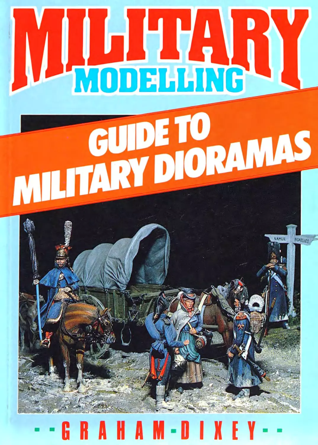
Cover photo: Napoleonic diorama by Michael Creese
PREFACE
In my previous book, The Art of the Model Soldier, the subject of vign-
ettes and dioramas occupied just two chapters. Therefore, when the
chance arose to write a whole book devoted solely to this aspect of
military modelling, I welcomed it. This is the result.
There can be few modellers who have not, at some time or another,
been impressed by a well-executed diorama. Exciting though a
beautifully painted and presented single figure may be, a diorama of-
fers an extra dimension. It is possible to make it represent a “frozen
moment of time”, rather like a three-dimensional photograph. This is
the essence of the “diorama” and it has nothing to do with how many
figures or horses or vehicles there are, or how much scenery is incor-
porated. A good diorama creates its impact from the arrangement of
the pieces in it, not the quantity of them.
It is possible that there are many modellers who already have some
experience of figure painting and now want to try diorama modelling
themselves. Perhaps they have, and have been less than happy with
the results. This book is written for such people. Here I hope they will
find both the inspiration and practical advice to allow them to realise
their ambitions to create a “tableau” (to use a possible alternative
word) depicting some event, historical or fanciful, that appeals to them
personally. The diorama is a means of self-expression beyond the
limits of the single static figure and each will have his or her own idea
of how it should be presented. Nonetheless, there is some basic
“know-how" that needs to be acquired to obtain the maximum impact.
This implies attention both to the arrangement or “composition” of the
diorama and to the modelling aspects.
Within these pages will be found photographs of my own work and
that of some of the best diorama modellers in the country. With the aid
of these photographs, supplemented by text and drawings, I have
tried to explore as many situations as possible and, therefore, to pro-
vide the broadest cross-section of the military modelling scene. My
aim was to create a book that did not merely instruct but would also
inspire, as well as acting as a useful reference to which the modeller
could return again and again. Writing it has given me a great deal of
pleasure; I hope it gives the same pleasure to the reader.
Harrow
1988
Graham Dixey
ACKNOWLEDGEMENTS
It would not be right if I did not acknowledge the help that I have re-
ceived from fellow modellers in the preparation of this book, in allow-
ing me to photograph the fruits of their labours and in providing the
specialist knowledge that has taken them years to acquire. Anyone
who reads this book will be only too aware of the frequent occurrence
of three names - Jack Higgs, John Hunter and Barry Bowen, all great
masters of the art of diorama modelling and very good friends. I am
happy to dedicate this book to them particularly.
I should also like to acknowledge my debt to Ken Jones, Editor of
Military Modelling, for the friendship and help that he has shown over
the years and the inspiration that he has often provided. To him I also
dedicate this book.
I must also make a final dedication, to my long suffering wife,
Carole, and my equally neglected daughter, Anna, and my apologies
to them for the long absences when I have been shut away with a
steadily accumulating pile of papers and photographs that, through
the skill of Rab MacWilliam and Folly Marland and the other staff of
Argus Books, eventually became what you now see before you.
1 THE APPEAL OF DIORAMAS
Before considering the diorama in detail, it may be as well to consider
the word itself. Only those totally new to the world of military modelling
will have no conception at all as to what is generally meant by a
diorama. Leafing through a dictionary, such as the Concise Oxford,
may bring a surprise. Paraphrasing what this particular dictionary
says, “a diorama is a spectacular painting which produces natural ef-
fects, sunrise for example, by the direction and colour of light falling
upon it”. There’s not a word about modelling in the definition!
From this it is obvious that the word has been borrowed and its
meaning modified to suit our own particular purposes. So, bearing this
in mind, what now needs to be done is to define more clearly what is
generally meant by a diorama, in modelling terms, and specifically
what it means in terms of the treatment given it in this book.
Fig. 1.1 A Vally goes to War, a splendid, largely scratchbuilt diorama, with a
touch of black humour, by Jack Higgs. A “Vally” is a Valentine tank.
In general, a diorama, as distinct from a single figure or group of
figures, is a representation of a scene, historical or fictional, formed
from a number of figures and related artefacts, whether natural or
man-made. In essence it is the three-dimensional “frozen moment of
time” mentioned in the preface. The figures and the rest of the scene
will have been placed in such a way as to show quite clearly some
relationship. In a good diorama every item has a meaning; it is not put
there simply to fill a space. Except for boxed dioramas, it is possible to
walk around it and see it from many different viewpoints. This in itself
implies careful thought to the layout.
Notice that there is no mention of size, nor any limit, lower or upper,
on the number of figures. Nonetheless, there tends to be a rather hazy
distinction between what many consider a diorama to be and other
types of scene such as vignettes and placquettes. The latter term will
not be considered further; it has little use these days and merely
serves to complicate matters further. The vignette may be thought of
as a kind of mini-diorama, usually based on no more than two or three
figures with minimal scenery. Thus, in this book, the vignette will be
considered as coming within the general class of dioramas and sub-
ject to the same rules. It has a chapter of its own so that it may be
considered as an introduction to the general subject.
In the presentation of a single static figure, the emphasis will be on
Fig. 1.2 Finished with Engines, another superb diorama by Jack Higgs; the
‘water’ consists of no less than 22 coats of varnish over a painted ground!
Fig. 1.3 The Liberators Liberated, a diorama by John Hunter. Many hours of
work went into creating this award winning model.
Fig. 1.4 The Fishing Party by Barry Bowen, something peaceful for a change!
An example of superb scenic modelling (only a fragment is shown here). The
tree, rocks and waterfall are particularly noteworthy.
good painting coupled with authenticity. An “action” pose will give
such a figure more life than a formal pose. Its appeal will probably de-
pend upon the subject itself, the manner of its painting and the way it
has been presented. Even a single figure may have some related
scenery. It is possible for it to become a “single figure diorama” if the
extra modelling is taken to extremes. Those readers who remember
Norman Abbey’s Mountain Man of a few years ago will know what this
means.
In a diorama good painting will still matter, as will authenticity. In
fact the latter will be especially important if the scene depicts an actual
historical incident. What will matter particularly in a diorama is the spa-
tial relation between the figures and their surroundings. There will also
be other modelling skills involved. The terrain itself will need to be
modelled; this may be flat, hilly, grassy, rocky, sandy, snow-covered;
may have trees, bushes, man-made features - bridges, buildings,
walls, fences - there may be a stream flowing through it, which will
have its own vegetation, perhaps ducks swimming on it, and so on -
the possibilities are endless.
Creating a diorama may well take the modeller into other areas of
figure modelling, such as “converting”. This is because the average
stock figure may not fit into the particular “scenario” that the modeller
Fig. 1.5 Salerno Salvo, another splendid model by John Hunter, showing great
attention to detail.
has in mind. The model soldier catalogues are full of fine figures, but
in the majority of cases they were meant to be seen as individuals.
There are exceptions and some will be seen in this book. Some manu-
facturers have created groups of figures in “action stances” that need
only be dropped into the appropriate scenery to create a diorama.
This is a good starting point, since it allows the modeller to concen-
trate his efforts on the aspects of composition and groundwork. Obvi-
ously a given set of figures can be rearranged, both in relation to each
other and their surroundings, an endless number of times. Many of
these figures are plastic ones, from makers such as Historex, Tamiya,
Italeri and ESCI. They fall into two time slots - those from Historex
mainly into the Napoleonic period, those from the other three makers
into World War II. Fortunately, these are two eras that are of great in-
terest to many modellers. There are, however, some fine and quite
suitable white metal figures. Tradition, Phoenix and Scale Link are
among the makers who produce figures that will slot easily into a vari-
ety of dioramas.
However, any modeller who wishes to produce a diorama for one
of the less popular historical periods may well have to convert existing
figures. Even where the right figures are available, some conversion
may need to be done. This might well be not so much a change of
uniform as a change of position, to make the figure take up an attitude
in keeping with the function he is performing in the diorama.
It shouldn’t be thought that this is an attempt to put anybody off the
subject. Far from it! The aim is to stimulate the imagination and to
show how exciting this aspect of military modelling can be.
Most people have their favourite period of history, that they enjoy
reading about, or studying the dress and weapons. A collection of the
armies of that time may constitute a study in itself, as well as being an
attractive talking point. The diorama takes it further - it allows the re-
creation of an incident that has appealed to the modeller’s imagina-
tion. It may be said to “breathe life into the figures” as they are placed
in their natural setting, whether they are locked in combat, advancing
on the enemy, engaged in conference, playing pinochle, taking a well-
earned rest or involved in any other of the many possible activities.
Boxed dioramas were mentioned earlier. These are less popular
than the “open” types, probably because they are often quite bulky
but also because of the need to make the box itself, a job that does not
appeal to everyone. The skills of assembling and painting model sol-
diers and those of woodworking are far apart. There is also the fact
that some form of lighting may be required, perhaps making it depen-
dent upon heavy and expensive batteries or upon a mains trans-
former, with associated wiring, switches, fuses, etc., if the job is to be
Fig. 1.6 Panzers on the Flank, another winning diorama by John Hunter.
Fig. 1.7 On Russian Soil, an interesting grouping of figures around a Greif
radio vehicle, also by John Hunter.
13
Fig. 1.8 There's a long, long trail awindlng, using the words of a popular song
of the day, a rare World War I trench diorama by G. Alexander.
done properly. Actually the type of woodwork involved in making the
“box” of a boxed diorama is not that difficult, largely due to the re-
sources of the modern DIY emporium and the excellence of current
adhesives that dispense with fancy joinery.
Those who have seen really effective boxed dioramas will under-
stand their appeal, at least to the viewer. There is a certain psychologi-
cal element present. Whereas the open diorama is exposed to view
from all angles, the observer of a boxed diorama is forced to view the
subject through glass from one direction only. He is, in effect, “peep-
ing through a window” into an encapsulated moment of history. There
is a decidedly theatrical aspect to the boxed diorama, which will ap-
peal to particular people. In this book, boxed dioramas have a chapter
of their own so that any doubts that may exist can be disposed of.
They can be bulky but they don’t necessarily have to be. Some boxed
dioramas can be hung on the wall like a picture! The electrical aspects
don’t pose any problems that common sense, understanding and
care, and perhaps some skilled advice, can’t solve.
In the chapters that follow, every attempt has been made to cover
the maximum number of options. From the essential initial planning
onwards, every phase of construction is shown and explained in de-
tail; many examples of geographical variation are described and the
use of the appropriate tools discussed. The techniques are more or
Fig. 1.9 Band of the Guard Grenadiers, a simple but effective grouping of
Historex figures by Peter Godden.
less independent of the size of the figure, apart from the matter of the
availability of proprietary parts. Probably most people will think in
terms of the “standard” figure size of 54mm, especially since there is
so much available from makers like Historex and Tamiya (actually
1 /35th scale in the latter case) for the diorama builder. But there is a
special appeal about the smaller figures, some of which are of ex-
tremely good quality, and these have a chapter of their own too, which
includes the “flat” figure. Whatever the choice, there is much pleasure
to be had in modelling military dioramas.
15
2 PLANNING THE DIORAMA
Every diorama is based upon an idea that has occurred to the model-
ler in one way or another. The question is, where does this idea come
from? What sources of ideas are there apart from sudden bursts of
inspiration? The answer is that there are many different sources, rich
in potential, upon which the diorama modeller can draw for themes for
dioramas.
For a start, there are paintings. For the 19th century, especially the
Napoleonic period, there are the masterly works of people like Lady
Butler, Lejeune, Detaille, Vernet, R. Caton Woodville and others.
Many a fine diorama has been created by taking a painting and turn-
ing it into a three-dimensional translation. This does not mean that the
painting is literally copied figure by figure onto a scenic base; in many
cases this would be totally impossible. Some of the painters referred
to painted on a large scale, cramming hundreds of figures on to their
canvases. In such cases, what has to be done is to isolate part of the
scene, just a few figures, and base the diorama on those. Study of
such a painting often reveals that, although a full-scale battle is in
progress, there is at least one group of figures that has been placed to
catch the viewer’s eye. A case in point is Edgar Paxson’s painting of
Custer’s Last Stand at the Battle of the Little Big Horn, in which the
whole canvas “heaves” with figures, living, dead and dying, men and
horses. To reproduce the whole scene as shown in the painting would
require an enormous diorama and would probably end up by being
merely confusing. Yet, on inspection, a particular group isolates itself.
This group pivots on Custer himself, standing out from the rest be-
cause he alone is dressed in fringed buckskins and a red scarf.
Around him, kneeling, are four troopers, one firing a revolver, the
others firing carbines; one faces forward (as does Custer), the others
face outwards in different directions. Just behind and to the right is a
trooper with a flag raised high and revolver drawn. This little group of
just six figures could quite well represent the spirit of the entire battle,
the outcome of which is well enough known. The arrangement of the
figures, facing all ways, epitomises the feeling of hopelessness, a fight
Fig. 2.1 Custer's Last Stand, an 80mm vignette, using Tradition figures.
against long odds, yet shows the essential determination to go on to
the end. The composition is well balanced by the fact that two figures
are standing (Custer and the flag bearer) and four are kneeling. Care-
ful grouping will give what is known as the classical “triangular” ar-
rangement. The firm of Tradition have interpreted this event with a
group of just three figures, including Custer himself, of course. The
result is an attractive vignette, which is shown in Fig. 2.1.
Books are an excellent and readily available source of inspiration.
Paintings appear in books, but so do photographs. In every major war
since the middle of the 19th century, a cameraman has been there
somewhere. World War II offers a vast amount of pictorial information
for every theatre of this great conflict. More material is being published
all the time. There seems no end to the enormous interest in this war.
World War I, less popular with modellers than its successor, nonethe-
less is extremely well documented and, in spite of its rather static na-
ture, still offers rich rewards to the imaginative modeller. Less global
but still significant wars are well covered too - the Korean war, the
Yom Kippur war, the Vietnam war, the conflicts that, sadly, continue
to rage in just about every part of the world all offer scope to the
diorama modeller.
Another source, and a good starting point for the newcomer to
diorama modelling, is a kit. There is a very good selection of kits that ---------
contain the ingredients of a vignette or small scale diorama. These ----------LL_
are available in both plastic form and as sets of white metal castings.
Naturally the plastic ones are a lot cheaper.
Tradition make a range of white metal diorama kits in 54mm, which
include The Retreat from Moscow, Parts One and Two; Camerone:
Danjou's Last Stand; The Retreat to Corunna (this is based on a paint-
ing by Chas. Stadden) and Rifle Brigade, Sebastopol 1854. The
number of figures in these varies between two and twenty, depending
upon the subject.
For those whose interest is World War I, Scale Link issue a
catalogue describing their range of 1/32nd scale figures and equip-
ment, all in white metal. The British, French and German armies are
covered and the general idea is that the modeller selects his own
combination of heads, bodies and arms, thus allowing a great variety
of possibilities and giving much scope for individual expression. The
figures are very well supported with all the everyday paraphernalia of
equipment, including both domestic items and small arms, that the
front line soldier would need.
In plastic kits there is a great variety in sizes from 25mm to 54mm
or the alternative 1/35th scale, 54mm actually being 1/32nd scale
(some say 1 /30th), though the difference is sometimes quite notice-
able and, at other times, quite academic.
A brief look at current catalogues from the makers of plastic kits re-
veals that a wide range of interests is covered, though perhaps with a
fairly strong bias towards two particular periods, namely the ever-
popular Napoleonic period and World War II.
Perhaps of particular interest to the beginner is the range of
“diorama kits” produced by the Italian maker ESCI. There are 28 kits
in the range altogether, of which 27 are World War II and the other
one, the Tet Offensive, of the Vietnam war. The scenario for each ap-
pears in colour on the box lid. These are in 1/72nd scale. A com-
plementary range to the same scale is their “Historic Battles” series,
which is more wide-ranging in its timescale. There are 15 kits in this
series, covering the time-span from the Romans on Hadrian’s Wall to
the Foreign Legion wars of 1912. However, these are essentially for
wargaming, since the contents run to several hundred pieces.
Good composition is vital to an effective diorama. It is very impor-
tant to have some knowledge of the subject if the finished diorama is
to do what the modeller intends. Creating a diorama is not just a mat-
ter of having an idea and then randomly laying out figures, vehicles
and other items on a base with some contrived groundwork. Nor does
it mean slavishly copying the detail of a painting, as discussed earlier.
The “elements” (an element is any item in a diorama) of a diorama
must have a proper relation, not only to each other, but also to the
base itself. This could obviously be overcome by using a round base!
However, while this may sometimes be a good idea, many dioramas
are more suited to a rectangular or oval shape of base. Of the two, the
rectangular is much easier to make. This won’t matter if only ready
made bases are going to be used, but the chances are that many
modellers will want to make their own, especially for the diorama of
any size. Very large mahogany bases can be prohibitively expensive,
even if they do look very nice.
As an example of composition, suppose that the chosen subject
consists of several figures (perhaps with a vehicle) moving along a
road. Running alongside this road is a grassy bank on which grows a
tree. If the road and the grassy bank were laid parallel to the long edge
of the base, this would give a most uninteresting composition, espe-
cially if the tree was placed in the middle of the bank. It would now
matter little where the figures or vehicle were placed because the
basic layout would be so poor. So how can it be improved? The ques-
tion almost answers itself.
Instead of having a long, uniform and, hence, rather boring grassy
bank, a much better idea would be to build a rather shorter section
and place it diagonally across one corner. The remaining area then
becomes the road. The groundwork doesn’t have to divide the base in
two; either the road can be slightly larger in area or the grassy bank
area can; it is a matter of personal choice. The net result is that, in-
stead of there being two rectangles, as in the original composition,
there are now two areas that are roughly triangular.
The placing of the figures is now quite important. It could be argued
that they could be placed to the left, in the middle or to the right. How
do we make a decision? If the tree is at the right, the last thing that
should be done is to place the figures there too, since the arrange-
ment will be quite lop-sided, that is “unbalanced”. This is because all
of the interest is at one side of the base. This leads to the obvious
deduction that the best place to put them is at the left. If this is done,
the balance of the composition will be greatly improved. It is a good
starting point, but is not the only possibility. If there are several figures,
they might not have to be in a group; one or two could be detached
from the rest. For example, one might be level with the tree and the
remainder at the other end of the base. Or they might be strung out
uniformly along the road. Either of these would be much better than
the first composition. The last point to argue is whether the figures
should move towards the tree or away from it. The most effective way
to demonstrate this point would be to try both. It should be found that
the case where the figures are moving towards the tree is the stronger ----------
one. Surprised? The reason is simple. ------——
The eye tends to follow the direction of movement of the figures.
Where they are moving away from the tree the eye follows them and
moves out of the scene (the last thing that is wanted). Where they are
moving towards the tree, the eye follows them but then comes up
against the tree, which stops it leaving the scene. Any significant ob-
ject can be used in this way, to prevent the eye from straying away
from the area of interest. Other examples are a piece of ruined build-
ing or a lamp-post or telegraph pole.
Perhaps this seems rather too psychological. Well, that’s what
composition relies upon after all, our response to what we see. But it
isn’t necessary to study Freud to get the layout of a diorama right!
There is an easy “trial and error” way of designing it. Since the layout
affects our own reaction to a diorama, it is easy to test whether a par-
ticular arrangement is weak or strong, just by placing the major ele-
ments of the diorama within a rectangle (to represent the base) ruled
on a piece of paper. Taking a sensible starting point, these elements
can then be shuffled around until the composition seems right. When
satisfied, the positions of the elements can be marked out, later to be
transferred to the real base.
In general when placing figures, they should not be spread out
evenly within the base area, because this lacks impact. A group
“doing something” attracts the attention. A group may be balanced
by a single figure placed elsewhere in the diorama, or even by another
group that is either smaller or larger, or by an object such as a tree,
bush, part of a building, a vehicle, drinking fountain, telegraph pole,
lamp-post or any one of a wide range of possibilities.
One of the fascinating things about rules is that sometimes it pays
to break them. This may be the case when an attempt to follow a rule
rather slavishly is not giving quite the result that is wanted. To take an
example:
Consider the rule about not having the edge of a major element
parallel to the edge of the base, as just discussed above. Having said
why this should be followed, it is now possible to see how not to do so
and yet still get an interesting composition. A common example of this
is where use is made of the corner of a ruined building. This, of course,
has two straight edges at right angles and it would be quite feasible to
rotate it so these edges were at some angle to the base edges. But it
is equally possible to align the building so that its shape “echoes” that
of the base. Then the major element/s could be placed within the open
side of the ruin at an angle to create the interest. There are numerous
possibilities that include artillery, tanks or infantry positioned to fire
through the door or window openings.
It is possible to sum up the stages of planning a diorama as follows.
(1) Decide on the period in which the scene is to be set.
(2) Determine the location for the action, hence the type of
groundwork (in the loosest sense of the word) required - town or
country, indoors or outdoors, forest or desert, on land or at sea (in the
air?).
(3) What is the story line? What will be included to tell the story? It
is important to remember that every item in the diorama must be there
for a reason, either because it is directly involved in the plot or be-
cause it would be there naturally (referring to minor items, such as
clothing, arms, food, pots and pans, etc.). A scene should never be
cluttered up just for the sake of it; instead, every item should be made
to tell.
(4) The cast - who are they? What is their relation to each other in
the story? Is there a source of figures that are directly suitable or can
be converted?
(5) How large will the base need to be? Related to this question
are some others.
(i) What scale will be used?
(ii) How many figures and other items will be needed?
(6) Experiment with the composition. Place the figures, and other
scenery items (or something to represent them), on a sheet of paper
and move them around until the best arrangement is found. Mark their
positions on the paper. Alternatively this can be done directly on the
base if the material for this is to hand.
One final word about designing the layout of the diorama. It pays to
look at the work of other people and make notes of how they achieve
their effects. Then base your own dioramas on such sound ideas. It
isn’t slavish copying: it is learning by example. Use your own props
but within the type of framework that appeals to you. Soon, the design
of a new diorama will become second nature, and perhaps others will
then start to copy your efforts!
Making bases for dioramas
The bases for dioramas are generally larger than those used for single
figures or small groups. This means that proprietary bases are going
to be quite expensive. A large mahogany base with a nicely moulded
edge and baize underfelt will cost quite a few pounds, though the ap-
pearance may justify the outlay. However, modellers, being the practi- -——
cal people that they are, often like to go the whole hog and make the --------
base as well. No great woodworking skill is needed and the end pro-
duct can be very attractive without having cost a fortune.
For a start, it is best to forget about natural wood. It may be possible
to find offcuts of good quality wood, but they should be examined
carefully for flatness and the wood must be well seasoned if it is not to
warp later. Traditional woodworking skills will be needed to get a satis-
fying end result. What is about to be described is for the DIY person,
not the skilled “chippie”.
The offcuts that are wanted from the local timber yard are those of
that much maligned material “chipboard”. The grade to look for is the
very smooth, “close-grained”, thinner type of board, about a half-inch
thick, though the thicker, sometimes slightly coarser material can also
be used, especially for large bases. Offcuts are usually incredibly
cheap and a year’s supply will cost almost nothing. In spite of not
being “real” wood, chipboard does have its own unique advantages.
Because it is not a living wood, it doesn’t change its shape, subject to
two provisos - that it is well supported and is kept dry. In this particular
application both of these conditions are easily met. It cuts easily with
a sharp saw and can be filed in any direction with a rasp.
What it doesn’t do, in its raw state, is to look nice. Fortunately this
can be overcome by veneering it. Iron-on veneer is obtainable, in dif-
ferent wood finishes, from good DIY stores. It is very easy to apply
and can be varnished to a nice finish after its surface has been lightly
Fig. 2.2 Tools and materials for making cheap but attractive bases.
Fig. 2.3 “Iron-on veneer strip” means just that; a hot iron and firm pressure
fixes the veneer firmly in place.
Fig. 2.4 Most of the excess veneer can be removed with a large craft knife.
Fig. 2.5 A razor plane is very useful for a clean finish.
Fig. 2.6 The first stage in cutting the mitre is to attach two overlapping strips by
the centres only.
24
sanded. Because most of the surface area of the base will eventually
be covered by groundwork, it is only necessary to veneer the vertical
edges and the top edge all round for a width of, say, %in. This is the
usual width of iron-on veneer strips anyway, although it is also possi-
ble to get it in a two-inch width as well. This leaves a bare rectangle in
the middle for the groundwork. The latter can be restrained in one of
two ways. Either a thin stripwood retaining wall can be fitted all round
to act as a natural boundary for the groundwork material; or the
groundwork can be finished in a way that some people prefer, as a
“cliff-like” edge which, if worked with a spatula while still wet, will give,
after painting, a natural rocklike appearance.
To make a base by the method to be described, the following are
needed. First, a piece of chipboard cut to the required size. To calcu-
late the correct size, it is simply necessary to know the length and
breadth of the “diorama itself”; then one-and-a-half inches (about
4cm) should be added to each of these dimensions to allow for the
width of the veneers that will form a finishing border on the top surface.
The chipboard can be marked out with a pencil, square and ruler, cut
out with an ordinary handsaw and cleaned up with a rasp, ensuring
that the edges remain as square as possible. To attach the veneer
strips themselves, an ordinary domestic iron, set fairly high - say on
the “cotton” setting - is needed. Also needed are a sharp, heavy duty
craft knife, a glasspaper block and, if it is available, a razor plane.
Fig. 2.2 shows some of these essentials.
The procedure for veneering the base is to deal with the vertical
edges first. The four strips should be cut just overlength. Each is
placed in turn along one edge of the chipboard, the edge of the strip
being aligned with the edge of the chipboard (it may be wider than the
chipboard itself) and the hot iron run smoothly but firmly along it, back-
wards and forwards several times, maintaining a firm, constant pres-
sure (Fig. 2.3). This operation will be a lot easier if the piece of chip-
board being veneered is held in a large vice such as a Workmate. The
adhesive will soon melt and attach the veneer in place. It should be
checked for soundness all the way along and the iron re-applied any-
where where it seems less than secure. This iron-on veneer strip is
very easy to use and quite forgiving. Should it be positioned badly at
first, it can be removed by re-heating it with the iron and peeling it off.
It can then be re-attached in the correct position. As soon as the ven-
eer has cooled it should be found that a sound joint has been made.
The surplus veneer can then be carefully pared off with a heavy duty
craft knife (Fig. 2.4). A razor plane (Fig. 2.5) is very useful for removing
the last bit of material, after which final finishing can be done with a
glasspaper block.
Fig. 2.7 A steel ruler is placed across the overlap at the required angle to guide
the knife, which must cut through both pieces.
Fig. 2.8 The result is a perfect mitre after a hot iron has been passed over the
join.
26
Fig. 2.9 Strips of obechi can be cut with a razor saw and glued inside the veneer
to act as an edge for the groundwork.
This procedure should be repeated for the other three sides and
attention then turned to the top sections. They should also be cut just
oversize; it is easier and better to trim away surplus material rather
than try to fill small gaps. The success of this phase of the construction
is going to depend upon how well the mitres are cut. The better they
are cut, the neater the result will be. It is possible to use a set-square
and pencil to mark out a line at 45 degrees across the end of each
piece. However, it is surprising that, no matter how much care is
taken, when two pieces are marked out and cut out individually in this
way, there is often a discrepancy. But there is a very simple way of
cutting mitres and getting a perfect fit every time.
First of all two strips of veneer should be cut to length, one long side
and one short side. Using the iron, these should be attached in their
correct positions but by “the middle only”. The end of one will overlap
the end of the other. This is shown in Fig. 2.6. If a steel ruler is placed
across the junction of the two strips, running from the inside corner to
the outside corner, this will define the cutting line for a mitre (Fig. 2.7).
Now using a sharp craft knife, and holding the ruler firmly in place, it is
possible to cut down - using several light strokes rather than one
heavy one - through both veneer strips at once. The result will be a
guaranteed perfect mitre every time. Even if the ruler is not held at ---------
exactly 45 degrees, this won’t matter. The two pieces match perfectly ---——
and that is what really matters. How effective this can be is shown in
Fig. 2.8.
After trimming off any surplus with a sharp knife, all of the veneered
surfaces should then be thoroughly sanded. The top horizontal edge
and the corner vertical edge should be rounded off slightly; it will look
neater and protect the edge of the relatively fragile veneer.
At this stage, if it is required to fit strips of wood within the rectangle
defined by the veneer strips, this should be done. Thin strip wood,
such as obechi or a similar hardwood from a model shop, can be cut
with a razor saw, cleaned up with a glasspaper block and fitted in
place with PVA glue. The base, at this stage, is shown in Fig. 2.9.
To get a really nice look to a veneered finish it can be given two
coats of “button polish” (shellac), rubbing down between coats when
dry, followed by two coats of satin varnish. See Figs. 2.10 and 2.11.
One addition that is worth making to a home-made base is a piece
of felt on the underside. This will give protection to any surface on
which the finished diorama subsequently stands and will help to fend
off any possibility of domestic discord that might otherwise result! Felt
can be obtained in craft shops and the ideal adhesive is Copydex or a
similar latex preparation. The felt should be cut so that its size is
slightly less than the area of the base; it will not then actually be visible.
A coat of Copydex should then be applied evenly over the underside
Fig. 2.10 Button polish (shellac) gives the wood a nice colour.
Fig. 2.11 The final finish can be given with a coat or two of satin varnish.
Fig. 2.12 To protect any surface on which the base may have to stand, a piece
of felt should be attached to the underside with Copydex or a similar latex
adhesive.
of the base, using the built-in brush, and the felt immediately placed
carefully in position and smoothed down. See Fig. 2.12.
Bases made by the above method are inexpensive and practical
and can be made exactly to the required size; they will nicely comple-
ment the fine work that it is hoped will shortly grace the area above!
30
3 TOOLS AND MATERIALS
Tools
Modellers with some previous experience will already have a good
selection of tools suitable for modelling dioramas. There are a few
extra, not very expensive, items that may be worth acquiring. These
will be discussed in their turn. Adhesives perform a vital role in model-
ling and, of the vast array on the market today, some are more suit-
able for particular jobs than others. A great variety of materials exists
to allow the creation of an even greater diversity of subject matter.
Reviewing the requirements for tools, those for cutting will be con-
sidered first. A possible selection is shown in Fig. 3.1. A small craft
knife with a selection of different blades, or the Swann-Morton knife
with just one straight blade and one curved one, will find many uses.
As an alternative, a surgeon’s scalpel is popular with some modellers,
and a good selection of blade types is available for these, of a not sur-
Fig. 3.1 A selection of cutting tools.
31
Fig. 3.2 Some of the tools for shaping various materials.
prising sharpness! A rather heavier knife that is well worth having is
the heavy duty craft knife, sometimes known as a “Stanley” knife, but
actually made by a variety of makers. It is preferable to buy one that
has a retractable blade for safety. These are very good for cutting
such materials as heavy gauges of cardboard and plastic card. If the
blade is new it will slice cleanly through sheets of expanded polys-
tyrene, not the easiest of materials to cut, in spite of its softness, un-
less the knife edge is really keen. For rather rougher, less scientific,
work, a heavy duty knife of this type can be used for scoring wooden
bases to improve the adhesion of the groundwork materials. Another
very useful cutting tool, especially for stripwood, is the razor saw.
Scissors are also cutting tools, of course, and the key here is
"always to buy the best that can be afforded”. One good, sharp pair
will meet most modelling needs.
Tools for shaping various materials (see Fig. 3.2) include files,
among these a few needle files of different sections - round, flat, half-
round and knife-edge being the most useful for general modelling, in-
cluding scratchbuilding various man-made structures, such as build-
ings, bridges, etc. They will also be found useful when it comes to as-
sembling similar items from proprietary kits of parts. One or two some-
what larger files will almost certainly come in useful now and again,
such as a six or eight inch half-round, perhaps one bastard and one
second-cut. A wood rasp, especially a double-sided one, will be useful
for shaping chipboard for making diorama bases.
Fig. 3.3 Some of the variety of tools of use in diorama modelling.
Also playing an important part in the shaping and finishing proces-
ses is abrasive paper. A selection of several grades from quite coarse
to extremely fine (glasspaper through to flour paper) will be useful,
plus a sheet or two of “wet-and-dry” paper. For most operations the
use of abrasive papers needs some control, either by laying a sheet
flat on the bench and rubbing the part over it, or holding the paper in a
glasspaper block while the part being operated on is held on the
bench or in a vice, depending upon circumstances. Holding both ab-
rasive paper and workpiece in the air is not conducive to accuracy.
Then there are drills. Probably most people own a power tool these
days, though a hand drill with a small selection of drill bits will do just
as well. For the small, more fiddly drilling operations, a pin-vice or two
with some correspondingly small bits will come in handy. There’s no
real need for mains power for most jobs, though it can be a boon for
the bigger stuff, especially when it comes to assembling largish boxed
dioramas.
So now for the miscellaneous items (most are shown in Fig. 3.3) -
a really mixed bag! Top of the list is a pair of tweezers for handling
small parts. Next come a few clothes pegs (for “putting the squeeze”
on parts as they set), an artist’s or chemist’s spatula (for mixing up
groundwork materials), a small trowel for handling larger quantities of
the same, a plastic syringe (for adding small, controlled quantities of
water to plasters, etc.), some model-maker’s G-clamps (various --------------
uses), a selection of brushes, some for painting and some for working -^3—
Fig. 3.4 An airbrush
is excellent for
colouring ground-
work, though it is a
luxury and not a
necessity.
over the wet groundwork; also for painting, if the budget will stand it,
an airbrush (Fig. 3.4). A small pair of fine-nosed electronic assembly
pliers (preferably with built-in side-cutters) will be useful when it
comes to cutting and forming wire, for example when making bushes
and trees.
Larger tools may be required if anything really ambitious is going to
be tackled. Ambitious here means large-scale dioramas, open or
boxed, involving substantial amounts of woodwork. Then one has to
consider saws of various types, chisels, a plane, hammers, and so
on. It’s really getting away from the general run of model dioramas,
though some of these tools will be needed for assembling boxed
Fig. 3.5 Some of the most useful adhesives.
Fig. 3.6 The types
of plaster most
commonly used for
groundwork,
including the slightly
unusual “Topsoil”.
dioramas, and a saw will be needed for cutting chipboard to size. Any
special tools needed for making boxed dioramas will be discussed in
Chapter 10.
Of the vast range of adhesives available on the market today, there
are a few that will cover the whole of the modeller’s needs (Fig. 3.5).
For joining polystyrene parts, whether of figures or other assemblies,
the best adhesive is liquid polystyrene cement. It is much nicer to use
than the tube variety, much more controllable and totally free from
“stringing”. There is a choice of makes, Humbrol being the one most
people think of, but Slater’s Mek-Pak and EMA Plastic Weld are suit-
able alternatives. A number of kit-makers also have their own branded
bottles of polystyrene cement.
For wood-to-wood joins, white PVA glue is really very good, and it
can be used for other materials too, especially paper and cardboard,
but also for expanded polystyrene. Other adhesives all with their own
uses are latex adhesives such as Copydex, epoxy adhesives, of
which Araldite Rapid is a representative of the class of “fast” epoxies,
a contact adhesive such as Bostik Clear or Evostik and those tiny
tubes containing the cyanoacrylates (the so-called “super glues”).
With regard to the latter, the conventional “thin” variety has now been
supplemented by a thick variety that has better gap-filling properties.
Materials
The materials for diorama modelling are many and various and will be
discussed in detail as and when they are employed. The following is a
brief survey of some of the more usual materials and other items that
are likely to be useful.
Looking for neat sub-headings for the various classes of materials
leads to the following possibilities: materials for:
Fig. 3.7 Materials
for various textural
effects include flock
grass, cork
“boulders”, dried
lentils, rocks and
sand.
(a) Ground contours.
(b) Surface textures.
(c) Natural vegetation, including bushes and trees.
(d) Buildings of various types.
(e) Simulating water.
(f) Furnishing the diorama.
(g) Finishing the diorama.
The term “materials” is used in a very broad sense here. It includes
not only raw materials but kits for making any part of the diorama, as
well as ready-assembled proprietary parts that are of use as well. Tak-
ing each in turn.
(a) Ground contours will vary from completely flat terrain, through
landscape incorporating undulations, ditches, river banks, etc., to the
Fig. 3.8 One packet
of cork bark, very
useful for modelling
rocky landscapes.
36
Fig. 3.9 A variety of
fine veneers, from
model and craft
shops, easily cut
with a sharp knife
and a steel rule.
more extreme case of very hilly landscape. Where large variations of
level occur, what is required is “bulk” without excessive weight. The
usual way of achieving this is to use a light, laminated core of ex-
panded polystyrene (ceiling tiles are ideal), covered with a layer of
some form of plaster. It is possible to use builder’s plaster, Polyfilla,
Tetrion or dental plaster, to name some of the most commonly
employed varieties (Fig. 3.6). For the modeller there is a product de-
signed for the job, called Carr’s Topsoil. This is quite different in nature
from, though said to be compatible with, the other materials men-
tioned and is pleasant to work, giving plenty of time for achieving the
required contours and surface texture. It also has the great advantage
of remaining workable for long periods of time if it is put into an airtight
plastic container. This makes it particularly economical since, if too
much is mixed up at a time, the surplus can be kept for a later date.
(b) There are numerous types of surface to consider, both natural
and man-made. Whereas natural surfaces will often be laid over a
core of groundwork, as described in (a) above, this will not necessarily
be so for all man-made surfaces and almost certainly won’t be the
case in town scenes. Road surfaces can vary from smooth asphalt to
cobbled. The former can be obtained by little more than an airbrushed
coat of paint. A cobbled surface can be obtained, in the smaller
scales, by using embossed plastic card (found in model railway
shops) and, in the larger scales, by the use of split peas or lentils. The
materials for natural surfaces can usually be found in a model railway
shop, including such items as scatter grass (flock), fine sand, cork
“boulders”, track ballast (useful for a really rough surface), and so on.
One’s own garden may also prove a useful source of small stones
which can be incorporated into various landscapes. Cat litter can also -----——
be used to represent small rocks. Some of these materials are shown -------------
in Fig. 3.7 while Fig. 3.8 shows the contents of a single pack of cork
bark, enough for quite a bit of rocky landscape.
There are also indoor surfaces to consider, which are usually of
stone (or tiles) or wood. The making of these will be discussed in the
appropriate place but the material for the latter is worth a mention
now. Marquetry veneers (Fig. 3.9) can be obtained in a great variety
of different woods and lead to the possibility of producing some really
splendid floors, if the modeller is sufficiently dedicated. Even a plain
planked floor, properly finished, can look very attractive using these
quite inexpensive materials.
(c) Natural vegetation needs to be done well to be effective. Grass
in very small scale dioramas is best suggested by “texture” alone.
Very fine sand, with washes of green, yellow and brown paint can be
very effective. There’s no need to represent every blade of grass. At
the larger scales, something else is called for. Scatter grass can be
used effectively, especially if it is over-painted afterwards, to eliminate
its often unnatural colour. Coarse clumps of grass can be produced
by unravelling sisal string and colouring it. Bristles cut from domestic
brushes are also useful for representing rushes and other tall plants.
A very effective, close-cropped grass effect can be obtained by using
a West German product called Sander Struktur Scenery Mat, which is
available in several shades (Fig. 3.10). This can be cut up and, to
some extent, forced to follow the contours of the ground. It looks very
realistic, can be coloured locally for greater realism, and allows bare
patches to be created (for footpaths, etc) by wetting and scraping the
appropriate area.
Trees and bushes will generally need to be made. Those in model
railway shops are often unsuitable as sold, since they tend to lack
realism. It is possible to improve them, however. A “bare” tree can be
Fig. 3.10 Sander
Struktur scenery mat
offers the easy way
of simulating grass.
Fig. 3.11 A variety
of vegetation
available from model
railway shops
includes the very
useful foam plastic
leaves.
made from scratch from twisted wires, covered with Tetrion "bark”; to
this can be added foam "foliage” or “leaves” which are sold in packets
and come in a number of different shades and grades; these are
shown in Fig. 3.11 together with some foam plastic vegetation and
small scale hedging from the model railway shop. Of course, if it’s
winter, the leaves can be left off the trees completely. Another ap-
proach is to find small, dried twigs and trim them to tree-like shapes
and then add leaves as before. These techniques are discussed in
more detail in Chapter 6.
Other ways of representing nature will be met later; it is surprising
just what can be pressed into service - dried, coloured tea leaves,
sphagnum moss, dried decorative grasses, for example. It is advis-
able always to be on the look-out for possibilities.
(d) Buildings rarely need to be built to their full depth. They would
normally be far too large, for one thing. A common trick, especially in
a World War II scenario, is to include a section of a ruin, often just a
Fig. 3.12 There is a
great variety of
plastic kits for
buildings and
accessories.
39
Fig. 3.13 Building
kits in resin are also
available; this is a
Normandy farm kit
by Francois
Verlinden.
Ag. 3.14 Part of the
Langley ‘system’
described in the text
for producing 1/76
(OO/HO) Victorian/
Edwardian buildings.
corner of the building, with a convenient doorway and window. These
can be built from scratch, but a very good selection is available from
such makers as Verlinden and Italeri, in 1 /35th scale. They also pro-
duce other useful scenic accessories such as wells and fountains,
which can be included in large dioramas or form an attractive centre
piece of a smaller vignette. Examples of these are shown in Figs. 3.12
and 3.13. Naturally the range, from an architectural point of view, is
limited, and not everyone wants ruins in their dioramas. This usually
means scratchbuilding, the materials for which include plastic card,
cardboard and balsa, all easily obtainable.
In 1/76th scale (OO/HO) Langley Miniature Models produce a
splendid range of shop-plus-upper-storey facades with a full range of
fittings, that can be used anywhere in the Victorian to 1950s time
range (Fig. 3.14). The facades themselves are of a special vac-
formed plastic, with white metal and etched brass fittings. A wide
range of different buildings can be made by using different combina-
tions of lower and upper storeys as well as varying the choice of other
architectural details.
Fig. 3.15 Some
modellers like using
casting resin for
producing the effect
of water in dioramas.
Fig. 3.16 Especially
for the Napoleonic
modeller, Historex
market many useful
accessory kits.
(e) There are several ways of representing water, each being
applicable to a particular type of presentation. It is possible to sculpt
the water out of plaster and paint it. This allows the creation of large
waves (as seen later in the vignette using the Italeri frogmen). Another
method is particularly applicable where the maximum impression of
depth is required, perhaps with the inclusion of some underwater de-
tails. This method is based on the use of clear casting resin (Fig. 3.15),
to which is added suitable colouring agents, such as thinned paints or
animal or vegetable dyes. Other methods include building up the feel-
ing of water by using layers of varnish or glue over an area that has
been previously painted. This can be used at any scale but is particu-
larly useful for small scale dioramas, where casting resin is inappro-
priate, or for very shallow water, such as pools or even puddles in
larger scale dioramas. It can also be used very effectively, if properly
done, for deep water as well - provided that no underwater details
need to be seen.
(f) Furnishing the diorama simply means providing the little details ----
that give life to the scene. This includes such things as tables and
Fig. 3.17 A
selection of Carr’s
weathering powders.
chairs, crockery, bottles and cutlery, hams, chickens and other items
of food, weapons and equipment (the latter in the broadest sense),
and so on. Such items are not all that difficult to make. Simple furniture
can be made from balsa or plastic card and many other small items
can be formed from Milliput epoxy putty and painted. However, there
is a good variety of such “impedimenta” to be found in various
maker’s catalogues - Historex (Fig. 3.16), Verlinden, Tamiya, Italeri,
Phoenix, etc. Thus, much extra detail can be added quite easily.
(g) Finishing the diorama, in the sense intended here, means apply-
ing techniques to it that turn it from a slickly painted model into some-
thing living that, through the lens of the camera at least, would be dif-
ficult to tell from the real thing. To take a common illustration or two -
a vehicle straight from the factory doesn’t stay that way very long on
active service; what it needs is weathering. A uniform doesn’t stay in
pristine condition for ever either; it also needs some treatment to give
it a worn look. Two possible techniques for producing this extra di-
mension are drybrushing and the use of weathering powders. For the
latter, Carr’s have produced a series of weathering powders (Fig. 3.17)
that cover every possibility from the growth of fungus, through red
rust, to a really sooty look! Used subtly they are a valuable aid to en-
hanced realism.
The above survey could be extended almost indefinitely. Many
other materials will suggest themselves to the dedicated modeller
who keeps his eyes open and his mind alert. New products are com-
ing onto the market all the time. The basic ingredients are there; it is
now time to do something about putting them together.
42
4 VIGNETTES
While the vignette is undoubtedly an art form in its own right, it is also
perfectly reasonable to consider it as an introduction to the art of
diorama modelling generally. It is subject to the same basic disci-
plines, needs the same care in preliminary planning in order to get the
composition right and will often involve making various items. It will
almost certainly require some form of groundwork to be applied to the
base. As an introduction to diorama modelling, it has the advantage
that quite a few makers produce small groups of figures (two or more),
sometimes with one or two related items, that are specifically meant
for the creation of vignettes. This offers an inexpensive lead-in to this
aspect of the hobby. For those with some ability at converting figures
it offers a fascinating path to a highly rewarding activity. It is also not
too difficult to summon up ideas for small groups of figures. Large
Fig. 4.1 A simple vignette, ideal for the novice, using a stock kit.
quantities of figures tend to be more difficult to place in a satisfactory
composition.
It would be useful to consider some of the formulae that have been
used successfully in the past. These will give a number of possible
starting points for a variety of individual and interesting vignettes. In a
sense, they are rather like plots for short stories. Each has a particular
structure around which many quite different stories can be told,
merely by interpreting the “plot” in a unique way. Listed below are ten
possible arrangements for vignettes (there are others that may occur
to the reader).
(1) A single figure, mounted or on foot, in an informal pose, with at
least one other major prop. Examples for the latter include a fountain,
drinking well, piece of fence, gate or wall, tree, etc.
(2) Two figures, one mounted, one on foot. The two figures should
have an obvious relationship. For example, the mounted figure (a
man) may be leaning down out of the saddle to speak to the other
(perhaps his girl whom he is leaving behind). Any props used should
form an unobtrusive background only, a low fence, a small tree, etc.
(3) Two, possibly three, figures in action. They could be standing or
kneeling (firing over rocks, sandbags or a low stone wall?). To create
Fig. 4.2 A vignette using a number of stock figures and one minor conversion.
One soldier seems unaware or indifferent!
a more interesting arrangement, they should not all face in exactly the
same direction.
(4) An indoor scene, two or three figures (or even just one). Usual
props for this sort of scene are tables and chairs, with the utensils for
eating and drinking. It is possible to suggest a particular type of indoor
scene, with just a few interior details - a section of floor: wood parquet,
wood planked, tiled or quarry stone, wooden panelled walls, papered
walls, a picture or two on the walls, a dog stretched out in front of a fire.
In fact, it is not absolutely necessary to provide any walls at all. The
floor and the other props can be used by themselves to put the ar-
rangement into the proper context.
(5) Three figures, in a “triangular” composition, the centre one
being behind the others and raised in some way, perhaps on higher
ground or higher simply because he is standing and the others are
kneeling. This has two effects - it makes the arrangement more in-
teresting and also strengthens the basic composition. The “triangle”
doesn’t have to be regular; it can have its apex to one side or other of
the group.
(6) Two figures, one seated and the other standing. The one seated
could have his back against a tree, while the other could be leaning
Fig. 4.3 The Italeri frogmen set in action on a plaster sea - fully described in
Chapter 7.
45
nonchalantly against the trunk. They can be made to relate in various
ways, by having them conversing or sharing a drink, to quote just two
examples that spring easily to mind. A deceptively simple arrange-
ment like this can be made to be very effective.
(7) Three figures with an artillery piece, firing through a broken wall
or fence, through the doorway or window of a house, or over a piece
of high ground or hedge, in the case of high angle pieces such as mor-
tars, bombards or howitzers. This composition is frequently used for
World War II vignettes but can be utilised over a very wide time scale.
(8) Small vehicle in “action”. The word action is stressed here delib-
erately because many modellers, having made a very nice model,
usually simply display it by placing it on a perfectly flat surface such as
a piece of roadway, as if that says enough by itself. In fact great in-
terest can be created if the vehicle can be caught “airborne” (or partly
so) as it bounces on a piece of rough ground. Jeeps, Landrovers,
KObelwagens, motorcycle combinations can be portrayed in this way,
but it is better if the occupants are not firmly glued to their seats; more
atmosphere will be created if they are themselves half out of the
vehicle! As an alternative, an amphibious vehicle such as a Schwimm-
wagen could be shown coming out of a river, or a tank in similar
circumstances.
(9) Two figures, both seated, engaged in some peaceful pursuit. A
possibility is that they are fishing from a bridge, punt or landing stage.
Or they could be carousing (a few bottles in evidence and all their
equipment, plunder, etc., strewn around), or playing cards.
(10) A single horseman, seated on a log, large rock, etc., his horse,
unsaddled, drinking or grazing nearby.
Well, there are some ideas that may provide some inspiration for a
first vignette, or for further vignettes if one or more have already been
attempted. Each of these basic “plots” is capable of being embodied
into a wide variety of vignettes, regardless of time period or geographi-
cal location.
With regard to the illustrations that have been chosen for this chap-
ter, here are some brief background details.
The first of these, Fig. 4.1, shows how simply a scene can be
created by taking a commercially available kit and providing just a little
groundwork to complement it. The kit in this case is Tamiya’s U.S.
107mm mortar and crew and it is this type of kit that is ideal for the
beginner. The box art shows how to relate the figures and all the mod-
eller has to do in addition is model a little groundwork - in this instance
Fig. 4.4 The charm of the Regency period and Phoenix figures. Vignettes like
this show that dioramas don't always have to be about the bloody side of military
history.
Fig. 4.5 Yet another side to a soldier’s life! The boredom of waiting for a train -
In Transit by Jack Higgs.
47
Fig. 4.6 As if Fig. 4.5 wasn't enough, this little scene in a Nissen hut will remind
old sweats of “happier” times! It is entitled What did you do in the war, Dad? and
is modelled by that humorist, Jack Higgs.
some level, grassy ground with a rock or two and some scrubby
bushes. The rocks are cork bark and the bushes come straight from a
packet of foam plastic vegetation, bought in a model railway shop.
The next scene, Fig. 4.2, uses a combination of two plastic kits and
a metal one. The plastic kits are Tamiya’s for the four seated German
soldiers and Italeri’s for the fountain. The metal kit is actually a minor
conversion of a Chota Sahib A.T.S. girl into a Luftwaffe Signals Aux-
iliary. The groundwork is an area of a cobbled square, the construc-
tion of which is shown in full in Chapter 5. This is an example of an
idea conceived by noting the attitudes of the Tamiya figures (all stock
types) and then giving them something of interest to look at. It’s just a
matter of knowing what is available.
Fig. 4.3 provides an aerial view of a vignette that also uses perfectly
stock figures (and an inflatable), all in one box by Italeri. What gives
the result individuality is the presentation, the boat riding what is obvi-
ously quite rough water. The latter is sculpted from plaster and
painted and varnished to obtain the required effect. This process is
explained in full in Chapter 7.
Phoenix 54mm metal figures and a chaise-longue from the same
maker have been used for the little vignette of Fig. 4.4. They are
standing on a polished wood, planked floor made from marquetry
veneers. The laying of this floor is described in Chapter 5. This could
be extended further by adding other accessories but the uncluttered
approach at least focuses attention on the figures and their arrange-
ment. The title is Conversation Piece. The figures are all from the
Regency Period. The subaltern behind the chaise is obviously bored
with the eloquence of the civilian who is holding forth to the two attrac-
tive young ladies!
Jack Higgs has a real knack of summoning up the feelings of ser-
vicemen in a variety of situations - first hand experience is valuable of
course. In Fig. 4.5 Jack has captured the atmosphere splendidly of
the “squaddie” waiting despondently for the train that never seems to
come!
Finally, in Fig. 4.6 Jack Higgs has created a vignette that has a nice
touch of humour in it. This humorous element is found in the title, What
Did You Do In The War, Dad?. Apart from that aspect, the little scene
is full of detailed observations that will strike a chord in the memories
of many an ex-serviceman. Virtually all of the scene is scratchbuilt,
the corrugated roof of the Nissen hut being made from Slater's plas-
ticard. The end wall is from plywood, the bed is fabricated from brass
wire, with .balsa wood mattresses and tissue blankets. The tunic hang-
ing up in the corner was made from Milliput, while sprues from various
plastic kits provided many of the smaller items seen. A true tribute to
ingenuity!
49
5 GROUNDWORK
The groundwork will normally be the first part of the diorama to be
tackled. Its nature can be extremely varied, from one diorama to
another or even within the same diorama. It may be flat or hilly or
gently undulating; it may be grassy (from a smooth lawn-like surface
to wild heathland), muddy, rocky, sandy or bare earth; in town it may
be a cobbled road surface, or plain tarmacadam. It may be dry or wet
or pock-marked with water-filled craters; there may be a quiet stream,
the corner of a lake, a pool or pond or a rough sea. There may also be
various combinations of these. In the interior of a building there may
be a wooden floor - fancy parquet or plain wooden boards; there may
be a tiled floor or a flagged floor. The various ways of representing
water are fully discussed in Chapter 7; in any case, water is hardly
groundwork as such, even though the latter will have to be laid in such
a way that the water itself can be accommodated later.
The basic groundwork
Many outdoor scenes have no great variations in contour. Where this
is the case, any slight variations that there are can be accommodated
just by varying the thickness of the basic groundwork material. All that
needs to be mastered is the simple skill of mixing and handling this
material. Two possibilities will be considered here. Either will produce
excellent results with a little practice. Other materials can be, and
have been used but they are merely alternatives and are unlikely to
have any significant advantage over those discussed here.
The first of these is readily obtainable at any DI Y store and is called
Tetrion. Essentially it is a fine plaster, available in ready mixed or pow-
der form, which is intended for household repairs. It is relatively slow
drying; at least it gives the user ample time to manipulate it for his own
purposes. It also is not too prone to shrinkage, though it is better to
build up significant thicknesses in thin layers, allowing each to dry be-
fore the next is applied, rather than trying to achieve the final thickness
in one go. Whether the ready mixed variety or the powder is used, the
end product should be the same. A tub of ready mixed Tetrion is prob-
Fig. 5.1 The baseboard should always be well scored with a knife to improve
the adhesion when plaster is to be used.
ably more convenient and saves the chore of trying to get the consis-
tency right.
To apply Tetrion, a small trowel, spatula or artist’s palette knife can
be used to transfer it, in small quantities, to the diorama base. To
make sure of the best adhesion, the latter should be fairly deeply
scored in a criss-cross pattern with a heavy duty craft knife (Fig. 5.1).
As the Tetrion is applied the aim should be no more than to get a good
approximation to the shape of the ground required, without unduly
worrying about the actual finish. However, if the trowel is kept wet, by
frequently dipping its blade into a handy pot of water, trowel marks
can be greatly minimised. When sufficient Tetrion for the purpose has
been applied, then is the time to turn one’s attention to its surface.
Any trowel marks that are left can be removed by taking a fairly
large brush, a 1 in. paint brush for example, wetting just the tips of the
bristles and using it to “stipple” the entire surface. This stippling is
easy enough to do. All that it consists of is very rapid dabbing of the
ends of the bristles on the plaster surface, which eliminates the trowel
marks and gives it a slightly textured finish at the same time. The
brush should not actually be full of water, otherwise a rather sloppy
mess will be the result. The brush can also be used as it is when paint-
ing, provided that the plaster is still reasonably wet, otherwise the ------
brush marks will be too obvious. _____—____
Fig. 5.2 A plastic syringe is particularly useful when mixing small quantities of
plaster.
Once the contours are as required and the surface has been dealt
with in this way there are several points to consider.
Provision should now be made for any items that have to be
positioned in the plaster. Items in this context include the figures them-
selves and others such as rocks, trees, bushes, etc. The rocks should
be positioned in the plaster while it is still fairly wet and pushed well
down. As each piece of rock is established in this way, the wet paint
brush should be used again around its edges to “naturalise” its ap-
pearance. Some of the plaster can be pushed up the edges of the rock
to form a natural fillet between the rock and the ground; in nature,
rocks and earth mingle without any hard edges between them.
Fences and trees can be similarly set in at the same time but not the
figures themselves for the moment. It is sometimes a good idea to
take each figure in turn and impress it lightly into the plaster and then
remove it; it depends upon how the figure is finally anchored to the
ground. If the figure has pegs under the feet, the usual practice is to
drill corresponding holes in the groundwork when it is dry. Nonethe-
less, it is sometimes still quite useful to have impressed the figure’s
position in the groundwork. This can also be done with vehicles.
Incidentally, on the subject of vehicles, their weight should be borne
in mind. Heavy vehicles will not sit on the surface (unless it is a man-
made one such as tarmac) but will sink into it to an extent determined
by the vehicle’s weight (and how it is distributed) and the softness of
the ground. This ought to be obvious. Nonetheless, model vehicles
are often seen displayed sitting on the surface of obviously soft
ground!
At this point the groundwork can be left to set fully before the final
surface texture is applied. However, it may be necessary to do some-
thing about the edges. This will depend upon how these have been
finished. There are several points of view, all equally valid.
If the groundwork has not been built up to any real height, and is
contained within a retaining strip, nothing more needs to be done
other than to ensure that it finishes neatly at this strip. It is best to pro-
tect this with masking tape during the actual plastering operation.
Afterwards it can be removed and the chances are that only a little
tidying up will be required.
A retaining strip is not always used; some modellers like the effect
that is possible by modelling the edge of the plaster itself. In fact, they
often emphasise this to the extent of building the edge up to a veritable
“mini-cliff”! This can be worked with the edge of a spatula or an
old dinner knife or even a screwdriver blade. The aim is to produce
a stratified appearance, which is afterwards made more natural
by painting it with thinned oils or acrylics, usually in warm greys,
the edges of the strata being dry-brushed with a highlighting colour.
In some cases where vegetation abounds on the diorama itself, this
Fig. 5.3 The consistency to aim for - never make the plaster mix too wet, just
moist throughout.
can be allowed to trail over the edge, giving added interest to the
presentation.
Finally, a third option; again no restraining strip is used and the
edge is built up to some extent. However, instead of working the edge
into a rocklike appearance, it is smoothed off to present a clean cut
edge that is given a flat coat of, say, black or dark brown paint. With
this type of edge it will almost certainly be necessary to apply a wet
spatula to it, with gentle strokes, in order to get the edge as uniform as
possible.
An alternative groundwork material, that is made especially for the
model market by Carr’s is called, logically enough, Carr’s Topsoil. It
starts off with a slight edge on building type plasters in that its colour is
an earthy brown. But what the modeller will notice, when he uses it for
the first time, is its texture. It is a light, dry, fluffy powder. In fact the
makers have referred to it as a “furry" topsoil, a title which is quite apt.
It should be mixed with water in the usual way, until a workable consis-
tency is obtained (Figs. 5.2 and 5.3). For small quantities a plastic
syringe is very useful to control the amount of water added; it is very
easy to add too much and end up with a watery mess. When a mixture
Fig. 5.4 For contoured groundwork the desired contours and other salient
areas, such as a stream, should be marked out on the baseboard.
54
of the right consistency has been obtained, it can then be spread out
on the surface just like any other plaster. It differs from other plasters
in that it stays workable much longer. In fact, it was found in practice
that it tended to take rather too long to dry out, slowing down the crea-
tion of a diorama substantially.
During the drying out stage “Topsoil” can be worked into the re-
quired surface texture with any implement that comes to mind -
combs, cocktail sticks, screwdriver blades and so on. As already im-
plied, it was found in practice that, if the initial mix was applied in a
fairly wet state, it would stay workable for several days. If a large quan-
tity is made up, it can be kept usable much longer, as already men-
tioned, by putting it into an airtight plastic container.
Once it has dried it is quite hard but can then be worked with a knife
or a file if desired. The unusual nature of Topsoil gives it an interesting
and useful property, not shared by conventional plasters. Its “furry”
nature can be brought out, before it is quite dry, by “teasing” the sur-
face with an old nylon toothbrush. This gives one a head start in creat-
ing a grassy effect.
One word of warning if using this product. It shouldn’t be stirred too
vigorously otherwise one may end up breathing in a fine but irritating
powder. It is claimed that it is quite inert but it is wiser not to inhale
such materials, if it can be avoided. The use of a face mask will obvi-
ously avoid any possibility of this.
Contoured groundwork
If contours of any size are to be part of the diorama landscape, the
bulk of them should first be established with a light core. If the full
height of the contours is modelled in plaster, the result will be very
heavy and there is also a chance of cracking occurring at a later date.
A particularly suitable and inexpensive material for supplying this bulk
is expanded polystyrene. It is most conveniently found in the local DIY
store in the form of ceiling tiles. A pack of these will keep the average
modeller stocked up for a good many dioramas at very little cost.
The actual shape of the various contours to be cut out, at the differ-
ent levels, is best determined by estimation. After all, it’s hardly likely
to be critical. They can be cut out with a craft knife but the blade must
be extremely sharp; a blunt blade merely produces a ragged edge.
Perhaps this doesn’t seem to matter that much - it’s really a question
of how much pride each individual takes in his/her own workmanship.
The best starting point is to sketch out on the base plan the farthest
limit of the lowest contour. The next contour will lie inside this one and
its actual size will depend upon how steeply the ground is required to
slope. A gentle slope will mean that the next contour is substantially
55
Ag. 5.5 Contours marked out on polystyrene tiles are easily cut out with a
sharp craft knife.
smaller than the first one. A steep slope implies one that is only mar-
ginally smaller. Of course it is possible to have ground that slopes
steeply in some places (contour edges close together) and slopes
quite gently elsewhere (contour edges fairly wide apart). Once the
ground plan for the diorama (Fig. 5.4) has been sketched out, the con-
tours can be transferred on to the ceiling tiles for cutting out with a
sharp craft knife (Fig. 5.5).
Once the individual contours have been cut out of the polystyrene
tiles, they can be stuck down in position on the base, and to each
other, with white PVA adhesive (Fig. 5.6). A contact adhesive such as
Evostik is no good at all for this purpose as it will actually cause the
tiles to melt. Fig. 5.7 shows the contours after they have been stuck
down on the baseboard.
At this stage the groundwork will consist of a series of abrupt steps,
following the rise and fall of the terrain. These must now be converted
into a smoothly flowing landscape. Here are two possible ways of
carrying this out.
In the first method, the groundwork plaster chosen for the job is
applied by trowel over the entire contours and smoothed out using the
trowel again, but well wetted this time. Over much of the area the plas-
ter should be fairly thin; only a skin is really needed since the poly-
styrene provides the bulk of the landscape. However, where the steps
occur, the plaster will be much thicker because it has to “fill in” the
Fig. 5.6 Contours can be stuck down firmly with PVA glue.
Fig. 5.7 Once the contours are stuck in place they are ready for plastering.
Tetrion is very popular for this because of its “low shrink” properties.
Fig. 5.8 The plaster should be spread evenly over the contours and base using
a wet trowel.
Fig. 5.9 The finished contours ready for the next stage of groundwork.
abrupt changes in contour. This is a standard method that works very
well. Fig. 5.8. shows Tetrion being trowelled over the surface, the
completed contours being shown in Fig. 5.9.
The second method is rather messier and should only be done out
of doors. Nonetheless, it has the advantage of using rather less plas-
ter. In this alternative method, once the contours have been stuck
down and the adhesive is thoroughly set, the cut edges are wire-
brushed downhill with the very stiff type of wire brush sold in car ac-
cessory shops for removing rust from metal parts. Doing this gently
abrades away the cut edges of the polystyrene until they disappear all
together. What is left is the final form of the terrain but with a rather
rough surface. A thin skin of plaster can now be applied over this. This
is an excellent method, the main disadvantage being the coarse
polystyrene dust that results. It is strongly suggested that, if this
method is used, a protective face mask is worn.
SURFACE FINISHES
1. Grass. There is, of course, no such thing as “standard” grass. It
comes in various lengths, colours and textures.
With regard to its length, it is easiest to represent the two extremes
of very short-cropped, fairly uniform grass and very coarse, high
clumpy grass. The former type can be represented in several different
ways, depending mainly upon the scale of the diorama.
If the scale is very small a grassy effect can be obtained quite easily
by brushing the terrain surface with thinned PVA adhesive and sprink-
ling very fine sand over it. When this is quite dry, the surplus can be
shaken off and the surface painted with the appropriate colours. This
method merely suggests grass by means of texture and colour. At
these scales it is, however, quite effective.
At the larger scales, grass is often represented by means of “flock”
powder, which is obtainable from model railway shops. The colours
are often rather unrealistic but this limitation can be overcome by
painting it in a more realistic shade, preferably with a hobby spray
or airbrush. It is easy to dislodge flock if a conventional brush is used.
To lay flock powder, the surface of the terrain should be coated with
thinned PVA adhesive and the powder sprinkled on. Gently blowing
it removes the surplus and causes the remainder to stand up more
naturally. When thoroughly dry it can then be painted as suggested
above.
Another method that is very realistic and much easier to lay than
flock powder (and that stays in place once it is laid!), is the use of --—-
“scenery mat”. This is the West German product called Sander Struk- ---------
tur discussed in Chapter 3 which can be obtained in rolls from model
railway shops. It is actually made from a flock-type material that has
been stuck down uniformly on to a brown paper backing. It can be cut
to size and fixed in place with PVA adhesive. If it is crumpled up in
one’s hand first, it can usually be persuaded to follow gentle contours.
The cut edges will need disguising, which can be done by plastering
over them, so causing the grass to merge into some bare earth or
rocky ground, for example. The colour is quite good but, again, it can
be painted to any desired shade, either overall or in random patches.
Another feature of this product is that an area of the flock can be easily
removed to create a bare patch or even a footpath. This is done by
wetting it with a soft brush dipped in water, leaving it for a few minutes
and then gently scraping away the now loosened flock with a finger-
nail. In Fig. 5.10 pieces of this material have been used for the terrain
on either side of a stretch of water; this is the same baseboard on
which the contours were recently laid and plastered.
Clumps of long coarse grass are usually obtained by unpicking that
rather hairy string made from sisal. They can be dyed to a reasonable
colour by using Boots cold water dyes, for example. It can then be
glued in clumps into holes made in the groundwork. Other alternatives
are bristles from old toothbrushes, paint brushes or other domestic
brushes and brooms.
After the groundwork has been given a covering of grass, by what-
ever means, any variations in the shade can be applied by giving it a
spray or thin wash of either acrylic paint or oil paint. Except on bowling
greens, grass is rarely uniform in colour, partly because of the exist-
ence of different species of grass in the same area and also because
of the presence of other plants that mingle with it. A more realistic
effect will always be obtained by varying the colour washes, a patch
of very dark green here, a reddish-brown or purplish patch there,
perhaps some yellow (mustard or buttercups?) and so on. Undoubt-
edly the nicest way to apply these colour washes is by airbrush,
mainly because it causes the least surface disturbance. However, fail-
ing this, it can be applied with a large, soft brush, well loaded with the
thinned out paint.
2. Rocks. Most dioramas can be given extra interest with at least a
few rocks, provided that some thought is given to their placing. It is
possible to add just a few judiciously placed rocks of varying sizes or
to have a massive outcrop as part of the scene.
One way of representing rocks is to use the real thing, though on a
much smaller scale! Depending upon where one lives, there may be
found a variety of small and interesting stones that can be used in a
diorama. Astute modellers keep their eyes open at all times for such
treasures and collect them as the opportunities occur. Assuming that
what is wanted can’t always be found in Mother Nature, it will be
necessary to devise them in some other way. A visit to the local model
railway shop can be very useful. Railway modellers have been land-
scaping their layouts for years and, as a result, a small industry has
sprung up to supply their varied needs. There is now a bewildering
array of plastic packets to be found, which contain, among other
things, rocks made of cork! These are nice and light, so they stick
down easily and can be coloured to choice. There are also packets of
ballast, a small grey stone which may sometimes be useful.
Really hefty rocky outcroppings can be built up using polystyrene
layers, in exactly the same way as contoured groundwork is pro-
duced. The arrangement of layers can be inverted in those places
where overhangs are required. Tetrion plastered over these built-up
sections and worked with the edge of a screwdriver can produce
some of the fantastic shapes that are found in real life. An alternative
is to buy lumps of “cork bark”, either from a florist’s or from a model
railway shop, and break off pieces of the required size and shape. A
thin coat of Tetrion or other plaster, worked with a suitable tool, results
in a very realistic rock formation. The photograph (Fig. 5.11) of Barry
Fig. 5.10 The easiest way of laying grass is to stick pieces of Sander scenery
mat in place using PVA glue.
61
Fig. 5.11 Barry
Bowen’s Indian
scout shows how
effective cork bark
can be in modelling
rocky ground.
Bowen’s Indian scout, standing on a high pinnacle of rock, shows just
how realistic this method can be in the hands of an expert.
After the plaster is dry, the rocks can be coloured in the usual way.
On the subject of colour, they should not be thought of as simply
“grey”; they aren’t always, but when they are, it is rarely the rather
cold colour obtained by mixing black and white. A “warm” grey is
much more natural. A mixture of blue and reddish-brown is a good
starting point, with black or white added to achieve a darker or lighter
tone, respectively.
In certain areas natural rocks may be red or yellow. To get the right
shade for a particular diorama it is worth going to the public library and
borrowing a travel book, one with colour pictures, for the geographical
area in which the diorama is to be based. It is not a good idea to guess
or invent; it is too easy to get caught out! A very good source is the
National Geographic Magazine, which is very well illustrated. Having
found a suitable colour reference, experiments can be carried out,
mixing paints on a suitable surface or in a suitable container until the
proper hue and tone are obtained. This is equally valid whether oils,
enamels or acrylics are used, since each range is fully intermixable.
3. Mud. Mud is a fact of life in many theatres of war. In World War I it
was a constant source of misery for the poor wretches who had to live
with it. It can be very effective in dioramas if done well and gives a
dramatic quality to the modelled scene.
It will be represented mainly by texture and colour. Texture may
seem an odd word for such a glutinous substance but the term is used
loosely to describe how it appears to “feel”. No separate material is
needed to represent it; it will depend upon how the groundwork plaster
is treated. Because mud is so “plastic” it will have a surface appear-
ance that will depend upon everything that has passed over it. It will
rarely be smooth but will be churned up by the wheels of carts and
trucks, by the hooves of horses, and by the feet of men. It will attach
itself liberally to everything that comes into contact with it so that if, for
example, the scene being modelled includes a wheeled vehicle, not
only will the wheels be sunk well into the mud, but they will be thick
with the stuff, which will also have been flung up in quantity on to the
chassis of the vehicle in question.
A scene in which mud plays a major role must be well planned. At
the stage that the plaster is trowelled onto the base, it must be known
what vehicles, horses and men have recently passed that way. If
vehicles and figures are to be shown well down in the mire, they must
be available, ready painted, so as to be placed in position. This is an
exception to the general rule of placing figures in place afterwards. It
can be justified by the fact that mud is relatively easy to paint and the
figures are fairly safe from the modeller’s efforts with the brush. Mud
traps a variety of objects, from complete vehicles to the odd gumboot.
A few choice objects, protruding here and there, will add conviction -
but it shouldn’t be overdone. World War I was covered very well by
the photographers of the day, so suitable sources for inspiration are
readily available.
Mud invariably looks very wet. There may even be pools of water
here and there. These can be added with varnish over suitable col-
ours or simulated with casting resin. The treatment of water is covered
in detail in Chapter 7. The wet appearance of mud can be obtained by
varnishing the groundwork after it has been painted. To obtain some
variation in what could become a rather boring, monotonous land-
scape, some subtle and even not so subtle changes can be tried in
the colours used. Whatever paints are being used - acrylics, oils or
enamels, there are enough browns, yellows and greys (plus mixtures ------——
of these) to create some splendid mud effects. It is worth trying the ---
use of gloss varnish where the mud is supposed to be particularly wet
and satin varnish elsewhere. Humbrol Gloss Cote and Satin Cote var-
nishes are especially suitable.
Another way of relieving the tedium of mud is to remember that
what is now mud may well have been a green field previously. Some
of this original surface may be untouched and can be shown by includ-
ing isolated grassy areas, little areas of pure green within the dreary
brown.
4. Sand. The best way of representing sand is with - sand! It is really
a matter of finding some of the right colour and fineness. Sand from a
builder’s yard usually appears far too coarse but, in fact, it contains
grains of every conceivable size; it is just a matter of separating them
out. This can be done quite easily using a fine flour sieve. Another
possible source of sand is the beach. In some parts of the country it is
very fine and quite suitable for dioramas. One way of reducing the
apparent coarseness of sand in a diorama is used by Jack Higgs of
Aidershot. If the sand, once it is firmly stuck down on the surface, is
sprayed with matt enamel in the appropriate colours, this tends to “fill
in” the areas between the individual grains, but leaves a noticeably
sandy texture - unless of course the spraying hand is a little too
heavy!
A “sandy” finish used by John Hunter makes use of something that
is easily obtainable and is a splendid example of how the most unex-
pected sources often yield the most useful materials. The soil residue
that collects in the angle between the kerbstone and the road surface
is very fine and can be sieved and sprinkled on to either wet plaster or
plaster that has been given a coat of thinned PVA. It costs nothing to
obtain and little effort to try and may turn out to produce just the re-
quired effect.
5. Snow. This is one of the more difficult effects to represent. It is also
a question of how much snow is to be shown. Probably the best
solution is to apply just a light sprinkling of it. There are some exotic
chemicals that some people use, that are not generally available to
the public. Commonly obtainable materials include ordinary table salt,
sprinkled over a white painted finish, which has been given a thin coat
of PVA glue, or salts of alum from the chemist, applied in a similar
manner. Either way the effect of the crystals is to give a sparkle to the
snow, enhancing its realism. If a heavy covering of snow is required it
can be applied by using thinned down plaster. It may require a little
trial and error to obtain a convincing effect. Freshly fallen snow, with
some wind about, creates some fantastic shapes with “blue”
shadows. Where it comes up against a vertical surface, such as the
wall of a house, it will rise up this surface in a smooth curve. The real
thing, or photographs of it, should be studied before attempting a
diorama with this type of setting. Further reference is made to snow
and ice in Chapter 7.
6. Road surfaces. Using the term in the broadest sense, the actual
surface can vary from a bare earth or sandy track, with potholes and
other obstacles, through cobbles, to a modern smooth highway.
A modern tarmacadam surface can be easily produced by painting
the appropriate colour on to a smooth surface. The best surface is a
sheet of thick plastic card, well stuck down before painting. Road sur-
faces of this type are never actually solid black in colour but some
shade of grey, often much lighter than one thinks. If the scene is a
modern one, then it will be discoloured down the middle of each lane
with streaks of oil. Road markings will need to be applied which can
be done with the use of stencils (which will have to be made). Continu-
ous and broken white lines can be laid down neatly by using masking
tape. First the centre of the road surface should be painted white.
Then, when it is dry, strips of masking tape, cut to the exact size of the
required markings, can be laid down where the markings are to ap-
Fig. 5.12 The first stage in laying cobbles. The easiest way of handling the split,
dried lentils is with the tip of a craft knife. Once in contact with the glue they
come away from the blade.
65
Fig. 5.13 The full area of cobbles laid, still showing gaps between them.
Fig. 5.14 The cobbles can be grouted with a very wet application of plaster,
after which they are ready for painting.
66
pear. The main colour of the road should then be applied, preferably
with a spray or airbrush for evenness. When the paint is dry, the strips
of masking tape can be peeled off to reveal the white markings.
Cobbles are quite easy to do, especially at the smaller scales of
1/72nd or 1/76th. For these, embossed plastic sheets can be bought
at a model railway shop for various surfaces including cobblestones.
At the larger scales the cobbles have to laid individually. It is best not
to choose a very large area of cobbles, unless one is the patient type.
Cost is negligible; all that is needed are some split peas or split lentils,
dried of course. The surface to be laid with cobblestones should be
treated, a little at a time according to the rate of progress, with PVA
adhesive. The cobbles are laid using the tip of a sharp knife (Fig. 5.12).
They can either be put down one at a time, literally, or a few sprinkled
on to the glue and then turned “round side up” and pushed into posi-
tion. It is best to avoid getting them in lines and spacing should be var-
ied a little. The generally random effect may be gauged from Fig. 5.13.
When they are all in position and the glue has dried they should be
“grouted” with well thinned down plaster and, when this is dry, given
a coat or two of matt varnish to protect them from any moisture in the
atmosphere (Fig. 5.14). After this they should be painted in the ap-
propriate colours.
7. Indoor surfaces. Indoor scenes also need groundwork, though of
a very different type. Floors are generally of stone, tiles or wood. It is
possible to cut regular or irregular stones or tiles from thick plastic card
and stick them down, either leaving a slight gap between them or
grouting them after they have been painted with something like
Polyfilla. Alternatively, they can be represented by spreading a very
thin coat of Tetrion or a similar plaster on to the surface of the base
and, when it has started to dry, using a pointed implement to mark out
the required pattern. When this is properly dry the tiles or stones can
be painted.
The same principle can be applied to flagstones used in outdoor
scenes. However, the divisions between adjacent stones will usually
acquire dirt and moss. This can be represented by brushing on a wash
of well-thinned dirty green enamel or oil paint and then immediately
wiping it off. This will have the effect of weathering the stones them-
selves and leaving the appearance of moss between them. Alterna-
tively, it is possible, with care, to brush an appropriate colour from the
range of Carr’s weathering powders into the gaps between the
stones.
Wooden floors are quite easy to lay, assuming that the very ornate ----—-
parquet floors are avoided. The best material to use is marquetry ven- --_
Fig. 5.15 To lay a wooden floor, many strips of standard width but varying
lengths are cut from veneer. PVA glue is used to stick them down.
Fia. 5.16 Any surplus glue must be wiped off immediately with a damp cloth
ot.jvrwise varnish will not take to the surface.
Fig. 5.17 The
fully planked
floor, ready for
varnishing and
polishing.
eer. This can be obtained easily from good model shops or craft
shops, cuts nicely with a sharp knife and is available in a very large
variety of different woods. Assuming that a planked floor is to be laid,
it is worth visiting a stately home to see the real thing before tackling
the model version. While some very elaborate patterned floors are to
be found, many are simply well polished, plain, planked floors. The
way in which the floor has been laid should be noted. Whereas, in
modern houses, floorboards are laid in a regular pattern rather like
bricks, with alternate joints between the end of one plank and the next,
in earlier times this was not always so. The pattern may well appear
quite random.
Tо lay such floors in model form, it is only necessary to cut a number
of veneer strips (Fig. 5.15), of a width equivalent to about four inches
(1 Ocm) in full-size, with a sharp knife and steel rule; a variety of lengths
should then be cut and laid side by side. As long as two adjacent
planks do not actually have their joins near each other, no regularity of
pattern need be attempted. The lengths are quite arbitrary. As for
many other uses, white PVA adhesive is suitable, with a damp rag
handy (Fig. 5.16) to wipe off any surplus that oozes from between the
planks. The fully planked floor, prior to the final finishing treatment, is
shown in Fig. 5.17.
A very nice finish can be obtained by using a couple of coats of shel-
lac (button polish), rubbing down between each coat. The final finish
may be obtained either by varnishing or, for the totally dedicated, by
the use of the real thing - polish! The end product was shown in use
in the Regency vignette of Fig. 4.4.
69
6 TREES, BUSHES AND OTHER
NATURAL VEGETATION
Generally speaking, dioramas representing outdoor scenes will con-
tain some forms of natural growth other than just grass. This may also
be true of town scenes, where it is possible to include such features
as hedges, a tree behind a wall, or a climbing plant such as ivy or wis-
teria over an archway or on a wall. Any one of these will add a touch
of extra interest to the view. In a country scene the additional growth
could vary from a few clumps of coarse vegetation to a tree or trees.
The problems for the modeller are how to obtain a convincing appear-
ance, in terms of natural arrangement, and their representation in
form, colour and texture. These problems have been faced and
resolved by a couple of generations, at least, of railway modellers.
However, without being unkind to the latter, it is probably reasonable
to say that they have been more concerned with securing a com-
promise between acceptable appearance and modelling conveni-
ence rather than absolute accuracy. Modellers of military dioramas
are usually looking for a closer approximation to the truth, since it is
fundamental to obtain as perfect an illusion as possible.
Nonetheless, it is well worth spending a little time in a model railway
shop examining the wide range of scenic products available. Com-
panies such as Peco, Woodland Scenes, Model Scenics, RIKO and
Heki market products that are certainly adaptable to our own pur-
poses.
Model railway scenic items
There is a variety of small trees, bushes and hedges available in
OO/HO scale (1/76th scale) that are fairly stylised but could be im-
proved and used in small scale dioramas. One very real improvement
that could be made is to repaint them in rather more subtle and,
hence, more realistic colours. Another possibility is “to have a go” at
the trunks and liven them up with some Milliput “bark” (engraved in a
suitable pattern with the tip of a cocktail stick), painting them in a
realistic shade afterwards. A snip with a pair of cutters here and there
would make the shapes a little less regular too. Some extra foliage
Fig. 6.1 Modelling by Barry Bowen, an expert at this type of work. The fallen
tree is modelled in Tetrion on a wire armature. The ferns are etched metal from
Scale Link Co. and the overall effect is most realistic.
could also be added here and there, either with a little wire wool
“teased out”, attached and painted or with a sprinkling of foam plastic
leaves in one or two places, where a little adhesive has been brushed
on to hold them.
Natural sources of vegetation
Although modellers, being modellers, may find it perfectly natural that
“modelled” items (whether made by themselves or shop-bought)
should be used in their dioramas, it is also possible, on occasions, to
utilise the real thing. Nature has provided a number of opportunities
for this. To take a few examples.
(a) It may be that a fallen tree trunk is to be included in a diorama
(perhaps as a natural resting place for some tired soldiers), the inten-
tion being that it should represent an old leafless hulk, with only the
vestigial remains of any branches. What can often be used very effec-
tively is a dried piece of fairly stout twig, the sort that has gone greyish-
brown and quite brittle. A suitable piece snapped off to the required
length will often produce a quite natural looking break, especially
if the wood is dry enough. However, the break may actually appear ------------------
far too clean to represent an old one convincingly; a wash of a dirty --------——
greyish paint should be applied to it to age it. Alternatively, weathering
powders could be used.
A fallen tree trunk, however made, when placed in position in the
diorama, must look as if it has weight. The real thing, when it falls, will
have all of its branches crushed on the underside and its weight will
make it look as if it is part of the ground. To utilise it effectively in the
model, any shoots on the side that is to be underneath should be re-
moved. The “trunk” should then be impressed slightly into the plaster
groundwork while the latter is still wet. If this is not done, the tree trunk
will sit most unrealistically on the ground. When a fallen tree trunk has
been lying on the ground for any length of time, it will become partly
hidden by growth that occurs around it. Some etched metal bracken
or coarse grasses should be “planted” around the trunk to naturalise
its setting. How effectively this can be done by a really first rate model-
ler is shown in Fig. 6.1 which shows a close-up of one of Barry
Bowen’s dioramas; it is almost impossible to tell this from the real
thing!
(b) Live moss or lichens, which can be found growing on stonework,
man-made or natural, are rarely looked at closely but, when critically
examined, are seen to be much less uniform in appearance than is
evident from a casual glance. In fact they are usually found to be ex-
tremely attractive, full of variety and giving an excellent representation
of wild flowers and grasses in a meadow or beside a stream. To ap-
Fig. 6.2 Some of the etched metal foliage sets available from Francois
Verlinden and Phoenix.
predate this properly it is, of course, necessary to get down with one’s
nose to the ground. Only then can the possibilities be fully ap-
preciated. Some modellers use this effectively in dioramas to repre-
sent the type of terrain which is rich in wild plant life. The moss should,
of course, be allowed to dry out before it is used.
(c) Dried grasses, in various shades of red and brown, can be ob-
tained from a florist’s. They can be stained to any other colour if re-
quired. The character of these grasses is extremely varied, offering
many possibilities, especially if the diorama is set in a fairly exotic
locale.
So far we have looked at two ways of representing natural growth,
either adopting model railway products or using miniature forms of the
real thing. The third alternative is to make them, either from ready
made parts, or from raw materials - that is to scratchbuild them.
Before looking at the methods of scratchbuilding nature, it is worth
considering an alternative source, albeit a limited one, for making fine
scale foliage. There are a few makers offering etched metal sets of
tree and plant leaves and branches, which are extremely delicate and
easily formed into realistic shapes. They can be painted to give a con-
vincing display of the real thing in miniature.
The versatile and prolific Francois Verlinden, in his range of
diorama accessories, includes “palm plants”, “water plants” and
“jungle foliage”, all to 1 /35th scale.
Phoenix Model Developments Ltd. have some palm fronds and
other indoor plants in their catalogue. These are to 54mm scale and
are intended for use in indoor scenes. There are also two sets of “fan-
tasy” plants though they are not too outlandish to find their way into a
“serious” diorama. Phoenix also do a set of white metal plant bowls
and pots.
Some of the products of these two makers are shown in Fig. 6.2.
Also worth looking at are the products of The Scale Link Co., who
produce a great variety of etched metal sets, in 4mm and 7-9mm
model railway scales. Nonetheless, they can often be used in other
scales, representing smaller or larger versions of the same species.
There are far too many varieties to mention but the selection includes
not only ground plants such as bracken and tall grasses, but also
pond and canal plants, and the branch and leaf formations of various
common trees, for which they also produce white metal kits for the
trunk and main branches, to be utilised in conjunction with these
etched metal frets. Their catalogue is especially useful in giving much
well-illustrated advice on using the aforementioned parts to the best --------—-
effect. ------—
(a)
Fig. 6.3 Stages in the construction of trees using a wire armature and plaster,
(a) The basic “armature” made from a bundle of twisted wires, as described in
the text, (b) The armature after covering with plaster and using a sharp tool to
engrave the bark pattern. After colouring the trunk and branches, the leaves are
then added.
There are other ways of making trees, an occupation that has its
own particular fascination. The usual method is to obtain some soft
wire of differing diameters; copper (electrical wire of various gauges)
or soft iron wire (used in florists’ for binding plants) are suitable. A
number of strands can be twisted tightly together to obtain the re-
quired girth for the trunk and also to form the branches later by un-
ravelling them progressively as the tree is built, from the roots up.
Fig. 6.3 includes the stage by stage construction of a small tree. The
same procedure can be adopted to make a bush. The strands can
also be unravelled at the bottom end and splayed out to form the
roots; note though that not all trees show their roots above ground. A
really fanciful and gnarled set of roots is possible. If the core of wire
strands is composed of thicker wires than those on the outside, this
can be helpful in forming the thinner, more delicate branches as the
wire strands are unravelled. If a really heavy trunk is required, it is
wasteful of copper wire, as well as unnecessary, to twist up lots of
wires to make a core. Any piece of tube or pipe of a suitable diameter
can be used as an armature and the bundle of wires lashed around
this. If a suitable size of tube cannot be found, then thick wooden
dowel can be used instead. There is a solution to every problem.
It is possible, even desirable, to give the tree more strength, as the
strands are unravelled, either by soft soldering or by using a little
superglue. If the soldering method is to be used, it is vital to clean the
wire well first (by drawing it through a piece of glasspaper held be-
tween the fingers while rotating it at the same time) and then running
some liquid flux into the strands before applying the iron and solder
together. Of the two methods, soldering is to be preferred. It is totally
compatible with copper wire (provided that the latter is clean), has
predictable strength and there is no danger of the tree sticking firmly
to one’s fingers, as may happen with superglue, if one’s attention
wanders!
During the making of such a tree, it may be found that, as the
strands are unravelled, they run out before the design is completed. If
this happens, it is quite an easy matter to keep “splicing in” a few more
until the creation is complete.
It is a matter of personal choice whether an actual species of tree is
modelled or whether the modeller simply tries to create some general
“tree” form. The identifying features of trees are their shape and the
form and colour of their leaves. It is perfectly possible to create the
correct “tree shape” merely by adjusting the lengths, shapes and posi-
tions of the branches as the tree is constructed. Except by using
etched metal leaves it will be virtually impossible to represent leaves
accurately except by colour. The companies “Woodland Scenes” and
Carr’s both produce packets of leaves of specific tree colours, which
are actually minute foam plastic particles suitably coloured.
One point to bear in mind, an obvious one really but nonetheless
easily overlooked, is that many trees are far too large to be incorpor-
ated into dioramas, except as very young trees or saplings. Therefore,
the desire to include a mighty English oak in one’s diorama should be
resisted, bearing in mind that at 1 /76th scale, a mature specimen can
easily be between 12 and 18 inches in height (30-45cm), while at
54mm scale the same tree would be over three feet (one metre) in
height! It is best to curb one's aims just a little and limit them to one or
two bushes and perhaps a younger specimen of a tree.
Once the trunk and main branches have been made, they will need
texturing and colouring. At the moment all that meets the eye is the
arrangement of twisted wires. A very satisfactory way of producing the
bark is to coat the trunk and branches with a thin coating of Tetrion
plaster and, when it is beginning to dry out, to work a fine pattern of
lines into it with the tip of a suitable implement in order to reproduce
the pattern of the bark. An alternative material that can be used for the
trunk is Milliput epoxy putty. This is applied in much the same way as
plaster - the use of a little water helps - the bark texture can be added
with a suitable tool any time after application. Of course, some trees
are quite smooth, but many have a noticeable bark formation. It al-
ways pays to study the real thing for this sort of detail. At least there
are plenty of models standing around for study, quite free of charge!
Many of the points discussed above are illustrated in Fig. 6.3.
75
Once the Tetrion has dried thoroughly it can be given a couple of
coats of primer prior to painting. It doesn’t much matter what paint is
used as long as it isn’t gloss enamel. Artist’s oils are quite suitable and
allow as much blending for local colour variations as is wanted. How-
ever, matt enamels or acrylics are also suitable and have the advan-
tage of drying much faster. There are many excellent ranges of both
types of paint on the market these days.
Attaching the leaves, assuming that a wintry, leafless effect is not
the one being aimed for, depends upon the type of leaf being used.
The foam plastic variety are easy enough to fix. The branches need to
be coated with glue and the “leaves” sprinkled all over them. They
should then be left to dry and the surplus shaken off. In the case of the
Woodland Scenes foliage, the leaves are held in a fine “matting”
which only needs pulling out to the required form before putting it into
place. A very good way of getting the adhesive on to the branches,
without undue disturbance to them, is to spray them with “photo-
mount” adhesive from an aerosol; however, care must be taken that
only the branches and not the trunk as well come in for this treatment.
Alternatively, a thinned mix of PVA glue and water can be made up
and carefully brushed all over the branches. This method is obviously
more selective.
Etched metal leaves can be attached by one of four methods. They
can be soldered in place (the strongest method), they can be attached
using an ordinary glue such as UHII, they can be fixed with “super-
glue” (cyano glue) or alternatively they can be fixed with spots of
epoxy resin adhesive. Though the latter doesn’t have much "tack” at
first, the negligible weight of the etched metal leaves will ensure that,
with care, they will stay put.
Alternative ways of making trees, that are also quite effective, and
somewhat easier than the previous methods described, are based on
the use of a piece of dry twig to represent the trunk and main
branches. The formation of smaller branches and leaves can be
added, either by using plastic lichen, attached with PVA glue, or by
using “teased out” wire wool to which the small plastic leaves men-
tioned earlier have been attached. Appearance can be improved in
two ways. If the plastic lichen is used, it too can be given a more realis-
tic texture by spraying it with photo-mount adhesive, or brushing on
thinned down PVA glue, and then sprinkling on some foam plastic
leaves. A small tree, made by this method and using wire wool for its
shape, is shown in Fig. 6.4.
A wire wool bush can be made in exactly the same way and one
such is shown in Fig. 6.5. It is convenient to hold it in a pair of tweezers
while it is being worked upon. Many bushes grow quite close to the
Fig. 6.4 A tree made from a piece of twig found in the garden, wire wool and
foam plastic leaves.
Fig. 6.5 A small bush made from wire wool and foam plastic leaves.
ground, showing little if any trunk. The bush made by the method just
described will represent this type of bush nicely, just by attaching it
directly to the groundwork with a few spots of PVA adhesive. Alterna-
tively, a trunk (or several trunks if a group of bushes is being rep-
resented) can be made from a short length of real twig, or from twisted
wires coated with Tetrion or Milliput. The upper part of this should then
be coated with glue and pushed up into the body of the bush.
Fig. 6.6 shows part of one of Jack Higgs’ dioramas, entitled The
Elephant Hunters, Italy 1944. In it he has used bristles from an old
broom to represent the reeds growing alongside the resin water,
through which the “hunters” are wading. The tree is of particular in-
terest since it was made using the twisted wire method for the main
trunk and branches, but with Plastic Padding for the bark instead of
Tetrion. The foliage was then made using wire wool, as just described,
but grass-type flock powder was sprinkled on to a coating of PVA glue
to complete the appearance.
Earlier a reference was made to creeper-type plants growing on
walls or over arches. The “vines” of this type of plant can be made
from the type of stranded connector found in electronic equipment.
Frequently these consist of seven or 14 strands of fine gauge tinned
copper wire, which can be unravelled in exactly the same manner as
when making trees. Further wires can be spliced in at intervals to rep-
Fig. 6.6 A view of Jack Higgs’ diorama The Elephant Hunters, details of which
appear in the text.
Fig. 6.7 An easy way of producing ivy and other creepers on buildings. First the
pattern of the ivy is “painted” in PVA glue.
Fig. 6.8 Then the ivy is formed by sprinkling on foam plastic leaves and shaking
off the surplus.
79
resent the many fine runners of this type of plant. Afterwards they can
be coated with Tetrion that has been thinned somewhat with water.
As the Tetrion begins to dry out, texturing can be carried out with a
brush, the brush marks suggesting the nature of the bark. A gentle
coating of glue and a sprinkling of foam plastic leaves completes the
job. At larger scales, another way of representing ivy is by using wire
as before, but using silver birch seeds, attached with PVA glue, for the
leaves.
Another alternative to using foam plastic leaves is to use real ones!
This is not quite as silly as it sounds, because the leaves in question
are “tea leaves”. After use, they can be dried out and used instead of
the artificial variety. They are particularly suitable for the larger scales.
There is yet another alternative and being the easiest of all to do, as
well as being very effective, this is the method illustrated here. In
Fig. 6.7 the desired ivy pattern has been “painted” on the wall with
PVA glue, while in Fig. 6.8 Carr’s’ “Willow and Beech” leaves have
been sprinkled on, the surplus being shaken off immediately. The re-
sult is quite convincing especially if the brick or stone work has previ-
ously been weathered with “moss colour” powders.
Another growth that frequently occurs on walls and other man-
made structures is moss. Since it grows most profusely where it is
damp, it will grow on that side of a building away from the sun or in a
sheltered situation, and in places which are perpetually damp, such
as around and in wells and fountains, in the arched openings of
bridges, etc. Since moss is very fine in nature, it cannot be “made” as
such. It can be suggested by using a dry-brushed coat of green paint
on the surface in question or by using the appropriate shade of weath-
ering powder. However, it is possible to give it more bulk by coating
the surface with a thin coat of glue and sprinkling talcum powder over
it. When this is dry it can be coloured either with paint or weathering
powders. As with other natural growths, moss is not uniform in colour
and a greater degree of realism can be created (as well as added in-
terest for the viewer) if the actual colour is varied somewhat through-
out the area of its growth.
There are plants that grow in and by water. Tall reed-like plants and
rushes can be made from the bristles of old brushes or short lengths
of thin copper wire, heads being made by dipping the ends first into
glue and then into sawdust. A good range of etched metal aquatic
plants is available from Scale Link Ltd. and Verlinden Productions.
Having such sources available makes life that much easier for the
diorama modeller. It is, of course, possible to scratchbuild such plants
from fine wire and metal foil but many will prefer to use the shop-
bought items.
7 REPRESENTING WATER
There are many opportunities for including water in a diorama, any-
thing from a mere puddle to the open sea! A wide variety of moods is
also possible. The "frogmen” vignette shown in Fig. 4.3 gave the op-
portunity for some real action where it might otherwise have been a
case of sailing on a flat sea. There are several different techniques for
representing water which are not necessarily interchangeable for the
same set of circumstances. Water is essentially a transparent, or at
least translucent, element but may actually vary from being crystal
clear to totally opaque according to the geography of the location. This
needs to be kept in mind when planning a diorama in which water
is to be represented. The objective is the same as for every other
element in the diorama - to obtain a realistic appearance so that the
viewer, in spite of knowing that it isn’t real water, will still find the illu-
sion thoroughly convincing.
Before considering the actual methods that can be used for the suc-
cessful execution of this illusion, it is worth justifying its use in a
diorama.
The range of effects possible covers a variety of situations. It is
worth considering a few of these; just one might start off a train of crea-
tive thought.
One possibility is that the diorama might show a portion of a
battlefield (or other scene) where it has recently rained heavily. As a
result, there would almost certainly be a number of puddles lying
about. It would be sufficient to show just one or two of these in the
average sized diorama. What is required is to create the illusion of
water without there necessarily being any real depth to it. If the puddle
has formed in a slight grassy hollow, then the grass will still be quite
obvious. Puddles can, of course, form anywhere where there is a de-
pression to catch and hold the rain, even if only temporarily. It is
equally valid to have puddles of water lying about in street scenes.
The rest of the scene should, at the very least, appear rather damp if
the overall effect is to be convincing. Considering the typical Euro- -------—
pean climate, it is perhaps rather surprising that virtually all dioramas ---—
Fig. 7.1 To represent water with varnish the first stage is to paint in the various
deeps and shallows.
Fig. 7.2 When this pattern is dry several coats of varnish can be applied until
the desired effect is achieved.
produced depict dry weather! Perhaps this is due solely to personal
choice, but it could also be due to lack of thought or imagination, or to
an uncertainty as to how to produce the required effect with any de-
gree of conviction.
Quite popular in dioramas is the use of a portion of a stream com-
bined with some man-made structure, such as a small bridge, a punt
or a landing stage, and a few figures. In this case, the water will have
some depth (though the bottom will often be evident) and this illusion
of depth must be rendered realistically. It is possible to include a figure
or two actually standing in the water, though this is not often done
perhaps because of a fear of unknown complications. It is actually
quite easy to do and adds great interest to the diorama. In a scene of
this type there is great scope for adding the flora (if not the fauna) that
one expects in a quiet country stream. This will depend upon whether
the water is fast or slow. Fast water does not encourage the same
plant life as slow water. The latter may abound in clumps of rushes
and masses of water-lilies. The fast water, by comparison, may be
totally devoid of this type of plant life but have slender bottom-growing
plants that lean almost to the horizontal with the flow of the current.
Very deep water, as occurs in a harbour, will give no indication of
the nature of the bottom under normal circumstances. The depth of
the water will influence its colour, which is also affected by the nature
of the light falling on it. Thus the colour of the sky can influence the
colour of the sea. However, since the sky hardly ever appears in
dioramas, except boxed ones, this is rarely a complicating factor. This
leaves one the free choice to create one’s own mood by deciding
whether the water will tend towards a green, blue or brown bias.
Flecks of white can be used to show the effects of wind on the surface.
This, in turn, implies that the water surface has to be textured and not
simply left flat.
Other examples where water may occur in dioramas are ornamen-
tal fountains, drinking troughs and shell craters. Once a general un-
derstanding of the techniques available has been acquired, it is fairly
simple to apply the appropriate method to the particular cir-
cumstances. Now is the time to discuss these techniques.
Varnishes
The use of varnish, usually gloss, to represent water is much more
effective than might be thought. Its degree of realism depends less
upon the varnish itself than on what lies beneath it, namely the painted
river or stream bed. By careful painting it is possible to create an im-
pression of real depth and also to indicate something of the nature of --------
the water. ------—
Fig. 7.3 Just how effective varnish water can be is seen in Jack Higgs’ midget
submarine diorama. Notice the barrels “floating” in the water.
To use this method, the first step is to define the area of water in
some way, normally by marking it out on the baseboard with a pencil.
This should then be given several coats of matt white primer. On this
the variations in depth should be sketched in with a pencil, as a series
of “contour lines”. In the simplest case, it might be decided that the
middle of the stream will be deeper than the edges, a reasonable as-
sumption. An irregular, deeper channel should then be marked in. It is
then necessary to choose the colours for the stream bed. That chosen
for the middle must be darker than that for the edges. The actual col-
ours chosen will depend upon the effect required. Some experimenta-
tion is not a bad idea. It is easy enough to make changes, merely by
overpainting what has gone before. What could be tried is two shades
of brown, the shade for the deep water in the middle of the stream
being noticeably darker than that for the edges. In fact, if these colours
are a mixture of green and brown, that might be found to be even bet-
ter. These colours are painted in solidly and left to dry (Fig. 7.1). It
doesn’t matter at all what paint is used - it can be artist’s oils, enamels
or acrylics - all are equally suitable.
When the paint is thoroughly dry, the first coat of varnish should be
brushed smoothly on and left to dry. Then the next coat is applied and
left to dry and so on. It is a matter for the individual just how many
coats are given. The time to stop is when the right appearance has
Fig. 7.4 A pool of varnish water in the corner of John Hunter’s diorama, Panzers
on the Flank.
been achieved (Fig. 7.2). In his diorama depicting the return of the
midget submarines to Portsmouth in 1944 (Fig. 7.3), it obviously took
Jack Higgs quite a while until he was satisfied with the effect, since he
used no less than 22 coats of varnish to create the feeling of depth
that he wanted! This may be considered an exceptional case, since
most modellers will probably feel that a reasonable appearance has
been achieved after just four or five coats.
It is obvious that the final appearance is going to depend very much
upon the underpainting carried out at the beginning. It is worth spend-
ing some time on this phase, trying out ideas, such as various colours
(more than two different ones are possible), and painting in local
areas of greater depth or extreme shallowness. The rule is “the
deeper the water, the darker it appears, and vice-versa”.
If any plants are to appear growing out of the water they should be
planted right at the beginning. If they have already been painted, it will
be better to add them after the coats of primer have been applied.
They should be glued into holes drilled into the baseboard and al-
lowed some time to set. The possible exception to this are lilies that
float on the surface. In this case, the cut-out lily leaves can be stuck on
the surface after the last coat of varnish; in fact this final varnish coat
can be used as the adhesive. ------—
It is possible to enliven the surface of the water if some impression -_
of movement is required. A very effective way of doing this is to use
“strings” of tube polystyrene cement, highlighted with touches of
white paint. This can be run around the edges of anything that juts up
out of the water, this description obviously including both plants and
man-made structures. The direction of the water flow can be indicated
quite effectively by laying a string of cement "downstream” from any
plant that breaks the surface. Eddies can also be created in this way.
A corner of John Hunter’s diorama, Panzers on the Flank (Fig. 7.4),
shows a pool of water. This has been painted and varnished in such a
convincing manner that most people who see it think it is produced
with casting resin! It is worth looking closely at this photograph to see
the amount of detail that exists in just this tiny comer. The growth
around the pool has been made from dried moss and sisal string dyed
to colour.
PVA glue
This is not perhaps an obvious choice but it is one that works very
well, especially if the effect of troubled water is required. A characteris-
tic of PVA glue is that when it comes from the bottle it is pure white but
as it dries it clears somewhat and finally becomes translucent. One
should notice that the word “translucent” is used and not “transpar-
ent”. This is important for, as layers of this glue are built up, it becomes
whiter and whiter. Thus, if the first coat is flowed fairly thinly over a
painted surface (same preliminary treatment as for the varnish
method), it will find its own level and dry to quite a translucent finish,
showing the colours beneath. Now, if thicker coats of PVA glue are
laid on in irregular patches, it becomes possible to create isolated
areas of water that are whiter than elsewhere. Exactly as happens
when water tumbles about at speed. An obvious addition in this case
Fig. 7.5 When casting resin is used to simulate water it should be applied in
several thin layers of varying density. The plants, rocks, etc, will obviously have
to be in place first
Contoured groundwork
Plants epoxied into holes
in baseboard
is to plant some nice dark, sharp, rocks in the river bed before applying
any glue. Extra layers of glue can be applied around and between
rocks close together to create the illusion.
Casting resin
Casting resin is a two-part mix that can be obtained from craft shops.
It is a brilliantly clear resin that is commonly used for creating orna-
ments in which a variety of objects can be buried. In the context of this
book, the “buried objects” will be anything that lies or grows on the
river bed or stands in it. The latter could even include a figure cooling
his feet after a long march on a hot, dry, dusty day. The general ap-
proach when using casting resin is the same as for the previous two
methods. Namely, the required bottom finish is painted over the area
defined for the water. However, there are also some major differ-
ences.
The first, and most obvious, one is that we are dealing with a fluid
medium with some real depth. It is, therefore, necessary to stop the
liquid resin from running off the edge of the board. If the water being
represented is a complete puddle, pool or pond, then there is no prob-
lem, since it will have its own restraining boundary. However, if the
water is part of a river or stream running along one edge of the
baseboard, it will be necessary to fit an upright piece to contain the
resin when it is poured in. This can be just a solid length of wood or
plastic, but it might be considered an advantage to have it clear, in
which case a strip of acrylic sheet (Perspex) could be used.
The resin, when it is poured in, should not be poured in at once to
the full and final depth. It is better to do it in stages, each stage being
no more than 5mm in thickness, preferably less. Each layer must be
thoroughly dry before the next is applied and should be covered while
drying, to prevent dust settling on the surface and spoiling the effect.
Doing it this way also allows control over the impression of depth
gained. The resin itself is crystal clear and will rarely be used in this
condition. An exception would be where it is required to represent one
of those shallow, gin clear streams that flow over gravel and in which
the occasional trout may be seen swimming about. In this case, the
bottom can be created by sprinkling builder’s sand over a thin coat of
PVA, to create the impression of gravel. The resin water can be
poured on in, say, three, quite shallow, separate layers, this providing
the opportunity to include a few fish at different depths if one’s am-
bitions towards reality stretch this far.
Otherwise, colour, in the form of enamels or oils, can be added to
the resin mix as it is made up. Supposing that the resin water is to be
built up in three layers, the first mix will represent the water at the
87
greatest depth and will have the deepest colour added. In the second
mix the depth of colour will be reduced and in the third mix there will
be very little colour.
Any objects that are to be supported on the bottom, whether human
feet, plants or old bicycles, must be firmly attached before the first
layer of resin is cast in. Any plants that grow from the bottom to the
surface must either be self supporting or be given some support from
above while the resin is setting.
Water produced in this way is illustrated in Fig. 7.5.
Movement on the surface of resin water can be represented in sev-
eral different ways. When the resin is still liquid, the surface can be
physically “stirred” where movement is required, to prevent it from
drying absolutely flat. One way of getting general movement into the
water’s surface is to use a hair dryer on it. Once the resin is set, the
only way of imparting movement is limited to adding either strings of
tube polystyrene cement, as discussed earlier, or flowing layers of
PVA glue on to the surface, just in the areas where the movement is
Fig. 7.6 Just look
at that waterfall in
Barry Bowen’s
diorama, The
Fishing Party. It is
formed from
carefully controlled
resin with tube
polystyrene cement
laid over the top.
88
required. In Barry Bowen’s splendid North American Indian diorama,
The Fishing Party, the waterfall has been created using layers of
resin, carefully controlled to provide a gradual build up of the cascad-
ing water. But on top of this, tube polystyrene cement has been added
to give the whitish translucency of water in extreme motion. Fig. 7.6
shows the waterfall itself, cascading down a rockface made from Tet-
rion laid over an expanded polystyrene core. Fig. 7.7 shows how ef-
fectively Barry has created the tumbling mass of water as it cascades
into the stream, as well as showing how the impression of movement
has been obtained in the stream itself.
Plaster
The only reason for using the solidity of plaster to represent such a
fluid medium as water is to make it possible to capture the movement
of water in one of its most extreme states. The vignette using the Italeri
frogmen is an example of this application, where it was desired that
the inflatable craft should be riding on the tops of the waves. By this
means it was hoped that it would produce a greater feeling of drama
and a stronger sense of movement than if the vessel had simply been
set in an area of calm water. The objective, once the vessel and its
crew have been modelled and painted, is, after all, to display them to
the best advantage.
The first requirement was to position the inflatable at the required
Fig. 7.7 At the foot of the waterfall the feeling of movement is very real.
height and angle above the baseboard. This was done using a piece
of heavy gauge plastic card plus several smaller supporting pieces.
The whole assembly was rigidly cemented together (Fig. 7.8) at the
required angle and allowed to set before further work was carried out.
It must be obvious at this stage that the master plan was to fill the
gap between the baseboard and the underside of the boat with plaster
and to form this into waves. Quite correct, but if the volume referred to
had been filled with plaster, then the whole assembly would have be-
come unnecessarily heavy. What was needed was bulk with light-
ness, which meant using the same technique as that employed for
building up ground contours, namely to produce the bulk by means of
expanded polystyrene (Fig. 7.9). This was attached with PVA glue.
The polystyrene core had to extend some little way on either side of
the boat. When the plaster is laid on in this sort of application, it has to
be done so in a fairly thick state and then formed into the shape of the
waves. Provided that the plaster is fairly stiff it is quite an easy matter,
with very little practice, to sweep it up into waves using a one-inch
paint brush. In fact this is much easier to use, and far more sensitive,
than anything of a more rigid nature, such as a spatula. It is possible
to include little “flicks” into one’s brush strokes to create a series of
small and irregular, choppy waves. It has to be tried to be fully ap-
preciated, but is quite a satisfying experience. This stage is shown in
Fig. 7.10.
Fig. 7.8 To model a boat on a plaster sea it must first be supported on a plastic
card cradle at the required angle.
Fig. 7.9 The polystyrene blocks are used to keep the quantity of plaster needed
to a minimum.
Fig. 7.10 The plaster is applied with a trowel but worked into the shapes of
waves with a large, stiff paint brush.
Fig. 7.11 The result of painting and varnishing the plaster sea, as described in
the text.
The plaster having been used to create the “shape” of the sea, it is
then necessary to colour it realistically. Following the priming of the
plaster with matt white enamel, this can best be considered as a
series of four distinct steps, as follows.
(i) Tamiya acrylic flat medium blue paint (XF18), well-thinned with
water was applied overall. The right mix is about 50:50 and the aim is
not to get a solid blue coat but for the deeper tone to collect in the
hollows while the crests are just tinted. Done properly the effect of
moving water is gained immediately. What follows enhances it.
(ii) In the second stage white paint is flicked on to the wave tops and
along the flanks of waves to emphasise the movement. This coat
should not be thinned. In particular the water under the bow and in the
propellor wake should be richly white. The aim should be to get the
maximum intensity of white at the peaks of the waves and just a
suggestion down the flanks.
(iii) More depth and greater realism are the result of the third stage.
A mixture of Tamiya flat medium blue (XF18 as before) and flat green
(XF5) produces a blue-green colour that is also well thinned and
brushed over the surface so that it falls mainly into the hollows but also
allows a thin wash to cover the white areas. The end result is most
convincing, giving a real feeling of water.
(iv) This effect is taken further in the final stage, when a coat or two
of satin varnish are used to make the water actually look wet.
The final result can be judged from Fig. 7.11.
Water in other forms
Water in a diorama doesn’t necessarily mean the presence of a river,
stream, lake or the sea. It could simply mean that it is raining or has
rained recently! For some reason, and this point was mentioned ear-
lier, this “watery” effect is hardly ever used. It seems that in military
dioramas the sun shines perpetually. It is obviously going to add a
further element of drama if the figures, instead of marching along in
smart, immaculate uniforms, are plodding along beneath sopping
capes (or whatever wet weather gear is appropriate to the period),
through ankle deep mud or over glistening roads. Meanwhile the rain
seems to drip off every tree and bush. Is this picture strong enough to
start a creative train of thought? Very few dioramas along these lines
are ever seen. There was one once, set in the Flanders mud of World
War I, where the men, clad in capes, trudged miserably alongside a
“Little Willie” tank, the sticky ooze hanging from its tracks and running
gear. Even at 1 /76th scale it was most impressive.
So, how is it possible to represent wet or even just damp condi-
tions? It is obvious that falling rain can’t actually be simulated, only its
effect. The fact that it is raining must be shown by the attitudes of the
soldiers (or civilians) in the diorama - those two huddled under their
groundsheets, or beneath a crude shelter of branches, or just walking
with bowed heads, their clothes glistening with water. There’s the
clue! Water glistens. The difference between a dry scene and a wet
one is a matter of a coat or two of varnish. Maybe that is why so few
people attempt it; it means coating everything in sight with shiny var-
nish - the very antithesis of what the average modeller strives to
achieve - a nice matt uniform finish. That is the unpalatable truth. The
only way to represent rain is with something like varnish.
There are two degrees that can be achieved - wetness and damp-
ness. In the former case, gloss varnish can be used; in the latter case,
satin varnish. The first actually glistens while the latter has the subtler
sheen associated with a surface which was recently wet but is now
drying. If an impression of really heavy rain is required, the gleam of
the varnish really needs to be supplemented by a few deep puddles of
water around in various hollows. These will need to be created with
small quantities of resin otherwise there is nothing to differentiate a
merely wet area from a flooded one. A compromise could be made if
the whole area is given a couple of coats of satin varnish and the pud- ------——
die areas are created with gloss varnish. This should give sufficient -------------
differentiation between the two effects, especially if the gloss areas
occur where puddles would normally be expected.
Ice and snow
Ice can be represented by a piece of translucent plastic sheet, assum-
ing that we are talking about the frozen surface of water. This is
another effect that modellers tend to shy away from. Since the ice is
translucent some suggestion of what lies below will be evident. The
area to be ice-covered should be painted in brown and green streaks,
since the water beneath the ice would be dark due to the reduction in
the light reaching it. When the required area has been painted, the
piece of plastic should be laid over it, attached by the edges only with
PVA glue. Then the ground work should be laid so as to cover the
edges of the plastic sheet. The top of the “ice” can be coloured in
places with a mix of blue and grey paints, ensuring that the edges of
the painted areas are soft. If enamels are used, this can be achieved
either by moistening the area of plastic with white spirit first, or by lay-
ing the paint on and then softening its edge with a brush moistened
with white spirit. Part of the surface, especially near the edges, can be
painted with matt white paint to represent snow or a frosty appear-
ance. Satin varnish over this will liven it up.
Fig. 7.12 Polystyrene tube
cement for icicles and alum
for snow.
94
If a small pool of ice is required, another way of achieving this is by
using PVA glue, remembering that, as the thickness of this is built up,
it becomes whiter and whiter, hence acquiring translucency in a
natural manner. At any time, if the surface finish needs making either
more or less shiny, this can be done by applying a suitable type of
varnish, for example Humbrol Satin Cote or Gloss Cote.
Ice also occurs as icicles hanging from fences, branches and the
eaves of houses, the spout of a fountain, etc. One way of making
these is to use tube polystyrene cement. It takes a certain amount of
patience to produce them and it is wise to have something underneath
to catch the inevitable drips. The result appears in Fig. 7.12 which
shows a wintry shrine from which such polystyrene icicles hang. The
snow is salts of alum as discussed in the final paragraph.
Snow is, of course, also a form of water and it has been referred to
in Chapter 5 when discussing groundwork. Now is an appropriate
time to show that snow can be represented with reasonably accuracy
by using alum from a chemist’s shop. See Fig. 7.13 for the evidence,
which also shows a small frozen pool formed from a piece of opal ac-
rylic sheet buried in the groundwork. Some of the “snow” has been
allowed to drift over the edges. Alum as bought from a chemist is
rather coarse and needs crushing, ideally with a pestle and mortar,
otherwise with a spoon in a saucer. It should then be sprinkled over
the ground, prepared with PVA glue, through a fine-mesh tea strainer.
Fig. 7.13 A frozen pool of water, made from a piece of opal acrylic sheet set into
plaster groundwork, with alum snow laid over the top.
8 BUILDINGS, BRIDGES AND OTHER
MAN-MADE FEATURES
The inclusion of a building, or even part of one, in a diorama adds
extra interest and often helps the composition by providing an effec-
tive backdrop for any figures and vehicles. The main problem is likely
to be one of scale. Even a relatively small domestic building of, say,
two storeys is quite large at 54mm scale, especially if it is modelled
with any real depth. It really depends how large one likes one’s
dioramas to be. There are some modellers who do not baulk at all at
having dioramas whose dimensions are expressed in feet rather than
inches! While such modellers appear to have unlimited storage space
- judging by the huge size of the dioramas one occasionally sees -
most people are not in such a fortunate position. It has to be accepted
therefore that, except in the smaller scales, buildings will only be rep-
resented in part or, if they are modelled to their full height, only the
facades will be included. This latter approach is the one that provides
the “backdrop” mentioned at the beginning of this paragraph.
Bridges in dioramas are normally limited to the small stone or
wooden varieties used to span fairly narrow streams; anything more
ambitious is usually reserved for the smaller scales. There are occa-
sional exceptions. One very good example that springs to mind, that
has been modelled successfully on at least one occasion, is that well
known episode in Napoleon’s retreat from Moscow in 1812, namely,
The Crossing of the Berezina. One way of handling this is to model
the whole of the bridge (or a very good proportion of it) right across the
span of the diorama, but giving the diorama just enough depth to in-
clude little more than the width of the bridge. Thus the scene becomes
a very long and narrow one, a panorama stretching across the view
from right to left, in which the viewer’s attention is drawn to the events
on the bridge itself, these being depicted as the frantic passage of
a pathetic and ragged stream of refugees, the barely recognisable
remnants of the Grande Armee.
Other man-made features, by comparison, will normally be quite
small and can usually be modelled in full. Examples are fountains,
drinking troughs, sentry boxes, wayside shrines, tables, chairs, etc.
Fig. 8.1 Some of the wide range of card building kits available.
A building adds interest to a diorama because its walls give it height;
the open doors and windows may provide a glimpse, real or imagin-
ary, into a separate aspect of the diorama, and a ruined building can
intrigue by the atmosphere of destruction that it conjures up. It is quite
easy for the modeller to make up his own sections of ruined building.
Alternatively, there is an excellent choice of kits for such features on
the market, requiring only assembly, painting and weathering to pro-
duce a realistic appearance. If there is any disadvantage to this ap-
proach, it is that people tend to recognise the source too readily some-
times, not that this need really bother the modeller. Having said that,
there is little doubt that an original creation, whether a building or a
figure, will usually hold more interest for the viewer than one he has
seen on numerous previous occasions. To some extent it comes
down to whether the modeller is building the diorama for himself
alone, or for a wider audience. The latter is a stronger consideration
when competitions are considered.
Dioramas including ruined buildings are especially popular for
World War II subjects, no doubt because the path of the advancing
and retreating armies invariably left a series of townscapes devas-
tated by the action of artillery and aerial bombardments. Such was the
damage inflicted that often a building barely rose above first floor
level. To caterfor modellers interested in this particular period, several
makers have produced a range of building ruins for various theatres ---------
of war. Foremost among these names is that of Francois Verlinden, _______2Z.
who not only has a large number of 1 /35th scale kits for such ruins,
but offers tremendous support with a range of auxiliary items that in-
cludes just about everything from ammunition boxes and barbed wire
to scaled down and suitably tom and faded replicas of posters, for at-
taching to buildings, both to help the viewer identify the specific locale
for the action and to add to the general realism.
There are other makers offering kits at the same scale for the same
period, as well as a number of makers producing an excellent range
of buildings, walls, etc., in the smaller scales. The latter are generally
intended for wargamers or railway modellers, but are usually so good
that they can be used with complete success in small scale dioramas.
A list of makers with an indication of their product range is included in
an appendix to this book.
Those buildings that are quite obviously of French origin can also
be used for World War I. Although this “War to end all Wars” is
thought of as being essentially a trench-based war, nonetheless the
fluctuations in the front line frequently brought towns, villages and
farms within reach of the relentless artillery barrage. For some reason
World War I has not captured the imaginations of modellers to the
same extent as World War II. Perhaps this is partly due to its greater
remoteness in time; in terms of uniforms it is actually more colourful
than the latter war. It is a pity if it is to continue to be neglected. It has
Fig. 8.2 A street scene using the OO/HO Langley building kits, plus an
assortment of people and vehicles.
much to offer the diorama modeller and there is no shortage of photo-
graphic material to provide the inspiration for a model.
An advantage of the smaller scales is that it then becomes possible
to include not merely whole buildings but even whole villages, in a
diorama of sensible dimensions. There is a great variety of country
domestic buildings available - cottages, farm buildings, churches -
supplemented by sections of wall, windmills and bridges. These are
produced either as resin castings, requiring painting and weathering
to fit into the diorama, or as card cut-out models, pre-coloured or plain.
The latter require a little more care to make them appear realistic, but
can be very effective when done well. They are generally quite inex-
pensive. A selection of card buildings kits are shown in Fig. 8.1.
Once again it is possible to look at products designed specifically
for the railway modeller. There is a vast range of building kits in the
popular OO/HO scale (1 /76th scale), many of which can be used for
small scale dioramas. Some of these are of very quick construction,
extremely well printed on stout card and capable of being super-
detailed to improve their appearance. One should beware of lightly
dismissing a product because, on the face of it, it seems too “toylike”.
It is surprising how an enterprising modeller can take a basic product
and alter it beyond recognition. It is this ability that often distinguishes
the “master modeller” from the also-rans. Good quality card is an ex-
tremely useful medium for architectural modelling. It can be used by
itself or in conjunction with other materials. The latter include that
other very adaptable medium, balsa wood, and plastic card and strip.
The latter can be obtained in a variety of cross-sections under the
“Plastruct” label.
One product mentioned briefly in an earlier chapter is the range of
OO/HO buildings marketed by Langley Miniature Models. These con-
sist of two sets of vac-formed plastic facades - a total of six different
shop fronts and six upper storeys - supported by a range of white
metal and etched brass fittings sets. They are intended to be used in
the approximate time span; Victorian, through Edwardian, to the
1950s. They can, of course, be used wherever such architectural
styles still survived. Any of the upper storeys can be mixed with any
lower storey. The appearance can be changed in countless ways by
the choice of window styles - Georgian, Victorian, Jacobean or brick-
lined - by using Victorian, Georgian or fluted pilasters, or a similar
choice in cornice boards. In addition, there are a variety of smaller fit-
tings that help to establish the period atmosphere, such as wall-
mounted street lamps, window boxes, porticos, columns, corbels,
trap-doors and cellar flaps, guttering, roof finials, knobs and knockers,
etc. The system has been very well thought out and would be particu- 99
larly suitable for small-scale boxed dioramas. A wide range of people
and vehicles, including a number of sets of soldiers, is also included in
the range. There are also white metal fittings sets to equip the interiors
of the shops. A short section of street, with figures for the Edwardian
period, is shown in Fig. 8.2
Returning to the ranges of kits in the larger scales, say 1 /35th, the
main choice is between plastic kits, such as those by Italeri, and resin
kits like those from Francois Verlinden. Some of these were illustrated
in Chapter 3.
The plastic kits are easily assembled using liquid polystyrene ce-
ment, the work of a few moments only. The key to realism with these
lies in the painting and weathering aspects, if it is assumed that the
assembly procedure has eliminated unsightly join lines and moulding
defects. Either enamels or acrylics are suitable paints. Primer is not
essential if enamels are to be used but is advisable with acrylics to
give the paint a better “key” with the plastic surface. White primer has
another advantage. It tends to show up any defects arising during as-
sembly, giving one the chance to correct it at this early stage rather
than find out the truth when the painting is almost complete. Finishes
can be applied either by airbrush or conventional brush. Whichever
method is used, there is more to follow before a realistic appearance
is obtained. When any man-made structure, such as the Italeri drink-
ing fountain of Fig. 8.3, is first built it may have a clean and uniform
colour finish. But over the years it will become dirty, most dirt ac-
cumulating in the hollows and crevices between the stones or bricks.
Moss will grow on it, turning it green in places, and sometimes even
small plants will seed themselves in the ledges of dirt that will build up
here and there.
To produce the discoloration two techniques can be used, either
separately or together. In one case a very thin wash of enamel paint
(that is, a little paint and a lot of white spirit) applied liberally over the
stones with a largish brush and then immediately wiped off will pro-
duce “not-quite-clean” stones and leave the wash lying in the detail to
represent the accumulated dirt. This wash will, of course, be a dark
paint. It is a general technique that is frequently used to enhance de-
tails in a variety of objects; black is often used in such cases. In this
particular instance, very dark green or brown might be found to be
more appropriate. Fig. 8.4 shows the fountain being treated in this
way, the raised areas being wiped with a piece of rag immediately
afterwards, the final result being as in Fig. 8.5.
The second method uses weathering powders. These, as was
mentioned in an earlier chapter, are made by Carr’s and are available
100 in a wide range of colours. A small quantity can be picked up with a
Fig. 8.3 The Italeri fountain after assembly and painting.
soft brush and applied to the area to be treated. With care it can be
brushed into the crevices and looks very realistic. To combine the two
methods, the paint wash can be applied in a general way to bring out
the detail and then, when the surface is dry, the weathering powders
Fig. 8.4 Putting on a wash of thinned oil paint to accentuate the details of the
stones.
Fig. 8.5 The result of the operation of Fig. 8.4.
used in specific areas to give local colour - the green of moss, the
reddish-brown of rust, the bluish-green of verdigris or the black of soot
being typical cases. In Fig. 8.6 weathering powder is being brushed
under the fountain’s spout to simulate the stain normally found here.
Fig. 8.6 Brushing on stains with Carr’s weathering powders.
A further stage can be added to give even more impact to the final
appearance. Highlights can be brushed on. Done well, this will make
the individual stones or bricks stand out really strongly, because there
are now three tones associated with each one. There is the middle
tone, the natural colour originally applied; there is the “shadow” tone,
caused by the wash creating an appearance of trapped dirt and, fi-
nally, there is the highlight tone. This can be made simply by mixing
the middle tone with white paint to lighten it substantially. The
technique of dry-brushing involves picking up some of this paint on a
brush and then wiping most of it off. It is best done with a well worn
brush, because it involves brushing the surface to be highlighted quite
firmly in order to persuade some of the residual paint in the brush hairs
to transfer to the surface of the model. The art, obtained with a little
practice, is to have just the right amount of paint remaining in the
brush. Too much and the effect is too strong; too little and hardly any
effect is noticed. It is easier to dry-brush with enamels than acrylics;
the latter dry much too quickly for most people to handle successfully.
This technique is shown being applied in Fig. 8.7.
In the available ranges of plastic kits there are many useful diorama
accessories, usually in 1 /35th or 1/32nd scales. Tamiya produce a lot
of the smaller items-sandbags, road signs and street lamps, barbed
wire obstacles, oil drums, small arms, etc. Italeri have a good range of
the slightly larger items - church ruins, check point, first aid post, as
well as some smaller sets similar to Tamiya’s. Historex have several
Fig. 8.7 Accentuating highlight detail by drybrushing.
very useful diorama sets for the Napoleonic diorama builder. These
include far too many items to list, but include a whole range of domes-
tic items, large and small, and sets for troops “on the march” or “in
bivouac”. Especially attractive are their wayside shrines and frontier
post markers. In all cases the treatment for these is as just described
for the drinking fountain.
There is possibly a little bit of built-in prejudice against card models.
Perhaps there is too great an association in the mind between this
type of construction and that of the cut-outs often found on the back of
breakfast cereal packets! If that is the case, then one should think
again because very good work can be done with card kits, and card of
various grades and thicknesses can also be used extensively in
scratchbuilt models.
As far as card kits are concerned, these are mostly for the smaller
scales. The usual scales are 1/120th, for use with 15mm figures, and
1/300th, for use with 6mm figures. The latter are strictly for the war-
gamers but it is quite possible to build a miniature diorama based on
these buildings and these diminutive figures. The “Hard Cover” series
includes bridges, windmills, a fortified manor house and a European
inn, all ideal for the “horse and musket” era at the very least. The stan-
dard of printing is very good indeed. The German firm of Schreiber
are well known for what must be some of the finest card kits ever pro-
duced. These include many European style buildings to a scale of
1/120th. Village Craft kits, which are also to a scale of 1/120th, em-
brace a small selection of Tudor buildings.
The assembly of card kits requires a simple set-up, the first essen-
tial for which is a nice flat cutting board, plus a steel rule and a very
sharp knife; the straight-edge Swann-Morton knife with a new blade is
ideal. Nothing blunts steel like paper and card so one should be pre-
pared to change blades at regular intervals. In general all cutting out
should be carried out with a knife against the edge of a steel rule;
scissors, if very sharp, pointed ones, may sometimes be used to get
around small radii, but rarely otherwise.
Bends are made by lightly scoring the card (again using the knife
and rule) on the outside of the bend, and then making the actual bend
over the edge of the steel rule, now with the latter held on the inside of
the bend. The best adhesive to use is white PVA glue, applied with
the tip of a wooden cocktail stick. It is convenient to have to hand a
piece of card on which a small quantity of PVA glue has been
squeezed out; the tip of the cocktail stick can be dipped into this as
required. Also to hand should be a piece of damp rag to wipe off the
surplus glue before it dries. Tweezers are very useful, not only for
handling some of the parts but also for “putting the squeeze” on some
Fig. 8.8 Some of the MBG resin diorama accessories.
joints, holding them for a few moments while the glue has a chance to
set. PVA glue is quite fast setting and not too much patience is needed
with its use.
One point that will detract from the appearance of any card model
is the cut or scored edge that shows at each join or angle. Provided
that the surplus glue was wiped off as suggested, this can be made
invisible with a gentle touch of poster or acrylic paint. It is handy to
have a small selection of one of these water-based paints available
for this type of modelling.
The appearance of card buildings can be enhanced greatly by the
addition of further detail and by weathering. Most of the detail on these
buildings is printed on in the natural colours. From a distance this is
effective but is less so at close range. It is quite easy to add just
enough detail to make the illusion greater. As an example, consider a
building with a timbered front. The dark timbers will be printed on, con-
trasting usually with white walls. Pieces of card or balsa wood, cut to
the same shape as these timbers, stuck over them and then painted
in, will give greater depth to these details and so improve the effect
enormously. Downpipes can be added with lengths of plastic rod;
twisted wire and fine foam plastic can be used to create ivy growing
on the walls of the house: the careful and sparing use of weathering
powders will tone down the printed card to a duller, more lifelike ap-
pearance. Small foam plastic bushes can be added, growing right up
to the building to naturalise it in its setting. Separate ridge tiles, barge 105
Fig. 8.9 Jack Higgs' diorama showing scratchbuiit stables from plywood/
Polyfilia walls, balsa wood doors and Plastruct plumbing.
boards, finials and gutters can be added to the roof. The enhanced
realism lies in the hands of the modeller, a product of his imagination,
inventiveness and skill. The result is a mass-produced product turned
into an original creation.
Resin-cast kits are very popular and there are quite a few makers
utilising this medium, especially in the smaller scales. As already
noted, Francois Verlinden has issued a wide range of resin diorama
kits suitable for World War II scenarios, together with supporting ac-
cessories. The firm of MBG have produced a number of resin cast
settings for use with 54mm figures; they also produce a number of
buildings and other structures, complete and ruined, at the smaller
scales for various historical periods. The artillery earthworks included
(top centre) in Fig. 8.8 is from their “horse and musket” era range at
25mm scale, while the other resin-cast items shown in this photo-
graph are intended for use in 54mm dioramas. They include a number
of useful items such as fallen tree trunks, camp fires, rough paths, bro-
ken wall sections, etc.
Scratchbuilding
Up to now only kit-building has been considered. The ability to
scratchbuild frees the modeller from the constraints of “what is avail-
able”. Scratchbuilding of man-made structures is relatively easy,
compared with making figures or vehicles from scratch, for example.
After all, nearly all of the shapes encountered are bounded by straight
lines, that is they are mostly either squares or rectangles. The choice
of material should include consideration of card, plastic card and
balsa, all of which are easy to work and quite cheap to buy.
The starting point has to be a drawing or sketch of the proposed
structure. This may be taken from a book of architectural styles of the
particular period - the local library should be tried for this. Or it may be
sketched to scale from one seen in a painting or drawing. If a building
is being considered the decision has to be made as to how much of
the building is actually going to be modelled. It is perfectly feasible to
limit this to a very small portion of the building, perhaps nothing more
than an entrance archway and part of the ground floor. The ability to
isolate the appropriate detail and to see one’s planned diorama with
the intended grouping of figures is important. It is essential always to
aim for the maximum impact.
The main wall of a building can be made in a number of ways. A
common method, that is both light and effective, especially for ruined
buildings, is to make it from a piece of polystyrene tile as the core, with
a thin coat of Tetrion or other plaster applied all over it. The latter can
be textured to represent any required finish. Any pointed tool will do
for this, whether it is the tip of a wooden cocktail stick or a screwdriver.
Producing a large area of brick wall by this method is rather labour
intensive but it works well for stone walls. When dry it can be rubbed
down with fine glasspaper, then primed, painted and weathered as
already described. Alternative finishes, such as “stucco" can be pro-
duced by waiting until the plaster has dried out a little and then stip-
pling the surface with an old toothbrush. This should produce a slightly
roughened surface. Stucco is usually laid over bricks, so it is possible
to give the effect of a decaying wall by scraping away an area of plas-
ter before it sets fully and painting in a few bricks in the area thus
exposed.
A brick wall, made by plastering over an expanded polystyrene
core, is shown in Fig. 8.9. In this case, the modeller, Jack Higgs, had
had a personal acquaintance with the architecture so was familiar with
it. The door and windows, made from wood strip and card, are also
worth noting, as are other details such as fire hydrant and downpipes.
When making walls for buildings, openings will have to be left for
windows and doors, obviously, and these latter items will have to be
made. Card and balsa are excellent materials. It is just a matter of cut-
ting strips of the appropriate thickness to length and building them up
over a pattern drawn on a piece of paper. It is vital to use some accu- --—-
rate reference to obtain the right style and not rely on one’s imagina- ----
Fig. 8.10 Jack Higgs’ diorama entitled Dear Mum, at present we are staying at a
farm, mentioned in the text.
tion too much. Windows can be glazed with clear plastic, which can
be cut jaggedly if a broken window effect is required. With ruined
buildings the standard practice tends to be to include little or no detail
on the back of the wall and to set this wall at the edge of the diorama
base, thus ignoring what otherwise exists of the rest of the building by
considering it to be outside the area of the diorama. An example of
this is seen in Fig. 8.10 which shows Jack Higgs’ humorous diorama
entitled, Dear Mum, at present we are staying at a farm. By contrast
John Hunter’s diorama Objective Taken has lots of modelled detail at
the back, making it of almost equal interest from both directions. The
enormous amount of work put into this diorama can be gauged from
Figs. 8.11 and 8.12.
If the building is not a ruined one, the latter approach is less satis-
factory. It is better to blank off the view completely by fitting a false wall
behind the real one and painting the inside of it black. This gives the
impression of depth, since looking at the windows shows darkness
beyond, which is an approximation to what one generally sees in
practice.
At 1 /35th scale it is possible to produce sections of brick wall from
Tamiya kits. These can interlock together, if required, to build up any
required height or length. Moving down the scale, the “Linka System”
(Fig. 8.13) is capable of producing in plaster, using rubber moulds,
Fig. 8.11 Front view
of John Hunter’s
diorama Objective
Taken, showing the
incredible sense of
the destructive
power of war that he
manages to
introduce into his
dioramas.
Fig. 8.12 A view
that is reinforced by
the rear view of the
same diorama!
either walls or entire buildings. A range of moulds is available that al-
lows both brick and stone walls of various types to be cast, as well as
different roofs, a variety of windows, chimneys, etc. There are also
pre-printed clear plastic sets for glazing the windows. Designed origi-
nally for railway modellers in OO/HO scale, they can easily be
adapted for dioramas and wargaming. They are classified here under
scratchbuilding because they allow original structures to be made at
the wishes of the modeller. The instruction booklet does, however,
give suggestions for various possibilities.
The sort of possibility envisaged is that of Fig. 8.14 in which Jack
Higgs has used Linka moulds to produce the facade of a church in a
1/72nd scale World War II diorama.
Plastic card will, of course, take paint without any problems, includ-
ing acrylic paint if it is primed first. Card will take water-based paints,
such as acrylics, poster colours or gouache but tends to be too ab-
sorbent for any oil-based paints. Balsa will take any type of paint but
a rather hairy grain will then rise, totally spoiling the appearance. It is
best to give this material two or three coats, at least, of cellulose
“sanding sealer” before priming and painting. The surface should be
well sanded with fine flour or garnet paper between coats. Otherwise,
balsa is an excellent material, since it is easy to work with a sharp knife
and is available in a very wide range of widths and thicknesses. For
Fig. 8.13 The Linka system of OO/HO building kits.
the relatively small quantities used in the average diorama it is also
quite cheap.
Bridges fall into two classes in the main, each having a totally differ-
ent approach. The classification is by the type of building material,
wood or stone (or brick). The former bridge is very easy to scratch-
build so will be considered first.
Balsa is the obvious material for this, provided that the bridge would
have been made of properly hewn and fully prepared timbers. Other-
wise, a more realistic answer is to make use of lengths of dry twig, of
suitable diameters, cut to length, the aim being to simulate a bridge
made by chopping down trees in the vicinity. The simplest type of
bridge would consist of a number of load-bearing vertical members
set into the river bed (the number depending upon the width of water
to be spanned), bridged by longitudinal members from bank to bank.
Close-set planks (or rough-hewn tree trunks or branches) laid across
these would form the track. To give the bridge adequate rigidity there
would also be some members set diagonally between the verticals, in
both directions, across the current as well as with it. A single or double
hand-rail would probably have been provided as well. All joints would
be made by lashings of leather or rope. How neat such a bridge would
have appeared would have depended upon the circumstances of its
construction. A permanent bridge would obviously be more workman-
Fig. 8.14 The Aftermath of War, a small scale diorama by Jack Higgs making
use of a Linka buildino kit for the church
X
Fig. 8.15 Construction of a small rustic wooden footbridge.
Section on X-X
like in appearance than one hastily constructed to bridge a river or
stream during an advance or retreat. The bridges used to evacuate
Napoleon’s army across the river Berezina during the retreat from
Moscow were constructed solidly but from the available materials;
anything to hand would have been pressed into service. This will often
be the case. The construction of a simple bridge of this type is shown
in Fig. 8.15.
Whether resin water or varnish is to be used, the bridge should be
built first and the water applied afterwards. The obvious starting point
for the modeller is the same as the original sappers would have used,
namely to set the vertical members in first. The difference is that, in
the model case, the operation is a little easier because these mem-
bers can be glued firmly into holes drilled in the river bed! Once these
are securely in place the diagonals, followed by the longitudinal
pieces, would follow, all being lashed together with stout thread of a
neutral colour. The exact positions of the diagonals will depend upon
a guess as to where they meet the vertical members somewhere
under water, not at all a critical matter. There’s no need to drill holes at
odd angles to take these if they are cut diagonally at a sensible angle,
the cut section being secured to the base with PVA glue while the
upper end is lashed in position. By this stage the bridge has ample
strength and it is a simple matter to lash the short cross-ways mem-
bers in position, followed by a handrail if required.
A stone bridge is best made by making the core of the structure
from pieces cut out of polystyrene ceiling tiles or the thicker packing
materials. The roadway can be cut from a piece of heavy gai ge plas-
tic card, or even strawboard, and the inner surfaces of the arches from
a lighter gauge bent to shape. The whole lot can be assembled using
PVA adhesive. If it seems to lack strength, this can be increased by
adding a stiffener or two in the right places, these being made from
pieces of ceiling tile.
Once the basis of the bridge is complete, the next stage effects a
transformation and is satisfying because it brings the bridge to life, so
to speak. A thin coat of Tetrion or similar plaster (about 2-3mm thick
for a 54mm scale bridge) should be laid evenly over the core just
Fig. 8.16 A single-span stone bridge made with Tetrion on a polystyrene core
by Barry Bowen.
made. It will probably be found more convenient to deal with the in-
sides of the arches first before turning the bridge the right way up and
tackling the rest. With the coat of plaster in position and not too wet,
the detail can be worked into the surface with a suitable implement,
exactly as described for the construction of stone walls by the identical
method. The amount of detail under the arches need only be fairly
minimal, a series of parallel lines divided regularly to represent the in-
dividual stones. More work will be needed on the outside and it is
worth working slowly and carefully at this to get a really satisfying re-
sult. Once all the stonework has been engraved into the plaster, the
road surface can be dealt with. This may be a smooth surface of thin
plaster, a rough dirt track or may be cobbled by the method described
in Chapter 5.
It is essential to do a little research in advance to have some idea of
how the real thing was made. A good understanding of how the
stones were laid is vital to the making of a convincing model. Any at-
tempt to guess at the structure is bound to lead to eventual humiliation
before a better informed observer; apart from which there is little satis-
faction to be gained from making something unless one knows that it
is at least reasonably close to the truth. The photograph of the stone
bridge (Fig. 8.16) made by this method by Barry Bowen shows the -------------
attention to detail needed. The shape and position of the “keystone”, ___111
Fig. 8.17 Making a small stone bridge. Using a template, the sides are cut from
expanded polystyrene sheet and stuck to the heavy card arch using PVA glue.
The “roadway” of the bridge is also shown.
Fig. 8.18 The components of the bridge pinned together to allow the PVA glue
to set.
114
Fig. 8.19 Plastering of the bridge begins.
essential to the strength of the arch, should be noted.
This type of bridge in particular should be primed, painted and
weathered once it has dried out thoroughly.
The stages in building a small, single-span stone bridge are shown
in Figs. 8.17 to 8.20.
Fig. 8.20 The completed bridge, now painted in a dull stone colour.
115
Fig. 8.21 Jack Higgs’ diorama Jankers showing the ingenuity described in the
text.
There are a number of other simpler man-made structures that
might be incorporated into a diorama. Where they cannot be bought
ready-made or in kit form, they can usually be fabricated without
undue trouble by the average modeller. Such items include fences
and gates, landing stages, simple wooden huts, etc.
The guardroom diorama of Fig. 8.21, called appropriately Jankers,
is worthy of note in providing an example of the ingenuity of many
modellers. The wall is plywood and Polyfilla, with the brick pattern
being scribed when almost set, the roof tiles are from card (plastic
card is used extensively) the gutters are from Plastruct, the cast iron
uprights are made from discarded BIC pens, the buckets are Tamiya
parts and the hose, in a plastic card cabinet, is a piece of string.
Finally, Fig. 8.22 shows a further detail from John Hunter’s diorama,
Panzers on the Flank. Apart from the figures, weapons and ammuni-
tion boxes, all of the other details are scratchbuilt. Balsa has been
used extensively for the wooden structures, remains of walls are plas-
tered-over pieces of polystyrene, the netting is a piece of surgical
gauze and the sandbags are made from Milliput, surgical gauze again
being used to impress the pattern into the surface. Just for the record,
these award-winning dioramas, made so splendidly by John Hunter,
each involve about three months’ work with an average of two hours
per day being spent on them!
Fig. 8.22 Another corner of John Hunter’s diorama Panzers on the Flank,
showing the scratchbuilt sandbags and other details.
117
9 A DIORAMA FROM START TO FINISH
The previous chapters have discussed a general background to
dioramas and vignettes, the tools and materials applicable to the
topic, as well as some of the ways of representing typical features that
one might expect to find in the average diorama plan. Some of these
ideas and some of these features have also been seen, throughout
the preceding chapters, in photographs showing completed vignettes
or dioramas. The aim of this chapter is to show how a diorama is
created from start to finish, beginning with the basic idea and initial
planning and a suitable choice of base. The layout is then discussed
prior to starting the actual construction. From this point onwards, each
phase of the construction is discussed in turn, so that the diorama is
seen to grow, stage by stage, to its final completion.
Planning the diorama
It is all very well having an idea for a diorama but no use at all if it can’t
be translated into a practicable plan. Right at the beginning the idea
should be put down on paper as a sketch of the possible layout, no
matter how rough this first drawing is. There is no need to draw the
figures; it is sufficient to represent them by letters. Assuming that the
sketch is now made, the next step can be quite a revealing one. It is a
matter of working out the actual dimensions according to the scale to
be used. The larger the scale, the bigger will a given diorama turn out
to be - an obvious statement, perhaps, but an important one nonethe-
less.
To take two examples, using the scales of 1/32nd (54mm) and
1/72nd, some important facts would emerge. It is useful to consider a
sample plan, which we will assume incorporates a length of road and
a section of field with bushes and a few small trees. Assume that the
width of the carriageway is 20 feet (6 metres) and that a length of road
is required that is twice the carriageway width. This will be 40 feet (12
metres). This would dictate the length of the diorama base.
At 1/32nd scale, the length of road works out at <%г feet, which is
1.25 feet or 15 inches (38cm). Not an unreasonable size.
At 1/72nd scale, the length of road now works out at % feet, which
is just over 6.5 inches (nearly 17cm).
Although these dimensions are quite sensible, a moment’s thought
reveals that it doesn't actually represent much area of “real” terrain.
Moreover, if a more ambitious layout had been planned, the size
would quickly have got out of hand, especially if the larger scale had
been used.
For a stretch of road equal in length to four widths, the scale length,
at 54mm scale, would work out at 30 inches (76cm), while an eight-
width length would be no less than 60 inches (1.52 metres)! This
shows a vital point that must be considered right at the first planning
stage. To keep the size of the diorama within reasonable bounds, it is
vital to restrict one’s ambitions as to how much of the scene is actually
modelled. Even if the scenario calls for roads, fields, bridges, trees
and houses, unless a mammoth base is acceptable, the plan must
have a more practicable basis. The other alternative is to work in the
smaller scale, but this is not always an acceptable solution.
Fig. 9.1 shows the sketch plan for the diorama that is to be modelled
during the course of this chapter. The “scenario” that was drawn up
(mentally!) at the beginning was as follows.
There should be a bridge, and hence a stretch of river (or at least a
stream). The road, after leaving the bridge, should then fork into two
alternative routes, to add more interest. There should be fields (a)
Fig. 9.1 Planning the layout on paper with a few calculations.
11t
bounded by the river and one road (b) bounded by the same road and
the edge of the baseboard (c) bounded by the other road and another
edge of the baseboard. The theme was to be a Napoleonic one, using
the Historex “Vivandiere set” and other Historex diorama acces-
sories, such as a wayside shrine, as seemed appropriate. Other fig-
ures were to appear, including at least one horse. The idea was that
the appearance of the vivandiere (the Napoleonic equivalent of a
modern day NAAFI girl!) would cause some excitement to the dry and
hungry soldiers who were relaxing by the river. What was obviously
vitally important was the placing of the vivandiere, with her laden don-
key, and the other figures.
The initial idea was to effect a number of Historex conversions (the
course of action in many cases) but a chance browse through Tradi-
tion’s 54mm diorama catalogue uncovered several figures that could
be made to relate within the spirit of the original idea. These included
two soldiers, sitting on logs, playing cards but turning round to look at
something (the approaching vivandiere). Another figure was that of a
comely young peasant girl, noteworthy for two reasons. She is bend-
ing over (thus likely to be talking to the two card-playing soldiers) and
pointing into the distance (at the vivandiere seen crossing the bridge);
she is wearing a low-cut blouse, the type of garment likely to be attrac-
tive to soldiers and, hence, to be a distraction. As a result, a fourth
figure, a lancer (whose unsaddled horse is also in the scene, by the
water’s edge), has his attention torn between two conflicting interests.
In spite of the apparent complexity of this diorama, as described
above, a little planning, aided by a few calculations, showed that the
whole of it could be accommodated on an effective base area only
13.5 ins by 11.25 ins (34cm by 28cm approximately). This was consi-
dered to be quite reasonable. It is fair to mention that the plan shown
in Fig. 9.1 was the result of several sketches and related calculations.
Sometimes the mental image (a large meadow by a rolling river) dif-
fers from the actual model (a small grassy area between a small
stream and a narrow road!). The principal difficulties to be overcome
were the size of the bridge and the area of the two roads. The bridge
is the largest single object in the diorama and acts as a focal point; it
is, after all, the entry point for the most important “person” in the
diorama, namely the vivandiere herself. Even with this advance plan-
ning, some later changes were made, as will be seen. The lancer’s
horse was omitted because its placing would obstruct, to some extent,
the line of sight between the card players and the vivandiere; the fi-
gure sitting on the bridge was left out for the same reason. It was felt
that the impact would actually be greater with fewer figures, especially
if they were carefully placed.
The diorama is set in a time when roads were often very narrow
and, since not all streams could be forded, a small, stone bridge would
be in order. Such a bridge would only need to have a single span and
a reasonable, full-size set of dimensions of 18 feet (5.5 metres) long
by 8 feet (2.5 metres) wide was arrived at. At 54mm scale these di-
mensions worked out at 6.75 inches (17cm) by 3.0 inches (7.6cm).
This made it possible to locate the bridge at the top left-hand corner of
the diorama, at a slight angle to make it more interesting, and still
leave enough room for the rest of the features, the meadow and road
areas.
The result of sketching the layout fairly closely to scale was the dis-
covery that the only principal area of grass would be by the stream
(where the action is largely anyway), the other two fields previously
mentioned being of severely limited area. To add more variety to the
diorama, it was decided to use different types of boundary for each of
the fields. A low hedge seemed a good idea for the boundary of the
largest area of meadow, not too regular with perhaps a gap or two in
it. A stone wall was chosen for the right hand boundary and, since the
grassy area behind this is virtually non-existent, a tree was planned to
show over the wall, at least to suggest something beyond it other than
the edge of the baseboard! Finally, for the top meadow, a wooden
fence, with stile, to meet the wing of the bridge. Other forms of vegeta-
tion, by the stream and around the stonework of the bridge could be
added as the diorama grew; not every single tiny detail has to be plan-
ned in advance. Sometimes a good idea or two occurs during the ac-
tual construction.
Another decision that must be made fairly early in the planning is
whether the terrain should be completely flat or whether there should
be some contours and, if so, what will be their extent. If the diorama is
supposed to represent an actual historical incident, in a well-known
location, this may well determine, very largely, the nature of the ter-
rain. In a more imaginative scene the choice will usually be much
wider. If contours are to be included, some imagination will have to be
used to plot, mentally at first, the rise and fall of the ground throughout
the area of the modelled scene. Contour lines should be included on
the plan to show these variations. Where the rise or fall is steep, the
contour lines will be close together; where the slope is gentle, they will
be further apart. These points were discussed in Chapter 5.
It was decided that, in the case of the Napoleonic diorama being
used as an example, the ground on the left bank of the stream should
rise steeply from the water level, while on the right bank the rise in
ground level should be much more gentle. This is where the figures
are placed so it is reasonable that the ground variations would be less
121
extreme here. These contour lines are shown quite clearly in Fig. 9.1.
It makes life easier, when placing a structure such as a bridge, if the
ground levels on which the piers of the bridge stand are the same,
though they don’t have to be in practice.
Choice of abase
Another factor to be considered is the choice of a base and its con-
struction. As already discussed, a perfectly good base can be made
from chipboard, and at minimal expense. For moderately sized
dioramas the thinner grade of chipboard will be adequate, but it may
be better to use the thicker grade if the diorama is very large, or even
if a slightly deeper base is preferred. In the example to follow the
thicker grade was used, edged with mahogany veneer strip as de-
scribed in Chapter 2. This was rubbed down carefully, given a coat of
button polish and two coats of clear satin polyurethane varnish. A nar-
row vertical strip of wood was glued in position around the inside of
the horizontal veneer strips. This was reduced in height in parts where
the ground fell away, though it isn’t vital to do so.
Building the diorama
Once the planning stage is complete and the base has been made,
the design should be transferred to the surface of the latter. The
easiest way to do this is to use the time-honoured method of rubbing
Fig. 9.2 The design transferred to the baseboard.
the back of the design with a soft pencil, after which it is turned over,
laid in place on the base, and the design gone over with a hard pencil.
The design so transferred (Fig. 9.2) can then be emphasised with a
black felt pen. Naturally, this design will gradually become hidden
under the groundwork and other features as the work proceeds, but
the original design still exists on paper for reference.
Since the contours are known, the next stage is to cut them out and
try them in position (Fig. 9.3). If, at this point, they don’t look right, it is
possible to make adjustments. When they appear to be satisfactory
they can be stuck down, and to each other, with PVA glue. They
should be left to dry before any further work is carried out. Once they
are dry, a decision must be made as to whether they should be re-
duced to the correct slope by the wirebrushing method described in
Chapter 5, or whether this will be taken care of by the next stage,
when the plaster is laid.
However, at this point it is wise to stop and consider whether there
are any objects that should be placed in position before the plaster is
laid. The bridge, for example, could be put into position at this time,
but it might be better not to do so since it would then restrict access to
part of the river, which can’t really be modelled until the basic
groundwork is complete. In fact, a few moments of consideration
show that the only structure that could usefully be placed in position at
this time is the drystone wall. In Fig. 9.3 this is represented by a length
Fig. 9.3 The contours cut out and attached, together with the core of the stone
wall.
of polystyrene tile cut slightly undersize, to act as the core of the wall;
the wall itself will be formed by plastering over this core and engraving
the courses of stones with a sharp tool.
When the plaster is “trowelled on” it the amount used should be
minimal. This will keep the weight of the finished model down and also
reduce the risk of cracking and shrinkage that can occur with thick
layers of plaster. Fig. 9.4 shows the plaster (ready-mixed Tetrion in
this case) at the stage where it has been both laid on and smoothed
out, ready to receive the Sander mat "grass” shortly. The level of the
roads is fractionally lower than that of the land on either side, this
being achieved by using slightly less plaster on these surfaces. The
bridge, made as shown in Chapter 8, was placed temporarily in its cor-
rect position, which was marked out and some of the groundwork cut
away (Fig. 9.5) to allow it to sit properly in place later. It was then re-
moved and set aside.
At the time that the main area of plaster was being laid, a thin skim
of plaster was also laid over the wall. The actual modelling of the
stonework of the wall is best done before the plaster is dry. Putting in
the indentations that represent the gaps between adjacent stones
raises a ridge on either side of them - the plaster removed has to go
somewhere after all. This can be left until the plaster is quite dry and
then rubbed down gently with moderately rough abrasive paper.
Once all of the plastering is done, nothing more should be attempted
until it is quite dry.
The next point to consider is the laying of the grass. As already said,
in this case it was decided to use the Sander grass mat. Pieces were
cut to the approximate shapes, crumpled in the hand (a technique re-
commended by the makers for covering compound curves) and stuck
firmly down with PVA glue. A fair amount of pressure should be used
here to make the mat follow the desired contours. With the latter well
and truly dry, it becomes possible to blend the edges of the mat into
the groundwork with thin layers of plaster. Just enough should be
used to hide the edges of the mat. Paints should be used to colour this
plaster appropriately.
The next logical area to deal with is the stream. Again a choice has
to be made as to how the water is to be represented. It was decided
that a painted and varnished stream would be used since, as already
stated, this can be very effective if done well. Consequently, the bot-
tom of the stream was painted in various greens and browns, with
much darker tones at the centre and other selected spots. Fig. 9.6
shows the situation after the grass has been laid and the stream bed
painted in.
Plants were to be placed in and by the water, various aquatic plants
Fig. 9.4 The groundwork and wall after plastering, with cut-outs made to take
the bridge.
including bullrushes. For these use was made of the Verlinden etched
brass plants, which were placed in position by epoxying them into
small holes drilled into the stream bed. They were painted using
Tamiya acrylic paints and are shown in place in Fig. 9.7. At this stage,
Fig. 9.5 Trying the bridge in place.
Fig. 9.6 The grass has now been laid and the stream painted in.
prior to fitting the bridge, the stream was given five coats of gloss var-
nish.
The next logical step is the fitting of the bridge, which dropped
straight into the slight indentations made previously, when it was tem-
Fig. 9.7 At this stage the plants have been epoxied into position and the stream
varnished.
porarily placed in position. After sticking it down with PVA glue and
giving time for the glue to dry, it was “naturalised” into the diorama by
putting in fillets of fairly runny plaster at the junction of the bridge and
the ground and pushing clumps of grass and a few other plants into
this. On the far bank the join was disguised even better by the use of
a bush made from wire wool and foam plastic leaves. At the same
time a hedge, of similar construction, was planted along the edge of
the road.
The diorama is now beginning to take on real shape and, from this
point onwards, it becomes a matter of building up the details that help
to give the scene its character and then adding the people themselves
and their animals. A fairly simple detail to add is the fence with stile for
the top field. This was made, in this case, from pieces of dry twig, re-
membering that, at such a time in history, there would not have been
the same access to sawn and planed timber that there is today. As a
result, a lot of simple wooden structures, of which this fence is just one
example, would merely have been cut from local trees. Holes to take
the fence timbers can be made through the plaster and polystyrene
using a drill, if it is intended to go right down into the material of the
base, or they can be created with a pointed tool such as bradawl. In
either case, the timbers can be stuck in place with PVA glue.
Fig. 9.8 Almost complete! The bridge is glued into position and blended in with
plaster and paint; the tree and hedges are in position, and the stile has been
fitted. The road surfaces were made by sprinkling fine sand over PVA glue and
giving it washes of well-thinned acrylic paint.
Fig. 9.9 The finished diorama as the “vivandiere” arrives over the bridge.
Two other details that are added next are the tree (made as shown
in Chapter 6 from a twig, wire wool and foam leaves) and the Historex
wayside shrine. In both cases they were glued into holes drilled in
the groundwork. At the same time a worn path was created on botn
sides of the road, implying a well-used path from the top field, across
the stile, through the hedge and down by the stream. This was done
by wetting the area of the path with a brush loaded with water and, a
few minutes later, scraping away some of the grass flock. It was then
coloured a muddy hue with acrylics. The diorama now looks as in
Fig. 9.8.
It is a good idea at this stage, before the “inhabitants” arrive, to con-
sider how effective the scene looks and how much extra work needs
to be done in terms of weathering, adding extra vegetation and other
features. It is not an excuse to clutter up the view with everything that
comes to hand. The temptation to fill the landscape with broken wag-
gon wheels, discarded helmets and other paraphernalia should be re-
stricted! The occasional small bush, an extra clump of grass and a
spot of further weathering, perhaps some moss, on the stonework of
the bridge is the sort of addition that is justifiable at this stage.
And to complete the diorama, the people themselves. Because the
figures were not being placed in direct contact with the plaster, it was
not necessary to place them temporarily in position at an earlier stage.
At this point, each was tried in position and the groundwork “adjusted”
Fig. 9.10 Another view of the completed diorama.
to accommodate them. Often this simply means drilling a hole to take
the locating peg under the foot of the figure, if it is a standing figure.
If the figure does not come with such a peg, one should be fitted by
drilling upwards into the figure and fitting a piece of plastic or brass
rod; it is trusting too much to luck just to stick the figure to the land-
scape! If any more work than this is required, it may mean cutting out
a small piece of groundwork to make the figure “sit” better; this can be
easily touched in afterwards. As each figure is located, a critical eye
should be cast over it to see that it appears natural. The actual and
imagined effects may sometimes differ slightly.
The diorama, now completed, appears in Figs. 9.9 and 9.10.
129
10 BOXED DIORAMAS
Boxed dioramas may sometimes be thought to be, and often are,
rather bulky items. They don’t necessarily have to be but if they are, at
least they have one advantage over the open diorama - only the box
collects dust and not the figures or scenery! But this is certainly not the
only advantage, since the sense of illusion can be greatly heightened
if the work has been done well. Consider the effect obtained by
Michael Creese in his boxed diorama (Fig. 10.1) after a painting by
the artist Meissonier. This uses flat figures but skilful arrangement and
painting, of both the figures and the backdrop, has created a wonder-
ful sense of depth.
What the boxed diorama very obviously does, that an open
diorama doesn’t, is to confine the observer’s viewpoint within a very
Fig. 10.1 A wonderfully atmospheric effect created by Michael Creese with his
Napoleonic diorama, combining splendidly painted “flats”, effective groundwork
and a clever backdrop that gives the scene a sense of depth. The white mark
above the officer’s head is not a Congreve rocket but a small reflection on the
glass!
130
much narrower angle. This has the effect of creating a picture with
depth, the dramatic qualities of which can be increased by the clever
use of lighting, either open or concealed, or even both. This brings the
boxed diorama much closer to the true meaning of the word
“diorama” as defined at the beginning of the book. The actual depth
of the box, relative to the dimensions of the front, may be quite deep
or extremely shallow. In the former case the impression is somewhat
“voyeuristic”; the observer looks through a window into another world
created in miniature. In the case of a shallow box, frequently used with
displays of flat figures, it is more like a deepened picture frame than a
true box, though the same basic rules apply.
Before concerning ourselves with the aesthetic aspects of the
boxed diorama and the planning involved in creating the desired ef-
fect, it is probably as well to deal with some of the practical aspects of
making the “box” itself. This may be considered as being, essentially,
a box, usually fabricated from plywood, that is attached to the back of
an ornamental frame. This frame will usually be of the same type as
used for traditional paintings, a fact which makes available a very wide
choice of mouldings. Moulding is the term given either to describe the
cross-section of the frame material, or to refer to one of the lengths of
wood from which the frame is made up.
There are several sources for picture frames, the choice of which
Fig. 10.2 Using Draper metal clamps to assemble a set of mouldings for a
diorama front. The black plastic clamp to the right is an inexpensive one marketed
by Copydex.
may be determined to some extent by the inclinations and practical
abilities of the modeller. It doesn’t necessarily follow that a person who
is very good at assembling, painting and displaying figures and acces-
sories is equally adept at making up picture frames. Sad to say, it is
quite possible to see exquisite scenes housed in boxes that have defi-
nitely not had the same loving care lavished on them as had the con-
tents.
It is possible to obtain ready-made frames. Some specialist picture
framers carry a very wide stock and it may be the good luck of the
buyer to find one that is the right size and an acceptable style. To
some extent the size isn’t that critical; the frame can be chosen first
and the final dimensions of the layout adjusted to fit this. Another way
of getting ready-made frames is to buy them second-hand. They
sometimes turn up in jumble sales, car boot sales or antiques fairs.
Occasionally a bargain is found in this way, even if a minor repair or a
touch of paint is required.
Ready-made frames can be quite expensive. Some cost can be
saved by assembling ready-cut mouldings. It is a question of finding a
frame maker who is prepared to cut mouldings to order. Magazines
like The Artist or the Leisure Painter often carry advertisements offer-
ing this type of service. Such suppliers will sell sample mouldings for
a nominal price and/or issue lists of available mouldings. Some care
is needed in assembling the mouldings squarely and accurately. It
isn’t difficult and requires only fairly inexpensive jigs and tools.
The final alternative is to buy long lengths of moulding and from this
cut and assemble suitable lengths into frames of the required size.
This is taking the last option a stage further by including what is actu-
ally the most difficult part, cutting the mitres. It is surprisingly difficult to
cut four pieces of wood, of rather awkward cross-sections, to the cor-
rect lengths and with the ends cut to exactly 45°. Personally, it is one
aspect of the job that is probably better left to the professionals. Even
jigs that were supposed to make the task easier produced results that
usually fell well short of perfection. It is not an area where compromise
should be considered, since the frame is the very first part of the
boxed diorama that greets the observer’s eye - and, as they say, first
impressions count.
Assuming that it is decided to assemble four mouldings (however
obtained) into a frame, it is vital to ensure that they are truly square
and there is no distortion in the completed frame. A flat surface is obvi-
ously essential for assembling a truly flat frame and the use of a fram-
ing jig or angle clamps will hold the assembly square while the adhe-
sive sets. The mouldings should be assembled with the use of white
PVA glue, wiping off the surplus with a damp rag as it oozes out, and
x^Screw and block fixings to allow
front and back to be detached
Picture frame front
Fig. 10.3 Typical construction for the “box” of a boxed diorama.
while the frame sides are clamped up, long, thin steel pins can be
driven in, one at each corner, for additional strength. The small heads
of these pins, if driven flush with the surface, shouldn’t be too obtru-
sive. While they do add strength to any frame, they can be omitted
from small frames, if desired, since PVA glue is very strong.
There are various types of jig or angle clamp for holding the frame
mouldings. Nothing very expensive is needed. Any DIY shop or
super-store should be able to supply such clamps. Those by Draper
or Copydex are quite suitable and once bought will last for ever, if
looked after. A set of four could be bought or just two, the mouldings
being assembled in two stages in the latter case. A frame being
clamped up in two Draper’s clamps is shown in Fig. 10.2, which also
shows one of the plastic Copydex clamps. These latter are very good
with frames of limited cross-section.
Fig. 10.3 shows a typical section through a complete box for a
diorama. The various parts, apart from the front, can all be cut from
plywood. The thickness of the latter will obviously depend upon the
size of the box. It is usually possible to pick up large enough offcuts -----——
from timber yards for a fraction of the price that would have to be paid ----1”.
otherwise. A stock can be accumulated for use as the occasion re-
quires.
The use of a false floor and false back is quite usual, since these
allow the wiring and electrical components such as a transformer to
be hidden, if the display is to have electric lighting. Another feature
worthy of note, a simple but effective idea, is the way in which the true
back has been extended downwards in order to support the box cor-
rectly in the horizontal plane. In addition to providing a means for hid-
ing any wiring etc. the false floor is really there to provide a “ground
plane” at the right height so that, on looking into the box, the spectator
isn’t looking down into the scene but is seeing it from a more natural
viewpoint. A box made in this way, with a solid top, is shown in
Fig. 10.4 together with typical tools needed to assemble it. The parts
are cut from ply sheet using a normal handsaw and assembled with
PVA glue and steel pins.
The top surface of the box may either be of ply in common with the
rest of the construction or may be a piece of opal acrylic sheet. Which
is actually used will depend upon the lighting effect required. Some
scenes are lit entirely by artificial light - interior scenes, for example.
Others benefit from natural light falling from above. The use of this
opal acrylic “diffuser” allows a soft top light to illuminate the scene.
Fig. 10.4 A boxed diorama under construction. The frame has been assembled
as have the main components of the box itself. All assembly is carried out with
PVA glue and small steel pins; no fancy joints are necessary.
The main problem with this method is the unpredictability of the light-
ing effect obtained, since it will obviously depend upon a suitable light
source being in the right position relative to the diorama. At home it
may be possible to place the diorama in just the right spot to catch the
best light; at a show this may be totally impossible. For this reason
many modellers of boxed dioramas predetermine the lighting effect
by using concealed interior lighting. This can be very effective, espe-
cially as great control over the quality of the light is possible. The main
problem is the placing of the lights, since they should never be visible
to the viewer. They can be placed to illuminate the scene through a
false ceiling made of some translucent material, or carefully hidden
behind scenic details, for example behind part of a building or trees,
etc. In interior scenes, lights can shinethroughwindowsoropen doors.
To consider the matter of lighting further, it is feasible to match the
lighting to the time of day in which the portrayed scene is set. If the
scene is supposed to be at midday, the lighting should be overhead
with short shadows; it would also be“white” light. By contrast evening
light is lower, giving long shadows and is very much “warmer”, that is
it has a yellow bias. The shadows aren’t so important and are often
neglected but the other qualities of the light do matter. It is possible to
simulate the effect of evening light by using coloured plastic filters to
warm it up and by hiding it at the rear of the scene (behind a tree line
or buildings, for example) rather than placing it above the scene.
It will be necessary to decide, at an early stage, how the power for
the lighting is to be supplied. There are two obvious alternatives which
are batteries or mains power. Batteries have the advantage of making
the diorama independent of the requirement for a nearby mains sock-
et; this can be a real factor to consider if the diorama is taken around
to shows. However, they have limited life (dependent upon how am-
bitious the lighting plan is, and how large the batteries are that can be
housed within the spare space of the box) and are expensive. Re-
chargeable batteries can be used and may be considered an attrac-
tive alternative to standard batteries. However, they are not quite the
gift to mankind that they are often made out to be. For one thing, they
start off at only about 1.2 volts per cell in the fully charged state, com-
pared with the nominal 1.5 volts per cell of the standard type. Thus, if
six rechargeable cells are connected in series, the total voltage is a
mere 7.2 volts, whereas six standard cells would provide 9 volts. Also
rechargeable cells seem to have a very limited life between re-charg-
ing cycles, so they may well collapse if they are on for any length of
time, probably during the moment of the judges’ deliberations!
Mains power is constant and, apart from a fuse blowing, is much
less likely to disappear at an embarrassing moment. However, it must
135
Fig. 10.5 An excellent boxed diorama and a worthy second place winner at the
1986 Euro-Militaire competitions, Last Respects, by Dr G. Brown, uses mains
power to create internal lighting effects.
be treated with respect and wiring carried out in accordance with cer-
tain, quite simple, criteria to ensure proper safety. Since the nominal
value of the mains in the U.K. is 240 volts, it will need transforming
down to operate the low voltage lamps that are likely to be used. The
exception to this is where a very large boxed diorama is involved and
miniature fluorescent tubes are used for the lighting. Transformers are
available from electronics suppliers to transform the mains down to
any required low voltage, 9 volts and 12 volts being typical values that
might be found useful. An alternative is to use a model railway trans-
former, which will usually provide an alternating voltage of 16 volts,
this being standard in the hobby. This value of a.c. is used for lighting
on model railway layouts so that small bulbs can be found in model
railway shops, the “grain of wheat” bulb being an example. The boxed
diorama Last Respects by Dr. G. Brown, shown in Fig. 10.5, was a
second place winner in the Boxed Dioramas class at the 1986 Euro-
Militaire competitions and used grain of wheat bulbs for the candles
and took its power from the mains.
Other suitable bulbs are the 12 volt, low wattage ones used for au-
tomobiles and, of course, those used in bicycle lamps. It may require
a little ingenuity to mount them if suitable holders can’t be found. At a
pinch, since the life of these bulbs is likely to be quite long, soldered
connections can be made to them.
Fig. 10.6 The correct method of using L.E.D.S with a.c. or d.c. power, with
means of limiting the current to a safe value and identifying the connections to
the diode.
Voltage V (Volts) Resistor value (ohms)
6 220
9 330
12 470
15 680
18 820
Only required if V is a.c.
Flat
LED
Another small light source is the Light Emitting Diode (LED) used
as an indicator in a host of electronic applications. On the plus side
they have a more or less indefinite life if they are not abused and can
be physically quite small. Against them is the fact that they are only
available in red, amber or green - useful for traffic lights, less useful
for other applications perhaps! Their current consumption is quite low,
only 10-20 milliamps. (mA). They require an operating voltage of
about two volts and the standard method, which ensures their long
life, is to supply a somewhat higher voltage and to drop the excess
across a series-connected resistor. This can be quite easily calcu-
lated but, to save the need to do so, a table of resistor values, for dif-
ferent supply voltages, is included in Fig. 10.6, which also shows the
correct way of connecting a diode into circuit. The “anode” and
“cathode” of the diode can quite clearly be distinguished by their
shapes within the coloured plastic encapsulation.
As far as the voltage is concerned, only the magnitude has been
discussed so far. The voltage taken direct from the secondary winding
of a mains transformer will be alternating. For all the types of bulb
mentioned this will be quite suitable; there is absolutely no need to go
to the trouble and expense of a rectifier to convert it to a direct voltage
(d.c.). This is also true of LEDs except that the brightness will be
somewhat reduced compared with operating it from the same value
of direct voltage. Also they should have a small diode, such as a
1N4148, connected in “inverse parallel” with them (Fig. 10.6) when
operating from a.c. supplies.
If mains power is used, the lead connecting it to the power source
must be firmly clamped within the box, so as to be capable of taking
reasonable strains, including someone tripping over the lead on the
floor! A plastic cleat or a “strain relieving grommet” may be obtained
from electronics components suppliers such as Tandy, a firm with
branches throughout the country. This company may also be able to
supply any other electrical/electronic components required. Alterna-
137
tively, they can certainly be obtained by mail order from Maplin Ltd.,
whose address appears in the Appendix. On the matter of safety, it is
certainly not advisable to clamp a mains lead with a home-made
metal clamp, nor should any wiring be carried out unless one is really
competent to do it. It is advisable to ensure that the fuse fitted in the
mains plug is suitable for these low current applications, a 2A or ЗА
type usually being suitable. Under no circumstances should a 13A
fuse be fitted as this offers no protection whatever. It is not absolutely
vital to provide a mains switch on the box though it is a good idea.
Lighting generates a certain amount of heat and some ventilation
should be provided for this. Apart from the obvious risk of fire, there is
also some danger to the contents of the box if the internal temperature
rise is excessive. Plastic figures melt at quite a low temperature and
other items, of wood or card, may scorch if they are placed too close
to tungsten light sources. Even a very small tungsten lamp throws out
quite a lot of heat at close quarters. With a reasonable sized box and
a not too high-powered lighting scheme there is actually little danger,
but it is as well to think these aspects out first to save heartache later.
Ventilation can be provided by drilling a pattern of holes in the back or
bottom of the box or including a panel of perforated hardboard (peg-
board).
The arrangement of the diorama itself is obviously a much more
interesting exercise than making and wiring the box. It also needs
some thought and careful planning, though. It isn’t just a matter of
building a diorama inside a box instead of on a flat piece of wood. The
obvious difference is the totally different way in which the scene will
be viewed. Right from the beginning one should consider:
(a) The arrangement of the figures and the event they portray.
(b) What appears at the sides and rear of the figures to limit the
scene.
(c) What lighting will be used to create the right mood.
Assuming that the modeller knows exactly what he wants to show
in (a), it is then possible to pass on to consider (b). Theie are three
obvious choices:
(i) The scene is set in the country, requiring a suitable landscape
backdrop.
(ii) The scene is set in town or village, necessitating some buildings
to be represented.
(iii) The scene is set indoors, in which case it will be necessary to
model the walls, floor and furniture, etc.
Curved backdrop
Fig. 10.7 Joins between the backdrop and the walls or ground plane may be
disguised by means of curves.
If a landscape backdrop is required, this is usually painted by the
modeller himself, unless he is lucky enough to have a suitable illustra-
tion clipped from a magazine or calendar. To have the proper effect it
should not just be pasted to the back of the display area but be long
enough to wrap around the sides of the box as well. In other words, no
unnatural joins should appear to spoil the illusion. This also applies to
the junction with ground level, which should be masked with a series
of short paper fillets, touched in with paint afterwards, or otherwise
blended in with the groundwork. This general method is shown in
Fig. 10.7. Each case must be considered separately, since each will
dictate a particular solution to the question of hiding the join between
ground and background. It could be, that in a particular case, the
diorama has a rising groundwork of hills that meet the sky background
at the natural horizon.
If the scene is set in a town or village environment, then the build-
ings themselves will probably hide the ground/background join. A dif-
ferent problem appears - how to arrange the buildings and how much
of them to model. Almost certainly only the facades of buildings, to a
depth of no more than two or three centimetres, will be included.
These should then be modelled and arranged to create a feeling of
perspective. This will mean that all buildings parallel to the line of sight
must be scratchbuilt, since they must be constructed so that the hori-
zontal lines of these buildings follow the general rules of perspective
and go towards a vanishing point on the horizon (even if the latter
does not actually have a physical existence in the diorama). This idea
is shown in Fig. 10.8.
To increase the feeling of perspective, and hence the effective
depth, the diorama could be created within a box that is itself made by
the same principles of perspective, that is the sides are not parallel
but are somewhat closer together at the back than at the front. The
ground plane may also incline upwards slightly but, for obvious
Fig. 10.8 To reinforce the impression of depth, use can be made of perspective
by making horizontal building lines above eye level go to an imaginary
“vanishing point” on the horizon.
reasons, this cannot be done where the figures are to stand, but just
shghtly in the far distance. This does not mean that the actual box is
made to a rather odd shape. It merely means that an internal perspec-
tive box, of thin ply or heavy card, is created within a box of normal
appearance.
There are other tricks to increase the feeling of depth. One of these
is to control the colours used to paint all scenic details, such that near
the front of the scene the colours are brighter, while in the distance
they are substantially less bright. Thus, a red roof on a foreground
building should be quite positive in colour while that on a background
building should be toned down to a dull reddish-brown.
Another trick is to ensure that there is rather less modelled detail in
the background than in the foreground. Some diorama modellers
have managed to include figures that diminish in size and complexity
as one goes from the front to the back of the scene. The ideal is to
have fully round and well detailed figures at the front, slightly smaller,
half-round and less detailed figures in the middle distance and much
smaller, totally flat figures in the distance. This approach is only feasi-
ble if the modeller either has access to suitable figures, probably un-
likely, or can make them himself. Also, if the scene requires this de-
gree of depth to be represented; not all do.
If the scene is an interior one, perspective may also be used,
though it often isn’t relevant. Jack Higgs’ diorama, The Birth of
Matilda, shown in Fig. 10.9, obviously didn’t need any special tricks,
just good modelling and lots of authentic detail. If perspective is in-
cluded in interior scenes, it is preferable to keep the floor flat (after all
the figures will have to stand on it) and make the side walls slope in-
wards and the ceiling slope downwards slightly towards the back.
There is no need to hide the join lines between walls and floor in this
case, since they occur naturally anyway. Lighting by one of several
different methods is possible. An opal diffuser at the top front of the
scene could be used; a light source could be placed outside of, but
not actually seen through, a window or windows in one or more walls;
simulated artificial light, such as a pendant ceiling fitting, could be pro-
vided, using grain of wheat bulbs.
Finally a word or two more on the subject of perspective and the
horizon. The latter is a line, real or imaginary depending upon the cir-
cumstances, which is normally at the eye level of the subject. In this
case, the “subject” is a figure in the diorama, so the eye level is his or
hers. Having established the position of the horizon, the perspective
rule can be applied to it. All horizontal lines will terminate on the hori-
zon. Those starting at a point above the horizon, such as roof lines of
buildings, will descend towards the horizon; those starting below the
horizon will rise towards it. To make life a little easier, this rule can be
relaxed a little to cover only those lines above the horizon. In other
words, as long as the lines of roofs and upper storey windows are
made to slope downwards, this will usually be sufficient. All other lines
can be left horizontal. In case there is any doubt about it, a//vertical
Fig. 10.9 A boxed diorama by Jack Higgs, entitled Behind Closed Doors.
Research is obviously vital to be able to reproduce the amount of detail that
would exist in a workshop of this type.
141
lines in the scene are left strictly alone and maintained vertical.
Arranging figures and objects in a boxed diorama follows the same
rules already discussed for dioramas in general. The boxed diorama
has the advantage of providing a more positive composition by its
fixed viewpoint. It becomes possible to think of it as if it were a paint-
ing. The right choice of position for the central character/s is important.
The wrong position is smack in the middle. The strongest position lies
on a line one third in from either side. In fact the strongest position
actually lies on the intersection of two lines that are one third in from a
vertical edge and one third in from a horizontal edge. It may not always
be possible to achieve this because it isn’t so easy to move figures up
and down in space as it is in a painting. It is a valuable rule to be aware
of, though. Subsidiary figures and other “elements” should be placed
where they contribute to the scene in a way that the modeller feels
instinctively is right.
Modelling the groundwork in boxed dioramas uses the same
methods as other types of diorama. It is obviously going to be awk-
ward to handle the materials and carry out the painting through the
actual diorama front. It is sound practice to make both the front and
back of the diorama detachable (see Fig. 10.3) so that full access both
to the scene itself and the electrics is possible at all times. One should
always think of these needs when designing boxed dioramas.
Fig. 10.10 A piece of glass is held in a frame by laying it in the rebate and lightly
hammering in small steel pins (also known as brads or sprigs) tight up against
the glass.
142
TWY .ЫЛММ
Fig. 10.11 The Patrol, a boxed diorama by Michael Creese which uses a card
mount to display the title and narrow the field of view. The sense of depth is
excellent.
The front of the diorama should be glazed, to keep out the ever
present dust, and also prying fingers. Lightweight glass, of 2mm
thickness, is usually adequate and can be cut to size quite cheaply
at a glazier’s. The glass fits into the rebate formed at the rear of the
frame and can be held quite securely by placing the front face down,
laying the glass in place and hammering in small steel or brass pins
against the glass and into the frame. A small, light hammer should
be used for this. The principle is shown in Fig. 10.10. Putty is totally
unnecessary for this work.
Finally, unless the diorama is to be dropped into a hole in the wall to
leave only the frame showing (rarely possible, needless to say), the
rest of the box should be made a little more attractive by rubbing down
and staining and varnishing the wood. To leave the wood in the plain
state is not making the best of the job. An attractive addition worth in-
cluding is a card mount with the title of the diorama on it. This goes
behind the glass and reduces the angle of vision somewhat. Used in
Michael Creese’s diorama, The Patrol, shown in Fig. 10.11, it also
gives a real feeling of “peeping into history".
143
11 SMALL-SCALE DIORAMAS
A little thought about the subject of this chapter leads to the following
conclusions.
(1) Small scale dioramas take up little space compared with those
using 54mm figures or larger. This means a particular diorama can be
smaller than its larger scale equivalent, or that a much more complex
diorama can be fitted into the same area.
(2) The reduction in scale results in an even greater reduction in
cost. As an example, a single white metal 54mm foot figure might cost
about £4.00, but a similar type of figure in 25mm scale will only be
about 40p; even a mounted figure at the latter scale will cost little more
than a pound.
(3) There is a vast range of small scale figures available, both metal
and plastic, covering every significant period in history.
(4) These figures are supported by excellent ranges of scenic addi-
tions and other accessories, especially buildings of various types and
other structures such as bridges.
(5) Small scale dioramas have a particular appeal of their own.
The size of a diorama can be a very real factor in influencing the
decision as to whether to take up diorama modelling or stick to the
less space-hungry single figure. In many homes, where the hobby
has to share space with other domestic activities, even a few average
size dioramas can make their presence felt. Since all models are
notorious dust collectors anyway - and dioramas are almost impossi-
ble to dust - they must either be packed away in boxes or put safely
behind glass. Storing them in boxes means that they cannot be ap-
preciated by visitors except by getting the boxes out and unpacking
them - a great shame after so much work. Putting them behind glass
means finding space for large display cabinets, easy for some but not
for all. It doesn’t take many dioramas to fill even quite a good sized
cabinet. The small scale diorama makes substantially less demands
on space and even a modest display cabinet will hold the work of
many dedicated hours.
I know of one particular modeller who has specialised in small scale
vignettes and dioramas for many years and now has a collection of
more than fifty of them. All are housed in two display cabinets of mod-
est size, that stand in his living room and hall. They have won, and
continue to win, many well-deserved trophies.
There is a tendency, an unfortunate one, for many modellers and
wargamers to consider themselves as existing in totally separate
camps. The word “unfortunate” is used because each could teach the
other a great deal. The modeller could help the wargamer with his
painting (this does not imply that all wargamers cannot paint - some
are splendid painters), while the wargamer could help the modeller
put his creations into a proper historical context (and some modellers
have a very good grasp of military history). Because of this lack of con-
tact between what are almost opposing factions, it is quite possible
that many modellers are totally unaware of what is available on the
wargames market. If they were, they would realise that there are
many makers of wargames figures today who turn out figures of ex-
cellent quality. It might not be thought really necessary for the figures
for wargaming to be other than simple representations of the soldiers
they portray. It probably isn’t. Nonetheless, it hasn’t stopped the mak-
Fig. 11.1 A small scale diorama (or vignette?) using 25mm figures from the
“Grand Alliance” period by Dixon Miniatures.
14i
ers of these figures from trying harder and harder to produce creations
that are more and more realistic, closer and closer to scale.
This has had an interesting repercussion; wargames shows often
include competitions that are purely about painting and modelling.
There often isn’t a hint of wargaming about them. Often miniature
dioramas number among the entrants, and many are quite exquisite.
A growing awareness of this led me to explore the wargames market
and go to wargames shows to see just what was around. The result
was quite exciting.
Every conceivable historical period is covered, by a range of figures
whose heights lie between the incredibly small size of 5mm and the
very useful height of 25mm. The term useful is used here because, at
this height, much detail can be included in the figures, they are large
enough to be handled comfortably for conversions, and yet they are
cheap and even a fair-sized group takes up very little space. Figs.
11.1 and 11.2 show two 25mm vignettes made using figures from
Dixon Miniatures. The tree used with the Samurai is an 00 scale rail-
way tree.
The very smallest figures, 5mm and 6mm only, make possible
really tiny dioramas that have a certain novelty value and, I suppose,
for most modellers, very little else. To give some idea of what can
be found in this size, one maker alone (Heroics & Ros) have a
Napoleonic range that embraces the armies of six countries, as
follows - the numbers in brackets indicate the different sets available
in each case.
France (27), Britain (21), Prussia (9), Austria (10), Russia (11),
Spain (6).
Such sets include infantry, cavalry, artillery (including the gun
teams, of course), general staff and supporting equipment.
The next sizes up from these are 10mm and 15mm, which are,
perhaps, becoming rather more practicable. There are many different
figures available at these larger sizes. Again taking the output of one
maker alone, in this case Miniature Figurines, the following list gives
some idea of the range embraced - in this case the numbers in brac-
kets are the countries and/or states represented within the stated
period.
Napoleonic (13), Seven Years War (5), American Civil War
(Union and Confederate), English Civil War (Royalist, Parliament,
New Model Army, Scots Royalist - Montrose, Scots Covenanter),
Italian Wars (5), Renaissance Age (9), Ancient (40), Medieval (19),
Colonial (figures of opposing forces for Zulu War, Sudan, N.W. Frontier,
Boer War, French Foreign Legion), World War I (6).
That is quite an impressive listing from just one maker. It gives a
Fig. 11.2 More
25mm figures from
Dixon Miniatures,
this time from their
extensive Samurai
range. The “lord”
has been
deliberately placed
on higher ground
than his attendant
generals in order to
emphasise his
superior status.
very good idea of what is available and is, in fact, the tip of the iceberg.
There are many makers of 15mm figures covering the same periods
as above plus many other periods as well. It is unlikely that figures are
unavailable except for the most obscure campaigns.
It would be repetitious to draw up similar lists for 25mm figures. Suf-
fice it to say that whatever is available in 15mm is also to be found in
the larger scale.
In addition to the figures themselves there are many buildings
and other structures on the market, both as card kits and as resin cast-
ings. The firms of “Mainly Military & MBG Accessories”, “Jena Enter-
prises” and “Hovels”, to mention just three well-known makers, be-
tween them have a very wide range of resin cast buildings and other
structures, such as bridges, walls, fences, barricades, artillery re-
doubts and mills.
There is a moderate degree of compatibility between the 25mm
ranges of figures and accessories and the railway scale of OO/HO. --------------
The latter figures are actually about 21 mm in height but many items, ------—
Fig. 11.3 The first of two views of a small scale (1 /76th) diorama by Jack Higgs,
entitled Con vol Exceptionnel, Normandy.
such as trees, fences, etc., would be quite usable in a 25mm diorama.
This immediately makes available a whole host of items that can be
used in these small dioramas.
Because wargames figures are invariably used in “action” situa-
tions, they are usually already animated into poses that are ideal for
dioramas. Infantry figures can be obtained “kneeling firing”, “standing
firing”, etc.; cavalry can be obtained at the trot, canter or gallop. It
should be found that, in practice, minor changes of position are often
quite possible without too much difficulty. Either gentle bending can
be applied to a limb or it can be cut, “chopped” and refitted, using
either low melting point solder or super-glue.
Turning now to plastic figures, the situation is even better. Not only
are there many figures and vehicles available in the small scales but
they are very cheap too! There is a slight discrepancy between the
scales of some figures and vehicles, but most people don’t seem to
mind this. To put the record straight, two scales are used which are
1/72nd and 1 /76th (OO/HO). Both figures and vehicles appear in both
scales from a variety of makers. With regard to the dual scales of
1 /76th (OO/HO), it is the 00 part (Double-О) that scales to 1 /76th (HO
actually = 1/87th). Sometimes the maker quotes OO/HO (Airfix),
sometimes he quotes 1/76th (Matchbox). Effectively they mean the
same thing and the difference between them and 1 /72nd scale is fairly
academic.
Apart from a very wide range of vehicles, AFVs and soft-tops, etc.,
there are many packaged sets of figures, for example:
Airfix produce sets for the American War of Independence, the
Napoleonic period and World War II.
Matchbox cover World War II and some modern NATO para-
troopers.
Figs. 11.3 and 11.4 show two views of Jack Higgs’ diorama Convoi
Exceptionnel, Normandy. This uses 1 /76th scale vehicles, Linka 00
building kits and modified Dapol 00 railway workmen.
ESCI produce not only boxed sets of figures for particular periods -
Napoleonic, Crimean, Zulu War, World War II, etc., (Fig. 11.5 shows
Fig. 11.4 The second view of Jack Higgs’ diorama. It should be noticed how
cleverly everything - houses, vehicles and people - has been positioned.
This has created a scene that is perfectly natural.
some of their American Civil War figures and Muslim Warriors - the
latter out of the box), they also produce no less than fifteen “Historic
Battles” sets and twenty-eight “Diorama” sets, the former spanning a
wide time range, the latter mostly for World War II; Hasegawa pro-
duce a good range of vehicle kits, some accessories and two sets of
U.S. and German infantry.
The standard of moulding of these figures is excellent and if there is
a criticism of them, it is that they are invariably moulded in polythene.
The main objections to this material are that it is very tricky removing
the flash, they are virtually impossible to glue, so conversion is im-
practicable, and the surface resists paint, because of its greasy na-
ture. It is difficult to understand why polythene is used for these
figures; perhaps the makers don’t take them seriously themselves!
It is a shame, and too great a one to be dismissed lightly. As usual,
there is a solution.
To clean up the figures, a very sharp blade is needed. It is quite
impossible to scrape, sand or file the material; the flash must be re-
moved by running the knife blade through the flash, as close to the
figure’s surface as possible, but without cutting into it. A little practice
will make perfect, as usual.
As for painting them, if they are first coated with Unibond glue this
acts as an effective base for the paint; a coat of matt white enamel can
Fig. 11.5 Some of ESCI’s 1 /72 scale plastic figure kits. The Muslims have been
removed from their box; the detail on these is really very good for their small size.
50
Fig. 11.6 Two groups of Napoleonic flats which could be used as the basis for
a diorama - Buffs versus French Hussars?
then be followed by whatever paints one wishes to use. This also
gives a clue as to how minor changes, such as head and limb swaps,
can be made. A clean cut through the material will sever the head or
limb and the new one can be attached with a short length of pin into
each half. A coat of Unibond glue over all will secure it.
Dioramas from flat figures
The “standard” size for flat figures is 30mm, so these come under the
heading of the small scale as well. Fig. 11.6 shows two sets of flats
that could obviously be used in a small diorama. The group on the left
are painted as British Napoleonic infantry (3rd Foot or Buffs), while
the group on the right offers the rather unlikely possibility of French
Hussars fighting it out on foot for a change! Flats are suitable for
dioramas for several reasons.
Sets of flats are readily available for every possible historical period,
for just about every unit of every arm of the more popular European
wars prior to the 20th century; there is little for World War I and nothing
at all worth considering for World War II. The Seven Years War, Thirty
Years War and the Napoleonic era are all splendidly covered. Other
periods that are very well represented in the world of flats are Ancient
Egypt, Ancient Rome and Ancient Greece, and that embraces many,
many states, countries and dynasties.
Flats work particularly well in boxed dioramas, because they can
only be properly viewed from directly in front or directly behind, and
that is assuming that the painter has actually painted both sides, not
always the case. However, there are open dioramas using flats, some
of which are of vast size. To quote just one example, the diorama -------——
in the Zinnfigurenmuseum in Pottenbrunn, Austria, of the “Siege of ----------
Vienna by the Turks in 1683”; this enormous diorama contains no
less than 4,000 figures and 60 guns! Part of the city wall and the build-
ings beyond are also fully modelled.
This is, of course, an extreme example of a diorama. Nonetheless,
dioramas containing several hundred figures are quite commonplace,
though usually in museums, while dioramas with several dozen
figures in them are well within the scope of the average modeller.
To support the flat figures themselves there is a limited range of
other flat features. These include some very good trees and a number
of small buildings. While the purist might insist that everything in a flat
diorama should itself be flat, this is rather restrictive and most model-
lers would be happy to include one or two flat trees in the background
and make the remainder of the features, especially the groundwork,
in solid, reassuring three-dimensional form!
In general, dioramas, of whatever scale, will follow the same basic
principles. They must be designed soundly in the first place, with
proper regard for some simple rules of composition. The basic
groundwork, the construction of natural foliage, the surface textures
and the man-made features will all be developed using similar
techniques for the most part. What is sure is that whatever the scale
of the diorama, whether it is open or enclosed, whatever historical
period it portrays, it should provide equal satisfaction to builder and
viewer alike.
APPENDIX
List of makers mentioned in the text
Maker
Dixon Miniatures,
UnitP,
Spring Grove Mills,
Linthwaite,
Huddersfield,
West Yorks. HD75QG
Historex Agents,
3 Castle Street,
Dover,
KentCT161QJ
Hovels,
18 Glebe Road,
Scartho,
Grimsby,
South Humberside,
DN332HL
Langley Miniature Models,
166 Three Bridges Road,
Crawley,
Sussex
Linka System,
Alnwick,
Northumberland
MBG Accessories,
103 Walsall Road,
Lichfield,
Staffs. WS138AD
Product range
15mm and 25mm figures.
Historex figure and diorama
accessory kits; Verlinden diorama
kits and accessories.
15mm figures, 1 /76th scale
accessories, 15mm and 25mm
scale buildings.
OO/HO building kits, figures and
accessories.
OO/HO building kits.
Diorama accessories and buildings in
all scales from 1 /300th to 54mm.
153
Maplin Electronics, PO Box 3, Rayleigh, Essex SS6 8LR A wide range of electronic kits and components.
Phoenix Model Developments Fine quality white metal figures in
Ltd., The Square, Earls Barton, Northampton NN60NA scales from 30mm to 80mm and related diorama accessories.
Scale Link Co., 42 Appleby Close, Twickenham, Middx. TW25NA 1 /32nd scale World War I figures and related diorama accessories. Also a range of white metal parts and etched metal kits in scales from 4mm/ft. to 9mm/ft.
Tradition, 5A Shepherd Street, Mayfair, London W1 A wide range of single figures, vignette groups and diorama groups in a variety of scales.
BIBLIOGRAPHY
Historex Catalogue, Historex Agents, 3 Castle Street, Dover, Kent
CT161QJ.
The Encyclopaedia of Military Modelling, edited by Vic Smeed, Oc-
topus Books Ltd., 1981 (and by Peerage Books, 1985).
Military Modelling Guide to Military Modelling, Ken Jones, Argus
Books, 1987.
The Art of the Model Soldier, Graham Dixey, Argus Books, 1988.
The Modelmaker’s Handbook, Albert Jackson & David Day, Pelham
Books, 1981.
The Verlinden Way, Vols I—VI, Historex Agents, 3 Castle Street,
Dover, Kent CT16 1QJ.
155
INDEX
Alum salts 95
Araldite 35
Bases (construction) 21-30,32
Bushes 38
Carr’s Topsoil 37,54-55
Casting resin 86-89
Clamps (angle) 133
Cobbles 66—67
Composition 17-21,43-46
Contact adhesive 35,56
Contours 39, 55,121-123
Copydex adhesive 28-29,35
Cyanoacrylate adhesive 35
Drybrushing 42, 53-59,103
Element (of diorama) 18,20,142
Epoxy adhesive 35
ESCI12,18,149-150
Flat figures 151-152
Floors, stone or wooden, 67-69
Formulae (for vignettes) 44-46
Glazing (for boxed dioramas) 142-143
Grass 38-39,59-60
Groundwork 12,18-19, 21,25, 32-34, 37, 50-69
Historex 12,15,42,103,120,128
Italeri 12,40,42,49,100,103
Ice 94-95
Jig (for clamping frames) 133
Langley Miniature Models 40,99
Lighting (for boxed dioramas) 12,134-138
Linka System 108,110-111,149
MBG Accessories 106,147
Milliput (epoxy putty) 42,49, 70,75,78,116
Moulding (for frames) 131-133
Mud 63-64
PVA glue 34,56-57,59-60,67-69, 76, 78-80,85-87,104,112,123-124,
127,132-134
Perspective (in boxed dioramas) 140-142
Phoenix Model Developments 12,42,49,73
Plaster (representing water) 89-93
Polyfilla 37,67,116
Polystyrene cement 35,86,88-89,95
Resin water 86-89,112
Road Surfaces 65-67
Rocks 60-62
Sand 64
Sander Struktur (scenery mat) 38, 59,124
Scale Link Co 12,18,73,80
Snow 64—65
Sources (for ideas) 16
Stippling 51
Tamiya 12,15,42,46,48-49,103,108,116,125
Tetrion plaster 37,39,50-51,56,61,67,75-76,78,80,107,112
Topsoil (Carr’s) 37,54-55
Tradition 12,17,18
Trees 38,73-76
Varnish 83-86,93-95,112,126
Veneering (of bases) 22-28,122
Verlinden Diorama Accessories 40,42,73,80,97,100,106
Weathering, weathering powders 42,67,97,99,100-102,105
157
Other titles in the Military Modelling series
Military Modelling Guide to Military Modelling
Ken Jones
Military Modelling Guide to Wargaming
Stuart Asquith
Military Modelling Guide to Solo Wargaming
Stuart Asquith
The Art of the Model Soldier
Graham Dixey
Military Modelling Guide to Military Vehicles
Robin Buckland
158
W6AM&
GoreFUford
Ю66
MILITARY MODELLING is the leading magazine in its field - for
modellers, wargamers and military enthusiasts of all persuasions
- which continuously breaks new ground and is a trendsetter
within the hobbies for which it caters. Full colour illustrations
provide modellers and wargamers with the information they
need and give military uniform enthusaists and historians plenty
of material to add to their collections.
PRACTICAL WARGAMER is published for wargamers of all ages
and experiences. It covers everything from fantasy to hard-core
Napoleonic wargaming. All periods and types are featured to
produce a magazine wargamers have desired for many years.
Take out a subscription to MILITARY MODELLING or PRACTICAL
WARGAMER and join thousands of other satisfied subscribers
who enjoy the privilege of having their favourite specialist
magazine delivered to their homes POST FREE*!
SUBSCRIPTION RATES
Middle Far Rest of
U.K. Europe East East World
Military Modelling £16 80 £23.60 £23.85 £25.45 £24.30
Published monthly
Practical Wargamer £7.80 £9.90 £10.00 £10.70 £10.10
Published quarterly
Airmail Rates on Request
* Overseas subscriptions include postage.
Chieftain Sytxew • Kngs Royal Yorkers
Fire омет England-Armodo re-enoctmear
M. МЛ.* HCWV •*>«««*
Your remittance with delivery details should be sent to:
The Subscription Manager (CG/7)
Argus Specialist Publications
1 Golden Square
LONDON W1R ЗАВ
A well-constructed diorama is not only an
al 11 active representation of a moment in time, it
should also tell a story.
In this book, Graham Dixey explains how best to
capture both these aspects. He discusses planning
the diorama, the tools and materials, vignettes,
groundwork, trees and vegetation, water and
man-made features. He then outlines the
construction off a Napoleonic diorama from start to
finish, and concludes with chapters on boxed and
small scale dioramas.
All military modellers - and, indeed, modellers
generally - will find the information, advice and
suggestions invaluable and Guide to Military
Dioramas will rapidly become the standard
reference work on the subject.
£6.95 net UK
ISBN 0-85242-959-2