/






Text
                    Service

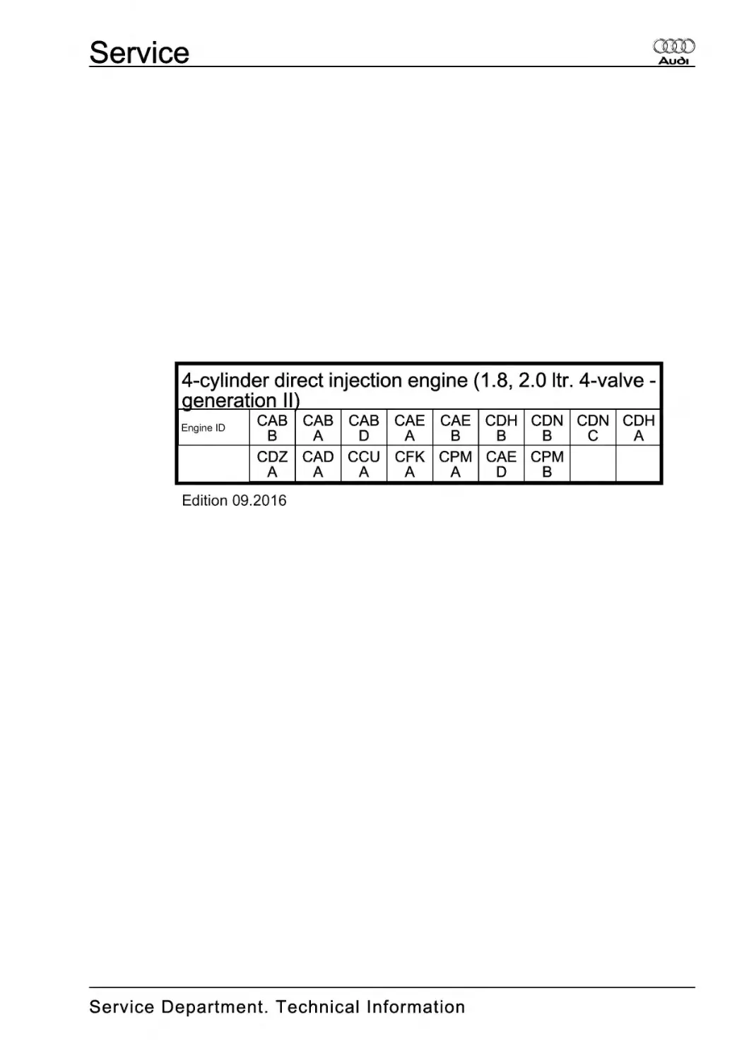
4-cylinder direct injection engine (1.8, 2.0 ltr. 4-valve generation II)
Engine ID

CAB CAB CAB CAE CAE CDH CDN CDN CDH
B
A
D
A
B
B
B
C
A
CDZ CAD CCU CFK CPM CAE CPM
A
A
A
A
A
D
B

Edition 09.2016

Service Department. Technical Information

Service
List of Workshop Manual Repair Groups

Repair Group
00 - Technical data
10 - Removing and installing engine
13 - Crankshaft group
15 - Cylinder head, valve gear
17 - Lubrication
19 - Cooling
21 - Turbocharging/supercharging
24 - Mixture preparation - injection
26 - Exhaust system
28 - Ignition system

Technical information should always be available to the foremen and mechanics, because their
careful and constant adherence to the instructions is essential to ensure vehicle road-worthiness and
safety. In addition, the normal basic safety precautions for working on motor vehicles must, as a
matter of course, be observed.

A005A401720

Audi A4 2008 ➤ , Audi A5 Cabriolet 2009 ➤ , Audi A5 Coupé 2008 ➤
4-cylinder direct injection engine (1.8, 2.0 ltr. 4-valve - generation II) - Edition 09.2016

Contents
00 - Technical data . . . . . . . . . . . . . . . . . . . . . . . . . . . . . . . . . . . . . . . . . . . . . . . . . . . .
1
1.1
2
2.1
2.2
2.3
2.4
2.5
2.6
3
3.1
3.2
3.3
3.4
3.5

1

Identification . . . . . . . . . . . . . . . . . . . . . . . . . . . . . . . . . . . . . . . . . . . . . . . . . . . . . . . . . . . .
Engine identification number/engine data . . . . . . . . . . . . . . . . . . . . . . . . . . . . . . . . . . . . . .
Safety precautions . . . . . . . . . . . . . . . . . . . . . . . . . . . . . . . . . . . . . . . . . . . . . . . . . . . . . . . .
Safety precautions when working on the fuel supply system . . . . . . . . . . . . . . . . . . . . . . . .
Safety precautions when working on vehicles with start/stop system . . . . . . . . . . . . . . . .
Safety precautions when working on the subframe . . . . . . . . . . . . . . . . . . . . . . . . . . . . . .
Safety precautions when using testers and measuring instruments during a road test . . . .
Safety precautions when working on the ignition system . . . . . . . . . . . . . . . . . . . . . . . . . .
Safety precautions when working on the cooling system . . . . . . . . . . . . . . . . . . . . . . . . . .
Repair instructions . . . . . . . . . . . . . . . . . . . . . . . . . . . . . . . . . . . . . . . . . . . . . . . . . . . . . . . .
Rules for cleanliness . . . . . . . . . . . . . . . . . . . . . . . . . . . . . . . . . . . . . . . . . . . . . . . . . . . . . .
Foreign particles in engine . . . . . . . . . . . . . . . . . . . . . . . . . . . . . . . . . . . . . . . . . . . . . . . . . .
Contact corrosion . . . . . . . . . . . . . . . . . . . . . . . . . . . . . . . . . . . . . . . . . . . . . . . . . . . . . . . .
Routing and attachment of pipes, hoses and wiring . . . . . . . . . . . . . . . . . . . . . . . . . . . . . .
Installing radiators and condensers . . . . . . . . . . . . . . . . . . . . . . . . . . . . . . . . . . . . . . . . . .

1
1
2
2
2
3
3
3
4
5
5
5
5
6
6

10 - Removing and installing engine . . . . . . . . . . . . . . . . . . . . . . . . . . . . . . . . . . . . . .

7

1
1.1
1.2
1.3
2
2.1
2.2
2.3
3
3.1

Removing and installing engine . . . . . . . . . . . . . . . . . . . . . . . . . . . . . . . . . . . . . . . . . . . . . .
Removing engine . . . . . . . . . . . . . . . . . . . . . . . . . . . . . . . . . . . . . . . . . . . . . . . . . . . . . . . .
Securing engine to engine and gearbox support . . . . . . . . . . . . . . . . . . . . . . . . . . . . . . . .
Installing engine . . . . . . . . . . . . . . . . . . . . . . . . . . . . . . . . . . . . . . . . . . . . . . . . . . . . . . . . . .
Assembly mountings . . . . . . . . . . . . . . . . . . . . . . . . . . . . . . . . . . . . . . . . . . . . . . . . . . . . . .
Exploded view - assembly mountings . . . . . . . . . . . . . . . . . . . . . . . . . . . . . . . . . . . . . . . .
Removing and installing engine mountings . . . . . . . . . . . . . . . . . . . . . . . . . . . . . . . . . . . .
Supporting engine in installation position . . . . . . . . . . . . . . . . . . . . . . . . . . . . . . . . . . . . . .
Engine cover panel . . . . . . . . . . . . . . . . . . . . . . . . . . . . . . . . . . . . . . . . . . . . . . . . . . . . . . . .
Removing and installing engine cover panel . . . . . . . . . . . . . . . . . . . . . . . . . . . . . . . . . . . .

7
7
23
26
33
33
34
35
37
37

13 - Crankshaft group . . . . . . . . . . . . . . . . . . . . . . . . . . . . . . . . . . . . . . . . . . . . . . . . . . 38
1
1.1
1.2
1.3
1.4
1.5
2
2.1
2.2
2.3
2.4
3
3.1
3.2
3.3
3.4
3.5
3.6

Cylinder block (pulley end) . . . . . . . . . . . . . . . . . . . . . . . . . . . . . . . . . . . . . . . . . . . . . . . . . .
Exploded view - cylinder block (pulley end) . . . . . . . . . . . . . . . . . . . . . . . . . . . . . . . . . . . .
Removing and installing poly V-belt . . . . . . . . . . . . . . . . . . . . . . . . . . . . . . . . . . . . . . . . . .
Removing and installing tensioner for poly V-belt . . . . . . . . . . . . . . . . . . . . . . . . . . . . . . . .
Removing and installing vibration damper . . . . . . . . . . . . . . . . . . . . . . . . . . . . . . . . . . . . . .
Removing and installing bracket for ancillaries . . . . . . . . . . . . . . . . . . . . . . . . . . . . . . . . . .
Cylinder block (gearbox end) . . . . . . . . . . . . . . . . . . . . . . . . . . . . . . . . . . . . . . . . . . . . . . . .
Exploded view - cylinder block (gearbox end) . . . . . . . . . . . . . . . . . . . . . . . . . . . . . . . . . .
Removing and installing drive plate . . . . . . . . . . . . . . . . . . . . . . . . . . . . . . . . . . . . . . . . . .
Removing and installing sealing flange (gearbox end) . . . . . . . . . . . . . . . . . . . . . . . . . . . .
Renewing needle bearing in drive plate . . . . . . . . . . . . . . . . . . . . . . . . . . . . . . . . . . . . . . . .
Crankshaft . . . . . . . . . . . . . . . . . . . . . . . . . . . . . . . . . . . . . . . . . . . . . . . . . . . . . . . . . . . . . .
Exploded view - crankshaft . . . . . . . . . . . . . . . . . . . . . . . . . . . . . . . . . . . . . . . . . . . . . . . .
Crankshaft dimensions . . . . . . . . . . . . . . . . . . . . . . . . . . . . . . . . . . . . . . . . . . . . . . . . . . . .
Allocation of main bearing shells . . . . . . . . . . . . . . . . . . . . . . . . . . . . . . . . . . . . . . . . . . . .
Measuring axial clearance of crankshaft . . . . . . . . . . . . . . . . . . . . . . . . . . . . . . . . . . . . . .
Measuring radial clearance of crankshaft . . . . . . . . . . . . . . . . . . . . . . . . . . . . . . . . . . . . . .
Removing and installing sender wheel . . . . . . . . . . . . . . . . . . . . . . . . . . . . . . . . . . . . . . . .

38
38
43
46
47
53
60
60
61
62
64
66
66
67
68
69
70
70

4
4.1
4.2
4.3

Balance shaft . . . . . . . . . . . . . . . . . . . . . . . . . . . . . . . . . . . . . . . . . . . . . . . . . . . . . . . . . . . .
Exploded view - balance shaft . . . . . . . . . . . . . . . . . . . . . . . . . . . . . . . . . . . . . . . . . . . . . .
Removing and installing balance shaft . . . . . . . . . . . . . . . . . . . . . . . . . . . . . . . . . . . . . . . .
Renewing oil seal for balance shaft (inlet side) . . . . . . . . . . . . . . . . . . . . . . . . . . . . . . . . . .

72
72
73
79

Contents

i

Audi A4 2008 ➤ , Audi A5 Cabriolet 2009 ➤ , Audi A5 Coupé 2008 ➤
4-cylinder direct injection engine (1.8, 2.0 ltr. 4-valve - generation II) - Edition 09.2016

5
5.1
5.2
5.3
5.4
5.5

Pistons and conrods . . . . . . . . . . . . . . . . . . . . . . . . . . . . . . . . . . . . . . . . . . . . . . . . . . . . . .
Exploded view - pistons and conrods . . . . . . . . . . . . . . . . . . . . . . . . . . . . . . . . . . . . . . . . . .
Removing and installing pistons . . . . . . . . . . . . . . . . . . . . . . . . . . . . . . . . . . . . . . . . . . . . . .
Checking pistons and cylinder bores . . . . . . . . . . . . . . . . . . . . . . . . . . . . . . . . . . . . . . . . . .
Separating parts of new conrod . . . . . . . . . . . . . . . . . . . . . . . . . . . . . . . . . . . . . . . . . . . . . .
Checking radial clearance of conrod bearings . . . . . . . . . . . . . . . . . . . . . . . . . . . . . . . . . .

81
81
82
84
85
86

15 - Cylinder head, valve gear . . . . . . . . . . . . . . . . . . . . . . . . . . . . . . . . . . . . . . . . . . 87
1
1.1
1.2
1.3
2
2.1
2.2
2.3
2.4
2.5
2.6

Timing chain cover . . . . . . . . . . . . . . . . . . . . . . . . . . . . . . . . . . . . . . . . . . . . . . . . . . . . . . . . 87
Exploded view - timing chain cover . . . . . . . . . . . . . . . . . . . . . . . . . . . . . . . . . . . . . . . . . . 87
Removing and installing timing chain cover . . . . . . . . . . . . . . . . . . . . . . . . . . . . . . . . . . . . 89
Renewing oil seal for vibration damper . . . . . . . . . . . . . . . . . . . . . . . . . . . . . . . . . . . . . . . . 93
Chain drive . . . . . . . . . . . . . . . . . . . . . . . . . . . . . . . . . . . . . . . . . . . . . . . . . . . . . . . . . . . . . . 96
Exploded view - camshaft timing chains . . . . . . . . . . . . . . . . . . . . . . . . . . . . . . . . . . . . . . 96
Exploded view - drive chain for balance shaft . . . . . . . . . . . . . . . . . . . . . . . . . . . . . . . . . . 97
Removing and installing bearing saddle . . . . . . . . . . . . . . . . . . . . . . . . . . . . . . . . . . . . . . . . 98
Removing and installing camshaft timing chain . . . . . . . . . . . . . . . . . . . . . . . . . . . . . . . . . . 103
Removing and installing drive chain for balance shaft . . . . . . . . . . . . . . . . . . . . . . . . . . . . 112
Checking valve timing . . . . . . . . . . . . . . . . . . . . . . . . . . . . . . . . . . . . . . . . . . . . . . . . . . . . 114

3
3.1
3.2
3.3
4
4.1
4.2
4.3
4.4
4.5
5
5.1
5.2
5.3

Cylinder head . . . . . . . . . . . . . . . . . . . . . . . . . . . . . . . . . . . . . . . . . . . . . . . . . . . . . . . . . . . .
Exploded view - cylinder head . . . . . . . . . . . . . . . . . . . . . . . . . . . . . . . . . . . . . . . . . . . . . .
Removing and installing cylinder head . . . . . . . . . . . . . . . . . . . . . . . . . . . . . . . . . . . . . . . .
Checking compression . . . . . . . . . . . . . . . . . . . . . . . . . . . . . . . . . . . . . . . . . . . . . . . . . . . .
Valve gear . . . . . . . . . . . . . . . . . . . . . . . . . . . . . . . . . . . . . . . . . . . . . . . . . . . . . . . . . . . . . .
Exploded view - valve gear . . . . . . . . . . . . . . . . . . . . . . . . . . . . . . . . . . . . . . . . . . . . . . . .
Removing and installing camshaft . . . . . . . . . . . . . . . . . . . . . . . . . . . . . . . . . . . . . . . . . . . .
Installing ball for slider . . . . . . . . . . . . . . . . . . . . . . . . . . . . . . . . . . . . . . . . . . . . . . . . . . . .
Removing and installing camshaft control valve 1 N205 . . . . . . . . . . . . . . . . . . . . . . . . . .
Removing and installing valve stem oil seals . . . . . . . . . . . . . . . . . . . . . . . . . . . . . . . . . . . .
Inlet and exhaust valves . . . . . . . . . . . . . . . . . . . . . . . . . . . . . . . . . . . . . . . . . . . . . . . . . . . .
Checking valve guides . . . . . . . . . . . . . . . . . . . . . . . . . . . . . . . . . . . . . . . . . . . . . . . . . . . .
Checking valves . . . . . . . . . . . . . . . . . . . . . . . . . . . . . . . . . . . . . . . . . . . . . . . . . . . . . . . . . .
Valve dimensions . . . . . . . . . . . . . . . . . . . . . . . . . . . . . . . . . . . . . . . . . . . . . . . . . . . . . . . .

117
117
126
173
175
175
180
209
210
210
219
219
220
220

17 - Lubrication . . . . . . . . . . . . . . . . . . . . . . . . . . . . . . . . . . . . . . . . . . . . . . . . . . . . . . 221
1
1.1
1.2
1.3
1.4
1.5
1.6
2
2.1
3
3.1
4
4.1
4.2
4.3
4.4
4.5

Sump/oil pump . . . . . . . . . . . . . . . . . . . . . . . . . . . . . . . . . . . . . . . . . . . . . . . . . . . . . . . . . .
Exploded view - sump/oil pump . . . . . . . . . . . . . . . . . . . . . . . . . . . . . . . . . . . . . . . . . . . . . .
Engine oil . . . . . . . . . . . . . . . . . . . . . . . . . . . . . . . . . . . . . . . . . . . . . . . . . . . . . . . . . . . . . .
Removing and installing sump (bottom section) . . . . . . . . . . . . . . . . . . . . . . . . . . . . . . . . . .
Removing and installing sump (top section) . . . . . . . . . . . . . . . . . . . . . . . . . . . . . . . . . . . .
Removing and installing oil pump . . . . . . . . . . . . . . . . . . . . . . . . . . . . . . . . . . . . . . . . . . . .
Removing and installing oil level and oil temperature sender G266 . . . . . . . . . . . . . . . . . .
Engine oil cooler . . . . . . . . . . . . . . . . . . . . . . . . . . . . . . . . . . . . . . . . . . . . . . . . . . . . . . . . . .
Removing and installing engine oil cooler . . . . . . . . . . . . . . . . . . . . . . . . . . . . . . . . . . . . . .
Crankcase breather . . . . . . . . . . . . . . . . . . . . . . . . . . . . . . . . . . . . . . . . . . . . . . . . . . . . . .
Removing and installing oil separator . . . . . . . . . . . . . . . . . . . . . . . . . . . . . . . . . . . . . . . .
Oil filter/oil pressure switch . . . . . . . . . . . . . . . . . . . . . . . . . . . . . . . . . . . . . . . . . . . . . . . . . .
Exploded view - oil filter/oil pressure switches . . . . . . . . . . . . . . . . . . . . . . . . . . . . . . . . . .
Removing and installing oil pressure switch F22 . . . . . . . . . . . . . . . . . . . . . . . . . . . . . . . .
Removing and installing oil pressure switch for reduced oil pressure F378 . . . . . . . . . . . .
Checking oil pressure . . . . . . . . . . . . . . . . . . . . . . . . . . . . . . . . . . . . . . . . . . . . . . . . . . . . . .
Removing and installing valve for oil pressure control N428 . . . . . . . . . . . . . . . . . . . . . . . .

221
221
224
224
227
230
232
233
233
234
234
235
235
236
237
238
239

19 - Cooling . . . . . . . . . . . . . . . . . . . . . . . . . . . . . . . . . . . . . . . . . . . . . . . . . . . . . . . . . . 241

ii

Contents

Audi A4 2008 ➤ , Audi A5 Cabriolet 2009 ➤ , Audi A5 Coupé 2008 ➤
4-cylinder direct injection engine (1.8, 2.0 ltr. 4-valve - generation II) - Edition 09.2016

1
1.1
1.2
1.3
2
2.1
2.2
2.3
2.4
2.5
2.6
2.7
2.8
2.9
3
3.1
3.2
4
4.1
4.2
4.3

Cooling system/coolant . . . . . . . . . . . . . . . . . . . . . . . . . . . . . . . . . . . . . . . . . . . . . . . . . . . .
Connection diagram - coolant hoses . . . . . . . . . . . . . . . . . . . . . . . . . . . . . . . . . . . . . . . . . .
Checking cooling system for leaks . . . . . . . . . . . . . . . . . . . . . . . . . . . . . . . . . . . . . . . . . . . .
Draining and filling cooling system . . . . . . . . . . . . . . . . . . . . . . . . . . . . . . . . . . . . . . . . . . . .
Coolant pump/thermostat assembly . . . . . . . . . . . . . . . . . . . . . . . . . . . . . . . . . . . . . . . . . .
Exploded view - coolant pump/thermostat . . . . . . . . . . . . . . . . . . . . . . . . . . . . . . . . . . . . . .
Exploded view - coolant valves . . . . . . . . . . . . . . . . . . . . . . . . . . . . . . . . . . . . . . . . . . . . . .
Removing and installing electric coolant pump . . . . . . . . . . . . . . . . . . . . . . . . . . . . . . . . . .
Removing and installing coolant pump . . . . . . . . . . . . . . . . . . . . . . . . . . . . . . . . . . . . . . . .
Removing and installing toothed belt for coolant pump . . . . . . . . . . . . . . . . . . . . . . . . . . . .
Removing and installing thermostat . . . . . . . . . . . . . . . . . . . . . . . . . . . . . . . . . . . . . . . . . .
Checking thermostat . . . . . . . . . . . . . . . . . . . . . . . . . . . . . . . . . . . . . . . . . . . . . . . . . . . . . .
Removing and installing coolant temperature sender G62 . . . . . . . . . . . . . . . . . . . . . . . .
Removing and installing coolant valves . . . . . . . . . . . . . . . . . . . . . . . . . . . . . . . . . . . . . . . .
Coolant pipes . . . . . . . . . . . . . . . . . . . . . . . . . . . . . . . . . . . . . . . . . . . . . . . . . . . . . . . . . . . .
Exploded view - coolant pipes . . . . . . . . . . . . . . . . . . . . . . . . . . . . . . . . . . . . . . . . . . . . . .
Removing and installing coolant pipes . . . . . . . . . . . . . . . . . . . . . . . . . . . . . . . . . . . . . . . .
Radiator/radiator fans . . . . . . . . . . . . . . . . . . . . . . . . . . . . . . . . . . . . . . . . . . . . . . . . . . . . . .
Exploded view - radiator/radiator fans . . . . . . . . . . . . . . . . . . . . . . . . . . . . . . . . . . . . . . . .
Removing and installing radiator . . . . . . . . . . . . . . . . . . . . . . . . . . . . . . . . . . . . . . . . . . . .
Removing and installing radiator fan V7 . . . . . . . . . . . . . . . . . . . . . . . . . . . . . . . . . . . . . .

241
241
246
247
254
254
256
256
257
259
261
262
262
264
266
266
267
270
270
271
277

21 - Turbocharging/supercharging . . . . . . . . . . . . . . . . . . . . . . . . . . . . . . . . . . . . . . . . 279
1
1.1
1.2
1.3
1.4
1.5
2
2.1
2.2
2.3
2.4

Turbocharger . . . . . . . . . . . . . . . . . . . . . . . . . . . . . . . . . . . . . . . . . . . . . . . . . . . . . . . . . . . .
Exploded view - turbocharger . . . . . . . . . . . . . . . . . . . . . . . . . . . . . . . . . . . . . . . . . . . . . . . .
Removing and installing turbocharger . . . . . . . . . . . . . . . . . . . . . . . . . . . . . . . . . . . . . . . .
Checking vacuum unit for turbocharger . . . . . . . . . . . . . . . . . . . . . . . . . . . . . . . . . . . . . . . .
Renewing vacuum unit for turbocharger . . . . . . . . . . . . . . . . . . . . . . . . . . . . . . . . . . . . . .
Adjusting vacuum unit for turbocharger . . . . . . . . . . . . . . . . . . . . . . . . . . . . . . . . . . . . . . . .
Charge air system . . . . . . . . . . . . . . . . . . . . . . . . . . . . . . . . . . . . . . . . . . . . . . . . . . . . . . . .
Exploded view - charge air system . . . . . . . . . . . . . . . . . . . . . . . . . . . . . . . . . . . . . . . . . . . .
Removing and installing charge air cooler . . . . . . . . . . . . . . . . . . . . . . . . . . . . . . . . . . . . . .
Removing and installing charge pressure sender G31 . . . . . . . . . . . . . . . . . . . . . . . . . . . .
Checking charge air system for leaks . . . . . . . . . . . . . . . . . . . . . . . . . . . . . . . . . . . . . . . .

279
279
284
288
290
291
295
295
296
299
299

24 - Mixture preparation - injection . . . . . . . . . . . . . . . . . . . . . . . . . . . . . . . . . . . . . . . . 302
1
1.1
2
2.1
2.2
2.3
3
3.1
3.2
4
4.1
4.2
4.3
4.4
4.5
4.6
4.7
5

Injection system . . . . . . . . . . . . . . . . . . . . . . . . . . . . . . . . . . . . . . . . . . . . . . . . . . . . . . . . . .
Overview of fitting locations - injection system . . . . . . . . . . . . . . . . . . . . . . . . . . . . . . . . . .
Vacuum system . . . . . . . . . . . . . . . . . . . . . . . . . . . . . . . . . . . . . . . . . . . . . . . . . . . . . . . . . .
Removing and installing activated charcoal filter solenoid valve 1 N80 . . . . . . . . . . . . . .
Checking dual non-return valve . . . . . . . . . . . . . . . . . . . . . . . . . . . . . . . . . . . . . . . . . . . . . .
Checking vacuum system . . . . . . . . . . . . . . . . . . . . . . . . . . . . . . . . . . . . . . . . . . . . . . . . . .
Air cleaner . . . . . . . . . . . . . . . . . . . . . . . . . . . . . . . . . . . . . . . . . . . . . . . . . . . . . . . . . . . . . .
Exploded view - air cleaner housing . . . . . . . . . . . . . . . . . . . . . . . . . . . . . . . . . . . . . . . . . .
Removing and installing air cleaner housing . . . . . . . . . . . . . . . . . . . . . . . . . . . . . . . . . . . .
Intake manifold . . . . . . . . . . . . . . . . . . . . . . . . . . . . . . . . . . . . . . . . . . . . . . . . . . . . . . . . . .
Exploded view - intake manifold . . . . . . . . . . . . . . . . . . . . . . . . . . . . . . . . . . . . . . . . . . . . . .
Removing and installing intake manifold . . . . . . . . . . . . . . . . . . . . . . . . . . . . . . . . . . . . . .
Removing and installing intake manifold (top section) . . . . . . . . . . . . . . . . . . . . . . . . . . . .
Removing and installing intake manifold (bottom section) . . . . . . . . . . . . . . . . . . . . . . . . . .
Removing and installing throttle valve module J338 . . . . . . . . . . . . . . . . . . . . . . . . . . . . . .
Cleaning throttle valve module . . . . . . . . . . . . . . . . . . . . . . . . . . . . . . . . . . . . . . . . . . . . . .
Checking intake manifold change-over function . . . . . . . . . . . . . . . . . . . . . . . . . . . . . . . . . .
Injectors . . . . . . . . . . . . . . . . . . . . . . . . . . . . . . . . . . . . . . . . . . . . . . . . . . . . . . . . . . . . . . . .
Contents

302
302
312
312
313
315
317
317
318
320
320
325
328
332
333
334
334
337

iii

Audi A4 2008 ➤ , Audi A5 Cabriolet 2009 ➤ , Audi A5 Coupé 2008 ➤
4-cylinder direct injection engine (1.8, 2.0 ltr. 4-valve - generation II) - Edition 09.2016
5.1
5.2
5.3
5.4
5.5
6
6.1
6.2
6.3
6.4
7
7.1
7.2
8
8.1
8.2
9
9.1
9.2

Exploded view - fuel rail with injectors . . . . . . . . . . . . . . . . . . . . . . . . . . . . . . . . . . . . . . . .
Removing and installing fuel rail . . . . . . . . . . . . . . . . . . . . . . . . . . . . . . . . . . . . . . . . . . . . . .
Removing and installing injectors . . . . . . . . . . . . . . . . . . . . . . . . . . . . . . . . . . . . . . . . . . . .
Cleaning injectors . . . . . . . . . . . . . . . . . . . . . . . . . . . . . . . . . . . . . . . . . . . . . . . . . . . . . . . .
Removing and installing cold-start valve N17 . . . . . . . . . . . . . . . . . . . . . . . . . . . . . . . . . .
Senders and sensors . . . . . . . . . . . . . . . . . . . . . . . . . . . . . . . . . . . . . . . . . . . . . . . . . . . . . .
Removing and installing fuel pressure sender G247 . . . . . . . . . . . . . . . . . . . . . . . . . . . . . .
Checking fuel pressure sender G247 . . . . . . . . . . . . . . . . . . . . . . . . . . . . . . . . . . . . . . . .
Removing and installing air mass meter . . . . . . . . . . . . . . . . . . . . . . . . . . . . . . . . . . . . . .
Removing and installing intake air temperature sender G42 . . . . . . . . . . . . . . . . . . . . . .
High-pressure pump . . . . . . . . . . . . . . . . . . . . . . . . . . . . . . . . . . . . . . . . . . . . . . . . . . . . . .
Exploded view - high-pressure pump . . . . . . . . . . . . . . . . . . . . . . . . . . . . . . . . . . . . . . . . . .
Removing and installing high-pressure pump . . . . . . . . . . . . . . . . . . . . . . . . . . . . . . . . . .
Lambda probe . . . . . . . . . . . . . . . . . . . . . . . . . . . . . . . . . . . . . . . . . . . . . . . . . . . . . . . . . .
Exploded view - Lambda probe . . . . . . . . . . . . . . . . . . . . . . . . . . . . . . . . . . . . . . . . . . . . . .
Removing and installing Lambda probe . . . . . . . . . . . . . . . . . . . . . . . . . . . . . . . . . . . . . . . .
Engine control unit . . . . . . . . . . . . . . . . . . . . . . . . . . . . . . . . . . . . . . . . . . . . . . . . . . . . . . . .
Wiring and component check . . . . . . . . . . . . . . . . . . . . . . . . . . . . . . . . . . . . . . . . . . . . . . . .
Removing and installing engine control unit J623 . . . . . . . . . . . . . . . . . . . . . . . . . . . . . . . .

337
340
341
345
346
348
348
349
351
352
353
353
354
357
357
358
361
361
363

26 - Exhaust system . . . . . . . . . . . . . . . . . . . . . . . . . . . . . . . . . . . . . . . . . . . . . . . . . . 367
1
1.1
1.2
1.3
1.4
1.5
1.6
2
2.1
2.2

Exhaust pipes/silencers . . . . . . . . . . . . . . . . . . . . . . . . . . . . . . . . . . . . . . . . . . . . . . . . . . . .
Exploded view - silencers . . . . . . . . . . . . . . . . . . . . . . . . . . . . . . . . . . . . . . . . . . . . . . . . . .
Removing and installing front exhaust pipe . . . . . . . . . . . . . . . . . . . . . . . . . . . . . . . . . . . .
Separating exhaust pipes/silencers . . . . . . . . . . . . . . . . . . . . . . . . . . . . . . . . . . . . . . . . . .
Stress-free alignment of exhaust system . . . . . . . . . . . . . . . . . . . . . . . . . . . . . . . . . . . . . .
Renewing tailpipes . . . . . . . . . . . . . . . . . . . . . . . . . . . . . . . . . . . . . . . . . . . . . . . . . . . . . . . .
Checking exhaust system for leaks . . . . . . . . . . . . . . . . . . . . . . . . . . . . . . . . . . . . . . . . . .
Emission control system . . . . . . . . . . . . . . . . . . . . . . . . . . . . . . . . . . . . . . . . . . . . . . . . . . . .
Exploded view - emission control system . . . . . . . . . . . . . . . . . . . . . . . . . . . . . . . . . . . . . .
Removing and installing catalytic converter . . . . . . . . . . . . . . . . . . . . . . . . . . . . . . . . . . . .

367
367
374
375
378
381
382
383
383
384

28 - Ignition system . . . . . . . . . . . . . . . . . . . . . . . . . . . . . . . . . . . . . . . . . . . . . . . . . . . . 387
1
1.1
1.2
1.3
1.4
1.5
1.6

iv

Contents

Ignition system . . . . . . . . . . . . . . . . . . . . . . . . . . . . . . . . . . . . . . . . . . . . . . . . . . . . . . . . . .
Exploded view - ignition system . . . . . . . . . . . . . . . . . . . . . . . . . . . . . . . . . . . . . . . . . . . . . .
Test data, spark plugs . . . . . . . . . . . . . . . . . . . . . . . . . . . . . . . . . . . . . . . . . . . . . . . . . . . .
Removing and installing ignition coils with output stages . . . . . . . . . . . . . . . . . . . . . . . . . .
Removing and installing knock sensor . . . . . . . . . . . . . . . . . . . . . . . . . . . . . . . . . . . . . . . .
Removing and installing Hall senders . . . . . . . . . . . . . . . . . . . . . . . . . . . . . . . . . . . . . . . .
Removing and installing engine speed sender G28 . . . . . . . . . . . . . . . . . . . . . . . . . . . . . .

387
387
388
388
390
391
391

Audi A4 2008 ➤ , Audi A5 Cabriolet 2009 ➤ , Audi A5 Coupé 2008 ➤
4-cylinder direct injection engine (1.8, 2.0 ltr. 4-valve - generation II) - Edition 09.2016

00 –

Technical data

1

Identification

(ARL004882; Edition 09.2016)
⇒ “1.1 Engine identification number/engine data”, page 1

1.1

Engine identification number/engine da‐
ta

Engine number
♦ The engine number (“engine code” and “serial number”) can
be found at the joint between engine and gearbox -arrow-.
♦ Additionally there is a sticker on the toothed belt cover (top)
with engine code and serial number.
♦ Engine codes starting with the letter “C” have four letters (pre‐
viously three letters).
♦ The first 3 characters of the engine code stand for the engine
capacity and the mechanical construction and design. They
are stamped onto the cylinder block together with the serial
number.
♦ The 4th character indicates the power output and torque of the
engine and is determined by the engine control unit.
♦ The engine code can be found on the type plate (in versions
for some countries only) and on the vehicle data sticker and
the engine control unit.
♦ Fitting locations of the type plate (certain countries only) and
the vehicle data sticker ⇒ Maintenance ; Booklet 812 .
For engine data refer to ⇒ Technical data for petrol engines; Rep.
gr. 00 ; Overview of engines .

1. Identification

1

Audi A4 2008 ➤ , Audi A5 Cabriolet 2009 ➤ , Audi A5 Coupé 2008 ➤
4-cylinder direct injection engine (1.8, 2.0 ltr. 4-valve - generation II) - Edition 09.2016

2

Safety precautions

⇒ “2.1 Safety precautions when working on the fuel supply sys‐
tem”, page 2
⇒ “2.2 Safety precautions when working on vehicles with start/
stop system”, page 2
⇒ “2.3 Safety precautions when working on the subframe”,
page 3
⇒ “2.4 Safety precautions when using testers and measuring in‐
struments during a road test”, page 3
⇒ “2.5 Safety precautions when working on the ignition system”,
page 3
⇒ “2.6 Safety precautions when working on the cooling system”,
page 4

2.1

Safety precautions when working on the fuel supply system

Risk of injury - fuel system operates under high pressure
The fuel system is pressurised. There is a risk of injury as fuel
may spray out.
Before opening the fuel system:
– Put on safety goggles.
– Put on protective gloves.
– Release pressure (wrap clean cloth around connection and
open connection carefully).

Risk of fire due to escaping fuel
If the battery is connected, the door contact switch activates the
fuel pump when the driver's door is opened. Escaping fuel may
ignite, causing a fire.
– Before opening the fuel system, disconnect power supply to
fuel pump.

2.2

Safety precautions when working on vehicles with start/stop system

Risk of injury - engine may start unexpectedly
On vehicles with the start/stop system activated, the engine may
start unexpectedly. A message in the instrument cluster indicates
whether the start/stop system is activated.
– Deactivate start/stop system by switching off ignition.

2

Rep. gr.00 - Technical data

Audi A4 2008 ➤ , Audi A5 Cabriolet 2009 ➤ , Audi A5 Coupé 2008 ➤
4-cylinder direct injection engine (1.8, 2.0 ltr. 4-valve - generation II) - Edition 09.2016

2.3

Safety precautions when working on the
subframe
Caution

Risk of damage to running gear components.
♦ The vehicle must NOT be lowered onto its wheels if the
engine/gearbox mountings, steering rack or subframe
cross brace are not properly installed.
♦ The vehicle must NOT be supported by applying a trolley
jack or similar to the subframe or subframe cross brace.

2.4

Safety precautions when using testers and measuring instruments during
a road test

Risk of injury if test equipment is not secured
If an accident occurs and the front passenger's airbag is triggered,
test equipment which is not secured adequately may be catapul‐
ted through the vehicle with potentially serious consequences.
– Secure test equipment on the rear seat with a strap.
Or
– Have a second mechanic operate test equipment on the rear
seat.

2.5

Safety precautions when working on the ignition system

Risk of injury due to electric shock
When the engine is running, there are high voltage levels in the
ignition system. There is a risk of electric shock when touching
the ignition system!
– Never touch or disconnect ignition wiring when the engine is
running or being turned at cranking speed.

Risk of damage to components
Washing the engine or connecting/disconnecting electrical wiring
may result in components being damaged if the engine is running.
– Switch off ignition before connecting/disconnecting electrical
wiring.
– Switch off ignition before cleaning engine.

2. Safety precautions

3

Audi A4 2008 ➤ , Audi A5 Cabriolet 2009 ➤ , Audi A5 Coupé 2008 ➤
4-cylinder direct injection engine (1.8, 2.0 ltr. 4-valve - generation II) - Edition 09.2016

2.6

Safety precautions when working on the cooling system

Risk of scalding as hot coolant can escape
The cooling system is under pressure when the engine is hot. Hot
steam/hot coolant can escape - risk of scalding.
– Put on protective gloves.
– Put on safety goggles.
– Release pressure (cover filler cap on coolant expansion tank
with a cloth and open carefully).

4

Rep. gr.00 - Technical data

Audi A4 2008 ➤ , Audi A5 Cabriolet 2009 ➤ , Audi A5 Coupé 2008 ➤
4-cylinder direct injection engine (1.8, 2.0 ltr. 4-valve - generation II) - Edition 09.2016

3

Repair instructions

⇒ “3.1 Rules for cleanliness”, page 5
⇒ “3.2 Foreign particles in engine”, page 5
⇒ “3.3 Contact corrosion”, page 5
⇒ “3.4 Routing and attachment of pipes, hoses and wiring”, page
6
⇒ “3.5 Installing radiators and condensers”, page 6

3.1

Rules for cleanliness

Even small quantities of dirt can lead to defects. For this reason,
please observe the following rules when working on the fuel sup‐
ply system, injection system and turbocharger:
♦ Carefully clean connection points and the surrounding area
with engine cleaner or brake cleaner and dry thoroughly before
opening.
♦ Immediately seal open lines and connections with clean plugs,
for example from engine bung set - VAS 6122- .
♦ Place removed parts on a clean surface and cover them. Use
only lint-free cloths.
♦ Carefully cover or seal open components if repairs cannot be
carried out immediately.
♦ Only install clean components; replacement parts should only
be unpacked immediately prior to installation. Do not use parts
that have not been stored in their packing (e.g. in tool boxes
etc.).
♦ When the system is open, do not work with compressed air
and do not move the vehicle.
♦ Make sure that no fuel runs onto the fuel hoses. Should this
occur, the fuel hoses must be cleaned again immediately.
♦ Protect unplugged electrical connectors against dirt and mois‐
ture and make sure connections are dry when attaching.

3.2

Foreign particles in engine

♦ When performing assembly work on the engine, all open pas‐
sages in the intake and exhaust systems must be sealed with
suitable plugs (e.g. from engine bung set - VAS 6122- ) to
prevent foreign particles from entering the engine.
Note

If the turbocharger has suffered mechanical damage
⇒ page 285

3.3

Contact corrosion

Contact corrosion can occur if unsuitable fasteners are used (e.g.
bolts, nuts, washers, etc.).
For this reason, only fasteners with a special surface coating are
fitted.
Additionally, all rubber and plastic parts and all adhesives are
made of non-conductive materials.
Always install new parts if you are not sure whether used parts
can be re-fitted ⇒ Electronic parts catalogue .
3. Repair instructions

5

Audi A4 2008 ➤ , Audi A5 Cabriolet 2009 ➤ , Audi A5 Coupé 2008 ➤
4-cylinder direct injection engine (1.8, 2.0 ltr. 4-valve - generation II) - Edition 09.2016
Please note:
♦ We recommend using only genuine replacement parts; these
have been tested and are compatible with aluminium.
♦ We recommend the use of Audi accessories.
♦ Damage caused by contact corrosion is not covered by war‐
ranty.

3.4

Routing and attachment of pipes, hoses
and wiring

♦ Mark fuel lines, vacuum lines, pipes/hoses for activated char‐
coal filter system and electrical wiring etc. before removal so
they can be re-installed in the original positions and correctly
connected. Make sketches or take photographs if necessary.
♦ To prevent damaging pipes, hoses and wiring, ensure suffi‐
cient clearance from all moving or hot components in engine
compartment (little space in engine compartment).

3.5

Installing radiators and condensers

Even when the radiator, condenser and charge air cooler are cor‐
rectly installed, slight impressions may be visible on the fins of
these components. This does not mean that the components are
damaged. If the fins are only very slightly distorted, this does not
justify renewal of the radiator, condenser or charge air cooler.

6

Rep. gr.00 - Technical data

Audi A4 2008 ➤ , Audi A5 Cabriolet 2009 ➤ , Audi A5 Coupé 2008 ➤
4-cylinder direct injection engine (1.8, 2.0 ltr. 4-valve - generation II) - Edition 09.2016

10 –

Removing and installing engine

1

Removing and installing engine

⇒ “1.1 Removing engine”, page 7
⇒ “1.2 Securing engine to engine and gearbox support”,
page 23
⇒ “1.3 Installing engine”, page 26

1.1

Removing engine

Special tools and workshop equipment required
♦ Lifting tackle - 2024 A-

♦ Support bracket - 10-222A-

♦ Shackle - 10-222A/12-

1. Removing and installing engine

7

Audi A4 2008 ➤ , Audi A5 Cabriolet 2009 ➤ , Audi A5 Coupé 2008 ➤
4-cylinder direct injection engine (1.8, 2.0 ltr. 4-valve - generation II) - Edition 09.2016
♦ Removal lever - 80 - 200-

♦ Engine and gearbox jack - V.A.G 1383 A-

♦ Workshop hoist - VAS 6100-

♦ Engine bung set - VAS 6122-

8

Rep. gr.10 - Removing and installing engine

Audi A4 2008 ➤ , Audi A5 Cabriolet 2009 ➤ , Audi A5 Coupé 2008 ➤
4-cylinder direct injection engine (1.8, 2.0 ltr. 4-valve - generation II) - Edition 09.2016
♦ Drip tray for workshop hoist - VAS 6208-

♦ Hose clip pliers - VAS 6362-

♦ Locking pin - T10060A-

♦ Gearbox support - T10337-

1. Removing and installing engine

9

Audi A4 2008 ➤ , Audi A5 Cabriolet 2009 ➤ , Audi A5 Coupé 2008 ➤
4-cylinder direct injection engine (1.8, 2.0 ltr. 4-valve - generation II) - Edition 09.2016
♦ Locking tool - T40098-

♦ Release tool - T40138-

Procedure
WARNING

Make sure the vehicle cannot tip over when the engine is re‐
moved.
♦ Secure the vehicle, to do so, the luggage compartment
must be empty.

Note
♦ Lift out engine without gearbox.
♦ Collect drained coolant in a clean container for re-use or dis‐

posal.

♦ Fit all cable ties in the original positions when installing.
♦ On four-wheel drive vehicles the electromechanical parking

brake must be released before disconnecting the battery, so
that the propshaft can be turned during removal.

♦ All open inlet and exhaust ports must be sealed with suitable

plugs (e.g. from engine bung set - VAS 6122- ).
Caution

To prevent irreparable damage to the electronic components
when disconnecting the battery:
♦ Observe notes on procedure for disconnecting the battery.

10

Rep. gr.10 - Removing and installing engine

Audi A4 2008 ➤ , Audi A5 Cabriolet 2009 ➤ , Audi A5 Coupé 2008 ➤
4-cylinder direct injection engine (1.8, 2.0 ltr. 4-valve - generation II) - Edition 09.2016
– Disconnect battery ⇒ Electrical system; Rep. gr. 27 ; Battery;
Disconnecting and connecting battery .
– Remove both front wheels.
– Remove wheel spoilers (front) on both sides ⇒ General body
repairs, exterior; Rep. gr. 66 ; Wheel housing liners; Exploded
view - wheel housing liner (front) .
– Remove noise insulation ⇒ General body repairs, exterior;
Rep. gr. 66 ; Noise insulation; Removing and installing noise
insulation .
– Set service position ⇒ General body repairs, exterior; Rep.
gr. 50 ; Lock carrier; Setting service position and returning to
normal position .
– Remove front exhaust pipe/front silencer ⇒ page 374 .
– Unplug connector -1- from air mass meter - G70- .
– Disconnect air intake hose -2-.
– Pull air cleaner housing upwards -arrows-.

– Remove engine cover panel -arrows-.
– Remove plenum chamber cover ⇒ General body repairs, ex‐
terior; Rep. gr. 50 ; Bulkhead; Removing and installing plenum
chamber cover .

– Lift off foam plastic block -1- on both sides of vehicle
-arrows-.

1. Removing and installing engine

11

Audi A4 2008 ➤ , Audi A5 Cabriolet 2009 ➤ , Audi A5 Coupé 2008 ➤
4-cylinder direct injection engine (1.8, 2.0 ltr. 4-valve - generation II) - Edition 09.2016
– Release retainer -arrow A- and open cover -arrow B-.

– Remove nuts -1 ... 3- for electrical wiring.
– Detach electrical connector -4- from bracket and unplug.
– Remove bolt -5- and detach wiring junction from body brace
-arrow-.

– Working from wheel housing, release catches using a 5.5 mm
ring spanner -item 1- and remove wiring protector -2- from
above.

– Wiring duct (version 1): release catch -arrow B- and move wir‐
ing harness clear by pulling it towards front -arrow A-.

12

Rep. gr.10 - Removing and installing engine

Audi A4 2008 ➤ , Audi A5 Cabriolet 2009 ➤ , Audi A5 Coupé 2008 ➤
4-cylinder direct injection engine (1.8, 2.0 ltr. 4-valve - generation II) - Edition 09.2016
– Wiring duct (version 2): release catch -arrow- to open wiring
duct -1- and move wiring harness clear.

– Remove nut -1- and swivel filler neck for washer fluid reservoir
slightly upwards -arrow A-.
– Pull filler neck -2- with filler pipe out of washer fluid reservoir
and through opening in body -arrow B-.

– Remove bolts -1- and nuts -2- and detach body brace -3-.

– Remove bolts -arrows- and detach cover for electronics box in
engine compartment.
– Remove nut -1- and move electrical wiring clear.

1. Removing and installing engine

13

Audi A4 2008 ➤ , Audi A5 Cabriolet 2009 ➤ , Audi A5 Coupé 2008 ➤
4-cylinder direct injection engine (1.8, 2.0 ltr. 4-valve - generation II) - Edition 09.2016
– Release catches -arrows A- and take out engine control unit
-arrow B-.

– Unplug electrical connectors -4- and unscrew nut -3- for wiring.
– If fitted, unplug electrical connector -2-.
– Release catches -arrow- and detach relay carrier with fuse
holder -1-.

– Release catches -arrows A- and lift off wiring protector -1-arrow B-.
– Disengage engine wiring harness at electronics box in engine
compartment and move clear.
– Place wiring harness on engine and secure engine control unit
to prevent it from dropping.
WARNING

Hot steam/hot coolant can escape - risk of scalding.
♦ The cooling system is under pressure when the engine is
hot.
♦ To allow pressure to dissipate, cover filler cap on coolant
expansion tank with cloth and open carefully.
– Open filler cap on coolant expansion tank.
– Place drip tray for workshop hoist - VAS 6208- beneath en‐
gine.

14

Rep. gr.10 - Removing and installing engine

Audi A4 2008 ➤ , Audi A5 Cabriolet 2009 ➤ , Audi A5 Coupé 2008 ➤
4-cylinder direct injection engine (1.8, 2.0 ltr. 4-valve - generation II) - Edition 09.2016
– Unscrew radiator drain tap -1- at connection and drain off
coolant, then detach connection -2- from radiator.

– Remove nuts -3- and longitudinal struts -2- on both sides.

– Open hose clip -arrow-, detach air hose and swivel to side.

– Unscrew nut -1- on longitudinal member (right-side) and move
earth cables clear.
– Remove nut -2- for bracket with wiring on right-hand side of
vehicle.

1. Removing and installing engine

15

Audi A4 2008 ➤ , Audi A5 Cabriolet 2009 ➤ , Audi A5 Coupé 2008 ➤
4-cylinder direct injection engine (1.8, 2.0 ltr. 4-valve - generation II) - Edition 09.2016
– Unplug electrical connector -1- for radiator fan (push retainer
to the rear -arrow- and press down release catch).
– Place wiring harness on engine and secure to prevent it from
dropping.

– Disconnect vacuum hose -3- on rear of plenum chamber par‐
tition panel -arrow- and detach vacuum connection -2- from
plenum chamber partition panel.

– Remove nut -5-.
– Detach coolant hoses -1- to -4- and remove plenum chamber
partition panel.

– Remove bolts -2 ... 6-.

16

Rep. gr.10 - Removing and installing engine

Audi A4 2008 ➤ , Audi A5 Cabriolet 2009 ➤ , Audi A5 Coupé 2008 ➤
4-cylinder direct injection engine (1.8, 2.0 ltr. 4-valve - generation II) - Edition 09.2016

Note
♦ Bolt -2- secures the starter to the gearbox and is provided with

a spacer sleeve -arrow-.

♦ Pay attention to the spacer sleeve -arrow- when removing and

installing the engine. The spacer sleeve must be fitted be‐
tween starter and gearbox.

– Detach coolant hose -2- and permanent breather -1-.

– Detach permanent breather -1- and coolant hose -2- from
coolant expansion tank.

– Release hose clips -arrows- and detach air hose.
– Unplug electrical connector for charge pressure sender - G31-1- and move clear.
– Remove catalytic converter ⇒ page 384 .

1. Removing and installing engine

17

Audi A4 2008 ➤ , Audi A5 Cabriolet 2009 ➤ , Audi A5 Coupé 2008 ➤
4-cylinder direct injection engine (1.8, 2.0 ltr. 4-valve - generation II) - Edition 09.2016
Vehicles with hydraulic power steering:
Caution

Wrong direction of rotation for a used poly V-belt can lead to
irreparable damage.
♦ Before removing the poly V-belt mark the direction of ro‐
tation with chalk or a felt-tip pen for re-installation.
– To slacken poly V-belt turn tensioner in direction of -arrow-.
– Lock tensioner with locking tool - T40098- .
– Take off poly V-belt.
Vehicles with electromechanical power steering:
Caution

Wrong direction of rotation for a used poly V-belt can lead to
irreparable damage.
♦ Before removing the poly V-belt mark the direction of ro‐
tation with chalk or a felt-tip pen for re-installation.
– To slacken poly V-belt turn tensioner in direction of -arrow-.
– Lock tensioner with locking pin - T10060 A- .
– Take off poly V-belt.
Continued for all vehicles:
– Unplug electrical connector -1- for magnetic clutch on air con‐
ditioner compressor.
WARNING

Risk of injury caused by refrigerant.
♦ The air conditioner refrigerant circuit must not be opened.
– Remove bolts -arrows- for air conditioner compressor.
Caution

Danger of damage to refrigerant lines and hoses.
♦ Do NOT stretch, kink or bend refrigerant lines and hoses.
– Tie up air conditioner compressor together with refrigerant ho‐
ses to longitudinal member (refrigerant hoses remain connec‐
ted).

18

Rep. gr.10 - Removing and installing engine

Audi A4 2008 ➤ , Audi A5 Cabriolet 2009 ➤ , Audi A5 Coupé 2008 ➤
4-cylinder direct injection engine (1.8, 2.0 ltr. 4-valve - generation II) - Edition 09.2016
Vehicles with hydraulic power steering:
Note

Leave hydraulic lines of power steering pump connected.
– Remove bolts -1- from front (through pulley); remove bolt -2from rear.
Note

Illustration shows power steering pump without pulley and hy‐
draulic lines.
– Place power steering pump on longitudinal member with hy‐
draulic lines attached.
Continued for all vehicles:
Caution

Observe rules for cleanliness when working on the fuel supply
system.
– Disconnect fuel supply hose -1- and fuel return hose -2-.

– Support gearbox using engine and gearbox jack - V.A.G 1383
A- with gearbox support - T10337- attached.

– Remove bolts -arrows- for tunnel cross member.

1. Removing and installing engine

19

Audi A4 2008 ➤ , Audi A5 Cabriolet 2009 ➤ , Audi A5 Coupé 2008 ➤
4-cylinder direct injection engine (1.8, 2.0 ltr. 4-valve - generation II) - Edition 09.2016
Vehicles with manual gearbox:
– Lower gearbox using engine and gearbox jack - V.A.G 1383
A- as far as distance -a-.
•

Dimension -a- = 80 mm (maximum).

– Use release tool -F4- to unplug electrical connector -1- at re‐
versing light switch - T40138- and move clear.

Vehicles with dual clutch gearbox/multitronic gearbox:
– Remove bolts -arrows- for ATF lines.
Note

Disregard items -1 and 2-.

20

Rep. gr.10 - Removing and installing engine

Audi A4 2008 ➤ , Audi A5 Cabriolet 2009 ➤ , Audi A5 Coupé 2008 ➤
4-cylinder direct injection engine (1.8, 2.0 ltr. 4-valve - generation II) - Edition 09.2016
Continued for all vehicles:
– Unclip electrical wiring -A- from gearbox and unplug electrical
connector -C-.

– Raise gearbox using engine and gearbox jack - V.A.G 1383
A- and fit bolts -arrows- for tunnel cross member.

– Detach bottom cover -1- from gearbox -arrow-.

– Remove 3 bolts -arrow- for flywheel. Turn crankshaft each
time by 120° in direction of engine rotation.

1. Removing and installing engine

21

Audi A4 2008 ➤ , Audi A5 Cabriolet 2009 ➤ , Audi A5 Coupé 2008 ➤
4-cylinder direct injection engine (1.8, 2.0 ltr. 4-valve - generation II) - Edition 09.2016
– Remove bolt -1- securing starter (work from side facing en‐
gine).
– Separate starter from gearbox and leave in position.
– Remove remaining bolts securing engine to gearbox.
– Support gearbox:

Version 1
– Set up support bracket - 10-222A- with adapter - 10-222A/8on suspension turrets (left and right) as illustrated.
– Use shackle - 10-222A/12- to hook spindle onto gearbox.
Note

Shown in illustration with engine removed.
– Pre-tension spindle of support bracket - 10-222A- slightly.

Version 2
– Set up support bracket - 10-222A- with adapter - 10-222A/8on suspension turrets (left and right) as illustrated.
– Use puller - T40132- , multi-purpose tool - VW 771/40- and
eye-head bolt - 3368- to hook spindle onto gearbox, as shown
in illustration.
Note

Shown in illustration with engine removed.
– Pre-tension spindle of support bracket - 10-222A- slightly.

22

Rep. gr.10 - Removing and installing engine

Audi A4 2008 ➤ , Audi A5 Cabriolet 2009 ➤ , Audi A5 Coupé 2008 ➤
4-cylinder direct injection engine (1.8, 2.0 ltr. 4-valve - generation II) - Edition 09.2016
All vehicles:
– Attach lifting tackle - 2024 A- to engine and workshop hoist VAS 6100- as shown in illustration.
WARNING

The hook attachments and locating pins on the lifting tackle
must be secured with locking pins.

– Tighten bolts -1- for left and right engine mountings.
Note

Disregard -arrow-.
– Raise engine until engine mountings are clear.
– Tighten spindle of support bracket - 10-222A- further.
Caution

Danger of damage to hoses, pipes and wiring connections and
to engine compartment.
♦ Check that all hoses and wiring connections between en‐
gine, gearbox, subframe and body have been detached.
♦ Carefully guide engine out of engine compartment when
lifting out.
– Separate engine from gearbox and lift engine out of engine
compartment.

1.2

Securing engine to engine and gearbox
support

Special tools and workshop equipment required

1. Removing and installing engine

23

Audi A4 2008 ➤ , Audi A5 Cabriolet 2009 ➤ , Audi A5 Coupé 2008 ➤
4-cylinder direct injection engine (1.8, 2.0 ltr. 4-valve - generation II) - Edition 09.2016
♦ Counterhold tool - 10-201-

♦ Lifting tackle - 2024A-

♦ Engine and gearbox support - VW 540-

♦ Workshop hoist - VAS 6100-

24

Rep. gr.10 - Removing and installing engine

Audi A4 2008 ➤ , Audi A5 Cabriolet 2009 ➤ , Audi A5 Coupé 2008 ➤
4-cylinder direct injection engine (1.8, 2.0 ltr. 4-valve - generation II) - Edition 09.2016
♦ Engine and gearbox support - VAS 6095-

Procedure
– Insert counterhold tool - 10-201- to slacken bolts.
Caution

Take care not to damage outer surface of bearing flange on
drive plate.
♦ Use a multi-point socket bit with a length of at least 40 mm
to slacken and tighten the drive plate bolts.
– Remove bolts and take off drive plate.
WARNING

Accident risk from loose components of lifting tackle.
♦ The support hooks and retaining pins on the lifting tackle
must be secured with locking pins -arrows-.
– Engage lifting tackle - 2024 A- on engine and workshop hoist
- VAS 6100- .
Note

To adjust to the centre of gravity of the assembly, the perforated
rails of the support hooks must be positioned as shown.

1. Removing and installing engine

25

Audi A4 2008 ➤ , Audi A5 Cabriolet 2009 ➤ , Audi A5 Coupé 2008 ➤
4-cylinder direct injection engine (1.8, 2.0 ltr. 4-valve - generation II) - Edition 09.2016
– Secure engine and gearbox support - VW 540- to engine for
repair work.
– Secure engine to engine and gearbox support - VW 540- using
-VAS 6095- .

1.3

Installing engine

Special tools and workshop equipment required
♦ Counterhold tool - T10355- for vehicles with dual clutch gear‐
box

♦ Assembly aid - T40169-

♦ Transport lock - T40170-

26

Rep. gr.10 - Removing and installing engine

Audi A4 2008 ➤ , Audi A5 Cabriolet 2009 ➤ , Audi A5 Coupé 2008 ➤
4-cylinder direct injection engine (1.8, 2.0 ltr. 4-valve - generation II) - Edition 09.2016
Tightening torques
Note
♦ Tightening torques apply only to lightly greased, oiled,

phosphated or black-finished nuts and bolts.

♦ Additional lubricants such as engine or gear oil may be used,

but do not use lubricants containing graphite.

♦ Do not use degreased parts.
♦ Tolerance for tightening torques: ± 15 %.
Component
Bolts/nuts

Nm
M6 9
M8 20
M10 40
M12

65

♦ ⇒ “2.1 Exploded view - assembly mountings”, page 33
♦ Engine to manual gearbox or dual clutch gearbox ⇒ Rep. gr.
34 ; Removing and installing gearbox; Tightening torques for
gearbox
♦ Engine to multitronic ⇒ Rep. gr. 37 ; Removing and installing
gearbox; Tightening torques for gearbox
Procedure
Note
♦ Renew the bolts tightened with specified tightening angle.
♦ Renew self-locking nuts and bolts as well as seals, gaskets

and O-rings.

♦ On vehicles with manual gearbox, a needle bearing is fitted in

the drive plate. Before installing, check that the needle bearing
is fitted. Removing and installing needle bearing in drive plate
(pressing in and out) ⇒ page 64 .

♦ Hose connections and hoses for charge air system must be

free of oil and grease prior to fitting.

♦ Secure all hose connections with the correct type of hose clips

(same as original equipment) ⇒ Electronic parts catalogue .

♦ To secure the charge air hoses at their connections, spray rust

remover onto the worm thread of the used hose clips before
installing.

♦ Fit all cable ties in the original positions when installing.
– Before installing gearbox, remove residue from threaded holes
for engine/gearbox bolts in cylinder block using a thread tap.
– The following preparations are required before joining engine
and gearbox.

1. Removing and installing engine

27

Audi A4 2008 ➤ , Audi A5 Cabriolet 2009 ➤ , Audi A5 Coupé 2008 ➤
4-cylinder direct injection engine (1.8, 2.0 ltr. 4-valve - generation II) - Edition 09.2016
– Insert assembly aid - T40169- into gearbox housing and fly‐
wheel from below, as illustrated.
•

The assembly aid - T40169- must engage in the semi-circular
recess -1- and in the inspection hole -2-.
Note

There is only one inspection hole on the circumference; turn the
flywheel accordingly.

– Insert transport lock - T40170- into gearbox housing from be‐
low and clamp onto flange shaft -1-.

Note

The next work step is only required if a drive plate with locating
pins -2- is fitted.
– In addition, align drive plate relative to clutch module so that
locating pins -2- (if fitted) on drive plate are in position to en‐
gage in large holes -1- in clutch module.
Caution

Incorrect installation will cause the clutch mechanism to mal‐
function.
♦ If the locating pins of the drive plate -2- do not engage in
the holes in the clutch module -1-, this can cause serious
malfunctioning of the clutch mechanism.

28

Rep. gr.10 - Removing and installing engine

Audi A4 2008 ➤ , Audi A5 Cabriolet 2009 ➤ , Audi A5 Coupé 2008 ➤
4-cylinder direct injection engine (1.8, 2.0 ltr. 4-valve - generation II) - Edition 09.2016

Note
♦ Bolt -2- secures the starter to the gearbox and is provided with

a spacer sleeve -arrow-.

♦ The spacer sleeve must be fitted between starter and gearbox.
– Check whether aluminium bolts securing engine to gearbox
can be reused; if so, apply marking ⇒ Rep. gr. 34 ; Removing
and installing gearbox; Tightening torques for gearbox / ⇒
Rep. gr. 37 ; Removing and installing gearbox; Tightening
torques for gearbox .
Vehicles with manual gearbox or multitronic gearbox:
– Check whether dowel sleeves -A- for centring engine and
gearbox are fitted in cylinder block; install missing dowel
sleeves.
– Bring gearbox into position on engine and tighten bolts
-7 … 11- securing engine to gearbox. Tightening torques ⇒
Rep. gr. 34 ; Removing and installing gearbox; Tightening
torques for gearbox or ⇒ Rep. gr. 37 ; Removing and installing
gearbox; Tightening torques for gearbox

Vehicles with dual clutch gearbox:
– Check whether dowel sleeves -A- for centring engine and
gearbox are fitted in cylinder block; install missing dowel
sleeves.
– Bring gearbox into position on engine and tighten bolts
-7 … 10- securing engine to gearbox. Tightening torques ⇒
Rep. gr. 34 ; Removing and installing gearbox; Tightening
torques for gearbox

Continued for all vehicles:
– Release spindle of support bracket - 10-222A- .
– Lower workshop hoist and place engine/gearbox assembly
onto engine mounting.

1. Removing and installing engine

29

Audi A4 2008 ➤ , Audi A5 Cabriolet 2009 ➤ , Audi A5 Coupé 2008 ➤
4-cylinder direct injection engine (1.8, 2.0 ltr. 4-valve - generation II) - Edition 09.2016
– Fit bolts -1- for left and right engine mountings.
– Detach workshop hoist - VAS 6100- and lifting tackle - 2024
A- .

– Screw in bolts -1 ... 6- securing engine to gearbox and tighten.
Note

Illustration shows manual gearbox (similar on other gearbox ver‐
sions).

Vehicles with manual gearbox:
– Fit front wheels ⇒ Running gear, axles, steering; Rep. gr. 44 ;
Wheels, tyres; Tightening torque for wheel bolts .
– Engage 4th gear and turn front wheels in direction of travel
until flywheel is rotated by one complete turn (360°).
•

The inspection hole -arrow- should be visible again in the re‐
cess on the gearbox housing.

Continued for all vehicles:
– Remove transport lock - T40170- and assembly aid - T40169- .
Note

The following step is necessary to ensure that the flywheel is
straight and that it makes even contact with the drive plate.
– Use assembly lever -1- to press flywheel -2- slightly against
drive plate -3- in direction of -arrow-.

30

Rep. gr.10 - Removing and installing engine

Audi A4 2008 ➤ , Audi A5 Cabriolet 2009 ➤ , Audi A5 Coupé 2008 ➤
4-cylinder direct injection engine (1.8, 2.0 ltr. 4-valve - generation II) - Edition 09.2016
Tightening sequence - flywheel to drive plate
– Screw in first bolt -arrow- hand-tight.
– Turn crankshaft by 120° in direction of engine rotation and fit
second bolt hand-tight.
– Turn crankshaft by 120° in direction of engine rotation once
again.
– Now tighten third bolt to specified torque ⇒ Rep. gr. 30 ;
Clutch; Exploded view - clutch module or ⇒ Rep. gr. 37 ;
Removing and installing gearbox .
– Then tighten remaining bolts to final torque.
The remaining installation steps are carried out in the reverse se‐
quence.
– Install starter ⇒ Electrical system; Rep. gr. 27 ; Starter; Re‐
moving and installing starter .
– Install ATF lines ⇒ Rep. gr. 34 ; ATF circuit; Removing and
installing ATF lines or ⇒ Rep. gr. 37 ; ATF circuit; Removing
and installing ATF lines .
– Install catalytic converter ⇒ page 384 .
– Install front exhaust pipe/front silencer ⇒ page 374 .
– Align the exhaust system so it is free of stress ⇒ page 378 .
– Install power steering pump ⇒ Running gear, axles, steering;
Rep. gr. 48 ; Hydraulic power steering; Removing and instal‐
ling power steering pump .
– Install air conditioner compressor ⇒ Heating, air conditioning;
Rep. gr. 87 ; Air conditioner compressor; Detaching and at‐
taching air conditioner compressor at bracket .
– Install poly V-belt ⇒ page 43 .
– Electrical connections and routing ⇒ Current flow diagrams,
Electrical fault finding and Fitting locations.
– Install engine control unit ⇒ page 363 .
– Install electrical wiring, terminal 30 wiring junction 2 - TV22and cover for electronics box in engine compartment ⇒ Elec‐
trical system; Rep. gr. 97 ; Relay carriers, fuse carriers,
electronics boxes .
– Install body brace ⇒ Running gear, axles, steering; Rep. gr.
40 ; Suspension strut, upper links; Removing and installing
body brace .
– Install filler neck for washer fluid reservoir ⇒ Electrical system;
Rep. gr. 92 ; Windscreen washer system; Removing and in‐
stalling washer fluid reservoir .
– Observe steps required after re-connecting battery ⇒ Electri‐
cal system; Rep. gr. 27 ; Battery; Disconnecting and connect‐
ing battery .
Caution

Risk of irreparable damage to control units because of exces‐
sive voltage.
♦ Never use battery charging equipment for boost starting.
– Install air cleaner housing ⇒ page 318 .

1. Removing and installing engine

31

Audi A4 2008 ➤ , Audi A5 Cabriolet 2009 ➤ , Audi A5 Coupé 2008 ➤
4-cylinder direct injection engine (1.8, 2.0 ltr. 4-valve - generation II) - Edition 09.2016
– Reset service position ⇒ General body repairs, exterior; Rep.
gr. 50 ; Lock carrier; Setting service position and returning to
normal position .
– Check oil level: A4 ⇒ Maintenance ; Booklet 812 , A5 Coupé
⇒ Maintenance ; Booklet 811 , A5 Cabriolet ⇒ Maintenance ;
Booklet 818 .
Note

Do not reuse coolant.
– Fill up with coolant ⇒ page 249 .
– Install noise insulation ⇒ General body repairs, exterior; Rep.
gr. 66 ; Noise insulation; Exploded view - noise insulation .
– Install front wheel housing liners ⇒ General body repairs, ex‐
terior; Rep. gr. 66 ; Wheel housing liners; Exploded view wheel housing liner (front) .
– After renewing engine, misfire adaptions must be reset. To do
so, select 01 - Reset adaptions misfires in Guided
Functions mode of ⇒ Vehicle diagnostic tester.

32

Rep. gr.10 - Removing and installing engine

Audi A4 2008 ➤ , Audi A5 Cabriolet 2009 ➤ , Audi A5 Coupé 2008 ➤
4-cylinder direct injection engine (1.8, 2.0 ltr. 4-valve - generation II) - Edition 09.2016

2

Assembly mountings

⇒ “2.1 Exploded view - assembly mountings”, page 33
⇒ “2.2 Removing and installing engine mountings”, page 34
⇒ “2.3 Supporting engine in installation position”, page 35

2.1

Exploded view - assembly mountings

1 - Not fitted
2 - Bolt
❑ 20 Nm
3 - Retaining plate
❑ For engine mounting
❑ Renew bracket if engine
mounting is defective
❑ Check bracket on oppo‐
site side; renew if nec‐
essary
4 - Retainer
❑ For hydraulic line
❑ Only on vehicles with
hydraulic power steer‐
ing
5 - Nut
❑ 9 Nm
6 - Bolt
❑ 40 Nm
7 - Engine support
8 - Bolt
❑ 10 Nm
9 - Heat shield
10 - Bolt
❑ Renew
❑ 90 Nm + turn 90° further
11 - Engine mounting
❑ Depending on equip‐
ment and version, only
with left electrohydraulic engine mounting solenoid valve - N144- on left side
❑ Depending on equipment and version, additionally with right electrohydraulic engine mounting solenoid
valve - N145- on right side
❑ Removing and installing ⇒ page 34
❑ Always renew both sides together
12 - Subframe
13 - Bolt
❑ 55 Nm

2. Assembly mountings

33

Audi A4 2008 ➤ , Audi A5 Cabriolet 2009 ➤ , Audi A5 Coupé 2008 ➤
4-cylinder direct injection engine (1.8, 2.0 ltr. 4-valve - generation II) - Edition 09.2016

2.2

Removing and installing engine mount‐
ings
Note

♦ Renew engine mountings on both sides together.
♦ Also renew corresponding brackets.
♦ The following chapter describes the procedure for the engine

mounting (left-side).

Special tools and workshop equipment required
♦ Support bracket - 10-222A-

Removing
– Remove engine cover panel ⇒ page 37 .
– Remove body brace ⇒ Running gear, axles, steering; Rep.
gr. 40 ; Suspension strut, upper links; Removing and installing
body brace .
– Set up support bracket - 10-222A- on suspension turrets (left
and right) as illustrated.
– Attach spindle - 10-222A/11- to rear engine lifting eye.
– Partly take up weight of engine with spindle.
– Remove front left wheel.
– Remove noise insulation (front) ⇒ General body repairs, ex‐
terior; Rep. gr. 66 ; Noise insulation; Removing and installing
noise insulation .
– Remove wheel housing liner (front left) ⇒ General body re‐
pairs, exterior; Rep. gr. 66 ; Wheel housing liners; Exploded
view - wheel housing liner (front) .
– Vehicles with hydraulic power steering: Remove nut -2- and
move bracket -1- clear.

34

Rep. gr.10 - Removing and installing engine

Audi A4 2008 ➤ , Audi A5 Cabriolet 2009 ➤ , Audi A5 Coupé 2008 ➤
4-cylinder direct injection engine (1.8, 2.0 ltr. 4-valve - generation II) - Edition 09.2016
– If fitted: Move clear and unplug electrical connector -3- for
electrohydraulic engine mounting solenoid valve.
– Remove bolts -1, 4, 5- for engine mounting.
– Move retaining plate -2- for engine mounting clear to the side.
– Detach engine mounting.
Installing
•

Tightening torques
⇒ “2.1 Exploded view - assembly mountings”, page 33

Installation is carried out in the reverse order; note the following:
Note

Renew the bolts tightened with specified tightening angle.
– Install noise insulation ⇒ General body repairs, exterior; Rep.
gr. 66 ; Noise insulation; Exploded view - noise insulation .
– Install front wheel housing liner (left-side) ⇒ General body re‐
pairs, exterior; Rep. gr. 66 ; Wheel housing liners; Exploded
view - wheel housing liner (front) .
– Fit front wheel ⇒ Running gear, axles, steering; Rep. gr. 44 ;
Wheels, tyres; Tightening torque for wheel bolts .
– Install body brace ⇒ Running gear, axles, steering; Rep. gr.
40 ; Suspension strut, upper links; Removing and installing
body brace .
– Install engine cover panel ⇒ page 37 .

2.3

Supporting engine in installation posi‐
tion

Special tools and workshop equipment required
♦ Support bracket - 10-222A-

2. Assembly mountings

35

Audi A4 2008 ➤ , Audi A5 Cabriolet 2009 ➤ , Audi A5 Coupé 2008 ➤
4-cylinder direct injection engine (1.8, 2.0 ltr. 4-valve - generation II) - Edition 09.2016
Supporting
– Remove engine cover panel ⇒ page 37 .
– Set up support bracket - 10-222A- with adapters -10-222A/3on suspension turrets (left and right) as illustrated.
– Attach spindles -10-222A/11- to engine lifting eyes.
– Partly take up weight of engine with spindles.

36

Rep. gr.10 - Removing and installing engine

Audi A4 2008 ➤ , Audi A5 Cabriolet 2009 ➤ , Audi A5 Coupé 2008 ➤
4-cylinder direct injection engine (1.8, 2.0 ltr. 4-valve - generation II) - Edition 09.2016

3

Engine cover panel

⇒ “3.1 Removing and installing engine cover panel”, page 37

3.1

Removing and installing engine cover
panel

Removing
– Carefully pull off engine cover panel -arrows-.
Installing
– To avoid damage, do not strike the engine cover panel with
your fist or with any kind of tool.
– When fitting engine cover panel, take care not to damage oil
filler neck.
– First press engine cover panel onto rear ball studs and then
onto front ball studs with both hands.

3. Engine cover panel

37

Audi A4 2008 ➤ , Audi A5 Cabriolet 2009 ➤ , Audi A5 Coupé 2008 ➤
4-cylinder direct injection engine (1.8, 2.0 ltr. 4-valve - generation II) - Edition 09.2016

13 –

Crankshaft group

1

Cylinder block (pulley end)

⇒ “1.1 Exploded view - cylinder block (pulley end)”, page 38
⇒ “1.2 Removing and installing poly V-belt”, page 43
⇒ “1.3 Removing and installing tensioner for poly V-belt”,
page 46
⇒ “1.4 Removing and installing vibration damper”, page 47
⇒ “1.5 Removing and installing bracket for ancillaries”,
page 53

1.1

Exploded view - cylinder block (pulley
end)

⇒ “1.1.1 Exploded view - cylinder block (pulley end), vehicles with
hydraulic power steering”, page 38
⇒ “1.1.2 Exploded view - cylinder block (pulley end), vehicles with
electromechanical power steering”, page 41

1.1.1

38

Exploded view - cylinder block (pulley end), vehicles with hydraulic power
steering

Rep. gr.13 - Crankshaft group

Audi A4 2008 ➤ , Audi A5 Cabriolet 2009 ➤ , Audi A5 Coupé 2008 ➤
4-cylinder direct injection engine (1.8, 2.0 ltr. 4-valve - generation II) - Edition 09.2016
1 - Poly V-belt
❑ Check for wear
❑ Do not kink
❑ Routing of poly V-belt
⇒ page 40
Caution

Wrong direction of rota‐
tion for a used poly V-belt
can lead to irreparable
damage.
Before
♦
removing the poly
V-belt mark the direction
of rotation with chalk or a
felt-tip pen for re-installa‐
tion.
❑ Removing and installing
⇒ page 43
❑ When installing, make
sure it is properly seated
on pulleys.
2 - Idler roller
❑ 20 Nm
3 - Bolt
❑ Renew
❑ Lubricate O-ring with oil
❑ 150 Nm + turn 90° fur‐
ther
4 - O-ring
❑ Not available as re‐
placement part; sup‐
plied together with bolt
5 - Vibration damper
❑ With poly V-belt pulley
❑ Removing and installing ⇒ page 47
6 - Bolt
❑ 40 Nm
7 - Tensioner for poly V-belt
❑ Pivot with wrench to slacken poly V-belt
❑ Lock using locking tool - T40098❑ Removing and installing ⇒ page 46
8 - Bracket for ancillaries
❑ With oil filter and engine oil cooler
❑ Removing and installing bracket for ancillaries ⇒ page 53
❑ Removing and installing engine oil cooler ⇒ page 233
9 - Alternator
❑ Removing and installing ⇒ Electrical system; Rep. gr. 27 ; Alternator; Removing and installing alternator
10 - Bolt
❑ Tightening torque ⇒ Electrical system; Rep. gr. 27 ; Alternator; Exploded view - alternator
11 - Bolt
❑ Tightening sequence ⇒ page 40

1. Cylinder block (pulley end)

39

Audi A4 2008 ➤ , Audi A5 Cabriolet 2009 ➤ , Audi A5 Coupé 2008 ➤
4-cylinder direct injection engine (1.8, 2.0 ltr. 4-valve - generation II) - Edition 09.2016
12 - Bolt
❑ Tightening torque ⇒ Running gear, axles, steering; Rep. gr. 48 ; Hydraulic power steering; Exploded
view - power steering pump
13 - Sleeve
14 - Power steering pump
❑ Removing and installing ⇒ Running gear, axles, steering; Rep. gr. 48 ; Hydraulic power steering; Re‐
moving and installing power steering pump
15 - Air conditioner compressor
❑ Do not unscrew or disconnect refrigerant hoses or pipes
❑ Removing and installing ⇒ Heating, air conditioning; Rep. gr. 87 ; Air conditioner compressor; Detaching
and attaching air conditioner compressor at bracket
16 - Bolt
❑ Tightening torque ⇒ Heating, air conditioning; Rep. gr. 87 ; Air conditioner compressor; Exploded view
- air conditioner compressor drive unit
17 - Dowel sleeve
❑ For air conditioner compressor
18 - Bolt
❑ Tightening torque ⇒ Running gear, axles, steering; Rep. gr. 48 ; Hydraulic power steering; Exploded
view - power steering pump
Tightening sequence on bracket for ancillaries
– Fit bracket for ancillaries (first tighten bolt -4-).
– Tighten bolts in the sequence -1 ... 5- in 3 stages as follows:
1.

Tighten bolts hand tight.

2.

Tighten bolts to 20 Nm.

3.

Turn bolts 90° further.

Routing of poly V-belt
1-

Vibration damper

2-

Idler roller

3-

Poly V-belt tensioner

4-

Alternator

5-

Power steering pump

6-

Air conditioner compressor

40

Rep. gr.13 - Crankshaft group

Audi A4 2008 ➤ , Audi A5 Cabriolet 2009 ➤ , Audi A5 Coupé 2008 ➤
4-cylinder direct injection engine (1.8, 2.0 ltr. 4-valve - generation II) - Edition 09.2016

1.1.2

Exploded view - cylinder block (pulley end), vehicles with electromechanical
power steering

1 - Poly V-belt
❑ Check for wear
❑ Do not kink
❑ Routing of poly V-belt
⇒ page 42
Caution

Wrong direction of rota‐
tion for a used poly V-belt
can lead to irreparable
damage.
Before
♦
removing the poly
V-belt mark the direction
of rotation with chalk or a
felt-tip pen for re-installa‐
tion.
❑ Removing and installing
⇒ page 44
❑ When installing, make
sure it is properly seated
on pulleys.
2 - Tensioner for poly V-belt
❑ Pivot with wrench to
slacken poly V-belt
❑ Lock in position with
locking pin - T10060 A- .
❑ Removing and installing
⇒ page 46
3 - Bolt
❑ Renew
❑ 8 Nm + turn 45° further
4 - Bolt
❑ Renew
❑ Lubricate O-ring with oil
❑ 150 Nm + turn 90° further
5 - O-ring
❑ Not available as replacement part; supplied together with bolt
6 - Vibration damper
❑ With poly V-belt pulley
❑ Removing and installing ⇒ page 47
7 - Bracket for ancillaries
❑ With oil filter and engine oil cooler
❑ Removing and installing bracket for ancillaries ⇒ page 56
❑ Removing and installing engine oil cooler ⇒ page 233
8 - Gasket
❑ Renew
9 - Bolt
❑ Tightening torque and sequence ⇒ page 42
1. Cylinder block (pulley end)

41

Audi A4 2008 ➤ , Audi A5 Cabriolet 2009 ➤ , Audi A5 Coupé 2008 ➤
4-cylinder direct injection engine (1.8, 2.0 ltr. 4-valve - generation II) - Edition 09.2016
10 - Bolt
❑ Tightening torque ⇒ Electrical system; Rep. gr. 27 ; Alternator; Exploded view - alternator
11 - Alternator
❑ Removing and installing ⇒ Electrical system; Rep. gr. 27 ; Alternator; Removing and installing alternator
12 - Dowel sleeve
❑ For air conditioner compressor
13 - Air conditioner compressor
❑ Do not unscrew or disconnect refrigerant hoses or pipes
❑ Removing and installing ⇒ Heating, air conditioning; Rep. gr. 87 ; Air conditioner compressor; Detaching
and attaching air conditioner compressor at bracket
14 - Bolt
❑ Tightening torque ⇒ Heating, air conditioning; Rep. gr. 87 ; Air conditioner compressor; Exploded view
- air conditioner compressor drive unit
Bracket for ancillaries - tightening torque and tightening sequence
– Fit bracket for ancillaries (first tighten bolt -4-).
– Tighten bolts in the sequence -1 ... 5- in 3 stages as follows:
1.

Tighten bolts hand tight.

2.

Tighten bolts to 20 Nm.

3.

Turn bolts 90° further.

Routing of poly V-belt
1-

Vibration damper

2-

Tensioner for poly V-belt

3-

Alternator

4-

Air conditioner compressor

42

Rep. gr.13 - Crankshaft group

Audi A4 2008 ➤ , Audi A5 Cabriolet 2009 ➤ , Audi A5 Coupé 2008 ➤
4-cylinder direct injection engine (1.8, 2.0 ltr. 4-valve - generation II) - Edition 09.2016

1.2

Removing and installing poly V-belt

⇒ “1.2.1 Removing and installing poly V-belt - vehicles with hy‐
draulic power steering”, page 43
⇒ “1.2.2 Removing and installing poly V-belt - vehicles with elec‐
tromechanical power steering”, page 44

1.2.1

Removing and installing poly V-belt - ve‐
hicles with hydraulic power steering

Special tools and workshop equipment required
♦ Locking tool - T40098-

Removing
Caution

Wrong direction of rotation for a used poly V-belt can lead to
irreparable damage.
♦ Before removing the poly V-belt mark the direction of ro‐
tation with chalk or a felt-tip pen for re-installation.
– To slacken poly V-belt turn tensioner in direction of -arrow-.
– Lock tensioner with locking tool - T40098- .
– Take off poly V-belt.
Installing
Installation is carried out in the reverse order; note the following:
Note

Secure alternator and air conditioner compressor before fitting
poly V-belt.

1. Cylinder block (pulley end)

43

Audi A4 2008 ➤ , Audi A5 Cabriolet 2009 ➤ , Audi A5 Coupé 2008 ➤
4-cylinder direct injection engine (1.8, 2.0 ltr. 4-valve - generation II) - Edition 09.2016
– Fit poly V-belt as shown in illustration.

– Turn tensioner in direction of -arrow- and remove locking tool
- T40098- .
– Release tensioner.
– Check that poly V-belt is properly seated.
– Start engine and check that poly V-belt runs properly.

1.2.2

Removing and installing poly V-belt - ve‐
hicles with electromechanical power
steering

Special tools and workshop equipment required
♦ Locking pin - T10060 A-

44

Rep. gr.13 - Crankshaft group

Audi A4 2008 ➤ , Audi A5 Cabriolet 2009 ➤ , Audi A5 Coupé 2008 ➤
4-cylinder direct injection engine (1.8, 2.0 ltr. 4-valve - generation II) - Edition 09.2016
Removing
Caution

Wrong direction of rotation for a used poly V-belt can lead to
irreparable damage.
♦ Before removing the poly V-belt mark the direction of ro‐
tation with chalk or a felt-tip pen for re-installation.
– To slacken poly V-belt turn tensioner in direction of -arrow-.
– Lock tensioner with locking pin - T10060 A- .
– Take off poly V-belt.
Installing
Installation is carried out in the reverse order; note the following:
Note

Secure alternator and air conditioner compressor before fitting
poly V-belt.
– Fit poly V-belt as shown in illustration.

– Turn tensioner in direction of -arrow- and remove locking pin
- T10060 A- .
– Release tensioner.
– Check that poly V-belt is properly seated.
– Start engine and check that poly V-belt runs properly.

1. Cylinder block (pulley end)

45

Audi A4 2008 ➤ , Audi A5 Cabriolet 2009 ➤ , Audi A5 Coupé 2008 ➤
4-cylinder direct injection engine (1.8, 2.0 ltr. 4-valve - generation II) - Edition 09.2016

1.3

Removing and installing tensioner for
poly V-belt

⇒ “1.3.1 Removing and installing tensioner for poly V-belt - vehi‐
cles with hydraulic power steering”, page 46
⇒ “1.3.2 Removing and installing tensioner for poly V-belt - vehi‐
cles with electromechanical power steering”, page 46

1.3.1

Removing and installing tensioner for
poly V-belt - vehicles with hydraulic pow‐
er steering

Special tools and workshop equipment required
♦ Locking tool - T40098-

Removing
Caution

Wrong direction of rotation for a used poly V-belt can lead to
irreparable damage.
♦ Before removing the poly V-belt mark the direction of ro‐
tation with chalk or a felt-tip pen for re-installation.
– To slacken poly V-belt turn tensioner in direction of -arrow-.
– Lock tensioner with locking tool - T40098- .
– Detach poly V-belt from tensioner.
– Remove bolt -1- and take off tensioner for poly V-belt from
bracket for ancillaries.
Installing
Installation is carried out in the reverse order; note the following:
– Install poly V-belt ⇒ page 43 .
Tightening torques
♦ ⇒ “1.1.1 Exploded view - cylinder block (pulley end), vehicles
with hydraulic power steering”, page 38

1.3.2

Removing and installing tensioner for
poly V-belt - vehicles with electrome‐
chanical power steering

Removing
– Detach poly V-belt from tensioner ⇒ page 44 .

46

Rep. gr.13 - Crankshaft group

Audi A4 2008 ➤ , Audi A5 Cabriolet 2009 ➤ , Audi A5 Coupé 2008 ➤
4-cylinder direct injection engine (1.8, 2.0 ltr. 4-valve - generation II) - Edition 09.2016
– Remove bolts -arrows- and take off tensioner -1- for poly Vbelt from bracket for ancillaries.
Installing
Installation is carried out in the reverse order; note the following:
– Install poly V-belt ⇒ page 44 .
Tightening torques
♦ ⇒ “1.1.2 Exploded view - cylinder block (pulley end), vehicles
with electromechanical power steering”, page 41

1.4

Removing and installing vibration damp‐
er

Special tools and workshop equipment required
♦ Counterhold tool - T10355-

♦ Assembly tool - T10531-

Note

The securing bolt for the vibration damper -A- secures the vibra‐
tion damper -1-, timing chain sprocket -2- and crankshaft -3- to
each other. Before removing the securing bolt, the timing chain
sprocket must be secured to the crankshaft as described below.
Removing
– Remove noise insulation (front) ⇒ General body repairs, ex‐
terior; Rep. gr. 66 ; Noise insulation; Removing and installing
noise insulation .

1. Cylinder block (pulley end)

47

Audi A4 2008 ➤ , Audi A5 Cabriolet 2009 ➤ , Audi A5 Coupé 2008 ➤
4-cylinder direct injection engine (1.8, 2.0 ltr. 4-valve - generation II) - Edition 09.2016
– Take electrical connector -1- for radiator fan out of bracket and
unplug connector (push retainer to the rear -arrow- and press
down release catch).
– Move clear electrical wiring harness going to radiator fan con‐
trol unit.

– Unplug electrical connectors -2- and -3-.
– Unscrew bolt -arrow- and remove radiator fan control unit -1-.
– Remove poly V-belt from pulley on vibration damper
⇒ page 43 .

– Turn vibration damper to “TDC” position using counterhold tool
- T10355- .
•

Notch on vibration damper must align with arrow marking on
timing chain cover (bottom) -arrow-.

•

Marking on cover must be in »4 o'clock position«.
Caution

Do not loosen securing bolt for vibration damper by more than
a half turn at this stage.
– Loosen bolt for vibration damper by approx. a half turn using
counterhold tool - T10355- .
– If vibration damper has been twisted out of position, correct
TDC position.

48

Rep. gr.13 - Crankshaft group

Audi A4 2008 ➤ , Audi A5 Cabriolet 2009 ➤ , Audi A5 Coupé 2008 ➤
4-cylinder direct injection engine (1.8, 2.0 ltr. 4-valve - generation II) - Edition 09.2016
– Remove bolts -arrows- (as illustrated) from timing chain cover.
These bolts must be renewed.

– Apply support - T10531/1- (as illustrated) to vibration damper
and secure hand-tight with knurled screws -arrows-.
– Remove bolt for vibration damper completely.

– Check whether turning-over tool -A- slides easily over clamps
-B-. Turn tensioning bolt -arrow- if necessary.
Note

Do not turn the tensioning bolt from this stage onwards; otherwise
the clamping pin - T10531/2- will get stuck when it is screwed into
the crankshaft.

– Screw clamping pin - T10531/2- into crankshaft and handtighten with open-end spanner, 12 mm -A-.

1. Cylinder block (pulley end)

49

Audi A4 2008 ➤ , Audi A5 Cabriolet 2009 ➤ , Audi A5 Coupé 2008 ➤
4-cylinder direct injection engine (1.8, 2.0 ltr. 4-valve - generation II) - Edition 09.2016
– Hand-tighten tensioning bolt -A- to secure chain sprocket to
crankshaft.

– Remove knurled screws -arrows-. Detach support - T10531/1and vibration damper -A-.

If crankshaft needs to be rotated without vibration damper:
– Fit turning-over tool -A- onto clamping pin (pay attention to
tooth-shaped profile on chain sprocket). In TDC position, flat
surface of tool faces upwards.
– Tighten turning-over tool with flange nut -B-.

– Crankshaft can now be rotated at hexagon flats -arrow-.

50

Rep. gr.13 - Crankshaft group

Audi A4 2008 ➤ , Audi A5 Cabriolet 2009 ➤ , Audi A5 Coupé 2008 ➤
4-cylinder direct injection engine (1.8, 2.0 ltr. 4-valve - generation II) - Edition 09.2016
Installing
– If necessary, detach flange nut -B- and turning-over tool -Afrom clamping pin.

– Fit vibration damper in TDC position (pay attention to toothshaped profile -arrow- on chain sprocket).

– Fit turning-over tool -A- onto clamping pin. The hexagon flats
should face the vibration damper.
– Screw flange nut -B- on while moving vibration damper back
and forth slightly to check whether vibration damper is seated
correctly in tooth-shaped profile. Tighten flange nut until vi‐
bration damper can no longer be rotated.

– Apply support - T10531/1- (as illustrated) to vibration damper
and secure hand-tight with knurled screws -arrows-.

1. Cylinder block (pulley end)

51

Audi A4 2008 ➤ , Audi A5 Cabriolet 2009 ➤ , Audi A5 Coupé 2008 ➤
4-cylinder direct injection engine (1.8, 2.0 ltr. 4-valve - generation II) - Edition 09.2016
– Unscrew flange nut -A- and loosen tensioning bolt -B-.
– Unscrew clamping pin and remove with turning-over tool .

– Screw in new bolt for vibration damper with lubricated O-ring
-1- hand-tight.

– Remove knurled screws -arrows- and detach support T10531/1- .

– Tighten bolt for vibration damper using counterhold tool T10355- .

52

Rep. gr.13 - Crankshaft group

Audi A4 2008 ➤ , Audi A5 Cabriolet 2009 ➤ , Audi A5 Coupé 2008 ➤
4-cylinder direct injection engine (1.8, 2.0 ltr. 4-valve - generation II) - Edition 09.2016
– Screw in new securing bolts -arrows-.
– Install poly V-belt ⇒ page 43 .
– Install radiator fan control unit - J293- ⇒ page 277 .
Tightening torques
♦ ⇒ “1.1 Exploded view - cylinder block (pulley end)”, page 38
♦ ⇒ “1.1 Exploded view - timing chain cover”, page 87

1.5

Removing and installing bracket for an‐
cillaries

⇒ “1.5.1 Removing and installing bracket for ancillaries - vehicles
with hydraulic power steering”, page 53
⇒ “1.5.2 Removing and installing bracket for ancillaries - vehicles
with electromechanical power steering”, page 56

1.5.1

Removing and installing bracket for an‐
cillaries - vehicles with hydraulic power
steering

Special tools and workshop equipment required
♦ Locking tool - T40098-

1. Cylinder block (pulley end)

53

Audi A4 2008 ➤ , Audi A5 Cabriolet 2009 ➤ , Audi A5 Coupé 2008 ➤
4-cylinder direct injection engine (1.8, 2.0 ltr. 4-valve - generation II) - Edition 09.2016
Removing
– Drain coolant ⇒ page 247 .
Caution

Wrong direction of rotation for a used poly V-belt can lead to
irreparable damage.
♦ Before removing the poly V-belt mark the direction of ro‐
tation with chalk or a felt-tip pen for re-installation.
– To slacken poly V-belt turn tensioner in direction of -arrow-.
– Lock tensioner with locking tool - T40098- .
– Take off poly V-belt.
– Remove bolt -1- and take off tensioner for poly V-belt from
bracket for ancillaries.
Note

Place a cloth underneath bracket for ancillaries to catch any es‐
caping oil.
– Unplug electrical connectors -1 and 4- from oil pressure switch
- F22- and oil pressure switch for reduced oil pressure - F378- .

– Release hose clips -arrows- and detach air hose.
– Remove alternator ⇒ Electrical system; Rep. gr. 27 ; Alter‐
nator; Removing and installing alternator .

54

Rep. gr.13 - Crankshaft group

Audi A4 2008 ➤ , Audi A5 Cabriolet 2009 ➤ , Audi A5 Coupé 2008 ➤
4-cylinder direct injection engine (1.8, 2.0 ltr. 4-valve - generation II) - Edition 09.2016
– Unplug electrical connector -1- for magnetic clutch on air con‐
ditioner compressor.
WARNING

Risk of injury caused by refrigerant.
♦ The air conditioner refrigerant circuit must not be opened.
– Remove bolts -arrows- for air conditioner compressor.
Caution

Danger of damage to refrigerant lines and hoses.
♦ Do NOT stretch, kink or bend refrigerant lines and hoses.
– Tie up air conditioner compressor together with refrigerant ho‐
ses to longitudinal member (refrigerant hoses remain connec‐
ted).
Note

Leave hydraulic lines of power steering pump connected.
– Remove bolts -1- from front (through pulley); remove bolt -2from rear.
Note

Illustration shows power steering pump without pulley and hy‐
draulic lines.
– Place power steering pump on longitudinal member with hy‐
draulic lines attached.
– Remove oil filter: A4 ⇒ Maintenance ; Booklet 812 , A5 Coupé
⇒ Maintenance ; Booklet 811 , A5 Cabriolet ⇒ Maintenance ;
Booklet 818 .

1. Cylinder block (pulley end)

55

Audi A4 2008 ➤ , Audi A5 Cabriolet 2009 ➤ , Audi A5 Coupé 2008 ➤
4-cylinder direct injection engine (1.8, 2.0 ltr. 4-valve - generation II) - Edition 09.2016
– Remove bolt -arrow- for dipstick guide tube.
– Unscrew bolts -1 ... 5- and detach bracket for ancillaries from
coolant pump housing.
Installing
Installation is carried out in the reverse order; note the following:
Note
♦ Renew the bolts tightened with specified tightening angle.
♦ Renew O-rings and gaskets.

– Lubricate O-rings -4- with coolant additive, for coolant additive
refer to ⇒ Electronic parts catalogue .
– Insert connection -2- into coolant pump housing -3-.
– Push bracket for ancillaries -1- onto connection, fit bolts and
tighten; tightening sequence ⇒ page 40 .
– Install power steering pump ⇒ Running gear, axles, steering;
Rep. gr. 48 ; Hydraulic power steering; Removing and instal‐
ling power steering pump .
– Install air conditioner compressor ⇒ Heating, air conditioning;
Rep. gr. 87 ; Air conditioner compressor; Detaching and at‐
taching air conditioner compressor at bracket .
– Install alternator ⇒ Electrical system; Rep. gr. 27 ; Alternator;
Removing and installing alternator .
– Install poly V-belt tensioner ⇒ page 46 .
Note

Do not reuse coolant.
– Fill up with coolant ⇒ page 249 .
– Check oil level: A4 ⇒ Maintenance ; Booklet 812 , A5 Coupé
⇒ Maintenance ; Booklet 811 , A5 Cabriolet ⇒ Maintenance ;
Booklet 818 .
Tightening torques
♦ ⇒ “1.1.1 Exploded view - cylinder block (pulley end), vehicles
with hydraulic power steering”, page 38

1.5.2

Removing and installing bracket for an‐
cillaries - vehicles with electromechani‐
cal power steering

Special tools and workshop equipment required

56

Rep. gr.13 - Crankshaft group

Audi A4 2008 ➤ , Audi A5 Cabriolet 2009 ➤ , Audi A5 Coupé 2008 ➤
4-cylinder direct injection engine (1.8, 2.0 ltr. 4-valve - generation II) - Edition 09.2016
♦ Locking pin - T10060 A-

Removing
WARNING

Hot steam/hot coolant can escape - risk of scalding.
♦ The cooling system is under pressure when the engine is
hot.
♦ Cover filler cap on coolant expansion tank with a cloth and
open carefully to dissipate pressure.
– Drain coolant ⇒ page 247 .
Caution

Wrong direction of rotation for a used poly V-belt can lead to
irreparable damage.
♦ Before removing the poly V-belt mark the direction of ro‐
tation with chalk or a felt-tip pen for re-installation.
– To slacken poly V-belt turn tensioner in direction of -arrow-.
– Lock tensioner with locking pin - T10060 A- .
– Take off poly V-belt.
– Unplug electrical connectors -2 and 3- from oil pressure switch
- F22- and oil pressure switch for reduced oil pressure - F378- .
Note

Disregard items -1 and 4-.

1. Cylinder block (pulley end)

57

Audi A4 2008 ➤ , Audi A5 Cabriolet 2009 ➤ , Audi A5 Coupé 2008 ➤
4-cylinder direct injection engine (1.8, 2.0 ltr. 4-valve - generation II) - Edition 09.2016
– Open hose clips -arrows- and detach air hose.
– Unplug electrical connector for charge pressure sender - G31-item 1- and move electrical wiring clear.

– Unscrew bolts -1- and -2- and swivel coolant pipe (left-side)
upwards.
Note

Disregard -arrows-.
– Remove alternator ⇒ Electrical system; Rep. gr. 27 ; Alter‐
nator; Removing and installing alternator .

– Unplug electrical connector -1- for magnetic clutch on air con‐
ditioner compressor.
WARNING

Risk of injury caused by refrigerant.
♦ The air conditioner refrigerant circuit must not be opened.
– Remove bolts -arrows- for air conditioner compressor.
Caution

Danger of damage to refrigerant lines and hoses.
♦ Do NOT stretch, kink or bend refrigerant lines and hoses.
– Tie up air conditioner compressor together with refrigerant ho‐
ses to longitudinal member (refrigerant hoses remain connec‐
ted).
– Remove oil filter: A4 ⇒ Maintenance ; Booklet 812 , A5 Coupé
⇒ Maintenance ; Booklet 811 , A5 Cabriolet ⇒ Maintenance ;
Booklet 818 .

58

Rep. gr.13 - Crankshaft group

Audi A4 2008 ➤ , Audi A5 Cabriolet 2009 ➤ , Audi A5 Coupé 2008 ➤
4-cylinder direct injection engine (1.8, 2.0 ltr. 4-valve - generation II) - Edition 09.2016

Note

Place a cloth underneath bracket for ancillaries to catch any es‐
caping oil.
– Unscrew bolts -1 ... 5- and detach bracket for ancillaries from
coolant pump housing.
Installing
Installation is carried out in the reverse order; note the following:
Note
♦ Renew the bolts tightened with specified tightening angle.
♦ Renew O-rings and gaskets.

– Lubricate O-rings -4- with coolant additive, for coolant additive
refer to ⇒ Electronic parts catalogue .
– Insert connection -2- into coolant pump housing -3-.
– Push bracket for ancillaries -1- onto connection, fit bolts and
tighten; tightening sequence ⇒ page 42 .
– Install air conditioner compressor ⇒ Heating, air conditioning;
Rep. gr. 87 ; Air conditioner compressor; Detaching and at‐
taching air conditioner compressor at bracket .
– Install alternator ⇒ Electrical system; Rep. gr. 27 ; Alternator;
Removing and installing alternator .
– Install coolant pipe (left-side) ⇒ page 267 .
– Install poly V-belt ⇒ page 44 .
Note

Do not reuse coolant.
– Fill up with coolant ⇒ page 249 .
– Install oil filter and check oil level: A4 ⇒ Maintenance ; Booklet
812 , A5 Coupé ⇒ Maintenance ; Booklet 811 , A5 Cabriolet
⇒ Maintenance ; Booklet 818 .
Tightening torques
♦ ⇒ “1.1.2 Exploded view - cylinder block (pulley end), vehicles
with electromechanical power steering”, page 41

1. Cylinder block (pulley end)

59

Audi A4 2008 ➤ , Audi A5 Cabriolet 2009 ➤ , Audi A5 Coupé 2008 ➤
4-cylinder direct injection engine (1.8, 2.0 ltr. 4-valve - generation II) - Edition 09.2016

2

Cylinder block (gearbox end)

⇒ “2.1 Exploded view - cylinder block (gearbox end)”, page 60
⇒ “2.2 Removing and installing drive plate”, page 61
⇒ “2.3 Removing and installing sealing flange (gearbox end)”,
page 62
⇒ “2.4 Renewing needle bearing in drive plate”, page 64

2.1

Exploded view - cylinder block (gearbox end)

1 - Cylinder block
2 - Sealing flange with oil seal
❑ Renew
❑ Removing and installing
⇒ page 62
❑ Do not lubricate/grease
sealing lip of oil seal
❑ Before installing, re‐
move oil residue from
crankshaft journal with a
clean cloth
3 - Bolt
❑ Tightening sequence
with 8 bolts
⇒ page 61
❑ Tightening sequence
with 6 bolts
⇒ page 61
4 - Drive plate
❑ Lock with counterhold
tool - 10 - 201- to slack‐
en off securing bolts
5 - Bolt
❑ 60 Nm + 90°
❑ Renew
6 - Needle bearing
❑ For vehicles with man‐
ual gearbox
❑ Removing and installing
needle bearing
⇒ page 64
7 - Intermediate plate
❑ Must be positioned on dowel sleeves
❑ Do not damage/bend when assembling
❑ Is fitted onto sealing flange ⇒ page 61
8 - Dowel sleeve
❑ 2x

60

Rep. gr.13 - Crankshaft group

Audi A4 2008 ➤ , Audi A5 Cabriolet 2009 ➤ , Audi A5 Coupé 2008 ➤
4-cylinder direct injection engine (1.8, 2.0 ltr. 4-valve - generation II) - Edition 09.2016
Sealing flange (gearbox end) - tightening sequence with 8 bolts
– Tighten new bolts -1 to 8- in the sequence shown:
– 1. Screw in bolts hand-tight.
– 2. Tighten bolts to 9 Nm.

Sealing flange (gearbox end) - tightening sequence with 6 bolts
– Tighten new bolts -1 to 6- in the sequence shown:
– 1. Screw in bolts hand-tight.
– 2. Tighten bolts to 4 Nm + turn 45° further.
Note

Only 6 bolts are fitted; 2 bolt holes remain free.

Installing intermediate plate
– Fit intermediate plate on sealing flange and push onto dowel
sleeves -arrows-.

2.2

Removing and installing drive plate

Special tools and workshop equipment required
♦ Counterhold tool - 10 - 201-

2. Cylinder block (gearbox end)

61

Audi A4 2008 ➤ , Audi A5 Cabriolet 2009 ➤ , Audi A5 Coupé 2008 ➤
4-cylinder direct injection engine (1.8, 2.0 ltr. 4-valve - generation II) - Edition 09.2016
Removing
•

Gearbox removed

– Insert counterhold tool - 10 - 201- to slacken bolts.
Caution

Take care not to damage outer surface of bearing flange on
drive plate.
♦ Use a multi-point socket bit with a length of at least 40 mm
to slacken and tighten the drive plate bolts.
– Remove bolts and take off drive plate and sender wheel.
Installing
Installation is carried out in the reverse order; note the following:
Note
♦ Renew bolts for drive plate.
♦ On vehicles with manual gearbox, a needle bearing is fitted in

the drive plate. Before installing, check that the needle bearing
is fitted. Removing and installing needle bearing in drive plate
(pressing in and out) ⇒ page 64 .

– Pay attention to dowel pin when installing drive plate.
– Fit counterhold tool - 10 - 201- the other way round to tighten
bolts.
Tightening torques
♦ ⇒ “2.1 Exploded view - cylinder block (gearbox end)”,
page 60

2.3

Removing and installing sealing flange
(gearbox end)

Special tools and workshop equipment required
♦ Assembly sleeve - T20097-

♦ Electric drill with plastic brush attachment
♦ Safety goggles
♦ Sealant ⇒ Electronic parts catalogue
Removing
•

Gearbox removed

62

Rep. gr.13 - Crankshaft group

Audi A4 2008 ➤ , Audi A5 Cabriolet 2009 ➤ , Audi A5 Coupé 2008 ➤
4-cylinder direct injection engine (1.8, 2.0 ltr. 4-valve - generation II) - Edition 09.2016
– Remove drive plate ⇒ page 61 .
– Remove bolts -1 ... 8-. (Some versions may only have six
bolts.)
– Release sealing flange from bonded joint.
Installing
♦ Silicone sealant: ⇒ Electronic parts catalogue .
Note
♦ Note the expiry date of the silicone sealant.
♦ The sealing flange must be installed within 5 minutes after ap‐

plying silicone sealant.

– Remove sealant remaining on cylinder block with flat scraper.
– Cut off nozzle of tube at front marking (∅ of nozzle approx.
2 mm).

– Apply silicone sealant onto clean sealing surface of new cover,
as illustrated.
♦ Thickness of sealant bead: 2 ... 3 mm.
Note
♦ The sealing flange must be installed within 5 minutes after ap‐

plying silicone sealant.

♦ The bead of sealant must not be thicker than specified, other‐

wise excess sealant can enter the sump and obstruct the
strainer in the oil intake pipe.

2. Cylinder block (gearbox end)

63

Audi A4 2008 ➤ , Audi A5 Cabriolet 2009 ➤ , Audi A5 Coupé 2008 ➤
4-cylinder direct injection engine (1.8, 2.0 ltr. 4-valve - generation II) - Edition 09.2016
– Fit guide sleeve - T20097- onto crankshaft journal -A-.
– Push sealing flange over guide sleeve - T20097- onto crank‐
shaft journal and tighten bolts; tightening sequence:
♦ Cover with 8 bolts
⇒ Fig. ““Sealing flange (gearbox end) - tightening sequence
with 8 bolts”“ , page 61
♦ Cover with 6 bolts
⇒ Fig. ““Sealing flange (gearbox end) - tightening sequence
with 6 bolts”“ , page 61
•

After installing sealing flange, wait about 30 minutes for seal‐
ant to dry. Then (and only then) fill the engine with engine oil.

Remaining installation steps are carried out in reverse sequence;
note the following:
– Install drive plate ⇒ page 61 .
– Check oil level: A4 ⇒ Maintenance ; Booklet 812 , A5 Coupé
⇒ Maintenance ; Booklet 811 , A5 Cabriolet ⇒ Maintenance ;
Booklet 818 .
Tightening torques
♦ Cover with 8 bolts
⇒ Fig. ““Sealing flange (gearbox end) - tightening sequence
with 8 bolts”“ , page 61
♦ Cover with 6 bolts
⇒ Fig. ““Sealing flange (gearbox end) - tightening sequence
with 6 bolts”“ , page 61
♦ Tightening torques
⇒ “2.1 Exploded view - cylinder block (gearbox end)”,
page 60

2.4

Renewing needle bearing in drive plate
Note

A needle bearing is fitted in the drive plate only on vehicles with
manual gearbox.
Special tools and workshop equipment required
♦ Tube - VW 418 A-

64

Rep. gr.13 - Crankshaft group

Audi A4 2008 ➤ , Audi A5 Cabriolet 2009 ➤ , Audi A5 Coupé 2008 ➤
4-cylinder direct injection engine (1.8, 2.0 ltr. 4-valve - generation II) - Edition 09.2016
♦ Tube - VW 421-

♦ Support - 40-103-

Procedure
•

Gearbox removed

– Remove drive plate ⇒ page 61 .
– Place support - 40-103- under drive plate when pressing out
and pressing in needle bearing.
– Use tube - VW 421- and workshop press and press out needle
bearing.
•

Smaller diameter of tube -VW 421- faces drive plate.

– Carefully press in needle bearing as far as stop, using tube VW 418 A- and workshop press.
•

Installation position: closed side of needle bearing faces en‐
gine.

– Install drive plate ⇒ page 61 .

2. Cylinder block (gearbox end)

65

Audi A4 2008 ➤ , Audi A5 Cabriolet 2009 ➤ , Audi A5 Coupé 2008 ➤
4-cylinder direct injection engine (1.8, 2.0 ltr. 4-valve - generation II) - Edition 09.2016

3

Crankshaft

⇒ “3.1 Exploded view - crankshaft”, page 66
⇒ “3.2 Crankshaft dimensions”, page 67
⇒ “3.3 Allocation of main bearing shells”, page 68
⇒ “3.4 Measuring axial clearance of crankshaft”, page 69
⇒ “3.5 Measuring radial clearance of crankshaft”, page 70
⇒ “3.6 Removing and installing sender wheel”, page 70

3.1

Exploded view - crankshaft
Note

Secure engine to engine and gearbox support - VAS 6095- when
dismantling/assembling engine ⇒ page 23 .
1 - Cylinder block
2 - Bearing shell for cylinder
block
❑ With oil groove
❑ Lubricate
❑ Renew used bearing
shells
❑ Classification of crank‐
shaft bearing shells
⇒ page 68
3 - Crankshaft
❑ After removing, place it
down so that the sender
wheel
⇒ Item 8 (page 67)
does not become dam‐
aged
❑ If crankshaft is renewed,
new bearing shells must
be assigned to bearing
caps ⇒ page 68
❑ Measuring axial clear‐
ance ⇒ page 69
❑ Measuring radial clear‐
ance ⇒ page 70
❑ Crankshaft dimensions
⇒ page 67
4 - Bearing shell for bearing
cap
❑ Without oil groove
❑ Lubricate
❑ Renew used bearing
shells
❑ Classification of crank‐
shaft bearing shells ⇒ page 68
5 - Bolt
❑ Renew

66

Rep. gr.13 - Crankshaft group

Audi A4 2008 ➤ , Audi A5 Cabriolet 2009 ➤ , Audi A5 Coupé 2008 ➤
4-cylinder direct injection engine (1.8, 2.0 ltr. 4-valve - generation II) - Edition 09.2016
❑ Use old bolts when measuring radial clearance
❑ Tightening sequence ⇒ page 67
6 - Bearing caps
❑ Bearing cap 1: Pulley end
❑ Bearing shell retaining lugs (cylinder block/bearing cap) must be on the same side
7 - Bolt
❑ Renew
❑ Sender wheel must be renewed if bolts are loosened ⇒ page 70
❑ 10 Nm + turn 90° further
8 - Sender wheel
❑ For engine speed sender - G28❑ Can only be installed in one position. Holes are off-set
❑ Sender wheel must be renewed if bolts are loosened
❑ Removing and installing ⇒ page 70
9 - Thrust washers
❑ Lubricate
❑ For bearing No. 3
10 - Bolt
❑ Renew
❑ Tightening sequence ⇒ page 67
Crankshaft - tightening sequence
– Tighten crankshaft bolts in the sequence -1 ... 5- as follows:
1.

Screw in bolts -1 ... 10- and -arrows A- hand-tight.

2.

Initially tighten bolts -1 ... 10- to 65 Nm.

3.

Turn bolts -1 ... 10- 90° further using a rigid wrench.

4.

Initially tighten bolts -arrows A- to 20 Nm.

5.

Turn bolts -arrows A- 90° further using a rigid wrench.

3.2

Crankshaft dimensions

(in mm)
Honing dimension
1)

Basic dimension

Crankshaft main
bearing journal ∅
58.00

Conrod journal ∅
47.80

1) There is currently no provision for machining used crankshafts.

3. Crankshaft

67

Audi A4 2008 ➤ , Audi A5 Cabriolet 2009 ➤ , Audi A5 Coupé 2008 ➤
4-cylinder direct injection engine (1.8, 2.0 ltr. 4-valve - generation II) - Edition 09.2016

3.3

Allocation of main bearing shells

Bearing shells of the correct thickness are allocated to the cylin‐
der block at the factory. Coloured dots are used to identify the
thickness of the bearing shells.
Letter codes on lower sealing surface or end of cylinder block
indicate which bearing shell is to be fitted in cylinder block (top
bearing shell) at each location.
Letter codes on crankshaft indicate which bearing shell is to be
fitted in bearing cap (bottom bearing shell).
The first letter stands for bearing cap 1, the second letter for bear‐
ing cap 2, etc.
Marking on bearing shell for cylinder block:
Note

Markings on cylinder block are applied either onto sealing surface
for sump or gearbox end of cylinder block.

Marking on cylinder block refers to top bearing shell (bearing shell
for cylinder block).
– Note down letters and refer to table for colour code to be fitted.

68

Rep. gr.13 - Crankshaft group

Audi A4 2008 ➤ , Audi A5 Cabriolet 2009 ➤ , Audi A5 Coupé 2008 ➤
4-cylinder direct injection engine (1.8, 2.0 ltr. 4-valve - generation II) - Edition 09.2016
Marking on bearing shell for bearing cap:
Marking on crankshaft refers to bottom bearing shell (bearing
shell for bearing cap).
– Note down letters and refer to table for colour code to be fitted.
S
R
G
B
W

=
=
=
=
=

Black
Red
Yellow
Blue
White

3.4

Measuring axial clearance of crankshaft

Special tools and workshop equipment required
♦ Universal dial gauge bracket - VW 387-

♦ Dial gauge - VAS 6079-

3. Crankshaft

69

Audi A4 2008 ➤ , Audi A5 Cabriolet 2009 ➤ , Audi A5 Coupé 2008 ➤
4-cylinder direct injection engine (1.8, 2.0 ltr. 4-valve - generation II) - Edition 09.2016
Procedure
– Bolt dial gauge - VAS 6079- with universal dial gauge bracket
- VW 387- onto cylinder block and set it against crank web.
– Push crankshaft against dial gauge by hand and set gauge to
“0”.
– Push crankshaft away from dial gauge and read off value.
Axial clearance:
•

New: 0.070 ... 0.231 mm.

•

Wear limit: 0.30 mm.

3.5

Measuring radial clearance of crank‐
shaft

Special tools and workshop equipment required
♦ Plastigage
Procedure
Note
♦ Do not interchange used bearings.
♦ Bearing shells worn down to nickel layer must be renewed.
– Remove crankshaft bearing caps and clean bearing caps and
journals.
– Place a length of Plastigage corresponding to the width of the
bearing on the bearing journal or bearing shell.
•

The Plastigage must be positioned in the centre of the bearing
shell.

– Fit crankshaft bearing caps and secure with old bolts
-1 ... 10- ⇒ page 67 without rotating crankshaft.
Note

Disregard bolts indicated by -arrows A-.
– Remove crankshaft bearing caps again.
– Compare width of Plastigage with measurement scale.
Radial clearance:
•

New: 0.017 ... 0.037 mm.

•

Wear limit: 0.15 mm.

– When carrying out final assembly, renew bolts.

3.6

Removing and installing sender wheel

Procedure
– Remove engine.
– Remove sealing flange (gearbox end) ⇒ page 62 .

70

Rep. gr.13 - Crankshaft group

Audi A4 2008 ➤ , Audi A5 Cabriolet 2009 ➤ , Audi A5 Coupé 2008 ➤
4-cylinder direct injection engine (1.8, 2.0 ltr. 4-valve - generation II) - Edition 09.2016
– Remove sump (top section) ⇒ page 227 .
– Remove drive chain for balance shaft ⇒ page 112 .
– Unbolt conrod bearing caps.
– Remove crankshaft bearing caps.
– Remove crankshaft and unbolt sender wheel.
– Sender wheel -2- must always be renewed after slackening off
bolts -1-.
Note
♦ If the countersunk bolts are tightened a second time, the seats

for the bolt heads in the sender wheel will be deformed to such
an extent that the bolt heads make contact with the crankshaft
-3- -arrows- and the sender wheel beneath the bolts will be
loose.

♦ Sender wheel can only be fitted in one position because holes

are offset.

– After renewing sender wheel, misfire adaptions must be reset.
To do so, select 01 - Reset adaptions misfires in Guided Functions mode of ⇒ Vehicle diagnostic tester.
Tightening torques
♦ ⇒ “3.1 Exploded view - crankshaft”, page 66

3. Crankshaft

71

Audi A4 2008 ➤ , Audi A5 Cabriolet 2009 ➤ , Audi A5 Coupé 2008 ➤
4-cylinder direct injection engine (1.8, 2.0 ltr. 4-valve - generation II) - Edition 09.2016

4

Balance shaft

⇒ “4.1 Exploded view - balance shaft”, page 72
⇒ “4.2 Removing and installing balance shaft”, page 73
⇒ “4.3 Renewing oil seal for balance shaft (inlet side)”,
page 79

4.1

Exploded view - balance shaft

1 - Bolt
❑ Renew
❑ 9 Nm
2 - Balance shaft
❑ Inlet side
❑ Always renew after re‐
moval
❑ Lubricate bearing with
engine oil
❑ Renewing ⇒ page 73
3 - Balance shaft
❑ Exhaust side
❑ Always renew after re‐
moval
❑ Lubricate bearing with
engine oil
❑ Renewing ⇒ page 76
4 - Bolt
❑ Renew
❑ 9 Nm
5 - Tube for balance shaft
❑ Installation position
⇒ page 72
6 - Oil seal for balance shaft
(inlet side)
❑ Renewing ⇒ page 79

Tube for balance shaft - installation position
•

Lug on tube for balance shaft must engage in slot -arrow-.

72

Rep. gr.13 - Crankshaft group

Audi A4 2008 ➤ , Audi A5 Cabriolet 2009 ➤ , Audi A5 Coupé 2008 ➤
4-cylinder direct injection engine (1.8, 2.0 ltr. 4-valve - generation II) - Edition 09.2016

4.2

Removing and installing balance shaft

⇒ “4.2.1 Removing and installing balance shaft (inlet side)”, page
73
⇒ “4.2.2 Removing and installing balance shaft (exhaust side)”,
page 76

4.2.1

Removing and installing balance shaft
(inlet side)

Special tools and workshop equipment required
♦ Puller - T10394-

♦ Puller - T10055-

Removing
Note

Always renew balance shaft for inlet camshaft after removal.
– Remove toothed belt for coolant pump ⇒ page 259 .
– Remove timing chain cover (top) ⇒ page 89 .
– Remove timing chain cover (bottom) ⇒ page 89 .
– Remove camshaft timing chain ⇒ page 103 .
– Remove drive chain for balance shaft ⇒ page 112 .

4. Balance shaft

73

Audi A4 2008 ➤ , Audi A5 Cabriolet 2009 ➤ , Audi A5 Coupé 2008 ➤
4-cylinder direct injection engine (1.8, 2.0 ltr. 4-valve - generation II) - Edition 09.2016
– Unscrew bolt -2- and detach drive sprocket -1- for toothed belt
for coolant pump.

– Remove idler gear -1-.

– Remove bolt -2- securing balance shaft for inlet camshaft.

– Insert half shell - T10394/1- of puller - T10394- and turn up‐
wards in direction of arrow.

74

Rep. gr.13 - Crankshaft group

Audi A4 2008 ➤ , Audi A5 Cabriolet 2009 ➤ , Audi A5 Coupé 2008 ➤
4-cylinder direct injection engine (1.8, 2.0 ltr. 4-valve - generation II) - Edition 09.2016
– Insert puller - T10394- and press locking collar in direction of
-arrow-.

– Screw puller - T10055- into puller - T10394- and knock out
balance shaft in direction of -arrow-.
Installing
Note

It might be necessary to cool the balance shaft before installing
due to the minimal clearance between balance shaft and cylinder
block. Check if it is possible to insert the balance shaft into the
cylinder block without applying force. If this is not the case, the
balance shaft must be cooled before installing.
– Put new balance shaft for 30 minutes into freezer compart‐
ment or spray with chilling agent (commercially available) if
necessary.
– Lubricate balance shaft bearing with engine oil.
– Install new balance shaft for inlet camshaft and tighten bolt
-2-.

– Renew O-ring -1- and lubricate with engine oil.
– Lubricate bearing mounting with engine oil and install; dowel
pin -arrow- for bearing mounting must engage in bore in cyl‐
inder block.
Caution

Always renew idler gear. If this is not done, there is no back‐
lash, which causes engine damage.
The new idler gear has a special lubricant coating which wears
off after a short running period and thus automatically creates
the specified backlash.

4. Balance shaft

75

Audi A4 2008 ➤ , Audi A5 Cabriolet 2009 ➤ , Audi A5 Coupé 2008 ➤
4-cylinder direct injection engine (1.8, 2.0 ltr. 4-valve - generation II) - Edition 09.2016
– Mark faces of gear teeth of idler gear with paint marker
-arrow-.
– Insert idler gear; marking on balance shaft must be positioned
between markings on faces of gear teeth.

– Tighten bolt -1- for idler gear: tightening sequence
⇒ page 98 .
– Check markings on idler gear/balance shaft -arrow-.
Further assembly is basically carried out in reverse order of dis‐
mantling. Note the following:
– Install drive chain for balance shaft ⇒ page 112 .
– Install camshaft timing chain ⇒ page 103 .
– Install timing chain cover (bottom) ⇒ page 89 .
– Install timing chain cover (top) ⇒ page 89 .
– Install poly V-belt tensioner ⇒ page 46 .
– Install poly V-belt ⇒ page 43 .
– Renew oil seal for balance shaft (inlet side) ⇒ page 79 .
– Install toothed belt for coolant pump ⇒ page 259 .
Tightening torques
♦ ⇒ “4.1 Exploded view - balance shaft”, page 72

4.2.2

Removing and installing balance shaft
(exhaust side)

Special tools and workshop equipment required
♦ Puller - T10394-

76

Rep. gr.13 - Crankshaft group

Audi A4 2008 ➤ , Audi A5 Cabriolet 2009 ➤ , Audi A5 Coupé 2008 ➤
4-cylinder direct injection engine (1.8, 2.0 ltr. 4-valve - generation II) - Edition 09.2016
♦ Puller - T10055-

Removing
Note

Always renew balance shaft for exhaust camshaft after removal.
– Remove timing chain cover (top) ⇒ page 89 .
– Remove timing chain cover (bottom) ⇒ page 89 .
– Remove camshaft timing chain ⇒ page 103 .
– Remove drive chain for balance shaft ⇒ page 112 .
– Remove bolt -1- securing balance shaft for outlet camshaft.

– Insert half shell -T10394/1- from puller - T10394- .

4. Balance shaft

77

Audi A4 2008 ➤ , Audi A5 Cabriolet 2009 ➤ , Audi A5 Coupé 2008 ➤
4-cylinder direct injection engine (1.8, 2.0 ltr. 4-valve - generation II) - Edition 09.2016
– Insert puller - T10394- and press locking collar in direction of
-arrow-.

– Screw puller - T10055- into puller - T10394- and knock out
balance shaft.
Installing
Note

It might be necessary to cool the balance shaft before installing
due to the minimal clearance between balance shaft and cylinder
block. Check if it is possible to insert the balance shaft into the
cylinder block without applying force. If this is not the case, the
balance shaft must be cooled before installing.
– Check installation position of tube for balance shaft -arrow-.
Lug -arrow- must engage in slot.
– Put new balance shaft for 30 minutes into freezer compart‐
ment or spray with chilling agent (commercially available) if
necessary.
– Lubricate balance shaft bearing with engine oil.

78

Rep. gr.13 - Crankshaft group

Audi A4 2008 ➤ , Audi A5 Cabriolet 2009 ➤ , Audi A5 Coupé 2008 ➤
4-cylinder direct injection engine (1.8, 2.0 ltr. 4-valve - generation II) - Edition 09.2016
– Install new balance shaft for exhaust camshaft.
– Make sure that balance shaft is in full contact with crankcase
before tightening bolt -1-.
Note

Repeat insertion of tube for balance shaft if the balance shaft is
not in full contact.
Further assembly is basically carried out in reverse order of dis‐
mantling. Note the following:
– Install drive chain for balance shaft ⇒ page 112 .
– Install camshaft timing chain ⇒ page 103 .
– Install timing chain cover (bottom) ⇒ page 89 .
– Install timing chain cover (top) ⇒ page 89 .
– Install poly V-belt tensioner ⇒ page 46 .
– Install poly V-belt ⇒ page 43 .
Tightening torques
♦ ⇒ “4.1 Exploded view - balance shaft”, page 72

4.3

Renewing oil seal for balance shaft (inlet
side)

Special tools and workshop equipment required
♦ Thrust piece - T10353-

Procedure
– Remove small coolant pipe ⇒ page 268 .
– Remove toothed belt for coolant pump ⇒ page 259 .
– Unscrew bolt -2- and detach drive sprocket -1- for toothed belt
for coolant pump.

4. Balance shaft

79

Audi A4 2008 ➤ , Audi A5 Cabriolet 2009 ➤ , Audi A5 Coupé 2008 ➤
4-cylinder direct injection engine (1.8, 2.0 ltr. 4-valve - generation II) - Edition 09.2016
– Press screwdriver -1- firmly onto section -2- of oil seal
-arrow B-.
– Lever out oil seal -arrow A-.
– Clean contact surface and sealing surface.

– Lubricate sealing surface of balance shaft -2- with gear oil.
– Fit oil seal -1- onto balance shaft.
•

The marking “Luftseite” (“Outside”) -arrow- should be legible
from the outside.

Caution

Risk of damage to thread.
♦ The drive sprocket bolt has a left-hand thread.
– Apply thrust piece - T10353- to oil seal -1- and press into cyl‐
inder block as far as stop using bolt -2- (take care not to tilt oil
seal).
– Install toothed belt for coolant pump ⇒ page 259 .
– Install small coolant pipe ⇒ page 268 .
Note

Do not reuse coolant.
– Fill up with coolant ⇒ page 249 .

80

Rep. gr.13 - Crankshaft group

Audi A4 2008 ➤ , Audi A5 Cabriolet 2009 ➤ , Audi A5 Coupé 2008 ➤
4-cylinder direct injection engine (1.8, 2.0 ltr. 4-valve - generation II) - Edition 09.2016

5

Pistons and conrods

⇒ “5.1 Exploded view - pistons and conrods”, page 81
⇒ “5.2 Removing and installing pistons”, page 82
⇒ “5.3 Checking pistons and cylinder bores”, page 84
⇒ “5.4 Separating parts of new conrod”, page 85
⇒ “5.5 Checking radial clearance of conrod bearings”,
page 86

5.1

Exploded view - pistons and conrods

1 - Conrod bolts
❑ Renew
❑ Lubricate threads and
contact surface
❑ Use old bolts when
measuring radial clear‐
ance
❑ M8: 30 Nm + turn 90°
further
❑ M9: 45 Nm + turn 90°
further
2 - Conrod bearing cap
❑ Note installation posi‐
tion
❑ Due to the cracking
method used to sepa‐
rate the bearing cap
from the conrod in man‐
ufacture, the caps only
fit in one position and
only on the appropriate
conrod
❑ Mark cylinder and con‐
rod allocation in colour
-A❑ Installation position:
Marking -B- faces to‐
wards pulley end
❑ Separating parts of new
conrod ⇒ page 85
3 - Bearing shells
❑ Installation position
⇒ page 82
❑ Renew after removing
❑ Axial clearance when
new: 0.10 ... 0.35 mm; wear limit: 0.40 mm
❑ Measuring radial clearance ⇒ page 86
4 - Pressure relief valve
❑ 27 Nm
5 - Oil spray jet
❑ For piston cooling
❑ Do not bend oil spray jet
❑ Always renew bent oil spray jets

5. Pistons and conrods

81

Audi A4 2008 ➤ , Audi A5 Cabriolet 2009 ➤ , Audi A5 Coupé 2008 ➤
4-cylinder direct injection engine (1.8, 2.0 ltr. 4-valve - generation II) - Edition 09.2016
6 - Circlip
❑ Renew
7 - Piston pin
8 - Piston
❑ Removing and installing ⇒ page 82
❑ Mark installation position and cylinder number
❑ Arrow on piston crown points to pulley end
❑ Checking pistons and cylinder bores ⇒ page 84
9 - Compression rings
❑ Use piston ring pliers (commercially available) to remove and install
❑ Offset gaps by 120°
❑ Installation position: marking “TOP” or “R” faces towards piston crown
❑ Checking ring gap ⇒ page 84
❑ Checking ring-to-groove clearance ⇒ page 84
10 - Oil scraper ring
❑ 2 parts
❑ Install with gap offset by 120° to next compression ring
❑ “TOP” or “R” must face towards piston crown
❑ Checking ring gap ⇒ page 84
❑ Ring-to-groove clearance cannot be checked
11 - Conrod
❑ Only renew as a complete set
❑ Mark cylinder and conrod bearing cap allocation in colour -A❑ Mark cylinder and conrod bearing cap allocation
❑ Installation position: Marking -B- faces towards pulley end
❑ Separating parts of new conrod ⇒ page 85
❑ Measuring radial clearance ⇒ page 86
Installation position of bearing shells
– Position bearing shells in centre of conrod and conrod bearing
cap when fitting.
Dimension -a- must be identical on both sides.

5.2

Removing and installing pistons

Special tools and workshop equipment required

82

Rep. gr.13 - Crankshaft group

Audi A4 2008 ➤ , Audi A5 Cabriolet 2009 ➤ , Audi A5 Coupé 2008 ➤
4-cylinder direct injection engine (1.8, 2.0 ltr. 4-valve - generation II) - Edition 09.2016
♦ Drift - VW 222A-

♦ Piston ring clamp, commercially available
Removing
– Remove engine ⇒ page 7 .
– Secure engine to engine and gearbox support - VAS 6095⇒ page 23 .
– Remove cylinder head ⇒ page 126 .
– Remove sump (top section) ⇒ page 227 .
– Mark installation position and cylinder number of piston.
– Mark installation position and cylinder number of conrod
⇒ Item 11 (page 82) .
– Remove conrod bearing cap and pull out piston and conrod
upwards.
Note

If piston pin is difficult to remove, heat piston to approx. 60 °C.
– Take circlip out of piston pin boss.
– Use drift - VW 222A- to drive out piston pin.
Installing
Installation is carried out in the reverse order; note the following:
Note
♦ Renew the bolts tightened with specified tightening angle.
♦ Arrow on piston crown points to pulley end.
♦ Piston ring gaps should be spaced at 120°.
– Oil running surfaces of bearing shells.
– Install piston using commercially available piston ring clamp;
note installation position ⇒ Item 8 (page 82) .
– Install conrod bearing cap; note installation position
⇒ Item 2 (page 81) .
– Install cylinder head ⇒ page 126 .
– Install sump (upper section) ⇒ page 227 .
Tightening torques
♦ ⇒ “5.1 Exploded view - pistons and conrods”, page 81
5. Pistons and conrods

83

Audi A4 2008 ➤ , Audi A5 Cabriolet 2009 ➤ , Audi A5 Coupé 2008 ➤
4-cylinder direct injection engine (1.8, 2.0 ltr. 4-valve - generation II) - Edition 09.2016

5.3

Checking pistons and cylinder bores

Checking piston
– Using a micrometer (75 ... 100 mm), measure approx. 15 mm
from the lower edge, perpendicular to the piston pin axis.
♦ Difference between actual and nominal diameter: not more
than 0.04 mm.
Piston ∅
Basic dimension
•

mm

82.465 1)

1)Dimensions not including graphite coating (thickness 0.02

mm). The graphite coating will wear down in service.

Checking piston ring gap
– Insert piston ring at right angle to cylinder wall from above and
push down into lower cylinder opening approx. 15 mm from
bottom of cylinder. Use a piston without rings to push ring into
bore.
– Check gap using feeler gauge.
Piston ring
Dimensions in mm

New

Wear limit

Compression ring
Oil scraper ring

0.20 ... 0.40
0.25 ... 0.50

0.80
0.80

Checking ring-to-groove clearance
– Clean annular groove of piston.
– Check gap using feeler gauge.
Piston ring
Dimensions in mm
1st compression ring
2nd compression ring
Oil scraper rings

New

0.06 … 0.09
0.20
0.03 … 0.06
0.15
Cannot be measured

Checking cylinder bore

84

Wear limit

Rep. gr.13 - Crankshaft group

Audi A4 2008 ➤ , Audi A5 Cabriolet 2009 ➤ , Audi A5 Coupé 2008 ➤
4-cylinder direct injection engine (1.8, 2.0 ltr. 4-valve - generation II) - Edition 09.2016
Special tools and workshop equipment required
♦ Cylinder gauge - VAS 6078Note
♦ Dark or shiny patches on the cylinder wall do not indicate

damage to the cylinder bore so long as the cross-hatching is
visible.

♦ The cylinder bore should always be measured at three points

in the transverse direction and in the longitudinal direction us‐
ing cylinder gauge - VAS 6078- .
Caution

Machining (reboring, honing, grinding) cylinder bore with work‐
shop equipment is not permitted. The surface of the cylinder
bore is damaged by machining.
– Use a cylinder gauge - VAS 6078- to take measurements at 3
points in transverse direction -A- and in longitudinal direction
-B-.
♦ Difference between actual and nominal diameter: not more
than 0.08 mm.
Cylinder bore ∅
Basic dimension

mm

82.51

Note

Measuring the cylinder bores must not be done when the cylinder
block is mounted to the engine and gearbox stand - VAS 6095- ,
as incorrect measurements may result.

5.4

Separating parts of new conrod

It is possible that the two parts of a new conrod are not completely
separated as intended. If it is not possible to take off the conrod
bearing cap by hand, proceed as follows:
– To avoid any risk of damage, the conrod should only be clam‐
ped lightly in a vice using jaw covers as shown in illustration.
Note
♦ To avoid any risk of damage, the conrod should only be clam‐

ped lightly.

♦ The conrod is clamped in a position below the dotted line.
– Unscrew bolts -arrows- approx. 5 turns.

5. Pistons and conrods

85

Audi A4 2008 ➤ , Audi A5 Cabriolet 2009 ➤ , Audi A5 Coupé 2008 ➤
4-cylinder direct injection engine (1.8, 2.0 ltr. 4-valve - generation II) - Edition 09.2016
– Using a plastic hammer, carefully knock conrod bearing cap
loose -arrow-.

5.5

Checking radial clearance of conrod
bearings

Special tools and workshop equipment required
♦ Plastigage
Procedure
Note

Use old bolts when measuring radial clearance.
– Remove conrod bearing cap.
– Clean bearing cap and bearing journal.
– Place a length of Plastigage corresponding to the width of the
bearing on the bearing journal or in the bearing shell.
– Fit conrod bearing caps and tighten through specified angle
⇒ Item 1 (page 81) without rotating crankshaft.
– Remove conrod bearing cap again.
– Compare width of Plastigage with measurement scale.
Radial clearance:
•

New: 0.02 ... 0.06 mm.

•

Wear limit: 0.09 mm.

– When carrying out final assembly, renew bolts.

86

Rep. gr.13 - Crankshaft group

Audi A4 2008 ➤ , Audi A5 Cabriolet 2009 ➤ , Audi A5 Coupé 2008 ➤
4-cylinder direct injection engine (1.8, 2.0 ltr. 4-valve - generation II) - Edition 09.2016

15 –

Cylinder head, valve gear

1

Timing chain cover

⇒ “1.1 Exploded view - timing chain cover”, page 87
⇒ “1.2 Removing and installing timing chain cover”, page 89
⇒ “1.3 Renewing oil seal for vibration damper”, page 93

1.1

Exploded view - timing chain cover

1 - O-ring
❑ Renew
❑ Lubricate before instal‐
ling
2 - Guide tube for oil dipstick
3 - Bolt
❑ 9 Nm
4 - Bolt
❑ 9 Nm
5 - Camshaft control valve 1 N205❑ Removing and installing
⇒ page 210
6 - Oil seal
❑ Lubricate before instal‐
ling
❑ Renew if damaged
7 - Bolt
❑ Tightening sequence
⇒ page 88
8 - Timing chain cover (top)
❑ Removing and installing
⇒ page 88
9 - Gasket
❑ Renew if damaged
10 - O-ring
❑ Renew
❑ Lubricate before instal‐
ling
11 - Dowel pins
❑ For centring cover
12 - Timing chain cover (bottom)
❑ Renewing ⇒ page 89
13 - Bolt
❑ Renew
❑ Tightening sequence with 15 bolts ⇒ page 88
❑ Tightening sequence with 8 bolts ⇒ page 88

1. Timing chain cover

87

Audi A4 2008 ➤ , Audi A5 Cabriolet 2009 ➤ , Audi A5 Coupé 2008 ➤
4-cylinder direct injection engine (1.8, 2.0 ltr. 4-valve - generation II) - Edition 09.2016
14 - Oil seal
❑ For vibration damper
❑ Renewing ⇒ page 93
15 - Sealing plug
❑ Renew
Timing chain cover (top) - tightening sequence
– Tighten bolts -1 to 5- in the sequence shown:
1.

Tighten bolts to 9 Nm.

Timing chain cover (bottom), tightening sequence with 15 bolts
– Tighten bolts -1 to 15- in two stages in the sequence shown:
– 1. Tighten bolts to 8 Nm.
– 2. Turn bolts 45° further.

Timing chain cover (bottom), tightening sequence with 8 bolts
– Tighten bolts -1 to 8- in two stages in the sequence shown:
– 1. Tighten bolts to 4 Nm.
– 2. Turn bolts 45° further.

88

Rep. gr.15 - Cylinder head, valve gear

Audi A4 2008 ➤ , Audi A5 Cabriolet 2009 ➤ , Audi A5 Coupé 2008 ➤
4-cylinder direct injection engine (1.8, 2.0 ltr. 4-valve - generation II) - Edition 09.2016

1.2

Removing and installing timing chain
cover

⇒ “1.2.1 Removing and installing timing chain cover (top)”,
page 89
⇒ “1.2.2 Renewing timing chain cover (bottom)”, page 89

1.2.1

Removing and installing timing chain
cover (top)

Removing
– Detach connector from camshaft control valve 1 - N205- -1-.
– Unscrew bolts -arrows- and remove camshaft control valve 1
- N205- .

– Unscrew bolts -1 to 5- and remove timing chain cover (top).
Installing
Installation is carried out in the reverse order; note the following:
Note

Renew O-ring.
– Lubricate oil seal and O-ring with engine oil.
– Install timing chain cover (top); tightening sequence
⇒ page 88 .
– Install camshaft control valve 1 - N205- ⇒ page 210 .
Tightening torques
♦ ⇒ “1.1 Exploded view - timing chain cover”, page 87

1.2.2

Renewing timing chain cover (bottom)

Note

The timing chain cover is bent out of shape when it is removed
because of the adhesive strength of the sealant; it must therefore
always be renewed.
Special tools and workshop equipment required

1. Timing chain cover

89

Audi A4 2008 ➤ , Audi A5 Cabriolet 2009 ➤ , Audi A5 Coupé 2008 ➤
4-cylinder direct injection engine (1.8, 2.0 ltr. 4-valve - generation II) - Edition 09.2016
♦ Assembly tool - T10531-

Removing
– Remove noise insulation (front) ⇒ General body repairs, ex‐
terior; Rep. gr. 66 ; Noise insulation; Removing and installing
noise insulation .
– Set service position ⇒ General body repairs, exterior; Rep.
gr. 50 ; Lock carrier; Setting service position and returning to
normal position .
– Remove vibration damper ⇒ page 47 .
– Remove bolts -arrows- and take off tensioner -1- for poly Vbelt from bracket for ancillaries.

– Remove bolts -arrows- and detach guide tube for oil dipstick
from timing chain cover.

90

Rep. gr.15 - Cylinder head, valve gear

Audi A4 2008 ➤ , Audi A5 Cabriolet 2009 ➤ , Audi A5 Coupé 2008 ➤
4-cylinder direct injection engine (1.8, 2.0 ltr. 4-valve - generation II) - Edition 09.2016
– Remove bolts -1 ... 15-.
Note

Some versions have only 8 bolts.
– Prise off timing chain cover (bottom).
Installing
♦ Silicone sealant ⇒ Electronic parts catalogue
Note
♦ Note the expiry date of the silicone sealant.
♦ The cover must be installed within 5 minutes after applying the

silicone sealant.

♦ Renew the bolts tightened with specified tightening angle.
♦ Renew seals, gaskets and self-locking nuts.
Caution

Protect lubrication system against contamination.
♦ Cover exposed parts of the engine.
– Remove sealant remaining on cylinder block with flat scraper.
– Clean surfaces; they must be free of oil and grease.
– Check that both dowel pins are fitted in cover -arrows-.

– Cut off nozzle of tube at front marking (∅ of nozzle approx.
2 mm).

1. Timing chain cover

91

Audi A4 2008 ➤ , Audi A5 Cabriolet 2009 ➤ , Audi A5 Coupé 2008 ➤
4-cylinder direct injection engine (1.8, 2.0 ltr. 4-valve - generation II) - Edition 09.2016
Cover with 15 bolts
– Apply silicone sealant onto clean sealing surface -arrow 1- and
onto edges -arrow 2- of new cover, as illustrated.
♦ Thickness of sealant bead: 2 ... 3 mm

92

Rep. gr.15 - Cylinder head, valve gear

Audi A4 2008 ➤ , Audi A5 Cabriolet 2009 ➤ , Audi A5 Coupé 2008 ➤
4-cylinder direct injection engine (1.8, 2.0 ltr. 4-valve - generation II) - Edition 09.2016
Cover with 8 bolts
– Apply silicone sealant onto clean sealing surface -arrow 1- and
onto edges -arrow 2- of new cover, as illustrated.
♦ Thickness of sealant bead: 2 ... 3 mm
Note
♦ The cover must be installed within 5 minutes after applying the

silicone sealant.

♦ The bead of sealant must not be thicker than specified, other‐

wise excess sealant can enter the sump and obstruct the
strainer in the oil intake pipe.

– Immediately fit timing chain cover and tighten bolts:
♦ Cover with 15 bolts ⇒ page 88
♦ Cover with 8 bolts ⇒ page 88
Note

After fitting cover, let sealant dry for approx. 30 minutes. Then
(and only then) fill the engine with engine oil.
– Install vibration damper ⇒ page 47 .
– Install poly V-belt tensioner ⇒ page 46 .
– Install poly V-belt ⇒ page 43 .
– Reset service position ⇒ General body repairs, exterior; Rep.
gr. 50 ; Lock carrier; Setting service position and returning to
normal position .
– Install noise insulation (front) ⇒ General body repairs, exterior;
Rep. gr. 66 ; Noise insulation; Exploded view - noise insula‐
tion .
– Check oil level: A4 ⇒ Maintenance ; Booklet 812 , A5 Coupé
⇒ Maintenance ; Booklet 811 , A5 Cabriolet ⇒ Maintenance ;
Booklet 818 .
Tightening torques
♦ ⇒ “1.1 Exploded view - timing chain cover”, page 87

1.3

Renewing oil seal for vibration damper

Special tools and workshop equipment required
♦ Thrust piece - T10354-

1. Timing chain cover

93

Audi A4 2008 ➤ , Audi A5 Cabriolet 2009 ➤ , Audi A5 Coupé 2008 ➤
4-cylinder direct injection engine (1.8, 2.0 ltr. 4-valve - generation II) - Edition 09.2016
♦ Thrust pad - T10375-

♦ Flange nut - 10531/4- from assembly tool - T10531-

♦ Extractor hook - T40274-

Removing
– Remove vibration damper ⇒ page 47 .
•

Clamping pin - T10531/2- is inserted.

– Pry out oil seal -arrow- using extractor hook - T40274- .

94

Rep. gr.15 - Cylinder head, valve gear

Audi A4 2008 ➤ , Audi A5 Cabriolet 2009 ➤ , Audi A5 Coupé 2008 ➤
4-cylinder direct injection engine (1.8, 2.0 ltr. 4-valve - generation II) - Edition 09.2016
Installing
– Clean contact surface and sealing surface.
– Fit oil seal -arrow- onto thrust piece - T10354- .
•

Closed side of oil seal faces thrust piece - T10354- .

– Slide oil seal -arrow- with thrust piece - T10354- onto clamping
pin - T10531/2- and position on timing chain cover (bottom).

– Also fit thrust pad - T10375- and tighten flange nut - 10531/4- .
– Drive oil seal in as far as stop using thrust piece - T10354- .
Note
♦ Renew bolt for vibration damper.
♦ Renew O-ring.
Further assembly is basically carried out in reverse order of dis‐
mantling. Note the following:
– Install vibration damper ⇒ page 47 .

1. Timing chain cover

95

Audi A4 2008 ➤ , Audi A5 Cabriolet 2009 ➤ , Audi A5 Coupé 2008 ➤
4-cylinder direct injection engine (1.8, 2.0 ltr. 4-valve - generation II) - Edition 09.2016

2

Chain drive

⇒ “2.1 Exploded view - camshaft timing chains”, page 96
⇒ “2.2 Exploded view - drive chain for balance shaft”, page 97
⇒ “2.3 Removing and installing bearing saddle”, page 98
⇒ “2.4 Removing and installing camshaft timing chain”,
page 103
⇒ “2.5 Removing and installing drive chain for balance shaft”,
page 112
⇒ “2.6 Checking valve timing”, page 114

2.1

Exploded view - camshaft timing chains

1 - Bolt
❑ 9 Nm
2 - Chain tensioner
❑ Exerts spring pressure
❑ Before removing, lock in
place using locking pin T400113 - Tensioning rail for timing
chain
4 - Guide pin
❑ 20 Nm
5 - Bolt
❑ 9 Nm
6 - Timing valve
❑ Left-hand thread
❑ Depending on version,
use assembly tool T10352- or assembly
tool - T10352/1A- for re‐
moval
❑ 35 Nm
7 - Bolt
❑ Renew
❑ On vehicles with 1.8 ltr.
engine: 8 Nm + turn 90°
further
❑ On vehicles with 2.0 ltr.
engine: 20 Nm + turn
90° further
8 - Washer
9 - Bearing saddle
❑ Removing and installing ⇒ page 98
10 - Guide rail for camshaft timing chain
11 - Camshaft housing
12 - Camshaft timing chain
❑ Before removing, mark running direction with paint

96

Rep. gr.15 - Cylinder head, valve gear

Audi A4 2008 ➤ , Audi A5 Cabriolet 2009 ➤ , Audi A5 Coupé 2008 ➤
4-cylinder direct injection engine (1.8, 2.0 ltr. 4-valve - generation II) - Edition 09.2016
13 - Guide rail for camshaft timing chain
14 - Guide pin
❑ 20 Nm
15 - Three-part chain sprocket assembly
❑ Crankshaft
❑ Installation position ⇒ page 97
Three-part chain sprocket assembly - installation position
•

The two sections -arrows- must be aligned.

2.2

Exploded view - drive chain for balance shaft

1 - Guide pin
❑ 20 Nm
2 - Guide rail
❑ For timing chain
3 - Drive chain for balance
shaft
❑ Removing ⇒ page 112
4 - Guide pin
❑ 20 Nm
5 - Tensioning rail
❑ For drive chain for bal‐
ance shafts
6 - Balance shaft
❑ Exhaust side
❑ Always renew after re‐
moval
❑ Lubricate bearing with
engine oil
❑ Renewing ⇒ page 76
7 - Guide pin
❑ 20 Nm
8 - Guide rail
❑ For timing chain
9 - Chain tensioner
❑ 85 Nm
❑ Apply sealant to seal

2. Chain drive

97

Audi A4 2008 ➤ , Audi A5 Cabriolet 2009 ➤ , Audi A5 Coupé 2008 ➤
4-cylinder direct injection engine (1.8, 2.0 ltr. 4-valve - generation II) - Edition 09.2016
10 - Three-part chain sprocket assembly
❑ Installation position ⇒ page 97
11 - O-ring
❑ Lubricate with engine oil
12 - Bearing mounting
❑ Lubricate with engine oil
❑ Installation position ⇒ page 98
13 - Idler gear
❑ If bolt ⇒ Item 15 (page 98) has been loosened, idler gear must be renewed
14 - Washer
15 - Bolt
❑ Renew
❑ If bolt has been loosened, idler gear ⇒ Item 13 (page 98) must be renewed
❑ Tightening sequence ⇒ page 98
Bearing mounting - installation position
•

Renew O-ring -1- and lubricate with oil.

•

Dowel pin -arrow- for bearing mounting must engage in bore
in cylinder block.

•

Lubricate bearing mounting.

Idler gear - tightening sequence
Caution

Always renew idler gear. If this is not done, there is no back‐
lash, which causes engine damage.
The new idler gear has a special lubricant coating which wears
off after a short running period and thus automatically creates
the specified backlash.
– Secure with new bolt as follows:
1.

Tighten with torque wrench initially to 10 Nm.

2.

Turn idler gear.

Idler gear must be without play; otherwise loosen bolt and tighten
again.
3.

Tighten with torque wrench to 25 Nm.

4.

Use rigid wrench to turn 90° further.

2.3

Removing and installing bearing saddle

Special tools and workshop equipment required

98

Rep. gr.15 - Cylinder head, valve gear

Audi A4 2008 ➤ , Audi A5 Cabriolet 2009 ➤ , Audi A5 Coupé 2008 ➤
4-cylinder direct injection engine (1.8, 2.0 ltr. 4-valve - generation II) - Edition 09.2016
♦ Assembly tool - T10352-

♦ Assembly lever - T40243-

♦ Locking tool - T40267-

♦ Locking pin - T40011-

2. Chain drive

99

Audi A4 2008 ➤ , Audi A5 Cabriolet 2009 ➤ , Audi A5 Coupé 2008 ➤
4-cylinder direct injection engine (1.8, 2.0 ltr. 4-valve - generation II) - Edition 09.2016
Removing
– Remove timing chain cover (top) ⇒ page 89 .
Caution

Risk of damage to thread.
♦ The timing valves have a left-hand thread.
– Depending on version, turn assembly tool - T10352- or as‐
sembly tool - T10352/1A- in direction of -arrow- to remove
timing valve.
– Remove bolts -arrows-.
WARNING

Risk of damage to bearing saddle.
♦ Detach bearing saddle carefully without tilting it.
– Detach bearing saddle.

– Remove sealing plug -arrow-.

– Remove bolts -arrows-.

100

Rep. gr.15 - Cylinder head, valve gear

Audi A4 2008 ➤ , Audi A5 Cabriolet 2009 ➤ , Audi A5 Coupé 2008 ➤
4-cylinder direct injection engine (1.8, 2.0 ltr. 4-valve - generation II) - Edition 09.2016
– Remove bolt -arrow-.

Depending on version, 2 different chain tensioners may be in‐
stalled.
Version 1
– Screw in lever - T40243- -arrows-.
– Lift locking element for chain tensioner; to do so, insert scriber
or suitable screwdriver in hole of chain tensioner in direction
of -arrow 1-, press lever - T40243- slowly in direction of
-arrow 2- and hold in place.

– Hold chain tensioner in position with locking pin - T40011- .

2. Chain drive

101

Audi A4 2008 ➤ , Audi A5 Cabriolet 2009 ➤ , Audi A5 Coupé 2008 ➤
4-cylinder direct injection engine (1.8, 2.0 ltr. 4-valve - generation II) - Edition 09.2016
Version 2
– Screw in lever - T40243- -arrows-.
– Compress circlip -1- for chain tensioner, press lever - T40243slowly in direction of -arrow- and hold in place.

– Hold chain tensioner in position with locking tool - T40267- .
All versions
– Remove lever - T40243- .

Installing
– Fit and tighten bolts -arrows-. Tightening torque
⇒ Item 4 (page 121)

– Lubricate hole -arrow- with engine oil.

102

Rep. gr.15 - Cylinder head, valve gear

Audi A4 2008 ➤ , Audi A5 Cabriolet 2009 ➤ , Audi A5 Coupé 2008 ➤
4-cylinder direct injection engine (1.8, 2.0 ltr. 4-valve - generation II) - Edition 09.2016

WARNING

Risk of damage to bearing saddle.
♦ Carefully attach bearing saddle without tilting it.
– Attach bearing saddle and screw in bolts -arrows- hand-tight.
– Depending on version, remove locking pin - T40011- or locking
tool - T40267- .
– Tighten bolts -arrows- for bearing saddle ⇒ page 96 .
– Screw in bolt -arrow-.
– Install timing valve ⇒ Item 6 (page 96) .
Remaining installation steps are carried out in reverse sequence;
note the following:
– Install timing chain cover (top) ⇒ page 89 .
Tightening torques
♦ ⇒ “2.1 Exploded view - camshaft timing chains”, page 96
♦ ⇒ “1.1 Exploded view - timing chain cover”, page 87
♦ ⇒ “3.1.2 Exploded view - cylinder head (2.0 ltr. engine with
assembly clearance feature)”, page 120

2.4

Removing and installing camshaft timing chain

2. Chain drive

103

Audi A4 2008 ➤ , Audi A5 Cabriolet 2009 ➤ , Audi A5 Coupé 2008 ➤
4-cylinder direct injection engine (1.8, 2.0 ltr. 4-valve - generation II) - Edition 09.2016
Special tools and workshop
equipment required
♦ Removal tool - T10352♦ Counterhold tool - T10355♦ Locking pin - T40011♦ Assembly lever - T40243♦ Locking tool - T40267♦ Camshaft clamp - T40271-

Removing
– Set service position ⇒ General body repairs, exterior; Rep.
gr. 50 ; Lock carrier; Setting service position and returning to
normal position .
– Remove timing chain cover (top) ⇒ page 89 .
Caution

The timing valve has a left-hand thread.
– Depending on version, turn assembly tool - T10352- or as‐
sembly tool - T10352/1A- in direction of -arrow- to remove
timing valve.

104

Rep. gr.15 - Cylinder head, valve gear

Audi A4 2008 ➤ , Audi A5 Cabriolet 2009 ➤ , Audi A5 Coupé 2008 ➤
4-cylinder direct injection engine (1.8, 2.0 ltr. 4-valve - generation II) - Edition 09.2016
– Remove bolts -arrows-.
WARNING

Risk of damage to bearing saddle.
♦ Detach bearing saddle carefully without tilting it.
– Detach bearing saddle.

– Turn vibration damper to “TDC” position using counterhold tool
- T10355- .
•

Notch on vibration damper and marking on cover for timing
chains (bottom) must be aligned -arrow-.

•

The markings -1- on the camshafts must face upwards.

– Remove timing chain cover (bottom) ⇒ page 89 .

– Press oil pump chain tensioner in direction of -arrow- and lock
in place using locking pin - T40011- .
– Remove oil pump chain tensioner -1-.
– Detach drive chain for oil pump.

– Remove bolts -arrows-.

2. Chain drive

105

Audi A4 2008 ➤ , Audi A5 Cabriolet 2009 ➤ , Audi A5 Coupé 2008 ➤
4-cylinder direct injection engine (1.8, 2.0 ltr. 4-valve - generation II) - Edition 09.2016
Depending on version, 2 different chain tensioners may be in‐
stalled.
Version 1
– Screw in assembly lever - T40243- -arrows-.
– Lift locking element for chain tensioner; to do so, insert scriber
or suitable screwdriver in hole of chain tensioner in direction
of -arrow 1- and hold in place.
– Push assembly lever - T40243- slowly in direction of
-arrow 2- and hold in place.

– Hold chain tensioner in position with locking pin - T40011- .

Version 2
– Screw in assembly lever - T40243- -arrows-.
– Compress and hold circlip -1- for chain tensioner.
– Push assembly lever - T40243- slowly in direction of -arrowand hold in place.

106

Rep. gr.15 - Cylinder head, valve gear

Audi A4 2008 ➤ , Audi A5 Cabriolet 2009 ➤ , Audi A5 Coupé 2008 ➤
4-cylinder direct injection engine (1.8, 2.0 ltr. 4-valve - generation II) - Edition 09.2016
– Hold chain tensioner in position with locking tool - T40267- .

All versions
– Remove assembly lever - T40243- .
– Bolt camshaft clamp - T40271/2- onto cylinder head and slide
into teeth on chain sprocket in direction of -arrow 2-; if neces‐
sary, use spanner to turn inlet camshaft in direction of
-arrow 1-.

– Remove tensioning rail for timing chain -2-.

2. Chain drive

107

Audi A4 2008 ➤ , Audi A5 Cabriolet 2009 ➤ , Audi A5 Coupé 2008 ➤
4-cylinder direct injection engine (1.8, 2.0 ltr. 4-valve - generation II) - Edition 09.2016
– Bolt camshaft clamp - T40271/1- onto cylinder head.
– Use spanner to turn exhaust camshaft in direction of
-arrow 1- and slide camshaft clamp - T40271/1- into teeth on
chain sprocket in direction of -arrow 2-.

– Use screwdriver to release catch and press off top guide rail
-arrow- towards front.

– Remove guide rail for camshaft timing chain -1-.
– Remove timing chain.

108

Rep. gr.15 - Cylinder head, valve gear

Audi A4 2008 ➤ , Audi A5 Cabriolet 2009 ➤ , Audi A5 Coupé 2008 ➤
4-cylinder direct injection engine (1.8, 2.0 ltr. 4-valve - generation II) - Edition 09.2016
Installing
Note

The timing chain links with coloured markings must be positioned
at the markings on the chain sprockets.
– Fit timing chain onto inlet camshaft.
– Fit timing chain onto exhaust camshaft.
– Fit timing chain onto crankshaft and hold in place.

– Fit guide rail for camshaft timing chain and tighten bolts -1-.

– Install top guide rail -arrow-.

2. Chain drive

109

Audi A4 2008 ➤ , Audi A5 Cabriolet 2009 ➤ , Audi A5 Coupé 2008 ➤
4-cylinder direct injection engine (1.8, 2.0 ltr. 4-valve - generation II) - Edition 09.2016
– Turn exhaust camshaft in direction of -arrow 1- and slide cam‐
shaft clamp - T40271/1- out of teeth on chain sprocket in
direction of -arrow 2- and release camshaft.
– Remove camshaft clamp - T40271/1- .

– Fit tensioning rail for timing chain and tighten bolt -2-.

– Turn inlet camshaft in direction of -arrow 1- and slide camshaft
clamp - T40271/2- out of teeth on chain sprocket in direction
of -arrow 2- and release camshaft.
– Remove camshaft clamp - T40271/2- .

110

Rep. gr.15 - Cylinder head, valve gear

Audi A4 2008 ➤ , Audi A5 Cabriolet 2009 ➤ , Audi A5 Coupé 2008 ➤
4-cylinder direct injection engine (1.8, 2.0 ltr. 4-valve - generation II) - Edition 09.2016
– Check that timing chain links with coloured markings are
aligned with markings on chain sprockets.

– Install drive chain for oil pump and chain tensioner. Tighten
bolt -1- and remove locking pin - T40011- .

– Fit and tighten bolts -arrows-.

– Lubricate hole -arrow- with engine oil.

2. Chain drive

111

Audi A4 2008 ➤ , Audi A5 Cabriolet 2009 ➤ , Audi A5 Coupé 2008 ➤
4-cylinder direct injection engine (1.8, 2.0 ltr. 4-valve - generation II) - Edition 09.2016

WARNING

Risk of damage to bearing saddle.
♦ Detach bearing saddle carefully without tilting it.
– Attach bearing saddle and screw in bolts -arrows- hand-tight.
– Depending on version, remove locking pin - T40011- or locking
tool - T40267- .
– Tighten bolts -arrows- for bearing saddle ⇒ page 96 .
– Install timing valve ⇒ Item 6 (page 96) .
Further assembly is basically carried out in reverse order of dis‐
mantling. Note the following:
– Install timing chain cover (bottom) ⇒ page 89 .
– Install timing chain cover (top) ⇒ page 89 .
– Reset service position ⇒ General body repairs, exterior; Rep.
gr. 50 ; Lock carrier; Setting service position and returning to
normal position .
Tightening torques
♦ ⇒ “2.1 Exploded view - camshaft timing chains”, page 96
♦ ⇒ “3.1.2 Exploded view - cylinder head (2.0 ltr. engine with
assembly clearance feature)”, page 120

2.5

Removing and installing drive chain for
balance shaft

Removing
– Remove timing chain cover (top) ⇒ page 89 .
– Remove timing chain cover (bottom) ⇒ page 89 .
– Remove camshaft timing chain ⇒ page 103 .
– Remove chain tensioner for camshaft timing chain -3-.

112

Rep. gr.15 - Cylinder head, valve gear

Audi A4 2008 ➤ , Audi A5 Cabriolet 2009 ➤ , Audi A5 Coupé 2008 ➤
4-cylinder direct injection engine (1.8, 2.0 ltr. 4-valve - generation II) - Edition 09.2016
– Remove chain tensioner for drive chain for balance shaft -1-.
– Remove tensioning rail -2-.
– Remove guide rail -3-.
– Remove guide rail -4-.
– Remove timing chain.

Installing
– Turn idler gear/balance shaft to markings -arrow-.
Note

The timing chain links with coloured markings must be positioned
at the markings on the chain sprockets.

– Fit timing chain; the timing chain links with coloured markings
must be positioned at the markings on the chain sprockets.

– Fit guide rail for timing chain and tighten bolts -4-.
– Fit guide rail for timing chain and tighten bolts -3-.
– Fit tensioning rail for timing chain and tighten bolt -2-.
– Apply sealant to seal of chain tensioner -1-; for sealant, refer
to ⇒ Electronic parts catalogue (ETKA) .
– Screw in chain tensioner for timing chain -1-.

2. Chain drive

113

Audi A4 2008 ➤ , Audi A5 Cabriolet 2009 ➤ , Audi A5 Coupé 2008 ➤
4-cylinder direct injection engine (1.8, 2.0 ltr. 4-valve - generation II) - Edition 09.2016
– Check adjustment again.

– Check markings on idler gear/balance shaft -arrow-.
Note

For illustration purposes, the markings on the idler gear/balance
shaft are shown with the chain removed.
Further assembly is basically carried out in reverse order of dis‐
mantling. Note the following:
– Install camshaft timing chain ⇒ page 103 .
– Install timing chain cover (bottom) ⇒ page 89 .
– Install timing chain cover (top) ⇒ page 89 .
Tightening torques
♦ ⇒ “2.2 Exploded view - drive chain for balance shaft”,
page 97

2.6

Checking valve timing

Special tools and workshop equipment required
♦ Dial gauge - VAS 6079-

114

Rep. gr.15 - Cylinder head, valve gear

Audi A4 2008 ➤ , Audi A5 Cabriolet 2009 ➤ , Audi A5 Coupé 2008 ➤
4-cylinder direct injection engine (1.8, 2.0 ltr. 4-valve - generation II) - Edition 09.2016
♦ Adapter for dial gauge - T10170 A-

Procedure
– Remove timing chain cover (top) ⇒ page 89 .
– Remove noise insulation ⇒ General body repairs, exterior;
Rep. gr. 66 ; Noise insulation; Removing and installing noise
insulation .
– Using 24 mm socket, turn crankshaft via vibration damper in
normal direction of rotation until markings -arrows- are almost
at top.
– Remove spark plug on cylinder 1.

– Screw dial gauge adapter - T10170/A- into spark plug thread
as far as stop.
– Insert dial gauge - VAS 6079- with extension - T10170A/1- as
far as stop and secure with locking nut -arrow-.
– Turn crankshaft slowly in normal direction of engine rotation
until needle in dial gauge has reached maximum position.
When needle has moved to maximum position (i.e. turning
point in dial gauge), piston is at »TDC«.
Note
♦ To turn the vibration damper, use a ratchet with 24 mm socket.
♦ If the crankshaft has been turned beyond the “TDC” position,

it must again be turned two rotations in normal direction of
engine rotation. Do not turn engine in opposite direction to
normal rotation.

2. Chain drive

115

Audi A4 2008 ➤ , Audi A5 Cabriolet 2009 ➤ , Audi A5 Coupé 2008 ➤
4-cylinder direct injection engine (1.8, 2.0 ltr. 4-valve - generation II) - Edition 09.2016
– Measure distance from left outer edge of rib -1- to marking
-2- on inlet camshaft.
•

Specification: 61 … 64 mm.

– If specification is obtained, measure distance between mark‐
ing on exhaust camshaft -3- and marking on inlet camshaft
-4-.
•

Specification: 124 … 126 mm.
Note

If the timing chain is one tooth out of position, this results in a
deviation of approx. 6 mm from specification. The timing chain
must be refitted if it is not in the correct position.
•

Notch on vibration damper must align with arrow marking on
timing chain cover (bottom) -arrow-.

116

Rep. gr.15 - Cylinder head, valve gear

Audi A4 2008 ➤ , Audi A5 Cabriolet 2009 ➤ , Audi A5 Coupé 2008 ➤
4-cylinder direct injection engine (1.8, 2.0 ltr. 4-valve - generation II) - Edition 09.2016

3

Cylinder head

⇒ “3.1 Exploded view - cylinder head”, page 117
⇒ “3.2 Removing and installing cylinder head”, page 126
⇒ “3.3 Checking compression”, page 173

3.1

Exploded view - cylinder head

⇒ “3.1.1 Exploded view - cylinder head (1.8 ltr. engine)”,
page 117
⇒ “3.1.2 Exploded view - cylinder head (2.0 ltr. engine with as‐
sembly clearance feature)”, page 120
⇒ “3.1.3 Exploded view - cylinder head (2.0 ltr. engine without
assembly clearance feature)”, page 123

3.1.1

Exploded view - cylinder head (1.8 ltr.
engine)

Note
♦ Renew the cylinder head bolts.
♦ During assembly, renew oil seals and gaskets as well as self-

locking nuts and bolts that are tightened by turning through to
a specified angle.

♦ The plastic protectors fitted to protect the open valves must

only be removed immediately before fitting the cylinder head.

♦ After fitting a new cylinder head or cylinder head gasket,

change the engine oil and coolant.

3. Cylinder head

117

Audi A4 2008 ➤ , Audi A5 Cabriolet 2009 ➤ , Audi A5 Coupé 2008 ➤
4-cylinder direct injection engine (1.8, 2.0 ltr. 4-valve - generation II) - Edition 09.2016
1 - Cylinder head gasket
❑ Renew
❑ Note installation posi‐
tion: part number must
face cylinder head
2 - Bolt
❑ 25 Nm
3 - Transport plate
4 - Bolt
❑ Tightening sequence
⇒ page 120
5 - Cylinder head
❑ Removing and installing
⇒ page 126
❑ Checking for distortion
⇒ page 120
6 - Cylinder head bolt
❑ Renew
❑ Note correct sequence
when loosening (1.8 ltr.
engine) ⇒ page 120
❑ Note correct sequence
when tightening (1.8 ltr.
engine) ⇒ page 120
7 - O-ring
❑ Renew
❑ Lubricate with engine oil
8 - Sealing plug
❑ 5 Nm
❑ With ball head for en‐
gine cover panel
9 - Sealing cap
❑ With seal
10 - O-ring
❑ Renew
❑ Lubricate with engine oil
11 - Sealing plug
12 - To intake manifold
13 - Heat shield
14 - Bolt
❑ 20 Nm
15 - Bolt
❑ 20 Nm
16 - To intake manifold/turbocharger
17 - Breather pipe
18 - O-ring
❑ Not available as replacement part
19 - Seal
❑ Not available as replacement part

118

Rep. gr.15 - Cylinder head, valve gear

Audi A4 2008 ➤ , Audi A5 Cabriolet 2009 ➤ , Audi A5 Coupé 2008 ➤
4-cylinder direct injection engine (1.8, 2.0 ltr. 4-valve - generation II) - Edition 09.2016
20 - Engine cover panel
21 - Bolt
❑ Tightening sequence ⇒ page 119
22 - Crankcase breather
❑ Note correct sequence when tightening ⇒ page 119
23 - Gasket
❑ Not available as replacement part
24 - Gasket
❑ Renew if damaged
25 - Vacuum pump
❑ Removing and installing ⇒ Brake system; Rep. gr. 47 ; Vacuum system; Removing and installing vacuum
pump
26 - Bolt
❑ Tightening torque ⇒ Brake system; Rep. gr. 47 ; Vacuum system; Exploded view - vacuum pump
27 - Connection
28 - Bracket
29 - Bolt
❑ 9 Nm
30 - O-ring
❑ Renew
❑ Lubricate with coolant
31 - Transport plate
32 - Bolt
❑ 25 Nm
33 - Bolt
❑ 9 Nm
34 - Hall sender - G4035 - Separating plate
Crankcase breather system - tightening torque
Note
♦ The bolts are thread-forming bolts. When renewing the cylin‐

der head, it is important that you use only genuine bolts since
the cylinder head is supplied without threaded holes for at‐
tachment of the crankcase breather.

♦ Do NOT make threaded holes using a thread tap.
– Tighten bolts for crankcase breather system in the sequence
-1 ... 10- to 11 Nm.

3. Cylinder head

119

Audi A4 2008 ➤ , Audi A5 Cabriolet 2009 ➤ , Audi A5 Coupé 2008 ➤
4-cylinder direct injection engine (1.8, 2.0 ltr. 4-valve - generation II) - Edition 09.2016
Slackening cylinder head bolts (1.8 ltr. engine)
– Remove bolts -arrows-.
– Slacken cylinder head bolts in the sequence -1 ... 5-.

Cylinder head bolts - tightening sequence (1.8 ltr. engine)
– Tighten cylinder head bolts in the sequence -1 ... 5- as follows:
1.

Tighten with torque wrench initially to 40 Nm.

2.

Use rigid wrench to turn 90° further.

3.

Use rigid wrench to turn 90° further.

4.

Pre-tighten bolts -arrows- to 8 Nm.

5.

Turn bolts -arrows- 90° further using a rigid wrench.

Checking cylinder head for distortion
– Use straight edge and feeler gauge to measure cylinder head
for distortion at several points.
♦ Max. permissible distortion: 0.05 mm

3.1.2

Exploded view - cylinder head (2.0 ltr.
engine with assembly clearance fea‐
ture)

Note
♦ Renew the cylinder head bolts.
♦ During assembly, renew oil seals and gaskets as well as self-

locking nuts and bolts that are tightened by turning through to
a specified angle.

♦ The plastic protectors fitted to protect the open valves must

only be removed immediately before fitting the cylinder head.

♦ After fitting a new cylinder head or cylinder head gasket,

change the engine oil and coolant.

120

Rep. gr.15 - Cylinder head, valve gear

Audi A4 2008 ➤ , Audi A5 Cabriolet 2009 ➤ , Audi A5 Coupé 2008 ➤
4-cylinder direct injection engine (1.8, 2.0 ltr. 4-valve - generation II) - Edition 09.2016
1 - Cylinder head gasket
❑ Renew
❑ Note installation posi‐
tion: part number must
face cylinder head
2 - Bolt
❑ 25 Nm
3 - Transport plate
4 - Bolt
❑ Tighten in two stages:
1.

Tighten to 8 Nm

2.

Use rigid wrench to
turn 90° further

5 - Cylinder head
❑ Removing and installing
⇒ page 144
❑ Checking for distortion
⇒ page 120
6 - Cylinder head bolt
❑ Renew
❑ Note procedure when
tightening ⇒ page 161
❑ Tighten in three stages:
1.

Tighten to 40 Nm

2.

Use rigid wrench to
turn 90° further

3.

Use rigid wrench to
turn 90° further

7 - O-ring
❑ Renew
❑ Lubricate with engine oil
8 - Actuator for camshaft adjustment
9 - Bolt
❑ 5 Nm
10 - O-ring
❑ Renew
❑ Lubricate with engine oil
11 - Sealing plug
❑ 5 Nm
❑ With ball head for engine cover panel
12 - Sealing cap
❑ With seal
13 - O-ring
❑ Renew
❑ Lubricate with engine oil

3. Cylinder head

121

Audi A4 2008 ➤ , Audi A5 Cabriolet 2009 ➤ , Audi A5 Coupé 2008 ➤
4-cylinder direct injection engine (1.8, 2.0 ltr. 4-valve - generation II) - Edition 09.2016
14 - Sealing plug
15 - To intake manifold
16 - Heat shield
17 - Bolt
❑ 20 Nm
18 - Bolt
❑ 20 Nm
19 - To intake manifold/turbocharger
20 - Breather pipe
21 - O-ring
❑ Not available as replacement part
22 - Seal
❑ Not available as replacement part
23 - Engine cover panel
24 - Bolt
❑ Tightening sequence ⇒ page 119
25 - Crankcase breather
26 - Gasket
❑ Renew if damaged
27 - Gasket
❑ Renew if damaged
28 - Vacuum pump
❑ Removing and installing ⇒ Brake system; Rep. gr. 47 ; Vacuum system; Removing and installing vacuum
pump
29 - Bolt
❑ Tightening torque ⇒ Brake system; Rep. gr. 47 ; Vacuum system; Exploded view - vacuum pump
30 - Connection
31 - Bracket
32 - Bolt
❑ 9 Nm
33 - O-ring
❑ Renew
❑ Lubricate with coolant
34 - Transport plate
35 - Bolt
❑ 25 Nm
36 - Bolt
❑ 9 Nm
37 - Hall sender - G4038 - Separating plate
39 - O-ring
❑ Renew
❑ Lubricate with engine oil

122

Rep. gr.15 - Cylinder head, valve gear

Audi A4 2008 ➤ , Audi A5 Cabriolet 2009 ➤ , Audi A5 Coupé 2008 ➤
4-cylinder direct injection engine (1.8, 2.0 ltr. 4-valve - generation II) - Edition 09.2016
Assembly clearance feature
Camshafts with assembly clearance feature have tool recesses
at the points marked with -arrows-.
Camshafts with no assembly clearance feature do not have these
recesses.

To check this feature, turn sealing plugs -arrows- anti-clockwise
90° in direction indicated by -arrow- and remove.

3.1.3

Exploded view - cylinder head (2.0 ltr.
engine without assembly clearance fea‐
ture)

Note
♦ Renew the cylinder head bolts.
♦ During assembly, renew oil seals and gaskets as well as self-

locking nuts and bolts that are tightened by turning through to
a specified angle.

♦ The plastic protectors fitted to protect the open valves must

only be removed immediately before fitting the cylinder head.

♦ After fitting a new cylinder head or cylinder head gasket,

change the engine oil and coolant.

3. Cylinder head

123

Audi A4 2008 ➤ , Audi A5 Cabriolet 2009 ➤ , Audi A5 Coupé 2008 ➤
4-cylinder direct injection engine (1.8, 2.0 ltr. 4-valve - generation II) - Edition 09.2016
1 - Cylinder head gasket
❑ Renew
❑ Note installation posi‐
tion: part number must
face cylinder head
2 - Bolt
❑ 25 Nm
3 - Transport plate
4 - Bolt
❑ Renew
❑ Note procedure when
loosening ⇒ page 126
❑ Note procedure when
tightening ⇒ page 126
5 - Cylinder head
❑ Removing and installing
⇒ page 164
❑ Checking for distortion
⇒ page 120
6 - Cylinder head bolt
❑ Renew
❑ Note procedure when
loosening ⇒ page 126
❑ Note procedure when
tightening ⇒ page 126
7 - O-ring
❑ Renew
❑ Lubricate with engine oil
8 - Actuator for camshaft ad‐
justment
9 - Bolt
❑ 5 Nm
10 - O-ring
❑ Renew
❑ Lubricate with engine oil
11 - Sealing plug
❑ 5 Nm
❑ With ball head for engine cover panel
12 - Sealing cap
❑ With seal
13 - O-ring
❑ Renew
❑ Lubricate with engine oil
14 - Sealing plug
15 - To intake manifold
16 - Heat shield
17 - Bolt
❑ 20 Nm

124

Rep. gr.15 - Cylinder head, valve gear

Audi A4 2008 ➤ , Audi A5 Cabriolet 2009 ➤ , Audi A5 Coupé 2008 ➤
4-cylinder direct injection engine (1.8, 2.0 ltr. 4-valve - generation II) - Edition 09.2016
18 - Bolt
❑ 20 Nm
19 - To intake manifold/turbocharger
20 - Breather pipe
21 - O-ring
❑ Not available as replacement part
22 - Seal
❑ Not available as replacement part
23 - Engine cover panel
24 - Bolt
❑ Tightening sequence ⇒ page 119
25 - Crankcase breather
26 - Gasket
❑ Renew if damaged
27 - Gasket
❑ Renew if damaged
28 - Vacuum pump
❑ Removing and installing ⇒ Brake system; Rep. gr. 47 ; Vacuum system; Removing and installing vacuum
pump
29 - Bolt
❑ Tightening torque ⇒ Brake system; Rep. gr. 47 ; Vacuum system; Exploded view - vacuum pump
30 - Connection
31 - Bracket
32 - Bolt
❑ 9 Nm
33 - O-ring
❑ Renew
❑ Lubricate with coolant
34 - Transport plate
35 - Bolt
❑ 25 Nm
36 - Bolt
❑ 9 Nm
37 - Hall sender - G4038 - Separating plate
39 - O-ring
❑ Renew
❑ Lubricate with engine oil

3. Cylinder head

125

Audi A4 2008 ➤ , Audi A5 Cabriolet 2009 ➤ , Audi A5 Coupé 2008 ➤
4-cylinder direct injection engine (1.8, 2.0 ltr. 4-valve - generation II) - Edition 09.2016
Slackening cylinder head bolts
– Remove bolts -arrows-.
– Slacken cylinder head bolts in the sequence -1 ... 10-.

Tightening sequence for cylinder head
– Tighten cylinder head bolts in the sequence -1 ... 10- as fol‐
lows:
1.

Tighten with torque wrench initially to 40 Nm.

2.

Use rigid wrench to turn 90° further.

3.

Use rigid wrench to turn 90° further.

4.

Pre-tighten bolts -arrows- to 8 Nm.

5.

Turn bolts -arrows- 90° further using a rigid wrench.

3.2

Removing and installing cylinder head

⇒ “3.2.1 Removing and installing cylinder head (1.8 ltr. engine)”,
page 126
⇒ “3.2.2 Removing and installing cylinder head (2.0 ltr. engine
with assembly clearance feature)”, page 144
⇒ “3.2.3 Removing and installing cylinder head (2.0 ltr. engine
without assembly clearance feature)”, page 164

3.2.1

126

Removing and installing cylinder head (1.8 ltr. engine)

Rep. gr.15 - Cylinder head, valve gear

Audi A4 2008 ➤ , Audi A5 Cabriolet 2009 ➤ , Audi A5 Coupé 2008 ➤
4-cylinder direct injection engine (1.8, 2.0 ltr. 4-valve - generation II) - Edition 09.2016
Special tools and workshop
equipment required
♦ Assembly tool - T10352♦ Counterhold tool - T10355♦ Locking pin - T40011♦ Assembly lever - T40243♦ Locking tool - T40267♦ Camshaft clamp - T40271-

♦ Engine bung set - VAS 6122-

3. Cylinder head

127

Audi A4 2008 ➤ , Audi A5 Cabriolet 2009 ➤ , Audi A5 Coupé 2008 ➤
4-cylinder direct injection engine (1.8, 2.0 ltr. 4-valve - generation II) - Edition 09.2016
♦ Special wrench (Polydrive) - T10070-

♦ Bit XZN 12 - T40270-

Removing
Note
♦ Fit cable ties in the original positions when installing.
♦ All open inlet and exhaust ports must be sealed with suitable

plugs (e.g. from engine bung set - VAS 6122- ).

– Remove noise insulation (front) ⇒ General body repairs, ex‐
terior; Rep. gr. 66 ; Noise insulation; Removing and installing
noise insulation .
WARNING

Hot steam/hot coolant can escape - risk of scalding.
♦ The cooling system is under pressure when the engine is
hot.
♦ Cover filler cap on coolant expansion tank with a cloth and
open carefully to dissipate pressure.
– Drain coolant ⇒ page 247 .
– Remove front exhaust pipe/front silencer ⇒ page 374 .
– Remove engine cover panel ⇒ page 37 .
– Remove plenum chamber cover ⇒ General body repairs, ex‐
terior; Rep. gr. 50 ; Bulkhead; Removing and installing plenum
chamber cover .

128

Rep. gr.15 - Cylinder head, valve gear

Audi A4 2008 ➤ , Audi A5 Cabriolet 2009 ➤ , Audi A5 Coupé 2008 ➤
4-cylinder direct injection engine (1.8, 2.0 ltr. 4-valve - generation II) - Edition 09.2016
– Disconnect vacuum hose -3- on rear of plenum chamber par‐
tition panel -arrow- and detach vacuum connection -2- from
plenum chamber partition panel.
– Disconnect coolant hoses on rear of cylinder head.

– Disconnect fuel lines -1 and 2-.
Caution

Observe rules for cleanliness when working on the fuel supply
system.
– Set service position ⇒ General body repairs, exterior; Rep.
gr. 50 ; Lock carrier; Setting service position and returning to
normal position .
– Remove air cleaner housing ⇒ page 318 .
– Release hose clips -arrows- and detach air hose.

– Unplug the following electrical connectors:
2 - From knock sensor 1 - G61- (unplug and move clear).
3 - From intake manifold flap valve - N316- , fuel pressure sender
- G247- and Hall sender - G404 - From injectors
5 - From throttle valve module - J3386 - From intake air temperature sender - G42-

3. Cylinder head

129

Audi A4 2008 ➤ , Audi A5 Cabriolet 2009 ➤ , Audi A5 Coupé 2008 ➤
4-cylinder direct injection engine (1.8, 2.0 ltr. 4-valve - generation II) - Edition 09.2016
– Unplug electrical connector -2- and move wiring clear.

– Unbolt bracket for coolant pipe -arrow-.
Note

The installation position is shown in the following illustrations with
the engine removed.

– Remove intake manifold support (remove securing nut -1- and
bolt -2-).

– Disconnect coolant hose -arrow-.

130

Rep. gr.15 - Cylinder head, valve gear

Audi A4 2008 ➤ , Audi A5 Cabriolet 2009 ➤ , Audi A5 Coupé 2008 ➤
4-cylinder direct injection engine (1.8, 2.0 ltr. 4-valve - generation II) - Edition 09.2016
– Unscrew bolts -1 and 2- and move oil supply line clear to one
side.
– Unscrew bolt -3- and move coolant pipe clear to one side.

– Open hose clip -arrow-, detach air hose and swivel to side.

– Unplug electrical connectors -1 and 4- from oil pressure switch
- F22- and oil pressure switch for reduced oil pressure - F378- .

– Unplug electrical connectors -1 and 2- and move wiring clear.

3. Cylinder head

131

Audi A4 2008 ➤ , Audi A5 Cabriolet 2009 ➤ , Audi A5 Coupé 2008 ➤
4-cylinder direct injection engine (1.8, 2.0 ltr. 4-valve - generation II) - Edition 09.2016
– Slacken bolts -1- from top.
– Remove bolt -2- from underneath.

– Remove bolts -arrows- at oil return line.

– Unscrew nuts -arrows- and push catalytic converter to rear.

– Detach connector from camshaft control valve 1 - N205- -1-.
– Unscrew bolts -arrows- and remove camshaft control valve 1
- N205- .

132

Rep. gr.15 - Cylinder head, valve gear

Audi A4 2008 ➤ , Audi A5 Cabriolet 2009 ➤ , Audi A5 Coupé 2008 ➤
4-cylinder direct injection engine (1.8, 2.0 ltr. 4-valve - generation II) - Edition 09.2016
– Unscrew bolts -1 to 5- and remove timing chain cover (top).

Caution

The timing valve has a left-hand thread.
– Depending on version, turn assembly tool - T10352- or as‐
sembly tool - T10352/1A- in direction of -arrow- to remove
timing valve.

– Remove bolts -arrows-.
WARNING

Risk of damage to bearing saddle.
♦ Detach bearing saddle carefully without tilting it.
– Detach bearing saddle.

– Turn vibration damper to “TDC” position using counterhold tool
- T10355- .
•

Notch on vibration damper and marking on cover for timing
chains (bottom) must be aligned -arrow-.

•

The markings -1- on the camshafts must face upwards.

3. Cylinder head

133

Audi A4 2008 ➤ , Audi A5 Cabriolet 2009 ➤ , Audi A5 Coupé 2008 ➤
4-cylinder direct injection engine (1.8, 2.0 ltr. 4-valve - generation II) - Edition 09.2016
– Use a waterproof pen to mark camshaft timing chain and cyl‐
inder head -arrows- relative to markings on chain sprockets
-1-.
– Use a waterproof pen to mark camshaft timing chain relative
to guide rail of timing chain -2- as well.

– Remove sealing plug -arrow-.

– Remove bolts -arrows-.

– Remove bolt -arrow-.

134

Rep. gr.15 - Cylinder head, valve gear

Audi A4 2008 ➤ , Audi A5 Cabriolet 2009 ➤ , Audi A5 Coupé 2008 ➤
4-cylinder direct injection engine (1.8, 2.0 ltr. 4-valve - generation II) - Edition 09.2016
Depending on version, 2 different chain tensioners may be in‐
stalled.
Version 1
– Screw in assembly lever - T40243- -arrows-.
– Lift locking element for chain tensioner; to do so, insert scriber
or suitable screwdriver in hole of chain tensioner in direction
of -arrow 1-, press assembly lever - T40243- slowly in direction
of -arrow 2- and hold in place.

– Hold chain tensioner in position with locking pin - T40011- .

Version 2
– Screw in assembly lever - T40243- -arrows-.
– Compress circlip -1- for chain tensioner, press lever - T40243slowly in direction of -arrow- and hold in place.

3. Cylinder head

135

Audi A4 2008 ➤ , Audi A5 Cabriolet 2009 ➤ , Audi A5 Coupé 2008 ➤
4-cylinder direct injection engine (1.8, 2.0 ltr. 4-valve - generation II) - Edition 09.2016
– Hold chain tensioner in position with locking tool - T40267- .

All versions
– Remove assembly lever - T40243- .
– Bolt camshaft clamp - T40271/2- onto cylinder head and slide
into teeth on chain sprocket in direction of -arrow 2-; if neces‐
sary, use spanner to turn inlet camshaft in direction of
-arrow 1-.

– Remove bolt -1- and guide tensioning rail -2- downwards.

136

Rep. gr.15 - Cylinder head, valve gear

Audi A4 2008 ➤ , Audi A5 Cabriolet 2009 ➤ , Audi A5 Coupé 2008 ➤
4-cylinder direct injection engine (1.8, 2.0 ltr. 4-valve - generation II) - Edition 09.2016
– Bolt camshaft clamp - T40271/1- onto cylinder head.
– Use spanner to turn exhaust camshaft in direction of
-arrow 1- and slide camshaft clamp - T40271/1- into teeth on
chain sprocket in direction of -arrow 2-.

– Use screwdriver to release catch and press off top guide rail
-arrow- towards front.
– Remove camshaft timing chain from camshaft sprockets.
Caution

Risk of damage to valves and piston crowns.
♦ Do not turn the crankshaft after the camshaft timing chain
has been removed from the cylinder head.
– Remove ignition coils with output stages ⇒ page 388 .
– Disconnect crankcase breather hose -1-.
– Remove bolts -arrows-, detach crankcase breather system
and disconnect from crankcase breather hose -2- in direction
of -arrow-.

– Turn sealing plugs -arrows- 90° anti-clockwise -arrow- and re‐
move.
– Unscrew ball heads -1 ... 2-.
– Detach filler cap.

3. Cylinder head

137

Audi A4 2008 ➤ , Audi A5 Cabriolet 2009 ➤ , Audi A5 Coupé 2008 ➤
4-cylinder direct injection engine (1.8, 2.0 ltr. 4-valve - generation II) - Edition 09.2016
– Remove bolts -arrows-.
– Use special wrench (Polydrive) - T10070- or bit XZN 12 T40270- to remove cylinder head bolts in the sequence
-1 ... 5-.
Note
♦ Make sure all hoses/pipes and wiring on component are dis‐

connected.

♦ Make sure tensioning rail and guide rail are not damaged when

lifting off cylinder head.

– Take off cylinder head.
– Place cylinder head onto soft surface (foam plastic).
Installing
Caution

Risk of damage to sealing surfaces.
♦ Carefully remove sealant residue from cylinder head and
cylinder block.
♦ Ensure that no long scores or scratches are made on the
surfaces.
Risk of damage to cylinder block.
♦ No oil or coolant must be allowed to remain in the blind
holes for the cylinder head bolts in the cylinder block.
Ensure that cylinder head gasket seals properly:
♦ Carefully remove any remaining emery and abrasive ma‐
terial.
♦ Do not remove new cylinder head gasket from packaging
until it is ready to be fitted.
♦ Handle the cylinder head gasket very carefully to prevent
damage to the silicone coating or the indented area of the
gasket.
Risk of damage to open valves.
♦ When installing an exchange cylinder head, the plastic
protectors fitted to protect the open valves should not be
removed until the cylinder head is ready to be fitted.
Risk of damage to valves and piston crowns after working on
valve gear.
♦ Turn the engine carefully at least 2 rotations to ensure that
none of the valves make contact when the starter is op‐
erated.

138

Rep. gr.15 - Cylinder head, valve gear

Audi A4 2008 ➤ , Audi A5 Cabriolet 2009 ➤ , Audi A5 Coupé 2008 ➤
4-cylinder direct injection engine (1.8, 2.0 ltr. 4-valve - generation II) - Edition 09.2016

Note
♦ Renew the bolts tightened with specified tightening angle.
♦ Renew self-locking nuts as well as seals, gaskets and O-rings.
♦ When installing an exchange cylinder head, the contact sur‐

faces between the hydraulic compensation elements, roller
rocker fingers and cams must be oiled before installing the
camshafts.

♦ Hose connections and air pipes and hoses must be free of oil

and grease before assembly.

♦ Secure all hose connections with the correct type of hose clips

(same as original equipment) ⇒ Electronic parts catalogue .

♦ To ensure that the charge air hoses can be properly secured

at their connections, spray rust remover onto the worm thread
of used hose clips before installing.

♦ After fitting a new cylinder head or cylinder head gasket,

change the engine oil and the coolant in the entire cooling
system.

If using a new cylinder head
– Mark camshaft chain sprockets relative to camshaft clamp T40271/1- and camshaft clamp - T40271/2- -arrows-.

– Use spanner to turn inlet camshaft in direction of -arrow 1- and
slide camshaft clamp - T40271/2- out of teeth on chain sprock‐
et in direction of -arrow 2- and move camshaft into rest posi‐
tion.
– Remove camshaft clamp - T40271/2- .

3. Cylinder head

139

Audi A4 2008 ➤ , Audi A5 Cabriolet 2009 ➤ , Audi A5 Coupé 2008 ➤
4-cylinder direct injection engine (1.8, 2.0 ltr. 4-valve - generation II) - Edition 09.2016
– Use spanner to turn exhaust camshaft in direction of
-arrow 1- and slide camshaft clamp - T40271/1- out of teeth
on chain sprocket in direction of -arrow 2- and move camshaft
into rest position.
– Remove camshaft clamp - T40271/1- .
– Transfer markings made on old camshafts onto new cam‐
shafts.

– Bolt camshaft clamp - T40271/2- onto cylinder head.
– Turn inlet camshaft in direction of -arrow 1- until marking -3aligns with camshaft clamp - T40271/2- .
– Slide camshaft clamp - T40271/2- into teeth of chain sprocket
in direction of -arrow 2-.

– Bolt camshaft clamp - T40271/1- onto cylinder head.
– Turn exhaust camshaft in direction of -arrow 1- until marking
-3- aligns with camshaft clamp - T40271/1- .
– Slide camshaft clamp - T40271/1- into teeth of chain sprocket
in direction of -arrow 2-.

140

Rep. gr.15 - Cylinder head, valve gear

Audi A4 2008 ➤ , Audi A5 Cabriolet 2009 ➤ , Audi A5 Coupé 2008 ➤
4-cylinder direct injection engine (1.8, 2.0 ltr. 4-valve - generation II) - Edition 09.2016
All vehicles:
– Place cylinder head gasket in position.
♦ Note position of centring pins in cylinder block -arrows-.
♦ Note installation position of cylinder head gasket. Part No.
should be legible from inlet side.
WARNING

Make sure that components are not damaged by the timing
chain when rotating the crankshaft.
– If crankshaft has been rotated: set No. 1 cylinder piston to top
dead centre and then turn crankshaft back slightly.
– Fit cylinder head.
– Insert and hand-tighten cylinder head bolts.
– Tightening sequence for cylinder head
⇒ Fig. ““Cylinder head bolts - tightening sequence (1.8 ltr. en‐
gine)”“ , page 120
Note

Cylinder head bolts do not have to be torqued down again later
after repair work.
– Turn vibration damper to “TDC” position -arrow- using coun‐
terhold tool - T10355- .
•

Notch on vibration damper must align with arrow marking on
cover for timing chains (bottom).

– Fit timing chain; to do so, position markings on chain links
-arrows- at markings on chain sprockets -1-.
– Install top guide rail -2-.

3. Cylinder head

141

Audi A4 2008 ➤ , Audi A5 Cabriolet 2009 ➤ , Audi A5 Coupé 2008 ➤
4-cylinder direct injection engine (1.8, 2.0 ltr. 4-valve - generation II) - Edition 09.2016
– Turn exhaust camshaft in direction of -arrow 1- and slide cam‐
shaft clamp - T40271/1- out of teeth on chain sprocket in
direction of -arrow 2- and release camshaft.
– Remove camshaft clamp - T40271/1- .

– Move guide rail -2- upwards and screw in bolt -1-.

– Turn inlet camshaft in direction of -arrow 1- and slide camshaft
clamp - T40271/2- out of teeth on chain sprocket in direction
of -arrow 2- and release camshaft.
– Remove camshaft clamp - T40271/2- .

142

Rep. gr.15 - Cylinder head, valve gear

Audi A4 2008 ➤ , Audi A5 Cabriolet 2009 ➤ , Audi A5 Coupé 2008 ➤
4-cylinder direct injection engine (1.8, 2.0 ltr. 4-valve - generation II) - Edition 09.2016
– Check valve timing; markings on camshaft timing chain and
cylinder head -arrows- must align with markings on chain
sprockets -1-.
– Markings on camshaft timing chain and on guide rail for cam‐
shaft timing chain -2- must be opposite one another.
– Notch on vibration damper must align with marking on cover
for timing chain (bottom) -3-.
Note

If the markings you have made are no longer visible, check the
valve timing ⇒ page 114 .

– Lubricate hole -arrow- with engine oil.

WARNING

Risk of damage to bearing saddle.
♦ Detach bearing saddle carefully without tilting it.
– Attach bearing saddle and screw in bolts -arrows- hand-tight.
– Depending on version, remove locking pin - T40011- or locking
tool - T40267- .
– Tighten bolts -arrows- for bearing saddle ⇒ page 96 .

3. Cylinder head

143

Audi A4 2008 ➤ , Audi A5 Cabriolet 2009 ➤ , Audi A5 Coupé 2008 ➤
4-cylinder direct injection engine (1.8, 2.0 ltr. 4-valve - generation II) - Edition 09.2016
– Screw in bolt -arrow-.
– Install timing valve ⇒ Item 6 (page 96) .
The remaining installation steps are carried out in the reverse se‐
quence. Note the following points:
– Change engine oil: A4 ⇒ Maintenance ; Booklet 812 , A5
Coupé ⇒ Maintenance ; Booklet 811 , A5 Cabriolet ⇒ Main‐
tenance ; Booklet 818 .
– Install timing chain cover (top) ⇒ page 89 .
– Fill cooling system with fresh coolant ⇒ page 247 .
– Install catalytic converter ⇒ page 384 .
– Install front exhaust pipe/front silencer ⇒ page 374 .
– Install ignition coils with output stages ⇒ page 388 .
WARNING

Never use battery charging equipment for boost starting. There
is danger of damaging the vehicle's control units.
Tightening torques
♦ ⇒ “3.1.1 Exploded view - cylinder head (1.8 ltr. engine)”, page
117

3.2.2

Removing and installing cylinder head
(2.0 ltr. engine with assembly clearance
feature)

Note

Camshafts with assembly clearance feature are provided with tool
recesses ⇒ page 123 .

144

Rep. gr.15 - Cylinder head, valve gear

Audi A4 2008 ➤ , Audi A5 Cabriolet 2009 ➤ , Audi A5 Coupé 2008 ➤
4-cylinder direct injection engine (1.8, 2.0 ltr. 4-valve - generation II) - Edition 09.2016
Special tools and workshop
equipment required
♦ Assembly tool - T10352♦ Counterhold tool - T10355♦ Locking pin - T40011♦ Assembly lever - T40243♦ Locking tool - T40267♦ Camshaft clamp - T40271-

♦ Engine bung set - VAS 6122-

3. Cylinder head

145

Audi A4 2008 ➤ , Audi A5 Cabriolet 2009 ➤ , Audi A5 Coupé 2008 ➤
4-cylinder direct injection engine (1.8, 2.0 ltr. 4-valve - generation II) - Edition 09.2016
♦ Special wrench (Polydrive) - T10070-

♦ Bit XZN 12 - T40270-

♦ Drift - T40196-

Removing
Note
♦ Fit cable ties in the original positions when installing.
♦ All open inlet and exhaust ports must be sealed with suitable

plugs (e.g. from engine bung set - VAS 6122- ).

– Remove noise insulation (front) ⇒ General body repairs, ex‐
terior; Rep. gr. 66 ; Noise insulation; Removing and installing
noise insulation .

146

Rep. gr.15 - Cylinder head, valve gear

Audi A4 2008 ➤ , Audi A5 Cabriolet 2009 ➤ , Audi A5 Coupé 2008 ➤
4-cylinder direct injection engine (1.8, 2.0 ltr. 4-valve - generation II) - Edition 09.2016

WARNING

Hot steam/hot coolant can escape - risk of scalding.
♦ The cooling system is under pressure when the engine is
hot.
♦ Cover filler cap on coolant expansion tank with a cloth and
open carefully to dissipate pressure.
– Drain coolant ⇒ page 247 .
– Remove front exhaust pipe/front silencer ⇒ page 374 .
– Remove engine cover panel ⇒ page 37 .
– Remove plenum chamber cover ⇒ General body repairs, ex‐
terior; Rep. gr. 50 ; Bulkhead; Removing and installing plenum
chamber cover .
– Disconnect vacuum hose -3- on rear of plenum chamber par‐
tition panel -arrow- and detach vacuum connection -2- from
plenum chamber partition panel.
– Disconnect coolant hoses on rear of cylinder head.

Caution

Protect fuel system against contamination.
♦ Rules for cleanliness when working on the injection sys‐
tem ⇒ page 5 .
– Disconnect fuel lines -1 and 2-.
– Set service position ⇒ General body repairs, exterior; Rep.
gr. 50 ; Lock carrier; Setting service position and returning to
normal position .
– Remove air cleaner housing ⇒ page 318 .
– Release hose clips -arrows- and detach air hose.

3. Cylinder head

147

Audi A4 2008 ➤ , Audi A5 Cabriolet 2009 ➤ , Audi A5 Coupé 2008 ➤
4-cylinder direct injection engine (1.8, 2.0 ltr. 4-valve - generation II) - Edition 09.2016
– Unplug the following electrical connectors:
2 - From knock sensor 1 - G61- (unplug and move clear).
3 - From intake manifold flap valve - N316- , fuel pressure sender
- G247- and Hall sender - G404 - From injectors
5 - From throttle valve module - J3386 - From intake air temperature sender - G42-

– Unplug electrical connector -2- and move wiring clear.

– Unbolt bracket for coolant pipe -arrow-.
Note

The installation position is shown in the following illustrations with
the engine removed.

– Remove intake manifold support (remove securing nut -1- and
bolt -2-).

148

Rep. gr.15 - Cylinder head, valve gear

Audi A4 2008 ➤ , Audi A5 Cabriolet 2009 ➤ , Audi A5 Coupé 2008 ➤
4-cylinder direct injection engine (1.8, 2.0 ltr. 4-valve - generation II) - Edition 09.2016
– Disconnect coolant hose -arrow-.

– Unscrew bolts -1 and 2- and move oil supply line clear to one
side.
– Unscrew bolt -3- and move coolant pipe clear to one side.

– Open hose clip -arrow-, detach air hose and swivel to side.

– Unplug electrical connectors -1 and 4- from oil pressure switch
- F22- and oil pressure switch for reduced oil pressure - F378- .

3. Cylinder head

149

Audi A4 2008 ➤ , Audi A5 Cabriolet 2009 ➤ , Audi A5 Coupé 2008 ➤
4-cylinder direct injection engine (1.8, 2.0 ltr. 4-valve - generation II) - Edition 09.2016
– Unplug electrical connectors -1 and 2- and move wiring clear.

– Slacken bolts -1- from top.
– Remove bolt -2- from underneath.

– Remove bolts -arrows- at oil return line.

– Unscrew nuts -arrows- and push catalytic converter to rear.

150

Rep. gr.15 - Cylinder head, valve gear

Audi A4 2008 ➤ , Audi A5 Cabriolet 2009 ➤ , Audi A5 Coupé 2008 ➤
4-cylinder direct injection engine (1.8, 2.0 ltr. 4-valve - generation II) - Edition 09.2016
– Detach connector from camshaft control valve 1 - N205- -1-.
– Unscrew bolts -arrows- and remove camshaft control valve 1
- N205- .

– Unscrew bolts -1 to 5- and remove timing chain cover (top).
– Remove ignition coils with output stages ⇒ page 388 .
– Remove spark plugs with spark plug spanner - 3122 B- .

– Disconnect crankcase breather hose -1-.
– Remove bolts -arrows-, detach crankcase breather system
and disconnect from crankcase breather hose -2- in direction
of -arrow-.

– Unplug connectors -arrows- from actuators for camshaft ad‐
justment .

3. Cylinder head

151

Audi A4 2008 ➤ , Audi A5 Cabriolet 2009 ➤ , Audi A5 Coupé 2008 ➤
4-cylinder direct injection engine (1.8, 2.0 ltr. 4-valve - generation II) - Edition 09.2016
– Remove actuators for camshaft adjustment -arrows-.

– Turn sealing plugs -arrows- 90° anti-clockwise -arrow- and re‐
move.
– Unscrew ball heads -1 ... 2-.
– Detach filler cap.

– Turn vibration damper to “TDC” position using counterhold tool
- T10355- .
•

Notch on vibration damper and marking on cover for timing
chains (bottom) must be aligned -arrow-.

•

The markings -1- on the camshafts must face upwards.

– Remove cylinder head bolts -1 and 2- using special wrench
(Polydrive) - T10070- .

152

Rep. gr.15 - Cylinder head, valve gear

Audi A4 2008 ➤ , Audi A5 Cabriolet 2009 ➤ , Audi A5 Coupé 2008 ➤
4-cylinder direct injection engine (1.8, 2.0 ltr. 4-valve - generation II) - Edition 09.2016

Caution

Risk of irreparable damage to engine.
♦ Only insert drifts - T40196- in points marked in illustration.
– Insert drifts - T40196- as shown in illustration.
– Turn crankshaft 4 rotations in direction of engine rotation.
– Remove drifts - T40196- .

Caution

The timing valve has a left-hand thread.
– Depending on version, turn assembly tool - T10352- or as‐
sembly tool - T10352/1A- in direction of -arrow- to remove
timing valve.

– Remove bolts -arrows-.
WARNING

Risk of damage to bearing saddle.
♦ Detach bearing saddle carefully without tilting it.
– Detach bearing saddle.

– Turn vibration damper to “TDC” position using counterhold tool
- T10355- .
•

Notch on vibration damper and marking on cover for timing
chains (bottom) must be aligned -arrow-.

•

The markings -1- on the camshafts must face upwards.

3. Cylinder head

153

Audi A4 2008 ➤ , Audi A5 Cabriolet 2009 ➤ , Audi A5 Coupé 2008 ➤
4-cylinder direct injection engine (1.8, 2.0 ltr. 4-valve - generation II) - Edition 09.2016
– Use a waterproof pen to mark camshaft timing chain and cyl‐
inder head -arrows- relative to markings on chain sprockets
-1-.
– Use a waterproof pen to mark camshaft timing chain relative
to guide rail of timing chain -2- as well.

– Remove sealing plug -arrow-.

– Remove bolts -arrows-.

– Remove bolt -arrow-.

154

Rep. gr.15 - Cylinder head, valve gear

Audi A4 2008 ➤ , Audi A5 Cabriolet 2009 ➤ , Audi A5 Coupé 2008 ➤
4-cylinder direct injection engine (1.8, 2.0 ltr. 4-valve - generation II) - Edition 09.2016
Depending on version, 2 different chain tensioners may be in‐
stalled.
Version 1
– Screw in assembly lever - T40243- -arrows-.
– Lift locking element for chain tensioner; to do so, insert scriber
or suitable screwdriver in hole of chain tensioner in direction
of -arrow 1-, press assembly lever - T40243- slowly in direction
of -arrow 2- and hold in place.

– Hold chain tensioner in position with locking pin - T40011- .

Version 2
– Screw in assembly lever - T40243- -arrows-.
– Compress circlip -1- for chain tensioner, press lever - T40243slowly in direction of -arrow- and hold in place.

3. Cylinder head

155

Audi A4 2008 ➤ , Audi A5 Cabriolet 2009 ➤ , Audi A5 Coupé 2008 ➤
4-cylinder direct injection engine (1.8, 2.0 ltr. 4-valve - generation II) - Edition 09.2016
– Hold chain tensioner in position with locking tool - T40267- .

All versions
– Remove assembly lever - T40243- .
– Bolt camshaft clamp - T40271/2- onto cylinder head and slide
into teeth on chain sprocket in direction of -arrow 2-; if neces‐
sary, use spanner to turn inlet camshaft in direction of
-arrow 1-.

– Remove bolt -1- and guide tensioning rail -2- downwards.

156

Rep. gr.15 - Cylinder head, valve gear

Audi A4 2008 ➤ , Audi A5 Cabriolet 2009 ➤ , Audi A5 Coupé 2008 ➤
4-cylinder direct injection engine (1.8, 2.0 ltr. 4-valve - generation II) - Edition 09.2016
– Bolt camshaft clamp - T40271/1- onto cylinder head.
– Use spanner to turn exhaust camshaft in direction of
-arrow 1- and slide camshaft clamp - T40271/1- into teeth on
chain sprocket in direction of -arrow 2-.

– Use screwdriver to release catch and press off top guide rail
-arrow- towards front.
– Remove camshaft timing chain from camshaft sprockets.
Caution

Risk of damage to valves and piston crowns.
♦ Do not turn the crankshaft after the camshaft timing chain
has been removed from the cylinder head.

3. Cylinder head

157

Audi A4 2008 ➤ , Audi A5 Cabriolet 2009 ➤ , Audi A5 Coupé 2008 ➤
4-cylinder direct injection engine (1.8, 2.0 ltr. 4-valve - generation II) - Edition 09.2016
– Remove bolts -arrows-.
– Use special wrench (Polydrive) - T10070- or bit XZN 12 T40270- to remove cylinder head bolts in the sequence
-1 ... 8-.
Note
♦ Make sure all hoses/pipes and wiring on component are dis‐

connected.

♦ Make sure tensioning rail and guide rail are not damaged when

lifting off cylinder head.

– Take off cylinder head.
– Place cylinder head onto soft surface (foam plastic).
Installing
Caution

Risk of damage to sealing surfaces.
♦ Carefully remove sealant residue from cylinder head and
cylinder block.
♦ Ensure that no long scores or scratches are made on the
surfaces.
Risk of damage to cylinder block.
♦ No oil or coolant must be allowed to remain in the blind
holes for the cylinder head bolts in the cylinder block.
Ensure that cylinder head gasket seals properly:
♦ Carefully remove any remaining emery and abrasive ma‐
terial.
♦ Do not remove new cylinder head gasket from packaging
until it is ready to be fitted.
♦ Handle the cylinder head gasket very carefully to prevent
damage to the silicone coating or the indented area of the
gasket.
Risk of damage to open valves.
♦ When installing an exchange cylinder head, the plastic
protectors fitted to protect the open valves should not be
removed until the cylinder head is ready to be fitted.
Risk of damage to valves and piston crowns after working on
valve gear.
♦ Turn the engine carefully at least 2 rotations to ensure that
none of the valves make contact when the starter is op‐
erated.

158

Rep. gr.15 - Cylinder head, valve gear

Audi A4 2008 ➤ , Audi A5 Cabriolet 2009 ➤ , Audi A5 Coupé 2008 ➤
4-cylinder direct injection engine (1.8, 2.0 ltr. 4-valve - generation II) - Edition 09.2016

Note
♦ Renew the bolts tightened with specified tightening angle.
♦ Renew self-locking nuts as well as seals, gaskets and O-rings.
♦ When installing an exchange cylinder head, the contact sur‐

faces between the hydraulic compensation elements, roller
rocker fingers and cams must be oiled before installing the
camshafts.

♦ Hose connections and air pipes and hoses must be free of oil

and grease before assembly.

♦ Secure all hose connections with the correct type of hose clips

(same as original equipment) ⇒ Electronic parts catalogue .

♦ To ensure that the charge air hoses can be properly secured

at their connections, spray rust remover onto the worm thread
of used hose clips before installing.

♦ After fitting a new cylinder head or cylinder head gasket,

change the engine oil and the coolant in the entire cooling
system.

If using a new cylinder head
– Mark camshaft chain sprockets relative to camshaft clamp T40271/1- and camshaft clamp - T40271/2- -arrows-.

– Use spanner to turn inlet camshaft in direction of -arrow 1- and
slide camshaft clamp - T40271/2- out of teeth on chain sprock‐
et in direction of -arrow 2- and move camshaft into rest posi‐
tion.
– Remove camshaft clamp - T40271/2- .

3. Cylinder head

159

Audi A4 2008 ➤ , Audi A5 Cabriolet 2009 ➤ , Audi A5 Coupé 2008 ➤
4-cylinder direct injection engine (1.8, 2.0 ltr. 4-valve - generation II) - Edition 09.2016
– Use spanner to turn exhaust camshaft in direction of
-arrow 1- and slide camshaft clamp - T40271/1- out of teeth
on chain sprocket in direction of -arrow 2- and move camshaft
into rest position.
– Remove camshaft clamp - T40271/1- .
– Transfer markings made on old camshafts onto new cam‐
shafts.

– Bolt camshaft clamp - T40271/2- onto new cylinder head.
– Turn inlet camshaft in direction of -arrow 1- until marking -3aligns with camshaft clamp - T40271/2- .
– Slide camshaft clamp - T40271/2- into teeth of chain sprocket
in direction of -arrow 2-.

– Bolt camshaft clamp - T40271/1- onto new cylinder head.
– Turn exhaust camshaft in direction of -arrow 1- until marking
-3- aligns with camshaft clamp - T40271/1- .
– Slide camshaft clamp - T40271/1- into teeth of chain sprocket
in direction of -arrow 2-.

160

Rep. gr.15 - Cylinder head, valve gear

Audi A4 2008 ➤ , Audi A5 Cabriolet 2009 ➤ , Audi A5 Coupé 2008 ➤
4-cylinder direct injection engine (1.8, 2.0 ltr. 4-valve - generation II) - Edition 09.2016
All vehicles:
– Place cylinder head gasket in position.
♦ Note position of centring pins in cylinder block -arrows-.
♦ Note installation position of cylinder head gasket. Part No.
should be legible from inlet side.
WARNING

Make sure that components are not damaged by the timing
chain when rotating the crankshaft.
– If crankshaft has been rotated: set No. 1 cylinder piston to top
dead centre and then turn crankshaft back slightly.
– Fit cylinder head.
– Fit bolts -1 … 8-.
– Tighten cylinder head bolts ⇒ Item 6 (page 121) in the se‐
quence -1 ... 8- in 3 stages using special wrench (Polydrive) T10070- or bit XZN 12 - T40270- .
– Tighten bolts -arrows- in 2 stages ⇒ Item 4 (page 121) .
Note

Cylinder head bolts do not have to be torqued down again later
after repair work.
– Turn vibration damper to “TDC” position -arrow- using coun‐
terhold tool - T10355- .
•

Notch on vibration damper must align with arrow marking on
cover for timing chains (bottom).

– Fit timing chain; to do so, position markings on chain links
-arrows- at markings on chain sprockets -1-.
– Install top guide rail -2-.

3. Cylinder head

161

Audi A4 2008 ➤ , Audi A5 Cabriolet 2009 ➤ , Audi A5 Coupé 2008 ➤
4-cylinder direct injection engine (1.8, 2.0 ltr. 4-valve - generation II) - Edition 09.2016
– Turn exhaust camshaft in direction of -arrow 1- and slide cam‐
shaft clamp - T40271/1- out of teeth on chain sprocket in
direction of -arrow 2- and release camshaft.
– Remove camshaft clamp - T40271/1- .

– Move guide rail -2- upwards and screw in bolt -1-.

– Turn inlet camshaft in direction of -arrow 1- and slide camshaft
clamp - T40271/2- out of teeth on chain sprocket in direction
of -arrow 2- and release camshaft.
– Remove camshaft clamp - T40271/2- .

162

Rep. gr.15 - Cylinder head, valve gear

Audi A4 2008 ➤ , Audi A5 Cabriolet 2009 ➤ , Audi A5 Coupé 2008 ➤
4-cylinder direct injection engine (1.8, 2.0 ltr. 4-valve - generation II) - Edition 09.2016
– Check valve timing; markings on camshaft timing chain and
cylinder head -arrows- must align with markings on chain
sprockets -1-.
– Markings on camshaft timing chain and on guide rail for cam‐
shaft timing chain -2- must be opposite one another.
– Notch on vibration damper must align with marking on cover
for timing chain (bottom) -3-.
Note

If the markings you have made are no longer visible, check the
valve timing ⇒ page 114 .

– Lubricate hole -arrow- with engine oil.

WARNING

Risk of damage to bearing saddle.
♦ Detach bearing saddle carefully without tilting it.
– Attach bearing saddle and screw in bolts -arrows- hand-tight.
– Depending on version, remove locking pin - T40011- or locking
tool - T40267- .
– Tighten bolts -arrows- for bearing saddle ⇒ page 96 .
– Screw in bolt -arrow-.
– Install timing valve ⇒ Item 6 (page 96) .

3. Cylinder head

163

Audi A4 2008 ➤ , Audi A5 Cabriolet 2009 ➤ , Audi A5 Coupé 2008 ➤
4-cylinder direct injection engine (1.8, 2.0 ltr. 4-valve - generation II) - Edition 09.2016
– Insert drifts - T40196- as shown in illustration.
– Turn crankshaft 4 rotations in direction of engine rotation.
– Remove drifts - T40196- .

– Fit bolts -1 and 2-.
– Tighten cylinder head bolts ⇒ Item 6 (page 121) in the se‐
quence -1 and 2- in 3 stages using special wrench (Polydrive)
- T10070- .
The remaining installation steps are carried out in the reverse se‐
quence. Note the following points:
– Change engine oil: A4 ⇒ Maintenance ; Booklet 812 , A5
Coupé ⇒ Maintenance ; Booklet 811 , A5 Cabriolet ⇒ Main‐
tenance ; Booklet 818 .
– Install timing chain cover (top) ⇒ page 89 .
– Fill cooling system with fresh coolant ⇒ page 247 .
– Install catalytic converter ⇒ page 384 .
– Install front exhaust pipe/front silencer ⇒ page 374 .
– Install ignition coils with output stages ⇒ page 388 .
WARNING

Never use battery charging equipment for boost starting. There
is danger of damaging the vehicle's control units.
Tightening torques
♦ ⇒ “3.1.2 Exploded view - cylinder head (2.0 ltr. engine with
assembly clearance feature)”, page 120

3.2.3

Removing and installing cylinder head
(2.0 ltr. engine without assembly clear‐
ance feature)

Note

Camshafts with no assembly clearance feature do not have tool
recesses ⇒ page 123 .

164

Rep. gr.15 - Cylinder head, valve gear

Audi A4 2008 ➤ , Audi A5 Cabriolet 2009 ➤ , Audi A5 Coupé 2008 ➤
4-cylinder direct injection engine (1.8, 2.0 ltr. 4-valve - generation II) - Edition 09.2016
Special tools and workshop
equipment required
♦ Assembly tool - T10352♦ Counterhold tool - T10355♦ Locking pin - T40011♦ Assembly lever - T40243♦ Locking tool - T40267♦ Camshaft clamp - T40271-

♦ Engine bung set - VAS 6122-

3. Cylinder head

165

Audi A4 2008 ➤ , Audi A5 Cabriolet 2009 ➤ , Audi A5 Coupé 2008 ➤
4-cylinder direct injection engine (1.8, 2.0 ltr. 4-valve - generation II) - Edition 09.2016
♦ Special wrench (Polydrive) - T10070-

♦ Bit XZN 12 - T40270-

Removing
Note
♦ Fit cable ties in the original positions when installing.
♦ All open inlet and exhaust ports must be sealed with suitable

plugs (e.g. from engine bung set - VAS 6122- ).

– Remove camshafts ⇒ page 193 .
Caution

Risk of damage to valves and piston crowns.
♦ Do not turn the crankshaft after the camshafts have been
removed.
Risk of scalding as hot coolant can escape
The cooling system is under pressure when the engine is hot. Hot
steam/hot coolant can escape - risk of scalding.
– Put on protective gloves.
– Put on safety goggles.
– Release pressure (cover filler cap on coolant expansion tank
with a cloth and open carefully).

– Drain coolant ⇒ page 247 .
– Remove front exhaust pipe/front silencer ⇒ page 374 .

166

Rep. gr.15 - Cylinder head, valve gear

Audi A4 2008 ➤ , Audi A5 Cabriolet 2009 ➤ , Audi A5 Coupé 2008 ➤
4-cylinder direct injection engine (1.8, 2.0 ltr. 4-valve - generation II) - Edition 09.2016
– Remove plenum chamber cover ⇒ General body repairs, ex‐
terior; Rep. gr. 50 ; Bulkhead; Removing and installing plenum
chamber cover .
– Disconnect vacuum hose -3- on rear of plenum chamber par‐
tition panel -arrow- and detach vacuum connection -2- from
plenum chamber partition panel.
– Disconnect coolant hoses on rear of cylinder head.

Caution

Protect fuel system against contamination.
♦ Rules for cleanliness when working on the injection sys‐
tem ⇒ page 5 .

Risk of injury - fuel system operates under high pressure
The fuel system is pressurised. There is a risk of injury as fuel
may spray out.
Before opening the fuel system:
– Put on safety goggles.
– Put on protective gloves.
– Release pressure (wrap clean cloth around connection and
open connection carefully).

– Disconnect fuel lines -1 and 2-.
– Release hose clips -arrows- and detach air hose.

3. Cylinder head

167

Audi A4 2008 ➤ , Audi A5 Cabriolet 2009 ➤ , Audi A5 Coupé 2008 ➤
4-cylinder direct injection engine (1.8, 2.0 ltr. 4-valve - generation II) - Edition 09.2016
– Unplug the following electrical connectors:
2 - From knock sensor 1 - G61- (unplug and move clear).
3 - From intake manifold flap valve - N316- , fuel pressure sender
- G247- and Hall sender - G404 - From injectors
5 - From throttle valve module - J3386 - From intake air temperature sender - G42-

– Unplug electrical connector -2- and move wiring clear.

– Unbolt bracket for coolant pipe -arrow-.

Note

The installation position is shown in the following illustrations with
the engine removed.
– Remove intake manifold support (remove securing nut -1- and
bolt -2-).

168

Rep. gr.15 - Cylinder head, valve gear

Audi A4 2008 ➤ , Audi A5 Cabriolet 2009 ➤ , Audi A5 Coupé 2008 ➤
4-cylinder direct injection engine (1.8, 2.0 ltr. 4-valve - generation II) - Edition 09.2016
– Disconnect coolant hose -arrow-.

– Unscrew bolts -1 and 2- and move oil supply line clear to one
side.
– Unscrew bolt -3- and move coolant pipe clear to one side.

– Open hose clip -arrow-, detach air hose and swivel to side.

– Unplug electrical connectors -1 and 4- from oil pressure switch
- F22- and oil pressure switch for reduced oil pressure - F378- .

3. Cylinder head

169

Audi A4 2008 ➤ , Audi A5 Cabriolet 2009 ➤ , Audi A5 Coupé 2008 ➤
4-cylinder direct injection engine (1.8, 2.0 ltr. 4-valve - generation II) - Edition 09.2016
– Unplug electrical connectors -1 and 2- and move wiring clear.

– Slacken bolts -1- from top.
– Remove bolt -2- from underneath.

– Remove bolts -arrows- at oil return line.

– Unscrew nuts -arrows- and push catalytic converter to rear.
– Remove spark plugs with spark plug spanner - 3122 B- .

170

Rep. gr.15 - Cylinder head, valve gear

Audi A4 2008 ➤ , Audi A5 Cabriolet 2009 ➤ , Audi A5 Coupé 2008 ➤
4-cylinder direct injection engine (1.8, 2.0 ltr. 4-valve - generation II) - Edition 09.2016
– Remove bolts -arrows-.
– Use special wrench (Polydrive) - T10070- or bit XZN 12 T40270- to remove cylinder head bolts in the sequence
-1 ... 10-.
Note
♦ Make sure all hoses/pipes and wiring on component are dis‐

connected.

♦ Make sure tensioning rail and guide rail are not damaged when

lifting off cylinder head.

– Take off cylinder head.
– Place cylinder head onto soft surface (foam plastic).
Installing
Caution

Risk of damage to sealing surfaces.
♦ Carefully remove sealant residue from cylinder head and
cylinder block.
♦ Ensure that no long scores or scratches are made on the
surfaces.
Risk of damage to cylinder block.
♦ No oil or coolant must be allowed to remain in the blind
holes for the cylinder head bolts in the cylinder block.
Ensure that cylinder head gasket seals properly:
♦ Carefully remove any remaining emery and abrasive ma‐
terial.
♦ Do not remove new cylinder head gasket from packaging
until it is ready to be fitted.
♦ Handle the cylinder head gasket very carefully to prevent
damage to the silicone coating or the indented area of the
gasket.
Risk of damage to open valves.
♦ When installing an exchange cylinder head, the plastic
protectors fitted to protect the open valves should not be
removed until the cylinder head is ready to be fitted.
Risk of damage to valves and piston crowns after working on
valve gear.
♦ Turn the engine carefully at least 2 rotations to ensure that
none of the valves make contact when the starter is op‐
erated.

3. Cylinder head

171

Audi A4 2008 ➤ , Audi A5 Cabriolet 2009 ➤ , Audi A5 Coupé 2008 ➤
4-cylinder direct injection engine (1.8, 2.0 ltr. 4-valve - generation II) - Edition 09.2016

Note
♦ Renew the bolts tightened with specified tightening angle.
♦ Renew seals, gaskets and self-locking nuts.
♦ Note the different sealants for sealing surfaces and cylinder

head bolts.

♦ When installing an exchange cylinder head, the contact sur‐

faces between the hydraulic compensation elements, roller
rocker fingers and cams must be oiled before installing the
camshafts.

♦ Hose connections and air pipes and hoses must be free of oil

and grease before assembly.

♦ Secure all hose connections with the correct type of hose clips

(same as original equipment) ⇒ Electronic parts catalogue .

♦ To ensure that the charge air hoses can be properly secured

at their connections, spray rust remover onto the worm thread
of used hose clips before installing.

♦ After fitting a new cylinder head or cylinder head gasket,

change the engine oil and coolant.

– Place cylinder head gasket in position.
♦ Note position of centring pins in cylinder block -arrows-.
♦ Note installation position of cylinder head gasket. Part No.
should be legible from inlet side.
WARNING

Make sure that components are not damaged by the timing
chain when rotating the crankshaft.
– If crankshaft has been rotated: set No. 1 cylinder piston to top
dead centre and then turn crankshaft back slightly.
– Fit cylinder head.
– Insert and hand-tighten cylinder head bolts.
– Tightening sequence for cylinder head ⇒ page 126
Note

Cylinder head bolts do not have to be torqued down again later
after repair work.

172

Rep. gr.15 - Cylinder head, valve gear

Audi A4 2008 ➤ , Audi A5 Cabriolet 2009 ➤ , Audi A5 Coupé 2008 ➤
4-cylinder direct injection engine (1.8, 2.0 ltr. 4-valve - generation II) - Edition 09.2016
– Turn vibration damper to “TDC” position -arrow- using coun‐
terhold tool - T10355- .
•

Notch on vibration damper must align with arrow marking on
cover for timing chains (bottom).

The remaining installation steps are carried out in the reverse se‐
quence. Note the following points:
– Install camshafts ⇒ page 193 .
– Install timing chain cover (top) ⇒ page 89 .
– Change engine oil: A4 ⇒ Maintenance ; Booklet 812 , A5
Coupé ⇒ Maintenance ; Booklet 811 , A5 Cabriolet ⇒ Main‐
tenance ; Booklet 818 .
– Fill cooling system with fresh coolant ⇒ page 247 .
– Install catalytic converter ⇒ page 384 .
– Install front exhaust pipe/front silencer ⇒ page 374 .
WARNING

Never use battery charging equipment for boost starting. There
is danger of damaging the vehicle's control units.
Tightening torques
♦ ⇒ Fig. ““Tightening sequence for cylinder head”“ , page 126
♦ ⇒ “3.1.3 Exploded view - cylinder head (2.0 ltr. engine without
assembly clearance feature)”, page 123

3.3

Checking compression

Special tools and workshop equipment required
♦ Spark plug spanner - 3122 B-

♦ Compression tester - V.A.G 1763-

3. Cylinder head

173

Audi A4 2008 ➤ , Audi A5 Cabriolet 2009 ➤ , Audi A5 Coupé 2008 ➤
4-cylinder direct injection engine (1.8, 2.0 ltr. 4-valve - generation II) - Edition 09.2016
Test sequence
Note
♦ Engine oil temperature at least 30 °C
♦ Battery voltage at least 12.7 V
– Remove engine cover panel ⇒ page 37 .
– Remove ignition coils with output stages ⇒ page 388 .
– Remove spark plugs with spark plug spanner - 3122 B- .
– Check compression pressure with compression tester - V.A.G
1763- and adapter - V.A.G 1763/6- .
Note

Using the compression tester ⇒ Operating instructions .
– Operate starter until pressure reading on tester no longer
rises.
Compression pressure:
New pressure in bar

Wear limit in bar

Permissible differ‐
ence between cylin‐
ders in bar

11.0 … 14.0

7.0

3.0 (maximum)

– Install spark plugs: A4 ⇒ Maintenance ; Booklet 812 , A5
Coupé ⇒ Maintenance ; Booklet 811 , A5 Cabriolet ⇒ Main‐
tenance ; Booklet 818 .
– Install ignition coils with output stages ⇒ page 388 .
– Install engine cover panel ⇒ page 37 .
– Erase any entries in event memory resulting from testing ⇒ Ve‐
hicle diagnostic tester, Guided Functions , Interrogate
event memory , then Generate readiness code .

174

Rep. gr.15 - Cylinder head, valve gear

Audi A4 2008 ➤ , Audi A5 Cabriolet 2009 ➤ , Audi A5 Coupé 2008 ➤
4-cylinder direct injection engine (1.8, 2.0 ltr. 4-valve - generation II) - Edition 09.2016

4

Valve gear

⇒ “4.1 Exploded view - valve gear”, page 175
⇒ “4.2 Removing and installing camshaft”, page 180
⇒ “4.3 Installing ball for slider”, page 209
⇒ “4.4 Removing and installing camshaft control valve 1 N205 ”,
page 210
⇒ “4.5 Removing and installing valve stem oil seals”, page 210

4.1

Exploded view - valve gear

⇒ “4.1.1 Exploded view - valve gear (1.8 ltr. engine)”, page 175
⇒ “4.1.2 Exploded view - valve gear (2.0 ltr. engine)”, page 178

4.1.1

Exploded view - valve gear (1.8 ltr. en‐
gine)

Note
♦ Cylinder head and cylinder head cover must be renewed to‐

gether.

♦ After installing camshafts, wait for approx. 30 minutes before

starting engine. The hydraulic compensation elements must
settle (otherwise valves will strike pistons).

♦ After working on the valve gear, turn the engine carefully at

least 2 rotations to ensure that none of the valves make con‐
tact when the starter is operated.

4. Valve gear

175

Audi A4 2008 ➤ , Audi A5 Cabriolet 2009 ➤ , Audi A5 Coupé 2008 ➤
4-cylinder direct injection engine (1.8, 2.0 ltr. 4-valve - generation II) - Edition 09.2016
1 - Exhaust valve
❑ Do not machine, only
grinding-in is permitted
❑ Valve dimensions
⇒ page 220
❑ Checking valve guides
⇒ page 219
2 - Cylinder head
3 - Valve guide
❑ Checking ⇒ page 219
4 - Valve stem oil seal
❑ Renewing: with cylinder
head installed
⇒ page 210 , with cylin‐
der head removed
⇒ page 214
5 - Valve spring
6 - Valve spring plate
7 - Valve cotters
8 - Hydraulic compensation el‐
ement
❑ With roller rocker finger
❑ Do not interchange
❑ Lubricate contact sur‐
face
9 - Exhaust camshaft
❑ Removing and installing
⇒ page 180
❑ Check radial clearance
with Plastigage (roller
rocker fingers removed)
❑ Radial clearance: 0.024 ... 0.066 mm
❑ Runout: max. 0.04 mm
10 - Cylinder head cover
❑ With integrated camshaft bearings
❑ Clean sealing surface; machining not permitted
❑ Remove old sealant residues
11 - Bolt
❑ Renew
❑ Slackening ⇒ page 177
❑ Tightening sequence ⇒ page 177
12 - O-ring
❑ Renew
❑ Lubricate with engine oil
13 - Sealing plug
14 - Inlet camshaft
❑ Removing and installing ⇒ page 180
❑ Check radial clearance with Plastigage (roller rocker fingers removed)
❑ Radial clearance: 0.024 ... 0.066 mm
❑ Runout: max. 0.04 mm

176

Rep. gr.15 - Cylinder head, valve gear

Audi A4 2008 ➤ , Audi A5 Cabriolet 2009 ➤ , Audi A5 Coupé 2008 ➤
4-cylinder direct injection engine (1.8, 2.0 ltr. 4-valve - generation II) - Edition 09.2016
15 - Sealing cap
❑ Renew
❑ Removing sealing cap with cylinder head cover installed: pierce on one side with an awl and pry out
❑ Installing ⇒ page 190
16 - Inlet valve
❑ Do not machine, only grinding-in is permitted
❑ Valve dimensions ⇒ page 220
❑ Checking valve guides ⇒ page 219
Loosening cylinder head cover
– Loosen cylinder head cover bolts in the sequence 1 ... 6.

Tightening sequence for cylinder head cover
– Renew bolts.
1.

Fit bolts in the sequence -1 ... 6- and hand-tighten in several
stages.

2.

Tighten bolts in the sequence -1 ... 6- to 8 Nm using torque
wrench.

3.

Turn 90° further in the sequence -1 ... 6- using a rigid
wrench.
Note

Take care to keep cylinder head cover straight.

4. Valve gear

177

Audi A4 2008 ➤ , Audi A5 Cabriolet 2009 ➤ , Audi A5 Coupé 2008 ➤
4-cylinder direct injection engine (1.8, 2.0 ltr. 4-valve - generation II) - Edition 09.2016

4.1.2

Exploded view - valve gear (2.0 ltr. engine)

1 - Exhaust valve
❑ Do not machine, only
grinding-in is permitted
❑ Valve dimensions
⇒ page 220
❑ Checking valve guides
⇒ page 219
2 - Cylinder head
3 - Valve guide
❑ Checking ⇒ page 219
4 - Valve stem oil seal
❑ Renewing: with cylinder
head installed
⇒ page 210 , with cylin‐
der head removed
⇒ page 214
5 - Valve spring
6 - Valve spring plate
7 - Valve cotters
8 - Hydraulic compensation el‐
ement
❑ With roller rocker finger
❑ Do not interchange
❑ Lubricate contact sur‐
face
9 - Exhaust camshaft
❑ Removing and installing
⇒ page 193
❑ Check radial clearance
with Plastigage (roller
rocker fingers removed)
❑ Radial clearance: 0.024 ... 0.066 mm
❑ Runout: max. 0.04 mm
10 - Spring
❑ Not available as replacement part
11 - Ball
❑ For slider
❑ Installing ⇒ page 209
12 - Cylinder head cover
❑ With integrated camshaft bearings
❑ Clean sealing surface; machining not permitted
❑ Remove old sealant residues
13 - Bolt
❑ Renew
❑ Slackening ⇒ page 179
❑ Tightening sequence ⇒ page 179
14 - O-ring
❑ Not available as a replacement part, supplied together with actuator for camshaft adjustment -item 15-

178

Rep. gr.15 - Cylinder head, valve gear

Audi A4 2008 ➤ , Audi A5 Cabriolet 2009 ➤ , Audi A5 Coupé 2008 ➤
4-cylinder direct injection engine (1.8, 2.0 ltr. 4-valve - generation II) - Edition 09.2016
❑ Lubricate with engine oil
15 - Actuator for camshaft adjustment
16 - Bolt
❑ 5 Nm
17 - O-ring
❑ Renew
❑ Lubricate with engine oil
18 - Sealing plug
19 - Inlet camshaft
❑ Removing and installing ⇒ page 193
❑ Check radial clearance with Plastigage (roller rocker fingers removed)
❑ Radial clearance: 0.024 ... 0.066 mm
❑ Runout: max. 0.04 mm
20 - Sealing cap
❑ Renew
❑ Removing sealing cap with cylinder head cover installed: pierce on one side with an awl and pry out
❑ Installing ⇒ page 205
21 - Inlet valve
❑ Do not machine, only grinding-in is permitted
❑ Valve dimensions ⇒ page 220
❑ Checking valve guides ⇒ page 219
Loosening cylinder head cover
– Loosen cylinder head cover bolts in the sequence -1 ... 6-.

Tightening sequence for cylinder head cover
– Renew bolts.
1.

Fit bolts in the sequence -1 ... 6- and hand-tighten in several
stages.

2.

Tighten bolts in the sequence -1 ... 6- to 8 Nm using torque
wrench.

3.

Turn 90° further in the sequence -1 ... 6- using a rigid
wrench.
Note

Take care to keep cylinder head cover straight.

4. Valve gear

179

Audi A4 2008 ➤ , Audi A5 Cabriolet 2009 ➤ , Audi A5 Coupé 2008 ➤
4-cylinder direct injection engine (1.8, 2.0 ltr. 4-valve - generation II) - Edition 09.2016

4.2

Removing and installing camshaft

⇒ “4.2.1 Removing and installing camshaft (1.8 ltr. engine)”, page
180
⇒ “4.2.2 Removing and installing camshaft (2.0 ltr. engine)”, page
193

4.2.1

Removing and installing camshaft (1.8 ltr. engine)

Special tools and workshop
equipment required
♦ Assembly tool - T10352♦ Counterhold tool - T10355♦ Locking pin - T40011♦ Assembly lever - T40243♦ Locking tool - T40267♦ Camshaft clamp - T40271-

♦ Engine bung set - VAS 6122-

180

Rep. gr.15 - Cylinder head, valve gear

Audi A4 2008 ➤ , Audi A5 Cabriolet 2009 ➤ , Audi A5 Coupé 2008 ➤
4-cylinder direct injection engine (1.8, 2.0 ltr. 4-valve - generation II) - Edition 09.2016
♦ Thrust piece - T10174-

Removing
Note
♦ Sealing surfaces at bottom of cylinder head cover and top of

cylinder head must not be machined.

♦ The camshaft bearings are integrated into the cylinder head

and cylinder head cover. The timing chain must be slackened
before removing the cylinder head cover.

♦ Renew sealing cap ⇒ Item 15 (page 177) if cylinder head cover

has been detached.

♦ Fit cable ties in the original positions when installing.
♦ All open inlet and exhaust ports must be sealed with suitable

plugs (e.g. from engine bung set - VAS 6122- ).

– Set service position ⇒ General body repairs, exterior; Rep.
gr. 50 ; Lock carrier; Setting service position and returning to
normal position .
– Remove engine cover panel ⇒ page 37 .
– Remove air cleaner housing ⇒ page 318 .
– Detach connector from camshaft control valve 1 - N205- -1-.
– Unscrew bolts -arrows- and remove camshaft control valve 1
- N205- .

4. Valve gear

181

Audi A4 2008 ➤ , Audi A5 Cabriolet 2009 ➤ , Audi A5 Coupé 2008 ➤
4-cylinder direct injection engine (1.8, 2.0 ltr. 4-valve - generation II) - Edition 09.2016
– Unscrew bolts -1 to 5- and remove timing chain cover (top).

Caution

The timing valve has a left-hand thread.
– Depending on version, turn assembly tool - T10352- or as‐
sembly tool - T10352/1A- in direction of -arrow- to remove
timing valve.

– Remove bolts -arrows-.
WARNING

Risk of damage to bearing saddle.
♦ Detach bearing saddle carefully without tilting it.
– Detach bearing saddle.

– Turn vibration damper to “TDC” position using counterhold tool
- T10355- .
•

Notch on vibration damper and marking on cover for timing
chains (bottom) must be aligned -arrow-.

•

The markings -1- on the camshafts must face upwards.

182

Rep. gr.15 - Cylinder head, valve gear

Audi A4 2008 ➤ , Audi A5 Cabriolet 2009 ➤ , Audi A5 Coupé 2008 ➤
4-cylinder direct injection engine (1.8, 2.0 ltr. 4-valve - generation II) - Edition 09.2016
– Use a waterproof pen to mark camshaft timing chain and cyl‐
inder head -arrows- relative to markings on chain sprockets
-1-.
– Use a waterproof pen to mark camshaft timing chain relative
to guide rail of timing chain -2- as well.

– Remove sealing plug -arrow-.

– Remove bolts -arrows-.

– Remove bolt -arrow-.

4. Valve gear

183

Audi A4 2008 ➤ , Audi A5 Cabriolet 2009 ➤ , Audi A5 Coupé 2008 ➤
4-cylinder direct injection engine (1.8, 2.0 ltr. 4-valve - generation II) - Edition 09.2016
Depending on version, 2 different chain tensioners may be in‐
stalled.
Version 1
– Screw in assembly lever - T40243- -arrows-.
– Lift locking element for chain tensioner; to do so, insert scriber
or suitable screwdriver in hole of chain tensioner in direction
of -arrow 1-, press assembly lever - T40243- slowly in direction
of -arrow 2- and hold in place.

– Hold chain tensioner in position with locking pin - T40011- .

Version 2
– Screw in assembly lever - T40243- -arrows-.
– Compress circlip -1- for chain tensioner, press lever - T40243slowly in direction of -arrow- and hold in place.

184

Rep. gr.15 - Cylinder head, valve gear

Audi A4 2008 ➤ , Audi A5 Cabriolet 2009 ➤ , Audi A5 Coupé 2008 ➤
4-cylinder direct injection engine (1.8, 2.0 ltr. 4-valve - generation II) - Edition 09.2016
– Hold chain tensioner in position with locking tool - T40267- .

All versions
– Remove assembly lever - T40243- .
– Bolt camshaft clamp - T40271/2- onto cylinder head and slide
into teeth on chain sprocket in direction of -arrow 2-; if neces‐
sary, use spanner to turn inlet camshaft in direction of
-arrow 1-.

– Remove bolt -1- and guide tensioning rail -2- downwards.

4. Valve gear

185

Audi A4 2008 ➤ , Audi A5 Cabriolet 2009 ➤ , Audi A5 Coupé 2008 ➤
4-cylinder direct injection engine (1.8, 2.0 ltr. 4-valve - generation II) - Edition 09.2016
– Bolt camshaft clamp - T40271/1- onto cylinder head.
– Use spanner to turn exhaust camshaft in direction of
-arrow 1- and slide camshaft clamp - T40271/1- into teeth on
chain sprocket in direction of -arrow 2-.

Note
♦ Mark camshafts relative to camshaft clamp - T40271/1- and

camshaft clamp - T40271/2- .

♦ If using new camshafts: Transfer markings made on old cam‐

shafts onto new camshafts.

♦ It will take much more time to install the new camshafts if the

markings are not applied.

– Mark camshaft chain sprockets relative to camshaft clamp T40271/1- and camshaft clamp - T40271/2- -arrows-.
– Use screwdriver to release catch and press off top guide rail
-1- forwards.
– Remove camshaft timing chain from camshaft sprockets.
Caution

Risk of damage to valves and piston crowns.
♦ Do not turn the crankshaft after the camshaft timing chain
has been removed from the cylinder head.

186

Rep. gr.15 - Cylinder head, valve gear

Audi A4 2008 ➤ , Audi A5 Cabriolet 2009 ➤ , Audi A5 Coupé 2008 ➤
4-cylinder direct injection engine (1.8, 2.0 ltr. 4-valve - generation II) - Edition 09.2016
– Use spanner to turn inlet camshaft in direction of -arrow 1- and
slide camshaft clamp - T40271/2- out of teeth on chain sprock‐
et in direction of -arrow 2- and move camshaft into rest posi‐
tion.

– Use spanner to turn exhaust camshaft in direction of
-arrow 1- and slide camshaft clamp - T40271/1- out of teeth
on chain sprocket in direction of -arrow 2- and move camshaft
into rest position.
– Remove ignition coils with output stages ⇒ page 388 .

– Disconnect crankcase breather hose -1-.
– Remove bolts -arrows-, detach crankcase breather system
and disconnect from crankcase breather hose -2- in direction
of -arrow-.

4. Valve gear

187

Audi A4 2008 ➤ , Audi A5 Cabriolet 2009 ➤ , Audi A5 Coupé 2008 ➤
4-cylinder direct injection engine (1.8, 2.0 ltr. 4-valve - generation II) - Edition 09.2016
– Disconnect pipe -arrows-.
– Unplug electrical connector -1- from Hall sender - G40- .
– Remove high-pressure pump ⇒ page 354 .
– Remove vacuum pump ⇒ Brake system; Rep. gr. 47 ; Vac‐
uum system; Removing and installing vacuum pump .

– Remove cylinder head cover bolts in the sequence -1 ... 6-.
– Detach cylinder head cover.
– Detach camshafts.
Caution

Protect lubrication system and bearings against contamina‐
tion.
♦ Cover exposed parts of the engine.
Installing
Note
♦ The sealing surfaces must be free of oil and grease.
♦ Pistons must not be at TDC.
♦ Ensure that all roller rocker fingers contact the valve ends cor‐

rectly.

– Remove sealant remaining on cylinder head with flat scraper.
WARNING

Risk of eye injury.
♦ Put on safety goggles.

Caution

Protect lubrication system and bearings against contamina‐
tion.
♦ Cover exposed parts of the engine.

188

Rep. gr.15 - Cylinder head, valve gear

Audi A4 2008 ➤ , Audi A5 Cabriolet 2009 ➤ , Audi A5 Coupé 2008 ➤
4-cylinder direct injection engine (1.8, 2.0 ltr. 4-valve - generation II) - Edition 09.2016
– Remove sealant residue in groove of cylinder head cover and
on sealing surfaces -1- using a rotating plastic brush or similar.
– Clean sealing surfaces; they must be free of oil and grease.

– Cut off nozzle of tube at front marking (∅ of nozzle approx.
2 mm).
– Oil running surfaces of both camshafts.
On new camshafts
– Transfer markings made on old camshafts onto new cam‐
shafts.

All vehicles:
– Fit camshafts in cylinder head, recesses -arrows- must face
each other.
– Renew bolts for cylinder head cover.

– Apply silicone sealant onto clean sealing surface of cylinder
head cover, as illustrated -arrows-.
♦ Thickness of sealant bead: 2 ... 3 mm.
Note
♦ The cylinder head cover must be installed within 5 minutes

after applying the silicone sealant.

♦ The bead of sealant must not be thicker than specified, other‐

wise excess sealant can enter the sump and obstruct the
strainer in the oil intake pipe.

♦ Note the use-by date of the sealant.
Sealant ⇒ Electronic parts catalogue
– Tighten bolts in several stages; tightening sequence
⇒ page 177 .

4. Valve gear

189

Audi A4 2008 ➤ , Audi A5 Cabriolet 2009 ➤ , Audi A5 Coupé 2008 ➤
4-cylinder direct injection engine (1.8, 2.0 ltr. 4-valve - generation II) - Edition 09.2016

Note
♦ Take care to keep cylinder head cover straight.
♦ Use thrust piece - T10174- to drive in sealing cap -1- (do not

apply sealant).

♦ -a- = 1 ... 2 mm

– Turn vibration damper to “TDC” position -arrow- using coun‐
terhold tool - T10355- .
•

Notch on vibration damper must align with arrow marking on
cover for timing chains (bottom).

– Turn inlet camshaft in direction of -arrow 1- until marking -3aligns with camshaft clamp - T40271/2- .
– Slide camshaft clamp - T40271/2- into teeth of chain sprocket
in direction of -arrow 2-.

190

Rep. gr.15 - Cylinder head, valve gear

Audi A4 2008 ➤ , Audi A5 Cabriolet 2009 ➤ , Audi A5 Coupé 2008 ➤
4-cylinder direct injection engine (1.8, 2.0 ltr. 4-valve - generation II) - Edition 09.2016
– Turn exhaust camshaft in direction of -arrow 1- until marking
-3- aligns with camshaft clamp - T40271/1- .
– Slide camshaft clamp - T40271/1- into teeth of chain sprocket
in direction of -arrow 2-.

– Fit timing chain; to do so, position markings on chain links
-arrows- at markings on chain sprockets -1-.
– Install top guide rail -2-.

– Turn exhaust camshaft in direction of -arrow 1- and slide cam‐
shaft clamp - T40271/1- out of teeth on chain sprocket in
direction of -arrow 2- and release camshaft.
– Remove camshaft clamp - T40271/1- .

4. Valve gear

191

Audi A4 2008 ➤ , Audi A5 Cabriolet 2009 ➤ , Audi A5 Coupé 2008 ➤
4-cylinder direct injection engine (1.8, 2.0 ltr. 4-valve - generation II) - Edition 09.2016
– Move guide rail -2- upwards and screw in bolt -1-.

– Turn inlet camshaft in direction of -arrow 1- and slide camshaft
clamp - T40271/2- out of teeth on chain sprocket in direction
of -arrow 2- and release camshaft.
– Remove camshaft clamp - T40271/2- .

– Check valve timing; markings on camshaft timing chain and
cylinder head -arrows- must align with markings on chain
sprockets -1-.
– Markings on camshaft timing chain and on guide rail for cam‐
shaft timing chain -2- must be opposite one another.
– Notch on vibration damper must align with marking on cover
for timing chain (bottom) -3-.
Note

If the markings you have made are no longer visible, check the
valve timing ⇒ page 114 .

192

Rep. gr.15 - Cylinder head, valve gear

Audi A4 2008 ➤ , Audi A5 Cabriolet 2009 ➤ , Audi A5 Coupé 2008 ➤
4-cylinder direct injection engine (1.8, 2.0 ltr. 4-valve - generation II) - Edition 09.2016
– Lubricate hole -arrow- with engine oil.

WARNING

Risk of damage to bearing saddle.
♦ Detach bearing saddle carefully without tilting it.
– Attach bearing saddle and screw in bolts -arrows- hand-tight.
– Depending on version, remove locking pin - T40011- or locking
tool - T40267- .
– Tighten bolts -arrows- for bearing saddle ⇒ page 96 .
– Screw in bolt -arrow-.
– Install timing valve ⇒ Item 6 (page 96) .
– Install timing chain cover (top) ⇒ page 89 .
– Install vacuum pump ⇒ Brake system; Rep. gr. 47 ; Vacuum
system; Removing and installing vacuum pump .
– Install high-pressure pump ⇒ page 354 .
– Install ignition coils with output stages ⇒ page 388 .
Further assembly is basically carried out in reverse order of dis‐
mantling.
– Reset service position ⇒ General body repairs, exterior; Rep.
gr. 50 ; Lock carrier; Setting service position and returning to
normal position .
Tightening torques
♦ ⇒ “4.1.1 Exploded view - valve gear (1.8 ltr. engine)”,
page 175

4.2.2

Removing and installing camshaft (2.0 ltr. engine)

4. Valve gear

193

Audi A4 2008 ➤ , Audi A5 Cabriolet 2009 ➤ , Audi A5 Coupé 2008 ➤
4-cylinder direct injection engine (1.8, 2.0 ltr. 4-valve - generation II) - Edition 09.2016
Special tools and workshop
equipment required
♦ Assembly tool - T10352♦ Counterhold tool - T10355♦ Locking pin - T40011♦ Assembly lever - T40243♦ Locking tool - T40267♦ Camshaft clamp - T40271-

♦ Engine bung set - VAS 6122-

194

Rep. gr.15 - Cylinder head, valve gear

Audi A4 2008 ➤ , Audi A5 Cabriolet 2009 ➤ , Audi A5 Coupé 2008 ➤
4-cylinder direct injection engine (1.8, 2.0 ltr. 4-valve - generation II) - Edition 09.2016
♦ Thrust piece - T10174-

♦ Spacers - T40191-

♦ Drifts - T40196-

Removing
Note
♦ Sealing surfaces at bottom of cylinder head cover and top of

cylinder head must not be machined.

♦ The camshaft bearings are integrated into the cylinder head

and cylinder head cover. The timing chain must be slackened
before removing the cylinder head cover.

♦ Renew sealing cap ⇒ Item 20 (page 179) if cylinder head cover

has been detached.

♦ Fit cable ties in the original positions when installing.
♦ All open inlet and exhaust ports must be sealed with suitable

plugs (e.g. from engine bung set - VAS 6122- ).

– Set service position ⇒ General body repairs, exterior; Rep.
gr. 50 ; Lock carrier; Setting service position and returning to
normal position .

4. Valve gear

195

Audi A4 2008 ➤ , Audi A5 Cabriolet 2009 ➤ , Audi A5 Coupé 2008 ➤
4-cylinder direct injection engine (1.8, 2.0 ltr. 4-valve - generation II) - Edition 09.2016
– Remove engine cover panel ⇒ page 37 .
– Remove air cleaner housing ⇒ page 318 .
– Remove ignition coils with output stages ⇒ page 388 .
– Unplug electrical connectors -arrows- at actuators for cam‐
shaft adjustment.

– Disconnect crankcase breather hose -1-.
– Remove bolts -arrows-, detach crankcase breather system
and disconnect from crankcase breather hose -2- in direction
of -arrow-.

– Disconnect pipe -arrows-.
– Unplug electrical connector -1- from Hall sender - G40- .

– Detach connector from camshaft control valve 1 - N205- -1-.
– Unscrew bolts -arrows- and remove camshaft control valve 1
- N205- .

196

Rep. gr.15 - Cylinder head, valve gear

Audi A4 2008 ➤ , Audi A5 Cabriolet 2009 ➤ , Audi A5 Coupé 2008 ➤
4-cylinder direct injection engine (1.8, 2.0 ltr. 4-valve - generation II) - Edition 09.2016
– Unscrew bolts -1 to 5- and remove timing chain cover (top).

Caution

The timing valve has a left-hand thread.
– Depending on version, turn assembly tool - T10352- or as‐
sembly tool - T10352/1A- in direction of -arrow- to remove
timing valve.

– Remove bolts -arrows-.
WARNING

Risk of damage to bearing saddle.
♦ Detach bearing saddle carefully without tilting it.
– Detach bearing saddle.

– Turn vibration damper to “TDC” position using counterhold tool
- T10355- .
•

Notch on vibration damper and marking on cover for timing
chains (bottom) must be aligned -arrow-.

•

The markings -1- on the camshafts must face upwards.

4. Valve gear

197

Audi A4 2008 ➤ , Audi A5 Cabriolet 2009 ➤ , Audi A5 Coupé 2008 ➤
4-cylinder direct injection engine (1.8, 2.0 ltr. 4-valve - generation II) - Edition 09.2016

Caution

Risk of irreparable damage to engine.
♦ Only insert drifts - T40196- in points marked in illustration.
– Insert drifts - T40196- as shown in illustration.
– Turn crankshaft 2 rotations in direction of engine rotation.
Note

Engine must be at “TDC” position again.
– Remove drifts - T40196- .
– Use a waterproof pen to mark camshaft timing chain and cyl‐
inder head -arrows- relative to markings on chain sprockets
-1-.
– Use a waterproof pen to mark camshaft timing chain relative
to guide rail of timing chain -2- as well.

– Remove sealing plug -arrow-.

– Remove bolts -arrows-.

198

Rep. gr.15 - Cylinder head, valve gear

Audi A4 2008 ➤ , Audi A5 Cabriolet 2009 ➤ , Audi A5 Coupé 2008 ➤
4-cylinder direct injection engine (1.8, 2.0 ltr. 4-valve - generation II) - Edition 09.2016
– If fitted, remove bolt -arrow-.

Depending on version, 2 different chain tensioners may be in‐
stalled.
Version 1
– Screw in assembly lever - T40243- -arrows-.
– Lift locking element for chain tensioner; to do so, insert scriber
or suitable screwdriver in hole of chain tensioner in direction
of -arrow 1-, press assembly lever - T40243- slowly in direction
of -arrow 2- and hold in place.

– Hold chain tensioner in position with locking pin - T40011- .

4. Valve gear

199

Audi A4 2008 ➤ , Audi A5 Cabriolet 2009 ➤ , Audi A5 Coupé 2008 ➤
4-cylinder direct injection engine (1.8, 2.0 ltr. 4-valve - generation II) - Edition 09.2016
Version 2
– Screw in assembly lever - T40243- -arrows-.
– Compress circlip -1- for chain tensioner, press lever - T40243slowly in direction of -arrow- and hold in place.

– Hold chain tensioner in position with locking tool - T40267- .

All versions
– Remove assembly lever - T40243- .
– Bolt camshaft clamp - T40271/2- onto cylinder head and slide
into teeth on chain sprocket in direction of -arrow 2-; if neces‐
sary, use spanner to turn inlet camshaft in direction of
-arrow 1-.

200

Rep. gr.15 - Cylinder head, valve gear

Audi A4 2008 ➤ , Audi A5 Cabriolet 2009 ➤ , Audi A5 Coupé 2008 ➤
4-cylinder direct injection engine (1.8, 2.0 ltr. 4-valve - generation II) - Edition 09.2016
– Remove bolt -1- and guide tensioning rail -2- downwards.

– Bolt camshaft clamp - T40271/1- onto cylinder head.
– Use spanner to turn exhaust camshaft in direction of
-arrow 1- and slide camshaft clamp - T40271/1- into teeth on
chain sprocket in direction of -arrow 2-.

Note
♦ Mark camshafts relative to camshaft clamp - T40271/1- and

camshaft clamp - T40271/2- .

♦ If using new camshafts: Transfer markings made on old cam‐

shafts onto new camshafts.

♦ It will take much more time to install the new camshafts if the

markings are not applied.

– Mark camshaft chain sprockets relative to camshaft clamp T40271/1- and camshaft clamp - T40271/2- -arrows-.
– Use screwdriver to release catch and press off top guide rail
-1- forwards.
– Remove camshaft timing chain from camshaft sprockets.
Caution

Risk of damage to valves and piston crowns.
♦ Do not turn the crankshaft after the camshaft timing chain
has been removed from the cylinder head.

4. Valve gear

201

Audi A4 2008 ➤ , Audi A5 Cabriolet 2009 ➤ , Audi A5 Coupé 2008 ➤
4-cylinder direct injection engine (1.8, 2.0 ltr. 4-valve - generation II) - Edition 09.2016
– Use spanner to turn inlet camshaft in direction of -arrow 1- and
slide camshaft clamp - T40271/2- out of teeth on chain sprock‐
et in direction of -arrow 2- and move camshaft into rest posi‐
tion.

– Use spanner to turn exhaust camshaft in direction of
-arrow 1- and slide camshaft clamp - T40271/1- out of teeth
on chain sprocket in direction of -arrow 2- and move camshaft
into rest position.
– Remove high-pressure pump ⇒ page 354 .
– Remove vacuum pump ⇒ Brake system; Rep. gr. 47 ; Vac‐
uum system; Removing and installing vacuum pump .

202

Rep. gr.15 - Cylinder head, valve gear

Audi A4 2008 ➤ , Audi A5 Cabriolet 2009 ➤ , Audi A5 Coupé 2008 ➤
4-cylinder direct injection engine (1.8, 2.0 ltr. 4-valve - generation II) - Edition 09.2016
– Remove cylinder head cover bolts in the sequence -1 ... 6-.
– Detach cylinder head cover.
– Detach camshafts.
Caution

Protect lubrication system and bearings against contamina‐
tion.
♦ Cover exposed parts of the engine.
Installing
Note
♦ The sealing surfaces must be free of oil and grease.
♦ Pistons must not be at TDC.
♦ Ensure that all roller rocker fingers contact the valve ends cor‐

rectly.

– Remove sealant remaining on cylinder head with flat scraper.
WARNING

Risk of eye injury.
♦ Put on safety goggles.

Caution

Protect lubrication system and bearings against contamina‐
tion.
♦ Cover exposed parts of the engine.
– Remove sealant residue in groove of cylinder head cover -1and on sealing surfaces using a rotating plastic brush or
similar.
– Clean sealing surfaces; they must be free of oil and grease.
– Oil running surfaces of both camshafts.
On new camshafts
– Transfer markings made on old camshafts onto new cam‐
shafts.

4. Valve gear

203

Audi A4 2008 ➤ , Audi A5 Cabriolet 2009 ➤ , Audi A5 Coupé 2008 ➤
4-cylinder direct injection engine (1.8, 2.0 ltr. 4-valve - generation II) - Edition 09.2016
All vehicles:
WARNING

Risk of eye injury.
♦ Put on safety goggles.
– Lock camshaft with spacers - T40191- as shown in illustration;
if necessary, move sliders to correct positions.
Note

If available, use second set of spacers - T40191- , or re-position
-T40191/1- .
– Place camshafts in cylinder head; factory markings -arrowsmust be positioned as shown in illustration.
Note

Disregard the markings you have made.

– Check alignment -arrows- of camshafts.

– Cut off nozzle of tube at front marking (∅ of nozzle approx. 2
mm).

204

Rep. gr.15 - Cylinder head, valve gear

Audi A4 2008 ➤ , Audi A5 Cabriolet 2009 ➤ , Audi A5 Coupé 2008 ➤
4-cylinder direct injection engine (1.8, 2.0 ltr. 4-valve - generation II) - Edition 09.2016
– Apply silicone sealant onto clean sealing surface of cylinder
head cover, as illustrated -arrows-.
♦ Thickness of sealant bead: 2 ... 3 mm.
Note
♦ The cylinder head cover must be installed within 5 minutes

after applying the silicone sealant.

♦ The bead of sealant must not be thicker than specified, other‐

wise excess sealant can enter the sump and obstruct the
strainer in the oil intake pipe.

♦ Note the use-by date of the sealant.
Sealant ⇒ Electronic parts catalogue
– Fit cylinder head cover on cylinder head.
– Renew bolts for cylinder head cover.
– Tighten bolts in several stages; tightening sequence
⇒ page 179 .
Note

Take care to keep cylinder head cover straight.
– Use thrust piece - T10174- to drive in sealing cap -1- (do not
apply sealant).
-a- = 1 ... 2 mm

– Turn vibration damper to “TDC” position -arrow- using coun‐
terhold tool - T10355- .
•

Notch on vibration damper must align with arrow marking on
cover for timing chains (bottom).

4. Valve gear

205

Audi A4 2008 ➤ , Audi A5 Cabriolet 2009 ➤ , Audi A5 Coupé 2008 ➤
4-cylinder direct injection engine (1.8, 2.0 ltr. 4-valve - generation II) - Edition 09.2016
– Turn inlet camshaft in direction of -arrow 1- until marking -3aligns with camshaft clamp - T40271/2- .
– Slide camshaft clamp - T40271/2- into teeth of chain sprocket
in direction of -arrow 2-.

– Turn exhaust camshaft in direction of -arrow 1- until marking
-3- aligns with camshaft clamp - T40271/1- .
– Slide camshaft clamp - T40271/1- into teeth of chain sprocket
in direction of -arrow 2-.

– Fit timing chain; to do so, position markings on chain links
-arrows- at markings on chain sprockets -1-.
– Install top guide rail -2-.

206

Rep. gr.15 - Cylinder head, valve gear

Audi A4 2008 ➤ , Audi A5 Cabriolet 2009 ➤ , Audi A5 Coupé 2008 ➤
4-cylinder direct injection engine (1.8, 2.0 ltr. 4-valve - generation II) - Edition 09.2016
– Turn exhaust camshaft in direction of -arrow 1- and slide cam‐
shaft clamp - T40271/1- out of teeth on chain sprocket in
direction of -arrow 2- and release camshaft.
– Remove camshaft clamp - T40271/1- .

– Move guide rail -2- upwards and screw in bolt -1-.

– Turn inlet camshaft in direction of -arrow 1- and slide camshaft
clamp - T40271/2- out of teeth on chain sprocket in direction
of -arrow 2- and release camshaft.
– Remove camshaft clamp - T40271/2- .

4. Valve gear

207

Audi A4 2008 ➤ , Audi A5 Cabriolet 2009 ➤ , Audi A5 Coupé 2008 ➤
4-cylinder direct injection engine (1.8, 2.0 ltr. 4-valve - generation II) - Edition 09.2016
– Check valve timing; markings on camshaft timing chain and
cylinder head -arrows- must align with markings on chain
sprockets -1-.
– Markings on camshaft timing chain and on guide rail for cam‐
shaft timing chain -2- must be opposite one another.
– Notch on vibration damper must align with marking on cover
for timing chain (bottom) -3-.
Note

If the markings you have made are no longer visible, check the
valve timing ⇒ page 114 .

– Lubricate hole -arrow- with engine oil.

WARNING

Risk of damage to bearing saddle.
♦ Detach bearing saddle carefully without tilting it.
– Attach bearing saddle and screw in bolts -arrows- hand-tight.
– Depending on version, remove locking pin - T40011- or locking
tool - T40267- .
– Tighten bolts -arrows- for bearing saddle ⇒ page 96 .
– Screw in bolt -arrow-.
– Install timing valve ⇒ Item 6 (page 96) .

208

Rep. gr.15 - Cylinder head, valve gear

Audi A4 2008 ➤ , Audi A5 Cabriolet 2009 ➤ , Audi A5 Coupé 2008 ➤
4-cylinder direct injection engine (1.8, 2.0 ltr. 4-valve - generation II) - Edition 09.2016
– Insert drifts - T40196- as shown in illustration.
– Turn crankshaft 4 rotations in direction of engine rotation.
– Remove drifts - T40196- .
– Install timing chain cover (top) ⇒ page 89 .
– Install vacuum pump ⇒ Brake system; Rep. gr. 47 ; Vacuum
system; Removing and installing vacuum pump .
– Install high-pressure pump ⇒ page 354 .
– Install ignition coils with output stages ⇒ page 388 .
– Reset service position ⇒ General body repairs, exterior; Rep.
gr. 50 ; Lock carrier; Setting service position and returning to
normal position .
– Install air cleaner housing ⇒ page 318 .
Further assembly is basically carried out in reverse order of dis‐
mantling.
Tightening torques
♦ ⇒ “4.1.2 Exploded view - valve gear (2.0 ltr. engine)”,
page 178

4.3

Installing ball for slider

Special tools and workshop equipment required
♦ Spacers - T40191-

Installing
WARNING

Ball may spring out - risk of eye injury.
♦ Put on safety goggles.

4. Valve gear

209

Audi A4 2008 ➤ , Audi A5 Cabriolet 2009 ➤ , Audi A5 Coupé 2008 ➤
4-cylinder direct injection engine (1.8, 2.0 ltr. 4-valve - generation II) - Edition 09.2016
– Insert spring -1- in camshaft.
– Place ball -2- on spring in camshaft.
– Push ball and spring downwards in direction of -arrow A- with
spacer - T40191/1- and hold in place.
– Push slider -3- in direction of -arrow B-.

4.4

Removing and installing camshaft con‐
trol valve 1 - N205-

Removing
– Detach connector from camshaft control valve 1 - N205- -1-.
– Unscrew bolts -arrows- and remove camshaft control valve 1
- N205- .
Installing
Installation is carried out in the reverse order; note the following:
Note

Renew O-ring.
– Lubricate oil seal and O-ring with engine oil.
Tightening torques
♦ ⇒ “1.1 Exploded view - timing chain cover”, page 87

4.5

Removing and installing valve stem oil
seals

⇒ “4.5.1 Removing and installing valve stem oil seals (cylinder
head installed)”, page 210
⇒ “4.5.2 Removing and installing valve stem oil seals (cylinder
head removed)”, page 214

4.5.1

210

Removing and installing valve stem oil seals (cylinder head installed)

Rep. gr.15 - Cylinder head, valve gear

Audi A4 2008 ➤ , Audi A5 Cabriolet 2009 ➤ , Audi A5 Coupé 2008 ➤
4-cylinder direct injection engine (1.8, 2.0 ltr. 4-valve - generation II) - Edition 09.2016
Special tools and workshop
equipment required
♦ Spark plug spanner - 3122
B♦ Valve stem seal puller 3364♦ Valve stem seal fitting tool 3365♦ Adapter - T40012♦ Torque wrench - V.A.G
1331♦ Removal and installation
device for valve cotters VAS 5161 A♦ Guide plate for 2.0 ltr. and
3.0 ltr. FSI engine - VAS
5161/19B-

Removing valve stem oil seals
– Remove camshafts; 1.8 ltr. engine ⇒ page 180 , 2.0 ltr. engine
⇒ page 193 .
– Mark original positions of roller rocker fingers and hydraulic
compensation elements for re-installation.
– Remove roller rocker fingers together with hydraulic compen‐
sation elements and put down on a clean surface.
– Remove spark plugs with spark plug spanner - 3122 B- .
– Secure guide plate for 2.0 ltr. and 3.0 ltr. FSI engine - VAS
5161/19B- to cylinder head with knurled screws - VAS
5161/12- as shown.
– Set piston of appropriate cylinder to “bottom dead centre”.

4. Valve gear

211

Audi A4 2008 ➤ , Audi A5 Cabriolet 2009 ➤ , Audi A5 Coupé 2008 ➤
4-cylinder direct injection engine (1.8, 2.0 ltr. 4-valve - generation II) - Edition 09.2016
– Screw adapter - T40012- into spark plug thread.
– Connect to compressed air supply of at least 6 bar.
– Knock loose sticking valve cotters using punch - VAS 5161/3and a plastic-headed hammer.

For inlet side
– Screw snap-in device - VAS 5161/6- with engaging fork - VAS
5161/5- into centre thread on guide plate for 2.0 ltr. and 3.0 ltr.
FSI engine - VAS 5161/19B- .
– Insert assembly cartridge - VAS 5161/8- into guide plate for
2.0 ltr. and 3.0 ltr. FSI engine - VAS 5161/19B- .
– Engage pressure fork - VAS 5161/2- on snap-in device - VAS
5161/6- .

For exhaust side
– Screw snap-in device - VAS 5161/6- with engaging fork - VAS
5161/5- into outer thread on guide plate for 2.0 ltr. and 3.0 ltr.
FSI engine - VAS 5161/19B- .
– Press down assembly cartridge - VAS 5161/8- and at the same
time, turn knurled screw of assembly cartridge - VAS 5161/8clockwise until tips engage in valve cotters.
– Move knurled screw back and forth slightly; the valve cotters
are thus forced apart and taken up by the assembly cartridge.
– Release pressure fork - VAS 5161/2- .
– Take out assembly cartridge - VAS 5161/8- .
– Pull off valve stem oil seal with valve stem seal puller - 3364- .

212

Rep. gr.15 - Cylinder head, valve gear

Audi A4 2008 ➤ , Audi A5 Cabriolet 2009 ➤ , Audi A5 Coupé 2008 ➤
4-cylinder direct injection engine (1.8, 2.0 ltr. 4-valve - generation II) - Edition 09.2016
– If valve stem seal puller - 3364- cannot be used on account of
restricted space, knock out pin -arrow- with a punch and re‐
move the impact extractor attachment.

– Position lower part of valve stem seal puller - 3364- on valve
stem oil seal.
– Insert a punch -1- through hole in lower section of puller.
– Apply assembly lever to puller and pull out valve stem oil seal
-arrow-.

Installing valve stem oil seals
– To prevent damage to the new valve stem seals -B-, attach
plastic sleeve -A- to valve stem.
– Lubricate sealing lip of valve stem oil seal -B-, place it in the
valve stem seal fitting tool - 3365- and push carefully onto
valve guide.
– Remove plastic sleeve -A-.
– Insert valve spring and valve spring plate.
– Set up removal and installation device for valve cotters - VAS
5161- as shown.
Inlet side

4. Valve gear

213

Audi A4 2008 ➤ , Audi A5 Cabriolet 2009 ➤ , Audi A5 Coupé 2008 ➤
4-cylinder direct injection engine (1.8, 2.0 ltr. 4-valve - generation II) - Edition 09.2016
Exhaust side

Note
♦ If valve cotters have been removed from assembly cartridge,

they need to be put into insertion device - VAS 5161/18- first.

♦ Press assembly cartridge -VAS 5161/8- onto insertion device

from above and pick up valve cotters.

– Use pressure fork - VAS 5161/8- to press down assembly car‐
tridge - VAS 5161/2- , then turn knurled screw of assembly
cartridge back and forth while pulling upwards.
– Release pressure fork - VAS 5161/2- with knurled screw in
pulled position.
– Detach removal and installation device for valve cotters - VAS
5161- .
The remaining installation steps are carried out in the reverse se‐
quence. Note the following:
– Install camshafts; 1.8 ltr. engine ⇒ page 180 , 2.0 ltr. engine
⇒ page 193 .

4.5.2

214

Removing and installing valve stem oil seals (cylinder head removed)

Rep. gr.15 - Cylinder head, valve gear

Audi A4 2008 ➤ , Audi A5 Cabriolet 2009 ➤ , Audi A5 Coupé 2008 ➤
4-cylinder direct injection engine (1.8, 2.0 ltr. 4-valve - generation II) - Edition 09.2016
Special tools and workshop
equipment required
♦ Valve stem seal puller 3364♦ Valve stem seal fitting tool 3365♦ Removal and installation
device for valve cotters VAS 5161 A♦ Guide plate for 2.0 ltr. and
3.0 ltr. FSI engine - VAS
5161/19B♦ Engine and gearbox sup‐
port - VAS 6095♦ Cylinder head tensioning
device - VAS 6419-

Procedure
– Remove camshafts; 1.8 ltr. engine ⇒ page 180 , 2.0 ltr. engine
⇒ page 193 .
– Mark original positions of roller rocker fingers and hydraulic
compensation elements for re-installation.
– Remove roller rocker fingers together with hydraulic compen‐
sation elements and put down on a clean surface.
– Insert cylinder head tensioning device - VAS 6419- into engine
and gearbox support - VAS 6095- .
– Secure cylinder head in cylinder head tensioning device, as
shown in illustration.
– Connect cylinder head tensioning device to compressed air
supply.

4. Valve gear

215

Audi A4 2008 ➤ , Audi A5 Cabriolet 2009 ➤ , Audi A5 Coupé 2008 ➤
4-cylinder direct injection engine (1.8, 2.0 ltr. 4-valve - generation II) - Edition 09.2016
– Using lever -arrow-, slide air pad under combustion chamber
where valve stem oil seal is to be removed.
– Apply just enough compressed air to bring air pad into contact
with valve heads.

– Secure guide plate for 2.0 ltr. and 3.0 ltr. FSI engine - VAS
5161/19B- to cylinder head with knurled screws - VAS
5161/12- as shown.
– Insert drift -VAS 5161/3- into guide plate and use plastic-head‐
ed hammer to release sticking valve cotters.

For inlet side
– Screw snap-in device - VAS 5161/6- with engaging fork - VAS
5161/5- into centre thread on guide plate for 2.0 ltr. and 3.0 ltr.
FSI engine - VAS 5161/19B- .
– Insert assembly cartridge - VAS 5161/8- into guide plate for
2.0 ltr. and 3.0 ltr. FSI engine - VAS 5161/19B- .
– Engage pressure fork - VAS 5161/2- on snap-in device - VAS
5161/6- .

For exhaust side
– Screw snap-in device - VAS 5161/6- with engaging fork - VAS
5161/5- into outer thread on guide plate for 2.0 ltr. and 3.0 ltr.
FSI engine - VAS 5161/19B- .
– Press down assembly cartridge - VAS 5161/8- and at the same
time, turn knurled screw of assembly cartridge - VAS 5161/8clockwise until tips engage in valve cotters.
– Move knurled screw back and forth slightly; the valve cotters
are thus forced apart and taken up by the assembly cartridge.
– Release pressure fork - VAS 5161/2- .
– Take out assembly cartridge - VAS 5161/8- .

216

Rep. gr.15 - Cylinder head, valve gear

Audi A4 2008 ➤ , Audi A5 Cabriolet 2009 ➤ , Audi A5 Coupé 2008 ➤
4-cylinder direct injection engine (1.8, 2.0 ltr. 4-valve - generation II) - Edition 09.2016
– Pull off valve stem oil seal with valve stem seal puller - 3364- .
Installing valve stem oil seals
Caution

Make sure valve stem oil seals are not damaged when instal‐
ling.
♦ New valve stem oil seals -B- are supplied with plastic
sleeve; fit plastic sleeve -A- onto valve stem.

– Lightly oil sealing lip of valve stem oil seal.
– Slide valve stem oil seal onto plastic sleeve.
– Carefully press valve stem oil seal onto valve guide using
valve stem seal fitting tool - 3365- .
– Take off plastic sleeve.
– Insert valve spring and valve spring plate.
– Set up removal and installation device for valve cotters - VAS
5161- as shown.

Inlet side

Exhaust side

4. Valve gear

217

Audi A4 2008 ➤ , Audi A5 Cabriolet 2009 ➤ , Audi A5 Coupé 2008 ➤
4-cylinder direct injection engine (1.8, 2.0 ltr. 4-valve - generation II) - Edition 09.2016

Note
♦ If valve cotters have been removed from assembly cartridge,

they need to be put into insertion device - VAS 5161/18- first.

♦ Press assembly cartridge -VAS 5161/8- onto insertion device

from above and pick up valve cotters.

– Use pressure fork - VAS 5161/8- to press down assembly car‐
tridge - VAS 5161/2- , then turn knurled screw of assembly
cartridge back and forth while pulling upwards.
– Release pressure fork - VAS 5161/2- with knurled screw in
pulled position.
– Detach removal and installation device for valve cotters - VAS
5161- .
Further assembly is basically carried out in reverse order of dis‐
mantling. Note the following:
– Install camshafts; 1.8 ltr. engine ⇒ page 180 , 2.0 ltr. engine
⇒ page 193 .

218

Rep. gr.15 - Cylinder head, valve gear

Audi A4 2008 ➤ , Audi A5 Cabriolet 2009 ➤ , Audi A5 Coupé 2008 ➤
4-cylinder direct injection engine (1.8, 2.0 ltr. 4-valve - generation II) - Edition 09.2016

5

Inlet and exhaust valves

⇒ “5.1 Checking valve guides”, page 219
⇒ “5.2 Checking valves”, page 220
⇒ “5.3 Valve dimensions”, page 220

5.1

Checking valve guides

Special tools and workshop equipment required
♦ Universal dial gauge bracket - VW 387-

♦ Dial gauge - VAS 6079-

Test sequence
– Insert valve into guide. End of valve stem must be flush with
guide. Only insert inlet valve into inlet valve guide and exhaust
valve into exhaust valve guide, as the stem diameters are dif‐
ferent.
– Measure the amount of sideways play.
Wear limit
Inlet valve guide

Exhaust valve guide

0.60 mm

0.60 mm

Note
♦ If the wear limit is exceeded, repeat the measurement with

new valves. Renew cylinder head if wear limit is still exceeded.

♦ If the valve has to be renewed as part of a repair, use a new

valve for the measurement.

5. Inlet and exhaust valves

219

Audi A4 2008 ➤ , Audi A5 Cabriolet 2009 ➤ , Audi A5 Coupé 2008 ➤
4-cylinder direct injection engine (1.8, 2.0 ltr. 4-valve - generation II) - Edition 09.2016

5.2

Checking valves

– Visually inspect for scoring on valve stems and valve seat sur‐
faces.
– Renew valve if scoring is clearly visible.

5.3

Valve dimensions
Note

Inlet and exhaust valves must not be machined. Only grinding-in
is permitted.
Dimension
∅a
∅b
c
α

220

mm
mm
mm
∠°

Inlet valve

Exhaust valve

33.85 + 0.10
5.98 + 0.01
104.0 + 0.2
45

28.0 + 0.1
5.96 + 0.01
101.9 + 0.2
45

Rep. gr.15 - Cylinder head, valve gear

Audi A4 2008 ➤ , Audi A5 Cabriolet 2009 ➤ , Audi A5 Coupé 2008 ➤
4-cylinder direct injection engine (1.8, 2.0 ltr. 4-valve - generation II) - Edition 09.2016

17 –

Lubrication

1

Sump/oil pump

⇒ “1.1 Exploded view - sump/oil pump”, page 221
⇒ “1.2 Engine oil”, page 224
⇒ “1.3 Removing and installing sump (bottom section)”,
page 224
⇒ “1.4 Removing and installing sump (top section)”, page 227
⇒ “1.5 Removing and installing oil pump”, page 230
⇒ “1.6 Removing and installing oil level and oil temperature send‐
er G266 ”, page 232

1.1

Exploded view - sump/oil pump
Note

If large quantities of metal shavings or other particles are found in the engine oil when repairing the engine
(possibly caused by partial seizure of crankshaft and conrod bearings), clean the oil passages thoroughly and
renew the engine oil cooler to prevent further damage occurring later.

1. Sump/oil pump

221

Audi A4 2008 ➤ , Audi A5 Cabriolet 2009 ➤ , Audi A5 Coupé 2008 ➤
4-cylinder direct injection engine (1.8, 2.0 ltr. 4-valve - generation II) - Edition 09.2016
1 - Oil level and oil temperature
sender - G266❑ Removing and installing
⇒ page 232
2 - Seal
❑ Renew
3 - Bolt
❑ Renew
❑ Tightening sequence
⇒ page 223
4 - Sump (bottom section)
❑ Removing and installing
⇒ page 224
5 - Baffle plate
❑ Renew
6 - Suction pipe
❑ Clean strainer if dirty
7 - Bolt
❑ 9 Nm
8 - O-ring
❑ Renew
❑ Lubricate
9 - Oil pump
❑ Removing and installing
⇒ page 230
10 - Centring sleeve
11 - O-ring
❑ Renew
12 - Valve for oil pressure con‐
trol - N428❑ Removing and installing ⇒ page 239
13 - Bolt
❑ 9 Nm
14 - Chain tensioner
15 - Drive chain for oil pump
❑ Mark direction of rotation before removing
16 - Bolt
❑ 9 Nm
17 - Gasket
❑ Renew
18 - Coarse oil separator
❑ Removing and installing ⇒ page 234
19 - Bolt
❑ Tightening sequence ⇒ page 224
20 - Sump (top section)
❑ Removing and installing ⇒ page 227

222

Rep. gr.17 - Lubrication

Audi A4 2008 ➤ , Audi A5 Cabriolet 2009 ➤ , Audi A5 Coupé 2008 ➤
4-cylinder direct injection engine (1.8, 2.0 ltr. 4-valve - generation II) - Edition 09.2016
21 - Bolt
❑ Renew
❑ Tightening sequence ⇒ page 223
22 - Bolt
❑ Renew
❑ Tightening sequence ⇒ page 223
23 - Bolt
❑ 20 Nm
24 - Seal
25 - Bolt
❑ 9 Nm
26 - Seal
27 - Non-return valve
28 - Oil drain plug
❑ Renew
❑ 30 Nm
29 - Nut
❑ 9 Nm
Tightening sequence for sump (bottom section)
– Tighten bolts in the sequence -1 ... 19- in two stages as follows:
1.

Tighten bolts to 8 Nm.

2.

Turn bolts 45° further.

Tightening sequence for sump (top section)
– Tighten bolts in the sequence -1 ... 13- in two stages as follows:
– 1. Tighten bolts to 15 Nm.
– 2. Turn bolts 90° further.

1. Sump/oil pump

223

Audi A4 2008 ➤ , Audi A5 Cabriolet 2009 ➤ , Audi A5 Coupé 2008 ➤
4-cylinder direct injection engine (1.8, 2.0 ltr. 4-valve - generation II) - Edition 09.2016
Tightening sequence for coarse oil separator
– Tighten bolts in the sequence -1 ... 9- to 9 Nm.

1.2

Engine oil

Refer to ⇒ Maintenance tables for viscosity grades, oil specifi‐
cations and engine oil capacity.

1.3

Removing and installing sump (bottom
section)

Special tools and workshop equipment required
♦ Used oil collection and extraction unit - VAS 6622A-

♦ Electric drill with plastic brush attachment
♦ Safety goggles
♦ Silicone sealant: ⇒ Electronic parts catalogue
Removing
– Remove noise insulation ⇒ General body repairs, exterior;
Rep. gr. 66 ; Noise insulation; Removing and installing noise
insulation .

224

Rep. gr.17 - Lubrication

Audi A4 2008 ➤ , Audi A5 Cabriolet 2009 ➤ , Audi A5 Coupé 2008 ➤
4-cylinder direct injection engine (1.8, 2.0 ltr. 4-valve - generation II) - Edition 09.2016
– Remove subframe cross brace -4- ⇒ Running gear, axles,
steering; Rep. gr. 40 ; Subframe; Removing and installing
subframe cross brace .
– Remove anti-roll bar -1- ⇒ Running gear, axles, steering; Rep.
gr. 40 ; Subframe; Removing and installing anti-roll bar .
– Unscrew bolts -2- and remove nuts -3-.
– Guide steering rack -5- slightly to the right, lower by approx.
10 cm and tie up.
Caution

Danger of damage to oil lines and hoses.
♦ Do NOT stretch, kink or bend oil lines or hoses.

Caution

Risk of damage to running gear components.
Never lower the vehicle onto its wheels if the assembly mount‐
ings, steering rack or subframe cross brace are not properly
installed.
The vehicle must NOT be supported by applying a trolley jack
or similar to the subframe or subframe cross brace.
– Remove bolt -arrow-.
– Detach steering column -1- from steering rack -2-.
– Place used oil collection and extraction unit - VAS 6622A- be‐
low engine and drain off engine oil.
Note

Please observe requirements for disposal.

– Unplug connector from oil level and oil temperature sender G266- -arrow-.
– Remove oil level and oil temperature sender - G266- .

1. Sump/oil pump

225

Audi A4 2008 ➤ , Audi A5 Cabriolet 2009 ➤ , Audi A5 Coupé 2008 ➤
4-cylinder direct injection engine (1.8, 2.0 ltr. 4-valve - generation II) - Edition 09.2016
– Remove bolts -1 ... 19-.
– Take off sump: if necessary loosen it by striking lightly with a
rubber hammer.
Installing
•

Tightening torques
⇒ “1.1 Exploded view - sump/oil pump”, page 221

♦ Silicone sealant: ⇒ Electronic parts catalogue
Note
♦ Note expiry date of silicone sealant.
♦ The sump must be installed within 5 minutes after applying the

silicone sealant.

♦ Renew the bolts tightened with specified tightening angle.
♦ Renew seals, gaskets and self-locking nuts.
– Spray sealing surface with sealant remover and wait for it to
take effect.
– Remove sealant remaining on sump (top section) with flat
scraper.
WARNING

Risk of eye injury.
♦ Put on safety goggles.
– Remove sealant residue on sump (bottom section) -1- using
rotating plastic brush or similar.
– Clean sealing surfaces; they must be free of oil and grease.

– Cut off nozzle of tube at front marking (∅ of nozzle approx.
3 mm).

226

Rep. gr.17 - Lubrication

Audi A4 2008 ➤ , Audi A5 Cabriolet 2009 ➤ , Audi A5 Coupé 2008 ➤
4-cylinder direct injection engine (1.8, 2.0 ltr. 4-valve - generation II) - Edition 09.2016
– Apply the bead of silicone sealant onto the clean sealing sur‐
face of the sump (bottom section), as illustrated.
♦ Thickness of sealant bead: 2 ... 3 mm
Note
♦ The sump must be installed within 5 minutes after applying the

silicone sealant.

♦ The bead of sealant must not be thicker than specified, other‐

wise excess sealant can enter the sump and obstruct the
strainer in the oil intake pipe.

– Immediately fit sump (bottom section) and tighten bolts; tight‐
ening sequence ⇒ page 223 .
Note

After fitting sump assembly, the sealant must dry for approx. 30
minutes. Then (and only then) fill the engine with engine oil.
– Fill up engine oil and check oil level: A4 ⇒ Maintenance ;
Booklet 812 , A5 Coupé ⇒ Maintenance ; Booklet 811 , A5
Cabriolet ⇒ Maintenance ; Booklet 818 .
– Install steering rack ⇒ Running gear, axles, steering; Rep. gr.
48 ; Steering rack; Removing and installing steering rack .
– Install anti-roll bar ⇒ Running gear, axles, steering; Rep. gr.
40 ; Subframe; Removing and installing anti-roll bar .
– Install subframe cross brace ⇒ Running gear, axles, steering;
Rep. gr. 40 ; Subframe; Removing and installing subframe
cross brace .
– Install noise insulation ⇒ General body repairs, exterior; Rep.
gr. 66 ; Noise insulation; Exploded view - noise insulation .
Further assembly is basically carried out in reverse order of dis‐
mantling.
Tightening torques
♦ ⇒ Fig. ““Tightening sequence for sump (bottom section)”“ ,
page 223
♦ ⇒ “1.1 Exploded view - sump/oil pump”, page 221

1.4

Removing and installing sump (top sec‐
tion)

Special tools and workshop equipment required
♦ Electric drill with plastic brush
♦ Safety goggles
♦ Silicone sealant ⇒ Electronic parts catalogue
Removing
•

Gearbox removed

– Remove sump (bottom section) ⇒ page 224 .
– Remove rear sealing flange ⇒ page 62 .
– Remove oil pump ⇒ page 230 .

1. Sump/oil pump

227

Audi A4 2008 ➤ , Audi A5 Cabriolet 2009 ➤ , Audi A5 Coupé 2008 ➤
4-cylinder direct injection engine (1.8, 2.0 ltr. 4-valve - generation II) - Edition 09.2016
– Unplug electrical connector -1-.

– Remove bolts -arrows-.

– Remove bolts -1 to 13- and detach sump (top section).
Caution

Lever off sump (top section) at gearbox end first. Take care
timing chain cover is not bent when levering off.
Installing
♦ Silicone sealant ⇒ Electronic parts catalogue
Note
♦ Note expiry date of silicone sealant.
♦ The sump (top section) must be installed within 5 minutes after

applying the silicone sealant.

♦ Renew the bolts tightened with specified tightening angle.
♦ Renew seals, gaskets and self-locking nuts.
– Remove sealant remaining on cylinder block with flat scraper.
WARNING

Risk of eye injury.
♦ Put on safety goggles.

228

Rep. gr.17 - Lubrication

Audi A4 2008 ➤ , Audi A5 Cabriolet 2009 ➤ , Audi A5 Coupé 2008 ➤
4-cylinder direct injection engine (1.8, 2.0 ltr. 4-valve - generation II) - Edition 09.2016
– Remove sealant residue on sump (top section) -1- using ro‐
tating plastic brush or similar.
Note

Check if timing chain cover is deformed. For this purpose, first fit
sump (top section) without sealant and determine gap between
cover and sump (top section). If the cover is deformed and cannot
be straightened, renew cover after installing sump (top section).
– Clean sealing surfaces; they must be free of oil and grease.
– Check oil passages in sump (top section) and crankcase for
contamination.
– Cut off nozzle of tube at front marking (∅ of nozzle approx. 2
mm).

Caution

Make sure lubrication system is not clogged by excess sealant.
♦ The bead of sealant must not be thicker than specified.
♦ Thickness of sealant bead: 2 ... 3 mm.
– Apply silicone sealant onto clean sealing surface of sump (top
section) as illustrated -arrow-.
– Apply silicone sealant between cylinder block and timing chain
cover (bottom), as illustrated -arrows-.
Note
♦ The sump (top section) must be installed within 5 minutes after

applying the silicone sealant.

♦ The bead of sealant must not be thicker than specified, other‐

wise excess sealant can enter the sump and obstruct the
strainer in the oil intake pipe.

•

Sump (top section) and crankcase must be flush at gearbox
end.

– Immediately fit sump (top section) and tighten bolts, tightening
torque ⇒ page 223 .

1. Sump/oil pump

229

Audi A4 2008 ➤ , Audi A5 Cabriolet 2009 ➤ , Audi A5 Coupé 2008 ➤
4-cylinder direct injection engine (1.8, 2.0 ltr. 4-valve - generation II) - Edition 09.2016
– Fit bolts -arrows-. Tightening torques ⇒ Item 13 (page 87)
– Install rear sealing flange ⇒ page 62 .
– Install oil pump ⇒ page 230 .
– Fit new baffle plate and secure in position.
– Install sump (bottom section) ⇒ page 224 .
Further assembly is basically carried out in reverse order of dis‐
mantling.
– Fill up engine oil and check oil level: A4 ⇒ Maintenance ;
Booklet 812 , A5 Coupé ⇒ Maintenance ; Booklet 811 , A5
Cabriolet ⇒ Maintenance ; Booklet 818 .
Tightening torques
♦ ⇒ Fig. ““Tightening sequence for sump (top section)”“ ,
page 223
♦ ⇒ “1.1 Exploded view - sump/oil pump”, page 221

1.5

Removing and installing oil pump

Special tools and workshop equipment required
♦ Assembly tool - T10118-

♦ Locking tool - T40265-

Removing
– Remove sump (bottom section) ⇒ page 224 .

230

Rep. gr.17 - Lubrication

Audi A4 2008 ➤ , Audi A5 Cabriolet 2009 ➤ , Audi A5 Coupé 2008 ➤
4-cylinder direct injection engine (1.8, 2.0 ltr. 4-valve - generation II) - Edition 09.2016
– Remove baffle plate -arrows-.

– Using assembly tool - T10118- , pull spring of chain tensioner
in direction of -arrow- and secure with locking tool - T40265- .

– Remove bolts -arrows- and detach oil pump.
Installing
Installation is carried out in the reverse order; note the following:
– Check that both centring sleeves are fitted in oil pump.
– Guide oil pump sprocket into drive chain and install oil pump.
Caution

Risk of irreparable damage to engine.
♦ The following step must be performed to ensure that
spring of chain tensioner returns to installation position:

1. Sump/oil pump

231

Audi A4 2008 ➤ , Audi A5 Cabriolet 2009 ➤ , Audi A5 Coupé 2008 ➤
4-cylinder direct injection engine (1.8, 2.0 ltr. 4-valve - generation II) - Edition 09.2016
– Using assembly tool - T10118- , pull spring of chain tensioner
in direction of -arrow- and remove locking tool - T40265- .
– Fit new baffle plate and secure in position.
Note

The plastic fins on the baffle plate are deformed permanently
when tightening. The plastic fins make sure that the baffle plate
rests on the contact surface without play and does not cause rat‐
tling noises. The baffle plate must therefore always be renewed.
– Install sump (bottom section) ⇒ page 224 .
– Fill up engine oil and check oil level: A4 ⇒ Maintenance ;
Booklet 812 , A5 Coupé ⇒ Maintenance ; Booklet 811 , A5
Cabriolet ⇒ Maintenance ; Booklet 818 .
Tightening torques
♦ ⇒ “1.1 Exploded view - sump/oil pump”, page 221

1.6

Removing and installing oil level and oil
temperature sender - G266-

Removing
•

Engine oil drained: A4 ⇒ Maintenance ; Booklet 812 , A5
Coupé ⇒ Maintenance ; Booklet 811 , A5 Cabriolet ⇒ Main‐
tenance ; Booklet 818 .

– Remove noise insulation ⇒ General body repairs, exterior;
Rep. gr. 66 ; Noise insulation; Removing and installing noise
insulation .
– Unplug electrical connector -2-.
– Remove nuts -1- and detach oil level and oil temperature
sender - G266- -item 3-.
Installing
Installation is carried out in the reverse order; note the following:
– Renew seal -4-.
– Fill up engine oil and check oil level: A4 ⇒ Maintenance ;
Booklet 812 , A5 Coupé ⇒ Maintenance ; Booklet 811 , A5
Cabriolet ⇒ Maintenance ; Booklet 818 .
Tightening torques
♦ ⇒ “1.1 Exploded view - sump/oil pump”, page 221

232

Rep. gr.17 - Lubrication

Audi A4 2008 ➤ , Audi A5 Cabriolet 2009 ➤ , Audi A5 Coupé 2008 ➤
4-cylinder direct injection engine (1.8, 2.0 ltr. 4-valve - generation II) - Edition 09.2016

2

Engine oil cooler

⇒ “2.1 Removing and installing engine oil cooler”, page 233

2.1

Removing and installing engine oil cool‐
er

Removing
WARNING

Hot steam/hot coolant can escape - risk of scalding.
♦ The cooling system is under pressure when the engine is
hot.
♦ Cover filler cap on coolant expansion tank with a cloth and
open carefully to dissipate pressure.
– Drain coolant ⇒ page 247 .
– Remove bracket for ancillaries ⇒ page 53 .
– Unscrew bolts -4 and 5- and remove engine oil cooler -3- to‐
gether with seal -2-.
Installing
Installation is carried out in the reverse order; note the following:
Note
♦ Renew gaskets and seals.
♦ Secure all hose connections with the correct type of hose clips

(same as original equipment) ⇒ Electronic parts catalogue .

– Install engine oil cooler -3- with new seal -2-.
– Install bracket for ancillaries ⇒ page 53 .
– Fill up with coolant ⇒ page 249 .
– Fill up engine oil and check oil level: A4 ⇒ Maintenance ;
Booklet 812 , A5 Coupé ⇒ Maintenance ; Booklet 811 , A5
Cabriolet ⇒ Maintenance ; Booklet 818 .
Tightening torques
♦ ⇒ “4.1 Exploded view - oil filter/oil pressure switches”,
page 235

2. Engine oil cooler

233

Audi A4 2008 ➤ , Audi A5 Cabriolet 2009 ➤ , Audi A5 Coupé 2008 ➤
4-cylinder direct injection engine (1.8, 2.0 ltr. 4-valve - generation II) - Edition 09.2016

3

Crankcase breather

⇒ “3.1 Removing and installing oil separator”, page 234

3.1

Removing and installing oil separator

Removing
– Remove engine mounting (left-side) ⇒ page 34 .
– Release hose clips -arrows- and detach air hose.

– Remove bolts -arrows- and detach engine support (left-side)
-1-.

– Unscrew bolts -1 ... 9- and remove coarse oil separator.
Installing
Installation is carried out in the reverse order; note the following:
– Install air hose ⇒ page 295 .
– Install engine mounting (left-side) ⇒ page 34 .
Tightening torques
♦ ⇒ Fig. ““Tightening sequence for coarse oil separator”“ , page
224
♦ ⇒ “2.1 Exploded view - assembly mountings”, page 33

234

Rep. gr.17 - Lubrication

Audi A4 2008 ➤ , Audi A5 Cabriolet 2009 ➤ , Audi A5 Coupé 2008 ➤
4-cylinder direct injection engine (1.8, 2.0 ltr. 4-valve - generation II) - Edition 09.2016

4

Oil filter/oil pressure switch

⇒ “4.1 Exploded view - oil filter/oil pressure switches”,
page 235
⇒ “4.2 Removing and installing oil pressure switch F22 ”,
page 236
⇒ “4.3 Removing and installing oil pressure switch for reduced oil
pressure F378 ”, page 237
⇒ “4.4 Checking oil pressure”, page 238
⇒ “4.5 Removing and installing valve for oil pressure control N428
”, page 239

4.1

Exploded view - oil filter/oil pressure switches

1 - Bracket for ancillaries
❑ Removing and installing
⇒ page 53
2 - Oil pressure switch - F22❑ Blue insulation
❑ Removing and installing
⇒ page 236
❑ Checking ⇒ Vehicle di‐
agnostic tester
❑ 20 Nm
3 - Seal
❑ Renew
4 - Gasket
❑ Renew
5 - O-ring
❑ Not available as re‐
placement part, sup‐
plied together with valve
unit
6 - O-ring
❑ Not available as re‐
placement part, sup‐
plied together with valve
unit
7 - Valve unit
❑ With O-rings
8 - Oil filter
❑ Removing and instal‐
ling: A4 ⇒ Maintenance ;
Booklet 812 , A5 Coupé
⇒ Maintenance ; Book‐
let 811 , A5 Cabriolet
⇒ Maintenance ; Booklet 818
9 - Seal
❑ Renew
10 - Oil pressure switch for reduced oil pressure - F378❑ Brown insulation
❑ Removing and installing ⇒ page 237

4. Oil filter/oil pressure switch

235

Audi A4 2008 ➤ , Audi A5 Cabriolet 2009 ➤ , Audi A5 Coupé 2008 ➤
4-cylinder direct injection engine (1.8, 2.0 ltr. 4-valve - generation II) - Edition 09.2016
❑ Checking ⇒ Vehicle diagnostic tester
❑ 20 Nm
11 - Bolt
❑ 23 Nm
12 - Connection
13 - Seal
❑ Renew
❑ Lubricate with coolant additive; coolant ⇒ Electronic parts catalogue
14 - Engine oil cooler
❑ See note ⇒ page 221
❑ Ensure clearance from surrounding components
❑ Removing and installing ⇒ page 233
15 - Gasket
❑ Renew
16 - Bolt
❑ Tightening sequence ⇒ page 40

4.2

Removing and installing oil pressure
switch - F22-

Removing
Note

Place a cloth underneath bracket for ancillaries to catch any es‐
caping oil.
Version 1:
– Unplug electrical connector -1- on oil pressure switch - F22- .
– Remove oil pressure switch - F22- -2-.

236

Rep. gr.17 - Lubrication

Audi A4 2008 ➤ , Audi A5 Cabriolet 2009 ➤ , Audi A5 Coupé 2008 ➤
4-cylinder direct injection engine (1.8, 2.0 ltr. 4-valve - generation II) - Edition 09.2016
Version 2:
– Unplug electrical connector -3- on oil pressure switch - F22- .
– Remove oil pressure switch - F22- -4-.
Note

Disregard items -1 and 2-.
Installing
Installation is carried out in the reverse order; note the following:
Note
♦ Renew seal.
♦ Fit the new oil pressure switch - F22- into the connection im‐

mediately to avoid loss of oil.

– Check oil level: A4 ⇒ Maintenance ; Booklet 812 , A5 Coupé
⇒ Maintenance ; Booklet 811 , A5 Cabriolet ⇒ Maintenance ;
Booklet 818 .
Tightening torques
♦ ⇒ “4.1 Exploded view - oil filter/oil pressure switches”,
page 235

4.3

Removing and installing oil pressure
switch for reduced oil pressure - F378-

Removing
Note

Place a cloth underneath bracket for ancillaries to catch any es‐
caping oil.
Version 1:
– Unplug electrical connector -4- at oil pressure switch for re‐
duced oil pressure - F378- .
– Unscrew oil pressure switch for reduced oil pressure - F378-3-.

4. Oil filter/oil pressure switch

237

Audi A4 2008 ➤ , Audi A5 Cabriolet 2009 ➤ , Audi A5 Coupé 2008 ➤
4-cylinder direct injection engine (1.8, 2.0 ltr. 4-valve - generation II) - Edition 09.2016
Version 2:
– Unplug electrical connector -2- at oil pressure switch for re‐
duced oil pressure - F378- .
– Unscrew oil pressure switch for reduced oil pressure - F378-1-.
Note

Disregard items -3 and 4-.
Installing
Installation is carried out in the reverse order; note the following:
Note
♦ Renew seal.
♦ Fit the new oil pressure switch for reduced oil pressure - F378-

into the connection immediately to avoid loss of oil.

– Check oil level: A4 ⇒ Maintenance ; Booklet 812 , A5 Coupé
⇒ Maintenance ; Booklet 811 , A5 Cabriolet ⇒ Maintenance ;
Booklet 818 .
Tightening torques
♦ ⇒ “4.1 Exploded view - oil filter/oil pressure switches”,
page 235

4.4

Checking oil pressure

Special tools and workshop equipment required
♦ Oil pressure tester - V.A.G 1342-

Test requirements
•

Oil level OK, checking: ⇒ Maintenance ; Booklet 812 , A5
Coupé ⇒ Maintenance ; Booklet 811 , A5 Cabriolet ⇒ Main‐
tenance ; Booklet 818

•

Engine oil temperature at least 80 °C (radiator fan must have
run once).

Test sequence
– Unscrew oil pressure switch for reduced oil pressure - F378⇒ page 237 .
– Screw oil pressure tester - V.A.G 1342- into oil filter bracket in
place of oil pressure switch.

238

Rep. gr.17 - Lubrication

Audi A4 2008 ➤ , Audi A5 Cabriolet 2009 ➤ , Audi A5 Coupé 2008 ➤
4-cylinder direct injection engine (1.8, 2.0 ltr. 4-valve - generation II) - Edition 09.2016
– Screw oil pressure switch for reduced oil pressure - F378- into
oil pressure tester - V.A.G 1342- .
– Start engine.
•

Oil pressure at idling speed: 1.2 ... 2.0 bar.

•

Oil pressure at 2000 rpm: 1.6 ... 2.2 bar.

•

Oil pressure at 3700 rpm: 3.0 ... 4.0 bar.
Note

During the running-in period, the oil pressure at 2000 rpm can be
between 3.0 and 4.0 bar.
Assembling
– Install oil pressure switch for reduced oil pressure - F378⇒ page 237 .

4.5

Removing and installing valve for oil
pressure control - N428-

Special tools and workshop equipment required
♦ Used oil collection and extraction unit - VAS 6622A-

Removing
– Remove noise insulation ⇒ General body repairs, exterior;
Rep. gr. 66 ; Noise insulation; Removing and installing noise
insulation .

4. Oil filter/oil pressure switch

239

Audi A4 2008 ➤ , Audi A5 Cabriolet 2009 ➤ , Audi A5 Coupé 2008 ➤
4-cylinder direct injection engine (1.8, 2.0 ltr. 4-valve - generation II) - Edition 09.2016
– Place used oil collection and extraction unit - VAS 6622A- un‐
derneath.
– Unplug electrical connector -1-.
– Remove bolt -2- and detach valve for oil pressure control N428- -item 3-.
Installing
Installation is carried out in the reverse order; note the following:
Note

Fit new O-ring.
– Install noise insulation ⇒ General body repairs, exterior; Rep.
gr. 66 ; Noise insulation; Exploded view - noise insulation .
Tightening torques
♦ ⇒ “1.1 Exploded view - sump/oil pump”, page 221

240

Rep. gr.17 - Lubrication

Audi A4 2008 ➤ , Audi A5 Cabriolet 2009 ➤ , Audi A5 Coupé 2008 ➤
4-cylinder direct injection engine (1.8, 2.0 ltr. 4-valve - generation II) - Edition 09.2016

19 –

Cooling

1

Cooling system/coolant

⇒ “1.1 Connection diagram - coolant hoses”, page 241
⇒ “1.2 Checking cooling system for leaks”, page 246
⇒ “1.3 Draining and filling cooling system”, page 247

1.1

Connection diagram - coolant hoses

⇒ “1.1.1 Connection diagram - coolant hoses, vehicles without
gear oil heating and without auxiliary heater”, page 241
⇒ “1.1.2 Connection diagram - coolant hoses, vehicles without
gear oil heating and with auxiliary heater”, page 243
⇒ “1.1.3 Connection diagram - coolant hoses, vehicles with gear
oil heating and without auxiliary heater”, page 244
⇒ “1.1.4 Connection diagram - coolant hoses, vehicles with gear
oil heating and with auxiliary heater”, page 245

1.1.1

Connection diagram - coolant hoses, vehicles without gear oil heating and
without auxiliary heater

Note
♦ Blue = Large coolant circuit.
♦ Red = Small coolant circuit.
♦ Brown = Heating circuit.

1. Cooling system/coolant

241

Audi A4 2008 ➤ , Audi A5 Cabriolet 2009 ➤ , Audi A5 Coupé 2008 ➤
4-cylinder direct injection engine (1.8, 2.0 ltr. 4-valve - generation II) - Edition 09.2016
1 - Radiator
2 - Turbocharger
3 - Cylinder head/cylinder
block
4 - Coolant shut-off valve
❑ Activated by Climatronic
coolant shut-off valve N422- (negative pres‐
sure)
5 - Bleeder hole
6 - Heat exchanger for heater
❑ Removing and installing
⇒ Heating, air condi‐
tioning; Rep. gr. 87 ;
Front air conditioning
unit; Removing and in‐
stalling heat exchanger
7 - Coolant circulation pump V50❑ Only installed on vehi‐
cles with start/stop sys‐
tem
8 - Coolant pump
❑ Removing and installing
⇒ page 257
9 - Restrictor
10 - Filler cap for expansion
tank
❑ Checking pressure re‐
lief valve ⇒ page 247
11 - Coolant expansion tank
12 - Non-return valve
13 - Continued coolant circulation pump - V51❑ Only fitted on vehicles equipped for hot climates
14 - Thermostat
15 - Coolant temperature sender - G6216 - Engine oil cooler

242

Rep. gr.19 - Cooling

Audi A4 2008 ➤ , Audi A5 Cabriolet 2009 ➤ , Audi A5 Coupé 2008 ➤
4-cylinder direct injection engine (1.8, 2.0 ltr. 4-valve - generation II) - Edition 09.2016

1.1.2

Connection diagram - coolant hoses, vehicles without gear oil heating and
with auxiliary heater

Note
♦ Blue = Large coolant circuit.
♦ Red = Small coolant circuit.
♦ Brown = Heating circuit.
1 - Radiator
2 - Turbocharger
3 - Cylinder head/cylinder
block
4 - Auxiliary heater
5 - Bleeder hole
6 - Heater coolant shut-off
valve - N279❑ Removing and installing
⇒ Auxiliary heater, sup‐
plementary heater; Rep.
gr. 82 ; Coolant circuit
with auxiliary/supple‐
mentary heater; Re‐
moving and installing
heater coolant shut-off
valve
7 - Heat exchanger for heater
❑ Removing and installing
⇒ Heating, air condi‐
tioning; Rep. gr. 87 ;
Front air conditioning
unit; Removing and in‐
stalling heat exchanger
8 - Non-return valve
❑ Arrow indicates direc‐
tion of flow
9 - Coolant pump
❑ Removing and installing
⇒ page 257
10 - Restrictor
11 - Filler cap for expansion
tank
❑ Checking pressure relief valve ⇒ page 247
12 - Coolant expansion tank
13 - Non-return valve
14 - Continued coolant circulation pump - V51❑ Only fitted on vehicles equipped for hot climates
15 - Thermostat
16 - Engine oil cooler
17 - Coolant temperature sender - G62-

1. Cooling system/coolant

243

Audi A4 2008 ➤ , Audi A5 Cabriolet 2009 ➤ , Audi A5 Coupé 2008 ➤
4-cylinder direct injection engine (1.8, 2.0 ltr. 4-valve - generation II) - Edition 09.2016

1.1.3

Connection diagram - coolant hoses, vehicles with gear oil heating and
without auxiliary heater

Note
♦ Blue = Large coolant circuit.
♦ Red = Small coolant circuit.
♦ Brown = Heating circuit.
♦ Green = Gearbox heating circuit.
1 - Radiator
2 - Turbocharger
3 - Cylinder head/cylinder
block
4 - Coolant circulation pump V50❑ Only installed on vehi‐
cles with start/stop sys‐
tem
5 - Coolant shut-off valve
❑ Activated by Climatronic
coolant shut-off valve N422- (negative pres‐
sure)
❑ Removing and installing
⇒ Heating, air condi‐
tioning; Rep. gr. 87 ;
Coolant circuit
6 - Bleeder hole
7 - Heat exchanger for heater
❑ Removing and installing
⇒ Heating, air condi‐
tioning; Rep. gr. 87 ;
Front air conditioning
unit; Removing and in‐
stalling heat exchanger
8 - Heat exchanger for gearbox
❑ In gearbox housing
9 - Coolant valve for gearbox N48810 - Coolant pump
11 - Restrictor
12 - Filler cap for expansion tank
❑ Checking pressure relief valve ⇒ page 247
13 - Coolant expansion tank
14 - Non-return valve
15 - Continued coolant circulation pump - V51❑ Only fitted on vehicles equipped for hot climates

244

Rep. gr.19 - Cooling

Audi A4 2008 ➤ , Audi A5 Cabriolet 2009 ➤ , Audi A5 Coupé 2008 ➤
4-cylinder direct injection engine (1.8, 2.0 ltr. 4-valve - generation II) - Edition 09.2016
16 - Thermostat
17 - Coolant temperature sender - G6218 - Engine oil cooler

1.1.4

Connection diagram - coolant hoses, vehicles with gear oil heating and with
auxiliary heater

Note
♦ Blue = Large coolant circuit.
♦ Red = Small coolant circuit.
♦ Brown = Heating circuit.
♦ Green = Gearbox heating circuit.
1 - Radiator
2 - Turbocharger
3 - Cylinder head/cylinder
block
4 - Auxiliary heater
5 - Coolant shut-off valve N826 - Bleeder hole
7 - Heat exchanger for heater
❑ Removing and installing
⇒ Heating, air condi‐
tioning; Rep. gr. 87 ;
Front air conditioning
unit; Removing and in‐
stalling heat exchanger
8 - Non-return valve
9 - Heat exchanger for gearbox
❑ In gearbox housing
10 - Coolant valve for gearbox
- N48811 - Coolant pump
12 - Restrictor
13 - Filler cap for expansion
tank
❑ Checking pressure re‐
lief valve ⇒ page 247
14 - Coolant expansion tank
15 - Non-return valve
16 - Continued coolant circula‐
tion pump - V51❑ Only fitted on vehicles equipped for hot climates

1. Cooling system/coolant

245

Audi A4 2008 ➤ , Audi A5 Cabriolet 2009 ➤ , Audi A5 Coupé 2008 ➤
4-cylinder direct injection engine (1.8, 2.0 ltr. 4-valve - generation II) - Edition 09.2016
17 - Thermostat
18 - Coolant temperature sender - G6219 - Engine oil cooler

1.2

Checking cooling system for leaks

Special tools and workshop equipment required
♦ Cooling system tester - V.A.G 1274 B-

♦ Adapter for cooling system tester - V.A.G 1274/8-

♦ Adapter for cooling system tester - V.A.G 1274/9-

Procedure
•

Engine must be warm.

246

Rep. gr.19 - Cooling

Audi A4 2008 ➤ , Audi A5 Cabriolet 2009 ➤ , Audi A5 Coupé 2008 ➤
4-cylinder direct injection engine (1.8, 2.0 ltr. 4-valve - generation II) - Edition 09.2016

WARNING

The cooling system is under pressure when the engine is hot.
Hot steam/hot coolant can escape - risk of scalding.
Danger of scalding skin and other parts of the body.
♦ Put on protective gloves.
♦ Put on safety goggles.
♦ Release pressure (cover filler cap on coolant expansion
tank with a cloth and open carefully).
– Open filler cap on coolant expansion tank.
– Fit cooling system tester - V.A.G 1274 B- with adapter V.A.G 1274/8- onto coolant expansion tank.
– Using hand pump on cooling system tester, build up a pres‐
sure of approx. 1.5 bar.
•

The pressure should not drop more than 0.2 bar within 10 mi‐
nutes.

– If the pressure drops more than 0.2 bar, locate leak and elim‐
inate fault.
Note

The drop in pressure of 0.2 bar within 10 minutes is caused by
the decrease in coolant temperature. The colder the engine is,
the less the pressure will fall. If necessary, check again when the
engine is cold.

Checking pressure relief valve in filler cap
– Fit cooling system tester - V.A.G 1274 B- with adapter V.A.G 1274/9- onto filler cap.
– Build up pressure with hand pump on cooling system tester.
Blue filler cap
♦ The pressure relief valve should open at a pressure of
1.4 ... 1.6 bar.
Black filler cap
♦ The pressure relief valve should open at a pressure of
1.6 ... 1.8 bar.

1.3

Draining and filling cooling system

1. Cooling system/coolant

247

Audi A4 2008 ➤ , Audi A5 Cabriolet 2009 ➤ , Audi A5 Coupé 2008 ➤
4-cylinder direct injection engine (1.8, 2.0 ltr. 4-valve - generation II) - Edition 09.2016
Special tools and workshop
equipment required
♦ Adapter for cooling system
tester - V.A.G 1274/8♦ Pipe for cooling system
tester - V.A.G 1274/10♦ Cooling system charge unit
- VAS 6096♦ Drip tray for workshop hoist
- VAS 6208♦ Hose clip pliers - VAS
6362♦ Refractometer - T10007 A-

Draining
Risk of scalding as hot coolant can escape
The cooling system is under pressure when the engine is hot. Hot
steam/hot coolant can escape - risk of scalding.
– Put on protective gloves.
– Put on safety goggles.
– Release pressure (cover filler cap on coolant expansion tank
with a cloth and open carefully).

– Open filler cap on coolant expansion tank.
– Remove noise insulation (front) ⇒ General body repairs, ex‐
terior; Rep. gr. 66 ; Noise insulation; Removing and installing
noise insulation .

248

Rep. gr.19 - Cooling

Audi A4 2008 ➤ , Audi A5 Cabriolet 2009 ➤ , Audi A5 Coupé 2008 ➤
4-cylinder direct injection engine (1.8, 2.0 ltr. 4-valve - generation II) - Edition 09.2016
– Place drip tray for workshop hoist - VAS 6208- beneath en‐
gine.
– Remove drain plug -1- and drain off coolant.
Note

Disregard -item 2-.

Vehicles with gear oil heating:
– Release hose clips -1 and 2-, disconnect coolant hoses and
drain off coolant.
Filling
Caution

To ensure optimal corrosion protection, only distilled water
may be mixed with coolant additives.

1. Cooling system/coolant

249

Audi A4 2008 ➤ , Audi A5 Cabriolet 2009 ➤ , Audi A5 Coupé 2008 ➤
4-cylinder direct injection engine (1.8, 2.0 ltr. 4-valve - generation II) - Edition 09.2016

Note
♦ The effectiveness of the coolant is greatly influenced by the

quality of the water with which it is mixed. Because water may
contain different substances depending on the country or even
the region, the water quality to be used for cooling systems
has been specified. Distilled water meets all the requirements
and is therefore recommended for use when topping up or fill‐
ing up with coolant.

♦ Use only coolant additives listed in the ⇒ Electronic parts

catalogue (ETKA) . If you use other coolant additives, this can
significantly impair in particular the corrosion protection effect.
The resulting damage could lead to loss of coolant and con‐
sequently to serious engine damage.

♦ Coolant with the recommended mixture ratio prevents frost

and corrosion damage and stops scaling. At the same time it
raises the boiling point of the fluid in the system. For this rea‐
son the cooling system must be filled all year round with the
correct coolant additive.

♦ Because of its high boiling point, the coolant improves engine

reliability under heavy loads, particularly in countries with trop‐
ical climates.

♦ The refractometer - T10007A- MUST be used to determine the

current level of frost protection.

♦ The mixture must guarantee frost protection down to at least

-25 ℃ (in countries with arctic climate: down to -36 ℃). The
amount of antifreeze should only be increased if greater frost
protection is required in very cold climates. This must only be
down to -48 ℃, however, as otherwise the cooling efficiency
of the coolant is impaired.

♦ The coolant concentration must not be reduced by adding wa‐

ter even in warmer seasons and in warmer countries. Frost
protection must be provided to at least -25 ℃.

♦ Read off the level of frost protection on the scale for the rele‐

vant coolant additive.

♦ The temperature indicated on the refractometer - T10007A-

corresponds to the temperature at which the first ice crystals
can form in the coolant.

♦ Do not reuse coolant.
♦ Only use water/coolant additive as a lubricant for coolant ho‐

ses.

Recommended mixture ratio for coolant
•

Coolant (40 %) and distilled water (60 %) for frost protection
to -25 °C

•

Coolant (50 %) and distilled water (50 %) for frost protection
to -36 ℃

•

Coolant ⇒ Electronic parts catalogue (ETKA)

250

Rep. gr.19 - Cooling

Audi A4 2008 ➤ , Audi A5 Cabriolet 2009 ➤ , Audi A5 Coupé 2008 ➤
4-cylinder direct injection engine (1.8, 2.0 ltr. 4-valve - generation II) - Edition 09.2016

– Close drain plug -1-.

Vehicles with gear oil heating:
– Connect coolant hoses with hose clips -1 and 2-.

Continued for all vehicles:
– Fill reservoir of cooling system charge unit - VAS 6096- with
10 litres of premixed coolant (according to recommended ra‐
tio). For recommended ratio, refer to ⇒ page 250 .
– Fit adapter for cooling system tester - V.A.G 1274/8- onto
coolant expansion tank.
– Attach cooling system charge unit - VAS 6096- to adapter for
cooling system tester - V.A.G 1274/8- .
– Run vent hose -1- into a small container -2-.
Note

The vented air draws along a small amount of coolant, which
should be collected.
– Close both valves -A- and -B- (turn lever at right angles to di‐
rection of flow).
– Connect hose -3- to compressed air supply.
•

Pressure: 7 ... 10 bar.

1. Cooling system/coolant

251

Audi A4 2008 ➤ , Audi A5 Cabriolet 2009 ➤ , Audi A5 Coupé 2008 ➤
4-cylinder direct injection engine (1.8, 2.0 ltr. 4-valve - generation II) - Edition 09.2016
– Open valve -B- by setting lever in direction of flow.
•

The suction jet pump generates a partial vacuum in the cooling
system; the needle on the gauge should move into the green
zone.

– Also briefly open valve -A- (turn lever in direction of flow) so
that hose on reservoir of cooling system charge unit VAS 6096- can fill with coolant.
– Close valve -A- again.
– Leave valve -B- open for another 2 minutes.
•

The suction jet pump continues to generate a partial vacuum
in the cooling system; the needle on the gauge should remain
in the green zone.

– Close valve -B-.
•

The needle on the gauge should stop in the green zone. The
vacuum level in the cooling system is then sufficient for sub‐
sequent filling.
Note

♦ If the needle does not reach the green zone, repeat the proc‐

ess.

♦ Check cooling system for leaks if the vacuum is not main‐

tained.

– Detach compressed air hose.
– Open valve -A-.
•

The vacuum in the cooling system causes the coolant to be
drawn out of the reservoir of the cooling system charge unit VAS 6096- ; the cooling system is then filled.

– Detach cooling system charge unit - VAS 6096- from adapter
for cooling system tester - V.A.G 1274/8- on coolant expansion
tank.
– Fit pipe for cooling system tester - V.A.G 1274/10- onto adapt‐
er for cooling system tester - V.A.G 1274/8- .
– Fill up pipe for cooling system tester - V.A.G 1274/10- with
coolant. If required, add further coolant when performing
bleeding procedure.
– Remove plenum chamber cover ⇒ General body repairs, ex‐
terior; Rep. gr. 50 ; Bulkhead; Removing and installing plenum
chamber cover .

252

Rep. gr.19 - Cooling

Audi A4 2008 ➤ , Audi A5 Cabriolet 2009 ➤ , Audi A5 Coupé 2008 ➤
4-cylinder direct injection engine (1.8, 2.0 ltr. 4-valve - generation II) - Edition 09.2016
– Release coolant hose going to heat exchanger for heater and
pull back hose until bleeder hole -arrow- in hose is no longer
blocked by connection.
– Fill up with coolant until it flows out at bleeder hole in coolant
hose.
– Push coolant hose back onto connection and secure with
spring-type hose clip.
– Close filler cap on expansion tank.
– Start engine.
– Set temperature to “HI” in all zones.
– Set fresh air blower to lowest setting.
– Switch off air conditioner compressor (press AC button).
•

LED in button should not light up.

– Run engine for 3 minutes at 2000 rpm.
– Allow engine to run at idling speed until both large coolant ho‐
ses at radiator become warm.
– Run engine for 2 minutes at 2000 rpm.
– Switch off ignition and allow engine to cool down.
– On vehicles with auxiliary heater, switch heater on for approx.
30 seconds and allow engine to run at idling speed.
– Install noise insulation (front) ⇒ General body repairs, exterior;
Rep. gr. 66 ; Noise insulation; Exploded view - noise insula‐
tion .
Risk of scalding as hot coolant can escape
The cooling system is under pressure when the engine is hot. Hot
steam/hot coolant can escape - risk of scalding.
– Put on protective gloves.
– Put on safety goggles.
– Release pressure (cover filler cap on coolant expansion tank
with a cloth and open carefully).

– Check coolant level.
•

The coolant level must be at the “MAX” marking when the en‐
gine is cold.

•

The coolant level can be above the “MAX” marking when the
engine is warm.

1. Cooling system/coolant

253

Audi A4 2008 ➤ , Audi A5 Cabriolet 2009 ➤ , Audi A5 Coupé 2008 ➤
4-cylinder direct injection engine (1.8, 2.0 ltr. 4-valve - generation II) - Edition 09.2016

2

Coolant pump/thermostat assembly

⇒ “2.1 Exploded view - coolant pump/thermostat”, page 254
⇒ “2.2 Exploded view - coolant valves”, page 256
⇒ “2.3 Removing and installing electric coolant pump”,
page 256
⇒ “2.4 Removing and installing coolant pump”, page 257
⇒ “2.5 Removing and installing toothed belt for coolant pump”,
page 259
⇒ “2.6 Removing and installing thermostat”, page 261
⇒ “2.7 Checking thermostat”, page 262
⇒ “2.8 Removing and installing coolant temperature sender G62
”, page 262

2.1

Exploded view - coolant pump/thermostat

1 - Bolt
❑ Tightening sequence
⇒ page 255
2 - O-rings
❑ Renew
3 - Connection
4 - Retaining clip
❑ Only on clip-on version
❑ Check that it is securely
seated
5 - Bolt
❑ 4 Nm
❑ Only on bolted version
6 - Retaining plate
❑ Only on bolted version
7 - Coolant temperature send‐
er - G62❑ Removing and installing
⇒ page 262
8 - O-ring
❑ Renew
9 - Coolant pump
❑ Removing and installing
⇒ page 257
❑ New coolant pump: re‐
move protective cap
10 - Gasket
❑ Renew
11 - Centring pin
❑ 2x
12 - Toothed belt
❑ For coolant pump
❑ Removing and installing ⇒ page 259

254

Rep. gr.19 - Cooling

Audi A4 2008 ➤ , Audi A5 Cabriolet 2009 ➤ , Audi A5 Coupé 2008 ➤
4-cylinder direct injection engine (1.8, 2.0 ltr. 4-valve - generation II) - Edition 09.2016
13 - Toothed belt cover
14 - Bolt
❑ 9 Nm
15 - Bolt
❑ Left-hand thread
❑ Renew
❑ 10 Nm + turn 90° further
16 - Toothed belt drive sprocket
❑ Note installation position
17 - Oil seal for balance shaft (inlet side)
❑ Renewing ⇒ page 79
18 - Balance shaft
19 - Thermostat
❑ Removing and installing ⇒ page 261
❑ Checking ⇒ page 262
20 - Centring pin
21 - O-ring
❑ Renew
22 - Connection
23 - Bolt
❑ 9 Nm
Coolant pump - tightening sequence
– Tighten bolts for coolant pump in the sequence -1 ... 5- to
9 Nm.

2. Coolant pump/thermostat assembly

255

Audi A4 2008 ➤ , Audi A5 Cabriolet 2009 ➤ , Audi A5 Coupé 2008 ➤
4-cylinder direct injection engine (1.8, 2.0 ltr. 4-valve - generation II) - Edition 09.2016

2.2

Exploded view - coolant valves

1 - Coolant valve for gearbox N488❑ Removing and installing
⇒ page 264
2 - Coolant hose
3 - Bolt
❑ 23 Nm
4 - Bracket
❑ For coolant valve for
gearbox - N4885 - Nut
❑ 9 Nm
6 - Coolant hose

2.3

Removing and installing electric coolant
pump

Special tools and workshop equipment required
♦ Hose clamps, up to 25 mm - 3094-

256

Rep. gr.19 - Cooling

Audi A4 2008 ➤ , Audi A5 Cabriolet 2009 ➤ , Audi A5 Coupé 2008 ➤
4-cylinder direct injection engine (1.8, 2.0 ltr. 4-valve - generation II) - Edition 09.2016
♦ Hose clip pliers - VAS 6362-

Removing
– Release hose clips -arrows- and detach air hose.
Note

Disregard -item 1-.

Note

Place a cloth under coolant pipe to catch escaping coolant.
– Clamp off coolant hoses -arrows- with hose clamps up to
25 mm - 3094- and detach.
– Unplug electrical connector -2-.
– Remove bolt -1- and detach continued coolant circulation
pump - V51- .
Installing
Installation is carried out in the reverse order; note the following:
Note
♦ Hose connections and air pipes/hoses must be free of oil and

grease prior to fitting.

♦ Secure all hose connections with the correct type of hose clips

(same as original equipment) ⇒ Electronic parts catalogue .

♦ To ensure that the air hoses can be properly secured at their

connections, spray rust remover onto the worm thread of used
hose clips before installing.

– Check coolant level ⇒ page 253 .

2.4

Removing and installing coolant pump

Removing
– Remove small coolant pipe ⇒ page 268 .
– Remove toothed belt for coolant pump ⇒ page 259 .
2. Coolant pump/thermostat assembly

257

Audi A4 2008 ➤ , Audi A5 Cabriolet 2009 ➤ , Audi A5 Coupé 2008 ➤
4-cylinder direct injection engine (1.8, 2.0 ltr. 4-valve - generation II) - Edition 09.2016
– Unplug electrical connector -1- at throttle valve module J338- .
– Unscrew bolts -arrows- and detach throttle valve module J338- .

– Unplug electrical connector -1- at coolant temperature sender
- G62- .
Note

Disregard items marked -2 and arrows-.

– Lift retaining clips -1- and -2-, detach coolant hoses and move
them clear to one side.

– Remove bolts -1 ... 5-.
– Detach coolant pump from centring pins and pull pump off en‐
gine oil cooler.
Note

Disregard -arrow-.
Installing
Installation is carried out in the reverse order; note the following:
Note

Renew gaskets and O-rings.

258

Rep. gr.19 - Cooling

Audi A4 2008 ➤ , Audi A5 Cabriolet 2009 ➤ , Audi A5 Coupé 2008 ➤
4-cylinder direct injection engine (1.8, 2.0 ltr. 4-valve - generation II) - Edition 09.2016
– Lubricate O-rings -4- with coolant, for coolant refer to ⇒ Elec‐
tronic parts catalogue .
– Check whether the two centring pins are fitted in the cylinder
block; install if necessary.
– Fit connecting piece -2- into engine oil cooler -1-.
– Push coolant pump -3- onto connecting piece and centring
pins in cylinder block.

– Tighten coolant pump bolts ⇒ page 255 .
Note

Detach protective cap -arrow- if a new coolant pump has been
fitted.
– Install toothed belt for coolant pump ⇒ page 259 .
– Install throttle valve module - J338- ⇒ page 333 .
– Install small coolant pipe ⇒ page 268 .
Note

Do not reuse coolant.
– Fill up with coolant ⇒ page 249 .
Tightening torques
♦ ⇒ “2.1 Exploded view - coolant pump/thermostat”, page 254

2.5

Removing and installing toothed belt for
coolant pump

Special tools and workshop equipment required
♦ Tool insert - T10360-

2. Coolant pump/thermostat assembly

259

Audi A4 2008 ➤ , Audi A5 Cabriolet 2009 ➤ , Audi A5 Coupé 2008 ➤
4-cylinder direct injection engine (1.8, 2.0 ltr. 4-valve - generation II) - Edition 09.2016
Removing
– Remove small coolant pipe ⇒ page 268 .
– Disconnect coolant hoses -1 and 2- and move clear to one
side.

– Remove bolts -arrows- and detach toothed belt cover.

260

Rep. gr.19 - Cooling

Audi A4 2008 ➤ , Audi A5 Cabriolet 2009 ➤ , Audi A5 Coupé 2008 ➤
4-cylinder direct injection engine (1.8, 2.0 ltr. 4-valve - generation II) - Edition 09.2016

Caution

Risk of damage to thread.
♦ The drive sprocket bolt has a left-hand thread.
– Use torque wrench - V.A.G 1410- and insert tool - T10360- to
loosen bolt on coolant pump drive sprocket -1- in a clockwise
direction (direction of -arrow-) and unscrew three turns (coun‐
terhold at vibration damper).
– Remove toothed belt -2-.
Installing
Installation is carried out in the reverse order; note the following:
Note
♦ Renew drive sprocket bolt.
♦ Renew gaskets and O-rings.
♦ Note installation position of toothed belt sprocket

⇒ Item 16 (page 255) .

– Install small coolant pipe ⇒ page 268 .
Note

Do not reuse coolant.
– Fill up with coolant ⇒ page 249 .
Tightening torques
♦ ⇒ “2.1 Exploded view - coolant pump/thermostat”, page 254

2.6

Removing and installing thermostat

Removing
– Drain coolant ⇒ page 247 .
– Remove coolant pump ⇒ page 257 .
– Unscrew bolts -arrows- and remove connection.
– Detach thermostat.
Installing
Installation is carried out in the reverse order; note the following:
Note

Renew gaskets and O-rings.
– Clean sealing surface for O-ring.
– Coat O-ring with coolant, coolant ⇒ Electronic parts cata‐
logue .

2. Coolant pump/thermostat assembly

261

Audi A4 2008 ➤ , Audi A5 Cabriolet 2009 ➤ , Audi A5 Coupé 2008 ➤
4-cylinder direct injection engine (1.8, 2.0 ltr. 4-valve - generation II) - Edition 09.2016
– Insert thermostat -4- in coolant pump housing -5- and swivel
forwards slightly -arrow-.
– Fit connection -3- carefully (insert centring pin -2- in guide
-1-).
– Install support for intake manifold
⇒ “4.1 Exploded view - intake manifold”, page 320 .
Note

Do not reuse coolant.
– Fill up with coolant ⇒ page 249 .
Tightening torques
♦ ⇒ “2.1 Exploded view - coolant pump/thermostat”, page 254

2.7
•

Checking thermostat

Thermostat removed ⇒ page 261

– Heat thermostat in water bath.

•

Starts to open

Fully open

Opening travel

approx. 95°

approx. 105° 1)

at least 8 mm

1)

Cannot be checked

2.8

Removing and installing coolant temper‐
ature sender - G62-

Removing
•

Engine cold.

– Open filler cap on coolant expansion tank briefly and allow re‐
sidual pressure in cooling system to dissipate.
– Release hose clips -arrows- and detach air hose.
Note

Disregard -item 1-.

262

Rep. gr.19 - Cooling

Audi A4 2008 ➤ , Audi A5 Cabriolet 2009 ➤ , Audi A5 Coupé 2008 ➤
4-cylinder direct injection engine (1.8, 2.0 ltr. 4-valve - generation II) - Edition 09.2016
– Unplug electrical connector -1- at throttle valve module J338- .
– Unscrew bolts -arrows- and detach throttle valve module J338- .

– Remove support for intake manifold (remove nut -2- and bolt
-1-).
Note

Depending on version, different coolant temperature senders G62- can be fitted.

Clip-on version
– Unplug electrical connector -1- at coolant temperature sender
- G62- .
Note

Place a cloth underneath to catch escaping coolant.
– Detach retaining clip (press release tabs -arrows-).
– Detach coolant temperature sender - G62- -2-

2. Coolant pump/thermostat assembly

263

Audi A4 2008 ➤ , Audi A5 Cabriolet 2009 ➤ , Audi A5 Coupé 2008 ➤
4-cylinder direct injection engine (1.8, 2.0 ltr. 4-valve - generation II) - Edition 09.2016
Bolted version
– Unplug electrical connector -2- at coolant temperature sender
- G62- .
Note

Place a cloth underneath to catch escaping coolant.
– Unscrew bolts -arrows- and remove retaining plate -1-.
– Detach coolant temperature sender - G62- .
Installing
Installation is carried out in the reverse order; note the following:
Note
♦ Fit new O-rings.
♦ Insert new coolant temperature sender - G62- immediately in‐

to connection to avoid loss of coolant.

♦ Hose connections and air pipes/hoses must be free of oil and

grease prior to fitting.

♦ Secure all hose connections with the correct type of hose clips

(same as original equipment) ⇒ Electronic parts catalogue .

♦ The screw sections of used screw-type clips must be sprayed

with rust remover prior to fitting so that the air hoses can be
attached securely to the hose connections.

– Install throttle valve module - J338- ⇒ page 333 .
– Check coolant level ⇒ page 253 .
Tightening torques
♦ ⇒ “2.1 Exploded view - coolant pump/thermostat”, page 254
♦ Support for intake manifold
⇒ “4.1 Exploded view - intake manifold”, page 320

2.9

Removing and installing coolant valves

Special tools and workshop equipment required
♦ Hose clamps, up to 25 mm - 3094-

264

Rep. gr.19 - Cooling

Audi A4 2008 ➤ , Audi A5 Cabriolet 2009 ➤ , Audi A5 Coupé 2008 ➤
4-cylinder direct injection engine (1.8, 2.0 ltr. 4-valve - generation II) - Edition 09.2016
♦ Hose clip pliers - VAS 6362-

Removing
– Remove noise insulation (rear) ⇒ General body repairs, ex‐
terior; Rep. gr. 66 ; Noise insulation; Removing and installing
noise insulation .
– Unplug electrical connector -2-.
– Clamp off coolant hoses using hose clamps up to 25 mm 3094- , release hose clips -1- and disconnect hoses.
– Remove nuts -arrows- and detach coolant valve for gearbox N488- .
Installing
Installation is carried out in the reverse order; note the following:
Note

Secure all hose connections with the correct type of hose clips
(same as original equipment) ⇒ Electronic parts catalogue .
– Install noise insulation (rear) ⇒ General body repairs, exterior;
Rep. gr. 66 ; Noise insulation; Exploded view - noise insula‐
tion .
Tightening torques
♦ ⇒ “2.2 Exploded view - coolant valves”, page 256

2. Coolant pump/thermostat assembly

265

Audi A4 2008 ➤ , Audi A5 Cabriolet 2009 ➤ , Audi A5 Coupé 2008 ➤
4-cylinder direct injection engine (1.8, 2.0 ltr. 4-valve - generation II) - Edition 09.2016

3

Coolant pipes

⇒ “3.1 Exploded view - coolant pipes”, page 266
⇒ “3.2 Removing and installing coolant pipes”, page 267

3.1

Exploded view - coolant pipes

1 - Coolant hose
2 - Bolt
❑ 6 Nm
3 - Small coolant pipe
❑ Removing and installing
⇒ page 268
4 - Bolt
❑ 9 Nm
5 - O-ring
❑ Renew
6 - Bolt
❑ 9 Nm
7 - O-ring
❑ Renew
8 - Coolant hose
❑ Lift retaining clip to de‐
tach
❑ Connecting to radiator
⇒ page 271
9 - Coolant pipe (front)
❑ Removing and installing
⇒ page 267
10 - Coolant hose
11 - Bolt
❑ 6 Nm
12 - Coolant hose
13 - Continued coolant circula‐
tion pump - V51❑ Removing and installing ⇒ page 256
14 - Bolt
❑ 4 Nm
15 - Bracket
16 - Bolt
❑ 9 Nm
17 - Bracket

266

Rep. gr.19 - Cooling

Audi A4 2008 ➤ , Audi A5 Cabriolet 2009 ➤ , Audi A5 Coupé 2008 ➤
4-cylinder direct injection engine (1.8, 2.0 ltr. 4-valve - generation II) - Edition 09.2016

3.2

Removing and installing coolant pipes

⇒ “3.2.1 Removing and installing coolant pipe (front)”,
page 267
⇒ “3.2.2 Removing and installing small coolant pipe”, page 268

3.2.1

Removing and installing coolant pipe
(front)

Special tools and workshop equipment required
♦ Hose clamps, up to 25 mm - 3094-

♦ Hose clip pliers - VAS 6362-

3. Coolant pipes

267

Audi A4 2008 ➤ , Audi A5 Cabriolet 2009 ➤ , Audi A5 Coupé 2008 ➤
4-cylinder direct injection engine (1.8, 2.0 ltr. 4-valve - generation II) - Edition 09.2016
Removing
Note

Place a cloth under coolant pipe to catch escaping coolant.
– Unscrew bolts -1- and -2- and swivel coolant pipe (front) up‐
wards.
– Clamp off coolant hoses -arrows- with hose clamps up to
25 mm - 3094- and detach.
Installing
Installation is carried out in the reverse order; note the following:
Note

Secure all hose connections with the correct type of hose clips
(same as original equipment) ⇒ Electronic parts catalogue .
– Check coolant level ⇒ page 253 .
Tightening torques
♦ ⇒ “3.1 Exploded view - coolant pipes”, page 266

3.2.2

Removing and installing small coolant
pipe

Special tools and workshop equipment required
♦ Hose clip pliers - VAS 6340-

Removing
– Drain coolant ⇒ page 247 .
– Release hose clips -arrows- and detach air hose.

268

Rep. gr.19 - Cooling

Audi A4 2008 ➤ , Audi A5 Cabriolet 2009 ➤ , Audi A5 Coupé 2008 ➤
4-cylinder direct injection engine (1.8, 2.0 ltr. 4-valve - generation II) - Edition 09.2016
– Remove bolts -arrows- and detach electrical connectors
-1 ... 3- from retainer.

– Release hose clip -1-, lift retaining clip -2- and detach coolant
hoses.
– Unscrew bolts -arrows- and detach small coolant pipe.
Installing
Installation is carried out in the reverse order; note the following:
Note
♦ Fit new O-rings.
♦ Hose connections and air pipes/hoses must be free of oil and

grease prior to fitting.

♦ Secure all hose connections with the correct type of hose clips

(same as original equipment) ⇒ Electronic parts catalogue .

♦ To ensure that the air hoses can be properly secured at their

connections, spray rust remover onto the worm thread of used
hose clips before installing.

– Connect coolant hose with plug-in connector ⇒ page 271 .
Note

Do not reuse coolant.
– Fill up with coolant ⇒ page 249 .
Tightening torques
♦ ⇒ “3.1 Exploded view - coolant pipes”, page 266

3. Coolant pipes

269

Audi A4 2008 ➤ , Audi A5 Cabriolet 2009 ➤ , Audi A5 Coupé 2008 ➤
4-cylinder direct injection engine (1.8, 2.0 ltr. 4-valve - generation II) - Edition 09.2016

4

Radiator/radiator fans

⇒ “4.1 Exploded view - radiator/radiator fans”, page 270
⇒ “4.2 Removing and installing radiator”, page 271
⇒ “4.3 Removing and installing radiator fan V7 ”, page 277

4.1

Exploded view - radiator/radiator fans

1 - Bolt
❑ 2.5 Nm
2 - Radiator fan control unit J293❑ Removing and installing
⇒ page 277
3 - Bolt
❑ 5 Nm
4 - Radiator cowl
❑ Removing and installing
⇒ page 271
5 - Radiator fan - V7❑ Removing and installing
⇒ page 277
6 - Bolt
❑ 3.5 Nm
7 - Washer
8 - Rubber bush
❑ For radiator
9 - Coolant hose
❑ Lift retaining clip to de‐
tach
10 - O-ring
❑ Renew
11 - Coolant hose
❑ Lift retaining clip to de‐
tach
12 - O-ring
❑ Renew
13 - Coolant hose
❑ To coolant expansion tank
14 - O-ring
❑ Renew
15 - Radiator
❑ Remove and install together with radiator cowl ⇒ page 271
❑ If renewed, change coolant in entire system
16 - Retaining pin
❑ Use screwdriver to release and pull off

270

Rep. gr.19 - Cooling

Audi A4 2008 ➤ , Audi A5 Cabriolet 2009 ➤ , Audi A5 Coupé 2008 ➤
4-cylinder direct injection engine (1.8, 2.0 ltr. 4-valve - generation II) - Edition 09.2016
17 - Rubber buffer
18 - Radiator bracket
19 - Bolt
❑ 5.5 Nm
20 - Radiator fan 2 - V177❑ Not fitted if fan runs with 400 W
❑ Removing and installing ⇒ page 277
21 - Bolt
❑ 5 Nm
Connecting coolant hose with plug-in connector
– Remove old O-ring -2- from coolant hose -3-.
– Lubricate new O-ring with coolant additive and fit O-ring in
coolant hose.
– Press coolant hose onto coolant pipe -1- until it engages with
a click.
– Press coolant hose in again and then pull to check that plugin connector is correctly engaged.

4.2

Removing and installing radiator
Note

♦ Radiator and radiator cowl can only be removed and installed

together as one unit.

♦ On more recent versions it is no longer possible to remove the

condenser from the radiator with the refrigerant lines attached.
This is described below under “version 2”.

Special tools and workshop equipment required
♦ Engine bung set - VAS 6122- for vehicles with dual clutch
gearbox

4. Radiator/radiator fans

271

Audi A4 2008 ➤ , Audi A5 Cabriolet 2009 ➤ , Audi A5 Coupé 2008 ➤
4-cylinder direct injection engine (1.8, 2.0 ltr. 4-valve - generation II) - Edition 09.2016
♦ Drip tray for workshop hoist - VAS 6208-

♦ Used oil collection and extraction unit - VAS 6622A- for vehi‐
cles with dual clutch gearbox

Removing
Note

If there are slight impressions on the fins, refer to ⇒ page 6 .
– Remove noise insulation ⇒ General body repairs, exterior;
Rep. gr. 66 ; Noise insulation; Removing and installing noise
insulation .
– Remove impact bar ⇒ General body repairs, exterior; Rep.
gr. 63 ; Bumper (front); Removing and installing impact bar .
– Remove charge air cooler ⇒ page 296 .
Vehicles with refrigerant lines (version 2):
– Remove condenser ⇒ Heating, air conditioning; Rep. gr. 87 ;
Refrigerant circuit; Removing and installing condenser .
A4 vehicles
– Remove headlight (right-side) ⇒ Electrical system; Rep. gr.
94 ; Headlights; Removing and installing headlights .
– If fitted, remove headlight washer jet (right-side) ⇒ Electrical
system; Rep. gr. 92 ; Headlight washer system; Removing
and installing washer jets .

272

Rep. gr.19 - Cooling

Audi A4 2008 ➤ , Audi A5 Cabriolet 2009 ➤ , Audi A5 Coupé 2008 ➤
4-cylinder direct injection engine (1.8, 2.0 ltr. 4-valve - generation II) - Edition 09.2016
– Unplug electrical connector -1- at front airbag crash sensor for
front passenger side - G284- ⇒ General body repairs, interior;
Rep. gr. 69 ; Crash sensors for airbags; Overview of fitting
locations - crash sensors for airbags .

– Remove bolts -1- and -2-.
– Unclip mounting for headlight (right-side) -arrows- and re‐
move.

All vehicles
– Place drip tray for workshop hoist - VAS 6208- beneath en‐
gine.
– Remove drain plug -1- and drain off coolant.
– Then disconnect coolant hose -2- from radiator (pull out re‐
taining clip).

WARNING

Risk of injury as the radiator fan(s) may start up automatically.
♦ Unplug electrical connectors before starting to work in the
area of radiator cowl.
– Take electrical connector -1- for radiator fan out of bracket and
unplug connector (push retainer to the rear -arrow- and press
down release catch).

4. Radiator/radiator fans

273

Audi A4 2008 ➤ , Audi A5 Cabriolet 2009 ➤ , Audi A5 Coupé 2008 ➤
4-cylinder direct injection engine (1.8, 2.0 ltr. 4-valve - generation II) - Edition 09.2016
– Remove bolts -1, 2, 3, 5-.
– Lift cover -4- above lock carrier and detach from radiator grille
-arrow-.

– Remove bolts -arrows-.

– Detach connections -1- and -2- from radiator (lift retaining clip).
– Remove air duct -1- and intermediate flange -2-.

Vehicles with dual clutch gearbox/multitronic gearbox:
– Position used oil collection and extraction unit - V.A.G 1782below connection point.
Note

Observe rules for cleanliness when working on gearbox ⇒ Rep.
gr. 00 ; Repair instructions; Rules for cleanliness .
– Unscrew bolts -arrows- and detach ATF lines from radiator.
Note
♦ Tie ATF lines up onto longitudinal member to prevent fluid es‐

caping.

♦ To prevent dirt from entering, seal off open pipes/lines and

connections with a clean plug from engine bung set - VAS
6122- .

274

Rep. gr.19 - Cooling

Audi A4 2008 ➤ , Audi A5 Cabriolet 2009 ➤ , Audi A5 Coupé 2008 ➤
4-cylinder direct injection engine (1.8, 2.0 ltr. 4-valve - generation II) - Edition 09.2016
All vehicles
– Release catches -arrows A- and detach air duct -1- on left and
right -arrow B-.

– Release retaining pins for radiator on both sides and pull out
upwards -arrows-.

– Remove bolts -1- on both sides and detach radiator bracket
with radiator from lock carrier -arrow-.
– Slightly lower radiator.

4. Radiator/radiator fans

275

Audi A4 2008 ➤ , Audi A5 Cabriolet 2009 ➤ , Audi A5 Coupé 2008 ➤
4-cylinder direct injection engine (1.8, 2.0 ltr. 4-valve - generation II) - Edition 09.2016
Vehicles with refrigerant lines (version 1):
Caution

Risk of damage to condenser, refrigerant lines and refrigerant
hoses.
♦ Do NOT stretch, kink or bend refrigerant lines and hoses.
– Have a second mechanic release retaining clips -1- in direction
of -arrow A- and lift condenser -2- out of mountings on radiator
-arrows B-.
– Pivot condenser forwards with pipes/hoses attached.

Continued for all vehicles:
– Detach radiator.
– Press locking tabs on left and right sides of radiator cowl
-arrow- and at the same time lift radiator cowl off radiator.
Installing
Installation is carried out in the reverse order; note the following:
– On vehicles with multitronic gearbox: secure ATF lines ⇒ Rep.
gr. 37 ; ATF circuit; Exploded view - ATF circuit .
– Install charge air cooler ⇒ page 296 .
– Install impact bar ⇒ General body repairs, exterior; Rep. gr.
63 ; Bumper (front); Removing and installing impact bar .
– Connect coolant hose with plug-in connector to coolant pipe
⇒ page 271 .
Note

Do not reuse coolant.
– Fill up with coolant ⇒ page 247 .
– On vehicles with multitronic gearbox: check ATF level ⇒ Rep.
gr. 37 ; ATF; Checking ATF level .
Tightening torques
♦ ⇒ “4.1 Exploded view - radiator/radiator fans”, page 270
♦ Air duct
⇒ “3.1 Exploded view - air cleaner housing”, page 317

276

Rep. gr.19 - Cooling

Audi A4 2008 ➤ , Audi A5 Cabriolet 2009 ➤ , Audi A5 Coupé 2008 ➤
4-cylinder direct injection engine (1.8, 2.0 ltr. 4-valve - generation II) - Edition 09.2016

4.3

Removing and installing radiator fan V7-

⇒ “4.3.1 Removing and installing radiator fan V7 ”, page 277
⇒ “4.3.2 Removing and installing radiator fan control unit J293 ”,
page 277

4.3.1

Removing and installing radiator fan V7-

Removing
Note

Fit all cable ties in the original positions when installing.
– Remove radiator cowl ⇒ page 271 .
Radiator fan - V7– Unplug electrical connector -1-.
– Unscrew bolts -arrows- and remove radiator fan - V7- .

Radiator fan 2 - V177Note

Radiator fan 2 - V177- not fitted if fan runs with 400 W.
– Unplug electrical connector -1-.
– Unscrew bolts -arrows- and remove radiator fan 2 - V177- .
Installing
Installation is carried out in the reverse order; note the following:
– Install radiator cowl ⇒ page 271 .
Tightening torques
♦ ⇒ “4.1 Exploded view - radiator/radiator fans”, page 270

4.3.2

Removing and installing radiator fan
control unit - J293-

Removing
Note

Fit all cable ties in the original positions when installing.

4. Radiator/radiator fans

277

Audi A4 2008 ➤ , Audi A5 Cabriolet 2009 ➤ , Audi A5 Coupé 2008 ➤
4-cylinder direct injection engine (1.8, 2.0 ltr. 4-valve - generation II) - Edition 09.2016
– Remove noise insulation ⇒ General body repairs, exterior;
Rep. gr. 66 ; Noise insulation; Removing and installing noise
insulation .
– Take electrical connector -1- for radiator fan out of bracket and
unplug connector (push retainer to the rear -arrow- and press
down release catch).
– Move clear electrical wiring harness going to radiator fan con‐
trol unit.

– Unplug electrical connectors -2- and -3-.
– Unscrew bolt -arrow- and remove radiator fan control unit -1-.
Installing
Installation is carried out in the reverse order; note the following:
– Install noise insulation (front) ⇒ General body repairs, exterior;
Rep. gr. 66 ; Noise insulation; Exploded view - noise insula‐
tion .
Tightening torques
♦ ⇒ “4.1 Exploded view - radiator/radiator fans”, page 270

278

Rep. gr.19 - Cooling

Audi A4 2008 ➤ , Audi A5 Cabriolet 2009 ➤ , Audi A5 Coupé 2008 ➤
4-cylinder direct injection engine (1.8, 2.0 ltr. 4-valve - generation II) - Edition 09.2016

21 –

Turbocharging/supercharging

1

Turbocharger

⇒ “1.1 Exploded view - turbocharger”, page 279
⇒ “1.2 Removing and installing turbocharger”, page 284
⇒ “1.3 Checking vacuum unit for turbocharger”, page 288
⇒ “1.4 Renewing vacuum unit for turbocharger”, page 290
⇒ “1.5 Adjusting vacuum unit for turbocharger”, page 291

1.1

Exploded view - turbocharger

Part I
Part II ⇒ page 280
Part III ⇒ page 281
Part IV - only for 1.8 ltr. engine ⇒ page 283
1 - Turbocharger
❑ Can only be renewed to‐
gether with exhaust
manifold and vacuum
unit as one unit
❑ Removing and installing
⇒ page 284
2 - Hose
3 - Vacuum unit for turbocharg‐
er
❑ Can only be renewed to‐
gether with turbocharg‐
er
4 - Hose clip
5 - Hose
6 - Hose
7 - Bolt
❑ 3 Nm
8 - Charge pressure control
solenoid valve - N759 - Hose
10 - Turbocharger air recircu‐
lation valve - N249❑ Note installation posi‐
tion ⇒ page 280
11 - Bolt
❑ 7 Nm
12 - O-ring
❑ Renew
13 - O-ring
❑ Renew

1. Turbocharger

279

Audi A4 2008 ➤ , Audi A5 Cabriolet 2009 ➤ , Audi A5 Coupé 2008 ➤
4-cylinder direct injection engine (1.8, 2.0 ltr. 4-valve - generation II) - Edition 09.2016
14 - Connection
15 - Bolt
❑ 9 Nm
Fitting location of turbocharger air recirculation valve - N249– Note installation position -arrows-.

Part II
Part I ⇒ page 279
Part III ⇒ page 281
Part IV - only for 1.8 ltr. engine ⇒ page 283
1 - Turbocharger
❑ Can only be renewed to‐
gether with exhaust
manifold and vacuum
unit as one unit
❑ Removing and installing
⇒ page 284
2 - Bolt
❑ 9 Nm
3 - Crankcase breather hose
4 - Gasket
❑ Renew
5 - Seal
❑ Renew
6 - Bolt
❑ 30 Nm
7 - Oil supply line
8 - Bolt
❑ 9 Nm
9 - Bolt
❑ 9 Nm
10 - O-ring
❑ Renew
11 - Seal
❑ Renew
12 - Bolt
❑ 35 Nm

280

Rep. gr.21 - Turbocharging/supercharging

Audi A4 2008 ➤ , Audi A5 Cabriolet 2009 ➤ , Audi A5 Coupé 2008 ➤
4-cylinder direct injection engine (1.8, 2.0 ltr. 4-valve - generation II) - Edition 09.2016
13 - Bolt
❑ 9 Nm
14 - Bolt
❑ 35 Nm
15 - Seal
❑ Renew
16 - Coolant supply line
17 - Bolt
❑ 9 Nm
18 - Bolt
❑ 9 Nm
19 - Gasket
❑ Renew
20 - Oil return line
21 - Gasket
❑ Renew
Part III
Part I ⇒ page 279
Part II ⇒ page 280
Part IV - only for 1.8 ltr. engine ⇒ page 283

1. Turbocharger

281

Audi A4 2008 ➤ , Audi A5 Cabriolet 2009 ➤ , Audi A5 Coupé 2008 ➤
4-cylinder direct injection engine (1.8, 2.0 ltr. 4-valve - generation II) - Edition 09.2016
1 - Gasket
❑ Renew
2 - Nut
❑ Renew
❑ Tightening sequence
⇒ page 283
❑ Lubricate exhaust mani‐
fold studs with high-tem‐
perature paste. For
high-temperature paste
refer to ⇒ Electronic
parts catalogue
3 - Bolt
❑ 35 Nm
4 - Seal
❑ Renew
5 - Coolant return line
6 - Bolt
❑ 9 Nm
7 - Turbocharger
❑ Can only be renewed to‐
gether with exhaust
manifold and vacuum
unit as one unit
❑ Removing and installing
⇒ page 284
8 - Bolt
❑ 30 Nm
9 - Bracket
10 - Support
11 - Bolt
❑ 30 Nm
12 - Bolt
❑ 30 Nm
❑ Coat with high-temperature paste; for high-temperature paste refer to ⇒ Electronic parts catalogue
13 - Nut
❑ Do not open when removing turbocharger
❑ Renew
❑ 30 Nm
❑ Lubricate exhaust manifold studs with high-temperature paste. For high-temperature paste refer to ⇒
Electronic parts catalogue
14 - Fastening strip

282

Rep. gr.21 - Turbocharging/supercharging

Audi A4 2008 ➤ , Audi A5 Cabriolet 2009 ➤ , Audi A5 Coupé 2008 ➤
4-cylinder direct injection engine (1.8, 2.0 ltr. 4-valve - generation II) - Edition 09.2016
Turbocharger - tightening sequence
– Tighten nuts -1 to 5- in four stages as follows:
– 1. Tighten nuts to 5 Nm.
– 2. Tighten nuts to 12 Nm.
– 3. Tighten nuts to 16 Nm.
– 4. Tighten nuts to 25 Nm.

Part IV - only for 1.8 ltr. engine
Part I ⇒ page 279
Part II ⇒ page 280
Part III ⇒ page 281
1 - Turbocharger
❑ Can only be renewed to‐
gether with exhaust
manifold and vacuum
unit as one unit
❑ Removing and installing
⇒ page 284
2 - Vacuum unit for turbocharg‐
er
❑ Checking ⇒ page 288
❑ Removing and installing
⇒ page 290
❑ Adjusting ⇒ page 291
3 - Bolt
❑ 10 Nm
4 - Nut
❑ 9 Nm
❑ Secure with sealant
paint; for sealing paint
refer to ⇒ Electronic
parts catalogue
5 - Retaining clip
❑ Renew
6 - Knurled nut

Further tightening torques
Component

Nm

Air pipe (right-side) to sump

10
1. Turbocharger

283

Audi A4 2008 ➤ , Audi A5 Cabriolet 2009 ➤ , Audi A5 Coupé 2008 ➤
4-cylinder direct injection engine (1.8, 2.0 ltr. 4-valve - generation II) - Edition 09.2016
Component

Nm

Air pipe to bracket

10

1.2

Removing and installing turbocharger

Special tools and workshop equipment required
♦ Engine bung set - VAS 6122-

♦ Hose clip pliers - VAS 6340-

♦ Hose clip pliers - VAS 6362-

Removing
Note
♦ Observe rules for cleanliness ⇒ page 5 .
♦ All open inlet and exhaust ports must be sealed with suitable

plugs (e.g. from engine bung set - VAS 6122- ).

284

Rep. gr.21 - Turbocharging/supercharging

Audi A4 2008 ➤ , Audi A5 Cabriolet 2009 ➤ , Audi A5 Coupé 2008 ➤
4-cylinder direct injection engine (1.8, 2.0 ltr. 4-valve - generation II) - Edition 09.2016

Caution

If the turbocharger has suffered mechanical damage (e.g.
damaged compressor wheel), it is not sufficient merely to fit a
new turbocharger. The following work must be performed in
order to avoid further damage:
♦ Check air cleaner housing, air filter element and air hoses
for dirt and foreign particles.
♦ Check the entire charge air system (including the charge
air cooler) for foreign matter.
♦ If foreign matter is found in the charge air system, clean
all relevant ducts and hoses and renew charge air cooler
if necessary.
– Remove engine cover panel ⇒ page 37 .
– Remove air cleaner housing ⇒ page 318 .
– Drain coolant ⇒ page 247 .
– Disconnect coolant hose -arrow-.
Note

The installation position is shown in the following illustrations with
the engine removed.

– Remove heat shield -arrows-.

– Remove bolts -arrows- and detach crankcase breather system
from turbocharger.
– Disconnect hose -1- from turbocharger.

1. Turbocharger

285

Audi A4 2008 ➤ , Audi A5 Cabriolet 2009 ➤ , Audi A5 Coupé 2008 ➤
4-cylinder direct injection engine (1.8, 2.0 ltr. 4-valve - generation II) - Edition 09.2016
– Unscrew bolts -1 and 2- and move oil supply line clear to one
side.
– Unscrew bolt -3- and move coolant pipe clear to one side.

– Open hose clip -arrow-, detach air hose and swivel to side.

– Unplug electrical connectors -1 and 2- and move wiring clear.

– Remove bolts -arrows- at oil return line.

286

Rep. gr.21 - Turbocharging/supercharging

Audi A4 2008 ➤ , Audi A5 Cabriolet 2009 ➤ , Audi A5 Coupé 2008 ➤
4-cylinder direct injection engine (1.8, 2.0 ltr. 4-valve - generation II) - Edition 09.2016

Caution

Risk of damage to flexible joints in front silencer.
♦ Do NOT bend the flexible joints in the front silencer more
than 10°.
– Loosen bolted connections -arrows- and push clamp towards
rear.

– Lower front silencer slightly and tie up to cross piece -arrow-.

– Unfasten connection -1-, remove bolt -2- and take out mount‐
ing for catalytic converter.

– Unscrew nuts -arrows- and press catalytic converter towards
rear.

1. Turbocharger

287

Audi A4 2008 ➤ , Audi A5 Cabriolet 2009 ➤ , Audi A5 Coupé 2008 ➤
4-cylinder direct injection engine (1.8, 2.0 ltr. 4-valve - generation II) - Edition 09.2016
– Slacken bolts -1- from top.
– Remove bolt -2- from underneath.

– Remove nuts -arrows-.
– Lift out turbocharger with exhaust manifold.
Installing
Installation is carried out in the reverse order; note the following:
Note
♦ Renew seals, gaskets, O-rings and self-locking nuts.
♦ Fill turbocharger with engine oil at connection for oil supply

line.

♦ Hose connections and charge air system hoses must be free

of oil and grease prior to fitting.

♦ Secure all hose connections with the correct type of hose clips

(same as original equipment) ⇒ Electronic parts catalogue .

– Install catalytic converter ⇒ page 384 .
– Align the exhaust system so it is free of stress ⇒ page 378 .
Note

Do not reuse coolant.
– Fill up with coolant ⇒ page 249 .
– Check oil level: A4 ⇒ Maintenance ; Booklet 812 , A5 Coupé
⇒ Maintenance ; Booklet 811 , A5 Cabriolet ⇒ Maintenance ;
Booklet 818 .
Note

After installing turbocharger, allow engine to idle for approx. 1 mi‐
nute and do not rev up immediately to ensure turbocharger is
supplied with oil.
Tightening torques
♦ ⇒ “1.1 Exploded view - turbocharger”, page 279

1.3

Checking vacuum unit for turbocharger

Special tools and workshop equipment required

288

Rep. gr.21 - Turbocharging/supercharging

Audi A4 2008 ➤ , Audi A5 Cabriolet 2009 ➤ , Audi A5 Coupé 2008 ➤
4-cylinder direct injection engine (1.8, 2.0 ltr. 4-valve - generation II) - Edition 09.2016
♦ Hand vacuum pump - VAS 6213-

Test condition:
♦ Hose from turbocharger via charge pressure control solenoid
valve - N75- to vacuum unit must not be blocked.
♦ Charge pressure control solenoid valve - N75- OK.
Procedure:
– Remove engine cover panel ⇒ page 37 .
– Connect hand vacuum pump - VAS 6213- to vacuum unit
-arrow-.

– Move adjuster ring -1- on hand vacuum pump - VAS 6213- to
position -B- to select “pressure”.
Caution

The pressure must not exceed 750 mbar. The vacuum unit
could be damaged if the pressure is exceeded.
– Operate hand vacuum pump - VAS 6213- several times and
at the same time observe linkage.

1. Turbocharger

289

Audi A4 2008 ➤ , Audi A5 Cabriolet 2009 ➤ , Audi A5 Coupé 2008 ➤
4-cylinder direct injection engine (1.8, 2.0 ltr. 4-valve - generation II) - Edition 09.2016
The linkage -A- should start to move at a pressure of approx.
300 mbar and be at its limit stop at a pressure of approx.
700 mbar.
The linkage should travel approx. 10 mm.
Note

If it is not possible to build up pressure with hand vacuum pump
- VAS 6213- or if the pressure drops again immediately, check
hand vacuum pump - VAS 6213- and connecting hoses for leaks.
If no faults are detected on hand vacuum pump - VAS 6213- and
connecting hoses:
♦ On 1.8 ltr. engines: renew vacuum unit ⇒ page 290 .
♦ On 2.0 ltr. engines: renew turbocharger ⇒ page 284 .

1.4

Renewing vacuum unit for turbocharger
Note

This procedure only applies to the 1.8 ltr. engine.
Removing
– Remove turbocharger ⇒ page 284 .
– Detach locking plate -1- on turbocharger linkage.

– Loosen lock nut -2-.
– Detach linkage from turbocharger -3-.
– Remove bolts -4- and take out vacuum unit -1-.
Installing
Installation is carried out in the reverse order; note the following:
– Adjust vacuum unit for turbocharger ⇒ page 291 .
– Install turbocharger ⇒ page 284 .
Tightening torques
♦ ⇒ “1.1 Exploded view - turbocharger”, page 279

290

Rep. gr.21 - Turbocharging/supercharging

Audi A4 2008 ➤ , Audi A5 Cabriolet 2009 ➤ , Audi A5 Coupé 2008 ➤
4-cylinder direct injection engine (1.8, 2.0 ltr. 4-valve - generation II) - Edition 09.2016

1.5

Adjusting vacuum unit for turbocharger
Note

This procedure only applies to the 1.8 ltr. engine.
Special tools and workshop
equipment required
♦ Universal dial gauge brack‐
et - VW 387♦ Hand vacuum pump - VAS
6213♦ Pressure control valve VAS 6342♦ Turbocharger tester V.A.G 1397A♦ Dial gauge set, 4-part - VAS
6341♦ Torque wrench - V.A.G
1783-

♦ Open-end spanner insert AF 10 - V.A.G 1783/1-

1. Turbocharger

291

Audi A4 2008 ➤ , Audi A5 Cabriolet 2009 ➤ , Audi A5 Coupé 2008 ➤
4-cylinder direct injection engine (1.8, 2.0 ltr. 4-valve - generation II) - Edition 09.2016
Adjusting
•

Turbocharger removed
Note

It is only necessary to adjust the vacuum unit if the vacuum unit
has been removed.
– Pre-adjust bypass flap -1- via nut -arrow- so that bypass flap
can still just be turned by hand.

– Secure universal dial gauge bracket - VW 387- to turbocharger
-arrow-.
Note
♦ The dial gauge values (mm) listed here include the 1 mm pre‐

load that is initially set on the gauge.

♦ Dial gauge - VAS 6341/1- with dial gauge extension, 30 mm -

VAS 6341/3- must align with linkage of vacuum unit.

– Attach dial gauge - VAS 6341/1- with extension, 30 mm - VAS
6341/3- and flat probe - VAS 6341/4- to universal dial gauge
bracket - VW 387- .
– Set dial gauge - VAS 6341/1- to 1 mm preload.
– Set scale of dial gauge - VAS 6341/1- to 0.
– Make sure that dial gauge can move freely.
– Turn nut -1- approx. 7 turns in direction of -arrow-.
– Turn nut -2- in direction of -arrow- until dial gauge displays 7
mm.
– Hand-tighten nut -1-.
– Set dial gauge - VAS 6341/1- to 1 mm preload.
– Set scale of dial gauge - VAS 6341/1- to 0.

292

Rep. gr.21 - Turbocharging/supercharging

Audi A4 2008 ➤ , Audi A5 Cabriolet 2009 ➤ , Audi A5 Coupé 2008 ➤
4-cylinder direct injection engine (1.8, 2.0 ltr. 4-valve - generation II) - Edition 09.2016
– Connect up hand vacuum pump - VAS 6213- , turbocharger
tester - V.A.G 1397A- (connection II) and pressure control
valve - VAS 6342- as shown in illustration.
– Switch on turbocharger tester - V.A.G 1397A- and set sliding
switch to position II.
– Close pressure control valve - VAS 6342- at lever -1-.

– Move adjuster ring -1- on hand vacuum pump - VAS 6213- to
position -B- to select “pressure”.
Note

The following measurements must be performed in continuous
sequence. Do not allow the pressure to drop to 0 between meas‐
urements.
– Operate hand vacuum pump - VAS 6213- until turbocharger
tester - V.A.G 1397A- indicates 460 +/- 5 mbar.
Note

If value exceeds 460 +/-5 mbar, repeat entire measurement.
– Read off and note value indicated on dial gauge - VAS
6341/1- .
– Operate hand vacuum pump - VAS 6213- until turbocharger
tester - V.A.G 1397A- indicates 650 to 700 mbar.
– Vent system via pressure control valve - VAS 6342- so that
pressure reading drops to 460 +/- 5 mbar.
Note

If value does not reach 460 +/- 5 mbar, repeat entire measure‐
ment.
– Read off and note value indicated on dial gauge - VAS
6341/1- .
– Add values 1 and 2 together and divide by 2.
– The result (mean value) should be 5 +/- 0.5 mm.

1. Turbocharger

293

Audi A4 2008 ➤ , Audi A5 Cabriolet 2009 ➤ , Audi A5 Coupé 2008 ➤
4-cylinder direct injection engine (1.8, 2.0 ltr. 4-valve - generation II) - Edition 09.2016
– If value is higher, relieve pressure until it is 0 bar, loosen nut
-1- and turn nut -2- half a turn in direction of arrow and handtighten nut -1-.
– Set dial gauge - VAS 6341/1- to 1 mm preload.
– Set scale of dial gauge - VAS 6341/1- to 0 and repeat meas‐
urement.
– If result (mean value) is 5 +/- 0.5 mm, tighten lock nut and
repeat measurement.
– If result (mean value) is 5 +/- 0.5 mm, secure nuts with sealing
paint. Sealing paint ⇒ Electronic parts catalogue .
– Secure new locking plate -1- on linkage of vacuum unit.
Tightening torques
♦ Vacuum unit for turbocharger ⇒ page 283

294

Rep. gr.21 - Turbocharging/supercharging

Audi A4 2008 ➤ , Audi A5 Cabriolet 2009 ➤ , Audi A5 Coupé 2008 ➤
4-cylinder direct injection engine (1.8, 2.0 ltr. 4-valve - generation II) - Edition 09.2016

2

Charge air system

⇒ “2.1 Exploded view - charge air system”, page 295
⇒ “2.2 Removing and installing charge air cooler”, page 296
⇒ “2.3 Removing and installing charge pressure sender G31 ”,
page 299
⇒ “2.4 Checking charge air system for leaks”, page 299

2.1

Exploded view - charge air system

1 - Charge air cooler
❑ Removing and installing
⇒ page 296
Note

If there are slight impressions on the
fins, refer to ⇒ page 6 .
2 - Hose clip
❑ Reinforced
❑ 5.5 Nm
3 - Air hose
❑ To turbocharger
❑ Must be free of oil or
grease when installing
4 - Hose clip
❑ Reinforced
❑ 5.5 Nm
5 - Hose clip
❑ Reinforced
❑ 5.5 Nm
6 - Air hose
❑ To intake manifold
❑ Must be free of oil or
grease when installing
7 - Hose clip
❑ Reinforced
❑ 5.5 Nm
8 - O-ring
❑ Renew
9 - Charge pressure sender - G31❑ Removing and installing ⇒ page 299
10 - Bolt
❑ 5 Nm
11 - Rubber grommet
12 - Bush
13 - Nut
❑ 9 Nm

2. Charge air system

295

Audi A4 2008 ➤ , Audi A5 Cabriolet 2009 ➤ , Audi A5 Coupé 2008 ➤
4-cylinder direct injection engine (1.8, 2.0 ltr. 4-valve - generation II) - Edition 09.2016
14 - Rubber grommet
15 - Hose clip
❑ Reinforced
❑ 5.5 Nm
16 - Air pipe
17 - Hose clip
❑ Reinforced
❑ 5.5 Nm
18 - Air hose
❑ From charge air cooler
❑ Must be free of oil or grease when installing
19 - Hose clip
❑ Reinforced
❑ 5.5 Nm
20 - Bolt
❑ 7 Nm
21 - Resonator
22 - Rubber grommet
23 - Hose clip
❑ Reinforced
❑ 5.5 Nm
24 - Air hose
❑ To resonator
❑ Must be free of oil or grease when installing

2.2

Removing and installing charge air cool‐
er

Special tools and workshop equipment required
♦ Engine bung set - VAS 6122-

Removing
Note

Observe rules for cleanliness ⇒ page 5 .
– Remove lock carrier cover ⇒ General body repairs, exterior;
Rep. gr. 50 ; Lock carrier .

296

Rep. gr.21 - Turbocharging/supercharging

Audi A4 2008 ➤ , Audi A5 Cabriolet 2009 ➤ , Audi A5 Coupé 2008 ➤
4-cylinder direct injection engine (1.8, 2.0 ltr. 4-valve - generation II) - Edition 09.2016
– Remove air cleaner housing ⇒ page 318 .
– Loosen bolts -1- and -2- and detach noise insulation at front
bumper cover towards rear.

– Release retaining clips -arrows A- and detach air intake grille
-1- on left and right from bottom section of bumper cover
-arrow B-.
Note

For illustration purposes, the installation position is shown in the
following illustrations with the bumper removed.

– Release catches -arrows A- and swivel air duct -1- on left and
right to centre of vehicle -arrow B-.

– Release hose clip -arrow- and detach air hose from charge air
cooler.
– Remove bolt -1-.

2. Charge air system

297

Audi A4 2008 ➤ , Audi A5 Cabriolet 2009 ➤ , Audi A5 Coupé 2008 ➤
4-cylinder direct injection engine (1.8, 2.0 ltr. 4-valve - generation II) - Edition 09.2016
– Release hose clip -1- and detach air hose from charge air
cooler.
– Push catch down -arrow A- and move top of charge air cooler
slightly in direction of -arrow B-.

– Lift charge air cooler off radiator -arrows A- and press in di‐
rection of -arrow B-.
– Pull left side of charge air cooler downwards -arrow C- and
detach charge air cooler.
Installing
Installation is carried out in the reverse order; note the following:
Note

If there are slight impressions on the fins, refer to ⇒ page 6 .
Note
♦ Hose connections and hoses for charge air system must be

free of oil and grease prior to fitting.

♦ Secure all hose connections with the correct type of hose clips

(same as original equipment) ⇒ Electronic parts catalogue .

♦ To ensure that the charge air hoses can be properly secured

at their connections, spray rust remover onto the worm thread
of used hose clips before installing.

Tightening torques
♦ ⇒ “2.1 Exploded view - charge air system”, page 295

298

Rep. gr.21 - Turbocharging/supercharging

Audi A4 2008 ➤ , Audi A5 Cabriolet 2009 ➤ , Audi A5 Coupé 2008 ➤
4-cylinder direct injection engine (1.8, 2.0 ltr. 4-valve - generation II) - Edition 09.2016

2.3

Removing and installing charge pres‐
sure sender - G31-

Removing
– Unplug electrical connector -1- from charge pressure sender
- G31- .
– Remove bolts -arrows- and pull charge pressure sender - G31out of air pipe.
Installing
Installation is carried out in the reverse order; note the following:
Note

Fit new O-ring.
Tightening torques
♦ ⇒ “2.1 Exploded view - charge air system”, page 295

2.4

Checking charge air system for leaks

Special tools and workshop equipment required
♦ Charge air system tester - V.A.G 1687-

Procedure
– Remove noise insulation ⇒ General body repairs, exterior;
Rep. gr. 66 ; Noise insulation; Removing and installing noise
insulation .
– Open hose clip -arrow-, detach air hose and swivel to side.

2. Charge air system

299

Audi A4 2008 ➤ , Audi A5 Cabriolet 2009 ➤ , Audi A5 Coupé 2008 ➤
4-cylinder direct injection engine (1.8, 2.0 ltr. 4-valve - generation II) - Edition 09.2016
– Depending on hose diameter, insert adapter - 1687/10- ,
-1687/11- or -1687/12- into air hose -1- and secure with hose
clip.
– Connect charge air system tester - V.A.G 1687- as shown on
illustration.

Prepare charge air system tester - V.A.G 1687- as follows:
– Unscrew pressure control valve -2- completely and close
valves -3- and -4-.
Note

Make sure knob is pulled out before turning pressure control valve
-2-.

300

Rep. gr.21 - Turbocharging/supercharging

Audi A4 2008 ➤ , Audi A5 Cabriolet 2009 ➤ , Audi A5 Coupé 2008 ➤
4-cylinder direct injection engine (1.8, 2.0 ltr. 4-valve - generation II) - Edition 09.2016
– Using a commercially available connection piece, connect
charge air system tester - V.A.G 1687- to compressed air -1-.
Note

If there is water in sight glass, remove drain plug -6- and drain
water.
– Open valve -3-.
Caution

Risk of damage if pressure is set too high.
♦ The pressure must not exceed 0.5 bar.
– Adjust pressure to 0.5 bar via pressure control valve -2-.
– Open valve -4- and wait until test system is pressurised. If
necessary, adjust pressure to 0.5 bar again.
– Check charge air system for audible leaks or leaks that can be
felt with the hand; apply commercially available leak detecting
spray or use ultrasonic tester - V.A.G 1842- .
Note
♦ A small amount of air escapes through the valves and enters

the engine. Therefore it is not possible to perform a pressure
retention test.

♦ Operation of ultrasonic tester - V.A.G 1842- ⇒ Operating in‐

structions .

♦ Release pressure in test circuit by detaching coupling from

adapter before removing adapter.

♦ Hose connections and air pipes/hoses must be free of oil and

grease prior to fitting.

♦ Secure all hose connections with the correct type of hose clips

(same as original equipment) ⇒ Electronic parts catalogue .

♦ To secure the air hoses properly at their connections, spray

rust remover onto the worm thread of the used hose clips be‐
fore installing.

2. Charge air system

301

Audi A4 2008 ➤ , Audi A5 Cabriolet 2009 ➤ , Audi A5 Coupé 2008 ➤
4-cylinder direct injection engine (1.8, 2.0 ltr. 4-valve - generation II) - Edition 09.2016

24 –

Mixture preparation - injection

1

Injection system

⇒ “1.1 Overview of fitting locations - injection system”,
page 302

1.1

Overview of fitting locations - injection system

Overview of fitting locations - engine compartment, vehicles with
all engine codes except CFKA, CPMA, CPMB
1 - Air mass meter - G70❑ Exploded view
⇒ page 317
2 - Right electrohydraulic en‐
gine mounting solenoid valve N145❑ Not fitted on all versions
❑ Fitting location
⇒ page 305
3 - Ignition coil 1 with output
stage - N70❑ Exploded view
⇒ page 387
4 - Ignition coil 2 with output
stage - N1275 - Ignition coil 3 with output
stage - N2916 - Ignition coil 4 with output
stage - N2927 - Gearbox neutral position
sender - G701❑ For vehicles with man‐
ual gearbox (depending
on equipment and ver‐
sion)
❑ Fitting location
⇒ page 306
8 - Coolant valve for gearbox N488❑ For vehicles with man‐
ual gearbox with gear‐
box heating
❑ Fitting location
⇒ page 306
9 - Gear detector switch - F208- or gear detection sensor - G604❑ For vehicles with manual gearbox (depending on equipment and version)
❑ Fitting location ⇒ page 306
10 - Brake servo pressure sensor - G294❑ Depending on equipment
11 - Accelerator position sender - G79- and accelerator position sender 2 - G185❑ Fitting location ⇒ page 305

302

Rep. gr.24 - Mixture preparation - injection

Audi A4 2008 ➤ , Audi A5 Cabriolet 2009 ➤ , Audi A5 Coupé 2008 ➤
4-cylinder direct injection engine (1.8, 2.0 ltr. 4-valve - generation II) - Edition 09.2016
❑ Exploded view ⇒ Fuel supply system; Rep. gr. 20 ; Accelerator mechanism; Exploded view - accelerator
pedal module
12 - Brake light switch - F❑ Fitting location ⇒ page 305
❑ Removing and installing ⇒ Brake system; Rep. gr. 45 ; Sensors; Removing and installing brake light
sensor
13 - Clutch position sender - G476❑ With clutch pedal switch - F36- / clutch pedal switch for engine start - F194❑ For vehicles with manual gearbox
❑ Fitting location ⇒ page 305
14 - Engine control unit - J623❑ Removing and installing ⇒ page 363
15 - Charge pressure sender - G31❑ Exploded view ⇒ page 295
16 - Left electrohydraulic engine mounting solenoid valve - N144❑ Not fitted on all versions
❑ Fitting location ⇒ page 305
17 - Injector, cylinder 4 - N33❑ Exploded view ⇒ page 337
18 - Injector, cylinder 3 - N3219 - Injector, cylinder 2 - N3120 - Injector, cylinder 1 - N30Overview of fitting locations - engine compartment, vehicles with
engine codes CFKA, CPMA, CPMB

1. Injection system

303

Audi A4 2008 ➤ , Audi A5 Cabriolet 2009 ➤ , Audi A5 Coupé 2008 ➤
4-cylinder direct injection engine (1.8, 2.0 ltr. 4-valve - generation II) - Edition 09.2016
1 - Ignition coil 1 with output
stage - N70❑ Exploded view
⇒ page 387
2 - Air mass meter - G70❑ Exploded view
⇒ page 317
3 - Right electrohydraulic en‐
gine mounting solenoid valve N145❑ Fitting location
⇒ page 305
4 - Ignition coil 2 with output
stage - N1275 - Ignition coil 3 with output
stage - N2916 - Ignition coil 4 with output
stage - N2927 - Fuel quality sender - G446❑ Fitting location
⇒ page 307
8 - Gear detection sensor G604❑ For vehicles with man‐
ual gearbox
❑ Fitting location
⇒ page 306
9 - Coolant valve for gearbox N488❑ For vehicles with man‐
ual gearbox with gear‐
box heating
❑ Fitting location
⇒ page 306
❑ Exploded view ⇒ page 256
10 - Brake servo pressure sensor - G29411 - Accelerator position sender - G79- and accelerator position sender 2 - G185❑ Fitting location ⇒ page 305
❑ Exploded view ⇒ Fuel supply system; Rep. gr. 20 ; Accelerator mechanism; Exploded view - accelerator
pedal module
12 - Brake light switch - F❑ Fitting location ⇒ page 305
❑ Removing and installing ⇒ Brake system; Rep. gr. 45 ; Sensors; Removing and installing brake light
switch
13 - Clutch position sender - G476❑ With clutch pedal switch - F36- / clutch pedal switch for engine start - F194❑ For vehicles with manual gearbox
❑ Fitting location ⇒ page 305
14 - Engine control unit - J623❑ Removing and installing ⇒ page 363
15 - Injector, cylinder 4 - N33❑ Exploded view ⇒ page 337

304

Rep. gr.24 - Mixture preparation - injection

Audi A4 2008 ➤ , Audi A5 Cabriolet 2009 ➤ , Audi A5 Coupé 2008 ➤
4-cylinder direct injection engine (1.8, 2.0 ltr. 4-valve - generation II) - Edition 09.2016
16 - Fuel pressure sender for low pressure - G410❑ Exploded view ⇒ page 323
17 - Charge pressure sender - G31❑ Fitting location ⇒ page 306
❑ Exploded view ⇒ page 295
18 - Left electrohydraulic engine mounting solenoid valve - N144❑ Fitting location ⇒ page 305
19 - Injector, cylinder 3 - N3220 - Injector, cylinder 2 - N3121 - Injector, cylinder 1 - N30Fitting location of accelerator position sender - G79- / accelerator
position sender 2 - G185♦ Integrated in accelerator pedal module
2 - Electrical connector

Fitting location of brake light switch - F- / clutch position sender G476♦ On mounting bracket for pedal cluster
1-

Brake light switch - F-

2-

Clutch position sender - G476- with clutch pedal switch F36- / clutch pedal switch for engine start - F194- for vehi‐
cles with manual gearbox

Fitting location of electrohydraulic engine mounting solenoid
valve -N144- / -N145♦ On engine mounting (both sides)
1-

Electrical connector for left electrohydraulic engine mount‐
ing solenoid valve - N144-

1. Injection system

305

Audi A4 2008 ➤ , Audi A5 Cabriolet 2009 ➤ , Audi A5 Coupé 2008 ➤
4-cylinder direct injection engine (1.8, 2.0 ltr. 4-valve - generation II) - Edition 09.2016
Fitting location of gearbox neutral position sender - G701-

Fitting location of gear detector switch - F208- or gear detector
switch - G604♦ On top of manual gearbox
2 - Electrical connector

Fitting location of charge pressure sender - G31♦ In air pipe (left-side)
1-

Connect electrical connector for charge pressure sender G31-

Fitting location of coolant valve for gearbox - N488♦ On manual gearbox (left-side)
2 - Electrical connector for coolant valve for gearbox - N488-

306

Rep. gr.24 - Mixture preparation - injection

Audi A4 2008 ➤ , Audi A5 Cabriolet 2009 ➤ , Audi A5 Coupé 2008 ➤
4-cylinder direct injection engine (1.8, 2.0 ltr. 4-valve - generation II) - Edition 09.2016
Fitting location of fuel pressure sender for low-pressure - G410-1-

Fitting location of cold-start valve - N17- -item 1-

Fitting location of fuel quality sender - G446♦ On right side of underbody (-arrow- points in direction of trav‐
el).
1-

Fuel quality sender - G446-

Overview of fitting locations - engine from left, vehicles with all
engine codes except CFKA, CPMA, CPMB

1. Injection system

307

Audi A4 2008 ➤ , Audi A5 Cabriolet 2009 ➤ , Audi A5 Coupé 2008 ➤
4-cylinder direct injection engine (1.8, 2.0 ltr. 4-valve - generation II) - Edition 09.2016
1 - Valve for oil pressure con‐
trol - N428❑ Exploded view
⇒ page 221
2 - Continued coolant circula‐
tion pump - V51❑ Not fitted on all versions
❑ Exploded view
⇒ page 266
3 - Coolant temperature send‐
er - G62❑ Exploded view
⇒ page 254
4 - Oil pressure switch - F22❑ Installation position var‐
ies depending on en‐
gine version
❑ Exploded view
⇒ page 235
5 - Oil pressure switch for re‐
duced oil pressure - F378❑ Installation position var‐
ies depending on en‐
gine version
❑ Exploded view
⇒ page 235
6 - Intake manifold flap poten‐
tiometer - G336❑ Exploded view
⇒ page 320
7 - Fuel pressure sender G247❑ Exploded view
⇒ page 337
8 - Intake air temperature sender - G42❑ Exploded view ⇒ page 320
9 - Hall sender - G40❑ Exploded view ⇒ page 387
10 - Throttle valve module - J338❑ Including throttle valve drive (electric throttle operation) - G186- , angle sender for throttle valve drive G187- and angle sender 2 for throttle valve drive - G188❑ Exploded view ⇒ page 320
11 - Activated charcoal filter solenoid valve 1 - N8012 - Fuel metering valve - N290- or fuel pressure regulating valve - N276❑ Fuel metering valve - N290- or fuel pressure regulating valve - N276- may be fitted, depending on version
❑ Integrated in high-pressure pump
❑ Exploded view ⇒ page 353
13 - Intake manifold flap valve - N316❑ Exploded view ⇒ page 320
14 - Knock sensor 1 - G61❑ Exploded view ⇒ page 387

308

Rep. gr.24 - Mixture preparation - injection

Audi A4 2008 ➤ , Audi A5 Cabriolet 2009 ➤ , Audi A5 Coupé 2008 ➤
4-cylinder direct injection engine (1.8, 2.0 ltr. 4-valve - generation II) - Edition 09.2016
15 - Engine speed sender - G28❑ Exploded view ⇒ page 387
Overview of fitting locations - engine from left, vehicles with en‐
gine codes CFKA, CPMA, CPMB
1 - Valve for oil pressure con‐
trol - N428❑ Exploded view
⇒ page 221
2 - Continued coolant circula‐
tion pump - V51❑ Not fitted on all versions
❑ Exploded view
⇒ page 266
3 - Fuel pressure sender G247❑ Exploded view
⇒ page 337
4 - Oil pressure switch - F22❑ Installation position var‐
ies depending on en‐
gine version
❑ Exploded view
⇒ page 235
5 - Oil pressure switch for re‐
duced oil pressure - F378❑ Installation position var‐
ies depending on en‐
gine version
❑ Exploded view
⇒ page 235
6 - Intake manifold flap poten‐
tiometer - G336❑ Exploded view
⇒ page 320
7 - Intake air temperature
sender - G42❑ Exploded view
⇒ page 320
8 - Cold-start valve - N17❑ Removing and installing ⇒ page 346
9 - Hall sender - G40❑ Exploded view ⇒ page 387
10 - Throttle valve module - J338❑ Including throttle valve drive (electric throttle operation) - G186- , angle sender for throttle valve drive G187- and angle sender 2 for throttle valve drive - G188❑ Exploded view ⇒ page 320
11 - Activated charcoal filter solenoid valve 1 - N8012 - Fuel metering valve - N290- or fuel pressure regulating valve - N276❑ Fuel metering valve - N290- or fuel pressure regulating valve - N276- may be fitted, depending on version
❑ Integrated in high-pressure pump

1. Injection system

309

Audi A4 2008 ➤ , Audi A5 Cabriolet 2009 ➤ , Audi A5 Coupé 2008 ➤
4-cylinder direct injection engine (1.8, 2.0 ltr. 4-valve - generation II) - Edition 09.2016
❑ Exploded view ⇒ page 353
13 - Intake manifold flap valve - N316❑ Exploded view ⇒ page 320
14 - Coolant temperature sender - G62❑ Exploded view ⇒ page 254
15 - Knock sensor 1 - G61❑ Exploded view ⇒ page 387
16 - Engine speed sender - G28❑ Exploded view ⇒ page 387
Overview of fitting locations - engine (view from right side)
1 - Lambda probe after catalyt‐
ic converter - G130- and Lamb‐
da probe heater 1 after catalyt‐
ic converter - Z29❑ Exploded view
⇒ page 357
2 - Lambda probe - G39- and
Lambda probe heater - Z19❑ Exploded view
⇒ page 357
3 - Actuator 8 for camshaft ad‐
justment - F373- (for cylinder
No. 4)
❑ 2.0 ltr. engine only
❑ Exploded view
⇒ page 178
4 - Actuator 7 for camshaft ad‐
justment - F372- (for cylinder
No. 4)
❑ 2.0 ltr. engine only
❑ Exploded view
⇒ page 178
5 - Actuator 6 for camshaft ad‐
justment - F371- (for cylinder
No. 3)
❑ 2.0 ltr. engine only
❑ Exploded view
⇒ page 178
6 - Actuator 5 for camshaft ad‐
justment - F370- (for cylinder
No. 3)
❑ 2.0 ltr. engine only
❑ Exploded view
⇒ page 178
7 - Actuator 4 for camshaft adjustment - F369- (for cylinder No. 2)
❑ 2.0 ltr. engine only
❑ Exploded view ⇒ page 178
8 - Actuator 3 for camshaft adjustment - F368- (for cylinder No. 2)
❑ 2.0 ltr. engine only
❑ Exploded view ⇒ page 178

310

Rep. gr.24 - Mixture preparation - injection

Audi A4 2008 ➤ , Audi A5 Cabriolet 2009 ➤ , Audi A5 Coupé 2008 ➤
4-cylinder direct injection engine (1.8, 2.0 ltr. 4-valve - generation II) - Edition 09.2016
9 - Actuator 2 for camshaft adjustment - F367- (for cylinder No. 1)
❑ 2.0 ltr. engine only
❑ Exploded view ⇒ page 178
10 - Actuator 1 for camshaft adjustment - F366- (for cylinder No. 1)
❑ 2.0 ltr. engine only
❑ Exploded view ⇒ page 178
11 - Camshaft control valve 1 - N205❑ Exploded view ⇒ page 87
12 - Charge pressure control solenoid valve - N75❑ Exploded view ⇒ page 279
13 - Turbocharger air recirculation valve - N249❑ Exploded view ⇒ page 279
14 - Oil level and oil temperature sender - G266❑ Exploded view ⇒ page 221

1. Injection system

311

Audi A4 2008 ➤ , Audi A5 Cabriolet 2009 ➤ , Audi A5 Coupé 2008 ➤
4-cylinder direct injection engine (1.8, 2.0 ltr. 4-valve - generation II) - Edition 09.2016

2

Vacuum system

⇒ “2.1 Removing and installing activated charcoal filter solenoid
valve 1 N80 ”, page 312
⇒ “2.2 Checking dual non-return valve”, page 313
⇒ “2.3 Checking vacuum system”, page 315

2.1

Removing and installing activated char‐
coal filter solenoid valve 1 - N80-

⇒ “2.1.1 Removing and installing activated charcoal filter solenoid
valve 1 N80 , vehicles with all engine codes except CFKA, CPMA,
CPMB”, page 312
⇒ “2.1.2 Removing and installing activated charcoal filter solenoid
valve 1 N80 , vehicles with engine codes CFKA, CPMA, CPMB”,
page 313

2.1.1

Removing and installing activated char‐
coal filter solenoid valve 1 - N80- , vehi‐
cles with all engine codes except CFKA,
CPMA, CPMB

Special tools and workshop equipment required
♦ Hose clip pliers - V.A.G 1921-

Removing
– Remove engine cover panel ⇒ page 37 .
– Remove throttle valve module - J338- ⇒ page 333 .
– Remove bolts -1, 2- and push bracket with electrical connec‐
tors to one side.

312

Rep. gr.24 - Mixture preparation - injection

Audi A4 2008 ➤ , Audi A5 Cabriolet 2009 ➤ , Audi A5 Coupé 2008 ➤
4-cylinder direct injection engine (1.8, 2.0 ltr. 4-valve - generation II) - Edition 09.2016
– Unscrew bolt -2- and nut -1- for support for intake manifold.
– Move electrical wiring harness clear and detach support for
intake manifold.
– Unplug following electrical connectors:

– Unplug electrical connector -4-.
– Release hose clip -5- and detach vacuum line.
– Unscrew bolt -3- and detach retaining clip.
– Press release tabs on both sides and disconnect vacuum line
-1- at intake manifold and at connection point -2-.
– Detach activated charcoal filter solenoid valve 1 - N80- from
bracket and guide out vacuum line.
Installing
Installation is carried out in the reverse order; note the following:
– Install throttle valve module - J338- ⇒ page 333 .
– Install engine cover panel ⇒ page 37 .

2.1.2

Removing and installing activated char‐
coal filter solenoid valve 1 - N80- , vehi‐
cles with engine codes CFKA, CPMA,
CPMB

Removing
– Remove engine cover panel ⇒ page 37 .
– Unplug electrical connector from activated charcoal filter sol‐
enoid valve 1 - N80- -5-.
– Detach activated charcoal filter solenoid valve 1 - N80- -5from bracket.
– Release hose clip -3-.
– Detach line for active charcoal filter at intake manifold (top
section) and at connection -arrows-.
– Guide line coming from activated charcoal filter out under‐
neath fuel lines.
Installing
Installation is carried out in the reverse order; note the following:
– Install engine cover panel ⇒ page 37 .

2.2

Checking dual non-return valve

Special tools and workshop equipment required

2. Vacuum system

313

Audi A4 2008 ➤ , Audi A5 Cabriolet 2009 ➤ , Audi A5 Coupé 2008 ➤
4-cylinder direct injection engine (1.8, 2.0 ltr. 4-valve - generation II) - Edition 09.2016
♦ Hand vacuum pump - VAS 6213-

♦ Auxiliary measuring set - V.A.G 1594C-

Test condition:
•

Activated charcoal filter solenoid valve 1 - N80- has been
checked with ⇒ Vehicle diagnostic tester and is OK.

– Remove engine cover panel ⇒ page 37 .
– Unplug connector -1- and detach breather hose -arrow- from
activated charcoal filter solenoid valve 1 - N80- .

– Move adjuster ring -1- on hand vacuum pump - VAS 6213- to
position -A- to select "vacuum".

314

Rep. gr.24 - Mixture preparation - injection

Audi A4 2008 ➤ , Audi A5 Cabriolet 2009 ➤ , Audi A5 Coupé 2008 ➤
4-cylinder direct injection engine (1.8, 2.0 ltr. 4-valve - generation II) - Edition 09.2016
– Connect hand vacuum pump - VAS 6213- to activated char‐
coal filter solenoid valve 1 - N80- .
– Connect contacts of activated charcoal filter solenoid valve 1
- N80- -1- to battery using test leads. This will open activated
charcoal filter solenoid valve 1 - N80- .
Then immediately operate hand vacuum pump - VAS 6213- sev‐
eral times.
•

Vacuum should build up.

– Disconnect test leads from battery again to cut off current sup‐
ply.
If vacuum does not build up:
– Renew activated charcoal filter system solenoid valve 1 N80- .
Note

Dual non-return valve, activated charcoal filter solenoid valve 1 N80- and plastic hoses are combined as one unit and can only be
renewed together.
– Install engine cover panel ⇒ page 37 .

2.3

Checking vacuum system

Special tools and workshop equipment required
♦ Hand vacuum pump - VAS 6213-

Procedure
– Check all vacuum lines in the complete vacuum system for:
♦ Cracks
♦ Traces of animal bites
♦ Kinked or crushed lines
♦ Porous or leaking lines
– Check vacuum line to solenoid valve and from solenoid valve
to corresponding component.
– If a fault is stored in the event memory, check all vacuum lines
leading to the corresponding component, and also check the
remaining vacuum lines leading to other components.
– If it is not possible to build up pressure with the hand vacuum
pump - VAS 6213- or if the pressure drops again immediately,
check the hand vacuum pump and connecting hoses for leaks.

2. Vacuum system

315

Audi A4 2008 ➤ , Audi A5 Cabriolet 2009 ➤ , Audi A5 Coupé 2008 ➤
4-cylinder direct injection engine (1.8, 2.0 ltr. 4-valve - generation II) - Edition 09.2016
– If it is not possible to build up pressure with the hand vacuum
pump - VAS 6213- or if the pressure drops again immediately,
check the hand vacuum pump and connecting hoses for leaks.

316

Rep. gr.24 - Mixture preparation - injection

Audi A4 2008 ➤ , Audi A5 Cabriolet 2009 ➤ , Audi A5 Coupé 2008 ➤
4-cylinder direct injection engine (1.8, 2.0 ltr. 4-valve - generation II) - Edition 09.2016

3

Air cleaner

⇒ “3.1 Exploded view - air cleaner housing”, page 317
⇒ “3.2 Removing and installing air cleaner housing”, page 318

3.1

Exploded view - air cleaner housing

1 - Hose clip
2 - Air hose
3 - Hose clip
4 - Air duct
❑ Clipped into air cleaner
housing
❑ Clean out dirt and
leaves, etc.
5 - Air duct
❑ Clean out dirt and
leaves, etc.
6 - Air duct
❑ Clean out dirt and
leaves, etc.
❑ Secure to lock carrier
(2 Nm)
7 - Rubber grommet
8 - Water drain hose
❑ Clean out dirt and
leaves, etc.
9 - Guide for water drain hose
10 - Hot air intake
❑ For cold climates
❑ Insert as far as stop and
turn clockwise until you
feel it engage
11 - Air cleaner housing
❑ Clean out salt deposits,
dirt and leaves, etc.
❑ Important: Check for dirt
in water drain and clean as required
❑ Removing and installing ⇒ page 318
12 - Bracket
❑ For air cleaner housing
❑ Must engage positively
❑ Do not use any lubricants
13 - Variable intake manifold change-over valve - N335❑ Country-specific version
14 - Bolt
15 - Air filter element
❑ Change intervals ⇒ Maintenance tables
❑ Removing and installing: A4 ⇒ Maintenance ; Booklet 812 , A5 Coupé ⇒ Maintenance ; Booklet 811 ,
A5 Cabriolet ⇒ Maintenance ; Booklet 818
3. Air cleaner

317

Audi A4 2008 ➤ , Audi A5 Cabriolet 2009 ➤ , Audi A5 Coupé 2008 ➤
4-cylinder direct injection engine (1.8, 2.0 ltr. 4-valve - generation II) - Edition 09.2016
❑ Always use genuine part for air filter element
❑ Also clean snow screen (if fitted)
16 - Frame insert
❑ For air cleaner housing
17 - Air cleaner (top section)
❑ Clean out salt deposits, dirt and leaves, etc.
18 - Bolt
19 - O-ring
❑ Renew if damaged
20 - Air mass meter - G70❑ Removing and installing ⇒ page 351

3.2

Removing and installing air cleaner
housing

Removing
– Unplug electrical connector -1- at air mass meter - G70- .
– Open hose clip -2- on air hose leading to turbocharger and
disconnect hose at air mass meter - G70- .
– Remove air duct -3-.

– Detach vacuum hose -arrow- (if fitted).

318

Rep. gr.24 - Mixture preparation - injection

Audi A4 2008 ➤ , Audi A5 Cabriolet 2009 ➤ , Audi A5 Coupé 2008 ➤
4-cylinder direct injection engine (1.8, 2.0 ltr. 4-valve - generation II) - Edition 09.2016
– Release retainer -4- for bottom section of air cleaner (press in
rubber on left and right side and pull upwards).
Note
♦ These components (bypass flap with variable intake manifold

change-over valve - N335- -1-) are not installed on certain
equipment versions or on vehicles for certain export markets.

♦ Do not use lubricants when installing retainer.
– Lift off air cleaner housing.
– Disconnect electrical connector at variable intake manifold
change-over valve - N335- (if fitted).
Installing
To ensure the proper function of the air mass meter - G70- it is
important to observe the following instructions.
Note
♦ Use a silicone-free lubricant when installing the intake hose.
♦ Secure all hose connections with the correct type of hose clips

(same as original equipment) ⇒ Electronic parts catalogue .

– If hot air intake is fitted (for countries with cold climates only),
make sure that air intake connection has engaged properly
-arrows- (pay attention to marking).
– Check intake duct as far as air filter element for dirt.
– Check air mass meter and air hose (engine intake side) for salt
residue, dirt and leaves.
– Re-attach electrical connector at variable intake manifold
change-over valve - N335- (if fitted).
– Check water drain hose -1- in air cleaner (bottom section) for
dirt and other obstructions (clean if necessary).
Note

The water drain hose must be routed straight downwards; make
sure it is not kinked or twisted.
– Re-attach vacuum hose -arrow- (if fitted previously).
– Ensure secure fit of air hose at air mass meter - G70- .
– The remaining installation steps are carried out in the reverse
sequence.

3. Air cleaner

319

Audi A4 2008 ➤ , Audi A5 Cabriolet 2009 ➤ , Audi A5 Coupé 2008 ➤
4-cylinder direct injection engine (1.8, 2.0 ltr. 4-valve - generation II) - Edition 09.2016

4

Intake manifold

⇒ “4.1 Exploded view - intake manifold”, page 320
⇒ “4.2 Removing and installing intake manifold”, page 325
⇒ “4.3 Removing and installing intake manifold (top section)”,
page 328
⇒ “4.4 Removing and installing intake manifold (bottom section)”,
page 332
⇒ “4.5 Removing and installing throttle valve module J338 ”, page
333
⇒ “4.6 Cleaning throttle valve module”, page 334
⇒ “4.7 Checking intake manifold change-over function”,
page 334

4.1

Exploded view - intake manifold

⇒ “4.1.1 Exploded view - intake manifold, vehicles with all engine
codes except CFKA, CPMA, CPMB”, page 320
⇒ “4.1.2 Exploded view - intake manifold, vehicles with engine
codes CFKA, CPMA, CPMB”, page 323

4.1.1

320

Exploded view - intake manifold, vehicles with all engine codes except
CFKA, CPMA, CPMB

Rep. gr.24 - Mixture preparation - injection

Audi A4 2008 ➤ , Audi A5 Cabriolet 2009 ➤ , Audi A5 Coupé 2008 ➤
4-cylinder direct injection engine (1.8, 2.0 ltr. 4-valve - generation II) - Edition 09.2016
1 - Bolt
❑ 20 Nm
2 - Support for intake manifold
3 - Nut
❑ 10 Nm
4 - Throttle valve module J338❑ Including throttle valve
drive for electric throttle
- G186- , throttle valve
drive angle sender 1 for
electric throttle - G187and throttle valve drive
angle sender 2 for elec‐
tric throttle - G188❑ Removing and installing
⇒ page 333
❑ Cleaning ⇒ page 334
❑ After renewing, perform
“Adaption” for engine
control unit - J623- /
throttle valve module J338- in ⇒ Vehicle diag‐
nostic tester, Guided
Functions

5 - Bolt
❑ 7 Nm
6 - Seal
❑ Renew
7 - Bolt
❑ 5 Nm
8 - Intake air temperature
sender - G42❑ Removing and installing ⇒ page 37
9 - O-ring
❑ Renew
10 - Nut
❑ Pre-tightening torque: 3 Nm
❑ Final tightening torque: 10 Nm
11 - Intake manifold flap potentiometer - G336❑ After renewing, perform “Adaption” for engine control unit - J623- / intake manifold flap potentiometer G336- using ⇒ Vehicle diagnostic tester, Guided Functions
12 - Bolt
❑ Thread-forming
❑ Fit and screw in bolt by hand so that it is screwed into old thread. Then tighten bolt to torque.
❑ 0.8 Nm
13 - Intake manifold
❑ Version for 2.0 ltr. engine is shown as an example
❑ Removing and installing ⇒ page 325
❑ After installing, perform “Adaption” for engine control unit - J623- / intake manifold flap potentiometer G336- in ⇒ Vehicle diagnostic tester, Guided Functions

4. Intake manifold

321

Audi A4 2008 ➤ , Audi A5 Cabriolet 2009 ➤ , Audi A5 Coupé 2008 ➤
4-cylinder direct injection engine (1.8, 2.0 ltr. 4-valve - generation II) - Edition 09.2016
14 - Bolt
❑ Pre-tightening torque: 3 Nm
❑ Final tightening torque: 10 Nm
15 - O-ring
❑ Renew
16 - Bolt
❑ Thread-forming
❑ Fit and screw in bolt by hand so that it is screwed into old thread. Then tighten bolt to torque.
❑ 4 Nm
17 - Vacuum hose
18 - Gasket
❑ Renew
19 - O-ring
❑ Renew
20 - Hose
❑ For crankcase breather
21 - Retainer
❑ For electrical connectors
22 - Bolt
❑ Thread-forming
❑ Fit and screw in bolt by hand so that it is screwed into old thread. Then tighten bolt to torque.
❑ 4 Nm
23 - Bonded rubber bush
❑ 10 Nm

322

Rep. gr.24 - Mixture preparation - injection

Audi A4 2008 ➤ , Audi A5 Cabriolet 2009 ➤ , Audi A5 Coupé 2008 ➤
4-cylinder direct injection engine (1.8, 2.0 ltr. 4-valve - generation II) - Edition 09.2016

4.1.2

Exploded view - intake manifold, vehicles with engine codes CFKA, CPMA,
CPMB

1 - Bolt
❑ 20 Nm
2 - Support for intake manifold
3 - Bonded rubber mounting
❑ 10 Nm
4 - Bolt
❑ 9 Nm
5 - Throttle valve module J338❑ Including throttle valve
drive for electric throttle
- G186- , throttle valve
drive angle sender 1 for
electric throttle - G187and throttle valve drive
angle sender 2 for elec‐
tric throttle - G188❑ Removing and installing
⇒ page 333
❑ Cleaning ⇒ page 334
❑ After renewing, perform
“Adaption” for engine
control unit - J623- /
throttle valve module J338- in ⇒ Vehicle diag‐
nostic tester, Guided
Functions

6 - Gasket
❑ Renew
7 - Hose
❑ For crankcase breather
8 - O-rings
❑ Renew
9 - Bolt
❑ 5 Nm
10 - Intake air temperature sender - G42❑ Removing and installing ⇒ page 352
11 - O-ring
❑ Renew
12 - Nut
❑ Pre-tightening torque: 3 Nm
❑ Final tightening torque: 10 Nm
13 - Intake manifold (top section)
❑ Removing and installing ⇒ page 328
❑ After installing, perform “Adaption” for engine control unit - J623- / intake manifold flap potentiometer G336- in ⇒ Vehicle diagnostic tester, Guided Functions
14 - Bolt
❑ Pre-tightening torque: 3 Nm
4. Intake manifold

323

Audi A4 2008 ➤ , Audi A5 Cabriolet 2009 ➤ , Audi A5 Coupé 2008 ➤
4-cylinder direct injection engine (1.8, 2.0 ltr. 4-valve - generation II) - Edition 09.2016
❑ Final tightening torque: 10 Nm
15 - Gaskets
❑ Renew
16 - Bolt
❑ Thread-forming
❑ Fit and screw in bolt by hand so that it is screwed into old thread. Then tighten bolt to torque.
❑ 0.8 Nm
17 - Intake manifold flap potentiometer - G336❑ After renewing, perform “Adaption” for engine control unit - J623- / intake manifold flap potentiometer G336- using ⇒ Vehicle diagnostic tester, Guided Functions
18 - Connection
❑ For crankcase breather
19 - O-rings
❑ Renew
20 - O-rings
❑ Renew
21 - Connection
❑ For crankcase breather
22 - Gasket
❑ Renew
23 - Intake manifold (bottom section)
❑ Removing and installing ⇒ page 332
24 - Fuel pressure sender for low pressure - G410❑ 27 Nm
25 - Bolt
❑ 9 Nm
26 - Fuel line
❑ With bracket for cold-start valve - N1727 - Bolt
❑ 9 Nm
28 - Bracket
❑ For electrical connectors
29 - Bolt
❑ Thread-forming
❑ Fit and screw in bolt by hand so that it is screwed into old thread. Then tighten bolt to torque.
❑ 4 Nm
30 - Clip
31 - O-ring
❑ Renew
32 - Cold-start valve - N17❑ Removing and installing ⇒ page 346
33 - O-ring
❑ Renew
34 - Nut
❑ 10 Nm

324

Rep. gr.24 - Mixture preparation - injection

Audi A4 2008 ➤ , Audi A5 Cabriolet 2009 ➤ , Audi A5 Coupé 2008 ➤
4-cylinder direct injection engine (1.8, 2.0 ltr. 4-valve - generation II) - Edition 09.2016

4.2

Removing and installing intake manifold

Special tools and workshop equipment required
♦ Hose clip pliers - VAS 6362-

♦ Assembly tool - T10118-

♦ Socket - T10347-

Removing
– Remove engine cover panel ⇒ page 37 .
– Remove oil filter: A4 ⇒ Maintenance ; Booklet 812 , A5 Coupé
⇒ Maintenance ; Booklet 811 , A5 Cabriolet ⇒ Maintenance ;
Booklet 818 .

4. Intake manifold

325

Audi A4 2008 ➤ , Audi A5 Cabriolet 2009 ➤ , Audi A5 Coupé 2008 ➤
4-cylinder direct injection engine (1.8, 2.0 ltr. 4-valve - generation II) - Edition 09.2016
– Press release tabs -2, 3- on both sides and remove crankcase
breather hose.
– Release hose clip -4-.
– Press release tabs -arrow- on both sides and disconnect line
from activated charcoal filter.
– Unplug electrical connectors:
1 - For Hall sender - G405 - For throttle valve module - J3386 - For intake air temperature sender - G42– Remove bolts -1, 2- and push coolant pipe to side with coolant
hoses -arrows- connected.

– Open hose clip -arrow- securing air hose and disconnect hose
downwards from throttle valve module - J338- .

– Disconnect vacuum hose -3- and move clear.
– Unplug electrical connectors:
2 - For fuel pressure sender - G2475 - For activated charcoal filter solenoid valve 1 - N806 - For intake manifold flap valve - N316– Remove bolts -4-.
– Release fasteners -arrows A- and move clear electrical wiring
harness.
– Unplug electrical wiring harness from fuel rail -arrows- and
unclip at -item 1-.

326

Rep. gr.24 - Mixture preparation - injection

Audi A4 2008 ➤ , Audi A5 Cabriolet 2009 ➤ , Audi A5 Coupé 2008 ➤
4-cylinder direct injection engine (1.8, 2.0 ltr. 4-valve - generation II) - Edition 09.2016

WARNING

The fuel system is pressurised.
Risk of injury as fuel may spray out.
•

Put on safety goggles.

•

Put on protective gloves.

•

Release pressure (wrap clean cloth around connection
and open connection carefully).

– Remove union nuts -2, 3- and bolt -1- and detach high-pres‐
sure pipe.
Note
♦ Use a clean cloth to catch escaping fuel.
♦ Seal off open connections with clean caps. It is essential to

ensure that no dirt enters the fuel system.

– Move electrical wiring clear.
– Remove bolt -2-.
Note

Disregard -item 1-.

4. Intake manifold

327

Audi A4 2008 ➤ , Audi A5 Cabriolet 2009 ➤ , Audi A5 Coupé 2008 ➤
4-cylinder direct injection engine (1.8, 2.0 ltr. 4-valve - generation II) - Edition 09.2016
– Remove bolts -arrows- and nuts -2, 3-.
– Detach intake manifold and unplug electrical connector -1from intake manifold flap potentiometer - G336- .
Note
♦ The injectors can remain in the fuel rail. Unplug electrical con‐

nector from corresponding injector.

♦ Block off intake ports with clean cloths.
Installing
– Fit intake manifold onto studs (left and right) on cylinder head.
– Tighten intake manifold bolts to torque, working from inside to
outside.
– The remaining installation steps are carried out in the reverse
sequence.
– Install oil filter: A4 ⇒ Maintenance ; Booklet 812 , A5 Coupé
⇒ Maintenance ; Booklet 811 , A5 Cabriolet ⇒ Maintenance ;
Booklet 818 .
– Electrical wiring and routing ⇒ Current flow diagrams, Electri‐
cal fault finding and Fitting locations.
– After installing intake manifold, perform “Adaption” for engine
control unit - J623- / intake manifold flap potentiometer - G336in ⇒ Vehicle diagnostic tester, Guided Functions
Tightening torques
♦ ⇒ “4.1 Exploded view - intake manifold”, page 320
♦ ⇒ “5.1 Exploded view - fuel rail with injectors”, page 337

4.3

Removing and installing intake manifold
(top section)

Special tools and workshop equipment required
♦ Hose clip pliers - VAS 6362-

328

Rep. gr.24 - Mixture preparation - injection

Audi A4 2008 ➤ , Audi A5 Cabriolet 2009 ➤ , Audi A5 Coupé 2008 ➤
4-cylinder direct injection engine (1.8, 2.0 ltr. 4-valve - generation II) - Edition 09.2016
♦ Assembly tool - T10118-

♦ Socket - T10347-

Removing
– Remove engine cover panel ⇒ page 37 .
– Remove oil filter: A4 ⇒ Maintenance ; Booklet 812 , A5 Coupé
⇒ Maintenance ; Booklet 811 , A5 Cabriolet ⇒ Maintenance ;
Booklet 818 .
– Unplug electrical connectors:
1 - For intake air temperature sender - G423 - For activated charcoal filter solenoid valve 1 - N806 - For throttle valve module - J338Note

Disregard -items 2, 4, 5-.

– Unscrew bolts -1 and 2- and detach bracket for electrical con‐
nectors.

4. Intake manifold

329

Audi A4 2008 ➤ , Audi A5 Cabriolet 2009 ➤ , Audi A5 Coupé 2008 ➤
4-cylinder direct injection engine (1.8, 2.0 ltr. 4-valve - generation II) - Edition 09.2016

Caution

Protect fuel system against contamination.
♦ Rules for cleanliness when working on the injection sys‐
tem ⇒ page 5 .
– Disconnect fuel supply hose -1- by pressing release ring.
– Move fuel hose clear.
Note

Disregard -item 2-.
– Release hose clip -5- and detach fuel hose.
– Unplug electrical connector -4- at fuel pressure sender for low
pressure - G410- .
– Unplug electrical connector -1- at Hall sender - G40- .
– Move wiring -3- for actuating intake manifold flaps clear.
– Press release tabs and disconnect line -7- coming from acti‐
vated charcoal filter at intake manifold (top section) and at
connection point -2-.
– Unscrew bolt -arrow- and remove retaining clip.
– Detach activated charcoal filter solenoid valve 1 - N80-item 6- from bracket.
– Guide line coming from activated charcoal filter out under‐
neath fuel lines and put to one side.

– Open hose clip -arrow- securing air hose and disconnect hose
downwards from throttle valve module - J338- .

330

Rep. gr.24 - Mixture preparation - injection

Audi A4 2008 ➤ , Audi A5 Cabriolet 2009 ➤ , Audi A5 Coupé 2008 ➤
4-cylinder direct injection engine (1.8, 2.0 ltr. 4-valve - generation II) - Edition 09.2016

WARNING

The fuel system is pressurised.
Risk of injury as fuel may spray out.
•

Put on safety goggles.

•

Put on protective gloves.

•

Release pressure (wrap clean cloth around connection
and open connection carefully).

– Remove bolt -1- and union nuts -arrows- and detach highpressure pipe.
– Remove bolt -2- for support for intake manifold.
Note

Disregard -item 1-.
– Move electrical wiring harness clear.

– Remove bolt -arrow- for coolant line from intake manifold (top
section).

4. Intake manifold

331

Audi A4 2008 ➤ , Audi A5 Cabriolet 2009 ➤ , Audi A5 Coupé 2008 ➤
4-cylinder direct injection engine (1.8, 2.0 ltr. 4-valve - generation II) - Edition 09.2016
– Remove bolts -arrows- and nuts -2, 3-.
– Detach intake manifold (top section) and unplug electrical con‐
nector -1- from cold-start valve - N17- .
Installing
– Renew connecting pieces for high-pressure fuel line at highpressure fuel pump and at fuel rail.
– Fit intake manifold onto studs (left and right) on cylinder head.
– Tighten union nuts on high-pressure fuel line hand-tight.
– Install oil filter: A4 ⇒ Maintenance ; Booklet 812 , A5 Coupé
⇒ Maintenance ; Booklet 811 , A5 Cabriolet ⇒ Maintenance ;
Booklet 818 .
– Tighten intake manifold bolts to torque, working from inside to
outside.
– Secure high-pressure fuel line (specified torque).
– The remaining installation steps are carried out in the reverse
sequence.
– After installing intake manifold (top section), perform “Adap‐
tion” for engine control unit - J623- / intake manifold flap
potentiometer - G336- in ⇒ Vehicle diagnostic tester, Guided
Functions

Tightening torques
♦ ⇒ “4.1.2 Exploded view - intake manifold, vehicles with engine
codes CFKA, CPMA, CPMB”, page 323
♦ ⇒ “5.1.2 Exploded view - fuel rail with injectors, vehicles with
engine codes CFKA, CPMA, CPMB”, page 339

4.4

Removing and installing intake manifold
(bottom section)

Removing
– Remove intake manifold (top section) ⇒ page 328 .
– Remove ignition coils with output stage for cylinders “2” and
“3” ⇒ page 388 .
– Remove bolts -arrows-.
– Detach oil separator and move to one side; to do so, press
release tabs on crankcase breather pipe -1-.
– Cover open valve gear with a clean cloth.

332

Rep. gr.24 - Mixture preparation - injection

Audi A4 2008 ➤ , Audi A5 Cabriolet 2009 ➤ , Audi A5 Coupé 2008 ➤
4-cylinder direct injection engine (1.8, 2.0 ltr. 4-valve - generation II) - Edition 09.2016
– Detach vacuum hose -3- and move clear.
– Move electrical wiring harness -5- clear and unplug electrical
connector -4-.
– Unscrew connection -6-.
– Detach intake manifold (bottom section) -2- and unplug elec‐
trical connector -1- from intake manifold flap potentiometer G336- .
– Install ignition coils with output stages ⇒ page 388 .
Installing
– Install in reverse sequence.
Note
♦ Renew seals and gaskets.
♦ Renew both connecting pieces for fuel supply line.
– Install intake manifold (top section) ⇒ page 328 .
– Install oil separator ⇒ page 234
Tightening torques
♦ ⇒ “4.1.2 Exploded view - intake manifold, vehicles with engine
codes CFKA, CPMA, CPMB”, page 323
♦ ⇒ “5.1.2 Exploded view - fuel rail with injectors, vehicles with
engine codes CFKA, CPMA, CPMB”, page 339

4.5

Removing and installing throttle valve
module - J338-

Removing
– Remove engine cover panel ⇒ page 37 .
– Open hose clip -arrow- securing air hose and disconnect hose
downwards from throttle valve module - J338- .
– Unplug electrical connector -1- from throttle valve module J338- .

4. Intake manifold

333

Audi A4 2008 ➤ , Audi A5 Cabriolet 2009 ➤ , Audi A5 Coupé 2008 ➤
4-cylinder direct injection engine (1.8, 2.0 ltr. 4-valve - generation II) - Edition 09.2016
– Remove the four bolts -arrows- from throttle valve module J338- and detach throttle valve module - J338- .
Installing
– Install in reverse sequence.
– Clean sealing surface for seal.
– Renew seal.
– Install engine cover panel ⇒ page 37 .
– After renewing throttle valve module, perform “Adaption” for
engine control unit - J623- / throttle valve module - J338- in
⇒ Vehicle diagnostic tester, Guided Functions .
Tightening torques
♦ ⇒ “4.1 Exploded view - intake manifold”, page 320

4.6

Cleaning throttle valve module
Note

Take care not to scratch the throttle valve housing when cleaning
it.
– Remove throttle valve module - J338- ⇒ page 333 .
– Open throttle valve by hand and block it in the open position
with a suitable object (e.g. plastic or wooden wedge) -arrow-.
WARNING

Acetone is highly flammable. Please observe all accident pre‐
vention regulations and safety precautions when handling
flammable liquids. Do not use compressed air when cleaning
the throttle valve. Wear safety goggles and protective clothing
to avoid possible injury and skin contact.

– Clean throttle valve housing thoroughly, especially around the
points -arrows- where the throttle valve closes, using com‐
mercially available acetone and a small brush.
– Wipe out throttle valve housing with a lint-free cloth.
– Allow acetone to evaporate completely and re-install throttle
valve module after cleaning ⇒ page 333 .
– After installing throttle valve module, perform “Adaption” for
engine control unit - J623- / throttle valve module - J338- in
⇒ Vehicle diagnostic tester, Guided Functions .

4.7

Checking intake manifold change-over
function

Only perform this test if there is a loss of engine torque (poor
flexibility or lack of pulling power).
Special tools and workshop equipment required

334

Rep. gr.24 - Mixture preparation - injection

Audi A4 2008 ➤ , Audi A5 Cabriolet 2009 ➤ , Audi A5 Coupé 2008 ➤
4-cylinder direct injection engine (1.8, 2.0 ltr. 4-valve - generation II) - Edition 09.2016
♦ Hand vacuum pump - VAS 6213-

Test condition:
♦ Intake manifold flap valve - N316- has been checked with a
vehicle diagnostic tester.
Procedure
Perform the following steps if the intake manifold flap valve N316- is OK.
– Remove engine cover panel ⇒ page 37 .
– Start engine and run at idling speed.
– Have a second mechanic rev up engine quickly (short burst of
throttle) and observe vacuum unit for intake manifold changeover.
•

The vacuum unit should pick up -arrow-.

If the change-over does not operate as described:
– Check vacuum system for leaks.
– Check that change-over mechanism moves freely by operat‐
ing linkage manually.
– Check proper connection of vacuum lines.
– Check vacuum hoses for porosity.

– Disconnect vacuum hose -1- leading to vacuum unit for intake
manifold flap valve - N316- at intake manifold flap valve N316- -2-.

4. Intake manifold

335

Audi A4 2008 ➤ , Audi A5 Cabriolet 2009 ➤ , Audi A5 Coupé 2008 ➤
4-cylinder direct injection engine (1.8, 2.0 ltr. 4-valve - generation II) - Edition 09.2016
– Move adjuster ring -1- on hand vacuum pump - VAS 6213- to
position -A- to select "vacuum".

– Connect hand vacuum pump - VAS 6213- to vacuum unit for
intake manifold flap valve - N316- .
– Operate the hand vacuum pump - VAS 6213- several times.
The vacuum unit should move -arrows-.
– If vacuum unit does not move, renew vacuum unit.
– Install engine cover panel ⇒ page 37 .

336

Rep. gr.24 - Mixture preparation - injection

Audi A4 2008 ➤ , Audi A5 Cabriolet 2009 ➤ , Audi A5 Coupé 2008 ➤
4-cylinder direct injection engine (1.8, 2.0 ltr. 4-valve - generation II) - Edition 09.2016

5

Injectors

⇒ “5.1 Exploded view - fuel rail with injectors”, page 337
⇒ “5.2 Removing and installing fuel rail”, page 340
⇒ “5.3 Removing and installing injectors”, page 341
⇒ “5.4 Cleaning injectors”, page 345
⇒ “5.5 Removing and installing cold-start valve N17 ”, page 346

5.1

Exploded view - fuel rail with injectors

⇒ “5.1.1 Exploded view - fuel rail with injectors, vehicles with all
engine codes except CFKA, CPMA, CPMB”, page 337
⇒ “5.1.2 Exploded view - fuel rail with injectors, vehicles with en‐
gine codes CFKA, CPMA, CPMB”, page 339

5.1.1

Exploded view - fuel rail with injectors, vehicles with all engine codes except
CFKA, CPMA, CPMB

1 - High-pressure pipe
❑ Connections must not
be damaged
❑ Do not alter shape
❑ Lubricate thread of un‐
ion nut with clean en‐
gine oil
❑ Tighten union nut to 27
Nm
2 - Fuel rail
❑ Connections must not
be damaged
❑ Removing and installing
⇒ page 340
3 - Fuel pressure sender G247❑ Removing and installing
⇒ page 348
❑ Lubricate threads lightly
with clean engine oil
❑ 27 Nm
4 - Bolt
❑ 5 Nm
5 - Support ring
❑ Make sure it is correctly
seated
❑ Via this support ring, the
fuel rail exerts the force
which holds the injector
in the cylinder head
6 - O-ring
❑ Renew
❑ Lubricate lightly with clean engine oil
7 - Spacer ring
❑ Renew if damaged
5. Injectors

337

Audi A4 2008 ➤ , Audi A5 Cabriolet 2009 ➤ , Audi A5 Coupé 2008 ➤
4-cylinder direct injection engine (1.8, 2.0 ltr. 4-valve - generation II) - Edition 09.2016
8 - Injector
❑ Different versions; for allocation refer to ⇒ Electronic parts catalogue
❑ Ensure correct installation position.
❑ Removing and installing ⇒ page 341
9 - Sealing element
10 - Retainer
❑ For sealing element
11 - Combustion chamber ring seal
❑ Renewing ⇒ “5.3 Removing and installing injectors”, page 341
12 - Bolt
❑ Thread-forming
❑ Fit and screw in bolt by hand so that it is screwed into old thread. Then tighten bolt to torque.
❑ 5 Nm
13 - Retaining clamp
❑ For high-pressure pipe
14 - Connecting piece
❑ For high-pressure pipe
❑ Counterhold when loosening union nut
❑ Renew after removing
❑ 40 Nm

338

Rep. gr.24 - Mixture preparation - injection

Audi A4 2008 ➤ , Audi A5 Cabriolet 2009 ➤ , Audi A5 Coupé 2008 ➤
4-cylinder direct injection engine (1.8, 2.0 ltr. 4-valve - generation II) - Edition 09.2016

5.1.2

Exploded view - fuel rail with injectors, vehicles with engine codes CFKA,
CPMA, CPMB

1 - High-pressure pipe
❑ Connections must not
be damaged
❑ Do not alter shape
❑ Lubricate thread of un‐
ion nut with clean en‐
gine oil
❑ Tighten union nut to 27
Nm
2 - Fuel rail
❑ Connections must not
be damaged
❑ Removing and installing
⇒ page 340
3 - Fuel pressure sender G247❑ Removing and installing
⇒ page 348
❑ Lubricate threads lightly
with clean engine oil
❑ 27 Nm
4 - Bolt
❑ 9 Nm
5 - Support ring
❑ Make sure it is correctly
seated
❑ Via this support ring, the
fuel rail exerts the force
which holds the injector
in the cylinder head
6 - O-ring
❑ Renew
❑ Lubricate lightly with clean engine oil
7 - Spacer ring
❑ Renew if damaged
8 - Injector
❑ Different versions; for allocation refer to ⇒ Electronic parts catalogue
❑ Ensure correct installation position.
❑ Removing and installing ⇒ page 341
9 - Sealing element
10 - Retainer
❑ For sealing element
11 - Combustion chamber ring seal
❑ Renewing ⇒ “5.3 Removing and installing injectors”, page 341
12 - Retaining clamp
❑ For high-pressure pipe

5. Injectors

339

Audi A4 2008 ➤ , Audi A5 Cabriolet 2009 ➤ , Audi A5 Coupé 2008 ➤
4-cylinder direct injection engine (1.8, 2.0 ltr. 4-valve - generation II) - Edition 09.2016
13 - Bolt
❑ 5 Nm
14 - Connection
❑ For high-pressure pipe
❑ Counterhold when loosening union nut
❑ Renew after removing
❑ 40 Nm

5.2

Removing and installing fuel rail

⇒ “5.2.1 Removing and installing fuel rail - vehicles with all engine
codes except CFKA, CPMA, CPMB”, page 340
⇒ “5.2.2 Removing and installing fuel rail - vehicles with engine
codes CFKA, CPMA, CPMB”, page 340

5.2.1

Removing and installing fuel rail - vehi‐
cles with all engine codes except CFKA,
CPMA, CPMB

Removing
– Remove intake manifold
⇒ “4.2 Removing and installing intake manifold”, page 325 .
– Remove bolts -arrows-.
– Detach fuel rail from intake manifold.
Note

Disregard -item 1-.
Installing
– Installation is carried out in the reverse order; note the follow‐
ing:
– Always renew both connecting pieces for fuel supply line.
– Connect and tighten fuel line.
– Plug electrical connector back in.
– Install intake manifold
⇒ “4.2 Removing and installing intake manifold”, page 325 .
Tightening torques
♦ ⇒ “5.1.1 Exploded view - fuel rail with injectors, vehicles with
all engine codes except CFKA, CPMA, CPMB”, page 337

5.2.2

Removing and installing fuel rail - vehi‐
cles with engine codes CFKA, CPMA,
CPMB

Removing
– Remove intake manifold (bottom section) ⇒ page 332 .

340

Rep. gr.24 - Mixture preparation - injection

Audi A4 2008 ➤ , Audi A5 Cabriolet 2009 ➤ , Audi A5 Coupé 2008 ➤
4-cylinder direct injection engine (1.8, 2.0 ltr. 4-valve - generation II) - Edition 09.2016
– Unplug electrical connector -1- at fuel pressure sender G247- .
– Remove bolts -arrows- and pull fuel rail off injectors.
Note

The injectors can remain in the fuel rail. Unplug electrical con‐
nector from corresponding injector.
Installing
– Install in reverse sequence.
Note

Make sure that injectors are installed correctly.
– Install intake manifold (bottom section) ⇒ page 332 .
Tightening torques
♦ ⇒ “5.1.2 Exploded view - fuel rail with injectors, vehicles with
engine codes CFKA, CPMA, CPMB”, page 339

5.3

Removing and installing injectors

Special tools and workshop equipment required
♦ Tool set for FSI engines - T10133 C-

Note

Special tool T10133/2 (puller) has been modified and now has the
designation puller T10133/2 A . If you have not yet received the
new tool you can make the modification yourself.
Modifying puller T10133/2 to make it equivalent to puller
T10133/2 A
Special tools and workshop equipment required
♦ Round file, approx. 6 mm
– File out a semi-circular recess as shown in the illustration. The
recess allows the tool to be pushed further onto the injector so
the contact surface is increased.

5. Injectors

341

Audi A4 2008 ➤ , Audi A5 Cabriolet 2009 ➤ , Audi A5 Coupé 2008 ➤
4-cylinder direct injection engine (1.8, 2.0 ltr. 4-valve - generation II) - Edition 09.2016
– For identification purposes, mark the modified tool with the
letter “A” after the tool number.
Removing
– Vehicles with all engine codes except CFKA, CPMA, CPMB:
Remove intake manifold ⇒ page 325 .
– Vehicles with engine codes CFKA, CPMA, CPMB: Remove
fuel rail ⇒ page 340 .
Note

Carefully pull out any injectors that remain lodged in the fuel rail.
– Cover open inlet ports with a clean cloth.
– Unplug electrical connector on injector that is to be removed
and pull off support ring.
– Guide puller -T10133/2A- into groove on injector.
– Then attach removal tool -T10133/16- and pull out injector by
turning bolt -1-.

Injector (old version)
1 - Injector
2 - Spacer ring - renew
3 - O-ring - renew (apply thin coating of clean engine oil prior to
installation)
4 - Support ring - renew (via this support ring, fuel rail exerts force
which secures injector in cylinder head)
5 - Intermediate ring/retaining ring (top) - note installation position;
renew if visibly damaged or worn (no longer available; replaced
with an intermediate ring - see next illustration ⇒ page 343 )
6 - Intermediate ring/retaining ring (bottom) - note installation po‐
sition; renew if visibly damaged or worn (no longer available;
replaced with an intermediate ring - see next illustration
⇒ page 343 )
7 - Circlip - do not stretch (no longer available; replaced with a
retaining ring - see next illustration ⇒ page 343 )
8 - Combustion chamber ring seal (teflon ring seal) - renew; when
fitting, do not grease ring or use any other lubricant. Carefully re‐
move old combustion chamber ring seal. To do so, cut open
combustion chamber ring seal using knife or prise open with small
screwdriver and then pull off forwards. Take care not to damage
groove on injector. Injector must be renewed if groove is dam‐
aged.

342

Rep. gr.24 - Mixture preparation - injection

Audi A4 2008 ➤ , Audi A5 Cabriolet 2009 ➤ , Audi A5 Coupé 2008 ➤
4-cylinder direct injection engine (1.8, 2.0 ltr. 4-valve - generation II) - Edition 09.2016
Injector (new version)
1 - Retaining ring - renew (combined as a unit with intermediate
ring -2-)
2 - Intermediate ring - renew (combined as a unit with retaining
ring -1-)
3 - Combustion chamber ring seal (teflon ring seal) - renew; when
fitting, do not grease ring or use any other lubricant
4 - Injector
5 - Spacer ring - renew
6 - O-ring - renew (apply thin coating of clean engine oil prior to
installation)
7 - Support ring - renew (via this support ring, fuel rail exerts force
which secures injector in cylinder head)
Dismantling injector
– Pull O-ring -6- and spacer ring -5- off injector -4-.
– Unclip sealing element -1-.
– Carefully remove old combustion chamber ring seal -3-. To do
so, cut open combustion chamber ring seal using knife or prise
open with small screwdriver and then pull off forwards.
Note

Take care not to damage groove on injector. Injector must be re‐
newed if groove is damaged.
Installing
Note
♦ Renew sealing element, combustion chamber ring seal and

O-ring.

♦ Renew spacer ring if damaged.
♦ Lubricate O-rings of injectors lightly with clean engine oil.
– Before new combustion chamber ring seal is fitted, any com‐
bustion residue must be removed from ring groove and injector
stem using a clean cloth.
– Fit assembly cone -T10133/5- with new combustion chamber
ring seal -1- onto injector -2-.

5. Injectors

343

Audi A4 2008 ➤ , Audi A5 Cabriolet 2009 ➤ , Audi A5 Coupé 2008 ➤
4-cylinder direct injection engine (1.8, 2.0 ltr. 4-valve - generation II) - Edition 09.2016
– Using assembly sleeve -T10133/6- , push combustion cham‐
ber ring seal onto assembly cone -T10133/5- as far as it will
go.

– Turn assembly sleeve - T10133/6- upside down and push
combustion chamber ring seal to end of assembly cone T10133/5- .
– Remove assembly cone - T10133/5- and push combustion
chamber ring seal into sealing ring groove using assembly
sleeve - T10133/6- .

– Push calibration sleeve -T10133/7- onto injector as far as it will
go and simultaneously turn it slightly (approx. 180°).
– Pull calibration sleeve -T10133/7- off again by turning it in the
opposite direction.

– Push calibration sleeve -T10133/8- onto injector as far as it will
go and simultaneously turn it slightly (approx. 180°).
– Pull calibration sleeve -T10133/8- off again by turning it in the
opposite direction.
– Fully assemble injector using parts from repair kit.
Note
♦ The combustion chamber ring seal on the injector must not be

oiled or greased.

♦ Make sure that there is no cleaning fluid or oil in the holes in

the cylinder head when installing the injectors.

344

Rep. gr.24 - Mixture preparation - injection

Audi A4 2008 ➤ , Audi A5 Cabriolet 2009 ➤ , Audi A5 Coupé 2008 ➤
4-cylinder direct injection engine (1.8, 2.0 ltr. 4-valve - generation II) - Edition 09.2016
– Before installing injectors, thoroughly clean apertures for in‐
jectors in cylinder head using supplied nylon brush T10133/4- .

– Press injector by hand as far as it will go into aperture in cyl‐
inder head (aperture must be free of oil and grease). Ensure
that the injector is properly seated -arrow- in the cylinder head.

Note

If the injector cannot be pushed in by hand, use puller T10133/2A- -2- with striker - T10133/3- to insert the injector.
– Fit support ring onto injector.
– Lightly lubricate O-rings for injectors with clean engine oil.
– Position fuel rail on injectors and press into place evenly.
– Vehicles with all engine codes except CFKA, CPMA, CPMB:
Install intake manifold ⇒ page 325 .
– Vehicles with engine codes CFKA, CPMA, CPMB: Install fuel
rail ⇒ page 340 .

5.4

Cleaning injectors

Special tools and workshop equipment required
♦ Ultrasonic cleaning unit - VAS 6418♦ Mounting plate for injection modules - VAS 6418/1♦ Cleaning fluid - VAS 6418/2-

5. Injectors

345

Audi A4 2008 ➤ , Audi A5 Cabriolet 2009 ➤ , Audi A5 Coupé 2008 ➤
4-cylinder direct injection engine (1.8, 2.0 ltr. 4-valve - generation II) - Edition 09.2016
Cleaning
– Close drain tap -arrow- on ultrasonic cleaning unit - VAS 6418(located on right side of housing).
– Fill ultrasonic unit with 2,120 ml of water which has been al‐
lowed to settle for a few minutes and cleaning fluid - VAS
6418/2- .
Mixture ratio for cleaning fluid
•

2,100 ml of tap water which has been allowed to settle for a
few minutes and 20 ml of cleaning fluid - VAS 6418/2-

– Remove injectors ⇒ page 341 .

– Place mounting plate for injection modules - VAS 6418/1- on
top of cleaning unit.
WARNING

It is important to read the safety notes in the operating instruc‐
tions before switching on the ultrasonic cleaning unit - VAS
6418- .
The ideal fluid level is approx. 1-4 mm above the base of the
mounting plate. The ultrasonic cleaning unit - VAS 6418- can
be damaged if the fluid level is too low.
– Insert FSI injectors all the way into guides of mounting plate
for injection modules - VAS 6418/1- .
– Switch on cleaning unit by pressing on/off button -C-.
– Select a cleaning time of 30 minutes with rotary control -A-.
– Set rotary control -B- to a temperature of 50°C.
– Press ► button -D- to start cleaning procedure.
Note
♦ The temperature-controlled cleaning process is now started.

While the fluid is being heated, the ultrasound is activated at
intervals in order to circulate the cleaning solution. The ultra‐
sound is activated continuously when the preselected tem‐
perature is reached.

♦ The actual cleaning process commences when the tempera‐

ture reaches at least 50 ℃ and must last for at least 30
minutes.

– Install injectors with new combustion chamber seal
⇒ page 341 .

5.5

Removing and installing cold-start valve
- N17-

Removing
– Remove intake manifold (top section) ⇒ page 328 .

346

Rep. gr.24 - Mixture preparation - injection

Audi A4 2008 ➤ , Audi A5 Cabriolet 2009 ➤ , Audi A5 Coupé 2008 ➤
4-cylinder direct injection engine (1.8, 2.0 ltr. 4-valve - generation II) - Edition 09.2016
– Pull off retaining clip -1-.
– Remove bolts -arrows- and disconnect fuel lines with bracket
-2- from cold-start valve - N17- .
– Disconnect cold-start valve - N17- from intake manifold (top
section)/from bracket with fuel lines.
Installing
– Install in reverse sequence.
– Install intake manifold (top section) ⇒ page 328 .
Tightening torques
♦ ⇒ “5.1.2 Exploded view - fuel rail with injectors, vehicles with
engine codes CFKA, CPMA, CPMB”, page 339

5. Injectors

347

Audi A4 2008 ➤ , Audi A5 Cabriolet 2009 ➤ , Audi A5 Coupé 2008 ➤
4-cylinder direct injection engine (1.8, 2.0 ltr. 4-valve - generation II) - Edition 09.2016

6

Senders and sensors

⇒ “6.1 Removing and installing fuel pressure sender G247 ”, page
348
⇒ “6.2 Checking fuel pressure sender G247 ”, page 349
⇒ “6.3 Removing and installing air mass meter”, page 351
⇒ “6.4 Removing and installing intake air temperature sender G42
”, page 352

6.1

Removing and installing fuel pressure
sender - G247-

If the fuel pressure sender - G247- fails, the fuel metering valve N290- or fuel pressure regulating valve - N276- is switched off,
the electric fuel pump is activated fully and the engine is operated
with the fuel pressure which remains. This will reduce engine tor‐
que considerably.
Special tools and workshop equipment required
♦ Assembly tool - T10118-

♦ Bit (27 mm) - T40218- or commercially available socket
(27 mm)

Removing
– Remove engine cover panel ⇒ page 37 .

348

Rep. gr.24 - Mixture preparation - injection

Audi A4 2008 ➤ , Audi A5 Cabriolet 2009 ➤ , Audi A5 Coupé 2008 ➤
4-cylinder direct injection engine (1.8, 2.0 ltr. 4-valve - generation II) - Edition 09.2016
– Remove bolts -1, 2- and push coolant pipe to side with coolant
hoses -arrows- connected.

WARNING

The fuel system is pressurised.
Risk of injury as fuel may spray out.
•

Put on safety goggles.

•

Put on protective gloves.

•

Release pressure (wrap clean cloth around connection
and open connection carefully).

– Release electrical connector at fuel pressure sender - G247-item 1- using assembly tool - T10118- .
– Unscrew fuel pressure sender using bit, 27 mm - T40218- .
Note

Installation position varies depending on engine version
Installing
– Install in reverse sequence.
Tightening torques
♦ ⇒ “5.1 Exploded view - fuel rail with injectors”, page 337

6.2

Checking fuel pressure sender - G247-

Special tools and workshop equipment required
♦ Vehicle diagnostic tester
♦ Test instrument adapter - VAS 5570-

6. Senders and sensors

349

Audi A4 2008 ➤ , Audi A5 Cabriolet 2009 ➤ , Audi A5 Coupé 2008 ➤
4-cylinder direct injection engine (1.8, 2.0 ltr. 4-valve - generation II) - Edition 09.2016
♦ Pressure sensor tester - VAS 6394♦ Adapter - VAS 6394/2Procedure
– Remove engine cover panel ⇒ page 37 .
– Remove fuel pressure sender - G247- ⇒ page 348 .
– Screw in adapter - VAS 6294/2- in place of fuel pressure send‐
er - G247- and tighten adapter with the same torque as that
specified for fuel pressure sender - G247- .

– Unscrew plug -2- on pressure sensor tester - VAS 6394/1- and
screw in the removed fuel pressure sender - G247- . Tighten
to torque normally specified for fuel pressure sender.

– Use test instrument adapter - VAS 5570- to make electrical
connection between vehicle and fuel pressure sender G247- .
– Connect a ⇒ Vehicle diagnostic tester.
– Switch on ignition.
– Select “Engine electronics” in vehicle self-diagnosis.
– Then select “Measured values”.
– Select “Fuel pressure” from the list.
The actual pressure value being transmitted to the engine control
unit by the fuel pressure sender - G247- is displayed.
– Switch on pressure sensor tester - VAS 6394/1- by pressing
button -A- once briefly.
Note

You can press and hold button -A- for 2 seconds to switch on the
illumination for 20 seconds.
Pressure sensor tester - VAS 6394/1- should indicate 0 bar. If this
is not the case, press button -C- once briefly to zero the tester.

350

Rep. gr.24 - Mixture preparation - injection

Audi A4 2008 ➤ , Audi A5 Cabriolet 2009 ➤ , Audi A5 Coupé 2008 ➤
4-cylinder direct injection engine (1.8, 2.0 ltr. 4-valve - generation II) - Edition 09.2016
– Connect pressure line of pressure sensor tester - VAS 6394/1to adapter - VAS 6394/2- .
– Start the engine.
– Compare the pressure indicated by the pressure sensor tester
- VAS 6394/1- with the actual pressure value on the ⇒ Vehicle
diagnostic tester.
•

The pressure readings must not deviate by more than 5 bar.

– If the deviation is more than 5 bar, test a new fuel pressure
sender - G247- .
– Screw a new fuel pressure sender - G247- into the pressure
gauge - VAS 6394/1- .
– Repeat the test with the new fuel pressure sender - G247- and
compare the two pressure values.
If the two values still do not agree:
– Check the electrical connection between the fuel pressure
sender - G247- and the engine control unit; refer to ⇒ Current
flow diagrams, Electrical fault finding and Fitting locations.
If the values agree:
– Install the new fuel pressure sender - G247- ⇒ page 348 .
Tightening torques
♦ ⇒ “5.1 Exploded view - fuel rail with injectors”, page 337

6.3

Removing and installing air mass meter

Removing
– Detach electrical connector -1- from air mass meter - G70- .
– Open hose clip -2- on air hose leading to turbocharger and
disconnect hose at air mass meter - G70- .

6. Senders and sensors

351

Audi A4 2008 ➤ , Audi A5 Cabriolet 2009 ➤ , Audi A5 Coupé 2008 ➤
4-cylinder direct injection engine (1.8, 2.0 ltr. 4-valve - generation II) - Edition 09.2016
– Unscrew bolts -arrows- for air mass meter - G70- .
– Then carefully pull air mass meter - G70- out of guide on air
cleaner housing.
Installing
To ensure the correct function of the air mass meter - G70- , it is
important to observe the following notes and instructions.
Note
♦ If the air filter element is very dirty or wet, dirt particles or water

can reach the air mass meter - G70- and falsify the detected
air mass values. This will cause a loss of power, as the cal‐
culated injection quantities will be too low.

♦ Always use genuine air filter elements (same as original equip‐

ment).

♦ Use a silicone-free lubricant when installing the air hose.
♦ Secure all hose connections with the correct type of hose clips

(same as original equipment) ⇒ Electronic parts catalogue .

– Check for salt residue, dirt and leaves in air mass meter and
air intake hose (engine intake side).
– Check intake duct as far as air filter element for dirt. If neces‐
sary, clean salt residue, dirt and leaves out of air cleaner
housing (top and bottom sections); wash out or use a vacuum
cleaner as required.
The remaining installation steps are carried out in the reverse se‐
quence.

6.4

Removing and installing intake air tem‐
perature sender - G42-

Removing
– Remove engine cover panel ⇒ page 37 .
– Unplug electrical connector -1-.
– Unscrew bolt and detach intake air temperature sender G42- .
Note
♦ Installation position varies depending on engine version
♦ Disregard -item 2-.
Installing
– Installation is carried out in the reverse order; note the follow‐
ing:
– Install engine cover panel ⇒ page 37 .
Tightening torques
♦ ⇒ “4.1 Exploded view - intake manifold”, page 320

352

Rep. gr.24 - Mixture preparation - injection

Audi A4 2008 ➤ , Audi A5 Cabriolet 2009 ➤ , Audi A5 Coupé 2008 ➤
4-cylinder direct injection engine (1.8, 2.0 ltr. 4-valve - generation II) - Edition 09.2016

7

High-pressure pump

⇒ “7.1 Exploded view - high-pressure pump”, page 353
⇒ “7.2 Removing and installing high-pressure pump”, page 354

7.1

Exploded view - high-pressure pump

1 - Quick release coupling
❑ With cut-off valve
2 - Electrical connector
3 - Fuel metering valve - N290or fuel pressure regulating
valve - N276❑ Fuel metering valve N290- or fuel pressure
regulating valve - N276may be fitted, depend‐
ing on version
❑ Integrated in high-pres‐
sure pump; cannot be
renewed separately
4 - High-pressure pump
❑ With fuel metering valve
- N290- or fuel pressure
regulating valve - N276(do not loosen)
❑ Observe rules for clean‐
liness when installing
⇒ page 5
❑ Removing and installing
⇒ page 354
❑ Take care not to tilt
when installing
5 - O-ring
❑ Renew after removing
❑ Lubricate lightly with en‐
gine oil
6 - Roller tappet
❑ May remain lodged in
vacuum pump when
high-pressure pump is
removed
7 - Vacuum pump
8 - Connection
❑ For high-pressure pipe
❑ Counterhold when loosening union nut
❑ Must always be renewed once loosened
❑ 40 Nm
9 - High-pressure pipe
❑ Do not alter shape
❑ Install so that parts are free of tension
❑ Lubricate thread of union nut with clean engine oil
❑ Tighten union nut to 27 Nm

7. High-pressure pump

353

Audi A4 2008 ➤ , Audi A5 Cabriolet 2009 ➤ , Audi A5 Coupé 2008 ➤
4-cylinder direct injection engine (1.8, 2.0 ltr. 4-valve - generation II) - Edition 09.2016
10 - Bolt
❑ M6; renew
❑ Tightening torque and sequence ⇒ page 354
11 - Fuel supply hose
❑ From fuel tank
12 - Spring-type clip
❑ Renew
13 - Spring-type clip
❑ Renew
High-pressure pump - tightening torque and sequence
To prevent flange of high-pressure pump from being deformed
during installation, fit high-pressure pump as follows:
– Tighten bolts in stages as follows:
Stage

Bolts

Tightening torque

1.
2.

-arrows-arrows-

Screw in by hand until contact is made
Tighten one turn alternately until
flange of high-pressure pump makes
contact with vacuum pump
M6 bolt: 8 Nm + 90°; renew bolts after
removal
M8 bolt: 20 Nm

3.

-arrows-

7.2

Removing and installing high-pressure
pump
Note

♦ The high-pressure fuel pump may only be removed and in‐

stalled when the engine is cold.

♦ When installing the high-pressure fuel pump, it is essential to

ensure that no dirt enters the fuel system.

♦ Use a cloth to catch escaping fuel.
♦ The O-ring must always be renewed.
♦ Always ensure that the high-pressure fuel pipes are free of

tension when tightening the connections.

Removing
– Remove engine cover panel ⇒ page 37 .

354

Rep. gr.24 - Mixture preparation - injection

Audi A4 2008 ➤ , Audi A5 Cabriolet 2009 ➤ , Audi A5 Coupé 2008 ➤
4-cylinder direct injection engine (1.8, 2.0 ltr. 4-valve - generation II) - Edition 09.2016
– Unplug electrical connector -1-.

WARNING

The fuel system is pressurised.
Risk of injury as fuel may spray out.
•

Put on safety goggles.

•

Put on protective gloves.

•

Release pressure (wrap clean cloth around connection
and open connection carefully).

– Disconnect both fuel lines -arrows-.

7. High-pressure pump

355

Audi A4 2008 ➤ , Audi A5 Cabriolet 2009 ➤ , Audi A5 Coupé 2008 ➤
4-cylinder direct injection engine (1.8, 2.0 ltr. 4-valve - generation II) - Edition 09.2016
– Remove 2 bolts -arrows-.
– Carefully pull out high-pressure pump. It is possible that the
roller tappet may remain lodged in the vacuum pump.
Installing
– Renew O-ring for high-pressure pump.
– Fit roller tappet in vacuum pump (check roller tappet for dam‐
age first).
Note
♦ The roller tappet must be positioned at the lowest point when

installing the high-pressure pump.

♦ When installing a used high-pressure pump, the connecting

piece for the fuel supply line (high-pressure section of the sys‐
tem) must be renewed.

– Turn crankshaft until roller tappet is positioned at lowest point.
– Fit high-pressure pump in vacuum pump.
– Tighten bolts in stages ⇒ page 354 .
Note

The high-pressure pump can be damaged if it is tightened too
much on one side (keep it straight).
– Tighten union nut on high-pressure pipe hand-tight initially.
Position high-pressure pipe so it is free of stress and tighten
union nut.
Note

Check fuel system for leaks.
Tightening torques
♦ ⇒ “7.1 Exploded view - high-pressure pump”, page 353
♦ ⇒ Fig. ““High-pressure pump - tightening torque and se‐
quence”“ , page 354

356

Rep. gr.24 - Mixture preparation - injection

Audi A4 2008 ➤ , Audi A5 Cabriolet 2009 ➤ , Audi A5 Coupé 2008 ➤
4-cylinder direct injection engine (1.8, 2.0 ltr. 4-valve - generation II) - Edition 09.2016

8

Lambda probe

⇒ “8.1 Exploded view - Lambda probe”, page 357
⇒ “8.2 Removing and installing Lambda probe”, page 358

8.1

Exploded view - Lambda probe

1 - Nut
❑ Tightening torque
⇒ Item 1 (page 383)
2 - Gasket
❑ Renew
3 - Turbocharger
4 - Lambda probe - G39- and
Lambda probe heater - Z19❑ Allocation ⇒ Electronic
parts catalogue
❑ The threads on the new
Lambda probes are
coated with a special as‐
sembly paste.
❑ If re-installing old Lamb‐
da probe, coat thread
with high-temperature
paste: Refer to ⇒ Elec‐
tronic parts catalogue
for high-temperature
paste
❑ The assembly paste/
high-temperature paste
must not get into the
slots on the Lambda
probe body
❑ Removing and installing
⇒ page 358
❑ 55 Nm
5 - Lambda probe after catalyt‐
ic converter - G130- and Lamb‐
da probe heater 1 after catalyt‐
ic converter - Z29❑ Allocation ⇒ Electronic
parts catalogue
❑ The threads on the new Lambda probes are coated with a special assembly paste.
❑ If re-installing old Lambda probe, coat thread with high-temperature paste: Refer to ⇒ Electronic parts
catalogue for high-temperature paste
❑ The assembly paste/high-temperature paste must not get into the slots on the Lambda probe body
❑ Removing and installing ⇒ page 359
❑ 55 Nm
6 - Catalytic converter
❑ Removing and installing ⇒ page 384
7 - Nut
❑ Tightening torque ⇒ Item 7 (page 383)
8 - Gasket
❑ Renew

8. Lambda probe

357

Audi A4 2008 ➤ , Audi A5 Cabriolet 2009 ➤ , Audi A5 Coupé 2008 ➤
4-cylinder direct injection engine (1.8, 2.0 ltr. 4-valve - generation II) - Edition 09.2016
9 - Front silencer

8.2

Removing and installing Lambda probe

⇒ “8.2.1 Removing and installing Lambda probe G39 ”,
page 358
⇒ “8.2.2 Removing and installing Lambda probe after catalytic
converter G130 ”, page 359

8.2.1

Removing and installing Lambda probe
- G39-

Special tools and workshop equipment required
♦ Lambda probe open ring spanner set - 3337-

Removing
Bracket for electrical connectors, version 1:
– Unplug electrical connector -3- for Lambda probe - G39- and
Lambda probe heater - Z19- .
Note

Disregard items -1 and 2-.

Bracket for electrical connectors, version 2:
– Unplug electrical connector -arrow- for Lambda probe - G39and Lambda probe heater - Z19- .

358

Rep. gr.24 - Mixture preparation - injection

Audi A4 2008 ➤ , Audi A5 Cabriolet 2009 ➤ , Audi A5 Coupé 2008 ➤
4-cylinder direct injection engine (1.8, 2.0 ltr. 4-valve - generation II) - Edition 09.2016
Continued for all vehicles:
– Unscrew Lambda probe - G39- -2- using tool from Lambda
probe open ring spanner set - 3337- .
Installing
When installing, note the following:
Note
♦ Threads of new Lambda probes are already coated with as‐

sembly paste; the paste must not get into the slots on the probe
body.

♦ In the case of a used Lambda probe grease only the thread

with high-temperature paste. The paste must not get into the
slots on the Lambda probe body. For high-temperature paste
refer to ⇒ Parts catalogue .

♦ When installing, the Lambda probe wire must always be reat‐

tached at the same locations to prevent it from coming into
contact with the exhaust pipe.

Tightening torques
♦ ⇒ “8.1 Exploded view - Lambda probe”, page 357

8.2.2

Removing and installing Lambda probe
after catalytic converter - G130-

Special tools and workshop equipment required
♦ Lambda probe open ring spanner set - 3337-

Removing
Bracket for electrical connectors, version 1:
– Unplug electrical connector -2- for Lambda probe after cata‐
lytic converter - G130- and Lambda probe 1 heater after
catalytic converter - Z29- .
Note

Disregard items -1 and 3-.

8. Lambda probe

359

Audi A4 2008 ➤ , Audi A5 Cabriolet 2009 ➤ , Audi A5 Coupé 2008 ➤
4-cylinder direct injection engine (1.8, 2.0 ltr. 4-valve - generation II) - Edition 09.2016
Bracket for electrical connectors, version 2:
– Unplug electrical connector -arrow- for Lambda probe after
catalytic converter - G130- and Lambda probe 1 heater after
catalytic converter - Z29- .

Continued for all vehicles:
– Unscrew Lambda probe after catalytic converter - G130- -1using tool from Lambda probe open ring spanner set - 3337- .
Installing
When installing, note the following:
Note
♦ Threads of new Lambda probes are already coated with as‐

sembly paste; the paste must not get into the slots on the probe
body.

♦ In the case of a used Lambda probe grease only the thread

with high-temperature paste. The paste must not get into the
slots on the Lambda probe body. For high-temperature paste
refer to ⇒ Parts catalogue .

♦ When installing, the Lambda probe wire must always be reat‐

tached at the same locations to prevent it from coming into
contact with the exhaust pipe.

Tightening torques
♦ ⇒ “8.1 Exploded view - Lambda probe”, page 357

360

Rep. gr.24 - Mixture preparation - injection

Audi A4 2008 ➤ , Audi A5 Cabriolet 2009 ➤ , Audi A5 Coupé 2008 ➤
4-cylinder direct injection engine (1.8, 2.0 ltr. 4-valve - generation II) - Edition 09.2016

9

Engine control unit

⇒ “9.1 Wiring and component check”, page 361
⇒ “9.2 Removing and installing engine control unit J623 ”,
page 363

9.1

Wiring and component check

Special tools and workshop equipment required
♦ Adapter cable - V.A.G 1598/39-1-

♦ Adapter cable - V.A.G 1598/39-2♦ Test box - V.A.G 1598/42-

9. Engine control unit

361

Audi A4 2008 ➤ , Audi A5 Cabriolet 2009 ➤ , Audi A5 Coupé 2008 ➤
4-cylinder direct injection engine (1.8, 2.0 ltr. 4-valve - generation II) - Edition 09.2016

Note
♦ The test box has 105 sockets. The connecting cable can be

disconnected from the test box. This means that only the cable
(and not the test box) has to be purchased for future engine
control units with different types of connectors.

♦ The smaller of the two connectors on the engine control unit

has the contacts 1 to 60. The larger of the two connectors has
the contacts 1 to 94.

♦ To carry out tests on the 60-pin wiring harness connector, the

adapter cable - V.A.G 1598/39-1- is connected to connector
“A” on the test box. For components connected to 60-pin wiring
harness connector ⇒ Current flow diagrams, Electrical fault
finding and Fitting locations.

♦ To carry out tests on the 94-pin wiring harness connector, the

adapter cable - V.A.G 1598/39-2- must be connected to con‐
nectors -A- and -B- on the test box. For components connec‐
ted to 94-pin wiring harness connector ⇒ Current flow
diagrams, Electrical fault finding and Fitting locations.

♦ The test box - V.A.G 1598/42- is designed so it can be con‐

nected both to the wiring harness for the engine control unit
and to the engine control unit itself at the same time.

♦ The advantage of this is that the electronic engine control sys‐

tem remains fully functional when the test box is connected
(for example, for measuring signals when the engine is run‐
ning).

♦ The relevant test procedure will state whether it is necessary

to also connect the engine control unit to the test box.
WARNING

To prevent irreparable damage to the electronic components,
select appropriate measuring range before connecting the
measuring cables and observe the test requirements.
– Remove engine control unit ⇒ page 363 .
– Connect the test box - V.A.G 1598/42- to wiring harness with
adapter cable - V.A.G 1598/39-1- or adapter cable - V.A.G
1598/39-2- . Connect earth clip of test box to negative terminal
of battery. The instructions for performing the individual tests
indicate whether or not the engine control unit itself also needs
to be connected to the test box.
– Carry out test as described in appropriate repair procedures.
Installing engine control unit
Installation is performed in the reverse sequence; the engine con‐
trol unit must be installed with the protective housing. New shear
bolts must be used.
– Interrogate event memory and erase if necessary. Use ⇒ Ve‐
hicle diagnostic tester.

362

Rep. gr.24 - Mixture preparation - injection

Audi A4 2008 ➤ , Audi A5 Cabriolet 2009 ➤ , Audi A5 Coupé 2008 ➤
4-cylinder direct injection engine (1.8, 2.0 ltr. 4-valve - generation II) - Edition 09.2016

Note

After completion of the Guided Fault Finding routine, the tester
will attempt to erase the event memories of all control units. If this
is not successful, the remaining events saved in the memories
must be dealt with so that all event memory entries can be erased.

9.2

Removing and installing engine control
unit - J623Note

♦ Not every engine control unit is bolted to a protective housing.

Whether a protective housing is fitted depends on the engine/
gearbox combination.

♦ The engine control unit -1- is bolted to a protective casing

-2 and 5-. To make it more difficult to unscrew the shear bolts
-4- for locking plate -2-, their threads have been coated with
locking fluid.

♦ The protective housing has to be removed before the connec‐

tors can be unplugged from the engine control unit (e.g. to
connect the test box or renew the engine control unit).

The following special tools are required if a protective housing is
fitted:
Special tools and workshop equipment required
♦ Hot air blower - VAS 1978/14A- -item 1- with nozzle attach‐
ment -2- from wiring harness repair set - VAS 1978 B♦ Small, commercially available mole grips -3-

Removing
– When renewing engine control unit, select diagnosis object
“Replace engine control unit” in “Guided Functions” mode of
⇒ Vehicle diagnostic tester.
– Switch off ignition and remove ignition key.

9. Engine control unit

363

Audi A4 2008 ➤ , Audi A5 Cabriolet 2009 ➤ , Audi A5 Coupé 2008 ➤
4-cylinder direct injection engine (1.8, 2.0 ltr. 4-valve - generation II) - Edition 09.2016
– Slightly pull off rubber seal in front of nut -1- on plenum cham‐
ber cover.
– Unhook wiring harness -2- from retainers -A-.
– Unscrew nut -1-.
– Pull filler neck -3- with filler pipe out of washer fluid reservoir
and through opening in body.

– Unscrew bolts -arrows- and take off lid for electronics box.

– Release retainers -arrows A- and pull out engine control unit
- J623- -arrow B-.

Perform the following work steps if a protective housing is fitted:
To help prevent unauthorised access to the connectors on the
engine control unit, the engine control unit -1- is bolted to a pro‐
tective housing -5- by means of shear bolts -3 and 4- and a locking
plate -2-.
The threads of the two shear bolts -4- which are not screwed into
the engine control unit are secured with locking fluid. To unscrew
these two bolts, the threads must therefore be heated with the hot
air blower.

364

Rep. gr.24 - Mixture preparation - injection

Audi A4 2008 ➤ , Audi A5 Cabriolet 2009 ➤ , Audi A5 Coupé 2008 ➤
4-cylinder direct injection engine (1.8, 2.0 ltr. 4-valve - generation II) - Edition 09.2016
The threads of the two shear bolts -3- which are screwed into the
engine control unit are not secured with locking fluid. Do not apply
heat to the threads in the control unit housing; this is not neces‐
sary and would cause overheating of the control unit.

– Select settings on hot air blower as shown in illustration, i.e.
set temperature potentiometer -2- to maximum heat output
and two-stage air flow switch -3- to position 3.
WARNING

The shear bolts and protective housing also become very hot
when heating the threads of the locking mechanism. Take care
to avoid burns. It is also important to ensure that only the thread
is heated and none of the surrounding components if at all
possible. These should be covered if necessary.
Apply heat to the threads of the shear bolts on the connector side
as shown in the illustration.
Switch on the hot air blower and heat the bolt for approximately
20 ... 30 seconds.
– Unscrew shear bolts using mole grips (see arrow in illustra‐
tion).

9. Engine control unit

365

Audi A4 2008 ➤ , Audi A5 Cabriolet 2009 ➤ , Audi A5 Coupé 2008 ➤
4-cylinder direct injection engine (1.8, 2.0 ltr. 4-valve - generation II) - Edition 09.2016
– The two shear bolts screwed into the engine control unit do
not need to be heated. They should be removed without being
heated.
– Detach protective housing from control unit connectors.
– Release connectors on engine control unit and unplug con‐
nectors.
– Detach engine control unit - J623- .
Installing
Installation is performed in the reverse sequence.
– It is important that the protective housing is re-fitted on the
engine control unit - J623- (if fitted previously).
– Clean threaded holes for shear bolts to remove any residue
from locking fluid. This can be done using a thread tap.
– Always use new shear bolts.
After installing a new engine control unit, the following operation
must be performed:
– Activate engine control unit using ⇒ Vehicle diagnostic tester
in “Guided Functions” mode, “Replace engine control unit”.
Tightening torques
♦ ⇒ Electrical system; Rep. gr. 97 ; Relay carriers, fuse carriers,
electronics boxes; Overview of fitting locations - relay carriers,
fuse carriers, electronics boxes

366

Rep. gr.24 - Mixture preparation - injection

Audi A4 2008 ➤ , Audi A5 Cabriolet 2009 ➤ , Audi A5 Coupé 2008 ➤
4-cylinder direct injection engine (1.8, 2.0 ltr. 4-valve - generation II) - Edition 09.2016

26 –

Exhaust system

1

Exhaust pipes/silencers

⇒ “1.1 Exploded view - silencers”, page 367
⇒ “1.2 Removing and installing front exhaust pipe”, page 374
⇒ “1.3 Separating exhaust pipes/silencers”, page 375
⇒ “1.4 Stress-free alignment of exhaust system”, page 378
⇒ “1.5 Renewing tailpipes”, page 381
⇒ “1.6 Checking exhaust system for leaks”, page 382

1.1

Exploded view - silencers

⇒ “1.1.1 Exploded view - silencers, vehicles with one rear silenc‐
er”, page 367
⇒ “1.1.2 Exploded view - silencers, vehicles with two rear silenc‐
ers”, page 371

1.1.1

Exploded view - silencers, vehicles with one rear silencer

Note

The exhaust manifold and the turbocharger are combined as one unit; removing and installing ⇒ page 279 .

1. Exhaust pipes/silencers

367

Audi A4 2008 ➤ , Audi A5 Cabriolet 2009 ➤ , Audi A5 Coupé 2008 ➤
4-cylinder direct injection engine (1.8, 2.0 ltr. 4-valve - generation II) - Edition 09.2016
1 - Rear silencer
❑ Combined in one unit
with centre silencer as
original equipment. Can
be renewed individually
for repair purposes
❑ Cutting point
⇒ page 375
❑ Align exhaust system so
it is free of stress
⇒ page 378
2 - Nut
❑ 25 Nm
3 - Clamp (rear)
❑ Before tightening, align
exhaust system so it is
free of stress
⇒ page 378
❑ Installation position
⇒ page 370
❑ Tighten bolt connec‐
tions evenly.
4 - Bolt
❑ 23 Nm
5 - Bracket
6 - Rubber mounting
❑ Renew if damaged
7 - Nut
❑ 25 Nm
8 - Clamp (front)
❑ Before tightening, align
exhaust system so it is
free of stress ⇒ page 378
❑ Installation position ⇒ page 370
❑ Tighten bolt connections evenly.
9 - Gasket
❑ Renew
10 - Nut
❑ 25 Nm
11 - Catalytic converter
❑ Protect catalytic converter from damage by knocks and impact
❑ Removing and installing ⇒ page 384
❑ Align exhaust system so it is free of stress ⇒ page 378
12 - Nut
❑ 40 Nm
❑ Renew
❑ Coat studs of turbocharger with high-temperature paste
❑ High-temperature paste ⇒ Electronic parts catalogue
13 - Gasket
❑ Renew

368

Rep. gr.26 - Exhaust system

Audi A4 2008 ➤ , Audi A5 Cabriolet 2009 ➤ , Audi A5 Coupé 2008 ➤
4-cylinder direct injection engine (1.8, 2.0 ltr. 4-valve - generation II) - Edition 09.2016
14 - Lambda probe - G39- and Lambda probe heater - Z19❑ The threads on the new Lambda probes are coated with a special assembly paste.
❑ If re-installing old Lambda probe, coat thread with high-temperature paste: Refer to ⇒ Electronic parts
catalogue for high-temperature paste
❑ The assembly paste/high-temperature paste must not get into the slots on the Lambda probe body
❑ Removing and installing ⇒ page 358
15 - Lambda probe after catalytic converter - G130- and Lambda probe heater 1 after catalytic converter - Z29❑ The threads on the new Lambda probes are coated with a special assembly paste.
❑ If re-installing old Lambda probe, coat thread with high-temperature paste: Refer to ⇒ Electronic parts
catalogue for high-temperature paste
❑ The assembly paste/high-temperature paste must not get into the slots on the Lambda probe body
❑ Removing and installing ⇒ page 359
16 - Front silencer
❑ With flexible joint
Caution

Risk of damage to flexi‐
ble joint.
Do
♦ not bend flexible joint
more than 10°.
Install
♦
flexible joint so that
it is not under tension.
Take
♦
care not to damage
wire mesh on flexible
joint.
❑ Depending on version, front exhaust pipe ⇒ Item 17 (page 369) might be installed instead of front silencer
❑ Removing and installing ⇒ page 374
❑ Align exhaust system so it is free of stress ⇒ page 378
17 - Front exhaust pipe
❑ With flexible joint
Caution

Risk of damage to flexi‐
ble joint.
Do
♦ not bend flexible joint
more than 10°.
Install
♦
flexible joint so that
it is not under tension.
Take
♦
care not to damage
wire mesh on flexible
joint.
❑ Depending on version, front silencer ⇒ Item 16 (page 369) might be installed instead of front exhaust
pipe
❑ Removing and installing ⇒ page 374
❑ Align exhaust system so it is free of stress ⇒ page 378
18 - Bolt
❑ 23 Nm
19 - Mounting
❑ Renew if damaged
❑ Check preload ⇒ page 378

1. Exhaust pipes/silencers

369

Audi A4 2008 ➤ , Audi A5 Cabriolet 2009 ➤ , Audi A5 Coupé 2008 ➤
4-cylinder direct injection engine (1.8, 2.0 ltr. 4-valve - generation II) - Edition 09.2016
20 - Centre silencer
❑ Combined in one unit with rear silencer as original equipment. Can be renewed individually for repair
purposes
❑ Cutting point ⇒ page 375
❑ Align exhaust system so it is free of stress ⇒ page 378
21 - Mounting
❑ Renew if damaged
❑ Check preload ⇒ page 378
22 - Bolt
❑ 23 Nm
23 - Tailpipe
❑ Can be renewed separately for repair purposes ⇒ page 381
❑ Cutting point between rear silencer and tailpipe ⇒ page 381
24 - Clamp
❑ 60 Nm
Installation position of front clamp
– Fit the clamp at the angle shown.
•

Bolted connections face to right.

•

Nuts face upwards.

•

α = approx. 20°

Installation position of rear clamp
– Install clamp so that ends of bolts do not protrude beyond bot‐
tom of clamp.
•

Bolted connections face downwards.

370

Rep. gr.26 - Exhaust system

Audi A4 2008 ➤ , Audi A5 Cabriolet 2009 ➤ , Audi A5 Coupé 2008 ➤
4-cylinder direct injection engine (1.8, 2.0 ltr. 4-valve - generation II) - Edition 09.2016

1.1.2

Exploded view - silencers, vehicles with two rear silencers

Note

The exhaust manifold and the turbocharger are combined as one unit; removing and installing ⇒ page 279 .
1 - Gasket
❑ Renew
2 - Lambda probe - G39- and
Lambda probe heater - Z19❑ The threads on the new
Lambda probes are
coated with a special as‐
sembly paste.
❑ If re-installing old Lamb‐
da probe, coat thread
with high-temperature
paste: Refer to ⇒ Elec‐
tronic parts catalogue
for high-temperature
paste
❑ The assembly paste/
high-temperature paste
must not get into the
slots on the Lambda
probe body
❑ Removing and installing
⇒ page 358
3 - Lambda probe after catalyt‐
ic converter - G130- and Lamb‐
da probe heater 1 after catalyt‐
ic converter - Z29❑ The threads on the new
Lambda probes are
coated with a special as‐
sembly paste.
❑ If re-installing old Lamb‐
da probe, coat thread
with high-temperature
paste: Refer to ⇒ Elec‐
tronic parts catalogue
for high-temperature
paste
❑ The assembly paste/high-temperature paste must not get into the slots on the Lambda probe body
❑ Removing and installing ⇒ page 359
4 - Catalytic converter
❑ Protect catalytic converter from damage by knocks and impact
❑ Removing and installing ⇒ page 384
❑ Align exhaust system so it is free of stress ⇒ page 379

1. Exhaust pipes/silencers

371

Audi A4 2008 ➤ , Audi A5 Cabriolet 2009 ➤ , Audi A5 Coupé 2008 ➤
4-cylinder direct injection engine (1.8, 2.0 ltr. 4-valve - generation II) - Edition 09.2016
5 - Front silencer
Caution

Risk of damage to flexi‐
ble joint.
Do
♦ not bend flexible joint
more than 10°.
Install
♦
flexible joint so that
it is not under tension.
Take
♦
care not to damage
wire mesh on flexible
joint.
❑ Removing and installing ⇒ page 374
❑ Align exhaust system so it is free of stress ⇒ page 379
6 - Clamp (front)
❑ Before tightening, align exhaust system so it is free of stress ⇒ page 379
❑ Installation position ⇒ page 373
❑ Tighten bolt connections evenly.
7 - Nut
❑ 23 Nm
8 - Centre silencer
❑ Combined in one unit with rear silencers as original equipment. Can be renewed individually for repair
purposes
❑ Remove diagonal struts prior to removal ⇒ page 374
❑ Cutting point ⇒ page 377
❑ Align exhaust system so it is free of stress ⇒ page 379
9 - Clamp (rear left)
❑ For separate replacement of centre and rear silencers
❑ Installation position ⇒ page 374
❑ Before tightening, align exhaust system so it is free of stress ⇒ page 379
❑ Tighten bolted connections evenly
10 - Rear silencer (left-side)
❑ Combined as one unit with centre silencer and tailpipe as original equipment
❑ Remove diagonal struts prior to removal ⇒ page 374
❑ Centre silencer, rear silencer and tailpipe can be renewed separately as required
❑ Cutting point: centre silencer / rear silencer ⇒ page 377
❑ Cutting point between rear silencer and tailpipe ⇒ page 381
❑ Align exhaust system so it is free of stress ⇒ page 379
11 - Tailpipe
❑ Combined in one unit with rear silencer as original equipment. Can be renewed individually for repair
purposes
❑ Cutting point ⇒ page 381
❑ Aligning ⇒ page 379
12 - Clamp
❑ 23 Nm
13 - Mounting
❑ Renew if damaged
❑ Check preload ⇒ page 379

372

Rep. gr.26 - Exhaust system

Audi A4 2008 ➤ , Audi A5 Cabriolet 2009 ➤ , Audi A5 Coupé 2008 ➤
4-cylinder direct injection engine (1.8, 2.0 ltr. 4-valve - generation II) - Edition 09.2016
14 - Nut
❑ Renew
❑ 20 Nm
15 - Nut
❑ 23 Nm
16 - Rear silencer (right-side)
❑ Combined as one unit with centre silencer and tailpipe as original equipment
❑ Remove diagonal struts prior to removal ⇒ page 374
❑ Centre silencer, rear silencer and tailpipe can be renewed separately as required
❑ Cutting point: centre silencer / rear silencer ⇒ page 377
❑ Cutting point between rear silencer and tailpipe ⇒ page 381
❑ Align exhaust system so it is free of stress ⇒ page 379
17 - Clamp (rear right)
❑ For separate replacement of centre and rear silencers
❑ Installation position ⇒ page 374
❑ Before tightening, align exhaust system so it is free of stress ⇒ page 379
❑ Tighten bolted connections evenly
18 - Bolt
❑ Renew
❑ 20 Nm
19 - Mounting
❑ Renew if damaged
❑ Check preload ⇒ page 379
20 - Gasket
❑ Renew
21 - Nut
❑ 25 Nm
22 - Nut
❑ 40 Nm
❑ Renew
❑ Coat studs of turbocharger with high-temperature paste
❑ High-temperature paste ⇒ Electronic parts catalogue
Installation position of front clamp
– Fit the clamp at the angle shown.
•

Bolted connections face to right.

•

Nuts face upwards.

•

α = approx. 20°

1. Exhaust pipes/silencers

373

Audi A4 2008 ➤ , Audi A5 Cabriolet 2009 ➤ , Audi A5 Coupé 2008 ➤
4-cylinder direct injection engine (1.8, 2.0 ltr. 4-valve - generation II) - Edition 09.2016
Installation position of rear clamp
– Install clamps so that the bolt ends do not protrude beyond
bottom of clamp.
•

Installation position: bolted connections face forwards.

Diagonal struts
– Remove diagonal struts -1- and -2- when removing centre si‐
lencer and rear silencer unit.
– Install diagonal struts ⇒ Running gear, axles, steering; Rep.
gr. 42 ; Subframe; Exploded view - subframe .

1.2

Removing and installing front exhaust
pipe
Note

Depending on version, either front exhaust pipe or front silencer
may be fitted.

374

Rep. gr.26 - Exhaust system

Audi A4 2008 ➤ , Audi A5 Cabriolet 2009 ➤ , Audi A5 Coupé 2008 ➤
4-cylinder direct injection engine (1.8, 2.0 ltr. 4-valve - generation II) - Edition 09.2016
Removing
– Remove noise insulation ⇒ General body repairs, exterior;
Rep. gr. 66 ; Noise insulation; Removing and installing noise
insulation .
– Remove nuts -arrows-.

Caution

Risk of damage to flexible joint.
♦ Do not bend flexible joint more than 10°.
♦ Install flexible joint so that it is not under tension.
♦ Take care not to damage wire mesh on flexible joint.
– Loosen bolts -arrows-, push back clamp and detach front ex‐
haust pipe/front silencer.
Installing
Installation is carried out in the reverse order; note the following:
Note

Renew seals, gaskets and self-locking nuts.
– Align the exhaust system so it is free of stress ⇒ page 378 .
– Install noise insulation ⇒ General body repairs, exterior; Rep.
gr. 66 ; Noise insulation; Exploded view - noise insulation .
Tightening torques
♦ ⇒ “1.1 Exploded view - silencers”, page 367

1.3

Separating exhaust pipes/silencers

⇒ “1.3.1 Separating exhaust pipes/silencers - vehicles with one
rear silencer”, page 375
⇒ “1.3.2 Separating exhaust pipes/silencers - vehicles with two
rear silencers”, page 377

1.3.1

Separating exhaust pipes/silencers - ve‐
hicles with one rear silencer

♦ The connecting pipe can be cut through at the cutting location
in order to renew the centre and rear silencers separately.

1. Exhaust pipes/silencers

375

Audi A4 2008 ➤ , Audi A5 Cabriolet 2009 ➤ , Audi A5 Coupé 2008 ➤
4-cylinder direct injection engine (1.8, 2.0 ltr. 4-valve - generation II) - Edition 09.2016
♦ The cutting point is marked by an indentation on the circum‐
ference of the exhaust pipe.
Special tools and workshop equipment required
♦ Chain pipe cutter - VAS 6254-

Procedure
– Cut through exhaust pipe at right angles at the position marked
-arrow- using chain-type pipe cutter - VAS 6254-

– Position centre of clamp -arrow- over cutting location.

– Install clamp so that ends of bolts do not protrude beyond bot‐
tom of clamp.
•

Bolted connection faces to left.

– Align the exhaust system so it is free of stress ⇒ page 378 .

376

Rep. gr.26 - Exhaust system

Audi A4 2008 ➤ , Audi A5 Cabriolet 2009 ➤ , Audi A5 Coupé 2008 ➤
4-cylinder direct injection engine (1.8, 2.0 ltr. 4-valve - generation II) - Edition 09.2016

1.3.2

Separating exhaust pipes/silencers - ve‐
hicles with two rear silencers

♦ The connecting pipe can be cut through at the cutting point in
order to renew the centre or rear silencer separately.
♦ The cutting point is marked by an indentation on the circum‐
ference of the exhaust pipe.
Special tools and workshop equipment required
♦ Chain pipe cutter - VAS 6254-

Procedure
– Cut through exhaust pipes at right angles at the positions
marked -arrows- using chain pipe cutter - VAS 6254- .

– Position centre of clamps -arrows- over cutting location.

1. Exhaust pipes/silencers

377

Audi A4 2008 ➤ , Audi A5 Cabriolet 2009 ➤ , Audi A5 Coupé 2008 ➤
4-cylinder direct injection engine (1.8, 2.0 ltr. 4-valve - generation II) - Edition 09.2016
– Install clamps so that the bolt ends do not protrude beyond
bottom of clamp.
•

Installation position: bolted connections face forwards.

– Align the exhaust system so it is free of stress ⇒ page 379 .

1.4

Stress-free alignment of exhaust system

⇒ “1.4.1 Stress-free alignment of exhaust system - vehicles with
one rear silencer”, page 378
⇒ “1.4.2 Stress-free alignment of exhaust system - vehicles with
two rear silencers”, page 379

1.4.1

Stress-free alignment of exhaust system
- vehicles with one rear silencer

Procedure
•

The exhaust system must be aligned when it is cool.

Vehicles without clamps between centre silencer and rear silenc‐
er
– Loosen bolted connections on front clamp.
– Push exhaust system towards front of vehicle -arrow- so that
rear mountings for rear silencer are preloaded by -a- =
6 ... 10 mm.
– Align rear silencer so it is horizontal.

– Check clearance between tailpipes and bumper:
•

Dimension -x- (left-side) = dimension -x- (right-side)

– Tighten bolt connections on clamp evenly.
Vehicles with clamps between centre silencer and rear silencer
– Loosen bolted connections on front and rear clamps.

378

Rep. gr.26 - Exhaust system

Audi A4 2008 ➤ , Audi A5 Cabriolet 2009 ➤ , Audi A5 Coupé 2008 ➤
4-cylinder direct injection engine (1.8, 2.0 ltr. 4-valve - generation II) - Edition 09.2016
– Push centre silencer towards front of vehicle -arrow- until
mounting for centre silencer is preloaded by -a- = 6 ... 10 mm.
– Tighten bolt connections on front clamp evenly.

– Push rear silencer towards front of vehicle -arrow- so that rear
mounting for rear silencer is preloaded by -a- = 11 ... 15 mm.
– Align rear silencer so it is horizontal.

– Check clearance between tailpipes and bumper:
•

Dimension -x- (left-side) = dimension -x- (right-side)

– Tighten bolted connections on rear clamps evenly.
Tightening torques
♦ ⇒ “1.1.1 Exploded view - silencers, vehicles with one rear si‐
lencer”, page 367

1.4.2

Stress-free alignment of exhaust system
- vehicles with two rear silencers

Procedure
•

The exhaust system must be aligned when it is cool.

Vehicles without clamps between centre silencer and rear silenc‐
er
– Loosen bolted connections on front clamp.
– Push exhaust system towards front of vehicle -arrow- so that
rear mountings for rear silencer are preloaded by -a- =
6 ... 10 mm.
– Align rear silencer so it is horizontal.

1. Exhaust pipes/silencers

379

Audi A4 2008 ➤ , Audi A5 Cabriolet 2009 ➤ , Audi A5 Coupé 2008 ➤
4-cylinder direct injection engine (1.8, 2.0 ltr. 4-valve - generation II) - Edition 09.2016
– Check clearance between tailpipes and bumper:
•

Dimension -x- (left-side) = dimension -x- (right-side)

– Tighten bolt connections on clamp evenly.
Vehicles with clamps between centre silencer and rear silencer
– Loosen bolted connections on front and rear clamps.

– Push centre silencer towards front of vehicle -arrow- until
mounting for centre silencer is preloaded by -a- = 6 ... 10 mm.
– Tighten bolt connections on front clamp evenly.

– Push rear silencer towards front of vehicle -arrow- so that rear
mounting for rear silencer is preloaded by -a- = 11 ... 15 mm.
– Align rear silencer so it is horizontal.

– Check clearance between tailpipes and bumper:
•

Dimension -x- (left-side) = dimension -x- (right-side)

– Tighten bolted connections on rear clamps evenly.
Tightening torques
♦ ⇒ “1.1.2 Exploded view - silencers, vehicles with two rear si‐
lencers”, page 371

380

Rep. gr.26 - Exhaust system

Audi A4 2008 ➤ , Audi A5 Cabriolet 2009 ➤ , Audi A5 Coupé 2008 ➤
4-cylinder direct injection engine (1.8, 2.0 ltr. 4-valve - generation II) - Edition 09.2016

1.5

Renewing tailpipes

⇒ “1.5.1 Renewing tailpipes - vehicles with one rear silencer”,
page 381
⇒ “1.5.2 Renewing tailpipes - vehicles with two rear silencers”,
page 381

1.5.1

Renewing tailpipes - vehicles with one
rear silencer

♦ The tailpipes can be cut through at the point marked so that
the tailpipes can be renewed separately.
♦ The cutting point is marked by an indentation on the circum‐
ference of the exhaust pipe.
– Cut through exhaust pipe at right angle at the position marked
by -arrows- using chain pipe cutter - VAS 6254- .
– Fit tailpipes.

– Check clearance between tailpipes and bumper:
•

Dimension -x- (left-side) = dimension -x- (right-side)

– Tighten bolt connections on clamps.
Tightening torques
♦ ⇒ “1.1.1 Exploded view - silencers, vehicles with one rear si‐
lencer”, page 367

1.5.2

Renewing tailpipes - vehicles with two
rear silencers

Special tools and workshop equipment required
♦ Chain pipe cutter - VAS 6254-

1. Exhaust pipes/silencers

381

Audi A4 2008 ➤ , Audi A5 Cabriolet 2009 ➤ , Audi A5 Coupé 2008 ➤
4-cylinder direct injection engine (1.8, 2.0 ltr. 4-valve - generation II) - Edition 09.2016
Procedure
– Cut through tailpipe -1- with chain pipe cutter - VAS 6254- at
the position marked -C-.
– Push new tailpipe -3- onto tailpipe as far as marking -A-. Slot
on tailpipe should align with marking -B-.
– Tighten nut for clamp -2-.
Tightening torques
♦ ⇒ “1.1.2 Exploded view - silencers, vehicles with two rear si‐
lencers”, page 371

1.6

Checking exhaust system for leaks

– Start engine and run at idling speed.
– Plug tailpipes (e. g. with rags or stopper) and leave plugged
until the check is complete.
– Listen for noise at connection points (cylinder head/exhaust
manifold, exhaust manifold/front exhaust pipe, etc.) to locate
any leaks.
– Rectify any leaks that are found.

382

Rep. gr.26 - Exhaust system

Audi A4 2008 ➤ , Audi A5 Cabriolet 2009 ➤ , Audi A5 Coupé 2008 ➤
4-cylinder direct injection engine (1.8, 2.0 ltr. 4-valve - generation II) - Edition 09.2016

2

Emission control system

⇒ “2.1 Exploded view - emission control system”, page 383
⇒ “2.2 Removing and installing catalytic converter”, page 384

2.1

Exploded view - emission control system

1 - Nut
❑ Renew
❑ Coat studs of turbo‐
charger with high-tem‐
perature paste
❑ High-temperature paste
⇒ Electronic parts cata‐
logue
❑ 40 Nm
2 - Gasket
❑ Renew
3 - Turbocharger
4 - Lambda probe - G39- and
Lambda probe heater - Z19❑ Removing and installing
⇒ page 358
5 - Lambda probe after catalyt‐
ic converter - G130- and Lamb‐
da probe heater 1 after catalyt‐
ic converter - Z29❑ Removing and installing
⇒ page 359
6 - Catalytic converter
❑ Protect catalytic con‐
verter from damage by
knocks and impact
❑ Removing and installing
⇒ page 384
❑ Align exhaust system so
it is free of stress
⇒ page 378
7 - Nut
❑ Renew
❑ 25 Nm
8 - Gasket
❑ Renew
9 - Front silencer
❑ With flexible joint

2. Emission control system

383

Audi A4 2008 ➤ , Audi A5 Cabriolet 2009 ➤ , Audi A5 Coupé 2008 ➤
4-cylinder direct injection engine (1.8, 2.0 ltr. 4-valve - generation II) - Edition 09.2016

Caution

Risk of damage to flexi‐
ble joint.
Do
♦ not bend flexible joint
more than 10°.
Install
♦
flexible joint so that
it is not under tension.
Take
♦
care not to damage
wire mesh on flexible
joint.
❑ Depending on version, front exhaust pipe ⇒ Item 17 (page 369) might be installed instead of front silencer
❑ Removing and installing ⇒ page 374
❑ Align exhaust system so it is free of stress ⇒ page 378
Components of mountings for catalytic converter
1-

Nut

2-

Spacer sleeve

3-

Bracket

4-

Compression spring

5-

Washer

6-

Bolt, 23 Nm

7-

Bolt, 23 Nm

8-

Spacer sleeve

9-

Buffer

10 - Bolt, 23 Nm
11 - Bracket
Note

Illustration shows vehicle with dual clutch gearbox.

2.2

Removing and installing catalytic con‐
verter

Special tools and workshop equipment required
♦ Hose clamps, up to 25 mm - 3094-

384

Rep. gr.26 - Exhaust system

Audi A4 2008 ➤ , Audi A5 Cabriolet 2009 ➤ , Audi A5 Coupé 2008 ➤
4-cylinder direct injection engine (1.8, 2.0 ltr. 4-valve - generation II) - Edition 09.2016
Removing
Note

Fit all cable ties in the original positions when installing.
– Unplug electrical connector for Lambda probe after catalytic
converter - G130- and Lambda probe 1 heater after catalytic
converter - Z29- and move electrical wiring clear.
– Unplug electrical connector for Lambda probe - G39- and
Lambda probe heater - Z19- and move electrical wiring clear.
– Remove air cleaner housing ⇒ page 318 .
– Remove noise insulation ⇒ General body repairs, exterior;
Rep. gr. 66 ; Noise insulation; Removing and installing noise
insulation .
Vehicles with auxiliary heater
– Clamp off coolant lines (top) for auxiliary heater with hose
clamps up to 25 mm - 3094- and detach coolant lines.
– Unfasten coolant lines -1- from body.

– Clamp off coolant lines (bottom) for auxiliary heater with hose
clamps up to 25 mm - 3094- and detach coolant pipes.
– Unfasten coolant lines -1- from body and detach.

All vehicles:
– Remove front exhaust pipe/front silencer ⇒ page 374 .
– Unfasten connection -1-, remove bolt -2- and take out mount‐
ing for catalytic converter.

2. Emission control system

385

Audi A4 2008 ➤ , Audi A5 Cabriolet 2009 ➤ , Audi A5 Coupé 2008 ➤
4-cylinder direct injection engine (1.8, 2.0 ltr. 4-valve - generation II) - Edition 09.2016
– Remove bolts -arrows- and detach heat shield for drive shaft
(right-side).

– Remove nuts -arrows- and lift out catalytic converter.
Installing
Installation is carried out in the reverse order; note the following:
Note

Renew seals, gaskets and self-locking nuts.
– Install front exhaust pipe/front silencer ⇒ page 374 .
Vehicles with auxiliary heater
– Bleed auxiliary heater ⇒ Auxiliary heater, supplementary heat‐
er; Rep. gr. 82 ; Coolant circuit with auxiliary/supplementary
heater .
Tightening torques
♦ ⇒ “2.1 Exploded view - emission control system”, page 383

386

Rep. gr.26 - Exhaust system

Audi A4 2008 ➤ , Audi A5 Cabriolet 2009 ➤ , Audi A5 Coupé 2008 ➤
4-cylinder direct injection engine (1.8, 2.0 ltr. 4-valve - generation II) - Edition 09.2016

28 –

Ignition system

1

Ignition system

⇒ “1.1 Exploded view - ignition system”, page 387
⇒ “1.2 Test data, spark plugs”, page 388
⇒ “1.3 Removing and installing ignition coils with output stages”,
page 388
⇒ “1.4 Removing and installing knock sensor”, page 390
⇒ “1.5 Removing and installing Hall senders”, page 391
⇒ “1.6 Removing and installing engine speed sender G28 ”, page
391

1.1

Exploded view - ignition system

1 - Bolt
❑ The tightening torque in‐
fluences the function of
the knock sensor
❑ 20 Nm
2 - Knock sensor 1 - G61❑ Contacts gold-plated
❑ Removing and installing
⇒ page 390
3 - Bolt
❑ 9 Nm
4 - Hall sender - G40❑ Removing and installing
⇒ page 391
5 - O-ring
❑ Renew
6 - Ignition coil with output
stage
♦ Ignition coil 1 with output
stage - N70♦ Ignition coil 2 with output
stage - N127♦ Ignition coil 3 with output
stage - N291♦ Ignition coil 4 with output
stage - N292❑ Removing and installing
⇒ page 388
7 - Spark plug
❑ Removing and instal‐
ling, tightening torque:
A4 ⇒ Maintenance ; Booklet 812 , A5 Coupé ⇒ Maintenance ; Booklet 811 , A5 Cabriolet ⇒ Maintenance ;
Booklet 818
8 - O-ring
❑ Renew

1. Ignition system

387

Audi A4 2008 ➤ , Audi A5 Cabriolet 2009 ➤ , Audi A5 Coupé 2008 ➤
4-cylinder direct injection engine (1.8, 2.0 ltr. 4-valve - generation II) - Edition 09.2016
9 - Engine speed sender - G28❑ Removing and installing ⇒ page 391
10 - Bolt
❑ 4.5 Nm
Electrical connectors for ignition coils - tightening torque
– Tighten bolts -arrow- to 5 Nm.

1.2

Test data, spark plugs

Engine data

1.8 ltr./2.0 ltr. turbo FSI engine

Idling speed (cannot be adjusted; is regulated by idling speed
640...800 rpm
stabilisation)
Engine speed limiter (deactivates injectors/closes throttle
approx. 6,500 rpm
valve)
Ignition timing is determined by the control unit. Ignition timing
cannot be adjusted.
Ignition system
Multi-coil system with 4 ignition coils (output
stages integrated) connected directly to spark
plugs via spark plug connectors
Firing order
1-3-4-2
Spark plugs
⇒ Electronic parts catalogue

1.3

Removing and installing ignition coils
with output stages

Special tools and workshop equipment required
♦ Puller - T40039-

388

Rep. gr.28 - Ignition system

Audi A4 2008 ➤ , Audi A5 Cabriolet 2009 ➤ , Audi A5 Coupé 2008 ➤
4-cylinder direct injection engine (1.8, 2.0 ltr. 4-valve - generation II) - Edition 09.2016
Removing
– Remove engine cover panel ⇒ page 37 .
– Remove bolts -arrow- for connector rail.

Note
♦ To remove ignition coils, fit puller - T40039- onto upper (thick)

rib -arrow- of ignition coil with output stage.

♦ The lower ribs can be damaged if they are used.

– Using puller - T40039- , pull all ignition coils approx. 30 mm
out of spark plug holes.

– Release connectors and unplug all connectors from the igni‐
tion coils at the same time.

1. Ignition system

389

Audi A4 2008 ➤ , Audi A5 Cabriolet 2009 ➤ , Audi A5 Coupé 2008 ➤
4-cylinder direct injection engine (1.8, 2.0 ltr. 4-valve - generation II) - Edition 09.2016
Installing
– Apply a thin bead of silicone paste all around end of sealing
hose of ignition coil with output stage -arrow-.
Silicone paste ⇒ Electronic parts catalogue (ETKA) .

– Fit all ignition coils loosely into spark plug holes.
– Align ignition coils with electrical connectors and plug all con‐
nectors simultaneously onto coils.
– Press ignition coils onto spark plugs by hand with uniform
pressure (do not use any tools).
– Install engine cover panel ⇒ page 37 .
Tightening torques
♦ ⇒ Fig. ““Electrical connectors for ignition coils - tightening tor‐
que”“ , page 388

1.4

Removing and installing knock sensor

Removing
– Unplug electrical connector -2- at knock sensor 1 - G61- .
– Remove thermostat ⇒ page 261 .
Note

Knock sensor 1 - G61- is located below the intake manifold and
behind the coolant pump.
– Remove knock sensor 1 - G61- .
Installing
– Install in reverse sequence.
– Install thermostat ⇒ page 261 .
Tightening torques
♦ ⇒ “1.1 Exploded view - ignition system”, page 387

390

Rep. gr.28 - Ignition system

Audi A4 2008 ➤ , Audi A5 Cabriolet 2009 ➤ , Audi A5 Coupé 2008 ➤
4-cylinder direct injection engine (1.8, 2.0 ltr. 4-valve - generation II) - Edition 09.2016

1.5

Removing and installing Hall senders

Removing
– Remove engine cover panel ⇒ page 37 .
– Unplug electrical connector -1-.
– Unscrew bolt -2- and detach Hall sender - G40- .
Installing
Installation is carried out in the reverse order; note the following:
Note

Renew O-ring.
– Install engine cover panel ⇒ page 37 .
Tightening torques
♦ ⇒ “1.1 Exploded view - ignition system”, page 387

1.6

Removing and installing engine speed
sender - G28-

Special tools and workshop equipment required
♦ Assembly tool - T10118-

Removing
– Unplug electrical connector at engine speed sender - G28-2- using assembly tool - T10118- .
Note

To release electrical connector without assembly tool - T10118- ,
press connector on engine speed sender in with a screwdriver
and at the same time lift release tab with a thin wire hook.
– Remove securing bolt -1-.
Installing
Install in reverse sequence.
Tightening torques
♦ ⇒ “1.1 Exploded view - ignition system”, page 387

1. Ignition system

391