/


Text
TO BMS 1F-16CM-34-1-1
AVIONICS AND NONNUCLEAR WEAPONS DELIVERY
FLIGHT MANUAL
CHANGE 4.34.0
Public
TO BMS1-F16CM-34-1-1
FOREWORD
PURPOSE AND SCOPE
This manual contains data describing relevant aircraft avionics, weapons systems, support equipment and munitions designated
for carriage on the aircraft and data necessary to execute air-to-air and air-to-ground missions employing nonnuclear munitions.
The following manuals supplement this manual to establish the complete Falcon BMS 4.35 series:
•
TO‐BMS1F‐16CM‐1 (aircraft, avionics, normal procedures and abnormal procedures).
•
BMS-Training (documentation to accompany Falcon BMS training missions).
•
BMS-Manual (Falcon 4 BMS 4.35 front end, anything specific to the simulation).
•
Checklists and Cockpit Diagrams (avionics, emergency, non-F-16 pit layouts).
•
BMS-Comms & Navigation Manual (with supporting KTO AIP, Charts, etc.).
•
BMS-Technical Manual (Key Files & Editor, Keystrokes, Callbacks, etc.).
•
BMS-Naval-Ops (Naval Operations from aircraft carriers in BMS).
These are all located in the \Doc’s folder of your Falcon BMS install, with other supporting documents.
COPYRIGHT STATEMENTS
BMS TEAM all rights reserved.
Distribution Statement: Distribution is authorized by the BMS DEV TEAM.
2
CHANGE 4.36.0
Public
TO BMS1-F16CM-34-1-1
1
TABLE OF CONTENTS
2
AVIONICS SYSTEMS AND CONTROLS ................................................................................................................ 8
2.1
COCKPIT CONTROLS AND DISPLAYS....................................................................................................................................... 9
2.1.1
Philosophy of Cockpit Controls and Displays .................................................................................................................. 10
2.1.2
F-16 Mode and Sensor Concepts..................................................................................................................................... 16
2.2
INERTIAL NAVIGATION SYSTEM (INS) .................................................................................................................................. 18
2.2.1
Steerpoints ...................................................................................................................................................................... 18
2.2.2
DED pages........................................................................................................................................................................ 19
2.2.3
Sighting Options ............................................................................................................................................................. 22
2.3
TACAN .................................................................................................................................................................................. 26
2.3.1
Air-to-Ground Modelling ................................................................................................................................................. 27
2.3.2
Air-to-Air Modelling ........................................................................................................................................................ 28
2.4
AN/APG-68(V)5 FIRE CONTROL RADAR .............................................................................................................................. 29
2.4.1
Background ..................................................................................................................................................................... 29
2.4.2
FCR Controls .................................................................................................................................................................... 31
2.4.3
Radar Modes ................................................................................................................................................................... 35
2.4.4
Radar Air-to-Air Modes ................................................................................................................................................... 40
2.4.5
Gunsights ......................................................................................................................................................................... 73
2.4.6
Air to Ground Ranging ..................................................................................................................................................... 77
2.4.7
Radar Air-to-Ground Modes ............................................................................................................................................ 82
2.4.8
FCR Faults ........................................................................................................................................................................ 91
2.5
IMPROVED DATA MODEM (IDM) ........................................................................................................................................ 92
2.5.1
Background ..................................................................................................................................................................... 92
2.5.2
DATA LINK OPERATION OVERVIEW ................................................................................................................................. 92
2.5.3
Data Link Symbology ....................................................................................................................................................... 93
2.5.4
Data Link Initialization via the UFC .................................................................................................................................. 94
2.5.5
Air-to-Air Intraflight Data Link ......................................................................................................................................... 96
2.5.6
Air-To-Ground Intraflight Data Link................................................................................................................................. 99
2.5.7
IDM Use Scenarios......................................................................................................................................................... 102
2.5.8
IDM Operational Considerations ................................................................................................................................... 104
2.6
RADAR WARNING RECEIVERS ............................................................................................................................................ 105
2.6.1
General information and default modes of operation .................................................................................................. 105
2.6.2
Systems (Loral) AN/ALR-56M ........................................................................................................................................ 108
2.6.3
Raytheon (Litton) AN/ALR-69(V) ................................................................................................................................... 110
2.6.4
Raytheon (Litton) AN/ALR-93(V)1 ................................................................................................................................. 112
3
CHANGE 4.36.0
Public
TO BMS1-F16CM-34-1-1
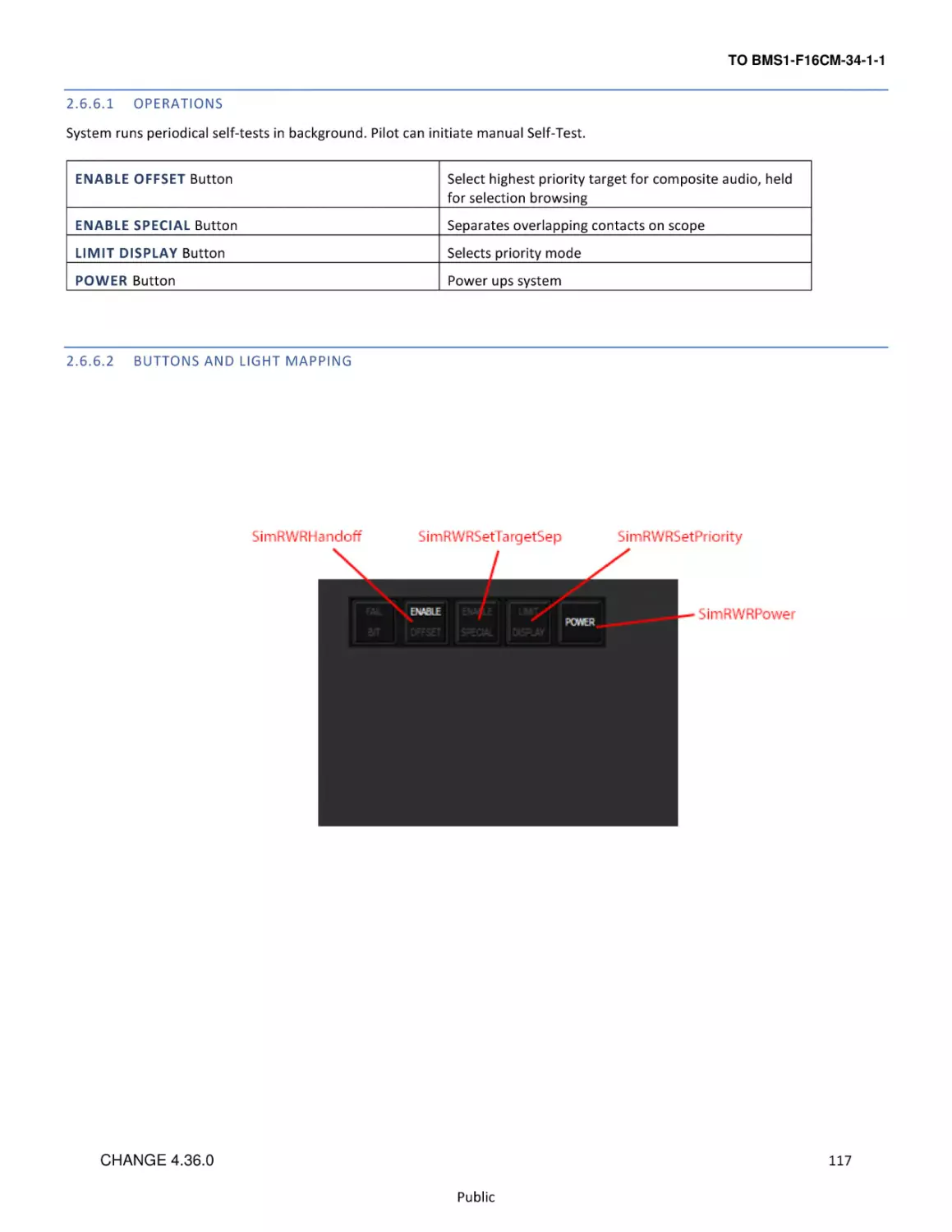
2.6.5
Thales Airborne Systems Carapace ............................................................................................................................... 114
2.6.6
Raytheon (Litton) AN/ALR-67(V)3 ................................................................................................................................. 116
2.6.7
Elisra SPS-1000V-5 ......................................................................................................................................................... 118
2.7
ALE-47 COUNTERMEASURES DISPENSER SET .................................................................................................................... 119
2.7.1
CMDS Modes ................................................................................................................................................................. 120
2.7.2
CMDS Programs............................................................................................................................................................. 120
2.7.3
EWS DED Upfront Controls............................................................................................................................................ 121
2.8
LANTIRN ............................................................................................................................................................................. 123
2.8.1
AN/AAQ-13 Navigation Pod (NVP) ................................................................................................................................ 123
2.8.2
AN/AAQ-14 Targeting Pod (TGP) ................................................................................................................................... 124
2.9
TERRAIN FOLLOWING RADAR (TFR)................................................................................................................................... 125
2.9.1
Terrain Following Radar MFD Page ............................................................................................................................... 126
2.9.2
TFR Operating Modes and Options ............................................................................................................................... 127
2.9.3
TFR Confidence Display ................................................................................................................................................. 129
2.9.4
TFR Controls .................................................................................................................................................................. 130
2.9.5
TFR Modes ..................................................................................................................................................................... 131
2.9.6
Cautions, Warnings and Advisories ............................................................................................................................... 133
2.9.7
Fly-ups / Rollouts ........................................................................................................................................................... 139
2.9.8
TFR Procedures.............................................................................................................................................................. 140
2.10
AN/AAQ-33 SNIPER XR ADVANCED TARGETING POD........................................................................................................ 143
2.10.1 Background ................................................................................................................................................................... 143
2.10.2 TGP Base and Control pages for Sniper XR ATP............................................................................................................ 143
2.10.3 FLIR Sensor .................................................................................................................................................................... 144
2.10.4 Laser Designator/Ranger ............................................................................................................................................... 146
2.10.5 IR Pointer ....................................................................................................................................................................... 149
2.10.6 Sniper XR ATP Controls and Displays............................................................................................................................. 150
2.10.7 Pod Modes .................................................................................................................................................................... 151
2.10.8 AGM-65 Hand Off .......................................................................................................................................................... 159
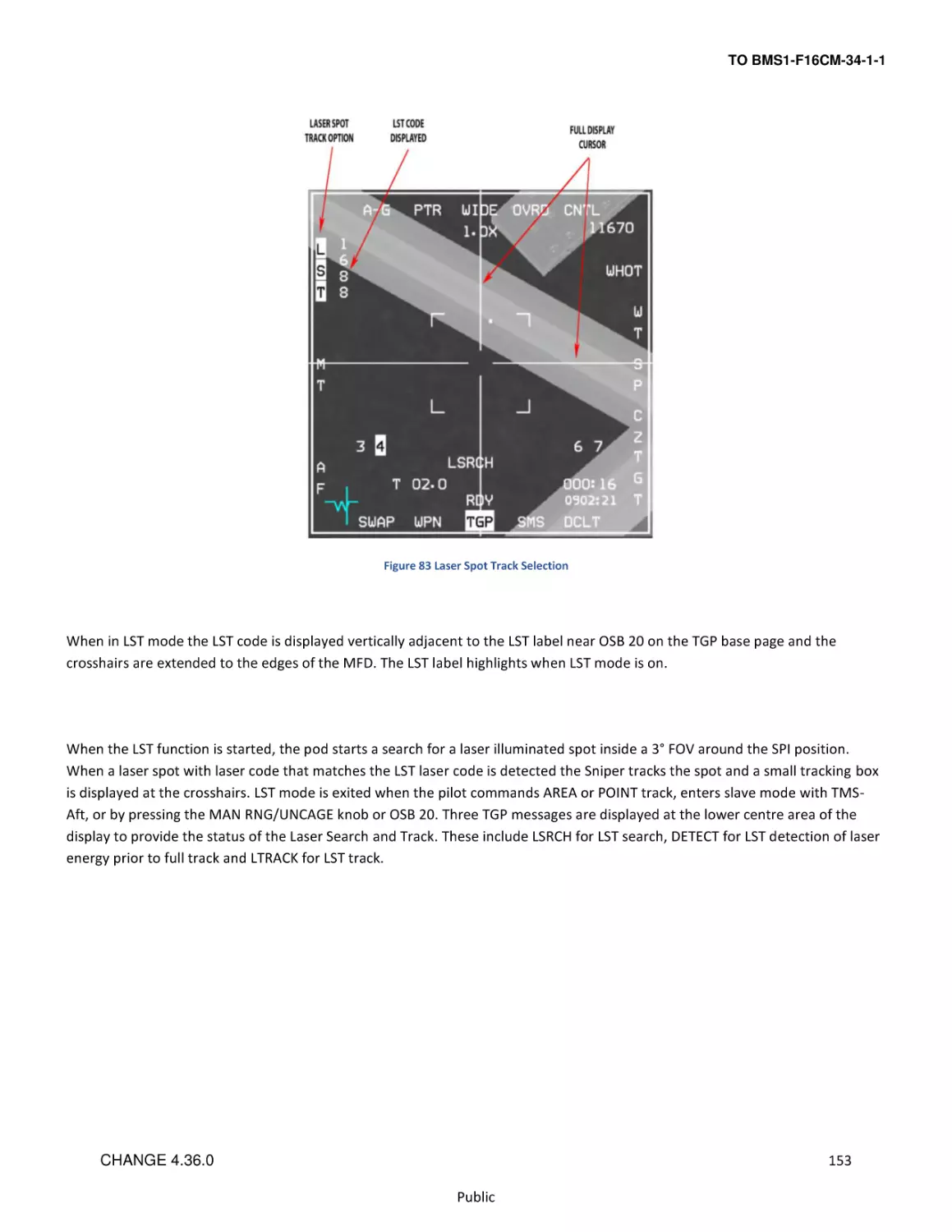
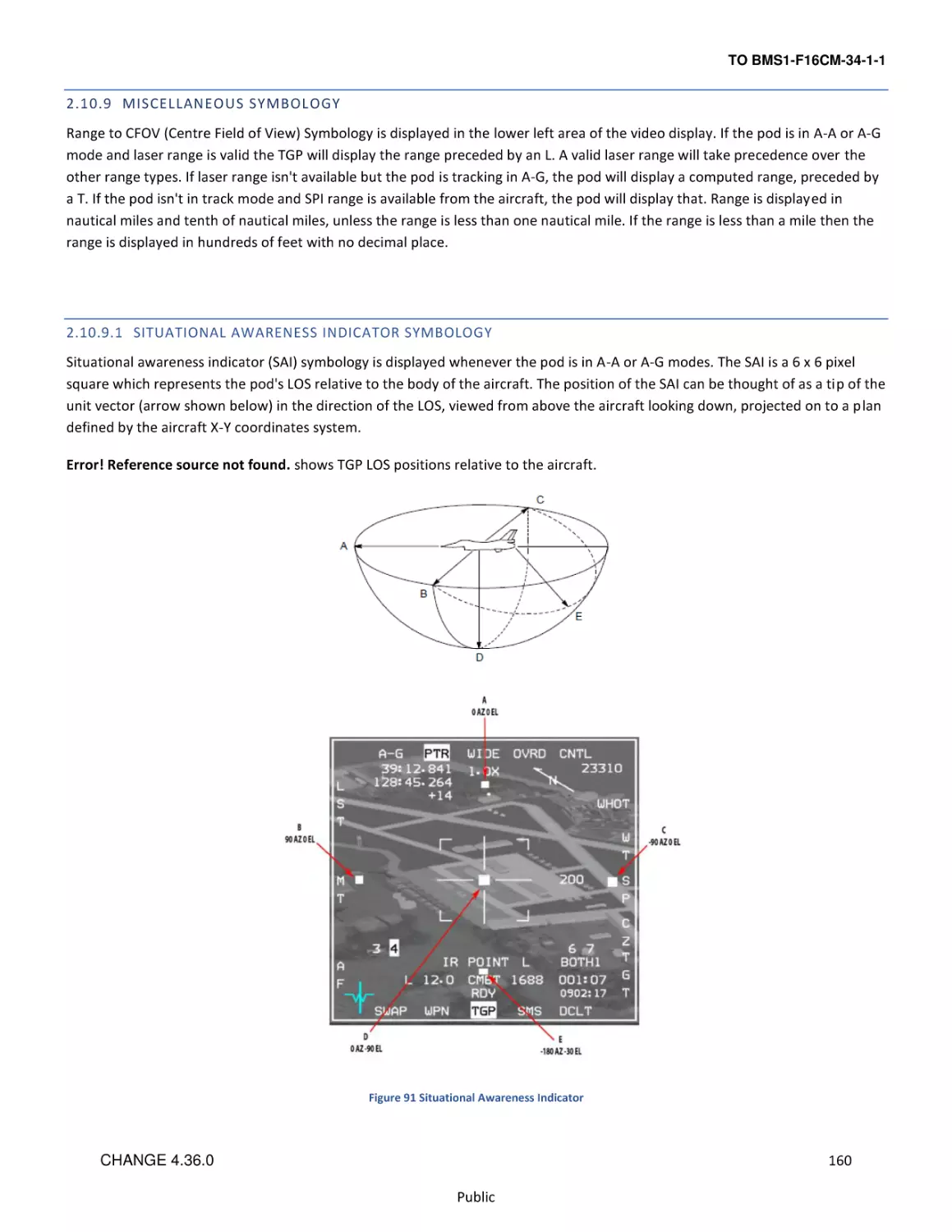
2.10.9 Miscellaneous Symbology ............................................................................................................................................. 160
2.10.10 Additional Notes ............................................................................................................................................................ 162
2.10.11 Operational Considerations .......................................................................................................................................... 162
2.11
HELMET MOUNTED CUEING SYSTEM (HMCS) ................................................................................................................... 166
2.11.1 Control Pages ................................................................................................................................................................ 166
2.11.2 Alignment ...................................................................................................................................................................... 167
2.11.3 Hands-On HMCS Blanking ............................................................................................................................................. 168
2.11.4 HMCS Dynamic Aiming Cross ........................................................................................................................................ 168
2.11.5 Air-to-Air Operations ..................................................................................................................................................... 168
4
CHANGE 4.36.0
Public
TO BMS1-F16CM-34-1-1
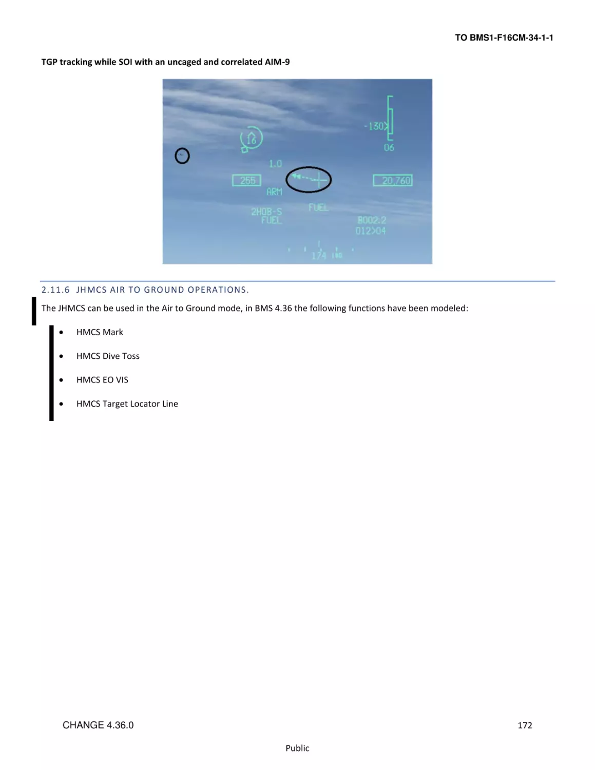
2.11.6 JHMCS Air to Ground Operations. ................................................................................................................................. 172
3
AIR-TO-AIR-COMBAT ......................................................................................................................................... 185
3.1
When Should You Chuck Your Spears? .............................................................................................................................. 185
3.1.1
A Bit of Theory .............................................................................................................................................................. 185
3.1.2
AIM-120 MODES OF OPERATION .................................................................................................................................. 186
3.1.3
HUD Symbology: The Dynamic Launch Zone (DLZ) ....................................................................................................... 186
3.1.4
HUD Symbology: ASEC/ASC ........................................................................................................................................... 189
3.1.5
HPRF vs. MPRF, A/F-pole cues and Missile Datalink ..................................................................................................... 190
3.1.6
Tactics - Some Basics ..................................................................................................................................................... 192
4
AIR-TO-GROUND ................................................................................................................................................ 193
4.1
SPI MANAGEMENT ............................................................................................................................................................ 193
4.1.1
Introduction .................................................................................................................................................................. 193
4.1.2
SPI Description .............................................................................................................................................................. 193
4.1.3
System Delta and its effect on INS/EGI (Embedded GPS/INS) ...................................................................................... 194
4.1.4
Cursor Zero (CZ)............................................................................................................................................................. 196
4.1.5
Snowplow Mode .......................................................................................................................................................... 196
4.1.6
A-G Radar and SPI.......................................................................................................................................................... 196
4.1.7
Targeting Pod (TGP) and SPI .......................................................................................................................................... 196
4.2
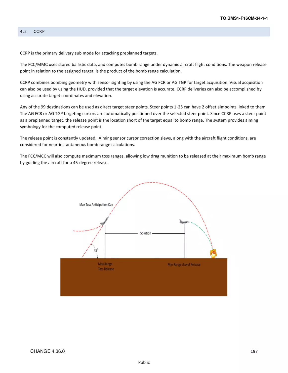
CCRP................................................................................................................................................................................... 197
4.2.1
CCRP mode Access ........................................................................................................................................................ 198
4.2.2
CCRP Loft Delivery ......................................................................................................................................................... 199
4.2.3
Air to Ground Target Designator Box (TD box).............................................................................................................. 199
4.2.4
Azimuth Steering Line (ASL) .......................................................................................................................................... 199
4.2.5
Max toss anticipation cue ............................................................................................................................................. 200
4.2.6
Vertical Steering Cue (VSC) ........................................................................................................................................... 200
4.2.7
Time to pull ................................................................................................................................................................... 201
4.2.8
Time to release .............................................................................................................................................................. 201
4.2.9
Slant Range .................................................................................................................................................................... 202
4.2.10 HUD Bearing and Range to Target. ............................................................................................................................... 202
4.2.11 Air-to-Ground Target Locator Line (AGTLL) ................................................................................................................... 202
4.2.12 Solution cue ................................................................................................................................................................... 204
4.2.13 CCRP/LOFT Release angle scale ..................................................................................................................................... 204
4.2.14 PUAC.............................................................................................................................................................................. 206
4.2.15 CCRP Level Deliveries .................................................................................................................................................... 206
4.2.16 CCRP AG SMS setup ....................................................................................................................................................... 208
4.2.17 Fuzing Option ................................................................................................................................................................ 209
4.2.18 System Altitude ............................................................................................................................................................. 209
5
CHANGE 4.36.0
Public
TO BMS1-F16CM-34-1-1
4.2.19 Backup Bombing Sensors .............................................................................................................................................. 211
4.3
AGM-65D/G MAVERICK MISSILE ....................................................................................................................................... 212
4.3.1
AGM-65 Operational Limitations .................................................................................................................................. 214
4.3.2
AGM-65 Time Limitations.............................................................................................................................................. 214
4.3.3
HOTAS Functions ........................................................................................................................................................... 215
4.3.4
AGM-65 Base Page OSB Functions ................................................................................................................................ 216
4.3.5
SMS E-O WPN Control/Data Entry Pages ...................................................................................................................... 218
4.3.6
Electro-Optical Weapon (E-O WPN) Page ..................................................................................................................... 218
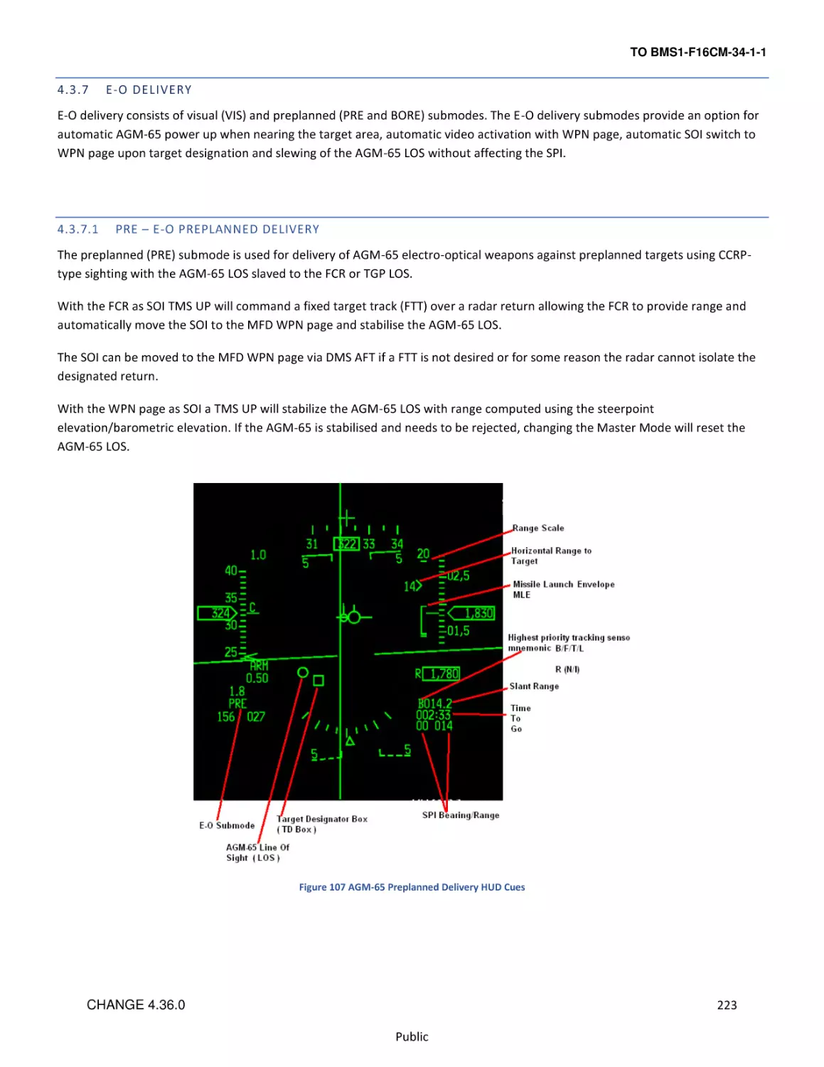
4.3.7
E-O Delivery ................................................................................................................................................................... 223
4.3.8
Targeting Pod E-O Delivery (Handoff) ........................................................................................................................... 229
4.3.9
AGM-65D/G Missile Boresight Procedures ................................................................................................................... 232
4.3.10 AGM-65L ....................................................................................................................................................................... 233
4.4
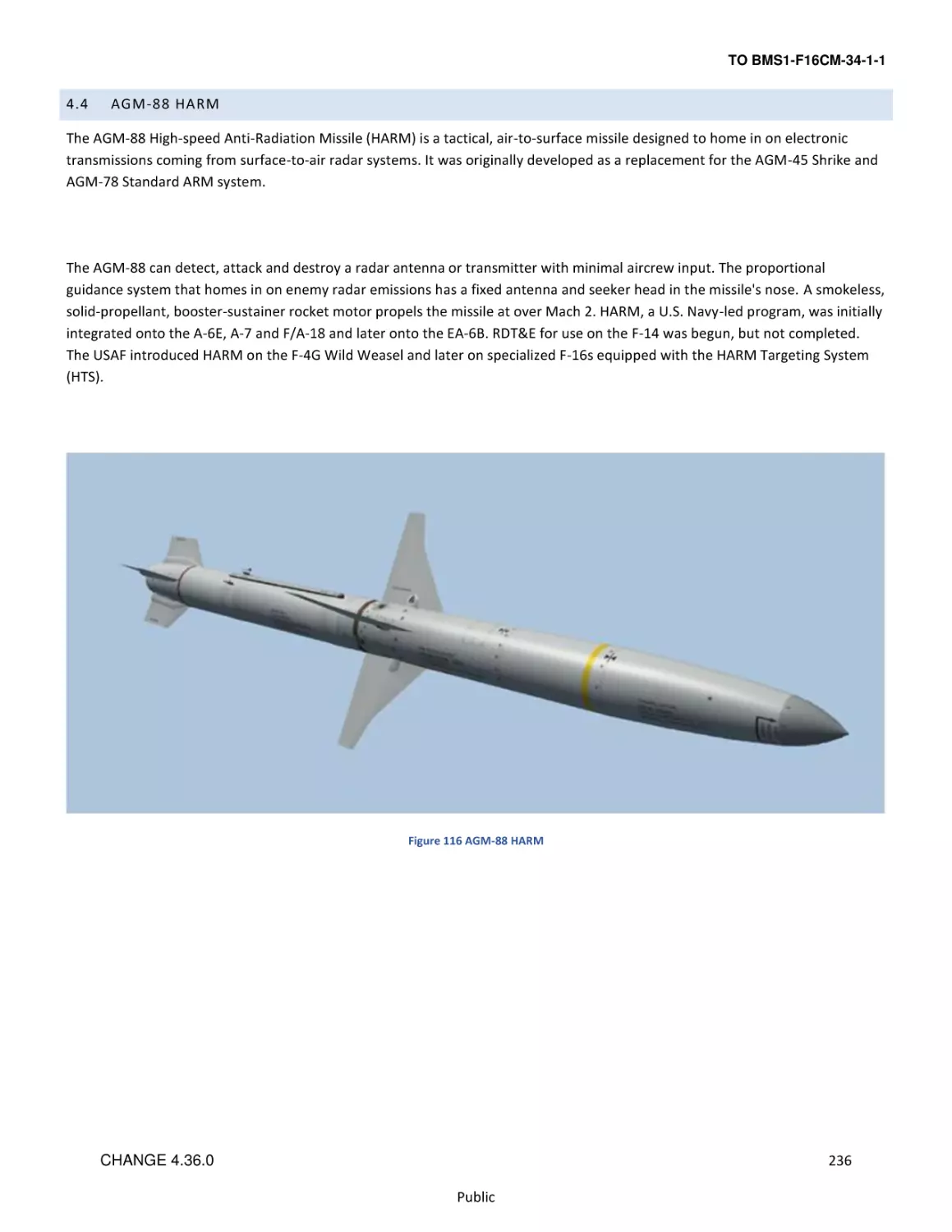
AGM-88 HARM .................................................................................................................................................................. 236
4.4.1
Harm threat tables. ....................................................................................................................................................... 237
4.4.2
SMS Base Page .............................................................................................................................................................. 238
4.4.3
HARM Modes ................................................................................................................................................................ 240
4.4.4
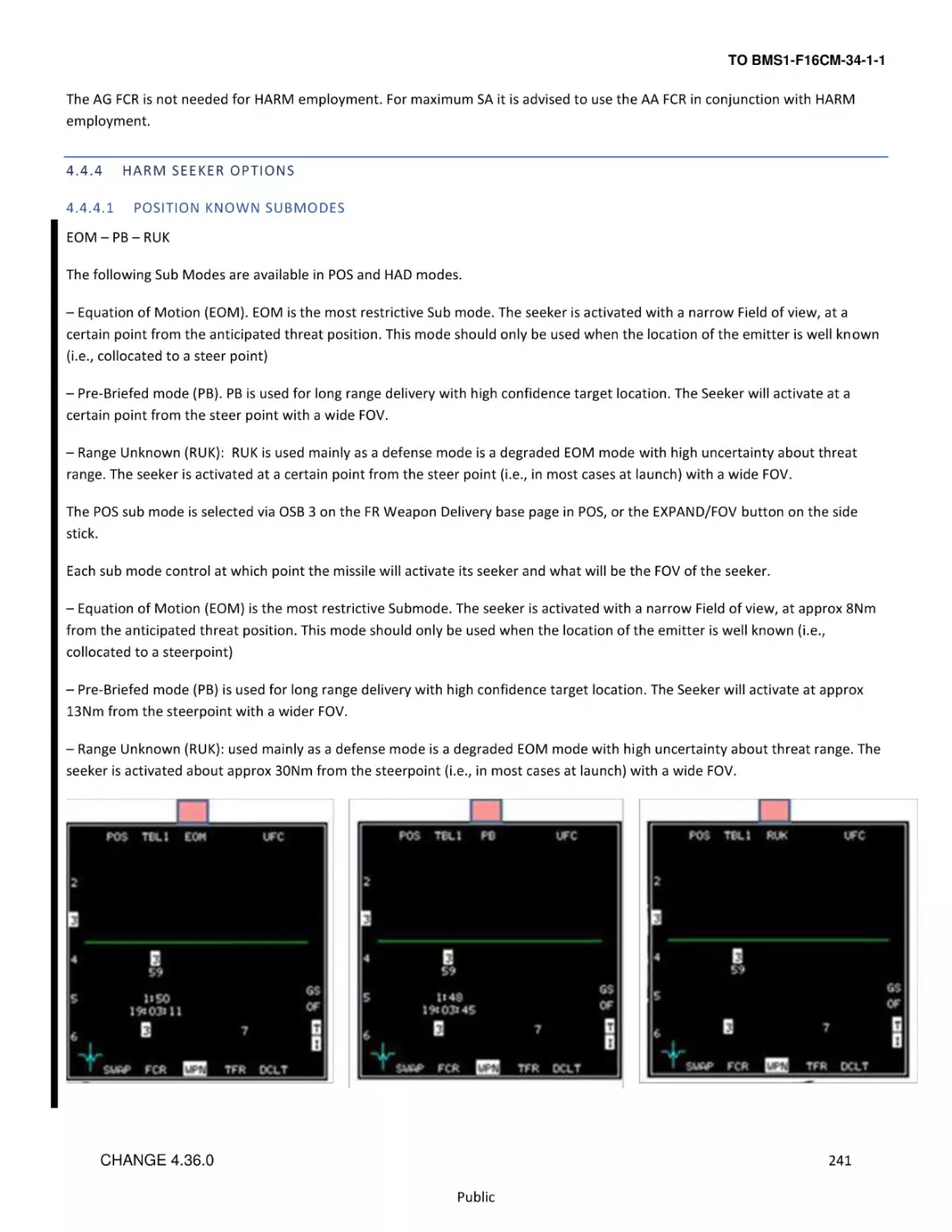
Harm Seeker options ..................................................................................................................................................... 241
4.4.5
POS Mode ...................................................................................................................................................................... 247
4.4.6
HAS Mode...................................................................................................................................................................... 255
4.4.7
HOTAS Controls Summary ............................................................................................................................................. 259
4.4.8
Harm Attack Display HAD .............................................................................................................................................. 259
4.4.9
HUD CUES ...................................................................................................................................................................... 266
4.5
INERTIALLY AIDED MUNITIONS ......................................................................................................................................... 267
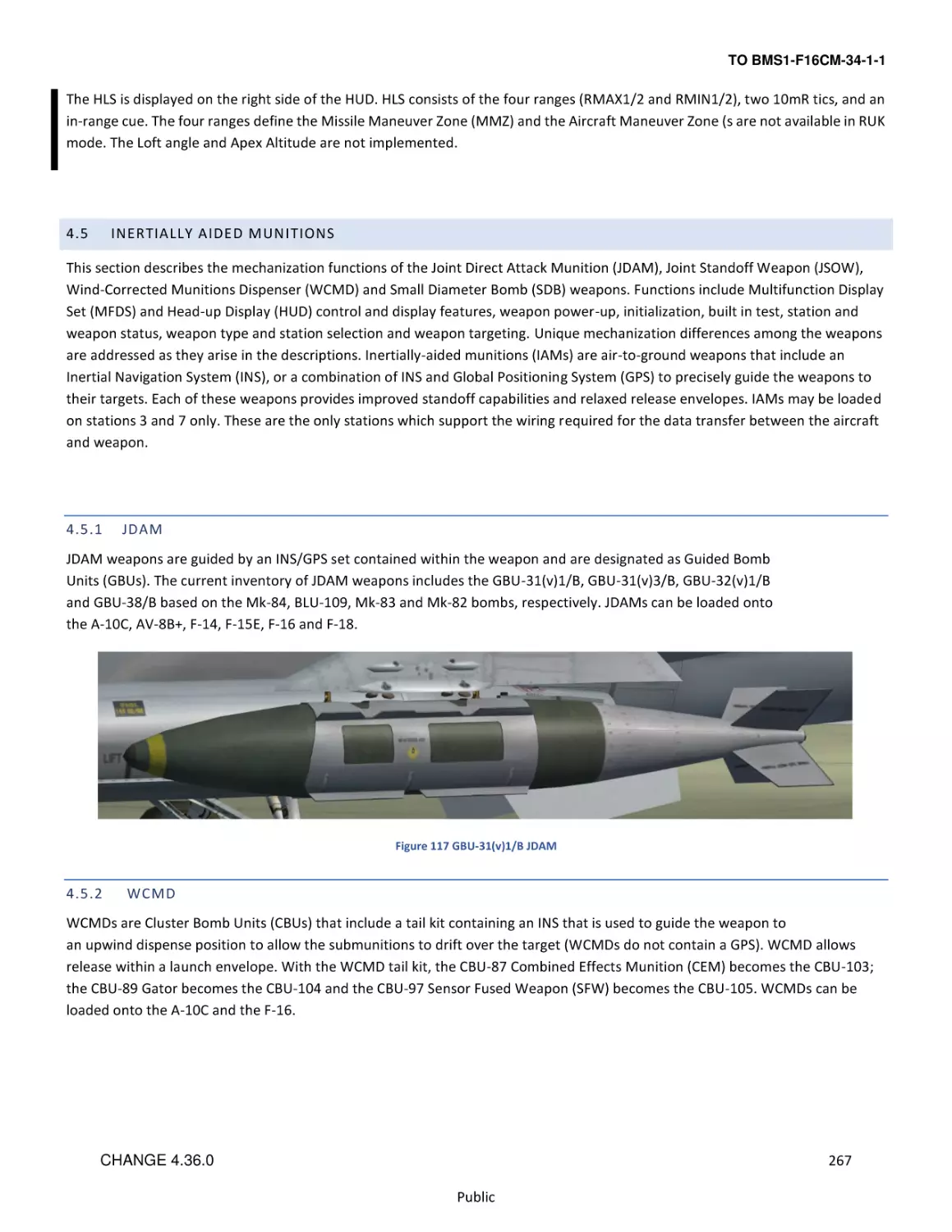
4.5.1
JDAM ............................................................................................................................................................................. 267
4.5.2
WCMD .......................................................................................................................................................................... 267
4.5.3
JSOW ............................................................................................................................................................................. 268
4.5.4
SDB ................................................................................................................................................................................ 268
4.5.5
Laser JDAM .................................................................................................................................................................... 269
4.5.6
IAM SMS Pages .............................................................................................................................................................. 270
4.5.7
Weapon Delivery Submodes ......................................................................................................................................... 278
4.5.8
Impact Option (JSOW, WCMD)...................................................................................................................................... 279
4.5.9
Impact Spacing (JSOW, WCMD) .................................................................................................................................... 281
4.5.10 Target Profile Data Sets (JDAM) .................................................................................................................................... 281
4.5.11 HUD Symbology for IAM Weapons Delivery ................................................................................................................. 283
4.5.12 IAM Weapon Release Considerations ........................................................................................................................... 286
4.5.13 JSOW, JDAM, SDB, WCMD PRE Weapons Delivery Procedures .................................................................................... 287
4.5.14 JSOW, JDAM, WCMD VIS Weapons Delivery Procedures ............................................................................................. 288
6
CHANGE 4.36.0
Public
TO BMS1-F16CM-34-1-1
4.5.15 Guide on IAM usage ...................................................................................................................................................... 289
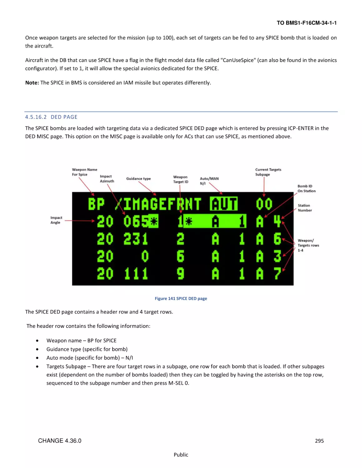
4.5.16 SPICE Bomb ................................................................................................................................................................... 294
4.5.17 LGMs – Laser Guided Missiles ....................................................................................................................................... 298
4.6
Laser Guided Bombs (LGBs) ............................................................................................................................................... 300
4.6.1
LGB SMS page................................................................................................................................................................ 301
4.6.2
LGB CNTL page .............................................................................................................................................................. 301
4.6.3
LASER UFC page............................................................................................................................................................. 302
4.7
Man-in-the-Loop Weapons ............................................................................................................................................... 303
4.7.1
General Information ...................................................................................................................................................... 303
4.7.2
SMS Page ....................................................................................................................................................................... 306
4.7.3
WPN Page ...................................................................................................................................................................... 307
4.7.4
Man in the Loop Hands-On Controls ............................................................................................................................. 313
4.7.5
HUD ............................................................................................................................................................................... 314
4.7.6
HSD ................................................................................................................................................................................ 315
4.7.7
Weapon Release Procedure .......................................................................................................................................... 316
4.8
AGM-84 Harpoon............................................................................................................................................................... 317
4.8.1
Harpoon Target and Waypoint Data Loading via UFC ................................................................................................... 319
4.8.2
SMS Base Page .............................................................................................................................................................. 321
4.8.3
RBL – Range And Bearing Launch Mode........................................................................................................................ 322
4.8.4
BOL – Bearing Only Launch Mode ................................................................................................................................. 330
4.8.5
LOS – Line Of Sight Launch Mode .................................................................................................................................. 334
7
CHANGE 4.36.0
Public
TO BMS1-F16CM-34-1-1
2
AVIONICS SYSTEMS AND CONTROLS
8
CHANGE 4.36.0
Public
TO BMS1-F16CM-34-1-1
2.1
COCKPIT CONTROLS AND DISPLAYS
This section describes the location and function of the weapon system related controls and displays. Its purpose is to provide a
quick reference guide to finding or using the system described in this manual.
When applicable, this section will contain a reference to the place that the system is described in detail.
9
CHANGE 4.36.0
Public
TO BMS1-F16CM-34-1-1
2.1.1
PHILOSOPHY OF COCKPIT CONTROLS AND DISPL AYS
The F-16 avionic system incorporates master mode, cursor control and sensor-of-interest (SOI) features designed to integrate
controls and displays and simplify display and sensor management. For this section, the cockpit controls and displays are
categorized as follows:
•
•
•
•
Key Avionic Console Switches.
Upfront Controls.
Video Displays.
Hands-On Controls.
The layout of the cockpit is designed to afford the operator the greatest flexibility in system mode, sensor and weapon selection
while optimizing efficiency of movement in the cockpit and thereby reducing pilot workload.
The avionic system allows the pilot to prepare preplanned set-ups for modes, sensors and weapons; either automatically or
manually before takeoff. These preplanned set-ups let the pilot utilize the hands-on controls, Multifunction Displays, Upfront
Controls, and Head-Up Display/Helmet Mounted Cueing System so that a minimum amount of time is spent looking inside the
cockpit.
2.1.1.1
KEY AVIONIC CONSOLE SWITCHES
Console panels are positioned so that those switches which can be set during ramp start and then forgotten are located on the
right console, out of sight. Consoles which affect specific mission completion (i.e. communications, navigation, landing gear) are
grouped together for easy access in flight and generally located on the left console.
2.1.1.2
UPFRONT CONTROLS
Upfront Controls (UFC) consist of the Integrated Control Panel (ICP), the Data Entry Display (DED) and Pilot Fault List Display
(PFLD). The UFC consolidates and automates the communication, navigation and identification (CNI) functions. The UFC set is
partitioned between frequently used controls on the ICP and infrequently used controls on the side consoles. Frequently used
controls such as override and priority functions are accessed via a single push-button on the ICP.
2.1.1.3
VIDEO DISPLAYS
Two Colour Multifunction Displays (MFD’s), a Head-Up Display (HUD) and a Helmet Mounted Cueing System (HMCS) provide the
pilot with essential mission information for head-down and head-up operations.
The MFD’s are intended to allow common operation and control of various subsystems and sensors as well as provide video
display for the radar, weapons, targeting pod and Navigation pod.
The HUD allows the pilot to monitor both navigation and weapon delivery information and still remain focused outside the
aircraft.
The HMCS is an electro-optical device that displays information in front of the pilot’s right eye; it is intended primarily for
daytime operation. The HMCS also provides the pilot with the ability to cue the aircraft sensor suite and weapons outside the
HUD field of view (FOV) and provides feedback to the pilot on sensor and weapon data. The HMCS is basically an extension of the
HUD, and as such they are considered as one SOI (i.e. they share the same Hands-On Control switchology).
10
CHANGE 4.36.0
Public
TO BMS1-F16CM-34-1-1
2.1.1.4
HANDS-ON CONTROLS
The hands-on controls consist of switches located on the throttle grip and the side-stick controller. Functions that require
instantaneous access (e.g., radio transmit, target designate, weapon release) and functions that must be accomplished during
maneuvering flight, when the pilot cannot remove his hands from the stick and throttle, are controlled by the hands-on controls.
The following diagrams illustrate the typical F-16 HOTAS control grips and the various functions assigned to them. With the
exception of the black-out switch (HOBO), all HOTAS functions are modelled in the game.
The sections which follow illustrate the functionality of the various controls in A-A and A-G modes and provide the names of the
key file callback names that are typically mapped to each switch position on the stick and throttle grips. They should be referred
back to as necessary.
Figure 1 F-16 HOTAS Throttle (TQS) and Stick (SSC) Controls
11
CHANGE 4.36.0
Public
TO BMS1-F16CM-34-1-1
2.1.1.4.1
AIR-TO-AIR MISSION – STICK
12
CHANGE 4.36.0
Public
TO BMS1-F16CM-34-1-1
2.1.1.4.2
AIR-TO-AIR MISSION - THROTTLE
13
CHANGE 4.36.0
Public
TO BMS1-F16CM-34-1-1
2.1.1.4.3
AIR-TO-GROUND MISSION – STICK
14
CHANGE 4.36.0
Public
TO BMS1-F16CM-34-1-1
2.1.1.4.4
AIR-TO-GROUND MISSION – THROTTLE
15
CHANGE 4.36.0
Public
TO BMS1-F16CM-34-1-1
2.1.2
F-16 MODE AND SENSOR CONCEPTS
2.1.2.1
MASTER MODE SELECTION AND CONTROL
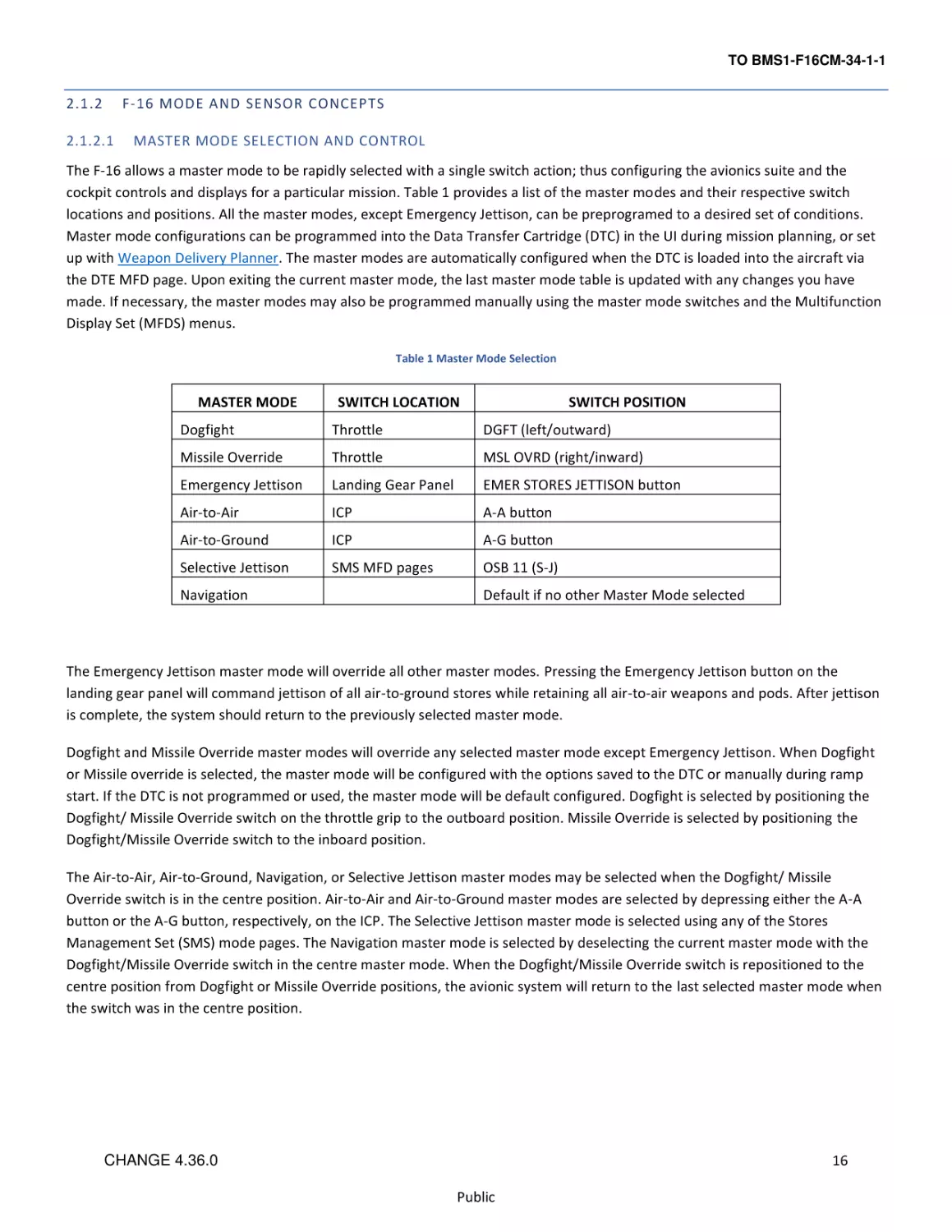
The F-16 allows a master mode to be rapidly selected with a single switch action; thus configuring the avionics suite and the
cockpit controls and displays for a particular mission. Table 1 provides a list of the master modes and their respective switch
locations and positions. All the master modes, except Emergency Jettison, can be preprogramed to a desired set of conditions.
Master mode configurations can be programmed into the Data Transfer Cartridge (DTC) in the UI during mission planning, or set
up with Weapon Delivery Planner. The master modes are automatically configured when the DTC is loaded into the aircraft via
the DTE MFD page. Upon exiting the current master mode, the last master mode table is updated with any changes you have
made. If necessary, the master modes may also be programmed manually using the master mode switches and the Multifunction
Display Set (MFDS) menus.
Table 1 Master Mode Selection
MASTER MODE
SWITCH LOCATION
SWITCH POSITION
Dogfight
Throttle
DGFT (left/outward)
Missile Override
Throttle
MSL OVRD (right/inward)
Emergency Jettison
Landing Gear Panel
EMER STORES JETTISON button
Air-to-Air
ICP
A-A button
Air-to-Ground
ICP
A-G button
Selective Jettison
SMS MFD pages
OSB 11 (S-J)
Navigation
Default if no other Master Mode selected
The Emergency Jettison master mode will override all other master modes. Pressing the Emergency Jettison button on the
landing gear panel will command jettison of all air-to-ground stores while retaining all air-to-air weapons and pods. After jettison
is complete, the system should return to the previously selected master mode.
Dogfight and Missile Override master modes will override any selected master mode except Emergency Jettison. When Dogfight
or Missile override is selected, the master mode will be configured with the options saved to the DTC or manually during ramp
start. If the DTC is not programmed or used, the master mode will be default configured. Dogfight is selected by positioning the
Dogfight/ Missile Override switch on the throttle grip to the outboard position. Missile Override is selected by positioning the
Dogfight/Missile Override switch to the inboard position.
The Air-to-Air, Air-to-Ground, Navigation, or Selective Jettison master modes may be selected when the Dogfight/ Missile
Override switch is in the centre position. Air-to-Air and Air-to-Ground master modes are selected by depressing either the A-A
button or the A-G button, respectively, on the ICP. The Selective Jettison master mode is selected using any of the Stores
Management Set (SMS) mode pages. The Navigation master mode is selected by deselecting the current master mode with the
Dogfight/Missile Override switch in the centre master mode. When the Dogfight/Missile Override switch is repositioned to the
centre position from Dogfight or Missile Override positions, the avionic system will return to the last selected master mode when
the switch was in the centre position.
16
CHANGE 4.36.0
Public
TO BMS1-F16CM-34-1-1
2.1.2.2
SYSTEM POINT-OF-INTEREST (SPI)
F-16 sensor management is based on a single line-of-sight concept where all sensors are slaved to a common aimpoint, referred
to as the System Point-of-Interest (SPI). Please see SPI MANAGEMENT SPI MANAGEMENT for more details.
2.1.2.3
SENSOR-OF-INTEREST (SOI)
SOI mechanization simplifies multiple sensor management by designating one sensor format for hands-on control.
If the SOI is the HUD/HMCS, the SOI asterisk symbol is positioned on the upper left of the HUD. If the SOI is an MFD, the SOI
symbol consists of a line drawn around the edge of the MFD. SOI designation is a function of either the highest priority sensor or
of pilot intent.
Examples of pilot intent include:
•
•
•
•
If the Display Management Switch (DMS) is moved up, the SOI designation transitions to the HUD, if allowed.
If the HUD is the SOI and the DMS is moved down, the SOI designation transitions to the MFDs.
If the DMS is moved down and the SOI is on the MFDs, then the SOI transitions to the other MFD, if allowed.
If the SWAP OSB on an MFD is depressed, the SOI symbol follows the sensor display to the other MFD.
The SOI cannot be designated in the MARK OFLY submode, or the snowplow (SP) function in the pre-designate (PRE) state.
Only FCR, TGP, WPN, HAD, and HSD formats may be the designated SOI display on the MFD. The HUD may be the designated SOI
only in the navigation and air-to-ground master modes. The SOI display is restricted in the air-to-air master mode to the FCR, HSD
and TGP formats.
On the FCR, TGP, HSD, HAD and WPN formats, NOT SOI appears whenever the format is not selected as the sensor of interest.
Figure 2 FCR NOT SOI Display
Please refer to the companion T.O. BMS1F-16CM-1 manual (Dash 1) for general information on Cockpit Arrangement, Up Front
Controls, Multi-Function Displays and the Head Up Display. Specific information about cockpit controls and displays relevant to
describing aircraft avionics, weapons systems, support equipment and munitions will be covered later in this manual.
17
CHANGE 4.36.0
Public
TO BMS1-F16CM-34-1-1
2.2
2.2.1
INERTIAL NAVIGATION SYSTEM (INS)
STEERPOINTS
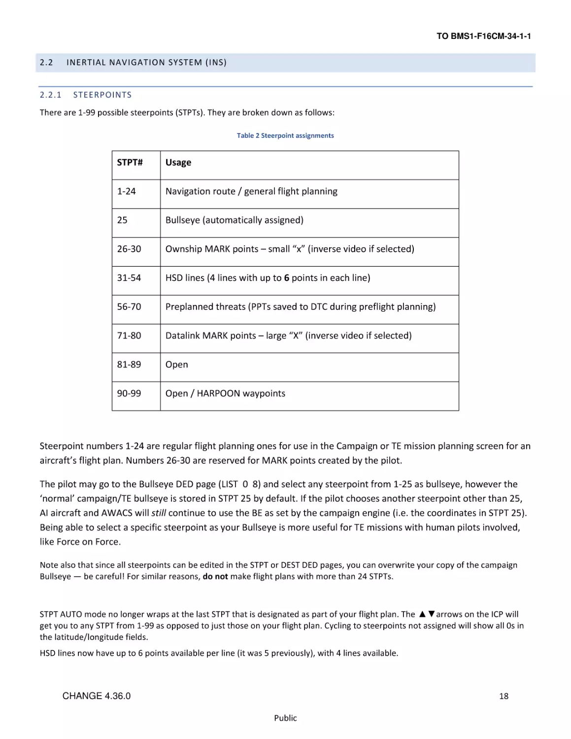
There are 1-99 possible steerpoints (STPTs). They are broken down as follows:
Table 2 Steerpoint assignments
STPT#
Usage
1-24
Navigation route / general flight planning
25
Bullseye (automatically assigned)
26-30
Ownship MARK points – small “x” (inverse video if selected)
31-54
HSD lines (4 lines with up to 6 points in each line)
56-70
Preplanned threats (PPTs saved to DTC during preflight planning)
71-80
Datalink MARK points – large “X” (inverse video if selected)
81-89
Open
90-99
Open / HARPOON waypoints
Steerpoint numbers 1-24 are regular flight planning ones for use in the Campaign or TE mission planning screen for an
aircraft’s flight plan. Numbers 26-30 are reserved for MARK points created by the pilot.
The pilot may go to the Bullseye DED page (LIST 0 8) and select any steerpoint from 1-25 as bullseye, however the
‘normal’ campaign/TE bullseye is stored in STPT 25 by default. If the pilot chooses another steerpoint other than 25,
AI aircraft and AWACS will still continue to use the BE as set by the campaign engine (i.e. the coordinates in STPT 25).
Being able to select a specific steerpoint as your Bullseye is more useful for TE missions with human pilots involved,
like Force on Force.
Note also that since all steerpoints can be edited in the STPT or DEST DED pages, you can overwrite your copy of the campaign
Bullseye — be careful! For similar reasons, do not make flight plans with more than 24 STPTs.
STPT AUTO mode no longer wraps at the last STPT that is designated as part of your flight plan. The ▲▼arrows on the ICP will
get you to any STPT from 1-99 as opposed to just those on your flight plan. Cycling to steerpoints not assigned will show all 0s in
the latitude/longitude fields.
HSD lines now have up to 6 points available per line (it was 5 previously), with 4 lines available.
18
CHANGE 4.36.0
Public
TO BMS1-F16CM-34-1-1
2.2.2
DED PAGES
INS related DED pages include the STPT, DEST, and BULLSEYE. For a more comprehensive explanation of Up Front Controls please
refer to the companion T.O. BMS1F-16CM-1 manual (Dash 1).
2.2.2.1
DED STEERPOINT PAGE
→
→
→
→
Punching “4” on the ICP brings the pilot to the Steerpoint (STPT) page. The scratchpad asterisks will initially be at the top as seen
above. The pilot may punch another number (4, ENTR) to select a different steerpoint as the current steerpoint. All steering cues
will update to reflect the new selection (#4 in this example).
The pilot may “Dobber” down with the Data Control Switch (DCS) to each individual field on the page and edit it as desired:
latitude, longitude, elevation and Time on Station (TOS). Note that while editing lat/long, the pilot will see immediate feedback
from his steering cues (tadpole, STPT diamond, ETE/ETA, bearing/distance, etc.) in the HUD and in heads-down displays since the
STPT he is editing is the current steerpoint. Elevation may be edited as well and it now functions like the real aircraft, i.e. it is the
MSL elevation of the steerpoint at ground level. This is automatically set by the campaign/TE flight plan generator for any
steerpoints set up in the UI.
The pilot may also toggle auto steerpoint sequencing (AUTO) on/off (MAN) by dobbering right (towards SEQ) on the steerpoint
DED page. With auto steerpoint sequencing the system will automatically increment the steerpoint when the aircraft is within
2Nm of the steerpoint and the range is increasing. Auto steerpoint sequencing is indicated on the CNI page with a letter “A”
displayed next to the current steerpoint. Nothing is displayed in manual.
19
CHANGE 4.36.0
Public
TO BMS1-F16CM-34-1-1
2.2.2.2
DED DESTINATION PAGE
→
→
→
→
→
The Destination (DEST DIR) DED page is nearly identical to the STPT page. The only difference is that the DEST page can be used
to change coordinates of a particular steerpoint without affecting navigation to the current steerpoint.
2.2.2.3
→
DED BULLSEYE PAGE
→
→
→
→
→
→
As mentioned above the default Bullseye steerpoint is #25. Bullseye can be changed to any steerpoint. In the example above,
Bullseye is changed to STPT 3 and the pilot sees STPT and Bullseye co-located on the FCR and HSD.
Remember: the AI and AWACS will only use the location that is stored in STPT 25 and that the pilot has the possibility of
overwriting this location, so be careful.
20
CHANGE 4.36.0
Public
TO BMS1-F16CM-34-1-1
2.2.2.4
→
DED TIME PAGE
→
→
→
→
→
→
(5 minutes)
Hitting 0- designates a negative value.
The Time page includes the system time, a hack clock time and a delta time on station. The hack clock may be started or stopped
by using the ▲▼switch. The DELTA TOS value allows you to adjust TOS to all destinations with one entry, to accommodate
changes in takeoff and/or rendezvous times.
Dobber down to the DELTA TOS field and enter the delta time to any steerpoint. If required, press the 0- key prior to your entry
to designate it as a negative value (i.e. you want to arrive earlier at all steerpoints). Press ENTR to apply the DELTA TOS to all TOS.
2.2.2.5
DED MARK POINTS
When entering DED MARK page (ICP 7) the MARK mode will be set automatically according to the Master Mode and relevant
sensor state.
•
FCR - If the system is in NAV or AG master modes, the FCR is in AG mode (not AGR), the FCR is the SOI and the FCR is
designating something, MARK mode will be automatically set to FCR. When entering MARK page at this state, a FCR
MARKPOINT will be recorded when you TMS Up.
•
TGP - If the system is in NAV or AG master modes, the TGP is in AG mode, the TGP is the SOI and ground stabilized,
MARK mode will be automatically set to TGP. When entering MARK mode at this state, a TGP MARKPOINT will be
recorded when you TMS Up.
•
OFLY - If the system is in AA master mode, MARK mode will be automatically set to OFLY. When entering MARK mode at
this state, an OFLY MARKPOINT will be recorded immediately. No TMS Up is needed.
•
HUD - If the system is in NAV or AG master modes and conditions are not sufficient to set FCR or TGP modes, MARK
mode will be automatically set to HUD and a HUD Mark Cue (HMC - a 12mr circle with a 1mr aiming dot inside it) will
appear on the FPM in the HUD. This is pre-designate mode.
21
CHANGE 4.36.0
Public
TO BMS1-F16CM-34-1-1
The HMC can be cursor-slewed to the desired position and TMS Up ground stabilizes it (post-designate mode). The position may
be refined using the cursors and then a second TMS Up will save the Markpoint.
In post-designate with the HMC ground stabilized, a TMS Down will cancel the stabilization and return to pre-designate mode,
and the HMC will again be tied to the FPM. Note that if trying to ground stabilize or mark with TMS Up when the cue is not on the
ground, nothing will happen.
If you select a MARK mode with the ICP sequence (SEQ) button which does not match the current system and sensor state (for
example setting FCR MARK when the system is in AA master mode), an OFLY MARKPOINT will be recorded when you TMS Up.
When the MARK DED page is displayed and the current MARKPOINT is valid (has positional data) then depressing the M-SEL
button (ICP 0) will set that MARKPOINT as the current active steerpoint.
The MARK mode rotary will cycle through the 4 existing modes in this order: HUD, TGP, OFLY, and FCR. When the MARK DED
page is displayed and one of the 1-9 ICP buttons is pressed, a MARK mode change will happen (just like using the sequence
button).
A Markpoint is just like any other steerpoint and can be sent to another aircraft via the IDM.
2.2.3
SIGHTING OPTIONS
Aircraft sensors are pointed along a common line-of-sight (LOS) to a specific point on the ground for air-to-ground sighting known
as the System Point-of-Interest (SPI). The following sighting options and cursor position features are available:
STP/TGT –
Steerpoint and Target Direct Aimpoint sighting
OA1/OA2 –
Offset Aimpoint sighting
IP –
Visual Initial Point sighting
RP –
Visual Reference Point sighting
SP –
Snowplow sighting
The STP/TGT, OA1/OA2, IP, and RP sighting options are selected via the sighting point rotary on the MFD GM FCR page (OSB 10).
Additionally the sighting point options are selectable via TMS right. Offset (OA1/OA2), initial point (IP) sighting, and reference
point (RP) sighting are used for aim points where positions are known or estimated to be near specified steerpoints. Bearing
from true north, range, and elevation data are entered via the upfront controls. Note: For simplification, entering “0” for
elevation places offsets at ground level, regardless of terrain MSL altitude. Thus, pilots should normally enter “0” for altitude.
2.2.3.1
DIRECT AIMPOINT SIGHTING (STPT/TGT)
Direct sighting can be used in any bombing mode. All sensors are pointed at the selected steerpoint. Slewing the cursor via the
cursor control may be required to place the steerpoint position over a desired aim point more precisely. Slew corrections may be
zeroed via the cursor zero OSB.
22
CHANGE 4.36.0
Public
TO BMS1-F16CM-34-1-1
2.2.3.2
OFFSET AIMPOINT SIGHTING (OA1/OA2)
Steerpoints may have up to two offsets, each defined as a true bearing and range from the steerpoint and each with a separate
elevation. If an offset aim point has zero range, it is skipped in the sighting point rotary. If OA1 or OA2, all sensors are pointed to
the offset position; however, the steerpoint defines the target location. As a result, weapons may be delivered against a target
that presents a poor radar return by aiming at a radar-significant object. Offset aim point sighting is provided in preplanned
submodes (CCRP in this case, since LADD and ULFT are not implemented) only. The OA symbol is an isosceles triangle 12 mr high
and 6 mr wide. It is displayed in NAV and A-G mastermodes.
Offset aim point selections are remembered by the system through master mode and steerpoint changes.
2.2.3.3
VISUAL INITIAL POINT SIGHTING (VIP)
Visual initial point (VIP) sighting is used in preplanned submodes to plot a target on the HUD at a true bearing and range from a
visually identifiable overfly point. Overfly updates to the SPI and HUD slews are not implemented at this time.
The VIP sighting mode also allows for an unknown target position to be referenced from a known position (steerpoint) during a
mission. By preplanning the IP, bearing, range, and elevation can be entered while airborne to define the target.
While in VIP, navigation steering to the IP is provided via the HSI and the azimuth steering line to the target on the HUD. Cursor
zero reverts the system solution back to the original navigation solution if cursor slews are made. Bearing, range and elevation
data for the IP may be entered by pressing LIST→3 on the ICP. VIP is mode-selected by placing the scratchpad asterisks on “VIPTO-TGT” and pressing “0” to mode select. Offset aim points and IP sighting may be used simultaneously.
TD Box
Offset Aimpoint
Pull-up Point (PUP)
Visual Initial Point (VIP) (STPT 10)
*VIP-TO-TGT*
VIP 10 ^
TBRG 356.0
VIP-TO-PUP
VIP 10 ^
TBRG 030.0
Figure 3 VIP Sighting
23
CHANGE 4.36.0
Public
TO BMS1-F16CM-34-1-1
2.2.3.4
VISUAL REFERENCE POINT SIGHTING (VRP)
Visual reference point (VRP) sighting mode is used in preplanned submodes to plot a reference point on the HUD as a true
bearing and range from the target. This allows the utilization of a known, visually identifiable position, or RP point, to initiate an
attack. Again, overfly updates to the SPI and HUD slews are not implemented at this time.
While in VRP, navigation steering is provided to the target via the HSI and via the azimuth steering line on the HUD. Initially, the
sighting point rotary is on TGT. While in VRP, the steerpoint defines the target and the RP is defined as a bearing and range from
the target and an elevation (remember, use “0”). Bearing, range and elevation data for the RP may be entered by pressing
LIST→9 on the ICP. VRP is mode-selected by placing the scratchpad asterisks on “TGT-TO-VRP” and pressing “0”. Offset aim
point and RP sighting are available simultaneously.
(STPT 10)
TD Box
Offset Aimpoint
Pull-up Point (PUP)
Visual Reference Point (VRP)
*TGT-TO-VRP*
TGT 10 ^
TBRG 178.0
TGT-TO-PUP
TGT 10 ^
TBRG 150.0
Figure 4 VRP Sighting
24
CHANGE 4.36.0
Public
TO BMS1-F16CM-34-1-1
2.2.3.5
POP-UP POINT (PUP) CUE.
The pop-up point (PUP) is entered via the VIP-TO-PUP or VRP-TO-PUP page of the DED. DCS right (SEQ) to select the PUP page
from the VIP or VRP pages. When the PUP is limited in the HUD FOV, an X is superimposed over it.
2.2.3.6
FINAL IP AND RP NOTES
Note how aim points and PUPs are defined in both VIP and VRP (they are always off the steerpoint—the VIP is a steerpoint while
the VRP is not). Careful study of the geometry in both modes will ease understanding and help the pilot make the decision in
which mode would be best utilized. Target type, location, terrain features and delivery methods may also be factors to consider
when using one mode or the other. VIP and VRP may not be used simultaneously. Mode-selecting one will de-mode-select the
other. It is not advisable to try and use both modes for one steerpoint as OA and PUP geometry will change if one mode is
selected but the offsets were intended for (or entered in) the other.
2.2.3.7
SNOWPLOW (SP) SIGHTING
Depress OSB 8 next to the SP mnemonic in GM/GMT to select the snowplow option. The mnemonic highlights indicating that
you are in the SP mode. SP sighting directs each sensor line-of-sight straight ahead in azimuth, disregarding any selected
steerpoints. In the GM, GMT, and SEA modes, the ground map cursor will be positioned at half the range selected, i.e., the
centre of the MFD. The cursors remain at this range while the ground map video moves, or "snowplows," across the MFD. At
this point, there is no SOI, and the cursors cannot be slewed. The cursors can be slewed to a target or aim point with the
CURSOR/ENABLE switch after you ground stabilize them by using TMS forward.
TMS forward establishes the radar as the SOI and enables cursor slewing. TMS forward again over a target to command single
target track. All cursor slews in SP are zeroed when SP is deselected. After ground stabilizing, the point under the cursors at the
time of stabilization effectively becomes your steerpoint. All NAV and weapon delivery steering and symbology, including great
circle steering, will be referenced to this "pseudo steerpoint." Displays return to the previously selected sighting point when SP is
deselected. For example, SP can be used to accomplish an FCR mark on a point 5 NM in front of your position when the
steerpoint selected is 40 NM away. It may often be used with IR Mavericks where target coordinates are not known in advance.
25
CHANGE 4.36.0
Public
TO BMS1-F16CM-34-1-1
2.3
TACAN
TACAN means TACtical Air Navigation and is primarily a military navigation aid. It essentially combines two navigation systems
(but with differences) from civilian air navigation: VOR (VHF Omni directional Range) and DME (Distance Measuring Equipment).
Often, a VOR and a TACAN are combined into a unique system called a VORTAC. Usually, only military airbases are equipped with
TACAN, but since it is the only navigational aid we have in Falcon, civilian VORDMEs & VORTACs in the real Korea have been
associated with TACANs in Falcon.
TACAN is a radio signal (UHF 960-1215 MHz) and as such depends on Line of Sight. That means if a mountain is between your
aircraft and the TACAN station, your instrument will not be able to receive the signal. You will get longer TACAN range when
flying at high altitude. When down in the weeds the TACAN signal will probably be degraded because of the limited line of sight.
TACANs are set with a channel (from 0 to 126) and a band (X or Y) (252 channels total) and an operating mode, air-to-ground or
air-to-air (T/R and A/A TR). The F-16 has two ways to set the TACAN system: One primary and one backup.
The backup system is set through the AUX COMM panel where the channel, band and mode are set and will work as long as the
CNI switch is set to BACKUP.
Figure 5 AUX COMM Panel
Newer or upgraded blocks may have an IFF panel instead. On these panels backup TACAN controls have been replaced by
backup IFF controls and the CNI switch is now labelled C&I.
Figure 6 IFF panel
In these jets backup TACAN controls have a dedicated MFD page. It is advisable to set this up during ramp start in
case you lose both MFDs during the mission.
26
CHANGE 4.36.0
Public
TO BMS1-F16CM-34-1-1
Figure 7 Backup TACAN MFD page
The primary way to set up TACAN is the UFC (Up Front Controller) and is used as soon as the CNI / C&I switch is set to UFC. On
the ICP T-ILS sub-page, enter the channel in the scratchpad, press M-SEL/0 to toggle the band (X or Y) and DCS right to toggle the
mode (T/R or A/A TR).
Figure 8T-ILS (TACAN-ILS) DED page
2.3.1
AIR-TO-GROUND MODELLING
TACAN can be used in both air-to-ground (A-G) and air-to-air (A-A). A-G obviously is used for tuning a ground navigation station
and using it to navigate your airplane to/from a fixed ground location. Currently in BMS all ground stations are in the X TACAN
band. Refer to the charts (in the \Docs\03 KTO Charts folder) for specific TACAN channels.
To tune into a ground station, simply input the TACAN channel and band into your navigation system and set your HSI to TACAN
mode. If the TACAN is in range and within line of sight, all relevant information on the instrument will be relative to that ground
station.
27
CHANGE 4.36.0
Public
TO BMS1-F16CM-34-1-1
2.3.2
AIR-TO-AIR MODELLING
Aircraft are also equipped with TACAN emitters as in real life. Depending on the type of aircraft, only distance information or
both distance and bearing are transmitted. In Falcon BMS, only the KC-10 has both; all the other aircraft (F-16 included) are only
able to transmit range information via DME (Distance Measuring Equipment).
A-A TACAN is a little bit more complicated than A-G. The channels between the two coupled aircraft need to be 63 apart. The
maximum allowed channel is 126, one way or another. So if you want to tune into another aircraft that is on channel 11, you
need to input channel 74 (11+63= 74). If the other aircraft is on channel 80, you will have to set channel 17 (80-63= 17). You can’t
set 80+63=144Y as that’s over the 126 limit. In A-A mode the band can be X or Y, but the mode needs to be set to A/A TR.
When two aircraft are tied with A-A TACAN, the DME information appears in the DME window of the HSI and on the lower right
corner of the DED if the A-A TACAN signal is valid. The bearing pointer on the HSI (set to TCN) will spin at 30°/s when no bearing
information is received, or will point to the direction of the emitter when receiving bearing information (KC-10 only).
In addition, regardless of HSI mode selection, if you put the TACAN in A/A TR mode, the DED CNI page will show you DME to the
aircraft your TACAN is locked on to if one exists (either as XX.X if less than 100Nm range or XXX miles if greater). If you see "-----"
instead, then you have selected a channel that has no partner aircraft to lock on to.
Humans can select any TACAN channel and any band for A-A TACAN. If more than one receiver is tied, only the DME range to the
closest one will be displayed.
Example: Flight with #2 in Fighting Wing and #3 in Spread. Fighting wing is a visual formation and #2 does not really need A-A
TACAN. The guy in spread might use an A-A TACAN though, especially in a simulated environment where judging distance on a
flat screen might be a problem. So lead sets an A-A TACAN of 10Y and transmits that information to his flight members. If both #2
and #3 set their TACAN to 73Y (10+63=73Y), both will get the distance from their lead but lead will only get the distance from the
closest tied aircraft. Obviously, that’s #2, when he does not need to know the distance from his immediate wingman. To avoid
that, lead and element lead can tie together and wingmen can tie together as well on a different TACAN channel/ band. It can be
one channel apart or even better one band apart but on the same channel, e.g.: Lead (#1) on 10Y paired with Element Lead (#3)
on 73Y and lead’s wingman (#2) on 73X and element lead’s wingman (#4) on 10X. That way, element leads are tied together and
wingmen are tied together as well, but by simply changing the A-A TACAN band (X ⇄ Y); they can quickly make a check on their
respective lead, or switch to those channels if the elements split to maintain better SA.
While humans can select any channel and band, AI aircraft use fixed TACAN channels in the Y band. The first AI flight will use: 12,
22, 75 & 85Y. The next AI flight is one number higher: 13, 23, 76 & 86Y. BMS can support up to five flights of AI with this system.
That means that you can always find an AI controlled aircraft in the first 5 flights.
Refueling aircraft use fixed TACAN channels. The first tanker in the TE is assigned channel 92Y. This is the most "logical" tanker
channel to use, because the reciprocal channel is easy to find: 92-63=29Y – the digits are simply reversed.
If there is more than one tanker in the TE, then the next one will default to 126Y, then 125Y and so on. To tie on them, pilots will
set 63Y, 62Y, etc. You can always ask AWACS (if one is available) for a vector to the nearest tanker; the response will include the
tanker’s TACAN channel (and UHF frequency, position and several other bits of information very handy when you’re getting low
on gas), but remember that the operator in the AWACS will always give you the TACAN channel that you need to enter in your
UFC to tie with the tanker.
Finally note that you can operate the up-front controls (ICP/DED) TACAN settings and those will govern the operation of your on
board TACAN as long as the AUX COMM panel CNI (or IFF panel C&I) switch is in “UFC”. If the switch is in “BUP” then the TACAN
settings on the AUX COMM panel (or TCN MFD page for IFF panel aircraft) will be used for TACAN operation. This can come in
handy if you want to switch quickly between two separate aircraft. There is still only one TACAN transceiver available though.
28
CHANGE 4.36.0
Public
TO BMS1-F16CM-34-1-1
2.4
2.4.1
AN/APG-68(V)5 FIRE CONTROL RADAR
BACKGROUND
The AN/APG-68(V)5 fire control radar (FCR) is a multimode, digital sensor designed to provide all-weather air-to-air and air-toground modes with dogfight and weapons delivery capabilities. Introduced with F-16 C/D Block 50/52 aircraft (and export specific
variants) it is a descendent of the AN/APG-68(V)1 fitted to Block 40/42 aircraft, the AN/APG-68 (Block 25 and onwards) and the
AN/APG-66 family of radars that were used in earlier F-16 A/B and MLU versions.
The air-to-air modes detect and track targets at forward aspects of maximum ±60° off boresight in elevation and ±60° off
boresight in azimuth at all altitudes, either in the clear or with ground clutter.
Target data in the air-to-air modes is presented as synthetic video on a B-scope display. Air-to-ground modes provide mapping
and navigation as well as target detection, location, and tracking.
29
CHANGE 4.36.0
Public
TO BMS1-F16CM-34-1-1
2.4.1.1
RADAR THEORY
Air-to-Air radar detects aircraft by emitting radio frequency (RF) energy in a narrow beam and then detecting RF energy reflected
by the target.
Low frequency is more effective for long range detection but requires large, heavy equipment. High frequency has shorter range
capacity but higher accuracy needed for targeting and requires smaller, lighter equipment.
Transmissions are sent out in pulses so that the transmitter and receiver can share one antenna. The APG-68 antenna is a
mechanically scanned phased array design driven by electric motors and gimballed in two axes. It provides coverage of 120° in
azimuth and in elevation.
Pulse Recurrence/Repetition Frequency (PRF) is the number of pulses of RF that are transmitted every second. The APG-68 has
low, medium and high PRF capability. Low PRF is best for long range detection. High PRF is better for accuracy at the expense of
range.
Pulse radars detect targets by detecting the raw returns from these transmissions and display everything in raw video with no
filtering. These images require skill to interpret and targets are easily lost in look-down situations due to ground clutter masking
the real target return.
Doppler shift is a small change in RF frequency as a result of relative motion between a transmitter and target which can be used
to calculate velocity.
Pulse Doppler radars, such as the APG-68 rely on a Doppler filter and reject targets below a set speed threshold called the
Moving Target Reject (MTR). Doppler Effect is also used to filter out ground returns so that returns with closure similar to aircraft
groundspeed are not displayed. This creates a small range of masked closure rates around aircraft groundspeed called the
Doppler Notch. The real APG-68 has selectable notch values.
Pulse Doppler radars have a high resistance to chaff as target detection is based on relative velocity. Chaff once dispensed
decelerates rapidly as it disperses and is quickly rejected by the Doppler filter.
Pulse Doppler radars are however susceptible to beaming when the perceived closing velocity of a target can fall below the
threshold set by the filter.
Target range is calculated by measuring the time between transmission and reception of RF energy.
The position of the radar antenna, both in azimuth (left/right) and elevation (up/down), is used to determine the position of the
target(s).
30
CHANGE 4.36.0
Public
TO BMS1-F16CM-34-1-1
2.4.2
FCR CONTROLS
2.4.2.1
HOTAS
Figure 9 HOTAS Throttle (TQS) and Stick (SSC) Controls
2.4.2.1.1
MANUAL RANGE/UNCAGE/GAIN (MAN RNG/UNCAGE) CONTROL
Operation of the MAN RNG/UNCAGE control is a function of the system mode. In ground-map (GM) modes, the gain knob
controls radar map gain. Rotating the knob clockwise or counterclockwise increases or decreases the gain, respectively.
31
CHANGE 4.36.0
Public
TO BMS1-F16CM-34-1-1
2.4.2.1.2
ANTENNA ELEVATION (ANT ELEV) KNOB
The ANT ELEV knob provides manual control of antenna elevation. Rotating the knob clockwise or counter-clockwise from the 0°
detent position causes the antenna scan centre to move upward or downward to the maximum antenna elevation limit of ±60°.
Antenna elevation angle can be manually adjusted in A-A search modes. In A-G mapping modes, the tilt control offsets the
antenna tilt angle from MMC commanded cursor position. The knob has no effect in radar track modes.
2.4.2.1.3
COMMUNICATION SWITCH
The A-A FCR B-scope may be decluttered of IDM symbology by a Communication switch left for less than 0.5 seconds. The display
will remain decluttered until Comms switch left <0.5 secs is toggled again.
2.4.2.1.4
DOGFIGHT/MRM OVERRIDE SWITCH
The three-position DOGFIGHT/MRM override switch provides a hands-on override of all master modes except emergency
jettison. The DOGFIGHT, or outboard, position provides both gun firing and missile delivery. The missile override, or inboard,
position provides missile delivery only. Any air-to-air radar mode may be programmed for either switch position.
2.4.2.1.5
RDR CURSOR/ENABLE CONTROL
The multidirectional tilt feature of the CURSOR/ENABLE switch controls cursor slewing on the SOI display. Because the throttle
grip slides forward, down, backward, and up to control engine thrust, controller deflection is more accurately described with
respect to the position of the base of the thumb. For example, tilting the switch to the left of the base of the thumb moves the
cursor on the SOI display to the left. The cursor control portion of the CURSOR/ENABLE control allows A-G cursor slewing in
normal fields of view, video slewing in expanded fields of view, acquisition cursor slewing in A-A FCR modes, and scan slewing in
slewable ACM.
2.4.2.1.6
EXPAND/FOV BUTTON
The EXPAND/FOV button is used to select available expanded or alternate FOVs for the SOI by stepping through the selectable
options.
2.4.2.1.7
DISPLAY MANAGEMENT SWITCH (DMS)
The DMS, which is spring-loaded to the centre position, controls SOI selection and format (MFD page) stepping.
2.4.2.1.8
TARGET MANAGEMENT SWITCH (TMS)
The spring-loaded TMS controls target designation and data on the FCR display according to master mode (A-A, A-G), radar mode
and submode. Master mode specific information is detailed below.
32
CHANGE 4.36.0
Public
TO BMS1-F16CM-34-1-1
2.4.2.2
SENSOR POWER (SNSR PWR) PANEL
The SNSR PWR panel is located on the forward section of the pilot’s right console and contains four ON/OFF switches. The third
switch from the left, labelled FCR, applies power to the Fire Control Radar.
2.4.2.3
QUIET / SILENT SWITCH
The FCR will not emit RF energy if the RF Mode switch is moved to Quiet or Silent in BMS. NO RAD is displayed in the HUD when
the MMC silences the FCR Transmitter.
2.4.2.4
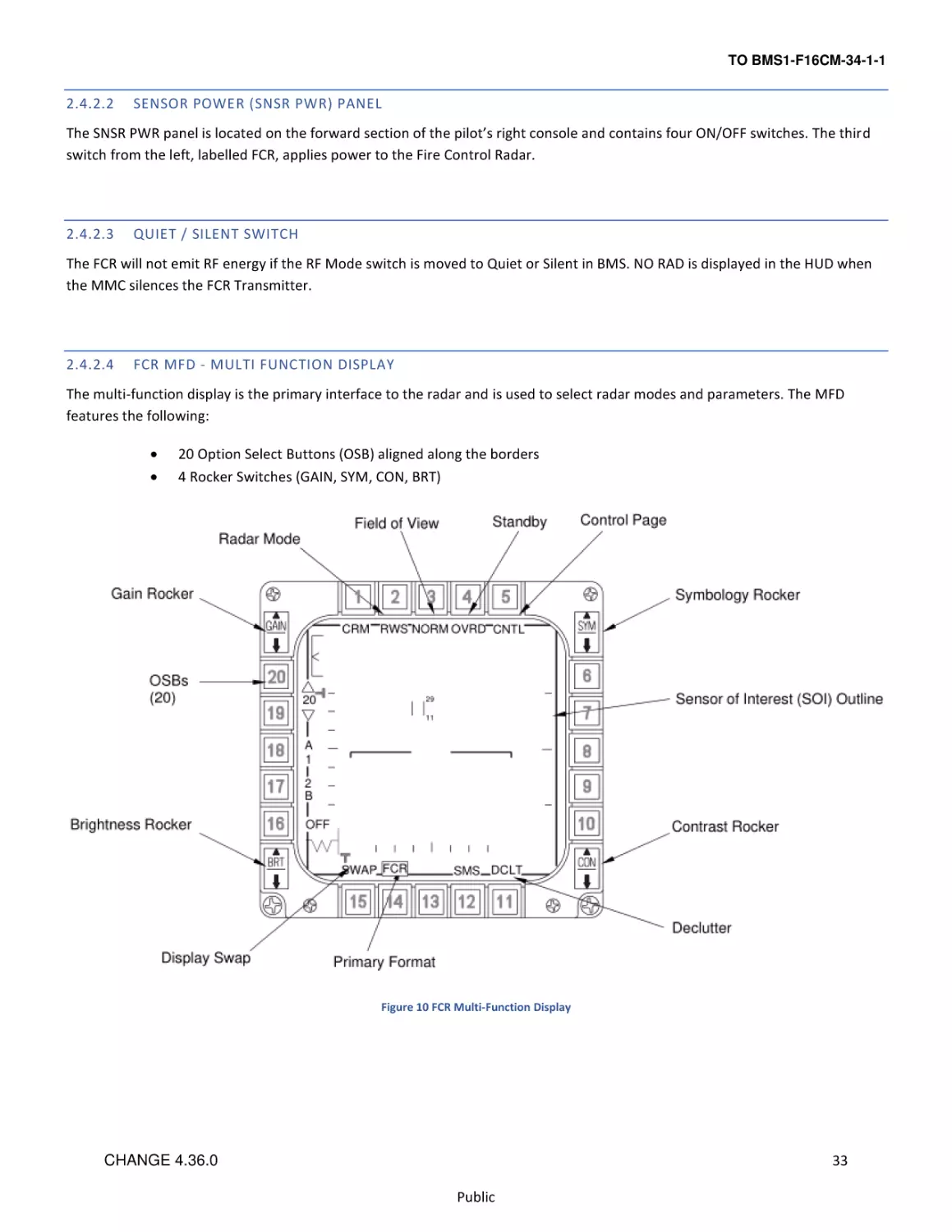
FCR MFD - MULTI FUNCTION DISPLAY
The multi-function display is the primary interface to the radar and is used to select radar modes and parameters. The MFD
features the following:
•
•
20 Option Select Buttons (OSB) aligned along the borders
4 Rocker Switches (GAIN, SYM, CON, BRT)
Figure 10 FCR Multi-Function Display
33
CHANGE 4.36.0
Public
TO BMS1-F16CM-34-1-1
2.4.2.4.1
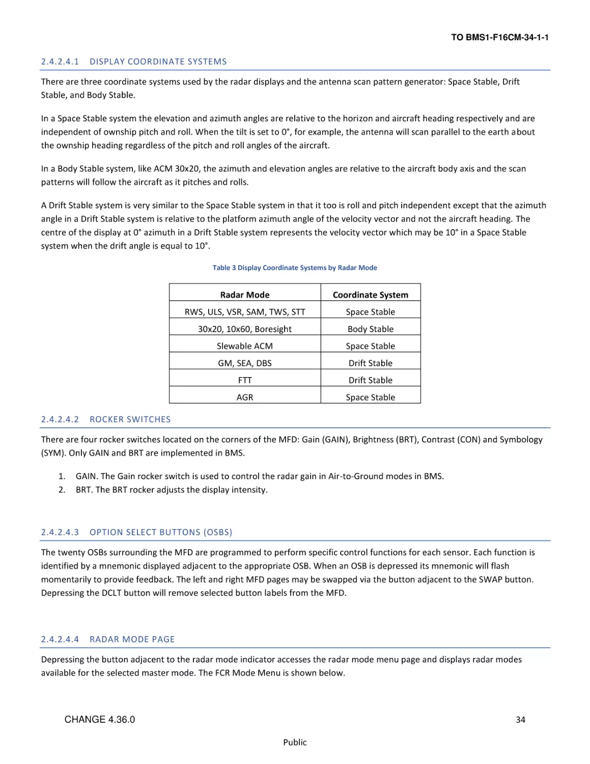
DISPLAY COORDINATE SYSTEMS
There are three coordinate systems used by the radar displays and the antenna scan pattern generator: Space Stable, Drift
Stable, and Body Stable.
In a Space Stable system the elevation and azimuth angles are relative to the horizon and aircraft heading respectively and are
independent of ownship pitch and roll. When the tilt is set to 0°, for example, the antenna will scan parallel to the earth about
the ownship heading regardless of the pitch and roll angles of the aircraft.
In a Body Stable system, like ACM 30x20, the azimuth and elevation angles are relative to the aircraft body axis and the scan
patterns will follow the aircraft as it pitches and rolls.
A Drift Stable system is very similar to the Space Stable system in that it too is roll and pitch independent except that the azimuth
angle in a Drift Stable system is relative to the platform azimuth angle of the velocity vector and not the aircraft heading. The
centre of the display at 0° azimuth in a Drift Stable system represents the velocity vector which may be 10° in a Space Stable
system when the drift angle is equal to 10°.
Table 3 Display Coordinate Systems by Radar Mode
2.4.2.4.2
Radar Mode
Coordinate System
RWS, ULS, VSR, SAM, TWS, STT
Space Stable
30x20, 10x60, Boresight
Body Stable
Slewable ACM
Space Stable
GM, SEA, DBS
Drift Stable
FTT
Drift Stable
AGR
Space Stable
ROCKER SWITCHES
There are four rocker switches located on the corners of the MFD: Gain (GAIN), Brightness (BRT), Contrast (CON) and Symbology
(SYM). Only GAIN and BRT are implemented in BMS.
1.
2.
GAIN. The Gain rocker switch is used to control the radar gain in Air-to-Ground modes in BMS.
BRT. The BRT rocker adjusts the display intensity.
2.4.2.4.3
OPTION SELECT BUTTONS (OSBS)
The twenty OSBs surrounding the MFD are programmed to perform specific control functions for each sensor. Each function is
identified by a mnemonic displayed adjacent to the appropriate OSB. When an OSB is depressed its mnemonic will flash
momentarily to provide feedback. The left and right MFD pages may be swapped via the button adjacent to the SWAP button.
Depressing the DCLT button will remove selected button labels from the MFD.
2.4.2.4.4
RADAR MODE PAGE
Depressing the button adjacent to the radar mode indicator accesses the radar mode menu page and displays radar modes
available for the selected master mode. The FCR Mode Menu is shown below.
34
CHANGE 4.36.0
Public
TO BMS1-F16CM-34-1-1
All radar modes except AGR and BIT are available in the NAV Master Mode. Depressing the FCR mode OSB accesses the selected
mode and returns to the basic FCR format page. FCR A-A or A-G modes can be selected before takeoff, via the FCR mode menu
page, or simply loaded from the Data Cartridge (DTC). During flight the mode menu page may be selected without interrupting
the present FCR operating mode. Whenever communication between the MFDs and FCR is missing FCR OFF is displayed in the
centre of the MFD.
Figure 11 FCR Mode page
2.4.3
RADAR MODES
2.4.3.1
FCR FORMATS
The FCR format (page) provides radar video, controls and status as a function of one of the following FCR modes:
•
•
2.4.3.1.1
Standby (STBY)
Built-in test (BIT)
AIR-TO-AIR MODES
The available air-to-air modes in BMS are:
•
•
Combined Radar Mode (CRM):
o
Range-While-Search (RWS)
o
Situation Awareness Mode (SAM)
o
Single Target Track (STT)
o
Up-Look Search (ULS)
o
Velocity Search with Ranging (VSR)
o
Track-While-Scan (TWS)
Air Combat Mode (ACM)
35
CHANGE 4.36.0
Public
TO BMS1-F16CM-34-1-1
2.4.3.1.2
AIR-TO-GROUND MODES
The available air-to-ground modes in BMS are:
•
Ground map (GM)
•
Fixed Target Track (FTT)
•
Ground Moving Target (GMT)
•
Sea (SEA)
•
Beacon (BCN) (displayed on Menu page but not implemented)
•
Air-to-Ground Ranging (AGR)
Depressing OSB 1 above the present mode mnemonic accesses the FCR mode menu page and displays the FCR modes available in
the selected master mode. Depressing the OSB adjacent to the desired FCR mode deselects the current mode, accesses the
selected mode and returns the display to the basic FCR format for that mode.
2.4.3.2
2.4.3.2.1
FCR TURN-ON/OFF
FCR POWER-ON
Before power can be applied to the FCR and other avionic subsystems, proper cooling from the Environmental Control System
(ECS) must be present, i.e. ensure the AIR SOURCE knob position is set to NORM, otherwise the FCR will shut down automatically
to avoid overheating. The MMC, MFDs and UFC should be operating prior to power-on.
The FCR format display page is accessed by depressing the FCR button on the basic MFD format and menu page or by depressing
the highlighted primary format mnemonic on a MFD page other than the FCR page. Following FCR power application the FCR
page will continue to display “FCR OFF” during the initial warm-up period (approximately 30 seconds after the application of
power). The FCR then enters Built-In-Test (BIT) at Power- On.
2.4.3.2.2
FCR POWER-OFF
Placing the FCR Power Switch to OFF will start a power down sequence. This sequence lasts for approximately four seconds. If the
switch is returned to ON/FCR before four seconds has elapsed the FCR software is reinitialized in a quick restart; the FCR will
enter a shorter BIT and the transmitter does not have to “time-out” (perform its usual 3 minute warm-up). The FCR will re-enter
the mode in which it left before the FCR switch was momentarily turned off and assume initial default conditions.
2.4.3.3
BIT - RADAR BUILT IN TEST
The AN/APG-68 performs a sequence of tests to alert for any FCR related problems. These tests, known as BITs, are a group of
sequenced tests either automatically initiated at FCR power-on, referred to as BIT at Power-On (around 3 minutes), or manually
initiated (via the TEST page), referred to as Pilot Selected BIT (approx. 30 seconds). BIT provides a thorough indication of
operational system readiness.
During the BIT you can preset the desired antenna elevation and range (though the physical antenna remains stowed in the full
up/left position) which will be selected as soon as you no longer have weight on wheels (WOW). If you leave the Power-On BIT to
36
CHANGE 4.36.0
Public
TO BMS1-F16CM-34-1-1
run its course the FCR will go to STBY mode after completion. If you press OSB 1 (BIT) while the Power-On BIT is running you can
preselect the desired FCR mode from the Radar Mode page.
Figure 12 FCR BIT test
2.4.3.4
STANDBY (STBY)/OVERRIDE (OVRD)
STBY is automatically entered after the completion of BIT (if no other mode has been selected). STBY mode can be manually
selected by either of the following two methods:
1.
2.
From a FCR mode display, depress the OVRD button (OSB 4).
From the FCR mode menu page display, depress the STBY button (OSB 1).
The OVRD button has the same function as the STBY button; depressing either button commands the FCR to STBY mode. At mode
entry the mnemonic STBY appears in the upper left hand corner of the MFD and the OVRD mnemonic is highlighted. The OVRD
button gives a quick way of selecting the STBY mode at any time, without having to select the FCR mode menu page first.
Figure 13 FCR OVRD
37
CHANGE 4.36.0
Public
TO BMS1-F16CM-34-1-1
2.4.3.5
NO RAD / NOT SOI DISPLAY
Two displays are provided on the MFDs and HUD/HMCS to improve response to FCR operations.
The NO RAD display is provided on the HUD/HMCS to indicate that the FCR is not radiating. Situations that create this possibility
are as follows:
•
•
•
STBY/OVRD submode selected.
RF switch in QUIET or SILENT.
ACM:
o Initial entry into ACM (without a bugged target from another air-to-air mode) 30x20 NO RAD.
o From any ACM radiating submode, TMS down also enters ACM 30x20 NO RAD.
o With HUD as SOI, TMS down commands ACM BORE NO RAD when the FCR is slaved to the HMCS.
o With HUD as SOI, TMS up and held commands ACM BORE NO RAD when the FCR is slaved to the HMCS in
BORE.
o With FCR as SOI and ACM radiating, TMS down rejects the target and commands 30x20 NO RAD (if FCR is
not slaved to the HMCS in BORE).
Figure 14 HUD NO RAD display
The NOT SOI display is provided on (FCR, TGP, and WPN) MFD displays to indicate that the format is not currently the Sensor of
Interest. Since the SOI symbol has a tendency to blend with the video, this display reduces time spent searching for a possibly
nonexistent SOI symbol.
38
CHANGE 4.36.0
Public
TO BMS1-F16CM-34-1-1
Figure 15 FCR NOT SOI
2.4.3.6
FCR INFORMATIONAL MESSAGES
FCR informational messages are displayed on the MFD when certain conditions within the FCR occur. These messages inform
what corrective action, if any, should be initiated to make the FCR operational again.
2.4.3.6.1
“WAIT”
The “WAIT” message occurs when the FCR system is being reset. The length of time that the FCR needs to be reset is dependent
on the condition which caused the message to appear. The FCR will start operation in 4 or 12 seconds without intervention. Once
the commanded mode is entered, the message will clear.
2.4.3.6.2
“CHK FCR CONTROL PAGE”
The “CHK FCR CONTROL PAGE” message will be displayed after the FCR restarts and the BIT has completed. The purpose of this
message is to inform the pilot that all pilot selectable parameters, i.e. control page values, azimuth selection, elevation bars and
range scales are back to default values. The corrective action, if any, will be to reinitialize these to the desired values.
Figure 16 CHK FCR CONTROL PAGE message
39
CHANGE 4.36.0
Public
TO BMS1-F16CM-34-1-1
2.4.4
RADAR AIR-TO-AIR MODES
The complement of air-to-air radar modes provides the capability for search, detection and track of multiple targets to provide
situation awareness and to support air-to-air weapon delivery. The air-to-air modes are divided into two top level radar modes:
Combined Radar Mode (CRM) and Air Combat Maneuvering (ACM) mode.
2.4.4.1
2.4.4.1.1
MFD SYMBOLOGY AND DATA
B-SCOPE DISPLAY
Air-to-air FCR modes use a synthetic display, called the B-scope (aka B-scan), produced by the radar signal processor. It takes the
radar cone and stretches the bottom of the cone along the bottom axis of the display. The entire bottom of the scope represents
your F-16’s position, not just the centre. The target symbol as displayed on the radar represents your line of sight to the target.
This helps to separate contacts as they get closer, but is not as intuitive at first. To visualize the difference the figure below shows
how the bottom of the pie-shaped radar coverage is stretched to fit the square B-scope display.
Figure 17 B-scope
40
CHANGE 4.36.0
Public
TO BMS1-F16CM-34-1-1
2.4.4.1.2
CURRENT FCR OPERATING MODE (OSB 1)
Possible mnemonics are:
•
•
CRM: Combined Radar Mode
ACM: Air Combat Mode
2.4.4.1.3
CURRENT CRM/ACM SUBMODE/TRACK STATUS (OSB 2)
Possible mnemonics are:
•
•
CRM Submode:
o RWS: Range-While-Search Mode
o ULS: Up-Look Search Mode
o VSR: Velocity Search w/ranging Mode
o TWS: Track-While-Scan Mode
ACM Submode:
o 20: 30 x 20°
o SLEW: Slewable
o BORE: Boresight
o 60: 10 x 60°
2.4.4.1.4
FCR A-A FIELD OF VIEW SELECT (OSB 3)
Options are:
•
•
NORM: Normal FOV
EXP: Expanded FOV
2.4.4.1.5
STANDBY OVERRIDE SELECT/DESELECT (OSB 4)
“OVRD” selects FCR standby page.
2.4.4.1.6
FCR CONTROL PAGE SELECT (OSB 5)
The FCR Control Page is accessed via OSB 5 above the CNTL mnemonic. Depressing the OSB highlights the CNTL mnemonic and
displays the control page options. The Control page may be accessed during flight without interrupting the present operating
mode.
Currently only TGT HIS and AIFF CPL/DCPL is implemented in BMS.
2.4.4.1.6.1 TARGET HISTORY (TGT HIS) ROTARY (OSB 18)
This rotary controls the display of target position history from the current frame and up to three previous frames.
•
•
•
•
TGT HIS 1 displays targets detected on the current frame.
TGT HIS 2 displays targets detected on the current and the preceding frame.
TGT HIS 3 displays targets on the current and two previous frames.
TGT HIS 4 displays all targets detected on the current and three previous frames.
Each history symbol becomes dimmer the longer it is displayed, disappearing entirely after it has been displayed the selected
number of times. Initial value at power up in BMS is TGT HIS 2.
41
CHANGE 4.36.0
Public
TO BMS1-F16CM-34-1-1
2.4.4.1.6.2 AIFF COUPLE/DECOUPLE (OSB 10)
Advanced IFF (AIFF) CPL/DCPL is displayed adjacent to OSB 10. Selection couples the AIFF Interrogator FOV to the FCR FOV in the
AIFF scan mode.
Figure 18 FCR CNTL page
2.4.4.1.7
EXPANDED TARGET DATA (BELOW OSB 1-5 MNEMONICS)
Target Aspect Angle. Target aspect angle is displayed in tens of degrees (°) for the tracked target at the upper left corner of the
MFD and is defined as the angle between the target longitudinal axis projected to the rear and the line of sight from the target to
the aircraft. When the angle is at 0° the aircraft is on the tail of the target; at 180° the aircraft is on the nose of the target. Aspect
angles from 0 - 70° indicate a tail aspect, 70 - 110° indicate a beam aspect, and 110 - 180° indicate a front aspect. The L or R
mnemonic displayed next to the aspect angle readout indicates the target wing closest to the aircraft.
Target Ground Track. Target magnetic ground track is displayed in 10° increments immediately to the right of the target aspect
angle at the upper left of the MFD.
Non Cooperative Target Recognition (NCTR). If NCTR has been successful in identifying the bugged target the target ID (e.g.
MG29) will be displayed under the FOV mnemonic, otherwise it will read UNKN (unknown).
Calibrated Airspeed for Bugged/Priority Target. Target calibrated airspeed (KCAS) is displayed in 10 knot increments below the
OVRD mnemonic.
Target Closure Rate. Target closure rate is displayed in knots true airspeed (KTAS) at the upper right of the MFD. When in Coast
the MFD displays “COAST”.
42
CHANGE 4.36.0
Public
TO BMS1-F16CM-34-1-1
Figure 19 Expanded Target Data (left) and FCR in COAST (right)
2.4.4.1.8
DATA LINK MODE (OSB 6). IDM DATA LINK MODE ROTARY
IDM Data Link Mode rotary:
•
•
•
ASGN
CONT
DMD
2.4.4.1.9
DATA LINK ASSIGNMENT TRANSMIT STATUS (OSB 7-10)
Depression of OSB 7-10 (representing flight member numbers 1-4) transmits an IDM Assignment to that flight member and
causes “XMT” to be displayed for 2 seconds.
2.4.4.1.10 AIM-120 DYNAMIC LAUNCH ZONE (DLZ)
The dynamic launch zone consists of various range scales displayed along the right side of the MFD and HUD when the AIM-120 is
the selected weapon.
Missile Time Remaining, Post Launch Range or Missile Time of Flight are displayed below the DLZ.
See also AIM-120 Advanced Medium Range A-A Missile (AMRAAM) and HUD Symbology: The Dynamic Launch Zone (DLZ).
43
CHANGE 4.36.0
Public
TO BMS1-F16CM-34-1-1
2.4.4.1.11 FCR A-A DECLUTTER SELECT/DESELECT (OSB 11)
When the DCLT OSB is depressed selected items are removed from the MFDs. Declutter is deselected by depressing the DCLT
OSB a second time.
Figure 20 FCR DCLT
2.4.4.1.12 AIFF INTERROGATION DATA (ADJACENT TO OSB 16)
The Interrogator Type mnemonic (M1/M2/M3/M4/M+/OFF) and the Interrogator Mode (SCAN/LOS) are displayed on the air-toair FCR page. See IDENTIFICATION FRIEND or FOE (IFF) chapter in the T.O. BMS1F-16CM-1 (Dash 1) manual.
2.4.4.1.13 BULLSEYE SYMBOL/BEARING AND RANGE (ADJACENT TO OSB 16)
The bullseye bearing and range are computed by the MMC and displayed at the lower left corner of the FCR and HSD pages
adjacent to OSB 16. There are four possible bearing and range solutions (depicted above the bullseye circle) based on the mode
of the radar page. The four bearing and range solution possibilities are:
1.
2.
3.
4.
From the mode-selected bullseye to the cursor. Bullseye is mode-selected and the cursor is present on the radar page.
From the mode-selected bullseye to the TOI (bugged target). Bullseye is mode-selected and the cursor is not present
(the radar is in Single Target Track (STT) or suspended SAM).
From the currently selected steerpoint to the cursor. Bullseye is not mode-selected and the cursor is present on the
radar page.
From the currently selected steerpoint to the TOI. Bullseye is not mode-selected and the cursor is not present (the radar
is in STT or suspended SAM).
For solutions 3 and 4 the bullseye LOS Bearing and Range circle displayed at the lower left corner of the MFD is replaced with the
Aircraft Reference symbol.
The bullseye LOS Bearing and Range circle displayed at the lower left corner of the MFD indicates the bearing and range from the
current aircraft position to the bullseye (bearing solution A). The directional tic on the circle indicates the bearing to the bullseye
while the 2-digit number inside the circle indicates the range (2-digit so max 99 NM).
44
CHANGE 4.36.0
Public
TO BMS1-F16CM-34-1-1
The 3-digit number below the circle indicates the magnetic bearing from the bullseye to the current aircraft position (bearing
solution B). Magnetic bearing and range from bullseye to ownship are also displayed on the HUD.
Figure 21 Merged Bullseye and Steerpoint Symbols
2.4.4.1.14 RADAR SCAN COVERAGE (OSB 17-18)
You control the power of the transmitter by setting the radar range and specify where the radar looks by controlling the position
of the radar antenna.
The FCR can scan forward ±60° left and right as well as ±60° up and down, which means that the F-16 radar can scan a block of
120° by 120°. You control where the radar looks by first pointing your aircraft in the general direction of interest. Then you
control the specific area by specifying the magnitude of the azimuth and elevation scan. You can also physically point the radar
up or down, left or right within its gimbal limits of ±60°.
While the radar antenna has this physical range of motion, it is important to understand that you will not be able to scan this
entire volume at once. Think of each of the air-to-air radar modes as providing a certain amount of focus to the viewing area, like
shining a torch in a dark room. As you narrow the beam of light from the torch and get more focus, you can acquire more
information, but the area you can look at gets correspondingly smaller and anything you are looking at is more likely to notice
you!
You control the azimuth by adjusting the scan volume. The azimuth scans, depending on the mode, can be ±60° (the whole width
of the radar scope) centred about the nose, or ±30°, ±25°, ±20° or ±10° centred about the acquisition (ACQ) cursor anywhere
within the ±60° gimbal limits.
The ±25° azimuth (3 bar) scan is exclusive to Track-While-Scan (TWS) and Dual Target (DT) SAM modes.
45
CHANGE 4.36.0
Public
TO BMS1-F16CM-34-1-1
Figure 22 FCR Azimuth Limits
Radar elevation scan volume is controlled by specifying the bar scan. The beam that the antenna normally emits is not able to
scan more than 4.9° in the vertical. If the radar just moves left to right and back that is considered 1 bar as it will scan just the
single 4.9° slice of airspace. However, the radar can scan a larger area of vertical space if it moves down after a scan.
On a 2 bar scan, for example, the radar scans left to right, moves down a few degrees and scans back right to left. Because the
radar antenna is pointing lower the return scan looks at a different area of space than the first scan.
Bar spacing is 2.2° for the 2 bar, 3 bar and 4 bar scans to overlap and avoid gaps in radar coverage.
A 4 bar scan covers the most area but takes the longest to complete. A 1 bar scan covers the least area but is the fastest; the 2
bar scan falls in between. You trade off coverage for increased refresh rate of targets.
3 bar (±25° azimuth) scans are only available in Track-While-Scan (TWS) and Dual Target (DT) SAM modes.
46
CHANGE 4.36.0
Public
TO BMS1-F16CM-34-1-1
Figure 23 FCR Elevation Scan Limits (left) and Antenna Elevation Scan Coverage (right)
2.4.4.1.14.1 RADAR ANTENNA ELEVATION
The scan pattern is adjusted for altitude coverage by the position of the ANT ELEV thumbwheel located on the throttle. The scan
pattern tilt angle can be centred from +60° to -60°. The scan pattern is roll and pitch stabilized with the tilt angle referenced to
the horizon.
2.4.4.1.14.2 ANTENNA ELEVATION CARET
Antenna elevation is indicated by the position of the horizontal T-shaped antenna elevation caret along the left edge of the MFD.
The range is space referenced and runs from +60° at the top of the MFD to -60° at the bottom. On the left side of the display are
7 elevation tics, each representing 10° (-30° to +30°).
The number of elevation bars that the radar scans is controlled via OSB 17, adjacent to the B mnemonic and one of the elevation
bar mnemonics (1, 2, 3, or 4).
2.4.4.1.14.3 MINIMUM/MAXIMUM (MIN/MAX) SEARCH ALTITUDES
To aid in adjusting antenna elevation in TWS and RWS, Min/Max Search Altitudes (rounded to the nearest thousand feet) are
displayed to the right of the ACQ cursor. Altitudes are at the ACQ cursor range and take into account antenna beam width, bar
spacing and antenna elevation.
2.4.4.1.14.4 ANTENNA AZIMUTH
Antenna azimuth is indicated by the position of the T-shaped antenna azimuth marker along the bottom of the MFD, where the
left edge of the FCR video represents -60°, the centre of the video represents 0° and the right edge represents +60°. The antenna
azimuth marker is space referenced in RWS. When not in ±60° two vertical scan lines are displayed in search, spotlight, and SAM
to indicate minimum and maximum azimuth scan limits. The vertical azimuth scan limit lines are also available in TWS but are not
available in TWS Expand or in STT. The lines are blanked as they approach the edge of the MFD.
47
CHANGE 4.36.0
Public
TO BMS1-F16CM-34-1-1
Scan width may be changed by moving the ACQ cursor to the left or right edge of the MFD, causing the scan width to toggle
between ±30° and ±60°. If the present scan width is ±10° (commanded via OSB) then ACQ cursor deflection toggles the scan
width to ±30°. Subsequent ACQ cursor control inputs toggle the scan width between ±30° and ±60°.
The ±60 degree azimuth scan width is the initial selection on the FCR format. Depressing OSB 18, adjacent to the A mnemonic
selects one of the following scan width mnemonics in the rotary from wide to narrow:
6 - ±60° scan width, centred about the nose (not available in TWS).
3 - ±30° scan width, centred about the ACQ cursor (not available in TWS).
2 - ±25° scan width, centred about the ACQ cursor (TWS & DT SAM only).
1 - ±10° scan width, centred about the ACQ cursor.
Figure 24 SAM Azimuth Scan Width vs Range
In all A-A search modes except TWS, search volume control allows the ACQ cursor to be placed anywhere within the FCR scan
volume. Azimuth gates no longer move with the ACQ cursor unless you get close to them and bump them. When the centre of
the ACQ cursor is within 4° of the edge of the search volume, the search volume centre will move with ACQ cursor motion.
In SAM, the pilot has control of the maximum size and location of the antenna scan pattern as in RWS. Typically, the radar
displays azimuth scan limits on the MFD indicating the actual scan volume. The azimuth scan limits on the MFD may be less than
the pilot scan width because there are occasions when the scan volume is reduced in order to allow SAM to maintain quality
tracks on the SAM targets; see Error! Reference source not found. above for scan width vs. range in SAM.
In DT SAM, the radar supports the pilot selected scan pattern until one of the targets has a range of less than 10 NM or an
AMRAAM has been launched. In either case, the radar will enter the SAM Dual Target Track (DTT) submode, where it sequentially
updates each of the SAM targets (ping pong) and does not interleave search processing.
48
CHANGE 4.36.0
Public
TO BMS1-F16CM-34-1-1
2.4.4.1.15 FCR RANGE DISPLAY (OSB 19-20)
Target range can be determined by observing the target symbol position along the MFD range scale. Each of the three tic marks
positioned along the right edge of the display dived the range into 4 equal sections. Range scale options are available as an
increment/decrement function adjacent to the range △ ▽ OSBs. The range scale is selected from a rotary containing: 5, 10, 20,
40, 80 and 160 NM ranges. Depressing either of these OSBs will step through the rotary.
The range scale can also be changed hands-on while in search via the cursor controller function of the CURSOR/ENABLE control. If
the ACQ cursor is slewed to a position of either less than 5% or greater than 95% of the selected range scale, the next lower or
higher scale will be selected and the ACQ cursor will be positioned to approximately 50% in range of the selected scale and at the
same azimuth as the previous scale. Range scale switching will not occur if it causes the target track to move off the display.
2.4.4.1.16 TARGET SYMBOLOGY
Search targets are displayed as solid squares with an aspect “Head” or “Tail” indicator. A bugged target is represented on the
MFD as a circle around a solid square with a velocity vector. The tracked target may later be represented by a different symbol
following identification of the bugged target. The bugged target is represented on the MFD by placement of a circle around that
target symbol. In STT all other search targets are removed from the display and only the bugged target is displayed. See Figure 40
Air-to-Air FCR Symbology below.
The bugged target is the highest priority target in all track modes (TWS, SAM, DTT). The bugged target altitude is displayed
numerically in thousands of feet MSL, just below the bugged target. Target aspect angle, magnetic ground track, calibrated
airspeed (KCAS) and closure rate (KTAS) are displayed across the top of the MFD. Only one bugged target may exist.
The tracked target symbol provides additional data. The symbol rotates in 11.25° increments defined by the aspect angle (see
Error! Reference source not found.). A line extending from the nose of the symbol increases in length as absolute target velocity
increases. Target altitude is displayed in thousands of feet beneath the symbol.
The target symbol as displayed on the radar represents your line of sight to the target. In the example top left you can see that
any contacts moving directly down the B-scope display are always coming straight towards you.
In the example top right, when you look at Target A (which is further away), you see more of the target’s front quarter (which is
why the aspect angle is closer to 0°).
Even though Target C is pointed in the same direction as Target A its orientation on the radar display (and its aspect angle) are
closer to the 9 o’clock position because it is closer, so you see more of its right side.
49
CHANGE 4.36.0
Public
TO BMS1-F16CM-34-1-1
Figure 25Tracked Target Symbology
50
CHANGE 4.36.0
Public
TO BMS1-F16CM-34-1-1
2.4.4.1.17 ACQUISITION (ACQ) CURSOR
The cursor symbol “| |” displayed during search consists of two parallel vertical lines. Search targets are locked on by slewing the
cursor over the search target symbol via the CURSOR/ENABLE control and designating via a TMS up. The maximum search
altitude readout is displayed digitally in thousands of feet at the upper right of the ACQ cursor; the minimum search altitude
readout is displayed at the lower right.
The width of the ACQ cursor = FCR range / 10, e.g.: on a 40 NM range scope the ACQ cursor width will be 4 NM.
2.4.4.1.18 STEERPOINT SYMBOLOGY
The pyramid-shaped (wedding cake) steerpoint symbol is displayed at the computed ground range and relative bearing from the
aircraft to the selected steerpoint.
2.4.4.1.19 HORIZON LINE
The horizon line indicates the aircraft roll and pitch angles.
Aircraft roll angle is read by comparing the angle the horizon line makes with the normal level position (parallel with the
top/bottom edges of the MFD) zero.
Aircraft pitch angle is read by observing how far the horizon has advanced from the centre of the display. The edges of the
display represent ±60° pitch.
The horizon line is limited at the edge of the display for angles greater than ±60°. Each end of the horizon line represents 30° left
and right of aircraft flight path.
2.4.4.1.20 COLLISION ANTENNA TRAIN ANGLE (CATA)
The CATA steering symbol “✠” provides horizontal steering to the tracked target and is displayed at target range. The CATA
symbol is not displayed when the collision angle exceeds 60°. To intercept the target the aircraft should be maneuvered toward
the CATA to place the CATA at the centre of the FCR display.
The CATA symbol is not displayed in newer blocks when the AIM-120 AMRAAM missile is selected; the ASC is used for steering
until the range is 1.2 x RAERO.
Figure 26 CATA
51
CHANGE 4.36.0
Public
TO BMS1-F16CM-34-1-1
2.4.4.2
2.4.4.2.1
AIR-TO-AIR FEATURES
ENHANCED SEARCH DISPLAY (ESD)
ESD automatically includes a “Head” or “Tail” indicator on all search targets. The ESD provides a target aspect indication for all
search targets with Doppler. The aspect indication provides the pilot with increased target information by displaying a short line
attached to the search target symbol showing whether a target is head or tail aspect. When a target is head/high aspect
(including near beam targets at 100° right/left) the indication will be pointing down. When a target is tail/low aspect (including
near beam targets at 80” right/left) the indication will be pointing up from the search target. This is available in RWS, VSR, TWS,
SAM, and DT SAM display modes.
2.4.4.2.2
SEARCH ALTITUDE DISPLAY (SAD)
The SAD capability is a feature which provides an estimate of a search target’s altitude. The SAD feature is displayed in RWS,
SAM, DT SAM and TWS when the ACQ cursor is slewed over a search target symbol.
The SAD value is displayed as thousands of feet above Mean Sea Level (MSL), rounded off to the nearest thousand feet. If the FCR
is in a single bar search scan, the altitude reported by SAD will be approximately the altitude corresponding to the centre of the
beam. The SAD is removed when the ACQ cursor is moved away from the search target.
Figure 27 ESD & SAD
2.4.4.2.2.1 CURSOR AREA OF EFFECT
The cursor area of effect is actually slightly larger (105%) than the size of the ACQ cursor (aka captain's “| |” bars) displayed on
the screen. This means you will get SAD display as the cursor moves very close to but not quite over a radar target on the display.
This greatly improves sorting capability without having to expand the field of view to separate the contacts.
For example to sort (i.e. designate/bug) the trail aircraft in a lead-trail group high-aspect on you simply move the cursor up to the
upper side of the group and TMS Up. The larger cursor area will allow you designate the trailing contact without having to put the
cursor precisely over the exact contact you want.
52
CHANGE 4.36.0
Public
TO BMS1-F16CM-34-1-1
2.4.4.2.3
SPOTLIGHT SEARCH
Spotlight search provides hands on temporary switching to a 4 bar ±10° scan pattern, increasing opportunity for target detection
in RWS and TWS.
Depressing and holding TMS Up for longer than 1 second will command the radar to spotlight search. The scan is centred about
the acquisition (ACQ) cursor and elevation (ANT ELEV) wheel setting and can be slewed. When slewing the ACQ cursor, the
spotlight scan pattern will remain centred in azimuth on the ACQ cursor. The scan coverage reverts to the previous pattern when
TMS is released, unless a target is beneath the ACQ cursor, at which time the radar will attempt to acquire and track the target.
Spotlight search is not available in RWS EXP.
Spotlight scan in TWS is similar to spotlight scan in RWS. The TWS spotlight search volume is initially centred about the ACQ
cursor. The spotlight search volume is not biased by the TWS track files, but is controlled through the use of the ACQ cursor and
the ANT ELEV thumbwheel. In other words, the pilot can override the TWS bug priority in azimuth and elevation. Spotlighting
outside the TWS priority scan volume will help establish track files on groups outside the previous TWS scan volume. Track
updates on the target of interest (TOI) and targets with AIM-120 missiles in flight will only occur if the spotlight scan volume
includes these targets.
Figure 28 Spotlight Search
2.4.4.2.4
EXPANDED (EXP) DISPLAY
An EXP A-A display is available to more clearly resolve closely grouped targets in RWS, SAM and TWS. A 4 to 1 expansion in range
and azimuth about the ACQ cursor is commanded by using either the EXPAND/FOV button (aka Pinky switch) on the stick, or by
pressing the Field of View (FOV) OSB 3 on the MFD. The same switch actions toggle back to the normal (NORM) display.
The MFD displays a NORM or a flashing EXP mnemonic to indicate the current FOV. The ACQ cursor remains at its true range and
azimuth in reference to the unexpanded display, while all other targets are expanded 4 to 1 about the ACQ cursor.
Coverage, location, and size of the antenna scan pattern remain unchanged in EXP; only the location of the targets on the display
changes. Bump AZ and Auto Range scale changes due to target range are disabled during EXP.
53
CHANGE 4.36.0
Public
TO BMS1-F16CM-34-1-1
The radar will automatically exit EXP when STT is commanded.
Figure 29 RWS NORM and EXP Display
2.4.4.2.5
NON-COOPERATIVE TARGET RECOGNITION (NCTR)
In STT mode the radar will use Non Cooperative Target Recognition (NCTR) algorithms to attempt to identify the aircraft being
tracked. NCTR analyses returns from the radar and compares them to stored profiles.
NCTR in the F-16 relies on the turbine blade return from each aircraft and hence will only work if the target aircraft is head-on
and the turbine blades are visible to the radar. If the radar cannot ‘see’ the turbines clearly and is unable to identify the target
"UNKN" will be displayed. "WAIT" means that radar is analysing data.
Figure 30 NCTR
54
CHANGE 4.36.0
Public
TO BMS1-F16CM-34-1-1
2.4.4.3
COMBINED RADAR MODE (CRM)
The CRM is designed to simplify pilot switchology by providing hands-on accessibility of Range While Search (RWS), Up-Look
Search (ULS), Velocity Search with Ranging (VSR) and Track While Scan (TWS) modes. CRM is divided into two modes of operation
- a search mode and a multiple target track mode. The search modes available are RWS, ULS, and VSR. The multiple target track
mode is TWS. RWS, ULS, VSR, and TWS are referred to as CRM submodes.
Both the Situation Awareness Mode (SAM) and Single Target Track (STT) are supported by CRM. STT is available in all A-A modes
while SAM is available in RWS and ULS. SAM can support up to two track files while maintaining situation awareness.
2.4.4.3.1
MODE ENTRY
The submode that the radar enters when the pilot selects CRM is dependent upon whether the radar has been in CRM
previously. If CRM is being selected for the first time since power up, the radar will enter RWS. However, if the radar has
previously been in CRM, the radar will enter the CRM search submode last exited (RWS, ULS, or VSR). Therefore the CRM
submode selection is not master mode dependent.
Upon CRM entry from ACM STT, SAM will be entered if the radar was in RWS or ULS the last time CRM was left and VSR STT will
be entered if the radar was in VSR last.
2.4.4.3.2
SUBMODE SELECTION
Once the radar has entered CRM, the pilot has the capability of entering TWS from any CRM search submode by pressing the
Target Management Switch (TMS) right for more than 1 second. The pilot can return to the CRM search submode by depressing
OSB 1 on the MFD and then reselecting “CRM” from the menu. If there was a bugged target in TWS this target will become the
SAM target if the CRM search mode is RWS or ULS, or the STT target if VSR was selected.
There are three hands-on methods to return to the CRM search submode:
•
•
•
To transfer without maintaining track on a TWS bugged target, a TMS down (Return-to-Search) followed by a
TMS right and hold, or TMS down 3 times, will clear all track files and transfer back to the CRM search mode
last exited.
To maintain track on the TWS bugged target the pilot can make a quick, momentary transfer to Dogfight (DGFT)
and back (Air Combat Maneuvering (ACM) must be the DGFT programmed mode).
And lastly, the pilot can command the last CRM search submode by holding TMS right for more than 1 second.
Upon return, the previously selected search mode will be selected and the TWS bugged target will become a
SAM or STT target.
CRM has a search mode rotary: RWS → ULS → VSR. The CRM search mode is changed by depressing OSB 2 which causes the next
search mode in the rotary to be selected.
55
CHANGE 4.36.0
Public
TO BMS1-F16CM-34-1-1
2.4.4.3.3
TARGET ACQUISITION AND MANAGEMENT
Figure 31 A-A HOTAS TMS functions (FCR SOI)
The following paragraphs provide an overview of CRM operations using the Target Management Switch (TMS):
•
•
•
•
Designating (TMS up) on an RWS search target changes it to a bugged/priority target and places the FCR into the SAM
submode.
Holding TMS up will initiate spotlight search. Upon release of the TMS, acquisition/track is attempted if a search target is
bracketed by, or very close to, the ACQ cursor.
Designating on a second RWS search target while tracking a target in SAM will transition the radar to dual target (DT)
SAM submode. When DT SAM is entered, the first bugged target remains the primary target, the second designated
target becomes the secondary target and the scan volume is adjusted to allow each target to be updated as the radar
continues to search in RWS.
When both the bugged/primary target and the secondary target are beyond 10 NM the search volume is fixed at ±25°
azimuth, 3 bar. The scan pattern is centred in azimuth on the ACQ cursor and is controlled in elevation via the ANT ELEV
wheel. TMS right for less than 1 second will step the bug between the two targets. When either target is within 10 NM
search is suspended and the radar spends all its time tracking the bugged and secondary targets (aka ping pong).
56
CHANGE 4.36.0
Public
TO BMS1-F16CM-34-1-1
•
When the scan pattern is moved off of both targets in DT SAM the scan width will adjust to optimize track versus search
time. As the scan pattern is moved away from both targets the scan width will become narrower. When the bugged
target is within 3 NM the radar automatically drops track on the secondary target and switches to STT on the bugged
target.
Designating on a bugged SAM target also places the radar into STT.
•
Designate actions (TMS up) change submodes from RWS → SAM → DT SAM → STT. Return-to-Search (RTS) actions
(TMS down) change the submodes back the other way. For example, if the pilot designates a target and puts the radar
into SAM submode a subsequent TMS down will return the bugged target to a search target and the radar will return to
RWS. TMS down in STT will switch the radar to DT SAM if a secondary target is being extrapolated, or to SAM if there is
no secondary target. TMS down from DT SAM will switch the radar to SAM. TMS down from SAM will return the radar to
RWS.
Depressing TMS right for more than 1 second, from any CRM RWS mode with or without a tracked target (SAM, DT SAM,
or STT), transitions the radar to TWS and retains any pre-existing bugged targets.
Commanding TMS right and hold from TWS with a bugged target and system track files will transition the radar to DT
SAM. The bugged target in TWS will become the primary (bugged) target in DT SAM. The TWS system track file selected
as the DT SAM secondary target is based on MMC and FCR prioritization, e.g. ACQ cursor over target or system track file.
•
•
•
2.4.4.4
RANGE-WHILE-SEARCH (RWS) MODE
In the Range-While-Search (RWS) mode the radar searches a selectable volume of space and displays the position of any
detected targets on the MFD. No track data (target range, velocity, angle or ground track) is available on these detected targets.
See Error! Reference source not found. for RWS display in NORM and EXP FOW.
A specific target can be tracked/bugged by slewing the acquisition (ACQ) cursor over the target and depressing and releasing TMS
up (designate). This causes entry into Situation Awareness Mode (SAM). TMS right for less than 1 second steps the bug to the
next priority target in DT SAM.
Holding TMS right for more than 1 second changes the mode to TWS. Stepping the radar target of interest (TOI), or
bugged/priority target, is limited to targets that are displayed on the currently selected FCR range scale.
In RWS, the ACQ cursor is used to:
• Request the Search Altitude Display (SAD).
• Select a target for SAM or STT.
• Change the search pattern azimuth width.
• Change the display range scale.
• Position the EXP square when EXP is entered.
57
CHANGE 4.36.0
Public
TO BMS1-F16CM-34-1-1
2.4.4.5
UP-LOOK SEARCH (ULS)
The ULS mode is a search submode of the CRM and in the real APG-68 is designed to detect aircraft at high altitudes in look-up,
clutter-free situations. Clutter is not rejected in ULS. When the scan coverage illuminates the ground or certain cloud formations,
many false targets are displayed. ULS is able to detect targets at longer ranges than RWS since its processing is designed for use
in a clutter- free environment. As these differences are not currently modelled in BMS ULS is functionally identical to RWS in
BMS.
In the real APG-68 ULS is identical to RWS in the areas of target display, cursor control and scan coverage but Enhanced Search
Display is not presented in ULS since Doppler information is not available in ULS.
Manual acquisition to SAM or STT from ULS is identical to acquisition from RWS.
2.4.4.6
VELOCITY SEARCH WITH RANGING (VSR)
VSR is a search submode of the CRM that interleaves high and medium Pulse Repetition Frequency (PRF) waveforms to provide
long range detection of forward aspect targets. VSR is designed to detect forward aspect targets only. In order to be displayed in
VSR, targets must have a velocity component along the radar’s LOS directed toward the F-16. Hence this mode will only display
contacts that are closing; contacts that are moving away (extending) are not displayed.
Contact detection and display in VSR is a two-step process consisting of a high PRF scan followed by a medium PRF scan. The first
scan is called the Alert scan during which a contact is first detected and its azimuth and velocity are stored. Immediately after a
Confirm scan is initiated with which the range is determined. After the contact has been detected in both Alert and Confirm
scans, the target is displayed.
Targets are displayed on the MFD as solid squares in a B-scope presentation similar to RWS. Only contacts that are closing are
displayed.
Manual Acquisition is the method by which the pilot selects a target to track in STT. Acquisition from VSR is the same as from
RWS, except that a single Designate (TMS up) switches to STT. SAM cannot be entered directly from VSR.
The cursor is used to select a target for STT, initiate SAD (Search Altitude Display), move the antenna search pattern in azimuth,
change the search pattern azimuth selection and change the displayed range scale.
Although only closing targets are detected and displayed in VSR search, acquisition of other targets is not specifically inhibited.
This allows the pilot to acquire a turning target that was forward aspect or closing in VSR search, but has turned to a tail aspect or
extending target by the time acquisition is commanded, or acquire a tail aspect target that just by coincidence happens to be in
the same angular line of sight as an alert for a forward aspect target.
Since the VSR mode is specifically tailored for detection of long range closing targets, it is the optimum mode for a corridor
search mission. Although it can be operated with larger scan volumes, frame times lengthen and reduce the effectiveness of the
mode, so VSR is best utilized with a small search pattern (1 or 2 elevation bars by ±10° or ±30° in azimuth).
58
CHANGE 4.36.0
Public
TO BMS1-F16CM-34-1-1
2.4.4.7
TRACK WHILE SCAN (TWS)
TWS is the multiple target track submode of the CRM and is designed to automatically track multiple airborne targets. Track
information is formulated from repetitive search target detections as the antenna sweeps the scan volume.
Options are available for target display, target prioritization, selecting search volumes, and target rejection. While TWS tracks
multiple targets, the pilot may select a target for STT to improve the accuracy of the track data for that target.
2.4.4.7.1
SCAN PATTERNS
To switch to the TWS submode, the pilot may press OSB 2 until “TWS” is displayed, or hold TMS right for more than 1 second to
switch from RWS/ULS to TWS. Upon entering TWS the radar azimuth will initialize to an “A2” or 50° azimuth scan (±25° either
side of boresight) and the elevation will initialize to a 3 bar “3B” scan.
Three scan patterns are available in TWS. They are:
±60°, 2 bar
±25°, 3 bar
±10°, 4 bar
2.4.4.7.2
TWS MECHANIZATION
As its name implies, TWS tracks multiple targets while searching for others. It is mechanized to begin forming track files
automatically from RWS search targets (solid squares) when the radar receives two hits (the radar detects something twice) in
6.5 seconds.
The radar is able to track 10 targets simultaneously. Since the radar does not pause on the track files while scanning, the track’s
positions are extrapolated in between updates (when the radar detects them again).
If a target is not updated, i.e. detected in 13 seconds, the radar will dump the track file until the target is detected again,
whereupon it will rebuild it into a track file. A dump could happen for a number of reasons, including a target moving out of the
radar’s current azimuth scan, elevation scan, or both. In Error! Reference source not found. below right the track files at 21,000ft
are outside the scan coverage, being extrapolated and about to be dumped.
Figure 32 TWS (left) and TWS with bugged/priority target (right)
59
CHANGE 4.36.0
Public
TO BMS1-F16CM-34-1-1
Also for example, if the pilot is tracking 10 targets and decides to designate on a search target, the radar will dump the lowest
priority track and automatically upgrade the search target into a track file. If the radar has not received a hit on a track on its
return scan where the radar thinks it should be based on the target’s last heading and speed, the track file will turn from yellow
to red to indicate this. When the track is detected again, it will turn back to yellow.
If a track is no longer detected it will turn red like previously mentioned and extrapolate for 13 seconds total. The last 5 seconds
before the radar dumps the track, the track will begin to flash. Tracks are prioritized by range and the order in which they were
built.
Without a bugged target, the azimuth scan centres on the cursors and elevation is controlled manually. When a target is bugged
the azimuth is biased to keep the bugged target in the scan and the elevation is centred on the bugged target. If the antenna
elevation is tilted while the pilot has a bugged target, upon dropping the bug, the elevation scan will move according to what the
pilot commanded to reflect the position set by the antenna elevation controls.
2.4.4.7.3
TARGET MANAGEMENT (MOVING THE “BUG”)
There are two ways to bug targets. The pilot may either slew the cursors over to a track file (or search target) and designate, or
may TMS right to jump to the closest track file. TMS right again will step the bug to the next highest priority track file and so on.
The pilot may enter STT (Single Target Track) by slewing the cursors over the bug and pressing TMS up. This will erase all search
targets and tracks from the radar, although the tracks will extrapolate for 13 seconds. TMS down (aka RTS (Return-to-Search)) is
used to return to TWS, the extrapolated tracks will reappear and the target will be bugged. If RTS is commanded again, the pilot
will drop the bug and the radar will continue to TWS. If RTS is commanded a third time, the radar will dump all tracks and begin
rebuilding tracks automatically. If RTS is commanded a fourth time, the radar will go back to RWS.
Targets are detected in TWS as they are in RWS, and search detection symbols (small filled squares with head or tails) are
displayed at the target range and azimuth. Search targets may be either manually or automatically acquired and tracked. Search
detections whose ground speed along the radar line of sight is greater than 200 knots will be automatically acquired and tracked
by the radar as described above. Targets whose speed is slower than 200 knots can be acquired manually by placing the ACQ
cursor over the target and designating. The speed gate prevents using a track slot for a low threat target or a potential false
alarm.
2.4.4.7.4
TWS OPERATIONAL CONSIDERATIONS
TWS provides a multiple target track situation awareness capability by limiting the time spent on updating track files. In contrast,
STT spends considerably more time updating the bugged target at the expense of situation awareness (SAM provides track
quality between TWS and STT quality).
Since TWS limits the amount of time that is spent updating a target a maneuvering target can be a significant distance away from
its expected position at the time of the next track update. The error introduced during the interval between track updates can
result in “jumpy” TWS track symbology on the MFD and HUD as compared to SAM and STT, or even track files disappearing and
reappearing.
Aside from some jumps of the TWS track symbology, the time between updates makes TWS an undesirable mode for target
ranges of less than 5 NM when the target is maneuvering. If a target engagement is expected, the pilot should consider entering
STT or SAM.
60
CHANGE 4.36.0
Public
TO BMS1-F16CM-34-1-1
2.4.4.8
SINGLE TARGET TRACK (STT)
STT is a submode of all radar modes. It is designed to automatically maintain a highly accurate track of a single airborne target for
weapon delivery.
2.4.4.8.1
STT DISPLAY
A STT bugged target is displayed just like all other bugged targets. Target altitude and target data are presented just like TWS and
SAM bugged targets.
When the target is acquired in RWS, ULS and VSR, the target symbol changes from a small square (search target symbol) to an
open square enclosed in a circle (tracked target symbol). When the target is acquired in TWS, the target symbol remains the
same and all other targets displayed (if any) are blanked from the MFD display and extrapolated by the radar software for a
maximum of 13 seconds from the last time each target was updated. In ACM, the target acquired will appear as an open square
enclosed in a circle. In the missile modes, this symbol will also have a tail if a slaved AIM-120 missile has been launched at the
target. The target range can be determined by comparing the position of the symbol to the range marks on the right edge of the
display or using the HUD/HMCS range window. The lateral position of the symbol represents azimuth.
Several features are available to aid in visually locating, intercepting and evaluating the target including:
•
•
•
•
A target designator box or locator line is displayed on the HUD/HMCS.
An intercept steering symbol is displayed on the radar format.
Target data is displayed digitally on the radar format and, to a lesser extent, on the HUD/HMCS.
The radar range scale is switched automatically to keep the target symbol in the central area of the MFD.
During STT a cross “✠” is displayed on the radar format at target range to aid in performing various intercept maneuvers. By
comparing the position of the symbol versus the centreline of the MFD, the pilot can fly collision, pursuit, or lead steering. This
intercept steering symbol provides horizontal steering only, not vertical. If the collision angle exceeds ±60°, the intercept steering
symbol disappears off the edge of the MFD.
Figure 33 STT
61
CHANGE 4.36.0
Public
TO BMS1-F16CM-34-1-1
2.4.4.8.2
STT MECHANIZATION
The radar filters ground clutter to enable lookdown operation. When the target is in the clutter (where the target’s Doppler
frequency falls within the band of frequencies occupied by the clutter aka Doppler Notch), the closure rate is uncertain. When
this happens, the closure rates displayed in the upper right of the MFD and next to the target range cue are replaced with the
mnemonic COAST. COAST is also indicated by a dashed TD Box and Target Locator Line (TLL) in the HUD/HMCS. In COAST the
target position is extrapolated from the last known information (i.e. it is no longer the actual position as in previous versions) and
the FCR searches for the target leaving the ground clutter’s Doppler region to resume a normal active track. If unsuccessful the
FCR will return to the previous search mode.
Currently in BMS a track target will flash after one failed update but is not dropped until 13 seconds have elapsed; the COAST
indication happens only 5 seconds before the track is dropped. So there is a period of around 8 seconds when the TD box and TTL
in the HUD/HMCS isn’t dashed.
With a bugged or STT target the FCR should not drop track when the target exits the FCR gimbals. The FCR will enter COAST as
above and the TTL will point to the estimated target position, therefore the TLL can display a number higher than the gimbal limit
of 60°. If the target is brought back inside the FCR scan volume within those 13 seconds the FCR will attempt to reacquire a valid
track on the target with a high chance of success. If unsuccessful at reacquiring the target the FCR will return to the previous
search mode.
If a high line of sight (LOS) target is gimbaled and is within 3 NM range, it will be dropped immediately instead of extrapolated.
This is helpful in a visual turning fight to avoid having to TMS down (RTS) to stop the FCR extrapolating every time a bandit with a
high LOS rate goes outside gimbals.
2.4.4.8.3
STT MODE SWITCHING
The radar can enter STT from any search mode. From RWS or ULS, the ACQ curser is slewed over a search target, then TMS up
(designate) and release twice; this bypasses SAM mode. From SAM or TWS, the ACQ curser is slewed over the bugged target,
then TMS up and release. Double designating the SAM secondary target, when the radar is in DTT, will cause the newly
designated target to become the STT target. From ACM, once a scan pattern has been selected and a target has been detected,
STT is automatically entered.
If ACM is selected from STT, or SAM, and the target is outside 10 NM, the target will continue to be tracked at the extended
range. When STT is terminated, ACM will revert to the 10 NM search processing.
When RTS is commanded (TMS down in STT), the STT bugged target becomes the SAM primary target and SAM operation is
resumed. Two successive RTS commands in STT will result in a transition directly back to RWS. RTS from TWS STT and the STT
target becomes the TWS primary target and TWS operation is resumed. If RTS is commanded when the upper level mode is ACM,
the radar will return to ACM 20 NO RAD.
2.4.4.8.4
STT OPERATIONAL CONSIDERATIONS
STT is the mode of choice for retaining a highly accurate track of a single airborne target for weapon delivery, as the antenna
beam remains constantly centred on the target. As a result using STT to obtain target information can reveal your position or
intent to any enemy with a Radar Warning Receiver (RWR).
STT is best used, therefore, to prosecute an attack once weapon parameters are reached, when you care less about giving away
your intentions and more about maximizing the success of your attack.
62
CHANGE 4.36.0
Public
TO BMS1-F16CM-34-1-1
2.4.4.9
SITUATION AWARENESS MODE (SAM)
Situation Awareness Mode (SAM) provides the capability to simultaneously track either a single target (ST SAM) or dual targets
(DT SAM) and search a controlled volume of space. The search volume is controlled via the hands-on antenna controls and MFD
selected parameters. The search volume may be reduced in azimuth (or even suspended) in order to maintain track on the
target(s) of interest.
2.4.4.9.1
SAM DISPLAY
The Primary SAM target (also referred to as the TOI or the bugged target) is displayed on the MFD like an STT target. Immediately
under the Primary SAM target, the target altitude is displayed numerically in thousands of feet above sea level. In addition,
numerical data associated with the Primary SAM target is presented across the top of the display indicating target aspect angle,
magnetic ground track, calibrated airspeed and closure rate.
The Secondary SAM target is displayed on the MFD like a TWS system track file. Immediately under the Secondary SAM target the
target altitude is displayed numerically in thousands of feet above sea level.
2.4.4.9.2
SCAN COVERAGE
The pilot has control of range and maximum size and location of the antenna scan pattern as in RWS. Typically, the radar displays
azimuth scan limits on the MFD indicating the actual scan volume. The azimuth scan limits on the MFD may be less than the pilotselected scan width because there are occasions when the scan volume is reduced in order to allow SAM to maintain quality
tracks on the SAM targets.
In DT SAM, the radar supports the pilot selected scan pattern until one of the targets has a range of less than 10 NM or an
AMRAAM has been launched. In either case, the radar will enter the SAM DTT submode where it sequentially updates each of the
SAM targets and does not interleave search processing.
Azimuth scan limits are not displayed on the MFD when the radar has entered Suspended SAM Search or DTT. The scan limits are
not displayed in order to cue the pilot that the radar is not providing any new situation awareness.
Figure 34 ST SAM entry > auto SAM (left) and DT SAM > DTT submode (right)
63
CHANGE 4.36.0
Public
TO BMS1-F16CM-34-1-1
2.4.4.9.3
CURSOR CONTROL
SAM has the same ACQ cursor control and SAD (Search Altitude Display) capability as RWS when the radar is not in a Long Track
Update or the DTT submode of SAM.
Upon ST SAM entry, the acquisition cursor is positioned over the SAM target and the cursor follows the target until the cursor is
slewed; this is known as auto SAM and allows for quick entry into STT. Moving the acquisition cursor disables auto SAM and full
control of the search area is available; this is known as manual SAM. Search elevation is then centred at the elevation selected by
the ANT ELEV knob. A quick TMS forward and TMS down sequence over the SAM target will resume auto SAM.
Upon entry into DT SAM, auto SAM is applied to a target that is upgraded to the target of interest via designating, but not to a
target that is upgraded via TMS right. DT SAM simultaneously tracks two targets while maintaining a RWS scan volume centred
on the secondary (non-bugged) target.
The azimuth and elevation of the primary SAM target are indicated by the position of the horizontal T-symbol and T-symbol on
the left and bottom edges of the MFD respectively.
2.4.4.9.4
SAM TRANSITIONS
The SAM submode is entered and exited using the designate (TMS up) and return-to-search (TMS down) commands or by a mode
transition to RWS from another air-to-air radar mode. Transition to RWS from another mode will enter ST SAM if there is only
one system track file or DT SAM if there are two or more system track files.
The bugged target, if it exists, will always be the primary SAM target. For DT SAM, the primary SAM target is the highest priority
target and the secondary SAM target is the second highest priority target.
If the FCR loses the bugged target while in DT SAM, the radar returns to ST SAM and the secondary target becomes the new
bugged target. Loss of the bugged target while in ST SAM results in a return to the search mode (RWS or ULS).
2.4.4.9.5
SAM TRACK
The FCR performs an initial or long track update on a search target that is designated. This track update typically lasts from 1 to
1.5 seconds. Following successful entry into ST SAM or DT SAM, the FCR periodically exits the search phase to perform track
update(s). These track updates require approximately one-half second.
There are three conditions when the search processing is interrupted and the FCR will discontinue the search volume:
1.
2.
3.
The first of these conditions occurs in ST SAM and DT SAM, as the FCR enters suspended search to dedicate all of the
resources to supporting the Primary SAM target. A dedicated track on the SAM Primary target occurs if the Primary
target range is less than 3 NM. When the FCR suspends search from DT SAM, the cursors, scan limit lines and secondary
target symbol are removed from the display.
The second condition occurs when the radar must dedicate all of the resources to supporting the Secondary SAM target.
The only time all the resources are dedicated to supporting the Secondary SAM target is when an initial track update is
being performed on it.
The third condition also occurs in DT SAM when the radar has two targets to support and has entered the dual target
track (DTT) submode of SAM. The DTT submode is the submode where the radar performs sequential updates (also
known as ping-pong) on the two SAM targets and does not have any search processing interleaved. DTT will be entered
64
CHANGE 4.36.0
Public
TO BMS1-F16CM-34-1-1
when one of the targets has a range of less than 10 NM. The scan lines are removed in this case; however, the cursors
remain displayed. See Error! Reference source not found. above.
2.4.4.9.6
SAM TARGET EXTRAPOLATION
A radar track will start degrading if the radar doesn't pick it up again within a reasonable (pattern dependent) time frame. If the
radar has not detected the tracked target lately (for example in the last 5 paints where the beam passes over the target aircraft
but doesn't get a strong enough return) and the radar is coasting (4 seconds since the last actual hit) extrapolation continues.
After the coast time the symbol will flash to indicate imminent loss of track status; sometimes you won't see this depending on
where the target was in the scan pattern. In this situation the track will disappear unless you get a paint and detection almost
immediately.
2.4.4.9.7
SAM OPERATIONAL CONSIDERATIONS
SAM offers some significant operational advantages compared to the other radar modes. One of its main advantages lies in its
usefulness in sorting long range targets. In addition, SAM provides a reduced chance of being detected or considered a threat especially when compared to STT. Using SAM reduces the time that the radar antenna is directly pointed at the enemy aircraft.
Therefore, the probability of revealing ownship position or intent to the enemy may be reduced. Furthermore, if the ownship
position is revealed in SAM, the detection may not be considered a threat by the enemy because of the small amount of time the
F-16 radar is performing a SAM track.
SAM also provides significant advantages as compared to TWS. SAM provides a more flexible situation awareness capability
because the search volume in SAM does not need to include the SAM track targets. In addition, SAM provides a higher quality
track on two targets than provided in TWS, especially when the radar is in DTT.
2.4.4.10 AIR COMBAT MODE (ACM)
ACM is designed to automatically acquire aircraft at short range. Four scan patterns, including three referenced to the body of
the F-16, allow the pilot to select the most appropriate submode for quick acquisition in STT.
2.4.4.10.1 ACM DISPLAY
Search targets and target history settings are not used in ACM since automatic acquisition is employed. The target is displayed on
the MFD as a circled triangle and other track information when valid track data is available.
Maximum acquisition range is 10 NM for all ACM submodes. When a target is acquired, automatic range scale switching is
enabled. If a target is acquired at (or subsequently moves to) a range greater than 9 NM, the range scale automatically increases
to the next larger scale. If a target is acquired (or subsequently moves to) a range less than 8 NM, the range scale automatically
decreases to the 10 NM range scale.
65
CHANGE 4.36.0
Public
TO BMS1-F16CM-34-1-1
2.4.4.10.2 ACM SCAN COVERAGE
There are four scan patterns or submodes available in ACM: 30° x 20°, 10° x 60°, Boresight and Slewable, represented on the MFD
below OSB 2 by the mnemonics: 20, 60, BORE and SLEW respectively. They all have in common:
•
•
•
•
ACM automatically acquires and tracks the first target detected within submode search range.
Holding the TMS forward commands BORE and inhibits auto-acquisition until TMS is released.
ACQ cursor and search target symbols are not displayed.
While in ACM STT: TMS up, TMS right or CURSOR/ENABLE slew will not cause a radar break lock nor command a new
scan pattern.
2.4.4.10.3 30° X 20° SUBMODE
The 30x20 ACM submode is the default selection commanded upon entry into ACM from any other mode. It is body stabilized
and searches the entire HUD field of view such that any target seen by the pilot in the HUD should be acquired by the radar in the
30x20 submode. The 30x20 submode can be entered from any other ACM submode by selecting OSB 2 on the MFD.
The 30° x 20° scan pattern searches an area slightly larger than the HUD FOV. The 30° x 20° ACM submode is indicated as follows:
•
•
•
The scan pattern is referenced to the F-16 body.
The scan centre is 6° below the HUD bore cross and uses a 4-bar pattern to cover the 30° wide, 20° high area. There is no
HUD symbology associated with the 30x20° scan pattern.
Contact range scale is 10 NM.
66
CHANGE 4.36.0
Public
TO BMS1-F16CM-34-1-1
Figure 35 ACM 30° x 20°
2.4.4.10.4 BORESIGHT SUBMODE
The Boresight submode is non-scanning and body stabilized, designed to allow the pilot to point the antenna at a selected single
target from a group of targets seen in the HUD. Pressing and holding TMS up inhibits acquisition. Once the desired target enters
the cross depicting BORESIGHT coverage in the HUD, releasing the TMS enables acquisition. The BORESIGHT scan pattern
searches a one-beamwidth area centred on the F-16 fuselage reference line.
TMS up and hold, while slewing, allows the pilot to slew the BORESIGHT cross and scan pattern within the HUD FOV.
When the FCR is placed in ACM BORE, the FCR can also be slaved to the HMCS Aiming Cross LOS. The FCR is commanded to the
HMCS LOS when: ACM BORE mode is selected, the FCR is SOI and TMS up is held.
The BORESIGHT ACM submode is indicated as follows:
•
•
•
The scan pattern is the antenna beam located 3° below the HUD bore cross.
A cross is displayed on the HUD with its intersection 3° below the bore cross to aid in positioning the target in the radar
beam.
Contact range scale is 10 NM.
67
CHANGE 4.36.0
Public
TO BMS1-F16CM-34-1-1
Figure 36 ACM Boresight
2.4.4.10.5 10° X 60° SUBMODE
The 10° x 60° scan pattern searches a narrow volume extending upward from the centre of the HUD and is used in high G
situations where the F-16 is pulling into the target. The 10° x 60° ACM submode is indicated as follows:
•
•
•
•
•
The scan pattern is referenced to the F-16 body.
Scan centre is 23° above the HUD bore cross and uses a 4 bar pattern to cover the 10° wide, 60° high area.
Total vertical coverage is 53° above to 7° below the HUD bore cross.
A vertical line extends from the HUD bore cross to the bottom of the HUD.
Contact range scale is 10 NM.
68
CHANGE 4.36.0
Public
TO BMS1-F16CM-34-1-1
Figure 37 ACM 10° X 60°
2.4.4.10.6 SLEWABLE SUBMODE
The slewable scan pattern is activated and controlled hands-on via the CURSOR/ENABLE control. Scan centre initializes to 0°
azimuth and 0° elevation. Further cursor control moves the scan centre. The SLEWABLE scan pattern searches a relatively large
area whose centre can be slewed up/down and left/right. It is indicated as follows:
•
•
The scan pattern is space-stabilized in pitch and roll. When the scan centre is slewed, HUD and MFD symbols move in
the same directions regardless of the roll angle. The SLEWABLE ACM circle is also locally stabilized.
The scan pattern is approximately 20° high by 60° wide with scan centre initialized to the horizon and 0° azimuth
position.
69
CHANGE 4.36.0
Public
TO BMS1-F16CM-34-1-1
•
•
•
Minimum and maximum search altitudes are based on 5 NM range and the position of the scan centre. Search altitudes
are displayed in the centre of the MFD and above/below the 8 mR circle on the HUD.
The antenna-pointing symbol (8 mR circle on the HUD, iron cross symbol on the MFD) is positioned at the centre of the
scan. A large cross-positioned at 3° below the boresight cross marks the initialized scan position.
Contact range scale is 10 NM.
Figure 38 ACM Slewable
2.4.4.10.7 ACM MODE SWITCHING
Upon selecting ACM, 30° x 20° submode is automatically entered. If the radar is not already tracking a target, the transmitter will
be turned off and “NO RAD” will be displayed above the HUD Boresight cross. The radar will begin transmitting when any
submode is selected.
TMS down is the only switch action that commands a break lock from an ACM track mode.
In any radiating ACM mode, TMS down will drop the current radar track (if there is one) and command 30x20 NO RAD. TMS down
again, the radar will switch to 10x60 and radiate. TMS down again to switch to 30x20 NO RAD again. With a track in any of the
70
CHANGE 4.36.0
Public
TO BMS1-F16CM-34-1-1
ACM modes, switching to another mode (with the exception of 10x60) will not drop the current track, but only switch modes,
e.g.: BORE mode → TMS right → 30x20.
In BMS 4.34 the DLZ and the IR diamond now also use extrapolated info. Before, if you were in SLAVE, the IR missile would
automagically lock (or try to lock) on the FCR target; it usually didn’t matter if you had another target closer in the same
direction. So in SLAVE, as long as you had tone, you didn’t need to uncage at all. Now, in SLAVE, it will look for targets in the same
way as it does in BORE, except along the FCR target LOS (line of sight). So make sure you always uncage, and then check the
missile is tracking the correct target, before you fire!
Figure 39 A-A HOTAS TMS functions (FCR SOI) ACM specifics highlighted
71
CHANGE 4.36.0
Public
TO BMS1-F16CM-34-1-1
2.4.4.11 AIM-120 ADVANCED MEDIUM RANGE A-A MISSILE (AMRAAM)
2.4.4.11.1 MFD SYMBOLOGY
The normal TWS, SAM, STT and DTT display symbology will be maintained during AIM-120 DL. In addition, there will be MFD and
HUD symbology related to the launch and control of the AIM-120 missile. This allows head-up or head-down weapon delivery.
The symbology on the B-scope when an AMRAAM is in flight is stored when the pilot bugs another contact.
When a slaved AIM-120 is launched against the target, a tail is displayed on the target symbol. The tail flashes at a 3Hz rate when
the missile goes HPRF active. A slash is placed over the symbol when the missile goes MPRF active. An X is placed over the symbol
at calculated missile impact for 8 seconds. After 8 seconds, the X flashes at a 5Hz rate for 5 seconds and is then removed from the
display. When the missile is calculated to miss the target, the word LOSE will alternate with the target altitude at a 3Hz rate.
2.4.4.11.2 AMRAAM MECHANIZATION IN TWS
The pilot fires on a bugged/priority track/TOI (target of interest) and the normal AMRAAM symbology is displayed. The pilot may
then bug another track or TMS right and fire on another track. The first track's symbology will be retained and the track will turn
magenta in colour. The pilot may bug additional tracks and shoot missiles. The AMRAAM missile timing information will be
retained for all missiles in flight for their respective track files, and displayed for the current bugged/priority track.
Search Target (high aspect)
System Track File
Bugged/Priority Track File
Bugged Track File with (inactive) AMRAAM in flight
BTF with active MPRF (HPRF if no \) AMRAAM in flight
BTF at AMRAAM predicted time of impact
BTF with Lose AMRAAM in flight
Search Target (low aspect)
.
Extrapolated Track File
.
ECM / jamming detected
.
Track File with (inactive) AMRAAM in flight
.
TF with active MPRF (HPRF if no \) AMRAAM in flight
.
TF at AMRAAM predicted time of impact
.
TF with Lose AMRAAM in flight
.
Figure 40 Air-to-Air FCR Symbology
72
CHANGE 4.36.0
Public
TO BMS1-F16CM-34-1-1
2.4.5
GUNSIGHTS
2.4.5.1
EEGS
Figure 41 EEGS funnel
Without a radar lock, EEGS displays a funnel and the Multiple Reference Gunsight (MRGS) lines along the bottom of the HUD. The
funnel width is based on the target wingspan entered in the LIST 5 page (MAN). For a good firing solution, track the target with
the funnel so that its wingtips touch each side. When the trigger is held, the Firing Evaluation Display System (FEDS) shows
simulated rounds as dot pairs which move down the sides of the funnel in the same way that tracers would move had they been
fired. The MRGS lines help with high LOS rate snapshots. Placing the target on one of the lines should cause it to fly through the
gun cross, scoring hits if you start shooting early enough so the target flies through the bullets.
Figure 42 EEGS Targeting Solution
73
CHANGE 4.36.0
Public
TO BMS1-F16CM-34-1-1
Once a target is locked, a target designator circle appears over it. This circle unwinds counterclockwise to display target range
inside 12,000 feet. Shortly after the lock, the radar obtains target velocity and aligns the gun funnel along the target’s plane of
motion. MRGS lines disappear.
Several other symbols appear. The plus inside the gun funnel is a 1G pipper, which shows the correct lead for a non-maneuvering
target. The minus is a max-G pipper, which shows the correct lead for a target pulling 7.3G directly towards you. On either side of
the plus are lines which indicate the target’s out-of-plane maneuver potential — the distance they could jink laterally while your
bullets are in flight.
Several seconds after lock on, the radar determines target acceleration and, once in range, a 4 mil circle appears this is the
correct lead assuming the target maintains their current flight path.
Figure 43 EEGS BATR
After squeezing the trigger, a 6-mil circle shows the location of the bullets as they pass the target. This Bullets at Target Range
(BATR) symbol is to help evaluate your shot and is displayed instead of FEDS whenever a target is locked. It disappears as the last
bullets from the burst pass the target.
74
CHANGE 4.36.0
Public
TO BMS1-F16CM-34-1-1
Figure 44 SNAP
EEGS — the most modern gunsight — provides with the most information, but older blocks have older, more limited sights. You
can cycle between them with OSB 2 on the A-A SMS page.
The first is the Snapshot (SNAP) gunsight. It displays a gun “snake” which shows the path of bullets fired in the past, like the EEGS
funnel does without a lock. Horizontal ticks show where bullets fired ½, 1, and 1½ seconds ago would be.
Without a radar lock, a small circle shows where bullets would be at the set range (700 or 1500 feet, controlled by the manual
range knob on the throttle). With a radar lock, the circle shows where bullets would be at target range.
The snapshot sight is the most difficult to use, since it only shows historical data (Where are bullets fired in the past?), not
predictive data (Where should I shoot so bullets hit the target when they reach it?). To score hits, you must track the target with
the snake for one Bullet Time of Flight (BTOF) or shoot when you think the range circle will pass over the target in one BTOF.
Next is the Lead Computing Optical Sight (LCOS). Without a lock, the pipper size matches the target wingspan at the set range
(700 or 1500 feet) and behaves like gyro gunsights in WW2 or Korean War-era fighters. Lead is shown for a target turning in your
plane of motion, at the same speed, with the same G. Any differences in these factors will make the pipper inaccurate.
When a target is locked, the pipper briefly jumps back to the gun cross before sliding into position once the radar determines
target acceleration. The outer ring of the pipper now shows target range with a “range L” that unwinds just like the EEGS TD
circle. An overtake caret also shows closure: The 12 o’clock position represents zero closure, positions to the right indicate
positive closure, and positions to the left indicates negative closure. Each o’clock position represents 100 knots, so a caret at the
3 o’clock position indicates 300 knots of closure, and a caret at the 6 o’clock position indicates the target is opening or closing in
excess of 600 knots.
A lag line extending from the center of the pipper shows the direction the pipper is moving — shooting before it settles is likely to
cause a miss.
75
CHANGE 4.36.0
Public
TO BMS1-F16CM-34-1-1
Figure 45 SSLC
Finally, is the combined Snapshot & LCOS (SSLC) gunsight. This combines the snapshot sight’s gun snake with the LCOS pipper
(without its lag line). Aim with the LCOS pipper, then evaluate your shot using the snake — the snake should pass over the target
as your bullets reach it.
Figure 46 Snapshot & SSLC
76
CHANGE 4.36.0
Public
TO BMS1-F16CM-34-1-1
2.4.5.2
GUNSIGHT EMPLOYMENT CONSIDERATIONS
Don’t forget the gun cross! Instead of trying to fly the pipper to the target, concentrate on establishing the gun cross in front of
the target, in its plane of motion. From there you should be able to make small adjustments to superimpose the pipper on the
target.
To prevent jittering and compensate for radar tracking errors, all pippers have about a ¼ second settling time. This means that to
hit the target, you must track it with the pipper ¼ of a second before shooting or start shooting that amount of time before the
pipper is on the target.
Aim snapshots with the gun cross, using MRGS lines or the gun snake to line up your shot. The pipper is especially inaccurate in
front-quarter shots due to rapidly changing LOS rates.
Gunshot opportunities in combat are rare. Don’t save rounds for other bandits — fire a lethal burst (1–2 seconds) on the one
you’re engaged with, then immediately reposition to avoid the resulting fireball. Once separated, assume you’ve been targeted
by a new threat. You’ve been very predictable and not checking six while getting your guns kill.
2.4.6
AIR TO GROUND RANGIN G
The Air−to−Ground Ranging (AGR) mode provides accurate range to a ground point for visual air to ground delivery modes,
marking, FIX and altitude calibration.
AGR is automatically commanded by the MMC/FCC when the following modes are selected, (unless the pilot selects Standby or
Override).
•
•
•
•
•
•
•
CCIP
DTOS
EOVIS
STRAFE
HUD MARK
HUD FIX (N/I)
HUD ACAL (N/I)
2.4.6.1
BASICS
AGR provides real-time slant range measurements to a point on the ground indicated in the HUD or HMCS, using a pencil beam.
A process called Lobe on Receive Only (LORO) changes the receive characteristic of the antenna to squint first above and then
below the center of the radiated beam. Knowing that the transmit beam illuminates the ground point undisturbed and assuming
the ground point and the area near it provide a consistent radar return, differences in the two received signals above and below
the ground point are used to determine an accurate range measurement to the center of the beam.
AGR provides ranging for all roll angles. This is accomplished by changing the LORO mechanization at the appropriate roll angles
from up-down to left-right with reference to the body of the aircraft.
77
CHANGE 4.36.0
Public
TO BMS1-F16CM-34-1-1
While AGR ranging is possible at all roll angles, bombing accuracy improves as the attitude at bomb release approaches wings
level. Bombing accuracy is also a function of grazing angle and slant range. Bombing accuracy increases with increasing angle or
with decreasing slant range.
The AGR mode provides automatic ranging data for determining the height of the aircraft (HAT) above the target, by measuring
accurate slant range along the radar line of sight to the surface target.
Using AGR, FTT, TGP in a track mode, laser ranging or RALT as the backup bombing sensor SALT is removed from the MMC/FCC's
HAT determination. If there is a SALT error, or if the entered target elevation is incorrect, inaccurate HAT and bomb range
calculations will result. This will cause a long or short miss.
2.4.6.2
TARGET SELECTION
AGR ranges to the point on the ground indicated by weapons delivery/FIX symbology in the HUD and HMCS.
Depending on the submode selecting AGR, the symbol in the HUD may be slewed to the desired point, or the aircraft can
maneuver to place the symbol at the desired point, or a combination of both. The symbol on the HMCS is initially moved on the
ground point with head movement Once the symbol is ground stabilized, it may be slewed. The CURSOR/ENABLE switch is used
to slew the symbol. Three different symbols are used to indicate the ranging point depending on the submode.
2.4.6.3
VISUAL AIR TO GROUND
Visual air to ground weapon delivery modes use AGR range to determine in range and time to release cues for the selected
weapon. AGR range is also used to determine the pull−up cues to avoid ground clobber. In the event the radar can no longer
determine a valid range measurement, weapon delivery solutions are based on the F−16’s SALT, which defaults to barometric
when the Inertial Navigation Unit (INU) goes down, and the current selected steerpoint elevation.
2.4.6.4
AGR DISPLAYS
AGR information is presented on the MFD, HUD, HMCS and DED.
78
CHANGE 4.36.0
Public
TO BMS1-F16CM-34-1-1
2.4.6.5
MFD
Range to the point is indicated by a solid diamond on the right side of the MFD. The diamond is positioned based on the range to
the top of the MFD equaling 10 NM. Field-of-view options are not available; only the 10-nautical-mile range scale is used and
cannot be changed. The gain gauge is not displayed; and antenna azimuth and elevation markers are body-referenced.
Figure 47 MFD Sensor AGR
The diamond changes to a square located at the last valid range for about 0.5 sec. When valid range can no longer be determined
and then will be pegged at the top right corner of the MFD.
Figure 48 MFD Sensor Invalid Range
79
CHANGE 4.36.0
Public
TO BMS1-F16CM-34-1-1
Figure 49 MFD & HUD Range
2.4.6.6
ANTENNA POINTING SYMBOL
A St. George’s cross indicates antenna azimuth and elevation and is displayed in addition to the azimuth and elevation carets on
the MFD.
The Antenna position is displayed with respect to the body axis of the F-16 along with antenna carets on the bottom and left side
of the display.
2.4.6.7
BACKUP BOMBING SENSOR
The backup bombing sensor rotary at OSB 6 on the FCR MFD page shows which sensor is being used to determine the height
above target HAT. The rotary defaults to BARO at FCC/MMC power-up. With BARO displayed, SALT is used to determine HAT
RALT is also included in the rotary. If RALT is selected, the CARA will be used to determine HAT. Since the CARA measurement will
be height above the release point rather than HAT, use of RALT as a backup sensor should only be used over flat terrain. The
backup sensor can be accessed also from any OFF MFD page
2.4.6.8
HUD
Slant range on the HUD is displayed in tenths of nautical miles for ranges greater than 1 nautical mile and hundreds of feet for
ranges less than 1nm.
The letter preceding the slant range value indicates the sensor that is being used to calculate the slant range.
If the AGR is returning a valid range the FCR (F) indication will precede the slant rage
If the AGR is not able to provide a valid range, the active backup sensor will be automatically used.
If BARO is selected B will be displayed.
If RALT is selected R will be displayed.
When ranging data is unavailable, XXX will be displayed.
80
CHANGE 4.36.0
Public
TO BMS1-F16CM-34-1-1
When DTOS submode is selected the TGP can be used as a backup ranging sensor
T is displayed when the targeting pod is in AG mode, is the priority sensor and is in a track mode.
L is displayed when the targeting pod is in AG mode, is the priority sensor is in a track mode and the laser is firing.
To select the TGP as the BUP sensor, move the SOI from the HUD to the TGP,and select AREA track mode. The DTOS TD box will
be ground stabilized and slewed to the point of interest.
Figure 50 HUD CCIP
2.4.6.9
HMCS
Figure 51 HUD Target Aimpoint
81
CHANGE 4.36.0
Public
TO BMS1-F16CM-34-1-1
2.4.7
RADAR AIR-TO-GROUND MODES
The radar provides A-G modes for ground map, target detection, tracking and air-to-ground ranging. The modes are GM, SEA,
FTT, GMT, AGR and BCN (not implemented).
All modes, except air-to-ground ranging, are used to locate preplanned targets presenting a radar return. The ground map video
may be expanded, frozen, or have Doppler Beam Sharpening (DBS) applied as aids in positioning the radar cursor over the target.
Fixed targets may be acquired and tracked in the GM and SEA modes. The GM mode provides accurate cursor placement on
conventional GM video for stationary targets. The GMT mode provides detection of moving ground targets. The SEA mode
provides sea clutter reduction in moderate sea states for direct and offset sighting options and fixed target track. The AGR mode
provides automatic ranging data for determining height above the target.
2.4.7.1
AIR-TO-GROUND FCR MFD SYMBOLOGY
A typical A-G MFD display (in Ground Map mode) is shown below:
Figure 52 Air-to-Ground (GM mode) Display
82
CHANGE 4.36.0
Public
TO BMS1-F16CM-34-1-1
2.4.7.1.1
CURRENT FCR OPERATING MODE (OSB 1)
Possible mnemonics are:
•
•
•
GM: Ground Map Mode
GMT: Ground Moving Target Mode
SEA: Sea Navigation Mode
2.4.7.1.2
RANGE SCALE SELECTION (OSB 2)
An automatic range scale option is available in the following modes: GM, EXP, DBS1, DBS2, FTT, SEA, GMTI and GMTT. Auto range
scale switching is enabled via OSB 2 which toggles AUTO or MAN. AUTO range scale switching, which is on by default, may be
disabled by depressing OSB 2 or by manually changing the range scale. Any range scale change made via OSB will return the radar
to manual (MAN) range scale operation.
For A-G search operation the AUTO range scale (cursor bump) will increase the FCR range if the cursor is at 95% of the way up the
MFD and decrease it if the cursor is at 42.5% of the way up the display, or less. These switch points are shown in Error! Reference
source not found. below as grey dashed lines. Note the bump will only happen if and when the cursor is not being slewed. This
function will allow you to refine the cursor position without interruption if an auto range scale change is required. For FTT and
GMTT the target position is the determining factor in changing range scales.
Figure 53 Auto Range Scale Switch Points
2.4.7.1.3
FIELD-OF-VIEW (FOV) OPTIONS (OSB 3)
In all A-G mapping modes the expanded (EXP) FOV option is available. Selection of EXP FOV results in a 4:1 range and azimuth
expansion of the patch of map surrounding the cursor position.
For GM mode only, two Doppler Beam Sharpening (DBS1 and DBS2) FOV’s are also available. Selection of DBS1 will provide the
same FOV as with EXP, but with improved resolution (8:1). DBS2 will provide a FOV roughly double that of EXP and DBS1 with
improved resolution (64:1). Either the EXPAND/FOV button on the stick or OSB 3 above the FOV mnemonic can be used to select
the available FOV’s in A-G mapping modes.
83
CHANGE 4.36.0
Public
TO BMS1-F16CM-34-1-1
Figure 54 GM FOV options (clockwise from top left: NORM, EXP, DBS1 and DBS2)
Expansion Cues. In the normal GM, SEA and GMTI displays, four expansion cues (tick marks) are provided on the X-Y cursors to
define the area that would be displayed upon selection of the EXP FOV. Similarly, in the GM mode, when the DBS1 FOV option
has been selected, expansion cues will be provided to define the area that will be displayed upon selection of DBS2. (See Error!
Reference source not found. above - note the cursor was slewed to the right and up to encompass the whole area of interest
before the screenshot was taken for the DBS2 image above.)
Situation Awareness Symbol. In any of the expanded ground map type mode FOV options including DBS1 and DBS2, a situation
awareness symbol (a thin cross) will be positioned on the display to show where the X-Y cursors would be upon return to the
unexpanded (NORM) display. This may be used to determine range to the selected sighting point.
Quarter Mile Scale Reference. In any of the EXP FOV options including DBS1 and DBS2, a horizontal line is displayed in the upper
left-hand corner of the display to indicate a length of 0.25 NM (1500 feet).
84
CHANGE 4.36.0
Public
TO BMS1-F16CM-34-1-1
2.4.7.1.4
STANDBY OVERRIDE SELECT/DESELECT (OSB 4)
“OVRD” selects FCR standby.
2.4.7.1.5
FCR CONTROL PAGE SELECT (OSB 5)
“CNTL” selects the FCR control page.
2.4.7.1.6
BACKUP BOMBING SENSOR (BBS) (OSB 6)
The Backup Bombing Sensor (BBS) is not currently implemented in BMS.
2.4.7.1.7
FREEZE (FZ) SUBMODE (OSB 7)
The FZ option terminates radar transmissions although the antenna continues scan movements. A frozen map display suitable for
navigation and weapons delivery is retained. The pilot can still refine cursor position. With a patch of the PPI sector frozen, cursor
refinements result in the movement of the vertical and horizontal lines depicting cursor position relative to the map. An aircraft
position symbol, depicted as a bold cross, is displayed on frozen scenes and is continuously updated. This symbol represents the
position of the aircraft relative to the frozen scene; that is, the symbol appears over that point on the map that is presently
directly beneath the aircraft. The FZ option may be deselecting by changing the FOV, changing the FCR mode, or by depressing
the FZ OSB again.
2.4.7.1.8
SNOWPLOW (SP) SUBMODE (OSB 8)
Depress OSB 8 next to the SP mnemonic to select the snowplow option. The mnemonic highlights indicating that you are in SP
mode. SP sighting directs each sensor line-of-sight straight ahead in azimuth; it is not referenced to any steerpoint. In GM, GMT
and SEA modes, the cursor will be positioned in the centre of the MFD. The cursors remain fixed while the ground map video
moves, or "snowplows," across the MFD.
At this point, there is no sensor of interest (SOI) and the cursors cannot be slewed. TMS up establishes the radar as SOI, groundstabilizes the cursor and enables cursor slewing with the CURSOR/ENABLE switch. TMS up again with the cursor over a target will
command target track. All cursor slews in SP are zeroed when SP is deselected.
After ground stabilizing, the point under the cursors at the time of stabilization effectively becomes your steerpoint. All NAV and
weapon delivery steering and symbology, including great circle steering, will be referenced to this "pseudo steerpoint." Displays
return to the previously selected sighting point when SP is deselected.
TMS down will only drop a ground target lock, placing the cursor at the same point it was before a lock attempt was made.
SP is deselected any of the following ways:
•
•
•
•
Depressing OSB 8 adjacent to the SP mnemonic.
Entering any air-to-ground visual submode (CCIP, DTOS, STRAFE, EO-VIS).
Changing steerpoint (only if SP is ground stabilized; pre-designate changes of steerpoint have no effect).
Entering any air-to-air radar mode.
85
CHANGE 4.36.0
Public
TO BMS1-F16CM-34-1-1
As SP mode is not tied to a steerpoint it is particularly useful where target coordinates are not known in advance; either because
specific enemy battalions are on the move, or for finding targets of opportunity. It can also be useful to scan ahead for potential
ground threats or terrain obstacles while navigating, especially at low altitude.
2.4.7.1.9
CURSOR ZERO (CZ) (OSB 9)
Depressing the OSB adjacent to the CZ mnemonic will zero accumulated A-G cursor corrections (slews). This mnemonic is
available on all A-G FCR base pages, TGP base pages and OFF pages when in A-G or NAV master modes. See also SPI
MANAGEMENT SPI MANAGEMENT.
2.4.7.1.10 SIGHTING POINT ROTARY (OSB 10)
The sighting point rotary determines the System Point of Interest (SPI). Depressing OSB 10 adjacent to one of the following
mnemonics selects the next available option in the rotary. Depressing TMS right will accomplish the same thing if the SOI is the
HUD or FCR (and the radar is in air-to- ground mode). This causes the tracking sensors to break lock and select the next option in
the rotary just as the OSB does.
•
•
•
TGT/STP - TGT or STP sighting, positions the cursor directly over target or steerpoint; i.e., destination coordinates plus
cursor corrections are at the entered target location when using VRP sighting. The option selected is a function of the
operating mode or submode.
OA1/OA2 - OA1 or OA2 positions the cursor at the entered range and bearing from the selected steerpoint. If an offset
aimpoint has a range of zero, it will not be in the sighting point rotary.
IP/RP - If the selected steerpoint is equal to the initial or reference point, the selected IP or RP sighting option causes the
cursor to be directly over the IP or RP. The option selected is a function of the operating mode or submode.
The air-to-ground tracking sensor will break track when the sighting point rotary is changed by the MFDs.
2.4.7.1.11 FCR A-G DECLUTTER SELECT/DESELECT (OSB 11)
When the DCLT OSB is depressed selected items are removed from the MFDs. Declutter is deselected by depressing the DCLT
OSB a second time.
2.4.7.1.12 TTG, TUI, AND TOF ON FCR (ABOVE OSB 11)
The FCR STBY, BIT, A-G Base page, and A-G Ranging (AGR) page (as well as the HSD and TGP) display the appropriate time-to-go
(TTG), time-until-impact (TUI), and time-of-flight (TOF) information in the lower right corner. Time-on-target (TOT) depiction is
placed directly below the time-to-pull-up/time-to-impact data.
86
CHANGE 4.36.0
Public
TO BMS1-F16CM-34-1-1
2.4.7.1.13 BEARING AND RANGE TO SYSTEM POINT OF INTEREST (SPI) (ABOVE OSB 15)
In any GM mode, location of the SPI is provided in two digital formats on the MFD. If the mode-selectable bullseye is not
selected, the location of the SPI relative to the system STP is displayed above the backup steering symbol (flying W) on the MFD.
If the mode-selectable bullseye has been selected, the flying W is replaced by ownship bullseye symbology, the same as on A-A
FCR displays. Location of the SPI is then displayed relative to the bullseye. In either case, location of the SPI relative to ownship is
also displayed to the right of the flying W or ownship bullseye symbology.
2.4.7.1.14 AZIMUTH SCAN PATTERN (OSB 18)
In all A-G mapping modes, the antenna azimuth scan pattern is initialized at ±60°. OSB 18 will cycle through the available antenna
azimuth scan patterns; A1, A3, or A6 for ±10°, ±30°, or ±60° azimuth scans respectively.
Antenna Azimuth Symbol. The radar antenna angle in azimuth is indicated by a T-symbol that moves along the bottom of the
MFD display. The azimuth angle of the antenna is estimated by observing the position of the azimuth caret relative to the display
width, which represents ±60° in unexpanded displays (in A-G modes, 0° is along the aircraft ground track).
2.4.7.1.15 FCR RANGE DISPLAY (OSB 19-20)
FCR range scale with △ ▽ (INC/DEC) switches are displayed.
2.4.7.1.16 GAIN CONTROL
The GAIN rocker switch, located at the top left of the MFD, adjusts the map gain around the default gain established by the radar.
Hands-on gain adjustment is available by rotating the MAN RNG/UNCAGE control. The map gain is increased or decreased by
approximately ±20% of the base setting when the knob is rotated.
In order to provide additional gain, an indicator is displayed top left, next to the rocker switch. With maximum gain, the caret will
be located at the top of the indicator; with minimum gain, the caret is located at the bottom.
2.4.7.1.17 ELEVATION SCAN PATTERN
Elevation scan pattern is not selectable in A-G modes. The scan pattern is a 1-bar scan except when in FTT, GMTT, or AGR.
Antenna Elevation Symbol. The radar antenna angle in elevation is indicated by a horizontal T-symbol that moves up and down
the left side of the MFD display. The elevation angle of the antenna is estimated by observing the vertical position of the
elevation caret relative to the display height, which represents ±60°.
87
CHANGE 4.36.0
Public
TO BMS1-F16CM-34-1-1
2.4.7.1.18 RANGE MARKS
For unexpanded GM-type modes, the range marks consist of a series of concentric arcs. The number of range marks is a function
of the selected range scale as follows:
Range Scale
Range Marks
Miles/Mark
10
1
5
20
3
5
40
3
10
80
3
20
2.4.7.1.19 GROUND TARGET TRACK
In GM, SEA, and GMT modes, if a target is being tracked, the target will appear as a solid diamond at the intersection of the X-Y
cursor and range will be displayed in the HUD slant range window.
2.4.7.2
GROUND MAP (GM)
GM mode is designed to provide a map display on the MFD suitable for navigation and for target detection. Weapons delivery is
supported by a ground stabilized cursor whose position is indicated on the map display and is used to centre the scan coverage.
GM returns are displayed on a plan position indicator (PPI) (polar coordinates) sector format. The submodes EXP, 8:1 DBS1, and
64:1 DBS2 magnify a patch of the PPI sector resulting in increased resolution of the map and more precise cursor placement. See
Error! Reference source not found. for all available expanded FOV options.
Transition to FTT is available from GM NORM, EXP and DBS.
STP, OA and SP cursor position are used for weapons delivery and centring of the map coverage. A STP, OA or SP can be selected
as an initial cursor position. STP and OA information is used to continually determine the cursor range in all three axes from the
aircraft to the STP. Therefore, the cursor is ground stabilized at that location.
SP allows observation of the map area in front of the aircraft without having to constantly select steerpoints located ahead of the
aircraft. Pressing TMS up creates a pseudo-steerpoint at the current cursor position. At this time, cursor position is ground
stabilized, similar to selecting a steerpoint for the initial cursor position, and cursor placement may be adjusted.
Cursor position is depicted relative to the map at the intersection of the horizontal and vertical lines on the MFD and is also
indicated by the steerpoint diamond in the HUD. The CURSOR/ENABLE control is used to move the cursor onto the feature of
interest on the displayed map.
Pressing CZ on the MFD removes previous adjustments made to the initial A-G cursor position. This is useful if adjusting gain,
changing submodes, or lowering range scale. In this case, the A-G cursor may be displaced from the correct position over the
target.
Scan pattern size and location in GM are controlled both automatically and manually. A 1-bar scan is roll and pitch stabilized with
±10, ±30, or ±60 azimuth scan width selections available from the MFD.
Range resolution increases by 2:1 for each decrease in range scale while in the NORM, EXP and DBS1 submodes. Changing range
scales in DBS2 has no effect on range resolution.
88
CHANGE 4.36.0
Public
TO BMS1-F16CM-34-1-1
2.4.7.3
SEA
SEA mode is designed to detect sea-borne targets in low sea states. SEA mode processing differs from GM in that more samples
are integrated to produce the map. This requires a slightly slower scan rate to increase the integration time on sea targets.
Control and operation of SEA mode is identical to GM except for the processing differences described above, and the lack of DBS
submodes. The NORM and EXP submodes are available as well as the FZ option and transition to FTT.
2.4.7.4
FIXED TARGET TRACK (FTT)
FTT is designed to automatically maintain an accurate track of a stationary discrete target for weapon delivery. FTT is available in
GM, SEA or DBS modes and is initiated with a TMS up. This action initiates an acquisition sequence where the radar searches for
targets about the cursor position with greater reflected intensity than the background clutter.
2.4.7.4.1
MULTIFUNCTION DISPLAY (MFD)
Track targets on the MFD are displayed as a solid diamond. The lines previously used to indicate cursor position now indicate
target position with the solid diamond at the intersection. The range rings and expansion cue are not displayed during FTT. A
typical FTT display is shown below:
Figure 55 FTT display
2.4.7.4.2
HEAD-UP DISPLAY (HUD)
FTT targets can be seen visually through the HUD. For weapon delivery, an A-G TD box is positioned at the target location. Slant
range to the target is also presented on the HUD.
89
CHANGE 4.36.0
Public
TO BMS1-F16CM-34-1-1
2.4.7.4.3
FTT ACQUISITION
Transition to FTT is available from all GM submodes (NORM, EXP, DBS1, and DBS2). If the SP option is selected, the cursor must
first be ground stabilized before acquisition of a target can be attempted. The pilot first selects a discrete ground return to track
in FTT. Accurately slewing the ground stabilized cursor to the target and pressing TMS up and release designates the target and
initiates the acquisition process.
If acquisition is successful, then the lines previously indicating cursor position now indicate the tracked target position, with a
solid diamond placed at the intersection. The FTT display format is a PPI sector similar to the GM NORM submode, but without
the map information, range rings or expansion cues.
It is generally preferable to acquire targets from EXP or DBS, since signal and thus image quality is increased, and it is easier to
differentiate targets.
2.4.7.4.4
LOSS OF TRACK
If FTT processing can no longer detect the target, or track is terminated due to signal fade, the cursor on the MFD is placed at the
last tracked position.
Return to search is commanded by TMS down. FTT is stopped and the previously selected search mode is resumed, with the FOV
option in effect at the time of designate. The cursor on the MFD is placed at the last tracked position.
FTT is exited and the previously selected search mode is resumed when the antenna reaches its mechanical gimbal limits. The
cursor on the MFD is placed at the gimbal limit position.
2.4.7.4.5
MODE SWITCHING
Changing to any other mode while in FTT results in an immediate mode change and the track is terminated.
2.4.7.5
GROUND MOVING TARGET (GMT)
GMT mode is designed to detect moving targets on land or sea. Moving vehicles including cars, tanks, trucks, ships, aircraft while
taxiing or helicopters in flight can be detected at low speeds. A background map is available for navigation and detection of
stationary targets. Normal (NORM) and expand (EXP) submodes are available along with the FZ option similar to GM.
Acquisition to Ground Moving Target Track mode (GMTT) is available for tracking moving targets in the real APG-68; however, in
BMS it is not currently modelled. Targeting pods (AN/AAQ-14 LANTIRN or AN/AAQ-33 Sniper) will allow you to acquire and track
moving vehicles once detected with GMT mode.
2.4.7.6
AIR-TO-GROUND RANGING (AGR)
The AGR mode is designed to provide accurate range to a ground point for visual A-G delivery modes (CCIP, DTOS, STRAFE, EOVIS). The radar is automatically commanded to AGR when the appropriate A-G weapon submode is selected (unless STBY or
OVRD is selected).
90
CHANGE 4.36.0
Public
TO BMS1-F16CM-34-1-1
AGR ranges to the point on the ground indicated by weapons delivery symbology in the HUD. Depending on the submode
selecting AGR, the symbol in the HUD may be slewed to the desired point, or the aircraft can manoeuvre to place the symbol at
the desired point, or a combination of both. The CURSOR/ENABLE switch on the throttle is used to slew the symbol. Different
symbols (see below) are used to indicate the ranging point depending on the submode.
Submode
Symbol
CCIP Pipper
HUD Mark
CCIP
2.4.8
Slew
(circle with dot)
Visual Air-to Ground
STRAFE
Pointing Method
CCIP Pipper
Manoeuvre aircraft
(circle with dot)
DTOS
A-G TD Box
Manoeuvre aircraft
EO-VIS
(square with dot)
Slew
FCR FAULTS
Table 4 FCR Faults
PFL
MFL
EFFECT
ACTION
LIGHTS
FCR BUS FAIL
FCR 003
FCR INOPERATIVE
N/A (NOT RECOVERABLE)
AVIONICS FAULT
FCR XMTR FAIL
FCR 094
FCR INOPERATIVE
N/A (NOT RECOVERABLE)
AVIONICS FAULT
91
CHANGE 4.36.0
Public
TO BMS1-F16CM-34-1-1
2.5
2.5.1
IMPROVED DATA MODEM (IDM)
BACKGROUND
The MD-1295A Improved Data Modem (IDM) provides the capability to transmit and receive air-to-air and air-to-ground data link
messages between aircraft (intraflight).
The IDM is essentially a wireless digital modem that operates in conjunction with on-board radios and the rest of the avionic
system to provide data communications with other users. In order to communicate with each other, each user must have an IDM
terminal that is operating on a radio tuned to the same frequency and has compatible initialization parameters set. The IDM
converts digital data to audio data for UHF or VHF radio transmission. When data is received from other users, the IDM converts
the audio data to digital data and sends it to the avionics system for display in the cockpit.
The IDM in the F-16 helps the pilot increase situational awareness (SA) by providing the ability to pass positional information
about each jet in the flight to all flight members, to target flight members on to specific air or ground targets, to easily execute
tactics outside the visual arena and to more easily regain visual mutual support should a flight member become a “lost
wingman”.
2.5.2
DATA LINK OPERATION OVERVIEW
The Data Link system allows up to 8 IDM equipped aircraft to transmit and receive intraflight data link messages.
Data link transmissions are initiated using the 4-position COMM switch on the throttle. Depressing the COMM switch inboard
transmits air-to-ground information and COMM switch outboard transmits air-to-air information.
For HOTAS Cougar users, SimCommsSwitchLeft (used for A-A operations) should be programmed to the “IFF OUT” switch and
SimCommsSwitchRight (used for A-G operations) should be programmed to the “IFF IN” switch. This is set up by default with the
profile included in the \Docs\01 Input Devices\03 HOTAS Setup\TM Cougar folder. For other joystick users, it is highly
recommended to have these programmed as well to allow easy hands-on control.
Note: IDM operates over VHF or UHF radio, so you cannot transmit on VHF or UHF and send/receive data link transmissions over
the same radio at the same time.
Transmitted air-to-air information consists of ownship position, altitude, velocity, magnetic ground track, flight member number,
and the position of the ownship’s bugged target.
Air-to-ground data link information consists of the selected steerpoint which may be a markpoint, a navigation steerpoint, or the
FCR air-to-ground cursor position.
Air-to-air and air-to-ground data link information may be selected for display on the HSD MFD format by selecting ADLINK (OSB
16) and/or GDLINK (OSB 17) on the HSD Control page (both are on by default). When ADLINK is selected, intraflight member’s
ownship positions and the locations of their bugged targets are displayed on the HSD. This same symbology is also displayed on
the FCR, provided the FCR is in one of the air-to-air radar modes.
When GDLINK is selected, data linked steerpoint (or markpoint) and FCR air-to-ground cursor positions will be displayed on the
HSD.
92
CHANGE 4.36.0
Public
TO BMS1-F16CM-34-1-1
2.5.3
DATA LINK SYMBOLOGY
The data link symbology displayed on the HSD is shown in Error! Reference source not found. below.
•
•
•
•
•
Data Link Friendly. Wingmen are displayed on the HSD by a half circle with a line projecting from the top of the half
circle. The symbols are oriented on the HSD based on ground track. Flight member number is displayed at the top of the
symbol and altitude is displayed at the bottom of the symbol.
Data Link Unknown. Ownship and wingmen's bugged targets are depicted as half squares with a line projecting from the
top half of the half square. Flight member assignment number and target altitude are displayed at the top and bottom of
the symbol, respectively.
Data Link Targets (see Error! Reference source not found.). Outside the HSD FOV. Data link friendly or data link
unknown targets which are outside of the HSD field-of-view are indicated by an arrow pointing in the direction of the
target positioned on the outer range ring of the HSD.
Data Link Steerpoints (see Error! Reference source not found.). Are stored in steerpoints 71-80. Ownship markpoints
are shown as a big X. Datalink steerpoints are shown as a small x. If you select one as your active steerpoint the X or x
will be highlighted in inverse video.
Data Link FCR A-G Cursor Position (see Error! Reference source not found.). The data link A-G cursor position is
displayed on the HSD as an asterisk with the sending flight member's number above it.
Figure 56 HSD Data Link Symbology
93
CHANGE 4.36.0
Public
TO BMS1-F16CM-34-1-1
2.5.4
DATA LINK INITIALIZA TION VIA THE UFC
In order to effectively exchange information, each participating data link user must have compatible parameters initialized into
his respective IDM terminal. In Falcon BMS, initialization parameters are automatically fed into the IDM, to an extent.
Ownship team address numbers and other flight member team addresses are done for you. These addresses are for you and the
rest of your flight. The additional team addresses 5-8 are not filled in and must be keyed in manually, based on pilot preference,
or as briefed by your flight lead or package commander. This will be discussed later. IDM initialization through the DTC is not
implemented. Using the UFC (Up-Front Controls) the pilot can confirm and manually change a number of IDM parameters.
The first step in initializing the system is to position the Data Link power switch located on the AVIONICS POWER Panel to the DL
position.
Once powered up, LIST → ENTR will select the A-G DL page. There are now 4 selectable options on this page:
•
•
•
•
COMM (UHF/VHF) – this option toggles which radio A-G datalink messages will be transmitted over. Note: everyone
must be on the same frequency, whichever radio is used. By default VHF is used for A-G datalink, with UHF used for A-A
(INTRAFLIGHT) datalink messages. This can be toggled by moving the * * asterisks around VHF/UHF using the DCS switch
and pressing a number key 1-9 on the ICP.
Note: while humans can use any radio/frequency, AI are always on UHF TACTICAL (UHF PRESET 6 by default).
XMT (Transmit Address) – this is the address (0-99) of the aircraft you want to send the datalink message to. By default
this is set to broadcast (multicast) to all members of your flight.
The transmit address on the A-G-DL page represents a unique destination address sent in every A-G datalink
transmission. The destination address indicates which receiving IDM will process the message by specifying its address.
All IDMs will receive the message, but will ignore it if not addressed to them.
Transmit addresses that end with a 0 are used to multicast to groups or teams with the same first digit in their ownship
address, e.g.: the 1st flight in a package will be 10, the 2nd flight will be 20 and so on.
0 is used to broadcast to all IDMs that are tuned to the same radio frequency.
OWN (Ownship Address) – this is the address of your aircraft and follows the same format as above, e.g.: flight lead of
the 1st flight in a package will be set up by default as 11, his/her wingman will be 12, the element lead 13 etc. The
address range is from 11-99.
FILL (ALL/NONE) – The FILL option determines whether the system stores (ALL) or ignores (NONE) any received data link
steerpoints (71-80). By default ALL is selected and the system will store the first message in STPT 71 and fill each
subsequent STPT until it hits 80, then it will wrap around to the oldest location (71) and overwrite that data. When
NONE is selected, no HUD or VMU (Voice Message Unit) messages are provided for these messages. The FILL option has
no impact on A-A intraflight or A-G cursor messages; they will be processed normally.
Sequencing right with the DCS switch (SEQ) changes to the INTRAFLIGHT page, where team addresses can be reviewed and
changed.
94
CHANGE 4.36.0
Public
TO BMS1-F16CM-34-1-1
Figure 57 Data Link Initialization Pages
Figure 58 All IDM addresses filled and displayed on FCR and HSD
95
CHANGE 4.36.0
Public
TO BMS1-F16CM-34-1-1
2.5.5
AIR-TO-AIR INTRAFLIGHT DATA LINK
The A-A intraflight data link has 3 modes selectable by the pilot to assist in situational awareness and employ coordinated
support and targeting of airborne targets: Demand (DMD), Assign (ASGN) and Continuous (CONT).
Note: to send/receive data link updates with AI you will need to be on their UHF TACTICAL frequency (UHF preset 6 for that flight).
Data link with humans can be done on any valid frequency, on either radio. The Data Link switch located on the AVIONICS POWER
Panel must be in the DL position for the system to function.
2.5.5.1
2.5.5.1.1
MODES OF OPERATION
DEMAND MODE OPERATION
The Demand (DMD) and Assign (ASGN) data link modes allow a team member to obtain a “one-shot” team situational awareness
update (an intraflight transmission round) on an “as needed” basis. The DMD and ASGN modes also enable the option to make
assignments to other flight members. When the IDM is in DMD or ASGN mode and is commanded to transmit, the IDM transmits
an A-A Request message to the intraflight team (up to four jets in a flight). The request message contains current aircraft
position, heading, and velocity.
If an FCR target of interest (TOI) is available at the time of transmission, the position, heading, and velocity of the TOI is also sent
in the request message. Each receiving aircraft then transmits an A-A Reply message (in turn based on their sequential order
requested by the request message). The A-A Reply message contains ownship and TOI data similar to the request message. The
messages transmitted allow each member to see the positions and headings of other members and their bugged target on the
HSD page and FCR page.
Both A-A Request and A-A Reply messages are snapshots in time. For example, once the pilot’s IDM receives A-A Reply messages,
the wingmen team symbols (cyan-coloured unless High Contrast MFDs option is selected (Error! Reference source not found.)
with the Configuration tool) and their bugged targets are extrapolated for 8 seconds. Once this extrapolation period ends, the
symbols will disappear and another data link round must be initiated by a team member (unless CONT mode is used). If heavy
maneuvering occurs during an extrapolation period, the next transmission round may result in wingmen symbols and their
bugged target symbols jumping on the displays (HSD and FCR) to their new location.
Figure 59 Friendly wingmen off HSD (bottom left)
96
CHANGE 4.36.0
Public
TO BMS1-F16CM-34-1-1
The following applies to the initiation and verification of a successful data link transmission round:
3.
4.
5.
6.
7.
Verify data link mode DMD or ASGN is displayed next to OSB 6 on the A-A FCR. Press OSB 6 if necessary to cycle through
the modes.
Depress COMM switch left for >0.5 sec (on the throttle if you have them programmed on the Cougar, else “Delete” or
whatever keystroke you have them assigned to); verify DMD or ASGN mnemonic is highlighted for 2 seconds.
Verify display of intraflight data link symbology (i.e., your wingmen team members) on the HSD when the reply
messages are received from team members.
Verify display of intraflight data link symbology on the A-A FCR page when the replying team members are in front of
ownship.
To declutter A-A intraflight data link symbology on the FCR page, depress COMM switch left for <0.5 sec.
The decluttered state will remain until you depress COMM switch left for <0.5 sec again.
The following applies to making a data link A-A assignment:
1.
2.
3.
Ensure the system currently has a FCR TOI (Target of Interest).
Depress the OSB (7 through 10) adjacent to the ID associated with the assignee team member (addresses in slots #1, 2,
3, or 4 on the INTRAFLIGHT page); verify assignment ID is replaced by highlighted “XMT” mnemonic for 2 seconds.
Verify display of the team member ID above the FCR target symbol on the FCR page. The ID is displayed until the FCR
track is no longer valid or a different target is assigned to the same team member.
Received messages are extrapolated and displayed on the HSD for 8 seconds. During this period, the data link ignores any A-A
Request command (COMM switch left >0.5 sec).
The following applies to assignment operation for receiving aircraft. Reception of an assignment message is independent of data
link mode. The following process describes the reception of an assignment message:
1.
2.
3.
Upon reception (indicated by the tone in the headset), verify display of “ASSIGN” in the upper middle part of the HUD.
The ASSIGN cue is displayed for 8 seconds or until depression of WARN RESET on the ICP.
Verify VMU (a.k.a., Bitchin’ Betty) message “DATA” in the headset if ownship was the assignee.
Verify display of data link assignment symbol on the FCR and HSD pages.
97
CHANGE 4.36.0
Public
TO BMS1-F16CM-34-1-1
Figure 60 Assignee (#3’s) FCR, HSD and HUD
Data link assignment target positions are extrapolated and displayed for 8 seconds similar to other A-A data link symbology. The
data link system will maintain 4 different slots for reception of assignment messages of the 4 team members. For example, if the
flight lead assigns targets one after another (including one to himself), it is possible for team members' displays to contain 4
different assignment symbols (with different ID's) indicating the assigned targets of each team member.
During the 2 seconds that XMT is displayed, another FCR target can be selected as the TOI; however another assignment cannot
be made until XMT is removed. The data link system also allows an assignment to be made to oneself by depressing and releasing
the OSB adjacent to ownship member number. This message is transmitted to all teammates similar to other assignments.
Although a data link assignment message is broadcast to all members of the intraflight team (up to 4 members currently – in the
future this may expand to 8), assignments can only be made to members whose addresses are entered in the left 4 slots (#1, #2,
#3, #4); hence, assignment ID's 1-4 on the A-A FCR page.
98
CHANGE 4.36.0
Public
TO BMS1-F16CM-34-1-1
2.5.5.1.2
CONTINUOUS MODE OPERATION
The Continuous (CONT) mode allows the pilot to request continuous update of request and reply intraflight messages. This is the
mode that also requires coordination amongst flight members if you are flying in the multiplayer environment, as only one
aircraft needs to be in CONT mode and initiates the CONT data link round.
All messages are broadcast to the intraflight team. The CONT loop starts when a team member (most likely the flight lead)
transmits an A-A Request while in the CONT mode. The CONT label is highlighted to show the aircraft is the controller of the
CONT round. The request message from the network controller is followed by the replies of team members and a time delay. The
sequence of the team member replies are dependent on the sequence of replies requested by the controller.
The aircraft automatically selects the reply sequence and it is not pilot changeable. This time delay (CONT mode delay), allows a
time window for transmissions of other non-A-A messages. After the delay period has expired, the controller aircraft
automatically resends the request message. The CONT loop ends when the pilot of the controller aircraft deselects the CONT
mode.
Received data link A-A Request and Reply messages are displayed on the HSD and FCR the same as DMD and ASGN modes.
Assignments of air targets can also be done in the CONT mode similar to DMD and ASGN modes using the “1, 2, 3, 4” labels next
to OSBs 7-10.
2.5.5.1.3
SYSTEM MASTER MODE VERSUS A-A INTRAFLIGHT DATA LINK
The ability to initiate an A-A Intraflight data link loop and to automatically reply is independent of system master mode and data
link mode. When A-A data link has been selected for display using the HSD Control page, all valid A-A data link symbols are
displayed on the HSD (when within the HSD FOV) independent of system master mode and data link mode.
This is consistent with the god’s eye situation awareness philosophy for the HSD. The radar page displays A-A data link symbols
only when the radar mode is one of the A-A modes.
2.5.5.1.4
FCR DECLUTTER
The A-A FCR scope may be decluttered of IDM symbology by a Comms switch left <0.5 secs. The display will remain decluttered
until Comms switch left <0.5 secs is toggled again.
2.5.6
AIR-TO-GROUND INTRAFLIGHT DATA LINK
The A-G intraflight data link function allows the transmission of data associated with the currently selected steerpoint or the A-G
radar cursor position, which can then be used by flight members to move their sensors (A-G radar cursors, TGP, etc.) onto a
target or point of interest.
99
CHANGE 4.36.0
Public
TO BMS1-F16CM-34-1-1
2.5.6.1
AIR-TO-GROUND DATA LINK STEERPOINT
A-G steerpoint data link is accomplished hands-on using the HSD as SOI. The HSD can be selected as the SOI using the DMS
(Display Management Switch) down position, upon which the MFD SOI (Sensor of Interest) box (around the MFD perimeter) is
placed on the HSD.
Hands-on selection of the steerpoint location is done by placing the HSD cursor on the desired steerpoint and designating with
TMS Up. Transmission of the A-G data link message is accomplished by depressing the Comms switch right while the HSD is SOI
and also triggers an audible tone in the headset. A highlighted XMT will also be displayed adjacent to OSB 6 on the HSD base
page. Alternatively, the pilot may select the steerpoint he wants to data link via the UFC (Up-Front Controls – ICP), switch the SOI
to the HSD and then depress Comms switch right. Data link steerpoints show up as a large X symbol on the HSD and are stored in
steerpoints 71-80, which allows multiple DL steerpoints to be retained by the navigation system. Once they are all filled up, #71
will be overwritten and subsequent DL STPTs will overwrite the other numbers.
Figure 61 Data link Switch Summary
Figure 62 Assignee (#3’s) HSD and HUD showing data linked Markpoint
2.5.6.1.1
Operational Considerations for A-G Data Link Transmit Address
The transmit address may be changed before transmitting a STPT or A-G cursor position (A-G cursor position is described below).
The system default is your flight’s broadcast address (a number ending in “0”, i.e., 20 if you are the second flight in a package).
Transmitting to this broadcast address will send the data to individual groups or teams with the same first digit in their ownship
address: e.g., transmit address 20 will transmit to addresses 21-24.
100
CHANGE 4.36.0
Public
TO BMS1-F16CM-34-1-1
If, for example, the flight leader of four F-16s wants to data link a markpoint to all members of his flight and their addresses are
21 through 24, he would enter a transmit address of 20 in the XMT field and initiate data link transmission with
SimCommsSwitchRight (Page Down). The data linked markpoint would be displayed on the HSDs of all flight members in the
intraflight link. Likewise, if his 4-ship is a part of a package of 8 aircraft and the other flight’s broadcast address was 10, he could
enter 10 and transmit A-G data to the other flight of four.
A transmit address not ending in zero is directed to a single respective aircraft. For example, if a pilot wanted to send a mark
point to only his #3 wingman, and the wingman's team address is 23, the pilot would have to enter 23 (the wingman’s address) in
the transmit address field on the A-G DL page (Error! Reference source not found.). When the pilot transmits the message, only
wingman #3 will have the markpoint displayed on his HSD.
Entering in a specific transmit address is only for A-G operations and does not affect the A-A intraflight data link. Transmission of
data to a single aircraft can be done to a member outside of your immediate 4-ship team. In other words, if you were address 21
and there was a flight of 4 with addresses 11-14 and you wanted to transmit a mark point to only the leader of that flight, you
would enter 11 as the transmit address and initiate the data link transmission as above.
2.5.6.2
AIR-TO-GROUND DATA LINK CURSOR POSITION
The A-G cursor function provides hands-on transmission of A-G FCR cursor position. This function is independent of system
master mode or data link mode while the FCR is in ground map (GM), ground moving target (GMT), or SEA modes and requires
the FCR to be the sensor of interest (SOI) for transmission.
Transmitting ownship A-G cursor coordinates is accomplished hands-on by making the FCR the SOI, slewing the radar cursor with
the CURSOR/ENABLE control to the point-of-interest and then depressing Comms switch right on the throttle (Page Down). An
audio tone is audible in the headset and the mnemonic XMT is highlighted for two seconds adjacent to OSB 6 on the HSD. The
pilot will not see his own A-G cursor position data link symbol, which is a yellow asterisk (*) symbol (Error! Reference source not
found.).
Reception of A-G cursor data link message is independent of the current data link mode. Several cues are provided by the
avionics system to indicate reception of a data link message. An audio tone is activated followed by the aural VMU message
“DATA” in the headset and the HUD message, “CURSOR” and “DATA” in the middle of HUD. This HUD message remains until the
DRIFT C/O switch is positioned to WARN RESET on the ICP or the data is no longer valid (i.e. 13 seconds has elapsed since cursor
reception). After reception of an A-G cursor message, the HSD and/or FCR (if it is in one of the three ground-map modes – GM,
GMT, SEA) displays the data linked A-G cursor symbol (*).
However, this symbol is blanked on the FCR if FZ is selected, or the radar is in FTT (fixed target track). The symbol is displayed
with an ID (1-4) which represents the message source (team member 1-4), or displayed as a 2-digit number representing the IDM
address of another member of the 8-ship team if not from team member 1-4.
This symbol remains on screen for a total of 13 seconds and begins flashing during the last 5 seconds if it is within display FOV. If
ground datalink has been decluttered (via OSB 17) on the HSD control page, no A-G cursor symbol will be displayed on the HSD.
The system stores and displays a maximum of 3 different data linked cursor positions simultaneously; subsequent receptions
overwrite existing locations in a rotary fashion. The data linked cursor position is not stored as a steerpoint.
101
CHANGE 4.36.0
Public
TO BMS1-F16CM-34-1-1
Figure 63 Assignee (#3’s) FCR, HSD and HUD. Assigner (#1) sent cursor data NNE of ownship Markpoint
“Datalink Ground Target” is a wingman/element command that will request the AI to datalink his A-G FCR cursor position of his
target of interest as described above. Note that this command only works if you are either a flight lead or an element lead (#3)
and have an AI wingman under your command.
2.5.7
IDM USE SCENARIOS
With the above knowledge you are ready to learn some basics in using the IDM in the tactical environment. We will discuss A-A
operations and A-G operations.
102
CHANGE 4.36.0
Public
TO BMS1-F16CM-34-1-1
2.5.7.1
AIR-TO-AIR
You are the flight lead of a 4-ship of human wingmen in a multiplayer OCA mission. Your role is to conduct a sweep to clear the
airspace of enemy fighters before the strikers behind you bomb their target. Armed with AIM-120s, AIM-9s and your trusty IDM,
you’re ready to deal with any enemy groups that come your way.
After getting safely airborne, your wingman, element lead and his wingman gain visual and join up in fluid 4. You briefed your
flight that you as flight lead would be the IDM controller for Continuous mode. You initiated the IDM “round” with “Comms
switch left >.5 secs” right after takeoff and have been receiving data link rounds from your flight ever since.
After fencing in and getting ready for combat, your formation picks up two groups split in azimuth 10 miles apart – it looks like
both groups are 2-ships. They are hot and have moved into factor range and you decide to commit on them. Knowing that you
can assign targets in CONT mode (even without the wingman labels showing on the FCR), you bug the eastern group lead contact
and hit OSB 9 on the FCR to transmit an assignment for #3 to target that group followed by a radio call to your #3: “Viper13,
target group bullseye 090/20, twenty thousand, data”. Number 3 responds: “3!” then does almost the same steps as you did and
targets his wingman, #4, onto the second contact in his group.
Next you slew your radar cursors to the group you intend to target, bug the second contact in that formation and hit OSB 8
followed by a radio call to your wingman: “Viper12, sort group bullseye 090/10, twenty thousand, data”. Number two sees the
IDM assignment and quickly calls: “2, sorted”. Lastly you lock up the lead contact in your group and hit OSB 7 to send an
assignment to your flight indicating your targeting assignment. Since you’re in CONT mode, from here on out, your flight
member’s bugged targets continue updating on the HSD and FCR every 8 seconds, along with their ownship positions, ensuring
everyone has situational awareness on both groups and each other. Soon, AIM-120s are screaming to their targets – it’s a quick
kill on all four.
2.5.7.2
AIR-TO-GROUND
In today’s tasking, you’ve been assigned to hit a column of T-62 tanks that are on their way towards the border, intent on
attacking friendlies. You’re the flight lead of a 2-ship of BLK 40 F-16s. You’re armed with 2 x CBU-87,
2 x GBU-12 and a targeting pod. Prior to taking off, you brief to your wingman that you will be the IDM net controller and will be
using CONT mode.
After takeoff your wingman checks his IDM mode is set to ASGN and then moves his Comms switch left for >.5 secs to request a
one-off situational awareness update from the flight. He uses 5 Nm scope in RWS, sees your IDM team member symbol next to
his radar contact and begins a quick rejoin.
After fence in you Comms switch left for >.5 secs and begin initiating a continuous loop. You’re getting close to where the tanks
are expected to be now, so you begin searching in GMT for the column. You pick up a line of movers 5 Nm north of your
steerpoint. You switch to SP mode, TMS forward and slew up to the movers. You Comms switch right with the radar as SOI and
send your GMT radar cursor position to your wingmen. Bitchin’ Betty gets his attention aurally in addition to the visual message
in the HUD. He’s got your GM cursor symbol (*) on both his HSD and FCR and slews to that position.
Next, you decide to create a markpoint at the location of the column. You hit MARK 7 on the ICP, SEQ Right to select FCR and
then TMS Up; you’ve got a markpoint. Mode-selecting it with the M-SEL 0 button makes it the active steerpoint. You hit CZ to
zero out your cursor slews, then switch SOI to the HSD and Comms switch right again.
This time it sends a datalink steerpoint to your wingman, which is a more permanent means for him to maintain SA on the
position of the column. He then switches to STPT 71, so you’re both referencing the same steerpoint. After positive ID of the
column, you and your wingman begin a high wheel attack on the column and lay down some serious punishment.
103
CHANGE 4.36.0
Public
TO BMS1-F16CM-34-1-1
With the background text and two examples, you should have a good working idea of the capabilities of IDM and how useful it
can be in the tactical environment. Practice and experimentation will lead to understanding and developing proficiency with this
valuable tool.
2.5.8
IDM OPERATIONAL CONSIDERATIONS
There are a few last considerations you need to know about the IDM system in Falcon. During mission planning/ mission building,
when you are building a package of aircraft, the first flight (in this case a 4-ship) in a package will be assigned addresses 11-14.
The next flight will be 21-24 and so on. If during planning you adjust takeoff times so that, for example, the first flight you created
takes off later than another flight in the package, the first flight you created will still use addresses 11-14. This is important
because your IDM addresses may be different than what you thought they were going to be if you were not familiar with the
order in which the flights within the package were created.
A good technique is to check the order of the flights in your package on the Briefing page in UI before you commit to 3D; it will
list them in order. This can help you select the right transmit addresses for other flight in your package (if there are several flights
in the package and you want to monitor the location of any of those flights).
Another consideration is the flexibility of the IDM. For example, you are 2-ship of DCA and the first flight of a package that has 4
flights in total. You are addresses 11-12; already in the left column. You decide that you want to maintain situational awareness
primarily on the flight leads of the other flights. You can enter 21, 31, and 41 in the IDM and receive their positions on the HSD,
or you can enter 2 of those addresses in the left column and also receive information on any radar contacts they lock up if you
are in IDM CONT or use Comms switch left to get an update.
The last consideration involves contingency planning. Normally the flight lead would be the net IDM controller of a flight. If he is
shot down, another flight member (normally #3) will have to take over and set CONT mode and reinitiate the DL rounds.
104
CHANGE 4.36.0
Public
TO BMS1-F16CM-34-1-1
2.6
RADAR WARNING RECEIV ERS
The Radar Warning Receiver consists of several antennas, a processing unit, a radar library and a display. It allows the aircraft to
detect and identify radio emissions of radar systems reaching the aircraft and is a vital tool in both A-A and A-G operations for
identifying, avoiding, evading or engaging threats.
Previous versions of Falcon had a RWR which was unrealistically accurate in identifying emissions and their direction and distance
from the aircraft. Additionally, the various RWRs equipping all F-16 variants were modelled on a single RWR, the ALR-56
equipping USAF F-16s. This version features the majority of RWRs present in most variants, each having custom modes of
operation, displays, sounds, controls and direction-finding accuracy. In addition, the distance of the emitter symbol from the
centre of the scope will not always be proportional to the actual distance, some ambiguities have been introduced.
2.6.1
GENERAL INFORMATION AND DEFAULT MODES OF OPERATION
This section describes in-depth the default modes of operation of the RWR, primarily based on the ALR-56M. Specific RWR
models and their idiosyncrasies are described starting from section 1.5.2.
2.6.1.1
HANDOFF MODES
How long the HANDOFF button is pressed determines what operating mode the RWR is in. The following describes the button
operation:
Short push = less than 1.0 second.
Long push = more than 1.0 second.
NOTE: Short push and long push are general RWR “control” terms and apply to using both a keystroke as well as using the mouse
to click the 3d cockpit. However, using these controls vary a little bit when using a keystroke versus the mouse.
There are 4 operational modes of the RWR. They are: normal, diamond float, transient and latch modes.
2.6.1.1.1
NORMAL
Using the HANDOFF button controls how each of these modes are entered and controls the function of the diamond symbol on
the display. In normal, the diamond symbol is inhibited and threat audio is limited to “new guy” (or new threat) alert and missile
launch audio. New guy audio is 3 bursts of sound in 1.5 seconds of that emitter. New guy alert is also seen visually by symbols
alternating between normal size and 1.5 times normal size for the first 4 seconds of display. Normal mode will yield a fairly quiet
RWR.
105
CHANGE 4.36.0
Public
TO BMS1-F16CM-34-1-1
2.6.1.1.2
DIAMOND FLOAT
Diamond float mode is entered via a short push of the HANDOFF button. In this mode the diamond symbol on the HANDOFF
button illuminates and the diamond on the display floats to the highest priority symbol. Sound for that emitter is heard
continuously. Another short push of the HANDOFF button will deselect this mode and go back into normal mode. This mode is
recommended for maximum SA.
2.6.1.1.3
TRANSIENT
Transient mode is entered by pressing and holding the HANDOFF button. In this mode the diamond symbol steps from the
highest priority symbol to the next highest in descending priority order. The diamond will continue stepping for as long as the
HANDOFF button is held and audio is played as the diamond enhances the symbol. Releasing the button changes the mode to
latched.
2.6.1.1.4
LATCH
In latched mode the diamond symbol remains on the last symbol it was on when the HANDOFF button is released. Sound for that
emitter is heard continuously. If the symbol times out (emitter no longer detected), the RWR will go back to diamond float
mode.
2.6.1.2
USING HANDOFF
The HANDOFF button may be actuated with a keystroke or with the cockpit art. For simplicity, it is recommended that pilots map
a keystroke to the keyboard or HOTAS, as the short and long pushes are modelled correctly as stated above. In the 3d cockpit,
clicking the mouse works as follows:
Left-click = short push.
Right-click = long push; then to “release” a long push, either left or right click.
2.6.1.3
NOISE BARS AND CYCLE TIMER
The RWR scope also consists of four noise bars located around the centre circle at 6, 9, 12 and 3 o’clock. They indicate the status
of noise in the bands 0, 1, 2, and 3 respectively; however this is not implemented and is graphical only. There is a cycle timer on
the left end of the band 3 noise bar. This is a vertical bar that moves up and down. As the RWR becomes saturated with signal
activity the cycle timer moves progressively slower. With no signal activity, it moves up and down in 1 second. With full RWR
activity, it moves up and down at a rate of 2.6 seconds.
106
CHANGE 4.36.0
Public
TO BMS1-F16CM-34-1-1
2.6.1.4
RWR CONTROL HEAD BUTTONS
This section describes the function of the buttons and the illumination pattern of the associated legends for the THREAT PRIME
and THREAT AUX control heads that are used to manage the RWR in the F-16.
All lamping should show green legends when illuminated and dark when not illuminated unless otherwise noted.
All button legends are white and visible when power is both on and off.
ALR-56M Buttons and Indicators
BUTTON
LEGEND
LAMP
LAMP OPERATION DESRIPTION
diamond
On only when a HANDOFF mode is engaged (FLOAT,
TRANSIENT or LATCH). Off otherwise.
HANDOFF
|H|
See description of HANDOFF function
above.
On full time but only when power is present to the RWR.
On provided there is power to the RWR and the PRIORITY
mode is engaged. Mutually exclusive with the OPEN lamp.
PRI
This lamp will also flash at 4Hz in PRIORITY mode and the
RWR is tracking more than 5 radar sources painting ownship.
MODE
BUTTON PRESS FUNCTION
OPEN
On provided there is power to the RWR and the PRIORITY
mode is NOT engaged. Mutually exclusive with the PRI lamp.
MISSILE
Red. On provided there is power to the RWR and if a radar
missile is being guided on ownship. Flashes at a 4Hz rate
when "on".
LAUNCH
Red. On provided there is power to the RWR and if a radar
missile is being guided on ownship. Flashes at a 4Hz rate
when "on".
TGT SET
On provided there is power to the RWR and the target
separate function has been selected by the player.
TGT SEP
On full time but only when power is present to the RWR.
ON
On when selected. Self-test shows two test screens.
SYS TEST
On full time but only when power is present to the RWR.
LAUNCH
Press to toggle between OPEN and
PRIORITY mode. OPEN mode shows
up to 12 tracks normally or 16 when
UNKNOWN mode is engaged.
PRIORITY mode shows only the most
lethal 5 tracks that the RWR currently
tracks.
No button function implemented.
T
SYS TEST
Pressing this button will spread out the
currently displayed emitter symbols for
5 seconds whereupon it returns to
normal display without further player
action.
Initiates self-test. Can be used to ‘reset’
the RWR if you get the ‘stuck RWR
bug’.
Can only be on if there is power present to the RWR and one
of the following conditions is true:
U
ship symbol
a) UNKNOWN mode has been selected by the player (lamp on
full time in this case); or
b) UNKNOWN mode is not engaged but the RWR detects
unknown type radars painting ownship (U flashes at 4Hz rate).
UNKNOWN
Press to toggle between UNKNOWN
mode on and off. When unknown mode
is on, the display will show up to 16
emitter symbols including any that are
in the list of unknown type.
On if there is power to the RWR and UNKNOWN mode has
been selected on by the player.
107
CHANGE 4.36.0
Public
TO BMS1-F16CM-34-1-1
Can only be on if there is power present to the RWR and one
of the following conditions is true:
SEARCH
S
a) SEARCH mode has been selected by the player (lamp on
full time in this case); or
b) SEARCH mode is not engaged but the RWR detects search
mode radars painting ownship (S flashes at 4Hz rate).
ACTIVITY
On when there is power to the RWR and the RWR detects
missile activity (guide or tracking modes).
ACT/PWR
No button function implemented.
POWER
On full time but only when power is present to the RWR.
LOW
On when there is power to the RWR and the player has
selected LOW altitude threat preferences.
ALT
On full time but only when power is present to the RWR.
SYSTEM
On full time but only when power is present to the RWR.
ALTITUDE
Press to toggle between LOW and
HIGH altitude threat assessment
biasing. SAM dat files assign relative
threat for a given SAM radar's base
lethality score for both LOW and HIGH
cases which the RWR uses in
assessing relative threat in real time.
Press to toggle between RWR power
on and off.
POWER
POWER
2.6.2
Press to toggle between SEARCH
mode on and off. When search mode is
on, the display will show S symbols for
emitters that are detected as being in
an air search radar mode.
On full time but only when power is present to the RWR.
SYSTEMS (LORAL) AN/A LR-56M
C/D band (0.5-2 GHz) and E through J band (2 to 20 GHz)
Direction-finding accuracy: 15 degrees (E through J band); omnidirectional (C/D band)
2.6.2.1
OPERATIONS
After boot up I indication is in middle of scope, after while it changes to WO indication in middle of scope. After initial BIT finishes
indications disappear.
System runs periodical self-tests in background. Pilot can initiate manual Self-Test.
108
CHANGE 4.36.0
Public
TO BMS1-F16CM-34-1-1
POWER Button
Power ups system
ALTITUDE Button
Selects low alt thread threat table, L indication in
middle of scope
SEARCH Button
Shows search (S symbol) radars, S indication in middle
of scope
ACT/PWR Lights
Indicates system power and activity on scope
TGT SEP Button
Separates overlapping contacts on scope
SYS TEST Button
Initiates self-test
UNKNOWN Button
Shows unknown contacts, U symbol flashes when there
is filtered out unknown contacts
MODE Button
Selects priority mode
LAUNCH Button
Indicates launch, initiates launch light test when
pressed
HANDOFF Button
Select highest priority target for composite audio, held
for selection browsing
2.6.2.2
SELF-TEST
Self-test shows two test screens.
After that if any fault is detected shows faults list screen and reverts to normal display with F in middle indicating fault.
109
CHANGE 4.36.0
Public
TO BMS1-F16CM-34-1-1
2.6.2.3
BUTTONS AND LIGHT MAPPING
Mappings are not changed from default ones.
2.6.3
RAYTHEON (LITTON) AN/ALR-69(V)
C/D band (0.5-2 GHz) and E through J band (2 to 20 GHz)
Direction-finding accuracy: 15 degrees (E through J band); omnidirectional (C/D band)
2.6.3.1
OPERATIONS
After boot up test patter is on scope, after while F appears in middle of scope for a moment. After initial BIT finishes indications
disappear.
System runs periodical self-tests in background. Pilot can initiate manual Self-Test.
POWER Button
Power ups system
ALTITUDE Button
Selects low alt thread threat table, L indication in
middle of scope
SEARCH Button
Shows search (S symbol) radars, S indication in middle
of scope
ACT/PWR Lights
Indicates system power and activity on scope
TGT SEP Button
Separates overlapping contacts on scope
SYS TEST Button
Initiates self-test, if pressed and within 0.5 sec
UNKNOWN button is pressed then it toggles naval
mode
UNKNOWN Button
Shows unknown contacts, U symbol flashes when there
is filtered out unknown contacts
110
CHANGE 4.36.0
Public
TO BMS1-F16CM-34-1-1
MODE Button
Selects priority mode
LAUNCH Button
Indicates launch, initiates launch light test when
pressed
HANDOFF Button
Select highest priority target for composite audio, held
for selection browsing
2.6.3.2
NAVAL MODE INDICATION
2.6.3.3
SELF-TEST
Self-test shows two test screens. If any fault is detected it will be indicated on second test screen with flashing BAD text. Scope
reverts to normal display with F in middle indicating fault.
2.6.3.4
BUTTONS AND LIGHT MAPPING
Mappings are not changed from default ones.
111
CHANGE 4.36.0
Public
TO BMS1-F16CM-34-1-1
2.6.4
RAYTHEON (LITTON) AN/ALR-93(V)1
C/D-band (0.5-2 GHz) and E through J band (2-20 GHz)
Direction-finding accuracy: 15 degrees (E through J band); omnidirectional (C/D band)
2.6.4.1
2.6.4.2
OPERATIONS
System runs periodical self-tests in background. Pilot can initiate manual Self-Test.
On the top of scope are indications of CMDS mode and ECM state. On the bottom is possible ECM interference indications
(repeated on FCR/TFR MFD and HUD). On the right side is ECM unavailable indications.
POWER Button
Power ups system
BIT Button
Initiates self-test, if fault detected FAULT light will be on
LIB SET Button
Toggles normal and training libraries, normal one
doesn’t contain search radars
PRIORITY Button
Selects priority mode
112
CHANGE 4.36.0
Public
TO BMS1-F16CM-34-1-1
2.6.4.3
SYMBOLS
2.6.4.4
SYMBOL CODES
For AAA, SEARCH, UNKNOWN, CW Emitters
PRI value (ms)
Symbol (first character of unknown emitter symbol)
200
201 - 300
301 - 400
401 - 500
501 - 700
701 - 900
901 - 1200
1201 - 1500
1501 - 2000
2001 - 10000
0
1
2
3
4
5
6
7
8
9
Band
Symbol
E
F
G
H
I
J
anything else
1
1
2
2
3
4
1
T means track-mode and is displayed after single-character emitters, e.g. 6T, for radars that are in track-mode.
A two characters limit means T cannot be displayed next to emitters that already have 2 characters, so to differentiate the radar
mode: octagon + beep every 7 seconds = lock (STT); if you do not hear a beep = track (SAM/TWS or similar).
113
CHANGE 4.36.0
Public
TO BMS1-F16CM-34-1-1
2.6.4.5
2.6.5
BUTTONS AND LIGHT MAPPING
THALES AIRBORNE SYSTEMS CARAPACE
C through K band (0.5 to 40 GHz)
Direction-finding accuracy: 1 degree (C through K band);
114
CHANGE 4.36.0
Public
TO BMS1-F16CM-34-1-1
2.6.5.1
OPERATIONS
System runs periodical self-tests in background. Pilot can initiate manual Self-Test.
After power up, female voice informs about faults. Same voice is present on manual Self-Test. Small FAIL light indicates fault as
well. This can be cleared only by power off/on cycle.
FAIL Light
Indicates fault
EXP Button
Separates overlapping contacts on scope, double click
within 1ses initiates self-test indicated by BIT light
PRIO Button
Selects priority mode
MODE Button
Toggles libraries, when AI indicator is on search radars
are included
EDS AUTO Light
Indicates CMDS AUTO MODE
MAN ON Light
Indicates CMDS MANUAL MODE
PWR Button
Power ups system
2.6.5.2
SYMBOLS
115
CHANGE 4.36.0
Public
TO BMS1-F16CM-34-1-1
2.6.5.3
2.6.6
BUTTONS AND LIGHT MAPPING
RAYTHEON (LITTON) AN/ALR-67(V)3
E through K band (2 to 40 GHz)
Direction-finding accuracy: 15 degrees (E through K band); omnidirectional (C/D band)
116
CHANGE 4.36.0
Public
TO BMS1-F16CM-34-1-1
2.6.6.1
OPERATIONS
System runs periodical self-tests in background. Pilot can initiate manual Self-Test.
ENABLE OFFSET Button
Select highest priority target for composite audio, held
for selection browsing
ENABLE SPECIAL Button
Separates overlapping contacts on scope
LIMIT DISPLAY Button
Selects priority mode
POWER Button
Power ups system
2.6.6.2
BUTTONS AND LIGHT MAPPING
117
CHANGE 4.36.0
Public
TO BMS1-F16CM-34-1-1
2.6.7
ELISRA SPS-1000V-5
Bands 0.5 - 18 GHz (band C to J)
Direction-finding accuracy: 15 degrees (C through J band)
2.6.7.1
OPERATIONS
Exactly same as ALR-69 minus test mode display
2.6.7.2
BUTTONS AND LIGHT MAPPING
Mappings are not changed from default ones.
118
CHANGE 4.36.0
Public
TO BMS1-F16CM-34-1-1
2.7
ALE-47 COUNTERMEASURES DISPENSER SET
The ALE-47 Countermeasures Dispenser Set (CMS switch and controls) and electronic warfare system (EWS) was rewritten for
4.32 but some key callbacks are different in 4.34. For further information on these please refer to the BMS-Manual and/or other
detailed manuals in the \Docs\01 Input Devices folder.
There are 6 chaff/flare programs: programs 1-4, selected on the CMDS control panel, activated in MAN mode with CMS up, or in
SEMI / AUTO modes with CMS down, manual program 5 activated via the cockpit slap switch and manual program 6 activated
with CMS left.
To program your HOTAS to operate realistically, the switch layout is as follows:
Figure 64 CMS Switch
Figure 65 CMDS Cockpit Control Unit (CCU)
119
CHANGE 4.36.0
Public
TO BMS1-F16CM-34-1-1
2.7.1
CMDS MODES
In AUTO (automatic), consent once given with CMS down is assumed until it is explicitly cancelled with a CMS right.
In SEMI (semi-automatic), consent allows the CMDS to run the program once only. If the system determines that the threat
persists after that (or another has appeared) then it will prompt you for consent again with the “COUNTER” VMU message.
Note that for SEMI and AUTO, the consent state is tracked even if the CMDS is not yet in SEMI/AUTO, so if you have previously
done a CMS down (consent) and then you switch the mode to AUTO with a threat detected, the CMDS will start dispensing right
away based on that previous consent. It is recommended that you inhibit release prior to entering SEMI or AUTO so you won't
inadvertently spew countermeasures. If the CMDS thinks it should be dispensing in SEMI or AUTO and you haven't yet
consented, it will always prompt you with “COUNTER”.
The way SEMI and AUTO modes work now is somewhat analogous to the difference between semi-automatic and automatic
weapons. For AUTO, once you have given consent, the CMDS unit will keep on dispensing, i.e. rerunning the program over and
over until the threat is no longer detected. In SEMI the CMDS unit will not dispense until you hit consent and then it will run one
program. If a threat is still being detected after that program is complete in SEMI, the "COUNTER" VMU message will play again
to prompt you for additional consent.
The MAN (manual) position of the MODE knob gives the pilot finer control of countermeasure expenditure as each press of CMS
up will result in the relevant program (1-4) being executed once only.
The BYP (bypass) position of the MODE knob will result in exactly one chaff and one flare for any dispense request that you
command manually (there is no auto or semi-auto dispense in BYP). This may be useful when you hit the BINGO values for chaff
and/or flares and want to be really careful with how many consumables you dump overboard, without having to reprogram any
of the programs in flight via the UFC.
STBY (standby) mode is used to inhibit chaff/flare release while making changes to any of the CMDS programs in the UFC. It is the
only mode in which changes to the programs can be made.
2.7.2
CMDS PROGRAMS
With the MODE knob in MAN (manual), SEMI or AUTO, the CMS up (run program) command will manually activate the program
currently selected via the PRGM knob (i.e. 1-4). Note that this manual activation will override any automated-initiation dispense
program that may be running (if any). Programs 1-4 are also run when consent is given and a threat (i.e. missile launch detected)
is present –one round for SEMI, continuous for AUTO. If you are in AUTO and there is a threat and a program is running and then
you mash CMS up, the manual program will run immediately (i.e. the program that the AUTO was running is stopped and a fresh
run is started – it's the same one because CMS up activates the same program(s) that SEMI/AUTO use). If after running the
manually commanded program run the threat is still being detected, AUTO will once again commence running programs for you.
There are two other programs that you can run at any time. Program 6 is always activated with CMS left. Program 5 is always
activated by the slap switch (‘S’ key by default - in the real jet this is a big button on the cockpit wall just outboard of and above
the throttle grip).
You therefore have one-touch control over manual activation of three separate programs, without changing the knob(s) on the
CMDS panel. For example a pilot could set their system up so that programs 1-4 are different chaff programs for countering
120
CHANGE 4.36.0
Public
TO BMS1-F16CM-34-1-1
specific radar threats, while 6 is a flare only program for close range A-A engagements or low level MANPAD defence and 5 is a
chaff/flare combo, designed to react quickly to unexpected or unknown threats.
2.7.3
EWS DED UPFRONT CONT ROLS
Figure 66 DED EWS Pages
The CMDS DED upfront controls are located on the EWS BINGO page (ICP LIST 7) and CMDS CHAFF and FLARE PGM pages as
shown in Error! Reference source not found.. Bingo quantities for expendables are DTC loadable and can be changed via the UFC
only if the CMDS CCU mode knob is in STBY.
The REQCTR (request to counter) option enables/disables the “COUNTER” VMU message used to indicate that the EWS has
determined that expendables should be dispensed and manual consent is requested.
The BINGO option enables both the “LOW” VMU message used to indicate that an expendable has reached the bingo quantity
and the “OUT” VMU message used to indicate that an expendable is depleted. Bingo quantity can be set to any value between 0
and 99.
121
CHANGE 4.36.0
Public
TO BMS1-F16CM-34-1-1
The FDBK (feedback) option enables/disables the “CHAFF FLARE” VMU message, used to indicate that an expendable program
has been initiated.
The CMDS PGMs can be changed when the CMDS CCU mode knob is in STBY. Positioning the DCS to SEQ selects the expendable
category (CHAFF first then another SEQ for FLARE) for the countermeasures program number shown in the upper right corner.
The program being displayed/changed is selected via the INC/DEC switch. Positioning the DCS up or down moves between the
different fields (burst quantity, burst interval, salvo quantity and salvo interval).
The program parameters can be changed to any value within the following limits:
•
Burst Quantity – 0 to 99.
•
Burst Interval – 0.020 to 10.000 seconds.
•
Salvo Quantity – 0 to 99.
•
Salvo Interval – 0.50 to 150.00 seconds.
NOTE: There are also two keystrokes that are used to control electrical POWER to the jammer (if fitted) or jamming pod (if
carried).
These may be used as necessary if the pilot wants to give consent to dispense chaff/flares, but not jam a threat. Note: ECM
standby (CMS right) means the ECM will not radiate (jam a threat).
ECM enable (CMS down) means the ECM will attempt to jam a threat. If the ECM (panel) power switch is OFF you will not be able
to jam any threats and ECM STBY and ECM enable will have no effect, since the jammer is off. They will however still change the
dispenser mode (semi from auto, consent).
122
CHANGE 4.36.0
Public
TO BMS1-F16CM-34-1-1
2.8
LANTIRN
The Low Altitude Navigation and Targeting Infrared for Night (LANTIRN) is an imaging infrared system providing tactical aircraft
with a day/night under-the-weather attack capability. Carried on the left and right chin stations, either side of the intake,
LANTIRN is designed to employ a wide variety of conventional and precision-guided munitions at night using day-like tactics and
deliveries. LANTIRN consists of three main components: AN/AAQ-13 navigation pod (NVP), AN/AAQ-14 targeting pod (TGP) and a
wide angle raster (WAR) HUD (Block 40/42 and some export models). It will also work with the more widespread wide angle
conventional (WAC) HUD.
Note: Pods are independently manually selectable from the LOADOUT screen in BMS 4.34, when available.
AN/AAQ-13 Navigation Pods will automatically be fitted to the left chin station; AN/AAQ-14 Targeting Pods will be mounted on
the right chin station.
2.8.1
AN/AAQ-13 NAVIGATION POD (NVP)
The AN/AAQ-13 navigation pod (NVP) is installed under the engine inlet on the left side of the aircraft. It has two main
components: the Forward-Imaging Navigation Set (FINS) sensor and the Ku-band Terrain Following Radar (TFR).
The FINS, a WFOV FLIR system, provides the pilot with an IR image of the terrain and airspace in front of the aircraft on the HUD.
It includes a look-into-turn (LIT) mode, which enables the pilot to look in the direction of a turn and a snap-look mode which
provides enhanced left, right, up, and down viewing controls while flying level, or in conjunction with LIT during turns. FINS
functions include video polarity control, video gain and level adjustment options, and a grey scale capability for manual gain and
level setting.
Figure 67 FLIR image in MFD and HUD
123
CHANGE 4.36.0
Public
TO BMS1-F16CM-34-1-1
OSB 18 places the FLIR in standby. OSB 20 places the FLIR in operational mode (OPER). The FLIR needs between 8 and 15 minutes
to cool down before use, so start the process as soon as possible during ramp start for missions requiring FLIR. The FLIR will be
ready to operate as soon as the NOT TIMED OUT message disappears from the MFD.
Once operational the FLIR page will display the infrared view in front of the pod. The image can be repeated on the HUD by
rotating the BRT ICP wheel upwards. The FLIR level can be changed with the ICP up and down FLIR arrows. The current gain and
level values are displayed on the top left corner of the FLIR MFD.
2.8.1.1
FLIR BORESIGHTING
OSB 10 is the BSGT (boresight) option. On the ground the FLIR camera is boresighted on top of the HUD, which may induce
parallax errors. The boresight procedure is used to align the image in the HUD with the image from the FLIR camera. Do not
boresight on close objects; it is advised to boresight on the furthest clearly defined object you can see along the horizon of the
HUD, such as the edge of a mountain or a road to minimise distracting parallax errors.
Depress OSB10 and the BSGT mnemonic highlights; the HUD FLIR image can then be slewed with the cursors. Once both images
are superimposed correctly depress OSB10 again and the BSGT mnemonic will return to its initial state.
Once the FLIR image is displayed on the HUD the MFD page does not need to be active, though it is advisable to have it on one of
the DA buttons for easy access to boresighting.
2.8.1.2
LOOK-INTO-TURN (LIT) AND SNAPLOOK
LOOK-INTO-TURN (LIT) and SNAPLOOK capabilities are available on the HUD.
LIT: when the bank angle is above 5°, holding DMS Up will shift the FLIR view slightly into the turn to provide lead obstacle
clearance. The FLIR image reverts to forward looking when DMS Up is released.
SNAPLOOK: The view can be shifted further in flight by holding DMS Up and moving the cursors in any direction, even in a turn.
The view will revert to forward looking when DMS Up is released.
When LIT or SNAPLOOK are active the FPM is dashed.
Please note: Terrain Following Radar is handled separately in the TERRAIN FOLLOWING RADAR (TFR) chapter.
2.8.2
AN/AAQ-14 TARGETING POD (TGP)
The AN/AAQ-14 targeting pod contains a high-resolution FLIR sensor, a laser designator/rangefinder for precise delivery of laserguided munitions, a missile boresight correlator for automatic lock-on of the AGM-65 Maverick imaging infrared missiles and
software for automatic target tracking. These features simplify the functions of target detection, recognition and attack and
permit pilots of single-seat fighters to attack targets with precision-guided weapons on a single pass.
Note: AN/AAQ-14 LANTIRN and AN/AAQ-33 Sniper Targeting Pods are functionally identical in 4.34 so please refer to the
AN/AAQ-33 SNIPER XR ADVANCED TARGETING POD chapter for information on the AN/AAQ-14 Targeting Pod.
124
CHANGE 4.36.0
Public
TO BMS1-F16CM-34-1-1
2.9
TERRAIN FOLLOWING RA DAR (TFR)
The primary function of the TFR is to detect the terrain along the aircraft flight path and to generate vertical steering commands
(g-commands) for the pilot (in manual mode) or FLCS (in auto mode) to follow in order to maintain a pilot-selected altitude above
the ground.
The TFR features include terrain following, obstacle warning and limited inclement weather flying. The Set Clearance Plane (SCP)
settings between 200 and 1000 feet AGL are available in the normal mode. In addition to normal operation of the TFR other
modes are available for specific operating conditions. These modes are Weather (WX), Low Probability of Intercept (LPI) and Very
Low Clearance (VLC).
Note: TFR is only available on F-16s carrying an AN/AAQ-13 LANTIRN navigation pod (on the left chin station).
Figure 68 TFR MFD Page
125
CHANGE 4.36.0
Public
TO BMS1-F16CM-34-1-1
2.9.1
TERRAIN FOLLOWING RA DAR MFD PAGE
The SNSR PWR control panel located on the right console contains the power switches for the left hardpoint (LEFT HDPT) and
right hardpoint (RIGHT HDPT) that are both used for the LANTIRN pods. The LEFT HDPT switch applies power to the Navigation
Pod (NVP), located on the left chin pylon. The right pylon holds the Targeting Pod (TGP).
Access the TFR page via the MFD Menu Page and assign it to one of the quick access buttons (OSB 12-14). If the TFR page is
accessed before power is applied to the NVP, TFR OFF will be displayed on the MFD.
Figure 69 TFR Operation
2.9.1.1
TFR MFD PAGE OSB DESCRIPTION
OSB 1
No function – displays the TFR Mode status.
OSB 2
HARD/SOFT/SMTH (Smooth) Rotary.
OSB 4
TFR power.
OSB 5
Brings up a menu of TFR frequency channel numbers which allows the pilot to select a TFR frequency that will
not interfere with other TFR radars. (N/I)
OSB 6
1000ft AGL clearance option.
OSB 7
500ft AGL clearance option.
OSB 8
300ft AGL clearance option.
OSB 9
200ft AGL clearance option.
OSB 10
VLC - Set clearance of 100ft.
126
CHANGE 4.36.0
Public
TO BMS1-F16CM-34-1-1
OSB 11
DCLT (Declutter).
OSB 17 - 20
TFR Mode.
ON/OFF TFR power is controlled with OSB 4. The TFR is automatically placed in STBY mode after power on. TFR power is off
when the OSB 4 mnemonic (OFF) is highlighted. TFR power ON can be also selected via OSB 18 (STBY).
Figure 70 TFR in STBY
After power is applied the TFR enters STBY mode. The NOT TIMED OUT advisory is displayed across the top of the MFD during its
cool-down period. During the NOT TIMED OUT period only the ride control, clearance settings and TFR power can be selected.
TFR timeout takes approximately 3 minutes.
2.9.2
TFR OPERATING MODES AND OPTIONS
The TFR mode options are mainly selected with the OSBs along the left side of the MFD.
Note: Weather mode can be selected via OSB 17 on the TFR page, or by pressing the WX button on the ICP.
2.9.2.1
NORM (NORMAL)
Transmits vertical steering cues to the HUD for manual terrain-following, or g-commands to the FLCS for automatic terrainfollowing for day or night low altitude flight with ride control and set clearance options. Normal mode has the highest accuracy
terrain following performance with turning flight capability and look into-turn.
127
CHANGE 4.36.0
Public
TO BMS1-F16CM-34-1-1
2.9.2.2
LPI (LOW PROBABILITY OF INTERCEPT)
Designed to minimize electronic detection of TFR transmission. Ride control and set clearance options are available. Because of
limited transmissions turning flight is allowed at a reduced turning rate and look into-turn is not available.
STRG SEL and HDG SEL functions of AUTO TF are therefore disabled in this mode.
2.9.2.3
WX (WEATHER)
The WX mode uses circular polarization and reductions in receiver sensitivity, processing range, and antenna up scan to minimize
the interference of false returns from rain and clouds. When flying, or about to fly, through inclement weather WX mode should
be engaged with the WX button on the ICP or OSB 17 to avoid uncommanded flyups.
Figure 71 TFR in WX mode
2.9.2.4
VLC (VERY LOW CLEARANCE)
Not displayed as a TFR mode option, but automatically selected when in NORM and the VLC option is selected. VLC should only
be used over water or extremely flat terrain. Turning rate is significantly reduced in this mode.
STRG SEL and HDG SEL functions of AUTO TF are also disabled in this mode.
2.9.2.5
TFR RIDE OPTIONS
The TFR ride options are selected via OSB 2 (HARD, SOFT, SMTH).
SOFT ride limits pull-up commands to 2.0 G and pushover commands to -0.5 G.
HARD and SMTH ride options both limit pull-up commands to 2.0 G and pushover commands to -0.9 G, but SMTH ride provides
peak-to-peak flying. Comparing the HARD and SOFT rides, the HARD ride allows the aircraft to fly closer to an obstacle before
commanding a climb.
128
CHANGE 4.36.0
Public
TO BMS1-F16CM-34-1-1
2.9.2.6
TFR SET CLEARANCE OPTIONS
The TFR set clearance options are selected via the OSB’s adjacent to the set clearances along the right side of the MFD. The set
clearance options are as follows:
1000 feet, 500 feet, 300 feet, 200 feet, VLC.
Aircraft altitude is continually monitored against the selected set clearance and a vertical clearance warning is issued if the
aircraft is below 75 percent of the set clearance. A LO TF message will be displayed on the HUD and a fly-up will occur if in AUTO
TF only.
2.9.3
TFR CONFIDENCE DISPL AY
The TFR confidence display provides terrain-following anticipation in bad weather via an E-squared (elevation versus exponential
range) format. Terrain video is displayed across the display from right to left. The zero command line (ZCL) is displayed as a
ground reference line and the horizontal flight path reference line is displayed as an aircraft reference line. Small symbols
displayed with video represent processed video ‘stored terrain’. The vertical lines represent unprocessed video from the primary
bar that the TFR is using at the time. The unprocessed video may be used to identify weather conditions (see Error! Reference
source not found. above). In addition, E-squared video is displayed in order to give the pilot confidence that the TF system is
working correctly. This capability is useful when flying AUTO TF.
The terrain video, zero command line, and obstacle warn line on the E-squared display is blanked if:
•
•
•
•
Bank angle > 85 degrees
Drift angle > 10 degrees
Pitch angle > 40 degrees nose up or 20 degrees nose down
Flight vector > 40 degrees nose up or 20 degrees nose down
129
CHANGE 4.36.0
Public
TO BMS1-F16CM-34-1-1
Figure 72 TFR Confidence Display
2.9.4
2.9.4.1
TFR CONTROLS
ADVANCED (ADV) MODE SWITCH
The ADV MODE switch, located on the miscellaneous panel, selects the desired terrain following (TF) mode. This switch is a duallighted push-button with the labels ACTIVE and STBY on the upper and lower halves of the switch.
The top half of the switch illuminates green when selected to indicate activation of the advanced mode (AUTO TF). The bottom
half of the switch illuminates amber to indicate that the advanced mode is in standby.
Figure 73 ADV Mode Switch
130
CHANGE 4.36.0
Public
TO BMS1-F16CM-34-1-1
2.9.4.2
RF SWITCH
When the RF switch is in NORMAL all TFR modes are available.
When the RF switch is placed in QUIET from NORM while the TFR is in NORM, VLC, or WX mode the TFR will transition to LPI. If
the TFR is in LPI, STBY, or OFF when the RF switch is placed in QUIET from NORM, the TFR mode will remain unchanged. While in
QUIET only requests for LPI, WX, STBY, or OFF are actioned. Function requests (clearance, ride, etc.) are honoured.
When the RF switch is moved from QUIET to NORM the TFR will remain in the last allowable mode selected while in QUIET. If no
selection was made while in QUIET the TFR will transition to the last mode selected while in NORM.
When the RF switch is moved from QUIET to SILENT the TFR will transition to STBY.
While in SILENT, only requests for STBY or OFF are honoured.
Note: When the RF switch is moved from NORM to SILENT, or QUIET to SILENT while AUTO TF is selected a TF fail indication and
fly-up will occur.
When the RF switch is moved from SILENT to QUIET the TFR will remain in the last allowable mode selected while in SILENT. If no
selection was made while in SILENT the TFR will return to the last mode selected while in QUIET.
Table 6 TFR RF Control available modes
RF SWITCH NORM
RF SWITCH QUIET
RF SWITCH SILENT
NORM
WX
WX
LPI
LPI
VLC
2.9.4.3
STBY
STBY
STBY
OFF
OFF
OFF
PADDLE SWITCH
When the paddle switch is depressed, all fly-ups are inhibited.
2.9.5
TFR MODES
The TFR has 3 modes MANUAL TF, AUTO TF and BLENDED TF.
2.9.5.1
MANUAL TF
Manual operation allows pilot control of flight and is automatically selected when TFR is operating; this is indicated by an unlit
ADV Mode switch on the MISC Panel.
The HUD manual TF cue is displayed as a box symbol in which the flight path marker is flown in the centre off.
131
CHANGE 4.36.0
Public
TO BMS1-F16CM-34-1-1
MAN TF
2.9.5.2
on SCP
above SCP
below SCP
AUTO TF
Depressing the ADV MODE switch with manual TF active engages automatic TF. The green ACTIVE light illuminates as an
indication along with a horizontal line in the HUD as a TF cue.
When auto TF is engaged, the currently selected roll autopilot mode is also activated. Pitch and roll trim from the stick will be
inoperative and the pitch trim wheel will be centred. Roll trim inputs can be made on the manual trim panel.
Note: due to limited turning flight capability in LPI and VLC modes, steering and heading select functions of auto TF are disabled.
AUTO TF
2.9.5.3
on SCP
above SCP
below SCP
BLENDED TF
The TF system can also be used in conjunction with the pitch autopilot in a blended mode. When this mode is in effect, the more
positive of the TF command and the attitude or altitude pitch autopilot command is used. The autopilot will hold the selected
MSL altitude or pitch attitude unless it has to fly higher to maintain selected terrain clearance. This mode also supports all three
roll autopilot modes (heading select, attitude hold and steering select).
Blended mode can be entered in three ways. The first two are by turning on the pitch autopilot from manual TF or auto TF. In
these cases, the STBY light illuminates. The third is to have the pitch autopilot already on when entering TF (TFR switched to an
operating mode). Due to autopilot interactions, the incremental g-command range for this mode is minus 0.5g to plus 2.0g. The
TF HUD cue in blended mode is the same line as in auto TF.
132
CHANGE 4.36.0
Public
TO BMS1-F16CM-34-1-1
BLENDED TF
2.9.6
above SCP
CAUTIONS, WARNINGS A ND ADVISORIES
The TFR provides many cautions and warnings to maximize pilot safety. Due to antenna scan limitations, valid g-commands can
only be made within certain limits of aircraft roll, dive, speed, turn rate, and turn acceleration.
When these limits are exceeded the message LIMIT appears on the HUD and flashes. If the limits are exceeded for too long the
HUD TF box blanks.
Cautions, warnings and advisories are a combination of visual cues on the HUD/ MFD, aural warnings, warning light illumination
and auto FLCS fly-ups.
2.9.6.1
SYSTEM WIDE INTEGRITY MANAGEMENT (SWIM)
The FLCS provides a safety check on the NVP and the TF critical systems via the SWIM monitors. When malfunctions of the TF
system are detected, the SWIM function provides for safe recovery and transition to manual flight control
133
CHANGE 4.36.0
Public
TO BMS1-F16CM-34-1-1
2.9.6.2
HUD CAUTIONS AND WARNINGS AND ADVISORIES
Figure 74 TFR HUD warnings
2.9.6.2.1
LIMIT
A flashing LIMIT appears on the HUD and flashes when TFR limits are exceeded. If the limits are exceeded for too long the HUD TF
box blanks.
2.9.6.2.2
WARN / TF-FAIL
If the TFR fails (as detected by either the NVP or the FLCS) the TF FAIL light on the glare shield illuminates, WARN is displayed on
the HUD and the aural “PULL-UP” message is activated.
2.9.6.2.3
LO TF VERTICAL CLEARANCE WARNING
A vertical clearance warning is issued if the aircraft is below 75 percent of the set clearance plane. A LO TF message will be
displayed on the HUD and a fly-up will occur if in AUTO TF.
134
CHANGE 4.36.0
Public
TO BMS1-F16CM-34-1-1
2.9.6.2.4
NO TER
The NO TER message will be displayed on the HUD when the TFR is not sensing terrain within the terrain present gates. As the
aircraft comes closer to reflective terrain the NO TER message should blank (the NO TER message may not blank over areas of
low reflectivity such as smooth water).
2.9.6.2.5
TERRAIN
The TFR provides right and left turn advisories when terrain to the right or left of the aircraft will cause a command greater than
2.0 G. In this case, the HUD will display ←TERRAIN, ←TERRAIN→, or TERRAIN→.
2.9.6.2.6
PULLUP
PULLUP is displayed on the HUD when a G-LIMIT/OBSTACLE WARNING occurs. An automatic fly-up is issued always in AUTO TF,
or in MAN TF only if the MANUAL TF FLY-UP switch is set to ENABLE.
2.9.6.2.7
SPEED SCALE
Flashing of the airspeed scale and the word LIMIT on the HUD occurs when the aircraft velocity is below 360 KCAS.
The TFR system is designed to perform from 300 to 600 knots groundspeed. However at very low speeds (below 300 knots),
where g-response cannot attain the commanded value, the set clearance of the aircraft cannot be maintained. In addition, at low
speeds, fly-up capability will also be impaired.
2.9.6.3
AURAL CAUTIONS AND WARNINGS AND ADVISORIES
2.9.6.3.1
PULLUP
An Aural “PULLUP” message will be heard when:
•
TF-FAILS
•
Limits exceeded too long (AUTO TF)
•
Vertical Clearance Warning (AUTO TF)
•
G-Limit / Obstacle Warning
•
Low Speed Warning
2.9.6.3.2
LOW SPEED TONE
When the aircraft slows to below 300 KCAS the low speed warning tone is generated, all TF symbology disappears and, if
in AUTO TF, the ATF NOT ENGAGED caution light illuminates.
135
CHANGE 4.36.0
Public
TO BMS1-F16CM-34-1-1
2.9.6.4
MFD CAUTIONS AND WARNINGS AND ADVISORIES
2.9.6.4.1
TFR LIMITS
A flashing TFR LIMITS will be displayed on both MFDs when:
•
TF Fails
•
TFR limits exceeded
•
TFR limits exceeded too long
•
Vertical clearance warning
•
Low speed advisory
•
Low speed warning
2.9.6.4.2
G-LIMIT / OBSTACLE WARNING BREAK X
A break X on the MFD indicates that an obstacle warning or g-limit has occurred. This will result in a 4 G or 3 G incremental fly-up,
respectively, to avoid the terrain at the set clearance plane. If this warning should occur an immediate fly-up should be made (an
automatic fly-up is issued if MANUAL TF FLYUP is set to ENABLE).
Table 7 TFR Warnings / Cautions / Advisories chart
TF FAIL
LIMIT EXCEEDED
LIMIT EXCEEDED TOO LONG
VERTICAL CLEARANCE WARNING
G LIMIT
OBSTACLE WARNING
TURN CAUTIONS
NO TERRAIN
LOW SPEED ADVISORY
LOW SPEED WARNING
MAN & AUTO
AUTO TF
MAN TF
136
CHANGE 4.36.0
Public
NONE
BREAK X
FLASHING LIMIT
MFD MESSAGE
NONE
IF ENABLED
FLYUP
ALWAYS
NONE
LOW SPEED TONE
PULLUP
FLASHING AIRSPEED
AURAL
WARNING
NO TER
←NO TERRAIN→
PULLUP
LO TF
LIMIT
HUD MESSAGE
WARN
NO CHANGE
4 G COMMAND
3 G COMMAND
2 G COMMAND
CUE BLANKED
TF COMMAND CUE
TO BMS1-F16CM-34-1-1
2.9.6.5
LANTIRN TFR ATTITUDE ADVISORY FUNCTION (AAF)
The AAF provides a head-down advisory to the pilot when the aircraft has exceeded specific criteria of pitch and/or roll attitudes
with the TFR in operation. AAF operation is dependent on an advisory altitude. During mission planning the pilot selects an
altitude at which the AAF is enabled and this is downloaded to the aircraft via the DTE. The pilot may also enter the advisory
altitude into the avionic system via the ALOW DED page (ALOW button on ICP).
If there is a MMC power cycle with the gear up, the avionic system retains the advisory altitude value that was last entered into
the system.
During the mission the AAF is triggered when the following conditions are met:
1.
The TFR is in an operating mode (i.e. NORM, WX, VLC, or LPI) and
2.
The aircraft is below the advisory altitude and
3.
The aircraft exceeds either of the attitudes defined below:
a)
> 75° bank and pitch < 0°
b) < 75° bank and pitch > -20°
This advisory consists of a flashing rectangular box containing a double set of words reading CHECK ATTITUDE, which is displayed
on both MFDs. The pilot can disable the AAF by entering an advisory altitude of 0 feet.
Figure 75 LANTIRN AAF CHECK ATTITUDE
Note: this is not to be confused with the TGP Attitude Advisory. The TGP Attitude Advisory is displayed when:
•
TGP format is displayed
•
TGP mode is A-G
•
INS roll/pitch data is valid
•
Aircraft exceeds either of the following attitudes:
o
Bank angle greater than 75° and pitch less than 0° or
o
Pitch less than -20°
137
CHANGE 4.36.0
Public
TO BMS1-F16CM-34-1-1
2.9.6.6
ATF NOT ENGAGED CAUTION LIGHT
The ATF NOT ENGAGED light will illuminate immediately with any of the triggers shown below:
Note: the light will not illuminate during a fly-up.
1.
ADV MODE switch is depressed when the TFR is not in an operate mode.
2.
AUTO TF engaged and:
• AR Door - OPEN
• AOA > 29°
• Aircraft low speed warning
• Alt flaps - EXTEND (if below 400 KCAS)
• Gear handle - DOWN
• NVP low speed warning (VGS < 300 knots)
• Trim A/P DISC – DISC
3.
BLENDED TF engaged and:
• AR Door - OPEN
• AOA > 29°
• Aircraft low speed warning
• Alt flaps - EXTEND (if below 400 KCAS)
• Gear handle - DOWN
• STBY GAINS
• Manual Pitch Override - OVRD
• CADC failures
• NVP low speed warning (VGS < 300 knots)
• Trim A/P DISC – DISC
138
CHANGE 4.36.0
Public
TO BMS1-F16CM-34-1-1
2.9.6.7
TFR FAULTS
Table 8 TFR Faults
2.9.7
PFL
MFL
EFFECT
ACTION
NVP BUS FAIL
NVP 003
NVP INOPERATIVE
NVP COMM FAIL
NVP 014
INS DATA INVALID
CHECK INS
NVP COMM FAIL
NVP 015
RALT INVALID
CHECK RALT
>SWIM ATTD FAIL<
FLCS 075
AUTO FLY-UP
>SWIM RALT FAIL<
FLS 080
AUTO FLY-UP
LHDPT OFF THEN ON.
RUN IBIT.
PADDLE PRESS
CHECK NVP COMM FAIL
PADDLE PRESS.
CHECK NVP COMM FAIL
LIGHTS
AVIONICS FAULT
AVIONICS FAULT
AVIONICS FAULT
TF-FAIL
TF-FAIL
FLY-UPS / ROLLOUTS
A roll to wings level fly-up is implemented in the FLCS to avoid potential impact with terrain during unsafe operating conditions.
The commanded rollout rate for symmetric wing stores/fuel is 20 degrees per second for bank angles of 45 degrees or less.
Above 45 degrees bank, the commanded rollout rate increases linearly from 20 to 35 degrees per second as bank angle goes
from 45 to 75 degrees. Asymmetric wing stores/fuel will decrease the roll rate; however, even at the maximum allowable
asymmetry, a minimal roll rate is still available. Beyond 75 degrees of bank, there is no rollout or fly-up. If the pilot maneuvers
back within 75 degrees of bank with a failure which would normally cause a fly-up, a fly-up will then occur.
Fly-ups may be interrupted at any time by depressing the paddle switch on the stick.
Note: A roll to wings level fly-up does not occur during a LIMIT EXCEEDED TOO LONG condition in blended auto TF and pitch
autopilot mode of operation.
When the TF system (either auto or manual) is operating properly, it never takes more than 2.0 incremental g’s to clear a
detectable obstacle in the flight path. Hence if a TF system failure is detected immediately a fly-up of 2.0 incremental g’s should
be sufficient to safely clear the terrain. If the TFR detects something requiring more than its normal 2.0 incremental g’s to clear, it
issues a g-limit warning, resulting in a 3.0g incremental fly-up. If more than 3.0 incremental g’s are necessary to stay clear of the
terrain, the NVP issues an obstacle warning which the FLCS turns into a 4.0g incremental fly-up. This obstacle warning could be
the result of turning flight or rain if the TFR is not in WX mode.
In summary, the fly-up levels are:
•
•
•
4 G incremental – obstacle warning
3 G incremental – g-limit, vertical clearance warning, DBU
2 G incremental – everything else
139
CHANGE 4.36.0
Public
TO BMS1-F16CM-34-1-1
All fly-ups are terminated at 300 knots or 45 degrees pitch attitude to prevent a possible stall. A departure from controlled flight
may be possible if the aircraft is not controlled by the pilot beyond this 45 degree point.
In all fly-up cases the VMU will generate an aural “PULL UP – PULL UP”. In auto TF these words will be accompanied by an
automatic fly-up. In manual TF the automatic fly-up will only occur when the MANUAL TF FLY-UP switch is in ENABLE. Hence,
when using the TFR, the pilot’s first response to any aural “PULL UP– PULL UP” should be to fly-up.
Some failures will cause fly-ups which will remain latched, and other conditions will cause fly-ups which will not.
Unlatched fly-ups will be caused by g-limit, obstacle, limit exceeded too long and vertical clearance warnings. As soon as the
condition which caused this unlatched fly-up is cleared, the fly-up will terminate and TF can be resumed. If the pilot interrupts an
unlatched fly-up with the paddle switch, the fly-up will resume when the paddle switch is released if the conditions that caused
the fly-up still exist.
A system malfunction will cause a latched fly-up. This latched fly-up command will remain until a FLCS reset (or paddle switch
release for SWIM faults) is performed. If the pilot interrupts a latched fly-up with the paddle switch, releasing the paddle switch
attempts a SWIM reset. If the reset is successful, TF can be resumed. If the reset is not successful, the active fly-up will not
resume, but the TF FAIL light will remain illuminated and no TF commands will be present.
When radar altimeter data is invalid or missing for 1 second the terrain following system will declare a radar altimeter data bad
MFL (FLCS 80), (NVP 015) and a TF RALT FAIL, NVP COMM FAIL PFL. These PFLs and MFLs are usually the result of switching the
NVP to an operating mode before setting the radar altimeter to an operate mode or when a radar altimeter break track occurs. In
this situation, it is appropriate to execute a SWIM reset and resume TF. If altimeter data is still missing (CARA inoperative) TF will
not resume. A bad INS will also trigger a SWIM fly-up with (NVP 014), (FLCS 075) MFLs and SWIM ATTD FAIL, NVP COMM FAIL
PFLs.
2.9.8
TFR PROCEDURES
These procedures can also be found in the \Docs\02 F-16 Checklists folder.
2.9.8.1
BEFORE TAXI
1. Sensor power panel - LHPT ON.
2. MFD - Select TFR page.
(a) Press OSB 4 or OSB 18 STBY and verify NOT TIMED OUT displayed.
3. MFD - Select Test page.
(a) TFR OSB. Verify TFR BIT displayed for ~1 minute (TFR BIT cannot be run until TFR timeout has occurred).
140
CHANGE 4.36.0
Public
TO BMS1-F16CM-34-1-1
2.9.8.2
BEFORE TAKEOFF CHECKS
1. MANUAL TF FLYUP switch - ENABLE.
2. TFR - STBY.
3. SCP - 1000 feet.
4. Ride - HARD.
5. ALOW - 900 feet.
6. CARA - ON.
2.9.8.3
TFR IN-FLIGHT CHECKS
1. After takeoff accelerate to 350 KCAS and climb above 1000 feet AGL.
(a) CARA - verify reading ±50 feet over known elevation.
(b) TFR - NORM, verify:
(1) Flashing LIMIT and airspeed scale displayed in HUD.
(2) Flashing TFR LIMITS displayed on MFDs.
(3) TF command box (manual TF) appears.
2. Accelerate to 400 KCAS and verify flashing airspeed limits disappear accelerating through 360 KCAS.
3. Bank aircraft past 60 degrees.
(a) Flashing LIMIT displayed in HUD.
(b) Flashing TFR LIMITS displayed on MFDs.
(c) TF command box (manual TF) disappears when turn held for more than 2 seconds.
4. Roll out and verify flashing turn limits disappear when TFR within limits and TF command box reappears.
5. Accomplish the following check over level terrain (if possible):
(a) AMS - Depress (verify ACTIVE light illuminates and AUTO TF line is displayed).
(b) Verify ground return in E-squared scope and NO TER not present in HUD.
(c) Verify aircraft commands level off at 1000 feet SCP.
(d) Establish gradual descent by pushing stick and verify:
(1) Aural ALTITUDE message at 900 feet AGL (ALOW).
141
CHANGE 4.36.0
Public
TO BMS1-F16CM-34-1-1
(2) Vertical clearance fly-up at 750 feet AGL (LO TF HUD advisory, TFR LIMITS on MFDs
and aural PULLUP MESSAGE).
(e) Allow fly-up to level/climbing attitude, then paddle switch - Depress (STBY light illuminates).
(f) AMS - Depress.
(g) Paddle switch - Release and verify ACTIVE light is out and manual TF box displayed.
(h) Re-establish descent (push over) until approximately 500 feet AGL and verify:
(1) G-LIMIT/OBSTACLE WARNING fly-up occurs.
(2) PULLUP displayed on HUD.
(3) Flashing break X displayed on MFDs.
(4) Aural PULLUP message.
(i) Allow fly-up to level/climbing attitude, then paddle switch - Depress.
(j) SCP - Select minimum mission SCP.
(k) Paddle switch - Release.
(l) Follow manual TF command box to minimum mission SCP and check for correct level flight programming.
6. Establish 15-30 degree bank and perform RALT TEST (TEST page > OSB 7 RALT) and verify:
(a) Manual TF command box disappears and SWIM failure roll to wings level fly-up occurs.
(b) Aural PULLUP message.
(c) WARN displayed on HUD.
(d) TF FAIL warning light illuminated.
(e) TF FAIL PFL on PFLD (only if below 4500 feet AGL).
7. Paddle switch - Depress and hold.
8. Paddle switch - Release when RALT TEST is complete.
9. Mission parameters - Verify/select:
(a) ALOW - As required.
(b) Ride - As desired.
(c) SCP - As desired.
(d) TFR mode - As desired.
142
CHANGE 4.36.0
Public
TO BMS1-F16CM-34-1-1
2.10 AN/AAQ-33 SNIPER XR ADVANCED TARGETING P OD
2.10.1 BACKGROUND
The AN/AAQ-33 Sniper Extended Range (XR) ATP is an electro-optical targeting system in a single, lightweight pod that is
compatible with the latest precision-guided weapons for detecting, identifying and engaging multiple moving and fixed targets in
air-to-air and air-to-ground engagements.
With capabilities including long-range target detection and identification and continuous stabilized surveillance, Sniper enables
aircrews to find and destroy targets outside of jet noise ranges.
Sniper contains a diode-pumped laser with cockpit selectable tactical and eye-safe wavelengths, a laser spot tracker for acquiring
laser designations from other aircraft and laser marker (IR pointer) illumination for night vision goggles and target coordination.
The Sniper XR ATP installs under the engine inlet on the right side of the aircraft as with previous targeting pods, yet is
considerably narrower in diameter and lighter in weight, offering corresponding drag benefits.
2.10.2
TGP BASE AND CONTROL PAGES FOR SNIPER XR ATP
Figure 76 Sniper XR Base Page
143
CHANGE 4.36.0
Public
TO BMS1-F16CM-34-1-1
Figure 77 Sniper XR Control Page
Note: the AN/AAQ-14 LANTIRN Targeting Pod is functionally identical to the AN/AAQ-33 Sniper in BMS 4.34, though the wider and
heavier AN/AAQ-14 LANTIRN Targeting Pod will incur an additional 3 points of drag when fitted.
2.10.2.1 OPERATING MODE / MENU PAGE
OSB 1 displays the current operating mode and accesses the Mode Menu page. The TGP Mode Menu page provides switching
between TGP modes and displays only those modes available. Operating mode selection is Master mode dependent; for the A-A
Master mode, the TGP may be in A-A or STBY; for the A-G Master mode, the TGP maybe in A-G or STBY; and for the NAV Master
mode, the TGP may be in A-A, A-G, or STBY.
2.10.3 FLIR SENSOR
The FLIR sensor detects relative temperature differences between an object and its surroundings and displays them, rollstabilized, as different shades of grey on the MFD TGP page.
The FLIR video can show white objects as hot (WHOT) or black objects as hot (BHOT). Polarity can be changed by pressing OSB 6
hands off or by TMS-left on the HOTAS (with TGP as SOI).
144
CHANGE 4.36.0
Public
TO BMS1-F16CM-34-1-1
2.10.3.1 GAIN AND LEVEL CONTROL
Gain and level control allows you to adjust the gain and level of the picture. For now real gain and level values have no effect on
the picture. Level values may change by using OSBs 16 and 17 when in MGC (Manual Gain Control) mode, but will have no effect
on the video image. Gain control may be switched between MGC and AGC via OSB 18.
2.10.3.2 FIELD OF VIEW (FOV)
The Sniper has 2 FOVs for the FLIR sensor: Wide and Narrow. The FOV can be switched between WIDE and NARO via OSB 3 or
with the Expand/FOV switch (Pinky) on the HOTAS. WIDE or NARO will display above OSB 3 accordingly. The wide FOV is 3.6° x
3.6° degrees, while the narrow FOV is 1.0° x 1.0°.
NOTE: Although Sniper XR is simulated, for now actual XR capability isn't implemented.
2.10.3.3 VARIABLE ZOOM
The Sniper provides electronic zoom control that can be changed from 1x to 4x using the MAN RANGE/UNCAGE knob on the
HOTAS. The variable zoom stays the same between sensor changes and the variable zoom setting label appears below the FOV
label under OSB 3.
2.10.3.4 TV SENSOR
The TV sensor can be selected by pressing OSB 6 or by clicking TMS-Left twice in less than 0.5 seconds. The TV has only 1 FOV 0.5°
x 0.5° and one polarity, so TMS-Left will not change anything in this mode. Variable zoom can expand the picture from 1x to 4x.
When switching to TV, IR FOV and polarity are saved and will be restored when switching back to the IR sensor.
2.10.3.5 NORTH POINTER / METERSTICK
By selecting N/M via OSB 19 in the Control page the longitude, latitude and elevation of the current System Point Of Interest (SPI)
position will be displayed in the upper left corner of the MFD display along with an arrow pointing north in the upper right corner
and a number to the right of the meterstick (cross-hair) which is the length in meters of each line of the cross-hair.
145
CHANGE 4.36.0
Public
TO BMS1-F16CM-34-1-1
2.10.4 LASER DESIGNATOR/RAN GER
2.10.4.1 LASER CHARACTERISTICS
The Sniper XR ATP provides a laser transmitter and receiver operating at both combat and eye-safe wavelengths. The laser is
used for ranging for navigation updates, for mark points, designating for some weapons and for LGB delivery.
The laser and LST codes and modes may be set in the DED laser page. The laser may be set to any allowed code (1511-1788) and
the beam may be for training or combat.
Figure 78 Laser DED page
2.10.4.2 COMBAT/TRAINING LASER MODE SELECTION AND STATUS INDICATION
The laser mode is set to Training by default for both AA and AG modes. The pilot can change the laser code to Combat for AG
submode by placing the asterisks on the laser mode label and pressing any numeric key (1-9) on the ICP.
When the laser is armed additional information is included on the lower part of the pod display, below the track status field. The
laser mode (CMBT or TRNG) is displayed along with the selected laser code (combat laser only).
Figure 79 Laser Mode & Code and Laser/IR Pointer Status Indications
146
CHANGE 4.36.0
Public
TO BMS1-F16CM-34-1-1
Since the combat mode laser is not eye-safe (in the real world), even for scattered/reflected energy, it is imperative that the laser
beam not strike the aircraft. To accomplish this safety consideration the TGP determines if it is looking at the aircraft structure or
stores. When the TGP LOS is pointed at the aircraft, laser fire is inhibited. The mask zone blocks off the area surrounding the
wing tanks on stations 4 and 6 and a LANTIRN navigation pod on station 5L. All other stores are blocked by the wing tanks.
Indications of a masked condition includes an M on the TGP page to the right of the L or T in the bottom right portion of the MFD
and MASK adjacent to the flight path marker on the HUD. There is a warning zone outside of the actual mask zone which alerts
the pilot that a mask condition is approaching. When in the warning zone the TGP crosshairs flash and MASK flashes on the HUD.
When conditions warrant for a MASK condition, MASK is displayed steadily on the above mentioned displays.
When the laser is armed a laser status indication (L for combat or T for training) will appear to the right of the track status label.
The L or T will flash whenever the laser is firing (manual or automatic mode). If the IR Pointer is enabled a PTR label will be
displayed under the station numbers in the right bottom corner of the display; when the IR pointer is fired then the PTR label will
flash.
When changing laser status the CMBT or TRNG labels will flash for a couple of seconds on the MFD and on the DED. While the
status is changing the laser is unavailable to fire and the laser status L T label will blank from the display.
L or T will also appear in the lower right corner of the HUD and will also flash when the laser is firing. When the IR Pointer is
selected a P will appear next to the L or T and the P label will similarly flash when the IR Pointer is fired.
Figure 80 Laser/IR Pointer Status On HUD
147
CHANGE 4.36.0
Public
TO BMS1-F16CM-34-1-1
2.10.4.3 LASER OPERATION
The following conditions must be met in order to fire the laser:
•
•
•
•
•
•
•
LASER ARM switch in the LASER ARM position.
A-G – MASTER ARM switch in the ARM or SIMULATE position.
A-A – MASTER ARM switch in the ARM position, pod is tracking.
Weight off wheels.
Pod LOS not masked.
Altitude at 50,000 feet or below.
Pod not in LST mode.
The laser and IR Pointer are fired by pressing the first trigger detent. The laser will also fire by holding the pickle until bombs are
released.
2.10.4.4 LASER RANGING
When the laser is firing and the laser beam can reach the SPI position (laser is valid) an L will replace the T on the TGP MFD page
next to the range in the lower left corner. This indicates that the aircraft is measuring range to the SPI position using the laser
beam, which is the most accurate ranging sensor and takes precedence over other sensors. When laser ranging happens then the
range to SPI (slant range) information in the lower right of the HUD will be preceded by an L as well.
Note: in order for the laser to be valid, the range to the lased spot must be sufficient and the laser beam must have a clear path.
Cloud cover or even single clouds which are in the way of the beam may interrupt and prevent the laser being valid. If the laser
isn't valid, laser ranging isn't working so no L will precede the slant range value.
2.10.4.5 LASER GUIDED BOMBS OPERATION
To guide LGBs the A-G laser must be set to CMBT and the laser code must match the laser code that was set for the bombs (using
the SET CODE button on the LOADOUT screen) or the bomb(s) will not guide on the laser spot.
During LGB delivery the laser is designed to fire automatically for terminal guidance at the pre-defined time from bomb impact
that is set on the laser DED page; the laser will keep firing until 2 seconds after the expected impact time. The pilot can choose to
fire the laser manually by using the first trigger detent after bomb release. Pressing the pickle will also cause the laser to fire, but
only until the bombs release, then the laser will stop firing even if the pickle is kept depressed. The laser will fire only if all
conditions to fire the laser are met.
NOTE: A flashing L doesn't always indicate that the laser spot is valid for LGB guidance; it only indicates that the laser is firing. In
order to make sure the laser is valid, the pilot should verify that the laser is ranging.
148
CHANGE 4.36.0
Public
TO BMS1-F16CM-34-1-1
2.10.5 IR POINTER
2.10.5.1 IR POINTER CHARACTERISTICS
The Sniper can fire an IR Pointer beam that can be detected by NVGs. IR pointer status can be selected by pressing OSB 2 on the
MFD or by 2x TMS-Right < 0.5 seconds. The IR pointer is disabled in CCIP and CCIP-rockets mode and also if the laser is fired for
self-designated LGB delivery in auto-lasing mode, unless the BOTH option is selected.
Figure 81 IR Pointer Indications
2.10.5.2 USE OF IR POINTER WITH LASER DESIGNATOR/RANGER
When the IR pointer is selected, the PTR label under OSB 2 will be highlighted and a number 1-4 will show up in the lower right
corner next to PTR. The number 1-4 indicates the flash pattern that the PTR is using; this way it's possible to distinguish between
4 different IR pointers being fired at the same time. A P label is displayed in the bottom left corner of the HUD when the IR
Pointer is enabled and the P will flash when the IR Pointer is being fired.
2.10.5.3 SWITCHING BETWEEN IR POINTER AND THE DESIGNATING LASER
The IR Pointer status can be selected hands-off with OSB 2 and on the HOTAS via 2xTMS-Right < 0.5 seconds. The options for IR
Pointer are:
•
•
•
Disabled – PTR label not highlighted under OSB 2.
Enabled – PTR label highlighted under OSB 2.
BOTH – BOTH label under OSB 2.
149
CHANGE 4.36.0
Public
TO BMS1-F16CM-34-1-1
The IR Pointer is fired by pressing the trigger detent to either position. When the IR Pointer is fired, the PTR or BOTH labels under
OSB 2 and in the lower right corner of the MFD will flash. If BOTH mode is selected the IR Pointer and laser can be fired
simultaneously. IR Pointer firing is independent of the LASER ARM switch position. IR Pointer will be inhibited during auto-lasing
while the Sniper is self-designating for an LGB attack.
2.10.5.4 IR POINTER OPERATION
The following conditions must be met in order to fire the IR Pointer:
•
•
•
•
Pod not in LST mode.
IR Pointer enabled (Tick marks at the end of the cross-hairs or BOTH mode).
Weight off wheels.
Pod LOS not masked.
NOTE: The IR Pointer arm and fire regardless of the Laser Arm switch position.
2.10.6 SNIPER XR ATP CONTRO LS AND DISPLAYS
Control
Functionality
Condition
TMS-Up & hold
Commands AREA track mode
A-G mode only
TMS-Up & release
Commands POINT track on
centre of FOV
TMS-Right
Commands AREA track mode
2x TMS-Right < 0.5 seconds
Toggle IR Pointer mode:
PTR unlit → PTR highlighted
→ BOTH → PTR unlit
TMS-Left
Toggle Polarity
2x TMS-Left < 0.5 seconds
Change sensor: IR → TV → IR
TMS-Aft
Break track and return to slave mode
Trigger first detent
Fire Laser or IR pointer or both
A-G mode only
IR Sensor only
Fire Laser or IR pointer or both
Trigger second detent
If depressed in CCIP mode the laser fire is
latched for 30 seconds
150
CHANGE 4.36.0
Public
TO BMS1-F16CM-34-1-1
Expand/FOV
WPN REL
CURSOR/ENABLE
Toggle FOV
Wide → Narrow → Wide
Fire laser
IR Sensor only
CCRP or DTOS modes only
until bombs are released
Slew SPI if in Slave mode
Slew pod tracker if in track mode
MAN RNG/UNCAGE Rotate
Change variable zoom
MAN RNG/UNCAGE Press
Toggle LST mode
Table 9 Sniper XR ATP Controls
2.10.7 POD MODES
2.10.7.1 MODES
Standby (STBY): Standby mode is the default mode when the pod is powered up.
Air to Ground (A-G): pilot selected. The pod is configured for A-G operations while in this mode. The pod is capable of entering all
submodes and functions.
Air to Air (A-A): pilot selected. The pod is configured for A-A operations while in this mode. While in A-A mode the pod cannot:
fire the laser in CMBT mode, fire the IR Pointer, or enter AREA or LST modes. In A-A mode if there is a bugged target the TGP will
display the target, otherwise the LOS will be positioned 3 degrees below the aircraft boresight (gun cross).
2.10.7.2 SUBMODES
The pod's submode is closely tied to how the pod LOS is controlled. The following submodes are available with the Sniper XR ATP:
•
•
•
•
•
•
Slave (A-A and A-G modes)
LST (A-G mode)
o LST Search (LSRCH)
o LST Track (LTRACK)
Point Track (A-A and A-G modes)
Area Track (A-G mode)
Inertial Rates (A-A and A-G modes)
Menu Selection
151
CHANGE 4.36.0
Public
TO BMS1-F16CM-34-1-1
2.10.7.3 SLAVE SUBMODE
In slave submode the Sniper follows the System Point Of Interest (SPI) position. In A-G mode the SPI position is determined by the
current sensor that controls the SPI. In A-A mode the Sniper is slaved to a bugged target or will centre just below the aircraft
boresight.
Note: In slave submode the pods tracker isn't actually working and the pod tries to maintain its position without it, so there may
be unwanted wobble movements when the aircraft accelerates in any axis direction (when the control surfaces are moving via
input commands, either from pilot input or from other aircraft systems). The wobble should stop when acceleration stops.
Note: When the pod is slewed in A-G mode and slave submode, the pod LOS isn't moving directly as it does in tracking modes,
the aircraft SPI is slewed indirectly and the pod tries to maintain the LOS aimed to that point. Because of this indirect slewing of
the SPI, the slewing is more similar to the way the A-G radar is slewed rather than normal pod slewing. For example, if the SPI
position is behind a mountain which denies direct LOS, slewing the pod in slave submode will keep moving the SPI although the
pod itself can't really follow the point. If you then enter a tracking submode, the pod's LOS will align its position (and the SPI
position) on the mountain that covered the initial point. The pod's geographical coordinates will reflect this difference in the
position that the pod is following.
2.10.7.4 LASER SPOT TRACKER (LST) SUBMODES
The Sniper provides LST capability. The LST can detect and track laser spots being designated by other aircraft in BMS. The LST
detection FOV is 3° and the code of the fired laser must match the LST code that is set on the DED Laser page. The LST code range
is 1111-1788.
When using the LST the laser and IR pointer cannot fire.
LST mode is only available when the pod is in A-G mode, the pilot can select LST mode hands-off via OSB 20 or hands-on by
pressing the MAN RNG/UNCAGE knob.
Figure 82 Laser Codes on the DED Page
152
CHANGE 4.36.0
Public
TO BMS1-F16CM-34-1-1
Figure 83 Laser Spot Track Selection
When in LST mode the LST code is displayed vertically adjacent to the LST label near OSB 20 on the TGP base page and the
crosshairs are extended to the edges of the MFD. The LST label highlights when LST mode is on.
When the LST function is started, the pod starts a search for a laser illuminated spot inside a 3° FOV around the SPI position.
When a laser spot with laser code that matches the LST laser code is detected the Sniper tracks the spot and a small tracking box
is displayed at the crosshairs. LST mode is exited when the pilot commands AREA or POINT track, enters slave mode with TMSAft, or by pressing the MAN RNG/UNCAGE knob or OSB 20. Three TGP messages are displayed at the lower centre area of the
display to provide the status of the Laser Search and Track. These include LSRCH for LST search, DETECT for LST detection of laser
energy prior to full track and LTRACK for LST track.
153
CHANGE 4.36.0
Public
TO BMS1-F16CM-34-1-1
Figure 84 Laser Track Display
Note: The SPI position and the LST tracked spot position may not coincide. FCC solution and HUD symbology reflects the SPI
position and not the LST track spot position. The pilot should command AREA or POINT track before dropping ordnance on the
SPI.
The HUD also provides LST symbology. If the LST laser spot is inside the HUD FOV, a target identification set, laser (TISL) symbol is
displayed. If the target is outside the HUD FOV then the TISL will be displayed with an X mark on it and it will be located at the
edge of the display in the direction of the tracked spot position. In addition, a TLL line is displayed from the bore cross in the
direction of the target, and the angle to the target is indicated to the left of the bore cross.
154
CHANGE 4.36.0
Public
TO BMS1-F16CM-34-1-1
Figure 85 LST Indications in the HUD
155
CHANGE 4.36.0
Public
TO BMS1-F16CM-34-1-1
2.10.7.5 POINT TRACK
POINT track mode tracks single objects with well-defined edges, e.g. vehicles, some buildings. When POINT Track is established a
box grows from the centre of the crosshairs until the edges of the target are enclosed by it. The TGP tracker continuously
updates the tracker box such that, when the aircraft is maneuvered, the tracker box changes to the new viewing aspect of the
target. POINT is displayed below the crosshairs, indicating that track has been established. Designating with TMS-up and hold,
with TGP SOI, commands AREA track to ground-stabilize the LOS. POINT Track is commanded by releasing TMS-up.
If the TGP cannot maintain POINT track because LOS to the target is blocked (pod masked or target hidden behind another object
for example) then the pod will drop POINT track and switch to INR or AREA track until the pilot commands POINT track again on
the target; it will not return to POINT unless a new POINT Track command is initiated. If the pilot commands slewing when in
POINT track then the pod will drop the track and will try to reacquire POINT track once the slewing stops.
Figure 86 Point Track Display
TMS-aft commands the TGP to break track and return to the SLAVE mode, meaning it is slaved back to the radar LOS. If the
target cannot be POINT tracked because the target does not have sufficient edge detail, the TGP automatically defaults to AREA
Track.
Note: you can drop munitions on a target in either AREA or POINT track mode.
156
CHANGE 4.36.0
Public
TO BMS1-F16CM-34-1-1
2.10.7.5.1 A-A MODE
The TGP A-A mode provides visual target identification and tracking of A-A targets. In A-A the TGP is initially commanded to the
FCR LOS if the FCR is tracking an A-A target. If the TGP is not the SOI and the FCR is not tracking a target, the TGP LOS is
positioned to 0 degrees azimuth and –3 degrees elevation. The TGP can track and maintain an A-A target independent of the FCR
LOS, resulting in two A-A TD (target designator) boxes/TLL's (target locator lines). Once the TGP has been commanded to track,
the TGP LOS and the FCR LOS are independent. The TGP LOS is shown as a dotted 50-mr A-A TD box in the HUD. If the TGP LOS is
outside the HUD field-of-view, a dotted TLL and target angle are displayed. The FCR A-A TD box is a solid 50-mr box.
Figure 87 TGP in A-A Mode
Figure 88 TGP TD Box in HUD – TGP in A-A Mode
157
CHANGE 4.36.0
Public
TO BMS1-F16CM-34-1-1
2.10.7.6 AREA TRACK
AREA track can track areas which aren't capable of being point tracked (POINT track fails to track them) or when POINT track is
not desired (for example if you are targeting a bomb in between two point-trackable vehicles).
AREA track is often commanded first in order to help stabilize the TGP display before you find a specific target to be POINT
tracked. AREA track may be also used for POINT trackable targets where AREA track provides higher precision for tracking a
specific part of a large object, like a building. When the AREA tracker is controlling LOS, AREA is displayed below the crosshairs
near the bottom of the TGP page. AREA track is not available when the pod is in A-A mode.
AREA track is commanded by TMS-Right on the side stick controller when TGP is SOI. The pod will also enter AREA track with
TMS-Up and hold (release commands POINT track) if the pod is in A-G mode.
Figure 89 Area Track Display
158
CHANGE 4.36.0
Public
TO BMS1-F16CM-34-1-1
2.10.7.7 INERTIAL RATES (INR)
Sniper also has an Inertial Rates (INR) track mode. INR track is entered automatically when the pod cannot track the scene with
POINT or AREA tracking modes. This happens most often when the aircraft structure or stores mask the target. When in INR track
the POD LOS will usually drift slowly away from the target and you will usually have to manually slew back to the target and
reacquire a point or area track when you exit the mask situation.
2.10.8 AGM-65 HAND OFF
If the targeting pod is tracking an IR target and an AGM-65D/G is the selected weapon the AGM-65's LOS can be slaved to the
targeting pod LOS. The avionics system then routes the missile video to the TGP. The pod's missile boresight correlator then
compares the AGM-65 video to the TGP video, aligns the AGM-65 to the same target and commands the missile to track.
During a hand-off the message HANDOFF IN PROGRESS STATION X (where X is the appropriate missile station) is displayed on the
weapon (WPN) page. Hand-off status is displayed above the station number on the TGP page.
The following summarizes status indications:
S – Slave, the missile isn't tracking.
1 – Slew, the TGP is moving the missile LOS based on comparison of the Missile LOS and the TGP LOS.
2 – Slew, TGP is moving the missile LOS based on comparison of the Missile video and the TGP video (N/I).
T – Track, the TGP has commanded the missile to track.
C – Complete, Hand-Off is complete, missile is tracking.
Figure 90 AGM-65 Handoff Status
159
CHANGE 4.36.0
Public
TO BMS1-F16CM-34-1-1
2.10.9 MISCELLANEOUS SYMBOL OGY
Range to CFOV (Centre Field of View) Symbology is displayed in the lower left area of the video display. If the pod is in A-A or A-G
mode and laser range is valid the TGP will display the range preceded by an L. A valid laser range will take precedence over the
other range types. If laser range isn't available but the pod is tracking in A-G, the pod will display a computed range, preceded by
a T. If the pod isn't in track mode and SPI range is available from the aircraft, the pod will display that. Range is displayed in
nautical miles and tenth of nautical miles, unless the range is less than one nautical mile. If the range is less than a mile then the
range is displayed in hundreds of feet with no decimal place.
2.10.9.1 SITUATIONAL AWARENESS INDICATOR SYMBOLOGY
Situational awareness indicator (SAI) symbology is displayed whenever the pod is in A-A or A-G modes. The SAI is a 6 x 6 pixel
square which represents the pod's LOS relative to the body of the aircraft. The position of the SAI can be thought of as a tip of the
unit vector (arrow shown below) in the direction of the LOS, viewed from above the aircraft looking down, projected on to a plan
defined by the aircraft X-Y coordinates system.
Error! Reference source not found. shows TGP LOS positions relative to the aircraft.
Figure 91 Situational Awareness Indicator
160
CHANGE 4.36.0
Public
TO BMS1-F16CM-34-1-1
2.10.9.2 ATTITUDE ADVISORY FUNCTION (AAF)
If the TGP is in A-G mode, TGP format is displayed and the aircraft exceeds any of these defined attitudes:
a)
Bank > 75°; Pitch < 0°.
b) Pitch < -20°
A flashing red rectangular box with a double set of words CHECK ATTITUDE is displayed on both MFDs (all formats).
Figure 92 CHECK ATTITUDE on MFD
2.10.9.3 RADAR ALTITUDE SYMBOLOGY
Radar altitude symbology is displayed in the upper right corner of the video display. Radar altitude is displayed whenever the pod
is in A-A or A-G mode and the radar altitude received from CARA is valid.
2.10.9.4 MENU
Pressing OSB 2 in the Sniper Control page will bring up the Menu. Currently the Menu supports 2 functions: Frag circle and IR
pointer pattern selection.
•
Frag circle – The frag circle is a circle displayed in a selected radius around the TGP position. The radius of the circle and
the option to display the circle are defined inside the menu.
• IR Pointer pattern ID – IDs 1-4 are available for the IR pointer pattern. Selection of an option will command the IR
pointer to fire the IR beam in a different pattern.
Navigating in the menu is performed as follows:
• TMS-Up – Select/change an option that is currently pointed by the menu selection arrow.
• TMS-Right – Move the menu selection arrow 1 step down.
• TMS-Left – Move the menu selection arrow 1 step up.
161
CHANGE 4.36.0
Public
TO BMS1-F16CM-34-1-1
2.10.10 ADDITIONAL NOTES
Sharing Between Players - Laser and IR Pointer spots are shared between players. When a player is lasing or firing the IR Pointer,
a MP message is sent every 0.5 second and shared by all players.
LGB Code - LGBs use a pre-set laser code and can guide only on laser energy which is of the same code. The laser code for the
LGBs is set at the UI munitions screen in the SET CODE field. Once applied the code is programmed into all the LGBs mounted on
the aircraft and cannot be changed while airborne.
Buddy Lasing - Buddy lasing can be done by simply dropping LGBs in the vicinity (LGB basket) of a laser spot being fired from
another human pilot’s laser (AI or ground troops lasing isn't implemented) which matches the laser code of the LGB. If the bomb
finds a spot and tracks on it then it'll keep guiding towards that spot unless the spot is lost and then the bomb will look for a
different spot. If at the dropping moment more than one spot is detected, the bomb might guide on any of the spots.
Laser Ranging - In order to know if your laser fire is valid you can fire and check if you see valid ranging (L will appear next to the
range on the Sniper page). None valid ranging mean that the fired laser doesn't have enough energy to illuminate the spot; that
can happen because of range (the laser has limited range) or weather (clouds obscuring the LOS). In such cases the fired laser
can't be used to guide LGBs or be tracked by LST.
LGB LOS - LGBs will not guide on laser spot if the LOS between the bomb and the spot is masked by clouds.
Training And Combat Laser - When guiding LGBs or firing a laser that should be detected by LST, make sure to use the Combat
laser mode as the Training laser isn't for operational usage and has much lower energy output.
IR Pointer - IR Pointer fire validity also depends on range and LOS. The energy on the spot will be seen as a flashing bright dot
when NVGs are used (and on the TGP page). There are 4 patterns of IR Pointer flashing, selectable from the TGP MENU page (OSB
5 CNTL then OSB 2 MENU).
Time to Steerpoint/Release/Impact: Time to steerpoint, release, or impact is displayed in the lower right corner of the TGP page
depending on the master mode and whether a weapon has been released. In NAV master mode, this display indicates time to
steerpoint. In A-G master mode, this display indicates time to weapon release; then displays the estimated time until impact.
2.10.11 OPERATIONAL CONSIDER ATIONS
With the above knowledge in your hip pocket, you can begin to learn how to use the enhanced capabilities of this new targeting
pod. It will take some practice to get used to the system and its quarks and to become proficient. The following should get you
started off in the right direction. First, we’ll look at air-to-ground operations.
2.10.11.1 AIR-TO-GROUND
We’ll start off with a typical scenario that you the pilot have started off in Taxi or Takeoff mode. All of your systems are up and
running, including the TGP. This means you will not have to wait for the system to cool down before you can use it as would be
the case if you did a Ramp start.
162
CHANGE 4.36.0
Public
TO BMS1-F16CM-34-1-1
You are safely airborne and on your way to your target. The first thing you will want to do is call up Air-to-Ground (AG)
mastermode (mm). On your left MFD, you probably have the AG GM radar up and sweeping. On your right MFD, you will want
to call up the TGP base page. If you have the WPN page in one of the MFD slots and don’t have any weapons that require its use
(e.g., Mavericks), then replace that page with the TGP base page (I typically run with HSD, SMS and TGP as my set up on the right
MFD). Hit the OSB (option selection button) under “WPN” to switch to that page (if you’re not already on it), then hit that same
OSB again to switch to the main MFD menu. Hit the OSB next to “TGP”. You should now see the TGP is STBY mode, waiting for
you to select the operating mode. Next, hit OSB 1 (upper left) above “STBY”. Next select the OSB next to “A-G” (OSB #6). That
commands AG mode for the TGP. At this point the TGP page may still be blanked. If it is, select Master Arm on (if you’re actually
getting ready to attack or just want to arm the laser) and that will bring the video to life. NOTE: At this point in time, to arm the
Laser, you must be in Master Arm on. So, arm up the laser. If you’re not going to be attacking a target, select Master Arm
Simulate.
From here, you will want to decide what FCR radar mode and submode you will need to use which is dependent upon your
target. Are you hitting a building or looking for a column of tanks? Is the building at a steerpoint of mine? Is the column moving
or holding their position? Does the target(s) require continuous lasing or can I use delayed/automatic lasing? All of these are
questions you should think about while you are still planning your mission so you will know prior to getting to the target what
modes you will need to call up. We’ll run through two examples.
2.10.11.2 SCENARIO 1 – FIXED TARGET, ONE PASS
In the first example, we will be hitting a nuclear plant with 2 GBU-10s rippled in pairs from 22,000 ft and we have precise
lat/longs for the target entered into our STPT 5. We have our LASR page set to start automatically lasing the target 20 seconds
prior to impact. We will want to leave our radar in GM mode with STP/TGT (steerpoint/target) mode selected. That will allow
our GM radar to point/aim at the selected steerpoint when we switch to it making it easy to find our target. We’re 20 NM from
the target and we’ve acquired the plant on the radar. We’ve locked it up in GM STT. Next, DMS (display management switch)
down/aft to get the sensor of interest (the big box on the outside of the MFD) on the TGP MFD.
With the SOI box on the TGP page, TMS forward (or TMS right) to ground stabilize the TGP in AREA track. You should see the
target and now can refine your slew to the target you desire to hit. Select Master Arm on, make sure the laser is armed and
ensure you’ve got the proper munitions selected that you’re going to drop on the target. Follow the normal delivery cues as
necessary and drop the munitions. Be careful not to manoeuvre too aggressively and mask the target or make the TGP go into
RATES tracking. If it does, you will have to refine your slew again. A good technique is to make a gentle turn away from the
target toward your egress direction to keep it more off to the side rather than underneath your jet. But there shouldn’t be a
problem with over flying the target either if that is what is required. You’re eyeballing your TGP while also looking outside
clearing for threats. Thirty seconds prior to impact your laser should fire and provide terminal guidance to the bomb. Impact.
You can now TMS down to break AREA track and command the TGP to the FCR line-of-sight (LOS). You can exit AG mm and
egress.
2.10.11.3 SCENARIO 2 – MOVING TARGETS, MULTIPLE PASSES
In this example, our target is a column of T-62 tanks that are rapidly moving south, and we need to stop them. Our loadout is 4
GBU-12 which we will be dropping in singles. We’ve positioned our TGT STP 5 around in the vicinity of where we expect the
column to be when we arrive on target, but we’ve kept in the back of our mind that they may not be there.
163
CHANGE 4.36.0
Public
TO BMS1-F16CM-34-1-1
After safely airborne and enroute to the target, we begin the administrative tasks of checking our systems out in AG mm. Again,
we call up the TGP base page and select A-G mode of operation. This time, we’ve planned to initially use STP/TGT submode in
the GMT mode. Thirty to 25 miles out we begin looking for movers at our STPT 5—nothing so far. Ten miles from the STPT we
pick up some movers 5 miles to the north of our STPT. Since there are no friendlies around for miles, we know this is our target.
They appear to be heading toward our STPT. We switch into SP (Snowplow) mode in GMT. This mode is better suited for looking
for our targets not at our steerpoint. With the SOI on the GM scope, we TMS forward to enable us to slew the radar cursors
around. We slew over to the movers and lock one up. Next, we DMS down to switch the SOI to the TGP. Next, command TMS
forward to stabilize the TGP and enable slewing. We use the pinky switch to change the field of view (FOV) to EXP so we can get
a good visual. At last we see some tanks moving. We slew over to one of them, cease slewing, and then TMS forward and
command POINT track. We begin a shallow dive and release. We manually lase the mover with our trigger to ensure the bomb
will hit. Shack!
NOTE: It is important to cease slewing before commanding a POINT track or the cursors will “jump” off the target as you’re trying
to lock up the mover. You can practice this and see exactly what happens. It is also important NOT to make any slew inputs while
in POINT track as it will also make the cursors jump off and away of what you were tracking, unless you are intentionally wanting
to break POINT track. The cursors jumping off is a bug. As you can guess, this can make getting a POINT track on a mover a
challenge. It is best to lead the mover and let him drive into your cursors and then command POINT track. Also note that you may
likely need to be in narrow or expanded FOV to get a POINT track, as the size of the object is important in if the TGP can get a
track on it. Also, if you are too far away, POINT track may not be able to get a lock. Aggressive maneuvers or a MASK condition
can break a POINT track.
We plan to conduct multiple passes until all of our bombs are off. This can be accomplished a couple of ways. After the first
pass, we can leave our TGP in AREA track and make small slews to follow the column as they move and as we reposition for
another attack. You can also choose to TMS down and command the TGP to slave to the GM FCR LOS. Either works and
depending on the situation, you may want to use one over the other. If you TMS down, the TGP will be slaved to the radar, and
you will have to conduct another search similar to how you set up the first pass. Another thing you can do (on the first or
another pass) is after slewing the radar cursors to the column, since you don’t have a STPT at that exact location, you can hit 7
(MARK) on the ICP and then SEQ Right until you get to “FCR”, then hit ENTR to take a mark point on where the column is. Then
you can switch to that markpoint (#26) with M-SEL and press CZ to zero out the cursor slews, to aid in navigation and delivery, or
you can just use it as a reference on the HSD as to where the column is. Realize if they’re moving, they may not be in the same
place as the Mark. Take that into consideration for your aiming and even take another Mark point if desired on another pass.
Another important consideration is to ensure you give yourself enough time and spacing to conduct another pass without having
to rush it or make a sloppy delivery. This may mean getting as far away as 10 miles (or more) before turning back into the target.
With practice, experience and know-how, you can narrow this distance down and stay closer to the target between each pass.
But initially, you should give yourself plenty of time to work the sensors for each pass, otherwise you’ll wind up off dry and what
did you accomplish? Nothing except a miss, a dry pass, or just burned more of your gas down—not to mention maybe even got
shot at unnecessarily. Pacing and patience is important as you’re learning this new system. There are many methods, techniques
and procedures that one can do to effectively employ this new system. Practice is the biggest key and trying new ways in training
missions can pay off in learning new or better ways to employ.
164
CHANGE 4.36.0
Public
TO BMS1-F16CM-34-1-1
2.10.11.4 AIR-TO-AIR
The TGP can be a great asset in the A-A role. Its advanced optics and IR capabilities can see much farther than the Mark I eyeball,
making it an excellent ID tool for BVR or near-BVR ranges. As stated above, it can be slaved to the radar or also work
independently of it, just like in A-G. This allows the pilot the ability to monitor or track a target with the TGP but use his FCR to
continue searching or tracking other targets. The pilot can set the TGP in one of the MFD page slots in MSL OVRD, DGFT and/or
NAV modes and switch the SOI to the TGP to command expanded FOVs for ID purposes. Take the following example: The pilot
bugs a contact at 10NM on the radar. The A-A mode of the TGP is called up and the pilot sees the target as the TGP is slaved to
the radar. Switching the SOI to the TGP and commanding expanded FOV to get a better picture of the target, the pilot then TMS
forwards to command a POINT track on the target. Recall that just like in A-G modes, POINT tracks on targets far away may not
be possible. If the TGP drops a POINT track, a TMS down with the SOI on the TGP may be necessary to re-slave the TGP to the
FCR. Remember, display polarity selection is also available. At range, the TGP may display a better picture in WHOT compared to
TV mode, for example. With the SOI on the TGP, TMS left will cycle display polarity options (WHOT – BHOT – TV) or OSB 6 may
also be pressed to cycle it. Using the TGP effectively in combat takes switchology practice to gain proficiency, but once learned
can be a valuable tool.
165
CHANGE 4.36.0
Public
TO BMS1-F16CM-34-1-1
2.11 HELMET MOUNTED CUEIN G SYSTEM (HMCS)
The Helmet Mounted Cueing System (HMCS) is an Electro-Optical (E-O) device that serves as an extension of the HUD by
displaying weapon, sensor, and flight information to the pilot. Combined with high off-boresight missiles, the system gives first
look, first shot, first kill capability in the visual arena.
The HMCS is only available in aircraft in the database that have the “Has HMS” flag option selected. The HMCS is controlled via
HMCS symbology rheostat (OFF/ON & brightness control) in the 3d pit or with the [ ] keystrokes.
Figure 93 On/Off Brightness Control Switch
The HMCS is basically an extension of the HUD, and as such the HUD and HMCS are considered as one SOI (i.e. they share the
same hands-on-control switchology). The HMCS FOV is defined as a 20° diameter circle centred on the HMCS LOS. Wherever the
pilot looks within the HMCS field-of-regard (FOR), appropriate symbols from the aircraft are accurately displayed, based on the
current HMCS LOS.
The HMCS performs different functions:
1. Off boresight slaving of FCR in the A-A Mode
2. Off boresight slaving of AIM-9 missiles
3. Ownship performance information and status
2.11.1 CONTROL PAGES
The HMCS has two DED control pages. The first is accessed by pressing LIST→0. The second can be accessed by pressing SEQ on
the ICP. The first allows HUD and cockpit blanking, which allows the HMCS to turn off with the pilot looks either towards the
HUD or down in the cockpit. The HMCS and HUD share many symbols, which tend to visually conflict with one another when
looking through the HUD and an HMCS. Forward (HUD) blanking is a display declutter feature that removes all HMCS symbols (in
A-A or A-G mode) when the HMCS LOS (borecross) is within the inside edge of the HUD instantaneous FOV. The HUD blanking
region applies when the difference between the HMCS LOS and the CTFOV of the HUD is less than +10° in azimuth and +10° in
elevation.
166
CHANGE 4.36.0
Public
TO BMS1-F16CM-34-1-1
2.11.1.1 HUD BLANKING
The HUD blanking feature is controlled from the DED HMCS DISPLAY page by placing the asterisks around HUD BLNK and
depressing M-SEL on the ICP. When mode selected, HUD BLNK highlights and remains highlighted until deselected and the
asterisks auto step to cockpit blanking (CKPT BLNK). HUD blanking is deselected by placing the asterisks around the highlighted
HUD BLNK and depressing M-SEL. Invoking HUD BLNK has no impact on the ability to slave missiles to the HMCS LOS.
2.11.1.2 COCKPIT BLANKING
The cockpit blanking (CKPT BLNK) feature is a selectable display declutter feature that removes all HMCS symbols except the
missile diamond, steerpoint diamond, aiming cross, ACM bore symbol, and TD box from the display when the HMCS LOS is below
the cockpit canopy rails. The HMCS aiming cross, target locator line, and TD box will stay displayed on the HMCS when cockpit
blanking is enabled and the HMCS LOS is in the cockpit blanking region. Cockpit blanking reduces eye clutter when performing
head-down (in-cockpit) tasks. Cockpit blanking is controlled in a manner similar to HUD blanking.
2.11.1.3 DECLUTTER
The HMCS has 3 levels of declutter available. To rotary through the levels, position the asterisks around DECLUTTER and depress
any key 1-9. LVL1 is the lowest declutter state and declutters nothing. LVL2 declutters the following: altitude, range to
steerpoint, and helmet heading scale. LVL3 declutters the following: altitude, range to steerpoint, helmet heading scale,
airspeed, normal acceleration, and ARM status window.
Figure 94 Level 1 / Level 2 / Level 3
2.11.2 ALIGNMENT
The HMCS uses a magnetic field sensor to determine the position and orientation. In order to function correctly, the system
requires alignment at ramp-start. As the system builds up errors after take-off and over time, it is recommended to re-align every
20 minutes and/or before fence-in.
The alignment menu is accessed by DCS seq from the initial HMCS control page. The alignment modes can be selected by
highlighting the respective lines. And alignment mode is activated or deactivated using M-SEL on the ICP.
167
CHANGE 4.36.0
Public
TO BMS1-F16CM-34-1-1
2.11.2.1 COARSE ALIGNMENT
At ramp start first coarse alignment is to be performed. Upon activating the coarse mode a alignment cross is shown on both
HMCS and HUD. Align both crosses, hold the HMCS position and orientation and press cursor enable on the throttle to start the
alignment procedure. After 2 seconds the system will report the test result. If the alignment failed, another cursor enable
command will restart the alignment procedure.
2.11.2.2 FINE ALIGNMENT
To the final adjustment after coarse alignment or to re-align during flight, fine alignment is to be used. Upon activating a fine
alignment mode the HUD and HMCS alignment crosses appear showing the current alignment error. Cursor slew is used to
eliminate the alignment errors.
The system can buffer small movements, but in principle during fine alignment the position and orientation of the HMCS shall be
maintained.
2.11.3 HANDS-ON HMCS BLANKI NG
The display management switch (DMS) enables and disables HMCS display. A DMS-aft and hold for ≥ 0.5 seconds toggles the
HMCS between displaying symbology and not displaying symbology. This feature is independent of the HUD or CKPT blanking
states. Hands-on-control blanking overrides all other blanking including the HUD blanking feature and cockpit blanking feature
until the HMCS display is redisplayed via a second DMS-aft for ≥ 0.5 seconds. When the symbology is being blanked, the system
behaves as if a helmet is not in the avionic system and returns to baseline ACM operation and baseline missile bore operation.
2.11.4 HMCS DYNAMIC AIMING CROSS
The HMCS dynamic aiming cross is designed to allow the pilot to more easily slave weapons to the HMCS LOS during
high G, high look-up angle conditions. The cross moves linearly in elevation only from the centre of the HMCS FOV to
plus 168-mR head elevation changes from +30 degrees to +80 degrees.
2.11.5 AIR-TO-AIR OPERATIONS
The HMCS A-A mechanization provides the capability to slave the AIM-9 A-A missiles to the HMCS aiming cross LOS when the
missile is in the BORE LOS mode. In addition, when the FCR is placed in ACM BORE, the FCR is commanded to the HMCS LOS if
ACM BORE mode is selected and the FCR is SOI.
The HMCS populates its windows with data and position symbols based on the same conditions and requirements for displaying
data and symbols on the HUD.
2.11.5.1 AIM-9 MISSILE BORE OPERATION
When an AIM-9 missile is selected with HMCS and the missile LOS is BORE (cursor-z depression), the avionic system slaves the
missile LOS to the HMCS aiming cross LOS. Note that when the AIM-9 missile is uncaged, the enlarged missile diamond is
displayed on the HMCS. If HMCS is not on, the missile diamond is displayed only on the HUD.
168
CHANGE 4.36.0
Public
TO BMS1-F16CM-34-1-1
When SLAVE is selected with a TOI, the avionic system slaves the missile to the FCR LOS and the missile diamond is displayed at
the FCR LOS on the HMCS. With SLAVE selected and no TOI, the missile seeker points three degrees down from the HUD bore
cross.
NOTE: The missile diamond will be displayed in the centre of the HMCS up to 28° from boresight. Beyond 28°, the missile diamond
will move from the centre of the display until it reaches the edge of the HMCS display. Upon reaching this point, an X is displayed
over the missile diamond.
2.11.5.2 SLAVING FCR ACM BORE WITHOUT A TOI (FCR NOT LOCKED ON)
When ACM BORE is selected and TMS-forward is held, the radar is slaved to the HMCS aiming cross LOS in a non-radiating state.
The FCR ACM BORE ellipse is displayed on the HMCS at the FCR LOS. The radar is commanded to radiate when TMS-forward is
released. The radar automatically attempts to acquire a target in the ACM BORE ellipse when TMS-forward is released. Note
that if the HMCS LOS is moved past the FCR gimbal limits, the avionic system continues to try to slave the FCR LOS to the HMCS
LOS even though the FCR gimbal limits have been reached. In this case, the FCR ACM BORE ellipse remains displayed over the
HMCS aiming cross, even though the FCR is at its limit and can no longer attain the actual HMCS LOS.
2.11.5.3 SLAVING FCR ACM BORE WITH A TOI (FCR LOCKED ON)
If there is a valid TOI upon entry into ACM, the avionic system controls the ACM submodes per baseline.
2.11.5.4 BORE/SLAVE TOGGLE
Changing the BORE/SLAVE option on the SMS base page for either the AIM-9 or AIM-120 will simultaneously change BORE/SLAVE
status for both missile types (master mode dependent). The cursor-z axis can also be used to change to the opposite state as
long as the switch is held. Upon release of the cursor-z axis, the state returns to the original state (“dead-man” function). The
HMCS will indicate SRM-S or MRM-S for SLAVE, and SRM-V or MRM-V for Visual BORE.
2.11.5.5 HMCS A-A TARGET LOCATOR LINES (AATLL).
The HMC is now displaying Air to Air target locator lines. Those AATLL will be either plain or dashed according to which sensor is
locked on the air-to-air target. Either FCR or TGP.
Here are a few examples of it in BMS:
169
CHANGE 4.36.0
Public
TO BMS1-F16CM-34-1-1
FCR TOI (Non Correlated Target)
FCR Toi with Uncaged Correlated AIM-9
170
CHANGE 4.36.0
Public
TO BMS1-F16CM-34-1-1
TGP Tracking while SOI
TGP tracking while SOI with a caged and correlated AIM-9
171
CHANGE 4.36.0
Public
TO BMS1-F16CM-34-1-1
TGP tracking while SOI with an uncaged and correlated AIM-9
2.11.6 JHMCS AIR TO GROUND OPERATIONS.
The JHMCS can be used in the Air to Ground mode, in BMS 4.36 the following functions have been modeled:
•
HMCS Mark
•
HMCS Dive Toss
•
HMCS EO VIS
•
HMCS Target Locator Line
172
CHANGE 4.36.0
Public
TO BMS1-F16CM-34-1-1
2.11.6.1 HMCS MARK
The HMCS mark function allows you to slave the HUD mark cue to your HMCS aiming cross. This is done by accessing the Mark
function via the UFC.
Figure 95 HUD Mark
Note: when you are in the air to ground mode and that you have the TGP as SOI and that you hit the ICP 7 key, the mark page on
the DED will by default select the TGP as the sighting point, same logic applies when you have the FCR as SOI, the sighting point of
reference will be the FCR.
To slave the HUD mark cue to the HMCS aiming cross, press TMS UP for more than 0.50 seconds.
173
CHANGE 4.36.0
Public
TO BMS1-F16CM-34-1-1
Figure 96 HUD Mark Circle
When the symbol is limited on the total field-of-view, an “X” is superimposed over it.
Note: The system estimates of target position, based on HMCS LOS calculations see section HMCS ranging.
2.11.6.2 OPERATING PROCEDURE FOR HMCS MARK
1.
2.
3.
4.
5.
6.
7.
8.
With the CNI page displayed on DED, depress ICP Button 7 (MARK).
Sequence to HUD as the sighting point (if required), the SOI goes to the HUD.
Verify the MARK cue is slaved to the FPM.
TMS forward (first) > 0.5 seconds slaves the MARK LOS circle to the HMCS aiming cross.
Align the LOS circle with the MARK location via head movement.
TMS forward (second) to ground stabilize.
1. Refine MARK LOS via cursor controller and TMS forward (third) to store MARK data, or
2. TMS aft to re-slave the MARK LOS circle to the HMCS aiming cross.
TMS aft a second time to re-slave the LOS circle to the FPM on the HUD (ready for HUD MARK).
Dobber-left returns to the CNI page and returns the SOI to last left.
2.11.6.3 HMCS DIVE TOSS
Dive Toss is a visual bombing mode using AGR. The HMCS Dive Toss function allows the pilot to command AGR outside of the
HUD’s field of view. When selecting DTOS mode, the HUD is automatically set as SOI and the FCR is in AGR mode.
174
CHANGE 4.36.0
Public
TO BMS1-F16CM-34-1-1
2.11.6.4 DTOS PREDESIGNATE WITH THE HMCS
Figure 97 HMCS Ground
To unslave the HUD TD box from the FPM, TMS UP is held for more than 50s. The TD box will be slaved to the HMCS aiming cross,
the TD box will be blanked from the HUD. To unslave the TD BOX from the HMCS aiming cross TMS AFT must be held > 0.50s to
slave it back to the FPM.
Pre-designate slew with the cursors enable switch is not available with the HMCS. The logic behind that is that the pilot can move
his head around to pre-designate. Pre-designate slews are possible when the HUD is used to position the TD box.
The HUD TD box is more precise than the HMCS TD Box placement, therefore the pilot should anticipate refinement when the
HMCS is used to place the TD box. The FCR keeps accurate ranging to the TD box placement if the Target is kept within the +/- 60°
azimuth/elevation limit of the FCR and in less than 45° bank angle.
175
CHANGE 4.36.0
Public
TO BMS1-F16CM-34-1-1
2.11.6.5 DTOS POST DESIGNATE WITH THE HMCS
Figure 5
DTOS Post designate mode is entered with a second TMS UP. A post designate slew via the cursor enable switch is necessary to
obtain the most accurate FCR ranging. This is since the AGR is updated and used by the MMC only when the TD box is slewed via
the cursor enable switch.
2.11.6.6 OPERATING PROCEDURE FOR HMCS DTOS
SUBMODE SELECTION:
1.
2.
A-G display - Selected.
DTOS submode - Selected.
STORES RELEASE (SLEW METHOD):
1.
2.
3.
4.
5.
6.
7.
8.
MASTER ARM switch - MASTER ARM or SIMULATE.
(Optional) LASER ARM switch - LASER ARM.
TMS - Forward (> 0.5 sec).
Move TD box over target via pilot head action.
TMS - Forward (to designate target position and refine via cursors).
(Optional) Laser ranging employed by depressing trigger to first detent.
Follow HUD steering indications.
Depress WPN REL button and hold.
176
CHANGE 4.36.0
Public
TO BMS1-F16CM-34-1-1
STORES RELEASE (PICKLE AND PULL METHOD):
1.
2.
3.
4.
5.
6.
7.
MASTER ARM switch - MASTER ARM or SIMULATE.
(Optional) LASER ARM switch - LASER ARM.
TMS - Forward (> 0.5 sec).
Move TD box over target via pilot head action.
(Optional) Laser ranging employed by depressing trigger to first detent.
Follow HUD steering indications.
Depress WPN REL button and hold.
To complete the DTOS maneuver, point the nose of the aircraft at the ground stabilized TD BOX and place the FPM on the
azimuth steering line and fly until the release solution.
2.11.6.7 HMCS EO-VIS
The HMCS EO-VIS mode allows the pilot to visually acquire a target and fire an AGM- at it in the VIS submode.
When entering the VIS submode for the AGM-65, the Maverick line of sight can be slewed to the HMCS gun cross, this is done by
going TMS-UP for more than 0.5 seconds.
Figure 98 HMCS Mav
Once the the pilot has found a suitable target, the pilot actions TMS-UP one more time in order to get launch parameters
displayed on the HMCS.
177
CHANGE 4.36.0
Public
TO BMS1-F16CM-34-1-1
Figure 99 HMCS Mav Selected
On the HMCS, the AGM-65 MLE is displayed.
178
CHANGE 4.36.0
Public
TO BMS1-F16CM-34-1-1
2.11.6.8 OPERATING PROCEDURES FOR THE EO VIS SUBMODE USING HMCS
Slaved AGM-65 Launch:
1.
2.
3.
4.
A-G mode - selected
AGM-65 - Selected.
Verify the following configuration:
a. Either MFD: SMS format and VIS delivery submode.
b. HUD - VIS symbology and SOI symbol.
MASTER ARM switch - MASTER ARM or SIMULATE
Select WPN format:
1.
2.
POWER - ON
AGM-65 - UNCAGE to blow dome cover and obtain video.
Establish acquisition line-of-sight:
1.
2.
3.
Verify that HUD is SOI.
TMS - Forward (³0.5 sec).
a. TD box caged to HMCS aiming cross.
Maneuver aircraft or move TD box over target via pilot head action.
NOTE: Actual HMCS symbol slew direction with the HMCS LOS away from the HUD might be counterintuitive.
4.
5.
6.
7.
TMS - Forward.
a. To designate and ground-stabilize TD box.
AGM-65 MLE - Displayed.
TD box - Refine.
TMS forward or DMS aft to move SOI to MFDS WPN page. Verify SOI moves to MFDS WPN page.
Refine targeting as follows:
1.
2.
AGM-65 video over target on WPN format - Verified.
a. If the video is over target, TMS forward and release to command the AGM-65 to track, then go to Weapon
Release.
b. If the video is not over target, go to step 15 (AGM-65 cursor - Slew).
AGM-65 cursor - Slew.
a. Slew cursor over the target by moving the CURSOR/ENABLE control switch to align the video with the target,
then TMS forward and release to command the AGM-65 to track.
Weapon Release:
1.
2.
3.
Weapon and target track on WPN format - Verified.
a. Pointing cross not flashing.
Target is in range via the AGM-65 MLE - Verified.
WPN REL button - Depress.
179
CHANGE 4.36.0
Public
TO BMS1-F16CM-34-1-1
2.11.6.9 HMCS A-G TARGET LOCATOR LINE (AGTLL)
The A-G target is indicated on the HMCS using a A-G TD box.
When the A-G target is not within the HMCS FOV, the HMCS displays a TLL pointing to the target location. The TLL extends from
the HMCS aiming cross in azimuth/elevation out toward the target. The A-G TLL takes the form of a variable length line
originating from the CFOV of the HMCS.
2.11.6.10 RWR THREATS ON HMCS.
The pilot has the capability to display RWR threats on the HMCS. When selected, the pilot receives an indication in azimuth of the
highest priority threat currently being received by the RWR. Threat elevation depictions cannot be provided due to the inherent
elevation inaccuracies of current RWR systems.
The HMCS displays a circle (with a gap) that rotates around the circle symbol. The rotating circle gap shows the pilot’s head
position relative to the nose of the aircraft. The azimuth to the RWR priority threat is represented by a diamond, which is placed
with one point tangent to the circle at the RWR priority threat azimuth relative to the nose of the aircraft. An attached field,
which represents RWR threat ID symbology is placed in the center of the circle symbol. The pilot can attempt to acquire the RWR
threat visually by moving his head to center the circle gap at the threat diamond.
180
CHANGE 4.36.0
Public
TO BMS1-F16CM-34-1-1
The RWR priority threat symbol (diamond) is always placed at the line of bearing relative to the nose of the aircraft, and the circle
with the gap symbol rotates such that the line drawn through the center of the circle and through the center of the gap
represents the pilot’s head position relative to the nose of the airplane.
Looking directly at the threat:
181
CHANGE 4.36.0
Public
TO BMS1-F16CM-34-1-1
In this case an F-16
RWR symbology is only displayed when a RWR priority threat exists and the RWR display is selected ON via the RWR DSPLY field
on the HMCS DISPLAY DED page.
182
CHANGE 4.36.0
Public
TO BMS1-F16CM-34-1-1
In this case a Barlock radar
Conditions for the RWR threat to be displayed on the HMCS:
An RWR Priority Threat exists.
RWR is in floating mode., latched or transient mode.
By default, at Power Up the RWR is in floating mode. Pushing and holding the Handoff switch transitions the diamond to the
lower priority threats (transient mode) and when the Handoff switch is released, the diamond latches onto the last symbol
surrounded by the diamond (latched mode).
Short pushes (less than one second) will toggle the RWR system between floating mode and hand-off “OFF” mode. In the handoff “OFF” mode, there is no diamond over the threat on the RWR azimuth indicator and there will not be a threat displayed on
the HMCS.
The HMCS displays only the threat with the diamond around it. If the RWR is commanded to latch to the priority
threat, then floating the priority threat by the RWR is prohibited. This could cause the situation where a higher priority threat,
such as a SAM site or higher priority air interceptor, launches a missile, and the RWR will not automatically step to this threat
183
CHANGE 4.36.0
Public
TO BMS1-F16CM-34-1-1
because the current priority threat is “latched.” In this case, the pilot would be directing his attention to a lower priority threat
which is being displayed on the HMCS.
The following cues can alert the pilot that the RWR has detected another higher priority threat in the case of a missile launch:
The pilot will get the missile launch tone in the headset.
The RWR will flash a circle about the threat on its scope.
If the signal emitting from the threat is correlated with a target tracking radar, a box will be drawn around the symbol.
The LAUNCH button on the threat warning prime control panel will flash red.
It is advised that pilots should not exclusively rely on the HMCS priority threat especially if the threat has been latched.
184
CHANGE 4.36.0
Public
TO BMS1-F16CM-34-1-1
3
AIR-TO-AIR-COMBAT
3.1
WHEN SHOULD YOU CHUCK YOUR SPEARS?
Reproduced from the AMRAAM Pilot Guide article on bmsforum.org, originally published on March 13th, 2010.
The goal when you shoot an AIM-120 is to be able to preserve range while maintaining the highest probability of kill. To do so,
you will have to use all the tools at your disposal and a bit of sound logic! When talking about tools, I’m referring to the AMRAAM
Dynamic Launch Zone (DLZ) and the Head-Up Display (HUD) symbology modelled in BMS, which is simulating current F-16
software.
3.1.1
A Bit of Theory
Before going into details about the avionics itself and the tactics to be employed I’ll give you first some theory about the
AMRAAM and active missiles in general.
The AMRAAM is an active missile which is considered to be “fire and forget”. That’s not exactly true. The AIM-120 has its own
radar but this one is much smaller than the one of the launching aircraft. So the range at which the missile will be able to detect
and lock a target will be smaller than the radar detection range of the aircraft. However, the missile can be launched from further
away than its detection range. In this case, the launching aircraft will have to send information to the AMRAAM via datalink (or
support the missile) about the target position, aspect angle and speed until its own radar is able to detect it by itself (missile
becoming finally active). Once the missile is active, you will be able to break track of the target (which is called a 'snip') however
that’s not mandatory! Why continue to support the missile if it’s active? Accuracy when having 2 radars is always better than
one!
The AIM-120 has 2 active states: HPRF (High Pulse Repetition Frequency) and MPRF (Medium Pulse Repetition Frequency). I
won’t go into details about these right here (it is described below) but only know that HPRF will be used from further away than
MPRF and is less accurate concerning the information about the target location. Anyway, you can snip the target as soon as the
missile is HPRF active or choose to continue until MPRF active. This choice will depend on the tactical situation and will be
discussed later on.
When launching an AIM-120, this missile can end up with 2 different termination criteria. What are termination criteria? It
describes the kinetic energy and the manoeuvrability potential the missile has to successfully intercept the target and
destroy/damage it. It can have High Termination Criteria or Nominal Termination Criteria. The latter means the missile will have
less energy and manoeuvrability thus less probability to hit the target.
Sometimes, you will have to loft the missile to increase its effectiveness. Lofting will be done via a small pitch up manoeuvre of
generally 30 to 40°, just like throwing a stone as far as possible.
185
CHANGE 4.36.0
Public
TO BMS1-F16CM-34-1-1
3.1.2
AIM-120 MODES OF OPE RATION
The AIM-120 can be operated in 2 modes: SLAV and BORE. Switching between the two modes can be done either on the SMS
page, or with the CURSOR/ENABLE button. CURSOR/ENABLE can switch between SLAV and BORE either momentarily for as long
as it is pressed, or as a toggle, depending on the particular aircraft avionics.
SLAVE mode: SLAV is the standard mode of operation for the AIM-120. In SLAV mode, the missile is slaved to the FCR. When a
track is bugged on the FCR (SAM, TTS/DTT or STT), the missile will be fired at the bugged track. As long as the target remains
bugged on the FCR, the missile will receive updates on target position in-flight via the AIM-120 datalink up to the point when it is
close enough to activate its own seeker. With a bugged target in SLAV, the missile can be fired with a long press of the Pickle
button.
SLAV mode without a bugged target: A missile can be fired in SLAV without a bugged target, by a long simultaneous press of
UNCAGE and Pickle. The missile is then fired without a target and will not activate its seeker. This mode is essentially a missile
jettison.
BORE mode: BORE allows you to fire a missile relying solely on the missile seeker to find a target. In BORE launch, the missile
seeker goes active directly after launch and targets the first aircraft it ‘sees’. This mode should only be used for self-defence with
extreme caution, as the missile seeker will not discriminate friend or foe (the brevity for such a launch is MADDOG for good
reason). In BORE mode, missile fire is done by a simultaneous long press of UNCAGE and Pickle. In BORE mode, the missile will
ignore any bugged target on the FCR.
3.1.3
HUD SYMBOLOGY: THE D YNAMIC LAUNCH ZONE (DLZ)
What does it look like and what’s the use of all these numbers and symbols?
RAERO (Range Aerodynamic): Represents the max kinematic range of the missile, thus the longest range shot having a chance to hit
the target. This is assuming the target doesn't manoeuvre, the pilot performs optimal loft/steering and the missile will result in
Nominal Termination Criteria.
ROPT (Range Optimal): Basically the same as RAERO but with High Termination Criteria this time.
RPI (Range Probability of Intercept): Same as ROPT but without having to loft or make azimuth changes.
We still assume the target is non-maneuvering.
RTR (Range Turn and Run): Represents the max range shot, assuming the target turns away from your
aircraft to tail aspect at launch.
RMIN (Range Minimum): Self-explanatory!
A-POLE: Range from your aircraft to the target when the missile will go active (HPRF).
M-POLE: Same as A-POLE but MPRF active.
F-POLE: Range from your aircraft to the target when the missile will impact the target.
DMC (Digital Maneuvering Cue): Represents the heading change the target has to make to degrade the AMRAAM from high
termination criteria to nominal. This value will never exceed the AA (Aspect Angle) and the R TR cue will grow up to this value.
186
CHANGE 4.36.0
Public
TO BMS1-F16CM-34-1-1
For example:
Let’s see all the possibilities we can encounter in flight:
•
When the target is beyond 125% of RAERO (unexpanded DLZ)
•
When the target is within 125% of RAERO (expanded DLZ : RAERO grows up to the former tick mark)
187
CHANGE 4.36.0
Public
TO BMS1-F16CM-34-1-1
•
When the target is within ROPT
•
When the target is within high termination criteria of the AMRAAM (RPI)
•
When the target is within the no-escape zone of the AMRAAM (RTR)
188
CHANGE 4.36.0
Public
TO BMS1-F16CM-34-1-1
Once you’ve launched a missile, the M-pole or F-pole of the missile in-flight (depending if the missile is already MPRF active or
not) as well as the Time to HPRF active or Time to MPRF active or Time to Impact will appear below the DLZ. This is a dynamic
countdown that will be updated if the target or your aircraft maneuvers. Consider a shot taken at R OPT then you fly straight ahead
to the (maneuvering) target.
3.1.4
HUD SYMBOLOGY: ASEC/ ASC
Allowable Steering Error Circle (ASEC) – The ASEC is a variable diameter circle displayed on the HUD and MFD when an AIM-120 is
the selected weapon, sighting option is Slave, and a bugged target exists. The weapon status must be RDY or SIM (Master ARM in
ARM or SIM) in order for the ASEC/ASC and DLZ to appear. If there is no bugged target, the AIM-120 Boresight reticle will be
displayed. The ASEC is an aid for positioning the attack steering cue in order to take the best shot possible based on the steering.
At target ranges from outside Raero to Ropt, the ASEC is its smallest size, 11mr radius. At Ropt, the ASEC begins to grow in size
until target range reaches Rpi where it reaches its maximum size (the ASEC represents 45° of allowable steering error at Rpi).
From Rpi to midpoint Rtr, the ASEC remains its largest size, at which point it begins to shrink again until it reaches minimum size
at Rmin. The ASEC flashes when the target range is within the manoeuvre zone. The ASEC’s variable radius varies from 11mr to
56mr with a slaved target. For a bore shot, the radius is static at 131mr (262mr diameter). The ASEC on the MFD is identical in
function.
189
CHANGE 4.36.0
Public
TO BMS1-F16CM-34-1-1
Attack Steering Cue (ASC) – The ASC (8 mr diameter circle in the HUD, 10 pixel radius circle on the MFD) provides several types of
steering: horizontal aircraft steering, a blend of aircraft and missile steering, optimal missile steering (with horizontal and vertical
missile steering), or Rmin steering (shortest LOS to the target). The type of steering provided is a function of range to the target.
Horizontal aircraft steering is provided against targets beyond 1.2 x Raero (where Raero is the maximum kinematic range of the
missile) and is based on the limits of the ASEC and a 45 degress LOS to target limit. Blended aircraft and missile steering is
provided for target ranges between 1.2 Raero and Raero. Inside Raero, the steering provides optimal horizontal and vertical
missile steering. Once inside mid-point Rtr (half-way in the manoeuvre zone), the ASC provides Rmin steering. The pilot follows
the ASC cue by rolling until the cue is on the HUD centreline above the centre position of the ASEC and then pulls the aircraft (if
commanded) to put the ASC in the centre of the ASEC. When the target range is greater than Raero, a limit cross (X) is displayed
inside the ASC to indicate that an AIM-120 shot does not exist even if the pilot performed a loft manoeuvre. The limit cross will
also be displayed when the required lead angle exceeds 60°, even if the target is nominally in range. Neither the ASEC nor ASC
are displayed on the HUD in DGFT mode.
The following diagram sums ASC/ASEC relationship to the DLZ and the type of steering provided:
3.1.5
HPRF VS. MPRF, A/F-POLE CUES AND MISSILE D ATALINK
This version of BMS features a major revision of the AMRAAM DLZ A/F-pole cues and associated range and timing readouts. HUD,
HMS and FCR displays now all include updated A/F pole cues. In addition, the AMRAAM loft cue was moved (look above Raero
caret) to make room for the new Digital Manuevering Cue (DMC) (shown above the target closure value by the range indicator >).
The radar model for AMRAAMs now includes HPRF (Husky) mode for favourable target geometries. The missile will activate the
seeker well before the normal MPRF (Pitbull) range and attempt to track. HPRF is better at tracking high aspect targets with high
closing range rate. Datalink guidance will continue up to MPRF unless the pilot commands a snip (drops the radar track) before
that time. During HPRF with host (aircraft) DL guidance, the missile will use the best tracking solution available (either seeker or
host DL guidance). HPRF and MPRF activation are now entirely based on range to target (it used to be time-to-run based).
Note well: Flight models were comprehensively updated in 4.33 for many missiles, including the AIM-120B and AIM-120C, which
now have very different characteristics. Experienced pilots will notice many missiles behave more realistically now. As a result the
DLZ can be relied upon as a much more accurate trigger for offensive and defensive maneuvers; previously you often needed the
190
CHANGE 4.36.0
Public
TO BMS1-F16CM-34-1-1
target deep in the No Escape (Rtr) region in order to kill it. In simple terms, if you shot at Rpi the missile loss of energy at end
game allowed targets to be head-on when the missile went active (Pitbull), turn away, accelerate while going low, out drag the
missile for a good 30s and come out of it alive.
This also meant that Minimum Abort Ranges (see below) were not really critical and you could usually overshoot MAR without
sweating too much. Hopefully, with the new missiles, this won’t happen and Minimum Abort Range will be critical again.
The pilot can now select the RCS size on the AMRAAM's SMS page. Options are small, medium, large or unknown. Note: you can
select SMALL in the SMS page but doing so doesn't make a lot of sense in Falcon 4 since this is apparently intended for targeting
small RCS targets although it might be useful against helicopters. If you do choose small, MPRF ranges are reduced by around a
third compared to MED.
HUD A/F pole cues are provided for pre-launch and post-launch. Post-launch cues are relative to winning Missile-Of-Interest
(MOI) for the current bugged target. Changing the bug in TTS or TWS will provide A/F pole cues for the MOI for each if missiles
are in flight to both. Time remaining cues are provided for the MOI for the current bugged target. This can show "A" (time to
HPRF), "M" (time to MPRF), "T" (time to intercept) or "L" (time to termination; basically missile time of flight remaining). Note
that this timer is more persistent than before. It’s dynamic for bugged target and a winning MOI. For a winning missile where you
lost track or snipped, the count becomes a simple stop watch. One note of caution: it’s not a bug that the timer doesn't count
down in linear fashion for a bugged target with an active DL missile. The time to intercept is calculated dynamically and takes
target manoeuvre into account so it’s perfectly reasonable for that count to increase even in some cases.
Missile datalink has been fixed to allow you to support up to six missiles in flight. AMRAAMs may be fired on up to two targets
(TTS) or up to six targets (TWS). You can get A/F pole and time remaining data for all six missiles if you have six in flight and
provided that their intended targets are still present on the FCR as track files.
There is also a bug fix for bogus clearing of target when you flip between override modes or SMS changes from one missile type
to another while you have a bugged target – now the lock is maintained. There is also a fix for datalink – previously last slammer
was never provided with any datalink guidance making it significantly worse in performance compared to a missile fired with
more of the same (slammer) type left on the rail.
191
CHANGE 4.36.0
Public
TO BMS1-F16CM-34-1-1
3.1.6
TACTICS - SOME BASICS
This section is not intended to go into a full BVR employment discussion, but at least provide you with some very basics on how
to tactically apply the tools you learned above. Let’s see what you can do to maximize the probability of kill while staying alive!
Let’s play it safe by learning first how to survive the threat. For this purpose we’ll take as example a Mig-29A playing the threat
equipped with AA-10A missiles. Let's assume the maximum kinematic range of this missile while launched around 25,000 ft and
subsonic is around 18 NM against a head-on fighter. Less aspect angle will subsequently decrease the first launch opportunity
(FLO). To survive this missile launch, the simplest solution is simply to avoid this max kinematic range by turning away from the
MiG.
Does it mean that you have to turn @ 18 NM from the MiG? No! The kinematic range takes into account that the fighter will
continue straight ahead until missile impact. So the distance the missile will have to fly will be less than 18 NM. Actually, if you
turn away from the MiG at or beyond 13 NM, the missile will never catch you and will fall behind you. This distance at which you
have to turn cold (13 NM in this example) is called MAR - Minimum Abort Range.
The way you have to abort is simple: you obviously want to avoid being hit by the missile so put your nose down and try to keep
the maximum speed you can while turning away from the threat as fast as you can. A split-S manoeuvre can also work, but there
could be consequences for trading too much altitude for airspeed (for example you may not want to do this if there is a MANPAD
threat at lower altitudes). Anyway, watch your G’s and don’t over-g your aircraft! G’s should be around 5 to 6. This will give you a
good turn rate while preserving some speed.
Still alive? OK then we continue! From the theory we learned, we know that the maximum probability of kill of the AMRAAM
happens when it’s launched as close as possible from RTR (or even within RTR) and when the missile is MPRF active. The goal will
then be to have an AMRAAM in flight MPRF active before 13 NM as we will abort at that range if we are spiked or shot at. How
do we do that? We will look to the Pre-launch M-pole displayed on the left of the DLZ when inside ROPT and shoot not later than
13M! When approaching 13 NM from the MiG, the Time to MPRF Active should read M00 meaning the missile is MPRF active. So
you can snip the target (break radar lock) and perform the abort.
Happy Chucking!
192
CHANGE 4.36.0
Public
TO BMS1-F16CM-34-1-1
4
AIR-TO-GROUND
4.1
SPI MANAGEMENT
4.1.1
INTRODUCTION
In order to improve air-to-ground (A-G) experience in Falcon BMS, a little more accurate behaviour and interaction of the main AG sensors has been implemented. SPI is a key factor in the A-G environment and it is very important to understand how it works.
The purpose of this section is to introduce SPI management and its interaction with the main A-G sensors.
Please note that this section isn't an entire overview of the relevant sensors and it doesn't come as a replacement for reading the
more detailed explanations about each sensor.
4.1.2
SPI DESCRIPTION
SPI – System Point of Interest, as its name implies, is the point on the ground where (usually) the A-G system is concentrated. The
SPI position can be determined (or controlled) by 2 sensors:
•
•
FCR in GM/GMT/SEA while in STP mode.
Targeting Pod.
Each of these sensors can slave the SPI to where it is pointing according to the avionics and the sensor's mode. The SPI position is
then shared between those sensors if conditions fit.
When one of the above sensors is in tracking state (i.e. GM radar in FTT or TGP in non-slave mode) the SPI is slaved to the
tracking sensor. If one of the sensors is in tracking state and the pilot is commanding the other sensor to track as well, then the
first sensor will break track automatically and update its position with the SPI (which is slaved to the tracking sensor). It is not
possible to have both GM radar and TGP in tracking states at the same time.
If no tracking state exists, slewing the GM radar in STP mode will slew the SPI to the same position which will be shared by the
TGP. On the other hand, slewing the TGP in STP mode will also slew the SPI and the GM radar to the same position. If the tracking
state exists by either sensor and the other sensor is slewed to a different position then the slewing is local and has no effect on
the SPI position which stays with the tracking sensor.
193
CHANGE 4.36.0
Public
TO BMS1-F16CM-34-1-1
IMPORTANT NOTE: If one of the sensors is in tracking state and the other is slewed you may think there is a bug because the TD
box will not move with the slewing sensor. This behaviour is correct behaviour because the TD box is reflecting the position of the
SPI which stays with the tracking sensor.
4.1.3
SYSTEM DELTA AND ITS EFFECT ON INS/EGI (EMBEDDED GPS/INS)
System deltas are X and Y values which reflect the horizontal difference between the SPI position and the currently selected
Steerpoint’s original position. The SPI position is initially locked on the STPT position and once SPI is moved (by slewing the FCR or
TGP) system delta values change. These delta values are applied to all STPTs, even though the original steerpoint positions
(including Bullseye) will still be displayed on the FCR and HSD pages.
This means that when slewing the SPI in A-G mode, your current STPT position is changing too and following the SPI position.
You'll see the STPT diamond on the HUD following the SPI position. This change in STPT position affects all navigation STPTs, so
even if choosing a different STPT the position will be different than it was originally, as system delta values will have been added
to it.
Here is a short example to illustrate how system delta is applied when changing waypoints. On the first image the GM radar
cursor and SPI is slewed from its original position on STPT 4, creating a system delta. On the second image the selected STPT is
STPT 5 but the system delta is the same and so the SPI/cursor position is adjusted relative to STPT 5.
194
CHANGE 4.36.0
Public
TO BMS1-F16CM-34-1-1
Figure 100 HUD cues related to STPT position
HUD cues related to STPT position can point towards SPI or towards the original STPT position, depending on the selected master
mode. The following table describes where the different HUD cues are pointing for each master mode:
A-A
NAV
A-G
SPI
SPI
SPI
Tadpole Cue
STPT
STPT
SPI
Range
STPT
STPT
SPI
Time To Go
STPT
STPT
SPI
STPT Diamond
Please note: as you can see from the table above you can easily find yourself switching back to A-A or NAV mode after slewing
your SPI in A-G mode and being confused by the fact that your tadpole is no longer pointing to your steerpoint diamond. This is
because your STPT diamond is still on the SPI and your tadpole is pointing to the STPT.
Pilots should use the following routine to revert the system solution back to the original navigation solution:
1.
2.
3.
TMS down (to break any sensor tracking state).
Cursor Zero (to erase any previously created system deltas - see below).
Wide Field of View (HOTAS pinky or OSB 3 – to reset FCR to NORM/TGP to WIDE).
This habit should be developed after each cursor slew phase and at each IP if cursor slews have been made.
195
CHANGE 4.36.0
Public
TO BMS1-F16CM-34-1-1
4.1.4
CURSOR ZERO (CZ)
Cursor Zero (CZ) command will erase any previously created system deltas, return all STPTs to their original position and
therefore return SPI position to the current STPT position. CZ can be commanded by pressing the corresponding OSB on the A-G
FCR, TGP or HSD MFD pages. CZ command is effective only when no sensor tracking state exists, otherwise the SPI position will
not change as the tracking sensor will force it back to the same position.
The CZ mnemonic will be highlighted in aircraft with the Nav EGI upgrade if a system delta exists (i.e. SPI slew).
4.1.5
SNOWPLOW MODE
Snowplow (SP) mode is toggled by pressing OSB 8 on either A-G radar or TGP MFDs. Toggling SP mode sets both sensors into
snowplow (SP label will highlight on both MFDs) and not ground-stabilized position, in front of the aircraft and at half the range
of the A-G radar scale. TMS Up can then be used to ground-stabilize and allow slewing of the position. SP mode is always in sync
between A-G radar and TGP, so if for some reason the A-G radar SP mode is toggled off by switching radar or master modes then
the TGP will also exit SP mode. Slewing one of the sensors when in SP mode will also slew the other sensor to the same position
similar to how it is working when in normal (STP) mode. The SPI position is not affected when operating in SP mode, meaning
that SP mode allows focusing on a position different than the SPI without affecting the SPI.
Note that when Snowplow mode is selected and not yet stabilized (whether set by A-G radar or TGP), SOI is defined as being
"nowhere," so both A-G radar and TGP will not have the SOI border and NOT SOI will appear on the MFDs. TMS-Up will stabilize
SP position and SOI will normally move to the sensor which was SOI before entering SP mode.
4.1.6
A-G RADAR AND SPI
When the radar is in STP mode, its position is always in sync with the SPI (the only exception may occur in a case where the SPI is
slaved to the TGP because of tracking and the radar is slewed elsewhere). The radar cursor can be slewed freely anywhere with
no limitations. Even slewing the cursor outside of the MFD area, the cursor/SPI will keep slewing although the cursor itself will
look as it stays stuck on the MFD bounds. When slewing the radar cursor, the SPI position will update as well (on the HUD the TD
box will move and the STPT diamond will follow it if the current selected STPT is a navigation waypoint). When the radar isn't SOI
(and not tracking a target—i.e., FTT) and the TGP is the SOI, slewing the TGP will slew the SPI position and the radar cursor
position as well so all stay in sync. When the radar is in FTT mode (tracking a target) and STPT is changed, the radar will break
track and its position will be synced with the new position of the SPI (STPT position + system deltas).
4.1.7
TARGETING POD (TGP) AND SPI
When in STP mode the TGP position will be in sync with the A-G radar and with the SPI position (the exception to this case is if
the radar is tracking a target and the TGP becomes SOI and is slewed away from the SPI position as the SPI stays with the radar
track). If the TGP becomes the SOI then the SPI position will move along and update with TGP slews and the radar position will
update to the same location as well. If the TGP is tracking and the STPT is changed then the TGP will break track and sync with the
SPI position.
196
CHANGE 4.36.0
Public
TO BMS1-F16CM-34-1-1
4.2
CCRP
CCRP is the primary delivery sub mode for attacking preplanned targets.
The FCC/MMC uses stored ballistic data, and computes bomb range under dynamic aircraft flight conditions. The weapon release
point in relation to the assigned target, is the product of the bomb range calculation.
CCRP combines bombing geometry with sensor sighting by using the AG FCR or AG TGP for target acquisition. Visual acquisition
can also be used by using the HUD, provided that the target elevation is accurate. CCRP deliveries can also be accomplished by
using accurate target coordinates and elevation.
Any of the 99 destinations can be used as direct target steer points. Steer points 1-25 can have 2 offset aimpoints linked to them.
The AG FCR or AG TGP targeting cursors are automatically positioned over the selected steer point. Since CCRP uses a steer point
as a preplanned target, the release point is the location short of the target equal to bomb range. The system provides aiming
symbology for the computed release point.
The release point is constantly updated. Aiming sensor cursor correction slews, along with the aircraft flight conditions, are
considered for near-instantaneous bomb range calculations.
The FCC/MCC will also compute maximum toss ranges, allowing low drag munition to be released at their maximum bomb range
by guiding the aircraft for a 45-degree release.
197
CHANGE 4.36.0
Public
TO BMS1-F16CM-34-1-1
4.2.1
CCRP MODE ACCESS
To Access the CCRP mode, press the AG button on the ICP to select AG mode.
CRRP is the primary sub mode and will be selected upon AG mode entry.
If any other sub mode is selected, CCRP can be accessed either from the AG SMS page, or selected “hands on” via the MSL STEP
button.
On the AG SMS page, the currently selected sub mode is displayed below OBS 2. To select a different sub mode press OSB 2. The
AG sub mode menu appears with the currently selected sub mode highlighted. You can now select your new sub mode from the
menu, and the new sub mode will be displayed below OSB 2
For a “hands on “AG delivery sub mode selection, press the MSL STEP button on the flight stick.
MSL STEP rotary
Current mode
MSL STEP______
CCIP
DTOS→CCRP→CCIP→DTOS
DTOS
CCRP→CCIP→DTOS→CCRP
CCRP
CCIP→DTOS→CCRP→CCIP
LADD/MAN
CCIP→DTOS→CCRP→CCIP
LADD and MAN are not included in the rotary. They must be selected from the AG submenu page
198
CHANGE 4.36.0
Public
TO BMS1-F16CM-34-1-1
4.2.2
CCRP LOFT DELIVERY
The CCRP sub mode provides the capability to loft low drag weapons The HUD provides azimuth steering towards the target, loft
cues, time to pull for loft deliveries and time to release
4.2.3
AIR TO GROUND TARGET DESIGNATOR BOX (TD BOX)
In air to ground sub modes, the TD-box is 10 mR on each side with a 1 mR pipper in the center of the box. Outside of the HUD
FOV, an X-symbol is superimposed over it, or it is replaced by the target locator line. The TD box represents LOS to the target and
is positioned over the INS representation of the steer point.
4.2.4
AZIMUTH STEERING LINE (ASL)
The ASL guides for optimum lateral steering to the release point.
The displacement of the ASL will indicate the direction needed for the aircraft to turn for the ASL to be positioned on the FPM, to
attain precise azimuth steering to the computed weapons release point.
The ASL is blanked from the HUD, when the weapon status is MAL or blank.
199
CHANGE 4.36.0
Public
TO BMS1-F16CM-34-1-1
4.2.5
MAX TOSS ANTICIPATION CUE
The FCC/MMC continuously computes the maximum bomb range based on aircraft velocity, density altitude and weapon
ballistics. The maximum range of the weapon equates to a release at 45 degrees of climb.
To alert the pilot, two seconds prior to the aircraft reaching the max release toss range, the max toss anticipation cue appears.
The cue consists of a 100-mil circle below the boresight cross at 0° azimuth and -3° elevation. When the aircraft reaches the
maximum range, the range caret is coincident with the maximum release range tic and the cue will flash for two more seconds
before disappearing from the HUD. An immediate 4.0g pull-up to a 45 degree climb angle will result in a maximum range toss of
the weapon.
The maximum toss solution is mechanized with the following assumptions:
• The pilot will initiate a 4.0 G pull-up when the toss cue appears.
• A constant 4.0 G pull-up will be maintained.
• The impact point may be short if the pilot pulls more than 4.0 G.
• Airspeed bleed off is assumed.
• Selection of MIL at initiation of pull-up.
• Smooth transition from 1.0 G to 4.0 G’s in 2 seconds
The cue will appear just prior to bomb release for a level delivery with high-drag munition.
4.2.6
VERTICAL STEERING CUE (VSC)
The vertical steering line consists of a large horizontal line displayed on the ASL below the FPM. It initially appears when time to
pull is 10 seconds and it is opposed by the solution cue that is displayed above the FPM.
Both cues are equidistant from the FPM and move towards it as time to pull counts down to 000:00.
When both cues coincide over the FPM, they reset. Both cues then will be above the FPM and the VSC will provide guidance for a
smooth pull to 4 G’s in 2 seconds. This is achieved by keeping the FPM directly below the VSC during the pull.
Time to pull is replaced by time to release, and weapon release is achieved when the solution cue “hits” the FPM, (time to
release 000:00).
The VSC is not displayed when the release angle is set to 5 degrees or lower.
200
CHANGE 4.36.0
Public
TO BMS1-F16CM-34-1-1
4.2.7
TIME TO PULL
Time to pull is displayed on the HUD and MFD, indicating the time left until the solution cue and the VSCcoincide over the FPM.
When time to pull is 000:00 it indicates that the weapon will be released at the desired release angle if a 4.0 G pull within 2
seconds is executed.
If Time to pull reaches 000:00 and passes, it is replaced by time to release.
Time to pull is not displayed if the release angle is set at 5 degrees or lower.
Time to pull is not displayed for high drag munitions that are considered non-loftable munitions.
4.2.8
TIME TO RELEASE
Time to release is displayed on the HUD and MFD indicating the time left for a weapons release. At 000:00, the solution cue is
over the FPM.
Release consent is given by depressing the pickle button prior to the solution cue reaching the FPM and the time to release
showing 000:00. The FPM will flash when the FCC/MMC generates a release command.
201
CHANGE 4.36.0
Public
TO BMS1-F16CM-34-1-1
4.2.9
SLANT RANGE
Slant range is displayed in tenths of nautical miles for ranges greater than 1 nautical mile and hundreds of feet for ranges less
than 1nm.
The letter preceding the slant range value indicates the sensor that is being used to calculate the slant range.
B is displayed when the range is calculated using steer point elevation/ barometric data
R is displayed when the radar altimeter is providing range.
F is displayed if the radar is providing range. (This occurs when the ground mapping radar is in fixed target track, or AGR is
selected by the means of CCIP, DTOS, VIS and STRF FTT or AGR)
T is displayed when the targeting pod is in AG mode, is the priority sensor and is in a track mode.
L is displayed when the targeting pod is in AG mode, is the priority sensor is in a track mode and the laser is firing.
P is displayed if the range is computed using DTS passive ranging. (N/I).
H is displayed if the HTS is providing range.
BARO, RALT and DTS(N/I), are backup ranging sensors, and will provide ranging when FCR or TGP ranging is unavailable
If ranging data is unavailable, XXX will be displayed.
4.2.10 HUD BEARING AND RANG E TO TARGET.
Bearing and range to the target are displayed at the lower right of the HUD. The first two digits are bearing in tens of degrees.
The second set of digits is range in nautical miles.
4.2.11 AIR-TO-GROUND TARGET LOCATOR LINE (AGTLL)
In CCRP or DTOS sub modes when the target is outside the HUD field of view, the Air-to-Ground Target Locator Line is displayed
instead of the target designator box.
The AGTLL is a 40 mR long line that originates from the gun boresight cross and
points towards the target position. The orientation of the 40 mR long line is such that an angle of zero results in the line being
displayed vertically up and a positive value of the angle drives the line in a clockwise direction. The target bearing is displayed
adjacent to the bore cross.
202
CHANGE 4.36.0
Public
TO BMS1-F16CM-34-1-1
To avoid confusion with the ASL, the target locator line is not displayed when target position is straight down ±10 degrees.
Instead, the target designator box is superimposed by an X symbol at the bottom of the HUD.
203
CHANGE 4.36.0
Public
TO BMS1-F16CM-34-1-1
4.2.12 SOLUTION CUE
The solution cue consists of a short horizontal line displayed on the ASL above the FPM.
If the set release angle is above 5 degrees, it will Initially appear for low drag munitions when time to pull is 10 seconds and will
move down the ASL towards the FPM as time to pull counts down to zero. When time to pull reaches 000:00, it resets and
represents time to release, once again moving down towards the FPM as the aircraft approaches the release point.
If the release angle is less than 5 degrees, the solution cue will initially appear when time to release is 10 seconds and move
down the ASL towards the FPM.
For high drag munitions the solution appears on the ASL, indicating when
the aircraft is within a ballistic solution for the munitions that are to be released.
When the solution cue coincides with the FPM, time to release will be 000:00 and the weapon is automatically released if release
consent is given by holding down the pickle button.
4.2.13 CCRP/LOFT RELEASE AN GLE SCALE
CCRP/LOFT Release angle scale is displayed in CCRP when:
-Range to target is less than 15nm
-Bearing to target is less than 50 degrees
-The selected weapon is loftable.
When the target range is less than 15nm and above 10nm, the range caret remains pegged, adjacent to the upper tic mark.
The range of the scale is indicated above the upper tic mark. The upper tic mark represents 10nm and the lower tic mark 0 nm.
The position of the range caret within the 10 nm scale represents the targets range.
Within the 10nm scale, a bracket similar to the AA DLZ represents the max / min release range. The upper tic mark of the bracket
represents the maximum release range which equates to a 45-degree toss. The lower tic mark of the bracket represents the
minimum range that equates to a level release.
Adjacent to the range caret, the predicated climb angle at weapons release is displayed when the aircraft is at the 45-degree toss
range for weapons release. When the range is adjacent or below the level release tic, the predicted release angle disappears
The predicted climb angle indicates the approximate angle of release if the pilot initiated and maintained a 4.0 G pull within 2
seconds.
204
CHANGE 4.36.0
Public
TO BMS1-F16CM-34-1-1
Below the range scale, the predicted altitude at release is displayed in hundreds of feet and is displayed when the aircraft is at
the 45-degree toss range for weapon release.
When the range is adjacent or below the level release tic, the predicted altitude disappears.
The range caret may be positioned below the lower bracket of the loft scale during a dive delivery
205
CHANGE 4.36.0
Public
TO BMS1-F16CM-34-1-1
4.2.14 PUAC
The PUAC appears only in the AG mode in the form of a staple and is used to show either fuse arming or ground clobber.
The PUAC is displayed at its maximum displacement (4 degrees) below the FPM, when both time-to-release and the difference
between time-of-fall and time-to-fuze arming for the weapon is 10 seconds or less, The FPM corresponds to the minimum fuze
arming point. When time-to-release and the difference between time-of-fall and time-to-fuze arming are both less than 10
seconds, the cue is positioned according to the amount of time remaining between 0 and 10 seconds
If the aircraft is in a dive, and altitude lost during pull-out is no factor, the PUAC will display fuze arming information based on
the entered arming delay and burst altitude (if applicable) on the A-G SMS page. This cue for improper arming appears for all A-G
modes except for those modes or weapons where fuze arming information is not applicable, i.e., Rockets, Strafe, EO, and manual
deliveries
The PUAC moves upward toward the FPM as the aircraft dives to indicate that minimum altitude is approaching for the more
immediate of dive recovery or weapon release. The cue reaches the flight path marker when the aircraft is at minimum altitude
for proper fuze arming). For ripple releases, the PUAC is valid for the bomb with the shortest time for proper fuze arming. For
multiple bomb release in a dive delivery, the fuze arming anticipation cue will appear higher relative to the FPM compared to a
single bomb release to allow for proper arming for the bomb with the shortest time for fuze arming of that string. The LOW
mnemonic is displayed below the FPM when the aircraft is below the minimum altitude for fuze arming and the time-to-release is
less than 10 seconds. After reaching the FPM, the pull-up cue resets for the ground avoidance advisory. For ground avoidance in
the A-G master mode, the cue reaches the flight path marker when the aircraft is at minimum altitude for dive recovery. A large X
symbol flashes at a 5-Hz rate to warn that a pull-up maneuver, consisting of an immediate initiation of a 4.0 G (in 2 seconds) pullup, is necessary to avoid the ground.
4.2.15 CCRP LEVEL DELIVERIES
The CCRP sub mode also calculates a level release solution for both high and low frag weapons. The HUD provides azimuth
steering towards the target, and time to release.
When a high drag weapon is selected, it is considered as non loftable munition and the HUD will provide cues only for a level
delivery.
Azimuth steering is provided to the release point, and the time display on the HUD, as well as on the MFD, will be time to release.
Target range and bearing are displayed, and the TD box will be positioned in azimuth and elevation.
The CCRP/LOFT release angle scale and VSC are not displayed.
The solution cue appears on the steering line above the FPM, indicating when the aircraft is within a ballistic solution for the
munitions being released.
Max toss anticipation cue will appear just prior to bomb release for a level delivery with high-drag munition.
206
CHANGE 4.36.0
Public
TO BMS1-F16CM-34-1-1
Consent for release is given by depressing the pickle button prior to and until the solution cue reaching the FPM and the time to
release showing 000:00. The FPM flashes when the FCC/MMC generates a release command and weapons are automatically
released.
When a low drag weapon is selected and the release angle is set to 5 degrees or less,the displayed time on the HUD and MFD is
time to release, and the VSC will not be displayed. The rest of the symobolgy is identical to a CCRP loft.
Consent for release is given by depressing the pickle button prior to and until the solution cue reaching the FPM and the time to
release showing 000:00. The FPM flashes when the FCC/MMC generates a release command and weapons are automatically
released.
207
CHANGE 4.36.0
Public
TO BMS1-F16CM-34-1-1
If the release angle is set to a value higher than 5 degress, a level delivery can stil be achieved by allowing the time to pull to zero
out and pass. The time displayed will reset to time to release.
4.2.16 CCRP AG SMS SETUP
The SMS can be set up during your ground operations after engine start. Access the control page to enter the fuze arming delay
setting for your weapons.
Release angle can be set between 0–45°. A setting of 5° or more will result in CCRP loft cues to be displayed on the HUD to
achieve the entered release angle. However, the loft cues will only be displayed if a loftable munition is selected.
208
CHANGE 4.36.0
Public
TO BMS1-F16CM-34-1-1
4.2.17 FUZING OPTION
If a MK-82S, MK-82SBA, MK-36, BSU-49, BSU-50, or BSU-50B is selected with NOSE as the fuzing option, LO DRAG is displayed
along with NOSE adjacent to OSB 18
The munitions will be recognized as loftable munitions, and loft symbology will be displayed on the HUD.
If any of the mentioned weapons is selected with NSTL or TAIL as the fuzing option, HI DRAG will be displayed. The munitions will
be is recognized non-loftable munition, and loft symbology will not be displayed on the HUD.
NOSE - Nose lanyard only pulled.
TAIL - Tail lanyard only pulled.
NSTL - Nose and tail lanyards pulled.
MAL - Displayed if fuzing failure occurs.
For munitions that are not fitted with a retarding tail assembly, only the fuzing will be displayed.
4.2.18 SYSTEM ALTITUDE
The FCC/MCC continuously computes a nonstandard system altitude by adjusting the altitude input from the CADC for current
temperature and atmospheric pressure conditions. The FCC/ MMC mixes this adjusted altitude with the integration of INS vertical
velocity to obtain a system altitude that reacts rapidly to aircraft vertical movement. System altitude is used for positioning the
aiming symbols and cursors in modes that are not using a ranging sensor.
209
CHANGE 4.36.0
Public
TO BMS1-F16CM-34-1-1
When the AG FCR is in GM.GMT or, SEA the radar is ground-mapping and does not provide air-to-ground ranging unless it is in
Fixed Target Track. (FTT)
Preplanned sub modes that use the radar ground map in the non-tracking mode, use primarily system altitude to determine the
aircraft's height above the target (HAT). This is accomplished by subtracting the entered steer point (target) elevation from the
system altitude. If system altitude has no errors and the entered elevation is correct, then an accurate HAT is used for FCC/MMC
bomb range calculations. The weapon trajectory is projected through the vertical distance equal to HAT to place impact at the
target's elevation.
If there is a system altitude error, or if the entered target elevation is incorrect, bomb range calculations and HAT will be
inaccurate. This will cause a long or short miss.
If this error is uncorrected, the weapon will miss the target.
System altitude or target elevation errors can be recognized if the FCR cursors are over the target return of interest, but the TD
BOX appears long or short of the target.
The TD box is accurately placed on the correct coordinates, but system altitude or elevation errors will position the TD box on the
Z axis either above or below the target.
From the pilot’s perspective the TD BOX will appear to be long or short of the target.
If the TD box is perceived to be short, an attempt to correct the error visually by slewing the TD box visually over the target will
only result in a shift of the aimpoint long of the target. Only 3-9 corrections should be made visually by using the HUD as
reference
6-12 corrections will need the target return on the FCR as reference.
210
CHANGE 4.36.0
Public
TO BMS1-F16CM-34-1-1
If the target elevation is correct, using FTT, the TGP in a track mode, Laser ranging, AGR, or RALT as the backup bombing sensor,
will remove SALT from the FCC/MMC's height above target calculation.
4.2.19 BACKUP BOMBING SENSO RS
The backup bombing sensor rotary at OSB 6 on the FCR MFD page shows which
sensor is being used to determine the height above target HAT. The rotary defaults to BARO at FCC/MMC power-up. With BARO
displayed, SALT is used to determine HAT RALT is also included in the rotary. If RALT is selected, the CARA will be used to
determine HAT. Since the CARA measurement will be height above the release point rather than HAT, use of RALT as a backup
sensor should only be used over flat terrain.
The backup sensor can be accessed also from any OFF MFD page.
211
CHANGE 4.36.0
Public
TO BMS1-F16CM-34-1-1
4.3
AGM-65D/G MAVERICK MISSILE
The AGM-65D/G Maverick is an IR, rocket-propelled air-to-ground missile. It is capable of launch-and-leave operations, relying on
automatic self-guidance.
The AGM-65D uses a shaped charge warhead optimized for use against armored vehicles, bunkers, boats, radar vans and small
hard targets.
The AGM-65G uses a larger kinetic energy penetrator and blast/fragment warhead that is effective against both unusually shaped
targets such as hangars, bridges, and ships and against small point targets such as tanks and bunkers.
The AGM-65D utilizes a centroid mode of targeting like the AGM-65A and B. In addition to the centroid mode the AGM-65G can
also operate in a force correlate mode of operation for aimpoint selection of large targets.
Figure 85 AGM-65 Maverick
The AGM-65D is carried on and launched from LAU-88A/A or LAU-117/A launchers. The AGM-65G is carried on and launched only
from the LAU-117 due to its heavier weight.
212
CHANGE 4.36.0
Public
TO BMS1-F16CM-34-1-1
Figure 86 LAU-117/A and LAU-88A/A launchers (above)
Figure 87 LAU-88A/A and LAU-117/A launchers (below)
213
CHANGE 4.36.0
Public
TO BMS1-F16CM-34-1-1
4.3.1
AGM-65 OPERATIONAL LIMITATIONS
The maximum carriage airspeed with the AGM-65 is 600 KIAS or 0.95 Mach.
The AGM-65 is always HOT, meaning that it will launch when the pickle button is pressed regardless of seeker gimbal limits or a
valid lock (steady weapon pointing cross).
During time of lock on or initiating (TMS Up) handoff do not exceed 30° of bank angle. This will result in an invalid track (flashing
weapon pointing cross). Once you've initiated the handoff (and HANDOFF IN PROGRESS has repeated) you can exceed 30° bank
and once the target enters the weapon FOV the handoff should complete.
Do not launch the AGM-65 missile under conditions which exceed the following limits:
1.
2.
3.
4.
5.
6.
4.3.2
Maximum launch speed: Mach 1.2.
Maximum gimbal offset angle: AGM-65A = 15°; AGM-65B = 10°; AGM-65D/G = keyhole (see Error! Reference source not
found. below).
Maximum dive angle: 60°.
Maximum bank angle: 30°.
Maximum roll rate: 30°/s.
Minimum/maximum load factor: +0.5 g/+3.0 g.
AGM-65 TIME LIMITATIONS
These missile operational time limits represent missile design capability. As a general rule the missile may be operated for longer
time periods if the image presented on the cockpit display is usable.
1. Allow 3 minutes gyro spin up time before uncaging to prevent damage due to gyro tumble.
2. Power-On (Ready Mode).
Cumulative per mission – 60 minutes maximum (includes 3 minutes gyro spin-up time).
3. Video-On (Full-Power Mode).
(a) Each attack – 30 minutes maximum (AGM-65D and AGM-65G).
(b) Cumulative per mission – 30 minutes maximum.
214
CHANGE 4.36.0
Public
TO BMS1-F16CM-34-1-1
4.3.3
HOTAS FUNCTIONS
Assuming A-G Master Mode, FCR/TGP and WPN page selected.
HOTAS
SOI
MSL STEP
Action
Select next station
-----------------------------------------------------------------------------------------------------------------------------------------------------------CURSOR
WPN SOI
Cycle through WPN E-O modes
ENABLE
-----------------------------------------------------------------------------------------------------------------------------------------------------------UNCAGE
WPN SOI
Blow dome cover (AGM-65D)
-----------------------------------------------------------------------------------------------------------------------------------------------------------TMS UP
FCR SOI
FCR FTT → WPN SOI→ AGM65 LOS. (2nd TMS UP attempts AGM-65 track)
WPN SOI (FCR not SOI)
PRE MODE: AGM-65 Track
VIS MODE: Stabilizes the TD BOX/AGM-65 LOS
BSGT MODE: Stabilizes AGM-65 LOS
TGP SOI/ WPN PRE
TGP attempts POINT TRACK:
If POINT TRACK not successful TGP → AREA TRACK
If POINT TRACK successful → WPN HANDOFF attempt
-----------------------------------------------------------------------------------------------------------------------------------------------------------TMS DOWN
WPN SOI
REJECT TARGET
FCR SOI AND FTT
RETURNS TO GM/GMT/SEA
TGP SOI
POINT → AREA
-----------------------------------------------------------------------------------------------------------------------------------------------------------TMS RIGHT
TGP SOI + POINT TRACK
Rejects HANDOFF target and returns to AREA
WPN SOI
Force Correlation (AREA)
------------------------------------------------------------------------------------------------------------------------------------------------------------
215
CHANGE 4.36.0
Public
TO BMS1-F16CM-34-1-1
TMS LEFT
4.3.4
TGP SOI
WHOT/BHOT/TV
WPN SOI
COH/BOH
AGM-65 BASE PAGE OSB FUNCTIONS
Figure 101 AGM 65 Base Page (SMS EO WPN page)
OSB 1 Operating Mode (A-G/STRF)
OSB 2 E-O sub-modes
•
•
•
PRE – E-O preplanned delivery.
VIS – E-O visual delivery.
BORE – E-O preplanned delivery.
OSB 5 Access to E-O Weapons Control Page
OSB 6 Selected E-O Weapon / Select next available E-O Weapon type
The number of selected weapons remaining and the weapon status are displayed adjacent to the weapon mnemonic. The
weapon status mnemonic is also displayed above OSB 13 in descending order of priority as follows:
216
CHANGE 4.36.0
Public
TO BMS1-F16CM-34-1-1
•
•
•
•
•
REL (release) – Release signal has been issued to weapon.
RDY (ready) – Weapon is armed and ready for release.
MAL (malfunction) – Malfunction prohibits release of weapon.
SIM (simulate) – Weapon is unarmed, but release indications are provided (actual weapon release inhibited).
Blank – Arming symbology is not displayed on the HUD and release indications are not provided.
NOTE: Weapon status is displayed after EO-WPN page NOT TIMED OUT message disappears.
OSB 7 Manual Power for selected AGM-65 missiles
PWR ON – Power is being supplied to all selected AGM-65s.
PWR OFF – Power is removed from all selected AGM-65s.
When AUTO PWR ON is selected an A is displayed to the left of the PWR mnemonic on the SMS E-O WPN page; when AUTO PWR
OFF is selected the A is not present (see AGM-65 Control page).
OSB 8 Release Pulses
If AGM-65 D/Gs are loaded the number of release pulses requested is controlled via the OSB adjacent to the RP mnemonic and
the selected number.
OSB 9-16 Loaded Stations
The active station is highlighted. If the selected station has failed, or is degraded, or is hung an F or D or H will replace the station
number.
OSB 18 STEP
If the missile is loaded on the LAU-88/A or -88A/A the STEP mnemonic is also displayed. Depressing the STEP OSB should reject
the selected missile and step to the next missile on the selected station. It currently changes the station in the same way as the
MSL STEP button, or the OSB adjacent to the station number.
217
CHANGE 4.36.0
Public
TO BMS1-F16CM-34-1-1
4.3.5
SMS E-O WPN CONTROL/ DATA ENTRY PAGES
Selecting the CNTL page from the SMS E-O WPN page allows the missiles to be automatically powered up when the aircraft is <2
NM North, East, South or West of a selected steerpoint. The AUTO PWR option is selected/deselected with OSB 7. When AUTO
PWR ON is selected an A is displayed to the left of the PWR mnemonic on the SMS EO WPN page; when AUTO PWR OFF is
selected the A is not present. The desired steerpoint is changed/selected by depressing OSB 19, accessing the data entry page
and keying a valid steerpoint number (1-99). The cardinal position is selected by repeatedly depressing OSB 20 until the desired
direction (NORTH, EAST, SOUTH, or WEST) appears.
4.3.6
ELECTRO-OPTICAL WEAPON (E-O WPN) PAGE
The MFD WPN format provides for display of video from AGM-65 missiles. The following E-O states and modes are available:
•
•
•
•
•
•
•
•
•
•
•
•
•
•
•
OFF – Power to the AGM-65 is not supplied.
STBY – Power is applied to the AGM-65, but is not fully operational.
OPER – The AGM-65 is fully operational.
WPN OFF – Displayed at the centre of the WPN page to indicate that the AGM-65 is not powered.
NOT TIMED OUT – Indicates that the EO timer has been operating for less than 3 minutes.
BORE – The AGM-65 is pointed to the nominal HUD boresight.
BOW – Black-on-white polarity contrast option (AGM-65A/B).
WOB – White-on-black polarity contrast option (AGM-65A/B).
AUTO – Automatic polarity contrast option (AGM-65A/B).
HOC – Hot-on-cold polarity contrast option (AGM-65D/G).
COH – Cold-on-hot polarity contrast option (AGM-65D/G).
AREA – Forced correlate option (AGM-65G).
VIS – Visual E-O sub mode.
PRE – Preplanned E-O sub mode.
BSGT – Boresight correction for SLAVE modes (AGM-65D/G).
218
CHANGE 4.36.0
Public
TO BMS1-F16CM-34-1-1
Figure 102 Electro-Optical Weapon (E-O WPN) Page
Figure 103 Electro-Optical Weapon (E-O WPN) Page
219
CHANGE 4.36.0
Public
TO BMS1-F16CM-34-1-1
4.3.6.1
VIDEO DISPLAY
The video display image is composed of an IR scene video and electronically generated symbols consisting of crosshairs, a
pointing cross, seeker depression angle markers and four NFOV markers.
Video display is blank when the MASTER ARM switch is in the OFF position.
NOTE: AGM-65 power is limited to 1 hour without video and to 30 minutes with video on any one flight. After the maximum ontime has been reached the missile must be powered off for a period of 1 hour for AGM-65D/Gs and 2 hours for AGM-65A/Bs.
4.3.6.2
MODE STATUS
When power is applied to the AGM-65, but it is not fully operational, STBY is displayed below OSB1 along with a NOT TIMED OUT
message on the E-O WPN and SMS pages, indicating that the E-O timer has been operating for less than 3 minutes. During STBY
the IR image on the weapon page is inhibited.
If the F-16 is on the ground (WOW) the mode status will remain in STBY with the IR image off and the NOT TIMED OUT message
displayed, regardless of the E-O timer status, unless the GND JETT switch is moved to the ENABLE position while the mode status
is in STBY. When the AGM-65 is fully operational OPER is displayed below OSB1.
When the AGM-65 is not powered WPN OFF will be displayed at the centre of the E-O WPN page.
4.3.6.3
SEEKER DEPRESSION ANGLE MARKERS AND KEYHOLE
The Maverick gimbals are 10° in azimuth and 15° in elevation. The 5, 10 and 15° down elevation limits are displayed as horizontal
tick marks in the WPN page (available with the AGM-65D/G only) but the azimuth gimbals are not. The gimbal LOS of the missile
is actually shaped like an imaginary keyhole centred on the WPN page crosshairs.
Please note: To ensure a valid missile track after launch the pointing cross must be within that imaginary keyhole.
will most likely flash indicating an invalid track and the missile will almost certainly miss.
If it is not it
Figure 104 AGM-65D/G keyhole
220
CHANGE 4.36.0
Public
TO BMS1-F16CM-34-1-1
4.3.6.4
THE POINTING CROSS AND CROSSHAIRS
The displacement of the pointing cross from the centre of the display shows the relative bearing between the LOS of the missile
seeker and the longitudinal axis of the missile. Any portion of the pointing cross that is coincident with the tracking window is
blanked so as not to interfere with target identification. When a lock-on is attempted the pointing cross will flash until a valid
lock is obtained. A steady pointing cross on the display indicates a good lock.
A flashing pointing cross indicates a high probability of break-lock at launch!
The crosshairs are a set of horizontal and vertical lines extending through the centre of the display. The gap at the intersection of
the lines delineates the tracking window.
Adjustments of the tracker to accommodate larger targets can result in a widening of the crosshair gap.
The figures below show the gap widening to fit the hangar (and BSGT next to OSB 20 indicating a valid track):
Figure 105 AGM-65 crosshair and blanking area
4.3.6.5
•
•
•
DELIVERY OPTION
BORE – The AGM-65 is pointed to the nominal HUD boresight.
PRE – Preplanned E-O submode.
VIS – Visual E-O submode.
221
CHANGE 4.36.0
Public
TO BMS1-F16CM-34-1-1
4.3.6.6
FIELD OF VIEW
Dual-FOV capability with Wide (WFOV) for initial target acquisition and Narrow (NFOV) for improved target identification and
tracking. FOV is changed via OSB 3 or the pinky switch. Changing the FOV from WFOV to NFOV will remove the NFOV tracking
gates, the FOV mnemonic on OSB 3 doesn’t change; if you see the gates you are in WFOV.
There is a significant increase in probability of hit for missiles launched in NFOV over missiles launched in WFOV. Advantages of
NFOV are improved target identification and increased launch range. Missiles should be launched in NFOV whenever possible.
Launching at WFOV may cause a loss of track after launch.
4.3.6.7
HANDOFF
When the Handoff is complete a ‘C’ is displayed above the selected station (see Targeting Pod E-O Delivery-Handoff).
4.3.6.8
BSGT
If the lock on is valid BSGT will be displayed adjacent to OSB 20.
Depressing OSB 20 momentarily highlights the BSGT mnemonic (see Missile Boresight Procedures).
4.3.6.9
•
•
•
•
TRACK POLARITY
HOC – Hot-on-Cold polarity contrast option.
COH – Cold-on-Hot polarity contrast option.
AREA – Forced correlate option (AGM-65G).
BSGT – Boresight correction for SLAVE modes (AGM-65D/G).
Figure 106 Track Polarity
222
CHANGE 4.36.0
Public
TO BMS1-F16CM-34-1-1
4.3.7
E-O DELIVERY
E-O delivery consists of visual (VIS) and preplanned (PRE and BORE) submodes. The E-O delivery submodes provide an option for
automatic AGM-65 power up when nearing the target area, automatic video activation with WPN page, automatic SOI switch to
WPN page upon target designation and slewing of the AGM-65 LOS without affecting the SPI.
4.3.7.1
PRE – E-O PREPLANNED DELIVERY
The preplanned (PRE) submode is used for delivery of AGM-65 electro-optical weapons against preplanned targets using CCRPtype sighting with the AGM-65 LOS slaved to the FCR or TGP LOS.
With the FCR as SOI TMS UP will command a fixed target track (FTT) over a radar return allowing the FCR to provide range and
automatically move the SOI to the MFD WPN page and stabilise the AGM-65 LOS.
The SOI can be moved to the MFD WPN page via DMS AFT if a FTT is not desired or for some reason the radar cannot isolate the
designated return.
With the WPN page as SOI a TMS UP will stabilize the AGM-65 LOS with range computed using the steerpoint
elevation/barometric elevation. If the AGM-65 is stabilised and needs to be rejected, changing the Master Mode will reset the
AGM-65 LOS.
Figure 107 AGM-65 Preplanned Delivery HUD Cues
223
CHANGE 4.36.0
Public
TO BMS1-F16CM-34-1-1
4.3.7.2
VISUAL E-O DELIVERY
The visual (VIS) E-O submode is designed for delivery of AGM-65 electro-optical weapons using dive toss (DTOS) type sighting. In
VIS submode, the HUD is initialized as the SOI and the weapon seeker head is slaved to the HUD TD box.
Prior to designating a target, the TD box is caged about the FPM. The TD box can be positioned on the target either by
maneuvering the aircraft or with the cursor switch. The target is designated by positioning the TMS up. Designating the target
ground stabilises the TD box on or near the target and automatically moves the SOI to the TGP or WPN MFD page (TGP has
priority if active). Target rejection should be commanded by manually selecting the HUD as the SOI with DMS up and positioning
the TMS down.
Figure 108 AGM 65 Visual EO Delivery HUD Cues
224
CHANGE 4.36.0
Public
TO BMS1-F16CM-34-1-1
4.3.7.3
BORE – E-O DELIVERY
The BORE submode displays are similar to the PRE displays except that the AGM-65 seeker head is pointed to the nominal
boresight, which is roughly aligned with the E-O reticle (cross) on the HUD. This allows for firing on targets of opportunity without
disturbing the FCR track position. The aircraft is flown to place the HUD E-O reticle on or close to the target. With the WPN
format as SOI, the cursor is slewed to refine the AGM-65 target.
The Electro-Optical (E-O) Reticle. The E-O reticle consists of a cross that indicates the E-O weapon is pointed to the armament
datum line. For the AGM-65, the E-O reticle is positioned at the armament datum line if the boresight line of sight is selected.
Figure 109 EO Delivery HUD Cues
4.3.7.4
THE AGM-65 LOS
The AGM-65 LOS is represented on the HUD as a 10 mr circle. This appears whenever the AGM-65 is slewed or tracking. If the TD
box and AGM LOS are both at the same position the TD BOX will be displayed over the AGM-65 LOS as it has display priority.
225
CHANGE 4.36.0
Public
TO BMS1-F16CM-34-1-1
Two AGM-65 LOS can be stabilised or designated on two different targets prior to launch. Using MSL STEP, select the next station
and TMS UP to stabilise the 2nd AGM-65 LOS. Two LOS circles will now exist on the HUD. Next to shoot has a ‘1’ next to the circle
and the second to shoot has a ‘2’. MSL STEP will switch between the two LOS circles. Each station can be configured prior to
launch.
Figure 110 AGM-65 LOS HUD Cue
4.3.7.5
BEARING/RANGE TO TGT
Relative bearing is displayed in tens of degrees from the aircraft to the target or SPI. Ranges greater than 10 miles are displayed
in nautical miles; ranges of less than 10 miles are displayed in tenths of nautical miles.
In VIS mode relative bearing and range to SPI are available only after the AGM-65 LOS is stabilised.
4.3.7.6
SLANT RANGE
Displays the measured slant range to an air-to-air target or ground sighting point from the highest priority tracking sensor and a
mnemonic identifying that sensor. The mnemonics are: F, B, T, L, R (N/I)
•
•
•
•
•
F is displayed when the FCR is providing range.
R is displayed when the radar altimeter is providing range (N/I).
B is displayed if the range is computed using steerpoint elevation/barometric elevation.
T is displayed when the TGP is providing passive range.
L when the TGP laser is firing and being used.
226
CHANGE 4.36.0
Public
TO BMS1-F16CM-34-1-1
Slant range is displayed in tenths of nautical miles for ranges greater than 1 nautical mile and hundreds of feet for ranges less
than 1 nautical mile.
4.3.7.7
TIME TO GO
In Air-to-Ground weapon delivery modes its function is mode-dependent.
In E-O WPN mode, TTG is the calculated time for the aircraft to arrive at the selected SPI TD box.
4.3.7.8
RANGE SCALE / MLE
A missile launch envelope (MLE) scale is displayed on the HUD and on the MFD WPN page to assist in determining valid range
conditions for an AGM-65 launch.
The Range Scale is AGM-65 type dependent:
•
•
•
AGM-65A/B
AGM-65D
AGM-65G
range scale is fixed at 10nm.
range scale is fixed at 15nm.
range scale is fixed at 20nm.
The two fixed tick marks represent the scale boundaries, with the range cue representing the horizontal range to the target. A
target range window positioned next to the cue displays the range in nautical miles.
The dynamic open-sided rectangle (DLZ) represents the missile footprint (Rmax and Rmin). On the WPN page the rectangle is
solid.
Because the AGM-65 line-of-sight range is not available to the avionic system, the target range cue is positioned using range to
the target coordinates (SPI). Furthermore the bearing/range, slant range and azimuth steering line are also ‘tied’ to the SPI.
If the AGM-65 LOS circle has been slewed off of the target (seeker head slewed independently of the SPI), the MLE will be
somewhat inaccurate. The SPI can be slewed over the MAV LOS after stabilisation or lock on, to assist in a more accurate ranging.
The MLE is available when the following conditions are met:
•
•
•
•
•
•
SLAVE post-designate entered.
AGM-65A/B/D/G selected.
Horizontal range to target less than 15 nm.
Target within ±30° of the aircraft yaw axis.
INS data is valid.
CADC data is valid.
227
CHANGE 4.36.0
Public
TO BMS1-F16CM-34-1-1
Figure 111 AGM-65 accurate vs. inaccurate ranging
4.3.7.9
FORCE CORRELATION TRACK (AGM-65G MISSILE ONLY)
Some large targets may not be suitable for attack with an AGM-65G operating in the centroid track mode. A specific aim point
different from the centroid of the target may be the desired impact point (a certain building in an industrial complex, a specific
span of a bridge, etc.). The AGM-65G has a feature that allows the tracker to be forced into the correlation track mode prior to
launch to track a specific aim point. This action bypasses the centroid track circuitry.
To force the missile into correlation track mode the AREA (OSB 7) position of the aircraft Contrast Select switch is used with the
WPN page SOI. Pressing OSB 7 cycles through the options: HOC→COH→AREA→HOC…
SLEW actions are performed normally. Prior to commanding track (lock-on), selection of the AREA position must be made. When
TRACK is commanded, target tracking will be accomplished through the correlation tracker circuitry. When lock-on occurs, the
crosshairs will close, creating solid crosshairs in both the horizontal and vertical axes on the aim point in the centre of the display.
The pointing cross will indicate when good-lock logic criteria have been met.
Note: When the AGM-65G is set to Force Correlation Track (AREA) mode, the missile is not compatible with TGP
E-O Delivery (Handoff).
Note also: AREA mode cannot be used with COH polarity so TMS-left will be disabled when in AREA mode.
228
CHANGE 4.36.0
Public
TO BMS1-F16CM-34-1-1
Figure 112 AGM-65G Force Correlation Track
4.3.8
TARGETING POD E -O DELIVERY (HANDOFF)
NOTE: This capability is only available when AGM-65D or AGM-65G missiles are loaded, the TGP is operational and the SOI is not
on the WPN page.
The TGP is used to detect and track targets for semi-automated AGM-65D/G delivery. The missile boresight correlator (MBC)
takes control, selects, configures, and controls missile slew and lock-on of the AGM-65D/G to achieve a tracking missile. This
automated mechanization reduces workload by deleting the requirement of interfacing with the WPN page. When in A-G mode
with an AGM-65D/G selected and the SOI is the TGP, the MBC is active.
The TGP is operated in POINT track to support the missile. The AGM-65 video is compared to the TGP video and slewed to align
with the TGP video; track is then commanded.
Note: If the TGP is SOI and in WIDE FOV switching to NARO FOV (with pinky switch or OSB 3) will automatically switch the AGM65 WPN page to NFOV (no tracking gates will be visible).
In POINT track, if an AGM-65 D/G is selected, the TGP attempts to hand-off the target to the missile and the message HANDOFF
IN PROGRESS STATION X (where X is the active missile station) is displayed on the WPN page.
If the handoff is successful, a complete indication ‘C’ is displayed above the weapon station and a small box on the bottom of the
AGM-65 LOS circle indicates a successful handoff on the HUD (see Error! Reference source not found.); if the handoff is
incomplete an ‘I’ is displayed above the weapon station. If the pod is then slewed to a new target and another AGM-65 D/G
missile is selected, the TGP attempts to hand-off the new target to the new missile.
Note: there is a bug with a valid lock on when the target is outside the AGM-65 FOV. If handoff is commanded while the bank
angle is < 30°, followed immediately by a turn towards the target with a bank angle exceeding 30°, it results in an invalid track. To
avoid this wait until after the “HANDOFF IN PROGRESS “message is repeated (flashes) on the WPN page before turning towards
the target. The result is a valid track.
229
CHANGE 4.36.0
Public
TO BMS1-F16CM-34-1-1
TMS-right, with TGP SOI, at any time, causes the last missile to reject the last target.
4.3.8.1
HANDOFF STATUS
Handoff status is displayed above the station numbers on the TGP page.
The following summarises status indications:
•
S – Slave. The missile is slaved to the TGP but not tracking.
•
1 – Slew. The TGP is moving the missile LOS based on comparison of the missile LOS and the TGP LOS.
•
2 – Slew. The TGP is moving the missile LOS based on comparison of the missile and TGP video.
•
T – Track. The TGP has commanded the missile to track.
•
C – Complete. Handoff is complete, missile is tracking.
•
I – Incomplete. Handoff has failed, missile is not tracking.
Note: Phase 2 can compensate for a little bit of boresight error. If there is too much, handoff will oscillate between phase 1 and 2.
In the ‘T’ Phase, if the Maverick cannot track, it will keep trying until handoff is aborted or times out.
Figure 113 POINT track - TGP attempts handoff (HANDOFF IN PROGRESS shown on WPN page)
230
CHANGE 4.36.0
Public
TO BMS1-F16CM-34-1-1
Figure 114 Handoff Complete (also indicated with C above station number on WPN page)
Figure 115 LOS with successful handoff
4.3.8.2
ALIGNMENT OF AGM-65D/G BORESIGHT TO THE TARGETING POD
The AGM-65 mounting procedure induces an unknown amount of misalignment of the launcher. This misalignment must be
removed to improve accuracy and shorten the time required to achieve a handoff. Misalignment is corrected by boresighting the
missile LOS to the TGP LOS. The AGM-65 boresight procedure may only be performed on the ground if the missiles do not have
dome covers installed. If dome covers are present, the procedure must be done while airborne.
231
CHANGE 4.36.0
Public
TO BMS1-F16CM-34-1-1
4.3.9
AGM-65D/G MISSILE BORESIGHT PROCEDURES
AGM-65 boresight should not be attempted on the ground if dome covers are still in place.
To accomplish missile boresight, either a LAU-88A/A (AGM-65D), LAU-117/A, LAU-117A(V)1/A, or LAU-117A(V)3/A (AGM-65D and
G) launcher is required. The boresighting procedure only needs to be done once per launcher, even if there is more than one
AGM-65D missile on that launcher.
When the inventory on any weapon station is changed all AGM-65 missiles will power off. The pilot must power on the missile
and wait again for the (up to) 3-minute timeout. If the missile has previously been powered up this timeout may take
considerably less time.
AGM-65D/G power is limited to 1 hour without video and to 30 minutes with video on any one flight. If you do not intend to fire
your AGM-65s immediately after boresighting you should power them off after completing the procedure and then power them
back on at IP.
AGM-65 boresight may be accomplished visually in VIS, or with the FCR, or with the TGP.
4.3.9.1
1.
2.
3.
4.
5.
6.
7.
8.
9.
10.
11.
12.
13.
14.
15.
16.
17.
18.
19.
AGM-65D/G MISSILE BORESIGHT PROCEDURES
If on ground – GND JETT to ENABLE
ICP – Depress A-G button
Left MFD – Select desired pages (n/a if boresighting in VIS):
a. FCR page – Select GM/GMT/SEA submode
b. TGP page (if TGP available) – Select A-G submode
Right MFD – Select desired pages:
a. SMS page – Depress OSB 7 (PWR OFF) to power up AGM-65s (OSB changes to PWR ON)
b. WPN page – Confirm PRE submode (if boresighting in VIS – CURSOR ENABLE to change to VIS)
HUD – Confirm PRE symbology in lower left corner (or VIS if boresighting in VIS)
DMS – Select required sensor (TGP or FCR) as SOI (n/a in VIS – HUD will have * SOI indicator in top left corner)
MASTER ARM – ARM or SIM (as desired)
WPN page – NOT TIMED OUT disappears after <=3 minutes
UNCAGE – (if no video image in WPN page) and switch to NFOV as required
MSL STEP – repeat UNCAGE/NFOV for next hardpoint
TGP or FCR SOI – TMS Up to ground-stabilize sensor (if necessary)
Acquire target and expand FOV as necessary (n/a if boresighting in VIS)
TGP or FCR or HUD SOI – TMS Up to designate target. If TGP is SOI then move on to 14. WPN page, else:
a. After POINT Tracking target WPN page may remain in HANDOFF IN PROGRESS
b. AVIONICS FAULT lights up, PFLD shows TGP HADF FAIL, MASTER CAUTION light comes on
WPN page – Slew AGM-65 gates over the target
TMS - Up and release; confirm correct target tracked and that BSGT appears next to OSB 20
WPN page – Depress OSB 20 (BSGT)
MSL STEP button – Depress to select next hardpoint
Repeat steps 14-17 for additional AGM-65D/G launchers
(TGP only) – Press F-ACK to clear PFL; ‘AV’ will remain lit on right side of PFLD status line
232
CHANGE 4.36.0
Public
TO BMS1-F16CM-34-1-1
20. SMS page – Depress OSB 7 (PWR ON) to power off AGM-65s (unless testing HANDOFF or firing them immediately)
21. If on ground – GND JETT to OFF (unless testing HANDOFF - then delay until after AGM-65s powered down)
Optional steps (TGP only) to test if you can successfully HANDOFF a target after boresighting:
22.
23.
24.
25.
26.
27.
28.
Go to DGFT or MISSILE OVERRIDE (any master mode change) to reject all targets then switch back to A-G mode
TMS - Up to POINT TRACK desired target; WPN page shows HANDOFF IN PROGRESS
‘C’ appears over the station number on the WPN (and TGP) page when target successfully handed off
AV light in PFL goes off
Confirm AGM-65 is tracking the correct target
MSL STEP button – Depress to select next hardpoint and repeat step 23 (if desired)
SMS page – Depress OSB 7 (PWR ON) to power off AGM-65s (unless using them immediately)
Note: Slewing your ground cursor position (SPI) during the boresighting procedure will effectively slew your current steerpoint by
adding a system delta to all steerpoints. All NAV and weapon delivery steering and symbology, including the great circle steering
cue (tadpole) will be referenced to the amended steerpoint(s).
The CZ mnemonic will be highlighted in aircraft with the Nav EGI upgrade if a system delta exists (i.e. SPI slew).
Cursor Zero (CZ) will erase any previously created system deltas, returning all STPTs to their original position and SPI to the
current STPT position. CZ can be commanded by pressing the OSB marked CZ on the A-G FCR, TGP or HSD MFD pages. A Cursor
Zero command is effective only when no sensor tracking state exists, otherwise the SPI position will not change, as the tracking
sensor will force it back to the same position.
Note also: if you carry a TGP and plan to use HANDOFF during your attack you are not limited to boresighting with the TGP; you
can boresight in VIS (or with the FCR) as you prefer and then optionally test HANDOFF afterwards before you power down your
missiles.
4.3.10 AGM-65L
The AGM-65L is a Laser-guided model of the Maverick air-to-ground missile family.
This model uses a solid state, digital, semi-active Laser (SAL) detector as the seeker. The AGM-65L GCS is manufactured from the
older AGM-65A or AGM-65B GCS, using core HK circuit cards, the new semi-active Laser sensor, specialized signal processing
cards and redesigned master interconnect board. The AGM-65L is comprised of the Laser detector GCS mated to a heavyweight,
penetrating (300-pound), blast/fragmentation warhead CAS and pneumatic actuation system (PAS) for moving the control fins.
The missile generates synthetic video cues for displaying Laser PRF code, launch constraint circle, presence of properly coded
Laser energy detection and auto lock-on mode.
The missile can be operated in PRE, VIS and BORE modes. It can detect lasers emitted by ownship TGP or from other aircraft
(‘buddy lasing’) as well as JTAC laser painted targets.
233
CHANGE 4.36.0
Public
TO BMS1-F16CM-34-1-1
Targets must be Laser designated for the entire time of flight (TOF) of the missile to the target. Furthermore the locked laser code
programmed into the missile shall match the detected laser. And finally the detected laser position shall be in the synthetic
keyhole.
If all conditions are met for a successful launch, the Gimbal Position Indicator (GPI) will show a solid steady square. A flashing X
indicates correct laser code definition and detection, but outside the keyhole. A steady X indicates that the missile and detected
laser code do not match.
The missile laser code can be changed by unlocking the laser code. Slew the GPI to the laser status symbol “L” and command TMS
up short to unlock to code. Using the OSB-7 or TMS left short to toggle the polarity and change the laser code. Another TMS up
short at the status symbol “U” will lock the code. If the code is correctly entered, the cursor at the fifth position will remain
steady. A flashing cursor indicates an invalid code.
It is recommended to select BORE mode to slew the GPI.
Before Firing the Laser:
Laser Code
Status Symbol
234
CHANGE 4.36.0
Public
TO BMS1-F16CM-34-1-1
After Firing the laser:
Gimbal Position Indicator
(GPI
235
CHANGE 4.36.0
Public
TO BMS1-F16CM-34-1-1
4.4
AGM-88 HARM
The AGM-88 High-speed Anti-Radiation Missile (HARM) is a tactical, air-to-surface missile designed to home in on electronic
transmissions coming from surface-to-air radar systems. It was originally developed as a replacement for the AGM-45 Shrike and
AGM-78 Standard ARM system.
The AGM-88 can detect, attack and destroy a radar antenna or transmitter with minimal aircrew input. The proportional
guidance system that homes in on enemy radar emissions has a fixed antenna and seeker head in the missile's nose. A smokeless,
solid-propellant, booster-sustainer rocket motor propels the missile at over Mach 2. HARM, a U.S. Navy-led program, was initially
integrated onto the A-6E, A-7 and F/A-18 and later onto the EA-6B. RDT&E for use on the F-14 was begun, but not completed.
The USAF introduced HARM on the F-4G Wild Weasel and later on specialized F-16s equipped with the HARM Targeting System
(HTS).
Figure 116 AGM-88 HARM
236
CHANGE 4.36.0
Public
TO BMS1-F16CM-34-1-1
4.4.1
HARM THREAT TABLES.
Initial threat data may be entered via the DTE or, if necessary, the data associated with a given HARM threat table may be
accessed on the UFC DED. The three threat tables, (TBL1, TBL2 and TBL to TBL3) can be accessed either of two ways:
1)From the UFC DED. In AG master mode, if the HARM is selected in, “HARM” will be displayed adjacent to “0”. Press 0 on ICP to
access. If a HARM is not the selected weapon, “HARM” will be blanked on the DED MISC page next to label 0 and access to the
HARM DED pages is inhibited.
2)From POS or HAS page, by pressing OSB5 “UFC”. This will cause the HARM threat table currently displayed on the MFDS to be
displayed on the DED.
Threat Tables are cycled from TBL1 to TBL3 using the DED increment/decrement switch.
Data Control Switch (DCS) is used to position the asterisks to the desired field.
.
.
The HARM threat table page displays and allows changes to the 5 entries in each of the HARM tables. Each field can accept
decimal id’s ranging from 0 to 4095. Note that Id’s must be unique, two identical Id’s cannot be set up in the same page or across
pages. To enter a new decimal ID into a table, position the asterisks around the desired threat code and enter a new decimal ID.
After the new decimal ID has been typed in, depress “ENTR”.
Each entry can be:
1)
A SAM system (e.g., 2 for SA2)
Or
237
CHANGE 4.36.0
Public
TO BMS1-F16CM-34-1-1
2)
A specific radar (e.g., 2T for FAN SONG):
•
“T” stands for tracking radar, i.e., FCR radars
•
“A” stands for acquisition, i.e., EWR radars
4.4.2
SMS BASE PAGE
Missile power is selected via OSB 7 adjacent to the PWR ON/PWR OFF mnemonic on the SMS base page. When PWR ON is selected,
all of the missiles loaded on the aircraft (of the selected type) are simultaneously powered up.
The selection of PWR ON automatically launches a BIT sequence. The BIT sequence last approximatively 10 seconds and is identified
by the BIT mnemonic being highlighted. Once the BIT sequence is completed and successful, “RDY” is displayed at the bottom of
the MFD page. Missiles remain powered up until PWR OFF is selected or a change is made to the current weapon inventory.
238
CHANGE 4.36.0
Public
TO BMS1-F16CM-34-1-1
Initiating BIT manually is possible and might clear a faulty missile. OSB 8 can be depressed to initiate a BIT on the HARM missiles.
The BIT mnemonic highlights when the BIT is performed, and “RDY” will be displayed when successful.
When an anti-radiation missile is selected, the appropriate mnemonic (AG88) is displayed adjacent to OSB 6 on the SMS base
page, along with the total number of missiles loaded in inventory.
OSB2 steps the Tertiary threat tables from TBL0 to TBL3, default TBL1.Tertiary targets
corresponding to the selected table will be loaded at Handoff. If TBL0 is selected, no
tertiary target will be loaded, Ref.1.4.3.1 Command Destruct (OSB 20) and Burst Height
(OSB 19) are not implemented.
239
CHANGE 4.36.0
Public
TO BMS1-F16CM-34-1-1
4.4.3
HARM MODES
HARMS in BMS can be used in 3 modes:
•
Position (POS) subdivided into 3 submodes: EOM, PB, RUK.
•
HARM as Sensor (HAS).
•
HARM Attack Display (HAD) (Works only when the HARM Targeting System (HTS) pod is carried).
HAD also has three submodes: EOM, PB, RUK.
•
DL is not implemented
AGM-88 weapons have automatic station selection logic and selection order with MASTER ARM in MASTER ARM. When stepping
between loaded stations (HOTAS MSL STEP), the avionics system remembers the launch parameters selected for that particular
station and will initialize to the last known launch parameters when returning to that station. You can have thus one missile on
station 3 pre-programmed with POS EOM at a set steerpoint and missile on station 7 preset with HAS mode. MSL STEP button on
side stick will step missiles as usual.
It is good practice to set the left MFD as A-A FCR and right MFD as HSD and WPN page.
List of prelaunch parameters:
HARM Mode
HARM Sub mode
Threat table
Primary threat.
Steer point
Target Isolate
Geographic Specificity.
240
CHANGE 4.36.0
Public
TO BMS1-F16CM-34-1-1
The AG FCR is not needed for HARM employment. For maximum SA it is advised to use the AA FCR in conjunction with HARM
employment.
4.4.4
4.4.4.1
HARM SEEKER OPTIONS
POSITION KNOWN SUBMODES
EOM – PB – RUK
The following Sub Modes are available in POS and HAD modes.
– Equation of Motion (EOM). EOM is the most restrictive Sub mode. The seeker is activated with a narrow Field of view, at a
certain point from the anticipated threat position. This mode should only be used when the location of the emitter is well known
(i.e., collocated to a steer point)
– Pre-Briefed mode (PB). PB is used for long range delivery with high confidence target location. The Seeker will activate at a
certain point from the steer point with a wide FOV.
– Range Unknown (RUK): RUK is used mainly as a defense mode is a degraded EOM mode with high uncertainty about threat
range. The seeker is activated at a certain point from the steer point (i.e., in most cases at launch) with a wide FOV.
The POS sub mode is selected via OSB 3 on the FR Weapon Delivery base page in POS, or the EXPAND/FOV button on the side
stick.
Each sub mode control at which point the missile will activate its seeker and what will be the FOV of the seeker.
– Equation of Motion (EOM) is the most restrictive Submode. The seeker is activated with a narrow Field of view, at approx 8Nm
from the anticipated threat position. This mode should only be used when the location of the emitter is well known (i.e.,
collocated to a steerpoint)
– Pre-Briefed mode (PB) is used for long range delivery with high confidence target location. The Seeker will activate at approx
13Nm from the steerpoint with a wider FOV.
– Range Unknown (RUK): used mainly as a defense mode is a degraded EOM mode with high uncertainty about threat range. The
seeker is activated about approx 30Nm from the steerpoint (i.e., in most cases at launch) with a wide FOV.
241
CHANGE 4.36.0
Public
TO BMS1-F16CM-34-1-1
4.4.4.2
GEOGRAPHIC SPECIFICITY (GS) OPTIONS
Geographic Specificity options are available in POS and HAD modes
The HARM Geographic Specificity (GS) option allows the option to restrict the HARM seeker within a geographic region defined
by a circle centered around the selected steerpoint (POS) or target (HAS).
The GS option overrides all other seeker options.
OSB 9 cycles through GS options. The GS mnemonic highlights when GS is selected. The Handoff process is restarted whenever
the GS option is selected. The GS option is will either be on (highlighted), or GS off.
In GS-DE or GS-MP, the Diameter of the area restricted is dependent on the distance at launch, the bigger the distance at launch,
the bigger the restricted area. The difference between GS-DE and GS-MP is not implemented.
242
CHANGE 4.36.0
Public
TO BMS1-F16CM-34-1-1
4.4.4.3
TARGET ISOLATE
Target Isolate options are available in POS / HAS and HAD modes
The TI options allow to select FLEX and GLIDE options.
243
CHANGE 4.36.0
Public
TO BMS1-F16CM-34-1-1
Target Isolate option allows the pilot to command the HARM to attack only the designated threat type and to control the flex and
glide characteristics of the missile.
FLEX means that the HARM will start searching for alternate threat emitter types. A HARM will flex when it has reached the range
at which it should have acquired the primary threat type but has not yet acquired it.
Glide means that the HARM will maximize its time aloft to increase its chances of finding a threat.
•
The Primary target is the handed off threat, in case of system it is the most dangerous threat (usually the FCR)
•
The Secondary targets are the remaining threat on the active threat table or the Priority targets for the HAD mode.
•
The Tertiary targets are the threats loaded on the TER selected table. Which table will be loaded as the TER table is
defined on the SMS page. If TBL0 is selected as TER table, not tertiary targets are loaded If a SAM system defined as a threat on
the threat table both FCR and EWR are loaded as secondary targets.
4.4.4.4
GLIDE
Allows the missile to change its flying profile. Glide will maximize its time aloft to increase its chances of finding a threat.
244
CHANGE 4.36.0
Public
TO BMS1-F16CM-34-1-1
Two glide modes are possible and allow the HARM to be used a SEAD weapon rather than a DEAD weapon
4.4.4.5
LOTG: LOSS OF TRACK GLIDE
Allows the missile to enter intoenter gliding profile when the primary threat was detected but lost during flight. If the missile lost
guidance, the INS deviation and limited warhead makes it very unlikely to hit the target in case the missile keeps inertial
guidance. Therefore, it can be more efficient to make it glide to maximize its time of flight awaiting the threat to come live again
(or any other threat if flex option has been activated).
When entering intoentering LOTG, the HARM seeker is opened widely to maximize the chances to find the threat.
245
CHANGE 4.36.0
Public
TO BMS1-F16CM-34-1-1
4.4.4.6
EOMG: EQUATION OF MOTIONS GLIDE
Allows the missile to enter gliding profile in case the primary Threat has not been detected after reaching a certain point. It
maximizes its time of flight awaiting the threat to come live (or any other threat if flex option has been activated). It allows as
well to search for targets in a footprint further away from the initial handed off steer point When entering EOMG, the HARM
seeker is opened widely to maximize the chances to find the threat.
OSB 10 cycles through TI options. The TI option may also be toggled by depressing the uncage switch on the throttle.
246
CHANGE 4.36.0
Public
TO BMS1-F16CM-34-1-1
4.4.5
POS MODE
In the POS mode, the aircraft attitude and target position are passed to the HARM. The threats’ location is the selected steer
point allowing a pre-emptive launch against a silent SAM. After launch the missile will fly toward the selected steer point and to a
certain trip point, depending on the sub mode, it will activate its seeker in search for the primary threat (handed off threat). If
the primary threat comes online, the missile will guide towards it. If not, depending on the Target Isolate (TI) and the Geographic
Specificity (GS) options, the missile will flex/glide for the secondary and tertiary threats. If no target is found, it will miss.
An important point is that the pilot has no clue if the SAM radar is radiating from the MFD WPN page in POS mode. Remember
you do not fire at a specific radar, you fire at an area and let the missile make its search depending on POS sub mode and TI / GS
options.
Prior Launch, all parameters: threat, steer point, TI and GS options, must be loaded into the missile, this is called the Handoff
process. Each change of one of those parameters requires another hand Off sequence. When handoff process is completed,
“RDY” is displayed at the bottom of the HUD (“SIM” is displayed in Master Arm SIM). A missile launched without being properly
handed off will result in a failure.
247
CHANGE 4.36.0
Public
TO BMS1-F16CM-34-1-1
Threat types within the same TBL are displayed along the left side of the display.
GS and TI options are displayed don the right side of the display.
The center of the POS base page contains missile employment information. It is divided into two sections by the launch status
divider line (LSDL - Green line).
Prelaunch information is displayed below the LSDL directly above the selected missile station. Post Launch information is displayed
above the LSDL and in reverse order from the station. The centre of the POS base page contains missile employment information.
It is divided into two sections by the launch status divider line (LSDL - Green line).
Prelaunch information is displayed below the LSDL directly above the selected missile station. Post Launch information is displayed
above the LSDL and in reverse order from the station. Threat types within the same TBL are displayed along the left side of the
display.
248
CHANGE 4.36.0
Public
TO BMS1-F16CM-34-1-1
4.4.5.1
PRELAUNCH DATA
-Selected Threat Type - The currently selected threat type that will be launched against. The threat type will be highlighted after
that threat is successfully handed-off. The Threat Type is blank until a threat is selected via OSB or Hands-on (TMS right).
- Selected Threat Position - The position of the target that will be attacked. Target position will a steer point.
- Missile Time-of-Flight (TOF) - TOF is based on a current condition launch from the present aircraft location if the aircraft is within
launch parameters. If the aircraft is not within launch parameters (e.g., the relative bearing to the target exceeds 5 degrees and
the PB flight profile is selected), the TOF is calculated assuming a zero relative bearing to the target. If the aircraft is out of range
of the HARM, the TOF is calculated by adding the time-of-flight to bring the aircraft within range, assuming a zero relative bearing
to the target and current airspeed and altitude, to the time-of-flight of the missile assuming a launch with current conditions at the
edge of the launch envelope, again assuming a zero relative bearing to the target. TOF is not displayed until a threat has been
handed-off. The TOF data is not available in the RUK flight profile.
- Time-on-Target (TOT) - The real-world TOT will be displayed directly below missile TOF. It will indicate the TOT of the next missile
to be launched based on current aircraft position and launch conditions using system time. TOT is not displayed until a threat is
selected for hand-off to the HARM. TOT data is not displayed in the RUK flight profile.
-HARM loaded stations - The stations on which HARM missiles are loaded will be displayed across the bottom portion of the MFD.
The selected station (only one at a time) will be highlighted.
4.4.5.2
POST LAUNCH DATA
Threat type attacked.
Threat location attacked. Time-until-impact (TUI). The TUI is initialized to the pre-launch TOF counting down from missile launch
to the predicted missile impact. When the TUI counts to zero, 0:00 will be displayed for five seconds and then is removed from
the display. TUI is not displayed in the RUK flight profile.
249
CHANGE 4.36.0
Public
TO BMS1-F16CM-34-1-1
4.4.5.3
POS MODE THREAT
Three tables are used, for a maximum of 30 radars (2 radars per system)
Tables are selected from OSB2 on the WPN page or TMS Left. Threats are located on the left edge (OSB 16-20) of the WPN MFD
and can be toggled with TMS Right. Once the correct table is selected, you can handoff a threat to the missile. Select first the HARM
station and depress threat mnemonic OSB or use TMS Right.
250
CHANGE 4.36.0
Public
TO BMS1-F16CM-34-1-1
You can handoff another threat to another station by switching weapon and repeating the procedure. In fact, you can preprogram each station with a specific threat, POS sub mode, and HARM mode. The WPN page will remember the handoff threat
for each weapon.
4.4.5.4
POS MODE: TARGET STEER-POINT
In POS mode, the threat position is known. The position of the threat is stored in a STP, or PPT during the planning time or in real
time by the use of the aircraft’s sensors.
The active steer point will be assigned to the selected HARM after the handoff is complete. After the hand off, the pilot may
change the steer point via the UFC. The missile will keep the first handed off steer point in memory. That way several program
several HARMS can be pre-programmed with different steer points and continue navigation.
HARM on station 3 has been handed off with a SA3 threat and the current steer
point of interest is PPT59. Once fired, the missile will fly to PPT59 and seek a Low
Blow (3T) radar in the vicinity of the steer point.
Selecting steer point from the UFC is probably basic. It can be done with the ICP #4 button (STPT) or by incrementing the STPT
with the ICP arrows, but you will more usually fire at a PPT (pre-planned steer point) in this mode instead.
251
CHANGE 4.36.0
Public
TO BMS1-F16CM-34-1-1
If the briefing was done correctly, you should have a list of PPT numbers with assigned SAMs. You can then simply select the PPT
as the Steer point of Interest in the UFC and it that location will automatically be assigned to the missile. But the situation can
become quickly confusing in flight because the HSD does not give you the PPT number but rather the threat linked to the PPT in
the DTC. Similarly, you might have multiple threats of the same type on your HSD and receiving an order to take out a SAM might
be hard to resolve without receiving the PPT number.
It might be a good idea to select the Steer point of Interest straight from the HSD page rather than from the UFC
Simply make the HSD the SOI with DMS down and move the cursor to the PPT you want to select. Use pinky switch to zoom if
required. Once over the PPT, depress TMS up to make that PPT the Steer point of Interest in the system. Confirm in the UFC and in
the WPN page that the PPT number is assigned to the HARM.
252
CHANGE 4.36.0
Public
TO BMS1-F16CM-34-1-1
Depress TMS up to select that steer point as Steer point of interest.
Unzoom (pinky) and check UFC and WPN page to make sure that the Steer point switched to the SA4 PPT.
Toggling between 2 pre-programmed HARMS (pre-launch)
•
Use MSL step to select station.
•
The missile will retain the last handed off threat, mode & sub mode, steer point GS and TI.
253
CHANGE 4.36.0
Public
TO BMS1-F16CM-34-1-1
HARM on station 3 pre-programmed. (EOM, TBL1 (SA3) and threat location STP 59 = SOI)
HARM on station 7 pre-programmed. (EOM, TBL1 (SA4) and threat location STP 59 = SOI)
4.4.5.5
POS MODE: TIMERS
POS mode is mainly used for preemptive launches against knows threats.
The pre-launch information, which is displayed below the LSDL, can be used for suppression of a SAM system.
The Missile time on target, can be used to plan the impact time of the missile to be equal to the time any friendly aircraft enters
the SAM’s threat envelope.
Prelaunch data: Missile time of flight (TOF) and Missile time of impact the threat (TOT)
Post launch data: Time until impact. (TUI)
Timers are not displayed in RUK Sub Mode
254
CHANGE 4.36.0
Public
TO BMS1-F16CM-34-1-1
4.4.6
HAS MODE
HAS (HARM as Sensor) mode displays only emitting radars (up to 10). Contrary to POS mode, you do not need to know the threat
position; emitting systems are displayed on the MFD. The sensor is the missile; therefore, it is limited to the FOV of the HARM
seeker (120°) and once the last missile is fired, the HAS page is no longer accessible.
Only the threat displayed on the left side of the MFD are actively searched. The system is scanning from the first threat and then
searches through the remaining of the table before returning to the first one.
The timer “scan cycle time” indicates the remaining seconds before a whole scan cycle is completed. The scan cycle counter
indicates the number of cycles since last reset. The total cycle time depends on the type of threats selected and the FOV option
selected.
The contacts in the ALIC are positioned from Elevation and Azimuth of the radar signals that are received by the HARM seeker.
The ALIC display is roll and pitch stabilized.
OSB 1 - changes HARM MODE
OSB2 - toggles tables 1-3: each time a table is changed, the scan cycle timer resets
OSB 3 – access to Search Filter page
OSB 4 – Direct access to DED HARM page
OSB7 - RS resets the scan cycle timer and counter.
The Detected Threat Status Box indicates what threats corresponding to the threat table are actually detected.
255
CHANGE 4.36.0
Public
TO BMS1-F16CM-34-1-1
When a threat in the table is a SAM system, the HAS will display its subsystems. In the case that two radars of the same systems
are closed from each other, the ALIC will display only one threat corresponding to the system symbol.
Illustration: if “5” is selected as a threat in the table, the Bar lock – 5A and the Square Pair – 5T will be merged into a “5” symbol
if they are detected close from each other.
256
CHANGE 4.36.0
Public
TO BMS1-F16CM-34-1-1
4.4.6.1
HAS MODE FIELD OF VIEW
OSB3 - HAS Field of View: WIDE (all direction, long range, CENTER (front only with half the
WIDE range), LT (Left only), RT (Right only). Each time the FOV is changed the HAS page
resets and threats disappear until detected again. This option acts as a ZOOM and therefore
allows to declutter close contacts.
4.4.6.2
HAS MODE: SEARCH FILTER PAGE
OSB 4 brings you the search filter page, which allows to narrow the threats from the tables and thus reduce scan total cycle time.
Depress OSB2 to toggle between the 3 tables and depress OSB 16 to 20 to remove a threat from the search. In the Search page,
the scan cycle time is static and indicates the total cycle scan time of the selected threat configuration. Depress OSB4 to display
the HAS page once set.
257
CHANGE 4.36.0
Public
TO BMS1-F16CM-34-1-1
HAS mode: Handoff
To handoff a threat or a system in HAS mode make the WPN page SOI and move the cursor over the threat. Select it with TMS
Up, or TMS right to select the first displayed threat.
The other emitting stations remain displayed in the DTSB for approximatively 6 seconds but not in the display area. In case of a
Sam System has been handed off, all radar contacts of the selected system will be displayed. TMS right allows to step between
different radars to unselect a threat, use TMS down and the video will revert to the normal scan cycle.
Radars that become outside the FOV of the HARM (or simply contact lost) will start blinking and system will return to HAS after
10 second.
Handoff takes about 5 seconds and is reset each time a new radar is selected. RDY is displayed above OSB 13 when handoff is
complete. Missiles fired before the handoff is complete will miss.
258
CHANGE 4.36.0
Public
TO BMS1-F16CM-34-1-1
4.4.7
HOTAS CONTROLS SUMMARY
•
Cursor enable – Toggles between POS and HAS modes (WPN page needs to be SOI).
•
Cursors: Move captain bars in HAS/HAD display.
•
TMS Up – Handoff the threat in HAS/HAD.
•
TMS Up LONG - POS/HAD: cycles HARM Sub Modes
•
TMS down – Deselects the currently selected threat in HAS/HAD.
•
TMS Right
- HAS: Selects first valid threat; a 2nd TMS Right steps to the next threat.
- POS: Cycles threats from the selected Threat Table
•
TMS Left – Toggles between threat tables.
•
Pinky Switch
- POS: Cycles the HARM Sub Modes
- HAS: Cycles the FOV.
4.4.8
HARM ATTACK DISPLAY HAD
The AN/ASQ-213 HARM Targeting System (HTS) pod can be loaded on USAF F-16C/D Block 40/42 & 50/52 aircraft even if HARMs
are not carried as part of the loadout.
The HTS (HARM Targeting System) pod gives pilots the capability to employ the AGM-88 HARM missile in its most effective mode.
It can autonomously detect, identify and locate radar guided threats at long ranges and displays the target estimated location to
the pilot for HARM designation and firing.
Note: Pods are independently manually selectable from the LOADOUT screen in BMS 4.34. AN/ASQ-213HTS pods will
automatically be fitted to the left chin station of compatible USAF F-16C/D Block 40/42 & 50/52 aircraft if selected.
259
CHANGE 4.36.0
Public
TO BMS1-F16CM-34-1-1
The HAD is selected from the main MFD menu by pressing OSB 2 (HAD label). The HAD may be selected in any master mode but it
can only be operated in A-G master mode with HTS and AGM-88s loaded.
4.4.8.1
MAIN DISPLAY
The HAD shares all display features as the HSD including mnemonic:
-
Waypoints & flight plan
-
PPTs and threat circles
-
Datalink contacts
-
Bulleyes information
-
Range Rings
-
STPT Lines
260
CHANGE 4.36.0
Public
TO BMS1-F16CM-34-1-1
HAD cursor movement and expanded FOV (OSB 3 or pinky switch) options are similar to the HSD as well. The pilot may select the
HAD range (HAD as the SOI) by slewing the cursors up and down the display to bump range or by pressing OSBs 19 and 20.
261
CHANGE 4.36.0
Public
TO BMS1-F16CM-34-1-1
In addition to the standard HSD display, the HAD displays specific information.
262
CHANGE 4.36.0
Public
TO BMS1-F16CM-34-1-1
4.4.8.2
HTS PRINCIPLE OF OPERATION
The HTS/HAD is very different from the HAS. On the contrary of the HAS, when fired on a HAD locked target, the HARM does not
track the target with its own seeker from the start.
The HAD is used to handoff the threat and the estimated position of the target. The HARM is actually fired in POS mode, flying to
the estimated handed off position before actually activating its own seeker, exactly like the POS mode.
It is therefore critical that the estimated position of the threat coming from the HTS be computed with the best possible accuracy.
However, the HTS is not an active device, it is a passive device that logs the elevation and azimuth of radar sources. As such, there
is no possibility for the HTS to accurately compute the range of the emitter from a single ping. It could be a weak emitter close or
a strong emitter far away. On top of this is added the error coming from the HTS antenna resolution.
Therefore, the error on the location of the emitter can be extremely important, we are talking dozens of NM, which can be dramatic
for the HARM that would totally miss the target area.
In order to reduce the error in positioning, the HTS keeps track of the contacts and by triangulation of every ping received, reduces
the error.
The more azimuth deviation between two pings, the quicker the error is reduced.
The “Major Axis” number represents the size of the longest axis of the error box in NM and in Ft below 1000 ft.
The “Minor Axis” number represents the size of the smallest axis of the error box in NM and in Ft below 1000 ft.
The PGM index represents the level of trust in the accuracy of the contact. The lowest the best accuracy. Firing a HARM with a
PGM5 could result in a miss from several miles.
263
CHANGE 4.36.0
Public
TO BMS1-F16CM-34-1-1
The HTS does not provide any information on the Radar emitter status (searching/ tracking/ guiding).
Detected emitters are colored as follows:
Emitter not active but detected once / Emitter behind 3-9 line
Emitter active
Priority Target
Primary target Selected
Primary target Handed off
The hand off process is automatic after TMS UP and takes a few seconds. Firing a HARM before handoff process is completed will
result in a dead missile.
264
CHANGE 4.36.0
Public
TO BMS1-F16CM-34-1-1
The HARM WEZ/Footprint is based on Rmax of the AGM-88 and will increase/decrease in size according to your speed and altitude.
If the HARM WEZ is greater than the selected display range, the lines will be dashed.
THE HARM WEZ / Footprint is dependent on the HARM Sub mode. The HARM Sub Mode is automatically selected between RUK
and EOM depending on the PGM index status. Manual override is possible with TMS up Long. As the HARM is actually fired in POS
mode, the GS and TI options are available with identical behavior than POS mode.
Target lock is possible with the HAD page after all own ship HARMs have been fired. This allows you to direct your AI wingmen to
attack based on either a lock on your HAD page or hovering over a threat with the HAD page cursor, provided the HAD page is SOI.
4.4.8.3
HAD PRIORITY TARGETS
TMS UP designates a contact as a primary target.
If another contact is designated with TMS up, the previous primary target becomes a Priority target. 3 priority targets can be set
up that way. Once priority targets have been set up, TMS right steps through them (including the designated primary target).
Defining priority targets allow to speed up the designating process and fire several harms quickly. Priority targets are also handed
off as secondary targets: see 1.4.3.1TMS down on a priority target removes the target from the priority list TMS down in the middle
of nothing resets entirely priority targets and designated primary target.
265
CHANGE 4.36.0
Public
TO BMS1-F16CM-34-1-1
4.4.9
HUD CUES
The HARM FOV box flashes when in range. This is the main cue for firing the missile. HARM FOV is smaller in EOM as the missile
Field of view is smaller than in PB and RUK mode.
Azimuth Steering Line (ASL)
Function is similar to ASL in CCRP
Provide steering to direct missile bore sight line at TGT
Is displayed in POS regardless of threat handoff
Loft solution cues
Two loft solution cues are positioned on the Azimuth Steering Line (ASL). A third cue is displayed in PB mode only and is located
centrally on the ASL with two carets: It is the Optimal loft cue (see PB mode).
HARM Launch Scale (HLS).
266
CHANGE 4.36.0
Public
TO BMS1-F16CM-34-1-1
The HLS is displayed on the right side of the HUD. HLS consists of the four ranges (RMAX1/2 and RMIN1/2), two 10mR tics, and an
in-range cue. The four ranges define the Missile Maneuver Zone (MMZ) and the Aircraft Maneuver Zone (s are not available in RUK
mode. The Loft angle and Apex Altitude are not implemented.
4.5
INERTIALLY AIDED MUNITIONS
This section describes the mechanization functions of the Joint Direct Attack Munition (JDAM), Joint Standoff Weapon (JSOW),
Wind-Corrected Munitions Dispenser (WCMD) and Small Diameter Bomb (SDB) weapons. Functions include Multifunction Display
Set (MFDS) and Head-up Display (HUD) control and display features, weapon power-up, initialization, built in test, station and
weapon status, weapon type and station selection and weapon targeting. Unique mechanization differences among the weapons
are addressed as they arise in the descriptions. Inertially-aided munitions (IAMs) are air-to-ground weapons that include an
Inertial Navigation System (INS), or a combination of INS and Global Positioning System (GPS) to precisely guide the weapons to
their targets. Each of these weapons provides improved standoff capabilities and relaxed release envelopes. IAMs may be loaded
on stations 3 and 7 only. These are the only stations which support the wiring required for the data transfer between the aircraft
and weapon.
4.5.1
JDAM
JDAM weapons are guided by an INS/GPS set contained within the weapon and are designated as Guided Bomb
Units (GBUs). The current inventory of JDAM weapons includes the GBU-31(v)1/B, GBU-31(v)3/B, GBU-32(v)1/B
and GBU-38/B based on the Mk-84, BLU-109, Mk-83 and Mk-82 bombs, respectively. JDAMs can be loaded onto
the A-10C, AV-8B+, F-14, F-15E, F-16 and F-18.
Figure 117 GBU-31(v)1/B JDAM
4.5.2
WCMD
WCMDs are Cluster Bomb Units (CBUs) that include a tail kit containing an INS that is used to guide the weapon to
an upwind dispense position to allow the submunitions to drift over the target (WCMDs do not contain a GPS). WCMD allows
release within a launch envelope. With the WCMD tail kit, the CBU-87 Combined Effects Munition (CEM) becomes the CBU-103;
the CBU-89 Gator becomes the CBU-104 and the CBU-97 Sensor Fused Weapon (SFW) becomes the CBU-105. WCMDs can be
loaded onto the A-10C and the F-16.
267
CHANGE 4.36.0
Public
TO BMS1-F16CM-34-1-1
Figure 118 CBU-105 SFW
4.5.3
JSOW
JSOW is an unpowered, glide weapon that has deployable wings and is guided by a self-contained INS/GPS set. JSOW comes in
two variants, the AGM-154A and the AGM-154C and may be launched from standoff ranges beyond 20 NM at low or high
altitudes in day or at night in all weather conditions. The warhead of the AGM-154A consists of 145 BLU-97/B Combined Effects
Bomb (CEB) submunitions. These bomblets have a shaped charge for armour defeating capability, a fragmenting case for material
destruction and a zirconium ring for incendiary effects. It is most effective against non-moving targets. The AGM-154C uses a
penetration warhead and is most efficient against hard targets like runways, bunkers and hardened aircraft shelters. JSOWs can
attack pre-planned targets downloaded from the DTE (includes associated waypoints to the target), targets tracked by onboard
aircraft sensors, targets provided by datalink, or targets entered by the pilot on the UFC. The JSOW weapon does not require the
aircraft to fly directly at the target, but allows release within a launch envelope. JSOWs can be loaded onto the F-15E, F-16 and F18.
Figure 119 AGM-154A JSOW
4.5.4
SDB
SDB is an unpowered, glide weapon that has deployable wings and is guided by a self-contained INS/GPS set. Small diameter
bombs may be launched from standoff ranges beyond 30 NM at low or high altitudes in day or at night in all weather conditions.
The GBU-39 is most effective against non-moving targets. The GBU-39 uses a high explosive warhead and is most efficient against
soft-skinned targets like air defence vehicles, artillery pieces, radars and communications towers, fuel tanks, etc. SDBs can attack
pre-planned targets downloaded from the DTE, targets tracked by onboard aircraft sensors, targets provided by datalink, or
268
CHANGE 4.36.0
Public
TO BMS1-F16CM-34-1-1
targets entered by the pilot on the UFC.
The SDB weapon does not require the aircraft to fly directly towards the target, but allows release within a launch envelope.
SDBs can be loaded onto the A-10C, F-15E and the F-16.
Figure 120 GBU-39 SDB
4.5.5
LASER JDAM
Laser JDAM expands the capabilities of JDAM as it allows dual guidance with a Precision Laser Guidance Set (PLGS) added to
JDAM guided bombs. The GBU-54 is based on the Mk-82 500lb GP bomb.
Laser JDAM can be released to fly independently to the target like a JDAM, or guide to any stationary or moving target by
tracking a laser spot like a Laser Guided Bomb. Laser JDAM does not require continuous lasing if the target is stationary, because
unlike LGBs LJDAM extracts coordinates from the laser spot position, so even lasing for a few moments will cause the bomb to
change target towards the laser spot position and it will keep heading towards the updated position without the need to lase
continuously.
Figure 121 GBU-54 Laser JDAM
Note: the Laser JDAM control page contains 2 subpages. The subpages can be toggled via OSB 9.
269
CHANGE 4.36.0
Public
TO BMS1-F16CM-34-1-1
4.5.6
IAM SMS PAGES
JDAM, JSOW and WCMD base pages and their associated control pages that are described in figures below. There are several
common functions shared by all IAMs as well as unique functions for each weapon.
4.5.6.1
JDAM
ARMING DELAY
SUBMODE
0 TO 99 SECONDS
PRE
VIS
TARGET PROFILE
POWER
PROF 1-4
IMPACT ANGLE
IMPACT AZIMUTH
0 TO 99 DEGREES
0 TO 360 DEGREES
BLANKED FOR 0 ENTRY, VIS
SUBMODE
STATION STATUS
IMPACT VELOCITY
# = GOOD
0 TO 9999 FPS
D = DEGRADED
F = FAIL
H = HUNG
Figure 122 JDAM SMS base page
IMPACT ANGLE
(N/I)
IMPACT AZIMUTH
ARMING DELAY
0 TO 360 DEGREES
0 TO 99 SECONDS
BLANKED FOR 0 ENTRY, VIS
SUBMODE
IMPACT VELOCITY
0 TO 9999 FPS
(N/I)
Figure 123 JDAM SMS control page
270
CHANGE 4.36.0
Public
TO BMS1-F16CM-34-1-1
4.5.6.2
WCMD
SINGLE
TARGET WIND
BEARING & SPEED
(N/I)
SIDE BY SIDE
WIND TYPE
IMPACT OPTION
TANDEM
IMPACT SPACING
MP = MISSION
PLANNING WIND
0 TO 9999FT
SY = SYSTEM WIND
NOT DISPLAYED
WITH SINGLE
OPTION
PI = PILOT
ENTERED WIND
(N/I)
BURST ALTITUDE
ATTACK AZIMUTH
ARMING DELAY
0 TO 360 DEGREES
0 TO 99 SECONDS
BLANKED FOR 0
ENTRY, VIS SUBMODE
Figure 124 WCMD SMS base page
ATTACK AZIMUTH
TARGET WIND
BEARING & SPEED
(N/I)
BEARING FROM
MAGNETIC NORTH, 0
WEAPON GOES
DIRECTLY TO TARGET
WIND TYPE
MP = MISSION
PLANNING WIND
ARMING DELAY
SY = SYSTEM WIND
0 TO 99 SECONDS
PI = PILOT
ENTERED WIND
BURST ALTITUDE
Figure 125 WCMD SMS cotrol page
271
CHANGE 4.36.0
Public
TO BMS1-F16CM-34-1-1
4.5.6.3
JSOW
IMPACT OPTION
SINGLE
SIDE BY SIDE
TANDEM
IMPACT
SPACING
0 TO 9999FT
NOT DISPLAYED
WITH SINGLE
OPTION
END GAME
ATTACK AZIMUTH
ENTRY ALTITUDE
0 TO 360 DEGREES
ONLY WITH
AGM154A
SELECTED
BLANKED FOR 0
ENTRY, VIS SUBMODE
RANGE ON BEARING
Figure 126 JSOW SMS base page
ATTACK AZIMUTH
0 TO 360 DEGREES
BLANKED FOR 0
ENTRY, VIS SUBMODE
END GAME
ENTRY ALTITUDE
ONLY WITH
AGM154A
SELECTED
RANGE ON BEARING
Figure 127 JSOW SMS control page
272
CHANGE 4.36.0
Public
TO BMS1-F16CM-34-1-1
4.5.6.4
SDB
RANGE ON BEARING
Figure 115 GBU-39 SDB SMS base page
ATTACK AZIMUTH
0 TO 360 DEGREES
BLANKED FOR 0
ENTRY, VIS SUBMODE
RANGE ON BEARING
Figure 128 GBU-39 SDB SMS control page
273
CHANGE 4.36.0
Public
TO BMS1-F16CM-34-1-1
4.5.6.5
LJDAM
Figure 129 Laser JDAM SMS base page
Figure 130 Laser JDAM SMS control page
274
CHANGE 4.36.0
Public
TO BMS1-F16CM-34-1-1
Figure 131 Laser JDAM SMS control page 2
4.5.6.6
POWER
IAMs are powered on by depressing and releasing (D&R) OSB 7 on the JDAM, JSOW, and WCMD SMS weapon base pages. Power
is provided to all IAMs and is maintained until launch or manual deselection of power (D&R OSB). Before applying power at any
station, IAM weapon power at the selected station should be allowable. IAM weapon power is allowable at a station when a
store is present and the station is not hung.
4.5.6.7
STATION STATUS REPORTING
The station status indicates the operational status of the IAM loaded at each respective station. Station status is displayed
adjacent to OSB 10 (station 7) and OSB 16 (station 3) on the SMS base and control pages. The station number ("7" at OSB 10 or
"3" at OSB 16) indicates a "good" weapon status. The station numbers are replaced with D, F, or H for stations having
malfunctioning weapons.
•
•
•
•
# - Station number indicates a good weapon status
D - indicates a degraded weapon.
F - Indicates a failed weapon. This may indicate an MMC communications failure between weapon/station and the MMC
or an internal weapon failure.
H - Indicates that the weapon is a "Hung" store. An "H" would typically be displayed after a weapon release had been
unsuccessfully attempted.
275
CHANGE 4.36.0
Public
TO BMS1-F16CM-34-1-1
4.5.6.8
DISPLAY OF IAM WARM-UP AND ALIGNMENT STATUS
After the automatic BIT on the IAM weapon(s) has been performed, mass data transfer (MDT) occurs for all IAMs (except for the
wind corrected munitions dispenser (WCMD) which does not contain a GPS unit). All mission planned weapon data is
automatically downloaded from the DTE to the weapon without pilot interaction. The MDT process is performed sequentially for
all of the IAM stations that are powered on (a power on command commands power to all IAM loaded stations that meet power
on requirements of a positive quantity and a store present). INT status is displayed during MDT.
After initial BIT and MDT, IAM warm-up may take up to three minutes. During this period the weapon navigation solution quality
goes from unsatisfactory to marginal and on until the weapon alignment becomes RDY. Status is only provided when a weapon is
loaded; no emulation is provided with zero quantity loaded.
After weapon initialization has been completed, the transfer alignment (TXA) quality countdown will begin followed by the
alignment status being displayed as ALN, RDY, or SIM above OSB 13 (Figure 37). The other alignment statuses are MAL, REL and
(Blank) (See the list below):
•
•
•
•
•
•
REL - Indicates that the MMC has confirmed release consent for the selected station.
RDY - Nav solution quality is Good, all conditions for launch have been met.
ALN - Nav solution quality is Marginal, but all conditions for launch have been met.
MAL- Indicates that some failures exist and the weapon cannot be launched.
SIM - Nav solution quality is Good for simulated loading (for inventory and training).
(Blank) - Indicates none of the above statuses apply.
The TXA counts down alignment status (i.e. “A10”, “A08”, “A06”.... where “A10” is the worst alignment status), when minimum
transfer alignment is received from the weapon.
276
CHANGE 4.36.0
Public
TO BMS1-F16CM-34-1-1
Figure 120 TXA counts down alignment status
When the navigation solution quality becomes “good”, either “RDY” or “SIM” is displayed both adjacent to OSB 6 and above OSB
13. “RDY” is displayed in both windows if the MASTER ARM switch is in ARM. “SIM” is displayed in both windows if MASTER ARM
is in SIM. If MASTER ARM is in the OFF position and navigation solution quality is “good”, TXA quality continues to be displayed
adjacent to OSB 6, while the window above OSB 13 remains blank. The table below shows the TXA values for the different IAMs:
Table 10 TXA values for the different IAMs
277
CHANGE 4.36.0
Public
TO BMS1-F16CM-34-1-1
If MASTER ARM is in the OFF position and navigation solution quality is “marginal”, the TXA quality continues to be displayed
adjacent to OSB 6 and the window above OSB 13 remains blank. With MASTER ARM OFF, a “good” status will have the same
indications—blank at OSB 13 and TXA countdown at OSB 6. If a failure occurs during MDT or transfer alignment, “MAL” is
displayed in both windows for the selected station. The display of “MAL” will be independent of the position of the MASTER ARM
switch.
NOTE: Releasing an IAM when warm-up status is Unsat or Marginal is not recommended and will probably cause the weapon to
miss its designated target.
4.5.7
WEAPON DELIVERY SUBM ODES
All three IAMs include A-G mechanizations for Preplanned (PRE) and VIS weapon delivery submodes. Additionally, the JSOW has a
Mission Planned Preplanned (MPPRE) submode. See Figure below for PRE, VIS, and MPPRE typical weapon delivery flight path
profiles (MPPRE is not implemented at this time and is equivalent to PRE).
4.5.7.1
VIS
VIS is used for visually acquired targets. In VIS mode, the weapon attack azimuth is the aircraft LOS to the target and the weapon
flies directly to the target. The appropriate impact spacing is applied if a multiple release impact option (side-by-side or tandem)
is selected.
4.5.7.2
PRE
PRE is used to attack any steerpoint sensor track such as TGP, FCR Fixed Target Track (FTT), or datalink point. PRE target data may
include latitude, longitude, elevation, target offset, and attack axis. The weapon flies to the target along a defined Attack Azimuth
(JSOW, WCMD)/Impact Azimuth (JDAM), or directly to the target if no attack azimuth has been defined. The appropriate impact
spacing is applied if a multiple release impact option (side-by-side or tandem) is selected. For JSOW PRE, JSOW In-Zone (JIZ)
indicates that when released the weapon will fly to the target along the attack azimuth, if an attack azimuth is specified (i.e., nonzero), or will fly directly to the target if no attack azimuth is specified.
4.5.7.3
MISSION PLANNED PREPLANNED (JSOW) (N/I)
MPPRE is unique to the JSOW weapon and provides for a single weapon release (no ripple available) against preplanned targets
normally having associated waypoints. In MPPRE, the JSOW will fly through up to eight waypoints and then to the target on a
final attack azimuth if defined. The weapon will revert to direct targeting along the attack azimuth if it cannot reach the target by
flying through all the defined waypoints.
278
CHANGE 4.36.0
Public
TO BMS1-F16CM-34-1-1
The figure below summarizes IAM delivery submodes and describing the associated weapon flight path profiles:
Figure 132 IAM delivery submodes weapon flight path profiles
PLEASE NOTE: For now, until an appropriate UI DTC feature is implemented to support MPPRE waypoints definitions and
management, MPPRE mode will not have waypoints support but only direct targeting or via attack azimuth. MPPRE mode can be
selected only when the current STPT is a target STPT. When in MPPRE mode, FCR and TGP slewing will not affect target position
and it'll stay permanently on the MPPRE location.
WEAPON PARAMETERS SPECIAL NOTE: While for each IAM all the MFD labels and options are implemented only some of those
parameters have a real effect in the simulation environment. For now, the following parameters have no real effect on gameplay
although you can set/change their values: JDAM Impact Angle, JDAM Impact Velocity, WCMD Attack Azimuth (while not used for
weapon flight it is used for ripple impact option to calculate impact spacing offset), WCMD Target Wind and WCMD Wind Source.
4.5.8
IMPACT OPTION (JSOW, WCMD)
Impact option provides the capability to select whether one or two weapons may be released against a target. The option to
select whether two weapons may be released against one target is only available for JSOW (PRE and VIS delivery submodes only)
and WCMD (JDAM can only be launched singly). The impact option is selectable for change via OSB 19 on the JSOW and WCMD
weapon base pages. The impact option is not displayed on the SMS control pages. Depressing OSB 19 on the base page rotaries
though the allowable impact options that is summarized below.
279
CHANGE 4.36.0
Public
TO BMS1-F16CM-34-1-1
The following are JSOW and WCMD Impact Geometries:
•
•
•
Single (One Triangle). One weapon is to be dropped on the target.
Tandem (Two Triangles Stacked Vertically). Two weapons are to be dropped on the target with impact points along the
attack axis. The first weapon in the ripple sequence (currently selected weapon) will be released against the short
impact point and the second weapon will be released against the long impact point.
Side-By-Side - (Two Triangles Abreast) Two weapons are to be dropped on the target with impacts points perpendicular
to the attack axis. The station 3 weapon will be released against the left impact point and the station 7 weapon will be
released against the right impact point.
Figure 133 JSOW and WCMD impact geometries
NOTE: When the tandem or side-by-side impact option is selected, the avionic system will automatically select the ripple release
option. Each weapon receives target latitude, longitude and elevation. In addition, weapon-unique offsets values are sent to each
weapon based on the selected impact spacing option, attack azimuth and impact spacing distance. When any of the following
conditions occur, the avionic system will automatically default the release option to single and ripple will not be available:
1)
2)
3)
4)
5)
Only one IAM station in a pair is loaded in inventory (even quantity zero).
MPPRE is the currently selected delivery option. (JSOW only).
There is a mix of IAMs actually loaded on the aircraft, or
Different weapon IDs have been inadvertently loaded on stations 3 and 7
A station is loaded with a failed JSOW or WCMD.
280
CHANGE 4.36.0
Public
TO BMS1-F16CM-34-1-1
4.5.9
IMPACT SPACING (JSOW, WCMD)
The impact spacing value determines the distance between the centres of the two submunition dispense patterns during a ripple
release (tandem or side-by-side). The pilot defined target location is the centre of the combined sub-munitions patterns. The
impact spacing can be changed using OSB 18 on the JSOW and WCMD Weapon base pages. Impact spacing is not displayed on
the JSOW and WCMD Weapon control pages. Depressing OSB 18 on the base page will access the data entry MFD page for
modification of the impact spacing value. If a value of zero is entered, the weapons will have coincident impact points. Although
an impact spacing of 9999 feet may be entered, the DLZ is only calculated to the centre point. This could lead to one of the
weapons being released outside acceptable parameters. The impact spacing value is not displayed on the JSOW and WCMD
Weapon base pages when the Single impact option is selected.
4.5.10 TARGET PROFILE DATA SETS (JDAM)
Four different profiles (one each for up to four individual targets) can be defined based on the individual target characteristics.
Target profile data sets may be used with all JDAM variants. The four targeting and weapon parameters below constitute a target
profile data set in BMS:
1)
2)
3)
4)
Impact Azimuth (see Attack/Impact Azimuth in this Section).
Impact Angle (Not currently implemented).
Impact Velocity (Not currently implemented).
Arming Delay (see Arming Delay in this Section).
The profile numbers have a logical relation to the target desired. As the pilot rotaries through the different profiles (PROF 1
through PROF 4) the parameters change reflecting the different target characteristics. As mentioned in the preceding
descriptions, the pilot may select each of the targeting/weapon parameters for change on the JDAM weapon control page. When
a parameter is changed on the control page, the data set associated with the PROF number currently being displayed at OSB 20
on the JDAM weapon base and weapon control pages is also changed.
4.5.10.1 ATTACK AZIMUTH (JSOW, WCMD)/IMPACT AZIMUTH (JDAM)
Attack/impact azimuth provides the capability to allow the weapon to attack the target from a specific direction always
referenced to North. Attack azimuth is the terminology used for JSOW and WCMD, while impact azimuth is the terminology used
for JDAM. The attack azimuth value is selectable for change for JSOW and WCMD at OSB 20 on the JSOW and WCMD control
pages. Azimuth is entered through the mission planning system or control pages. The JDAM impact azimuth value is selectable for
change at OSB 7 on the JDAM control page. Depression of the ATK AZ or IMP AZ OSBs will access the data entry MFD page for
attack/impact azimuth. Any value between 0 and 360° may be entered; however, an entry of 0 will be considered invalid to the
weapon and will cause the weapon to fly from the release point direct to the target. For WCMD in ripple release mode, the
avionic system uses the attack azimuth to calculate target offsets for each weapon to achieve at the target. At release, the bombs
will fly from the aircraft direct to the target and the offset sent to the weapon is corrected/adjusted for the Attack Azimuth input.
NOTE: The avionic system will accept manually entered attack/impact azimuth greater than 360°. Attack azimuth inputs greater
than 360° will be reduced by 360° or multiples of 360° and sent to the weapon. For example, an entry of 370° results in 10° and
an entry of 740° results in 20° being sent to the weapon. In the VIS delivery submode, the avionic system will set the
impact/attack azimuth to the aircraft LOS to the target.
281
CHANGE 4.36.0
Public
TO BMS1-F16CM-34-1-1
4.5.10.2 ARMING DELAY (JDAM, WCMD)
The arming delay is a weapon function that provides a safe separation arm time for JDAM and WCMD weapons. The arming delay
is displayed on the SMS base and control pages. The arming may be changed at OSB 19 on the WCMD and JDAM control pages.
Depressing OSB 19 on the appropriate control page accesses the data entry MFD page for the arming delay value. Any value
between 0 and 99.99 seconds may be entered.
4.5.10.3 BURST ALTITUDE (WCMD)
Burst altitude is the desired function altitude for WCMD and is displayed on the WCMD SMS base and control pages. Burst
altitude may be modified at OSB 18 on the WCMD SMS control page. Depressing OSB 18 accesses the data entry MFD page for
modification of the burst altitude value. Burst altitudes are in feet Above Ground Level (AGL).
4.5.10.4 EGEA (END GAME ENTRY ALTITUDE) AND ROB (RANGE ON BEARING) FOR JSOW VARIANTS
The EGEA and ROB parameters for JSOW in the PRE delivery mode are displayed on the SMS JSOW base and CNTL pages. The
pilot may modify these values using the SMS JSOW CNTL page. EGEA defines a minimum altitude relative to the target altitude
that the weapon will fly at endgame entry range. This range from the target is where the JSOW will begin its terminal maneuvers.
ROB is defined as the minimum range from the target where the weapon’s velocity vector will be in line with the planned attack
azimuth. ROB has a range of 4 to 9 NM for the A variant and 2.5 to 9 NM for the B (and C) variant. Changing the EGEA will affect
the elevation of the JSOW flight path weapon trajectory in order to avoid weapon impact with the terrain prior to arriving at the
target. Changing the ROB will change the JSOW flight intercept point with the attack azimuth. JSOW approaches the target along
a specified bearing and intercepts that bearing at or beyond the specified ROB from the target. The altitude of the weapon at the
ROB intercept point is not specified.
Figure 134 JSOW EGEA and ROB
282
CHANGE 4.36.0
Public
TO BMS1-F16CM-34-1-1
AGM- 154C does not have EGEA, and thus, EGEA and its value (all modes) are not displayed on the base page. For AGM-154A, the
default value for EGEA is 700 feet and the default value for ROB is 4.0 nm. The AGM-154C does not have EGEA capability; the
default value for ROB is 2.5 nm. EGEA value is limited between 500 to 2500 feet and ROB is limited between 4.0 and 9.0NM for
AGM-154A and between 2.5 and 9.0NM for AGM-154C.
4.5.10.5 LASER CODE FOR LASER JDAM
The laser code for Laser JDAM can be changed while airborne via OSB 7 in control page 1. Pressing OSB 7 will switch the MFD to
input display mode where the new laser code can be entered. Valid values for the laser code are between 1511 and 1788. The
laser code is only changed for the selected weapon and doesn't apply to any other Laser JDAMs loaded on the jet; so unless a
different laser code (than the default) is necessary, it will still be more efficient to load all the bombs with the required laser code
in the LOADOUT screen before the flight.
4.5.10.6 LASER RECEIVER MODE FOR LASER JDAM
The laser receiver mode can be found in control page 2 and the valid values are either OFF or AFTER. The receiver mode defines
whether the bomb will operate the laser receiver after release. The default value is OFF which means that the laser receiver will
not operate after release and the bomb will act as a JDAM only. Switching to AFTER mode before a drop will instruct the bomb to
operate its laser receiver; if a laser spot with matching laser code is detected, the bomb will follow the laser spot coordinates. For
static targets Laser JDAM doesn't require continues lasing like LGBs because once a laser spot is detected, the bomb will extract
the coordinates from the laser spot and use those coordinates to maneuver to the updated target position.
When impact azimuth is set for Laser JDAMs and the bomb is released within LAR2 range to follow the selected azimuth, the
bomb will follow the laser spot only at the end game maneuver towards the target.
If impact azimuth is selected and the laser spot is too far away from the target position that the bomb was released at, the end
game maneuver may be too great for the bomb to reach the target.
4.5.11 HUD SYMBOLOGY FOR IA M WEAPONS DELIVERY
The IAM weapons and the avionic system provide the pilot with information to aid in the weapon delivery. Much of this
information is portrayed using the HUD symbology. The symbology includes the HUD Dynamic Launch Zone (DLZ), and other
miscellaneous HUD steering and release cues.
4.5.11.1 IAM HUD DLZ
The HUD DLZ is displayed when an IAM weapon is selected, valid LAR (Launch Acceptable Region) data for the selected weapon
has been downloaded to the MMC, the appropriate delivery submode (MPPRE, PRE, VIS post designate) is selected, the weapon
status is REL, RDY, ALN, or SIM, and INS and CADC data are valid.
283
CHANGE 4.36.0
Public
TO BMS1-F16CM-34-1-1
4.5.11.2 IAM HUD DLZ COMPOSITION
1.
2.
3.
4.
5.
6.
Upper and lower range scale tics. No range scale value is displayed above the upper range scale tic. For JDAM and
WCMD, the DLZ is displayed "normalized" so that the RMAX1 range tic is always displayed at 70% of the selected IAM
weapon's kinematic range. The DLZ is normalized to 70% for JSOW PRE and VIS modes.
Target range caret (>). The target range caret appears to the left of the kinematic and optimum release zones/staples.
RMAX1 / RMIN1 ([). The maximum and minimum weapon kinematic ranges form an outer staple (kinematic release
zone) that opens to the right. Releasing the weapon with the target range caret between RMAX1 and RMIN1 (within the
kinematic release zone) ensures that the weapon can get to the target. However, the weapon may not arrive with
enough energy to meet all end-game parameters such as impact angle, impact azimuth, and minimum impact velocity.
With the exception of the JSOW, IAM weapon releases are inhibited until the target range cue is between RMAX1 /
RMIN1. The kinematic release zone is based on current aircraft flight conditions.
RMAX2 / RMIN2 (]). The maximum and minimum optimum release ranges form an inner staple (optimum release zone)
that opens to the left. Releasing the weapon with the target range caret between RMAX2 to RMIN2 ensures that the
weapon can get to the target with enough energy to meet all end-game parameters. The optimum release zone is based
on current aircraft flight conditions. For JSOW PRE and VIS and for CBU-103 and CBU-104, there is no RMAX2/RMIN2
since there are no end-game parameters to satisfy.
JIZ Indication. JSOW In-Zone (JIZ) is sent by the weapon and displayed in HUD adjacent to the range caret, to indicate
JSOW in-zone conditions based on selected weapon delivery submode. The DLZ is calculated by the MMC and may not
correlate with weapon JIZ indications. The weapon release button is always hot whenever JIZ is displayed. If a non-zero
quantity of JSOWs are loaded in inventory, “JIZ” is displayed for JSOW when the weapon is reporting that it is “in-range.”
Required turn angle below the DLZ. This window is the direction and magnitude of turn required to position the aircraft
in the LAR (for JDAM only and displayed when above 60° offset from target bearing). The depiction consists of one alpha
character indicating turn direction left (L) or right (R) followed by two numeric characters indication magnitude in
degrees 00-99. For example L05 indicates a left turn of 5°.
NOTE: IAM LAR and DLZ depictions are based on a limited quantity of weapon flight data (truth data) and are the most accurate
for medium altitude level releases. LARs and DLZs for low altitude and/or diving releases are typically derived by extrapolation of
level release truth data and tend to be less accurate.
The DLZ for JDAM and WCMD will be blanked when aircraft speeds are less than 0.5 Mach or greater than 1.5 Mach. In addition,
the DLZ will be blanked under any of the following conditions:
•
•
For JDAM, when target bearing exceeds +/- 60°, pitch angle exceeds +/- 60°, impact angle lower than 20° or impact
velocity greater than 1200 ft/sec.
For WCMD, when aircraft altitude is below the fuse function altitude of the weapon or target bearing exceeds +/- 45.
The JIZ depiction is blanked for all JSOW delivery submodes when aircraft speeds are less than 0.6 Mach or greater than 0.95
Mach, aircraft climb/dive angles exceed +/-30°, when target bearing exceeds +/- 60°, or aircraft altitude exceeds 40,000 feet.
284
CHANGE 4.36.0
Public
TO BMS1-F16CM-34-1-1
4.5.11.3 HUD STEERING AND RELEASE CUES
SOLUTION CUE
UPPER RANGE
SCALE TICK
AZIMUTH STEERING LINE
RMAX1 – MAXIMUM
KINEMATIC RELEASE
DYNAMIC LAUNCH
ZONE
RMIN1 – MINIMUM
KINEMATIC RELEASE
JIZ – JSOW
IN ZONE
TIME UNTIL
NEXT CUE
A-G MODE
SELECTED
TIME AT
NEXT CUE
BEARING AND RANGE
TO TARGET
Figure 135 JDAM/WCMD/JSOW PRE/VIS-Post-Designate and JSOW MPPRE HUD steering and release cues
MASTER
ARM STATUS
TIME ON/TO
TARGET
VIS MODE
SELECTED
DISTANCE TO
STPT/STPT NUMBER
Figure 136 Predefined steerpoints location
285
CHANGE 4.36.0
Public
TO BMS1-F16CM-34-1-1
Time until next cue. This is displayed until the countdown to the next cue (time to loft, time to RMAX1) reaches zero (then
time since RMAX1 until RMAX2 and weapon release actually counts upwards for a few seconds) or a launch has been
completed, whereupon it displays predicted time to impact for the last weapon released.
Time at next cue. This indicates the system time at the next cue (as above) based on current flight conditions.
Range and bearing to target. For JDAM, WCMD, or JSOW (PRE and VIS) the bearing and range to the target is displayed in
the HUD.
Azimuth steering line (ASL). The ASL provides optimum steering to the weapon release zone. In JDAM, JSOW, and WCMD
PRE or VIS, and JSOW MPPRE with no waypoints defined, the ASL provides steering to the target. The ASL is blanked from the
HUD, when the weapon status is MAL or blank. The ASL is displayed when weapon status is ALN, RDY, or SIM.
A-G solution cue. The solution cue is displayed when the aircraft approaches the optimal release zone (RMAX1 to RMIN1) or
when a change in climb angle can bring the aircraft within the optimal release zone and is centred in azimuth on the azimuth
steering line. The cue begins moving down toward the flight-path marker at max loft release range. The cue is coincident
with the flight-path marker when the aircraft is within the optimal release zone indicating that the current conditions
support a release. When a dive is required to achieve release conditions, the cue will move below the flight-path marker. The
solution cue is displayed when weapon status is ALN, RDY, or SIM. Since JSOWs are not meant to be lofted, the solution cue
will only be displayed when the aircraft is within the aircraft computed optimal release zone. Thus, the cue should be ignored
for JSOW since release determination is based on the weapon computed in-range/in-zone and not the aircraft computed
DLZ. The solution cue is blanked when the weapon status is MAL or blank. The pickle button is hot prior to the solution cue
being coincident with the FPM.
Target designator (TD) box. The TD box represents line-of-sight to the target. The TD box is blanked when the weapon status
is MAL or blank. The TD box is displayed when weapon status is ALN, RDY, or SIM.
Arming Status. The position of the master arm switch (ARM or SIM) is displayed below the HUD airspeed scale.
Delivery Mode Indication. The currently selected delivery IAM submode (MPPRE, PRE, or VIS) is displayed at the lower left
portion of the HUD.
JDAM/WCMD LAR2 scale: When Impact or attack azimuth is selected for JDAMs or WCMDs, a LAR2 will appear on the HUD
DLZ. The LAR2 upper tick will mark the minimum release range which will allow the bomb to follow the attack azimuth on the
way to the target. Release above that range will force the bomb to give up the attack azimuth and fly directly to the target.
4.5.12 IAM WEAPON RELEASE C ONSIDERATIONS
1.
2.
To successfully launch IAM weapons, the weapon release button must be depressed throughout the entire launch
sequence. This can take up to 1.6 seconds for a single release and over three seconds for a ripple release. If the pickle
button is not held down throughout the launch sequence, the launch will be permanently aborted and subsequent
release attempts for that weapon will not be possible (selective or emergency jettison
can still be used to jettison the weapon). For either weapon release sequence, if the
pilot releases the weapon release button prior to the actual release of that weapon, the
aircraft will set the weapon status at the applicable station to “H” (HUNG status).
Cursor Zero: To prevent unwanted cursor slews from being applied to the weapon
solution, a cursor zero should be commanded prior to weapon release.
286
CHANGE 4.36.0
Public
TO BMS1-F16CM-34-1-1
3.
4.
Weapon Release Button for JDAM and WCMD: The weapon release button is hot in all applicable delivery submodes
whenever the aircraft is within the kinematic release zone (RMAX1 to RMIN1) of the weapon. Weapon release can be
initiated in one of two ways: 1) if the aircraft is within RMAX1 to RMIN1, weapon release will be initiated when the
pickle button is depressed, 2) if the aircraft is outside of RMAX1 to RMIN1, hold the pickle button depressed and fly the
aircraft into the DLZ at which time the release sequence will be initiated. NOTE: When initiating a multiple release
sequence close to RMIN, and closing in to the target, the release sequence will continue and the second weapon may
miss the target, depending on the conditions.
Weapon Release Button for JSOW/SDB: In-range and in-zone are JSOW weapon generated range functions, and the DLZ
range data (RMAX1 / RMIN1 are generated from aircraft (core computer) calculations. There are conditions where the
weapon-generated functions and DLZ range data will not agree. As a result, DLZ information should be considered to be
"rule of thumb" data and the weapon-generated data should be considered the most accurate. The weapon release
button will always be hot whenever the weapon reports an in-range condition regardless of weapon delivery submode
or DLZ range depictions. However, cockpit indications do not always advise when a JSOW in-range condition has been
satisfied. In PRE, VIS, or MPPRE, JIZ is displayed on the HUD and the weapon release button becomes hot when the
weapon is indicating in-range regardless of where the DLZ range cue is positioned. For JSOW PRE and MPPRE, JIZ
indicates that when released, the weapon will fly direct to the target if no attack azimuth has been defined. Otherwise,
the weapon will fly to a target offset point that provides sufficient maneuvering space to turn and hit the target on the
specified attack azimuth. The weapon release button becomes hot when the weapon reports an in-range condition.
Since there is no cockpit indication that an in-range condition has occurred and that the weapon release button is hot,
an inadvertent (in-range) release may be possible.
4.5.13 JSOW, JDAM, SDB, WCM D PRE WEAPONS DELIVE RY PROCEDURES
1.
1 ICP - Select/verify A-G Master Mode.
2.
UFC/DED a.
3.
Select/verify desired PRE target (steerpoint number).
SMS weapon base and control page a.
Verify/input correct weapon inventory load.
b.
Verify power ON for each loaded station.
c.
Verify PRE submode selected.
d.
Verify correct weapon stations selected.
e.
Verify weapon status.
4.
Cursor Control - Zero cursor, unless cursor corrections required.
5.
MASTER ARM switch - ARM.
6.
HUD
7.
a.
Use HUD steering cues to manoeuvre until range caret is within launch zone.
b.
Verify JIZ displayed adjacent to range caret (JSOW only).
c.
Verify range caret within RMAX1 / RMIN1 (JDAM/WCMD).
WPN REL button - Depress and hold until the FPM flashes (> 1.6 seconds for single, or 3.2 seconds for ripple).
287
CHANGE 4.36.0
Public
TO BMS1-F16CM-34-1-1
4.5.14 JSOW, JDAM, WCMD VIS WEAPONS DELIVERY PROCEDURES
1.
ICP - Select/verify A-G master mode.
2.
SMS weapon base and control page a.
Verify correct weapon stations selected.
b.
Weapon power ON for each loaded station.
c.
Verify weapon status.
3.
MASTER ARM switch - ARM
4.
HUD a.
Select/Verify TD Box is displayed coincident with FPM. Verify vertical position and/or velocity errors (FPM not
on horizon in level flight).
b.
Slew or fly TD box over the target and designate. Do not designate the target via the WPN REL button unless no
slew refinements are required.
5.
c.
Verify azimuth steering to the TD box is displayed.
d.
Use HUD steering cues to manoeuvre into release parameters.
e.
Verify JIZ displayed adjacent to range caret (JSOW only).
f.
Verify range caret within RMAX1 / RMIN1 (JDAM and WCMD)
WPN REL button - Depress and hold until the FPM flashes (> 1.6 seconds for single, 3.2 seconds for ripple).
288
CHANGE 4.36.0
Public
TO BMS1-F16CM-34-1-1
4.5.15 GUIDE ON IAM USAGE
4.5.15.1 PRE MODE
In order to use IAMs as pre-planned GPS targeting weapons you need to assign the target you want to a steerpoint. Choosing PRE
will automatically set the current steerpoint position set as the weapon target position. If release conditions are met, releasing
the IAM will send it to hit the target (steerpoint) position. In PRE mode, any slewing of the current used sensor (FCR or TGP) will
change the target position and send it to the weapon. Releasing a weapon at this stage will send it to the position where the
sensor cursors are pointing.
4.5.15.2 JDAMS AND SDBS SINGLE PASS – MULTIPLE TARGETS PROCEDURE
The F-16 cannot release JDAMs in ripple mode so in order to release multiple JDAMs in one pass on multiple targets you should
follow these steps:
1.
2.
3.
4.
During planning in the UI map screen, assign a steerpoint for each target in subsequent order— i.e., 5-6-7-8 for 4
targets.
When in range of the targets (assuming they are all in the same area, otherwise this will not work) with the first target
steerpoint chosen and cursor-zero (no slewing necessary), releasing the first JDAM/SDB will send it towards the first
target.
Quickly choose next steerpoint.
Release a second JDAM/SDB. Repeat step 3 for the remaining bombs.
Following this procedure (which is real for the F-16) will let you use JDAMs or SDBs as a pre-planned GPS guided weapon and
drop many in one pass.
Note that since the LAR is flexible and assuming flight conditions allow, targeting four different targets in one pass by slewing the
TGP between drops is possible.
4.5.15.3 VIS MODE
Vis mode is similar to the Mavericks visual mode and enables targets to be attached in a fast, visual way. It has two stages—preand post-designate. When in pre-designate state the TD box will be attached to the FPM and may be slewed or flown to the
target position. A TMS-UP command will stabilize the TD box and cursor slews will fine tune its position. When post-designated,
no further action is necessary in order to release a weapon on the target position. Once the post-designate stage is reached, the
TD box position has been sent to the weapon and once released the munition will guide to that target position.
289
CHANGE 4.36.0
Public
TO BMS1-F16CM-34-1-1
4.5.15.4 NOTES AND UNIQUE SIMULATION INFORMATION
1)
2)
3)
4)
5)
6)
7)
8)
9)
WCMDs are modelled regardless of the wind in the sim and they will hit targets like the JDAMs do.
1.6 seconds pickle delay is implemented for all IAMs and when launch parameters allow (pickle is hot) and pickle button
is pressed, you must hold it until weapon release, otherwise you'll get a HUNG weapon. If you suffer a HUNG weapon
you'll be able to switch stations using the missile step command. JDAMs/WCMDs can switch stations just like missiles.
AI will use IAM bombs before they use other bombs (LGBs or dumb). They will release multiple IAM bombs in one pass
on different targets. They do that automatically if they are on independent flights and they will do that as wingmen if
you direct them to "attack targets." AI will be limited to single IAM bomb drops and to the pickle delay.
When firing long range missiles, the player can turn back and the targets should stay deaggregated until the missiles
explode. Note this feature might saturate multi-player bandwidth availability. A maximum of four long range missiles
(per player) are supported to force target deaggregation in any direction in the theatre.
While not directly related to IAMs, FCR/TGP track points will force deaggregation of the targets in the area of the
cursors.
JSOW MPPRE mode will be allowed only when the current steerpoint is a target.
The TGP will be loaded automatically when IAMs are loaded, just as it does for LGBs.
IAMs do not require any kind of "locking" of targets. If you are having trouble releasing and hitting targets with IAMs,
follow the procedures explained in the "How To" section.
While attack azimuth is used for JSOW and affects the flight path, it may not be completely accurate. There may be
some undesired differences between the required azimuth and the practical one. Hopefully this will improve in the
future.
4.5.15.5 SPECIAL JDAM OPTIONS
Note: The following section applies primarily to IAF F-16 C/D and IAF F-16I versions.
To support special JDAM options for all aircraft types, a variable is available in the FM data file. The variable is named
avionicsJDAMAvionicsType *** CAUTION! Changing aircraft data may cause multiplayer problems! ***
The valid values are 0-3 and can also be found in the avionics configurator under JDAM option.
The valid values for this variable represent the following:
Value 0 – Normal JDAM behaviour as described in section JDAM (default value if not specified in FM).
Value 1 – Allow ripple for JDAMs. Ripple value can be set in the SMS page and the JDAMs will be rippled by the specified
amount with every pickle press. Other than that, the avionics and functionality will be same as described in section JDAM.
Values 2 & 3 – This option represents a special JDAM pre-planned targets setting that can be done via a dedicated JDAM’s
page on the DED. With this option enabled, the ripple option will appear on the SMS page but it will not necessarily
represent the actual ripple number. The value on the SMS page will define a global ripple value, while the actual ripple for
every pre-planned target will be defined separately on the DED profile along with other parameters that in the default
option (Value 0) being defined in the SMS page.
The JDAMs DED page is entered by pressing 0 in the DED MISC page (the option itself will appear on the MISC page
only for aircraft that have option 2/3 set for JDAM avionics type).
290
CHANGE 4.36.0
Public
TO BMS1-F16CM-34-1-1
4.5.15.6 DED PAGE
Figure 137 JDAM DED page
The JDAM’s DED page contains a header row and 4 target rows.
The header row contains the following information:
• Weapon name – BC for JDAMs
• Targets step mode – Options are Automatic (AUT) and Manual (MAN). Auto is the default. In Auto mode the system
will step to the next target row at pickle release.
• Current targets page—Subpage that is currently shown, counting from 00 up to as many subpages as necessary
according to the number of bombs loaded (4 for a subpage). Subpages can be toggled by placing the asterisks on
the number and pressing M-SEL on the ICP.
The data in every row contains the following information which is assigned for the specified target (listed from left to
right):
▪
▪
▪
▪
▪
▪
Impact angle
Impact azimuth
Impact velocity
Ripple count
Target STPT number
"SP" (STPT)
Note: When exiting the JDAMs DED page (CNI-Reset) the first target will be automatically selected by the system,
meaning that the next release will be on the first target in the list.
291
CHANGE 4.36.0
Public
TO BMS1-F16CM-34-1-1
4.5.15.7 SMS PAGE
Figure 138 JDAM SMS page
The SMS page contains the same data as the default type JDAM (Value 0) with the following additional information:
•
•
•
Ripple count – Global ripple count, meaning that even if the ripple count that was specified in the DED for the
current target is greater than this value, or for mode 3 the overall ripple on the targets is greater than this
value, the ripple sequence will stop after the number of bombs of this value have been released.
Target STPT ID – The current target STPT.
Target Description – The name of the current target (the name that appears in the UI recon page).
292
CHANGE 4.36.0
Public
TO BMS1-F16CM-34-1-1
4.5.15.8 RELEASE CONSIDERATIONS
Multiple targets support with a single pickle press
The difference between options 2 and 3 is that in option 2 there is no multi-targeting support. This means that every
pickle press will release bombs on the current target STPT only. If Auto step is specified then the next target row will be
selected automatically at release of the pickle. In option 3, multi-targeting is supported and so target step may happen in
a single pickle press, for each target at the specified ripple count that was assigned to it. For example, in the profile that
is described by Error! Reference source not found. above (assuming there are 6 JDAM bombs loaded of the same type
and the SMS ripple count is set to at least 6) and the target STPTs 7, 8, 9 and 10 are close to each other (so all targets are
in-range when pickle is depressed), the FCC will release 2 bombs on STPT target 7, 2 bombs on STPT target 8, and 1
bomb for STPT targets 9 and 10.
Note: For option 3, in the case that multiple targets are supposed to be targeted, the TD box and other target specific
data will correspond to the average position between the targets with the current pickle press. The average information
will be shown regardless of if the targets are in-range. It is the pilot’s responsibility to make sure that all targets are inrange at pickle depress, otherwise the sequence will stop when a target is out of range.
JDAM avionics option 2 is assigned by default in the BMS DB to IAF F-16 C/D versions.
JDAM avionics option 3 is assigned by default in the BMS DB to IAF F-16I version.
293
CHANGE 4.36.0
Public
TO BMS1-F16CM-34-1-1
4.5.16 SPICE BOMB
Figure 139 Spice Bomb
The SPICE (Smart, Precise Impact, Cost Effective) is an advanced EO/GPS guidance kit that was developed by the Israeli company
Rafael Advanced Defense Systems. The SPICE can be fed (via a special memory card) preflight with the coordinates of ~100
targets which then can be selected in flight and targeted. It does not have the capability of other IAMs to attack targets of
opportunity. The SPICE has a relatively long range thanks to twelve advanced control surfaces. SPICE -1000 variants also have
deployable wings similar to JSOW and SDB that help to extend the range even further.
4.5.16.1 TARGETING INFORMATION
In order to simulate the pre-planned targets feed for the SPICE bombs, a new set of 100 special "weapon target" STPTs
information was added to the UI and to the missions/callsign.ini files. In the UI, WPN TGTs can be assigned for the SPICE bomb in
the same way as precision TRG STPTs for other weapons.
Figure 140 Weapon target selection
294
CHANGE 4.36.0
Public
TO BMS1-F16CM-34-1-1
Once weapon targets are selected for the mission (up to 100), each set of targets can be fed to any SPICE bomb that is loaded on
the aircraft.
Aircraft in the DB that can use SPICE have a flag in the flight model data file called "CanUseSpice" (can also be found in the avionics
configurator). If set to 1, it will allow the special avionics dedicated for the SPICE.
Note: The SPICE in BMS is considered an IAM missile but operates differently.
4.5.16.2 DED PAGE
The SPICE bombs are loaded with targeting data via a dedicated SPICE DED page which is entered by pressing ICP-ENTER in the
DED MISC page. This option on the MISC page is available only for ACs that can use SPICE, as mentioned above.
Figure 141 SPICE DED page
The SPICE DED page contains a header row and 4 target rows.
The header row contains the following information:
•
•
•
•
Weapon name – BP for SPICE
Guidance type (specific for bomb)
Auto mode (specific for bomb) – N/I
Targets Subpage – There are four target rows in a subpage, one row for each bomb that is loaded. If other subpages
exist (dependent on the number of bombs loaded) then they can be toggled by having the asterisks on the top row,
sequenced to the subpage number and then press M-SEL 0.
295
CHANGE 4.36.0
Public
TO BMS1-F16CM-34-1-1
For every Weapon/Target row, the following information appears:
•
•
•
•
•
•
•
•
Guidance type – Appears on the top row but belongs to each weapon separately. The type can be toggled between:
Image front (default), Image top and GPS. The GPS option requires the weapon to be GPS aligned like any other IAM,
otherwise the weapon will use its picture processing technology to find the target.
Use ICP-SEQ to put the asterisks of the current weapon on the guidance type field and press M-SEL 0.
Auto mode – appears on the top row for each weapon – N/I
Impact angle – can be changed but has no real impact.
Impact Azimuth
Weapon target ID – this number will reflect the target that is assigned to this weapon from the Weapon targets list
(simulating the memory card of the real weapon).
"A 1" – Appears on every weapon’s row.
Bomb ID on station – Tell this weapon's position in the station—A for the 1st bomb, B for 2nd and C for 3rd.
Station ID – The station that this weapon is loaded on.
Note: Every weapon row in the DED page represents a specific SPICE bomb that is loaded on the aircraft and the settings of that
row apply specifically to that bomb.
4.5.16.3 SMS PAGE
Figure 142 SPICE SMS page
296
CHANGE 4.36.0
Public
TO BMS1-F16CM-34-1-1
The SPICE SMS page contains same data as JSOWs with the following additional information:
• Ripple count – the number of bombs released when pickle is depressed
• Weapon target ID – the weapon target that is selected for the current weapon
• Target Description – the name of the current target (the name that appears in the UI recon page)
SPICE bombs release sequence is not dependent on the row that is currently selected in the SPICE DED page but only on the
station that is currently selected. HUD cues of the SPICE are identical to the JSOWs cues. In the case of a ripple release the TD-Box
and all other target-based information will correspond to the average position between the selected targets.
LAR2 Scale: When an attack azimuth is selected for the current
SPICE
weapon, a LAR2 scale will appear on the LAR scale. The LAR2 scale will indicate
if the range is sufficient for the weapon to fly to the target through the selected
attack azimuth. If the weapon is released when inside the LAR scale but outside
of the LAR2 scale, the weapon will fly directly to the target and not through the
attack azimuth.
Note: If the average target is in range then the weapon will be released even if
the actual target of that weapon is out of range.
Figure 143 SPICE LAR2 Scale
Four variants of the SPICE exist in the BMS DB:
1.
2.
3.
4.
SPICE 2000 – 2000lb HE bomb
SPICE 2000P – 2000lb Penetration bomb
SPICE 1000 – 1000lb HE bomb
SPICE 1000P – 1000lb penetration bomb
4.5.16.4 SPICE RELEASE PROCEDURE
1.
2.
3.
4.
5.
6.
7.
8.
Before the mission, set up the necessary weapon targets in the UI.
Power up the weapons from the SMS page and note good calibration after warm-up time (RDY label).
Open the SPICE DED page.
Set for every SPICE bomb the necessary parameters – Target ID, Impact Azimuth, Impact Angle.
Set the wanted ripple count if ripple is preferred.
Verify In-Range on HUD DLZ. If impact azimuth is selected, verify also that the range marker is below the top mark of the LAR
2.
Verify that all targets are In-Range in case of ripple release.
Pickle – verify not in dive angle in order to avoid undershoots.
297
CHANGE 4.36.0
Public
TO BMS1-F16CM-34-1-1
4.5.17 LGMS – LASER GUIDED MISSILES
Laser Guided Missiles are missiles that guides on laser energy. An example is the AGM-123 Skipper II.
AGM-123 Skipper II is a short-range laser-guided missile developed by the United States Navy. The Skipper was intended as an
anti-ship weapon, capable of disabling the largest vessels with a 1,000-lb (450-kg) impact-fused warhead.
It is composed of a Mark 83 bomb fitted with a Paveway II guidance kit and two Mk 78 solid propellant rockets that fire upon
launch. The rockets allow the munition to be dropped further away from the target than free-fall bombs, which helps protect the
delivery aircraft from surface-to-air-missiles and anti-aircraft artillery near the target.
Figure 144 AGM-123 Skipper II
4.5.17.1 SMS PAGE
Figure 145 LGM SMS page
298
CHANGE 4.36.0
Public
TO BMS1-F16CM-34-1-1
LGM SMS page contains:
•
•
Power up status – ON/OFF states
BIT
Power: Once power is applied via OSB 7, all LGMs on all stations will be powered up. Weapons will be ready after a short BIT of a
few seconds.
BIT: Built-In test on demand can be applied by pressing OSB 8. The BIT mnemonic will highlight for a few seconds during the BIT.
During BIT the missiles cannot be launched.
4.5.17.2 LGM RELEASE PROCEDURE
1.
2.
3.
4.
5.
Power up the missiles via the SMS page.
Fly towards the target until the weapon is in range (DLZ)
Make sure there is a stable laser spot on the target (using self or Buddy lasing)
Pickle to release the missile
In case of self lasing keep the TGP pointed at the target and keep firing the laser until the missile hits.
299
CHANGE 4.36.0
Public
TO BMS1-F16CM-34-1-1
4.6
LASER GUIDED BOMBS (LGBS)
A Laser Guided Bomb (LGB) is a manoeuvrable free-fall weapon, attached with a laser guidance kit, which guides to a
spot of laser energy reflected off the target. The LGB is delivered like a normal GP bomb, and the laser guidance kit
will correct the trajectory errors in order to hit the laser illuminated target.
Since the weapon is tracking a light signature and not the object itself, the target must be illuminated from a separate
source. In BMS we have two generations of LGB’s: Paveway II (LGTR-59, GBU-10, GBU-12) and III (GBU-24, GBU-27,
LGTR-60). (LGTR-60 is actually a Paveway II but with a better flight profile and should be used to train delivery of
Paveway III)
Figure 135 GBU 10 Paveway II
Figure 136 GBU-24 Paveway III
Figure 137 GBU-12 Paveway II
Figure 138 GBU-27 Paveway III
The main difference between the two generations of weapons is the type of control. The newer Paveway III has implemented a
proportional control in place of the older “bang-bang” control of the Paveway II (either full deflection of the control fins, or
none).
300
CHANGE 4.36.0
Public
TO BMS1-F16CM-34-1-1
This gives the Paveway III a more efficient flight path, and with the enhancement of the seeker field of view and
larger fins, the range of the weapon was increased. In BMS the only difference between the two is the range, for now.
But as a good practice you should start to use the lasing time the correct way:
•
•
4.6.1
Paveway II: lasing should start 12 sec before impact (to minimize the movements of the “bang-bang” control,
and consequently the bomb falling short or long)
Paveway III: 20 sec or more, in BMS it is advised to start lasing manually as soon as the bomb is released
LGB SMS PAGE
The LGB SMS page is the same as any general purpose bomb.
4.6.2
LGB CNTL PAGE
The LGB Control page (accessed by OSB #5 of the SMS page) is the same as any general purpose bomb.
For LGB, C1 should be used and set accordingly as there is no need for Burst parameters. The LADD settings in regard to OSB #6
are not implemented in BMS. The RELease ANGle is the desired pull up angle for LOFT attack but this is still buggy in BMS.
301
CHANGE 4.36.0
Public
TO BMS1-F16CM-34-1-1
4.6.3
LASER UFC PAGE
See BMS dash-1 for a complete explanation of the LASER UFC page.
In order for a LGB to guide on a laser beam, their code must match.
An LGB is set on the ground with a specific laser code, usually by the weapon crew and cross check by the pilot during
its pre-flight. This is done in BMS at the UI arming screen before flight.
As a pilot you will pre-flight your loaded weapons and you will cross check the bomb code. If you need to change it, you may
input another code and confirm the change by pushing the button SET CODE.
Please note, the bomb code cannot be changed after take-off.
The laser illuminating the target must be set to the same LGB code.
This is set in the TGP code of the LASER UFC page.
•
•
If you lase your own bombs with your TGP pod, set your UFC page to reflect your bomb code.
If you need to lase your wingman bombs (buddy lasing) you must set the code of your wingman bombs on your UFC
page.
For specific operations and procedure releasing laser Guided bombs, refer to the TGP chapter in this manual, UFC, HUD and MFD
chapter in dash-1 and training manual for Paveway II release procedure training (Training mission #11)
302
CHANGE 4.36.0
Public
TO BMS1-F16CM-34-1-1
4.7
MAN-IN-THE-LOOP WEAPONS
Figure 146 GBU-15
Man-in-the-Loop weapons are a family of weapons that allows the pilot/WSO to control the weapon after launch via data link.
The pilot/WSO can guide the weapon manually to the target by sending the weapon maneuvering commands via data link, while
watching the video image that is received from the weapon in real-time.
4.7.1
GENERAL INFORMATION
Data Link Pod: In order to keep communication with an airborne Man in the Loop weapon, the launching aircraft must carry a
data link pod that matches the weapon. Data Link pods will be automatically loaded for AI controlled jets if the loadout decided
by the ATO contains a MITL weapon. Human players must load the pod manually if they decide to load a MITL weapon.
Note: At this moment, mutual guidance of weapons is not implemented, so every launching aircraft must carry its own Data Link
Pod.
303
CHANGE 4.36.0
Public
TO BMS1-F16CM-34-1-1
Figure 147 AGM-84H SLAM-ER
The following table contains data for every Man in the Loop weapon that exists in the database and the Data Link Pod it requires,
the middle "type" column specifies the value that is expected to be in the weapon's FM file in order to match a given pod:
Data Link
Pod
Data Link
Pod Type
AN/AXQ-14
1
AN/ASW-55
2
AN/AWW-9 (aka
AN/AWW-13)
3
Supported
Weapons
Weapon Platforms
GBU-15
F-16D Block 30 IAF, D40, D40 IAF, F-16I, F-15I,
F-4, F-15E
AGM-130
AGM-142
F-15I, F-15C-IAF, F-4 ESK, F-4F
Delilah
AGM-62-1
F/A-18
AGM-62-2
F/A-18, F-4E IAF
AGM-84E SLAM
F/A-18, AV-8B+, F-15K
AGM-84H SLAM-ER
APK-9
4
AS-18
MiG-27, Su-30
Table 11 Data Link Pods and supported MITL weapons
304
CHANGE 4.36.0
Public
TO BMS1-F16CM-34-1-1
Weapon Generation
There are many variants of Man-in-the-Loop weapons—five different generations exist in BMS:
•
0th Generation – old and primitive Man-in-the-Loop weapons. They have no support for flight stages at all. Maneuvering
commands sent to the weapon will be executed directly—meaning that the weapon is actually "flown" by the operator.
Careless maneuvering commands may easily lead to loss of control over the weapon due to instability. An example for
such weapon is the AS-18 missile.
•
1st Generation—supports three different flight stages. Commands sent to the weapon move the aiming cross (and the
video image) and the weapon executes yaw/pitch corrections accordingly in a direct fashion. There is no stabilized
terminal stage. An example for such weapon is the GBU-15 bomb.
•
2nd Generation—supports three different flight stages. Commands sent to the weapon move the aiming cross (and the
video image) and the weapon executes yaw/pitch corrections. Corrections in TRANS mode are done only as soon as the
operator stops moving the aiming cross. TERM mode supports a stabilized stage. There is an INS in the weapon so SPI
reference position is supported. An example for such a weapon is the AGM-130 missile.
•
3rd Generation – weapons with on board GPS and autopilot capability. 2 flight stages exist, CRUS and TERM. Relevant
flight data relative to the target position will appear on the MFD:
Azimuth,
Speed,
Altitude,
Range,
Time-to-go,
Range to the reference SPI,
Bearing relative to the reference SPI.
Commands sent to the weapon move the aiming cross (and the video image) and the weapon executes yaw/pitch
corrections. While in CRUS mode the weapon will keep a pre-defined altitude and execute yaw corrections only when a
specific command to do correction comes from the operator. Autopilot function will keep the weapon aimed towards
the reference SPI when in CRUS mode (in TERM mode the autopilot can be engaged but it has no functionality). TERM
mode supports a stabilized stage. An example for such a weapon is the AGM-84E SLAM.
•
4th Generation – same characteristics as 3rd Generation but with an additional ability for a Go-Around function which
supports automatic loiter over the target area. An example weapon is the AGM-84H SLAM-ER.
305
CHANGE 4.36.0
Public
TO BMS1-F16CM-34-1-1
4.7.2
SMS PAGE
Figure 148 Man-in-the-Loop SMS page
Man-in-the-Loop weapons SMS page contains:
•
•
Power up status – ON/OFF states
BIT
Power: Once power is applied via OSB 7, all Man-in-the-Loop weapons on all stations will be powered up. A short BIT lasting a
few seconds will be executed.
BIT: Built-In test on demand can be applied by pressing OSB 8. The BIT mnemonic will highlight for a few seconds during the BIT.
During BIT the weapon cannot be launched.
Warm-up Time: There is a warm up time of three minutes before the weapon's video will be available on the WPN page. While
warm-up is ongoing a "NOT TIMED OUT" message will appear on the SMS and WPN pages. As soon as the
three minutes of warm-up time period had passed, the WPN page will display the video image that comes
from the weapon's sensor (IR or TV).
306
CHANGE 4.36.0
Public
TO BMS1-F16CM-34-1-1
4.7.3
WPN PAGE
Figure 149 Man-in-the-Loop WPN page - Strapped
Figure 150 Man-in-the-Loop WPN Control page - Strapped
307
CHANGE 4.36.0
Public
TO BMS1-F16CM-34-1-1
Video Source: The POD VID label can be highlighted or un-highlighted, which indicates whether the displayed video image is
coming through the data link pod or not. When the image is coming through the data link pod it means the
weapon is airborne (launched) and it is transmitting the video image through the pod.
If the label is not highlighted the video image is coming from a weapon still strapped to the aircraft.
By pressing OSB 8 when there is a launched weapon airborne the pilot/WSO may switch between managing an
airborne weapon or a strapped weapon that is on the aircraft.
Pressing OSB 8 POD VID when there is no airborne weapon to communicate with will result in a "NO SIGNAL"
message appearing on the MFD and no video image will be visible.
If no matching Data Link Pod is loaded the POD VID label will be blanked.
Video Polarity: Can be selected between BOW/WOB. The MFD symbology will turn black/white accordingly. There is no image
polarity change, but only the symbology will change. The image will always be white hot for IR sensors.
FOV: The EXP label will always appear under OSB 3. Pressing the OSB will switch FOV between wide and narrow.
Channel: Channels 1-7 are available to control up to seven airborne weapons. Pressing OSB 4 will switch to the next channel.
When a weapon is launched the selected channel at the moment of launch will be the channel used to control that
weapon after launch. The channel cannot be switched after the missile is launched.
AFT Antenna: The A ANT label highlighted or un-highlighted will indicate if the rear antenna of the data link pod is used to keep
data link communication with the weapon. Depending on the position of the weapon and the aspect of the
aircraft, the rear antenna may need to be used in order to stay in contact with the weapon.
Signal strength and communication with the weapon depends on the ability of the pod's antenna to receive the
signals from the weapon. The angular limitations of the front and AFT antennas are given in the table below:
ANT Mode
Front
AFT
Azimuth limits
(in degrees)
+/- 60°
Elevation limits
(in degrees)
+2° (looking up)
-60° (looking down)
+/- 60° to +/- 165°
+5° (looking up)
-90° (looking down)
The pilot must fly the aircraft inside the angular limitations in order to keep data link communication with the
weapon. When there is no communication a "NO SIGNAL" message will appear on the WPN MFD instead of the
video picture and the weapon will not receive any commands signals.
Weapon Stage:
Weapon stage appears at OSB 17 and can be changed hands-off by pressing OSB 17 or hands-on via TMS-Up when the WPN page
is SOI. For Generation 1 and 2 weapons, once the next stage is selected it is impossible to get back to a previous stage.
Generation 3 and 4 weapons can get back from TERM stage to CRUS stage and also get out of ground stabilized TERM mode back
to none-stabilized mode. Generation 0 weapons do not use stages at all and OSB 17 will be blanked when such a weapon is
airborne.
There are 4 possible stages:
1. STRP – Strapped – The weapon is still on the aircraft, pre-launch.
308
CHANGE 4.36.0
Public
TO BMS1-F16CM-34-1-1
2.
3.
4.
LOFT – For weapons of generations 1 and 2 only. The weapon at LOFT stage is airborne and will keep a straight and level
flight in order to save energy and not lose altitude.
TRANS/CRUS:
TRANS - Transmission – For weapons of generations 1 and 2 only. The weapon in TRANS stage will keep the
nose at -3 degrees relative to the horizon. The weapon will correct azimuth according to the operator's
aiming cross movements. Weapons of generation 1 will yaw immediately and continuously while
weapons of generation 2 will only start yawing when the operator stopped slewing in order to save
energy on potentially unnecessary maneuvers.
CRUS – Cruise – For weapons of generations 3 and 4 only. After launch the weapon will enter CRUS mode and
will level off at either launch altitude if cruise altitude was not defined, or at the defined cruise
altitude. If autopilot is engaged the weapon will correct its bearing towards the SPI reference, without
autopilot the weapon will fly straight ahead and will perform yaw corrections according to the aiming
cross position only when the operator sends a command via TMS-Right.
At TRANS/CRUS stages the weapon will not use its full manoeuvrability, but will only correct yaw gently in order
to save energy.
TERM – Terminal – The weapon will become fully manoeuvrable and will align its attitude towards the target according
to the command coming from the operator. At this stage the situation awareness indicator should be closing on the
centre of the aiming cross, meaning that the weapon's head is aligning towards the target. For generation 2 weapons
and above, terminal stage also has a ground stabilized mode that will be entered once the pilot commands TMS-Up
when already in TERM stage. Weapons of generation 3 and 4 can get out of ground stabilized mode via TMS-Down.
Fuse State: FUSE ARM mnemonic at OSB 18 will be highlighted if the weapon's fuse is active. The fuse can be armed before the
weapon is launched, or while the weapon is airborne. The fuse must be armed for the weapon to detonate when
hitting the ground/target.
AP Mode: The Autopilot Mode mnemonic at OSB 16 will appear on the MFD For weapons of generation 3 and 4. The options are
ON/OFF and the mnemonic will be highlighted when ON mode is selected. AP ON means that the weapon will align
its bearing with the reference SPI position. Autopilot Status may be changed while the weapon is airborne.
309
CHANGE 4.36.0
Public
TO BMS1-F16CM-34-1-1
4.7.3.1
WPN PAGE FOR AIRBORNE WEAPON
Figure 151 Man-in-the-Loop WPN page - Airborne
Figure 152 Generation 0/1 Airborne WPN page
310
CHANGE 4.36.0
Public
TO BMS1-F16CM-34-1-1
TOF: The TOF indication represents a timer that counts minutes and seconds since the weapon was launched.
PSA Side: The PSA Side indication indicates the direction of the weapon's antenna relative to the position of the target.
SPI Reference Position: For Generation 2 - 4 weapons a Reference SPI position, represented by a triangle, is shown in the display.
While the weapon is strapped to the Aircraft the triangle will move if the SPI position in the system is
moved. After launch the SPI position will represent the SPI position of the system at the time of
launch. After launch The SPI reference position may be updated by the operator via 2 x TMS-Right <
0.5 seconds and if Autopilot is engaged the weapon will correct heading towards the updated SPI
reference position.
Generation 3/4 Data: For Generation 3 and 4 weapons a data set will be displayed in the top-right corner of the video image.
The data set will include the following information:
• Heading – The current heading of the weapon.
• Speed – Speed of the weapon in knots.
• Altitude – The altitude of the weapon in feet above sea level.
• Range To Target – The range to the current target (where the aiming cross is pointing) in Nm.
• Time To Go – Time until the weapon will impact on the current target. Format is M:SS for
minutes
and seconds.
• Range To SPI – Range to the reference SPI in Nm.
• Bearing towards SPI – The bearing relative to the reference SPI. R/L will indicate Right or Left.
Cruise Altitude: Generation 3 and 4 weapons have an option to set a cruise altitude that the weapon will try to keep while in
CRUS flight stage. The cruise altitude setting is positioned in the WPN Control page near OSB 19. Pressing the
OSB will switch the MFD to a cruise altitude data input page. The input must be made of exactly 3 digits
which will define the flight level of the cruise altitude. For example in order to set 5000 feet, the input in the
data page should be 050.
Go Around Mode: Generation 4 weapons have an option to loiter in the target area without operator involvement. GA mode
can be set to SHORT, LONG or OFF. Setting it to SHORT or LONG when the Autopilot is engaged will
command the weapon to fly past the SPI reference position without changing heading. The weapon will
keep flying away until 1 minute remains on the GA timer when the weapon will start turning back towards
the SPI position. The turnaround manoeuvre should take about 1 minute, so the weapon should be aligned
towards the target when the timer reaches 0.
If GA mode is set to SHORT or LONG then the GA label at the centre bottom part of the MFD will display
the GA SHORT/LONG mode if the weapon has not yet passed the SPI position, or the time until the weapon
is expected to be aligned with the SPI if the SPI has already been passed. Once The GA timer has started
counting it will keep showing updated numbers even if communication with the weapon is lost
momentarily; this is useful as the operator can use the time until the weapon comes back from the GA
manoeuvre to operate the aircraft.
While in TERM mode, Go Around can be commanded with TMS-Right, the weapon will go back to CRUS
flight stage, AP will be engaged and GA mode will be set to SHORT. A second TMS-Right will switch the GA
mode to LONG and another TMS-Right will switch GA OFF. The GA SHORT and LONG timers may be set in
the Control page via OSBs 18 and 17 accordingly. Pressing one of the other OSBs will switch the WPN page
to Go Around Time data input mode; the input must be made of exactly 3 digits which will define minutes
and seconds in M:SS format. For example, for entering 1:30 to the timer, the input in the data input page
should be 130.
311
CHANGE 4.36.0
Public
TO BMS1-F16CM-34-1-1
4.7.3.2
STABILIZED WPN PAGE FOR AIRBORNE WEAPON
Figure 153 Man-in-the-Loop WPN page – Generation 3/4 – Ground Stabilized
In order to improve aiming in the final moments before reaching the target, generation 2, 3 and 4 weapons can enter ground
stabilized mode during the terminal flight stage. Commanding TMS-Up while in TERM will cause the weapon's sensor to attempt
to enter ground-stabilized mode. If it succeeds, the video image will become ground stabilized.
•
Generation 3/4 weapons in Ground Stabilized mode have a much larger cross than in none-stabilized modes. The cross
will move with slew commands, similar to AREA mode in the TGP. The image will be stable and the situational awareness
indicator will show the weapon's attitude with relation to the target position.
312
CHANGE 4.36.0
Public
TO BMS1-F16CM-34-1-1
Figure 154 Man-in-the-Loop WPN page – Generation 2 – Ground Stabilized
•
Generation 2 Ground Stabilized mode has the following additional information:
•
Stabilization Box.
•
LOCK mnemonic – To notify that the aimpoint is locked by the weapon.
•
The Aimpoint Cross will become smaller.
When in ground stabilized mode, in order to change the aimpoint of the weapon, the operator should move the cursor as usual.
As the cursor is moved a second cross will appear on the video image and will move away from the current aimpoint towards the
new aimpoint. If the operator commands TMS-Up the "LOCK" mnemonic will disappear from the display and the original aiming
cross will move towards the new aimpoint and settle there to join the new cross. At this point the "LOCK" mnemonic will
reappear to notify that the sensor is now locked on the new aimpoint.
4.7.4
MAN IN THE LOOP HAND S-ON CONTROLS
Table 12 Man in the Loop Hands-On Controls
Control
TMS-Up
TMS-Up Long
TMS-Right
2xTMS-Right < 0.5 Seconds
TMS-Right Long
Functionality
Toggle Flight Stage/ Enter
stabilized Mode
Toggle Fuse Arm
Command/ Toggle Go
Around mode
Update SPI Reference
position to the cross
aimpoint position
Command weapon to
Condition
Generations 1-4
Generation 4
Generations 2-4
Generations 3-4 in CRUS
313
CHANGE 4.36.0
Public
TO BMS1-F16CM-34-1-1
TMS-Left
align azimuth with the
cross aimpoint
Toggle Polarity
2xTMS-Left < 0.5 Seconds
Toggle AFT-Antenna
TMS-Left Long
Toggle Autopilot
Generations 3-4
Cancel Ground Stabilized
mode
Generations 2-4 in
TERM mode
Switch from TERM mode
back to CRUS
Generations 3-4 in
TERM mode
TMS-Down
4.7.5
flight stage
HUD
314
CHANGE 4.36.0
Public
TO BMS1-F16CM-34-1-1
Figure 155 Man-in-the-Loop Weapon HUD
When a Man-in-the-Loop weapon is selected the HUD will be in Slave mode, the TD-Box will be located where the SPI is pointing
and a 10 mr LOS reticle will represent the weapon's LOS position. The LOS reticle represents the LOS of the current strapped
(next to be launched) weapon only.
4.7.6
HSD
315
CHANGE 4.36.0
Public
TO BMS1-F16CM-34-1-1
Figure 156 Man-in-the-Loop Weapon HSD
When a Man-in-the-Loop weapon is selected, the HSD will display additional symbology.
Antenna Coverage Footage: This represents the footage of the antenna mode that is currently selected, relative to the AC
position. It will be displayed irrespective of the currently selected HSD range.
The antenna footage will be displayed with or without an airborne weapon.
Weapon Estimated Position: When there is a weapon airborne the estimated position of that weapon is displayed on the HSD as
a yellow cross. If communication with the weapon is lost the cross position will be based on the
last known position and estimated movement since.
Weapon Azimuth Line: When there is a weapon airborne an azimuth line is displayed on the HSD. The line will originate from the
AC symbol and end at the weapon's estimated position.
When communication with the weapon is lost this azimuth line will be dashed.
Note: The weapon dependent symbology is always related to the airborne weapon that is currently being managed according to
the selected channel.
4.7.7
WEAPON RELEASE PROCE DURE
316
CHANGE 4.36.0
Public
TO BMS1-F16CM-34-1-1
1.
Power up the weapon from the SMS page, early enough for the 3 minutes warm-up duration.
2.
Set the SPI position to the general area of the target (optional).
3.
Select the WPN page and make it SOI.
4.
Use the cursor and aircraft maneuvers to have the weapon's LOS close to the target position (optional).
5.
Set TGP/HSD on the other MFD to aid post-launch operation (optional).
6.
When in-range – Pickle to release the weapon.
7.
Manoeuvre the aircraft in order to fly away from the target as necessary (optional).
8.
Select the appropriate antenna mode and verify that data link communication with the weapon is stable.
9.
Watch the weapon course and verify that it is on track to target, if not then move to an appropriate flight stage and
correct course as necessary.
10. When close to target, enter terminal stage and arm the fuse.
11. For finer aiming, stabilized mode should be entered (optional).
12. Correct course or target position (stabilized mode) in order to hit the target effectively.
Note: These release procedures may not all be relevant for all generations of weapons. Generation 0 weapons in particular
need to be managed closely right after launch because of the lack of flight stages support.
Note: Man-in-the-Loop weapons are always hot and will be launched whenever the pickle is depressed, even if launch
conditions aren't satisfied.
4.8
AGM-84 HARPOON
317
CHANGE 4.36.0
Public
TO BMS1-F16CM-34-1-1
Figure 157 AGM-84A Harpoon
The AGM–84 Harpoon is a sub-sonic, air-to-surface anti-ship missile. It is turbojet propelled and inertially guided with an active
radar seeker for target acquisition. The missile is 151 inches long, 13.5-inches in diameter, with a 36-inch span on the control fins
and wings. The missile weighs 1145 pounds with JP5 fuel or 1165 pounds with JP10 fuel. A 500-pound blast warhead provides a
high degree of effectiveness against ships. The missile’s long range (67+ nm) at high subsonic speeds, is achieved by using an airbreathing turbojet sustainer engine.
The Harpoon contains an active radar seeker with frequency agility that affords all-weather hit capability and good performance
in an electronic warfare environment. A three axis, strap-down attitude reference system plus a digital computer and a radar
altimeter are used for mid-course guidance. The missile flight path is controlled by electromechanically operated fins.
The missile is designed to be fired over water against naval targets. It provides all weather, day or night, anti-ship capability at
standoff ranges.
The Harpoon is loaded on a MAU–12 and interfaces with the aircraft using the Harpoon Interface Adapter Kit (HIAK). The HIAK,
located in the weapon pylon, converts control data from the pilot and the avionic system into the discrete and serial data format
required by the Harpoon. The HIAK reports the weapon status back to the pilot.
When simulate is selected, the MMC reports it to the HIAK, and the HIAK provides a Harpoon simulation capability. When a
Harpoon missile is not loaded, the HIAK simulates the Harpoon interface and responds to launch mode and option changes. The
HIAK does not support a simulated launch. If a missile is present with simulate selected, the HIAK continues its normal operation
and conditions the missile normally.
The F-16 launch platform controls the launch sequence and provides the missile with initialization and targeting data prior to
launch. The missile does not require inputs from the launch platform after launch.
Refer to Error! Reference source not found. for typical Harpoon flight profiles. When the missile is ejected from the aircraft, it
immediately begins attitude rate damping. Pitch control is initiated shortly thereafter and the Harpoon begins a 30-degree
318
CHANGE 4.36.0
Public
TO BMS1-F16CM-34-1-1
descent to cruise altitude. Next, it turns to the programmed heading enroute to the target or waypoint. During the descent, the
radar altimeter is turned on and the sustainer engine is started.
During the mid-course phase of flight, the missile flies at the programmed altitude on the programmed heading to the target. If a
waypoint is commanded, the missile flies to the waypoint and then turns toward the target. The midcourse altitude is measured
by the radar altimeter. The heading reference is provided by the three-axis attitude reference assembly. At a programmed
distance from the target, the radar seeker begins an area search pattern. When target acquisition is achieved, the missile
descends to a lower altitude.
A terminal "pop-up" or "skim" maneuver (selectable by the pilot) is initiated when the missile is within a preset distance from the
acquired target. The terminal maneuver is designed to counter close-in enemy defenses and maximize warhead effectiveness.
During the terminal phase, the missile will also turn as required to hit high speed maneuvering targets.
Figure 158 Typical Harpoon Profiles
4.8.1
HARPOON TARGET AND WAYPOINT DATA LOADING VIA UFC
319
CHANGE 4.36.0
Public
TO BMS1-F16CM-34-1-1
Target and waypoint data can be loaded through the DTE or entered manually through the UFC. When entering this data through
the UFC, the pilot first selects one of the ten Harpoon (HPN) destination DED pages, 90 through 99. The pilot then sequences
(SEQ) to the Harpoon waypoint-to-target (WPT- TO-TGT) page for BOL, or target-to-waypoint (TGT-TO-WPT) page for RBL. The
following data fields are enterable on the Harpoon steerpoint DED pages:
1.
HPN WPT page: Waypoint latitude, longitude, and elevation.
2.
WPT-TO-TGT page: True bearing to target.
3.
HPN TGT page: Target latitude, longitude, elevation, and time–over–steerpoint
4.
TGT-TO-WPT page: True bearing to waypoint and range.
The pilot depresses the data control switch (DCS) up/ down to place the asterisks around the field he desires to change. Then, he
keys in the new data via the Integrated Control Panel (ICP), and presses the enter (ENTR) button. Additionally, the pilot can
change the range units on the TGT-TO-WPT page. With the asterisks around the range unit, depressing any key 1 through 9 will
rotary through nautical miles (NM), displayed to the nearest tenth; kilometers (KM), displayed to the nearest hundredth; and feet
(FT), displayed to the nearest foot.
Pressing LIST and then T-ILS 1 on the ICP, the DEST page will appear on the DED. Selecting AGM-84 as the current weapon and
switching the selected steerpoint in the DEST page to one of the Harpoon dedicated target steerpoints 90-99 will bring the HPN
WPT (BOL) or HPN TGT (RBL) to appear on the DED:
RBL
Figure 159 Harpoon DED TGT page
BOL
320
CHANGE 4.36.0
Public
TO BMS1-F16CM-34-1-1
Figure 160 Harpoon DED WPT page
4.8.2
SMS BASE PAGE
Figure 161 Harpoon SMS Page
When a Harpoon missile is selected,”AG84” is displayed adjacent to OSB 6 and the total number of Harpoon missiles loaded in
inventory is displayed left of the mnemonic.
321
CHANGE 4.36.0
Public
TO BMS1-F16CM-34-1-1
Missile Power: Missile power is selected via a missile power rotary adjacent to OSB 7. When “PWR ON” is displayed, the selected
Harpoon missile will be powered on. Missiles will remain powered up until OSB 7 is depressed, another weapon type is selected,
the A–G mode is exited, or a change is made to the current weapon inventory. Missile power does not have to be turned on prior
to selecting a station or setting up the missile launch parameters, but must be turned on prior to launching the missile. Selecting
missile power on will apply power to the missile
on the selected station only. Because of a chance of overheating the missile when power is applied, power should only be applied
for 20 minutes or less. The missile takes approximately 15 seconds to come up to full operation once power has been applied.
Built In Test: The Harpoon BIT option, available via OSB 8, should be run prior to takeoff to verify the missiles are operational.
Selecting OSB 8 commands a BIT to the Harpoon at the selected station. Missile Power must be applied before the BIT mnemonic
is displayed. While Harpoon BIT is being performed, the BIT mnemonic will be highlighted. After a Harpoon BIT, the MFD will
continue to display the station number for the selected station or replace the station number with an “F” for Harpoons with a
failed status.
Hung Store Advisory: When a hung store condition exists, the MAL advisory message is displayed in the lower center portion of
the SMS base page display, and the station number is replaced with an H.
4.8.3
RBL – RANGE AND BEARING LAUNCH MODE
The primary launch mode, RBL, should be used when full targeting information is available. In the RBL mode, the aircraft attitude,
altitude, and target position are passed to the Harpoon. In the RBL mode, if the steerpoint is entered as a Harpoon target
(steerpoints 90 through 99), the Harpoon also has the capability to accept waypoint position data from the aircraft. After launch,
the Harpoon flies to the waypoint position (if selected) turns toward the target and as the target position is approached, activates
its seeker. For launch against targets that are not included within the steerpoint range 90 to 99, waypoints are not available.
In the RBL mode, aircraft inertial and target data is processed by the Harpoon Interface Adapter Unit (HIAU - part of the HIAK) to
compute direction, altimeter turn on time, engine start time, seeker turn on time, search pattern parameters, and missile
destruction time. This data is transmitted to the Harpoon and is used to initialize the missile prior to launch. The seeker turn on
time is computed to occur when the missile has reached a predetermined distance from the predicted target location. The
destruction time is computed to occur when the missile has flown through the search pattern and the seeker is not locked-on to
a target. Three seeker search patterns, small, medium, and large, are selectable by the pilot as a function of target range and
mission scenario. The small and medium search patterns are a fixed size as preprogrammed in the HIAU. The size of large search
patterns is provided to the missile by the aircraft computer as a function of range to the target at launch. This search pattern is
initially positioned over the predicted target location and is small at seeker turn on; however, the search pattern expands to full
size as the missile moves toward the target. The small and medium search patterns provide for attack on selected targets in a
cluttered environment or restricted waterways.
322
CHANGE 4.36.0
Public
TO BMS1-F16CM-34-1-1
Figure 162 Harpoon WPN Page
Harpoon Search Area Size: The Harpoon search area size is displayed adjacent to OSB 20 when the selected delivery mode is RBL.
It is used to communicate the search area size with the missile. Depressing OSB 20 will rotary through the choices of small
(SMALL), medium (MED), and large (LARGE). The LARGE size (default) represents an expanding area mode (i.e., at longer ranges,
the area to be searched expands). The MED and SMALL sizes are both fixed area modes (i.e., the area is independent of the
range). The SMALL and MED search area sizes are more useful when there are numerous ships in the target area or when there is
a nearby land mass. There is the potential for a target ship to move out of a smaller target area before the missile reaches it, if
the range is very large. INU errors in the aircraft before launch, or in the missile during flight could also contribute to a missed
target when using the SMALL or MED search areas.
Harpoon Search Priority: The Harpoon search priority is displayed adjacent to OSB 19 when the selected delivery mode is RBL
and the Harpoon search area size selection is AREA LARGE. It is used to communicate the missile target area search sequence.
The option can be used when the target is one of a cluster. Depressing OSB 19 will rotary through the choices of NORM, NEAR,
FAR, LEFT, and RIGHT. The NORM search priority is the default selection and commands the missile to begin its target search in
the center of the search area and expand outward in all directions. The NEAR selection commands the missile to begin its target
search at the front of the search area and expand its search to the left, right, and back of the search area. The FAR selection
commands the missile to begin its search at the back of the search area and expand its search to the left, right, and front of the
search area. The LEFT selection commands the missile to begin its search at the left side of the search area and expand the search
toward the front, back, and right of the search area. The RIGHT selection commands the missile to begin its search at the right
side of the search area and expand the search toward the front, back, and left of the search area. Selecting an option other than
NORM is useful when the target is in a cluster and its position within the cluster is not at the center.
323
CHANGE 4.36.0
Public
TO BMS1-F16CM-34-1-1
Harpoon Fly-Out Mode: The Harpoon fly-out mode is selected via OSB 18. Depressing OSB 18 will rotary through choices of LOW
and HIGH fly-out profiles. The missile can either fly to a low level immediately after launch (LOW fly-out-profile) or remain at a
higher altitude until it reaches a fixed distance from the launch point. For the HIGH fly-out profile, the missile descends at either
10 nm from launch, the waypoint, or the enable range (BOL mode only), whichever is shorter. The low level mode helps minimize
detection, while the high level mode helps avoid obstacles (such as friendly ships) near the launch point.
Figure 163 Harpoon Fly-Out Profiles
Harpoon Terminal Maneuver: The Harpoon terminal maneuver option is displayed adjacent to OSB 17. Depressing OSB 17 will
rotary through the choices of POP and SKIM. The terminal maneuver option programs the missile to impact the target from
above, or to impact near the water line. POP is the default option that may be more effective against target defenses. During the
pop-up maneuver, the missile becomes a more dynamic target for enemy defenses and, in the case of smaller targets, POP may
avoid the missile flying over the target as could occur in SKIM.
Figure 164 Harpoon Terminal Maneuver Profile
Priority Alert Messages: Priority alert messages are common to all launch modes (RBL, BOL, and LOS) and are displayed in the
top center portion of the WPN page. There are currently two priority alert messages: “MISSILE OFF” and “BATTERY ACTIVE”. The
“MISSILE OFF” message reminds the pilot to return to the SMS page to turn missile power on. The “BATTERY ACTIVE” message is
displayed in the case of an interrupted launch sequence. It informs the pilot that the missile is being powered by its internal
battery and launch must occur soon to insure enough battery life for the missile to reach the target.
Alert Messages: Harpoon alert messages that apply to all launch modes (RBL, BOL, and LOS) are displayed just below the priority
alert message window. The alert messages include information about missile status and aircraft parameters that could prevent or
degrade a missile launch. The alert messages that are not launch-mode dependent are shown in Table 13.
324
CHANGE 4.36.0
Public
TO BMS1-F16CM-34-1-1
Table 13 Common Harpoon Alert Messages
Alert Mnemonic
INVALID MISSILE TYPE
Priority
Description And Impact
Corrective Action
1
A missile other than an AGM-
None
84D has been loaded onto the
wing. The missile will not be
powered and cannot be
launched.
MISSILE
2
ABORTED
MISSILE
The missile has been aborted
None
and cannot be launched.
3
NOT SAFE
There is a failure in missile
None
safety loop and cannot be
powered or launched.
MISSILE
4
FAIL
MISSILE
The missile has failed BIT and
None
cannot be launched.
The communications between
Select LOS
COMM
the A/C and the missile has
mode
FAIL
failed. Only LOS is available.
MISSILE
6
7
The gyros in the missile are
Wait for the
NOT
not up to speed or valid target
gyros to spin
READY
data has not been sent to the
up or for the
missile. A RDY indication will
missile to be
not be displayed and missile
initialized.
cannot be launched
AIRCRAFT
10
TOO HIGH
The A/C is out of the missile
Fly to a lower
launch envelope and the missile
altitude.
could miss the target.
AIRCRAFT
11
TOO LOW
The A/C is out of the missile
Fly to a higher
launch envelope and the missile
altitude.
could hit the water and
detonate before being able to
reach stable flight.
PITCH
12
The A/C is out of the missile
Fly the A/C at
TOO
launch envelope by being
a more level
GREAT
pitched up or down too far.
attitude.
The missile could miss the target.
MACH
NUMBER
13
The A/C is out of the missile
Raise or
launch envelope because the
lower the current
325
CHANGE 4.36.0
Public
TO BMS1-F16CM-34-1-1
OUT OF
current mach is too high or too
A/C
RANGE
low. The missile could miss
mach number
the target.
as appropriate.
The A/C is out of the missile
Speed up.
AIRSPEED
14
TOO
launch envelope. There may
SLOW
not be sufficient speed to start
the missile’s jet engine.
INITIAL
15
The initial turn that the missile
Turn the A/C
TURN
must make to reach the waypoint
heading
TOO
or target is too sharp.
closer to the
LARGE
The missile could miss the target.
target or waypoint
to make
the turn
smaller.
WPT TOO
16
CLOSE
The entered waypoint is too
Move the
close to the current A/C position.
waypoint further
The missile could miss
from the
the waypoint and target.
A/C or vice
versa.
WPT
17
The turn from the waypoint to
Move the
TURN
the target is too large. The
waypoint or
TOO
missile may not turn sharp
launch point
LARGE
enough and miss the target.
so that the
missile turn is
not as long.
The alert messages specific to the RBL mode are also displayed just below the priority alert message window and are shown in
Table 14.
Table 14 Alert Messages For RBL Mode
Alert Mnemonic
Priority
Description And Impact
Corrective Action
RBL MODE
8
The RBL Mode is not available
Select the LOS
due to INS, CADC, or
Mode.
UNAVAILABLE
Target data invalidity. The
missile can only be
launched in the LOS Mode.
TGT TO
18
The waypoint is too close
Increase the
WPT
to the target. The missile
range entered on
RANGE
may not have time to complete
the TGT-TOWPT
326
CHANGE 4.36.0
Public
TO BMS1-F16CM-34-1-1
TOO
its turn at the waypoint
DED page
SMALL
and activate its
(Move the waypoint
seeker before passing the
further
target.
away from the
target).
OUT OF
RANGE
20
The target is beyond the
Fly closer before
range of the missile given
launching the
the current A/C parameters.
missile or modify
The missile may not
waypoint position
reach the target.
to shorten
missile flight
path.
Launch Status Divider Line: The Launch Status Divider Line is displayed in the center of the WPN page while in RBL mode. The
line is used by the pilot to differentiate between pre–launch and post–launch data. Pre–launch data is displayed below the line
and when the launch occurs, the data moves above the line.
Pre And Post Launch Data: Harpoon RBL pre- and post-launch data including the target steerpoint, missile time of flight, and
missile time on target are displayed in the center of the WPN page just above the applicable station numbers. The target location
is the steerpoint number that the missile will be/has been launched against. The pre-launch data is displayed for the selected
station only, while the post-launch data is displayed for all Harpoon loaded stations. The missile time of flight is the time the
missile would take to reach the target if launched. The missile time on target is the time of day (system time) that the missile
would reach the target. If no missiles have been launched, this data is displayed below the launch status divider line for the
selected station only. Once a missile has been launched, the data for that station moves above the line, the station number is
removed from the SMS and WPN pages, and the pre–launch data for the newly selected missile will be shown. Upon launch of
the last Harpoon missile, the mnemonics adjacent OSBs 1–10 and 16–20 will be cleared. The post-launch timing data (time of
flight and time on target) will be removed 5 seconds after the missile time of flight has reached zero.When the last Harpoon
missile has been launched and all the times of flight have counted down to zero, the WPN OFF page will be displayed.
Harpoon Launch Mode: The selected Harpoon launch mode is displayed adjacent to OSB 1. Depressing OSB 1 brings up the
Harpoon Launch Mode Menu page where the pilot can select one of the three launch modes. Depressing the OSB adjacent to the
desired Harpoon launch mode (RBL, BOL, or LOS) will select that mode and return the display to the Harpoon Base page.
HSD Harpoon RBL Symbology: The HSD format supports situational awareness during Harpoon deliveries. On the HSD base and
control pages, ownship Harpoon targets are depicted with a yellow letter “H”. The targets represent Harpoon targets in the
steerpoint range 90 through 99. The pilot also has the option of displaying the missile fly-out line by selecting HPN on the HSD
CNTL page (see Error! Reference source not found.). This figure also shows the Harpoon fly-out line with a waypoint. A diamond
is displayed at the waypoint (if selected) and a triangle is displayed at the target. The end of the fly-out line indicates the
maximum range of the missile. The Harpoon HSD display aids situational awareness by giving the pilot a visual indication of the
waypoint location with respect to the target, aircraft location, and missile maximum range.
327
CHANGE 4.36.0
Public
TO BMS1-F16CM-34-1-1
Figure 165 Harpoon Fly-out on HSD
HUD Harpoon RBL Symbology: On the right side of the HUD is a Harpoon dynamic launch zone (DLZ) scale (the DLZ is not
displayed in the BOL or LOS modes). The Harpoon launch scale is displayed on the HUD when the missile range to target is 120%
or less of the missile maximum range. The scale consists of minimum and maximum range indications. The in–range cue (>) is
displayed adjacent to the launch scale. Displayed just left of the in–range cue is the current range to target in nautical miles. The
range to target includes the missile flight through the waypoint. When the in–range cue is displayed between the minimum range
and maximum range indications, the target is in range.
The bearing and range to the target, or to the waypoint if selected, is displayed in the bottom right corner of the HUD. Above the
bearing and range is the estimated time of impact (based on system time). Above the time of impact is the missile time of flight.
The A–G TD Box is displayed on the target and when a waypoint has been selected, a diamond is displayed on the waypoint.
Figure 166 Harpoon RBL HUD Symbology
328
CHANGE 4.36.0
Public
TO BMS1-F16CM-34-1-1
RBL Launch Sequence: The launch sequence begins with the selection of the Harpoon weapon type. The pilot selects the desired
missile flight options and launch mode on the WPN page. Then find a target by entering the target coordinates, slewing the radar
or target pod cursors over a target, or using the snowplow mode. Once the SPI is on the target, waypoint bearing and range can
be used. In order to use a waypoint, the target number on the TGT-TO-WPT page must be the currently selected steerpoint and
the page must be mode selected (like VRP). To prepare the missile for launch, missile power must be turned on from the SMS
page and Master Arm must be in the ARM position. The missile can be powered on prior to target acquisition as well. The
Harpoon has a maximum power on time of about 20 minutes to avoid overheating. Once missile power is applied, the missile
gyros must come up to speed and the missile must be initialized (this takes about 10 seconds). “MISSILE NOT READY” is displayed
until the missile is initialized.
To launch the missile, the pilot depresses and holds the weapon release switch. Missile launch should nominally take 1 to 2
seconds but could be as long as 6 seconds. The launch delay is to allow the missile battery squibs to fire and the battery to reach
proper voltage. If the pilot does not hold the weapon release button down long enough to complete the release, the missile
battery squib will fire but the MMC will inhibit missile release until the weapon release button is depressed again. When the
weapon release button is not held long enough for the release to occur, HIAK will provide a “BATTERY ACTIVE” alert on the WPN
page when the battery is up to voltage to let the pilot know that the battery squib was fired. If the battery fails to come up to
voltage after 6 seconds, the missile will automatically abort and cannot be launched.
Once the release has occurred (i.e., the carts have fired), the flight path marker in the HUD will flash and the station number will
be removed from the SMS and Weapon pages. Upon release of the weapon release button, the store quantity will count down,
and the next Harpoon station will be selected.
RBL Weapon Delivery Procedure:
1.
Verify/Enter A–G via ICP
2.
Select SMS format on MFD
3.
Select Harpoon missile
4.
Power on selected Harpoon station from SMS page
5.
Select one MFD format to WPN page and the other MFD as desired
6.
Select Missile Options (i.e., search pattern size, search priority, fly-out altitude, terminal maneuver)
Note - Missile option selections can be made prior to power-on of missile
7.
MASTER ARM – ARM or SIMULATE
8.
Select appropriate target location (steerpoint) via ICP/DED.
9.
(Optional) RBL delivery with a waypoint
a. Select TGT–TO–WPT page via Destination Direct Page or WPN format on MFD
b. Verify/select TGT number the same as the currently selected steerpoint
c. Verify/enter bearing and range to waypoint
d. Verify/mode select TGT–TO–WPT
10. Verify RBL HUD Symbology
11. Verify RBL HSD Symbology
12. Verify no Alerts on WPN page
13. Position aircraft such that in–range cue is between minimum and maximum ranges
329
CHANGE 4.36.0
Public
TO BMS1-F16CM-34-1-1
14. Depress and hold weapon release. Verify flight path marker (FPM) flashes, target location number and missile timing
data move above the line on the WPN page, and the station number is removed from the SMS and WPN pages. Hold
weapon release until missile separation occurs or a missile abort alert is displayed. Nominally, launch takes 1 to 2
seconds, however, the worst case can be as long as 6 seconds.
4.8.4
BOL – BEARING ONLY LAUNCH MODE
The BOL mode is a slightly degraded mode that is used when actual target range is unknown but bearing to the target is known.
In the BOL mode, the seeker turn-on time, search pattern parameters, and missile destruction time computations are performed
by the HIAK and do not require target range data. When operating in the BOL mode, there are no search pattern options
available. The BOL search pattern is used. The pilot has the option of defining the ranges at which the missile seeker turns on and
the missile destructs. This mode is normally used in the event target range is denied or the BOL search pattern is desired. The
BOL mode is used when there is not an exact location for the target, but the pilot has a bearing to a target’s location. Without a
waypoint, the missile flies at the boresight heading at launch. However, a waypoint may also be used, if included within the
steerpoint range 90 to 99. The missile will fly to the waypoint and then take up a bearing toward the range-unknown target.
Weapon Base Page: The Harpoon Weapon Page in the BOL mode is very similar to the weapon page in the RBL mode. Differences
include the removal of the launch status divider line, target location, and missile timing data. Also search area and priority are
replaced with an enable and destruct range. Unique BOL features are discussed in the following sections.
Figure 167 Harpoon WPN Page with BOL Mode
330
CHANGE 4.36.0
Public
TO BMS1-F16CM-34-1-1
Harpoon Enable Range: The Harpoon enable range (in nautical miles) is displayed adjacent to OSB 20. The enable range is used to
tell the missile how far to go before “enabling” (turning on) its radar seeker. The enable range is measured from the launch point
if a waypoint has not been selected, or from the waypoint if one has been selected. Depressing OSB 20 brings up the Harpoon
Data Entry page. On the Harpoon Data Entry page, the pilot must enter two digits (i.e., 5 nautical miles must be entered as “05”).
Once the second digit is entered, the display returns to the Harpoon weapon base page with the new enable range shown. Entry
of “00” will return a value of “1.” The default value for the enable range is 1 nautical mile.
Note: If high fly-out is selected, the missile will only fly at the high fly-out altitude until it reaches the enable range, waypoint (if
waypoint selected), or 10 miles, whichever is less.
Harpoon Destruct Range: The Harpoon destruct range (in nautical miles) is displayed adjacent to OSB 19. The destruct range is
used to tell the missile how far to go without finding the target before self-destructing. The destruct range is measured from the
launch point if a waypoint has not been selected, or from the waypoint if one has been selected. Depressing OSB 19 brings up the
Harpoon Data Entry page. The Harpoon Data Entry page for entering the destruct range works the same as for entering the
enable range. The default value for the destruct range is 95 miles with a maximum value of 99 nautical miles.
Alert Messages: In addition to the common alert messages that were defined in Table 13, the BOL-unique alert messages are
shown in Table 15.
Table 15 Alert Messages For BOL Mode
Alert Mnemonic
BOL MODE
Priority
Description And Impact
Corrective Action
9
The BOL Mode is not available
Select the
due to INS or CADC data invalidity.
LOS Mode.
UNAVAILABLE
The missile can only be
launched in the LOS Mode.
ACTIVE
The destruct range is too close
Increase the
RANGE
to the enable range. The missile
space
TOO
may not have sufficient time
between the
SMALL
after enabling its seeker to
enable and
locate the target before selfdestructing.
destruct range
19
on the WPN
page.
DSTR
The destruct range is too small.
Increase the
RANGE
The missile may not have time
destruct range
TOO
to enable its seeker and locate
in the WPN
SMALL
the target before self-destructing.
page.
21
HSD Harpoon BOL Symbology: The HSD display in BOL (Error! Reference source not found.) is similar to the display in RBL. The
biggest difference is that there is not a defined target point, so the triangle is not displayed. The BOL mode allows for the entry of
an enable and destruct range and this information is displayed on the HSD.
331
CHANGE 4.36.0
Public
TO BMS1-F16CM-34-1-1
Figure 168 Harpoon BOL Display on HSD
HUD Harpoon BOL Symbology: Because there is no known target position, the Harpoon launch scale, missile time of flight,
missile time on target, azimuth steering line, and the A–G TD Box are not displayed in the BOL mode. The steerpoint diamond will
be displayed on the selected steerpoint (which could also be the selected waypoint). The data displayed in the lower right corner
of the HUD (i.e. time to destination and slant range) are the same as would be displayed in the NAV mode. In the very bottom
right of the HUD, range and bearing to the selected waypoint will be displayed if a waypoint is selected; otherwise, the range and
selected steerpoint number will be displayed.
332
CHANGE 4.36.0
Public
TO BMS1-F16CM-34-1-1
Figure 169 Harpoon BOL HUD Symbology
BOL Launch Sequence: The actual launch sequence for the BOL mode is the same as for the RBL mode. The biggest difference
between the two modes is in setting up the target. A missile in the BOL mode without a waypoint selected will be launched along
the current aircraft heading (boresight). With a waypoint selected, the missile will fly to the selected waypoint prior to turning to
the entered bearing.
BOL Weapon Delivery Procedure:
1.
Verify/Enter A–G via ICP
2.
Select SMS page on the MFD
3.
Select Harpoon missile
4.
Power on selected Harpoon station from SMS page
5.
Select one MFD format to WPN page and the other MFD as desired
6.
Select Missile Options (i.e., enable range, destruct range, fly-out altitude, terminal maneuver)
Note - Missile option selections can be made prior to power-on of missile
7.
MASTER ARM – ARM or SIMULATE
8.
(Optional) BOL Delivery with a waypoint (N/I)
a. Select WPT–TO–TGT page via Destination Direct Page or WPN page on MFD
b. Verify/select WPT number the same as selected steerpoint
c. Verify/Enter bearing to target
333
CHANGE 4.36.0
Public
TO BMS1-F16CM-34-1-1
d. Verify/Mode select WPT–TO–TGT
9.
Verify BOL HUD Symbology
10. Verify BOL HSD Symbology (N/I)
11. Verify no Alerts on WPN format
12. Depress weapon release. Verify FPM flashes and that the station number is removed from the SMS page and the WPN
page. Hold Weapon release until missile separation occurs or a missile abort alert is displayed. Nominally, launch takes 1
to 2 seconds however, the worst case can be as long as 6 seconds
4.8.5
LOS – LINE OF SIGHT LAUNCH MODE
The Line of Sight (LOS) mode is used in the event Harpoon related aircraft avionics malfunctions exist or there is no digital
communications between the aircraft and missile. In the LOS mode, the missile’s attitude reference is established in a self-level
mode, and the bearing to target is established by pointing the aircraft at the target. In the self-level mode, it is necessary to
establish straight and level flight toward the target, power up missile, and continue straight and level flight for at least 40 seconds
prior to launch. Waypoints are not available for use in the LOS mode, nor is the Harpoon line displayed on the HSD. In the LOS
mode, there is no designated target. The missile is launched boresight and shortly after launch activates its radar and looks for a
target. The search pattern used in this mode is a preprogrammed BOL search pattern contained in the missile.
Weapon Base Page: In the LOS mode, all of the delivery options are removed. There is a special advisory displayed when in the
LOS mode. When the LOS mode is selected and missile power is turned on a “FLY WINGS LEVEL XX SECONDS” advisory is
displayed with the “XX” starting at 40 and counting down to 0 (if the digital communications has failed, the count down timer will
not be displayed).
Figure 170 Harpoon WPN Page with LOS Mode
334
CHANGE 4.36.0
Public
TO BMS1-F16CM-34-1-1
Alert Messages: In addition to the common alert messages that were defined in Table 13, the BOL-unique alert messages are
shown in Table 16.
Table 16 Alert Messages For LOS Mode
Alert Mnemonic
FLY WINGS
Priority
Description And Impact
Corrective Action
5
The LOS mode has been selected and less than 40
seconds have elapsed since the missile was
powered on.
Wait until the
LEVEL
XX SECONDS
FLY WINGS
LEVEL
The missile should not be launched until the timer
reaches 0.
5
The LOS mode has been selected and more than 40
seconds have elapsed since the missile was
powered on.
timer counts
down.
None
HUD Harpoon LOS Symbology: The HUD symbology in LOS mode is just like the symbology in BOL mode without a waypoint
selected.
335
CHANGE 4.36.0
Public
TO BMS1-F16CM-34-1-1
LOS Launch Sequence: The launch sequence for the LOS mode is very simple. The pilot selects the LOS mode on the WPN format.
If missile power was on prior to selecting the LOS mode, it will automatically be turned off when the LOS mode is selected. Once
the pilot is flying straight and level towards the target, the missile power can be turned on. Once the timer has counted down,
the advisory will be “FLY WINGS LEVEL.” After continuing to fly straight and level towards the target for 40 seconds, the missile is
ready to be launched. At this point, the sequence is just like the RBL and BOL modes. The missile launch is not inhibited prior to
the 40 seconds time-out, however, until the timer has counted down, the missile may not fly correctly. The RDY status will be
displayed almost instantly after powering up the missile even though the counter has not counted down.
LOS Weapon Delivery Procedure:
1.
Verify/Enter A–G via ICP
2.
Select SMS page on MFD
3.
Select Harpoon missile
4.
Select one MFD format to WPN page and the other MFD as desired
5.
MASTER ARM – ARM or SIMULATE
6.
Verify/Select LOS delivery mode on WPN page
Note - Missile power for the selected station will be removed, if applied, upon selection of the LOS mode
7.
Fly the aircraft straight and level on bearing toward the target
8.
Power on selected Harpoon station
9.
Continue to fly the aircraft straight and level on bearing toward the target until 40-second timer has counted down
10. Depress and hold weapon release. Verify FPM flashes and that the station number is removed from the SMS page and
the WPN page. Nominally, launch takes 1 to 2 seconds; however, the worst case can be as long as 6 seconds.
336
CHANGE 4.36.0
Public
TO BMS1-F16CM-34-1-1
PAGE INTENTIONALLY BLANK
337
CHANGE 4.36.0
Public