/


Tags: weapons military affairs patent
Year: 2005


Text
US006862832B2
(12) United States Patent
Barrett
(io) Patent No.: US 6,862,832 B2
(45) Date of Patent: Mar. 8,2005
(54) DIGITAL ELEVATION KNOB
(76) Inventor: Ronnie G. Barrett, P.O. Box 1077,
Murfreesboro, TN (US) 37133
( * ) Notice: Subject to any disclaimer, the term of this
patent is extended or adjusted under 35
U.S.C. 154(b) by 242 days.
(21) Appl. No.: 10/620,693
(22) Filed: Jul. 17, 2003
(65) Prior Publication Data
US 2004/0088898 Al May 13, 2004
Related U.S. Application Data
(60) Provisional application No. 60/396,244, filed on Jul. 17,
2002.
(51) Int. Cl.7............................. F41G 1/38
(52) U.S. Cl.................. 42/119; 42/125; 33/245;
33/246; 33/248
(58) Field of Search ............... 42/119, 120, 122,
42/125, 136; 33/245, 248, 246
(56) References Cited
U.S. PATENT DOCUMENTS
4,543,526 A 9/1985 Burckhardt et al........... 324/61 R
4,554,745 A 11/1985 Repa .................. 33/257
5,141,313 A 8/1992 Brun ................. 356/251
5,375,072 A 12/1994 Cohen ................ 364/561
5,528,847 A 6/1996 Fisher et al........... 42/101
6,269,581 Bl * 8/2001 Groh .................. 42/122
6,516,699 B2 * 2/2003 Sammut et al......... 89/41.17
* cited by examiner
Primary Examiner—J. Woodrow Eldred
(74) Attorney, Agent, or Firm—Richard C. Litman
(57)
ABSTRACT
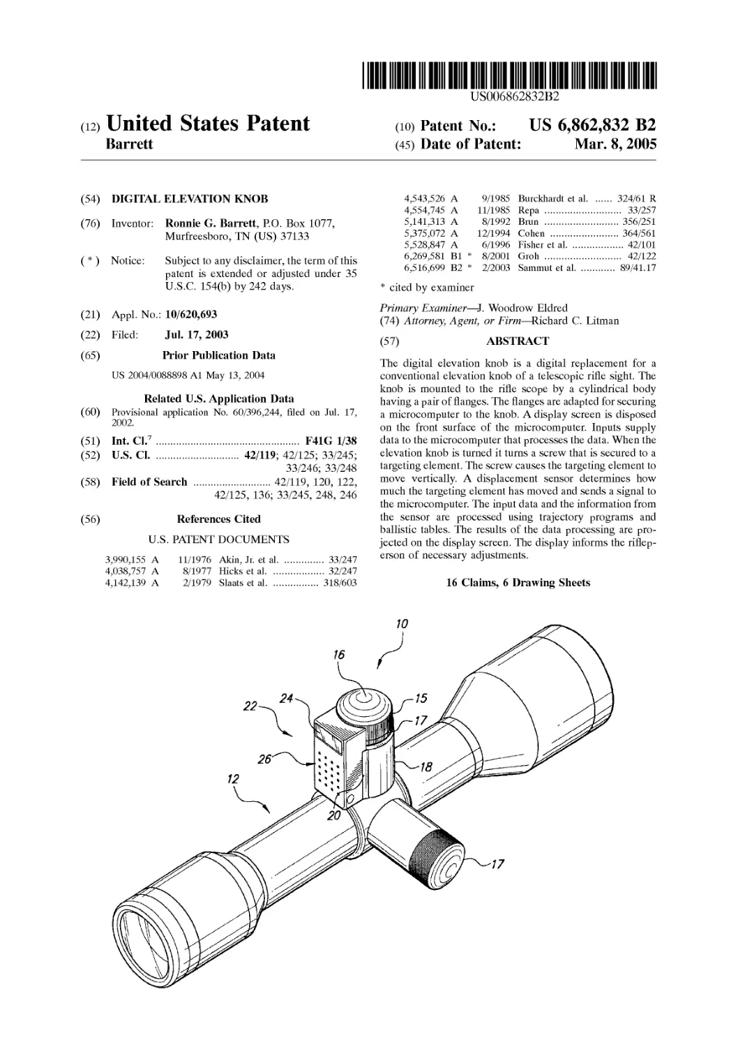
The digital elevation knob is a digital replacement for a
conventional elevation knob of a telescopic rifle sight. The
knob is mounted to the rifle scope by a cylindrical body
having a pair of flanges. The flanges are adapted for securing
a microcomputer to the knob. A display screen is disposed
on the front surface of the microcomputer. Inputs supply
data to the microcomputer that processes the data. When the
elevation knob is turned it turns a screw that is secured to a
targeting element. The screw causes the targeting element to
move vertically. A displacement sensor determines how
much the targeting element has moved and sends a signal to
the microcomputer. The input data and the information from
the sensor are processed using trajectory programs and
ballistic tables. The results of the data processing are pro-
jected on the display screen. The display informs the riflep-
erson of necessary adjustments.
16 Claims, 6 Drawing Sheets
3,990,155 A 11/1976 Akin, Jr. et al........ 33/247
4,038,757 A 8/1977 Hicks et al........... 32/247
4,142,139 A 2/1979 Slaats et al.......... 318/603
U.S. Patent
Mar. 8, 2005
Sheet 1 of 6
US 6,862,832 B2
U.S. Patent
Mar. 8, 2005
Sheet 2 of 6
US 6,862,832 B2
Fig. 2
U.S. Patent
Mar. 8, 2005
Sheet 3 of 6
US 6,862,832 B2
Fig. 3
U.S. Patent
Mar. 8, 2005
Sheet 4 of 6
US 6,862,832 B2
Fig. 4
U.S. Patent Mar. 8,2005 Sheet 5 of 6 US 6,862,832 B2
30
AMMUNITION DATA
-TYPE
OR
-WEIGHT
-CALIBER
-MUZZLE VELOCITY
-LOAD
-DRAG
COEFFICIENTS
32 36 INPUTS 42 44 46
SCOPE MODEL COEFFICIENTS CUCKSTURN #OF TURNS AMBIENT CONDITIONS -TEMPERATURE -WINDAGE -RELATIVE HUMIDITY FIREARM MODEL COEFFICIENTS -BARREL LENGTH -MUZZLE BRAKE SIGHTING-IN DATA -CORRECTIONAL COEFFICIENTS MEASUREMENT UNITS -YARDS -METERS TARGET DATA -ELEVATION -DIRECTION -SPEED
SOFTWARE UPDATES -ALTITUDE -BAROMETRIC PRESSURE HOME POSITION RESET AFTER POWER-UP r~'4O
PERSONAL COMPUTER
OR OTHER EXTERNAL
EQUIPMENT
48
112
158
70
SIGNAL
CONDITIONING
100
COMMUNICATIONS
PORT
KEYBOARD
- MODE SELECT
- ALPHA
POWERSUPPLY
-BATTERY
-EXTERNAL POWER
POWER CONTROL
-SLEEP
-WAKE-UP
-POWER STATUS
-CHARGING STATUS
-INTERNAL
(BATTERY)
-EXTERNAL POWER
REGULATION
72
INPUT OUTPUT
CONTROL
CENTRAL
PROCESSING UNIT
50
52
READOUT
-MODE
-INPUT PROMPTS
-KEYBOARD INPUTS
DURING ENTRY
-CORRECTED RANGE
AS DEFAULT
-PROCESSING STATUS
-POWER STATUS
-WEAPON LAY
-CANT STATUS OR
ANGLE
-TARGET MINUTE OF
ADJUSTMENT
76
DATA STORAGE
-BALLISTIC TABLES
-OPERATING
SYSTEM
-APPLICATION
PROGRAMS
-TRAJECTORY
PROGRAMS
SETUP
ROUTINES
U.S. Patent Mar. 8,2005 Sheet 6 of 6 US 6,862,832 B2
US 6,862,832 B2
1
DIGITAL ELEVATION KNOB
CROSS REFERENCE TO RELATED
APPLICATION
This application claims the benefit of U.S. Provisional
Patent Application Ser. No. 60/396,244, filed Jul. 17, 2002.
BACKGROUND OF THE INVENTION
1. Field of the Invention
The present invention relates generally to riflescopes and,
more specifically, to a digital elevation knob, for replace-
ment of a conventional elevation knob.
2. Description of the Related Art
Rifles and other guns are typically equipped with tele-
scopes for improving the hunter’s targeting. The telescopes
provide elevation knobs for adjusting the sight and other
variables of the telescope. Presently, conventional elevation
knobs on rifle telescopes have engraved or painted gradua-
tion marks to indicate adjustment of the scope. In order to
relate these marks to the hunter’s rifle the hunter must equate
ballistic data. A separate ballistic sheet is needed for each
variable including caliber, bullet speed, temperature, etc.
The relevant art of interest describes various aligning ele-
ments for an adjustable telescopic rifle sight, but none
disclose the present invention. There is a need for a digital
elevation knob, retrofittable to a telescopic sight, which can
be programmed for various parameters and readouts on a
display screen. The relevant art will be discussed in the order
of perceived relevance to the present invention.
U.S. Pat. No. 5,375,072 issued on Dec. 20, 1994, to
Stephen E. Cohen describes a microcomputer device with a
triangulation rangefinder for a firearm trajectory compensa-
tion comprising a computerized instrument for displacing
the aiming mark of a rifle or other small arms to compensate
for ballistic trajectory. The device has means for retaining
data for several types of small arms ammunition, a ballistics
data program, an electric aiming mark displacement system,
and a display system for the outputted aiming mark adjust-
ment data controlled by timer devices and a battery. The
device is distinguishable for its integration directly with a
telescopic sight and its requirement for triangulation, timers
and a battery.
U.S. Pat. No. 4,142,139 issued on Feb. 27, 1979, to
Mathew A. Slaats et al. describes a search mount for a
telescope comprising a motorized telescope mount with an
array of buttons for entering elevation and windage settings
and a digital signaling system. The digital circuitry includes
a paper tape reader, a magnetic card reader, and a two-
position display system with one display showing the
present position of the horizontal motor, and the second
display showing the data entered by the user. A photocell and
lamp are used for each of two motors to count the number
of revolutions of the motor shafts. The device is distinguish-
able for its motorized mount, manual switches, photocells,
lamps, and readers for a paper tape and a magnetic card.
U.S. Pat. No. 4,554,745 issued on Nov. 26, 1985, to Otto
Repa describes a device for aligning an adjustable sight
element for a rifle comprising a battery driven digital
eyepiece attachment that visually indicates at all times the
magnitude of horizontal and vertical movement of the
adjustable sight element. The device is distinguishable for its
limited capability.
U.S. Pat. No. 3,990,155 issued on Nov. 9, 1976, to Alfred
A. Akin, Jr. et al. describes a riflescope elevation assembly
integrated with the riflescope that reads target distance
5
10
15
20
25
30
35
40
45
50
55
60
65
2
directly and provides conventional “click” elevation set-
tings. A knob having a distance scale on its skirt is viewed
through an opening in the elevation adjustable assembly.
The device is distinguishable for its limitation to manual
elevation settings.
U.S. Pat. No. 4,038,757 issued on Aug. 2, 1977, to
Edward H. Hicks et al. describes two external adjustment
knobs with a cylindrical body attached to a telescopic sight
that cooperate with the adjustment screw that forms a part of
the sight. The device is limited to manual operation of the
riflescope’s windage and elevation adjustment screws absent
the conventional cap.
U.S. Pat. No. 5,141,313 issued on Aug. 25, 1992, to
Robert Brun describes an apparatus for producing a colli-
mating mark within an optical sighting device which
includes a light source to generate a light beam for the mark,
imaging optics and a beam splitter. The apparatus is distin-
guishable for being limited to enhancing optics.
U.S. Pat. No. 5,528,847 issued on Jun. 25, 1996, to
Timothy D. Fisher et al. describes a variable power tele-
scopic sight device comprising an externally located zoom
adjusting ring rotatable about the sighting means’ axis and
modified to provide a digitally-activated zooming feature.
The device is distinguishable for its required zooming
structure.
None of the above inventions and patents, taken either
singly or in combination, is seen to describe the instant
invention as claimed. Thus a digital elevation knob solving
the aforementioned problems is desired.
SUMMARY OF THE INVENTION
The present invention is a digital elevation knob for
replacement of a conventional elevation knob on a tele-
scopic rifle sight. The digital elevation knob may be built
onto a new riflescope or be made to retrofit onto an existing
riflescope. The digital elevation knob has a displacement
sensor, a unit containing elevation programs for different
ammunition, and a battery operated display screen. The
digital elevation knob is mounted to a conventional rifle-
scope. The knob is mounted to the riflescope by a generally
cylindrical body having a pair of flanges. The flanges are
adapted for securing a microcomputer to the elevation knob.
The display screen is disposed on the front surface of the
microcomputer.
A plurality of inputs supply information to the microcom-
puter. The information is input into the microcomputer
through either a communications port or through the key-
board on the microcomputer. The input information is sent
to a central processing unit where it is stored and processed.
The input information contains several variables including,
but not limited to, environmental conditions, ammunition
data, measurement units and target data.
The elevation knob is turned, which turns a screw that is
secured to a targeting element. The screw causes the target-
ing element to move up and down. The displacement sensor
determines how much the targeting element has moved and
sends a signal to the microcomputer. A weapon lay sensor
also determines the pitch and cant of the gun and sends
another signal to the microcomputer. These signals are sent
to the central processing unit and are processed with the
input information. The input information and the informa-
tion from the sensor are entered into data storage and several
calculations are made using trajectory programs and ballistic
tables. The results of the data processing are projected on the
readout display screen on the front of the microcomputer.
The readout displays the corrected range and informs the
user of the rifle of any adjustments that need to be made.
US 6,862,832 B2
3
Accordingly, it is a principal object of the invention to
provide a digital elevation knob for a telescopic rifle sight.
It is another object of the invention to provide a retrofit-
table digital elevation knob device having a display screen.
It is a further object of the invention to provide a digital
elevation knob device having a peripherally located dis-
placement sensor.
Still another object of the invention is to provide a digital
elevation knob device having a unit containing elevation
programs for different ammunition.
It is an object of the invention to provide improved
elements and arrangements thereof in an apparatus for the
purposes described which is inexpensive, dependable and
fully effective in accomplishing its intended purposes.
These and other objects of the present invention will
become readily apparent upon further review of the follow-
ing specification and drawings.
BRIEF DESCRIPTION OF THE DRAWINGS
FIG. 1 is an environmental, perspective view of a digital
elevation knob on a rifle telescopic sight according to the
present invention.
FIG. 2 is a front elevational view of the digital elevation
knob.
FIG. 3 is a side elevational view of the digital elevation
knob.
FIG. 4 is a top view of the digital elevation knob.
FIG. 5 is a block diagram of the data input and output of
the digital elevation knob and a partial perspective view of
the device.
FIG. 6 is a block diagram of the data input and out put of
the digital elevation knob and a partial perspective view of
the device according to a preferred embodiment of the
present invention.
Similar reference characters denote corresponding fea-
tures consistently throughout the attached drawings.
DETAILED DESCRIPTION OF THE
PREFERRED EMBODIMENTS
In FIGS. 1 through 4, the present invention is directed to
a digital elevation knob device 10 for a telescopic sight 12
(FIG. 1) for a rifle, long barreled pistol, or any other form of
sighted weapon. A conventional horizontal adjustment knob
14 is utilized for wind and sight adjustment. The device 10
comprises a cylindrical ribbed knob element 16 for replace-
ment of a conventional elevation knob. The ribbed knob is
inserted into a non-rotating cylindrical body 18 having a
longitudinal axis coincident with the cylindrical ribbed knob
element 16 and a longitudinally arranged pair of flanges 20
(FIGS. 1, 3 and 4). The rotatable knob 16 communicates
with a microcomputer 22 (FIGS. 1-3) in the microcomputer
22 housing. According to preferred embodiments of the
present invention the microcomputer 22 is secured to the
device 10 by the flanges 20. The microcomputer 22,
however, is not limited to being mounted to the riflescope in
this manner and the microcomputer 22 may also be remote
from the riflescope.
As FIG. 2 illustrates, a generally rectangular microcom-
puter 22 is attached to the non-rotating body 18 and includes
a programmable computer energized by a watch-type battery
or other power source (hidden). A display screen 24 in an
upper portion of the microcomputer 22 indicates informative
data including: (1) distance; (2) caliber of ammunition; (3)
program numbers being used; (4) temperature; and other
5
10
15
20
25
30
35
40
45
50
55
60
65
4
pertinent information such as direction and firing times. The
display screen 24 may be any suitable type of screen
including, but not limited to, liquid crystal display (LCD),
laser emitting diode (LED), and plasma screens.
A plurality of push buttons 26, are positioned in a lower
portion of the microcomputer 22 for selection of multiple
functions and entering of numerical parameters explained in
detail in FIG. 5. The microcomputer 22 also contains a
displacement sensor signal reader for conditioning the sig-
nals from the sensor, a unit containing an elevation program
for different calibers, and an external interface plug-in
socket 28 on one side (FIG. 3), whereby a rifleperson can
enter data into the microcomputer 22 to obtain the optimum
elevation setting for shooting the rifle at a specific target.
The interface plug-in socket 28 (or any wireless interface
accessory) is utilized to upload programs from a personal
computer to the programmable microcomputer 22 of the
device 10 and download firing data to the personal computer
or other device. Conventional ballistic programs are avail-
able by Sierra, Oehler, and PRODAS, which can be incor-
porated.
FIGS. 5 and 6 describe the input parameters that are
entered into the microcomputer 22 of the digital elevation
knob device 10. The input parameters 30 to 46 are entered
into the microcomputer 22 through either the communica-
tions port 48 or a keyboard 50. The keyboard 50 enters the
input data as alpha-numeric characters and also selects the
particular mode that the device is set in. Input data may also
be entered into the microcomputer 22 from a personal
computer or other external device 49. The personal com-
puter 22 is coupled to the microcomputer 22 through the
interface socket 28 and then transfers data through the
communications port 48.
The first data inputted is ammunition data 30 which
accepts specific ammunition data such as (1) type of ammu-
nition or more specific data as (2) weight of the bullet, (3)
caliber or diameter of the bullet, (4) muzzle velocity of the
bullet, (4) powder load in the cartridge, and (5) drag coef-
ficient of the bullet when fired in the barrel.
A second input 32 requires the scope model coefficients
such as (1) the number of clicks per turn, and (2) the number
of turns required.
A third input 34 associated with the second input 32 enters
periodic updated software data.
A fourth input 36 requires the inputs of ambient condi-
tions during firing such as (1) temperature, (2) windage in
compass direction and velocity of the wind, (3) relative
humidity, (4) altitude, and (5) barometric pressure.
A fifth input 38 enters firearm coefficients such as (1)
barrel length and (2) muzzle brake.
A sixth input 40 resets the home position during the hunt
after powering up the microcomputer 22.
A seventh input 42 enters sighting-in data such as cor-
rectional coefficients when the user is off the mark during
practice.
An eighth input 44 enters what measurement units are
employed such as yards or meters.
A ninth input 46 enters target data such as (1) elevation of
the target, (2) direction of the target, and (3) speed of the
target.
FIG. 5 also depicts a partial perspective view of the digital
elevation knob device 10 according to a first embodiment.
The present elevation knob 16 operates analogously to a
conventional linear caliper device, such as that described in
U.S. Pat. No. 4,543,526, issued Sep. 24,1985 to Burckhardt
US 6,862,832 B2
5
et al., having a fixed magnetic tape on a bar over which a
slider unit is disposed, the slider unit having a display
screen, a magnetic tape reader, and a microcomputer for
calculating linear displacement. However, in the present
invention the digital magnetic tape 17 on the ribbed knob
element 16 slides by the fixed magnetic tape reader in the
microcomputer 22, which measures angular or radial dis-
placement.
In use, the elevation adjuster knob or ribbed knob element
16 is rotated to rotate the digital magnetic tape element 17
having a magnetized region 19. An elevation adjuster screw
54 is manipulated for correct direction on the rifle (not
shown) viewing through the cross hairs in the erector tube
56, which is supported by a position return spring 58. The
magnetic tape element 17 measures the displacement of the
erector tube 56.
The magnetic flux from the peripherally arranged digital
magnetic tape 17 on the elevation adjuster knob 16 is
transmitted to a magnetic flux transducer A 60 and a trans-
ducer В 62. Transducer A 60 transmits its signal to a signal
conditioning unit A 64, and transducer В 62 transmits its
signal to a signal conditioning unit В 66, wherein both signal
conditioning units transmit their signal to the input-output
control 52.
FIG. 6 depicts a partial perspective view of the preferred
embodiment of the present invention. The digital elevation
device 100 of the present embodiment uses alternate sensors
as opposed to the magnetic elements of the previous
embodiment. An optical element 156 is housed inside of the
scope tube 112. The optical element is supported by a
position return spring 158.
The user of the rifle turns the elevation knob 16, which
then turns the adjuster push screw 154. Turning the screw
154 causes the optical element 156 to move up and down.
The displacement of the optical element 156 is measured by
an optical element feed back sensor 162. The sensor 162
sends a signal to a signal conditioning unit 64 in the
microcomputer 22. The signal notifies the microcomputer
the amount that the knob 16 has turned. The microcomputer
22 can then determine the displacement of the optical
element 156. The optical element feed back sensor 162 may
be any type of suitable sensor for determining the displace-
ment of the optical element 156 including, but not limited to,
optical encoders, precision potentiometers, and absolute
multi-turn sensors.
The device 100 further comprises a weapon lay sensor
160 located below the optical element feed back sensor 160.
The weapon lay sensor 160 determines if the weapon is
canted. The weapon lay sensor 160 senses if the barrel of the
gun is raised or tilted so that proper adjustments can be
made. If the weapon is canted the lay sensor 160 sends a
signal to the microcomputer 22, which activates a status
light on the display screen 24 that informs the user that the
weapon is canted.
Referring to FIGS. 5 and 6, a schematic drawing is shown
depicting the path of the signals once they are transmitted
from the sensors 160,162 or the transducers 60,62 into the
microcomputer 22. Once the signal enters the microcom-
puter 22 it is sent to a signal conditioning unit 64,66. The
signal conditioning unit 64,66 formats the signals so that
they can be read by the central processing unit 72. The signal
conditioning unit 64,66 can perform several functions
including, but not limited to, converting a signal from analog
to digital, regulating signals, filtering signals and amplifying
signals.
The signal is next transferred to an input/output control
unit 52. The control unit 52 controls the timing and flow of
5
10
15
20
25
30
35
40
45
50
55
60
65
6
the input and output data in the microcomputer 22. The
input/output control 52 transmits signals to the power con-
trol element 68, the communications port 48, the central
processing unit 72, and a readout unit 74.
The central processing unit 72 receives input data and
conditioned signals from the input/output control 52. The
central processing unit 72 processes the input data and
signals using information retrieved from the data storage
unit 76. The data storage unit 76 contains ballistic tables,
operating system data, and application programs for trajec-
tory and setup routines. Once the data is processed the
central processing unit 72 transfers processed data to a
readout unit 74 through the input/output unit 52.
The readout unit 74 receives processed data from the
central processing unit 72 as well as a power control unit 68
and the signal conditioning unit 64. The readout unit 74
supplies information to the display screen 24, which dis-
plays the information to the rifleperson. The readout unit 74
supplies information on the mode setting, input prompts,
keyboard inputs during their entry, processing status, cor-
rected range status, and power status. The power status is
displayed by retrieving information from the power control
unit 68. The power control unit 68 controls the status of the
device 10. The power control unit 68 can put the device into
a sleep, wake-up, power, or charging mode. The power
control unit 68 controls the signal conditioning units 64,66,
the communication port 48, the keyboard 50, the input/
output control 52, the central processing unit 72, the readout
unit 74 and the data storage unit 76. The power control
element 6B is energized by a power supply 70, which is
either an internal battery or an external D.C. power source.
This integrated system of inputs and the related functions
shown in FIG. 5 enables a rifleperson to accurately sight
his/her telescopic sight on the specific rifle, or other type of
gun, and ammunition used for the variables shown. With the
present widespread use of personal computers and other
electronic data devices, this invention can be used in concert
with present state of the art devices to decrease the time and
effort required to calibrate the riflescope. Thus, it has been
shown that the present invention improves the use of prior
art elevation knobs which have engraved or painted gradu-
ation marks requiring a separate ballistic sheet to indicate
adjustment of the scope for each caliber, bullet velocity,
temperature, and other parameters.
It is to be understood that the present invention is not
limited to the present embodiments described above, but
encompasses any and all embodiments within the scope of
the following claims.
I claim:
1. A digital elevation knob device, comprising:
a generally cylindrical, rotating ribbed knob;
a non-rotating generally cylindrical scope mount having a
longitudinal axis coincident with that of said ribbed
knob, and a longitudinally arranged pair of flanges, said
scope mount being adapted and configured for receiv-
ing said ribbed knob and mounting said knob to a rifle
scope; and
a computer housing, said housing comprising a program-
mable computer, a display screen disposed on an upper
front portion of said housing for indicating readout
data, a plurality of push buttons disposed on a lower
front portion of said housing for selection of functions
and entering of numerical parameters, an interface plug
for receiving an exterior data entry device, and a power
source;
whereby a rifleperson can enter data into the computer to
obtain the optimum elevation setting for firing the rifle
at a target.
US 6,862,832 B2
7
2. The digital elevation knob device according to claim 1,
further comprising a target viewing element disposed inside
of the tube of the rifle scope, a target adjuster screw secured
to the bottom of said knob and positioned above the target
viewing element, a positioning spring disposed beneath and
supporting the target viewing element and a displacement
sensing element for determining the displacement of the
target viewing element.
3. The digital elevation knob device according to claim 2,
wherein said displacement sensing element is selected from
the group consisting of a magnetic tape coupled to a pair of
magnetic flux transducers, optical sensors, optical encoders,
precision potentiometers and absolute multi-turn sensors.
4. The digital elevation knob device according to claim 2,
further comprising a weapon lay sensor located proximate to
said displacement sensing element, wherein said weapon lay
sensor determines if the rifle is canted or inclined.
5. The digital elevation knob device according to claim 1,
wherein said display screen is selected from the group
consisting of liquid crystal display screens, laser emitting
diode screens and plasma screens.
6. The digital elevation knob device according to claim 1,
wherein said power source is selected from the group
consisting of internal batteries and external D.C. power
sources.
7. The digital elevation knob device according to claim 1,
wherein said programmable computer further comprises:
a communications port for receiving input data in said
computer;
at least one signal conditioning unit for receiving and
formatting signals delivered to the programmable com-
puter from the displacement sensing element and the
weapon lay sensor;
an input and output control unit that controls the timing
and flow of input data and output data in the program-
mable computer;
a data storage unit for storing ballistic tables, operating
system data, and application programs for trajectory
and setup routines;
a central processing unit for receiving processing input
data and conditioned signals from the control unit and
processing the input data with stored data retrieved
from the data storage unit;
a power control unit for controlling the settings of the
knob device, wherein the power control unit can
change the status of the knob device to a sleep mode,
a charging mode, a wake-up mode and a power mode,
and regulates the power supplied by said power source;
and
a readout unit that supplies readout information to said
display screen;
whereby the input control transmits signals and data to the
power control unit, the communications port, the cen-
tral processing unit and the readout unit.
8. The digital elevation knob device according to claim 1,
wherein said computer housing is attached to said scope
mount between the pair of flanges.
9. A method of calibrating the telescopic scope of a rifle
using a digital elevation knob, comprising the steps of:
entering input parameters in a programmable computer
mounted to the telescopic scope using a communication
port and a keypad;
adjusting a target viewing element disposed inside of the
telescopic scope and transferring a signal containing
the degree of displacement of the target viewing ele-
ment to the programmable computer;
5
10
15
20
25
30
35
40
45
50
55
60
65
8
processing the signal and the input parameters entered
into the programmable computer; and
displaying processed information to the user of the tele-
scopic rifle scope;
whereby the user of the telescopic rifle scope is supplied
with information to properly adjust the telescopic rifle
scope to accurately sight a specific target.
10. The method according to claim 9 wherein said enter-
ing input parameters step further comprises the steps of:
entering ammunition data comprising type of
ammunition, weight of bullet, caliber of bullet, muzzle
velocity of bullet and drag coefficient of bullet when
fired;
entering scope model coefficients;
entering periodic updated software data;
entering ambient conditions data comprising temperature,
wind velocity in compass direction, relative humidity,
altitude and barometric pressure;
entering firearm coefficients comprising barrel length and
muzzle break;
resetting the home position after the programmable com-
puter is charged;
entering correctional coefficients if the user is off the mark
during target practice;
entering measurement units; and
entering target data comprising elevation of target, direc-
tion of target and speed of target.
11. The method according to claim 9 wherein said target
viewing element adjustment step further comprises:
rotating an adjuster knob that in turn rotates an adjuster
screw positioned above the target viewing element;
determining the displacement of the target viewing ele-
ment with a displacement sensing element; and
transferring the displacement signal from the displace-
ment sensing element to the programmable computer.
12. The method according to claim 9 further comprising
the step of measuring the cant of the firearm with a weapon
lay sensor and transmitting a cant signal and a rifle inclina-
tion signal to the programmable computer.
13. The method according to claim 9, wherein said
processing step further comprises:
formatting the signals in a signal conditioning unit so that
the signals may be read by a central processing unit;
transferring the formatted signals to the central processing
unit through an input and output control unit;
transferring the input parameters to the central processing
unit through the input and output control unit; and
processing the signals and input parameters with infor-
mation retrieved from a data storage unit, said infor-
mation comprising ballistic tables, operating system
data, and application programs for trajectory and setup
routines.
14. The method according to claim 9 further comprising
the step of receiving input data from an external data source
through an interface socket disposed on the programmable
computer.
15. The method according to claim 14 further comprising
the step of transmitting output data to the external data
source through the interface socket.
16. A digital riflescope device comprising:
a telescopic sight for a gun having a scope tube and a
target viewing element disposed inside of the scope
tube;
a horizontal adjustment knob disposed along the side of
said telescopic sight for making wind and sight adjust-
ments;
US 6,862,832 B2
9
a generally cylindrical, rotating ribbed knob;
a non-rotating generally cylindrical scope mount having a
longitudinal axis coincident with that of said ribbed
knob, and a longitudinally arranged pair of flanges, said
scope mount being adapted and configured for receiv- 5
ing said ribbed knob and mounting said knob to a rifle
scope; and
a computer housing comprising a programmable
computer, a display screen disposed on an upper front
portion of said housing for indicating readout data, a
10
plurality of push buttons disposed on a lower front
portion of said housing for selection of functions and
entering of numerical parameters, an interface plug for
receiving an exterior data entry device, and a power
source;
whereby a rifleperson can enter data into the computer to
obtain the optimum elevation setting for firing the gun
at a target.