/


Similar


Text
РОММ 9-1005-270-12
THIS PUBLICATION DOES NOT CONTAIN CLASSIFIED INFORMATION
PRELIMINARY OPERATOR'S
AND ORGANIZATIONAL
MAINTENANCE MANUAL
5.56MM MEDIUM MACHINEGUN,
BELT FED: STONER 63
MANUFACTURED BY
CADILLAC GAGE COMPANY
Weapon System Division
Warren, Michigan
FOR
U.S, ARMY WEAPONS COMMAND
Rock Island, Illinois
THIS PUBLICATION IS NOT AVAILABLE THROUGH
ADJUTANT GENERAL PUBLICATIONS CHANNELS.
Table of Contents
Paragraphs Page
CHAPTER 1. INTRODUCTION
Section I. General * . . 1 1
II. Description and data. 2 2
CHAPTER 2. OPERATING INSTRUCTIONS
Section I. Service upon receipt of materiel 5 4
II. Controls . 7 5
in. Operation under usual conditions 9 7
CHAPTER 3. ORGANIZATIONAL MAINTENANCE INSTRUCTIONS
Section 1. Repair parts, tools, and equipment 21 11
IL Lubrication 24 12
in. Preventive - maintenance services 27 14
IV. Troubleshooting . 29 16
CHAPTER 4. MAINTENANCE OF MACHINEGUN 31 19
CHAPTER 5. MAINTENANCE UNDER UNUSUAL CONDITIONS 36 29
CHAPTER 6. AMMUNITION 39 30
CHAPTER 7. DESTRUCTION OF MATERIAL TO
PREVENT ENEMY USE 41 31
APPENDIX I. REFERENCES 32
APPENDIX П. BASIC ISSUE ITEMS LIST 33
APPENDIX Ш. ORGANIZATIONAL MAINTENANCE REPAIR PARTS,
AND SPECIAL TOOL LIST 3,7
5. 56ММ MEDIUM MACHINEGUN, BELT FED: STONER 63
ERRATA
Make the following pen-and-ink changes to the pages indicated:
Page 3, paragraph 4d: Strike out grenade, blank from Type of Ammunition, so that only
ball, tracer remains.
Page 3, paragraph 4£: Change Maximum Effective Range from 500 yds (460 meters) to
1203 yds (1100 meters),.
Page 9, paragraph 17: Change line 3, last word, from course to cause.
Page 14, Table 2, item 2: Change line 3, from tube to cylinder.
Page 19, paragraph 32 b (2): Change line 1, from trunnion rest lock to trunnion nest lock.
Page 26, paragraph 36: Change paragraph no. from 36 to 34.
Page 27, paragraph 37: Change paragraph no. from 37 to 35.
CHAPTER 1
INTRODUCTION
Section I. GENERAL
1. SCOPE
a. This manual contains instructions for operator and organizational maintenance of the
Stoner medium machinegun,
b. Appendix I contains a list of current references and publications applicable to this
materiel.
c. Appendix II contains a list of basic issue items 1 repair parts, and tools and equipment
which are required for operational maintenance of the weapon.
d. Appendix Ш contains a list of repair parts, special tools and equipment which are
required for performing organizational maintenance of the weapon.
1
Section П. DESCRIPTION AND DATA
2. DESCRIPTION
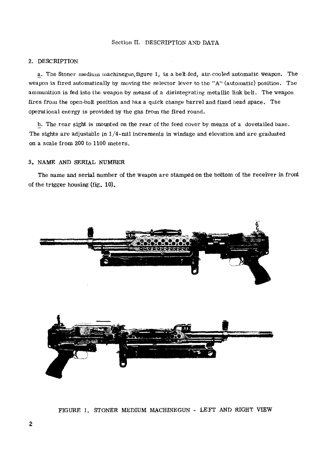
a. The Stoner medium machine gun, figure 1, is a beltfed, air- cooled automatic weapon. The
weapon is fired automatically by moving the selector lever to the "A” (automatic) position. The
ammunition is fed into the weapon by means of a disintegrating metallic link belt. The weapon
fires from the open-bolt position and has a quick change barrel and fixed head space. The
operational energy is provided by the gas from the fired round.
b. The rear sight is mounted on the rear of the feed cover by means of a dovetailed base.
The sights are adjustable in 1/4-mil increments in windage and elevation and are graduated
on a scale from 200 to 1100 meters.
3, NAME AND SERIAL NUMBER
The name and serial number of the weapon are stamped on the bottom of the receiver in front
of the trigger housing (fig. 10) Q
FIGURE 1. STONER MEDIUM MACHINEGUN - LEFT AND RIGHT VIEW
2
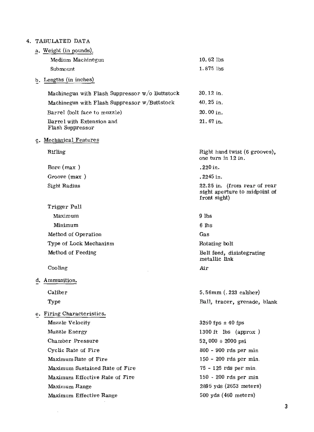
4. TABULATED DATA
a. Weight (in pounds).
Medium Machinegun
Sub mount
b. Lengths (in inches)
Machinegun with Flash Suppressor w/o Buttstock
Machinegun with Flash Suppressor w/Buttstock
Barrel (bolt face to muzzle)
Barrel with Extension and
Flash Suppressor
c. Mechanical Features
Rifling
Bore (max )
Groove (max )
Sight Radius
Trigger Pull
Maximum
Miniinum
Method of Operation
Type of Lock Mechanism
Method of Feeding
Cooling
d. Ammunition.
Caliber
Type
e« Firing Characteristics-
Muzzle Velocity
Muzzle Energy
Chamber Pressure
Cyclic Rate of Fire
Maximum Rate of Fire
Maximum Sustained Rate of Fire
Maximum Effective Rate of Fire
Maximum Range
Maximum Effective Range
10. 62 lbs
1.875 lbs
30.12 in.
40. 25 in.
20. 00 in.
21.67 in.
Right hand twist (6 grooves),
one turn in 12 in.
.220 in-
.2245 in.
22.25 in. (from rear of rear
sight aperture to midpoint of
front sight)
9 lbs
6 lbs
Gas
Rotating bolt
Belt feed, disintegrating
metallic link
Air
5.56mm (.223 caliber)
Ball, tracer, grenade, blank
3250 fps ± 40 fps
1300 ft lbs (approx )
52, 000 ± 2000 psi
800 - 900 rds per min
150 - 200 rds per min.
75 - 125 rds per min
150 - 200 rds per min
2895 yds (2653 meters)
500 yds (460 meters)
3
CHAPTER 2
OPERATING INSTRUCTIONS
Section I. SERVICE UPON RECEIPT OF MATERIEL
5. GENERAL
a. When a weapon is received, it is the responsibility of the officer in charge to determine
whether the materiel lias been properly prepared for service by the supplying organization and
to be sure it is in condition to perform its function.
b. All repair parts, tools, and equipment will be checked with the listing in Appendix П and
Ш.
c. A record will be made of all missing parts, tools, and equipment and of any malfunctions
Deficiencies will be corrected as quickly as possible.
6. SERVICES
When preparing weapons for use that are packed with volatile-corrosion inhibitor (VCI), the
following procedures shall be followed:
a. Unpacking. Open container and remove weapon and equipment. Remove VCI wrapping
from all surfaceso Clean per paragraph (b) below and assemble.
b. Cleaning. Wipe off excess oil with a clean,dry cloth. Run a clean,dry patch through the
bore of the weapon before firing,
c. Lubrication. Lubricate as indicated in paragraphs 24 through 26.
d. Inspection. Perform inspection as indicated in paragraph 33.
e. Submounts. For service pertaining to the submount refer to paragraph 33(5)(9).
4
Section П. CONTROLS
7. GENERAL
This section describes, locates, and illustrates the various controls provided for the opera-
tion and organizational maintenance of the weapon.
8. WEAPON CONTROLS
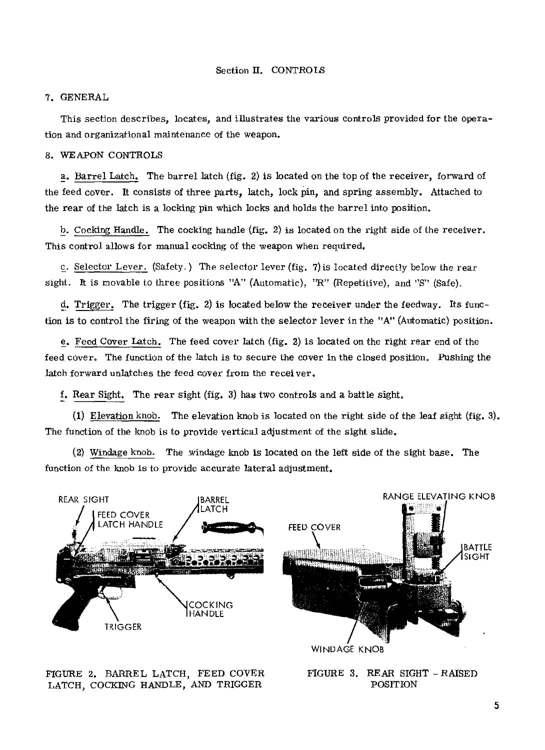
a о Barrel Latch. The barrel latch (fig. 2) is located on the top of the receiver, forward of
the feed cover. It consists of three parts, latch, lock pin, and spring assembly. Attached to
the rear of the latch is a locking pin which locks and holds the barrel into position.
b. Cocking Handle. The cocking handle (fig. 2) is located on the right side of the receiver.
This control allows for manual cocking of the weapon when required.
c. Selector Lever. (Safety.) The selector lever (fig. 7) is located directly below the rear
sight. It is movable to three positions "A" (Automatic), "R,r (Repetitive), and ”8” (Safe).
d. Trigger. The trigger (fig. 2) is located below the receiver under the feedway. Its func-
tion is to control the firing of the weapon with the selector lever in the "A" (Automatic) position.
e. Feed Cover Latch. The feed cover latch (fig. 2) is located on the right rear end of the
feed cover. The function of the latch is to secure the cover in the closed position. Pushing the
latch forward unlatches the feed cover from the receiver.
f. Rear Sight. The rear sight (fig. 3) has two controls and a battle sight.
(1) Elevation knob. The elevation knob is located on the right side of the leaf sight (fig. 3).
The function of the knob is to provide vertical adjustment of the sight slide,
(2) Windage knob. The windage knob is located on the left side of the sight base. The
function of the knob is to provide accurate lateral adjustment.
FIGURE 2. BARREL LATCH, FEED COVER
LATCH, COCKING HANDLE, AND TRIGGER
FIGURE 3. REAR SIGHT - RAISED
POSITION
5
(3) Battle sight. The battle sight is located on the base of the sight and is used when the
leaf rear sight is in the down position and corresponds to the. operative sight set at a range of
200 meters.
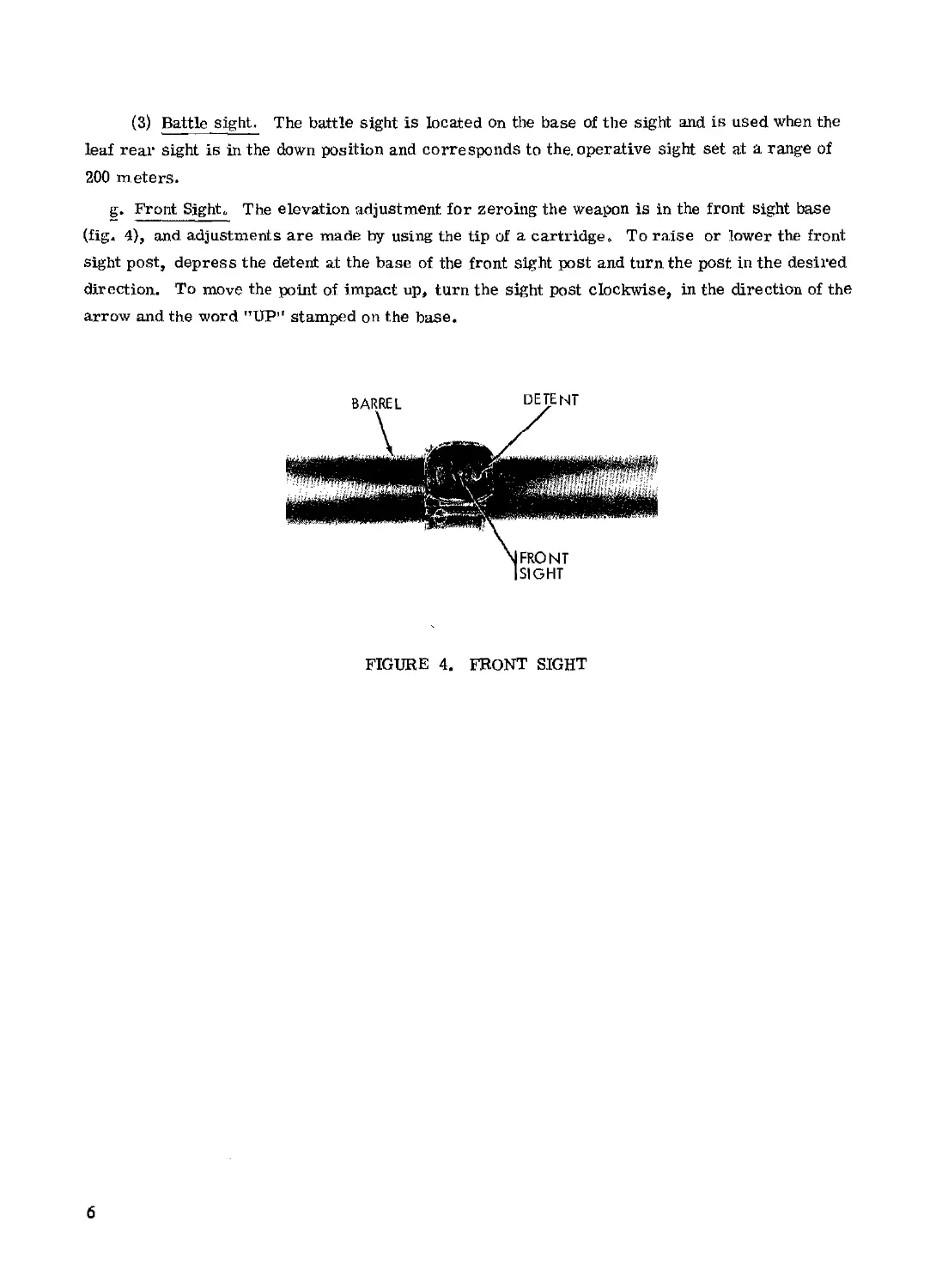
g. Front Sights The elevation adjustment for zeroing the weapon is in the front sight base
(fig. 4), and adjustments are made by using the tip of a cartridge. To raise or lower the front
sight post, depress the detent at the base of the front sight post and turn the post in the desired
direction. To move the point of impact up, turn the sight post clockwise, in the direction of the
arrow and the word "UP” stamped on the base.
FIGURE 4. FRONT SIGHT
6
Section Ш. OPERATION UNDER USUAL CONDITIONS
9. GENERAL
This section contains instructions for the operation of the weapon under conditions of
moderate temperatures and humidity.
10. PREPARATION FOR FIRING
a. Check all ammunition to be sure proper type and grade are being used.
b. Check weapon to see if it has been thoroughly cleaned and lubricated. Inspect for mal-
function or other defects.
11. SERVICE BEFORE FIRING
Perform the before-firing operations as described in Table 2„
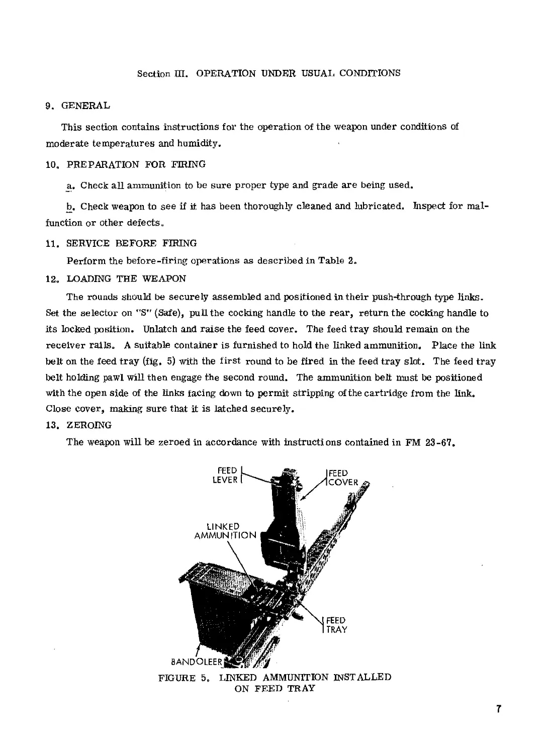
12„ LOADING THE WEAPON
The rounds should be securely assembled and positioned in their push-through type links.
Set the selector on *TS" (Safe), pull the cocking handle to the rear, return the cocking handle to
its locked position. Unlatch and raise the feed cover. The feed tray should remain on the
receiver railso A suitable container is furnished to hold the linked ammunition. Place the link
belt on the feed tray (fig, 5) with the first round to be fired in the feed tray slot. The feed tray
belt holding pawl will then engage the second round. The ammunition belt must be positioned
with the open side of the links facing down to permit stripping of the cartridge from the link.
Close cover, making sure that it is latched securely.
13. ZEROING
The weapon will be zeroed in accordance with instructions contained in FM 23-67.
FIGURE 5, LINKED AMMUNITION INSTALLED
ON FEED TRAY
7
14. FIRING WEAPON
WARNING: Make sure the selector lever is in the "Sr (Safe) position when the weapon is
not being fired.
WARNING: The machinegun also fires automatically when the selector lever is in the "R”
(Repetitive) position.
With the machinegun loaded and aimed, move the selector lever to the "An (automatic)
position and pull the trigger. The machinegun will continue to fire until the linked ammunition
is exhausted or the trigger is released. When the ammunition is exhausted, the last link of the
belt will remain in the feed tray, and must be removed by hand when the cover is opened to
reload,
15. MISFIRE, HANGFIRE, AND COOKOFF
a. Misfire. A misfire is a complete failure to fire. A misfire in itself is not dangerous
but, since it cannot be immediately distinguished from a delay in the functioning of the firing
mechanism or from a hangfire (b below), it should be considered as a possible delayed firing
until such possibility has been eliminated. Such delay in the functioning of the firing mechanism,
for example, could result from the presence of foreign matter such as grit, sand, frost, ice, or
improper or excessive oil or grease which might create initially a partial mechanical restraint
which, after some indeterminate delay, is overcome and the firing pin is then driven into the
primer in the normal manner. In this connection, no round should be left in a hot weapon any
longer than the circumstances require because of the possibility of a cookoff (c below). Refer
to paragraph 16 for removal procedures.
b. Hangfire. A hangfire is a delay in the functioning of a propelling charge at the time of
fi ring. The amount of delay is unpredictable but, in most cases, will fall within the range of a
split second to several seconds. Thus, a hangfire cannot be distinguished immediately from a
misfire and therein lies the principal danger of assuming a failure of the weapon to fire imme-
diately upon actuation of the firing mechanism is a misfire, whereas, in fact, it may prove to be
a hangfire.
WARNING: During the prescribed time intervals, the weapon will be kept trained on the
target. All personnel will stand clear of the muzzle. Refer to paragraph 16 for removal
procedures.
c. Cookoff. A cookoff is a functioning of any or all of the explosive components of a round
chambered in a very hot weapon due to the heat of the weapon. If the primer or propelling
charger should cookoff, the projectile may be propelled from the weapon with normal velocity
even though no attempt was made to fire the primer by actuating the firing mechanism. In such
a case, although there may be uncertainty as to whether or when the round will fire, the pre-
cautions to be observed are the same as those prescribed for a hangfire (b above). To prevent
8
a cookoff, a round of ammunition which has been loaded into a very hot weapon should be fired
or removed after round is in weapon 5 seconds. Refer to the following paragraphs for removal
procedures.
16. PROCEDURES FOR REMOVING A ROUND IN CASE OF FAILURE TO FIRE
a. General. After a failure to fire, due to the possibility of a hangfire or cookoff, the
following general precautions, as applicable, will be observed until the round has been removed
from the weapon and the cause of failure determined.
(1) Keep the weapon trained on the target. All personnel will stand clear of the muzzle.
(2) Before retracting the bolt, either to remove the round or recock as the case may be,
personnel not required for the operation will be cleared from the vicinity.
(3) The round, after removal from the weapon, will be kept separate from other rounds
until it has been determined whether the round or the firing mechanism was at fault. If it is
determined that the round is at fault, it will continue to be kept separated from other rounds
until disposed of. On the other hand, if examination reveals that the firing mechanism was at
fault, the round may be reloaded and fired after correction of the cause for failure to fire.
b. Time Interval. The definite time intervals for waiting after failure of weapon to fire are
prescribed as follows: Always keep the round locked in the chamber for 5 seconds from the time
a misfire occurs, to insure against an explosion outside of the gun in the event a hangfire
develops. If the barrel is hot and a misfire stops automatic operation of the gun, wait 5 seconds
with the round locked in the chamber to insure against hangfire dangers, then extract immediately
to prevent a cookoff. If the round cannot be extracted within 10 seconds, it must remain locked
in the chamber for at least 5 minutes due to the possibility of a cookoff.
WARNING: Do not retract the bolt when a hangfire or cookoff is suspected. A hangfire will
normally occur within 5 seconds from the time the primer is struck and a cookoff after 10
seconds of contact with the chamber in a hot barrel. One hundred-fifty rounds fired in a 2-
minute period will make a barrel hot enough to produce a cookoff.
17. DOUBLE FEED
A double feed is a malfunction which occurs when the empty case fails to eject and another
round is picked up by the bolt. Neither can feed or chamber properly and both become jammed
and deformed. Both rounds can be ejected manually using the cocking handle. The course
normally is a short recoil which indicates a dirty gas port or faulty ammunition.
18. SERVICE DUR,ING FIRING
No during-firing service operations are required for this weapon.
9
19, UNLOADING THE WEAPON
To unload a cocked, loaded machinegun, move the selector lever to the "S" (Safe) position.
Raise the feed cover, remove the belt and remaining link in the feed tray. Check the receiver
and chamber to make sure no rounds remain.
20. SERVICE AFTER FIRING
Perform the after firing operations. Refer to table 2.
10
CHAPTER 3
ORGANIZATIONAL MAINTENANCE INSTRUCTIONS
Section I. REPAIR PARTS, TOOLS, AND EQUIPMENT
21. GENERAL
Repair parts, tools, and equipment are issued to the using organization for operating and
maintaining the materiel. Tools and equipment should not be used for purposes other than pre-
scribed and, when not in use, should be properly stowed.
22. REPAIR PARTS
Repair parts are supplied to the using organization for replacement of those parts most
likely to become worn, broken, or otherwise unserviceable, when replacement of these parts
is authorized to the using organization. Repair parts supplied to the using organization are
listed in Appendix II, which is the authority for requisitioning replacements. Repair parts
supplied for organizational maintenance are listed in Appendix III
23. SPECIAL TOOLS AND EQUIPMENT
Special tools are listed in Appendix Ш.
11
Section П. LUBRICATION
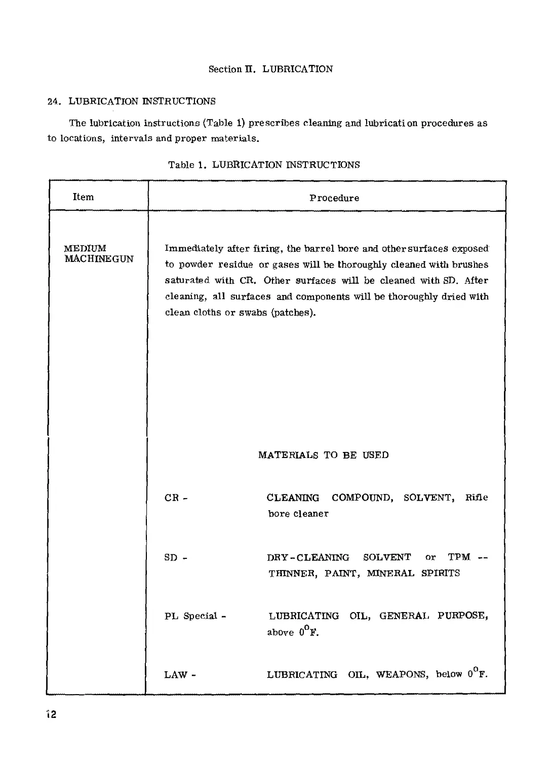
24. LUBRICATION INSTRUCTIONS
The lubrication instructions (Table 1) prescribes cleaning and lubrication procedures as
to locations, intervals and proper materials.
Table 1. LUBRICATION INSTRUCTIONS
Item Procedure
MEDIUM MACHINEGUN Immediately after firing, the barrel bore and other surfaces exposed to powder residue or gases will be thoroughly cleaned with brushes saturated with CR. Other surfaces will be cleaned with SD. After cleaning, all surfaces and components will be thoroughly dried with clean cloths or swabs (patches). MATERIALS TO BE USED CR - CLEANING COMPOUND, SOLVENT, Rifle bore cleaner SD - DRY-CLEANING SOLVENT or TPM — THINNER, PAINT, MINERAL SPIRITS PL Special - LUBRICATING OIL, GENERAL PURPOSE, above 0°F. LAW - LUBRICATING OIL, WEAPONS, below 0°F.
12
25. GENERAL LUBRICATION INSTRUCTIONS
a. Usual Conditions, Lubrication intervals specified in Table 1 are for normal operation
and where moderate temperature and humidity prevail.
b. Reports and Records. Report unsatisfactory performance of the weapon effect of pre-
scribed lubricants and preserving materials.
26. SPECIFIC LUBRICATION INSTRUCTIONS
a. General. Lubrication will be performed more frequently than specified in Table 1 to
compensate for abnormal operation and extreme conditions, such as high or low temperatures,
prolonged periods of highrate operation, or continued exposure to moisture, any one of which
may quickly destroy the protective qualities of the lubricant,
b. Changing Grade of Lubricants. Lubricants are prescribed in accordance with tempera-
ture ranges: above 0°F., and below 0°F. The time to change the grade of lubricants is deter-
mined by maintaining a close check of the operation of the weapon during the approach to change-
over periods in accordance with weather forecast data. Ordinarily, it will be necessary to
change grade of lubricants only when air temperature is consistently above or below 0°F.
Co Extreme Cold Weather, Apply a light coat of weapons lubricating oil (LAW) to all
operating mechanism surfaces. The weapon should be exercised more frequently during periods
of low temperature to insure proper functioning.
d. Extreme Hot Weather. Special lubricants will ordinarily not be required at extremely
high temperatures, as lubricants prescribed for temperatures above 0°F, provide adequate
protection. However, more frequent servicing than specified in Tables 2 and 3 is necessary
because the heat tends to dissipate the lubricants.
e. Humid and Salt-Air Conditions. High humidity, moisture, or salt air contaminate
lubricants, necessitating more frequent service than specified in Tables 2 and3,
f. Before Immersion. Lubricate materiel before amphibious operation as prescribed in
Table 1,
g. After Immersion. After immersion, perform the maintenance described in paragraph
which covers maintenance operations after immersion and includes special lubrication
instructions.
h. Sandy or Dusty Conditions. If firing or prolonged travel has occurred under dusty or
sandy conditions, clean and inspect all lubricated surfaces for fouled lubricants. Lubricate as
necessary.
13
Section Ш, PREVENTIVE-MAINTENANCE SERVICES
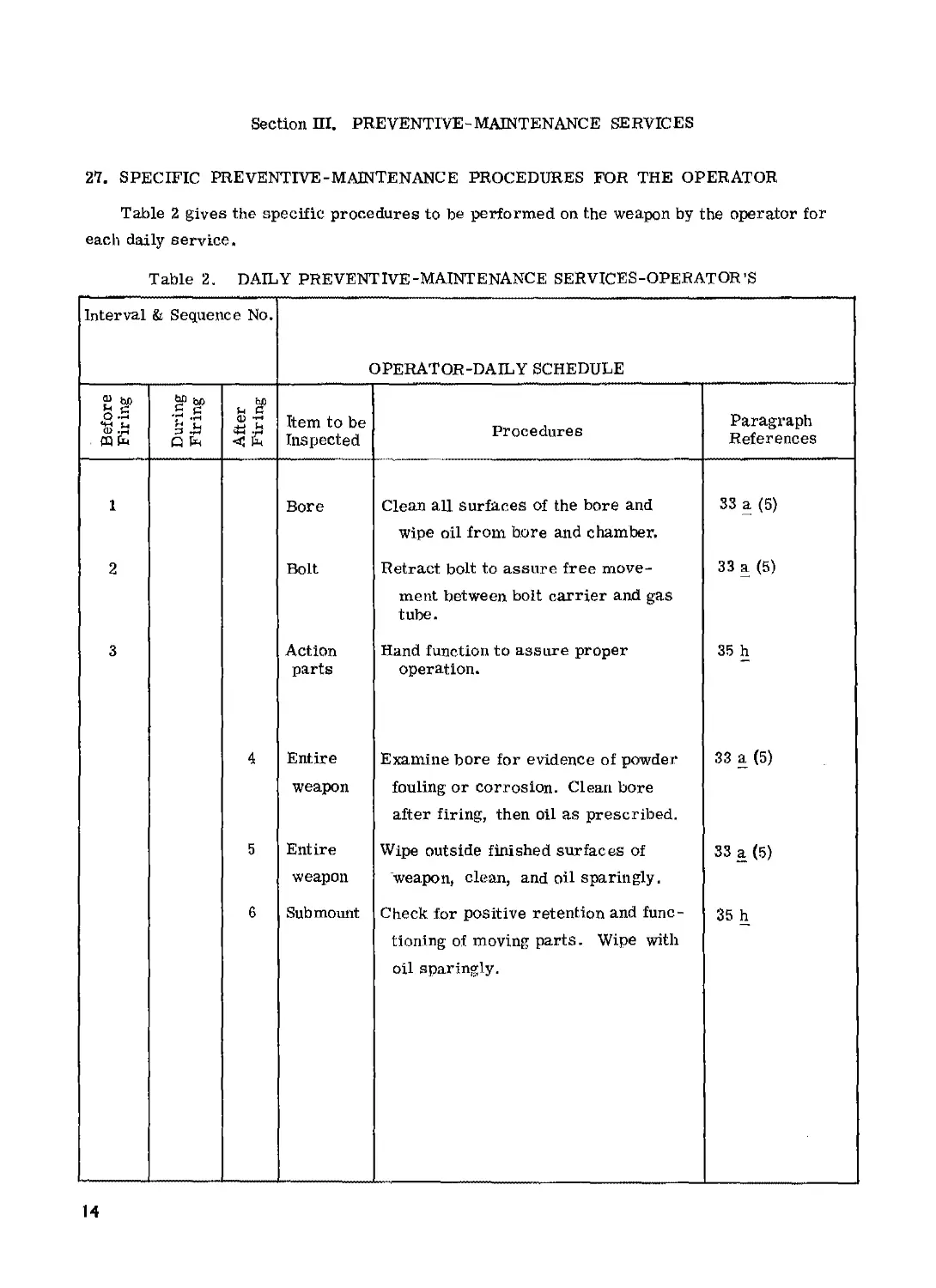
27. SPECIFIC PREVENTIVE-MAINTENANCE PROCEDURES FOR THE OPERATOR
Table 2 gives the specific procedures to be performed on the weapon by the operator for
each daily service.
Table 2. DAILY PREVENTIVE-MAINTENANCE SERVICES-OPERATOR’S
Interval & Sequence No. operator-daily schedule
Before Firing During Firing After J Firing Item to be Inspected Procedures Paragraph References
1 Bore Clean all surfaces of the bore and 33 a (5)
wipe oil from bore and chamber.
2 Bolt Retract bolt to assure free move- 33 a (5)
ment between bolt carrier and gas tube.
3 Action parts Hand function to assure proper operation. 35
4 Entire Examine bore for evidence of powder 33 a (5)
weapon fouling or corrosion. Clean bore after firing, then oil as prescribed.
5 Entire Wipe outside finished surfaces of 33 a (5)
weapon weapon, clean, and oil sparingly.
6 Sub mount Check for positive retention and func- 35 h
tioning of moving parts. Wipe with oil sparingly.
14
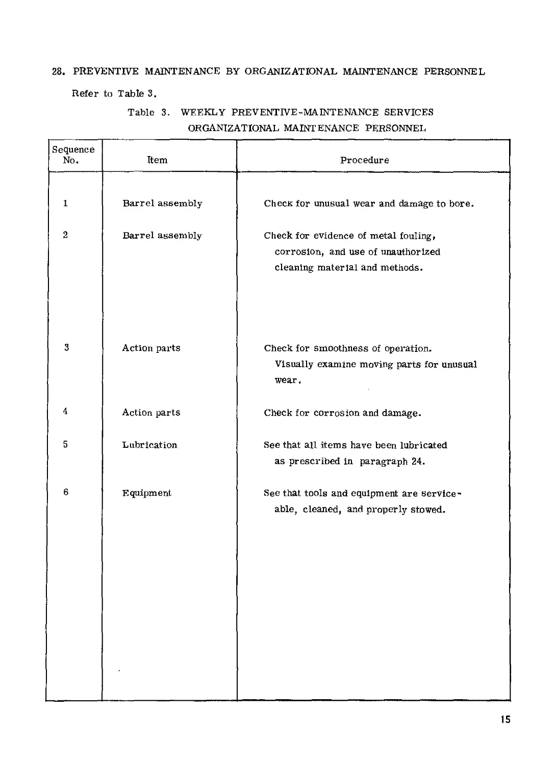
28. PREVENTIVE MAINTENANCE BY ORGANIZATIONAL MAINTENANCE PERSONNEL
Refer to Table 3.
Table 3. WEEKLY PREVENTIVE-MAINTENANCE SERVICES
ORGANIZATIONAL MAINTENANCE PERSONNEL
Sequence No. Item Procedure
1 Barrel assembly Check for unusual wear and damage to bore.
2 Barrel assembly Check for evidence of metal fouling, corrosion, and use of unauthorized cleaning material and methods.
3 Action parts Check for smoothness of operation. Visually examine moving parts for unusual wear.
4 Action parts Check for corrosion and damage.
5 Lubrication See that all items have been lubricated as prescribed in paragraph 24.
6 Equipment See that tools and equipment are service - able, cleaned, and properly stowed.
15
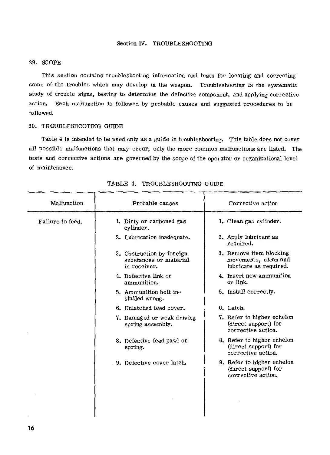
Section IV. TROUBLESHOOTING
29. SCOPE
This section contains troubleshooting information and tests for locating and correcting
some of the troubles which may develop in the weapon. Troubleshooting is the systematic
study of trouble signs, testing to determine the defective component, and applying corrective
action* Each malfunction is followed by probable causes and suggested procedures to be
followed.
30. TROUBLESHOOTING GUIDE
Table 4 is intended to be used only as a guide in troubleshooting. This table does not cover
all possible malfunctions that may occur; only the more common malfunctions are listed. The
tests and corrective actions are governed by the scope of the operator or organizational level
of maintenance.
TABLE 4. TROUBLESHOOTING GUIDE
Malfunction Probable causes Corrective action
Failure to feed. 1. Dirty or carboned gas cylinder. 1. Clean gas cylinder.
2. Lubrication inadequate. 2. Apply lubricant as required.
3. Obstruction by foreign substances or material in receiver. 3. Remove item blocking movements, clean and lubricate as required.
4. Defective link or ammunition. 4. Insert new ammunition or link.
5. Ammunition belt in~ stalled wrong. 5. Install correctly.
6. Unlatched feed cover. 6. Latch.
7, Damaged or weak driving spring assembly. 7. Refer to higher echelon (direct support) for corrective action.
8. Defective feed pawl or spring. 8, Refer to higher echelon (direct support) for corrective action.
9. Defective cover latch. 9. Refer to higher echelon (direct support) for corrective action.
16
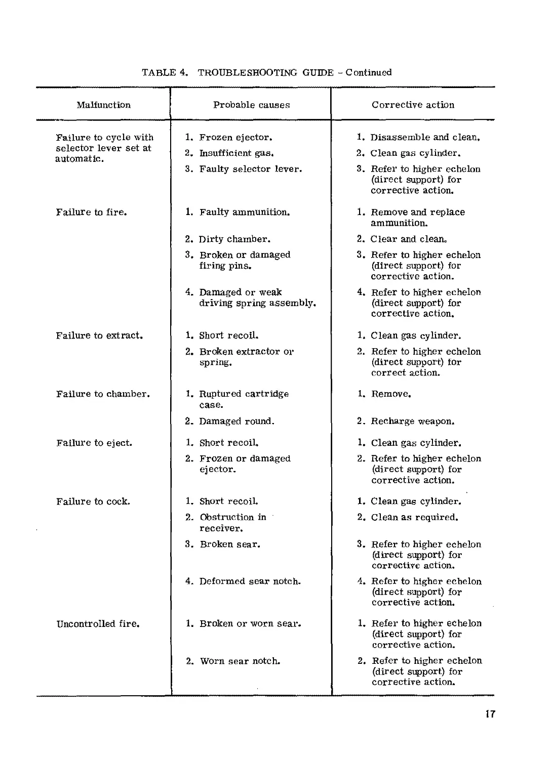
TABLE 4, TROUBLESHOOTING GUIDE - Continued
Malfunction
Probable causes
Corrective action
Failure to cycle with selector lever set at automatic. Failure to fire. Failure to extract. Failure to chamber. Failure to eject. Failure to cock. Uncontrolled fire. 1. Frozen ejector. 2. Insufficient gas. 3. Faulty selector lever. 1. Faulty ammunition. 2. Dirty chamber. 3. Broken or damaged firing pins. 4. Damaged or weak driving spring assembly. 1. Short recoil. 2. Broken extractor or spring. 1. Ruptured cartridge case. 2. Damaged round. 1. Short recoil. 2. Frozen or damaged ejector. 1. Short recoil. 2. Obstruction in receiver. 3. Broken sear. 4. Deformed sear notch- 1, Broken or worn sear* 2. Worn sear notch. 1. Disassemble and clean. 2. Clean gas cylinder. 3. Refer to higher echelon (direct support) for corrective action. 1. Remove and replace ammunition. 2. Clear and cleano 3. Refer to higher echelon (direct support) for corrective action. 4. Refer to higher echelon (direct support) for corrective action. 1. Clean gas cylinder. 2. Refer to higher echelon (direct support) tor correct action. 1. Remove. 2. Recharge weapon. 1* Clean gas cylinder. 2. Refer to higher echelon (direct support) for corrective action. 1. Clean gas cylinder. 2. Clean as required. 3. Refer to higher echelon (direct support) for corrective action. 4. Refer to higher echelon (direct support) for corrective action. 1. Refer to higher echelon (direct support) for corrective action. 2. Refer to higher echelon (direct support) for corrective action.
17
CHAPTER 4
MAINTENANCE OF MACHINEGUN
31. GENERAL
a. Maintenance includes all measures taken to keep the weapon in top operating condition.
This includes normal cleaning, inspection for defective parts, repair, and lubrication. The
individual is authorized to disassemble his weapon to the extent called field ’'stripping”. The
amount of disassembly allowed is adequate for normal maintenance» The frequency of dis-
assembly and assembly should be kept to a minimum, consistent with maintenance and instruc-
tional requirements.
bo The weapon has been designed so that it can be taken apart and put together easily. No
force is needed if it is disassembled and assembled correctly. As the weapon is disassembled,
the parts should be laid out from the left to right. This makes assembly easier because the
parts are assembled in the reverse order of disassembly. Disassembly may be accomplished
in the field using only a cartridge,
32. DISASSEMBLY
a. Inspection for Safe Condition. The following procedures are to be followed prior to dis-
assembly of the weapon.
(1) Move the selector lever to the "S” (Safe) position, (fig. 7),
(2) Pull the cocking handle on the right side of the receiver to the rear until the action is
locked open*
(3) Return the cocking handle to the forward, locked position.
(4) Push forward on the cover latch handle (fig. 2) and raise the cover.
(5) Check the receiver and chamber to be sure that the weapon is cleared of all
ammunition and is safe to disassemble,
(6) Move the selector lever to the "A" (Automatic) position.
(7) Pull the cocking handle (fig, 2) to the rear, still holding the cocking handle, pull the
trigger, then ease the bolt forward closing the action.
b0 Submount Assembly.
(1) Description. The submount assembly (fig. 6) is required when mounting the Stoner
machinegun on the М2 mount* The elevating and traversing mechanism and the pintle are
attached to the submount assembly.
18
TRUNNION SUB-MOUNT
NEST LOCK
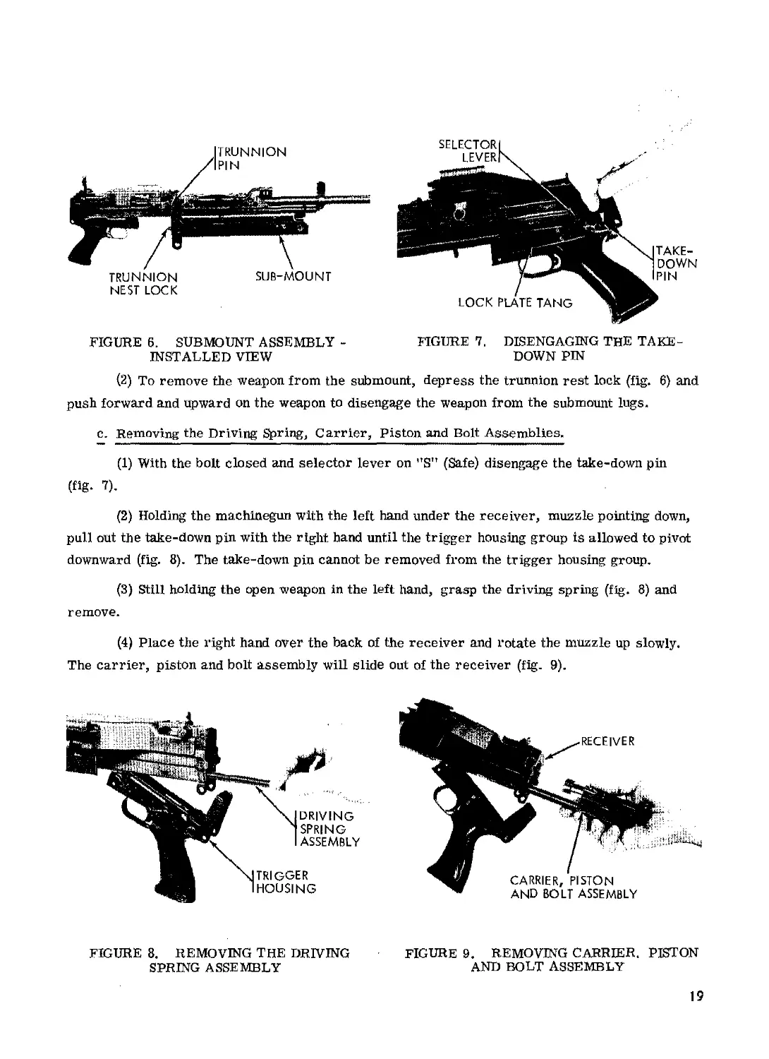
FIGURE 6. SUBMOUNT ASSEMBLY -
INSTALLED VIEW
FIGURE 7, DISENGAGING THE TAKE-
DOWN PIN
(2) To remove the weapon from the submount, depress the trunnion rest lock (fig. 6) and
push forward and upward on the weapon to disengage the weapon from the sub mount lugs.
c. Removing the Driving Spring, Carrier, Piston and Bolt Assemblies.
(1) With the bolt closed and selector lever on "S" (Safe) disengage the take-down pin
(flg> 7).
(2) Holding the machinegun with the left hand under the receiver, muzzle pointing down,
pull out the take-down pin with the right hand until the trigger housing group is allowed to pivot
downward (fig. 8). The take-down pin cannot be removed from the trigger housing group.
(3) Still holding the open weapon in the left hand, grasp the driving spring (fig. 8) and
remove.
(4) Place the right hand over the back of the receiver and rotate the muzzle up slowly.
The carrier, piston and bolt assembly will slide out of the receiver (fig. 9).
FIGURE 8. REMOVING THE DRIVING FIGURE 9. REMOVING CARRIER. PISTON
SPRING ASSEMBLY AND BOLT ASSEMBLY
19
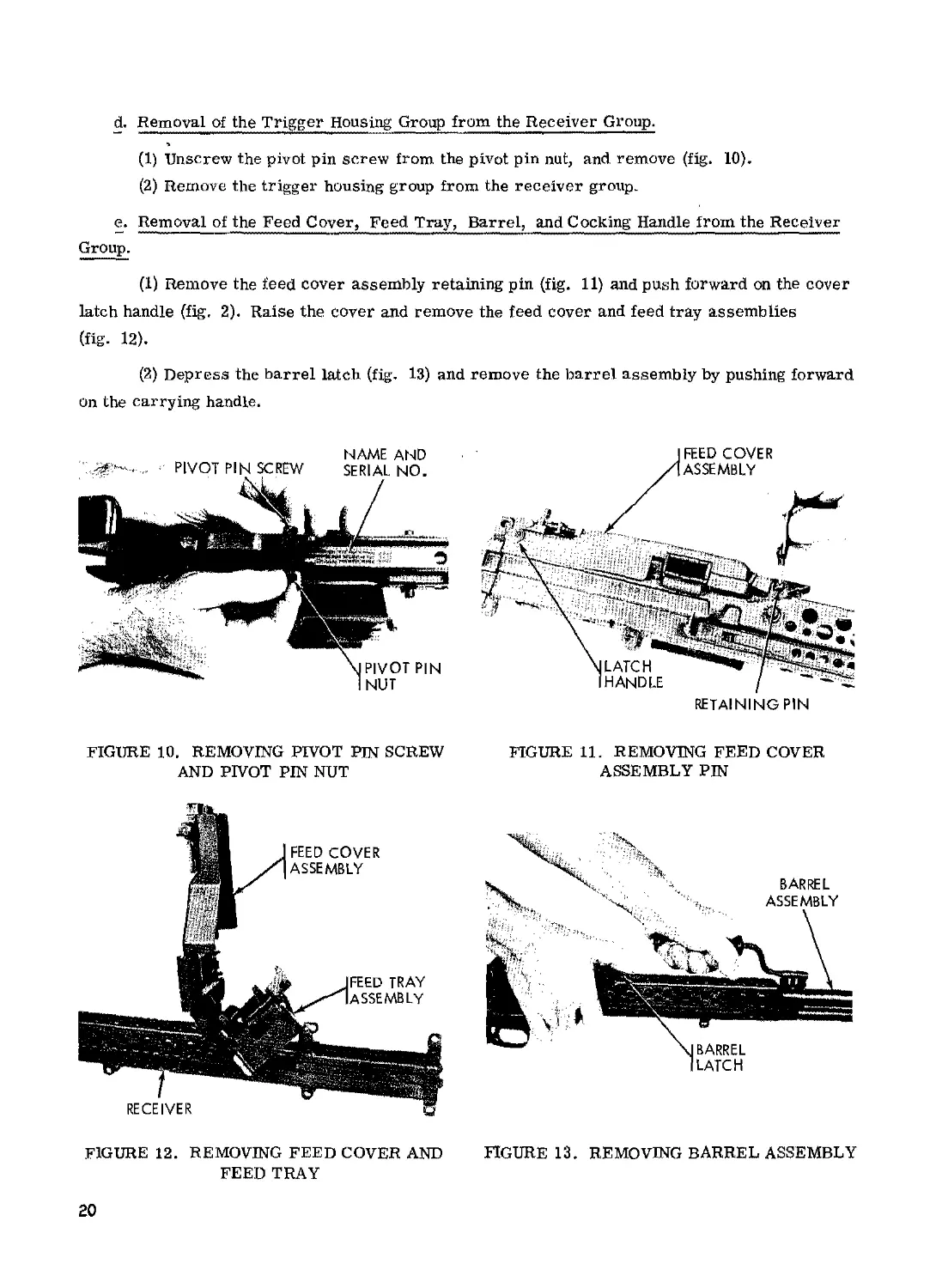
d. Removal of the Trigger Housing Group from the Receiver Group.
>
(1) Unscrew the pivot pin screw from the pivot pin nut, and remove (fig. 10).
(2) Remove the trigger housing group from the receiver group.
e. Removal of the Feed Cover, Feed Tray, Barrel, and Cocking Handle from the Receiver
Group.
(1) Remove the feed cover assembly retaining pin (fig. 11) and push forward on the cover
latch handle (fig. 2). Raise the cover and remove the feed cover and feed tray assemblies
(fig. 12).
(2) Depress the barrel latch (fig. 13) and remove the barrel assembly by pushing forward
on the carrying handle.
FIGURE 10. REMOVING PIVOT PIN SCREW
AND PIVOT PIN NUT
RETAINING PIN
FIGURE 11. REMOVING FEED COVER
ASSEMBLY PIN
FIGURE 12. REMOVING FEED COVER AND
FEED TRAY
FIGURE 13. REMOVING BARREL ASSEMBLY
20
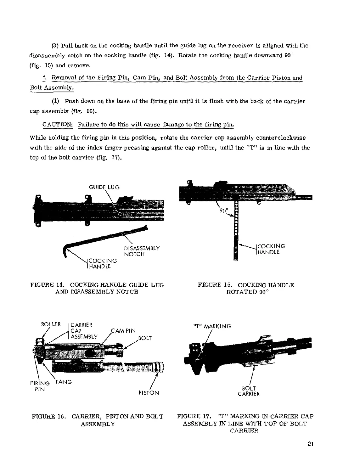
(3) Pull back on the cocking handle until the guide lug on the receiver is aligned with the
disassembly notch on the cocking handle (fig. 14). Rotate the cocking handle downward 90°
(fig. 15) and remove.
f. Removal of the Firing Pin, Cam Pin, and Bolt Assembly from the Carrier Piston and
Bolt Assembly.
(1) Push down on the base of the firing pin until it is flush with the back of the carrier
cap assembly (fig. 16).
CAUTION: Failure to do this will cause damage to the firing pin.
While holding the firing pin in this position, rotate the carrier cap assembly counterclockwise
with the side of the index finger pressing against the cap roller, until the "T" is in line with the
top of the bolt carrier (fig, 17).
GUIDE LUG
FIGURE 14. COCKING HANDLE GUIDE LUG
AND DISASSEMBLY NOTCH
FIGURE 15. COCKING HANDLE
ROTATED 90°
FIGURE 16. CARRIER, PISTON AND BOLT
ASSEMBLY
MT” MARKING
BOLT
CARRIER
FIGURE 17. ”T” MARKING IN CARRIER CAP
ASSEMBLY IN LINE WITH TOP OF BOLT
CARRIER
21
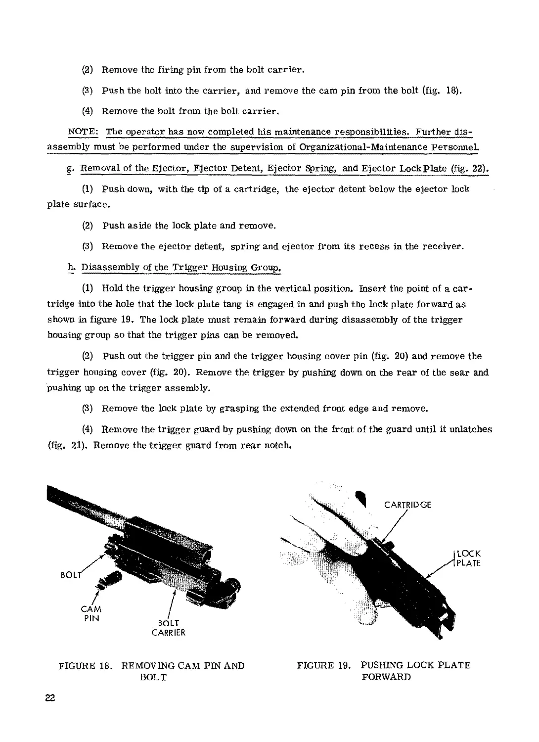
(2) Remove the firing pin from the bolt carrier.
(3) Push the holt into the carrier, and remove the cam pin from the bolt (fig. 18).
(4) Remove the bolt from the bolt carrier,
NOTE: The operator has now completed his maintenance responsibilities. Further dis-
assembly must be performed under the supervision of Organizational-Maintenance Personnel.
g. Removal of the Ejector, Ejector Detent, Ejector Spring, and Ejector Lock plate (fig. 22).
(1) Push down, with the tip of a cartridge, the ejector detent below the ejector lock
plate surface.
(2) Push aside the lock plate and remove.
(3) Remove the ejector detent, spring and ejector from its recess in the receiver.
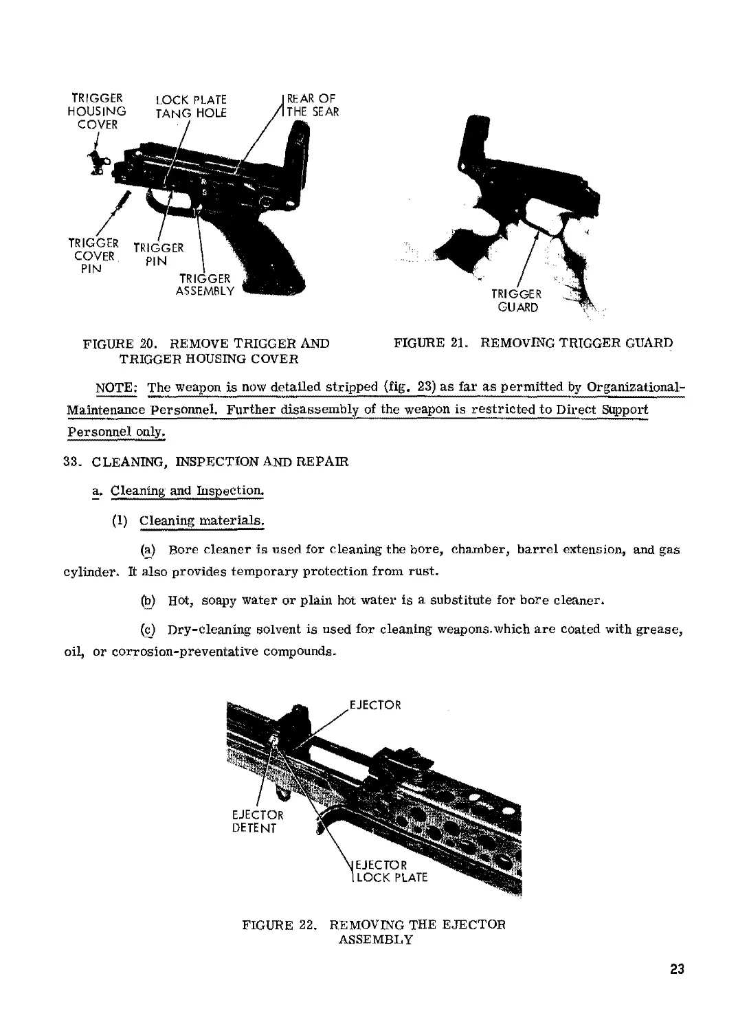
h. D is as s e m b ly of the Tr Igger Hou s ing Gr oup,
(1) Hold the trigger housing group in the vertical position. Insert the point of a car-
tridge into the hole that the lock plate tang is engaged in and push the lock plate forward as
shown in figure 19, The lock plate must remain forward during disassembly of the trigger
housing group so that the trigger pins can be removed.
(2) Push out the trigger pin and the trigger housing cover pin (fig. 20) and remove the
trigger housing cover (fig. 20). Remove the trigger by pushing down on the rear of the sear and
pushing up on the trigger assembly,
(3) Remove the lock plate by grasping the extended front edge and remove.
(4) Remove the trigger guard by pushing down on the front of the guard until it unlatches
(fig. 21). Remove the trigger guard from rear notch.
CARRIER
FIGURE 18. REMOVING CAM PIN AND
BOLT
22
CARTRIDGE
LOCK
PLATE
FIGURE 19, PUSHING LOCK PLATE
FORWARD
FIGURE 20. REMOVE TRIGGER AND FIGURE 21. REMOVING TRIGGER GUARD
TRIGGER HOUSING COVER
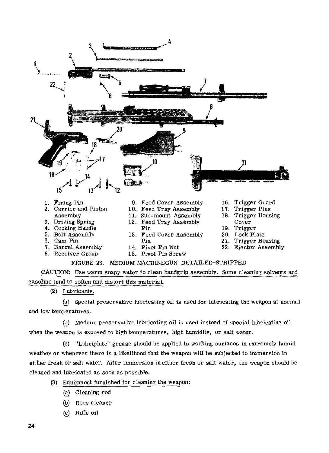
NOTE: The weapon is now detailed stripped (fig. 23) as far as permitted by Organizational-
Maintenance personnel. Further disassembly of the weapon is restricted to Direct Support
Personnel only.
33. cleaning, inspection and repair
a. Cleaning and Inspection.
(1) Cleaning materials.
(a) Bore cleaner is used for cleaning the bore, chamber, barrel extension, and gas
cylinder. It also provides temporary protection from rust.
(b) Hot, soapy water or plain hot water is a substitute for bore cleaner.
(c) Dry-cleaning solvent is used for cleaning weapons.which are coated with grease,
oil, or corrosion-preventative compounds.
FIGURE 22. REMOVING THE EJECTOR
ASSEMBLY
23
4
1. Firing Pin
2. Carrier and Piston
Assembly
3, Driving Spring
4. Cocking Handle
5. Bolt Assembly
6. Cam Pin
7. Barrel Assembly
8. Receiver Group
9, Feed Cover Assembly
10. Feed Tray Assembly
11. Sub-mount Assembly
12. Feed Tray Assembly
Pin
13. Feed Cover Assembly
Pin
14. Pivot Pin Nut
15. Pivot Pin Screw
16. Trigger Guard
17. Trigger Pins
18. Trigger Housing
Cover
19. Trigger
20. Lock Plate
21. Trigger Housing
22. Ejector Assembly
FIGURE 23. MEDIUM MACHINEGUN DETAILED-STRIPPED
CAUTION: Use warm soapy water to clean handgrip assembly. Some cleaning solvents and
gasoline tend to soften and distort this material.
(2) Lubricants.
(a) Special preservative lubricating oil is used for lubricating the weapon at normal
and low temperatures.
(b) Medium preservative lubricating oil is used instead of special lubricating oil
when the weapon is exposed to high temperatures, high humidity, or salt water.
(c) "Lubriplate’' grease should be applied to working surfaces in extremely humid
weather or whenever there is a likelihood that the weapon will be subjected to immersion in
either fresh or salt water. After immersion in either fresh or salt water, the weapon should be
cleaned and lubricated as soon as possible.
(3) Equipment furnished for cleaning the weapon:
(a) Cleaning rod
(b) Bore cleaner
(c) Rifle oil
24
(d) Brushes (See Appendix IL)
(e) Cleaning patches. Satisfactory caliber 5.56mm patches can be obtained by
cutting . 30 caliber patches into quarters.
(4) Before firing.
(a) The bore and chamber should be cleaned and dried. A light coat of oil should be
placed on all metal parts except those which come in contact with ammunition.
(b) "Lubriplate” should be applied to the parts that show friction wear. This is
particularly important when the weapon is exposed to rain or salt water. A small amount of
Lubriplate is applied to those parts that show wear. Lubriplate is not used in extremely cold
temperatures or when the weapon is exposed to extremes of sand and dust.
(c) In cold climates (temperatures below freezing) the weapon must be kept free of
moisture and excess oil. Moisture and excess oil on the working parts cause them to operate
sluggishly or to fail completely. The weapon must be disassembled and wiped with a clean dry
cloth. Dry-cleaning solvent may be used if necessary to remove oil or grease. Parts that show
signs of wear may be wiped with a patch lightly dampened with a special preservative lubricating
oil. It is best to keep the weapon as close as possible to outside temperatures at all times due to
the collection of moisture which occurs when cold metal comes in contact with warm air. If the
weapon is brought into a warm room, it should be allowed to reach room temperatures so that
condensation will appear before it is cleaned,
(d) In hot, dry climates, the weapon must be cleaned daily, or more often to re-
move sand and/or dust from the bore and working parts. Tn sandy areas, the weapon should be
kept dry to prevent the collection of sand. The muzzle and receiver should be kept covered
during sand and dust storms.
(5) After firing.
(a.) The weapon must be cleaned after it lias been fired because firing produces de-
posits of primer fouling, powder ashes, carbon, and metal fouling. The ammunition has a non-
corrosive primer which makes cleaning easier, but no less important. The primer still leaves
a deposit that may collect moisture and promote rust If it is not removed. The cleaning de-
scribed below will remove all deposits except metal fouling which is relatively uncommon and
is removed by ordnance personnel.
(b) The weapon should be disassembled and cleaned in the following manner after
it has been fired.
1. Bore. Run patches dampened with bore cleaner or hot soapy water back and
forth through the bore several times. Next, attach the bore brush to the cleaning rod and run it
back and forth through the bore once or twice. Follow this with more wet patches. Run several
dry patches through the bore and inspect each patch as it is removed. The bore is clean when a
25
dry patch comes out clean with no evidence of fouling. Finally, run an oily patch through the
bore to leave a light coat of oil inside the barrel.
NOTE: The patch or brush must be pushed all the way through the bore before it is with-
drawn.
2. Chamber and barrel extension. Using the appropriate brushes (fig, 6) clean
the lugs of the barrel extension and the chamber. After removing the carbon, particles of dirt
and/or brass filings, dry the chamber with a clean patch, The lugs of the barrel extension
should be oiled lightly-
3. Gas cylinder. Using the appropriate brush (fig. 22) clean the inside of the gas
cylinder. Put two patches on the patch holder of the cleaning rod, moisten them with bore
cleaner and swab the cylinder bore. Dry the cylinder bore with clean dry patches. Use no
abrasives in cleaning the cylinder.
4. Carrier and piston assembly. Shake the gas cylinder assembly (fig. 16) to
determine if the inertia pin in the piston rod has free movement. И it is not free, remove the
roll pin and piston head and clean. Saturate patches with bore cleaner and wipe the exterior
surface of the piston as clean as possible. The piston does not need to have a shiny surface to
function properly. Do not use abrasives to clean the piston.
5. Face of the bolt. Clean the face of the bolt with a patch and bore cleaner-
Wipe with a dry patch, and oil the bolt lightly-
6. B01* cajt’rier. Remove all carbon and foreign materials from the bolt carrier
with a patch dampened with bore cleaner. Wipe off the bolt carrier with dry patches and apply
a light coat of oil.
Receiver group and trigger housing group. Inspect both groups for dirt and
brass filings. Clean both groups with the appropriate brush (fig. 22) and oil all surfaces lightly.
Place a drop of oil on each of the pins in the trigger housing group for lubrication.
8- Ejector. The ejector is spring actuated. It is important that it has free
movement. Visually inspect and manually operate ejector for proper function. Dirt, brass
filing, or lack of lubrication may hinder proper function.
9. Submount. Remove all rust, dirt and foreign matter from the submount
(fig, 6); apply a light coat of oil on all exposed surfaces. Place a few drops of oil on the locking
device.
36. REPLACEMENT OF PARTS.
All replacement parts (Appendix nt) are interchangeable and require no adjustments when
being installed in this weapon.
26
37. ASSEMBLY.
NOTE: The weapon should be assembled in the reverse order of disassembly.
a. Assembly of the Trigger Housing Group.
(1) Place the lock plate in the left side of the trigger housing group, as shown in figure
19, insuring that the lock plate is held in position by the two lock plate guide pins- The lock
plate must remain forward during assembly of the trigger housing group.
(2) Depressing the rear of the sear, insert the trigger from the the top of the trigger
housing.
(3) Replace the trigger pin.
(4) Replace the trigger housing cover (fig. 20) and insert the trigger housing cover pin.
(5) Align the trigger pins, and push the extending edge of the lock plate to the rear.
The front edge of the lock plate should be flush with the forward edge of the trigger housing, and
the lock plate tang should be seated in the lock plate tang hole (fig. 20).
(6) Replace the trigger guard (fig. 21) by engaging it in the notches provided,
b. Assembly of the Ejector, Ejector Spring, Detent and Lock Plate.
(1) Insert the ejector with the ejector spring and detent into the recess of the receiver.
(2) Depress the ejector detent and spring below the lock plate recess and insert the
lock plate in the slots of the receiver.
(3) Slide the lock plate over the detent until the detent pops up into the hole in the lock
plate.
£• Assembly of the Bolt Assembly, Cam Pin, and Firing Pin.
(1) Replace the bolt in the bolt carrier with the ejector groove in the bolt facing toward
the cam track in the bolt carrier.
(2) Insert the cam pin thru the cam track and into the cam pin hole in the bolt. The flat
side of the cam pin guide lug must be in line with the lower side of the bolt carrier, as shown in
figure 20.
(3) Replace the firing pin in the bolt carrier. Push down on the rear of the firing pin
until it is flush with the rear of the carrier cap assembly. Holding the firing pin in this position
rotate the carrier cap assembly 1/4 turn, so the tang on the carrier cap assembly is in the down-
ward position as shown in figure 16.
d. Assembly of the Cocking Handle, Barrel, Feed Tray, and Feed Cover, with the Receiver
Group.
(1) Replace the cocking handle (fig. 15).
27
(2) To replace the barrel assembly, depress the barrel latch (fig. 13) and insert, the
barrel into the receiver group. Lock the barrel into place by releasing the barrel latch.
(3) Replace the feed tray assembly (fig. 12).
(4) Replace the feed cover assembly and insert the feed cover assembly retaining pin.
e. Replacing the Trigger Housing Group on the Receiver Group. Place the trigger group on
the receiver group and replace the pivot pin nut. Screw the pivot pin screw into the pivot pin nut
until fingertight (fig. 10).
f. Replacing the Carrier-Piston, Bolt and Driving Spring Assemblies.
(1) Holding the machinegun in the left hand, muzzle pointing down, insert the carrier-
piston bolt assembly (fig, 9). The bolt must be in the forward position with the cam pin aligned
with the bolt carrier rail (fig. 16).
(2) Replace the driving spring assembly (fig. 8),
g. Locking the Trigger Group to the Receiver Group.
(1) Before rotating the trigger housing group upward, check to be sure that the take-
down pin has been pulled to the right as far as it will go. Then rotate the trigger housing group
upward and lock it to the receiver group with the take-down pin (fig. 7).
h. Functioning Test.
(1) A function test will be performed after assembly of the machinegun. A complete
function check of the weapon consists of checking its operation while the selector lever is in the
"S” (Safe), and "A” (Automatic) positions. The following sequence will be followed.
(a) Clear the machinegun. Place the selector lever on "S'* (Safe). Pull the cocking
handle to the rear. Return the cocking handle to its locked position. Pull the trigger. The
operating parts should not go into battery.
(b) Place the selector lever on "A" (Automatic). Pull the trigger. The operating
parts should go into battery-
28
CHAPTER 5
MAINTENANCE UNDER UNUSUAL CONDITIONS
36. EXTREME-COLD WEATHER MAINTENANCE
37, EXTREME-HOT WEATHER MAINTENANCE
38. MAINTENANCE AFTER AMPHIBIOUS OPERATION
29
CHAPTER 6
AMMUNITION
39. GENERAL
40* CARE, HANDLING, AND PRESERVATION
30
CHAPTER 7
41. GENERAL
destruction of materiel to prevent enemy use
31
APPENDIX I
REFERENCES
The following references should be consulted for additional procedures for the maintenance
of the materiel covered by this publication.
FM-23-67................Machinegun, 7.62mm, M60.
FM-3170.................Basic Cold Weather Manual.
TM 9-207 ...............Operation and Maintenance of
Army Material in Extreme
Cold Weather 0Q to -65°F.
32
APPENDIX П
BASIC ISSUE ITEMS LIST
Section I. PREFACE
1. GENERAL
This appendix is a list of the basic issue items that are required for stockage by first-echelon
maintenance. It includes the first-echelon maintenance tools and repair parts accompanying the
equipment, all of which constitute the major end item for issue to users.
2, EXPLANATION OF COLUMNS
a. Source, Maintenance, and Recoverability Code. This column lists a code that indicates
the selection status and source of supply of the repair part, the lowest echelon capable of install-
ing or manufacturing the repair part, and the rec over ability and expendability aspects of the
repair parts. An example of this code is P, O, R, The "P” indicates that the item is a mission
stockage list repair part that is procured and stocked on a national program basis, the "O"
indicates that the repair part is authorized to Organizational Maintenance, and the ”R" indicates
that the repair part is an expendable, recoverable item. When repair parts supply responsibility
lias been assigned to a technical service other than Ordnance, the basic number of the supplying
technical service is listed in the first position of the source Code, for example, ”11" for a
Signal Corps item. Refer to paragraph 4 for an explanation of all codes appearing in this manual.
b. Federal Stock Number. This column lists the Federal stock number which has been as-
signed by the Cataloging Division, Armed Forces Supply Support Center.
c. Descript! on. This column lists the Federal item name (shown in capital letters) and any
additional description required for supply operations. The abbreviation ”w/e" (with equipment)
when used as a portion of the nomenclature indicates that the major item or major combination
includes all armament, equipment, accessories, and repair parts issued with the item. The
technical service or manufacturer's part number is also included for reference.
d. Unit of Issue. This column lists the minimum quantity that will be supplied. All items
are considered as each except where the unit of issue is shown as ft., in., such as for bulk
materials; the requisition should indicate the exact amount that is required, for example, 6 ft.
e. Quantity Authorized. This column lists the quantity of the listed item authorized for
stockage by first echelon.
f. Illustration. This column indicates the figure number of the illustration that depicts the
item. When more than one item appears on an illustration, the item number is also indicated.
33
3. ABBREVIATIONS
assy .................. . . ........................................... assembly(ies)
cal........................................................................... caliber
ctg...........................................................................cartridge
ctn............................................................................. carton
equip. .......................................................................equipment
wdn .............................................................................wooden
w/e ......................................................................with equipment
4. EXPLANATION OF CODES
a. Source.
Code
P
b. Maintenance Level,
Code
О
Explanation
Applied to repair parts which are high -
mortality parts procured by technical
services, stocked in and supplied from
the technical service depot system, and
authorized for use at indicated main-
tenance echelons.
Explanation
Organizational Maintenance
c. Recoverability.
Code Explanation
NR Indicates a repair part or assembly that
is nonexpendable and recoverable and is
economically repairable.
R Indicates a repair part or assembly that
is expendable and recoverable and is
economically repairable and, when
available, is furnished by supply on an
exchange basis.
d. Illustration
Code Explanation
NT Indicates a standard military issue item
and therefore not illustrated in this
handbook.
34
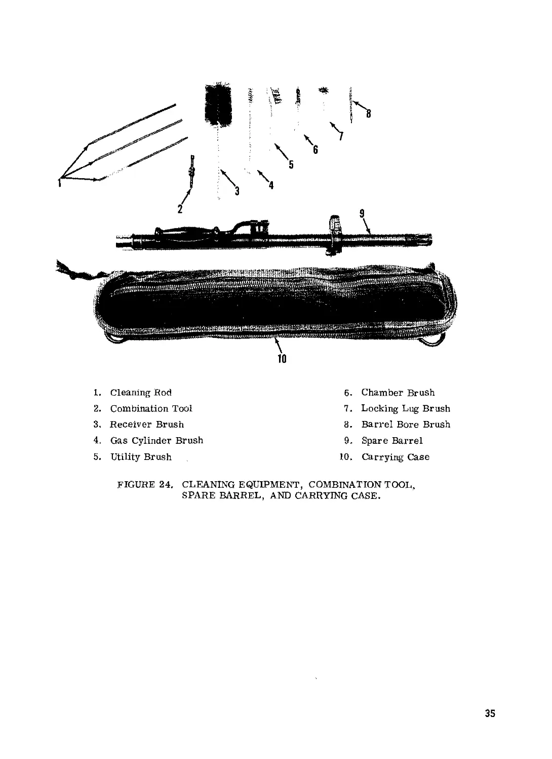
1. Cleaning Rod
2. Combination Tool
3. Receiver Brush
4. Gas Cylinder Brush
5. Utility Brush
6. Chamber Brush
7. Locking Lug Brush
8. Barrel Bore Brush
9, Spare Barrel
10. Carrying Case
FIGURE 24, CLEANING EQUIPMENT, COMBINATION TOOL,
SPARE BARREL, AND CARRYING CASE.
35
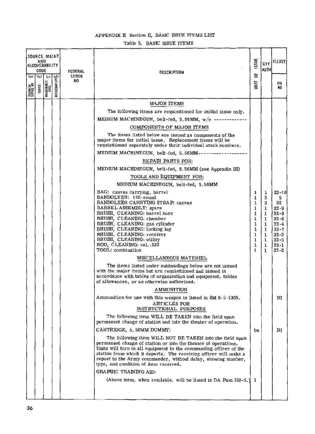
APPENDIX П Section П, BASIC ISSUE ITEMS LIST
Table 5. BASIC ISSUE ITEMS
SOURCE, MAIN! AND RECOVERABILITY CODE FEDERAL STOCK NO DESCRIPTION UNIT OF ISSUE QTY AUTH ILLUST
7 OH DlAJiS i' TO №31 (b) s (c) z ж (d) E S 0 FIG NO
MAJOR ITEMS
The following items are requisitioned for initial issue only.
MEDIUM MACHINEGUN, belt-fed, 5.56MM, w/e
COMPONENTS OF MAJOR ITEMS
The items listed below are issued as components of the major items for initial issue, Replacement items will be requisitioned separately under their individual stock numbers.
MEDIUM MACHINEGUN, belt-fed, 5. 56MM
REPAIR PARTS FOR:
MEDIUM MACHINEGUN, belt-fed, 5. 56MM (see Appendix HI)
TOOLS AND EQUIPMENT FOR:
MEDIUM MACHINEGUN, belt-fed, 5.56MM
BAG; canvas carrying', barrel BANDOLE ER; 150 - round BANDOLEER CARRYING STRAP: canvas BARREL ASSEMBLY: spare BRUSH, CLEANING: barrel bore BRUSH, CLEANING; chamber BRUSH, CLEANING: gas cylinder BRUSH, CLEANING: locking lug BRUSH, CLEANING: receiver BRUSH, CLEANING: utility ROD, CLEANING: cal..223 TOOL: combination 1 1 1 1 1 1 1 1 1 1 1 1 1 3 3 1 1 1 1 1 1 1 1 1 22-10 5 NI 22-9 22-8 22-6 22-4 22-7 22-3 22-5 22-1 22-2
MISCELLANEOUS MATERIEL
The items listed under subheadings below are not issued with the major items but are requisitioned and issued in accordance with tables of organization and equipment, tables of allowances, or aa otherwise authorized.
AMMUNITION
Ammunition for use with this weapon is listed in SM 9-5-1305. ARTICLES FOR INSTRUCTIONAL PURPOSES NI
The following item WILL BE TAKEN into the field upon permanent change of station and into the theater of operation.
CARTRIDGE, 5. 56MM DUMMY." bx NI
The following item WILL NOT BE TAKEN into the field upon permanent change of station or into the theater of operations. Units will turn in all equipment to the commanding officer of the station from which it departs. The receiving officer will make a report to the Army commander, without delay, showing number, type, and condition of item received.
GRAPHIC TRAINING AID:
(Above item, when available, will be listed in DA Pam 310-5/ 1
36
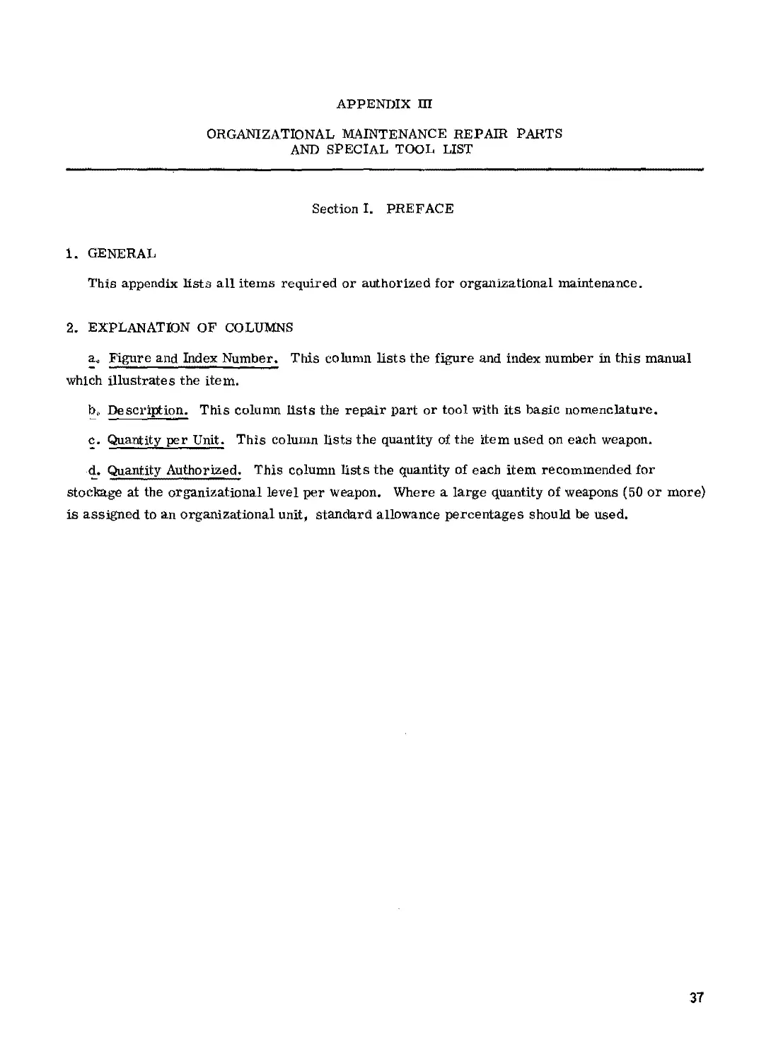
APPENDIX Ш
ORGANIZATIONAL MAINTENANCE REPAIR PARTS
AND SPECIAL TOOL LIST
Section I. PREFACE
1. GENERAL
This appendix lists all items required or authorized for organizational maintenance.
2. EXPLANATION OF COLUMNS
ac Figure and Index Number. This column lists the figure and index number in this manual
which illustrates the item.
b(, Description. This column lists the repair part or tool with its basic nomenclature.
c. Quantity per Unit. This column lists the quantity of the item used on each weapon.
d. Quantity Authorized. This column lists the quantity of each item recommended for
stockage at the organizational level per weapon. Where a large quantity of weapons (50 or more)
is assigned to an organizational unit, standard allowance percentages should be used.
37
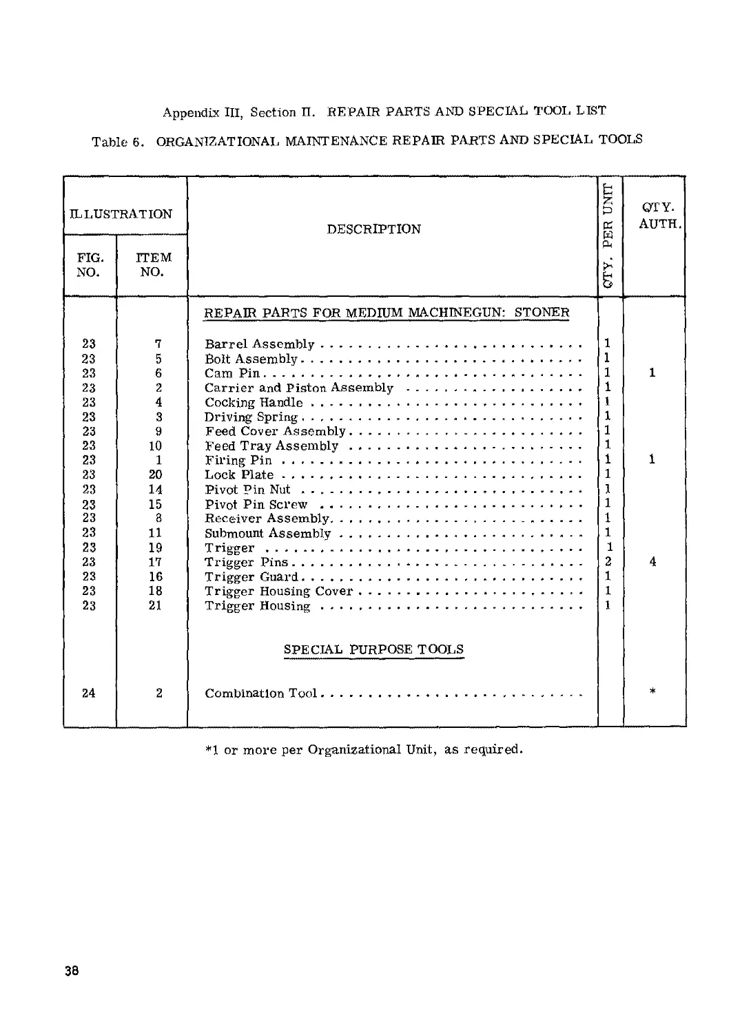
Appendix III, Section П. REPAIR PARTS AND SPECIAL TOOL LIST
Table 6. ORGANIZATIONAL MAINTENANCE REPAIR PARTS AND SPECIAL TOOLS
ILLUSTRATION DESCRIPTION QTY, PER UNIT QTY. AUTH.
FIG. NO. ГГЕМ NO.
REPAIR PARTS FOR MEDIUM MACHINEGUN: STONER
23 7 Barrel Assembly * 1
23 5 Bolt Assembly 1
23 6 Cam Pin 1 1
23 2 Carrier and Piston Assembly . 1
23 4 Cocking Handle . 1
23 3 Driving Spring 1
23 9 Feed Cover Assembly 1
23 10 Feed Tray Assembly * 1
23 1 Firing Pin 1 1
23 20 Lock Plate 1
23 14 Pivot Pin Nut 1
23 15 Pivot Pin Screw 1
23 8 Receiver Assembly 1
23 11 Submount Assembly 1
23 19 Trigger 1
23 17 Trigger Pins 2 4
23 16 Trigger Guard. 1
23 18 Trigger Housing Cover 1
23 21 Trigger Housing SPECIAL PURPOSE TOOLS 1
24 2 Combination Tool *
*1 or more per Organizational Unit, as required.
38