/


Author: Miessler G.L. Donald A.T.
Tags: chemistry


Text
Inorganic
Chemistry
Third Edition
Gary L Miessler * Donald A. Tarr
Inorganic
Chemistry
Third Edition
GARY L. MIESSLER DONALD A. TARR
St. Olaf College
Northfield, Minnesota
PEARSON
Pearson Education International
Brief Contents
1
2
3
4
5
6
7
8
9
10
11
12
13
14
15
16
Appendix A
Appendix B-1
Appendix B-2
Appendix B-3
Appendix B-4
Appendix B-5
Appendix B-6
Appendix B-7
Appendix C
Appendix D
Preface xiii
Introduction to Inorganic Chemistry 1
Atomic Structure 15
Simple Bonding Theory 51
Symmetry and Group Theory 76
Molecular Orbitals 116
Acid-Base and Donor-Acceptor Chemistry 165
The Crystalline Solid State 207
Chemistry of the Main Group Elements 240
Coordination Chemistry I: Structures and Isomers 299
Coordination Chemistry II: Bonding 337
Coordination Chemistry III: Electronic Spectra 379
Coordination Chemistry IV: Reactions and Mechanisms 412
Organometallic Chemistry 454
Organometallic Reactions and Catalysis 520
Parallels Between Main Group and Organometallic Chemistry
Bioinorganic and Environmental Chemistry 594
Answers to Exercises 637
Ionic Radii 668
Ionization Energy 671
Electron Affinity 672
Electronegativity 673
Absolute Hardness Parameters 674
CA,EA,CB, and EB Values 675
Latimer Diagrams for Selected Elements 676
Character Tables 681
Electron-Dot Diagrams and Formal Charge 691
Index 697
556
iii
Contents
PREFACE xiii
1 INTRODUCTION TO INORGANIC CHEMISTRY 1
1-1 What is Inorganic Chemistry? 1
1-2 Contrasts with Organic Chemistry 1
1-3 Genesis of the Elements (The Big Bang) and Formation of the Earth 5
1-4 Nuclear Reactions and Radioactivity 8
1-5 Distribution of Elements on Earth 9
1-6 The History of Inorganic Chemistry 11
2 ATOMIC STRUCTURE 15
2-1 Historical Development of Atomic Theory 15
2-1-1 The Periodic Table 16
2-1-2 Discovery of Subatomic Particles and the Bohr Atom 17
2-2 The Schrodinger Equation 21
2-2-1 The Particle in a Box 23
2-2-2 Quantum Numbers and Atomic Wave Functions 25
2-2-3 The Aufbau Principle 34
2-2-4 Shielding 38
2-3 Periodic Properties of Atoms 43
2-3-1 Ionization Energy 43
2-3-2 Electron Affinity 44
2-3-3 Covalent and Ionic Radii 44
3 SIMPLE BONDING THEORY 51
3-1 Lewis Electron-Dot Diagrams 51
3-1-1 Resonance 52
3-1-2 Expanded Shells 53
3-1-3 Formal Charge 53
3-1-4 Multiple Bonds in Be and В Compounds 56
3-2 Valence Shell Electron Pair Repulsion Theory 57
3-2-1 Lone Pair Repulsion 59
3-2-2 Multiple Bonds 62
3-2-3 Electronegativity and Atomic Size Effects 63
3-2-4 Ligand Close-Packing 66
3-3 Polar Molecules 67
3-4 Hydrogen Bonding 69
V
VI Contents
4 SYMMETRY AND GROUP THEORY 76
4-1 Symmetry Elements and Operations 76
4-2 Point Groups 82
4-2-1 Groups of Low and High Symmetry 84
4-2-2 Other Groups 86
4-3 Properties and Representations of Groups 92
4-3-1 Matrices 92
4-3-2 Representations of Point Groups 94
4-3-3 Character Tables 97
4-4 Examples and Applications of Symmetry 102
4-4-1 Chirality 102
4-4-2 Molecular Vibrations 103
5 MOLECULAR ORBITALS 116
5-1 Formation of Molecular Orbitals from Atomic Orbitals 116
5-1-1 Molecular Orbitals from s Orbitals 117
5-1-2 Molecular Orbitals from p Orbitals 119
5-1-3 Molecular Orbitals from d Orbitals 120
5-1-4 Nonbonding Orbitals and Other Factors 122
5-2 Homonuclear Diatomic Molecules 122
5-2-1 Molecular Orbitals 122
5-2-2 Orbital Mixing 124
5-2-3 First and Second Row Molecules 125
5-2-4 Photoelectron Spectroscopy 130
5-2-5 Correlation Diagrams 132
5-3 Heteronuclear Diatomic Molecules 134
5-3-1 Polar Bonds 134
5-3-2 Ionic Compounds and Molecular Orbitals 138
5-4 Molecular Orbitals for Larger Molecules 139
5-4-1 FHF" 140
5-4-2 CO2 143
5-4-3 H2O 148
5-4-4 NH3 151
5-4-5 BF3 154
5-4-6 Molecular Shapes 157
5-4-7 Hybrid Orbitals 157
5-5 Expanded Shells and Molecular Orbitals 161
6 ACID-BASE AND DONOR-ACCEPTOR CHEMISTRY 165
6-1 Acid-Base Concepts as Organizing Concepts 165
6-1-1 History 165
6-2 Major Acid-Base Concepts 166
6-2-1 Arrhenius Concept 166
6-2-2 Bronsted-Lowry Concept 167
6-2-3 Solvent System Concept 168
6-2-4 Lewis Concept 170
6-2-5 Frontier Orbitals and Acid-Base Reactions 171
6-2-6 Hydrogen Bonding 174
6-2-7 Electronic Spectra (Including Charge Transfer) 178
Contents VII
6-3 Hard and Soft Acids and Bases 179
6-3-1 Theory of Hard and Soft Acids and Bases 183
6-3-2 Quantitative Measures 187
6-4 Acid and Base Strength 192
6-4-1 Measurement of Acid-Base Interactions 192
6-4-2 Thermodynamic Measurements 193
6-4-3 Proton Affinity 194
6-4-4 Acidity and Basicity of Binary Hydrogen Compounds 194
6-4-5 Inductive Effects 196
6-4-6 Strength of Oxy acids 196
6-4-7 Acidity of Cations in Aqueous Solution 197
6-4-8 Steric Effects 199
6-4-9 Solvation and Acid-Base Strength 200
6-4-10 Nonaqueous Solvents and Acid-Base Strength 201
6-4-11 Superacids 203
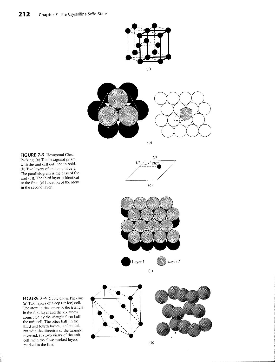
7 THE CRYSTALLINE SOLID STATE 207
7-1 Formulas and Structures 207
7-1-1 Simple Structures 207
7-1-2 Structures of Binary Compounds 214
7-1-3 More Complex Compounds 218
7-1-4 Radius Ratio 218
7-2 Thermodynamics of Ionic Crystal Formation 220
7-2-1 Lattice Energy and Madelung Constant 220
7-2-2 Solubility, Ion Size (Large-Large and Small-Small), and HSAB 222
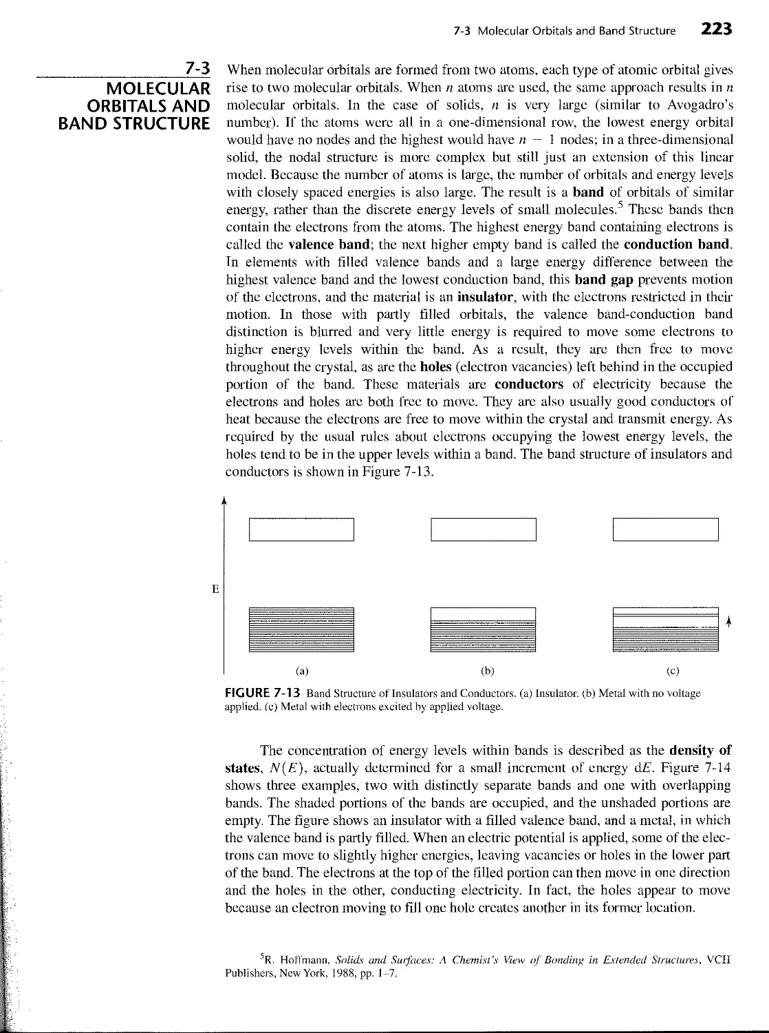
7-3 Molecular Orbitals and Band Structure 223
7-3-1 Diodes, The Photovoltaic Effect, and
Light-Emitting Diodes 226
7-4 Superconductivity 228
7-4-1 Low-Temperature Superconducting Alloys 228
7-4-2 The Theory of Superconductivity (Cooper Pairs) 229
7-4-3 High-Temperature Superconductors
(YBa^Cu ft)7 and Related Compounds) 230
7-5 Bonding in Ionic Crystals 231
7-6 Imperfections in Solids 231
7-7 Silicates 232
8 CHEMISTRY OF THE MAIN GROUP ELEMENTS 240
8-1 General Trends in Main Group Chemistry 241
8-1-1 Physical Properties 241
8-1 -2 Electronegativity 243
8-1-3 Ionization Energy 244
8-1 -4 Chemical Properties 244
8-2 Hydrogen 247
8-2-1 Chemical Properties 248
8-3 Group 1 (IA): The Alkali Metals 249
8-3-1 The Elements 249
8-3-2 Chemical Properties 250
8-4 Group 2 (IIA): The Alkaline Earths 253
8-4-1 The Elements 253
8-4-2 Chemical Properties 254
VIII Contents
8-5 Group 13 (IIIA) 256
8-5-1 The Elements 256
8-5-2 Other Chemistry of the Group 13 (IIIA) Elements 260
8-6 Group 14 (IVA) 261
8-6-1 The Elements 261
8-6-2 Compounds 267
8-7 Group 15 (VA) 272
8-7-1 The Elements 272
8-7-2 Compounds 274
8-8 Group 16 (VIA) 279
8-8-1 The Elements 279
8-9 Group 17 (VIIA): The Halogens 285
8-9-1 The Elements 285
8-10 Group 18 (VIIIA): The Noble Gases 291
8-10-1 The Elements 291
8-10-2 Chemistry 292
9 COORDINATION CHEMISTRY I: STRUCTURES AND
ISOMERS 299
9-1 History 299
9-2 Nomenclature 304
9-3 Isomerism 309
9-3-1 Stereoisomers 310
9-3-2 Four-Coordinate Complexes 310
9-3-3 Chirality 311
9-3-4 Six-Coordinate Complexes 311
9-3-5 Combinations of Chelate Rings 315
9-3-6 Ligand Ring Conformation 318
9-3-7 Constitutional Isomers 319
9-3-8 Experimental Separation and Identification of Isomers 322
9-4 Coordination Numbers and Structures 323
9-4-1 Low Coordination Numbers (CN = 1,2, and 3) 325
9-4-2 Coordination Number 4 327
9-4-3 Coordination Number 5 328
9-4-4 Coordination Number 6 329
9-4-5 Coordination Number 7 331
9-4-6 Coordination Number 8 332
9-4-7 Larger Coordination Numbers 333
10 COORDINATION CHEMISTRY II: BONDING 337
10-1 Experimental Evidence for Electronic Structures 337
10-1-1 Thermodynamic Data 337
10-1 -2 Magnetic Susceptibility 339
10-1-3 Electronic Spectra 342
10-1-4 Coordination Numbers and Molecular Shapes 342
10-2 Theories of Electronic Structure 342
10-2-1 Terminology 342
10-2-2 Historical Background 343
10-3 Ligand Field Theory 345
10-3-1 Molecular Orbitals for Octahedral Complexes 345
10-3-2 Orbital Splitting and Electron Spin 346
10-3-3 Ligand Field Stabilization Energy 350
Contents
IX
10-3-4 Pi Bonding 352
10-3-5 Square-Planar Complexes 356
10-3-6 Tetrahedral Complexes 360
10-4 Angular Overlap 362
10-4-1 Sigma-Donor Interactions 362
10-4-2 Pi-Acceptor Interactions 364
10-4-3 Pi-Donor Interactions 366
10-4-4 Types of Ligands and the Spectrochemical Series 367
10-4-5 Magnitudes of e„, e^, and Д 368
10-5 The Jahn-Teller Effect 370
10-6 Four- and Six-Coordinate Preferences 373
10-7 Other Shapes 375
11 COORDINATION CHEMISTRY III: ELECTRONIC
SPECTRA 379
11-1 Absorption of Light 380
11-1-1 Beer-Lambert Absorption Law 380
11 -2 Quantum Numbers of Multielectron Atoms 382
11-2-1 Spin-Orbit Coupling 387
11-3 Electronic Spectra of Coordination Compounds 388
11-3-1 Selection Rules 390
11-3-2 Correlation Diagrams 391
11-3-3 Tanabe-Sugano Diagrams 393
11-3-4 Jahn-Teller Distortions and Spectra 398
11-3-5 Examples of Applications of Tanabe-Sugano Diagrams:
Determining До from Spectra 401
11-3-6 Tetrahedral Complexes 406
11-3-7 Charge-Transfer Spectra 407
12 COORDINATION CHEMISTRY IV: REACTIONS AND
MECHANISMS 412
12-1 History and Principles 412
12-2 Substitution Reactions 414
12-2-1 Inert and Labile Compounds 414
12-2-2 Mechanisms of Substitution 415
12-3 Kinetic Consequences of Reaction Pathways 417
12-3-1 Dissociation (D) 417
12-3-2 Interchange (I) 418
12-3-3 Association (A) 419
12-4 Experimental Evidence in Octahedral Substitution 420
12-4-1 Dissociation 420
12-4-2 Linear Free Energy Relationships 423
12-4-3 Associative Mechanisms 425
12-4-4 The Conjugate Base Mechanism 426
12-4-5 The Kinetic Chelate Effect 428
12-5 Stereochemistry of Reactions 429
12-5-1 Substitution in trans Complexes 430
12-5-2 Substitution in cis Complexes 432
12-5-3 Isomerization of Chelate Rings 433
12-6 Substitution Reactions of Square-Planar Complexes 434
12-6-1 Kinetics and Stereochemistry of Square-Planar Substitutions 434
12-6-2 Evidence for Associative Reactions 435
X Contents
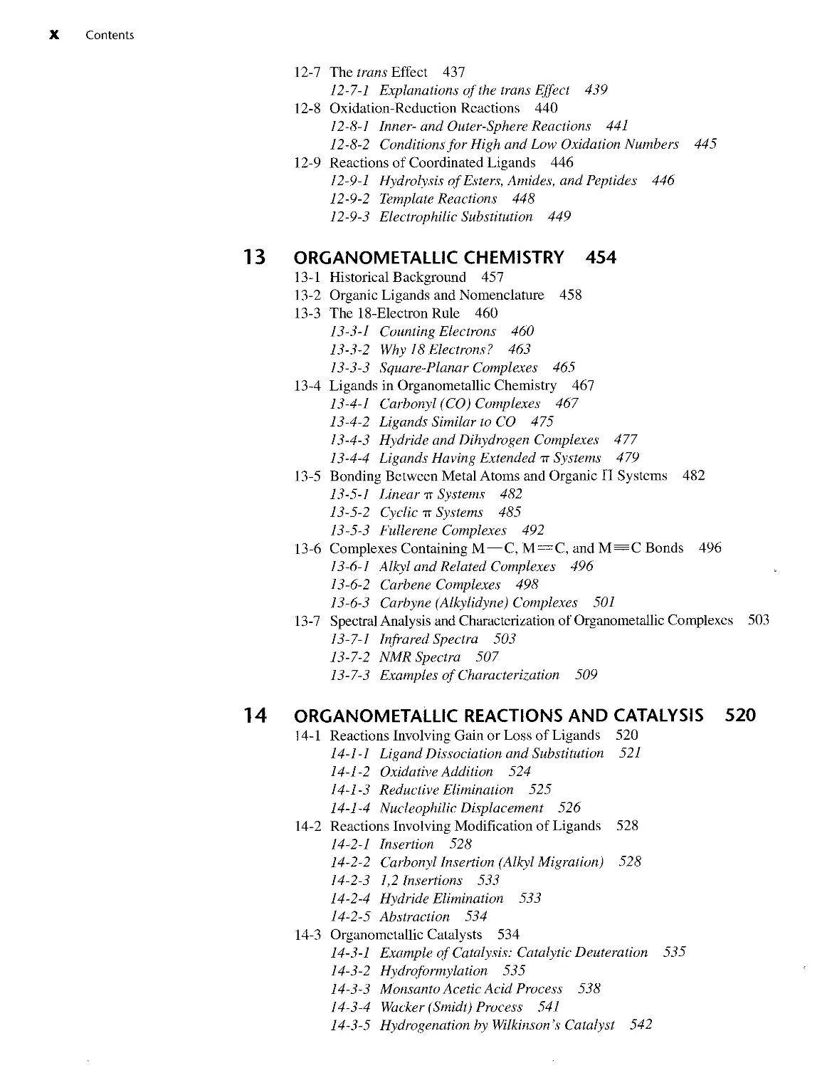
12-7 The trans Effect 437 12-7-1 Explanations of the trans Effect 439 12-8 Oxidation-Reduction Reactions 440 12-8-1 Inner-and Outer-Sphere Reactions 441 12-8-2 Conditions for High and Low Oxidation Numbers 445 12-9 Reactions of Coordinated Ligands 446 12-9-1 Hydrolysis of Esters, Amides, and Peptides 446 12-9-2 Template Reactions 448 12-9-3 Electrophilic Substitution 449
13 ORGANOMETALLIC CHEMISTRY 454 13-1 Historical Background 457 13-2 Organic Ligands and Nomenclature 458 13-3 The 18-Electron Rule 460 13-3-1 Counting Electrons 460 13-3-2 Why 18 Electrons? 463 13-3-3 Square-Planar Complexes 465 13-4 Ligands in Organometallic Chemistry 467 13-4-1 Carbonyl (CO) Complexes 467 13-4-2 Ligands Similar to CO 475 13-4-3 Hydride and Dihydrogen Complexes 477 13-4-4 Ligands Having Extended tt Systems 479 13-5 Bonding Between Metal Atoms and Organic П Systems 482 13-5-1 Linear tt Systems 482 13-5-2 Cyclic tt Systems 485 13-5-3 Fullerene Complexes 492 13-6 Complexes Containing M — C, M=C, and M = C Bonds 496 13-6-1 Alkyl and Related Complexes 496 13-6-2 Carbene Complexes 498 13-6-3 Carbyne (Alkylidyne) Complexes 501 13-7 Spectral Analysis and Characterization of Organometallic Complexes 503 13-7-1 Infrared Spectra 503 13-7-2 NMR Spectra 507 13-7-3 Examples of Characterization 509
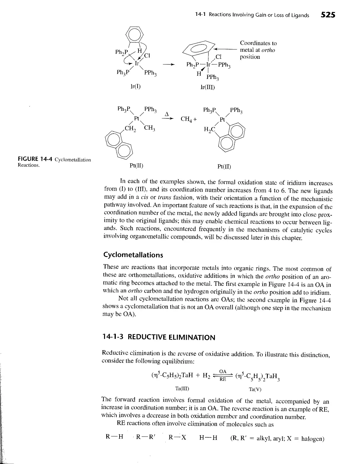
14 ORGANOMETALLIC REACTIONS AND CATALYSIS 520 14-1 Reactions Involving Gain or Loss of Ligands 520 14-1-1 Ligand Dissociation and Substitution 521 14-1-2 Oxidative Addition 524 14-1-3 Reductive Elimination 525 14-1-4 Nucleophilic Displacement 526 14-2 Reactions Involving Modification of Ligands 528 14-2-1 Insertion 528 14-2-2 Carbonyl Insertion (Alkyl Migration) 528 14-2-3 1,2 Insertions 533 14-2-4 Hydride Elimination 533 14-2-5 Ab str action 534 14-3 Organometallic Catalysts 534 14-3-1 Example of Catalysis: Catalytic Deuteration 535 14-3-2 Hydroformylation 535 14-3-3 Monsanto Acetic Acid Process 538 14-3-4 Wacker (Smidt) Process 541 14-3-5 Hydrogenation by Wilkinson’s Catalyst 542
Contents XI
16
APPENDIX A
APPENDIX B-1
APPENDIX B-2
APPENDIX B-3
APPENDIX B-4
APPENDIX B-5
APPENDIX B-6
APPENDIX B-7
APPENDIX C
APPENDIX D
14-3-6 Olefin Metathesis 544
14-4 Heterogeneous Catalysts 548
14-4-1 Ziegler-Natta Polymerizations 548
14-4-2 Water Gas Reaction 549
PARALLELS BETWEEN MAIN GROUP AND
ORGANOMETALLIC CHEMISTRY 556
15-1 Main Group Parallels with Binary Carbonyl Complexes 556
15-2 The Isolobal Analogy 558
15-2-1 Extensions of the Analogy 561
15-2-2 Examples of Applications of the Analogy 565
15-3 Metal-Metal Bonds 566
15-3-1 Multiple Metal-Metal Bonds 568
15-4 Cluster Compounds 572
15-4-1 Boranes 572
15-4-2 Heteroboranes 577
15-4-3 Metallaboranes and Metallacarboranes 579
15-4-4 Carbonyl Clusters 582
15-4-5 Carbide Clusters 587
15-4-6 Additional Comments on Clusters 588
BIOINORGANIC AND ENVIRONMENTAL CHEMISTRY 594
16-1 Porphyrins and Related Complexes 596
16-1-1 Iron Porphyrins 597
16-1-2 Similar Ring Compounds 600
16-2 Other Iron Compounds 604
16-3 Zinc and Copper Enzymes 606
16-4 Nitrogen Fixation 611
16-5 Nitric Oxide 616
16-6 Inorganic Medicinal Compounds 618
16-6-1 Cisplatin and Related Complexes 618
16-6-2 Auranofin and Arthritis Treatment 622
16-6-3 Vanadium Complexes in Medicine 622
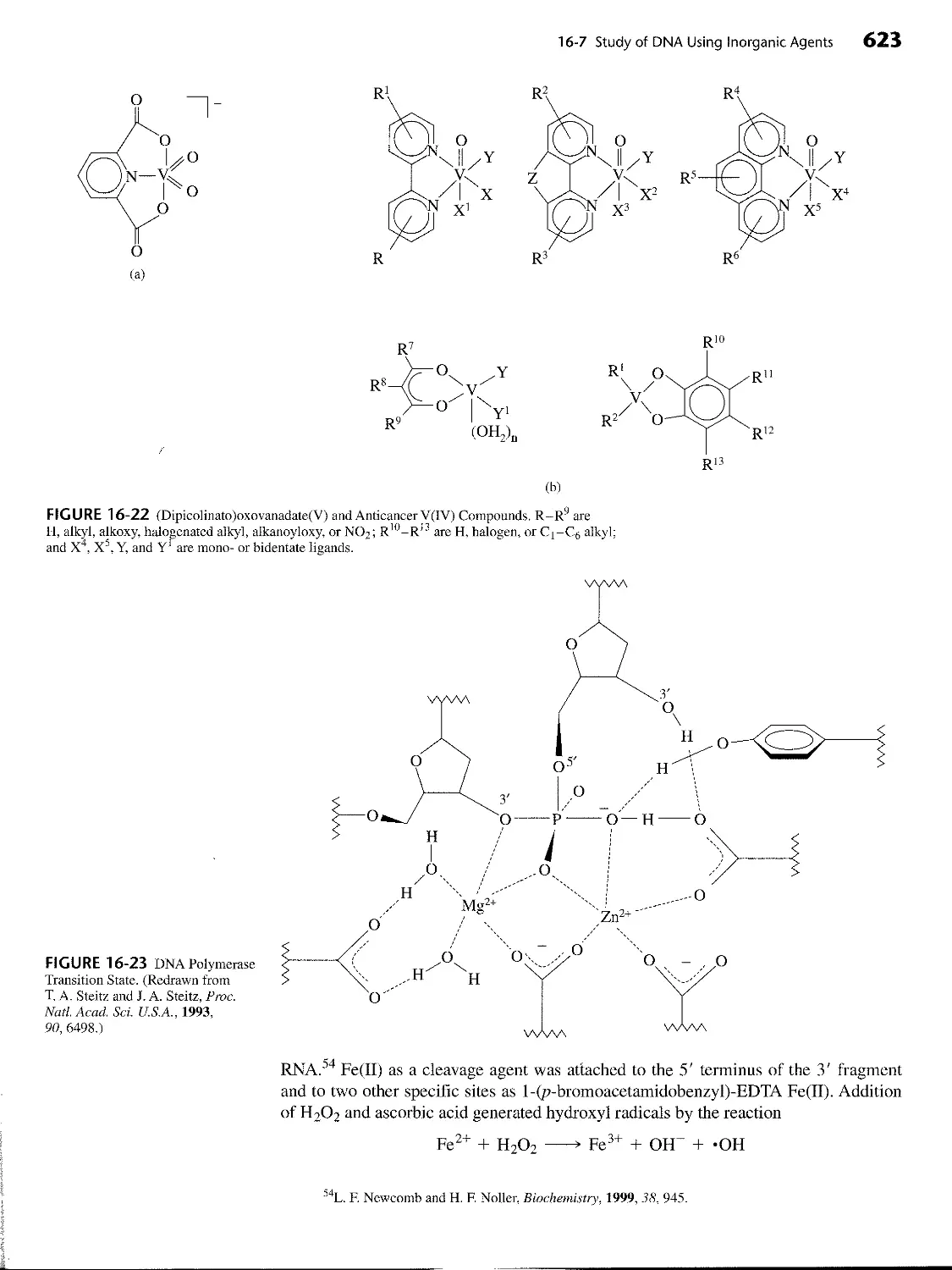
16-7 Study of DNA Using Inorganic Agents 622
16-8 Environmental Chemistry 624
16-8-1 Metals 624
16-8-2 Nonmetals 629
ANSWERS TO EXERCISES 637
IONIC RADII 668
IONIZATION ENERGY 671
ELECTRON AFFINITY 672
ELECTRONEGATIVITY 673
ABSOLUTE HARDNESS PARAMETERS 674
CA, Ea, Cb, AND Eb VALUES 675
LATIMER DIAGRAMS FOR SELECTED ELEMENTS 676
CHARACTER TABLES 681
ELECTRON-DOT DIAGRAMS AND FORMAL CHARGE 691
INDEX 697
CHAPTER
1
Introduction to
Inorganic Chemistry
_________1-1
WHAT IS
INORGANIC
CHEMISTRY?
If organic chemistry is defined as the chemistry of hydrocarbon compounds and their
derivatives, inorganic chemistry can be described broadly as the chemistry of “every-
thing else.” This includes all the remaining elements in the periodic table, as well as car-
bon, which plays a major role in many inorganic compounds. Organometallic
chemistry, a very large and rapidly growing field, bridges both areas by considering
compounds containing direct metal-carbon bonds, and includes catalysis of many or-
ganic reactions. Bioinorganic chemistry bridges biochemistry and inorganic chemistry,
and environmental chemistry includes the study of both inorganic and organic com-
pounds. As can be imagined, the inorganic realm is extremely broad, providing essen-
tially limitless areas for investigation.
___________1-2
CONTRASTS
WITH ORGANIC
CHEMISTRY
Some comparisons between organic and inorganic compounds are in order. In both
areas, single, double, and triple covalent bonds are found, as shown in Figure 1-1; for
inorganic compounds, these include direct metal-metal bonds and metal-carbon bonds.
However, although the maximum number of bonds between two carbon atoms is three,
there are many compounds containing quadruple bonds between metal atoms. In
addition to the sigma and pi bonds common in organic chemistry, quadruply bonded
metal atoms contain a delta (8) bond (Figure 1-2); a combination of one sigma bond,
two pi bonds, and one delta bond makes up the quadruple bond. The delta bond is
possible in these cases because metal atoms have d orbitals to use in bonding, whereas
carbon has only s and p orbitals available.
In organic compounds, hydrogen is nearly always bonded to a single carbon. In
inorganic compounds, especially of the Group 13 (IIIA) elements, hydrogen is fre-
quently encountered as a bridging atom between two or more other atoms. Bridging hy-
drogen atoms can also occur in metal cluster compounds. In these clusters, hydrogen
atoms form bridges across edges or faces of polyhedra of metal atoms. Alkyl groups
may also act as bridges in inorganic compounds, a function rarely encountered in or-
ganic chemistry (except in reaction intermediates). Examples of terminal and bridging
hydrogen atoms and alkyl groups in inorganic compounds are shown in Figure 1-3.
1
2 Chapter 1 Introduction to Inorganic Chemistry
Inorganic
Organometallic
Organic
F—F [Hg—Hg]2+
ОС—Mn—CH3
H H
C=C
H H
0=0
Cl C1/C112
Ch. \ //
H—c=c—H N=N Os=Os
C1 z V"ci
Cl Cl
C1 Cl CL'Cl П2-
Rc=Rc
УV Cl
cf Cl Cl 1
FIGURE 1-1 Single and Multiple Bonds in Organic and Inorganic Molecules.
I—Cr=C—CH
FIGURE 1-2 Examples of
Bonding Interactions.
3
Some of the most striking differences between the chemistry of carbon and that of
many other elements are in coordination number and geometry. Although carbon is usu-
ally limited to a maximum coordination number of four (a maximum of four atoms
bonded to carbon, as in CH4), inorganic compounds having coordination numbers of
five, six, seven, and more are very common; the most common coordination geometry is
an octahedral arrangement around a central atom, as shown for |TiF(, |3 in Figure 1-4.
1-2 Contrasts with Organic Chemistry 3
FIGURE 1-3 Examples of
Inorganic Compounds Containing
Terminal and Bridging Hydrogens
and Alkyl Groups.
Each CH3 bridges a face
of the Li4 tetrahedron
FIGURE 1-4 Examples of
Geometries of Inorganic
Compounds.
F „Л3-
F — Ti— F
F^f
Furthermore, inorganic compounds present coordination geometries different from
those found for carbon. For example, although 4-coordinate carbon is nearly always
tetrahedral, both tetrahedral and square planar shapes occur for 4-coordinate compounds
of both metals and nonmetals. When metals are the central atoms, with anions or neutral
molecules bonded to them (frequently through N, O, or S), these are called coordination
complexes; when carbon is the element directly bonded to metal atoms or ions, they are
called organometallic compounds.
The tetrahedral geometry usually found in 4-coordinate compounds of carbon
also occurs in a different form in some inorganic molecules. Methane contains four hy-
drogens in a regular tetrahedron around carbon. Elemental phosphorus is tetratomic
(P4) and also is tetrahedral, but with no central atom. Examples of some of the geome-
tries found for inorganic compounds are shown in Figure 1-4.
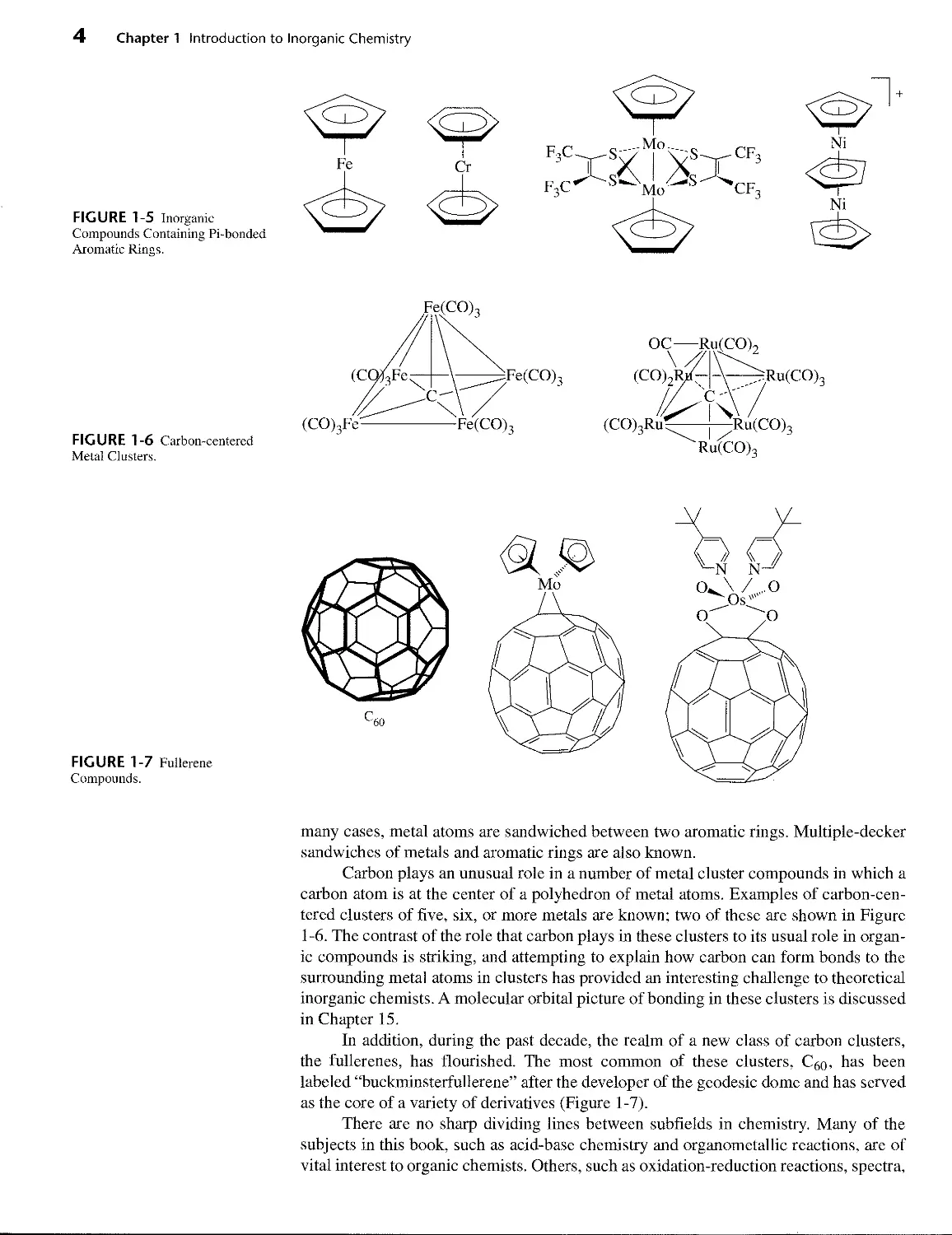
Aromatic rings are common in organic chemistry, and aryl groups can also form
sigma bonds to metals. However, aromatic rings can also bond to metals in a dramati-
cally different fashion using their pi orbitals, as shown in Figure 1-5. The result is a
metal atom bonded above the center of the ring, almost as if suspended in space. In
4
Chapter 1 Introduction to Inorganic Chemistry
FIGURE 1-6 Carbon-centered
Metal Clusters.
FIGURE 1-7 Fullerene
Compounds.
FIGURE 1-5 Inorganic
Compounds Containing Pi-bonded
Aromatic Rings.
ОС----Ru(CO)2
(CO)2]
(CO)3Ru
;Ru(CO)3
-^Ru(CO)3
RutC0)3
many cases, metal atoms are sandwiched between two aromatic rings. Multiple-decker
sandwiches of metals and aromatic rings are also known.
Carbon plays an unusual role in a number of metal cluster compounds in which a
carbon atom is at the center of a polyhedron of metal atoms. Examples of carbon-cen-
tered clusters of five, six, or more metals are known; two of these are shown in Figure
1 -6. The contrast of the role that carbon plays in these clusters to its usual role in organ-
ic compounds is striking, and attempting to explain how carbon can form bonds to the
surrounding metal atoms in clusters has provided an interesting challenge to theoretical
inorganic chemists. A molecular orbital picture of bonding in these clusters is discussed
in Chapter 15.
In addition, during the past decade, the realm of a new class of carbon clusters,
the fullerenes, has flourished. The most common of these clusters, Cgo, has been
labeled “buckminsterfullerene” after the developer of the geodesic dome and has served
as the core of a variety of derivatives (Figure 1-7).
There are no sharp dividing lines between subfields in chemistry. Many of the
subjects in this book, such as acid-base chemistry and organometallic reactions, are of
vital interest to organic chemists. Others, such as oxidation-reduction reactions, spectra,
1-3 Genesis of the Elements (the Big Bang) and Formation of the Earth 5
____________1-3
GENESIS OF THE
ELEMENTS
(THE BIG BANG)
AND FORMATION
OF THE EARTH
and solubility relations, also interest analytical chemists. Subjects related to structure
determination, spectra, and theories of bonding appeal to physical chemists. Finally, the
use of organometallic catalysts provides a connection to petroleum and polymer chem-
istry, and the presence of coordination compounds such as hemoglobin and metal-con-
taining enzymes provides a similar tie to biochemistry. This list is not intended to
describe a fragmented field of study, but rather to show some of the interconnections
between inorganic chemistry and other fields of chemistry.
The remainder of this chapter is devoted to the origins of inorganic chemistry,
from the creation of the elements to the present. It is a short history, intended only to
provide the reader with a sense of connection to the past and with a means of putting
some of the topics of inorganic chemistry into the context of larger historical events. In
many later chapters, a brief history of each topic is given, with the same intention. Al-
though time and space do not allow for much attention to history, we want to avoid the
impression that any part of chemistry has sprung full-blown from any one person’s
work or has appeared suddenly. Although certain events, such as a new theory or a new
type of compound or reaction, can later be identified as marking a dramatic change of
direction in inorganic chemistry, all new ideas are built on past achievements. In some
cases, experimental observations from the past become understandable in the light of
new theoretical developments. In others, the theory is already in place, ready for the
new compounds or phenomena that it will explain.
We begin our study of inorganic chemistry with the genesis of the elements and the
creation of the universe. Among the difficult tasks facing anyone who attempts to
explain the origin of the universe are the inevitable questions: “What about the time
just before the creation? Where did the starting material, whether energy or matter,
come from?” The whole idea of an origin at a specific time means that there was
nothing before that instant. By its very nature, no theory attempting to explain the
origin of the universe can be expected to extend infinitely far back in time.
Current opinion favors the big bang theory1 over other creation theories, although
many controversial points are yet to be explained. Other theories, such as the steady-
state or oscillating theories, have their advocates, and the creation of the universe is cer-
tain to remain a source of controversy and study.
According to the big bang theory, the universe began about 1.8 X IO10 years ago
with an extreme concentration of energy in a very small space. In fact, extrapolation
back to the time of origin requires zero volume and infinite temperature. Whether this is
true or not is still a source of argument. What is almost universally agreed on is that the
universe is expanding rapidly, from an initial event during which neutrons were formed
and decayed quickly (half-life =11.3 min) into protons, electrons, and antineutrinos:
n -----> p + e~ + ve
or
Jn ----» 1H + _?e + Pe
In this and subsequent equations,
{И = p = a proton of charge +1 and mass 1.007 atomic mass unit (amu)2
7 = a gamma ray (high-energy photon) with zero mass
*P. A. Cox, The Elements, Their Origin, Abundance and Distribution, Oxford University Press, Ox-
ford, 1990, pp. 66-92; J. Selbin, J. Chem. Educ., 1973, 50, 306, 380; A. A. Penzias, Science, 1979, 105, 549.
2More accurate masses are given inside the back cover of this text.
6 Chapter 1 Introduction to Inorganic Chemistry
e = e = an electron of charge — 1 and mass amu (a^so known as a [3 particle)
°e = e+ = a positron with charge +1 and mass amu
ve = a neutrino with no charge and a very small mass
Te = an antineutrino with no charge and a very small mass
on = a neutron with no charge and a mass of 1.009 amu
Nuclei are described by the convention
mass number „„„.к-1 __ proton plus neutrons iVmL„i
atomic number symD01 ОГ F nuclear charge symbol
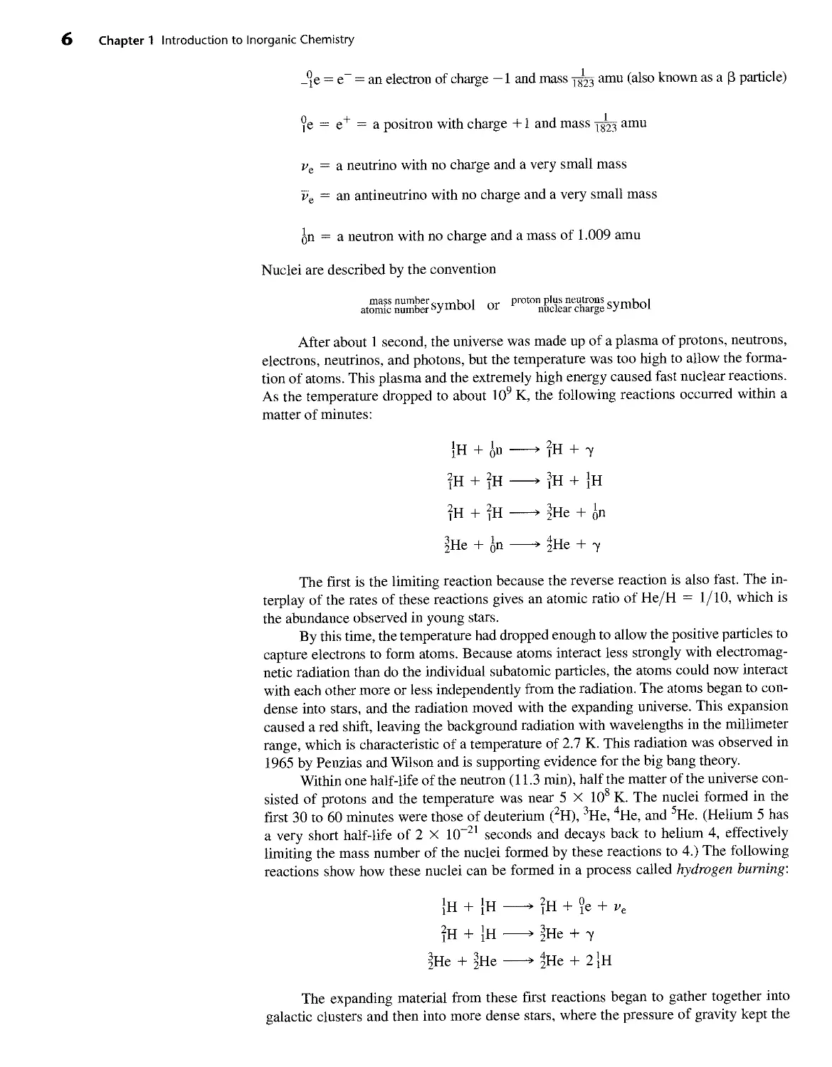
After about 1 second, the universe was made up of a plasma of protons, neutrons,
electrons, neutrinos, and photons, but the temperature was too high to allow the forma-
tion of atoms. This plasma and the extremely high energy caused fast nuclear reactions.
As the temperature dropped to about 109 K, the following reactions occurred within a
matter of minutes:
1H + -----> ?H + у
|н + ?h —> । н + }h
2H + 2H ------> 3He + ln
гНе + Jo------> 2He + T
The first is the limiting reaction because the reverse reaction is also fast. The in-
terplay of the rates of these reactions gives an atomic ratio of He/H = 1/10, which is
the abundance observed in young stars.
By this time, the temperature had dropped enough to allow the positive particles to
capture electrons to form atoms. Because atoms interact less strongly with electromag-
netic radiation than do the individual subatomic particles, the atoms could now interact
with each other more or less independently from the radiation. The atoms began to con-
dense into stars, and the radiation moved with the expanding universe. This expansion
caused a red shift, leaving the background radiation with wavelengths in the millimeter
range, which is characteristic of a temperature of 2.7 K. This radiation was observed in
1965 by Penzias and Wilson and is supporting evidence for the big bang theory.
Within one half-life of the neutron (11.3 min), half the matter of the universe con-
sisted of protons and the temperature was near 5 X 10⁸ K. The nuclei formed in the
first 30 to 60 minutes were those of deuterium (2H), 3He, 4He, and 5He. (Helium 5 has
a very short half-life of 2 X КГ21 seconds and decays back to helium 4, effectively
limiting the mass number of the nuclei formed by these reactions to 4.) The following
reactions show how these nuclei can be formed in a process called hydrogen burning:
}H + }H-------> 2H + °e + ve
?H + 1H ------> гНе + 7
/He + |He-------> 4He + 2}H
The expanding material from these first reactions began to gather together into
galactic clusters and then into more dense stars, where the pressure of gravity kept the
1-3 Genesis of the Elements (the Big Bang) and Formation of the Earth 7
temperature high and promoted further reactions. The combination of hydrogen and he-
lium with many protons and neutrons led rapidly to the formation of heavier elements.
In stars with internal temperatures of 107 to 108 K, the reactions forming 2H, 3He, and
4He continued, along with reactions that produced heavier nuclei. The following
helium-burning reactions are among those known to take place under these conditions:
2 llle-----> |Be + у
4He + |Be ------> ЧС + у
n6C + }H--------> 13N------> 136C + ?e + pe
In more massive stars (temperatures of 6 X 10⁸ К or higher), the carbon-nitrogen cycle
is possible:
126c + |H- 13N + У
13N — , I3r + ?e + ve
136c + }H~ Цы + У
14n + 1H- 158O + У
158o - 13N + ?e + ve
13N + }H- 2He + 12 6C
The net result of this cycle is the formation of helium from hydrogen, with gamma rays,
positrons, and neutrinos as byproducts. In addition, even heavier elements are formed:
126C + l26C -------> ToNe + |He
2 'fO--------> ffSi + 4He
2 lO --------> jl6S +
At still higher temperatures, further reactions take place:
у + ?|Si--------> ^Mg + ^He
ffSi + lHe -----HiS + 7
liS + lHe-------> IfAr + у
Even heavier elements can be formed, with the actual amounts depending on a
complex relationship among their inherent stability, the temperature of the star, and the
lifetime of the star. The curve of inherent stability of nuclei has a maximum at |бЕе, ac-
counting for the high relative abundance of iron in the universe. If these reactions con-
tinued indefinitely, the result should be nearly complete dominance of elements near
iron over the other elements. However, as parts of the universe cooled, the reactions
slowed or stopped. Consequently, both lighter and heavier elements are common. For-
mation of elements of higher atomic number takes place by the addition of neutrons to
a nucleus, followed by electron emission decay. In environments of low neutron densi-
ty, this addition of neutrons is relatively slow, one neutron at a time; in the high neutron
density environment of a nova, 10 to 15 neutrons may be added in a very short time, and
the resulting nucleus is then neutron rich:
2бРе + 13 qD > 2б?е * 27C0 + -ie
8 Chapter 1 Introduction to Inorganic Chemistry
FIGURE 1-8 Cosmic Abundances of the Elements. (Reprinted with permission from N. N. Green-
wood and A. Earnshaw, Chemistry of the Elements, Butterworth-Heinemann, Oxford, 1997, p. 4.)
The very heavy elements are also formed by reactions such as this. After the ad-
dition of the neutrons, [3 decay (loss of electrons from the nucleus as a neutron is con-
verted to a proton plus an electron) leads to nuclei with larger atomic numbers. Figure
1-8 shows the cosmic abundances of some of the elements.
Gravitational attraction combined with rotation gradually formed the expanding
cloud of material into relatively flat spiral galaxies containing millions of stars each.
Complex interactions within the stars led to black holes and other types of stars, some
of which exploded as supernovas and scattered their material widely. Further gradual
accretion of some of this material into planets followed. At the lower temperatures
found in planets, the buildup of heavy elements stopped, and decay of unstable radioac-
tive isotopes of the elements became the predominant nuclear reactions.
____________1-4
NUCLEAR
REACTIONS AND
RADIOACTIVITY
Some nuclei were formed that were stable, never undergoing further reactions. Others
have lifetimes ranging from 1016 years to 1(Г16 second. The usual method of
describing nuclear decay is in terms of the half-life, or the time needed for half the
nuclei to react. Because decay follows first-order kinetics, the half-life is a well-
defined value, not dependent on the amount present. In addition to the overall curve of
nuclear stability, which has its most stable region near atomic number Z = 26,
combinations of protons and neutrons at each atomic number exhibit different
stabilities. In some elements such as fluorine (19F), there is only one stable isotope (a
specific combination of protons and neutrons). In others, such as chlorine, there are two
1-5 Distribution of Elements on Earth 9
or more stable isotopes. 35C1 has a natural abundance of 75.77%, and 37C1 has a
natural abundance of 24.23%. Both are stable, as are all the natural isotopes of the
lighter elements. The radioactive isotopes of these elements have short half-lives and
have had more than enough time to decay to more stable elements. * 3H, 14C, and a few
other radioactive nuclei are continually being formed by cosmic rays and have a low
constant concentration.
Heavier elements (Z = 40 or higher) may also have radioactive isotopes with
longer half-lives. As a result, some of these radioactive isotopes have not had time to
decay completely, and the natural substances are radioactive. Further discussion of iso-
topic abundances and radioactivity can be found in larger or more specialized sources.3
As atomic mass increases, the ratio of neutrons to protons in stable isotopes grad-
ually increases from 1:1 to 1.6:1 for 298U. There is also a set of nuclear energy levels
similar to the electron energy levels described in Chapter 2 that result in stable nuclei
with 2, 8, 20, 28, 50, 82, and 126 protons or neutrons. In nature, the most stable nuclei
are those with the numbers of both protons and neutrons matching one of these num-
bers; эНе, ^O, гоСа, and s2SPb are examples.
Elements not present in nature can be formed by bombardment of one element
with nuclei of another; if the atoms are carefully chosen and the energy is right, the two
nuclei can merge to form one nucleus and then eject a portion of the nucleus to form a
new element. This procedure has been used to extend the periodic table beyond uranium.
Neptunium and plutonium can be formed by addition of neutrons to uranium followed
by release of electrons (£ particles). Still heavier elements require heavier projectiles
and higher energies. Using this approach, elements up to 112, temporarily called unun-
bium for its atomic number, have been synthesized. Synthesis of elements 114,116, and
118 has been claimed, but the claim for 118 was later withdrawn. Calculations indicate
that there may be some relatively stable (half-lives longer than a few seconds) isotopes
of some of the superheavy elements, if the appropriate target isotopes and projectiles
are used. Suggestions include 248Cm, 250Cm, and 244Pu as targets and 48Ca as the pro-
jectile. Predictions such as this have fueled the search for still heavier elements, even
though their stability is so low that they must be detected within seconds of their cre-
ation before they decompose to lighter elements. Hoffman and Lee4 have reviewed the
efforts to study the chemistry of these new elements. The subtitle of their article, “One
Atom at a Time,” described the difficulty of such studies. In one case, а-daughter decay
chains of 265Sg were detected from only three atoms during 5000 experiments, but this
was sufficient to show that Sg(VI) is similar to W(VI) and Mo(VI) in forming neutral or
negative species in HNO3-HF solution, but not like U(VI), which forms [иОг]2+ under
these conditions. Element 108, hassium, formed by bombarding 248Cm with high-ener-
gy atoms of 26Mg, was found to form an oxide similar to that of osmium on the basis of
six oxide molecules carried from the reaction site to a detector by a stream of helium.5
This may be the most massive atom on which “chemistry” has been performed to date.
Theories that attempt to explain the formation of the specific structures of the Earth
are at least as numerous as those for the formation of the universe. Although the details
of these theories differ, there is general agreement that the Earth was much hotter
during its early life, and that the materials fractionated into gaseous, liquid, and solid
states at that time. As the surface of the Earth cooled, the lighter materials in the crust
solidified and still float on a molten inner layer, according to the plate tectonics
3N. N. Greenwood and A. Earnshaw, Chemistry of the Elements, 2nd ed., Butterworth-Heinemann,
Oxford, 1997; J. Silk, The Big Bang. The Creation and Evolution of the Universe, W. H. Freeman, San Fran-
cisco, 1980.
4D. C. Hoffman and D. M. Lee, J. Chem. Educ., 1999, 76, 331.
5Chem. Eng. News, June 4, 2001, p. 47.
____________1-5
DISTRIBUTION OF
ELEMENTS ON
EARTH
10 Chapter 1 Introduction to Inorganic Chemistry
explanation of geology. There is also general agreement that the Earth has a core of
iron and nickel, which is solid at the center and liquid above that. The outer half of the
Earth’s radius is composed of silicate minerals in the mantle; silicate, oxide, and
sulfide minerals in the crust; and a wide variety of materials at the surface, including
abundant water and the gases of the atmosphere.
The different types of forces apparent in the early planet Earth can now be seen
indirectly in the distribution of minerals and elements. In locations where liquid magma
broke through the crust, compounds that are readily soluble in such molten rock were
carried along and deposited as ores. Fractionation of the minerals then depended on
their melting points and solubilities in the magma. In other locations, water was the
source of the formation of ore bodies. At these sites, water leached minerals from the
surrounding area and later evaporated, leaving the minerals behind. The solubilities of
the minerals in either magma or water depend on the elements, their oxidation states,
and the other elements with which they are combined. A rough division of the elements
can be made according to their ease of reduction to the element and their combination
with oxygen and sulfur. Siderophiles (iron-loving elements) concentrate in the metallic
core, lithophiles (rock-loving elements) combine primarily with oxygen and the halides
and are more abundant in the crust, and chalcophiles (Greek, Khalkos, copper) com-
bine more readily with sulfur, selenium, and arsenic and are also found in the crust.
Atmophiles are present as gases. These divisions are shown in the periodic table in
Figure 1-9.
As an example of the action of water, we can explain the formation of bauxite
(hydrated A12O3) deposits by the leaching away of the more soluble salts from alumi-
nosilicate deposits. The silicate portion is soluble enough in water that it can be leached
away, leaving a higher concentration of aluminum. This is shown in the reaction
4 KAlSi3O8(^) + 4 CO2 + 22 H2O ------> 4 K+ + 4 HCO3“ + Al4Si4O10(OH)8(s) + 8 H4SiO4(a?)
aluminosilicate
higher concentration
of Al
silicate
(leached away)
1 2 3 4 5 6 7 8 9 10 11 12 13 14 15 16 17 18
Lithophiles
Siderophiles
Chalcophiles
i , ...
i Atmophiles
Both lithophile
and chalcophile
# Including lanthanides Ce through Lu
* Including actinides Th, U
FIGURE 1-9 Geochemical Classification of the Elements. (Adapted with permission from
P. A. Cox, The Elements, Their Origin, Abundance, and Distribution, Oxford University Press,
Oxford, 1990, p. 13.)
1-6 The History of Inorganic Chemistry 11
in which H4SiO4 is a generic representation for a number of soluble silicate species.
This mechanism provides at least a partial explanation for the presence of bauxite de-
posits in tropical areas or in areas that once were tropical, with large amounts of rainfall
in the past.
Further explanations of these geological processes must be left to more special-
ized sources.6 Such explanations are based on concepts treated later in this text. For
example, modern acid-base theory helps explain the different solubilities of minerals in
water or molten rock and their resulting deposits in specific locations. The divisions
illustrated in Figure 1-9 can be partly explained by this theory, which is discussed in
Chapter 6 and used in later chapters.
____________1-6
THE HISTORY OF
INORGANIC
CHEMISTRY
Even before alchemy became a subject of study, many chemical reactions were used
and the products applied to daily life. For example, the first metals used were probably
gold and copper, which can be found in the metallic state. Copper can also be readily
formed by the reduction of malachite—basic copper carbonate, Cu2(CO3)(OH)2—in
charcoal fires. Silver, tin, antimony, and lead were also known as early as 3000 вс.
Iron appeared in classical Greece and in other areas around the Mediterranean Sea by
1500 вс. At about the same time, colored glasses and ceramic glazes, largely
composed of silicon dioxide (SiO^, the major component of sand) and other metallic
oxides, which had been melted and allowed to cool to amorphous solids, were
introduced.
Alchemists were active in China, Egypt, and other centers of civilization early in
the first centuries ad. Although much effort went into attempts to “transmute” base met-
als into gold, the treatises of these alchemists also described many other chemical reac-
tions and operations. Distillation, sublimation, crystallization, and other techniques
were developed and used in their studies. Because of the political and social changes of
the time, alchemy shifted into the Arab world and later (about 1000 to 1500 ad) reap-
peared in Europe. Gunpowder was used in Chinese fireworks as early as 1150, and
alchemy was also widespread in China and India at that time. Alchemists appeared in
art, literature, and science until at least 1600, by which time chemistry was beginning to
take shape as a science. Roger Bacon (1214-1294), recognized as one of the first great
experimental scientists, also wrote extensively about alchemy.
By the 17th century, the common strong acids (nitric, sulfuric, and hydrochloric)
were known, and more systematic descriptions of common salts and their reactions
were being accumulated. The combination of acids and bases to form salts was appreci-
ated by some chemists. As experimental techniques improved, the quantitative study of
chemical reactions and the properties of gases became more common, atomic and mol-
ecular weights were determined more accurately, and the groundwork was laid for what
later became the periodic table. By 1869, the concepts of atoms and molecules were
well established, and it was possible for Mendeleev and Meyer to describe different
forms of the periodic table. Figure 1-10 illustrates Mendeleev’s original periodic table.
The chemical industry, which had been in existence since very early times in the
form of factories for the purification of salts and the smelting and refining of metals, ex-
panded as methods for the preparation of relatively pure materials became more com-
mon. In 1896, Becquerel discovered radioactivity, and another area of study was
opened. Studies of subatomic particles, spectra, and electricity finally led to the atomic
theory of Bohr in 1913, which was soon modified by the quantum mechanics of
Schrodinger and Heisenberg in 1926 and 1927.
6J. E. Fergusson, Inorganic Chemistry and the Earth, Pergamon Press, Elmsford, NY, 1982; J. E. Fer-
gusson, The Heavy Elements, Pergamon Press, Elmsford, NY, 1990.
12 Chapter 1 Introduction to Inorganic Chemistry
FIGURE 1-10 Mendeleev’s 1869
Periodic Table. Two years later, he
revised his table into a form similar
to a modem short-form periodic
table, with eight groups across.
Ti = 50 Zr = 90 ?= 180
V = 51 Nb = 94 Ta = 182
Cr = 52 Mo = 96 W= 186
Mn = 53 Rh = 104.4 Pt = 197.4
Fe = 56 Ru = 104.2 Ir=198
Ni = Co = 59 Pd = 106.6 Os = 199
H= 1 Cu = 63.4 Ag = 108 Hg = 200
Be = 9.4 Mg = 24 Zn = 65.2 Cd = 112
B = 11 Al = 27.4 ? = 68 Ur= 116 Au = 197?
C= 12 Si = 28 ? = 70 Sn= 118
N= 14 P = 31 As = 75 Sb = 122 Bi = 210?
O= 16 S = 32 Se = 79.4 Te= 128?
F= 19 Cl = 35.5 Br=80 J= 127
Li = 7 Na = 23 К = 39 Rb = 85.4 Cs = 133 Tl = 204
Ca = 40 Sr = 87.6 Ba =137 Pb = 207
? = 45 Ce = 92
?Er = 56 La = 94
?Yt = 60 Di = 95
?In = 75.6 Th= 118 ?
Inorganic chemistry as a field of study was extremely important during the early
years of the exploration and development of mineral resources. Qualitative analysis
methods were developed to help identify minerals and, combined with quantitative
methods, to assess their purity and value. As the industrial revolution progressed, so did
the chemical industry. By the early 20th century, plants for the production of ammonia,
nitric acid, sulfuric acid, sodium hydroxide, and many other inorganic chemicals pro-
duced on a large scale were common.
In spite of the work of Werner and Jorgensen on coordination chemistry near the
beginning of the 20th century and the discovery of a number of organometallic com-
pounds, the popularity of inorganic chemistry as a field of study gradually declined dur-
ing most of the first half of the century. The need for inorganic chemists to work on
military projects during World War II rejuvenated interest in the field. As work was
done on many projects (not least of which was the Manhattan Project, in which scien-
tists developed the fission bomb that later led to the development of the fusion bomb),
new areas of research appeared, old areas were found to have missing information, and
new theories were proposed that prompted further experimental work. A great expan-
sion of inorganic chemistry started in the 1940s, sparked by the enthusiasm and ideas
generated during World War II.
In the 1950s, an earlier method used to describe the spectra of metal ions sur-
rounded by negatively charged ions in crystals (crystal field theory)7 was extended by
the use of molecular orbital theory8 to develop ligand field theory for use in coordina-
tion compounds, in which metal ions are surrounded by ions or molecules that donate
electron pairs. This theory, explained in Chapter 10, gave a more complete picture of the
bonding in these compounds. The field developed rapidly as a result of this theoretical
framework, the new instruments developed about this same time, and the generally
reawakened interest in inorganic chemistry.
In 1955, Ziegler9 and associates and Natta10 discovered organometallic com-
pounds that could catalyze the polymerization of ethylene at lower temperatures and
7H. A. Bethe, Ann. Physik, 1929, 3, 133.
8J. S. Griffith and L. E. Orgel, Q. Rev. Chem. Soc., 1957, XI, 381.
9K. Ziegler, E. Holzkamp, H. Breil, and H. Martin, Angew. Chem., 1955, <57, 541.
10G. Natta, J. Polym. Set., 1955,16, 143.
1-6 The History of Inorganic Chemistry 13
pressures than the common industrial method used up to that time. In addition, the poly-
ethylene formed was more likely to be made up of linear rather than branched mole-
cules and, as a consequence, was stronger and more durable. Other catalysts were soon
developed, and their study contributed to the rapid expansion of organometallic chem-
istry, still one of the fastest growing areas of chemistry today.
The study of biological materials containing metal atoms has also progressed
rapidly. Again, the development of new experimental methods allowed more thorough
study of these compounds, and the related theoretical work provided connections to
other areas of study. Attempts to make model compounds that have chemical and bio-
logical activity similar to the natural compounds have also led to many new synthetic
techniques. Two of the many biological molecules that contain metals are shown in
Figure 1-11. Although these molecules have very different roles, they share similar
ring systems.
One current problem that bridges organometallic chemistry and bioinorganic
chemistry is the conversion of nitrogen to ammonia:
N2 + 3 H2 -----> 2 NH3
This reaction is one of the most important industrial processes, with over 120 million
tons of ammonia produced in 1990 worldwide. However, in spite of metal oxide cata-
lysts introduced in the Haber-Bosch process in 1913 and improved since then, it is also
a reaction that requires temperatures near 400° C and 200 atm pressure and that still re-
sults in a yield of only 15% ammonia. Bacteria, however, manage to fix nitrogen (con-
vert it to ammonia and then to nitrite and nitrate) at 0.8 atm at room temperature in
FIGURE 1-11 Biological Molecules Containing Metal Ions, (a) Chlorophyll a, the active agent in
photosynthesis, (b) Vitamin В12 coenzyme, a naturally occurring organometallic compound.
14 Chapter 1 Introduction to Inorganic Chemistry
nodules on the roots of legumes. The nitrogenase enzyme that catalyzes this reaction is
a complex iron-molybdenum-sulfur protein. The structure of the active sites have been
determined by X-ray crystallography.11 This problem and others linking biological re-
actions to inorganic chemistry are described in Chapter 16.
With this brief survey of the marvelously complex field of inorganic chemistry,
we now turn to the details in the remainder of this book. The topics included provide a
broad introduction to the field. However, even a cursory examination of a chemical li-
brary or one of the many inorganic journals shows some important aspects of inorganic
chemistry that must be omitted in a short textbook. The references cited in the text sug-
gest resources for further study, including historical sources, texts, and reference works
that can provide useful additional material.
GENERAL
REFERENCES
For those interested in further discussion of the physics of the big bang and related cos-
mology, a nonmathematical treatment is in S. W. Hawking, A Brief History of Time,
Bantam, New York, 1988. The title of P. A. Cox, The Elements, Their Origin, Abun-
dance, and Distribution, Oxford University Press, Oxford, 1990, describes its contents
exactly. The inorganic chemistry of minerals, their extraction, and their environmental
impact at a level understandable to anyone with some background in chemistry can be
found in J. E. Fergusson, Inorganic Chemistry and the Earth, Pergamon Press, Elms-
ford, NY, 1982. Among the many general reference works available, three of the most
useful and complete are N. N. Greenwood and A. Earnshaw, Chemistry of the Elements,
2nd ed., Butterworth-Heinemann, Oxford, 1997; F. A. Cotton, G. Wilkinson, C. A.
Murillo, and M. Bochman, Advanced Inorganic Chemistry, 6th ed., John Wiley & Sons,
New York, 1999; and A. F. Wells, Structural Inorganic Chemistry, 5th ed., Oxford Uni-
versity Press, New York, 1984. An interesting study of inorganic reactions from a dif-
ferent perspective can be found in G. Wulfsberg, Principles of Descriptive Inorganic
Chemistry, Brooks/Cole, Belmont, CA, 1987.
nM. K. Chan, J. Kin, and D. C. Rees, Science, 1993, 260, 792.
CHAPTER
Atomic Structure
The theories of atomic and molecular structure depend on quantum mechanics to de-
scribe atoms and molecules in mathematical terms. Although the details of quantum
mechanics require considerable mathematical sophistication, it is possible to under-
stand the principles involved with only a moderate amount of mathematics. This chap-
ter presents the fundamentals needed to explain atomic and molecular structures in
qualitative or semiquantitative terms.
2-1 Although the Greek philosophers Democritus (460-370 вс) and Epicurus (341-270
HISTORICAL
DEVELOPMENT OF
ATOMIC THEORY
вс) presented views of nature that included atoms, many hundreds of years passed
before experimental studies could establish the quantitative relationships needed for a
coherent atomic theory. In 1808, John Dalton published A New System of Chemical
Philosophy,1 in which he proposed that
... the ultimate particles of all homogeneous bodies are perfectly alike in weight, figure,
etc. In other words, every particle of water is like every other particle of water, every parti-
cle of hydrogen is like every other particle of hydrogen, etc.2
and that atoms combine in simple numerical ratios to form compounds. The terminolo-
gy he used has since been modified, but he clearly presented the ideas of atoms and
molecules, described many observations about heat (or caloric, as it was called), and
made quantitative observations of the masses and volumes of substances combining to
form new compounds. Because of confusion about elemental molecules such as ID and
C>2, which he assumed to be monatomic H and O, he did not find the correct formula for
water. Dalton said that
'John Dalton, A New System of Chemical Philosophy, 1808; reprinted with an introduction by Alexan-
der Joseph, Peter Owen Limited, London, 1965.
2Ibid., p. 113.
15
16 Chapter 2 Atomic Structure
When two measures of hydrogen and one of oxygen gas are mixed, and fired by the elec-
tric spark, the whole is converted into steam, and if the pressure be great, this steam be-
comes water. It is most probable then that there is the same number of particles in two
measures of hydrogen as in one of oxygen.3
In fact, he then changed his mind about the number of molecules in equal volumes of
different gases:
At the time I formed the theory of mixed gases, I had a confused idea, as many have, I sup-
pose, at this time, that the particles of elastic fluids are all of the same size; that a given vol-
ume of oxygenous gas contains just as many particles as the same volume of hydrogenous;
or if not, that we had no data from which the question could be solved.... I [later] became
convinced... That every species of pure elastic fluid has its particles globular and all of a
size; but that no two species agree in the size of their particles, the pressure and tempera-
ture being the same.4
Only a few years later, Avogadro used data from Gay-Lussac to argue that equal
volumes of gas at equal temperatures and pressures contain the same number of mole-
cules, but uncertainties about the nature of sulfur, phosphorus, arsenic, and mercury va-
pors delayed acceptance of this idea. Widespread confusion about atomic weights and
molecular formulas contributed to the delay; in 1861, Kekule gave 19 different possible
formulas for acetic acid!5 In the 1850s, Cannizzaro revived the argument of Avogadro
and argued that everyone should use the same set of atomic weights rather than the
many different sets then being used. At a meeting in Karlsruhe in 1860, he distributed a
pamphlet describing his views.6 His proposal was eventually accepted, and a consistent
set of atomic weights and formulas gradually evolved. In 1869, Mendeleev7 and Meyer8
independently proposed periodic tables nearly like those used today, and from that time
the development of atomic theory progressed rapidly.
2-1-1 THE PERIODIC TABLE
The idea of arranging the elements into a periodic table had been considered by many
chemists, but either the data to support the idea were insufficient or the classification
schemes were incomplete. Mendeleev and Meyer organized the elements in order of
atomic weight and then identified families of elements with similar properties. By ar-
ranging these families in rows or columns, and by considering similarities in chemical
behavior as well as atomic weight, Mendeleev found vacancies in the table and was able
to predict the properties of several elements (gallium, scandium, germanium, polonium)
that had not yet been discovered. When his predictions proved accurate, the concept of
a periodic table was quickly established (see Figure 1-10). The discovery of additional
elements not known in Mendeleev’s time and the synthesis of heavy elements have led
to the more complete modem periodic table, shown inside the front cover of this text.
In the modem periodic table, a horizontal row of elements is called a period, and
a vertical column is a group or family. The traditional designations of groups in the
United States differ from those used in Europe. The International Union of Pure and
Applied Chemistry (IUPAC) has recommended that the groups be numbered 1 through
18, a recommendation that has generated considerable controversy. In this text, we will
3Ibid.,p. 133
*//>4/..рр. 144145.
5J.R. Partington, A Short History of Chemistry, 3rd ed., Macmillan, London, 1957; reprinted, 1960,
Harper & Row, New York, p. 255.
6Ibid„ pp. 256-258.
7D. I. Mendeleev, J. Russ. Phys. Chem. Soc., 1869, i, 60.
8L. Meyer, Justus Liebigs Ann. Chem., 1870, Suppl. vii, 354.
2-1 Historical Development of Atomic Theory 1 7
Groups (American tradition)
IA IIA IIIB IVB VB VIB VIIB VIIIB
Groups (European tradition)
IA IIA ША IVA VA VIA VIIA VIII
IB IIB IIIA IVA VA VIA VIIA VIIIA
IB IIB IIIB IVB VB VIB VIIB 0
Groups (IUPAC)
1 2 3
FIGURE 2-1 Names for Parts of
the Periodic Table.
4 5 6 7 8 9 10 11
12 13 14 15 16 17 18
use the IUPAC group numbers, with the traditional American numbers in parentheses.
Some sections of the periodic table have traditional names, as shown in Figure 2-1.
2-1-2 DISCOVERY OF SUBATOMIC
PARTICLES AND THE BOHR ATOM
During the 50 years after the periodic tables of Mendeleev and Meyer were proposed,
experimental advances came rapidly. Some of these discoveries are shown in Table 2-1.
Parallel discoveries in atomic spectra showed that each element emits light of
specific energies when excited by an electric discharge or heat. In 1885, Balmer showed
that the energies of visible light emitted by the hydrogen atom are given by the equation
n2hj
TABLE 2-1
Discoveries in Atomic Structure
1896 A. H. Becquerel
1897 J. J. Thomson
1909 R. A. Millikan
1911 E. Rutherford
1913 H. G. J. Moseley
Discovered radioactivity of uranium
Showed that electrons have a negative charge, with
charge/mass = 1.76 X 10nC/kg
Measured the electronic charge (1.60 X IO !9 C); therefore, the mass of
-si 1
the electron is 9.11 X 10 kg, of the mass of the H atom
1836
Established the nuclear model of the atom (very small, heavy nucleus
surrounded by mostly empty space)
Determined nuclear charges by X-ray emission, establishing atomic
numbers as more fundamental than atomic masses
18 Chapter 2 Atomic Structure
where
Hh = integer, with nh > 2
RH = Rydberg constant for hydrogen = 1.097 X 10⁷ m”1 = 2.179 X 10“18J
and the energy is related to the wavelength, frequency, and wave number of the light, as
given by the equation
where9
E = hv = — = hcv
7
h = Planck’s constant = 6.626 X 10“34 J s
v = frequency of the light, in s1
c = speed of light = 2.998 X 10х m s l
к = wavelength of the light, frequently in nm
v = wavenumber of the light, usually in cm '1
The Balmer equation was later made more general, as spectral lines in the ultravio-
let and infrared regions of the spectrum were discovered, by replacing 22 by n2, with the
condition that nz < nh. These quantities, и,, are called quantum numbers. (These are the
principal quantum numbers; other quantum numbers are discussed in Section 2-2-2.)
The origin of this energy was unknown until Niels Bohr’s quantum theory of the atom,10
first published in 1913 and refined over the following 10 years. This theory assumed that
negative electrons in atoms move in stable circular orbits around the positive nucleus with
no absorption or emission of energy. However, electrons may absorb light of certain spe-
cific energies and be excited to orbits of higher energy; they may also emit light of specif-
ic energies and fall to orbits of lower energy. The energy of the light emitted or absorbed
can be found, according to the Bohr model of the hydrogen atom, from the equation
/ 1 1 \
- Rh\ 2 2 /
\nl nhJ
where R =
И =
=
2ir2pZ2e4
(4tts0)2^2
reduced mass of the electron-nucleus combination
p. Ше ^nucleus
mass of the electron
mnucleus = mass of the nucleus
Z = charge of the nucleus
e = electronic charge
h = Planck’s constant
= quantum number describing the higher energy state
ri[ = quantum number describing the lower energy state
4tts0 = permittivity of a vacuum
9More accurate values for the constants and energy conversion factors are given inside the back cover
of this book.
10N. Bohr, Philos. Mag., 1913, 26, 1.
2-1 Historical Development of Atomic Theory 19
This equation shows that the Rydberg constant depends on the mass of the nucleus as
well as on the fundamental constants.
Examples of the transitions observed for the hydrogen atom and the energy levels
responsible are shown in Figure 2-2. As the electrons drop from level to щ (h for
higher level, I for lower level), energy is released in the form of electromagnetic radia-
tion. Conversely, if radiation of the correct energy is absorbed by an atom, electrons are
raised from level щ to level nh. The inverse-square dependence of energy on щ results
in energy levels that are far apart in energy at small and become much closer in ener-
gy at larger щ. In the upper limit, as щ approaches infinity, the energy approaches a
limit of zero. Individual electrons can have more energy, but above this point they are
no longer part of the atom; an infinite quantum number means that the nucleus and the
electron are separate entities.
EXERCISE 2-1
Find the energy of the transition from nh = 3 to щ = 2 for the hydrogen atom in both joules
and cnf (a common unit in spectroscopy). This transition results in a red line in the visible
emission spectrum of hydrogen. (Solutions to the exercises are given in Appendix A.)
When applied to hydrogen, Bohr’s theory worked well; when atoms with more
electrons were considered, the theory failed. Complications such as elliptical rather
than circular orbits were introduced in an attempt to fit the data to Bohr’s theory.11 The
developing experimental science of atomic spectroscopy provided extensive data for
testing of the Bohr theory and its modifications and forced the theorists to work hard to
explain the spectroscopists’ observations. In spite of their efforts, the Bohr theory even-
tually proved unsatisfactory; the energy levels shown in Figure 2-2 are valid only for the
hydrogen atom. An important characteristic of the electron, its wave nature, still needed
to be considered.
According to the de Broglie equation,12 proposed in the 1920s, all moving parti-
cles have wave properties described by the equation
h
X = —
mv
where X = wavelength of the particle
h = Planck’s constant
m = mass of the particle
v = velocity of the particle
Particles massive enough to be visible have very short wavelengths, too small to
be measured. Electrons, on the other hand, have wave properties because of their very
small mass.
Electrons moving in circles around the nucleus, as in Bohr’s theory, can be
thought of as forming standing waves that can be described by the de Broglie equation.
However, we no longer believe that it is possible to describe the motion of an electron in
an atom so precisely. This is a consequence of another fundamental principle of modern
physics, Heisenberg’s uncertainty principle,13 which states that there is a relationship
HG. Herzberg, Atomic Spectra and Atomic Structure, 2nd ed., Dover Publications, New York, 1994,
P- 18.
12L. de Broglie, Philos. Mag. 1924. 47, 446; Ann. Phys., 1925, 3, 22.
13W. Heisenberg, Z. Phys., 1927, 43, 172.
20 Chapter 2 Atomic Structure
Energy
0
^Rn
Г 15 RH
~1RH
Quantum
Number n
---;------------------------------------------------ 6
----------------------------------------------5
---------------------------------------------------- 4
Paschen series (IR)
------------------ill------------------------- з
Balmer series
(visible transitions shown)
---------------------------------------------- 2
Lyman
series
(UV)
FIGURE 2-2 Hydrogen Atom
Energy Levels. И
2-2 The Schrodinger Equation 21
between the inherent uncertainties in the location and momentum of an electron moving
in the x direction:
_____________2-2
THE SCHRODINGER
EQUATION
Дх Дрг > —
4тт
where
Дх = uncertainty in the position of the electron
Дрх = uncertainty in the momentum of the electron
The energy of spectral lines can be measured with great precision (as an example,
the Rydberg constant is known to 11 significant figures), in turn allowing precise deter-
mination of the energy of electrons in atoms. This precision in energy also implies preci-
sion in momentum (Дрх is small); therefore, according to Heisenberg, there is a large
uncertainty in the location of the electron (Дх is large). These concepts mean that we
cannot treat electrons as simple particles with their motion described precisely, but we
must instead consider the wave properties of electrons, characterized by a degree of un-
certainty in their location. In other words, instead of being able to describe precise orbits
of electrons, as in the Bohr theory, we can only describe orbitals, regions that describe
the probable location of electrons. The probability of finding the electron at a particular
point in space (also called the electron density) can be calculated, at least in principle.
In 1926 and 1927, Schrodinger14 and Heisenberg13 published papers on wave
mechanics (descriptions of the wave properties of electrons in atoms) that used very
different mathematical techniques. In spite of the different approaches, it was soon
shown that their theories were equivalent. Schrodinger’s differential equations are
more commonly used to introduce the theory, and we will follow that practice.
The Schrodinger equation describes the wave properties of an electron in terms of
its position, mass, total energy, and potential energy. The equation is based on the wave
function, T'. which describes an electron wave in space; in other words, it describes an
atomic orbital. In its simplest notation, the equation is
ЯФ = E'V
where Я = the Hamiltonian operator
E = energy of the electron
4' = the wave function
The Hamiltonian operator (frequently just called the Hamiltonian) includes de-
rivatives that operate on the wave function.15 When the Hamiltonian is carried out, the
result is a constant (the energy) times 'Ф'. The operation can be performed on any wave
function describing an atomic orbital. Different orbitals have different functions and
different values of E. This is another way of describing quantization in that each orbital,
characterized by its own function has a characteristic energy.
14E. Schrodinger, Ann. Phys. (Leipzig), 1926, 79, 361, 489, 734; 1926, 80, 437; 1926, 81, 109;
Naturwissenshaften, 1926,14, 664; Phys. Rev., 1926. 28, 1049.
15An operator is an instruction or set of instructions that states what to do with the function that fol-
lows it. It may be a simple instruction such as “multiply the following function by 6 ” or it may be much more
complicated than the Hamiltonian. The Hamiltonian operator is sometimes written H, with the * (hat) symbol
designating an operator.
22 Chapter 2 Atomic Structure
In the form used for calculating energy levels, the Hamiltonian operator is
—h2 f a2 + a2 + a2 \
8rr2m \dx2 dy2 dz2 /
Ze2
4itsq vx2 + y2 + z2
where
This part of the operator describes the
kinetic energy of the electron
This part of the operator describes the
potential energy of the electron, the result of
electrostatic attraction between the electron
and the nucleus. It is commonly designated
as V.
h = Planck’s constant
m = mass of the particle (electron)
e = charge of the electron
x2 + y2 + z2 = r = distance from the nucleus
Z = charge of the nucleus
4itsq = permittivity of a vacuum
When this operator is applied to a wave function ^P,
-h2 fa2 a2 a2A .
8тг m ydx dy dz )
T'(x,y,z) = £AP(x,y,z)
where
V
-Ze1
4ттеог
-Ze2
4TTe0Vx2 + y2 + z2
The potential energy V is a result of electrostatic attraction between the electron
and the nucleus. Attractive forces, like those between a positive nucleus and a negative
electron, are defined by convention to have a negative potential energy. An electron near
the nucleus (small r) is strongly attracted to the nucleus and has a large negative poten-
tial energy. Electrons farther from the nucleus have potential energies that are small and
negative. For an electron at infinite distance from the nucleus (r = oo), the attraction
between the nucleus and the electron is zero, and the potential energy is zero.
Because every matches an atomic orbital, there is no limit to the number of so-
lutions of the Schrodinger equation for an atom. Each 4' describes the wave properties
of a given electron in a particular orbital. The probability of finding an electron at a
given point in space is proportional to T/2. A number of conditions are required for a
physically realistic solution for 4':
1. The wave function 4' must be sin-
gle-valued.
2. The wave function 4' and its first
derivatives must be continuous.
3. The wave function must ap-
proach zero as r approaches infinity.
There cannot be two probabilities for
an electron at any position in space.
The probability must be defined at all
positions in space and cannot change
abruptly from one point to the next.
For large distances from the nucleus,
the probability must grow smaller and
smaller (the atom must be finite).
2-2 The Schrodinger Equation 23
4. The integral
У ФдТ/ di = 1
all space
5. The integral
У Т.4Ф/Л/т = 0
all space
The total probability of an electron
being somewhere in space = 1. This
is called normalizing the wave
function.
All orbitals in an atom must be orthog-
onal to each other. In some cases, this
means that the orbitals must be perpen-
dicular, as with the px, py, and p-
orbitals.
2-2-1 THE PARTICLE IN A BOX
A simple example of the wave equation, the one-dimensional particle in a box, shows
how these conditions are used. We will give an outline of the method; details are avail-
able elsewhere.16 17 The “box” is shown in Figure 2-3. The potential energy V(x) inside
the box, between x = 0 and x = a, is defined to be zero. Outside the box, the potential
energy is infinite. This means that the particle is completely trapped in the box and
would require an infinite amount of energy to leave the box. However, there are no
forces acting on it within the box.
The wave equation for locations within the box is
-h2 ( d2W(x)\
—т— --------т— = £’’'Ir(x), because V(x) = 0
8tt2w \ dx2
Sine and cosine functions have the properties that we associate with waves—a
well-defined wavelength and amplitude—and we may therefore propose that the wave
characteristics of our particle may be described by a combination of sine and cosine
functions. A general solution to describe the possible waves in the box would then be
= A sin rx + В cos sx
FIGURE 2-3 Potential Energy
Well for the Particle in a Box.
16Because the wave functions may have imaginary values (containing V—T), 'I' Ч'* is used to make
the integral real. In many cases, the wave functions themselves are real, and this integral becomes
У Т/Л.
all space
17G. M. Barrow, Physical Chemistry, 6th ed., McGraw-Hill, New York, 1996, pp. 65, 430, calls this
the “particle on a line” problem. Many other physical chemistry texts also include solutions.
24 Chapter 2 Atomic Structure
where A, B, r, and s are constants. Substitution into the wave equation allows solution
for r and л (see Problem 4 at the end of the chapter):
Because Ф must be continuous and must equal zero at x < 0 and x > a (be-
cause the particle is confined to the box), Ф must go to zero at x = 0 and x = a. Be-
cause cos sx = 1 for x = О, Ф can equal zero in the general solution above only if
В = 0. This reduces the expression for Ф to
Ф = A sin rx
At x = а, Ф must also equal zero; therefore, sin ra = 0, which is possible only
if ra is an integral multiple of tt:
ra = ±n~ or r =
±итт
where n = any integer A 0.18 Substituting the positive value (because both positive
and negative values yield the same results) for r into the solution for r gives
2tt
2mE —
h
This expression may be solved for E:
8ma2
These are the energy levels predicted by the particle in a box model for any particle in a
one-dimensional box of length a. The energy levels are quantized according to
quantum numbers n = 1, 2, 3,...
Substituting r = iraja into the wave function gives
and applying the normalizing requirement / ФФ* d~ ~ 1 gives
The total solution is then
18If n = 0, then r = 0 and = 0 at all points. The probability of finding the electron is
J ф’ф'* dx = 0, and there is no electron at all.
2-2 The Schrodinger Equation 25
x/a
Particle in a box
Wave function 4*
FIGURE 2-4 Wave Functions and
Their Squares for the Particle in a
Box with n = 1, 2, and 3.
x/a
The resulting wave functions and their squares for the first three states (the ground state
and first two excited states) are plotted in Figure 2-4.
The squared wave functions are the probability densities and show the difference
between classical and quantum mechanical behavior. Classical mechanics predicts that
the electron has equal probability of being at any point in the box. The wave nature
of the electron gives it the extremes of high and low probability at different locations
in the box.
2-2-2 QUANTUM NUMBERS AND ATOMIC
WAVE FUNCTIONS
The particle in a box example shows how a wave function operates in one dimension.
Mathematically, atomic orbitals are discrete solutions of the three-dimensional
Schrodinger equations. The same methods used for the one-dimensional box can be
expanded to three dimensions for atoms. These orbital equations include three
26 Chapter 2 Atomic Structure
quantum numbers, n, I, and mz. A fourth quantum number, ms, a result of relativistic
corrections to the Schrodinger equation, completes the description by accounting for
the magnetic moment of the electron. The quantum numbers are summarized in Tables
2-2, 2-3, and 2-4.
TABLE 2-2
Quantum Numbers and Their Properties
Symbol Name Values Role
П Principal 1,2,3,... Determines the major part of the energy
l Angular momentum 0, 1,2, ...,n - 1 Describes angular dependence and contributes to the energy
ml Magnetic 0, ± 1, ±2,..., ±Z Describes orientation in space (angular momentum in the z direction)
ms Spin 1 ±2 Describes orientation of the electron spin (magnetic moment) in space
Orbitals with different I values are known by the following labels, derived from early terms for different
families of spectroscopic lines:
I 0 1 2 3 4 5,. . .
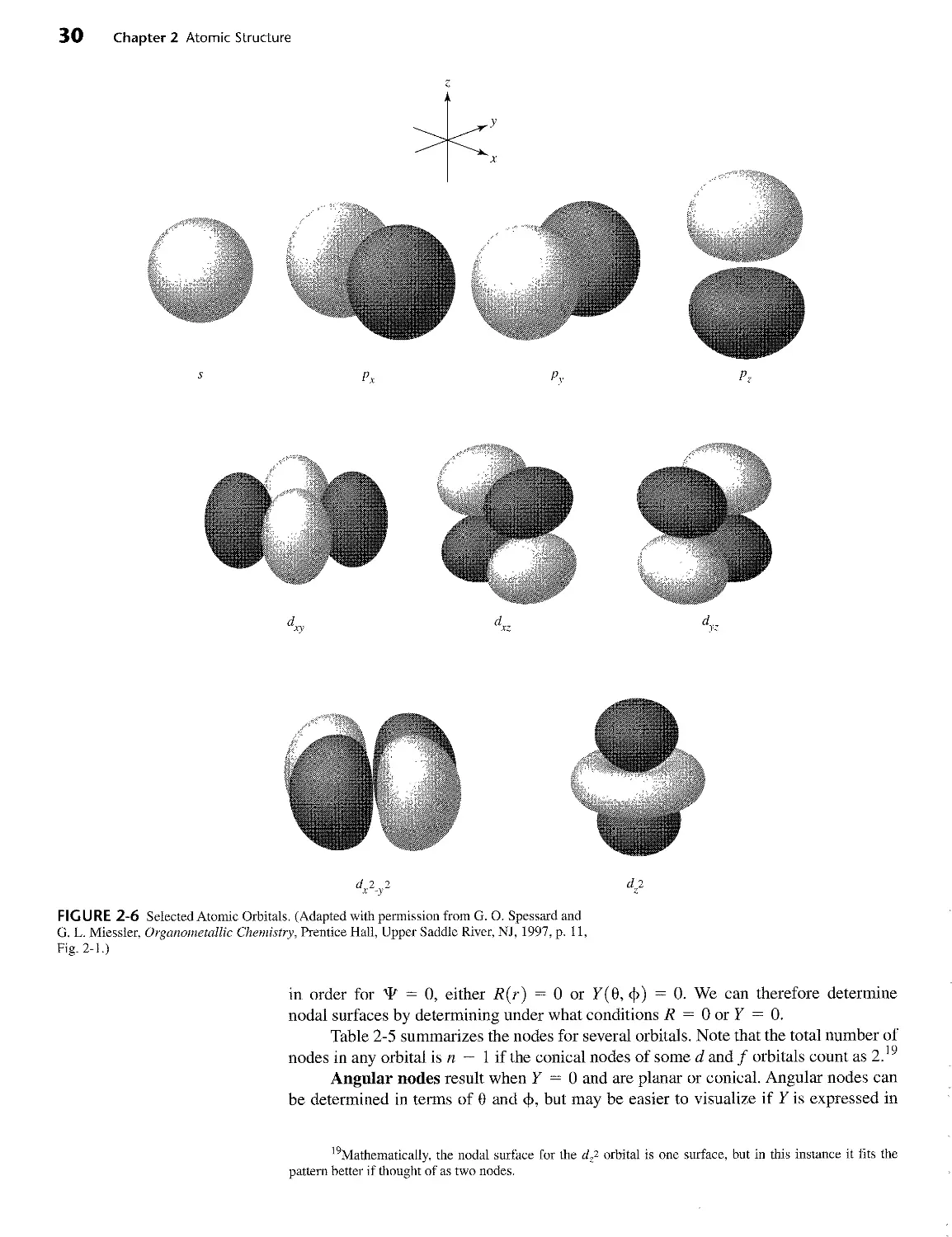
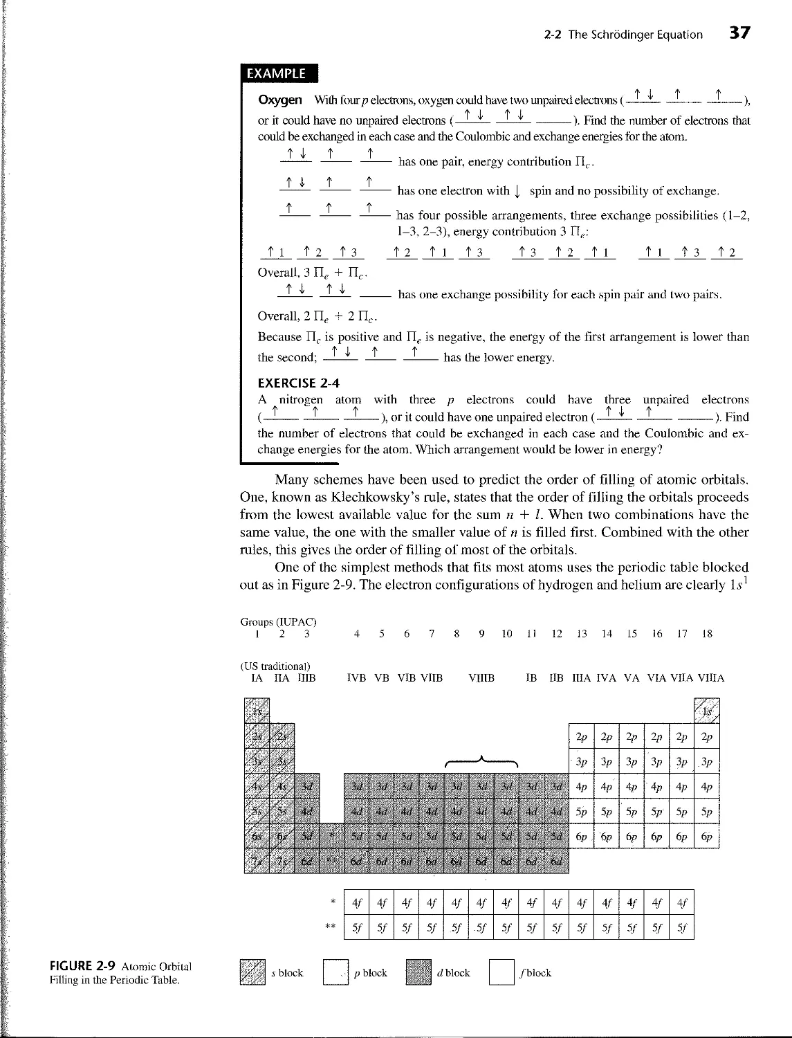
Label s p d f g continuing alphabetically
TABLE 2-3 Hydrogen Atom Wave Functions: Angular Functions Real wave functions
Angular factors
Related to angular momentum Functions ofQ In Polar coordinates In Cartesian coordinates Shapes Label
I m[ Ф e ОФ(9,ф) 0Ф(х, у, z)
0(.) 0 1 V2it i V5 z 1 2Vtt 1 2Vrr \ ) s
1(P) 0 1 V6 cos 9 2 1 2^COS0 £ 1 2 V rrr A X P.
+ 1 1 V2it V3 s — sm0 f i Гз -J — sm 9 cos ф 1 /It 2\тгг У Px
-1 ! е~'Ф V2it Vi . sin 9 2 > < i Гз . -л — sin 9 sm ф 2 у it i [зу 2^7 ~ p>-
2(d) 0 1 V2it |J|(3cos20 “ ~ /1(3 COS2 9 - 1) 4 у it 1 [5 ~ x2 - V2) -Q- 4 V rr r2 ~ d-f
+ 1 ~-/=Тф V 2rr V15 > cos 9 sin 9 2 ' ( 1 /"15 —л/— cos 9 sin 9 cos ф 2 V it 1 /Utz -7 2\ тт r2 Jr dx.
-1 V 2it V15 cos 9 sin 9 2 > 1 /15 —л — cos 9 sm 9 sin ф 2 V it 1 /Hz£ -С/t 2\ tt r2 N/ dy.
+2 --f=e2;* V2rr J V15 . 2 x —-— sm2 e 4 , I /15 2 —,— sin 9 cos 2ф 4 у тт 1 I3 ~ 4 V rr r2 dx2-v2
-2 _zL_e-2«l> V2tt V15 ? sm^ 9 4 > 1 /15 . x — snr 9 sm 2ф 4 V rr 1 /Utz 4 V it r2 > dxy
Source: Adapted from G. M. Barrow, Physical Chemistry, 5th ed., McGraw-Hill, New York, 1988, p. 450, with permission.
Note: The relations (<?'* - e-'*)/(2/) = sin ф and (<?'* + e~'c*>)/2 = cos ф can be used to convert the exponential imaginary functions to real
trigonometric functions, combining the two orbitals with = ±1 to give two orbitals with sin ф and cos ф. In a similar fashion, the orbitals with
m/ = ±2 result in real functions with cos2 ф and sin2 ф. These functions have then been converted to Cartesian form by using the functions
л = r sin 9 cos ф, у = r sin 0 sin ф, and z = r cos 9.
2-2 The Schrodinger Equation 27
TABLE 2-4
Hydrogen Atom Wave Functions: Radial Functions
Radial Functions R(r), with ст = Zr/ag
Orbital n I
15 1 0
2s 2 0
2p 1
3s 3 0
3p 1
3d 2
R(r)
z "I3/2
— (27 - 18cr + 2o-2Kct'/3
3a0_
I 2Z
(6 - ст)сте^/3
The fourth quantum number explains several experimental observations. Two of
these observations are that lines in alkali metal emission spectra are doubled, and that a
beam of alkali metal atoms splits into two parts if it passes through a magnetic field.
Both of these can be explained by attributing a magnetic moment to the electron; it be-
haves like a tiny bar magnet. This is usually described as the spin of the electron be-
cause a spinning electrically charged particle also has a magnetic moment, but it should
not be taken as an accurate description; it is a purely quantum mechanical property.
The quantum number n is primarily responsible for determining the overall energy of
an atomic orbital; the other quantum numbers have smaller effects on the energy. The quan-
tum number I determines the angular momentum of the orbital or shape of the orbital and
has a smaller effect on the energy. The quantum number m/ determines the orientation of the
angular momentum vector in a magnetic field, or the position of the orbital in space, as
shown in Table 2-3. The quantum number ms determines the orientation of the electron
magnetic moment in a magnetic field, either in the direction of the field (+ or opposed to
it (— |). When no field is present, all m/ values (all three p orbitals or all five d orbitals) have
the same energy and both ms values have the same energy. Together, the quantum numbers
n, I, and mi define an atomic orbital; the quantum number ms describes the electron spin
within the orbital.
One feature that should be mentioned is the appearance of i (= V-~T) in the p
and d orbital wave equations in Table 2-3. Because it is much more convenient to work
with real functions than complex functions, we usually take advantage of another prop-
erty of the wave equation. For differential equations of this type, any linear combination
of solutions (sums or differences of the functions, with each multiplied by any coeffi-
cient) to the equation is also a solution to the equation. The combinations usually cho-
sen for the p orbitals are the sum and difference of the p orbitals having = +1 and
— 1, normalized by multiplying by the constants and —7=, respectively:
V2 V2
1 1 /з”
'J'2/л, = + ^-1) = sine cos Ф
^2/ry = ~ ^-1) = I зУ“[Л(Г)] sin ° sinc>
28 Chapter 2 Atomic Structure
FIGURE 2-5 Spherical Coordi-
nates and Volume Element for a
Spherical Shell in Spherical
Coordinates.
Spherical Coordinates
Volume Element
The same procedure used on the d orbital functions for mi = ±1 and ±2 gives the
functions in the column headed 0Ф(0, ф) in Table 2-3, which are the familiar d orbitals.
The rfz2 orbital (mz = 0) actually uses the function 2z2 - x2 - y2, which we shorten to z2
for convenience. These functions are now real functions, so T = and 1I/'ll/* = T/2.
A more detailed look at the Schrodinger equation shows the mathematical origin
of atomic orbitals. In three dimensions, may be expressed in terms of Cartesian co-
ordinates (x, y, z) or in terms of spherical coordinates (r, 0, ф). Spherical coordinates,
as shown in Figure 2-5, are especially useful in that r represents the distance from the
nucleus. The spherical coordinate 0 is the angle from the z axis, varying from 0 to тт,
and ф is the angle from the x axis, varying from 0 to 2тг. It is possible to convert be-
tween Cartesian and spherical coordinates using the following expressions:
x = r sin 0 cos ф
у = r sin 0 sin ф
z = r cos 0
In spherical coordinates, the three sides of the volume element are
r dQ, r sin 0 г/ф, and dr. The product of the three sides is r2 sin 0 dO d<\> dr, equivalent
to dx dy dz. The volume of the thin shell between r and r + dr is 4ттг2 dr, which is the
integral over ф from 0 to тт, and over 0 from 0 to 2tt. This integral is useful in describ-
ing the electron density as a function of distance from the nucleus.
can be factored into a radial component and two angular components. The
radial function, R, describes electron density at different distances from the nucleus;
the angular functions, 0 and Ф, describe the shape of the orbital and its orientation in
space. The two angular factors are sometimes combined into one factor, called Y:
^(г,0,ф) = 7?(г)0(0)Ф(ф) = Я(г)Т(0,ф)
Л is a function only of r; Y is a function of 0 and ф, and gives the distinctive shapes of
s, p, d, and other orbitals. R, 0, and Ф are shown separately in Tables 2-3 and 2-4.
2-2 The Schrodinger Equation 29
The angular functions
The angular functions 0 and Ф determine how the probability changes from point to
point at a given distance from the center of the atom; in other words, they give the shape
of the orbitals and their orientation in space. The angular functions 0 and Ф are deter-
mined by the quantum numbers I and mt. The shapes of s, p, and d orbitals are shown in
Table 2-3 and Figure 2-6.
In the center of Table 2-3 are the shapes for the 0 portion; when the Ф portion is
included, with values of ф = 0 to 2тг, the three-dimensional shapes in the far-right col-
umn are formed. In the diagrams of orbitals in Table 2-3, the orbital lobes are shaded
where the wave function is negative. The probabilities are the same for locations with
positive and negative signs for 4^, but it is useful to distinguish regions of opposite
signs for bonding purposes, as we will see in Chapter 5.
The radial functions
The radial factor R(r) (Table 2-4) is determined by the quantum numbers n and Z, the
principal and angular momentum quantum numbers.
The radial probability function is 4тгг27?2. This function describes the probabil-
ity of finding the electron at a given distance from the nucleus, summed over all angles,
with the 4тгг2 factor the result of integrating over all angles. The radial wave functions
and radial probability functions are plotted for the и = 1,2, and 3 orbitals in Figure 2-7.
Both 7?(r) and 4тгг27?2 are scaled with a0, the Bohr radius, to give reasonable units on
the axes of the graphs. The Bohr radius, = 52.9 pm, is a common unit in quantum
mechanics. It is the value of r at the maximum of Ф2 for a hydrogen Is orbital and is
also the radius of a Is orbital according to the Bohr model.
In all the radial probability plots, the electron density, or probability of finding the
electron, falls off rapidly as the distance from the nucleus increases. It falls off most
quickly for the Is orbital; by r = 5a0, the probability is approaching zero. By contrast,
the 3d orbital has a maximum at r = 9a0 and does not approach zero until approxi-
mately r = 20a0. All the orbitals, including the s orbitals, have zero probability at the
center of the nucleus, because 4тгг27?2 = 0 at r = 0. The radial probability functions
are a combination of 4тгг2, which increases rapidly with r, and R2, which may have
maxima and minima, but generally decreases exponentially with r. The product of these
two factors gives the characteristic probabilities seen in the plots. Because chemical re-
actions depend on the shape and extent of orbitals at large distances from the nucleus,
the radial probability functions help show which orbitals are most likely to be involved
in reactions.
Nodal surfaces
At large distances from the nucleus, the electron density, or probability of finding the
electron, falls off rapidly. The 2s orbital also has a nodal surface, a surface with zero
electron density, in this case a sphere with r = 2a0 where the probability is zero. Nodes
appear naturally as a result of the wave nature of the electron; they occur in the func-
tions that result from solving the wave equation for Ф. A node is a surface where the
wave function is zero as it changes sign (as at r = 2a0, in the 2s orbital); this requires
that Ф = 0, and the probability of finding the electron at that point is also zero.
If the probability of finding an electron is zero (4'2 = О), '!' must also be equal
to zero. Because
^(r, в, ф) = /?(г)т(е,Ф)
30 Chapter 2 Atomic Structure
d 2 2
x -y
FIGURE 2-6 Selected Atomic Orbitals. (Adapted with permission from G. O. Spessard and
G. L. Miessler, Organometallic Chemistry, Prentice Hall, Upper Saddle River, NJ, 1997, p. 11,
Fig. 2-1.)
in order for УР = 0, either R(r) = 0 or У(0, ф) = 0. We can therefore determine
nodal surfaces by determining under what conditions R = 0 or Y = 0.
Table 2-5 summarizes the nodes for several orbitals. Note that the total number of
nodes in any orbital is n - 1 if the conical nodes of some d and f orbitals count as 2.19
Angular nodes result when У = 0 and are planar or conical. Angular nodes can
be determined in terms of 0 and ф, but may be easier to visualize if У is expressed in
19Mathematically, the nodal surface for the ф2 orbital is one surface, but in this instance it fits the
pattern better if thought of as two nodes.
2-2 The Schrodinger Equation 31
Radial Probability Functions
.6-1
.5-
.4-
.3-
0 5 10 15 20 25 30
r/a
о
0 5 10 15 20 25 30
r/aQ
FIGURE 2-7 Radial Wave Functions and Radial Probability Functions.
32 Chapter 2 Atomic Structure
TABLE 2-5
Nodal Surfaces
Spherical nodes [7?(r) = 0]
Examples (number of spherical nodes)
Is 0 2p 0 3d 0
2s 1 3p 1 4d 1
3s 2 4p 2 5d 2
Angular nodes [У(0, Ф) = 0]
Examples (number of angular nodes)
s orbitals 0
p orbitals 1 plane for each orbital
d orbitals 2 planes for each orbital except dd-
1 conical surface for dp
Cartesian (x, y, z) coordinates (see Table 2-3). In addition, the regions where the wave
function is positive and where it is negative can be found. This information will be use-
ful in working with molecular orbitals in later chapters. There are I angular nodes in any
orbital, with the conical surface in the df- and similar orbitals counted as two nodes.
Radial nodes, or spherical nodes, result when R = 0, and give the atom a lay-
ered appearance, shown in Figure 2-8 for the 3s and 3pz orbitals. These nodes occur
when the radial function changes sign; they are depicted in the radial function graphs
by R(r) = 0 and in the radial probability graphs by 4irr2R2 = 0. The 15, 2p, and 3d
orbitals (the lowest energy orbitals of each shape) have no radial nodes and the number
of nodes increases as n increases. The number of radial nodes for a given orbital is al-
ways equal to n — I — 1.
Nodal surfaces can be puzzling. For example, a p orbital has a nodal plane
through the nucleus. How can an electron be on both sides of a node at the same time
without ever having been at the node (at which the probability is zero)? One explanation
is that the probability does not go quite to zero.20
Another explanation is that such a question really has no meaning for an electron
thought of as a wave. Recall the particle in a box example. Figure 2-4 shows nodes at
x/a = 0.5 for n = 2 and at x/a = 0.33 and 0.67 for n = 3. The same diagrams could
represent the amplitudes of the motion of vibrating strings at the fundamental frequen-
cy (и = 1) and multiples of 2 and 3. A plucked violin string vibrates at a specific fre-
quency, and nodes at which the amplitude of vibration is zero are a natural result. Zero
amplitude does not mean that the string does not exist at these points, but simply that
the magnitude of the vibration is zero. An electron wave exists at the node as well as on
both sides of a nodal surface, just as a violin string exists at the nodes and on both sides
of points having zero amplitude.
Still another explanation, in a lighter vein, was suggested by R. M. Fuoss to one
of the authors (DAT) in a class on bonding. Paraphrased from St. Thomas Aquinas,
“Angels are not material beings. Therefore, they can be first in one place and later in
another, without ever having been in between.” If the word “electrons” replaces the
word “angels,” a semitheological interpretation of nodes could result.
20A. Szabo, J. Chem. Educ., 1969, 46. 678, uses relativistic arguments to explain that the electron
probablity at a nodal surface has a very small, but finite, value.
2-2 The Schrodinger Equation 33
FIGURE 2-8 Constant Electron Density Surfaces for Selected Atomic Orbitals, (a)-(d) The cross-
sectional plane is any plane containing the z axis, (e) The cross section is taken through the xz or yz
plane, (f) The cross section is taken through the r y plane. (Figures (b)-(f) reproduced with permis-
sion from E. A. Orgyzlo and G. B. Porter, J. Chem. Educ., 1963, 40, 258.)
EXAMPLES
pz The angular factor Y is given in Table 2-3 in terms of Cartesian coordinates:
1
Y = -
2
This orbital is designated pz because z appears in the Y expression. For an angular node, Y
must equal zero, which is true only if z = 0. Therefore, z = 0 (the xy plane) is an angular
nodal surface for the pz orbital as shown in Table 2-5 and Figure 2-8. The wave function is
positive where z > 0 and negative where z < 0. In addition, a 2pz orbital has no spherical
nodes, a 3pz orbital has one spherical node, and so on.
34 Chapter 2 Atomic Structure
Here, the expression x2 - y2 appears in the equation, so the designation is <L2-V2. Because
there are two solutions to the equation Y = 0 (or x2 ~ у2 = 0), x = у and x = —y, the
planes defined by these equations are the angular nodal surfaces. They are planes containing
the z axis and making 45° angles with the x and у axes (see Table 2-5). The function is positive
where x > у and negative where x < y. In addition, a 3<7V2 . v2 orbital has no spherical nodes,
a has one spherical node, and so on.
EXERCISE 2-2
Describe the angular nodal surfaces for a d-'- orbital, whose angular wave function is
_ £ /Т (2z2 - x2 - y2)
4 V tt r2
EXERCISE 2-3
Describe the angular nodal surfaces for а orbital, whose angular wave function is
y = i
2 V tt r2
The result of the calculations is the set of atomic orbitals familiar to all chemists.
Figure 2-7 shows diagrams of s, p, and d orbitals and Figure 2-8 shows lines of constant
electron density in several orbitals. The different signs on the wave functions are shown
by different shadings of the orbital lobes in Figure 2-7, and the outer surfaces shown en-
close 90% of the total electron density of the orbitals. The orbitals we use are the com-
mon ones used by chemists; others that are also solutions of the Schrodinger equation
can be chosen for special purposes.21
2-2-3 THE AUFBAU PRINCIPLE
Limitations on the values of the quantum numbers lead to the familiar aufbau (German,
Aufbau, building up) principle, where the buildup of electrons in atoms results from
continually increasing the quantum numbers. Any combination of the quantum numbers
presented so far correctly describes electron behavior in a hydrogen atom, where there
is only one electron. However, interactions between electrons in polyelectronic atoms
require that the order of filling of orbitals be specified when more than one electron is
in the same atom. In this process, we start with the lowest n, I, and m>, values (1, 0, and
0, respectively) and either of the ms values (we will arbitrarily use - j first). Three rules
will then give us the proper order for the remaining electrons as we increase the quan-
tum numbers in the order m;, ms, I, and n.
1. Electrons are placed in orbitals to give the lowest total energy to the atom. This
means that the lowest values of n and I are filled first. Because the orbitals within
each set (p, d, etc.) have the same energy, the orders for values of in/ and ms are
indeterminate.
21R. E. Powell, J. Chem. Educ., 1968, 45, 45.
2-2 The Schrodinger Equation 35
2. The Pauli exclusion principle22 requires that each electron in an atom have a
unique set of quantum numbers. At least one quantum number must be different
from those of every other electron. This principle does not come from the
Schrodinger equation, but from experimental determination of electronic structures.
3. Hund’s rule of maximum multiplicity23 requires that electrons be placed in or-
bitals so as to give the maximum total spin possible (or the maximum number of
parallel spins). Two electrons in the same orbital have a higher energy than two
electrons in different orbitals, caused by electrostatic repulsion (electrons in the
same orbital repel each other more than electrons in separate orbitals). Therefore,
this rule is a consequence of the lowest possible energy rule (Rule 1). When there
are one to six electrons in p orbitals, the required arrangements are those given in
Table 2-6. The multiplicity is the number of unpaired electrons plus 1, or n + 1.
This is the number of possible energy levels that depend on the orientation of the
net magnetic moment in a magnetic field. Any other arrangement of electrons re-
sults in fewer unpaired electrons. This is only one of Hund’s rules; others are de-
scribed in Chapter 11.
TABLE 2-6
Hund's Rule and Multiplicity
Number of
Electrons Arrangement Unpaired e Multiplicity
1 1 2 2
2 3
3 3 4
4 2 3
5 2
6 o 1
This rule is a consequence of the energy required for pairing electrons in the
same orbital. When two electrons occupy the same part of the space around an atom,
they repel each other because of their mutual negative charges with a Coulombic en-
ergy of repulsion, Пс, per pair of electrons. As a result, this repulsive force favors
electrons in different orbitals (different regions of space) over electrons in the same
orbitals.
In addition, there is an exchange energy, Щ, which arises from purely quantum
mechanical considerations. This energy depends on the number of possible exchanges
between two electrons with the same energy and the same spin.
For example, the electron configuration of a carbon atom is ls22s22p2. Three
arrangements of the 2p electrons can be considered:
(i) (Т)Л nt
The first arrangement involves Coulombic energy, Пс, because it is the only one
that pairs electrons in the same orbital. The energy of this arrangement is higher than
that of the other two by Пс as a result of electron-electron repulsion.
22W. Pauli, Z. Physik, 1925, 31, 765.
23F. Hund, Z. Physik, 1925, 33. 345.
36 Chapter 2 Atomic Structure
In the first two cases there is only one possible way to arrange the electrons to
give the same diagram, because there is only a single electron in each having + or -
spin. However, in the third case there are two possible ways in which the electrons can
be arranged:
1* 1 t 2 t 2 t 1(one exchange of electron)
The exchange energy is Пе per possible exchange of parallel electrons and is negative.
The higher the number of possible exchanges, the lower the energy. Consequently, the
third configuration is lower in energy than the second by Пе.
The results may be summarized in an energy diagram:
These two pairing terms add to produce the total pairing energy, П:
П = Пс + П).
The Coulombic energy, Пс, is positive and is nearly constant for each pair of
electrons. The exchange energy, Пе, is negative and is also nearly constant for each pos-
sible exchange of electrons with the same spin. When the orbitals are degenerate (have
the same energy), both Coulombic and pairing energies favor the unpaired configura-
tion over the paired configuration. If there is a difference in energy between the levels
involved, this difference, in combination with the total pairing energy, determines the
final configuration. For atoms, this usually means that one set of orbitals is filled before
another has any electrons. However, this breaks down in some of the transition ele-
ments, because the 4s and 3d (or the higher corresponding levels) are so close in ener-
gy that the pairing energy is nearly the same as the difference between levels. Section
2-2-4 explains what happens in these cases.
2-2 The Schrodinger Equation 37
EXAMPLE
ф I ф Ф
Oxygen With four p electrons, oxygen could have two unpaired electrons (——x-!-----!---),
ф i ф i
or it could have no unpaired electrons (——A-L_±---------). Find the number of electrons that
could be exchanged in each case and the Coulombic and exchange energies for the atom.
----- ------- ----- has one pair, energy contribution Пс.
T I ? ?
----- ------- ----- has one electron with j, spin and no possibility of exchange.
t t t
----- ------- -----has four possible arrangements, three exchange possibilities (1-2,
1-3, 2-3), energy contribution 3 П,.:
fl f 2 t 3 t 2 11 t 3 t 3 f 2 fl fl f 3 t 2
Overall, 3 П,. + Пг.
ф I ф I
—!—— _—— ---------- has one exchange possibility for each spin pair and two pairs.
Overall, 2 П(. + 2 Пс.
Because Пс is positive and П(. is negative, the energy of the first arrangement is lower than
the second; ——------1----------has the lower energy.
EXERCISE 2-4
A nitrogen atom with three p electrons could have three unpaired electrons
Ф ф ф Ж I ж
(—!------!-------!-----), or it could have one unpaired electron (—!—I-!----------). Find
the number of electrons that could be exchanged in each case and the Coulombic and ex-
change energies for the atom. Which arrangement would be lower in energy?
Many schemes have been used to predict the order of filling of atomic orbitals.
One, known as Klechkowsky’s rule, states that the order of filling the orbitals proceeds
from the lowest available value for the sum n + I. When two combinations have the
same value, the one with the smaller value of n is filled first. Combined with the other
rules, this gives the order of filling of most of the orbitals.
One of the simplest methods that fits most atoms uses the periodic table blocked
out as in Figure 2-9. The electron configurations of hydrogen and helium are clearly lx1
Groups (IUPAC)
1 2 3 4 5 6 7 8 9 10 11 12 13 14 15 16 17 18
(US traditional)
IA IIA IIIB
IVB VB VIB VIIB VIIIB
IB IIB IIIA IVA VA VIA VIIA VIIIA
4/ 4/ 4/ 4/ 4/ 4/ 4/ 4/ 4/ 4/ 4/ 4/ 4/ 4/
5/ 5/ 5/ 5/ 5/ .5/ 5/ 5/ 5/ 5/ 5/ 5/ 5/ 5/
/block
FIGURE 2-9 Atomic Orbital
Filling in the Periodic Table.
s block
. p block
38 Chapter 2 Atomic Structure
and Is2. After that, the elements in the first two columns on the left (Groups 1 and 2 or
IA and IIA) are filling 5 orbitals, with / = 0; those in the six columns on the right
(Groups 13 to 18 or IIIA to VIIIA) are filling p orbitals, with I = 1; and the ten in the
middle (the transition elements, Groups 3 to 12 or ШВ to 11B) are filling d orbitals, with
I = 2. The lanthanide and actinide series (numbers 58 to 71 and 90 to 103) are filling f
orbitals, with I = 3. Either of these two methods is too simple, as shown in the follow-
ing paragraphs, but they do fit most atoms and provide starting points for the others.
2-2-4 SHIELDING
In atoms with more than one electron, energies of specific levels are difficult to predict
quantitatively, but one of the more common approaches is to use the idea of shielding.
Each electron acts as a shield for electrons farther out from the nucleus, reducing the at-
traction between the nucleus and the distant electrons.
Although the quantum number n is most important in determining the energy, I
must also be included in the calculation of the energy in atoms with more than one elec-
tron. As the atomic number increases, the electrons are drawn toward the nucleus and
the orbital energies become more negative. Although the energies decrease with in-
creasing Z, the changes are irregular because of shielding of outer electrons by inner
electrons. The resulting order of orbital filling for the electrons is shown in Table 2-7.
As a result of shielding and other more subtle interactions between the electrons, the
simple order of orbitals (in order of energy increasing with increasing n) holds only at very
low atomic number Z and for the innermost electrons of any atom. For the outer orbitals,
the increasing energy difference between levels with the same n but different I values forces
the overlap of energy levels with n = 3 and n = 4, and 4s fills before 3d. In a similar
fashion, 5л fills before 4d, 6s before 5d, 4f before 5d, and 5f before 6d (Figure 2-10).
Slater24 formulated a set of simple rules that serve as a rough guide to this effect.
He defined the effective nuclear charge Z* as a measure of the nuclear attraction for an
electron. Z* can be calculated from Z* = Z — S, where Z is the nuclear charge and .5' is
the shielding constant. The rules for determining 5 for a specific electron are as follows:
1. The electronic structure of the atom is written in groupings as follows: (Is)
(2s, 2p) (3s, 3p) (3d) (45, 4p) (4d) (4/) (5s, 5p), etc.
2. Electrons in higher groups (to the right in the list above) do not shield those in
lower groups.
3. For ns or np valence electrons:
a. Electrons in the same ns, np group contribute 0.35, except the I v, where 0.30
works better.
b. Electrons in the n — 1 group contribute 0.85.
c. Electrons in the n — 2 or lower groups contribute 1.00.
4. For nd and nf valence electrons:
a. Electrons in the same nd or nf group contribute 0.35.
b. Electrons in groups to the left contribute 1.00.
The shielding constant S obtained from the sum of the contributions above is sub-
tracted from the nuclear charge Z to obtain the effective nuclear charge Z* affecting the
selected electron. Some examples follow.
24J.C. Slater. Phys. Rev., 1930, 36, 57.
TABLE 2-7
Electron Configurations of the Elements
Element z Configuration Element z Configuration
H 1 15* Ce 58 *[Xe]6s24/1 5г/1
He 2 1? Pr 59 [Хе]6?4/3
Li Be 3 4 [He]2? [He]2s2 Nd Pm 60 61 [Xe]6?4/4 [Xe]6?4/5
в 5 [Не]2?2р’ Sm 62 [Хе]6?4/6
c 6 [He]2s22p2 Eu 63 [Xe]6?4/7
N 7 [He]2s22p3 Gd 64 *[Xe]6i24/7 5dl
О 8 [He]2s22p4 Tb 65 [Xe]6s24/9
F 9 [He]2s22p5 Dy 66 [Xe]6s24/10
Ne 10 [He]2s22p6 Ho 67 [Xe]6s24f11
11 12 13 [Ne]3? [Ne]3? [Ne]3523p' Er 68 [Xe]6?4f12
Na Mg Al Tm Yb 69 70 [Хе]6?4/13 [Xe]6?4/14
Si 14 [Ne]3.v23p2 Lu 71 [Xe]6?4/,4541
P 15 [Ne]3s23p3 Hf 72 [Xe]6s24/14542
S 16 [Ne]3?3p4 Ta 73 [Xe]6?4/145</3
Cl 17 [Ne]3?3p5 W 74 [Xe]6?4/I45</4
Ar 18 [Ne]3s23p6 Re 75 [Xe]6s24/145</5
[Аг]4? [Аг]4? [Ar]4i23<71 [Ar]4s2342 Os 76 [Xe]6s24/14546
К Ca Sc Ti 19 20 21 22 Ir Pt Au 77 78 79 [Xe]6s24f145d7 *[Xe]6s'4/14549 *[Хе]6?4/145</10
V 23 [Аг]4?343 Hg 80 [Xe]6s24/145</10
Cr 24 *[Аг]4?345 Tl 81 [Xe]6?4/,454106p1
Mn 25 [Ar]4i23<75 Pb 82 [Xe]6?4/145r/106p2
Fe 26 [Ar]4s23<76 Bi 83 [Xe]6s-24/1454106p3
Co 27 [Ar]4?3</7 Po 84 [Xe]6s24/145r/106p4
Ni 28 [Ar]4s23d8 At 85 [Xe]6s24/l454106p5
Cu 29 *[Аг]4?3</10 Rn 86 [Xe]6«24/1454106p6
Zn 30 [Ar]4s23</10
Ga 31 [Ar]4s23r/,04p1 Fr 87 [Rn]7p
Ge 32 [Ar]4.s234104p2 Ra 88 [Rn]7?
As 33 [Ar]4s23r/104p3 Ac 89 *[Rn]7? 6d'
Se 34 [Аг]4?3</104р4 Th 90 *[Rn]7? 6d2
Br 35 [Ar]4s’23<7104p5 Pa 91 *[Rn]7?5/2 6d'
Kr 36 [Ar]4?3r/104p6 U 92 *[Rn]7s25/3 6dl
Rb 37 [Kr]5? Np 93 *[Rn]7?5/4 641
Sr 38 [Kr]5s2 Pu 94 [Rn]7?5/6
|Кг)5л244‘ Am 95 |Rn|7.v25/
Y 39 Cm 96 *[Rn]7?5/7 641
Zr 40 [Кг]5я24<72 Bk 97 [Rn]7?5/9
Nb 41 *[Кг]5?4</4 Cf 98 *[Rn]7j25/9 641
Mo 42 *[Kr]5s14r/5 Es 99 [Rn]7j25/”
Tc 43 [Kr|5s241'/5 Fm 100 [Rn]7i25/12
Ru Rh Pd 44 45 46 *[Kr]5s,1447 *[Kr]5?4</8 *[Kr]4r/10 Md No 101 102 [Rn]7?5/13 [Rn]7?5/14
Ag Cd 47 48 *[Кг]5т14г/10 [Кг]5?4</10 Lr 103 or [Rn]7s25/146r/1 [Rn]7?5/147p1
In 49 [iC]5s24dw5px Rf 104 [Rn]7?5/14642
Sn 50 [Kr]5s24</105p2 Db 105 [Rn]7s25/14643
Sb 51 [Kr]5?4r/105p3 Sg 106 [Rn]7s25/146</4
Те 52 [Kr]5?44105p4 Bh 107 [Rn]7s25/14645
I 53 [Kr]5?44105p5 Hs 108 [Rn]7s25/14646
Xe 54 [Кг]5л,244105/)6 Mt 109 [Rn]7?5/’4647
[Xe]6? [Xe]6s2 Uun 110 *[Rn]7i15/14649
Cs Ba 55 56 Uuu Uub 111 112 [Рп]7?5/146410 [Rn]7?5/146410
La 57 *[Xe]6s25</1
* Elements with configurations that do not follow the simple order of orbital filling.
Note: Actinide configurations are from J. J. Katz, G. T. Seaborg, and L. R. Morss, The Chemistry of the Actinide Elements, 2nd ed., Chapman and
Hall, New York and London, 1986. Configurations for elements 100 to 112 are predicted, not experimental.
39
40 Chapter 2 Atomic Structure
n = 2
FIGURE 2-10 Energy Level
Splitting and Overlap. The differ-
ences between the upper levels are
exaggerated for easier visualization.
EXAMPLES
Oxygen The electron configuration is (lx2) (2s2 2p4).
For the outermost electron,
z* = z - s
= 8 - [2 X (0.85)] - [5 X (0.35)] = 4.55
(Is) (2s, 2p)
The two Is electrons each contribute 0.85, and the five 2s and 2p electrons (the last electron is
not counted, as we are finding Z* for it) each contribute 0.35, for a total shielding constant
S = 3.45. The net effective nuclear charge is then Z* = 4.55. Therefore, the last electron is
held with about 57% of the force expected for a +8 nucleus and a — 1 electron.
Nickel The electron configuration is (Is2) (2s2 2p6) (3s2 3p6) (3d8) (4s2).
For a 3d electron,
Z* = Z - S
= 28 - [18 X (1.00)] ...... [7 X (0.35)] = 7.55
(Is, 2s, 2p, 3s, 3p) (3d)
The 18 electrons in the Is, 2s, 2p, 3s, and 3p levels contribute 1.00 each, the other 7 in 3d
contribute 0.35, and the 4s contribute nothing. The total shielding constant is S = 20.45 and
Z* = 7.55 for the last 3d electron.
2-2 The Schrodinger Equation 41
For the 4^ electron,
Z* = Z - S
= 28 - [10 X (1.00)] - [16 X (0.85)] - [1 X (0.35)] = 4.05
(15,25,2/?) (3s,3p,3d) (45)
The ten I5, 25, and 2p electrons each contribute 1.00, the sixteen 3s, 3p, and 3d electrons each
contribute 0.85, and the other 45 electron contributes 0.35, for a total S = 23.95 and
Z* = 4.05, considerably smaller than the value for the 3d electron above. The 45 electron is
held less tightly than the 3d and should therefore be the first removed in ionization. This is
consistent with experimental observations on nickel compounds. Ni2+, the most common oxi-
dation state of nickel, has an electron configuration of [Ar]3t/“ (rather than [Ar]3d6452), cor-
responding to loss of the 45 electrons from nickel atoms. All the transition metals follow this
same pattern of losing ns electrons more readily than (n - l)d electrons.
EXERCISE 2-5
Calculate the effective nuclear charge on a 5s, a 5p, and а 4с/ electron in a tin atom.
EXERCISE 2-6
Calculate the effective nuclear charge on a 75, a 5f, and a 6d electron in a uranium atom.
Justification for Slater’s rules (aside from the fact that they work) comes from the
electron probability curves for the orbitals. The 5 and p orbitals have higher probabili-
ties near the nucleus than do d orbitals of the same n, as shown earlier in Figure 2-7.
Therefore, the shielding of 3d electrons by (35, 3p) electrons is calculated as 100% ef-
fective (a contribution of 1.00). At the same time, shielding of 3 s or 3p electrons by
(25, 2p) electrons is only 85% effective (a contribution of 0.85), because the 3s and 3p
orbitals have regions of significant probability close to the nucleus. Therefore, electrons
in these orbitals are not completely shielded by (25, 2p) electrons.
A complication arises at Cr (Z = 24) and Cu (Z = 29) in the first transition se-
ries and in an increasing number of atoms under them in the second and third transition
series. This effect places an extra electron in the 3d level and removes one electron from
the 45 level. Cr, for example, has a configuration of [Ar]4513d5 (rather than [Ar|4.s23c/4).
Traditionally, this phenomenon has often been explained as a consequence of the “spe-
cial stability of half-filled subshells.” Half-filled and filled d and f subshells are, in fact,
fairly common, as shown in Figure 2-11. A more accurate explanation considers both
the effects of increasing nuclear charge on the energies of the 45 and 3d levels and the
interactions (repulsions) between the electrons sharing the same orbital.25 This ap-
proach requires totaling the energies of all the electrons with their interactions; results
of the complete calculations match the experimental results.
Another explanation that is more pictorial and considers the electron-electron in-
teractions was proposed by Rich.26 He explained the structure of these atoms by specif-
ically considering the difference in energy between the energy of one electron in an
orbital and two electrons in the same orbital. Although the orbital itself is usually as-
sumed to have only one energy, the electrostatic repulsion of the two electrons in one
orbital adds the electron pairing energy described previously as part of Hund’s rule. We
can visualize two parallel energy levels, each with electrons of only one spin, separated
by the electron pairing energy, as shown in Figure 2-12. As the nuclear charge increas-
es, the electrons are more strongly attracted and the energy levels decrease in energy,
becoming more stable, with the d orbitals changing more rapidly than the 5 orbitals
because the d orbitals are not shielded as well from the nucleus. Electrons fill the
25L. G. Vanquickenbome, K. Pierloot, and D. Devoghel, J. Chem. Educ., 1994, 71, 469.
26R. L. Rich, Periodic Correlations, W. A. Benjamin, Menlo Park, CA, 1965, pp. 9-11.
42 Chapter 2 Atomic Structure
Na Mg Half-filled d Filled d Al Si P S Cl Ar
К Ca Sc 3d1 Ti 3d2 V 3d3 Cr 3d5 4s Mn il’ Fe 3d6 Co 3d7 Ni 3d8 1 Cu | Zn 3d10 ! 3d‘° 451 i 4s2 Ga Ge As Se Br Kr
Rb Sr Y 4d‘ Zr 4d2 Nb 1 Mo 4d5 5s1 Tc 4d5 5s2 Ru 4d7 5s Rh 4d8 5s1 Pd 4d10 Ag led 4d10 J 4d10 5s1 | 5s2 In Sn Sb Те I Xe
Cs Ba La 5d' * Hf V14 5d2 Ta 4/14 5d3 W 4/14 5d4 Re 5d5 6s2 Os 5d6 Ir 5d7 Pt 5d9 6s1 1 Au 1 Hg 5d'° | 5d10 6s1 I 6s2 TI Pb Bi Po At Rn
Fr Ra Ac 6d' ** Rf V14 6d2 Db 5/14 6d3 Sg 5/14 6d4 Bh 5/14 6d5 Hs 5/14 6d6 Mt 5f>4 6d7 Uun 6d9 Uuti l Uub 6d10 | 6d10 7s{_ J 7s2 Uuq Uuh Uuo
Filled /
) 6d^ 6d 6<r
| Ce i Pr Nd Pm Sm
। 4/1 j 4/3 4/4 4/5 4/6
I 5d]_l
Frh I Pa U Np I Pu
| 6d2 | 5/2 5/3 5/4 I 5/6
Half filled/
Eu 1 Gd 4/7 | 4/7 I5d‘ Tb 4/9 Dy 4/-Ю Ho V11 Er 4/12
Am I Cm Bk ; cf! Es Fm
5/7; s/7 5/9 1V91 5/" 5/12
1 6d ' J 16d' I
Tm
4/-I3
Md
5/13
Yb
V’4
No
5/14
Lu
4/14
5d'
Lr
5/14
6dl
FIGURE 2-11 Electron Configurations of Transition Metals, Including Lanthanides and Actinides.
Solid lines surrounding elements designate filled (d10 or /14) or half-filled (d6 or /7) subshells.
Dashed lines surrounding elements designate irregularities in sequential orbital filling, which is also
found within some of the solid lines.
FIGURE 2-12 Schematic Energy
Levels for Transition Elements,
(a) Schematic interpretation of
electron configurations for transition
elements in terms of intraorbital
repulsion and trends in subshell
energies, (b) A similar diagram for
ions, showing the shift in the
crossover points on removal of an
electron. The diagram shows that s
electrons are removed before d
electrons. The shift is even more
pronounced for metal ions having
2+ or greater charges. As a conse-
quence, transition metal ions with
2+ or greater charges have no s elec-
trons, only d electrons in their outer
levels. Similar diagrams, although
more complex, can be drawn for the
heavier transition elements and the
lanthanides. (Reprinted with permis-
sion from R. L. Rich, Periodic
Correlations, W. A. Benjamin,
Menlo Park. CA, 1965, pp. 9-Ю.)
2-3 Periodic Properties of Atoms 43
lowest available orbitals in order up to their capacity, with the results shown in Fig-
ure 2-12 and in Table 2-7, which gives electronic structures.
The schematic diagram in Figure 2-12(a) shows the order in which the levels fill,
from bottom to top in energy. For example, Ti has two 4s electrons, one in each spin
level, and two 3d electrons, both with the same spin. Fe has two 4s electrons, one in
each spin level, five 3d electrons with spin - | and one 3d electron with spin + \.
For vanadium, the first two electrons enter the 4s, -| and 4s, +1 levels, the next
three are all in the 3d, — | level, and vanadium has the configuration 4.s 23<7 ’. The 3d, — |
line crosses the 4s, +1 line between V and Cr. When the six electrons of chromium are
filled in from the lowest level, chromium has the configuration 4.sJ Зб/5. A similar cross-
ing gives copper its 4s’13a?10 structure. This explanation does not depend on the stability
of half-filled shells or other additional factors; those explanations break down for zirco-
nium (5x24t/2), niobium (5.v14<r/4), and others in the lower periods.
Formation of a positive ion by removal of an electron reduces the overall electron
repulsion and lowers the energy of the d orbitals more than that of the x orbitals, as
shown in Figure 2-12(b). As a result, the remaining electrons occupy the d orbitals and
we can use the shorthand notion that the electrons with highest n (in this case, those in
the x orbitals) are always removed first in the formation of ions from the transition ele-
ments. This effect is even stronger for 2+ ions. Transition metal ions have no x elec-
trons, but only d electrons in their outer levels. The shorthand version of this
phenomenon is the statement that the 4.s electrons are the first ones removed when a
first-row transition metal forms an ion.
Д similar, but more complex, crossing of levels appears in the lanthanide and ac-
tinide series. The simple explanation would have them start filling f orbitals at lan-
thanum (57) and actinium (89), but these atoms have one d electron instead. Other
elements in these series also show deviations from the “normal” sequence. Rich has
shown how these may also be explained by similar diagrams, and the reader should
refer to his book for further details.
___________2-3
PERIODIC
PROPERTIES OF
ATOMS
2-3-1 IONIZATION ENERGY
The ionization energy, also known as the ionization potential, is the energy required to
remove an electron from a gaseous atom or ion:
A"+(g) -----* A(,l+1)+(g) + e~ ionization energy = At/
where n = 0 (first ionization energy), 1,2,... (second, third,...).
As would be expected from the effects of shielding, the ionization energy varies
with different nuclei and different numbers of electrons. Trends for the first ionization en-
ergies of the early elements in the periodic table are shown in Figure 2-13. The general
trend across a period is an increase in ionization energy as the nuclear charge increases. A
plot of Z*/r, the potential energy for attraction between an electron and the shielded nu-
cleus, is nearly a straight line, with approximately the same slope as the shorter segments
(boron through nitrogen, for example) shown in Figure 2-13 (a different representation is
shown later, in Figure 8-3). However, the experimental values show a break in the trend at
boron and again at oxygen. Because the new electron in В is in a new p orbital that has
most of its electron density farther away from the nucleus than the other electrons, its ion-
ization energy is smaller than that of the 2,s 2 electrons of Be. At the fourth p electron, at
oxygen, a similar drop in ionization energy occurs. Here, the new electron shares an or-
bital with one of the previous 2p electrons, and the fourth p electron has a higher energy
than the trend would indicate because it must be paired with another in the same p orbital.
The pairing energy, or repulsion between two electrons in the same region of space, re-
duces the ionization energy. Similar patterns appear in lower periods. The transition
elements have smaller differences in ionization energies, usually with a lower value for
44 Chapter 2 Atomic Structure
FIGURE 2-13 Ionization Energies
and Electron Affinities. Ionization
energy = Д1/ for
M(g) --» M+(g) + e
(Data from C.E. Moore, Ionization
Potentials and Ionization Limits,
National Standards Reference Data
Series, U. S. National Bureau of
Standards, Washington, DC, 1970,
NSRDS-NBS 34) Electron
affinity = ДС/ for
M~(g) -> M(g) + e~ (Data
from H. Hotop and W. C. Lineberger,
J. Phys. Chem. Ref. Data, 1985,
14, 731). Numerical values are in
Appendices B-2 and B-3.
heavier atoms in the same family because of increased shielding by inner electrons and
increased distance between the nucleus and the outer electrons.
Much larger decreases in ionization energy occur at the start of each new period, be-
cause the change to the next major quantum number requires that the new x electron have a
much higher energy. The maxima at the noble gases decrease with increasing Z because the
outer electrons are farther from the nucleus in the heavier elements. Overall, the trends are
toward higher ionization energy from left to right in the periodic table (the major change)
and lower ionization energy from top to bottom (a minor change). The differences de-
scribed in the previous paragraph are superimposed on these more general changes.
2-3-2 ELECTRON AFFINITY
Electron affinity can be defined as the energy required to remove an electron from a
negative ion:
/1(g) ----» A(g) + e electron affinity = AL/(or£’A)
(Historically, the definition is - ДU for the reverse reaction, adding an electron to the
neutral atom. The definition we use avoids the sign change.) Because of the similarity
of this reaction to the ionization for an atom, electron affinity is sometimes described as
the zeroth ionization energy. This reaction is endothermic (positive At/), except for the
noble gases and the alkaline earth elements. The pattern of electron affinities with
changing Z shown in Figure 2-13 is similar to that of the ionization energies, but for one
larger Z value (one more electron for each species) and with much smaller absolute
numbers. For either of the reactions, removal of the first electron past a noble gas con-
figuration is easy, so the noble gases have the lowest electron affinities. The electron
affinities are all much smaller than the corresponding ionization energies because elec-
tron removal from a negative ion is easier than removal from a neutral atom.
2-3-3 COVALENT AND IONIC RADII
The sizes of atoms and ions are also related to the ionization energies and electron affini-
ties. As the nuclear charge increases, the electrons are pulled in toward the center of the
atom, and the size of any particular orbital decreases. On the other hand, as the nuclear
charge increases, more electrons are added to the atom and their mutual repulsion keeps
the outer orbitals large. The interaction of these two effects (increasing nuclear charge
and increasing number of electrons) results in a gradual decrease in atomic size across
each period. Table 2-8 gives nonpolar covalent radii, calculated for ideal molecules with
Nonpolar Covalent Radii (pun)
7 2 3 4 5 6 7 8 9 10 77 72 13 14 75 16 77 18
H He
32 31
Li Be В C N 0 F Ne
123 89 82 77 75 73 71 69
Na Mg Al Si P S Cl Ar
154 136 118 111 106 102 99 98
К Ca Sc Ti V Cr Mn Fe Co Ni Cu Zn Ga Ge As Se Br Kr
203 174 144 132 122 118 117 117 116 115 117 125 126 122 120 117 114 111
Rb Sr Y Zr Nb Mo Tc Ru Rh Pd Ag Cd In Sn Sb Те I Xe
216 191 162 145 134 130 127 125 125 128 134 148 144 140 140 136 133 126
Cs Ba La Hf Ta W Re Os Ir Pt Au Hg Tl Pb Bi Po Al Ra
235 198 169 144 134 130 128 126 127 130 134 149 148 147 146 (146) (145)
Source: R. T. Sanderson, Inorganic Chemistry, Reinhold, New York, 1967, p. 74; and E. С. M. Chen, J. G. Dojahn, and W. E. Wentworth, J. Phys. Chem. A, 1997,101, 3088.
46 Chapter 2 Atomic Structure
TABLE 2-9
Crystal Radii for Selected ions
z Element Radius (pm)
Alkali metal ions 3 Li+ 90
11 Na+ 116
19 K+ 152
37 Rb+ 166
55 Cs+ 181
Alkaline earth ions 4 Be2+ 59
12 Mg2+ 86
20 Ca2+ 114
38 Sr2+ 132
56 Ba2+ 149
Other cations 13 Al3+ 68
30 Zn2+ 88
Halide ions 9 F 119
17 cr 167
35 Br 182
53 Г 206
Other anions 8 о2 126
16 S2- 170
Source: R. D. Shannon, Acta Crystallogr. 1976, A32, 751. A longer list is given in Appendix B-l. All
the values are for 6-coordinate ions.
no polarity. There are other measures of atomic size, such as the van der Waals radius, in
which collisions with other atoms are used to define the size. It is difficult to obtain con-
sistent data for any such measure, because the polarity, chemical structure, and physical
state of molecules change drastically from one compound to another. The numbers
shown here are sufficient for a general comparison of one element with another.
There are similar problems in determining the size of ions. Because the stable
ions of the different elements have different charges and different numbers of electrons,
as well as different crystal structures for their compounds, it is difficult to find a suitable
set of numbers for comparison. Earlier data were based on Pauling’s approach, in which
the ratio of the radii of isoelectronic ions was assumed to be equal to the ratio of their
effective nuclear charges. More recent calculations are based on a number of consider-
ations, including electron density maps from X-ray data that show larger cations and
smaller anions than those previously found. Those in Table 2-9 and Appendix В were
called “crystal radii” by Shannon,27 and are generally different from the older values of
“ionic radii” by +14 pm for cations and —14 pm for anions, as well as being revised be-
cause of more recent measurements. The radii in Table 2-9 and Appendix B-l can be
used for rough estimation of the packing of ions in crystals and other calculations, as
long as the “fuzzy” nature of atoms and ions is kept in mind.
Factors that influence ionic size include the coordination number of the ion, the
covalent character of the bonding, distortions of regular crystal geometries, and delo-
calization of electrons (metallic or semiconducting character, described in Chapter 7).
The radius of the anion is also influenced by the size and charge of the cation (the anion
exerts a smaller influence on the radius of the cation).28 The table in Appendix B-l
shows the effect of coordination number.
27R. D. Shannon, Acta Crystallogr., 1976, A32, 751.
28O. Johnson, Inorg. Chem., 1973,12, 780.
Problems 47
The values in Table 2-10 show that anions are generally larger than cations with similar numbers of electrons (F“ and Na+ differ only in nuclear charge, but the radius of fluoride is 37% larger). The radius decreases as nuclear charge increases for ions with the same electronic structure, such as O2 , F~, Na+, and Mg2+, with a much larger change with nuclear charge for the cations. Within a family, the ionic radius increases as Z increases because of the larger number of electrons in the ions and, for the same ele- ment, the radius decreases with increasing charge on the cation. Examples of these trends are shown in Tables 2-10, 2-11, and 2-12. TABLE2-10. %. Crystal Radius and Nuclear Charge Ion Protons Electrons Radius (pm) O2“ 8 10 126 1 9 10 119 Na+ 11 10 116 Mg2+ 12 10 86 TABLE 2-11 Crystal Radius and Total Number of Electrons Ion Protons Electrons Radius (pm) O2 8 10 126 S2 16 18 170 Se2’ 34 36 184 Te2~ 52 54 207 TABLE 2-12 Crystal Radius and Ionic Charge Ion Protons Electrons Radius (pm) Ti2+ 22 20 100 Ti3+ 22 19 81 Ti4+ 22 18 75
GENERAL REFERENCES Additional information on the history of atomic theory can be found in J. R. Partington, A Short History of Chemistry, 3rd ed„ Macmillan, London, 1957, reprinted by Harper & Row, New York, 1960, and in the Journal of Chemical Education. A more thorough treatment of the electronic structure of atoms is in M. Gerloch, Orbitals, Terms, and States, John Wiley & Sons, New York, 1986.
PROBLEMS 2-1 Determine the de Broglie wavelength of a. An electron moving at one-tenth the speed of light. b. A 400 g Frisbee moving at 10 km/h. fl 1 \ 2-2 Using the equation E = RH\ —z z , determine the energies and wavelengths of \22 n2hJ the four visible emission bands in the atomic spectrum of hydrogen arising from nh = 4, 5, and 6. (The red line in this spectrum was calculated in Exercise 2-1.)
48 Chapter 2 Atomic Structure
2-3 The transition from the n = 7 to the n = 2 level of the hydrogen atom is accompanied by the emission of light slightly beyond the range of human perception, in the ultravio- let region of the spectrum. Determine the energy and wavelength of this light.
2-4 The details of several steps in the particle in a box model in this chapter have been omitted. Work out the details of the following steps: a. Show that if Ф = A sin rx + В cos sx (A, B, r, and j are constants) is a solution to the wave equation for the one-dimensional box, then / /2тт\ r = s = V 2mE — \h J b. Show that if Ф = A sin rx, the boundary conditions (Ф = 0 when x = 0 and ИТТ x = a) require that r = ± —, where n = any integer other than zero. rrrr c. Show that if r = ± —, the energy levels of the particle are given by n2h2 E = у 8ma d. Show that substituting the above value of r into Ф = A sin rx and applying the nor- malizing requirement gives A = л/2/а.
2-5 For the 3pz and 4r/1? hydrogen-like atomic orbitals, sketch the following: a. The radial function R. b. The radial probability function a0r2R2. c. Contour maps of electron density.
2-6 Repeat the exercise in Problem 5 for the 4s and 5d^-yi orbitals.
2-7 Repeat the exercise in Problem 5 for the 5s and 4d-.- orbitals.
2-8 The 4/A v2.1;2| orbital has the angular function Y = (constant)z(x2 — y2). a. How many spherical nodes does this orbital have? b. How many angular nodes does it have? c. Describe the angular nodal surfaces. d. Sketch the shape of the orbital.
2-9 Repeat the exercise in Problem 8 for the 3fxyz orbital, which has Y = (constant~)xyz.
2-10 a. Find the possible values for the / and quantum numbers for a 5d electron, a 4/ electron, and a 7g electron. b. Find the possible values for all four quantum numbers for a 3d electron.
2-11 Give explanations of the following phenomena: a. The electron configuration of Cr is [Ar]4№3r/5 rather than [Ar]4s23r/4. b. The electron configuration of Ti is [Ar]4s23r/2, but that of Cr2+ is [Ar]3<f4.
2-12 Give electron configurations for the following: a. V b. Br c. Ru3+ d. Hg2+ e. Sb
2-13 Which 2+ ion has five 3d electrons? Which one has two 3d electrons?
2-14 Determine the Coulombic and exchange energies for the following configurations and determine which configuration is favored (of lower energy): 4 4 , t 4 a. and b. -1 1 ^andAk_t
2-15 Using Slater’s rules, determine Z* for a. A 3p electron in P, S, Cl, and Ar. Is the calculated value of Z* consistent with the relative sizes of these atoms? b. A 2p electron in O2”, F , Na+, and Mg2+. Is the calculated value of Z* consistent with the relative sizes of these ions?
Problems 49
c. A 4.v and a 3d electron of Cu. Which type of electron is more likely to be lost when
copper forms a positive ion?
d. A 4/ electron in Ce, Pr, and Nd. There is a decrease in size, commonly known as the
lanthanide contraction, with increasing atomic number in the lanthanides. Are
your values of Z* consistent with this trend?
2-16 Select the better choice in each of the following, and explain your selection briefly.
a. Higher ionization energy: Ca or Ga
b. Higher ionization energy: Mg or Ca
c. Higher electron affinity: Si or P
d. More likely configuration for Mn2+:[Ar]4s23<?3 or [Ar]3<75
2-17 Ionization energies should depend on the effective nuclear charge that holds the elec-
trons in the atom. Calculate Z* (Slater’s rules) for N, P, and As. Do their ionization en-
ergies seem to match these effective nuclear charges? If not, what other factors
influence the ionization energies?
2-18 The ionization energies for СГ, Cl, and Cl+ are 349, 1251, and 2300 kJ/mol, respec-
tively. Explain this trend.
2-19 Why are the ionization energies of the alkali metals in the order Li > Na > К > Rb?
2-20 The second ionization of carbon (C+ ---------> C2+ + e“) and the first ionization of boron
(B -----> B+ + e+) both fit the reaction ls22s22p] = ls22s2 + e~. Compare the two
ionization energies (24.383 eV and 8.298 eV, respectively) and the effective nuclear
charges, Z*. Is this an adequate explanation of the difference in ionization energies? If
not, suggest other factors.
2-21 In each of the following pairs, pick the element with the higher ionization energy and
explain your choice,
a. Fe, Ru b. P, S с. K, Br d. C, N e. Cd, In
2-22 On the basis of electron configurations, explain why
a. Sulfur has a lower electron affinity than chlorine.
b. Iodine has a lower electron affinity than bromine.
c. Boron has a lower ionization energy than beryllium.
d. Sulfur has a lower ionization energy than phosphorus.
e. Chlorine has a lower ionization energy than fluorine.
2-23 a. The graph of ionization energy versus atomic number for the elements Na through
Ar (Figure 2-13) shows maxima at Mg and P and minima at Al and S. Explain these
maxima and minima.
b. The graph of electron affinity vs. atomic number for the elements Na through Ar
(Figure 2-13) also shows maxima and minima, but shifted one element in comparison
with the ionization energy graph. Why are the maxima and minima shifted in this way?
2-24 The second ionization energy of He is almost exactly four times the ionization energy
of H, and the third ionization energy of Li is almost exactly nine times the ionization
energy of H:
H(g) -----> H+(g) + e~
He+(g) ---” He2+(g) + e
Li2+(g) --> Li3+(g) + e“
ZE (MJ mol-1)
1.3120
5.2504
11.8149
Explain this trend on the basis of the Bohr equation for energy levels of single-
electron systems.
2-25 The size of the transition metal atoms decreases slightly from left to right in the period-
ic table. What factors must be considered in explaining this decrease? In particular, why
does the size decrease at all, and why is the decrease so gradual?
50 Chapter 2 Atomic Structure
2-26 Predict the largest and smallest in each series:
a. Se2 Br Rb+ Sr2+
b. Y3+ Zr4+ Nb5+
c. Co4+ Co3+ Co2+ Co
2-27 Prepare a diagram such as the one in Figure 2-12(a) for the fifth period in the periodic
table, elements Zr through Pd. The configurations in Table 2-7 can be used to determine
the crossover points of the lines. Can a diagram be drawn that is completely consistent
with the configurations in the table?
2-28 There are a number of websites that display atomic orbitals. Use a search engine to find
a. A complete set of the f orbitals.
b. A complete set of the g orbitals.
Include the URL for the site with each of these, along with sketches or printouts of the
orbitals. [One website that allows display of any orbital, complete with rotation and
scaling, is http://www.orbital.com/.]
CHAPTER
3
Simple Bonding
Theory
We now turn from the use of quantum mechanics and its description of the atom to an
elementary description of molecules. Although most of the discussion of bonding in this
book uses the molecular orbital approach to chemical bonding, simpler methods that
provide approximate pictures of the overall shapes and polarities of molecules are also
very useful. This chapter provides an overview of Lewis dot structures, valence shell
electron pair repulsion (VSEPR), and related topics. The molecular orbital descriptions
of some of the same molecules are presented in Chapter 5 and later chapters, but the
ideas of this chapter provide a starting point for that more modem treatment. General
chemistry texts include discussions of most of these topics; this chapter provides a re-
view for those who have not used them recently.
Ultimately, any description of bonding must be consistent with experimental data
on bond lengths, bond angles, and bond strengths. Angles and distances are most fre-
quently determined by diffraction (X-ray crystallography, electron diffraction, neutron
diffraction) or spectroscopic (microwave, infrared) methods. For many molecules, there
is general agreement on the bonding, although there are alternative ways to describe it.
For some others, there is considerable difference of opinion on the best way to describe
the bonding. In this chapter and Chapter 5, we describe some useful qualitative ap-
proaches, including some of the opposing views.
_____________3-1
LEWIS ELECTRON-
DOT DIAGRAMS
Lewis electron-dot diagrams, although very much oversimplified, provide a good
starting point for analyzing the bonding in molecules. Credit for their initial use goes
to G. N. Lewis,1 an American chemist who contributed much to thermodynamics and
chemical bonding in the early years of the 20th century. In Lewis diagrams, bonds
between two atoms exist when they share one or more pairs of electrons. In addition,
some molecules have nonbonding pairs (also called lone pairs) of electrons on atoms.
'G. N. Lewis, J. Am. Chem. Soc., 1916, 38, 762; Valence and the Structure of Atoms and Molecules,
Chemical Catalogue Co., New York, 1923.
51
52 Chapter 3 Simple Bonding Theory
These electrons contribute to the shape and reactivity of the molecule, but do not
directly bond the atoms together. Most Lewis structures are based on the concept that
eight valence electrons (corresponding to 5 and p electrons outside the noble gas core)
form a particularly stable arrangement, as in the noble gases with s2p6 configurations.
An exception is hydrogen, which is stable with two valence electrons. Also, some
molecules require more than eight electrons around a given central atom.
A more detailed approach to electron-dot diagrams is presented in Appendix D.
Simple molecules such as water follow the octet rule, in which eight electrons
surround the oxygen atom. The hydrogen atoms share two electrons each with the oxy-
gen, forming the familiar picture with two bonds and two lone pairs:
Z°\
H H
Shared electrons are considered to contribute to the electron requirements of both
atoms involved; thus, the electron pairs shared by H and О in the water molecule are
counted toward both the 8-electron requirement of oxygen and the 2-electron require-
ment of hydrogen.
Some bonds are double bonds, containing four electrons, or triple bonds, contain-
ing six electrons:
:p=c=o: h—c=c-н
3-1-1 RESONANCE
In many molecules, the choice of which atoms are connected by multiple bonds is arbi-
trary. When several choices exist, all of them should be drawn. For example, as shown
in Figure 3-1, three drawings (resonance structures) of CO; ’’ are needed to show the
double bond in each of the three possible C — О positions. In fact, experimental evi-
dence shows that all the C — О bonds are identical, with bond lengths (129 pm) be-
tween double-bond and single-bond distances (116 pm and 143 pm respectively); none
of the drawings alone is adequate to describe the molecular structure, which is a combi-
nation of all three, not an equilibrium between them. This is called resonance to signi-
fy that there is more than one possible way in which the valence electrons can be placed
in a Lewis structure. Note that in resonance structures, such as those shown for CO;2
in Figure 3-1, the electrons are drawn in different places but the atomic nuclei remain in
fixed positions.
The species CO;2 , NO3 , and SO3, are isoelectronic (have the same electronic
structure). Their Lewis diagrams are identical, except for the identity of the central atom.
When a molecule has several resonance structures, its overall electronic energy is
lowered, making it more stable. Just as the energy levels of a particle in a box are low-
ered by making the box larger, the electronic energy levels of the bonding electrons are
lowered when the electrons can occupy a larger space. The molecular orbital descrip-
tion of this effect is presented in Chapter 5.
FIGURE 3-1 Lewis Diagrams for
CO;2t
:б: П2“ _ -O’ П2" К*
. с ” с ' с.
•‘.о’-’ ’’.о;. :р.'' ’’.о;. •.о.’' '•’о-.
52 Chapter 3 Simple Bonding Theory
These electrons contribute to the shape and reactivity of the molecule, but do not
directly bond the atoms together. Most Lewis structures are based on the concept that
eight valence electrons (corresponding to 5 and p electrons outside the noble gas core)
form a particularly stable arrangement, as in the noble gases with s2p6 configurations.
An exception is hydrogen, which is stable with two valence electrons. Also, some
molecules require more than eight electrons around a given central atom.
A more detailed approach to electron-dot diagrams is presented in Appendix D.
Simple molecules such as water follow the octet rule, in which eight electrons
surround the oxygen atom. The hydrogen atoms share two electrons each with the oxy-
gen, forming the familiar picture with two bonds and two lone pairs:
Z°\
H H
Shared electrons are considered to contribute to the electron requirements of both
atoms involved; thus, the electron pairs shared by H and О in the water molecule are
counted toward both the 8-electron requirement of oxygen and the 2-electron require-
ment of hydrogen.
Some bonds are double bonds, containing four electrons, or triple bonds, contain-
ing six electrons:
:p=c=o: h—c=c-н
3-1-1 RESONANCE
In many molecules, the choice of which atoms are connected by multiple bonds is arbi-
trary. When several choices exist, all of them should be drawn. For example, as shown
in Figure 3-1, three drawings (resonance structures) of COf are needed to show the
double bond in each of the three possible C — О positions. In fact, experimental evi-
dence shows that all the C — О bonds are identical, with bond lengths (129 pm) be-
tween double-bond and single-bond distances (116 pm and 143 pm respectively); none
of the drawings alone is adequate to describe the molecular structure, which is a combi-
nation of all three, not an equilibrium between them. This is called resonance to signi-
fy that there is more than one possible way in which the valence electrons can be placed
in a Lewis structure. Note that in resonance structures, such as those shown for CO32
in Figure 3-1, the electrons are drawn in different places but the atomic nuclei remain in
fixed positions.
The species CO32. NO3 , and SO3, are isoelectronic (have the same electronic
structure). Their Lewis diagrams are identical, except for the identity of the central atom.
When a molecule has several resonance structures, its overall electronic energy is
lowered, making it more stable. Just as the energy levels of a particle in a box are low-
ered by making the box larger, the electronic energy levels of the bonding electrons are
lowered when the electrons can occupy a larger space. The molecular orbital descrip-
tion of this effect is presented in Chapter 5.
FIGURE 3-
coA.
Lewis Diagrams for
:б: П2-
•C . .
•o’- ’ • .0)
’O’ |2"
. C . .
;o. ‘ ’ .o’
:б; П2-
. c.
’.o. • ’ -’o-.
3-1 Lewis Electron-Dot Diagrams 53
FIGURE 3-2 Structures of CIFj
and SF6.
F
F—Cl'C
F
F
l/F
F—S—F
F
E I ,F
I i F
F
3-1-2 EXPANDED SHELLS
When it is impossible to draw a structure consistent with the octet rule, it is necessary to
increase the number of electrons around the central atom. An option limited to elements
of the third and higher periods is to use d orbitals for this expansion, although more re-
cent theoretical work suggests that expansion beyond the 5 and p orbitals is unnecessary
for most main group molecules.2 In most cases, two or four added electrons will com-
plete the bonding, but more can be added if necessary. Ten electrons are required around
chlorine in C1F3 and 12 around sulfur in SF6 (Figure 3-2). The increased number of
electrons is described as an expanded shell or an expanded electron count.
There are examples with even more electrons around the central atom, such as IF7
(14 electrons), [TaFg]3“ (16 electrons), and [XeFs]2 (18 electrons). There are rarely
more than 18 electrons (2 for s, 6 for p, and 10 for d orbitals) around a single atom in the
top half of the periodic table, and crowding of the outer atoms usually keeps the number
below this, even for the much heavier atoms with f orbitals energetically available.
3-1-3 FORMAL CHARGE
Formal charges can be used to help in the assessment of resonance structures and mole-
cular topology. The use of formal charges is presented here as a simplified method of
describing structures, just as the Bohr atom is a simple method of describing electronic
configurations in atoms. Both of these methods are incomplete and newer approaches
are more accurate, but they can be useful as long as their limitations are kept in mind.
Formal charges can help in assigning bonding when there are several possibilities.
This can eliminate the least likely forms when we are considering resonance structures
and, in some cases, suggests multiple bonds beyond those required by the octet rule. It
is essential, however, to remember that formal charge is only a tool for assessing Lewis
structures, not a measure of any actual charge on the atoms.
Formal charge is the apparent electronic charge of each atom in a molecule, based
on the electron-dot structure. The number of valence electrons available in a free atom
of an element minus the total for that atom in the molecule (determined by counting
lone pairs as two electrons and bonding pairs as one assigned to each atom) is the for-
mal charge on the atom:
Formal charge =
number of valence
electrons in a free
atom of the element
number of unshared
electrons on the atom
number of bonds
to the atom
In addition,
Charge on the molecule or ion = sum of all the formal charges
2L. Suidan, J. K. Badenhoop, E. D. Glendening, and F. Weinhold, J. Chem. Educ., 1995, 72, 583;
J. Cioslowski and S. T. Mixon, Inorg. Chem., 1993, 32, 3209; E. Magnusson, J. Am. Chem. Soc., 1990, 772,
7940.
54 Chapter 3 Simple Bonding Theory
Structures minimizing formal charges, placing negative formal charges on more
electronegative (in the upper right-hand part of the periodic table) elements, and with
smaller separation of charges tend to be favored. Examples of formal charge calcula-
tions are given in Appendix D for those who need more review. Three examples, SCN \
OCN, and CNO , will illustrate the use of formal charges in describing electronic
structures.
EXAMPLES
1- 1-
:’s=C=N.‘ :s—C=N:
A В
1+ 2-
:S=C—N:
c
FIGURE 3-3 Resonance Struc-
tures of Thiocyanate, SCN~.
1- 1-
:p=C=N: :O — Csn:
A В
1+ 2-
:O=C-N:
c
FIGURE 3-4 Resonance Struc-
tures of Cyanate, OCX .
SCN~ In the thiocyanate ion, SCN~, three resonance structures are consistent with the
electron-dot method, as shown in Figure 3-3. Structure A has only one negative formal charge
on the nitrogen atom, the most electronegative atom in the ion, and fits the rules well. Struc-
ture В has a single negative charge on the S, which is less electronegative than N. Structure C
has charges of 2— on N and 1 + on S, consistent with the relative electronegativities of the
atoms but with a larger charge and greater charge separation than the first. Therefore, these
structures lead to the prediction that structure A is most important, structure В is next in im-
portance, and any contribution from C is minor.
The bond lengths in Table 3-1 are consistent with this conclusion, with bond lengths
between those of structures A and B. Protonation of the ion forms HNCS, consistent with a
negative charge on N in SCN . The bond lengths in HNCS are those of double bonds, consis-
tent with the structure H—N = C=S.
TABLE 3-1
Table of S—C and C-^-N Bond Lengths (pm)
s—c C —N
SCN 165 117
HNCS 156 122
Single bond 181 147
Double bond 155 128 (approximate)
Triple bond 116
Source: A. F. Wells, Structural Inorganic Chemistry, 5th ed., Oxford
University Press, New York, 1984, pp. 807, 926, 934-936.
OCN The isoelectronic cyanate ion, OCN (Figure 3-4), has the same possibilities, but
the larger electronegativity of О makes structure В more important than in thiocyanate. The
protonated form contains 97% HNCO and 3% HOCN, consistent with structure A and a small
contribution from B. The bond lengths in OCN’ and HNCO in Table 3-2 are consistent with
this picture, but do not agree perfectly.
TABLE 3-2
Table of О—C and C—N Bond Lengths (pm)
o—c C—N
OCN 113 121
HNCO 118 120
Single bond 143 147
Double bond 119 128 (approximate)
Triple bond 113 116
Source: A. F. Wells, Structural Inorganic Chemistry, 5th ed., Oxford
University Press, New York, 1984, pp. 807, 926, 933-934; R. J. Gillex-
pie and P. L. A. Popelier, Chemical Bonding and Molecular Geometry,
Oxford University Press, New York, 2001, p. 117.
3-1 Lewis Electron-Dot Diagrams 55
2- 1+ 3- 1+ 1+
:c=N==q: :c—N=o:
A В
1- 1+ 1-
:C = N—о:
c
FIGURE 3-5 Resonance Struc-
tures of Fulminate, CNO~.
CNO- The isomeric fulminate ion, CNO (Figure 3-5), can be drawn with three similar
structures, but the resulting formal charges are unlikely. Because the order of electronegativities
is C < N < O, none of these are plausible structures and the ion is predicted to be unstable.
The only common fulminate salts are of mercury and silver; both are explosive. Fulminic acid is
linear HCNO in the vapor phase, consistent with structure C, and coordination complexes of
CNO with many transition metal ions are known with MCNO structures.3
EXERCISE 3-1
Use electron-dot diagrams and formal charges to find the bond order for each bond in POF3,
SOF4, and SO3F .
Some molecules have satisfactory electron-dot structures with octets, but have
better structures with expanded shells when formal charges are considered. In each of
the cases in Figure 3-6, the observed structures are consistent with expanded shells on
the central atom and with the resonance structure that uses multiple bonds to minimize
formal charges. The multiple bonds may also influence the shapes of the molecules.
Octet Expanded
Molecule Atom Formal Charge Atom Formal Charge Expanded to:
SNF3 :n; :F—S—F: .. ! .. :f: S N 2+ N 2— .. Ill .. :F—S—F: :f: S N 0 0 12
SO2C12 :o: :ci—S—o; .. ! .. :C1: S О t+_ .. T . :ci—s=o; :C1: S О 0 0 12
XeO, :o: .. 1 .. :Q—Хе—O: Xe О 3+ 1- 'O' :p=Xe=O: Xe О 0 0 14
:o: :o—cp—o: :o: o' CZD S О 2+ ’O' ft .. II .. :O —S —O: " II ” .O. S О 0 0,1- 12
SO32- .. s .. ’°' .. 0 :O-S-o: FIGURE 3-6 Formal Charge and Expanded Shells. 1 + H .. ° .. :p — S—0: s 0 0 0,1- 10
3A. G. Sharpe, “Cyanides and Fulminates,” in Comprehensive Coordination Chemistry, G. Wilkinson,
R. D. Gillard, and J. S. McCleverty, eds., Pergamon Press, New York, 1987, Vol. 2, pp. 12-14.
56 Chapter 3 Simple Bonding Theory
3-1-4 MULTIPLE BONDS IN Be AND В
COMPOUNDS
A few molecules, such as BeF2, BeCl2, and BF3, seem to require multiple bonds to sat-
isfy the octet rule for Be and B, even though we do not usually expect multiple bonds
for fluorine and chlorine. Structures minimizing formal charges for these molecules
have only four electrons in the valence shell of Be and six electrons in the valence shell
of B, in both cases less than the usual octet. The alternative, requiring eight electrons on
the central atom, predicts multiple bonds, with BeF2 analogous to CO2 and BF3 analo-
gous to SO3 (Figure 3-7). These structures, however, result in formal charges (2— on Be
and 1+ on F in BeF2, and 1- on В and 1+ on the double-bonded F in BF3), which are
unlikely by the usual rules.
It has not been experimentally determined whether the bond lengths in BeF2 and
BeCl2 are those of double bonds, because molecules with clear-cut double bonds are
not available for comparison. In the solid, a complex network is formed with coordina-
tion number 4 for the Be atom (see Figure 3-7). BeCl2 tends to dimerize to a 3-coordi-
nate structure in the vapor phase, but the linear monomer is also known at high
temperatures. The monomeric structure is unstable; in the dimer and polymer, the halo-
gen atoms share lone pairs with the Be atom and bring it closer to the octet structure.
The monomer is still frequently drawn as a singly bonded structure with only four elec-
trons around the beryllium and the ability to accept more from lone pairs of other mol-
ecules (Lewis acid behavior, discussed in Chapter 6).
Bond lengths in all the boron trihalides are shorter than expected for single bonds,
so the partial double bond character predicted seems reasonable in spite of the formal
charges. Molecular orbital calculations for these molecules support significant double
bond character. On the other hand, they combine readily with other molecules that can
Actual solid
:F=Be=F
Predicted
:ci=Be=ci:
\ Cl /C1\ Cl / /C1\
Be< ?Be ВеГ_ _Be Cl—Bex Be—Cl
/ \ / ^*CI^ \ \ /
Cl Cl
Solid
Vapor
FIGURE 3-7 Structures of BeF2,
BeCl2, and BF3. (Reference:
A. F. Wells, Structural Inorganic
Chemistry, 5th ed., Oxford Universi-
ty Press, Oxford, England, 1984,
pp. 412, 1047.)
Predicted
Predicted
The В—F bond length is 131 pm;
the calculated single-bond length is 152 pm.
3-2 Valence Shell Electron Pair Repulsion Theory 57
contribute a lone pair of electrons (Lewis bases), forming a roughly tetrahedral structure
with four bonds:
F
I
В +
.4
F F
Xh
Because of this tendency, they are frequently drawn with only six electrons around
the boron.
Other boron compounds that do not fit simple electron-dot structures include the
hydrides, such as B2H6, and a large array of more complex molecules. Their structures
are discussed in Chapters 8 and 15.
_______________3-2
VALENCE SHELL
ELECTRON PAIR
REPULSION THEORY
Valence shell electron pair repulsion theory (VSEPR) provides a method for
predicting the shape of molecules, based on the electron pair electrostatic repulsion. It
was described by Sidgwick and Powell4 in 1940 and further developed by Gillespie
and Nyholm5 in 1957. In spite of this method’s very simple approach, based on Lewis
electron-dot structures, the VSEPR method predicts shapes that compare favorably
with those determined experimentally. However, this approach at best provides
approximate shapes for molecules, not a complete picture of bonding. The most
common method of determining the actual structures is X-ray diffraction, although
electron diffraction, neutron diffraction, and many types of spectroscopy are also
used.6 In Chapter 5, we will provide some of the molecular orbital arguments for the
shapes of simple molecules.
Electrons repel each other because they are negatively charged. The quantum me-
chanical rules force some of them to be fairly close to each other in bonding pairs or
lone pairs, but each pair repels all other pairs. According to the VSEPR model, there-
fore, molecules adopt geometries in which their valence electron pairs position them-
selves as far from each other as possible. A molecule can be described by the generic
formula AXmE„, where A is the central atom, X stands for any atom or group of atoms
surrounding the central atom, and E represents a lone pair of electrons. The steric
number (SN = m + n) is the number of positions occupied by atoms or lone pairs
around a central atom; lone pairs and bonds are nearly equal in their influence on mole-
cular shape.
О
O=C=O ,S-
O'' о
Carbon dioxide is an example with two bonding positions (SN = 2) on the cen-
tral atom and double bonds in each direction. The electrons in each double bond must
be between C and O, and the repulsion between the electrons in the double bonds forces
4N. V. Sidgwick and H. M. Powell, Proc. R. Soc., 1940, A7 76, 153.
5R. J. Gillespie and R. S. Nyholm, Q. Rev. Chem. Soc., 1957, XI, 339, a very thorough and clear de-
scription of the principles, with many more examples than are included here; R. J. Gillespie, J. Chem. Educ.,
1910,47, 18.
6G. M. Barrow, Physical Chemistry, 6th ed., McGraw-Hill, New York, 1988, pp. 567-699; R. S.
Drago, Physical Methods for Chemists, 2nd ed., Saunders College Publishing, Philadelphia, 1977,
pp. 689-711.
58 Chapter 3 Simple Bonding Theory
a linear structure on the molecule. Sulfur trioxide has three bonding positions
(SN = 3), with partial double bond character in each. The best positions for the oxy-
gens in this molecule are at the comers of an equilateral triangle, with О — S — О bond
angles of 120°. The multiple bonding does not affect the geometry because it is shared
equally among the three bonds.
The same pattern of finding the Lewis structure and then matching it to a geome-
try that minimizes the repulsive energy of bonding electrons is followed through steric
numbers four, five, six, seven, and eight, as shown in Figure 3-8.
The structures for two, three, four, and six electron pairs are completely regular,
with all bond angles and distances the same. Neither 5- nor 7-coordinate structures can
have uniform angles and distances, because there are no regular polyhedra with these
numbers of vertices. The 5-coordinate molecules have a trigonal bipyramidal structure,
with a central triangular plane of three positions plus two other positions above and
below the center of the plane. The 7-coordinate molecules have a pentagonal bipyrami-
dal structure, with a pentagonal plane of five positions and positions above and below
Steric Number Geometry Examples Calculated Bond Angles
2 Linear CO2 180° O=C=O о
3 Planar triangular (trigonal) SO3 120° S„ O '' Уз H
4 Tetrahedral CH4 109.5° H H Cl CL, I
5 Trigonal bipyramidal PC15 120°, 90° JP —Cl Cl^l Cl F F.. I ,.F
6 Octahedral SF6 90° F*^l ^F F R F F4 1 ,-F
7 Pentagonal bipyramidal IF; 72°, 90° F—r / 1 F F F
Square antiprismatic
TaI-s ! 70.5°, 99.6°, 109.5°
FIGURE 3-8 VSEPR Predictions.
3-2 Valence Shell Electron Pair Repulsion Theory
59
FIGURE 3-9 Conversion of a
Cube into a Square Antiprism.
the center of the plane. The regular square antiprism structure (SN = 8) is like a cube
with the top and bottom faces twisted 45° into the antiprism arrangement, as shown in
Figure 3-9. It has three different bond angles for adjacent fluorines. |TaFs|3 has
square antiprism symmetry, but is distorted from this ideal in the solid.7 (A simple cube
has only the 109.5° and 70.5° bond angles measured between two corners and the cen-
ter of the cube, because all edges are equal and any square face can be taken as the bot-
tom or top.)
3-2-1 LONE PAIR REPULSION
н
H—с—H
I
H
H-N—H
I
H
106.6°
We must keep in mind that we are always attempting to match our explanations to ex-
perimental data. The explanation that fits the data best should be the current favorite,
but new theories are continually being suggested and tested. Because we are working
with such a wide variety of atoms and molecular structures, it is unlikely that a single,
simple approach will work for all of them. Although the fundamental ideas of atomic
and molecular structures are relatively simple, their application to complex molecules is
not. It is also helpful to keep in mind that for many purposes, prediction of exact bond
angles is not usually required. To a first approximation, lone pairs, single bonds, double
bonds, and triple bonds can all be treated similarly when predicting molecular shapes.
However, better predictions of overall shapes can be made by considering some impor-
tant differences between lone pairs and bonding pairs. These methods are sufficient to
show the trends and explain the bonding, as in explaining why the H — N — H angle in
ammonia is smaller than the tetrahedral angle in methane and larger than the
H—О — H angle in water.
H-6:
I
H
•b<
104.5°
FIGURE 3-10 Shapes of Methane,
Ammonia, and Water.
Steric number = 4
The isoelectronic molecules CH4, NH3, and H2O (Figure 3-10) illustrate the effect of
lone pairs on molecular shape. Methane has four identical bonds between carbon and
each of the hydrogens. When the four pairs of electrons are arranged as far from each
other as possible, the result is the familiar tetrahedral shape. The tetrahedron, with all
H—C — H angles measuring 109.5°, has four identical bonds.
7J. L. Hoard, W. J. Martin, M. E. Smith, and J. F. Whitney, J. Am. Chem. Soc., 1954, 76, 3820.
60 Chapter 3 Simple Bonding Theory
F
Equatorial lone pair
F
Axial lone pair
FIGURE 3-11 Structure of SF4
Ammonia also has four pairs of electrons around the central atom, but three are
bonding pairs between N and H and the fourth is a lone pair on the nitrogen. The nuclei
form a trigonal pyramid with the three bonding pairs; with the lone pair, they make a near-
ly tetrahedral shape. Because each of the three bonding pairs is attracted by two positive-
ly charged nuclei (H and N), these pairs are largely confined to the regions between the H
and N atoms. The lone pair, on the other hand, is concentrated near the nitrogen; it has no
second nucleus to confine it to a small region of space. Consequently, the lone pair tends
to spread out and to occupy more space around the nitrogen than the bonding pairs. As a
result, the H — N — H angles are 106.6°, nearly 3° smaller than the angles in methane.
The same principles apply to the water molecule, in which two lone pairs and two
bonding pairs repel each other. Again, the electron pairs have a nearly tetrahedral
arrangement, with the atoms arranged in a V shape. The angle of largest repulsion, be-
tween the two lone pairs, is not directly measurable. However, the lone pair-bonding
pair (Ip-bp) repulsion is greater than the bonding pair-bonding pair (bp-bp) repulsion,
and as a result the H — О — H bond angle is only 104.5°, another 2. Г decrease from
the ammonia angles. The net result is that we can predict approximate molecular shapes
by assigning more space to lone electron pairs; being attracted to one nucleus rather
than two, the lone pairs are able to spread out and occupy more space.
Steric number = 5
For trigonal bipyramidal geometry, there are two possible locations of lone pairs, axial
and equatorial. If there is a single lone pair, for example in SF4, the lone pair occupies
an equatorial position. This position provides the lone pair with the most space and min-
imizes the interactions between the lone pair and bonding pairs. If the lone pair were
axial, it would have three 90° interactions with bonding pairs; in an equatorial position
it has only two such interactions, as shown in Figure 3-11. The actual structure is dis-
torted by the lone pair as it spreads out in space and effectively squeezes the rest of the
molecule together.
C1F3 provides a second example of the influence of lone pairs in molecules hav-
ing a steric number of 5. There are three possible structures for CIF3, as shown in
Figure 3-12. Lone pairs in the figure are designated Ip and bonding pairs are bp.
In determining the structure of molecules, the lone pair-lone pair interactions
are most important, with the lone pair-bonding pair interactions next in importance.
In addition, interactions at angles of 90° or less are most important; larger angles gen-
erally have less influence. In C1F3, structure В can be eliminated quickly because of
FIGURE 3-12 Possible Structures
ofClF3.
F F F
I --F 1 F । --F : — Cl । ^*F F—C1C | • f—c<:
F F
A в C Experimental
Calculated Experimental
A В c
Ip-lp 180° 90° 120° cannot be determined
Ip-bp 6 at 90° 3 at 90° 4 at 90° cannot be determined
2 at 120° 2 at 120°
bp-bp 3 at 120° 2 at 90° 2 at 90° 2 at 87.5°
1 at 120° Axial Cl—F 169.8 pm
Equatorial Cl—F 159.8 pm
3-2 Valence Shell Electron Pair Repulsion Theory 61
the 90° Ip-lp angle. The Ip-lp angles are large for A and C, so the choice must come
from the Ip-bp and bp-bp angles. Because the Ip-bp angles are more important, C,
which has only four 90° Ip-bp interactions, is favored over A, which has six such in-
teractions. Experiments have confirmed that the structure is based on C, with slight
distortions due to the lone pairs. The lone pair-bonding pair repulsion causes the
Ip-bp angles to be larger than 90° and the bp-bp angles less than 90° (actually, 87.5°).
The Cl — F bond distances show the repulsive effects as well, with the axial fluorines
(approximately 90° Ip-bp angles) at 169.8 pm and the equatorial fluorine (in the plane
with two lone pairs) at 159.8 pm.8 Angles involving lone pairs cannot be determined
experimentally. The angles in Figure 3-12 are calculated assuming maximum symme-
try consistent with the experimental shape.
Additional examples of structures with lone pairs are illustrated in Figure 3-13.
Notice that the structures based on a trigonal bipyramidal arrangement of electron pairs
around a central atom always place any lone pairs in the equatorial plane, as in SF4,
ВгРз, and XeF2. These are the shapes that minimize both lone pair-lone pair and lone
pair-bonding pair repulsions. The shapes are called teeter-totter or seesaw (SF4),
distorted T (ВгРз), and linear (XeF2).
Number of Lone Pairs on Central Atom
Steric Number ----------------------------------------------------
None 123
:ci=Be=cf:
6
H H
V
c
H H
Cl
I
;p-
I
ci
F
UF
F s—F
F^l
F
FIGURE 3-13 Structures Containing Lone Pairs.
106.6°
r.^
F 81.9°
ИГ'О-:
104.5° 7/
H
F^86.2'
,’^Br—F
F
f ZF
F—Xe—F
FZ J.
F
I
,^'Xe—:
F
8A. F. Wells, Structural Inorganic Chemistry, 5th ed., Oxford University Press, New York, 1984, p. 390.
62 Chapter 3 Simple Bonding Theory
EXAMPLES
F^|4F
F
SbF4~ has a single lone pair on Sb. Its structure is therefore similar to SF4, with a lone pair
occupying an equatorial position. This lone pair causes considerable distortion, giving an
F—Sb — F (axial positions) angle of 155° and an F — Sb—F (equatorial) angle of 90°.
SF$ has a single lone pair. Its structure is based on an octahedron, with the ion distorted
away from the lone pair, as in IF5.
SeF3 + has a single lone pair. This lone pair reduces the F—Se—F bond angle significant-
ly, to 94°.
EXERCISE 3-2
Predict the structures of the following ions. Include a description of distortions from the ideal
angles (for example, less than 109.5° because ...).
NH2 NH4+ I3” PCI 6
3-2-2 MULTIPLE BONDS
H,C 122.2° H
/
115.6°^ C=C^
H3C H
FIGURE 3-14 Bond Angles in
(CH3)2C = CH2.
The VSEPR model considers double and triple bonds to have slightly greater repulsive
effects than single bonds because of the repulsive effect of тт electrons. For example,
the H3C —C —CH3 angle in (CH3)2C = CH2 is smaller and the H3C~C = CH2
angle is larger than the trigonal 120° (Figure 3-14).9
Additional examples of the effect of multiple bonds on molecular geometry are
shown in Figure 3-15. Comparing Figures 3-14 and 3-15 indicates that multiple bonds
tend to occupy the same positions as lone pairs. For example, the double bonds to oxygen
in SOF4, C1O2F3, and XeO3F2 are all equatorial, as are the lone pairs in the matching
compounds of steric number 5, SF4, BrF3, and XeF2. Also, multiple bonds, like lone
pairs, tend to occupy more space than single bonds and to cause distortions that in effect
squeeze the rest of the molecule together. In molecules that have both lone pairs and mul-
tiple bonds, these features may compete for space; examples are shown in Figure 3-16.
EXAMPLES
II
F^I —F
F I
,xSe^o
C17 0
Cl
HCP, like HCN, is linear, with a triple bond: H—C=P.
iof4 has a single lone pair on the side opposite the oxygen. The lone pair has a slightly
greater repulsive effect than the double bond to oxygen, as shown by the average О—I—F
angle of 89°. (Because oxygen is less electronegative than fluorine, the extra repulsive charac-
ter of the 1=0 bond places it opposite the lone pair.)
SeOCI2 has both a lone pair and double bonding to the oxygen. The lone pair has a greater
effect than the double bond to oxygen; the Cl—Se — Cl angle is reduced to 97° by this effect,
and the Cl — Se—О angle is 106°.
EXERCISE 3-3
Predict the structures of the following. Indicate the direction of distortions from the regular
structures.
XeOF2 CIOF3 SOC12
9R. J. Gillespie and I. Hargittai, The VSEPR Model of Molecular Geometry, Allyn & Bacon, Boston,
1991, p. 77.
3-2 Valence Shell Electron Pair Repulsion Theory 63
Number of Bonds with Multiple Bond Character
Steric Number ---------------------------
12 3 4
2 o=c=o
3 0 ii*xl26° f<!>f 108° ovj'o 115° 0 <Ao
4 N III F<> F -<F 94° 0 ||^120° V 111° -Xe^ ° u 103° 0 “ o' F
5 F 90.7° 110°f ^8 = 0 F 125° F * o.-.„ / 'Cl —F F F * °''?'Xe=O
6
II -F
F^I —F
F I
F
* The bond angles of these molecules have not been determined accurately. However,
spectroscopic measurements are consistent with the structures shown.
FIGURE 3-15 Structures Containing Multiple Bonds.
FIGURE 3-16 Structures
Containing Both Lone Pairs and
Multiple Bonds.
102°
i ,-F
p——к
3-2-3 ELECTRONEGATIVITY AND ATOMIC
SIZE EFFECTS
Electronegativity was mentioned earlier as a guide in the use of formal charge arguments. It
also can play an important role in determining the arrangement of outer atoms around a cen-
tral atom and in influencing bond angles. The effects of electronegativity and atomic size
frequently parallel each other, but in the few cases in which they have opposite effects, elec-
tronegativity seems to prevail. Table 3-3 contains data that we can use in this discussion.
64 Chapter 3 Simple Bonding Theory
TABLE 3-3 Electronegativity (Pauling Units) 13 14 15 16 17 18
1 2 12
H He
2.300 4.160
Li Be в C N 0 F Ne
0.912 1.576 2.051 2.544 3.066 3.610 4.193 4.787
Na Mg Al Si P s Cl Ar
0.869 1.293 1.613 1.916 2.253 2.589 2.869 3.242
К Ca Zn Ga Ge As Se Br Kr
0.734 1.034 1.588 1.756 1.994 2.211 2.424 2.685 2.966
Rb Sr Cd In Sn Sb Те I Xe
0.706 0.963 1.521 1.656 1.824 1.984 2.158 2.359 2.582
Cs Ba Hg T1 Pb Bi Po At Rn
0.659 0.881 1.765 1.789 1.854 (2.01) (2.19) (2.39) (2.60)
Source: J. B. Mann, T. L. Meek, and L. C. Allen, J. Am. Chem. Soc., 2000, 722, 2780, Table 2.
Electronegativity scales
The concept of electronegativity was first introduced by Linus Pauling in the 1930s as a
means of describing bond energies. Bond energies of polar bonds (formed by atoms
with different electronegativities) are larger than the average of the bond energies of the
two homonuclear species. For example, HC1 has a bond energy of 428 kJ/mol, com-
pared to a calculated value of 336 kJ/mol, the average of the bond energies of H2
(432kJ/mol) and Cl2 (240kJ/mol). From data like these, Pauling calculated elec-
tronegativity values that could be used to predict other bond energies. More recent val-
ues have come from other molecular properties and from atomic properties, such as
ionization energy and electron affinity. Regardless of the method of calculation, the
scale used is usually adjusted to give values near those of Pauling to allow better com-
parison. Table 3-4 summarizes approaches used for determining different scales.
TABLE 3-4
Electronegativity Scales
Principal Authors Method of Calculation or Description
D Г JO Pauling Mulliken10 11 12 13 4 1? Allred & Rochow c , 13 Sanderson r> 14 Pearson Allen15 Jaffe16 Bond energies Average of electron affinity and ionization energy Electrostatic attraction proportional to Z*/r2 Electron densities of atoms Average of electron affinity and ionization energy Average energy of valence shell electrons, configuration energies Orbital electronegativities
10L. Pauling, The Nature of the Chemical Bond, 3rd ed., 1960, Cornell University Press, Ithaca, NY;
A. L. Allred, J. Inorg. Nucl. Chem., 1961,17, 215.
nR. S. Mulliken, J. Chem. Phys., 1934, 2, 782; 1935, 3, 573; W. Moffitt, Proc. R. Soc. (London),
1950, A202, 548; R. G. Parr, R. A. Donnelly, M. Levy, and W. E. Palke, J. Chem. Phys., 1978, 68, 3801-3807;
R. G. Pearson, Inorg. Chem., 1988, 27, 734-740; S. G. Bratsch, J. Chem. Educ., 1988, 65, 34-41, 223-226.
12A. L. Allred and E. G. Rochow, J. Inorg. Nucl. Chem., 1958, 5, 264.
13R. T. Sanderson, J. Chem. Educ., 1952, 29, 539; 1954, 31, 2, 238; Inorganic Chemistry, Van
Nostrand-Reinhold, New York, 1967.
l4R. G. Pearson, Acc. Chem. Res., 1990, 23, 1.
15L. C. Allen, J. Am. Chem. Soc., 1989, 111, 9003; J. B. Mann, T. L. Meek, and L. C. Allen, J. Am.
Chem. Soc., 2000, 122, 2780; J. B. Mann, T. L. Meek, E. T. Knight, J. F. Capitani, and L. C. Allen, J. Am.
Chem. Soc., 2000, 722, 5132.
16J. Hinze and H. H. Jaffe', J. Am. Chem. Soc., 1962, 84, 540; J. Phys. Chem., 1963, 67, 1501; J. E.
Huheey, Inorganic Chemistry, 3rd ed., Harper & Row, New York, 1983, pp. 152-156.
3-2 Valence Shell Electron Pair Repulsion Theory 65
Appendix B-4 shows electronegativity values for a larger set of elements. Any set can
be used for the prediction of bond angles and molecular shape; specific sets are more
useful for the calculation of properties for which they are designed. A graphic represen-
tation of electronegativity is in Figure 8-1.
Calculation of electronegativities from bond energies requires averaging over a
number of compounds to cancel out experimental uncertainties and other minor effects.
Methods that use ionization energies and other atomic properties can be calculated
more directly. The electronegativities reported here and in Appendix B-4 are suitable
for most uses, but the actual values for atoms in molecules may differ from this average,
depending on their electronic environment.
Many of those interested in electronegativity agree that it depends on the structure
of the molecule as well as the atom. Jaffe used this idea to develop a theory of the elec-
tronegativity of orbitals rather than atoms. Such theories are useful in detailed calcula-
tions of properties that change with subtle changes in structure, but we will not discuss
this aspect further. The differences between values from the different scales are rela-
tively small, except for those of the transition metals.17 All will give the same results in
qualitative arguments, the way most chemists use them.
Remember that all electronegativities are measures of an atom’s ability to attract
electrons from a neighboring atom to which it is bonded. A critique of all electronega-
tivity scales, and particularly Pauling’s, describes conditions that all scales should meet
and many of their deficiencies.18
With the exception of helium and neon, which have large calculated electronega-
tivities and no known stable compounds, fluorine has the largest value, and electroneg-
ativity decreases toward the lower left corner of the periodic table. Hydrogen, although
usually classified with Group 1 (IA), is quite dissimilar from the alkali metals in its
electronegativity, as well as in many other properties, both chemical and physical. Hy-
drogen’s chemistry is distinctive from all the groups.
Electronegativities of the noble gases can be calculated more easily from ioniza-
tion energies than from bond energies. Because the noble gases have higher ionization
energies than the halogens, other calculations have suggested that the electronegativi-
ties of the noble gases may match or even exceed those of the halogens19 (Table 3-3).
The noble gas atoms are somewhat smaller than the neighboring halogen atoms (for ex-
ample, Ne is smaller than F) as a consequence of a greater effective nuclear charge. This
charge, which is able to attract noble gas electrons strongly toward the nucleus, is also
likely to exert a strong attraction on electrons of neighboring atoms; hence, the high
electronegativities predicted for the noble gases are reasonable.
Electronegativity and bond angles
Many bond angles can be explained by either electronegativity or size arguments. Mol-
ecules that have a larger difference in electronegativity values between their central and
outer atoms have smaller bond angles. The atom with larger electronegativity draws the
electrons toward itself and away from the central atom, reducing the repulsive effect of
those bonding electrons. The compounds of the halogens in Table 3-5 show this effect;
the compounds containing fluorine have smaller angles than those containing chlorine,
which in turn have smaller angles than those containing bromine or iodine. As a result,
the lone pair effect is relatively larger and forces smaller bond angles. The same result
is obtained if size is considered; as the size of the outer atom increases in the
F < Cl < Br < I series, the angle increases.
17J. B. Mann, T. L. Meek, E. T. Knight, J. F. Capitani, and L. C. Allen, J. Am. Chem. Soc., 2000, 722,5132.
18L. R. Murphy, T. L. Meek, A. L. Allred, and L. C. Allen, J. Am. Chem. Soc., 2000, 122, 5867.
,9L. C. Allen and J. E. Huheey, J. Inorg. Nucl. Chem., 1980, 42, 1523.
66 Chapter 3 Simple Bonding Theory
TABLE 3-5
Bond Angles and Lengths
Molecule Bond Angle n Bond Length (pm) Molecule Bond Angle (°) Bond Length (pm) Molecule Bond Angle (°) Bond Length (pm) Molecule Bond Angle (°) Bond Length (pm)
H2O 104.5 97 of2 103.3 OC12 110.9
H2S 92 135 sf2 98 159 SC12 103 201
H2Se 91 146
H2Te 90 169
NH3 106.6 101.5 NF3 102.2 137 NC13 106.8 175
PH3 93.8 142 PF3 97.8 157 PC13 100.3 204 PBr3 101 220
AsH3 91.83 151.9 AsF3 96.2 170.6 AsCl3 97.7 217 AsBr3 97.7 236
SbH3 91.3 170.7 SbF3 87.3 192 SbCl3 97.2 233 SbBr3 95 249
Source: N. N. Greenwood and A. Earnshaw, Chemistry of the Elements, 2nd ed., Butterworth-Heinemann, Oxford, 1997, pp. 557, 767; A. F.
Wells, Structural Inorganic Chemistry, 5th ed., Oxford University Press, Oxford, 1987, pp. 705, 793, 846, and 879.
For the molecules containing hydrogen, neither the electronegativity nor the size
argument works well. NH3 should have the largest angle in the series of nitrogen com-
pounds based on the electronegativity argument and the smallest angle based on the size
argument; instead, it has nearly the same angle as NC13. Similar problems are found for
H2O, H2S, PH3, AsH3, and SbH3. The two effects seem to counterbalance each other,
resulting in the intermediate angles.
Similar arguments can be made in situations in which the outer atoms remain the
same but the central atom is changed. For example, consider the hydrogen series and
the chlorine series in Table 3-5. For these molecules, the electronegativity and size of the
central atom need to be considered. As the central atom becomes more electronegative, it
pulls electrons in bonding pairs more strongly toward itself. This effect increases the
concentration of bonding pair electrons near the central atom, causing the bonding pairs
to repel each other more strongly, increasing the bond angles. In these situations, the
compound with the most electronegative central atom has the largest bond angle.
The size of the central atom can also be used to determine the angles in the series.
When the central atom is larger, all the electron pairs are naturally at greater distances from
each other. However, the effect is greater for the bonded pairs, which are pulled away from
the central atom by outer atoms. This leads to a relatively larger repulsive effect by the lone
pairs and decreasing angles in the order О > S > Se > Те and N > P > As > Sb.
EXERCISE 3-4
Which compound has the smallest bond angle in each series?
a. osf2 OSC12 OSBr2 (halogen—S—halogen angle)
b. SbCl3 SbBr3 Sbl3
c. PI3 Asl3 Sbl3
3-2-4 LIGAND CLOSE-PACKING
Another approach to bond angles has been developed by Gillespie.20 The ligand close-
packing (LCP) model uses the distances between the outer atoms in molecules as a
guide. For a series of molecules with the same central atom, the nonbonded distances
between the outer atoms are consistent, but the bond angles and bond lengths change.
For example, a series of BF2X and BF3X compounds, where X = F, OH, NH2, Cl, H,
CH3, CF3, and PH3, have В—F bond distances of 130.7 to 142.4 pm and F—В—F
20R. J. Gillespie, Coord. Chem. Rev., 2000,197, 51.
3-3 Polar Molecules 67
TABLE 3-6
Ligand Close-Packing Data
Molecule Coordination Number ofM В — F Distance (pm) FBF Angle (°) F-"F Distance (pm)
BF3 3 130.7 120.0 226
BF2OH 3 132.3 118.0 227
bf2nh2 3 132.5 117.9 227
bf2ci 3 131.5 118.1 226
bf2h 3 131.1 118.3 225
bf2bf2 3 131.7 117.2 225
Bl'4 4 138.2 109.5 226
BF3CH3“ 4 142.4 105.4 227
BF3CF3" 4 139.1 109.9 228
bf3ph3 4 137.2 112.1 228
ВНзММсз 4 137.2 111.5 229
Source: R. J. Gillespie and P. L. A. Popelier, Chemical Bonding and Molecular Geometry, Oxford University Press, New York, 2001, Table 5.3,
p. 119; R. J. Gillespie, Coord. Chem. Rev., 2000,197, 51.
bond angles of 105.4° to 120.0°, but the nonbonded F---F distances remain nearly
constant at 225 to 229 pm. Examples are shown in Table 3-6. Gillespie and Popelier
have also described several other approaches to molecular geometry, together with
their advantages and disadvantages.21
_____________3-3
POLAR MOLECULES
Whenever atoms with different electronegativities combine, the resulting molecule has
polar bonds, with the electrons of the bond concentrated (perhaps very slightly) on the
more electronegative atom; the greater the difference in electronegativity, the more
polar the bond. As a result, the bonds are dipolar, with positive and negative ends. This
polarity causes specific interactions between molecules, depending on the overall
structure of the molecule.
Experimentally, the polarity of molecules is measured indirectly by measuring
the dielectric constant, which is the ratio of the capacitance of a cell filled with the sub-
stance to be measured to the capacitance of the same cell with a vacuum between the
electrodes. Orientation of polar molecules in the electric field partially cancels the ef-
fect of the field and results in a larger dielectric constant. Measurements at different
temperatures allow calculation of the dipole moment for the molecule, defined as
= Qr
where Q is the charge on each of two atoms separated by a distance, r.22 Dipole mo-
ments of diatomic molecules can be calculated directly. In more complex molecules,
vector addition of the individual bond dipole moments gives the net molecular dipole
moment. However, it is usually not possible to calculate molecular dipoles directly from
bond dipoles. Table 3-7 shows experimental and calculated dipole moments of
chloromethanes. The values calculated from vectors use C—H and C — Cl bond
dipoles of 1.3 and 4.9 X 10“30 C m, respectively, and tetrahedral bond angles. Part of
the discrepancy arises from bond angles that differ from the tetrahedral, but the column
21R. J. Gillespie and P. L. A. Popelier, Chemical Bonding and Molecular Geometry, Oxford Universi-
ty Press, New York, 2001, pp. 113-133.
22The SI unit for dipole moment is coulomb meter (C m), but a commonly used unit is the debye (D).
1 D = 3.338 X I O’” Cm.
68 Chapter 3 Simple Bonding Theory
TABLE 3-7
Dipole Moments of Chloromethanes
Molecule Experimental (D) Calculated (D)
Calculated from Vectors Calculated by PC Spartan
CH3C1 1.87 1.77 1.51
CH2C12 1.60 2.08 1.50
CHC13 1.01 1.82 1.16
Source: Experimental data, Handbook of Chemistry and Physics, 66th ed., CRC Press, Cleveland, OH,
1985-86, p. E-58 (from NBS table NSRDS-NBS 10); Spartan, see footnote 23.
of data from PC Spartan,23 a molecular modeling program, shows the difficulty of cal-
culating dipoles. Clearly, calculating dipole moments is more complex than simply
adding the vectors for individual bond moments, but we will not consider that here. For
most purposes, a qualitative approach is sufficient.
The dipole moments of NH3, H2O, and NF3 (Figure 3-17) reveal the effect of
lone pairs, which can be dramatic. In ammonia, the averaged N — H bond polarities and
the lone pair all point in the same direction, resulting in a large dipole moment. Water
has an even larger dipole moment because the polarities of the О — H bonds and the
two lone pairs results in polarities all reinforcing each other. On the other hand, NF3 has
a very small dipole moment, the result of the polarity of the three N—F bonds oppos-
ing polarity of the lone pair. The sum of the three N—F bond moments is larger than
the lone pair effect, and the lone pair is the positive end of the molecule. In cases such
as those of NF3 and SO2, the direction of the dipole is not easily predicted because of
the opposing polarities. SO2 has a large dipole moment (1.63 D), with the polarity of
the lone pair prevailing over that of the S — О bonds.
Molecules with dipole moments interact electrostatically with each other and
with other polar molecules. When the dipoles are large enough, the molecules orient
themselves with the positive end of one molecule toward the negative end of another be-
cause of these attractive forces, and higher melting and boiling points result. Details of
the most dramatic effects are given in the discussion of hydrogen bonding later in this
chapter and in Chapter 6.
On the other hand, if the molecule has a very symmetric structure or if the polari-
ties of different bonds cancel each other, the molecule as a whole may be nonpolar, even
though the individual bonds are quite polar. Tetrahedral molecules such as CH4 and
CC14 and trigonal molecules and ions such as SO3, NO3 . and CO32- are all nonpolar.
The C — H bond has very little polarity, but the bonds in the other molecules and ions
are quite polar. In all these cases, the sum of all the polar bonds is zero because of the
symmetry of the molecules, as shown in Figure 3-18.
Nonpolar molecules, whether they have polar bonds or not, still have intermolec-
ular attractive forces acting on them. Small fluctuations in the electron density in such
FIGURE 3-17 Bond Dipoles and
Molecular Dipoles.
T 8-
H H 6+
н 0+
Net dipole, 1,47 D
Calculated, 1.85 D
"h 6+
Net dipole, 1.85 D
Calculated, 1.86 D
F
6+
8-
Net dipole, 0.23 D
Calculated, 0.32 D
23Spartan is obtainable from Wavefunction, Inc., 18401 Von Karman Ave, Suite 370, Irvine, CA
92612; see http://www.wavefun.com.
3-4 Hydrogen Bonding 69
FIGURE 3-18 Cancellation of
Bond Dipoles due to Molecular
Symmetry.
H
Cl
T
C4
Cl VCI
о
T
s
oz 4o
Zero net dipole for all three
molecules create small temporary dipoles, with extremely short lifetimes. These dipoles
in turn attract or repel electrons in adjacent molecules, setting up dipoles in them as
well. The result is an overall attraction among molecules. These attractive forces are
called London or dispersion forces, and make liquefaction of the noble gases and non-
polar molecules such as hydrogen, nitrogen, and carbon dioxide possible. As a general
rule, London forces are more important when there are more electrons in a molecule,
because the attraction of the nuclei is shielded by inner electrons and the electron cloud
is more polarizable.
_______3-4
HYDROGEN
BONDING
Ammonia, water, and hydrogen fluoride all have much higher boiling points than other
similar molecules, as shown in Figure 3-19. In water and hydrogen fluoride, these high
boiling points are caused by hydrogen bonds, in which hydrogen atoms bonded to О or
F also form weaker bonds to a lone pair of electrons on another О or F. Bonds between
hydrogen and these strongly electronegative atoms are very polar, with a partial
positive charge on the hydrogen. This partially positive H is strongly attracted to the
partially negative О or F of neighboring molecules. In the past, the attraction among
these molecules was considered primarily electrostatic in nature, but an alternative
molecular orbital approach, which will be described in Chapters 5 and 6, gives a more
complete description of this phenomenon. Regardless of the detailed explanation of
FIGURE 3-19 Boiling Points of
Hydrogen Compounds.
70 Chapter 3 Simple Bonding Theory
the forces involved in hydrogen bonding, the strongly positive H and the strongly
negative lone pairs tend to line up and hold the molecules together. Other atoms with
high electronegativity, such as Cl, can also form hydrogen bonds in strongly polar
molecules such as chloroform, CHCI3.
In general, boiling points rise with increasing molecular weight, both because the
additional mass requires higher temperature for rapid movement of the molecules and
because the larger number of electrons in the heavier molecules provides larger London
forces. The difference in temperature between the actual boiling point of water and the
extrapolation of the line connecting the boiling points of the heavier analogous com-
pounds is almost 200° C. Ammonia and hydrogen fluoride have similar but smaller dif-
ferences from the extrapolated values for their families. Water has a much larger effect,
because each molecule can have as many as four hydrogen bonds (two through the lone
pairs and two through the hydrogen atoms). Hydrogen fluoride can average no more
than two, because HF has only one H available.
Hydrogen bonding in ammonia is less certain. Several experimental studies24 in
the gas phase fit a model of the dimer with a “cyclic” structure, although probably asym-
metric, as shown in Figure 3-20(b). Theoretical studies depend on the method of calcula-
tion, the size of the basis set used (how many functions are used in the fitting), and the
assumptions used by the investigators, and conclude that the structure is either linear or
cyclic, but that in any case it is very far from rigid.25 The umbrella vibrational mode (in-
verting the NH3 tripod like an umbrella in a high wind) and the interchange mode (in
which the angles between the molecules switch) appear to have transitions that allow
easy conversions between the two extremes of a dimer with a near-linear N — H — N hy-
drogen bond and a centrosymmetric dimer with C^h symmetry. Linear N—H—N
bonds seem more likely in larger clusters, as confirmed by both experiment and calcula-
tion. There is no doubt that the ammonia molecule can accept a hydrogen and form a hy-
drogen bond through the lone pair on the nitrogen atom with ЩО, HF, and other polar
molecules, but it does not readily donate a hydrogen atom to another molecule. On the
other hand, hydrogen donation from nitrogen to carbonyl oxygen is common in proteins
and hydrogen bonding in both directions to nitrogen is found in the DNA double helix.
F -HF
RH= 1.83 A
^'O -HF
Rh=1.80A
^'o-h—О
H
R„ = 2.05 A
rl
H—Q4
7 XH
R„ = 2.02 A
H
N--H—N
/ V
Not observed
.--H
/ _H
H-—№*3.34 A*rN''
11 L-""" Чн
H
< /Н-,
H
N
FIGURE 3-20 Dimer Structures in
the Gas Phase, (a) Known hydrogen-
bonded structures. RH = hydrogen
bond distance, (b) Proposed struc-
tures of the NH3 dimer and trimer.
N—-HF
R„ = 1.78A
rl
(a)
H-N-H
H H
Ф)
24D. D. Nelson, Jr., G. T. Fraser, and W. Klemperer, Science, 1987, 238, 1670; M. Behrens, U. Buck,
R. Frochtenicht, andM. Hartmann, J. Chem. Phys., 1997,107, 7179; F. Huisken andT. Pertsch, Chem. Phys.,
1988,126, 213.
25J. S. Lee and S. Y. Park, J. Chem. Phys., 2001, 112, 230; A. van der Avoird, E. H. T. Olthof, and
P. E. S. Wormer, Faraday Discuss., 1994, 97, 43, and references therein.
3-4 Hydrogen Bonding 71
Water has other unusual properties because of hydrogen bonding. For example,
the freezing point of water is much higher than that of similar molecules. An even more
striking feature is the decrease in density as water freezes. The tetrahedral structure
around each oxygen atom with two regular bonds to hydrogen and two hydrogen bonds
to other molecules requires a very open structure with large spaces between ice mole-
cules (Figure 3-21). This makes the solid less dense than the more random liquid water
surrounding it, so ice floats. Life on earth would be very different if this were not so.
Lakes, rivers, and oceans would freeze from the bottom up, ice cubes would sink, and
ice fishing would be impossible. The results are difficult to imagine, but would certain-
ly require a much different biology and geology. The same forces cause coiling of pro-
tein and polynucleic acid molecules (Figure 3-22); a combination of hydrogen bonding
with other dipolar forces imposes considerable secondary structure on these large mol-
ecules. In Figure 3-22(a), hydrogen bonds between carbonyl oxygen atoms and hydro-
gens attached to nitrogen atoms hold the molecule in a helical structure. In
Figure 3-22(b), similar hydrogen bonds hold the parallel peptide chains together; the
bond angles of the chains result in the pleated appearance of the sheet formed by the
peptides. These are two of the many different structures that can be formed from pep-
tides, depending on the side-chain groups R and the surrounding environment.
Another example is a theory of anesthesia by non-hydrogen bonding molecules
such as cyclopropane, chloroform, and nitrous oxide, proposed by Pauling.26 These
molecules are of a size and shape that can fit neatly into a hydrogen-bonded water
structure with even larger open spaces than ordinary ice. Such structures, with mole-
cules trapped in holes in a solid, are called clathrates. Pauling proposed that similar
hydrogen-bonded microcrystals form even more readily in nerve tissue because of the
presence of other solutes in the tissue. These microcrystals could then interfere with the
transmission of nerve impulses. Similar structures of methane and water are believed to
FIGURE 3-21 Two Drawings of Ice. (a) From T. L. Brown and H. E. LeMay, Jr., Chemistry, The
Central Science, Prentice Hall, Englewood Cliffs, NJ, 1988, p. 628. Reproduced with permission.
The rectangular lines are included to aid visualization; all bonding is between hydrogen and oxygen
atoms, (b) Copyright © 1976 by W. G. Davies and J. W. Moore, used by permission; reprinted from
Chemistry, J. W. Moore, W. G. Davies, and R. W. Collins, McGraw-Hill, New York, 1978. All rights
reserved.
26L. Pauling, Science, 1961,134, 15.
72
Chapter 3 Simple Bonding Theory
FIGURE 3-22 Hydrogen-Bonded
Protein Structures, (a) A protein a
helix. Peptide carbonyls and N—H
hydrogens on adjacent turns of the
helix are hydrogen-bonded. (From
T. L. Brown and H. E. LeMay, Jr.,
Chemistry, the Central Science,
Prentice Hall, Englewood Clifts,
NJ, 1988, p. 946. Reproduced with
permission.) (b) The pleated sheet
arrangement. Each peptide carbonyl
group is hydrogen-bonded to a N — H
hydrogen on an adjacent peptide
chain. (Reproduced with permission
from L. G. Wade, Jr., Organic Chem-
istry, Prentice Hall, Englewood Cliffs,
NJ, 1988, pp. 1255-1256.)
H R
C
('ll<
CH C N
/
R О 11
R fl 6
\
CH .x .(
C ( 11
О R
о н
II I
C. X'
CH с
R 9
RO H RO
/ li -к / - v II
Cll ( \ Cll C.
x ch c N 'ch
/ . I /
HR О H R
(') II К H
С X -СП C
(11 'С' X '‘Cll (
/ II I / II
R О II R О
(.0
R 6
/ II
Cll C
N ( H
. I /
11 R
hold large quantities of methane in the polar ice caps. The amount of methane in such
crystals can be so great that they bum if ignited.27
More specific interactions involving the sharing of electron pairs between mole-
cules are discussed in Chapter 6 as part of acid-base theories.
27L. A. Stern, S. H. Kirby, W. B. Durham, Science, 1996, 273, 1765 (cover picture), 1843.
Problems 73
GENERAL Good sources for bond lengths and bond angles are the references by Wells, Greenwood
REFERENCES and Earnshaw, and Cotton and Wilkinson cited in Chapter 1. Appendix D provides a re-
view of electron-dot diagrams and formal charges at the level of most general chemistry
texts. Alternative approaches to these topics are available in most general chemistry
texts, as are descriptions of VSEPR theory. One of the best VSEPR references is still the
early paper by R. J. Gillespie and R. S. Nyholm, Q. Rev. Chem. Soc. 1957, XI, 339-380.
More recent expositions of the theory are in R. J. Gillespie and I. Hargittai, The VSEPR
Model of Molecular Geometry, Allyn & Bacon, Boston, 1991, and R. J. Gillespie and P.
L. A. Popelier, Chemical Bonding and Molecular Geometry: From Lewis to Electron
Densities, Oxford University Press, New York, 2001. Molecular orbital arguments for
the shapes of many of the same molecules are presented in В. M. Gimarc, Molecular
Structure and Bonding, Academic Press, New York, 1979, and J. K. Burdett, Molecular
Shapes, John Wiley & Sons, New York, 1980.
PROBLEMS 3-1 The dimethyldithiocarbamate ion, [S2CN(CH3)2] , has the following skeletal structure: S\ /СНз C—N S CH3 a. Give the important resonance structures of this ion, including any formal charges where necessary. Select the resonance structure likely to provide the best descrip- tion of this ion. b. Repeat for dimethylthiocarbamate, [OSCN(CH3)2]~.
3-2 Several resonance structures are possible for each of the following ions. For each, draw these resonance structures, assign formal charges, and select the resonance structure likely to provide the best description for the ion. a. Selenocyanate ion, SeC.N b. Thioformate ion, H—C S c. Dithiocarbonate, [S2CO|2 (C is central)
3-3 Draw the resonance structures for the isoelectronic ions N'SO and SNO”, and assign formal charges. Which ion is likely to be more stable?
3-4 Three isomers having the formula N2CO are known: ONCN (nitrosyl cyanide), ONNC (nitrosyl isocyanide), and NOCN (isonitrosyl cyanide). Draw the most important reso- nance structures of these isomers, and determine the formal charges. Which isomer do you predict to be the most stable (lowest energy) form? (Reference: G. Maier, H. P. Reinsenauer, J. Eckwert, M. Naumann, and M. De Marco, Angew. Chem., Int. Ed., 1997, 36, 1707.)
3-5 Predict and sketch the structure of the (as yet) hypothetical ion IF32 .
3-6 Select from each set the molecule or ion having the smallest bond angle, and briefly ex- plain your choice: a. NH3, PH3, or AsH3 b. O3+, O3.or()3 с. О \ Cl о V F (halogen—S—halogen angle) Cl F d. NO2 or O3 e. CIO3 or BrO3”
74 Chapter 3 Simple Bonding Theory
3-7 Sketch the most likely structure of PCl3Br2 and explain your reasoning.
3-8 Give Lewis dot structures and sketch the shapes of the following: a. SeCl4 b. I3~ c. PSCI3 (P is central) d. IF4 e. PH2 f. TeF42~ g. N3 h. SeOCl4 (Se is central) i. PH4+ j. NO
3-9 Give Lewis dot structures and sketch the shapes of the following: a. IC12” b. H3PO3 (one H is bonded to P) c. BH4“ d. POCI3 e. IO4~ f. Ю(ОН)5 g. SOC12 h. CIOF4" i. XeO2F2 j. C1OF2+
3-10 Give Lewis dot structures and sketch the shapes of the following: a. SOI ), (one F is attached to O) b. POF3 c. C1O2 d. NO2 e. S2O42’ (symmetric, with an S — S bond) f. N2H4 (symmetric, with an N—N bond)
3-11 a. Compare the structures of the azide ion, N3“, and the ozone molecule, O3. b. How would you expect the structure of the ozonide ion, O3 . to differ from that of ozone?
3-12 Give Lewis dot structures and shapes for the following: a. VOCI3 b. PCI3 c. SOF4 d. CIO2 e. CIO-/ f. P4O6 (P4O6 is a closed structure with overall tetrahedral arrangement of phosphorus atoms; an oxygen atom bridges each pair of phosphorus atoms.)
3-13 Consider the series NH3, N(CH3)3, N(SiH3)3, and N(GeH3)3. These have bond an- gles at the nitrogen atom of 106.6°, 110.9°, 120°, and 120°, respectively. Account for this trend.
3-14 Explain the trends in bond angles and bond lengths of the following ions:
x—0 (pm) O—X—О Angle
C1O3" 149 107°
BrO? 165 104°
IO3' 181 100°
3-15 Compare the bond orders expected in C1O3 and СЮ4 ions.
3-16 Give Lewis dot structures and sketch the shapes for the following:
a. PH3 d. pf5 b. H2Se e. ICI4 c. SeF4 f. XeO3
g. NO/ h. SnCl2 i. PO42,
j- SF6 k. IF5 1. IC13
m. S2O32 n. BF2C1
3-17 Which of the molecules or ions in Problem 3-16 are polar?
3-18 Carbon monoxide has a larger bond dissociation energy (1072 kJ/mol) than molecular
nitrogen (945 kJ/mol). Suggest an explanation.
3-19 a. Which has the longer axial P—F distance, PF2(CH3)3 or PF2(CF3)3? Explain briefly,
b. A12O has oxygen in the center. Predict the approximate bond angle in this molecule
and explain your answer.
Problems 75
c. Predict the structure of CA14. (Reference: X. Li, L-S. Wang, A. I. Boldyrev, and
J. Simons, J. Am. Chem. Soc., 1999,121, 6033.)
3-20 For each of the following bonds, indicate which atom is more negative. Then rank the
series in order of polarity.
a. C—N b. N—О с. С—I d. O—Cl e. P—Br f. S — Cl
3-21 Explain the following:
a. PCI5 is a stable molecule, but NCI5 is not.
b. SF4 and SF6 are known, but OF4 and Oly, are not.
3-22 Provide explanations for the following:
a. Methanol, CH3OH, has a much higher boiling point than methyl mercaptan, CH3SH.
b. Carbon monoxide has slightly higher melting and boiling points than N2.
c. The ortho isomer of hydroxybenzoic acid [СбН4(ОН)(СО2Н)] has a much lower
melting point than the meta and para isomers.
d. The boiling points of the noble gases increase with atomic number.
e. Acetic acid in the gas phase has a significantly lower pressure (approaching a limit
of one half) than predicted by the ideal gas law.
f. Mixtures of acetone and chloroform exhibit significant negative deviations from
Raoult’s law (which states that the vapor pressure of a volatile liquid is proportional
to its mole fraction). For example, an equimolar mixture of acetone and chloroform
has a lower vapor pressure than either of the pure liquids.
3-23 L. C. Allen has suggested that a more meaningful formal charge can be obtained by tak-
ing into account the electronegativities of the atoms involved. Allen’s formula for this
type of charge, referred to as the Lewis-Langmuir (L-L) charge, of an atom, A, bonded
to another atom, B, is
L L char e - ^S) gr0UP _ number of unshared _ у Xa / number of bonds \
ё number of A electrons on А в Xa + Xb \ between A and В J
where xa and xb designate the electronegativities. Using this equation, calculate the
L-L charges for CO, NO . and HF and compare the results with the corresponding for-
mal charges. Do you think the L-L charges are a better representation of electron distri-
bution? (Reference: L. C. Allen, J. Am. Chem. Soc., 1989, 777,9115.)
3-24 Predict the structure of I(CF3)C12. Do you expect the CF3 group to be in an axial or
equatorial position? Why? (Reference: R. Minkwitz and M. Merkei, Inorg. Chem.,
1999,38, 5041.)
3-25 Two ions isoelectronic with carbon suboxide, C3O2, are N5+ and OCNCO+. Whereas
C3O2 is linear, both N5+ and OCNCO+ are bent at the central nitrogen. Suggest an
explanation. Also predict which has the smaller outer atom—N—outer atom angle
and explain your reasoning. (References: I. Bernhardi, T. Drews, and K. Seppelt,
Angew. Chem., Int. Ed., 1999, 38, 2232; К. O. Christe, W. W. Wilson, J. A. Sheehy, and
J. A. Boatz, Angew. Chem., Int. Ed., 1999, 38, 2004.)
3-26 The thiazyl dichloride ion, NSC12“, has recently been reported. This ion is
isoelectronic with thionyl dichloride, OSC12.
a. Which of these species has the smaller Cl — S—Cl angle? Explain briefly.
b. Which do you predict to have the longer S—Cl bond? Why? (Reference: E.
Kessenich, F. Kopp, P. Mayer, and A. Schulz, Angew. Chem., Int. Ed., 2001,40,1904.)
3-27 Although the C—F distances and the F—C—F bond angles differ considerably in
F2C=CF2, F2CO, CF4, and F3CO (C—F distances: 131.9 to 139.2 pm; F—C—F
bond angles: 101.3° to 109.5°), the F • • • F distance in all four structures is very nearly
the same (215 to 218 pm). Explain, using the LCP model of Gillespie. (Reference: R. J.
Gillespie, Coord. Chem. Rev., 2000,197, 51.)
CHAPTER
Symmetry and
Group Theory
___________4-1
SYMMETRY
ELEMENTS AND
OPERATIONS
Symmetry is a phenomenon of the natural world, as well as the world of human inven-
tion (Figure 4-1). In nature, many types of flowers and plants, snowflakes, insects, cer-
tain fruits and vegetables, and a wide variety of microscopic plants and animals exhibit
characteristic symmetry. Many engineering achievements have a degree of symmetry
that contributes to their esthetic appeal. Examples include cloverleaf intersections, the
pyramids of ancient Egypt, and the Eiffel Tower.
Symmetry concepts can be extremely useful in chemistry. By analyzing the sym-
metry of molecules, we can predict infrared spectra, describe the types of orbitals used
in bonding, predict optical activity, interpret electronic spectra, and study a number of
additional molecular properties. In this chapter, we first define symmetry very specifi-
cally in terms of five fundamental symmetry operations. We then describe how mole-
cules can be classified on the basis of the types of symmetry they possess. We conclude
with examples of how symmetry can be used to predict optical activity of molecules and
to determine the number and types of infrared-active stretching vibrations.
In later chapters, symmetry will be a valuable tool in the construction of molecu-
lar orbitals (Chapters 5 and 10) and in the interpretation of electronic spectra of coordi-
nation compounds (Chapter 11) and vibrational spectra of organometallic compounds
(Chapter 13).
A molecular model kit is a very useful study aid for this chapter, even for those who
can visualize three-dimensional objects easily. We strongly encourage the use of such a kit.
All molecules can be described in terms of their symmetry, even if it is only to say they
have none. Molecules or any other objects may contain symmetry elements such as
mirror planes, axes of rotation, and inversion centers. The actual reflection, rotation, or
inversion is called the symmetry operation. To contain a given symmetry element, a
molecule must have exactly the same appearance after the operation as before. In other
words, photographs of the molecule (if such photographs were possible!) taken from
the same location before and after the symmetry operation would be indistinguishable.
If a symmetry operation yields a molecule that can be distinguished from the original in
76
4-1 Symmetry Elements and Operations 77
FIGURE 4-1 Symmetry in Nature, Art, and Architecture.
any way, then that operation is not a symmetry operation of the molecule. The examples
in Figures 4-2 through 4-6 illustrate the possible types of molecular symmetry
operations and elements.
The identity operation (E) causes no change in the molecule. It is included for
mathematical completeness. An identity operation is characteristic of every molecule,
even if it has no other symmetry.
The rotation operation (CH) (also called proper rotation) is rotation through
360°/n about a rotation axis. We use counterclockwise rotation as a positive rotation. An
example of a molecule having a threefold (C3) axis is CHC13. The rotation axis is coinci-
dent with the C — H bond axis, and the rotation angle is 360°/3 = 120°. Two C3 opera-
tions may be performed consecutively to give a new rotation of 240°. The resulting
78 Chapter 4 Symmetry and Group Theory
C3 rotations of CHCI ,
Cross section of protein disk
of tobacco mosaic virus
FIGURE 4-2 Rotations. The cross section of the tobacco mosaic virus is a cover diagram from
Nature, 1976, 259. © 1976, Macmillan Journals Ltd. Reproduced with permission of Aaron Klug.
operation is designated C32 and is also a symmetry operation of the molecule. Three suc-
cessive C3 operations are the same as the identity operation (C33 s E). The identity oper-
ation is included in all molecules. Many molecules and other objects have multiple rotation
axes. Snowflakes are a case in point, with complex shapes that are nearly always hexagonal
and nearly planar. The line through the center of the flake perpendicular to the plane of the
flake contains a twofold (C2) axis, a threefold (C3) axis, and a sixfold (Cg) axis. Rotations
by 240° (C32) and 300° (Cg5) are also symmetry operations of the snowflake.
Rotation Angle Symmetry Operation
60° Q
120° Q (^Q2)
180° c2 (s c63)
240° C32 (^C64)
300° Q5
360° E (= C66)
There are also two sets of three Cp axes in the plane of the snowflake, one set
through opposite points and one through the cut-in regions between the points. One of
each of these axes is shown in Figure 4-2. In molecules with more than one rotation axis,
the Cn axis having the largest value of n is the highest order rotation axis or principal
axis. The highest order rotation axis for a snowflake is the Cg axis. (In assigning Carte-
sian coordinates, the highest order Cn axis is usually chosen as the z axis.) When neces-
sary, the C2 axes perpendicular to the principal axis are designated with primes; a single
prime (C2O indicates that the axis passes through several atoms of the molecule, where-
as a double prime (C2") indicates that it passes between the outer atoms.
Finding rotation axes for some three-dimensional figures is more difficult, but the
same in principle. Remember that nature is not always simple when it comes to
symmetry—the protein disk of the tobacco mosaic virus has a 17-fold rotation axis!
In the reflection operation (<r) the molecule contains a mirror plane. If details
such as hair style and location of internal organs are ignored, the human body has a left-
right mirror plane, as in Figure 4-3. Many molecules have mirror planes, although they
may not be immediately obvious. The reflection operation exchanges left and right, as if
each point had moved perpendicularly through the plane to a position exactly as far from
the plane as when it started. Linear objects such as a round wood pencil or molecules
4-1 Symmetry Elements and Operations 79
FIGURE 4-3 Reflections.
(b)
such as acetylene or carbon dioxide have an infinite number of mirror planes that include
the center line of the object.
When the plane is perpendicular to the principal axis of rotation, it is called <rh
(horizontal). Other planes, which contain the principal axis of rotation, are labeled
or ud.
Inversion (i) is a more complex operation. Each point moves through the center of
the molecule to a position opposite the original position and as far from the central point as
when it started.1 An example of a molecule having a center of inversion is ethane in the
staggered conformation, for which the inversion operation is shown in Figure 4-4.
Many molecules that seem at first glance to have an inversion center do not; for
example, methane and other tetrahedral molecules lack inversion symmetry. To see this,
hold a methane model with two hydrogen atoms in the vertical plane on the right and
two hydrogen atoms in the horizontal plane on the left, as in Figure 4-4. Inversion re-
sults in two hydrogen atoms in the horizontal plane on the right and two hydrogen
atoms in the vertical plane on the left. Inversion is therefore not a symmetry operation
of methane, because the orientation of the molecule following the i operation differs
from the original orientation.
Squares, rectangles, parallelograms, rectangular solids, octahedra, and snowflakes
have inversion centers; tetrahedra, triangles, and pentagons do not (Figure 4-5).
A rotation-reflection operation (Sn) (sometimes called improper rotation) re-
quires rotation of 360°/n, followed by reflection through a plane perpendicular to the
axis of rotation. In methane, for example, a line through the carbon and bisecting the
H
Center of inversion
FIGURE 4-4 Inversion.
No center of inversion
'This operation must be distinguished from the inversion of a tetrahedral carbon in a bimolecular re-
action, which is more like that of an umbrella in a high wind.
80 Chapter 4 Symmetry and Group Theory
FIGURE 4-5 Figures (a) With and
(b) Without Inversion Centers.
angle between two hydrogen atoms on each side is an S4 axis. There are three such
lines, for a total of three S4 axes. The operation requires a 90° rotation of the molecule
followed by reflection through the plane perpendicular to the axis of rotation. Two Sn
operations in succession generate a Cn/2 operation. In methane, two S'4 operations gen-
erate a C2- These operations are shown in Figure 4-6, along with a table of C and S'
equivalences for methane.
Molecules sometimes have an Sn axis that is coincident with a Cn axis. For example,
in addition to the rotation axes described previously, snowflakes have S2 (— i), S3, and Sg
axes coincident with the Cg axis. Molecules may also have S'2„ axes coincident with Cn;
methane is an example, with S4 axes coincident with C2 axes, as shown in Figure 4-6.
Note that an S2 operation is the same as inversion; an Sj operation is the same as
a reflection plane. The i and or notations are preferred in these cases. Symmetry elements
and operations are summarized in Table 4-1.
Rotation Angle Symmetry Operation
FIGURE 4-6 Improper Rotation or
Rotation-Reflection.
90°
180°
270°
360°
S4
C2 (^S42)
5?
E V)
4-1 Symmetry Elements and Operations 81
TABLE 4-1
Summary Table of Symmetry Elements and Operations
Symmetry Operation Symmetry Element Operation
Examples
Identity, E None
Rotation, C2 Rotation axis
Q
c4
C5
C6
Reflection, cr Mirror plane
Inversion, i Inversion center (point)
Rotation-reflection, .S4 Rotation-reflection axis (improper axis)
s6
All atoms unshifted
Rotation by 360'7»
Reflection through a mirror
plane
Inversion through the center
Rotation by 360 7/7. followed by
reflection in the plane
perpendicular to the rotation axis
510
[PtCl4]2~
Ferrocene (staggered)
S2. Chapter 4 Symmetry and Group Theory
EXAMPLES
H2O
z°\
H H
Find all the symmetry elements in the following molecules; consider only the atoms when as-
signing symmetry. Lone pairs influence shapes, but molecular symmetry is based on the
geometry of the atoms.
H2O has two planes of symmetry, one in the plane of the molecule and one
perpendicular to the molecular plane, as shown in Table 4-1. It also has a
C2 axis collinear with the intersection of the mirror planes. H2O has no in-
version center.
p-Dichlorobenzene This molecule has three mirror planes: the molecular plane; a plane
perpendicular to the molecule, passing through both chlorines; and a plane
Cl
Cl
perpendicular to the first two, bisecting the molecule between the chlo-
rines. It also has three C2 axes, one perpendicular to the molecular plane
(see Table 4-1) and two within the plane: one passing through both chlo-
rines and one perpendicular to the axis passing through the chlorines. Fi-
nally, p-dichlorobenzene has an inversion center.
Ethane (staggered conformation) Ethane has three mirror planes, each containing the
C—C bond axis and passing through two hydrogens on opposite ends of the
molecule. It has a C3 axis collinear with the carbon-carbon bond and three C2
axes bisecting the angles between the mirror planes. (Use of a model is espe-
cially helpful for viewing the C2 axes). Ethane also has a center of inversion
and an S6 axis collinear with the C3 axis (see Table 4-1).
EXERCISE 4-1
Using diagrams as necessary, show that S2 = i and 5| = <r.
EXERCISE 4-2
Find all the symmetry elements in the following molecules:
NH3 Cyclohexane (boat conformation) Cyclohexane (chair conformation) XeF2
__________4-2
POINT GROUPS
Each molecule has a set of symmetry operations that describes the molecule’s overall
symmetry. This set of symmetry operations is called the point group of the molecule.
Group theory, the mathematical treatment of the properties of groups, can be used to
determine the molecular orbitals, vibrations, and other properties of the molecule. With
only a few exceptions, the rules for assigning a molecule to a point group are simple and
straightforward. We need only to follow these steps in sequence until a final
classification of the molecule is made. A diagram of these steps is shown in Figure 4-7.
1. Determine whether the molecule belongs to one of the cases of very low symme-
try (C], Cs, or high symmetry (Td, Oh, C^, D^, or Ih) described in Tables
4-2 and 4-3.
2. For all remaining molecules, find the rotation axis with the highest n, the highest
order Cn axis for the molecule.
3. Does the molecule have any C2 axes perpendicular to the Cn axis? If it does, there
will be n of such C2 axes, and the molecule is in the D set of groups. If not, it is in
the C or S set.
4. Does the molecule have a mirror plane (crA) perpendicular to the C„ axis? If so, it
is classified as Cnh or Dnh. If not, continue with Step 5.
5. Does the molecule have any mirror planes that contain the Cn axis (crr or <rd)? If
so, it is classified as Cnv or Dnd. If not, but it is in the D set, it is classified as Dn.
If the molecule is in the C or S set, continue with Step 6.
4-2 Point Groups
83
FIGURE 4-7 Diagram of the Point
Group Assignment Method.
6. Is there an S2n axis collinear with the Cn axis? If so, it is classified as S2n. If not,
the molecule is classified as Cn.
Each step is illustrated in the following text by assigning the molecules in
Figure 4-8 to their point groups. The low- and high-symmetry cases are treated dif-
ferently because of their special nature. Molecules that are not in one of these low-
or high-symmetry point groups can be assigned to a point group by following Steps
2 through 6.
84 Chapter 4 Symmetry and Group Theory
H—Cl
HC1
o=c=o
CO2
П. TT
^c._
н V'h
н
H3CCH3
[Co(en)3]3+a
Н/ XH
H
NH3
н
I
H
ch4
CHFCIBr
H Cl
/c=c\
H Br
H2C=CClBr
Br H
cioc—c"7
/ \C1
H Br
HCIBrC — CHClBr
F —S'—F
SF6
Br
1,5-dibromonaphthalene 1,3,5,7-tetrafluoro-
cyclooctatetraene
FIGURE 4-8 Molecules to be Assigned to Point Groups.
aen = ethylenediamine = XHtCIFCHtNH,. represented by N N.
dodecahydro-c/oso-dodecaborate
(2-) ion, B]2H122- (each corner has
a BH unit)
4-2-1 GROUPS OF LOW AND HIGH
SYMMETRY
1. Determine whether the molecule belongs to one of the special cases of low or
high symmetry.
First, inspection of the molecule will determine if it fits one of the low-symmetry
cases. These groups have few or no symmetry operations and are described in Table 4-2.
TABLE 4-2
Groups of Low Symmetry Group Symmetry Examples
No symmetry other than
the identity operation
CHFCIBr
H
XT
f'7 Br
Cl
Only one mirror plane
H2C = CClBr
H ZC1
/c=c\
H Br
Br H
Only an inversion center;
few molecular examples
HCIBrC —CHClBr
(staggered conformation)
>-c4-ci
H Br
4-2 Point Groups 85
Low symmetry
CHFCIBr has no symmetry other than the identity operation and has Q symmetry,
H2C = CClBr has only one mirror plane and Cs symmetry, and HCIBrC — CHClBr in
the conformation shown has only a center of inversion and Q symmetry.
High symmetry
Molecules with many symmetry operations may fit one of the high-symmetry cases
of linear, tetrahedral, octahedral, or icosahedral symmetry with the characteristics de-
scribed in Table 4-3. Molecules with very high symmetry are of two types, linear and
polyhedral. Linear molecules having a center of inversion have symmetry; those
lacking an inversion center have Cxv symmetry. The highly symmetric point groups
Td,Oh, and lh are described in Table 4-3. It is helpful to note the Cn axes of these mol-
ecules. Molecules with Td symmetry have only C3 and C2 axes; those with Oh sym-
metry have C4 axes in addition to C3 and C2; and Ih molecules have C5, C3, and C2
axes.
TABLE 4-3
Groups of High Symmetry
Group Description
These molecules are linear, with an infinite number of
rotations and an infinite number of reflection planes
containing the rotation axis. They do not have a center of
inversion.
These molecules are linear, with an infinite number of
rotations and an infinite number of reflection planes
containing the rotation axis. They also have perpendicular
C2 axes, a perpendicular reflection plane, and an inversion center.
Examples
с.^-н-ci
Td Most (but not all) molecules in this point group have H
the familiar tetrahedral geometry. They have four C'5 axes, three C2 axes, three S< axes, and six crd planes. They have no C4 axes. h-Ah
H
Oj, These molecules include those of octahedral structure,
although some other geometrical forms, such as the cube,
share the same set of symmetry operations. Among their 48
symmetry operations are four C3 rotations, three C4
rotations, and an inversion.
4 Icosahedral structures are best recognized by their six C5
axes (as well as many other symmetry operations—120
total).
B]2H|22~ with BH
at each vertex of an
icosahedron
In addition, there are four other groups, T, T^, O, and I, which are rarely seen in nature. These groups are
discussed at the end of this section.
86 Chapter 4 Symmetry and Group Theory
HC1 has C,x,; symmetry, CO2 has symmetry, CH4 has tetrahedral (7j)
symmetry, SF6 has octahedral (OA) symmetry, and BijHp2" has icosahedral (4)
symmetry
There are now seven molecules left to be assigned to point groups out of the
original 15.
4-2-2 OTHER GROUPS
2. Find the rotation axis with the highest n, the highest order Cn axis for the
molecule. This is the principal axis of the molecule.
The rotation axes for the examples are shown in Figure 4-9. If they are all equiv-
alent, any one can be chosen as the principal axis.
FIGURE 4-9 Rotation Axes.
H3CCH3
F
1,3,5,7-tetrafluoro-
cyclooctatetraene
C3 perpendicular to
the plane of the page
[Co(en)3]3+
NH3 C2 perpendicular to the
plane of the molecule
1,5-dibromonaphthalene
H
H2°2
3. Does the molecule have any C2 axes perpendicular to the Cn axis?
The C2 axes are shown in Figure 4-IO.
FIGURE 4-10 Perpendicular C2
Axes.
H2°2
No
1,3,5,7-tetrafluorocy looctatetraene
No
NH3 1,5-dibromonaphthalene
No No
pf5
Yes
H H H
H3CCH3
Yes
N-. ! Л\ ЛС2
[Co(en)3]3+
Yes
4-2 Point Groups 87
Yes D Groups
PF5, H3CCH3, [Co(en)3]3+
Molecules with C'2 axes perpendicular
to the principal axis are in one of the
groups designated by the letter D;
there are n C2 axes.
No C or S Groups
NH3, 1,5-dibromonaphthalene, H2O2,
1,3,5,7-tetrafluorocyclooctatetraene
Molecules with no perpendicular C2
axes are in one of the groups desig-
nated by the letters C or S.
No final assignments of point groups have been made, but the molecules have
now been divided into two major categories, the D set and the C or S set.
4. Does the molecule have a mirror plane (crh horizontal plane) perpendicular to
the Cn axis?
The horizontal mirror planes are shown in Figure 4-11.
FIGURE 4-11 Horizontal Mirror
Planes.
D Groups
H3CCH3 [Co(en)3]3+
No No
C and S Groups
D Groups
Yes I Dnh
PF5 is D3h
C and S Groups
Yes Cnh
1,5-dibromonaphthalene is C3h
These molecules are now assigned to point groups and need not be considered
further. Both have horizontal mirror planes.
No Dn orDnd
H3CCH3, [Co(en)3]3+
No Cn, Cnv, or S3n
nh3,h2o2,
1,3,5,7-tetrafluorocyclooctatetraene
None of these have horizontal mirror planes; they must be carried further in
the process.
5. Does the molecule have any mirror planes that contain the Cn axis?
88 Chapter 4 Symmetry and Croup Theory
FIGURE 4-12 Vertical or Dihedral
Mirror Planes or V,,, Axes.
These mirror planes are shown in Figure 4-12.
D Groups C and S Groups
Yes |~dJ Yes C„v
H3CCH3 (staggered) is D3d
NH3 is C3v
These molecules have mirror planes containing the major Cn axis, but no horizon-
tal mirror planes, and are assigned to the corresponding point groups. There will be n of
these planes.
No Dn
[Co(en)3]3+ is D3
No Cn or S2n
H 2O2, 1,3,5,7 -tetr afluorocy clooctate-
traene
These molecules are in the simpler rotation groups Dn,Cn, and S2n because they
do not have any mirror planes. Dn and Cn point groups have only Cn axes. S2n point
groups have C„ and S2n axes and may have an inversion center.
6. Is there an S2n axis collinear with the Cn axis?
D Groups
Any molecules in this category
that have S2n axes have already
been assigned to groups. There
are no additional groups to be
considered here.
C and S Groups
Yesp^T
1,3,5,7-tetrafluorocyclooctatetraene is .S4
No C„
H2O2 is C2
We have only one example in our list that falls into the S2n groups, as seen in
Figure 4-12.
A branching diagram that summarizes this method of assigning point groups was
given in Figure 4-7 and more examples are given in Table 4-4.
4-2 Point Groups 89
TABLE 4-4
Further Examples of C and D Point Groups
General Label Point Group and Example
Cnh Cih difliiorodiazene
Cih B(OH)3, planar
C,W C2l, H2O
civ PC13
c4l, BrFj (square pyramid)
F
N=N
F
H
О
H В
О О
Н
Н Н
С1'/ ^С1
С1
F
F.. | ,,F
Br
F*^ ^*F
Стс„ HF, СО, HCN
н —F С = О Н—
Dnh
С2 N2H4, which has а
gauche conformation
C3 P(СЛ115)3, which is like a
three-bladed propeller
distorted out of the
planar shape by a
lone pair on the P
£>3/1 BF3
DAh PtCl42
D5h Os(C5H5)2 (eclipsed)
Continued
90 Chapter 4 Symmetry and Group Theory
TABLE 4-4—-cont'd
Further Examples of C and D Point Groups
General Label Point Group and Example
&6h benzene
Qx>h f2,n2, acetylene (C2H2)
^nd D2d H2C=C = CH2, allene
F—F N=N
H—c=c—H
£>4(i Ni(cyclobutadiene)2 (staggered)
D5d Fe(C5H5)2 (staggered)
D3 [Ru(NH2CH2CH2NH2)3]2+
(treating the NH2CH2CH2NH2
group as a planar ring)
EXAMPLES
Determine the point groups of the following molecules and ions from Figures 3-13 and 3-16:
XeF4 1. XeF4 is not in the groups of low or high symmetry.
2. Its highest order rotation axis is C4.
3. It has four C2 axes perpendicular to the C4 axis and is therefore in the D set of groups.
4. It has a horizontal plane perpendicular to the C4 axis. Therefore its point group is D4h.
SF4 1. It is not in the groups of high or low symmetry.
2. Its highest order (and only) rotation axis is a C2 axis passing through the lone pair.
3. The ion has no other C2 axes and is therefore in the C or 5 set.
4. It has no mirror plane perpendicular to the C2.
5. It has two mirror planes containing the C2 axis. Therefore, the point group is C2t,.
IOF3 1. The molecule has no symmetry (other than E). Its point group is Ct.
EXERCISE 4-3
Use the procedure described above to verify the point groups of the molecules in Table 4-4.
4-2 Point Groups 91
C versus D point group classifications
All molecules having these classifications must have a Cn axis. If more than one Cn axis
is found, the highest order axis (largest value of n) is used as the reference axis. In gen-
eral, it is useful to orient this axis vertically.
D Classifications C Classifications
General Case: Look for nC2 axes ± Cn axis No C2 axes ± Cn axis
Cn axes perpendicular to the highest order Cn axis. Subcategories: If a horizontal plane of
symmetry exists: Dnh ^nh
If n vertical planes exist: If no planes of symmetry D nd c ^nv
exist: Dn C„
Notes:
1. Vertical planes contain the highest order C„ axis. In the Dl!td case, the planes are
designated dihedral because they are between the C2 axes—thus, the subscript d.
2. Simply having a Cn axis does not guarantee that a molecule will be in a D or C
category; don’t forget that the high-symmetry 7j, 0/,, and Ih point groups and
related groups have a large number of Cn axes.
3. When in doubt, you can always check the character tables (Appendix C) for a
complete list of symmetry elements for any point group.
Groups related to //,, O^, and Tj groups
The high-symmetry point groups and Td are well known in chemistry and are
represented by such classic molecules as Cf,o, SF6, and CH4. For each of these point
groups, there is also a purely rotational subgroup (I, O, and T, respectively) in which the
only symmetry operations other than the identity operation are proper axes of rotation.
The symmetry operations for these point groups are in Table 4-5.
We are not yet finished with high-symmetry point groups. One more group, Th,
remains. The Th point group is derived by adding a center of inversion to the T point
group; adding i generates the additional symmetry operations S6, S65, and ah.
TABLE4-5
Symmetry Operations for High-Symmetry Point Groups and Their Rotational Subgroups
Point Group Symmetry Operations
4 E 12C5 12C32 20C3 15C2 i 12S1Q Ш103 2056 15<r
I E 12Cs 12CS2 20Q 15C2
°h E 8C3 6C2 6C4 3C2 C42) i 6S4 8S6 3<rA 6o-4
0 E 8C3 6C2 6C4 3C2 (^ C42)
Td E 8C3 3C2 6.S4 6°d
T E 4C3 4C32 3C2
T„ E 4C34C32 3C2 i 4S6 4565 3<rA
>92 Chapter 4 Symmetry and Croup Theory
H3C PH3
V
H3C N
H3C
_____________4-3
PROPERTIES AND
REPRESENTATIONS
OF GROUPS
FIGURE 4-14 Symmetry Opera-
tions for Ammonia. (Top view) NH3
is of point group C3„, with the sym-
metry operations £, C3, C32, av,
cr/, usually written as E, 2C3,
and За-j, (note that C33 = £).
FIGURE 4-13 W[N(CH3)2]6,
a Molecule with Th Symmetry.
Th symmetry is rare but is known for a few molecules. The compound shown in
Figure 4-13 is an example. I, O, and T symmetry are rarely if ever encountered in chemistry.
That’s all there is to it! It takes a fair amount of practice, preferably using molec-
ular models, to learn the point groups well, but once you know them, they can be ex-
tremely useful. Several practical applications of point groups appear later in this
chapter, and additional applications are included in later chapters.
All mathematical groups (of which point groups are special types) must have certain
properties. These properties are listed and illustrated in Table 4-6, using the symmetry
operations of NH3 in Figure 4-14 as an example.
4-3-1 MATRICES
Important information about the symmetry aspects of point groups is summarized in
character tables, described later in this chapter. To understand the construction and use
of character tables, we first need to consider the properties of matrices, which are the
basis for the tables.2
(yz)\_
One of the mirror planes
C3 rotation about the z axis
N
Hf T-,
H
Hf 4H2
NH3 after E NH3 after C3 NH3 after <y. (yz)
2More details on matrices and their manipulation are available in Appendix 1 of E A. Cotton,
Chemical Applications of Group Theory, 3rd ed., John Wiley & Sons, New York, 1990, and in linear algebra
and finite mathematics textbooks.
4-3 Properties and Representations of Groups 93
TABLE 4-6
Properties of a Group
Property of Group
Examples from Point Group Cyv
1. Each group must contain an identity operation that com-
mutes (in other words, EA = AE) with all other members
of the group and leaves them unchanged (EA = AE = A).
2. Each operation must have an inverse that, when combined
with the operation, yields the identity operation (sometimes
a symmetry operation may be its own inverse). Note: By
convention, we perform combined symmetry operations
from right to left as written.
Ci,. molecules (and all molecules) contain the identity operation E.
C32 C3 = E (C3 and C32 are inverses of each other)
Hl
N
H2 H3
T1
Nx
H3 H2
T1
N
H2 H3
sv <jv = E (mirror planes are shown as dashed lines; <r,; is its own inverse)
3. The product of any two group operations must also be a
member of the group. This includes the product of any
operation with itself.
T1
N
H2 H3
H3
Nx
Hl H2
H3
N
H2 Hj
H3
N
H2 H]
<г,.С'з has the same overall effect as oy,"; therefore, we write сгвСз = uv".
It can be shown that the products of any two operations in Сзв are also
members of Cf,..
4. The associative property of combination must hold. In other
words, A(BC) = (AB)C.
Сз(<Е> СГ„')
(G3 <rB)crB
By matrix we mean an ordered array of numbers, such as
or [2 0 1 3 5]
To multiply matrices, it is first required that the number of vertical columns of the first
matrix be equal to the number of horizontal rows of the second matrix. To find the prod-
uct, sum, term by term, the products of each row of the first matrix by each column of
the second (each term in a row must be multiplied by its corresponding term in the ap-
propriate column of the second matrix). Place the resulting sum in the product matrix
with the row determined by the row of the first matrix and the column determined by
the column of the second matrix:
Gy - X Bkj
Here Cy = product matrix, with i rows and j columns
Aik = initial matrix, with i rows and к columns
Bkj = initial matrix, with к rows and j columns
94 Chapter 4 Symmetry and Group Theory
EXAMPLES
1 Г7 4 Г(1)(7Н(5)(4)
2 6 J L4 8J L(2)(7) + (6)(4) (2)(3) + (6)(8)
27 43
38 54
This example has 2 rows and 2 columns in each initial matrix, so it has 2 rows and 2 columns
in the product matrix; i = j = к = 2.
к j
0
[(1)(1) + (2)(0) + (3)(0) + (2)( —1) + (3)(0) (l)(0) + (2)(0) + (3)(l)]i = [1 -2 3]i
Here, i = 1, j = 3, and к = 3, so the product matrix has 1 row (i) and 3 columns (J).
1 0
i 0 —I
0 0
0
0
1
1~1 Г(1)(1) + (0)(2) + (0)(3)
2 к = (0)(l) + (-1)(2) + (0)(3) i
3j LCO)(1) + (0)(2) + (1)(3)_
1
—2 i
3
Here i = 3, j = 1, and к = 3, so the product matrix has 3 rows (i) and 1 column (j).
EXERCISE 4-4
Do the following multiplications:
5 1 3
4 2 2
1 2 3
1 1
2 3
4 3
-1 "2
1 -1 X
-1 -2
1 -1
2 1
4-3-2 REPRESENTATIONS OF POINT GROUPS
Symmetry operations: Matrix
representations
Consider the effects of the symmetry operations of the C^v point group on the set of x,
y, and z coordinates. [The set of p orbitals (px, py, pz) behaves the same way, so this is
a useful exercise.] The water molecule is an example of a molecule having C^-v symme-
try. It has a C2 axis through the oxygen and in the plane of the molecule, no perpendic-
ular C2 axes, and no horizontal mirror plane, but it does have two vertical mirror planes,
4-3 Properties and Representations of Groups 95
FIGURE 4-15 Symmetry Opera-
tions of the Water Molecule.
Coordinate system
/°\
H2 Hj
After C2
/°\
Hi H2
After ov(xz)
/°\
H2 Hi
After Gv'(yz)
as shown in Table 4-1 and Figure 4-15. The z axis is usually chosen as the axis of high-
est rotational symmetry; for H2O, this is the only rotational axis. The other axes are ar-
bitrary. We will use the xz plane as the plane of the molecule.3 This set of axes is chosen
to obey the right-hand rule (the thumb and first two fingers of the right hand, held per-
pendicular to each other, are labeled x, y, and z, respectively).
Each symmetry operation may be expressed as a transformation matrix as follows:
[New coordinates] = [transformation matrix] [old coordinates]
As examples, consider how transformation matrices can be used to represent the sym-
metry operations of the C2/. point group:
C2'. Rotate a point having coordinates (x, y, z) about the C2(z) axis. The new coordi-
nates are given by
x' = new x — — x
y' = new у = -у
z' = new z = z
-10 0
0-1 0
0 0 1
transformation matrix for C2
In matrix notation,
New
transformation
new coordinates
coordinates
matrix
coordinates in terms of old
<rv(xz): Reflect a point with coordinates (x, y, z) through the xz plane.
x' = new x = x
y' = new у — — у
z.' = new z = z
1 0
0 -1
0 0
transformation matrix for crv(xz)
0
0
1
3Some sources use yz as the plane of the molecule. The assignment of P>, and B2 in Section 4-3-3 is
reversed with this choice.
96 Chapter 4 Symmetry and Group Theory
The transformation matrices for the four symmetry operations of the group are
'1 0 o' '-1 0 o’ '1 0 o’ '-1 0 o'
E: 0 1 0 Q: 0 -1 0 o-r(xz): 0 -1 0 w/O): 0 1 0
_0 0 1_ 0 0 1_ _0 0 1_ 0 0 1_
EXERCISE 4-5
Verify the transformation matrices for the E and cr„'(yz) operations of the C2i> point group.
This set of matrices satisfies the properties of a mathematical group. We call this a
matrix representation of the C2l, point group. This representation is a set of matrices,
each corresponding to an operation in the group; these matrices combine in the same
way as the operations themselves. For example, multiplying two of the matrices is
equivalent to carrying out the two corresponding operations and results in a matrix that
corresponds to the resulting operation (the operations are carried out right to left, so
C2 X <jv means uv followed by C2):
The matrices of the matrix representation of the C2i: group also describe the oper-
ations of the group shown in Figure 4-15. The C2 and av'(yz) operations interchange
Hj and H2, whereas E and сгг,(лг) leave them unchanged.
Characters
The character, defined only for a square matrix, is the trace of the matrix, or the sum of
the numbers on the diagonal from upper left to lower right. For the C2v point group, the
following characters are obtained from the preceding matrices:
E C2 (rv(xz) <rv’(yz)
3-1 1 1
We can say that this set of characters also forms a representation. It is an alter-
nate shorthand version of the matrix representation. Whether in matrix or character for-
mat, this representation is called a reducible representation, a combination of more
fundamental irreducible representations as described in the next section. Reducible
representations are frequently designated with a capital gamma (Г).
Reducible and irreducible representations
Each transformation matrix in the C21) set above is “block diagonalized”; that is, it can
be broken down into smaller matrices along the diagonal, with all other matrix elements
equal to zero:
E-
1] 0 o' '[-1] 0 0 ’ '[1] 0 0 1 [-1] 0 0
0 [1] 0 C2: 0 [-1] 0 ct^(xz): ° M] ° o [i] o
0 0 [1]_ -° 0 [1]_ _ 0 0 [1]_ 0 0 [1]_
All the nonzero elements become 1X1 matrices along the principal diagonal.
4-3 Properties and Representations of Groups 97
When matrices are block diagonalized in this way, the x, y, and z coordinates are
also block diagonalized. As a result, the x, y, and z coordinates are independent of each
other. The matrix elements in the 1,1 positions (numbered as row, column) describe the
results of the symmetry operations on the x coordinate, those in the 2,2 positions de-
scribe the results of the operations on the у coordinate, and those in the 3,3 positions de-
scribe the results of the operations on the z coordinate. The four matrix elements for x
form a representation of the group, those for у form a second representation, and those
for z form a third representation, all shown in the following table:
Irreducible representations E c2 <r/(yz) Coordinate Used
of the C2v point group, 1 ”1 1 -1 x
which add to make up the 1 -1 -1 1 У
reducible representation Г 1 1 1 1 z
Г 3 -1 1 1
Each row is an irreducible representation (it cannot be simplified further), and the
characters of these three irreducible representations added together under each opera-
tion (column) make up the characters of the reducible representation Г, just as the com-
bination of all the matrices for the x, y, and z coordinates makes up the matrices of the
reducible representation. For example, the sum of the three characters for x, y, and z
under the C2 operation is —1, the character for Г under this same operation.
The set of 3 X 3 matrices obtained for H2O is called a reducible representation,
because it is the sum of irreducible representations (the block diagonalized 1 X 1 ma-
trices), which cannot be reduced to smaller component parts. The set of characters of
these matrices also forms the reducible representation Г, for the same reason.
4-3-3 CHARACTER TABLES
Three of the representations for C2„, labeled A], B,, and B2 below, have been deter-
mined so far. The fourth, called A2, can be found by using the properties of a group de-
scribed in Table 4-7. A complete set of irreducible representations for a point group is
called the character table for that group. The character table for each point group is
unique; character tables for the common point groups are included in Appendix C.
The complete character table for C2j) with the irreducible representations in the
order commonly used, is
c2v E c2 o\,(xz) отЪг)
Ai 1 1 1 1 z x2,y2, z2
a2 1 1 -1 -1 xy
Bl 1 -1 1 -I x, Ry xz
B2 1 -1 -1 1 y,Rx yz
The labels used with character tables are as follows:
x. y, z transformations of the x. y, z coordinates or combinations thereof
Rx, Rv, R rotation about the x, y, and z axes
R any symmetry operation [such as C2 or av(xz)]
X character of an operation
i and / designation of different representations (such as A j or A2)
h order of the group (the total number of symmetry operations in the group)
98 Chapter 4 Symmetry and Croup Theory
The labels in the left column used to designate the representations will be described
later in this section. Other useful terms are defined in Table 4-7.
Proptertiiss , Characters of IrffeduclbleRepresentations In Point Groups
Property Example: C2v
1. The total number of symmetry operations in
the group is called the order (Й). To deter-
mine the order of a group, simply total the
number of symmetry operations as listed in
the top row of the character table.
2. Symmetry operations are arranged in
classes. All operations in a class have
identical characters for their transformation
matrices and are grouped in the same col-
umn in character tables.
3. The number of irreducible representations
equals the number of classes. This means
that character tables have the same number
of rows and columns (they are square).
4. The sum of the squares of the dimensions
(characters under E) of each of the irre-
ducible representations equals the order of
the group.
h = %Ш2
5. For any irreducible representation, the sum
of the squares of the characters multiplied
by the number of operations in the class (see
Table 4-8 for an example), equals the order
of the group.
R
6. Irreducible representations are orthogonal
to each other. The sum of the products of the
characters (multiplied together for each
class) for any pair of irreducible representa-
tions is 0.
Sx/Wx/R) = 0, when; * j
R
Taking any pair of irreducible representations,
multiplying together the characters for each
class and multiplying by the number of oper-
ations in the class (see Table 4-8 for an exam-
z'pti₽), and adding the products gives zero.
7. A totally symmetric representation is in-
cluded in all groups, with characters of 1 for
all operations.
Order = 4 [4 symmetry operations: E, C2,
av(xz), and сгДуг)].
Each symmetry operation is in a separate class;
therefore, there are 4 columns in the charac-
ter table.
Because there are 4 classes, there must also be 4
irreducible representations—and there are.
I2 + I2 + I2 + I2 = 4 = h. the order of the
group.
For A2, I2 + I2 + (-1)2 + (-1)2 = 4 = h.
Each operation is its own class in this group.
B] and B2 are orthogonal:
(1) (1)-+-(— 1) (— 1) + (1) (— 1) + (— 1) (1) = 0
E C2 o-j/xz) oV(yz)
Each operation is its own class in this group.
C2v has Ab which has all characters = 1.
The A 2 representation of the Су» group can now be explained. The character table
has four columns; it has four classes of symmetry operations (Property 2 in Table 4-7).
It must therefore have four irreducible representations (Property 3). The sum of the
products of the characters of any two representations must equal zero (orthogonality,
Property 6). Therefore, a product of Аг and the unknown representation must have 1 for
two of the characters and -1 for the other two. The character for the identity operation
of this new representation must be 1 [x(E) = 1 ] in order to have the sum of the squares
4-3 Properties and Representations of Groups 99
of these characters equal 4 (required by Property 4). Because no two representations
can be the same, A2 must then have y(E) = \(C2) = l,and\(o\z) = y(crK) = -1.
This representation is also orthogonal to and B2, as required.
Another example: C3v(NH3)
Full descriptions of the matrices for the operations in this group will not be given, but
the characters can be found by using the properties of a group. Consider the C3 rotation
shown in Figure 4-16. Rotation of 120° results in new x' and y' as shown, which can be
described in terms of the vector sums of x and у by using trigonometric functions:
2tt 2tt
x = x cos —------у sin —
3 3
, 2tt 2~
у = x sm — + у cos —
1 V3
—x —--
Л 1
ТХ~2У
The transformation matrices for the symmetry operations shown are as follows:
2n 2tt
cos— — sm —
3 3
. 2rr 2tt
sm — cos —
3 3
In the C2v point group, x(C32) = x(C3), which means that they are in the same
class and described as 2C3 in the character table. In addition, the three reflections have
identical characters and are in the same class, described as Зст^.
The transformation matrices for C3 and C32 cannot be block diagonalized into
1X1 matrices because the C3 matrix has off-diagonal entries; however, the matrices
can be block diagonalized into 2X2 and 1X1 matrices, with all other matrix ele-
ments equal to zero:
E:
FIGURE 4-16 Effect of Rotation
on Coordinates of a Point.
1 0
° 1
_ 0 0
100 Chapter 4 Symmetry and Group Theory
The C3 matrix must be blocked this way because the (x, y) combination is need-
ed for the new x' and y’; the other matrices must follow the same pattern for consisten-
cy across the representation. In this case, x and у are not independent of each other.
The characters of the matrices are the sums of the numbers on the principal diag-
onal (from upper left to lower right). The set of 2 X 2 matrices has the characters cor-
responding to the E representation in the following character table; the set of 1 X 1
matrices matches the Аг representation. The third irreducible representation, A2, can be
found by using the defining properties of a mathematical group, as in the C2v example
above. Table 4-8 gives the properties of the characters for the C31) point group.
C?,V E 2C3
1 1 1 z x2 + y2,z2
a2 1 1 -1 R,
E 2 -1 0 (x,y), (Rx, Ry) (x2 - y\ xy), (xz, yz)
TABLE 4-8
Properties of the Characters for the C3v Point Group
Property C3ll Example
1. Order 6 (6 symmetry operations)
2. Classes 3 classes: E 2C3(=C3,C32) (— Op, 0^ , O'?.’ )
3. Number of irreducible representations 3(AbA2,E)
4. Sum of squares of dimensions equals the order of the group I2 + l2 + 22 = 6
5. Sum of squares of characters multiplied by the number of operations in each class equals the order of the group E 2C3 Зоу, Aj:!2 + 2(1)2 + 3(1)2 =6 A2:l2 + 2(1)2 + 3(-1)2 = 6 E: 22 + 2( —I)2 + 3(0)2 = 6 (multiply the squares by the number of symmetry operations in each class)
6. Orthogonal representations The sum of the products of any two representations multiplied by the number of operations in each class equals 0. Example of A2 X E: (1)(2) + 2(1)(-1) + 3(-l)(0) = 0
7. Totally symmetric representation A i, with all characters = 1
Additional features of character tables
1. When operations such as C3 are in the same class, the listing in a character table
is 2C3, indicating that the results are the same whether rotation is in a clockwise
or counterclockwise direction (or, alternately, that C3 and C32 give the same re-
sult). In either case, this is equivalent to two columns in the table being shown as
one. Similar notation is used for multiple reflections.
4-3 Properties and Representations of Croups
101
2. When necessary, the C2 axes perpendicular to the principal axis (in a D group) are
designated with primes; a single prime indicates that the axis passes through sev-
eral atoms of the molecule, whereas a double prime indicates that it passes
between the atoms.
3. When the mirror plane is perpendicular to the principal axis, or horizontal, the re-
flection is called <r/;. Other planes are labeled av or crd; see the character tables in
Appendix C.
4. The expressions listed to the right of the characters indicate the symmetry of
mathematical functions of the coordinates x, y, and z and of rotation about the
axes (Rx, Ry, Rz). These can be used to find the orbitals that match the represen-
tation. For example, x with positive and negative directions matches the px orbital
with positive and negative lobes in the quadrants in the xy plane, and the product
xy with alternating signs on the quadrants matches lobes of the dxy orbital, as in
Figure 4-17. In all cases, the totally symmetric s orbital matches the first repre-
sentation in the group, one of the A set. The rotational functions are used to de-
scribe the rotational motions of the molecule. Rotation and other motions of the
water molecule are discussed in Section 4-4-2.
FIGURE 4-17 Orbitals and
Representations.
px orbitals have the same symmetry as x
(positive in half the quadrants, negative
in the other half).
dxy orbitals have the same symmetry as the
function xy (sign of the function in the four
quadrants).
In the C3v example described previously the x and у coordinates appeared togeth-
er in the E irreducible representation. The notation for this is to group them as
(x, у) in this section of the table. This means that x and у together have the same
symmetry properties as the E irreducible representation. Consequently, the px and
py orbitals together have the same symmetry as the E irreducible representation in
this point group.
5. Matching the symmetry operations of a molecule with those listed in the top row
of the character table will confirm any point group assignment.
6. Irreducible representations are assigned labels according to the following rules, in
which symmetric means a character of 1 and antisymmetric a character of — 1
(see the character tables in Appendix C for examples).
a. Letters are assigned according to the dimension of the irreducible representa-
tion (the character for the identity operation).
Dimension Symmetry Label
1 A if the representation is symmetric to the principal rotation operation (x(C„) = 1).
В if it is antisymmetric (x(C„) = —1).
2 E
3 T
102
Chapter 4 Symmetry and Group Theory
b. Subscript 1 designates a representation symmetric to a rotation perpendicu-
lar to the principal axis, and subscript 2 designates a representation antisym-
metric to the C2- If there are no perpendicular axes, 1 designates a
representation symmetric to a vertical plane, and 2 designates a representation
antisymmetric to a vertical plane.
c. Subscript g (gerade) designates symmetric to inversion, and subscript u
(ungerade) designates antisymmetric to inversion.
d. Single primes are symmetric to ст/, and double primes are antisymmetric to crh
when a distinction between representations is needed (C3A, C5/,, D^, D5fl).
_____________4-4
EXAMPLES AND
APPLICATIONS OF
SYMMETRY
4-4-1 CHIRALITY
Many molecules are not superimposable on their mirror image. Such molecules, labeled
chiral or dissymmetric, may have important chemical properties as a consequence of
this nonsuperimposability. An example of a chiral organic molecule is CBrCIFI, and
many examples of chiral objects can also be found on the macroscopic scale, as in
Figure 4-18.
Chiral objects are termed dissymmetric. This term does not imply that these ob-
jects necessarily have no symmetry. For example, the propellers shown in Figure 4-18
each have a C3 axis, yet they are nonsuperimposable (if both were spun in a clockwise
direction, they would move an airplane in opposite directions!). In general, we can say
that a molecule or some other object is chiral if it has no symmetry operations (other
than E) or if it has only proper rotation axes.
EXERCISE 4-6
Which point groups are possible for chiral molecules? (Hint: Refer as necessary to the charac-
ter tables in Appendix C.)
Air blowing past the stationary propellers in Figure 4-18 will be rotated in either
a clockwise or counterclockwise direction. By the same token, plane-polarized light
will be rotated on passing through chiral molecules (Figure 4-19); clockwise rotation is
designated dextrorotatory, and counterclockwise rotation levorotatory. The ability of
chiral molecules to rotate plane-polarized light is termed optical activity and may be
measured experimentally.
Many coordination compounds are chiral and thus exhibit optical activity if they
can be resolved into the two isomers. One of these is [Ru(NH2CH2CH2NH2)3]2+, with
F I F
I I ।
,CL । _C.
ci 1к \"-ci
Br I Br
FIGURE 4-18 A Chiral Molecule
and Other Chiral Objects.
4-4 Examples and Applications of Symmetry 103
FIGURE 4-19 Rotation of Plane-Polarized Light.
FIGURE 4-20 Chiral Isomers of
[Ru(NH2CH2CH2NH2)3]2+.
D3 symmetry (Figure 4-20). Mirror images of this molecule look much like left- and
right-handed three-bladed propellers. Further examples will be discussed in Chapter 9.
4-4-2 MOLECULAR VIBRATIONS
Symmetry can be helpful in determining the modes of vibration of molecules. Vibra-
tional modes of water and the stretching modes of CO in carbonyl complexes are exam-
ples that can be treated quite simply, as described in the following pages. Other
molecules can be studied using the same methods.
Water (C2v symmetry)
FIGURE 4-21 A Set of Axes for
the Water Molecule.
Because the study of vibrations is the study of motion of the individual atoms in a mol-
ecule, we must first attach a set of x, y, and z coordinates to each atom. For convenience,
we assign the z axes parallel to the C2 axis of the molecule, the x axes in the plane of the
molecule, and the у axes perpendicular to the plane (Figure 4-21). Each atom can move
in all three directions, so a total of nine transformations (motion of each atom in the x,
y, and z directions) must be considered. For N atoms in a molecule, there are 3N total
motions, known as degrees of freedom. Degrees of freedom for different geometries
are summarized in Table 4-9. Because water has three atoms, there must be nine differ-
ent motions.
We will use transformation matrices to determine the symmetry of all nine mo-
tions and then assign them to translation, rotation, and vibration. Fortunately, it is only
necessary to determine the characters of the transformation matrices, not the individual
matrix elements.
In this case, the initial axes make a column matrix with nine elements, and each
transformation matrix is 9 X 9. A nonzero entry appears along the diagonal of the ma-
trix only for an atom that does not change position. If the atom changes position during
the symmetry operation, a 0 is entered. If the atom remains in its original location and
104 Chapter 4 Symmetry and Croup Theory
TABLE4-9
Degrees df Freedom
Number of Atoms Total Degrees of Freedom Translational Modes Rotational Modes Vibrational Modes
N (linear) 3N 3 2 3N - 5
3 (HCN) 9 3 2 4
N (nonlinear) 3N 3 3 3N - 6
3 (H2O) 9 3 3 3
the vector direction is unchanged, a 1 is entered. If the atom remains but the vector di-
rection is reversed, a — 1 is entered. (Because all the operations change vector directions
by 0° or 180° in the C^v point group, these are the only possibilities.) When all nine vec-
tors are summed, the character of the reducible representation Г is obtained. The full
9X9 matrix for is shown as an example; note that only the diagonal entries are used
in finding the character.
The Ha and Н/, entries are not on the principal diagonal because Ha and Н/, ex-
change with each other in a rotation, and x'(Ha) = —х(Н^), y'(Ha) = —у(Щ),
and z'(Ha) = z(H*). Only the oxygen atom contributes to the character for this opera-
tion, for a total of —1.
The other entries for Г can also be found without writing out the matrices, as follows:
E: All nine vectors are unchanged in the identity operation, so the char-
acter is 9.
Cf- The hydrogen atoms change position in a C? rotation, so all their vec-
tors have zero contribution to the character. The oxygen atom vectors
in the x and у directions are reversed, each contributing — 1, and in the
Z direction they remain the same, contributing 1, for a total of —1. [The
sum of the principal diagonal = x(C2) = (-l) + (- l) + (l) = -1.]
(jv(xz)'. Reflection in the plane of the molecule changes the direction of all the
у vectors and leaves the x and z vectors unchanged, for a total of
3 - 3 + 3 = 3.
o-/(yz): Finally, reflection perpendicular to the plane of the molecule changes
the position of the hydrogens so their contribution is zero; the x vector
on the oxygen changes direction and the у and z vectors are unchanged,
for a total of 1.
Because all nine direction vectors are included in this representation, it represents
all the motions of the molecule, three translations, three rotations, and (by difference)
three vibrations. The characters of the reducible representation Г are shown as the last
row below the irreducible representations in the C^v character table.
4-4 Examples and Applications of Symmetry 105
Czv E c2 cr„(xz) oVO)
rtj 1 1 1 1 z. 2 2 2 X ,y ,z
a2 1 1 -1 -1 Rz xy
1 -1 1 -1 x, Rv xz
B2 1 -1 -1 1 У, Rx yz
г 9 -1 3 1
Reducing representations to irreducible
representations
The next step is to separate this representation into its component irreducible represen-
tations. This requires another property of groups. The number of times that any irre-
ducible representation appears in a reducible representation is equal to the sum of the
products of the characters of the reducible and irreducible representations taken one
operation at a time, divided by the order of the group. This may be expressed in equa-
tion form, with the sum taken over all symmetry operations of the group.4
Number of irreducible
representations of
a given type
— 2
order д'
number \ / character of \ / character of
of operations X reducible X irreducible
in the class / \ representation / \ representation
In the water example, the order of C2r is 4, with one operation in each class
(E, C2, o-y, ст/). The results are then
«a, =^[(9)(1) + (-1)(1) + (3)(1) + (1)(1)] = 3
«л2 = |[(9)(1) + (-D(l) + (3)(-l) + (1)(-1)] = 1
= ”[(9)(1) + (-!)(-!) + (3)(1) + (1)(-1)] = 3
= j[(9)(l) + (-1)(-1) + (3)(-l) + (1)(1)] = 2
z 4
The reducible representation for all motions of the water molecule is therefore
reduced to ЗА] + A2 + 3B] + 2B2.
Examination of the columns on the far right in the character table shows that
translation along the x, y, and z directions is A j + + B2 (translation is motion along
the x, y, and z directions, so it transforms in the same way as the three axes) and that
rotation in the three directions (Rx. Ry, Rz) is A2 + Bj + B2. Subtracting these from
the total above leaves 2A] + B], the three vibrational modes, as shown in Table 4-10.
The number of vibrational modes equals ЗА' — 6, as described earlier. Two of the
modes are totally symmetric (Aj) and do not change the symmetry of the molecule, but
one is antisymmetric to C2 rotation and to reflection perpendicular to the plane of the
molecule (Bj). These modes are illustrated as symmetric stretch, symmetric bend, and
antisymmetric stretch in Table 4-11.
4This procedure should yield an integer for the number of irreducible representations of each type;
obtaining a fraction in this step indicates a calculation error.
106 Chapter 4 Symmetry and Group Theory
TABLE 4-10
Symmetry of Molecular Motions of Water
All Motions Translation (x, y,z) Rotation (R*, Ry, Vibration (Remaining Modes)
3At Al 2Aj
A2 a2
3B> Bi Bi Bi
2B2 b2 B2
TABLE 4-11
The Vibrational Modes of Water
H H
51 z()\
H H
H<°>H
Symmetric stretch: change in dipole moment; more distance
between positive hydrogens and negative oxygen
IR active
Antisymmetric stretch: change in dipole moment; change in
distances between positive hydrogens and negative oxygen
IR active
Symmetric bend: change in dipole moment;
angle between H—О vectors changes
IR active
A molecular vibration is infrared active (has an infrared absorption) only if it re- ; §
suits in a change in the dipole moment of the molecule. The three vibrations of water Z
can be analyzed this way to determine their infrared behavior. In fact, the oxygen atom '?
also moves. Its motion is opposite that of the hydrogens and is very small, because its g
mass is so much larger than that of the hydrogen atoms. The center of mass of the mol- |
ecule does not move in vibrations. |
Group theory can give us the same information (and can account for the more )
complicated cases as well; in fact, group theory in principle can account for all vibra-
tional modes of a molecule). In group theory terms, a vibrational mode is active in the
infrared if it corresponds to an irreducible representation that has the same symmetry
(or transforms) as the Cartesian coordinates x, y, or z, because a vibrational motion that
shifts the center of charge of the molecule in any of the x, y, or z directions results in a
change in dipole moment. Otherwise, the vibrational mode is not infrared active.
EXAMPLES
Reduce the following representations to their irreducible representations in the point group
indicated (refer to the character tables in Appendix C):
c2h E C2 i ил
г 4 0 2 2
Solution:
= |[(4)(1) + (o)(l) + (2)(1) + (2)(1)] = 2
5 4
= j[(4)(l) + (0)(-l) + (2)(1) + (2)( —1)] = 1
5 4
nAu = |[(4)(1) + (0)(l) + (2)( —1) + (2)( —1)] = 0
»BU = ”[(4)(1) + (0)(-l) + (2)( — 1) + (2)(1)] = 1
4-4 Examples and Applications of Symmetry 107
Therefore, Г = 2A„ + B„ + Bu.
S <5 u
C3« E 2C3 3<t„
г 6 3 2
Solution:
nAl = |[(6)(1) + (2)(3)(1) + (3)(—2)(1)] = 1
«a2 = |[(6)(1) + (2)(3)(1) + (3)(—2)( —1)] = 3
«Е = |[(6)(2) + (2)(3)( —1) + (3)(—2)(0)J = 1
Therefore, Г = A । + 3A2 + E.
Be sure to include the number of symmetry operations in a class (column) of the character
table. This means that the second term in the C3v calculation must be multiplied by 2 (2C3;
there are two operations in this class), and the third term must be multiplied by 3, as shown.
EXERCISE 4-7
Reduce the following representations to their irreducible representations in the point
groups indicated:
Td E 8C3 3C2 6.S4 6<rd
r> 4 1 0 0 2
D2d E 254 Cl 2C2' 2crd
Г2 4 0 0 2 0
E 2C4 Cl 2er„ 2'6/
Г3 7 -1 -1 -1 -1
EXERCISE 4-8
Analysis of the x, y, and z coordinates of each atom in NH3 gives the following representation:
c3v E 2C3 3o-„
Г 12 0 2
a. Reduce Г to its irreducible representations.
b. Classify the irreducible representations into translational, rotational, and vibrational
modes.
c. Show that the total number of degrees of freedom = 3/V.
d. Which vibrational modes are infrared active?
108 Chapter 4 Symmetry and Group Theory
FIGURE 4-22 Carbonyl Stretch-
ing Vibrations of cis- and trans-
Dicarbonyl Square Planar
Complexes.
Cis-dicarbonyl complex
Trans-dicarbonyl complex
Selected vibrational modes
It is often useful to consider a particular type of vibrational mode for a compound. For
example, useful information often can be obtained from the C — О stretching bands in
infrared spectra of metal complexes containing CO (carbonyl) ligands. The following
example of cis- and /raw.s-dicarbonyl square planar complexes shows the procedure. For
these complexes,5 a simple IR spectrum can distinguish whether a sample is cis- or
trans-MI^tCOf; the number of C — О stretching bands is determined by the geome-
try of the complex (Figure 4-22).
cm-ML2(CO)2, point group C2v. The principal axis (C2) is the z axis, with the xz
plane assigned as the plane of the molecule. Possible C — О stretching motions are
shown by arrows in Figure 4-23; either an increase or decrease in the C — О distance is
possible. These vectors are used to create the reducible representation below using the
symmetry operations of the C2v point group. AC — О bond will transform with a char-
acter of 1 if it remains unchanged by the symmetry operations, and with a character of
0 if it is changed. These operations and their characters are shown in Figure 4-23. Both
FIGURE 4-23 Symmetry
Operations and Characters for
с/5-МЬ2(СО)2.
E C2 a (xz) ct' (yz)
Г 2 0
5M represents any metal and L any ligand other than CO in these formulas.
4-4 Examples and Applications of Symmetry 109
stretches are unchanged in the identity operation and in the reflection through the plane
of the molecule, so each contributes 1 to the character, for a total of 2 for each opera-
tion. Both vectors move to new locations on rotation or reflection perpendicular to the
plane of the molecule, so these two characters are 0.
The reducible representation Г reduces to A 3 + By.
C2j) E c2 ^'(yz)
г 2 0 2 0
A 1 1 1 1 z 222 x , у , z
Bl 1 -1 1 -1 x, Rv xz
A j is an appropriate irreducible representation for an IR-active band, because it
transforms as (has the symmetry of) the Cartesian coordinate z. Furthermore, the vibra-
tional mode corresponding to B\ should be IR active, because it transforms as the Carte-
sian coordinate x.
In summary:
There are two vibrational modes for C—О stretching, one having Aj symmetry and one
5| symmetry. Both modes are IR active, and we therefore expect to see two C — О stretch-
es in the IR. This assumes that the C—О stretches are not sufficiently similar in energy to
overlap in the infrared spectrum.
trans-ML.2(CO)2, point group £>2Л- The principal axis, C2, is again chosen as the z
axis, which this time makes the plane of the molecule the xy plane. Using the symme-
try operation of the ZJ2/, point group, we obtain a reducible representation for C — О
stretches that reduces to Ag + B3u:
D^h E C2(z) C2(y) C2(x) i o(xy) <r(xz) <r(yz)
Г 2 0 0 2 0 2 2 0
Ag 1 1 1 1 1 1 1 1 2 2 2 x , у , z
Bju 1 -1 -1 1 -1 1 1 -1 X
The vibrational mode of Ag symmetry is not IR active, because it does not have
the same symmetry as a Cartesian coordinate x, y, or z (this is the IR-inactive symmet-
ric stretch). The mode of symmetry B3u. on the other hand, is IR active, because it has
the same symmetry as x.
In summary:
There are two vibrational modes for C — О stretching, one having the same symmetry as
Ag, and one the same symmetry as B3„. The Л„ mode is IR inactive (does not have the
symmetry of x, y, or z); the B3u mode is IR active (has the symmetry of x). We therefore
expect to see one C—О stretch in the IR.
It is therefore possible to distinguish cis- and tran5-ML2(CO)2 by taking an IR
spectrum. If one C—О stretching band appears, the molecule is trans-, if two bands
appear, the molecule is cis. A significant distinction can be made by a very simple
measurement.
110 Chapter 4 Symmetry and Group Theory
EXAMPLE
Determine the number of IR-active CO stretching modes for /аоМо(СО)3(ЫССНз)з, as
shown in the diagram.
О
CH,CN—Mo —C->-O
Z|
rN N
C c
H3 CH3
This molecule has Ci/; symmetry. The operations to be consid-
ered are E, C3, and <т„. E leaves the three bond vectors un-
changed, giving a character of 3. C3 moves all three vectors,
giving a character of 0. Each <r,. plane passed through one of the
CO groups, leaving it unchanged, while interchanging the other
two. The resulting character is 1.
The representation to be reduced, therefore, is
E 2С^ 3<тг,
3 0 1
This reduces to A; + E. A j has the same symmetry as the Cartesian coordinate г and is there-
fore IR active. E has the same symmetry as the x and у coordinates together and is also IR ac-
tive. It represents a degenerate pair of vibrations, which appear as one absorption band.
EXERCISE 4-9
Determine the number of IR-active C — О stretching modes for Mn(C0)5Cl.
GENERAL
REFERENCES
PROBLEMS
There are several helpful books on this subject. Good examples are F. A. Cotton,
Chemical Applications of Group Theory, 3rd ed., John Wiley & Sons, New York, 1990;
S. F. A. Kettle, Symmetry and Structure (Readable Group Theory for Chemists), 2nd
ed., John Wiley & Sons, New York, 1995; and I. Hargittai and M. Hargittai, Symmetry
Through the Eyes of a Chemist, 2nd ed., Plenum Press, New York, 1995. The latter two
also provide information on space groups used in solid state symmetry, and all give rel-
atively gentle introductions to the mathematics of the subject.
4-1 Determine the point groups for
a. Ethane (staggered conformation)
b. Ethane (eclipsed conformation)
c. Chloroethane (staggered conformation)
d. 1,2-Dichloroethane (staggered anti conformation)
4-2 Determine the point groups for
Hx /Н
a. Ethylene C=C
H H
b. Chloroethylene
c. The possible isomers of dichloroethylene
4-3 Determine the point groups for
a. Acetylene
b. H—c=c—F
c. h—C = C—CH3
d. H—C =C-CH2C1
e. H—C=C-Ph (Ph = phenyl)
Problems 111
4-4
Determine the point groups for
a. Naphthalene
b. 1,8-Dichloronaphthalene Cl Cl
c. 1,5-Dichloronaphthalene Cl
Cl
4-5 Determine the point groups for
e- O2F2 1
/O-o>
f. Formaldehyde, H2CO
g. S8 (puckered ring)
112 Chapter 4 Symmetry and Croup Theory
h. Borazine (planar)
H H
\ /
в—N
И—nQVh
/В—N
H H
i. [Cr(C2O4)3]3~
О—Cr—О
j. A tennis ball (ignoring the label, but including the pattern on the surface)
4-6 Determine the point group for
a. Cyclohexane (chair conformation)
b. Tetrachloroallene
c. SO42
d. A snowflake
e. Diborane
C12C=C=CC12
f. The possible isomers of tribromobenzene
g. A tetrahedron inscribed in a cube (alternate comers of the cube are also comers of
the tetrahedron).
h. B3H8 н jj
4-7 Determine the point group for
a. A sheet of typing paper
b. An Erlenmeyer flask (no label)
c. A screw
d. The number 96
e. Five examples of objects from everyday life; select items from five different
point groups.
f. A pair of eyeglasses (assuming lenses of equal strength)
g. A five-pointed star
h. A fork (assuming no decoration)
i. Captain Ahab, who lost a leg to Moby Dick
j. A metal washer
4-8 Determine the point groups of the molecules in the following end-of-chapter problems
from Chapter 3:
a. Problem 3-12
b. Problem 3-16
4-9 Determine the point groups of the molecules and ions in
a. Figure 3-8
b. Figure 3-15
4-10 Determine the point groups of the following atomic orbitals, including the signs on the
orbital lobes:
a. px b. dxy
d. d-2
Problems 113
4-11 Show that a cube has the same symmetry elements as an octahedron.
4-12 For trans-1,2-dichloroethylene, of C2ft symmetry,
a. List all the symmetry operations for this molecule.
b. Write a set of transformation matrices that describe the effect of each symmetry op-
eration in the C2h group on a set of coordinates x, y, z for a point. (Your answer
should consist of four 3X3 transformation matrices.)
c. Using the terms along the diagonal, obtain as many irreducible representations as
possible from the transformation matrices. (You should be able to obtain three irre-
ducible representations in this way, but two will be duplicates.) You may check your
results using the C2/z character table.
d. Using the C2/, character table, verify that the irreducible representations are mutual-
ly orthogonal.
4-13 Ethylene is a molecule of D2h symmetry.
a. List all the symmetry operations of ethylene.
b. Write a transformation matrix for each symmetry operation that describes the effect
of that operation on the coordinates of a point x, y, z.
c. Using the characters of your transformation matrices, obtain a reducible representation.
d. Using the diagonal elements of your matrices, obtain three of the D2h irreducible
representations.
e. Show that your irreducible representations are mutually orthogonal.
4-14 Using the D2d character table,
a. Determine the order of the group.
b. Verify that the E irreducible representation is orthogonal to each of the other irre-
ducible representations.
c. For each of the irreducible representations, verify that the sum of the squares of the
characters equals the order of the group.
d. Reduce the following representations to their component irreducible representations:
D2d E 2S4 c2 2C2' X/
Г1 6 0 2 2 2
r2 6 4 6 2 0
4-15 Reduce the following representations to irreducible representations:
C3v E 2C3 3<r,.
Г1 r2 6 3 2 5 -I -1
Oh E 8C3 6C2 6C4 3C2 i 6S4 8S6 3(7/2 6o-rf
Г 6 0 0 2 2 0 0 0 4 2
4-16 For Ddh symmetry show, using sketches, that dxy orbitals have B2g symmetry and that
dx2_y2 orbitals have Blg symmetry. (Hint: you may find it useful to select a molecule
that has D4/, symmetry as a reference for the operations of the Ddh point group.)
4-17 Which items in Problems 5, 6, and 7 are chiral? List three items not from this chapter
that are chiral.
4-18
For the following molecules, determine the number of IR-active C
vibrations:
О stretching
^C!
ОС—Fe—Cl
C! C°
ОС—Fe—CO
114 Chapter 4 Symmetry and Croup Theory
4-19 Using the x, y, and z coordinates for each atom in SFf). determine the reducible repre-
sentation, reduce it, classify the irreducible representations into translational, rotation-
al, and vibrational modes, and decide which vibrational modes are infrared active.
4-20 Three isomers of W2C14(NHEt)2(PMe3)2 have been reported. These isomers have the
core structures shown below. Determine the point group of each (Reference: F. A. Cot-
ton, E. V. Dikarev, and W.-Y. Wong, Inorg. Chem., 1997, 36, 2670.)
4-21 There is considerable evidence for the existence of protonated methane, CH5+. Calcu-
lations have indicated that the lowest energy form of this ion has C, symmetry. Sketch
a reasonable structure for this structure. The structure is unusual, with a type of bond-
ing only mentioned briefly in previous chapters. (Reference: G. A. Olah and G. Rasul,
Acc. Chem. Res., 1997, 30, 245.)
4-22 The hexaazidoarsenate(V) ion, |/\s(N3)6] . has been reported as the first structurally
characterized binary arsenic (V) azide species. Two views of its structure are shown
below. A view with three As—N bonds pointing up and three pointing down (alternat-
ing) is shown in (a); a view down one of the N—As—N axes is shown in (b). What is
its point group? (Reference: T. M. Klapotke, H. Noth, T. Schutt, and M. Warchhold,
Angew Chem., Int. Ed., 2000, 39, 2108.)
N /N
I N
N-^ !
'N' I ^»N
N I
4-23 Derivatives of methane can be obtained by replacing one or more hydrogen atoms with
other atoms, such as F, Cl, or Br. Suppose you had a supply of methane and the neces-
sary chemicals and equipment to make derivatives of methane containing all possible
combinations of the elements H, F, Cl, and Br. What would be the point groups of the
molecules you could make? You should find 35 possible molecules, but they can be
arranged into five sets for assignment of point groups.
4-24 Determine the point groups of the following molecules:
a. F3SCCF3, with a triple S=C bond
F\ .-Fr
F.^S~C—C^F
F
Problems 115
b. СбНбР2С12Вг2, a derivative of cyclohexane, in a chair conformation
c. M2Cl6Br4, where M is a metal atom
Cl Br
Br. | .Cl. | .Cl
cix I X'K | ^*вг
Br Cl
d. M(NH2C2H4PH2)3, considering the NH2C2H4PH2 rings as planar
rO
I <-p
rP—M—N
4-25 Use the Internet to search for molecules with the symmetry of
a. The S6 point group
b. The T point group
c. The Ih point group
Report the molecules, the URL of the Web site where you found them, and the search
strategy you used.
B5BLIOTECA
ОХКТШЕО-
ISSHmscienze
Molecular orbital theory uses the methods of group theory to describe the bonding in
molecules and complements and extends the simple pictures of bonding introduced in
Chapter 3. The symmetry properties and relative energies of atomic orbitals determine
how they interact to form molecular orbitals. These molecular orbitals are then filled
with the available electrons according to the same rules used for atomic orbitals, and the
total energy of the electrons in the molecular orbitals is compared with the initial total
energy of electrons in the atomic orbitals. If the total energy of the electrons in the mol-
ecular orbitals is less than in the atomic orbitals, the molecule is stable compared with
the atoms; if not, the molecule is unstable and the compound does not form. We will
first describe the bonding (or lack of it) in the first ten homonuclear diatomic molecules
(H2 through Ne2) and then expand the treatment to heteronuclear diatomic molecules
and to molecules having more than two atoms.
A simple pictorial approach is adequate to describe bonding in many cases and
can provide clues to more complete descriptions in more difficult cases. On the other
hand, it is helpful to know how a more elaborate group theoretical approach can be
used, both to provide background for the simpler approach and to have it available in
cases in which it is needed. In this chapter, we will describe both approaches, showing
the simpler pictorial approach and developing the symmetry arguments required for
some of the more complex cases.
_____________5-1
FORMATION OF
MOLECULAR
ORBITALS FROM
ATOMIC ORBITALS
As in the case of atomic orbitals, Schrodinger equations can be written for electrons in
molecules. Approximate solutions to these molecular Schrodinger equations can be
constructed from linear combinations of the atomic orbitals (LCAO), the sums and
differences of the atomic wave functions. For diatomic molecules such as H2, such
wave functions have the form
= ca^a + cbtyb,
where is the molecular wave function, and ф/, are atomic wave functions, and c,
116
5-1 Formation of Molecular Orbitals from Atomic Orbitals 117
and cj, are adjustable coefficients. The coefficients can be equal or unequal, positive or
negative, depending on the individual orbitals and their energies. As the distance be-
tween two atoms is decreased, their orbitals overlap, with significant probability for
electrons from both atoms in the region of overlap. As a result, molecular orbitals
form. Electrons in bonding molecular orbitals occupy the space between the nuclei,
and the electrostatic forces between the electrons and the two positive nuclei hold the
atoms together.
Three conditions are essential for overlap to lead to bonding. First, the symmetry
of the orbitals must be such that regions with the same sign of Ф overlap. Second, the en-
ergies of the atomic orbitals must be similar. When the energies differ by a large amount,
the change in energy on formation of the molecular orbitals is small and the net reduc-
tion in energy of the electrons is too small for significant bonding. Third, the distance
between the atoms must be short enough to provide good overlap of the orbitals, but not
so short that repulsive forces of other electrons or the nuclei interfere. When these con-
ditions are met, the overall energy of the electrons in the occupied molecular orbitals
will be lower in energy than the overall energy of the electrons in the original atomic
orbitals, and the resulting molecule has a lower total energy than the separated atoms.
5-1-1 MOLECULAR ORBITALS FROM
s ORBITALS
We will consider first the combination of two 5 orbitals, as in H2. For convenience, we
label the atoms of a diatomic molecule a and b, so the atomic orbital wave functions are
ф(1$а) and ф(15/,). We can visualize the two atoms moving closer to each other until
the electron clouds overlap and merge into larger molecular electron clouds. The result-
ing molecular orbitals are linear combinations of the atomic orbitals, the sum of the two
orbitals and the difference between them:
In general terms For H2
^(ct) = А[саф(Ьа) + сйф(1^)] = —^[ф(1$а) + Ф(15й)]
V2
and
Ф(о-*) = /V[ca<Wl\,j - сйф(кй)] = —^[ф(ка) - ф(1^)]
V2
(На + Щ)
(На - Щ)
/V is the normalizing factor (so f W*:/- = 1), and ca and ch are adjustable co-
efficients. In this case, the two atomic orbitals are identical and the coefficients are
nearly identical as well.1 These orbitals are depicted in Figure 5-1. In this diagram, as in
all the orbital diagrams in this book (such as Table 2-3 and Figure 2-6), the signs of or-
bital lobes are indicated by shading. Light and dark lobes indicate opposite signs of Ф.
The choice of positive and negative for specific atomic orbitals is arbitrary; what is im-
portant is how they fit together to form molecular orbitals. In the diagrams on the right
side in the figure, light and dark shading show opposite signs of the wave function.
'More precise calculations show that the coefficients of the <r* orbital are slightly larger than for the <r
orbital, but this difference is usually ignored in the simple approach we use. For identical atoms, we will use
ca = l'i: ~ 1 and N = 1/V2. The difference in coefficients for the cr and <r* orbitals also results in a larger
energy change (increase) from atomic to the cr* molecular orbitals than for the cr orbitals (decrease).
118 Chapter 5 Molecular Orbitals
FIGURE 5-1 Molecular Orbitals
from Hydrogen Is Orbitals.
Because the ст molecular orbital is the sum of the two atomic orbitals,
—т=[ф(15а) + and results in an increased concentration of electrons between
V2
the two nuclei where both atomic wave functions contribute, it is a bonding molecular
orbital and has a lower energy than the starting atomic orbitals. The ст* molecular
orbital is the difference of the two atomic orbitals,—т=[ф(15а) — It has a
V2
node with zero electron density between the nuclei caused by cancellation of the two
wave functions and has a higher energy; it is therefore called an antibonding orbital.
Electrons in bonding orbitals are concentrated between the nuclei and attract the nuclei
and hold them together. Antibonding orbitals have one or more nodes between the nu-
clei; electrons in these orbitals cause a mutual repulsion between the atoms. The differ-
ence in energy between an antibonding orbital and the initial atomic orbitals is slightly
larger than the same difference between a bonding orbital and the initial atomic orbitals.
Nonbonding orbitals are also possible. The energy of a nonbonding orbital is essen-
tially that of an atomic orbital, either because the orbital on one atom has a symmetry
that does not match any orbitals on the other atom, or the energy of the molecular
orbital matches that of the atomic orbital by coincidence.
The ст (sigma) notation indicates orbitals that are symmetric to rotation about the
line connecting the nuclei:
o* from v orbital
a* from // orbital
An asterisk is frequently used to indicate antibonding orbitals, the orbitals of higher
energy. Because the bonding, nonbonding, or antibonding nature of a molecular orbital
is sometimes uncertain, the asterisk notation will be used only in the simpler cases in
which the bonding and antibonding characters are clear.
The pattern described for H2 is the usual model for combining two orbitals: two
atomic orbitals combine to form two molecular orbitals, one bonding orbital with a
lower energy and one antibonding orbital with a higher energy. Regardless of the num-
ber of orbitals, the unvarying rule is that the number of resulting molecular orbitals is
the same as the initial number of atomic orbitals in the atoms.
5-1 Formation of Molecular Orbitals from Atomic Orbitals
119
5-1-2 MOLECULAR ORBITALS FROM
p ORBITALS
Molecular orbitals formed from p orbitals are more complex because of the symmetry
of the orbitals. The algebraic sign of the wave function must be included when inter-
actions between the orbitals are considered. When two orbitals overlap and the over-
lapping regions have the same sign, the sum of the two orbitals has an increased
electron probability in the overlap region. When two regions of opposite sign overlap,
the combination has a decreased electron probability in the overlap region. Figure 5-1
shows this effect for the sum and difference of the l.s' orbitals of H2; similar effects
result from overlapping lobes of p orbitals with their alternating signs. The interac-
tions of p orbitals are shown in Figure 5-2. For convenience, we will choose a com-
mon z axis connecting the nuclei. Once the axes are set for a particular molecule, they
do not change.
f/a) Pz(b)
a interaction
px(a) + px(b)
n interaction
(a)
(c)
FIGURE 5-2 Interactions of p Orbitals, (a) Formation of molecular orbitals, (b) Orbitals that do
not form molecular orbitals, (c) Energy level diagram.
s(a) px(b)
Py(a) px(b)
no interaction
(b)
z
*120 Chapter 5 Molecular Orbitals
When we draw the z axes for the two atoms pointing in the same direction,2 the
orbitals subtract to form ст and add to form ст* orbitals, both of which are symmetric to
rotation about the z axis and with nodes perpendicular to the line that connects the nu-
clei. Interactions between px and py orbitals lead to тг and тг* orbitals, as shown. The тг
(pi) notation indicates a change in sign with С-_ rotation about the bond axis:
As in the case of the s orbitals, the overlap of two regions with the same sign leads to an
increased concentration of electrons, and the overlap of two regions of opposite sign
leads to a node of zero electron density. In addition, the nodes of the atomic orbitals be-
come the nodes of the resulting molecular orbitals. In the тг* antibonding case, four
lobes result that are similar in appearance to an expanded d orbital (Figure 5-2(c)).
The px, py, and pz orbital pairs need to be considered separately. Because the z
axis was chosen as the internuclear axis, the orbitals derived from the pz orbitals are
symmetric to rotation around the bond axis and are labeled ст and ст* for the bonding
and antibonding orbitals, respectively. Similar combinations of the py orbitals form or-
bitals whose wave functions change sign with C2 rotation about the bond axis; they are
labeled тг and тг* for the bonding and antibonding orbitals, respectively. In the same
way, the px orbitals also form тг and тг* orbitals.
When orbitals overlap equally with both the same and opposite signs, as in the
.s' + px example in Figure 5-2(b), the bonding and antibonding effects cancel and no
molecular orbital results. Another way to describe this is that the symmetry proper-
ties of the orbitals do not match and no combination is possible. If the symmetry of
an atomic orbital does not match any orbital of the other atom, it is called a non-
bonding orbital. Homonuclear diatomic molecules have only bonding and antibond-
ing molecular orbitals; nonbonding orbitals are described further in Sections 5-1-4,
5-2-2, and 5-4-3.
5-1-3 MOLECULAR ORBITALS FROM
d ORBITALS
In the heavier elements, particularly the transition metals, d orbitals can be involved in
bonding in a similar way. Figure 5-3 shows the possible combinations. When the z axes
are collinear, two dz2 orbitals can combine end on for ст bonding. The d,~ and dyz or-
bitals form тг orbitals. When atomic orbitals meet from two parallel planes and combine
side to side, as do the dx2_y2 and dxy orbitals with collinear z axes, they form 8 (delta)
orbitals. (The 8 notation indicates sign changes on C4 rotation about the bond axis.)
Sigma orbitals have no nodes that include the line of centers of the atoms, pi orbitals
have one node that includes the line of centers, and delta orbitals have two nodes that in-
clude the line of centers. Combinations of orbitals involving overlapping regions with
opposite signs cannot form molecular orbitals; for example, pz and dxz have zero net
overlap (one region with overlapping regions of the same sign and another with oppo-
site signs).
2The choice of direction of the z axes is arbitrary. When both are positive in the same direction,
>, the difference between the pz orbitals is the bonding combination. When the
positive z axes are chosen to point toward each other, > ' , the sum of the p. orbitals is
the bonding combination. We have chosen to have them positive in the same direction for consistency with
our treatment of triatomic and larger molecules.
5-1 Formation of Molecular Orbitals from Atomic Orbitals 121
d2 orbitals
end-to-end
dx or d,,_ orbitals
in the same plane
d.2 _ 2 or d_ orbitals
in parallel planes
FIGURE 5-3 Interactions of d Orbitals, (a) Formation of molecular orbitals, (b) Orbitals that do
not form molecular orbitals.
EXAMPLE
Sketch the overlap regions of the following combination of orbitals, all with collinear z axes.
Classify the interactions.
p, and dxz
s and d?2
no interaction
s’ d
c interaction
EXERCISE 5-1
Repeat the process for the preceding example for the following orbital combinations, again
using collinear z axes.
Px and dxz
pz and г/г2
.s and dx2my2
122 Chapter 5 Molecular Orbitals
FIGURE 5-4 Energy Match and
Molecular Orbital Formation.
A A—A A
Equal energies
А А—В В
Unequal energies
А А—В В
Very unequal energies
5-1-4 NONBONDINC ORBITALS AND
OTHER FACTORS
As mentioned previously, there can also be nonbonding molecular orbitals, whose ener-
gy is essentially that of the original atomic orbitals. These can form when there are three
atomic orbitals of the same symmetry and similar energies, a situation that requires the
formation of three molecular orbitals. One is a low-energy bonding orbital, one is a
high-energy antibonding orbital, and one is of intermediate energy and is a nonbonding
orbital. Examples will be considered in Section 5-4. Sometimes, atomic orbitals whose
symmetries do not match and therefore remain unchanged in the molecule are also
called nonbonding. For example, the 5 and dyz orbitals of the preceding example are
nonbonding with respect to each other. There are examples of both types of nonbonding
orbitals later in this chapter.
In addition to symmetry, the second major factor that must be considered in form-
ing molecular orbitals is the relative energy of the atomic orbitals. As shown in Figure
5-4, when the two atomic orbitals have the same energy, the resulting interaction is
strong and the resulting molecular orbitals have energies well below (bonding) and
above (antibonding) that of the original atomic orbitals. When the two atomic orbitals
have quite different energies, the interaction is weak, and the resulting molecular or-
bitals have nearly the same energies and shapes as the original atomic orbitals. For ex-
ample, although they have the same symmetry, l.v and 2s orbitals do not combine
significantly in diatomic molecules such as N2 because their energies are too far apart.
As we will see, there is some interaction between 2s and 2p, but it is relatively small.
The general rule is that the closer the energy match, the stronger the interaction.
__________5-2
HOMONUCLEAR
DIATOMIC
MOLECULES
5-2-1 MOLECULAR ORBITALS
Although apparently satisfactory Lewis electron-dot diagrams of N2, O2, and F2 can be
drawn, the same is not true of Li2, Be2, B2, and C2, which cannot show the usual octet
structure. In addition, the Lewis diagram of O2 shows a simple double-bonded mole-
cule, but experiment has shown it to have two unpaired electrons, making it paramag-
netic (in fact, liquid oxygen poured between the poles of a large horseshoe magnet is
attracted into the field and held there). As we will see, the molecular orbital description
is more in agreement with experiment. Figure 5-5 shows the full set of molecular or-
bitals for the homonuclear diatomic molecules of the first 10 elements, with the ener-
gies appropriate for O2. The diagram shows the order of energy levels for the molecular
orbitals assuming interactions only between atomic orbitals of identical energy. The en-
ergies of the molecular orbitals change with increasing atomic number but the general
pattern remains similar (with some subtle changes, as described in several examples that
follow), even for heavier atoms lower in the periodic table. Electrons fill the molecular
5-2 Homonuclear Diatomic Molecules 123
FIGURE 5-5 Molecular Orbitals
for the First 10 Elements, with no
cr-cr Interaction.
orbitals according to the same rules that govern the filling of atomic orbitals (filling
from lowest to highest energy [aufbau], maximum spin multiplicity consistent with the
lowest net energy [Hund’s rules], and no two electrons with identical quantum numbers
[Pauli exclusion principle]).
The overall number of bonding and antibonding electrons determines the number
of bonds (bond order):
1
Bond order = —
2
number of electrons
in bonding orbitals
number of electrons
in antibonding orbitals
For example, O2, with 10 electrons in bonding orbitals and 6 electrons in antibonding
orbitals, has a bond order of 2, a double bond. Counting only valence electrons (8 bond-
ing and 4 antibonding) gives the same result. Because the molecular orbitals derived
from the Is orbitals have the same number of bonding and antibonding electrons, they
have no net effect on the bonding.
Additional labels are helpful in describing the orbitals and have been added to
Figure 5-5. We have added g and и subscripts, which are used as described at the end of
124 Chapter 5 Molecular Orbitals
Section 4-3-3: g for gerade. orbitals symmetric to inversion, and и for ungerade, orbitals
antisymmetric to inversion (those whose signs change on inversion). The g or и notation
describes the symmetry of the orbitals without a judgment as to their relative energies.
EXAMPLE
Add a g or и label to each of the molecular orbitals in the energy level diagram in Figure 5-2.
From top to bottom, the orbitals are ст/', тг^4', tt„, and <r„.
EXERCISE 5-2
Add a g or и label to each of the molecular orbitals in Figure 5-3(a).
5-2-2 ORBITAL MIXING
So far, we have considered primarily interactions between orbitals of identical energy.
However, orbitals with similar, but not equal, energies interact if they have appropriate
symmetries. We will outline two approaches to analyzing this interaction, one in which
the molecular orbitals interact and one in which the atomic orbitals interact directly.
When two molecular orbitals of the same symmetry have similar energies, they in-
teract to lower the energy of the lower orbital and raise the energy of the higher. For ex-
ample, in the homonuclear diatomics, the crg(2s) and <yg(2p) orbitals both have &g
symmetry (symmetric to infinite rotation and inversion); these orbitals interact to lower
the energy of the ug(2s) and to raise the energy of the ug(2p), as shown in Figure 5-6(b).
FIGURE 5-6 Interaction between
Molecular Orbitals. Mixing molecu-
lar orbitals of the same symmetry
results in a greater energy difference
between the orbitals. The a orbitals
mix strongly; the ст* orbitals differ
more in energy and mix weakly.
No mixing
(a)
Mixing of G orbitals
° g
(b)
5-2 Homonuclear Diatomic Molecules
125
Similarly, the ct„*(25) and стн*(2р) orbitals interact to lower the energy of the cth*(2.s)
and to raise the energy of the стм*(2р). This phenomenon is called mixing. Mixing takes
into account that molecular orbitals with similar energies interact if they have appropriate
symmetry, a factor that has been ignored in Figure 5-5. When two molecular orbitals of
the same symmetry mix, the one with higher energy moves still higher and the one with
lower energy moves lower in energy.
Alternatively, we can consider that the four molecular orbitals (MOs) result from
combining the four atomic orbitals (two 2 s and two 2рг) that have similar energies. The
resulting molecular orbitals have the following general form (where a and b identify the
two atoms):
= C!4»(2sa) ± с2ф(2^) ± с3ф(2ра) ± с4ф(2р&)
For homonuclear molecules, <j = c2 and c3 = c4 in each of the four MOs. The
lowest energy MO has larger values of <j and c2, the highest has larger values of c3 and
c4, and the two intermediate MOs have intermediate values for all four coefficients. The
symmetry of these four orbitals is the same as those without mixing, but their shapes are
changed somewhat by having the mixture of 5 and p character. In addition, the energies
are shifted, higher for the upper two and lower for the two lower energy orbitals.
As we will see, s-p mixing can have an important influence on the energy of mol-
ecular orbitals. For example, in the early part of the second period (Li2 to N2), the (rg or-
bital formed from 2p orbitals is higher in energy than the irM orbitals formed from the
other 2p orbitals. This is an inverted order from that expected without mixing
(Figure 5-6). For B2 and C2, this affects the magnetic properties of the molecules. In
addition, mixing changes the bonding-antibonding nature of some of the orbitals. The
orbitals with intermediate energies may have either slightly bonding or slightly anti-
bonding character and contribute in minor ways to the bonding, but in some cases may
be considered essentially nonbonding orbitals because of their small contribution and
intermediate energy. Each orbital must be considered separately on the basis of the
actual energies and electron distributions.
5-2-3 FIRST AND SECOND ROW MOLECULES
Before proceeding with examples of homonuclear diatomic molecules, it is necessary to
define two types of magnetic behavior, paramagnetic and diamagnetic. Paramagnetic
compounds are attracted by an external magnetic field. This attraction is a consequence
of one or more unpaired electrons behaving as tiny magnets. Diamagnetic compounds,
on the other hand, have no unpaired electrons and are repelled slightly by magnetic
fields. (An experimental measure of the magnetism of compounds is the magnetic
moment, a term that will be described further in Chapter 10 in the discussion of the
magnetic properties of coordination compounds.)
H2, He2, and the homonuclear diatomic species shown in Figure 5-7 will be dis-
cussed in the following pages. In the progression across the periodic table, the energy of
all the orbitals decreases as the increased nuclear charge attracts the electrons more
strongly. As shown in Figure 5-7, the change is larger for ст orbitals than for тг orbitals,
resulting from the larger overlap of the atomic orbitals that participate in ст interactions.
As shown in Figure 2-7, the atomic orbitals from which the ст orbitals are derived have
higher electron densities near the nucleus.
H2 [<r/(l5)]
This the simplest of the diatomic molecules. The MO description (see Figure 5-1)
shows a single ст bond containing one electron pair. The ionic species H2+, having a
126 Chapter 5 Molecular Orbitals
o„*(2p) —
ng*(2p) -------
______ — H °B* (2P)
------
W Ж, Ж1
14 14 7t * (2p)
^,(2p) - 4
Пи----------
u
ои* (2s)
Ц 14 nu (2p)
“ vg(2p)
(2s)
n
n
H
u
FIGURE 5-7 Energy Levels of
the Homonuclear Diatomics of the
Second Period.
Li2 Be2 B2 C2
Bond order 10 12
Unpaired e” 0 0 2 0
1 V (2s)
n o, (2s)
N2 °2 F2 Ne2
3 2 1 0
0 2 0 0
bond order of has been detected in low-pressure gas discharge systems. As expected,
it is less stable than H2 and has a considerably longer bond distance (106 pm) than H2
(74.2 pm).
He2 [ад2(гы*2(15)]
The molecular orbital description of He2 predicts two electrons in a bonding orbital and
two electrons in an antibonding orbital, with a bond order of zero—in other words, no
bond. This is what is observed experimentally. The noble gas He has no significant
tendency to form diatomic molecules and, like the other noble gases, exists in the form
of free atoms. He2 has been detected only in very low pressure and low temperature
molecular beams. It has a very low binding energy,3 approximately 0.01 J/mol; for
comparison, H2 has a bond energy of 436 kJ/mol.
3F. Luo, G. C. McBane, G. Kim, С. F. Giese, and W. R. Gentry, J. Chem. Phys., 1993, 98, 3564.
5-2 Homonuclear Diatomic Molecules
127
Li2 [<rg2(2s)]
As shown in Figure 5-7, the MO model predicts a single Li—Li bond in Li2, in agree-
ment with gas phase observations of the molecule.
Be2 [<Tg2<ru*2(2s)]
Be2 has the same number of antibonding and bonding electrons and consequently a
bond order of zero. Hence, like He2, Be2 is not a stable chemical species.
в2 ИтАЛгр)]
Here is an example in which the MO model has a distinct advantage over the Lewis dot
picture. B2 is found only in the gas phase; solid boron is found in several very hard
forms with complex bonding, primarily involving Bi2 icosahedra. B2 is paramagnetic.
This behavior can be explained if its two highest energy electrons occupy separate tt or-
bitals as shown. The Lewis dot model cannot account for the paramagnetic behavior of
this molecule.
B2 is also a good example of the energy level shift caused by the mixing of s and
p orbitals. In the absence of mixing, the <rg(2p) orbital is expected to be lower in ener-
gy than the тти(2р) orbitals and the resulting molecule would be diamagnetic. Howev-
er, mixing of the CTg(2s) orbital with the <rg(2p) orbital (see Figure 5-6) lowers the
energy of the CTg(2i) orbital and increases the energy of the a „(Ip) orbital to a higher
level than the tt orbitals, giving the order of energies shown in Figure 5-7. As a result,
the last two electrons are unpaired in the degenerate (having the same energy) tt or-
bitals, and the molecule is paramagnetic. Overall, the bond order is 1, even though the
two tt electrons are in different orbitals.
C2 ['пи2'пи2(2р)]
The simple MO picture of C2 predicts a doubly bonded molecule with all electrons
paired, but with both highest occupied molecular orbitals (HOMOs) having tt sym-
metry. It is unusual because it has two tt bonds and no ст bond. The bond dissociation
energies of B2, C2, and N2 increase steadily, indicating single, double, and triple bonds
with increasing atomic number. Although C2 is not a commonly encountered chemical
species (carbon is more stable as diamond, graphite, and the fullerenes described in
Chapter 8), the acetylide ion, C22 . is well known, particularly in compounds with al-
kali metals, alkaline earths, and lanthanides. According to the molecular orbital model,
C22 should have a bond order of 3 (configuration TTu2TTM2CTg2). This is supported by
the similar C — C distances in acetylene and calcium carbide (acetylide)4,5:
C — C Distance (pm)
C = C (gas phase) 132
H—c=c—H 120.5
CaC2 119.1
4M. Atoji, J. Chem. Phys., 1961, 35, 1950.
5J. Overend and H. W. Thompson, Proc. R. Soc. London, 1954, A234, 306.
128 Chapter 5 Molecular Orbitals
N2 [~u2~u2(rg2(2p)]
N2 has a triple bond according to both the Lewis and the molecular orbital models. This
is in agreement with its very short N—N distance (109.8 pm) and extremely high bond
dissociation energy (942 kJ/mol). Atomic orbitals decrease in energy with increasing
nuclear charge Z as shown in Figure 5-7; as the effective nuclear charge increases, all
orbitals are pulled to lower energies. The shielding effect and electron-electron interac-
tions described in Section 2-2-4 cause an increase in the difference between the 2s and
2p orbital energies as Z increases, from 5.7 eV for boron to 8.8 eV for carbon and
12.4 eV for nitrogen. (A table of these energies is given in Table 5-1 in Section 5-3-1.)
As a result, the o-g(2x) and <т^(2р) levels of N2 interact (mix) less than the B2 and C2
levels, and the o-g(2p) and тти(2р) are very close in energy. The order of energies of
these orbitals has been a matter of controversy and will be discussed in more detail in
Section 5-2-4 on photoelectron spectroscopy.6
O2 [<Гд2^Ц2'СТи2'*/1'СТд*1(2р)]
O2 is paramagnetic. This property, as for B2, cannot be explained by the traditional
Lewis dot structure (.’p=OJ), but is evident from the MO picture, which assigns two
electrons to the degenerate rrg* orbitals. The paramagnetism can be demonstrated by
pouring liquid O2 between the poles of a strong magnet; some of the O2 will be held be-
tween the pole faces until it evaporates. Several ionic forms of diatomic oxygen are
known, including O2+, O2~, and O22-. The intemuclear О — О distance can be conve-
niently correlated with the bond order predicted by the molecular orbital model, as
shown in the following table.
Bond Order Intemuclear Distance (pm)
O2+ (dioxygenyl)7 2.5 112.3
O2 (dioxygen)8 2.0 120.07
()2 (superoxide)9 1.5 128
O22 (peroxide)8 1.0 149
Note: Oxygen-oxygen distances in O2~ and O22” are influenced by the
cation. This influence is especially strong in the case of O22 and is one
factor in its unusually long bond distance.
The extent of mixing is not sufficient in O2 to push the <Tg(2p) orbital to higher
energy than the тт^(2/>) orbitals. The order of molecular orbitals shown is consistent
with the photoelectron spectrum discussed in Section 5-2-4.
F? 1^д2^и2^и2^д*2^д*2(2р)]
The MO picture of F2 shows a diamagnetic molecule having a single fluorine-fluorine
bond, in agreement with experimental data on this very reactive molecule.
The net bond order in N2,02, and F2 is the same whether or not mixing is taken into
account, but the order of the filled orbitals is different. The switching of the order of the
6In the first and second editions of this text, the order of the <jg and ir„ orbitals in Nj was reversed
from the order in Figure 5-7. We have since become persuaded that the <r., orbital has the higher energy.
7G. Herzberg, Molecular Spectra and Molecular Structure I: The Spectra of Diatomic Molecules, Van
Nostrand-Reinhold, New York, 1950, p. 366.
8S. L. Miller and С. H. Townes, Phys. Rev., 1953, 90, 537.
9N.-G. Vannerberg, Prog. Inorg. Chem., 1963, 4, 125.
5-2 Homonuclear Diatomic Molecules
129
CTg(2p) and rru(2p) orbitals can occur because these orbitals are so close in energy; minor
changes in either orbital can switch their order. The energy difference between the 2s and
2p orbitals of the atoms increases with increasing nuclear charge, from 5.7 eV in boron to
27.7 eV in fluorine (details are in Section 5-3-1). Because the difference becomes greater,
the s-p interaction decreases and the “normal” order of molecular orbitals returns in
O2 and F2. The higher <yg orbital is seen again in CO, described later in Section 5-3-1.
Ne2
All the molecular orbitals are filled, there are equal numbers of bonding and antibond-
ing electrons, and the bond order is therefore zero. The Ne2 molecule is a transient
species, if it exists at all.
One triumph of molecular orbital theory is its prediction of two unpaired elec-
trons for O2. It had long been known that ordinary oxygen is paramagnetic, but the ear-
lier bonding theories required use of a special “three-electron bond”10 to explain this
phenomenon. On the other hand, the molecular orbital description provides for the un-
paired electrons directly. In the other cases described previously, the experimental facts
(paramagnetic B2, diamagnetic C2) require a shift of orbital energies, raising <rg above
тти, but they do not require addition of any different type of orbitals or bonding. Once
the order has been determined experimentally, molecular calculations can be tested
against the experimental results to complete the picture.
Bond lengths in homonuclear diatomic
molecules
Figure 5-8 shows the variation of bond distance with the number of valence electrons in
second-period p block homonuclear diatomic molecules. As the number of electrons in-
creases, the number in bonding orbitals also increases, the bond strength becomes greater,
and the bond length becomes shorter. This continues up to 10 valence electrons in N2 and
then the trend reverses because the additional electrons occupy antibonding orbitals. The
ions N2+, O2+, O2“, and O22” are also shown in the figure and follow a similar trend.
FIGURE 5-8 Bond Distances of
Homonuclear Diatomic Molecules
and Ions.
1()L. Pauling, The Nature of the Chemical Bond, 3rd ed., Cornell University Press, Ithaca, NY, 1960,
pp. 340-354.
132 Chapter 5 Molecular Orbitals
spectrum (about 3 eV between the first and third major peaks in N2, about 6 eV for the
corresponding difference in O2), and some theoretical calculations have disagreed
about the order of the highest occupied orbitals. A recent paper12 compared different
calculation methods and showed that the different order of energy levels was simply a
consequence of the method of calculation used; the methods favored by the authors
agree with the experimental results, with crg above tt„ .
The photoelectron spectrum shows the ttm lower (Figure 5-10). In addition to the
ionization energies of the orbitals, the spectrum shows the interaction of the electronic
energy with the vibrational energy of the molecule. Because vibrational energy levels
are much closer in energy than electronic levels, any collection of molecules has an en-
ergy distribution through many different vibrational levels. Because of this, transitions
between electronic levels also include transitions between different vibrational levels,
resulting in multiple peaks for a single electronic transition. Orbitals that are strongly
involved in bonding have vibrational fine structure (multiple peaks); orbitals that are
less involved in bonding have only a few individual peaks at each energy level.13 The
N2 spectrum indicates that the тти orbitals are more involved in the bonding than either
of the ст orbitals. The CO photoelectron spectrum (Figure 5-14) has a similar pattern.
The O2 photoelectron spectrum (Figure 5-11) has much more vibrational fine structure
for all the energy levels, with the тти levels again more involved in bonding than the
other orbitals.
The photoelectron spectra of O2 (Figure 5-11) and of CO (Figure 5-14) show the
expected order of energy levels. The vibrational fine structure indicates that all the
orbitals are important to bonding in the molecules.
5-2-5 CORRELATION DIAGRAMS
Mixing of orbitals of the same symmetry, as in the examples of Section 5-2-3, is seen in
many other molecules. A correlation diagram14 for this phenomenon is shown in
Figure 5-12. This diagram shows the calculated effect of moving two atoms together,
from a large interatomic distance on the right, with no interatomic interaction, to zero
interatomic distance on the left, where the two nuclei become, in effect, a single nucle-
us. The simplest example has two hydrogen atoms on the right and a helium atom on the
left. Naturally, such merging of two atoms into one never happens outside the realm of
high-energy physics, but we consider the orbital changes as if it could. The diagram
shows how the energies of the orbitals change with the internuclear distance and change
from the order of atomic orbitals on the left to the order of molecular orbitals of similar
symmetry on the right.
On the right are the usual atomic orbitals—Is, 2s, and 2p for each of the two sep-
arated atoms. As the atoms approach each other, their atomic orbitals interact to form
molecular orbitals.15 The Is orbitals form lcr„ and lcrH*, 2s form 2ag and 2сти*, and 2p
form 3crg, 1ttu, liig*, and 3cr„*. As the atoms move closer together (toward the left in
the diagram), the bonding MOs decrease in energy, while the antibonding MOs increase
in energy. At the far left, the MOs become the atomic orbitals of a united atom with
twice the nuclear charge.
12R. Stowasser and R. Hoffmann, J. Am. Chem. Soc., 1999,121, 3414.
13R. S. Drago, Physical Methods in Chemistry, 2nd ed., Saunders College Publishing, Philadelphia,
1992, pp. 671677.
14R. McWeeny, Coulson’s Valence, 3rd Ed., Oxford University Press, Oxford, 1979, pp. 97-103.
15Molecular orbitals are labeled in many different ways. Most in this book are numbered within each
set of the same symmetry (lo-g, 2crg and 1<ти*, 2<r,/’). In some figures, lcrg and 1сти* MOs from Is atomic
orbitals are understood to be at lower energies than the MOs shown and are omitted.
5-2 Homonuclear Diatomic Molecules
133
FIGURE 5-12 Correlation Dia-
gram for Homonuclear Diatomic
Molecular Orbitals.
Symmetry is used to connect the molecular orbitals with the atomic orbitals of
the united atom. Consider the 1сги* orbital as an example. It is formed as the antibond-
ing orbital from two 15 orbitals, as shown on the right side of the diagram. It has the
same symmetry as a 2pz atomic orbital (where z is the axis through both nuclei), which
is the limit on the left side of the diagram. The degenerate 1ttu MOs are also connected
to the 2p orbitals of the united atom, because they have the same symmetry as a 2px or
2py orbital (see Figure 5-2).
As another example, the degenerate pair of Itt,,* MOs, formed by the differ-
ence of the 2px or 2py orbitals of the separate atoms, is connected to the 3d orbitals on
the left side because the Itt^* orbitals have the same symmetry as the dxz or dyz orbitals
(see Figure 5-2). The tt orbitals formed from p, and py orbitals are degenerate (have the
same energy), as are the p orbitals of the merged atom, and the tt* orbitals from the
same atomic orbitals are degenerate, as are the d orbitals of the merged atom.
Another consequence of this phenomenon is called the noncrossing rule, which
states that orbitals of the same symmetry interact so that their energies never cross.16
This rule helps in assigning correlations. If two sets of orbitals of the same symmetry
seem to result in crossing in the correlation diagram, the matchups must be changed to
prevent it.
16C. J. Ballhausen and H. B. Gray, Molecular Orbital Theory, W. A. Benjamin, New York, 1965,
pp. 36-38.
1 34 Chapter 5 Molecular Orbitals
The actual energies of molecular orbitals for diatomic molecules are intermediate
between the extremes of this diagram, approximately in the region set off by the verti-
cal lines. Toward the right within this region, closer to the separated atoms, the energy
sequence is the “normal” one of O2 and F2; further to the left, the order of molecular or-
bitals is that of B2, C2 and N2, with ffg(2p) above ттн(2р).
___________5-3
HETERONUCLEAR
DIATOMIC
MOLECULES
5-3-1 POLAR BONDS
Heteronuclear diatomic molecules follow the same general bonding pattern as the
homonuclear molecules described previously, but a greater nuclear charge on one of
the atoms lowers its atomic energy levels and shifts the resulting molecular orbital lev-
els. In dealing with heteronuclear molecules, it is necessary to have a way to estimate
the energies of the atomic orbitals that may interact. For this purpose, the orbital poten-
tial energies, given in Table 5-1 and Figure 5-13, are useful. These potential energies are
negative, because they represent attraction between valence electrons and atomic nu-
clei. The values are the average energies for all electrons in the same level (for example,
all 3p electrons), and are weighted averages of all the energy states possible. These
TABLE 5-1
Orbital Potential Energies
Orbital Potential Energy (eV)
Atomic
Number Element Is 2s 2p 3s 3p 4s
1 H -13.61
2 He -24.59
3 Li -5.39
4 Be -9.32
5 В -14.05 -8.30
6 c -19.43 -10.66
7 N -25.56 -13.18
8 О -32.38 -15.85
9 F -40.17 -18.65
10 Ne -48.47 -21.59
11 Na -5.14
12 Mg -7.65
13 Al -11.32 -5.98
14 Si -15.89 -7.78
15 P -18.84 -9.65
16 S -22.71 -11.62
17 Cl -25.23 -13.67
18 Ar -29.24 -15.82'
19 К -4.34
20 Ca -6.11
30 Zn -9.39
31 Ga -12.61 -5.93
32 Ge -16.05 -7.54
33 As -18.94 -9.17
34 Se -21.37 -10.82
35 Br -24.37 -12.49
36 Kr -27.51 -14.22
Source: J. B. Mann, T. L. Meek, and L. C. Allen, J. Am. Chem. Soc., 2000,122, 2780.
Note: All energies are negative, representing average attractive potentials between the electrons and the
nucleus for all terms of the specified orbitals.
5-3 Heteronuclear Diatomic Molecules
135
FIGURE 5-13 Orbital Potential
Energies.
states are called terms and are explained in Chapter 11. For this reason, the values do
not show the variations of the ionization energies seen in Figure 2-10, but steadily be-
come more negative from left to right within a period, as the increasing nuclear charge
attracts all the electrons more strongly.
The atomic orbitals of homonuclear diatomic molecules have identical energies,
and both atoms contribute equally to a given MO. Therefore, in the equations for the
molecular orbitals, the coefficients for the two atomic orbitals are identical. In het-
eronuclear diatomic molecules such as CO and HF, the atomic orbitals have different
energies and a given MO receives unequal contributions from the atomic orbitals; the
equation for that MO has a different coefficient for each of the atomic orbitals that com-
pose it. As the energies of the atomic orbitals get farther apart, the magnitude of the in-
teraction decreases. The atomic orbital closer in energy to an MO contributes more to
the MO, and its coefficient is larger in the wave equation.
The molecular orbitals of CO are shown in Figure 5-14. CO has C.xv symmetry,
but the px and py orbitals have C2v symmetry if the signs of the orbital lobes are ignored
as in the diagram (the signs are ignored only for the purpose of choosing a point group,
but must be included for the rest of the process). Using the СЧ,, point group rather than
Cqov simplifies the orbital analysis by avoiding the infinite rotation axis of Cm. The 5
and pz group orbitals have A । symmetry and form molecular orbitals with о symmetry;
the px and py group orbitals have Bj and B2 symmetry, respectively (the />, and py or-
bitals change sign on C2 rotation and change sign on one reflection, but not on the
other), and form rr orbitals. When combined to form molecular orbitals, the B\ and B2
orbitals have the same energy, behaving like the E\ representation of the C.xv group.
Diagram of СЧ,, symmetry of p orbitals
1 36 Chapter 5 Molecular Orbitals
26; 2b2
(2C))
2a ।
E(eV)
C
FIGURE 5-14 Molecular Orbitals and Photoelectron Spectrum of CO. Molecular orbitals lo and
1 o* are from the Is orbitals and are not shown, The and e2 labels in the left-hand column are for
the Cinfinityv symmetry labels; the by and Ьг labels are for C2t> symmetry. (Photoelectron spectrum
reproduced with permission from J. L. Gardner and J. A. R. Samson, J. Chem. Phys., 1975, 62, 1447.)
5-3 Heteronuclear Diatomic Molecules 137
The bonding orbital 2ct has more contribution from (and is closer in energy to) the
lower energy oxygen 2s atomic orbital; the antibonding 2cr* orbital has more contribu-
tion from (and is closer in energy to) the higher energy carbon 2s atomic orbital. In the
simplest case, the bonding orbital is nearly the same in energy and shape as the lower
energy atomic orbital, and the antibonding orbital is nearly the same in energy and
shape as the higher energy atomic orbital. In more complicated cases (such as the 2cr*
orbital of CO) other orbitals (the oxygen 2pz orbital) contribute, and the orbital shapes
and energies are not as easily predicted. As a practical matter, atomic orbitals with en-
ergy differences greater than 12 or 13 eV usually do not interact significantly.
Mixing of the two ст levels and the two ст* levels, like that seen in the homonu-
clear cr„ and сти orbitals, causes a larger split in energy between them, and the Зст is
higher than the tt levels. The px and py orbitals also form four molecular tt orbitals, two
bonding and two antibonding. When the electrons are filled in as in Figure 5-14, the va-
lence orbitals form four bonding pairs and one antibonding pair for a net of three bonds.
EXAMPLE
Molecular orbitals for HF can be found by using the techniques just described. The symmetry
of the molecule is C^, which can be simplified to C2v, just as in the CO case. The 2s orbital
of the F atom has an energy about 27 eV lower than that of the hydrogen 1 s, so there is very
little interaction between them. The F orbital retains a pair of electrons. The F 2pz orbital and
the H l.v, on the other hand, have similar energies and matching A] symmetries, allowing
them to combine into bonding a and antibonding ст* orbitals. The F 2px and 2py orbitals have
B] and B2 symmetries and remain nonbonding, each with a pair of electrons. Overall, there is
one bonding pair of electrons and three lone pairs.
T
-13.6 eV—<
Is \ \
bi b2
\4 tt tt__________________
\ я я 2p
O] CT
“18.7 eV
EXERCISE 5-3
Use similar arguments to explain the bonding in the OH ion.
The molecular orbitals that will be of greatest interest for reactions between mol-
ecules are the highest occupied molecular orbital (HOMO) and the lowest unoccu-
pied molecular orbital (LUMO), collectively known as frontier orbitals because they
lie at the occupied-unoccupied frontier. The MO diagram of CO helps explain its
138 Chapter 5 Molecular Orbitals
reaction chemistry with transition metals, which is not that predicted by simple elec-
tronegativity arguments that place more electron density on the oxygen. If this were
true, metal carbonyls should bond as M — О — C, with the negative oxygen attached to
the positive metal. The actual bonding is in the order M — C — O. The HOMO of CO is
3<r, with a higher electron density and a larger lobe on the carbon. The lone pair in this
orbital forms a bond with a vacant orbital on the metal. The interaction between CO and
metal orbitals is enormously important in the field of organometallic chemistry and will
be discussed in detail in Chapter 13.
In simple cases, bonding MOs have a greater contribution from the lower energy
atomic orbital, and their electron density is concentrated on the atom with the lower
energy levels or higher electronegativity (see Figure 5-14). If this is so, why does the
HOMO of CO, a bonding MO, have greater electron density on carbon, which has
the higher energy levels? The answer lies in the way the atomic orbital contributions are
divided. The pz of oxygen has an energy that enables it to contribute to the 2<r*. the 3<r
(the HOMO), and the Зст* MOs. The higher energy carbon pz, however, only contributes
significantly to the latter two. Because the pz of the oxygen atom is divided among three
MOs, it has a relatively weaker contribution to each one, and the pz of the carbon atom
has a relatively stronger contribution to each of the two orbitals to which it contributes.
The LUMOs are the 2тг* orbitals and are concentrated on carbon, as expected. The
frontier orbitals can contribute electrons (HOMO) or accept electrons (LUMO) in reactions.
Both are important in metal carbonyl bonding, which will be discussed in Chapter 13.
5-3-2 IONIC COMPOUNDS AND
MOLECULAR ORBITALS
Ionic compounds can be considered the limiting form of polarity in heteronuclear
diatomic molecules. As the atoms differ more in electronegativity, the difference in energy
of the orbitals also increases, and the concentration of electrons shifts toward the more
electronegative atom. At this limit, the electron is transferred completely to the more elec-
tronegative atom to form a negative ion, leaving a positive ion with a high-energy vacant
orbital. When two elements with a large difference in their electronegativities (such as Li
and F) combine, the result is an ionic compound. However, in molecular orbital terms, we
can also consider an ion pair as if it were a covalent compound. In Figure 5-15, the atom-
ic orbitals and an approximate indication of molecular orbitals for such a diatomic mole-
cule are given. On formation of the compound LiF, the electron from the Li 2s orbital is
transferred to the F 2p orbital, and the energy level of the 2p orbital is lowered.
In a more accurate picture of ionic crystals, the ions are held together in a three-
dimensional lattice by a combination of electrostatic attraction and covalent bonding.
Although there is a small amount of covalent character in even the most ionic com-
pounds, there are no directional bonds, and each Li+ ion is surrounded by six F ions,
each of which in turn is surrounded by six Li+ ions. The crystal molecular orbitals form
energy bands, described in Chapter 7.
Formation of the ions can be described as a sequence of elementary steps, begin-
ning with solid Li and gaseous F2:
Li(s) ----» Li(g)
Li(g) ----> Li+(g) + e"
|F2(g)----> F(g)
F(g) + e ------> F“(g)
Li(s) + jF2(g) ---> Li+(g) + F (g)
161 kJ/mol
531 kJ/mol
79 kJ/mol
-328 kJ/mol
(sublimation)
(ionization, IE)
(dissociation)
(ionization, — EA)
443 kj/mole
5-4 Molecular Orbitals for Larger Molecules 139
FIGURE 5-15 Approximate LiF
Molecular Orbitals.
Li
u u
c 2s
LiT F
-40.2 eV
In order for a reaction to proceed spontaneously, the free energy change
(AG = A// — TAS) must be negative. Although the entropy change for this reaction
is positive, the very large positive AH results in a positive AG. If this were the final re-
sult, Li+ and F would not react. However, the large attraction between the ions results
in the release of 709 kJ/mol on formation of a single Li+F“ ion pair, and 1239 kJ/mol
on formation of a crystal:
Li+(g) + F"(g) -----> LiF(g)
Li+(g) + F~(g)------> LiF(s)
—709 kJ/mole (ion pairs)
— 1239 kJ/mole (lattice enthalpy)
The lattice enthalpy for crystal formation is large enough to overcome all the en-
dothermic processes (and the negative entropy change) and to make formation of LiF
from the elements a very favorable reaction.
______________5-4
MOLECULAR
ORBITALS FOR
LARGER MOLECULES
The methods described previously for diatomic molecules can be extended to obtain
molecular orbitals for molecules consisting of three or more atoms, but more complex
cases benefit from the use of formal methods of group theory. The process uses the
following steps:
1. Determine the point group of the molecule. If it is a linear molecule, substituting
a simpler point group that retains the symmetry of the orbitals (ignoring the signs)
makes the process easier. Substitute D2h for D^, C21, for This substitution
retains the symmetry of the orbitals without the infinite-fold rotation axis.
2. Assign x. y, and z coordinates to the atoms, chosen for convenience. Experience is
the best guide here. The general rule in all the examples in this book is that the
highest order rotation axis of the molecule is chosen as the z axis of the cen-
tral atom. In nonlinear molecules, the у axes of the outer atoms are chosen to
point toward the central atom.
3. Find the characters of the representation for the combination of the 2s orbitals on
the outer atoms and then repeat the process, finding the representations for each
of the other sets of orbitals (px, py, and pz). Later, these will be combined with
140 Chapters Molecular Orbitals
the appropriate orbitals of the central atom. As in the case of the vectors described
in Chapter 4, any orbital that changes position during a symmetry operation con-
tributes zero to the character of the resulting representation, any orbital that re-
mains in its original position contributes 1, and any orbital that remains in the
original position with the signs of its lobes reversed contributes — 1.
4. Reduce each representation from Step 3 to its irreducible representations. This is
equivalent to finding the symmetry of the group orbitals or the symmetry-
adapted linear combinations (SALCs) of the orbitals. The group orbitals are
then the combinations of atomic orbitals that match the symmetry of the irre-
ducible representations.
5. Find the atomic orbitals of the central atom with the same symmetries (irre-
ducible representations) as those found in Step 4.
6. Combine the atomic orbitals of the central atom and those of the group orbitals
with the same symmetry and similar energy to form molecular orbitals. The total
number of molecular orbitals formed equals the number of atomic orbitals used
from all the atoms.17
In summary, the process used in creating molecular orbitals is to match the
symmetries of the group orbitals (using their irreducible representations) with the
symmetries of the central atom orbitals. If the symmetries match and the energies are
not too different, there is an interaction (both bonding and antibonding); if not, there
is no interaction.
The process can be carried further to obtain numerical values of the coefficients
of the atomic orbitals used in the molecular orbitals.18 For the qualitative pictures we
will describe, it is sufficient to say that a given orbital is primarily composed of one
of the atomic orbitals or that it is composed of roughly equal contributions from each
of several atomic orbitals. The coefficients may be small or large, positive or nega-
tive, similar or quite different, depending on the characteristics of the orbital under
consideration. Several computer software packages are available that will calculate
these coefficients and generate the pictorial diagrams that describe the molecular
orbitals.
5-4-1 FHF"
FHF”, an example of very strong hydrogen bonding,19 is a linear ion. FHF has
symmetry, but the infinite rotation axis of the D^h point group is difficult to work with.
In cases like this, it is possible to use a simpler point group that still retains the symme-
try of the orbitals. D2/! works well in this case, so it will be used for the rest of this sec-
tion (see Section 5-3-1 for a similar choice for CO). The character table of this group
shows the symmetry of the orbitals as well as the coordinate axes. For example, В1и has
the symmetry of the z axis and of the pz orbitals on the fluorines; they are unchanged by
the E, C2(z), cr(xz), and tr(yz) operations, and the C2(y), C2(x), i, and <r(xy) opera-
tions change their signs.
,7We use lower case labels on the molecular orbitals, with upper case for the atomic orbitals and for
representations in general. This practice is common, but not universal.
18F. A. Cotton, Chemical Applications of Group Theory, 3rd ed., John Wiley & Sons, New York, 1990,
pp. 133 188.
19J. H. Clark, J. Emsley, D. J. Jones, and R. E. Overill, J. Chem. Soc., 1981, 1219; J. Emsley, N. M.
Reza, H. M. Dawes, and M. B. Hursthouse, J. Chem. Soc. Dalton Trans., 1986, 313.
5-4 Molecular Orbitals for Larger Molecules 141
Dlh E C2(z) СгЫ C2(x) i tr(xy) <t(xz) <r(yz)
Ag 1 1 1 1 1 1 1 1 x2, y2, z2
Blg 1 1 -1 J 1 1 “1 — 1 Rz xy
B2g 1 -1 1 -1 1 -1 1 -1 Ry xz
B3g 1 -1 -1 1 1 -1 -1 1 Rx yz
A„ 1 1 1 1 -1 -1 -1 -1
B\u 1 1 -1 -1 -1 -1 1 1 z
B2u 1 -1 1 -1 -1 1 -1 I У
Взи 1 -1 -1 1 -1 1 1 — 1 X
The axes used and the fluorine atom group orbitals are given in Figure 5-16; they
are the 2s and 2p orbitals of the fluorine atoms, considered as pairs. These are the same
combinations that formed bonding and antibonding orbitals in diatomic molecules (e.g.,
Pxa + Pxb> Pxa ~ Pxb\ but they are now separated by the central H atom. As usual, we
need to consider only the valence atomic orbitals (2s and 2p). The orbitals are num-
bered 1 through 8 for easier reference. The symmetry of each group orbital (SALC) can
be found by comparing its behavior with each symmetry operation with the irreducible
representations of the character table. The symmetry labels in Figure 5-16 show the
results. For example, the 2s orbitals on the fluorine atoms give the two group orbitals 1
and 2. The designation “group orbital” does not imply direct bonding between the two
fluorine atoms. Instead, group orbitals should be viewed merely as sets of similar or-
bitals. As before, the number of orbitals is always conserved, so the number of group
orbitals is the same as the number of atomic orbitals combined to form them. We will
now consider how these group orbitals may interact with atomic orbitals on the central
atom, with each group orbital being treated in the same manner as an atomic orbital.
Atomic orbitals and group orbitals of the same symmetry can combine to form
molecular orbitals, just as atomic orbitals of the same symmetry can combine to form
FIGURE 5-16 Group Orbitals for
I;HF.
142 Chapters Molecular Orbitals
group orbitals. Interaction of the Ag 1л orbital of hydrogen with the Ag orbitals of the
fluorine atoms (group orbitals 1 and 3) forms bonding and antibonding orbitals, as
shown in Figure 5-17. The overall set of molecular orbitals is shown in Figure 5-18.
Fluorine Orbitals Used
2Рг
Bonding
Antibonding
FIGURE 5-17 Interaction of
Fluorine Group Orbitals with the
Hydrogen Is Orbital.
H
FIGURE 5-18 Molecular Orbital Diagram of FHF .
HU
F-F Group Orbitals
5-4 Molecular Orbitals for Larger Molecules 143
Both sets of interactions are permitted by the symmetry of the orbitals involved.
However, the energy match of the Is orbital of hydrogen (orbital potential
energy = —13.6 eV) is much better with the 2pz of fluorine (—18.7 eV) than with the
2s of fluorine (—40.2 eV). Consequently, the Is orbital of hydrogen interacts much
more strongly with group orbital 3 than with group orbital 1 (Figure 5-18). Although the
orbital potential energies of the H Is and F 2s orbitals differ by almost 30 eV, some cal-
culations show a small interaction between them.
In sketching the molecular orbital energy diagrams of polyatomic species, we will
show the orbitals of the central atom on the far left, the group orbitals of the surround-
ing atoms on the far right, and the resulting molecular orbitals in the middle.
Five of the six group orbitals derived from the 2p orbitals of the fluorines do not
interact with the central atom; these orbitals remain essentially nonbonding and contain
lone pairs of electrons. There is a slight interaction between orbitals on non-neighboring
atoms, but not enough to change their energies significantly. The sixth 2p group orbital,
the 2pz group orbital (number 3), interacts with the Is orbital of hydrogen to give two
molecular orbitals, one bonding and one antibonding. An electron pair occupies the
bonding orbital. The group orbitals from the 2s orbitals of the fluorine atoms are much
lower in energy than the 1 .s' orbital of the hydrogen atom and are essentially nonbonding.
The Lewis approach to bonding requires two electrons to represent a single bond
between two atoms and would result in four electrons around the hydrogen atom of
FHF-. The molecular orbital picture is more successful, with a 2-electron bond delocal-
ized over three atoms (a 3-center, 2-electron bond). The bonding MO in Figures 5-17
and 5-18 shows how the molecular orbital approach represents such a bond: two elec-
trons occupy a low-energy orbital formed by the interaction of all three atoms (a central
atom and a two-atom group orbital). The remaining electrons are in the group orbitals
derived from the px and py orbitals of the fluorine, at essentially the same energy as that
of the atomic orbitals.
In general, larger molecular orbitals (extending over more atoms) have lower en-
ergies. Bonding molecular orbitals derived from three or more atoms, like the one in
Figure 5-18, usually have lower energies than those that include molecular orbitals from
only two atoms, but the total energy of a molecule is the sum of the energies of all of the
electrons in all the orbitals. FHF- has a bond energy of 212 kJ/mol and F—H dis-
tances of 114.5 pm. HF has a bond energy of 574 kJ/mol and an F—H bond distance
of 91.7 pm.20
EXERCISE 5-4
Sketch the energy levels and the molecular orbitals for the Нз+ ion, using linear geometry.
Include the symmetry labels for the orbitals.
5-4-2 CO2
Carbon dioxide, another linear molecule, has a more complicated molecular orbital
description than FHF-. Although the group orbitals for the oxygen atoms are identical
to the group orbitals for the fluorine atoms in FHF-, the central carbon atom in CO2 has
both s and p orbitals capable of interacting with the 2p group orbitals on the oxygen
atoms. As in the case of FHF-, CO2 has symmetry, but the simpler D2h point group
will be used.
20M. Mautner, J. Am. Chem. Soc., 1984,106, 1257.
144 Chapters Molecular Orbitals
Oxygen Orbitals Used
Group Orbitals
FIGURE 5-19 Group Orbital Symmetry in CO2.
The group orbitals of the oxygen atoms are the same as those for the fluorine
atoms shown in Figure 5-16. To determine which atomic orbitals of carbon are of cor-
rect symmetry to interact with the group orbitals, we will consider each of the group or-
bitals in turn. The combinations are shown again in Figure 5-19 and the carbon atomic
orbitals are shown in Figure 5-20 with their symmetry labels for the £>2л point group.
FIGURE 5-20 Symmetry of the
Carbon Atomic Orbitals in the D2ft
Point Group.
2s
Blu
2P1
2Px
Group orbitals 1 and 2 in Figure 5-21, formed by adding and subtracting the oxy-
gen 2s orbitals, have Ag and Biu symmetry, respectively. Group orbital 1 is of appropri-
ate symmetry to interact with the 2s orbital of carbon (both have Ag symmetry), and
group orbital 2 is of appropriate symmetry to interact with the 2pz orbital of carbon
(both have Blu symmetry).
2s group orbitals ^o®o
\ A‘
I ©©
\ \O ' О
ОСО -с- ОСО 0-0
ОСО
FIGURE 5-21 Group Orbitals 1 and 2 for CO2.
Group orbitals 3 and 4 in Figure 5-22, formed by adding and subtracting the oxy-
gen 2pz orbitals, have the same Ag and B\u symmetries. As in the first two, group
orbital 3 can interact with the 2s of carbon and group orbital 4 can interact with the
carbon 2pz.
5-4 Molecular Orbitals for Larger Molecules 145
2/y group orbitals
о с о -с- о с о
FIGURE 5-22 Group Orbitals 3 and 4 for CO2
The 2s and 2pz orbitals of carbon, therefore, have two possible sets of group or-
bitals with which they may interact. In other words, all four interactions in Figures 5-21
and 5-22 occur, and all four are symmetry allowed. It is then necessary to estimate
which interactions can be expected to be the strongest from the potential energies of the
2s and 2p orbitals of carbon and oxygen given in Figure 5-23.
Interactions are strongest for orbitals having similar energies. Both group orbital
1, from the 2s orbitals of the oxygen, and group orbital 3, from the 2pz orbitals, have the
proper symmetry to interact with the 2s orbital of carbon. However, the energy match
between group orbital 3 and the 2s orbital of carbon is much better (a difference of
3.6 eV) than the energy match between group orbital 1 and the 2s of carbon (a difference
of 12.9 eV); therefore, the primary interaction is between the 2pz orbitals of oxygen and
Orbital 2s 2g -10 2g
Carbon -19.4 eV -10.7 eV E -20 2s
Oxygen -32.4 eV -15.9 eV
2b
-30 - 2s
С О
FIGURE 5-23 Orbital Potential
Energies of Carbon and Oxygen.
Orbital
potential energies
146 Chapters Molecular Orbitals
5
oco
2/7 group orbitals
FIGURE 5-24 Group Orbitals 5 and 6 for СОг-
0-8
4
ОСО о•о
the 2s orbital of carbon. Group orbital 2 also has energy too low for strong interaction
with the carbon pz (a difference of 21.7 eV), so the final molecular orbital diagram
(Figure 5-26) shows no interaction with carbon orbitals for group orbitals 1 and 2.
EXERCISE 5-5
Using orbital potential energies, show that group orbital 4 is more likely than group orbital 2
to interact strongly with the 2pz orbital of carbon.
The 2py orbital of carbon has Я2„ symmetry and interacts with group orbital 5
(Figure 5-24). The result is the formation of two тт molecular orbitals, one bonding and
one antibonding. However, there is no orbital on carbon with Bjg symmetry to interact
with group orbital 6, formed by combining 2py orbitals of oxygen. Therefore, group or-
bital 6 is nonbonding.
Interactions of the 2px orbitals are similar to those of the 2py orbitals. Group or-
bital 7, with %, symmetry, interacts with the 2px orbital of carbon to form rr bonding
and antibonding orbitals, whereas group orbital 8 is nonbonding (Figure 5-25).
The overall molecular orbital diagram of CO2 is shown in Figure 5-26. The 16 va-
lence electrons occupy, from the bottom, two essentially nonbonding ст orbitals, two
bonding ст orbitals, two bonding тт orbitals, and two nonbonding тт orbitals. In other
words, two of the bonding electron pairs are in ст orbitals and two are in тт orbitals, and
there are four bonds in the molecule, as expected. As in the FHF case, all the occupied
molecular orbitals are 3-center, 2-electron orbitals and all are more stable (have lower
energy) than 2-center orbitals.
The molecular orbital picture of other linear triatomic species, such as N2~, CS2,
and OCN~, can be determined similarly. Likewise, the molecular orbitals of longer
FIGURE 5-25 Group Orbitals 7 and 8 for CO,.
5-4 Molecular Orbitals for Larger Molecules 147
co2
Molecular orbitals
C
20
Group orbitals
FIGURE 5-26 Molecular Orbitals of CO2.
polyatomic species can be described by a similar method. Examples of bonding in
linear тг systems will be considered in Chapter 13.
EXERCISE 5-6
Prepare a molecular orbital diagram for the azide ion, N3'.
EXERCISE 5-7
Prepare a molecular orbital diagram for the BeH2 molecule.
148 Chapters Molecular Orbitals
FIGURE 5-27 Symmetry of the
Water Molecule.
5-4-3 H2O
Molecular orbitals of nonlinear molecules can be determined by the same procedures.
Water will be used as an example, and the steps of the previous section will be used.
1. Water is a simple triatomic bent molecule with a C2 axis through the oxygen and
two mirror planes that intersect in this axis, as shown in Figure 5-27. The point
group is therefore C2v
2. The C2 axis is chosen as the z axis and the xz plane as the plane of the molecule.21
Because the hydrogen 1л- orbitals have no directionality, it is not necessary to as-
sign axes to the hydrogens.
3. Because the hydrogen atoms determine the symmetry of the molecule, we will
use their orbitals as a starting point. The characters for each operation for the l.s
orbitals of the hydrogen atoms can be obtained easily. The sum of the contribu-
tions to the character (1,0, or -1, as described previously) for each symmetry op-
eration is the character for that operation, and the complete list for all operations
of the group is the reducible representation for the atomic orbitals. The identity
operation leaves both hydrogen orbitals unchanged, with a character of 2.
Twofold rotation interchanges the orbitals, so each contributes 0, for a total char-
acter of 0. Reflection in the plane of the molecule (ct„) leaves both hydrogens un-
changed, for a character of 2; reflection perpendicular to the plane of the
molecule (<tp') switches the two orbitals, for a character of 0, as in Table 5-2.
TABLE 5-2
Representations for C2v Symmetry Operations for Hydrogen Atoms in Water
C2v Character Table
C2v E c2 ot(xz) O\'(yz)
Z11 1 1 1 1 z
1 1 -1 -1 R.
Bi 1 -1 1 -1 x, Ry
B2 1 -1 -1 1 y, R.
1 0
0 1
for the identity operation
x2, y2, z2
xy
xz
Hfc'
Н/
Ho'
Hfe'
Н/
for the C2v operation
for the <r., reflection (xz plane)
for the er/ reflection (yz plane)
The reducible representation Г = Aj + B(:
C2v E C2 o-y(xz) oV(yz)
Г_____2_____0______2______0_____
Aj 1 1 1 1 z
Bi 1 I 1 -lx
2ISome sources use the yz plane as the plane of the molecule. This convention results in Г = A1 + B2
and switches the b, and b2 labels of the molecular orbitals.
5-4 Molecular Orbitals for Larger Molecules 149
Hydrogen orbitals E c2 °;
Characters 1 -1 1 -i
A,
"a + "b
Characters 1 1 1 i
a b a b a b a b
Oxygen orbitals E C2
Py B2
Characters 1 -1 -1 1
Px Bl CD CD СЦ) О О CD CD C
Characters 1 -1 1 -1
Pi Al 0 0 0 ® 0
Characters 1 1 1 1
FIGURE 5-28 Symmetry of Atomic and Group Orbitals in the Water Molecule. 5 Aj Characters 1 1 1 1
4. The representation Г can be reduced to the irreducible representations A t ,
representing the symmetries of the group orbitals. These group orbitals can now
be matched with orbitals of matching symmetries on oxygen. Both 2s and 2p:,
orbitals have Aj symmetry, and the 2px orbital has B| symmetry. In finding
molecular orbitals, the first step is to combine the two hydrogen Is orbitals.
The sum of the two, —y= [Ф(На) + Ф(Н/,)], has symmetry Aj and the difference,
1 2
—-/= [Ф(Ha) — 'Ф'(H6)], has symmetry Bj, as can be seen by examining Figure
v2
5-28. These group orbitals, or symmetry-adapted linear combinations, are each
then treated as if they were atomic orbitals. In this case, the atomic orbitals are
identical and have equal coefficients, so they contribute equally to the group
orbitals. The normalizing factor is —-/=. In general, the normalizing factor for a
group orbital is 2
1
=
where c, = the coefficients on the atomic orbitals. Again, each group orbital is
treated as a single orbital in combining with the oxygen orbitals.
5. The same type of analysis can be applied to the oxygen orbitals. This requires
only the addition of — 1 as a possible character when a p orbital changes sign.
Each orbital can be treated independently.
150 Chapter 5 Molecular Orbitals
TABLE 5-3
Molecular Orbitals for Water
Symmetry Molecular Orbitals Oxygen Atomic Orbitals Group Orbitals from Hydrogen Atoms Description
Si ^6 = C9 Ф(Рх) + Qo [Ф(На) Ф(Нг,)] antibonding (с10 is negative)
Ai ^5 = С?ф(5) + с8[ф(Ня) + ф(Щ)] antibonding (c8 is negative)
T4 = Ф(Ру) nonbonding
A) C5 Ф(Рг) + с6 [ф(На) + ф(Щ)] bonding; с6 is very small) nearly nonbonding (slightly
51 = Cl Ф(л) + С4 (Ф(на) - Ф(нй)] bonding (c4 is positive)
A, С1ф(л) + е2 [ф(На) + ф(Щ)] bonding (c2 is positive)
The 5 orbital is unchanged by all the operations, so it has A, symmetry.
The px orbital has the Bl symmetry of the x axis.
The py orbital has the B2 symmetry of the у axis.
The pz orbital has the Ai symmetry of the z axis.
The x, y, and z variables and the more complex functions in the character tables
assist in assigning representations to the atomic orbitals.
6. The atomic and group orbitals with the same symmetry are combined into molec-
ular orbitals, as listed in Table 5-3 and shown in Figure 5-29. They are numbered
'P j through 'Pei11 order of their energy, with 1 the lowest and 6 the highest.
The A] group orbital combines with the s and pz orbitals of the oxygen to form
three molecular orbitals: one bonding, one nearly nonbonding (slightly bonding), and
one antibonding (three atomic or group orbitals forming three molecular orbitals, 'P j,
Ф3, and 'Pj). The oxygen pz has only minor contributions from the other orbitals in the
weakly bonding 'Рз orbital, and the oxygen 5 and the hydrogen group orbitals combine
weakly to form bonding and antibonding 'Pi and 'Pj orbitals that are changed only
slightly from the atomic orbital energies.
The hydrogen B\ group orbital combines with the oxygen px orbital to form two
MOs, one bonding and one antibonding ('Рг and 'Pfj. The oxygen py (^4, with B2
symmetry) does not have the same symmetry as any of the hydrogen lx group orbitals,
and is a nonbonding orbital. Overall, there are two bonding orbitals, two nonbonding or
nearly nonbonding orbitals, and two antibonding orbitals. The oxygen 2s orbital is near-
ly 20 eV below the hydrogen orbitals in energy, so it has very little interaction with
them. The oxygen 2p orbitals are a good match for the hydrogen lx energy, allowing
formation of the bonding bi and molecular orbitals.
When the eight valence electrons available are added, there are two pairs in bond-
ing orbitals and two pairs in nonbonding orbitals, which are equivalent to the two bonds
and two lone pairs of the Lewis electron-dot structure. The lone pairs are in molecular
orbitals, one b2 from the py of the oxygen, the other a\ from a combination of s and pz
of the oxygen and the two hydrogen Is orbitals. The resulting molecular orbital diagram
is shown in Figure 5-29.
The molecular orbital picture differs from the common conception of the water
molecule as having two equivalent lone electron pairs and two equivalent О — H bonds.
In the MO picture, the highest energy electron pair is truly nonbonding, occupying the
2py orbital perpendicular to the plane of the molecule. The next two pairs are bonding
pairs, resulting from overlap of the 2pz and 2px orbital with the Is orbitals of the hy-
drogens. The lowest energy pair is a lone pair in the essentially unchanged 2s orbital of
the oxygen. Here, all four occupied molecular orbitals are different.
5-4 Molecular Orbitals for Larger Molecules 151
FIGURE 5-29 Molecular Orbitals
ofH2O.
5-4-4 NH3
Valence shell electron pair repulsion (VSEPR) arguments describe ammonia as a pyra-
midal molecule with a lone pair of electrons and C3v symmetry. For the purpose of ob-
taining a molecular orbital picture of NH3, it is convenient to view this molecule
looking down on the lone pair (down the C3, or z, axis) and with the the yz plane pass-
ing through one of the hydrogens. The reducible representation for the three H atom Is
orbitals is given in Table 5-4. It can be reduced by the methods given in Chapter 4 to the
Ai and E irreducible representations, with the orbital combinations in Figure 5-30. Be-
cause three hydrogen Is orbitals are to be considered, there must be three group orbitals
formed from them, one with Aj symmetry and two with E symmetry.
152 Chapter 5 Molecular Orbitals
TABLE 5-4
Representations for Atomic Orbitals in Ammonia
C<,, Character Table
E 2 Ci 3 <r„
Aj 1 1 1 z x2 + y2,z2
A2 1 1 1
E 2 -1 0 (x, y), (Rx, Ry) (x2 - y\ xy) (xz,yz)
The reducible representation Г = + E:
Civ E 2 Ci 3
Г 3 0 1
Ai 1 1 1 z x2 + y2, z2
E 2 -1 0 (x, y,), (Rx,Ry) {x2 ~ y2, xy) (xz, yz)
FIGURE 5-30 Group Orbitals of
NH3.
Hydrogen orbitals
Ai
Ha + Hb + He
Characters
E
2Ha-Hb~Hc
Hb-Hc
Characters
Nitrogen orbitals
E
Px
Py
Characters
A1
Pz
s
Characters
The s and pz orbitals of nitrogen both have Aj symmetry, and the pair px, py has
E symmetry, exactly the same as the representations of the hydrogen lx orbitals. There-
fore, all orbitals of nitrogen are capable of combining with the hydrogen orbitals. As in
water, the orbitals are grouped by symmetry and then combined.
Up to this point, it has been a simple matter to obtain a description of the group
orbitals. Each polyatomic example considered (FHF , CO2, H2O) has had two atoms
attached to a central atom and the group orbitals could be obtained by matching atomic
orbitals on the terminal atoms in both a bonding and antibonding sense. In NH3, this is
5-4 Molecular Orbitals for Larger Molecules 153
no longer possible. The Аг symmetry of the sum of the three hydrogen Is orbitals is
easily seen, but the two group orbitals of E symmetry are more difficult to see. (The ma-
trix description of C3 rotation for the x and у axes in Section 4-3-3 may also be helpful.)
One condition of the equations describing the molecular orbitals is that the sum of the
squares of the coefficients of each of the atomic orbitals in the LCAOs equals 1 for each
atomic orbital. A second condition is that the symmetry of the central atom orbitals
matches the symmetry of the group orbitals with which they are combined. In this case,
the E symmetry of the SALCs must match the E symmetry of the nitrogen px, py group
orbitals that are being combined. This condition requires one node for each of the E
group orbitals. With three atomic orbitals, the appropriate combinations are then
~[2Ф(НЙ) - Ф(Щ) - Ф(НС)] and - Ф(НС)]
V6 V2
The coefficients in these group orbitals result in equal contribution by each atom-
ic orbital when each term is squared (as is done in calculating probabilities) and the
terms for each orbital summed.
/ 2 \2 2
For Нй, the contribution is I —: I = —
\V6/ 3
( 1 \2 ( 1 \2 2
For Н/, and Hc, the contribution is I —7= I + I —I = —
\V6/ \V2/ 3
Нй, Н/,, and Hc each also have a contribution of * 3 in the Aj group orbital,
^[Ф(На) + ^(Щ) + Ф(НС)],
/з
3
giving a total contribution of 1 by each of the atomic orbitals.
Again, each group orbital is treated as a single orbital, as shown in Figures 5-30
and 5-31, in combining with the nitrogen orbitals. The nitrogen s and pz orbitals com-
bine with the hydrogen A) group orbital to give three a\ orbitals, one bonding, one non-
bonding, and one antibonding. The nonbonding orbital is almost entirely nitrogen pz,
with the nitrogen 5 orbital combining effectively with the hydrogen group orbital for the
bonding and antibonding orbitals.
The nitrogen px and py orbitals combine with the E group orbitals
~[2Ф(НЙ) - Ф(Щ) - Ф(НС)] and Ф(НС)]
V6 V2
to form four e orbitals, two bonding and two antibonding (e has a dimension of 2, which
requires a pair of degenerate orbitals). When eight electrons are put into the lowest en-
ergy levels, three bonds and one nonbonded lone pair are obtained, as suggested by the
Lewis electron-dot structure. The I v orbital energies of the hydrogen atoms match well
with the energies of the nitrogen 2p orbitals, resulting in large differences between the
bonding and antibonding orbital energies. The nitrogen 2s has an energy low enough
that its interaction with the hydrogen orbitals is quite small and the molecular orbital
has nearly the same energy as the nitrogen 2s orbital.
The HOMO of NH3 is slightly bonding, because it contains an electron pair in an
orbital resulting from interaction of the 2pz orbital of nitrogen with the Iv orbitals of the
hydrogens (from the zero-node group orbital). This is the lone pair of the electron-dot
and VSEPR models. It is also the pair donated by ammonia when it functions as a Lewis
base (discussed in Chapter 6).
154 Chapter 5 Molecular Orbitals
FIGURE 5-31 Molecular Orbitals of NH3. All are shown with the orientation of the molecule at
the bottom.
5-4-5 BF3
Boron trifluoride is a classic Lewis acid. Therefore, an accurate molecular orbital
picture of BF3 should show, among other things, an orbital capable of acting as an
electron pair acceptor. The VSEPR shape is a planar triangle, consistent with experi-
mental observations.
Although both molecules have threefold symmetry, the procedure for describing
molecular orbitals of BF3 differs from NH3, because the fluorine atoms surrounding the
central boron atom have 2p as well as 2s electrons to be considered. In this case, the py
axes of the fluorine atoms are chosen so that they are pointing toward the boron atom
and the px axes are in the plane of the molecule. The group orbitals and their symmetry
in the £>3/, point group are shown in Figure 5-32. The molecular orbitals are shown in
5-4 Molecular Orbitals for Larger Molecules 155
F BF3 В F F Group orbitals (2p ): *2 0 1 i 1 E"
Central В orbitals of suitable symmetry: Q Q 8 : в None None
Group orbitals (2p ) ' T E’ eo
Central В orbitals of suitable symmetry: None । None None
Group orbitals (2p ): A1'g 1 E'
Central В orbitals
of suitable
symmetry:
FIGURE 5-32 Group Orbitals for
BF3.
Group orbitals (2s): A1 © i E' 9 1
О 0 О ; ® 0 0
0 Node 1 Node
Central В orbitals of suitable symmetry: О a ®
Figure 5-33 (omitting sketches of the five nonbonding 2/t group orbitals of the fluorine
atoms for clarity).
As discussed in Chapter 3, resonance structures may be drawn for BF3 showing
this molecule to have some double-bond character in the В—F bonds. The molecular
orbital view of BF3 has an electron pair in a bonding tt orbital with n2" symmetry delo-
calized over all four atoms (this is the orbital slightly below the five nonbonding elec-
tron pairs in energy). Overall, BF3 has three bonding ст orbitals (a/ and e') and one
slightly bonding tt orbital (a2") occupied by electron pairs, together with eight non-
bonding pairs on the fluorine atoms. The greater than 10 eV difference between the В
and F p orbital energies means that this tt orbital is only slightly bonding.
The LUMO of BF3 is an empty tt orbital (a2"), which has antibonding interac-
tions between the 2pz orbital on boron and the 2pz orbitals of the surrounding fluorines.
1 56 Chapter 5 Molecular Orbitals
U H
le
U .
3aj'
BF3
В
FIGURE 5-33 Molecular Orbitals of BF3
This orbital can act as an electron-pair acceptor (for example, from the HOMO of NH3)
in Lewis acid-base interactions.
The molecular orbitals of other trigonal species can be treated by similar proce-
dures. The planar trigonal molecules SO3, NO3“, and CO32 are isoelectronic with
BF3, with three ст bonds and one rr bond, as expected. Group orbitals can also be used
to derive molecular orbital descriptions of more complicated molecules. The simple
5-4 Molecular Orbitals for Larger Molecules 1 57
approach described in these past few pages with minimal use of group theory can lead
conveniently to a qualitatively useful description of bonding in simple molecules.
More advanced methods based on computer calculations are necessary to deal with
more complex molecules and to obtain wave equations for the molecular orbitals.
These more advanced methods often use molecular symmetry and group theory.
The qualitative methods described do not allow us to determine the energies of
the molecular orbitals, but we can place them in approximate order from their shapes
and the expected overlap. The intermediate energy levels in particular are difficult to
place in order. Whether an individual orbital is precisely nonbonding, slightly bonding,
or slightly antibonding is likely to make little difference in the overall energy of the
molecule. Such intermediate orbitals can be described as essentially nonbonding.
Differences in energy between two clearly bonding orbitals are likely to be more sig-
nificant in the overall energy of a molecule. The it interactions are generally weaker than cr
interactions, so a double bond made up of one o' orbital and one tt orbital is not twice as
strong as a single bond. In addition, single bonds between the same atoms may have widely
different energies. For example, the C — C bond is usually described as having an energy
near 345 kJ/mol, a value averaged from a large number of different molecules. These indi-
vidual values may vary tremendously, with some as low as 63 and others as high as
628 kJ/mol.22 The low value is for hexaphenyl ethane ((C6H5)3C— C(C6H5)3) and the
high is for diacetylene (H — C^C — C = C — H), which are examples of extremes in
steric crowding and bonding, respectively, on either side of the C — C bond.
5-4-6 MOLECULAR SHAPES
We used simple electron repulsion arguments to determine the shapes of molecules in
Chapter 3, and assumed that we knew the shapes of the molecules described in this
chapter. How can we determine the shapes of molecules from a molecular orbital ap-
proach? The method is simple in concept, but requires the use of molecular modeling
software on a computer to make it a practical exercise.
There are several approaches to the calculation of molecular orbitals. Frequently,
the actual calculation is preceded by a simple determination of the shape based on semi-
empirical arguments similar to those used in Chapter 3. With the shape determined, the
calculations can proceed to determine the energies and compositions of the molecular
orbitals. In other cases, an initial estimate of the shape is made and then the two calcu-
lations are combined. By calculating the overall energy at different bond distances and
angles, the minimum energy is found. One of the principles of quantum mechanics is
that any energy calculated will be equal to or greater than the true energy, so we can be
confident that the energy calculated is not below the true value.
5-4-7 HYBRID ORBITALS
It is sometimes convenient to label the atomic orbitals that combine to form molecular
orbitals as hybrid orbitals, or hybrids. In this method, the orbitals of the central atom
are combined into equivalent hybrids. These hybrid orbitals are then used to form bonds
with other atoms whose orbitals overlap properly. This approach is not essential in de-
scribing bonding, but was developed as part of the valence bond approach to bonding to
describe equivalent bonds in a molecule. Its use is less common today, but it is included
here because it has been used so much in the past and still appears in the literature. It
has the advantage of emphasizing the overall symmetry of molecules, but is not com-
monly used in calculating molecular orbitals today.
22S. W. Benson, J. Chem. Educ., 1965, 42, 502.
158 Chapter 5 Molecular Orbitals
Hybrid orbitals are localized in space and are directional, pointing in a specific di-
rection. In general, these hybrids point from a central atom toward surrounding atoms
or lone pairs. Therefore, the symmetry properties of a set of hybrid orbitals will be iden-
tical to the properties of a set of vectors with origins at the nucleus of the central atom
of the molecule and pointing toward the surrounding atoms.
For methane, the vectors point at the corners of a tetrahedron or at alternate cor-
ners of a cube. Using the Td point group, we can use these four vectors as the basis of a
reducible representation. As usual, the character for each vector is 1 if it remains un-
changed by the symmetry operation, and 0 if it changes position in any other way (re-
versing direction is not an option for hybrids). The reducible representation for these
four vectors is then Г = A} + T2.
Td E 8C3 3C2 6S4 6<rd
г 4 1 0 0 2
Ai 1 1 1 1 1 x2 + y2 + ?
T2 3 0 -1 -1 1 (x, y,z) {xy, xz, yz)
A j, the totally symmetric representation, has the same symmetry as the 2s orbital
of carbon, and Ti has the same symmetry as the three 2p orbitals taken together or the
dxy, dxz, and d,z orbitals taken together. Because the d orbitals of carbon are at much
higher energy and are therefore a poor match for the energies of the Is orbitals of the
hydrogens, the hybridization for methane must be sp3, combining all four atomic or-
bitals (one s and three />) into four equivalent hybrid orbitals, one directed toward each
hydrogen atom.
Ammonia fits the same pattern. Bonding in NH3 uses all the nitrogen valence or-
bitals, so the hybrids are sp3, including one s orbital and all three p orbitals, with over-
all tetrahedral symmetry. The predicted HNH angle is 109.5°, narrowed to the actual
106.6° by repulsion from the lone pair, which also occupies an sp3 orbital.
There are two alternative approaches to hybridization for the water molecule. For
example, the electron pairs around the oxygen atom in water can be considered as hav-
ing nearly tetrahedral symmetry (counting the two lone pairs and the two bonds equal-
ly). All four valence orbitals of oxygen are used, and the hybrid orbitals are sp3. The
predicted bond angle is then the tetrahedral angle of 109.5° compared with the experi-
mental value of 104.5°. Repulsion by the lone pairs, as described in the VSEPR section
of Chapter 3, is one explanation for this smaller angle.
In the other approach, which is closer to the molecular orbital description of
Section 5-4-3, the bent planar shape indicates that the oxygen orbitals used in mol-
ecular orbital bonding in water are the 2s, 2px, and 2pz (in the plane of the mole-
cule). As a result, the hybrids could be described as sp2, a combination of one 5
orbital and two p orbitals. Three sp2 orbitals have trigonal symmetry and a predict-
ed HOH angle of 120°, considerably larger than the experimental value. Repulsion
by the lone pairs on the oxygen (one in an sp2 orbital, one in the remaining py or-
bital) forces the angle to be smaller.
Similarly, CO2 uses sp hybrids and SO3 uses sp2 hybrids. Only the cr bonding is
considered when determining the orbitals used in hybridization; p orbitals not used in
the hybrids are available for тт interactions. The number of atomic orbitals used in the
hybrids is frequently the same as the number of directions counted in the VSEPR
method. All these hybrids are summarized in Figure 5-34, along with others that use d
orbitals.
Both the simple descriptive approach and the group theory approach to hybridiza-
tion are used in the following example.
5-4 Molecular Orbitals for Larger Molecules 159
Geometry
Atomic orbitals used
Linear
Trigonal
Tetrahedral
FIGURE 5-34 Hybrid Orbitals.
\ Each single hybrid has the general
shape . The figures here
show all the resulting hybrids com-
bined, omitting the smaller lobe in
the sp3 and higher orbitals.
Five dsp3 hybrid orbitals
Six d2sp3 hybrid orbitals
Hybrid orbitals
Two sp hybrid orbitals
Three sp1 2 hybrid orbitals
Four sp3 hybrid orbitals
EXAMPLE
Determine the types of hybrid orbitals for boron in BF3.
For a trigonal planar molecule such as BF3, the orbitals likely to be involved in bond-
ing are the 2s, 2px, and 2p, orbitals. This can be confirmed by finding the reducible represen-
tation in the Dy, point group of vectors pointing at the three fluorines and reducing it to the
irreducible representations. The procedure for doing this is outlined below.
1. Determine the shape of the molecule by VSEPR techniques and consider each sigma
bond to the central atom and each lone pair on the central atom to be a vector pointing out
from the center.
2. Find the reducible representation for the vectors, using the appropriate group and char-
acter table, and find the irreducible representations that combine to form the reducible
representation.
3. The atomic orbitals that fit the irreducible representations are those used in the hybrid orbitals.
Using the symmetry operations of the D3/, group, we find that the reducible representation
Г = А/ + E'.
160 Chapter 5 Molecular Orbitals
D3h
Г
Ai'
E'
2C3 3C2 <r,, 2S3 3av
3 0 1 3 0 1
1 111 11
2-10 2-10
x2 + y2, z2
(x2 - y2, xy)
This means that the atomic orbitals in the hybrids must have the same symmetry prop-
erties as A]' and E'. More specifically, it means that one orbital must have the same symme-
try as Af (which is one-dimensional) and two orbitals must have the same symmetry,
collectively, as E' (which is two-dimensional). This means that we must select one orbital
with Aj symmetry and one pair of orbitals that collectively have E' symmetry. Looking at the
functions listed for each in the right-hand column of the character table, we see that the s or-
bital (not listed, but understood to be present for the totally symmetric representation) and the
dff orbitals match the Af symmetry. However, the 3d orbitals, the lowest possible d orbitals,
are too high in energy for bonding in BF3 compared with the 2s and 2p. Therefore, the 2s or-
bital is the contributor, with A}' symmetry.
The functions listed for E' symmetry match the (px, py) set or the dxy) set.
The d orbitals are too high in energy for effective bonding, so the 2px and 2py orbitals are used
by the central atom. A combination of one p orbital and one d orbital cannot be chosen be-
cause orbitals in parentheses must always be taken together.
Overall, the orbitals used in the hybridization are the 2s, 2px, and 2py orbitals of boron,
comprising the familiar sp2 hybrids. The difference between this approach and the molecular
orbital approach is that these orbitals are combined to form the hybrids before considering
their interactions with the fluorine orbitals. Because the overall symmetry is trigonal planar,
the resulting hybrids must have that same symmetry, so the three sp2 orbitals point at the three
comers of a planar triangle, and each interacts with a fluorine p orbital to form the three a
bonds. The energy level diagram is similar to the diagram in Figure 5-33, but the three ст or-
bitals and the three <r* orbitals each form degenerate sets. The 2pz orbital is not involved in
the bonding and serves as an acceptor in acid-base reactions.
EXERCISE 5-8
Determine the types of hybrid orbitals that are consistent with the symmetry of the central
atom in
a. PF5
b. | PtCI |]2 . a square planar ion
The procedure just described for determining hybrids is very similar to that used in
finding the molecular orbitals. Hybridization uses vectors pointing toward the outlying
atoms and usually deals only with ст bonding. Once the ст hybrids are known, rr bonding
is easily added. It is also possible to use hybridization techniques for tt bonding, but that
approach will not be discussed here.23 Hybridization may be quicker than the molecular
orbital approach because the molecular orbital approach uses all the atomic orbitals of
the atoms and includes both ст and tt bonding directly. Both methods are useful and the
choice of method depends on the particular problem and personal preference.
EXERCISE 5-9
Find the reducible representation for all the ст bonds, reduce it to its irreducible representa-
tions, and determine the sulfur orbitals used in bonding for SOC12.
23F. A. Cotton, Chemical Applications of Group Theory, 3rd ed., John Wiley & Sons, New York, 1990,
pp. 227-230.
General References 161
Formal Charges
FIGURE 5-35 Sulfate and Sulfur
Hexafluoride as Described by the
Natural Orbital Method. Formal Charges
° O2-
o—s-o O=s—0
0 0
S = 2+ 0 = 1- S = 2+ 0 = 2-, l-,0
F l/F F’ 1 2+ ,F 1
F—S—F F—S—F
FX| Fx
F F-
S = 0 F=0 S = 2+ F = 1-, 0
_____________5-5
EXPANDED SHELLS
AND MOLECULAR
ORBITALS
A few molecules described in Chapter 3 required expanded shells in order to have two
electrons in each bond (sometimes called hypervalent or hypercoordinate molecules).
In addition, formal charge arguments lead to bonding descriptions that involve more
than eight electrons around the central atom, even when there are only three or four
outer atoms (see Figure 3-6). For example, we have also described SO42 as having two
double bonds and two single bonds, with 12 electrons around the sulfur. This has been
disputed by theoreticians who use the natural bond orbital or the natural resonance the-
ory method. Their results indicate that the bonding in sulfate is more accurately de-
scribed as a mixture of a simple tetrahedral ion with all single bonds to all the oxygen
atoms (66.2%) and structures with one double bond, two single bonds, and one ionic
bond (23.1% total, from 12 possible structures), as in Figure 5-35.24 Some texts have
described SO2 and SO3 as having two and three double bonds, respectively, which fit
the bond distances (143 pm in each) reported for them. However, the octet structures
with only one double bond in each molecule fit the calculations of the natural resonance
theory method better.
Molecules such as SF6, which seems to require the use of d orbitals to provide
room for 12 electrons around the sulfur atom, are described instead as having four sin-
gle S — F bonds and two ionic bonds, or as (SF42+)(F~)2, also shown in Figure 5-35.25
This conclusion is based on calculation of the atomic charges and electron densities for
the atoms. The low reactivity of SFg is attributed to steric crowding by the six fluorine
atoms that prevents attack by other molecules or ions, rather than to strong covalent
bonds. These results do not mean that we should completely abandon the descriptions
presented previously, but that we should be cautious about using oversimplified de-
scriptions. They may be easier to describe and understand, but they are frequently less
accurate than the more complete descriptions of molecular orbital theory, and there is
still discussion about the best model to use for the calculations. In spite of the remark-
able advances in calculation of molecular structures, there is still much to be done.
GENERAL There are many books describing bonding and molecular orbitals, with levels ranging
REFERENCES from those even more descriptive and qualitative than the treatment in this chapter to
those designed for the theoretician interested in the latest methods. A classic that starts at
the level of this chapter and includes many more details is R. McWeeny’s revision of
Coulson’s Valence, 3rd ed., Oxford University Press, Oxford, 1979. A different approach
that uses the concept of generator orbitals is that of J. G. Verkade, in A Pictorial
24L. Suidan, J. K. Badenhoop, E. D. Glendening, and F. Weinhold, J. Chem. Educ., 1995, 72, 583.
25J. Cioslowski and S. T. Mixon, Inorg. Chem., 1993, 32, 3209; E. Magnusson, J. Am. Chem. Sac.,
1990, 312, 7940.
162 Chapter 5 Molecular Orbitals
Approach to Molecular Bonding and Vibrations, 2nd ed., Springer-Verlag, New York,
1997. The group theory approach in this chapter is similar to that of F. A. Cotton,
Chemical Applications of Group Theory, 3rd ed., John Wiley & Sons, New York, 1990. A
more recent book that extends the description is Y. Jean and F. Volatron, An Introduction
to Molecular Orbitals, translated and edited by J. K. Burdett, Oxford University Press,
Oxford, 1993. J. K. Burdett, Molecular Shapes, John Wiley & Sons, New York, 1980,
and В. M. Gimarc, Molecular Structure and Bonding, Academic Press, New York, 1979,
are both good introductions to the qualitative molecular orbital description of bonding.
PROBLEMS 5-1 Expand the list of orbitals considered in Figures 5-2 and 5-3 by using all three p orbitals of atom A and all five d orbitals of atom B. Which of these have the necessary match of symmetry for bonding and antibonding orbitals? These combinations are rarely seen in simple molecules, but can be important in transition metal complexes.
5-2 Compare the bonding in O22”, O2~, and O2. Include Lewis structures, molecular or- bital structures, bond lengths, and bond strengths in your discussion.
5-3 Although the peroxide ion, O22”, and the acetylide ion, C22”, have long been known, the diazenide ion (N22 ) has only recently been prepared. By comparison with the other diatomic species, predict the bond order, bond distance, and number of unpaired electrons for N22 . (Reference: G. Auffermann, Y. Prots, and R. Kniep, Angew. Chem., Int. Ed., 2001, 40, 547)
5-4 a. Prepare a molecular orbital energy level diagram for NO, showing clearly how the atomic orbitals interact to form MOs. b. How does your diagram illustrate the difference in electronegativity between N and 0? c. Predict the bond order and the number of unpaired electrons. d. NO+ and NO” are also known. Compare the bond orders of these ions with the bond order of NO. Which of the three would you predict to have the shortest bond? Why?
5-5 a. Prepare a molecular orbital energy level diagram for the cyanide ion. Use sketches to show clearly how the atomic orbitals interact to form MOs. b. What is the bond order, and how many unpaired electrons does cyanide have? c. Which molecular orbital of CN” would you predict to interact most strongly with a hydrogen 1j orbital to form an H—C bond in the reaction CN” + H+ > HCN? Explain.
5-6 The hypofluorite ion, OF”, can be observed only with difficulty. a. Prepare a molecular orbital energy level diagram for this ion. b. What is the bond order and how many unpaired electrons are in this ion? c. What is the most likely position for adding H+ to the OF” ion? Explain your choice.
5-7 Although KrF+ and XeF+ have been studied, KrBr+ has not yet been prepared. For KrBr+: a. Propose a molecular orbital diagram, showing the interactions of the valence shell ,v and p orbitals to form molecular orbitals. b. Toward which atom would the HOMO be polarized? Why? c. Predict the bond order. d. Which is more electronegative, Kr or Br? Explain your reasoning.
5-8 Prepare a molecular orbital energy level diagram for SH”, including sketches of the or- bital shapes and the number of electrons in each of the orbitals. If a program for calcu- lating molecular orbitals is available, use it to confirm your predictions or to explain why they differ.
5-9 Methylene, CH2, plays an important role in many reactions. One possible structure of methylene is linear. a. Construct a molecular orbital energy level diagram for this species. Include sketches of the group orbitals, and indicate how they interact with the appropriate orbitals of carbon. b. Would you expect linear methylene to be diamagnetic or paramagnetic?
Problems
163
5-10 In the gas phase, BeF2 forms linear monomeric molecules. Prepare a molecular orbital
energy level diagram for BeF2, showing clearly which atomic orbitals are involved in
bonding and which are nonbonding.
5-11 For the compound XeF2:
a. Sketch the valence shell group orbitals for the fluorine atoms (with the z axes
collinear with the molecular axis).
b. For each of the group orbitals, determine which outermost s, p, and d orbitals of
xenon are of suitable symmetry for interaction and bonding.
5-12 Prepare a molecular orbital energy level diagram for the ozone molecule, O3, for each
of the following conditions:
a. Without mixing of the s and p orbitals.
b. Indicate the changes in molecular orbital energies that you would predict on mixing
of 5 and p orbitals.
5-13 The ion H3+ has been observed, but its structure has been the subject of some contro-
versy. Prepare a molecular orbital energy level diagram for H3+, assuming a cyclic
structure. (The same problem for a linear structure is given in Exercise 5-4.)
5-14 Describe the bonding in SO3 by using group theory to find the molecular orbitals. In-
clude both the ст and тг orbitals, and try to put the resulting orbitals in approximate
order of energy. (The actual results are more complex because of mixing of orbitals, but
a simple description can be found by the methods given in this chapter.)
5-15 Use molecular orbital arguments to explain the structures of SCN. OCN. and CNO
and compare the results with the electron-dot pictures of Chapter 3.
5-16 Thiocyanate and cyanate ions both bond to H+ through the nitrogen atoms (HNCS
and HNCO), whereas SCN” forms bonds with metal ions through either nitrogen or
sulfur, depending on the rest of the molecule. What does this suggest about the rela-
tive importance of S and N orbitals in the MOs of SCN”? (Hint: See the discussion of
CO2 bonding.)
5-17 The thiocyanate ion, SCN”, can form bonds to metals through either S or N (Prob-
lem 5-16). What is the likelihood of cyanide, CN”, forming bonds to metals through
N as well as C?
5-18 The isomeric ions NSO” (thiazate) and SNO” (thionitrite) ions have been reported by
S. P. So, Inorg. Chem., 1989, 28, 2888.
a. On the basis of the resonance structures of these ions, predict which would be
more stable.
b. Sketch the approximate shapes of the тг and tt* orbitals of these ions.
c. Predict which ion would have the shorter N—S bond and which would have the high-
er energy N—S stretching vibration? (Stronger bonds have higher energy vibrations.)
5-19 SF4 has C2l, symmetry. Predict the possible hybridization schemes for the sulfur atom
in SF4.
5-20 Consider a square pyramidal AB5 molecule. Using the C4v character table, determine
the possible hybridization schemes for central atom A. Which of these schemes would
you expect to be most likely?
5-21 In coordination chemistry, many square planar species are known (for example,
PtCl42"). For a square planar molecule, use the appropriate character table to determine
the types of hybridization possible for a metal surrounded in a square planar fashion by
four ligands (consider hybrids used in <t bonding only).
5-22 For the molecule PCI5:
a. Using the character table for the point group of PC15, determine the possible type(s)
of hybrid orbitals that can be used by P in forming <r bonds to the five Cl atoms.
b. What type(s) of hybrids can be used in bonding to the axial chlorine atoms? To the
equatorial chlorine atoms?
c. Considering your answer to Part b, explain the experimental observation that the
axial P—Cl bonds (219 pm) are longer than the equatorial bonds (204 pm).
164 Chapter 5 Molecular Orbitals
5-23 Describe the bonding in the sulfite ion, SOr. in terms of the electron-dot pictures of
Chapter 3, including reduction of the formal charges as much as possible, then in terms
of molecular orbitals, and, finally, using the combined covalent-ionic mixture described
by L. Suidan, J. K. Badenhoop, E. D. Glendening, and F. Weinhold, J. Chem. Educ.,
1995, 72, 583.
5-24 Diborane, B2H6, has the structure shown. Using molecular orbitals (and showing ap-
propriate orbitals on В and H from which the MOs are formed), explain how hydrogen
can form “bridges” between two В atoms. (This type of bonding is discussed in
Chapter 8.)
/H\
уч ..--H
H
5-25 Although the Cl2+ ion has not been isolated, it has been detected in the gas phase by
UV spectroscopy. An attempt to prepare this ion by reaction of Cl2 with IrF6 yielded
not Cl2+, but the rectangular ion Cl4+. (Reference: S. Seidel and K. Seppelt, Angew.
Chem., Int. Ed., 2000, 39, 3923.)
a. Compare the bond distance and bond energy of Cl2+ with Cl2.
b. Account for the bonding in Cl4+. This ion contains two short Cl — Cl bonds and
two much longer ones. Would you expect the shorter Cl—Cl distances in Cl4+ to be
longer or shorter than the Cl—Cl distance in Cl2+? Explain.
5-26 BF3 is often described as a molecule in which boron is electron deficient, with an elec-
tron count of six. However, resonance structures can be drawn in which boron has an
octet, with delocalized тт electrons.
a. Draw these structures.
b. Find the molecular orbital in Figure 5-33 that shows this delocalization and explain
your choice.
c. BF3 is the classic Lewis acid, accepting a pair of electrons from molecules with lone
pairs. Find the orbital in Figure 5-33 that is this acceptor and explain your choice,
including why it looks like a good electron acceptor.
d. What is the relationship between the orbitals identified in Parts b and c?
The following problems require the use of molecular modeling software.
5-27 a. Identify the point group of the la2", 2a2", la2', and le" molecular orbitals in
Figure 5-33.
b. Use molecular modeling software to calculate and view the molecular orbitals BF3.
c. Print out the contributions of the atomic orbitals to the atomic orbitals of the 3a f,
4ai', la2", la3',and 2a2" molecular orbitals, confirming (if you can) the atomic
orbital combinations shown in Figure 5-33.
5-28 The ions and molecules NO+, CN , CO, and N2 form an isoelectronic series. The chang-
ing nuclear charges will also change the molecular energy levels of the orbitals formed
from the 2p atomic orbitals (Itt, 3<r, and Itt*). Use molecular modeling software to
a. Calculate and display the shapes of these three molecular orbitals for each species
(CO and N2 are included in this chapter).
b. Compare the shapes of each of the orbitals for each of the species (for example, the
shapes of the 1 тт orbitals for each). What trends do you observe?
c. Compare the energies of each of the orbitals. For which do you see evidence of mixing?
5-29 Calculate and display the orbitals for the linear molecule BeH2. Describe how they il-
lustrate the interaction of the outer group orbitals with the orbitals on the central atom.
5-30 Calculate and display the orbitals for the linear molecule BeF2. Compare the orbitals
and their interactions with those of BeH2 from Problem 5-29. In particular, indicate the
outer group orbitals that do not interact with orbitals on the central atom.
5-31 The azide ion, N3 . is another linear triatomic species. Calculate and display the or-
bitals for this ion and compare the three highest energy occupied orbitals with those of
BeF2. How do the outer atom group orbitals differ in their interactions with the central
atom orbitals? How do the orbitals compare with the CO2 orbitals?
5-32 a. Calculate and display the molecular orbitals for linear and cyclic H3+.
b. Which species is more likely to exist (i.e., which is more stable)?
_________6-1
ACID-BASE
CONCEPTS AS
ORGANIZING
CONCEPTS
The concept of acids and bases has been important since ancient times. It has been used
to correlate large amounts of data and to predict trends. Jensen1 has described a useful
approach in the preface to his book on the Lewis acid-base concept:
... acid-base concepts occupy a somewhat nebulous position in the logical structure of
chemistry. They are, strictly speaking, neither facts nor theories and are, therefore, never re-
ally “right” or “wrong.” Rather they are classificatory definitions or organizational analo-
gies. They are useful or not useful ... acid-base definitions are always a reflection of the
facts and theories current in chemistry at the time of their formulation and ... they must,
necessarily, evolve and change as the facts and theories themselves evolve and change ...
The changing definitions described in this chapter have generally led to a more
inclusive and useful approach to acid-base concepts. Most of this chapter is concerned
with the Lewis definition, its more recent explanation in terms of molecular orbitals,
and its application to inorganic chemistry.
6-1-1 HISTORY
Practical acid-base chemistry was known in ancient times and developed gradually dur-
ing the time of the alchemists. During the early development of acid-base theory, exper-
imental observations included the sour taste of acids and the bitter taste of bases, color
changes in indicators caused by acids and bases, and the reaction of acids with bases to
form salts. Partial explanations included the idea that all acids contained oxygen (ox-
ides of nitrogen, phosphorus, sulfur, and the halogens all form acids in water), but by
the early 19th century, many acids that do not contain oxygen were known. By 1838,
Liebig defined acids as “compounds containing hydrogen, in which the hydrogen can
be replaced by a metal,” 2 a definition that still works well in many instances.
\V. B. Jensen, The Lewis Acid-Base Concepts, Wiley-Interscience, New York, 1980, p. vii.
2R. P. Bell, The Proton in Chemistry, 2nd ed., Cornell University Press, Ithaca, NY, 1973, p. 9.
165
166 Chapter 6 Acid-Base and Donor-Acceptor Chemistry
TABLE 6-1
Comparison of Add-Base Definitions
Description Date Definitions Examples
Acid Base Acid Base
Lavoisier -1776 Oxide of N,P,S Reacts with acid SO3 NaOH
Liebig 1838 H replaceable by metal Reacts with acid HNO3 NaOH
Arrhenius 1894 Forms hydronium ion Forms hydroxide ion H+ OH
Brpnsted-Lowry 1923 Hydrogen ion donor Hydrogen ion acceptor H3O+ H2O
H2O OH'
nh4+ NH3
Lewis 1923 Electron pair acceptor Electron pair donor Ag+ NH3
Ingold-Robinson 1932 Electrophile (electron pair acceptor) Nucleophile (electron pair donor) BF3 NH3
Lux-Flood 1939 Oxide ion acceptor Oxide ion donor SiO2 CaO
Usanovich 1939 Electron acceptor Electron donor ci2 Na
Solvent system 1950s Solvent cation Solvent anion BrF2+ BrF4'
Frontier orbitals 1960s LUMO of acceptor HOMO of donor BF3 NH3
Although many other acid-base definitions have been proposed and have been
useful in particular types of reactions, only a few have been widely adopted for general
use. Among these are the ones attributed to Arrhenius (based on hydrogen and hydrox-
ide ion formation), Brpnsted-Lowry (hydrogen ion donors and acceptors), and Lewis
(electron pair donors and acceptors). Others have received less attention or are useful
only in a narrow range of situations. For example, the Lux-Flood definition* 3 is based on
oxide ion, O2T as the unit transferred between acids (oxide ion acceptors) and bases
(oxide ion donors). The Usanovich definition4 proposes that any reaction leading to a
salt (including oxidation-reduction reactions) should be considered an acid-base reac-
tion. This definition could include nearly all reactions, and has been criticized for this
all-inclusive approach. The Usanovich definition is rarely used today, but it fits the fron-
tier orbital approach described in Section 6-2-5. The electrophile-nucleophile approach
of Ingold5 and Robinson,6 widely used in organic chemistry, is essentially the Lewis
theory with terminology related to reactivity (electrophilic reagents are acids, nucle-
ophilic reagents are bases). Another approach that is described later in this chapter is an
extension of the Lewis theory in terms of frontier orbitals. Table 6-1 summarizes these
acid-base definitions.
______________6-2
MAJOR ACID-BASE
CONCEPTS
6-2-1 ARRHENIUS CONCEPT
Acid-base chemistry was first satisfactorily explained in molecular terms after Ostwald
and Arrhenius established the existence of ions in aqueous solution in 1880-1890 (after
much controversy and professional difficulties, Arrhenius received the 1903 Nobel
Prize in Chemistry for this theory). As defined at that time, Arrhenius acids form
3H. Lux, Z. Electrochem., 1939, 45, 303; H. Flood and T. Forland, Acta Chem. Scand., 1947, /. 592,
718; W. B. Jensen, The Lewis Acid-Base Concepts, Wiley-Interscience, New York, 1980, pp. 54-55.
4M. Usanovich, Zh. Obshch. Khim., 1939, 9, 182; H. Gehlen, Z. Phys. Chem., 1954, 203, 125; H. L.
Finston and A. C. Rychtman, A New View of Current Acid-Base Theories, John Wiley & Sons, New York,
1982, pp. 140-146.
5C. K. Ingold, J. Chem. Soc., 1933, 1120; Chem. Rev., 1934, 15, 225; Structure and Mechanism in
Organic Chemistry, Cornell University Press, Ithaca, NY, 1953, Chapter V; W. B. Jensen, The Lewis Acid-
Base Concepts, Wiley-Interscience, New York, 1980, pp. 58-59.
6R. Robinson, Outline of an Electrochemical (Electronic) Theory of the Course of Organic Reactions,
Institute of Chemistry, London, 1932, pp. 12-15; W. B. Jensen, The Lewis Acid-Base Concepts, Wiley-
Interscience, New York, 1980, pp. 58-59.
6-2 Major Acid-Base Concepts 167
hydrogen ions (now frequently called hydronium or oxonium7 ions, H3O+) in
aqueous solution, Arrhenius bases form hydroxide ions in aqueous solution, and
the reaction of hydrogen ions and hydroxide ions to form water is the universal aqueous
acid-base reaction. The ions accompanying the hydrogen and hydroxide ions form a
salt, so the overall Arrhenius acid-base reaction can be written
acid + base -----> salt + water
For example,
hydrochloric acid + sodium hydroxide ----> sodium chloride + water
H+ + СГ + Na+ + OH“ -----------> Na+ + СГ + H2O
This explanation works well in aqueous solution, but it is inadequate for non-
aqueous solutions and for gas and solid phase reactions in which H+ and OH may not
exist. Definitions by В rousted and Lewis are more appropriate for general use.
6-2-2 BR0NSTED-LOWRY CONCEPT
In 1923, В rousted8 and Lowry9 defined an acid as a species with a tendency to lose a
hydrogen ion and a base as a species with a tendency to gain a hydrogen ion.7 This
definition expanded the Arrhenius list of acids and bases to include the gases HC1 and
NH3, along with many other compounds. This definition also introduced the concept of
conjugate acids and bases, differing only in the presence or absence of a proton, and
described all reactions as occurring between a stronger acid and base to form a weaker
acid and base:
H3O+ + no2 —* H2O + hno2
acid 1 base 2 base 1 acid 2
Conjugate acid-base pairs:
Acid Base
H3O+ H2O
hno2 not
In water, HC1 and NaOH react as the acid H3O+ and the base OH- to form water, which
is the conjugate base of H3O+ and the conjugate acid of OH“. Reactions in nonaqueous
solvents having ionizable hydrogens parallel those in water. An example of such a sol-
vent is liquid ammonia, in which NH4C1 and NaNH2 react as the acid NH4+ and the
base NH2 to form NH3, which is both a conjugate base and a conjugate acid:
NH4+ + СГ + Na+ + NH2 -------------> Na+ + СГ + 2 NH3
with the net reaction
NH4+ + NH2 ---------» 2 NH3
acid base conjugate base
and conjugate acid
7In American practice, H3O+ is frequently called the hydronium ion. The International Union of Pure
and Applied Chemistry (IUPAC) now recommends oxonium for this species. In many equations, the shorthand
H+ notation is used, for which the IUPAC recommends the terms hydron or hydrogen ion, rather than proton.
8J. N. Brpnsted, Rec. Trav. Chem., 1923, 42, 718.
9T. M. Lowry, Chem. Ind. (London), 1923,42, 43.
168 Chapter 6 Acid-Base and Donor-Acceptor Chemistry
In any solvent, the direction of the reaction always favors the formation of weaker acids
or bases than the reactants. In the two examples above, НзО+ is a stronger acid than
HNO2 and the amide ion is a stronger base than ammonia (and ammonium ion is a
stronger acid than ammonia), so the reactions favor formation of HNO2 and ammonia.
6-2-3 SOLVENT SYSTEM CONCEPT
Aprotic nonaqueous solutions require a similar approach, but with a different definition
of acid and base. The solvent system definition applies to any solvent that can dissociate
into a cation and an anion (autodissociation), where the cation resulting from autodis-
sociation of the solvent is the acid and the anion is the base. Solutes that increase
the concentration of the cation of the solvent are considered acids and solutes that
increase the concentration of the anion are considered bases.
The classic solvent system is water, which undergoes autodissociation:
2 H2O H3O+ + OH
By the solvent system definition, the cation, H3O+, is the acid and the anion, OH-, is
the base. For example, in the reaction
H2SO4 + H2O--------» H3O+ + HSO4-
sulfuric acid increases the concentration of the hydronium ion and is an acid by any of
the three definitions given.
The solvent system approach can also be used with solvents that do not contain
hydrogen. For example, BrF3 also undergoes autodissociation:
2 BrF3 v..— BrF2+ + BrF4-
Solutes that increase the concentration of the acid, BrF2+, are considered acids. For
example, SbF5 is an acid in BrF3:
SbF5 + BrF3 -----» BrF2+ + SbF6-
and solutes such as KF that increase the concentration of BrF4- are considered bases:
F + BrF3 ------» BrF4
Acid-base reactions in the solvent system concept are the reverse of autodissociation:
H3O+ + OH----» 2 H2O
BrF2+ + BrF4-----» 2 BrF3
The Arrhenius, Brpnsted-Lowry, and solvent system neutralization reactions can be
compared as follows:
Arrhenius:
Brpnsted:
Solvent system:
acid + base------» salt + water
acid 1 + base 2------» base 1 + acid 2
acid + base------» solvent
6-2 Major Acid-Base Concepts 169
EXERCISE 6-1
IF5 undergoes autodissociation into IF4+ + IF6 . SbF5 acts as an acid and KF acts as a base
when dissolved in IF5. Write balanced chemical equations for these reactions.
Table 6-2 gives some properties of common solvents. The pKion is the autodisso-
ciation constant for the pure solvent, indicating that, among these acids, sulfuric acid
dissociates much more readily than any of the others, and that acetonitrile is least likely
to autodissociate. The boiling points are given to provide an estimate of the conditions
under which each solvent might be used.
Caution is needed in interpreting these reactions. For example, SOC12 and SO32
react as acid and base in SO2 solvent, with the reaction apparently occurring as
SOC12 + SO32 ;=^ 2 SO2 + 2 СГ
It was at first believed that SOC12 dissociated and that the resulting SO2+ reacted
with SO;2:
SOC12 ;=± SO2+ + 2 СГ
SO2+ + SO32“ ;=± 2 SO2
However, the reverse reactions should lead to the exchange of oxygen atoms between
SO2 and SOC12, but none is observed.10 The details of the SOC12 + SO;2 reaction
are still uncertain, but may involve dissociation of only one chloride, as in
SOC12 ;=± SOC1+ + CI-
TABLE 6-2
Properties of Solvents
Protic Solvents
Solvent Acid Cation Base Anion pKion (25° C) Boiling point (°C)
Sulfuric acid, H2SO4 H3SO4+ HSO4 3.4(10°) 330
Hydrogen fluoride, HF H2F+ hf2- -12(0°) 19.5
Water, H2O H3O+ OU 14 100
Acetic acid, CH3COOH CH3COOH2+ CHiCOO 14.45 118.2
Methanol, CH3OH CH3OH2+ CH;O 18.9 64.7
Ammonia, NH3 nh4+ nh2- 27 -33.4
Acetonitrile, CH3CN CH3CNH+ CH,CN 28.6 81
Aprotic Solvents
Solvent Boiling Point (°C)
Sulfur dioxide, SO2 -10.2
Dinitrogen tetroxide, N2O4 21.2
Pyridine, C5H5N 115.5
Bromine trifluoride, BrF3 127.6
Diglyme, CH3(OCH2CH2)2OCH3 162
Source: Data from W. L. Jolly, The Synthesis and Characterization of Inorganic Compounds, Prentice Hall, Englewood Cliffs, NJ, 1970,
pp. 99-101. Data for many other solvents are also given by Jolly.
10W. L. Jolly, The Synthesis and Characterization of Inorganic Compounds, Prentice Hall, Englewood
Cliffs. NJ, 1970, pp. 108-109; R. E. Johnson, T. H. Norris, and J. L. Huston, J. Am. Chem. Soc., 1951, 73,
3052.
170 Chapter 6 Acid-Base and Donor-Acceptor Chemistry
EXERCISE 6-2
Show that the reverse of the reactions
SOC12 SO2+ + 2 СГ
SO2+ + SO32 2 SO2
should lead to oxygen atom exchange between SO2 and SOC12, if one of them initially
contains 18O.
6-2-4 LEWIS CONCEPT
Lewis11 defined a base as an electron-pair donor and an acid as an electron-pair
acceptor. This definition further expands the list to include metal ions and other elec-
tron pair acceptors as acids and provides a handy framework for nonaqueous reactions.
Most of the acid-base descriptions in this book will use the Lewis definition, which
encompasses the Brpnsted-Lowry and solvent system definitions. In addition to all the
reactions discussed previously, the Lewis definition includes reactions such as
Ag+ + 2 =NH3 ----» [H3N=Ag:NH3]+
with silver ion (or other cation) as an acid and ammonia (or other electron-pair donor)
as a base. In reactions such as this one, the product is often called an adduct, a product
of the reaction of a Lewis acid and base to form a new combination. Another example is
the boron trifluoride-ammonia adduct, BF3-NH3. The BF3 molecule described in
Sections 3-1-4, 3-2-3, and 5-4-5 has a planar triangular structure with some double
bond character in each В — F bond. Because fluorine is the most electronegative ele-
ment, the boron atom in BF3 is quite positive, and the boron is frequently described as
electron-deficient. The lone pair in the HOMO of the ammonia molecule combines with
the empty LUMO of the BF3, which has very large, empty orbital lobes on boron, to
form the adduct. The molecular orbitals involved are depicted in Figure 6-1 and the en-
ergy levels of these orbitals are shown in Figure 6-2. The В — F bonds in the product
FIGURE 6-1 Donor-Acceptor
Bonding in BFi'NIi i.
nG. N. Lewis, Valence and the Structure of Atoms and Molecules, Chemical Catalog, New York,
1923, pp. 141-142; J. Franklin Inst., 1938, 226, 293.
6-2 Major Acid-Base Concepts 1 71
LUMO
HOMO
FIGURE 6-2 Energy Levels for
the BF3-NH3 Adduct.
BF.
BF3-NH.
NH3
are bent away from the ammonia into a nearly tetrahedral geometry around the boron.
Similar interactions in which electrons are donated or accepted completely (oxidation-
reduction reactions) or shared, as in this reaction, are described in more detail in
Sections 6-2-5 through 6-2-8.
Another common adduct, the boron trifluoride-diethyl ether adduct,
BF3-O(C2H5)2, is frequently used in synthesis. Lone pairs on the oxygen of the diethyl
ether are attracted to the boron; the result is that one of the lone pairs bonds to boron,
changing the geometry around В from planar to nearly tetrahedral, as shown in Figure
6-3. As a result, BF3, with a boiling point of —99.9° C, and diethyl ether, with a boiling
point of 34.5° C, form an adduct with a boiling point of 125° to 126° C (at which tem-
perature it decomposes into its two components). The formation of the adduct raises the
boiling point enormously, a common result of such reactions.
Lewis acid-base adducts involving metal ions are called coordination com-
pounds (bonds formed with both electrons from one atom are called coordinate bonds);
their chemistry will be discussed in Chapters 9 through 14.
FIGURE 6-3 Boron Trifluoride-
Ether Adduct.
F
В +
/Л
F F
zC2H5
O°^C2H5
\ zC2H5
B—Or-C2H5
6-2-5 FRONTIER ORBITALS AND ACID-BASE
REACTIONS12
The molecular orbital description of acid-base reactions mentioned in Section 6-2-4
uses frontier molecular orbitals (those at the occupied-unoccupied frontier), and can
be illustrated by the simple reaction NH3 + H+----> NH4+. In this reaction, the a\
orbital containing the lone pair electrons of the ammonia molecule (see Figure 5-31)
12W. B. Jensen, The Lewis Acid-base Concepts, Wiley-Interscience, New York, 1980, pp. 112-155.
172 Chapter 6 Acid-Base and Donor-Acceptor Chemistry
New antibonding
orbital (t2) j_[
®O N>H
/ x
/ \ н
FIGURE 6-4
NH3 + H+------> NH4+ Molecular
Energy Levels. H+
H
New bonding Ц
orbital (t2)
tt
Q1
NHJ
al
NH3
combines with the empty Is orbital of the hydrogen ion to form bonding and antibond-
ing orbitals. The lone pair in the a\ orbital of NH3 is stabilized by this interaction, as
shown in Figure 6-4. The NH4+ ion has the same molecular orbital structure as
methane, CH4, with four bonding orbitals (a\ and f2) and four antibonding orbitals
(also a i and f2). Combining the seven NH3 orbitals and the one H+ orbital, with the
change in symmetry from C3/. to Td, gives the eight orbitals of the NH4+. When the
eight valence electrons are placed in these orbitals, one pair enters the bonding a\ or-
bital and three pairs enter bonding t2 orbitals. The net result is a lowering of energy as
the nonbonding ci\ becomes a bonding t2, making the combined NH4+ more stable than
the separated NH3 + H+. This is an example of the combination of the HOMO of the
base NH3 and the LUMO of the acid H+ accompanied by a change in symmetry to
make the new sets of orbitals, one bonding and one antibonding.
In most acid-base reactions, a HOMO-LUMO combination forms new HOMO
and LUMO orbitals of the product. We can see that orbitals whose shapes allow sig-
nificant overlap and whose energies are similar form useful bonding and antibonding
orbitals. On the other hand, if the orbital combinations have no useful overlap, no net
bonding is possible (as shown in Chapter 5) and they cannot form acid-base products.13
Even when the orbital shapes match, several reactions may be possible, depend-
ing on the relative energies. A single species can act as an oxidant, an acid, a base, or a
reductant, depending on the other reactant. These possibilities are shown in Figure 6-5.
Although predictions on the basis of these arguments may be difficult when the orbital
energies are not known, they still provide a useful background to these reactions.
13In a few cases, the orbitals with the required geometry and energy do not include the HOMO; this
possibility should be kept in mind. When this happens, the HOMO is usually a lone pair that does not have the
geometry needed for bonding with the acid.
6-2 Major Acid-Base Concepts 173
u
A
W
В
1
c
u
D
FIGURE 6-5 HOMO-LUMO In-
teractions. (Adapted with permission
from W. B. Jensen, The Lewis Acid-
Base Concepts, Wiley-Interscience,
New York, 1980, Figure 4-6, p. 140.
Copyright © 1980, John Wiley &
Sons, Inc. Reprinted by permission
of John Wiley & Sons, Inc.)
Examples: H2O Ca
(Reference
Compound)
Mg2+
u
E
f2
Reactant A is taken as a reference; water is a good example. The first combination
of reactants, A + B, has all the В orbitals at a much higher energy than those of water
(Ca, for example; the alkali metals react similarly but have only one electron in their
highest s orbital). The energies are so different that no adduct can form, but a transfer of
electrons can take place from В to A. From simple electron transfer, we might expect
formation of H2O”, but reduction of water yields hydrogen gas instead. As a result,
water is reduced to Щ and OH”, Ca is oxidized to Ca2+:
2 H2O + Ca--------» Ca2+ + 2 OH” + H2 (water as oxidant)
If orbitals with matching shapes have similar energies, the resulting bonding
orbitals will have lower energy than the reactant HOMOs, and a net decrease in energy
(stabilization of electrons in the new HOMOs) results. An adduct is formed, with its sta-
bility dependent on the difference between the total energy of the product and the total
energy of the reactants.
An example with water as acceptor (with lower energy orbitals) is the reaction
with chloride ion (C in Figure 6-5):
n H2O + СГ--------» [C1(H2O)J” (water as acid)
In this reaction, water is the acceptor, and the LUMO used is an antibonding or-
bital centered primarily on the hydrogen atoms (the chloride HOMO is one of its lone
pairs from a 3p orbital).
A reactant with orbitals lower in energy than those of water (for example, Mg2+,
D in Figure 6-5) allows water to act as a donor:
6 H2O + Mg2+--------> [Mg(H2O)6]2+ (water as base)
Here, water is the donor, contributing a lone pair primarily from the HOMO, which has
a large contribution from the px orbital on the oxygen atom (the magnesium ion LUMO
is the vacant 3.s- orbital). The molecular orbital levels that result from reactions with В or
C are similar to those in Figures 6-7 and 6-8 for hydrogen bonding.
174 Chapter 6 Acid-Base and Donor-Acceptor Chemistry
Finally, if the reactant has orbitals much lower than the water orbitals (F2, for ex-
ample, E in Figure 6-5), water can act as a reductant and transfer electrons to the other
reactant. The product is not the simple result of electron transfer (H2O+), but the result
of the breakup of the water molecule to molecular oxygen and hydrogen ions:
2 H2O + 2 F2 -------> 4 F" + 4 H+ + O2 (water as reductant)
Similar reactions can be described for other species, and the adducts formed in
the acid-base reactions can be quite stable or very unstable, depending on the exact
relationship between the orbital energies.
We are now in a position to reformulate the Lewis definition of acids and bases
in terms of frontier orbitals: A base has an electron pair in a HOMO of suitable
symmetry to interact with the LUMO of the acid (although lone pair orbitals with
the wrong geometry may need to be ignored). The better the energy match between the
base’s HOMO and the acid’s LUMO, the stronger the interaction.
6-2-6 HYDROGEN BONDING
The effects of hydrogen bonding were described in Section 3-4. In this section, the mol-
ecular orbital basis for hydrogen bonding is described as an introduction to the frontier
molecular orbital approach to acid-base behavior.
The molecular orbitals for the symmetric FHF” ion were described in Chapter 5
(Figure 5-18) as combinations of the atomic orbitals. They may also be generated by
combining the molecular orbitals (MOs) of HF with F”, as shown in Figure 6-6. The px
and py lone pair orbitals on the fluorines of both F~ and HF can be ignored, because
there are no matching orbitals on the H atom. The shapes of the other orbitals are appro-
priate for bonding; overlap of the cr F~ orbital with the <r and cr* HF orbitals forms the
three product orbitals. These three orbitals are all symmetric about the central H nucleus.
The lowest orbital is distinctly bonding, with all three component orbitals contributing
and no nodes between the atoms. The middle (HOMO) orbital is essentially nonbond-
ing, with nodes through each of the nuclei. The highest energy orbital (LUMO) is anti-
bonding, with nodes between each pair of atoms. The symmetry of the molecule dictates
the nodal pattern, increasing from two to three to four nodes with increasing energy. In
general, orbitals with nodes between adjacent atoms are antibonding; orbitals with
nodes through atoms may be either bonding or nonbonding, depending on the orbitals
involved. When three atomic orbitals are used (2p orbitals from each F” and the U
orbital from H+), the resulting pattern is one low-energy molecular orbital, one high-
energy molecular orbital, and one intermediate-energy molecular orbital. The intermedi-
ate orbital may be slightly bonding, slightly antibonding, or nonbonding; we describe
such orbitals as essentially nonbonding. The two lowest energy orbitals of Figure 5-18
are essentially nonbonding; the fluorine 2s orbitals are the major contributors. The ener-
gy of the hydrogen Is orbital is too high to participate significantly in these molecular
orbitals.
For unsymmetrical hydrogen bonding, such as that of В + HA x.......- BHA
shown in Figure 6-7, the pattern is similar. The two electron pairs in the lower orbitals
have a lower total energy than the total for the electrons in the two reactants.
Regardless of the exact energies and location of the nodes, the general pattern is
the same. The resulting FHF” or BHA structure has a total energy lower than the sum of
the energies of the reactants. For the general case of В + HA, three possibilities exist,
but with a difference from the earlier HOMO-LUMO illustration (see Figure 6-5) creat-
ed by the possibility of hydrogen ion transfer. These possibilities are illustrated in
6-2 Major Acid-Base Concepts 175
F~ FHF- HF
FIGURE 6-6 Molecular Orbitals for Hydrogen Bonding in FHF . The Is and the 2p nonbonding
orbitals of F" are omitted. Figure 5-18 shows the full set of molecular orbitals.
Figure 6-8. First, for a poor match of energies when the occupied reactant orbitals are
lower in total energy than those of the possible hydrogen-bonded product, no new prod-
uct will be formed; there will be no hydrogen bonding. Second, for a good match of en-
ergies, the occupied product orbitals are lower in energy and a hydrogen-bonded
product forms. The greater the lowering of energies of these orbitals, the stronger the
hydrogen bonding. Finally, for a very poor match of energies, occupied orbitals of the
species BH + A are lower than those of В + HA; in this case, complete hydrogen ion
transfer occurs.
In Figure 6-8(a), the energy of the HOMO of В is well below that of the LUMO
of HA. Because the lowest molecular orbital is only slightly lower than the HA orbital,
and the middle orbital is higher than the В orbital, little or no reaction occurs. In aque-
ous solution, interactions between water and molecules with almost no acid-base char-
acter, such as CH4, fit this group. Little or no interaction occurs between the hydrogens
of the methane molecule and the lone pairs of surrounding water molecules.
In Figure 6-8(b), the LUMO of HA and the HOMO of В have similar energies,
both occupied product orbitals are lower than the respective reactant orbitals, and a
176 Chapter 6 Acid-Base and Donor-Acceptor Chemistry
FIGURE 6-7 Molecular Orbitals
for Unsymmetrical Hydrogen
Bonding,
hydrogen-bonded product forms with a lower total energy than the reactants. The node
of the product HOMO is near the H atom, and the hydrogen-bonded product has a
В — H bond similar in strength to the H — A bond. If the В HOMO is slightly higher
than the HA LUMO, as in the figure, the H — A portion of the hydrogen bond is
stronger. If the В HOMO is lower than the HA LUMO, the В—H portion is stronger
(the product HOMO consists of more В than A orbital). Weak acids such as acetic acid
are examples of hydrogen-bonding solutes in water. Acetic acid hydrogen bonds strong-
ly with water (and to some extent with other acetic acid molecules), with a small
amount of hydrogen ion transfer to water to give hydronium and acetate ions.
In Figure 6-8(c), the HOMO-LUMO energy match is so poor that no useful
adduct orbitals can be formed. The product MOs here are those of A and BH+, and the
hydrogen ion is transferred from A to B. Strong acids such as HC1 will donate their hy-
drogen ions completely to water, after which the H3O+ formed will hydrogen bond
strongly with other water molecules.
In all these diagrams, either HA or BH (or both) may have a positive charge and
either A or В (or both) may have a negative charge, depending on the circumstances.
When A is a highly electronegative element such as F, O, or N, the highest occu-
pied orWtal of A has lower energy than the hydrogen Ls orbital and the H—A bond
is relatively weak, with most of the electron density near A and with H somewhat
6-2 Major Acid-Base Concepts 1 77
HOMO --
w
HOMO
В BH+ A- HA
(c)
FIGURE 6-8 Orbital Possibilities for Hydrogen Bonding, (a) Poor match of HOMO-LUMO ener-
gies, little or no hydrogen bonding (HOMO of В well below LUMO of HA; reactants’ energy below
that of BHA). (b) Good match of energies, good hydrogen bonding (HOMO of В at nearly the same
energy as LUMO of HA; BHA energy lower than reactants), (c) Very poor match of energies, trans-
fer of hydrogen ion (HOMO of В below both LUMO and HOMO of HA; BH+ + A energy lower
than В + HA or BHA).
positively charged. This favors the hydrogen-bonding interaction by lowering the over-
all energy of the HA bonding orbital and improving overlap with the В orbital. In other
words, when the reactant HA has a structure close to H+---A‘hydrogen bonding is
more likely. This explains the strong hydrogen bonding in cases with hydrogen bridging
between F, O, and N atoms in molecules and the much weaker or nonexistent hydrogen
1 78 Chapter 6 Acid-Base and Donor-Acceptor Chemistry
bonding between other atoms. The description above can be described as a three-center
four-electron model,14 which results in a bond angle at the hydrogen within 10° to 15°
of a linear 180° angle.
6-2-7 ELECTRONIC SPECTRA (INCLUDING
CHARGE TRANSFER)
One reaction that shows the effect of adduct formation dramatically is the reaction of I2
as an acid with different solvents and ions that act as bases. The changes in spectra and
visible color caused by changes in electronic energy levels (shown in Figures 6-9 and
6-10) are striking. The upper molecular orbitals of I2 are shown on the left in
Figure 6-9, with a net single bond due to the filled 9a „ orbital and lone pairs in the 4ira
and 4тт§* orbitals. In the gas phase, I2 is violet, absorbing light near 500 nm because of
promotion of an electron from the 4rrg* level to the 9au* level (shown in Figure 6-9).
This absorption removes the middle yellow, green, and blue parts of the visible spec-
trum, leaving red and violet at opposite ends of the spectrum to combine in the violet
color that is seen.
In nondonor solvents such as hexane, the iodine color remains essentially the
same violet, but in benzene and other тт-electron solvents it becomes more red-violet,
and in good donors such as ethers, alcohols, and amines the color becomes distinctly
brown. The solubility of I2 also increases with increasing donor character of the solvent.
Interaction of the donor orbital of the solvent with the 9сти* orbital results in a lower oc-
cupied bonding orbital and a higher unoccupied antibonding orbital. As a result, the
iTg* ----> au* transition for I2 + donor (Lewis base) has a higher energy and an ab-
sorbance peak shifted toward the blue. The transmitted color shifts toward brown (com-
bined red, yellow, and green), as more of the yellow and green light passes through.
Water is also a donor, but not a very good one; I2 is only slightly soluble in water, and
the solution is yellow-brown. Adding I- (a very good donor) results in the formation of
I3 . which is brown and, being ionic, is very soluble in water. When the interaction be-
tween the donor and I2 is strong, the LUMO of the adduct has a higher energy and the
energy of the donor-acceptor transition (irg* -> ctm*) increases.
In addition to these shifts, a new charge-transfer band appears at the edge of the
ultraviolet (230-400 nm, marked CT in Figure 6-10). This band is due to the transition
ст ---» ст*, between the two new orbitals formed by the interaction. Because the ст or-
bital has a larger proportion of the donor (solvent or I-) orbital and the ст* orbital has a
larger proportion of the I2 orbital, the transition transfers an electron from an orbital that
is primarily of donor composition to one that is primarily of acceptor composition;
hence, the name charge transfer for this transition. The energy of this transition is less
predictable because it depends on the energy of the donor orbital. The transition may be
shown schematically as
I2-Donor -~+ [I2p[Donor]+
The charge-transfer phenomenon also appears in many other adducts. If the
charge-transfer transition actually transfers the electron permanently, the result is an
oxidation-reduction reaction—the donor is oxidized and the acceptor is reduced. The
sequence of reactions of [Fe(H2O)g]3+ (the acid) and aquated halide ions (the bases)
14R. L. DeKock and W. B. Bosnia, J. Chem. Educ., 1988, 65, 194.
6-3 Hard and Soft Acids and Bases 179
Donor-acceptor
transition
Charge transfer
transition
I2 transition
(5p) — —
' JL -
4л,, (5p) — —
‘to,, (Sp) —
FIGURE 6-9 Electronic Transi-
tions in I2 Adducts.
Adduct
Donor
forming [Fe(H2O)5X]2+ illustrates the whole range of possibilities as the energy of the
HOMO of the halide ion increases from F to I-. All of them show charge-transfer
transitions. In concentrated iodide, there is complete transfer of the electron through
the reaction 2 Fe3+ + 21”-------> 2 Fe2+ + I2.
______________6-3
HARD AND SOFT
ACIDS AND BASES
In addition to their intrinsic strength, acids and bases have other properties that determine
the extent of reaction. For example, silver halides have a range of solubilities in aqueous
solution. A simple series shows the trend: + F~(aq) Ksp = 205
AgF(j) + H2O - Ag+(a<7)
AgCl(s) + H2O — Ag+(a<7) + Cl”(ag) Ksp = 1.8 X IO”10
AgBrfsj + H2O — -* Ag +ac/) + Brtrti/) Ksp = 5.2 X 10”13
Agl(s) + H2O — -> Ag+(a<7) + T~(aq) Ksp = 8.3 X Ю”17
Solvation of the ions is certainly a factor in these reactions, with fluoride ion being
much more strongly solvated than the other anions. However, the trend is also related to
changes in the degree of interaction between the halides and the silver ions. The inter-
actions can be expressed in terms of hard and soft acids and bases (HSAB), in which
180 Chapter 6 Acid-Base and Donor-Acceptor Chemistry
Wavelength (nm)
Wavelength (nm)
FIGURE 6-10 Spectra of I2 with
Different Bases.
I2 vapor is purple or violet, absorb-
ing near 520 nm, with no charge-
transfer bands.
I2 in hexane is purple or violet,
absorbing near 520 nm, with a
charge-transfer band at about
225 nm.
I2 in benzene is red-violet, absorbing
near 500 nm, with a charge-transfer
band at about 300 nm.
I2 in methanol is yellow-brown,
absorbing near 450 nm, with a
charge-transfer band near 240 nm
and a shoulder at 290 nm.
I2 in aqueous KI is brown, absorbing
near 360 nm, with charge-transfer
bands at higher energy.
Wavelength (nm)
CT
200 300 400 500 600 700 800
Wavelength (nm)
the metal cation is the Lewis acid and the halide anion is the Lewis base. Hard acids and
bases are small and nonpolarizable, whereas soft acids and bases are larger and more
polarizable; interactions between two hard or two soft species are stronger than those
between one hard and one soft species. In the series of silver ion-halide reactions,
6-3 Hard and Soft Acids and Bases 181
iodide ion is much softer (more polarizable) than the others, and interacts more strongly
with silver ion, a soft cation. The result is a more covalent bond. The colors of the salts
are also worth noting. Silver iodide is yellow, silver bromide is slightly yellow, and silver
chloride and silver fluoride are white. Color depends on the difference in energy between
occupied and unoccupied orbitals. A large difference results in absorption in the ultravi-
olet region of the spectrum; a smaller difference in energy levels moves the absorption
into the visible region. Compounds absorbing violet appear to be yellow; as the absorp-
tion band moves toward lower energy, the color shifts and becomes more intense. Black
indicates very broad and very strong absorption. Color and low solubility typically go
with soft-soft interactions; colorless compounds and high solubility generally go with
hard-hard interactions, although some hard-hard combinations have low solubility.
For example, the lithium halides have solubilities roughly in the reverse order:
LiBr > LiCl > Lil > LiF. The solubilities show a strong hard-hard interaction in LiF
that overcomes the solvation of water, but the weaker hard-soft interactions of the other
halides are not strong enough to prevent solvation and these halides are more soluble
than LiF. Lil is out of order, probably because of the poor solvation of the very large io-
dide ion, but it is still about 100 times as soluble as LiF on a molecular basis.
These reactions illustrate the general rules described by Fajans in 1923.* 15 They
can be summarized in four rules, in which increased covalent character means lower
solubility, increased color, and shorter interionic distances:
1. For a given cation, covalent character increases with increase in size of the anion.
2. For a given anion, covalent character increases with decrease in size of the cation.
3. Covalent character increases with increasing charge on either ion.
4. Covalent character is greater for cations with nonnoble gas electronic configurations.
EXAMPLE
Explain each the following, using Fajan’s rules:
a. Ag2S is much less soluble than Ag2O.
Rule 1: S2 is much larger than O2 .
b. Fe(OH)3 is much less soluble than Fe(OH)2 •
Rule 3: Fe3+ has a larger charge than Fe2+.
EXERCISE 6-3
Explain each of the following:
a. FeS is much less soluble than Fe(OH)2.
b. Ag2S is much less soluble than AgCl.
c. Salts of the transition metals are usually less soluble than the corresponding salts of the
alkali and alkaline earth metals.
These rules are helpful in predicting behavior of specific cation-anion combina-
tions in relation to others, although they are not enough to explain all such reactions.
For example, the lithium series (omitting Lil) does not fit and requires a different ex-
planation, which is provided by HSAB arguments. The solubilities of the alkaline earth
carbonates are MgCO3 > CaCO3 > SrCO3 > BaCO3. Rule 2 predicts the reverse of
this order. The difference appears to lie in the aquation of the metal ions. Mg2+ (small,
15K. Fajans, Naturwissenschaften, 1923,11, 165.
182 Chapter 6 Acid-Base and Donor-Acceptor Chemistry
with higher charge density) attracts water molecules much more strongly than the
others, with Ba2+ (large, with smaller charge density) the least strongly solvated.
Ahrland, Chatt, and Davies16 classified some of the same phenomena (as well as
others) by dividing the metal ions into two classes:
Class (a) ions Class (b) ions
Most metals Cu2+, Pd2+, Ag+, Pt2+, Au+, Hg22+, Hg2+, Tl+, Tl3+, Pb2+, and heavier transition
metal ions
The members of class (b) are located in a small region in the periodic table at the lower
right-hand side of the transition metals. In the periodic table of Figure 6-11, the ele-
ments that are always in class (b) and those that are commonly in class (b) when they
have low or zero oxidation states are identified. In addition, the transition metals have
class (b) character in compounds in which their oxidation state is zero (organometallic
compounds). The class (b) ions form halides whose solubility is in the order
F- > СГ > Br” > I“. The solubility of class (a) halides is in the reverse order. The
class (b) metal ions also have a larger enthalpy of reaction with phosphorus donors than
with nitrogen donors, again the reverse of the class (a) metal ion reactions.
Ahrland, Chatt, and Davies explained the class (b) metals as having d electrons
available for rr bonding (a discussion of metal-ligand bonding is included in Chapters 10
and 13). Therefore, high oxidation states of elements to the right of the transition metals
have more class (b) character than low oxidation states. For example, thallium(III) and
thallium(I) are both class (b) in their reactions with halides, but Tl(III) shows stronger
class (b) character because T1(I) has two 6s electrons that screen the 5d electrons and
keep them from being fully available for тг bonding. Elements farther left in the table
have more class (b) character in low or zero oxidation states, when more d electrons
are present.
Donor molecules or ions that have the most favorable enthalpies of reaction with
class (b) metals are those that are readily polarizable and have vacant d or tt* orbitals
available for tt bonding.
FIGURE 6-11 Location of Class
(b) Metals in the Periodic Table.
Those in the outlined region are
always class (b) acceptors. Others
indicated by their symbols are
borderline elements, whose behavior
depends on their oxidation state and
the donor. The remainder (blank) are
class (a) acceptors. (Adapted with
permission from S. Ahrland, J. Chatt,
and N. R. Davies, O, Rev. Chem.
Soc., 1958,12, 265.)
57 71
89 103
16S. Ahrland, J. Chatt, and N. R. Davies, Q. Rev. Chem. Soc., 1958,12, 265.
6-3 Hard and Soft Acids and Bases 183
6-3-1 THEORY OF HARD AND SOFT
ACIDS AND BASES
Pearson17 designated the class (a) ions hard acids and class (b) ions soft acids. Bases
are also classified as hard or soft. The halide ions range from F~, a very hard base,
through less hard СГ and Br to I”, a soft base. Reactions are more favorable for hard-
hard and soft-soft interactions than for a mix of hard and soft in the reactants. For
example, in aqueous solution:
Ag+ + I~ ------» Agl(i) is a very favorable soft-soft reaction; Agl is very insoluble.
Li+ + F -------> LiF(s) is a very favorable hard-hard reaction; LiF is only slightly soluble.
Ag+ + F -------> AgFl.v) is a soft-hard reaction that is not favored; AgF is moderately soluble.
Li+ + I~-----> Lil(s) is a hard-soft reaction that is not favored; Lil is soluble
(although it is something of a special case, as mentioned earlier).
Much of the hard-soft distinction depends on polarizability, the degree to which a
molecule or ion is easily distorted by interaction with other molecules or ions. Electrons
in polarizable molecules can be attracted or repelled by charges on other molecules,
forming slightly polar species that can then interact with the other molecules. Hard
acids and bases are relatively small, compact, and nonpolarizable; soft acids and bases
are larger and more polarizable (therefore “softer”). The hard acids are therefore any
cations with large positive charge (3 + or larger) or those whose d electrons are relative-
ly unavailable for tt bonding (e.g., alkaline earth ions, Al3+). Other hard acid cations
that do not fit this description are Cr3+, Mn2+, Fe3+, and Co3+. Soft acids are those
whose d electrons or orbitals are readily available for tt bonding ( + 1 cations, heavier
+2 cations). In addition, the larger and more massive the atom, the softer it is likely to
be, because the large numbers of inner electrons shield the outer ones and make the
atom more polarizable. This description fits the class (b) ions well because they are pri-
marily 1 + and 2+ ions with filled or nearly filled d orbitals, and most are in the second
and third rows of the transition elements, with 45 or more electrons. Tables 6-3 and
6-4 list bases and acids in terms of their hardness or softness.
TABLE 6-3
Hard and Soft Bases
Hard Bases Borderline Bases Soft Bases
Н"
FT СГ Br" I"
H2O, OH", O2" H2S, HS", S2"
ROH, RO", R2O, CH3COO RSH, RS", R2S
NO3", C1O4" NO2", N3" SCN", CN", RNC, CO
CO32“, SO42", PO43" SO32" S2O32"
NH3, RNH2, N2H4 c6h5nh2, c5h5n, n2 R3P, (RO)3P, R3As C2H4, C6H6
Source: Adapted from R. G. Pearson, J. Chem. Educ., 1968, 45, 581.
17R. G. Pearson, J. Am. Chem. Soc., 1963, 85, 3533; Chem. Br., 1967, 3, 103; R. G. Pearson, ed., Hard
and Soft Acids and Bases, Dowden, Hutchinson & Ross, Stroudsburg, PA, 1973. The terms hard and soft are
atributed to D. H. Busch in the first paper of this footnote.
184 Chapter 6 Acid-Base and Donor-Acceptor Chemistry
TABLE 6-4
Har’d and Soft Acids
Hard Acids Borderline Acids Soft Acids
H+, Li+, Na+, K+ Be2+, Mg2+, Ca2+, Sr2 BF3, BC13, B(OR)3 B(CH3)3 BH3,T1+,T1(CH3)3
Al3+, A1(CH3)3, A1C13, A1H3 Cr3+, Mn2+, Fe3+, Co3+ Fe2+, Co2+, Ni2+, Cu2+, Zn2+ Cu+, Ag+, Au+, Cd2+, Hg22+,
Ions with oxidation states of 4 or higher HX (hydrogen-bonding molecules) Rh3+, Ir3+, Ru3+, Os2+ Hg2+, CH3Hg+, [Co(CN)5]3“, Pd2+, Pt2+, Pt4+, Br2,I2 Metals with zero oxidation state тт acceptors: e.g., trinitrobenzene, quinones, tetracyanoethylene
Source: Adapted from R. G. Pearson, J. Chem. Educ., 1968, 45, 581.
The trends in bases are even easier to see, with fluoride hard and iodide soft.
Again, more electrons and larger size lead to softer behavior. In another example, S2 is
softer than O2 because it has more electrons spread over a slightly larger volume, mak-
ing S2- more polarizable. Within a group, such comparisons are easy; as the electronic
structure and size change, comparisons become more difficult but are still possible.
Thus, S2 is softer than СГ, which has the same electronic structure, because S2 has a
smaller nuclear charge and a slightly larger size. As a result, the negative charge is more
available for polarization. Soft acids tend to react with soft bases and hard acids with
hard bases, so the reactions produce hard-hard and soft-soft combinations. Quantitative
measures of hard-soft parameters are described in Section 6-3-2.
EXAMPLE
Is OH or S2 more likely to form insoluble salts with 3+ transition metal ions? Which is
more likely to form insoluble salts with 2+ transition metal ions?
Because OH is hard and S2“ is soft, OH is more likely to form insoluble salts with
3+ transition metal ions (hard) and S2 is more likely to form insoluble salts with 2+ transi-
tion metal ions (borderline or soft).
EXERCISE 6-4
Some of the products of the following reactions will be insoluble and some form soluble
adducts. Consider only the HSAB characteristics in your answers.
a. Will Cu2+ react more strongly with OH- or NH3 ? With O2~ or S2?
b. Will Fe3+ react more strongly with OH or NH3 ? With O2” or S2 ?
c. Will Ag+ react more strongly with NH3 or PH3 ?
d. Will Fe, Fe2+, or Fe3+ react more strongly with CO?
More detailed comparisons are possible, but another factor, called the inherent
acid-base strength, must also be kept in mind in these comparisons. An acid or a base
may be either hard or soft and at the same time be either strong or weak. The strength of
the acid or base may be more important than the hard-soft characteristics; both must be
considered at the same time. If two soft bases are in competition for the same acid, the
one with more inherent base strength may be favored unless there is considerable dif-
ference in softness. As an example, consider the following reaction. Two hard-soft
6-3 Hard and Soft Acids and Bases 185
combinations react to give a hard-hard and a soft-soft combination, although ZnO is
composed of the strongest acid (Zn2+) and the strongest base (O2-):
ZnO + 2 LiC4H9 Zn(C4H9)2 + Li2O
soft-hard hard-soft
soft-soft hard-hard
In this case, the HSAB parameters are more important than acid-base strength, because
Zn2+ is considerably softer than Li+. As a general rule, hard-hard combinations are
more favorable energetically than soft-soft combinations.
EXAMPLE
Qualitative Analysis
TABLE 6-5
HSAB and Qualitative Analysis
Qualitative Analysis Separation
Group 1 Group 2 Group 3 Group 4 Group 5
HSAB acids Soft Borderline and soft Borderline Hard Hard
Reagent HC1 H2S (acidic) H2S (basic) (NH4)2CO3 Soluble
Precipitates AgCl HgS MnS CaC03 Na+
PbCl2 CdS FeS SrCO3 K+
Hg2Cl2 CuS CoS BaCO3 nh4+
SnS NiS
As2S3 ZnS
Sb2S3 A1(OH)3
Bi2S3 Cr(OH)3
Precipitates All gr oups Solutions
HC1
H2S (acidic)
Group 1
H2S (basic)
Group 2
(NH4)2CO3
Group 3
Soluble
Group 4
Group 5
The traditional qualitative analysis scheme can be used to show how the HSAB theory
can be used to correlate solubility behavior; it also can show some of the difficulties with such
correlations. In qualitative analysis for metal ions, the cations are successively separated into
groups by precipitation for further detailed analysis. The details differ with the specific
reagents used, but generally fall into the categories in Table 6-5. In the usual analysis, the
reagents are used in the order given from left to right. The cations Ag+, Pb2+, and Hg22+
(Group 1) are the only metal ions that precipitate with chloride, even though they are consid-
ered soft acids and chloride is a marginally hard base. Apparently, the sizes of the ions permit
strong bonding in the crystal lattice in spite of this mismatch, partly because their interaction
with water (another hard base) is not strong enough to prevent precipitation. The reaction
Mn+(H2O)m + nCF(H2O)p----------> MC14 + (m + /7)11,0
is favorable (although PbCl2 is appreciably soluble in hot water).
186 Chapter 6 Acid-Base and Donor-Acceptor Chemistry
Group 2 is made up of borderline and soft acids that are readily precipitated in acidic
H2S solution, in which the S2~ concentration is very low because the equilibrium
H2S 2 H+ + S2
lies far to the left in acid solution. The metal ions in this group are soft enough that a low con-
centration of the soft sulfide is sufficient to precipitate them. Group 3 cleans up the remaining
transition metals in the list, all of which are borderline acids. In the basic H2S solution, the
equilibrium above lies far to the right and the high sulfide ion concentration precipitates even
these cations. Al’ and Cr3+ are hard enough that they prefer OH over S2’ and precipitate as
hydroxides. Another hard acid could be Fe3+, but it is reduced by S2 . and iron precipitates as
FeS. Group 4 is a clear-cut case of hard-hard interactions, and Group 5 cations are larger, with
only a single electronic charge, and thus have small electrostatic attractions for anions. For
this reason, they do not precipitate except with certain highly specific reagents, such as per-
chlorate, CIO4 , for potassium and tetraphenylborate, (B(C6II5)4] . or zinc uranyl acetate,
[Zn(UO2)3(C2H3O2)9F, for sodium.
This quick summary of the analysis scheme shows where hard-hard or soft-soft
combinations lead to insoluble salts, but also shows that the rules have limitations.
Some cations considered hard will precipitate under the same conditions as others that
are clearly soft. For this reason, any solubility predictions based on HSAB must be con-
sidered tentative, and solvent and other interactions must be considered carefully.
HSAB arguments such as these explain the formation of some metallic ores de-
scribed in Chapter 1 (soft and borderline metal ions form sulfide ores, hard metal ions
form oxide ores, some ores such as bauxite result from the leaching away of soluble
salts) and some of the reactions of ligands with metals (borderline acid cations of Co,
Ni, Cu, and Zn tend to form —NCS complexes, whereas softer acid cations of Rh, Ir,
Pd, Pt, Au, and Hg tend to form —SCN complexes). Few of these cases involve only
this one factor, but it is important in explaining trends in many reactions. There are ex-
amples of both —SCN and —NCS bonding with the same metal (Section 9-3-7),
along with compounds in which both types of bonding are found, with the thiocyanate
bridging between two metal atoms.
A somewhat oversimplified way to look at the hard-soft question considers the
hard-hard interactions as simple electrostatic interactions, with the LUMO of the
acid far above the HOMO of the base and relatively little change in orbital energies
on adduct formation.18 A soft-soft interaction involves HOMO and LUMO energies
that are much closer and give a large change in orbital energies on adduct formation.
Diagrams of such interactions are shown in Figure 6-12, but they need to be used
with caution. The small drop in energy in the hard-hard case that seems to indicate
only small interactions is not necessarily the entire story. The hard-hard interaction
depends on a longer range electrostatic force, and this interaction can be quite
strong. Many comparisons of hard-hard and soft-soft interactions indicate that the
hard-hard combination is stronger and is the primary driving force for the reaction.
The contrast between the hard-hard product and the hard-soft reactants in such cases
provides the net energy difference that leads to the products. One should also re-
member that many reactions to which the HSAB approach is applied involve compe-
tition between two different conjugate acid-base pairs; only in a limited number of
cases is one interaction large enough to overwhelm the others and determine whether
the reaction will proceed.
18Jensen, pp. 262-265; С. K. Jprgensen, Struct. Bonding (Berlin), 1966,1, 234.
6-3 Hard and Soft Acids and Bases 187
--LUMO
LUMO---
\tt
— HOMO
tt
HOMO —
tt
tt
!tt
tt
'tt
tt
tt
FIGURE 6-12 HOMO-LUMO
Diagrams for Hard-Hard and Soft-
Soft Interactions. (Adapted with
permission from W. B. Jensen, The
Lewis Acid-Base Concepts, Wiley-
Interscience, New York, 1980,
pp. 262- 263. Copyright © 1980,
John Wiley & Sons, Inc. Reprinted
by permission of John Wiley &
Sons, Inc.)
tt
tt
Idealized
Hard
Species
Acid A:B Base
Hard Hard Interaction
Idealized
Soft
Species
Acid
A:B
Soft-Soft Interaction
Base
6-3-2 QUANTITATIVE MEASURES
There are two major approaches to quantitative measures of acid-base reactions. One,
developed by Pearson,19 uses the hard-soft terminology, and defines the absolute hard-
ness, T), as one-half the difference between the ionization energy and the electron affin-
ity (both in eV):
I - A
This definition of hardness is related to Mulliken’s definition of electronegativity, called
absolute electronegativity by Pearson:
1 + A
x _
This approach describes a hard acid or base as a species that has a large difference be-
tween its ionization energy and its electron affinity. Ionization energy is assumed to
measure the energy of the HOMO and electron affinity is assumed to measure the
19R. G. Pearson, Inorg. Chem., 1988, 27, 734.
188 Chapter 6 Acid-Base and Donor-Acceptor Chemistry
LUMO for a given molecule: EH0M0 = -I, ELUM0 = -A. Softness is defined as the
inverse of hardness, cr = —. Because there are no electron affinities for anions, Pearson
Л
uses the values for the atoms as approximate equivalents.
The halogen molecules offer good examples of the use of these orbital arguments
to illustrate HSAB. For the halogens, the trend in t) parallels the change in HOMO ener-
gies because the LUMO energies are nearly the same, as shown in Figure 6-13. Fluorine
is the most electronegative halogen. It is also the smallest and least polarizable halogen
and is therefore the hardest. In orbital terms, the LUMOs of all the halogen molecules are
nearly identical, and the HOMOs increase in energy from F2 to I2. The absolute elec-
tronegativities decrease in order F2 > Cl2 > Br2 > I2 as the HOMO energies increase.
The hardness also decreases in the same order as the difference between the HOMO and
LUMO decreases. Data for a number of other species are given in Table 6-6 and more are
given in Appendix B-5.
EXERCISE 6-5
Confirm the absolute electronegativity and absolute hardness values for the following species,
using data from Table 6-6 and Appendix B-5:
a. Al3+, Fe3+, Co3+
b. Oil . CT, no2
c. H2O,NH3,PH3
The absolute hardness is not enough to fully describe reactivity (for example,
some hard acids are weak acids and some are strong) and it deals only with gas phase
Energy (eV)
On
FIGURE 6-13 Energy Levels for
Halogens. Relationships between
absolute electronegativity (x),
absolute hardness (t|), and HOMO
and LUMO energies for
the halogens.
-2-
-4- -6- -8- -10- LUMO -X 1 i LUMO -X LUMO -X 1 1 LUMO -X HOMO
-12- -14- I HOMO HOMO
-16-
elvmo~ ''
ehomo~ 1
-18-
HOMO
-20 J F Cl Br I
% — A+l
6-3 Hard and Soft Acids and Bases 189
TABLE 6-6
Hardness Parameters (eV)
Ion I A X if
Al3+ 119.99 28.45 74.22 45.77
Li+ 75.64 5.39 40.52 35.12
Mg2+ 80.14 15.04 47.59 32.55
Na+ 47.29 5.14 26.21 21.08
Ca2+ 50.91 11.87 31.39 19.52
Sr2+ 43.6 11.03 27.3 16.3
K+ 31.63 4.34 17.99 13.64
Zn2+ 39.72 17.96 28.84 10.88
Hg2+ 34.2 18.76 26.5 7.7
Ag+ 21.49 7.58 14.53 6.96
Pd2+ 32.93 19.43 26.18 6.75
Rh2+ 31.06 18.08 24.57 6.49
Cu+ 20.29 7.73 14.01 6.28
Sc2+ 24.76 12.80 18.78 5.98
Ru2+ 28.47 16.76 22.62 5.86
Au+ 20.5 9.23 14.90 5.6
BF3 15.81 -3.5 6.2 9.7
H2O 12.6 -6.4 3.1 9.5
NH3 10.7 -5.6 2.6 8.2
PF3 12.3 -1.0 5.7 6.7
(CH3)3N 7.8 -4.8 1.5 6.3
PH3 10.0 -1.9 4.1 6.0
(CH3)3P 8.6 -3.1 2.8 5.9
so2 12.3 1.1 6.7 5.6
C6H6 9.3 -1.2 4.1 5.3
C5H5N 9.3 -0.6 4.4 5.0
1 17.42 3.40 10.41 7.01
OH 13.17 1.83 7.50 5.67
CN 14.02 3.82 8.92 5.10
cr 13.01 3.62 8.31 4.70
Br 11.84 3.36 7.60 4.24
no2~ >10.1 2.30 >6.2 >3.9
Г 10.45 3.06 6.76 3.70
Source: Data from R. G. Pearson, Inorg. Chem., 1988, 27, 734.
Note: The anion values are calculated from data for the radicals or atoms.
conditions. Drago and Wayland20 have proposed a quantitative system of acid-base
parameters to account more fully for reactivity by including electrostatic and covalent
factors. This approach uses the equation
-ДЯ = EaEb + CACB
where Д W is the enthalpy of the reaction A + В --------» AB in the gas phase or in an
inert solvent, and E and C are parameters calculated from experimental data. E is a
measure of the capacity for electrostatic (ionic) interactions and C is a measure of the
20R. S. Drago and В. B. Wayland, J. Am. Chem. Soc., 1965, 87, 3571; R. S. Drago, G. C. Vogel, and
T. E. Needham, J. Am. Chem. Soc., 1971, 93, 6014; R. S. Drago, Struct. Bonding (Berlin), 1973,15, 73; R. S.
Drago, L. B. Parr, and C. S. Chamberlain, J. Am. Chem. Soc., 1977, 99, 3203.
190 Chapter 6 Acid-Base and Donor-Acceptor Chemistry
TABLE 6-7
Сд, Ед, Св, and Efi Values (kcal/mol)
Acid cA ea
Trimethylboron, B(CH3)3 1.70 6.14
Boron trifluoride (gas), BF3 1.62 9.88
Trimethylaluminum, A1(CH3)3 1.43 16.9
Iodine (standard), I2 1.00* 1.00*
Trimethylgallium, Ga(CH3)3 0.881 13.3
Iodine monochloride, ICI 0.830 5.10
Sulfur dioxide, SO2 0.808 0.920
Phenol, C6H5OH 0.442 4.33
tert-butyl alcohol, C4H9OH 0.300 2.04
Pyrrole, C4H4NH 0.295 2.54
Chloroform, CHC13 0.159 3.02
Base Cg EB
1-Azabicyclo[2.2.21 octane, HC(C2H4)3N (quinuclidine) 13.2 0.704
Trimethylamine, (CH3)3N 11.54 0.808
Triethylamine, (C2H5)3N 11.09 0.991
Dimethylamine, (CH3)2NH 8.73 1.09
Diethyl sulfide, (C2H5)2S 7.40* 0.399
Pyridine, C5H5N 6.40 1.17
Methylamine, CH3NH2 5.88 1.30
Ammonia, NH3 3.46 1.36
Diethyl ether, (C2Hj)2O 3.25 0.963
N,N-dimethylacetamide, (CH3)2NCOCH3 2.58 1.32*
Benzene, C6H6 0.681 0.525
Source: Data from R. S. Drago, J. Chem. Educ., 1974, 57, 300.
Note: * Reference values.
tendency to form covalent bonds. The subscripts refer to values assigned to the acid and
base, with I2 chosen as the reference acid and N,N-dimethylacetamide and diethyl
sulfide as reference bases. The defined values (in units of kcal/mol) are
cA EA Св Ев
I2 N,N-dimethylacetamide Diethyl sulfide 1.00 1.00 7.40 1.32
Values of Ед and CA for selected acids and EB and CB for selected bases are given
in Table 6-7, and a longer list is in Appendix B-6. Combining the values of these para-
meters for acid-base pairs gives the enthalpy of reaction in kcal/mol; multiplying by
4.184 J/cal converts to joules (although we use joules in this book, these numbers were
originally derived for calories and we have chosen to leave them unchanged).
Examination of the data shows that most acids have lower CA values and higher
Ea values than I2. Because I2 has no permanent dipole, it has little electrostatic attrac-
tion for bases and has a low EA. On the other hand, it has a strong tendency to bond
with some other bases, indicated by a relatively large CA. Because 1.00 was chosen as
the reference value for both parameters for I2, most CA values are below 1 and most EA
values are above 1. For CB and EB, this relationship is reversed.
6-3 Hard and Soft Acids and Bases
191
The example of iodine and benzene shows how these tables can be used.
I2 + C6H6 -----> I2-C6H6
acid base
-AH = EaEb + CACB or AH = -(EaEb + CACB)
AH = —([1.00 X 0.681] + [1.00 X 0.525]) =—1.206kcal/mol, or—5.046kJ/mol
The experimental value of AH is —1.3 kcal/mol, or —5.5 kJ/mol, 10% larger.21
This is a weak adduct (other bases combining with I2 have enthalpies 10 times as large),
and the calculation does not agree with experiment as well as many. Because there can
be only one set of numbers for each compound, Drago developed statistical methods for
averaging experimental data from many different combinations. In many cases, the
agreement between calculated and experimental enthalpies is within 5%.
One phenomenon not well accounted for by other approaches is seen in Table
6-8.22 It shows a series of four acids and five bases in which both E and C increase. In
most descriptions of bonding, as electrostatic (ionic) bonding increases, covalent bond-
ing decreases, but these data show both increasing at the same time. Drago argued that
this means that the E and C approach explains acid-base adduct formation better than
the HSAB theory described earlier.
EXAMPLE
Calculate the enthalpy of adduct formation predicted by Drago’s E, C equation for the reac-
tions of I2 with diethyl ether and diethyl sulfide.
Ea EB CA CB AH (kcal/mol) Experimental AH
Diethyl ether —([1.00 X 0.963] + [1.00 X 3.25]) = -4.21 -4.2
Diethyl sulfide -([1.00 X 0.339] + [1.00 X 7.40]) = -7.74 -7.8
Agreement is very good, with the product CA X Cg by far the dominant factor. The softer
sulfur reacts more strongly with the soft I2.
EXERCISE 6-6
Calculate the enthalpy of adduct formation predicted by Drago’s E, C equation for the follow-
ing combinations and explain the trends in terms of the electrostatic and covalent contributions:
a. BF3 reacting with ammonia, methylamine, dimethylamine, and trimethylamine
b. Pyridine reacting with trimethylboron, trimethylaluminum, and trimethylgallium
TABLE 6-8
Acids and Bases with Parallel Changes in E and C
Acids cA ea
CHC13 0.154 3.02
C6H5OH 0.442 4.33
m-CF3C6H4OH 0.530 4.48
B(CH3)3 1.70 6.14
Bases CB EB
C6H6 0.681 0.525
CH3CN 1.34 0.886
(CH3)2CO 2.33 0.987
(CH3)2SO 2.85 1.34
NH3 3.46 1.36
2IR. M. Keefer and L. J. Andrews, J. Am. Chem. Soc., 1955. 77, 2164.
22R. S. Drago, J. Chem. Educ., 1974, 51, 300.
192 Chapter 6 Acid-Base and Donor-Acceptor Chemistry
___________6-4
ACID AND BASE
STRENGTH
Drago’s system emphasized the two factors involved in acid-base strength (elec-
trostatic and covalent) in the two terms of his equation for enthalpy of reaction. Pear-
son’s system put more obvious emphasis on the covalent factor. Pearson23 proposed
the equation log К = SASB + <гл<гй, with the inherent strength .S' modified by a soft-
ness factor cr. Larger values of strength and softness then lead to larger equilibrium con-
stants or rate constants. Although Pearson attached no numbers to this equation, it does
show the need to consider more than just hardness or softness in working with acid-base
reactions. However, his more recent development of absolute hardness based on orbital
energies returns to a single parameter and considers only gas phase reactions. Both
Drago’s E and C parameters and Pearson’s HSAB are useful, but neither covers every
case, and it is usually necessary to make judgments about reactions for which informa-
tion is incomplete. With E and C numbers available, quantitative comparisons can be
made. When they are not, the qualitative HSAB approach can provide a rough guide for
predicting reactions. Examination of the tables also shows little overlap of the examples
chosen by Drago and Pearson.
An additional factor that has been mentioned frequently in this chapter is solva-
tion. Neither of the two quantitative theories takes this factor into account. Under most
conditions, reactions will be influenced by solvent interactions, and they can promote or
hinder reactions, depending on the details of these interactions.
6-4-1 MEASUREMENT OF ACID-BASE
INTERACTIONS
Interaction between acids and bases can be measured in many ways:
1. Changes in boiling or melting points can indicate the presence of adducts.
Hydrogen-bonded solvents such as water and methanol and adducts such as
BF3-O(C2H5)2 have higher boiling points or melting points than would otherwise
be expected.
2. Direct calorimetric methods or temperature dependence of equilibrium constants
can be used to measure enthalpies and entropies of acid-base reactions. The fol-
lowing section gives more details on use of data from these measurements.
3. Gas phase measurements of the formation of protonated species can provide simi-
lar thermodynamic data.
4. Infrared spectra can provide indirect measures of bonding in acid-base adducts by
showing changes in bond force constants. For example, free CO has a C — О
stretching band at 2143 cmLandCOin Ni(CO)4hasaC — Obandat2058 cm-1.
5. Nuclear magnetic resonance coupling constants provide a similar indirect mea-
sure of changes in bonding on adduct formation.
6. Ultraviolet or visible spectra can show changes in energy levels in the molecules
as they combine.
Different methods of measuring acid-base strength yield different results, which
is not surprising when the physical properties being measured are considered. Some
aspects of acid-base strength are explained in the following section, with brief explana-
tions of the experimental methods used.
23R. G. Pearson, J. Chem. Educ, 1968, 45, 581.
6-4 Acid and Base Strength 193
6-4-2 THERMODYNAMIC MEASUREMENTS
The enthalpy change of some reactions can be measured directly, but for those that do
not go to completion (as is common in acid-base reactions), thermodynamic data from
reactions that do go to completion can be combined using Hess’s law to obtain the need-
ed data. For example, the enthalpy and entropy of ionization of a weak acid, HA, can be
found by measuring (1) the enthalpy of reaction of HA with NaOH, (2) the enthalpy of
reaction of a strong acid (such as HC1) with NaOH, and (3) the equilibrium constant for
dissociation of the acid (usually determined from the titration curve).
Enthalpy Change
(1) HA + OH > A" + H2O AH,
(2) H3O+ + OH" - —-> 2H2O ah2
Ka
(3) HA + H2O x - H3O + A AH3
From the usual thermodynamic relationships,
(4) AH3° = AH]° - AH2°
[because Reaction (3) = Reaction (1) — Reaction (2)]
(5) AA3° = A5]° - AS2°
(6) AG3° = -AT In Ka = AH3° - TAS3°
Rearranging (6):
(7)
1пНй = -AH3°/RT + A53°/A
Naturally, the final calculation can be more complex than this when HA is already
partly dissociated in the first reaction, but the approach remains the same. It is also pos-
sible to measure the equilibrium constant at different temperatures and use Equation (6)
to calculate AH0 and AA°. On a plot of In Ka versus 1/T, the slope is — AH3°/R and
the intercept is ASj°/R. This method works as long as AH0 and AA° do not change
appreciably over the temperature range used. This is sometimes a difficult condition.
Data for AH°, A .S'”. and Ka for acetic acid are given in Table 6-9.
TABLE 6-9
Thermodynamics of Acetic Acid Dissociation
LH°(kJmor‘) &S° (ЛГ1 тоГ1)
H3O+ + OH 2 H2O HOAc + OH H2O + OAc -55.9 -56.3 -80.4 -12.0
HOAc 7=a H+ + OAc"
T(K) 303 308 313 318 323
Ka (X10"5) 1.750 1.728 1.703 1.670 1.633
Note: Д/7° and A .S' for these reactions change rapidly with temperature. Calculations based on these
data are valid only over the limited temperature range given above.
194 Chapter 6 Acid-Base and Donor-Acceptor Chemistry
EXERCISE 6-7
Use the data in Table 6-9 to calculate the enthalpy and entropy of reaction for dissociation of
acetic acid using (a) Equations (4) and (5) and (b) the temperature dependence of K,, of Equa-
tion (7) by graphing In Ka versus 1/Г.
Pyridine Aniline
FIGURE 6-14 Pyridine and
Aniline Structures.
6-4-3 PROTON AFFINITY
One of the purest measures of acid-base strength, but one difficult to relate to solution
reactions, is gas phase proton affinity:24
BH+(g) -----» B(g) + H+(g) proton affinity = ДЯ
A large proton affinity means it is difficult to remove the hydrogen ion; this
means that В is a strong base and BH+ is a weak acid in the gas phase. In favorable
cases, mass spectroscopy and ion cyclotron resonance spectroscopy25 can be used to
measure the reaction indirectly. The voltage of the ionizing electron beam in mixtures
of В and H2 is changed until BH+ appears in the output from the spectrometer. The en-
thalpy of formation for BH+ can then be calculated from the voltage of the electron
beam, and combined with enthalpies of formation of В and H+ to calculate the enthalpy
change for the reaction.
In spite of the simple concept, the measured values of proton affinities have large
uncertainties because the molecules involved frequently are in excited states (with ex-
cess energy above their normal ground states) and some species do not yield BH+ as a
fragment. In addition, under common experimental conditions, the proton affinity must
be combined with solvent or other environmental effects to fit the actual reactions.
However, gas phase proton affinities are useful in sorting out the different factors influ-
encing acid-base behavior and their importance. For example, the alkali metal hydrox-
ides, which are of equal basicity in aqueous solution, have gas phase basicities in the
order LiOH < NaOH < KOH < CsOH. This order matches the increase in the elec-
tron-releasing ability of the cation in these hydroxides. Proton affinity studies have also
shown that pyridine and aniline, shown in Figure 6-14, are stronger bases than ammo-
nia in the gas phase, but they are weaker than ammonia in aqueous solution,26 presum-
ably because the interaction of the ammonium ion with water is more favorable than
the interaction with the pyridinium or anilinium ions. Other comparisons of gas phase
data with solution data allow at least partial separation of the different factors influenc-
ing reactions.
6-4-4 ACIDITY AND BASICITY OF BINARY
HYDROGEN COMPOUNDS
The binary hydrogen compounds (compounds containing only hydrogen and one other
element) range from the strong acids HC1, HBr, and HI to the weak base NH3. Others,
such as CH4, show almost no acid-base properties. Some of these molecules in order of
increasing gas phase acidities from left to right are shown in Figure 6-15.
24H. L. Finston and A. C. Rychtman, A New View of Current Acid-Base Theories, John Wiley & Sons,
New York, 1982, pp. 53-62.
25R. S. Drago, Physical Methods in Chemistry, W. B. Saunders, Philadelphia, 1977, pp. 552-565.
26H. L. Finston and A. C. Rychtman, A New View of Current Acid-base Theories, John Wiley & Sons,
New York, 1982, pp. 59-60.
6-4 Acid and Base Strength 195
Least acidic
1
Most acidic
FIGURE 6-15 Acidity of Binary
Hydrogen Compounds. Enthalpy of
dissociation in kJ/mole for the reac-
tion AH(g) -----> A"(g) + H+(g)
(numerically the same as the proton
affinity). (Data from J. E. Bartmess,
J. A. Scott, and R. T. McIver, Jr.,
J. Am. Chem. Soc., 1979,101, 6046;
AsHj value from J. E. Bartmess and
R. T. McIver, Jr., Gas Phase Ion
Chemistry, M. T. Bowers, ed., Acad-
emic Press, New York, 1979, p. 87.)
2
I 3
о
cu
4
CH4 NH3 H2O HF
SiH4 PH3 H2S HC1
GeH4 Asli, H2Se HBr
1700
1600 1500 1400
AH(kJmol-’)
1300
5
Two apparently contradictory trends are seen in these data. Acidity increases with
increasing number of electrons in the central atom, either going across the table or
down, but the electronegativity effects are opposite for the two directions, as shown in
Figure 6-16.
Within each group (column of the periodic table), acidity increases on going
down the series, as in H2Se > H2S > H2O. The strongest acid is the largest, heaviest
member, low in the periodic table, containing the nonmetal of lowest electronegativity
of the group. An explanation of this is that the conjugate bases (SeH . SH . and OH-)
of the larger molecules have lower charge density and therefore a smaller attraction for
hydrogen ions (the H—О bond is stronger than the H — S bond, which in turn is
stronger than the H—Se bond). As a result, the larger molecules are stronger acids and
their conjugate bases are weaker.
On the other hand, within a period, acidity is greatest for the compounds of ele-
ments toward the right, with greater electronegativity. The electronegativity argument
cannot be used, because in this series the more electronegative elements form the
stronger acids. Although it may have no fundamental significance, one explanation that
assists in remembering the trends divides the -1 charge of each conjugate base evenly
among the lone pairs. Thus, NH2- has a charge of -1 spread over two lone pairs, or
on each, OH- has a charge of — 1 spread over three lone pairs, or on each, and F-
has a charge of — 1 spread over four lone pairs, or —| on each lone pair. The amide ion,
NH2-, has the strongest attraction for protons, and is therefore the strongest of these
three conjugate bases and ammonia is the weakest acid of the three. The order of acid
strength follows this trend, NH3 < H2O < HF.
The same general trends persist when the acidity of these compounds is measured
in aqueous solution. The reactions are more complex, forming aquated ions, but the
overall effects are similar. The three heaviest hydrohalic acids (HC1, HBr, HI) are equally
Increasing electronegativity
Increasing acidity
FIGURE 6-16 Trends in Acidity and Electronegativity of Binary Hydrides.
196 Chapter 6 Acid-Base and Donor-Acceptor Chemistry
strong in water, because of the leveling effect of the water. (Details of the leveling effect
and other solvent effects are considered in greater detail in Sections 6-4-9 and 6-4-10.)
All the other binary hydrogen compounds are weaker acids, with their acid strength
decreasing toward the left in the periodic table. Methane and ammonia exhibit no acidic
behavior in aqueous solution, nor do silane (SiH4) and phosphine (PH3).
6-4-5 INDUCTIVE EFFECTS
Substitution of electronegative atoms or groups, such as fluorine or chlorine, in place of
hydrogen on ammonia or phosphine results in weaker bases. The electronegative atom
draws electrons toward itself, and as a result the nitrogen or phosphorus atom has less
negative charge and its lone pair is less readily donated to an acid. For example, PF3 is
a much weaker base than PH3.
p
H £h
A similar effect in the reverse direction results from substitution of alkyl groups for
hydrogen. For example, in amines the alkyl groups contribute electrons to the nitrogen,
increasing its negative character and making it a stronger base. Additional substitutions
increase the effect, with the following resulting order of base strength in the gas phase:
NMe3 > NHMe2 > NH2Me > NH3
These inductive effects are similar to the effects seen in organic molecules con-
taining electron-contributing or electron-withdrawing groups. Once again, caution is re-
quired in applying this idea to other compounds. The boron halides do not follow this
argument because BF3 and BC13 have significant тт bonding that increases the electron
density on the boron atom. Inductive effects would make BF3 the strongest acid because
the large electronegativity of the fluorine atoms draws electrons away from the boron
atom. In fact, the acid strength is in the order BF3 < BC13 < BBr3.
6-4-6 STRENGTH OF OXYACIDS
In the series of oxyacids of chlorine, the acid strength in aqueous solution is in the order
HC1O4 > HC1O3 > HC1O2 > HOC1
h—o—ci—о
н—о—ci—о
н—о—Cl
H —O —Cl
Pauling suggested a rule that predicts the strength of such acids semiquantitative-
ly, based on n, the number of nonhydrogenated oxygen atoms per molecule. Pauling’s
equation describing the acidity at 25° C is pKa ~ 9 — In. Several other equations have
been proposed; pKa « 8 — 5n fits some acids better. (Remember: the stronger the
acid, the smaller the pKa.) The pKa values of the acids above are then
6-4 Acid and Base Strength 197
Acid Strongest НСЮ4 НСЮ3 HC1O2 Weakest HOC1
n 3 2 1 0
pKa (calculated by 9 - In) -12 —5 2 9
pKa (calculated by 8 - 5n) -7 —2 3 8
pKa (experimental) (-10) -1 2 7.2
where the experimental value of HCIO4 is somewhat uncertain. Neither equation is very
accurate, but either provides approximate values.
For oxyacids with more than one ionizable hydrogen, the pKa values increase by
about 5 units with each successive proton removal:
H3PO4 II2PO4 HPO42 H2SO4 HSO4
pKa (by 9 - In) 2 7 12 -5 0
pKa (by 8 - 5n) 3 8 13 —2 3
pKa (experimental) 2.15 7.20 12.37 <0 2
The molecular explanation for these approximations hinges on electronegativity.
Because each nonhydrogenated oxygen is highly electronegative, it draws electrons
away from the central atom, increasing the positive charge on the central atom. This pos-
itive charge in turn draws the electrons of the hydrogenated oxygen toward itself. The
net result is a weaker О — H bond (lower electron density in these bonds), which makes
it easier for the molecule to act as an acid by losing the H+. As the number of highly
electronegative oxygens increases, the acid strength of the molecule also increases.
The same argument can be seen from the point of view of the conjugate base. The
negative charge of the conjugate base is spread over all the nonhydrogenated oxygens.
The larger the number of these oxygens to share the negative charge, the more stable
and weaker the conjugate base and the stronger the hydrogenated acid. This explanation
gives the same result as the first: the larger the number of nonhydrogenated oxygens,
the stronger the acid.
EXERCISE 6-8
a. Calculate approximate pKa values for H2SO3, using both the equations above.
b. H3PO3 has one hydrogen bonded directly to the phosphorus. Calculate approximate pKa
values for H3PO3, using both the equations above.
6-4-7 ACIDITY OF CATIONS IN AQUEOUS
SOLUTION
Many positive ions exhibit acidic behavior in solution. For example, Fe3+ in water
forms an acidic solution, with yellow or brown iron species formed by reactions such as
[Fe(H2O)6]3+ + H2O [Fe(H2O)5(OH)]2+ + H3O+
[Fe(H2O)5(OH)]2+ + H2O [Fe(H2O)4(OH)2]+ + H3O+
198 Chapter 6 Acid-Base and Donor-Acceptor Chemistry
In less acidic (or more basic) solutions, hydroxide or oxide bridges between metal atoms
form, the high positive charge promotes more hydrogen ion dissociation, and a large ag-
gregate of hydrated metal hydroxide precipitates. A possible first step in this process is
2 [Fe(H2O)5(OH)]2+
H
[(H2O)4Fe^ ^Fe(H2O)4]4+ + 2 H2O
H
In general, metal ions with larger charges and smaller radii are stronger acids. The
alkali metals show essentially no acidity, the alkaline earth metals show it only slightly,
2+ transition metal ions are weakly acidic, 3+ transition metal ions are moderately
acidic, and ions that would have charges of 4+ or higher as monatomic ions are such
strong acids in aqueous solutions that they exist only as oxygenated ions. Some exam-
ples of acid dissociation constants are given in Table 6-10.
TABLE 6-10
Hydrated Metal Ion Acidities Metal Ion Ka Metal Ion Ka
Fe3+ 6.7 X IO ! Cr3+ 1.6 X IO4 Al3+ 1.1 X 10"' Sc3+ 1.1 X 10 5 Fe2+ 5 X IO9 Cu2+ 5 X IO"9 Ni2+ 5 X IO"10 Zn2+ 2.5 X IO"10
Note: These are equilibrium constants for [M(H2O)m]n+ - H-0 ;=± [M(H2O)m„1(OH)](n"l)++ H3O+.
Solubility of the metal hydroxide is also a measure of cation acidity. The stronger
the cation acid, the less soluble the hydroxide. Generally, transition metal 3+ ions are
acidic enough to form hydroxides that precipitate even in the slightly acidic solutions
formed when their salts are dissolved in water. The yellow color of iron(III) solutions
mentioned earlier is an example. A slight precipitate is also formed in concentrated so-
lutions unless acid is added. When acid is added, the precipitate dissolves and the color
disappears (Fe(III) is very faintly violet in concentrated solutions, colorless in dilute so-
lutions). The 2+ d-block ions and Mg2+ precipitate as hydroxides in neutral or slightly
basic solutions, and the alkali and remaining alkaline earth ions are so weakly acidic
that no pH effects are measured. Some solubility products are given in Table 6-11.
TABLE 6-11
Solubility Product Constants
Metal Hydroxide Ksp Metal Hydroxide к.,,
Fe(OH)3 6 X IO"38 Fe(OH)2 8 x 10"16
Cr(OH)3 7 X 10"31 Cu(OH)2 2.2 X IO"20
A1(OH)3 1.4 X 10"34 Ni(OH)2 2 X 10"15
Zn(OH)2 7 X 10"18
Mg(OH)2 1.1 X 10"1’
Note: These are equilibrium constants for the reaction M(OH)„(s) .— Mn+(aq) + n OH .
At the highly charged extreme, the free metal cation is no longer a detectable
species. Instead, ions such as permanganate (MnO4“), chromate (CrO42 ), uranyl
(UO2+), dioxovanadium (VO2+), and vanadyl (VO2+) are formed, with oxidation
6-4 Acid and Base Strength 199
numbers of 7, 6, 5, 5, and 4 for the metals, respectively. Permanganate and chromate
are strong oxidizing agents, particularly in acidic solutions. These ions are also very
weak bases. For example,
CrO42 + H+ HCrO4 Kb = 3.2 X 10 х
HCrO4 + H+ H2CrO4 Kb = 5.6 X 10¹⁴
In concentrated acid, the dichromate ion is formed by loss of water:
2 HCrO4 Cr2O72 + H2O
6-4-8 STERIC EFFECTS
There are also steric effects that influence acid-base behavior. When bulky groups are
forced together by adduct formation, their mutual repulsion makes the reaction less fa-
vorable. Brown has contributed a great deal to these studies.27 He described molecules
as having F (front) strain or В (back) strain, depending on whether the bulky groups in-
terfere directly with the approach of an acid and a base to each other or whether the
bulky groups interfere with each other when VSEPR effects force them to bend away
from the other molecule forming the adduct. He also called effects from electronic dif-
ferences within similar molecules I (internal) strain. Many reactions involving substi-
tuted amines and pyridines were used to sort out these effects.
EXAMPLE
Reactions of a series of substituted pyridines with hydrogen ions show the order of base
strengths to be
2,6-dimethylpyridine > 2-methylpyridine > 2-f-butylpyridine > pyridine
which matches the expected order for electron donation (induction) by alkyl groups (the
t-butyl group has counterbalancing inductive and steric effects). However, reaction with larger
acids such as BF3 or BMe3 shows the following order of basicity:
pyridine > 2-methylpyridine > 2,6-dimethylpyridine > 2-t-butylpyridine
Explain the difference between these two series.
The larger fluorine atoms or methyl groups attached to the boron and the groups on the
ortho position of the substituted pyridines interfere with each other when the molecules ap-
proach each other, so reaction with the substituted pyridines is less favorable. Interference is
greater with the 2,6-substituted pyridine and greater still for the t-butyl substituted pyridine.
This is an example of F strain.
EXERCISE 6-9
Based on inductive arguments, would you expect boron trifluoride or trimethylboron to be the
stronger acid in reaction with NH3 ? Is this the same order expected for reaction with the bulky
bases in the preceding example?
27H.C. Brown, J. Chem. Soc., 1956, 1248.
200 Chapter 6 Acid-Base and Donor-Acceptor Chemistry
TABLE 6-12
Methyl Amine Reactions
Amine AH of Hydrogen Ion Addition (kJ/mol) pKb (Aqueous) ДН of Adduct Formation
BF3 (Order) BMe3 (kJ/mol) B(t-Bu)3 (Order)
NH3 -846 4.75 4 -57.53 2
CH3NH2 -884 3.38 2 -73.81 1
(CH3)2NH -912 3.23 1 -80.58 3
(CH3)3N -929 4.20 3 -73.72 4
(C2H5)3N -958 ~—42
Quinuclidine -967 -84
z A V
Pyridine -912 -74.9
Source: Hydrogen ion addition: P. Kebarle, Ann. Rev. Phys. Chem., 1977, 28, 445; aqueouspK values: N. S. Isaacs, Physical Organic Chemistry,
Longman/Wiley, New York, 1987, p. 213; adduct formation: H. C. Brown, J. Chem. Soc., 1956, 1248.
Gas phase measurements of proton affinity show the sequence of basic strength
Me3N > Me2NH > MeNH2 > NH3, as predicted on the basis of electron donation
(induction) by the methyl groups and resulting increased electron density and basicity of
the nitrogen.28 When larger acids are used, the order changes, as shown in Table 6-12.
With both BF3 and BMe3, Me3N is a much weaker base, very nearly the same as
MeNH2. With the even more bulky acid tri(t-butyl)boron, the order is nearly reversed
from the proton affinity order, although ammonia is still weaker than methylamine.
Brown has argued that these effects are from crowding of the methyl groups at the back
of the nitrogen as the adduct is formed (B strain). It may also be argued that some direct
interference is also present as well.
When triethylamine is used as the base, it does not form an adduct with trimethyl-
boron, although the enthalpy change for such a reaction is slightly favorable. Initially,
this seems to be another example of В strain, but examination of molecular models
shows that one ethyl group is normally twisted out to the front of the molecule, where it
interferes with adduct formation. When the alkyl chains are linked into rings, as in quin-
uclidine (l-azabicyclo[2.2.2]octane), adduct formation is more favorable because the
potentially interfering chains are pinned back and do not change on adduct formation.
The proton affinities of quinuclidine and triethylamine are nearly identical, 967 and
958 kJ/mol. When mixed with trimethylboron, whose methyl groups are large enough
to interfere with the ethyl groups of triethylamine, the quinuclidine reaction is twice as
favorable as that of triethylamine (—84 versus —42kJ/mol for adduct formation).
Whether the triethylamine effect is due to interference at the front or the back of the
amine is a subtle question, because the interference at the front is indirectly caused by
other steric interference at the back between the ethyl groups.
6-4-9 SOLVATION AND ACID-BASE
STRENGTH
A further complication appears in the amine series. In aqueous solution, the methyl-
substituted amines have basicities in the order Me2NH > MeNH2 > Me3N > NH3,
as given in Table 6-12 (a smaller pKq, indicates a stronger base); ethyl-substituted
28M. S. B. Munson, J. Am. Chem. Soc., 1965, 87, 2332; J. I. Brauman and L. K. Blair, J. Am. Chem.
Soc., 1968, 90, 6561; J. I. Brauman, J. M. Riveros, and L. K. Blair, J. Am. Chem. Soc., 1971, 93, 3914.
6-4 Acid and Base Strength 201
amines are in the order Et2NH > EtNH2 = Et3N > NH3. In both series, the trisubsti-
tuted amines are weaker bases than expected, because of the reduced solvation of their
protonated cations. Solvation energies (absolute values) for the reaction
R„H4_„N+(g) + H2O --------> R„H4^„N+(a<7)
are in the order RNH3+ > R2NH2+ > R3NH+.29 Solvation is dependent on the
number of hydrogen atoms available for hydrogen bonding to water to form
H — O---H — N hydrogen bonds. With fewer hydrogens available for such hydrogen
bonding, the more highly substituted molecules are less basic. Competition between the
two effects (induction and solvation) gives the scrambled order of solution basicity.
6-4-10 NONAQUEOUS SOLVENTS
AND ACID-BASE STRENGTH
Reactions of acids or bases with water are only one aspect of solvent effects. Any acid
will react with a basic solvent and any base will react with an acidic solvent, with the
extent of the reaction varying with their relative strengths. For example, acetic acid (a
weak acid) will react with water to a very slight extent, but hydrochloric acid (a strong
acid) reacts completely, both forming H3O+, together with the acetate ion and chloride
ion, respectively.
HOAc + H2O - H3O+ + OAc (about 1.3% in 0.1 M solution)
HC1 + H2O H3O+ + СГ (100% in 0.1 M solution)
Similarly, water will react slightly with the weak base ammonia and completely with
the strong base sodium oxide, forming hydroxide ion in both cases, together with the
ammonium ion and the sodium ion:
NH3 + H3O <......“ NH4+ + OH (about 1.3% in 0.1 M solution)
Na2O + H2O -—- 2 Na+ + 2 OH (100% in 0.1 M solution)
These reactions show that water is amphoteric, with both acidic and basic properties.
The strongest acid possible in water is the hydronium (oxonium) ion, and the
strongest base is the hydroxide ion, so they are formed in reactions with the stronger
acid HC1 and the stronger base Na2O, respectively. Weaker acids and bases react simi-
larly, but only to a small extent. In glacial acetic acid solvent (100% acetic acid), only
the strongest acids can force another hydrogen ion onto the acetic acid molecule, but
acetic acid will react readily with any base, forming the conjugate acid of the base and
the acetate ion:
H2SO4 + HOAc H2OAc+ + HSO4
NH3 + HOAc NH4+ + OAc
The strongest base possible in pure acetic acid is the acetate ion; any stronger base
reacts with acetic acid solvent to form acetate ion, as in
OH“ + HOAc ---------> H2O + OAc
This is called the leveling effect, in which acids or bases are brought down to the limit-
ing conjugate acid or base of the solvent. Because of this, nitric, sulfuric, perchloric,
29E. M. Arnett, J. Chem. Educ., 1985, 62, 385 reviews the effects of solvation, with many references.
202 Chapter 6 Acid-Base and Donor-Acceptor Chemistry
pH Range possible in different solvents
-20 -10 0 10 20 30
h2so4
HOAc
EtOH
H2O
XH,
Et2°
C6H14
FIGURE 6-17 The Leveling
Effect and Solvent Properties.
(Adapted from R. P. Bell, The Proton
in Chemistry, 2nd edition, 1973,
p. 50. Second edition, copyright ©
1973 by R. P. Bell. Used by permis-
sion of Cornell University Press.)
Approximate pK values of acids in water
-20 -10 0 10
НСЮ4 HC1 HN03 HF
h3po4 I i2po4 hpo42~
H2SO4 HSO,
сдисоон
о 5
nh4+
CH3NH3+
О 0 3
c5h5nh+
and hydrochloric acids are all equally strong acids in dilute aqueous solutions, reacting
to form H3O+, the strongest acid possible in water. In acetic acid, their acid strength is
in the order HC1O4 > HC1 > H2SO4 > HNO3, based on their ability to force a sec-
ond hydrogen ion onto the carboxylic acid to form H2OAc+. Therefore, acidic solvents
allow separation of strong acids in order of strength; basic solvents allow a similar sep-
aration of bases in order of strength. On the other hand, even weak bases appear strong
in acidic solvents and weak acids appear strong in basic solvents.
This concept provides information that is frequently useful in choosing solvents
for specific reactions, and in describing the range of pH that is possible for different
solvents, as shown in Figure 6-17.
Inert solvents, with neither acidic nor basic properties, allow a wider range of
acid-base behavior. For example, hydrocarbon solvents do not limit acid or base
strength because they do not form solvent acid or base species. In such solvents, the
acid or base strengths of the solutes determine the reactivity and there is no leveling
effect. Balancing the possible acid-base effects of a solvent with requirements for solu-
bility, safety, and availability is one of the challenges for experimental chemists.
EXAMPLE
What are the reactions that take place and the major species in solution at the beginning, mid-
point, and end of the titration of a solution of ammonia in water by hydrochloric acid in water?
Beginning NH3 and a very small amount of NH4+ and OH are present. As a weak base,
ammonia dissociates very little.
Midpoint The reaction taking place during the titration is H3O+ + NH3 ------------------------->
NH4+ + H2O, because HC1 is a strong acid and completely dissociated. At the midpoint,
6-4 Acid and Base Strength 203
equal amounts of NH3 and NH4+ are present, along with about 5.4 X 1O~10 M H3O+ and
1.8 X 10s M OH (because pH = pKa at the midpoint, pH = 9.3). СГ is the major anion
present.
End point All NH3 has been converted to NH4+, so NH4+ and СГ are the major species in
solution, along with about 2 X 10 fi M H3O (pH about 5.7).
After the end point Excess HC1 has been added, so the H3O concentration is now
larger, and the pH is lower. NH4+ and СГ are still the major species.
EXERCISE 6-10
What are the reactions that take place and the major species in solution at the beginning, mid-
point, and end of the following titrations? Include estimates of the extent of reaction (i.e., the
acid dissociates completely, to a large extent, or very little).
a. Titration of a solution of acetic acid in water by sodium hydroxide in water.
b. Titration of a solution of acetic acid in pyridine by tetramethylammonium hydroxide in
pyridine.
6-4-11 SUPERACIDS
Acid solutions more acidic than sulfuric acid are called superacids,30 for which George
Olah won the Nobel Prize in Chemistry in 1994. The acidity of such solutions is
frequently measured by the Hammett acidity function:31
Яо = Р^вн+ “ log
[BH+]
[B]
where В and BH+ are a nitroaniline indicator and its conjugate acid. The stronger the
acid, the more negative its Ho value. On this scale, pure sulfuric acid has an HQ of
-11.9. Fuming sulfuric acid (oleum) is made by dissolving SO3 in sulfuric acid. This
solution contains H2S2O7 and higher polysulfuric acids, all of them stronger acids than
H2SO4. Other superacid solutions and their acidities are given in Table 6-13.
TABLE6-13 Superacids Acid Ho
Sulfuric acid H2SO4 -11.9
Hydrofluoric acid HF -11.0
Perchloric acid HC1O4 -13.0
Fluorosulfonic acid HSO3F -15.6
Trifluoromethanesulfonic acid (triflic acid) HSO3CF3 -14.6
Magic Acid* HSO3F-SbF5 -21.0 to -25 (depending on concentration)
Fluoroantimonic acid HF-SbF5 -21 to -28 (depending on concentration)
Note: * Magic Acid is a registered trademark of Cationics, Inc., Columbia, SC.
30G. Olah and G. K. S. Prakash, Superacids, John Wiley & Sons, New York, 1985; G. Olah, G. K. S.
Prakash, and J. Sommer, Science, 1979, 206, 13; R. J. Gillespie, Acc. Chem. Res., 1968,1, 202.
3iL. P. Hammett and A. J. Deyrup, J. Am. Chem. Soc., 1932, 54, 2721.
204 Chapter 6 Acid-Base and Donor-Acceptor Chemistry
The Lewis superacids formed by the fluorides are a result of transfer of anions to
form complex fluoro anions:
2 HF + 2 SbF5 H2F+ + Sb2Fn
acid base acid base
2 HSO3F + 2 SbF5 H2SO3F+ + Sb2F10(SO3F)~
acid base acid base
These acids are very strong Friedel-Crafts catalysts. For this purpose, the term su-
peracid applies to any acid stronger than A1C13, the most common Friedel-Crafts cata-
lyst. Other fluorides, such as those of arsenic, tantalum, niobium, and bismuth, also
form superacids. Many other compounds exhibit similar behavior; additions to the list
of superacids include HSO3F-Nb(SO3F)5 and HSO3F-Ta(SO3F)5, synthesized by oxi-
dation of niobium and tantalum in HSO3F by S2OgF2.32 Their acidity is explained by
reactions similar to those for Sbl-5 in fluorosulfonic acid. Crystal structures of a number
of the oxonium salts of Sb2Fn" and cesium salts of several fhiorosulfato ions have
more recently been determined,33 and AsF5 and SbF5 in HF have been used to protonate
H2Se, H3As, H3Sb, H2Se, H4P2, H2O2, and, H2S2.34
GENERAL W. B. Jensen, The Lewis Acid-Base Concepts: An Overview, Wiley-Interscience, New
REFERENCES York, 1980, and H. L Finston and Allen C. Rychtman, A New View of Current Acid-Base
Theories, John Wiley & Sons, New York, 1982, provide good overviews of the history
of acid-base theories and critical discussions of the different theories. R. G. Pearson’s
Hard and Soft Acids and Bases, Dowden, Hutchinson, & Ross, Stroudsburg, PA, 1973,
is a review by one of the leading exponents of HSAB. For other viewpoints, the refer-
ences provided in this chapter should be consulted.
PROBLEMS Additional acid-base problems may be found at the end of Chapter 8.
6-1 For each of the following reactions identify the acid and the base. Also indicate which
acid-base definition (Lewis, solvent system, Brpnsted) applies. In some cases, more
than one definition may apply.
a, BF3 + 2 C1F-----> [C12F]+ + [BF4T
b. НСЮ4 + CH3CN---------> CH3CNH+ + C1O4"
c. PC15 + IC1-----> [PC14]+ + [1С12Г
d. NOF + C1F3 -----> [NO]+ + [C1F4L
e, 2 C1O3“ + SO2-----> 2 C1O2 + SO42
f. Pt + XeF4------> PtF4 + Xe
g. XeO3 + OH ------> [HXeO4]~
h. 2 HF + SbF5 ----> [H2F]+ + [SbL6]
i. 2 NOCI + Sn-----» SnCl2 + 2 NO (in N2O4 solvent)
j. PtF5 + C1F3 ----> [C1F2]+ + [PtF6]-
k. (benzyl)3N + CH3COOH ------> (benzyl)3NH+ + CH3COO
1. BH4 + 8 OH" ------> B(OH)4" + 4 H2O
6-2 Baking powder is a mixture of aluminum sulfate and sodium hydrogen carbonate, which
generates a gas and makes bubbles in biscuit dough. Explain what the reactions are.
32 W. V. Cicha and E Aubke, J. Am. Chem. Soc., 1989, 111, 4328.
33 D. Zhang, S. J. Rettig, J. Trotter, and F. Aubke, Inorg. Chem., 1996, 35, 6113.
34 R. Minkwitz, A. Kormath, W. Sawodny, and J. Hahn, Inorg. Chem., 1996, 35, 3622, and
references therein.
Problems 205
6-3 The conductivity of BrF3 is increased by adding either AgF or SnF4- Explain this
increase, using the appropriate chemical equations.
6-4 The conductivity of IC1 is increased by adding either NaCl or AICI3.
a. Suggest an equation to describe the autodissociation of IC1.
b. Account for the increase in conductivity by the two solutes.
6-5 Titration of NH4CI with SnCl4 in IC1 requires 2 moles of NH4CI for every mole of
SnC^ to reach the endpoint. Explain, using chemical equations.
6-6 Dissolution of KF in IF5 increases the conductivity of the latter. Suggest an explanation.
6-7 Anhydrous H2SO4 and anhydrous H3PO4 both have high electrical conductivities. Explain.
6-8 The X-ray structure of B^As-C^Etg-AsB^ (Et = ethyl) has been reported
(Reference: H. Schmidbaur, W. Bublak, B. Huber, and G. Muller, Angew. Chem., Int.
Ed., 1987, 26, 234).
a. What is the point group of this structure?
b. Propose an explanation of how the frontier orbitals of AsBr ; and C§Et6 can interact
to form chemical bonds that stabilize this structure.
6-9 When AICI3 and OPCI3 are mixed, the product, C13A1 — О—PC13, has a nearly linear
Al — О—P arrangement (bond angle 176°). Suggest an explanation for this unusually
large angle. (Reference: N. Burford, A. D. Phillips, R. W. Schurko, R. E. Wasilishen,
and J. F. Richardson, Chem. Commun. (Cambridge), 1997, 2363.)
6-10 Of the donor-acceptor complexes (CH3)3N — SO3 and H3N — SO3 in the gas phase,
a. Which has the longer N — S bond?
b. Which has the larger N — S — О angle?
Explain your answers briefly. (Reference: D. L. Fiacco, A. Toro, and K. R. Leopold,
Inorg. Chem., 2000, 39, 37.)
6-11 The ion NO can react with H+ to form a chemical bond. Which structure is more
likely, HON or HNO? Explain your reasoning.
6-12 The absorption spectra of solutions containing Br2 are solvent-dependent. When ele-
mental bromine is dissolved in nonpolar solvents such as hexane, a single absorption
band in the visible spectrum is observed near 500 nm. When Br2 is dissolved in
methanol, however, this absorption band shifts and a new band is formed.
a. Account for the appearance of the new band.
b. Is the 500 nm band likely to shift to a longer or shorter wavelength in methanol? Why?
In your answers, you should show clearly how appropriate orbitals of Br2 and
methanol interact.
6-13 A1F3 is insoluble in liquid HF, but dissolves if NaF is present. When BF3 is added to the
solution, AIF3 precipitates. Explain.
6-14 Why were most of the metals used in early prehistory class (b) (soft in HSAB termi-
nology) metals?
6-15 The most common source of mercury is cinnabar (HgS), whereas Zn and Cd in the
same group occur as sulfide, carbonate, silicate, and oxide. Why?
6-16 The difference between melting point and boiling point (° C) is given below for each of
the Group ПВ halides.
F cr Br“ r
Zn2+ 630 405 355 285
Cd2+ 640 390 300 405
Hg2+ 5 25 80 100
What deductions can you draw?
6-17 a. Use Drago’s E and C parameters to calculate AH for the reactions of pyridine and
BF3 and of pyridine and B(CH3)3. Compare your results with the reported experi-
mental values of -71.1 and -64kJ/mol for pyridine-B(CH3)3 and —105 kJ/mol
for pyridine-BF3.
b. Explain the differences found in Part a in terms of the structures of BF3 and B(CH3)3.
c. Explain the differences in terms of HSAB theory.
206 Chapter 6 Acid-Base and Donor-Acceptor Chemistry
6-18 Repeat the calculations of the preceding problem with NH3 as the base, and put the four
reactions in order of the magnitudes of their AH values.
6-19 Compare the results of Problems 17 and 18 with the absolute hardness parameters of
Appendix B-5 for BF3, NH3, and pyridine (C5H5N). What value of would you
predict for B(CH3)3? (Compare NH3 and N(CH3)3 as a guide.)
6-20 CsI is much less soluble in water than CsF, and LiF is much less soluble than Lil. Why?
6-21 Rationalize the following data in HSAB terms:
AH (kcal)
CH3CH3 + H2O------> CH3OH + CH4 12
CH3COCH3 + H2O-------» CH3COOH + CH4 -13
6-22 Predict the order of solubility in water of each of the following series and explain the
factors involved:
a. MgSO4 CaSO4 b. PbCl2 PbBr2 SrSO4 РЫ2 BaSO4 PbS
6-23 Choose and explain: a. Strongest Brpnsted acid b. Strongest Brpnsted base SnH4 SbH3 TeH2 NH3 PH3 SbH3
c. Strongest base to H+ (gas phase) d. Strongest base to BMe3 NH3 CH3NH2 (CH3)2NH (CH3)3N pyridine 2-methylpyridine 4-methylpyridine
6-24 B2O3 is acidic, Al2O3 is amphoteric, and Sc2O3 is basic. Why?
6-25 Predict the reactions of the following hydrogen compounds with water, and explain
your reasoning.
a. CaH2 b. HBr c. H2S d. CH4
6-26 List the following acids in order of their acid strength when reacting with NH3:
BF3 B(CH3)3 B(C2H5)3 B(C6H2(CH3)3)3 (C6H2(CH3)3 is 2,4,6-trimethylphenyl)
6-27 Choose the stronger acid or base in the following pairs and explain your choice:
a. CH3NH2 or NH3 in reaction with H+
b. Pyridine or 2-methylpyridine in reaction with trimethylboron
c. Triphenylboron or trimethylboron in reaction with ammonia
6-28 List the following acids in order of acid strength in aqueous solution:
a. HMnO4 H3AsO4 H2SO3 H2SO4
b. HC1O HC1O4 HC1O2 HC1O3
6-29 Solvents can change the acid-base behavior of solutes. Compare the acid-base proper-
ties of dimethylamine in water, acetic acid, and 2-butanone.
6-30 HF has Hq = 11.0. Addition of 4% SbF5 lowers Яо to —21.0. Explain why this should
be true, and why the resulting solution is so strongly acidic that it can protonate alkenes:
(CH3)2C=CH2 + H+----------» (CH3)3C+
The following problems use molecular modeling software.
6-31 a. Calculate and display the molecular orbitals of NO? Show how the reaction of
NO and H+ can be described as a H0M0-LUM0 interaction.
b. Calculate and display the molecular orbitals of HNO and HON. On the basis of your
calculations and your answer to Part a, which structure is favored?
6-32 Calculate and display the frontier orbitals of Br2, methanol, and the Br2-methanol
adduct to show how the orbitals of the reactants interact.
Solid-state chemistry uses the same principles for bonding as those for molecules. The
differences from molecular bonding come from the magnitude of the “molecules” in the
solid state. In many cases, a macroscopic crystal can reasonably be described as a sin-
gle molecule, with molecular orbitals extending throughout. This description leads to
significant differences in the molecular orbitals and behavior of solids compared with
those of small molecules. There are two major classifications of solid materials: crystals
and amorphous materials. Our attention in this chapter is on crystalline solids composed
of atoms or ions.
We will first describe the common structures of crystals and then give the molec-
ular orbital explanation of their bonding. Finally, we will describe some of the thermo-
dynamic and electronic properties of these materials and their uses.
___________7-1
FORMULAS AND
STRUCTURES
Crystalline solids have atoms, ions, or molecules packed in regular geometric arrays,
with the structural unit called the unit cell. Some of the common crystal geometries
are described in this section. In addition, we will consider the role of the relative sizes
of the components in determining the structure. Use of a model kit, such as the one
available from ICE,1 makes the study of these structures much easier.
7-1-1 SIMPLE STRUCTURES
The crystal structures of metals are simple. Those of some minerals can be very com-
plex, but usually have simpler structures that can be recognized within the more com-
plex structure. The unit cell is a structural component that, when repeated in all
’institute for Chemical Education, Department of Chemistry, University of Wisconsin-Madison, 1101
University Ave., Madison, WI 53706. Sources for other model kits are given in A. B. Ellis, M. J. Geselbracht,
B. J. Johnson, G. C. Lisensky, and W. R. Robinson, Teaching General Chemistry: A Materials Science
Companion, American Chemical Society, Washington, DC, 1993.
207
208 Chapter 7 The Crystalline Solid State
directions, results in a macroscopic crystal. Structures of the 14 possible crystal struc-
tures (Bravais lattices) are shown in Figure 7-1. Several different unit cells are possible
for some structures; the one used may be chosen for convenience, depending on the par-
ticular application. The atoms on the corners, edges, or faces of the unit cell are shared
with other unit cells. Those on the comers of rectangular unit cells are shared equally by
eight unit cells and contribute | to each (| of the atom is counted as part of each cell).
The total for a single unit cell is 8 X | = 1 atom for all of the comers. Those on the
corners of nonrectangular unit cells also contribute one atom total to the unit cell; small
fractions on one comer are matched by larger fractions on another. Atoms on edges of
unit cells are shared by four unit cells (two in one layer, two in the adjacent layer) and
contribute | to each, and those on the faces of unit cells are shared between two unit
Cubic
a = b = c
n = p = y=90°
Primitive
Tetragonal
а = ЬФс
а = Р = у=90°
Hexagonal
а = Ьфс
a = p = 90°
y= 120°
Trigonal
(Rhombohedral)
a = b = c
120° > cc= p = 7* 90°
Orthorhombic
a b Ф c
a=p = 7=90°
Monoclinic
Body-centered Face-centered End-centered
The full hexagonal prism is shown,
although the unit cell is just the part
outlined in solid lines.
FIGURE 7-1 The Seven Crystal
Classes and Fourteen Bravais
Lattices. The points shown are not
necessarily individual atoms, but are
included to show the necessary
symmetry.
а Ф b Ф c
a = 7 = 90°
p #90°
Triclinic
а Ф b Ф c
атьр*7*90°
7-1 Formulas and Structures 209
cells and contribute | to each. As can be seen in Figure 7-1, unit cells need not have
equal dimensions or angles. For example, triclinic crystals have three different angles
and may have three different distances for the dimensions of the unit cell.
EXAMPLE
The diagram below shows a space-filling diagram of a face-centered cubic unit cell cut to
show only the part of each atom that is inside the unit cell boundaries. The comer atoms are
each shared among eight unit cells, so | of the atom is in the unit cell shown. The face-
centered atoms are shared between two unit cells, so | of the atom is in the unit cell shown.
The eight corners of the unit cell then total 8 X g = 1 atom, the six faces total 6X^ = 3
atoms, and there is a total of 4 atoms in the unit cell.
EXERCISE 7-1
Calculate the number of atoms in each unit cell of
a. A body-centered cubic structure.
b. A hexagonal structure.
The structures are shown in Figure 7-1.
The positions of atoms are frequently described in lattice points, expressed as
fractions of the unit cell dimensions. For example, the body-centered cube has atoms at
the origin [л = 0, у = 0, z = 0, or (0, 0, 0)] and at the center of the cube [x = j,
у = 5, z = 5, or (5,5,5)]. The other atoms can be generated by moving these two
atoms in each direction in increments of one cell length.
Cubic
The most basic crystal structure is the simple cube, called the primitive cubic structure,
with atoms at the eight corners. It can be described by specifying the length of one side,
the angle 90°, and the single lattice point (0, 0, 0). Because each of the atoms is shared
between eight cubes, four in one layer and four in the layer above or below, the total
number of atoms in the unit cell is 8 X | = 1, the number of lattice points required.
Each atom is surrounded by six others, for a coordination number (CN) of 6. This
structure is not efficiently packed because the spheres occupy only 52.4% of the total
volume. In the center of the cube is a vacant space that has eight nearest neighbors or a
210 Chapter 7 The Crystalline Solid State
coordination number of 8. Calculation shows that a sphere with a radius 0.73r (where r
is the radius of the corner spheres) would fit in the center of this cube if the comer
spheres are in contact with each other.
Body-centered cubic
If another sphere is added in the center of the simple cubic structure, the result is called
body-centered cubic (bcc). If the added sphere has the same radius as the others, the
size of the unit cell expands so that the diagonal distance through the cube is 4r, where
r is the radius of the spheres. The comer atoms are no longer in contact with each other.
The new unit cell is 2.3 Ir on each side and contains two atoms because the body-
centered atom is completely within the unit cell. This cell has two lattice points, at the
origin (0, 0, 0) and at the center of the cell (5,5,5).
EXERCISE 7-2
Show that the side of the unit cell for a body-centered cubic crystal is 2.31 times the radius of
the atoms in the crystal.
Close-packed structures
When marbles or ball bearings are poured into a flat box, they tend to form a close-
packed layer, in which each sphere is surrounded by six others in the same plane. This
arrangement provides the most efficient packing possible for a single layer. When three
or more close-packed layers are placed on top of each other systematically, two struc-
tures are possible: hexagonal close packing (hep) and cubic close packing (ccp), also
known as face-centered cubic (fee). In both, the coordination number for each atom is
12, six in its own layer, three in the layer above, and three in the layer below. When the
third layer is placed with all atoms directly above those of the first layer, the result is an
ABA structure called hexagonal close packing (hep). When the third layer is displaced
so each atom is above a hole in the first layer, the resulting ABC structure is called
cubic close packing (ccp) or face-centered cubic (fee). These are shown in Figure 7-2.
In both these structures, there are two tetrahedral holes per atom (coordination number
4, formed by three atoms in one layer and one in the layer above or below) and one
octahedral hole per atom (three atoms in each layer, total coordination number of 6).
Hexagonal close packing is relatively easy to see, with hexagonal prisms sharing
vertical faces in the larger crystal (Figure 7-3). The minimal unit cell is smaller than the
hexagonal prism; taking any four atoms that all touch each other in one layer and ex-
tending lines up to the third layer will generate a unit cell with a parallelogram as the
base. As shown in Figure 7-3, it contains half an atom in the first layer (four atoms av-
eraging | each), four similar atoms in the third layer, and one atom from the second
layer whose center is within the unit cell, for a total of two atoms in the unit cell. The
unit cell has dimensions of 2r, 2r, and 2.83r and an angle of 120° between the first two
axes in the basal plane and 90° between each of these axes and the third, vertical axis.
The atoms are at the lattice points (0, 0, 0) and (5,3,5).
The cube in cubic close packing is harder to see when each of the layers is close-
packed. The unit cell cube rests on one corner, with four close-packed layers required to
complete the cube. The first layer has only one sphere and the second has six in a trian-
gle, as shown in Figure 7-4(a). The third layer has another six-membered triangle with
the vertices rotated 60° from the one in the second layer, and the fourth layer again has
one sphere. The cubic shape of the cell is easier to see if the faces are placed in the con-
ventional horizontal and vertical directions, as in Figure 7-4(b).
7-1 Formulas and Structures 211
A single close-packed layer, A, with
the hexagonal packing outlined.
Two close-packed layers, A and B.
Octahedral holes can be seen extending
through both layers surrounded by three
atoms in each layer. Tetrahedral holes are
under each atom of the second layer and
over each atom of the bottom layer. Each is
made up of three atoms from one layer and
one from the other.
Cubic close-packed layers, in an ABC
pattern. Octahedral holes are offset, so
no hole extends through all three layers.
Hexagonal close-packed layers. The third
layer is exactly over the first layer in this
ABA pattern. Octahedral holes are aligned
exactly over each other, one set between the
first two layers A and B, the other between
the second and third layers, В and A.
FIGURE 7-1 Close-packed
Structures.
Layer 1 (A)
I Layer 2 (B)
Layer 3 (A or C)
The unit cell of the cubic close-packed structure is a face-centered cube, with
spheres at the corners and in the middle of each of the six faces. The lattice points are at
(0, 0, 0), (5,5, 0), Q, 0, 5), and (0, 5), for a total of four atoms in the unit cell,
j X 8 at the comers and | X 6 in the faces. In both close-packed structures, the spheres
occupy 74.1% of the total volume.
Ionic crystals can also be described in terms of the interstices, or holes, in the
structures. Figure 7-5 shows the location of tetrahedral and octahedral holes in close-
packed structures. Whenever an atom is placed in a new layer over a close-packed layer,
it creates a tetrahedral hole surrounded by three atoms in the first layer and one in the
second (CN = 4). When additional atoms are added to the second layer, they create
tetrahedral holes surrounded by one atom in the one layer and three in the other. In ad-
dition, there are octahedral holes (CN = 6) surrounded by three atoms in each layer.
Overall, close-packed structures have two tetrahedral holes and one octahedral hole per
atom. These holes can be filled by smaller ions, the tetrahedral holes by ions with radius
0.225r, where r is the radius of the larger ions, and the octahedral holes by ions with ra-
dius 0.414r. In more complex crystals, even if the ions are not in contact with each
other, the geometry is described in the same terminology. For example, NaCl has chlo-
ride ions in a cubic close-packed array, with sodium ions (also in a ccp array) in the
212 Chapter 7 The Crystalline Solid State
(a)
(b)
FIGURE 7-3 Hexagonal Close
Packing, (a) The hexagonal prism
with the unit cell outlined in bold,
(b) Two layers of an hep unit cell.
The parallelogram is the base of the
unit cell. The third layer is identical
to the first, (c) Location of the atom
in the second layer.
FIGURE 7-4 Cubic Close Packing,
(a) Two layers of a ccp (or fee) cell.
The atom in the center of the triangle
in the first layer and the six atoms
connected by the triangle form half
the unit cell. The other half, in the
third and fourth layers, is identical,
but with the direction of the triangle
reversed, (b) Two views of the unit
cell, with the close-packed layers
marked in the first.
7-1 Formulas and Structures 213
FIGURE 7-5 Tetrahedral and
Octahedral Holes in Close-packed
Layers, (a) Tetrahedral holes are
under each x and at each point where
an atom of the first layer appears in
the triangle between three atoms in
the second layer, (b) An octahedral
hole is outlined, surrounded by three
atoms in each layer.
octahedral holes. The sodium ions have a radius 0.695 times the radius of the chloride
ion (r+ = 0.695r ), large enough to force the chloride ions apart, but not large enough
to allow a coordination number larger than 6.
Metallic crystals
Except for the actinides, most metals crystallize in body-centered cubic, cubic close-
packed, and hexagonal close-packed structures, with approximately equal numbers of
each type. In addition, changing pressure or temperature will change many metallic
crystals from one structure to another. This variability shows that we should not think of
these metal atoms as hard spheres that pack together in crystals independent of elec-
tronic structure. Instead, the sizes and packing of atoms are somewhat variable. Atoms
attract each other at moderate distances and repel each other when they are close
enough that their electron clouds overlap too much. The balance between these forces,
modified by the specific electronic configuration of the atoms, determines the net forces
between them and the structure that is most stable. Simple geometric calculations can-
not be relied on.
Properties of metals
The single property that best distinguishes metals from nonmetals is conductivity. Met-
als have high conductivity, or low resistance, to the passage of electricity and of heat;
nonmetals have low conductivity or high resistance. One exception is diamond, which
has low electrical conductivity and high heat conductivity. Conductivity is discussed
further in Section 7-3 on the electronic structure of metals and semiconductors.
Aside from conductivity, metals have quite varied properties. Some are soft and
easily deformed by pressure or impact, or malleable (Cu, fee structure), whereas others
are hard and brittle, more likely to break rather than bend (Zn, hep). However, most can
be shaped by hammering or bending. This is possible because the bonding is nondirec-
tional; each atom is rather weakly bonded to all neighboring atoms, rather than to indi-
vidual atoms, as is the case in discrete molecules. When force is applied, the atoms can
slide over each other and realign into new structures with nearly the same overall ener-
gy. This effect is facilitated by dislocations, where the crystal is imperfect and atoms
are out of place and occupy those positions because of the rigidity of the rest of the
crystal. The effects of these discontinuities are increased by impurity atoms, especially
those with a size different from that of the host. These atoms tend to accumulate at dis-
continuities in the crystal, making it even less uniform. These imperfections allow grad-
ual slippage of layers, rather than requiring an entire layer to move at the same time.
Some metals can be work-hardened by repeated deformation. When the metal is ham-
mered, the defects tend to group together, eventually resisting deformation. Heating can
restore flexibility by redistributing the dislocations and reducing the number of them.
For different metals or alloys (mixtures of metals), heat treatment and slow or fast
214 Chapter 7 The Crystalline Solid State
FIGURE 7-6 The Structure of
Diamond, (a) Subdivision of the unit
cell, with atoms in alternating
smaller cubes, (b) The tetrahedral
coordination of carbon is shown for
the four interior atoms.
(a)
cooling can lead to much different results. Some metals can be tempered to be harder
and hold a sharp edge better, others can be heat-treated to be more resilient, flexing
without being permanently bent. Still others can be treated to have “shape memory.”
These alloys can be bent, but return to their initial shape on moderate heating.
Diamond
The final simple structure we will consider is that of diamond (Figure 7-6), which has
the same overall geometry as zinc blende (described later), but with all atoms identical.
If a face-centered cubic crystal is divided into eight smaller cubes by planes cutting
through the middle in all three directions, and additional atoms are added in the centers
of four of the smaller cubes, none of them adjacent, the diamond structure is the result.
Each carbon atom is bonded tetrahedrally to four nearest neighbors, and the bonding
between them is similar to ordinary carbon-carbon single bonds. The strength of the
crystal comes from the covalent nature of the bonding and the fact that each carbon has
its complete set of four bonds. Although there are cleavage planes in diamond, the
structure has essentially the same strength in all directions. In addition to carbon, three
other elements in the same group (silicon, germanium, and а-tin) have the same struc-
ture. Ice also has the same crystal symmetry (see Figure 3-21), with О—H — О bonds
between all the oxygens. The ice structure is more open because of the greater distance
between oxygen atoms.
7-1-2 STRUCTURES OF BINARY COMPOUNDS
Binary compounds (compounds consisting of two elements) may have very simple
crystal structures and can be described in several different ways. Two simple structures
are shown in Figure 7-7. As described in Section 7-1-1, there are two tetrahedral holes
FIGURE 7-7 Sodium Chloride and
Cesium Chloride Unit Cells.
Sodium chloride
О Sodium (or chloride)
• Chloride (or sodium)
(a)
ф Chloride (or cesium)
(b)
7-1 Formulas and Structures 215
and one octahedral hole per atom in close-packed structures. If the larger ions (usually
the anions) are in close-packed structures, ions of the opposite charge occupy these
holes, depending primarily on two factors:
1. The relative sizes of the atoms or ions. The radius ratio (usually r+/r~ but some-
times r_/r+, where r+ is the radius of the cation and r~ is the radius of the anion)
is generally used to measure this. Small cations will fit in the tetrahedral or octa-
hedral holes of a close-packed anion lattice. Somewhat larger cations will fit in
the octahedral holes, but not in tetrahedral holes, of the same lattice. Still larger
cations force a change in structure. This will be explained more fully in
Section 7-1-4.
2. The relative numbers of cations and anions. For example, a formula of M2X will
not allow a close-packed anion lattice and occupancy of all of the octahedral
holes by the cations because there are too many cations. The structure must either
have the cations in tetrahedral holes, have many vacancies in the anion lattice, or
have an anion lattice that is not close-packed.
The structures described in this section are generic, but are named for the most common
compound with the structure. Although some structures are also influenced by the elec-
tronic structure of the ions, particularly when there is a high degree of covalency, this
effect will not be considered here.
Sodium chloride, NaCI
NaCl, Figure 7-7(a), is made up of face-centered cubes of sodium ions and face-
centered cubes of chloride ions combined, but offset by half a unit cell length in one
direction so that the sodium ions are centered in the edges of the chloride lattice (and
vice versa). If all the ions were identical, the NaCl unit cell would be made up of eight
simple cubic unit cells. Many alkali halides and other simple compounds share this
same structure. For these crystals, the ions tend to have quite different sizes, usually
with the anions larger than the cations. Each sodium ion is surrounded by six nearest-
neighbor chloride ions, and each chloride ion is surrounded by six nearest-neighbor
sodium ions.
Cesium chloride, CsCI
As mentioned previously, a sphere of radius 0.73r will fit exactly in the center of a
cubic structure. Although the fit is not perfect, this is what happens in CsCI,
Figure 7-7(b), where the chloride ions form simple cubes with cesium ions in the cen-
ters. In the same way, the cesium ions form simple cubes with chloride ions in the centers.
The average chloride ion radius is 0.83 times as large as the cesium ion (167 pm and
202 pm, respectively), but the interionic distance in CsCI is 356 pm, about 3.5% smaller
than the sum of the average ionic radii. Only CsCI, CsBr, Csl, T1C1, TIBr, TH, and CsSH
have this structure at ordinary temperatures and pressures, although some other alkali
halides have this structure at high pressure and high temperature. The cesium salts can
also be made to crystallize in the NaCl lattice on NaCl or KBr substrates, and CsCI
converts to the NaCl lattice at about 469° C.
Zinc blende, ZnS
ZnS has two common crystalline forms, both with coordination number 4. Zinc blende,
Figure 7-8(a), is the most common zinc ore and has essentially the same geometry as
diamond, with alternating layers of Zn and S. It can also be
216 Chapter 7 The Crystalline Solid State
(a) Zinc blende (the same structure results
if the Zn and S positions are reversed)
• Zn
(b) Wurtzite
(c) One sulfide layer and one zinc layer of
wurtzite. The third layer contains sulfide
ions, directly above the zinc ions. The
fourth layer is zinc ions, directly above
the sulfides of the first layer.
FIGURE 7-8 ZnS Crystal Structures, (a) Zinc blende, (b, c) Wurtzite.
ions and sulfide ions, each in face-centered lattices, so that each ion is in a tetrahedral
hole of the other lattice. The stoichiometry requires half of these tetrahedral holes to be
occupied, with alternating occupied and vacant sites.
Wurtzite, ZnS
The wurtzite form of ZnS, Figure 7-8(b, c), is much rarer than zinc blende, and is
formed at higher temperatures than zinc blende. It also has zinc and sulfide each in a
tetrahedral hole of the other lattice, but each type of ion forms a hexagonal close-packed
lattice. As in zinc blende, half of the tetrahedral holes in each lattice are occupied.
Fluorite, CaF2
The fluorite structure, Figure 7-9, can be described as having the calcium ions in a cubic
close-packed lattice, with eight fluoride ions surrounding each one and occupying
all of the tetrahedral holes. An alternative description of the same structure, shown in
FIGURE 7-9 Fluorite and Antiflu-
orite Crystal Structures, (a) Fluorite
shown as Ca''' in a cubic close-
packed lattice, each surrounded by
eight F in the tetrahedral holes,
(b) Fluorite shown as 1- in a simple
cubic array, with Ca2+ in alternate
body centers. Solid lines enclose the
cubes containing Ca2+ ions. If the
positive and negative ion positions
are reversed, as in Li2O, the structure
is known as antifluorite.
О Calcium • Fluoride
7-1 Formulas and Structures 217
Figure 7-9(b), has the fluoride ions in a simple cubic array, with calcium ions in alter-
nate body centers. The ionic radii are nearly perfect fits for this geometry. There is also
an antifluorite structure in which the cation-anion stoichiometry is reversed. This struc-
ture is found in all the oxides and sulfides of Li, Na, K, and Rb, and in Li2Te and Be2C.
In the antifluorite structure, every tetrahedral hole in the anion lattice is occupied by a
cation, in contrast to the ZnS structures, in which half the tetrahedral holes of the sulfide
ion lattice are occupied by zinc ions.
NiAs
The nickel arsenide structure (Figure 7-10) has arsenic atoms in identical close-packed
layers stacked directly over each other, with nickel atoms in all the octahedral holes.
The larger arsenic atoms are in the center of trigonal prisms of nickel atoms. Both types
of atoms have coordination number 6, with layers of nickel atoms close enough that
each nickel can also be considered as bonded to two others. An alternate description is
that the nickel atoms occupy all the octahedral holes of a hexagonal close-packed ar-
senic lattice. This structure is also adopted by many MX compounds, where M is a tran-
sition metal and X is from Groups 14, 15, or 16 (Sn, As, Sb, Bi, S, Se, or Те). This
structure is easily changed to allow for larger amounts of the nonmetal to be incorporat-
ed into nonstoichiometric materials.
Rutile, TiO2
TiO2 in the rutile structure (Figure 7-11) has distorted TiOft octahedra that form
columns by sharing edges, resulting in coordination numbers of 6 and 3 for titanium
and oxygen, respectively. Adjacent columns are connected by sharing corners of the oc-
tahedra. The oxide ions have three nearest-neighbor titanium ions in a planar configura-
tion, one at a slightly greater distance than the other two. The unit cell has titanium ions
at the corners and in the body center, two oxygens in opposite quadrants of the bottom
face, two oxygens directly above the first two in the top face, and two oxygens in the
plane with the body-centered titanium forming the final two positions of the oxide octa-
hedron. The same geometry is found for MgF2, ZnF2, and some transition metal fluo-
rides. Compounds that contain larger metal ions adopt the fluorite structure with
coordination numbers of 8 and 4.
FIGURE 7-10 NiAs Crystal
Structure.
FIGURE 7-11 Rutile (TiO2) Crys-
tal Structure. The figure shows two
unit cells of rutile. The heavy line
across the middle shows the edge
shared between two TiO<, octahedra.
218 Chapter 7 The Crystalline Solid State
7-1-3 MORE COMPLEX COMPOUNDS
It is possible to form many compounds by substitution of one ion for another in part of
the locations in a lattice. If the charges and ionic sizes are the same, there may be a wide
range of possibilities. If the charges or sizes differ, the structure must change, some-
times balancing charge by leaving vacancies and frequently adjusting the lattice to ac-
commodate larger or smaller ions. When the anions are complex and nonspherical, the
crystal structure must accommodate the shape by distortions, and large cations may re-
quire increased coordination numbers. A large number of salts (LiNO3, NaNO3,
MgCO3, CaCO3, FeCO3, InBO3, YBO3) adopt the calcite structure, Figure 7-12(a),
named for a hexagonal form of calcium carbonate, in which the metal has six nearest-
neighbor oxygens. A smaller number (KNO3, SrCO3, LaBO3), with larger cations,
adopt the aragonite structure, Figure 7-12(b), an orthorhombic form of CaCO3, which
has 9-coordinate metal ions.
7-1-4 RADIUS RATIO
Coordination numbers in different crystals depend on the sizes and shapes of the ions or
atoms, their electronic structures, and, in some cases, the temperature and pressure
under which they were formed. A simple, but at best approximate, approach to predict-
ing coordination numbers uses the radius ratio, r+/r. Simple calculation from tables of
FIGURE 7-12 Structures of Calcium Carbonate, CaCO3. (a) Calcite, (b) Two views of aragonite.
7-1 Formulas and Structures
219
ionic radii or of the size of the holes in a specific structure allows prediction of possible
structures, treating the ions as if they were hard spheres.
For hard spheres, the ideal size for a smaller cation in an octahedral hole of an
anion lattice is a radius of 0.414r_. Similar calculations for other geometries result in
the radius ratios (r+/r_) shown in Table 7-1.
TABLE 7-1 Radius Ratios and Coordination Numbers
Radius Ratio Limiting Values Coordination Number Geometry Ionic Compounds
0.414 4 Tetrahedral ZnS
4 Square planar None
0.732 6 Octahedral NaCI, TiO2 (rutile)
8 Cubic CsCl, CaF2 (fluorite)
1.00
12 Cubooctahedron No ionic examples, but many metals are 12-coordinate
EXAMPLE
NaCI Using the radius of the Na+ cation (Appendix B-1) for either CN = 4 or CN = 6,
r+/r_ = 113/167 = 0.677 or 116/167 = 0.695, both of which predict CN = 6. The Na+
cation fits easily into the octahedral holes of the СГ lattice, which is ccp.
ZnS The zinc ion radius varies more with coordination number. The radius ratios are
= 74/170 = 0.435 for the CN = 4 and r:./r = 88/170 = 0.518 for the CN = 6 ra-
dius. Both predict CN = 6, but the smaller one is close to the tetrahedral limit of 0.414. Ex-
perimentally, the Zn2+ cation fits into the tetrahedral holes of the S2“ lattice, which is either
ccp (zinc blende) or hep (wurtzite).
EXERCISE 7-3
Fluorite (CaF2) has fluoride ions in a simple cubic array and calcium ions in alternate body
centers, with r+/r„ = 0.97. What are the coordination numbers of the two ions predicted by
the radius ratio? What are the coordination numbers observed? Predict the coordination
number of Ca2+ in CaCl2 and CaBr2.
The predictions of the example and exercise match reasonably well with the facts
for these two compounds, even though ZnS is largely covalent rather than ionic. How-
ever, all radius ratio predictions should be used with caution because ions are not hard
spheres and there are many cases in which the radius ratio predictions are not correct.
One study2 reported that the actual structure matches the predicted structure in about
two-thirds of cases, with a higher fraction correct at CN = 8 and a lower fraction cor-
rect at CN = 4.
There are also compounds in which the cations are larger than the anions; in these
cases, the appropriate radius ratio is r-fr+, which determines the CN of the anions in the
holes of a cation lattice. Cesium fluoride is an example, with r_/r+ = 119/181 = 0.657,
which places it in the six-coordinate range, consistent with the NaCI structure observed
for this compound.
2L. C. Nathan, J. Chem. Educ., 1985, 62, 215.
220 Chapter 7 The Crystalline Solid State
When the ions are nearly equal in size, a cubic arrangement of anions with the
cation in the body center results, as in cesium chloride with CN = 8. Although a close-
packed structure (ignoring the difference between cations and anions) would seem to
give larger attractive forces, the CsCl structure separates ions of the same charge,
reducing the repulsive forces between them.
Compounds whose stoichiometry is not 1:1 (such as CaF2 and Na2S) may either
have different coordination numbers for the cations and anions or structures in which
only a fraction of the possible sites are occupied. Details of such structures are available
in Wells3 and other references.
_____________7-2
THERMODYNAMICS
OF IONIC CRYSTAL
FORMATION
Formation of ionic compounds from the elements appears to be one of the simpler
overall reactions, but can also be written as a series of steps adding up to the overall
reaction. The Born-Haber cycle is the process of considering the series of component
reactions that can be imagined as the individual steps in compound formation. For the
example of lithium fluoride, the first five reactions added together result in the sixth
overall reaction.
Li(y) - Li(g) Д Hsub 161 kJ/mol Sublimation (1)
> F(g) &Hdis = 79 kJ/mol Dissociation (2)
Li(g) - —* Li+(g) + ^Hio„ = 531 kJ/mol Ionization energy (3)
F(g) + e > F~(g) -328 kJ/mol -Electron affinity (4)
Li+(g) + F~(g) > LiF(v) ^Hxtal ~~ — 1239kJ/moI Lattice enthalpy (5)
Li(v) + jF2(g) > LiF(s) —796 kJ/mol Formation (6)
Historically, such calculations were used to determine electron affinities when the en-
thalpies for all the other reactions could either be measured or calculated. Calculated
lattice enthalpies were combined with experimental values for the other reactions and
for the overall reaction of Li(s) + |F2(g) -* LiF(v). Now that it is easier to measure
electron affinities, the complete cycle can be used to determine more accurate lattice en-
thalpies. Although this is a very simple calculation, it can be very powerful in calculat-
ing thermodynamic properties for reactions that are difficult to measure directly.
7-2-1 LATTICE ENERGY AND MADELUNG
CONSTANT
At first glance, calculation of the lattice energy of a crystal may seem simple: just take
every pair of ions and calculate the sum of the electrostatic energy between each pair,
using the equation below.
ДП =
r0 \ 4tt£0
where
Zh Zj = ionic charges in electron units
r0 = distance between ion centers
e = electronic charge = 1.602 X 10~19 C
3A. F. Wells, Structural Inorganic Chemistry, 5th ed., Oxford University Press, New York, 1988.
7-2 Thermodynamics of Ionic Crystal Formation
221
4ттб0 = permittivity of a vacuum = 1.11 X 10 10 C2 J 1 m 1
e2
-----= 2.307 X KF28 J m
4ттео
Summing the nearest-neighbor interactions is insufficient, because significant en-
ergy is involved in longer range interactions between the ions. For a crystal as simple as
NaCl, the closest neighbors to a sodium ion are six chloride ions at half the unit cell dis-
tance, but the set of next-nearest neighbors is a set of 12 sodium ions at 0.707 times the
unit cell distance, and the numbers rise rapidly from there. The sum of all these geo-
metric factors carried out until the interactions become infinitesimal is called the
Madelung constant. It is used in the similar equation for the molar energy
ДС =
NMZ+Z-1 e2
r0 \4ттб0
where N is Avogadro’s number and M is the Madelung constant. Repulsion between
close neighbors is a more complex function, frequently involving an inverse sixth- to
twelfth-power dependence on the distance. The Born-Mayer equation, a simple and
usually satisfactory equation, corrects for this using only the distance and a constant, p:
Д[/ =
NMZ+Z^f e2 У p
го \4тге0Д го
For simple compounds, p = 30 pm works well when r0 is also in pm. Lattice enthalpies
are twice as large when charges of 2 and 1 are present, and four times as large when
both ions are doubly charged. Madelung constants for some crystal structures are given
in Table 7-2.
TABLE 7-2
Madelung Constants
Crystal Structure Madelung Constant, M
NaCl 1.74756
CsCI 1.76267
ZnS (zinc blende) 1.63805
ZnS (wurtzite) 1.64132
CaF2 2.51939
T1O2 (rutile) 2.3850
AI2O3 (corundum) 4.040
Source: D. Quane, J. Chem. Educ., 1970, 47, 396, has
described this definition and several others, which
include all or part of the charge (Z) in the constant.
Caution is needed when using this constant because
of the different possible definitions.
The lattice enthalpy is &Hxtai — &U + Д(РУ) = ДС7 + LnRT, where Дп is
the change in number of gas phase particles on formation of the crystal (e.g., —2 for AB
compounds, —3 for AB2 compounds). The value of iXnRT is small (—4.95 kJ/mol for
AB, —7.43 kJ/mol for AB2); for approximate calculations, Mlai- ~ Д(/.
EXERCISE 7-4
Calculate the lattice energy for NaCl, using the ionic radii from Appendix B-l.
222 Chapter 7 The Crystalline Solid State
7-2-2 SOLUBILITY, ION SIZE (LARGE-LARGE
AND SMALL-SMALL), AND HSAB
Thermodynamic calculations can also be used to show the effects of solvation and
solubility. For the overall reaction AgCl(s) + H2O -> Ag (ag) + CT (aq), the fol-
lowing reactions can be used:
AgCl(s-) > Ag+(g) + CL(g) ДН = 917kJ/mol —Lattice enthalpy
Ag+(g) + H2O > Ag+(aq) ДЯ = -475 kJ/mol Solvation
CT(g) + H2O > СГ(ад) AH = —369kJ/mol Solvation
AgCl(5) + H2O-----> Ag+(aq) + Cl (aq) Д/7 = 73 kJ/mol Dissolution
If any three of the four reactions can be measured or calculated, the fourth can be found
by completing the cycle. It has been possible to estimate the solvation effects of many
ions by comparing similar measurements on a number of different compounds. Natural-
ly, the entropy of solvation also needs to be included as part of the thermodynamics of
solubility.
Many factors are involved in the thermodynamics of solubility, including ionic
size and charge, the hardness or softness of the ions (HSAB), the crystal structure of the
solid, and the electronic structure of each of the ions. Small ions have strong electrosta-
tic attraction for each other, and for water molecules, whereas large ions have weaker
attraction for each other and for water molecules but can accommodate more water
molecules around each ion. These factors work together to make compounds formed of
two large ions or of two small ions less soluble than compounds containing one large
ion and one small ion, particularly when they have the same charge magnitude. In the
examples given by Basolo,4 LiF, with two small ions, and CsI, with two large ions, are
less soluble than Lil and CsF, with one large and one small ion. For the small ions, the
larger lattice energy overcomes the larger hydration enthalpies, and for the large ions,
the smaller hydration enthalpies allow the lattice energy to dominate. The significance
of entropy can be seen by the fact that a saturated CsI solution is about 15 times as con-
centrated as a LiF solution (molarity) in spite of the less favorable enthalpy change.
Cation Hydration Enthalpy Hydration Enthalpy Lattice Energy Net Enthalpy of (kJ/mol) Anion (kJ/mol) (kJ/mol) Solution (kJ/mol)
Li+ Li+ Cs+ Cs+ 519 1 506 -1025 0 -519 Г -293 -745 -67 -276 F -506 -724 -58 -276 Г -293 -590 +21
In this same set of four compounds, the reaction Lil(.s) + CsF(.s) --------->
Csl(s) + LiF(s) is exothermic (ДЯ = —146 kJ/mol) because of the large lattice en-
thalpy of LiF. This is contrary to the simple electronegativity argument that the most
electropositive and the most electronegative elements form the most stable compounds.
However, these same compounds fit the hard-soft arguments, with LiF, the hard-hard
combination, and CsI, the soft-soft combination, the least soluble salts (Section 6-3).
Sometimes these factors are also modified by particular interactions because of the
electronic structures of the ions.
4F. Basolo, Coord. Chem. Rev., 1968, 3, 213.
7-3 Molecular Orbitals and Band Structure 223
____________7-3
MOLECULAR
ORBITALS AND
BAND STRUCTURE
When molecular orbitals are formed from two atoms, each type of atomic orbital gives
rise to two molecular orbitals. When n atoms are used, the same approach results in n
molecular orbitals. In the case of solids, n is very large (similar to Avogadro’s
number). If the atoms were all in a one-dimensional row, the lowest energy orbital
would have no nodes and the highest would have n — 1 nodes; in a three-dimensional
solid, the nodal structure is more complex but still just an extension of this linear
model. Because the number of atoms is large, the number of orbitals and energy levels
with closely spaced energies is also large. The result is a band of orbitals of similar
energy, rather than the discrete energy levels of small molecules.5 These bands then
contain the electrons from the atoms. The highest energy band containing electrons is
called the valence band; the next higher empty band is called the conduction band.
In elements with filled valence bands and a large energy difference between the
highest valence band and the lowest conduction band, this band gap prevents motion
of the electrons, and the material is an insulator, with the electrons restricted in their
motion. In those with partly filled orbitals, the valence band-conduction band
distinction is blurred and very little energy is required to move some electrons to
higher energy levels within the band. As a result, they are then free to move
throughout the crystal, as are the holes (electron vacancies) left behind in the occupied
portion of the band. These materials are conductors of electricity because the
electrons and holes are both free to move. They are also usually good conductors of
heat because the electrons are free to move within the crystal and transmit energy. As
required by the usual rules about electrons occupying the lowest energy levels, the
holes tend to be in the upper levels within a band. The band structure of insulators and
conductors is shown in Figure 7-13.
FIGURE 7-13 Band Structure oftnsulators and Conductors, (a) Insulator, (b) Metal with no voltage
applied, (c) Metal with electrons excited by applied voltage.
The concentration of energy levels within bands is described as the density of
states, N(E), actually determined for a small increment of energy dE. Figure 7-14
shows three examples, two with distinctly separate bands and one with overlapping
bands. The shaded portions of the bands are occupied, and the unshaded portions are
empty. The figure shows an insulator with a filled valence band, and a metal, in which
the valence band is partly filled. When an electric potential is applied, some of the elec-
trons can move to slightly higher energies, leaving vacancies or holes in the lower part
of the band. The electrons at the top of the filled portion can then move in one direction
and the holes in the other, conducting electricity. In fact, the holes appear to move
because an electron moving to fill one hole creates another in its former location.
5R. Hoffmann, Solids and Surfaces: A Chemist’s View of Bonding in Extended Structures, VCH
Publishers, New York, 1988, pp. 17.
224 Chapter 7 The Crystalline Solid State
FIGURE 7-14 Energy Bands and
Density of States, (a) An insulator,
with a filled valence band, (b) A
metal, with a partly filled valence
band and a separate empty band,
(c) A metal with overlapping bands
caused by similar energies of the
initial atomic orbitals.
N(E)
(b)
N(E)
(c)
EXERCISE 7-5
Hoffmann uses a linear chain of hydrogen atoms as a starting model for his explanation of
band theory. Using a chain of eight hydrogen atoms, sketch the phase relationships (positive
and negative signs) of all the molecular orbitals that can be formed. These orbitals, bonding at
the bottom and antibonding at the top, form a band.
The conductance of metals decreases with increasing temperature, because the in-
creasing vibrational motion of the atoms interferes with the motion of the electrons and
increases the resistance to electron flow. High conductance (low resistance) in general,
and decreasing conductance with increasing temperature, are characteristics of metals.
Some elements have bands that are either completely filled or completely empty, but
differ from insulators by having the bands very close in energy (near 2 eV or less). Sili-
con and germanium are examples. Their diamond structure crystals have bonds that are
more nearly like ordinary covalent bonds, with four bonds to each atom. At very low
temperatures, they are insulators, but the conduction band is very near the valence band
in energy. At higher temperatures, when a potential is placed across the crystal, a few
electrons can jump into the higher (vacant) conduction band, as in Figure 7-15(a).
These electrons are then free to move through the crystal. The vacancies, or holes, left
in the lower energy band can also appear to move as electrons move into them. In this
way, a small amount of current can flow. When the temperature is raised, more electrons
are excited into the upper band, more holes are created in the lower band, and conduc-
tance increases (resistance decreases). This is the distinguishing characteristic of
semiconductors. They have much higher conductivity than insulators and have much
lower conductivity than conductors.
It is possible to change the properties of semiconductors within very close limits.
As a result, the flow of electrons can be controlled by applying the proper voltages to
some of these modified semiconductors. The entire field of solid-state electronics (tran-
sistors and integrated circuits) depends on these phenomena. Silicon and germanium are
intrinsic semiconductors, meaning that the pure materials have semiconductive proper-
ties. Both molecular and nonmolecular compounds can also be semiconductors. A short
list of some of the nonmolecular compounds and their band gaps is given in Table 7-3.
Other elements that are not semiconductors in the pure state can be modified by adding a
small amount of another element with energy levels close to those of the host to make
doped semiconductors. Doping can be thought of as replacing a few atoms of the origi-
7-3 Molecular Orbitals and Band Structure 225
FIGURE 7-15 Semiconductor
Bands at О К and at Room tempera-
ture. (a) Intrinsic semiconductor.
(b) «-type semiconductor, (с) /Муре
semiconductor.
(c)
TABLE 7-3
Semiconductors
Material Band Gap (eV)
Elemental
Si 1.11
Ge 2.2
Group 1.1-15 Compounds
GaP 2.25
GaAs 1.42
InSb 0.17
Group 12-16 Compounds
CdS 2.40
ZnTe 2.26
nal element with atoms having either more or fewer electrons. If the added material has
more electrons in the valence shell than the host material, the result is an и-type semi-
conductor (n for negative, adding electrons), shown in Figure 7-15(b). Phosphorus is an
example in a silicon host, with five valence electrons compared with four in silicon.
These electrons have energies just slightly lower in energy than the conduction band of
silicon. With addition of a small amount of energy, electrons from this added energy level
can jump up into the empty band of the host material, resulting in higher conductance.
If the added material has fewer valence electrons than the host, it adds positive
holes and the result is a p-type semiconductor, shown in Figure 7-15(c). Aluminum is
a p-type dopant in a silicon host, with three electrons instead of four in a band very
close in energy to that of the silicon valence band. Addition of a small amount of ener-
gy boosts electrons from the host valence band into this new level and generates more
holes in the valence band of the host, thus increasing the conductance. With careful
doping, the conductance can be carefully tailored to the need. Layers of intrinsic, n-
type, and p-type semiconductors together with insulating materials are used to create
the integrated circuits that are so essential to the electronics industry. Controlling the
voltage applied to the junctions between the different layers controls conductance
through the device.
The number of electrons that are able to make the jump between the valence and
the conduction band depends on the temperature and on the energy gap between the two
bands. In an intrinsic semiconductor, the Fermi level (Ep, Figure 7-15), the energy at
which an electron is equally likely to be in each of the two levels, is near the middle of
226 Chapter 7 The Crystalline Solid State
I + Applied voltage
p-type «-type p-type «-type
(a) (b)
FIGURE 7-16 Band-energy Diagram of a p-n Junction, (a) At equilibrium, the two Fermi levels
are at the same energy, changing from the pure n- or p-type Fermi levels because a few electrons can
move across the boundary (vertical dashed line), (b) With forward bias, current flows readily.
(c) With reverse bias, very little current flows.
Applied voltage +
p-type «-type
(c)
the band gap. Addition of an и-type dopant raises the Fermi level to an energy near the
middle of the band gap between the new band and the conduction band of the host. Ad-
dition of a p-type dopant lowers the Fermi level to a point near the middle of the band
gap between the new conduction band and the valence band of the host.
7-3-1 DIODES, THE PHOTOVOLTAIC
EFFECT, AND LIGHT-EMITTING DIODES
FIGURE 7-17 Diode Behavior.
(a) With no applied voltage, no
current flows, and few charges are
neutralized near the junction by
transfer of electrons, (b) Forward
bias: current flows readily, with
holes and electrons combining at the
junction, (c) Reverse bias: very little
current can flow because the holes
and electrons move away from each
other.
Putting layers of p-type and и-type semiconductors together creates a p-n junction. A
few of the electrons in the conduction band of the и-type material can migrate to the va-
lence band of the p-type material, leaving the и type positively charged and the p type
negatively charged. An equilibrium is quickly established because the electrostatic
forces are too large to allow much charge to accumulate. The separation of charges then
prevents transfer of any more electrons. At this point, the Fermi levels are at the same
energy, as shown in Figure 7-16. The band gap remains the same in both layers, with
the energy levels of the и-type layer lowered by the buildup of positive charge. If a neg-
ative potential is applied to the и-type and a positive potential to the p-type side of the
junction, it is called a forward bias. The excess electrons raise the level of the «-type
conduction band and then have enough energy to move into the p-type side. Holes
move toward the junction from the left and electrons move toward the junction from the
right, canceling each other at the junction, and current can flow readily. If the potential
is reversed (reverse bias), the energy of the n-type levels is lowered compared with the
p-type, the holes and electrons both move away from the junction, and veiy little cur-
rent flows. This is the description of a diode, which allows current to flow readily in
one direction, but has a high resistance to current flow in the opposite direction, as in
Figure 7-17.
A junction of this sort can be used as a light-sensitive switch. With a reverse bias
applied (extra electrons supplied to the p side), no current would flow, as described for
diodes. However, if the difference in energy between the valence band and the conduc-
tion band of a semiconductor is small enough, light of visible wavelengths is energetic
p-side «-side
© ® ® © ® 1 © ® © © ©
©Ф®© © Q © © V
(a)
©®® ®e© © © © ® © © © © © © © ж®
(b)
(0
7-3 Molecular Orbitals and Band Structure 227
FIGURE 7-18 The Photovoltaic
Effect, (a) As a light-activated
switch, (b) Generating electricity.
Light promotes electrons into the
conduction band in the junction.
E
Applied voltage
/'-type "-type
(a)
E
+ Resulting voltage
/'-type n-type
(b)
enough to lift electrons from the valence band into the conduction band, as shown in
Figure 7-18. Light falling on the junction increases the number of electrons in the con-
duction band and the number of holes in the valence band, allowing current to flow in
spite of the reverse bias. Such a junction then acts as a photoelectric switch, passing cur-
rent when light strikes it.
If no external voltage is applied and if the gap has the appropriate energy, light
falling on the junction can increase the transfer of electrons from the p-type material
into the conduction band of the и-type material. If external connections are made to the
two layers, current can flow through this external circuit. Photovoltaic cells of this sort
are commonly used in calculators or in remote locations, and are increasingly being
used to generate electricity for home and commercial use.
A forward-biased junction can reverse this process and emit light as a light-
emitting diode (LED). The current is carried by holes on the p-type side and by elec-
trons on the и-type side. When electrons move from the n-type layer to the p-type layer,
they recombine with the holes. If the resulting energy change is of the right magnitude,
it can be released as visible light (luminescence) and an LED results. In practice,
GaPt AS| . A with x = 1.00 to 0.40 can be used for LEDs that emit red light (band gap
of 1.88 eV) to green light (2.23 eV). The energy of the light emitted can be changed by
adjusting the composition of the material. GaAs has a band gap of about 1.4 eV; GaP
has a band gap of about 2.25 eV. The band gap increases steadily as the fraction of phos-
phorus is increased, with an abrupt change in slope at x = 0.45, where there is a change
from a direct band gap to an indirect band gap.6 In arsenic-rich materials, the electrons
drop directly across the energy gap into holes in the lower level (a direct band gap) and
the light is emitted with high efficiency. In phosphorus-rich materials, this process must
be accompanied by a change in vibrational energy of the crystal (an indirect band gap).
This indirect process is less efficient and requires addition of a dopant to give efficient
emission by relaxing these rules. These materials also have more complex emission or
absorption spectra because of the addition of the dopant, in contrast to the arsenic-rich
materials, which have spectra with one simple band. The efficiency of emission is also
improved for both types at lower temperatures, at which the intensity of vibrations is
reduced. Similar behavior is observed in AI^Gai jAs LEDs; emission bands (from
840 nm for x — 0.05 to 625 nm for x = 0.35) shift to shorter wavelengths and much
greater intensity on cooling to the temperature of liquid nitrogen (77 K).
Adding a third layer with a larger band gap and making the device exactly the
right dimensions changes the behavior of an LED into a solid-state laser. Gallium ar-
senide doped to provide an n-type layer, a //-type layer, and then a larger band gap in a
p-type layer with Al added to the GaAs is a commonly used combination. The general
6A. G. Thompson, M. Cardona, K. L. Shaklee, and J. C. Wooley, Phys. Rev.. 1966,146,601; H. Mathieu,
P. Merle, and E. L. Ameziane, Phys. Rev., 1977, BI5,2048; M. E. Staumanis, J. P. Krumme, and M. Rubenstein,
J. Electrochem. Soc., 1977,146, 640.
228 Chapter 7 The Crystalline Solid State
behavior is the same as in the LED, with a forward bias on the junction creating lumi-
nescence. The larger band gap added to the p-type layer prevents the electrons from
moving out of the middle p-type layer. If the length of the device is exactly a half-
integral number of wavelengths of the light emitted, photons released by recombination
of electrons and holes are reflected by the edges and stimulate release of more photons
in phase with the first ones. The net result is a large increase in the number of photons
and a specific direction for their release in a laser beam. The commonly seen red laser
light used for pointers and in supermarket scanners uses this phenomenon.
_______________7-4
SUPERCONDUCTIVITY
The conductivity of some metals changes abruptly near liquid helium temperatures
(frequently below 10 K), as in Figure 7-19, and they become superconductors, an
effect discovered by Kammerling Onnes in 19117 while studying mercury at liquid
helium temperature. In this state, the metals offer no resistance to the flow of
electrons, and currents started in a loop will continue to flow indefinitely (several
decades at least) without significant change. For chemists, one of the most common
uses of this effect is in superconducting magnets used in nuclear magnetic resonance
instruments, in which they allow generation of much larger magnetic fields than can be
obtained with ordinary electromagnets.
7-4-1 LOW-TEMPERATURE
SUPERCONDUCTING ALLOYS
Some of the most common superconducting materials are alloys of niobium, particular-
ly Nb-Ti alloys, which can be formed into wire and handled with relative ease. These
Type I superconductors have the additional property of expelling all magnetic flux
when cooled below the critical temperature, Tc. This is called the Meissner effect. It
prevails until the magnetic field reaches a critical value, Hc, at which point the applied
field destroys the superconductivity. As in the temperature dependence, the change be-
tween superconducting and normal conduction is abrupt rather than gradual. The high-
est Tc found for niobium alloys is 23.3 К for Nb3Ge.8
FIGURE 7-19 Temperature
Dependence of Resistivity in
Semiconductors, Metals, and
Superconductors.
7H. Kammerlingh Onnes, Akad. Van Wetenschappen (Amsterdam), 1911. 14, 113, and Leiden Comm.,
1911,122b, 124c.
8C. P. Poole, Jr., H. A. Farach, and R. J. Creswick, Superconductivity, Academic Press, San Diego,
1995, p. 22.
7-4 Superconductivity 229
Type II superconductors have a more complicated field dependence. Below a
given critical temperature, they exclude the magnetic field completely. Between this
first critical temperature and a second critical temperature, they allow partial penetra-
tion by the field, and above this second critical temperature they lose their supercon-
ductivity and display normal conductance behavior. In the intermediate temperature
region, these materials seem to have a mixture of superconducting and normal regions.
The Meissner effect is being explored for practical use in many areas, including
magnetic levitation of trains, although other electromagnetic effects are presently being
used for this. A common demonstration is to cool a small piece of superconducting ma-
terial below its critical temperature and then place a small magnet above it. The magnet
is suspended above the superconductor because the superconductor repels the magnetic
flux of the magnet. As long as the superconductor remains below its critical tempera-
ture, it expels the magnetic flux from its interior and holds the magnet at a distance.
The levitation demonstration works only with Type II superconductors because
the magnetic field lines that do enter the superconductor resist sideways motion and
allow the balance of magnetic repulsion and gravitation to “float” the magnet above the
superconductor. With Type I superconductors, the magnetic field lines cannot enter the
superconductor at all and, because there is no resistance to sideways motion, the mag-
net will not remain stationary over the superconductor.
The materials used in the coils of superconducting magnets are frequently Nb-Ti-
Cu or Nb jSn-Cu mixtures, providing a balance between ductility for easier formation
into wire and Tc, which is about 10 К for these materials.
Superconducting magnets allow very high currents to flow with no change indef-
initely as long as the magnet is kept cold enough. In practice, an outer Dewar flask con-
taining liquid nitrogen (boiling point 77.3 K) reduces boil-off of liquid helium (boiling
point 4.23 K) from the inner Dewar flask surrounding the magnet coils. A power supply
is attached to the magnet, electrical current is supplied to bring it to the proper field, and
the power supply is then removed and current flows continuously, maintaining the mag-
netic field.
A major goal of superconductor research is a material that is superconducting at
higher temperatures, to remove the need for liquid helium and liquid nitrogen for cooling.
7-4-2 THE THEORY OF SUPERCONDUCTIVITY
(COOPER PAIRS)
In the late 1950s, more than 40 years after its discovery, Bardeen, Cooper, and
Schrieffer9 (BCS) provided a theory to explain superconductivity. Their BCS theory
postulated that electrons travel through the material in pairs in spite of their mutual
electrostatic repulsion, as long as the two have opposite spins. The formation of these
Cooper pairs is assisted by small vibrations of the atoms in the lattice; as one electron
moves past, the nearest positively charged atoms are drawn very slightly toward it. This
increases the positive charge density, which attracts the second electron. This effect
then continues through the crystal, in a manner somewhat analogous to a sports crowd
doing the wave. The attraction between the two electrons is small, and they change
partners frequently, but the overall effect is that the lattice helps them on their way
rather than interfering, as is the case with metallic conductivity. If the temperature rises
above Tc, the thermal motion of the atoms is sufficient to overcome the slight attraction
between the electrons and the superconductivity ceases.
9J. Bardeen, L. Cooper, and J. R. Schrieffer, Phys. Rev., 1957, 108, 1175; J. R. Schrieffer, Theory of
Superconductivity, W. A.. Benjamin, New York, 1964; A. Simon, Angew. Chem., Int. Ed., 1997, 36, 1788.
230 Chapter 7 The Crystalline Solid State
7-4-3 HIGH-TEMPERATURE
SUPERCONDUCTORS (YBa2Cu3O7
AND RELATED COMPOUNDS)
In 1986, Bednorz and Muller discovered that the ceramic oxide La2CuO4 was super-
conducting above 30 К when doped with Ba, Sr, or Ca to form compounds such as
fLa2--fSrjCLiO4.10 This opened many more possibilities for the use of superconductiv-
ity. Then, in 1987, YBa2Cu3O7 was discovered to have an even higher Tc, 93 K.11 This
material, called 1-2-3 for the stoichiometry of the metals in it, is a Type II superconduc-
tor, which expels magnetic flux at low fields, but allows some magnetic field lines to
enter at higher fields and consequently ceases to be superconducting at high fields. A
number of other similar compounds have since been prepared and found to be super-
conducting at these or even higher temperatures. These high-temperature superconduc-
tors are of great practical interest, because they would allow cooling with liquid
nitrogen rather than liquid helium, a much more expensive coolant. However, the ce-
ramic nature of these materials makes them more difficult to work with than metals.
They are brittle and cannot be drawn into wire, making fabrication a problem. Re-
searchers are working to overcome these problems by modifying the formulas or by de-
positing the materials on a flexible substrate. The present record is a critical temperature
of 164 К for HgBa2Ca2Cu3Ox_g under pressure.12
The structures of all the high-temperature superconductors are related, most with
copper oxide planes and chains, as shown in Figure 7-20. In YBa2Cu3O7, these are
FIGURE 7-20 Two Views of
Orthorhombic YBajCujOy. (a) The
unit cell. The Y atom in the middle is
in a reflection plane. (Adapted from
С. P. Poole, Jr., H. A. Farach, and
R. J. Creswick, Superconductivity,
Academic Press, San Diego, 1995,
p. 181, with permission.) (b) Stack-
ing of copper oxide units. (Adapted
from С. P. Poole, Jr., T. Datta, and
H. A. Farach, Copper Oxide
Superconductors, John Wiley &
Sons, New York, 1988, p. 100. ©
John Wiley & Sons, used by
permission.)
10J. G. Bednorz and K. A. Muller, Z. Phys. B, 1986, 64, 189.
nM. K. Wu, J. R. Ashburn, C. J. Torng, P. H. Hor, R. L. Meng, L. Gao, Z. J. Huang, Y. Q. Wang, and
C. W. Chu, Phys. Rev. Lett., 1987, 58, 908.
12L. Gao, Y. Y. Xue, F. Chen, Q. Ziong, R. L. Meng, D. Ramirez, C. W. Chu, J. H. Eggert, and H. K.
Mao, Phys. Rev. B, 1994, 50, 4260.
7-6 Imperfections in Solids 231
stacked with square-pyramidal, square-planar, and inverted square-pyramidal units. The
copper atoms in the top and bottom layers of Figure 7-20(a) are those in the square-
planar units of Figure 7-20(b); two units are shown. In a related tetragonal structure, the
oxygen atoms of the top and bottom planes in 7-20(a) are randomly dispersed in the
four equivalent edges of the plane; the resulting material is not superconducting.
Oxygen-deficient structures are also possible and are superconducting until about
8 = 0.65; materials closer to the formula УВа2Си30б are not superconducting.
The understanding of superconductivity in the high-temperature superconductors
is incomplete, but at this point an extension of the BCS theory seems to fit much of the
known data. The mechanism of electron pairing and the details of the behavior of the
electron pairs are less clear. Other theories have been proposed, but none has gained
general acceptance yet.
______________7-5
BONDING IN IONIC
CRYSTALS
Vanadium Q Sulfur
FIGURE 7-21 Structure of VS.
The simplest picture of bonding in ionic crystals is of hard-sphere ions held together
by purely electrostatic forces. This picture is far too simple, even for compounds such
as NaCl that are expected to be strongly ionic in character. It is the deviation from this
simple model that makes questions about ion sizes so difficult. For example, the
Pauling radius of Li+ is 60 pm. The crystal radius given by Shannon (Appendix B-l)
for a six-coordinate structure is 90 pm, a value that is much closer to the position of
minimum electron density between ions determined by X-ray crystallography. The
four-coordinate Li+ has a radius of 73 pm, and estimates by Goldschmidt and Ladd are
between 73 and 90 pm.13 The sharing of electrons or the transfer of charge back from
the anion to the cation varies from a few percent in NaCl to as much as 0.33 electron
per atom in Lil. Each set of radii is self-consistent, but mixing some radii from one set
with some from another does not work.
Some of the structures shown earlier in this chapter (e.g., ZnS, in Figure 7-8, and
NiAs, in Figure 7-10) are given as if the components were simple ions, when we know
that the bonding is strongly covalent. In any of these structures, this ambiguity must be
kept in mind. The band structures described previously are much more complete in their
descriptions of the bonding. Hoffmann14 has described the bands in VS, an example of
the NiAs structure. The crystal has layers that could be described as ABACA in the
hexagonal unit cell, with the identical A layers made up of a hexagonal array of V
atoms, and the В and C layers made up of S atoms in the alternate trigonal prisms
formed by the metal (Figure 7-21). In this structure, both atoms are six-coordinate, with
V atoms octahedrally coordinated to S atoms and S atoms in a trigonal prism of V
atoms. The very complex band structure derived from this structure has been analyzed
by Hoffmann in terms of smaller components of the crystal.
Hoffmann has also shown that the contributions to the density of states of specif-
ic orbitals can be calculated.15 In rutile (TiO2), a clear separation of the d orbital contri-
bution into t2g and eg parts can be seen, as predicted by ligand field theory (Chapter 10).
___________7-6
IMPERFECTIONS
IN SOLIDS
In practice, all crystals have imperfections. If a substance crystallizes rapidly, it is
likely to have many more imperfections, because crystal growth starts at many sites
almost simultaneously. Each small crystallite grows until it runs into its neighbors; the
boundaries between these small crystallites are called grain boundaries, which can be
13N. N. Greenwood and A. Earnshaw, Chemistry of the Elements, 2nd ed., Butterworth-Heinemann,
Oxford, 1997, p. 81.
14R. Hoffmann, Solids and Surfaces: A Chemist’s View of Bonding in Extended Structures, VCH Pub-
lishers, New York, 1988, pp. 102-107.
15R. Hoffmann, Solids and Surfaces, p. 34.
232
Chapter 7 The Crystalline Solid State
seen on microscopic examination of a polished surface. Slow crystal growth reduces
the number of grain boundaries because crystal growth starts from a smaller number of
sites. However, even if a crystal appears to be perfect, it will have imperfections on an
atomic level caused by impurities in the material or by dislocations within the lattice.
Vacancies and self-interstitials
Vacancies are missing atoms and are the simplest defects. Because higher temperatures
increase vibrational motion and expand a crystal, more vacancies are formed at higher
temperatures. However, even near the melting point, the number of vacancies is small
relative to the total number of atoms, about 1 in 10,000. The effect of a vacancy on the
rest of the lattice is small, because it is a localized defect and the rest of the lattice re-
mains unaffected. Self-interstitials are atoms displaced from their normal location and
appear in one of the interstices in the lattice. Here, the distortion spreads at least a few
layers in the crystal because the atoms are much larger than the available space. In most
cases, the number of these defects is much smaller than the number of vacancies.
Substitutions
Substitution of one atom for another is a common phenomenon. These mixtures are also
called solid solutions. For example, nickel and copper atoms have similar sizes and elec-
tronegativities and the same fee crystal structures. Mixtures of the two are stable in any
proportion, with random arrangement of the atoms in the alloys. Other combinations that
can work well have a very small atom in a lattice of larger atoms. In this case, the small
atom occupies one of the interstices in the larger lattice, with small effects on the rest of
the lattice but potentially large effects on behavior of the mixture. If the impurity atoms
are larger than the holes, lattice strains result and a new solid phase may be formed.
Dislocations
Edge dislocations result when atoms in one layer do not match up precisely with those
of the next. As a result, the distances between the dislocated atoms and atoms in adja-
cent rows are larger than usual and the angles between atoms are distorted for a number
of rows on either side of the dislocation. A screw dislocation is one that has part of one
layer shifted a fraction of a cell dimension. This kind of dislocation frequently causes a
rapidly growing site during crystal growth and forms a helical path, which leads to the
name. Because they provide sites that allow atoms from the solution or melt to fit into a
corner where attractions from three directions can hold them in place, screw disloca-
tions are frequently growth sites for crystals.
In general, dislocations are undesirable in crystals. Mechanically, they can lead to
weakness that can cause fracture. Electrically, they interfere with conduction of elec-
trons and reduce reliability, reproducibility, and efficiency in semiconductor devices.
For example, one of the challenges of photocell manufacture is to raise the efficiency of
cells made of polycrystalline silicon to levels that are reached by single crystals.
_______7-7
SILICATES
Oxygen, silicon, and aluminum are the most abundant elements in the surface of the
earth (more than 80% of the atoms in the solid crust are oxygen or silicon, mostly in
the form of silicates). The number of compounds and minerals that contain these
elements is very large, and their importance in industrial uses matches their number.
We can give only a very brief description of some of these compounds and will focus
on a few of the silicates.
Silica, SiO2, has three crystalline forms, quartz at temperatures below 870° C,
tridymite from 870° to 1470° C, and cristobalite from 1470° to 1710° C, at which tem-
7-7 Silicates 233
perature it melts. The high viscosity of molten silica makes crystallization slow; instead
of crystallizing, it frequently forms a glass which softens near 1500° C. Conversion
from one crystalline form to another is difficult and slow even at high temperatures be-
cause it requires breaking Si — О bonds. All forms contain SiC>4 tetrahedra sharing oxy-
gen atoms, with Si — О — Si angles of 143.6°.
Quartz is the most common form of silica and contains helical chains of SiC>4
tetrahedra, which are chiral, with clockwise or counterclockwise twists. Each full turn
of the helix contains three Si atoms and three О atoms, and six of these helices combine
to form the overall hexagonal shape (Figure 7-22).16
The four-coordination of silicon is also present in the silicates, forming chains,
double chains, rings, sheets, and three-dimensional arrays. Al3+ can substitute for Si4+,
requiring addition of another cation to maintain charge balance. Aluminum, magnesium,
ф Top layer
@ Middle layer
О Bottom layer
(a)
FIGURE 7-22 Crystal Structure of
[J-Quartz. (a) Overall structure,
showing silicon atoms only.
(b) Three-dimensional representation
with both silicon (larger) and oxygen
atoms. There are six triangular units
surrounding and forming each
hexagonal unit. Each triangular unit
is helical, with a counterclockwise
twist, three silicon atoms and three
oxygen atoms per turn. a-Quartz has
a similar, but less regular, structure.
16This figure was prepared with the assistance of Robert M. Hanson’s Origami program and the
Chime plug-in (MDL) to Netscape.
234 Chapter 7 The Crystalline Solid State
Sio32“
Si <1 6 Si О *
’',9 'W, 18
FIGURE 7-23 Common Silicate Structures. Reproduced with permission from N. N. Greenwood
and A. Earnshaw, Chemistry of the Elements, Pergamon Press, Elmsford, N. Y., 1984, pp. 403, 405,
© 1984; and from A. F. Wells, Structural Inorganic Chemistry, 5th ed., Oxford University Press, New
York, 1984, pp. 1006, 1024.
iron, and titanium are common cations that occupy octahedral holes in the aluminosili-
cate structure, although any metal cation can be present. Some of the simpler examples
of silicate structures are shown in Figure 7-23. These subunits pack together to form oc-
tahedral holes to accommodate the cations required to balance the charge. As mentioned
previously, aluminum can substitute for silicon. A series of minerals is known with sim-
ilar structures but different ratios of silicon to aluminum.
EXAMPLE
Relate the formulas of SiO32~ and Si2O<’ to the number of corners shared in the structures
shown in Figure 7-23.
Consider the first tetrahedron in the chains of SiCf2 to have four oxygen atoms, or
SiO4. Extending the chain by adding SiO3 units with the fourth position sharing an oxygen
atom of the previous tetrahedron results in an infinite chain with the formula SiO3. The charge
can be calculated based on Si4+ and O2~.
Si2O52~ can be described similarly. Beginning with one Si2O2 unit can start the chain.
Adding Si2C>5 units (two tetrahedra sharing one comer and each with a vacant corner for shar-
ing with the previous unit) can continue the chain indefinitely. Again, the charge can be calcu-
lated from the formula.
EXERCISE 7-6
Describe the structure of Si3O96 in a similar fashion.
One common family has units of two layers of silicates in the S14O1,6 geometry
bound together by Mg2+ or Al3+ (or other metal ions) and hydroxide ions to form
Mg3(OH)4Si2O5 or A14(OH)8Si4Oio (kaolinite). Kaolinite is a china-clay mineral that
forms very small hexagonal plates. If three magnesium ions substitute for two alu-
7-7 Silicates 235
О
Si
°"о"°
НО онон
(а)
о у о
Si
I
(4)
(1)
(2)
>(3)
НО ОНОН (5)
FIGURE 7-24 Layer Structure of
Mg(OH)2-Si2O5 Minerals, (a) Side
view of the separate layers, (b) Sepa-
rate views of the layers, (c) The two
layers superimposed, showing the
sharing of О and OH between them.
minum ions (for charge balance), the result is talc, Mg3(OH)2Si4O]0. In either case, the
oxygen atoms of the silicate units that are not shared between silicon atoms are in a
hexagonal array that fits with the positions of hydroxide ions around the cation. The re-
sult is hydroxide ion bridging between Al or Mg and Si, as shown in Figure 7-24(a). The
layers in talc are (1) all oxygen (the three shared by silicate tetrahedra); (2) all silicon;
(3) oxygen and hydroxide in a 2:1 ratio (shared by silicon and magnesium); (4) magne-
sium; and (5) hydroxide (shared between magnesium ions). If another silicate layer
(made up of individual layers 3, 2, and 1) is on top of these layers, as in kaolinite, the
mineral is called pyrophyllite. In both pyrophyllite and talc, the outer surfaces of these
layered structures are the oxygen atoms of silicate tetrahedra, resulting in weak attrac-
tive forces and very soft materials. Soapstone and the talc used in cosmetics, paints, and
ceramics are commercial products with these structures.
236 Chapter 7 The Crystalline Solid State
Hydrated montmorillonite has water between the silicate-aluminate-silicate layers.
The micas (e.g., muscovite) have potassium ions in comparable positions and also have
aluminum substituting for silicon in about 25% of the silicate sites. Changes in the pro-
portions of aluminum and silicon in either of these allow the introduction of other cations
and the formation of a large number of minerals. The layered structures of some micas is
very obvious, allowing them to be cleaved into sheets used for high-temperature applica-
tions in which a transparent window is needed. They also have valuable insulating prop-
erties and are used in electrical devices. If the octahedral Al3+ is partially replaced by
Mg2+, additional cations with charges of 1 + or 2+ are also added to the structures, and
montmorillonites are the result. These clays have ion exchange properties, swell on the
absorption of water, and have thixotropic properties. They are gels when undisturbed
but become liquid when stirred, making them useful as oil field “muds” and in paints.
Their formulas are variable, with Na0 33[(Mg0.33Ali.67(OH)2(Si40io)],n H2O as an ex-
ample. The cations can include Mg, Al, and Fe in the framework and H, Na, K, Mg, or
Ca in the exchangeable positions.
The term asbestos is usually applied to a fibrous group of minerals, including the
amphiboles, such as tremolite, Ca2(OH)2Mg5(Si4On)2, with double-chain structures,
and chrysotile, Mg3(OH)4Si2O5. In chrysotile, the dimensions of the silicate and mag-
nesium layers are different, resulting in a curling that forms the characteristic cylindri-
cal fibers.
The final group we will consider are the zeolites, mixed aluminosilicates contain-
ing (Si, Al)nO2„ frameworks with cations added to maintain charge balance. These min-
erals contain cavities that are large enough for other molecules to enter. In fact, it is now
possible to make synthetic zeolites with cavities tailored for specific purposes. The
holes that provide entrances to the cavities can have from 4 to 12 silicon atoms around
them. A common feature of many of these is a cubo-octahedral cavity formed from 24
silicate tetrahedra, each sharing oxygens on three corners. These units can then be
linked by sharing of the external oxygen atoms to form cubic or tetrahedral units with
still larger cavities. These minerals exhibit ion exchange properties, in which alkali and
alkaline earth metal cations can exchange, depending on concentration. They were used
as water softeners to remove excess Ca2+ and Mg2+ until the development of poly-
styrene ion exchange resins. They can also be used to absorb water, oil, and other mol-
ecules and are known in the laboratory as molecular sieves; a larger commercial market
is as cat litter and oil absorbent. They are also used in the petroleum industry as cata-
lysts and as supports for other surface catalysts. A large number of zeolites have been
described and illustrated in the Atlas of Zeolite Structure Types У1 The references by
Wells and Greenwood and Earnshaw, cited previously in this book, also provide more
information about these essential materials.
Figure 7-25 shows an example of the type of structure possible in the zeolites.
Others have larger or smaller pores and larger or smaller entries into the pores (from 4
to 12 Si — О units are possible).
The extreme range of sizes for the pores (260 to 1120 pm) makes it possible to
control entry to and escape from the pores based on the size and branching geometry of
the added material. In addition, the surfaces of the pores can be prepared with reactive
metal atoms, providing opportunities for surface-catalyzed reactions. Although much of
the design of these catalytic zeolites is of the “try it and see what happens” style, pat-
terns are emerging from the extensive base of data and planned synthesis of catalysts is
possible in some cases.
17W. M. Meier and D. H. Olson, Atlas of Zeolite Structure Types, 2nd ed., Structure Commission of
the International Zeolite Commission, Butterworths, London, 1988.
Problems 237
FIGURE 7-25 An Example of an
Aluminosilicate Structure, Illustrated
is the space-filling arrangement of
truncated octahedra, cubes, and trun-
cated cuboctahedra. (Reproduced
with permission from A. F. Wells,
Structural Inorganic Chemistry, 5th
ed., Oxford University Press, Ox-
ford, 1975, p. 1039.)
GENERAL
REFERENCES
Good introductions to most of the topics in this chapter (and many others) are in A. B.
Ellis, et. al., Teaching General Chemistry: A Materials Science Companion, American
Chemical Society, Washington, DC, 1993; P. A. Cox, Electronic Structure and Chem-
istry of Solids, Oxford University Press, Oxford, 1987; and L. Smart and E. Moore,
Solid State Chemistry, Chapman & Hall, London, 1992. Cox presents more of the theo-
ry and Smart and Moore present more description of structures and their properties. Su-
perconductivity is described by С. P. Poole, Jr., H. A. Farach, and R. J. Creswick,
Superconductivity, Academic Press, San Diego, 1995; and G. Burns, High-Temperature
Superconductivity, Academic Press, San Diego, 1992. A. F. Wells, Structural Inorganic
Chemistry, 5th ed., Clarendon Press, Oxford, 1984, and N. N. Greenwood and A. Earn-
shaw, Chemistry of the Elements, 2nd ed., Butterworth-Heinemann, Oxford, 1997, de-
scribe the structures of a very large number of solids and discuss the bonding in them. A
very good web site on superconductors is www.superconductors.org.
PROBLEMS 7-1 What experimental evidence is there for the model of alkali halides as consisting of positive and negative ions?
7-2 LiBr has a density of 3.464 g/cm3 and the NaCl crystal structure. Calculate the inter- ionic distance and compare your answer with the value from the sum of the ionic radii found in Appendix B-l.
7-3 7-4 Compare the CsCI and CaF2 lattices, particularly their coordination numbers. Using the diagrams of unit cells shown below, count the number of atoms at each type of position (comer, edge, face, internal) and each atom’s fraction in the unit cell to de- termine the formulas (MmXn) of the compounds represented. Open circles represent cations and closed circles represent anions.
238
Chapter 7 The Crystalline Solid State
7-5 Show that atoms occupy only 52.4% of the total volume in a primitive cubic structure
in which all the atoms are identical.
7-6 Show that the zinc blende structure can be described as having zinc and sulfide ions
each in face-centered lattices, merged so that each ion is in a tetrahedral hole of the
other lattice.
7-7 Graphite has a layered structure, with each layer made up of six-membered rings of car-
bon fused with other similar rings on all sides. The Lewis structure shows alternating
single and double bonds. Diamond is an insulator and graphite is a moderately good
conductor. Explain these facts in terms of the bonding in each. (Conductance of
graphite is significantly lower than metals but is higher than most nonmetals.) What be-
havior would you predict for carbon nanotubes, the cylindrical form of fullerenes?
7-8 Show that a sphere of radius 0.73r, where r is the radius of the comer atoms, will fit in
the center of a primitive cubic structure.
7-9 Mercury(I) chloride (and all other Hg(I) salts) are diamagnetic. Explain how this can be
true. You may want to check the molecular formulas of these compounds.
7-10 Calculate the electron affinity of Cl from the following data for NaCl and compare your
result with the value in Appendix B-l: Cl2 bond energy = 239 kJ/mol;
ДН/NaCl) =-413 kJ/mol; AH^(Na) = 109kJ/mol; IE (Na) = 5.14 eV; and
r+ + r... = 281 pm.
7-11 CaO is harder and has a higher melting point than KF, and MgO is harder and has a
higher melting point than CaFy. CaO, KF, and MgO have the NaCl structure. Explain
these differences.
7-12 Comment on the trends in the following values f or interionic distances (pm):
LiF 201 NaF 231 AgF 246
LiCl 257 NaCl 281 AgCl 277
LiBr 275 NaBr 298 AgBr 288
7-13 Calculate the lattice energies of the hypothetical compounds NaCl2 and MgCl, assum-
ing that the Mg+ and Na+ ions and the Na2+ and Mg‘ ions have the same radii. How
do these results explain the compounds that are found experimentally? Use the follow-
ing data in the calculation: Second ionization energies (M+-------------------» M2+ + e~): Na,
4562 kJ/mol; Mg, 1451 kJ/mol; enthalpy of formation: NaCl, -411 kJ/mol; MgCI2.
-642kJ/mol.
7-14 Use the Born-Haber cycle to calculate the enthalpy of formation of KBr, which crystal-
lizes in the NaCl lattice. Use these data in the calculation: A/7r„;,(Br2) = 29.8kJ/mol;
Br2 bond energy = 190.2 kJ/mol; and ДНяЛ(К) = 79kJ/mol.
7-15 Use the Born-Haber cycle to calculate the enthalpy of formation of MgO, which crys-
tallizes in the rutile lattice. Use these data in the calculation: O2 bond
energy = 247 kJ/mol; AHwZ,(Mg) = 37 kJ/mol. Second ionization energy of
Mg = 1451 kJ/mol; second electron affinity of О = -744kJ/mol.
7-16 Calculate the radius ratios for the alkali halides. Which fit the radius ratio rules and j
which violate them? (Reference: L. C. Nathan, J. Chem. Educ., 1985, 62, 215.) J
7-17 a. Formation of anions from neutral atoms results in an increase in size, but formation of J
cations from neutral atoms results in a decrease in size. What causes these changes? (
b. The oxide ion and the fluoride ion both have the same electronic structure, but the 3
oxide ion is larger. Why? g
7-18 Using crystal radii from Appendix B-l, calculate the lattice energy for PbS, which 7
crystallizes in the NaCl structure. Compare the results with the Born-Haber cycle val- j
ues obtained using the ionization energies and the following data for enthalpies of for- : 1
mation. Remember that enthalpies of formation are calculated beginning with the |
stable form of the elements. Use these data: &Hf'. S2"(g), 535 kJ/mol; Pb(g), |
196 kJ/mol; PbS, —98 kJ/mol. The second ionization energy of Pb = 15.03 eV.
Problems 239
7-19 In addition to the doping described in this chapter, и-type semiconductors can be
formed by increasing the amount of metal in ZnO or TiO2 and p-type semiconductors
can be formed by increasing the amount of nonmetal in Cu2S, Cui, or ZnO. Explain
how this is possible.
7-20 Explain how Cooper pairs can exist in superconducting materials, even though elec-
trons repel each other.
7-21 Referring to other references if necessary, explain how zeolites containing sodium ions
can be used to soften water.
7-22 CaC2 is an insulating ionic crystal. However, Y2Br2C2, which can be described as con-
taining C24~ ions, is metallic in two dimensions and becomes superconducting at 5 K.
Describe the possible electronic structure of C24”. In the crystal, monoclinic crystal
symmetry results in distortion of the Y6 surrounding structure. How might this change
the electronic structure of the ion? (Reference: A. Simon, Angew. Chem., Int. Ed.,
1997, 36, 1788.)
Chemistry of the
Main Group Elements
This chapter presents some of the most significant physical and chemical data on
each of the main groups of elements (also known as the representative elements), treat-
ing hydrogen first and continuing in sequence through Groups 1, 2, and 13 through 18
(Groups IA through VIIIA, in common American notation).
The 20 industrial chemicals produced in greatest amounts in the United States are
main group elements or compounds (Table 8-1), and eight of the top ten may be classi-
fied as “inorganic”; numerous other compounds of these elements are of great commer-
cial importance.
A discussion of main group chemistry provides a useful context in which to intro-
duce a variety of topics not covered previously in this text. These topics may be partic-
ularly characteristic of main group chemistry but may be applicable to the chemistry of
other elements as well. For example, many examples are known in which atoms form
bridges between other atoms. Main group examples include
H С1ч /F^
В В Al Al Be Be
In this chapter, we will discuss in some detail one important type of bridge, the
hydrogens that form bridges between boron atoms in boranes. A similar approach can
be used to describe bridges by other atoms and by groups such as CO (CO bridges
between transition metal atoms will be discussed in Chapter 13).
This chapter also provides examples in which modem chemistry has developed in
ways surprisingly different from previously held ideas. Examples include compounds in
which carbon is bonded to more than four atoms, the synthesis of alkali metal anions, and
the now fairly extensive chemistry of noble gas elements. The past two decades have also
seen the remarkable development of the fullerenes, previously unknown clusters of car-
bon atoms. Much of the information in this chapter is included for the sake of handy ref-
erence; for more details, the interested reader should consult the references listed at the
end of this chapter. The bonding and structures of main group compounds (Chapters 3
240
8-1 General Trends in Main Group Chemistry 241
TABLE 8-1 Top 20 Industrial Chemicals Produced in the United States, 2001
Rank Chemical Production (/ ]()'' kg)
1 Sodium chloride, NaCI 45.1
2 Sulfuric acid, H2SO4 36.3
3 Phosphate rock, MPO4 34.2
4 Nitrogen, N2 29.4
5 Ethylene, H2C = CH2 22.5
6 Oxygen, O2 21.6
7 Lime, CaO 18.7
8 Propylene, H2C = CH—CH3 13.2
9 Ammonia, NH3 11.8
10 Chlorine, Cl2 10.9
11 Phosphoric acid, H3PO4 10.5
12 Sodium carbonate, Na2CO3 10.3
13 Sodium hydroxide, NaOH 9.7
14 Dichloroethane, H2C1C — CH2C1 9.4
15 Sulfur, S8 9.2
16 Nitric acid, HNO3 7.1
17 Ammonium nitrate, NH4NO3 6.4
18 Benzene, C6f L. 6.4
19 Urea, (NH2)2C = O 6.4
20 Ethylbenzene (C2H3C6H5) 4.7
Source: Chem. Eng. News, 2002, 80, 60.
and 5) and acid-base reactions involving these compounds (Chapter 6) have already been
discussed in this text.
_______________8-1
GENERAL TRENDS IN
MAIN GROUP
CHEMISTRY
8-1-1 PHYSICAL PROPERTIES
The main group elements complete their electron configurations using s and p elec-
trons. The total number of such electrons in the outermost shell is conveniently given
by the traditional American group numbers in the periodic table. It is also the last digit
in the group numbers recommended by the IUPAC (Groups 1, 2, and 13 through 18).1
These elements range from the most metallic to the most nonmetallic, with elements of
intermediate properties, the semimetals (also known as metalloids), in between. On the
far left, the alkali metals and alkaline earths exhibit the expected metallic characteristics
of luster, high ability to conduct heat and electricity, and malleability. The distinction
between metals and nonmetals is best illustrated by their difference in conductance. In
Figure 8-1, electrical resistivities (inversely proportional to conductivity) of the solid
main group elements are plotted.2 At the far left are the alkali metals, having low resis-
tivities (high conductances); at the far right are the nonmetals. Metals contain loosely
bound valence electrons that are relatively free to move and thereby conduct cunent. In
most cases, nonmetals contain much more localized lone electron pairs and covalently
bonded pairs that are less mobile. An exception, as we will see, is graphite, a form of
carbon that has a much greater ability to conduct than most nonmetals because of delo-
calized electron pairs.
1 Ct. J. Leigh, ed., Nomenclature of Inorganic Chemistry, Recommendations 1990, International Union
of Pure and Applied Chemistry, Blackwell Scientific Publications, Oxford, pp. 41-43.
2The electrical resistivity shown for carbon is for the diamond allotrope. Graphite, another allotrope of
carbon, has a resistivity between that of metals and semiconductors.
242 Chapter 8 Chemistry of the Main Group Elements
FIGURE 8-1 Electrical Resistivi-
ties of the Main Group Elements.
Dashed lines indicate estimated
values. (Data from J. Emsley, The
Elements, Oxford University Press,
New York, 1989.)
Elements along a rough diagonal from boron to polonium are intermediate in be-
havior, in some cases having both metallic and nonmetallic allotropes (elemental
forms); these elements are designated as metalloids or semimetals. As described in
Chapter 7, some elements, such as silicon and germanium, are capable of having their
conductivity finely tuned by the addition of small amounts of impurities and are conse-
quently of enormous importance in the manufacture of semiconductors in the computer
industry.
Some of the columns of main group elements have long been designated by com-
mon names (e.g., the halogens); names for others have been suggested, and some have
been used more frequently in recent years:
Group Common Name Group Common Name
1(D Alkali metals 15(V) Pnicogens
2(11) Alkaline earths 16(VI) Chalcogens
13(111) Triel elements 17(VII) Halogens
14(IV) Tetrel elements 18(VIII) Noble gases
8-1 General Trends in Main Group Chemistry 243
8-1-2 ELECTRONEGATIVITY
Electronegativity, shown in Figure 8-2, also provides a guide to the chemical behavior
of the main group elements. The extremely high electronegativity of the nonmetal fluo-
rine and the noble gases helium and neon are evident, with a steady decline in elec-
tronegativity toward the left and the bottom of the periodic table. The semimetals form
a diagonal of intermediate electronegativity. Definitions of electronegativity have been
given in Chapter 3 (Section 3-2-3) and tabulated values for the elements are given in
Table 3-3 and Appendix B-4.
Hydrogen, although usually classified with Group 1 (IA), is quite dissimilar from
the alkali metals in its electronegativity, as well as in many other properties, both chem-
ical and physical. Hydrogen’s chemistry is distinctive from all the groups, so this ele-
ment will be discussed separately in this chapter.
The noble gases have higher ionization energies than the halogens, and calcula-
tions have suggested that the electronegativities of the noble gases may match or even
exceed those of the halogens.3 The noble gas atoms are somewhat smaller than the
neighboring halogen atoms (e.g., Ne is smaller than F) as a consequence of a greater ef-
fective nuclear charge. This charge, which attracts noble gas electrons strongly toward
the nucleus, is also likely to exert a strong attraction on electrons of neighboring atoms;
hence, high electronegativities predicted for the noble gases are reasonable. Estimated
values of these electronegativities are included in Figure 8-2 and Appendix B-4.
FIGURE 8-2 Electronegativities
of the Main Group Elements. (Data
from J. B. Mann, T. L. Meek, and
L. C. Allen, J, Am. Chem. Soc., 2000,
122,2780.)
T. C. Allen and J. E. Huheey, J. Inorg. Nucl. Chem., 1980, 42. 1523; T. L. Meek, J. Chem. Educ.,
1995, 72, 17.
244 Chapter 8 Chemistry of the Main Group Elements
8-1-3 IONIZATION ENERGY
Ionization energies of the main group elements exhibit trends similar to those of elec-
tronegativity, as shown in Figure 8-3. There are some subtle differences, however.
As discussed in Section 2-3-1, although a general increase in ionization energy
occurs toward the upper right-hand comer of the periodic table, two of the Group 13
(IIIA) elements have lower ionization energies than the preceding Group 2 (IIA) ele-
ments, and several Group 16 (VIA) elements have lower ionization energies than the
preceding Group 15 (VA) elements. For example, the ionization energy of boron is
lower than that of beryllium, and the ionization energy of oxygen is lower than that of
nitrogen (see also Figure 2-13). Be and N have electron subshells that are completely
filled (2s2 for Be) or half-filled (2p2 for N). The next atoms (B and O) have an addi-
tional electron that is lost with comparative ease. In boron, the outermost electron, a 2p,
has significantly higher energy (higher quantum number /) than the filled 1 s and 2s or-
bitals and is thus more easily lost than a 2s electron of Be. In oxygen, the fourth 2p
electron must pair with another 2p electron; occupation of this orbital by two electrons
is accompanied by an increase in electron-electron repulsions that facilitates loss of an
electron. Additional examples of this phenomenon can be seen in Figures 8-3 and 2-13
(tabulated values of ionization energies are included in Appendix B-2).
8-1-4 CHEMICAL PROPERTIES
Efforts to find similarities in the chemistry of the main group elements began well be-
fore the formulation of the modem periodic table. The strongest parallels are within
each group: the alkali metals most strongly resemble other alkali metals, halogens re-
semble other halogens, and so on. In addition, certain similarities have been recognized
FIGURE 8-3 Ionization Energies
of the Main Group Elements. (Data
from С. E. Moore, Ionization Poten-
tials and Ionization Limits Derived
from the Analyses of Optical Spectra,
National Standard Reference Data
Series, U. S. National Bureau of
Standards, NSRDS-NBS 34,
Washington, DC, 1970.)
8-1 General Trends in Main Group Chemistry 245
between some elements along diagonals (upper left to lower right) in the periodic table.
One example is that of electronegativities. As can be seen from Figure 8-2, electroneg-
ativities along diagonals are similar; for example, values along the diagonal from В to
Те are in the range 1.9 to 2.2. Other “diagonal” similarities include the unusually low
solubilities of LiF and MgF2 (a consequence of the small sizes of Li+ and Mg2+, which
lead to high lattice energies in these ionic compounds), similarities in solubilities of car-
bonates and hydroxides of Be and Al, and the formation of complex three-dimensional
structures based on SiO4 and BO4 tetrahedra. These parallels are interesting but some-
what limited in scope; they can often be explained on the basis of similarities in sizes
and electronic structures of the compounds in question.
The main group elements show the “first-row anomaly” (counting the elements Li
through Ne as the first row). Properties of elements in this row are frequently signifi-
cantly different from properties of other elements in the same group. For example, con-
sider the following: F2 has a much lower bond energy than expected by extrapolation of
the bond energies of Cl2, Br2, and I2; HF is a weak acid in aqueous solution, whereas
HC1, HBr, and HI are all strong acids; multiple bonds between carbon atoms are much
more common than between other elements in Group 14 (IVA); and hydrogen bonding
is much stronger for compounds of F, O, and N than for compounds of other elements
in their groups. No single explanation accounts for all the differences between elements
in this row and other elements. However, in many cases, the distinctive chemistry of the
first-row elements is related to the small atomic sizes and the related high electronega-
tivities of these elements.
Oxidation-reduction reactions
Oxidation-reduction reactions of inorganic species can be described in many different
ways. For example, hydrogen exhibits oxidation states of — 1, 0, and +1. In acidic
aqueous solution, these oxidation states occur in the half-reactions
2 H+ + 2 e" > H2
<g° = 0 V
(1)
H2 + 2 e"---> 2 H" <S'° = -2.25 V
(2)
These oxidation states and their matching reduction potentials are shown in a Latimer
diagram4 as
+ 1 0 — 1 <---- Oxidation states
h+ -2_> H2 H-
In basic solution, the half-reactions for hydrogen are
H2O + e --------> OH" + 5H2 = -0.828 V (3)
H2 + 2 e"-------> 2 H" S° = -2.25 V (4)
The matching Latimer diagram is
+ 1 0 -1
—0.828 -2.25
H2O * 1J.2 * H
4W. M. Latimer, Oxidation Potentials, Prentice Hall, Englewood Cliffs, NJ, 1952.
246 Chapter 8 Chemistry of the Main Croup Elements
(a)
FIGURE 8-4 Frost Diagrams for Hydrogen, (a) Acidic solution, (b) Basic solution.
(b)
The half-reaction 2 H+ + 2 e~ -----> H2 is used as the standard for all electrode poten-
tials in acid solutions; all the others shown are less favorable, as shown by the negative
potentials.
Another way to describe the same reactions is with Frost diagrams, as shown in
Figure 8-4, in which -n<F (proportional to the free energy change, AG° = °,
where n is the oxidation state) is plotted against the oxidation state in the same order as
in Latimer diagrams. In these graphs, the element has a value of zero on both scales,
and the species with the lowest potential (lowest free energy) is the most stable. Simi-
lar diagrams for oxygen show that the most stable form in either acid or base is water
or hydroxide ion.
The Latimer diagrams for oxygen are
0 -1 -2
0.695 TT 1.763
O2---------> H2O2--------> H2O m acid
0 I —2
(1.0649 TT^ _ 0.867 _TT_ . ,
Э2---------> HO2 ---------> OH in base
and the Frost diagrams are given in Figure 8-5. Species such as HO2, OH, and O2' are
omitted from these diagrams for simplicity. They are needed when dealing with free
radical reactions, but not with ordinary solution chemistry.
Latimer diagrams for many elements are in Appendix В-7.
(a)
FIGURE 8-5 Frost Diagrams for Oxygen, (a) Acidic solution, (b) Basic solution.
(b)
8-2 Hydrogen 247
_______8-2
HYDROGEN
The most appropriate position of hydrogen in the periodic table has been a matter of
some dispute among chemists. Its electron configuration, Is1, is similar to the valence
electron configurations of the alkali metals (ns1); hence, hydrogen is most commonly
listed in the periodic table at the top of Group 1 (IA). However, it has little chemical
similarity to the alkali metals. Hydrogen is also one electron short of a noble gas
configuration and could conceivably be classified with the halogens. Although
hydrogen has some similarities with the halogens—for example, in forming a diatomic
molecule and an ion of 1 — charge—these similarities are limited. A third possibility is
to place hydrogen in Group 14 (IVA) above carbon: both elements have half-filled
valence electron shells, are of similar electronegativity, and usually form covalent
rather than ionic bonds. We prefer not to attempt to fit hydrogen into any particular
group in the periodic table because it is a unique element in many ways and deserves
separate consideration.
Hydrogen is by far the most abundant element in the universe (and on the sun)
and, primarily in its compounds, is the third most abundant element in the Earth’s
crust. The element occurs as three isotopes: ordinary hydrogen or protium, 'fl: deu-
terium, 2H or D; and tritium, 3H or T. Both !H and 2H have stable nuclei; 3H undergoes
P decay
fH-------> 32He + Ле
and has a half-life of 12.35 years. Naturally occurring hydrogen is 99.985% 'H and
essentially all the remainder is 2H; only traces of the radioactive 3H are found on earth.
Deuterium compounds are used extensively as solvents for nuclear magnetic resonance
(NMR) spectroscopy and in kinetic studies on reactions involving bonds to hydrogen
(deuterium isotope effects). Tritium is produced in nuclear reactors by bombardment of
6Li nuclei with neutrons:
fLi + on------> гНе + у H
It has many applications as a tracer, for example, to study the movement of ground
waters, and to study the absorption of hydrogen by metals and the adsorption of hydro-
gen on metal surfaces. Many deuterated and tritiated compounds have been synthesized
and studied. Some of the important physical properties of the isotopes of hydrogen are
listed in Table 8-2.
TABLE 8-2
Properties of Hydrogen, Deuterium, and Tritium
Properties of Molecules, X2
Isotope Abundance (%) Atomic Mass Melting Point (K) Boiling Point (K) Critical Temperature (Kf Enthalpy of Dissociation
Protium (’ H), H 99.985 1.007825 13.957 20.30 33.19 435.88
Deuterium (2H), D 0.015 2.014102 18.73 23.67 38.35 443.35
Tritium (3H), T ~io~16 3.016049 20.62 25.04 40.6 (calc) 446.9
Sources: Abundance and atomic mass data from I. Mills, T. Cuitos, K. Homann, N. Kallay, and K. Kuchitsu, eds., Quantities, Units, and Symbols
in Physical Chemistry, International Union of Pure and Applied Chemistry, Blackwell Scientific Publications, Oxford, 1988. Other data are from
N. N. Greenwood and A. Earnshaw, Chemistry of the Elements, Pergamon Press, Elmsford, NY, 1984.
Note: aThe highest temperature at which a gas can be condensed to a liquid.
248 Chapter 8 Chemistry of the Main Group Elements
8-2-1 CHEMICAL PROPERTIES
Hydrogen can gain an electron to achieve a noble gas configuration in forming the hy-
dride ion, H". Many metals, such as the alkali metals and alkaline earths, form hydrides
that are essentially ionic and contain discrete H ions. The hydride ion is a powerful
reducing agent = 2.25 V for 2 H --------> H2 + 2 e~); it reacts, for example, with
water and other protic solvents to generate H2:
2 H" + H2O -----> H2 + 2 OH"
In many other cases, bonding to hydrogen atoms is essentially covalent—for example,
in compounds with carbon and the other nonmetals. Hydride ions may also act as
ligands in bonding to metals, with as many as nine hydrogens on a single metal, as in
ReHy2". Many complex hydrides, such as BH4" and A1H4", serve as important
reagents in organic and inorganic synthesis. Although such complexes may be
described formally as hydrides, their bonding is essentially covalent.
Lithium aluminum hydride can be prepared by the treatment of lithium hydride
with a solution of aluminum chloride in ether:5
4 LiH + A1C13 -----> LiAlH4 + 3 LiCl
LiAlH4 is a versatile reducing agent for many organic compounds, such as ketones, alde-
hydes, nitriles, and nitro compounds. This ion also has many applications in inorganic
synthesis. Examples of the inorganic conversions effected by LiAlH4 include
SiCl4-----> SiH4
BCI3 —> B2H6
NO------> HON=NOH
Reference to the “hydrogen ion,” H+, is also common. However, in the presence
of solvent, the extremely small size of the proton (radius approximately 1.5 X 10~3 pm)
requires that it be associated with solvent molecules or other dissolved species. In
aqueous solution, a more correct description is H3O+(a<?), although larger species such
as H9O4+ are also likely. Another important characteristic of H+ that is a consequence
of its small size is its ability to form hydrogen bonds.
The ready combustibility of hydrogen, together with the lack of potentially pol-
luting byproducts, has led to the proposal to use hydrogen as a fuel. For example, as a
potential fuel for automobiles, H2 can provide a greater amount of energy per unit mass
than gasoline without producing such environmentally damaging byproducts as carbon
monoxide, sulfur dioxide, and unburned hydrocarbons. A challenge for chemists is to
develop practical thermal or photochemical processes for generating hydrogen from its
most abundant source, water.
Small amounts of H2 can be generated in the laboratory by reacting “active”
metals such as zinc, magnesium, or aluminum with acid:
Zn(y) + 2 H+(aq) ----> H2(g) + Zn2'(s)
Commercially, H2 is frequently prepared by “cracking” petroleum hydrocarbons with
solid catalysts, also forming alkenes:
c2H6 —> C2H4 + H2
or by steam reforming of natural gas, typically using a nickel catalyst:
CH4 + H2O-------> CO + 3H2
Molecular hydrogen is also an important reagent, especially in the industrial hy-
drogenation of unsaturated organic molecules. Examples of such processes involving
transition metal catalysts are discussed in Chapter 14.
5A. E. Finholt, A. C. Bond, Jr., and H. I. Schlesinger, J. Am. Chem. Soc., 1947, 69, 1199.
8-3 Group 1 (IA): The Alkali Metals 249
________________8-3
GROUP 1 (IA):
THE ALKALI METALS
Alkali metal salts, in particular sodium chloride, have been known and used since
antiquity. In early times, long before the chemistry of these compounds was
understood, salt was used in the preservation and flavoring of food and even as a
medium of exchange. However, because of the difficulty of reducing the alkali metal
ions, the elements were not isolated until comparatively recently, well after many
other elements. Two of the alkali metals, sodium and potassium, are essential for
human life; their careful regulation is often important in treating a variety of medical
conditions.
8-3-1 THE ELEMENTS
Potassium and sodium were first isolated within a few days of each other in 1807 by
Humphry Davy as products of the electrolysis of molten KOH and NaOH. In 1817, J.
A. Arfvedson, a young chemist working with J. J. Berzelius, recognized similarities
between the solubilities of compounds of lithium and those of sodium and potassium.
The following year, Davy also became the first to isolate lithium, this time by elec-
trolysis of molten Li2O. Cesium and rubidium were discovered with the help of the
spectroscope in 1860 and 1861, respectively; they were named after the colors of the
most prominent emission lines (Latin, caesius, sky blue, rubidus, deep red). Francium
was not identified until 1939 as a short-lived radioactive isotope from the nuclear
decay of actinium.
The alkali metals are silvery (except for cesium, which has a golden appearance),
highly reactive solids having low melting points. They are ordinarily stored under non-
reactive oil to prevent air oxidation, and are soft enough to be easily cut with a knife or
spatula. Their melting points decrease with increasing atomic number because metallic
bonding between the atoms becomes weaker with increasing atomic size. Physical
properties of the alkali metals are summarized in Table 8-3.
TABLE 8-3
Properties of the Group 1 (IA) Elements: The Alkali Metals
Element Ionization Energy (kJ mol1) Electron Affinity (kJ mol"1) Melting Point CO Boiling Point co Electro- negativity (M+ > M) (Vf
Li 520 60 180.5 1347 0.912 -3.04
Na 496 53 97.8 881 0.869 -2.71
К 419 48 63.2 766 0.734 -2.92
Rb 403 47 39.0 688 0.706 -2.92
Cs 376 46 28.5 705 0.659 -2.92
Fr 400b'c 60b’d 27 0.7b -2.9d
Sources: Ionization energies cited in this chapter are from С. E. Moore, Ionization Potentials and
Ionization Limits Derived from the Analyses of Optical Spectra, National Standard Reference Data
Series, U.S. National Bureau of Standards, NSRDS-NBS 34, Washington, DC, 1970, unless noted other-
wise. Electron affinity values listed in this chapter are from H. Hotop and W. C. Lineberger, J. Phys.
Chem. Ref. Data, 1985, 14, 731. Standard electrode potentials listed in this chapter are from A. J. Bard,
R. Parsons, and
J. Jordan, eds., Standard Potentials in Aqueous Solutions, Marcel Dekker (for IUPAC), New York, 1985.
Electronegativities cited in this chapter are from J. B. Mann, T. L. Meek, and L. C. Allen, J. Am. Chem.
Soc., 2000, 122, 2780, Table 2. Other data are from N. N. Greenwood and A. Earnshaw, Chemistry of the
Elements, Pergamon Press, Elmsford, NY, 1984, except where noted.
Notes: “Aqueous solution, 25° C.
bApproximate value.
CJ. Emsley, The Elements, Oxford University Press, New York, 1989.
dS. G. Bratsch, J. Chem. Educ., 1988, 65, 34.
250 Chapter 8 Chemistry of the Main Group Elements
8-3-2 CHEMICAL PROPERTIES
The alkali metals are very similar in their chemical properties, which are governed in
large part by the ease with which they can lose one electron (the alkali metals have the
lowest ionization energies of all the elements) and thereby achieve a noble gas configu-
ration. All are highly reactive metals and are excellent reducing agents. The metals react
vigorously with water to form hydrogen; for example,
2 Na + 2 H2O -----> 2 NaOH + H2
This reaction is highly exothermic, and the hydrogen formed may ignite in air, some-
times explosively if a large quantity of sodium is used. Consequently, special pre-
cautions must be taken to prevent these metals from coming into contact with water
when they are stored.
Alkali metals react with oxygen to form oxides, peroxides, and superoxides,
depending on the metal. Combustion in air yields the following products:6
Principal Combustion Product (Minor Product)
Alkali Metal Oxide Peroxide Superoxide
Li Li2O (Li2O2)
Na (Na2O) Na2^2
К KO2
Rb RbO2
Cs CsO2
Alkali metals dissolve in liquid ammonia and other donor solvents, such as
aliphatic amines (NR3, in which R = alkyl) and OP(NMe2)3 (hexamethylphospho-
ramide), to give blue solutions believed to contain solvated electrons:
Na + x NH3 -----> Na+ + e(NH3)x
Because of these solvated electrons, dilute solutions of alkali metals in ammonia con-
duct electricity far better than completely dissociated ionic compounds in aqueous solu-
tions. As the concentration of the alkali metals is increased, the conductivity first
declines, then increases. At sufficiently high concentration, the solution acquires a
bronze metallic luster and a conductivity comparable to a molten metal. Dilute solu-
tions are paramagnetic, with approximately one unpaired electron per metal atom (cor-
responding to one solvated electron per metal atom); this paramagnetism decreases at
higher concentrations. One interesting aspect of these solutions is that they are less
dense than liquid ammonia itself. The solvated electrons may be viewed as creating cav-
ities for themselves (estimated radius of approximately 300 pm) in the solvent, thus in-
creasing the volume significantly. The blue color, corresponding to a broad absorption
band near 1500 nm that tails into the visible range, is attributed to the solvated electron
(alkali metal ions are colorless). At higher concentrations these solutions have a cop-
pery color and contain alkali metal anions, M~.
Not surprisingly, solutions of alkali metals in liquid ammonia are excellent reduc-
ing agents. Examples of reductions that can be effected by these solutions:
RC = CH + e~ -—» R(=(T + ^H2
NH4+ + e~------------> NH3 + |H2
Additional information on the peroxide, superoxide, and other oxygen-containing ions is provided in
Table 8-12.
8-3 Group 1 (IA): The Alkali Metals 251
S§ + 2 e ------* Sg2
Fe(CO)5 + 2 e~------> |Fe(CO)4|2 + CO
The solutions of alkali metals are unstable and undergo slow decomposition to form amides:
M + NH3
mnh2 + |h2
Other metals—especially the alkaline earths Ca, Sr, and Ba and the lanthanides Eu and
Yb (both of which can form 2+ ions)—can also dissolve in liquid ammonia to give the
solvated electron; however, the alkali metals undergo this reaction more efficiently and
have been used far more extensively for synthetic purposes.
Alkali metal atoms have very low ionization energies and readily lose their outer-
most (ns1) electron to form their common ions of 1 + charge. These ions can form com-
plexes with a variety of Lewis bases (ligands, to be discussed more fully in Chapters 9
through 14). Of particular interest are cyclic Lewis bases that have several donor atoms
that can surround, or trap, cations. Examples of such molecules are shown in Fig-
ure 8-6. The first of these is one of a large group of cyclic ethers, commonly known as
“crown” ethers, which donate electron density to metals through their oxygen atoms. The
second, one of a family of cryptands (or cryptates), can be even more effective as a cage
with eight donor atoms surrounding a central metal. Metallacrowns, which incorporate
metals into the crown structure, have also been developed.7 An example of the frame-
work structure of an iron-containing metallacrown is also shown in Figure 8-6. The im-
portance of these structures is shown by the fact that D. J. Cram, C. J. Pedersen, and
J.-M. Lehn won the Nobel Prize in Chemistry in 1987 for work with these compounds.8
As might be expected, the ability of a cryptand to trap an alkali metal cation de-
pends on the sizes of both the cage and the metal ion: the better the match between these
sizes, the more effectively the ion can be trapped. This effect is shown graphically for
the alkali metal ions in Figure 8-7.
The largest of the alkali metal cations, Cs+, is trapped most effectively by the
largest cryptand ([3.2.2]), and the smallest, Li+, by the smallest cryptand ([2.1.1]).9
Other correlations can easily be seen in Figure 8-6. Cryptands have played an important
role in the study of a characteristic of the alkali metals that was not recognized until
rather recently, a capacity to form negatively charged ions.
Although the alkali metals are known primarily for their formation of unipositive
ions, numerous examples of alkali metal anions (alkalides) have been reported since 1974.
18-crown-6
Cryptand [2.2.2]
FIGURE 8-6 A Crown Ether, a Cryptand, a Metal ton Encased in a Cryptand, and a Metallacrown.
7V. L. Pecoraro, A. J. Stemmier, B. R. Gibney, J. J. Bodwin, H. Wang, J. W. Kampf, and A. Barwinski,
“Metallacrowns: A New Class of Molecular Recognition Agents,” in Progr. Inorg. Chem., 1997, 45, 83—177.
8Their Nobel Prize lectures: D. J. Cram, Angew. Chem., 1988, 100, 1041; C. J. Pedersen, Angew
Chem., 1988,100, 1053; J.-M. Lehn, Angew. Chem., 1988,100, 91.
9The numbers indicate the number of oxygen atoms in each bridge between the nitrogens. Thus,
cryptand [2.2.2] has one bridge with three oxygens and two bridges with two oxygens, as shown in Figure 8-7.
252 Chapter 8 Chemistry of the Main Group Elements
OX)
о
hJ
FIGURE 8-7 Formation Constants of Alkali Metal Cryptands. (From J. L. Dye, Progr. Inorg.
Chem., 1984 32, 337. © 1984, John Wiley & Sons. Reproduced by permission of John Wiley &
Sons, Inc.)
The first of these was the sodide ion, Na , formed from the reaction of sodium with the
cryptand N{(C2H4O)2C2H4}3N in the presence of ethylamine:
2 Na + N{(C2H4O)2C2H4}3N --------> [Na N{(C2H4O)2C2H4}3N]+ + Na
cryptand[2.2.2] [Na(cryptand[2.2.2])]+
In this complex, the Na" occupies a site sufficiently remote from the coordinating N
and О atoms of the cryptand that it can be viewed as a separate entity; it is formed as the
result of disproportionation of Na into Na+ (surrounded by the cryptand) plus Na”.
Alkalide ions are also known for the other members of Group 1 (IA) and for other met-
als, especially those for which al — charge gives rise to an ,s2c/10 electron configuration.
As might be expected, alkalide ions are powerful reducing agents. This means that the
cryptand or other cyclic group must be highly resistant to reduction to avoid being
reduced by the alkalide ion. Even if such groups are carefully chosen, most alkalides are
rather unstable and subject to irreversible decomposition.
The crystal structure of the crown ether sandwich electride Cs+(15C5)2e” in
Figure 8-8(a) shows both the coordination of two 15C5 rings to each Cs+ ion and the
cavity occupied by the electron e”.10
Among the intriguing developments in alkalide chemistry has been the recent
synthesis of “inverse sodium hydride,” which contains a sodide ion, Na”, and an H+ ion
encapsulated in 36 adamanzane.11 The H+ in this structure is strongly coordinated by
four nitrogen atoms in the adamanzane ligand, shown in Figure 8-8(b).
10J. L. Dye, Inorg. Chem., 1997, 36, 3816.
nM. Y. Redko, M. Vlassa, J. E. Jackson, A. W. Misiolek, R. H. Huang, and J. L. Dye, J. Am. Chem.
Soc., 2002,124, 5928.
8-4 Croup 2 (IIA): The Alkaline Earths 253
______________8-4
GROUP 2 (IIA): THE
ALKALINE EARTHS
FIGURE 8-8 (a) Cs TI5C5)2e. a
crown ether electride. (Reproduced
with permission from J. L. Dye,
Inorg. Chem., 1997, 36, 3816.)
(b) Na~H+ 36 adamanzane complex.
(Reproduced with permission from
M.Y. Redko, M. Vlassa, J. E. Jack-
son, A. W. Misiolek, R. H. Huang,
and J. L. Dye, J. Am. Chem. Soc.,
2002,124, 5928.)
8-4-1 THE ELEMENTS
Compounds of magnesium and calcium have been used since antiquity. For example,
the ancient Romans used mortars containing lime (CaO) mixed with sand, and the an-
cient Egyptians used gypsum (CaSO4-2 H2O) in the plasters used to decorate their
tombs. These two alkaline earths are among the most abundant elements in the Earth’s
crust (calcium is fifth and magnesium sixth by mass) and occur in a wide variety of
minerals. Strontium and barium are less abundant; like magnesium and calcium, they
commonly occur as sulfates and carbonates in their mineral deposits. Beryllium is fifth
in abundance of the alkaline earths and is obtained primarily from the mineral beryl
(Be3Al2(SiO3)6). All isotopes of radium are radioactive (longest lived isotope is 226Ra,
half-life of 1600 years); it was first isolated by Pierre and Marie Curie from the urani-
um ore pitchblende in 1898. Selected physical properties of the alkaline earths are
given in Table 8-4.
254 Chapter 8 Chemistry of the Main Croup Elements
TABLE 8-4
Properties of the Group 2 (IIA) Elements: The Alkaline Earths
Element Ionization Energy (kJ mol 1) Electron Affinity (к1тоГ’)ь Melting Point (°C) Boiling Point (°C) Electro- negativity (M2++2 W (V)a -> M)
Be 899 -50 1287 2500b 1.576 -1.97
Mg 738 -40 649 1105 1.293 -2.36
Ca 590 -30 839 1494 1.034 -2.84
Sr 549 -30 768 1381 0.963 -2.89
Ba 503 -30 727 185Ob 0.881 -2.92
Ra 509 -30 700b 1700b 0.9b -2.92
Source: See Table 8-3.
Notes: “Aqueous solution, 25° C.
b Approximate values.
Atoms of the Group 2 (IIA) elements are smaller than the neighboring Group 1
(IA) elements as a consequence of the greater nuclear charge of the former. The ob-
served result of this decrease in size is that the Group 2 elements are more dense and
have higher ionization energies than the Group 1 elements. They also have higher melt-
ing and boiling points and higher enthalpies of fusion and vaporization, as can be seen
from Tables 8-3 and 8-4. Beryllium, the lightest of the alkaline earth metals, is widely
used in alloys with copper, nickel, and other metals. When added in small amounts to
copper, for example, beryllium increases the strength of the metal dramatically and im-
proves the corrosion resistance while preserving high conductivity and other desirable
properties. Emeralds and aquamarine are obtained from two types of beryl, the mineral
source of beryllium; the vivid green and blue colors of these stones are the result of
small amounts of chromium and other impurities. Magnesium, with its alloys, is used
widely as a strong, but very light, construction material; its density is less than one
fourth that of steel. The other alkaline earth metals are used occasionally, but in much
smaller amounts, in alloys. Radium has been used in the treatment of cancerous tumors,
but its use has largely been superseded by other radioisotopes.
8-4-2 CHEMICAL PROPERTIES
The elements in Group 2 (IIA), with the exception of beryllium, have very similar chem-
ical properties, with much of their chemistry governed by their tendency to lose two
electrons to achieve a noble gas electron configuration. In general, therefore, elements in
this group are good reducing agents. Although not as violently reactive toward water as
the alkali metals, the alkaline earths react readily with acids to generate hydrogen:
Mg + 2 H+ ---> Mg2+ + H2
The reducing ability of these elements increases with atomic number. As a conse-
quence, calcium and the heavier alkaline earths react directly with water in a reaction
that can conveniently generate small quantities of hydrogen:
Ca + 2 H2O----> Ca(OH)2 + H2
Beryllium is distinctly different from the other alkaline earths in its chemical
properties. The smallest of the alkaline earths, it participates primarily in covalent
rather than ionic bonding. Although the ion [Be(H2O)4]2+ is known, free Be2+ ions are
8-4 Group 2 (IIA): The Alkaline Earths 255
Crystal
FIGURE 8-9 Structure of BeClx
Cl —Be
Vapor
Be—Cl
Cl —Be—Cl
Vapor (>900°C)
rarely, if ever, encountered. Beryllium and its compounds are extremely toxic, and spe-
cial precautions are required in their handling. As discussed in Section 3-1-4, although
beryllium halides of formula BeX2 may be monomeric and linear in the gas phase at
high temperature, in the crystal the molecules polymerize to form halogen-bridged
chains, with tetrahedral coordination around beryllium, as shown in Figure 8-9. Berylli-
um hydride, BeH2, is also polymeric in the solid, with bridging hydrogens. The three-
center bonding involved in bridging by halogens, hydrogen, and other atoms and groups
is also commonly encountered in the chemistry of the Group 13 (IIIA) elements and
will be discussed more fully with those elements in Section 8-5.
Among the most chemically useful magnesium compounds are the Grignard
reagents, of general formula RMgX (X = alkyl or aryl). These reagents are complex in
their structure and function, consisting of a variety of species in solution linked by equi-
libria such as those shown in Figure 8-10. The relative positions of these equilibria, and
hence the concentrations of the various species, are affected by the nature of the R
group and the halogen, the solvent, and the temperature. Grignard reagents are versatile
and can be used to synthesize a vast range of organic compounds, including alcohols,
aldehydes, ketones, carboxylic acids, esters, thiols, and amines. Details of these synthe-
ses are presented in many organic chemistry texts.12
Chlorophylls contain magnesium coordinated by chlorin groups. These com-
pounds, essential in photosynthesis, will be discussed in Chapter 16.
Portland cement, a complex mixture of calcium silicates, aluminates, and ferrates,
is one of the world’s most important construction materials, with annual worldwide pro-
duction in excess of 1012 kg. When mixed with water and sand, it changes by slow hy-
dration to concrete. Water and hydroxide link the other components into larger crystals
with great strength.
2RMg+ + 2X
2 RMgX
RMg+ + RMgX2“
MgR2 + MgX2
/
X R
/ \ /
Mg Mg
X R
FIGURE 8-10 Grignard Reagent Equilibria.
12The development of these reagents since their original discovery by Victor Grignard in 1900 has
been reviewed. See Bull. Soc. Chim. France, 1972, 2127-2186.
256 Chapter 8 Chemistry of the Main Group Elements
8-5 8-5-1 THE ELEMENTS
GROUP 13 (IIIA)
Elements in this group include one nonmetal, boron, and four elements that are primarily
metallic in their properties. Physical properties of these elements are shown in Table 8-5.
TABLE 8-5
Properties of the Group 13 (IIIA) Elements
Element Ionization Energy (kJ тоГ') Electron Affinity (kJ mol'1) Melting Point (°C) Boiling Point (°C) Electro- negativity
В 801 27 2180 3650a 2.051
Al 578 43 660 2467 1.613
Ga 579 30a 29.8 2403 1.756
In 558 30a 157 2080 1.656
T1 589 20a 304 1457 1.789
Source: See Table 8-3.
Note: “Approximate values.
Boron
Boron’s chemistry is so different from that of the other elements in this group that it
deserves separate discussion. Chemically, boron is a nonmetal; in its tendency to form
covalent bonds, it shares more similarities with carbon and silicon than with aluminum
and the other Group 13 elements. Like carbon, boron forms many hydrides; like silicon,
it forms oxygen-containing minerals with complex structures (borates). Compounds of
boron have been used since ancient times in the preparation of glazes and borosilicate
glasses, but the element itself has proven extremely difficult to purify. The pure element
has a wide diversity of allotropes (different forms of the pure element), many of which
are based on the icosahedral B,2 unit.
In the boron hydrides, called boranes, hydrogen often serves as a bridge between
boron atoms, a function rarely performed by hydrogen in carbon chemistry. How is it
possible for hydrogen to serve as a bridge? One way to address this question is to
consider the bonding in diborane, В2Щ:
H
xb
Diborane
Diborane has 12 valence electrons. By the Lewis approach to bonding, eight of
these electrons are involved in bonding to the terminal hydrogens. Thus, four electrons
remain to account for bonding in the bridges. This type of bonding, involving three
atoms and two bonding electrons per bridge, is described as three-center, two-electron
bonding.13 To understand how this type of bonding is possible, we need to consider the
orbital interactions in this molecule.
Diborane has D-o, symmetry. Focusing on the boron atoms and the bridging
hydrogens, we can use the approach of Chapter 5 to sketch the group orbitals and deter-
mine their matching irreducible representations, as shown in Figure 8-11. The possible
interactions between the boron group orbitals and the group orbitals of the bridging
hydrogens can be determined by matching the labels of the irreducible representations.
For example, one group orbital in each set has B3u symmetry. This involves the hydrogen
13W. N. Lipscomb, Boron Hydrides, W. A. Benjamin, New York, 1963.
8-5 Croup 13 (IПА) 257
Reducible representation for p orbitals involved in bonding with bridging
hydrogens:
p_: OB© Ob© p: в в
x IB III
H H
E C2(z) C2(y) C2(v) i <5 (xy) <5 (xz) a (yz)
V(pz) ~2 1 0 0 0 0 2 2~~
Г (px) 2 -2 0 0 0 0 2 -2
= A + B.
g 1“
— B, + B-,
2g 3u
The irreducible representations have the following symmetries:
©BO Ob® Ob© Ob© в в в в
© 0 © ©
Ag Biu B2g В3и
Reducible representation for Is orbitals of bridging hydrogens:
H
E c2(z) C2(y) C2(x) о (Xy) о (%г) о (yz)
Г (Is) 2 0 0 2 0 2 2 0
This reduces to Ag + B2u, which have the following symmetries:
FIGURE 8-11 Group Orbitals of
Diborane.
В В В в
group orbital with lobes of opposite sign and one of the boron group orbitals derived
from px atomic orbitals. The results, shown in Figure 8-12, are two molecular orbitals
of by, symmetry, one bonding and one antibonding. The bonding orbital, with lobes on
the top and bottom spanning the В — H—В bridges, is one of the orbitals chiefly
responsible for the stability of the bridges.
The other hydrogen group orbital has Ag symmetry. Two boron group orbitals have
Ag symmetry: one is derived from pz orbitals and one is derived from v orbitals. All
three group orbitals have similar energy. The result of the Ag interactions is the formation of
three molecular orbitals, one strongly bonding, one weakly bonding, and one antibonding.14
(The other boron group orbitals, with BIu and B2g symmetry, do not participate in interac-
tions with the bridging hydrogens.) These interactions are summarized in Figure 8-13.15 In
contrast to the simple model (two three-center, two-electron bonds), three bonding orbitals
play a significant role in joining the boron atoms through the hydride bridges, two of ag
symmetry and one of by, symmetry. The shapes of these orbitals are shown in Figure 8-14.
14One of the group orbitals on the terminal hydrogens also has Ag symmetry. The interaction of this group
orbital with the other orbitals of Ag symmetry influences the energy and shape of the ag molecular orbitals, shown
in Figure 8-12, and generates a fourth, antibonding ag molecular orbital (not shown in the figure).
15This figure does not show interactions with terminal hydrogens. One terminal atom group orbital
has Bla symmetry and therefore interacts with the Biu group orbitals of boron, resulting in molecular orbitals
that are no longer nonbonding.
258 Chapter 8 Chemistry of the Main Group Elements
В В В В
FIGURE 8-12 В3„ Orbital Interac-
tions in Diborane.
FIGURE 8-13 Bridging Orbital Interactions in Diborane.
FIGURE 8-14 Bonding Orbitals
Involved in Hydrogen Bridges in
Diborane.
(lowest energy)
8-5 Croup 13 (IIIA) 259
Carboranes
H3
н3сх Я ,CH3
Al Al
h3cz У чсн3
Нз
FIGURE 8-15 Boranes,
Carboranes, and Bridged Aluminum
Compounds.
Bridged Aluminum Compounds
Similar bridging hydrogen atoms occur in many other boranes, as well as in
carboranes, which contain both boron and carbon atoms arranged in clusters. In addi-
tion, bridging hydrogens and alkyl groups are frequently encountered in aluminum
chemistry. A few examples of these compounds are shown in Figure 8-15.
The boranes, carboranes, and related compounds are also of interest in the field of
cluster chemistry, the chemistry of compounds containing metal-metal bonds. The
bonding in these compounds will be discussed and compared with the bonding in tran-
sition metal cluster compounds in Chapter 15.
Boron has two stable isotopes, nB (80.4% abundance) and l0B (19.6%). 10B has
a very high neutron absorption cross section (it is a good absorber of neutrons). This
property has been developed for use in the treatment of cancerous tumors in a process
called boron neutron capture therapy (BNCT).16 Boron-containing compounds having a
16M. F. Hawthorne, Angew. Chem., Int. Ed., 1993, 32, 950.
260 Chapter 8 Chemistry of the Main Group Elements
strong preference for attraction to tumor sites, rather than healthy sites, can be irradiated
with beams of neutrons. The subsequent nuclear decay emits high-energy particles, 3Li
and 2He (alpha particles), which can kill the adjacent cancerous tissue:
+ in —> Цв
Цв ------> 3Li + 2He
The challenge to chemists has been to develop boron-containing reagents that can be
selectively concentrated in cancerous tissue while avoiding healthy tissue. Various
approaches to this task have been attempted.17
8-5-2 OTHER CHEMISTRY OF THE GROUP
13 (IIIA) ELEMENTS
Elements in this group, especially boron and aluminum, form three-coordinate Lewis
acids capable of accepting an electron pair and increasing their coordination number.
Some of the most commonly used Lewis acids are the boron trihalides, BX3. These com-
pounds are monomeric (unlike diborane, ELHfi- and aluminum halides, A12X6) and, as
discussed in Section 3-1-4, are planar molecules having significant it bonding. In their
Lewis acid role, they can accept an electron pair from a halide ion to form tetrahaloborate
ions, B X4 . The Lewis acid behavior of these compounds has been discussed in Chapter 6.
Boron halides can also act as halide ion acceptors when they serve as catalysts—
for example, in the Friedel-Crafts alkylation of aromatic hydrocarbons:
BF3 + RX------> R+ + BF3X“
R+ + PhH -----> H+ + RPh
H+ + BF3X"-------> HX + BF3
Net: RX + PhH ------> RPh + HX
The metallic nature of the elements in Group 13 (IIIA) increases as one descends
in the group. Aluminum, gallium, indium, and thallium commonly form 3+ ions by loss
of their valence p electron and both valence s electrons. Thallium also forms a 1 + ion
by losing its p electron and retaining its two \ electrons. This is the first case we have
encountered of the inert pair effect, in which a metal has an oxidation state that is 2
less than the traditional American group number. For example, Pb is in Group IVA ac-
cording to the traditional numbering system (Group 14 in IUPAC) and it has a 2+ ion as
well as a 4+ ion. The effect is commonly ascribed to the stability of an electron config-
uration with entirely filled subshells: in the inert pair effect, a metal loses all the p elec-
trons in its outermost subshell, leaving a filled s2 subshell; the pair of s electrons seems
relatively “inert” and is less easily removed. The actual reasons for this effect are con-
siderably more complex than described here.18
Parallels between main group and organic chemistry can be instructive. One of
the best known of these parallels is between the organic molecule benzene and the
isoelectronic borazine (alias “inorganic benzene”), B3N3H6. Some of the similarities in
physical properties between these two are striking, as shown in Table 8-6.
l7See S. B. Kahl and J. Li, Inorg. Chem., 1996, 35, 3878, and references therein.
18See, for example, N. N. Greenwood and A. Earnshaw, Chemistry of the Elements, Pergamon Press,
Elmsford, NY, 1984, pp. 255-256.
8-6 Group 14 (IVA) 261
TABLE 8-6
Benzene and Borazine
H H
c—cz
h—с с—H
\O/
/С—c\
H H
H H
в —NZ
H—N В—H
\O/
B—N
H H
Property Benzene Borazine
Melting point (°C) 6 -57
Boiling point (°C) 80 55
Density (Z) (g cm ’’)a 0.81 0.81
Surface tension (Z) (N m1 )a 0.0310 0.0311
Dipole moment 0 0
Internuclear distance in ring (pm) 142 144
Intemuclear distance, bonds to H (pm) (>H: 108 B—- H: 120
N—H: 102
Source: Data from N. N. Greenwood and A. Earnshaw, Chemistry of the Elements, Pergamon Press,
Elmsford, NY, 1984, p. 238.
Note: aAt the melting point.
Despite these parallels, the chemistry of these two compounds is quite different.
In borazine, the difference in electronegativity between boron (2.051) and nitrogen
(3.066) adds considerable polarity to the В — N bonds and makes the molecule much
more susceptible to attack by nucleophiles (at the more positive boron) and elec-
trophiles (at the more negative nitrogen) than benzene.
Parallels between benzene and isoelectronic inorganic rings remain of interest.
Some examples include reports on boraphosphabenzenes (containing B3P3 rings)19 and
[(CH3)AlN(2,6-diisopropylphenyl)]3 containing an A13N3 ring.20
Another interesting parallel between boron-nitrogen chemistry and carbon chem-
istry is offered by boron nitride, BN. Like carbon (Section 8-6), boron nitride exists in a
diamond-like form and in a form similar to graphite. In the diamond-like (cubic) form,
each nitrogen is coordinated tetrahedrally by four borons and each boron by four nitro-
gens. As in diamond, such coordination gives high rigidity to the structure and makes
BN comparable to diamond in hardness. In the graphite-like hexagonal form, BN also
occurs in extended fused ring systems. However, there is much less delocalization of тт
electrons in this form and, unlike graphite, hexagonal BN is a poor conductor. As in the
case of diamond, the harder, more dense form (cubic) can be formed from the less dense
form (hexagonal) under high pressures.
8-6 8-6-1 THE ELEMENTS
GROUP 14 (IVA)
Elements in this group range from a nonmetal, carbon, to the metals tin and lead, with
the intervening elements showing semimetallic behavior. Carbon has been known from
prehistory as the charcoal resulting from partial combustion of organic matter. In
recorded history, diamonds have been prized as precious gems for thousands of years.
Neither form of carbon, however, was recognized as a chemical element until late in the
l9H. V. R. Dias and P. P. Power, Angew. Chem., Int. Ed., 1987,26,1270; J. Am. Chem. Soc., 1989,111,144.
20K. M. Waggoner, H. Hope, and P. P. Power, Angew. Chem., Int. Ed., 1988, 27, 1699.
262 Chapter 8 Chemistry of the Main Croup Elements
18th century. Tools made of flint (primarily SiO2) were used throughout the Stone Age.
However, free silicon was not isolated until 1823, when J. J. Berzelius obtained it by re-
ducing K2Sip6 with potassium. Tin and lead have also been known since ancient times.
A major early use of tin was in combination with copper in the alloy bronze; weapons
and tools containing bronze date back more than 5000 years. Lead was used by the an-
cient Egyptians in pottery glazes and by the Romans for plumbing and other purposes.
In recent decades, the toxic effects of lead and lead compounds in the environment have
gained increasing attention and have led to restrictions on the use of lead compounds—
for example, in paint pigments and in gasoline additives, primarily tetraethyllead,
(C2H5)4Pb. Germanium was a “missing” element for a number of years. Mendeleev ac-
curately predicted the properties of this then-unknown element in 1871 (“eka-silicon”)
but it was not discovered until 1886, by C. A. Winkler. Properties of the Group 14 (IVA)
elements are summarized in Table 8-7.
TABLE 8-7
Properties of the Group 14 (IVA) Elements
Element Ionization Energy (kJ mol 1) Electron Affinity (kJтоГ1) Melting Point (°C) Boiling Point (°C) Electro- negativity
C 1086 122 4100 a 2.544
Si 786 134 1420 3280b 1.916
Ge 762 120 945 2850 1.994
Sn 709 120 232 2623 1.824
Pb 716 35 327 1751 1.854
Source: See Table 8-3.
Notes: “Sublimes.
b Approximate value.
Although carbon occurs primarily as the isotope 12C (whose atomic mass serves
as the basis of the modern system of atomic mass), two other isotopes, 13C and 14C, are
important as well. ]3C, which has a natural abundance of 1.11 %, has a nuclear spin of
in contrast to 12C, which has zero nuclear spin. This means that even though 13C com-
prises only about 1 part in 90 of naturally occurring carbon, it can be used as the basis
of NMR observations for the characterization of carbon-containing compounds. With
the advent of Fourier transform technology, 13C NMR spectrometry has become a valu-
able tool in both organic and inorganic chemistry. Uses of 13C NMR in organometallic
chemistry are described in Chapter 13.
14C is formed in the atmosphere from nitrogen by thermal neutrons from the
action of cosmic rays:
14N + in ----> + }H
14C is formed by this reaction in comparatively small amounts (approximately
1.2 X 10"“10% of atmospheric carbon); it is incorporated into plant and animal tissues
by biological processes. When a plant or animal dies, the process of exchange of its car-
bon with the environment by respiration and other biological processes ceases, and the
14C in its system is effectively trapped. However, 14C decays by beta emission, with a
half-life of 5730 years:
14C ----» 14N + _0e
Therefore, by measuring the remaining amount of 14C, one can determine to what ex-
tent this isotope has decayed and, in turn, the time elapsed since death. Often called
8-6 Group 14 (IVA) 263
simply “radiocarbon dating,” this procedure has been used to estimate the ages of many
archeological samples, including Egyptian remains, charcoal from early campfires, and
the Shroud of Turin.
EXAMPLE
What fraction of 14C remains in a sample that is 50,000 years old?
This is 50,000/5730 = 8.73 half-lives. For first-order reactions (such as radioactive
decay), the initial amount decreases by 5 during each half-life, so the fraction remaining is
(5)8373 = 2.36 X I0 3.
EXERCISE 8-1
A sample of charcoal from an archeological site has a remaining fraction of ,4C of
3.5 X 10 2. What is its age?
Until 1985, carbon was encountered primarily in two allotropes, diamond and
graphite. The diamond structure is very rigid, with each atom surrounded tetrahedrally
by four other atoms in a structure that has a cubic unit cell; as a result, diamond is ex-
tremely hard, the hardest of all naturally occurring substances. Graphite, on the other
hand, consists of layers of fused six-membered rings of carbon atoms. The carbon
atoms in these layers may be viewed as being sp2 hybridized. The remaining, unhy-
bridized p orbitals are perpendicular to the layers and participate in extensive tt bond-
ing, with tt electron density delocalized over the layers. Because of the relatively weak
interactions between the layers, the layers are free to slip with respect to each other, and
tt electrons are free to move within each layer, making graphite a good lubricant and
electrical conductor. The structures of diamond and graphite are shown in Figure 8-16,
and their important physical properties are given in Table 8-8.
TABLE 8 8
Physical Properties of Diamond and Graphite
Property Diamond Graphite
Density (g cm '; 3.513 2.260
Electrical resistivity (fhn) 10п 1.375 х I0' 3
Standard molar entropy (J тоГ1 К1,) 2.377 5.740
Cp at 25° C (J тоГ1 К1) 6.113 8.527
С—С distance (рт) 154.4 141.5 (within layer) 335.4 (between layers)
Source: J. Elmsley, The Elements, Oxford University Press, New York, 1989, p. 44.
At room temperature, graphite is thermodynamically the more stable form.
However, the density of diamond is much greater than that of graphite, and graphite
can be converted to diamond at very high pressure (high temperature and molten
metal catalysts are also used to facilitate this conversion). Since the first successful
synthesis of diamonds from graphite in the mid-1950s, the manufacture of industrial
diamonds has developed rapidly, and nearly half of all industrial diamonds are now
produced synthetically.
A thin layer of hydrogen bonded to a diamond surface significantly reduces the
coefficient of friction of the surface in comparison with a clean diamond surface, pre-
sumably because the clean surface provides sites for attachment of molecules—bonds
that must be broken for surfaces to be able to slip with respect to each other.21
21R. J. A. van den Oetelaar and C. F. J. Flipse, Surf. Sei., 1997, 384, L828.
264
Chapter 8 Chemistry of the Main Group Elements
C20
FIGURE 8-16 Diamond, Graphite, and Fullerenes.
8-6 Group 14 (IVA) 265
One of the most fascinating developments in modern chemistry has been the
synthesis of buckminsterfullerene,22 Cf)(), and the related “fullerenes,” molecules having
near-spherical shapes resembling geodesic domes. First reported by Kroto and col-
leagues23 in 1985, CgQ, C70, CSi), and a variety of related species were soon synthe-
sized; examples of their structures are shown in Figure 8-16. Subsequent work has been
extensive, and many compounds of fullerenes containing groups attached to the outside
of these large clusters have been synthesized. In addition, small atoms and molecules
have been trapped inside fullerene cages. Remarkably, roughly 9 years after the first
synthesis of fullerenes, natural deposits of these molecules were discovered at the im-
pact sites of ancient meteorites.24 The development of large-scale synthetic procedures
for fullerenes has been a challenging undertaking, with most methods to date involving
condensation of carbon in an inert atmosphere from laser or other high-energy vapor-
ization of graphite or from controlled pyrolysis of aromatic hydrocarbons.25
The prototypical fullerene, consists of fused five- and six-membered car-
bon rings. Each 6-membered ring is surrounded, alternately, by hexagons and pen-
tagons of carbons; each pentagon is fused to five hexagons. The consequence of this
structural motif is that each hexagon is like the base of a bowl; the three pentagons
fused to this ring, linked by hexagons, force the structure to curve (in contrast to
graphite, in which each hexagon is fused to six surrounding hexagons in the same
plane). This phenomenon, best seen by assembling a model of results in a dome-
like structure that eventually curves around on itself to give a structure resembling a
sphere.26 The shape resembles a soccer ball (the most common soccer ball has an
identical arrangement of pentagons and hexagons on its surface); all 60 atoms are
equivalent and give rise to a single 13C NMR resonance.
Although all atoms in C60 are equivalent, the bonds are not. Two types of bonds
occur (best viewed using a model), at the fusion of two six-membered rings and at the
fusion of five- and six-membered rings. X-ray crystallographic studies on Cgo com-
plexes have shown that the C — C bond lengths at the fusion of two six-membered rings
in these complexes are shorter, 135.5 pm, in comparison with the comparable distances
at the fusion of five- and six-membered rings, 146.7 pm.27 This indicates a greater de-
gree of tt bonding at the fusion of the six-membered rings.
Surrounding each six-membered ring with two pentagons (on opposite sides)
and four hexagons (with each pentagon, as in Cf)(). fused to five hexagons) gives a
slightly larger, somewhat prolate structure with 70 carbon atoms. C70 is often obtained
as a byproduct of the synthesis of Cgo and is among the most stable of the fullerenes.
Unlike C60, five different types of carbon are present in C7o, giving rise to five 13C
NMR resonances.28
Structural variations on fullerenes have evolved well beyond the individual
clusters themselves. Examples include the following:
22More familiarly known as “buckyball.”
23H. W. Kroto, J. R. Heath, S. C. O’Brien, R. F. Curl, and R. E. Smalley, Nature (London), 1985,
318, 162.
24L. Becker, J. L. Bada, R. E. Winans, J. E. Hunt, T. E. Bunch, and В. M. French, Science, 1994, 265,
642; D. Heymann, L. P. F. Chibante, R. R. Brooks, W. S. Wolbach, and R. E. Smalley, Science, 1994,
265, 645.
25J. R. Bowser, Adv. Inorg. Chem., 1994, 36, 61-62, and references therein.
26The structure of C6!j has the same symmetry as an icosahedron.
27These distances were obtained for a twinned crystal of Cgo at 110 K. (S. Liu, Y. Lu, M. M. Kappes,
and J. A. Ibers, Science, 1991, 254, 408. Neutron diffraction data at 5 К give slightly different results: 139.1
pm at the fusion of the 6-membered rings and 145.5 pm at the fusion of 5- and 6-membered rings (W. I. F.
David, R. M. Ibberson, J. C. Matthew, K. Pressides, T. J. Dannis, J. P. Hare, H. W. Kroto, R. Taylor, and D. C.
M. Walton, Nature, 1991, 353, 147).
28R. Taylor, J. P. Hare, A. K. Abdul-Sada, and H. W. Kroto, Chem. Commun (Cambridge),
1990, 1423.
266 Chapter 8 Chemistry of the Main Group Elements
Nanotubes. If the ends of the nanotube shown in Figure 8-16 are uncapped, the result
is a hollow tube of very small dimension. Such rianotubes have been synthesized both
with single and multiple walls (multiple layers built up on the outside of the innermost
tube). One of the most promising potential applications of such structures is in the elec-
tronics industry. Extensive work has been done to devise methods for constructing com-
puter circuits that use carbon nanotubes, and the iiaiiotubes have been cited as the
leading candidate to replace silicon when the size limit on miniaturization of silicon
chips has been reached.29
Megatubes. These tubes are larger in diameter than nanotubes and can be prepared
with walls of different thicknesses. Potentially, these can be used for the transport of a
variety of molecules of different sizes.30
Polymers. The rhombohedral polymer of C60 shown in Figure 8-17(a) has been re-
ported to act as a ferromagnet at room temperature and above.31 Linear chain polymers
have also been reported.32
Nano “onions.” These are spherical particles based on multiple carbon layers sur-
rounding a C60 or other fullerene core. One proposed use is in lubricants.33
Other linked structures. These include fullerene rings,34 linked “ball-and-chain”
dimers,35 and an increasing variety of other forms. Examples are shown in Figure 8-17.
The smallest known fullerene is C20 (Figure 8-16), synthesized by replacing the hy-
drogen atoms of dodecahedrane, C2oH2o, with bromines, followed by debromination.36
Additional forms of carbon, involving long —C = C — С=С — C = C —
chains, have been identified in nature; they may also be prepared from graphite at high
temperatures and pressures.
Silicon and germanium crystallize in the diamond structure. However, they have
somewhat weaker covalent bonds than carbon as a consequence of less efficient orbital
overlap. These weaker bonds result in lower melting points for silicon (1420°C for Si
and 945°C for Ge, compared with 4100°C for diamond) and greater chemical reactivi-
ty. Both silicon and germanium are semiconductors, described in Chapter 7.
On the other hand, tin has two allotropes, a diamond form (a) more stable below
13.2°C and a metallic form (0) more stable at higher temperatures.37 Lead is entirely
metallic and is among the most dense (and most poisonous) of the metals.
29V. Derycke, R. Martel, J. Appenzeller, and P. Avouris, Nano Lett., 2001, /. 453.
30D. R. Mitchell, R. M. Brown, Jr., T. L. Spires, D. K. Romanovicz, and R. J. Lagow, Inorg. Chem.,
2001,40,2751.
31T. L. Makarova, B. Sundqvist, R. Hohne, P. Esquinazi, Y. Kopelevich, P. Scharff, V. A. Davydov,
L. S. Kashevarova, and A. V. Rakhmanina, Nature (London), 2001, 413, 716; Chem. Eng. News, 2001,
79, 10.
32H. Brumm, E. Peters, and M. Jansen, Angew. Chem., Int. Ed., 2001, 40, 2069.
33N. Sano, H. Wang, M. Chhowalla, I. Alexandrou, and G. A. J. Amaratunga, Nature (London), 2001,
414, 506.
34Y. Li, Y. Huang, S. Du, and R. Liu, Chem. Phys. Lett., 2001, 335, 524.
35A. A. Shvartsburg, R. R. Hudgins, R. Gutierrez, G. Jungnickel, T. Frauenheim, K. A. Jackson, and
M. F. Jarrold, J. Phys. Chem. A, 1999, 103, 5275.
36H. Prinzbach, A. Weller, P. Landenberger, F. Wahl, J. Worth, L. T. Scott, M. Gelmont, D. Olevano,
and B. Issendorff, Nature (London), 2000, 407, 60.
37These forms are not similar to the a and p forms of graphite (Figure 8-16).
8-6 Group 14 (IVA) 267
FIGURE 8-17 Polymers of Cgg. (a) Rhombohedral polymer, (b) Ball-and-chain dimers. Top to
bottom, sp, closed-66 sp2, open-66 sp2, open-56 sp2, open-56 sp2 in a distorted configuration,
(c) Double [2 + 2] closed-66 isomer for Сш- (d) Other linked and linear chains. The 56 and 66
labels indicate that the bonds are to carbons common to five- and six-membered rings and to two
six-membered rings, respectively, [(a) and (d) from M. Nunez-Tegueiro, L. Marques, J. L. Hodeau,
0. Bethoux, and M. Perroux, Phys. Rev. Lett., 1995, 74, 278; (b) and (c) from A. A. Shvartsburg,
R. R. Hudgins, R. Gutierrez, G. Jungnickel, T. Frauenheim, K. A. Jackson, and M. F. Jarrold,
J. Phys. Chem. A, 1999,103, 5275. Reproduced with permission.]
8-6-2 COMPOUNDS
A common misconception is that carbon can, at most, be four-coordinate. Although carbon
is bonded to four or fewer atoms in the vast majority of its compounds, many examples are
now known in which carbon has coordination numbers of 5, 6, or higher. Five-coordinate
carbon is actually rather common, with methyl and other groups frequently forming
bridges between two metal atoms, as in A12(CH3)6 (see Figure 8-15). There is even
considerable evidence for the five-coordinate ion CH5+.38 Many organometallic cluster
compounds contain carbon atoms surrounded by polyhedra of metal atoms. Such com-
pounds, often designated carbide clusters, are discussed in Chapter 15. Examples of carbon
atoms having coordination numbers of 5,6,7, and 8 are shown in Figure 8-18.
The two most familiar oxides of carbon, CO and C02, are colorless, odorless
gases. Carbon monoxide is a rarity of sorts, a stable compound in which carbon formal-
ly has only three bonds. It is extremely toxic, forming a bright red complex with the
iron in hemoglobin, which has a greater affinity for CO than for 02. As described in
Chapter 5, the highest occupied molecular orbital of CO is concentrated on carbon; this
provides the molecule an opportunity to interact strongly with a variety of metal atoms,
which in turn can donate electron density through their d orbitals to empty tt* orbitals
(LUMOs) on CO. The details of such interactions will be described more fully in
Chapter 13.
38G. a. Olah and G. Rasul, Acc. Chem. Res., 1997, 30, 245.
268 Chapter 8 Chemistry of the Main Group Elements
(CO)3
Fe
(OC)3Fe^P^Fe(CO)3
iOCiJt— —Fe(CO)3
О (CO)2
C'—Ru
(OC)3Ru
Ru
(CO)3
FIGURE 8-18 High Coordination
Numbers of Carbon.
RhRh (CO),
oc_ /W\\ _co
-RhZ-l TUri-t
Rh _ Rh
oc \\l//l co
Rh—Rh (CO)3
C
О
Rh8C(CO)19
Not shown: Eight COs bridging
edges of polyhedron
[Co8C(CO)18J2~
COs not shown: One on each
cobalt; ten bridging edges of
polyhedron
Carbon dioxide is familiar as a component of the Earth’s atmosphere (although
only fifth in abundance, after nitrogen, oxygen, argon, and water vapor) and as the
product of respiration, combustion, and other natural and industrial processes. It was
the first gaseous component to be isolated from air, the “fixed air” isolated by Joseph
Black in 1752. More recently, CO2 has gained international attention because of its
role in the “greenhouse” effect and the potential atmospheric warming and other cli-
matic consequences of an increase in CO2 abundance. Because of the energies of car-
bon dioxide’s vibrational levels, it absorbs a significant amount of thermal energy
and, hence, acts as a sort of atmospheric blanket. Since the beginning of the Industri-
al Revolution, the carbon dioxide concentration in the atmosphere has increased sub-
stantially, an increase that will continue indefinitely unless major policy changes are
made by the industrialized nations. A start was made on policies for greenhouse gas
reduction at an international conference in Kyoto, Japan, in 1997. The consequences
of a continuing increase in atmospheric CO2 are difficult to forecast; the dynamics of
the atmosphere are extremely complex, and the interplay between atmospheric com-
position, human activity, the oceans, solar cycles, and other factors is not yet well
understood.
Although only two forms of elemental carbon are common, carbon forms several
anions, especially in combination with the most electropositive metals. In these com-
pounds, called collectively the carbides, there is considerable covalent as well as ionic
bonding, with the proportion of each depending on the metal. The best characterized
carbide ions are shown here.
Ion Common Name Systematic Name Example Major Hydrolysis Product
C4- Carbide or methanide Carbide A14C3 CH4
C22' Acetylide Dicarbide (2-) CaC2 h—c=c—H
c34~ Tricarbide (4-) Mg2C3a H ,C- C=: С H
Note: aThis is the only known compound containing the C34 ion.
8-6 Croup 14 (IVA) 269
FIGURE 8-19 Crystal Structures
of NaCI and CaC2.
These carbides, as indicated, liberate organic molecules on reaction with water. For
example,
AI4C3 + 12 H2O -------> 4 A1(OH)3 + 3 CH4
CaC2 + 2H2O----------> Ca(OH)2 + HC=CH
Calcium carbide, CaC2, is the most important of the metal carbides. Its crystal
structure resembles that of NaCI, with parallel C22- units, as shown in Figure 8-19.
Before compressed gases were readily available, calcium carbide was commonly
used as a source of acetylene for lighting and welding; carbide headlights were on
early automobiles.
It may seem surprising that carbon, with its vast range of literally millions of
compounds, is not the most abundant element in this group. By far the most abundant
of Group 14 (IVA) elements on Earth is silicon, which comprises 27% of the Earth’s
crust (by mass) and is second in abundance (after oxygen); carbon is only 17th in abun-
dance. Silicon, with its semimetallic properties, is of enormous importance in the semi-
conductor industry, with wide applications in such fields as computers and solar energy
collection.
In nature, silicon occurs almost exclusively in combination with oxygen, with
many minerals containing tetrahedral SiO4 structural units. Silicon dioxide, SiO2, oc-
curs in a variety of forms in nature, the most common of which is a-quartz, a major
constituent of sandstone and granite. SiO2 is of major industrial importance as the
major component of glass, in finely divided form as a chromatographic support (silica
gel) and catalyst substrate, as a filtration aid (as diatomaceous earth, the remains of
diatoms, tiny unicellular algae), and in many other applications.
The SiO4 structural units occur in nature in silicates, compounds in which these
units may be fused by sharing corners, edges, or faces in diverse ways. Examples of sil-
icate structures are shown in Figure 8-20. The interested reader can find extensive dis-
cussions of these structures in the chemical literature.39
With carbon forming the basis for the colossal number of organic compounds, it
is interesting to consider whether silicon or other members of this group can form the
39A. F. Wells, Structural Inorganic Chemistry, 5th ed., Clarendon Press, Oxford, 1984,
pp. 1009-1043.
270 Chapter 8 Chemistry of the Main Group Elements
[Si3O9]6~
(a)
[Si4O12]8-
(b)
[Si6O18]12-
(c)
FIGURE 8-20 Examples of
Silicate Structures. [Reproduced
with permission, (a, b, c, d, e) from
N. N. Greenwood and A. Earnshaw,
Chemistry of the Elements, Perga-
mon Press, Elmsford, NY, 1984,
pp. 403, 405, © 1984; and (f, g) from
A. F. Wells, Structural Inorganic
Chemistry, 5th ed., Oxford
University Press, New York,
1984, pp. 1006, 1024.]
CSi2°5 ]n net [Si4°lb In net
(g)
foundation for an equally vast array of compounds. Unfortunately, such does not seem
the case; the ability to catenate (form bonds with other atoms of the same element) is
much lower for the other Group 14 (IVA) elements than for carbon, and the hydrides of
these elements are also much less stable.
8-6 Group 14 (IVA) 271
Silane, SiH4, is stable and, like methane, tetrahedral. However, although silanes
(of formula Si„H,i+2) up to eight silicon atoms in length have been synthesized, their
stability decreases markedly with chain length; Si2H6 (disilane) undergoes only very
slow decomposition, but Si8H18 decomposes rapidly. In recent years, a few compounds
containing Si = Si bonds have been synthesized, but there is no promise of a chemistry
of multiply bonded Si species comparable at all in diversity with the chemistry of un-
saturated organic compounds. Germanes of formulas GeH4 to Ge5H12 have been made,
as have SnH4 (stannane), Sn2H6 and, possibly, PbH4 (plumbane), but the chemistry in
these cases is even more limited than of the silanes.
Why are the silanes and other analogous compounds less stable (more reactive)
than the corresponding hydrocarbons? First, the Si — Si bond is slightly weaker than
the C — C bond (approximate bond energies, 340 and 368 kJ mol”1, respectively), and
Si — H bonds are weaker than C — H bonds (393 versus 435 kJ mol”1). Silicon is less
electronegative (1.92) than hydrogen (2.30) and is, therefore, more susceptible to nucle-
ophilic attack (in contrast to carbon, which is more electronegative [2.54] than hydro-
gen). Silicon atoms are also larger and therefore provide greater surface area for attack
by nucleophiles. In addition, silicon atoms have low-lying d orbitals that can act as ac-
ceptors of electron pairs from nucleophiles. Similar arguments can be used to describe
the high reactivity of germanes, stannanes, and plumbanes. Silanes are believed to de-
compose by elimination of :SiH2 by way of a transition state having a bridging hydro-
gen, as shown in Figure 8-21. This reaction, incidentally, can be used to prepare silicon
of extremely high purity.
FIGURE 8-21 Decomposition of
Silanes.
H H
I I
H—Si—Si—H
IM
H H
H H
H—Si ---Si— H
i
H
I
---> H—Si—H + :SiH,
I
H 1
Si + H2
As mentioned, elemental silicon has the diamond structure. Silicon carbide, SiC,
occurs in many crystalline forms, some based on the diamond structure and some on the
wurtzite structure (see Figures 7-6 and 7-8(b)). It can be made from the elements at high
temperature. Carborundum, one form of silicon carbide, is widely used as an abrasive,
with a hardness nearly as great as diamond and a low chemical reactivity. SiC has now
garnered interest as a high-temperature semiconductor.
The elements germanium, tin, and lead show increasing importance of the 2+
oxidation state, an example of the inert pair effect. For example, all three show two
sets of halides, of formula MX4 and MX2. For germanium, the most stable halides
have the formula GeX4; for lead, it is PbX2. For the dihalides, the metal exhibits a
stereochemically active lone pair. This leads to bent geometry for the free molecules
and to crystalline structures in which the lone pair is evident, as shown for SnCl2 in
Figure 8-22.
FIGURE 8-22 Structure of SnCl2
in Gas and Crystalline Phases.
T
Sn
С1^95°^ Cl
Gas
Sn Sn
С1^сР
Crystalline
272 Chapter 8 Chemistry of the Main Group Elements
__________8-7
GROUP 15 (VA)
Nitrogen is the most abundant component of the Earth’s atmosphere (78.1% by
volume). However, the element was not successfully isolated from air until 1772,
when Rutherford, Cavendish, and Scheele achieved the isolation nearly simultane-
ously by successively removing oxygen and carbon dioxide from air. Phosphorus was
first isolated from urine by H. Brandt in 1669. Because the element glowed in the
dark on exposure to air, it was named after the Greek phos, light, and phoros,
bringing. Interestingly, the last three elements in Group 15 (VA)40 had long been
isolated by the time nitrogen and phosphorus were discovered. Their dates of
discovery are lost in history, but all had been studied extensively, especially by
alchemists, by the 15th century.
These elements again span the range from nonmetallic (nitrogen and phosphorus)
to metallic (bismuth) behavior, with the elements in between (arsenic and antimony)
having intermediate properties. Selected physical properties are given in Table 8-9.
TABLE 8-9
Properties of the Group 15 (VA) Elements
Element Ionization Energy (kJ mol ') Electron Affinity (kJ mni'i Melting Point (°O Boiling Point (°C) Electro- negativity
N 1402 -7 -210 -195.8 3.066
P 1012 72 44» 280.5 2.053
As 947 78 b b 2.211
Sb 834 103 631 1587 1.984
Bi 703 91 271 1564 2.01°
Source: See Table 8-3.
Notes: aa-P4.
bSublimes at 615°.
° Approximate value.
8-7-1 THE ELEMENTS
Nitrogen is a colorless diatomic gas. As discussed in Chapter 5, the dinitrogen molecule
has a nitrogen-nitrogen triple bond of unusual stability. In large part, the stability of this
bond is responsible for the low reactivity of this molecule (although it is by no means
totally inert). Nitrogen is therefore suitable as an inert environment for many chemical
studies of reactions that are either oxygen or moisture sensitive. Liquid nitrogen, at
77 K, is frequently used as a convenient, rather inexpensive coolant for studying low-
temperature reactions, trapping of solvent vapors, and cooling superconducting mag-
nets (actually, for preserving the liquid helium coolant, which boils at 4 K).
For more than a century, the only isolable chemical species containing nitrogen
and no other elements were N2 and the azide ion, N2. Remarkably, in 1999, a third
such species, N5+, was reported, a product of the following reaction:
N2F+[AsF6]“ + HN3 ------> N5+[AsF6F + HF
N5+[AsF6]“ is not stable at room temperature but can be preserved for weeks at
78''C. The N5+ ion has a V-shaped structure, bent at the central nitrogen and linear at
the neighboring atoms.41 Furthermore, even though the ions C22 and O22 have been
40Elements in this group are sometimes called the pnicogens or pnictogens.
41K. O. Christe, W. W. Wilson, J. A. Sheehy, and J. A. Boatz, Angew. Chem., hit. Ed., 1999,38,2004; for
more information on nitrogen-containing species, see T. M. Klapotke, Angew. Chem., Int. Ed., 1999, 38, 2536.
8-7 Group 15 (VA) 273
known for many years, the N22~ ion was not characterized until recently.42 In SrN2,
the bond distance in this ion is 122.4 pm, comparable to 120.7 pm in the isoelectronic
O2 molecule.
Phosphorus has many allotropes. The most common of these is white phosphorus,
which exists in two modifications, a-P4 (cubic) and p-P4 (hexagonal). Condensation of
phosphorus from the gas or liquid phases (both of which contain tetrahedral P4 mole-
cules) gives primarily the a form, which slowly converts to the P form at temperatures
above —76.9°C. During slow air oxidation, a-P4 emits a yellow-green light, an example
of phosphorescence that has been known since antiquity (and is the source of the name
of this element); to slow such oxidation, white phosphorus is commonly stored under
water. White phosphorus was once used in matches; however, its extremely high toxici-
ty has led to its replacement by other materials, especially P4S3 and red phosphorus,
which are much less toxic.
Heating of white phosphorus in the absence of air gives red phosphorus, an amor-
phous material that exists in a variety of polymeric modifications. Still another al-
lotrope, black phosphorus, is the most thermodynamically stable form; it can be
obtained from white phosphorus by heating at very high pressures. Black phosphorus
converts to other forms at still higher pressures. Examples of these structures are shown
in Figure 8-23. The interested reader can find more detailed information on allotropes
of phosphorus in other sources.43
As mentioned, phosphorus exists as tetrahedral P4 molecules in the liquid and gas
phases. At very high temperatures, P4 can dissociate into P2:
2PaP
At approximately 1800°C, this dissociation reaches 50%.
FIGURE 8-23 Allotropes of
Phosphorus. (Reproduced with per-
mission from N. N. Greenwood and
A. Earnshaw, Chemistry of the
Elements, Pergamon Press,
Elmsford, NY, 1984, p. 558.
© 1984, Pergamon Press PLC.)
42G. Auffermann, Y. Prots, and R. Kniep, Angew. Chem., Int. Ed., 2001, 40, 547.
43A. F. Wells, Structural Inorganic Chemistry, 5th ed., Clarendon Press, Oxford, 1984, pp. 838-840,
and references therein.
274 Chapter 8 Chemistry of the Main Group Elements
Arsenic, antimony, and bismuth also exhibit a variety of allotropes. The most sta-
ble allotrope of arsenic is the gray (a) form, which is similar to the rhombohedral form
of phosphorus. In the vapor phase, arsenic, like phosphorus, exists as tetrahedral As4.
Antimony and bismuth also have similar a forms. These three elements have a some-
what metallic appearance but are brittle and are only moderately good conductors. Ar-
senic, for example, is the best conductor in this group but has an electrical resistivity
nearly 20 times as great as copper.
Bismuth is the heaviest element to have a stable, nonradioactive nucleus; poloni-
um and all heavier elements are radioactive.
Anions
Nitrogen exists in three anionic forms, N3~ (nitride), N3" (azide), and N2-.44 Nitrides of
primarily ionic character are formed by lithium and the Group 2 (IIA) elements; many
other nitrides having a greater degree of covalence are also known. In addition, N3' is a
strong тт-donor ligand toward transition metals (metal-ligand interactions will be de-
scribed in Chapter 10). Stable compounds containing the linear N3~ ion include those of
the Groups 1 and 2 (IA and IIA) metals. However, some other azides are explosive.
Pb(N3)2, for example, is shock sensitive and used as a primer for explosives.
Although phosphides, arsenides, and other Group 15 compounds are known with
formulas that may suggest that they are ionic (e.g., Na3P, Ca3As2), such compounds are
generally lustrous and have good thermal and electrical conductivity, properties more
consistent with metallic than with ionic bonding.
8-7-2 COMPOUNDS
Hydrides
In addition to ammonia, nitrogen forms the hydrides N2H4 (hydrazine), N2H2 (diazene
or diimide), and HN3 (hydrazoic acid). Structures of these compounds are shown in
Figure 8-24.
The chemistry of ammonia and the ammonium ion is vast; ammonia is of im-
mense industrial importance and is produced in larger molar quantities than any other
chemical. More than 80% of the ammonia produced is used in fertilizers, with addition-
al uses including the synthesis of explosives, the manufacture of synthetic fibers (such
as rayon, nylon, and polyurethanes), and the synthesis of a wide variety of organic and
inorganic compounds. As described in Chapter 6, liquid ammonia is used extensively as
a nonaqueous ionizing solvent.
In nature, ammonia is produced by the action of nitrogen-fixing bacteria on at-
mospheric N2 under very mild conditions (room temperature and 0.8 atm N2 pressure).
These bacteria contain nitrogenases, iron- and molybdenum-containing enzymes that
catalyze the formation of NH3. Industrially, NH3 is synthesized from its elements by
the Haber-Bosch process, which typically uses finely divided iron as catalyst: i
N2 + 3 H2 ----> 2 NH 3
Even with a catalyst, this process is far more difficult than the nitrogenase-catalyzed f
route in bacteria; typically, temperatures above 380° C and pressures of approximately (
200 atm are necessary. Fritz Haber won the 1918 Nobel Prize for this discovery and is
, t
44N44” as a bridging ligand has also been reported by W. Massa, R. Kujanek, G. Baum, and |
K. Dehnicke, Angew. Chem., Int. Ed., 1984, 23, 149. J
8-7 Croup 15 (VA) 275
,-N
hhOh
n 106.6°
Ammonia
H. , JI н н
-95"( V
H-: ••
End view
Hydrazine
\ \
N----— N------N
• 124 pm 113 pm
Hydrazoic acid
FIGURE 8-24 Nitrogen Hydrides.
Some multiple bonds are not shown.
(Bond angles and distances are from
A. F. Wells, Structural Inorganic
Chemistry, 5th ed., Oxford Universi-
ty Press, New York, 1984.)
H
I
‘N==N.
/
H
trans
Diazene isomers
н юо° H
\
.N===N.
• 123 pm ’
cis
credited both with making commercial fertilizers possible and for helping Germany in
World War I to replace imported nitrates used in explosives.
The nitrogen for this process is obtained from fractional distillation of liquid air. Al-
though originally obtained from electrolyis of water, H2 is now obtained more economi-
cally from hydrocarbons (see p. 248).
Oxidation of hydrazine is highly exothermic:
N2H4 + O2---------> N2 + 2 H2O ДН° = -622 kJ moF1
Advantage has been taken of this reaction in the major use of hydrazine and its methyl
derivatives, in rocket fuels. Hydrazine is also a convenient and versatile reducing agent,
capable of being oxidized by a wide variety of oxidizing agents, in acidic (as the proto-
nated hydrazonium ion, N2H5+) and basic solutions. It may be oxidized by one, two, or
four electrons, depending on the oxidizing agent:
Oxidation Reaction
<f° (Oxidation; V)
Examples of
Oxidizing Agents
N2H5+ ?=± NH4+ + jN2 + H+ + e~
N2H5+ jNH4+ + |HN3 + |H+ + 2 e~
N2H5+ N2 + 5 H+ + 4 e~
1.74 MnO4 , Ce4+
-0.11 H2O2
0.23 I2
Both the cis and trans isomers of diazene are known; they are unstable except at
very low temperatures. The fluoro derivatives, N2F2, are more stable and have been
characterized structurally. Both isomers of N2F2 show N—N distances consistent with
double bonds (cis, 120.9 pm; trans, 122.4 pm).
Phosphine, PH3, is a highly poisonous gas. Phosphine has significantly weaker
intermolecular attractions than NH3 in the solid state; consequently, its melting and
276 Chapter 8 Chemistry of the Main Croup Elements
boiling points are much lower than those of ammonia (—133.5°C and —87.5°C for PH3
versus - 77.8°C and -34.5 'C for NH3). Phosphine derivatives of formula PR3 (phos-
phines; R = H, alkyl, or aryl) and P(OR)3 (phosphites) are important ligands that form
numerous coordination compounds. Examples of phosphine compounds will be dis-
. cussed in Chapters 13 and 14. Arsines, AsR3, and stibines, SbR3, are also important
ligands in coordination chemistry.
Nitrogen oxides and oxyions
Nitrogen oxides and ions containing nitrogen and oxygen are among the most frequent-
ly encountered species in inorganic chemistry. The most common of these are summa-
rized in Table 8-10.
Nitrous oxide, N2O, is commonly used as a mild dental anesthetic and propellant
for aerosols; on atmospheric decomposition, it yields its innocuous parent gases and is
therefore an environmentally acceptable substitute for chlorofluorocarbons. On the
other hand, N2O contributes to the greenhouse effect and is increasing in the atmos-
phere. Nitric oxide, NO, is an effective coordinating ligand; its function in this context is
discussed in Chapter 13. It also has many biological functions, discussed in Chapter 16.
The gases N2O4 and NO2 form an interesting pair. At ordinary temperatures and
pressures, both exist in significant amounts in equilibrium:
N2O4(g) 2NO2(g) Д//' = 57.20 kJ moF1
Colorless, diamagnetic N2O4 has a weak N — N bond that can readily dissociate to give
the brown, paramagnetic NO2.
Nitric oxide is formed in the combustion of fossil fuels and is present in the
exhausts of automobiles and power plants; it can also be formed from the action of
lightning on atmospheric N2 and O2. In the atmosphere, NO is oxidized to NO2. These
gases, often collectively designated NO(. contribute to the problem of acid rain,
primarily because NO2 reacts with atmospheric water to form nitric acid:
3 NO2 + H2O ------> 2 HNO3 + NO
Nitrogen oxides are also believed to be instrumental in the destruction of the Earth’s
ozone layer, as will be discussed in the following section.
Nitric acid is of immense industrial importance, especially in the synthesis of am-
monium nitrate and other chemicals. Ammonium nitrate is used primarily as a fertilizer.
In addition, it is thermally unstable and undergoes violently exothermic decomposition
at elevated temperature:
2 NH4NO3 ------> 2 N2 + O2 + 4 H2O
Because this reaction generates a large amount of gas in addition to being strongly
exothermic, ammonium nitrate was recognized early as a potentially useful explosive.
Its use in commercial explosives is now second in importance to its use as a fertilizer.
Nitric acid is also of interest as a nonaqueous solvent and undergoes the following
autoionization:
2 HNO3 H2NO3+ + NO3“ H2O + NO2+ + NO3
Nitric acid is synthesized commercially via two nitrogen oxides. First, ammonia is
reacted with oxygen using a platinum-rhodium gauze catalyst to form nitric oxide, NO:
4 NH3 + 5 O2
4 NO + 6 H2O
TABLE 8-10
Compounds and Ions Containing Nitrogen and Oxygen
Formula Name Structure^ Notes
N2O Nitrous oxide N = N—0 mp = -90.9°С; bp = -88.5°С
NO Nitric oxide 115 №-O mp = -163.6°C;bp = -151.8°C; bond order approximately 2.5; paramagnetic
no2 Nitrogen dioxide 0 K> ° 134° Brown, paramagnetic gas; exists in equilibrium with N2O4;2NO2 ?=± N2O4
n2o3 Dinitrogen trioxide 105° ОД e>0 mp = — 100.1°C; dissociates above melting point: N2O3 :==± NO + NO2
n2o4 Dinitrogen tetroxide ° 0 ' 175 / .N —N ;135° 0 0 mp = -H.2°C;bp = -21.15°C; dissociates into 2 NO2 [ Д//(dissociation) = 57 kJ/mol]
n2o5 Dinitrogen pentoxide 0 0 \ / N—0 —N OZ N—О — N bond may be bent; consists of NO2+NO3 in the solid
NO+ Nitrosonium or nitrosyl 106 N=O Isoelectronic with CO
no2+ Nitronium or nitryl 115 O=N = O Isoelectronic with CO2
no2 Nitrite O' 0 N—О distance varies from 113 to 123 pm and bond angle varies from 116° to 132° depending on cation; versatile ligand (see Chapter 9)
NO3 Nitrate 0 1*4120° 0 0 Forms compounds with nearly all metals; as ligand, has a variety of coordination modes
N2O22 Hyponitrite 0 N=NZ Q> Useful reducing agent
no4! Orthonitrate 0 O/O 0 Na and К salts known; decomposes in presence of H2O and CO2
hno2 Nitrous acid H®" '(Ж 111^ о Weak acid (pKa = 3.3 at 25°C); disproportionates: 3 HNO2 —7 H3O+ + 2 NO + NO3 in aqueous solution
HNO3 Nitric acid 102° \ ’-0/ж O^N J)130o 114° 0 Strong acid in aqueous solution; concentrated aqueous solutions are strong oxidizing agents
278 Chapter 8 Chemistry of the Main Group Elements
The nitric oxide is then oxidized by air and water:
2 NO + O2 -> 2 NO2
3 NO2 + H2O--> 2 HNO3 + NO
Dihedral angle
FIGURE 8-25 Peroxynitrite
Structure.
The first step, oxidation of NH3, requires a catalyst that is specific for NO generation;
otherwise, oxidation to form N2 can occur:
4 NH3 + 3 O2------> 2 N2 + 6 H2O
An additional nitrogen oxyanion is peroxy nitrite, ONOO, whose structure has
recently been reported.45 The structure of one conformation of ONOO is shown in
Figure 8-25; a twisted form with different bond angles and a different N — О distance is
also found in the crystal. Peroxynitrite may play important roles in cellular defense
against infection and in environmental water chemistry.46
Nitrogen has a rich redox chemistry in aqueous solution, as shown in the Latimer
and Frost diagrams in the following example and in Figure 8-26. The Frost diagram in
Figure 8-26 shows that the ammonium ion and elemental N2 are the most stable nitrogen
species in acidic solution, and hydroxylammonium ion, NH3OH+, and nitrate ion,
NO3 , are the least stable.
FIGURE 8-26 Frost Diagram for
Nitrogen Compounds in Acid.
EXAMPLE
Combining haif-reactions to find the potentials for other reactions depends on the fact that free
energies are additive, but potentials may not be. If an oxidation reaction and a reduction reac-
tion add to give a balanced reaction (no electrons in the final reaction), the potentials are addi-
tive. If the result is another half reaction, the potentials are not additive, and the n<o0 values
(proportional to free energy, which is additive) must be used.
Part of the Latimer diagram for nitrogen in acidic solution is
+5 +4 +3
NO, °'80 NO2 1-07 HNO2
45M. Worle, P. Latal, R. Kissner, R. Nesper, and W. H. Koppenol, Chem. Res. Toxicol., 1999, /2. 305.
46O. V. Gerasimov and S. V. Lymar, Inorg. Chem., 1999, 38,4317; Chem. Res. Toxicol., 1998,II. 709.
8-8 Group 16 (VIA) 279
To calculate £° for the conversion of NO3 to HNO2, it is necessary to find the change in free
energy for each step:
AG° =
NO3 + e ---*
NO2 + e~ -»
no3~ + 2 e —>
no2
hno2
hno2
0.80 V
1.07 V
—(l)(2₽)(O.8O V) = -0.80 V%
—(1)(9?)(1.07 V) = -1.07 W
-(W° = -1.87 VS5
2 electrons transferred overall: V°
— 1.87Vgf
-29?
= 0.94 V
EXERCISE 8-2
Use the same approach to find the potential for the NO ---> N2O reaction, given the following:
NO ---> N2
N2O --> N2
= 1.68 V
= 1.77 V
EXERCISE 8-3
Show whether the decomposition of NH4NO3 can be a spontaneous reaction, based on the
potentials given in Appendix B-7.
__________8-8
GROUP 16 (VIA)
Among all the acids, phosphoric acid, H3PO4, is second only to sulfuric acid in
industrial production. Two methods are commonly used. The first of these involves the
combustion of molten phosphorus, sprayed into a mixture of air and steam in a stainless
steel chamber. The P4OW formed initially is converted into H3PO4:
P4 + 5 O2 ----> P4O10
P4O10 + 6 H2O------> 4 H3PO4
Alternatively, phosphoric acid is made by treating phosphate minerals with sulfuric
acid. For example,
Ca3(PO4)2 + 3 H2SO4 -----> 2 H3PO4 + 3 CaSO4
8-8-1 THE ELEMENTS
The first two elements of this group, occasionally designated the “chalcogen” group,
are familiar as O2, the colorless gas that comprises about 21% of the earth’s atmos-
phere, and sulfur, a yellow solid of typical nonmetallic properties. The third element in
this group, selenium, is perhaps not as well known, but is important in the xerography
process. A brilliant red formed by a combination of CdS and CdSe is used in colored
glasses. Although elemental selenium is highly poisonous, trace amounts of the element
are essential for life. Tellurium is of less commercial interest but is used in small
amounts in metal alloys, tinting of glass, and catalysts in the rubber industry. All iso-
topes of polonium, a metal, are radioactive. The highly exothermic radioactive decay of
this element has made it a useful power source for satellites.
Sulfur, which occurs as the free element in numerous natural deposits, has been
known since prehistoric times; it is the “brimstone” of the Bible. It was of considerable
interest to the alchemists and, following the development of gunpowder (a mixture of
sulfur, KNO3, and powdered charcoal) in the 13th century, to military leaders as well.
280 Chapter 8 Chemistry of the Main Group Elements
Although oxygen is widespread in the Earth’s atmosphere and, combined with other el-
ements, in the Earth’s crust (which contains 46% oxygen by mass) and in bodies of
water, the pure element was not isolated and characterized until the 1770s by C.W.
Scheele and J. Priestley. Priestley’s classic synthesis of oxygen by heating HgO with
sunlight focused by a magnifying glass was a landmark in the history of experimental
chemistry. Selenium (1817) and tellurium (1782) were soon discovered and, because of
their chemical similarities, were named after the moon (Greek, selene) and earth (Latin,
tellus). Polonium was discovered by Marie Curie in 1898; like radium, it was isolated in
trace amounts from tons of uranium ore. Some important physical properties of these
elements are summarized in Table 8-11.
TABLE 8-11
Properties of the Group 16 (VIA) Elements
Element Ionization Energy (kJ mol1) Electron Affinity (kJ mol Melting Point (°C) Boiling Point (ac) Electro- negativity
0 1314 141 -218.8 -183.0 3.610
s 1000 200 112.8 444.7 2.589
Se 941 195 217 685 2.424
Те 869 190 452 990 2.158
Po 812 180“ 250“ 962 2.19“
Source: See Table 8-3.
Note: “Approximate value.
Oxygen
Oxygen exists primarily in the diatomic form, O2, but traces of ozone, O3, are found in
the upper atmosphere and in the vicinity of electrical discharges. O2 is paramagnetic
and O3 is diamagnetic. As discussed in Chapter 5, the paramagnetism of O3 is the con-
sequence of two electrons with parallel spin occupying тт*(2р) orbitals. In addition, the
two known excited states of O2 have tt* electrons of opposite spin and are higher in
energy as a consequence of the effects of pairing energy and exchange energy (see
Section 2-2-3):
Relative Energy (kJ mol h
Excited states: —!—*_ 157.85
£_ 94.72
A A
Ground state:----------------!— 0
The excited states of O2 can be achieved when photons are absorbed in the liquid
phase during molecular collisions; under these conditions, a single photon can simulte-
neously excite two colliding molecules. This absorption occurs in the visible region of
the spectrum, at 631 and 474 nm, and gives rise to the blue color of the liquid.47 The
excited states are also important in many oxidation processes. Of course, O2 is essential
for respiration. The mechanism for oxygen transport to the cells via hemoglobin has
received much attention and will be discussed briefly in Chapter 16.
47E. A. Ogryzlo, J. Chem. Educ., 1965, 42, M7.
8-8 Group 16 (VIA) 281
Ozone absorbs ultraviolet radiation below 320 nm. It thus forms an indispensable
shield in the upper atmosphere, protecting the Earth’s surface from most of the poten-
tially hazardous effects of such high-energy electromagnetic radiation. There is now in-
creasing concern because atmospheric pollutants are depleting the ozone layer
worldwide, with the most serious depletion over Antarctica as a result of seasonal varia-
tions in high-altitude air circulation. In the upper atmosphere, ozone is formed from O2:
O2 "hv> 2 0 X 242 nm
О + O2 ------* O3
Absorption of ultraviolet radiation by O3 causes it to decompose to O2. In the
upper atmosphere, therefore, a steady-state concentration of ozone is achieved, a con-
centration ordinarily sufficient to provide significant ultraviolet protection of the Earth’s
surface. However, pollutants in the upper atmosphere such as nitrogen oxides (some of
which occur in trace amounts naturally) from high-flying aircraft and chlorine atoms
from photolytic decomposition of chlorofluorocarbons (from aerosols, refrigerants, and
other sources) catalyze the decomposition of ozone. The overall processes governing the
concentration of ozone in the atmosphere are extremely complex. The following reactions
can be studied in the laboratory and are examples of the processes believed to be involved
in the atmosphere:
NO2 + O3 --» NO3 + O2
NO3 ---> NO + O2
Net:
Net:
NO + O3 ---> NO2 + O2
2 O3 -> 3 O2
Cl + O3 ---> CIO + 02
CIO + О ---> Cl + 02
O3 + О ----> 2 O2
Cl formed from photodecomposition
of chlorofluorocarbons
Ozone is a more potent oxidizing agent than O2; in acidic solution, it is exceeded only
by fluorine among the elements as an oxidizing agent.
Several diatomic and triatomic oxygen ions are known and are summarized in
Table 8-12.
TABLE 8-12 Neutral and Ionic O2 and O3 Species
Formula Name 0—0 Distance (pm) Notes
O2+ Dioxygenyl 112.3 Bond order 2.5
O2 Dioxygen 120.7 Coordinates to transition metals; singlet O2 (excited state) important in photochemical reactions; oxidizing agent
O2' Superoxide 128 Moderate oxidizing agent; most stable compounds are KO2, RbO2, CsO2
0? Peroxide 149 Forms ionic compounds with alkali metals, Ca, Sr, Ba; strong oxidizing agent
O3 Ozone 127.8 Bond angle 116.8°; strong oxidizing agent; absorbs in UV (below 320 nm)
o3 Ozonide 134 Formed from reaction of O3 with dry alkali metal hydroxides, decomposes to O2~
Source: N. N. Greenwood and A. Earnshaw, Chemistry of the Elements, Pergamon Press,
Elmsford, NY, 1984.
282 Chapter 8 Chemistry of the Main Croup Elements
Sulfur
More allotropes are known for sulfur than for any other element, with the most stable
form at room temperature (orthorhombic, a-Sg) having eight sulfur atoms arranged in a
puckered ring. Two of the most common sulfur allotropes are shown in Figure 8-27.48
(b)
FIGURE 8-27 Allotropes of Sulfur, (a) S6. (b) and (c) a-S8, two different views, (a) and (b)
reproduced with permission from M. Schmidt and W. Siebert, “Sulphur,” in J. C. Bailar, Jr.,
H. C. Emeleus, R. Nyholm, and A. E Trotman-Dickinson, eds., Comprehensive Inorganic Chemistry,
vol. 2, Pergamon Press, Elmsford, NY, 1973, pp. 804, 806. © 1973, Pergamon Press PLC.)
Heating sulfur results in interesting changes in viscosity. At approximately
119° C, sulfur melts to give a yellow liquid, whose viscosity gradually decreases be-
cause of greater thermal motion until approximately 155° C (Figure 8-28). Further heat-
ing causes the viscosity to increase, dramatically so above 159° C, until the liquid pours
very sluggishly. Above about 200° C, the viscosity again decreases, with the liquid
eventually acquiring a reddish hue at higher temperatures.49
48B. Meyer, Chem. Rev., 1976, 76, 367.
49W. N. Tuller, ed., The Sulphur Data Book, McGraw-Hill, New York, 1954.
8-8 Group 16 (VIA) 283
FIGURE 8-28 The Viscosity of
Sulfur.
The explanation of these changes in viscosity involves the tendency of S — S
bonds to break and to reform at high temperatures. Above 159° C, the Sg rings begin to
open; the resulting S8 chains can react with other S8 rings to open them and form S16
chains, S24 chains, and so on:
s^s^s^s^s
S/S\S/S\S/SKS/S
s16
$24
The longer the chains, the greater the viscosity (the more the chains can intertwine with
each other). Large rings can also form, by the linking of ends of chains. Chains exceed-
ing 200,000 sulfur atoms are formed at the temperature of maximum viscosity, near
180° C. At higher temperatures, thermal breaking of sulfur chains occurs more rapidly
than propagation of chains, and the average chain length decreases, accompanied by a
decrease in viscosity. At very high temperatures, brightly colored species such as S3 in-
crease in abundance and the liquid has a reddish coloration. When molten sulfur is
poured into cold water, it forms a rubbery solid that can be molded readily. However,
this form eventually converts to the yellow crystalline a form, the most thermodynami-
cally stable allotrope, which consists again of the S8 rings.
Sulfuric acid, produced in greater amounts than any other chemical, has been man-
ufactured commercially for approximately 400 years. The modern process for produc-
ing H2SO4 begins with the synthesis of SO2, either by combustion of sulfur or by roasting
(heating in the presence of oxygen) of sulfide minerals:
S + O2------> SO2 Combustion of sulfur
MA-SV + O2------> у SO2 + MVOV Roasting of sulfide ore
SO2 is then converted to SO3 by the exothermic reaction
SO2 + O2------> SO3
using V2O5 or another suitable catalyst in a multiple-stage catalytic converter (multiple
stages are necessary to achieve high yields of SO3). The SO3 then reacts with water to
form sulfuric acid:
SO3 + H2O ------> H2SO4
If SO3 is passed directly into water, a fine aerosol of H2SO4 droplets is formed. To
avoid this, the SO3 is absorbed into 98% H2SC>4 solution to form disulfuric acid,
H2S2O7 (oleum):
SO3 + H2SO4
H2S2O7
284 Chapter 8 Chemistry of the Main Croup Elements
TABLE 8-13 Molecules and Ions Containing Sulfur and Oxygen
Formula Name Structure^
SO2 Sulfur dioxide O'yjO 119°
SO3 Sulfur trioxide 0 m । C O'" 0
Trimer
Notes
mp = -75.5°C;bp = -10.0°C; colorless, choking gas;
product of combustion of elemental sulfur
mp = 16.9°C; bp = 44.6°C; formed from oxidation of
SO2; SO2 + 2 O2 ----------» SO3; in equilibrium with trimer
S3O9 in liquid and gas phases; reacts with water to form
sulfuric acid
SO/ Sulfite
Conjugate base of HSO3 , formed when SO2 dissolves
in water
SO42 Sulfate
Tj symmetry, extremely common ion, used in gravi-
metric analysis
S2O32 Thiosulfate
Moderate reducing agent, used in analytical determination
of A h + 2 8,0.2-----------> 2Г + S,Of,2
S2O42 Dithionite
Very long S — S bond; dissociates into SO2
S2O42~ *.....—- 2 SO2"; Zn and Na salts used as
reducing agents
S/'K2 Peroxodisulfate
Useful oxidizing agent, readily reduced to sulfate:
S2OX2 + 2 c 2 SO42~, A = 2.01 V
H2SO4 Sulfuric acid
C2 symmetry; mp = 10.4°C; bp = - 300 C (dec); strong
acid in aqueous solution; undergoes autoionization:
2 H2SO4 H3SO4+ + HSO4", pK = 3.57 at 25° C
Source: N. N. Greenwood and A. Earnshaw, Chemistry of the Elements, Pergamon Press, Elmsford, NY, 1984, pp. 821-854.
Note: “Distances in pm.
8-9 Group 17 (VIIA): The Halogens 285
The H2S2O7 is then mixed with water to form sulfuric acid:
H2S2O7 + H2O-------> 2 H2SO4
Sulfuric acid is a dense (1.83 g cm-3) viscous liquid that reacts very exothermi-
cally with water. When concentrated sulfuric acid is diluted with water, it is therefore
essential to add the acid carefully to water; adding water to the acid is likely to lead to
spattering (the solution at the top may boil). Sulfuric acid also has a high affinity for
water. For example, it causes sugar to char (by removing water, leaving carbon behind)
and can cause rapid and serious bums to human tissue.
Anhydrous H2SO4 undergoes significant autoionization:
2 H2SO4 H3SO4+ + HSO4“ К = 2.7 X HF4 at 25° C
Many compounds and ions containing sulfur and oxygen are known; many of
these are important acids or conjugate bases. Some useful information about these com-
pounds and ions is summarized in Table 8-13.
Other elements
Selenium, a highly poisonous element, and tellurium also exist in a variety of al-
lotropic forms, whereas polonium, a radioactive element, exists in two metallic
allotropes. Selenium is a photoconductor, a poor conductor ordinarily, but a good con-
ductor in the presence of light. It is used extensively in xerography, photoelectric cells,
and semiconductor devices.
___________8-9
GROUP 17 (VIIA):
THE HALOGENS
8-9-1 THE ELEMENTS
Compounds containing the halogens (Greek, halos + gen, salt former) have been used
since antiquity, with the first use probably that of rock or sea salt (primarily NaCl) as a
food preservative. Isolation and characterization of the neutral elements, however, has
occurred comparatively recently.50 Chlorine was first recognized as a gas by J. B. van
Helmont in approximately 1630, first studied carefully by C. W. Scheele in the 1770s
(hydrochloric acid, which was used in these early syntheses, had been prepared by the
alchemists around the year 900 a.d.). Iodine was next, obtained by Courtois in 1811 by
subliming the product of the reaction of sulfuric acid with seaweed ash. A. J. Balard
obtained bromine in 1826 by reacting chlorine with MgBr2, which was present in salt-
water marshes. Although hydrofluoric acid had been used to etch glass since the latter
part of the 17th century, elemental fluorine was not isolated until 1886, when H.
Moissan obtained a small amount of the very reactive gas by the electrolysis of KHF2 in
anhydrous HF. Astatine, one of the last of the nontransuranium elements to be pro-
duced, was first synthesized in 1940 by D. R. Corson, K. R. Mackenzie, and E. Segre by
bombardment of 209Bi with alpha particles. All isotopes of astatine are radioactive (the
longest lived isotope has a half-life of 8.1 hours) and, consequently, the chemistry of
this element has been studied only with the greatest difficulty.
50M. E. Weeks, “The Halogen Family,” in Discovery of the Elements, 7th ed, revised by H. M. Leices-
ter, Journal of Chemical Education, Easton, PA, 1968, pp. 701-749.
286 Chapter 8 Chemistry of the Main Croup Elements
All neutral halogens are diatomic and readily reduced to halide ions. All combine
with hydrogen to form gases which, except for HF, are strong acids in aqueous solution.
Some physical properties of the halogens are summarized in Table 8-14.
TABLE 8-14
Properties of the Group 17 (V1IA) Elements: The Halogens3
Element Ionization Energy (kJ moi ) Electron Affinity (kJ тпГ ‘ ) Electro- negativity Halogen Molecules, X2
Melting Point (°C) Boiling Point (°C) X —X Distance (pm) ДНо/ Dissociation (kJ mol’)
F 1681 328 4.193 -218.6 -188.1 143 158.8
Cl 1251 349 2.869 -101.0 -34.0 199 242.6
Br 1140 325 2.685 -7.25 59.5 228 192.8
I 1008 295 2.359 113.6a 185.2 266 151.1
At 93Ob 270b 2.39b 3O2b
Source: See Table 8-3. Ionization energy for At is from J. Emsley, The Elements, Oxford University
Press, New York, 1989, p. 23.
Notes: aSublimes readily.
bApproximate value.
The chemistry of the halogens is governed in large part by their tendency to ac-
quire an electron to attain a noble gas electron configuration. Consequently, the halo-
gens are excellent oxidizing agents, with F2 being the strongest oxidizing agent of all
the elements. The tendency of the halogen atoms to attract electrons is also shown in
their high electron affinities and electronegativities.
F2 is extremely reactive and cannot be handled except by special techniques; it is
ordinarily prepared by electrolysis of molten fluorides such as KF. Cl2 is a yellow gas
and has an odor that is recognizable as the characteristic scent of “chlorine” bleach (an
alkaline solution of the hypochlorite ion, CIO-, which exists in equilibrium with small
amounts of Cl2). Br2 is a dark-red liquid that evaporates easily and is also a strong oxi-
dizing agent. I2 is a black lustrous solid, readily sublimable at room temperature to pro-
duce a purple vapor, and, like the other halogens, highly soluble in nonpolar solvents.
The color of iodine solutions varies significantly with the donor ability of the solvent as
a consequence of charge transfer interactions, as described in Chapter 6. Iodine is also a
moderately good oxidizing agent, but the weakest of the halogens. Because of its ra-
dioactivity, astatine has not been studied extensively; it would be interesting to be able
to compare its properties and reactions with those of the other halogens.
Several trends in physical properties of the halogens are immediately apparent, as
can be seen in Table 8-14. As the atomic number increases, the ability of the nucleus to
attract outermost electrons decreases; consequently, fluorine is the most electronegative
and has the highest ionization energy, and astatine is lowest in both properties. With in-
creasing size and number of electrons of the diatomic molecules in going down the pe-
riodic table, the London interactions between the molecules increase: F2 and Cl2 are
gases, Br2 is a liquid, and I2 is a solid as a consequence of these interactions. The trends
are not entirely predictable because fluorine and its compounds exhibit some behavior
that is substantially different than would be predicted by extrapolation of the character-
istics of the other members of the group.
One of the most striking properties of F2 is its remarkably low bond dissociation
enthalpy, an extremely important factor in the high reactivity of this molecule. Extrapo-
lation from the bond dissociation enthalpies of the other halogens would yield a value
of approximately 290 kJ mol-1, nearly double the actual value. Several suggestions
8-9 Group 17 (VIIA): The Halogens 287
have been made to account for this low value. It is likely that the weakness of the F—F
bond is largely a consequence of repulsions between the nonbonding electron pairs.51
The small size of the fluorine atom brings these pairs into close proximity when F—F
bonds are formed. Electrostatic repulsions between these pairs on neighboring atoms
result in weaker bonding and an equilibrium bond distance significantly greater than
would be expected in the absence of such repulsions. In orbital terms, the small size of
the fluorine atoms leads to poorer overlap in the formation of bonding molecular
orbitals and to improved overlap of antibonding тг* orbitals than would be expected by
extrapolation from the other halogens.
For example, the covalent radius obtained for other compounds of fluorine is
64 pm; an F — F distance of 128 pm would therefore be expected in F2. However, the
actual distance is 143 pm. In this connection, it is significant that oxygen and nitrogen
share similar anomalies with fluorine; the О — О bonds in peroxides and the N—N
bonds in hydrazines are longer than the sums of their covalent radii, and these bonds are
weaker than the corresponding S — S and P—P bonds in the respective groups of these
elements. In the case of oxygen and nitrogen, it is likely that the repulsion of electron
pairs on neighboring atoms also plays a major role in the weakness of these bonds.52
The weakness of the fluorine-fluorine bond, in combination with the small size and high
electronegativity of fluorine, account in large part for the very high reactivity of F2.
Of the hydrohalic acids, HF is by far the weakest in aqueous solution (pKa = 3.2
at 25° С); HC1, HBr, and HI are all strong acids. Although HF reacts with water, strong
hydrogen bonding occurs between F” and the hydronium ion (F~ — H+ — OH2) to
form the ion pair H3O+F~, reducing the activity coefficient of H3O+. As the concentra-
tion of HF increases, however, its tendency to form H3O+ increases as a result of further
reaction of this ion pair with HF:
H30 ‘ F + HF H3O+ + HF2~
This view is supported by X-ray crystallographic studies of the ion pairs H3O+F” and
H3O+F2~.53
Chlorine and chlorine compounds are used as bleaching and disinfecting agents
in many industries. Perhaps the most commonly known of these compounds is
hypochlorite, OC1~, a common household bleach prepared by dissolving chlorine gas in
sodium or calcium hydroxide;
Cl2 + 2 OH --------> СГ + CIO” + H2O
The redox potentials supporting this reaction and others are shown in the Frost diagram
in Figure 8-29. The disproportionation of Cl2 to Cl and ОСГ in basic solution can be
seen in Figure 8-29 because Cl2 is above the line between СГ and ОСГ. The free ener-
gy change from Cl2 to ОСГ is positive (higher on the —nS° scale), but the free energy
change from Cl2 to СГ is negative and larger in magnitude, resulting in a net negative
free energy change and a spontaneous reaction. The oxidizing power of the higher oxi-
dation number species in acid is also evident. Perchlorate is an extremely strong oxidiz-
ing agent, and ammonium perchlorate is used as a rocket fuel. In the fall of 2001,
chlorine dioxide, C1O2, was used to disinfect U.S. mail and at least one congressional of-
fice that may have been infected with anthrax. This gas is also used as an alternative to
Cl2 for purifying drinking water and as a bleaching agent in the paper industry.
5,J. Berkowitz and A. C. Wahl, Adv. Fluorine Chem., 1973, 7, 147.
52Anomalous properties of fluorine, oxygen, and nitrogen have been discussed by P. Politzer in J. Am.
Chem. Soc., 1969, 91, 6235, and Inorg. Chem., 1977,16, 3350.
53D. Mootz, Angew. Chem., Int. Ed., 1981, 20, 791.
288 Chapter 8 Chemistry of the Main Group Elements
FIGURE 8-29 Frost Diagram for
Chlorine Species. The solid line is
for acidic solutions and the dashed
line is for basic solutions.
Polyatomic ions
In addition to the common monatomic halide ions, numerous polyatomic species, both
cationic and anionic, have been prepared. Many readers will be familiar with the brown
triiodide ion, I3-, formed from I2 and I-:
I2 + 1“ ....— I3" К » 698 at 25° C in aqueous solution
Many other polyiodide ions have been characterized; in general, these may be viewed
as aggregates of I2 and I- (sometimes I3~). Examples are shown in Figure 8-30.
334 । 280 j______
FIGURE 8-30 Polyiodide Ions.
(Bond angles and distances, in pm,
are from A. F. Wells, Structural
Inorganic Chemistry, 5th ed., Oxford
University Press, New York, 1984,
pp. 396-399.)
♦Distances in triiodide vary depending on the cation. In some cases both I—I distances are
identical, but in the majority of cases they are different. Differences in I—I distances as great
as 33 pm have been reported.
8-9 Group 17 (VIIA): The Halogens 289
The halogens Cl2, Br2, and I2 can also be oxidized to cationic species. Examples
include the diatomic ions Br2+ and I2+ (Cl2+ has been characterized in low-pressure
discharge tubes but is much less stable), I3+, and I5+. I2+ dimerizes into I42+:
2I2+ —I42+
Interhalogens
Halogens form many compounds containing two or more different halogens. Like the
halogens themselves, these may be diatomic (such as C1F) or polyatomic (such as C1F3,
BrF5. or IF7). In addition, polyatomic ions containing two or more halogens have been
synthesized for many of the possible combinations. Selected neutral boxed and ionic in-
terhalogen species are listed in Table 8-15. The effect of the size of the central atom can
readily be seen, with iodine the only element able to have up to seven fluorine atoms in
a neutral molecule, whereas chlorine and bromine have a maximum of five fluorines.
The effect of size is also evident in the ions, with iodine being the only halogen large
enough to exhibit ions of formula XF6+ and XFS .
TABLE 8-15
Interhalogen Species
Formation Oxidation State of Central Atom Number of Lone Pairs on Central Atom Compounds and Ions
+7 0 | IF7 | nV if8~
+5 1 1 CIFs BrFs IFS 1 C1F4+ BrF4+ IF4+ BrF6~ IF6'
+3 2 | CIF3 BrF3 IF3 I2C16 | C1F2+ BrF2+ IF2+ IC12+ IBr2+ IBrCl+ GIF, BiTV IF4~ IC14"
+ 1 3 1C1F BrF IF BrCl IC1 IBr | Clb BrF2” IF2" BrCl2 IC12~ (Вгг Вг2СГ I2Cr FBr IBrCF
Neutral interhalogens can be prepared in a variety of ways, including direct re-
action of the elements (the favored product often depending on the ratio of halogens used)
and reaction of halogens with metal halides or other halogenating agents. Examples
include
Cl2 + F2-----> 2 C1F T = 225°C
I2 + 5 F2 ---> 2IF5 Room temperature
I2 + 3 XeF2 ---> 2IF3 + 3 Хе T < -30°C
I2 + AgF-----> IF + Agl 0°C
290 Chapter 8 Chemistry of the Main Croup Elements
Interhalogens can also serve as intermediates in the synthesis of other interhalogens:
C1F + F2--------------------------------> C1F3 T = 200°C to 300°C
CIF3 + F2 -----* CIF5 hv, room temperature
Several interhalogens undergo autoionization in the liquid phase and have been studied
'as nonaqueous solvents. Examples of these are
3 IX I2X+ + IX2" (X = Cl, Br)
2 BrF3 ^=± BrF2+ + BrF4“
I2C16 IC12+ + IClzT
IF5 IF4+ + IF6”
Examples of acid-base reactions in the autoionizing solvents BrF3 and IF5 have been
discussed in Chapter 6.
Pseudohalogens
Parallels have been observed between the chemistry of the halogens and a number of
other dimeric species. Dimeric molecules showing considerable similarity to the halo-
gens are often called pseudohalogens. Some of the most important parallels in chem-
istry between the halogens and pseudohalogens include those illustrated for chlorine in
Table 8-16.
For example, there are many similarities between the halogens and cyanogen,
NCCN. The monoanion, CN”, is, of course, well known; it combines with hydrogen to
form the weak acid HCN and, with Ag+ and Pb2+, to form precipitates of low solubili-
ty in water. Interhalogen compounds such as FCN, C1CN, BrCN, and ICN are all
known. Cyanogen, like the halogens, can add across double or triple carbon-carbon
bonds. The pseudohalogen idea is a useful classification tool, although not many cases
are known in which all six characteristics are satisfied. Some examples of pseudohalo-
gens are given in Table 8-16.54
TABLE 8-16
Pseudohalogens
Characteristics Examples11
Neutral diatomic species ci2 (CN)2 [Co(CO)4]2
Ion of 1 — charge cr CN' [Co(CO)4]~
Formation of hydrohalic acids HC1 HCN HCo(CO)4 (strong)b
Formation of interhalogen compounds IC1, BrCl, OF Cl2 + (CN)2 » 2 C1CN [Co(CO)4]2 + I2 » 2 ICo(CO)4
Formation of heavy metal salts of low solubility Addition to unsaturated species AgCl, PbCl2 Cl Cl \ / II CU + C=C - — С—C— 2 / \ || AgCN F\ ZF [Co(CO)4]2+ c=c »- Fz T' AgCo(CO)4 F F 1 1 (OC)4Co—C—C—Co(CO)4 F F
Notes: “Metal carbonyl (CO) compounds will be discussed in Chapters 13 to 15.
bHowever, HCo(CO)4 is only slightly soluble in water.
54For additional examples of pseudohalogens, see J. Ellis, J. Chem. Educ., 1976, 53, 2.
8-10 Group 18 (VIIIA): The Noble Gases 291
________________8-10
GROUP 18 (VIIIA):
THE NOBLE GASES
The elements in Group 18 (VIIIA), long designated the “inert” or “rare” gases, no
longer satisfy these early labels. They are now known to have an interesting, although
somewhat limited, chemistry, and they are rather abundant. Helium, for example, is
the second most abundant element in the universe, and argon is the third most
abundant component of dry air, approximately 30 times as abundant by volume as
carbon dioxide.
8-10-1 THE ELEMENTS
The first experimental evidence for the noble gases was obtained by Henry Cavendish
in 1766. In a series of experiments on air, he was able to sequentially remove nitrogen
(then known as “phlogisticated air”), oxygen (“dephlogisticated air”), and carbon diox-
ide (“fixed air”) from air by chemical means, but a small residue, no more than one part
in 120, resisted all attempts at reaction.55 The nature of Cavendish’s unreactive fraction
of air remained a mystery for more than a century. This fraction was, of course, eventu-
ally shown to be a mixture of argon and other noble gases.56
During a solar eclipse in 1868, a new emission line, matching no known element,
was found in the spectrum of the solar corona. J. N. Locklear and E. Frankland pro-
posed the existence of a new element named, appropriately, helium (Greek, hellos. sun).
The same spectral line was subsequently observed in the gases of Mount Vesuvius.
In the early 1890s, Lord Rayleigh and William Ramsay observed a discrepancy in
the apparent density of nitrogen isolated from air and from ammonia. The two re-
searchers independently performed painstaking experiments to isolate and characterize
what seemed to be either a new form of nitrogen (the formula N3 was one suggestion)
or a new element. Eventually the two worked cooperatively, with Ramsay apparently
the first to suggest that the unknown gas might fit into the periodic table after the ele-
ment chlorine. In 1895, they reported the details of their experiments and evidence for
the element they had isolated, argon (Greek, argos, no work, lazy).57
Within 3 years, Ramsay and M. W. Travers had isolated three additional elements
by low-temperature distillation of liquid air, neon (Greek, neos, new), krypton (Greek,
kryptos, concealed), and xenon (Greek, xenos. strange). The last of the noble gases,
radon, was isolated as a nuclear decay product in 1902.
Helium is fairly rare on Earth, but it is the second most abundant element in the
universe (76% H, 23% He) and is a major component of stars. Commercially, helium is
obtained from natural gas. The other noble gases, with the exception of radon, are pre-
sent in small amounts in air (see Table 8-16) and are commonly obtained by fractional
distillation of liquid air. Helium is used as an inert atmosphere for arc welding, in weath-
er and other balloons, and in gas mixtures used in deep-sea diving, where it gives voices
a higher pitch, but is less soluble in blood than nitrogen. Recently, liquid helium (with a
boiling point of 4.2 K) has increasingly been used as a coolant for superconducting mag-
nets in NMR instruments. Argon, the least expensive noble gas, is commonly used as an
inert atmosphere for studying chemical reactions, for high-temperature metallurgical
processes, and for filling incandescent bulbs. One useful property of the noble gases is
that they emit light of vivid colors when an electrical discharge is passed through them;
neon’s emission spectrum, for example, is responsible for the bright orange-red of neon
signs. Other noble gases are also used in discharge tubes, in which the color depends on
55H. Cavendish, Philos. Trans., 1785, 75, 372.
56Cavendish’s experiments and other early developments in noble gas chemistry have been described
in E. N. Hiebert, “Historical Remarks on the Discovery of Argon: The First Noble Gas”, in H. H. Hyman, ed.,
Noble Gas Compounds, University of Chicago Press, Chicago, 1963, pp. 3-20.
57Lord Rayleigh and W. Ramsay, Philos. Trans. A, 1895, 186, 187.
292 Chapter 8 Chemistry of the Main Croup Elements
the gases used. All isotopes of radon are radioactive; the longest lived isotope, 222Rn,
has a half-life of only 3.825 days. There has been concern regarding the level of radon in
many homes. A potential cause of lung cancer, radon is formed from the decay of trace
amounts of uranium in certain rock formations and itself undergoes a decay, leaving ra-
dioactive daughter isotopes in the lungs. Radon commonly enters homes through base-
ment walls and floors.
Important properties of the noble gases are summarized in Table 8-17.
TABLE 8-17
Properties of the Group 18 (VIIIA) Elements: The Noble Gases
Element Ionization Energy (kJ тоГ*) Melting Point (°C) Boiling Point (°C) Enthalpy of Vaporization (kJ mol ') Electronegativity Abundance in Dry Air (% by Volume)
He“ 2372 — -268.93 0.08 4.160 0.000524
Ne 2081 -248.61 -246.06 1.74 4.787 0.001818
Ar 1521 -189.37 -185.86 6.52 3.242 0.934
Kr 1351 -157.20 -153.35 9.05 2.966 0.000114
Xe 1170 -111.80 -108.13 12.65 2.582 0.0000087
Rn 1037 -71 -62 18.1 2.60b Trace
Source: See Table 8-3.
Notes: “Helium cannot be frozen at 1 atm pressure.
bApproximate value.
8-10-2 CHEMISTRY
For many years, these elements were known as the “inert” gases because they were
believed to be totally unreactive as a consequence of the very stable “octet” valence
electron configurations of their atoms. Their chemistry was simple: they had none!
The first chemical compounds containing noble gases were known as clathrates,
“cage” compounds in which noble gas atoms could be trapped. Experiments begun in
the late 1940s showed that when water or solutions containing quinone (p-dihydroxy-
benzene, HO—СбН4—OH) were crystallized under high pressures of certain gases,
hydrogen-bonded lattices having rather large cavities could be formed, with gas mole-
cules of suitable size trapped in the cavities. Clathrates containing the noble gases
argon, krypton, and xenon, as well as those containing small molecules such as SO2,
CH4, and O2, have been prepared. No clathrates have been found for helium and neon;
these atoms are simply too small to be trapped.
Even though clathrates of three of the noble gases had been prepared by the begin-
ning of the 1960s, no compounds containing covalently bonded noble gas atoms had
been synthesized. Attempts had been made to react xenon with elemental fluorine, the
most reactive of the elements, but without apparent success. However, in 1962, this situ-
ation changed dramatically. Neil Bartlett had observed that the compound PtF6 changed
color on exposure to air. With D. H. Lohmann, he demonstrated that PtF6 was serving as
a very strong oxidizing agent in this reaction and that the color change was due to the for-
mation of O2+[PtF6]-.58 Bartlett noted the similarity of the ionization energies of xenon
(1169 kJ тоГ1) and O2 (1175 kJ тоГ1) and repeated the experiment, reacting Xe with
PtF6. He observed a color change from the deep red of PtFg to orange-yellow and re-
ported the product as Xe r[Ptb6] .59 Although the product of this reaction later proved to
be a complex mixture of several xenon compounds, these were the first covalently bonded
58N. Bartlett and D. H. Lohmann, Proc. Chem. Soc., 1962, 115.
59N. Bartlett, Proc. Chem. Soc., 1962, 218.
8-10 Croup 18 (VIIIA): The Noble Cases 293
noble gas compounds to be synthesized, and their discovery stimulated study of the
chemistry of the noble gases in earnest. In a matter of months, the compounds XeF2 and
XeF4 had been characterized, and other noble gas compounds soon followed.60
Scores of compounds of noble gas elements are now known, although the number
remains modest in comparison with the other groups. The known noble gas compounds
of xenon are by far the most diverse, and most of the other chemistry of this group is of
compounds of krypton. There is evidence for the formation of such radon compounds as
RnF2, but the study of radon chemistry is hampered by the element’s high radioactivity.
Recently, the first “stable” compound of argon, HArF, has been reported.61 This com-
pound was synthesized by condensing a mixture of argon and an HF-pyridine polymer
onto a CsI substrate at 7.5 K. Although stable at a low temperature, HArF decomposes
at room temperature and above. Transient species containing helium and neon have been
observed using mass spectrometry. However, most of the stable noble gas compounds
are those of xenon with the highly electronegative elements F, O, and Cl; a few com-
pounds have also been reported with Xe — N, Xe — C, and even Xe—transition metal
bonds. Some of the compounds and ions of the noble gases are shown in Table 8-18.
TABLE 8-18
Noble Gas Compounds and Ions
Formal Oxidation Number of
State of Lone Pairs on
Noble Gas Central Atom Compounds and Ions
+1 3 KrF+ XeF+
KrF2 XeF2
+4 2 XeF3+
XeF4 XeOF2
XeF5~
+6 1 XeF5+ XeOF4 XeO3
XeF6 XeO2F2
XeF- XeO.F
XeF82~ XeOI-s
+8 0 XeO3F2 XeO4
XeO64-
Several of these compounds and ions have interesting structures which have pro-
vided tests for models of bonding. For example, structures of the xenon fluorides have
been interpreted on the basis of the VSEPR model (Figure 8-31). XeF2 and XeF4 have
structures entirely in accord with their VSEPR descriptions: XeF2 is linear (three lone
pairs on Xe) and XeF4 is planar (two lone pairs).
F
,-F-
Xe—:
FIGURE 8-31 Structures of
Xenon Fluorides.
F
XeF2
XeF4
fZ V]
r I-
XeF6
XeF82~
60For a discussion of the development of the chemistry of xenon compounds, see P. Laszlo and
G. L. Schrobilgen, Angew. Chem., Int. Ed., 1988, 27, 479.
61L. Khriachtchev, M. Pettersson, N. Runeberg, J. Lundell, and M. Rasanen, Nature (London), 2000,
406, 874.
294 Chapter 8 Chemistry of the Main Group Elements
XcF6 and [XeF8]2-, on the other hand, are more difficult to interpret by VSEPR.
Each has a single lone pair on the central xenon. The VSEPR model would predict this
lone pair to occupy a definite position on the xenon, as do single lone pairs in such mol-
ecules as NH3, SF4, and IF5. However, no definite location is found for the central lone
pair of XcF(, or XeF82'“. One explanation is based on the degree of crowding around
xenon. With a large number of fluorines attached to the central atom, repulsions be-
tween the electrons in the xenon-fluorine bonds are strong—too strong to enable a lone
pair to occupy a well-defined position by itself. The central lone pair does play a role,
however. In XcF6, the structure is not octahedral but somewhat distorted as a conse-
quence of the lone pair on xenon. Although the structure of XcF6 in the gas phase has
been very difficult to determine, spectroscopic evidence indicates that the lowest ener-
gy form has C3v symmetry, as shown in Figure 8-31. This is not a rigid structure, how-
ever; the molecule apparently undergoes rapid rearrangement from one C3v structure to
another (the lone pair appears to move from the center of one face to another) by way of
intermediates having other symmetry.62 Solid XeF6 contains at least four phases con-
sisting of square-pyramidal XeF5+ ions bridged by fluoride ions, as shown for one of
the phases in Figure 8-32.63
FIGURE 8-32 Xenon Hexafluo-
ride (Crystalline Forms).
(Reproduced with permission from
R. D. Burbank and G. R. Jones,
J. Am. Chem. Soc., 1984, 96, 43. ©
1974 American Chemical Society.)
FIGURE 8-33 |XeI-]’|RuFft] .
(Data from N. Bartlett, M. Gennis,
D. D. Gibler, В. K. Morrell, and
A. Zalkin, Inorg. Chem., 1973,
12, 1717.)
The structure of XcFs2 is also distorted, but very slightly. As shown in Figure 8-31,
XeF82- is nearly a square antiprism (Dyj symmetry), but one face is slightly larger than the
opposite face (resulting in approximate C41, symmetry).64 Although this distortion may be a
consequence of the way in which these ions pack in the crystal, it is also possible that the dis-
tortion is caused by a lone pair exerting some influence on the size of the larger face.65
Positive ions containing xenon are also known. For example, Bartlett’s original
reaction of xenon with PtFfi is now believed to proceed as follows:
Xe + 2PtF6 -----> [XeF]+[PtF6]- + PtF5 ----> [XeF| ,|Pt2FllJ
The ion XeF+ does not ordinarily occur as a discrete ion but rather is attached covalent-
ly to a fluorine on the anion; an example, [XeF]+[RuF6F, is shown in Figure 8-33.66
62K. Seppelt and D. Lentz, Progr. Inorg. Chem., 1982, 29, 172-180; E. A. V. Ebsworth, D. W. H.
Rankin, and S. Craddock, Structural Methods in Inorganic Chemistry, Blackwell Scientific Publications,
Oxford, 1987, pp. 397-398.
63R. D. Burbank and G. R. Jones, J. Am. Chem. Soc., 1974, 96, 43.
64S. W. Peterson, J. H. Holloway, B. A. Coyle, and J. M. Williams, Science, 1971,173, 1238.
65The effect of lone pairs can be difficult to predict. For examples of sterically active and inactive lone
pairs in ions of formula AXfl,r . see К. O. Christe and W. Wilson, Inorg. Chem., 1989, 28, 3275, and
references therein.
66N. Bartlett, Inorg. Chem., 1973, 12, 1717.
8-10 Group 18 (VIIIA): The Noble Gases 295
Xe *\T Xe
v
X'Zp
FIGURE 8-34 [AuXe4]2+
Structure in [АиХе^ДЗЬгРц].
i t
it
&=-!--
F
I
Kr
FIGURE 8-35 Krypton Fluoride
Crystal Structure.
A remarkable aspect of the chemistry of xenon is its ability to act as a ligand
toward Au2+. Figure 8-34 shows square planar AuXe42-; other ions are
cA-[AuXe2]2+([Sb2F11]“)2 and 7ran5-[AuXe2]2+([Sb2F6]“)2.67 Synthesis of [AuXe4]
[Sb2Fn]2 occurs in the very strong acid HF-SbF5, in which Xe is a stronger base than
HF and can displace HF from [Au(HF)„]2+ complexes. Xe also serves as a weak reduc-
ing agent, reducing Au3+ to Au2+ rather than to Au+ as expected.
Krypton forms several species with fluorine, including the ions KrF+ and Kr2F3+
as well as the neutral KrF2. KrF2 exists in two forms in the solid. In the alpha form,
shown in Figure 8-35, all molecules are parallel to each other, with eight molecules cen-
tered at the comers of the unit cell and a ninth centered in the cell.68
Several reactions of the noble gas compounds are worth noting. Interest in using
noble gas compounds as reagents in organic and inorganic synthesis has been stimulat-
ed in part because the byproduct of such reactions is often the noble gas itself. The xenon
fluorides XeF2, XeF4, and XeF6 have been used as fluorinating agents for both organic
and inorganic compounds. For example,
2 SF4 + XeF4-------> 2 SF6 + Xe
C6H5I + XeF2 -------> C6H5IF2 + Xe
XeF4 can also selectively fluorinate aromatic positions in arenes such as toluene.
The oxides XeO3 and XeO4 are extremely explosive and must be handled under
special precautions. XeO3 is a powerful oxidizing agent in aqueous solution. The elec-
trode potential of the half-reaction
F I
|
F F
-|--Kr
h
F 1 T
f T
I F
F
XeO3 + 6 H+ + 6 e“--> Xe + 3 H2O
is 2.10 V. In basic solution, XeO3 forms HXeO4 :
XeO3 + ОН HXeO4” К = 1.5 X IO3
The HXeO4 ion subsequently disproportionates to form the perxenate ion, XeO(4:
2 HXeO4 + 2 OH ----------> XeO64 + Xe + O2 + 2 H2O
The perxenate ion is an even more powerful oxidizing agent than XeO3 and is capable
of oxidizing Mn2+ to permanganate, MnO4“ in acidic solution.
The chemistry of krypton is much more limited, with fewer than a dozen com-
pounds reported to date. The only neutral halide is KrF2. Reports of other krypton com-
pounds are sparse; two examples are [F—Kr—N=CH]+AsF6“ 69 and Kr(OTeF5)2,70
The radioactivity of radon has made the study of its chemistry difficult; RnF2 and a few
other compounds have been observed through tracer studies.
67S. Seidel and K. Seppelt, Science, 2000, 290, 117; T. Drews, S. Seidel, and K. Seppelt, Angew.
Chem., Int. Ed., 2002, 41, 454.
68J. F. Lehmann, D. A. Dixon, and G. J. Schrobilgen, Inorg. Chem., 2001, 40, 3002. This reference
also has structural data on compounds containing KrF+ and Kr2F3+.
69P. J. MacDougall, G. J. Schrobilgen, and R. F. W. Bader, Inorg. Chem., 1989, 28, 763.
70J. С. P. Saunders and G. J. Schrobilgen, Chem. Commun. (Cambridge), 1989, 1576.
296 Chapter 8 Chemistry of the Main Group Elements
GENERAL
REFERENCES
PROBLEMS
More detailed descriptions of the chemistry of the main group elements can be found in
N. N. Greenwood and A. Earnshaw, Chemistry of the Elements, 2nd ed., Butterworth-
Heinemann, London, 1997, and in E A. Cotton, G. Wilkinson, C. A. Murillo, and M.
Bochman, Advanced Inorganic Chemistry, 6th ed., Wiley-Interscience, New York, 1999. A
handy reference on the properties of the elements themselves, including many physical
properties, is J. Emsley, The Elements, 3rd ed., Oxford University Press, 1998. For exten-
sive structural information on inorganic compounds, see A. F. Wells, Structural Inorganic
Chemistry, 5th ed., Clarendon Press, Oxford, 1984. Three useful references on the chem-
istry of nonmetals are R. B. King, Inorganic Chemistry of Main Group Elements, VCH
Publishers, New York, 1995; P. Powell and P. Timms, The Chemistry of the Nonmetals,
Chapman and Hall, London, 1974; and R. Steudel, Chemistry of the Non-Metals, Walter de
Gruyter, Berlin, 1976 (English edition by F. C. Nachod and J. J. Zuckerman). The most
complete reference on chemistry of the main group compounds through the early 1970s is
the five-volume set, J. C. Bailar, Jr., H. C. Emeleus, R. Nyholm, and A. E Trotman-
Dickinson, eds., Comprehensive Inorganic Chemistry, Pergamon Press, Oxford, 1973. We
encourage the reader to consult these references to supplement the information in this
chapter.
8-1 The ions I L and H3+ have been observed in gas discharges.
a. H2+ has been reported to have a bond distance of 106 pm and a bond dissociation
enthalpy of 255 kJ mol-1. Comparable values for the neutral molecule are 74.2 pm
and 436 kJ mol-1. Are these values for H2+ in agreement with the molecular orbital
picture of this ion? Explain.
b. Assuming H3+ to be triangular (the probable geometry), describe the molecular
orbitals of this ion and determine the expected H—H bond order.
8-2 The species He2+ and HeH+ have been observed spectroscopically. Prepare molecular
orbital diagrams for these two ions. What would you predict for the bond order of each?
8-3 The equilibrium constant for the formation of the cryptand [Sr(cryptand(2.2.1)]2+ is
larger than the equilibrium constants for the analogous calcium and barium cryptands.
Suggest an explanation. (Reference: E. Kauffmann, J-M. Lehn, and J-P. Sauvage, Helv.
Chim. Acta, 1976, 59, 1099.)
8-4 Gas phase BeF2 is monomeric and linear. Prepare a molecular orbital description of the
bonding in BeF2.
8-5 In the gas phase BeCl2 forms a dimer of structure
Cl
Cl—Be Be —Cl
xci
Describe the bonding of the chlorine bridges in this dimer in molecular orbital terms.
8-6 BF can be obtained by reaction of BF3 with boron at 1850° C and low pressure; BF is
highly reactive but can be preserved at liquid nitrogen temperature (77 K). Prepare a
molecular orbital diagram of BF. How would the molecular orbitals of BF differ from
CO, with which BF is isoelectronic?
8-7 A12(CH3)6 is isostructural with diborane, B2H6. On the basis of the orbitals involved,
describe the Al — C—Al bonding for the bridging methyl groups in Al2(CH3)g.
8-8 Referring to the description of bonding in diborane in Figure 8-12:
a. Show that the representation Г(рг) reduces to Ag + Bla.
b. Show that the representation Г(рх) reduces to B2g + B3u.
c. Show that the representation Г( Is) reduces to Ag + B3a.
d. Using the D2h character table, verify that the sketches for the group orbitals match
their respective symmetry designations (Ag, B2g, Biu, B3u).
8-9 The compound C(PPh3)2 is bent at carbon; the P—C—P angle in one form of this
compound has been reported as 130.1°. Account for the nonlinearity at carbon.
Problems 297
8-10 The C—C distances in carbides of formula MC2 are in the range 119 to 124 pm if M is
a Group 2 (IIA) metal or other metal commonly forming a 2+ ion, but in the approxi-
mate range 128 to 130 pm for Group 3 (ШВ) metals, including the lanthanides. Why is
the C—C distance greater for the carbides of the Group 3 metals?
8-11 The half-life of i4C is 5730 years. A sample taken for radiocarbon dating was found
to contain 56% of its original 14C. What was the age of the sample? (Radioactive decay
of l4C follows first-order kinetics.)
8-12 Prepare a model of buckminsterfullerene, Сй0. Verify by referring to the character table
that this molecule has Ih symmetry.
8-13 a. What is the point group of C70 ?
b. Remarkably, the fullerene C70 can be dimerized simply by grinding C70 with
К2СОз by hand with a mortar and pestle. Two isomers are formed from [2 + 2 cy-
cloaddition reactions involving C-C bonds between a “capping” pentagon (through
which a C5 axis passes) and one of the closest pentagons on each molecule. What
point groups are possible for such dimers?
(Reference: G. S. Forman, N. Tagmatarchis, and H. Shinohara, J. Am. Chem. Soc.,
2002,124, 178.)
8-14 Explain the increasing stability of the 2+ oxidation state for the Group 14 (IVA)
elements with increasing atomic number.
8-15 1,2-diiododisilane has been observed in both anti and gauche conformations.
(Reference: K. Hassler, W. Koell, and K. Schenzel, J. Mol. Struct., 1995, 348, 353.) For
the anti conformation, shown here,
\
.Si—Si
7
H I
a. What is the point group?
b. Predict the number of infrared-active silicon-hydrogen stretching vibrations.
8-16 The reaction P4(g) t...... ~~ 2P2(g) has AH = 217 kJ тоГ1. If the bond energy of a
single phosphorus-phosphorus bond is 200 kJ тоГ1, calculate the bond energy of
the P=P bond. Compare the value you obtain with the bond energy in N2
(946 kJ тоГ1), and suggest an explanation for the difference in bond energies in P2
and N2.
8-17 The azide ion, N3~, is linear, with equal N—N bond distances.
a. Describe the tt molecular orbitals of azide.
b. Describe, in HOMO-LUMO terms, the reaction between azide and H+ to form
hydrazoic acid, HN3.
c. The N—N bond distances in HN3 are given in Figure 8-24. Explain why the termi-
nal N—N distance is shorter than the central N—N distance in this molecule.
8-18 In aqueous solution, hydrazine is a weaker base than ammonia. Why? > pKh values at
25° C: NH3,4.74; N2H4, 6.07)
8-19 The bond angles for the hydrides of the Group 15 (VA) elements are as follows: NH3,
107.8°; PH3, 93.6°; AsH3, 91.8°; and SbH3, 91.3°. Account for this trend.
8-20 Gas phase measurements show that the nitric acid molecule is planar. Account for the
planarity of this molecule.
8-21 With the exception of NO,/ . all the molecules and ions in Table 8-10 are planar.
Assign their point groups.
8-22 The sulfur-sulfur distance in S2, the major component of sulfur vapor above ~720° C,
is 189 pm, significantly shorter than the sulfur-sulfur distance of 206 pm in Sg. Suggest
an explanation for the shorter distance in S2. (Reference: C. L. Liao and C. Y. Ng, J.
Chem. Phys., 1986, 84, 778.)
8-23 Because of its high reactivity with most chemical reagents, F2 is ordinarily synthe-
sized electrochemically. However, the chemical synthesis of F2 has been recorded via
the reaction
2 K2MnF6 + 4 SbF5 ------> 4 KSbF6 + 2 MnF3 + F2
This reaction can be viewed as a Lewis acid-base reaction. Explain. (Reference: К. O.
Christe, Inorg. Chem., 1986, 25, 3722.)
298 Chapter 8 Chemistry of the Main Group Elements
8-24 The triiodide ion, I3 is linear, but I3+ is bent. Explain.
8-25 Although B2H6 has Dy, symmetry, I2C16 is planar. Account for the difference in the
structures of these two molecules.
8-26 BrF3 undergoes autodissociation according to the equilibrium:
2 BrF3 BrF2+ + Brl j
Ionic fluorides such as KF behave as bases in BrF3, whereas some covalent fluorides
such as SbF3 behave as acids. On the basis of the solvent system concept, write
balanced chemical equations for these acid-base reactions of fluorides with BrF3.
8-27 The diatomic cations Br2+ and I2+ are both known.
a. On the basis of the molecular orbital model, what would you predict for the bond
orders of these ions? Would you predict these cations to have longer or shorter
bonds than the corresponding neutral diatomic molecules?
b. Br2+ is red and I2+ is bright blue. What electronic transition is most likely
responsible for absorption in these ions? Which ion has the more closely spaced
HOMO and LUMO?
c. I2 is violet and I2+ is blue. On the basis of frontier orbitals (identify them), account
for the difference in their colors.
8-28 I2+ exists in equilibrium with its dimer I42+ in solution. I2+ is paramagnetic and the
dimer is diamagnetic. Crystal structures of compounds containing I42+ have shown this
ion to be planar and rectangular, with two short I — I distances (258 pm) and two
longer distances (326 pm).
a. Using molecular orbitals, propose an explanation for the interaction between two
I2+ units to form I42+.
b. Which form is favored at high temperature, I2+ or I42+? Why?
8-29 Bartlett’s original reaction of xenon with PtF6 apparently yielded products other than the ex-
pected Xe T’tFf, ? However, when xenon and Ptly, are reacted in the presence of a large
excess of sulfur hexafluoride, Xe+PtF6~ is apparently formed. Suggest the function of SF()
in this reaction. (Reference: K. Seppelt and D. Lentz, Progr. Inorg. Chem., 1982, 29,
170-171.)
8-30 On the basis of VSEPR, predict the structures of XeOF2, XeOF4, XeO2F2, and
XeO3F2. Assign the point group of each.
8-31 The ст bonding in the linear molecule XeF2 may be described as a three-center, four-
electron bond. If the z axis is assigned as the internuclear axis, use the p- orbitals on
each of the atoms to prepare a molecular orbital description of the о bonding in XeF2.
8-32 The OTeF5 group can stabilize compounds of xenon in formal oxidation states (IV) and
(VI). On the basis of VSEPR, predict the structures of Xe(OTeF5)4 and O=Xe(OTeF5)4.
8-33 Write a balanced equation for the oxidation of Mn2+ to MnO; by the perxenate ion in
acidic solution (assume that neutral Xe is formed).
8-34 Perhaps the only known example of pentagonal planar symmetry is the ion Xely . On
the basis of the symmetry of this ion, predict the number of infrared-active xenon-
fluorine stretching vibrations.
The following problems use molecular modeling software.
8-35 It has been proposed that salts containing the cation [FBeNg]+ (Ng = He, Ne, or Ar)
may be stable. Use molecular modeling software to calculate and display the molecular
orbitals of [FBeNe]+. Which molecular orbitals would be the primary ones engaged in
bonding in this ion? (Reference: M. Aschi and F. Grandinetti, Angew. Chem., Int. Ed.,
2000, 39, 1690.)
8-36 The dixenon cation, Xe2+, has been characterized structurally. Using molecular model-
ing software, calculate and observe the energies and shapes of the molecular orbitals of
this ion. Classify each of the seven highest-energy occupied orbitals as ст, тт, or 8, and
as bonding or antibonding. The bond in this compound was reported as the longest
main group to main group bond observed to date. Account for this very long bond.
(Reference: T. Drews and K. Seppelt, Angew. Chem., Int. Ed., 1997, 36, 273.)
CHAPTER
9
Coordination
Chemistry I:
Structures
and Isomers
Coordination compounds, as the term is usually used in inorganic chemistry, include
compounds composed of a metal atom or ion and one or more ligands (atoms, ions, or
molecules) that formally donate electrons to the metal. This definition includes com-
pounds with metal-carbon bonds, called organometallic compounds, which are
described in Chapters 13 to 15.
The name coordination compound comes from the coordinate covalent bond,
which historically was considered to form by donation of a pair of electrons from one
atom to another. Because these compounds are usually formed by donation of electron
pairs of ligands to metals, the name is appropriate. Coordinate covalent bonds are iden-
tical to covalent bonds formally formed by combining one electron from each atom;
only the formal electron counting distinguishes them. Coordination compounds are also
acid-base adducts, as described in Chapter 6, and are frequently called complexes or, if
charged, complex ions.
9-1
HISTORY
Although the history of bonding and the interpretation of reactions of coordination
compounds really begins with Alfred Werner (1866-1919), coordination compounds
were known much earlier. Many coordination compounds have been used as pigments
since antiquity. Examples still in use include Prussian blue (KFe[Fe(CN)6]), aureolin
(Кз[Со(МО2)б]’6Н2О, yellow), and alizarin red dye (the calcium aluminum salt of
l,2-dihydroxy-9,10-anthraquinone). The striking colors of compounds such as these
and their color changes on reaction were described in very early documents and
provided impetus for further studies. The ion known today as tetraamminecopper(II)
(actually [Cu(NH3)4(H2O)2]2+ in solution), which has a striking royal blue color, was
certainly known in prehistoric times. With the gradual development of analytical
methods, the formulas of many of these compounds became known late in the 19th
century, and theories of structure and bonding became possible.
299
300 Chapter 9 Coordination Chemistry I: Structures and Isomers
Inorganic chemists tried to use the advances in organic bonding theory and the
simple ideas of ionic charges to explain bonding in coordination compounds, but found
that the theories were inadequate. In a compound such as hexaamminecobalt(III) chlo-
ride, [Со(ЬШз)б]С13, the early bonding theories allowed only three other atoms to be
attached to the cobalt (because of its “valence” of 3). By analogy with ordinary salts,
such as FeCl3, the chlorides were assigned this role. This left the six ammonia mole-
cules with no means of participating in bonding, and it was necessary to develop new
ideas to explain the structure. One theory, proposed first by C. W. Blomstrand1
(1826-1894) and developed further by S. M. Jorgensen2 (1837-1914), was that the
nitrogens could form chains much like those of carbon (and thus could have a valence
of 5) as shown in Table 9-1, and that chloride ions attached directly to cobalt were
bonded more strongly than those bonded to nitrogen. Alfred Werner3 (1866-1919)
proposed instead that all six ammonias could bond directly to the cobalt ion. Werner
allowed for a looser bonding of the chloride ions; we now consider them as independent
ions. The series of compounds in Table 9-1 illustrates how both the chain theory and
Werner’s coordination theory predict the number of ions to be formed by a series of
cobalt complexes. Blomstrand’s theory allowed dissociation of chlorides attached to
ammonia but not of chlorides attached directly to cobalt. Werner’s theory also included
two kinds of chlorides. The number of chlorides attached to the cobalt (and therefore
unavailable as ions) plus the number of ammonia molecules totaled six. The other
chlorides were considered less firmly bound and could therefore form ions in solution.
We now consider them to be ions in the solid state as well.
TABLE 9-1
Comparison of Blomstrand's Chain Theory and Werner's Coordination Theory
Werner Formula (Modern Form) Number of Ions Predicted Blomstrand Chain Formula Number of Ions Predicted
[Co(NH3)6]CZ3 4 Cl Co— NH3— NH3— NH3—NH3— Cl 4NH- Cl 4
[Co(NH3)5Cl]C72 3 ^.NH— Cl Co—NH — NH3—NH— NH3— Cl ^C1 3
[Co(NH3)4C12]CZ 2 /C1 Co—NH3—NH3—NH3—NH3— Cl ^C1 2
[Co(NH3)3C13] 0 /C1 Co— NH3—NH3—NH3— Cl ^Cl 2
Note: The italicized chlorides dissociate in solution, according to the two theories.
’C. W. Blomstrand, Berichte, 1871, 4, 40; translated by G. B. Kauffman, Classics in Coordination
Chemistry, Part 2, Dover, New York, 1976, pp. 75-93.
2S. M. Jorgensen, Z. Anorg. Chem., 1899,19, 109; translated by G. B. Kauffman, Classics in Coordi-
nation Chemistry, Part 2, pp. 94-164.
3A. Werner, Z. Anorg. Chem., 1893, 3,267; Berichte, 1907, 40, 4817; 1911, 44, 1887; 1914, 47, 3087;
A. Werner and A. Miolati, Z Phys. Chem., 1893, 12, 35; 1894, 14, 506, all translated by G. B. Kauffman,
Classics in Coordination Chemistry, Part 1, New York, 1968.
9-1 History 301
[Co(NH3)4C12]+
[Co(H2NC2H4NH2)2C12J+
trans
green
H3X | ,Nli71
Cl u
h2c—h2n^ Y ,nh2— chTI
I I
H2C -h2n 4nh2-ch2
cis
violet
FIGURE 9-1 Cis and Trans
Isomers.
Cl
H3N_ I ,,C1
.'Co
H=N Ah>h=
mc-iyC.? ,-cl
I ,c°
‘“- ILN
"cHf^
Except for the last compound in the table, the predictions match, and the ionic be-
havior does not distinguish between them. Even with the last compound, problems with
purity and conductance measurements left some ambiguity. The argument between Jpr-
gensen and Werner continued for many years, with each presenting data and explana-
tions favoring his own position. This case illustrates some of the good features of such
controversy. Werner was forced to develop his theory further and synthesize new com-
pounds to test his ideas because Jorgensen defended the earlier theory so vigorously.
Werner proposed an octahedral structure for compounds such as those in Table 9-1. He
prepared and characterized many isomers, including both green and violet forms of
[Co(H2NC2H4NH2)2C12]+. He claimed that these compounds had the chlorides
arranged trans (opposite each other) and cis (adjacent to each other) respectively, in an
overall octahedral geometry, as in Figure 9-1. Jorgensen offered alternative isomeric
structures but finally conceded defeat in 1907, when Werner succeeded in synthesizing
the green trans and the violet cis isomers of [Co(NH3)4C12]+, for which there were no
counterparts in the chain theory.
However, even synthesis of this compound and the later discovery of optically active
coordination compounds did not completely convince all chemists, although such com-
pounds could not be explained directly by the chain theory. It was argued that Werner’s op-
tically active compounds still contained carbon, and that their chirality could be due to the
carbon atoms. Finally, Werner resolved the compound [Co(Co(NH3)4(OH)2)3]Br6 (Fig-
ure 9-2), initially prepared by Jorgensen, into its two optically active forms, using d- and
/-a-bromocamphor-TT-sulfonate as the resolving agents. With this final proof of optical
activity without carbon, the validity of Werner’s theory was finally accepted. Pauling4
extended the theory in terms of hybrid orbitals, and later theories5 have adapted arguments
first used for electronic structures of ions in crystals to coordination compounds.
H3N
H3N
FIGURE 9-2 Werner’s Totally
Inorganic Optically
Active Compound,
[Co(Co(NH3)4(OH)2)3JBr6.
NH,
H3N„„ | JnH3
Co
UXT,OH
Co ^Co.
I чон
NH3H H(\ I .^NH3
Co
NH3
6+
6Br
4L. Pauling, J. Chem. Soc., 1948, 1461; The Nature of the Chemical Bond, 3rd ed., Cornel] University
Press, Ithaca, NY, 1960, pp. 145-182.
5J. S. Griffith and L. E. Orgel, Q. Rev. Chem. Soc., 1957, XI, 381.
302 Chapter 9 Coordination Chemistry I: Structures and Isomers
The Werner theory of coordination compounds was based on a group of com-
pounds that is relatively slow to react in solution and thus easier to study. For this rea-
son, many of his examples were compounds of Co(III), Rh(III), Cr(III), Pt(II), and
Pt(IV), which are kinetically inert or slow to react. Examination of more reactive com-
pounds over the years has confirmed their similarity to those originally studied, so we
will include examples of both types of compounds in the descriptions that follow.
Werner’s theory required two kinds of bonding in the compound: a primary one in
which the positive charge of the central metal ion is balanced by negative ions in the com-
pound, and a secondary one in which molecules or ions (known collectively as ligands)
are attached directly to the transition metal ion. The secondary bonded unit has been given
many different names, such as the complex ion or the coordination sphere, and the for-
mula is written with this part in brackets. Current practice considers this coordination
sphere the more important, so the words primary and secondary no longer bear the same
significance. In the examples in Table 9-1, the coordination sphere acts as a unit; the ions
outside the brackets balance the charge and are free ions in solution. Depending on the na-
ture of the metal and the ligands, the metal can have from one up to at least 16 atoms at-
tached to it, with 4 and 6 the most common numbers.6 Additional water molecules may be
added to the coordination sphere when the compound is dissolved in water. We should in-
clude the water molecules specifically in the description of the compound, but in some
cases they are omitted in order to concentrate on the other ligands. The discussion that fol-
lows concentrates on the coordination sphere; the other ions associated with it can fre-
quently vary without changing the bonding between ligands and the central metal.
Werner used compounds with four or six ligands in developing his theories, with
the shapes of the coordination compounds established by the synthesis of isomers. For
example, he was able to synthesize only two isomers of the K'olNHsLChr ion. The
possible structures with six ligands are octahedral, trigonal prismatic, trigonal antipris-
matic, and hexagonal (either planar or pyramidal). Because there are two possible iso-
mers for the octahedral shape and three for each of the others, as shown in Figure 9-3,
Werner claimed that the structure was octahedral. Such an argument cannot be conclu-
sive, because a missing isomer may simply be difficult to synthesize or isolate. Howev-
er, later experiments confirmed the octahedral shape, with cis and trans isomers as
shown in Figure 9-3.
Werner’s synthesis and separation of optical isomers proved the octahedral shape
conclusively, because none of the other six-coordinate geometries could have similar
optical activity.
In a similar way, other experiments were consistent with square-planar Pt(II)
compounds, with the four ligands at the corners of a square. Only two isomers are found
for [Pt(NH3)2Cl2]. Although the two could have had different shapes (tetrahedral and
square-planar, for example), Werner assumed that they had the same overall shape and,
because only one tetrahedral structure is possible for this compound, he argued that they
must have square-planar shapes with cis and trans geometries. Again, his arguments
were correct, although the evidence he presented could not be conclusive. The possible
structures are shown in Figure 9-4.
After Werner’s evidence for the octahedral and square-planar natures of many
complexes, it was clear that any acceptable theory needed to account for bonds between
ligands and metals and that the number of bonds required was more than that common-
ly accepted at that time. Transition metal compounds with six ligands, for example, can-
not fit the simple Lewis theory with eight electrons around each atom, and even
6N. N. Greenwood and A. Earnshaw, Chemistry of the Elements, Pergamon Press, Elmsford, NY, 1984,
p. 1077. The larger numbers depend on how the number of donors in organometallic compounds are counted;
some would assign smaller coordination numbers because of the special nature of the organic ligands.
9-1 History 303
cis - and trans - Tetramminedichlorocobalt (III), [Co(NH3)4C12]+
NH3
Hexagonal pyramidal (three isomers)
Trigonal antiprismatic (three isomers)
FIGURE 9-3 Possible Isomers for
Hexacoordinate Complexes.
H3N\, I ,.C1
Co
H,NX I ^NH
3 NH3
H3N/„
Octahedral (two isomers)
NH3
NH3
cis - and trans - Diamminedichloroplatinum (II), [PtCl2(NH3)2]
Cl
Cl
Tetrahedral (one isomer)
Pt
NH3 Cl
Square planar (two isomers)
FIGURE 9-4 Possible Structures
for Tetracoordinate Complexes.
304 Chapter 9 Coordination Chemistry I: Structures and Isomers
expanding the shell to 10 or 12 electrons does not work in cases such as |Fe(CN)6|4 * *,
with a total of 18 electrons to accommodate. In fact, the 18-electron rule is sometimes
useful in accounting for the bonding in many coordination compounds in a simple way;
the total number of valence electrons around the central atom is counted, with 18 as a
common result. This approach is more often used in organometallic compounds and is
discussed in Chapter 13.
Pauling7 used his valence bond approach to explain differences in magnetic be-
havior among coordination compounds by use of either 3d or 4d orbitals of the metal
ion. Griffith and Orgel8 developed and popularized the use of ligand field theory, de-
rived from the crystal field theory of Bethe9 and Van Vleck10 on the behavior of metal
ions in crystals and from the molecular orbital treatment of Van Vleck.11 Several of
these approaches are described in Chapter 10, with emphasis on the ligand field theory.
This chapter describes a sampling of the different shapes of coordination com-
pounds. Because of the complex factors involved in determining shapes of coordination
compounds, it is difficult to predict shapes with any confidence except when com-
pounds of similar composition are already known. It is possible, however, to relate
some structures to the individual factors that interact to produce them. This chapter also
describes some of the isomers possible for coordination compounds and some of the ex-
perimental methods used to study them. Structures of some organometallic compounds
are even more difficult to predict, as will be seen in Chapters 13 through 15.
___________9-2
NOMENCLATURE
As in any field of study, careful attention to nomenclature is required. The rules for
names and formulas of coordination compounds are given here, with examples to
show their use, but we need to be aware of changes in nomenclature with time. In
many cases, the notation used by those who first prepared a compound is retained and
expanded; in other cases, conflicting rules for names are proposed by different people
and only after some time is a standard established. The literature naturally includes
papers using all the possible names, and sometimes careful research is necessary to
interpret those names that had relatively short lifetimes.
Following are the major rules required to name the compounds in this text and
those found in the general literature. Reference to more complete sources may be
needed to determine the names of other compounds.12
Organic (and some inorganic) ligands are frequently named with older trivial
names rather than with IUPAC (International Union of Pure and Applied Chemistry)
names. The IUPAC names are more correct, but trivial names and abbreviations are still
commonly used. Tables 9-2, 9-3, and 9-4 list some of the common ligands. Ligands
with two or more points of attachment to metal atoms are called chelating ligands, and
the compounds are called chelates (pronounced key-lates), a name derived from the
7Pauling, The Nature of the Chemical Bond, pp. 145-182.
8Griffith and Orgel, op. cit.; L. E. Orgel, An Introduction to Transition-Metal Chemistry, Methuen,
London, 1960.
9H. Bethe, Ann. Phys., 1929, 3. 133.
10J. H. Van Vleck, Phys. Rev., 1932, 41, 208.
nJ. H. Van Vleck, J. Chem. Phys., 1935, 3. 807.
12T. E. Sloan, “Nomenclature of Coordination Compounds,”, in G. Wilkinson, R. D. Gillard, and
J. A. McCleverty, eds., Comprehensive Coordination Chemistry, Pergamon Press, Oxford, 1987, Vol. 1,
pp. 109-134; G. J. Leigh, ed., International Union of Pure and Applied Chemistry, Nomenclature of Inorganic
Chemistry: Recommendations 1990, Blackwell Scientific Publications, Cambridge, MA, 1990; J. A. McClev-
erty and N. G. Connelly, eds., International Union of Pure and Applied Chemistry, Nomenclature of Inorgan-
ic Chemistry II: Recommendations 2000, Royal Society of Chemistry, Cambridge, UK, 2001.
9-2 Nomenclature 305
TABLE 9-2 Common Monodentate Ligands
Common Name IUPAC Name Formula
fluoro fluoro 1
chloro chloro СГ
bromo bromo Br
iodo iodo r
azido azido N3"
cyano cyano CN"
thiocyano thiocyanato-S (S-bonded) sc\
isothiocyano thiocyanato-N (N-bonded) NCS
hydroxo hydroxo OH"
aqua aqua H2O
carbonyl carbonyl co
thiocarbonyl thiocarbonyl cs
nitrosyl nitrosyl NO+
nitro nitrito-N (N-bonded) \02
nitrito nitrito-0 (O-bonded) ONO"
methyl isocyanide methylisocyanide CH3NC
phosphine phosphane PR3
pyridine pyridine РУ
ammine ammine NH3
methylamine methylamine MeNH2
amido amido NH2"
TABLE 9-3
Common Chelating Amines
Chelating Points Common Name IUPAC Name Abbreviation Formula
monodentate ammine, methylamine ammine, methylamine NH3,CH3NH2
bidentate ethylenediamine 1,2-ethanediamine en nh2ch2ch2nh2
tridentate diethylenetriamine 2,2'-diaminodiethylamine or 1,4,7-triazaheptane dien nh2ch2ch2nhch2ch2nh2
tetradentate triethylenetetraamine 1,4,7,10-tetraazadecane trien nh2ch2ch2nhch2ch2nhch2ch2nh2
P,P',P"- triaminotriethylamine P, P', p"-tris(2- aminoethyl)amine tren nh2ch2ch2nch2ch2nh2
ch2ch2nh2
pentadentate tetraethy lenepentam i ne 1,4,7,10,13- pentaazatridecane nh2ch2ch2nhch2ch2nhch2ch2nhch2ch2nh2
hexadentate ethylenediaminetetraacetate 1,2-ethanediyl (dinitrilo) tetraacetate EDTA "OOCH2CH2 CH2CH2OO" NCH,CH,N / \ "OOCH2CH2 CH2CH2OO"
Abbreviation Formula and Structure
TABLE 9-4
Common Multidentate (Chelating) Ligands
Common Name IUPAC Name
acetylacetonato 2,2'-bipyridine 2,4-pentanediono 2,2'-bipyridyl acac bipy CFCCOCHCOCH, c10HgN2 о о
1 \ 71
Сх "СН, 3 н 3
—N N—,
\CZv—
1,10-phenanthroline phenanthroline 1,10-diami nophenanthrene phen, o-phen c12h8n2 Q Z'°
oxalato oxalato ox c2o42 oz О S'X /R
dialkyldithiocarbamato dialkylcarbamodithioato dtc s2cnr2 - )C— sz XR Ph Ph
1,2-bis (diphenylphosphino)ethane 1,2-ethanediylbis (diphenylphosphane) dppe Ph2PC2H4PPh2 /Р. P. Ph \ / Ph c—C H2 H2 Me^ Me
o-phenylenebis (dimethylarsine) 1,2-phenylenebis (dimethylarsane) diars CeH4(AS(CH3)2)2 As As Me"' ^Me H3C\ /CH3 xc—cz
dimethylglyoximato butanediene dioxime DMG HONCC(CH3)C(CH3)NO~ NZ"' <XN О О хн
ethylenediaminetetraacetato 1,2-ethanediyl (dinitrilo)tetraacetato EDTA (“OOCCH2)2NCH2CH2N(CH2COO“)2 о о II - II - осн2с сн2со nch2ch2n ОСН2С сн., со II - II - о о
pyrazolylborato
hydrotris-(pyrazo-1 -yl)borato
306
9-2 Nomenclature 307
Greek (khele, claw of a crab). Ligands such as ammonia are monodentate, with one
point of attachment (literally, one tooth). Other ligands are described as bidentate for
two points of attachment, as in ethylenediamine (NH2CH2CH2NH2), which can bond
to a metal ion through the two nitrogens. The prefixes tri-, tetra-, penta-, and hexa- are
used for three through six bonding positions, as shown in Table 9-3. Chelate rings may
have any number of atoms; the most common contain five or six atoms, including the
metal ion. Smaller rings have angles and distances that lead to strain; larger rings fre-
quently result in crowding, both within the ring and between adjoining ligands. Some
ligands can form more than one ring; ethylenediaminetetraacetate (EDTA) can form
five by using the four carboxylate groups and the two amine nitrogens.
Nomenclature rules
1. The positive ion (cation) comes first, followed by the negative ion (anion). This is
also the common order for simple salts.
Examples: diamminesilver(I) chloride, [Ag(NH3)2]Cl
potassium hexacyanoferrate(III), K3[Fe(CN)6]
2. The inner coordination sphere is enclosed in square brackets in the formula. With-
in the coordination sphere, the ligands are named before the metal, but in formu-
las the metal ion is written first.
Examples: tetraamminecopper(II) sulfate, [Cu(NH3)4]SO4
hexaamminecobalt(III) chloride, |Co(NH3)6]Cl3
3. The number of ligands of one kind is given by the following prefixes. If the ligand
name includes these prefixes or is complicated, it is set off in parentheses and the
second set of prefixes is used.
2 di bis
3 tri tris
4 tetra tetrakis
5 penta pentakis
6 hexa hexakis
7 hepta heptakis
8 octa octakis
9 nona nonakis
10 deca decakis
Examples: dichlorobis(ethylenediamine)cobalt(III),
[Co(NH2CH2CH2NH2)2C12]+
tris(bipyridine)iron(II), [Fe(NH4C5-C5H4N)3]2+
4. Ligands are named in alphabetical order (according to the name of the ligand, not
the prefix), although exceptions to this rule are common. An earlier rule gave
anionic ligands first, then neutral ligands, each listed alphabetically.
Examples: tetraamminedichlorocobalt(III), [Co(NH3)4C12]+
(tetraammine is alphabetized by a and dichloro by c, not by the
prefixes)
amminebromochloromethylamineplatinum(II),
Pt(NH3)BrCl(CH3NH2)
5. Anionic ligands are given an о suffix. Neutral ligands retain their usual name.
Coordinated water is called aqua and coordinated ammonia is called ammine.
308 Chapter 9 Coordination Chemistry I: Structures and Isomers
Examples: chloro, СГ methylamine, CH3NH2 bromo, Br ammine, NH3 (the double m distinguishes NH3 sulfato, SO42- from alkyl amines) aqua, H2O 6. Two systems exist for designating charge or oxidation number: a. The Stock system puts the calculated oxidation number of the metal ion as a Roman numeral in parentheses after the name of the metal. This is the more common convention, although there are cases in which it is difficult to assign oxidation numbers. b. The Ewing-Bassett system puts the charge on the coordination sphere in parentheses after the name of the metal. This convention is used by Chemical Abstracts and offers an unambiguous identification of the species. In either case, if the charge is negative, the suffix -ate is added to the name of the coordination sphere. Examples: tetraammineplatinum(II) or tetraammineplatinum(2+), [Pt(NH3)4]2+ tetrachloroplatinate(II) or tetrachloroplatinate(2—), [PtCl4]2 hexachloroplatinate(IV) or hexachloroplatinate(2—), [PtCIpl2 7. The prefixes cis- and trans- designate adjacent and opposite geometric locations. Examples are in Figures 9-1 and 9-5. Other prefixes are used as well and will be introduced as needed in the text. Examples: cis- and trans-diamminedichloroplatinum(II), [PtC12(NH3)2] cis- and zraHv-tetraamminedichlorocobalt(III), [CoCl2(NH3)4]+
FIGURE 9-5 Cis and Trans Isomers of Diamminedichloroplat- inum(II), [PtC12(NHj)2]. The cis isomer, also known as cisplatin, is used in cancer treatment. H3NV ZC1 H3N4 ZC1 'Pt' ' 'Pt' H3NZ \1 C1Z 4NH3 cis trans 8. Bridging ligands between two metal ions as in Figures 9-2 and 9-6 have the prefix p,- Examples: tris(tetraammine-p,-dihydroxocobalt)cobalt(6+), [Co(Co(NH3)4(OH)2)3]6+ p,-amido- p-hy droxobis(tetramminecobalt)(4+), [(NH3)4Co(OH)(NH2)Co(NH3)4]4+
FIGURE 9-6 Bridging Amide and Hydroxide Ligands in p.-amido-p. -hydroxobis (tetraamminecobalt) (4+), [(NH3)4Co(OH)(NH2) Co(NH3)4J4+. ^Co Co H.N । ^0^1 ^NH, 3 NH3 H NH3 3 9. When the complex is negatively charged, the names for the following metals are derived from the sources of their symbols, rather than from their English names: iron (Fe) ferrate lead (Pb) plumbate silver (Ag) argentate tin(Sn) stannate gold (Au) aurate
9-3 Isomerism 309
Examples: tetrachloroferrate(III) or tetrachloroferrate(l -), [FeCl4]
dicyanoaurate(I) or dicyanoaurate(l-), [Au(CN)2]~
EXERCISE 9-1
Name the following coordination complexes:
a. Cr(NH3)3Cl3
b. Pt(en)Cl2
c. [Pt(ox)2]2~
d. [Cr(H2O)5Br]2+
e. [Cu(NH2CH2CH2NH2)C14]2~
f. [Fe(OH)4]-
EXERCISE 9-2
Give the structures of the following coordination complexes:
a. Tris(acetylacetonato) iron(III)
b. Hexabromoplatinate(2—)
c. Potassium diamminetetrabromocobaltate(III)
d. Tris(ethylenediamine)copper(II) sulfate
e. Hexacarbonylmanganese(I) perchlorate
f. Ammonium tetrachlororuthenate( 1 —)
_______9-3
ISOMERISM
The variety of coordination numbers in these compounds as compared with organic
compounds provides a large number of isomers, even though we usually keep the
ligand the same in considering isomers. For example, coordination compounds of the
ligands 1-aminopropane and 2-aminopropane are isomers, but we do not include them
in our discussion because they do not change the metal-ligand bonding. We will limit
our discussion of isomers to those with the same ligands arranged in different
geometries. Naturally, the number of possible isomers increases with coordination
number. In the following examples, we also limit our discussion to the more common
coordination numbers, primarily 4 and 6, but the reader should keep in mind the
possibilities for isomerization in other cases as well.
Isomers in coordination chemistry include many types. Hydrate or solvent
isomers, ionization isomers, and coordination isomers have the same overall formula
but have different ligands attached to the central atom or ion. The names indicate
whether solvent, anions, or other coordination compounds form the changeable part of
the structure. The terms linkage isomerism or ambidentate isomerism are used for
cases of bonding through different atoms of the same ligand. Stereoisomers have the
same ligands, but differ in the geometric arrangement of the ligands. The diagram and
examples that follow may help make the distinctions clearer.
310 Chapter 9 Coordination Chemistry I: Structures and Isomers
Two or more molecules with identical formulas
Are the bonds between the same atoms?
Yes
No
Stereo or configurational isomers
Is each identical to its mirror image?
Structural or constitutional isomers
9-3-1 STEREOISOMERS
Stereoisomers include cis and trans isomers, chiral isomers, compounds with different
conformations of chelate rings, and other isomers that differ only in the geometry of at-
tachment to the metal ion. As mentioned at the beginning of this chapter, study of
stereoisomers provided much of the experimental evidence used by Werner to develop
and defend his coordination theory. Similar study of new compounds is useful in estab-
lishing structures and reactions, even though development of experimental methods
such as automated X-ray diffraction can shorten the process considerably.
9-3-2 FOUR-COORDINATE COMPLEXES f
Square-planar complexes may have cis and trans isomers as shown in Figure 9-4, but no |
chiral isomers are possible when the molecule has a mirror plane (as do many square- |
planar molecules). In making decisions about whether a molecule has a mirror plane, |
we usually ignore minor changes in the ligand such as rotation of substituent groups, |
conformational changes in ligand rings, and bending of bonds. Examples of square- |
planar complexes that do have chiral isomers are (meso-stilbenediamine)(wo-butylene- |
diamine)platinum(II) and palladium(II) (Figure 9-7). In this case, the geometry of the |
9-3 Isomerism 311
H2 Ho 7
C—N\ /N-C.CH,
н-r—I/
H p N XN—С H
H 2 H2 CH3
FIGURE 9-7 Chiral Isomers of
Square-Planar Complexes: (meso-
stilbenediamine)(Ao-butylenedi-
amine)platinum(II) and
palladium(ll). (From W. H. Mills and
T. H. H. Quibell, J. Chem, Soc.,
1935, 839; A. G. Lidstone and W. H.
Mills, J. Chem. Soc., 1939, 1754.)
H2
/N-C.CH,
MC
XN—С H
H2 XCH3
H
/
ligands rule out the mirror planes. If the complexes were tetrahedral, only one structure
would be possible, with a mirror plane splitting the molecule between the two phenyl
groups and between the two methyl groups.
Cis and trans isomers of square-planar complexes are common, with platinum(II)
being one of the most common metal ions studied. Examples of [Pt(NH3)2Cl2] isomers
are shown in Figure 9-4. The cis isomer is used in medicine as an antitumor agent called
cisplatin (see Chapter 16). Chelate rings can require the cis structure, because the
chelating ligand is too small to span the trans positions. The distance across the two
trans positions is too large for all but very large ligands, and synthesis with such large
rings is difficult.
9-3-3 CHIRALITY
Chiral molecules (Greek, kheir, hand) have a degree of asymmetry that makes their
mirror images nonsuperimposable. This condition can also be expressed in terms of
symmetry elements. A molecule can be chiral only if it has no rotation-reflection (S„)
axes (Section 4-1). This means that chiral molecules either have no symmetry elements
or have only axes of proper rotation (C„). Tetrahedral molecules with four different lig-
ands or with unsymmetrical chelating ligands can be chiral, as can octahedral molecules
with bidentate or higher chelating ligands or with [Ma2b2c2], [Mabc2d2], [Mabcd3],
[Mabcde2], or [Mabcdef] structures (M = metal, a, b, c, d, e, f = monodentate lig-
ands). Not all the isomers of such molecules are chiral, but the possibility must be con-
sidered for each.
The only isomers possible for tetrahedral complexes are chiral. All attempts to
draw nonchiral isomers of tetrahedral complexes fail because of the inherent symmetry
of the tetrahedron.
9-3-4 SIX-COORDINATE COMPLEXES
Complexes of the formula ML3L3, where L and L' are monodentate ligands, may have
two isomeric forms called fac- and mer- (for facial and meridional). Fac isomers have
three identical ligands on one triangular face; mer isomers have three identical ligands
in a plane bisecting the molecule. Similar isomers are possible with some chelating lig-
ands. Examples with monodentate and tridentate ligands are shown in Figure 9-8.
312
Chapter 9 Coordination Chemistry I: Structures and Isomers
FIGURE 9-8 Facialand
Meridional Isomers of
[Co(NH3)3Cl3] and [Co(dien)2]3+.
[Co(NH3)3Cl3]
[Co(dien)2]3+
Special nomenclature has been proposed for other isomers of a similar type. For
example, triethylenetetramine compounds have three forms: a, with all three chelate
rings in different planes; fE>, with two of the rings coplanar; and trans, with all three
rings coplanar, as in Figure 9-9. Additional isomeric forms are possible, some of which
will be discussed later in this chapter (both a and P have chiral isomers, and all three
have additional isomers that depend on the conformations of the individual rings). Even
when one multidentate ligand has a single geometry, other ligands may result in iso-
mers. For example, the p, [3', p "-triaminotriethylamine (tren) ligand bonds to four ad-
jacent sites, but an asymmetric ligand such as salicylate can then bond in the two ways
shown in Figure 9-10, with the carboxylate cis and trans to the tertiary nitrogen.
Other isomers are possible when the number of different ligands is increased.
There have been several schemes for calculating the maximum number of isomers for
each case,13 although omissions were difficult to avoid until computer programs were
used to assist in the process. One such program14 begins with a single structure, gener-
ates all the others by switching ligands from one position to another, and then rotates
the new form to all possible positions for comparison with the earlier structures. It is
FIGURE 9-9 Isomers of Triethyl-
enetetramine Complexes.
a
No coplanar rings
Two coplanar rings
X
Nr~|^N
( Co"
I
X
trans
Three coplanar rings
13J. C. Bailar, Jr., J. Chem. Educ., 1957, 34, 334; S. A. Meyper, J. Chem. Educ., 1957, 34, 623.
i4W. E. Bennett, Inorg. Chem., 1969, 8, 1325.
&
9-3 Isomerism 313
FIGURE 9-10 Isomers of
[Co(tren)(sal)]+.
COO trans to tertiary N
also possible to calculate the number of isomers using group theory, in a procedure
developed by Polya.15
One approach to tabulating isomers is shown in Figure 9-11 and Table 9-5. The
notation <ab> indicates that a and b are trans to each other, with M the metal ion and
a, b, c, d, e, and f monodentate ligands. The [M<abXcdXef>] isomers of
Pt(py)(NH3)(NO2)(Cl)(Br)(I) are examples,16 shown in Figure 9-11. The six octahedral
positions are commonly numbered as in the figure, with positions 1 and 6 in axial posi-
tions and with 2 through 5 in counterclockwise order as viewed from the 1 position.
a
c. | ,f
"M"
e*^ | Xl
b
FIGURE 9-11
[M<abXcdXef>] Isomers and
the Octahedral Numbering System.
1
3. | .2
4*^ | ^5
6
TABLE 9-5
[Mabcdef] Isomers
A В c
1 ab ab ab
cd ce cf
ef df de
2 ac ac ac
bd be bf
ef df de
3 ad ad ad
be be bf
ef cf ce
4 ae ae ae
be bf bd
df cd cf
5 af af af
be bd be
de ce cd
If the ligands are completely scrambled rather than limited to the trans pairs shown
in Figure 9-11, there are 15 different diastereoisomers (different structures that are not mir-
ror images of each other), each of which has an enantiomer (mirror image). This means
that a complex with six different ligands in an octahedral shape can have 30 different iso-
mers! The isomers of [Mabcdef] are given in Table 9-5. Each of the 15 entries represents
an isomer and its enantiomer, for a total of 30 isomers. Each entry lists the trans pairs of
ligands; for example, C3 represents the two enantiomers of [M<ad> <bfXce>].
Finding the number and identity of the isomers of a complex is primarily a matter
of systematically listing the possible structures and then checking for identical species
and chirality. The method suggested by Bailar uses a list of isomers. One trans pair,
such as <ab>, is held constant, the second pair has one component constant and the
other is systematically changed, and the third pair is whatever is left over. Then, the sec-
ond component of the first pair is changed and the process is continued. The results are
given in Table 9-5.
Each isomer (Al, A2, ...) has the trans pairs listed. Al is shown in Figure 9-11.
Each isomer also has a mirror image (enantiomer).
15S. Pevac and G. Crundwell, J. Chem. Educ., 2000, 77, 1358; I. Baraldi and D. Vanossi, J. Chem. Inf.
Comput. Sci., 1999, 40, 386.
I6L. N. Essen and A. D. Gel’man, Zh. Neorg. Khim., 1956,1, 2475.
314
«
Chapter 9 Coordination Chemistry I: Structures and Isomers
The same approach can be used for chelating ligands, with limits on the location
of the ring. For example, a normal bidentate chelate ring cannot connect trans positions.
EXAMPLE
’The isomers of Ma2b2C2 can be found by this method. In each row, the first pair of ligands is
held constant (<aa>, <ab>, and <ac> in rows 1, 2, and 3, respectively). In column B, one
component of the second pair is traded for a component of the third pair (for example, in
row 2, <ab> and <cc> become <ac> and <bc>).
В
1
A
no chirality
aa
be
be
2
3
no chirality
no chirality
chiral
chiral
no chirality
Once all the trans arrangements are listed, drawn, and checked for chirality, we can check for
duplicates; in this case, A3 and B2 are identical. Overall, there are four nonchiral isomers and
one chiral pair, for a total of six.
EXERCISE 9-3
Find the number and identity of all the isomers of [Maybacd],
After listing all the isomers without this restriction, those that are sterically im-
possible can be quickly eliminated and the others checked for duplicates and then for
enantiomers. Table 9-6 lists the number of isomers and enantiomers for many general
formulas, all calculated using a computer program similar to Bennett’s.17
EXAMPLE
A methodical approach is important in finding isomers. AA and В В must be in cis positions
because they are linked in the chelate ring. For M(AA)(BB)cd, we first try c and d in cis posi-
tions. One A and one В must be trans to each other:
A'A <~A
C~-L-A A I ,c
d*T*B B*T*d
B-> “B
B~A ^B
Вфс
d'T'A A'T'd
A—7 4—A
c opposite В
d opposite A
c opposite A
d opposite В
The mirror image is different,
so there is a chiral pair.
The mirror image is different,
so there is a chiral pair.
I7W. E. Bennett, Inorg. Chem., 1969, 8, 1325; B. A. Kennedy, D. A. MacQuarrie, and С. H. Brubaker,
Jr., Inorg. Chem., 1964, 3, 265.
9-3 Isomerism
315
Table 9-6
Number of Possible Isomers for Specific Complexes
Formula Number of Stereoisomers Pairs of Enantiomers
Ma6 1 0
Ma5b 1 0
Ma4b2 2 0
Ma2b3 2 0
Ma4bc 2 0
.\1a>bcd 5 1
Ma2bcde 15 6
Mabcdef 30 15
Ma2b2c2 6 1
Ma2b2cd 8 2
Ma3b2c 3 0
M(AA)(BC)de 10 5
M(AB)(AB)cd 11 5
M(AB)(CD)ef 20 10
M(AB)3 4 2
M(ABA)cde 9 3
M(ABC)2 11 5
M(ABBA)cd 7 3
M(ABCBA)d 7 3
Note: Uppercase letters represent chelating ligands and lowercase letters represent
monodentate ligands.
Then, trying c and d in trans positions, where AA and BB are in the horizontal plane:
c c
zA-JL-Bs zB'JL'A-
'B*T*A
d d
The mirror images are identical, so there is only one isomer. There are two chiral pairs and one
individual isomer, for a total of five isomers.
EXERCISE 9-4
Find the number and identity of all isomers of [M(AA)bcde], where AA is a bidentate ligand
with identical coordinating groups.
9-3-5 COMBINATIONS OF CHELATE RINGS
Before discussing nomenclature rules for ring geometry, we need to establish clearly
the idea of the handedness of propellers and helices. Consider the propellers shown in
Figure 9-12. The first is a left-handed propeller, which means that rotating it
counterclockwise in air or water would move it away from the observer. The second, a
right-handed propeller, moves away on clockwise rotation. The tips of the propeller
blades describe left- and right-handed helices, respectively. With rare exceptions, the
threads on screws and bolts are right-handed helices; a clockwise twist with a screw-
driver or wrench drives them into a nut or piece of wood. The same clockwise motion
drives a nut onto a stationary bolt. Another example of a helix is a coil spring, which can
usually have either handedness without affecting its operation. -—я alBLl©
316 Chapter 9 Coordination Chemistry I: Structures and Isomers
Front Side
view view
(a)
FIGURE 9-12 Right- and Left-
handed Propellers, (a) Left-handed
propeller and helix traced by the tips
of the blades, (b) Right-handed
propeller and helix traced by the
tips of the blades.
Front Side
view view
(b)
Complexes with three rings, such as [Со(еп)з]3+, can be treated like three-bladed
propellers by looking at the molecule down a threefold axis. Figure 9-13 shows a num-
ber of different ways to draw these structures, all equivalent. The counterclockwise (Л)
or clockwise (Д) character can also be found by the procedure in the next paragraph.
Complexes with two or more nonadjacent chelate rings may have chiral character.
Any two noncoplanar and nonadjacent chelate rings (not sharing a common atom bond-
ed to the metal) can be used to determine the handedness. Figure 9-14 illustrates the
process. Rotate the molecule to place a triangular face at the back (away from the view-
er), with one ring on the top edge in a horizontal position. Imagine that the second ring
was originally at the front, also on the top edge of a triangular face (requiring that the
molecule have the shape of a trigonal prism). If it takes a counterclockwise (ccw) twist
of the front face to place the ligand as it is in the actual molecule, the rings have а Л
relationship. If it takes a clockwise (cw) twist to orient the front ligand properly, the
rings have а Д relationship.
A molecule with more than one pair of rings may require more than one label, but
it is treated similarly. The handedness of each pair of skew rings is determined, and the
final description then includes all the designations. For example, an EDTA complex
has six points of attachment and five rings. One isomer is shown in Figure 9-15, where
the rings are numbered arbitrarily Rj through R5. All ring pairs that are not coplanar
and are not connected at the same atom are used in the description. The N — N ring
(R3) is omitted because it is connected at the same atom with each of the other rings.
FIGURE 9-13 Left- and Right-handed Chelates.
9-3 Isomerism
317
1'
*
> FIGURE 9-14 Procedure for
p Determining Handedness.
1. Rotate the figure to place one ring
j horizontally across the back, at
» the top of one of the triangular
:t faces.
: 2. Imagine the ring in the front
I; triangular face as having original-
p: ly been parallel to the ring at the
1 back. Determine what rotation is
: required to obtain the actual con-
t figuration.
p. 3. If the rotation from Step 2 is
i 1. counterclockwise, the structure is
p. designated lambda (A). If the
| P rotation is clockwise, the
I: designation is delta (A).
z N N~"\ N4
N J ,,N N, J ,,N NT'jAN
^c°C ) = ( ^Co =
V_N N_^ V_N
Л д
FIGURE 9-15 Labeling of Chiral
Rings. The rings are numbered arbi-
trarily R| through R5. The combina-
tion R1-R4 is Л, RrR5 is Д, and
R2-R5 is Л. The notation for this
structure is then AAA-(ethylenedia-
minetetraacetato)cobaltate(III).
CoLDTA
A
A A
Considering only the four О — N rings, there are three useful pairs, R j -R4, R ] -R5, and
R2-Ry- The fourth pair, R2-R4, is not used because the two rings are coplanar. The
method described above gives Л for R ,-R4, Д for R1-R5, and A for R2-R5. The nota-
tion for the compound given is then AAA-(ethylenediaminetetraacetato)cobaltate(III).
The order of the designations is arbitrary, and could as well be ЛАД or ДАЛ.
EXAMPLE
Determine the chirality label(s) for the complex shown:
I
bk 1/CI
'Co
Cl
Rotating the figure 180° about the vertical axis puts one ring across the back and the other
connecting the top and the front right positions. If this front ring were originally parallel to the
back one, a clockwise rotation would put it into the correct position. Therefore, the structure is
A-CM-dichlorobis(ethylenediamine) cobalt(III).
EXERCISE 9-5
Determine the chirality label(s) for the complex shown:
Cl П
Co
Cl*' i^N
KL
I
I
318 Chapter 9 Coordination Chemistry I: Structures and Isomers
9-3-6 LIGAND RING CONFORMATION
Because many chelate rings are not planar, they can have different conformations in
different molecules, even in otherwise identical molecules. In some cases, these differ-
ent conformations are also chiral. The notation used also requires using two lines to es-
tablish the handedness and the lower case labels X and 8. The first line connects the
atoms bonded to the metal. In the case of ethylenediamine, this line connects the two
nitrogen atoms. The second line connects the two carbon atoms of the ethylenediamine,
and the handedness of the two rings is found by the method described in Section 9-3-5
for separate rings. A counterclockwise rotation of the second line is called X (lambda)
and a clockwise rotation is called 8 (delta), as shown in Figure 9-16. Complete descrip-
tion of a complex then requires identification of the overall chirality and the chirality of
each ring.
FIGURE 9-16 Chelate Ring
Conformations.
Corey and Bailar18 examined some examples and found the same steric interac-
tions found in cyclohexane and other ring structures. For example, the Д XXX form of
[Со(еп)з]3+ was calculated to be 7.5 kJ/mol more stable than the Д888 form because of
interactions between protons on the nitrogens. For the Л form, the 888 ring conforma-
tions are more stable. Although there are examples in which this preference is not fol-
lowed, in general the experimental results have confirmed their calculations. In solution,
the small difference in energy allows rapid interconversion of conformation between X
and 8 and the most abundant configuration for the A isomer is 88X.19
An additional isomeric possibility arises because the symmetry of ligands can be
changed by coordination. An example is a secondary amine in a ligand such as diethyl-
enetriamine (dien) or triethylenetetraamine (trien). As a free ligand, inversion at the ni-
trogen is easy and only one isomer is possible. After coordination there may be
additional chiral isomers. If there are chiral centers on the ligands, either inherent in
their structure or created by coordination (as in some secondary amines), their structure
must be described by the R and S notation familiar from organic chemistry.20 The trien
structures are illustrated in Figures 9-17 and 9-18 and described in the following exam-
ple. The a, (3, and trans structures appear in Figure 9-9 without the ring conformations.
FIGURE 9-1 7 Chiral Structures of
trans-[CoX2(trien)]+.
18E. J. Corey and J. C. Bailar, Jr., J. Am. Chem. Soc., 1959, 81, 2620.
19J. K. Beattie, Acc. Chem. Res., 1971, 4. 253.
20R. S. Cahn and С. K. Ingold, J. Chem. Soc., 1951, 612; Cahn, Ingold, and V. Prelog, Experientia,
1956,12, 81.
9-3 Isomerism
319
FIGURE 9-18 a and |j forms of
[CoX2(trien)]+.
EXAMPLE
Confirm the chirality of the rings in the Zram-[CoX2trien| structures in Figure 9-17.
Take the ring on the front edge of the first structure, with the line between the two nitrogens as
the reference. If the line connecting the two carbons was originally parallel to the N—N line,
a clockwise rotation is required to reach the actual conformation, so it is 8. The ring on the
back of the molecule is the same, so it is also 8. The tetrahedral nature of the ligand N forces
the hydrogens on the two secondary nitrogens into the positions shown, so the middle ring
must be X. However, it need not be labeled as such because there is no other possibility. The
label is then 88.
The same procedure on the other two structures results in labels of 8X and XX, respectively.
Again, the middle ring has only one possible structure, so it need not be labeled.
EXERCISE 9-6
[Co(dien)2]3+ can have several forms, two of which are shown below. Identify the Д or A
chirality of the rings, using all unconnected pairs. Each complex may have three labels.
9-3-7 CONSTITUTIONAL ISOMERS
Hydrate isomerism
Hydrate isomerism is not common but deserves mention because it contributed to some
of the confusion in describing coordination compounds before the Werner theory was
generally accepted. It differs from other types of isomerism in having water as either a
ligand or an added part of the crystal structure, as in the hydrates of sodium sulfate
(Na2SO4, Na2SO4-7 H2O, and Na2SO4-10 H2O are known). More strictly, it should be
called solvent isomerism to allow for the possibility of ammonia or other ligands also
used as solvents to participate in the structure, but many examples involve water.
The standard example is CrCl3-6 H2O, which can have three distinctly different
crystalline compounds, now known as [Cr(H2O)6]Cl3 (violet), [CrCl(H2O)5]Cl2-H2O
(blue-green), and [CrCl2(H2O)4]CT2 H2O (dark green). A fourth isomer, [CrCl3(H2O)3]
(yellow-green) also occurs at high concentrations of HC1.21 The three cationic isomers can
be separated by cation ion exchange from commercial CrCl3-6 H2O, in which the major
21S. Diaz-Moreno, A. Munoz-Paez, J. M. Martinez, R. R. Pappalardo, and E. S. Marcos, J. Am. Chem.
Soc., 1996,118, 12654.
320 Chapter 9 Coordination Chemistry I: Structures and Isomers
component is [CrCl2(H2O)4]CF2 H2O in the trans configuration. Other examples are
also known; a few are listed below.
[Co(NH3)4(H2O)C1]C12 and [Co(NH3)4C12]C1-H2O
[Co(NH3)5(H2O)](NO3)3 and [Co(NH3)5(NO3)](NO3)2-H2O
Ionization isomerism
Compounds with the same formula, but which give different ions in solution, exhibit
ionization isomerization. The difference is in which ion is included as a ligand and
which is present to balance the overall charge. Some examples are also hydrate isomers,
such as the first one listed below.
[Co(NH3)4(H2O)Cl]Br2 and [Co(NH3)4Br2]Cl-H2O
[Co(NH3)5SO4]NO3 and [Co(NH3)5NO3]SO4
[Co(NH3)4(NO2)C1]C1 and [Co(NH3)4C12]NO2
Many other examples, and even more possibilities, exist. Enthusiasm for prepar-
ing and characterizing such compounds is not great at this time, and new examples are
more likely to be discovered only as part of other studies.
Coordination isomerism
Examples of a complete series of coordination isomers require at least two metal ions
and sometimes more. The total ratio of ligand to metal remains the same, but the ligands
attached to a specific metal ion change. This is best described by example.
For the empirical formula Pt(NH3)2Cl2, there are three possibilities:
[Pt(NH3)2Cl2]
[Pt(NH3)3Cl][Pt(NH3)Cl3]
[Pt(NH3)4][PtCl4]
(This compound apparently has not been
reported, but the individual ions are known.)
(Magnus’ green salt, the first platinum
ammine, was discovered in 1828.)
Other examples are possible with different metal ions and with different oxida-
tion states:
[Co(en)3][Cr(CN)6] and [Cr(en)3][Co(CN)6]
[Pt(NH3)4][PtCl6] and [Pt(NH3)4Cl2][PtCl4]
Pt(II) Pt(IV)
Pt(IV) Pt(II)
Linkage (ambidentate) isomerism
Some ligands can bond to the metal through different atoms. The most common early
examples were thiocyanate, SCN-, and nitrite, NO2-. Class (a) metal ions (hard acids)
tend to bond to the nitrogen of thiocyanate and class (b) metal ions (soft acids) bond
through the sulfur, but the differences are small and the solvent used influences the
bonding. Compounds of rhodium and iridium with the general formula
[M(PPh3)2(CO)(NCS)2] form M — S bonds in solvents of large dielectric constant and
9-3 Isomerism
321
As(C6H5)3
NCS—Pd—SCN
As(C6H5)3
Solvents of low
dielectric constant
Solvents of high
dielectric constant
SCN—Pd—NCS
I
As(C6H5)3
(a)
(CH3)2N----\
I )
S — C yg N — Pd — P(C6H5)2
178.6° 177.6°Л~з
107.3°V
C J)
N 173.0°
(b)
I 2+ ---1 2+
NH3NH3/O I hv N^ZNH3 I
H3N —Co—N H3N —Co—O —N
H3NZNH3 0 H3NZnh3 0
yellow red
(c)
[O—N — Ru(N0)4(0H)] 2-
FICURE 9-19 Linkage (Ambiden- Stable form
tate) Isomers.
— [N — О — Ru(NO)4(OH)]2-
Metastable form
(d)
M — N bonds in solvents of low dielectric constant,22 as shown in Figure 9-19(a).
There are also compounds23 with both M-SCN (thiocyanato) and M-NCS (isothio-
cyanato) [isothiocyanatothiocyanato(l-diphenylphosphino-3-dimethylaminopropane)
palladium(II); Figure 9-19(b)]. M-NCS combinations are linear and M-SCN combina-
tions are bent at the S atom in all thiocyanate complexes. This bend means that the M-
SCN isomer has a larger steric effect, particularly if it can rotate about the M — S bond.
The nitrite isomers of [Co(NH3)5NC>2]2+ were studied by Jorgensen and Werner,
who observed that there were two compounds of the same chemical formula but of dif-
ferent colors [Figure 9-19(c)]. A red form of low stability converted readily to a yellow
form. The red form was thought to be the M—ONO nitrito isomer and the yellow form
the M—NO2 nitro isomer, based on comparison with compounds of similar color. This
conclusion was later confirmed, and kinetic24 and 18O labeling25 experiments showed
that conversion of one form to the other is strictly intramolecular, not a result of disso-
ciation of the NO2 ion followed by reattachment. In a more recent example, the stable
О — N—Ru form of [Ru(NO)3(OH)]2“ is in equilibrium with the metastable
N—О—Ru form26 [Figure 9-19(d)].
22J. L. Burmeister, R. L. Hassel, and R. J. Phelen, Inorg. Chem., 1971, 10, 2032; J. E. Huheey and S.
O. Grim, Inorg. Nucl. Chem. Lett., 1974, 10, 973.
23D. W. Meek, P. E. Nicpon, and V. I. Meek, J. Am. Chem. Soc., 1970, 92, 5351; G. R. Clark and G. J.
Palenik, Inorg. Chem., 1970, 9, 2754.
24B. Adell, Z. Anorg. Chem., 1944, 252, 277.
25R. K. Murmann and H. Taube, J. Am. Chem. Soc., 1956, 78, 4886.
26D. V. Fornitchev and P. Coppens, Inorg. Chem., 1996, 35, 7021.
322 Chapter 9 Coordination Chemistry I: Structures and Isomers
9-3-8 EXPERIMENTAL SEPARATION AND
IDENTIFICATION OF ISOMERS
Separation of geometric isomers frequently requires fractional crystallization with dif-
ferent counterions. Because different isomers will have slightly different shapes, the
packing in crystals will depend on the fit of the ions and their overall solubility. One
helpful idea, systematized by Basolo,27 is that ionic compounds are least soluble when
the positive and negative ions have the same size and magnitude of charge. For exam-
ple, large cations of charge 2+ are best crystallized with large anions of charge 2—. Al-
though not a surefire method to separate isomers, this method helps to decide what
combinations to try.
Separation of chiral isomers requires chiral counterions. Cations are frequently
resolved by using the anions d-tartrate, antimony d-tartrate, and ct-bromocamphor-rr
-sulfonate; anionic complexes are resolved by the bases brucine or strychnine or by
using resolved cationic complexes such as [Rh(en)3]3+.28 In the case of compounds that
racemize at appreciable rates, adding a chiral counterion may shift the equilibrium even
if it does not precipitate one form. Apparently, interactions between the ions in solution
are sufficient to stabilize one form over the other.29
The best method of identifying isomers, when crystallization allows it, is X-ray
crystallography. Current methods allow for the rapid determination of the absolute con-
figuration at costs that compare favorably with other, more indirect methods, and in
many cases new compounds are routinely examined this way.
Measurement of optical activity is a natural method for assigning absolute con-
figuration to chiral isomers, but it usually requires more than simple determination of
molar rotation at a single wavelength. Optical rotation changes markedly with the wave-
length of the light used in the measurement and changes sign near absorption peaks.
Many organic compounds have their largest rotation in the ultraviolet, and the old stan-
dard of molar rotation at the sodium D wavelength is a measurement of the tail of the
much larger peak. Coordination compounds frequently have their major absorption
(and therefore rotation) bands in the visible part of the spectrum, and it then becomes
necessary to examine the rotation as a function of wavelength to determine the isomer
present. Before the development of the X-ray methods now used, debates over assign-
ments of configuration were common, since comparison of similar compounds could
lead to contradictory assignments depending on which measurements and compounds
were compared.
Polarized light can be either circularly polarized or plane polarized. When circu-
larly polarized, the electric or magnetic vector rotates (right-handed if clockwise rotation
when viewed facing the source, left-handed if counterclockwise) with a frequency relat-
ed to the frequency of the light. Plane-polarized light is made up of both right- and left-
handed components; when combined, the vectors reinforce each other at 0° and 180° and
cancel at 90° and 270°, leaving a planar motion of the vector. When plane-polarized light
passes through a chiral substance, the plane of polarization is rotated. This optical
rotatory dispersion (ORD) or optical rotation is caused by a difference in the refractive
indices of the right and left circularly polarized light, according to the equation
W “ hr
rv = -------
27F. Basolo, Coord. Chem. Rev., 1968, 3, 213.
28R. D. Gillard, D. J. Shepherd, andD. A. Tarr, J. Chem. Soc., Dalton Trans., 1976, 594.
29J. C. Bailar, ed., Chemistry of the Coordination Compounds, Reinhold Publishing, New York, 1956,
pp. 334-335, cites several instances, specifically [Fe(phen)3]2+ (Dwyer), [Cr(C2C>4)3]3~ (King), and
[Co(en)3]3+ (Jonassen, Bailar, and Huffmann).
9-4 Coordination Numbers and Structures 323
where rp and T|, are the refractive indices for left and right circularly polarized light and
X is the wavelength of the light. ORD is measured by passing light through a polarizing
medium, then through the substance to be measured, and then through an analyzing po-
larizer. The polarizer is rotated until the angle at which the maximum amount of light
passing through the substance is found, and the measurement is repeated at different
wavelengths. ORD frequently shows a positive value on one side of an absorption max-
imum and a negative value on the other, passing through zero at or near the absorption
maximum, and also frequently shows a long tail extending far from the absorption
wavelength. When optical rotation of colorless compounds is measured using visible
light, it is this tail that is measured, far from the ultraviolet absorption band. The vari-
ance with wavelength is known as the Cotton effect, positive when the rotation is posi-
tive (right-handed) at low energy and negative when it is positive at high energy.
Another measurement, circular dichroism, CD, is caused by a difference in the
absorption of right and left circularly polarized light, defined by the equation
Circular dichroism = £/ — er
where «/ and sr are the molar absorption coefficients for left and right circularly polar-
ized light. CD spectrometers have an optical system much like UV-visible spectropho-
tometers with the addition of a crystal of ammonium phosphate mounted to allow
imposition of a large electrostatic field on it. When the field is imposed, the crystal al-
lows only circularly polarized light to pass through; changing the direction of the field
rapidly provides alternating left and right circularly polarized light. The light received
by the detector is compared electronically and presented as the difference between the
absorbances.
Circular dichroism is usually observed only in the vicinity of an absorption band,
a positive Cotton effect showing a positive peak at the absorption maximum and a neg-
ative effect showing a negative peak. This simple spectrum makes CD more selective
and easier to interpret than ORD. With improvements in instrumentation, it has become
the method of choice for studying chiral complexes. Both ORD and CD spectra are
shown in Figure 9-20.
Even with CD, spectra are not always easily interpreted because there may be
overlapping bands of different signs.30 Interpretation requires determination of the
overall symmetry around the metal ion and assignment of absorption spectra to specif-
ic transitions between energy levels (discussed in Chapter 11) in order to assign
specific CD peaks to the appropriate transitions. Even then, there are cases in which
the CD peaks do not match the absorption peaks and interpretation becomes much
more difficult.
The isomers described to this point have had octahedral or square-planar geometry. In
this section, we describe some other common geometries. Explanations for some of the
shapes are easy and follow the VSEPR approach presented in Chapter 3, usually ignor-
ing the d electrons of the metal. In these cases, three-coordinate complexes have a trig-
onal-planar shape, four-coordinate complexes are tetrahedral, and so forth, assuming
that each ligand-metal bond results from a two-electron donor atom interacting with the
metal. Some complexes do not follow these rules, and require more elaborate explana-
tions, or have no ready explanation.
___________9-4
COORDINATION
NUMBERS AND
STRUCTURES
30R. D. Gillard, “Optical Rotatory Dispersion and Circular Dichroism,” in H. A. O. Hill and P. Day,
eds., Physical Methods in Advanced Inorganic Chemistry, Wiley-Interscience, New York, 1968, pp. 183-185;
C. J. Hawkins, Absolute Configuration of Metal Complexes, Wiley-Interscience, New York, 1971, p. 156.
324 Chapter 9 Coordination Chemistry I: Structures and Isomers
(a)
(c)
FIGURE 9-20 The Cotton Effect in ORD and CD. (a) Idealized optical rotatory dispersion (ORD)
and circular dichroism (CD) curves at an absorption peak, with a positive Cotton effect, (b) Struc-
tures of tris-(S-alaninato) cobalt(IIl) complexes, (c) Absorption and circular dichroism spectra of the
compounds in (b). (Data and structures in (b) adapted with permission from R. G. Denning and
T. S. Piper, Inorg. Chem., 1966, 5, 1056. © 1966 American Chemical Society. Curves in (c) adapted
with permission from J. Fujita and Y. Shimura, Optical Rotatory Dispersion and Circular Dichroism,
in K. Nakamoto and P. J. McCarthy, eds., Spectroscopy and Structure of Metal Chelate Compounds,
John Wiley & Sons Inc., New York, 1968, p. 193. © 1968 John Wiley & Sons, Inc. Reprinted by
permission of John Wiley & Sons, Inc.)
The overall shape of a coordination compound is the product of several interact-
ing factors. One factor may be dominant in one compound, with another factor domi-
nant in another. Some factors involved in determining the structures of coordination
complexes include the following:
1. The number of bonds. Because bond formation is usually considered exothermic,
more bonds should make for a more stable molecule.
2. VSEPR arguments, as used in the simpler cases of the main group elements.
3. Occupancy of d orbitals. Examples of how the number of d electrons may affect
the geometry (e.g., square-planar versus tetrahedral) will be discussed in
Chapter 10.
9-4 Coordination Numbers and Structures 325
4. Steric interference by large ligands crowding each other around the central metal.
5. Crystal packing effects. These include the effects resulting from the sizes of ions
and the overall shape of coordination complexes. The regular shape of a com-
pound may be distorted when it is packed into a crystalline lattice, and it is diffi-
cult to determine whether deviations from regular geometry are caused by effects
within a given unit or by packing into a crystal.
The angles in a crystal lattice may fit none of the ideal cases. It is frequently dif-
ficult to predict shapes, and all predictions should be addressed skeptically unless
backed by experimental evidence.
9-4-1 LOW COORDINATION NUMBERS
(CN = 1, 2, AND 3)
Coordination number 1 is rare, except in ion pairs in the gas phase. Even species in
aqueous solution that seem to be singly coordinated usually have water attached as well
and have an overall coordination number higher than 1. Two organometallic compounds
with coordination number 1 are the T1(I) and In(I) complexes of 2,6-Trip2C6H3.31,32
The thallium compound is shown in Figure 9-21. In spite of the very bulky ligand that
prevents any bridging between metals, the indium complex can also complex with
Мп(л5-С5Н5)(СО)2. Ga[C(SiMe3)3] is an example of a monomeric singly coordinated
organometallic in the gas phase.3 32 33 A transient species that seems to be singly
coordinated is VO2+.
Coordination number 2 is also rare. The best known example is [Ag(NH3)2]+, the
diamminesilver(I) ion. The silver 1+ ion is dw (a filled, spherical subshell), so the only
electrons to be considered in the VSEPR treatment are those forming the bonds with the
FIGURE 9-21 Coordination Num-
ber 1. Shown is 2,6-Trip2CgH3Tl
(Trip = 2,4,6-tPr3C6H2).
(Reproduced with permission from
M. Niemeyer and P. P. Power,
Angew. Chem., Int. Ed., 1998, 37,
Ш.)
3IM. Niemeyer and P. P. Power, Angew. Chem., Int. Ed., 1998, 37, 1277; S. T. Haubrich and
P. P. Power, J. Am. Chem. Soc., 1998,120, 2202.
32The earlier editions of this book included Cu(l) and Ag(I) complexes of 2,4,6-РЬ3СбН2~
(5'-phenyl-m-terphenyl-2'-yl) as having CN = 1. Later analysis made this claim unlikely. (A. Haaland,
K. Rypdal, H. P. Verne, W. Scherer, and W. R. Thiel, Angew. Chem., Int. Ed., 1994, 33, 2443.)
33A. Haaland, K.-G. Martinsen, H. V Volden, W. Kaim, E. Waldhor, W. Uhl, and U. Schutz,
Organometallics, 1996,15, 1146.
326 Chapter 9 Coordination Chemistry I: Structures and Isomers
FIGURE 9-22 Complexes
with Coordination Number 2.
([Mn(N[SiMePh2]2)2] reproduced
with permission from H. Chen,
R.A. Bartlett, H. V. R. Dias,
M. M. Olmstead, and P. P. Power,
J. Am. Chem. Soc., 1989, 111, 4338.
© 1989 American Chemical Society.)
[Mn(N(SiMePh2)2)2]
H3N —Ag — NH?T"
Cl —Си —сП
NC —Hg —CN
CN—Au —С1Л
ammonia ligands, and the structure is linear as expected for two bonding positions.
Other examples are also d10 and linear ([CuCl2]-, Hg(CN)2, [Au(CN)2]~), except for
d5 Mn[N(SiMePh2)2]2, which is shown in Figure 9-22. Examples of 2-coordinate d6
and J7 complexes also exist.34,35 Large ligands such as the silylamine help force a
linear or near-linear arrangement.
Coordination number 3 also is more likely with J10 ions, with a trigonal-planar
structure being the most common. Three-coordinate Au(I) and Cu(I) complexes that are
known include [Au(PPh3)3]+, [Au(PPh3)2Cl], and [Cu(SPPh3)3]+.36,37 Most three-
coordinate complexes seem to have a low coordination number because of ligand
crowding. Ligands such as triphenylphosphine, PPh3, and di(trimethylsilyl)amide,
N(SiMe3)2~, are bulky enough to prevent larger coordination numbers, even when the
electronic structure favors them. All the first-row transition metals except Mn(III) form
such complexes, either with three identical ligands or two of one ligand and one of the
other. These complexes have a geometry close to trigonal planar around the metal. Oth-
ers with three ligands are MnO3+, Hgl3~, and the cyclic compound [Cu(SPMe3)Cl]3.
Some of these complexes are shown in Figure 9-23.
[Au(PPh3)3]+
(a)
FIGURE 9-23 Complexes with Coordination Number 3. [(c) reproduced with permission from
J. A. Tiethof, J. K. Stalick, and D. W. Meek, Inorg. Chem., 1973,12. 1170. © 1973 American
Chemical Society.]
[Cu(SP(CH3)3Cl]3
(c)
34D. C. Bradley and K. J. Fisher, J. Am. Chem. Soc., 1971, 93, 2058.
35H. Chen, R. A. Bartlett, H. V. R. Dias, M. M. Olmstead, and P. P. Power, J. Am. Chem. Soc., 1989,
777,4338.
36F. Klanberg, E. L. Muetterties, and L. J. Guggenberger, Inorg. Chem., 1968, 7, 2273.
37N. C. Baenziger, К. M. Dittemore, and J. R. Doyle, Inorg. Chem., 1974,13, 805.
9-4 Coordination Numbers and Structures 327
FIGURE 9-24 K2Au2P2Se6, a
Gold Complex with Gold in Three
Different Geometries. Dark circles,
Au; large open circles, Se; small
open circles, P. |P2SefJ.4 ions bridge
Au(I) in linear and trigonal geome-
tries and Au(III) in square-planar
geometry. The structure is a long
chain, stacking to form open chan-
nels containing the K+ ions.
(Reproduced with permission from
K. Chordroudis, T. J. McCarthy, and
M. G. Kanatzidis, Inorg. Chem.,
1996, 35. 3451. © 1996 American
Chemical Society.)
A final example (Figure 9-24) shows gold with three different geometries, linear
Au(I), trigonal Au(I), and square planar Au(III).38
9-4-2 COORDINATION NUMBER 439
Tetrahedral and square-planar structures are two common structures with four ligands.
Another structure, with four bonds and one lone pair, appears in main group compounds
such as SF4 and TeCl4, giving a “seesaw” structure, as described in Chapter 3
(Figure 3-11). Crowding around small ions of high positive charge prevents higher co-
ordination numbers for ions such as Mn(VII) and Cr(VI), and large ligands can prevent
higher coordination for other ions. Many d° or d10 complexes have tetrahedral struc-
tures, such as MnO4~, CrO42-, [Ni(CO)4], and [Cu(py)4]+, with a few d5, such as
MnCI42. In such cases, the shape can be explained on the basis of VSEPR arguments,
because the d orbital occupancy is spherically symmetrical with zero, one, or two elec-
trons in each d orbital. However, a number of tetrahedral Co(II) (J7) species are also
known (CoC142~ is one), as well as some for other transition metal complexes, such as
[Co(PF3)4], TiCl4, [NiCl4]2~, and [NiCl2(PPh3)2], Tetrahedral structures are also found
in the tetrahalide complexes of Cu(II). Cs2[CuCl4] and (NMe4)2[CuCl4] contain
CuC142~ ions that are close to tetrahedral, as are the same ions in solution. The Jahn-
Teller effect described in Chapter 10 causes distortion of the tetrahedron, with two of
the Cl — Cu — Cl bond angles near 102° and two near 125°. The bromide complexes
have similar structures. Examples of tetrahedral species are given in Figure 9-25.
Square-planar geometry is also possible for four-coordinate species, with the
same geometric requirements imposed by octahedral geometry (both require 90° angles
between ligands). The only common square-planar complexes whose structures are not
imposed by a planar ligand contain ds ions [Ni(II), Pd(II), Pt(II), for example], although
F..
F*''
F
FIGURE 9-25 Complexes with
Tetrahedral Geometry. BFz
MnO4‘ Ni(CO)4
38K. Chordroudis, T. J. McCarthy, and M. G. Kanatzidis, Inorg. Chem., 1996, 35, 3451.
39M. C. Favas and D. L. Kepert, Prog. Inorg. Chem., 1980, 27, 325.
328 Chapter 9 Coordination Chemistry I: Structures and Isomers
FIGURE 9-26 Complexes with
Square-Planar Geometry.
(a) PtCl2(NH3)2. (b) |PdCI4|2 .
(c) N-Methylphenethylammonium
tetrachlorocuprate(II) at 25°C. At
70°C, the Cut'll2’ anion is nearly
tetrahedral. (Adapted with permis-
sion from R. L. Harlow, W. J. Wells,
III, G. W. Watt, and S. H. Simonsen,
Inorg. Chem., 1974,13, 2106. ©
1974 American Chemical Society.)
H3NX ZC1
Pt
H3NZ
C1\ ZC1
Pd
ciz
(b)
(c)
Ni(II) and Cu(II) can have tetrahedral, square-planar, or intermediate shapes, depending
on both the ligand and the counterion in the crystal. Cases such as these indicate that the
energy difference between the two structures is small and crystal packing can have a
large influence on the choice. Many copper complexes have distorted six-coordinate
structures between octahedral and square-planar in shape. Pd(II) and Pt(II) complexes
are square-planar, as are the <7 8 complexes [AgFq]-, [RhCl(PPh3)3], [Ni(CN)4]2A and
[NiCl2(PMe3)2J. At least one compound, [NiBr2(P(C6H5)2(CH2C6H5)2], has both
square-planar and tetrahedral isomers in the same crystal.40 Some square-planar com-
plexes are shown in Figure 9-26.
9-4-3 COORDINATION NUMBER 541
The structures possible for coordination number 5 are the trigonal bipyramid, the square
pyramid, and the pentagonal plane (which is unknown except for [XeFyf . probably be-
cause of the crowding that would be required of the ligands). The energy difference be-
tween the trigonal bipyramid and the square pyramid is very small. In fact, many
molecules with five ligands either have structures between these two or can switch eas-
ily from one to the other in fluxional behavior. For example, Fe(CO)3 and PF5 have nu-
clear magnetic resonance spectra (using 13C and 19F, respectively) that shows only one
peak, indicating that the atoms are identical on the NMR time scale. Because both the
trigonal bipyramid and the square pyramid have ligands in two different environments,
the experiment shows that the compounds switch from one structure to another rapidly
or that they have a solution structure intermediate between the two. In the solid state,
both are trigonal bipyramids. [VO(acac)2] is a square pyramid, with the doubly bonded
oxygen in the apical site. There is also evidence that [Cu(NH3)5]2+ exists as a square-
pyramidal structure in liquid ammonia.42 Other five-coordinate complexes are known
for the full range of transition metals, including | CuCI5|3 and [FeCl(S2C2H2)2]. Exam-
ples of five-coordinate complexes are shown in Figure 9-27.
40B. T. Kilboum, H. M. Powell, and J. A. C. Darbyshire, Proc. Chem. Soc., 1963, 207.
41R. R. Holmes, Prog. Inorg. Chem., 1984, 32, 119; T. P. E. Auf der Heyde and H.-B. Biirgi, Inorg.
Chem., 1989, 28, 3960.
42M. Valli, S. Matsuo, H. Wakita, Y. Yamaguchi, and M. Nomura, Inorg. Chem., 1996, 35, 5642.
9-4 Coordination Numbers and Structures 329
FIGURE 9-27 Complexes
with Coordination Number 5.
(a) [CuCI5|3 . (From [Cr(NH3)6]
[CuCl5], K. N. Raymond, D. W.
Meek, and J. A. Ibers, Inorg. Chem.,
1968, 7, 1111.) (b) [Ni(CN)5]3C
(From [Cr(en)3][Ni(CN)5], K. N.
Raymond, P. W. R. Corfield, and
J. A. Ibers, Inorg. Chem., 1968, 7,
1362.) (c) [Ni(CN)2(PPh(OEt)2)3.
(From J. K. Stalick and J. A. Ibers,
Inorg. Chem., 1969, 8, 1084.)
(Reproduced with permission of the
American Chemical Society. © 1968
and 1969.)
[Ni(CN)2(PPh(OEt)2)2]
(c)
9-4-4 COORDINATION NUMBER 6
Six is the most common coordination number. The most common structure is octahe-
dral; some trigonal prismatic structures are also known. If a metal ion is large enough to
allow six ligands to fit around it and the d electrons are ignored, an octahedral shape re-
sults from VSEPR arguments. Such compounds exist for all the transition metals with
d° to r/10 configurations.
Octahedral compounds have been used in many of the earlier illustrations in this
chapter and others. Other octahedral complexes include tris(ethylenediamine) cobalt(III),
([Co(en)3]3+), and hexanitritocobaltate(III), ПСо(М)2)6]3), shown in Figure 9-28.
H2 П3+
FIGURE 9-28 Complexes with
Octahedral Geometry.
[Co(en)3]3+
nv NO,
°2N, f 2.NO2
''Co''
°2nZN(VNO2
[Co(NO2)6]3-
33Q Chapter 9 Coordination Chemistry I: Structures and Isomers
Elongated Compressed
FIGURE 9-29 Tetragonal
Distortions of the Octahedron.
For complexes that are not regular octahedra, several types of distortion are pos-
sible. The first is elongation, leaving four short bonds in a square-planar arrangement
together with two longer bonds above and below the plane. Second is the reverse, a
compression with two short bonds at the top and bottom and four longer bonds in the
plane. Either results in a tetragonal shape, as shown in Figure 9-29. Chromium di-
halides exhibit tetragonal elongation; crystalline CrF2 has a distorted rutile structure,
with four Cr—F distances of 200 pm and two of 243 pm, and other chromium(II)
halides have similar bond distances, but different crystal structures.43
A trigonal elongation or compression results in a trigonal antiprism when the
angle between the top and bottom triangular faces is 60°, and a trigonal prism when the
two triangular faces are eclipsed, as shown in Figure 9-30. Most trigonal prismatic com-
plexes have three bidentate ligands (dithiolates, S2C2R2, or oxalates are common) link-
ing the top and bottom triangular faces. Although similar in other ways, [3-diketone
complexes usually have skew conformations and have near-octahedral symmetry
around the metal. Trigonal prismatic dithiolate complexes are shown in Figure 9-30.
The trigonal structures of complexes such as these may be due to tt interactions be-
tween adjacent sulfur atoms in the trigonal faces. Campbell and Harris44 summarize the
arguments for stability of the trigonal prismatic structure relative to octahedral.
A number of complexes that appear to be four-coordinate are more accurately de-
scribed as six-coordinate. Although (NH4)2[CuC14] is frequently cited as having a
square-planar [C11CI4I2’ ion, the ions in the crystal are packed so that two more chlo-
rides are above and below the plane at considerably larger distances in a distorted octa-
hedral structure. The Jahn-Teller effect described in Chapter 10 is the cause of this
(b)
FIGURE 9-30 Complexes with Trigonal Prismatic Geometry, (a) A trigonal prism, (b) A trigonal
antiprism, (c), (d) Re(S2C2(C6l15)2)3. Part (d) is a perspective drawing of the coordination geometry
of (c) excluding the phenyl rings. (Reproduced with permission from R. Eisenberg and J. A. Ibers,
Inorg. Chem., 1966, 5, 411. © 1966 American Chemical Society.) (e) Tris(benzene-l,2-dithiolato)
niobate(V), [Nb(S2C6H4)3]'omitting the hydrogens. (Reproduced with permission from M. Cowie
and M. J. Bennett, Inorg. Chem., 1976, 75, 1589. © 1976 American Chemical Society.)
43A. F. Wells, Structural Inorganic Chemistry, 5th ed., Oxford University Press, Oxford, 1984, p. 413.
44S. Campbell and S. Harris, Inorg. Chem., 1996, 35. 3285.
9-4 Coordination Numbers and Structures 331
distortion. Similarly, [Cu(NH3)4]SO4'H2O has the ammonias in a square-planar
arrangement, but each copper is also connected to distant bridging water molecules
above and below the plane.
Another nonoctahedral six-coordinate ion is [CuCl6]4“ in the compound
[tnX2-aminoethyl)amineH4]2[CuCl6]C14-2H2O.45 There are three different Cu — Cl
bond distances, in trans pairs at 225.1, 236.1, and 310.5 pm, resulting in approximately
D2/i symmetry. Many hydrogen-bond interactions occur between the chlorides and the
water molecules in this crystal; if the hydrogen bonds are strong, the Cu — Cl bonds are
longer.
9-4-5 COORDINATION NUMBER 746
Three structures are possible for seven-coordinate complexes, the pentagonal bipyra-
mid, capped trigonal prism, and capped octahedron. In the capped shapes, the seventh
ligand is simply added to a face of the structure, with related adjustments in the other
angles to allow it to fit. Although seven-coordination is not common, all three shapes
are found experimentally, with the differences apparently resulting from different coun-
terions and the steric requirements of the ligands (especially chelating ligands).
Examples include the following: [M(trenpy)]2+ [M = any of the metals from Mn
to Zn, and trenpy = (C5H4NCH = NCH2CH2)3N], in which the central nitrogen of the
ligand caps a trigonal face of an octahedron; 2,13-dimethyl-3,6,9,12,18-pentaazabicy-
clo[12.3.1]-octadeca-l(18),2,12,14,16-pentaenebis(thiocyanato)iron, [UO2F5]3~, and
[NbOF6]3~, pentagonal bipyramids; |Nif7|2 and |Nbl;7|2, in both of which the sev-
enth fluoride caps a rectangular face of a trigonal prism; and [W(CO)4Br3]A a mono-
capped octahedron. Some of these complexes are shown in Figure 9-31. An analysis of
different geometries and many references has been presented by Lin and Bytheway.47
FIGURE 9-31 Complexes with Coordination Number 7. (a) Heptafluoroniobate(V), [NbF7]2”, a
capped trigonal prism. The capping F is at the top. (b) 2,13-dimethyl-3,6,9,12,18-
pentaazabicyclo[12.3.1]-octadeca-l(18),2,12,14,16-pentaene complex of Fe(II) with two axial
thiocyanates, a pentagonal bipyramid. (From E. Fleischer and S. Hawkinson, J. Am. Chem. Soc.,
1967, 89, 720.) (c) Tribromotetracarbonyltungstate(II) anion, [WfCOi jBr,] . a capped octahedron,
and an octahedron in the same orientation. The capping CO is at the top. (From M. G. B. Drew and
A. P. Wolters, Chem. Commun. (Cambridge UK), 1972, 457.)
(c)
45M. Wei, R. D. Willett, and K. W. Hipps, Inorg. Chem., 1996, 35, 5300.
46D. L. Kepert, Prog. Inorg. Chem., 1979, 25, 41.
47Z. Lin and I. Bytheway, Inorg. Chem., 1996, 35, 594.
332 Chapter 9 Coordination Chemistry I: Structures and Isomers
9-4-6 COORDINATION NUMBER 848
Although the cube has eight-coordinate geometry, it exists only in simple ionic lattices
such as CsCl. The square antiprism and dodecahedron are common in transition metal
complexes, and there are many eight-coordinate complexes. Because the central ion must
be*large in order to accommodate eight ligands, eight-coordination is rare among the first-
row transition metals (although it is likely in [Fe(edta)(H2O)2]+ in solution). Solid-state
examples include Na7Zr6F3i, which has square antiprisms of ZrF8 units, and [Zr(acac)4],
a regular dodecahedron. [AmCl2(H2O)6]+ is a trigonal prism of water ligands with chlo-
ride caps on the trigonal faces. Three of these complexes are shown in Figure 9-32.
FIGURE 9-32 Complexes with
Coordination Number 8.
(a) NaiZi'd' i , square antiprisms
of ZrFg. (Reproduced with permis-
sion from J. H. Burns, R. D. Ellison,
and H. A. Levy, Acta Crystallogr.,
1968, B24, 230.)
(b) [Zr(acac)2(NO3)2], regular
dodecahedron. (Reproduced with
permission from V. W. Day and
R. C. Fay, J. Am. Chem. Soc., 1915,
97, 5136. © 1975 American Chemi-
cal Society.) (c) MoAs82“. (Redrawn
from B. W. Eichhorn, S. P. Matta-
mana, D. R. Gardner, and
J. C. Fettinger, J. Am. Chem. Soc.,
1998, /20, 9708.)
48D. L. Kepert, Prog. Inorg. Chem., 1978, 24, 179.
Problems 333
[Yb(NH3)8]3+ also has a square-antiprism structure.* 49 In addition, coordination number 8
is observed in [Mo(CN)8]4” ions50 in a compressed square-antiprism structure and when
As8 rings bond to transition metals in a “crownlike” configuration, as in MoAsx2 (also
shown in Figure 9-32) and similar complexes.51
9-4-7 LARGER COORDINATION NUMBERS
Coordination numbers are known up to 16, but most over 8 are special cases.52 53 Two
examples are shown in Figure 9-33. [Ьа(МНз)9]3+ has a capped square-antiprism
structure.
FIGURE 9-33 Complexes with
Larger Coordination Numbers,
(a) [Ce(NO3)6]3~, with bidentate ni-
trates. (Reproduced with permission
from T. A. Beinecke and J. Delgau-
dio, Inorg. Chem., 1968, 7, 715. ©
1968 American Chemical Society.)
(b) [ReHg]2”, tricapped trigonal
prism. (Reproduced with permission
from S. C. Abrahams, A. P. Ginsberg,
and K. Knox, Inorg. Chem., 1964, 3,
558. © 1964 American Chemical
Society.)
GENERAL
REFERENCES
The official documents on IUPAC nomenclature are G. J. Leigh, ed., Nomenclature of
Inorganic Chemistry, Blackwell Scientific Publications, Oxford, England, 1990, and
J. A. McCleverty and N. G. Connelly, eds., IUPAC, Nomenclature of Inorganic Chem-
istry II: Recommendations 2000, Royal Society of Chemistry, Cambridge, UK, 2001.
The best single reference for isomers and geometric structures is G. Wilkinson, R. D.
Gillard, and J. A. McCleverty, eds., Comprehensive Coordination Chemistry, Perga-
mon Press, Oxford, 1987. The reviews cited in the individual sections are also very
comprehensive.
PROBLEMS
9-1 Name:
a, [Fe(CN)2(CH3NC)4]
b. Rb[AgF4]
c. [Ir(CO)Cl(PPh3)2] (two isomers)
9-2 Give structures for
a. Bis(en)Co(in)-pL-imido-p,-hydroxobis(en)Co(III) ion
b. Diaquadiiododinitrito Pd(IV) (all isomers)
49D. M. Young, G. L. Schimek, and J. W. Kolis, Inorg. Chem., 1996, 35, 7620.
50W. Meske and D. Babel, Z. Naturforsch., B: Chem. Sci., 1999, 54, 117.
51H. W. Eichhorn, S. P. Mattamana, D. R. Gardner, and J. C. Fettinger, J. Am. Chem. Soc., 1998, 120,
9708; J. Li and K. Wu, Inorg. Chem., 2000, 39, 1538.
52M. C. Favas and D. L. Kepert, Prog. Inorg. Chem., 1981, 28, 309.
53D. M. Young, G. L. Schimek, and J. W. Kolis, Inorg. Chem., 1996, 35, 7620.
334 Chapter 9 Coordination Chemistry I: Structures and Isomers
9-3
9-4
9-5
9-6
9-7
Sketch structures of all isomers of M(AB)3 and label them properly. AB is a bidentate
unsymmetrical ligand.
Name:
a. [Co(N3)(NH3)5]SO4
b. Na[AlCl4]
c. [Co(en)2CO3]Cl
Give structures for
a. Triammineaquadichlorocobalt(III) chloride (all isomers)
b. |jL-oxo-bis[pentaamminechromium(III)] ion
c. Potassium diaquabis(oxalato)manganate(III)
Glycine has the structure NH2CH2COOH. It can lose a proton from the carboxyl group
and form chelate rings bonded through both the N and one of the О atoms. Draw
structures for all possible isomers of tris(glycinato)cobalt(III).
Three isomers of formula W2Cl4(NHR)2(PMe3)2 are possible. The central W2CI4N2P2
cores of these isomers are shown below. Determine the point group of each.
(Reference: F. A. Cotton, E. V. Dikarev, and W. Wong, Inorg. Chem., 1997, 36, 2670.)
I II III
9-8
Sketch all isomers of the following. Indicate clearly each pair of enantiomers.
a. [Pt(NH3)3Cl3]+
b. [Co(NH3)2(H2O)2Cl2]+
c. [Co(NH3)2(H2O)2BrCl]+
d. [Cr(H2O)3BrClI]
e. [Pt(en)2Cl2]2+
f. [Cr(o-phen)(NH3)2Cl2]+
g. [Pt(bipy)2BrCl]2+
h. Fe(dtc)3
dtc =
S\ /СНз
'iC—N
SZ XH
i. Re(arphos)2Br2
As(CH3)2
P(CH3)2
9-9
9-10
j. Re(dien)Br2Cl
A molecule of formula Сг(СО)2(СН)2Вг2 has been synthesized. In the infrared
spectrum, it shows two bands attributable to C — О stretching, but only one band
attributable to C—N stretching. What is the most likely structure of this molecule?
(See Section 4-4-2.)
Name all the complexes in Problem 9-8 (omitting isomer designations).
Problems 335
9-11 Name all the complexes in Problem 9-15 (omitting isomer designations).
9-12 Give chemical names for the following:
a. [Cu(NH3)4]2+
b. |PtCI4]2
c. Fe(S2CNMe2)3
d. [Mn(CN)6]4“
e. [ReH9]2“
f. [Ag(NH3)2][BF4]
g. Fe(CN)2(CH3NC)4
h. [Co(en)2CO3]Br
i. [Co(N3)(NH3)5]SO4
9-13 Give structural formulas for the following:
a. cM-Diamminebromochloroplatinum(II)
b. Diaquadiiododinitritopalladium(IV) (all ligands trans)
c. Tri- p.-carbonylbis(tricarbonyliron)(0)
9-14 How many isomers of an octahedral complex having the formula M(ABC)(NH3)
(H2O)Br, where ABC = the tridentate ligand H2N—C2H4—PH—C2H4—AsH2,
are possible? How many of these consist of pairs of enantiomers? Sketch all isomers,
showing clearly any pairs of enantiomers. The tridentate ligand may be abbreviated as
N—P—As for simplicity.
9-15 Assign absolute configurations (Л or Д) to the following:
a. S S = dimethyldithiocarbamate
О
I --O
О
jj О О = oxalate
9-16 Which of the following molecules are chiral?
Ligand = EDTA
NH3 H2
X. T 3-N. CH2
Co XI
FLN*'' I CH2
NH3 H2
Ru
N*'' i
\N
N N = ethylenediamine
N->
CL-. I ,--N
Ni
Cl^ | "*N
N->
N N = 2, 2'-bipyridine
Hydrogens
omitted for clarity
336 Chapter 9 Coordination Chemistry I: Structures and Isomers
9-17 Give the symmetry designations (X. or 8) for the chelate rings in Problem 9-16b and c.
9-18 When cts-OsO2F4 is dissolved in SbF5, the cation OsO2F3+ is formed. The 19F NMR
spectrum of this cation shows two resonances, a doublet and a triplet having relative in-
tensities of 2:1. What is the most likely structure of this ion? What is its point group?
(Reference: W. J. Casteel, Jr., D. A. Dixon, H. P. A. Mercier, and G. J. Schrobilgen,
Inorg. Chem., 1996, 35, 4310.)
9-19 When solid Cu(CN)2 was ablated with 1064 nm laser pulses, various ions containing
two-coordinate Cu2+ bridged by cyanide ions were formed. These ions collectively
have been dubbed a metal cyanide “abacus.” What are the likely structures of such ions
(including the most likely geometry around the copper ion)? (Reference: I. G. Dance,
P. A. W. Dean, and K. J. Fisher, Inorg. Chem., 1994, 33, 6261.)
9-20 Complexes with the formula [Au(PR3)2]+, where R = mesityl, exhibit “propeller”
isomerism at low temperature as a consequence of crowding around the phosphorus.
How many such isomers are possible? (Reference: A. Baylor, G. A. Bowmaker, and
H. Schmidbaur, Inorg. Chem., 1996, 35, 5959.)
CHAPTER
10
Coordination
Chemistry П: Bonding
10-1
EXPERIMENTAL
EVIDENCE FOR
ELECTRONIC
STRUCTURES
Any theory of bonding in coordination complexes must explain the experimental be-
havior of the complexes. Some of the methods used most frequently to study these com-
plexes are described here. These, and other methods, have been used to provide
evidence for theories used to explain the electronic structure and bonding of coordina-
tion complexes.
10-1-1 THERMODYNAMIC DATA
One of the primary goals of a bonding theory must be to explain the energy of com-
pounds. Experimentally, the energy is frequently not determined directly, but thermo-
dynamic measurements of enthalpies and free energies of reaction are used to
compare compounds.
Inorganic chemists, and coordination chemists in particular, frequently use
stability constants (sometimes called formation constants) as indicators of bonding
strengths (Table 10-1). These are the equilibrium constants for formation of coordina-
tion complexes, usually measured in aqueous solution. Examples of these reactions and
corresponding stability constant expressions include the following:
[Fe(H2O)6]3+ + SCN"(a<7) [FeSCN(H2O)5]2+ + H2O
Kx
[FeSCN2+]
|Fe3||SCNJ
= 9 X 10²
[Cu(H2O)6]2+ + 4 NH3(a?) [Cu(NH3)4(H2O)2]2+ + 4 H2O
[Cu(NH3)42+] =
[Cu2+][NH3]4
^4
(Water molecules have been omitted from the equilibrium constant expressions for sim-
plicity.) The large stability constants indicate that bonding with the incoming ligand is
much more favorable than bonding with water, although entropy effects must also be
considered in equilibria.
337
340 Chapter 10 Coordination Chemistry II: Bonding
heavier. With a paramagnetic sample, the tube and magnet attract each other and the
magnet appears slightly lighter. The measurement of the known compound provides a
standard from which the mass susceptibility (susceptibility per gram) of the sample can
be calculated and converted to the molar susceptibility. More precise measurements
require temperature control and measurement at different magnetic field strengths to
correct for possible impurities.
Magnetic susceptibility (x) is commonly measured in units of cm3/mole; the
magnetic moment, p., is
p. = 2.828 (уТр (T = Kelvin temperature) The unit of magnetic moment is
the Bohr magneton, with 1 |лв = 9.27 X 10 24JT H
(joules/tesla).
Paramagnetism arises because electrons behave as tiny magnets. Although there
is no direct evidence for spinning movement by electrons, a charged particle spinning
rapidly would generate a spin magnetic moment and the popular term has therefore
become electron spin. Electrons with ms = — \ are said to have a negative spin; those
with ms = +| have a positive spin. The total spin magnetic moment is characterized
by the spin quantum number S, which is equal to the maximum total spin (sum of the
ms values). For example, an isolated oxygen atom with electron configuration
l№2v22p4 in its ground state has one electron in each of two 2p orbitals and a pair in
the third. The total spin isS’ = +| + | + |- | = 1. The orbital angular momentum,
characterized by the quantum number L, where L is equal to the maximum possible
sum of the values, results in an additional orbital magnetic moment. For the oxygen
atom, the maximum possible sum of the m/ values for the p4 electrons occurs when
two electrons have = +1 and one each have mi = 0 and m/ = — 1. In this case,
L=+l+0— 1 + 1 = 1. The combination of these two contributions to the mag-
netic moment, added as vectors, is the total magnetic moment of the atom or molecule.
Additional details of quantum numbers 5 and L are provided in Chapter 11.
EXERCISE 10-1
Calculate L and 5 for the nitrogen atom.
The equation for the magnetic moment is
Ps+L = + 0] + + ip
where p = magnetic moment
g = gyromagnetic ratio (conversion to magnetic moment)
S = spin quantum number
L = orbital quantum number
Although detailed determination of the electronic structure requires consideration
of the orbital moment, for most complexes of the first transition series, the spin-only
moment is sufficient, because any orbital contribution is small.
Fs = g\/+ T)
External fields from other atoms and ions may effectively quench the orbital moment in
these complexes. For the heavier transition metals and the lanthanides, the orbital con-
tribution is larger and must be taken into account. Because we are usually concerned
10-1 Experimental Evidence for Electronic Structures 341
primarily with the number of unpaired electrons in the compound, and the possible
values of p differ significantly for different numbers of unpaired electrons, the errors
introduced by considering only the spin moment are usually not large enough to cause
difficulty. From this point, we will consider only the spin moment.
In Bohr magnetons, the gyromagnetic ratio, g, is 2.00023, frequently rounded to
2. The equation for the spin-only moment pis, then becomes
Py = Z\/s(S + 1) = ^4S(S + 1)
Because S = |, 1, |,... for 1, 2, 3,..., unpaired electrons, this equation can also be
written
Ps = \/n(n + 2)
where n = number of unpaired electrons. This is the equation that is used most fre-
quently. Table 10-3 shows the change in p5 and ps+z. with n, along with some experi-
mental moments.
EXERCISE 10-2
Show that \/4S(S + l)and\/n(n + 2) are equivalent expressions.
EXERCISE 10-3
Calculate the spin-only magnetic moment for the following atoms and ions. (Remember the
order of loss of electrons from transition metals described near the end of Section 2-2-4.)
Fe Fe2+ Cr Cr3+ Cu Cu2+
There are several other techniques to measure magnetic susceptibility, including
nuclear magnetic resonance5 and the Faraday method using an unsymmetrical mag-
netic field.6
TABLE 10-3
Calculated and Experimental Magnetic Moments
Ion n S L Ry P-s+z. Observed
v4+ 1 1 2 2 1.73 3.00 1.7-1.8
Cu2+ 1 1 2 2 1.73 3.00 1.7-2.2
V3+ 2 1 3 2.83 4.47 2.6-2.8
Ni2+ 2 1 3 2.83 4.47 2.8-4.0
Cr3+ 3 3 2 3 3.87 5.20 ~3.8
Co2+ 3 3 2 3 3.87 5.20 4.1-5.2
Fe2+ 4 2 2 4.90 5.48 5.1-5.5
Co3+ 4 2 2 4.90 5.48 ~5.4
Mn2+ 5 5 2 0 5.92 5.92 ~5.9
Fe3+ 5 5 2 0 5.92 5.92 ~5.9
Source: F. A. Cotton and G. Wilkinson, Advanced Inorganic Chemistry, 4th ed., Wiley, New York, 1980,
pp. 627 628.
Note: All moments are given in Bohr magnetons.
5D. F. Evans, J. Chem. Soc., 1959, 2003.
6L. N. Malay and I. L. Mulay, Anal. Chem., 1972, 44, 324R.
342 Chapter 10 Coordination Chemistry II: Bonding
10-1-3 ELECTRONIC SPECTRA
Direct evidence of orbital energy levels can be obtained from electronic spectra. The en-
ergy of the light absorbed as electrons are raised to higher levels is the difference in
energy between the states, which depend on the orbital energy levels and their occupan-
cy. The observed spectra are frequently more complex than the simple energy diagrams
used in this chapter seem to indicate; Chapter 11 gives a more complete picture of elec-
tronic spectra of coordination compounds. Much information about bonding and elec-
tronic structures in complexes has come from the study of electronic spectra.
10-1-4 COORDINATION NUMBERSAND
MOLECULAR SHAPES
Although a number of factors influence the number of ligands bonded to a metal and the
shapes of the resulting species, in some cases we can predict which structure is favored
from the electronic structure of the complex. For example, two four-coordinate struc-
tures are possible, tetrahedral and square planar. Some metals, such as Pt(II), form al-
most exclusively square-planar complexes. Others, such as Ni(II) and Cu(II), exhibit
both structures, depending on the ligands. Subtle differences in electronic structure,
described later in this chapter, help to explain these differences.
________10-2
THEORIES OF
ELECTRONIC
STRUCTURE
10-2-1 TERMINOLOGY
Different names have been used for the theoretical approaches to the electronic struc-
ture of coordination complexes, depending on the preferences of the authors. The labels
we will use are described here, in order of their historical development:
Valence bond theory. This method describes bonding using hybrid orbitals
and electron pairs, as an extension of the electron-dot and hybrid orbital meth-
ods used for simpler molecules. Although the theory as originally proposed is
seldom used today, the hybrid notation is still common in discussing bonding.
Crystal field theory. This is an electrostatic approach, used to describe the
split in metal d-orbital energies. It provides an approximate description of the
electronic energy levels that determine the ultraviolet and visible spectra, but
does not describe the bonding.
Ligand field theory. This is a more complete description of bonding in terms
of the electronic energy levels of the frontier orbitals. It uses some of the ter-
minology of crystal field theory but includes the bonding orbitals. However,
most descriptions do not include the energy of these bonding orbitals.
Angular overlap method. This is a method of estimating the relative magni-
tudes of the orbital energies in a molecular orbital calculation. It explicitly
takes into account the bonding energy as well as the relative orientation of the
frontier orbitals.
In the following pages, the valence bond theory and the crystal field theory are
described very briefly to set more recent developments in their historical context. The
rest of the chapter describes the ligand field theory and the method of angular overlap,
which can be used to estimate the orbital energy levels. These two supply the basic
approach to bonding in coordination compounds for the remainder of the book.
10-2 Theories of Electronic Structure 343
10-2-2 HISTORICAL BACKGROUND
Valence bond theory
The valence bond theory, originally proposed by Pauling in the 1930s, uses the hy-
bridization ideas presented in Chapter 5.7 For octahedral complexes, d^sp3 hybrids of
the metal orbitals are required. However, the d orbitals used by the first-row transition
metals could be either 3d or 4 J. Pauling originally described the structures resulting
from these as covalent and ionic, respectively. He later changed the terms to “hyperli-
gated” and “hypoligated,” and they are also known as inner orbital (using 3d) and outer
orbital (using 4d) complexes. The number of unpaired electrons, measured by the mag-
netic behavior of the compounds, determines which d orbitals are used. Low spin and
high spin are now used as more descriptive labels for the two configurations possible
for ri4 through <7 7 ions (discussed in Section 10-3-2).
Fe(III) has five unpaired electrons as an isolated ion, one in each of the 3d or-
bitals. In octahedral coordination compounds, it may have either one or five unpaired
electrons. In complexes with one unpaired electron, the ligand electrons force the metal
d electrons to pair up and leave two 3d orbitals available for hybridization and bonding.
In complexes with five unpaired electrons, the ligands do not bond strongly enough to
force pairing of the 3d electrons. Pauling proposed that the 4ri orbitals could be used for
bonding in such cases, with the arrangement of electrons shown in Figure 10-2.
When seven electrons must be provided for, as in Co(II), there are either one or
three unpaired electrons. In the low-spin case with one unpaired electron, the seventh
electron must go into a higher orbital (unspecified by Pauling, but presumed to be 5.y).8
In the high-spin case with three unpaired electrons, the 4ri or outer orbital hybrid must
be used for bonding, leaving the metal electrons in the 3d levels. Similar arrangements
are necessary for eight or nine electrons [Ni(II) and Cu(II)], although they frequently
change geometry to either tetrahedral or square-planar structures.
For a d5 metal ion:
Inner orbital
For a d7 metal ion:
Inner orbital
LLMH n nnu_______________________ nnnnu L Щ r
3d 45 4p 4d 3d 4s 4p 5s
|| || (or 4d)
d2sp3 Ssp3
For a if' metal ion: For a <P metal ion:
Outer orbital Outer orbital
LLLLL L MH M__________ LML1 L ML LL_
3d 4s 4p 4d 3d 4s 4p 4d
sp3d2 sp3d2
FIGURE 10-2 Inner and Outer Orbital Complexes. In each case, ligand electrons fill the d2sp3
bonding orbitals. The remaining orbitals contain the electrons from the metal.
7L. Pauling, The Nature of the Chemical Bond, 3rd ed., Cornell University Press, Ithaca, NY, 1960,
Chapter 5.
8B. N. Figgis and R. S. Nyholm, J. Chem. Soc., 1959, 338; J. S. Griffith and L. E. Orgel, Q. Rev. Chem.
Soc., 1957, XI, 381.
344 Chapter 10 Coordination Chemistry II: Bonding
The valence bond theory was of great importance in the development of bonding
theory for coordination compounds, but it is rarely used today except when discussing the
hybrid orbitals used in bonding. Although it provided a set of orbitals for bonding, the use
of the very high energy 4-d orbitals seems unlikely, and the results do not lend themselves
to a good explanation of the electronic spectra of complexes. Because much of our experi-
mehtal data are derived from electronic spectra, this is a serious shortcoming.
Crystal field theory
As originally developed, crystal field theory9 was used to describe the electronic struc-
ture of metal ions in crystals, where they are surrounded by oxide ions or other anions
that create an electrostatic field with symmetry dependent on the crystal structure. The
energies of the d orbitals of the metal ions are split by the electrostatic field, and ap-
proximate values for these energies can be calculated. No attempt was made to deal
with covalent bonding, because the ionic crystals did not require it. Crystal field theory
was developed in the 1930s. Shortly afterward, it was recognized that the same arrange-
ment of charged or neutral electron pair donor species around a metal ion existed in
crystals and in coordination complexes, and a more complete molecular orbital theory
was developed.10 However, neither was widely used until the 1950s, when interest in
coordination chemistry increased.
When the d orbitals of a metal ion are placed in an octahedral field of ligand elec-
tron pairs, any electrons in them are repelled by the field. As a result, the d-,3 and de
orbitals, which are directed at the surrounding ligands, are raised in energy. The
dxy, dxz, and dyz orbitals, which are directed between the surrounding ions, are rela-
tively unaffected by the field. The resulting energy difference is identified as Ao (o for
octahedral; some older references use the term 1 QDq instead of До). This approach pro-
vides a simple means of identifying the J-orbital splitting found in coordination com-
plexes and can be extended to include more quantitative calculations. It requires
extension to the more complete ligand field theory to include тт bonding and more
accurate calculations of the resulting energy levels.
The average energy of the five d orbitals is above that of the free ion orbitals, be-
cause the electrostatic field of the ligands raises their energy. The t2g orbitals are 0.4Ao
below and the eg orbitals are 0.6Ao above this average energy, as shown in Figure 10-3.
The three t2g orbitals then have a total energy of -0.4 Ao X 3 = -1.2A0 and the two
eg orbitals have a total energy of +0.6 A„ X 2 = + 1.2A0 compared with the average.
0.6A
О
FIGURE 10-3 Crystal Field
Splitting.
Free ion
Steric field
0.4Ao
--------------l2g
Octahedral field
9H. Bethe, Ann. Phys., 1929, 3, 133.
10J. H. Van Vleck, J. Chem. Phys., 1935, 3, 807.
10-3 Ligand Field Theory 345
The energy difference between the actual distribution of electrons and that for all elec-
trons in the uniform field levels is called the crystal field stabilization energy (CFSE).
It is equal in magnitude to the ligand field stabilization energy (LFSE) described later in
this chapter.
The chief drawbacks to the crystal field approach are in its concept of the repul-
sion of orbitals by the ligands and its lack of any explanation for bonding in coordina-
tion complexes. As we have seen in all our discussions of molecular orbitals, any
interaction between orbitals leads to both higher and lower energy molecular orbitals.
The purely electrostatic approach does not allow for the lower (bonding) molecular
orbitals, and thus fails to provide a complete picture of the electronic structure.
_________10-3
LIGAND FIELD
THEORY
The electrostatic crystal field theory and the molecular orbital theory were combined
into a more complete theory called ligand field theory, described qualitatively by
Griffith and Orgel.11 Many of the details presented here come from their work.
10-3-1 MOLECULAR ORBITALS FOR
OCTAHEDRAL COMPLEXES
For octahedral complexes, the molecular orbitals can be described as resulting from a
combination of a central metal atom accepting a pair of electrons from each of six ст
donor ligands. The interaction of these ligands with some of the metal d orbitals is
shown in Figure 10-4. The dx^-^ and d^ orbitals can form bonding orbitals with the
ligand orbitals, but the dxy, dxz, and dyz orbitals cannot form bonding orbitals. Bonding
interactions are possible with the s (weak, but uniformly with all the ligands) and the p
orbitals of the metal, with one pair of ligand orbitals interacting with each p orbital.
The six ligand donor orbitals collectively form a reducible representation Г in the
point group Oh. This representation can be reduced by the method described in Section
4-4-2 applied to the character table in Table 10-4. This results in Г - + Tlu + Eg,
shown in the last rows of the table.
Bonding interaction between Bonding interaction between
two ligand orbitals four ligand orbitals
and metal d, 2 orbital and metal dp _ y 2 orbital
FIGURE 10-4 Orbital Interactions in Octahedral Complexes.
Nonbonding (no interaction)
four ligand orbitals
and metal d orbital
-V
1 !J. S. Griffith and L. E. Orgel, 0. Rev. Chem. Soc., 1957, XI, 381.
346 Chapter 10 Coordination Chemistry II: Bonding
TABLE 10-4
Character table for
Oh E 8C3 6C2 6C4 3C2(= c42) i 6.S'4 856 3(7^ 6<Td
Alg 1 1 1 1 1 1 1 1 I 1
Aig 1 1 -1 -1. 1 1 -1 1 ] -1
ES 2 -1 0 0 2 2 0 -1 2 0 (2z2 - x2 - y2, x2 - y2)
Lg 3 0 -1 1 -1 3 1 0 -1 -1 (R>,Ry,Rj
?2g 3 0 1 -1 -1 3 -1 0 -1 1 (xy, xz, yz)
^lu 1 1 1 1 1 -1 -1 -1 -1 1
A2u 1 1 "1 -1 1 -1 1 “1 -1 1
Eu 2 -1 0 0 2 -2 0 1 -2 0
Tlu 3 0 -1 1 -1 -3 -1 0 I 1 (x,y,z)
T2u 3 0 1 -1 -1 -3 1 0 1 -1
Г 6 0 0 2 2 0 0 0 4 2 X2 + y2 + z2
Aig 1 1 1 1 1 1 1 I 1 1
Tlu 3 0 -1 1 -1 -3 -1 0 1 1 (a y, z)
Eg 2 -1 0 0 2 2 0 -1 2 0 (2z2 - x2 - y2, x2 - y2)
The six ligand a donor orbitals (p orbitals or hybrid orbitals with the same symme-
try) match the symmetries of the 4s, 4px, 4py, 4pz, 3d-d and 3dd_-d metal orbitals.
The combination of the ligand and metal orbitals form six bonding and six antibonding
orbitals with alg, eg, and tlu symmetries. The six bonding orbitals are filled by elec-
trons donated by the ligands. The metal T2g orbitals (dxy, dxz, and dyz) do not have ap- ;
propriate symmetry to interact with the ligands and are nonbonding. Any electrons of
the metal occupy these orbitals and the higher energy antibonding orbitals.
The set of <r energy levels common to all octahedral complexes is shown in
Figure 10-5. All tt interactions are ignored for the moment. They will be discussed later
in Section 10-3-3.
Most of the discussion of octahedral ligand fields is concentrated on the t2g and
higher orbitals. Electrons in bonding orbitals provide the potential energy that holds
molecules together. Electrons in the higher levels affected by ligand field effects help j
determine the details of the structure, magnetic properties, and electronic spectrum. )
10-3-2 ORBITAL SPLITTING AND j
ELECTRON SPIN 1
1
In octahedral coordination complexes, electrons from the ligands fill all six bonding J
molecular orbitals, and any electrons from the metal ion occupy the nonbonding t2g and |
the antibonding eg orbitals. The split between these two sets of orbitals (t2g and eg) is |
called До (o for octahedral). Ligands whose orbitals interact strongly with the metal or- |
bitals are called strong-field ligands. With these, the split between the t2g and eg |
orbitals is large, and as a result Ao is large. Ligands with small interactions are called . J
weak-field ligands; the split between the t2g and eg orbitals is smaller and A„ is small. |
For through d3 and tZ8 through <710 ions, only one electron configuration is possible, |
10-3 Ligand Field Theory 347
FIGURE 10-5 Molecular Orbitals
for an Octahedral Transition Metal
Complex. As in Chapter 5, the sym-
metry labels of the atomic orbitals
are capitalized and the labels of the
molecular orbitals are in lowercase.
(Adapted from F. A. Cotton,
Chemical Applications of Group
Theory, 3rd ed., Wiley-Interscience,
New York, 1990, p. 232, omitting it
orbitals. © 1990, John Wiley & Sons,
Inc. Reprinted by permission of John
Wiley & Sons, Inc.)
so there is no difference in the net spin of the electrons for strong- and weak-field cases.
On the other hand, the c/4 through c/7 ions exhibit high-spin and low-spin states, as
shown in Table 10-5. Strong ligand fields lead to low-spin complexes, and weak ligand
fields lead to high-spin complexes.
Terminology for these configurations is summarized as follows:
Strong ligand field = large Ao = low spin
Weak ligand field = small До = high spin
As explained in Section 2-2-3, the energy of pairing two electrons depends on the
Coulombic energy of repulsion between two electrons in the same region of space, Пс,
and the purely quantum mechanical exchange energy, Пе. The relationship between the
348 Chapter 10 Coordination Chemistry II: Bonding
TABLE 10-5
Spin States and Ligand Field Strength
Complex with Weak Field Ligands (High Spin)
Д О ф f f J1 d2 d2. L_ t T t d* LL LLL d5
W T
WWW
d9
w w
WWW
d10
Complex with Strong Field Ligands (Low Spin)
L_ LL w L w w
WWW WWW WWW WWW WWW
d6 d7 d8 d9 </10
difference between the r2g and eg energy levels, the Coulombic energy, and the ex-
change energy (До, Пс, and Пе respectively) determines the orbital configuration of
the electrons. The configuration with the lower total energy is the ground state for the
complex. Remember that Пс is a positive energy, indicating less stability, and П,, is a
negative energy, indicating more stability.
For example, a d5 ion could have five unpaired electrons, three in t2g and two in
eg orbitals, as a high-spin case or it could have only one unpaired electron, with all five
electrons in the t2g levels, as a low-spin case. The possibilities for all cases, d1 through
d10, are given in Table 10-5.
10-3 Ligand Field Theory 349
EXAMPLE
Ti Ф i Ъ fs
fill Ък ФзФз
Determine the exchange energies for high-spin and low-spin df' ions in an octahedral complex.
A df' ion has four exchangeable pairs in a high-spin complex and
six in a low-spin complex.
In the high-spin complex, the electron spins are as shown on the
right. The five f electrons have exchangeable pairs 1-2, 1-3,
2-3, and 4-5, for a total of four. The exchange energy is therefore
411,.. Only electrons at the same energy can exchange.
In the low-spin complex, as shown on the right, each set of three electrons with the same spin
has exchangeable pairs 1-2, 1-3, and 2-3, for a total of six, and the exchange energy is 611,..
The difference between the high-spin and low-spin complexes is two exchangeable pairs.
EXERCISE 10-4
Find the exchange energy for a d5 ion, both as a high-spin and as a low-spin complex.
The change in exchange energy from high spin to low spin is zero for d5 ions and
favorable (negative) for d6 ions. The pairing energy is the same (two new pairs formed),
as shown in Table 10-5. Overall, the change is energetically easier for d6 ions.
Unlike the total pairing energy П, Ao is strongly dependent on the ligands and
on the metal. Table 10-6 presents values of Ao for aqueous ions, in which water is a
relatively weak-field ligand (small Ao). In general, Ao for 3+ ions is larger than Ao
for 2+ ions with the same number of electrons, and values for d5 ions are smaller
than for d4 and d6 ions. The number of unpaired electrons in the complex depends
on the balance between Ao and П. When До > П, there is a net loss in energy (in-
crease in stability) on pairing electrons in the lower levels and the low-spin configu-
ration is more stable; when До < П, the total energy is lower with more unpaired
electrons and the high-spin configuration is more stable. In Table 10-6, only Co3+
has Ao near the size of П, and [Со(Н2О)б]3+ is the only low-spin aqua complex. All
the other first-row transition metal ions require a stronger field ligand than water for
a low-spin configuration.
TABLE 10-6
Orbital Splitting (До) and Mean Pairing Energy (П) for Aqueous lonsa
Ion А» П Ion Ao П
dl Ti3+ 18,800
d2 v3+ 18,400
d3 V2+ 12,300 Cr3+ 17,400
Cr2+ 9,250 23,500 Mn3+ 15,800 28,000
d5 Mn2+ 7,850b 25,500 Fe3+ 14,000 30,000
d6 Fe2+ 9,350 17,600 Co3+ 16,750 21,000
d2 Co2+ 8,400 22,500 Ni3+ 27,000
d* Ni2+ 8,600
d9 Cu2+ 7,850
d'° Zn2+ 0
Sources: For Д„: M2+ data from D. A. Johnson and P. G. Nelson, Inorg. Chem., 1995, 34. 5666; M3+
data from D. A. Johnson and P. G. Nelson, Inorg. Chem., 1999, 38, 4949. For П: Data from D. S. Mc-
Clure, The Effects of Inner-orbitals on Thermodynamic Properties, in T. M. Dunn, D. S. McClure, and
R. G. Pearson, Some Aspects of Crystal Field Theory, Harper & Row, New York, 1965, p. 82.
Note: “Values given are in cm L
b Estimated value.
350 Chapter 10 Coordination Chemistry II: Bonding
Another factor that influences electron configurations and the resulting spin is the
position of the metal in the periodic table. Metals from the second and third transition
series form low-spin complexes more readily than metals from the first transition series.
This is a consequence of two cooperating effects: one is the greater overlap between the
larger 4<7 and 5d orbitals and the ligand orbitals, and the other is a decreased pairing
energy due to the larger volume available for electrons in the 4d and 5d orbitals as com-
pared with 3d orbitals.
10-3-3 LIGAND FIELD STABILIZATION ENERGY
The difference between (1) the total energy of a coordination complex with the electron
configuration resulting from ligand field splitting of the orbitals and (2) the total energy
for the same complex with all the d orbitals equally populated is called the ligand field
stabilization energy, or LFSE. The LFSE represents the stabilization of the d electrons
because of the metal-ligand environment. A common way to calculate LFSE is shown
in Figure 10-6. The interaction of the d orbitals of the metal with the orbitals of the lig-
ands results in a lower energy for the t2g sct of orbitals (—|Д0 relative to the average
energy of all f2g and eg orbitals) and an increased2energy for the eg set (|ДО). The total
energy of a one-electron system would then be — -До and the total energy of a high-spin
four-electron system would be |Д0 + 3(-|Д0) = -|Д0. An alternative method of
arriving at these energies is given by Cotton.12
EXERCISE 10-5
Find the LFSE for a d6 ion for both high-spin and low-spin cases.
Table 10-7 has the LFSE values for ст-bonded octahedral complexes with one
through ten electrons in both high- and low-spin arrangements. These values are com-
monly used as approximations even when significant тг bonding is included. The final
columns in Table 10-7 show the difference in LFSE between low-spin and high-spin
complexes with the same total number of d electrons and the associated pairing ener-
gies. For one to three and eight to ten electrons, there is no difference in the number of
unpaired electrons or the LFSE. For four to seven electrons, there is a significant differ-
ence in both.
FIGURE 10-6 Splitting of Orbital Energies in a Ligand Field.
12F. A. Cotton, J. Chem. Educ., 1964, 41, 466.
10-3 Ligand Field Theory 351
TABLE 10-7
Ligand Field Stabilization Energies
Number ofd Electrons 'Weak-Field Arrangement LF5£(AO) Coulombic Energy Exchange Energy
eg
1 t ’ __2 5
2 t t 4 5 IL
3 t t t _6 5 3IIe
4 t t t T 3 5 3IL
5 t t t T t 0 411,
6 u t t T t _2 5 IL 4IL
7 n n t T t 4 5 2IL 5 IL
8 n n u T t 6 5 3iic 7ПС
9 u n n u t 3 5 4ПС 7 IL
10 u n n u n 0 5IL 8 IL
Number
ofd Strong-Field Arrangement Coulombic Exchange Strong Field
Electrons Lg eg LFS£(AO) Energy Energy — Weak Field
1 t _2 5 0
2 t t 4 5 ne 0
3 t t t 6 5 3IL 0
4 n t t _8 5 IL ЗПе — До + Пс
5 u n t __1P 5 2ПС 4IL - 2Д„ + 2ПС
6 u П u 12 5 3IL 6Пе -2ДО + 2ПС + 2Пе
7 n u n t 9 5 зпс 6IL — &0 + Пс + Пе
8 u n u t t _6 5 зпс 7IL 0
9 n u u tl t 3 5 4П, 7IL 0
10 n u n n n 0 5 IL 8Пе 0
Note: In addition to the LFSE, each pair formed has a positive Coulombic energy, Пс., and each set of two electrons with the same spin has a negative
exchange energy, Пе. When До > 11, for d4 or d5 or when До > Пс. + П,. for d6 or d7, the strong-field arrangement (low spin) is favored.
The most common example of LFSE in thermodynamic data appears in the
exothermic enthalpy of hydration of bivalent ions of the first transition series, usually
assumed to have six waters of hydration:
M2+(g) + 6H2O(Z) ------> [M(H2O)6]2+(ag)
Ions with spherical symmetry should have Д// becoming increasingly exother-
mic (more negative) continuously across the transition series due to the decreasing ra-
dius of the ions with increasing nuclear charge and corresponding increase in
electrostatic attraction for the ligands. Instead, the enthalpies show the characteristic
double-loop shape shown in Figure 10-7, where ДН is plotted. The almost linear curve
of the “corrected” enthalpies is expected for ions with decreasing radius. The differ-
ences between this curve and the double-humped experimental values are approximate-
ly equal to the LFSE values in Table 10-7 for high-spin complexes,13 with additional
13L. E. Orgel, J. Chem. Soc., 1952,4756; P. George and D. S. McClure, Prog. Inorg. Chem., 1959, 7, 381.
352 Chapter 10 Coordination Chemistry II: Bonding
(a)
О Experimental values
• Corrected values
(b)
FIGURE 10-7 Enthalpies of Hydration of Transition Metal Ions. The lower curves show experi-
mental values; the upper curves result when contributions from spin-orbit splitting, a relaxation
effect from contraction of the metal-ligand distance, and interelectronic repulsion energy are
subtracted, (a) 2+ ions, (b) 3+ ions. (Reproduced with permission from D. A. Johnson and
P. G. Nelson, Inorg. Chem., 1995, 34, 5666 (M2+ data); and D. A. Johnson and P. G. Nelson, Inorg.
Chem., 1999, 4949 (M3+ data). © 1995, 1999, American Chemical Society.)
smaller corrections for spin-orbit splittings (0 to 16 kJ/mol), a relaxation effect caused
by contraction of the metal-ligand distance (0 to 24kJ/mol), and an interelectronic
repulsion energy that depends on the exchange interactions between electrons with the
same spins (0 to -19 kJ/mol for M2+, 0 to -156 kJ/mol for M3+).14 The net effect of
the latter three effects is small, but improves the shape of the parabolic curve for the
corrected values significantly. In the case of the hexaaqua and hexafluoro complexes of
the 3+ transition metal ions, the interelectronic repulsion energy (sometimes called the
nephelauxetic effect) is larger, and is required to remove the deviation from a smooth
curve through the d°, d5, and <710 values.
Why do we care about LFSE? There are two principal reasons. First, it provides a
more quantitative approach to the high-spin-low-spin electron configurations, helping
predict which configuration will be more likely. Second, it is the basis for our later dis-
cussion of the spectra of these complexes. Measurements of Ao are commonly provid-
ed in studies of these complexes, with a goal of eventually allowing a better and more
quantitative understanding of the bonding interactions. At this point, the relative sizes of
До, Пс, and Пе are the important features.
10-3-4 PI BONDING
The description of LFSE and bonding in coordination complexes given up to this point
has included only cr-donor ligands. Addition of the other ligand orbitals allows the pos-
sibility of тт bonding. This addition involves the other p or тт* orbitals of the ligands
(those that are not involved in cr bonding). The axes for the ligand atoms can be chosen
,4D. a. Johnson and P. G. Nelson, Inorg. Chem., 1995, 34, 3253; 1995, 34, 5666; 1999, 38, 4949.
10-3 Ligand Field Theory 353
FIGURE 10-8 Coordinate System
for Octahedral tt Orbitals.
in any consistent way. In Figure 10-8, the у axes are pointing toward the metal atom.
The x and z axes (which are appropriate for tt symmetry) make a right-handed set at
each ligand, with the directions chosen to avoid a bias in any direction. Opposite ligands
have x axes at right angles to each other, and z axes are also perpendicular.
The x and z axes (and their corresponding orbitals) must be taken as a single set of
12, because each axis can be converted into every other axis by one of the symmetry op-
erations (C4 or one of the cr). The reducible representation for these 12 orbitals is in the
top row of Table 10-8. The reducible representation is
Гтт = Tlg + T2g + T1M + T2u
EXERCISE 10-6
Show that the representations in Table 10-8 can be obtained from the orbitals in Figure 10-8.
Of these four representations, Tlg and T2ll have no match among the metal or-
bitals, T2g matches the dxy, dxz, dyz orbitals, and Г1и matches the px, py, pz orbitals of
the metal. The p orbitals of the metal are already used in <r bonding and will not overlap
well with the ligand tt orbitals because of the larger bond distances in coordination
complexes; therefore, they are unlikely to be used also for tt bonding. There are then
three orbitals on the metal (dxy, dxz, dyz) available for tt bonds distributed over the six
ligand-metal pairs. The t2g orbitals of the metal, which are nonbonding in the cr-only
orbital calculations shown in Figure 10-5, participate in the tt interaction to produce a
lower bonding set and a higher antibonding set.
Pi bonding in coordination complexes is possible when the ligand has p or tt* mol-
ecular orbitals available. Because the effects are smaller for occupied orbitals, we will first
treat the more important case of ligands with empty tt* orbitals, or тт-acceptor ligands.
TABLE 10-8
Representations of Octahedral ® Orbitals
Oh E 8C3 6C2 6C4 3C2(= C42) i 654 8S6 3<TA 6<rd
12 0 0 0 -4 0 0 0 0 0
3 0 -1 1 -1 3 1 0 -1 -1
T2g 3 0 1 -1 -1 3 -1 0 -1 1 (dxy, dxz, dyz)
Thl 3 0 -1 1 -3 1 0 1 1 (.Px’P^Pz)
Till 3 0 1 4 -1 -3 1 0 1 -1
354 Chapter 10 Coordination Chemistry II: Bonding
2r>
FIGURE 10-9 Cyanide Molecular
Orbitals.
The cyanide ion (Figure 10-9) provides an example. The molecular orbital picture
of CN is intermediate between those of N2 and CO given in Chapter 5, because the en-
ergy differences between C and N orbitals are significant but less than those between C
and О orbitals. The HOMO for CN is a cr orbital with considerable bonding character
and a concentration of electron density on the carbon. This is the donor orbital used by
CN- in forming cr orbitals in the complex. Above the HOMO, the LUMO orbitals of
CN are two empty тт* orbitals that can be used for тт bonding with the metal. Overlap
of ligand orbitals with metal d orbitals is shown in Figure 10-10.
The ligand тт* orbitals have energies slightly higher than those of the metal t2§
(dxy, dxz, dyz) orbitals, with which they overlap. As a result, they form molecular or-
bitals, with the bonding orbitals lower in energy than the initial metal t2g orbitals. The
corresponding antibonding orbitals are higher in energy than the eg cr antibonding or-
bitals. Metal ion d electrons occupy the bonding orbitals (now the HOMO), resulting in
a larger value for Ao and increased bonding strength, as shown in Figure 10-11(a). Sig-
nificant energy stabilization can result from this added тт bonding. This metal-to-
FIGURE 10-10 Overlap of d, тт*,
and p Orbitals with Metal d Orbitals.
Overlap is good with ligand d and
it* orbitals, but poorer with ligand p
orbitals.
10-3 Ligand Field Theory 355
FIGURE 10-11 Effects of тг
Bonding on До (using a d3 ion as
example).
Empty
ligand
group '
orbital 1
%
M-»L
я bonding
я acceptor ligands
/ 2.?
Filled
ligand
group
orbital
L^M
л bonding
n donor ligands
(a) (b)
ligand (M------» L) tt bonding is also called tt back-bonding, with electrons from d
orbitals of the metal donated back to the ligands.
When the ligand has electrons in its p orbitals (as in F or СГ), the bonding mol-
ecular tt orbitals will be occupied by these electrons, and there are two net results: the
?2g bonding orbitals (derived primarily from ligand orbitals) strengthen the ligand-metal
linkage slightly, and the corresponding t2g ‘ levels (derived primarily from metal d or-
bitals) are raised in energy and become antibonding. This reduces Ao, as in Figure
10-11(b). The metal ion d electrons are pushed into the higher t2g* orbital by the ligand
electrons. This is described as ligand-to-metal (L-----» M) tt bonding, with the tt
electrons from the ligands being donated to the metal ion. Ligands participating in such
interactions are called тт-donor ligands. The decrease in the energy of the bonding or-
bitals is partly counterbalanced by the increase in the energy of the t2g* orbitals. In ad-
dition, the combined ст and tt donations from the ligands give the metal more negative
charge, which decreases attraction between the metal and the ligands and makes this
type of bonding less favorable.
Overall, filled tt* or p orbitals on ligands (frequently with relatively low energy)
result in L----» M tt bonding and a smaller Ao for the overall complex. Empty high-
er energy tt or d orbitals on the ligands result in M -» L tt bonding and a larger Ao
for the complex. Ligand-to-metal tt bonding usually gives decreased stability for the
complex, favoring high-spin configurations; metal-to-ligand tt bonding usually gives
increased stability and favors low-spin configurations.
356 Chapter 10 Coordination Chemistry II: Bonding
Part of the stabilizing effect of тт back-bonding is a result of transfer of negative
charge away from the metal ion. The positive ion accepts electrons from the ligands to
form the cr bonds. The metal is then left with a large negative charge. When the тт orbitals
can be used to transfer part of this charge back to the ligands, the overall stability is im-
proved. The тт-acceptor ligands that can participate in тт back-bonding are extremely im-
portant in organometallic chemistry and will be discussed further in Chapter 13.
• Complexes with тт bonding will have LFSE values modified by the changes in the
t2g levels described previously. Many good тт-acceptor ligands form complexes with
large differences between t2g and eg levels. The changes in energy levels caused by these
different effects can be calculated by the angular overlap method covered in Section 10-4.
10-3-5 SQUARE-PLANAR COMPLEXES
Sigma bonding
The same general approach works for any geometry, although some are more complicat-
ed than others. Square-planar complexes such as | N ifCN )412, with D4A symmetry, pro-
vide an example. As before, the axes for the ligand atoms are chosen for convenience.
The у axis of each ligand is directed toward the central atom, the x axis is in the plane of
the molecule, and the z axis is perpendicular to the plane of the molecule, as shown in
Figure 10-12. The py set of ligand orbitals is used in ст bonding. Unlike the octahedral
case, there are two distinctly different sets of potential тт-bonding orbitals, the parallel
set (ттц or px, in the molecular plane) and the perpendicular set (tt± or pz, perpendicular
to the plane). By taking each set in turn, we can use the techniques of Chapter 4 to find
the representations that fit the different symmetries. Table 10-9 gives the results.
The matching metal orbitals for ст bonding in the first transition series are those
with lobes in the x and у directions, 3Jx2_y2, and 4py, with some contribution
from the less directed and 45. Ignoring the other orbitals for the moment, we can
construct the energy level diagram for the ст bonds, as in Figure 10-13. Comparing
Figures 10-5 and 10-13, we see that the square-planar diagram looks more complex be-
cause the lower symmetry results in sets with less degeneracy than in the octahedral
case. £>4/, symmetry splits the d orbitals into three single representations (alg, blg, and
b2g, for d.4, dxZ-yz, and dxy respectively) and the degenerate eg for the dxz, dyz pair.
The b2g and eg levels are nonbonding (no ligand ст orbital matches their symmetry) and
the difference between them and the antibonding alg level corresponds to A.
EXERCISE 10-7
Derive the reducible representations for square-planar bonding and then show that their
component irreducible representations are those in Table 10-9.
FIGURE 10-12 Coordinate
System for Square-Planar Orbitals.
10-3 Ligand Field Theory 357
TABLE 10-9
Representations and Orbital Symmetry for Square-Planar Complexes
£>4/, E 2C4 c2 2C2’ 2C2" i 2S4 O'/! 2(7^ 2od
1 1 1 1 1 1 1 1 1 x2 + y2, ?
A2g 1 1 1 -1 1 1 1 -1 -1 Rz
Blg 1 .-1 1 1 1 -1 1 1 -1 x2~y2
B2g 1 -1 1 -1 1 -1 1 -1 1 xy
Eg 2 0 —2 0 2 0 -2 0 0 (Rx,Ry) )xz, yz)
&lu 1 1 1 1 -1 -1 -1 -1 -1
1 1 1 -1 -1 -1 J 1 1 z
B\u 1 И 1 1 -1 1 -1 -1 1
B2u 1 -1 1 -1 -1 1 -1 1 -1
Eu 2 0 -2 0 -2 0 2 0 0 )uy)
E>4h E 2C4 c2 2C2' 2C2" i 2.S4 O/i 2<r„ 2 o',/
4 0 0 -2 0 0 4 -2 0 P\\
4 0 0 2 0 0 4 2 0 Pa
ГСг 4 0 0 —2 0 0 —4 2 0 P±
= Aig + Big + Eu (cr) Matching orbitals on the central atom:
s, dp, dP~p, (px, Py)
= &2g + B2g + Eu (||) Matching orbitals on the central atom:
лу, (Px, Py)
= A2u + B2u + Eg (J_) Matching orbitals on the central atom:
(<K, dyz)
Pi bonding
The тт-bonding orbitals are also shown in Table 10-9. The dxy (b2g) orbital interacts
with the px (тгц) ligand orbitals, and the dxz and dyz (<?„) orbitals interact with the
Pz ('7r±) ligand orbitals, as shown in Figure 10-14. The b2g orbital is in the plane of the
molecule. The two eg orbitals have lobes above and below the plane. The py and pz
orbitals of the metal have the proper symmetry to form tt bonds, but do not usually
overlap effectively with the ligand orbitals. The results of these interactions are shown
in Figure 10-15, as calculated for | Pt(CN)4|2 .
This diagram shows all the orbitals and is very complex. At first, it may seem
overwhelming, but it can be understood if taken bit by bit. The rr and rr* ligand orbitals
are labeled parallel (for those in the plane of the complex, in the x direction) and per-
pendicular (for those perpendicular to the plane of the complex, in the z direction). The
molecular orbitals are more easily described in the groups set off by boxes in the figure.
The lowest energy set contains the bonding orbitals, as in the simpler сг-bonding dia-
gram. Eight electrons from the ligand orbitals fill them. The next higher set consists of
the eight тг-donor orbitals of the ligand, essentially lone pairs on a simple halide ion or
tt orbitals on CN . Their interaction with the metal orbitals is small and has the effect
of decreasing the energy difference between the orbitals of the next higher set. The third
set of molecular orbitals is primarily metal d orbitals, modified by interaction with the
ligand orbitals. The order of these orbitals has been described in several ways, depend-
ing on the detailed method used in the calculations.15 The order shown is that found by
15T. Ziegler, J. K. Nagle, J. G. Snijders, and E. J. Baerends, J, Am. Chem. Soc., 1989, JU, 5631, and
the references cited therein.
358 Chapter 10 Coordination Chemistry II: Bonding
FIGURE 10-13 Molecular
Orbitals (ст orbitals only). (Adapted
from T. A. Albright, J. K. Burdett,
and M.-Y. Whangbo, Orbital
Interactions in Chemistry, Wiley-
Interscience, New York, 1985,
p. 296. © 1985, John Wiley & Sons,
Inc. Reprinted by permission of
John Wiley & Sons, Inc.)
Ligand
orbitals
Metal d orbital
ligand p orbital
FIGURE 10-14 —-Bonding Orbitals in O4ft Molecules.
z
Metal d orbital
ligand p. orbital
using relativistic corrections in the calculations. In all cases, there is, however, agree-
ment that the b2g, eg, and aig orbitals are all low and have small differences in energy
(from a few hundred to 12,600 cm”1), and the big orbital has a much higher energy
(20,000 to more than 30,000 cm”1 above the next highest orbital). In the [Pt(CN)4|2
ion, it is described as being higher in energy than the a2u (mostly from the metal pz).
10-3 Ligand Field Theory 359
FIGURE 10-15 D4A Molecular Orbitals, Including тт Orbitals. Interactions with metal d orbitals
are indicated by solid lines, interactions with metal s and /> orbitals by dashed lines, and nonbonding
orbitals by dotted lines.
360 Chapter 10 Coordination Chemistry II: Bonding
The remaining high-energy orbitals are important only in excited states, and will not be
considered further.
The important parts of this diagram are these major groups. Eight electrons from
the ligands form the ст bonds, the next 16 electrons from the ligands can either тт bond
slightly or remain essentially nonbonding, and the remaining electrons from the metal
ion occupy the third set. In the case of Ni2+ and Pt2+, there are eight d electrons and
there is a large gap in energy between their orbitals and the LUMO (2а2и), leading to
diamagnetic complexes. The effect of the тт* orbitals of the ligand is to increase the dif-
ference in energy between these orbitals. For example, in |PtCI4]2, with no тт*
orbitals, the difference between the 2<?g and 2a lg orbitals is about 6000 cm ’1 and the
difference between the 2a ц, and 2а2и orbitals is about 23,500 cm-1. The corresponding
differences for [Pt(CN)4]2~ are 12,600 and more than 30,000 cm 46
The energy differences between the orbitals in this set are labeled Aj, Д2, and
Д3 from top to bottom. Because b2g and eg are it orbitals, their energies will change
significantly if the ligands are changed. We should also note that Д । is related to До, is
usually much larger than Д2 and Д3, and is almost always larger than П, the pairing
energy. This means that the b]g or a2u level, whichever is lower, is usually empty for
metal ions with fewer than nine electrons.
10-3-6 TETRAHEDRAL COMPLEXES
Sigma bonding
The ст-bonding orbitals for tetrahedral complexes are easily determined on the basis of
symmetry, using the coordinate system illustrated in Figure 10-16 to give the results in
Table 10-10. The reducible representation includes the /11 and T2 irreducible represen-
tations, allowing for four bonding MOs. The energy level picture for the d orbitals is
inverted from the octahedral levels, with e the nonbonding and t2 the bonding and
antibonding levels. In addition, the split (now called Дг) is smaller than for octahedral
geometry; the general result is Дг = |ДО (Figure 10-17).
Pi bonding
The it orbitals are more difficult to see, but if the у axis of the ligand orbitals is chosen
along the bond axis and the x and z axes are arranged to allow the C2 operation to work
properly, the results in Table 10-10 are obtained. The reducible representation includes
the E, I\, and T2 irreducible representations. The T\ has no matching metal atom
TABLE 10-10
Representations of Tetrahedral Orbitals
Td E 8C3 3C2 6.$4 6ct4
Al 1 1 1 1 x2 + y2 + z2
Аг 1 -1 1 - 1
E 2 1 2 0 (2x2 - x2 - y2, x2 - y2)
T\ 3 0 -1 1 (Rx, Ry, RJ
T2 3 0 -1 1 U, z) (xy, yz, xz)
U 4 1 0 0 Ai + T2
Г. 8 -1 0 0 E + 7) +T2
16H. B. Gray and C. J. Ballhausen, J. Am. Chem. Soc., 1963, 85, 260.
10-3 Ligand Field Theory 361
FIGURE 10-17 Orbital Splitting
in Octahedral and Tetrahedral
Geometries.
FIGURE 10-16 Coordinate
System for Tetrahedral Orbitals.
orbitals, E matches dz- and <Zx2-y2, and T2 matches dxy, dxz, and dyz. The E and T2 in-
teractions lower the energy of the bonding orbitals, and raise the corresponding anti-
bonding orbitals, for a net increase in Az. An additional complication appears when
both bonding and antibonding tt orbitals are available on the ligand, as is true for CO or
CN-. Figure 10-18 shows the orbitals and their relative energies for Ni(C0)4, in which
the interactions of the CO cr and tt orbitals with the metal orbitals are probably small.
Much of the bonding is from M --> L tt bonding. In cases in which the d orbitals are
not fully occupied, cr bonding is likely to be more important, with resulting shifts of the
czi and ?2 orbitals to lower energies and the 4,s and 4p orbitals to higher energies.
llr2
~P~T~
FIGURE 10-18 Molecular
Orbitals for Tetrahedral Ni(C0)4.
C. W. Bauschlicher, Jr., and P. S.
Bagus, J. Chem. Phys., 1984, 81,
5889, argue that there is almost no <r
bonding from the 4s- and 4/> orbitals
of Ni, and that the d10 configuration
is the best starting place for the cal-
culations, as shown here. G. Cooper,
К. H. Sze, and С. E. Brion, J. Am.
Chem. Soc., 1989, 111, 5051, include
the metal 4 s as a significant part of <r
bonding, but with essentially the
same net result in molecular orbitals.
10t2
4'X -------
ununth/''' X/
3rf(£, r2) ,'''/
"X tt tt tt X'
X “ 9t,
Л,\
' ^XX
2 e
tt n tt tt
tt tt tt tt ____----"'"5o (a,, r2) (HOMO)
8 a । 8 12
tttt tttttt tttttt________________tttttttttttttttt
le 11 tj 7 f2 lit (e, tp t2)
tt tttttt__________________tttttttt
7 Qj 612 4G(apt2)
Ni Ni(CO)4 4 CO
362 Chapter 10 Coordination Chemistry II: Bonding
____________10-4
ANGULAR OVERLAP
Although the formation of bonding orbitals is included in the description of the ligand
field model, there is no explicit use of the energy change that results. In addition, the
ligand field approach to energy levels in coordination complexes is more difficult to
use when considering an assortment of ligands or structures with symmetry other than
octahedral, square planar, or tetrahedral. A variation with the flexibility to deal with a
variety of possible geometries and with a mixture of ligands is called the angular
overlap model.17,18 This approach estimates the strength of interaction between
individual ligand orbitals and metal d orbitals based on the overlap between them and
then combines these values for all ligands and all d orbitals for the complete picture.
Both ст and tt interactions are considered, and different coordination numbers and
geometries can be treated. The term angular overlap is used because the amount of
overlap depends strongly on the angles of the metal orbitals and the angle at which the
ligand approaches.
In the angular overlap approach, the energy of a metal d orbital in a coordination
complex is determined by summing the effects of each of the ligands on that orbital.
Some ligands will have a strong effect on a particular d orbital, some a weaker effect,
and some no effect at all, because of their angular dependence. Similarly, both ст and tt
interactions must be taken into account to determine the final energy of a particular or-
bital. By systematically considering each of the five d orbitals, we can use this approach
to determine the overall energy pattern corresponding to the coordination geometry
around the metal.
10-4-1 SIGMA-DONOR INTERACTIONS
The strongest <t interaction is between a metal d- orbital and a ligand p orbital (or a hy-
brid ligand orbital of the same symmetry), as shown in Figure 10-19. The strength of all
other ст interactions is determined relative to the strength of this reference interaction.
Interaction between these two orbitals results in a bonding orbital, which has a larger
component of the ligand orbital, and an antibonding orbital, which is largely metal or-
bital in composition. Although the increase in energy of the antibonding orbital is larg-
er than the decrease in energy of the bonding orbital, we will approximate the molecular
orbital energies by an increase in the antibonding (mostly metal d) orbital of ea and a
decrease in energy of the bonding (mostly ligand) orbital of e„.
Similar changes in orbital energy result from other interactions between metal d
orbitals and ligand orbitals, with the magnitude dependent on the ligand location and the
specific d orbital being considered. Table 10-11 gives values of these energy changes for
a variety of shapes. Calculation of the numbers in the table (all in ea units) is beyond the
FIGURE 10-19 Sigma Interaction
for Angular Overlap.
,8J. K. Burdett, Molecular Shapes, Wiley-Interscience, New York, 1980.
10-4 Angular Overlap 363
TABLE 10-11
Angular Overlap Parameters: Sigma Interactions
Octahedral positions
Tetrahedral positions
Trigonal-bipyramidal positions
Sigma Interactions (all in units of ea)
Metal d Orbital
CN Shape Positions Ligand Position z2 2 2 x — у xy xz yz
2 Linear 1,6 1 1 0 0 0 0
3 Trigonal 2, 11, 12 2 1 4 3 4 0 0 0
3 T shape 1,3,5 3 1 4 3 4 0 0 0
4 Tetrahedral 7, 8,9, 10 4 1 4 3 4 0 0 0
4 Square planar 2, 3, 4, 5 5 1 4 3 4 0 0 0
5 Trigonal bipyramidal 1,2, 6, 11, 12 6 1 0 0 0 0
5 Square pyramidal 1,2, 3,4, 5 7 0 0 1 3 1 3 1 3
6 Octahedral 1,2, 3,4, 5, 6 8 0 0 I 3 1 3 1 3
9 0 0 3 3 3
10 0 0 I 3 1 3 1 3
11 1 4 3 16 9 16 0 0
12 1 4 3 16 9 16 0 0
scope of this book, but the reader should be able to justify the numbers qualitatively by
comparing the amount of overlap between the orbitals being considered.
The angular overlap approach is best described by example. We will consider first
the most common geometry for coordination complexes, octahedral.
EXAMPLE
[M(NH3)6]n+ [M(NH3)6]"+ ions are examples of octahedral complexes with only <r inter-
actions. The ammonia ligands have no тт orbitals available, either of donor or acceptor char-
acter, for bonding with the metal ion. The lone pair orbital is mostly nitrogen pz orbital in
composition, and the other p orbitals are used in bonding to the hydrogens (see Figure 5-31).
In calculating the orbital energies in a complex, the value for a given d orbital is the sum of the
numbers for the appropriate ligands in the vertical column for that orbital in Table 10-11. The
change in energy for a specific ligand orbital is the sum of the numbers for all d orbitals in the
horizontal row for the required ligand position.
Metal d Orbitals dp orbital: The interaction is strongest with ligands in positions 1
and 6, along the z axis. Each interacts with the orbital to raise its energy by ea. The ligands in
positions 2, 3, 4, and 5 interact more weakly with the dp orbital, each raising the energy of the
orbital by | eo. Overall, the energy of the dp orbital is increased by the sum of all these
interactions, for a total of 3eCT.
dyZ-yi orbital: The ligands in positions 1 and 6 do not interact with this metal orbital.
However, the ligands in positions 2, 3, 4, and 5 each interact to raise the energy of the metal
orbital by | ea, for a total increase of 3<?,r.
and dyZ orbitals: None of these orbitals interact in a sigma fashion with any of
the ligand orbitals, so the energy of these metal orbitals remains unchanged.
364 Chapter 10 Coordination Chemistry II: Bonding
d Orbitals in
FIGURE 10-20 Energies of d
Orbitals in Octahedral Complexes:
Sigma-Donor Ligands. Ao = 3ea.
Metal 5 and p orbitals also contribute
to the bonding molecular orbitals.
uncoordinated \ \
metal \ \
\ ________________________________
e ' T ,'' Ligand о orbitals
tt UUUtt,''''
Ligand Orbitals The energy changes for the ligand orbitals are the same as those above for
each interaction. The totals, however, are taken across a row of the Table 10-11, including
each of the d orbitals.
Ligands in positions 1 and 6 interact strongly with and are lowered by eCT. They do not
interact with the other d orbitals.
Ligands in positions 2, 3, 4, and 5 are lowered by | ea by interaction with and by | ea by
interaction with d^-y?, for a total of ea.
Overall, each ligand orbital is lowered by eCT.
The resulting energy pattern is also shown in Figure 10-20. This result is the same
as the pattern obtained from the ligand field approach. Both describe how the metal com-
plex is stabilized: as two of the d orbitals of the metal increase in energy and three remain
unchanged, the six ligand orbitals fall in energy, and electron pairs in those orbitals are
stabilized in the formation of ligand-metal bonds. The net stabilization is \2ea for the
bonding pairs; any d electrons in the upper (eg) level are destabilized by 3e(r each.
The more complete MO picture that includes use of the metal s and p orbitals in
the formation of the bonding MOs and the four additional antibonding orbitals was
shown in Figure 10-5. There are no examples of complexes with electrons in the anti-
bonding orbitals from s and p orbitals, and these high-energy antibonding orbitals are not
significant in describing the spectra of complexes, so we will not consider them further.
EXERCISE 10-8
Using the angular overlap model, determine the relative energies of d orbitals in a metal
complex of formula ML4 having tetrahedral geometry. Assume that the ligands are capable of
ст interactions only.
How does this result for At compare with the value for До?
10-4-2 PI-ACCEPTOR INTERACTIONS
Ligands such as CO, CN . and phosphines (of formula PR3) are тг acceptors, with
empty orbitals that can interact with metal d orbitals in а тг fashion. In the angular over-
lap model, the strongest тг interaction is considered to be between a metal dxz orbital
and a ligand тг* orbital, as shown in Figure 10-21. Because the ligand тг* orbitals are
higher in energy than the original metal d orbitals, the resulting bonding MOs are lower
in energy than the metal d orbitals (a difference of eT) and the antibonding MOs are
higher in energy. The d electrons then occupy the bonding MO, with a net energy
change of for each electron, as in Figure 10-22.
Because the overlap for these orbitals is smaller than the ст overlap described in
the previous section, < e(v. The other тг interactions are weaker than this reference
interaction, with the magnitudes depending on the degree of overlap between the or-
bitals. Table 10-12 gives values for ligands at the same angles as in Table 10-11.
10-4 Angular Overlap 365
FIGURE 10-21 Pi-Acceptor
Interactions.
FIGURE 10-22 Energies of d
Orbitals in Octahedral Complexes:
Sigma-Donor and Pi-Acceptor
Ligands. Ao = 3eCT + 4^. Metal t
and p orbitals also contribute to the
bonding molecular orbitals.
Pi acceptance
Pi acceptance
Metal Complex Ligand
Ligand tt* orbitals
d Orbitals in
uncoordinated
metal
Тиллих
H U H u u u
Ligand ct orbitals
TABLE 10-12
Angular Overlap Parameters: PI Interactions
|Z 3
4—M-j?2
5^1
6
Octahedral positions
Tetrahedral positions
Trigonal bipyramidal positions
Pi Interactions (all in units ofe~)
Metal d Orbital
CN Shape Positions Ligand Position z2 2 2 x — у xy xz yz
2 Linear 1,6 1 0 0 0 1 1
3 Trigonal 2, 11, 12 2 0 0 1 1 0
3 T shape 1,3,5 3 0 0 1 0 1
4 Tetrahedral 7, 8,9, 10 4 0 0 1 1 0
4 Square planar 2, 3, 4, 5 5 0 0 1 0 1
5 Trigonal bipyramidal 1,2, 6,11, 12 6 0 0 0 1 1
5 Square pyramidal 1,2, 3,4, 5 7 2 3 2 3 2 9 2 9 2 9
6 Octahedral 1,2, 3,4, 5, 6 8 2 3 2 3 2 9 2 9 2 9
2 2 2 2 2
3 3 9 9 9
10 2 3 2 3 2 9 2 9 2 9
11 0 3 4 1 4 1 4 3 4
12 0 3 4 1 4 1 4 3 4
366 Chapter 10 Coordination Chemistry II: Bonding
FIGURE 10-23 Pi-Donor
Interactions.
EXAMPLE
Metal Complex Ligand
[M(CN)6]n“ The result of these interactions for [М(СЫ)б]” complexes is shown in
Figure 10-22. The dxy, dxz, and dyz orbitals are lowered by 4ex each and the six ligand po-
sitions have an average increase in orbital energy of 2e^. The resulting ligand тт* orbitals
have high energies and are not involved directly in the bonding. The net value of the t2g-eg
split is До = 3e,r + 4<?_.
10-4-3 PI-DONOR INTERACTIONS
The interactions between occupied ligand p, d, or тт* orbitals and metal d orbitals are
similar to those in the тт-acceptor case. In other words, the angular overlap model treats
тт-donor ligands similarly to тт-acceptor ligands except that/or тт-donor ligands, the
signs of the changes in energy are reversed, as shown in Figure 10-23. The metal d
orbitals are raised in energy, whereas the ligand тт orbitals are lowered in energy. The
overall effect is shown in Figure 10-24.
EXAMPLE
[MX6]"- Halide ions donate electron density to a metal via py orbitals, a cr interaction; the
ions also have px and pz orbitals that can interact with metal orbitals and donate additional
electron density via тт interactions. We will use as our example, where X is a halide
ion or other ligand that is both a cr and а тт donor.
dz2 and dxi-f- orbitals: Neither of these orbitals has the correct orientation for тт
interactions; therefore, the rr orbitals have no effect on the energies of these d orbitals.
dxy, dxz, dyz orbitals: Each of these orbitals interacts in а тт fashion with four of the
ligands. For example, the dxy orbital interacts with ligands in positions 2, 3, 4, and 5 with a
d Orbitals in
uncoordinated
metal
FIGURE 10-24 Energies of d
Orbitals in Octahedral Complexes:
Sigma-Donor and Pi-Donor Ligands.
До = 3ea — 4e... Metal s and p
orbitals also contribute to the
bonding molecular orbitals.
H U H u w n
Ligand orbitals
10-4 Angular Overlap 367
strength of lev, resulting in a total increase of the energy of the dxy orbital of 4t-_ (the inter-
action with ligands at positions 1 and 6 is zero). The reader should verify by using Table 10-12
that the dxz and dyz orbitals are also raised in energy by 4ew.
The overall effect on the energies of the d orbitals of the metal, including both cr and tt
donor interactions, is shown in Figure 10-24.
EXERCISE 10-9
Using the angular overlap model, determine the splitting pattern of d orbitals for a tetrahedral
complex of formula MX4, where X is a ligand that can act as cr donor and tt donor.
In general, in situations involving ligands that can behave as both tt acceptors and
tt donors (such as CO and CN-), the тт-acceptor nature predominates. Although
тт-donor ligands cause the value of До to decrease, the larger effect of the rr-acceptor
ligands cause До to increase. Pi-acceptor ligands are better at splitting the d orbitals
(causing larger changes in До).
EXERCISE 10-10
Determine the energies of the d orbitals predicted by the angular overlap model for a square-
planar complex:
a. Considering cr interactions only.
b. Considering both u-donor and тт-acceptor interactions.
Ю-4-4 TYPES OF LIGANDS AND THE
SPECTROCHEMICAL SERIES
Ligands are frequently classified by their donor and acceptor capabilities. Some, like
ammonia, are cr donors only, with no orbitals of appropriate symmetry for tt bonding.
Bonding by these ligands is relatively simple, using only the cr orbitals identified in
Figure 10-4. The ligand field split, Д, then depends on the relative energies of the metal
ion and ligand orbitals and on the degree of overlap. Ethylenediamine has a stronger
effect than ammonia among these ligands, generating a larger Д. This is also the order
of their proton basicity:
en > NH3
The halide ions have ligand field strengths in the order
F- > СГ > Br- > Г
which is also the order of proton basicity of these ligands.
Ligands that have occupied p orbitals are potentially tt donors. They tend to
donate these electrons to the metal along with the cr-bonding electrons. As shown in
Section 10-4-3, this тт-donor interaction decreases Д. As a result, most halide complex-
es have high-spin configurations. Other primarily сг-donor ligands that can also act as tt
donors include H2O, OH-, and RCO2-. They fit into the series in the order
H2O > F- > RCO2“ > OH- > СГ > Br- > Г
with OH- below H2O in the series because it has more тт-donating tendency.
368 Chapter 10 Coordination Chemistry II: Bonding
When ligands have vacant тг* or d orbitals, there is the possibility of тг back-
bonding, and the ligands are тг acceptors. This addition to the bonding scheme increas-
es Д. Ligands that do this very effectively include CN , CO, and many others. A
selected list of these ligands in order is
CO, CN > phenanthroline (phen) > NO2 > NCS
When the two lists of ligands are combined, thiocyanate turns out to have a
smaller effect than ammonia. This list is called the spectrochemical series and runs
roughly in order from strong тг-acceptor effect to strong тт-donor effect:
CO, CN- > phen > NO2' > en > NH3 > NCS' > H2O > F' > RCO, > OIL > СГ > Br' > Г
Low spin
Strong field
Large Д
tt acceptors
ст donor only
High spin
Weak field
Small Д
тг donors
Many of the large number of other ligands possible could be included in such a
list, but because the effects are changed by other circumstances (different metal ion,
different charge on the metal, other ligands also present), attempting to put a large
number of ligands in such a list is not generally helpful.
10-4-5 MAGNITUDES OF ea, AND Д
Changing the ligand or the metal changes the magnitude of e„ and , with resulting
changes in Д and a possible change in the number of unpaired electrons. For example,
water is a relatively weak-field ligand. When combined with Co2+ in an octahedral
geometry, the result is a high-spin complex with three unpaired electrons. Combined
with Co3+, water gives a low-spin complex with no unpaired electrons. The increase in
charge on the metal changes До sufficiently to favor low spin, as shown in Figure 10-25.
Similar effects appear with different ligands. [Fe(H2O)6]3+ is a high-spin species,
and [Fe(CN)g]3' is low-spin. Replacing H2O with CN' is enough to favor low spin and,
in this case, the change in До is caused solely by the ligand. As described in Section
10-3, the balance between Д, Пс and Пе (the Coulombic and exchange energies) deter-
mines whether a specific complex will be high or low spin. Because is small, low-
spin tetrahedral complexes are unlikely; ligands with strong enough fields to give
low-spin complexes are likely to form low-spin octahedral complexes instead.
Tables 10-13 and 10-14 show values for some angular overlap parameters derived
from electronic spectra. Several trends can be seen in these data. First, ea is always larg-
er than e^, in some cases by a factor as large as 9, in others less than 2. This is as ex-
pected, because the ст interaction is based on overlap on the line through the nuclei,
along which the ligand orbital extends, whereas the tt interaction has smaller overlap
because the interacting orbitals are not directed toward each other. In addition, the mag-
nitudes of both the ст and тг parameters decrease with increasing size and decreasing
electronegativity of the halide ions. Increasing the size of the ligand and the corre-
sponding bond length leads to a smaller overlap with the metal d orbitals. In addition,
decreasing the electronegativity decreases the pull that the ligand exerts on the metal d
electrons, so the two effects reinforce each other.
In Table 10-13, ligands in each group are listed in their order in the spectrochem-
ical series. For example, for octahedral complexes of Cr3+, CN' is listed first; it is the
10-4 Angular Overlap 369
FIGURE 10-25
[Co(H20)6]2+, [Co(H2Ok
[Fe(H2O)6]3+, [Fe(CN)6]J-
Dnpaired Electrons.
and
tt tt t t t / tt tt t
{tttttt
Co2+ [Co(H2O)6]2+ [Co(H2O)6]3+
ф ф ф ф Ф
Fe3+
2 2 2
X - V
Д
A
tt tt
[Fe(H2O)6]3+
[Fe(CN)6]3
tt t t T.
Co3+
xy, xz, yz
highest in the spectrochemical series and is a tt acceptor (ev is negative). Ethylenedi-
amine and NH3 are next, listed in order of their e(r values (which measure o--donor abil-
ity). The halide ions are tt donors as well as o- donors and are at the bottom of the series.
Comparison of Pa(IV) and U(V), which are isoelectronic, shows that increasing
the metal’s nuclear charge increases both the <r and tt parameters while retaining ap-
proximately the same ratio between them, again an expected result from drawing the
ligands in closer to the metal nucleus.
Some measures of orbital interaction show different results. For example, these
parameters derived from spectra show the order of interaction as F~ > Cl > Br”,
whereas the reverse is predicted on the basis of donor ability. This can be rationalized as
resulting from measurements influenced by different orbitals. The spectral data are de-
rived from transitions to antibonding orbitals; other measures may be derived from
bonding molecular orbitals. In addition, the detailed calculation of the energies of the
molecular orbitals shows that the antibonding orbital energy is more strongly influ-
enced by the ligand orbitals, but the bonding orbital energy is more strongly influenced
by the metal orbitals.19 The magnitude of the antibonding effect is larger.
Special cases
The angular overlap model can describe the electronic energy of complexes with differ-
ent shapes or with combinations of different ligands. It is possible to estimate approxi-
mately the magnitudes of ea and with different ligands and to predict the effects on the
electronic structure of complexes such as [Co(NH3)4C12]+. This complex, like nearly all
19J. K. Burdett, Molecular Shapes, Wiley-Interscience, New York, 1980, p. 157.
370 Chapter 10 Coordination Chemistry II: Bonding
TABLE 10-13 Angular Overlap Parameters вттАт 0 Дсг (cm 1)
Metal X
Octahedral MX6 complexes
Cr3+ CN" 7530 -930 26,310
en 7260 21,780
NH3 7180 21,540
H2o 7550 1850 15,250
F 8200 2000 16,600
cr 5700 980 13,180
Br 5380 950 12,340
Г 4100 670 620
Ni2+ en 4000
NH3 3600
M(NH3)5X complexes
Cr(III) CN 1310
OH 8670 3000
NH3 7030 0
H2O 7900 -1100
NCS -1000
I 7390 1690 -1410
cr 5540 1160 -2120
Br 4920 830 -2510
I" -2970
РУ 5850 -670
Pa(IV) F 2870 1230
cr 1264 654
Br 976 683
r 725 618
U(V) F" 4337 1792
cr 2273 1174
Br" 1775 1174
Source: MX6 data from B. N. Figgis and M, A. Hitchman, Ligand Field Theory and Its Applications,
Wiley-VCH, New York, 2000, p. 71, and references therein; M(NH3)SX data adapted from J. K. Burdett,
Molecular Shapes, Wiley-Interscience, New York, 1980, p. 153, with permission.
Note: Дсг = c/NH ,) - eCT(X), the difference in energy between the b\ (iZx2-x2) and the at (dz2)
orbitals, determined by the difference between two spectral bands.
Co(III) complexes except [CoF6]3” and [Co(H2O)3F3], is low spin, so the magnetic
properties do not depend on До. However, the magnitude of До does have a significant
effect on the visible spectrum, as discussed in Chapter 11. Angular overlap can be used
to help compare the energies of different geometries—for example, to predict whether a
four-coordinate complex is likely to be tetrahedral or square planar, as described in
Section 10-6. It is also possible to use the angular overlap model to estimate the energy
change for reactions in which the transition state results in either a higher or lower coor-
dination number, as described in Chapter 12.
____________10-5
THE JAHN-TELLER
EFFECT
The Jahn-Teller theorem20 states that there cannot be unequal occupation of orbitals
with identical energies. To avoid such unequal occupation, the molecule distorts so
that these orbitals are no longer degenerate. For example, octahedral Cu(II), a d9 ion,
would have three electrons in the two eg levels without the Jahn-Teller effect, as in the
20H. A. Jahn and E. Teller, Proc. R. Soc. London, 1937, A161, 220.
10-5 The Jahn-Teller Effect 371
TABLE 10-14
Angular Overlap Parameters for MA4B2 Complexes
Equatorial Ligands (A) Axial Ligands (B) Reference
t-о-(cm A e^(cm ]) (cm ')
Сг'./>„, en 7233 0 F~ 7811 2016 a
* 7233 1 8033 2000 c
7333 СГ 5558 900 a
7500 cr 5857 1040 c
7567 Br 5341 1000 a
7500 Br 5120 750 c
6987 Г 4292 594 b
6840 OH 8633 2151 a
7490 H2O 7459 1370 a
7833 H2O 7497 1410 c
7534 dmso 6769 1653 b
H2O 7626 1370 (assumed) 1- 8510 2539 a
NH3 6967 0 F 7453 1751 a
Ni2,P4A
РУ 4670 570 cr 2980 540 c
4500 500 Br 2540 340 c
pyrazole 5480 1370 cr 2540 380 c
5440 1350 Br 1980 240 c
[CuX4]2 , Dod
cr 6764 1831 c
Br 4616 821 c
Source: aM. Keeton, B. Fa-chun Chou, and А. В. P. Lever, Can. J. Chem. 1971,49. 192; erratum, ibid., 1973, 51, 3690.
b T. J. Barton and R. C. Slade, J. Chem. Soc. Dalton Trans., 1975, 650.
c M. Gerloch and R. C. Slade, Ligand Field Parameters, Cambridge University Press, London, 1973, p. 186.
center of Figure 10-26. The Jahn-Teller effect requires that the shape of the complex
change slightly, resulting in a change in the energies of the orbitals. The resulting
distortion is most often an elongation along one axis, but compression along one axis
is also possible. In octahedral complexes, where the eg orbitals are directed toward the
ligands, distortion of the complex has a larger effect on these energy levels and a
smaller effect when the t2g orbitals are involved. The effect of both elongation and
compression on d orbital energies is shown in Figure 10-26, and the expected Jahn-
Teller effects are summarized in the following table:
Number of electrons 1 2 3 4 5 6 7 8 9 10
High-spin Jahn-Teller w w s w w s
Low-spin Jahn-Teller w w w w s s
w = weak Jahn-Teller effect expected (t2g orbitals unevenly occupied); s = strong Jahn-Teller effect
expected (eg orbitals unevenly occupied); No entry = no Jahn-Teller effect expected.
EXERCISE 10-11
Using the usual d-orbital splitting diagrams, show that the Jahn-Teller effects in the table
match the description in the preceding paragraph.
372 Chapter 10 Coordination Chemistry II: Bonding
FIGURE 10-26 Jahn-Teller Effect
on a r/y Complex. Elongation along
the z axis is coupled to a slight
decrease in bond length for the other
four bonding directions. Similar
changes in energy result when the
axial ligands have shorter bond
distances. The resulting splits are
larger for the eg orbitals than for the
t^g. The energy differences are
exaggerated in this figure.
L
I
L—M—L
. L
Elongation
T J_
/28 x у z /2o
M,, Л8
dz2 dx2 _ y2
L ,.^L
L—M—L
n
V d*y
dK dyz
_11
w n X-'''''' d*dyz
% \
t;
%3
2/3S
Compression
Examples of significant Jahn-Teller effects are found in complexes of Cr(II) (d4),
high-spin Mn(III) (rl4), and Cu(II) (rl9). Ni(III) (rl7), and low-spin Co(II) (r/7) should
also show this effect, but NiFg3- is the only known example for these metal ions. It has
a distorted structure consistent with the Jahn-Teller theorem.
Low-spin Cr(II) complexes are octahedral with tetragonal distortion (distorted
from 0/, to />4/, symmetry). They show two absorption bands, one in the visible and one
in the near-infrared region, caused by this distortion. In a pure octahedral field, there
should be only one d-d transition (see Chapter 11 for more details). Cr(II) also forms
dimeric complexes with Cr — Cr bonds in many complexes. The acetate, CiAOAchi, is
an example in which the acetate ions bridge between the two chromiums, with signifi-
cant Cr — Cr bonding resulting in a nearly diamagnetic complex.
Curiously, the [Mn(H2O)6]3+ ion appears to form an undistorted octahedron
in CsMn(SO4)2 • 12 H2O, although other Mn(III) complexes show the expected
distortion.21, 22
Cu(II) forms the most common complexes with significant Jahn-Teller effects. In
most cases, the distortion is an elongation of two bonds, but K2CuF4 forms a crystal
with two shortened bonds in the octahedron. Elongation also plays a part in the change
in equilibrium constants for complex formation. For example, [Cul'NELLl2 ’ is readily
formed in aqueous solution as a distorted octahedron with two water molecules at larg-
er distances than the ammonias, but liquid ammonia is required for formation of the
hexammine complex. The formation constants for these reactions show the difficulty of
putting the fifth and sixth ammonias on the metal.23 Which factor is the cause and
which the result is uncertain, but the bond distances for the two axial positions are
longer than those of the four equatorial positions, and the equilibrium constants are
much smaller.
[Cu(H2O)6]2+ + NH3 [Cu(NH3)(H2O)5]2+ + H2O
KY = 7. X 104
[Cu(NH3)(H2O)5]2+ + NH3 [Cu(NH3)2(H2O)4]2+ + H2O W, = 4 X 10³
[Cu(NH3)2(H2O)4]2+ + NH3 [Cu(NH3)3(H2O)3]2+ + H2O K3 = 1 X 10³
[Cu(NH3)3(H2O)3]2+ + NH3 [Cu(NH3)4(H2O)2]2+ + H2O K4 = 2 X 10²
[Cu(NH3)4(H2O)2]2+ + NH3 [Cu(NH3)5(H2O)]2+ + H2O K5 = 3 X I () ’
[Cu(NH3)5(H2O)]2+ + NH3 [Cu(NH3)6]2+ + H2O
Kf, = very small
2,A. Avdeef, J. A. Costamagna, and J. P. Fackler, Jr., inorg. Chem., 1974, 13, 1854.
22J. P. Fackler, Jr., and A. Avdeef, Inorg. Chem., 1974,13, 1864.
23R. M. Smith and A. E. Martell, Critical Stability Constants, Vol. 4, Inorganic Complexes, Plenum
Press, New York, 1976, p. 41.
10-6 Four- and Six-Coordinate Preferences 373
In many cases, Cu(II) complexes have square-planar or nearly square-planar geometry,
with nearly tetrahedral shapes also possible. [СиСЦ]2”, in particular, shows structures
ranging from tetrahedral through square planar to distorted octahedral, depending on
the cation present.24
________ 10-6
FOUR- AND SIX-
COORDINATE
PREFERENCES
Angular overlap calculations of the energies expected for different numbers of d
electrons and different geometries can give us some indication of relative stabilities.
Here, we will consider the three major geometries, octahedral, square planar, and
tetrahedral. In Chapter 12, similar calculations will be used to help describe reactions
at the coordination sites.
Figure 10-27 shows the results of angular overlap calculations for d° through d10
electron configurations. Figure 10-27(a) compares octahedral and square-planar
geometries. Because of the larger number of bonds formed in the octahedral complexes,
they are more stable (lower energy) for all configurations except d\ d':>. and г/10. A low-
spin square-planar geometry has the same net energy as either a high- or low-spin octa-
hedral geometry for all three of these configurations. This indicates that these
configurations are the most likely to have square-planar structures, although octahedral
is equally probable from this approach.
Figure 10-27(b) compares square-planar and tetrahedral structures. For strong-
field ligands, square planar is preferred in all cases except d°, dl, d2, and d10. In those
cases, the angular overlap approach predicts that the two structures are equally proba-
ble. For weak-field ligands, tetrahedral and square-planar structures also have equal en-
ergies in the d5, d6, and d2 cases.
How accurate are these predictions? Their success is variable, because there are
other differences between metals and between ligands. In addition, bond lengths for the
same ligand-metal pair depend on the geometry of the complex. One factor that must be
included in addition to the d electron energies is the interaction of the Л' and p orbitals of
the metal with the ligand orbitals. The bonding orbitals from these interactions are at a
lower energy than those from d orbital interactions and are therefore completely filled.
Their overall energy is, then, a combination of the energy of the metal atomic orbitals
(approximated by their orbital potential energies) and the ligand orbitals. Orbital poten-
tial energies for transition metals become more negative with increasing atomic num-
ber. As a result, the formation enthalpy for complexes also becomes more negative with
increasing atomic number and increasing ionization energy. This trend provides a
downward slope to the baseline under the contributions of the d orbital-ligand interac-
tions shown in Figure 10-27(a). Burdett25 has shown that the calculated values of en-
thalpy of hydration can reproduce the experimental values for enthalpy of hydration
very well by using this technique. Figure 10-28 shows a simplified version of this, sim-
ply adding —0.3ea (an arbitrary choice) to the total enthalpy for each increase in Z
(which equals the number of d electrons). The parallel lines show this slope running
through the d°, d5, and d10 points. Addition of a d electron beyond a completed spin set
increases the hydration enthalpy until the next set is complete. Comparison with Figure
10-7, in which the experimental values are given, shows that the approach is at least ap-
proximately valid. Certainly other factors need to be included for complete agreement
with experiment, but their influence seems small.
As expected from the values shown in Figure 10-27, Cu(II) (г/9) complexes show
great variability in geometry. Complicating the simple picture used in this section is the
change in bond distance that accompanies change in geometry. Overall, the two regular
24N. N. Greenwood and A. Earnshaw, Chemistry of the Elements, Pergamon Press, Elmsford, NY,
1984, pp. 1385-1386.
25J. K. Burdett, J. Chem. Soc. Dalton Trans., 1976, 1725.
374 Chapter 10 Coordination Chemistry II: Bonding
(a)
FIGURE 10-27 Angular Overlap
Energies of four- and six-Coordinate
Complexes. Only cr bonding is
considered, (a) Octahedral and
square-planar geometries, both
strong- and weak-field cases.
(b) Tetrahedral and square-planar
geometries, both strong- and weak-
field cases (there are no known low-
spin tetrahedral complexes).
d Electrons
(b)
structures most commonly seen are tetragonal (four ligands in a square-planar geometry
with two axial ligands at greater distances) and tetrahedral, sometimes flattened to ap-
proximately square planar. There are also trigonal-bipyramidal [CuCl5]3” ions in
[Co(NH3)6][CuC15J. By careful selection of ligands, many of the transition metal ions
can form compounds with geometries other than octahedral. For d3 ions, some of the
simpler possibilities are the square-planar Au(III), Pt(II), and Pd(ll) complexes. Ni(II)
forms tetrahedral [NiClq]2-, octahedral [Ni(en)3]2+, and square-planar INitCNjq]2
complexes, as well as other special cases such as the square-pyramidal [Ni(CN)j J3~'.
10-7 Other Shapes 375
FIGURE 10-28 Simulated
Hydration Enthalpies of M2+
Transition Metal Ions.
AW
1 hydration
Spherical dw
Spherical d5
Spherical d
r/° -r:/5 - <710 fine
The <7 7 Co(II) ion forms tetrahedral blue and octahedral pink complexes ([СоСЦ]2"" and
[Со(Н2О)б]2+ are simple examples), along with square-planar complexes when the lig-
ands have strong planar tendencies ([Co(salen)], where salen = bis(salicylaldehyde-
ethylenediimine) and a few trigonal-bipyramidal structures ([Co(CN)5]3”). Many other
examples can be found; descriptive works such as that by Greenwood and Earnshaw26
should be consulted for these.
_________107
OTHER SHAPES
Group theory and angular overlap can also be used to determine which d orbitals
interact with ligand <r orbitals and to obtain a rough idea of the energies of the
resulting molecular orbitals for geometries other than octahedral and square planar. As
usual, the reducible representation for the ligand о orbitals is determined and reduced
to its irreducible representations. The character table is then used to determine which
of the d orbitals match the representations. A qualitative estimate of the energies can
usually be determined by examination of the shapes of the orbitals and their apparent
overlap and confirmed by using the angular overlap tables.
As an example, we will consider a trigonal-bipyramidal complex ML5, in which
L is a ст donor only. The point group is D3h, and the reducible and irreducible represen-
tations are shown here:
D3h E 2C3 3C2 °7г 253 Зсг^ Orbitals
Г 5 2 1 3 0 3
^1' 1 1 1 1 1 1 s
A-i 1 1 1 1 1 1 df
a2" 1 1 -1 -1 1 1 Pz
E’ 2 -1 0 2 -1 0 (px, py), (df-f, dxy)
The dy orbital has two ligand orbitals overlapping with it and forms the highest
energy molecular orbital. The dy~y- and dxy are in the plane of the three equatorial lig-
ands, but overlap is small because of the angles. They form molecular orbitals relatively
high in energy, but not as high as the dy. The remaining two orbitals, dxz and dyz, do not
have symmetry matching that of the the ligand orbitals. These observations are enough to
allow us to draw the diagram in Figure 10-29. The angular overlap method is consistent
with these more qualitative results, with strong ст interaction with dy, somewhat weaker
interaction with dy^y and dxy, and no interaction with the dX7 and d,. orbitals.
26N. N. Greenwood and A. Earnshaw, Chemistry of the Elements, 2nd ed., Butterworth-Heinemann,
Oxford, 1997.
376 Chapter 10 Coordination Chemistry II: Bonding
FIGURE 10-29 Trigonal- Bipyramidal Energy Levels. Metal 5 and p orbitals also contribute to the bonding molecular orbitals. / \ / ''d 2 2» d\ \ / s' x^-y^ xy \ 4 Metal d orbitals \ d , d \ ' * \ '' \ \ \ Ligand о orbitals W ТФ ТФ W —- — —- .nu -• Molecular orbitals
GENERAL REFERENCES One of the best sources is G. Wilkinson, R. D. Gillard, and J. A. McCleverty, eds., Comprehensive Coordination Chemistry, Pergamon Press, Elmsford, NY, 1987; Vol. 1, Theory and Background, and Vol. 2, Ligands, are particularly useful. Others include the books cited in Chapter 4, which include chapters on coordination compounds. Some older, but still useful, sources are C. J. Ballhausen, Introduction to Ligand Field Theory, McGraw-Hill, New York, 1962; T. M. Dunn, D. S. McClure, and R. G. Pearson, Crystal Field Theory, Harper & Row, New York, 1965; and C. J. Ballhausen and H. B. Gray, Molecular Orbital Theory, W. A. Benjamin, New York, 1965. More recent volumes include T. A. Albright, J. K. Burdett, and M. Y. Whangbo, Orbital Interactions in Chem- istry, Wiley-Interscience, New York, 1985; and the related text by T. A. Albright and J. K. Burdett, Problems in Molecular Orbital Theory, Oxford University Press, Oxford, 1992, which offers examples of many problems and their solutions.
PROBLEMS 10-1 Predict the number of unpaired electrons for each of the following: a. A tetrahedral d6 ion b. [Co(H2O)6]2+ c. [Cr(H2O)6]3+ d. A square-planar d7 ion e. A coordination compound with a magnetic moment of 5.1 Bohr magnetons 10-2 Determine which of the following is paramagnetic, explain your choice, and estimate its magnetic moment. [Fe(CN)6]4- [Co(H2O)6]3+ [CoF6]! |RhF6|’ 10-3 A compound with the empirical formula Fe(H2O)4(CN)2 has a magnetic moment corresponding to 2| unpaired electrons per iron. How is this possible? (Hint: Two octahedral Fe(II) species are involved, each containing a single type of ligand.) 10-4 Show graphically how you would expect A// for the reaction [M(H2O)6]2+ + 6 NH3 > [M(NH3)6]2+ + 6 H2O to vary for the first transition series (M = Sc through Zn). 10-5 The stepwise stability constants in aqueous solution at 25°C for the formation of the ions [M(en)(H2O)4]2+, [M(en)2(H2O)2]2+, and [M(en)3]2+ for copper and nickel are given in the table. Why is there such a difference in the third values? (Hint: Consider the special nature of d9 complexes.) [M(en)(H2O)4J2+ [M(en)2(H2O)2]2+ [M(en)3]2+ Cu 3 X IO10 1 X 10⁹ 0.1 (estimated) Ni 2 X 107 IX 106 1 X 10⁴
Problems
377
10-6
10-7
10-8
10-9
10-10
10-11
10-12
10-13
10-14
Using the angular overlap model, determine the energies of the d orbitals of the metal
for each of the following geometries, first for ligands that act as ст donors only and
second for ligands that act as both ст donors and it acceptors.
a. Linear ML2
b. Trigonal-planar ML3
c. Square-pyramidal ML5
d. Trigonal-bipyramidal ML5
e. Cubic MLg (Hint: A cube is two superimposed tetrahedra.)
Consider a transition metal complex of formula ML4L'. Using the angular overlap model
and assuming trigonal-bipyramidal geometry, determine the energies of the d orbitals:
a. Considering ст interactions only (assume L and L' are similar in donor ability).
b. Considering L' as a tt acceptor as well. Consider L' in both (1) axial and (2) equa-
torial positions.
c. Based on the preceding answers, would you expect тт-acceptor ligands to preferen-
tially occupy axial or equatorial positions in five-coordinate complexes? What other
factors should be considered in addition to angular overlap?
On the basis of your answers to Problems 10-6 and 10-7, which geometry, square-
pyramidal or trigonal-bipyramidal, is predicted to be more likely for five-coordinate
complexes by the angular overlap model? Consider both ст-donor and combined
ст-donor and тт-acceptor ligands.
What are the possible magnetic moments of Co(II) in tetrahedral, octahedral, and
square-planar complexes?
Monothiocarbamate complexes of Fe(III) have been prepared. (Reference: K.R. Kunze,
D.L. Perry, and L.J. Wilson, Inorg. Chem., 1977, 16, 594.) For the methyl and ethyl
complexes, the magnetic moment, p, is 5.7 to 5.8 |x/; at 300 K, changes to 4.70 to 5 p(i
at 150 K, and drops still further to 3.6 to 4 p./; at 78 K. The color changes from red to
orange as the temperature is lowered. With larger R groups (propyl, piperidyl,
pyrrolidyl), p. > 5.3 p-/; at all temperatures, and is greater than 6 p.B in some. Explain
these changes. Monothiocarbamate complexes have the following structure.
\ %'S\
N—C( M
RZ 4OZ
|Co('H2OmI3 ' is a strong oxidizing agent that will oxidize water, but [Со(МН3)б]3+ is
stable in aqueous solution. Explain this difference. Table 10-6 gives data on the
aqueous complex; До for the ammine complex is about 24,000 cm \ Both are low-
spin complexes.
a. Find the number of unpaired electrons, magnetic moment, and ligand field stabiliza-
tion energy for each of the following complexes:
fCo(CO)4r [Cr(CN)6]4“ (Fe(H2O)6]3+ (Co(N02)6]4“
[Co(NH3)6]3+ MnO4~ [Cu(H2O)6]2+
b. Why are two of these complexes tetrahedral and the rest octahedral?
c. Why is tetrahedral geometry more stable for Co(II) than for Ni(II)?
Explain the order of the magnitudes of the following До values for Cr(III) complexes in
terms of the ст and tt donor and acceptor properties of the ligands.
Ligand I СГ H2O NH3 en CN
Д„ mm I 15,200 13,200 17,400 21,600 21,900 33,500
a. Explain the effect on the (/-orbital energies when an octahedral complex is
compressed along the z axis.
b. Explain the effect on the (/-orbital energies when an octahedral complex is stretched
along the z axis. In the limit, this results in a square-planar complex.
378 Chapter 10 Coordination Chemistry II: Bonding
10-15 The 2+ ions in the first transition series generally show a preference for octahedral
geometry over tetrahedral geometry. Nevertheless, the number of tetrahedral complexes
formed is in the order Co > Fe > Ni.
a. Calculate the ligand field stabilization energies for tetrahedral and octahedral
symmetries for these ions. Do these numbers explain this order?
b. Does the angular overlap model offer any advantage in explaining this order?
10-16 Except in cases in which ligand geometry requires it, square-planar geometry occurs
with d1, d&, and d9 ions and with strong-field, тт-acceptor ligands. Explain why these
restrictions apply.
10-17 Oxygen is more electronegative than nitrogen; fluorine is more electronegative than the
other halogens. Fluoride is a stronger field ligand than the other halides, but ammonia
is a stronger field ligand than water. Why?
10-18 Use the group theory approach of Section 10-7 to prepare an energy level diagram for a
square-pyramidal complex.
10-19 Solid CrF3 contains a Cr(III) ion surrounded by six F“ ions in an octahedral geometry,
all at distances of 190 pm. However, MnF3 is in a distorted geometry, with Mn—F
distances of 179, 191, and 209 pm (two of each). Suggest an explanation.
10-20 On the basis of molecular orbitals, explain why the Mn—О distance in | MnO4|2 is
longer (by 3.9 pm) than in [M11O4I . (Reference: G. J. Palenik, Inorg. Chem., 1967,
6, 503, 507.)
10-21 Predict the magnetic moments (spin-only) of the following species:
a. [Cr(H2O)6]2+
b. [Cr(CN)6]4-
c. [ГеС14|
d. [Fe(CN)6]3-
e. [Ni(H2O)6]2+
f. [Cu(en)2(H2O)2]2+
10-22 Use the angular overlap method to calculate the energies of both ligand and metal
orbitals for r/-a/js'-[Cr(NH3)4Cl2]+, taking into account that ammonia is a stronger cr
ligand than chloride, but chloride is a stronger tt donor. Use the 1 and 6 positions for
the chloride ions.
10-23 A possible geometry for an eight-coordinate complex ML3 might be a hexagonal
bipyramid:
a. Predict the effect of the eight ligands on the energies of the d orbitals of a metal M,
using the angular overlap model and assuming that the ligands are sigma donors
only. [Note: To determine the values of ест, you will need to add two more positions
to Table 10-11.]
b. Assign the symmetry labels of the d orbitals (labels of the irreducible representations).
c. Repeat the calculations in Part a for a ligand that can act both as a sigma donor and
a pi acceptor.
d. For this geometry and assuming low spin, which d" configurations would be
expected to give rise to Jahn-Teller distortions?
CHAPTER
11
Coordination
Chemistry III:
Electronic Spectra
Perhaps the most striking aspect of many coordination compounds of transition metals
is that they have vivid colors. The dye Prussian blue, for example, has been used as a
pigment for more than two centuries (and is still used in blueprints); it is a complicated
coordination compound involving iron(II) and iron(III) coordinated octahedrally by
cyanide. Many precious gems exhibit colors resulting from transition metal ions incor-
porated into their crystalline lattices. For example, emeralds are green as a consequence
of the incorporation of small amounts of chromium(III) into crystalline ВезА^ЗцО^;
amethysts are violet as a result of the presence of small amounts of iron(II), iron(III),
and titanium(IV) in an А12Оз lattice; and rubies are red because of chromium(III), also
in a lattice of AI2O3. The color of blood is caused by the red heme group, a coordina-
tion compound of iron present in hemoglobin. Most readers are probably familiar with
blue CuSOzpS H2O, a compound often used to demonstrate the growing of large, highly
symmetric crystals.
It is desirable to understand why so many coordination compounds are colored, in
contrast to most organic compounds, which are transparent, or nearly so, in the visible
spectrum. We will first review the concept of light absorption and how it is measured.
The ultraviolet and visible spectra of coordination compounds of transition metals in-
volve transitions between the d orbitals of the metals. Therefore, we will need to look
closely at the energies of these orbitals (as discussed in Chapter 10) and at the possible
ways in which electrons can be raised from lower to higher energy levels. The energy
levels of d electron configurations (as opposed to the energies of individual electrons)
are somewhat more complicated than might be expected, and we need to consider how
electrons in atomic orbitals can interact with each other.
For many coordination compounds, the electronic absorption spectrum provides a
convenient method for determining the magnitude of the effect of ligands on the d
orbitals of the metal. Although in principle we can study this effect for coordination
compounds of any geometry, we will concentrate on the most common geometry, octa-
hedral, and will examine how the absorption spectrum can be used to determine the
magnitude of the octahedral ligand field parameter Ao for a variety of complexes.
379
380 Chapter 11 Coordination Chemistry III: Electronic Spectra
_________1H
ABSORPTION OF
LIGHT
In explaining the colors of coordination compounds, we are dealing with the phenomenon
of complementary colors: if a compound absorbs light of one color, we see the
complement of that color. For example, when white light (containing a broad spectrum of
all visible wavelengths) passes through a substance that absorbs red light, the color
observed is green. Green is the complement of red, so green predominates visually when
red light is subtracted from white. Complementary colors can conveniently be remem-
bered as the color pairs on opposite sides of the color wheel shown in the margin.
An example from coordination chemistry is the deep blue color of aqueous solu-
tions of copper(II) compounds, containing the ion [Cu(H2O)g]2+. The blue color is a
consequence of the absorption of light between approximately 600 and 1000 nm (max-
imum near 800 nm; Figure 11-1), in the yellow to infrared region of the spectrum. The
color observed, blue, is the average complementary color of the light absorbed.
It is not always possible to make a simple prediction of color directly from the ab-
sorption spectrum, in large part because many coordination compounds contain two or
more absorption bands of different energies and intensities. The net color observed is
the color predominating after the various absorptions are removed from white light.
For reference, the approximate wavelengths and complementary colors to the
principal colors of the visible spectrum are given in Table 11-1.
11-1-1 BEER-LAMBERT ABSORPTION LAW
If light of intensity Io at a given wavelength passes through a solution containing a
species that absorbs light, the light emerges with intensity I, which may be measured by
a suitable detector (Figure 11-2).
FIGURE 11-1 Absorption
Spectrum of [Си(Н2О)б]2+.
(Reproduced with permission from
B. N. Figgis, Introduction to Ligand
Fields, Wiley-Interscience, New
York, 1966, p. 221.)
i___________i___________i_________i____________i___________i-----------1
2,000 1,000 667 500 400 333 286
nm
TABLE 11-1
Visible Light and Complementary Colors
Wavelength Range (nm) Wave Numbers (cm"'1) Color Complementary Color
<400 >25,000 Ultraviolet
400-450 22,000-25,000 Violet Yellow
450490 20,000-22,000 Blue Orange
490-550 18,000-20,000 Green Red
550-580 17,000-18,000 Yellow Violet
580-650 15,000-17,000 Orange Blue
650-700 14,000-15,000 Red Green
>700 <14,000 Infrared
11-1 Absorption of Light 381
FIGURE 11-2 Absorption of
Light by Solution. ,
Detector
<— Cell
Light
source
The Beer-Lambert law may be used to describe the absorption of light (ignoring
scattering and reflection of light from cell surfaces) at a given wavelength by an
absorbing species in solution:
logy = A = sic
where
A = absorbance
e = molar absorptivity (L mol 1 cm *) (also known as molar
extinction coefficient)
I - path length through solution (cm)
c = concentration of absorbing species (mol L-1)
Absorbance is a dimensionless quantity. An absorbance of 1.0 corresponds to 90%
absorption at a given wavelength,1 an absorbance of 2.0 corresponds to 99% absorption,
and so on. The most common units of the other quantities in the Beer-Lambert law are
shown in parentheses above.
Spectrophotometers commonly obtain spectra as plots of absorbance versus
wavelength. The molar absorptivity is a characteristic of the species that is absorbing
the light and is highly dependent on wavelength. A plot of molar absorptivity versus
wavelength gives a spectrum characteristic of the molecule or ion in question, as in
Figure 11-1. As we will see, this spectrum is a consequence of transitions between
states of different energies and can provide valuable information about those states and,
in turn, about the structure and bonding of the molecule or ion.
Although the quantity most commonly used to describe absorbed light is the
wavelength, energy and frequency are also used. In addition, the wavenumber (the
number of waves per centimeter), a quantity proportional to the energy, is frequently
used, especially in reference to infrared light. For reference, the relations between these
quantities are given by the equations
he ( 1 \ _
E = hv - — = hei — I = hev
X \ X /
where
E = energy
h = Planck’s constant = 6.626 X IO 34 J s
c = speed of light = 2.998 X 10⁸ m s-1
v = frequency (s ')
X. = wavelength (often reported in nm)
1 - -1
— = v = wavenumber (cm )
A
*For absorbance = 1.0, log (1О/1) = 1.0. Therefore, Io/I - 10, and / = 0.10 Io = 10% x 10%
of the light is transmitted, and 90% is absorbed.
382 Chapter 11 Coordination Chemistry III: Electronic Spectra
___________11-2
QUANTUM
NUMBERS OF
MULTIELECTRON
ATOMS
Absorption of light results in the excitation of electrons from lower to higher energy
states; because such states are quantized, we observe absorption in “bands” (as in
Figure 11-1), with the energy of each band corresponding to the difference in energy
between the initial and final states. To gain insight into these states and the energy
transitions between them, we first need to consider how electrons in atoms can interact
with each other.
Although the quantum numbers and energies of individual electrons can be de-
scribed in fairly simple terms, interactions between electrons complicate this picture. Some
of these interactions were discussed in Section 2-2-3: as a result of repulsions between
electrons (characterized by energy ПД electrons tend to occupy separate orbitals; as a re-
sult of exchange energy (ПД electrons in separate orbitals tend to have parallel spins.
Consider again the example of the energy levels of a carbon atom. Carbon has
the electron configuration Is22s22p2. At first glance, we might expect thep electrons
to have the same energy. However, there are three major energy levels for the p2 elec-
trons differing in energy by pairing and exchange energies (Пс and Пе) and, in addi-
tion, the lowest major energy level is split into three slightly different energies, for a
total of five energy levels. As an alternative to the discussion presented in
Section 2-2-3, each energy level can be described as a combination of the пц and ms
values of the 2p electrons.
Independently, each of the 2p electrons could have any of six possible mi, ms
combinations:
n = 2,1 = 1
mi = +1, 0, or — 1
ms = + jor - j
(quantum numbers defining 2p orbitals)
(three possible values)
(two possible values)
The 2p electrons are not independent of each other, however; the orbital angular mo-
menta (characterized by mi values) and the spin angular momenta (characterized by ms
values) of the 2p electrons interact in a manner called Russell-Saunders coupling or LS
coupling.2 The interactions produce atomic states called microstates that can be described
by new quantum numbers:
ML = Xm; Total orbital angular momentum
Ms = Sms Total spin angular momentum
We need to determine how many possible combinations of m/ and ms values
there are for a p2 configuration.3 Once these combinations are known, we can deter-
mine the corresponding values of ML and Ms. For shorthand, we will designate the
ms value of each electron by a superscript +, representing ms = +|, or —,
representing ms = — For example, an electron having m/ = +1 and ms = +1 will
be written as 1+.
One possible set of values for the two electrons in the p2 configuration would be
First electron: ms = +1
Second electron: mi = 0
and ms = +|| _
1 > Notation: l+0
and ms = — 2 J
Each set of possible quantum numbers (such as l+0 ) is called a microstate.
2For a more advanced discussion of coupling and its underlying theory, see M. Gerloch, Orbitals,
Terms, and States, Wiley-Interscience, New York, 1986.
Electrons in filled orbitals can be ignored, because their net spin and angular momenta are both zero.
11-2 Quantum Numbers of Multielectron Atoms 383
The next step is to tabulate the possible microstates. In doing this, we need to take
two precautions: (1) to be sure that no two electrons in the same microstate have identi-
cal quantum numbers (the Pauli exclusion principle applies); and (2) to count only the
unique microstates. For example, the microstates l+0“ and 0 17 0+0 and 0“0+ in a p2
configuration are duplicates and only one of each pair will be listed.
If we determine all possible microstates and tabulate them according to their ML
and Ms values, we obtain a total of 15 microstates.4 These microstates can be arranged
according to their ML and Ms values and listed conveniently in a microstate table, as
shown in Table 11-2.
TABLE 1Ц7;
Micrpstate Table for p2
Ms
-1 0 +1
+2 1+ г
+1 Г 0“ 1+ 0~ г 0+ 1+ 0+
0 -Г г -1+ Г 0+ 0" -r 1+ -1+ 1+
-1 -r 0“ -1+ 0“ -Г 0+ -1+ 0+
-2 -1+ -r
EXAMPLE
Determine the possible microstates for an si p' configuration and use them to prepare a
microstate table.
]_
2’
The .s' electron can have = 0 and ms = ±
The p electron can have гщ = + 1, 0, — 1 and ms = ±7
The resulting microstate table is then
Ms
-1 0 +1
+1 0 r 0- 1+ o+ r 0+ 1+
0 0“ 0 0+ 0“ 0 0+ 0+ 0+
-1 0“ -r 0“ -1+ o+ -r 0+ -1+
4The number of microstates = г!/[у!(i — _/)!], where i = number of m;, ms combinations (six here,
because m/ can have values of 1, 0, and — 1 and ms can have values of +1 and - j) and j = number of
electrons.
384 Chapter 11 Coordination Chemistry III: Electronic Spectra
In this case, 0+0 and 0 0+ are different microstates, because the first electron is an л and the
second electron is a p; both must be counted.
EXERCISE 11-1
Determine the possible microstates for a d1 configuration and use them to prepare a
microstate table. (Your table should contain 45 microstates.)
We have now seen how electronic quantum numbers mt and ms may be combined
into atomic quantum numbers ML and Ms, which describe atomic microstates. ML and
Ms, in turn, give atomic quantum numbers L, S, and J. These quantum numbers collec-
tively describe the energy and symmetry of an atom or ion and determine the possible
transitions between states of different energies. These transitions account for the colors
observed for many coordination complexes, as will be discussed later in this chapter.
The quantum numbers that describe states of multielectron atoms are defined
as follows:
L = total orbital angular momentum quantum number
5 = total spin angular momentum quantum number
J = total angular momentum quantum number
These total angular momentum quantum numbers are determined by vector sums
of the individual quantum numbers; determination of their values is described in this
section and the next.
Quantum numbers L and 8 describe collections of microstates, whereas ML and
Ms describe the microstates themselves. L and 8 are the largest possible values of ML
and Ms. ML is related to L much as is related to /, and the values of Ms and ms are
similarly related:
Atomic States
ML = 0, ±1, ±2,..., ±L
Ms = S,S - 1,5 - 2,...,-5
L = 0
L = 1
L = 2
L = 3
5 state
P state
D state
F state
Individual Electrons
mt = 0, ±1, ±2,..., ±1
ms = +|, -j
Just as the quantum number describes the component of the quantum number I in the
direction of a magnetic field for an electron, the quantum number ML describes the
component of L in the direction of a magnetic field for an atomic state. Similarly, ms
describes the component of an electron’s spin in a reference direction, and Mg describes
the component of S' in a reference direction for an atomic state.
The values of L correspond to atomic states described as S, P, D, F, and higher
states in a manner similar to the designation of atomic orbitals as s, p, d, and f. The val-
ues of 8 are used to calculate the spin multiplicity, defined as 25 + 1. For example,
states having spin multiplicities of 1, 2, 3, and 4, are described as singlet, doublet,
triplet, and quartet states. The spin multiplicity is designated as a left superscript. Ex-
amples of atomic states are given in Table 11-3 and in the examples that follow.5
Atomic states characterized by 8 and L are often called free-ion terms (sometimes
Russell-Saunders terms) because they describe individual atoms or ions, free of ligands.
5Unfortunately, 5 is used in two ways: to designate the atomic spin quantum number and to designate
a state having L = 0. Chemists are not always wise in choosing their symbols!
11-2 Quantum Numbers of Multielectron Atoms 385
TABLE 11-3
Examples of Atomic
States (Free-ion Terms)
and Quantum Numbers
Term L S
>s 0 0
2S 0 1 2
3P 1 1
4d 2 з 2
SF 3 2
Their labels are often called term symbols.6 Term symbols are composed of a letter re-
lating to the value of L and a left superscript for the spin multiplicity. For example, the
term symbol 3D corresponds to a state in which L = 2 and the spin multiplicity
{IS + 1) is 3; 5F marks a state in which L = 3 and 2S + 1 = 5.
Free-ion terms are very important in the interpretation of the spectra of coordina-
tion compounds. The following examples show how to determine the values of L, ML,
S, and Ms for a given term and how to prepare microstate tables from them.
EXAMPLES
(singlet 5) An S term has L = 0 and must therefore have = 0. The spin multiplic-
ity (the superscript) is 2S + 1. Because 2S + 1 = 1, 5 must equal 0 (and Ms = 0). There
can be only one microstate, having ML = 0 and Ms = 0 for a term. For the minimum con-
figuration of two electrons:
2P (doublet P) A P term has L = 1; therefore, ML can have three values: +1,0, and — 1. The
spin multiplicity is 2 = 2S + 1. Therefore, S = 5, and Ms can have two values: ') and —
There are six microstates in a 2P term (3 rows X 2 columns). For the minimum case of one
electron:
The spin multiplicity is equal to the number of possible values of Ms; therefore, the spin
multiplicity is simply the number of columns in the microstate table.
EXERCISE 11-2
For each of the following free-ion terms, determine the values of L, ML, S, and Ms, and
diagram the microstate table as in the preceding examples: 2D, lP, and 2S.
At last, we are in a position to return to the p2 microstate table and reduce it to its
constituent atomic states (terms). To do this, it is sufficient to designate each microstate
simply by x; it is important to tabulate the number of microstates, but it is not necessary
to write out each microstate in full.
To reduce this microstate table into its component free-ion terms, note that each
of the terms described in the examples and Exercise 11 -2 consists of a rectangular array
of microstates. To reduce the p2 microstate table into its terms, all that is necessary is to
find the rectangular arrays. This process is illustrated in Table 11-4. Note that for each
6 Although “term” and “state” are often used interchangeably, “term” is suggested as the preferred label
for the results of Russell-Saunders coupling just described, and “state” for the results of spin-orbit coupling
(described in the following section), including the quantum number J. In most cases, the meaning of
“term” and “state” can be deduced from the context. See B. N. Figgis, “Ligand Field Theory',” in G. Wilkinson,
R. D. Gillard, and J. A. McCleverty, eds. Comprehensive Coordination Chemistry, Vol. 1, Pergamon Press,
Elmsford, NY, 1987, p. 231.
386 Chapter 11 Coordination Chemistry III: Electronic Spectra
term, the spin multiplicity is the same as the number of columns of microstates: a sin-
glet term (such as 1£>) has a single column, a doublet term has two columns, a triplet
term (such as 3P) has three columns, and so forth.
Therefore, the p2 electron configuration gives rise to three free-ion terms, desig-
nated 3P, 1£>, and '.S'. These terms have different energies; they represent three states
with different degrees of electron-electron interactions. For our example of a p2 config-
uration for a carbon atom, the 3P, lD, and terms have three distinct energies, the
three tnajor energy levels observed experimentally.
The final step in this procedure is to determine which term has the lowest energy.
This can be done by using two of Hund’s rules:
1. The ground term (term of lowest energy) has the highest spin multiplicity. In our
example of p2, therefore, the ground term is the 3P. This term can be identified as
having the following configuration:
2p T t
2s t£
Is t f
This is sometimes called Hund’s rule of maximum multiplicity, introduced in
Section 2-2-3.
2. If two or more terms share the maximum spin multiplicity, the ground term is the one
having the highest value of L. For example, if 4P and 4F terms are both found for an
electron configuration, the 4P has lower energy (4P has L = 3; 4P has L = 1).
EXAMPLE
Reduce the microstate table for the s1p1 configuration to its component free-ion terms, and
identify the ground-state term.
The microstate table (prepared in the example preceding Exercise 11-1) is the sum of the
microstate tables for the 3P and lP terms:
Hund’s rule of maximum multiplicity requires 3P as the ground state.
EXERCISE 11-3
In Exercise 11-1, you obtained a microstate table for the d2 configuration. Reduce this to its
component free-ion terms, and identify the ground-state term.
11-2 Quantum Numbers of Multielectron Atoms 387
TABLE 11-4
The Micrpstate Table for p2 and its Reduction to Free-ion Terms
Ms
Note: The *5 and ' I) terms have higher energy than the 3P, but cannot be identified with a single electron con-
figuration. The relative energies of higher-energy terms like these also cannot be determined by simple rules.
11-2-1 SPIN-ORBIT COUPLING
To this point in the discussion of multielectron atoms, the spin and orbital angular
momenta have been treated separately. In addition, the spin and orbital angular momen-
ta couple with each other, a phenomenon known as spin-orbit coupling. In multielectron
atoms, the S and L quantum numbers combine into the total angular momentum quan-
tum number J. The quantum number J may have the following values:
J = L + S, L + S — 1, L + S — 2,... ,\L — S\
The value of J is given as a subscript.
EXAMPLE
Determine the possible values of J for the carbon terms.
For the term symbols just described for carbon, the ' D and *5 terms each have only one J value,
whereas the 3P term has three slightly different energies, each described by a different J. J can
have only the value 0 for the *5 term (0 + 0) and only the value 2 for the 1D term (2 + 0). For
the 3P term, J can have the three values 2, l,and0(l + 1,1 + 1 — 1,1 + 1— 2).
EXERCISE 11-4
Determine the possible values of J for the terms obtained from a d2 configuration in
Exercise 11-3.
388 Chapter 11 Coordination Chemistry III: Electronic Spectra
11-3
ELECTRONIC
SPECTRA OF
COORDINATION
COMPOUNDS
Spin-orbit coupling acts to split free-ion terms into states of different energies.
The 3P term therefore splits into states of three different energies, and the total energy
level diagram for the carbon atom can be shown as
. Is_____________
'_D__________
Ip_______—
LS coupling only
Energy (cm J)
. ____ ’So 21648.8
. ______’D2 10193.7
-----3P2 43.5
- -----3Pj 16.4
—4 0
Spin-orbit coupling
(exaggerated scale for 3/’)
These are the five energy states for the carbon atom referred to at the beginning of this
section. The state of lowest energy (spin-orbit coupling included) can be predicted from
Hund’s third rule.
3. For subshells (such as p2) that are less than half-filled, the state having the lowest
J value has the lowest energy (3Pq above); for subshells that are more than half-
filled, the state having the highest J value has the lowest energy. Half-filled
subshells have only one possible J value.
Spin-orbit coupling can have significant effects on the electronic spectra of coordi-
nations compounds, especially those involving fairly heavy metals (atomic number >40).
We can now make the connection between electron-electron interactions and the
absorption spectra of coordination compounds. In Section 11-2, we considered a
method for determining the microstates and free-ion terms for electron configurations.
For example, a d2 configuration gives rise to five free-ion terms, 3F, 3P, lG, [ D. and
lS, with the 3F term of lowest energy (Exercises 11-1 and 11-3). Absorption spectra of
coordination compounds in most cases involve the d orbitals of the metal, and it is
consequently important to know the free-ion terms for the possible d configurations.
Determining the microstates and free-ion terms for configurations of three or more
electrons can be a tedious process. For reference, therefore, these are listed for the
possible d electron configurations in Table 11-5.
In the interpretation of spectra of coordination compounds, it is often important to
identify the lowest-energy term. A quick and fairly simple way to do this is given here,
using as an example a d3 configuration in octahedral symmetry.
1.
2.
Sketch the energy levels, showing
the d electrons.
Spin multiplicity of lowest-energy
state = number of unpaired electrons + I.7
Spin multiplicity = 3 + 1=4
7This is equivalent to the spin multiplicity = IS + 1, as shown previously.
11-3 Electronic Spectra of Coordination Compounds 389
TABLE 11-5
Free-ion Terms for d" Configurations
Configuration Free-ion Terms
d' d2 d3 d3 d6 d2 d* d9 d10 2D 1s'd'g 3P3F 2d 4p 4f 2p 2d 2f 2g 2H 3D fi'DlG 3P3F 3P3D3F3G3H XD lF lG ’/ 2d 4p 4f 2p 2d 2f 2g 2h 2s 2d 2f 2g 21 4d 4g 6S Same as d4 Same as d3 Same as d2 Same as d1 ‘5
Note: For any configuration, the free-ion terms are the sum of those listed; for example, for the d2
configuration, the free-ion terms are *S + ’D + *G + 3P + 3F.
3. Determine the maximum possible value
of ML (=sum of mi values) for the
configuration as shown. This determines
the type of free-ion term (e.g., S, P, D)
4. Combine results of Steps 2 and 3 to get
the ground term:
maximum possible value of m/ for
three electrons as shown:
2 + 1 + 0 = 3
therefore, F term
4F
Step 3 deserves elaboration. The maximum value of m/ for the first electron
would be 2 (the highest value possible for a d electron). Because the electron spins are
parallel, the second electron cannot also have = 2 (it would violate the exclusion
principle); the highest value it can have is mi = 1. Finally, the third electron cannot
have mi = 2 or 1, because it would then have the same quantum numbers as one of the
first two electrons; the highest value this electron could have would therefore be 0.
Consequently, the maximum value of ML = 2+ 1 + 0 = 3.
EXAMPLE
d4 (low spin):
'Iff f
2. Spin multiplicity = 2+1 = 3
3. Highest possible value of ML = 2 + 2 + 1 + 0 = 5; therefore, H term.
Note that here mi = 2 for the first two electrons does not violate the exclusion principle,
because the electrons have opposite spins.
4. Therefore, the ground term is 3H.
EXERCISE 11-5
Determine the ground terms for high-spin and low-spin d6 configurations in Oh symmetry.
With this review of atomic states, we may now consider the electronic states of
coordination compounds and how transitions between these states can give rise to the
observed spectra. Before considering specific examples of spectra, however, we must
also consider which types of transitions are most probable and, therefore, give rise to
the most intense absorptions.
390 Chapter 11 Coordination Chemistry III: Electronic Spectra
11-3-1 SELECTION RULES
The relative intensities of absorption bands are governed by a series of selection rules.
On the basis of the symmetry and spin multiplicity of ground and excited electronic
states, two of these rules may be stated as follows:8,9
1. * Transitions between states of the same parity (symmetry with respect to a center
of inversion) are forbidden. For example, transitions between d orbitals are for-
bidden (g ---------» g transitions; d orbitals are symmetric to inversion), but between
d andp orbitals are allowed (g ----* и transitions; p orbitals are antisymmetric to
inversion). This is known as the Laporte selection rule.
2. Transitions between states of different spin multiplicities are forbidden. For ex-
ample, transitions between 4A2 and 47) states are “spin-allowed,” but between
4A2 and 2A2 are “spin-forbidden.” This is called the spin selection rule.
These rules would seem to rule out most electronic transitions for transition metal
complexes. However, many such complexes are vividly colored, a consequence of vari-
ous mechanisms by which these rules can be relaxed. Some of the most important of
these mechanisms are as follows:
1. The bonds in transition metal complexes are not rigid but undergo vibrations that
may temporarily change the symmetry. Octahedral complexes, for example, vi-
brate in ways in which the center of symmetry is temporarily lost; this phenome-
non, called vibronic coupling, provides a way to relax the first selection rule. As a
consequence, d-d transitions having molar absorptivities in the range of approxi-
mately 10 to 50 L тоГ1 cm-1 commonly occur (and are often responsible for the
bright colors of many of these complexes).
2. Tetrahedral complexes often absorb more strongly than octahedral complexes of
the same metal in the same oxidation state. Metal-ligand sigma bonding in
transition metal complexes of Td symmetry can be described as involving a
combination of sp3 and sd3 hybridization of the metal orbitals; both types of
hybridization are consistent with the symmetry. The mixing of p-orbital character
(of u symmetry) with d-orbital character provides a second way of relaxing the
first selection rule.
3. Spin-orbit coupling in some cases provides a mechanism of relaxing the second se-
lection rule, with the result that transitions may be observed from a ground state of
one spin multiplicity to an excited state of different spin multiplicity. Such absorp-
tion bands for first-row transition metal complexes are usually very weak, with
typical molar absorptivities less than 1 L mol 4 cm-1. For complexes of second-
and third-row transition metals, spin-orbit coupling can be more important.
Examples of spectra illustrating the selection rules and the ways in which they
may be relaxed are given in the following sections of this chapter. Our first example will
be a metal complex having a d2 configuration and octahedral geometry, [V(l-[2C))f,|2'.
In discussing spectra, it will be particularly useful to be able to relate the elec-
tronic spectra of transition metal complexes to the ligand field splitting, До for octahe-
dral complexes. To do this it will be necessary to introduce two special types of
diagrams, correlation diagrams and Tanabe-Sugano diagrams.
8B. N. Figgis and M. A. Hitehman, Ligand Field Theory and its Applications, Wiley-VCH, New York,
2000, pp. 181-183.
9B. N. Figgis, “Ligand Field Theory”, in G. Wilkinson, R. D. Gillard, and J. A. McCleverty, eds.,
Comprehensive Coordination Chemistry, Vol. 1, Pergamon Press, Elmsford, NY, 1987, pp. 243-246.
11-3 Electronic Spectra of Coordination Compounds 391
11-3-2 CORRELATION DIAGRAMS
Figure 11-3 is an example of a correlation diagram for the configuration d2. These
diagrams make use of two extremes:
1. Free ions (no ligand field). In Exercise 11-4, the terms 3F, 3P, 'G, }D, and LS'
were obtained for a d2 configuration, with the 3F term having the lowest energy.
These terms describe the energy levels of a “free” d2 ion (in our example, a V3+
ion) in the absence of any interactions with ligands. In correlation diagrams, we
will show these free-ion terms on the far left.
2. Strong ligand field. There are three possible configurations for two d electrons in
an octahedral ligand field:
К 2 I- e e 2
2g 2g 8 g
-----------------------------------------------------------------------t2g
In our example, these would be the possible electron configurations of V3+ in an
extremely strong ligand field (t2g2 would be the ground state; the others would be
excited states). In correlation diagrams, we will show these states on the far right,
as the “strong field limit.” Here, the effect of the ligands is so strong that it com-
pletely overrides the effects of LS coupling.
FIGURE 11-3 Correlation
Diagram for d2 in Octahedral Ligand
Field.
Energy
392 Chapter 11 Coordination Chemistry III: Electronic Spectra
In actual coordination compounds, the situation is intermediate between these ex-
tremes. At zero field, the m/ and ms values of the individual electrons couple to form,
for d2, the five terms 3F, 3P, 'G, ' D. and '.S', representing five atomic states with differ-
ent energies. At a very high ligand field, the t2g2, t2geg> anc> eg2 configurations predom-
inate. The correlation diagram shows the full range of in-between cases in which both
factors are important.
, Some details of the method for achieving this are beyond the scope of this text; the
interested reader should consult the literature10 for details omitted here. The aspect of
this problem that is important to us is that free-ion terms (shown on the far left in the cor-
relation diagrams) have symmetry characteristics that enable them to be reduced to their
constituent irreducible representations (in our example, these will be irreducible repre-
sentations in the point group). In an octahedral ligand field, the free-ion terms will be
split into states corresponding to the irreducible representations, as shown in Table 11-6.
TABLE 11-6
Splitting of Free-ion Terms in Octahedral Symmetry
Term Irreducible Representations
s
p Tg
D £g + T2g
F A2g + fig + Tig
G Aig + Eg + Tig + T2g
H Eg + 2Tlg + T2g
I Aig + A2g + Eg + Tig + 2T2g
Note: Although representations based on atomic orbitals may have
either g or и symmetry, the terms given here are for d orbitals and as
a result have only g symmetry. See F. A. Cotton, Chemical Applica-
tions of Group Theory, 3rd ed., Wiley-Interscience, New York, 1990,
pp. 263-264, for a discussion of these labels.
Similarly, irreducible representations may be obtained for the strong-field limit
configurations (in our example, t2g2, hgeg, and eg2)- The irreducible representations for
the two limiting situations must match; each irreducible representation for the free ion
must match, or correlate with, a representation for the strong-field limit. This is shown
in the correlation diagram for d2 in Figure 11-3.
Note especially the following characteristics of this correlation diagram:
1. The free-ion states (terms arising from LS coupling) are shown on the far left.
2. The extremely strong-field states are shown on the far right.
3. Both the free-ion and strong-field states can be reduced to irreducible representa-
tions, as shown. Each free-ion irreducible representation is matched with (corre-
lates with) a strong-field irreducible representation having the same symmetry
(same label). As mentioned in Section 11-3-1, transitions to excited states having
the same spin multiplicity as the ground state are more likely than transitions to
states of different spin multiplicity. To emphasize this, the ground state and states
of the same spin multiplicity as the ground state are shown as heavy lines, and
states having other spin multiplicities are shown as dashed lines.
In the correlation diagram the states are shown in order of energy. A noncrossing
rule is observed: lines connecting states of the same symmetry designation do not cross.
Correlation diagrams are available for other (/-electron configurations.] 1
10F. A. Cotton, Chemical Applications of Group Theory, 3rd ed., Wiley-Interscience, New York, 1990,
Chapter 9, pp. 253-303. 1
"B. N. Figgis and M. A. Hitchman, Ligand Field Theory and Its Applications, Wiley-VCH, New
York, 2000, pp. 128-134. :
11-3 Electronic Spectra of Coordination Compounds 393
11-3-3 TANABE-SUGANO DIAGRAMS
Tanabe-Sugano diagrams are special correlation diagrams that are particularly useful in
the interpretation of electronic spectra of coordination compounds.12 In Tanabe-Sugano
diagrams, the lowest-energy state is plotted along the horizontal axis; consequently, the
vertical distance above this axis is a measure of the energy of the excited state above the
ground state. For example, for the d2 configuration, the lowest-energy state is de-
scribed by the line in the correlation diagram (Figure 11-3) joining the 37’|„ state aris-
ing from the 3F free-ion term with the 37'ic, state arising from the strong-field term,
t2g2. In the Tanabe-Sugano diagram (Figure 11-4), this line is made horizontal; it is
labeled 37\g (F) and is shown to arise from the 3F term in the free-ion limit (left
side of diagram).13
The Tanabe-Sugano diagram also shows excited states. In the d2 diagram, the
excited states of the same spin multiplicity as the ground state are the 3T2g, 3Tlg (P),
and the 3 Aoy. The reader should verify that these are the same triplet excited states
shown in the d2 correlation diagram. Excited states of other spin multiplicities are
also shown but, as we will see, they are generally not as important in the interpreta-
tion of spectra.
FIGURE 11-4 Tanabe-Sugano
Diagram for d1 in Octahedral Ligand
Field.
,2Y. Tanabe and S. Sugano, J. Phys. Soc. Japan, 1954, 9,166.
13The F in parentheses distinguishes this 37'| „ term from the higher energy '7\., term arising from the
P term in the free-ion limit.
394 Chapter 11 Coordination Chemistry III: Electronic Spectra
Horizontal axis:
The quantities plotted in a Tanabe-Sugano diagram are as follows:
where До is the octahedral ligand field splitting,
described in Chapter 10.
Racah parameter, a measure of the repulsion
between terms of the same multiplicity. For d1,
for example, the energy difference between 3F
and3P is 15B.14
where E is the energy (of excited states) above
the ground state.
15 В
3F
, E
Vertical axis: —
В
As mentioned, one of the most useful characteristics of Tanabe-Sugano diagrams
is that the ground electronic state is always plotted along the horizontal axis; this makes
it easy to determine values of E/B above the ground state.
EXAMPLE
[V(H2O)6]3 + (d2) A good example of the utility of Tanabe-Sugano diagrams in explaining
electronic spectra is provided by the <7 2 complex [V(H2O)6]3+. The ground state is 3T\g (F);
under ordinary conditions this is the only electronic state that is appreciably occupied. Absorption
of light should occur primarily to excited states also having a spin multiplicity of 3. There are three
of these, 373„. 3Tlg (P), and 3/\2„. Therefore, three allowed transitions are expected, as shown in
Figure 11-5. Consequently, we expect three absorption bands for [ Vll l 2()y, |3 . one corresponding
to each allowed transition. Is this actually observed for [V(H2O)6]3+? Two bands are readily
observed at 17,800 and 25,700 cm as can be seen in Figure 11-6.15 A third band, at approxi-
mately 38.000 cm L is apparently obscured in aqueous solution by charge transfer bands
nearby (charge transfer bands of coordination compounds will be discussed later in this chap-
ter). In the solid state, however, a band attributed to the 3Т\,, -> 3A2g transition is observed
at 38,000 cm“*. These bands match the transitions v,, v2, and indicated on the Tanabe-
Sugano diagram (Figure 11-5).
Other electron configurations
Tanabe-Sugano diagrams for d1 through d& are shown in Figure 11-7. The cases of dl
and d9 configurations will be discussed in Section 11-3-4. The diagrams for d4, d5, d6,
and d7 have apparent discontinuities, marked by vertical lines near the center. These are
configurations for which low spin and high spin are both possible. For example,
consider the configuration d4:
High-spin (weak-field) d4 has four f
unpaired electrons, of parallel spin;
such a configuration has a spin f_______1______t
multiplicity of 5.
Low-spin (strong-field) d4, on the
other hand, has only two unpaired
electrons and a spin multiplicity of 3. 1 -I t t
5 = 4(|) = 2;
spin multiplicity = 2S + 1 = 2(2) + 1 = 5
5 = 2(i) = 1;
spin multiplicity = 2S’+1=2(1) + 1 = 3
,4For a discussion of Racah parameters, see Figgis, “Ligand Field Theory,” in Comprehensive
Coordination Chemistry, Vol. 1, p. 232.
,5The third band is in the ultraviolet and is off-scale to the right in the spectrum shown; see B. N.
Figgis, Introduction to Ligand Fields, Wiley-Interscience, New York, 1966, p. 219.
11-3 Electronic Spectra of Coordination Compounds 395
FIGURE 11-5 Spin -allowed
Transitions for d2 Configuration.
FIGURE 11-6 Absorption
Spectrum of [V(H2O)6]3+.
(Reproduced with permission from
B. N. Figgis, Introduction to Ligand
Fields, Wiley-Interscience,
New York, 1966, p. 221.)
In the weak-field part of the Tanabe-Sugano diagram (left of &0/B = 27), the ground
state is 3Eg, having the expected spin multiplicity of 5. On the right (strong-field) side
of the diagram, the ground state is 3Tlg (correlating with the 3H term in the free-ion
limit), having the required spin multiplicity of 3. The vertical line is thus a dividing line
between weak- and strong-field cases: high-spin (weak-field) complexes are to the left
of this line and low-spin (strong-field) complexes are to the right. At the dividing line,
the ground state changes from 5Eg to 3T\g. The spin multiplicity changes from 5 to 3 to
reflect the change in the number of unpaired electrons.
FIGURE 11-7 Simplified Tanabe-Sugano Diagrams of <72-<7s Electron Configurations in
Octahedral Ligand Fields. All terms have g symmetry; the subscript has been omitted for
clarity. Axes are as defined earlier in this section. (Reproduced from K. F. Purcell and
J. C. Kotz, Inorganic Chemistry, W. B. Saunders, Philadelphia, 1977, pp. 584—585. © 1977 by
Saunders College, Publishing, a division of Holt, Rinehart and Winston, Inc.; reprinted by
permission of the publisher.)
396
11-3 Electronic Spectra of Coordination Compounds 397
Figure 11-8 shows absorption spectra of first-row transition metal complexes of
the formula [M(H2O)6]"+. Because water is a rather weak-field ligand, these are all
high-spin complexes, represented by the left side of the Tanabe-Sugano diagrams. It is
an interesting exercise to compare the number of bands in these spectra with the number
of bands expected from the respective Tanabe-Sugano diagrams. Note that in some cases
absorption bands are off-scale, farther into the ultraviolet than the spectral region shown.
In Figure 11-8, molar absorptivities (extinction coefficients) are shown on the
vertical scale. The absorptivities for most bands are similar (1 to 20 L mol1 cm-1)
except for the spectrum of [Mn(H2O)6]2+, which has much weaker bands. Solutions
of [Мп(Н2О)б]2+ are an extremely pale pink, much more weakly colored than solu-
tions of the other ions shown. Why is absorption by [Мп(Н2О)б]2+ so weak? To an-
swer this question, it is useful to examine the corresponding Tanabe-Sugano
diagram, in this case for a d5 configuration. We expect [Мп(Н2О)б]2+ to be a high-
spin complex, because H2O is a rather weak-field ligand. The ground state for
FIGURE 11-8 Electronic Spectra
of First-Row Transition Metal
Complexes of Formula
[M(H2O)6]',+. (Reproduced with
permission from B. N. Figgis,
Introduction to Ligand Fields, Wiley-
Interscience, New York, 1966,
pp. 221,224.)
nm
cm’
I________I_________I________I_________I________I_________I
2,000 1,000 667 500 400 333 286
nm
398 Chapter 11 Coordination Chemistry III: Electronic Spectra
weak-field d5 is the 6A lg. There are no excited states of the same spin multiplicity
(6), and consequently there can be no spin-allowed absorptions. That [Мп(Н2О)б]2+
is colored at all is a consequence of very weak forbidden transitions to excited
states of spin multiplicity other than 6 (there are many such excited states, hence
the rather complicated spectrum).
11-3-4 JAHN-TELLER DISTORTIONS
AND SPECTRA
Up to this point, we have not discussed the spectra of d} and d9 complexes. By virtue of
the simple ^-electron configurations for these cases, we might expect each to exhibit one
absorption band corresponding to excitation of an electron from the t2g to the eg levels:
t , f 1 t I U .
----------------------------t2g ----------------------------t2g
d9
However, this view must be at least a modest oversimplification, because examination
of the spectra of [Ti(H2O)6]3+ (dL) and [Cu(H2O)6]2+ (d9) (see Figure 11-8) shows
these coordination compounds to exhibit two closely overlapping absorption bands
rather than a single band.
To account for the apparent splitting of bands in these examples, it is necessary to
recall that, as described in Section 10-5, some configurations can cause complexes to be
distorted. In 1937, Jahn and Teller showed that nonlinear molecules having a degener-
ate electronic state should distort to lower the symmetry of the molecule and to reduce
the degeneracy; this is commonly called the Jahn-Teller theorem.16 For example, a d9
metal in an octahedral complex has the electron configuration t2g6eg3', according to the
Jahn-Teller theorem, such a complex should distort. If the distortion takes the form of
an elongation along the z axis (the most common distortion observed experimentally),
the t2g and eg orbitals are affected as shown in Figure 11-9. Distortion from to D4h
symmetry results in stabilization of the molecule: the eg orbital is split into a lower alg
level and a higher big level.
FIGURE 11-9 Effect of Jahn-
Teller Distortion on d Orbitals of xz
Octahedral Complex. Оh
When degenerate orbitals are asymmetrically occupied, Jahn-Teller distortions
are likely . For example, the first two configurations below should give distortions, but
the third and fourth should not:
t 1* 1* 1~ J f J f t T t t J f J f J
16B. Bersucker, Coord. Chem. Rev., 1975,14, 357.
11-3 Electronic Spectra of Coordination Compounds 399
In practice, the only electron configurations for Oh symmetry that give rise to measur-
able Jahn-Teller distortions are those that have asymmetrically occupied eg orbitals,
such as the high-spin d4 configuration. The Jahn-Teller theorem does not predict what
the distortion will be; by far, the most common distortion observed is elongation along
the z axis. Although the Jahn-Teller theorem predicts that configurations having asym-
metrically occupied t2g orbitals, such as the low-spin d5 configuration, should also be
distorted, such distortions are too small to be measured in most cases.
The Jahn-Teller effect on spectra can easily be seen from the example of
[Cu(H2O)6]2+, a d9 complex. From Figure 11-9, which shows the effect on d orbitals of
distortion from Oh to D^h geometry, we can see the additional splitting of orbitals
accompanying the reduction of symmetry.
Symmetry labels for configurations
Electron configurations have symmetry labels that match their degeneracies, as follows:
Examples
T designates a triply degenerate--------------------
asymmetrically occupied state. .
E designates a doubly degenerate *__________________
asymmetrically occupied state. ...
A or В designate a nondegenerate state.
Each set of levels in an A or В . . .
state is symmetrically occupied.
EXERCISE 11-6
Identify the following configurations as T, A, or E states in octahedral complexes:
When a 2D term for d9 is split by an octahedral ligand field, two configura-
tions result:
g
Lower energy Higher energy
The lower energy configuration is doubly degenerate in the eg orbitals (occupation of
the eg orbitals could be !!_ or _? A—) and has the designation 2Eg; the high-
er energy configuration is triply degenerate in the t2g levels (three arrangements are
possible in these levels: •• • •• , •• •• • , or _?_____1?___) and
has the designation 2T2g. Thus, the lower energy configuration is the 2Eg, and the high-
er energy configuration is the 2T2g, as in Figure 11-10. This is the opposite of the order
of energies of the orbitals (t2g lower than eg), shown in Figure 11-9.
Similarly, for distortion to D^h, the order of labels of the orbitals in Figure 11 -9 is
the reverse of the order of labels of the energy configurations in Figure 11-10.
400 Chapter 11 Coordination Chemistry III: Electronic Spectra
FIGURE 11-10 Splitting of
Octahedral Free-ion Terms on
Jahn-Teller Distortion for d9
Configuration.
Free ion term Effect of Effect of
O, field D^h field
In summary, the 2D free-ion term is split into 2Eg and 2T2g by a field of Oh sym-
metry, and further split on distortion to symmetry. The labels of the states resulting
from the free-ion term (Figure 11-10) are in reverse order to the labels on the orbitals; for
example, the blg atomic orbital is of highest energy, whereas the Big state originating
from the 2D free-ion term is of lowest energy.17
For a d9 configuration, the ground state in octahedral symmetry is a 2Eg term and
the excited state is a 2T2g term. On distortion to D^h geometry, these terms split, as
shown in Figure 11-10. In an octahedral d9 complex, we would expect excitation from
the 2Eg state to the 2T2g state and a single absorption band. Distortion of the complex to
£>4A geometry splits the 2T2g level into two levels, the Eg and the B2g. Excitation can
now occur from the ground state (now the state) to the Aig, the Eg, or the B2g (the
splitting is exaggerated in Figure 11-10). The Blg ----> A\g transition is too low in
energy to be observed in the visible spectrum. If the distortion is strong enough, there-
fore, two separate absorption bands may be observed in the visible region, to the Eg or
the B2g levels (or a broadened or narrowly split peak is found, as in [Cu(H2O)6]2+).
For a c/1 complex, a single absorption band, corresponding to excitation of a t2g
electron to an eg orbital, might be expected:
_______________t„
2g
Ground
state
(%p
Exited
state
However, the spectrum of [Ti(H2O)6]3+, an example of a dx complex, shows two
apparently overlapping bands rather than a single band. How is this possible?
One explanation commonly used is that the excited state can undergo Jahn-Teller
distortion,18 as in Figure 11-10. As in the examples considered previously, asymmetric
occupation of the eg orbitals can split these orbitals into two of slightly different energy
(of Alg and Blg symmetry). Excitation can now occur from the t2g level to either of
these orbitals. Therefore, as in the case of the d9 configuration, there are now two
excited states of slightly different energy. The consequence may be a broadening of a
17Figgis, “Ligand Field Theory,” in Comprehensive Coordination Chemistry, Vol. 1, pp. 252-253.
,8C. J. Ballhausen, Introduction to Ligand Field Theory, McGraw-Hill, New York, 1962, p. 227, and
references therein.
11-3 Electronic Spectra of Coordination Compounds 401
spectrum into a two-humped peak, as in [Ti(H2O)6]3+, or in some cases into two more
clearly defined separate peaks.19
One additional point needs to be made in regard to Tanabe-Sugano diagrams.
These diagrams, as shown in Figure 11-8, assume Ch, symmetry, in excited states as well
as ground states. The consequence is that the diagrams are useful in predicting the gen-
eral properties of spectra; in fact, many complexes do have sharply defined bands that
fit the Tanabe-Sugano description well (see the d2, d3, and d4 examples in Figure 11-8).
However, distortions from pure octahedral symmetry are rather common, and the con-
sequence can be the splitting of bands—or, in some cases of severe distortion, situations
in which the bands are difficult to interpret. Additional examples of spectra showing the
splitting of absorption bands can be seen in Figure 11-8.
EXERCISE 11-7
[Fe(H2O)6]2+ has a two-humped absorption peak near 1000 nm. By using the appropriate
Tanabe-Sugano diagram, account for the most likely origin of this absorption. Then, account
for the splitting of the absorption band.
11-3-5 EXAMPLES OF APPLICATIONS OF
TANABE-SUGANO DIAGRAMS:
DETERMINING До FROM SPECTRA
Absorption spectra of coordination compounds can be used to determine the magnitude
of the ligand field splitting, which is До for octahedral complexes. It should be made
clear from the outset that the accuracy with which До can be determined is to some ex-
tent limited by the mathematical tools used to solve the problem. Absorption spectra
often have overlapping bands; to determine the positions of the bands accurately, there-
fore, requires an appropriate mathematical technique for reducing overlapping bands
into their individual components. Such analysis is beyond the scope of this text. How-
ever, we can often obtain Ao values (and sometimes values of the Racah parameter, B)
of reasonable accuracy simply by using the positions of the absorption maxima taken
directly from the spectra.
The ease with which Ao can be determined depends on the ^-electron configura-
tion of the metal; in some cases, Ao can be read easily from a spectrum, but in other
cases a more complicated analysis is necessary. The following discussion will proceed
from the simplest cases to the most complicated.
d1, d4 (high spin), d6 (high spin), d9
Each of these cases, as shown in Figure 11-11, corresponds to a simple excitation of an
electron from a t2g. to an eg orbital, with the final (excited) electron configuration hav-
ing the same spin multiplicity as the initial configuration. In each case, there is a single
excited state of the same spin multiplicity as the ground state. Consequently, there is a
single spin-allowed absorption, with the energy of the absorbed light equal to Ao. Ex-
amples of such complexes include [Ti(H2O)6]3+, [Cr(H2O)g]2+, [Fe(H2O)6]2+, and
[Cu(H2O)6]2+; note from Figure 11-8 that each of these complexes exhibits essentially
a single absorption band. In some cases, splitting of bands due to Jahn-Teller distortion
is observed, as discussed in Section 11-3-4.
19F. A. Cotton and G. Wilkinson, Advanced Inorganic Chemistry, 4th ed., Wiley-Interscience, New
York, 1980, pp. 680-681.
402 Chapter 11 Coordination Chemistry III: Electronic Spectra
d4 (high spin):
t t t
d6 (high spin): d9:
ft ttt tt T tt tt
FIGURE 11-11 Determining Ao for dl, d9 (High Spin), d6 (High Spin), and d9 Configurations.
d3, d8
These electron configurations have a ground state F term. In an octahedral ligand field, an F
term splits into three terms, an A2g, a T2g, and a Tlg. As shown in Figure 11-12, the A2g is
of lowest energy for d3 ord8. For these configurations, the difference in energy between the
two lowest-energy terms, the A2g and the T2g, is equal to Д o. Therefore, to find Д o, we sim-
ply find the energy of the lowest-energy transition in the absorption spectrum. Examples in-
clude [Cr(H2O)6]3+ and [Ni(H2O)6]2+. In each case, the lowest-energy band in the spectra
of these complexes (Figure 11-8) is for the transition from the 4 A2g ground state to the 4T2g
excited state. The energies of these bands, approximately 17,500 and 8,500 cm-1, respec-
tively, are the corresponding values of До.
d2, d7 (high spin)
As in the case of d3 and d8. the ground free-ion terms for these two configurations are
F terms. However, the determination of До is not as simple for d2 and d2. To explain
this, it is necessary to take a close look at the Tanabe-Sugano diagrams. We will com-
pare the d3 and d2 Tanabe-Sugano diagrams; the d8 and d2 (high-spin) cases can be
compared in a similar fashion [note the similarity of the d3 and d8 Tanabe-Sugano dia-
grams and of the d2 and d2 (high-spin region) diagrams].
In the d3 case, the ground state is a 4A2g state. There are three excited quartet
states, 4T2g, 4Tlg (from 4F term), and 4Tlg (from 4P term). Note the two states of the
same symmetry (4T]g). An important property of such states is that states of the same
symmetry may mix. The consequence of such mixing is that, as the ligand field is in-
creased, the states appear to repel each other; the lines in the Tanabe-Sugano diagram
curve away from each other. This effect can easily be seen in the Tanabe-Sugano dia-
gram for d3 (see Figure 11-7). However, this causes no difficulty in obtaining До for a
11-3 Electronic Spectra of Coordination Compounds 403
FIGURE 11-12 Splitting of F
Terms in Octahedral Symmetry.
d' (or ds) Configuration
d2 (or cl7) Configuration
d3 complex, because the lowest-energy transition (4A2g -----* 4T2g) is not affected by
such curvature. (The Tanabe-Sugano diagram shows that the energy of the 472g state
varies linearly with the strength of the ligand field.)
The situation in the d2 case is not quite as simple. For d2, the free-ion 3F term is
also split into 3Tlg + 3T2g + 3A2g; these are the same states obtained from d3, but in
reverse order (Figure 11-12). For d2, the ground state is 3Tlg. It is tempting to simply
determine the energy of the 3Tlg (F) -----> 3T2g band and assign this as the value of
До. After all, the 3Tjg (F) can be identified with the configuration t2g2 (see correlation
diagram, Figure 11-3), and 3T2g with the configuration t2geg, the difference between
these states should give До. However, the 3l\g (F) state can mix with the 3l\g state
arising from the 3P free-ion term, causing a slight curvature of both in the Tanabe-
Sugano diagram. This curvature can lead to some error in using the ground state to ob-
tain values of До.
Therefore, we must resort to an alternative: to determine the difference in energy
between the t2geg and eg2 configurations, which should also be equal to До (because the
energy necessary to excite a single electron from a t2g to an eg orbital is equal to ДД This
means that we can use the difference between 3T2g (for the t2geg configuration) and 3A2g
(for eg2; see Figure 11-3) to calculate До:
energy of transition 37 ц, --> 3A2„
- energy of transition 3Tlg ---» 3T2g
До = energy difference between 3A2g and 3T2g (see Figure 11-13)
The difficulty with this approach is that two lines cross in the Tanabe-Sugano di-
agram. Therefore, the assignment of the absorption bands may be in question. From the
diagram for d2, we can see that although the lowest energy absorption band (to 3T2g) is
easily assigned, there are two possibilities for the next band: to34 2„ for very weak field
ligands, or to 37| ,, (P) for stronger field ligands. In addition, the second and third
absorption bands may overlap, making it difficult to determine the exact positions of
the bands (the apparent positions of absorption maxima may be shifted if the bands
overlap). In such cases a more complicated analysis, involving a calculation of the
Racah parameter, B, may be necessary. This procedure is best illustrated by the follow-
ing example.
404 Chapter 11 Coordination Chemistry III: Electronic Spectra
FIGURE 11-13 Spin -allowed
Transitions for d2 Configuration.
v2Ag(f)
v3: 3Tlg(F)
В
EXAMPLE
[У(Н2О)б]3+ has absorption bands at 17,800 and 25,700 cm Using the Tanabe-Sugano
diagram for d2, estimate values of До and В for this complex.
From the Tanabe-Sugano diagram there are three possible spin-allowed transitions (Figure 11-13):
3Fg(F)-------* 3T2g(F') vt (lowest energy)
(F) -----» Vlg (P) v2 )
з , , з, , > (one of these must be the higher energy band)
r I? (r ----* J v3 (
When working with spectra, it is often useful to determine the ratio of energies of the absorp-
tion bands. In this example,
25,700 cm"1
17,800 cm"1
1.44
The ratio of energy of the higher energy transition (v2 or v3) to the lowest-energy transition
(vj) must therefore be approximately 1.44. From the Tanabe-Sugano diagram, we can see that
the ratio of v3 to vj is approximately 2, regardless of the strength of the ligand field; we can
therefore eliminate v3 as the possible transition occurring at 25,700 cm"1. This means that the
25,700 cm"1 band must be v2, corresponding to 3Tlg (F) ------> 37)g (P), and
v?
1.44 = —
Vf
The ratio v2/vi varies as a function of the strength of the ligand field. By plotting the ratio v2/v[
versus Д0/5 (Figure 11-14), we find that v2/v] = 1.44 at approximately До/ В = 3120,21
20N. N. Greenwood and A. Earnshaw, Chemistry of the Elements, Pergamon Press, Elmsford, NY,
1984, p. 1161; B. N. Figgis andM. A. Hitchman, Ligand Field Theory and Its Applications, Wiley-VCH, New
York, 2000, pp. 189-193.
21Different references report slightly different positions for the absorption bands of [V(H2O)6]3+ and
hence slightly different values of В and До.
11-3 Electronic Spectra of Coordination Compounds 405
FIGURE 11-14 Value of V[/v2
Ratio for cl2 Configuration.
v2: f = 42 (approximately);
vp f = 29 (approximately);
Because = 31:
D __ E _ 25,700 cm 1 _ z-in _—]
В = 42 . 42- 610cm
d _ £ _ 17,800cm-1 _ zrin
a — 29 ~~ 29 — О LU cm
До = 31 X В = 31 X 610 cm1 = 19,000 cm 1
This procedure can be followed for d1 and d1 complexes of octahedral geometry to estimate
values for До (and B).
EXERCISE 11-8
Use the Co(II) spectrum in Figure 11-8 and the Tanabe-Sugano diagrams of Figure 11-7 to find
До and B. The broad band near 20,000 cnf can be considered to have the 4T\g -> 4A2g
transition in the small shoulder near 16,000 cm 1 andthe47')!; (F) -» 4Tlg (P) transitional
the peak.* 22
Other configurations: d5 (high spin),
d4 to d7 (low spin)
As has been mentioned previously, high-spin d5 complexes have no excited states of the
same spin multiplicity (6) as the ground state. The bands that are observed are therefore
the consequence of spin-forbidden transitions and are typically very weak as, for exam-
ple, in [Мп(Н2О)б]2+. The interested reader is referred to the literature23 for an analysis
of such spectra. In the case of low-spin d4 to d7 octahedral complexes, the analysis can
be difficult, since there are many excited states of the same spin multiplicity as the
ground state (see right side of Tanabe-Sugano diagrams for d4 to d7, Figure 11-7).
Again, the chemical literature provides examples and analyses of the spectra of such
compounds.24
22The 47'| ., -> 4/C„ transition is generally weak in octahedral complexes of Co2+, because such a
transition corresponds to simultaneous excitation of two electrons and is less probable than the other spin-
allowed transitions, which are for excitations of single electrons.
23B. N. Figgis and M. A. Hitchman, Ligand Field Theory and Its Applications, Wiley-VCH, New
York, 2000, pp. 208 209.
24Figgis and Hitchman, Ligand Field Theory and its Applications, pp. 204-207; B. N. Figgis, in
G. Wilkinson, R. D. Gillard, and J. A. McCleverty, eds., Comprehensive Coordination Chemistry, Vol. 1,
Pergamon, Elmsord, NY, 1987, pp. 243-246.
406 Chapter 11 Coordination Chemistry III: Electronic Spectra
11-3-6 TETRAHEDRAL COMPLEXES
In general, tetrahedral complexes have more intense absorptions than octahedral com-
plexes. This is a consequence of the first (Laporte) selection rule (Section 11-3-1): tran-
sitions between d orbitals in a complex having a center of symmetry are forbidden. As a
result, absorption bands for octahedral complexes are weak (small molar absorptivi-
ties); that they absorb at all is the result of vibrational motions that act continually to
distort molecules slightly from pure Oh symmetry.
In tetrahedral complexes, the situation is different. The lack of a center of sym-
metry makes transitions between d orbitals more allowed; the consequence is that tetra-
hedral complexes often have much more intense absorption bands than octahedral
complexes.25
As we have seen, the d orbitals for tetrahedral complexes are split in the opposite
fashion to octahedral complexes:
--------------------L
______________e
--------------------\
Octahedral Tetrahedral
A useful comparison can be drawn between these by using what is called the hole
formalism. This can best be illustrated by example. Consider a d'1 configuration in an
octahedral complex. The one electron occupies an orbital in a triply degenerate set
(r2g). Now, consider a d9 configuration in a tetrahedral complex. This configuration has
a “hole” in a triply degenerate set of orbitals (t2)- It can be shown that, in terms of sym-
metry, the d1 Oh configuration is analogous to the r/9 Td configuration; the “hole” in d9
results in the same symmetry as the single electron in dx.
--------------pl (ole
t 1 t 1 T I t
U I I
I
---------------------
Octahedral Tetrahedral
In practical terms, this means that, for tetrahedral geometry, we can use the corre-
lation diagram for the d10~n configuration in octahedral geometry to describe the dn
configuration in tetrahedral geometry. Thus, for a d1 tetrahedral case, we can use the d*
octahedral correlation diagram, for the d3 tetrahedral case we can use the d7 octahedral
diagram, and so on. We can then identify the appropriate spin-allowed bands as in
octahedral geometry, with allowed transitions occurring between the ground state and
excited states of the same spin multiplicity. 23
23Two types of hybrid orbitals are possible for a central atom of Td symmetry: sd3 and sp3 (see
Chapter 5). These types of hybrids may be viewed as mixing, to yield hybrid orbitals that contain some p
character (note thatp orbitals are not symmetric to inversion), as well as d character. The mixing in of p char-
acter can be viewed as making transitions between these orbitals more allowed. For a more thorough discus-
sion of this phenomenon, see F. A. Cotton, Chemical Applications of Group Theory, 3rd ed., Wiley-
Interscience, New York, 1990, pp. 295-296. Pages 289-297 of this reference also give a more detailed
discussion of other selection rules.
11-3 Electronic Spectra of Coordination Compounds 407
Other geometries can also be considered according to the same principles as for
octahedral and tetrahedral complexes. The interested reader is referred to the literature
for a discussion of different geometries.26
11-3-7 CHARGE-TRANSFER SPECTRA
Examples of charge-transfer absorptions in solutions of halogens have been described
in Chapter 6. In these cases, a strong interaction between a donor solvent and a halogen
molecule, X2, leads to the formation of a complex in which an excited state (primarily
of X2 character) can accept electrons from a HOMO (primarily of solvent character) on
absorption of light of suitable energy:
X2-donor-----> [donor+][X2-]
The absorption band, known as a charge-transfer band, can be very intense; it is
responsible for the vivid colors of some of the halogens in donor solvents.
It is extremely common for coordination compounds also to exhibit strong
charge-transfer absorptions, typically in the ultraviolet and/or visible portions of the
spectrum. These absorptions may be much more intense than d-d transitions (which for
octahedral complexes usually have s values of 20 L тоГ1 cm-1 or less); molar absorp-
tivities of 50,000 L mole-1 cm-1 or greater are not uncommon for these bands. Such
absorption bands involve the transfer of electrons from molecular orbitals that are pri-
marily ligand in character to orbitals that are primarily metal in character (or vice
versa). For example, consider an octahedral d6 complex with o--donor ligands. The lig-
and electron pairs are stabilized, as shown in Figure 11-15.
The possibility exists that electrons can be excited, not only from the t2g level to
the eg but also from the cr orbitals originating from the ligands to the eg. The latter
excitation results in a charge-transfer transition; it may be designated as charge trans-
fer to metal (CTTM) or ligand to metal charge transfer (LMCT). This type of tran-
sition results in formal reduction of the metal. A CTTM excitation involving a cobalt
(III) complex, for example, would exhibit an excited state having cobalt(II).
Examples of charge-transfer absorptions are numerous. For example, the octahe-
dral complexes IrBr62- (<75) and IrBrg3- (<76) both show charge-transfer bands. For
IrBr62-, two bands appear, near 600 nm and near 270 nm; the former is attributed to
transitions to the t2g levels and the latter to the eg. In IrBr63-, the r2g levels are filled,
and the only possible CTTM absorption is therefore to the eg. Consequently, no low-
energy absorptions in the 600-nm range are observed, but strong absorption is seen near
FIGURE 11-15 Charge Transfer
to Metal. Uncoordinated metal
u /
Octahedral complex Ligand sigma orbitals
26Figgis and Hitchman, Ligand Field Theory and Its Applications, pp. 211-214; Cotton, Chemical
Applications of Group Theory, 3rd ed., pp. 295-303.
408 Chapter 11 Coordination Chemistry III: Electronic Spectra
FIGURE 11-16 Charge Transfer
to Ligand.
Uncoordinated metal Octahedral complex
Ligand rt* orbitals
250 nm, corresponding to charge transfer to eg. A common example of tetrahedral
geometry is the permanganate ion, MnO4”, which is intensely purple because of a
strong absorption involving charge transfer from orbitals derived primarily from the
filled oxygen p orbitals to empty orbitals derived primarily from the manganese(VII).
Similarly, it is possible for there to be charge transfer to ligand (CTTL), also
known as metal to ligand charge transfer (MLCT), transitions in coordination com-
pounds having ir-acceptor ligands. In these cases, empty tt* orbitals on the ligands be-
come the acceptor orbitals on absorption of light. Figure 11-16 illustrates this
phenomenon for a d5 complex.
CTTL results in oxidation of the metal; a CTTL excitation of an iron(III) complex
would give an iron(IV) excited state. CTTL most commonly occurs with ligands having
empty tt* orbitals, such as CO, CN”, SCN”, bipyridine, and dithiocarbamate (S2CNR2 ).
In complexes such as Сг(СО)б which have both ст-donor and тг-acceptor orbitals,
both types of charge transfer are possible. It is not always easy to determine the type of
charge transfer in a given coordination compound. Many ligands give highly colored
complexes that have a series of overlapping absorption bands in the ultraviolet part of
the spectrum as well as the visible. In such cases, the d-d transitions may be completely
overwhelmed and essentially impossible to observe.
Finally, the ligand itself may have a chromophore and still another type of ab-
sorption band, an intraligand band, may be observed. These bands may sometimes be
identified by comparing the spectra of complexes with the spectra of free ligands. How-
ever, coordination of a ligand to a metal may significantly alter the energies of the lig-
and orbitals, and such comparisons may be difficult, especially if charge-transfer bands
overlap the intraligand bands. Also, it should be noted that not all ligands exist in the
free state; some ligands owe their existence to the ability of metal atoms to stabilize
molecules that are otherwise highly unstable. Examples of several such ligands will be
discussed in later chapters.
EXERCISE 11-9
The isoelectronic ions VO43”, CrO42”, and MnO4” all have intense charge transfer transi-
tions. The wavelengths of these transitions increase in this series, with MnO4” having its
charge-transfer absorption at the longest wavelength. Suggest a reason for this trend.
GENERAL
REFERENCES
B. N. Figgis and M. A. Hitchman, Ligand Field Theory and Its Applications, Wiley -
VCH, New York, 2000, and B. N. Figgis, “Ligand Field Theory,” in G. Wilkinson, R. D.
Gillard, and J. A. McCleverty, eds., Comprehensive Coordination Chemistry, Vol. 1,
Pergamon Press, Elmsford, NY, 1987, pp. 213-280, provide extensive background in
the theory of electronic spectra, with numerous examples. Also useful is C. J. Ball-
hausen, Introduction to Ligand Field Theory, McGraw-Hill, New York, 1962. Important
aspects of symmetry applied to this topic can be found in F. A. Cotton, Chemical Appli-
cations of Group Theory, 3rd ed., Wiley-Interscience, New York, 1990.
Problems 409
PROBLEMS
11-1 For each of the following configurations, construct a microstate table and reduce the
table to its constituent free-ion terms. Identify the lowest-energy term for each.
з
a. p>
b. p1 d' (as in a 4-p'?id' configuration)
11-2 For each of the lowest-energy (ground state) terms in Problem 11-1, determine the
possible values of J. Which J value describes the state with the lowest energy?
11-3 For each of the following free-ion terms, determine the values of L, ML, S, and Ms:
a. 2D (d3)
b. 3G(rZ4)
c. 4F(d7)
11-4 For each of the free-ion terms in Problem 11-3, determine the possible values of J, and
decide which is the lowest in energy.
11-5 The most intense absorption band in the visible spectrum of [Mn(H2O)6]2+ is at
24,900 cm and has a molar absorptivity of 0.038 L тоГ1 cm”1. What concentration
of [Mn(H2O)g]2+ would be necessary to give an absorbance of 0.10 in a cell of path
length 1.00 cm?
11-6 a. Determine the wavelength and frequency of 24,900 cm light.
b. Determine the energy and frequency of 366 nm light.
11-7 Determine the ground terms for the following configurations:
a. d'' (Oh symmetry)
b. High-spin and low-spin d5 (О/, symmetry)
c. d4 (Tj symmetry)
d. d9 (D4h symmetry, square-planar)
11-8 The spectrum of [Ni(H2O)g]2+ (Figure 11 -8) shows three principal absorption bands,
with two of the bands showing signs of further splitting. Referring to the Tanabe-
Sugano diagram, estimate the value of До. Give a likely explanation for the further
splitting of the spectrum.
11-9 From the following spectral data, and using Tanabe-Sugano diagrams (Figure 11-7),
calculate A„ for the following:
а. [CrfC2O4i3|' , which has absorption bands at 23,600 and 17.400 cm A third
band occurs well into the ultraviolet.
b. [Ti(NCS)6]3A which has an asymmetric, slightly split band at 18,400 cm c (Also,
suggest a reason for the splitting of this band.)
c. [Ni(en)3]2+, which has three absorption bands: 11,200, 18,350, and 29,000 cm .
d. | VF(1|3 ', which has two absorption bands at 14,800 and 23,250 cm""1, plus a third
band in the ultraviolet. (Also, calculate В for this ion.)
e. The complex VC13(CH3CN)3, which has absorption bands at 694 and 467 nm.
Calculate Ao and В for this complex.
11-10 [Co(NH3)6]2+ has absorption bands at 9,000 and 21,100 cm . Calculate Ao and В for
this ion. (Hints: The 471!; --» 4A2g transition in this complex is too weak to be
observed. The graph in Figure 11-13 may be used for c/7 as well as d2 complexes.)
11-11 Classify the following configurations as A, E, or T in complexes having 0/, symmetry.
Some of these configurations represent excited states.
a. i2g4eg2 b. /2[,6 c. t2g3eg3 d. t2g5 e. eg
11-12 Of the first-row transition metal complexes of formula [M(NH3)6]3+, which metals are
predicted by the Jahn-Teller theorem to have distorted complexes?
11-13 MnO4 is a stronger oxidizing agent than ReO4. Both ions have charge-transfer
bands; however, the charge-transfer band for ReO4 is in the ultraviolet, whereas the
corresponding band for MnO4"~ is responsible for its intensely purple color. Are the rel-
ative positions of the charge transfer absorptions consistent with the oxidizing abilities
of these ions? Explain.
410 Chapter 11 Coordination Chemistry III: Electronic Spectra
11-14 The complexes [Co(NH3)5X]2+ (X = Cl, Br, I) have charge transfer to metal bands.
Which of these complexes would you expect to have the lowest-energy charge-
transfer band? Why?
11-15 [Fe(CN)6]3“ exhibits two sets of charge transfer absorptions, one of lower intensity in the
visible region of the spectrum, and one of higher intensity in the ultraviolet. [Fe(CN)6]4',
however, shows only the high-intensity charge-transfer in the ultraviolet. Explain.
11-16 The complexes [Ct(O)CI5]2 and [Mo(O)CI5|2 have C4[, symmetry.
a. Use the angular overlap approach (Chapter 10) to estimate the relative energies of
the d orbitals in these complexes.
b. Using the C4|, character table, determine the symmetry labels (labels of irreducible
representations) of these orbitals.
c. The 2B2 ------* 2E transition occurs at 12,900 cm'1 for [ C'rtO )C'I5|2 and
14,400 cnf for [Mo(O)Cl5]2'. Account for the higher energy for this transition in
the molybdenum complex. (Reference: W. A. Nugent and J. M. Mayer, Metal-
Ligand Multiple Bonds, John Wiley & Sons, New York, 1988, pp. 33-35.)
11-17 For the isoelectronic series [V(CO)g]', Cr(CO)g, and |Mn(CO)f,| , would you expect
the energy of metal to ligand charge-transfer bands to increase or decrease with in-
creasing charge on the complex? Why? (Reference: K. Pierloot, J. Verhulst, P. Verbeke,
and L. G. Vanquickenborne, Inorg. Chem., 1989, 28, 3059.)
11-18 The compound trani,-Fe(o-phen)2(NCS)2 has a magnetic moment of 0.65 Bohr magne-
ton at 80 K, increasing with temperature to 5.2 Bohr magnetons at 300 K.
a. Assuming a spin-only magnetic moment, calculate the number of unpaired
electrons at these two temperatures.
b. How can the increase in magnetic moment with temperature be explained? (Hint:
There is also a significant change in the UV-visible spectrum with temperature.)
11-19 The absorption spectrum of the linear ion NiO22~ has bands attributed to d-d
transitions at approximately 9,000 and 16,000 cm'1.
a. Using the angular overlap model (Chapter 10), predict the expected splitting pattern
of the d orbitals of nickel in this ion.
b. Account for the two absorption bands.
c. Calculate the approximate value of eCT and e~.
(Reference: M. A. Hitchman, H. Stratemeier, and R. Hoppe, Inorg. Chem., 1988,27,2506.)
11-20 The electronic absorption spectra of a series of complexes of formula
Re(CO)3(L)(DBSQ)[DBSQ = 3,5-ditert-butyl-l,2-benzosemiquinone] show a single
maximum in the visible spectrum. The absorption maxima for three of these
complexes in benzene solution are shown below; typical molar absorptivities are in the
range of 5,000 to 6,000 L mol-1 cm'1.
L vmax, cm'1
P(OPh3)3 18,250
PPh3 17,300
NEt3 16,670
Are these bands more likely due to charge transfer to metal or charge transfer to ligand?
Explain briefly. (Reference: F. Hartl and A. Vlcek, Jr., Inorg. Chem., 1996, 35, 1257.)
11-21 The d2 ions CrO44', MnO43“, FeO42', and RuO42' have been reported.
a. Which of these has the largest value of A;? The smallest? Explain briefly.
b. Of the first three, which ion has the shortest metal-oxygen bond distance?
Explain briefly.
c. The charge-transfer transitions for the first three complexes occur at 43,000, 33,000,
and 21,000 cm'1, respectively. Are these more likely to be ligand to metal or metal
to ligand charge-transfer transitions? Explain briefly.
(R eference: T. C. Brunhold and U. Giidel, Inorg. Chem., 1997, 36, 2084.)
Problems 411
11-22
11-23
11-24
11-25
11-26
An aqueous solution of Ni( NO3)2 is green. Addition of aqueous NH3 causes the color
of the solution to change to blue. If ethylenediamine is added to the green solution, the
color changes to violet. Account for the colors of these complexes. Are they consistent
with the expected positions of these ligands in the spectrochemical series?
The pertechnetate ion, TcO f , is often used to introduce the radioactive Tc into com-
pounds, some of which are used as medical tracers. Unlike the isoelectronic, vividly
purple permanganate ion, pertechnetate is very pale red.
a. Describe the most likely absorption that gives rise to colors in these ions. In addition
to a written description, your answer should include an energy level sketch showing
how d orbitals on the metals interact with oxide orbitals to form molecular orbitals.
b. Suggest why TcO4 is red but MnO4” is purple.
c. The manganate ion, MnO42”, is green. On the basis of your answers to a and b,
provide an explanation for this color.
A 2.00 X IO 4 M solution of Fe(S2CNEt2)3 (Et = C2H5) in CHC13 at 25°C has
absorption bands at 350 nm (A = 2.34), 514 nm (A = 0.532), 590 nm (A = 0.370),
and 1540 nm (A = 0.0016).
a. Calculate the molar absorptivity for this compound at each wavelength.
b. Are these bands due to d-d transitions or charge transfer transitions? Explain.
The nitrogen atom is one example of a valence /г configuration (Problem 11-la). As in
the case of the carbon atom, there are five energy levels associated with nitrogen’s /? ’
configuration, with energies of 0, 19224.46, 19233.18, 28838.92, and 28839.31 cm”1,
a. Account for these five energy levels.
b. Using information from Section 2-2-3, calculate Пе and П...
Use the spectral data below to find the term symbols for the ground and excited states of
each species, and calculate Ao and the Racah parameter, B, for each.
Species
Absorbance Bands (in cm 1)
[Ni(H2O)6]2+ 8,500 15,400 26,000
[Ni(NH3)6]2+ 10,750 17,500 28,200
[Ni(OS(CH3)2)6]2+ 7,728 12,970 24,038
[Ni(dma)6]2+ 7,576 12,738 23,809
11-27
For each of the compounds [Co(bipy)3]2+ and [Co(NH3)6]2+,
a. Find the ground state term symbol.
b. Use the Tanabe-Sugano diagram to identify the predicted spectral bands.
c. Calculate the ligand field stabilization energy.
d. Do you expect broad or narrow absorption bands in the visible and UV regions?
e. Sketch an MO energy level diagram for each.
vj (cm J) vj(cm !)
[Co(bipy)3]2+ 11,300 22,000
[Co(NH3)6]3” 9,000 21,100
CHAPTER
12
Coordination
Chemistry IV:
Reactions and
Mechanisms
Reactions of coordination compounds share some characteristics with reactions of other
molecules, both organic and inorganic, so an understanding of coordination compound
reactions can draw on some familiar concepts. However, the chemistry of coordination
compounds has some additional features because the molecules have more complex
geometries and more possibilities for rearrangement, the metal atoms exhibit more vari-
ability in their reactions, and different factors influence the course of reactions.
Reactions of coordination complexes can be conveniently divided into substitu-
tion reactions at the metal center, oxidation-reduction reactions, and reactions of the
ligands that do not change the attachments to the metal center. Reactions that include
more elaborate rearrangements of ligand structures are more often observed in
organometallic compounds; description of these reactions is given in Chapter 14.
_________12-1
HISTORY AND
PRINCIPLES
Synthesis of coordination compounds has always been a major part of chemistry.
Although the early chemists did not know the structures of the compounds they
worked with, they did learn how to make many of them and described them according
to the style of the time. The synthetic work done by Werner, Jorgensen, and others that
established the current picture of coordination geometry began the systematic
development of reactions for specific purposes. Many years of experimentation and
consideration of possible reaction pathways have led to the ideas described in this
chapter, and even now these ideas must be considered tentative and provisional in
many cases. The unification of reaction theory is still a goal of chemists, whether they
work with organic, inorganic, coordination, organometallic, polymeric, solid-state,
liquid, or gaseous compounds, but the goal is still far in the future. The discovery of
new reactions outruns the explanations, but correlation of these reactions with
theoretical explanations gradually extends our knowledge. Although the ability to
predict products and choose appropriate reaction conditions to obtain the desired
products is still a matter of art as well as science, the list of known reactions is now
long enough to provide considerable guidance.
412
12-1 History and Principles 413
The goals of those studying reaction kinetics and mechanisms vary, but a major
underlying reason for such studies is to understand the electronic structure of the com-
pounds and their interactions. The information from these studies also allows more con-
trol of reactions and the design of reaction steps that may be useful for synthesis. A
by-product of synthetic and kinetic studies is the esthetic pleasure of seeing the colors
that are characteristic of many coordination compounds and how they change with
changes in ligands and metal ions.
We will first review some of the background needed to understand reaction mech-
anisms, then consider the major categories of such mechanisms, and finally describe
some of the results of these mechanistic studies.
In general, chemical reactions move from one energy minimum (the reactants)
through a higher energy structure (the transition state) to another energy minimum (the
products). In simple cases, the energies and bond distances can be shown as a three-
dimensional surface, with two different bond distances along the base-plane axes and
free energy as the vertical dimension. The reaction MX + Y------> MY + X begins at
a point representing the short M—X distance of the bond to be broken and the longer
distance between the two reactants MX and Y. As the M — X bond breaks and the
M — Y bond forms, the reaction point moves to represent the short M — Y bond dis-
tance and the longer distance between the two products MY and X. The free energy sur-
face usually has a saddle shape, much like a mountain pass between two valleys. For
more complex reactions, such a visual representation is difficult or impossible, but the
path between the reactants and the products is always the lowest energy pathway and
must be the same regardless of the direction of the reaction. This is the principle of
microscopic reversibility, frequently described by the mountain pass analogy; the lowest
pass going in one direction must also be the lowest pass going in the opposite direction.
If the reaction is such that the conversion from reactants to products takes place
with no hesitation at the transition point as in Figure 12-1 (a), the structure at that state
is called the transition state. If there is a structure that lasts a bit longer as in
Figure 12-1(b), and particularly if it is detectable by some experimental means, it is
called an intermediate. Frequently, the kinetic equations include intermediates, even if
they remain undetected. Their presence allows treatment by a steady-state approxi-
mation, in which the concentration of the intermediate is assumed to be small and es-
sentially unchanging during much of the reaction. Details of this approach are
described later.
Free energy
(a)
FIGURE 12-1 Energy Profiles and Intermediate Formation, (a) No intermediate. The activation energy
is the energy difference between the reactants and the transition state, (b) An intermediate is present at
the small minimum at the top of the curve. The activation energy is measured at the maximum point of
the curve.
(b)
414 Chapter 12 Coordination Chemistry IV: Reactions and Mechanisms
A number of different parameters can be obtained from kinetics experiments.
First, the order of the reaction, indicated by the power of the reactant concentration in
the differential equation that describes it, can be determined, together with the rate
constant that describes the speed of the reaction. By studying a reaction at different
temperatures, the free energy of activation and the enthalpy (or heat) and entropy of
activation can be found. These allow further interpretation of the mechanism and the
energy surface. A somewhat more recent inclusion of pressure dependence provides the
volume’of activation, which offers insight into whether the transition state is larger or
smaller than the reactants.
_________12-2
SUBSTITUTION
REACTIONS
12-2-1 INERT AND LABILE COMPOUNDS
Many synthetic reactions require substitution, or replacing one ligand by another; this is
particularly true when the starting material is in aqueous solution, where the metal ion
is likely to be in the form [M(H2O)m]"+. Some simpler reactions of this type produce
colored products that can be used to identify metal ions:
[Cu(H2O)6]2+ + 4 NH3 [Cu(NH3)4(H2O)2]2+ + 4 H2O
blue much more intense blue
[Fe(H2O)6]3+ + SCN [Fe(H2O)5(SCN)]2+ + H2O
very pale violet red
These reactions, and others like them, are very fast and form species that can
undergo a variety of reactions that are also very fast. Addition of HNO3(H+),
NaCl(CF), H3PO4(PO43~), KSCN(SCN). and NaF(F”) successively to a solution of
Fe(NO3)3-9 H2O shows this very clearly. The initial solution is yellow because of the
presence of [Fe(H2O)g(OH)]2+ and other “hydrolyzed” species containing both water
and hydroxide ion. Although the exact species formed in this series depend on solution
concentrations, the products in the reactions given here are representative:
[Fe(H2O)5(OH)]2+ + H+---------> [Fe(H2O)6]3+
yellow colorless (very pale violet)
[Fe(H2O)6]3+ + СГ--------> [Fe(H2O)5(Cl)]2+ + H2O
yellow
[Fe(H2O)5(Cl)]2+ + PO43 --------> Fe(H2O)5(PO4) + СГ
colorless
Fe(H2O)5(PO4) + SCN ----------> [Fe(H2O)5(SCN)]2+ + PO43“
red
[Fe(H2O)5(SCN)]2+ + F"--------> [Fe(H2O)5(F)]2+ + SCN
colorless
Compounds such as these that react rapidly are called labile (la'-bil). In many ;
cases, exchange of one ligand for another can take place in the time of mixing the solu-
tions. Taube1 has suggested a reaction half-life (the time of disappearance of half the :
initial compound) of one minute or less as the criterion for lability. Compounds that j
‘H. Taube, Chem. Rev., 1952, 50, 69. .)
12-2 Substitution Reactions 415
react more slowly are called inert or robust (a term used less often). An inert com-
pound is not inert in the usual sense that no reaction can take place; it is simply slower
to react. These kinetic terms must also be distinguished from the thermodynamic terms
stable and unstable. A species such as [Fe(H2O)5(F)]2+ is very stable (has a large equi-
librium constant for formation), but it is also labile. On the other hand, hexa-
aminecobalt(3+) is thermodynamically unstable in acid and can decompose to the
equilibrium mixture on the right
[Co(NH3)6]3+ + 6 H3O+ ?==i [Co(H2O)6]3+ + 6 NH4+ (AG° < 0)
but it reacts very slowly (has a very high activation energy) and is therefore called inert
or robust. The possible confusion of terms is unfortunate, but no other terminology has
gained general acceptance. One possibility is to call the compounds substitutionally or
kinetically labile or inert, but these terms are not in general use at this time.
Werner studied cobalt(III), chromium(III), platinum(II), and platinum(IV) com-
pounds because they are inert and can be more readily characterized than labile com-
pounds. This tendency has continued, and much of the discussion in this chapter is
based on inert compounds because they can be more easily crystallized from solution
and their structures determined. Labile compounds have also been studied extensively,
but their study requires techniques capable of dealing with very short times (stopped
flow or relaxation methods, for example, temperature or pressure jump, nuclear mag-
netic resonance).
Although there are exceptions, general rules can be given for inert and labile elec-
tronic structures. Inert octahedral complexes are generally those with high ligand field
stabilization energies (described in Chapter 10), specifically those with d3 or low-spin
<74 through d(i electronic structures. Complexes with <7S configurations generally react
somewhat faster, but slower than the d1, d'1. or <710 compounds. With strong-field lig-
ands, atoms form square-planar complexes, many of which are inert. Compounds
with any other electronic structures tend to be labile. Summarizing, we get:
Slow Reactions (Inert) Intermediate Fast Reactions (Labile)
d3, low-spin d4, d5, and d6 dl, d2, high-spin d4, d5, and d6
Strong-field ds (square planar) Weak-field r/8 d1, d9, di0
12-2-2 MECHANISMS OF SUBSTITUTION
Langford and Gray2 have described the range of possibilities for substitution reac-
tions, listed in Table 12-1. At one extreme, the departing ligand leaves and a discernible
intermediate with a lower coordination number is formed, a mechanism labeled D for
dissociation. At the other extreme, the incoming ligand adds to the complex and an in-
termediate with an increased coordination number (discernible either by kinetic or ana-
lytical methods) is formed in a mechanism labeled A for association. Between the two
extremes is interchange, I, in which the incoming ligand is presumed to assist in the re-
action but no detectable intermediates appear. When the degree of assistance is small
and the reaction is primarily dissociative, it is called dissociative interchange, Id.
When the incoming ligand begins forming a bond to the central atom before the depart-
ing ligand bond is weakened appreciably, it is called associative interchange, Ia. Many
reactions are described by Ia or Id mechanisms rather than by A or D when the kinetic
evidence points to association or dissociation but detection of intermediates is not pos-
sible. Langford and Gray call these categories the stoichiometric mechanisms; the dis-
tinction between activation processes that are associative and dissociative is called the
2C. H. Langford and H. B. Gray, Ligand Substitution Processes, W. A. Benjamin, New York, 1966.
SEDE»50
416 Chapter 12 Coordination Chemistry IV: Reactions and Mechanisms
TABLE 12-1
Classification of Substitution Mechanisms
Stoichiometric Mechanism
Intimate Mechanism Dissociative 5-Coordinate Transition State for Octahedral Reactant Associative 7-Coordinate Transition State for Octahedral Reactant
Dissociative activation D Id
Associative activation la A
Alternative Labels
SN1 lim Spf2 lim
(limiting first-order (limiting second-order
nucleophilic substitution) nucleophilic substitution)
intimate mechanism. The energy profiles for associative and dissociative reactions are
shown in Figure 12-2. The clear separation of these two mechanisms in the figure
should not be taken as an indication that the distinction is easily made. In many cases,
there is no clear-cut evidence to distinguish them, and inferences must be made by
using the available evidence.
Kinetic experiments are frequently carried out with large excess of the incoming
reagent, Y. This simplifies the analysis of the progress of the reaction for each kinetic
run, but requires a number of runs at different concentrations of Y to determine the
order of the reaction with respect to Y.
(a)
FIGURE 12-2 Energy Profiles
for Dissociative and Associative
Reactions, (a) Dissociative
mechanism. The intermediate has a
lower coordination number than the
starting material, (b) Associative
mechanism. The intermediate has
a higher coordination number than
the reactant.
(b)
12-3 Kinetic Consequences of Reaction Pathways 417
_____________12-3
KINETIC
CONSEQUENCES OF
REACTION
PATHWAYS
Although the kinetic rate law is helpful in determining the mechanism of a reaction, it
does not always provide sufficient information. In cases of ambiguity, other evidence
must be used to find the mechanism. This chapter will describe a number of examples
in which the rate law and other experimental evidence have been used to find the
mechanism of a reaction. Our goal is to provide two related types of information: (1)
the type of information that is used to determine mechanisms, and (2) a selection of
specific reactions for which the mechanisms seem to be fairly completely determined.
The first is the more important, because it enables a chemist to examine data for other
reactions critically and to evaluate the proposed mechanisms. The second is also
helpful, because it provides part of the collection of knowledge that is required for
designing new syntheses. Each of the substitution mechanisms is described with its
required rate law.3
12-3-1 DISSOCIATION (D)
In a dissociative (£>) reaction, loss of a ligand to form an intermediate with a lower
coordination number is followed by addition of a new ligand to the intermediate:
ki
ml5x < ml5 + X
k-l
ML5 + Y------ML5Y
The stationary-state (or steady-state) hypothesis assumes a very small concentra-
tion of the intermediate, ML5, and requires that the rates of formation and reaction of
the intermediate must be equal. This in turn requires that the rate of change of [ML5] be
zero during much of the reaction. Expressed as a rate equation,
d[ML5]
= k![ML5X] - k_j[ML5][X] - k2[ML5][Y] = 0
Solving for [ML5],
5] fc-KX] + k2[Y]
and substituting into the rate law for formation of the product,
<Z[ML5Y]
dt
= k2[ML5][Y]
leads to the rate law:
4ml5y]
dt
k2ki[ML5X][Y]
k_![X] + k2[Y]
3In the reactions of this chapter, X will indicate the ligand that is leaving a complex, Y the ligand
that is entering, and L any ligands that are unchanged during the reaction. In cases of solvent exchange, all
(X, Y, and L) may be chemically the same species, but in the more general case they may all be different.
Charges will be omitted in the general case, but remember that any of the species may be ions. The general
examples will usually be 6-coordinate, but other coordination numbers could be chosen and the discussion
would be similar.
418 Chapter 12 Coordination Chemistry IV: Reactions and Mechanisms
One criterion for this mechanism is that the intermediate, ML5, be detectable dur-
ing the reaction. Direct detection at the low concentrations expected is a very difficult
experimental challenge, and there are very few clear-cut dissociative reactions. More
often, the evidence is indirect, but no intermediate has been found. Such reactions are
usually classified as following an interchange mechanism.
12-3-2 INTERCHANGE (/)
In an interchange (Г) reaction, a rapid equilibrium between the incoming ligand and the
6-coordinate reactant forms an ion pair or loosely bonded molecular combination. This
species, which is not described as having an increased coordination number and is not
directly detectable, then reacts to form the product and release the initial ligand.
ML5X + Y , ......- ML5X-Y
k-i
ML5X-Y .....ML5Y + X
When &2 k-i, the reverse reaction of the first step is fast enough that this step is
independent of the second step, and the first step is an equilibrium with = ky/k-y.
Applying the stationary-state hypothesis:
J[ML5X-Y]
—-----51 = ^[ML5X][Y] - A?-i[ML5X-Y] - £2[ML5X-Y] = 0
at
If [Y] is large compared with [ML5X] (a common experimental condition), the
concentration of the unstable transition species may be large enough to significantly
change the concentration of the ML5X, but not that of Y. For this reason, we must solve
for this species in terms of the total initial reactant concentrations of ML5X and Y,
which we will call [M]o and [Y]o:
[M]o = [ML5X] + [ML5X-Y]
Assuming that the concentration of the final product, [ML5Y], is too small to
change the concentration of Y significantly, then
[Y]o [Y]
From the stationary-state equation,
£i([M]0 - [ML5X-Y])[Y]o - fc_i[ML5X-Y] - fc2[ML5X-Y] = 0
The final rate equation then becomes
^[ML5Y] _ ^[MloEYJo ^2Xi[M]0[Y]0
dt 2[ 5 ’ 1 + Xi[Y]o + (W^-i) 1 + ВДо
where fc2/fc-i is very small and can be omitted because k2 « к~г is required for the
first step to be an equilibrium.
12-3 Kinetic Consequences of Reaction Pathways 419
A" । can be measured experimentally in some cases and estimated theoretically in
others from calculation of the electrostatic energy of the interaction, with fair agree-
ment in cases in which both methods have been used.
Two variations on the interchange mechanism are Id (dissociative interchange)
and Ia (associative interchange). The difference between them is in the degree of bond
formation in the first step of the mechanism. If bonding between the incoming ligand
and the metal is more important, it is an Ia mechanism. If breaking the bond between
the leaving ligand and the metal is more important, it is an Id mechanism. The distinc-
tion between them is subtle, and careful experimental design is required to determine
which description fits a given reaction.
As can be seen from these equations, both D and I mechanisms have the same
mathematical form for their rate laws. (If both the numerator and the denominator of the
D rate law are divided by k-\/k-y, the equations have the similar forms shown here.)
Rate =
Rate =
fc[M]0[Y]0
1 + *'[Y]o
fc[M][Y]
[X] + fc'[Y]
At low [Y], the denominator simplifies to [X] for the dissociative and to 1 for the
interchange equation. Both then are second order (first order in M and Y,
rate = A[M]0[Y]q or A[M]0[Y]0/[X]), with the rate of the dissociative reaction slowing
as more free X is formed.
At high [Y], a common condition in kinetic experiments, the second term in
the denominator is larger, [X] + fc'[Y] = A'[Y]andl + fc'[Y]0 = A'[Y]0, and [Y]
cancels, making the reaction first order in complex and zero order in Y
(rate = (АД')[М]0).
The change from one rate law to the other depends on the specific values of the
rate constants. The similarity of the rate laws limits their usefulness in determining the
mechanism and requires other means of distinguishing between different mechanisms.
12-3-3 ASSOCIATION (A)
In an associative reaction, the first step, forming an intermediate with an increased
coordination number, is the rate-determining step. It is followed by a faster reaction in
which the leaving ligand is lost:
ML5X + Y , ML5XY
ML5XY —.....> ML5Y + X
The same stationary-state approach used in the other rate laws results in the rate law
J[ML5Y]
dt
A!fc2[ML5X][Y]
fc-1 + k2
= A[ML5X][Y]
This is a second-order equation regardless of the concentration of Y.
EXERCISE 12-1
Show that the preceding equation is the result of the stationary-state approach for an
associative reaction.
420 Chapter 12 Coordination Chemistry IV: Reactions and Mechanisms
As with the dissociative mechanism, there are very few clear examples of asso-
ciative mechanisms in which the intermediate is detectable. Most reactions fit better be-
tween the two extremes, following associative or dissociative interchange mechanisms.
The next section summarizes the evidence for the different mechanisms.
12-4
EXPERIMENTAL
EVIDENCE IN
OCTAHEDRAL
SUBSTITUTION
12-4-1 DISSOCIATION
Most substitution reactions of octahedral complexes are believed to be dissociative,
with the complex losing one ligand to become a 5-coordinate square pyramid in the
transition state and the incoming ligand filling the vacant site to form the new octahe-
dral product. Theoretical justification for the inert and labile classifications of Section
12-2-1 comes from ligand field theory, with calculation of the change in LFSE between
the octahedral reactant and the presumed 5-coordinate transition state, either square-
pyramidal or trigonal-bipyramidal in shape. Table 12-2 gives the ligand field activa-
tion energy (LFAE), calculated as the difference between the LFSE of the square-
pyramidal transition state and the LFSE of the octahedral reactant. LFAEs calculated
for trigonal-bipyramidal transition states are generally the same or larger than those for
square-pyramidal transition states. These calculations provide estimates of the energy
necessary to form the transition state. When combined with the general change in en-
thalpies of formation described in Section 10-6, and particularly Figure 10-27, the acti-
vation energies of the square-pyramidal transition state match the experimental facts
(d3 and d3 complexes are inert in both the strong- and weak-field cases, and d6 strong-
field complexes are inert). Examination of these numbers shows that the activation en-
ergies of the square-pyramidal transition state match the experimental facts (d\
low-spin d4 through d6, and ds are inert). Therefore, the calculation of LFAE supports
a square-pyramidal geometry (and a dissociative mechanism) for the transition state.
However, all these numbers assume an idealized geometry not likely to be found in
practice, and the LFAE is only one factor that must be considered in any reaction.
TABLE 12-2
Ligand System Field Activation Energies Calculated by Angular Overlap
Strong Fields (units ofe,,) Weak Fields (units of e,p
LFSE Octahedral LFSE Square pyramidal LFAE LFSE Octahedral LFSE Square pyramidal LFAE
d° -12 -10 2 -12 -10 2
d1 -12 -10 2 -12 -10 2
d2 -12 -10 2 -12 -10 2
d3 -12 -10 2 -12 -10 2
d4 -12 -10 2 -9 -8 1
ds -12 -10 2 -6 -5 1
d6 -12 -10 2 -6 -5 1
d1 -9 -8 1 -6 -5 1
d* -6 -5 1 -6 -5 1
d9 -3 -3 0 -3 -3 0
d10 0 0 0 0 0 0
Note: For a square-pyramidal transition state, LFAE = LFSE (sq. pyr.) — LFSE (oct.), for o
donor only.
12-4 Experimental Evidence in Octahedral Substitution 421
FIGURE 12-3 Activation Energies
and Reaction Enthalpies, (a), (b),
Large Ea, slow reaction, (c) Small
Ea, fast reaction, (a), (b), ДН < 0,
large equilibrium constant;
(с) Д// > 0, small equilibrium
constant. In (b), the intermediate ij
potentially detectable.
(c)
Even for thermodynamically favorable reactions, a large activation energy means
that the reaction will be slow. For thermodynamically unfavorable reactions, even a fast
reaction (with small activation energy) would be unlikely to occur. The rate of reaction
depends on the activation energy, as in the Arrhenius equation
Ea £
к = Ae RT or In к = In A---------~
RT
Some of the possible energy relationships for reactions are shown in Figure 12-3. In (a)
and (b), the reaction is exothermic (ДЯ < 0), and the equilibrium constant is large
(entropy effects could be important, but are ignored for this discussion). In (a), the reac-
tion is spontaneous (ДЯ < 0), but Ea is large, so few molecules have enough energy
to get over the barrier and the reaction is slow. In (b), the reaction is spontaneous, with
an intermediate at the dip near the top of the activation energy curve. Intermediates of
this sort are frequently described, but can be detected and identified in only a few cases.
In (c), the reaction can go quickly because of the low activation energy, but has a small
equilibrium constant because the overall enthalpy change is positive.
When у and p orbital influences are added, the results are similar to those of the
thermodynamic case of enthalpy of hydration shown in Figure 10-7, with long half-
lives for d3 and d3 and short half-lives for d°, d4, d9, and as shown in Figure 12-4.
FIGURE 12-4 Stabilization
Energy and Experimental Half-Lives
? for Water Exchange. (Angular
overlap data (solid line) from
i J. K. Burdett, J. Chem. Soc. Dalton,
t 1976, 1725. Half-lives for water
t exchange (dashed line) from
E Basolo and R. G. Pearson,
Mechanisms of Inorganic Reactions,
2nd ed., John Wiley & Sons,
New York, 1967, p. 155.)
I___________________
422 Chapter 12 Coordination Chemistry IV: Reactions and Mechanisms
Other metal ion factors that affect reaction rates of octahedral complexes include
the following (relative rates for ligand exchange are indicated by the inequalities):
1. Oxidation state of the central ion. Central ions with higher oxidation states have
slower ligand exchange rates.
[AIF6|3 > [SiF6]2~ > [PF6F > SF6
3+ 4+ 5+ 6+
[Na(H2O)„| > [Mg(H2O)„]2+ > [A1(H2O)6]3+
1+ 2+ 3+
2. Ionic radius. Smaller ions have slower exchange rates.
[Sr(H2O)6]2+ > [Ca(H2O)6]2+ > [Mg(H2O)6]2+
112 pm 99 pm 66 pm
Both effects can be attributed to a higher electrostatic attraction between the
central atom and the attached ligands. A strong attraction between the two will slow the
reaction, because reaction is presumed to require dissociation of a ligand from the com-
plex. Figure 12-4 shows the half-lives for exchange of water molecules on aquated 2+
transition metal ions. All the ions in the figure are labile, with half-lives for the aqua
complexes shorter than 1 second; measurement of such fast reactions is done by indirect
methods, particularly relaxation methods4 5 6 (including temperature jump, pressure jump,
and NMR). The monovalent alkali metal cations have very short half-lives (HL9 second
or less); of the common 2+ metal ions, only Be2+ and V2+ have half-lives as long as
0.01 second. Al3+ has a half-life approaching 1 second, and Cr3+ has a half-life of 40
hours, the only inert aquated transition metal ion.
The evidence for dissociative mechanisms can be grouped as follows:5,6’7’8
1. The rate of reaction changes only slightly with changes in the incoming ligand. In
many cases, aquation (substitution by water) and anation (substitution by an
anion) rates are comparable. If dissociation is the rate-determining reaction, the
entering group should have no effect at all on the reaction rate. Although there is
no specific criterion for this, changes in rate constant of less than a factor of 10
are generally considered to be insignificant for this purpose.
2. Decreasing negative charge or increasing positive charge on the reactant complex
decreases the rate of substitution. Larger electrostatic attraction between the pos-
itive metal ion and the negative ligand should slow the dissociation.
3. Steric crowding on the reactant complex increases the rate of ligand dissociation.
When ligands on the reactant are crowded, loss of one of the ligands is made eas-
ier. On the other hand, if the reaction has an A or Ia mechanism, steric crowding
interferes with the incoming ligand and slows the reaction. .1
4F. Wilkinson, Chemical Kinetics and Reactions Mechanisms, Van Nostrand-Reinhold, New York,
1980, pp. 83-91.
5F. Basolo and R. G. Pearson, Mechanisms of Inorganic Reactions, 2nd ed., John Wiley & Sons, New ;
York, 1967, pp. 158-170. \
6R. G. Wilkins, The Study of Kinetics and Mechanism of Reactions of Transition Metal Complexes, '>
Allyn and Bacon, Boston, 1974, pp. 193-196. (•:
7J. D. Atwood, Inorganic and Organometallic Reaction Mechanisms, Brooks/Cole, Monterey, CA, {
1985, pp. 82-83.
8C. H. Langford andT. R. Stengle, Ann. Rev. Phys. Chem., 1968, 19, 193. : j
1
12-4 Experimental Evidence in Octahedral Substitution 423
4. The rate of reaction correlates with the metal-ligand bond strength of the leaving
group, in a linear free energy relationship (LFER, explained in the next section).
5. Activation energies and entropies are consistent with dissociation, although inter-
pretation of these parameters is difficult. Another activation parameter now being
measured by experiments at increased pressure is the volume of activation, the
change in volume on forming the activated complex. Dissociative mechanisms
generally result in positive values for &Vact because one species splits into two,
and associative mechanisms result in negative &Vact values because two species
combine into one, with a presumed volume smaller than the total for the reactants.
However, caution is needed in interpreting volume effects because solvation
effects, particularly for highly charged ions, may be larger than the difference
expected for the reaction otherwise.
12-4-2 LINEAR FREE ENERGY
RELATIONSHIPS
Many kinetic effects can be related to thermodynamic effects by a linear free energy
relationship (LFER).9 Such effects are seen when, for example, the bond strength of a
metal-ligand bond (a thermodynamic function) plays a major role in determining the
dissociation rate of that ligand (a kinetic function). When this is true, a plot of the loga-
rithm of the rate constants (kinetic) for different leaving ligands versus the logarithm of
the equilibrium constants (thermodynamic) for the same ligands in similar compounds
is linear. The justification for this correlation is found in the Arrhenius equation for tem-
perature dependence of rate constants and the equation for temperature dependence of
equilibrium constants. In logarithmic form, they are
, , > Ea , -AH°
In к = In A-----and In К =------------1-----
RT RT R
kinetic thermodynamic
If the pre-exponential factor, A, and the entropy, Д5°, are nearly constant and the
activation energy, Ea, depends on the enthalpy of reaction, AH°, there will be a linear
correlation between In к and In K. A straight line on such a log-log plot is indirect evi-
dence for a strong influence of the thermodynamic parameter, AH°, on the activation en-
ergy of the reaction. In molecular bonding terms, a stronger bond between the metal and
the leaving group results in a larger activation energy, a logical connection for a dissocia-
tive mechanism. Figure 12-5 shows an example from the hydrolysis of [Co(NH3)5X]2+:
[Co(NH3)5X]2+ + H2O [Co(NH3)5(H2O)]3+ + X
From this evidence, Langford10 argued that the X- group is essentially completely
dissociated and acts as a solvated anion in the transition state of acid hydrolysis and that
water is at most weakly bound in the transition state. Another example from reactions of
square-planar platinum complexes is given in Section 12-6-2.
9J. W. Moore and R. G. Pearson, Kinetics and Mechanism, 3rd ed., John Wiley & Sons, New York,
1981, pp. 357-363.
’°C. H. Langford, Inorg. Chem., 1965,4, 265.
424
Chapter 12 Coordination Chemistry IV: Reactions and Mechanisms
FIGURE 12-5 Linear Free Energy
and [Co(NH3)5X]2+ Hydrolysis.
The log of the rate constant is plotted
against the log of the equilibrium
constant for the acid hydrolysis
reaction of [Co(NH3)5X]2+ ions.
Measurements were made at 25.0°C.
Points are designated as follows:
1, X = F“; 2, X- = H2PO4 :
3, X- = СГ; 4, X = Br-;
5, X- = Г; 6, X” = NO,.
(Reproduced with permission from
С. H. Langford, Inorg. Chem., 1965,
4, 265. Data for F~ from S. C. Chan,
J. Chem. Soc., 1964, 2375, and for Г
from R. G. Yalman, Inorg. Chem.,
1962, 7,16. All other data from
A. Haim and H. Taube, Inorg.
Chem., 1964, 3, 1199.)
Examples of the effect (or lack of effect) of incoming ligand are given in Tables
12-3 and 12-4. In Table 12-3, the data are for the first-order region (large [Y]). The k\
column gives the rate constants for anion exchange; the ^/^(ЩО) shows the ratio of
k\ to the rate for water exchange. The rate constants are all relatively close to that for
water exchange, as would be expected for a dissociative mechanism. Table 12-4 gives
TABLE 12-3
Limiting Rate Constants for Anation or Water Exchange
of [Co(NH3)5H2O]3+ at 45°C
[Co(NH3)5H2O]3+ + Ym“------» [Co(NH3)5Y](3-m)+ + H2O
ym- k^kfH^O) Reference
H2O 100 1.0 a
N3- 100 1.0 b
SO42 24 0.24 c
cr 21 0.21 d
NCS 16 0.16 d
Sources: a W. Schmidt and H. Taube, Inorg. Chem., 1963, 2, 698.
bH. R. Hunt and H. Taube, J. Am. Chem. Soc., 1958, 75, 1463.
c T. W. Swaddle and G. Guastalla, Inorg. Chem., 1969, 8, 1604.
dC. H. Langford and W. R. Muir, J. Am. Chem. Soc., 1967, 89, 3141.
TABLE 12-4
Rate Constants for Substitution on [МЦНгОб]2*
Y k0K0(103 AT' .s') K0(M4) kotl&s4)
CH3PO42 290 40 0.7
CILCOO 100 3 3
NCS- 6 I 0.6
F- 8 1 0.8
HF 3 0.15 2
H2O 3
NH3 5 0.15 3
C5H5N, pyridine -4 0.15 ~3
C4H4N2, pyrazine 2.8 0.15 2
NH2(CH2)2NMe3+ 0.4 0.02 2
Source: Adapted with permission from R. G. Wilkins, Acc. Chem. Res., 1970, 3,
408; C4H4N2 data are from J. M. Malin and R. E. Shepherd, J. Inorg. Nucl.
Chem., 1972, 34, 3203.
Т2-4 Experimental Evidence in Octahedral Substitution 425
data for the second-order region for anation of [Ni(H2O)g]2+. The second-order rate
constant, коКо, is the product of the ion pair equilibrium constant, Ko, and the rate
constant, ко:
Ni — OH2 + L Ni OH2‘L Kq
Ni —OH2-L —> Ni —L + H2O k0
Ko is calculated from an electrostatic model that provides good agreement with the few
cases in which experimental evidence is also available. The rate constant, Lq, varies by
a factor of 5 or less and is close to the rate constant for the exchange of water. The close
agreement for the wide variety of different ligands shows that the effect of the incoming
ligand on the second step is minor, although the difference in ion pair formation is
significant. Both these reactions are consistent with D or Id mechanisms, with ion pair
formation likely as the first step in the nickel reactions.
12-4-3 ASSOCIATIVE MECHANISMS
Associative reactions are also possible in octahedral substitution, but are much less
common.11 Table 12-5 gives data for both dissociative and associative interchanges for
similar reactants. In the case of water substitution by several different anions in
[Cr(NH3)5(H2O)]3+, the rate constants are quite similar (within a factor of 6), indicative
of an Id mechanism. On the other hand, the same ligands reacting with [Cr(H2O)6]3+
show a large variation in rates (more than a 2000-fold difference), indicative of an Ia
mechanism. Data for similar Co(III) complexes are not conclusive, but their reactions
generally seem to have Id mechanisms.
Reactions of Ru(III) compounds frequently have associative mechanisms and
those of Ru(II) compounds have dissociative mechanisms. The entropies of activation
for substitution reactions of [Ru(III)(EDTA)(H2O)r are negative, indicating associa-
tion as part of the transition state. They also show a very large range of rate constants
TABLE 12-5
Effects of Entering Group and cis-Ligands on Rates
Rate Constants for Anation
Entering Ligand [Cr(H2O)6]3+ [Cr(NH3)5H2O]3+ к (1СГ8 M~‘ s~‘) к (ICT4 AT1 s A
NCS NO; СГ ВГ Г crcoo 180 4.2 73 2.9 0.7 1.0 3.7 0.08 — 1.4
Source: Reproduced with permission from J. D. Atwood, Inorganic and
Organometallic Reaction Mechanisms, Books/Cole, Monterey, CA, 1985, p. 85;
data from D. Thusius, Inorg. Chem., 1971, 10, 1106; T. Ramasami and
A. G. Sykes, Chem. Commun. (Cambridge), 1978, 378.
11 Atwood, Inorganic and Organometallic Reaction Mechanisms, p. 85.
426 Chapter 12 Coordination Chemistry IV: Reactions and Mechanisms
TABLE 12-6 Rate Constants for [Ru(lll)(EDTA)(H2O)] Substitution SS* (JmoC1 K~’)
Ligand к^ЬГ1 s~') ДЯФ (kJ тоГ1)
Pyrazine 20,000 ± 1,000 5.7 ± 0.5 -20 ± 3
Isonicotinamide 8,300 ± 600 6.6 ± 0.5 -19 ± 3
Pyridine 6,300 ± 500
Imidazole 1,860 ± 100
SCN" 270 ± 20 8.9 ± 0.5 -18 ± 3
CH3CN 30 ± 7 8.3 ± 0.5 -24 ± 4
Source: T. Matsubara and C. Creutz, Inorg. Chem., 1979, 18, 1956.
TABLE 12-7
Rate Constants for [Ru(ll)(EDTA)(H2O)]2 Substitution
Ligand kgM1 s
Isonicotinamide
CH3CN
SCN"
30 ± 15
13 ± 1
2.7 ± 0.2
Source: T. Matsubara and C. Creutz, Inorg. Chem., 1979,18, 1956.
depending on the incoming ligand (Table 12-6), as required for an Ia mechanism, but
those of Ru(II) (Table 12-7) are nearly the same for different ligands, as required for an
Id mechanism. The reasons for this difference are not certain. Both complexes have a
free carboxylate (the EDTA is pentadentate, with the sixth position occupied by a water
molecule). Hydrogen bonding between this free carboxylate and the bound water may
distort the shape sufficiently in the Ru(III) complex to open a place for entry by the
incoming ligand. Although similar hydrogen bonding may be possible for the Ru(II)
complex, the increased negative charge may reduce the Ru — H2O bond strength
enough to promote dissociation.
12-4-4 THE CONJUGATE BASE MECHANISM
Other cases in which second-order kinetics seemed to require an associative mechanism
have subsequently been found to have a conjugate base mechanism12 (called Sy-ICB,
for substitution, nucleophilic, unimolecular, conjugate base in Ingold’s notation13).
These reactions depend on amine, ammine, or aqua ligands that can lose protons to
form amido or hydroxo species that are then more likely to lose one of the other ligands.
If the structure allows it, the ligand trans to the amido or hydroxo group is frequently
the one lost.
[Co(NH3)5X]2+ + OH" ?=± [Co(NH3)4(NH2)X]+ + H2O (equilibrium) (1)
[Co(NH3)4(NH2)X]+-----> [Co(NH3)4(NH2)]2+ + X" (slow) (2)
[Co(NH3)4(NH2)]2+ + H2O----> [Co(NH3)5(OH)]2+ (fast) (3)
Overall,
[Co(NH3)5X]2+ + OH"------» [Co(NH3)5(OH)]2+ + X"
12Wilkins, The Study of Kinetics and Mechanism of Reactions of Transition Metal Complexes,
pp. 207-210; Basolo and Pearson, Mechanisms of Inorganic Reactions, pp. 177-193.
]3C. K. Ingold, Structure and Mechanism in Organic Chemistry, Cornell University Press, Ithaca, NY,
1953, Chapters 5 and 7.
12-4 Experimental Evidence in Octahedral Substitution 427
In the third step, addition of a ligand other than water is also possible; in basic solution,
the rate constant is fcOH and the equilibrium constant for the overall reaction is KOi(.
Additional evidence for the conjugate base mechanism has been provided by
several related studies:
1. Base-catalyzed exchange of hydrogen from the amine groups takes place under
the same conditions as these reactions.
2. The isotope ratio (18O/16O) in the product in 18O-enriched water is the same as
that in the water regardless of the leaving group (X = СГ, Br-, NO3-). If an
incoming water molecule had a large influence (an associative mechanism), a
higher concentration of 18O should be in the product, because the equilibrium
constant К = 1.040 for the reaction
H216O + 18OH- H218O + 16OH-
3. RNH2 compounds (R = alkyl) react faster than NH3 compounds, possibly be-
cause steric crowding favors the 5-coordinate intermediate formed in Step 2.
4. The rate constants and dissociation constants for these compounds form a linear
free energy relationship (LFER), in which a plot of In Z:OH versus In KOi3 is linear.
5. When substituted amines are used, and there are no protons on the nitrogens
available for ionization, the reaction is very slow or nonexistent.
Reactions with [Co(tren)(NH3)Cl]2+ isomers show that the position trans to the
leaving group is the most likely deprotonation site for a conjugate base mechanism.14
The reaction in Figure 12-6(a) is 104 times faster than that in Figure 12-6(b). In addi-
tion, most of the product in both reactions is best explained by a trigonal-bipyramidal
intermediate or transition state with the deprotonated amine in the trigonal plane. The
reaction in Figure 12-6(a) can form this state immediately; the reaction in Fig-
ure 12-6(b) requires rearrangement of an initial square-pyramidal structure.
85%
(b)
FIGURE 12-6 Base Hydrolysis of |Co(tren)(NH3)Cl]2+ Isomers, (a) Leaving group (Cl ) trans to
deprotonated nitrogen, (b) Leaving group (СГ) cis to deprotonated nitrogen, (a) is 104 faster than
(b), indicating that trans substitution is strongly favored. (Data from D. A. Buckingham,
P. J. Creswell, and A. M. Sargeson, Inorg. Chem., 1975, 14, 1485.)
15%
14D. A. Buckingham, P. J. Cressell, and A. M. Sargeson, Inorg. Chem., 1975, 14, 1485.
428 Chapter 12 Coordination Chemistry IV: Reactions and Mechanisms
Explanations of the promotional effect of the amido group center on its basic
strength, either as а ст donor or because of ligand to metal tt interaction. The tt interac-
tion is most effective when the amido group is part of the trigonal plane in a trigonal-
bipyramidal geometry, but there is at least one case in which this geometry is not
necessarily achieved.15
12-4-5 THE KINETIC CHELATE EFFECT
The thermodynamic chelate effect, which causes polydentate complexes to be thermo-
dynamically more stable than their monodentate counterparts,16 was described in
Section 10-1-1. The difference in the attachment and dissociation of the second (and
third or higher numbered) point of attachment for the ligand is also observed kinetically.
Substitution for a chelated ligand is generally a slower reaction than that for a
similar monodentate ligand. Explanations for this effect center on two factors, the in-
creased energy needed to remove the first bound atom and the probability of a reversal
of this first step.17
The reaction must have two dissociation steps for a bidentate ligand, one for each
bound atom (the addition of water in Steps 2 and 4 is likely to be fast, because of its
high concentration):
NH2—CH2
M
NH2—CH2
slow
nh2x
CH
nh2—ch/
0)
/0H2 nh2 Oh2
M\ /CH2 MZ + nh2ch2ch2nh2
nh2—ch/
/OH2
M
fast
H2o
/H2
M
XOH2
(4)
The first dissociation (1) is expected to be slower than a similar dissociation of
ammonia because the ligand must bend and rotate to move the free amine group away
from the metal. The second dissociation (3) is likely to be slow because the concentra-
tion of the intermediate is low and because the first dissociation can readily reverse. The
t5D. A. Buckingham, P. A. Marzilli, and A. M. Sargeson, Inorg. Chem., 1969, 8, 1595.
,6Basolo and Pearson, Mechanisms of Inorganic Reactions, pp. 27, 223; G. Schwarzenbach, Helv. J
Chim. Acta, 1952, 35, 2344. - (j
17D. W. Margerum, G. R. Cayley, D. C. Weatherburn, and G. K. Pagenkopf, “Kinetics of Complex )
Formation and Ligand Exchange,” in A. E. Martell, ed., Coordination Chemistry, Vol. 2, American Chemical .;
Society Monograph 174, Washington, DC, 1978, pp. 1-220. ij
4
______________________J
12-5 Stereochemistry of Reactions 429
uncoordinated nitrogen is held near the metal by the rest of the ligand, making reattach-
ment more likely. Overall, this kinetic chelate effect reduces the rates of aquation reac-
tions by factors from 20 to 105.
____________12-5
STEREOCHEMISTRY
OF REACTIONS
A common assumption is that reactions with dissociative mechanisms are more likely
to result in random isomerization or racemization and associative mechanisms are more
likely to result in single-product reactions; however, the evidence is much less clear-
cut. Dissociative mechanisms can lead to single-product reactions with either retention
of configuration or a change of configuration, depending on the circumstances. For
example, base hydrolysis of Л-см-[Со(еп)2С12]+ in dilute (<0.01 M) hydroxide
yields A-cw-[Co(en)2(OH)2]+, but in more concentrated (>0.25 M) hydroxide it gives
Д-см-[Со(еп)2(ОН)2]+ (Tables 12-8 and 12-9 and Figure 12-7).18 A conjugate base
mechanism is expected in both cases, with the hydroxide removing a proton from an
ethylenediamine nitrogen, followed by loss of the chloride trans to the deprotonated
nitrogen. In the more concentrated base, the higher concentration of ion pairs
([Co(en)2Cl2]+-OKT) is assumed to result in a water molecule (from the OH and the
H+ removed from ethylenediamine) positioned for easy addition with inversion of the
chiral center.
A similar change in product, this time dependent on temperature, takes place in the
substitution of ammonia for both chlorides in [Co(en)2Cl2]+.19 At low temperatures
(-33° C or below, in liquid ammonia), there is inversion of configuration; at higher tem-
peratures (above 25° C in liquid ammonia, alcohol solution, or solid exposed to gaseous
ammonia), there is retention. In both cases, there is also a small fraction of the trans isomer.
Although not a complete explanation of these reactions, all the reported inversion
reactions occur under conditions in which a conjugate base mechanism is possible.20
The orientation of the ligand entering the proposed trigonal-bipyramidal intermediate
Cl
h2n-7-'I~7nh2
Co
C1Z I \nH,
NH2J 2
+OH~
(dil)
Cl
H2N,—|-;nh2
Co
C1Z I 4nh2
XTU z
-cr
H2N' ~NH2
Co
CIZ I 4 NIL,
MU 2
+oh;
(dil)
OH
H2NrCNH, +H+
Co' -----
C1Z I 4nh2
NTU Ш 2
OH
H2Nr'|~7NH2
Co
CIZ I 4NH,
nh2j 2
FIGURE 12-7 Mechanisms of Base Hydrolysis of A-cts-[Co(en)2Cl2]+. (a) Retention of configu-
ration in dilute hydroxide, (b) Inversion of configuration in concentrated hydroxide.
h2n
Cl
H2N^|~7NH2
"'Co.
II,NZ I 4OH
2v_nh2
д
18L. J. Boucher, E. Kyuno, and J. C. Bailar, Jr., J. Am. Chem. Soc., 1964, 86, 3656.
19J. C. Bailar, Jr., J. H. Haslam, and E. M. Jones, J. Am. Chem. Soc., 1936, 58, 2226; E. Kyuno and
J. C. Bailar, Jr., J. Am. Chem. Soc., 1966, 88, 1125.
20Basolo and Pearson, Mechanisms of Inorganic Reactions, p. 272.
430 Chapter 12 Coordination Chemistry IV: Reactions and Mechanisms
TABLE 12-8
Stereochemistry of Acid Aquation
[Co(en)2LX]"+ + H2O ---> [Co(en)2LH2O](1+n)+ + X”
cis-L X % cis Product trans-L X % cis Product
OH cr 100 OH” Cl” 75
OH Br” 100 OH” Br” 73
Br” cr 100 Br” Cl” 50
СГ cr 100 Br” Br” 30
cr Br” 100 СГ cr 35
N3” cr 100 Cl” Br” 20
NCS cr 100 NCS” Cl” 50-70
NCS” Br” 100 NH3 cr 0
NO2” cr 100 NO2” cr 0
Source: Data from F. Basolo and R. G. Pearson, Mechanisms of Inorganic Reactions, 2nd ed., J. Wiley
& Sons, New York, 1967, p. 257.
TABLE 12-9 7; "< ; . 7 ;
jSttrjepchemlstry of B^se Substitution
[Co(en)2LX]"+ + OH -----> [Co(en)2LOH]”+ + X
cis-L X % cis Product trans-L X % cis Product
Д Racemica A
OH” cr 61 36 OH” cr 94
OH” Br” 96 OH” Br” 90
cr Cl” 21 16 Cl” cr 5
cr Br” 30 Cl” Br” 5
Br” Cl” 40 Br” Cl” 0
N3” Cl” 51 N3” Cl” 13
NCS” Cl” 56 24 NCS” cr 76
NH3 Br” 59 26 NCS” Br” 81
NH3 Cl” 60 24 NH3 Cl” 76
NO2” Cl” 46 20 NO2” cr 6
Source: Data from F. Basolo and R. G. Pearson, Mechanisms of Inorganic Reactions, 2nd ed., J. Wiley
& Sons, New York, 1967, p. 262.
Note: The total % cis product is the sum of Д and Л obtained from the Л-cis starting material.
The optically inactive trans isomer will yield racemic cis; % trans = 100% - % cis.
a Racemic reactant, so the product is also racemic.
then dictates the configuration of the product. In some cases, a preferred orientation
of the other ligands may dictate the product. For example, the £ form of trien complexes
is more stable than the a form; both are shown in Figure 9-18.
12-5-1 SUBSTITUTION IN TRANS COMPLEXES
Substitution of Y for X in trans-[M(LL)2BX] (LL = a bidentate ligand such as en) can
proceed by three different pathways. If dissociation of X from the reactant leaves a
square-pyramidal intermediate that then adds the new ligand directly into the vacant
site, the result is retention of configuration and the product, like the reactant, is trans,
shown in Figure 12-8(a). A trigonal-bipyramidal intermediate with В in the trigonal
plane leads to a mixture of trans and cis, as shown in Figure 12-8(b). The incoming
12-5 Stereochemistry of Reactions 431
(a)
FIGURE 12-8 Dissociation
Mechanism and Stereochemical
Changes for trans- [M(LL)iBX].
(a) Square-pyramidal intermediate
(retention of configuration), (b) Trig-
onal-bipyramidal intermediate (three
possible products), (c) Less likely
trigonal-bipyramidal intermediate
(two possible products.)
ligand can enter along any of the three sides of the triangle, resulting in two cis pos-
sibilities and one trans possibility. Dissociation to form a trigonal pyramid with В in
an axial position, Figure 12-8(c), allows two positions for attack by Y, both of which
give cis products (the third side of the triangle is blocked by an LL ring). An inter-
mediate with an axial В is less likely than one with an equatorial B, because an axial
В requires more rearrangement of the ligands (a 90° change by one nitrogen and 30°
changes by two others, in contrast to two 30° changes for the equatorial B) as well as
a larger stretch for the LL ring in the equatorial plane. As a result, the statistical
probability of a change from trans to cis is two thirds for a trigonal-bipyramidal
intermediate.
EXERCISE 12-2
Starting with the structure on the right, follow the example of
Figure 12-8(b) and show that the first two products would be Д
rather than A.
(Experimentally, the two chiral forms are equally likely, because
how we draw the structures has no effect on the experimental result.)
In fact, experimental results indicate that the statistical distribution is seldom fol-
lowed. With trans reactants, both acid aquation and base substitution reactions result in
a mixture of isomers; the fractions of cis and trans depend on the retained ligand and
range from 100% trans to 94% cis, as shown in Tables 12-8 and 12-9. Of course, any
432 Chapter 12 Coordination Chemistry IV: Reactions and Mechanisms
TABLE 12-10
Rate Constants for Reactions of [Co(en)2(H2O)X]n+ at 25°C, к (10-5 s-1)
X cis ---> trans trans -----> cis Racemization H2O Exchange
OH 200 300 — 160
Br 5.4 16.1 — —
cr 2.4 7.2 2.4 —
N3~ 2.5 7.4 — —
\cs . 0.0014 0.071 0.022 0.13
H2O 0.012 0.68 -0.015 1.0
NH3 <0.0001 0.002 0.003 0.10
no2 0.012 0.005 — —
Source: Adapted with permission from R. G. Wilkins, The Study of Kinetics and Mechanism of
Reactions of Transition Meted Complexes, Allyn and Bacon, Boston, 1974, p. 344. Data from
M. L. Tobe, in J. H. Ridd, ed., Studies in Structure and Reactivity, Methuen, London, 1966, and
M. N. Hughes, J. Chem. Soc., A, 1967, 1284.
cis isomer produced from the optically inactive trans reactants will be a racemic mix-
ture of A and A. For both the axial and equatorial types of trigonal-bipyramidal inter-
mediates, the chiral form of the product is determined by which square plane becomes
trigonal in the intermediate; A and Л products are equally likely.
Other factors, such as the leaving ligand, X, can strongly influence the mecha-
nism and the outcome, making the products deviate further from statistical probabili-
ty. Data on several reactions for [Co(en)2(H2O)X]"+ are shown in Table 12-10. For
X = СГ, SCN , and H2O, racemization and cis ----------* trans conversion are nearly
equal in rate, making it likely that they have identical intermediates. Water exchange
is faster than the other reactions for all but the hydroxide complex; simple exchange
with the solvent requires no rearrangement of the ligands and the high concentration
of water makes it more likely. For X = NH3, racemization and trans -----------» cis
conversion are faster than cis----» trans conversion. The reasons for this difference
are not clear.
12-5-2 SUBSTITUTION IN C/S COMPLEXES
Substitution in cis complexes can proceed by the same three intermediates as in the
trans complexes. Again, a square-pyramidal intermediate results in retention of config-
uration, providing a cis product in this case. If dissociation of X forms a trigonal bipyra-
mid with В in the trigonal plane, there are three possible locations for the addition of Y,
all in the same trigonal plane. Two of these result in cis products and one in a trans
product. The less likely trigonal bipyramid with an axial B, whether derived from a cis
or a trans reactant, produces two cis products that are half A and half A. These possi-
bilities are all shown in Figure 12-9.
An optically active cis complex can yield products that retain the same configura-
tion, convert to trans geometry, or create a racemic mixture. Statistically, the product of
substitution of a cw-[M(LL)2BX] complex through a trigonal-bipyramidal intermediate
should be 1/6 trans if both intermediates were equally likely and 1/3 trans if the axial
В form is not formed at all. Experimentally, aquation of cm-[M(LL)2BX] in acid results
in 100% cis isomer (Table 12-9), indicating a square-pyramidal transition state. Substi-
tution of optically active cis complexes in base gives products ranging from 95% to
30% cis, with about 2:1 retention of chiral configuration (Table 12-9). (Four of the re-
actants listed in Table 12-9 are racemic, so the product is also a racemic cis mixture.)
12-5 Stereochemistry of Reactions 433
x
A
FIGURE 12-9 Dissociation
Mechanism and Stereochemical
Changes for <A-|M(1 J.bBX.
(a) Square-pyramidal intermediate
(retention of configuration).
(b) Trigonal-bipyramidal
intermediate (three possible
products), (c) Unlikely trigonal
bipyramidal intermediate (two
possible products).
Among the compounds that retain their optical activity and geometry on hydrolysis are
[M(en)2Cl2]+ with M = Co, Rh, and Ru.21 As a general rule, cis reactants retain their
cis configuration, but trans reactants are more likely to give a mixture of cis and trans
products.
12-5-3 ISOMERIZATION OF CHELATE RINGS
Isomerization has been described previously for a number of complexes with mon-
odentate ligands or with two bidentate ligands. Similar reactions with three bidentate
ligands or with more complex ligands can follow two types of mechanism. In some
cases, one end of a chelate ring dissociates and the resulting 5-coordinate intermedi-
ate rearranges before reattachment of the loose end. This mechanism does not differ
appreciably from the substitution reactions described in Sections 12-5-1 and 12-5-2;
the ligand that dissociates in the first step is the same one that adds in the final step,
after rearrangement.
21S. A. Johnson, F. Basolo, and R. G. Pearson, 7. Am. Chem. Soc., 1963, 85, 1741; J. A. Broomhead
and L. Kane-Maguire, Inorg. Chem., 1969, 8, 2124.
434 Chapter 12 Coordination Chemistry IV: Reactions and Mechanisms
FIGURE 12-10 Twist Mechanisms for Isomerization of M(LL)3 and [Co(trien)Cl2]+ Complexes,
(a) Trigonal twist. The front triangular face rotates with respect to the back triangular face, (b) Twist
with perpendicular rings. The back ring remains stationary as the front two rings rotate clockwise,
(c) Twist with parallel rings. The back ring remains stationary as the front two rings rotate counter-
clockwise. (d) [Co(trien)Cl2]+ a- |j isomerization. The connected rings limit this isomerization to a
clockwise trigonal twist of the front triangular face.
(d)
Pseudorotation
Other isomerization mechanisms involving compounds containing chelating ligands
are different types of twists. A number of twist mechanisms have been described, with
different movements of the rings; those most commonly considered are shown in
Figure 12-10.
The trigonal, or Bailar, twist, Figure 12-10(a), requires twisting the two opposite
trigonal faces through a trigonal prismatic transition state to the new structure. In the
tetragonal twists, one chelate ring is held stationary while the other two are twisted to
the new structure. The first one illustrated, Figure 12-10(b), has a transition state with
the stationary ring perpendicular to those being twisted. The second tetragonal twist,
Figure 12-10(c), requires twisting the two rings through a transition state with all three
rings parallel. There have been attempts to determine which of these mechanisms is ap-
plicable, but the complexity of the reactions and the indirect means of measurement
leave them subject to different interpretations. NMR study of tris(trifluoroacetylaceto-
nato) metal(III) chelates shows that a trigonal twist mechanism is not possible for
M = Al, Ga, In, and/ac-Cr, but leaves it a possibility for/ас-Со.22 The multiple-ring
structure of C7T-a-[Co(trien)Cl2]+ allows only a trigonal twist in its conversion to the P
isomer, as shown in Figure 12-10(d).
___________12-6
SUBSTITUTION
REACTIONS OF
SQUARE-PLANAR
COMPLEXES
The products of substitution reactions of square-planar complexes [platinum(II)
complexes are the primary examples] have the same configuration as the reactants,
with direct replacement of the departing ligand by the new ligand. The rates vary
enormously, and different compounds can be formed, depending both on the entering
and the leaving ligands. This section and Section 12-7 describe some of these effects.
12-6-1 KINETICS AND STEREOCHEMISTRY
OF SQUARE-PLANAR SUBSTITUTIONS
Square-planar substitution reactions frequently show two term rate laws, of the form
Rate = fcfiCplx] + fc2[Cplx][Y]
22R. C. Fay and T. S. Piper, Inorg. Chem., 1964, 3, 348.
12-6 Substitution Reactions of Square-Planar Complexes 435
where [Cplx] = concentration of the complex and [Y] = concentration of the incom-
ing ligand. Both pathways (both terms in the rate law) are considered to be associative,
in spite of the difference in order. The Zr2 term easily fits an associative mechanism in
which the incoming ligand Y and the reacting complex form a 5-coordinate transition
state. The accepted explanation for the кг term is a solvent-assisted reaction, with sol-
vent replacing X on the complex through a similar 5-coordinate transition state, and
then itself being replaced by Y. The second step of this mechanism is presumed to be
faster than the first (Figure 12-11), and the concentration of solvent is large and
unchanging, so the overall rate law for this path is first order in complex.
Because many of the reactions studied have been with platinum compounds, we
will use the simplified reaction T — Pt—X + Y -----> T—Pt — Y + X, where T is
the ligand trans to the departing ligand X and Y is the incoming ligand. We will also
designate the plane of the molecule the xy plane and the Pt axis through T — Pt—X
the x axis. The other two ligands, L, are of lesser importance and will be ignored for
the moment.
12-6-2 EVIDENCE FOR ASSOCIATIVE
REACTIONS
It is generally accepted that reactions of square-planar compounds are associative, al-
though there is doubt about the degree of association, and they are classified as Ia. The
two mechanisms, both associative, are shown in Figure 12-11. The incoming ligand ap-
proaches along the z axis. As it bonds to the Pt, the complex rearranges to approximate
a trigonal bipyramid with Pt, T, X, and Y in the trigonal plane. As X leaves, Y moves
down into the plane of T, Pt, and the two L ligands. This same general description will
fit whether the incoming ligand bonds strongly to Pt before the departing ligand bond is
weakened appreciably (7a) or the departing ligand bond is weakened considerably be-
fore the incoming ligand forms its bond (7d). The solvent-assisted mechanism follows
the same pattern, but requires two associative steps for completion.
The evidence for a 5-coordinate intermediate is very strong, including isolation of
several 5-coordinate complexes with trigonal-bipyramidal geometry (|Ni(CN)s|3.
[PttSnCh^P . and similar complexes), although Basolo and Pearson argue that the
transition state may well be 6-coordinate, with assistance from solvent.23 The highest
energy transition state may be either during the formation of the intermediate or as the
leaving ligand dissociates from the intermediate.
FIGURE 12-11 The Interchange
Mechanism in Square-Planar
Reactions, (a) Direct substitution
by Y. (b) Solvent-assisted
substitution.
s S Y Y
th. T\PL +Y 'rX-L T\pL T L
L^X > L'v > L -c > iZ^Y
X 5
(b)
23Basolo and Pearson, Mechanisms of Inorganic Reactions, pp. 377-379, 395.
436 Chapter 12 Coordination Chemistry IV: Reactions and Mechanisms
TABLE 12-11
Rate Constants and LEER Parameters for Entering Groups
trans-PtL2Cl2 + Y ---------> Z/'u/i.v-PtLiClY + СГ
Y к (1(T3 M~J s~‘)
L = py (s = 7) L = PEt3 (s = 1.43) PPt
PPh3 249,000 8.93
SCN 180 371 5.75
Г 107 236 5.46
Br” 3.7 0.93 4.18
N3~ 1.55 0.2 3.58
NO- 0.68 0.027 3.22
NH3 0.47 3.07
СГ 0.45 0.029 3.04
Source: Rate constants from U. Belluco, L. Cattalini, F. Basolo, R. G. Pearson,
and A. Turco, J. Am. Chem. Soc., 1965, 87, 241; PPh3 and npt data from
R. G. Pearson, H. Sobel, and J. Songstad, J. Am. Chem. Soc., 1968, 90, 319.
Note: j and are nucleophilic reaction parameters explained in the text.
This mechanism explains naturally the effect of the incoming ligand. A strong
Lewis base is likely to react readily, but the hard-soft nature of the base has an even
larger effect. Pt(II) is generally a soft acid, so soft ligands react more readily with it. The
order of ligand reactivity depends somewhat on the other ligands on the Pt, but the order
for the reaction
irans-PlLsCh + Y ------> trans-Ptl^GY + Cl
for different Y in methanol was found to be as follows (examples are in Table 12-11):
PR3 > CN” > SCN > Г > Br” > N3” > NO2” > py > NH3 ~ СГ > CH3OH
A similar order, with some shuffling of the center of the list, is found for reactants
with ligands other than chloride as T. The ratio of the rate constants for the extremes in
the list is very large, with Zr(PPh3)/fc(CH3OH) = 9 X 10⁸. Because T and Y have sim-
ilar positions in the transition state, it is reasonable for them to have similar effects on
the rate, and they do. Discussion of this trans effect is in the next section.
By the same argument, the leaving group X should also have a significant influ-
ence on the rate, and it does (Table 12-12).24 The order of ligands is nearly the reverse
of that given above, with hard ligands such as CI”, NH3, and NO3” leaving quickly. Soft
ligands with considerable tt bonding such as CN” and NO2” leave reluctantly; in the
reaction
[Pt(dien)X+] + py -----> [Pt(dien)(py)]2+ + X”
the rate increases by a factor of 105 with H2O as compared with X” = CN” or NO2 as
the leaving group. The bond-strengthening effect of the metal-to-ligand tt bonding re-
duces the reactivity of these ligands significantly. In addition, tt bonding to the leaving
group uses the same orbitals as those bonding to the entering group in the trigonal plane.
These two effects result in the slow displacement of metal-to-ligand тт-bonding ligands
when compared with ligands with only ст bonding or ligand-to-metal tt bonding.
24Wilkins, The Study of Kinetics and Mechanism of Reactions of Transition Metal Complexes, p. 231.
12-7 The Trans Effect 437
TABLE 12-12
Rate Constants for Leaving Groups
[Pt(dien)X]+ + py-----> [Pt(dien)py]2+ + X
(Rate = (k} + £2[py])fPt(dien)X]+)
X" k2 (M~J s~])
NO3" very fast
cr 5.3 X 10~3
Br" 3.5 X 10"3
Г 1.5 X 10"3
N3" 1.3 X 10"4
SCN" 4.8 X 10"5
NO2" 3.8 X 10"6
CN" 2.8 X 10"6
Source: Calculated from data in F. Basolo,
H. B. Gray, and R. G. Pearson, J. Am. Chem. Soc.,
1960, 82, 4200.
Good leaving groups (those that leave easily) show little discrimination between
entering groups. Apparently, the ease of breaking the Pt—X bond takes precedence
over the formation of the Pt—Y bond. On the other hand, for complexes with less re-
active leaving groups, the other ligands have a significant role; the softer PEt3 and
AsEt3 ligands show a large selective effect when compared with the harder dien or en
ligands. The LFER equation25 for this comparison is
log kY = s Tipt + log ks
where kY = rate constant for reaction with Y
ks = rate constant for reaction with solvent
s = nucleophilic discrimination factor (for the complex)
T)Pt = nucleophilic reactivity constant (for the entering ligand)
The parameter у is defined as 1 for //an.s-f PtipyhChl and has values from 0.44
for the hard [Pt(dien)H2O]2+ to 1.43 for the soft trany-[Pt(PEt3)2Cl2]- Values of T]Pt
are found by the equation r]Pt = log(fcy/A:s)> where k$ refers to reaction with
tran5'-[Pt(py)2Cl2] in methanol at 30° C. Table 12-11 shows both these factors. For
L = PEt3, the change in rate constant is greater than for L = py because of the larger \
value, and the increase in rate constants parallels the increase in TqPt. Each of the para-
meters .v and T|Pl may change by a factor of 3 from fast reactions to slow reactions,
allowing for an overall ratio of 106 in the rates.
_____________12-7
THE 77MNS EFFECT
In 1926, Chernyaev26 introduced the concept of the trans effect in platinum chemistry.
In reactions of square-planar Pt(II) compounds, ligands trans to chloride are more
easily replaced than those trans to ligands such as ammonia; chloride is said to have a
stronger trans effect than ammonia. When coupled with the fact that chloride itself is
more easily replaced than ammonia, this trans effect allows the formation of isomeric
25Atwood, Inorganic and Organometallic Reaction Mechanisms, pp. 60-63.
26I. I. Chernyaev, Ann. Inst. Platine USSR., 1926, 4, 261.
438 Chapter 12 Coordination Chemistry IV: Reactions and Mechanisms
(a) NH, 1 NH3—Pt —NH3 NH3 ci- NH3 1 Cl—Pt —NH3 NH3 cr NH3 1 Cl—Pt —Cl NH3
Cl Cl Cl
1 NH3 1 NH3 [
(b) ci—Pt—Cl 1 > Cl—Pt—Cl >- Cl—Pt —NH3
1 Cl NH3 NH3
NH3 NH3 NH3
cr cr 1
(c) py —Pt —py py—Pt — Cl Cl —Pt —Cl 1
NH3 NH3 NH3
NH3 Cl Cl
j cr 1 cr 1
(d) py —Pt —py py—Pt—py py—Pt — py
NH3 NH3 Cl
РУ Cl Cl
cr 1 cr 1
(e) py- Pt- NH3 py—Pt —NH3 py—Pt — NH3
NH3 NH3 Cl
РУ РУ Cl
1 cr 1 cr 1
(f) py —Pt—NH3 py—Pt —NH3 py—Pt — NH3 1
NH3 Cl Cl
NH3 NH3 NH3
1 РУ РУ 1
(g) ci—Pt—Cl Cl—Pt—py py—Pt —py
FIGURE 12-12 Stereochemistry 1 1 1
and the trans Effect in Pt(II) NH3 NH3 NH3
Reactions. Charges have been
omitted for clarity. In (a) through (f),
the first substitution can be at any Cl Cl РУ
position, with the second controlled 1 РУ 1 РУ 1
by the trans effect. In (g) and (h), (h) ci—Pt —NH3 py—Pt —NH3 py—Pt —NH3
both substitutions are controlled by 1 1 1
the lability of chloride. NH3 NH3 NH3
Pt compounds, as shown in the reactions of Figure 12-12. In reaction (a), after the first
ammonia is replaced, the second replacement is trans to the first Cl . In reaction (b),
the second replacement is trans to Cl” (replacement of ammonia in the second
reaction is possible, but then the reactant and product are identical). The first steps in
reactions (c) through (f) are the possible replacements, with nearly equal probabilities
for replacement of ammonia or pyridine in any position. The second steps of (c)
through (f) depend on the trans effect of Cl”. Both steps of (g) and (h) depend on the
greater lability of chloride. By using reactions such as these, it is possible to prepare
specific isomers with different ligands. Chemyaev and coworkers did much of this,
12-7 The Trans Effect 439
preparing a wide variety of compounds and establishing the order of trans effect
ligands:
CN“ -CO- C2H4 > PH3 ~ SH2 > NO2“ > Г > Br“ > СГ > NH3 ~ py > OH > H2O
EXERCISE 12-3
Predict the products of these reactions (there may be more than one product when there are
conflicting preferences).
[P1CI4J2 + NO2“ > (a) (a) + NH3 - (b)
[PtCl3NH3F + NO2 > (c) (c) + NO2" > (d)
[PtCl(NH3)3]+ + NO2 > (e) (e) + NO2 > (f)
[PtCl4]2 + г —> (g) (g) + 1“ * (h)
[Ptl4]- + cr » (i) (i) + cr —- 0)
12-7-1 EXPLANATIONS OF THE TRANS EFFECT27
Sigma-bonding effects
Two factors dominate the explanations of the trans effect, weakening of the Pt—X
bond and stabilization of the presumed 5-coordinate transition state. The energy rela-
tionships are given in Figure 12-13, with the activation energy the difference between
the reactant ground state and the first transition state.
FIGURE 12-13 Activation Energy
and the trans Effect. The depth of the
energy curve for the intermediate and
the relative heights of the two
maxima will vary with the specific
reaction, (a) Poor trans effect, low
ground state, high transition state,
(b) o-Bonding effect, higher ground
state (trans influence).
(c) тг-Bonding effect, lower
transition state, (trans effect).
FIGURE 12-14 Sigma-Bonding
Effect. A strong a bond between Pt
andT weakens the Pt—X bond.
The Pt—X bond is influenced by the Pt—T bond, because both use the Pt px
and orbitals. When the Pt—To bond is strong, it uses a larger part of these
orbitals and leaves less for the Pt—X bond (Figure 12-14). As a result, the Pt—X bond
is weaker and its ground state (sigma-bonding orbital) is higher in energy, leading to a
smaller activation energy for the breaking of this bond [Figure 12-13(b)], This ground
state effect is sometimes called the trans influence and applies primarily to the leaving
group. It is a thermodynamic effect, contributing to the overall kinetic result by chang-
ing the reactant ground state. This part of the explanation predicts the order for the trans
effect based on the relative cr-donor properties of the ligands:
H“ > PR3 > SCN > Г ~ CH3~ ~ CO ~ CbT > Br~ > СГ > NH3 > OH
The order given here is not quite correct for the trans effect, particularly for CO
and CN. which have strong trans effects.
27Atwood, Inorganic and Organometallic Reactions Mechanisms, p. 54; Basolo and Pearson,
Mechanisms of Inorganic Reactions, p. 355.
440 Chapter 12 Coordination Chemistry IV: Reactions and Mechanisms
Pi-bonding effects
The additional factor needed is it bonding in the Pt—T bond. When the T ligand forms
a strong тт-acceptor bond with Pt, charge is removed from Pt and the entrance of anoth-
er ligand to form a 5-coordinate species is more likely. In addition to the charge effect,
the orbital, which is involved in ст bonding in the square-planar geometry, and
both the d.:- and dyz orbitals can contribute to тт bonding in the trigonal-bipyramidal
transition state. Here, the effect on the ground state of the reactant is small, but the
energy of the transition state is lowered, again reducing the activation energy
[Figure 12-13(c)], The order of тт-acceptor ability of the ligands is
C2H4 ~ CO > CN > NOW > SCN > Г > Br" > СГ > NH3 > OH"
The expanded overall trans effect list is then the result of the combination of the
two effects:
CO ~ CN" ~ C2H4 > PR3 ~ H" > CH3 ~ SC(NH2)2 > C6H5" >
N02" ~ SCN" ~ I" > Br" > СГ > py, NH3 ~ OH" ~ H20
Ligands highest in the series are strong тт acceptors, followed by strong ст donors.
Ligands at the low end of the series have neither strong ст-donor nor тт-acceptor
abilities. The trans effect can be very large; rates may differ as much as 106 between
complexes with strong trans effect ligands and those with weak trans effect ligands.
EXERCISE 12-4
It is possible to prepare different isomers of Pt(ll) complexes with four different ligands. Predict
the products expected if 1 mole of [PtCl4]2" is reacted successively with the following reagents
(e.g., the product of reaction a is used in reaction b):
a. 2 moles of ammonia
b. 2 moles of pyridine [see Reactions (g) and (h) in Figure 12-12]
c. 2 moles of chloride
d. 1 mole of nitrite, NO2"
_______12-8
OXIDATION-
REDUCTION
REACTIONS
Oxidation-reduction reactions of transition metal complexes, like all redox reactions,
involve the transfer of an electron from one species to another—in this case, from one
complex to another. The two molecules may be connected by a common ligand through
which the electron is transferred, in which case the reaction is called a bridging or
inner-sphere reaction, or the exchange may occur between two separate coordination
spheres in a nonbridging or outer-sphere reaction.
The rates have been studied by many different methods, including chemical
analysis of the products, stopped-flow spectrophotometry, and the use of radioactive
and stable isotope tracers. Taube’s research group has been responsible for a large
amount of the data, and their reviews cover the field.28
The rate of reaction for electron transfer depends on many factors, including the
rate of substitution in the coordination sphere of the reactants, the match of energy lev-
els of the two reactants, solvation of the two reactants, and the nature of the ligands.
28T. J. Meyer and H. Taube, “Electron Transfer Reactions,” in G. Wilkinson, R. D. Gillard, and
J. A. McCleverty, eds., Pergamon, Comprehensive Coordination Chemistry, Vol. 1, London, 1987,
pp. 331-384; H. Taube, Electron Transfer Reactions of Complex tons in Solution, Academic Press, New York,
1970; Chem. Rev., 1952, 50, 69; J. Chem. Educ., 1968, 45. 452.
12-8 Oxidation-Reduction Reactions 441
12-8-1 INNER-AND OUTER-SPHERE
REACTIONS
When the ligands of both reactants are tightly held and there is no change in the coordi-
nation sphere on reaction, the reaction proceeds by outer-sphere electron transfer.
Examples of these reactions are given in Table 12-13 with their rate constants.
TABLE 12-13
Rate Constants for Outer-Sphere Electron Transfer Reactions3
Reductants
Oxidant [Cr(bipy)3]2+ [Ru(NH3)6]2+
[Co(NH3)5(NH3)]3+ 6.9 X 10² 1.1 X I02
[Co(NH3)5(F)]2+ 1.8 x 10³
[Co(NH3)5(OH)]2+ 3 x 10⁴ 4 X 1(F2
[Co(NH3)5(NO3)]2+ 3.4 X 101
[Co(NH3)5(H20)]3+ 5 X 10⁴ 3.0
[Co(NH3)5(C1)]2+ 8 x 10⁵ 2.6 X 10²
[Co(NH3)5(Br)]2+ 5 x 10⁶ 1.6 X 10³
[Co(NH3)5(I)]2+ 6.7 X 10³
Source: [Cr(bipy)3]2+ data from J. P. Candlin, J. Halpern, and D. L. Trimm, J. Am. Chem. Soc., 1964,
86, 1019. | Rui NH jfj ’ ' data from J. F. Endicott and H. Taube, J. Am. Chem. Soc., 1964, 86, 1686.
Note: “Second-order rate constants in M s2 at 25°C.
The rates show very large differences, depending on the details of the reactions.
Characteristically, the rates depend on the ability of the electrons to tunnel through the
ligands. This is a quantum mechanical property whereby electrons can pass through po-
tential barriers that are too high to permit ordinary transfer. Ligands with тт or p elec-
trons or orbitals that can be used in bonding (as described in Chapter 10 for тт-donor
and тт-acceptor ligands) provide good pathways for tunneling; those like NH3, with no
extra lone pairs and no low-lying antibonding orbitals, do not.
In outer-sphere reactions, where the ligands in the coordination sphere do not
change, the primary change on electron transfer is a change in bond distance. A higher
oxidation state on the metal leads to shorter ст bonds, with the extent of change de-
pending on the electronic structure. The changes in bond distance are larger when eg
electrons are involved, as in the change from high-spin Co(II) (t2g5 eg2') to low-spin
Co(IIl) (t2g6). Because the eg orbitals are antibonding, removal of electrons from these
orbitals results in a more stable compound and shorter bond distances. A larger ligand
field stabilization energy makes oxidation easier. Comparing water and ammonia as
ligands, we can see that the stronger field of ammonia makes oxidation of Co(II) rela-
tively easy. [Co(NH3)6]3+ is a very weak oxidizing agent. The aqueous Co(III) ion, on
the other hand, has a large enough potential to oxidize water:
[Co(NH3)6]3+ + e" ?=± [Co(NH3)6]2+ = +0.108 V
Co3+H) + e~ Co2+(a<?) = + 1.808 V
Inner-sphere reactions also use the tunneling phenomenon, but in this case a sin-
gle ligand is the conduit. The reactions proceed in three steps: (1) a substitution reaction
that leaves the oxidant and reductant linked by the bridging ligand, (2) the actual trans-
fer of the electron (frequently accompanied by transfer of the ligand), and (3) separation
of the products:29
29J. P. Candlin and J. Halpern, Inorg. Chem., 1965, 4, 766.
442 Chapter 12 Coordination Chemistry IV: Reactions and Mechanisms
rCo(NH3)5(Cl)]2+ + fCr(H2O)6]2+ ------> [(NH3)5Co(Cl)Cr(H2O)5]4+ + H2O (1)
Co(III) oxidant Cr(II) reductant Co(lII) Cr(II)
[(NH3)5Co(Cl)Cr(H2O)5]4+--------> [(NH3)5Co(Cl)Cr(H2O)5]4+ (2)
Co(III) Cr(II) Co(II) Cr(III)
[(NH3)5Co(Cl)Cr(H2O)5]4+ + H2O-----> [(NH3)5Co(H2O)]2+ + [(Cl)Cr(H2O)5]2+ (3)
In this case, these are followed by a reaction made possible by the labile nature of
Co(II):
[(NH3)5Co(H2O)]2+ + 5 H2O-------> [Co(H2O)6]2+ + 5 NH3
The transfer of chloride to the chromium in these reactions is easy to follow ex-
perimentally because Cr(III) is substitutionally inert and the products can be separated
by ion exchange techniques and their composition can be determined. When this is
done, all the Cr(III) appears as CrCl2+. The [Cr(H2O)6]2+-[Cr(H2O)5Cl]2+ exchange
reaction (which results in no net change) has also been studied, using radioactive 51Cr
as a tracer.30 All the chloride in the product came from the reactant, with none entering
from excess СГ in the solution. The rate of the reaction could also be determined by
following the amount of radioactivity found in the CrCl2+ at different times during the
reaction.
In many cases, the choice between inner- and outer-sphere mechanisms is diffi-
cult. In the examples of Table 12-13, the outer-sphere mechanism is required by the re-
ducing agent. [Ru(NH3)g]2+ is an inert species and does not allow formation of bridging
species fast enough for the rate constants observed. Although [Cr(bipy)3]2+ is labile, the
parallels in the rate constants of the two species strongly suggest that its redox reactions
are also outer-sphere. In other cases, the oxidant may dictate an outer-sphere mecha-
nism. In Table 12-14, [Co(NH3)6]3+ and [Co(en)3]3+ have outer-sphere mechanisms be-
cause their ligands have no lone pairs with which to form bonds to the reductant. The
other reactions are less certain, although Cr2+(aq) is usually assumed to react by inner-
sphere mechanisms in all cases in which bridging is possible.
TABLE 12-14 Rate Constants for Aquated Reductants3 У 2+
Cr2+ Eu2+
[Co(en)3]3+ ~2 X 10~5 ~5 x I01 ~2 X 10~4
[Co(NH3)6]3+ 8.9 X 10 s 2 x 10~2 3.7 X 10~2
[Co(NH3)5(H2O)]3+ 5 X 10 1 1.5 X I01 ~5 X Ю”1
[Co(NH3)5(NO3)]2+ ~9 X 10* ~1 x 10²
[Co(NH3)5(C1)12+ 6 X 10⁵ 3.9 x 10² ~5
[Co(NH3)5(Br)]2+ 1.4 X 10⁶ 2.5 x 10² 2.5 X 10’
[Co(NH3)5(I)]2+ 3 X IO6 1.2 x 10² 1.2 X 10²
Source: Data from J. P. Candlin, J. Halpern, and D. L. Trimm, J. Am. Chem. Soc., 1964, 86, 1019; data
for Cr2+ reactions with halide complexes from J. P. Candlin and J. Halpern, Inorg. Chem., 1965, 4, 756;
data for [Co(NH3)e]3+ reactions with Cr2+ and V2+ from A. Zwickel and H. Taube,./. Am. Chem. Soc.,
1961,53,793.
aRate constants in M1 s \
30D. L. Ball and E. L. King, J. Am. Chem. Soc., 1958, 80, 1091.
12-8 Oxidation-Reduction Reactions 443
V2+(a<?) reactions appear to be similar to those of Cr21 fin/), although the range of
rate constants is smaller than that for Cr2+. This seems to indicate that the ligands are
less important and makes an outer-sphere mechanism more likely. This is reinforced by
comparison of the rate constants for the reactions of [Cr(bipy)3]2+ (outer-sphere, Table
12-13) and V2+ (Table 12-14) with the same oxidants. V2+ may have different mecha-
nisms for different oxidants, just as Cr2+ does.
Eu2+(aq) is an unusual case. The rate constants do not parallel those of either the
more common inner- or outer-sphere reactants, and the halide data are in reverse order
from any others. The explanation offered for these rate constants is that the thermody-
namic stability of the EuX+ species helps drive the reaction faster for F~, with slower
rates and stabilities as we go down the series. Because of the smaller range of rate con-
stants, Eu2+ reactions are usually classed as outer-sphere reactions.
When [Co(CN)5]3~ reacts with Co(III) oxidants ([Co(NH3)5X]2+) that have po-
tentially bridging ligands, the product is [Co(CN)sX]2+, evidence for an inner-sphere
mechanism. Rate constants for a number of these reactions are given in Table 12-15.
The reaction with hexamminecobalt(III) must be outer-sphere, but has a rate constant
similar to the others. The reactions with thiocyanate or nitrite as bridging groups also
show interesting behavior. With N-bonded [(NH3)5CoNCS]2+, it reacts by bonding to
the free S end of the ligand, because the cyanides soften the normally hard Co2+ ion.
With S-bonded [(NH3)5CoSCN]2+, it reacts initially by bonding to the free N end of the
ligand and then rearranges rapidly to the more stable S-bonded form. In a similar fash-
ion, a transient О-bonded intermediate is detected in reactions of [(ХН3)5Со(ХО2)]2+
with [Co(CN)5]3fi31
TABLE 12-15
Rate Constants for Reactions
with [Co(CN)5]3~
Oxidant k(M~' Г1)
[Co(NH3)5(F)]2+ 1.8 X 10³
[Co(NH3)5(OH)]2+ 9.3 X 10⁴
[Co(NH3)5(NH3)]3+ 8 X 10⁴a
[Co(NH3)5(NCS)]2+ l.l X 106
[Co(NH3)5(N3)]2+ 1.6 X 10⁶
[Co(NH3)5(C1)]2+ ~5 X 10⁷
Source: Data from J. P. Candlin, J. Halpern, and
S. Nakamura, J. Am. Chem. Soc., 1963, 85, 2517.
Note: aOuter-sphere mechanism caused by the
oxidant. Complexes with other potential bridging
groups (PO43fi SO42fi COfi , and several
carboxylic acids) also react by an outer-sphere
mechanism, with constants ranging from 5 X 10²
to 4 X 10⁴.
Other reactions that follow an inner-sphere mechanism have been studied to de-
termine which ligands bridge best. The overall rate of reaction usually depends on the
first two steps (substitution and transfer of electron), and in some cases it is possible to
draw conclusions about the rates of the individual steps. For example, ligands that are
reducible provide better pathways, and their complexes are more quickly reduced.32
Benzoic acid is difficult to reduce, but 4-carboxy-N-methylpyridine is relatively easy to
31J. Halpern and S. Nakamura, J. Am. Chem. Soc., 1965, 87, 3002, J. L. Burmeister, Inorg. Chem.,
1964, 3, 919.
32Taube, Electron Transfer Reactions of Complex Ions in Solution, pp. 64-66; E. S. Gould and
H. Taube, J. Am. Chem. Soc., 1964, 86, 1318.
444 Chapter 12 Coordination Chemistry IV: Reactions and Mechanisms
TABLE 12-16
Ligand Reducibility and Electron Transfer
Rate constants for the reaction
[(NH3)5CoL]2+ + [Cr(H2O)6]2+ ---> Co2+ + 5 NH3 + [Cr(H2O)5L]2+ + H2O
L к2 (М^1 S ’) Comments
О II с6н5с—О 0.15 Benzoate is difficult to reduce
о II сн3с—о 0.34 Acetic acid is difficult to reduce
о II ch3nc5h4c—о 1.3 N-methyl-4-carboxypyridine is more reducible
о II о=снс—о 3.1 Glyoxylate is easy to reduce
о II носн2с—о 7 X 10³ Glycolate is very easy to reduce
Source: H. Taube, Electron Transfer Reactions of Complex Ions in Solution, Academic Press, New York,
1970, pp. 64-66.
reduce. The rate constants for the reaction of the corresponding pentammine Co(III)
complexes of these two ligands with Cr(II) differ by a factor of 10, although both have
similar structures and transition states (Table 12-16). For both ligands, the mechanism
is inner-sphere, with transfer of the ligand to chromium, indicating that coordination to
the Cr(II) is through the carbonyl oxygen. The substitution reactions should have simi-
lar rates, so the difference in overall rates is a result of the transfer of electrons through
the ligand. The data of Table 12-16 show these effects and extend the data to glyoxylate
and glycolate, which are still more easily reduced. The transfer of an electron through
such ligands is very fast when compared with similar reactions with ligands that are not
reducible.
Remote attack on ligands with two potentially bonding groups is also found. Iso-
nicotinamide bonded through the pyridine nitrogen can react with Cr2+ through the car-
bonyl oxygen on the other end of the molecule, transferring the ligand to the chromium
and an electron through the ligand from the chromium to the other metal. The rate con-
stants for different metals are shown in Table 12-17. The rate constants for the cobalt
pentammine and the chromium pentaaqua complexes are much closer than usual. The
rate for Co compounds with other bridging ligands is frequently as much as 105 larger
than the rate for corresponding Cr compounds, primarily because of the greater oxidiz-
ing power of Co(III). With isonicotinamide compounds, the rate seems to depend more
on the rate of electron transfer from Cr2+ to the bridging ligand, and the readily re-
ducible isonicotinamide makes the two reactions more nearly equal in rate. The much
faster rate found for the ruthenium pentammine has been explained as the result of the
transfer of an electron through the тт system of the ligand into the t2g levels of Ru(III)
(low-spin Ru(III) has a vacancy in the t2g level). A similar electron transfer to Co(III) or
Cr(III) places the incoming electron in the e„ levels, which have cr symmetry.33
'll. Taube and E. S. Gould, Acc. Chem. Res., 1969, 2, 321.
12-8 Oxidation-Reduction Reactions 445
TABLE 12-17
Rate Constants for Reduction of Isonicotinamide (4-Pyridine
Carboxylic Acid Amide) Complexes by [Cr(H2O)6]2+
Oxidant &2 >M ! s1)
О
II
[(NH2C-C5H4N)Cr(H2O)5]3+ 18
О
II
[(NH2C—C5H4N)Co(NH3)5]3+
о
[(NH2C-C5H4N)Ru(NH3)5F 5 x io5
Source: H. Taube, Electron Transfer Reactions of Complex Ions in Solution,
Academic Press, New York, 1970, pp. 66-68.
12-8-2 CONDITIONS FOR HIGH AND LOW
OXIDATION NUMBERS
The overall stability of complexes with different charges on the metal ion depends on
many factors, including LFSE, bonding energy of ligands, and redox properties of the
ligands. When other factors are more or less equal, the hard and soft character of the lig-
ands also has an effect. For example, all the very high oxidation numbers for the transi-
tion metals are found in combination with hard ligands, such as fluoride and oxide.
Examples include MnO4, CrO42”, and FeO42 with oxide, and AgF2, RuF5, PtF6, and
OsF6 with fluoride. At the other extreme, the lowest oxidation states are found with soft
ligands, with carbon monoxide being one of the most common. Zero is a common for-
mal oxidation state for carbonyls; V(CO)6, Cr(CO)e, Fe(CO)5, Co2(CO)8, and
Ni(CO)4 are examples. All these are stable enough for characterization in air, but some
react slowly with air or decompose easily to the metal and CO. Their structures and
reactions are explained further in Chapters 13 and 14.
Reactions of copper complexes show these ligand effects. Table 12-18 lists some
of these reactions and their electrode potentials. If the reactions of the aquated Cu(II)
TABLE 12-18
Electrode Potentials of Cobalt and Copper Species
Cu(II)-Cu(I) Reactions (V)
Cu2+(aq) + 2 C\ + e“ [Си(СЫ)2Г(<Ч) + 1.103
Cu2+(a<7) + Г + e ' Cul(\) +0.86
Cu2+(a<z) + СГ + e t - CuCKr) +0.538
Cu2+(a<7) + e . Cu+(aq) +0.153
[Cu(NH3)4J2+ + e~ [Cu(NH3)2]+ + 2 NH3 -0.01
Cu(II)-Cu(0) Reactions (V)
Cu2+(a</) 12 e < Cuts) +0.337
[Cu(NH3)4]2+ - 2 e = Cu(s) + 4 NH3 -0.05
Co(III)-Co(II) Reactions (V)
Co3+(a<p + c Co2+(a<?) + 1.808
[Co(NH3)6]3+ + e~ [Co(NH3)6]2+ +0.108
[Co(CN)6]3“ - e = [Co(CN)6]4- -0.83
Source: T. Moeller, Inorganic Chemistry, Wiley-Interscience, New York,
1982, p. 742.
446 Chapter 12 Coordination Chemistry IV: Reactions and Mechanisms
_________12-9
REACTIONS OF
COORDINATED
LIGANDS
and Cu(I) are taken as the basis for comparison, it can be seen that complexing Cu(II)
with the hard ligand ammonia reduces the potential, stabilizing the higher oxidation
state as compared with either Cu(I) or Cu(0). On the other hand, the soft ligand cyanide
favors Cu(I), as do the halides (increased potentials). The halide cases are complicated
by precipitation, but still show the effects and also show that the soft iodide ligand
makes Cu(I) more stable than the harder chloride.
In other cases, almost any ligand can serve to stabilize a particular species, and
competing effects will have different results. Perhaps the most obvious example is the
Co(III)-Co(II) couple, mentioned earlier in Section 12-8-1. As the hydrated ion (or aqua
complex), Co(III) is a very strong oxidizing agent, reacting readily with water to form
oxygen and Co(II). However, when coordinated with any ligand other than water or flu-
oride, Co(III) is kinetically stable, and almost stable in the thermodynamic sense as well.
Part of the explanation is that До is quite large with any ligand, leading to an easy change
from the high-spin Co(II) configuration t2g5 eg2 to the low-spin Co(III) configuration
/2„6. This means that the reverse reduction is much less favorable, and the complex ions
have little tendency to oxidize other species. The reduction potentials (Table 12-18) for
Co(III)-Co(II) with different ligands are in the order H2O > NH3 > CN“, the order of
increasing Ao and decreasing hardness. The increasing LFSE change is strong enough to
overcome the usual effect of softer ligands stabilizing lower oxidation states.
The reactions described to this point are either substitution reactions or oxidation-
reduction reactions. Other reactions are primarily those of the ligands; in these
reactions, coordination to the metal changes the ligand properties sufficiently to
change the rate of a reaction or to make possible a reaction that would otherwise not
take place. Such reactions are important for many different types of compounds and
many different conditions. Chapter 14 describes such reactions for organometallic
compounds and Chapter 16 describes some reactions important in biochemistry. In this
chapter, we describe only a few examples of these reactions; the interested reader can
find many more examples in the references cited.
Organic chemists have long used inorganic compounds as reagents. For example,
Lewis acids such as AICI3, FeCl3, SnC'k, ZnCl2, and SbCIs are used in Friedel-Crafts
electrophilic substitutions. The labile complexes formed by acyl or alkyl halides and
these Lewis acids create positively charged carbon atoms that can react readily with
aromatic compounds. The reactions are generally the same as without the metal salts,
but their use speeds the reactions and makes them much more useful.
As usual, it is easier to study reactions of inert compounds, such as those of
Co(III), Cr(III), Pt(II), and Pt(IV), in which the products remain complexed to the metal
and can be isolated for more complete study. However, useful catalysis requires that the
products be easily separated from the catalyst, so relatively rapid dissociation from the
metal is a desirable feature. Although many of the reactions described here do not have
this capability, those with biological significance do, and chemists studying ligand
reactions for synthetic purposes try to incorporate it into their reactions.
12-9-1 HYDROLYSIS OF ESTERS, AMIDES,
AND PEPTIDES
Amino acid esters, amides, and peptides can be hydrolyzed in basic solution, and the
addition of many different metal ions speeds the reactions. Labile complexes of Cu(II),
Co(II), Ni(II), Mn(II), Ca(II), and Mg(II), as well as other metal ions, promote the reac-
tions. Whether the mechanism is through bidentate coordination of the a-amino group
and the carbonyl, or only through the amine, is uncertain, but seems to depend on the
12-9 Reactions of Coordinated Ligands 447
relative concentrations. Because the reactions depend on complex formation and hy-
drolysis as separate steps, their temperature dependence is complex, and interpretation
of all the effects is difficult.34
Co(III) complexes promote similar reactions. When four of the six octahedral po-
sitions are occupied by amine ligands and two cis positions are available for further re-
actions, it is possible to study not only the hydrolysis itself, but the steric preferences of
the complexes. In general, these compounds catalyze the hydrolysis of N-terminal
amino acids from peptides, and the amino acid that is removed remains as part of the
complex. The reactions apparently proceed by coordination of the free amine to cobalt,
followed either by coordination of the carbonyl to cobalt and subsequent reaction with
OH or H2O from the solution (path A in Figure 12-15) or reaction of the carbonyl
carbon with coordinated hydroxide (path B).35 As a result, the N-terminal amino acid is
removed from the peptide and left as part of the cobalt complex in which the ct-amino
nitrogen and the carbonyl oxygen are bonded to the cobalt. Esters and amides are also
hydrolyzed by the same mechanism, with the relative importance of the two pathways
dependent on the specific compounds used.
Other compounds such as phosphate esters, pyrophosphates, and amides of phos-
phoric acid, are hydrolyzed in similar reactions. Coordination may be through only one
oxygen of these phosphate compounds, but the overall effect is similar.
HO HO
I II I II
+H,N —С—C—N—С—C—
I II
R H R
h.
.^NH2
oz
<H>
<NH?
н н о
I I II
+N—С—C—
I I
H R
A
nh2
l/c-R
0=0 н о
H
H-O
N
H R
FIGURE 12-15 Peptide Hydrolysis by [Co(trien)(H2O)(OH)]2+. (Data from D. A. Buckingham,
J. P. Collman, D. A. R. Hopper, and L. G. Marzilli, J. Am. Chem. Soc., 1967, 89, 1082).
34M. M. Jones, Ligand Reactivity and Catalysis, Academic Press, New York, 1968. Chapter III
summarizes the arguments and mechanisms..
35J. P. Collman and D. A. Buckingham, J. Am. Chem. Soc., 1963. 85, 3039; D. A. Buckingham,
J. P. Collman, D. A. R. Hopper, and L. G. Marzelli, J. Am. Chem. Soc., 1967, 89, 1082.
448
Chapter 12 Coordination Chemistry IV: Reactions and Mechanisms
12-9-2 TEMPLATE REACTIONS
Template reactions are those in which formation of a complex places the ligands in the
correct geometry for reaction. One of the earliest was for the formation of phthalocya-
nines, shown in Figure 12-16. Although the compounds were known earlier, their study
really began in 1928 after discovery of a dark blue impurity in phthalimide prepared by
reaction of phthalic anhydride with ammonia in an enameled vessel. This impurity was
later discovered to be the iron phthalocyanine complex, created from iron released into
the mixture by a break in the enamel surface. A similar reaction takes place with copper,
which forms more useful pigments. The intermediates shown in Figure 12-16 have been
isolated. Phthalic acid and ammonia first form phthalimide, then l-keto-3-iminoisoin-
doline, and then l-amino-3-iminoisoindolenine. The cyclization reaction then occurs,
probably with the assistance of the metal ion, which holds the chelated reactants in po-
sition. This is confirmed by the lack of cyclization in the absence of the metals.36 Other
reagents can be used for this synthesis, but the essential feature of all these reactions is
the formation of the cyclic compound by coordination to a metal ion.
More recently, similar reactions have been used extensively in the formation of
macrocyclic compounds. Imine or Schiff base complexes (RjN=CHR2) have been ex-
tensively studied. In this case, the compounds can be formed without complexation, but
the reaction is much faster in the presence of metal ions. An example is shown in Figure
12-17. In the absence of copper, benzothiazoline is favored in the final step rather than
the imine; very little of the Schiff base is present at equilibrium.
A major feature of template reactions is geometric; formation of the complex
brings the reactants into close proximity with the proper orientation for reaction. In ad-
dition, complexation may change the electronic structure sufficiently to promote the re-
action. Both are common to all coordinated ligand reactions, but the geometric factor is
Phthalic Phthalimide
1 -Keto-3-imino- 1 -Amino-3-iminoiso-
anhydride isoindoline indolenine
FIGURE 12-16 Phthalocyanine
Synthesis.
Cu(II) phthalocyanine
36R. Price, “Dyes and Pigments,” in G. Wilkinson, R. D. Gillard, and J. A. McCleverty, eds.,
Comprehensive Coordination Chemistry, Vol. 6, Pergamon Press, Oxford, 1987, pp. 88-89.
12-9 Reactions of Coordinated Ligands 449
(a)
2-(2-Pyridyl)-benzothiazoline
(b)
Schiff base
FIGURE 12-17 Schiff Base Template Reaction, (a) The Ni(II)-o-aminothiophenol complex reacts
with pyridine-1-carboxaldehyde to form the Schiff base complex, (b) In the absence of the metal ion,
the product is benzthiazoline; very little of the Schiff base is formed. (From L. E Lindoy and
S. E. Livingstone, Inorg. Chem., 1968, 7, 1149.)
more obvious in these; the final product has a structure determined by the coordination
geometry. Template reactions have been reviewed and a large number of reactions and
products described.37
12-9-3 ELECTROPHILIC SUBSTITUTION
Acetyl acetone complexes are known to undergo a wide variety of reactions that are at
least superficially similar to aromatic electrophilic substitutions. Bromination, nitra-
tion, and similar reactions have been studied.38 In all cases, coordination forces the lig-
and into an enol form and promotes reaction at the center carbon by preventing reaction
at the oxygens and concentrating negative charge on carbon 3. Figure 12-18 shows the
reactions and a possible mechanism.
FIGURE 12-18 Electrophilic
Substitution on Acetylacetone
Complexes. X = Cl, Br, SCN, SAr,
SCI, NO2. CH2C1, CH2N(CH3)2,
COR, CHO.
37D. St. C. Black, “Stoichiometric Reactions of Coordinated Ligands,” in Wilkinson, Gillard, and
McCleverty, Comprehensive Coordination Chemistry, pp. 155-226.
38J. P. Collman, Angew. Chem., Int. Ed., 1965. 4, 132.
450 Chapter 12 Coordination Chemistry IV: Reactions and Mechanisms
GENERAL The general principles of kinetics and mechanisms have been described by J. W. Moore
REFERENCES and R. G. Pearson, Kinetics and Mechanism, 3rd ed., Wiley-Interscience, New York,
1981, and E Wilkinson, Chemical Kinetics and Reaction Mechanisms, Van Nostrand-
Reinhold, New York, 1980. The classic for coordination compounds is E Basolo and R.
G. Pearson, Mechanisms of Inorganic Reactions, 2nd ed., John Wiley & Sons, New
York, 1967. More recent books are by J. D. Atwood, Inorganic and Organometallic
Reaction Mechanisms, Brooks/Cole, Monterey, CA, 1985, and D. Katakis and G. Gordon,
Mechanisms of Inorganic Reactions, Wiley-Interscience, New York, 1987. The reviews
in G. Wilkinson, R. D. Gillard, and J. A. McCleverty, eds., Comprehensive Coordina-
tion Chemistry, Pergamon Press, Elmsford, New York, 1987, provide a more compre-
hensive collection and discussion of the data. Volume 1, Theory and Background,
covers substitution and redox reactions, and Volume 6, Applications, is particularly rich
in data on ligand reactions.
PROBLEMS 12-1 The high-spin d4 complex [Cr(H2O)6]2+ is labile, but the low-spin d4 complex ion (CriCN )Jl is inert. Explain.
12-2 Why is the existence of a series of entering groups with different rate constants evidence for an associative mechanism (A or Iff.
12-3 Predict whether these complexes would be labile or inert and explain your choices. The magnetic moment is given in Bohr magnetons (pB) after each complex. Ammonium oxopentachlorochromate(V) 1.82 Potassium hexaiodomanganate(IV) 3.82 Potassium hexacyanoferrate(III) 2.40 Hexammineiron(II) chloride 5.45
12-4 Consider the half-lives of substitution reactions of the pairs of complexes: Half-Lives Shorter than 1 Minute Half-Lives Longer than 1 Day [Cr(CN)6]4- [Cr(CN)6]3“ [Fe(H2O)6]3+ [Fe(CN)6]4” [Co(H2O)6]2+ [Co(NH3)5(H2O)]3+ (H2O exchange) Interpret the differences in half-lives in terms of the electronic structures.
12-5 The general rate law for substitution in square-planar Pt(II) complexes is valid for the reaction [Pt(NH3)4]2+ + СГ » [Pt(NH3)3Cl]+ + NH3
Design the experiments needed to verify this and to determine the rate constants. What
experimental data are needed, and how are the data to be treated?
Problems 451
12-6 The graph shows plots of /c,,i,s versus [X ] for the anation reactions
[Co(en)2(NO2)(DMSO)]2+ + X ----------» [Co(en)2(NO2)X]+ + DMSO, with A = NO2~,
in DMSO solvent 0 = СГ, and • = SCN . The broken line shows the rate of the
DMSO-exchange reaction. (Reproduced with permission from W. R. Muir and С. H.
Langford, Inorg. Chem., 1968, 7, 1032.)
All three reactions are presumed to have the same mechanism.
a. Why is the DMSO exchange so much faster than the other reactions?
b. Why are the curves shaped as they are?
c. Explain what the limiting rate constants (at high concentration) are in terms of the
rate laws for D and I ,i mechanisms.
d. The limiting rate constants are 0.5 X 10”4 s”1 and 1.2 X IO4 s ' for СГ and
NO2 , respectively. For SCN . the limiting rate constant can be estimated as
1 X IO4 s 1. Do these values constitute evidence for an Ц mechanism?
12-7 Account for the observation that two separate water exchange rates are found for
[Си(Н2О)б]2+ in aqueous solution.
12-8 Data for the reaction
Co(NO)(CO)3 + As(C6H5)3 ----> Co(NO)(CO)2(As(C6H5)3 + CO
in toluene at 45° C are given in the table. In all cases, the reaction is pseudo-first order
in Co(NO)(CO)3. Find the rate constant(s) and discuss their probable significance
(Reference: E. M. Thorsteinson and F. Basolo, J. Am. Chem. Soc., 1966, 88, 3929).
[As(C6H5)3](M) к (10~5 s"1)
0.014 2.3
0.098 3.9
0.525 12
1.02 23
452 Chapter 12 Coordination Chemistry IV: Reactions and Mechanisms
12-9
Shown here is the log of the rate constant for substitution of CO on Co(NO)(CO)3 by
phosphorus and nitrogen ligands plotted against the half-neutralization potential
(AHNP) of the ligands. ДHNP is a measure of the basicity of the compounds. Explain
the linearity of such a plot and why there are two different lines. Incoming nucleophilic
ligands: (1) P(C2H5)3, (2) P(n-C4H9)3, (3) P(C6H6)(C2H5)2, (4) P(C6H5)(C2H5)2,
(5) P(C6H5)2(n-C4H9), (6) P(p-CH3O6H4)3, (7) P(O-n-C4H9)3, (8) P(C6H5)3,
(9) P(OCH3)3, (10) P(OCH2)3CCH3, (11) Р(ОС6Н5)3, (12) 4-picoline, (13) pyridine,
(14) 3-chloropyridine. (Reproduced with permission from E. M. Thorsteinson and
F. Basolo, J. Am. Chem. Soc., 1966, 88, 3929. © 1966 American Chemical Society.)
AHNP
12-10
12-11
cA-PtCl2(PEt3)2 is stable in benzene solution. However, small amounts of free
triethylphosphine catalyze establishment of an equilibrium with the trans isomer:
«5,-PtCl2(PEt3)2 ....- trans-PtCl2(PEt3)2
For the conversion of cis to trans in benzene at 25° C, AH° = 10.3 kJ mol 1 and
AS° = 55.6 JmoF1 К -1.
a. Calculate the free energy change, AG°, and the equilibrium constant for this
isomerization.
b. Which isomer has the higher bond energy? Is this answer consistent with what you
would expect on the basis of тт bonding in the two isomers? Explain briefly.
c. Why is free triethylphosphine necessary to catalyze the isomerization?
This table shows the effect of changing ligands on the dissociation rates of CO cis to
those ligands. Explain the effect of these ligands on the rates of dissociation. Include
the effect of these ligands on Cr—CO bonding and on the transition state (presumed to
be square-pyramidal) (Reference: J. D. Atwood and T. L. Brown, J. Am. Chem. Soc.,
1976,98,3160).
Problems 453
Compound k(s 1) for CO Dissociation
Cr(CO)6 Cr(CO)5(PPh3) [Cr(CO)5I]- |Cr(CO)4Br| [Сг(СО)5С1Г СЛ to О ~ X X Л X X
12-12 When the two isomers of Pt(NH3)2Cl2 react with thiourea [tu = S = C(NH2)2], one
product is [Pt(tu)4]2+ and the other is [Pt(NH3)2(tu)2]2+. Identify the initial isomers and
explain the results.
12-13 Predict the products (equimolar mixtures):
a. [PtfCO)Cl3]_ + NH3
b. [Pt(NH3)Br3F + NH3
c. [(C2H4)PtCl3F + NH3
12-14 a. Design a sequence of reactions, beginning with [PtCI4|2 , that will result in
platinum (II) complexes with four different ligands, py, NH3, NO2 . and
CH3NH2, with two different sets of trans ligands. CH3NH2 is similar to NH3 in
its trans effect.
b. Pt(II) can be oxidized to Pt(IV) with Cl2 with no change in configuration (chloride
ions are added above and below the plane of the Pt(II) complex). Predict the results
if the two compounds from (a) are reacted with Cl2 and then with 1 mole of Br for
each mole of the Pt compound.
12-15 The rate constant for electron exchange between V2+(a<?) and V3+(a<?) is observed to
depend on the hydrogen ion concentration:
k = a + Z>/[H+]
Propose a mechanism, and express a and b in terms of the rate constants of the mecha-
nism. (Hint: V3+(a<?) hydrolyzes more easily than V2+(a<?).)
12-16 Is the reaction [Co(NH3)g]3+ + [Сг(Н2О)б]2+ likely to proceed by an inner-sphere or
outer-sphere mechanism? Explain your answer.
12-17 The rate constants for the exchange reaction
CrX2+ + *Cr2+-------> *CrX2+ + Cr2+
where *Cr is radioactive 51Cr, are given in the table for reactions at 0° C and 1 M
HC1O4. Explain the differences in the rate constants in terms of the probable mecha-
nism of the reaction.
X~
F"
cr
Br
NCS
N3~
к (Ы1 s~‘)
1.2 x 10“3
11
60
1.2 X IO 4 tat 24 C)
>1.2
CHAPTER
13
Organometallic
Chemistry
Organometallic chemistry, the chemistry of compounds containing metal-carbon bonds,
has grown enormously as a field of study during the past four decades. It encompasses
a wide variety of chemical compounds and their reactions, including compounds con-
taining both ст and тг bonds between metal atoms and carbon; many cluster compounds,
containing one or more metal-metal bonds; and molecules of structural types unusual or
unknown in organic chemistry. In some cases, reactions of organometallic compounds
bear similarities to known organic reactions, and in other cases they are dramatically
different. Aside from their intrinsically interesting nature, many organometallic com-
pounds form useful catalysts and consequently are of significant industrial interest. In
this chapter, we describe a variety of types of organometallic compounds and present
descriptions of organic ligands and how they bond to metals. Chapter 14 continues with
an outline of major types of reactions of organometallic compounds and how these re-
actions may be combined into catalytic cycles. Chapter 15 discusses parallels that may
be observed between organometallic chemistry and main group chemistry.
Certain organometallic compounds bear similarities to the types of coordination
compounds already discussed in this text. Cr(CO)g and | Ni( lI2O)612+, for example, are
both octahedral. Both CO and H2O are ст-donor ligands; in addition, CO is a strong тг
acceptor. Other ligands that can exhibit both behaviors include CN , РРЬз, SCN , and
many organic ligands. The metal-ligand bonding and electronic spectra of compounds
containing these ligands can be described using concepts discussed in Chapters 10 and
11. However, many organometallic molecules are strikingly different from any we have
considered previously. For example, cyclic organic ligands containing delocalized tt
systems can team up with metal atoms to form sandwich compounds, such as those
shown in Figure 13-1.
A characteristic of metal atoms bonded to organic ligands, especially CO, is that
they often exhibit the capability to form covalent bonds to other metal atoms to form
cluster compounds.1 These clusters may contain only two or three metal atoms or as
many as several dozen; there is no limit to their size or variety. They may contain single,
'Some cluster compounds are also known that contain no organic ligands.
454
Organometallic Chemistry 455
FIGURE 13-1 Examples of
Sandwich Compounds.
FIGURE 13-2 Examples of
Cluster Compounds.
double, triple, or quadruple bonds between the metal atoms and may in some cases have
ligands that bridge two or more of the metals. Examples of metal cluster compounds
containing organic ligands are shown in Figure 13-2; clusters will be discussed further
in Chapter 15.
456 Chapter 13 Organometallic Chemistry
FIGURE 13-3 More Examples of
Organometallic Compounds.
Carbon itself may play quite a different role than commonly encountered in
organic chemistry. Certain metal clusters encapsulate carbon atoms; the resulting
carbon-centered clusters, frequently called carbide clusters, in some cases contain car-
bon bonded to five, six, or more surrounding metals. The traditional notion of carbon
forming bonds to, at most, four additional atoms, must be reconsidered.2 Two examples
of carbide clusters are included in Figure 13-2.
Many other types of organometallic compounds have interesting structures and
chemical properties. Figure 13-3 shows several additional examples of the variety of
molecular structures encountered in this field.
Strictly speaking, the only compounds classified as organometallic are those that
contain metal-carbon bonds, but in practice complexes containing several other ligands
similar to CO in their bonding, such as NO and N2, are frequently included. (Cyanide
also forms complexes in a manner similar to CO, but is usually considered a classic,
nonorganic ligand.) Other тт-acceptor ligands, such as phosphines, often occur in
organometallic complexes, and their chemistry may be studied in association with the
chemistry of organic ligands. In addition, dihydrogen, H2, participates in important
aspects of organometallic chemistry and deserves consideration. We will include
examples of these and other nonorganic ligands as appropriate in our discussion of
organometallic chemistry.
2A few examples of carbon bonded to more than four atoms are also known in organic chemistry. See,
for example, G. A. Olah and G. Rasul, Acc. Chem. Res., 1997, 30, 245.
13-1 Historical Background 457
__________13-1
HISTORICAL
BACKGROUND
FIGURE 13-4 Anion of Zeise’s
Compound.
Fulvalene
The first organometallic compound to be reported was synthesized in 1827 by Zeise,
who obtained yellow needle-like crystals after refluxing a mixture of PtCl4 and PtC12
in ethanol, followed by addition of KC1 solution.3 Zeise correctly asserted that this
yellow product (subsequently dubbed Zeise’s salt) contained an ethylene group. This
assertion was questioned by other chemists, most notably Liebig, and was not verified
conclusively until experiments performed by Birnbaum in 1868. However, the structure
of the compound proved elusive and was not determined until more than 100 years
later!4 Zeise’s salt was the first compound identified as containing an organic molecule
attached to a metal using the rr electrons of the former. It is an ionic compound of
formula K[Pt(C2H4)Cl3]-H2O; the structure of the anion, shown in Figure 13-4, is
based on a square plane, with three chloro ligands occupying corners of the square and
the ethylene occupying the fourth corner, but perpendicular to the plane.
The first compound to be synthesized containing carbon monoxide as a ligand
was another platinum chloride complex, reported in 1867. In 1890, Mond reported the
preparation of Ni(CO)4, a compound that became commercially useful for the purifica-
tion of nickel.5 Other metal CO (carbonyl) complexes were soon obtained.
Reactions between magnesium and alkyl halides, performed by Barbier in 1898
and 1899, and subsequently by Grignard,6 led to the synthesis of alkyl magnesium com-
plexes now known as Grignard reagents. These complexes often have a complicated
structure and contain magnesium-carbon ст bonds. Their synthetic utility was recog-
nized early; by 1905, more than 200 research papers had appeared on the topic. Grig-
nard reagents and other reagents containing metal-alkyl ст bonds (such as organozinc
and organocadmium reagents) have been of immense importance in the development of
synthetic organic chemistry.
Organometallic chemistry developed slowly from the discovery of Zeise’s salt in
1827 until around 1950. Some organometallic compounds, such as Grignard reagents,
found utility in organic synthesis, but there was little systematic study of compounds
containing metal-carbon bonds. In 1951, in an attempt to synthesize fulvalene, shown in
the margin, from cyclopentadienyl bromide, Kealy and Pauson reacted the Grignard
reagent cycZo-C5H5MgBr with FeCl3, using anhydrous diethyl ether as the solvent.7
This reaction did not yield the desired fulvalene but rather an orange solid of formula
(C5H5)2Fe, ferrocene:
cyc/o-C5H5MgBr + FeCl3 ---> (C5H5)2Fe
ferrocene
The product was surprisingly stable; it could be sublimed in air without decomposition
and was resistant to catalytic hydrogenation and Diels-Alder reactions. In 1956, X-ray
diffraction showed the structure to consist of an iron atom sandwiched between two par-
allel C5H5 rings,8 but the details of the structure proved controversial. The initial study
indicated that the rings were in a staggered conformation (D5d symmetry). Electron dif-
fraction studies of gas phase ferrocene, on the other hand, showed the rings to be
3W. C. Zeise, Ann. Phys. Chem., 1831, 21, 497-541. A translation of excerpts from this paper can be
found in G. B. Kauffman, ed., Classics in Coordination Chemistry, Part 2, Dover, New York, 1976, pp. 21-37.
A review of the history of the anion of Zeise’s salt, including some earlier references, has recently been
published. See D. Seyferth, Organometallics, 2001, 20, 2.
4R. A. Love, T. F. Koetzle, G. J. B. Williams. L. C. Andrews, and R. Bau, Inorg. Chem., 1975,
14, 2653.
5L. Mond, J. Chem. Soc., 1890, 57, 749.
6V. Grignard, Ann. Chim., 1901, 24, 433. An English translation of most of this paper is in P. R. Jones
and E. Southwick, J. Chem. Ed., 1970, 47, 290.
7T. J. Kealy and P. L. Pauson, Nature, 1951,168, 1039.
8J. D. Dunitz, L. E. Orgel, and R. A. Rich, Acta Crystallogr, 1956, 9, 373.
458 Chapter 13 Organometallic Chemistry
FIGURE 13-5 Conformations of
Ferrocene.
Staggered rings Eclipsed rings Skew rings
eclipsed (Z)5A), or very nearly so. More recent X-ray diffraction studies of solid fer-
rocene have identified several crystalline phases, with an eclipsed conformation at 98 К
and with conformations having the rings slightly twisted (Z>5) in higher temperature
crystalline modifications (Figure 13-5).9
The discovery of the prototype sandwich compound ferrocene rapidly led to the
synthesis of other sandwich compounds, of other compounds containing metal atoms
bonded to the C5H5 ring in a similar fashion, and to a vast array of other compounds
containing other organic ligands. Therefore, it is often stated, and with justification, that
the discovery of ferrocene began the era of modern organometallic chemistry, an area
that continues to grow rapidly.10
Finally, a history of organometallic chemistry would be incomplete without men-
tion of what surely is the oldest known organometallic compound, vitamin В12 coen-
zyme. This naturally occurring cobalt complex, whose structure is illustrated in Figure
13-6, contains a cobalt-carbon tr bond. It is a cofactor in a number of enzymes that
catalyze 1,2 shifts in biochemical systems:
The chemistry of vitamin B12 is described briefly in Chapter 16.
__________13-2
ORGANIC
LIGANDS AND
NOMENCLATURE
Some of the most common organic ligands are shown in Figure 13-7.
Special nomenclature has been devised to designate the manner in which some of
these ligands bond to metal atoms; several of the ligands in Figure 13-7 may bond
through different numbers of atoms, depending on the molecule in question. The num-
ber of atoms through which a ligand bonds is indicated by the Greek letter q (eta) fol-
lowed by a superscript indicating the number of ligand atoms attached to the metal. For
example, because the cyclopentadienyl ligands in ferrocene bond through all five
atoms, they are designated T^-CyHs . The formula of ferrocene may therefore be written
G^-CsHs^Fe (in general we will write hydrocarbon ligands before the metal). In writ-
ten or spoken form, the q5-C5H5 ligand is designated the pentahaptocyclopentadienyl
ligand. Hapto comes from the Greek word for fasten; therefore, pentahapto means “fas-
tened in five places.” C5H5, probably the second most frequently encountered ligand in
organometallic chemistry (after CO), most commonly bonds to metals through five
9E. A. V. Ebsworth, D. W. H. Rankin, and S. Cradock, Structural Methods in Inorganic Chemistry,
Blackwell Scientific, Oxford, 1987.
10A special issue of the Journal of Organometallic Chemistry (2002, 637, 1) was recently devoted to
ferrocene, including recollections of some involved in its discovery; a brief summary of some of these
recollections has appeared in Chem. Eng. News, December 3, 2001, p. 37.
13-2 Organic Ligands and Nomenclature 459
Ligand
Name
CO
FIGURE 13-6 Vitamin B12
Coenzyme.
Carbonyl
Carbene (alkylidene)
Carbyne (alkylidyne)
Cyclopropenyl (cyc/o-C3H3)
Cyclobutadiene (cyc/o-C4H4)
Cyclopentadienyl (cycZo-C5H5)(Cp)
Ligand
Name
Benzene
1,5-cyclooctadiene (1,5-COD) (1,3-cyclooctadiene
complexes are also known)
Ethylene
Acetylene
Л-Allyl (C3H5)
Alkyl
Acyl
FIGURE 13-7 Common Organic Ligands.
positions, but under certain circumstances may bond through only one or three
positions. As a ligand, C5H5 is commonly abbreviated Cp.
The corresponding formulas and names are designated according to this system
as follows:11
1 'For ligands having all carbons bonded to a metal, sometimes the superscript is omitted. Ferrocene
may therefore be written and dibenzenechromium (трСуПлЬСг. Similarly, тг with no super-
script may occasionally be used to designate that all atoms in the тг system are bonded to the metal (for
example, (тг-С5Н5)2ре).
460 Chapter 13 Organometallic Chemistry
Number of Bonding Positions Formula Name
1 h’-CsHs monohaptocyclopentadienyl
3 h3 *-C5H5 trihaptocyclopentadienyl
5 T15 * * * * * *-C5H5 pentahaptocyclopentadienyl м^0)
As in the case of other coordination compounds, bridging ligands, which are very
common in organometallic chemistry, are designated by the prefix p,, followed by a
subscript indicating the number of metal atoms bridged. Bridging carbonyl ligands, for
example, are designated as follows:
Number of Atoms Bridged Formula
None (terminal) CO
2 P2-CO
3 p.j-CO
____________13-3
THE 18-ELECTRON
RULE
In main group chemistry, we have encountered the octet rule in which the electronic
structures of many main group compounds can be rationalized on the basis of a
valence shell requirement of 8 electrons. Similarly, in organometallic chemistry, the
electronic structures of many compounds are based on a total valence electron count of
18 on the central metal atom. As in the case of the octet rule, there are many
exceptions to the 18-electron rule,12 but the rule nevertheless provides some useful
guidelines to the chemistry of many organometallic complexes, especially those
containing strong тт-acceptor ligands.
13-3-1 COUNTING ELECTRONS
Several schemes exist for counting electrons in organometallic compounds. We
will describe two of these. First, here are two examples of electron counting in
18-electron species:
EXAMPLES
Cr(CO)6 A Cr atom has 6 electrons outside its noble gas core. Each CO is considered to act
as a donor of 2 electrons. The total electron count is therefore:
Cr 6 electrons
6(CO) 6 X 2 electrons = 12 electrons
Total =18 electrons
12A variation on the 18-electron rule, often called the effective atomic number (EAN) rule, is based on
electron counts relative to the total number of electrons in noble gases. The EAN rule gives the same results
as the 18-electron rule and will not be considered further in this text.
13-3 The 18-Electron Rule 461
Сг(СО)б is therefore considered an 18-electron complex. It is thermally stable; for example, it
can be sublimed without decomposition. Cr(CO)5, a 16-electron species, and Cr(CO)7, a 20-
electron species, on the other hand, are much less stable and are known only as transient
species. Likewise, the 17-electron [Cr( C’O)ftJ and 19-electron [Cr(CO)6]“ are far less stable
than the neutral, 18-electron Cr(CO)g.
The bonding in CriC’Oy,, which provides a rationale for the special stability of many
18-electron systems, will be discussed in Section 13-3-2.
(Л5-С5Н5)Ре(СО)2С1 Electrons in this complex may be counted in two ways:
Method A (Donor Pair Method)
This method considers ligands to donate electron pairs to the metal. To determine the total
electron count, we must take into account the charge on each ligand and determine the formal
oxidation state of the metal.
Pentahapto-C5H5 is considered by this method as C5H5~, a donor of 3 electron pairs; it is a
6-electron donor. As in the first example, CO is counted as a 2-electron donor. Chloride is con-
sidered СГ, a donor of 2 electrons. Therefore, (p5-C5H5)Fe(CO)2Cl is formally an iron(II)
complex. Iron(II) has 6 electrons beyond its noble gas core. Therefore, the electron count is
Fe(II) 6 electrons
il^-CjIIs 6 electrons
2 (CO) 4 electrons
СГ 2 electrons
Total =18 electrons
Method В (Neutral Ligand Method)
This method uses the number of electrons that would be donated by ligands if they were
neutral. For simple inorganic ligands, this usually means that ligands are considered to donate
the number of electrons equal to their negative charge as free ions. For example,
Cl is a 1-electron donor (charge on free ion = — 1)
О is a 2-electron donor (charge on free ion = — 2)
N is a 3-electron donor (charge on free ion = —3)
We do not need to determine the oxidation state of the metal to determine the total electron
count by this method.
For (p5-C5H5)Fe(CO)2Cl, an iron atom has 8 electrons beyond its noble gas core. р5-СзН5 is
now considered as if it were a neutral ligand (a 5-electron tt system), in which case it would
contribute 5 electrons. CO is a 2-electron donor and Cl (counted as if it were a neutral species)
is a 1-electron donor. The electron count is
Fe atom 8 electrons
p5-C5H5 5 electrons
2 (CO) 4 electrons
Cl 1 electron
Total =18 electrons
Many organometallic complexes are charged species, and this charge must be
included in determining the total electron count. The reader may wish to verify (by
either method of electron counting) that [Mn(CO)6]+ and [(т]5-С5Н5)Ре(СО)2Г are
both 18-electron ions.
In addition, metal-metal bonds must be counted. A metal-metal single bond counts
as one electron per metal, a double bond counts as two electrons per metal, and so forth.
For example, in the dimeric complex (CO)5Mn — MntCOis the electron count per
manganese atom is (by either method):
Mn 7 electrons
5 (CO) 10 electrons
Mn—Mnbond 1 electron
Total = 18 electrons
462 Chapter 13 Organometallic Chemistry
TABLE 13-1
Electron Counting Schemes for Common Ligands
Ligand Method A Method В
H 2 (HA 1
Cl, Br, I 2(X~) 1
OH, OR 2 I'OH . OR I 1
CN 2 (CN-) 1
CH3,CR3 2 iCH3 . CR3~) 1
NO (bent M—N — O) 2 (NO-) 1
NO (linear M — N — O) 2 (NO+) 3
CO, PR5 2 2
NH3,H2O 2 2
= CRR' (carbene) 2 2
H2C = CH2 (ethylene) 2 2
CNR 2 2
=o, =s 4 (O2“, S2-) 2
T|3-C3H5 (тг-allyl) 2 (C3H5+) 3
= CR (carbyne) 3 3
=N 6 (N3-) 3
Ethylenediamine (en) 4 (2 per nitrogen) 4
Bipyridine (bipy) 4 (2 per nitrogen) 4
Butadiene 4 4
t^-CjHj (cyclopentadienyl) 6 (C5H5-) 5
(benzene) 6 6
t|7-C7H7 (cycloheptatrienyl) 6 (C7H7+) 7
Electron counts for common ligands according to both schemes are given in Table 13-1.
EXAMPLES
Both methods of electron counting are illustrated for the following complexes.
Method A
Method В
ClMn(CO)5 Mn(I) 6 e Mn 7 e“
ci- 2 e Cl 1 e
sco ioe 5 CO 10 e-
18 e 18 e-
(-q5-C5H5)2Fe Fe(ll) 6 e“ Fe 8e
(ferrocene) 2n5-C5H5- 12 e- 2 -n5-C5H5 10 e
18 e~ 18 e~
[Re(CO)5(PF3)]+ Re(I) 6 e Re 7e-
5 CO 10 e- 5 CO 10 e-
PF3 2 e- PF3 2 e”
+ charge * + charge — 1 e~
18 e 18 e'
* Charge on ion is accounted for in assignment of oxidation state to Re.
The electron counting method of choice is a matter of individual preference.
Method A includes the formal oxidation state of the metal; Method В does not. Method
В may be simpler to use for ligands having extended it systems; for example, p5 ligands
have an electron count of 5, tq3 ligands an electron count of 3, and so on. Because nei-
ther description describes the bonding in any real sense, these methods should, like the
Lewis electron-dot approach in main group chemistry, be considered primarily electron
464 Chapter 13 Organometallic Chemistry
FIGURE 13-8 Molecular Orbital Energy Levels of Cr(CO)6. (Adapted with permission from
G. O. Spessard and G. L. Miessler, Organometallic Chemistry, Prentice Hall, Upper Saddle River,
NJ, 1997, pp. 53-54, Figs. 3-2 and 3-3.)
or more electrons to Cr(CO)6 would populate the eg orbitals, which are antibonding; the
consequence would be destabilization of the molecule. Removal of electrons from
Сг(СО)б would depopulate the t2g orbitals, which are bonding as a consequence of the
strong тт-acceptor ability of the CO ligands; a decrease in electron density in these
orbitals would also tend to destabilize the complex. The result is that the 18-electron
configuration for this molecule is the most stable.
By considering 6-coordinate molecules of octahedral geometry, we can gain
some insight as to when the 18-electron rule can be expected to be most valid. Сг(СО)б
13-3 The 18-Electron Rule 465
,— —, e -«— eg weakly antibonding; more
z ' than 18 electrons possible
z \
z \
z' До
/ I \ nonbonding; fewer than
d— — — — —f------------------------1---t2g \ -«—18 electrons possible
\tt tt tt tt tt tt
FIGURE 13-9 Exceptions to the
18-Electron Rule.
\tt tt tt tt tt tt/ ,
----------------— Minimum of 12 electrons
M ML6 6L
(OJ
obeys the rule because of two factors: the strong ст-donor ability of CO raises the eg
orbitals in energy, making them considerably antibonding (and raising the energy of
electrons in excess of 18); and the strong тт-acceptor ability of CO lowers the r2g or-
bitals in energy, making them bonding (and lowering the energies of electrons 13
through 18). Ligands that are both strong cr donors and tt acceptors should therefore be
the most effective at forcing adherence to the 18-electron rule. Other ligands, including
some organic ligands, do not have these features and consequently their compounds
may or may not adhere to the rule.
Examples of exceptions may be noted. [Zn(en)3]2+ is a 22-electron species; it has
both the and eg orbitals filled. Although en (ethylenediamine) is a good ст donor, it is
not as strong a donor as CO. As a result, electrons in the eg orbitals are not sufficiently
antibonding to cause significant destabilization of the complex, and the 22-electron
species, with 4 electrons in eg orbitals, is stable. An example of a 12-electron species is
TiF62. In this case, the fluoride ligand is a tt donor as well as а ст donor. The тт-donor
ability of F~ destabilizes the t2g orbitals of the complex, making them slightly anti-
bonding. The species TiF62 has 12 electrons in the bonding ст orbitals and no electrons
in the antibonding t2g or eg orbitals. These examples of exceptions to the 18-electron
rule are shown schematically in Figure 13-9.13
The same type of argument can be made for complexes of other geometries; in
most, but not all, cases there is an 18-electron configuration of special stability for com-
plexes of strongly тт-accepting ligands. Examples include trigonal-bipyramidal geome-
try (e.g., Fe(CO)5) and tetrahedral geometry (e.g., Ni(CO)4). The most common
exception is square-planar geometry, in which a 16-electron configuration may be the
most stable, especially for complexes of d" metals.
13-3-3 SQUARE-PLANAR COMPLEXES
Examples of square-planar complexes include the d\ 16-electron complexes shown
in Figure 13-10. To understand why 16-electron square-planar complexes might be
especially stable, it is necessary to examine the molecular orbitals of such a complex.
An energy diagram for the molecular orbitals of a square-planar molecule of formula
ML4 (L — ligand that can function as both ст donor and tt acceptor) is shown in
Figure 13-11.14
13P. R, Mitchell and R. V. Parish, J. Chem. Ed., 1969, 46, 311.
,4Figure 10-15 shows a more complete diagram.
466 Chapter 13 Organometallic Chemistry
FIGURE 13-10 Examples of
Square-Planar d8 Complexes.
Cl PPh3
Rh
Ph3P PPh3
О
Ph3P\ C
Ir
Cl PPh3
Wilkinson's complex
Vaska's complex
FIGURE 13-11 Molecular Orbital
Energy Levels for a Square-Planar
Complex.
The four lowest energy molecular orbitals in this diagram result from bonding inter-
actions between the сг-donor orbitals of the ligands and the dd.._d. d-d px, and pv orbitals
of the metal. These molecular orbitals are filled by 8 electrons from the ligands. The next
four orbitals are either slightly bonding, nonbonding, or slightly antibonding (derived pri-
marily from dxz, dyz, dxy, and d-2 orbital of the metal).15 These orbitals are occupied by a
maximum of 8 electrons from the metal.16 Additional electrons would occupy an orbital
derived from the antibonding interaction of a metal d^—f- orbital with the сг-donor or-
bitals of the ligands (the orbital points directly toward the ligands; its antibonding
interaction is therefore the strongest). Consequently, for square-planar complexes of lig-
ands having both ст-donor and Tf-acceptor characteristics, a 16-electron configuration is
more stable than an 18-electron configuration. Sixteen-electron square-planar complexes
15The d~'- orbital has A }g symmetry and interacts with an A !g group orbital. If this were the only metal
orbital of this symmetry, the molecular orbital labeled in Figure 13-11 would be antibonding. However,
the next higher energy x orbital of the metal also has A)g symmetry; the greater the degree to which this
orbital is involved, the lower the energy of the molecular orbital.
16The relative energies of all four of these orbitals depend on the nature of the specific ligands and
metal involved; in some cases, as shown in Figure 10-15, the ability of ligands to тт donate can cause the order
of energy levels to be different than shown in Figure 13-11.
13-4 Ligands in Organometallic Chemistry 467
may also be able to accept one or two ligands at the vacant coordination sites (along the z
axis) and thereby achieve an 18-electron configuration. As will be shown in the next chap-
ter, this is a common reaction of 16-electron square-planar complexes.
EXERCISE 13-3
Verify that the complexes in Figure 13-10 are 16-electron species.
Sixteen-electron square-planar species are most commonly encountered for г/8
metals, in particular for metals having formal oxidation states of 2+ (Ni2+, Pd2+, and
Pt2+) and 1 + (Rh+, Ir+). Square-planar geometry is also more common for second- and
third-row transition metal complexes than for first-row complexes. Some square-planar
complexes have important catalytic behavior. Two examples of square-planar zfi
complexes that are used as catalysts are Wilkinson’s complex and Vaska’s complex,
shown in Figure 13-10.
____________13-4
LIGANDS IN
ORGANOMETALLIC
CHEMISTRY
Hundreds of ligands are known to bond to metal atoms through carbon. Carbon
monoxide forms a very large number of metal complexes and deserves special mention,
along with several similar diatomic ligands. Many organic molecules containing linear
or cyclic tt systems also form numerous organometallic complexes. Complexes
containing such ligands will be discussed next, following a brief review of the it
systems in the ligands themselves. Finally, special attention will be paid to two types of
organometallic compounds of recent interest: carbene complexes, containing metal-
carbon double bonds, and carbyne complexes, containing metal-carbon triple bonds.
13-4-1 CARBONYL (CO) COMPLEXES
Carbon monoxide is the most common ligand in organometallic chemistry. It serves as
the only ligand in binary carbonyls such as Ni(CO)4, W(CO)g, and Fe2(CO)9 or, more
commonly, in combination with other ligands, both organic and inorganic. CO may
bond to a single metal or it may serve as a bridge between two or more metals. In this
section, we will consider the bonding between metals and CO, the synthesis and some
reactions of CO complexes, and examples of the various types of CO complexes.
Bonding
It is useful to review the bonding in CO. The molecular orbital picture of CO, shown in
Figure 5-14, is similar to that of N2. Sketches of the molecular orbitals derived primar-
ily from the 2p atomic orbitals of these molecules are shown in Figure 13-12.
Two features of the molecular orbitals of CO deserve attention. First, the highest
energy occupied orbital (the HOMO) has its largest lobe on carbon. It is through this or-
bital, occupied by an electron pair, that CO exerts its ст-donor function, donating elec-
tron density directly toward an appropriate metal orbital (such as an unfilled d or hybrid
orbital). Carbon monoxide also has two empty tt* orbitals (the lowest unoccupied, or
LUMO); these also have larger lobes on carbon than on oxygen. A metal atom having
electrons in a J orbital of suitable symmetry can donate electron density to these тг*
orbitals. These ст-donor and тт-acceptor interactions are illustrated in Figure 13-13.
The overall effect is synergistic. CO can donate electron density via а ст orbital to
a metal atom; the greater the electron density on the metal, the more effectively it can
468 Chapter 13 Organometallic Chemistry
FIGURE 13-12 Selected
Molecular Orbitals of Nj and CO.
FIGURE 13-13 trandtr
Interactions Between CO and a
Metal Atom.
LUMO
Sigma donation
Lobe of
acceptor
orbital
LUMO
Pi acceptance
Overall interaction
return electron density to the tt* orbitals of CO. The net effect can be strong bonding
between the metal and CO; however, as will be described later, the strength of this
bonding depends on several factors, including the charge on the complex and the ligand
environment of the metal.
EXERCISE 13-4
N2 has molecular orbitals rather similar to those of CO, as shown in Figure 13-12. Would you
expect N2 to be a stronger or weaker тг acceptor than CO?
If this picture of bonding between CO and metal atoms is correct, it should be
supported by experimental evidence. Two sources of such evidence are infrared spec-
troscopy and X-ray crystallography. First, any change in the bonding between carbon
and oxygen should be reflected in the C — О stretching vibration as observed by IR. As
in organic compounds, the C — О stretch in organometallic complexes is often very in-
tense (stretching the C — О bond results in a substantial change in dipole moment), and
its energy often provides valuable information about the molecular structure. Free car-
bon monoxide has a C — О stretch at 2143 cm-1. Cr(CO)g, on the other hand, has its
C — О stretch at 2000 cm1. The lower energy for the stretching mode means that the
C—О bond is weaker in Cr(CO)g.
13-4 Ligands in Organometallic Chemistry 469
The energy necessary to stretch a bond is proportional to -, where к = force constant
V p,
and |J. = reduced mass; for atoms of mass mx and m2, the reduced mass is given by
mj m2
p =-----------
/И] + m2
The stronger the bond between two atoms, the larger the force constant; consequently, the
greater the energy necessary to stretch the bond and the higher the energy of the corre-
sponding band (the higher the wavenumber, in cm’1) in the infrared spectrum. Similarly,
the more massive the atoms involved in the bond, as reflected in a higher reduced mass, the
less energy necessary to stretch the bond and the lower the energy of the absorption in the
infrared spectrum.
Both ст donation (which donates electron density from a bonding orbital on CO) and тт
acceptance (which places electron density in C — О antibonding orbitals) would be
expected to weaken the C — О bond and to decrease the energy necessary to stretch
that bond.
Additional evidence is provided by X-ray crystallography. In carbon monoxide,
the C — О distance has been measured at 112.8 pm. Weakening of the C — О bond by
the factors described above would be expected to cause this distance to increase. Such
an increase in bond length is found in complexes containing CO, with C — О distances
approximately 115 pm for many carbonyls. Although such measurements provide de-
finitive measures of bond distances, in practice it is far more convenient to use infrared
spectra to obtain data on the strength of C — О bonds.
The charge on a carbonyl complex is also reflected in its infrared spectrum. Five
isoelectronic hexacarbonyls have the following C — О stretching bands (compare with
v(CO) = 2143 cnT1 for free CO):17
Complex v (CO), cm 2
[Ti(CO)6]2^ 1748
[V(CO)6r 1859
Cr(CO)6 2000
[Mn(CO)6]+ 2100
[Fe(CO)6]2+ 2204
Of these five, [Ti(CO)6]2’ has the metal with the smallest nuclear charge; this means
that titanium has the weakest ability to attract electrons and the greatest tendency to
back-donate electron density to CO. Alternatively, the formal charges on the metals in-
crease from —2 for [Ti(CO)6]2“ to +2 for [Fe(CO)6)]2+. The titanium in |Ti(CO)6|2’ .
with the most negative formal charge, has the strongest tendency to donate to CO. The
consequence is strong population of the rr* orbitals of CO in |Ti(CO)6]2 and reduction
of the strength of the C — О bond. In general, the more negative the charge on the
organometallic species, the greater the tendency of the metal to donate electrons to the
тт* orbitals of CO and the lower the energy of the C — О stretching vibrations.
EXERCISE 13-5
Predict which of the complexes |V(CO)tl] . Cr(CO)f), and [Mn(CO)6]+ has the shortest C—О
bond.
17The positions of the C—О stretching vibrations in the ions may be affected by interactions with
solvents or counterions, and solid and solution spectra may differ slightly.
470 Chapter 13 Organometallic Chemistry
How is it possible for cationic carbonyl complexes such as [Fe(CO)6]2+ to have
C — О stretching bands even higher in energy than those in free CO? It has been argued
that in such complexes the CO ligand does not have тг-acceptor activity and that the
HOMO of CO, а ст orbital that is slightly antibonding with respect to the carbon-oxygen
bond, acts as a donor to the metal. If this orbital were to act as a donor, there would be
a decrease in the population of the HOMO and a consequent strengthening of the
carbon-oxygen bond. However, calculations have demonstrated that it is much more
likely that donation from the HOMO to the metal in cationic complexes is insignificant
in comparison with the polarization effect caused by the metal cation.18
In free CO, the electrons are polarized toward the more electronegative oxygen. For
example, the electrons in the tt orbitals are concentrated nearer to the oxygen atom than
to the carbon. The presence of a transition metal cation tends to reduce the polarization
in theC — О bond by attracting the bonding electrons:
8+ 8— 8+ 8—
c = o M"+ <----- C = O
The consequence is that the electrons in the positively charged complex are more
equally shared by the carbon and the oxygen, giving rise to a stronger bond and a higher
energy C — О stretch.
Bridging modes of CO
Although CO is most commonly found as a terminal ligand attached to a single metal
atom, many cases are known in which CO forms bridges between two or more metals.
Many such bridging modes are known; the most common are shown in Table 13-2.
TABLE 13-2
Bridging Modes of CO
Approximate Range
for v (CO) in Neutral
Type of CO Complexes (cm1)
Free CO
Terminal M — CO
Symmetric3 p,2—CO
О
c
MZ XM
2143
18502120
1700-1860
Symmetric3 p.3 — CO
1600-1700
Note: 3 Asymmetrically bridging p,2- ailcl Рз-CO are also
known.
The bridging mode is strongly correlated with the position of the C — О stretch-
ing band. In cases in which CO bridges two metal atoms, both metals can contribute
electron density into тг* orbitals of CO to weaken the C — О bond and lower the ener-
gy of the stretch. Consequently, the C — О stretch for doubly bridging CO is at a much
l8A. S. Goldman and K. Krogh-Jespersen, J. Am. Chem. Soc., 1996, 118, 12159.
13-4 Ligands in Organometallic Chemistry 471
FIGURE 13-14 Bridging CO.
о Donor
л Acceptor
= 2082, 2019cm”1
lower energy than for terminal COs. An example is shown in Figure 13-14. Interaction
of three metal atoms with a triply bridging CO further weakens the C — О bond; the
infrared band for the C — О stretch is still lower than in the doubly bridging case. (For
comparison, carbonyl stretches in organic molecules are typically in the range 1700 to
1850 cm-1, with many alkyl ketones near 1700 cm1.)
Ordinarily, terminal and bridging carbonyl ligands can be considered 2-electron
donors, with the donated electrons shared by the metal atoms in the bridging cases. For
example, in the complex
oc c C
О О
the bridging CO is a 2-electron donor overall, with a single electron donated to each
metal. The electron count for each Re atom according to method В is
Re 7 e
"П5-С5Н5 5 e~
2 CO (terminal) 4 e
72(рь2-СО) 1 e
M—Mbond le
Total = 18 e
A particularly interesting situation is that of nearly linear bridging carbonyls such
as in [trf-CslRjMotCOhli. When a sample of [(r)5-C5H5)Mo(CO)3]2 is heated, some
carbon monoxide is driven off; the product, [(t)5-C5H5)Mo(CO)2]2, reacts readily with
CO to reverse this reaction:19
Д
[(Л5-С5Н5)Мо(СО)3]2 ?=± [(t)5-C5H5)Mo(CO)2]2 + 2 CO
1960,1915 cm”1 1889, 1859 cm”1
I9D. S. Ginley and M. S. Wrighton, J. Am. Chem. Soc., 1975, 97, 3533; R. J. Klingler, W. Butler, and
M. D. Curtis, J. Am. Chem. Soc., 1975, 97, 3535.
472 Chapter 13 Organometallic Chemistry
FIGURE 13-15 Bridging CO in
[Cq5-C5H5)Mo(CO)2]2.
This reaction is accompanied by changes in the infrared spectrum in the CO region,
as listed above. The Mo — Mo bond distance also shortens by approximately
100 pm, consistent with an increase in the metal-metal bond order from 1 to 3. Al-
though it was originally proposed that the “linear” CO ligands may donate some
electron density to the neighboring metal from tt orbitals, subsequent calculations
have indicated that a more important interaction is donation from a metal d orbital to
the tt* orbital of CO, as shown in Figure 13-15.20 Such donation weakens the
carbon-oxygen bond in the ligand and results in the observed shift of the C — О
stretching bands to lower energies.
Additional information on infrared spectra of carbonyl complexes is included in
Section 13-7 at the end of this chapter.
Binary carbonyl complexes
Binary carbonyls, containing only metal atoms and CO, are numerous. Some represen-
tative binary carbonyl complexes are shown in Figure 13-16. Most of these complexes
obey the 18-electron rule. The cluster compounds Co6(CO)i6 and Rh6(CO)16 do not
obey the rule, however. More detailed analysis of the bonding in cluster compounds is
necessary to satisfactorily account for the electron counting in these and other cluster
compounds. This will be discussed in Chapter 15.
One other binary carbonyl does not obey the rule, the 17-electron V(CO)6. This
complex is one of a few cases in which strong тт-acceptor ligands do not succeed in re-
quiring an 18-electron configuration. In V(CO)6, the vanadium is apparently too small
to permit a seventh coordination site; hence, no metal-metal bonded dimer, which
would give an 18-electron configuration, is possible. However, VlCOy, is easily
reduced to [VlCOyr. a well-studied 18-electron complex.
EXERCISE 13-6
Verify the 18-electron rule for five of the binary carbonyls [other than V(CO)(1, Co6(CO)I6
and Rh6(CO)i6] shown in Figure 13-16.
20A. L. Sargent and M. B. Hall, J. Am. Chem. Soc., 1989, 111, 1563, and references therein.
13-4 Ligands in Organometallic Chemistry 473
Mononuclear [M(CO)x]
Polynuclear (CO represented by • for clarity)
0С-7 Co
c
о
M = Ni, Pd
О
c
°C-, I
co
oC^ I
c
о
M = Fe, Ru, Os
О
с о
I ,-'c
со—м—co
I
Oc c
о
M = V, Cr, Mo, W
Fe3(CO)]2
M3(CO)12
M = Ru, Os
Binuclear [M2(CO)x]
о о °
\ /с I
OC—Co------Co—CO
"CO
Co2(CO)g (solution)
Co2(CO)g (solid)
Fe2(CO)9
FIGURE 13-16 Binary Carbonyl Complexes.
M2(CO)|()
M = Mn, Tc, Re
M3(CO)12 lyCO),,
M = Co, Rh
M6(CO)]6
M = Co, Rh
An interesting feature of the structures of binary carbonyl complexes is that the
tendency of CO to bridge transition metals decreases in going down the periodic table.
For example, in FcyfCOjy there are three bridging carbonyls, but in Ru2(CO)9 and
Os2(CO)9 there is a single bridging CO. A possible explanation is that the orbitals of
bridging CO are less able to interact effectively with transition metal atoms as the size
of the metals increases.
Binary carbonyl complexes can be synthesized in many ways. Several of the most
common methods are as follows:
1. Direct reaction of a transition metal with CO. The most facile of these reactions
involves nickel, which reacts with CO at ambient temperature and 1 atm:
Ni + 4 CO ------> Ni(CO)4
Ni(CO)4 is a volatile, extremely toxic liquid that must be handled with great cau-
tion. It was first observed in Mond’s study of the reaction of CO with nickel
valves.21 Because the reaction can be reversed at high temperature, coupling of
the forward and reverse reactions has been used commercially in the Mond
process for obtaining purified nickel from ores. Other binary carbonyls can be ob-
tained from direct reaction of metal powders with CO, but elevated temperatures
and pressures are necessary.
21L. Mond, J. Chem. Soc., 1890, 57, 749.
474 Chapter 13 Organometallic Chemistry
2. Reductive carbonylation: reduction of a metal compound in the presence of CO and
an appropriate reducing agent. Examples are
CrCl3 + 6 CO + Al -------> Cr(CO)6 + A1C13
Re2O7 + 17 CO -------> Re2(CO)10 + 7 CO2
(CO acts as a reducing agent in the second reaction; high temperature and
pressure are required.)
3. Thermal or photochemical reaction of other binary carbonyls. Examples are
2 Fe(CO)5 Fe2(CO)9 + CO
д
3 Fe(CO)5 Fe3(CO)12 + 3 CO
The most common reaction of carbonyl complexes is CO dissociation. This reac-
tion, which may be initiated thermally or by absorption of ultraviolet light, characteris-
tically involves loss of CO from an 18-electron complex to give a 16-electron intermediate,
which may react in a variety of ways, depending on the nature of the complex and its
environment. A common reaction is replacement of the lost CO by another ligand to
form a new 18-electron species as product. For example,
Cr(CO)6 + PPh3 Cr(CO)5(PPh3) + CO
Re(CO)5Br + en —-—> /ac-Re(CO)3(en)Br + 2 CO
This type of reaction therefore provides a pathway in which CO complexes can be used
as precursors for a variety of complexes of other ligands. Additional aspects of CO
dissociation reactions will be discussed in Chapter 14.
Oxygen-bonded carbonyls
This section would not be complete without mentioning one additional aspect of CO as
a ligand: it can sometimes bond through oxygen as well as carbon. This phenomenon
was first noted in the ability of the oxygen of a metal-carbonyl complex to act as a
donor toward Lewis acids such as A1C13, with the overall function of CO serving as a
bridge between the two metals. Many examples are now known in which CO bonds
through its oxygen to transition metal atoms, with the C — О—metal arrangement gen-
erally bent. Attachment of a Lewis acid to the oxygen results in significant weakening
and lengthening of the C — О bond and a corresponding shift of the C — О stretching
vibration to lower energy in the infrared. This shift is typically between 100 and
200 cm”1. Examples of О-bonded carbonyls (sometimes called isocarbonyls) are
shown in Figure 13-17. The physical and chemical properties of oxygen-bonded
carbonyls have been reviewed.22
FIGURE 13-17 Oxygen-bonded
Carbonyls.
(b)
22C. P. Horwitz and D. F. Shriver, Adv. Organomet. Chem., 1984, 23. 219.
13-4 Ligands in Organometallic Chemistry 475
13-4-2 LIGANDS SIMILAR TO CO
Several diatomic ligands similar to CO are worth brief mention. Two of these, CS (thio-
carbonyl) and CSe (selenocarbonyl), are of interest in part for purposes of comparison
with CO. In most cases, synthesis of CS and CSe complexes is somewhat more difficult
than for analogous CO complexes, because CS and CSe do not exist as stable, free mol-
ecules and do not, therefore, provide a ready ligand source.23 Therefore, the compara-
tively small number of such complexes should not be viewed as an indication of their
stability. Thiocarbonyl complexes are also of interest as possible intermediates in
certain sulfur transfer reactions in the removal of sulfur from natural fuels. In recent
years, the chemistry of complexes containing these ligands has developed more rapidly
as avenues for their synthesis have been devised.
CS and CSe are similar to CO in their bonding modes in that they behave as both
cr donors and тг acceptors and can bond to metals in terminal or bridging modes. Of
these two ligands, CS has been studied more closely. It usually functions as a stronger cr
donor and tt acceptor than CO.24
Several other common ligands are isoelectronic with CO and, not surprisingly,
exhibit structural and chemical parallels with CO. Two examples are CN and N2.
Complexes of CN have been known even longer than carbonyl complexes. For exam-
ple, blue complexes (Prussian blue and Turnbull’s blue) containing the ion |Fe(CNy,|3
have been used as pigments in paints and inks for approximately three centuries.
Cyanide is a stronger cr donor and a somewhat weaker тг acceptor than CO; overall, it is
close to CO in the spectrochemical series. Unlike most organic ligands, which bond to
metals in low formal oxidation states, cyanide bonds readily to metals having higher ox-
idation states. As a good cr donor, CN" interacts strongly with positively charged metal
ions; as a weaker rr acceptor than CO (largely a consequence of the negative charge of
CN"), cyanide is not as able to stabilize metals in low oxidation states. Therefore, its
compounds are often studied in the context of classic coordination chemistry rather than
organometallic chemistry.
The recent discovery that hydrogenase enzymes contain both CO and CN" bound
to iron has stimulated interest in complexes containing both ligands. Remarkably, only
two iron complexes containing both CO and CN" and a single iron atom,
[Fe(CO)(CN)5]3" (reported in 1887) and [Fe(CO)4(CN)]" (reported in 1974), were
known before 2001. Both the cis and trans isomers of [Fe(CO)2(CN)4J2" and
/ac-[Fe(CO)3(CN)3J" have recently been prepared by simple pathways. Two of the
mixed ligand complexes can be prepared using Fe(CO)4I2 as starting material:25
Fe(CO)4I2 /ac-[Fe(CO)3(CN)3]" cA-[Fe(CO)2(CN)4]2"
The complex trrmx-[Fe(CO)2(CN)4]2" can be made simply by the addition of cyanide
to a solution of FeCl2 under an atmosphere of CO:26
co т
FeCl2(m? or CH3CN) + 4 CN" —» trans-[Fe(CO)2(CN)4J2
Dinitrogen is a weaker donor and acceptor than CO. However, N2 complexes are
of great interest, especially as possible intermediates in reactions that may simulate
natural processes of nitrogen fixation.
23E. J. Moltzen and K. J. Klabunde, Chem. Rev., 1988, 88, 391, provides a detailed review of CS
chemistry.
24P. V. Broadhurst, Polyhedron, 1985, 4, 1801.
25J. Jiang and S. A. Koch, Inorg. Chem., 2002, 41, 158.
2®J. Jiang and S. A. Koch, Angew. Chem., Int. Ed., 2001, 40, 2629; T. B. Rauchfuss, S. M. Contakes,
S. C. N. Hsu, M. A. Reynolds, and S. R. Wilson, J. Am. Chem. Soc.. 2001, 123, 6933; S. M. Contakes,
S. C. N. Hsu, T. B. Rauchfuss, and S. R. Wilson, Inorg. Chem., 2002, 41. 1670.
476 Chapter 13 Organometallic Chemistry
NO complexes
Although not an organic ligand, the NO (nitrosyl) ligand deserves discussion here be-
cause of its similarities to CO. Like CO, it is both a <t donor and тт acceptor and can
serve as a terminal or bridging ligand; useful information can be obtained about its
compounds by analysis of its infrared spectra. Unlike CO, however, terminal NO has
two common coordination modes, linear (like CO) and bent. Examples of NO
complexes are shown in Figure 13-18.
A formal analogy is often drawn between the linear bonding modes of both
ligands. NO+ is isoelectronic with CO; therefore, in its bonding to metals, linear NO is
considered by electron-counting scheme A as NO+, a 2-electron donor. By the neutral
ligand method (B), linear NO is counted as a 3-electron donor (it has one more electron
than the 2-electron donor CO).
The bent coordination mode of NO can be considered to arise formally from
NO”, with the bent geometry suggesting sp1 hybridization at the nitrogen. By electron-
counting scheme A, therefore, bent NO is considered the 2-electron donor NO"; by the
neutral ligand model, it is considered a 1-electron donor.
Although these electron-counting methods in NO complexes are useful, they do
not describe how NO actually bonds to metals. The use of NO+, NO, or NO” does not
necessarily imply degrees of ionic or covalent character in coordinated NO; these labels
are simply convenient means of counting electrons.
Useful information about the linear and bent bonding modes of NO is summa-
rized in Figure 13-19. Many complexes containing each mode are known, and examples
are also known in which both linear and bent NO occur in the same complex. Although
linear coordination usually gives rise to N — О stretching vibrations at a higher energy
than the bent mode, there is enough overlap in the ranges of these bands that infrared
spectra alone may not be sufficient to distinguish between the two. Furthermore, the
manner of packing in crystals may bend the metal—N — О bond considerably from
180° in the linear coordination mode.
One compound containing only a metal and NO ligands is known, Cr(NO)4, a tetra-
hedral molecule that is isoelectronic with Ni(CO)4.27 Complexes containing bridging
FIGURE 13-18 Examples of NO
and NS Complexes.
Linear Bent
Bridging NS complex
Linear Bent
FIGURE 13-19 Linear and Bent
Bonding Modes of NO.
M—N—О angle
v (N-O) in neutral molecules
Electron donor count
165°—180°
1610— 1830 cm
2 (as NO+)
3 (as neutral NO)
119° —140°
1520— 1720 cm
2 (as NO~)
1 (as neutral NO)
27Compounds containing only a single ligand, such as NO in Cr(NO)4 and CO in Mo(CO)6, are called
homoleptic compounds.
13-4 Ligands in Organometallic Chemistry Ai77
nitrosyl ligands are also known, with the neutral bridging ligand formally considered a
3-electron donor. One NO complex, the nitroprusside ion, [Fe(CN)g(NO)]2-, has been
widely used as a vasodilator in the treatment of high blood pressure. Its therapeutic effect
is a consequence of its ability to release its NO ligand; the NO itself acts as the vasodilat-
ing agent.
In recent years, several dozen compounds containing the isoelectronic NS (thionitro-
syl) ligand have been synthesized; one of these is shown in Figure 13-18. Infrared data have
indicated that, like NO, NS can function in linear, bent, and bridging modes. In general, NS
is similar to NO in its ability to act as a тт-acceptor ligand; the relative тт-acceptor abilities
of NO and NS depend on the electronic environment of the compounds being compared.28
13-4-3 HYDRIDE AND DIHYDROGEN
COMPLEXES
The simplest of all possible ligands is the hydrogen atom; similarly, the simplest possi-
ble diatomic ligand is H2. It is perhaps not surprising that these ligands have gained at-
tention by virtue of their apparent simplicity, as models for bonding schemes in
coordination compounds. Moreover, both ligands have played important roles in the de-
velopment of applications of organometallic chemistry to organic synthesis, and espe-
cially catalytic processes. Although the hydrogen atom (ordinarily designated the
hydride ligand) has been recognized as an important ligand for many years, the signifi-
cance of the dihydrogen ligand has become recognized only relatively recently.
Hydride complexes
Although hydrogen atoms form bonds with nearly every element, we will consider
specifically coordination compounds containing H bonded to transition metals.29 Be-
cause the hydrogen atom only has a l .v orbital of suitable energy for bonding, the bond
between H and a transition metal must by necessity be а ст interaction, involving metal
s, p, and/or d orbitals (or a hybrid orbital). As a ligand, H may be considered a 2-electron
donor as hydride (:H~, method A) or a 1-electron neutral donor (H atom, method B).
Although some transition metal complexes containing only the hydride ligand are
known—an example of some structural interest is the 9-coordinate [ReHy|2 ion (Fig-
ure 9-33), the classic example of a tricapped trigonal prism30—we are principally con-
cerned with complexes containing H in combination with other ligands. Such complexes
may be made in a variety of ways. Probably the most common synthesis is by reaction
of a transition metal complex with H2. For example,
Co2(CO)8 + H2 -----> 2 HCo(CO)4
tran5-Ir(CO)Cl(PEt3)2 + H2----> Ir(CO)Cl(H)2(PEt3)2
Carbonyl hydride complexes can also be formed by the reduction of carbonyl
complexes, followed by the addition of acid. For example,
Co2(CO)g + 2 Na------> 2 Na+[Co(CO)4]"
[Co(CO)4]~ + H+ -----> HCo(CO)4
28H. W. Roesky and К. K. Pandey, Adv. Inorg. Chem. Radiochem., 1983, 26, 337.
29G. J. Kubas, Comments Inorg. Chem., 1988, 7, 17; R. H. Crabtree, Arc. Chem. Res., 1990, 23, 95;
G. J. Kubas, Ace. Chem. Res., 1988, 21, 120.
30S. C. Abrahams, A. P. Ginsberg, and K. Knox, Inorg. Chem., 1964, 3, 558.
478 Chapter 13 Organometallic Chemistry
One of the most interesting aspects of transition metal hydride chemistry is the
relationship between this ligand and the rapidly developing chemistry of the dihydro-
gen ligand, H2.
Dihydrogen complexes
Although complexes containing H2 molecules coordinated to transition metals had
been proposed for many years, the first structural characterization of a dihydrogen
complex did not occur until 1984, when Kubas and coworkers synthesized
M(CO)3(PR3)2(H2) (M = Mo, W; R = cyclohexyl, isopropyl).31 Subsequently, many
H2 complexes have been identified, and the chemistry of this ligand has developed
rapidly.32
The bonding between dihydrogen and a transition metal can be described as
shown in Figure 13-20. The cr electrons in H2 can be donated to a suitable empty orbital
on the metal (such as a d orbital or hybrid orbital), and the empty cr* orbital of the lig-
and can accept electron density from an occupied d orbital of the metal. The result is an
overall weakening and lengthening of the H — H bond in comparison with free H2.
Typical H — H distances in complexes containing coordinated dihydrogen are in the
range of 82 to 90 pm, in comparison with 74.14 pm in free H2.
FIGURE 13-20 Bonding in
Dihydrogen Complexes.
cr donation
n acceptance
This bonding scheme leads to interesting ramifications that are distinctive from
other donor-acceptor ligands such as CO. If the metal is electron rich and donates
strongly to the cr* of H2, the H—H bond in the ligand can rupture, giving separate H
atoms. Consequently, the search for stable H2 complexes has centered on metals likely
to be relatively poor donors, such as those in high oxidation states or surrounded by
ligands that function as strong electron acceptors. In particular, good tt acceptors such
CO and NO can be effective at stabilizing the dihydrogen ligand.
EXERCISE 13-7
Explain why Mo(PMe3)5H2 is a dihydride (contains two separate H ligands), but Mo(CO)3
(PR3)2(H2) contains the dihydrogen ligand (Me = methyl, R = isopropyl).
Dihydrogen complexes have frequently been suggested as possible intermediates
in a variety of reactions of hydrogen at metal centers. Some of these reactions are steps
in catalytic processes of significant commercial interest. As this ligand becomes more
completely understood, the applications of its chemistry are likely to become
extremely important.
31G. J. Kubas, R. R. Ryan, В. I. Swanson, P. J. Vergamini, and H. J. Wasserman, J. Am. Chem. Soc.,
1984,106,451.
32J. K. Burdett, O. Eisenstein, and S. A. Jackson, “Transition Metal Dihydrogen Complexes: Theoret-
ical Studies,” in A. Dedieu, ed., Transition Metal Hydrides, VCH, New York, 1992, pp. 149-184.
13-4 Ligands in Organometallic Chemistry 479
13-4-4 LIGANDS HAVING EXTENDED
it SYSTEMS
Although it is relatively simple to describe pictorially how ligands such as CO and
РРЬз bond to metals, explaining bonding between metals and organic ligands having
extended тт systems can be more complex. For example, how are the C5H5 rings at-
tached to Fe in ferrocene, and how can 1,3-butadiene bond to metals? To understand
the bonding between metals and тт systems, we must first consider the тт bonding with-
in the ligands themselves. In the following discussion, we will first describe linear and
then cyclic тт systems, after which we will consider how molecules containing such
systems can bond to metals.
Linear тт systems
The simplest case of an organic molecule having a linear тт system is ethylene, which
has a single тт bond resulting from the interactions of two 2p orbitals on its carbon
atoms. Interactions of these p orbitals result in one bonding and one antibonding тт
orbital, as shown:
HqC — CH2 p orbitals interacting Relative energy
The antibonding interaction has a nodal plane perpendicular to the intemuclear axis, but
the bonding interaction has no such nodal plane.
Next is the three-atom тт system, the тт-allyl radical, C3H5. In this case, there are
three 2p orbitals to be considered, one from each of the carbon atoms participating
in the тт system. The possible interactions are as follows:
H2C—CH— CH2
p orbitals interacting
Relative energy
---------к*
----------- 7t
The lowest energy тт molecular orbital for this system has all three p orbitals interacting
constructively, to give a bonding molecular orbital. Higher in energy is the nonbonding
orbital (tt„), in which a nodal plane bisects the molecule, cutting through the central
carbon atom. In this case, the p orbital on the central carbon does not participate in the
molecular orbital; a nodal plane passes through the center of this тт orbital and thereby
cancels it from participation in the molecular orbital. Highest in energy is the antibond-
ing тт* orbital, in which there is an antibonding interaction between each neighboring
pair of carbon p orbitals.
480 Chapter 13 Organometallic Chemistry
The number of nodes perpendicular to the carbon chain increases in going from
lower energy to higher energy orbitals; for example, in the тг-allyl system, the number
of nodes increases from zero to one to two from the lowest to the highest energy orbital.
This is a trend that will also appear in the following examples.
One more example should suffice to illustrate this procedure. 1,3-Butadiene may
exist in cis or trans forms. For our purposes, we will treat both §as linear systems; the
nodal behavior of the molecular orbitals is the same in each case as in a linear tt system
of four atoms. The 2p orbitals of the carbon atoms in the chain may interact in four
ways, with the lowest energy тг molecular orbital having all constructive interactions
between neighboring p orbitals, and the energy of the other tt orbitals increasing with
the number of nodes between the atoms.
H^C—CH— CH— CH^ p orbitals interacting
Relative energy
<_______ ____________ _ _ >
T I
T 1
Similar patterns can be obtained for longer tt systems; two more examples are included
in Figure 13-21. As in the other examples, the number of tt molecular orbitals is equal
to the number of carbons in the tt system.
FIGURE 13-21
Linear Systems.
tt Orbitals for
p orbitals interacting Relative energy
p orbitals interacting Relative energy
888888
Cyclic tt systems
The procedure for obtaining a pictorial representation of the orbitals of cyclic tt sys-
tems of hydrocarbons is similar to the procedure for the linear systems described above.
The smallest such cyclic hydrocarbon is cyclo—C3H3. The lowest energy tt molecular
13-4 Ligands in Organometallic Chemistry 481
orbital for this system is the one resulting from constructive interaction between each of
the 2p orbitals in the ring:
Q @
U
Because the number of molecular orbitals must equal the number of atomic orbitals
used, two additional tt molecular orbitals are needed. Each of these has a single nodal
plane that is perpendicular to the plane of the molecule and bisects the molecule; the
nodes for these two molecular orbitals are perpendicular to each other:
These molecular orbitals have the same energy; tt molecular orbitals having the same
number of nodes in cyclic tt systems of hydrocarbons are degenerate (have the same
energy). The total tt molecular orbitals diagram for cyclo-CWV can therefore be sum-
marized as follows:
cyclo-C3H3
Relative energy
A simple way to determine the p orbital interactions and the relative energies of
the cyclic tt systems that are regular polygons is to draw the polygon with one vertex
pointed down. Each vertex then corresponds to the relative energy of a molecular
orbital. Furthermore, the number of nodal planes perpendicular to the plane of the mol-
ecule increases as one goes to higher energy, with the bottom orbital having zero nodes,
the next pair of orbitals a single node, and so on. For example, this scheme predicts that
the next cyclic tt system, сус/о-СдЕЦ (cyclobutadiene), would have molecular orbitals
as follows:33
Relative energy
One 2-node n orbital
Two 1-node it orbitals
One О-node n orbital
T T
T I
Similar results are obtained for other cyclic tt systems; two of these are shown in Figure
13-22. In these diagrams, nodal planes are disposed symmetrically. For example, in
cyclo-C4H4 the single-node molecular orbitals bisect the molecule through opposite
sides; the nodal planes are oriented perpendicularly to each other. The 2-node orbital for
this molecule also has perpendicular nodal planes.
33This approach predicts a diradical for cyclobutadiene (one electron in each 1-node orbital).
Although cyclobutadiene itself is very reactive (P. Reeves, T. Devon, and R. Pettit, J. Am. Chem. Soc., 1969,
91, 5890), complexes containing derivatives of cyclobutadiene are known. At 8 K, cyclobutadiene itself has
been isolated in an argon matrix (O. L. Chapman, C. L. McIntosh, and J. Pacansky, J. Am. Chem. Soc., 1973,
95, 614; A. Krantz, C. Y. Lin, and M. D. Newton, J. Am. Chem. Soc., 1973, 95, 2746).
482 Chapter 13 Organometallic Chemistry
FIGURE 13-22 Molecular Orbitals for Cyclic IT Systems.
This method may seem oversimplified, but the nodal behavior and relative ener-
gies are the same as those obtained from molecular orbital calculations. The method for
obtaining equations for the molecular orbitals of cyclic hydrocarbons of formula C„Hn
(n = 3 to 8) is given by Cotton.34 Throughout this discussion we have shown not the
actual shapes of the тт molecular orbitals, but rather the p orbitals used. The nodal be-
havior of both sets (the тт orbitals and the p orbitals used) is identical and therefore suf-
ficient for the discussion of bonding with metals that follows.35
13-5
BONDING BETWEEN
METAL ATOMS AND
ORGANIC П
SYSTEMS
We are now ready to consider metal-ligand interactions involving such systems. We
will begin with the simplest of the linear systems, ethylene, and conclude with the
classic example of ferrocene.
13-5-1 LINEAR тт SYSTEMS
тг-Ethylene complexes
Many complexes involve ethylene, C2H4, as a ligand, including the anion of Zeise’s
salt, [Р1(тд2-С2Н4)С1з]“, one of the earliest organometallic complexes. In such com-
plexes, ethylene most commonly acts as a sidebound ligand with the following geome-
try with respect to the metal:
h.h
Г/
c
Pt
34F. A. Cotton, Chemical Applications of Group Theory, 3rd ed., Wiley-Interscience, 1990,
pp. 142-159.
35Diagrams of many molecular orbitals for linear and cyclic rr systems can be found in
W. L. Jorgenson and L. Salem. The Organic Chemist’s Book of Orbitals, Academic Press, New York, 1973.
13-5 Bonding Between Metal Atoms and Organic П Systems 483
FIGURE 13-23 Bonding in Ethyl-
ene Complexes.
G Donation
The hydrogens in ethylene complexes are typically bent back away from the metal, as
shown. Ethylene donates electron density to the metal in а ст fashion, using its
тт-bonding electron pair, as shown in Figure 13-23. At the same time, electron density
can be donated back to the ligand in a tt fashion from a metal d orbital to the empty tt*
orbital of the ligand. This is another example of the synergistic effect of ст donation and
tt acceptance encountered earlier with the CO ligand.
If this picture of bonding in ethylene complexes is correct, it should be in agree-
ment with the measured C — C distance. The C — C distance in Zeise’s salt is 137.5 pm
in comparison with 133.7 pm in free ethylene. The lengthening of this bond can be ex-
plained by a combination of the two factors involved in the synergistic ст-donor,
тт-acceptor nature of the ligand: donation of electron density to the metal in а ст fashion
reduces the тт-bonding electron density within the ligand, weakening the C — C bond.
Furthermore, the back-donation of electron density from the metal to the tt* orbital of
the ligand also reduces the C — C bond strength by populating the antibonding orbital.
The net effect weakens and lengthens the C — C bond in the C2H4 ligand. In addition,
vibrational frequencies of coordinated ethylene are at lower energy than in free
ethylene; for example, the C = C stretch in the anion of Zeise’s salt is at 1516 cm 1 in
comparison with 1623 cm”1 in free ethylene.
it-Allyl complexes
The allyl group most commonly functions as a trihapto ligand, using delocalized tt
orbitals as described previously, or as a monohapto ligand, primarily ст bonded to a
metal. Examples of these types of coordination are shown in Figure 13-24.
Bonding between т]3-СзН5 and a metal atom is shown schematically in Figure 13-25.
The lowest energy tt orbital can donate electron density in а ст fashion to a suit-
able orbital on the metal. The next orbital, nonbonding in free allyl, can act as a donor
or acceptor, depending on the electron distribution between the metal and the ligand.
The highest energy tt orbital acts as an acceptor; thus, there can be synergistic ст and tt
interactions between allyl and the metal. The C — C — C angle within the ligand is
generally near 120°, consistent with sp2 hybridization.
Allyl complexes (or complexes of substituted allyls) are intermediates in many
reactions, some of which take advantage of the capability of this ligand to function in
П3-С3Н5: Л’-С3Н5:
FIGURE 13-24 Examples of Allyl
Complexes.
484 Chapter 13 Organometallic Chemistry
Other metal orbitals
of suitable symmetry
FIGURE 13-25 Bonding in
T]3-Allyl Complexes.
both a T]3 and t]1 fashion. Loss of CO from carbonyl complexes containing tq1-allyl
ligands often results in conversion of tq1- to T|3-allyl. For example,
[Mn(CO)5]- + C3H5C1
(тЙ-СзЬуМпССО^ A °Г >
+ C1' *1
H2C \
C—Mn(CO)s
/ \
H H
(n3-C3H5)Mn(CO)4
+ co
Mn(CO)4
The [Mn(CO)3]“ ion displaces СГ from allyl chloride to give an 18-electron
product containing T|]-C3H5. The allyl ligand switches to trihapto when a CO is lost,
preserving the 18-electron count.
Other linear тт systems
Many other such systems are known; several examples of organic ligands having longer тт
systems are shown in Figure 13-26. Butadiene and longer conjugated rr systems have the
possibility of isomeric ligand forms (cis and trans for butadiene). Larger cyclic ligands may
have а тт system extending through part of the ring. An example is cyclooctadiene (COD);
FIGURE 13-26 Examples of Molecules Containing Linear tt Systems.
13-5 Bonding Between Metal Atoms and Organic П Systems 485
the 1,3-isomer has a4-atom tt system comparable to butadiene; 1,5-cyclooctadiene has two
isolated double bonds, one or both of which may interact with a metal in a manner similar
to ethylene.
EXERCISE 13-8
Identify the transition metal in the following 18-electron complexes:
а. (т|5-С5Н5)(см-т]4-С4Нб)М(РМез)2(Н) (M = second-row transition metal)
b. (t|5-C5H5)M(C2H4)2 (M = first row-transition metal)
13-5-2 CYCLIC tt SYSTEMS
Cyclopentadienyl (Cp) complexes
The cyclopentadienyl group, C5H5, may bond to metals in a variety of ways, with many
examples known of the rj1-, t]3-. and r)5-bonding modes. As described previously in this
chapter, the discovery of the first cyclopentadienyl complex, ferrocene, was a landmark
in the development of organometallic chemistry and stimulated the search for other
compounds containing тт-bonded organic ligands. Substituted cyclopentadienyl ligands
are also known, such as С5(СНз)5 (often abbreviated Cp*) and Cs(benzyl)5.
Ferrocene and other cyclopentadienyl complexes can be prepared by reacting
metal salts with C5H5 .* 36 37 38
FeCl2 + 2 NaC5H5 --------> (л5-С5Н5)2Ре + 2 NaCl
Ferrocene, (T)5-C5Hs)2Fe. Ferrocene is the prototype of a series of sandwich com-
pounds, the metallocenes, with the formula (C5H5)2M. Electron counting in ferrocene
can be viewed in two ways. One possibility is to consider it an iron(II) complex with
two 6-electron cyclopentadienide tC’sHs) ions, another to view it as iron(O) coordinat-
ed by two neutral, 5-electron C5H5 ligands. The actual bonding situation in ferrocene is
much more complicated and requires an analysis of the various metal-ligand interac-
tions in this molecule. As usual, we expect orbitals on the central Fe and on the two
C5H5 rings to interact if they have appropriate symmetry; furthermore, we expect inter-
actions to be strongest if they are between orbitals of similar energy.
For the purposes of our analysis of this molecule, it will be useful to refer to
Figure 13-22 for diagrams of the tt molecular orbitals of a C5H5 ring. Two of these rings
are arranged in a parallel fashion in ferrocene to “sandwich in” the metal atom. Our discus-
sion will be based on the eclipsed D5h conformation of ferrocene, the conformation consis-
tent with gas phase and low-temperature data on this molecule.37,38 The same approach
using the staggered conformation would yield a similar molecular orbital picture. Descrip-
tions of the bonding in ferrocene based on D5(j symmetry are common in the chemical lit-
erature, because this was once believed to be the molecule’s most stable conformation.39
In developing the group orbitals for a pair of C5H5 rings, we pair up molecular
orbitals of the same energy and same number of nodes; for example, we pair the zero-
36Solutions of NaCsHj in tetrahydrofuran are available commercially. Alternatively, \aC5Hs can be
prepared in the laboratory by cracking of dicyclopentadiene, followed by reduction:
CioH]2(dicyclopentadiene) -> 2 CjH^lcyclopentadiene)
2 Na + 2 C5H6 ---> 2 NaC5H5 + H2
37A. Haaland and J. E. Nilsson, Acta Chem. Scand., 1968, 22, 2653; A. Haaland, Acc. Chem. Res.,
1979,12, 415.
38P. Seiler and J. Dunitz, Acta Crystallogr., Sect. B, 1982, 38, 1741.
39The Сз(СНз)5 and CAbenzyl h analogues of ferrocene do have staggered D5d symmetry, as do
several other metallocenes. See M.D. Rausch, W-M. Tsai, J. W. Chambers, R. D. Rogers, and H. G. Alt,
Organometallics, 1989, 8, 816. ,
486 Chapter 13 Organometallic Chemistry
node orbital of one ring with the zero-node orbital of the other.40 We also must pair up
the molecular orbitals in such a way that the nodal planes are coincident. Furthermore,
in each pairing there are two possible orientations of the ring molecular orbitals: one in
which lobes of like sign are pointed toward each other, and one in which lobes of oppo-
site sign are pointed toward each other. For example, the zero-node orbitals of the С5Нз
rings may be paired in the following two ways:
Orbital lobes of like
sign pointed toward
each other
Orbital lobes of opposite
sign pointed toward each
other
The ten group orbitals arising from the C5H5 ligands are shown in Figure 13-27.
The process of developing the molecular orbital picture of ferrocene now
becomes one of matching the group orbitals with the s, p, and d orbitals of appropriate
symmetry on Fe.
We will illustrate one of these interactions, between the dyz orbital of Fe and its
appropriate group orbital (one of the 1-node group orbitals shown in Figure 13-27).
This interaction can occur in a bonding and an antibonding fashion:
z
Actual shape of bonding
orbital 1
(Adapted with permission from G. O. Spessard and G. L. Miessler, Organometallic Chemistry, Prentice
Hall, Upper Saddle River, NJ, 1997, p. 93, Fig. 5-7.)
EXERCISE 13-9
Determine which orbitals on Fe are appropriate for interaction with each of the remaining
group orbitals in Figure 13-27.
40Not counting the nodal planes that are coplanar with the C5H5 rings.
13-5 Bonding Between Metal Atoms and Organic П Systems 487
FIGURE 13-27 Group Orbitals
for C5H5 Ligands of Ferrocene.
2-Node group orbitals
О-Node group orbitals
The complete energy level diagram for the molecular orbitals of ferrocene is
shown in Figure 13-28. The molecular orbital resulting from the dyz bonding interac-
tion, labeled 1 in the MO diagram, contains a pair of electrons. Its antibonding counter-
part, 2, is empty. It is a useful exercise to match the other group orbitals from
Figure 13-27 with the molecular orbitals in Figure 13-28 to verify the types of metal-
ligand interactions that occur.
The orbitals of ferrocene that are of most interest are those having the great-
est rf-orbital character; these are also the highest occupied and lowest unoccupied
orbitals (HOMO and LUMO). These orbitals are highlighted in the box in
Figure 13-28. Two of these orbitals, having largely dxy and d^..,2 character, are
weakly bonding and are occupied by electron pairs; one, having largely dj- charac-
ter, is essentially nonbonding and is also occupied by an electron pair; and two,
488 Chapter 13 Organometallic Chemistry
FIGURE 13-28 Molecular Orbital
Energy Levels of Ferrocene.
13-5 Bonding Between Metal Atoms and Organic П Systems 489
FIGURE 13-29 Molecular
Orbitals of Ferrocene Having
Greatest d Character.
having primarily dxz and dyz character, are empty. The relative energies of these or-
bitals and their c/-orbital-group-orbital interactions are shown in Figure 13-29.41 ’42
The overall bonding in ferrocene can now be summarized. The occupied orbitals
of the ,t]5-C5H5 ligands are stabilized by their interactions with iron. Note especially the
stabilization in energy of О-node and 1-node group orbitals that have bonding interac-
tions with the metal, forming molecular orbitals that are primarily ligand in nature (these
are the orbitals labeled, from lowest to highest energy, d^, s, pz, dyz, dxz, px, and py).
The orbitals next highest in energy are largely derived from iron d orbitals; they
are populated by 6 electrons as we would expect from iron (II), a db metal ion. These
molecular orbitals also have some ligand character, with the exception of the molecular
orbital derived from dP. The molecular orbital derived from has almost no ligand
character, because its cone-shaped nodal surface points almost directly toward the lobes
of the matching group orbital, making overlap slight and giving an essentially nonbond-
ing orbital localized on the iron. The molecular orbital description of ferrocene fits the
18-electron rule.
Other metallocenes have similar structures but do not necessarily obey the rule. For
example, cobaltocene and nickelocene are structurally similar 19- and 20-electron species.
4IThe relative energies of the lowest three orbitals shown in Figure 13-29 have been a matter of con-
troversy. UV photoelectron spectroscopy indicates that the order is as shown, with the orbital having largely
dp character slightly higher in energy than the degenerate pair having substantial dxy and dp_p character.
This order may be reversed for some metallocenes. See A. Haaland, Ace. Chem. Res., 1979,12, 415.
42J. C. Giordan, J. H. Moore, and J. A. Tossell, Ace. Chem. Res., 1986, 19, 281; E. Ruhl and
A. P. Hitchcock, J. Am. Chem. Soc., 1989, 111, 5069.
490 Chapter 13 Organometallic Chemistry
The extra electrons have important chemical and physical consequences, as can be seen
from comparative data in Table 13-3. Electrons 19 and 20 of the metallocenes occupy
slightly antibonding orbitals (largely dyz and d:(_ in character); as a consequence, the
metal-ligand distance increases, and ДН for metal-ligand dissociation decreases. Fer-
rocene itself shows much more chemical stability than cobaltocene and nickelocene;
many of the chemical reactions of the latter are characterized by a tendency to yield 18-
electron products. For example, ferrocene is unreactive toward iodine and rarely
participates in reactions in which other ligands substitute for the cyclopentadienyl lig-
and. However, cobaltocene and nickelocene undergo the following reactions to give 18-
electron products:
2 Cq5-C5H5)2Co + I2 -------->2 [(t15-C5H5)2Co]+ + 2 Г
19 e” 18e
cobalticinium ion
(rf-CsHjbNi + 4 PF3 ---» Ni(PF3)4 + organic products
20 e-
18 e-
TABLE 13-3
Comparative Data for Selected Metallocenes
Complex Electron Count M—C Distance (pm) ДН for M2+-C5H5 Dissociation (kJ/mol)
Cq5-C5H5)2Fe 18 206.4 1470
(t15-C5H5)2Co 19 211.9 1400
(-q5-C5H5)2Ni 20 219.6 1320
Cobalticinium reacts with hydride to give a neutral, 18-electron sandwich
compound in which one cyclopentadienyl ligand has been modified into т|4-С5Н6, as
shown in Figure 13-30.
Ferrocene, however, is by no means chemically inert. It undergoes a variety of re-
actions, including many on the cyclopentadienyl rings. A good example is that of elec-
trophilic acyl substitution (Figure 13-31), a reaction paralleling that of benzene and its
derivatives. In general, electrophilic aromatic substitution reactions are much more
rapid for ferrocene than for benzene, an indication of greater concentration of electron
density in the rings of the sandwich compound.
FIGURE 13-30 Reaction of
Cobalticinium with Hydride.
FIGURE 13-31 Electrophilic Acyl Substitution in Ferrocene.
13-5 Bonding Between Metal Atoms and Organic П Systems 491
Complexes containing cyclopentadienyl
and CO ligands
Not surprisingly, many complexes are known containing both Cp and CO ligands.
These include “half-sandwich” compounds such as (тг]5-С5Н5)Мп(СО)з and dimeric
and larger cluster molecules. Examples are shown in Figure 13-32. As for the binary
CO complexes, complexes of the second- and third-row transition metals show a
decreasing tendency of CO to act as a bridging ligand.
Many other linear and cyclic тг ligands are known. Examples of complexes con-
taining some of these ligands are shown in Figure 13-33. Depending on the ligand and
the electron requirements of the metal (or metals), these ligands may be capable of
Group 5
Group 8
Group 4
Similar structures
for Zr, Hf
Group 6
Similar structure
for W
Group 7
Similar structure
for Tc, Re
Similar structures
for Nb, Ta
Similar structure
for Cr
Similar structure
forRu
4
FIGURE 13-32 Complexes Containing C5H5 and CO.
FIGURE 13-33 Examples of Mol-
ecules Containing Cyclic tt Systems.
Uranocene
492 Chapter 13 Organometallic Chemistry
bonding in a monohapto or polyhapto fashion, and they may bridge two or more metals.
Particularly interesting are the cases in which cyclic ligands can bridge metals to give
“triple-decker” and higher order sandwich compounds. (See Figure 13-1.)
FIGURE 13-34 Structure of
C6o(0s04)(4-r-butylpyridme)2.
13-5-3 FULLERENE COMPLEXES
As immense tt systems, fullerenes were early recognized as candidates to serve as
ligands to transition metals. Fullerene-metal compounds43 have now been prepared for
a variety of metals. These compounds fall into several structural types:
• Adducts to the oxygens of osmium tetroxide.44
Example: C6o(Os04)(4-t-butylpyridine)2
• Complexes in which the fullerene itself behaves as a ligand.45
Examples: Ре(СО)4(тп2-С60), Mo(t]5-C5H5)2(ti2-C6o),
[(СбН5)зР]2Р1(л2-С6())
• Compounds containing encapsulated metals. These may contain one, two, or
three metals inside the fullerene sphere.46
Examples: UC60, LaC82, Sc2C74, Sc3C82
• Intercalation compounds of alkali metals.47 These contain alkali metal ions
occupying interstitial sites between fullerene clusters.
Examples: NaC60, RbC60, KC70, K3C60
These are conductive, in some cases superconductive materials (such as K3Cf)()
and Rb3C60) and are of great interest in the field of materials science. These are
principally ionic, rather than covalent compounds. The interested reader is en-
couraged to consult the reference below48 for additional information about these
compounds.
Adducts to oxygens of osmium tetroxide49
The first pure fullerene derivative to be prepared was C6o(Os04)(4-f-butylpyridine)2.
The X-ray crystal structure of this compound provided the first direct evidence that the
proposed structure for C60 was, in fact, correct. Osmium tetroxide, a powerful oxidizing
agent, can add across the double bonds of many compounds, including polycyclic aro-
matic hydrocarbons. When OsO4 was reacted with С7о and 4-terf-butylpyridine, 1:1
and 2:1 adducts were formed, products parallel to those anticipated in classic organic
chemistry. The 1:1 adduct has been characterized by X-ray crystallography; its structure
is shown in Figure 13-34.
43For a review of metal complexes of C6g through 1991, see P. J. Fagan, J. C. Calabrese, and
B. Malone, Acc. Chem. Res., 1992, 25, 134.
44J. M. Hawkins, A. Meyer, T. A. Lewis, S. D. Loren, and F. J. Hollander, Science, 1991, 252, 312.
45P. J. Fagan, J. C. Calabrese, and B. Malone, “The Chemical Nature of Cfl() as Revealed by the
Synthesis of Metal Complexes,” in G. S. Hammond and V. J. Kuck, eds., Fullerenes, ACS Symposium Series
481, American Chemical Society, Washington, DC. 1992, pp. 177-186; R. E. Douthwaite, M. L. H. Green,
A. H. H. Stephens, and J. F. C. Turner, Chem. Commun. (Cambridge), 1993, 1522; P. J. Fagan, J. C. Cal-
abrese, and B. Malone, Science, 1991, 252, 1160.
46J. R. Heath, S. C. O’Brien, Q. Zhang, Y. Liu, R. F. Curl, H. W. Kroto, and R. E. Smalley, J. Am.
Chem. Soc., 1985,107, 7779; H. Shinohara, H. Yamaguchi, N. Hayashi, H. Sato, M. Ohkohchi, Y. Ando, and
Y. Saito, J. Phys. Chem., 1993, 97, 4259.
47R. C. Haddon, A. F. Hebard, M. J. Rosseinsky, D. W. Murphy, S. H. Glarum, T. T. M. Palstra,
A. P. Ramirez, S. J. Duclos, R. M. Fleming, T. Siegrist, and R. Tycko, “Conductivity and Superconductivity in
Alkali Metal Doped C60,” in Hammond and Kuck, Fullerenes, pp. 71-89.
48R. C. Haddon, Acc. Chem. Res., 1992, 25, 127.
49J. M. Hawkins, Acc. Chem. Res., 1992, 25, 150, and references therein.
13-5 Bonding Between Metal Atoms and Organic П Systems 493
FIGURE 13-35 Bonding of Cgo to Metal. (Adapted with permission from G. O. Spessard and
G. L. Miessler, Organometallic Chemistry, Prentice Hall, Upper Saddle River, NJ, 1997, p. 509,
Fig. 13-11.)
Fullerenes as ligands50
As a ligand, CAo behaves primarily as an electron-deficient alkene (or arene) and bonds
to metals in a dihapto fashion through a C — C bond at the fusion of two 6-membered
rings, as shown in Figure 13-35. However, there are also instances in which C60 bonds
in a pentahapto or hexahapto fashion.
Dihapto bonding was observed in the first complex to be synthesized in which
C60 acts as a ligand toward a metal, [(СбН5)зР]2Р1(т]2-С6о),51 also shown in
Figure 13-35.
A common route to the synthesis of complexes involving fullerenes as ligands is
by displacement of other ligands, typically those weakly coordinated to metals. For ex-
ample, the platinum complex shown in Figure 13-35 can be formed by the displacement
of ethylene:
[(С6Н5)3Р]2Р1(л2-С2Н4) + C60 -------> [(C6H5)3P]2Pt(r12-C6o)
The d electron density of the metal can donate to an empty antibonding orbital of
a fullerene. This pulls the two carbons involved slightly away from the C6o surface. In
addition, the distance between these carbons is elongated slightly as a consequence of
this interaction, which populates an orbital that is antibonding with respect to the C — C
bond. This increase in C — C bond distance is analogous to the elongation that occurs
when ethylene and other alkenes bond to metals, as discussed in Section 13-5-1.
50P. J. Fagan, J. C. Calabrese, and B. Malone, Acc. Chem. Res., 1992, 25, 134.
51P. J. Fagan, J. C. Calabrese, and B. Malone, Science, 1991, 252, 1160.
494 Chapter 13 Organometallic Chemistry
In some cases, more than one metal can become attached to a fullerene surface. A
spectacular example is [(Et3P)2Pt]6C60,52 shown in Figure 13-36. In this structure, the
six (Et3P)2Pt units are arranged octahedrally around the C60.
Although complexes of C60 have been studied most extensively, some complexes
of other fullerenes have also been prepared. An example is (Tq2-C7o)Ir(CO)Cl(PPh3)2,
shown in Figure 13-37. As in the case of the known C60 complexes, bonding to the
metal occurs at the fusion of two 6-membered rings.
C60 bonds to transition metals primarily in a dihapto fashion, but at least one ex-
ample of a hexahapto structure has been reported. The coordination mode of the C(1o in
the triruthenium cluster in Figure 13-38(a) is perhaps best described as t|2, -q2, -q2-CM),
rather than Tq6-C60, because the C — C bonds bridged by the ruthenium atoms are
slightly shorter than the other C — C bonds in the 6-membered ring.
FIGURE 13-36 Structure of [(Et3P)2Pt]6C60. (Adapted with permission from G. O. Spessard and
G. L. Miessler, Organometallic Chemistry, Prentice Hall, Upper Saddle River, NJ, 1997, p. 511,
Fig. 13-13).
Detail
FIGURE 13-37 Stereoscopic
View of (т]2-С7о)1г(СО)С1(РРЬ3)2.
(Reproduced with permission from
A. L. Balch, V. J. Catalano,
J. W. Lee, M. M. Olmstead, and
S. R. Parkin, J. Am. Chem. Soc.,
1991, 113, 8953, © 1991 American
Chemical Society.)
52P. J. Fagan, J. C. Calabrese, and B. Malone, J. Am. Chem. Soc., 1991, 113, 9408. See also
P. V. Broadhurst, Polyhedron, 1985, 4, 1801.
13-5 Bonding Between Metal Atoms and Organic П Systems 495
FIGURE 13-38 (а) ИизССОШз-т)2, т|2. T|2-C60). (b) and (с) Ее(-п5-С5Н5)(т|5-С7о(СНз)з) in
Ortep and space-filling formats. (Reproduced with permission from H.-E Hsu and .1. R. Shapley,
J. Am. Chem. Soc., 1996,118, 9192, and from M. Sawamura, Y. Kuninobu, M. Toganoh, Y. Matsuo,
M. Yamanaka, and E. Nakamura, J. Am. Chem. Soc., 2002, 124, 9354. © 1996 American Chemical
Society.)
Recently, hybrids of a fullerene and a ferrocene have been reported in which an ion
is sandwiched between a t)5-C5H5 ring and a T)5-fullerene, shown in Figure 13-38(b).
The fullerenes used, C60(CH3)5, and С70(СНз)з, have methyl groups that apparently
help stabilize these compounds. The methyl groups are bonded to carbons adjacent to the
5-membered ring to which the iron bonds.
Complexes with encapsulated metals
These complexes are structural examples of “cage” organometallic complexes in which
the metal is completely surrounded by the fullerene. Typically, complexes containing
encapsulated metals are prepared by laser-induced vapor phase reactions between
carbon and the metals. These compounds contain central metal cations surrounded by a
fulleride, a fullerene that has been reduced.
Chemical formulas of fullerene compounds containing encapsulated metals are
written with the @ symbol to designate encapsulation: Examples are
U@C60 contains U surrounded by C60
Sc3@Cg2 contains three atoms of Sc surrounded by Cg253
This designation indicates structure only and does not include charges on ions that may
occur. For example, La@Cg2 is believed to contain La3+ surrounded by the Cg23 . Small
molecules and ions can also be encapsulated in fullerenes. An example is Sc3N@C7g,
which contains a triangular Sc3N inside the C78 cage, shown in Figure 13-39.
53H. Shinohara, H. Yamaguchi, N. Mayashi, H. Sato, M. Ohkohchi, Y. Ando, and Y. Saito, J. Phys.
Chem., 1993, 97, 4259.
496 Chapter 13 Organometallic Chemistry
_____________13-6
COMPLEXES
CONTAINING M —C,
M = C, AND M = C
BONDS
FIGURE 13-39 Sc3N@C80.
At the low temperature used for the
X-ray study, the Sc3N is planar, with
angles of 130.3°, 113.8°, and 115.9°,
and each Sc bonds loosely to a
C—C bond that is part of two six-
membered rings; however, at higher
temperatures, the Sc3N cluster
moves freely inside the cage.
(Reproduced with permission from
M. M. Olmstead, A. de Bettencort-
Dias, J. C. Duchamp, S. Stevenson,
D. Marciu, H. C. Dorn, and
A. L. Balch, Angew. Chem., Int. Ed.,
2001, 40, 1223.)
Complexes containing direct metal-carbon single, double, and triple bonds have been
studied extensively. Table 13-4 gives examples of the most important types of ligands
in these complexes.
13-6-1 ALKYL AND RELATED COMPLEXES
Some of the earliest known organometallic complexes were those having <j bonds be-
tween main group metal atoms and alkyl groups. Examples include Grignard reagents,
having magnesium-alkyl bonds (Figure 8-10), and alkyl complexes with alkali metals,
such as methyllithium.
TABLE 13-4
Complexes Containing M-С, M — C, and M =C Bonds
Ligand Formula Example
Alkyl —CR3 W(CH3)6 /OCH3 (OC)sCr =C
Carbene (alkylidene) = СГ<2 b о о c ,c
Carbyne (alkylidyne) ?=CR х“Сг=с-С6И5 c c о о P(CH3)3
Cumulene = C(=C)„RR' Cl—Ir=C = C=C=C^ 6 5 1 ^с6н5 P(CH3)3
13-6 Complexes Containing M — C, M=C, and M= C Bonds 497
The first stable transition metal alkyls were synthesized in the first decade of the
twentieth century; many such complexes are now known. The metal-ligand bonding in
these complexes may be viewed as primarily involving covalent sharing of electrons
between the metal and the carbon in а ст fashion, as shown here:
M
sp3 orbital
(R = H, alkyl, aryl)
In terms of electron counting, the alkyl ligand may be considered a 2-electron donor
:CR3 (method A) or a 1-electron donor -CR3 (method B). Significant ionic contribu-
tion to the bonding may occur in complexes of highly electropositive elements, such as
the alkali metals and alkaline earths.
Many synthetic routes to transition metal alkyl complexes have been developed.
Two of the most important of these methods are as follows:
1. Reaction of a transition metal halide with organolithium, organomagnesium, or
organoaluminum reagent.
Example: ZrCl4 + 4 PhCH2MgCl -------> Zr(CH2Ph)4 (Ph = phenyl)
2. Reaction of a metal carbonyl anion with alkyl halide.
Example: Na{Mn(CO)s] + CH3I —* CH3Mn(CO)5 + Nal
Although many complexes contain alkyl ligands, transition metal complexes con-
taining alkyl groups as the only ligands are relatively rare. Examples include Ti(CH3)4,
W(CH3)g, and Cr[CH2Si(CH3)3]4. Alkyl complexes have a tendency to be kinetically
unstable and difficult to isolate;54 their stability is enhanced by structural crowding,
which protects the coordination sites of the metal by blocking pathways to decomposi-
tion. For example, the 6-coordinate W(CH3)6 can be melted at 30° C without decompo-
sition, whereas the 4-coordinate Ti(CH3)4 is subject to decomposition at approximately
—40° C.55 In an interesting and unusual use of alkyls, diethylzinc has been used to treat
books and documents (neutralizing the acid in the paper) for their long-term preserva-
tion. Many alkyl complexes are important in catalytic processes; examples of reactions
of these complexes will be considered in Chapter 14.
Several other important ligands have direct metal-carbon cr bonds. Examples are
given in Table 13-5. In addition, there are many examples of metallacycles, complexes
containing metals incorporated into organic rings. The following reaction provides an
example of a metallacycle synthesis:
PtCl2(PR3)2 + Li
+ 2 LiCl
Metallacyclopentane
In addition to being interesting in their own right, metallacycles are proposed as
intermediates in a variety of catalytic processes.
54An interesting historical perspective on alkyl complexes is in G. Wilkinson, Science, 1974, 185, 109.
55A. J. Shortland andG. Wilkinson, J. Chem. Soc., Dalton Trans., 1973, 872.
498 Chapter 13 Organometallic Chemistry
TABLE 13-5
Other Ligands Forming <r Bonds to Metals
Ligand Formula Example
R3P
13-6-2 CARBENE COMPLEXES
Carbene complexes contain metal-carbon double bonds.56 First synthesized in 1964 by
Fischer,57 carbene complexes are now known for the majority of transition metals and
for a wide range of ligands, including the prototype carbene, -'СНз- The majority of
such complexes, including those first synthesized by Fischer, contain one or two highly
electronegative heteroatoms such as O, N, or S directly attached to the carbene carbon.
These are commonly designated as Fischer-type carbene complexes and have been
studied extensively. Other carbene complexes contain only carbon and/or hydrogen
attached to the carbene carbon. First synthesized several years after the initial Fischer
carbene complexes,58 these have been studied extensively by Schrock’s research group
and several others. They are sometimes designated as Schrock-type carbene complexes,
commonly referred to as alkylidenes. The distinctions between Fischer- and Schrock-
type carbene complexes are summarized in Table 13-6. In this text, we will focus
primarily on Fischer-type carbene complexes.
TABLE 13-6
Fischer- and Schrock-type Carbene Complexes
Characteristic Fischer-type Carbene Complex Schrock-type Carbene Complex
Typical metal Middle to late transition metal Early transition metal
[oxidation state] [Fe(0), Mo(0), Cr(0)] [Ti(IV), Ta(V)]
Substituents attached to Ccar^ene At least one highly electronegative heteroatom (such as O, N, or S) H or alkyl
Typical other ligands in complex Good tt acceptors Good cr or tt donors
Electron count 18 10-18
56IUPAC has recommended that the term “alkylidene” be used to describe all complexes containing
metal-carbon double bonds and that “carbene” be restricted to free :CR2- For a detailed description of the dis-
tinction between these two terms (and between “carbyne” and “alkylidynediscussed later in this chapter), see
W. A. Nugent and J. M. Mayer, Metal-Ligand Multiple Bonds, Wiley-Interscience, New York, 1988, pp. 11-16.
57E. O. Fischer and A. Maasbol, Angew. Chem., Int. Ed., 1964, 3, 580.
58R. R. Schrock, J. Am. Chem. Soc., 1974, 96, 6796.
13-6 Complexes Containing М — C, M=C, and M=C Bonds 499
FIGURE 13-40 Bonding in
Carbene Complexes and in Alkenes.
The formal double bond in carbene complexes may be compared with the double
bond in alkenes. In the case of a carbene complex, the metal must use a d orbital (rather
than a p orbital) to form the тг bond with carbon, as illustrated in Figure 13-40.
Another aspect of bonding of importance to carbene complexes is that complexes
having a highly electronegative atom such as O, N, or S attached to the carbene carbon
tend to be more stable than complexes lacking such an atom. For example,
Сг(СО)з[С(ОСНз)С6Н5], with an oxygen on the carbene carbon, is much more stable
than Cr(CO)5[C(H)C6H5]. The stability of the complex is enhanced if the highly elec-
tronegative atom can participate in the тг bonding, with the result a delocalized, 3-atom
тг system involving a d orbital on the metal and p orbitals on carbon and on the elec-
tronegative atom. Such a delocalized 3-atom system provides more stability to the
bonding тг electron pair than would a simple metal-to-carbon тг bond. An example of
such а тт system is shown in Figure 13-41.
The methoxycarbene complex CriCOjylCiOCH-jCyJIsl illustrates the bonding
just described and some important related chemistry.59 To synthesize this complex, we
can begin with the hexacarbonyl, Cr(CO)<,. As in organic chemistry, highly nucleophilic
reagents can attack the carbonyl carbon. For example, phenyllithium can react with
Сг(СО)б to §ive the anion [СбН5С(О)Сг(СО)5]~, which has two important resonance
structures, as shown here:
Li+:C6H5- + О = C — Cr(CO)5----> C6H5 — C — Cr“(CO)5 C6H5 — C = Cr(CO)5 + Li+
О
I'-
С6н5 —C—Cr(CO)5
Antibonding
FIGURE 13-41 Delocalized -rr
Bonding in Carbene Complexes.
E designates a highly electronegative
heteroatom such as O, N, or S.
59E. O. Fischer, Adv. Organomet. Chem. ,1976,14,}.
500 Chapter 13 Organometallic Chemistry
Alkylation by a source of CH3+ such as [(CH3)3O][BF4] or CH3I gives the methoxy-
carbene complex:
О 0CH3
С6н5 — C — Cr(CO)5 + [(CH3)3O] [BF4]----> C6H5 — C = Cr(CO)5 + BF4- + (CH3)2O
Evidence for double bonding between chromium and carbon is provided by X-ray
crystallography, which measures this distance at 204 pm, compared with a typical
Cr — C single bond distance of approximately 220 pm.
One very interesting aspect of this complex is that it exhibits a proton NMR spec-
trum that is temperature dependent. At room temperature, a single resonance is found
for the methyl protons; however, as the temperature is lowered, this peak first broadens
and then splits into two peaks. How can this behavior be explained?
A single proton resonance, corresponding to a single magnetic environment, is
expected for the carbene complex as illustrated, with a double bond between chromium
and carbon, and a single bond (permitting rapid rotation about the bond) between car-
bon and oxygen. The room-temperature NMR is therefore as expected. However, the
splitting of this peak at lower temperature into two peaks suggests two different proton
environments.60 Two environments are possible if rotation is hindered about the C—О
bond. A resonance structure for the complex can be drawn showing the possibility of
some double bonding between C and O; were such double bonding significant, cis and
trans isomers, as shown in Figure 13-42, might be observable at low temperatures.
Evidence for double-bond character in the C — О bond is also provided by crys-
tal structure data, which show a C — О bond distance of 133 pm, compared with a typ-
ical C — О single bond distance of 143 pm.6] The double bonding between C and O,
although weak (typical C = O bonds are much shorter, approximately 116 pm), is suf-
ficient to slow down rotation about the bond so that, at low temperatures, proton NMR
detects the cis and trans methyl protons separately. At higher temperature, there is suf-
ficient energy to cause rapid rotation about the C — О bond so that the NMR sees only
an average signal, which is observed as a single peak.
X-ray crystallographic data, as mentioned, show double-bond character in both the
Cr—C and C — О bonds. This supports the statement made at the beginning of this sec-
tion that тг bonding in complexes of this type (containing a highly electronegative atom, in
this case oxygen) may be considered delocalized over three atoms. Although not absolute-
ly essential for all carbene complexes, the delocalization of тг electron density over three
(or more) atoms provides an additional measure of stability to many of these complexes.62
IOC)5Cr-C
Чн,
trans
FIGURE 13-42 Resonance Struc-
tures and cis and trans Isomers for
Cr(CO)5[C(OCH3)C6H5].
p— CH3
/ 3
(OC)5Cr—C
C6H5
eoC. G. Kreiter and E. O. Fischer, Angew. Chem., Int. Ed., 1969, 8, 761.
6,O. S. Mills and A. D. Redhouse, J. Chem. Soc. A, 1968, 642.
62K. H. Dotz, H. Fischer, P. Hofmann, F. R. Kreissl, D. Schubert, and K. Weiss, Transition Metal
Carbene Complexes, Verlag Chemie, Weinheim, Germany, 1983, pp. 120-122.
13-6 Complexes Containing М — C, M = C, and М=С Bonds 501
Carbene complexes appear to be important intermediates in olefin metathesis
reactions, which are of significant industrial interest; these reactions are discussed in
Chapter 14.
13-6-3 CARBYNE (ALKYLIDYNE) COMPLEXES
Carbyne complexes have metal-carbon triple bonds; they are formally analogous to
alkynes.63 Many carbyne complexes are now known; examples of carbyne ligands
include the following:
M = C- R
where R = aryl, alkyl, H, SiMe3, NEt2, PMe3, SPh, Cl. Carbyne complexes were first
synthesized fortuitously in 1973 as products of the reactions of carbene complexes with
Lewis acids.64 For example, the methoxycarbene complex Сг(СО)5[С(ОСН3)СбН5]
was found to react with the Lewis acids BX3 (X = Cl, Br, or I):
First, the Lewis acid attacks the oxygen, the basic site on the carbene:
/OCH3
(CO)5Cr=C^
C6H5
+ BX3
[(CO)5Cr=C—C6H5]+X-
+ X2BOCH3
Subsequently, the intermediate loses CO, with the halogen coordinating in a
position trans to the carbyne:
[(CO)5Cr=C—C6H5]+X-
+ CO
The best evidence for the carbyne nature of the complex is provided by X-ray crystal-
lography, which gives a Cr — C bond distance of 168 pm (for X = Cl), considerably
shorter than the 204 pm for the parent carbene complex. The Cr = C — C angle is, as
expected, 180° for this complex; however, slight deviations from linearity are observed
for many complexes in crystalline form, in part a consequence of the manner of packing
in the crystal.
Bonding in carbyne complexes may be viewed as a combination of а ст bond plus
two tt bonds, as illustrated in Figure 13-43.
The carbyne ligand has a lone pair of electrons in an sp hybrid on carbon; this
lone pair can donate to a suitable orbital on Cr to form а ст bond. In addition, the carbon
has two p orbitals that can accept electron density from d orbitals on Cr to form tt
bonds. Thus, the overall function of the carbyne ligand is as both а ст donor and tt ac-
ceptor. (For electron counting purposes, a :CR ligand can be considered a 2-electron
donor; it is usually more convenient to count neutral CR as a 3-electron donor.)
63IUPAC has recommended that “alkylidyne” be used to designate complexes containing metal-
carbon triple bonds.
64E. O. Fischer, G. Kreis, C. G. Kreiter, J. Muller, G. Huttner, and H. Lorentz, Angew. Chem., Int. Ed.,
1973,12, 564.
502 Chapter 13 Organometallic Chemistry
Sigma
0c
R (May also involve d orbital
or hybrid orbital on metal)
Pi
FIGURE 13-43 Bonding in
Carbyne Complexes.
Carbyne complexes can be synthesized in a variety of ways in addition to Lewis
acid attack on carbene complexes. Synthetic routes for carbyne complexes and the reac-
tions of these complexes have been reviewed.65
In some cases, molecules have been synthesized containing two or three of the
types of ligands discussed in this section (alkyl, carbene, and carbyne). Such molecules
provide an opportunity to make direct comparisons of lengths of metal-carbon single,
double, and triple bonds, as shown in Figure 13-44.
EXERCISE 13-10
Are the compounds shown in Figure 13-44 18-electron species?
GIL
I 3
H2C M
icll<bi’--.J. I;1,
(CH3)3C^C^7 ^СНг(СНз)з
H
(a)
W—C 225.8 pm
W=C 194.2 pm
W=C 178.5 pm
FIGURE 13-44 Complexes con-
taining Alkyl, Carbene, and Carbyne
Ligands, (a) M. R. Churchill and
W. J. Young, Inorg. Chem., 1979,18,
2454. (b) L. J. Guggenberger and
R. R. Schrock, J. Am. Chem.
Soc., 1975, 97, 6578.
Ta—C 224.6 pm
Ta=C 202.6 pm
65H. P. Kim and R. J. Angelici, “Transition Metal Complexes with Terminal Carbyne Ligands,” in Adv.
Organomet. Chem., 1987, 27, 51; H. Fischer, P. Hoffmann, E R. Kreissl, R. R. Schrock, U. Schubert, and
K. Weiss, Carbyne Complexes, VCH, Weinheim, Germany, 1988.
13-7 Spectral Analysis and Characterization of Organometallic Complexes 503
______________13-7
SPECTRAL
ANALYSIS AND
CHARACTERIZATION
OF ORGANOMETALLIC
COMPLEXES
One of the most challenging (and sometimes most frustrating) aspects of organometal-
lic research is the characterization of new reaction products. Assuming that specific
products can be isolated (by chromatographic procedures, recrystallization, or other
techniques), determining the structure can present an interesting challenge. Many
complexes can be crystallized and characterized structurally by X-ray crystallography;
however, not all organometallic complexes can be crystallized, and not all that
crystallize lend themselves to structural solution by X-ray techniques. Furthermore, it
is frequently desirable to be able to use more convenient techniques than X-ray
crystallography (although, in some cases, an X-ray structural determination is the only
way to identify a compound conclusively—and may therefore be the most rapid and
inexpensive technique). Infrared spectroscopy and NMR spectrometry are often the
most useful. In addition, mass spectrometry, elemental analysis, conductivity
measurements, and other methods may be valuable in characterizing products of
organometallic reactions. We will consider primarily IR and NMR as techniques used
in the characterization of organometallic complexes.
13-7-1 INFRARED SPECTRA
IR can be useful in two respects. The number of IR bands, as discussed in Chapter 4, de-
pends on molecular symmetry; consequently, by determining the number of such bands
for a particular ligand (such as CO), we may be able to decide among several alternative
geometries for a compound or at least reduce the number of possibilities. In addition,
the position of the IR band can indicate the function of a ligand (e.g., terminal vs. bridg-
ing modes) and, in the case of тт-acceptor ligands, can describe the electron environ-
ment of the metal.
Number of infrared bands
In Section 4-4-2, a method was described for using molecular symmetry to determine
the number of IR-active stretching vibrations. The basis for this method is that vibra-
tional modes, to be IR active, must result in a change in the dipole moment of the mol-
ecule. In symmetry terms, the equivalent statement is that IR-active vibrational modes
must have irreducible representations of the same symmetry as the Cartesian coordi-
nates x, y, or z (or a linear combination of these coordinates). The procedure developed
in Chapter 4 is used in the following examples. It is suggested as an exercise that the
reader verify some of these results using the method described in Chapter 4.
Our examples will be carbonyl complexes. Identical reasoning applies to other
linear monodentate ligands (such as CN and NO). We will begin by considering
several simple cases.
Monocarbonyl complexes. These complexes have a single possible C — О stretch-
ing mode and consequently show a single band in the IR.
Dicarbonyl complexes. Two geometries, linear and bent, must be considered:
O—C—M—C—O C C
О- О
In the case of two CO ligands arranged linearly, only an antisymmetric vibration of the
ligands is IR active; a symmetric vibrational mode produces no change in dipole
504 Chapter 13 Organometallic Chemistry
moment and hence is inactive. However, if two CO ligands are oriented in a nonlinear
fashion, both symmetric and antisymmetric vibrations result in changes in dipole
moment, and both are IR active:
Symmetric Stretch
O< C — M— c—>o
No change in dipole moment;
IR inactive
Change in dipole moment:
IR active
Antisymmetric Stretch
O< C—M—c<—о
Change in dipole moment;
IR active
Change in dipole moment;
IR active
Therefore, an IR spectrum can be a convenient tool for determining structure for mole-
cules known to have exactly two CO ligands: a single band indicates linear orientation
of the CO ligands, and two bands indicate nonlinear orientation.
For molecules containing exactly two CO ligands on the same metal atom, the relative
intensities of the IR bands can be used to determine approximately the angle between the
COs, using the equation
Isymmetric ~
------------= cotan
I antisymmetric
where the angle between the ligands is ф. For example, for two CO ligands at 90°,
cotan2(45°) = 1. For this angle, two IR bands of equal intensity would be observed. For an
angle >90°, the ratio is less than 1; the IR band due to symmetric stretching is less intense
than the band due to antisymmetric stretching. If ф < 90°, the IR band for symmetric
stretching is the more intense. (For C—О stretching vibrations, the symmetric band occurs
at higher energy than the corresponding antisymmetric band.) In general, this calculation is
approximate and requires integrated values of intensities of absorption bands (rather than
the more easily determined intensity at the wavelength of maximum absorption).
Complexes containing three or more carbonyls. Here, the predictions are not quite )
so simple. The exact number of carbonyl bands can be determined according to the
symmetry approach of Chapter 4. For convenient reference, the numbers of bands J.
expected for a variety of CO complexes are given in Table 13-7. ;
Several additional points relating to the number of IR bands are worth noting.
First, although we can predict the number of IR-active bands by the methods of group
theory, fewer bands may sometimes be observed. In some cases, bands may overlap to
such a degree as to be indistinguishable; alternatively, one or more bands may be of
very low intensity and not readily observed. In some cases, isomers may be present m
the same sample, and it may be difficult to determine which IR absorptions belong to
which compound.
TABLE 13-7
Carbonyl Stretching Bands
Coordination Number
Number of CO Ligands 4 5 6
3 | °C-. 1 —по ''п о
M ОС/ oc 'co M—CO OcZI —м—со /1
IR bands: 2 1 2
о c . 1 | ,-С°
M — co — М—СО у 1
c о с о1
IR bands: 3 3
о с , 1
' м —со > 1
0е
IR bands: 3
4 о c 1 ро —по с° 1 ,-с
M ОС/ oc co м — /\ ос с о ос—м—со ocZI
IR bands: 1 4 1
°С 1 с° 1
м—СО ос—м— у I
х । ОС С о
IR bands: 3 4
п° —по 1 -с°
5 м—со у 1 ос—м—со у 1
ОС С о г 1 ос с О
IR bands: 2 3
С СО
6 ос—м—со у 1
г 1 ос с О
IR bands: 1
505
506 Chapter 13 Organometallic Chemistry
In carbonyl complexes, the number of C — О stretching bands cannot exceed the
number of CO ligands. The alternative is possible in some cases (more CO groups than
IR bands), when vibrational modes are not IR active (do not cause a change in dipole
moment). Examples are given in Table 13-7. Because of their symmetry, carbonyl
complexes of Td and 0/, symmetry have a single carbonyl band in the IR spectrum.
EXERCISE 13-11
The complex Мо(СО)з(МСС2Н5)з has the infrared
spectrum shown here. Is this complex more likely the
fac or mer isomer?
99.9 т,
90-
80-
70-
60 :
50-
40 :
30.6 :-
2100 2000 1900 1800
Wave number (cm-1)
Й
S
я
Positions of IR bands
We have already encountered in this chapter two examples in which the position of the
carbonyl stretching band provides useful information. In the case of the isoelectronic
species [Mn(CO)6]+, Cr(CO)6, and [V(CO)6F, an increase in negative charge on the
complex causes a significant reduction in the energy of the C — О band as a consequence
of additional тг back-bonding from the metal to the ligands (Section 13-4-1). The bond-
ing mode is also reflected in the infrared spectrum, with energy decreasing in the order
terminal CO > doubly bridging CO > triply bridging CO
The positions of infrared bands are also a function of other ligands present. For exam-
ple, consider the data in Tables 13-7 and 13-8.
TABLE 13-8
Examples of Carbonyl Stretching Bands: Molybdenum
Complexes Complex v (CO), cm 1
/ac-Mo(CO)3(PF3)3 /ас-Мо(СО)3(РС13)з /ac-Mo(CO)3(PClPh2)3 /ac-Mo(CO)3(PMe3)3 2090, 2055 2040, 1991 1977, 1885 1945, 1854
Source: F. A. Cotton, Inorg. Chem., 1964, 3, 702.
Going down the series in Table 13-8, the cr-donor ability of the phosphine ligands in-
creases and the тг-acceptor ability decreases. PF3 is the weakest donor (as a conse-
quence of the highly electronegative fluorines) and the strongest acceptor; conversely,
PMe3 is the strongest donor and the weakest acceptor. As a result, the molybdenum in
Mo(CO)3(PMe3)3 carries the greatest electron density; it is the most able to donate elec-
tron density to the tt* orbitals of the CO ligands. Consequently, the CO ligands in
Mo(CO)3(PMe3)3 have the weakest C — О bonds and the lowest energy stretching
bands. Many comparable series are known.
The important point is that the position of the carbonyl bands can provide impor-
tant clues to the electronic environment of the metal. The greater the electron density
on the metal (and the greater the negative charge), the greater the back bonding to CO
and the lower the energy of the carbonyl stretching vibrations. Similar correlations be- _
tween the metal environment and IR spectra can be shown for a variety of other ligands,
13-7 Spectral Analysis and Characterization of Organometallic Complexes S07
both organic and inorganic. NO, for example, has an IR spectrum that is strongly corre-
lated with the environment in a manner similar to that of CO. In combination with in-
formation on the number of IR bands, the positions of such bands for CO and other
ligands can therefore be extremely useful in characterizing organometallic compounds.
13-7-2 NMR SPECTRA
NMR is also a valuable tool in characterizing organometallic complexes. The advent of
high-field NMR instruments using superconducting magnets has in many ways revolu-
tionized the study of these compounds. Convenient NMR spectra can now be taken
using many metal nuclei as well as the more traditional nuclei such as 1H, '3C, l9F, and
31P; the combined spectral data of several nuclei make it possible to identify many com-
pounds by their NMR spectra alone.
As in organic chemistry, chemical shifts, splitting patterns, and coupling con-
stants are useful in characterizing the environments of individual atoms in organometal-
lic compounds. The reader may find it useful to review the basic theory of NMR as
presented in an organic chemistry text. More advanced discussions of NMR, especially
relating to 13C, have been presented elsewhere.66
13C NMR
Carbon-13 NMR has become increasingly useful with the advent of modern instrumen-
tation. Although the isotope 13C has a low natural abundance (approximately 1.1%)
and low sensitivity for the NMR experiment (about 1.6% as sensitive as 1H), Fourier
transform techniques now make it possible to obtain useful 13C spectra for most
organometallic species of reasonable stability. Nevertheless, the time necessary to ob-
tain a 13C spectrum may still be an experimental difficulty for compounds present in
very small amounts or of low solubility. Rapid reactions may also be inaccessible by
this technique. Some useful features of ,3C spectra include the following:
1. An opportunity to observe organic ligands that do not contain hydrogen (such
as CO and F3C — C = C — CF3).
2. Direct observation of the carbon skeleton of organic ligands.
3. 13C chemical shifts are more widely dispersed than 'H shifts. This often makes it
easy to distinguish between ligands in compounds containing several different
organic ligands.
13 C NMR is also a valuable tool for observing rapid intramolecular rearrangement
processes.67
Approximate ranges of chemical shifts for 13C spectra of some categories of
organometallic complexes are listed in Table 13-9. Several features of the data in this
table are worth noting:
1. Terminal carbonyl peaks are frequently in the range 8 195 to 225 ppm, a range
sufficiently distinctive that the CO groups are usually easy to distinguish from
other ligands.
66B. E. Mann, “' 'C NMR Chemical Shifts and Coupling Constants of Organometallic Compounds,”
in Adv. Organomet. Chem., 1974, 12, 135; P. W. Jolly and R. Mynott, “The Application of ,3C NMR Spec-
troscopy to Organo-Transition Metal Complexes,” in Adv. Organomet. Chem., 1981, 19, 257; E. Breitmaier
and W. Voelter, Carbon 13 NMR Spectroscopy, VCH, New York, 1987.
67Breitmaier and Voelter, Carbon 13 NMR Spectroscopy, pp. 127-133, 166-167, 172-178.
508 Chapter 13 Organometallic Chemistry
TABLE 13-9
13C Chemical Shifts for Organometallic Compounds
Ligand 13C Chemical Shift (Range)0
M — CH3
M = C\
-28.9 to 23.5
190 to 400
M = C— 235 to 401
M — CO 177 to 275
Neutral binary CO
M—(t)5-C5H5)
Fe(T]5-C5H5)2
C2
91 to 129
M-rf-CjHj)
183 to 223
790 to 1430
69.2
C।and C3
46 to 79
M—C ortho meta para
130 to 193 132 to 144 127 to 130 121 to 131
Note: a Parts per million (ppm) relative to Si(CH3)4.
2. The 13C chemical shift is correlated with the strength of the C — О bond; in
general, the stronger the C — О bond, the lower the chemical shift.68
3. Bridging carbonyls have slightly greater chemical shifts than terminal carbonyls
and consequently may lend themselves to easy identification. (However, IR is
usually a better tool than NMR for distinguishing between bridging and terminal
carbonyls.)
4. Cyclopentadienyl ligands have a wide range of chemical shifts, with the value for
ferrocene (68.2 ppm) near the low end for such values. Other organic ligands may
also have fairly wide ranges in ,3C chemical shifts.69
qH NMR
The 1 2H spectra of organometallic compounds containing hydrogens can also provide
useful structural information. For example, protons bonded directly to metals (in hy-
dride complexes, discussed in Section 13-4-3) are very strongly shielded, with chemi- •
cal shifts commonly in the approximate range —5 to —20 ppm relative to Si(CH3)4.
Such protons are typically easy to detect, because few other protons commonly appear
in this region.
Protons in methyl complexes (M — CH3) typically have chemical shifts between
1 and 4 ppm, similar to their positions in organic molecules. Cyclic tt ligands, such as T
t]5-C5H5 and p6 * * * * * 12-Cf,H(,. most co 4mmonly have 3H chemical shifts between 4 and 7 ppm 7;
and, because of the relatively large number of protons involved, may lend themselves to i
easy identification.70 Protons in other types of organic ligands also have characteristic i;
chemical shifts; examples are given in Table 13-10.
As in organic chemistry, integration of NMR peaks of organometallic complexes |
can provide the ratio of atoms in different environments. For example, the area of a |
peak is usually proportional to the number of nuclei giving rise to that peak. However, . i
for 13C, this calculation is less reliable. Relaxation times of different carbon atoms in = j|
organometallic complexes vary widely; this may lead to inaccuracy in correlating peak - (I
68P. C. Lauterbur and R. B. King, J. Am. Chem. Soc., 1965, 87, 3266. Я
69Extensive tables of chemical shifts and coupling constants can be found in В. E. Mann, “13C NMR ; "Л
Chemical Shifts and Coupling Constants of Organometallic Compounds,” in Adv. Organomet. Chem., 1974, if
12, 135. :
70These are ranges for diamagnetic complexes. Paramagnetic complexes may have much larger
chemical shifts, sometimes several hundred parts per million relative to tetramethylsilane.
13-7 Spectral Analysis and Characterization of Organometallic Complexes 509
TABLE 13-10
Examples of ’H Chemical Shifts for
Organometallic Compounds
Complex H Chemical Shift0
Mn(C0)5H -7.5
W(CH3)6 1.80
Ni(n2-C2H4)3 3.06
(n5-C5H5)2Fe 4.04
(q6-C6H6)2Cr 4.12
(П5-С5Н5)2Та(СН3)(=СН2) 10.22
Note: a Parts per million relative to Si(CH3)4.
area with the number of atoms (the correlation between area and number of atoms is de-
pendent on rapid relaxation). Adding paramagnetic reagents may speed up relaxation
and thereby improve the validity of integration data. One paramagnetic compound often
used is Cr(acac)3 [acac = acetylacetonate = H3CC(O)CHC(O)CH3|.71
Molecular rearrangement processes
The compound (C5H5)2Fe(CO)2 has interesting NMR behavior. This compound con-
tains both tq1- and t]5-C5H5 ligands (and consequently obeys the 18-electron rule). The
'И NMR spectrum at room temperature shows two singlets of equal area. A singlet
would be expected for the five equivalent protons of the t^-CjH, ring but is surprising
for the -q'-CsH s ring, because the protons are not all equivalent. At lower temperatures,
the peak at 4.5 ppm (tq5-C5H5) remains constant, but the other peak at 5.7 ppm spreads
and then splits into new peaks near 3.5 and between 5.9 and 6.4 ppm—all consistent
with a -q'-CsHs ligand. A “ring whizzer” mechanism,72 Figure 13-45, has been pro-
posed by which the five ring positions of the monohapto ring interchange via 1,2-metal
shifts so rapidly at 30° C that the NMR spectrometer can see only the average signal for
the ring.73 At lower temperatures, this process is slower and the different resonances
for the protons of become apparent, as also shown in Figure 13-45.
More detailed discussions of NMR spectra of organometallic compounds, includ-
ing nuclei not mentioned here, have been given by Elschenbroich and Salzer.74
13-7-3 EXAMPLES OF CHARACTERIZATION
In this chapter, we have considered just a few types of reactions of organometallic com-
pounds, principally the replacement of CO by other ligands and the reactions involved
in syntheses of carbene and carbyne complexes. Additional types of reactions will be
discussed in Chapter 14. We conclude this chapter with two examples of how spectral
data may be used in the characterization of organometallic compounds. Further exam-
ples can be found in the problems at the end of this chapter and in Chapter 14.
7IFor a discussion of the problems associated with integration in 13C NMR, see J. К. M. Saunders and
В. K. Hunter, Modern NMR Spectroscopy, W. B. Saunders, New York, 1992.
72C. H. Campbell and M. L. H. Green, J. Chem. Soc., A, 1970, 1318.
73M. J. Bennett, Jr., F. A. Cotton, A. Davison, J. W. Faller, S. J. Lippard, and S. M. Morehouse, J. Am.
Chem. Soc., 1966, 88,4371.
74C. Elschenbroich and A. Salzer, Organometallics, 2nd ed., VCH, New York, 1992.
510 Chapter 13 Organometallic Chemistry
+30
FIGURE 13-45 Ring Whizzer
Mechanism and Variable
Temperature NMR Spectra of
(C5H5)2Fe(CO)2 The central peak at
4.5 ppm, due to the тт]5-С5Н5 ligand,
remains constant throughout; it is not
shown except in the highest tempera-
ture spectrum in order to simplify the
figure. (NMR spectra reproduced
with permission from M. H. Bennett,
Jr., F. A. Cotton, A. Davison,
J. W. Faller, S. J. Lippard, and
S. M. Morehouse, J. Am. Chem. Soc.,
1966, 88, 4371. © 1966 American
Chemical Society.)
-19
-25
-40
-52
-56
-60
-64
-801
-100 J
n'-c5H5
Chemical Shift 8 (ppm)
EXAMPLE
8
H3C S S. CH3
-\ # % / '
N—с C—N
H3c S—S CH3
tds
[(C5H5)Mo(CO)3]2 reacts with tetramethylthiuramdisulfide (tds) in refluxing toluene to give a
molybdenum-containing product having the following characteristics:
!II NMR: Two singlets, at 8 5.48 (relative area = 5) and 8 3.18 (relative area = 6).
(For comparison, [(C5H5)Mo(CO)3]2 has a single 1H NMR peak at 8 5.30.)
IR: Strong bands at 1950 and 1860 cm \
Mass spectrum: A pattern similar to the Mo isotope pattern with the most intense peak
at m/e = 339. (The most abundant Mo isotope is 98Mo.)
What is the most likely identity of this product?
The 'H NMR singlet at 8 5.48 suggests retention of the C5H5 ligand (the chemical shift is a
close match for the starting material). The peak at 8 3.18 is most likely due to CH3 groups
originating from the tds. The 5:6 ratio of hydrogens suggests a 1:2 ratio of C5H5 ligands to
CH3 groups.
13-7 Spectral Analysis and Characterization of Organometallic Complexes 511
IR shows two bands in the carbonyl region, indicating at least two COs in the product.
The mass spectrum makes it possible to pin down the molecular formula. Subtracting the
molecular fragments believed to be present from the total mass:
Total mass: Mass of Mo (from mass spectrum pattern) Mass of C5H5 Mass of two COs 339 -98 -65 -56
Remaining mass 120
120 is exactly half the mass of tds; it corresponds to the mass of S2CN(CH3)2, the
dimethyldithiocarbamate ligand, which we have encountered in previous chapters. Therefore,
the likely formula of the product is (C5H5)Mo(CO)2[S2CN(CH3)2], This formula has the
necessary 5:6 ratio of protons in two magnetic environments and should give rise to two
C — О stretching vibrations (because the carbonyls would not be expected to be oriented at
180° angles with respect to each other in such a molecule).
co™
| ,co
Mo'
s s
\ I
c
W
N(CH3)2
In practice, additional information is likely to be available to help characterize reaction
products. For example, additional examination of the infrared spectrum in this case shows a
moderately intense band at 1526 cm , a common location for C — N stretching bands in
dithiocarbamate complexes. Analysis of the fragmentation pattern of mass spectra may also
provide useful information on molecular fragments.
EXAMPLE
When a toluene solution containing I and excess triphenylphosphine is heated to reflux, first
compound II is formed, and then compound III. II has infrared bands at 2038, 1958, and
1906 cm :. and III at 1944 and 1860 cm-1. *H and 13C NMR data [8 values (relative area)]
are as follows:
I II III
'H: 4.83 singlet 7.62, 7.41 multiplets (15) 4.19 multiplet (4) 7.70, 7.32 multiplets (15) 3.39 singlet (2)
13C: 224.31 231.02 237.19
187.21 194.98 201.85
185.39 189.92 193.83
184.01 188.98 127.75-134.08 (several peaks)
73.33 129.03-134.71 (several peaks) 72.26 68.80
512 Chapter 13 Organometallic Chemistry
Additional useful information: the 13C signal of I at 8 224.31 is similar to the chemical
shift of carbene carbons in similar compounds; the peaks between 8 184 and 202 corre-
spond to carbonyls; and the peak at 8 73.33 is typical of CH2CH2 bridges in dioxycar-
bene complexes.
Identify II and III.
This is a good example of the utility of 13C NMR. Both II and III have peaks with sim-
ilar chemical shifts to the peak at 8 224.31 for I, suggesting that the carbene ligand is
retained in the reaction. Similarly, II and III have peaks near 8 73.33, a further indica-
tion that the carbene ligand remains intact.
The l3C peaks in the range 8 184 to 202 can be assigned to carbonyl groups. II and III
show new peaks in the range 8 129 to 135. The most likely explanation is that the
chemical reaction involves replacement of carbonyls by triphenylphosphines and that
the new peaks in the 129 to 135 range are due to the phenyl carbons of the phosphines.
II NMR data are consistent with replacement of COs by phosphines. In both II and III,
integration of the —CH2CH2— peaks (8 4.19 and 3.39, respectively) and the phenyl
peaks (8 7.32 to 7.70) give the expected ratios for replacement of one and two COs.
Finally, IR data are in agreement with these conclusions. In II, the three bands in the car-
bonyl region are consistent with the presence of three COs either in a mer or afac arrange-
ment.* 75 In III, the two C — О stretches correspond to two carbonyls cis to each other.
The chemical formulas of these products can now be written as follows:
II: ReBr(CO)3(COCH2CH2O)(PPh3)
III: cis-ReBr(CO)2(COCH2CH26)(PPh3)2
О
С О _
I ,C O.
ОС —Re = C
Ph3PZBr °'
П
О
9 PPh3 О
\/ /
ОС —Re = C
Ph3pZBr X°
III
EXERCISE 13-12
Using 13C NMR data, determine if II is more likely the fac or mer isomer.76
GENERAL
REFERENCES
Much information on organometallic compounds is included in two general inorganic
references, N.N. Greenwood and A. Earnshaw, Chemistry of the Elements, 2nd ed., But-
terworth Heinemann, Oxford, 1997, and F. A. Cotton, G. Wilkinson, C. A. Murillo, and
M. Bochman, Advanced Inorganic Chemistry, 6th ed., Wiley-Interscience, New York, ;
1999. G. O. Spessard and G. L. Miessler, Organometallic Chemistry, Prentice Hall, j
Upper Saddle River, NJ, 1997, C. Elschenbroich and A. Salzer, Organometallics, 2nd 5
ed., VCH, New York, 1992, and J. P. Collman, L. S. Hegedus, J. R. Norton, and R. G. f
Finke, Principles and Applications of Organotransition Metal Chemistry, University Sci- J
ence Books, Mill Valley, CA, 1987, provide extensive discussion, with numerous refer- f j
ences, of many additional types of organometallic compounds in addition to those discussed )
75In an octahedral complex of formula /яс-M L/COji (having C2,; symmetry), only two carbonyl
stretching bands are expected if all ligands L are identical. However, in this case, there are three different >:
ligands in addition to CO, the point group is Cj, and three bands are expected. ;
76 G. L. Miessler, S. Kim, R. A. Jacobson, and R. A. Angelici, Inorg. Chem., 1987, 26, 1690. . 4
' I
Problems 513
in this chapter. The most comprehensive references on organometallic chemistry are
the multiple-volume sets G. Wilkinson and F. G. A. Stone, eds. Comprehensive
Organometallic Chemistry, Pergamon Press, Oxford, 1982, and E. W. Abel, F. G. A.
Stone, and G. Wilkinson, eds. Comprehensive Organometallic Chemistry II, Pergamon
Press, Oxford, 1995. Each of these sets has an extensive listing of references on
organometallic compounds that have been structurally characterized by X-ray, electron,
or neutron diffraction. A useful reference to literature sources on the synthesis, proper-
ties, and reactions of specific organometallic compounds is J. Buckingham and J. E.
Macintyre, eds., Dictionary of Organometallic Compounds, Chapman and Hall, Lon-
don, 1984, to which supplementary volumes have also been published. The series
Advances in Organometallic Chemistry, Academic Press, San Diego, provides valuable
review articles on a variety of organometallic topics.
PROBLEMS 13-1 Which of the following obey the 18-electron rule? a. Fe(CO)5 b. [Rh(bipy)2Cl]+ c. en5-Cp*)Re( = O)3 (Cp* = C5(CH3)5) d. Re(PPh3)2Cl2N e. Os(CO)(=CPh)(PPh3)2Cl
13-2 Which of the following square-planar complexes have 16-electron valence configurations? a. Ir(CO)Cl(PPh3)2 b. RhCl(PPh3)3 c. [Ni(CN)4]2~ d. cM-PtCl2(NH3)2
13-3 On the basis of the 18-electron rule, identify the first-row transition metal for each of the following: a. [M(CO)7]+ b. H3CM(CO)5 c. M(CO)2(CS)(PPh3)Br d. |(T),-C3FIi)(T)5-C5Fl5)M(CO)| e- OCH3 (OC)5M=C f. [(Л4-С4Н4)(Г]5-С5Н5)М]+ Xc6h5 g. (Ti3-C3H5)eq5-C5H5)M(CH3)(NO) h. [M(CO)4I(diphos)]~ (diphos = l,2-bis(diphenylphosphino)ethane)
13-4 Determine the metal-metal bond order consistent with the 18-electron rule for the following: a. [0ri5-C5H5)Fe(CO)2]2 b. l^-CsHjjMofCOhl2
13-5 Identify the most likely second-row transition metal for each of the following: a. [M(CO)3(NO)L b. [M(PF3)2(NO)2]+ (contains linear M—N—0) с. [M(CO)4(p.2-H)]3 d. M(CO)(PMe3)2Cl (square-planar complex)
13-6 On the basis of the 18-electron rule, determine the expected charge on the following: а. [Со(СО)3]г b. [Ni(C0)3(N0)]z (contains linear M—N—0) c. [Ru(CO)4(GeMe3)F d. f(3)-!-C3H5iV(CNCH3)5F e. |(uLc5Hfl)Fe(COi3h f. [('п5-С5Н5)3№3(Из-СО)2Г
514 Chapter 13 Organometallic Chemistry
13-7 Determine the unknown quantity:
a. [Cn5-C5H5)W(CO)J (has W—W single bond)
" Д
Br(CO) Re = C
V
c. [(CO)3Ni—Co(CO)3]z
d. [Ni(NO)3(SiMe3)]z (contains linear M — N — O)
e. [(Ti5-C5H5)Mn(CO)J2 (has Mn=Mn bond)
13-8 Nickel tetracarbonyl, Ni(CO)4, is an 18-electron species. Using a qualitative molecular
orbital diagram, explain the stability of this 18-valence electron molecule. (Reference:
A. W. Ehlers, S. Dapprich, S. V. Vyboishchikov, and G. Frenking, Organometalli.es,
1996,15, 105)
13-9 The Re—О stretching vibration in Re('6O)I(HC^CH)2 is at 975 cm Predict
the position of the Re—О stretching band in Re(18O)I(HC = CH)2. (Reference:
J. M. Mayer, D. L. Thorn, and T. H. Tulip, J. Am. Chem. Soc., 1985, 107, 7454.)
13-10 The compound W(O)Cl2(CO)(PMePh2)2 has v (CO) at 2006 cm !. Would you predict
v (CO) for W(S)Cl2(CO)(PMePh2)2 to be at higher or lower energy? Explain briefly.
(Reference: J. C. Bryan, S. J. Geib, A. L. Rheingold, and J. M. Mayer, J. Am. Chem.
Soc., 1987, 709, 2826)
13-11 The vanadium-carbon distance in V(CO)6 is 200 pm, but only 193 pm in [V(CO)e]~.
Explain.
13-12 Describe, using sketches, how the following ligands can act as both <r donors and tt
acceptors:
a. CN" b. P(CH3)3 c. SCN"
13-13 a. Account for the following trend in IR frequencies:
[Cr(CN)5(NO)]4~ v (NO) = 1515 cm"'
[Mn(CN)5(NO)]3~ v (NO) = 1725 cm"'
[Fe(CN)5(NO)]2" v (NO) = 1939 cm"1
b. The ion [RuCl(NO)2(PPh3)2]+ has N—О stretching bands at 1687 and 1845 cm"1.
The C — О stretching bands of dicarbonyl complexes typically are much closer in
energy. Explain.
13-14 Sketch the тг molecular orbitals for the following:
a. CO2 b. 1,3,5-hexatriene
c. Cyclobutadiene, C4H4 d. Cyc/o-C7H7
13-15 For the hypothetical molecule (t]4-C4H4)Mo(CO)4:
a. Assuming C4v geometry, predict the number of infrared-active C — О bands.
b. Sketch the n molecular orbitals of cyclobutadiene. For each, indicate which s, p,
and d orbitals of Mo are of suitable symmetry for interaction. (Hint: Assign the z
axis to be collinear with the C4 axis.)
13-16 Using the D5A character table in Appendix C:
a. Assign symmetry labels (labels of irreducible representations) for the group orbitals
shown in Figure 13-27.
b. Assign symmetry labels for the atomic orbitals of Fe in a ICi, environment.
c. Verify that the orbital interactions for ferrocene shown in Figure 13-28 are between
atomic orbitals of Fe and group orbitals of matching symmetry.
13-17 Dibenzenechromium, (т|6-СбНб)2Сг, is a sandwich compound having two parallel
benzene rings in an eclipsed conformation. For this molecule,
a. Sketch the tt orbitals of benzene.
b. Sketch the group orbitals, using the tt orbitals of the two benzene rings.
Problems
515
c. For each of the 12 group orbitals, identify the Cr orbital(s) of suitable symmetry for
interaction.
d. Sketch an energy level diagram of the molecular orbitals.
13-18 Predict the number of infrared-active C — О stretching vibrations for W(CO)3
(т]б-СбН6), assuming C3v geometry.
13-19 Refluxing W(CO)6 in butyronitrile (C3H7CN) gives, in succession, products in which
one, two, and three carbonyls have been replaced by coordinating butyronitrile. The fol-
lowing carbonyl stretching bands (in cm * ) are observed:
W(CO)5(NCC3H7) 2077, 1975, 1938
W(CO)4(NCC3H7)2 2107, 1898, 1842
W(CO)3(NCC3H7)3 1910, 1792
a. On the basis of the number of IR bands, determine the most likely isomers of
W(CO)4(NCC3H7)2 and W(CO)3(NCC3H7)3 formed in this reaction.
b. Account for the trend in the position of the C — О bands as CO ligands are replaced
by butyronitrile. (Reference: G. J. Kubas, Inorg. Chem., 1983, 22, 692.)
13-20 The infrared spectra of trans- and CM-[Fe(CO)2(CN)4]2~ (2 and 1, respectively) and of
[Fe(CO)(CN)5]3~ (3) are shown in the figure below.
a. Which stretching bands occur at lower energy, those for the CO ligand or those for
the CN ligand? Explain.
b. How many C—О and C — N stretching bands would you predict for each of these
complexes on the basis of their symmetry? Match the complexes with their spectra.
(Reproduced with permission from S. M. Contakes, S. C. N. Hsu, T. B. Rauchfuss,
and S. R. Wilson, Inorg. Chem., 2002, 41, 1670. © American Chemical Society.)
13-21 Samples of Fe(CO)(PF3)4 show two carbonyl stretching bands, at 2038 and 2009 cm .
a. How is it possible for this compound to exhibit two carbonyl bands?
b. Fe(CO)5 has carbonyl bands at 2025 and 2000 cm . Would you place PF3 above or
below CO in the spectrochemical series? Explain briefly. (Reference: H. Mahnke, R.
J. Clark, R. Rosanske, and R. K. Sheline, J. Chem. Phys., 1974, 60, 2997.)
13-22 Evidence has been reported for two isomers of Ru(CO)2(PEt2)3, one with the carbonyls
occupying axial positions in a trigonal-bipyramidal structure, and the other with the
carbonyls occupying equatorial positions. Could infrared spectroscopy distinguish be-
tween these isomers? How many carbon-oxygen stretching vibrations would be expect-
ed for each? (Reference: M. Ogasawara, F. Maseras, N. Gallego-Planas, W. E. Streib,
O. Eisenstein, and K. G. Caulton, Inorg. Chem., 1996, 35. 7468.)
13-23 Account for the observation that [Co(CO)3(PPh3)2]+ has only a single carbonyl stretch-
ing frequency.
13-24 In addition to the hexacarbonyl complexes shown in Section 13-4-1, the ion
[Ir(CO)6]3+ has been reported. Predict the position of the carbonyl stretching vibration
in this complex. (Reference: C. Bach, H. Willner, C. Wang, S. J. Rettig, J. Trotter, and
F. Aubke, Angew. Chem., Int. Ed., 1996, 35, 1974.)
13-25 Pathways to a variety of homoleptic transition metal carbonyl cations have now .дгЕ
been developed.
516 Chapter 13 Organometallic Chemistry
a. Three such cations are [Hg(CO)2]2+, [Pt(CO)4]2+, and |Os(CO)f)|2 . Predict which
of these has the lowest energy carbon-oxygen stretching vibration in the infrared.
(Reference: H. Willner and F. Aubke, Angew. Chem., Int. Ed., 1997, 36, 2402.)
b. The cation [{Pt(CO)3}2]2+ is believed to have the structure shown, with D2</
symmetry. Predict the number of carbon-oxygen stretching bands observable in the
infrared for this ion and predict the approximate region in the spectrum where these
bands might be observed.
13-26 One of the first thionitrosyl complexes to be reported was (Tf-CsHsiCriCObiNA).
This compound has carbonyl bands at 1962 and 2033 cm”1. The corresponding bands
for (•n5-C5H5)Cr(CO)2(NO) are at 1955 and 2028 cm”1. On the basis of the IR evi-
dence, is NS behaving as a stronger or weaker тт acceptor in these compounds? Explain
briefly. (Reference: T. J. Greenough, B. W. S. Kolthammer, P. Legzdins, and J. Trotter,
Chem. Commun. (Cambridge), 1978, 1036.)
13-27 The compound [Ru(CO)6][Sb2Fn]2 has a strong infrared band at 2199 cm”1. The
spectrum of [Ru(,3CO)6][Sb2F[]]2 has also been reported. Would you expect the
band observed at 2199 cm”1 for the 12C compound to be shifted to higher or lower
energy for the analogous 13C compound? (Reference: C. Wang, B. B.ey, G. Balzer-
Jollenbeck, A. R. Lewis, S. C. Siu, H. Willner, and F. Aubke, Chem. Commun.
(Cambridge), 1995, 2071.)
13-28 Predict the products of the following reactions:
a. Mo(CO)6 + Ph2P— CH2—PPh2
b. (T)5-C5H5)(711-C3H5)Fe(CO)2
c. (T]5-C5Me5)Rh(CO)2 —* (dimeric product, contains one CO per metal)
d. V(CO)6 + NO ------>
e. W(CO)5[C(C6H5)(OC2H5)] + BF3 ------>
f. [(715-C5H5)Fe(CO)2]2 + A1(C2H5)3 -->
13-29 Complexes of formula Rh(CO)(phosphine)2Cl have the C—О stretching bands shown
below. Match the infrared bands with the appropriate phosphine.
Phosphines: P(p-CgH4F)3, P(p-CgH4Me)3, P(r-C4Hg)3, P(Cf)F3)3
v (CO), cm”1: 1923, 1965,1984, 2004
13-30 For each of the following sets, which complex would be expected to have the highest
C—О stretching frequency?
a. Fe(CO)5 Fe(CO)4(PF3) Fe(CO)4(PCl3) Fe(CO)4(PMe3)
b. [Re(CO)6]+ W(CO)6 [Ta(CO)J
c. Mo(CO)3(PCl3)3 Mo(CO)3(PCl2Ph)3 Mo(CO)3(PPh3)3 Mo(CO)3py3
(РУ = pyridine)
Problems 517
13-31
13-32
13-33
13-34
13-35
13-36
Arrange the following complexes in order of the expected frequency of their v (CO)
bands. (Reference: M. F. Ernst and D. M. Roddick, Inorg. Chem., 1989, 28, 1624.)
Mo(CO)4(F2PCH2CH2PF2)
Mo(CO)4[(C6F5)2PCH2CH2P(C6F5)2]
Mo(CO)4(Et2PCH2CH2PEt2) (Et = C2H5)
Mo(CO)4(Ph2PCH2CH2PPh2) (Ph = C6H5)
Mo(CO)4[(C2F5)PCH2CH2P(C2H5)]
Free N2 has a stretching vibration (not observable by IR; why?) at 2331 cml Would
you expect the stretching vibration for coordinated N2 to be at higher or lower energy?
Explain briefly.
The !H NMR spectrum of the carbene complex shown below shows two peaks of equal
intensity at 40° C. At —40° C, the NMR shows four peaks, two of a lower intensity and
two of a higher intensity. The solution may be warmed and cooled repeatedly without
changing the NMR properties at these temperatures. Account for this NMR behavior.
О
С C° OCH3
ОС — Cr=C
qC CH3
о
The 1H NMR spectrum of (C5H5)2Fe(CO)2 shows two peaks of equal area at room tem-
perature but has four resonances of relative intensity 5:2:2:1 at low temperatures. Ex-
plain. (Reference: С. H. Campbell and M. L. H. Green, J. Chem. Soc., A, 1970, 1318.)
Of the compounds Сг(СО)3(РР3) and Cr(CO)s(PCl3), which would you expect to have
a. The shorter C — О bonds?
b. The higher energy Cr—C stretching bands in the infrared spectrum?
Select the best choice for each of the following:
a. Higher N—О stretching frequency:
[Fe(NO)(mnt)2]~ s cnH
mnt2~ = Y
[Fe(NO)(mnt)2]2- 'CN
b. Longest N—N bond:
N2
(CO)5Cr;№N
(CO)5Cr:N=N:Cr(CO)5
c. Shorter Ta—C distance in [(т|5-С5Н5)2Та(СН2)(СН3):
Ta—CH2
Ta—CH3
d. Shortest Cr—C distance:
Cr(CO)6
Cr—CO in tra«5-Cr(CO)4I(CCH3)
Cr—CCH3 in trans-Cr(CO)4I(CCH3)
e. Lowest C—О stretching frequency:
Ni(CO)4
[Co(CO)4]-
|Fe('CO)4]2
518 Chapter 13 Organometallic Chemistry
13-37 In this chapter, the assertion was made that highly symmetric binary carbonyls of Td
and O/2 symmetry should show only a single C — О stretching band in the infrared.
Check this assertion by analyzing the C — О vibrations of Ni(CO)4 and Cr(CO)6 by the
symmetry method described in Chapter 4.
13-38 Мп2(СО)ю and Re2(CO)10 have /)41/ symmetry. How many IR-active carbonyl stretch-
ing bands would you predict for these compounds?
13-39 A solution of blue Mo(CO)2(PEt3)2Br2 was treated with a 10-fold excess of
2-butyne to give X, a dark green product. X had bands in the 1H NMR at 8 0.90
(relative area = 3), 1.63 (2), and 3.16 (1). The peak at 3.16 was a singlet at room
temperature but split into two peaks at temperatures below —20° C. 31P NMR
showed only a single resonance. IR showed a single strong band at 1950 cm1.
Molecular weight determinations suggest that X has a molecular weight of
580 ± 15. Suggest a structure for X, and account for as much of the data as possi-
ble. (Reference: P. B. Winston, S. J. Nieter Burgmayer, and J. L. Templeton,
Organometallics, 1983, 2, 168.)
13-40 Photolysis at —78° of [(r]5-C5H5)Fe(CO)2]2 results in the loss of a colorless gas and the
formation of an iron-containing product having a single carbonyl band at 1785 cm-1
and containing 14.7% oxygen by mass. Suggest a structure for the product.
13-41 Nickel carbonyl reacts with cyclopentadiene to produce a red diamagnetic compound
of formula NiCi()H 12. The ]H NMR spectrum of this compound shows four different
types of hydrogen; integration gives relative areas of 5:4:2:1, with the most intense
peak in the aromatic region. Suggest a structure of NiCioHi2 that is consistent with this
NMR spectrum.
13-42 The carbonyl carbon—molybdenum—carbon angle in Cp(CO)2Mo[p.-S2C2(CF3)2]2
MoCp (Cp = t|5-C5H5) is 76.05°. Calculate the ratio of intensities Isymmetric/Iantisymmetric
expected for the C—О stretching bands of this compound. (Reference: K. Roesselet,
К. E. Doan, S. D. Johnson, P. Nicholls, G. L. Miessler, R. Kroeker, and S. H. Wheeler,
Organometallics, 1987, 6, 480.)
13-43 Reaction of Ir complex A with C60 gave a black solid residue В with the following spectral
characteristics: mass spectrum: M+ = 1056; NMR: 8 7.65 ppm (multiplet, 2H), 7.48
(multiplet, 2H), 6.89 (triplet, 1H), and 5.97 (doublet, 2H); IR: v (CO) = 1998 cm .
a. Propose a structure for B.
b. The carbonyl stretch of A was reported at 1954 cm . How does the electron density
at Ir change in going from A to B?
c. When В was treated with PPh3, a new complex C formed rapidly, along with some
C6(l. What is a likely structure of C?
(R eference: R. S. Koefod, M. F. Hudgens, and J. R. Shapley, J. Am. Chem. Soc., 1991,
113, 8957.)
13-44 Although it is a simple molecule, diisocyanomethane, H2C(NC)2, was not isolated and
characterized by X-ray crystallography until rather recently. This compound has been used
in organometallic synthesis as follows: (т]5-С5Н5)Мп(СО)3 was dissolved in tetrahydrofu-
ran and photolyzed, liberating some CO and forming compound Q. At 40' C, a solution of
H2C(NC)2 in dichloromethane was added to a solution of Q. Column chromatography of
the resulting solution led to the isolation of compound R. R had the following characteris-
tics: !H NMR (in CD2C12): 8 4.71 (relative area 5) 5.01, (2); 13C NMR: 8 50.1, 83.4,162.0,
210.5, 228.1; IR: 2147, 2086, 2010, 1903 cm-1. Suggest structures for Q and R.
(Reference: J. Buschmann, R. Bartolmas, D. Lentz, P. Luger, I. Neubert, and M. Rottger,
Angew. Chem., Inti. Ed., 1997,36, 2372.)
Problems 519
13-45 In solution, the cyclopentadienyl tricarbonyl dimers [CpMo(CO)3]2 and [CpW(CO)3]2
react to form the heterobimetallic complex Cp(CO)3Mo-W(CO)3Cp. However, the re-
action does not go to completion; a mixture results in which the [CpMo(CO)3]2 and
[CpW(CO)3]2 are in equilibrium with the mixed metal compound. The abundance of the
three organometallic complexes is governed statistically by the number of CpMo(CO)3
and CpW(CO)3 fragments present. If 0.00100 mmol of [CpMo(CO)3]2 and
0.00200 mmol of [CpW(CO)3]2 are dissolved in toluene until equilibrium is achieved,
calculate the amounts of the three organometallic complexes in the equilibrium solu-
tion. (Reference: T. Madach and H. Vahrenkamp, Z. Naturforsch., 1979, 34b, 573.)
13-46 Addition of BH3-THF to a slurry of [K([15]crown-5)2]2[Ti(CO)6] in tetrahydrofuran
at -60° C yielded an air-sensitive red solution from which an anion Z was isolated.
Z had strong infrared peaks at 1945 and 1811 cm1. (Note: |'li(CO)4(-q5-C5H5)] has
bands at 1921 and 1779 cm1.) Other peaks are observed at 2495, 2132, and
2058 cm-1; these are in the spectral region where В—H stretches commonly occur.
The NMR spectrum at —95° C showed broad singlets of relative intensity 3:1;
these peaks became more complex at higher temperature. Propose a formula and
structure for Z. (Reference: P. J. Fischer, V. G. Young, Jr., and J. E. Ellis, Angew.
Chem., Int. Ed., 2000, 39, 189.)
Use molecular modeling software for the following problems:
13-47 a. Generate and display the тт and u* orbitals of the cyclopentadienyl group, C5H5.
Compare the results with the diagrams in Figure 13-22. Identify the nodes that cut
through the plane of the atoms.
b. Generate and display the molecular orbitals of ferrocene. Identify the molecular
orbitals that result from interactions of тт orbitals of the C5H5 ligands with iron. Lo-
cate orbitals that show interactions of metal dxz and dyz with the ligands and com-
pare with the diagram preceding Exercise 13-9.
c. Compare the relative energies of the molecular orbitals with the molecular orbitals
shown in Figure 13-28. How do the relative energies of the orbitals in the box in
Figure 13-28 compare with the results of your calculations?
d. The dJ orbital is often described as essentially nonbonding in ferrocene. Do your
results support this designation?
13-48 Generate and display the molecular orbitals of the anion of Zeise’s salt, shown in
Figure 13-4. Identify the molecular orbitals that show how the тт and тт* orbitals of
ethylene interact with orbitals on platinum.
13-49 Generate and display the molecular orbitals of Cr('CO)6. Identify the t2g and eg*
orbitals (Figure 13-8). Verify that there are three equivalent and degenerate t2g orbitals
and that there are two degenerate eg* orbitals. Why do the eg* orbitals have
different shapes?
CHAPTER
14
Organometallic
Reactions and
Catalysis
О
c c°°
oc—Mn с — CHo
Z |
oc c
о
A | -CO
oc—Mn—CH
c
о
Organometallic compounds undergo a rich variety of reactions, comparable in diversity
to the reactions of organic molecules. These may involve loss or gain of ligands (or
both), molecular rearrangement, formation or breaking of metal-metal bonds, or reac-
tions at the ligands themselves. Often, reaction mechanisms involve multiple steps and,
frequently, reactions yield not one but a variety of products. Sequences of reactions may
be combined into catalytic cycles that may be useful, in some cases commercially. In
this chapter, we will not attempt to cover all possible types of organometallic reactions
but will concentrate on those that have proved most common and useful, particularly for
synthetic and catalytic processes. We will discuss organometallic reactions according to
the following outline:
I . Reactions involving gain or loss of ligands
A. Ligand dissociation and substitution
B. Oxidative addition
C. Reductive elimination
D. Nucleophilic displacement
IL Reactions involving modification of ligands
A. Insertion
B. Carbonyl insertion (alkyl migration)
C. Hydride elimination
D. Abstraction
____________14-1
REACTIONS
INVOLVING GAIN
OR LOSS OF
LIGANDS
Some of the most important reactions of organometallic compounds involve a change j
in coordination number of the metal by a gain or loss of ligands. If the formal |
oxidation state of the metal is retained, these reactions are considered addition or J
dissociation reactions; if the formal oxidation state is changed, they are termed
oxidative additions or reductive eliminations.
520
14-1 Reactions Involving Cain or Loss of Ligands 521
Type of Reaction Change in Coordination Number Change in Formal Oxidation State of Metal
Addition Increase None
Dissociation Decrease None
Oxidative addition Increase Increase
Reductive elimination Decrease Decrease
In classifying these reactions, it will frequently be necessary to determine formal oxida-
tion states of the metals in organometallic compounds. In general, method A (the donor
pair method) described in Chapter 13 can be used in assigning oxidation states. Exam-
ples will be given later in this chapter in the discussion of oxidative addition reactions.
We will first consider ligand dissociation reactions. When coupled with addition
reactions, dissociation reactions can be useful synthetically, providing an avenue to
replace ligands such as carbon monoxide and phosphines by other ligands.
14-1-1 LIGAND DISSOCIATION AND
SUBSTITUTION
CO dissociation
Chapter 13 gave a brief introduction to carbonyl dissociation reactions, in which CO
may be lost thermally or photochemically. Such a reaction may result in rearrangement
of the remaining molecule or replacement of CO by another ligand:
(P О q^O
qp — Mo—Mo^ A > \ (") Mo=Mo\ + 2 CO
о о
Fe(CO)5 + P(CH3)3 Fe(CO)4(P(CH3)3) + CO
The second type of reaction, involving ligand replacement, is an important way to
introduce new ligands into complexes and deserves further discussion.
Most thermal reactions involving replacement of CO by another ligand, L, have
rates that are independent of the concentration of L; they are first order with respect to
the metal complex. This behavior is consistent with a dissociative mechanism involving
slow loss of CO, followed by rapid reaction with L:
Ni(CO)4 ----> Ni(CO)3 + CO (slow) loss of CO from 18-electron complex
18 e 16 e~
Ni(CO)3 + L ----» NiiCOjiL (fast) addition of L to 16-electron intermediate
16 e 18e
Loss of CO from the stable, 18-electron Ni(CO)4 is slow relative to the addition
of L to the more reactive, 16-electron №(СО)з. Consequently, the first step is rate
limiting, and this mechanism has the following rate law:
Rate = *i[Ni(CO)4]
Some reactions show more complicated kinetics. For example, study of the reaction
Mo(CO)6 + L —» Mo(CO)5L + CO (L = phosphine)
522 Chapter 14 Organometallic Reactions and Catalysis
has shown that, for some phosphine ligands, the rate law has the following form:
Rate = Zcj[Mo(CO)6] + £2[Mo(CO)6][L]
The two terms in the rate law imply parallel pathways for the formation of Mo(CO)5L.
The first term is again consistent with a dissociative mechanism:
Mo(CO)6 Mo(CO)5 + CO (slow)
Mo(CO)5 + L-------> Mo(CO)5L (fast)
Ratej = fc1[Mo(CO)6]
The second term in the rate law is consistent with an associative process involving a
bimolecular reaction of Mo(CO)g and L to form a transition state that then loses CO:
Mo(CO)6 + L —[Mo(CO) -L] association of Mo(CO)6 and L
[Мо(СО)б —L] ------> Mo(CO)sL + CO loss of CO from transition state
Formation of the transition state is the rate-limiting step in this mechanism; the
rate law for this pathway is therefore
Rate 2 = £2[Mo(CO)6][L]
There is also strong evidence that solvent is involved in the first-order mechanism
for the replacement of CO; however, because the solvent is in great excess, it does not
appear in the rate law, and the observed rate law obtained in this case is the same as that
shown above.1
Because of the two pathways, the overall rate of formation of Mo(CO)sL is the
sum of the rates of the unimolecular and bimolecular mechanisms, Rate] + Rate2.
Although most CO substitution reactions proceed primarily by a dissociative
mechanism, an associative path is more likely for complexes of large metals (providing
favorable sites for incoming ligands to attack) and for reactions involving highly nucle-
ophilic ligands.
As pointed out in the introduction to this section, even though ligand dissociation
and association involve changes in coordination number, they do not involve changes in
the oxidation state of the metal.2
Dissociation of phosphine
Carbon monoxide is by no means the only ligand that can undergo dissociation from
metal complexes. Many other ligands can dissociate, with the ease of dissociation a
function of the strength of metal-ligand bonding and, in some cases, the degree of
crowding of ligands around the metal. These steric effects have been investigated for a
variety of ligands, especially phosphines and similar ligands.
'W. D. Covey andT. L. Brown, [norg. Chem., 1973, 72, 2820.
2Assuming that no oxidation-reduction reaction occurs between the ligand and the metal.
14-1 Reactions Involving Cain or Loss of Ligands 523
M
FIGURE 14-1 Ligand Cone
Angle.
TABLE 14-1
Ligand Cone Angles
Ligand Cone Angle 0 Ligand Cone Angle 0
PH3 87° P(CH3)(C6H5)2 136°
PF3 104° P(CF3)3 137°
P(OCH3)3 107° P(C6H5)3 145°
P(OC2H5)3 109° P(cyc/o-C6HH)3 170°
P(CH3)3 118° P(r-C4H9)3 182°
PC13 124° P(C6F5)3 184°
PBr3 131° P(o-C6H4CH3)3 194°
P(C2H5)3 132°
To describe steric effects, Tolman has defined the cone angle as the apex angle, 0,
of a cone that encompasses the van der Waals radii of the outermost atoms of a ligand, as
shown in Figure 14-1.3 Values of cone angles of selected ligands are given in Table 14-1.
As might be expected, the presence of bulky ligands, having large cone angles,
can lead to more rapid ligand dissociation as a consequence of crowding around the
metal. For example, the rate of the reaction
сй-Мо(СО)4Ь2 + CO -------» Mo(CO)5L + L (L = phosphine or phosphite)
which is first order in cA-Mo(CO)4L2, increases with increasing ligand bulk, as shown
in Figure 14-2; the larger the cone angle, the more rapidly the phosphine or phosphite is
lost.4 The overall effect is substantial; for example, the rate for the most bulky ligand
shown is more than four orders of magnitude greater than that for the least bulky ligand.
Many other examples of the effect of ligand bulk on the dissociation of ligands
have been reported in the chemical literature.5 For many dissociation reactions, the ef-
fect of ligand crowding may be more important than electronic effects in determining
reaction rates.
cis- Mo(CO)4L2
Mo(CO)5L + L
La 9 )
PPh2Cy 162° 6.40 x 10~2
PPh3 145° 3.16 x I0 3
P(0-o-tol)3 141° 1.60 x IO 4
PMePh2 136° 1.33 x 10 s
P(OPh)3 128° <1.0 x IO4
PMe2Ph 122° <1.0 x Ю 6
a Cy = cyclohexyl
Ph = phenyl
Me = methyl
FIGURE 14-2 Reaction Rate
Constant Versus Cone Angle for
Phosphine Dissociation.
Cone angle, 9
3C. A. Tolman, J. Am. Chem. Soc., 1970, 92, 2953; Chem. Rev., 1911, 77, 313.
4D. J. Darensbourg and A. H. Graves, Inorg. Chem., 1979, 18, 1257.
5For example, M. J. Wovkulich and J. D. Atwood, Organometallics, 1982, 1, 1316; J. D. Atwood,
M. J. Wovkulich, and D. C. Sonnenberger, Acc. Chem. Res., 1983,16, 350.
14-1 Reactions Involving Cain or Loss of Ligands 523
FIGURE 14-1 Ligand Cone
Angle.
TABLE 14-1
Ligand Cone Angles
Ligand Cone Angle 0 Ligand Cone Angle 0
PH3 87° P(CH3)(C6H5)2 136°
PF3 104° P(CF3)3 137°
P(OCH3)3 107° P(C6H5)3 145°
P(OC2H5)3 109° P(cyc/<?-CgH 11 )3 170°
P(CH3)3 118° P(t-C4H9)3 182°
PC13 124° P(C6FS)3 184°
PBr3 131° P(o-C6H4CH3)3 194°
P(C2H5)3 132°
To describe steric effects, Tolman has defined the cone angle as the apex angle, 0,
of a cone that encompasses the van der Waals radii of the outermost atoms of a ligand, as
shown in Figure 14-1.3 Values of cone angles of selected ligands are given in Table 14-1.
As might be expected, the presence of bulky ligands, having large cone angles,
can lead to more rapid ligand dissociation as a consequence of crowding around the
metal. For example, the rate of the reaction
c/.s-MofC'O^L', + CO -----> Mo(CO)5L + L (L = phosphine or phosphite)
which is first order in си-Мо(СО)4Ь2, increases with increasing ligand bulk, as shown
in Figure 14-2; the larger the cone angle, the more rapidly the phosphine or phosphite is
lost.4 The overall effect is substantial; for example, the rate for the most bulky ligand
shown is more than four orders of magnitude greater than that for the least bulky ligand.
Many other examples of the effect of ligand bulk on the dissociation of ligands
have been reported in the chemical literature.5 For many dissociation reactions, the ef-
fect of ligand crowding may be more important than electronic effects in determining
reaction rates.
cis- Mo(CO)4L2
Mo(CO)5L + L
La
PPh2Cy
PPh,
P(O-o-tol)3
PMePh2
P(OPh)3
PMe2Ph
0
162°
145°
141°
136°
128°
122°
k(s~'-)
6.40 x IO 2
3.16 x IO3
1.60/ IO 4
1.33 x 10°
<1.0 x 10°
<1.0 x 10 6
FIGURE 14-2 Reaction Rate
Constant Versus Cone Angle for
Phosphine Dissociation.
—!-----!-----!----1----!
130° 140° 150°
Cone angle, 0
a Cy = cyclohexyl
Ph = phenyl
Me = methyl
3C. A. Tolman, J. Am. Chem. Soc., 1970, 92, 2953; Chem. Rev., 1977, 77, 313.
4D. J. Darensbourg and A. H. Graves, Inorg. Chem., 1979,18, 1257.
5For example, M. J. Wovkulich and J. D. Atwood, Organometallics, 1982, /. 1316; J. D. Atwood,
M. J. Wovkulich, and D. C. Sonnenberger, Acc. Chem. Res., 1983,16, 350.
524 Chapter 14 Organometallic Reactions and Catalysis
14-1-2 OXIDATIVE ADDITION
These reactions, as the name suggests, involve an increase in both the formal oxidation
state and the coordination number of the metal. Oxidative addition (OA) reactions are
among the most important of organometallic reactions and are essential steps in many
catalytic processes. The reverse type of reaction, designated reductive elimination (RE),
is also very important. These reactions can be described schematically by the equation:
OA /
LM + X-Y LM
” RE " \
For example, heating Fe(CO)5 in the presence of I2 leads to formation of cw-I2Fe(CO)4.
The reaction has two steps:
Fe(CO)5 Fe(CO)4 + CO
Fe(CO)4 + I2------» cA-I2Fe(CO)4 (oxidative addition)
16 e 18 e~
The first step involves dissociation of CO to give a 4-coordinate iron(O) intermediate. In
the second step, iron is formally oxidized to iron(II) and the coordination number ex-
panded by the addition of two iodo ligands. This second step is an example of oxidative
addition. Like most oxidative additions, this step involves an increase by 2 in both the
oxidation state and coordination number of the metal.
It may be useful at this point to review briefly the assignment of oxidation states.
Coordinated ligands are generally assigned the charges of the free ligand (e.g., zero for
neutral ligands such as CO, 1- for СГ, CN-). Hydrogen atom ligands and organic
radicals are treated as anions:
H- CH3- C6H5- C5H5-
hydride methyl phenyl Tj-'C^lls
(The assigned charges on these ligands may have little chemical significance. For ex-
ample, in methyl complexes, the carbon-metal bond is largely covalent, and such com-
plexes should not be viewed as containing the free ion CH3-. The assignment of these
charges is a formalism, another electron-counting scheme.)
OA reactions of square-planar d* complexes have special chemical significance,
and we will therefore use one such complex, tran5-Ir(CO)Cl(PEt3)2, to illustrate these
reactions (Figure 14-3).
H2
[ I -*----H’s added in cis positions
I ₽Et3 У
ОС —Ir—H ---------Ir (III)
Et3P Q
FIGURE 14-3 Examples of
Oxidative Addition Reactions.
№3
OC —Ir —Cl
Et3pZ
Ir (I)
CH3Br
HI
I ,, rcu
OC—Ir —Cl -----------Ir(III)
Et3P Br
-----------------H +1 added in cis positions
|
OC—Ir —I -*----Ir (III)
Et3P Q
14-1 Reactions Involving Gain or Loss of Ligands 525
Ph3P PPh3
Coordinates to
metal at ortho
position
lr(I) Ir(III)
FIGURE 14-4 Cyclometallation
Reactions.
In each of the examples shown, the formal oxidation state of iridium increases
from (I) to (III), and its coordination number increases from 4 to 6. The new ligands
may add in a cis or trans fashion, with their orientation a function of the mechanistic
pathway involved. An important feature of such reactions is that, in the expansion of the
coordination number of the metal, the newly added ligands are brought into close prox-
imity to the original ligands; this may enable chemical reactions to occur between lig-
ands. Such reactions, encountered frequently in the mechanisms of catalytic cycles
involving organometallic compounds, will be discussed later in this chapter.
Cyclometallations
These are reactions that incorporate metals into organic rings. The most common of
these are orthometallations, oxidative additions in which the ortho position of an aro-
matic ring becomes attached to the metal. The first example in Figure 14-4 is an OA in
which an ortho carbon and the hydrogen originally in the ortho position add to iridium.
Not all cyclometallation reactions are OAs; the second example in Figure 14-4
shows a cyclometallation that is not an OA overall (although one step in the mechanism
may be OA).
14-1-3 REDUCTIVE ELIMINATION
Reductive elimination is the reverse of oxidative addition. To illustrate this distinction,
consider the following equilibrium:
015-C5H5)2TaH + H2 (7!5-C H ) TaH
гхЮ О 3 Z. 3
Ta(III) Ta(V)
The forward reaction involves formal oxidation of the metal, accompanied by an
increase in coordination number; it is an OA. The reverse reaction is an example of RE,
which involves a decrease in both oxidation number and coordination number.
RE reactions often involve elimination of molecules such as
R—H R—R' R—X H—H (R, R' = alkyl, aryl; X = halogen)
526 Chapter 14 Organometallic Reactions and Catalysis
TABLE 14-2
Relative Rates of Reductive Elimination
Complex Rate Constant (s^* 1) T(°C)
Ph3Px zch3
/Pd 1.04 X I o ’ 60
Ph3P CH3
MePh2P\ /CH.
Pd 9.62 X IO 5 60
MePh2PZ CH3
Ph Ph
\ /
/ p. CH,
С /Рс,/
"PZ ~CH.
/ \
Ph Ph
4.78 X 10~7
80
The products eliminated by these reactions may be important and useful organic com-
pounds (R — H, R—R', R—X). In some cases, the organic fragments (R, R') undergo
rearrangement or other reactions while coordinated to the metal. Examples of this
phenomenon will be discussed later in this chapter.
As might be expected, the rates of RE reactions are also affected by ligand bulk. An
example of this effect is shown in Table 14-2. The three cis-dimethyl complexes shown
undergo RE following replacement of a phosphine ligand by a solvent molecule (solv):
L CH, L CH,
\ / \ / RF
Pd + solv—► Pd —► LPd(solv) + H3C — CH3
/ \ -L / \
L CH3 solv CH3
RE yields ethane in each case. The most crowded complex, Pd(CH3)2(PPh3)2, under-
goes reductive elimination the most rapidly.6
14-1-4 NUCLEOPHILIC DISPLACEMENT
Ligand displacement reactions may be described as nucleophilic substitutions, involv-
ing incoming ligands as nucleophiles. Organometallic complexes, especially those car-
rying negative charges, may themselves behave as nucleophiles in displacement
reactions. For example, the anion [(p5-C5H5)Mo(CO)3] can displace iodide from
methyl iodide:
[(7]5-C5H5)Mo(CO)3] + CH3I -----> [(7]5-C5H5)(CH3)Mo(CO)3] + Г
6A. Gillie and J. K. Stille, J. Am. Chem. Soc., 1980, 102, 4933. Rates of other reductive elimination
reactions are also reported in this reference.
14-1 Reactions Involving Gain or Loss of Ligands S27
FIGURE 14-5 Synthetic Pathways
Using [Fe(CO)4]2“.
|Г;е(СО)4]2 is an extremely useful organometallic nucleophile. Cooke and Collman
developed the synthesis for the parent compound of this nucleophile, Na2Fe(CO)4,
commonly known as Collman’s reagent, by reacting sodium with Fe(CO)5 in dioxane:7
2 Na + Fe(CO)5 -dl0X--°e > Na2Fe(CO)4 • 1.5 dioxane + CO
The product of this reaction can be used to synthesize a variety of organic compounds.
For example, the nucleophilic attack of [Fe(CO)4]2“ on an organic halide RX yields
[RFe(CO)4]“, which can subsequently be converted to alkanes, ketones, carboxylic
acids, aldehydes, acid halides, or other organic products. These reactions are outlined in
Figure 14-5; note that |RFe(CO)4| undergoes other types of reactions in addition to
nucleophilic displacements, as shown for some examples in the figure. Additional
details of these reactions can be found in the literature.8
Another useful anionic nucleophile is [Co(CO)4]“, whose chemistry has been
developed by Heck.9 A rather mild nucleophile, [Co(CO)4]~~ can be synthesized by the
reduction of Co2(CO)8 by sodium; it reacts with organic halides to generate alkyl
complexes;
[Co(CO)4]~ + RX -------> RCo(CO)4 + X~
The alkyl complex reacts with carbon monoxide to apparently insert CO into the cobalt-
alkyl bond (insertion reactions will be discussed later in this chapter) to give an acyl
complex (containing a —C( = O)R ligand);
О
II
RCo(CO)4 + CO —► RCCo(CO)4
The acyl complex can then react with alcohols to generate esters:
О О
II II
RCCo(CO)4 + R'OH —>- RCOR' + HCo(CO)4
Reaction of HCo(CO)4, a strong acid, with base can regenerate the [Co(CO)4]- to make
the overall process catalytic.
7M. P. Cooke, J. Am. Chem. Soc., 1970, 92, 6080; J. P. Collman, Ace. Chem. Res., 1975, 8, 342;
R. G. Finke and T. N. Sorrell, Org. Synth., 1979, 59, 102.
8J. P. Collman, R. G. Finke, J. N. Cawse, and J. I. Brauman, J. Am. Chem. Soc., 1911, 99, 2515; J. Am.
Chem. Soc., 1978, JOO, 4166.
®R. F. Heck, in I. Wender and P. Pino, eds., Organic Synthesis via Metal Carbonyls, Vol. 1, Wiley,
New York, 1968, pp. 373-404.
528 Chapter 14 Organometallic Reactions and Catalysis
Many other nucleophilic anionic organometallic complexes have been studied,
and the relative nucleophilicities of various carbonyl anions have been reported.10
Parallels between these anions and anions of main group elements will be discussed in
Chapter 15.
14-2
REACTIONS
INVOLVING
MODIFICATION OF
LIGANDS
Many cases are known in which a ligand or molecular fragment appears to insert itself
into a metal-ligand bond. Although some of these reactions are believed to occur by
direct, single-step insertion, many “insertion” reactions are much more complicated
and do not involve a direct insertion step at all. The most studied of these reactions are
the carbonyl insertions; these will be discussed following a brief introduction to some
common insertion reactions.
14-2-1 INSERTION
The reactions in Figure 14-6 may be designated as 1,1 insertions, indicating that both
bonds to the inserted molecule are made to the same atom in that molecule. For example,
in the second reaction, both the Mn and CH3 are bonded to the sulfur of the inserted SO2.
1,2 insertions give products in which bonds to the inserted molecule are made to
adjacent atoms in that molecule. For example, in the reaction of HCo(CO)4 with tetra-
fluorethylene, as shown in Figure 14-7, the product has the Co(CO)4 group attached to
one carbon and H attached to the neighboring carbon.
14-2-2 CARBONYL INSERTION
(ALKYL MIGRATION)
Perhaps the most well-studied insertion reaction is carbonyl insertion, which involves
the reaction of CO with an alkyl complex to give an acyl [ — C(=O)R] product. For
example, the reaction of CH3Mn(CO)5 with CO has the following stoichiometry:
H3C—Mn(CO)5 + CO —►
О
II
CH3C —Mn(CO)5
FIGURE 14-6 Examples of 1,1
Insertion Reactions.
О
+ CO
о
с о
I Л /°
OC—Mn — C
/ I \
о
с о
I zC
OC—Mn—CH3 + so, —>-
czl
О C
о
C C0^
OC—Mn — s — CH
о
10R. E. Dessy, R. L. Pohl, and R. B. King, J. Am. Chem. Soc., 1966, 8S, 5121.
14-2 Reactions Involving Modification of Ligands 529
f2c=cf2
1 2
О
о C F F
C' I I I
Co — C — C — H
nczl I1 I2
о C F F
О
FIGURE 14-7 Examples of 1,2
Insertion Reactions.
The insertion of CO into a metal-carbon bond in alkyl complexes is of particular inter-
est in its potential applications to organic synthesis and catalysis (examples will be
discussed in Section 14-3), and its mechanism deserves careful consideration.
From the net equation, we might expect that the CO inserts directly into the
Mn — CH3 bond. However, other mechanisms are possible that would give the overall
reaction stoichiometry while involving steps other than the insertion of an incoming
CO. Three plausible mechanisms have been suggested for this reaction:
Mechanism 1: CO Insertion
Direct insertion of CO into metal-carbon bond.
Mechanism 2: CO Migration
Migration of CO to give intramolecular CO insertion. This would yield a 5-coordinate
intermediate, with a vacant site available for attachment of an incoming CO.
Mechanism 3: Alkyl Migration
In this case, the alkyl group would migrate, rather than the CO, and attach itself to a CO cis
to the alkyl. This would also give a 5-coordinate intermediate with a vacant site available
for an incoming CO.
These mechanisms are described schematically in Figure 14-8. In both Mechanisms 2
and 3, the intramolecular migration is considered to occur to one of the migrating
group’s nearest neighbors, located in cis positions.
Experimental evidence that may be used to evaluate these mechanisms includes
the following:11
1. Reaction of CH3Mn(CO)5 with 13CO gives a product with the labeled CO in
carbonyl ligands only; none is found in the acyl position.
2. The reverse reaction
О
CH3C—Mn(CO)5 —>- H3c—Mn(CO)5 + CO
which occurs readily on heating CH3C( = O)Mn(CO)5, when carried out with
13C in the acyl position, yields product CH3Mn(CO)3 with the labeled CO
entirely cis to CH3. No labeled CO is lost in this reaction.
nT..C. Flood, J. E. Jensen, and J. A. Statler, J. Am. Chem. Soc., 1981, 103, 4410, and references therein.
530 Chapter 14 Organometallic Reactions and Catalysis
CO Insertion Reactions
Mechanism 1
q Direct insertion
OC—Mn^CH3 + co —>
OC—Mn—c—CH
New CO in the acyl group
О
c f.oo
I /c II
OC—Mn — c — CH3
New CO cis to C — CH3
Mechanism 3
о
c
migration
CH3
OC—Mn—CH3
,c°
OC—Mn -s +
o=c
co
CH,
I
O=C CO
oc—Mn—co
oc c
u о
oc c
о
о
New CO cis to C — CH3
FIGURE 14-8 Possible Mechanisms for CO Insertion Reactions. Acyl groups are shown as C CH3
for clarity; the actual geometry around acyl carbons is trigonal.
3. The reverse reaction, when carried out with 13C in a carbonyl ligand cis to the
acyl group, gives a product that has a 2:1 ratio of cis to trans product (cis and
trans referring to the position of labeled CO relative to CH3 in the product). Some
labeled CO is also lost in this reaction.
The mechanisms can now be evaluated on the basis of these data. First, Mecha-
nism 1 is definitely ruled out by the first experiment. Direct insertion of 13CO must
result in 13C in the acyl ligand; because none is found, the mechanism cannot be a direct
insertion. Mechanisms 2 and 3, on the other hand, are both compatible with the results
of this experiment.
The principle of microscopic reversibility requires that any reversible reaction
must have identical pathways for the forward and reverse reactions, simply proceeding
in opposite directions. (This principle is similar to the idea that the lowest pathway over
a mountain chain must be the same regardless of the direction of travel.) If the forward
reaction is carbonyl migration (Mechanism 2), the reverse reaction must proceed by
loss of a CO ligand, followed by migration of CO from the acyl ligand to the empty site.
Because this migration is unlikely to occur to a trans position, all the product should be
14-2 Reactions Involving Modification of Ligands 531
Mechanism 2 versus Mechanism 3
О О,
(’ ,OO С* „О
l/C I, л lzC
ОС—Mn—c—CH3 ОС—Mn—CH3
Mechanism 2
О
c ,,oo
lzc II,
ОС—Mn—C—CH3
Mechanism 3
ОС—Mn—CH
FIGURE 14-9 Mechanisms of
Reverse Reactions for CO Migration
and Alkyl Insertion (1). C* indicates
the location of 13C.
ОС—Mn—C*O
cis. If the mechanism is alkyl migration (Mechanism 3), the reverse reaction must pro-
ceed by loss of a CO ligand, followed by migration of the alkyl portion of the acyl
ligand to the vacant site. Again, all the product should be cis. Both Mechanisms 2 and 3
would transfer labeled CO in the acyl group to a cis position and are therefore consis-
tent with the experimental data for the second experiment (Figure 14-9).
EXERCISE 14-1
О
_13H_
Show that heating of CH3 C Mn(CO)5 would not be expected to give the cis product
by Mechanism 1.
The third experiment differentiates conclusively between Mechanisms 2 and 3.
The CO migration of Mechanism 2, with 13CO cis to the acyl ligand, requires migration
of CO from the acyl ligand to the vacant site. As a result, 25% of the product should
have no 13CO label and 75% should have the labeled CO cis to the alkyl, as shown in
Figure 14-10. On the other hand, alkyl migration (Mechanism 3) should yield 25% with
no label, 50% with the label cis to the alkyl, and 25% with the label trans to the alkyl.
Because this is the ratio of cis to trans found in the experiment, the evidence supports
Mechanism 3, which is the accepted pathway for this reaction.
The result is that a reaction that initially appears to involve CO insertion, and is
often so designated, does not involve CO insertion at all! It is not uncommon, on close
study, for reactions to differ substantially from how they might at first appear; the “car-
bonyl insertion” reaction may in fact be more complicated than described here. In this
reaction, as well as in all chemical reactions, it is extremely important for chemists to
be willing to undertake mechanistic studies and to keep an open mind about possible
532
Chapter 14 Organometallic Reactions and Catalysis
Mechanism 2
Loss of ®—Mn —C —CH3
—Mn —CH3
NoC*O
ОС—Mn--c —CH3—
b®
Mechanism 3
ОС—Mn---C—CH3—
b®
Loss of (2)—Mn —C—CH3
Loss of (3)—Mn — C—CH3
Loss of @—Mn —C—CH3
Loss of ф—Mn — C—CH3
Loss of @—Mn —C—CH3
Loss of (3)—Mn — C—CH3
Loss of ©—Mn — C—CH3
—Mn —CH3
—Mn —CH3
— Mn —CH3
ch3
— Mn —
j ,-CH3
—Mn —
—Mn —
CH3
—Mn —
cis
cis
cis
NoC*O
cis
trans
cis
о ®
t* co о
о ®
’c* « Q
i Л и
О
О
О
О
О
H3c
FIGURE 14-10 Mechanisms of Reverse Reactions for CO Migration and Alkyl Insertion (2). C*
indicates the location of 13C.
alternative mechanisms. No mechanism can be proved; it is always possible to suggest
alternatives consistent with the known data.
One final point about the mechanism of these reactions should be made. In the pre-
vious discussion of Mechanisms 2 and 3, it was assumed that the intermediate was a square
pyramid and that no rearrangement to other geometries (such as trigonal-bipyramidal)
occurred. Other labeling studies, involving reactions of labeled СН3Мп(С0)з with phos-
phines, have supported a square-pyramidal intermediate.* 12
EXERCISE 14-2
Predict the product distribution for the reaction of cri-CH3Mn(CO)4(13CO) with
PR3(R = C2H5).
12T. C. Flood, J. E. Jensen, and J. A. Statler, J. Am. Chem. Soc., 1981, 103, 4410 and references ,
therein.
14-2 Reactions Involving Modification of Ligands 533
14-2-3 1,2 INSERTIONS
Two examples of 1,2 insertions have been shown in Figure 14-7. An important applica-
tion of 1,2 insertions of alkenes into metal-alkyl bonds is in the formation of polymers.
One such process is the Cossee-Arlman mechanism,13 proposed for the Ziegler-Natta
polymerization of alkenes (also discussed in Section 14-4-1). According to this mecha-
nism, a polymer chain can grow as a consequence of repeated 1,2 insertions into a
vacant coordination site, as follows:
M — CH,R + H,C = CHR'
й 1 2
vacant
site
—M —ch2r
H2C = CHR'
1 2
1,2
insertion
—► M — CH2— CHR'— CH2R
1 2
site available
for another
H2C = CHR'
14-2-4 HYDRIDE ELIMINATION
Hydride elimination reactions are characterized by the transfer of a hydrogen atom
from a ligand to a metal. Effectively, this may be considered an oxidative addition, with
both the coordination number and the formal oxidation state of the metal being in-
creased (the hydrogen transferred is formally considered as hydride, H). The most
common type is p elimination, with a proton in a p position14 on an alkyl ligand being
transferred to the metal by way of an intermediate in which the metal, the a and p
carbons, and the hydride are coplanar. An example is shown in Figure 14-11. p
Elimination is the reverse of 1,2-insertion.
EXERCISE 14-3
Show that the reverse of the reaction shown in Figure 14-11 would be 1,2 insertion.
P Eliminations, as will be seen later in this chapter, are important in many
catalytic processes involving organometallic complexes.
Several general comments can be made about p-elimination reactions. First, be-
cause only complexes that have p hydrogens can undergo these reactions, alkyl com-
plexes that lack p hydrogens tend to be more stable thermally than those that have such
hydrogens (although the former may undergo other types of reactions). Furthermore,
coordinatively saturated complexes (complexes in which all coordination sites are
filled) containing p hydrogens are in general more thermally stable than complexes
FIGURE 14-11 p Elimination.
16e Species
18e Species
13P. Cossee, J. Catal., 1964, 3. 80; E. J. Arlman and P. Cossee, J. Catal,, 1964,3, 99.
14The Greek letter a is used to designate the carbon atom directly attached to the metal, P is used for
the next carbon atom, and so forth.
534 Chapter 14 Organometallic Reactions and Catalysis
FIGURE 14-12 Abstraction
Reactions.
a Abstraction
О f
C OCH3
Fe —С—H
I I
PPh3 CH3
P Abstraction
[Ph3C]+BF4~
p-H removed by
the Lewis acid
[Ph3C]+
a-OCH3 removed
by the Lewis acid
Me3SiOSO2CF3
having empty coordination sites; the P-elimination mechanism requires transfer of a
hydrogen to an empty coordination site. Finally, other types of elimination reactions are
also known (such as the elimination of hydrogen from a and у positions); the interested
reader is referred to other sources for examples of such reactions.15
14-2-5 ABSTRACTION
Abstraction reactions are elimination reactions in which the coordination number of the
metal does not change. In general, they involve removal of a substituent from a ligand,
often by the action of an external reagent, such as a Lewis acid. Two types of abstrac-
tions, a and p abstractions, are illustrated in Figure 14-12; they involve, respectively,
removal of substituents from the a and p positions (with respect to the metal) of coor-
dinating ligands. «-Abstraction has been encountered previously, in the synthesis of
carbyne complexes discussed in Section 13-6-3.
____________14-3
ORGANOMETALLIC
CATALYSTS
In addition to having an intrinsic interest for chemists, organometallic reactions are
also of great interest industrially, especially in the development of catalysts for
reactions of commercial importance. The commercial interest in catalysis has been
spurred by the fundamental problem of how to convert relatively inexpensive
feedstocks (e.g., coal, petroleum, and water) into molecules of greater commercial
value. This frequently involves, as part of the industrial process, conversion of simple
molecules into more complex molecules (e.g., ethylene into acetaldehyde, methanol
into acetic acid, or organic monomers into polymers), conversion of one molecule into
another of the same type (one alkene into another), or a selective reaction at a
particular molecular site (e.g., replacement of hydrogen by deuterium, selective
hydrogenation of a specific double bond). Historically, many catalysts have been
heterogeneous in nature—that is, solid materials having catalytically active sites on
their surface, with only the surface in contact with the reactants. Homogeneous
catalysts, soluble in the reaction medium, are molecular species that are easier to study
15J. D. Fellmann, R. R. Schrock, and D. D. Traficante, Organometallics, 1982, 1, 481; J. P. Collman,
L. S. Hegedus, J. R. Norton, and R. G. Finke, Principles and Applications of Organotransition Metal
Chemistry, University Science Books, Mill Valley, CA, 1987, and references therein.
14-3 Organometallic Catalysts 535
and modify for specific applications than heterogeneous catalysts. Appropriate design
of catalyst molecules may provide high selectivity in the processes catalyzed; it is not
surprising that development of highly selective homogeneous catalysts has been of
considerable industrial interest. Not every catalytic cycle, however, is efficient or
profitable enough to be commercially feasible.
In the examples of catalysis that follow, the reader will find it useful to identify
the catalysts, the species regenerated in each complete reaction cycle. In addition, the
individual steps in these cycles will provide examples of the various types of
organometallic reactions introduced earlier in this chapter. In each case, the proposed
mechanisms presented in this section should be viewed as subject to modification as
additional research is conducted.
14-3-1 EXAMPLE OF CATALYSIS:
CATALYTIC DEUTERATION
If deuterium gas (D2) is bubbled through a benzene solution of (тп5-С5Н5)2ТаНз at an
elevated temperature, the hydrogen atoms of benzene are slowly replaced by deuterium;
eventually, perdeuterobenzene, C6D6, can be obtained (for use, for example, as an
NMR solvent).16 Replacement of H by D occurs in a series of alternating reductive
elimination and oxidative addition steps, as outlined in Figure 14-13.
The initial step in this process is loss of H2 (formally, reductive elimination) from the
18-electron (Tq5-C5H5)2TaH3 to give the 16-electron (т|5-С5Н5)2ТаН. (т|5-С5Н5)2ТаН
can then react with benzene in the second step (oxidative addition) to give an 18-electron
species containing a phenyl group сг-bonded to the metal. This species can undergo a sec-
ond loss of H2 to give another 16-electron species, (Tq5-C5H5)2TaH— C6H5.
(Tq5-C5H5)2TaH — CgHj subsequently adds D2 (another oxidative addition) to form an
18-electron species (Step 4), which in the last step eliminates CgHsD. Repetition of this
sequence in the presence of excess D2 eventually leads to C6D6. In each subsequent cycle,
the catalytic species (Tq5-C5H5)2TaD is regenerated.
14-3-2 HYDROFORMYLATION
The hydroformylation, or oxo, process is commercially useful for converting terminal
alkenes into a variety of other organic products, especially those having their carbon
chain increased by one. One of these processes, the conversion of an alkene of formula
R2C = CH2 into an aldehyde, R2CH — CH2 — CHO, is outlined in Figure 14-14.17
Each step of the hydroformylation cycle may be categorized according to its
characteristic type of organometallic reaction, as indicated in the figure. The cobalt-
containing intermediates in this cycle alternate between 18- and 16-electron species.
The 18-electron species react to formally reduce their electron count by 2 (by ligand
dissociation, 1,2 insertion of coordinated alkene, alkyl migration, reductive elimina-
tion), whereas the 16-electron species can increase their formal electron count (by coor-
dination of alkene or CO or by oxidative addition). Such a pattern is commonly
encountered in catalytic cycles involving organometallic complexes, with the catalytic
activity in large part a consequence of the capability of the metal to react by way of a
variety of 18- and 16-electron intermediates.
16J. W. Lauher and R. Hoffmann, J. Am. Chem. Soc., 1976, 98, 1729, and references therein.
17R. F. Heck and D. S. Breslow, J. Am. Chem. Soc., 1961, 83, 4023; see also E Heck, Adv. Organomet.
Chem., 1966,4, 243.
536 Chapter 14 Organometallic Reactions and Catalysis
FIGURE 14-13 Catalytic Deuteration.
14-3 Organometallic Catalysts 537
Hydroformylation (Oxo) Process
О
HCo(CO)4 II
R2C = CH2 + CO + H2 .;..r9ch —сн,—с —H
2 z 2 A, high P 2 2
FIGURE 14-14 Hydroformylation
Process.
(D
@
®
®
®
®
®
HCo(CO)4
|| -co
HCo(CO)3
||+r2c=ch2
HCo(CO),
I
r2c=ch2
R2c—CH2—Co(CO)3
H
|| + co
R2c —CH2—Co(CO)4
H
о
II
R2C — CH2 — C — Co(CO)3
H
|| +H2
1 OH
II I
R2C — CH2—C — Co(CO)3
H H
о
II
R2C — CH2—C — H + HCo(CO)3
H
I18e~I
Dissociation of CO; inhibited by excess CO
|16e"|
Coordination of olefin; first order in olefin
|18e~|
1,2 insertion (= reverse of P elimination)
|16e"|
Addition of CO
|18e~|
Alkyl migration
|16e~|
Addition of H2 (oxidative addition)
|18e~|
Reductive elimination
|16e~|
A few steps of the hydroformylation process are worth comment. The first step, in-
volving dissociation of CO from HCo(CO)4, is inhibited by high CO pressure, yet the
fourth step requires CO; thus, careful control of this pressure is necessary for optimum
yields and rates.18 The second step is first order in alkene; it is the slow (rate-determining)
step. In Step 3, the product is formed preferentially with a CH2 group rather than a CR2
group bonded to the metal; this preference for CH2 bonding to metal is enhanced by bulky
R groups. Step 6 involves addition of H2 (OA); however, high H2 pressure can lead to
18For more information on reaction conditions, see G. W. Parshall and S. D. Ittel, Homogeneous
Catalysis, 2nd ed., John Wiley & Sons, New York, 1992, pp. 106-111.
538 Chapter 14 Organometallic Reactions and Catalysis
addition of H2 to the 16-electron intermediate from Step 3, which would then eliminate an
alkane:
R2CH — CH2 -Co(CO)3 + H2----------> R2CH — CH2 — Co(H)2(CO)3 oxidative addition
16 e IXe
R2CH — CH2 — Co(H)2(CO)3 -------> R2CH— CH3 + HCo(CO)4 reductive elimination
18 e" 16e
Again, careful control of the experimental conditions is necessary to maximize yield
of the desired products.19 The actual catalytic species in this mechanism is the 16-
electron HCo(CO)3.
The main industrial application of hydroformylation is in the production of
butanal from propene (CH3CH = CH2 -----> CH3CH2CH2CHO). Subsequent hydro-
genation gives butanol, an important industrial solvent. Other aldehydes are also
produced industrially by hydroformylation, using either cobalt catalysts such as the one
in Figure 14-14 or rhodium-based catalysts.
EXERCISE 14-4
Show how (CH3)2CHCH2CHO can be prepared from (CH3)2C = CH2 by the hydroformyla-
tion process.
A shortcoming of the cobalt carbonyl-based hydroformylation process outlined in
Figure 14-14 is that it produces only about 80% of the much more valuable linear alde-
hydes, with the remainder having branched chains. Modifying the catalyst by replacing
one of the CO ligands of the starting complex by PBu3 (Bu = n-butyl) to give
HCO(CO)3(PBu3)20 increases the selectivity of the process to give a ratio of linear to
branched aldehydes of approximately 9:1. Finally, replacing the cobalt with rhodium
yields far more active catalysts (much less catalyst needs to be present) that can func-
tion with higher linear and branched selectivity at significantly lower temperatures and
pressures than cobalt-based catalysts.21 A proposed mechanism for an example of such
a catalytic process using HRh(CO)2(PPh3)2 is shown in Figure 14-15.22
EXERCISE 14-5
Classify each step of the mechanism in Figure 14-15 according to its reaction type.
14-3-3 MONSANTO ACETIC ACID PROCESS
The synthesis of acetic acid from methanol and CO is a process that has been used with
great commercial success by Monsanto since 1971. The mechanism of this process is
complex; a proposed outline is shown in Figure 14-16. As in the hydroformylation
process, the individual steps of this mechanism are the characteristic types of
19For a discussion of additional details, including possible alternative steps in this mechanism, see
T. Ziegler and L. Versluis, “The Tricarbonylhydridocobalt-Based Hydroformylation Reaction,” in W. R,
Moser and D. W. Slocum, eds., Homogeneous Transition Metal-Catalyzed Reactions, American Chemical
Society, Washington, DC, 1992, pp. 75-93.
20L. H. Slaugh and R. D. Mullineaux, J. Organomet. Chem., 1968, 13, 469.
21J. A. Osborne, J. F. Young, and G. Wilkinson, Chem. Commun. (Cambridge), 1965, 17; С. K. Brown
and G. Wilkinson, J. Chem. Soc., A, 1970, 2753.
22For a more detailed outline of the various cobalt- and rhodium-based hydroformylation catalysts and
for additional related references, see G. O. Spessard and G. L. Miessler, Organometallic Chemistry, Prentice
Hall, Upper Saddle River, NJ, 1997, pp. 257-265.
14-3 Organometallic Catalysts 539
HRh(CO)2(PPh3)2
H
P —Rh —P + CO
oc
+h2c=chr
p\ T CHR
Rh—II
pZ' CH2
О
® f|
,ch2ch2r
P— Rh—P
@ II + co
FIGURE 14-15 Hydroformylation
using HRh(CO)2(PPh3)3. P = PPh3.
From С. K. Brown and G. Wilkin-
son, J. Chem. Soc., A, 1970, 2753.
О
C zCH2CH2R
P — Rh—P
z
oc
® tl
о
\\
,c—ch2ch2r
P— Rh— P
z
@ || +H2
о
H
I zc —ch2ch2r
H— Rh— CO
@ I -rch2ch2—c
-------1 н
organometallic reactions described previously in this chapter; the intermediates are 18-
or 16-electron species having the capability to lose or gain, respectively, 2 electrons.
(Solvent molecules may occupy empty coordination sites in the 4- and 5-coordinate 16-
electron intermediates.) The first step, oxidative addition of CH3I to [RhI2(CO)2]-, is
rate determining.23
The final step involving rhodium is reductive elimination of IC( = O)CH3.
Acetic acid is formed by hydrolysis of this compound. The catalytic species,
23A discussion of the mechanism of this reaction can be found in D. Forster and T. W. Deklava,
J. Chem. Ed., 1986, 63, 204, and references therein.
540 Chapter 14 Organometallic Reactions and Catalysis
Monsanto Acetic Acid Synthesis
Rh catalyst
СЩОН + CO ---------™----*- CH.COOH
J til J
Possible mechanism:
FIGURE 14-16 Monsanto Acetic Acid Process. (References: A. Haynes, В. E. Mann, D. J. Gulliv-
er, G. E. Morris, and P. M. Maitlis, J. Am. Chem. Soc., 1991,113, 8567, and M. Cheong, R. Schmid,
andT. Ziegler, Organometallics, 2000,19, 1973.)
[Rh(CO)I2]~ (which may contain solvent in the empty coordination sites) is regenerat-
ed, as shown in the figure.
In addition to rhodium-based catalysts, iridium-based catalysts have also been de-
veloped in a process known as the Cativa process. The iridium system follows a cycle
similar to the rhodium system in Figure 14-16, beginning with oxidative addition of
CH3I to [Ir(CO)2I2]~. The first step in the iridium system is much more rapid than in the
Monsanto process and the second step is much slower; the second step, involving alkyl
migration, is rate determining for the Cativa process.24
24M. Cheong, R. Schmid, and T. Ziegler, Organometallics, 2000, 19, 1973, and references therein
14-3 Organometallic Catalysts 541
14-3-4 WACKER (SMIDT) PROCESS
The Wacker or Smidt process, used to synthesize acetaldehyde from ethylene, involves
a catalytic cycle that uses PdC^2-. A brief outline of a cycle proposed for this process
is shown in Figure 14-17. The fourth step in this cycle is substantially more complex
than that shown in the figure and has been the subject of much study.25
An important feature of this process is that it uses the ability of palladium to form
complexes with the reactant ethylene, with the important chemistry of ethylene occur-
ring while it is attached to the metal. In other words, the palladium modifies the chemi-
cal behavior of ethylene to enable reactions to occur that would not be possible for free
ethylene. Incidentally, the first ethylene complex with palladium in Figure 14-17 is
isoelectronic with Zeise’s complex, [Р1С1з(т]2-Н2С=СН2)]~.
Wacker (Struck) Process
|PdCI4]2
H2C=CH2 H2O *
Possible mechanism:
C1\
FIGURE 14-17 Wacker (Smidt) Process.
25For example, see J. M. Francis and P. M. Henry, Organometallics, 1991,10, 3498; 1992, 11, 2832.
542 Chapter 14 Organometallic Reactions and Catalysis
14-3-5 HYDROGENATION BY
WILKINSON'S CATALYST
Wilkinson’s catalyst, RhCl(PPh3)3, is not itself an organometallic compound but partic-
ipates in the same types of reactions as expected for 4-coordinate organometallic
compounds; for example, many reactions bear similarities to Vaska’s catalyst,
tra/M-IrCl(CO)(PPh3)2. RhCl(PPh3)3 participates in a wide variety of catalytic and
noncatalytic processes. The bulky phosphine ligands play an important role in making
the complex selective—for example, they limit coordination of Rh to unhindered
positions on alkenes. One example, involving catalytic hydrogenation of an alkene, is
shown in Figure 14-18.26
Hydrogenation Using Wilkinson's Catalyst
Pph3
Ph3P —Rh —PPh3
J Z
Cl
(T) || + H2 Oxidative addition
Ь'н
Ph,P —Rh —PPh,
Z |
C1 PPh3
@ fl - PPh3 Ligand dissociation
+ H2
LH
Ph,P — Rh — PPh,
Z
Cl
H H
Coordination of olefin
Ph3P — Rh— PPh3
Z
Cl
FIGURE 14-18 Catalytic
Hydrogenation Involving
Wilkinson’s Catalyst.
@ || 1,2 Insertion (rate-determining step)
c-c-
Ph,P — Rh— PPh3 H
3 Z
Cl
@ || Reductive elimination
----Ph3P —Rh—PPh3+ H H
Z II
Cl —c —C —
26B. R. James, Adv. Organomet. Chem., 1979, 17, 319; see also J. P. Collman, L. S. Hegedus
J. R. Norton, and R. G. Finke, Principles and Applications of Organotransition Metal Chemistry, Universit}
Science Books, Mill Valley, CA, 1987, pp. 531-535, and references therein.
14-3 Organometallic Catalysts 543
TABLE 14-3
Relative Rates of Hydrogenation Using Wilkinson's
Catalyst at 25°C
Compound Hydrogenated Rate Constant X 100(ЬтоГ~1 s~])
H H
z\ 9-9
H3C C2H5
H C2H5
CHo
d
C2H5 C2H5
Source: A. J. Birch and D. H. Williamson, Org. React., 1976, 24, 1.
The first two steps in this process give the catalytic species RhCl(H)2(PPh3)2,
which has a vacant coordination site. A C = C double bond can coordinate to this site,
gain the two hydrogens coordinated to Rh, and subsequently leave, if the double bond is
not sterically hindered. This effect is illustrated in Table 14-3, which shows relative
rates of hydrogenation using Wilkinson’s catalyst.
In molecules containing several double bonds, the least hindered double bonds
are reduced. The most hindered positions cannot coordinate effectively to Rh (largely
because of the presence of the bulky phosphines) and hence do not react as rapidly.
Consequently, Wilkinson’s catalyst is useful for selective hydrogenations of C = C
bonds that are not sterically hindered. Examples are shown in Figure 14-19.
Because the selectivity of Wilkinson’s catalyst is largely a consequence of the bulky
triphenylphosphine ligands, the selectivity can be fine-tuned somewhat by using phos-
phines having different cone angles than PPh3. Wilkinson’s catalyst and similar com-
pounds having different phosphine ligands are useful in a variety of other catalytic cycles.
FIGURE 14-19 Selective
Hydrogenation by Wilkinson’s
Catalyst,
544 Chapter 14 Organometallic Reactions and Catalysis
14-3-6 OLEFIN METATHESIS
Olefin metathesis, first discovered in the 1950s, involves the formal exchange of :CR2
fragments (R = H or alkyl) between alkenes. For example, metathesis between molecules
of formula H2C=CH2 and HRC = CHR would yield two molecules of H2C=CHR:
H2 HR
C C
II II
c c
H2 HR
H2C = CHR
h2c=chr
New double bonds are formed between the top and bottom two carbons in the diagram,
and the original double bonds are severed.* 27
EXAMPLE
Predict the possible products of metathesis of the following olefins. Be sure to consider that
two molecules of the same structure can also metathesize (undergo self-metathesis).
a. Between propene and 1-butene.
b. Between ethylene and cyclohexene.
Example b is an example of ring-opening metathesis (ROM), in which metathesis opens a
ring of a cyclic alkene. The reverse of this process is called, appropriately, ring-closing
metathesis (RCM). An example of ring-closing metathesis is shown in Figure 14-22.
EXERCISE 14-6
Predict the products of metathesis:
a. Between two molecules of propene.
b. Between propene and cyclopentene.
Metathesis, which is reversible and can be catalyzed by a variety of organometal-
lic complexes, has been the subject of considerable investigation, and many reviews on
this topic have been published.28 In 1970, Herisson and Chauvin proposed that these re-
actions are catalyzed by carbene (alkylidene) complexes that react with alkenes via the
formation of metallacyclobutane intermediates, as shown in Figure 14-20.29 This mech-
anism, now known as the “Chauvin mechanism,” has received considerable support and
is believed to be the pathway of the majority of transition metal-catalyzed olefin
metathesis reactions.
27Discussions of the history of the metathesis reaction written by two of its discoverers can be found
in R. L. Banks, Chemtech, 1986,16, 112 and H. Eleuterio, Chemtech, 1991, 2/. 92.
28For example, see T. M. Trnka and R. H. Grubbs, Acc. Chem. Res., 2001, 34. 18, and A. Fiirstner,
Angew. Chem., Int. Ed., 2000, 39, 3012.
29J.-L. Herisson and Y. Chauvin, Makromol. Chem., 1970,141, 161.
14-3 Organometallic Catalysts 545
FIGURE 14-20 Olefin
Metathesis.
Metallacyclobutane
FIGURE 14-21 Metathesis
Catalysts, (a) Schrock catalyst
(M = Mo, W) (b) Grubbs catalyst
(X = Cl, Br)
PR3
PR3
In this mechanism, a metal carbene complex first reacts with an alkene to form a
metallacyclobutane intermediate. This intermediate can either revert to reactants or
form new products; because all steps in the process are equilibria, an equilibrium
mixture of alkenes results.
The most thoroughly studied catalysts that effect alkene metathesis are of two
types, shown in Figure 14-21. Schrock metathesis catalysts are the most effective of all
metathesis catalysts but in general are highly sensitive to oxygen and water. These cata-
lysts are now available commercially; the catalyst having M = Mo and R = isopropyl
is sometimes called “Schrock’s catalyst.” An example of a reaction utilizing this catalyst
is the final step of the synthesis of the natural product dactylol, shown in Figure 14-22.30
The reaction shown in Figure 14-22 is an example of ring-closing metathesis
(RCM), in which the metathesis of two double bonds leads to ring formation. Like
ordinary metathesis, ring-closing metathesis is believed to occur by way of a metallacy-
clobutane intermediate; this intermediate is responsible for joining the originally sepa-
rate carbons into a ring.
Grubbs metathesis catalysts in general have less catalytic activity than Schrock
catalysts, but are less sensitive to oxygen and water. They are also substantially less
expensive than the molybdenum and tungsten catalysts. The catalyst having
R = cyclohexyl, X = Cl, and R' = phenyl has received particular attention and is
marketed as Grubbs’s catalyst. One requirement of these catalysts is the presence of
FIGURE 14-22 Ring-Closing
Metathesis (RCM).
30A. Fiirstner and K. Langemann, J. Org. Chem., 1996, 61, 8746.
546
Chapter 14 Organometallic Reactions and Catalysis
CK
Cl^
РСУз
PCy3
+ RCH=CH2
-RCH=CH2
FIGURE 14-23 Proposed
Mechanism for Formation of
Metallacyclobutane from Ruthenium
Catalyst.
+ PCy3 -PCy3
PCy3
FIGURE 14-24 Ring-Closing
Metathesis Catalyzed by the
IV-Heterocyclic Carbene Complex,
(a) Catalyst (R = mesityl) (b) Ring-
closing reaction (R = benzyl)
(b)
R
bulky phosphine ligands. This bulkiness facilitates phosphine dissociation, a key step in
the proposed mechanism involving the Grubbs catalyst, shown in Figure 14-23.31
Although much research in the field of homogeneous metathesis catalysis has fo-
cused on complexes resembling those of Schrock and Grubbs, various other avenues
have also been pursued. A promising recent development has been the introduction of
catalysts that contain ruthenium and A'-helerocyclic carbene ligands.32 These ligands
exceed trialkylphosphines in steric requirements and are more strongly electron donat-
ing;33 both features support improved catalytic activity. An example of such a catalyst,
and a ring-closing metathesis process that it catalyzes, are shown in Figure 14-24.34
Such catalysts compare favorably in activity with Schrock’s catalyst and typical-
ly are thermally stable with low sensitivity toward oxygen and water. The process
shown in Figure 14-24 has also been performed, using Schrock’s catalyst and Grubbs’s
catalyst. As shown in Table 14-4, the A-heterocyclic catalyst compares favorably with
Schrock’s catalyst and is far superior to Grubbs’s catalyst—at least for this reaction.
TABLE 14-4
Relative Activity of Metathesis Catalysts
Catalyst Reaction Time (h) Yield (%)
Schrock’s catalyst 1 92
Grubbs’s catalyst 60 32
Catalyst in Figure 14-24 2 89
3IE. L. Dias, S. T. Nguyen, and R. H. Grubbs, J. Am. Chem. Soc., 1997, 119, 3887.
32M. S. Sanford, J. A. Love, and R. H. Grubbs, J. Am. Chem. Soc., 2001, 123, 6543.
33J. Huang, H.-J. Schanz, E. D. Stevens, and S. P. Nolan, Organometallics, 1999,18, 2370.
34L. Ackermann, D. El Tom, and A. Fiirstner, Tetrahedron, 2000, 56, 2195.
14-3 Organometallic Catalysts 547
Norbornene
FIGURE 14-25 Polymerization of
Norbornene Using Carbene Catalyst.
GaBr3
R = CD2C(CH3)3
R'=C(CH3)3
An interesting variation on olefin metathesis is the use of carbene complexes to
catalyze alkene polymerization, also via a metallacyclobutane intermediate. An example
is the use of W(CH — t-Bu)(OCD2—t-Bu)2Br2 as a catalyst in the ring-opening poly-
merization of norbornene in the presence of GaBr3, as shown in Figure 14-25.35 Proton
and 13C NMR data are consistent with the proposed structure of the metallacyclobutane,
as well as the polymer growing off the carbene carbon.
Alkynes can also undergo metathesis reactions catalyzed by transition metal car-
byne complexes. The intermediates in these reactions are believed to be metallacy-
clobutadiene species, formed from the addition of an alkyne across a metal-carbon
triple bond of the carbyne (Figure 14-26). The structures of a variety of metallacyclobu-
tadiene complexes have been determined, and some have been shown to catalyze alkyne
metathesis.36
FIGURE 14-26 Alkyne
Metathesis.
Metallacyclobutadiene
35J. Kress, J. A. Osborn, R. M. E. Greene, K. J. Ivin, and J. J. Rooney, J. Am. Chem. Soc., 1987,
109, 899.
36W. A. Nugent and J. M. Mayer, Metal-Ligand Multiple Bonds, Wiley-Interscience, New York, 1988,
p. 311, and references therein; U. H. W. Bunz and L. Kloppenburg, Angew. Chem., Int. Ed., 1999, 38, 478.
548 Chapter 14 Organometallic Reactions and Catalysis
___________14-4
HETEROGENEOUS
CATALYSTS
In addition to the homogeneous catalytic processes described earlier, heterogeneous
processes, involving solid catalytic species, are very important, although the exact
nature of the reactions occurring on the surface of the catalyst may be extremely
difficult to ascertain. Of the 20 organic chemicals produced in 1995 in greatest
quantities in the United States, at least 14 were produced commercially by processes
that involve metal catalysts; most of these processes involve heterogeneous catalysis.
Selected examples from 2001 are given in (Table 14-5).37
TABLE 14-5
Leading Organic Compounds and Metal Catalysts
Compound U.S. Production 2001 (X109 kg) Example of Metal- Containing Catalyst Used
Ethylene 22.56
Propylene 13.20 TiClj or TiCl4 + A1R3 (R = alkyl)
Urea 12.65
1,2-Dichloroethane 9.36 FeCl3, AICI3
Benzene 6.42 Pt on AI2O3 support
Ethylbenzene 4.65 A1C13
Styrene 4.22 ZnO, Cr2O3
Ethylene oxide 3.35 Ag
Cumene 3.16
1,3 Butadiene 1.72 I c iO s or other metal oxide
Acrylonitrile 1.35 BiPMe12O40
Vinyl acetate 1.26 Pd salts
In many cases, the methods of preparing the catalysts and information on their
function are proprietary, the product of substantial corporate investment. Nevertheless,
it is important to mention several of these processes as important practical applications
of organometallic reactions.
14-4-1 ZIEGLER-NATTA POLYMERIZATIONS
In 1955, Ziegler and coworkers reported that solutions of TiC 14 in hydrocarbon solvents in
the presence of А1(С2Н5)з gave heterogeneous solutions capable of polymerizing ethyl-
ene.38 Subsequently, many other heterogeneous processes were developed for polymerizing
alkenes, using aluminum alkyls in combination with transition metal complexes. An outline
of a possible mechanism for the Ziegler-Natta process proposed by Cossee and Arlman is
given in Figure 14-27.39
First, reaction of TiCl4 with aluminum alkyl gives Ti CiI3, which on further reac-
tion with the aluminum alkyl gives a titanium alkyl complex, as shown in the figure.
Ethylene (or propylene) can then insert into the titanium-carbon bond, forming a longer
alkyl. This alkyl is further susceptible to insertion of ethylene to lengthen the chain. Al-
though the mechanism of the Ziegler-Natta process has proved difficult to understand,
37R. Chang and W. Tikkanen, The Top Fifty Industrial Chemicals, Random House, New York, 1988;
Chem. Eng. News, June 24, 2002, p. 61. The 1995 and 2001 data are not directly comparable because of
differences in data collection.
38K. Ziegler, E. Holzkamp, H. Breiland, and H. Martin, Angew. Chem., 1955, 67, 541.
39J. Cossee, J. Catal., 1964, 3, 80; E. J. Arlman, J. Catal., 1964, 3, 89; E. J. Arlman and J. Cossee,
J. Catal., 1964, 3, 99.
14-4 Heterogeneous Catalysts 549
Cossee-Arlman Mechanism
Ti —CH2R + H2C = CH2
Ti(CH2CH2)nCH2R
—► Ti—CH2R
| 1,2 Insertion
Ti —CH2CH2 —CH2R
Polymerization via Metallacyclobutane Intermediate
(1) Alkyl-alkylidene equilibrium
m—ch2r
H H
M = C
R
(2) Insertion via metallacyclobutane
FIGURE 14-27 Ziegler-Natta
Polymerization.
m—ch2ch2ch2r
I
i
M(CH2CH2)nCH2R
direct insertions of multiply bonded organics into titanium-carbon bonds have been
demonstrated, supporting the Cossee-Arlman mechanism.40
However, an alternative mechanism, involving a metallacyclobutane interme-
diate, has also been proposed.41 This mechanism, also shown in Figure 14-27, in-
volves the initial formation of alkylidene from a metal alkyl complex, followed by
addition of ethylene to give the metallacyclobutane, which then yields a product
having ethylene inserted into the original metal-carbon bond. Distinguishing be-
tween these mechanisms has been a long and difficult process, but experiments by
Grubbs and coworkers have strongly supported the Cossee-Arlman mechanism as
the likely pathway for polymerization in most cases.42 In at least one example,
however, there is strong evidence for ethene polymerization involving a metallacy-
cle intermediate.43
14-4-2 WATER GAS REACTION
This reaction occurs at elevated temperatures and pressures between water (steam) and
natural sources of carbon, such as coal or coke:
H2O + C --> H2 + CO
40J. J. Eisch, A. M. Piotrowski, S. K. Brownstein, E. J. Gabe, and F. L. Lee, J. Am. Chem. Soc., 1985,
/07,7219.
41K. J. Ivin, J. J. Rooney, C. D. Stewart, and M. L. H. Green, Chem. Commun. (Cambridge),
1978, 604.
42L. Clauson, J. Sato, S. L. Buchwald, M. L. Steigerwald, and R. H. Grubbs, J. Am. Chem. Soc.,
1985, 107, 3377. For a brief review of experiments used to distinguish between the two mechanisms, see
G. O. Spessard and G. L. Miessler, Organometallic Chemistry, Prentice Hall, Upper Saddle River, NJ, 1997,
pp. 357-369.
43W. H. Turner and R. R. Schrock, J. Am. Chem. Soc., 1982,104, 2331.
550
Chapter 14 Organometallic Reactions and Catalysis
The products of this reaction, an equimolar mixture of H2 and CO (called “synthesis
gas” or “syn gas”; some CO2 may be produced as a by-product), can be used with metal-
lic heterogeneous catalysts in the synthesis of a variety of useful organic products. For
example, the Fischer-Tropsch process, developed by German chemists in the early
1900s, uses transition metal catalysts to prepare hydrocarbons, alcohols, alkenes, and
other products from synthesis gas.44 For example,
H2 + CO > Alkanes Co catalyst
3H2 + co > CH4 + H2O Ni catalyst
2H2 + co —> CH3OH Co or Zn/Cu catalyst
Various heterogeneous catalysts are used industrially—for example, transition metals
on А120з and mixed transition metal oxides.
Most of these processes have been conducted under heterogenous conditions.
However, there has been considerable interest in developing homogenous systems to
catalyze the Fischer-Tropsch conversion.
These processes for obtaining synthetic fuels were used by a number of coun-
tries during World War II. They are, however, uneconomical in most cases, because
hydrogen and carbon monoxide in sufficient quantities must be obtained from coal
or petroleum sources. Currently, South Africa, which has large coal reserves, makes
the greatest use of Fischer-Tropsch reactions in the synthesis of fuels in its Sasol
plants.
In steam reforming, natural gas (consisting chiefly of methane) is mixed with
steam at high temperatures and pressures over a heterogeneous catalyst to generate
carbon monoxide and hydrogen:
CH4 + H2O ----------> CO + 3 H2 Ni catalyst, 700° to 1000°C
(Other alkanes also react with steam to give mixtures of CO and H2.) Steam reforming is
the principal industrial source of hydrogen gas. Additional hydrogen can be produced by
recycling the CO to react further with steam in the water gas shift reaction:
CO + H2O -------> CO2 + H2 Fe-Cr or Zn-Cu catalyst, 400°C
This reaction is favored thermodynamically: at 400°C, AG° = —14.0 kJ/mol. Re-
moval of CO2 by chemical means from the product can yield hydrogen of greater
than 99% purity. This reaction has been studied extensively with the objective of
being able to catalyze formation of H2 /zomogeneously.45 An example is shown in
Figure 14-28.46 However, these processes have not yet proved efficient enough for
commercial use.
In general, these processes, when performed using heterogeneous catalysts,
require significantly elevated temperatures and pressures. Consequently, as in the case
of the water gas shift reaction, there has been great interest in developing homogeneous
catalysts that can perform the same functions under much milder conditions.
44E. Fischer and H. Tropsch, Brennst. Chem., 1923, 4, 276.
45For example, see M. M. Taqui Khan, S. B. Halligudi, and S. Shukla, Angew. Chem., Int. Ed., 1988
27, 1735 and R. Ziessel, Angew. Chem., Int. Ed., 1992, 30, 844.
46J. P. Collins, R. Ruppert, and J .P. Sauvage, Nouv. J. Chim., 1985, 9, 395.
Problems 551
Ru(bpy)2Cl2
| + CO (-СГ)
[Ru(bpy)2(CO)Cl]+
(-H2)
+ H3o+
[Ru(bpy)2(CO)(H2O)]2+
+ CO (-H2O)
[Ru(bpy)2(CO)2]2+
[Ru(bpy)2(CO)H]+
-CO.
FIGURE 14-28 Homogeneous
Catalysis of Water Gas Shift
Reaction. (Adapted with permission
from H. Ishida, K. Tanaka,
M. Morimoto, and T. Tanaka,
Organometallics, 1986, 5, 724.
© 1986 American Chemical Society.)
[Ru(bpy)2(CO)(COOH)]+
+ OH"
Net reaction for cycle: CO + OH + H3O+ —► H2O + CO2 + H2
—► 2H2O
CO + H2O > co2 + H2
GENERAL J.P. Collman, L.S. Hegedus, J.R. Norton, and R.G Finke, Principles and Applications of
REFERENCES Organotransition Metal Chemistry, University Science Books, Mill Valley, CA, 1987,
provides a detailed discussion, with numerous references, of many of the reactions and
catalytic processes described in this chapter, as well as a variety of other types of
organometallic reactions. In addition to providing extensive information on the structur-
al and bonding properties of organometallic compounds, G. Wilkinson F. G. A. Stone,
and E. W. Abel, eds, Comprehensive Organometallic Chemistry, Pergamon Press, Ox-
ford, 1982, and E. W. Abel, F. G. A. Stone, and G. Wilkinson, eds, Comprehensive
Organometallic Chemistry II, Pergamon Press, Oxford, 1995, give the most comprehen-
sive information on organometallic reactions, with numerous references to the original
literature. S. T. Oyama and G. A. Somorjai, “Homogeneous, Heterogeneous, and Enzy-
matic Catalysis” in J. Chem. Educ., 1988, 65, 765, gives examples of the types and
amounts of catalysts used in a variety of industrial processes. The other references listed
at the end of Chapter 13 are also useful in connection with this chapter.
PROBLEMS 14-1 Predict the transition metal-containing products of the following reactions:
a. [Mn(CO)5]“ + H2C=CH—CH2C1-----------* initial product C°> final product
b. nwi.s-Ir(CO)Cl(PPh3)2 + CH3I -->
c. Ir(PPh3)3Cl
d. (r]5-C5H5)Fe(CO)2(CH3) + PPh3 --->
e. (Л5-С5Н5)Мо(СО)3[С(=О)СН3]
f. H3C—Mn(CO)5 + SO2--------> (no gases are evolved)
14-2 Predict the transition metal-containing products of the following reactions:
a. H3C—Mn(CO)5 + P(CH3)(CgH5)2 -------> (no gases are evolved)
b. [Мп(СО)5Г + (n5-C5H5)Fe(CO)2Br
c. tran5-Ir(CO)Cl(PPh3)2 + CH3I -->
d. W(CO)6 + C6H5Li ----->
e. cri-Re(CH3)(PEt3)(CO)4 + 13CO ---> (show all expected products,
percentage of each)
f. /ac-Mn(CO)3(CH3)(PMe3)2 + 13CO -----> (show all expected products,
percentage of each)
552 Chapter 14 Organometallic Reactions and Catalysis
14-3 Predict the transition metal-containing products of the following reactions:
а. cw-Mn(CO)4( 13CO)(COCH3) —(show all expected products, percentage of
each)
b. C6H5CH2 — Mn(CO)5 CO +
c. V(CO)6 + NO ------>
d. Cr(CO)6 + Na/NH3 ---->
e. Fe(CO)5 + NaC5H5 ----->
f. [Fe(CO)4]2" + CH3I --->
g. H3C —Rh(PPh3)3 CH4 +
14-4 Heating [(T]5-C5H5)Fe(CO)3]+ with NaH in solution gives A, which has the empirical
formula C7H6O2Fe. A reacts rapidly at room temperature to eliminate a colorless gas
B, forming a purple-brown solid C having the empirical formula C7H5O2Fe. Treatment
of C with iodine generates a brown solid D with the empirical formula C7H5O2FeI,
which on treatment with TIC5H5 gives a solid E with the formula Ci2Hio02Fe. E, on
heating, gives off a colorless gas, leaving an orange solid F with the formula CioHloFe.
Propose structural formulas for A through F.
14-5 Na[T]5-C5H5)Fe(CO)2] reacts with C1CH2CH2SCH3 to give A, a monomeric and dia-
magnetic substance of stoichiometry CioHi2Fe02S having two strong IR bands at 1980
and 1940 cm-1. Heating of A gives B, a monomeric, diamagnetic substance having
strong IR bands at 1920 and 1630 cm 1 Identify A and B.
14-6 The reaction of V(CO)5(NO) with P(OCH3)3 to give V(CO)4[P(OCH3)3](NO) has
the rate law
-d[V(CO)5(NO)]
-----= *i[V(CO)5(NO)] + k2[P(OCH3)3][V(CO)5(NO)J
at
a. Suggest a mechanism for this reaction consistent with the rate law.
b. One possible mechanism consistent with the last term in the rate includes a
transition state of formula V(CO)5[P(OCH3)3](NO). Would this necessarily be a
20-electron species? Explain.
14-7 The rate law for the reaction H2 + Co2(CO)8 --» 2 HCo(CO)4 is
_ k[Co2(CO)8][H2]
ate [CO]
Propose a mechanism consistent with this rate law.
14-8 Which of the following trans complexes would you expect to react most rapidly with
CO? Least rapidly? Briefly explain your choices.
Cr(CO)4(PPh3)2
Cr(CO)4(PPh3)(PBu3) (Bu = и-butyl)
Cr(CO)4(PPh3)[P(OMe)3]
Cr(CO)4(PPh3)[P(OPh)3]
(Reference: M. I. Wovkulich and J. D. Atwood, Organometallics, 1982,1, 1316.)
14-9 The equilibrium constants for the ligand dissociation reaction NiL4 NiL3 + L
have been determined for a variety of phosphines. (Reference: C. A. Tolman, W. C. Sei-
del, and L. W. Gosser, J, Am. Chem. Soc., 1974, 96, 53). For L = PMe3, PEt3,
PMePh2, and PPh3, arrange these equilibria in order of the expected magnitudes of
their equilibrium constants (from largest К to smallest).
14-10 The complex shown below loses carbon monoxide on heating. Would you expect this
carbon monoxide to be 12CO, 13CO, or a mixture of both? Why?
Qx CH3
13c c°
OC—Mn—PPh,
GZ 1
oc PPh3
Problems 553
14-11 a. Predict the products of the following reaction, showing clearly the structure of each:
О
? zCH3
OC—Mn—PMe3 + 13CO ----------------->
cZ 1
oc PMe3
b. Each product of this reaction has a new, rather strong IR band that is distinctly
different in energy from any bands in the reactants. Account for this band, and
predict its approximate location (in cm”1) in the IR spectrum.
14-12 Give structural formulas for A through D:
« Na/He Br2 L1AIH4 PhNa
(Tl5-C5H5)2Fe2(CO)4...L.7 > A----В----------> C------* A + D(a hydrocarbon)
vCo = 1961, 1942, 1790 cm”1 for (T]5-C5H5)2Fe2(CO)4
A has strong IR bands at 1880 and 1830 cm”1; C has a H NMR spectrum consisting of
two singlets of relative intensity 1:5 at approximately 8 12 ppm and 8 5 ppm,
respectively. (Hint: Metal hydrides often have protons with negative chemical shifts.)
14-13 Re(CO)5Br reacts with the ion Br—CH2CH2—O” to give compound Y + Br”.
a. What is the most likely site of attack of this ion on Re(CO)5Br? (Hint: Consider the
hardness (Chapter 6) of the Lewis base.)
b. Using the following information, propose a structural formula of Y and account for
each of the following:
Y obeys the 18-electron rule.
No gas is evolved in the reaction.
13C NMR indicates that there are five distinct magnetic environments for carbon in Y.
Addition of a solution of Ag+ to a solution of Y gives a white precipitate.
(Reference: M.M. Singh and R.J, Angelici, Inorg. Chem., 1984, 23, 2699.)
14-14 The carbene complex I shown below undergoes the following reactions. Propose
structural formulas for the reaction products.
? -Bl Z°
OC—Re=C
OC C 0
О
a. When a toluene solution containing I and excess triphenylphosphine is heated to
reflux, compound II is formed first, and then compound III. II has infrared bands
at 2038, 1958, and 1906 cm”1 and III at 1944 and 1860 cm”1. 'H NMR data 8
values (relative area) are as follows:
II: 7.62, 7.41 multiplets (15) III: 7.70, 7.32 multiplets (15)
4.19 multiplet (4) 3.39 singlet (2)
b. When a solution of I in toluene is heated to reflux with l,l-bis(diphenylphosphi-
no)methane, a colorless product IV is formed that has the following properties:
IR: 2036, 1959, 1914 cm”1
Elemental analysis (accurate to ±0.3%): 35.87% C, 2.73% H
с. I reacts rapidly with the dimethyldithiocarbamate ion S2CN(CH3)2” in solution
to form Re(CO)5Br + V, a product that does not contain a metal atom. This
product has no infrared bands between 1700 and 2300 cm”1. However, it does
554 Chapter 14 Organometallic Reactions and Catalysis
show moderately intense bands at 1500 and 977 cm The 'HNMR spectrum
of V shows bands at 8 3.91 (triplet), 3.60 (triplet), 3.57 (singlet), and 3.41
(singlet).
(Reference: G.L. Miessler, S. Kim, R.A. Jacobson, and R.J. Angelici, Inorg. Chem.,
1987, 26, 1690.)
14-15 The complex I in the preceding problem can be synthesized from Re(CO)5Br and
2-bromoethanol in ethylene oxide solution with solid NaBr present. Suggest a mecha-
nism for the formation of the carbene ligand.
14-16 BrCH2CH2CH2Mn(CO)3 is formed by reaction of [Mn(CO)5]~ with 1,3-dibromo-
propane. However, the reaction does not stop here; the product reacts with additional
[MniCOtj] to yield a carbene complex. Propose a structure for this complex and sug-
gest a mechanism for its formation.
14-17 An acyl metal carbonyl (R—C( = O)M(CO)T) is generally easier to protonate than ei-
ther a metal carbonyl or an organic ketone, such as acetone. Suggest an explanation.
14-18 Show how transition metal complexes could be used to effect the following syntheses:
a. Acetaldehyde from ethylene
b. CH3CH2COOCH3 from CH3CH2C1
c. CH3CH2CH2CH2CHO from CH3CH2CH=CH2
d. PhCH2CH2CH2CHO from an alkene (Ph = phenyl)
f. C6D5CH3 from toluene, C6H5CH3.
14-19 The complex Rh(H)(CO)2(PPh3)2 can be used in the catalytic synthesis of n-pentanal
from an alkene having one less carbon. Propose a mechanism for this process. Give an
appropriate designation for each type of reaction step (such as oxidative addition or
alkyl migration) and identify the catalytic species.
14-20 It is possible to synthesize the following aldehyde from an appropriate 5-carbon alkene
by using an appropriate transition metal catalyst:
CH, О
I II
H3c—CH2—CH —сн2 —с—H
Show how this synthesis could be effected catalytically. Identify the catalytic species.
14-21 Predict the products if the following compounds undergo metathesis:
b. 1-butene + 2-butene
c. 1,7-octadiene
14-22 The complex (iq5-C5H5)2Zr(CH3)2 reacts with the highly electrophilic borane
HB(C6F5)2 to form a product having stoichiometry (CH2)[HB(C6F5)2]2[(C5H5)2Zr];
the product is a rare example of pentacoordinate carbon.
a. Suggest a structure for this product.
Problems 555
b. An isomer of this product, [(C5H5)2ZrH]+[CH2{B(C6F5)2}2(|-i-H)]~, has been
proposed as a potential Ziegler-Natta catalyst. Suggest a mechanism by which this
isomer might serve as such a catalyst.
(Reference: R. E. von H. Spence, D. J. Parks, W. E. Piers, M. MacDonald, M. J. Za-
worotko, and S. J. Rettig, Angew. Chem^Int. Ed., 1995, 34, 1230.)
14-23 At low temperature and pressure, a gas phase reaction can occur between iron atoms
and toluene. The product, a rather unstable sandwich compound, reacts with ethylene
to give compound X. Compound X decomposes at room temperature to liberate ethyl-
ene; at —20° it reacts with P(OCH3)3 to give Fe(toluene)[P(OCH3)3]2. Suggest a struc-
ture for compound X. (Reference: U. Zenneck and W. Frank, Angew. Chem., Int. Ed.,
1986, 25, 831.)
14-24 The reaction of RhCl3 • 3 H2O with tri-o-tolylphosphine in ethanol at 25°C gives a
blue-green complex I (C42H42P2Cl2Rh) that has v (Rh—Cl) at 351 cm’1 and
1р.(/ = 2.3 BM. At a higher temperature, a diamagnetic yellow complex II that has an
Rh:Cl ratio of 1:1 is formed that has an intense band near 920 cm”1. Addition of
NaSCN to II replaces Cl with SCN to give a product III having the following
1 FI NMR spectrum:
Chemical Shift Relative Area Type
6.9-7.5 12 Aromatic
3.50 1 Doublet of 1:2:1 triplets
2.84 3 Singlet
2.40 3 Singlet
Treatment of П with NaCN gives a phosphine ligand IV with the empirical formula
C2iH19P and a molecular weight of 604. IV has an absorption band at 965 cm”1 and
the following 'H NMR spectrum:
Chemical Shift Relative Area Type
7.64 1 Singlet
6.9-7.5 12 Aromatic
2.37 6 Singlet
Determine the structural formulas of compounds I through IV, and account for as much
of the data as possible.
(Reference: M. A. Bennett and P. A. Longstaff, J. Am. Chem. Soc., 1969, 91, 6266.)
14-25 Ring-closing metathesis (RCM) is not restricted to alkenes; similar reactions are also
known for alkynes. The tungsten alkylidyne complex W(=CCMe3)(OCMe3)3 has
been used to catalyze such reactions. Predict the structures of the cyclic products for
metathesis of
a. [MeC = C(CH2)2OOC(CH2)]2
b. MeC^C(CH2)8COO(CH2)9C=CMe
(Reference: A Fiirstner and G. Seidel, Angew. Chem., Int. Ed., 1998, 37. 1734.)
14-26 More than two decades elapsed between the development of a homogeneous catalytic
process for producing acetic acid in the late 1960s and convincing experimental evi-
dence for the key intermediate [CH3Rh(CO)2I3]” (Figure 14-16). Describe the
evidence presented for this intermediate in A. Haynes, В. E. Mann, D. J. Gulliver,
G. E. Morris, and P. M. Maiths, J. Am. Chem. Soc., 1991, 113, 8567.
CHAPTER
15
Parallels Between
Main Group and
Organometallic
Chemistry
It is common to treat organic and inorganic chemistry as separate topics and, within in-
organic chemistry, to consider separately the chemistry of main group compounds and
organometallic compounds, as we have generally done so far in this text. However,
valuable insights can be gained by examining parallels between these different classifi-
cations of compounds. Such an examination may lead to a more thorough understand-
ing of the different types of compounds being compared and may suggest new chemical
compounds or new types of reactions. The objective of this chapter is to consider sever-
al of these parallels, especially between main group and organometallic compounds.
______________15-1
MAIN GROUP
PARALLELS WITH
BINARY CARBONYL
COMPLEXES
Comparisons within main group chemistry have already been discussed in earlier
chapters. These included the similarities (and differences) between borazine and
benzene, the relative instability of silanes in comparison with alkanes, and differences
in bonding in homonuclear and heteronuclear diatomic species (such as the isoelec-
tronic Nj and CO). In general, these parallels have centered around isoelectronic
species. Similarities also occur between main group and transition metal species that
are electronically equivalent, species that require the same number of electrons to
achieve a filled valence configuration.1 For example, a halogen atom, one electron short
of a valence shell octet, may be considered electronically equivalent to Mn(CO)5, a 17-
electron species one electron short of an 18-electron configuration. In this section, we ,
will discuss briefly some parallels between main group atoms and ions and
electronically equivalent binary carbonyl complexes.
Much chemistry of main group and metal carbonyl species can be rationalized 7
from the way in which these species can achieve closed shell (octet or 18-electron) '
configurations. These methods of achieving more stable configurations will be illustrated .j
for the following electronically equivalent species:
'j. E. Ellis, J. Chem. Educ., 1976, 53, 2.
556
15-1 Main Croup Parallels with Binary Carbonyl Complexes 557
Electrons Short of Filled Shell Examples of Electronically Equivalent Species Main Group Metal Carbonyl
1 2 3 Cl, Br, I Mn(CO)5, Co(CO)4 S Fe(CO)4,Os(CO)4 P Co(CO)3,Ir(CO)3
Halogen atoms, one electron short of a valence shell octet, exhibit chemical simi-
larities with 17-electron organometallic species; some of the most striking are the paral-
lels between halogen atoms and Co(CO)4, as summarized in Table 15-1. Both can reach
filled shell electron configurations by acquiring an electron or by dimerization. The neu-
tral dimers are capable of adding across multiple carbon-carbon bonds and can undergo
disproportionation by Lewis bases. Anions of both electronically equivalent species
have al — charge and can combine with H+ to form acids; both HX (X = Cl, Br, or I)
and HCo(CO)4 are strong acids in aqueous solution. Both types of anions form precipi-
tates with heavy metal ions such as Ag+ in aqueous solution. The parallels between
7-electron halogen atoms and 17-electron binary carbonyl species are sufficiently strong
to justify extending the label pseudohalogen (Chapter 8) to these carbonyls.
Similarly, 6-electron main group species show chemical similarities with 16-electron
organometallic species. As for the halogens and 17-electron organometallic complexes,
many of these similarities can be accounted for on the basis of ways in which the species
can acquire or share electrons to achieve filled shell configurations. Some similarities
between sulfur and the electronically equivalent Fe(CO)4 are listed in Table 15-2.
The concept of electronically equivalent groups can also be extended to 5-
electron main group elements [Group 15 (VA)] and 15-electron organometallic species.
For example, phosphorus and 1г(СО)з both form tetrahedral tetramers, as shown in Fig-
ure 15-1. The 15-electron Co(CO)3, which is isoelectronic with Ir(CO)3, can replace
one or more phosphorus atoms in the P4 tetrahedron, as also shown in this figure.
The parallels between electronically equivalent main group and organometallic
species are interesting and summarize a considerable amount of their chemistry. The
limitations of these parallels should also be recognized, however. For example, main
group compounds having expanded shells (central atoms exceeding an electron
count of 8) may not have organometallic analogues; organometallic analogues of such
TABLE 15-1
Parallels Between Cl and Co(CO)4
Characteristic Examples
Ion of 1 — charge СГ
Neutral dimeric species Cl2
Hydrohalic acid HC1 (strong acid in aqueous solution)
Formation of interhalogen
compounds Br2 + Cl2 2BrCl
Formation of heavy metal salts
of low solubility in water AgCl
ci ci
Addition to unsaturated species Cl2 + H2C = CH2----► H — C — C — H
H H
Examples
[Co(CO)4]~
[Co(CO)4]2
HCo(CO)4 (strong acid in aqueous solution)2
I2 + [Co(CO)4]2 ---» 2 ICo(CO)4
AgCo(CO)4
F F
I I
[Co(CO)4]2 + F2c = CF2---► (CO)4Co — C — C — Co(CO)4
F F
Disproportionation by Lewis bases Cl2 + N(CH3)3 ---------> [C1N(CH3)3]C1
[Co(CO)4]2 + C5Hj0NH-----» [(CO)4Co(C5H10NH)][Co(CO)4]
(piperidine)
Note: a However, HCo(CO)4 is only slightly soluble in water.
558 Chapter 15 Parallels Between Main Croup and Organometallic Chemistry
TABLE 15-2
Parallels Between Sulfur and Fe(CO)4
Characteristic Examples
Ion of 2— charge Neutral compound Hydride S2 [Fe(CO)4]2~ S8 Fe2(CO)9, [Fe(CO)4]3 H2S: рКг = 7.24a H2Fe(CO)4: pK} = 4.44a pK2 = 14.92 pK2 = 14
Phosphine adduct Polymeric mercury compound Ph3PS Ph3PFe(CO)4 s s s s 'S0'4 ,(?J’4 ,Ci°’4 Hg Hg Hg 'Hg 'Hg^ x
Compound with ethylene (CO)4 c Fe 1 H2C -—- CH2 H2c = CH2 (ethylene sulfide) (n complex)
Note: й pK values in aqueous solution at 25°C.
FIGURE 15-1 P4, [Ir(CO)3]4,
P3[Co(CO)3], and Co4(CO)i2-
(• = terminal CO)
compounds as IF7 and XeF4 are not known. Organometallic complexes of ligands sig-
nificantly weaker than CO in the spectrochemical series may not follow the 18-electron
rule and may consequently behave quite differently from electronically equivalent main
group species. In addition, the reaction chemistry of organometallic compounds may be
very different from main group chemistry. For example, loss of ligands such as CO is
far more common in organometallic chemistry than in main group chemistry. There-
fore, as in any scheme based on as simple a framework as electron counting, the concept
of electronically equivalent groups, although useful, has its limitations. It serves as
valuable background, however, for a potentially more versatile way to seek parallels
between main group and organometallic chemistry, the concept of isolobal groups.
_________15-2
THE ISOLOBAL
ANALOGY
An important contribution to the understanding of parallels between organic and inor-
ganic chemistry has been the concept of isolobal molecular fragments, described most
elaborately by Roald Hoffmann in his 1982 Nobel lecture.2 Hoffmann defined
molecular fragments to be isolobal
if the number, symmetry properties, approximate energy and shape of the frontier orbitals
and the number of electrons in them are similar—not identical, but similar.
To illustrate this definition, we will find it useful to compare fragments of
methane with fragments of an octahedrally coordinated transition metal complex, ML6.
For simplicity, we will consider only cr bonding between the metal and the ligands in
this complex.3 The fragments to be discussed are shown in Figure 15-2.
2R. Hoffmann, Angew. Chem., Int. Ed. 1982, 21, 711; see also H-J. Krause, Z. Chem., 1988, 28, 129.
3The model can be refined further to include it interactions between dxy, dxz, and dyz orbitals with
ligands having suitable donor and/or acceptor orbitals.
15-2 The Isolobal Analogy 559
ML6^ ______
/ Л ’Ur*’ CH4
d2sp3 Hybrids--( \ Cr(CO), CH4
, , , \ W \ ---------5--------
dzyd*zdyz --- \ ---
Уш»/'
M ML6 6L
0^7 \ /
Hybrids
С CH4 4H
CH.
a7
Mn(CO)5
•CH3
CH3
turn
даш.
FIGURE 15-2 Orbitals of
Octahedral and Tetrahedral
Fragments.
сн2
tt.__/' tt \
МШ \ »
\ ''jWW
WWW.-'-'''
d3 :сн2
Fe(CO)4 CH2
M ML4 4L С сн2 2H
The parent compounds have filled valence shell electron configurations, an octet
for CH4, and 18 electrons for MLg [Cr(CO)g is an example of such an ML6 com-
pound]. Methane may be considered to use sp3 hybrid orbitals in bonding, with 8 elec-
trons occupying bonding pairs formed from interactions between the hybrids and Is
orbitals on hydrogen. The metal in ML6, by similar reasoning, uses d2sp3 hybrids in
bonding to the ligands, with 12 electrons occupying bonding orbitals and 6 essentially
nonbonding electrons occupying dxy, dxz, and dyz orbitals.
Molecular fragments containing fewer ligands than the parent polyhedra can now
be described. For the purpose of the analogy, these fragments will be assumed to
preserve the geometry of the remaining ligands.
In the 7-electron fragment CH3, three of the sp3 orbitals of carbon are involved
in cr bonding with the hydrogens. The fourth hybrid is singly occupied and at higher
energy than the ст-bonding pairs of CH3, as shown in Figure 15-2. This situation is
similar to the 17-electron fragment Mn(CO)5. The cr interactions between the ligands
and Mn in this fragment may be considered to involve five of the metal’s d2sp3 hybrid
orbitals. The sixth hybrid is singly occupied and at higher energy than the five
cr-bonding orbitals.
As Figure 15-2 shows, each of these fragments has a single electron in a hybrid
orbital at the vacant site of the parent polyhedron. These orbitals are sufficiently similar
to meet Hoffmann’s isolobal definition. Using Hoffmann’s symbol «-ц-» to designate
groups as isolobal, we may write
CH3 ML5
560 Chapter 15 Parallels Between Main Group and Organometallic Chemistry
Similarly, 6-electron CH2 and 16-electron ML4 are isolobal. Both CH2 and ML4
are 2 electrons short of a filled shell octet or 18-electron configuration, so they are
electronically equivalent; each has 2 single electrons occupying hybrid orbitals at
otherwise vacant sites. Absence of a third ligand similarly gives a pair of isolobal
fragments, CH and ML3.
CH2 ML4
CH -*u>- ML3
To summarize:
Organic Inorganic Organo- metallic Example Vertices Missing from Parent Polyhedron Electrons Short of Filled Shell
Parent CH4 ML6 Cr(CO)6 0 0
Fragments CH3 MLj Mn(CO)5 1 1
CH2 ml4 Fe(CO)4 2 2
CH ML3 Co(CO)3 3 3
These fragments can be combined into molecules. For example, two CH3
fragments form ethane, and two Mn(C0)3 fragments form (OC)5Mn—Мп(С0)3.
Furthermore, these organic and organometallic fragments can be combined into
H3C — Mn(C0)3, which is also a known compound.
oc c
О
OC—Mn
C co °c c°
I\ /
OC—Mn----Mn — CO
O 8 Oc co
0 n
C c° H H
OC—Mn C
„S I \
The organic and organometallic parallels are not always this complete. For exam-
ple, although two 6-electron CH2 fragments form ethylene, H2C = CH2, the dimer of
the isolobal Fe(CO)4 is not nearly as stable; it is known as a transient species obtained
photochemically from Ре2(СО)д.4 However, both CH2 and Fe(CO)4 form three-
membered rings, cyclopropane and Fe3(CO)i2. Although cyclopropane is a trimer of
4M. Poliakoff and J. J. Turner, J. Chem. Soc., A, 1971, 2403.
О
C
15-2 The Isolobal Analogy 561
FIGURE 15-3 Structures
Resulting from Combinations of
Isolobal Co(CO)j and CR.
three CH2 fragments, Fe3(CO)12 has two bridging carbonyls and is therefore not a per-
fect trimer of Fe(CO)4. The isoelectronic Os3(CO)12, on the other hand, is a trimeric
combination of three Os(CO)4 fragments, which are isolobal with both Fe(CO)4 and
CH2 and can correctly be described as [Os(CO)4]3.
H
H
C3H6
Fe3(CO)12
(• = terminal carbonyl)
The isolobal species Ir(CO)3, Co(CO)3, CR, and P may also be combined in
several different ways. As mentioned previously, Ir(CO)3, a 15-electron fragment,
forms [Ir(CO)3]4, which has Td symmetry. The isoelectronic complex Co4(CO)12 has a
nearly tetrahedral array of cobalt atoms, but has three bridging carbonyls and hence C3()
symmetry. Compounds are also known that have a central tetrahedral structure, with
one or more Co(CO)3 fragments [which are isolobal and isoelectronic with Ir(CO)3] re-
placed by the isolobal CR fragment, as shown in Figure 15-3. This is similar to the
replacement of phosphorus atoms in the P4 tetrahedron by Co(CO)3 fragments; P may
also be described as isolobal with CR.
15-2-1 EXTENSIONS OF THE ANALOGY
The concept of isolobal fragments can be extended beyond the examples given so far to
include charged species, a variety of ligands other than CO, and organometallic frag-
ments based on structures other than octahedral. Some of the ways of extending the
isolobal parallels can be summarized as follows:
1. The isolobal definition may be extended to isoelectronic fragments having the
same coordination number. For example,
Because Mn(CO)3 «-ц-> CH3
(17-electron (7-electron
fragment) fragment)
Re(CO)5
[Fe(CO)5]+ CH3
[Cr(CO)5F
(17-electron (7-electron
fragments) fragment)
562 Chapter 15 Parallels Between Main Group and Organometallic Chemistry
2. Gain or loss of electrons from two isolobal fragments yields isolobal fragments.
For example,
Cr(CO)5
Because Mn(CO)s *-ц-* CH3,
Mo(CO)5 CH3+
(17-electron (7-electron
fragment) fragment)
W(CO)5
(16-electron (6-electron
fragments) fragment)
Fe(CO)5
Ru(CO)5 CH3~
Os(CO)5
(18-electron (8-electron
fragments) fragment)
Note that all the examples shown above are one ligand short of the parent com-
plex. Fe(CO)5 is isolobal with CH3“, for example, because both have filled elec-
tron shells and both are one vertex short of the parent polyhedron. By contrast,
Fe(CO)s and CH4 are not isolobal. Both have filled electron shells (18 and 8 elec-
trons, respectively), but CH4 has all vertices of the tetrahedron occupied, whereas
Fe(CO)5 has an empty vertex in the octahedron.
3. Other 2-electron donors are treated similarly to CO:5
Mn(CO)5 Mn(PR3)5 IMnCls]5 Mn(NCR)5 CH3
4. p5-C5H5 and p6-C6H6 are considered to occupy three coordination sites and to be
6-electron donors:6
Cn5-C5H5)Fe(CO)2
. г и |fe(CO)5| Mn(CO)5 (17-electron fragments)
(p -C6H6)Mn(CO)2
(r15-C5H5)Mn(CO)2
, 6 с TT [Mn(CO)5]+ *тг* Cr(CO)5 (16-electron fragments)
(T| -C6H6)Cr(CU)2
5. Octahedral fragments of formula ML,, (where M has a dx configuration) are
isolobal with square-planar fragments of formula ML„_ 2 (where M has a d''2
configuration and L = 2-electron donor):
Octahedral Square-planar
Fragments Fragments
ML,, MLre_2
Cr(CO)5 [Ptci3]-
d6 ds
Fe(CO)4 Pt(PR3)2
d* di0
The fifth of these extensions of the isolobal analogy is less obvious than the oth-
ers and deserves explanation. We will consider two examples, the parallels between
d6 ML5 (octahedral) and d" ML3 (square-planar) fragments and the parallels between
5Hoffmann uses electron-counting method A, in which chloride is considered a negatively
charged, 2-electron donor.
SjLCsHs is considered the 6-electron donor C5H5 .
15-2 The Isolobal Analogy 563
FIGURE 15-4 Comparison of
Square-planar Fragments with
Octahedral Fragments.
Square-planar fragment
dsp2 hybrids---(' \
ML4 d d d di WWW' WWW \
Uxy’ UxP ayz’az------------------\------- \
Example: [PtCIJ2
M ML4 4L
ML3 ШЖ W '\
Example: [PtCl3J-
M ML, 3L
ML2 '^Q ШЖ ШНп'\
\ \ш
Example: PtCl2
M ML2 2L
Octahedral fragment
Example: Cr(CO)6
Example: Cr(CO)5
Example: Cr(CO)4
d3 ML4 (octahedral) and d10ML2 (square-planar) fragments. The ML3 and ML2
fragments of a square-planar parent structure are shown in Figure 15-4. They will be
compared with the fragments of an octahedral ML6 molecule shown in Figure 15-2.
A square-planar ML3 fragment (such as [PtCl3]-) has an empty lobe of a
nonbonding hybrid orbital as its LUMO. This is comparable to the LUMO of a d6 ML5
fragment of an octahedron (e.g., Cr(CO)5):7
Cr(CO)5
[PtCl3r
A J8 * fragment such as [PtCl3]~ would therefore be isolobal with Cr(CO)5 and other
ML5 fragments provided the empty lobe in each case had suitable energy.8
A dw ML2 fragment such as Pt(PR3)2 would have 2 valence electrons more than
the example of PtCl2 shown in Figure 15-4. These electrons are considered to occupy
two nonbonding hybrid orbitals. This situation is very comparable to the Fe(CO)4 frag-
ment (Figure 15-2); each complex has two singly occupied lobes:
Pt(PR3)2
Fe(CO)4
7Such a fragment would have one less electron than shown for Mn(CO)5 in Figure 15-2.
8The highest occupied orbitals of ML3 have similar energies. For a detailed analysis of the energies
and symmetries of ML5, ML3, and other fragments, see M. Elian and R. Hoffmann, Inorg. Chem., 1975, 14,
1058, and T. A. Albright, R. Hoffmann, J. C. Thibeault, and D. L. Thorn, J. Am. Chem. Soc., 1979, /07, 3801.
564 Chapter 15 Parallels Between Main Group and Organometallic Chemistry
Examples of isolobal fragments containing CO and ligands are given in
Table 15-3.
TABLE 15-3
Examples of Isolobal Fragments
Neutral hydrocarbons |CH4 | [СН3] lc4 lCHl BO
Isolobal organometallic fragments Cr(CO)6 Mn(CO)5 Fe(CO)4 Co(CO)3 Ni(CO)2
(Cp = n5-C5H5) [Mn(CO)6J+ [Fe(CO)5]+ [Co(CO)4]+ [Ni(CO)3]+ [Cu(CO)2]+
CpMn(CO)3 CpFe(CO)2 CpCo(CO) CpNi
Anionic hydrocarbon fragments ch3" |ch2"| И
obtained by loss of H+
Isolobal organometallic fragments Fe(CO)5 Co(CO)4 Ni(CO)3
Cationic hydrocarbon fragments |ch4+| CH3+| |ch2+| |ch+I
obtained by gain of H+
Isolobal organometallic fragments V(CO)6 Cr(CO)5 Mn(CO)4 Fe(CO)3
EXAMPLE
Propose examples of organometallic fragments isolobal with CH2+.
For the purpose of this example, we will limit ourselves to the ligand CO and first-row transi-
tion metals. Other ligands and other metals may be used with equally valid results.
CH2+ is two ligands and 3 electrons short of its parent compound (CH4). The corresponding
octahedral fragment will therefore be a 15-electron species with the formula ML4 (two
ligands and 3 electrons short of its parent М(СО)б). If L = CO, the four carbon monoxides
contribute 8 electrons, requiring that the metal contribute the remaining 7. The first-row d1
metal is Mn. The overall result is CH2+ Mn(CO)4.
Other octahedral isolobal fragments can be found by changing the metal and the charge on the
complex. A positive charge compensates for a metal with one more electron and a negative
charge compensates for a metal with one less electron:
d1: Mn(CO)4 </8: [Fe(CO)4]+ d6: [CrtCO )4 ]
EXERCISE 15-1
For the following, propose examples of isolobal organometallic fragments other than those
just above and in Table 15-3:
a. A fragment isolobal with CH2+.
b. A fragment isolobal with CH ".
c. Three fragments isolobal with CH3.
EXERCISE 15-2
Find organic fragments isolobal with each of the following:
a. Ni(Ti5-C5H5)
b. Cr(CO)2(r]6-C6H6)
c. [Fe(CO)2(PPh3)]“
Analogies are by no means limited to octahedral and square-planar organometal-
lic fragments; similar arguments can be used to derive fragments of different polyhedra.
15-2 The Isolobal Analogy 565
For example, Co(CO)4, a 17-electron fragment of a trigonal bipyramid, is isolobal with
Mn(CO)5, a 17-electron fragment of an octahedron:
Examples of electron configurations of isolobal fragments of polyhedra having
five through nine vertices are given in Table 15-4.
TABLE 15-4 ' . / '
Isolobal Relationships for Fragments of Polyhedra
Organic Fragment Coordination Number of Transition Metal for Parent Polyhedron Valence Electrons of Fragment
5 6 7 8 9
CH. </9-ml4 d7-ML5 45-ML6 d3-ML7 d'-ML8 17
CH2 c/l0-ML3 /-ML4 rf6-ML5 d4-ML6 c/2-ML7 16
CH rf’-MLj T-ML4 rf5-ML5 d3-ML6 15
The interested reader is encouraged to refer to Hoffmann’s Nobel Lecture for
further information on how the isolobal analogy can be extended to include other
ligands and geometries.
15-2-2 EXAMPLES OF APPLICATIONS OF
THE ANALOGY
The isolobal analogy can be extended to any molecular fragment having frontier or-
bitals of suitable size, shape, symmetry, and energy. For example, the 5-electron frag-
ment CH is isolobal with P and other Group 15 atoms. A potential application of this
relationship is to seek phosphorus-containing analogues to organometallic complexes
containing cyclic тг ligands such as C5H5 and . Most of the examples developed to
date have been with metallocenes, [('CsHshM Not only can P5~, the analogue to the
cyclopentadienide ion C5H5T be prepared in solution,9 but sandwich compounds con-
taining P5 rings, such as those shown in Figure 15-5, have been synthesized. The first of
these, (r]5-C5Me5)Fe(Tq5-P5), was prepared, not directly from P5~, but rather from the
reaction of [(iq5-C5Me5)Fe(CO)2]2 with white phosphorus (P4).10
FIGURE 15-5 Metallocenes
Containing P5 rings.
9M. Baudler, S. Akpapoglou, D. Ouzounis, F. Wasgestian, B. Meinigke, H. Budzikiewicz, and
H. Munster, Angew. Chem. Int. Ed. 1988, 27, 280.
10O. J. Scherer and T. Briick, Angew. Chem. Int. Ed., 1987, 26, 59.
566 Chapter 15 Parallels Between Main Group and Organometallic Chemistry
Perhaps the most interesting of all the phosphorus analogues of metallocenes is
the first carbon-free metallocene, [(-qMAbTil1 2 * * This complex, prepared by the reac-
tion of |Ti(naphthalene)2]2 with P4, contains parallel, eclipsed P5 rings.11 The P5
ligand in this and other complexes functions as a weaker donor but substantially
stronger acceptor than the cyclopentadienyl ligand.
Another example, Au(PPh3), a 13-electron fragment, has a single electron in a
hybrid orbital pointing away from the phosphine.12 This electron is in an orbital of
similar symmetry but of somewhat higher energy than the singly occupied hybrid in the
Mn(CO)5 fragment.
Nevertheless, Au(PPh3) can combine with the isolobal Mn(CO)5 and CH3 to form
(OC)5Mn—Au(PPh3) and H3C—Au(PPh3).
Even a hydrogen atom, with a single electron in its Is orbital, can in some cases
be viewed as a fragment isolobal with such species as CH3, Mn(CO)3, and Au(PPh3).
Hydrides of the first two are well known, and Au(PPh3) and H in some cases show
surprisingly similar behavior, such as in their ability to bridge the triosmium clusters
shown here.13,14
Potentially, the greatest practical use of isolobal analogies is in the suggested
syntheses of new compounds. For example, CH2 is isolobal with 16-electron
Cu(Tq5-C5Me5) (extension 4 of the analogy) and 14-electron PtL2 (L = PR3, CO; ex-
tension 5). Recognition of these fragments as isolobal has been exploited in the synthe-
ses of organometallic compounds composed of fragments isolobal with fragments of
known compounds.15 Some of the compounds obtained in these studies are shown in
Figure 15-6.
_________15-3
METAL-METAL
BONDS
The isolobal approach was used in the previous section to describe the formation of
metal-metal bonds. These bonds differ from others only in the use of d orbitals on both
atoms. In addition to the usual cr and тг bonds, quadruple bonds are possible in
transition metal compounds. Furthermore, bridging by ligands and the ability to form
cluster compounds make for great variety in structures containing metal-metal bonds.
1 *E. Urneziius, W. W. Brennessel, C. J. Cramer, J. E. Ellis, and P. von Rague Schleyer, Science, 2002,
295, 832.
12D. G. Evans and D. M. P. Mingos, J. Organomet. Chem., 1982, 232, 171.
I3A. G. Orpen, A. V. Rivera, E. G. Bryan, D. Pippard, G. Sheldrick, and K. D. Rouse, Chem. Commun.
(Cambridge), 1978, 723.
14B. F. G. Johnson, D. A. Kaner, J. Lewis, and P. R. Raithby, J. Organomet. Chem., 1981, 215, C33.
15G. A. Carriedo, J. A. K. Howard, and F. G. A. Stone, J. Organomet. Chem., 1983, 250, C28.
15-3 Metal-Metal Bonds 567
н н
c
II
P(C6H5)3
R ОСИ,
\ /
(OC)5W—Pt(PMe3)2
FIGURE 15-6 Compounds
Composed of Isolobal Fragments.
Examples of compounds with carbon-carbon, other main group, and metal-metal
single, double, and triple bonds, together with a metal-metal quadruple bond, are
shown in Figure 15-7.
For nearly a century, compounds containing two or more metal atoms have been
known. The first of these compounds to be correctly identified, by Werner, were held
together by bridging ligands shared by the metals involved; X-ray crytallographic stud-
ies eventually showed that the metal atoms were too far apart to be likely participants in
direct metal-metal orbital interactions.
Not until 1935 did X-ray crystallography demonstrate direct metal-metal bond-
ing. In that year, Brosset reported the structure of K3W2C1<;. which contained the
| W2CI9I3 ion. In this ion, the tungsten-tungsten distance (240 pm) was found to be
substantially shorter than the interatomic distance in tungsten metal (275 pm):
Cl Cl Cl
The short distance between the metal atoms in this ion raised for the first time the seri-
ous possibility of direct bonding interactions between metal orbitals. However, little at-
tention was paid to this interesting question for many years, even though several
additional compounds having very short metal-metal distances were synthesized.
The modern development of the chemistry of metal-metal-bonded species was
spurred by the crystal structures of [Re3Cl12]3~ and [Re2CI8|2 .lft [Re3Cl 12]3~, origi-
nally believed to be monomeric ReCI^ , was shown in 1963 to be a trimeric cyclic ion
having very short rhenium-rhenium distances (248 pm). In the following year, during a
16F. A. Cotton, Chem. Soc. Rev., 1975, 4, 27.
568 Chapter 15 Parallels Between Main Croup and Organometallic Chemistry
Organic
Inorganic
H3C —CH3
F—F
Or 0 О
°C f c zc
OC -Mn-Mn— CO
FIGURE 15-7 Single, Double,
Triple, and Quadruple Bonds.
H H
X'c = C
H H
H—c=c—H
Re
Cl/Cl T
Re'
study on the synthesis of triruthenium complexes, the dimeric [ReiCfsl2 was synthe-
sized. This ion had a remarkably short metal-metal distance (224 pm) and was the first
complex found to have a quadruple bond:
[Re3Cl12]3"
cicl Cl/Cl
v _ //
Re=Re
/Cl
cf Cl cr
[Re2C!8|2
During the succeeding decades, many thousands of cluster compounds of transition
metals have been synthesized, including hundreds containing quadruple bonds. There-
fore, we need to consider briefly how metal atoms can bond to each other and, in
particular, how quadruple bonds between metals are possible.
15-3-1 MULTIPLE METAL-METAL BONDS
Transition metals may form single, double, triple, or quadruple bonds (or bonds of frac-
tional order) with other metal atoms. How are quadruple bonds possible? In main group
chemistry, atomic orbitals in general can interact in a о or tt fashion, with the highest
15-3 Metal-Metal Bonds 569
FIGURE 15-8 Bonding
Interactions Between Metal d
Orbitals.
о
n
possible bond order of 3 a combination of one <r bond and two тт bonds. When two tran-
sition metal atoms interact, the most important interactions are between their outermost
d orbitals. These d orbitals can combine to form not only <r and rr orbitals, but also 8
(delta) orbitals, as shown in Figure 15-8. If the z axis is chosen as the intemuclear axis,
the strongest interaction (involving greatest overlap) is the <r interaction between the dzt
orbitals. Next in effectiveness of overlap are the dxz and dyz orbitals, which form тт
orbitals as a result of interactions in two regions in space. The last, and weakest, of
these interactions are between the dxy and orbitals, which interact in four regions
in the formation of 8 molecular orbitals.
The relative energies of the resulting molecular orbitals are shown schematically
in Figure 15-9. In the absence of ligands, an M2 fragment would have five bonding or-
bitals resulting from d-d interactions, with molecular orbitals increasing in energy in
the order ст, it, 8, 8*, rr*, cr*, as shown. In [Re2Clg]2~, our example of quadruple bond-
ing, the configuration is eclipsed (D4h symmetry). For convenience, we can choose the
Re — Cl bonds to be oriented in the xz and yz planes. The ligand orbitals interact most
strongly with the metal orbitals pointing toward them, in this case the 8 and 8* orbitals
originating primarily from the c/A2_v2 atomic orbitals.17 The consequence of these inter-
actions is that new molecular orbitals are formed, as shown on the right side of Figure
15-9. The relative energies of these orbitals depend on the strength of the metal-ligand
interactions and therefore vary for different complexes.
In [Re2Clg12 ~, each rhenium is formally Re(III) and has 4 d electrons. If the 8 d
electrons for this ion are placed into the four lowest energy orbitals shown in Fig-
ure 15-9 (not including the low-energy orbital arising from the c/v2 v2 interactions,
17Analysis of the symmetry of this ion shows that the ,s, px, and py orbitals are also involved.
570 Chapter 15 Parallels Between Main Group and Organometallic Chemistry
FIGURE 15-9 Relative Energies
of Orbitals Formed from (/-Orbital
Interactions.
occupied by ligand electrons), the total bond order is 4, corresponding to (in increasing
energy) one ст bond, two tt bonds, and one 8 bond. The 8 bond is weakest; however, it
is strong enough to maintain this ion in its eclipsed conformation. The weakness of the
8 bond is illustrated by the small separation in energy of the 8 and 8* orbitals. This en-
ergy difference typically corresponds to the energy of visible light, with the conse-
quence that most quadruply bonded complexes are vividly colored. For example,
[Re2Cls|2 is royal blue and [Mo2Cl8|4 is bright red. By comparison, main group
compounds having filled tt and empty tt* orbitals are often colorless (e.g., N2 and CO),
because the energy difference between these orbitals is commonly in the ultraviolet part
of the spectrum.
Additional electrons populate 8* orbitals and reduce the bond order. For example,
[Os2Clx|2 , an osmium(III) species with a total of 10 d electrons, has a triple bond. The
8 bond order in this ion is zero; in the absence of such a bond, the eclipsed geometry as
found in quadruply bonded complexes such as [Re2Cl8]2~ is absent. X-ray crystallo-
graphic analysis has shown [Os2Cl8]2" to be very nearly staggered (/)w geometry), as
would be expected from VSEPR considerations.
15-3 Metal-Metal Bonds 571
8 — 1 tt tt tt
л tt tt tt tt tt tt tt tt
Bond order
Examples:
[Mo2(HPO4)4]2-
Mo — Mo = 223pm
[Mo2(SO4)4]3-
Mo — Mo = 217pm
[Mo2(SO4)4]4*
Mo — Mo = 211pm
[Re2Cl4(PMe2Ph)4]2+ [Re2Cl4(PMe2Ph)4]+ Re2Cl4(PMe2Ph)4
Re — Re = 221,5pm Re — Re = 221,8pm Re — Re = 224.1pm
С1 P P Cl
Re^sRe
P C1C1 P
FIGURE 15-10 Bond Order and Electron Count in Dimetal Clusters. (From A. Bino and
F. A. Cotton, Inorg. Chem., 1979, 18, 3562; andF. A. Cotton, Chem. Soc. Rev., 1983, 12, 35.)
Similarly, fewer than 8 valence electrons would also give a bond order less than 4.
Examples of such complexes are shown in Figure 15-10.
Metal-metal multiple bonding can have dramatic effects on bond distances, as
measured by X-ray crystallography. One way of describing the shortening of interatomic
distances by multiple bonds is by comparing the bond distances in multiple bonds to the
distances for single bonds. The ratios of these distances is sometimes called the formal
shortness ratio. Values of this ratio are compared below for main group triple bonds
and for some of the shortest of the measured transition metal quadruple bonds:
Multiple Bond Distance/Single Bond Distance
Bond Ratio Bond Ratio
C = C 0.783 Cr==Cr 0.767
№N 0.786 Mo=Mo 0.807
Re = Re 0.848
The ratios found for several quadruply bonded chromium complexes are the smallest
ratios found to date for any compounds. Considerable variation in bond distances has
been observed. Mo-Mo quadruple bonds, for example, have been found in the range
203.7 to 230.2 pm.18
The effect of population of 8 and 8* orbitals on bond distances can be some-
times be surprisingly small. For example, removal of 8* electrons on oxidation of
18F. A. Cotton and R. A. Walton, Multiple Bonds Between Metal Atoms, John Wiley & Sons, New
York, 1982, pp. 161-165.
572 Chapter 15 Parallels Between Main Croup and Organometallic Chemistry
TASl-E 15-5 Effect of Oxidation!) on 'Re Re Bo nd’ Distance in Re2 Complexes Formal
Number of Formal Re — Re Oxidation Re—Re
Complex d Electrons Bond Order State of Re Distance (pm)
Re2Cl4(PMe2Ph4)4 10 3 2 224.1
[Re2Cl4(PMe2Ph4)4]+ 9 3.5 2.5 221.8
[Re2C14(PMe2Ph4)4]2+ 8 4 3 221.5
Re2C14(PMe2Ph4)4 gives only very slight shortening of the Re — Re distances, as
shown in Table 15-5.19
A possible explanation for the small change in bond distance is that, with increas-
ing oxidation state of the metal, the d orbitals contract. This contraction may cause
overlap of d orbitals in it bonding to become less effective. Thus, as 8* electrons are
removed, the тт interactions become weaker; the two factors (increase in bond order and
increase in oxidation state of Re) very nearly offset each other.
_______15-4
CLUSTER
COMPOUNDS
Examples of cluster compounds have been given in previous sections of this chapter
and in several earlier chapters. Transition metal cluster chemistry has developed
rapidly since the 1980s. Beginning with simple dimeric molecules such as Co2(CO)8
and Fe2(CO)9,20 chemists have developed syntheses of far more complex clusters,
with some having interesting and unusual structures and chemical properties. Large
clusters have been studied with the objective of developing catalysts that may
duplicate or improve on the properties of heterogeneous catalysts; the surface of a
large cluster may in these cases mimic the behavior of the surface of a solid catalyst.
Before discussing transition metal clusters in more detail, we will find it useful to
consider compounds of boron, which has an extremely detailed cluster chemistry. As
mentioned in Chapter 8, boron forms numerous hydrides (boranes) with interesting
structures. Some of these compounds exhibit similarities in their bonding and structures
to transition metal clusters.
15-4-1 BORANES
There are many neutral and ionic species composed of boron and hydrogen, far too
many to describe in this text. For the purposes of illustrating parallels between these
species and transition metal clusters, we will first consider of one category of boranes,
closo (cagelike) boranes that have the formula B„H„2 . These boranes consist of closed
polyhedra with n corners and all triangular faces (triangulated polyhedra). Each corner
is occupied by a BH group.
Molecular orbital calculations have shown that closo boranes have In + 1 bond-
ing molecular orbitals, including n В — Ho- bonding orbitals and n + 1 bonding or-
bitals in the central core (described as framework or skeletal bonding orbitals).21 A
useful example is BgHg2-, which has О/, symmetry. In this ion, each boron has four va-
lence orbitals that can participate in bonding, giving a total of 24 boron orbitals for the
19F. A. Cotton, Chem. Soc. Rev., 1983, 12, 35.
20Some chemists define clusters as having at least three metal atoms.
21K. Wade, Electron Deficient Compounds, Thomas Nelson & Sons, London, 1971.
15-4 Cluster Compounds 573
FIGURE 15-11 Coordinate
System for Bonding in
cluster. These orbitals can be classified into two sets. If the z axis of each boron atom is
chosen to point toward the center of the octahedron (Figure 15-11), the pz and .s' orbitals
are a set of suitable symmetry to bond with the hydrogen atoms. A second set of
orbitals, consisting of the px and py orbitals of the borons, is then available for boron-
boron bonding.
The pz and л orbitals of the borons collectively have the same symmetry (which
reduces to the irreducible representations + Eg + Zi„; an analysis of the orbitals
in terms of symmetry is left as an exercise in Problem 15-17 at the end of this chapter)
and, therefore, may be considered to form sp hybrid orbitals. These hybrid orbitals, two
on each boron, point out toward the hydrogen atoms and in toward the center of the
cluster, as shown in Figure 15-12.
FIGURE 15-12 Bonding
in B6H62".
574 Chapter 15 Parallels Between Main Group and Organometallic Chemistry
Six of the hybrids form bonds with the Is orbitals of the hydrogens. The six re-
maining hybrids and the unhybridized 2p orbitals of the borons remain to participate in
bonding within the B6 core. Seven orbital combinations lead to bonding interactions;
these are also shown in Figure 15-12. Constructive overlap of all six hybrid orbitals at
the center of the octahedron yields a framework bonding orbital of A lg symmetry; as its
symmetry label indicates, this orbital is completely symmetric with respect to all sym-
metry operations of the 0/, point group. Additional bonding interactions are of two
types: overlap of two sp hybrid orbitals with parallel p orbitals on the remaining four
boron atoms (three such interactions, collectively of T]H symmetry) and overlap of p or-
bitals on four boron atoms within the same plane (three interactions, T^g symmetry).
The remaining orbital interactions lead to nonbonding or antibonding molecular
orbitals. To summarize,
From the 24 valence atomic orbitals of boron are formed:
13 bonding orbitals (= 2n + 1), consisting of
7 framework molecular orbitals (= n + 1), consisting of
1 bonding orbital (A]g) from overlap of sp hybrid orbitals
6 bonding orbitals from overlap of p orbitals of boron with sp
hybrid orbitals (7)B) or with other boron p orbitals (T2g)
6 boron-hydrogen bonding orbitals (= n)
11 nonbonding or antibonding orbitals
Similar descriptions of bonding can be derived for other close boranes. In each
case, one particularly useful similarity can be found: there is one more framework
bonding pair than the number of corners in the polyhedron. The extra framework bond-
ing pair is in a totally symmetric orbital (like the Alg orbital in Bf,H62 ) resulting from
the overlap of atomic (or hybrid) orbitals at the center of the polyhedron. In addition, a
significant gap in energy exists between the highest bonding orbital (HOMO) and the
lowest nonbonding orbital (LUMO).22 The numbers of bonding pairs for common
geometries are shown in Table 15-6.
TABLE 15-6
Bonding Pairs for close Boranes
Framework Bonding Pairs
Formula Total Valence Electron Pairs Ai Symmetry0 Other Symmetry в—H Bonding pairs
B6H6Z~ 13 1 6 6
b7h72- 15 1 7 7
Bdl82 17 1 8 8
B„H„2“ 2n + 1 1 n n
Note: “Symmetry designation depends on the point group (such as Ajg for О/, symmetry).
Together, the closo structures make up only a very small fraction of all known
borane species. Additional structural types can be obtained by removing one or more
comers from the closo framework. Removal of one comer yields a nido (nest-like) struc-
ture, removal of two comers an arachno (spiderweb-like) structure, removal of three
comers a hypho (net-like) structure, and removal of four comers a klado (branched)
structure.23 Examples of three related closo, nido, and arachno borane structures are
22K. Wade, “Some Bonding Considerations,” in B. F. G. Johnson, ed., Transition Metal Clusters, John
Wiley & Sons, New York, 1980, p. 217.
23Hypho- and klado- structures appear to be known only as derivatives. Additional details on naming
boron hydrides and related compounds can be found in the IUPAC publication, G. J. Leigh, ed., Nomenclature
of Inorganic Chemistry: Recommendations 1990, Blackwell Scientific Publications, Cambridge, MA, 1990,
pp. 207 237.
15-4 Cluster Compounds 575
c/aw>-B7H72
«(Wo-BgHjQ
(• = hydrogen)
FIGURE 15-13 Closo, nido, and arachno Borane Structures.
arachno-B^H^ ।
shown in Figure 15-13, and the structures for these boranes having 6 to 12 boron atoms
are shown in Figure 15-14.
The classification of structural types can often be done more conveniently on the
basis of valence electron counts. Various schemes for relating electron counts to structures
have been proposed, with most proposals based on the set of rules formulated by Wade.24
The classification scheme based on these rules is summarized in Table 15-7. In this table,
the number of pairs of framework bonding electrons is determined by subtracting one
В—H bonding pair per boron; the n + 1 remaining framework electron pairs may be
used in boron-boron bonding or in bonds between boron and other hydrogen atoms.
In addition, it is sometimes useful to relate the total valence electron count in bo-
ranes to the structural type. In closo boranes, the total number of valence electron pairs
is equal to the sum of the number of vertices in the polyhedron (each vertex has a boron-
hydrogen bonding pair) and the number of framework bond pairs. For example, in
BgHg2 there are 26 valence electrons, or 13 pairs (= 2n + 1, as mentioned previous-
ly). Six of these pairs are involved in bonding to the hydrogens (one per boron), and
seven pairs are involved in framework bonding. The polyhedron of the closo structure is
the parent polyhedron for the other structural types. Table 15-8 summarizes electron
counts and classifications for several examples of boranes.
A method for classifying boranes
Boranes can conveniently be classified by considering the following:
closo boranes to have the formula B„H„2 ;
nido boranes to be derived from BnH,,4 ions;
arachno boranes to be derived from B„H„6 ions;
hypho boranes to be derived from B„HZ,S ions; and
klado boranes to be derived from B„H,710 ions.
The formulas of boranes can be related to these formulas by formally subtracting
H+ ions from the formula to make the number of В and H atoms equal. For example, to
classify B9H14“ we can formally consider it to be derived from ByHy6:
B9H l4 - 5 H+ = B9H96~
The classification for this borane is therefore arachno.
24K. Wade, Adv. Inorg. Chem. Radiochem., 1976,18, 1—66.
576 Chapter 15 Parallels Between Main Group and Organometallic Chemistry
FIGURE 15-14 Structures of
closo, nido, and arachno Boranes
Having 6 to 12 Borons. (Reproduced
and adapted with permission from
R. W. Rudolph, Acc. Chem. Res.,
1976, 9, 446. © 1976 American
Chemical Society.)
Closo
Nido
Arachno
15-4 Cluster Compounds 577
TABLE 15-7
Classification of Cluster Structures
Structure Type Corners Occupied Pairs of Framework Bonding Electrons Empty Corners
Closo n corners of тг-cornered polyhedron n + 1 0
Nido (n - 1) corners of и-cornered polyhedron n + 1 1
Arachno (« — 2) corners of «-cornered polyhedron n + 1 2
Hypho (« - 3) corners of «-cornered polyhedron n + 1 3
Klado (« - 4) corners of «-cornered polyhedron « + 1 4
TABLE 15-8
Examples of Electron Counting in Boranes
Vertices in Parent Polyhedron Classification Boron Atoms in Cluster Valence Electrons Framework Electron Pairs Examples Formally Derived From
6 Closo 6 26 7 ВД2'
Nido 5 24 7 B5H9 B5H54~
Arachno 4 22 7 B4H10 B-H/’
7 Closo 7 30 8 B-H-2 B7H72~
Nido 6 28 8 B6H10 b6h64~
Arachno 5 26 8 B5Hn b5h56~
12 Closo 12 50 13 B12H122" b12h122~
Nido 11 48 13 ВцН132" ВцНп4-
Arachno 10 46 13 ВцН)52- Bi0H106~
EXAMPLES
Classify the following boranes by structural type.
Bi0H14
B10H14 - - 4H+ = B10H104- The classification is nido.
B2H7~ B2H- - 5 H+ = B2H26 The classification is arachno.
B8H16 B8H]6 - 8 H+ = B8H88~ The classification is hypho.
EXERCISE 15-3
Classify the following boranes by structural type:
а- ВцНц2’ b. B5H8 c. B7H72
d- B10H18
15-4-2 HETEROBORANES
The electron-counting schemes can be extended to isoelectronic species such as the
carboranes (also known as carbaboranes). The CH+ unit is isoelectronic with BH; many
compounds are known in which one or more BH groups have been replaced by CH+ (or
by C, which also has the same number of electrons as BH). For example, replacement of
two BH groups by CH+ in closo-B^H^ yields с/шо-СгВдЩ. a neutral compound.
Closo, nido, and arachno carboranes are all known, most commonly containing two
carbon atoms; examples are shown in Figure 15-15.
578 Chapter 15 Parallels Between Main Group and Organometallic Chemistry
FIGURE 15-15 Examples of
Carboranes.
closo
nido
c2B8H104-
(has one terminal H on
each В and C atom)
arachno
Chemical formulas corresponding to these designations are given in Table 15-9.
TABLE 15-9
Examples of Formulas of Boranes and Carboranes
Type Borane Example Carborane Example
Closo b12h122~ C2B„ 2H„ C2B10H12
Nido BnHn+4a B10H14 C2B„-2Hn+2 C2B8H12
Arachno B9H15 C2B„...2H„| C2B7H13
Note: aNido boranes may also have the formulas B„Hn+3 and B„Hn+22 ; arachno boranes may also
have the formulas В„11„ч and B„H„ . 42 .
Carboranes may be classified by structural type using the same method described
previously for boranes. Because a carbon atom has the same number of valence elec-
trons as a boron atom plus a hydrogen atom, formally each C should be converted to BH
in the classification scheme. For example, for a carborane having the formula C2BRH10,
С2В8Ню * B10H]2
B10H12-2H+ = B10Hl02
the classification of the carborane С2В8Ню is therefore closo.
EXAMPLES
Classify the following carboranes by structural type:
C2B9H12
C2B9H12 * BnH]4
ВцН14- 3H = BnHu4~
The classification is nido.
C2B7H13
C2B7H13 » B9H15
B9H15 - 6H+ = B9II4fi
The classification is arachno.
C4B2H6
C4B2H6 —> B6H10
B6H10 - 4H+ = B6H64"
The classification is nido.
EXERCISE 15-4
Classify the following carboranes by structural type:
a. C3B3H7 b. C2B5H7 c. C2B7H|2
15-4 Cluster Compounds 579
Many derivatives of boranes containing other main group atoms (designated het-
eroatoms) are also known. These heteroboranes may be classified by formally convert-
ing the heteroatom to a BH, group having the same number of valence electrons, and
then proceeding as in previous examples. For some of the more common heteroatoms,
the substitutions are
Replace with
Heteroatom.
C, Si, Ge, Sn BH
N, P, As BH2
S,Se BH3
EXAMPLES
Classify the following heteroboranes by structural type:
SB9Hn
SB9H]] » B10H14
B10H14 — 4 H+ = B|()H|o4 The classification is nido.
CPB10Hn
CPB10Hn -----> PBnH12 —> B12H14
B12H
14 2H+ = B12H 122 The classification is closo.
EXERCISE 15-5
Classify the following heteroboranes by structural type:
a. SB9H9 b. GeC2B9Hn c. SB9H|2
Although it may not be surprising that the same set of electron-counting rules can
be used to describe satisfactorily such similar compounds as boranes and carboranes,
we should examine how far the comparison can be extended. Can Wade’s rules, for
example, be used effectively on compounds containing metals bonded to boranes or
carboranes? Can the rules be extended even further to describe the bonding in polyhe-
dral metal clusters?
15-4-3 METALLABORANES AND
METALLACARBORANES
The CH group of a carborane is isolobal with 15-electron fragments of an octahedron
such as Со(СО)з. Similarly, BH, which has 4 valence electrons, is isolobal with 14-
electron fragments such as Ре(СО)з and Co(t]5-C5H5). These organometallic fragments
have been found in substituted boranes and carboranes in which the organometallic
fragments substitute for the isolobal main group fragments. For example, the
organometallic derivatives of B5H9 shown in Figure 15-16 have been synthesized. The-
oretical calculations on the iron derivative have supported the view that Fe(CO)3 in this
compound bonds in a fashion isolobal with BH.25 In both fragments, the orbitals in-
volved in framework bonding within the cluster are similar (Figure 15-17). In BH, the
orbitals participating in framework bonding are an spz hybrid pointing toward the cen-
ter of the polyhedron (similar to the orbitals participating in the bonding of /11 „ sym-
metry in ВбН62-; Figure 15-12) and px and py orbitals tangential to the surface of the
25R. L. DeKock and T. P. Fehlner, Polyhedron, 1982,1, 521.
580 Chapter 15 Parallels Between Main Group and Organometallic Chemistry
FIGURE 15-16 Organometallic
Derivatives of B5H9.
B5H9
(CO)3
Fe(CO)3B4H8
1-(H5-C5H5) CoB4H8 2-(t]5-C5H5) CoB4H8
(• = H)
FIGURE 15-17 Orbitals of
Isolobal Fragments BH and
Fe(CO)3.
cluster. In Fe(CO)3, an spz hybrid points toward the center, and pd hybrid orbitals are
oriented tangentially to the cluster surface.
There are many metalloboranes and metallocarboranes. Selected examples with
closo structures are given in Table 15-10.
Anionic boranes and carboranes can also act as ligands toward metals in a manner
resembling that of cyclic organic ligands. For example, nido carboranes of formula
C2B9Hn2~ have p orbital lobes pointing toward the “missing” site of the icosahedron
(remember that the nido structure corresponds to a closo structure, in this case the 12-
vertex icosahedron, with one vertex missing). This arrangement of p orbitals can be
compared with the p orbitals of the cyclopentadienyl ring, as shown in Figure 15-18.
Although the comparison between these ligands is not exact, the similarity is suf-
ficient that C2B9H112 can bond to iron to form a carborane analogue of ferrocene,
[Fe(Tq5-C2B9H]])2]2-. A mixed ligand sandwich compound containing one carborane
and one cyclopentadienyl ligand, [Fe('q5-C2B9H]iX'Tl5’C5H5)], has also been made
(Figure 15-19).26 Many other examples of boranes and carboranes serving as ligands to
transition metals are also known.27
Metallaboranes and metallacarboranes can be classified structurally by using a
procedure similar to the method described previously for boranes and their main group
derivatives. To classify borane derivatives with transition metal-containing fragments,
it is convenient to determine how many electrons the metal-containing fragment needs
to satisfy the requirement of the 18-electron rule. This fragment can be considered
equivalent to a BHX fragment needing the same number of electrons to satisfy the octet
rule. For example, a 14-electron fragment such as Co(Tq5-C5H5) is 4 electrons short of 18;
26M. F. Hawthorne, D. C. Young, and P. A. Wegner, J. Am. Chem. Soc., 1965, 87, 1818.
27K. P. Callahan and M. E Hawthorne, Adv. Organomet. Chem., 1976,14, 145.
15-4 Cluster Compounds 581
TABLE 15-10
Metallaboranes and Metallocarboranes with closo Structures
Number of
Skeletal Atoms Shape Examples
10
11
12
Octahedron
Pentagonal
bipyramid
Dodecahedron
Capped square
antiprism
Bicapped square
antiprism
Octadecahedron
Icosahedron
FIGURE 15-18 Comparison of
C2B9HЦ2 with С5Н5 . (Adapted
with permission from N. N. Green-
wood and A. Earnshaw, Chemistry of
the Elements, Pergamon Press,
Oxford, 1984, p. 210. © 1984,
Pergamon Press PLC.)
B4H6(CoCp)2
C2B3H5Fe(CO)3
C2B4H6Ni(PPh3)2 C2B3H5(CoCp)2
C2B4H4[(CH3)2Sn]CoCp
C2B6H8Pt(PMe3)2 C2B5H7(CoCp)2
|B4H4NiCp|
[СВ9Н10СоСрГ
C2B7H9(CoCp)3
(t|5-C5H5)-
CB7H8(CoCp)(NiCp)
C2B8H10IrH(PPh3)2
C2B9HnRu(CO)3
6
7
8
9
582 Chapter 15 Parallels Between Main Group and Organometallic Chemistry
FIGURE 15-19 Carborane
Analogs of Ferrocene. (Adapted with
permission from N. N. Greenwood
and A. Earnshaw, Chemistry of the
Elements, Pergamon Press, Oxford,
1984, pp. 211-212. © 1984,
Pergamon Press PLC.)
this fragment may be considered the equivalent of the 4-electron fragment BH, which is
4 electrons short of an octet. Shown here are examples of organometallic fragments and
their corresponding BH f fragments:
Valence Electrons in Organometallic Fragment Example Replace with
13 Mn(CO)3 В
14 CoCp BH
15 Co(CO)3 BH2
16 Fe(CO)4 BH3
EXAMPLES
Classify the following metallaboranes by structural type:
B4H6(CoCp)2
B4H6(CoCp)2 ------> B4H6(BH)2 = B6H8
B6H8 — 2 H+ = The classification is closo.
B3H7[Fe(CO)3]2
B3H7[Fe(CO)3]2----> B3H7[BH]2 = B5H9
B5H9 4 lf = B5II54 The classification is nido.
EXERCISE 15-6
Classify the following metallaboranes by structural type:
a. C2B7H9(CoCp)3 b. C2B4H6Ni(PPh3)2
15-4-4 CARBONYL CLUSTERS
The structures of several carbonyl cluster compounds were shown in Chapter 13. Many
carbonyl clusters have structures similar to boranes; it is therefore of interest to deter-
mine to what extent the approach used to describe bonding in boranes may also be
applicable to bonding in carbonyl clusters and other clusters.
15-4 Cluster Compounds 583
According to Wade, the valence electrons in a cluster can be assigned to frame-
work and metal-ligand bonding:28
Total number of number of electrons number of electrons
valence electrons = involved in framework + involved in metal-
in cluster bonding ligand bonding
As we have seen previously, the number of electrons involved in framework
bonding in boranes is related to the classification of the structure as closo, nido,
arachno, hypho, or klado. Rearranging this equation gives
Number of electrons total number of number of electrons
involved in framework = valence electrons — involved in metal-
bonding in cluster ligand bonding
For a borane, one electron pair is assigned to one boron-hydrogen bond on each boron.
The remaining valence electron pairs are regarded as framework bonding pairs.29 For a
transition metal carbonyl complex, on the other hand, Wade suggests that 6 electron
pairs per metal are involved either in metal-carbonyl bonding (to all carbonyls on a
metal) or are nonbonding and therefore unavailable for participation in framework
bonding. A metal-carbonyl cluster has 5 more electron pairs per framework atom, or 10
more electrons, than the corresponding borane. A metal-carbonyl analogue of
c/oso-B6H62-, which has 26 valence electrons, would therefore need a total of 86
valence electrons to adopt a closo structure. An 86-electron cluster that satisfies this
requirement is Сое(СО)16, which has an octahedral framework similar to . As in
the case of boranes, nido structures correspond to closo geometries from which one
vertex is empty, arachno structures lack two vertices, and so on.
A simpler way to compare electron counts in boranes and transition metal clusters
is to consider the different numbers of valence orbitals available to the framework atoms.
Transition metals, with nine valence orbitals (one s, three p, and five d orbitals), have five
more orbitals available for bonding than boron, which has only four valence orbitals;
these five extra orbitals, when filled as a consequence of bonding within the framework
and with surrounding ligands, give an increased electron count of 10 electrons per frame-
work atom. Consequently, a useful rule of thumb is to increase the electron requirement
of the cluster by 10 per framework atom when replacing a boron with a transition metal
atom. In the example cited previously, replacing the six borons in closo B6H62” with six
cobalts should, therefore, increase the electron count from 26 to 86 for a comparable
closo cobalt cluster. Соб(СО)16, an 86-electron cluster, meets this requirement.
The valence electron counts corresponding to the various structural classifications
for main group and transition metal clusters are summarized in Table 15-11.30 In this
table, n designates the number of framework atoms.
TABLE 15-11
Electron Counting in Main Group and Transition Metal Clusters
Structure Type Main Group Cluster Transition Metal Cluster
Closo 4zt + 2 14n + 2
Nido An + 4 14/2 + 4
Arachno 4« + 6 14/2 + 6
Hypho An + 8 14n + 8
28K. Wade, Adv. Inorg. Chem. Radiochem., 1980,18, 1.
29For structures involving bridging hydrogen atoms, the bridging hydrogens are considered to be
involved in framework bonding.
30D. M. P. Mingos, Ace. Chem. Res., 1984,17, 311.
584 Chapter 15 Parallels Between Main Group and Organometallic Chemistry
TABLE 15-12
Closo, nido, and arachno Borane and Transition Metal Clusters
Atoms in Cluster Vertices in Parent Polyhedron Framework Electron Pairs Valence Electrons (Boranes) Valence Electrons (Transition Metal Cluster)
Closo Nido Arachno Example Closo Nido Arachno Example
4 h 5 18 1 | 58 |
5 6 20 b4h7- 60 Co4(CO)j2
6 7 22 B4Hto 62 [Fe4C(CO)12]2~
5 1 5 6 22 | c2B3H5 72 | Os5(CO)j6
6 7 24 B5H9 74 Os5C(CO)15
7 8 26 B5Hn 76 [Ni5(CO)12]2~
6 h 7 26 B6H62~ | 86 | Co6(CO)j6
7 8 28 BfiHio 88 Os6(CO)17[P(OMe)3]3
8 9 30 B6H12 90
Examples of closo, nido, and arachno borane and transition metal clusters are
given in Table 15-12. Transition metal clusters formally containing seven metal-metal
framework bonding pairs are among the most common; examples illustrating the struc-
tural diversity of these clusters are given in Table 15-13 and Figure 15-20.
The predictions of structures of transition metal-carbonyl complexes, using
Wade’s rules are often, but not always, accurate. For example, the clusters M4(CO)i2
(M = Co, Rh, Ir) have 60 valence electrons and are predicted to be nido complexes
(14n + 4 valence electrons). A nido structure would correspond to a trigonal bipyramid
TABLE 15-13
Clusters Formally Containing Seven Metal-Metal Framework Bond Pairs
Number of Framework Atoms Cluster Type Shape Examples
7 Capped closo11 Capped octahedron IRh-lCO),,,]1
087(00)21
6 Closo Octahedron Rh6(CO),6
Ru6C(CO)17
6 Capped nido'' Capped square pyramid H2Os6(CO)j8
5 Nido Square pyramid Ru5C(CO)i5
4 Arachno Butterfly [Fe4(CO)13H]"b
Source: K. Wade, “Some Bonding Considerations,” in B. F. G. Johnson, ed., Transition Metal Clusters,
John Wiley & Sons, 1980, p. 232.
Note: a A capped closo cluster has a valence electron count equivalent to neutral B„H„. A capped nido
cluster has the same electron count as a closo cluster.
b This complex has an electron count matching a nido structure, but it adapts the butterfly structure
expected for arachno. This is one of the many examples in which the structure of metal clusters is not
predicted accurately by Wade’s rules. Limitations of Wade’s rules are discussed in R. N. Grimes, “Metal-
lacarboranes and Metallaboranes,” in G. Wilkinson, E G. A. Stone, and W. Abel, eds., Comprehensive
Organometallic Chemistry, Vol. 1, Pergamon Press, Elmsford, NY, 1982, p. 473.
15-4 Cluster Compounds 585
Capped octahedron
WC°)16
Octahedron
H2Os6(CO)18
Capped square pyramid
FIGURE 15-20 Metal Cores for
Clusters Containing Seven Skeletal
Bond Pairs.
Ru5C(CO)15
Square pyramid
(the parent structure) with one position vacant. X-ray crystallographic studies, however,
have shown these complexes to have tetrahedral metal cores.
Ionic clusters of main group elements can also be classified by a similar approach
to that used for other clusters. Many such clusters are known;31 they are sometimes
called Zintl ions. Examples are shown in Figure 15-21.
EXAMPLES
Classify the following main group clusters:
a. Pb52 : the total valence electron count is 22 (including each of the 4 valence electrons
per Pb, plus 2 electrons for the charge). Because n = 5, the total electron
count = 4n + 2; the classification is closo. (See Table 15-11.)
b. Sn94 : total number of valence electrons = 40. For n = 9, the electron
count = 4л + 4; the classification is nido. The structure, as shown in Figure
15-21, has one missing vertex.
a. Sb42”: total number of valence electrons = 22 = 4л + 6. The classification is arachno.
The square structure of this ion (Figure 15-21) corresponds to an octahedron with
two vertices missing.
EXERCISE 15-7
Classify the following main group clusters:
a. Ge92
b. Bi53+
31J. D. Corbett, Angew. Chem. Int. Ed., 2000, 39, 670.
586 Chapter 15 Parallels Between Main Group and Organometallic Chemistry
FIGURE 15-21 Ionic Clusters of
Main Group Elements (Zintl Ions).
(Tl710“ diagram reprinted with
permission from S. Kaskel and
J. D. Corbett, Inorg. Chem. 2000, 39,
778. © 2000, American Chemical
Society.)
Recently, an extension of Wade’s rules has been described for electron counting in
boranes, heteroboranes, metallaboranes, other clusters, and even metallocenes.32 This
approach called the mno rule, states that for a closed cluster structure to be stable, there
must be m + n + о skeletal electron pairs, where
m = number of condensed (linked) polyhedra
n = total number of vertices
о = number of single-atom bridges between two polyhedra
A fourth term, p, must be added for structures with missing vertices:
p = number of missing vertices (e.g., p = 1 for nido, p = 2 for arachno.)
This approach has been particularly developed for application to macropolyhe-
dral structures, clusters involving linked polyhedra, and many examples have been
described in detail.33
32E. D. Jemmis, M. M. Balakrishnarajan, and P. D. Pancharatna, J. Am. Chem. Soc., 2001,123, 4313.
33E. D. Jemmis, M. M. Balakrishnarajan, and P. D. Pancharatna, Chem. Rev., 2002,102, 93.
15-4 Cluster Compounds 587
This approach is best illustrated by some examples.
EXAMPLES
Determine the number of skeletal electron pairs predicted by the mno rule for the following:
B12H122 (see Figure 15-14)
m: This structure consists of a single polyhedron. m = 1
n: Each boron atom in the polyhedron is a vertex, n = 12
o: There are no bridges between polyhedra. о = 0
p: The structure is closo, so p ~ 0.
(Tq5-C2B9H11)2Fe2_ (see Figure 15-19)
m: This structure has two linked polyhedra.
n: All carbons, borons, and the Fe are vertices.
o: The Fe atom serves to bridge the polyhedra.
p-. The structure is closo, so p = 0.
Ferrocene, (тг)5-С5Н5)2Ее (see Figure 13-5)
m: The structure may be viewed as two linked
polyhedra (pentagonal pyramids).
n: Each atom in the structure is a vertex.
o: The iron atom bridges the polyhedra.
p: The structure is not closo; the top or bottom
may be viewed as a pentagonal bipyramid
lacking one vertex; the classification is nido.
EXERCISE 15-8
m + n + о = 13 electron pairs
m = 2
n = 23
о = 1
m + n + о = 26 electron pairs
m = 2
n = 11
о = 1
p = 2 (one open face per
polyhedron)
m + n + o + p = 16 electron pairs
Determine the number of skeletal electron pairs predicted by the mno rule for the following:
a. (T|5-C5H5)('r|5-C2B9H11)Fe (see Figure 15-19)
b. nido-1 .S-CTByH 11 2’ (see Figure 15-18)
15-4-5 CARBIDE CLUSTERS
Many compounds have been synthesized, often fortuitously, in which one or more
atoms have been partially or completely encapsulated within metal clusters. The most
common of these cases have been the carbide clusters, with carbon exhibiting coordina-
tion numbers and geometries not found in classic organic structures. Examples of these
unusual coordination geometries are shown in Figure 15-22.
FIGURE 15-22 Carbide Clusters.
CO ligands have been omitted for
clarity.
Fe
Ru
Fe4C(CO)13 Ru6C(CO)17
Co----------Co
[Co8C(CO)18]2“
Ru
[Ru5N(CO)14r
An example of a
nitride cluster
588 Chapter 15 Parallels Between Main Group and Organometallic Chemistry
FIGURE 15-23 Bonding
Interactions Between Central
Carbon and Octahedral Ru§.
Encapsulated atoms contribute their valence electrons to the total electron count.
For example, carbon contributes its 4 valence electrons in Ruf,C(COy)7 to give a total of
86 electrons, corresponding to a closo electron count (Table 15-12).
How can carbon, with only four valence orbitals, form bonds to more than four
surrounding transition metal atoms? RugC(CO)i7, with a central core of ()•, symmetry,
is a useful example. The 2s orbital of carbon has Alg symmetry and the 2p orbitals have
Tu symmetry in the Оц point group. The octahedral Rufl core has framework bonding
orbitals of the same symmetry as in described earlier in this chapter (see Figure
15-12): a centrally directed Alg group orbital and two sets of orbitals, oriented tangen-
tially to the core, of Tllt and T2g symmetry. Therefore, there are two ways in which the
symmetry match is correct for interactions between the carbon and the Rufl core, the
interactions of Alg and Tlu symmetry shown in Figure 15-23 (the T2g orbitals partici-
pate in Ru — Ru bonding but not in bonding with the central carbon). The net result is
the formation of four C—Ru bonding orbitals, occupied by electron pairs in the cluster,
and four unoccupied antibonding orbitals.34
EXERCISE 15-9
Classify the following clusters by structural type:
a. [Re7C(CO)21]3~ b. [l-e4N(CO)l2l
15-4-6 ADDITIONAL COMMENTS ON
CLUSTERS
As we have seen, transition metal clusters can adopt a wide variety of geometries and
can involve metal-metal bonds of order as high as 4. Clusters may also include much
larger polyhedra than shown so far in this chapter, polyhedra linked through vertices,
34G. A. Olah, G. K. S. Prakash, R. E. Williams, L. D. Field, and K. Wade, Hypercarbon Chemistry,
John Wiley & Sons, New York, 1987, pp. 123-133.
General References 589
Ni8(CO)8(PPh3)6 (• = PPh)
FIGURE 15-24 Examples of Large Clusters. CO and hydride ligands have been omitted to show
the metal-metal bonding more clearly.
[Pt19(CO)22]4-
FIGURE 15-25 A Hydride Ion
in a Cage of Eight Lithium Ions.
(Reproduced with permission from
D. R. Armstrong, W. Clegg,
R. P. Davies, S. T. Liddle,
D. J. Linton, P. R. Raithby,
R. Snaith, and A. E. H. Wheatley,
Angew. Chem., Int. Ed., 1999,
38, 3367. © 1999, Wiley-VCH and
A. E. H. Wheatley.)
edges, or faces, and extended three-dimensional arrays. Examples of these types of
clusters are given in Figure 15-24. Even an example of a hydride-centered cluster, with
a hydride ion within a cage of eight lithium ions, has been reported (Figure 15-25).
GENERAL
REFERENCES
The best reference on parallels between main group and organometallic chemistry is
Roald Hoffmann’s 1982 Nobel Lecture, “Building Bridges Between Inorganic and
Organic Chemistry,” in Angew. Chem., Int. Ed., 1982, 21, 711-724, which describes in
detail the isolobal analogy. Another very useful paper is John Ellis’s “The Teaching of
Organometallic Chemistry to Undergraduates,” in J. Chem. Educ., 1976, 53, 2-6.
K. Wade, Electron Deficient Compounds, Thomas Nelson, New York, 1971, provides
detailed descriptions of bonding in boranes and related compounds. Metallacarboranes
have been reviewed extensively by R. N. Grimes in E. W. Abel, F. G. A. Stone, and
G. Wilkinson, eds., Comprehensive Organometallic Chemistry II, Pergamon Press,
Oxford, 1995, Vol. 1, Chapter 9, pp. 373-430. Topics related to multiple bonds between
590 Chapter 15 Parallels Between Main Croup and Organometallic Chemistry
metal atoms are discussed in detail in E A. Cotton and R. A. Walton, Multiple Bonds
Between Metal Atoms, John Wiley & Sons, New York, 1982. Two articles in Chemical
and Engineering News are recommended for further discussion of applications of clus-
ter chemistry: E. L. Muetterties, “Metal Clusters,” Chem. Eng. News, Aug. 20, 1982,
pp. 28-41, and F. A. Cotton and M. H. Chisholm, “Bonds Between Metal Atoms,”
Chem. Eng. News, June 28, 1982, pp. 40-46.
PROBLEMS 15-1 Predict the following products: а. Мп2(СО)ю + Br2 > b. HCC13 + excess [Co(CO)4F » c. Co2(CO)8 + (SCN)2 > d. Co2(CO)8 + CgH5-C^C-CgH5 (product has single Co — Co bond) e. Mn2(CO)10 + |(V-C5H5)Fe(CO)2|2 >
15-2 Find organic fragments that are isolobal with a. Tc(CO)5 b. [Re(CO)4]~ c. [Co(CN)5]3" d. [CpFe(Tl6-CgH6)|l e. [Mn(CO)5]+ f. Os2(CO)8 (find organic molecule isolobal with this dimeric molecule)
15-3 Propose two organometallic fragments not mentioned in this chapter that are isolobal with a. CH3 b. CH c. CH3+ d. CH3" e. (n5-C5H5)Fe(CO)2 f. Sn(CH3)2
15-4 Propose an organometallic molecule that is isolobal with each of the following: a. Ethylene b. P4 c. Cyclobutane d. S8
15-5 Hydrides such as NaBH4 and LiAlH4 have been reacted with the complexes [(C5Me5)Fe(C6H6)]+, [(C5H5)Fe(CO)3]+, and [(C5H5)Fe(CO)2(PPh3)]+. (Reference: P. Michaud, C. Lapinte, and D. Astruc, Ann. N. Y. Acad. Sci., 1983, 415, 97). a. Show that these complexes are isolobal. b. Predict the products of the reactions of these complexes with hydride reagents.
15-6 Hoffmann has described the following molecules to be composed of isolobal fragments.
Subdivide the molecules into fragments, and show that the fragments are isolobal.
Problems 591
(CO)4
Re \
(OC)4Re^ Re(CO)4
ReZ
(CO)4
R (CD0)* R
R'
(CO)4
R'
15-7 Verify that the following compounds are composed of isolobal fragments:
Me3P ,C PMe3
)ptz| V
Me3P C PMe3
Ph 3
Ph
(Reference: G. A. Carriedo, J. A. K. Howard, and F. G. A. Stone, J. Organomet. Chem.,
1983, 250, C28.)
15-8 Calculations reported on the fragments \1n(CO)3. Mn(CO)3, Cu(PH3), and Au(PH3)
have shown that the energies of their singly occupied hybrid orbitals are in the order
Au(PH3) > Cu(PH3) > Mn(CO)3 > Mn(CO)5.
a. In the compound (OC)3Mn — Au(PH3), would you expect the electrons in the
Mn—Au bond to be polarized toward Mn or Au? Why? [Hint: Sketch an energy-
level diagram for the molecular orbital formed between Mn and Au.]
b. The Cu(PPh3) fragment bonds to C5H5 in a manner similar to the isolobal
Mn(CO)3 fragment. However, the geometry of the corresponding Au(PPh3)
complex is significantly different:
Suggest an explanation. (Reference: D. G. Evans and D. M. P. Mingos,
J. Organomet. Chem., 1982, 232, 171.)
15-9 a. A tin atom can bridge two Fe2(CO)8 groups in a structure similar to that of
spiropentane. Show that these two molecules are composed of isolobal fragments.
(OC)4Fe.
i 'Sn
Fe(CO)4
(OC)4Fe^
Fe(CO)4
H2C
C'C
H2C^
CH2
b. Tin can also bridge two Mn(CO)2(nr]5-C5Me5) fragments; the compound formed
has Mn — Sn — Mn arranged linearly. Explain this linear arrangement. (Hint: Find
a hydrocarbon isolobal with this compound. Reference: W. A. Herrmann, Angew.
Chem., Int. Ed., 1986, 25, 56.)
15-10 The AuPPh3 fragment is isolobal with the hydrogen atom. Furthermore, analogues of
the unstable CH5+, CH62+, and CH73+ ions can be prepared using AuPPh3 instead of
H. Predict the structures of the AuPPh3 analogues of these ions and suggest a reason for
their stability. (Hint: See G. A. Olah and G. Rasul, Acc. Chem. Res., 1997, 25, 56, and
references therein.)
592 Chapter 15 Parallels Between Main Group and Organometallic Chemistry
15-11 The C2 unit can form bridges between transition metals. For example, (CO)5
Mn(p,2-C2)Mn(CO)5 has been reported. (Reference: P. Balanzoni, N. Re, A. Sgamel-
lotti, and C. Floriani, J. Chem. Soc., Dalton Trans., 1997, 4773.)
a. Show how two Mn(CO)s fragments can interact in a о fashion with a bridging C2
ligand.
b. Show how tt interactions can occur between C2 and the Mn(CO)s fragments, with
the Mn(CO)s, using orbitals not involved in the cr interactions.
c. Compare your results with those reported in the literature.
15-12 The complex Mo2(NMe2)6 (Me = methyl) contains a metal-metal triple bond. Would
you predict this molecule to be more likely eclipsed or staggered? Explain.
15-13 In [Re2Cl8]2~, the dj—f orbitals of rhenium interact strongly with the ligands. For one
ReC14 unit in this ion, sketch the four group orbitals of the chloride ligands (assume
one ст donor orbital per Cl). Identify the group orbital of suitable symetry to interact
with the dpi orbital of rhenium.
15-14 [Tc2Cl8]2” has a higher bond order than [Tc2Clg]3~; however, the Tc—Tc bond
di stance in |Tc2Clxl2 is longer. Suggest an explanation. (Hint: See F. A. Cotton, Chem.
Soc. Rev., 1983, 122, 35, or F. A. Cotton and R. A Walton, Multiple Bonds Between
Metal Atoms, Clarendon Press, Oxford, 1993, pp. 122-123.)
15-15 Formal bond orders can sometimes be misleading. For example, [Re2Clg]~, which has a
metal-metal bond order of 3.0, has a longer Re—Re bond (270.4 pm) than [ReW'ly]2
(247.3 pm), which has a bond order of 2.5. Account for the shorter bond in [Re-jCLJ2 .
(Hint: See G. A. Heath, I. E. McGrady, R. G. Raptis, and A. C. Willis, Inorg. Chem., 1996,
35, 6838.)
15-16 The molybdenum compounds [Мо2(ОТо1Р)з]2(р.-ОН)2,1, and [Mo2(DTolF)3]2(p-O)2,
2, have similar core structures, shown below (DTolF = [(p-tolyl)NC(H)N(p-tolyl)]~).
The molybdenum-molybdenum distance in 2 (214.0 pm) is slightly greater than the com-
parable distance in 1 (210.7 pm). Suggest an explanation for this difference. (Reproduced
with permisssion from F. A. Cotton, L. M. Daniels, I. Guimet, R. W. Henning, G. T. Iordan
IV, C. Lin, C. A. Murillo; and A. J. Schultz, J. Am. Chem. Soc., 1998,120, 12531. © 1998,
American Chemical Society.)
C(3)
1 [Mo2(DTolF)3J2()j.-OH)2 2 [Mo2(DTolF)3]2(g-O)2
Hydrogens and the toluene rings are omitted to show the bonding to the Mo more clearly.
15-17 Using the coordinate system of Figure 15-11, for В6Н< \
a. Show that the p. orbitals of the borons collectively have the same symmetry as the
s orbitals (generate a representation based on the six p- orbitals of the borons, and
do the same for the six .v orbitals).
b. Show that these representations reduce to + Eg + T\u.
c. Show that the px and p, orbitals of the borons form molecular orbitals of T2g and
7'i„ symmetry.
15-18 For the closo cluster B7H72-, which has D5h symmetry, verify that there are 8 frame-
work bonding electron pairs.
15-19 Classify the following as closo, nido, or arachno:
а. С2ВзН7
b. B6H12
c. BnHn2-
d. C3B5H7
e. CBIOHI3
f. B10H142
Problems 593
15-20 Classify the following as closo, nido, or arachno:
a. SBloH|o2
b. NCB10Hn
c. SiCjB,}]-!^
d. AS2C2B7H9
e. PCB9H11
15-21 Classify the following as closo or nido:
a. B3H8Mn(CO)3
b. B4H6(CoCp)2
c. C2B7HHCoCp
d. BjHjoFeCp
e. C2B9H1 jRu(CO)3
15-22 Classify the following as closo, nido, or arachno:
a. Ge44
b. lnBi32
c. Bi82+
15-23 Determine the number of skeletal electron pairs predicted by the mno rule for the following:
a. arachno-Ъ^Нц
b. 1-(р5-С5Н5)СоВ4Н10 (see Figure 15-16)
c. (Tq5-C5H5)Fe(Tq5-C2B9H11) (see Figure 15-19)
15-24 The ligand P3 has been reported to act as a stronger acceptor than р5-С5Н5~
a. Using the group orbital approach as for ferrocene (see Figure 13-27), sketch the
group orbitals arising from the P5 rings. Then show how the group orbitals can
interact with appropriate orbitals on a central transition metal.
b. On the basis of your diagram, suggest why the P3 ligand might act as a stronger
acceptor than р5-С5Н5~.
c. Using molecular modeling software, calculate and display the molecular orbitals of
[(t|5-PjUTi]2. Compare your results with those described in the literature for this
complex. (References: E. Urnezius, W. W. Brennessel, C. J. Cramer, J. E. Ellis, and
P. von Rague Schleyer, Science, 2002, 295. 832; a comparison of the molecular or-
bitals of T|5-C3H3 and P3 can be found in H-J. Zhai, L-S. Wang, A. E. Kuznetsov,
and A. I. Boldyrev, J. Phys. Chem. A, 2002,106, 5600.)
15-25 Use molecular modeling software to draw Os3CI82 and Re2Clx2 (see Figure 15-6)
and calculate and display the molecular orbitals involved in metal-metal bonding. How
do your results compare with the triple and quadruple bonds reported, respectively, for
these ions?
15-26 Using molecular modeling software, draw c/aso-B6H62~ (see Figure 15-11), and calcu-
late its molecular orbitals. Identify and display the following:
a. The orbital having Alg symmetry resulting from overlap of p or hybrid orbitals
pointing toward the center of the octahedron (see Figure 15-12).
b. Three orbitals having Tiu symmetry involving it interactions between sets of four
boron p orbitals.
c. Three orbitals having T2g symmetry involving overlap of sets of four boron p
orbitals within the same plane.
15-27 Using molecular modeling software, draw the core carbon-centered cluster of
Ru6C(CO)17 (see Figure 15-22), and calculate its molecular orbitals. Identify and
display the following:
a. The orbital having A|g symmetry resulting from overlap of p or hybrid orbitals
pointing toward the center of the octahedron with the 2s orbital of carbon. (See
Figure 15-23.)
b. Three orbitals having Tlu symmetry involving tt interactions between sets of four
ruthenium p or d orbitals with 2p orbitals on carbon.
c. Three orbitals having T2g symmetry involving overlap of sets of four boron p or d
orbitals within the same plane.
CHAPTER
16
Bioinorganic and
Environmental
Chemistry
Inorganic compounds of many types have biological action—for example, as toxins or
medicines when ingested, as part of the body’s normal functioning, or enabling essen-
tial processes in plants. The list of such compounds is far too long to cover with any de-
gree of completeness in a short chapter. The approach here is to give only a few
representative examples of bioinorganic compounds and their actions, along with some
examples of the environmental effects of both metals and nonmetals.
Many biochemical reactions depend on the presence of metal ions. These ions
may be present in specific coordination complexes or may act to facilitate or inhibit
reactions in solution. In the first part of this chapter, we describe a few of these com-
pounds and reactions, together with the biochemistry of NO, which has many functions
that have only recently been discovered.
Many metals are essential to plant and animal life, although in many cases their
role is uncertain. The list includes all the first-row transition metals except scandium and
titanium, but only molybdenum and perhaps tungsten from the heavier transition metals.* 1
Table 16-1 lists several that are important in mammalian biochemistry. The importance
of iron is obvious from the number of roles it plays, from oxygen carrier in hemoglobin
and myoglobin to electron carrier in the cytochromes to detoxifying agent in catalase
and peroxidase.
How do inorganic compounds and ions help cause biochemical reactions? A par-
tial list of their actions is given here, most related to metal ion complexes.
1. Promotion of reactions by providing appropriate geometry for breaking or form-
ing bonds. Although many coordination sites in bioinorganic molecules are ap-
proximately tetrahedral, octahedral, or square-planar, they have subtle variations
that provide for unusual reactions. An organic ligand may provide a pocket that is
slightly too large or small for a particular reactant, or may have angles that make
other sites on the metal more reactive. The binding of small molecules can also
create reactive species by forcing them to adopt unusual angles or bond distances.
lE. Frieden, J. Chem. Educ., 1985, 65, 917.
594
Bioinorganic and Environmental Chemistry 595
TABLE 16-1
Metal-containing Enzymes and Proteins
Metal Compounds and Actions
Fe (heme) Hemoglobin, peroxidase, catalase, cytochrome P-450, tryptophan dioxyge- nase, cytochrome c, nitrite reductase
Fe (non-heme) Cu Pyrocatechase, ferredoxin, hemerythrin, transferrin, aconitase, nitrogenase Tyrosinase, amine oxidases, laccase, ascorbate oxidase, ceruloplasmin, superoxide dismutase, plastocyanin, nitrite reductase
Co (B j 2 coenzyme) Co(Il) (non-corrin) Zn(II) Glutamate mutase, dioldehydrase, methionine synthetase Dipeptidase Carbonic anhydrase, carboxypeptidase, alcohol dehydrogenase, DNA polymerase
Mg(II) K(I) Na(I) Mo Activates phosphotransferases and phosphohydrases, DNA polymerase Activates pyruvate phosphokinase and К-specific ATPase Activates Na-specific ATPase Nitrogenase, nitrate reductase, xanthine oxidase, formate dehydrogenase, sulfite oxidase, DMSO reductase
W Aldehyde ferredoxin oxidoreductase
2. Changes in acid-base activity. Water bound to a metal ion frequently is more
acidic than free water, and coordination to proteins enhances this effect still more.
This results in M — OH species that can then react with other substrates. Mg2+
and Zn2+ are common metal ions that serve this function.
3. Changes in redox potentials. Coordination by different ligands changes redox
potentials, making some reactions easier and some more difficult, and provides
pathways for electron transfer.
4. Some ions (Na+, K+, Ca2+, СГ) act as specific charge carriers, with concentra-
tion gradients maintained and modified by membrane ion pumps and trigger
mechanisms. Sudden changes in these concentration gradients are signals for
nerve or muscle action.
5. Organometallic reactions can create species that are otherwise not attainable.
Cobalamin enzymes are particular examples of these catalysts.
6. Inorganic ions, both cationic and anionic, are used as structural units to form bone
and other hard structures. Maintenance of cell membranes and DNA structure also
depends on the presence of cations to balance charges in the organic portions.
7. A few small molecules have specific effects that do not fit easily into any of the
categories above. Perhaps the most obvious is NO, which has many functions,
primarily related to control of blood flow, neurotransmission, learning, memory,
and, at higher concentrations, as a defensive cytotoxin against tumor cells and
pathogens.
A relatively new feature of the study of bioinorganic molecules is the use of mol-
ecular orbital calculations to guide research into their mechanism of action. This is sim-
ilar to calculations of minimum energies and transition states for other reactions, but
requires either careful design of models to include the essential features of the large
protein and nucleic acid molecules or their inclusion in the calculation, at considerable
cost in complexity and time. Although such calculations can uncover new possibilities
and show others as unlikely, they are not yet at the stage where they can prove any
mechanism to be the true description. The results frequently depend on the design of the
model, the complexity of the data sets used, and the computation methods; the envi-
ronment around the active site may also be very important to the results.
596 Chapter 16 Bioinorganic and Environmental Chemistry
___________16-1
PORPHYRINS AND
RELATED
COMPLEXES
One of the most important groups of compounds is the porphyrins, in which a metal
ion is surrounded by the four nitrogens of a porphine ring in a square-planar
geometry and the axial sites are available for other ligands. Different side chains,
metal ions, and surrounding species result in very different reactions and roles for
these compounds. The parent porphine ring and some specific porphyrin compounds
are shown in Figure 16-1.
Metalloporphyrin
COOH
COOH
Fe-protoporphyrin IX
protein
I
COOH COOH
Cytochrome c
FIGURE 16-1 Porphine,
Porphyrin, and Related Compounds.
16-1 Porphyrins and Related Complexes 597
16-1-1 IRON PORPHYRINS
Hemoglobin and myoglobin
The best known iron porphyrin compounds are hemoglobin and myoglobin, oxygen
transfer and storage agents in the blood and muscle tissue, respectively. Each of us has
nearly 1 kg of hemoglobin in our body, picking up molecular oxygen in the lungs and de-
livering it to the rest of the body. Each hemoglobin molecule is made up of four globin
protein subunits, two a and two [3. In each of these, the protein molecule partially en-
closes the heme group, bonding to one of the axial positions through an imidazole ni-
trogen, as shown in Figure 16-2. The other axial position is vacant or has water bound
to it (the imidazole ring from histidine E7 is too far from the iron atom to bond). When
dissolved oxygen is present, it can occupy this position, and subtle changes in the con-
formation of the proteins result. As one iron binds an oxygen molecule, the molecular
shape changes to make binding of additional oxygen molecules easier. The four irons
can each carry one O2, with generally increasing equilibrium constants:
Hb + O2 HbO2
HbO2 + O2 Hb(O2)2
Hb(O2)2 + O2 Hb(O2)3
Hb(O2)3 + O2 Hb(O2)4
Кг = 5 to 60
KA = 3000 to 6000
The equilibrium constants increase, with the fourth constant many times larger (de-
pending on the biological species from which the hemoglobin came) than the first; in the
absence of the structural changes, A"4 would be much smaller than К г. As a result, as soon
as some oxygen has been bound to the molecule, all four irons are readily oxygenated. In
a similar fashion, initial removal of oxygen triggers the release of the remainder and the
FIGURE 16-2 Heme Group Binding in Hemoglobin. Illustrated here is a stereo drawing of the
surroundings of the heme in the fl chain of hemoglobin. Broken lines indicate hydrogen bonds.
(Reprinted by permission from J. F. Perutz and H. Lehmann, Nature, 1968, 219, 902. © 1968
Macmillan Magazines Limited.)
598 Chapter 16 Bioinorganic and Environmental Chemistry
entire load of oxygen is delivered at the required site. The structural changes accompany-
ing oxygenation have been described thoroughly by Baldwin and Chothia2 and by Dick-
erson and Geis.3 This effect is also favored by pH changes caused by increased CO2
concentration in the capillaries. As the concentration of CO2 increases, formation of bi-
carbonate (2 H2O + CO2 -4...4 HCO3 + H3O+) causes the pH to decrease and the in-
creased acidity favors release of O2 from the oxyhemoglobin, called the Bohr effect.
Myoglobin has only one heme group per molecule and serves as an oxygen stor-
age molecule in the muscles. The myoglobin molecule is similar to a single subunit of
hemoglobin. Bonding between the iron and the oxygen molecule is similar to that in
hemoglobin, but the equilibrium is simpler because only one oxygen molecule is bound:
Mb + O2 MbO2
When hemoglobin releases oxygen to the muscle tissue, myoglobin picks it up
and stores it until it is needed. The Bohr effect and the cooperation of the four hemo-
globin binding sites make the transfer more complete when the oxygen concentration is
low and the carbon dioxide concentration is high; the opposite conditions in the lungs
promote the transfer of oxygen to hemoglobin and the transfer of CO2 to the gas phase
in the lungs. As shown in Figure 16-3, myoglobin binds O2 more strongly than the first
O2 of hemoglobin. However, the fourth equilibrium constant of hemoglobin is larger
than that for myoglobin by a factor of about 50.
In hemoglobin, the iron is formally Fe(II) and bonding to oxygen does not oxidize
it to Fe(III). However, when the heme group is removed from the protein, exposure to
oxygen oxidizes the iron quickly to a |л-охо dimer containing two Fe(III) ions. The
presence of hydrophilic protein around the heme seems to prevent oxidation of Fe(II) in
hemoglobin, but the presence of water alone allows oxidation of the free heme. In a test
of this hypothesis, Wang4 embedded a heme derivative saturated with CO in a poly-
styrene matrix and studied its equilibrium with CO and O2. He was able to cycle the
material between the oxygenated form, the СО-bound form, and the free heme with no
oxidation to Fe(III). From this evidence, he concluded that a nonaqueous environment
is required for reversible O2 or CO binding. In hemoglobin, the protein surrounding the
heme groups provides this nonaqueous environment and prevents oxidation. Others
FIGURE 16-3 Myoglobin and
Hemoglobin Binding Curves.
Myoglobin, and hemoglobin at five
different pH values: (a) 7.6. (b) 7.4,
(c) 7.2, (d) 7.0, (e) 6.8. (Reproduced
with permission from R. E. Dicker-
son and 1. Geis, Hemoglobin,
Benjamin/Cummings, Menlo Park,
CA, 1983, p. 24.) (Irving Geis rights
owned by Howard Hughes Medical
Institute. Not to be reproduced
without permission.)
Partial pressure of oxygen
Oxygen pressure
(millimeters of mercury)
2J. Baldwin and C. Chothia, J. Mol. Biol., 1979,129, 175.
3R. E. Dickerson and I. Geis, Hemoglobin, Benjamin/Cummings, Menlo Park, CA, 1983.
4J. H. Wang, J. Am. Chem. Soc., 1958, 80, 3168.
16-1 Porphyrins and Related Complexes 599
have argued that oxidation results from one oxygen molecule simultaneously bonding
to two hemes, which is effectively prevented by Wang’s polystyrene matrix or the
globin of native hemoglobin.
One method of studying hemoglobin (and many other complex biological sys-
tems) is through model compounds such as those used by Wang. Many heme derivatives
have been synthesized and tested for oxygen binding, with a more complete understand-
ing of the process as a goal.5 These compounds have been designed to protect the heme
from the approach of another heme to prevent oxidation of the iron(II) by a cooperative
reaction between two heme irons bridged by O2. In addition, some of the model com-
pounds have an imidazole or pyridine nitrogen linked to the heme to hold it in a conve-
nient location for binding to the iron. Some compounds have been tested as synthetic
hemoglobin substitutes in human blood. Current candidates6 include modified bovine
or human hemoglobin (polymerized to reduce loss by decomposition in the kidneys and
to reduce its osmotic effect in the blood) and perfluorocarbons. The hemoglobin prod-
ucts still have problems with vasoconstriction, perhaps because the hemoglobins scav-
enge NO from the lining of the blood vessels, preventing its relaxing effect. They have
much the same oxygen uptake curves as natural hemoglobin in red blood cells; the
perfluorocarbons have nearly linear uptake curves, but have been useful in the treatment
of premature infants with severe respiratory distress.
In hemoglobin, the Fe(II) is about 70 pm out of the plane of the porphyrin nitro-
gens in the direction of the imidazole nitrogen bonding to the axial position (Fig-
ure 16-2) and is a typical high-spin с/6 ion. When oxygen or carbon monoxide bond to
the sixth position, the iron becomes coplanar with the porphyrin and the resulting com-
pound is diamagnetic. Carbon monoxide is a strong enough ligand to force spin pairing
and the resulting back it bonding stabilizes the complex. Oxygen bonds at an angle of
approximately 130°, also with considerable back it bonding. Some have described the
bonding as nearly that of Fe(III) — O2 , with enough metal to ligand electron transfer
to result in a simple double bond between the oxygens. A structure, shown in Figure 16-4,
has been proposed in which the triplet O2 and the high-spin Fe(II) combine to form a
spin-paired compound. The stronger <j interaction is between the d-2 and Ttgz (anti-
bonding тт*) orbitals. The weaker тг interaction is between dxz and TTgx (antibonding тг*).
FIGURE 16-4 Electronic
Structure of Oxyhemoglobin, (a) The
most likely interaction between O2 in
the ground state rA .,1 and Fe(II)-
heme in the high-spin state; x and у
axes bisect the angle N — Fe — N.
The signs on the oxygen orbitals are
appropriate for the it* orbitals,
(b) The interaction between O> and
Fe(II)-heme expressed in an energy
level diagram. Fe in the high-spin
state is located a little out of the
porphyrin plane and, as the reaction
proceeds, it is thought to move to the
center in the plane. This effect is
shown by the broken lines.
(Reprinted with permission from
E.-I. Ochiai, J. Inorg. Nucl. Chem.,
1974, 36, 2129. © 1974, Pergamon
Press PLC.)
5K. S. Suslick and T. J. Reinert, J. Chem. Educ., 1985, 62, 974-983.
6J. E. Squires, Science, 2002, 295, 1004.
600 Chapter 16 Bioinorganic and Environmental Chemistry
TABLE 16-2
Rates of Hydrogen Per-
oxide Decomposition
Catalyst Relative Rate
Catalase 108
[Fe(trien)]3+ 104
Methemoglobin [Fe(III) Hb] 1
The increased ligand field results in pairing of the electrons and a weakened О — О
bond. In hemoglobin, CO also forms bent bonds to Fe, probably because surrounding
groups in the hemoglobin force it out of the linear form. This reduces the formation
constant for CO — Hb. Without this reduction, normal amounts of CO in the body
would be enough to interfere with oxygen transport.
Cytochromes, peroxidases, and catalases
Other heme compounds are also active biochemically. Cytochrome P-450 catalyzes
oxidation reactions in the liver and adrenal cortex, helping to detoxify some substances
by adding hydroxyl groups that make the compounds more water-soluble and more sus-
ceptible to further reactions. Unfortunately, at times this process has the reverse effect
because some relatively safe molecules are converted into potent carcinogens. Peroxi-
dases and catalases are Fe(III)-heme compounds that decompose hydrogen peroxide
and organic peroxides. The reactions seem to proceed through Fe(IV) compounds with
another unpaired electron on the porphyrin, which becomes a radical cation. Similar
intermediates are also known in simpler porphyrin molecules.7
A model compound that decomposes hydrogen peroxide rapidly has been made
from Fe(III) and triethylenetetramine (trien).8 Although the rate is not as high as that for
catalase (Table 16-2), it is many times faster than that for hydrated iron oxide, which
seems to have a large surface effect. The proposed mechanism for the [Fe(trien)]3+ re-
action is shown in Figure 16-5. Tracer studies using 18O-labeled water have shown that
the reaction produces oxygen gas in which all of the oxygen atoms come from the per-
oxide; as a result, the steps forming O2 must involve removal of hydrogen from H2O2.
Formation of water as the other product requires breakage of the oxygen-oxygen bond.
A group of cytochromes (labeled a, b, and c, depending on their spectra) serve as
oxidation-reduction agents, converting the energy of the oxidation process into the syn-
thesis of adenosine triphosphate (ATP), which makes the energy more available to other
reactions. Copper is also involved in these reactions. The copper cycles between Cu(II)
and Cu(I) and the iron cycles between Fe(nl) and Fe(II) during the reactions. Details of
the reactions are available in other sources.9,10
16-1-2 SIMILAR RING COMPOUNDS
Chlorophylls
A porphine ring with one double bond reduced is called a chlorin. The chlorophylls
(Figure 16-1) are examples of compounds containing this ring. They are green pigments
found in plants, contain magnesium, and start the process of photosynthesis. They ab-
sorb light at the red end of the visible spectrum, transfer an electron to adjacent com-
pounds and, by a series of complex reactions, finally transfer the energy of the light to
the metabolic processes of the plant. The overall process can be summarized in the two
reactions
2 H2O ----> O2 + 4 H+ + 4 e
CO2 + 4 H+ + 4 e~-----> [CH2O] + H2O
7D. L. Hickman, A. Nanthakumar, and H. M. Goff, J. Am. Chem. Soc., 1988,110, 6384.
8J. H. Wang, J. Am. Chem. Soc., 1955, 77, 822,4715; Acc. Chem. Res., 1970, 3, 90; R. C. Jarnagin and
J. H. Wang, J. Am. Chem. Soc., 1958, 80, 786.
9J. T. Groves, J. Chem. Educ., 1988,11, 928.
10E.-I. Ochiai, Bioinorganic Chemistry, Allyn and Bacon, Boston, 1977, pp. 150-165; T. E. Meyer
and M. D. Kamen, Adv. Protein Chem., 1982, 35, 105; G. R. Moore, C. G. S. Eley, and G. Williams, Adv.
Inorg. Bioinorg. Meeh., 1984, 3,1.
16-1 Porphyrins and Related Complexes 601
2 OH
FIGURE 16-5 Mechanism of the [Fe(trien)]3+-H2O2 Reaction. (Reproduced with permission from
J. H. Wang, J. Am. Chem. Soc., 1955, 77, 4715. © 1955 American Chemical Society.)
where [CH2O] represents sugars, carbohydrates, and cellulose synthesized in the plant.
In effect, this process also reverses the oxidation process that produces the energy for
animal life, in which the [CH2O] compounds are converted back to water and carbon
dioxide. The entire process is very complicated and is far from being completely under-
stood, but includes a vital role for manganese in the first reaction.
Other compounds containing metal ions, such as the ferredoxins,11 are involved
in electron-transfer reactions, part of the photosynthetic pathway in plants, and in electron-
transfer chains linked to hydroxylation and other reactions in mammals and bacteria.
Ferredoxins are iron-sulfur compounds, many of which have active sites sometimes
abbreviated as Fe2S2(cys)4 (cys = cysteine, HSCH2NH2CHCOOH). The structures
vary, but seem to have Fe(II) and Fe(III) in tetrahedral sites bridged by sulfide ions and
bound into the protein by Fe— S bonds to cysteine. There are also other more complex
ferredoxins that contain Fe4S4 or Fe3S4 units, again with tetrahedral iron and sulfide
bridges. A similar structure has been suggested for a more uncertain Fef,S6 compound.
Proposed structures for the Fe — S active sites of some of these compounds are shown
in Figure 16-6.
nC. R. Crossnoe, J. P. Germanas, P. LeMagueres, B. Mustata, and K. L. Krause, J. Mol. Biol., 2002,
318, 503; R. Morales, M. Frey, and J.-M. Mouesca, J. Am. Chem. Soc., 2002,124, 6714.
602 Chapter 16 Bioinorganic and Environmental Chemistry
FIGURE 16-6 Structures of Fe — S Protein-Active Sites, (a) Ferredoxin. (From E.-I. Ochiai,
Bioinorganic Chemistry, Allyn and Bacon, Boston, 1977, p. 184.) (b) Clostridial ferredoxin.
(Reproduced with permission from E. T. Adman, L. C. Sieker, and L. H. Jensen, J. Biol. Chem.,
1973, 248, 3987.) (c) A model for the structure of the Fe^Se active unit. (Reproduced with
permission from E.-I. Ochiai, Bioinorganic Chemistry, Allyn and Bacon, Boston, 1977, p. 192.)
Coenzyme B12
A vitamin known as coenzyme B12 is the only known organometallic compound in na-
ture. It incorporates cobalt into a corrin ring structure, which has one less =CH—
bridge between the pyrrole rings than the porphyrins (Figure 16-7). This compound is
known to prevent anemia and also has been found to have many catalytic properties.
During isolation of this compound from natural sources, the adenosine group is usually
replaced by cyanide, and it is in this cyanocobalamin (vitamin B12) form that it is used
medicinally. The cobalt can be counted as Co(III) in these compounds; the four corrin
nitrogens contribute electrons and a charge of 2—, the benzimidazole nitrogen con-
tributes two electrons, and the cyanide or adenosine in the sixth position contributes two
electrons and a charge of 1 — . Without the sixth ligand, the molecule is called cobalamin.
16-1 Porphyrins and Related Complexes 603
FIGURE 16-7 Coenzyme B12.
OH OH
Methylcobalamin can methylate many compounds, including metals. The reac-
tions of alkylcobalamins depend on cleavage of the alkyl — cobalt bond, which can
result in Co(l) and an alkyl cation, Co(II) and an alkyl radical, or Co(III) and an alkyl
anion, with the radical mechanism being the most common. The alkyl products can then
react in a number of ways. Some of the reactions include the following:12
Methylation or Hydroxymethylation
ho2cchch2ch2sh —>- ho2cchch2ch2sch3
nh2 nh2
h2n-ch,-co2h —>- H2N—CH—CO2H
CH2OH
Isomerization
HO2C —CH—CH2—CH2—CO2H —>- HO2C —CH —CH—CO2H
nh2 nh2 ch3
Isomerization and Dehydration
HOCH2—CH —CH3 —>- HOCH—CH2 —CH3 —>- HC—CH2—CH3 + H2O
он он о
12R. H. Abeles, “Current Status of the Mechanism of Action of B12-Coenzyme” in A. W. Addison,
W. R. Cullen, D. Dolphin, and B. R. James, eds., Biological Aspects of Inorganic Chemistry, Wiley-
Interscience, New York, 1977, pp. 245-260.
604 Chapter 16 Bioinorganic and Environmental Chemistry
_______16-2
OTHER IRON
COMPOUNDS
Ferritin and transferrin
Iron is stored in both plant and animal organisms in combination with a protein called
apoferritin. The resulting ferritin contains a micelle of ferric hydroxide-oxide-phosphate
surrounded by the protein and is present mainly in the spleen, liver, and bone marrow in
mammals. Individual subunits of the apoferritin have a molecular weight of about
18,500, and 24 of these subunits combine to form the complex, with a protein molecular
weight of about 445,000 and up to 4,300 atoms of Fe in the iron core, stored as ferrihydrite
phosphate, [(РеССООН^РеОРОзНзУхНгРОд]. The mechanisms for incorporation of
iron into this complex and removal for use in the body are uncertain, but it appears that
reduction to Fe(II) and chelation of the Fe(II) are required to remove iron from the core,
and the reverse process moves it into the storage core of the complex. It is known from
tracer experiments that all the oxygen atoms in the ferrihydrite are derived from water,
rather than O2. Other iron proteins, called transferrins, serve to transport iron as Fe(III)
in the blood and other fluids. One of these has iron bound as Fe(III) by two tyrosine phe-
noxy groups, an aspartic acid carboxyl group, a histidine imidazole, and either HCO (
or СОз2~, as shown in Figure 16-8.13
FIGURE 16-8 Lactotransferrin.
(Reproduced with permission from
S. J. Lippard and J. M. Berg,
Principles of Bioinorganic
Chemistry, University Science
Books, Mill Valley, CA, 1994,
p. 144.)
13R. E. Feeney and S. K. Komatsu, Struct. Bonding, 1966, 1, 149-206; E. E. Hazen, cited in
B. L. Vallee and W. E. C. Wacker, Metalloproteins, Academic Press, New York, 1969, p. 89.
16-2 Other Iron Compounds 605
Siderochromes
Bacteria and fungi also synthesize iron transfer compounds, called siderochromes.14
The common structures are complex hydroxamates (also called ferrichromes or ferriox-
amines) or complex catechols (enterobactin), all shown in Figure 16-9. They have pep-
tide backbones and are very strong chelating agents (Kf ~ IO30 to IO50), allowing the
organism to extract iron from surroundings that contain very little iron or are basic
enough that the iron is present as insoluble hydroxides or oxides. Some of these com-
pounds act as growth factors for bacteria and others act as antibiotics. There are also
examples in which the iron is bound by a mixture of phenolic hydroxyl, hydroxamate,
amine, and alcoholic hydroxyl groups.
О
CH,
/ 2
CH2
NH
(CH2)5
H2N—(CH2)S—N. T ,.-O—N
o—Fe—o^'
H3C
</°
N
(CH2)2
(CH2)5 x
"~NH
,c=o
FIGURE 16-9 Ferrichromes, Ferrioxamines, and Catechol Siderochromes. (a) Ferrichrome A.
(b) Ferrioxamine B. (c) Enterobactin, a catechol siderochrome. (d) The catechol complex of
enterobactin with Fe(III). The trilactone ring (omitted in the drawing) has all .S' conformation in the
chiral atoms, which in turn results in а Д conformation when the six catechol oxygen atoms complex
with Fe(III).
14K. N. Raymond, G. Mtiller, andB. E Matzanke, Top. Curr. Chem., 1984, 123, 49.
606 Chapter 16 Bioinorganic and Environmental Chemistry
16-3
ZINC AND
COPPER
ENZYMES
Zinc is found in more than 80 enzymes. Two of these, carboxypeptidase and carbonic
anhydrase, will be discussed here.15 Copper is also a common metal in enzymes and is
present in four different forms. Two of the copper enzymes will also be described.
Carboxypeptidase
Carboxypeptidase is a pancreatic enzyme that catalyzes the hydrolysis of the peptide
bond at the carboxyl end of proteins and peptides, with a strong preference for amino
acids with an aromatic or branched aliphatic side chain. The zinc ion is bound in a 5-
coordinate site by two histidine nitrogens, both oxygens from a glutamic acid carboxyl
group, and a water molecule. A pocket in the protein structure accommodates the side
chain of the substrate. Evidence indicates that the negative carboxyl group of the sub-
strate hydrogen bonds to an arginine on the enzyme while the zinc bonds to the oxygen of
the peptide carbonyl, as shown in Figure 16-10. A Zn — OH or Zn — OH2 combination
H
H—N
Peptide
substrate
------------>
FIGURE 16-10 Proposed Mechanism of Carboxypeptidase Action. Transfer of several hydrogen
ions is not shown.-.
15I. Bertini, C. Luchinat, and R. Monnanni, J. Chem. Educ., 1985, 62, 924.
16-3 Zinc and Copper Enzymes 607
seems to be the group that reacts with the carbonyl carbon, with assistance of a glutamic
acid carboxyl group from the enzyme that assists in the transfer of H+ from the bound
water to the amino acid product.16 An artificial peptidase model compound has been
made with a Cu(II) bound by four nitrogens in a chain that ends in a guanidinium ion,
all attached to a cross-finked polystyrene.17 The catalytic activity is high for hydrolysis
of amides with carboxyl groups attached, similar to a carboxypeptidase activity. The
H+ on the guanidinium group can hydrogen-bond to the carboxyl group, holding the
substrate in position near the Cu, which is the active site.
Carbonic anhydrase
In a few cases, theoretical calculations of transition state and intermediate energies and
geometries provide confirmation of experimental studies of the mechanism of enzyme
reactions and suggest directions for further study. One of these is the hydration of carbon
dioxide catalyzed by carbonic anhydrase, a zinc enzyme. Below pH 7, the uncatalyzed
reaction HCOA + H+ H2O + CO2 is favored. Above pH 7, the reaction is
HCO3 OH + CO2, catalyzed by carbonic anhydrases I, II, and III. II is
particularly active, with a rate enhancement of 106 or more, approaching a diffusion-
controlled rate.18
The active site has a zinc(II) ion bonded to three histidine imidazole groups and a
fourth site occupied by water or hydroxide ion, L3Zn2+OH~, where L = imidazole N
from histidine. Experimentally, the enzyme loses activity below pH 7, indicating that an
ionizable group of pK 7 is part of the active site. In addition, it is known that the prod-
uct of the hydration of CO2 is HCO3”, as would be expected in neutral or basic solution.
Calculations have shown that water bound to the zinc ion can lose a proton readi-
ly, but imidazole bound to the zinc ion cannot. There is still an unsettled question about
the first ionization from the zinc-bound water molecule. This reaction seems to be much
too fast and is dependent on buffer concentration. The role of the buffer is still
unknown, but in some fashion it assists in the reaction. The sequence of reactions usu-
ally used to describe the reaction is as follows:
L3Zn2iOH + CO2 ----> L3Zn2T)H -CO2 (1)
L3Zn2+OH“-CO2-----> L3Zn2+HOCO2“ (2)
L3Zn2 HOCO2 -----* L3Zn2' OCOOH (3)
L3Zn2+OCOOH“ + H2O -----» L3Zn2+(OCOOH")(H2O) (4)
L3Zn2+ (OCOOH~)(H2O)----» L3Zn2+OH2 + HCO3 (5)
L3Zn2+OH2-----» L3Zn2+OH" + H+ (which may be on a histidine N) (6)
The complex formed in (1) is loosely bound, moving to the more tightly bound product
of (2). The transition state for Reaction (3) may be a bidentate hydrogen carbonate,19 * or
there may be a proton transfer between the bound oxygen atom and one of the unbound
l6D. W. Christianson and W. N. Lipscomb, Acc. Chem. Res., 1989, 22, 62.
17J. Suh and S.-J. Moon, Inorg. Chem., 2001, 40, 4890.
18S. Lindskog, Adv. Bioinorg. Chem., 1982, 4.116; P. J. Stein, S. P. Merrill, and R. W. Henkens, J. Am.
Chem. Soc., 1977, 99, 3194; Biochemistry, 1985, 24, 2459.; S. Lindskog in T. G. Spiro, ed., Zinc Enzymes,
Wiley, New York, 1983, p. 77.
I9S. Lindskog, Ann. N.Y. Acad. Sei., 1984, 429, 61; D. N. Silverman and S. Lindskog, Acc. Chem.
Res., 1988, 27,30.
608 Chapter 16 Bioinorganic and Environmental Chemistry
FIGURE 16-11 Proposed
Mechanism for Carbonic
Anhydrase.
oxygen atoms.20 In either case, the result is probably a bound hydrogen carbonate ion
that has the OH group at as great a distance from the Zn as possible. Whether Reaction
(5) has a 5-coordinate Zn with addition of the water molecule is uncertain; it may just be
part of the transition state. There have been several attempts to determine the mechanism
and the transition states by theoretical calculations,21 but the details remain uncertain.
Some possibilities are shown in Figure 16-11. Future calculations that include more of
the protein structure surrounding the active site may reveal the “true” mechanism.
A study of spinach carbonic anhydrase showed very similar kinetic behavior, but
also showed that the Zn is bound to a sulfur atom.22 It was concluded that the two en-
zymes are convergently evolved, with different structures, but have equivalent functions.
Ceruloplasmin and superoxide dismutase
Copper is present in mammals in ceruloplasmin and superoxide dismutase and it is also
part of a number of enzymes in plants and other organisms, including laccase, ascorbate
oxidase, and plastocyanin. In these compounds, it is present in four different forms,
listed in Table 16-3.
TABLE 16-3
Forms of Copper in Proteins
Absorption Maximum (nm) Extinction Coefficients (L mol-1 cm"1) Comments
Type 1 600 nm 1000-4000 Responsible for the blue color of blue oxidases and electron-transfer proteins, L » M charge transfer spectrum of Cu—S bond
Type 2 Near 600 nm 300 Similar to ordinary tetragonal Cu(II) complexes, but more intensely colored
Type 3 330 nm 3000-5000 Paired Cu(II) ions, diamagnetic, associated with redox reactions of O2. where it undergoes a 2- electron change, bypassing superoxide
Cu(I) Colorless, diamagnetic, no epr spectrum (no unpaired electrons)
20W. N. Lipscomb, Ann. Rev. Biochem., 1983, 429, 17.
21J.-Y. Liang and W. N. Lipscomb, Biochemistry, 1987, 26, 5293; К. M. Merz, Jr., R. Hoffmann, and
M. J. S. Dewar, J. Am. Chem. Soc., 1989, 11], 5636; Y.-J. Zheung and К. M. Merz, Jr., J. Am. Chem. Soc.,
1992,114, 10498; M. Sola, A. Lledos, M. Duran, and J. Bertram J- Am. Chem. Soc., 1992,114, 869.
22R. S. Rowlett, M. R. Chance, M. D. Wirt, D. E. Sidelinger, J. R. Royal, M. Woodroffe, Y.-E A.
Wang, R. P. Saha, and M. G. Lam, Biochemistry, 1994, 33, 13967.
16-3 Zinc and Copper Enzymes 609
Ceruloplasmin23 is an intensely blue glycoprotein of the «^-globulin fraction of
mammalian blood, which acts as a copper transfer protein and probably has a role in
iron storage. The structure is known;24 it contains three Type 1 (Tl) sites (one of which
seems to be inactive) and a Type 2/Type 3 (T2/T3) trinuclear cluster. It is believed to be
part of the process of oxidizing Fe(II) to Fe(III) in the transfer of iron from ferritin to
transferrin. Reduction of two Tl sites and the T3 pair is fast, but reduction of the T2 Cu
site is slow; the pathways of electron transfer between the sites have been investigated,
but the complete mechanism is still unknown.25
Bovine superoxide dismutase26 contains one atom of Cu(II) and one atom of
Zn(II) in each of two subunits, with a molecular weight of about 16,000. The copper is
in a distorted square-pyramidal site, bound to four histidine nitrogens and a water; the
zinc is bound to three histidines (including a bridging imidazole ring bound to both
metal ions) and an aspartate carboxyl oxygen in a distorted tetrahedral structure, as
shown in Figure 16-12. Cu is the more essential metal, which cannot be replaced while
retaining activity. On the other hand, the Zn can be replaced by other divalent metals
with retention of most of the catalytic activity. The major role of zinc may be to provide
structural stability, as evidenced by the stability of the enzyme at high temperatures,
but the enzyme with Cu in both sites is still active in the presence of SCN”, which
breaks the histidine bridge between the Cu atoms.27 The superoxide ion, O2”, which
can be formed by dissociation of oxygen from heme proteins [leaving behind Fe(III)],
is relatively unreactive, but one of its products, HO2, is very reactive, so the superoxide
must be removed quickly. O2” is found in several metabolic processes and appears to
FIGURE 16-12 Active Site of
Bovine Superoxide Dismutase.
Shown is a drawing of the active site
channel as viewed from the solvent.
The main chain is shown in black,
the ligand side chains as open circles
and bonds, and the other side chains
as solid atoms and open bonds.
(Reproduced with permission from
J. A. Tainter, E. D. Getzoff,
J. S. Richardson, and D. C. Richard-
son, Nature, 1983, 306, 284. © 1983
Macmillan Magazines Limited.)
23S. H. Lawrie and E. S. Mohammed, Coord. Chem. Rev., 1980, 33. 279.
24I. Zaitseva, V. Zaitsev, G. Card, K. Moshov, B. Bax, A. Ralph, and P. Lindley, J. Biol. Inorg. Chem.,
1996,1, 15; P. F. Lindley, G. Card, I. Zaitseva, V. Zaitsev, B. Reinhammar, E. Selin-Lindgren, and K. Yoshi-
da, J. Biol. Inorg. Chem., 1997, 2, 454; V. N. Zaitsev, I. Zaitseva, M. Papiz, and P. F. Lindley, J. Biol. Inorg.
Chem., 1999, 4, 579.
25T. E. Machonkin and E. I. Solomon, J. Am. Chem. Soc., 2000, 122, 12547.
26I. Fridovich, Adv. Inorg. Biochem. 1979, 7, 67; J. S. Valentine and D. M. de Freitas, J. Chem. Educ.,
1985, 62, 728.
27K. G. Strothcamp and S. J. Lippard, Biochemistry, 1981, 20, 7488.
610 Chapter 16 Bioinorganic and Environmental Chemistry
be essential for a few (e.g., tumor necrosis factor, antibacterial effect of myeloperoxi-
dases), but large amounts form in some pathological conditions and cause serious
damage. One pathway of reaction is the formation of OH radicals and singlet oxygen,
both of which are toxic.
Some reactions of superoxide are the following:
2 O2” + 2 H+------> H2O2 + O2
O2 + HO2 -------* HO2 + o2
2 HO2----> O2 + H2O2
H2O2 + O2 + H+ ---» O2 + H2O + -OH
HO2 + O2 + H+----» O2 + H2O2
The reactions catalyzed by superoxide dismutases
2 O2 + 2 H+ H2O2 + O2
and
2 O2 + H2O HO2 + O2 + OH”
have large equilibrium constants, and can proceed by the reactions
HA + O2” -----» A” + HO2
and
H2O + HO2 + o2 —> H2O2 + O2 + OH
or
HO2 + HO2 ---* H2O2 + 02
Reactions seem to involve a Cu(II)-Cu(I) cycle, with H+ replacing the Cu(I) on the
bridging histidine at one stage. The rate-limiting step is the approach and/or bonding of
O2” to Cu. In saturated conditions, H+ transfer may be rate-limiting.
In a simple model of reaction, O2” and H+ react to form Cu(I) and H+-histidine-Zn
and O2, then O2 reacts with the enzyme to reform the Cu(II)-histidine-Zn and H2O2:
(His)3Cun —N —C — N —Zn(His)2(Asp) + O2” + H+ -> (HisbCu1 + H+N~C — N— Zn(His)2(Asp) + O2
(His^Cu1 + H+N — C—N—Zn(His)2(Asp) + O2” ------> (His^Cu11—N — C—N—Zn(His)2(Asp) + HO2”
A more detailed model28 has O2” replace H2O as the fifth ligand on Cu, with
hydrogen bonding to an arginine guanidinium group, transfer of H+ from water to the
histidine, and release of O2, forming Cu(I) and H+-histidine-Zn. These react with O2”
and H+ to form the arginine-H+-O2-Cu species, with hydrogen bonding to the H+ histi-
dine and water. Release of H2O2 reforms the native enzyme. It has also been suggested29
28R. Osman and H. Basch, J. Am. Chem. Soc., 1984, 106, 5710.
29L. S. Ellerby, D. E. Cabelli, J. A. Graden, and J. S. Valentine, J. Am. Chem. Soc., 1996, 118, 6556.
16-4 Nitrogen Fixation 611
that the Zn-histidine role is to promote the release of HO2 from the copper in this final
step by forcing the HO2~“ into the axial position, where it would be more weakly bound.
The roles of the copper enzymes in electron transport, oxygen transport, and
oxidation reactions have guaranteed continued interest in their study. In addition to
studies of the natural compounds, there have been many attempts to design model
structures of these enzymes, particularly of the binuclear species. Many of these
include both nitrogen and oxygen donors built into macrocyclic ligands, although
sulfur has been used as well.30
16-4
NITROGEN
FIXATION
A very important sequence of reactions converts nitrogen from the atmosphere into
ammonia:
N2 + 6 H+ + 6 e~------> 2 NH3
The NH3 can then be further converted into nitrate or nitrite or directly used in the syn-
thesis of amino acids and other essential compounds. This reaction takes place at 0.8
atm N2 pressure and ambient temperatures in Rhizobium bacteria in nodules on the
roots of legumes such as peas and beans, as well as in other independent bacteria. In
contrast to these mild conditions, industrial synthesis of ammonia requires high temper-
atures and pressures with iron oxide catalysts, and even then yields only 15% to 20%
conversion of the nitrogen to ammonia. Intensive efforts to determine the bacterial
mechanism and to improve the efficiency of the industrial process have so far been only
moderately successful; the goal of approaching enzymatic efficiency on an industrial
scale is still only a goal.
FIGURE 16-13 The FeMo-
Cofactor Site of Nitrogenase.
The nitrogenase enzymes responsible for nitrogen fixation contain two proteins.
The iron-molybdenum protein contains two metal centers. One, called the FeMo-
cofactor, contains molybdenum, iron, and sulfur (Figure 16-13). This may be the site of
nitrogen reduction; there are open binding sites on some of the iron atoms in the middle
and a pocket large enough for substrate binding. The other site, called the P-cluster,
contains eight iron atoms and eight sulfur atoms in two subunits that are nearly cubic.31
The P-cluster is believed to assist the reaction by transfer of electrons, but little more is
known about the mechanism of the reaction. The second protein contains two identical
subunits with a single 4Fe:4S cluster and an adenosine diphosphate (ADP) molecule
bound between the two subunits. In some fashion, this protein is reduced and transfers
single electrons to the FeMo-cofactor protein, where the reaction with nitrogen takes
place. Eight electrons are required for N2 conversion to 2 NH3 by the enzymes because
the reaction also forms H2.32 In addition, 16 molecules of MgATP are converted to
MgADP and inorganic phosphate.
N2 + 8 H+ + 8 e"-> 2 NH3 + H2
30K. D. Karlin andY. Gultneh, J. Chem. Educ., 1985, 62, 983, K. G. Strothcamp and S. J. Lippard,
Acc. Chem. Res., 1982, 25, 318.
31M. M. Georgiadis, H. Komiya, P. Chakrabarti, D. Woo, J. J. Kornuc, and D. C. Rees, Science, 1992,
257, pp.1653, 1677.
32F. B. Simpson and R. H. Burris, Science. 1984, 224. 1095.
612 Chapter 16 Bioinorganic and Environmental Chemistry
The nitrogenase reaction seems to begin with a series of four electron transfers,
leading to a reduced form of the enzyme that then can bind four H+ ions. After these
changes, N2 can be bound as H2 is released and, finally, the N2 is reduced to NH3 and re-
leased from the complex.33 Two alternative sites for the first proton to bind have been sug-
gested, one in the middle of the Fe6S3 cluster in the MoFe active site, and the other at an
alkoxy oxygen of homocitrate bound to Mo at one end of the cluster.34 Calculations show
the possibility of N2 bonding asymmetrically with one of the N atoms near the center of
the four Fe atoms, approximately at the comers of a square on the front face shown in
Figure 16-13 and the other sticking out toward the top front.35 This more distant N is posi-
tioned to accept H atoms from the nearby S atoms, which could release NH3. The remain-
ing N can then accept H atoms in a similar fashion from S atoms to form the second NH3.
In addition to the nitrogenases whose cofactor contains the structure MoFeySg,
others contain clusters with no Mo. Theoretical calculations36 based on an Fe2S3 clus-
ter (a portion of the larger cofactor), with one S bridging two Fe(II) atoms, have shown
that adding an H atom to the bridging S is required to allow formation of an N2 bridge
between the iron atoms. Once this occurs, addition of H to the N2 can proceed through
exothermic formation of N2H, N2H2, N2H3, and N2H4. Subsequent steps are less eas-
ily predicted, but the suggestion is that the next H atom combines with the H from the
bridging sulfur to form H2, known to be one of the products of the reaction. The next
H atom could add to the N2H4, forming NH3 and NH2, each bound to an iron atom,
and a final H creates the second NH3, with a large exothermic value. Preliminary cal-
culations based on an FegSy2 cluster, of the same structure as the cofactor but with
more symmetry because Fe replaces Mo, gives similar results, in which addition of H
atoms to the bridging sulfur atoms is required to open the structure sufficiently for ad-
dition of N2.
There have been many attempts to make model compounds for ammonia produc-
tion, but none have been successful. How the enzyme manages to carry out the reaction at
ambient temperature and less than 1 atm pressure of N2 is still an unanswered question.
Nitrification and denitrification
Oxidation of ammonia to nitrite, NO2 . and nitrate, NO3“, is called nitrification; the
reverse reaction is ammonification. Reduction from nitrite to nitrogen is called denitri-
fication. All these reactions, and more, occur in enzyme systems, many of which in-
clude transition metals. A molybdenum enzyme, nitrate reductase, reduces nitrate to
nitrite. Further reduction to ammonia seems to proceed by 2-electron steps, through an
uncertain intermediate with a +1 oxidation state (possibly hyponitrite, N2O22~~) and
hydroxylamine:
NO2 -------> N2O22 -------> NH2OH---------> NH3
Some nitrite reductases contain iron and copper; other enzymes active in these reactions
contain manganese. Reactions catalyzed by copper and iron enzymes with NO, N2O,
and N2 as products have also been reported.
Nitrite reductase from Alcaligenes xylosoxidans is made up of three idential sub-
units, each with an embedded Cu (Type I) and a Cu (Type II) bound by residues from
33R. N. F. Thornley and D. Lowe, inT. G. Spiro, ed., Molybdenum Enzymes, Wiley-Interscience, New
York, 1985.
34T. Lovell, J. Li, D. A. Case, and L. Noodleman, J. Am. Chem. Soc., 2002, 124, 4546.
35I. Dance, Chem. Commun. (Cambridge), 1997, 165.
36P. E. M. Siegbahn, J. Westerberg, M. Svensson, and R. H. Crabtree, J. Phys. Chem., 1998,
102, 1615.
16-4 Nitrogen Fixation 613
two of the subunits. Catalysis37 seems to proceed by binding of NO2 to the Type II Cu,
with carboxylate from an aspartate residue hydrogen-bonded to one of the NO2
oxygens, followed by transfer of an electron from the Type I Cu, transfer of H+ to the
same oxygen from a histidine residue, and release of NO to regenerate the active site
hydrogen-bonded to the aspartate through a water molecule, as shown in Figure 16-14.
This mechanism is supported by study of mutants in which the aspartate and histidine
were modified, which reduced the activity of the enzyme.38
Cytochrome cd} nitrite reductase from Paracoceus pantotrophus has a different
mechanism,39 with two identical subunits, each with domains containing a c-type
cytochrome heme and a J,-type cytochrome heme. Electrons from external donors
enter through the c heme; the d\ heme is the site of nitrite reduction to NO and oxygen
reduction to water. One of the puzzles of the mechanism is how the NO can escape from
+no2-
OH
o''
z
Asp98—C
xo
XH
His255
FIGURE 16-14 Proposed Mechanism of Nitrite Reductase. (Redrawn from M. J. Boulanger,
M. Kukimoto, M. Nishiyama, S. Horinouchi, and M. E. P. Murphy, J. Biol. Chem., 2000, 275, 23957.)
37S. Suzuki, K. Kataoka, and K. Yamaguchi, Acc. Chem. Res., 2000, 33, 728.
38M. J. Boulanger, M. Kukimoto, M. Nishiyama, S. Horinouchi, and M. E. P. Murphy, J. Biol. Chem.,
2000, 275, 23957.
39G. Ranghino, E. Scorza, T. Sjogren, P. A. Williams, M. Ricci, and J. Hajdu, Biochemistry, 2000,
39, 10958.
614 Chapter 16 Bioinorganic and Environmental Chemistry
the heme, for which it has a strong affinity. As in the case of the copper nitrite reduc-
tases, protonated nitrogen atoms on histidine residues play an important part. As shown
in Figure 16-15, crystallographic evidence points to an oxidized enzyme, with the heme
bound by a histidine-Fe bond on the bottom of the heme ring and a tyrosine oxygen on
His388 His345
V/ \+/
N N
\ /
H H
+ no2
-H2o
Fe(II)
H H
N
-NO
Oxidation of
heme Fe
FIGURE 16-15 Possible Routes for Nitrite Reduction by Cytochrome cd, Nitrite Reductase.
(Redrawn from G. Ranghino, E. Scorza, T. Sjogren, P. A. Williams, M. Ricci, and J. Hajdu,
Biochemistry, 2000, 39, 10958.)
16-4 Nitrogen Fixation 6*15
the top. The oxygen is hydrogen-bonded to a water molecule that in turn is hydrogen-
bonded to two histidines. On reduction, the tyrosine bond and the water molecule are
lost, leaving room for nitrite to enter and bond through the nitrogen atom to the iron, its
entry perhaps assisted by the positive charges on the protonated histidines. The two his-
tidines apparently participate in removal of one of the nitrite oxygens (hydrogen bonds
to the oxygen become stronger as the N — О bond weakens) and the bent Fe—N — О
is thought to change from Fe(II) — NO+ to Fe(III)—NO, which remains bent, in con-
trast to other Fe(III) — NO structures. The two protonated histidine nitrogens may be
involved in hydrogen bonding to the NO before it is released and the cycle can begin
again. The tyrosine oxygen can replace the NO on the Fe(III), with the release of over
330 kJ/mol of energy.
The reactions proceed by these steps:
(i) His345 and His388 are protonated in the active site of the unliganded reduced
form of cytochrome cd\.
(ii) Nitrite binds to this doubly protonated enzyme form.
(iii) Nitrite reduction starts with proton transfer from the histidines to the bound nitrite
ion. This process cleaves off a water molecule from the substrate and leaves an
NO+ cation on the still reduced d-, heme.
(iv) Electron transfer from the d\ heme to the bound NO+ cation creates the more
stable [Fe(III)-NO] product complex. The orientation and stability of nitric oxide
in this complex depend on possible hydrogen bonding interactions with His345
and His388 in the active site.
(v) Release of nitric oxide from the d\ heme can happen in more than one way. Delo-
calization is not continuous in the d} heme and, as a consequence, the four nitro-
gen ligands surrounding the iron in the heme plane are not equivalent. Tyr25 or
another ligand that can bond temporarily between the histidines may facilitate
NO release, influenced by their protonation (or lack thereof).
Still another nitrite reductase, cytochrome c NIR, contains five heme groups, only
one of which functions as the active site.40 A combination of calculations and crystallo-
graphic studies has suggested a mechanism in which nitrite replaces a water molecule
on one side of the Fe(II) heme (a lysine N is on the opposite side), one of the oxygens
of NO2 is protonated, and the N — О bond is broken with loss of H2O, leaving a linear
Fe(III)—NO species with a low-spin Fe(III). Addition of two electrons and H+ leads to
FenHNO, which is then reduced to FenH2NOH. Yet another electron and another H+
allow release of H2O and formation of an FeIIINH3 complex. Release of ammonia and
a final electron and water addition complete the cycle. Overall, six electrons and seven
hydrogen ions react with the nitrite:
6 e“ + 7 H+ + NO2“--------> NH3 + 2 H2O
With this enzyme, NO is not released, and NO added to the enzyme is only about
1% reduced.
FeS clusters have been known in nitrogenases and other enzymes for some time
and have been studied as less complicated species, partly in the hope of elucidating the
nitrogenase mechanism and partly because of the large number of possibilities and their
interesting nature. The 1'6484 cubane structure is present in high-potential Fe proteins
and ferredoxins; nitrogenase contains a Fe-S-Mo region (shown in Figure 16-13) at the
40O. Einsle, A. Messerschmidt, R. Huber, P. M. H. Kroneck, and F. Neese, J. Am. Chem. Soc., 2002.
124, 11737. Bli
616 Chapter 16 Bioinorganic and Environmental Chemistry
presumed active site. The clusters show a wide variety of structures and reactions,
which makes them difficult to categorize. A review describes a large number of
abiological iron-sulfur clusters and their reactions.41
16-5
NITRIC
OXIDE
The importance of NO in biochemistry has only been recognized since the middle of
the 1980s, but it was named Molecule of the Year in 1992 by Science.42 Before that
time, it was known primarily as a very reactive gas that is formed during combustion
and reacts with oxygen in the air to form NO2. These two gases, together with tiny
amounts of other oxides of nitrogen, are known as NO, in environmental chemistry,
where they are the starting compounds for many reactions. It is now known that
another large set of reactions is possible in the body, and the effects of NO are still
being discovered.43 For example, overproduction of NO is linked to immune-type
diabetes, inflammatory bowel disease, rheumatoid arthritis, carcinogenesis, septic
shock, multiple sclerosis, transplant rejection, and stroke. Insufficient NO production
is linked to hypertension, impotence, arteriosclerosis, and susceptibility to infection.44
NO is synthesized in the body by a number of enzymes, some producing small
amounts for nerve transmission and blood flow regulation and some producing large
amounts for defense against tumor cells. When large amounts are produced, NO can
also have negative effects, such as large blood pressure drops and destruction of tissue,
leading to inflammatory disease and degeneration of nerve and brain tissue. The struc-
ture of the active site of one of these enzymes, inducible nitric oxide synthase oxyge-
nase, has been determined.45 It contains a heme group in a large pocket of the protein,
with one side of the iron atom bound to a cysteine sulfur atom and the other side avail-
able for substrate binding. It functions by oxidizing arginine in what is believed to be
the following two-step reaction:
NH3+—С —H
CH2
ch2
ch2
NH
Z\
nh2+ nh2
NAPDH NADP+
NH-,' — С—H
I
CH2
I
CH,
I
CH,
I
NH
I
Z\
N NH2
OH
L-arginine + O, + H+ + NADPH —> NOH-L-arginine + H,O + NADP+
41H. Ogino, S. Inomata, and H. Tobita, Chem. Rev., 1998, 98, 2093.
42D. E. Koshland, Jr., Science, 1992, 258, 1861.
43P. J. Feldman, O. W. Griffith, and D. J. Stuehr, Chem. Eng. News, Dec. 20,1993, p. 26.
44S. Moncada and A. Higgs, N. Engl. J. Med., 1993, 329, 2002; C. Nathan and Q. Xie, Cell, 1994, 78,
915; H. H. Schmidt and U. Walter, Cell, 1994, 78, 919; O. W. Griffith and D. J. Stuehr, Ann. Rev. Physiol.,
1995, 57, 707; O. W. Griffith and C. Szabo, Biochem. Pharmacol., 1996, 51, 383.
45B. R. Crane, A. S. Arvai, R. Gachhui, C. Wu, D, K. Ghosh, E. D. Getzoff, D. J. Stuehr, and
J. A. Tainer, Science, 1997, 278, 425.
16-5 Nitric Oxide 617
NH3+—C—H
CH.
I
CH2
CH.
I
NH
{ NAPDH 2 NA DP’
NH3+—С —H
CH.
I
CH.
I
NH
z \
N NH2
OH
z \
о nh2
NOH-L-arginine + O2 + | (NADPH + H+) -> L-citrulline + NO + H2O + j NADP+
The energy for these reactions comes from the oxidation of nicotine-adenine
dinucleotide phosphate (NADPH) to NADP+ and from the conversion of molecular
oxygen to water.
Synthesis of this enzyme is triggered by external stimuli, such as cytokines, re-
leased by cancer cells. Once synthesized, the enzyme produces large quantities of NO,
which then diffuses into the tumor cells, disrupting DNA synthesis and inhibiting cell
growth. The other NO synthases are present at all times, but are activated in a sequence
of steps dependent on Ca2+ concentration. An activated neuron releases a chemical
messenger that opens calcium channels in the next neuron. As Ca2+ enters the nerve
cell, it binds with calmodulin and the NO synthase to activate it. The reactions de-
scribed earlier for formation of NO take place, and the NO then activates another en-
zyme, guanylyl cyclase. From this point on, the effects are uncertain, but may include
diffusion back to the first cell and reinforcement of the stimulus. One of the end results
seems to be relaxation of smooth muscle, related to the effect seen in blood vessels.
In blood vessels, a similar NO synthase is also activated by Ca2+ and calmodulin
binding. Increased Ca2+ concentration in the endothelial cells of the blood vessels is
controlled by calcium channels that can be opened in response to the action of a number
of hormones and drugs or by increased pressure in the blood vessel. Again, this acti-
vates the enzyme and the NO formed diffuses into the next layer of smooth muscle
cells, where it activates guanylyl cyclase to form cyclic guanosine monophosphate
(GMP). This compound, in turn, causes a decrease in free Ca2+. Because Ca2+ is re-
quired for muscle contraction, the net result is muscle relaxation, dilation of the blood
vessel, and lowering of the blood pressure. A similar, nonenzymatic effect can be
achieved by nitroglycerin, a common heart medicine. It releases NO directly and dilates
the blood vessels, thereby increasing blood flow to the heart (and other parts of the
body). Maintenance of proper blood pressure appears to require continual synthesis of
NO at low levels because the lifetime of NO in the blood or in cells is very short (half-
life of a few seconds, depending on the surroundings). NO can also diffuse into the
blood, where it decreases clotting ability. In red blood cells, NO is rapidly converted
into nitrate by reaction with oxyhemoglobin, in which the Fe(II) is simultaneously con-
verted to the inactive Fe(III) form, or methemoglobin. Other enzyme reactions reduce
the Fe(III) back to Fe(II) and restore the activity.
In a different organism, the effect of pH on NO bound to a heme group in the
protein nitrophorin 1 helps the bloodsucking insect Rhodnius prolixus obtain a meal.46
46J. M. C. Ribeiro, J. M. Hazzare, R. H. Suxxenzveig, D. E. Champagne, and E A. Walker, Science,
1993, 260, 539.
618 Chapter 16 Bioinorganic and Environmental Chemistry
________16-6
INORGANIC
MEDICINAL
COMPOUNDS
In the saliva of the insect, the pH is about 5 and the complex is stable. When the com-
plex is injected with the saliva into the blood of a victim, the pH rises to about 7 and the
NO is released. The vasodilator and anticoagulant action of the NO make it easier for
the insect to draw blood from the victim.
The chemistry of transition metal nitrosyls has been reviewed,47 with spectra of
many types used to study the electronic structure. Bonding, as described in Chapter 13,
can be thought of as a linear complex of NO+, isoelectronic with CO and with NO
stretching frequencies of 1700 to 2000 cm1, or a bent complex of NO-, isoelectronic
with O2 and with NO stretching frequencies of 1500 to 1700 cm-1. The number of
electrons on the metal ion and the influence of the other ligands on the metal provide for
changes from one to the other during reactions.
NO has a half-life on the order of seconds and is converted to many other prod-
ucts, including NO+, NO-, and ONOO-, which rapidly decomposes to *OH + NO2 or
isomerizes to NO3- + H+ after protonation. Each of these undergoes further reactions,
with *OH and ONOO- in particular causing many reactions with adverse effects.
Historically, a number of metallic compounds have been used in medicine, including
arsenic compounds for the treatment of syphilis and mercury compounds as antiseptics
and diuretics.
The general toxicity of these compounds has prompted their replacement, but oth-
ers have been developed for other diseases. Lithium has activity in the brain and is used
to treat hyperactivity, gold compounds are used in arthritis treatment, and antimony
compounds are used for the treatment of schistosomiasis. Barium sulfate is used in gas-
trointestinal X-rays as an imaging agent. Although barium is toxic, the extremely low
solubility of the sulfate prevents negative effects. There are other examples in ordinary
use, including antacids, fluoride as a tooth decay preventative, and other drugs using
copper, zinc, and tin. We will describe only three groups of these compounds, the anti-
cancer platinum complexes, gold compounds used in arthritis treatment, and vanadium
compounds used in diabetes and cancer treatment.
16-6-1 CISPLATIN AND RELATED COMPLEXES
One compound that is currently being used for the treatment of certain cancers is cis-
diamminedichloroplatinum(II), or cisplatin. This compound shares the common action
of chemotherapeutic agents by preventing cell growth and proliferation. It also shares
the common trait of affecting normal cells as well as cancerous cells, but of having a
larger effect on the cancerous cells because of their rapid growth rate.
H3N Cl
Pt
H3N Cl
Cisplatin
Its effect on cell growth was discovered by B. Rosenberg,48 when E. coli bacteria placed
in an electric field stopped dividing and grew into long filaments, similar to their action
when treated with antitumor agents. It was found that the ammonium chloride buffer
and the platinum electrode were forming compounds, including cisplatin. Cisplatin acts
47B. L. Westcott and J. H. Enemark, “Transition Metal Nitrosyls,” in E. I. Solomon and А. В. P. Lever,
eds., Inorganic Electronic Structure and Spectroscopy, John Wiley & Sons, New York, 1999, pp. 403-450.
48C/zem. Eng. News, June 21, 1999, p. 9.
16-6 Inorganic Medicinal Compounds 619
on the deoxyribonucleic acid (DNA) of the cells, disturbing the usual helical structure
and thus preventing duplication.
Deoxyribonucleic acids are chains of 5-membered deoxyribose sugar rings con-
nected by phosphate links between the 3' and 5' oxygen atoms, with each sugar
connected to one of four bases (cytosine, guanine, thymine, and adenine, abbreviated as
C, G, T, and A) shown in Figures 16-16 and 16-17.
DNA usually adopts the double-chain twisted ladder structure (the double helix)
shown in Figure 16-18 with complementary base sequences allowing hydrogen bonding
between the two chains, as in
3'ACGTTGGCCATA5'
I I I I I I I I I I I I
5'TGCAACCGGTAT3'
with the 3' end of one chain opposite the 5' end of the other. In this structure, the planar
rings of the bases are stacked in parallel planes on the inside of the helix, with the neg-
ative phosphate groups on the outside. Ribonucleic acids (RNAs) have a similar back-
bone, but the sugars have OH instead of H in the 2' positions and uracil replaces
thymine. RNAs have more varied structures and generally do not form the double helix
that is common in DNAs.
DNA carries the genetic code that dictates the amino acid sequence during the syn-
thesis of proteins, which in turn dictates the form of life and the details of structure and
action. RNA was until recently thought to be primarily a messenger, carrying information
FIGURE 16-16 DNA Backbone
Structure. The bases are cytosine,
guanine, thymine, or adenine
(CGTA).
Thymine Adenine Uracil
FIGURE 16-17 Purine and
Pyrimidine Bases of DNA and RNA.
Adenine and guanine are purines,
and cytosine, thymine, and uracil are
pyrimidines. The hydrogen-bonding
combinations of complementary base
pairs are shown.
sugar
Cytosine
Guanine
620 Chapter 16 Bioinorganic and Environmental Chemistry
FIGURE 16-18 The DNA Double
Helix.
Sugar, —
phosphate
backbone
from the DNA to the synthetic site. More recently, however, RNA has been found to have
enzymatic activity of its own.
During growth, the DNA molecule “unzips” and new partner molecules are
formed on each of the chains, resulting in two molecules where one existed before.
Many cancer treatments depend on interrupting this process to prevent the rampant
growth characteristic of cancer.
Cisplatin hydrolyzes to the diaqua complex, which then reacts with the nitrogen
atoms of guanine in the DNA, forming a crosslink between adjacent guanine bases, usual-
ly within the same strand or occasionally between strands. The result is a kink in the DNA
helix, with angles up to 34°. This change in shape is enough to interfere with the self-
replication of the DNA and slows growth of the cancer. In fact, this treatment actually re-
sults in shrinkage of cancers, although the mechanism for this is not yet clear. The structure
of cisplatin bound to a short segment of double-stranded DNA is shown in Figure 16-19.
The structure of a protein believed to be involved in anticancer activity when
combined with a cisplatin-modified DNA complex49 shows a larger kink (61°) in the
DNA and intercalation of a phenylalanine ring from the protein into the resulting notch
(where the phenylalanine ring is stacked between two base layers). Binding such as this
might prevent removal of the cisplatin and other repair reactions of the DNA.
Other compounds have been tested to determine the structural requirements for an
effective mutagenic agent. The requirements are as follows:50
1. A pair of hard (chloride or oxygen donors) cA-anionic ligands subject to substitu-
tion by DNA nitrogen bases
2. Water solubility and ability to pass through cell membranes (uncharged complexes)
3. Unreactive ligands on the other sites that are primary or secondary amines
49U.-M. Ohndorf, M. A. Rould, Q. He, C. 0. Pabo, and S. J. Lippard, Nature, 1999, 399, 708.
50D. B. Brown, A. R. Khokhar, M. P. Hacker, J. J. MacCormack, and R. A. Newman, “Synthesis and
Biological Studies of a New Class of Antitumor Platinum Complexes,” in S. J. Lippard, ed., Platinum, Gold,
and Other Metal Chemotherapeutic Agents, American Chemical Society, Washington, DC, 1983,
pp. 265-277.
16-6 Inorganic Medicinal Compounds 621
FIGURE 16-19 Structure of a
Cisplatin-DNA Complex. Shown is a
26° bend imposed by the GG
bonding. (Reproduced with
permission from P. M. Takahara,
C. A. Frederick, and S. J. Lippard,
J. Am. Chem. Soc., 1996. 118,
12309.)
These requirements limit the choices, but a few other compounds related to cisplatin
have been used successfully in practice. One goal of research in this area is to find a drug
that can be administered orally. (Cisplatin must be given intravenously.) At least one
Pt(IV) compound, bis-(acetato-O)amminedichlorobis(cyclohexanamine)platinum(IV),
shown in Figure 16-20, has been tested in clinical trials as an orally active antitumor
agent.51 Its action seems to be similar to that of cisplatin, but with the added feature that
its ligands protect it from reaction in the digestive system and allow it to be absorbed
into the bloodstream.
FIGURE 16-20 Bis(acetato-O)-
amminedichloro(cyclohexanamine)
platinum(lV).
5iC. M. Giandomenico, M. J. Abrams, B. A. Murrer, J. F. Vollano, M. I. Rheinheimer, S. B. Wyer,
G. E. Bossard, and J. D. Higgins III, Inorg. Chem., 1995, 34. 1015.
622 Chapter 16 Bioinorganic and Environmental Chemistry
16-6-2 AURANOFIN AND ARTHRITIS
TREATMENT
Gold in many forms has been used medicinally for hundreds of years, with relatively few
proven benefits and many examples of toxicity. More recently, gold complexes of thiols,
Figure 16-21(a) and (b), have been used for treatment of arthritis, but have the major
disadvantage that they must be administered by injection into the site of inflammation.
More recently, the compound auranofin, (2,3,4,6-tetra-O-acetyl-l-thio-P-glu-
copyranosato-S-)(triethylphosphine)gold(I), Figure 16-21(c), has been developed. It
has the advantage that it can be administered orally and still be effective.
The mechanism of action of these compounds is still not known. One possibility
is that they act through the formation of gold-sulfur complexes, which can inhibit the
formation of disulfide bonds. Because much of the biochemistry of arthritis is still
uncertain, the design of drugs for specific action is difficult.
16-6-3 VANADIUM COMPLEXES IN
MEDICINE
Several vanadium (IV) compounds have been found to have insulin-like activity. How-
ever, their toxicity prevents medical use. (Dipicolinato)oxovanadate(V), [VCHdipic] , is
effective as an oral agent in animals,52 and has less toxicity. The acid-base properties of
the compound make it likely that it is absorbed in the acidic environment of the stomach
or the first part of the small intestine; it protonates at pH ~ 1.
Several V(IV) compounds, shown in Figure 16-22, also have anticancer activity.53
_____________16-7
STUDY OF DNA
USING INORGANIC
AGENTS
DNA polymerases work by stitching together two nucleotides, one at the 3' end of a
DNA chain and the other a deoxynucleic acid triphosphate. The two are held in position
near each other by hydrogen bonding to the template DNA chain and are joined by
reaction of the first phosphate of the triphosphate with the OH of the saccharide ring of
the other base, releasing diphosphate. Mg2+ ions separated by about 390 pm are bound
on each side of the phosphorus in the transition state, as in Figure 16-23.
Information on the three-dimensional structure of RNA can be obtained by teth-
ering cleavage agents to known positions and then by studying the fragments produced
by the cleavage reactions. This has been used to study Escherichia coli ribosomal
FIGURE 16-21 Gold Antiarthritic
Drugs, (a) Sodium aurothiomalate,
(b) Aurothioglucose, (c) Auranofin.
(c)
52D. C. Crans, L. Yang, T. Jakusch, and T. Kiss, Inorg. Chem., 2000, 39, 4409, and references therein.
53F. M. Uckun, Y. Dong, and P. Gosh, U.S. Patent 6,245,808, 2002.
16-7 Study of DNA Using Inorganic Agents 623
(OH2)n
(b)
FIGURE 16-23 DNA Polymerase
Transition State. (Redrawn from
T. A. Steitz and J. A. Steitz, Proc.
Natl. Acad. Sci. U.S.A., 1993,
90, 6498.)
FIGURE 16-22 (Dipicolinato)oxovanadate(V) and Anticancer V(IV) Compounds. RR4 are
H, alkyl, alkoxy, halogenated alkyl, alkanoyloxy, or N'CF; Rlo-R13 are H, halogen, or Cj-Cg alkyl;
and X4, X5, Y, and Y1 are mono- or bidentate ligands.
RNA.54 Fe(II) as a cleavage agent was attached to the 5' terminus of the 3' fragment
and to two other specific sites as l-(p-bromoacetamidobenzyl)-EDTA Fe(II). Addition
of H2O2 and ascorbic acid generated hydroxyl radicals by the reaction
Fe2+ + H2O2 -----> Fe3+ + OH + -OH
54L. F. Newcomb and H. F. Noller, Biochemistry, 1999, 38, 945.
624 Chapter 16 Bioinorganic and Environmental Chemistry
___________16-8
ENVIRONMENTAL
CHEMISTRY
These free radicals can diffuse to nearby sites and react with the saccharide ring by
abstracting H from the 1' position. Several reactions follow, with the net result that the
RNA chain is cleaved, with formation of a small organic molecule as the result of
destruction of the saccharide ring. Some of the cleavage points are near the tethering
point in the same chain; others are distant in terms of chain position but close in terms
of three-dimensional folding. As a result of these experiments, several parts of the chain
are now known to be near each other in the folded structure. Similar studies offer the
promise of further elucidation of the complete structure. Methidium-EDTA-Fe(II) is
another tethered cleavage reagent; it generates superoxide from O2 and hydroxyl radical
from peroxide and is reduced back to Fe(II) by dithiothreitol.55
Hydroxyl radicals can also be generated by the reaction
[Cu(phen)2]+ + H2O2-------> [Cu(phen)2]2+ + OH + -OH
after which thiols or ascorbic acid can reduce Cu(II) back to Cu(I). [Cu(phen)2]+ inter-
calates (fitting between the parallel rings of the bases) in the minor groove of right-hand-
ed double-helix DNA.56 Intercalation unwinds the DNA by about 11 °, binding to two
base pairs. The reaction shows only a slight GC preference. Tethered Cu-phen complex-
es are also possible; these complexes and their cleavage reactions have been reviewed.57
[Ru(en)2phi]3+(phi = phenanthrenequinone diimine) intercalates with B-DNA.
The A isomer prefers 5'-GC sites in the major groove and the A isomer is site neu-
tral.58 On photoactivation, the complex abstracts H3' from the deoxyribose ring and
the chain is cleaved, leaving 3' and 5' phosphates, propenoic acid, and 3'-
phosphoglycaldehyde consistent with a reaction between O2 and the 3' carbon, as
shown in Figure 16-24.
16-8-1 METALS
Mercury and lead are two of the most prominent metallic environmental contaminants
today. Although there have been continued efforts to prevent distribution of these metals
and to clean up sources of contamination, they are still serious problems. Other metals
and semimetals, such as arsenic, also cause significant health effects. Some of them are
described here.
Mercury
Because mercury has a significant vapor pressure, the pure metal can be as serious a
problem as its compounds. Although the problem is usually less severe in laboratories
today, mercury contamination and poisoning have been a problem in chemistry and
physics laboratories for many years. Spills are inevitable when large amounts of the liq-
uid are used in manometers, Toeppler pumps, and mercury diffusion pumps on vacuum
lines. Because liquid mercury breaks into tiny drops, cleanup is extremely difficult and
contamination remains even after strenuous efforts to remove it. As a result, a low level
of mercury vapor is present in many laboratories and can result in toxic reactions. Mer-
cury interferes with nerve action, causing both physical and psychological symptoms.
Whether the behavior of the Mad Hatter in Lewis Carroll’s Alice in Wonderland had an
origin in fact is uncertain, but mercury compounds were used in felt making and some
hatters were victims of mercury poisoning as a result.
55R. P. Hertzberg and P. B. Dervan, J. Am. Chem. Soc., 1982,104, 313.
56L. E. Marshall, D. R. Graham, K. A. Reich, and D. S. Sigman, Biochemistry, 1981, 20,244; C. Yoon,
M. D. Kubawara, A. Spassky, and D. S. Sigman, Biochemistry, 1990, 29, 2116.
57D. S. Sigman, T. C. Bruice, A. Mazunder, C. L. Sutton, Acc. Chem. Res., 1993, 26, 98.
58T. P. Schields and J. K. Barton, Biochemistry, 1995, 34, 15037.
16-8 Environmental Chemistry 625
+O2
+H++e“
-OH
FIGURE 16-24 Proposed Mechanisms of DNA Cleavage, Initiated by [Ru(en)2(phi)]3+. (Redrawn
from A. Sitlani, E. C. Long, A. M. Pyle, and J. K. Barton, J. Am. Chem. Soc., 1992, 114, 2303.)
Several industrial processes use mercury in large amounts, and the resulting
potential for spills and loss to the environment is great. One of the largest is the
chloralkali industry, in which mercury is used as an electrode for the electrolysis of
brine to form chlorine gas and sodium hydroxide:
2 H2O + 2 e“------» H2 + 2 OH
and
2 СГ -----» Cl2 + 2 e“
In one tragic incident, an entire community on Minamata Bay in Japan was poi-
soned, with extremely serious birth defects, very painful reactions, mental disorders,
and many deaths. Only after lengthy research was the cause determined to be mercury
compounds discarded into a river by a plastics factory. Whether it was inorganic salts
or methylmercury compounds seems uncertain, but the contamination was immense
and methylmercury compounds were found in the silt and in animals and humans. The
methylmercury was readily taken up by the organisms living in the bay and, because the
people of the community depended on fish and other seafood from the bay for much of
their diet, the entire community was poisoned.
626 Chapter 16 Bioinorganic and Environmental Chemistry
This incident showed the concentrating effect of the food chain and the need for
extreme caution in predicting the outcome of dumping any material into the environ-
ment. Even though the concentration of methylmercury was low, it was readily taken up
by the plants and microorganisms in the water. As these organisms were eaten by larger
ones, each organism in the food chain retained the mercury and the concentration of
mercury in these predators increased, leading to harmful concentrations in the larger
fish and in other organisms eaten by the people.
During the research on mercury reactions in the environment, it was also discov-
ered that insoluble metallic mercury can be converted to soluble methylmercury by bac-
terial action involving methylcobalamin. Earlier, it had been thought that elemental
mercury was unreactive in lakes and rivers; now it is known to be dangerous. As a re-
sult, there are now many more toxic metal sources than had once been recognized. His-
torically, large amounts of metallic mercury were discharged into the Great Lakes and
other bodies of water in the belief that it was harmless.59 Cleanup of these sites seems
impossible, so the problem will remain with us for the foreseeable future.
Although concern about mercury contamination is now more visible, and indus-
tries have reduced its release into the environment, the increasing use of mercury in small
batteries and other products results in a greater distribution of mercury into the environ-
ment as a whole. As a result, the problem is changing from one of a few large sources of
contamination to many small ones and techniques for dealing with the problem must
change as well. Concerns are being expressed about heavy metal contamination of the
atmosphere by incinerators burning municipal garbage and trash, and it is likely that
removal of these materials from the trash before burning or scrubbing of the flue gases to
remove the volatile products will be needed. Another source of atmospheric mercury
(and other elements) is the burning of coal for electric power. In one plant burning
6 X 10⁸ tons of coal per year, 60 tons of mercury, 12,000 tons of lead, 240 tons of
cadmium, 3,000 tons of arsenic, 3,000 tons of selenium, 2,400 tons of antimony, 15,000
tons of vanadium, and 120,000 tons of zinc were released as particulates or gases.60 It is
now believed that the major source of mercury in many lakes is from the atmosphere.
Dimethylmercury has been found in the gases from landfills in Florida.61 Land-
fills may be a source of the methylated mercury species that appear in rain. The di-
methylmercury quickly breaks down to monomethylmercury, CH;,Hg4 . a species that is
water soluble and is commonly found in fish and other aquatic organisms.
A Canadian study designed to track the cycles of mercury in the atmosphere and
lakes is using three stable mercury isotopes, 198Hg for wetlands, 200Hg for uplands, and
202Hg for lakes,62 all isotopes that are common in nature (10%, 23%, and 30%, respec-
tively). These isotopes are being added to the area in amounts similar to those received
by the most atmospherically polluted lakes in eastern North America over a period of 3
years and their fate tracked by mass spectroscopy to determine the sources of mercury.
The isotopes are being applied to the uplands and wetlands by plane during rainstorms
and collectors are placed under the forest canopy to determine the amounts reaching the
ground. Ground vegetation and litter are also being sampled to determine whether the
mercury in them is old mercury that is being recycled or new mercury being added
through the atmosphere. Preliminary results have shown different reactions for new
mercury initially, but after a few days or weeks the compounds and reactions are the
same as for the mercury already in the soil and vegetation.
59A. T. Schwartz, D. M. Bance, R. G. Silberman, C. L. Stanitsti, W. J. Stratton, and A. P. Zipp,
Chemistr)’ in Context, 2nd ed., American Chemical Society, Washington, DC, Wm. C. Brown, Dubuque, IA,
1997. Chapter 7, describes the effects on Onondaga Lake in New York.
60N. E. Bolton, J. A. Carter, J. F. Emery, C. Feldman, W. Fulkerson, L. D. Hulett, and W. S. Lyon, in
S. P. Babu, ed., Trace Elements in Fuel, American Chemical Society, Washington, DC, 1975, p. 175.
6,S. E. Lindberg, Atmos. Environ., 2001, 35, 4011.
b2Chem. Eng. News, Sept. 24, 2001, pp. 35-38.
16-8 Environmental Chemistry 6i2^7
Mercury in the Arctic cycles with the seasons between the atmosphere and snow
on the ground.63 In the spring, as the sun reappears after the winter darkness, mercury
levels in the troposphere decline for about 3 months. At the same time, the level of mer-
cury in the snow increases 100-fold, both as methylmercury and as inorganic com-
pounds of mercury. Later in the year, as the snow melts, the levels in the snow drop and
mercury reappears in the troposphere. The elemental mercury in the atmosphere is con-
verted to particulates or reactive species, parallelling a decrease in atmospheric ozone,
and is then deposited in the snow. Later in the summer, the mercury levels in the atmos-
phere increase, probably due to temperature- or sunlight-induced emission of volatile
mercury species from the surface.
Lead
Lead is another metal that is widespread in the environment, principally as a result of
human activities. Two of the largest sources for environmental lead were paint pigments
and leaded gasoline, both now much reduced in importance. White lead [basic lead car-
bonate, 2 РЬСОз*РЬ(ОН)2] was used as a paint pigment for many years and older
buildings still have lead-containing paint, frequently under layers of more modern
paint. If children living in these buildings eat paint chips, they are likely to ingest sig-
nificant amounts of lead. In fact, in some cities, lead poisoning of children is a very
common problem.64 As is the case with mercury, lead can affect nerve action and cause
retardation and other mental problems, as well as causing acute illness. Unfortunately,
the only cure is complete removal of the paint, a very time-consuming and expensive
process.
Although heavy metal glazes are prohibited in commercial manufacture of ce-
ramics in many countries, there are still reports of lead and other toxic heavy metals
showing up in dishes imported from countries without similar controls or in ceramic
items made by individuals who do not take the appropriate precautions. Because the
glaze seems permanent and impervious to water and ordinary foods, it might seem that
such materials would not be a hazard, but acidic solutions can extract significant
amounts of the heavy metals and result in chronic low-level lead poisoning.
Lead in gasoline is being phased out in industrialized countries, but it is a contin-
uing problem in developing countries. Tetraethyl lead, Pb(C2H5)4, has been used as an
antiknock compound in gasoline for many years. When this compound is present, a low
grade of gasoline burns as efficiently in automobile engines as a higher grade without
the lead. Unfortunately, the lead from the gasoline has been distributed throughout the
environment. Some studies have found increased lead levels in roadside plants and soil,
and the population in general has been exposed to higher levels of lead as a result of this
use. Laws requiring the use of nonleaded gasoline in newer cars have required other
changes in the engines and in the refining of gasoline to compensate.
Catalytic converters
The use of catalytic converters to reduce the amount of unbumed hydrocarbons in exhaust
gases is an additional example of the use of metals. Reactions of these unbumed hydrocar-
bons in the atmosphere are described later, in the section on photochemical smog. The cat-
alyst currently used is a cordierite or alumina support treated with an А12Оз wash coat
containing rare earth oxides and 0.10% to 0.15% Pt, Pd, and/or Rh, which catalyzes the
combustion of hydrocarbons in the exhaust gases to carbon dioxide and water. Platinum,
63W. H. Schroeder, K. G. Anlauf, L. A. Barrie, J. Y. Lu, A. Steffen, D. R. Schneeberger, and T. Berg,
Nature, 1998, 394, 331.
64M. W. Oberle, Science, 1969,165, 991; P. Mushak and A. F. Crocetti, Environ. Res., 1989, 50, 210.
628 Chapter 16 Bioinorganic and Environmental Chemistry
palladium, and nickel are among the most reactive (and widely used) catalytic materials.
They are used in many different specific compounds and physical forms for reactions of
surprising specificity in the petroleum and chemical industries.
In another of the many interactions between problems and their solutions, cata-
lysts in catalytic converters are poisoned by lead. For this reason, cars with catalytic
converters are required to use only unleaded gasoline. One negative side effect of the
use of catalytic converters is an increase in N2O emission. The converters reduce NO
and NO2 to N2O, which has less immediate effects but has a greenhouse effect
(described later in this chapter).
Still another recently discovered side effect is the deposition of platinum, palladi-
um, and rhodium along roadsides as a result of catalyst breakdown.65 The amounts are
small (maximum was 70ng/g of Pt), but it has been suggested that the amounts
approach those that would make recovery economically feasible because the material
could be easily collected in comparison with usual mining operations.
Arsenic
Efforts to remove toxic materials from industrial sites, homes, and farms have un-
earthed other problems. For example, during the 1930s, farmers fought grasshopper
infestations with bran poisoned with arsenic compounds. Fifty or more years later,
burlap bags of arsenic-laced bran were found in bams and storage sheds, where they
were potentially serious hazards. Several states have begun programs to locate and re-
move these poisons for safe disposal but, because there is no way to detoxify a heavy
metal, the material will remain toxic forever. The only possible way to alleviate the
problem is to seal the material in a toxic waste dump and take every possible means to
prevent leaching or other ways of spreading the material or to find some other use for
the heavy metal compounds that is profitable enough to make reprocessing feasible. So
far, such uses have been very rare.
Arsenic is also present in groundwater whenever it percolates through minerals
containing arsenic compounds. One area where this is particularly common is
Bangladesh. In an attempt to reduce waterborne illness, international agencies have
been helping drill wells to provide water uncontaminated by bacteria and other surface
contaminants. However, increased incidence of birth defects and other health problems
began developing at the same time. It was finally discovered that the problem was the
high levels of arsenic in the water, 50 ppm or higher. Drinking water standards in the
United States require levels less than 50 ppb; a new standard will require reduction in
public water supplies to 10 ppb by 2005.66 There is now evidence that As(III) disrupts
endocrine function even at very low concentrations and interferes with DNA repair ca-
pacity.67 As further research uncovers the detailed mechanisms of these actions, even
more stringent limits may be indicated, in spite of their high costs.
Other heavy metals are also toxic, but fortunately are less widespread and are
present in smaller amounts. Mine tailings (waste rock remaining after the valuable
minerals have been removed) and waste material from processing plants are major
sources of such metals. Many major rivers and lakes have sources of metal contamina-
tion from industries whose processes were developed and facilities were built before
control of waste was recognized as a major problem.
65J. C. Ely, C. R. Neal, C. F. Kulpa, M. A. Schneegurt, J. A. Seidler, and J. C. Jain, Environ. Sci.
Technol., 2002, 35,3816.
66Details can be found at www.epa.gov/safewater/ars/arsenic.htinl.
67A. S. Andrew, M. R. Karagas, and J. W. Hamilton, Int. J. Cancer, 2003, 104, 263; R. C. Kaltreider,
A. M. Davis, J. P. Lariviere, and J. W. Hamilton, Env. Health Persp., 2001,109, 225.
16-8 Environmental Chemistry 629
Radioactive waste
Disposal of radioactive waste is a continuing controversial topic. Some argue that the
technical problems have been solved and that only politics remain in the way of effi-
cient permanent storage of such wastes, primarily in the Yucca Mountain site now being
constructed in Nevada. Others maintain that the technical problems are far from being
solved and, in addition, that the long half-lives of some of the isotopes will require pro-
tection of the disposal sites for hundreds or even thousands of years. At this time, it is
impossible to predict the outcome, beyond noting that no location is perfect, either geo-
logically or politically. Reports of contamination of water and land around processing
sites have led to even more suspicion of any reported solution, and have made the
choices even more difficult. An additional concern is the need to transport the wastes to
whatever storage site is selected. Although some argue that the containers and trans-
portation modes (either by truck or rail) have been developed and adequately tested,
others argue that public safety demands even more than has been done. One factor that
has been neglected in much of the discussion is that new fuel rods have been delivered
to nuclear reactors for years with few incidents. Again, the question is what degree of
safety is required and how it can be guaranteed.
As in the case of the heavy metals described earlier, the problem is the permanent
nature of the atoms. Even though they are undergoing radioactive decay, the process is
one that will leave some radioactive materials for thousands of years, and the radiation
will be dangerous for that length of time. A related problem is the wide variety of ele-
ments in much of the radioactive waste. Spent fuel rods from nuclear reactors contain
238U in large amounts, 235U in small amounts (largely depleted by the chain reaction),
239Pu, fission and other decay products of a bewildering variety, and the metal cladding
material that has become radioactive because of the intense neutron flux of the reactor.
Structural materials from decommissioned reactors and byproducts from ore processing
and isotope enrichment plants are other examples of relatively high-level wastes. Low-
level wastes from laboratories and hospitals present different technical difficulties
because of their relatively large volume but low radioactive level. For some purposes,
concentration of such wastes would be desirable, but loss to the environment during
processing is an additional problem. As a relatively small but very important part of the
overall problem of waste disposal, disposal of radioactive waste will long be the subject
of many fiercely fought battles.
16-8-2 NONMETALS
Sulfur
Mine tailings are a source of both metal and nonmetal contamination. A common
material in coal mines is iron pyrite, FeS2. As a contaminant of coal, this compound and
similar compounds contribute to the production of sulfur oxides in flue gases when coal
is burned. As a material in mine tailings, it contributes both iron and sulfur to water
pollution when the sulfide is oxidized in a series of reactions to sulfate and the Fe(II)
oxidized to Fe(III):
4 FeS2 + 15 O2 + 6 H2O-----> 4 [Fe(OH)]2+ + 8 HSO4
Because Fe(III) is a strongly acidic cation, the net result is a dilute solution of sulfuric
acid containing Fe(II), Fe(III), and other heavy metal ions dissolved in the acidic
solution (pH values of 2 to 3.5 have been measured). In areas with played-out mines,
such solutions are common in the streams and rivers, effectively killing most plant and
animal life in the water.
630 Chapter 16 Bioinorganic and Environmental Chemistry
When coal containing sulfur compounds is burned, the resulting sulfur dioxide
and sulfur trioxide can result in atmospheric contamination. There is much worldwide
controversy regarding such contamination, because it travels across political and natur-
al boundaries, and those who generate the contamination are rarely those who suffer its
direct consequences. The sulfur oxides and nitrogen oxides from high-temperature
combustion are readily dissolved in water droplets in the atmosphere and returned to the
earth as acid rain. Although the evidence is still being debated, there seems little doubt
that such acid rain has damaged forests and lakes globally, as well as attacking building
materials and artistic works. Studies of the damage to limestone statues and building
materials show an accelerating rate of destruction, with many carvings and sculptures
becoming completely unrecognizable over a relatively short time.
Although the amount of sulfur released by smelting is only about 10% of the total
released into the atmosphere, the dramatic effects of sulfur oxides can be seen locally
around smelting industries, where nickel or copper are mined and purified. The major
ores of these metals are sulfides, and the method of extracting the metal begins with
roasting the ore in air to convert it to the oxide:
MS + j O2 ------» MO + SO2 (M = Cu, Ni)
When compared with the United States, a larger fraction of the sulfur dioxide generated
in Canada is caused by smelting operations, because more of Canada’s power genera-
tion is hydroelectric and the total amount of power generated is smaller. Two sites that
have been studied thoroughly are in Trail, British Columbia, and Sudbury, Ontario.
When the area around Trail was studied from 1929 through 1936, after 30 to 40 years of
smelter operation, no conifers were found within 12 miles and damage to vegetation
could be seen as far as 39 miles from the source.68 Similar effects could also be seen
around Sudbury, with evidence of acidified lakes up to 40 miles away. Efforts to control
the emission of SO2 and SO3 have reduced the contamination, but recovery of the envi-
ronment is a very slow process.
One advantage of the recovery of sulfur oxides from smelting is that the amounts
are large enough to be economically useful; in most cases, the concentration of sulfur
dioxide and sulfur trioxide found in power plant flue gases is so small that it is simply
an added expense to remove them. Two techniques are used, removal of the sulfur com-
pounds from the coal before burning and scrubbing of the stack gases to remove the
oxides. Because FeS2 is much more dense than coal, much of it can be removed by
reducing the coal to a powder and separating the two by gravitational techniques.
Leaching with sodium hydroxide also removes much of the sulfide contaminant, but
scrubbing of the stack gases with a substance such as an aqueous slurry of СаСОз is
still required for complete removal. The resulting CaSCL and CaSCL must also be dis-
posed of or used in some way. Other techniques require gasification of the coal (partial
combustion in steam to CO and H2) and scrubbing of the gas to remove the resulting
H2S, combustion of a fluidized bed of finely pulverized coal and limestone, or complete
conversion of SO2 to SO3 on a V2O5 catalyst and removal of SO3 as H2SO4-
Nitrogen oxides and photochemical smog
Nitrogen oxides are also major contaminants, primarily from automobiles. The com-
bustion process in automotive engines takes place at a high enough temperature that NO
and NO2 are formed. In the air, NO is rapidly converted to NO2, and both can react with
the hydrocarbons that are also released by cars. The resulting compounds are among the
primary causes of smog seen in urban areas, particularly those where geography
prevents easy mixing of the atmosphere and removal of contaminants. Although
68C. G. Down and J. Stocks, Environmental Impact of Mining, Wiley, New York, 1977, p. 63.
16-8 Environmental Chemistry 631
improvements have been made, there are still serious problems. The nitrogen oxides can
also form nitric acid, which can contribute to acid rain:
3 NO2 + H2O -----> 2 HNO3 + NO-
Photochemical smog can form whenever air heavily laden with exhaust gases is
trapped by atmospheric and topographic conditions and exposed to sunlight. Ozone and
formaldehyde formed in the atmosphere from nitrogen oxides and hydrocarbons are also
major contributors to the smog. Some major reactions in this sequence are shown here.69
Reactions during combustion of gasoline include the following:
N2 + O2 ----+ 2 NO-
c„Hm + O2-------> CO2 + CO + H2O
Traces of ozone can be photolyzed, with hydroxyl radical the most important product:
O3 + hv ------> O- + O2
O- + H2O --------> 2 -OH
Another important species, the hydroperoxyl radical, is formed by the photolysis of
formaldehyde:
HCHO + hv--------> H + HCO-
H- + O2 + M-----HO2- + M
(M is an unreactive molecule that removes kinetic energy from the products after this
exothermic reaction.)
HCO- + O2 ------> HO2- + co
Oxidation of NO- at high concentration yields NO2-
2 NO- + O2 -----> 2 NO2-
and oxidation of NO by HO2- at low NO concentrations, which is more common, also
yields NO2:
NO- + HO2- ------> NO2- + -OH
Photolysis of NO2 forms oxygen atoms:
NO2- + hv -------> NO- + O-
(This requires light with X < 395 nm, at the ultraviolet edge of the visible region.)
Finally, production of ozone occurs:
O- + O2 + M ------> O3 + M
Oxygen atoms and ozone react with NO and NO, to form NO?, NO3, and N2O5.
These products then react with water to form HNO2 and HNO3. They also react with hy-
drocarbons to form aldehydes, oxygen-containing free radical species, and finally alkyl
nitrites and nitrates, all of which are very reactive and contribute to eye and lung irritation
and the damaging effects on vegetation, rubber, and plastics. One of the most reactive is
peroxyacetyl nitrate, formed by the reaction of aldehydes with hydroxyl radical and NO2:
О О
II II
сн3сн + -он —>- сн3с- + н2о
о о
II II
сн3с- + о2 —► сн3соо-
о о
II II
сн3соо- + no2- —► ch3coono2
69В. J. Finlayson-Pitts and J. N. Pitts, Jr., Atmospheric Chemistry: Fundamentals and Experimental
Techniques, Wiley, New York, 1986, pp. 29-37.
632 Chapter 16 Bioinorganic and Environmental Chemistry
Photochemical reactions of the aldehydes and alkyl nitrites generate more radicals and
continue the chain of reactions.
The ozone layer
Although it is an injurious pollutant in the lower atmosphere, ozone is an essential pro-
tective agent in the stratosphere. It is formed by photochemical dissociation of oxygen,
O2 + hv -------» О* + ’O*
(This requires light of X < 242 nm, in the far UV.)
The activated oxygen atoms, O*, react with molecular oxygen to form ozone:
•O* + O2 + M--------> O3 + M
The ozone formed in this way absorbs ultraviolet radiation with X < 340 nm,
regenerating molecular oxygen:
O3 + hv -------* O2 + O’
followed by
О* + O3 * 2 O2
This mechanism filters out much of the sun’s ultraviolet radiation, protecting plant and
animal life on the surface of the Earth from other damaging photochemical reactions.
This natural equilibrium is affected by compounds added to the atmosphere by humans.
The most well known of these compounds are the chlorofluorocarbons, especially
CF2C12 and CCI3F, known as CFC 12 and 11, respectively. The names can be deci-
phered by adding 90 to the numbers. The resulting sequence of numbers gives the num-
ber of carbon, hydrogen, and fluorine atoms; the number of chlorine atoms can be
deduced from this information. These compounds were once widely used as refriger-
ants, blowing agents for the manufacture of plastic foams, and propellants in aerosol
cans. Because their damaging effects have been demonstrated conclusively, substitutes
for chlorofluorocarbons have been found and nonessential uses are now restricted.
The destruction of ozone by these compounds is caused, paradoxically, by their
extreme stability and lack of reaction under ordinary conditions. Because they are so
stable, they remain in the atmosphere indefinitely and finally diffuse to the stratosphere.
The intense high-energy ultraviolet radiation in the stratosphere causes dissociation and
forms chlorine atoms, which then undergo a series of reactions that destroy ozone:70
CC12F2 + hv------> Cl- + ’CC1F2
.Cl- + O3-----> CIO’ + o2
CIO- + o- —> Cl- + o2
(This requires ultraviolet radiation with
X ~ 200 nm.)
(These two reactions remove O3 and oxygen
atoms without reducing the number of
chlorine atoms, Cb.)
Other compounds, such as NO and NO2, also contribute to the chain of events:
NO- + CIO- ----> -Cl + NO2-
NO2- + O3 ----> NO3- + O2
NO* + O3 * NO2’ + O2
no2* + no2* + M * N2O5 + M
The chains are terminated by reactions such as
•Cl + CH4-----> HC1 + ’CH3 and «С1 + H2--------> HC1 + H-
70M. J. Molina and F. S. Rowland, Nature, 1974, 249. 810; F. S. Rowland, Am. Sei., 1989, 77, 36.
16-8 Environmental Chemistry 633
that are followed by combinations of the new radicals to form stable molecules such as
CH4, H2, and C2Hg, and by a reaction that ties up the chlorine:
CIO- + NO2- + M---------> C1ONO2 + M
Although Rowland and Molina had predicted depletion of ozone concentrations
by these reactions, there were many who doubted their conclusions. The phenomenon
that finally brought the problem to the attention of the world was the discovery of the
ozone “hole” over the Antarctic in 1985.71 During the winter, a combination of air flow
pattern and low temperature create stratospheric clouds of ice particles. The surface of
these particles is an ideal location for reaction of NO2, OC1, and O3. These clouds con-
tain nitric acid hydrate, formed by
N2O5 + H2O--------> 2 HNO3
and
C1ONO2 + H2O --------> HOC1 + HNO3
These reactions, plus
HC1 + HOC1 ------> Cl2 + H2O and HC1 + C1ONO2 -------------> Cl2 + HNO3
remove chlorine from the air and generate Cl2 on the surface of the ice crystals. In the
spring, increased sunlight splits these molecules into chlorine atoms and the decompo-
sition of ozone proceeds at a much higher rate. The reaction with NO2 that would re-
move CIO from the air is prevented because the NO2 is mostly tied up as HNO3 in the
ice. The polar vortex prevents mixing with air containing a higher concentration of
ozone, and the result is a reduced concentration of ozone over the Antartic. As the air
warms in the summer, the circulation changes, the clouds dissipate, and the level of
ozone returns to a more nearly normal level. Within 2 years of the discovery of the
ozone hole, the international community had accepted this as evidence of a global prob-
lem, and the Montreal Protocol on Substances that Deplete the Ozone Layer was
signed. It set a schedule for decreasing use and production of CFCs and eventually for
their complete ban. Unfortunately, the limitations put on CFC production and use have
led to a black market and illegal international trade.
The size and duration of the Antarctic ozone hole have declined,72 but this
appears to be the result of unusual stratospheric weather patterns rather than a reduction
in CFCs. It is uncertain how long it will take for ozone levels to return to their previous
amounts; estimates of 50 years or more are common, depending on assumptions about
new sources.
Whether reduction in use of these chlorofluorocarbons will be sufficient to pre-
vent serious worldwide results caused by destruction of the ozone layer remains to be
seen. Predictions based on the materials already in the atmosphere indicate that the dam-
age will be significant, even if production could be stopped immediately, but such pre-
dictions are based on untested computer models and are subject to considerable error.
Production has stopped or declined drastically in most countries, but the compounds
proposed as substitutes are primarily those containing С, H, Cl, and F with lower stabil-
ity. Whether they really reduce the effects is still uncertain, and complete replacement
71J. C. Farman, B. G. Gardiner, and J. D. Shanklin, Nature, 1985, 315, 207.
^Chem. Eng. News, Oct. 7, 2002, p. 26.
634 Chapter 16 Bioinorganic and Environmental Chemistry
will require years.73 Methods for recycling CFCs from air conditioners and refrigeration
units have been developed, but there are still large amounts of CFCs in use that will
eventually make their way into the atmosphere.
More recent observations have detected a similar ozone hole in the Artic, but it is
smaller and much more variable, largely because the temperatures vary more there.74
Volcanic activity that injects sulfur dioxide into the atmosphere also has an effect that
depends on temperature and on the height of the SO2 injection. The SO2 reacts with air
to form SO3, which then reacts with water to form sulfuric acid aerosols. These vol-
canic aerosols, particularly at cold polar temperatures, reduce the nitrogen oxide con-
centration of the air and activate chlorine species that destroy ozone, as do the polar
stratospheric clouds described earlier. Because these aerosols are stable at warmer
temperatures ('-200 K) than the natural stratospheric clouds, and because they can exist
at lower altitudes, they can have significant effects. Until the level of chlorine is reduced
to preindustrial levels, low temperatures and volcanic activity are likely to create Arctic
ozone holes each spring as a result of reactions during the winter.
The greenhouse effect
Another atmospheric problem is the greenhouse effect. The major cause of the problem
in this case is carbon dioxide, released by combustion and decomposition of organic
matter. Other gases, including methane and CFCs, also contribute to the problem. In
this effect, visible and ultraviolet radiation from the sun that is not absorbed in the
stratosphere and upper atmosphere reaches the surface of the Earth and is absorbed and
converted to heat. This heat, in the form of infrared radiation, is transmitted out from the
Earth through the atmosphere. Molecules such as CO2 and CH4, which have low-
energy vibrational energy levels, absorb this radiation and reradiate the energy, much of
it toward the Earth. As a result, the energy cannot escape from the Earth, and its surface
and the atmosphere are warmed. A new greenhouse gas, SF5CF3, has recently been
found.75 Its origin is unknown, and its concentration in the atmosphere is only about 0.1
parts per trillion, but it is a very long-lived gas (several hundred years) and has the
largest greenhouse effect found. It may come from high-voltage breakdown of SF6,
which is used extensively as an insulator in high-voltage equipment.
Although there are still objections and the details are a source of controversy
(largely because of inadequate computer models and lack of sufficient data for good
projections), there is general agreement that the greenhouse effect is occurring and that
only the timing and amount of warming are uncertain. An international conference in
Kyoto, Japan, in 1997, reached preliminary agreement on reduction in greenhouse
gases, but implementation of the agreements will be difficult and lengthy, with the
United States officially objecting to the reductions in CO2 production proposed.
The arguments about global warming are complicated by seemingly contradicto-
ry evidence. For example, Antarctica has been growing colder overall in recent years,76
but the average temperature of the Antarctic Peninsula, which extends northward
73L. E. Manaer, Science, 1990, 249, 31.
74A. Tabazadeh, K. Drdla, M. R. Schoeberl, P. Hajill, and О. B. Toon, Proc. Natl. Acad. Set. U.S.A.,
2002, 99, 2609.
75W. T. Sturges, Science, 2000, 289, 611.
76P. T. Doran, J. C. Priscu, W. B. Lyons, J. E. Walsh, A. G. Fountain, D. M. McKnight, D. L. Moor-
head, R. A. Virginia, D. H. Wall, G. D. Clow, С. H. Fritson, С. P. McKay, and A. N. Parsons, Nature, 2002,
415, 517.
General References 635
toward South America, has been rising. (A giant ice shelf broke off in early 2002.)77
Another recent analysis78 shows that the fluctuations are the result of cooling in the
stratosphere, caused by the loss of ozone that would otherwise absorb solar energy. The
result is a stronger flow of air around the South Pole, leading to both effects.
If there is a significant warming, even as much as a 3° to 4°C increase in the
average temperature over large portions of the Earth, the consequences are expected to
be extreme. Rainfall patterns will change drastically, the oceans will rise with signifi-
cant melting of the polar ice caps and thermal expansion of the water (two small towns
in Alaska suffering from erosion and thawing of the permafrost are already planning to
move),79 and every part of the Earth will be affected. Efforts are being made to reduce
the production of CO2 and the release of hydrocarbons into the atmosphere, but the
sources are so diffuse that it is difficult to have much effect. Major sources of methane
in the atmosphere are rice paddies, swamps, and animals. Methane is produced as a re-
sult of decay of underwater vegetation in paddies and swamps and as a result of the di-
gestive processes in ruminants. Increasing population, coupled with increasing
agriculture and more grazing animals, increases the amount of methane released.
GENERAL A number of bioinorganic chemistry books are available, including S. J. Lippard and
REFERENCES J. M. Berg, Principles of Bioinorganic Chemistry, University Science Books, Mill
Valley, CA, 1994; J. A. Cowan, Inorganic Biochemistry, VCH, New York, 1993;
W. Kahn and B. Schwederski, Bioinorganic Chemistry: Inorganic Elements in the
Chemistry of Life, John Wiley & Sons, Chichester, England, 1994; and I. Bertini,
H. B. Gray, S. J. Lippard, and J. S. Valentine, eds., Bioinorganic Chemistry, University
Science Books, Sausalito, CA, 1994.
J. E. Fergusson, Inorganic Chemistry and the Earth, Pergamon Press, Elmsford,
NY, 1982, includes several chapters on environmental chemistry, and J. O’M. Bockris,
ed., Environmental Chemistry, Plenum Press, New York, 1977, offers the viewpoints of
many different authors. R. A. Bailey, H. M. Clarke, J. P. Farris, S. Krause, and R. L.
Strong, Chemistry of the Environment, Academic Press, New York, 1978, covers a very
broad range of environmental topics at an easily accessible level. S. E. Manahan,
Environmental Chemistry, 7th ed., CRC Press, Boca Raton, FL, and P. O'Neill,
Environmental Chemistry, 2nd ed., Chapman & Hall, London, are two comprehensive
texts on the subject. B. J. Finlayson-Pitts and J. N. Pitts, Jr., Atmospheric Chemistry:
Fundamentals and Experimental Techniques, John Wiley & Sons, New York, 1986,
offers very complete coverage of both the laboratory and field studies of all kinds of
chemicals and their reactions. A more specific report on the greenhouse effect is a
National Academy of Sciences report by the Carbon Dioxide Assessment Committee,
Changing Climate, National Academy Press, Washington, DC, 1983. A reference hand-
book on ozone is by D. E. Newton, The Ozone Dilemma, Instructional Horizons and
ABC-CLIO, Santa Barbara, CA, 1995. Finally, two of the standard references used
throughout this book must be mentioned again. F. A. Cotton, G. Wilkinson, C. A. Murillo,
and M. Bochman, Advanced Inorganic Chemistry, 6th ed., Wiley-Interscience, New
York, 1999, includes a good review of bioinorganic chemistry, as does G. Wilkinson,
R. D. Gillard, and J. A. McCleverty, Comprehensive Coordination Chemistry, Vol. 6,
Applications, Pergamon Press, Oxford, 1987.
~llChem. Eng. News, March 25, 2002, p. 12.
78D. W. J. Thompson and S. Solomon, Science, 2002, 296, 895.
79M. Mukerjee, Sci. Am., 2003, 288, 14.
636 Chapter 16 Bioinorganic and Environmental Chemistry
PROBLEMS
16-1 Describe possible mechanisms for the vitamin B12-catalyzed reactions given in the text.
16-2 The curves in the graph that follows show the degree of saturation of hemoglobin and
myoglobin as a function of the pressure of oxygen. Explain how these two compounds
are each best suited to their specific roles, with hemoglobin transferring oxygen from
the lungs to the blood and myoglobin transferring oxygen from the blood to the other
tissues. (Graph from J. M. Rifkin “Hemoglobin and Myoglobin,” in G. L. Eichhorn,
ed., Inorganic Biochemistry, Vol. 2, Elsevier, New York, 1973, p. 853. © Elsevier
Science Publishing Co., Inc. Reprinted by permission of the publisher.)
О
II
16-3 Acetohydroxamic acid (AcHA) is CH3CNHOH . Sketch the structure expected for a
complex of AcHA and Fe3+, including the possible resonance structures.
16-4 Oxygen can bind to metals in several ways. Proposals have been made for linear, bent,
and side-on bonding in hemoglobin and similar compounds. Review the arguments for
each of these and the evidence for the structure used in this chapter for HbO2.
(Reference: W. Kaim and B. Schwederski, Bioinorganic Chemistry: Inorganic
Elements in the Chemistry of Life, John Wiley & Sons, Chichester, England, 1994,
pp. 92-96, or a similar source.)
16-5 Dissociation of NO2 to NO and О requires light with a wavelength less than 395 nm.
Calculate the dissociation energy of NO2, assuming all the energy is concentrated in
this reaction. Dissociation of O2 requires X < 242 nm. Calculate the dissociation
energy of O2 with the same assumption. Do the results of these two calculations match
the bonding in these molecules described in Chapters 3 and 5?
16-6 Methyl cobalamin is usually described as a Co(II) compound, which changes to Со(Ш)
on dissociation of CH3 . Describe the probable electronic structure (splitting of d
levels and number of unpaired electrons) of the cobalt in both cases.
16-7 Lead can accumulate in the bones and other body tissues unless removed soon after
ingestion. In some cases, treatment with chelating agents such as EDTA has been used
to remove lead, mercury, or other heavy metals from the body. Discuss the advantages
and disadvantages of such treatment. Include both thermodynamic and kinetic argu-
ments in your answer.
16-8 Some of the reactions of NO in the blood do not cause problems at low concentrations,
but can upset the normal reactions of hemoglobin if there is a large concentration of
NO. The same reactions can cause trouble if a synthetic blood substitute contains a
molecule similar to hemoglobin, but does not contain all the other enzymes normally
contained in red blood cells. Explain what this problem is and how it arises.
CHAPTER 2 2-1
2-2
2-3
2-4
1\ ( 5 \ / 5 \
"7 = M 77 = 2.179 X IOIS J — = 3.026 X 10 19 J
32/ \36/ \36/
= I.097 X IO7rn '( 5 ) = 1.524 X 10⁶пГ9 X -.™.= 1.524 X 104cm-1
\36/ 100cm
The nodal surfaces require 2z2 — x2 — y1 = 0, so the angular nodal surface for a d-'-
orbital is the conical surface where 2z2 = x2 + y1.
The angular nodal surfaces for a dr- orbital are the planes where xz = 0, which means
that either x or z must be zero. The yz and xy planes satisfy this requirement.
If the 3p electrons all have the same spin, as in T1 ?2 _ti., there are three
exchange possibilities (1 and 2, 1 and 3, or 2 and 3) and no pairs. Overall, the total
energy is ЗПе.
If there is one unpaired electron, as in I x- —J— ----------, there is one electron with j,
spin, and no possibility of exchange, two electrons with f spin, with one exchange pos-
sibility, and one pair. Overall, the total energy is П(. + П,..
2-5
Because П(, is negative and Пс is positive, the configuration with three unpaired
electrons has a much lower energy.
Tin Total 5p 4d
Z 50 50 50 50
(1?) 2 2 2 2
(2sz2p6) 8 8 8 8
(3?3/) 8 8 8 8
(3rf10) 10 10 10 10
(4?4/) 8 8 X 0.85 8 X 0.85 8
(4d10) 10 10 X 0.85 10 x 0.85 9 X 0.35
(5s25p2) 4 3 X 0.35 3 X 0.35
Z* 5.65 5.65 10.85
637
638 Appendix A Answers to Exercises
CHAPTERS 3-1
2-6
Uranium Total 7s 5f 6d
Z 92 92 92 92
(1?) 2 2 2 2
(2?2p6) 8 8 8 8
(3?3p6) 8 8 8 8
10 10 10 10
(4?4p6) 8 8 8 8
(4d10) 10 10 10 10
(4/14) 14 14 14 14
(5?5p6) 8 8 8 8
(5t/i0) 10 10 10 10
(5/3) 3 3 2 X 0.35 3
(6s26p6) 8 8 X 0.85 8
(6d>) 1 1 X 0.85
(7?) 2 1 x 0.35
Z* 3.00 13.30 3.00
POF3: The octet rule results in single
P—F and P—О bonds; formal charge ar-
guments result in a double bond for P=O.
The actual distance is 143 pm, considerably
shorter than a regular P—О bond
(164 pm).
:d.J-
li+ ..
:F—P—F:
:f:
SOF4: This is a distorted trigonal bipyramidal structure, with an
S = O double bond and S—F single bonds required by formal
charge arguments. The short S=O bond length of 140 pm is in
agreement.
:p:
SOT: This is basically a tetrahedral structure, with two double bonds to oxygen
atoms and single bonds to fluorine and the third oxygen. The S — О bond order is then
1.67 and the bond length is 143 pm, shorter than the 149 pm of SO42”, which has a
bond order of 1.5.
:o—s=d:
•• I •
:f:
•cr
3-2 NH2“ NH4+
H—N—H < 109.5°
because of lone
pair repulsion
tetrahedral
I3- PC16~
linear octahedral
Cl
CK Cel
C1Z 14ci
Cl
Chapter 4 639
3-3 XeOF2
Steric number: 5
C1OF3
5
F
’'''Cl =0
SOC12
4
Angles: F—Xe —О near 90° F—Cl—F < 90°
Cl—S —Cl = 96'
Cl —S —О = 106'
3-4
О
98.2°
In OSF2, the fluorines exhibit the strongest attraction for electrons in the S — F bonds.
This reduces electron-electron repulsions near the S atom, enhancing the ability of the
lone pair and double bond to squeeze the rest of the molecule together.
b.
T
Sb-.,.
BrX V Br
\____J3r
98.2°
Cl, the most electronegative of the halogens in this series, pulls shared electrons
the most strongly away from Sb, reducing electron density near Sb. The conse-
quence is that the lone pair exerts the strongest influence on shape in SbC’F.
Phosphorus is the most electronegative of the central atoms. Consequently, it exerts
the strongest pull on shared electrons, concentrating these electrons near P and in-
creasing bonding pair-bonding pair repulsions—hence, the largest angle in PI3.
Sb, the least electronegative central atom, has the opposite effect: Shared electrons
are attracted away from Sb, reducing repulsions between the Sb—I bonds. The
consequence is that the effect of the lone pair is greatest in Sbl3, which has the
smallest angle.
Atomic size arguments can also be used for these species. Larger outer atoms result
in larger angles; larger central atoms result in smaller angles.
CHAPTER 4 4-1
S2 is made up of C2 followed by ay, which is shown in the figure below to be the same
as i.
640 Appendix A Answers to Exercises
5i is made up of C( followed by which is shown in the figure below to be the same
as cr.
4-2 NH3 has a threefold axis through the N perpendicular to the plane of the three hydrogen
atoms and three mirror planes, each including the N and one H. 2C,, 3cr„
Cyclohexane in the boat conformation has a Cz axis perpendicular to
the plane of the lower four carbon atoms and two mirror planes that
include this axis and are perpendicular to each other. Cz, 2<r„
Cyclohexane in the chair conformation has a C3 axis perpendicular to the q
average plane of the ring, three perpendicular Cz axes passing between
carbon atoms, and three mirror planes passing through opposite carbon
atoms and perpendicular to the average plane of the ring. It also contains
a center of inversion and an axis collinear with the C3 axis. A model is
very useful in analysis of this molecule. 2C3, 3C2, 3o\/, i, 25g
XeF2 is a linear molecule, with а Cx axis through the three nuclei, an p
infinite number of perpendicular C2 axes, a horizontal mirror plane |
(which is also an inversion center), and an infinite number of mirror Xe
planes that include the Сж axis. C^, oo C2, i = a/,, oo |
F
4-3 Several of the molecules below have additional symmetry elements in addition to those
used to assign the point group. See the character tables in Appendix C for the complete
list for each point group.
N2F2 has a mirror plane through all the atoms, which is the <т/, plane, perpendicular to the
C2 axis through the N=N bond. There are no other symmetry elements, so it is Czh
B(0H)3 also has a cr^ mirror plane, the plane of the molecule, perpendicular to the C3
axis through the В atom. Again, there are no others, so it is C3/,.
H2O has a C2 axis in the plane of the drawing, through the О atom and between the two
H atoms. It also has two mirror planes, one in the plane of the drawing and the other
perpendicular to it; overall, C2?).
PC13 has a C3 axis through the P atom and equidistant from the three Cl atoms. Like
NH3, it also has three cr„ planes, each through the P atom and one of the Cl atoms;
overall, C3?;.
BrF5 has one C4 axis through the Br atom and the F atom in the plane of the drawing,
two <jv planes (each through the Br atom, the F atom in the plane of the drawing, and two
of the other F atoms), and two <rci planes between the equatorial F atoms; overall, C^v.
HF, CO, and HCN all are linear, with the infinite rotation axis through the center of all
the atoms. There are also an infinite number of cr„ planes, all of which contain the Cx
axis; overall, Cx.,..
N2H4 has a C2 axis perpendicular to the N—N bond and splitting the angle between
the two lone pairs. There are no other symmetry elements, so it is C2.
Chapter 4 641
P(C6H5)3 has only a C3 axis, much like that in NH3 or B(OH)3. The twist of the phenyl
rings prevents any other symmetry; C3.
BF3 has a C3 axis perpendicular to the ah plane of the molecule and three C2 axes, each
through the В atom and an F atom; overall, D3fl.
PtC^2- has a C4 axis perpendicular to the 07, plane of the molecule. It also has four C2
axes in the plane of the molecule, two through opposite Cl atoms and two splitting the
Cl—Pt—Cl angles, thus making it D^h.
Os(C5H3)2 has a C5 axis through the center of the two cyclopentadienyl rings and the
Os, five C3 axes parallel to the rings and through the Os atom and a <r/, plane parallel to
the rings through the Os atom, for a D5h assignment.
Benzene has a Q axis perpendicular to the plane of the ring, and six C2 axes in the
plane of the ring, three through two C atoms each and three between the atoms. These
are sufficient to make it D6h.
F2, N2, and H—C=C — H are all linear, each with а Сж axis through the atoms.
There are also an infinite number of C2 axes perpendicular to the COT axes and а (Т/, plane
perpendicular to the C.x axes, sufficient to make them D^.
Allene, Н2С=С=СН2, has a C2 axis through the three carbon atoms and two C2
axes perpendicular to the line of the carbon atoms, both at 45° angles to the planes of
the H atoms. Two <jd mirror planes through each H—C—H combination complete the
assignment of D2d
Ni(C4H4)2 has a C4 axis through the centers of the C4H4 rings and the Ni, four C2 axes
perpendicular to the C4 through the Ni, and four <xd planes, each including two opposite
carbon atoms of the same ring and the Ni; overall, D:id.
Fe(C5H5)2 has a C5 axis through the centers of the rings and the Fe, five C2 axes per-
pendicular to the carbon atoms and through the Fe, and five <rd planes that include the
C5 axis; overall, Did.
[Ru(en)3]2+ has a C3 axis perpendicular to the drawing through the Ru and three C2
axes in the plane of the paper, each intersecting an en ring at the midpoint and passing
through the Ru; overall, Z>3.
4-4
a.
5 1 3
4 2 2
1 2 3
2 1 1
X 1 2 3
5 4 3
(5 X 2) + (1 X 1) + (3 X 5)
(4 X 2) + (2 X 1) + (2 X 5)
(1 X 2) + (2 X 1) + (3 X 5)
26 19 17"
20 16 16
19 17 16
(5 X 1) + (1 X 2) + (3 X 4)
(4 X 1) + (2 X 2) + (2 X 4)
(1 X 1) + (2 X 2) + (3 X 4)
(5 X 1) + (1 X 3) + (3 X 3)
(4 X 1) + (2 X 3) + (2 X 3)
(1 X 1) + (2 X 3) + (3 X 3)
(1 X 2) - (1 X 1) - (2 X 3)
(0 X 2) + (1 X 1) - (1 X 3)
(1 X 2) + (0 X 1) + (0 X 3)
-5
-2
2
с. [1 2 3] X
1 -1 —2
2 1 I
3 2 1
= [(1 X 1) + (2 X 2) + (3 X 3) IX (-1) + (2 X 1) + (3 X 2) IX (-2) + 2 X (-1) + (3 X 1)]
= [14 7 -1]
4-5
E: The new coordinates are
x' = new x = x
y' = new у = у
z' = new z = z
1
0
0
0
0
0
1
transformation matrix for E
1
0
642 Appendix A Answers to Exercises
In matrix notation,
cr,/(yz): Reflect a point with coordinates (x, y, z) through the yz plane.
x' = new x = —X ~”1 0 0"
y' = new у = У 0 1 0 = transformation matrix for <rv'(yz)
z' = new z = z 0 0 1_
4-7 а. Г, = A] + Ту
Td E 8C3 3C2 6.S4 60,/
Г1 4 1 0 0 2
1 1 1 1 1
A2 1 1 1 -1 1
E 2 -1 2 0 0
71 3 0 -1 1 -1
T2 3 0 -1 -1 1
For Ap Jj x [(4 x 1) + 8(1 x 1) + 3(0 x 1) + 6(0 x 1) + 6(2 x 1)] = 1
For A2: X [(4 X 1) + 8(1 X 1) + 3(0 X 1) + 6(0 X (-1)) + 6(2 X (-1))] = 0
ForE: X [(4 X 2) + 8(1 X (-1)) + 3(0 X 2) + 6(0 X 0) + 6(2 X 0)] = 0
ForTp 24 x [(4 x 3) + 8(1 x 0) + 3(0 x (-1)) + 6(0 x 1) + 6(2 x (-1))] = 0
Forr2: i X [(4 X 3) + 8(1 X 0) + 3(0 X (-1)) + 6(0 X (-1)) + 6(2 X 1)] = 1
Adding the characters of A । and Г2 for each operation confirms the result.
b. Г2 = A[ + + E:
D2d E 254 C2 2C2'
r2 4 0 0 2 0
A! 1 1 1 1 1
a2 1 1 1 -1 -1
Bl 1 I 1 1 1
B2 1 -1 1 -1 1
E 2 0 —2 0 0
For Ap | x [(4 x 1) + 2(0 x 1) + (0 x 1) + 2(2 x 1) + 2(0 x 1)] = 1
For A2: j x [(4 x 1) + 2(0 x 1) + (0 X 1) + 2(2 x ( -] )) + 2(0 X (-1))] = 0
For Bp | X [(4 X 1) + 2(0 X (-1)) + (0 X 1) + 2(2 X 1) + 2(0 X (-1))] = 1
ForB2: | x [(4 X 1) + 2(0 X ( ] )) + (0 X 1) + 2(2 X ( I )) + 2(0 X 1)] = 0
ForE: | X [(4 X 2) + 2(0 X 0) + (0 X (-2)) + 2(2 X 0) + 2(0 X 0)] = 1
Adding the characters of A,, Bp and E for each operation confirms the result.
Chapter 4 643
с. Г3 = A2 + + B2 + 2E:
c4v E 2C4 C2 2<r, 2<Trf
r3 7 -1 -1 -1 -1
Ai 1 1 1 1 1
a2 1 1 1 1 -1
Bi 1 -1 1 1 1
B2 1 -1 1 -1 1
E 2 0 -2 0 0
For Ар
For A2:
For :
For
For E:
| X [(7 X 1) + 2((-l) X 1) + ((-1) X 1) + 2(( — 1) X 1) + 2(( —1) X 1)] = 0
|X [(7X1) + 2(( —1) X 1) + ((-1) X 1) + 2(( —1) X (-1)) + 2(( —1) X (-1))] = 1
| X [(7 X 1) + 2(("1) X (-1)) + ((-1) X 1) + 2(( —1) X 1) + 2(( —1) X (-1))] = 1
|X [(7X1) + 2(( —1) X (-1)) + ((-1) X 1) + 2(( —1) X (-1)) + 2(( —1) X 1)] = 1
j X [(7 X 2) + 2((-l) X 0) + ((-1) X (-2)) + 2((-l) XO) + 2(( —1) X 0)] = 2
4-8 Vibrational analysis for NH3:
C3v E 2C3 3<r,
г 12 0 2
A| 1 1 1 z
a2 1 1 -1 R
E 2 -1 0 (xy) (Rx, Ry)
a. Ap |[(12 x 1) + 2(0 X 1) + 3(2 X 1)] = 3
A2: §[(12 X 1) + 2(0 X 1) + 3(2 X (-1))] = 1
E: |[(12 X 2) + 2(0 X (^ 4)) + 3(2 X 0)] = 4
Г = ЗА j +- A2 +- 4E
b. Translation: Ai +- E, based on the x, y, and z entries in the table.
Rotation: a2 + E, based on the Rx, Ry, and R- entries in the table.
Vibration: 2A + 2E remaining from the total. The Aj vibrations are
symmetric stretch and symmetric bend. The E vibrations are
asymmetric.
c. There are three translational modes, three rotational modes, and six vibrational
modes, for a total of 12. With 4 atoms in the molecule, 3N = 12, so there are 3N
degrees of freedom in the ammonia molecule.
d. All the vibrational modes are IR active (all have x, y, or z symmetry).
4-9 Taking only the C—О stretching modes for Мп(СО)3С1 (only the vectors between the
C and О atoms):
C4v E 2C4 C2 2o-v 2ctj C! CO
Г 5 1 1 3 1 OC — Mo- CO
1 1 1 1 1 z cz
a2 1 1 1 -1 -1 Rz о c о
Bl 1 -1 1 1 -I
B2 1 -1 1 -1 1
E 2 0 -2 0 0 (xy) (Rx, Ry)
644 Appendix A Answers to Exercises
Г = 2A, + B\ + E
MiitC'OhCi should have four IR-active stretching modes, the two A] and two from E.
The E modes are a degenerate pair; they give rise to a single infrared band. The B}
mode is IR-inactive.
CHAPTERS 5-1 px and dxz
pz and dz2
n interaction
о interaction
s and dr2-72
no interaction
5-2 In Figure 5-3, a, cr* is cr„, cr is cr^, tt* is ir^, it is ттц, 8* is 8„, 8 is 8^.
5-3 Bonding in the OH ion.
---------------------------------_ 32.4 eV
о 2s
al
OH~
The energy match of the H Is and the О 2p orbitals is fairly good, but that of the H Is
with the О 2s is poor. Therefore, molecular orbitals are formed between the H Is and
the О 2pz, as shown above (z is the axis through the nuclei). All the other О orbitals are
nonbonding, either because of poor energy match or lack of useful overlap.
Chapter 5 645
5-4 Нз+ energy levels
5-5 Group orbital 2 is made up of oxygen 2s orbitals, with an orbital potential energy of
—32.4 eV. Group orbital 4 is made up of oxygen 2pz orbitals, with an orbital potential
energy of —15.9 eV. The carbon 2pz orbital has an orbital potential energy of
—10.7 eV, a much better match for the energy of group orbital 4. In general, energy dif-
ferences greater than about 12 eV are too large for effective combination into molecu-
lar orbitals.
5-6 The molecular orbitals of N3~ differ from those of CO2 described in Section 5-4-2 be-
cause all the atoms have the same initial orbital energies. Therefore, the best orbitals are
formed by combinations of the three 2s orbitals or three 2p orbitals of the same type (x,
y, or z). The resulting pattern of orbitals is shown in the diagram. Note that the <r„ or-
bital is slightly higher in energy than the rr,, orbitals as a consequence of an antibond-
ing interaction with the 2s orbital of the central nitrogen. For symmetry labels on the
orbitals, see Figure 5-26.
'\ tt /
a
•N’ N3“ N’N
Central N Azide Group orbitals
(continued)
646 Appendix A Answers to Exercises
•N«
Central N
ct
NC
J
Azide
N’N
Group orbitals
5-7 BeH2 molecular orbitals:
5-8 a. PF5 has a trigonal bipyramidal geometry with 7Л/, symmetry. The group orbitals
for the five fluorine 2s or 2py orbitals (the у axes are directed toward the P) are
found from the reducible representation.
D3h E 2C3 3C2 2S3 3crv
Г 5 2 1 3 0 3
A]' 1 1 1 1 1 1 x2 + y2,z2
Ay' 1 1 1 1 1 -1
E’ 2 -1 0 2 -1 0 (M) (x2 - y2, xy)
A,” 1 1 1 -1 1 -1
a2” 1 1 -1 -1 -1 1 7
E" 2 1 0 -2 1 0 («:, yz)
Chapter 6 647
The reduction to Г = 2А/ + E' + A2" can be verified by the usual procedures. The P
orbitals that match are then 3s, 3d-2, 3px,3py, and 3pz, for dsp3 hybrids.
b. |PtCI4|2 has a square-planar geometry and a point group. The four
group orbitals can be found from the reducible representation, where
Г = A]g + Blg + Eu.
Dth E 2C4 C2 2C2' 2C2" i 254 ел 2<r, 2o-d
Г 4 0 0 2 0 0 0 4 2 0
Alg 1 1 1 1 1 1 1 1 1 1 x2 + y2,z2
1 A 1 1 -1 1 -1 1 1 -1 x2 - y2
Eu 2 0 -2 0 0 —2 0 2 0 0 (x.y)
The Pt orbitals used in bonding are then the s, d^ (both Alg), d.- p (B-[g), px, and py
{Ey). Symmetry allows two sets of hybrids, dsp~ or d2p2.
5-9 SOC12 has only a mirror plane and belongs to group Cs. Using ,s orbitals on О and the
two Cis, we can obtain the reducible representation and its irreducible components
shown in the table.
Cs E
г 3 1
A' 1 1 x, y, Rz 2 2 2 тг, z , xy
A" 1 -1 z, Rx, Ry yz, xz
Г = 2A' + A
The sulfur orbitals used in <r bonding are the 3px, 3py, and 3pz. The 3 s could be in-
volved, but the nonplanar shape of the molecule requires that all three p orbitals be
used.
CHAPTER 6 6-1
2IF5 IF4+ + IF6-
IF5 + SbF5 . IF4+ + SbFfi increases the concentration of IF4+, the acid in
this solvent.
IF5 + F IF6 results in an increased concentration of IFg , the base in this
solvent.
6-2 If SO2 is labeled with 18O, it becomes SO18O. Reaction with another molecule of SO2
then gives the results
SO,8O + SO2 S18O2+ + SO,2
or
SO18O + SO2 SO2+ + SO218O2~
If the S18O2+ product reacts with Cl , the result is labeled SOC12:
S18O2+ + 2 СГ S18OC12
If SOC12 is labeled, it again forms S18O2+ when it dissociates:
S18OC12 S18O2+ + 2СГ
If this product reacts with SO22~ from SO2 dissociation, the result is labeled SO2:
S18O2+ + SO,2’ SOI8O + SO2
648 Appendix A Answers to Exercises
6-3 a. Fe2+ is a borderline acid. S2 is a soft base; OH is a hard base.
011 interacts more strongly with acids harder than Fe2+. The match between the
soft S2- and the borderline Fe2+ is more favorable.
b. Ag+ is a soft acid. S2- is a soft base; Cl is a hard base.
The interaction between the soft Ag+ and the soft S2 is favored, leading to a lower
solubility.
c. Alkali and alkaline earth ions are classified as hard; many transition metal ions
(particularly those of charge 2+) are borderline or soft. Competition between an-
ions (even hard ones) and water results in many soluble alkali and alkaline earth
salts; the d-orbital electrons of the transition metal ions allow for stronger interac-
tions in the solids with most anions.
6-4 a. Cu2+ is a borderline soft acid and will react more readily with NH3 than with the hard-
er OH-, with the product [Cu(NH3)4]2+ in a solution containing significant amounts of
both NH3 and OH-. In the same fashion, it will react more readily with S2- than with
O2-, forming CuS in basic solutions of sulfide.
b. On the other hand, Fe3+ is a hard acid and will react more readily with OH- and
O2-. The product in basic ammonia is Fe(OH)3 (approximately; the product is an
ill-defined hydrated Fe(III) oxide and hydroxide mixture). In basic sulfide solution,
the same Fe(OH)3 product is formed. (There may also be some reduction of Fe(III)
to Fe(II) and precipitation of FeS.)
c. Silver ion is a soft acid and is likely to combine more readily with PH3 than with
NH3.
d. CO is a relatively soft base, Fe3+ is a very hard acid, Fe2+ is a borderline acid, and
Fe is a soft acid. Therefore, CO is more likely to combine effectively with Fe(O)
than with Fe(II) or Fe(III).
6-5 a. Al3+has/ = 119.99 and A = 28.45. Therefore,
119.99 + 28.45 л 119.99 28.45
X =------------------= 74.22 t] =------------------------= 45.77
л 2 2
Fe3+ has I = 54.8 and A = 30.65. Therefore,
54.8 + 30.65 л 54.8 - 30.655 ,
X =---------------= 42.7 ii =--------------------= 12.1
Co3+ has I = 51.3 and A = 33.50. Therefore,
51.3 + 33.50 л 51.3 - 33.50
X =---------------= 42.4 л =---------------------= 8.9
A 2 1 2
b. OH- has I = 13.17 and A = 1.83. Therefore,
Cl has I = 13.01 and A = 3.62. Therefore,
13.01+3.62 13.01-3.62
X =-------~-----= 8.31 ii =----------------= 4.70
NO2- has I > 10.1 and A = 2.30. Therefore,
>10.1 + 2.3
X =--------------> 6.2
10.1 - 2.3
3.9
c. H2O has I = 12.6 and A = -6.4. Therefore,
12.6 + (-6.4) 12.6 - (-6.4)
X =---------»-------= 3.1 Tl =---------------------= 9.5
Chapter 6 649
NH3 has I = 10.7 and A = -5.6. Therefore,
6-6 Acid 10.7 + (-5.6) X = 2 = 2 * * *'6 PH3 has I = 10.0 and A = — 1.! 10.7 - (-5.6) = 8.2 = 6.0 AH (C) AH (total)
11 2 1. Therefore, 10.0 - (-1.9)
10.0 + (-1.9) = 4.0
x - a. Ea Ca 2 Base
Л 2 CB AH (E)
EB
BF3 9.88 1.62 b. NH3 CH3NH2 (CH3)2NH (CH3)3N 1.36 1.30 1.09 0.808 3.46 -13.44 5.88 -12.84 8.73 ”10.77 11.54 -7.98 -5.60 -9.53 -14.14 -18.70 -19.04 -22.37 -24.91 -26.68
Base EB Cb Acid Ea CA ЫЦЕ) AH (C) AH (total)
РУ 1.17 6.40 Me3B Me3Al Me3Ga 6.14 16.9 13.3 1.70 -7.18 1.43 -19.77 0.881 -15.56 -10.88 -9.15 -5.64 -18.06 -28.92 -21.20
The amine series shows a steady increase in CB and decrease in EB as methyl groups
are added. The methyl groups push electrons onto the N, and the lone pair electrons are
then made more available to the acid BF3. As a result, covalent bonds to BF3 are more
likely with more methyl groups. The lone pairs of the molecules with fewer methyl
groups are more tightly held, with more ionic bonding and a larger EB and AH (E).
The covalent effect is stronger and has a larger change, so it determines the order in the
total.
The B, Al, Ga series is less regular. Possible arguments for Al being the strongest in EA
include the following:
1. The larger central atom leads to more electrostatic bonding and less covalent bond-
ing. This would make the order В < Al < Ga for electrostatic bonding, rather
than the В < Ga < Al that is calculated.
2. The d electrons in Ga shield the outer electrons, so they are held less tightly. This re-
sults in less electrostatic attraction for the outer electrons and those of the pyridine,
which makes them less likely to form either an electrostatic (ionic) or covalent bond.
6-7 Dissociation of acetic acid
a. By Hess’s law:
AH° = +55.9 - 56.3 = -OAkJmoF1
AS° = -80.4 - 12.0 = -92.4 J K-1 moF1
b. By temperature dependence (see the graph on the next page):
AH° = —2.8 kJ moF1 from the slope
A S° = -100 J К 1 moF1 from the intercept
Even over this small temperature range, the data show the change in these
functions with temperature and that different values are obtained by different
methods.
650 Appendix A Answers to Exercises
6-8
a. H2SO3 HSO3
pKa (9 - In) 2 7
pKa (8 — 5n) 3 8
pKa (exptl) 1.9 7.2
b. H3PO3 H2PO3-
pKa (9 - In) 2 7
pKa (8 - 5n) 3 8
pKa (exptl) 1.8 6.2
6-9
6-10
Boron trifluoride has electron-withdrawing fluorine atoms; trimethyl boron has
electron-donating methyl groups. As a result, boron trifluoride should be a stronger
acid, with a more positive boron atom, toward ammonia. There are no significant
steric interactions with ammonia.
With bulkier bases, the same results should be seen because BF3 is less bulky and would
have less steric interference, regardless of the structure of the base. In this case, BF3 is
the stronger acid toward both sterically hindered and sterically unhindered bases.
a. Acetic acid in water is only slightly dissociated according to the equation
HOAc ~ .- H+ + OAc
Sodium hydroxide is completely dissociated into Na+ and OH . During the
titration, the primary reaction is
HOAc + OH --» H2O + OAc
At the midpoint, half the original acetic acid is present as HOAc and half as OAc .
At the end point, all the HOAc has been converted to OAc- and the solution con-
tains primarily Na+ and OAc-. The next increment of OH- added does not react,
but remains as OH-.
b. Acetic acid acts as a strong base in pyridine, forming pyridinium ion and acetate:
HOAc + py--------------------------------> Hpy+ + OAc-
Chapter 7 6S1
Tetramethylammonium hydroxide is a strong base, completely dissociated
into (CH3)4N+ + OH“. During the titration, the hydroxide reacts with the
pyridinium ion:
Oil + Hpy+ ------> py + HjO
At the midpoint, half the pyridine is Hpy+ and half is py. At the end point, all the
pyridine is converted to the free base, py, and the remaining ions are (CH3)4N+ and
OAc . Any additional titrant added simply adds (CH3)4N+ and OH.
CHAPTER 7 7-1 a. Atom or ion in the center of the cell = 1
8 atoms or ions at the corners of the cell, each g within the cell = 1
Total = 2 atoms or ions per unit cell
b. 8 atoms at the corners of the cell, 4 of which are 15 (2 x g) in the cell and 4 of
which are j (у X in the cell = + g = 1 atom per unit cell.
7-2 If the edge of the unit cell has a length of a, the face diagonal is V2a and the body di-
agonal is V'///, from the Pythagorean theorem. The diagonal through a body-centered
unit cell also has a length of 4r, where r is the radius of each of the atoms (r for each
of the corner atoms and 2r for the body-centered atom). Therefore,
4r = y/3a, or a = 2.3 Ir
7-3 A simple cubic array of anions with radius r_ has a body diagonal of length 2V3r_.
With a cation of the ideal size in the body center, this distance is also 2r+ + 2r_. Setting
the two equal to each other and solving, r+ = 0.732/-, or a radius ratio of
r+/r_ = 0.732. Any ratio between 0.732 and 1.00 (the ideal for CN = 12) should fit the
fluorite structure. CaCl2 has r+/r_ between 126/167 = 0.754 (CN = 8) and
114/167 = 0.683 (CN = 6). CaBr2 has r+/r_ between 126/182 = 0.692 (CN = 8)
and 114/182 = 0.626 (CN = 6). CaCI2 is on the edge of the CN = 6, CN = 8
boundary, but CaBr2 is clearly in the CN = 6 region. Both crystallize with CN = 6 in
structures that are similar to rutile (TiO2).
7-4 Using the Born-Mayer equation from Section 7-2-1:
NMZ+Z_
U =----
''o
4ттео
with r0 = r+ + r_ = 116 + 167 = 283 pm, M = 1.74756, N = 6.02 X IO23,
e2
Z+ = Z_ = 1, p = 30 pm, and --= 2.3071 X 10 28 J m. Changing r0 to meters
4lT8o
in the first fraction, the result is 766 kJ mol1.
7-5 Nodes
•oooooeo?
O®OOOO®O6
® OOOO 05
E О О OO О•4
ООООООООз
О О О О 0 0 2
OOOOOOOOi
ОООООООО0
Atom 1 2 3 4 5 6 7 8
652 Appendix A Answers to Exercises
The diagram is approximate because some of the nodes are near, but not exactly over,
an atomic nucleus. Using a much larger number of atoms would show the alternating
signs more clearly.
7-6 Consider the bottom tetrahedron to have four oxygen atoms, or SiC>4. Proceeding
clockwise, the next tetrahedron duplicates one oxygen (shared with the first tetrahe-
dron), adding SiC>3. The last tetrahedron shares oxygens (one each) with the first two
tetrahedra, adding SiO2, for a total of three silicons and nine oxygens. Using the
charges Si+4 and O2” gives the formula S13O96 .
CHAPTERS 8-1
The fraction remaining for first-order decay = 0.5", where n = number of half-lives.
3.5 X IO”2 = 0.5”
n log 0.5 = log(3.5 X 10”2)
log(3.5 X 10”2)
n =-------------------= 4.836 half-lives
log 0.5
Age = n(5730 years) = 2.77 X 10⁴ years
8-2 NO ---------------> N2 <f° = 1.68 V
N2-----> N2O = —1.77 V
2H+ + 2NO + 4e“ >N2 + 2H2O AG° = -п.Ж° = -(4)(1.68 V)/Л = -6.72 V//
_________H2O + N2-------> N2O + 2 e” AG° = -и.Ж° = ~(2)(-1.77 V)/T = 3.54У/Л
2H+ + 2NO + 2e” » N2O + H2O AG° = -п/Л7° = -(2).^° = -3.18V.<
<f° = 3.18 V/2 = 1.59 V
8-3 In NH4+, Nhas oxidation state — 3; in NO3 ,Nhas oxidation state + 5. The average is +1,
which fits N2O, so the reaction is NH4NO3 -* 2 N2O + 2 H2O.
H2O + 2NH4+------> N2O + 10H” + 8 e” <?° = -1.30V
8 e” + 10 H+ + 2 NO3”-> N2O + 5 H2O/° = 2.34 V
2 NH4+ + 2 NO3” -> 2 N2O + 4 H2O = 1.04 V
With a positive net potential, the reaction will go spontaneously. With heating, this re-
action can be used to prepare small amounts of N2O, but is hazardous because it can
become explosive.
CHAPTER 9 9-1
a. Triamminetrichlorochromium(III)
b. Dichloroethylenediamineplatinum(II)
c. Bis(oxalato)platinate(II) or bis(oxalato)platinate(2—)
d. Pentaaquabromochromium(III) or pentaaquabromochromium(2+)
e. Tetrachloroethylenediaminecuprate(II) or tetrachloroethylenediaminecuprate(2—)
f. Tetrahydroxoferrate(III) or tetrahydroxoferrate(l —)
9-2 a. Tris(acetylacetonato) iron(III)
where
Д isomer; Л is also possible (Section 9-3-5)
b. Hexabromoplatinate(2-)
Br
Br I ,-Br
Br^ I >Br
Br
Chapter 9 653
c. Diarnminetetrabromocobaltate(III)
жП’
В r-. I ,„-Br
--Co or
| ^Br
NH3
trans
NH-Л
Br-. I ,-NH,
-C(>
Br*^ | >Br
Br
cis
d. Tris(ethylenediamine)copper(II)
9-3
N~^~~]2+
N-J zN
where n N = H2NCH2CH2NH2
Д isomer; Л is also possible (Section 9-3-5)
e. Hexacarbonylmanganese(I)
f. Tetrachlororuthenate(l—)
C
oc. I .co
''Mn
OC^ | ^co
c
о
Cl
pi—Ru.
/ Cl
Cl
Ma2b2cd has eight isomers, including two pairs of enantiomers, according to the
method of Section 9-3-4.
M<aaxbbxcd>
M<aaxbcxbd> M<acxadxbb> M<abxabxcd>
d S b
bTc
ь
bda
M<abxacxbd>
M<abxadxbc>
d
9-4
M(AA)bcde has six geometric isomers, each with enantiomers, for a total of 12
isomers.
M<AbXAO<de> M<Ab><Ad><ce> M<AbXAeXcd>
9-5
M<AO<AdXbe> M<AcXAe><bd> M<Ad><AeXbc>
This is a A configuration:
A
654 Appendix A Answers to Exercises
9-6 This can be analyzed more easily if it is flipped over, rotating about a horizontal axis in
the plane of the paper. The result on the right can be checked for the two rings on the
lower front as they relate to the ring across the back. One is A and one is Д:
Rotating the complex to bring the other upper ring (top to back right) into the hori-
zontal position, we find that one of the front rings is in the same plane and the other
is A.
Overall, AAA.
The other isomer is a meridional form. This has two A and two A combinations. The
first set is with the rings as originally shown. The second set is seen after a clockwise
C4 rotation about the axis through the top front and bottom rear nitrogens of the verti-
cal diethylenetriamine.
CHAPTER 10 10-1
Nitrogen has
three electrons in the 2p levels, with m; = —1,0, +1 and all with
1
m, = -I—.
* 2
1113 3
Mc = —I-1— = —, Мл = -1+0+1= 0, so S = - and Л = 0.
л 2 2 2 2 L 2
10-2 5 = n/2, with n the number of unpaired electrons.
4 5(5 + 1) = 4(и/2)(и/2 + 1) = n2 + In = n(n + 2), so V4S(5 + ]) = V+ 2)
Chapter 10 655
10-3 Fe has the electron configuration 4.v23<76, with four unpaired electrons. From the
equations in Exercise 10-2
[i = \/4(4 + 2) = 4.9 |xB (Bohr magnetons)
Fe2+ has the configuration 3r/6 (the 4,\ electrons are lost first), with four unpaired
electrons:
p, = \/4(4 + 2) = 4.9 |xB
Cr has the electron configuration 4sl3d5, with six unpaired electrons.
p, = \/б(6 + 2) = 6.9 p,B
Cr3+ has the electron configuration 3d3, with three unpaired electrons.
И = V3(3 + 2) = 3-9 ив
Cu has the electron configuration 4.?13<7I(I, with one unpaired electron.
p, = VlU + 2) = 1-7 |J-B
Cu2+ has the electron configuration 3d9, with one unpaired electron.
И = %/l(l + 2) = 1.7 Ив
10-4 If the two levels are very close in energy, exchange of electrons between the levels is possi-
ble. In this case, a high-spin d5 ion has five unpaired electrons and ten exchange possibili-
ties (1-2, 1-3, 1-4, 1-5, 2-3, 2-4, 2-5, 3-4, 3-5, 4-5), so the exchange energy is 10Пе. If the
levels are separated by enough energy to prevent exchange (but not enough to force pairing),
the high-spin d5 ion has three exchange possibilities in the t2g level (1-2,1-3, 2-3) and one
exchange possibility in the e„ level (4-5), for a total exchange energy of 4П,,.
A low-spin d5 ion has one unpaired electron. The set of three with the same spin has
three exchange possibilities (1-2, 1-3, 2-3) and the set of two has one exchange possi-
bility (4-5), for a total of four, and a total exchange energy of 4П,,.
10-5 A low-spin d6 ion has all six electrons in the lower t2g levels, each at -2/5 so the
total LFSE = 6(—2/5Д0) = -12/5Д0.
A high-spin d6 ion has four electrons in the t2g levels at — 2/5 До and two in the eg
levels at 3/5Д. LFSE = 4(-2/5До) + 2(3/5ДО) = -2/5Д0.
10-6 The representations of the octahedral tt orbitals can be found by using the x and z coor-
dinates of the ligands in Figure 10-8. The characters for the symmetry operations are in
the row labeled IA in Table 10-8. In the C2, C4, and ст operations, some of the vectors
do not move, but they are balanced by vectors whose direction is reversed. Only the E
and C2 = C42 operations have nonzero totals, so they are the only ones used in finding
the irreducible representations.
Oh E 8C3 6C2 6C4 3C2(=C42) i 6.S4 856 ЗсГ/г 6стй
Г. 12 0 0 0 -4 0 0 0 0 0
3 0 -1 1 -1 3 1 0 -1 -1
T2g 3 0 1 -1 -1 3 -1 0 -1 1 (dXy, dxz, dxz)
Eu 3 0 -1 1 -1 -3 -1 0 1 1 (.Px, Py, Pz)
T2U 3 0 1 -1 -1 -3 1 0 1 -1
Tlg, T2g,Tlu, and Tlu each total = ^[(12 X 3) + 3(-4)(-l)] = 1.
4o
All other representations total 0.
656 Appendix A Answers to Exercises
10-7 Using py orbitals of the four ligands, the reducible representation has four unchanged
vectors for the E and <rA operations and two for the CJ and <r„ operations (the vectors
along the C2' axis and contained in the av plane). All other operations result in changed
positions and a character of 0. The px and pz orbitals are similar, except that the px
changes direction with the C2' and <r,- operations and the pz changes direction with the
C2' and Oh operations.
£>4Л Е 2С4 С2 2С2' 2С2" i 254 nh 2ctv
4 0 0 2 0 0 0 4 2 0 О
Гр. 4 0 0 -2 0 0 0 4 -2 0
ГРг 4 0 0 -2 0 0 0 —4 2 0 'П'х
Only the nonzero operations need to be used in finding the irreducible representations.
For Г;л : Aig, and Blg each total тц [(4 X 1) + 2(2)(1) + 1(4)(1) + 2(2)(1)] = 1
Eu totals jL[(4 X 2) + 2(2)(0) + 1(4)(2) + 2(2)(0)] = 1
ForT^: A2g, Breach total (4 X 1) + 2(-l)(-2) + 1(1)(4) + 2(-l)(-2)] = 1
Eu totals i[(4 X 2) + 2(-2)(0) + 1(4)(2) + 2(-2)(0)] = 1
ForT^: A2a, B2u each total jL[(4 X 1) + 2(-l)(-2) + l(-l)(-4) + 2(1)(2)] = 1
Eg totals ^[(4 X 2) + 2(-2)(0) + l(-4)(-2) + 2(2)(0)] = 1
All others total 0.
10-8 Energy charges:
dxy total for 7, 8, 9, 10 = 1.33eCT
dxz total for 7, 8, 9, 10 = 1.33eCT
dyz total for 7, 8, 9, 10 = 1.33eCT
dz2 total for 7, 8, 9, 10 = 0 До = 3eCT, Д, = 1.33^, Д, = | До
dx2-y2 total for 7, 8, 9, 10 = 0
Ligands are lowered by e„ each.
A= 1.33eo
Metal
Ligands
U U H H
10-9 Adding тг bonding to the results of Exercise 10-8 results in these charges in energy:
dxv, dxz, dvz each total 0.89ew for 7, 8, 9, 10.
лу 1 AC. ’ ус II у 1 1
dz2 and d„2__, 2 each total 2.67ex for 7, 8, 9, 10.
Ligands decrease by 1ex each.
Chapter 10 657
"Ligands
/
,e„ + 2e
/ (5 7C
H____W_____H____^_/ |
10-10 Square planar (positions 2, 3, 4, 5)
a. Energy charges for <r only:
dy total for 2, 3, 4, 5 = ea
dy~y total for 2, 3, 4, 5 = 3eCT
d„, dX7, dV7 total for 2, 3, 4, 5 = 0
Ligands decrease by eCT each.
b. Adding тт:
dy, dy~y total for 2, 3, 4, 5 = 0
dX7, dV7 total for 2, 3, 4, 5 = 2e_
dxy total for 2, 3, 4, 5 = 4^
Ligand тт* orbitals increase by le^ each.
658 Appendix A Answers to Exercises
10-11 See Table 10-5 for the complete high-spin and low-spin configurations.
Number of electrons
High spin
eg
Jahn-Teller
%
123456789 10
The weak J-T cases have unequal occupation of t2g orbitals; the strong J-T cases have
unequal occupation of eg orbitals.
Chapter 11 659
CHAPTER 11
11-1 Microstate table for d2.
Ms
-1 0 +1
+4 2+ 2“
+3 X r 2+ Г 2” 1 + 2+ 1 +
+2 2' 0“ 2+ O’ 2“ 0+ 1+ r 2+ 0+
+1 X -Г r 0“ 2+ -Г X -1+ 1+ 0~ r 0+ 2+ -1+ 1+ 0+
0 -2~ 2“ -Г j_ -2+ X ~1+ r 0+ 0~ -r 1+ -2” 2+ -2+ 2+ -1+ 1+
-1 -Г 0“ -2~ Г -1+ 0" -r o+ -2“ 1+ _2+ r -1+ 0+ -2+ 1+
-2 -X 0“ 1 1 X. to bo о о X + 1 1 1 -2+ 0+
-3 -X -Г 1 1 1 to l' + "+ "“i i -2+ -1+
-4 -2+ -2“
11-2 2D L = 2, S = :P L = 1,5 = 0 25 L = 0, 5 = |
ML = -2,-1, 0, 1,2 ML = -1,0,1 ML = 0
= Ms = 0 Ms = -i,l
11-3 L = 4, 5 = 0, J = 4 ]G
L = 3, 5 = 1, J = 4, 3, 2 3F
Л = 2, 5 = 0,,/ = 2 '/)
L = 1,5 = 1, J = 2, 1,0 3P
/. = 0.S = (),./ = 0 г5
660 Appendix A Answers to Exercises
Following Hund’s rules:
1. The highest spin (5) is 1, so the ground state is 3F or 3P.
2. The highest L in step 1 is L = 3, so 3F is the ground state.
11-4 The J values for each term are shown in the solution to Exercise 11-3. The full set of
term symbols for a d1 configuration is 1G4,3F4, 3F3,3F2, xD2,3P2, 3P},3Pq, *5o-
Hund’s third rule predicts which J value corresponds to the lowest energy state. The d
orbitals are less than half-filled, so the minimum J value for 3F, J = 2, is the ground
state. Overall, it is 3F2.
11-5 High-spin d6 1. -p -p
2. Spin multiplicity = 4 + 1 = 5, 5 = 2
3. Maximum possible value of ML = 2 + 2 + 1 + 0 — 1 — 2 = 2,
therefore, D term. L = 2.
4. 5D
Low-spin d6 1.
2. Spin multiplicity = 0 + 1 = 1, 5 = 0
3. Maximum value of ML = 2 + 2 + l + l+ 0 + 0 = 6; therefore, I
term, L ~ 6.
4. ’/
11-6 a. The eg level is asymmetrically occupied, so this is an E state.
b. The eg and t2g levels are symmetrically occupied, making this an A state.
c. The t2g levels are asymmetrically occupied; this is a T state.
11-7 [Fe(H2O)6]2+ is a high-spin d6 complex. The weak field (left) part of the Tanabe-
Sugano diagram for d6 shows that the only excited state with the same spin multiplicity
(5) as the ground state is the 'E. The transition is therefore 5T2-> 5E. The excited
state t2g3eg3 is subject to Jahn-Teller distortion; consequently, as in the d1 complex
[Ti(H2O)6]3+, the absorption band is split.
11-8 First assigning transitions, which are to the left of the crossover point of 4A2 and 47\:
+ 1 ----* +2
4T1 —> 4a2
47 ) ---> 4Tj
not seen in this range iq
16,000 cm 1 = v2
20,000 cm4 = r>3
v3/v2 = L25
From the Tanabe-Sugano diagram, v2/v2 = 1.25 at k/B = 10, iq = 25 and
v2 = 20, v2/v2 = 1.25. В and Д can then be calculated:
v2 = 20 В = E/v2 = 16,000/20 = 800 cm 1
v3 = 25 В = E/v2 = 20,000/25 = 800 cm"1
Д/B = 10, Д = 10 X 800 = 8,000 cm"1
11-9 VO43", vanadate CrO42", chromate MnO4", permanganate
colorless yellow purple
As the charge on the nucleus increases, the vacant metal d orbitals are pulled to lower
energies. The difference between the oxygen donor orbitals and the metal d orbitals
grows smaller, and less energy is required for the CTTM transition.
Chapter 12 661
CHAPTER 12 12-1
ML5X + Y v ..s ML5 + XY
ML5XY.. *2~* ML5Y + X
Applying the stationary-state approach to ML5XY,
d[ML5XY]
--------- = Aq[ML5X][Y] - /< HML5XY] - £2[ML5XY] = 0
and
ГА4Т ™ MML5X][Y]
[ML5XY] = ————
k-1 + k2
From the second equation,
^[ML5Y]
dt
= /<2[ML5XY]
Combining the two,
12-2
rf|MI.5Y]
dt
M2[ML5X][Y]
£-1 + ^2
= /<[ ML5X |[Y|
12-3 ( PtCId2 + NO2“-------> (a) (a) + NH3 -----> (b)
(a) = [PtCl3(NO2)]2~ (b) = trans-[PtCl2(NO2)(NH3)F
NO2“ is a better trans director than СГ.
[PtCl3(NH3)r + NO2“-------> (c) (c) + NO2-------> (d)
(c) = cw-[PtCl2(NO2)(NH3)F (d) = /ra/7v-|PtCI(NO2)2(NH3)]
Cl has a larger trans effect than NH3, and NO2 has a larger trans effect than
either СГ or NH3. In the first step, СГ is a better leaving group than NH3.
[PtCl(NH3)3]+ + NO3 ------* (e)
(e) + NO2~ -> (f)
(e) = trans-[PtCl(NO2)(NH3)2] (f) = iraw5-[Pt(NO2)2(NH3)2]
СГ has a larger trans effect than NH3, and NO2 has a larger trans effect than
either Cl- or NH3.
[PtCl4]2’ + I"-----> (g) (g) + Г ------> (h)
(g) = [PtCl3I]2“ (h) = /ranv-|PtCI2I2|2
I has a larger trans effect than Cl .
|PtI4|2 + СГ----------> (i)
(i) = IPtCI I3]2
(i) + cr-----------> (j)
(j) = cA-[PtCl2I2]2“
I has a larger trans effect than Cl and replacement of Cl in the second step
would give no net change.
662 Appendix A Answers to Exercises
12-4 a. I PtCl4|2 + 2 NH3 ------------> CM-PtCl2(NH3)2 + 2 СГ
Because chloride is both a stronger trans director and a better leaving group, the
major product is the cis isomer.
b. cis-PtCl2(NH3)2 + 2 py -----» cis-[Ptpy2(NH3)2]2+ + 2 CF
As shown in (h) of Figure 12-12, the chloride is again a better leaving group, so the
major product is the cis isomer.
c. cw-[Ptpy2(NH3)2]2+ + 2 СГ--------» zra«.v-PtCJ2(NH3)py + py + NH3
The major product is the trans isomer, as shown in (e) and (f) of Figure 12-12.
Chloride is the strongest trans director, so the trans isomer is formed regardless of
whether py or NH3 is the first ligand replaced.
d. /ra//.s-PtCI2(NH3)py + NO2“------> Pt<Cl(NO2)X(NH3)py> + CF
Chloride is the strongest trans director (and the best leaving group), so one of them
is replaced.
This sequence has been used to form the complex with four different groups. With some
modification, it has been used with oxidation by Cl2 and another substitution to form
complexes with six different groups, with the geometry predictable to the last stage.
CHAPTER 13 13-1 Method A Method В
a. |lefCO)4|2 Fe2“ 10 Fe 8
4 CO 8 4 CO 8
2- 2
18 18
b. [(-q5-C5H5)2Co]+ Co3+ 6 Co 9
2Cp” 12 2 Cp 10
1+ ~1
18 18
c. (-q3-C5H5)(-q5-C5H5)Fe(CO) Fe 8 Fe 8
n3-Cp+ 2 h3<P з
rf-Cp 6 i]5-Cp 5
CO 2 CO 2
18 18
d. Co2(CO)8 Co 9 Co 9
4 CO 8 4 CO 8
bridging CO 1 bridging CO 1
18 18
13-2 Method A Method В
a. [M(CO)3PPh3r 3CO 6 3CO 6
PPh3 2 PPh3 2
1 1
8 9
Need 10 electrons for M“ or 9 electrons for M, so the metal is Co.
b. HM(CO)5 5 CO 10 5 CO 10
H 2 H 1
12 11
Need 6 electrons for M+ or 7 electrons for M, so the metal is Mn.
c. (ti4-C8H8)M(CO)3 3CO 6 3CO 6
<C8H8 4 <C8H8 4
10 10
Need 8 electrons for M, so the metal is Fe.
d. [(r]5-C5H5)M(CO)3]2 3CO 6 3CO 6
п5-с5н5 6 T15-C5H5 5
M—M 1 M—M 1
13 12
Need 5 electrons for M+ or 6 electrons for M, so the metal is Cr.
Chapter 13 663
13-3 Method A Method В
[Ni(CN)4]2' Ni(II) 8 Ni 10
4CN 8 4CN 4
2— 2
16 16
PtCI jen Pt(II) 8 Pt 10
2СГ 4 2 Cl 2
en 4 en 4
16 16
RhCl(PPh3)3 Rh(I) 8 Rh 9
cr 2 Cl 1
3 PPh3 6 3 PPh3 6
16 16
IrCl(CO)(PPh3)2 Ir® 8 Ir 9
СГ 2 Cl 1
CO 2 CO 2
2PPh3 4 2 PPh3 4
16 16
13-4 The N2 cr and tt levels are very close together in energy (see Chapter 5) and they are all
symmetric. The CO levels are farther apart in energy and skewed toward C. Therefore,
the geometric overlap for CO is better and CO has better ст-donor and тт-acceptor qual-
ities than N J.
13-5 The greater the negative charge on the complex, the greater the degree of tt acceptance
by the CO ligands. This increases the population of the tt* orbitals of CO, weakening
the carbon-oxygen bond. Consequently, [V(CO)6] has the longest C — О bond and
[Мп(СО)б]+ has the shortest.
13-6 The two methods of electron counting are equivalent for these examples.
M(CO)4 (M = Ni, pd) M 10
4 CO 8
18
M(CO)5 (M = Fe, Ru, Os) M 8
5 CO 10
18
M(CO)6 (M = Cr, Mo, W) M 6
6 CO 12
18
Co2(CO)8 (solution) Co 9
(for each Co) 4 CO 8
Co — Co 1
18
Co2(CO)8 (solid) Co 9
(for each Co) 3CO 6
2 |j,2-CO 2
Co — Co 1
18
Fe2(CO)9 Fe 8
(for each Fe) 3CO 6
3 p.2-CO 3
Fe—Fe 1
18
M2(CO)10 (M = Mn, Tc, Re) M 7
(for each M) 5 CO 10
M—M 1
18
664 Appendix A Answers to Exercises
Fe3(CO)12 Fe on left Fe 8
4 CO 2Fe —Fe 8 2 18
Other Fe Fe 3CO 2 p2-CO 2 Fe—Fe 8 6 2 2 18
M3(CO)J2 (Ru, Os) M 8
(for each M) 4 CO 2M-M 8 2 18
M4(CO)12 (M = Co, Rh), M on top M 3CO 3 M - M 9 6 3 18
Other M M 2 CO 2 p.2-CO 3M —M 9 4 2 3 18
Ir4(CO)12 Ir 9
(for each Ir) 3CO 3 Ir—Ir 6 3 18
13-7 PMe3 is a stronger cr donor and weaker тг acceptor than CO. Therefore, the Mo in
Mo(PMe3)5H2 has a greater concentration of electrons and a greater tendency to back-
bond to the hydrogens by donating to the cr* orbital of H2. This donation is strong
enough to rupture the H—H bond, converting H2 into two hydride ligands.
13-8 Method A Method В
a. (Ti5-C5H5)(cis-Ti4-C4H6)M(PMe3)2(H) rf-OH, 6 715-C5H5 5
t|4-C4H6 4 t|4-C4H6 4
PMe3 2 PMe3 2
II _2 14 M2+ needs 4 electrons, M needs 6. Mo fits. H J. 12
b. Cn5-C5H5)M(C2H4)2 t|5-C5H5 6 t15-C5H5 5
2 C2H4 _4 10 M+ needs 8 electrons, M needs 9. Co fits. 13-9 2-Node group orbitals 2 C2H4 9
None
d.
None
Chapter 14 665
l-Node group orbitals
13-10 Method A Method В
а. К(СНз)зССН)((СНз)3ССН2)(ССНз)(С2Н4(Р(СНз)2)^
w+ 5 W 6
(CH3)3)CCH 2 (СНз)зССН 2
(CH3)3CCH2- 2 (СН3)зССН2 1
CCH3 3 ССН3 3
C2H4(P(CH3)2)2 4 С2Н4(Р(СН3)2)2 4
16 16
b. Ta(Cp)2(CH3)(CH2) Та3+ 2 Та 5
2 Ср 12 2 Ср 10
СН3~ 2 СН3 1
сн2 2 СН2 2
18 18
CHAPTER 14
13-11 With just two bands, this is more likely the/ас isomer. The mer isomer should show
three bands; it would show two only if two bands coincide in energy.
13-12 II has three separate resonances in the CO range (at 194.98, 189.92, and 188.98) and
is more likely the fac isomer. The mer isomer would be expected to have two car-
bonyls of magnetically equivalent environments and one that is different.
14-1 The cis product is one with the labeled CO cis to CH3. The reverse of Mechanism 1 ire-
moves the acetyl 13CO from the molecule completely, which means that the product
should have no 13CO label at all.
14-2 The product distribution for the reaction of ct\-CH3Mn(CO)4(13CO) with
PR3(R = C2H5, *C = 13C):
25% has 13C in the CH3CO.
OC —Mn —CH3
° II
c "
I *c — CH3
25% has 13CO trans to the CH3CO.
S О
у *c
—► OC —Mn — PR3
/ I
o=c Д
CH3°
ббб Appendix A Answers to Exercises
50% has 13CO cis to the CH3CO.
О CH,
°
I/C
OC —Mn —
PR3
OC —Mn —CH
OC —Mn —
PR3
All the products have PEt3 cis to the CH3CO.
14-3 The reverse of the reaction has a тг-bonded ethylene and a hydride bonded to Rh rear-
ranging, with Rh going to carbon 1 of the ethylene and the hydrogen going to carbon 2 of
the ethylene, a 1,2 insertion of Rh and H into the double bond.
14-4 The hydroformylation process for the preparation of (СНз)3СН—CH2 — CHO from
(СНзЬС = CH2 is exactly that of Figure 14-14, with R = CH3.
14-5 1. Ligand dissociation
2. Coordination of olefin
3. 1,2 insertion
4. Ligand coordination
5. Alkyl migration (carbonyl insertion)
6. Oxidative addition
7. Reductive elimination
14-6 a. Metathesis between two molecules of propene, H2C=CHCH3:
H2C —CHCH3
Possible products:
ethylene, 2-butene,
and propene itself
b. Metathesis between propene and cyclopentene:
propene = HsC ” CHCH3
cyclopentene
1,6-octadiene
1,6- octadiene can participate in further metathesis reactions. For example,
Chapter 15 667
CHAPTER 15 15-1
15-2
15-3
15-4
15-5
15-6
15-7
15-8
15-9
There are many possible answers. Examples include the following:
a. Re(CO)4 Oi5-C5H5)Fe(CO)
b. Pt(CO)3 |1т]5-С5Н5)Со|2
c. Re(CO)5 [(Т15-С5Н5)МП1СО)2| (i]6-C6H6)Mn(CO)2
a. This is a 15-electron species with three vacant positions, isolobal with CH.
b. This is a 16-electron species with one vacant position, isolobal with CH3.
c. This is a 15-electron species with three vacant positions, isolobal with CH.
a. B| |H 132 is derived from ВцНц1", a nido species.
b. B5Hg- is derived from B5H54 , a nido species.
c. B7H72~ is a closo species.
d. B10Hi8 is derived from B10Hi08-, a hypho species.
a. C3B3H7 is equivalent to B(,H l(). derived from B6H64”, a nido species.
b. C2B5H7 is equivalent to B7H9, derived from B7H72, a closo species.
c. C2B7H12“ is equivalent to B9H14 , derived from B9H96~, an arachno species.
a. SB9H9 is equivalent to Bl0Hi2, derived from Bi0Hi02~, a closo species.
b. GeC2B9H, i is equivalent to В J2H14, derived from В 12H, 22 \ a closo species.
c. SB9H|2 is equivalent to Bi0H15-, derived from В l()H 106 , an arachno species.
a. C2B7H9(CoCp)3 is equivalent to В9Нц(СоСр)3 or B12H14, derived from
Bi2H122~, a closo species.
b. C2B4H6Ni(PPh3)2 is equivalent to B6H8Ni(PPh3)2 or B7H9, derived from B7H72-,
a closo species.
a. Gcy2 The total valence electron count is 38, four for each Ge plus 2 for the
charge, n = 9, so the electron count is 4n + 2, and the structure is closo.
b. Bi53+ The valence electron count is 22, five for each Bi minus 3 for the
charge. Because n = 5, the total count again is 4/i + 2, and the struc-
ture is closo.
a. (T]5-C5H5)(r|5-C2B9Hii)Fe m = 2 two linked polyhedra
n = 17 all Fe, B, and C atoms are vertices
o=l one atom, Fe, bridges the polyhedra
p = 1 the top polyhedron is not complete
m + n + o + p = 21 electron pairs
b. ra'<fo-7,8-C2B9Hn2“ m = 1 single polyhedron
n = 11 each В and C atom is a vertex
o = 0 no bridges between polyhedra
p = 1 nido classification
m + n + o + p= 13 electron pairs
a. [Re7C(CO)21]3“ Re 49
C 4
21 Co 42
3- _3
Total 98
A 98-electron, 7-metal cluster is two electrons short of a closo configuration. The
structure would be expected to be a capped closo, such as the 98-electron species
[Rh7fCOj!6J3 and Os7(CO)21 in Table 15-13.
b. |Fc4NfCOji2| 4 Fe 32
N 5
12 CO 24
1- 1
Total 62
A 62-electron, 4-metal cluster is classified as arachno.
APPENDIX В-1
IONIC RADII
The values given are the crystal radii of Shannon, calculated using electron density maps and
internuclear distances from X-ray data. Some of the trends that can be seen in these radii are the
following:
1. Increase in size with increasing coordination number
2. Increase in size for a given coordination number with increasing Z within a periodic group
3. Decreasing size with increasing nuclear charge for isoelectronic ions
4. Decreasing size with increasing ionic charge for the same Z
5. Irregular, slowly decreasing size with increasing Z for transition metal, lanthanide, or actinide
ions of the same charge
6. Larger size for high-spin ions than for low-spin ions of the same species and charge
Not shown in the table, but another apparent factor, is the decrease in anion size with
increasing cation field strength, determined by the charge and size of the cation in the crystal.
See O. Johnson, Inorg. Chem., 1973,12, 780, for the details.
668
B-1 Ionic Radii 669
z Coordination Number
2 4 6 8 10 12 14
1 H —4
2 He
3 Li+ 73 90 106
4 Be2+ 41 59
5 B3+ 25
6 C4+ 29
7 N3~ 132
8 O2“ 121 124 126 128
Oil 118 121 123
9 F 115 117 119
10 Ne
11 Na+ 113 116 132 153
12 Mg2+ 71 86 103
13 Al3+ 53 68
14 Si4+ 40 54
15 P3+ 58
16 S3 170
17 СГ 167
18 Ar
19 K+ 151 152 165 173 178
20 Ca2+ 114 126 137 148
21 Sc3+ 89 101
22 Ti2+ 100
Ti3+ 81
Ti4+ 56 75 88
23 V2+ 93
v3+ 78
24 Cr2+ hs 94
Cr2+ Is 87
Cr3+ 76
25 Mn2+ hs 80 hs 97
Mn2+ Is 81
Mn3+ hs 79
Mn3+ Is 72
26 Fe2+ hs 77 hs 92
Fe2+ Is 75
Fe3+ hs 63 hs 79
Fe3+ Is 69
27 Co2+ hs 72 hs 89
Co2+ Is 79
Co3+ hs 75
Co3+ Is 69
28 Ni2+ 69 83
Ni2+ sq 63
Ni3+ hs 74
Ni3+ Is 70
29 Cu+ 60 74 91
Cu2+ 71 87
30 Zn2+ 74 88 104
31 Ga3+ 61 76
Continued
670 Appendix В
Coordination Number
z 2 4 6 8 10 12 14
32 Ge4+ 53 67
33 As3+ 72
As54 48 60
34 Se2 184
35 Br“ 182
36 Kr
37 Rb+ 166 175 180 186 197
38 Sr2+ 132 140 150 158
39 Y3+ 104
40 Zr4+ 73 86 98
41 Nb3+ 86
Nb4+ 82 93
42 Mo3+ 83
Mo4+ 79
43 Tc4+ 79
44 Ru3+ 82
Ru4+ 76
45 Rh3+ 81
Rh4+ 74
46 Pd2+ sq 78 100
47 Ag+ 81 114 129 142
Ag+ sq 116
48 Cd2+ 92 109 124 145
49 In3+ 76 94 106
50 Sn4+ 69 83 95
51 Sb3+ 90
52 Те2 207
53 I” 206
54 Xe
55 Cs+ 181 188 195 202
56 Ba2+ 149 156 166 175
57 La3+ 117 130 141 150
58 Ce3+ 115 128 139 148
59 Pr3+ 113 127
60 Nd3+ 112 125 141
61 Pm3+ 111 123
62 Sm3+ 110 122 138
63 Eu3+ 109 121 -
64 Gd3+ 108 119
65 Tb3+ 106 118
66 Dy3+ 105 117
67 Ho3+ 104 116 126
68 Er3+ 103 114
69 Tm3+ 102 113
70 Yb3+ 101 113
71 Lu3+ 100 112
72 Hf4+ 72 85 97
73 Ta3+ 86
Ta4+ 82
74 W4+ 80
75 Re4+ 77
76 Os4+ 77
Continued
B-2 Ionization Energy
671
Coordination Number
z 2 4 6 8 10 72 14
77 Ir3+ 82
Ir4+ 77
78 Pt2+ sq 74 94
Pt4+ 77
79 Au+ 151
Au3+ sq 82 99
80 Hg2+ 83 110 116 128
81 Tl3+ 89 103 112
82 Pb2+ 112 133 143 154 163
Pb4+ 79 92 108
83 Bi3+ 117 131
84 Po4+ 108 122
85 At7+ 76
86 Rn
87 Fr+ 194
88 Ra2+ 162 184
89 Ac3+ 126
90 Th4+ 108 119 127 135
Source: R. D. Shannon, Acta Crystallogr., 1976, Л32. 751.
Note: hs = high spin, Is = low spin, sq = square planar.
Values for CN = 4 are for tetrahedral geometry unless designated square planar. All values are in
picometers.
APPENDIX B-2 Atomic No. Element eV kJ mol 1 Atomic No. Element eV kJ mol
IONIZATION 1 H 13.598 1,312.0 30 Zn 9.394 906.4
ENERGY 2 He 24.587 2,372.8 31 Ga 5.999 578.8
3 Li 5.392 520.2 32 Ge 7.899 762.1
4 Be 9.322 899.4 33 As 9.81 947
5 В 8.298 800.6 34 Se 9.752 940.9
6 C 11.260 1,086.5 35 Br 11.814 1,139.9
7 N 14.534 1,402.3 36 Kr 13.999 1,350.7
8 0 13.618 1,314.0 37 Rb 4.177 403.0
9 F 17.422 1,681.0 38 Sr 5.695 549.5
10 Ne 21.564 2,080.6 39 Y 6.38 616
11 Na 5.139 495.8 40 Zr 6.84 660
12 Mg 7.646 737.8 41 Nb 6.88 664
13 Al 5.986 577.6 42 Mo 7.099 684.9
14 Si 8.151 786.5 43 Tc 7.28 702
15 P 10.486 1,011.7 44 Ru 7.37 711
16 S 10.360 999.6 45 Rh 7.46 720
17 Cl 12.967 1,251.1 46 Pd 8.34 805
18 Ar 15.759 1,520.5 47 Ag 7.576 731.0
19 К 4.341 418.8 48 Cd 8.993 867.7
20 Ca 6.113 589.8 49 In 5.786 558.3
21 Sc 6.54 631 50 Sn 7.344 708.6
22 Ti 6.82 658 51 Sb 8.641 833.7
23 V 6.74 650 52 Те 9.009 869.2
24 Cr 6.766 652.8 53 I 10.451 1,008.4
25 Mn 7.435 717.4 54 Xe 12.130 1,170.4
26 Fe 7.870 759.3 55 Cs 3.894 375.7
27 Co 7.86 758 56 Ba 5.212 502.9
28 Ni 7.635 736.7 57 La 5.577 538.1
29 Cu 7.726 745.5 58 Ce 5.47 528
Continued
672. Appendix В
Atomic No. Element eV kJ mol 1 Atomic No. Element eV kJ mol 1
59 Pr 5.42 523 81 Tl 6.108 589.3
60 Nd 5.49 530 82 Pb 7.416 715.5
61 Pm 5.55 535 83 Bi 7.289 703.3
62 Sm 5.63 543 84 Po 8.42 812
63 Eu 5.67 547 85 At 7.289 703.3
64 Gd 6.14 592 86 Rn 10.748 1,037.1
65 Tb 5.85 564 87 Fr 4 400
66 Dy 5.93 572 88 Ra 5.279 509.3
67 Ho 6.02 581 89 Ac 6.9 666
68 Er 6.10 589 90 Th 6.1 590
69 Tm 6.18 596 91 Pa 5.9 570
70 Yb 6.254 603.4 92 U 6.1 590
71 Lu 5.426 523.5 93 Np 6.2 600
72 Hf 7.0 675 94 Pu 6.06 585
73 Ta 7.89 761 95 Am 5.99 578
74 W 7.98 770 96 Cm 6.02 581
75 Re 7.88 760 97 Bk 6.23 601
76 Os 8.7 839 98 Cf 6.30 608
77 Ir 9.1 878 99 Es 6.42 619
78 Pt 9.0 868 100 Fm 6.50 627
79 Au 9.225 890.1 101 Md 6.58 635
80 Hg 10.437 1,007.0 102 No 6.65 642
Source: С. E. Moore, Ionization Potentials and Limits Derived from the Analyses of Optical Spectra,
NSRDS-NBS 34, National Bureau of Standards, Washington, DC, 1970; W. C. Martin, L. Hagan,
J. Reador and J. Sugar, J. Phys. Chem. Ref. Data, 1974, 3, 771; and J. Sugar, J. Opt. Soc. Am., 1975,
65, 1366.
Note: 1 eV = 96.4853 kJ moF1.
APPENDIX B-3 Atomic No. Element eV kJ mol 1 Atomic No. Element eV kJ mol 1
ELECTRON 1 H 0.754 72.8 23 V 0.525 50.7
AFFINITY 2 He -0.5* -50 24 Cr 0.666 64.3
3 Li 0.618 59.6 25 Mn <0 <0.0
4 Be -0.5* -50 26 Fe 0.163 15.7
5 В 0.277 26.7 27 Co 0.661 63.8
6 C 1.263 121.9 28 Ni 1.156 111.5
7 N -0.07 — 7 29 Cu 1.228 118.5
8 0 1.461 141.0 30 Zn -0.6* -58
9 F 3.399 328.0 31 Ga 0.3 29
10 Ne -1.2* -116 32 Ge 1.2 115.8
11 Na 0.548 52.9 33 As 0.81 78
12 Mg -0.4* -39 34 Se 2.021 195.0
13 Al 0.441 42.6 35 Br 3.365 324.7
14 Si 1.385 133.6 36 Kr -1.0* -97
15 P 0.747 72.0 37 Rb 0.486 46.9
16 S 2.077 200.4 38 Sr -0.3* -29
17 Cl 3.617 349.0 39 Y 0.307 29.6
18 Ar -1.0* -97 40 Zr 0.426 41.1
19 К 0.501 48.4 41 Nb 0.893 86.2
20 Ca -0.3* -29 42 Mo 0.746 72.0
21 Sc 0.188 18.1 43 Tc 0.55 53.1
22 Ti 0.079 7.6 44 Ru 1.05 101.3
Continued
B-4 Electronegativity 673
Atomic No. Element eV kJ mol 1 Atomic No. Element eV kJ mol 1
45 Rh 1.137 109.7 67 Ho <0.5a <48
46 Pd 0.557 53.7 68 Er <0.5a <48
47 Ag 1.302 125.6 69 Tm <0.5a <48
48 Cd -0.7* -68 70 Yb <0.5a <48
49 In 0.3 29 71 Lu <0.5a <48
50 Sn 1.2 116 72 Hf ~0 ~0
51 Sb 1.07 103 73 Ta 0.322 31.1
52 Те 1.971 190.2 74 W 0.815 78.6
53 I 3.059 295.2 75 Re 0.15 14.5
54 Xe -0.8* -77 76 Os 1.1 106.1
55 Cs 0.472 45.5 77 Ir 1.565 151.0
56 Ba -0.3* -29 78 Pt 2.128 205.3
57 La 0.5 48 79 Au 2.309 222.8
58 Ce <0.5a <48 80 Hg -0.5* -48
59 Pr <0.5a <48 81 TI 0.2 19
60 Nd <0.5a <48 82 Pb 0.364 35.1
61 Pm <0.5a <48 83 Bi 0.946 91.3
62 Sm <0.5a <48 84 Po 1.9 183
63 Eu <0.5a <48 85 At 2.8 270
64 Gd <0.5a <48 86 Rn -0.7* -68
65 Tb <0.5a <48 87 Fr 0.6* 58
66 Dy <0.5a <48 88 Ra -0.3* -29
Source: All data from W. Hotop and W. C. Lineberger, J. Phys. Chem. Ref. Data, 1985, 74, 731, except
those marked *, which are from S. G. Bratsch and J. J. Lagowski, Polyhedron, 1986, 5, 1763.
Note: Many of these data are known to greater accuracy than shown in the table, some to 10 significant
figures.
a Estimated values.
APPENDIX B-4
ELECTRONEGATIVITY3
1 2 3 •4 5 6 7 8 9 10 11 12 13 14 15 16 17 18
H 2.300 He 4.160
Li 0.912 Be 1.576 / ;bv. . Я..051;' C 2.544 N 3.066 0 3.610 F 4.193 Ne 4.787
Na 0.869 Mg 1.293 Al 1.613 si..; 1.916 P 2.253 s 2.589 Cl 2.869 Ar 3.242
К 0.734 Ca 1.034 Sc 1.19 Ti 1.38 V 1.53 Cr 1.65 Mn 1.75 Fe 1.80 Co 1.84 Ni 1.88 Cu 1.85 Zn 1.588 Ga 1.756 .'Ge- 1.994 ,u-As '>•, '2.211. Se 2.424 Br 2.685 Kr 2.966
Rb 0.706 Sr 0.963 Y 1.12 Zr 1.32 Nb 1.41 Mo 1.47 Tc 1.51 Ru 1.54 Rh 1.56 Pd 1.58 Ag 1.87 Cd 1.521 In 1.656 Sn 1.824 Ш4, : :Te'"; .2,138; I 2.359 Xe 2.582
Cs 0.659 Ba 0.881 Lu 1.09 Hf 1.16 Ta 1.34 W 1.47 Re 1.60 Os 1.65 Ir 1.68 Pt 1.72 Au 1.92 Hg 1.765 Tl 1.789 Pb 1.854 Bi .(2. 19) At (2.39) Rn (2.60)
Source: J. B. Mann, T. L. Meek, and L. C. Allen, J. Am. Chem. Soc., 2000, 722, 2780, and J. B. Mann, T. L. Meek, E. T. Knight, J. F. Capitani,
and L. C. Allen, J. Am. Chem. Soc., 2000, 722, 5132.
a The shaded elements are metalloids, based on their electronegativities.
674 Appendix В
APPENDIX В-5 Hardness Parameters for Cations (all in eV)
ABSOLUTE Ion or Molecule I A X Tl
HARDNESS вз+ 259.37 37.93 148.65 110.72
PARAMETERS Be2+ 153.89 18.21 86.05 67.84
Cations Al3+ 119.99 28.45 74.22 45.77
Li+ 75.64 5.39 40.52 35.12
Mg2+ 80.14 15.04 47.59 32.55
Na+ 47.29 5.14 26.21 21.08
Ca2+ 50.91 11.87 31.39 19.52
Sr2+ 43.6 11.03 27.3 16.3
K+ 31.63 4.34 17.99 13.64
Fe3+ 54.8 30.65 42.73 12.08
Rb+ 27.28 4.18 15.77 11.55
Rh3+ 53.4 31.1 42.4 11.2
Zn2+ 39.72 17.96 28.84 10.88
Cs+ 25.1 3.89 14.5 10.6
Cd2+ 37.48 16.91 27.20 10.29
Cr3+ 49.1 30.96 40.0 9.1
Mn2+ 33.67 15.64 24.66 9.02
Mn3+ 51.2 33.67 42.4 8.8
Co3+ 51.3 33.50 42.4 8.9
y3+ 46.71 29.31 38.01 8.70
Ni2+ 35.17 18.17 26.67 8.50
Pb2+ 31.94 15.03 23.49 8.46
Au3+ 54.1 37.4 45.8 8.4
Cu2+ 36.83 20.29 28.56 8.27
Co2+ 33.50 17.06 25.28 8.22
Pt2+ 35.2 19.2 27.2 8.0
Sn2+ 30.50 14.63 22.57 7.94
Ir3+ 45.3 29.5 37.4 7.9
Hg2+ 34.2 18.76 26.5 7.7
y2+ 29.31 14.65 21.98 7.33
Fe2+ 30.65 16.18 23.42 7.24
Cr2+ 30.96 16.50 23.73 7.23
Ag+ 21.49 7.58 14.53 6.96
Ti2+ 27.49 13.58 20.54 6.96
Pd2+ 32.93 19.43 26.18 6.75
Rh2+ 31.06 18.08 24.57 6.49
Cu+ 20.29 7.73 14.01 6.28
Sc2+ 24.76 12.80 18.78 5.98
Ru2+ 28.47 16.76 22.62 5.86
Au+ 20.5 9.23 14.90 5.6
Molecules BF3 ’ 15.81 —3.5 6.2 9.7
H2O 12.6 -6.4 3.1 9.5
n2 15.58 -2.2 6.70 8.9
NH3 10.7 -5.6 2.6 8.2
CH3CN 12.2 -2.8 4.7 7.5
C2H2 11.4 -2.6 4.4 7.0
PF3 12.3 -1.0 5.7 6.7
(CH3)3N 7.8 -4.8 1.5 6.3
C2H4 10.5 -1.8 4.4 6.2
PH3 10.0 -1.9 4.1 6.0
02 12.2 0.4 6.3 5.9
(CH3)3P 8.6 -3.1 2.8 5.9
(CH3)3As 8.7 -2.7 3.0 5.7
so2 12.3 1.1 6.7 5.6
so3 12.7 1.7 7.2 5.5
C6H6 9.3 -1.2 4.1 5.3
C5H5N 9.3 -0.6 4.4 5.0
Butadiene 9.1 -0.6 4.3 4.9
PC13 10.2 0.8 5.5 4.7
PBr3 9.9 1.6 5.6 4.2
В-6 СА, Ед, Св, and Ев Values 675
Hardness Parameters for Atoms and Radicals (all in eV)a
Atom or Radical I A X n
F 17.42 3.40 10.41 7.01
H 13.60 0.75 7.18 6.43
OH 13.17 1.83 7.50 5.67
nh2 11.40 0.74 6.07 5.33
CN 14.02 3.82 8.92 5.10
CH3 9.82 0.08 4.96 4.87
Cl 13.01 3.62 8.31 4.70
C2H5 8.38 0.39 4.00 4.39
Br 11.84 3.36 7.60 4.24
C6Hj 9.20 1.1 5.2 4.1
no2 >10.1 2.30 >6.2 >3.9
I 10.45 3.06 6.76 3.70
SiH3 8.14 1.41 4.78 3.37
C6H5O 8.85 2.35 5.60 3.25
Mn(CO)5 8.44 2.0 5.2 3.2
CH3S 8.06 1.9 5.0 3.1
C6H5S 8.63 2.47 5.50 3.08
Source: R. G. Pearson, Inorg. Chem., 1988, 27, 734.
a The hardness values approximate those of the corresponding anions.
APPENDIX B-6 Acid Ca Ea
^-A/^Ar Cg, AND Eg Trimethylboron, B(CH3)3 1.70 6.14
.... irr Boron trifluoride (gas), BF3 1.62 9.88
L U t Э Trimethylaluminum, A1(CH3)3 1.43 16.9
Iodine (standard), I2 1.00a 1.00a
Trimethylgallium, Ga(CH3)3 0.881 13.3
Iodine monochloride, IC1 0.830 5.10
Sulfur dioxide, SO2 0.808 0.920
Phenol, C6H5OH 0.442 4.33
tert-Butyl alcohol, C4H9OH 0.300 2.04
Pyrrole, C4H4NH 0.295 2.54
Chloroform, CHC13 0.159 3.02
Base Cb EB
1-Azabicyclo[2.2.2] octane, HC(C2H4)3N 13.2 0.704
(quinuclidine)
Trimethylamine, (CH3)3N 11.54 0.808
Triethylamine, (C2H5)3N 11.09 0.991
Dimethylamine, (CH3)2NH 8.73 1.09
Diethyl sulfide, (C2H3)2S 7.40a 0.339
Pyridine, C5HjN 6.40 1.17
Methylamine, CH3NH2 5.88 1.30
Pyridine-N-oxide, C5H5NO 4.52 1.34
Tetrahydrofuran, C4H8O 4.27 0.978
7-Oxabicyclo[2.2.1] heptane, C6H10O 3.76 1.08
Ammonia, NH3 3.46 1.36
Diethyl ether, (C2H5)2O 3.25 0.963
Dimethyl sulfoxide, (CH3)2SO 2.85 1.34
N,N-dimethylacetamide, (CH3)2NCOCH3 2.58 1.32a
p-Dioxane, O(C2H4)2O 2.38 1.09
Acetone, CH3COCH3 2.33 0.987
Acetonitrile, CH3CN 1.34 0.886
Benzene, CgHg 0.681 0.525
Source: R. S. Drago, J. Chem. Educ., 1974,51, 300.
a Reference values.
676
Appendix В
APPENDIX B-7
ACIDIC SOLUTION
LATIMER
DIAGRAMS
FOR SELECTED
ELEMENTS1
h+ —
H2 H-
GROUP 1
Li+
т . XT + -2-71
Li Na ------------
l —2 92
Na K+ К Rb
-2 92
Rb
Cs+ Cs
GROUP 2
n 2+ —1-97 2+ "2.36 2+ —2.84 2+ "2.89 2+ "2.92
Be ---------» Be Mg ------------» Mg Ca ------------» Ca Sr -----------> Sr Baz ---------» Ba
GROUP 3
„ 3+ "2.03 „ хл3+ "2.37 v T 3+ "2.38 3+ -2.13
Sc ---------> Sc Y4--------------» Y La3 -------------» La Ac4 ------------» Ac
GROUP 4
TiO2+ Ti3+ Ti2+ Ti
GROUPS
V(0H)4+ — vo2+ v3+ V2+ V
GROUPS
Cr2O72“ 22^ Cr3+ Cr2+ —Cr
GROUP 7
1.507
, ' - 0.564 „ 2- 0.274 , „ 3_ 4.27 ГГТ 095 3+ 1.51 T 2+ -1.18
MnO4 ----------» MnO4 -----------» MnO4 -----------» MnO2--------» Mn ----------> Mn -----------> Mn
1-70
GROUPS
c ~ 2- 2.20 „ 3+ 0.771 „ 2+ "°-44
FeO4 --------» Fe3 -------> Fez --------
Fe
GROUP 9
1.416 3+ 1.92 2+ -0.277
CoO2-------» Co3+------> Co2+--------
Co
GROUP 10
х,..л 2— >1-8 _T._ 1.59 KT.2+ -0.257
NiO4 ---------» NiO2------» Nr ----------
I ____________________>i-6______________
Ni
GROUP 11
CuO2+ Cu2+ Cu+ Cu
0.340
'Data from A. J. Bard, R. Parsons, and J. Jordan, eds., Standard Potentials in Aqueous Solution,
Marcel Dekker, New York, 1985; A. Kaczmarcyzk, W. C. Nichols, W. H. Stockmayer, and T. B. Ames, Inorg.
Chem., 1968, 7, 1057; M. Pourbaix, Atlas of Electrochemical Equilibria in Aqueous Solution, 2d ed., translat-
ed by J. A. Franklin, National Association of Corrosion Engineers, Houston, TX, 1974.
B-7 Latimer Diagrams for Selected Elements 677
GROUP 12
Zn2+ 0 763 > Zn Cd2+ °-403 > Cd Hg2+ Hg22+ Hg
GROUP 13
________________________________0.47_______________________________
i(iH)3 в 4». B12H12=-42. B‘H10=~ TS.B.n.M B2HS 4i Вщ~
|0.67 f |0,24]"
Al3+ A1 Ga3+ Ga2+ Ga ln3+ ^2^ ln2+ ln+ ln
T13+ _222_> T]2+ T]+ 0 34 > ti
|1.25 J
GROUP 14
co2 -^125-» co c CH4
SiO2 °’X4S > Si 0443 > SiH4
GeO2 Ge2+ — Ge GeH4
|-0.25 ]"
Sn4+ Л11» Sn2+ Sn
рьо2 рь2+ 0425 > Pb
GROUP 15
XT,3 _ 0.803 ,, 1.07 ,,x.,3 0.996
NO3 * n2o4 * hno2
I 0.94 T
NO N2O N2 —NH30H+ N2H5+ NH4+
0.71 0.265 1 0.275 T
--->H2N2O2-------------------------1
h3po4 0,276 > h3po3 0,499 > h3po2 0,365 > p4 0,100 > p2h4 —ph3
-0.063
tt . TT °-560 TT * 0.240 л -0.225 , „
H3AsO4--------» H3AsO3------> As--------» AsH3
Sb2O5 SbO+ Sb SbH3
Bi2O5 BiO+ Bi —BiH
GROUP 16
0.695
o3 -ilS. HO! 421-H A
1.229 4 *
SO42“ —S2O62” so2 S4o62“ S2O32- S H2S
0.16
0.45
678 Appendix В
GROUP 17
SeO42
074
H2SeO3 —* Se
H2Se
H2TeO4 TeO2(5) Те —°—> H2Te
2-87 т,-
F2 -------» F
C1O4- C1O3- HC1O2 — HC1O — Cl2 cr
BrO4 BrO3 HBrO —
Br2(/) -1^ Br
H5IO6 — Юз-
1 44
HIO —
4 0.535
h(s)---------
BASIC SOLUTION
GROUP 1
Be2O32
2.62 „
----» Be
GROUP 2
Mg(OH)2 Mg
H2O
Ca(OH)2
Ca
H2
Sr(OH)2
H'
Sr
Ba(OH)2 —Ba
GROUP 3
Sc(OH)3 Sc
Y(OH)3
-2.85
La(OH)3
-2.80 T
------> La
GROUP 4
-1.90
TiO2--------» Ti
H3ZrO4 —Zr
HfO(OH)2
-2.50
Hf
GROUPS
VO43“ —
GROUP 6
____2_ -0.11
CrO4 --------
Cr(OH)3
Cr(OH)2 Cr
-0.72
------------>Cr(OH)4-
-1.33
GROUP 7
„ - 0564 2— °-27 ,, n 3- 0.96 Л1Г
MnO4 -----» MnO4 ----» MnO4 ----» MnO2
0-15 -0.25 ,,, -1.56
----» Mn2O3 ------» Mn(0H)2-------» Mn
GROUPS
FeO42 Fe(OH)3
-0.56 -0.887 „
-----> Fe(OH)2---------» Fe
GROUP 9
CoO2 Co(OH)3
—Co(OH)2 —Co
B-7 Latimer Diagrams for Selected Elements
679
GROUP 10
NiO2 ---------------------------» NiO2----> Ni(OH)2----» Ni
GROUP 11
„ -0.29 „ -0.365
CuO------» Cu2O------> Cu
GROUP 12
ZnO22- ~L285> Zn
GROUP 13
B4O72- в —B12H122- B10H102” B10H14(5) ~ B2H6 BH4-
H2A1O3 ”2'31 > Al
H2GaO3 ~b22> Ga
In(OH)3 In
T1(OH)3 Tl(OH) TI
GROUP 14
CO32 HCO2 —C CH4
SiO32“ —Si SiH4
HGeO3 Ge —GeH4
Sn(OH)62~ —HSnO2“ Sn
PbO2 PbO 0,58 > Pb
no3-
GROUP 15
42O4 NO2“ NO N2O N2 NH2OH N2H4 NH3
PO43” HPO32 —H2PO2” P4 PH3
AsO45 H2AsO3" As AsH3
Sb(OH)6~ ~°-465 > SbO2 .Sb SbH3
Bi2O5 Bi2O4 Bi2O3 Bi <"16> BiH3
680 Appendix В
GROUP 16
O3 O2 HO2~ OH"
SO?" SO32" — S4O62" ~ S2O32" s S2"
I-0.66]"
SeO42" SeO32" Se Se2"
TeO2(OH)42" TeO32" Те ~U-> Те2"
GROUP 17
F2 F"
cio4" СЮ3- cio2-^ cio2" cio" ci2 -2-^ cr
I 0.295]*
___ 1.025 „ 0.49 „ 0.455 „ ZIZ 1.065 „ _
BrO4 ---> BrO3 -» BrO -> Br2(/)-> Br
TT ТТЧ 2- °-65 ТТЛ - ол5 - ТТЛ- 0A2. т / ч °-535 ' т-
Н3Ю6 ----> Ю3 -» 10 --> I2(s) ——I
GROUP 18
НХеО63" НХеО4~ Хе
Index*
A
Abel, E.W., 551
Absolute electronegativity (x),
187-189
Absolute hardness < t|), 187-189,
674, 675
Absorbance, 381
Absorption of light, 380
Absorption spectra
Bohr atom, 18
coordination compounds, 388
[Cr(H2O)6]2+, 401
[Cr(H2O)6]3+, 402
[Cu(H2O)6]2+, 398 401
[Fe(H2O)6]2+, 401
1M(H2O)6]"+, 397, 398
[Mn(H2O)6]2+, 397, 405
lNi(H2O)6]2+, 402
Tetrahedral complexes, 390,406
lTi(H2O)6]3+, 398, 401
1V(H2O)6]3+, 394, 404
Abstraction reactions, 534
Abundances of the elements,
cosmic, 8
Acetaldehyde, synthesis from
ethylene, 541
Acetic acid dissociation,
thermodynamics, 193
Acetic acid process, Monsanto,
538, 539
Acetylene (C2H2), symmetry, 91
Acetylide, structure, 268
Acid and base strength, 203
Acid-base activity, changed by
coordination, 595
Acid-base concepts
Arrhenius, 166-168
as organizing concepts, 165
Br0nsted-Lowry, 166-168
frontier orbitals, 171-174
Ingold-Robinson, 166
Lavoisier, 165, 166
Lewis, 166, 170, 171
Liebig, 165, 166
Lux-Flood, 166
solvent system, 166, 168-170
Usanovich, 166
summary, 166
Acid-base definitions, 166
Acid-base parameters, quantitative,
187-194
Acid-base properties, binary
hydrogen compounds, 194
and frontier orbitals, 171-174
quantitative measures of,
187-194
Acid-base strength, 192-202
binary hydrogen compounds,
194, 195
of cations, 197-199
inductive effects, 196
inherent, 184, 186, 188, 191,
199
and nonaqueous solvents,
201,202
oxyacids, 196,197
proton affinity, 194
quantitative measures, 187-194
and solvation, 200, 201
and solvents, 200
steric effects, 199, 200
thermodynamic measurement,
193, 194
Acidity and electronegativity,
trends, 195
Acid rain, 630
Acids and bases with parallel
changes in E and C, 191
Aconitase, 595
Actinides, 17
Activation energies and reaction
enthalpies, 421
Addition reactions, 521, 524, 525
Addition to unsaturated species,
halogens and carbonyl
compounds, 557
Adduct formation, 192
acid-base, 170-176, 178, 179,
181, 182, 186
Adenosine triphosphate (ATP), 600
Ahrland, S., 182
A12(CH3)6 structure, 296
A14(OH)8Si4O1{) (kaolinite), 234
AI3N3 ring, 261
Alchemy, 11
Alcohol dehydrogenase, 595
Alizarin red dye, 299
Alkali metals (Group 1), 17,
249-253
anions, 240, 251
cryptands, 252
chemical properties, 249, 250
combustion products, 250
isolation, 249
properties, 249
solutions in liquid ammonia, 250
Alkalides, 251
Alkaline earth metals (Group 2),
17, 253
chemical properties, 254
sources, 253
uses, 254
Alkenyl (vinyl) ligands, 498
Alkyl complexes, 497
bonding, 496
synthesis, 496, 497
Alkyl groups
bridging, 1, 3
effect on base strength, 196
terminal, 1, 3
Alkyl ligands, 496,497
Alkyl migration mechanism,
528-532
Alkyne metathesis, 547
Alkynyl ligands, 498
Allen, L. C., electronegativity, 64
Allene (C3H4), symmetry, 90
Allred, A. L., electronegativity, 64
Allyl complexes, 483,484
Aluminosilicates, 10
kaolinite, 234
montmorillonite, 236
pyrophyllite, 234
structure, 234, 236, 237
zeolites, 236
Aluminum, properties, 260
Aluminum compounds, bridged, 259
Ambidentate isomerism, 309
Amethyst, color, 379
Amide ion (NH2-) structure and
shape, 62
Amine oxidases, 595
Amines, basicity of, 196
Ammonia
basicity and frontier orbitals, 172
boiling point, 69
bond angle, 59,60
dimer, 70
electron repulsion in, 60
group orbitals, 151
Haber-Bosch process, 13
hybrid orbitals, 158
hydrogen bonding, 70
molecular orbitals, 152-154
symmetry operations, 92
synthesis, 13, 274
synthesis by nitrogenase, 611
uses, 274
Ammonium ion (NH4+) structure
and shape, 62
Ammonium nitrate, uses, 276
Amphibole asbestos, 236
Amphoteric, 201
Anation, 422
Anesthesia, theory of, 71
Angels, 32
Angular functions
0,26, 29
Ф,26, 29
У, 33
Angular momentum quantum
numbers
/, 26, 27, 29
J, 384-387
Angular nodal surfaces, 30, 32, 33
Angular overlap model, 342
4- and 6-coordinate preferences,
373, 374
ligand field theoty, 362-368, 371
magnitudes of ea, and Д,
368-371
other shapes, 375
parameters, 371
tt acceptor interactions, 364,
365, 367
tt donor Interactions, 366, 367
cr donor interactions, 362-365
special cases, 369
trigonal bipyramidal complexes,
375,376
Antibonding molecular orbitals,
117, 118, 120
FHF“, 143
octahedral complexes, 346
Antifluorite structure, 217
Antimony, 272, 274
Antineutrino, 5, 6
Antisymmetric Stretch of CO, 504
Antitumor agent, cisplatin, 618
mechanism, 620
Apoferritin, 604
Aprotic Solvents, 168, 169
Aquation, 422
Arachno borane definition, 574
Aragonite structure, 218
Argon, 291
Aromatic rings as ligands, 3
Arrhenius, S., acid-base
definition, 166
Arsenic
Bangladesh water supply, 628
environmental, 628
properties, 272, 274
Arsine (AsH3) bond angle, 66
Arsines (AsR3), 276
Arthritis treatment, auranofin, 622
Aryl ligands, 498
Asbestos, 236
AsBr3, bond angle, 66
AsCl3, bond angle, 66
Ascorbate oxidase, 595
AsF3, bond angle, 66
AsH3, bond angle, 66
VSEPR and structure, 66
Associative interchange mechanism
(4), 415
Associative mechanism (A), 419
evidence for, 435-437
Ru(III) compounds, 425
substitution in octahedral
complexes, 425
Associative property, in a
group, 93
Astatine, 285
Atmophiles, 10
Atomic orbitals, 27, 33
mathematics of, 26, 28, 29
order of filling, 38
positive and negative signs,
117-122
shapes, 25, 27-29,31-33
Atomic theory, historical
development, 15-19, 21, 22
*Greek characters have been alphabetized according to their English phonetic spelling, isotopes are alphabetized according to the element symbol, and
compounds are alphabetized disregarding numbers and symbols.
698 Index
Atomic wave functions, 21- 30-
32, 33
Atoms and molecules, concept, 11
ATPase, 595
Atwood, J. D„ 450
Aufbau principle, 34
Au(PPh3) fragment, 566
Auranofin, antiarthritis
treatment, 622
Aureolin (K3[Co(NO2)6]-6H2O),
299
Avogadro, A., 16
В
B2, molecular orbitals, 127
Background radiation, 6
Bacon, Roger, 11
Bailar twist, 434
Bailey, R. A., 635
Baldwin, J., 598
Ball and chain dimers, fullerene, 266
Balmer series, hydrogen spectrum,
17-20
Band gap in solids, 223, 225-227
Band structure in solids, 223,225-227
Bardeen, J., 229
Base strength, inherent, 184
Basolo, E, 435, 450
Bauxite (hydrated A12O3), 10
Be2, molecular orbitals, 127
В eCl2, bonding, 56, 57
Becquerel, H., radioactivity, 11, 17
Bednorz, J. G., 230
Beer-Lambert absorption law,
380, 381
BeF2, bonding, 56, 57
Bennett, W. E., 314
Benzene, symmetry, 90
Benzene and borazine
comparison, 261
Berg, J. M., 635
Bertini, 1., 635
Beryllium, 254
P decay,8
Beta elimination, 533
Bethe, H. A., crystal field theory, 12,
304, 344
BF3
bonding, 58, 59
molecular orbitals, 154-156
symmetry, 89
BF3-NH3 adduct, 170, 171
BF3'O(C2H5)2 adduct, boiling
point, 171
B2H6, bonding, 256-258
bonding, 573, 574
B,3H !22 . symmetry, 85, 86
Bidentate ligands, 307
Big bang theory, 5
background radiation, 6
Bimolecular mechanism, 522
Binary carbonyl complexes, 472,473
Binary hydrogen compounds, acidity
and basicity, 194,195
Bismuth, 272,274
Bleach, chlorine and bromine, 286
Block diagonalized matrix, 96, 97
Blomstrand, C.W., chain theory, 300
Bockris, J. O’M., 635
Body-centered cubic, 209-213,
216,217
B(OH)3, symmetry, 89
Bohr atom, 17-19
Bohr magneton (|ая), 340
Bohr radius (a0), 29
Bohr, N.
atomic theory, 11, 18, 19
Boiling point
and adduct formation, 171, 192
and hydrogen bonding, 70
Bond angles
CH4, 59
and electronegativity, 66
H2O, 59-61
NH3,60, 61
and size of central atom, 66
VSEPR, 58-63, 65-67
Bond dipoles, 67-69
Bond lengths, and VSEPR, 66, 67
Bond order, 123
and electron count, dimetal
clusters, 570
Bond polarity, 67, 68
Bonding
H2, 118
of C(1o to metal, 493
in ionic crystals, 231
Bonding interactions between metal
d orbitals, 569
Bonding molecular orbitals, 118,120
Bonding orbitals
II1TL. 143
octahedral complexes, 346
Bonding pair-bonding pair (bp-bp)
repulsion, VSEPR, 57,
59-63
Bonding pair-lone pair (bp-lp)
repulsion, VSEPR, 60-63
Boranes, 259, 572, 574, 577
classification, 574, 577
Boraphosphabenzenes, 261
Borazine and benzene,
comparison, 261
Born-Haber cycle, 220
Boron
compounds, 256
hydrides, see boranes, 572
isotopes, 259
properties, 256
uses, 259
Boron nitride (BN) properties, 261
Boron trifluoride-diethyl ether
adduct, BF3-O(C2H5)2, 171
Boron trihalides (BX3) as Lewis
acids, 260
B3P3 rings, 261
Bravais lattices, 208
BrF3, 290
solvent, 168
VSEPR and structure, 60
BiT'4 .290
BrFj, symmetry, 89
Bridging ligands
alkyl groups, 1, 2
carbonyls (CO), 240, 473
hydrogen atoms, 1-3, 240
Bridging modes of CO, 470,471
Bromine, 285
Brpnsted, J. N., 166, 167
Brpnsted-Lowry acid-base
definition, 166-168
Brosset, C., 567
Brown, H. C, 199
Buckminsterfullerene, C60,4, 265
as ligand, 493-495
structure, 265
Buckyball, C60, 265
Burdett, J. K„ 162
Bums, G., 237
1,3-butadiene, as ligand, 480
Butanal, synthesis from propene, 538
C
I4C and radiocarbon dating, 262
13C NMR of complexes, 507, 508
13C NMR spectrometry, 262
C2, molecular orbitals, 127
C2 axes, perpendicular, 86, 87, 101
C2H2, 90
electron-dot diagram and
geometry, 52
C2H2Cl2Br2, symmetry, 85
C5H5, cyclopentadienyl, 485
C5H5 and CO complexes, 491
(C5H5)2Fe, ferrocene, 457
I(t15-C5H5)Mo(CO)2J2 and
bridging carbonyls, 471
C6D6 synthesis, 535
C50, buckminsterfullerene, 4, 265
as ligand, 493-495
C70, 265
Cgo, 265
Ca, Ед, Cb, and EB values, 190
“Cage” organometallic complexes,
495
Calcite structure, 218
Calorimetric methods, 192
Cannizzaro, S., 16
Capped octahedral geometry, 331
Capped square antiprismatic
structure, 333
Capped trigonal prismatic
geometry, 331
Carbaboranes, 577-582
Carbene (alkylidene) complexes,
496,498-501
Fischer-type, 498
!II NMR, 499
and heteroatoms, 498
methoxycarbene, 498
nomenclature, 498
-тт bonding, 499
Schrock-type, 498
Carbide clusters, 455,456, 584,
587,588
bonding, 588
Carbide, structure, 268
Carbon, 261
14C,9
5-coordinate, 267
isotopes, 7, 262
Carbon 13 NMR
of organometallic complexes,
507, 508
Carbon-centered clusters, 456,
577, 588
Carbon dioxide
electron-dot diagram, 57
geometry, 57
hybrid orbitals, 158
molecular orbitals, 143-147
properties, 268
vibrational levels and
greenhouse effect, 268
Carbon monoxide (CO), 267
infrared spectrum, 470
molecular orbitals and
photoelectron spectrum,
136,138
stretching modes, 108, 109
symmetry, 89
Carbon-nitrogen cycle, 7
Carbonate (C032~)
electron-dot structure and
resonance, 52
structure and dipole
moment, 68
Carbonic anhydrase, 595, 607
mechanism, 608
Carbonyl (CO) complexes, 467-474
binary, 472-474
bonding, 467-474
bridging, 470-472
clusters, 582, 583
C — О distance, 469
hydride complexes, 477
IR spectra, 468-471, 503-507
main group parallels, 556
synthesis of binary, 473, 474
Carbonyl insertion reactions,
mechanism, 528-532
Carbonyl stretching vibrations
cis- and tranv-dicarbonyl square
planar complexes, 108
IR spectra, 506
Carboranes, 259, 577-582
analogues of ferrocene, 582
classification, 578
Carborundum, properties, 271
Carboxypeptidase, mechanism, 595,
606, 607
Carbyne (alkylidyne) complexes,
496-498, 501, 502
bonding in, 501, 502
nomenclature, 498
synthesis, 534
Cartesian coordinates, 28
Cat litter, 236
Catalases, 595, 600
Catalysts, organometallic, 534-551
Catalytic converters, 627
Catalytic deuteration, 535
Cations, acidity, 197-199
Cativa process, acetic acid
synthesis, 540
CC14, dipole moment, 68
Ceruloplasmin, 595, 608, 609
Cesium chloride structure, 214
CFSE (crystal field stabilization
energy), 345
[(CHj)AlN
(2,6-diisopropylphenyl)]3,
261
CH4
dipole moment, 68
symmetry, 85, 86
VSEPR and structure, 59
Chalcogens (Group 16), 17, 279
Chalcophiles, 10
Character
of irreducible representations,
properties, 98
of a matrix, 96
of molecular motions, 104
Character tables, 97, 99-101,
681-690
features, 99-101
notation, 99-101
for octahedral complexes, 346
Characterization of organometallic
complexes, 509, 510
Characters, for cw-ML2(CO)2, 108
Charge transfer spectra, 407
and acid-base behavior, 178
Charge transfer to ligand
(CTTL), 408
Charge transfer to metal (CTTM),
407,408
Chatt, I, 182
Chauvin mechanism, olefin
metathesis, 544
Chelate rings, 307
conformations, 318
isomers, 315
Chelates, 304
Chelating ligands, 304
Chemical properties and the periodic
table, 244
diagonal similarities, 245
first row anomaly, 245
hydrogen, 248
CHFCIBr, symmetry, 84, 85
Chiral complexes, assigning
handedness, 316
Chiral isomers, 316
Chiral rings, labeling, 317
Index 699
Chirality, 102,103,311, 313
octahedral molecules, 311
tetrahedral molecules, 311
Chlorin, 600
Chlorine bleach, 286, 287
Chlorine, isolation, 285
Chlorofluorocarbons, and ozone
layer, 632
Chlorophyll a, 13
Chlorophylls, 255, 597,600
Chothia, C., 598
Chromate (CrO42~), acidity,
198,199
Chrysotile, 236
Circular dichroism (CD), and chiral
molecules, 319, 323
Cisplatin, antitumor agent, 311, 618
Cisplatin-DNA complex,
structure, 621
Class (a) metal ions, 182
Class (b) metal ions, 182
Class, group theory, 98, 100
Classes, of crystals, 208
Classification, of molecule’s point
group, 82
Clathrates, 71
Clathrates of noble gases, 292
C1F3, 53, 290
VSEPR and structure, 60
C1F5,290
CIOF3, structure, 62
Close-packed structures, 210-213
Closo borane definition, 574
Cluster compounds, 454, 455,
572-589
carbide, 587, 588
main group, 572-579, 585-587
metallaboranes and
metallacarboranes, 579-582
transition metal, 582-585
Cluster structures, classification, 577
C„ axis, 82
CN~ (cyanide), as ligand, 475
CNO (fulminate), VSEPR and
structure, 54, 55
CO (carbon monoxide), 267
infrared spectrum, 470
molecular orbitals and
photoelectron spectrum,
136, 138
stretching modes, 108, 109
symmetry, 89
CO (carbonyl) complexes,
467-474
binary, 471, 472
bonding, 467-474
bridging, 470-472
clusters, 582, 583
C — О distance, 469
hydride complexes, 477
IR spectra, 468-471, 504, 506
main group parallels, 556
synthesis of binary, 473
CO dissociation, 474, 521
CO2 (carbon dioxide), 267
electron-dot diagram, 52
geometry, 52
and greenhouse effect, 634
molecular orbitals, 143-147
symmetry, 85, 86
CO?’ (carbonate ion)
electron-dot diagram, 52
molecular orbitals, 156
structure and dipole moment, 68
Cobalamin, 602
catalysis, 603
Cobaltocene, 489,490
[Co(CO)4]~, 527
[Со(Со(ЬШ3)4(ОН)2)з]Вгб, totally
inorganic optically active
compound, 301
[Co(en)2(H2O)X]n+, rates of
substitution reactions, 432
[Co(en)3]3+
chirality of ring conformation,
318
symmetry, 87, 88
Coenzyme В12, 13
vitamin, 602-604
[Co(H2NC2H4NH2)2C12]+, cis and
trans isomers, 301
Coinage metals, 17
Collman, J.P., 527, 551
Collman’s reagent (Na2Fe(CO)4),
527
Colors
complementary, 380
coordination compounds, 379
gemstones, 379
Complex ions, 299, 302
Conditions for high and low
oxidation numbers, 445
Conduction band in solids, 223
Conductivity
diamond, 213
insulators, 223, 224
and metallic character, 241
metals, 213, 223, 224
semiconductors, 223, 224
temperature dependence,
224, 228
Conductor, band structure, 223, 224
Cone angle, ligand, 523
Configurational isomers, 310
Conformations, ligand ring,
318,319
[Co(NH3)4C12]+, cis and trans
isomers, 301
[Co(NH3)5(H20)]3+, rates of
substitution, 424
Conjugate acids and bases, 167
Conjugate base mechanism, 426,427
Constant electron density
surfaces, 33
Constitutional isomers, 310
Cooke, M. P„ 527
Cooper pairs in superconductors, 229
Coordinate covalent bond, 299
Coordinate system
for octahedral orbitals, 353
spherical, 28
for square planar orbitals, 356
for tetrahedral orbitals, 361
Coordination compounds, 299
acid-base definition, 171
crystal field theory, 304
defined, 299
history, 299-302, 304
isomerism, 309-313, 315, 316,
318-320, 322, 323
ligand field theory, 304
nomenclature, 299-302, 304,
305, 307, 308
valence bond theory, 304
Coordination geometry, 2
Coordination isomers, 309, 310, 320
Coordination number (CN). 2,
323-333
CN 1,2, and 3, 323,326, 327
CN 4, 327
CN 5, 328
CN 6, 329-331
CN 7, 331
CN 8, 332
and electronic structure, 342
CN larger than 8, 333
in solids, 209, 210, 212, 213,
215,217-219
Coordination sphere, 302
Copper enzymes, 608
Correlation diagram, 132, 133,
390-392
for homonuclear diatomic
molecules, 132, 133
for octahedral transition metal
complexes, 391, 392
Cosmic rays, 9
Cossee-Arlman mechanism, 533,549
[Co(tren)(sal)]+ isomers, 313
Cotton effect, in ORD and CD,
323, 324
Cotton, E A., 14,110, 162, 636
Coulomb energy (Пс)
electron repulsion, 35, 36
transition metal complexes,
347-349, 351
Counting electrons, 18-electron rule,
460-463
donor pair method, 460
neutral ligand method, 460
Covalent character, and acid-base
reactions, 181, 182
Covalent radii, 44,45
Cowan, J. A., 635
Cox, P. A., 14, 237
lCoX2(trien)]+, a and f>
forms, 319
Cr(II), Jahn-Teller effect, 372
Cr(CO)5[C(OCH3)C6H5], 499,
500
>H NMR, 499
cis and trans isomers, 499, 500
synthesis, 499
Cr(CO)6
and 18-electron rule, 463-465
molecular orbitals, 464
Creation of the universe, 5
Creswick, R. J., 237
Critical temperature (Tc) for
superconductivity, 228
Crown ether, alkali metal
complexes, 251
Cryptand, alkali metal
complexes, 251
Crystal field splitting, 344
Crystal field stabilization energy
(CFSE), 345
Crystal field theory, 12, 304,
342, 344
Crystal radii, 46, 47
Crystal structures
binary compounds, 214-217
body centered cubic, 210
close-packed, 210-213
CsCl, 215
cubic close packed, 210, 212
diamond, 213
face centered cubic, 209, 210,
212,213
fluorite (CaF2), 216
hexagonal close packed,
210, 212
NaCI, 215
NiAs, 217
primitive cubic, 209
rutile (TiO2), 217
wurtzite, 215, 216
zinc blende, 215
Crystallization, fractional,
for separation of
isomers, 322
CS (thiocarbonyl), 475
CsCl structure, 215
CSe (selenocarbonyl), 475
Cu(II), Jahn-Teller effect, 372
Cubic close packing (ccp), 210-213
Cubic geometry and VSEPR, 59
(Cu(H2O)6]2+ absorption
spectrum, 399
color, 380
Cyanate, OCN", structure, 54
Cyanide I'C N i
as ligand, 353, 354,456,475
molecular orbitals, 353, 354
Cyanogen, NCCN, as
pseudohalogen, 290
Cyclic tt systems, 480-482, 485,
486,489-491
Cyclobutadiene, as ligand, 481
cycZo-C3H3, as ligand, 480-482
Cyclometallation reactions, 525
Cyclooctadiene complexes, 484
Cyclopentadienyl (Cp), 485
complexes, 485, 486
as ligand, 458-460,485,486,
489-491
Cytochromes, 595, 597, 599, 600
C — O, stretching modes, 108-110,
468-471, 504, 506
D
d Orbital interactions, 569
d Orbitals in octahedral complexes,
energies, 364, 366
Dalton, John, 15, 16
Davies, N. R„ 182
de Broglie, L., equation, 19
Degenerate orbitals, 36,127, 133
Degrees of freedom, molecular
motion, 103, 104
Delta (5) bond, 1
Delta (8) orbitals, from d
orbitals, 120
ДН° from temperature dependence
of equilibrium constant,
192, 193
Д „ in octahedral complexes, 346
determining from spectra,
393-395, 401, 402
Д5° from temperature dependence
of equilibrium constant, 193
Democritus, 15
Denitrification, 612
Density of states, N(E), in solids,
223, 224
Deuterium (2H), 6, 247
Dextrorotatory, 102
Diamagnetic compounds,
magnetic susceptibility,
125, 339
Diamminedichloroplatinum(II),
[PtCl2(NH3)2], cis and
trans isomers, 308
Diamond, 214, 263, 364
Diastereomers, 310
Diatomaceous earth, 269
Diazene (N2H2), 274, 275
Diborane (B2H6), bonding,
256-258
1,5-Dibromonaphthalene,
symmetry, 87
Dicarbide ion, structure, 268
Dickerson, R. E„ 598
Difluorodiazene, symmetry, 89
Dihydrogen (H2)
complexes, bonding,
477, 478
as ligand, 456
Dimension of a representation, 98
Dimers (NH3), 70
Diodes
behavior, 226
light-emitting, 226, 227
photovoltaic cells, 226
structure, 226
Dioldehydrase, 595
700
Index
Dioxovanadium (VO2+),
acidity, 198
Dioxygen (O2), 128, 281
Dioxygenyl ion (O2+), 128, 281
Dipeptidase, 595
(Dipicolinato)oxovanadate(V),
insulin-like activity, 622
Dipole moment, 67, 68
Dislocations in crystals, 213, 232
Dispersion forces, 69
Displacement, nucleophilic, 526, 527
Dissociation energy, Born-Haber
cycle, 138
Dissociative mechanism (D), 417,
418,420-422
evidence for, 422
phosphine, mechanism, 521-523
rate equation, 417-419
Ru(II) compounds, 425
stereochemical changes for
cix-[M(LL)2BX, 433
Dissociative interchange, 74, 415
Dissymmetric, 102
Distorted T geometry, VSEPR, 61
DMSO reductase, 595
DNA
cleavage studies, 622, 624, 625
double helix, 620
structure, 619
DNA polymerase, 595
mechanism, 623
Dodecahedral geometry, 332, 333
Donor-acceptor bonding in
BF3-NH3, 170
Donor-acceptor transition, 178
Doped semiconductors, 224
Drago, R. S„ 189-191
E
E, C parameters, 189-191, 675
Earnshaw, A., 14, 237
Earth
formation, 5, 8
structure,9
EDTA complex, handedness of
rings, 316
Effective nuclear charge (Z*), 38,
40,41
Effects of entering group and
cis-ligands on rates, 425
Eighteen-electron rule, 304, 460,
462, 463, 465
exceptions, 465
Electrical resistivity and metallic
character, 241
Electrides, 252
Electrode potentials, 245, 246,
278, 288
Electron, 5, 6
Electron affinity, 44, 139, 672, 673
Born-Haber cycle, 220
Electron configurations
of the elements, 39
transition elements, 40—42
Electron counting
in cluster compounds, 583
common ligands, 462
in organometallic compounds,
459, 460,462,463,465
in square planar complexes,
465, 466
Electron density, 21
Electron-dot diagrams and formal
charge, 691-695
Electron-electron interactions in
transition metal atoms, 38,41
Electron spin, 340
Electron-pair acceptor, 170
Electron-pair donor, 170
Electronegativity, 63, 65, 66,
243, 673
absolute (x), 187, 189
and acidity or basicity, 195
Allen, L. C., 64
Allred, A. L„ 64
and bond energies, 64, 65
and bond polarity, 65, 66, 68
Jaffe, H. H„ 64
Mulliken, R. S„ 64, 187
noble gases, 243
orbital, 65
Pauling, L„ 64
Pearson, R. G., 64
Rochow, E. G., 64
Sanderson, R. T., 64
and VSEPR, 65, 66
Electronic absorption spectra,
76, 379
and acid-base behavior, 178
and electronic structure, 341
coordination compounds, 388,
390, 392, 394, 398-402,
406-408
free-ion terms, 391
Laporte selection rule, 390,406
vibronic coupling, 390
Electronic structure of coordination
complexes
angular overlap method, 342,
346, 361-368,371
crystal field theory, 342, 343,
345,346
ligand field theory, 342,
345-347, 349, 351-357,
360, 361
valence bond theory, 342,
343, 346
Electronic transitions in I2
adducts, 179
Electronically equivalent species,
556-558
Electrophile-nucleophile acid-base
definition, 166
Electrophilic substitution, acetylace-
tone complexes, 449
Elements, geochemical
classification, 10
Ellis, A. B„ 237
Emerald, color, 379
Emission spectra and the Bohr
atom, 17
Enantiomers, 310
Encapsulated metals in fullerenes,
492,495
Energy bands in solids, 138,
223-227
Energy level splitting and
overlap, 40
Energy levels
and spectra, 19
homonuclear diatomic
molecules, 126
transition elements, 42
Energy match and molecular orbital
formation, 122, 138, 145
Entering groups
effect on rate, 435—437
rate constants and LFER
parameters, 436
Enterobactin, 605, 606
Enthalpy change
by Hess’s Law, 193
from temperature dependence
of equilibrium constant, 193
Enthalpy of acid-base reaction, 192
Enthalpy of adduct formation, 192
Enthalpy of formation, ionic
compounds, 220
Enthalpy of hydration of bivalent
ions, 351, 352
LFSE, 351,352
simulated, 375
Enthalpy of reaction, complex
formation, 338
Entropy change
by temperature dependence of
equilibrium constant, 193
from Hess’s Law, 193
Entropy of acid-base reaction, 192
Environmental chemistry, 624-635
Enzymes, metal-containing, 595
Epicurus, 15
Equilibrium constant, temperature
dependence, 193
Ethane (C2H6), symmetry, 79, 82,
86-88
Ethylene (C2H4), as ligand, 479
Eu2+(aq) reactions, 443
Exchange energy (Пе), 35-37, 347,
349, 351
Expanded shells, 53
molecular orbitals, 161
Expanding universe, 6
F
F (front) strain, 199
F2
molecular orbitals, 127, 128
symmetry, 90
/ac-Mo(CO)3(NCCH3)3, CO
stretching modes, 110
Face centered cubic (fee), 209,
210,212
Fajans, K., rules of covalency, 181
Farach, H. A., 237
Fast kinetics, 415
Fast reactions (labile complexes)
electronic structures, 415
measurement, 422
Fe3+
as acid, 178, 197, 198
halide charge-transfer
complexes, 179
Fe(-n5-C5H5)(Ti5-C7o(CH3)3), 495
Fe(C5H5)2 (staggered), symmetry,
90
[Fe(CN)5(NO)]2~, vasodilator, 477
[Fe(CO)2(CN)4]2~, 475
[Fe(CO)3(CN)3F, 475
[ Fei'CO i4 p , in synthesis, 527
Fe-protoporphyrin IX, 597
Fergusson, J. E., 11,14, 635
Fermi level (Ep) in
semiconductors, 225-227
Ferredoxin, 595, 601, 602
Ferrichromes, 605
Ferrioxamines, 605
Ferritin, 604
Ferrocene, (Tq5-C5H5)2Fe
bonding, 486,489
conformation, 457, 458
molecular orbitals, 487,489
reactions, 490
synthesis, 457
[Fe(trien)]3+, peroxide
decomposition
catalyst, 600
П1Г
molecular orbitals, 140-143,
175
hydrogen bonding, 174
Figgis, B. N., 343
Finke, R. G, 527, 551
Finlayson-Pitts, B. J., 636
First row anomaly, 245
Fischer, E. O„ 498
Fischer-Tropsch process, 550
Fischer-type carbene complexes, 498
Fission bomb, 12
Five-coordinate molecules, 58
Fluorine
bonding, 287
isolation, 285
Fluorite (CaF2) structure, 216
Fluoroantimonic acid, 203
Fluorosulfonic acid, 203
Fluxional behavior of
complexes, 328
Formal charge, 53-55, 691-695
and expanded shells, 55
Formaldehyde, photochemical
smog, 631
Formate dehydrogenase, 595
Formation constants of complexes,
337,338
Four-coordinate and six-coordinate
preferences, 373
Four-coordinate compounds, 3
Framework molecular orbitals, 572
Free ion terms, 384-387, 391-394
dn configurations, 389, 391
Friedel-Crafts alkylation, BF3
catalyst, 260
Friedel-Crafts catalysts, 204
Frontier orbitals, 137, 558
and acid-base reactions,
171-174
and Lewis acid-base
definition, 174
Frost diagrams
chlorine, 288
hydrogen, 246
nitrogen, 278
oxygen, 246
Fullerene-ferrocene hybrids, 495
Fullerenes, 4
complexes, 492-494
with encapsulated metals, 492,
493,495
intercalation compounds, 492
as ligands, 492,493
structures, 264, 265
synthesis, 265
Fulminate (CNO ). 55
Fuming sulfuric acid (oleum), 203
Fusion bomb, 12
C
GaAs, as LED, 227
Gallium, 260
Gamma rays, 5, 7
Gay-Lussac, J. L., 16
Geis, I„ 598
Genesis of the elements, 5
Geometric isomers, 310
Geometries of inorganic
compounds, 3
Gerade, orbital symmetry, 124
Gerloch, M„ 47
Germanes, structure, 271
Germanium, 262
Gillard, R. D., 450, 636
Gillespie, R. J.
and ligand close packing,
66, 67
and VSEPR, 57
Gimarc, В. M„ 162
Glutamate mutase, 595
Gold complexes, in arthritis
treatment, 622
Gouy method for magnetic
susceptibility, 339
Grain boundaries, 231
Graphite, 263, 264
Gray, H. B„ 635
Index 701
Greenhouse effect, 634
C02, 268, 635
methane, 635
SFjCF3, 634
Greenwood, N. N., 14, 237
Griffith, J. S., 304, 343
ligand field theory, 12
Grignard reagent, 255, 457
Grignard, V., 457
Group 1 (IA) elements (alkali
metals), 249-252
Group 2 (IIA) elements (alkaline
earths), 253-255
Group 13 (IIIA) elements, 256-261
Group 14 (IVA) elements, 261-271
Group 15 (VA) elements, 272-279
Group 16 (VIA) elements, 279-285
Group 17 (VIIA) elements
(halogens), 285-290
Group 18 (VIIIA) elements (noble
gases), 291-295
Group, mathematical, 82-92
characters, 96-102
matrices, 92-97
properties, 93
Group orbitals, 140
BF3, 154-156
C5H5, 485, 486
CO2, 143-147
definition, 140
FHF . 141-143
NH3, 152, 153
use of, 140, 141, 143, 144, 146,
148-151, 153, 155, 157
Group theory, 82-102
approach to bonding, 139, 140
molecular orbitals, 140-157
Groups, low and high symmetry, 84
Gyromagnetic ratio, 341
H
*H NMR of complexes, 508, 509
H2
bonding, 118
complexes, 478
molecular orbitals, 125
source, 275
H2C = CClBr, symmetry, 84
H2O
bond angle, 60, 66
symmetry, 82, 89
VSEPR and structure, 59, 66
H2O2, symmetry, 87, 88
H2S, VSEPR and structure, 66
H2Se, VSEPR and structure, 66
H2SC>4, acid strength, 197
H2Te, VSEPR and structure, 66
H3+ ion, molecular orbitals, 143
H3CCH3, symmetry, 87, 88
H3PO4, acid strength, 197
Haber, E, 1918 Nobel Prize, 274
Haber-Bosch process, ammonia
synthesis, 13, 274
Half-life, 6
Half-sandwich compounds, 491
Halogens (Group 17), 17
energy levels, 188
properties, 286
Hamiltonian operator, 21
Hammett acidity function, 203
Handedness
of chelate rings, 315-317
determining for chiral
complexes, 317
of EDTA complex, 316
of ligand ring conformation,
318,319
of propellers and helices, 315
Hapticity, 458, 459
Hapto, organometallic
nomenclature, 458, 459
Hard and soft acids and bases,
theory (HSAB), 179-192
Hardness, absolute (in), 187-189,191
Hardness of acid or base, 188
Hardness parameters, 189
Hargittai, L, 110
Hargittai, M., 110
Hawking, S. W., 14
HBr, 287
Hc, critical magnetic field for
superconductivity, 228
HC1, 287
symmetry, 85, 86
HCIBrC —CHClBr, symmetry, 84
HCN
bonding, 62
symmetry, 89
HCo(CO)4, 527
HCP, 62
He2, molecular orbitals, 126
Heavy metal salts, carbonyl complex
parallels, 557
Heck, R. E, 527
Hegedus, L. S., 551
Heisenberg, W.
quantum mechanics, 11, 21
uncertainty principle, 19, 21
Helium
burning, 7
isotopes, 6
isolation, 291
properties, 291
Heme group, 597
binding in hemoglobin,
597,598
color, 379
Hemerythrin, 595
Hemoglobin, 5, 595, 597-599
Bohr effect, 598
CO binding, 598, 599
CO2 concentration, 598
color, 379
model compounds, 599
oxygen binding curve, 598
pH effect, 598
substitutes, 599
Hess’s Law, 193
Heteroboranes, 577, 579
Heterogeneous catalysis, 534,
548-571
Heteronuclear diatomic molecules,
134, 135, 138
Hexaamminecobalt(III) chloride, 300
Hexagonal close packing (hep), 210,
211, 213
HF, 287
symmetry, 89
HI, 287
High spin complexes, 347, 348, 351,
367, 368
High symmetry groups, 82-85
Highest occupied molecular orbital
(HOMO), 127, 137
Highest order rotation axis, 78
Hinze, J., electronegativity, 64
History of inorganic chemistry, 5,11
Hoffmann, R„ 558, 559, 561, 565
Hole formalism, 406
Holes (electron vacancies), 223,
225-227
Holes, octahedral and tetrahedral in
crystals, 210, 212
HOMO (highest occupied molecular
orbital), 127, 137
CO, 138
NH3, 153,154, 156, 170
and ionization energy, 187
HOMO-LUMO
combination and acid-base
reaction, 171-174, 176
diagrams, 173, 174, 177, 187
energies and hydrogen bonding,
177
interactions, 173, 174, 177, 187
Homogeneous catalysis, 534, 535,
537-539, 541, 543, 544,
547, 549, 550
water gas shift reaction, 550
Homoleptic compounds, 476
Homonuclear diatomic molecules,
116, 122,125-128, 130,
132, 133
HRh(CO)2(PPh3)3,
hydroformylation catalyst,
537,538
HSAB
halogens as examples, 188
and qualitative analysis, 185
and solubility, 222
HSO3F-Nb(SO3F)5, 204
HSO3F-Ta(SO3F)s, 204
Huheey, J.E., electronegativity,
64,65
Hund’s rules, 386, 388
maximum multiplicity, 35, 386
Hybrid orbitals, 158, 159
BF3,159, 160
and group theory, 157-161
SO3, sp2, 158
water, 158
Hydrate isomerism, 309, 310, 319
Hydrated metal ion acidities, 198
Hydration enthalpies of M2+
transition metal ions
LFSE, 351,352
simulated, 375
Hydrazine, 274
oxidation, 275
Hydrazoic acid (HN3), 274
Hydride complexes, 477
Hydride elimination, 533
Hydride ion, 248
Hydrides, 248
Hydrofluoric acid, 203
Hydroformylation, 535, 537, 538
Hydrogen, 247
bridging, 256, 257, 259
chemical properties, 248
preparation, 248
as a fuel, 248
Hydrogen atom
energy levels, 20
spectrum, 21
Hydrogen atom wave functions
angular functions, 26
radial functions, 27
Hydrogen atoms
bridging, 1, 3, 256, 257, 259
terminal, 1, 3
Hydrogen-bonded protein structures
a helix, 71, 72
pleated sheet, 71, 72
Hydrogen bonding, 174, 176
in ice, 71
and molecular orbitals, 174,
176, 177
in proteins, 71, 72
unsymmetrical, molecular
orbitals, 176
Hydrogen burning, 6
Hydrogen fluoride, boiling
point, 69
Hydrogen ion, 248
Hydrogen isotopes, 6, 9, 247
Hydrogen peroxide decomposition
rates, 600
Hydrogen sulfide (H2S) bond
angle, 66
Hydrogenase enzymes, 475
Hydrogenation, by Wilkinson’s
catalyst, 542-544
Hydrohalic acids, 287
carbonyl complex parallels, 557
Hydrolysis of esters, amides, and
peptides, 446
Hydronium ion, 167
Hydroxyl radical, photochemical
smog, 631
Hydroxymethylation, by
cobalamin, 603
I
I (internal) strain, 199
i, inversion operation, 79
I2, spectra in different
solvents, 178
Ice, structure, 71
IC14",290
Identity operation (E), 77, 81, 93
IF7, 53
Imperfections in Solids, 231, 232
Improper rotation, 79, 81
Indium, properties, 260
Inductive effects, 196
Industrial chemicals, top twenty, 240
Inert pair effect, 260, 271
Infrared spectra, 76, 103, 104,
106-110
and acid-base reactions, 192
carbonyl stretching bands, 506
infrared-active molecular
vibrations, 76, 103, 104,
106-110
number of infrared bands, 503
organometallic compounds, 503,
504, 506
Ingold-Robinson acid-base
definition, 166
Inner and outer orbital complexes,
343
Inorganic compounds, examples of
geometries, 3
Insertion reactions
1,1,527
1,2, 527, 528, 532
Insulator, band structure, 223
Interchange mechanism (7), 415
rate equation, 417—419
in square-planar reactions,
435, 436
Interhalogen compounds, 289
carbonyl parallels, 557
Intraligand bands, 408
Intrinsic semiconductor, 225
Inverse of a group operation, 93
Inversion (i), 79, 81
Iodine adduct colors, 178,180
Iodine, isolation, 285
IOF3, symmetry, 90
IOF4,62
Ion exchange properties of
zeolites, 236
Ionic compounds and molecular
orbitals, 138, 139
Ionic crystals, 138
Ionic radius, 44, 46, 47, 668-671
and ionic charge, 47
and nuclear charge, 47
and number of electrons, 47
reaction rates, 422
Ionization energy, 43, 44, 138, 139,
244, 671, 672
Born-Haber cycle, 220
Ionization isomerism, 309, 310, 320
Ionization potential, 43
702
Index
IR spectra
active vibrational modes, 76,
103, 104, 106 110
CO complexes, 109, 110,
468^171, 504, 506
Iron pyrites (FeS2)
in mine tailings, 629
Irreducible representation, 96-102,
105-107
characters of, 96
notation, 101, 102
Isocarbonyls (oxygen-bonded
carbonyls), 474
Isoelectronic molecules, 52, 156
Isolobal
analogy, 558-561, 563-566
analogy, extensions, 561,565
Co(CO)3 and CR, 561
definitions, 558-561
Mn(CO)5 andCR3,561
symbol, 559
Isomerism, coordination
compounds, 309-313, 315,
316, 318-320, 322, 323
Isomerization
by cobalamin, 603
of chelate rings, 433
twist mechanisms, 434
Isomers
ambidentate, 309, 320, 321
chelate ring combinations,
315-317
chiral, 310
cis and trans, 302, 304, 308,
310,311
cis and trans,
diamminedichloroplatinum
(II), [PtCl2(NH3)2], 308
classification, 310
conformational, 310
constitutional, 310
coordination, 309, 320
[Co(tren)(sal)]+, 313
A, 316
facial, 312
four-coordinate complexes,
310,311
geometric, 310
hydrate, 309, 310, 319
identification, 322
ionization, 309, 310, 320
A, 316
linkage, 309, 310, 320, 321
[Mabcdef], 313
Ma^b^cd, 314
meridional, 312
number for specific
complexes, 315
optical, 302, 310
separation, 322
six-coordinate complexes,
311-313,315
solvent, 309
stereo, 309, 310
structural, 310
of triaminotriethylamine
complexes, 312
X-ray crystallography for
identification, 322
Isotopes
definition, 8
hydrogen, 247
Jaffe, H. H., electronegativity, 64
Jahn-Teller
distortion, 370, 398,400
distortions and spectra, 398
effect, 327, 370-372, 398
excited states, 400
theorem, 398
Jean, Y„ 162
Jorgensen. S. M., coordination
chemistry, 12, 300, 301
К
Kaim, W., 635
Kammerling Onnes, H, 228
Kaolinite, 234
Kealy, T. J., 457
Kekule', F. A., 16
Kettle, S. F. A., 110
KF as base, 168
Kinetic chelate effect, 428
Kinetic consequences of reaction
pathways, 417
Kinetics and stereochemistry of
square-planar substitutions,
434
Klado borane definition, 574
Klechkowsky’s rule, 37
KrF2, 295
Krypton
fluoride compounds, 295
isolation, 291
Kyoto, Japan, conference on
greenhouse gases, 268
K[Pt(C2H4)Cl3]-H2O, Zeise’s salt,
457, 482,483
L
I, angular momentum quantum
number, 26-28
L, quantum number, 340
Laccase, 595
Lactotransferrin, 604
Lanthanide contraction, 49
Lanthanides, 17
Laporte selection rule, 390, 406
Latimer diagrams, 676-680
hydrogen, 245
nitrogen, 278
oxygen, 246
Lattice energy, 220, 221
Lattice enthalpy, 139, 221
and Madelung constant,
220, 221
Born-Haber cycle, 220
Lattice points, 209
Lavoisier, acid-base definition, 166
Lead, 262
environmental, 627
in paint, 627
in tetraethyllead, Pb(C2H5)4,
627
toxicity, 262
Leaving groups, effect on rate,
435^137
Leveling effect and solvent
properties, 201, 202
Levorotatory, 102
Lewis acid-base definition, 166, 170
Lewis acids, and carbyne
complexes, 56, 501
Lewis bases, disproportionation by,
57,557
Lewis model of FHF’, 143
Lewis, G. N, 170
electron-dot diagrams, 51-53,
55-61, 691-695
LFSE (ligand field stabilization
energy), 345, 348, 349, 351
calculation, 351
and tr bonding, 355, 356
of hydration, 351, 352
and water exchange rate, 421
Li2, molecular orbitals, 127
LiAlH4, 248
Liebig, J.
acid-base definition, 165, 166
and ethylene complexes, 457
Ligand bulk and reactivity, 523
Ligand close-packing (LCP), 66
Ligand cone angle, 523
Ligand dissociation reactions,
520-522
Ligand field activation energy
(LFAE), 420
Ligand field stabilization energy
(LFSE), 345, 349, 351
calculation, 351
enthalpy of hydration, 351,352
for aqueous ions, 349
tt bonding, 355
Ligand field strength and spin states,
348
Ligand field theory, 12, 304,
342,345
Ligand reducibility and electron
transfer, 444
Ligand ring conformation, 318, 319
Ligand substitution, 521, 522
Ligand to metal charge transfer
(LMCT), 407
Ligand to metal (L -----> M) tt
bonding, 355
Ligands, 302
ambidentate, 320
bidentate, 307
bridging, 308, 460
chelating, 302
common monodentate, 305
common multidentate, 306
defined, 299
organometallic, 462,467
organometallic compounds, 459
tt acceptor, 364, 365, 368
tt donor, 366-368
reactions of coordinated,
446,448
cr donor and spectra, 367
strong field, 346,347, 351, 367
weak field, 346,347,351,367
Light-activated switch, 227
Light-emitting diode (LED),
emission frequencies, 227
Linear tt systems, 479,480,
482^184
Linear combinations of the atomic
orbitals (LCAO), 116
Linear free energy relationship
(LFER), 423,424
Linear geometry, VSEPR, 58,
61-63
Linkage (ambidentate) isomerism,
309,310, 320
Lippard, S. J., 635
Lithium aluminum hydride, 248
Lithium halide solubilities, 181
Lithophiles, 10
London forces, 69
Lone pair repulsion, VSEPR, 59-62
Lone pair-bonding pair (lp-bp)
repulsion, VSEPR, 60-63
Lone pair-lone pair (Ip-lp) repulsion,
VSEPR, 60-63
Lone pairs, 51
structures containing, 61
Low spin complexes, 347, 348,
351,367
Low symmetry groups, 82-84
Low symmetry molecules, 84
Lowest unoccupied molecular
orbital (LUMO), 127, 137
Lowry, T. M., 167
LS coupling, 382, 391
Luminescence, and LED, 227
LUMO (lowest unoccupied
molecular orbital), 127, 137
BF3, 155, 170
CO, 138
and electron affinity, 187
Lux-Flood acid-base definition, 166
Lyman series, hydrogen
spectrum, 20
M
[Mabcdef] isomers, 313
Ma2b2cd isomers, 314
Madelung constant, 220, 221
Magic Acid, 203
Magnesium properties and
compounds, 255
Magnetic levitation, 229
Magnetic moment (p), 125, 340
spin only, 340, 341
Magnetic quantum number (m;), 26
Magnetic susceptibilityof
complexes, 339, 341
paramagnetic compounds, 339
diamagnetic compounds, 339
Magnitudes of ea, em, and A,
368-370
Main group compounds, carbonyl
complex parallels, 556
Malachite, copper ore, 11
Manhattan Project, 12
Mantle of Earth, 10
Mathematical group, 96
Matrices, 92-97
block diagonalized, 96, 99
multiplication, 93
representation of a group, 96
Maximum multiplicity, Hund’s rule,
386, 387
McCleverty, J. A., 450, 636
McWeeny, R., 161
Mechanisms of substitution
reactions, 415
associative, 419, 425
conjugate base, 426,427
dissociative, 417
interchange, 417,418
Medicinal compounds, inorganic,
618, 620
Megatubes, carbon, structure, 266
Meissner effect, 228, 229
Melting points, and adduct
formation, 192
Mendeleev, D. L, periodic table, 11,
12, 16
Mercury
Arctic studies, 626
environmental, 624, 626
lake studies, 626
Metal alkyls, 497
Metal-carbon bonds, 1, 3
Metal clusters, carbon-centered, 4
Metal-containing enzymes, 5
Metal hydroxides, solubility and
acid-base strength, 198
Metal-metal bonds, 1, 566-570, 572
multiple, 567-570, 572
Metal to ligand charge transfer
(MLCT), 408
Metal to ligand (M ----» L) tt
bonding, 354, 355
Metallaboranes, 579-581
Metallacarboranes, 579-581
Metallacrowns, 251
Metallacycles, 497
Metallacyclobutadiene, 547
Metallacyclobutane, 547, 549
synthesis, 546
Metallaporphyrin, 597
Metallocenes, 485,489,490
Index 703
Metalloids, 242
Metals, properties, 213
Metathesis, 547
catalysts, 546
Grubbs catalysts, 545
olefin, 544, 545
ring-closing, 545
Schrock catalysts, 545
Methane, and greenhouse effect, 634
Methionine synthetase, 595
Methoxycarbene complex, 499, 500
Methyl amine reactions, 200
Methylation, by methylcobalamin,
603
Methylcobalamin, 603
and methylmercury
synthesis, 626
Meyer, L, periodic table, 11, 16
Mg(OH)2-Si2O5 Minerals, structure,
235
Mg3(OH)4Si2O5, 234
[М(Н2О)б]"+, absorption spectra,
397
Mica, 236
Microscopic reversibility, principle
of, 530
Microstate table, 383
Microstates and quantum numbers,
382-385, 387
Millikan, R. A., electronic charge, 17
Minamata Bay tragedy, 625
Mine tailings, 628
Minerals, types, 10
Mirror planes, 78, 81, 82, 87, 88
dihedral, 87, 88
horizontal, 87
reflection operation, 101
vertical, 87, 88
Mixing of orbitals, 124, 125, 137
mi, magnetic quantum number, 26
Mn(III), Jahn-Teller effect, 372
[Мп(Н2О)б]2+, absorption
spectrum, 397, 405
mno rule, 586
|Mo2Clg]4", spectrum and
bonding, 570
Molar absorptivity, 381
Molecular dipoles, 67, 68
Molecular motions, character of, 104
Molecular orbital theory, 116
Molecular orbitals, 76,117,122,160
and acid-base adducts, 170-174
azide ion, N<. 147
and band structure in solids,
223-228
BF3, 156
calculations for mechanistic
studies, 595
CO, 135-137,468
CO2, 143, 145-147
CO,2 . 156
Cr(CO)e, 464
cyanide ion, 353
energy match for formation,
122, 145
FHF", 139, 143
framework, boranes, 572
from d orbitals, 120, 121
from/? orbitals, 119
H2O, 148, 151
homonuclear diatomic
molecules, 127-130
hydrogen bonding in FHF . 175
isolobal fragments, 559, 563
Li2, 127
LiF, 139
linear triatomic species, 146
NH3, 153, 154
Ni(CO)4, 360, 361
NO3", 156
octahedral complexes, 345-347
and photoelectrom spectrum of
CO, 136, 138
and photoelectron spectrum of
O2, 131
and photoelectron spectrum of
N2, 131
skeletal, boranes, 572
SO3,156
solid state, 207
square planar complex, 356,
357,466
tetrahedral complexes, 360, 361
Molecular rearrangement
processes, 509
Molecular shapes and electronic
structure, 342
Molecular sieves, 236
Molecular vibration, infrared active
and inactive, 104, 106,
108,109
Molecular wave function, 116
Molina, M. J., 633
Mond process, 473
Mond, L., 457
Monsanto Acetic Acid Process,
538, 539
Montmorillonite, 236
Moore, E., 237
Moore, J. W., 450
Moseley, H. G. J., 000
ms, spin quantum number, 26, 27
Muller, K. A., 230
Mulliken, R. S., electronegativity,
64, 187
and acid-base theory, 187
Multiple bonds
in Be and В compounds, 56, 57
and VSEPR, 62, 63
Multiple reflections, 100
Multiplicity, 35
Mutagenic agents, requirements for,
620
Myoglobin, 597-599
oxygen binding curve, 598
N
n, principal quantum number, 18,
26, 27, 29
n-type semiconductor, 225
N2 complexes, 475
N2, molecular orbitals, 128
photoelectron spectrum and
molecular orbitals, 131
symmetry, 90
N,2 structure, 273
N2H4, symmetry, 89
N2O, product of catalytic
converters, 628
N, . molecular orbital
diagram, 147
N5+, synthesis and structure, 272
Na2Fe(CO)4 (Collman’s
reagent), 527
NaCl
radius ratio, 219
structure, 215
Nano “onions”, fullerene, 266
Nanotubes, structure, 266
Natta, G., polymerization catalyst, 12
Natural bond orbital method, 161
Natural resonance theory, 161
NC13, bond angle, 66
Ne2, molecular orbitals, 127,129
Neutrino, 6
Neutron, 6
Newton, D. E., 636
NF3, bond angle, 66
NH3, 87, 88
character table, 99
molecular orbitals, 151-153
symmetry, 87, 88, 99
synthesis, 274
VSEPR and structure, 60, 61,
66, 68
NH4+ molecular energy levels, 172
Ni(II) complexes, 327
NiAs crystal structure, 217
Nickelocene, 489,490
Ni(CO)4, 457
molecular orbitals, 360, 361
synthesis, 473
Ni(cyclobutadiene)2, symmetry, 90
Nido borane definition, 574
[Ni(H2O)6]2+, rates of
substitution, 424
Nitrate <NO,) structure and dipole
moment, 68
Nitrate reductase, 595, 612
Nitric acid, properties, 276
Nitric oxide, NO, 276
biosynthesis, 616
in biochemistry, 616, 618
vasodilator, 616
Nitric oxide synthase oxygenase,
616,617
Nitride clusters, 584
Nitrification, 612
Nitrite reductase, 595, 612
mechanism, 613-615
structure, 615
Nitrogen fixation, 611
Nitrogen hydrides, 274,275
Nitrogen isotopes, 7
Nitrogen oxides, 276
and acid rain, 630
and photochemical smog, 630
and ozone depletion, 281
reactions, 276
Nitrogen, 272-274
Nitrogen-oxygen compounds, 277
Nitrogenase enzymes, 14, 274,
595,611
reactions, 612
structure, 611
Nitroglycerine, source of NO, 617
Nitrous oxide, N2O, 276
NMR Spectra, of complexes, 507,508
NO (nitrosyl), as ligand, 476
complexes, 476
linear and bent bonding
modes, 476
NO2, nitrogen dioxide, 276
NO, (nitrate ion), molecular
orbitals, 156
NO , and acid rain, 276
Noble gases (Group 18), 17
chemistry, 240, 292
compounds and ions, 293
electronegativity, 65
properties, 292
Nodes, 29, 30, 32-34
angular, 32-34
particle in a box, 32
in tt systems, 480
planes, C5H5,486
spherical (radial), 32, 33
Nomenclature
coordination compounds, 304,
305, 307, 308
organometallic, 458, 459
Nonaqueous solvents and acid-base
strength, 201, 202
Nonbonding orbitals, 118, 120
FHF", 143
octahedral complexes, 346
square planar complexes, 356
Nonbonding pairs, 51
Noncrossing rule, 133
Nonhydrogenated oxygen atoms and
acid strength, 196, 197
Nonsuperimposability, 102
Normalization, wave function,
22, 23
Normalizing factor, N, 117
Norton, J. R., 551
Nova, 7
NS (thionitrosyl), 477
complexes, 476
Nuclear charge and atomic
number, 17
Nuclear magnetic resonance, and
acid-base reactions, 192
Nuclear reactions, 6-8
Nuclear stability, 7, 8
Nuclear waste disposal, 629
Nucleophilic discrimination factor,
437
Nucleophilic displacement,
526, 527
Nucleophilic reactivity constant, 437
Nyholm, R. S„ 343
and VSEPR, 57
О
O2 (dioxygen), 128
molecular orbitals, 127, 128
paramagnetic, 128, 280
photoelectron spectrum and
molecular orbitals, 131
O2+ (dioxygenyl ion), 128
O22" (peroxide ion), 128
O2 (superoxide ion), 128
OA (oxidative addition), 521, 524,
525, 534, 537, 539
square planar dg complexes,
524, 525
Ochiai, E. I., 600
OC12, bond angle, 66
OCN" (cyanate ion), VSEPR and
structure, 54
Octahedral complexes, 329
molecular orbitals, 345-347
octahedral geometry, 2
VSEPR, 58, 61-63
Octahedral holes in crystal
lattice, 210
Octahedron, tetragonal
distortion, 330
Octet rule, 52, 53, 55, 56
Be and В compounds, 56
OF2, bond angle, 66
Oil absorbent, 236
ONOO" (peroxynitrite),
structure, 278
Operator, Hamiltonian, 21
Optical activity, 76, 102
Optical isomers, 302, 310
Optical rotatory dispersion (ORD)
and chiral molecules, 319,
322, 323
Orbital angular momentum,
total, 382
Orbital angular momentum quantum
number (£), 384-387
Orbital interactions in octahedral
complexes, 345
Orbital mixing, 124,125
Orbital potential energies, 134, 135
Orbital splitting (До)
for aqueous ions, 349
and electron spin, 346
Orbitals, 21, 22, 24-30, 32, 33
representations, 101
shapes, 26-30, 32-34
used in bonding, 76
704 Index
Orbits, electron, 21
Order, of a group, 98, 100
Ore deposits, 10
Organometallic nomenclature,
458,459
Organometallic catalysts, 534
Organometallic chemistry, 1,454
Organometallic compounds, 3, 454
13C NMR, 506, 508
catalysts, 5, 12
characterization, 509, 511
defined, 299
*H NMR, 508, 509
IR spectra, 503, 504, 506
main group parallels, 556
reactions, 520
Orgel, L. E., ligand field theory, 12,
304, 343
Origin of the universe, 5
Orthogonality of representations,
98, 100
[Os2Cl8]2-, bonding, 570
Os(C5H5)2 (eclipsed), symmetry, 89
Osmium tetroxide adducts, 492
Ostwald, W., ions in aqueous
solution, 166
Outer orbital complexes, 343
Overlap of atomic orbitals, 117
Oxidation states
conditions for high and low, 445
in organometallic compounds,
521, 524
and reaction rates, 422
Oxidation-reduction reactions, 245
of coordination compounds,
440-442,444,445
Frost diagram, 246
half reactions, 245
inner sphere mechanism,
440-442,444,445
Latimer diagram, 245, 246
outer sphere mechanism,
440-442, 444, 445
Oxidative addition (OA), 521, 524,
525, 534, 537,539
square planar d8 complexes,
524, 525
Oxide minerals, 10
Oxo process, 535, 537
Oxonium ion, 167
Oxyacids, strength of, 196
Oxygen, 280
isolation, 280
isotopes, 7
properties, 280
storage agents, hemoglobin and
myoglobin, 597-599
Oxygen-bonded carbonyls
(isocarbonyls), 474
Oxyhemoglobin, electronic
structure, 599
Oyama, S. T., 551
Ozone (O3)
as oxidizing agent, 281
properties, 280, 281
Ozone layer, 632-634
chlorofluorocarbons, 632
depletion by chlorine
compounds and nitrogen
oxides, 281, 632-634
formation, 632
hole, Antarctic, 632-634
hole, Arctic, 634
protective action, 281, 632
Ozonide ion, 281
P
P(C6H5)3, symmetry, 89
p-dichlorobenzene, symmetry, 82
p-n junction, 226
p-type semiconductor, 225
P4
electronic equivalents, 557
structure, 273
P4O10, and phosphoric acid
synthesis, 279
Pairing energy
for aqueous ions, 349
electron, 36
Paramagnetic compounds, 125
magnetic susceptibility, 339
Paramagnetism of O2, 128, 280
Particle in a box, 23-25
probability densities, 25
wave equation, 23-25
Partington, J. R„ 47
Paschen series, hydrogen
spectrum, 20
Pauli exclusion principle, 35
Pauling, L., 304, 343
electronegativity, 64
strength of oxyacids, 196, 197
Pauson, P. L„ 457
PBr3, bond angle, 66
PC13, bond angle, 66
symmetry, 89
PCI(1 , structure, 62
Pd(II) complexes, 327
Pearson, R. G., 187,435, 450
electronegativity, 64
hard and soft acids and bases,
183, 187
Pentagonal bipyramidal
geometry, 331
VSEPR, 58, 60
Perchloric acid, 203
Periodic properties of atoms, 43,44,
46,47
Periodic table, 16,17
families, groups, periods, 17
Permanganate (MnO,, ),
acidity, 198
Peroxidases, 595, 600
Peroxide ion (O22 ), 128, 281
Peroxyacetyl nitrate and
photochemical smog, 632
peroxynitrite (ONOO-), 278
PF3, bond angle, 66
PF5, symmetry, 87
PH3, VSEPR and structure, 66
Ф, angular function, 28
Phosphine (PH3)
bond angle, 66
properties, 275
Phosphine dissociation, 522
Phosphine ligands
тг-acceptor ability, 506
cr-donor ability, 506
Phosphohydrases, 595
Phosphoric acid (Н3РО4)
synthesis, 279
Phosphorus, 272, 273
Phosphotransferases, 595
Photochemical smog, 627
formaldehyde, 631
hydroxyl radical, 630
nitrogen oxides, 630
ozone, 631
Photoelectron spectra
and molecular orbitals of N2, 131
and molecular orbitals of CO, 136
and molecular orbitals of O2, 131
Photons, 6
Photosynthesis, 600
Photovoltaic effect, 226, 227
Phthalocyanine synthesis, 448
тт acceptor ligands, 364, 365, 368
angular overlap, 364, 365
back-bonding, 354, 355, 367, 368
of CO, 463,467-470
тг-allyl complexes, 483, 484
тг-allyl radical, as ligand, 479
тг-bonded aromatic rings, 3, 4
тг bonding
and A„, 355
and LFSE, 355
octahedral complexes, 352-355
in carbene complexes, 499
orbitals, square planar
complexes, 357
orbital overlap in octahedral
complexes, 354
тг donor ligands, 366-368
angular overlap, 366
тг-ethylene complexes, 482-484
тг interactions, between CO and a
metal, 468
тг orbitals from d orbitals, 120
тг orbitals from p orbitals, 119, 120
and group theory, 134
Pitts, J. N„ Jr., 636
Planar trigonal geometry, VSEPR,
58, 60, 62, 63
Planck’s constant, 18
Plane-polarized light, 103
Planets, formation, 8
Plastocyanin, 595
POF3, 55
Point groups, 82-92
assignment, 82-92
diagram, 83
examples, 82-92
Polar bonds, 67, 134, 138
Polarizability, and acid-base
properties, 183
Polonium, 280
Polyatomic halide ions, 288
Polyiodide ions, 288
Polymerization
of ethylene, 12
metallacyclobutane
intermediate, 547, 549
of norbomene using carbene
catalyst, 547
Polymers, C50, 266
Poole, С. P, Jr., 237
Porphine, 596, 597
Porphyrins, 596
iron, 597-600
similar ring compounds, 600,
603,604
Portland cement, 255
Positron, 6, 7
Potential energy, in quantum
mechanics, 21, 22
Powell, H. M., VSEPR, 57
Primitive cubic crystal
structure, 209
Principal axis, 78, 86
Principal quantum number (n), 18,
26, 27, 29
Probability, 21
densities, particle in a box, 25
Proper rotation axis (C„), 77
Properties and representations of
groups, 92
Properties of metals, 213
Properties of solvents, 169
Proteins
a-helix, 71,72
metal-containing, 595
pleated sheet, 71, 72
Protic solvents, 169
Proton, 5, 6
Proton affinity, 194, 200
Protonated species, formation
of, 192
Prussian blue (KFe[Fe(CN)6]),
299, 379
Pseudohalogens, 290
Pseudorotation, 434
'I', wave function, 21, 22, 116
properties, 22, 23
Pt(II) complexes, 327
[Pt(Br)(Cl)(I)(NH3)(NO2)(py)J
isomers, 313
[PtCl4]2"
spectrum and ligand field
splitting, 360
symmetry, 90
[Pt(CN)4]2- ion
bonding, 358
spectra and ligand field splitting,
360
Pyridine, as solvent, 203
Pyridines, basicity of substituted,
199
Pyrocatechase, 595
Pyrophyllite, 235
Pyruvate phosphokinase, 595
Q
Quadruple bonds between metal
atoms, 1, 568-572
Qualitative analysis, 12,185
Quantum numbers
angular momentum (/), 26-28
and atomic wave functions,
25-29, 32-34
magnetic (m/), 26-28
microstates, 382-385, 387
multielectron atoms, 382-385,
387
particle in a box, 24,25
principal (n), 18, 24, 26-28
properties, 26
spin (ms), 26—28
total angular momentum (J),
384-387
total orbital angular momentum
(£), 340, 384-387
total spin angular momentum
(5), 340, 384-387
Quantum theory of the atom, 18
Quartz structure, 233
R
Radial function, R, 27-29
Radial nodes, 32
Radial probability functions,
29, 32
Radial wave function, 28-30, 32
Radioactive waste, 629
Radioactivity, 8,11
Radius
covalent, 44,45
crystal, 44-47
ionic, 44-47, 668-671
Radius ratio, 215,218, 219
and coordination number, 219
Radon, 291, 292
Rate constants
for leaving groups, 437
for reactions of
[Co(en)2(H20)X]"+, 432
for [Ru(II)(EDTA)(H2O)]2-
substitution, 426
for [Ru(III)(EDTA)(H2O)]_
substitution, 426
Ratio of He/H in universe, 6
RE (Reductive elimination), 521,
524, 525, 534, 539
[Re2Cl8]2-
bonding, 569
8 bond, 569
spectrum and bonding, 570
Index
705
Redox potentials, 245
changed by coordination, 595
chlorine, 288
hydrogen, 245
nitrogen, 278
oxygen, 246
Reduced mass, |J,, 18, 469
Reducible representations, 96, 97,
104-107
characters of, 96, 97
hybrid orbitals, 159, 160
reducing to irreducible
representations, 105-107
Reductive carbonylation, 474
Reductive elimination (RE), 521,
524, 525, 534, 539
Reflection operation (cr), 78, 79,
81-84, 87,88, 90-95
dihedral, 79, 87, 88, 101
horizontal, 79, 87, 88, 101
vertical, 79, 87, 88, 101
Replacement, ligand, 521
Representations, 96
irreducible, 96-97
notation, 101, 102
of octahedral ligand orbitals,
345, 346, 353
of point groups, 94-97
reducible, 96, 97
reducing, 105, 106
rotational, 105, 106
of square planar complexes, 357
of tetrahedral complexes, 360
totally symmetric, 98
translational, 105, 106
vibrational, 105, 106, 108-110
Resonance, 52
CO32“, 52
thiocyanate, 54
Reversibility, principle of
microscopic, 530
RhCl(PPh3)3, Wilkinson’s
catalyst, 542
Rich, R. L„ 41, 42
RnF2, 295
Rochow, E. G., electronegativity, 64
Rotation axes, 77, 78, 81, 83, 86, 87
Rotation operation (C„), 77
Rotation, effect on coordinates
of a point, 100
Rotation-reflection axis (improper
axis, 5„), 79, 81
Rotational representations, 108
Rotational symmetry (Ry), 101,
104, 106
Rowland. F. S., 633
Ruby, color, 379
Ru3(CO)9(p.3-T|2, ту2, л2-С6о), 495
[Ru(II)(EDTA)(H2O)]2~, rates of
substitution reactions, 426
[Ru(III)(EDTA)(H2O)]~ rates of
substitution reactions, 426
[Ru(NH2CH2CH2NH2)3]2+,
symmetry, 90
Russell-Saunders coupling, 382
Rutherford, E., nuclear atom, 17
Rutile (TiO2) crystal structure, 217
Rydberg constant, 18
S
5, quantum number, 340
S^n axes, 83, 88
SALC, symmetry-adapted linear
combinations, 140
Sanderson, R. T., electronegativity, 64
Sandwich compounds, 4, 454,
455, 485
examples, 455
multiple-decker, 4
Sasol plants in South Africa, 550
SbBr3, bond angle, 66
SbC13, bond angle, 66
SbF3, bond angle, 66
SbF4-, 62
SbF5 as acid, 168
SbH3, VSEPR and structure, 66
Sc3N@C80, 496
Schrieffer, J. R., 229
Schrock metathesis catalysts, 545
Schrock-type carbene complexes, 498
SchrOdinger equation, three-
dimensional, 25
Schrodinger, E., wave equation,
21-24, 26-29, 32-36,
38,40,41,43
Schrodinger, E., quantum
mechanics, 11
Schwederski, B., 635
SC12, bond angle, 66
SCN- (thiocyanate) VSEPR and
structure, 54
Seesaw geometry, VSEPR, 61
SeF3-, 62
Selection rules, spectra, 390
Selenium, 279, 280, 285
Selenocarbonyl (CSe), 475
Self-interstitials, 232
Semiconductors
conductance, 224
defined, 224
doped, 224
energy bands, temperature
dependence, 225
Fermi level, 225-227
intrinsic, 224
n-type, 225
p-type, 225
temperature dependence of
conductance, 224
Semimetals, 242
SeOCl2, 62
Seven-coordinate molecules, 58
SF2, bond angle, 66
SF4, VSEPR and structure,
60,61
SF4, symmetry, 90
SF5-, 62
SF6
structure, 53, 58
symmetry, 85, 86
and natural orbital bonding, 161
Shannon, R. D, 46
Shape memory metals, 214
Shielding, 38, 40, 41, 43
Shielding constant S, 38,40, 41
Siderochromes, 605
Siderophiles, 10
Sidgwick, N. V, and VSEPR, 57
ст donor basicity, 367
ст-donor interactions, angular
overlap, 362
ст-donor ligands, octahedral
complexes, 362-364, 366
ст-donor orbitals, 463
ст interactions, between CO and a
metal, 468
ст orbitals, 117, 118,120, 122, 134
from d orbitals, 120
from p orbitals, 120
square planar complexes, 356
Стд1, mirror plane, 101
ст/i, perpendicular mirror
plane, 101
ctw, mirror plane, 101
Silanes, comparison with carbon
compounds, 271
Silanes, structure, 271
Silica gel, 269
Silica, SiO2, structure, 232, 233
Silicates
minerals, 10
structures, 232-237, 269, 270
Silicon carbide (SiC) structure, 271
Silicon compounds, 269
Silicon dioxide (SiO2), 232, 233
Silicon, isolation, 262
Silver chloride solubility,
thermodynamics, 222
Silver halide solubility
and acid-base properties, 179
Sixteen-electron complexes, square
planar, 465-467
Skeletal bonding orbitals, 572
Slater’s rules, shielding, 38,40
Slow reactions (inert complexes),
electronic structures, 415
Smart, L., 237
Sn, rotation-reflection operation, 80
SN1 lim mechanism, 416
SN1 CB mechanism, 426,427
Sn2 lim mechanism, 416
Snowflake, symmetry, 77, 78
SO3
dipole moment, 68
electron-dot structure, 52, 56
hybrid orbitals, sp2, 158
molecular orbitals, 156
SO3F“, 55
SOC12, structure, 62
Sodium chloride structure, 214, 215
Sodium hydroxide, 203
SOF4, 55
Soft acids and bases, 180-186
Softness of acid or base, 188
Solid-state laser, 227, 228
Solubility
and HSAB, 183, 185,222
and ion size, 222
of metal hydroxides, 198, 199
Solubility product constants, 198
Solvation and acid-base strength,
200, 201
Solvent isomers, 309
Solvent system, acid-base definition,
166, 168
Somorjai, G. A., 551
sp2 hybrids in water, 158
Spectra of I2 with different bases, 180
Spectral analysis of organometallic
complexes, 503
Spectrochemical series, 367, 368
Spherical coordinates, 28
Spherical nodes, 32, 33
Spin, electron, 27
Spin-allowed transitions, 390
Spin angular momentum quantum
number, S, 384-387
Spin angular momentum, total, 382
Spin magnetic moment, 340
Spin-orbit coupling, 387
Spin quantum number, ms, 26, 27
Spin states and ligand field
strength, 348
Splitting of free ion terms
in octahedral symmetry, 392
F, octahedral symmetry, 403
Jahn-Teller distortion, 400
Square antiprismatic geometry, 332,
333
VSEPR, 58-60
Square-planar complexes, 3, 327, 328
d8 complexes, OA reactions,
524, 525
electron counting, 465,466
electronic structure, 342
isomers, 310
molecular orbitals, 356-360,466
Pd(II) and Pt(Il) complexes, 327
tt bonding, 357, 360
ст bonding, 360
sixteen-electron, 465, 466
Square-pyramidal complexes, 328
Stability constants of complexes,
337,338
Stability of nuclei, curve, 7, 8
Stannane, structure, 271
State, defined, 385
Steam reforming, 550
Stereochemistry of reactions,
428-435
of acid aquation, 429-431
of base substitution, 429-431
Stereoisomerism, 310
Steric effects, 199, 200
Steric number (SN), 57
Stibine (SbH3) bond angle, 66
Stibines (SbR3), 276
Stone, F.G. A., 551
Strong and weak acids and
solvent, 202
Strong field limit, 391
Strong ligand field, 347
Strong-field ligands, 346
Structural isomers, 310
Subatomic particles, 17
Sublimation, 138
Born-Haber cycle, 220
Substituted pyridines, 199
Substitution, ligand, 521, 522
Substitution mechanisms,
classification, 415
Substitution reactions, 424
effect of civ-ligands on rates, 425
effect of entering group on
rates, 425
in trans complexes, 430,431
of cis complexes, 432, 433
of square-planar complexes,
434, 435
of [Co(NH3)5(H2O)]3+, 424
on [Co(en)2(H2O)X]"+,
rates, 432
Substitutions in crystals, 232
Sulfide minerals, 10
Sulfite oxidase, 595
Sulfur
allotropes, 282
environmental, 629
properties, 279
sources, 279
Sulfur dioxide, from coal
burning, 630
Sulfur oxides, 284, 285
and acid rain, 630
from smelting, 630
reactions, 283
Sulfur trioxide
dipole moment, 68
geometry, 58
Sulfuric acid, 203
dissociation, 168, 169,
197, 201
properties, 285
synthesis, 283
Superacids, 203
Superconductivity, 228-230
BCS theory, 229
high-temperature, 230
low-temperature, 228
Type I, 228
TypeП, 229,230
Superoxide ion (O2-), 128, 281, 609
Superoxide dismutase, 595, 608-611
reactions, 610
structure, active site, 609
Symmetric stretch of CO, 504
706 Index
Symmetry
applications, 102, 104, 106-110
in architecture, 77
in art, 77
elements, 76
elements and operations, table
of, 81
of molecular motions of
water, 106
in nature, 77
operations, 76
operations and characters for
ammonia, 92
operations and characters for
cw-ML2(CO)2, 108, 109
operations and characters for
water, 95-97
operations, matrix
representation, 94
Symmetry labels for configurations,
399
Symmetry-adapted linear
combinations (SALCs), 140
Synthesis gas (syn gas), 550
T
[TaF8|3~, VSEPR and structure,
53,58
Talc, 235
Tanabe-Sugano diagrams, 390,
393-395,401
high spin and low spin, 395
strong field and weak field, 395
Tellurium, 279, 280
Temperature, critical, magnetic, 228
Temperature dependence of
equilibrium constants, 192
Temperature dependence of
resistivity in
semiconductors, metals, 228
Tempering of metals, 214
Template reactions, 448
Schiff base, 449
Term, defined, 385
Tetraethyllead (Pb(C2H5)4), 262, 627
antiknock compound, 627
1,3,5,7-Tetrafluorocyclooctatetraene,
symmetry, 87, 88
Tetragonal distortions of the
octahedron, 330
Tetrahedral complexes, 3, 327
absorption spectra, 390
and electronic structure, 342
molecular orbitals, 360, 361
rr bonding, 360, 361
ст bonding, 360
Tetrahedral geometry, VSEPR, 60,
62-65
Tetrahedral holes in crystal lattice,
210,213
Tetramminecopper(II), 299
Thallium, 260
Thermodynamic measurements of
acid-base interaction, 193
Thermodynamics
of complex formation, 337, 338
of crystal formation, 220
0, angular function, 28
Thiocarbonyl (CS), 475
Thiocyanate, SCN~, structure, 54
Thionitrosyl (NS), 477
Thixotropic clays, 236
Thomson, J. J., e/m ratio of
electron, 17
Three-center two-electron bond
in B2H6, 256-258
in FHF', 143
[Ti(H2O)6]3+, absorption spectrum,
400
Tin allotropes, 266
Titration, 202
Tobacco mosaic virus, symmetry,
77, 78
Tolman, C. A., 523
Total pairing energy П, 349
Totally symmetric representation,
100
trans effect, 437-440
cr bonding effects, 439
it bonding effects, 440
trans influence, 439
trans-[CoX2(trien)]+, chiral
structures, 318
Transferrin, 595, 604
Transformation matrix, 95, 96, 99
Transition metals, 17
Transitions, electronic, H-atom,
19,21
Translational representations, 107
Translational symmetry, 101
Tricapped trigonal prismatic
geometry, 333
Tricarbide ion, structure, 268
Trifluoromethanesulfonic acid
(triflic acid), 203
Trigonal antiprismatic geometry, 330
Trigonal bipyramidal complexes, 328
Trigonal bipyramidal geometry,
VSEPR, 58, 60-63
Trigonal prismatic geometry,
330, 331
Triiodide ion, I3-, structure and
shape, 62
Tritium
production, 247
uses, 247
Tryptophan dioxygenase, 595
Twist mechanisms for isomerization,
434
Tyrosinase, 595
U
Ultraviolet spectra and acid-base
reactions, 192
Ungerade, orbital symmetry, 124
Unimolecular mechanism, 522
Unit cell, 207, 209, 210, 212-214
Uranyl (UO2+), acidity, 198
Usanovich, acid-base definition, 166
V
V(CO)6, 17-electron, 472
V(IV) compounds, anticancer
agents, 623
Valence band in solids, 223
Valence bond theory, 342, 344
coordination compounds, 304
Valence electrons, 52
Valence orbital potential energies,
134, 135
Valence shell electron pair repulsion
theory (VSEPR), see also
VSEPR, 57, 58, 60-63
Valentine, J. S., 635
VanVleck, J. H„ 304, 344
Vanadyl ion (VO2+), acidity, 198
Vaska’s complex, 466
Verkade, J. G., 161
|У(Н2О)б]3+, absorption spectrum,
394
Vibrational modes, 108
IR-active, 107, 109
of waler, 105, 106
representations, 107, 109
Vibrational spectra, 76, 103, 104,
106, 108-110
Vibronic coupling, 390
Visible spectra and acid-base
reactions, 192
Vitamin В12 coenzyme, 13, 458,
459, 602-604
Volatron, E, 162
VS and band structure, 231
VSEPR, 159
5-coordinate molecules, 58
7-coordinate molecules, 58
and multiple bonds, 62, 63
distorted T geometry, 61
square antiprism, 59
W
Wacker (Smidt) process, 541
Wade, K„ 575
Wade’s rules
boranes, 575
metallaboranes, 579-582
metallacarboranes, 579-582
Wang, J. H„ 598
Water
boiling point, 69
bond angle, 66
dipole moment, 68
electron repulsion in, 60
electron-dot structure, 52
hybrid orbitals, 158
hydrogen bonding, 69, 71
symmetry, 103, 104, 106, 148
symmetry of molecular motions,
103, 104, 106
symmetry operations, 96, 97
vibrational modes, 105, 106
vibrational motions, 103, 104,
106
VSEPR and bond angle, 60
Water exchange rate
and ion radius, 422
and LFSE, 421
and oxidation state, 421
Water gas reaction, 549
Water gas shift reaction,
homogeneous catalysis, 551
Wave equation
H-atom, 21-23
particle in a box, 23, 24
Wave function Ф, 21, 22, 116
properties, 22, 23
real and complex, 27
Wayland, B.B., 189
Weak ligand field, 347
Weak-field ligands, 346
Wells, A. E, 14, 237
Werner, A., 12, 300, 301, 567
theory of coordination
compounds, 300-302
Wilkinson, E, 450
Wilkinson, G., 14, 450, 551, 636
Wilkinson’s catalyst
(RhCl(PPh3)3), 466, 542
Work-hardening of metals, 213
Wulfsberg, G., 14
Wurtzite, ZnS, structure, 216
X
X-ray crystallography, for isomer
identification, 322
Xanthine oxidase, 595
Xe
as ligand, 294
oxygen compounds, 295
Xe-F compounds, 292
XeF+, structure, 294
XeF2
structure, 293
synthesis, 293
VSEPR and structure, 61
XeF4
structure, 293
synthesis, 293
symmetry, 90
XeFg, structure, 294
|Xef-sp , VSEPR and structure, 53
structure, 294
Xenon, 291-195
compounds, 292-294
reactions, 295
Xenon fluorides
as fluorinating agents, 295
structures, 293, 294
Xenon hexafluoride, structure, 294
XeO3 reactions, 295
XeO4 reactions, 295
XeOF2, structure, 62
YBa2Cu3O7
structure, 230
superconductor, 230
Z
Z*, effective nuclear charge, 38,
40,41
and electronegativity, 64
Zeise, W. C., 457
Zeise’s salt, k[Pt(C2H4)Cl3]*H2O,
457, 482, 483
Zeolites, 236
cat litter, 237
oil absorbent, 237
Ziegler, K., 548
polymerization catalyst, 12
Ziegler-Natta polymerization, 549
Cossee-Arlman Mechanism, 549
metallacyclobutane
intermediate, 548
Zinc blende structure,
214,216
Zinc enzymes, 606-608
Zintl ions, 585
ZnS, radius ratio, 219
Mdfbt