/


Tags: military affairs infantry weapons
Year: 1943

Text
U S Army ШНаг/History
SPECIAL SERIES, NO. 14
GERMAN
MAY 25, 1943
INFANTRY WEAPONS
REGRADED UNCLASSIFIED BY
authqbityofDOD DIR. 5200. 1 R
----ONjfrgJ.*
PREPARED BY
MILITARY INTELLIGENCE SERVICE
WAR DEPARTMENT
u
REGRADED UNCLASSIFIED BY
authorryof DOD DIR. 5200. 1 R
by
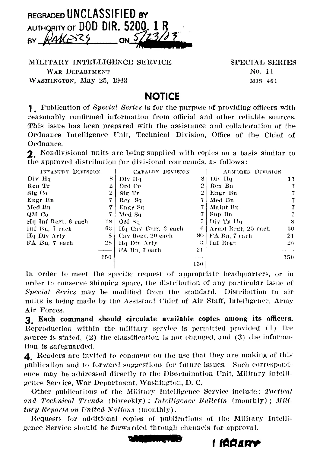
MILITARY INTELLIGENCE SERVICE
War Department
Washington, May 25, 1943
SPECIAL SERIES
No. 14
MIS 461
NOTICE
] Publication of Special Series is for the purpose of providing officers with
reasonably confirmed information from official and other reliable sources.
This issue has been prepared with tile assistance and collaboration of the
Ordnance Intelligence Unit, Technical Division, Office of the Chief of
Ordnance.
2. Nondivisional units are being supplied with copies on a basis similar to
the approved distribution for divisional commands, as follows:
Infantry Division Cavalry division AitMOitED Division
Div Hq 8 Div Hq 8 Div Hq 11
Ren Tr 2 Ord Co 2 Ren Bn 7
Sig Co 2 Sig Tr 2 Engr Bn 7
Engr Bn 7 Ren Sq 7 Med Bn 7
Med Bn 7 Engr Sq 7 Maint Bn 7
QM Co 7 Med Sq 7 Sup Bn 7
Hq Inf Regt, 6 eacli 18 QM Sq 7 Div Tn Hq 8
Inf Bn, 7 each 63 Ilq Cav Brig. .3 each 6 Armd Regt, 25 eacli 50
Hq Div Arty 8 Cav Regt, 20 each 80 FA Bn, 7 eaeh 21
FA Bn, 7 eaeh 28 Ilq Div Arty 3 Inf Regt J.i
150 FA Bn, 7 each 21 150 150
In order to meet the specific request of appropriate headquarters, or in
order to conserve shipping space, the distribution of any particular issue of
Special Series may be modified from the standard. Distribution to air
units is being made by the Assistant Chief of Air Staff, Intelligence, Army
Air Forces.
3 Each command should circulate available copies among its officers.
Reproduction within the military service is permitted provided (1) the
source is stated, (2) the classification is not changed, and (3) the informa-
tion is safeguarded.
4_ Readers are invited to comment on the use that they are making of this
publication and to forward suggestions for future issues. Such correspond-
ence may be addressed directly to the Dissemination Unit, Military Intelli-
gence Service, War Department, Washington, D. C.
Other publications of the Military Intelligence Service include: Tactical
and Technical Trends (biweekly) ; Intelligence Bulletin (monthly) ; Mili-
tary Reports on United Nations (monthly).
Requests for additional copies of publications of the Military Intelli-
gence Service should be forwarded through channels for approval.
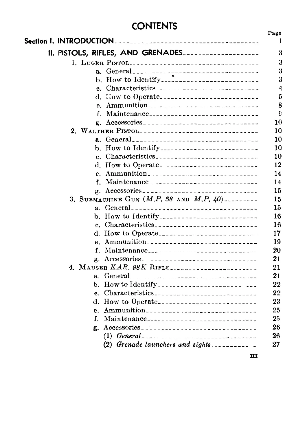
CONTENTS
Page
Section I. INTRODUCTION____________________________________________ 1
II. PISTOLS, RIFLES, AND GRENADES____________________________ 3
1. Luger Pistol_____________________________________ 3
a. General______________________________________ 3
b. How to Identify______________________________ 3
c. Characteristics______________________________ 4
d. How to Operate_______________________________ 5
e. Ammunition___________________________________ 8
f. Maintenance__________________________________ 9
g. Accessories_________________________________ 10
2. Walther Pistol____________________________________ 10
a. General_____________________________________ 10
b. How to Identify____________________________ 10
c. Characteristics_____________________________ 10
d. How to Operate_____________________________ 12
e. Ammunition__________________________________ 14
f. Maintenance_________________________________ 14
g. Accessories_________________________________ 15
3. Submachine Gun (M.P. 38 and M.P. 40)___________ 15
a. General_____________________________________ 15
b. How to Identify____________________________ 16
c. Characteristics_____________________________ 16
d. How to Operate_____________________________ 17
e. Ammunition__________________________________ 19
f. Maintenance_________________________________ 20
g. Accessories_________________________________ 21
4. Mauser KAR. 98К Rifle__________________________ 21
a. General_____________________________________ 21
b. How to Identify____________________________ 22
c. Characteristics_____________________________ 22
d. How to Operate______________________________ 23
e. Ammunition__________________________________ 25
f. Maintenance_________________________________ 25
g. Accessories, _______________________________ 26
(1) General_________________________________ 26
(2) Grenade launchers and sights_______ - 27
HI
IV
CONTENTS
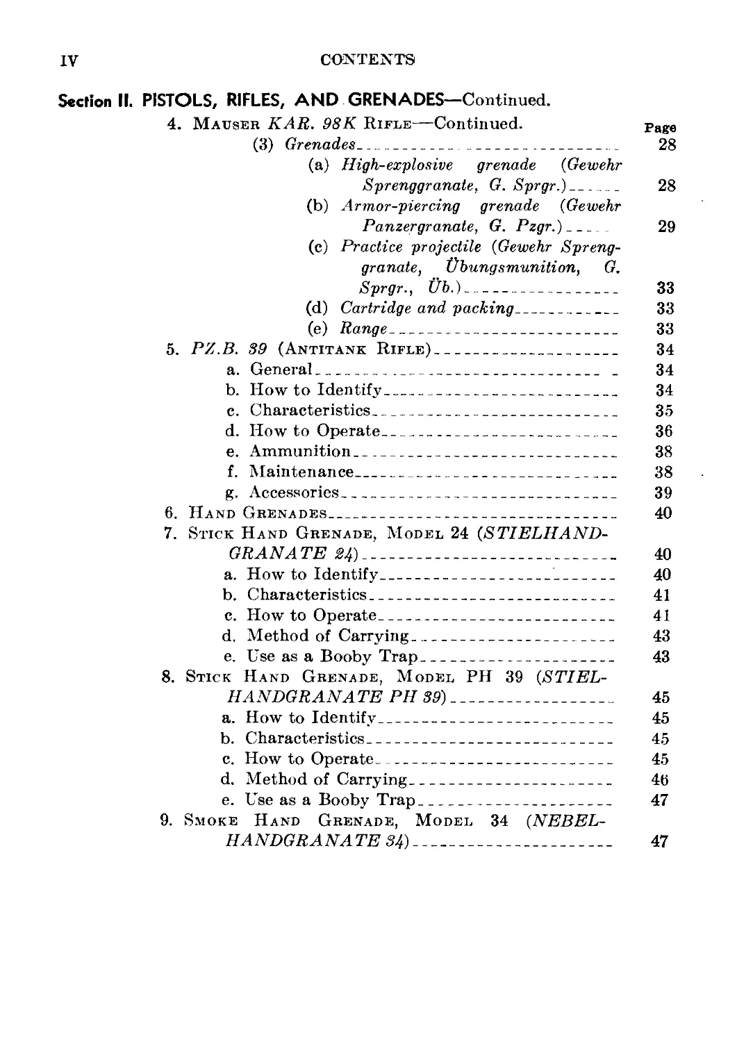
Section II. PISTOLS, RIFLES, AND GRENADES—Continued.
4. Mauser KAR. 98K Rifle—Continued. page
(3) Grenades_____________________________ 28
(a) High-explosive grenade (Gewehr
Sprenggranate, G. Sprgr.)__ 28
(b) Armor-piercing grenade (Gewehr
Panzergranate, G. Pzgr.)___ 29
(c) Practice projectile (Gewehr Spreng-
granate, Ubungs munition, G.
Sprgr., Ub.)------------------ 33
(d) Cartridge and packing__________ 33
(e) Range__________________________ 33
5. PZ.B. 39 (Antitank Rifle)______________________ 34
a. General________________________________ _ 34
b. How to Identify__________________________ 34
c. Characteristics__________________________ 35
d. How to Operate___________________________ 36
e. Ammunition_______________________________ 38
f. Maintenance______________________________ 38
g. Accessories______________________________ 39
6. Hand Grenades________________________________ 40
7. Stick Hand Grenade, Model 24 (STIELHAND-
GRANATE 24)______________________________________ 40
a. How to Identify_________________________ 40
b. Characteristics__________________________ 41
c. How to Operate___________________________ 41
d. Method of Carrying_______________________ 43
e. Use as a Booby Trap______________________ 43
8. Stick Hand Grenade, Model PH 39 (STIEL-
HANDGRANATE PH 39)_______________________________ 45
a. How to Identify__________________________ 45
b. Characteristics__________________________ 45
c. How to Operate___________________________ 45
d. Method of Carrying_______________________ 46
e. Use as a Booby Trap______________________ 47
9. Smoke Hand Grenade, Model 34 (NEBEL-
HANDGRANATE 34)__________________________________ 47
CONTENTS V
Section II. PISTOLS, RIFLES, AND GRENADES—Continued. Page
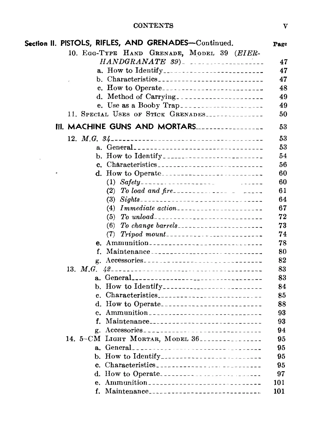
10. Egg-Type Hand Grenade, Model 39 (EIEU-
HANDGRANATE 39) ________________________________L__ 47
a. How to Identify____________________________ 47
b. Characteristics___________________________ 47
c. How to Operate_____________________________ 48
d. Method of Carrying________________________ 49
e. Use as a Booby Trap________________________ 49
11. Special Uses of Stick Grenades________________ 50
III. MACHINE GUNS AND MORTARS________________________ 53
12. M.G. 34_______________________________________ 53
a. General___________________________________ 53
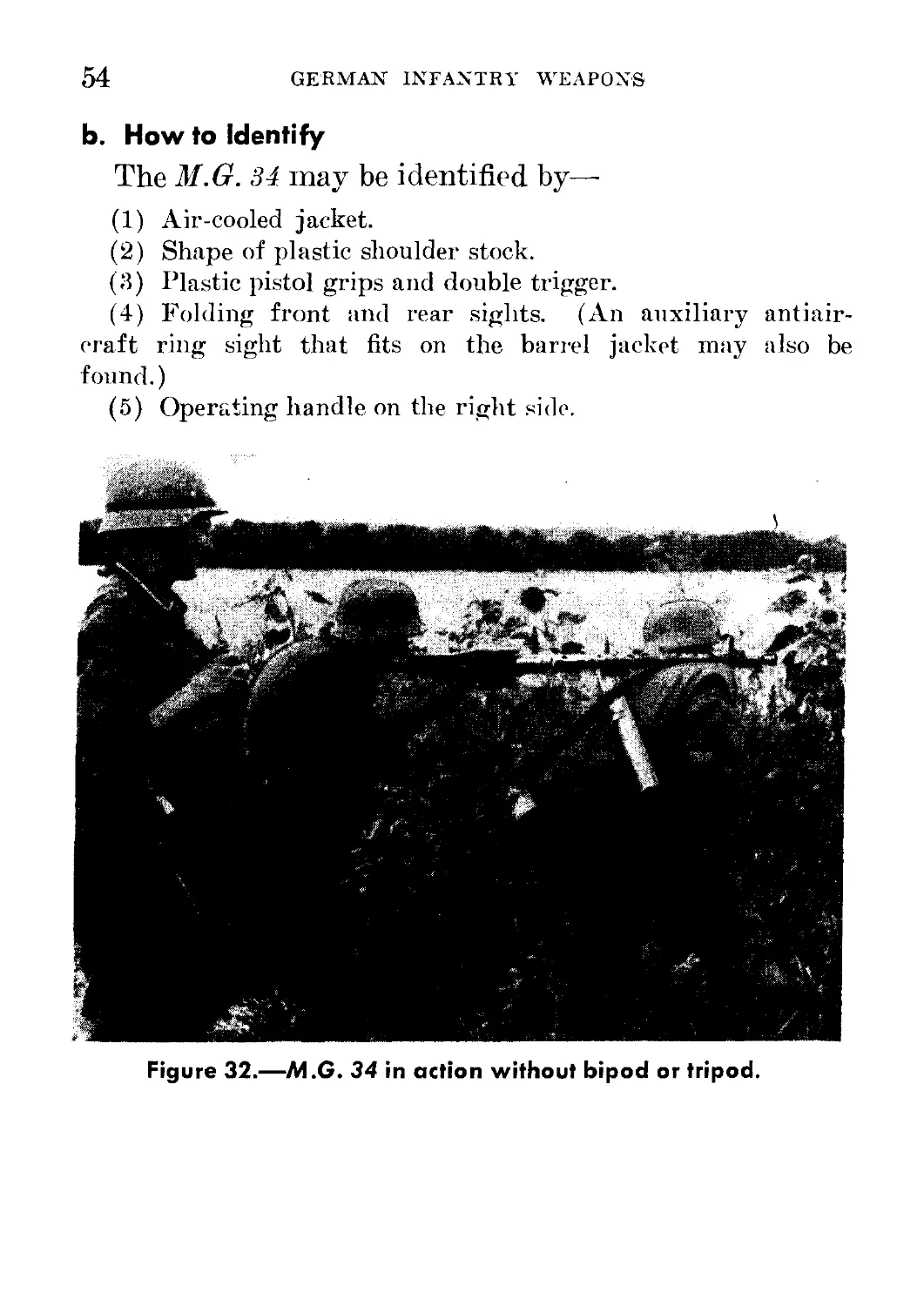
b. How to Identify___________________________ 54
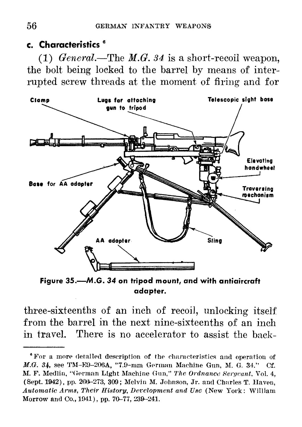
c. Characteristics___________________________ 56
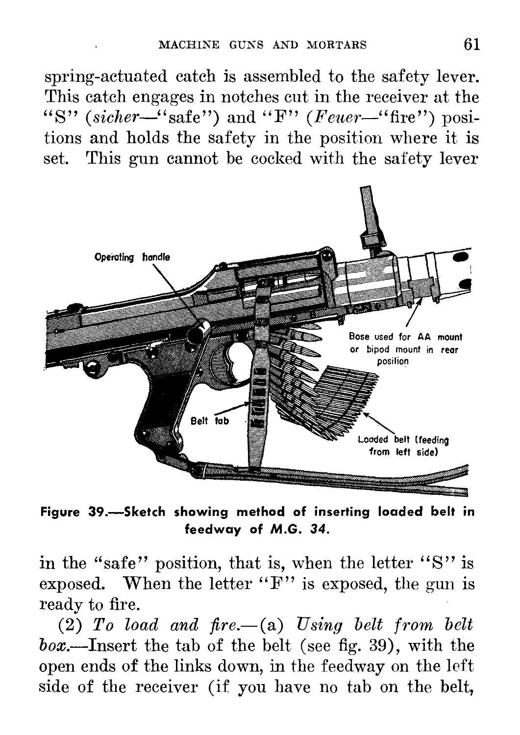
d. How to Operate____________________________ 60
(1) Safety------------------------------ 60
(2) To load and fire__________ _ _______ 61
(3) Sights-------------------------------- 64
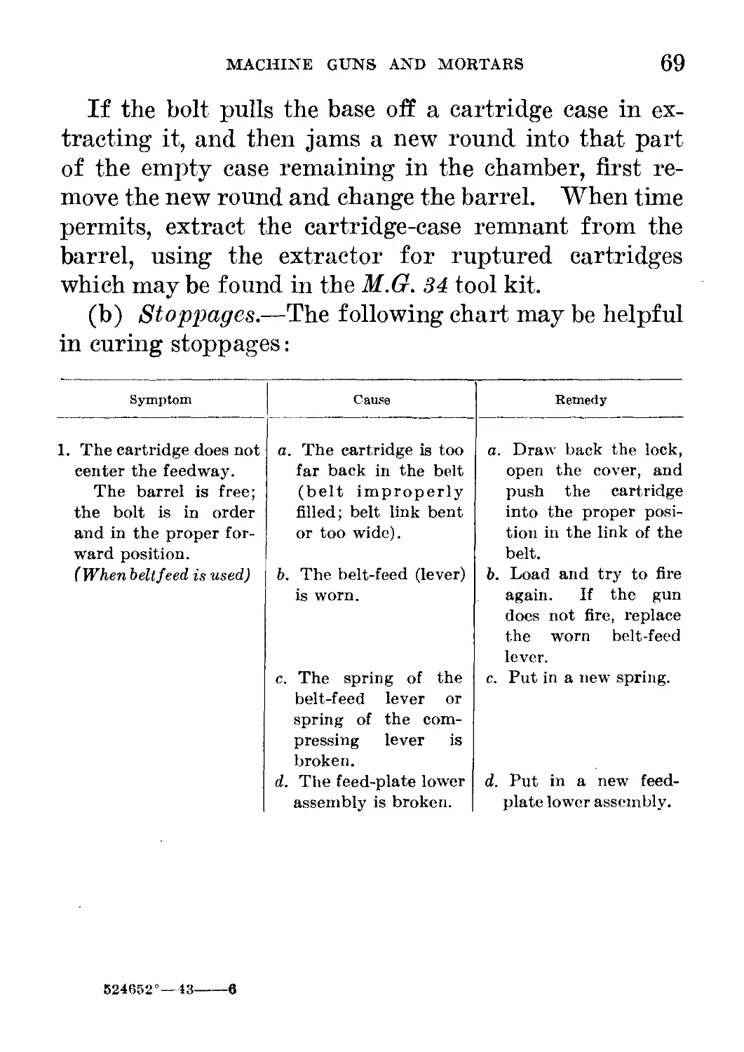
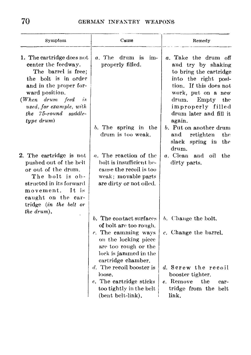
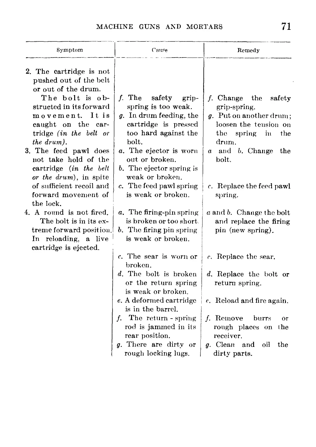
(4) Immediate action_______________________ 67
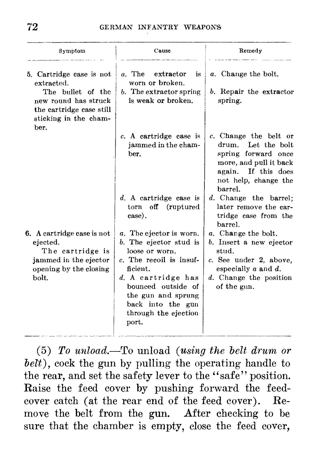
(5) To unload------------------------------ 72
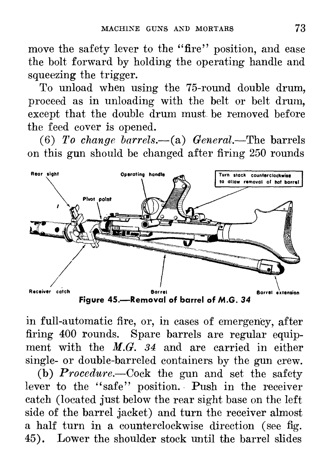
(6) To change barrels______________________ 73
(7) Tripod mount___________________________ 74
e. Ammunition----------------------------- 78
f. Maintenance_____________________________ 80
g. Accessories________________________________ 82
13. M.G. 42_______________________________________ 83
a. General__________________________________ 83
b. How to Identify__________________________ 84
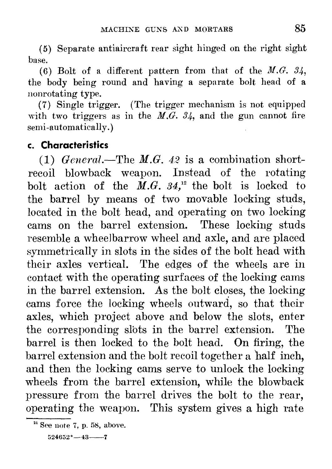
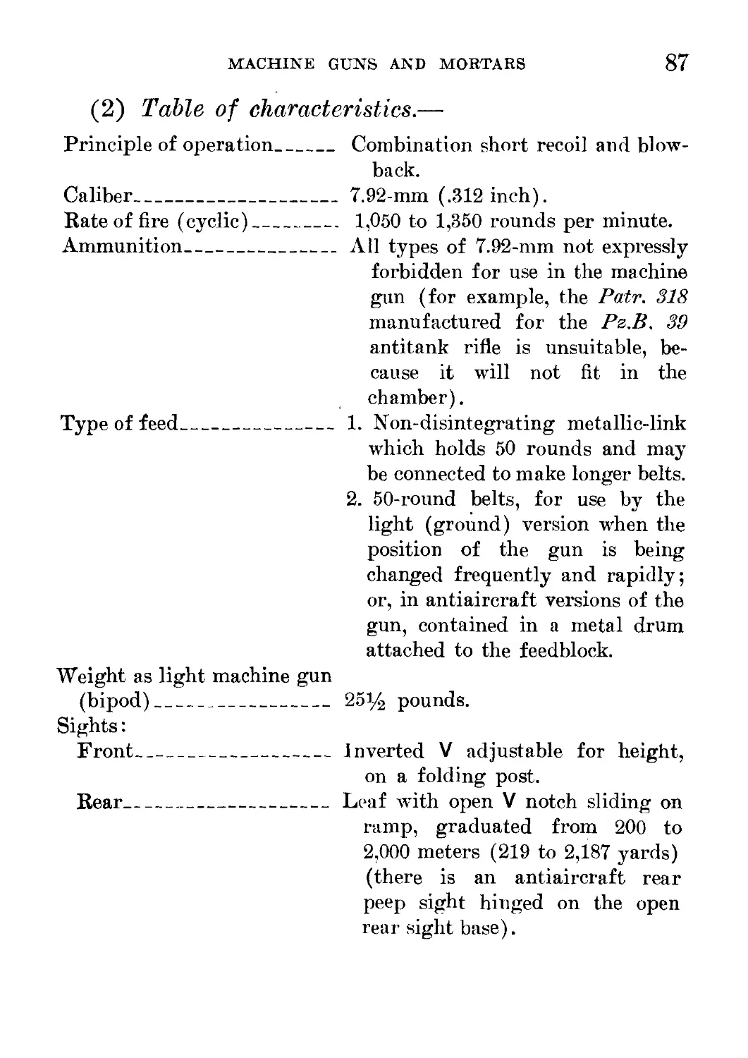
c. Characteristics____________________________ 85
d. How to Operate_____________________________ 88
e. Ammunition_________________________________ 93
f. Maintenance________________________________ 93
g. Accessories_______________________________ 94
14. 5-CM Light Mortar, Model 36____________________ 95
a. General__________________________________ 95
b. How to Identify__________________________ 95
c. Characteristics___________________________ 95
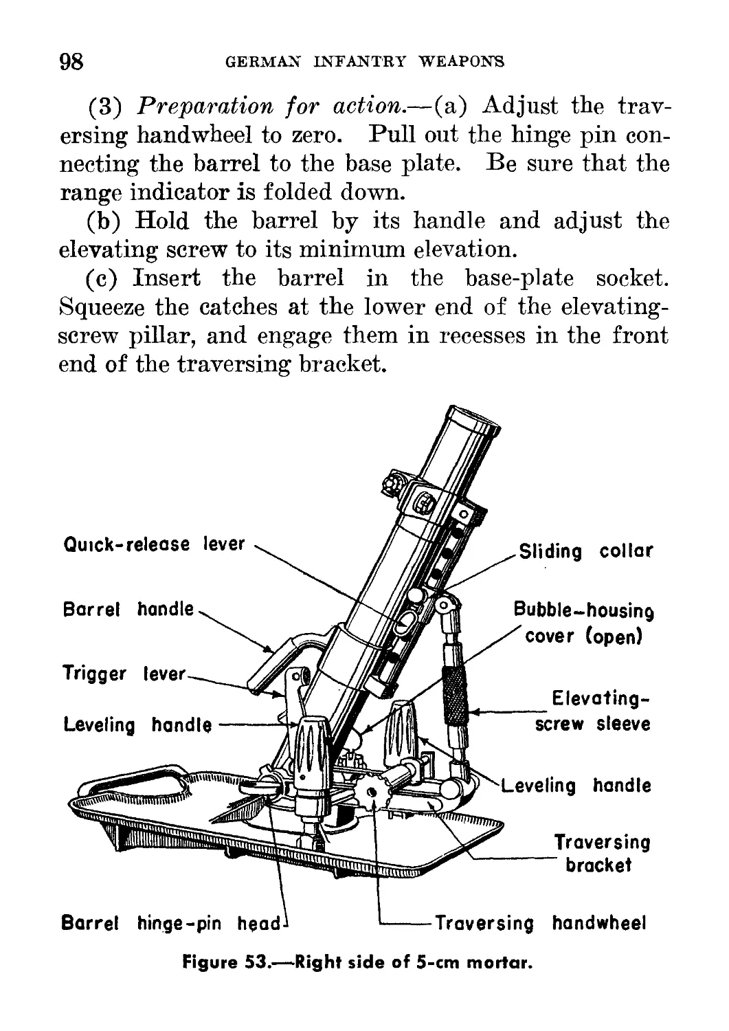
d. How to Operate--------------------------- 97
e. Ammunition_______________________________ 101
f. Maintenance_______________________________ 101
VI
CONTENTS
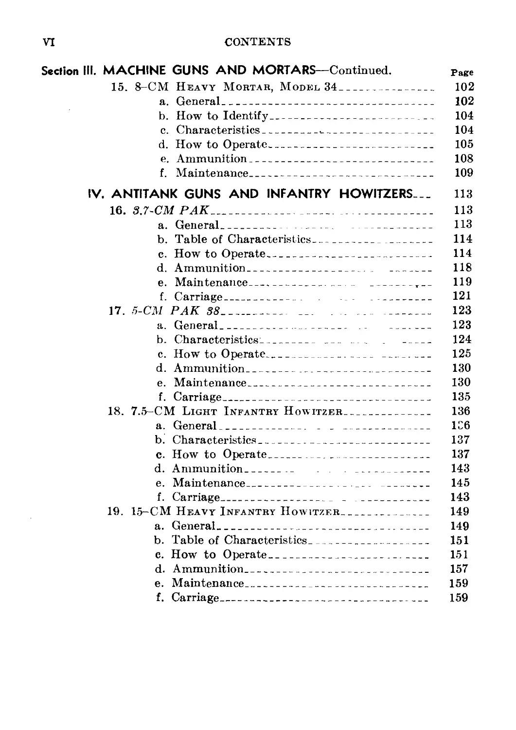
Section III. MACHINE GUNS AND MORTARS—Continued. Page
15. 8-CM Heavy Mortar, Model 34___________________ 102
a. General__________________________________ 102
b. How to Identify_________________________ 104
c. Characteristics_______,----------------- 104
d. How to Operate___________________________ 105
e. Ammunition_______________________________ 108
f. Maintenance______________________________ 109
IV . ANTITANK GUNS AND INFANTRY HOWITZERS-.. 113
16. 3.7-CM PAK____________________________________ 113
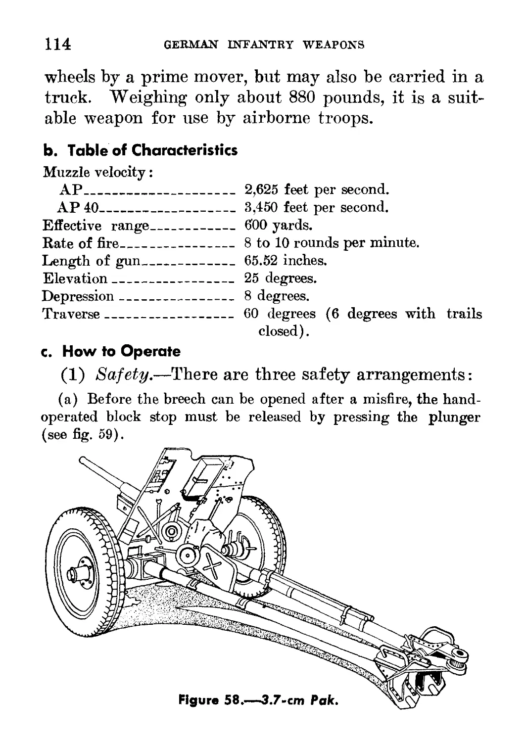
a. General___________-____ ________________ 113
b. Table of Characteristics________________ 114
c. How to Operate__________________________ 114
d. Ammunition___________________. --------- 118
e. Maintenance_______________ __________T__ 119
f. Carriage__________ . _ . _______________ 121
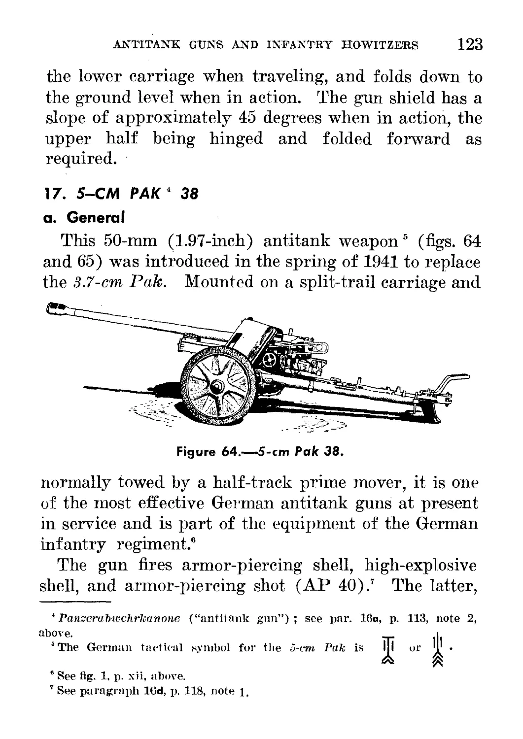
17. 5-CM PAK 38_____________ ... .... ______ 123
a. General__________________ .. _______ 123
b. Characteristics:_____________________ 124
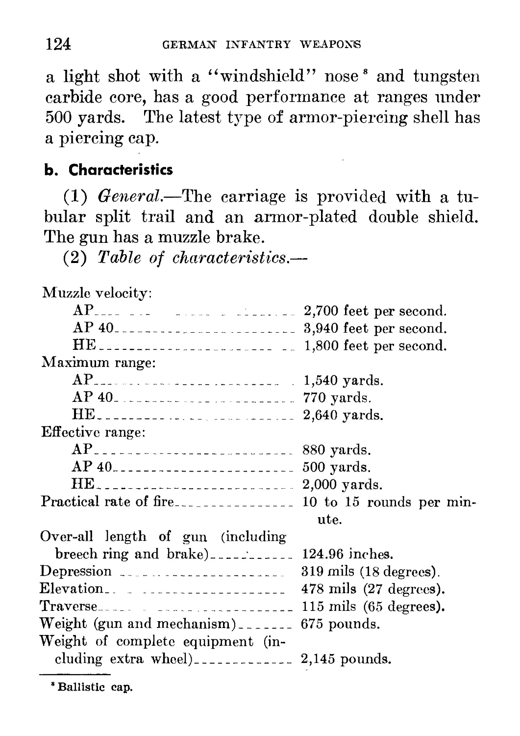
c. How to Operate________________________ 125
d. Ammunition_______________________________ 130
e. Maintenance______________________________ 130
f. Carriage_________________________________ 135
18. 7.5CM Light Infantry Howitzer__________________ 136
a. General_______________ . _ _____________ 136
b. Characteristics_________________________ 137
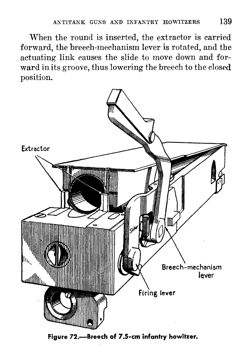
c. How to Operate___________________________ 137
d. Ammunition_____________________________ 143
e. Maintenance________________ _ . _______ 145
f. Carriage_______________ _ ______________ 143
19. 15-CM Heavy Infantry Howitzer__________________ 149
a. General_________________________________ 149
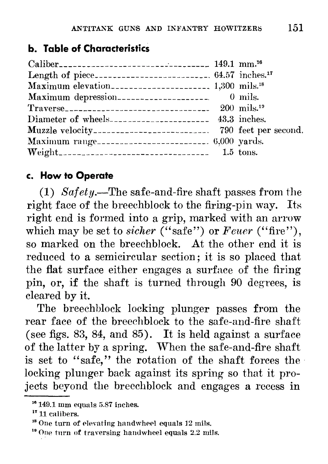
b. Table of Characteristics_________________ 151
c. How to Operate__________________________ 151
d. Ammunition_______________________________ 157
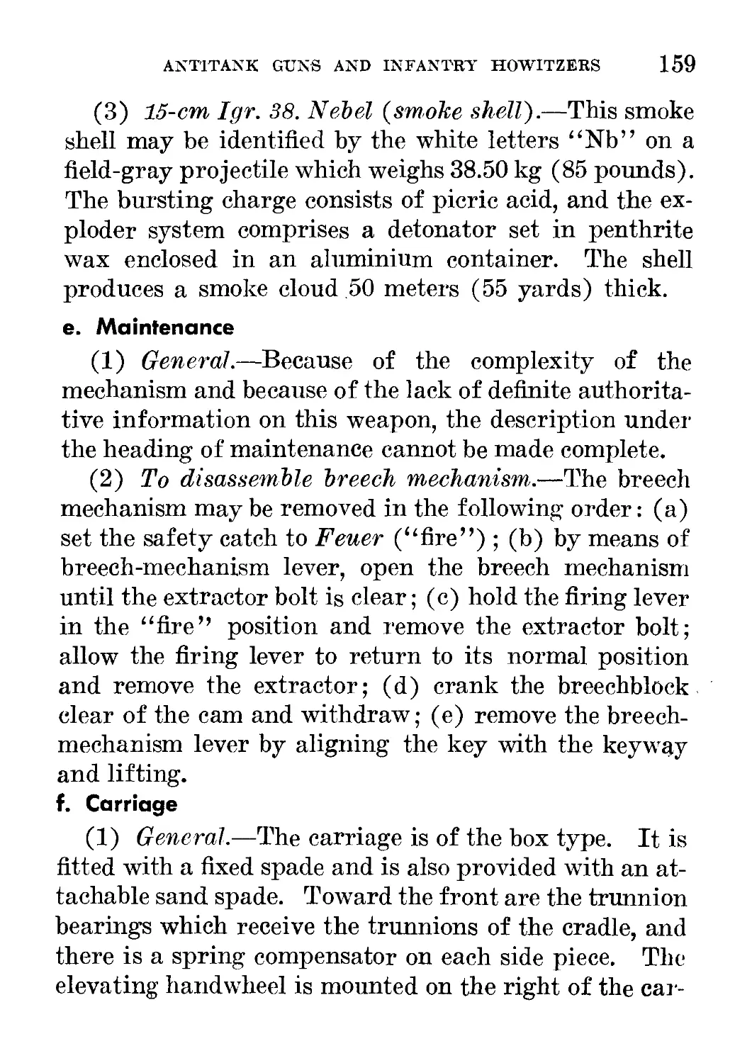
e. Maintenance_____________________________ 159
f. Carriage_________________________________ 159
CONTEXTS VII
Page
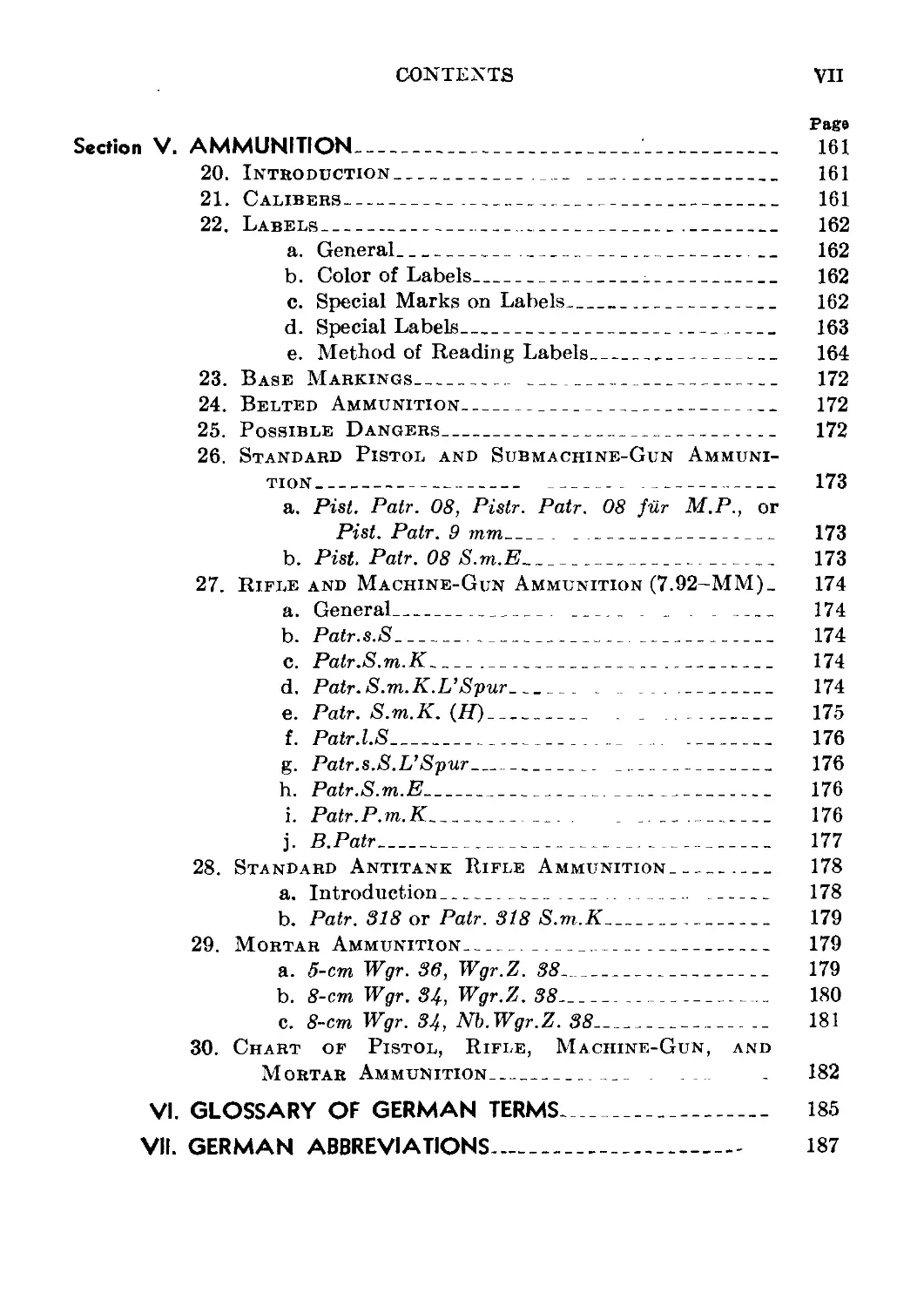
Section V. AMMUNITION______________________________________ 161
20. Introduction_______________________________ 161
21. Calibers-------------------------------------- 161
22. Labels_______________________________________ 162
a. General_______________________________ 162
b. Color of Labels_______________________ 162
c. Special Marks on Labels_________________ 162
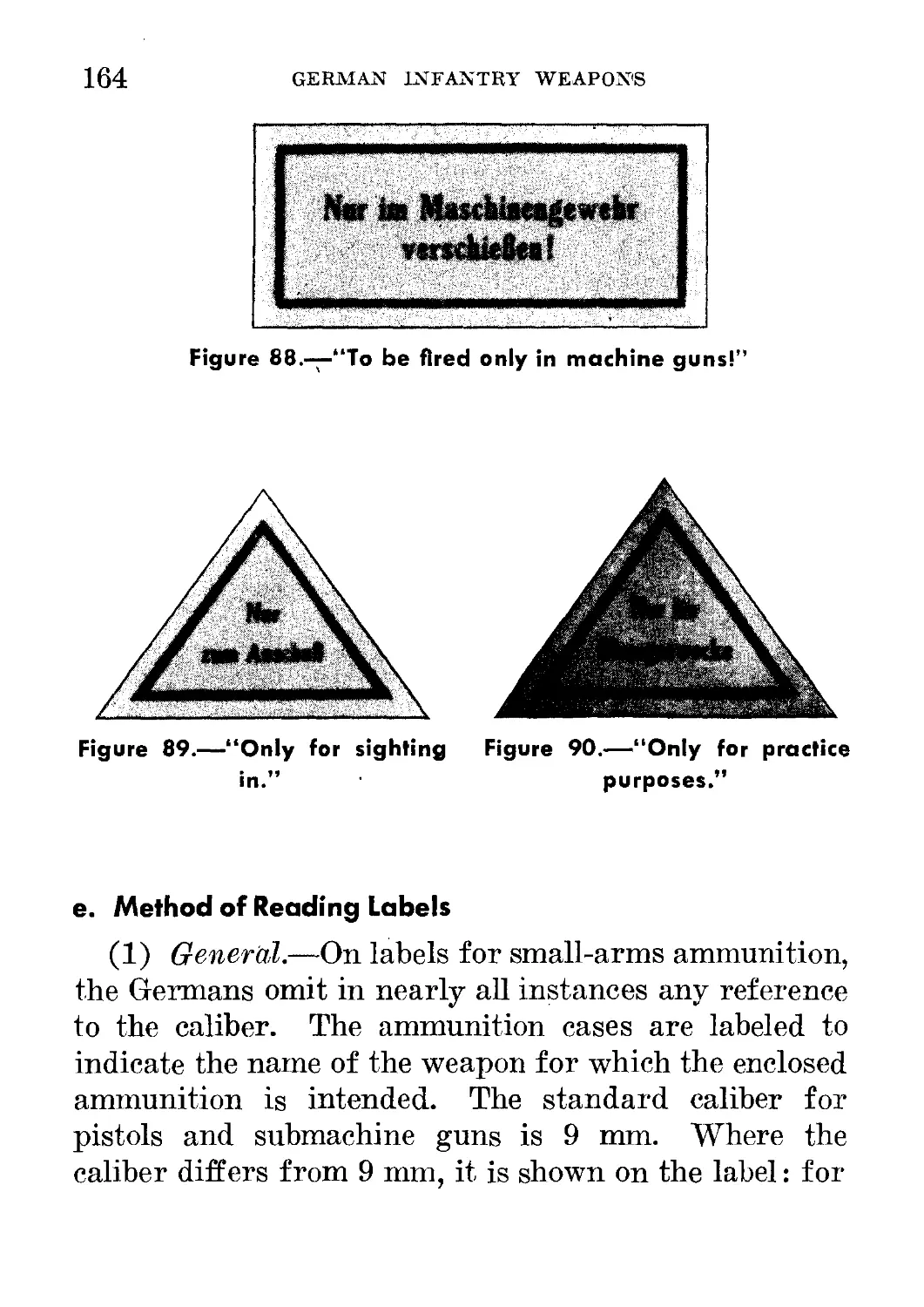
d. Special Labels__________________________ 163
e. Method of Reading Labels________________ 164
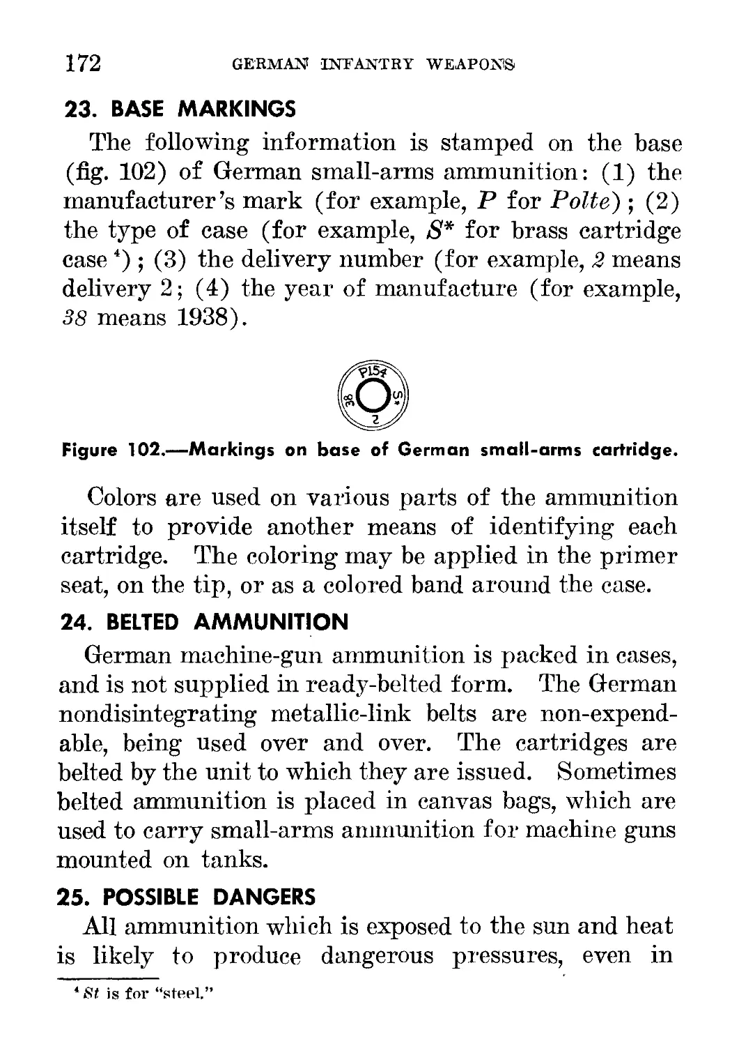
23. Base Markings___________________ ___________ 172
24. Belted Ammunition_____________________________ 172
25. Possible Dangers______________________________ 172
26. Standard Pistol and Submachine-Gun Ammuni-
tion_________________________________ _ _________ 173
a. Pist. Patr. 08, Pistr. Patr. 08 fur M.P., or
Pist. Patr. 9 mm____ _________________ 173
b. Pist. Patr. 08 S.m.E____________________ 173
27. Rifle and Machine-Gun Ammunition (7.92-MM). 174
a. General___________ _________ _ . . ___ 174
b. Patr.s.S________________________________ 174
c. Patr.S.m.K______________________________ 174
d. Patr. S.m.K.L’Spur____ . ..._______ 174
e. Patr. S.m.K. (H)______ . _ _______ 175
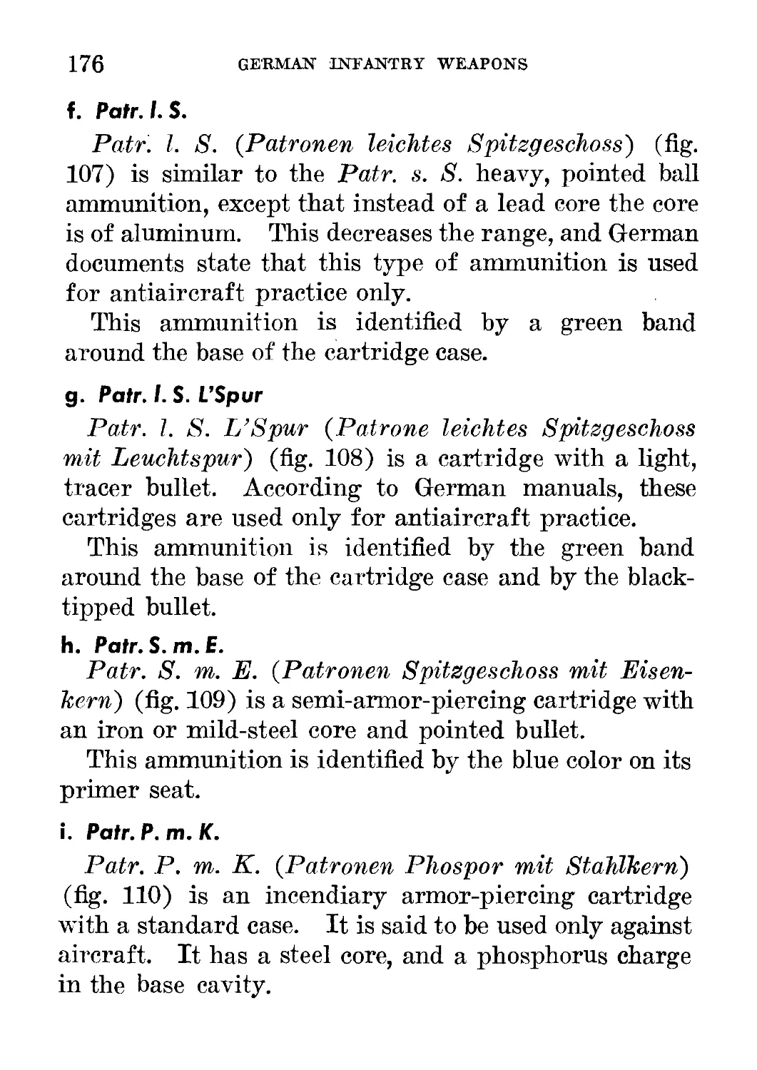
f. Patr.l.S_______________________________ 176
g. Patr. s.S.L’Spur_____________________ 176
h. Patr.S.m.E_____________________________ 176
i. Patr.P.m.K___________ . _______ 176
j. B.Patr___________________________________ 177
28. Standard Antitank Rifle Ammunition___________ 178
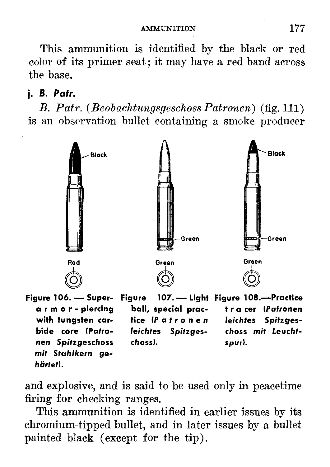
a. Introduction__________.. ______ ______ 178
b. Patr. 318 or Patr. 318 S.m.K__________ 179
29. Mortar Ammunition____________________________ 179
a. 5-cm Wffr. Зв, Wffr.Z. 38_______________ 179
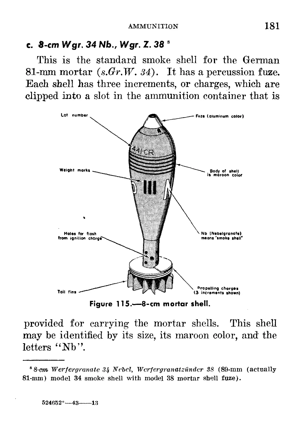
b. 8-cm Wffr. 34, Wffr.Z. 38______________ 180
c. 8-cm Wffr. 34, Kb. Wffr.Z. 38___________ 181
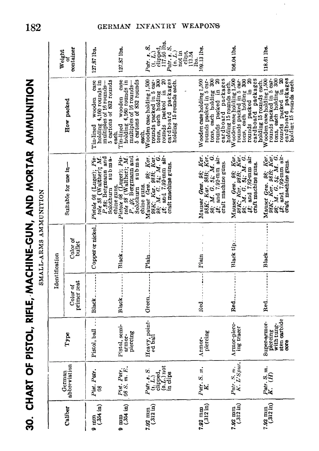
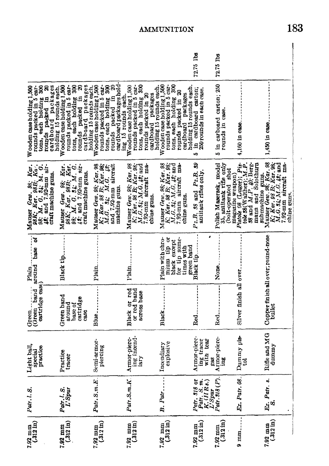
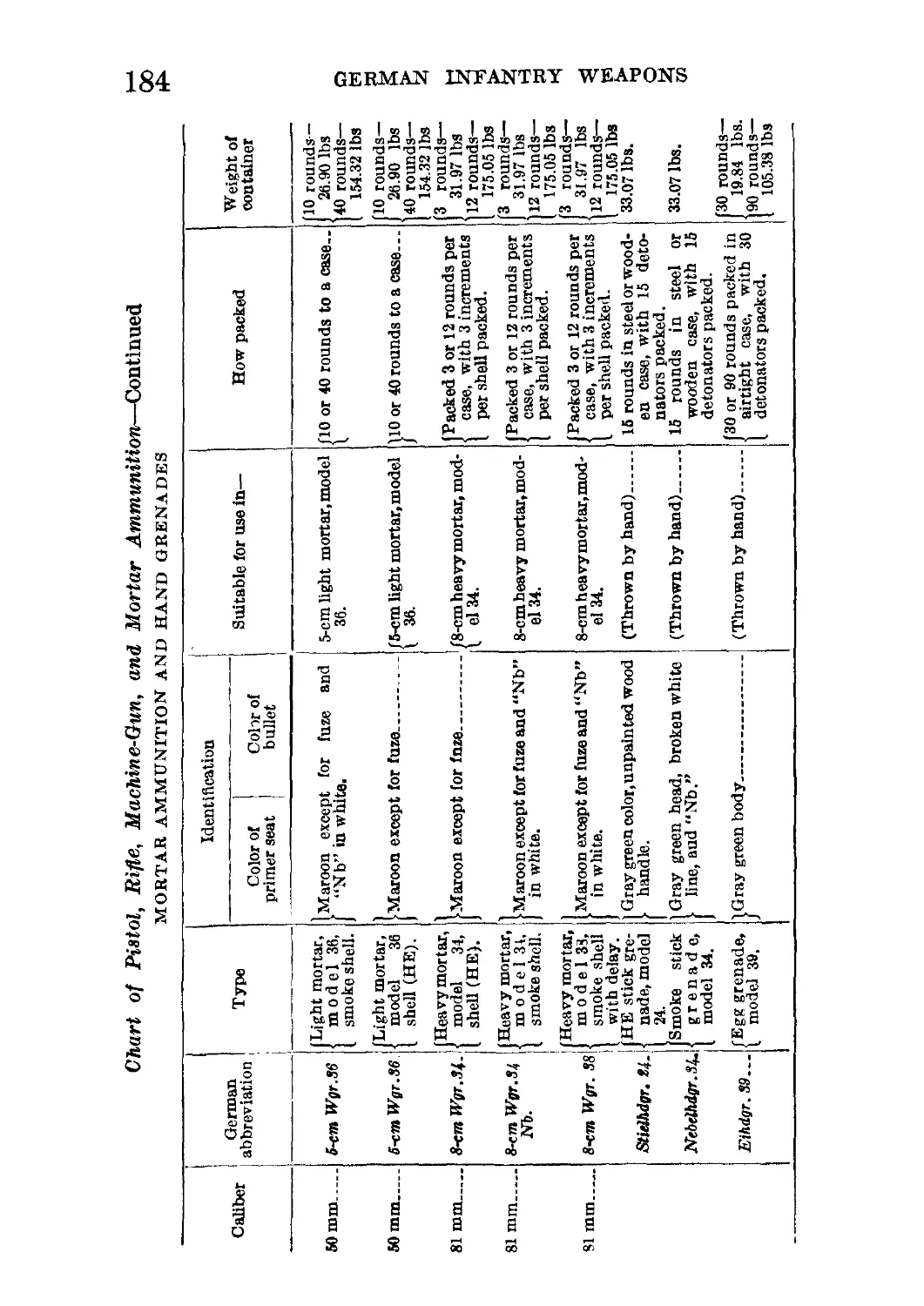
30. Chart of Pistol, Rifle, Machine-Gun, and
Mortar Ammunition______________________ ___ . 182
VI. GLOSSARY OF GERMAN TERMS________________________ 185
VII. GERMAN ABBREVIATIONS___________________________ 187
vni
CONTENTS
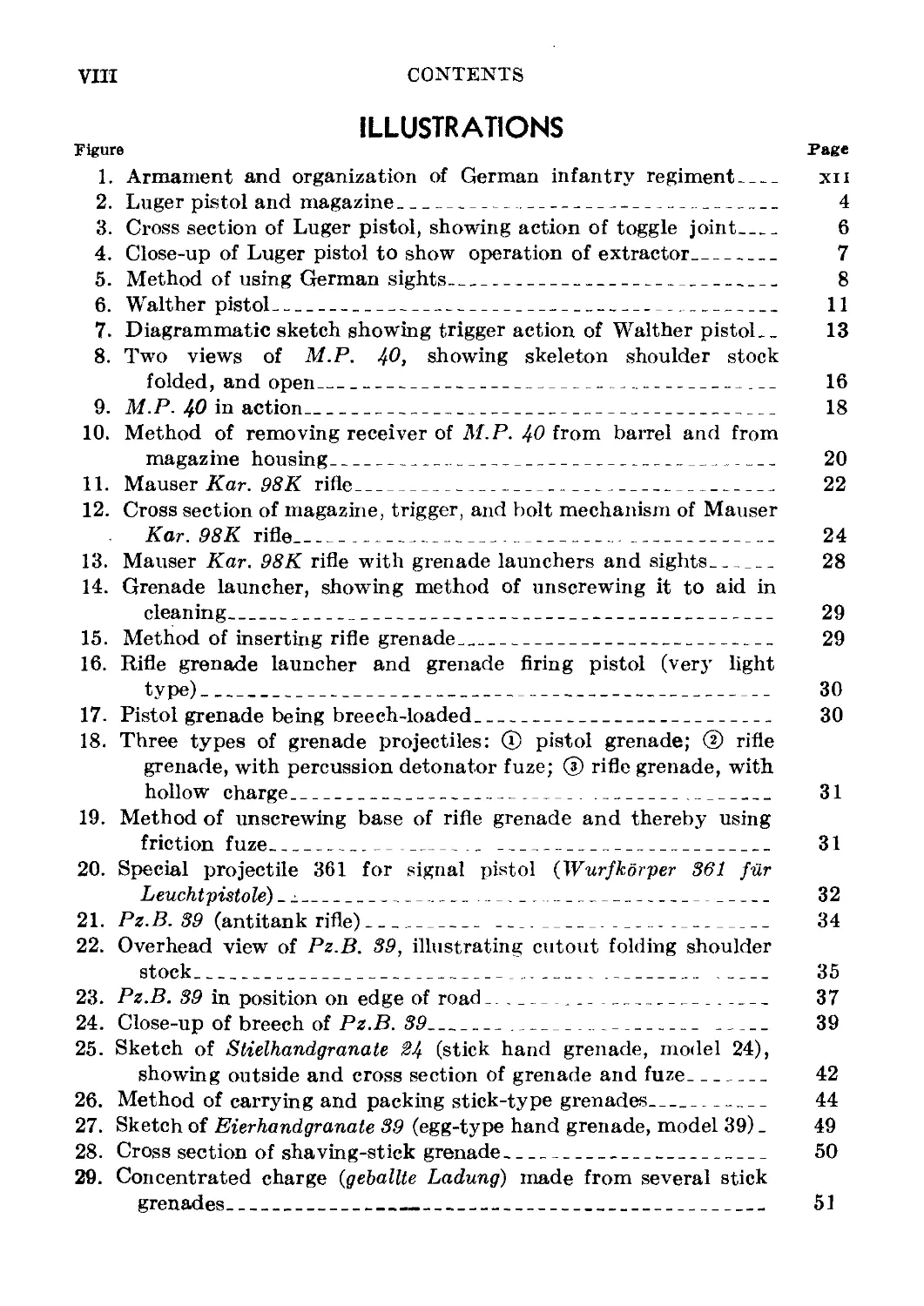
ILLUSTRATIONS
Figure Page
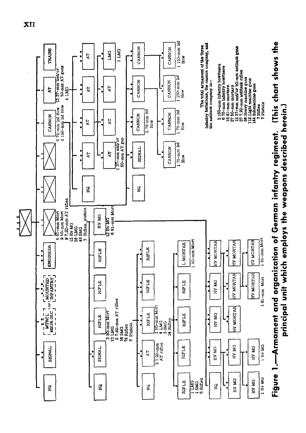
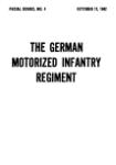
1. Armament and organization of German infantry regiment__________ xn
2. Luger pistol and magazine_____________________________________ 4
3. Cross section of Luger pistol, showing action of toggle joint_ 6
4. Close-up of Luger pistol to show operation of extractor_______ 7
5. Method of using German sights_________________________________ 8
6. Walther pistol________________________________________________ 11
7. Diagrammatic sketch showing trigger action of Walther pistol. _ 13
8. Two views of M.P. 40, showing skeleton shoulder stock
folded, and open_______________________________________________ 16
9. M.P. 40 in action_____________________________________________ 18
10. Method of removing receiver of M.P. 40 from barrel and from
magazine housing_________________________________________________ 20
11. Mauser Kar. 98К rifle___________________________________________ 22
12. Cross section of magazine, trigger, and bolt mechanism of Mauser
Kar. 98К rifle________________________ __________________________ 24
13. Mauser Kar. 98K rifle with grenade launchers and sights_________ 28
14. Grenade launcher, showing method of unscrewing it to aid in
cleaning___________________________________________________________ 29
15. Method of inserting rifle grenade_____________________________ 29
16. Rifle grenade launcher and grenade firing pistol (very light
type)______________________________________________________________ 30
17. Pistol grenade being breech-loaded____________________________ 30
18. Three types of grenade projectiles: ® pistol grenade; @ rifle
grenade, with percussion detonator fuze; ® rifle grenade, with
hollow charge_________________________________ __________________ 31
19. Method of unscrewing base of rifle grenade and thereby using
friction fuze_________________________ __________________________ 31
20. Special projectile 361 for signal pistol (Wurfkorper 361 fur
Leuchtpistole) _ j.______________________________________________ 32
21. Pz.B. 39 (antitank rifle)________ _____________________________ 34
22. Overhead view of Pz.B. 39, illustrating cutout folding shoulder
stock____________________________________________________________ 35
23. Pz.B. 39 in position on edge of road.. _______________________ 37
24. Close-up of breech of Pz.B. 39___________ ____________ ________ 39
25. Sketch of Stielhandgranate 24 (stick hand grenade, model 24),
showing outside and cross section of grenade and fuze____________ 42
26. Method of carrying and packing stick-type grenades_____________ 44
27. Sketch of Eierhandgranate 39 (egg-type hand grenade, model 39) _ 49
28. Cross section of shaving-stick grenade_________________________ 50
29. Concentrated charge (gebalUe Ladung) made from several stick
grenades_________________________________________________________ 51
CONTENTS IX
Figure Page
30. ® Stick grenade antipersonnel mine__________________________ 52
® Stick grenade cluster mine________________________________ 52
® Cross section of pressure igniter 35 (Pruckzunder 35, D.Z. 35). 52
31. Stick grenades used as Bangalore torpedo_______________________ 52
32. M.G. 34 in action without bipod or tripod_____________________ 54
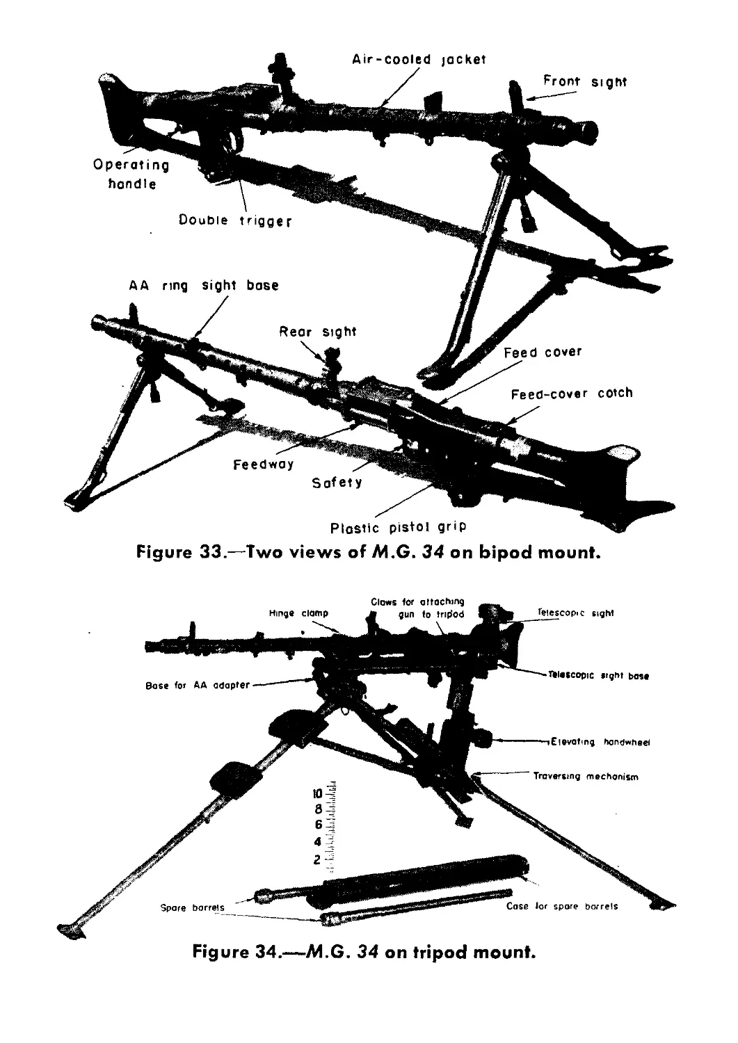
33. Two views of M.G. 34 on bipod mount___________________________ 55
34. M.G. 34 on tripod mount__________-____________________________ 55
35. M.G. 34 on tripod mount, and with antiaircraft adapter_____ 56
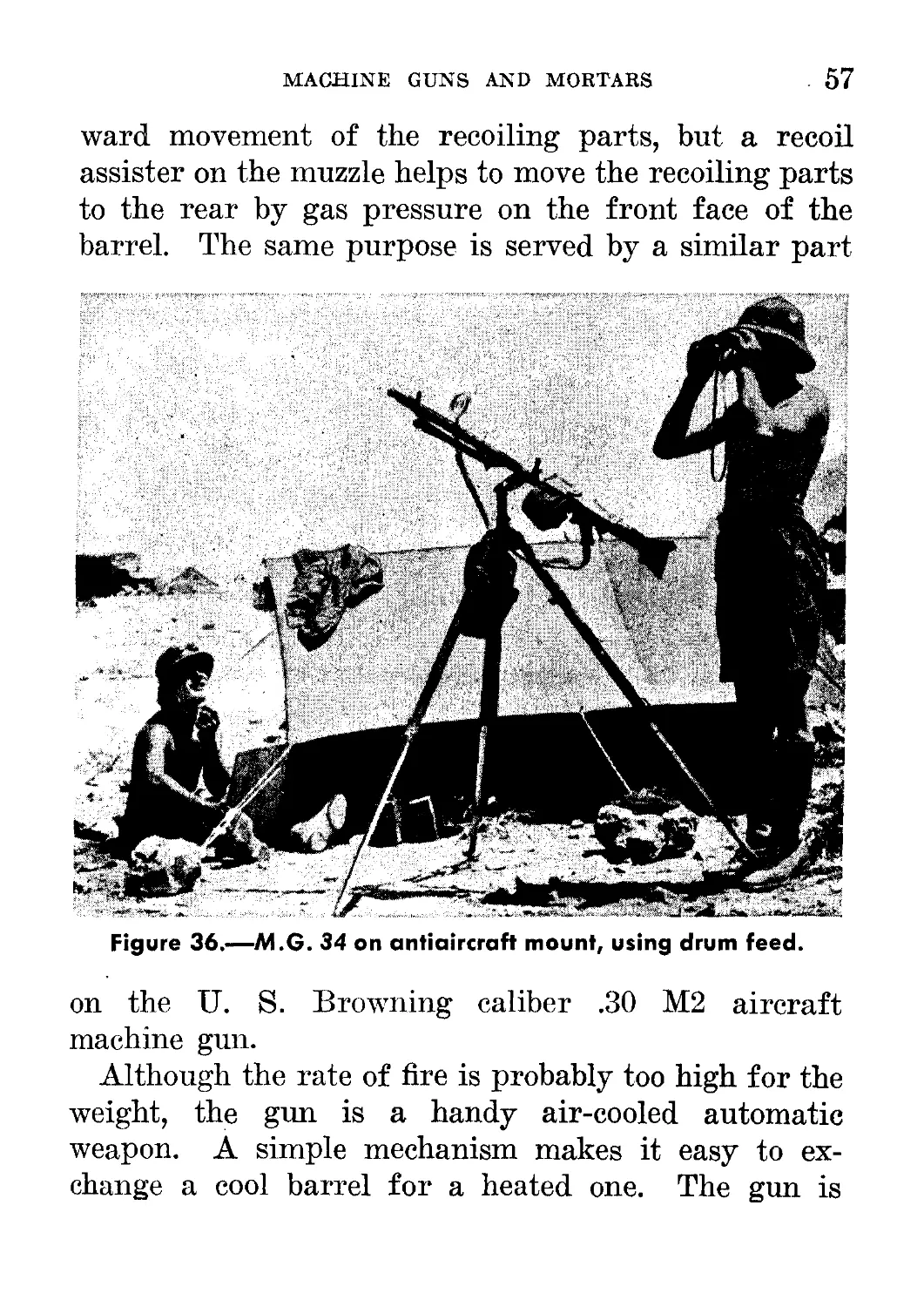
36. M.G. 34 on antiaircraft mount, using drum feed________________ 57
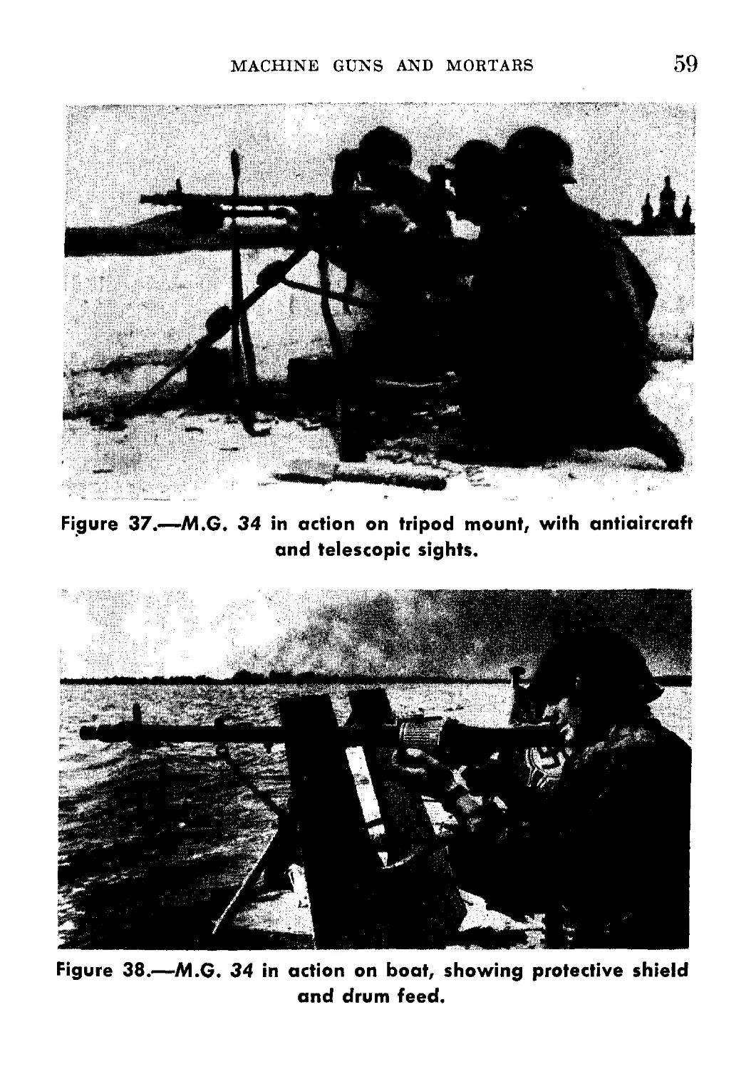
37. M.G. 34 in action on tripod mount, with antiaircraft and tele-
scopic sights---------------------------------------------------- 59
38. M.G. 34 in action on boat, showing protective shield and drum
feed______________________________________________ - ------ _ 59
39. Sketch showing method of inserting loaded belt in feedway of
M.G. 34___________________________________________________ 61
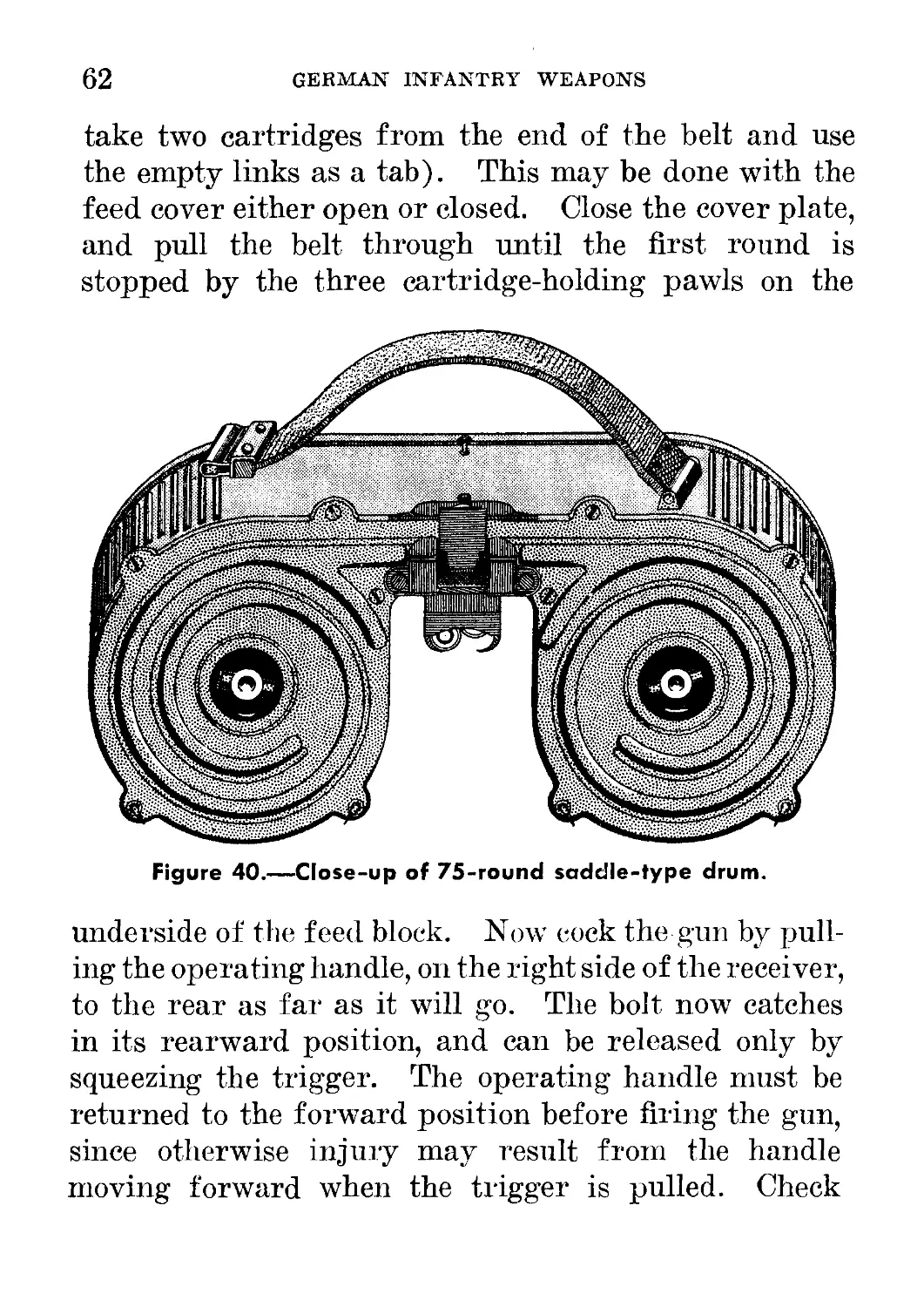
40. Close-up of 75-round saddle-type drum________ ______________ 62
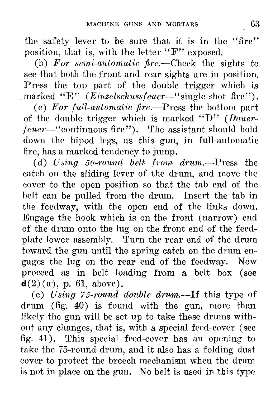
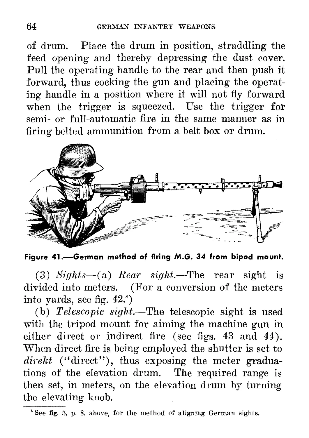
41. German method of firing M.G. 34 from bipod mount------------ 64
42. Rear sight of M.G. 34, showing relation between yards and meters. 65
43. Telescopic sight on M.G. 34------------------------------------- 66
44. Telescopic sight for M.G. 34 (rear view)_______________________ 67
45. Removal of barrel of M.G. 34________________________________ 73
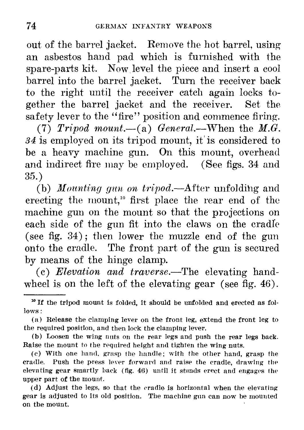
46. Rear view of tripod mount for M.G. 34__________________________ 75
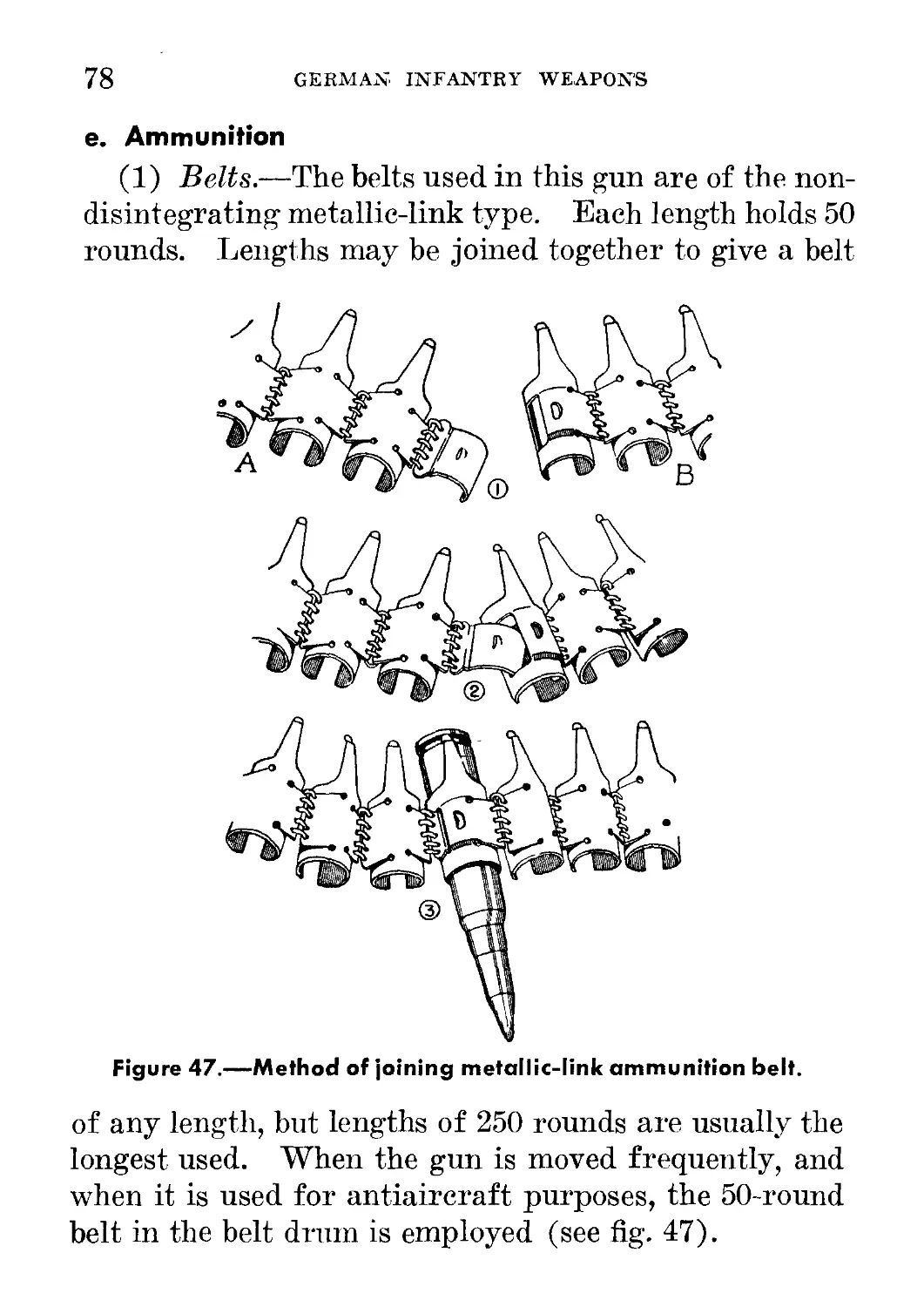
47. Method of joining metallic-link ammunition belt________________ 78
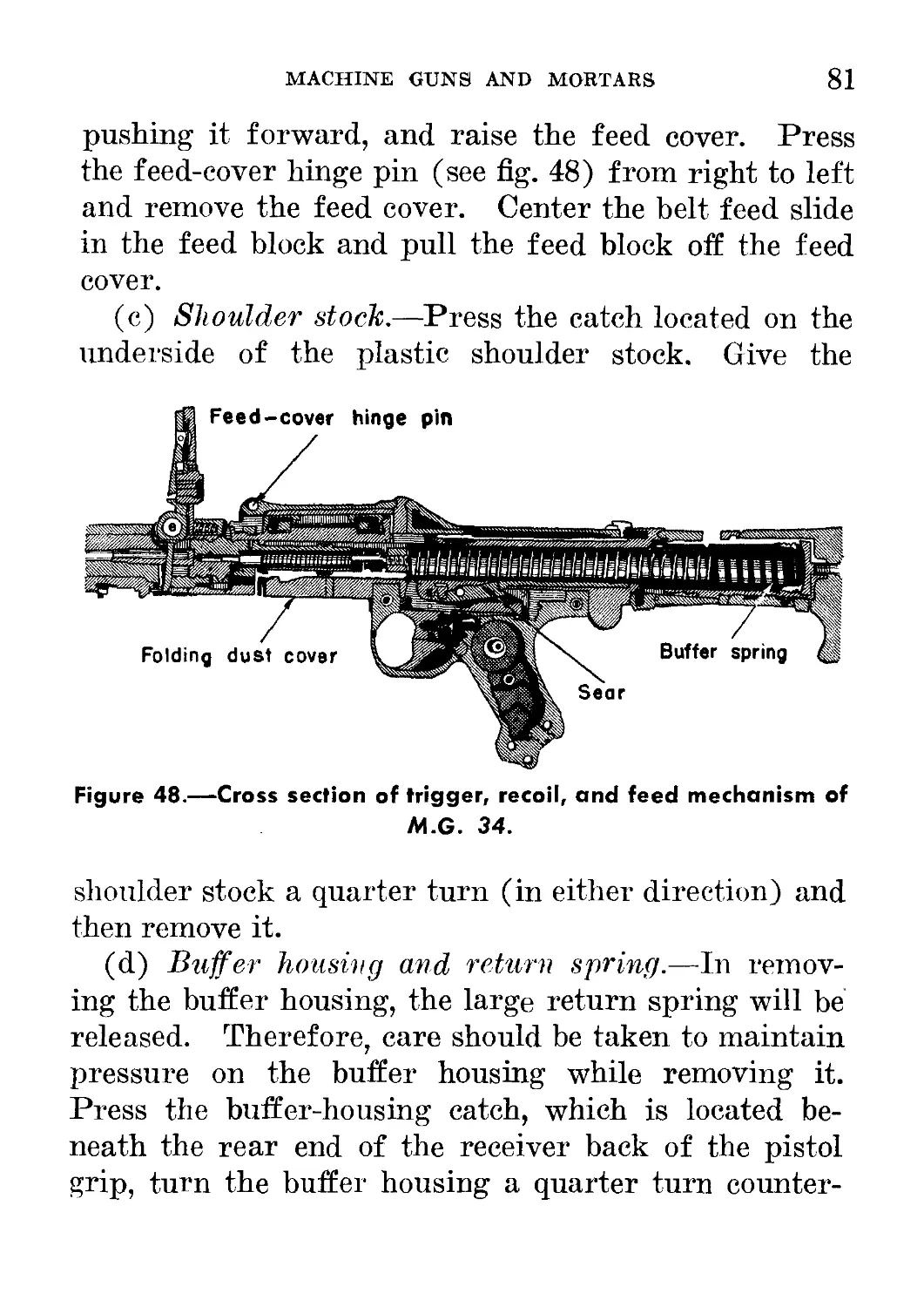
48. Cross section of trigger, recoil, and feed mechanism of M.G. 34-- 81
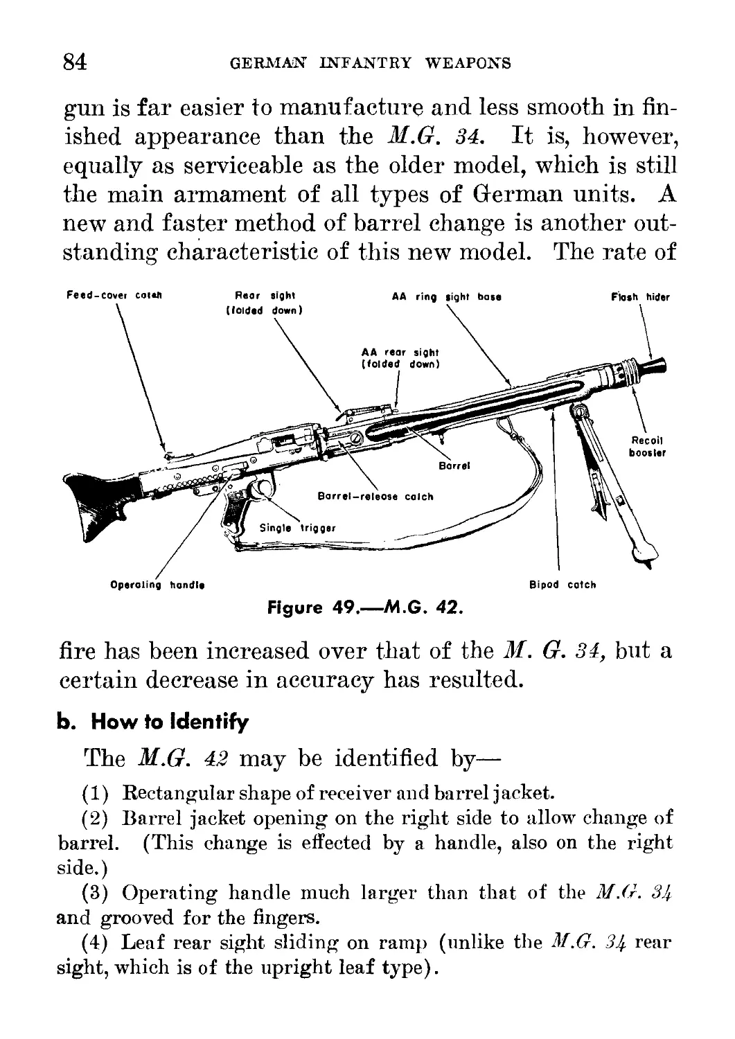
49. M.G. 42_____________________________________________________ 84
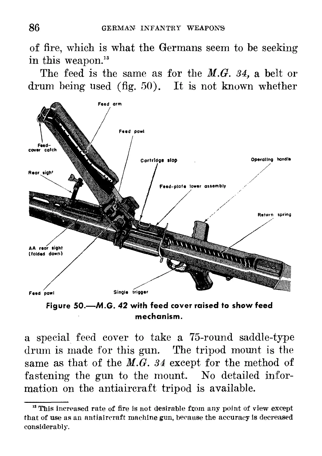
50. M.G. 4% with feed cover raised to show feed mechanism_______ 86
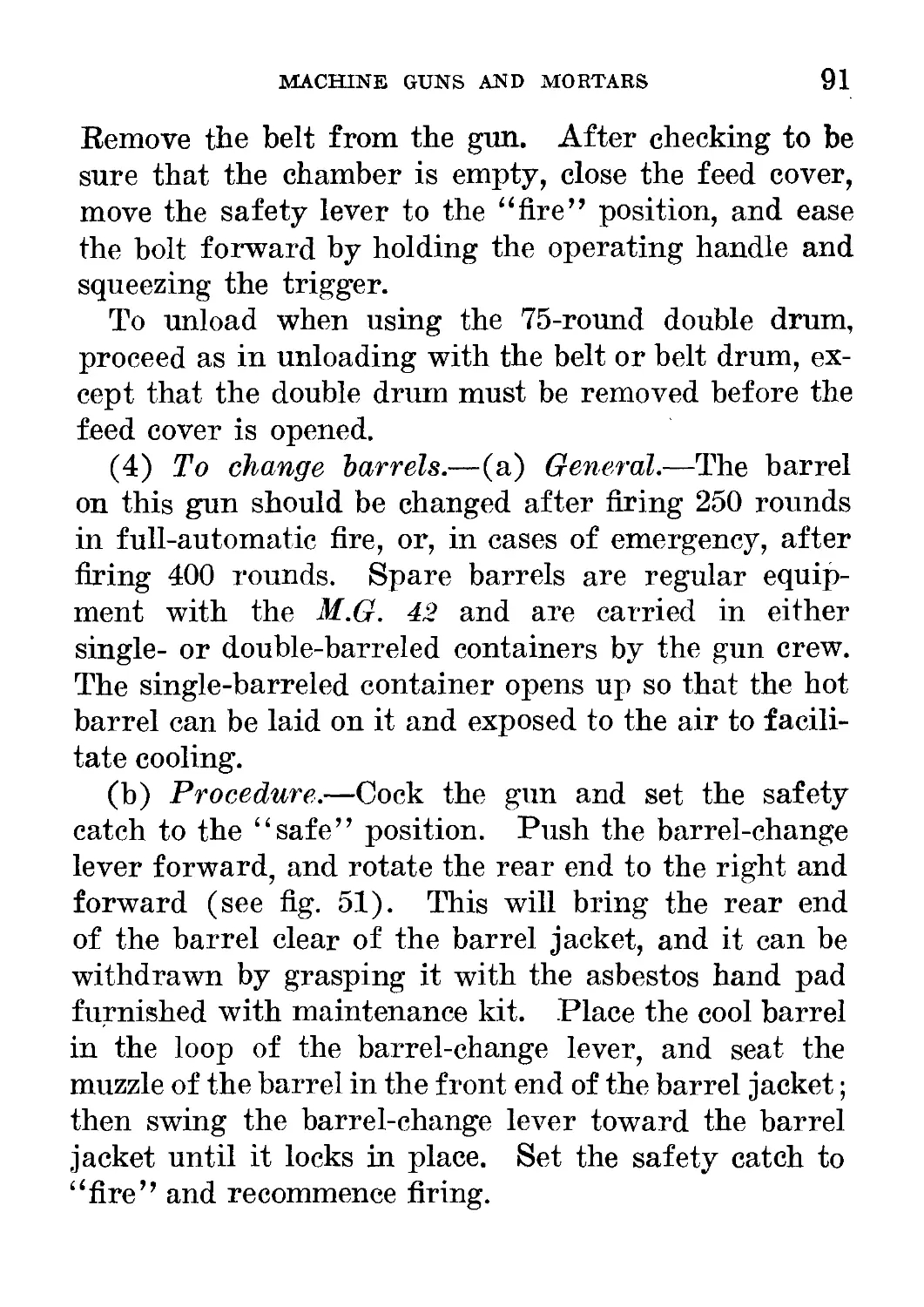
51. M.G. 42, showing method of operating barrel extension------- 92
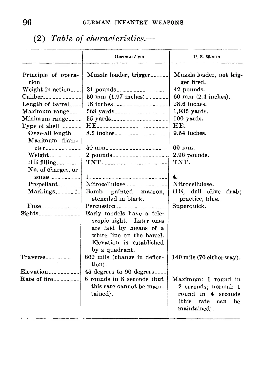
52. Left side of 5-cm mortar____________________________________ 97
53. Right side of 5-cm mortar___________________________________ 98
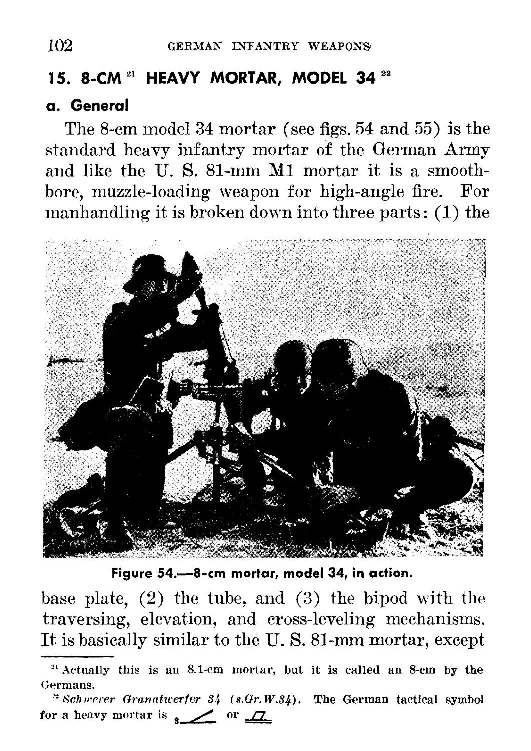
54. 8-cm mortar, model 34, in action_____________2______________ 102
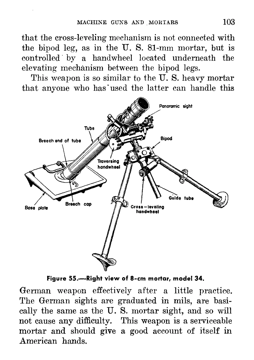
55. Right view of 8-cm mortar, model 34_________________________ 103
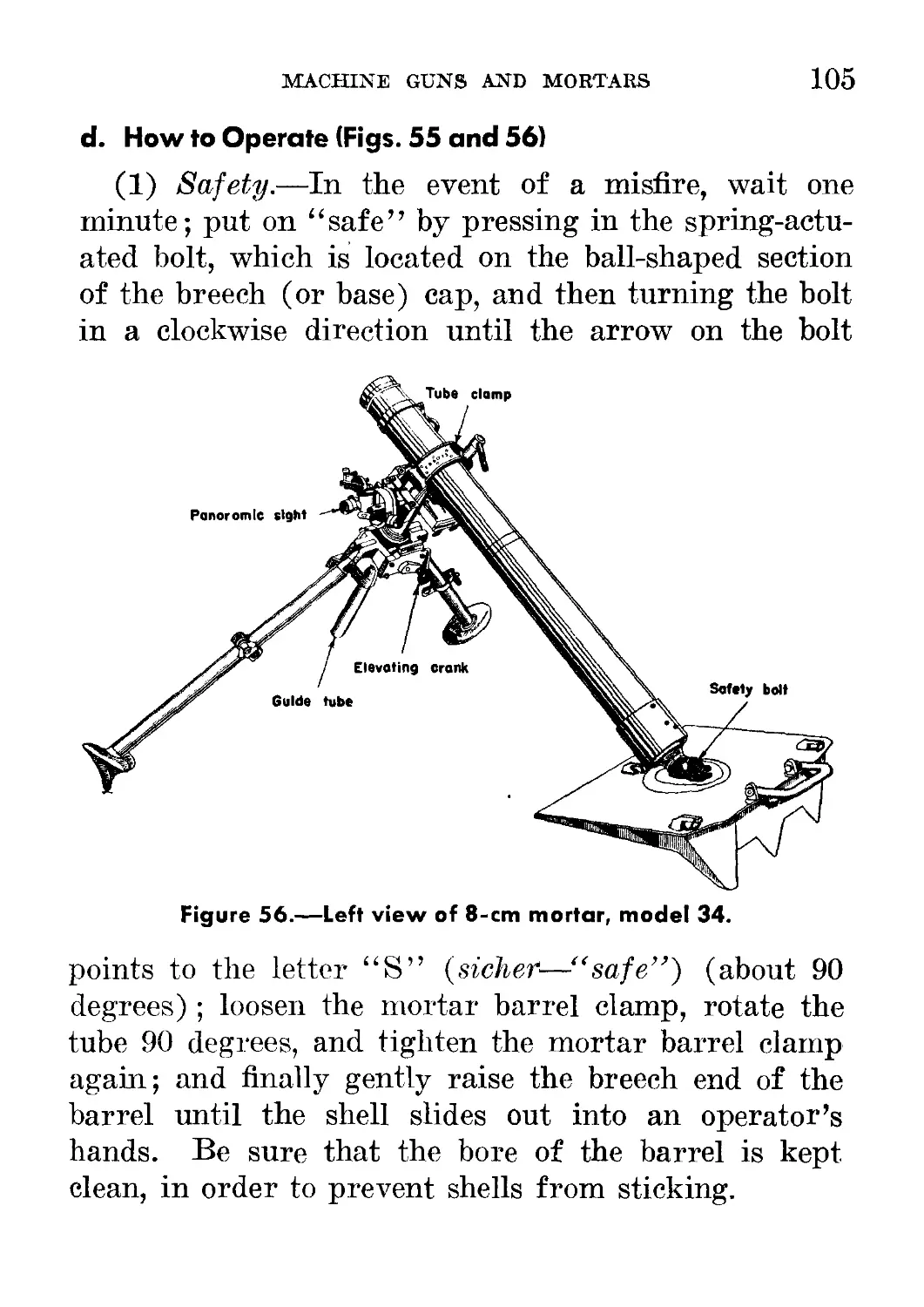
56. Left view of 8-cm mortar, model 34__________________________ 105
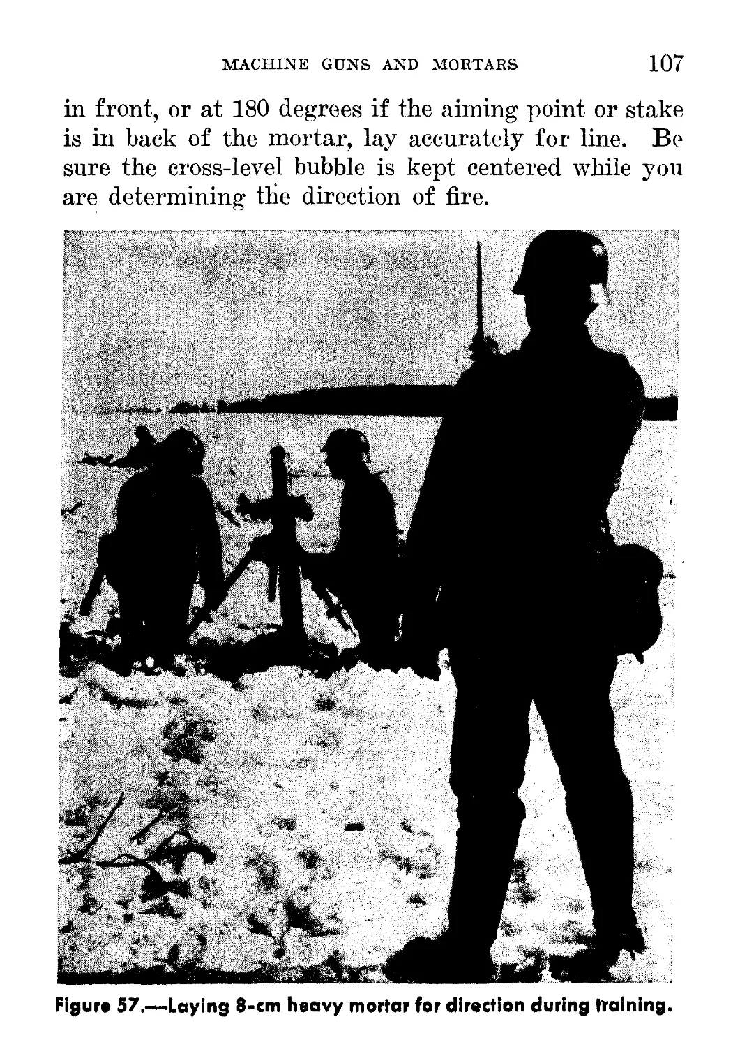
57. Laying 8-cm heavy mortar for direction during training______ 107
58. 3.7-cm Pak______________ ___________________________________ 114
59. 3.7-cm Pak in action_______ . ______________________________ 115
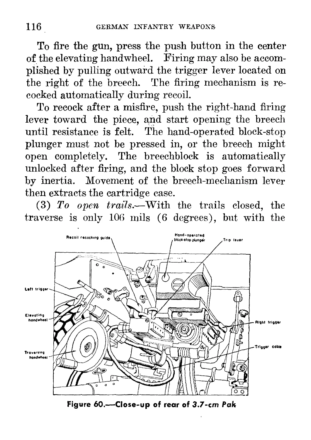
60. Close-up of rear of 3.7-cm Pak______________________________ 116
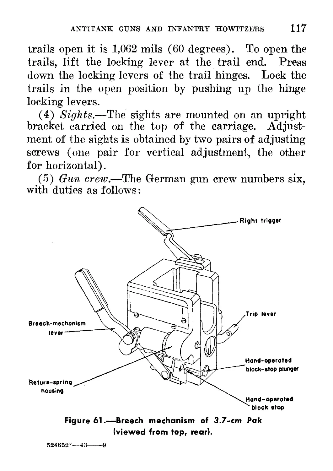
61. Breech mechanism of 3.7-cm Pak (viewed from top rear)_______ 117
62. Stick bomb for use with 3.7-cm Pak__________________ .._____ 119
63. Carriage of 3.7-cm Pak, showing traversing and elevating mech-
anisms____________________________________________ ______________ 122
64. 5-cm Pak 38_________________ _____ ______________________ __ 123
65. 5-cm Pak 38 from rear______ _ . --- ---------------------- 125
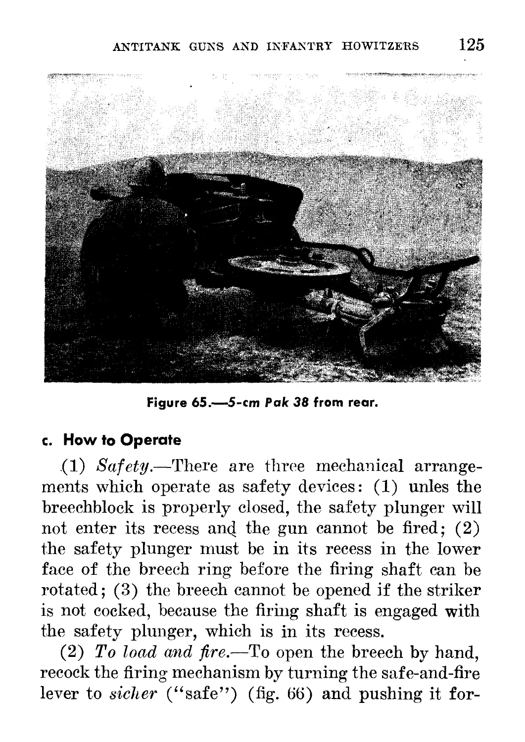
66. Breech of 5-cm Pak__________________________________________ 126
X
CONTENTS
Figure Page
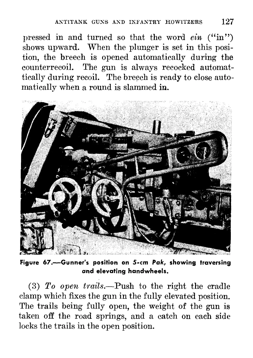
67. Gunner’s position on 5-cm Pak, showing traversing and elevating
handwheels- ____________________________________________________ 127
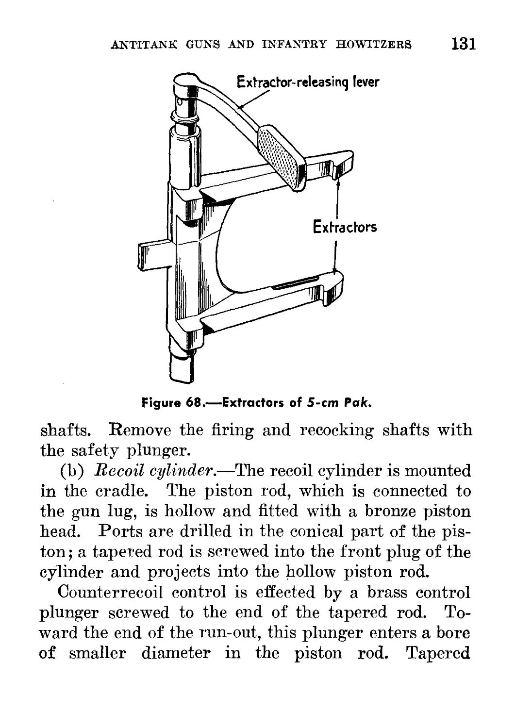
68. Extractors of 5-cm Pak____________________________________________ 131
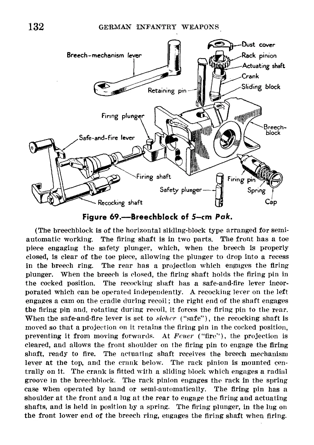
69. Breechblock of 5-cm Pak___________________________________________ 132
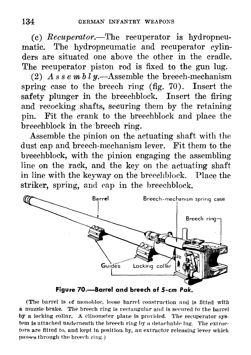
70. Barrel and breech of 5-cm Pak__________ ______________________ 134
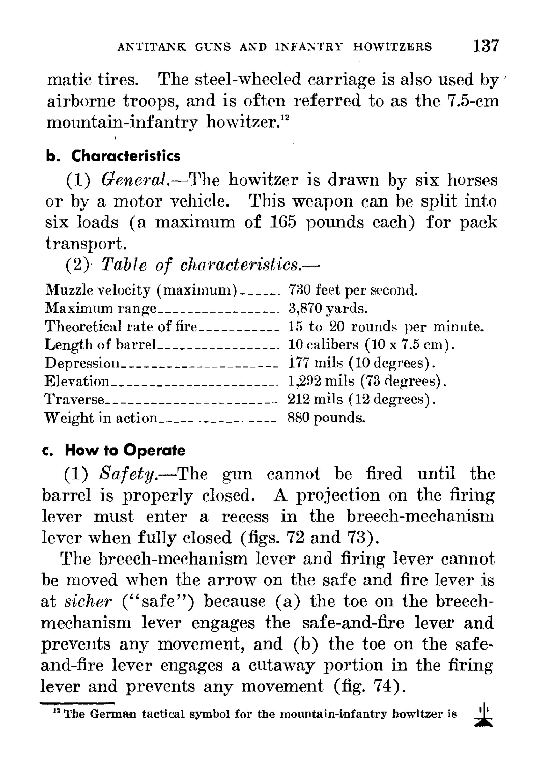
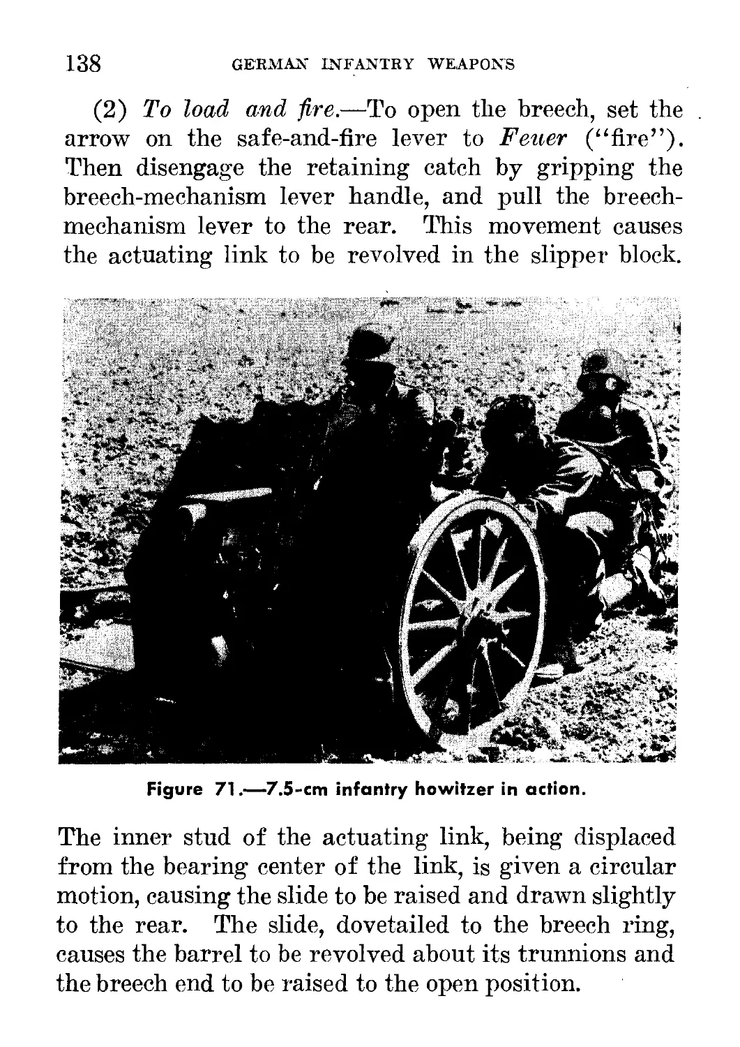
71. 7.5-cm infantry howitzer in action________________________________ 138
72. Breech of 7.5-cm infantry howitzer_________ __________________ 139
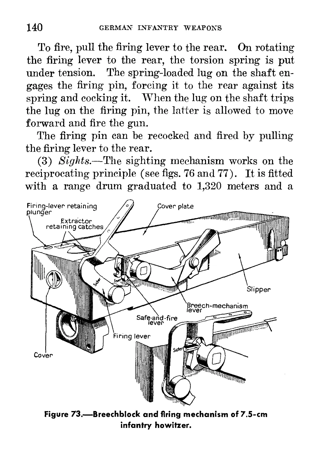
73. Breechblock and firing mechanism of 7.5-cm infantry howitzer. _ 140
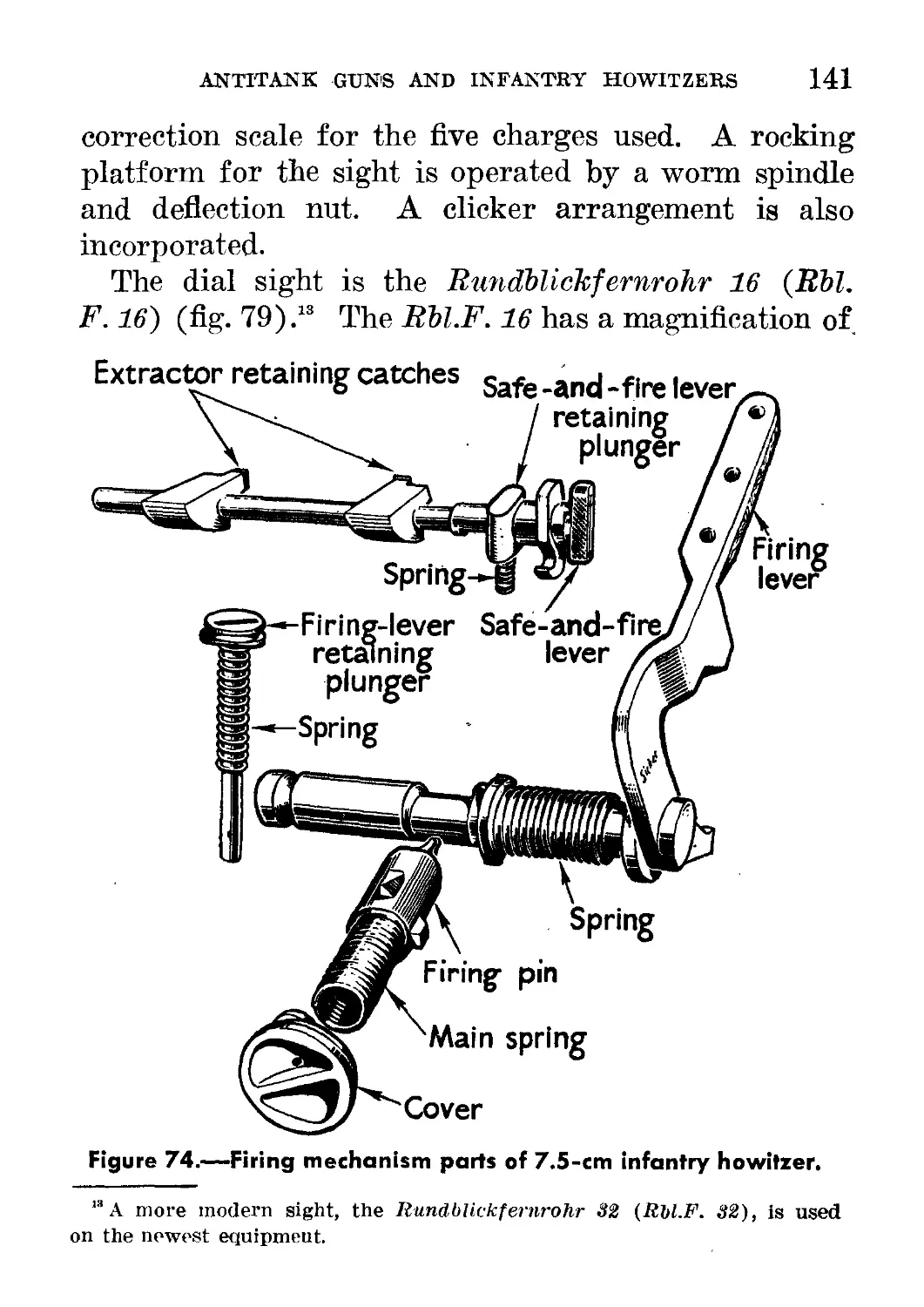
74. Firing mechanism parts of 7.5-cm infantry howitzer------------ 141
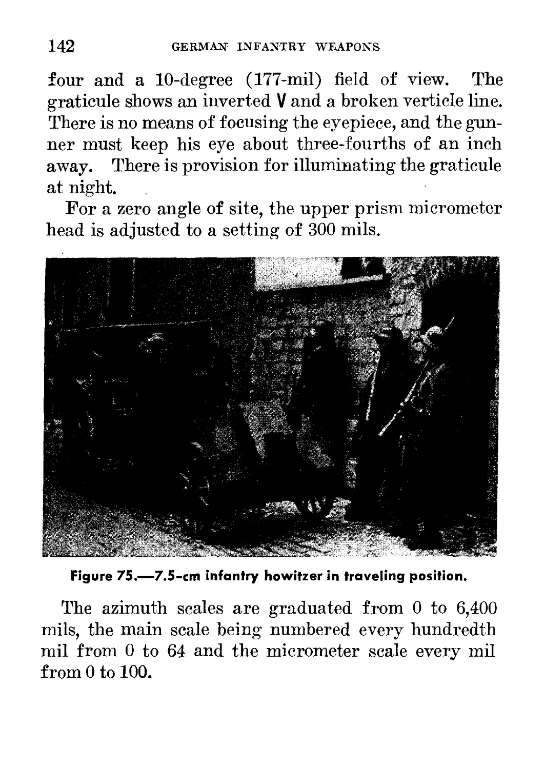
75. 7.5-cm infantry howitzer in traveling position________________ 142
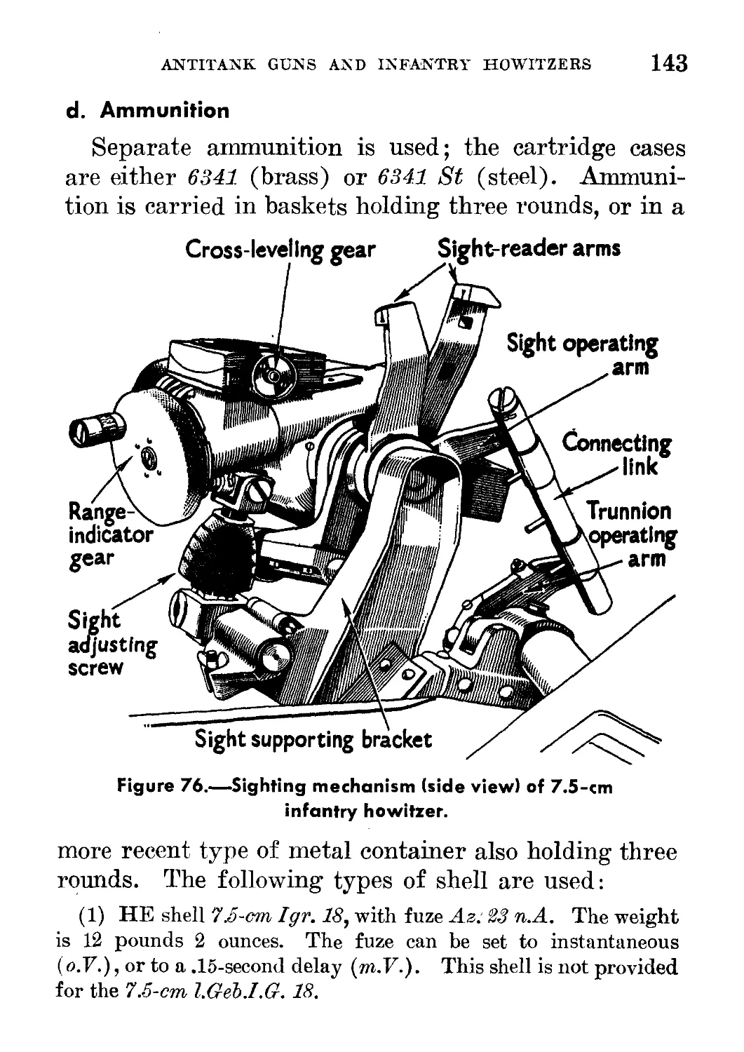
76. Sighting mechanism (side view) of 7.5-cm infantry howitzer____ 143
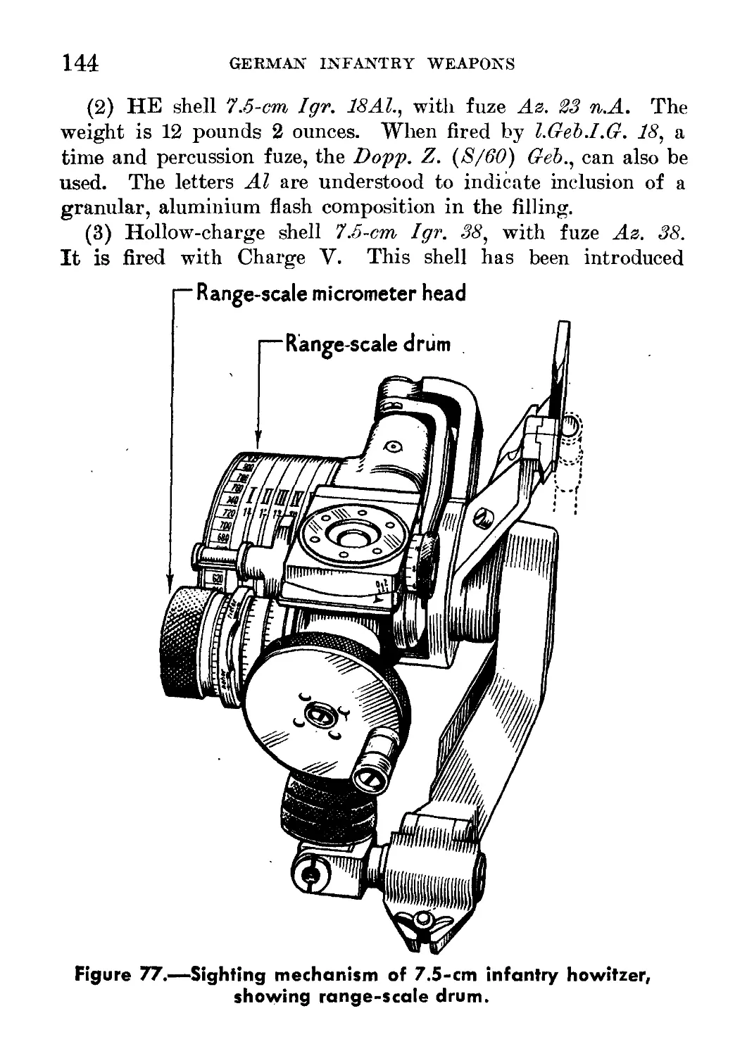
77. Sighting mechanism of 7.5-cm infantry howitzer, showing
range-scale drum___________________________ - --------------------- 144
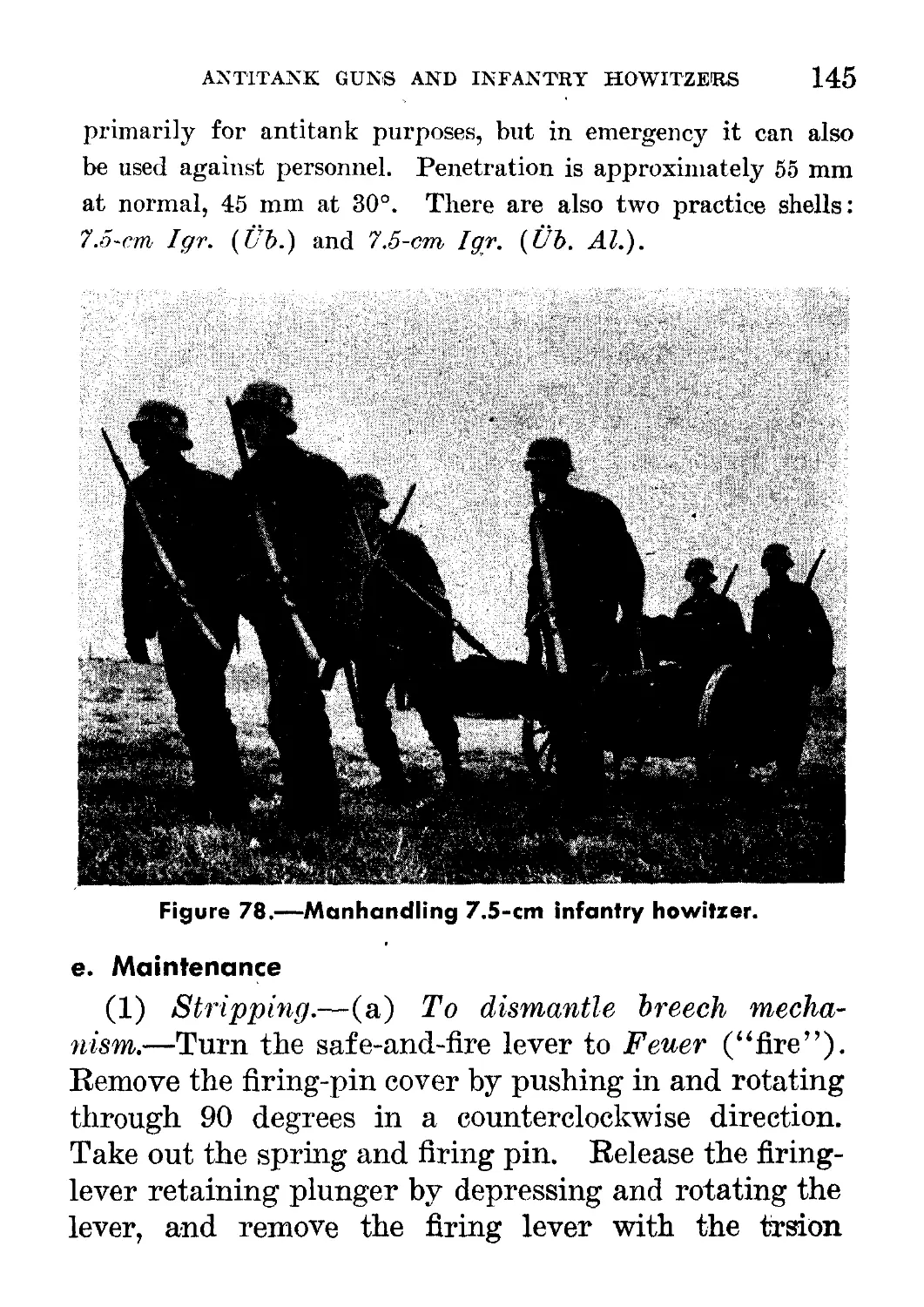
78. Manhandling 7.5-cm infantry howitzer. _ _______ . .. 145
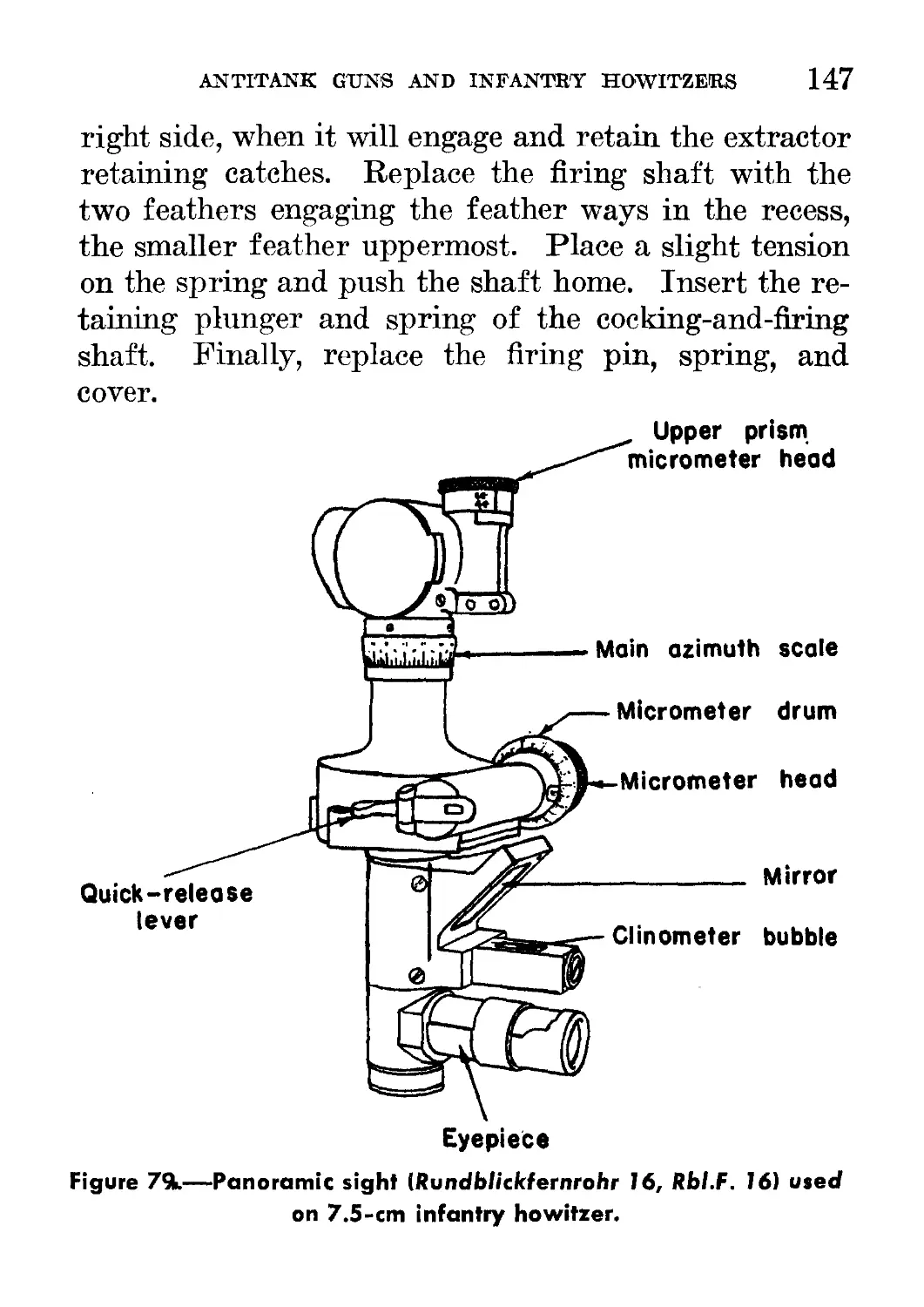
79. Panoramic sight {Rundblickfernrohr 16, Rbl.F. Iff) used on
7.5-c m infantry howitzer__________________________________ 147
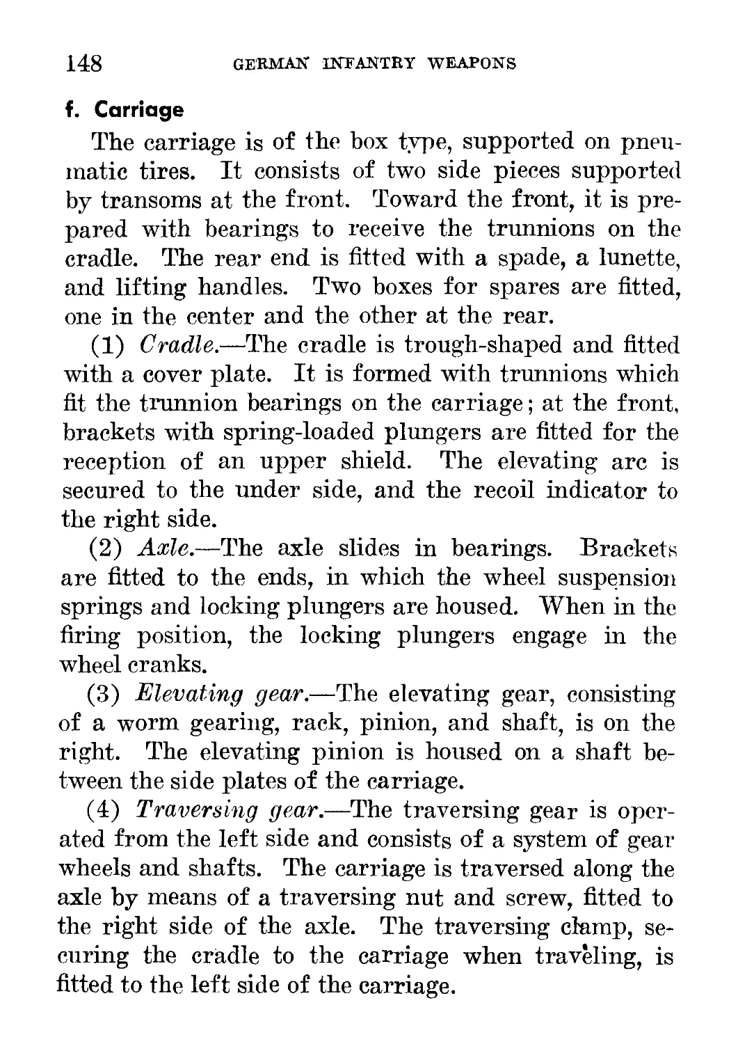
80. 15-cm infantry howitzer in action-------------------------------- 149
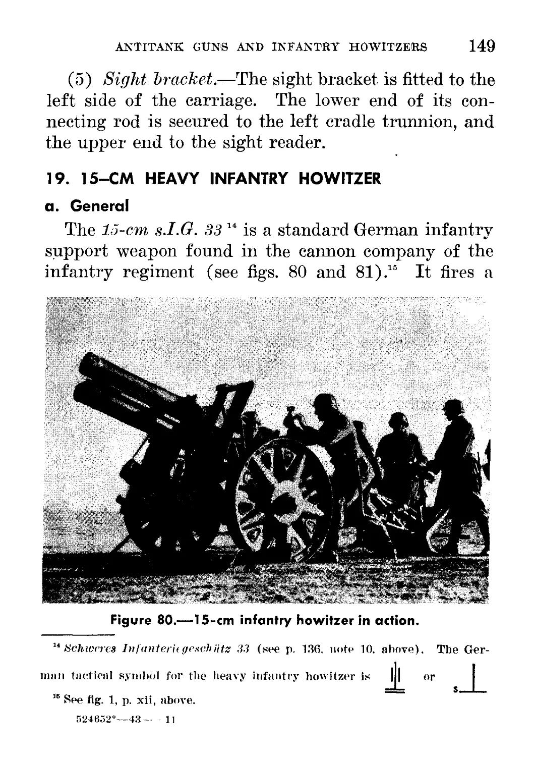
81. 15-cm infantry howitzer (rear view)______________________________ 150
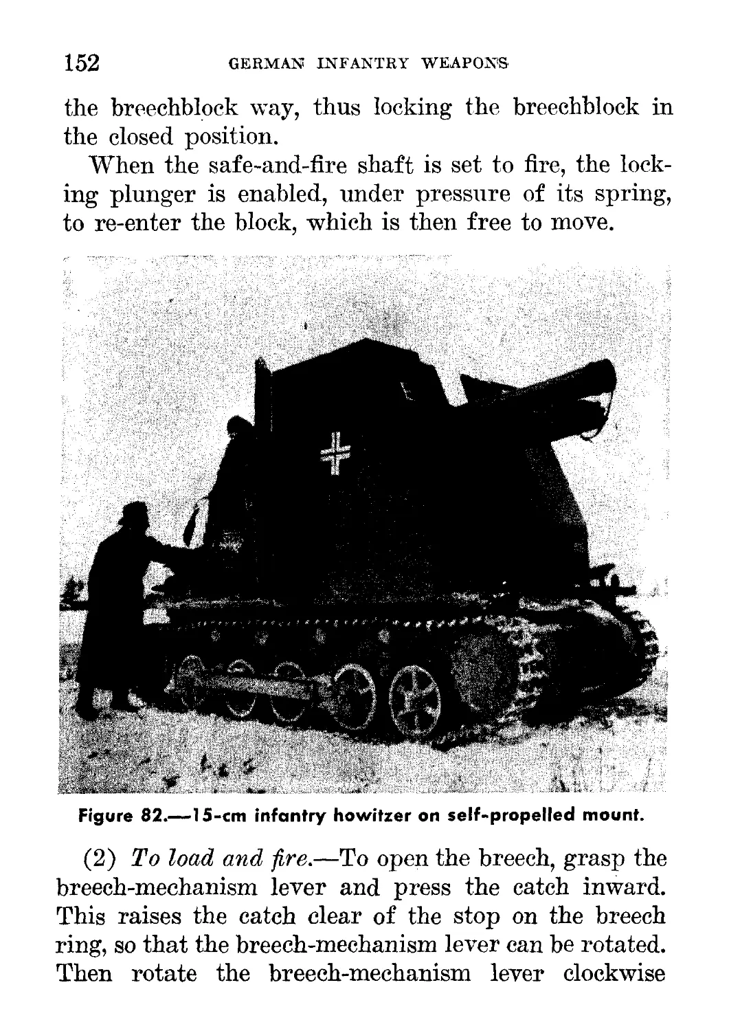
82. 15-cm infantry howitzer on self-propelled mount__________________ 152
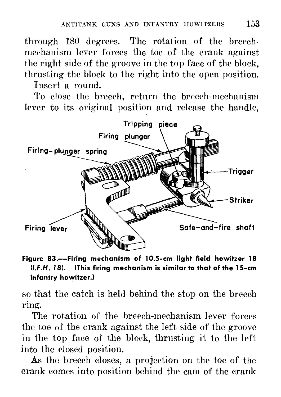
83. Firing mechanism of 10.5-cm light field howitzer 18 {l.F.H. 18)-- 154
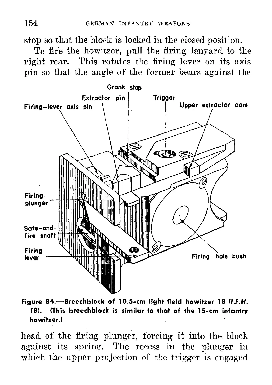
84. Breechblock of 10.5-cm light field howitzer 18 (l.F.H. 18)------- 153
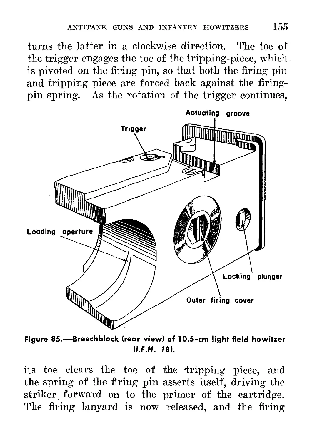
85. Breechblock (rear view) of 10.5-cm light field howitzer 18
(l.F.H. 18)______________________ - ______________ 155
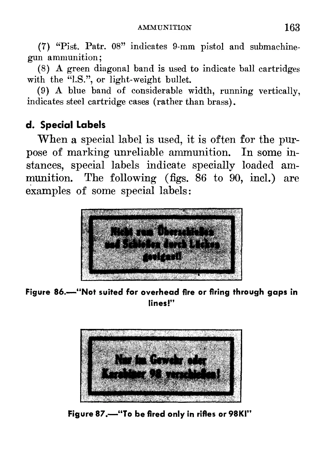
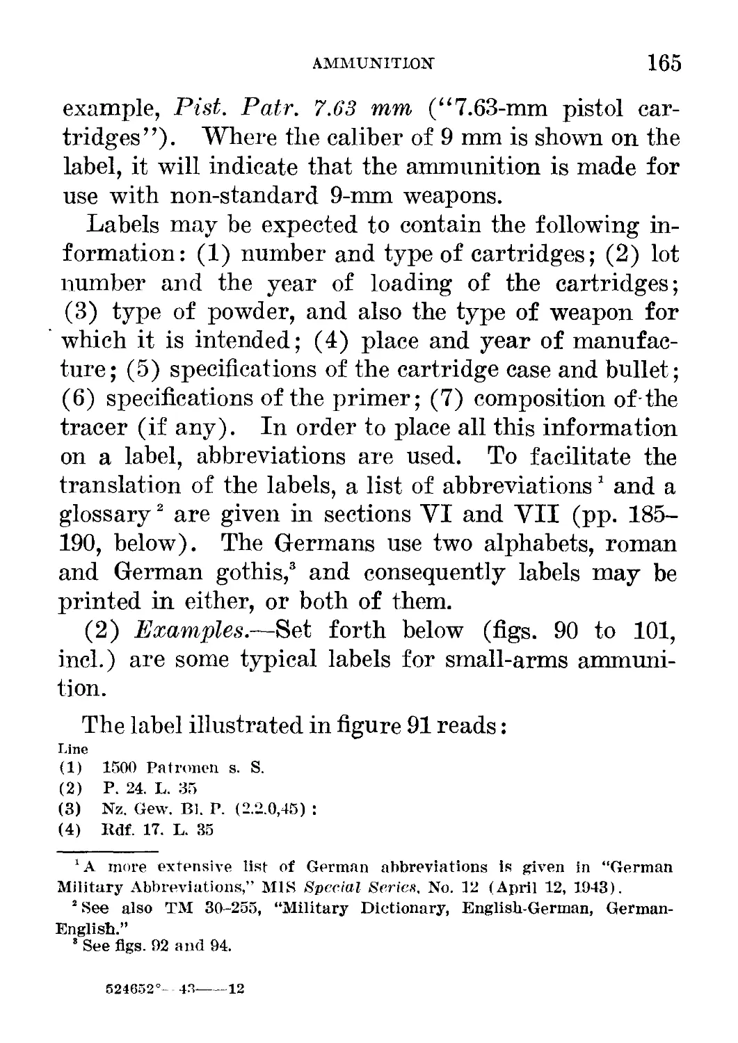
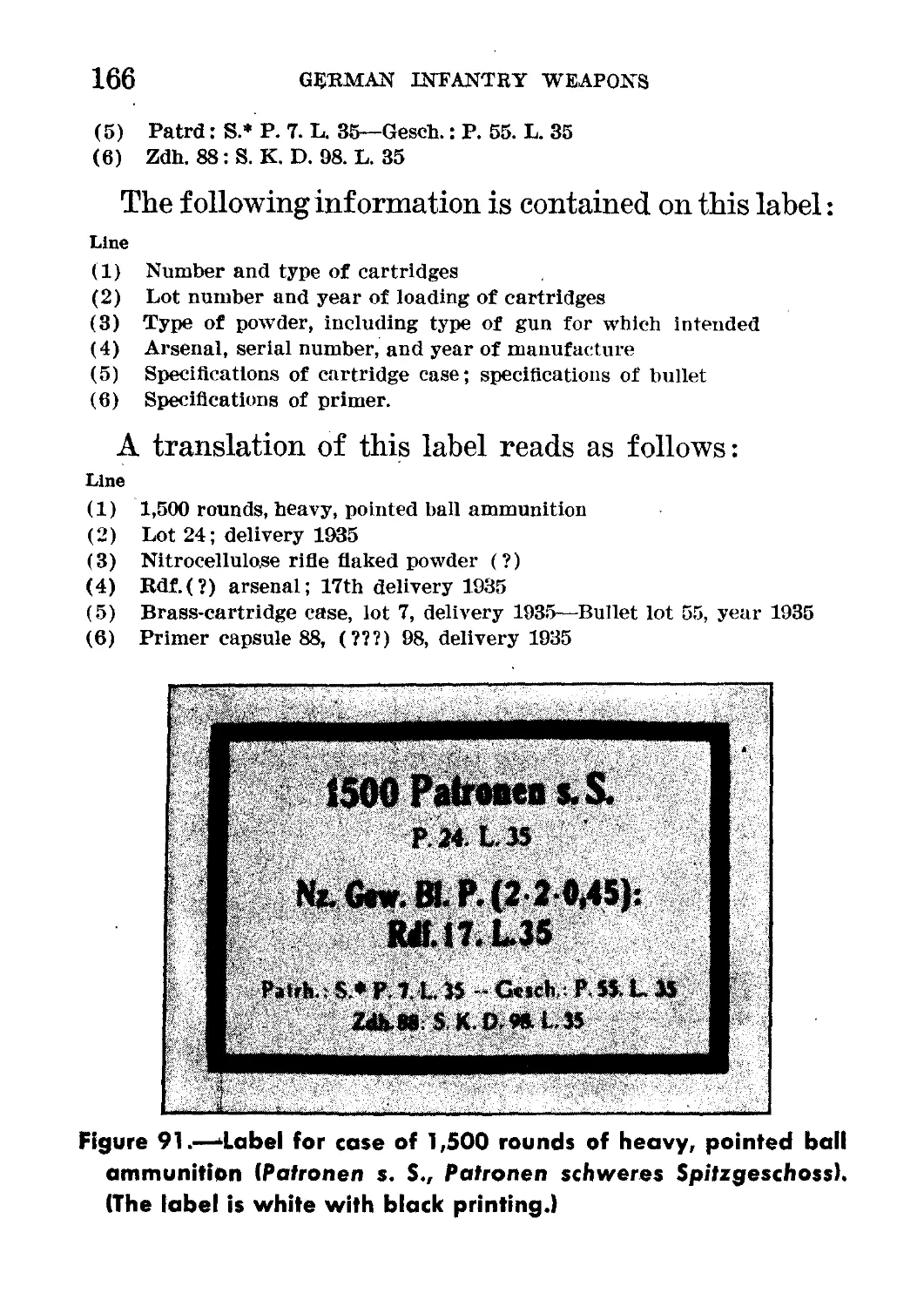
86-90. Special labels_______________________________ _ _________163, 164
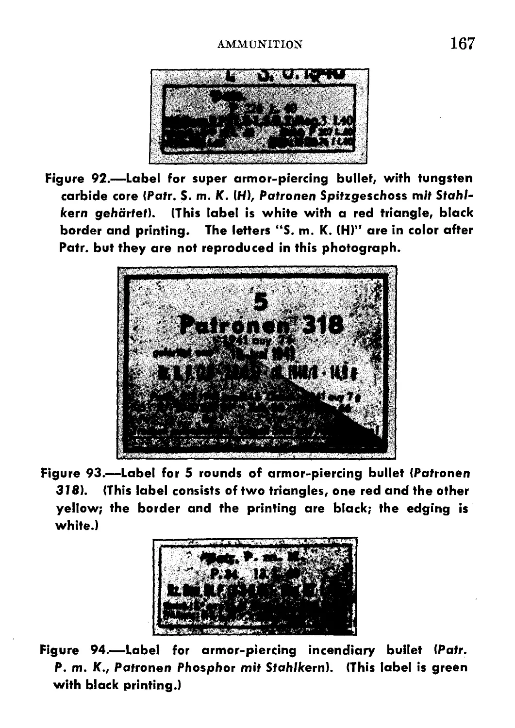
91. Label for case of 1,500 rounds of heavy, pointed ball ammunition
{Patronen s. S., Patronen schweres Spitzgeschoss)___________ 166
92. Label for super armor-piercing bullet with tungsten carbide core
{Patr. S.m.K.H., Patronen Spitzgeschoss mit Stahlkern gehartet) _ 167
93. Label for 5 rounds of armor-piercing bullet {Patronen 318)____ 167
94. Label for armor-piercing incendiary bullet {Palr.P.m.K., Patronen
Phosphor mit Stahlkern)__________...___ _______________ ____ 167
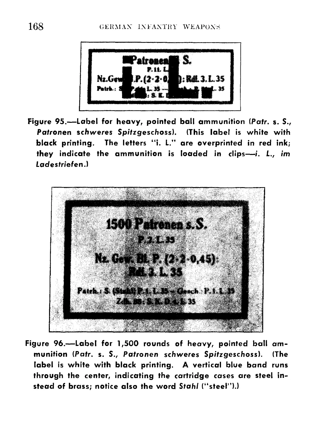
95. Label for heavy, pointed ball ammunition {Patr.s.S., Patronen
schweres Spitzgeschoss)_______ ... . __ ____________________ 168
96. Label for 1,500 rounds of heavy, pointed ball ammunition {Patr.
s.S., Patronen schweres Spitzgeschoss)________... __________ 168
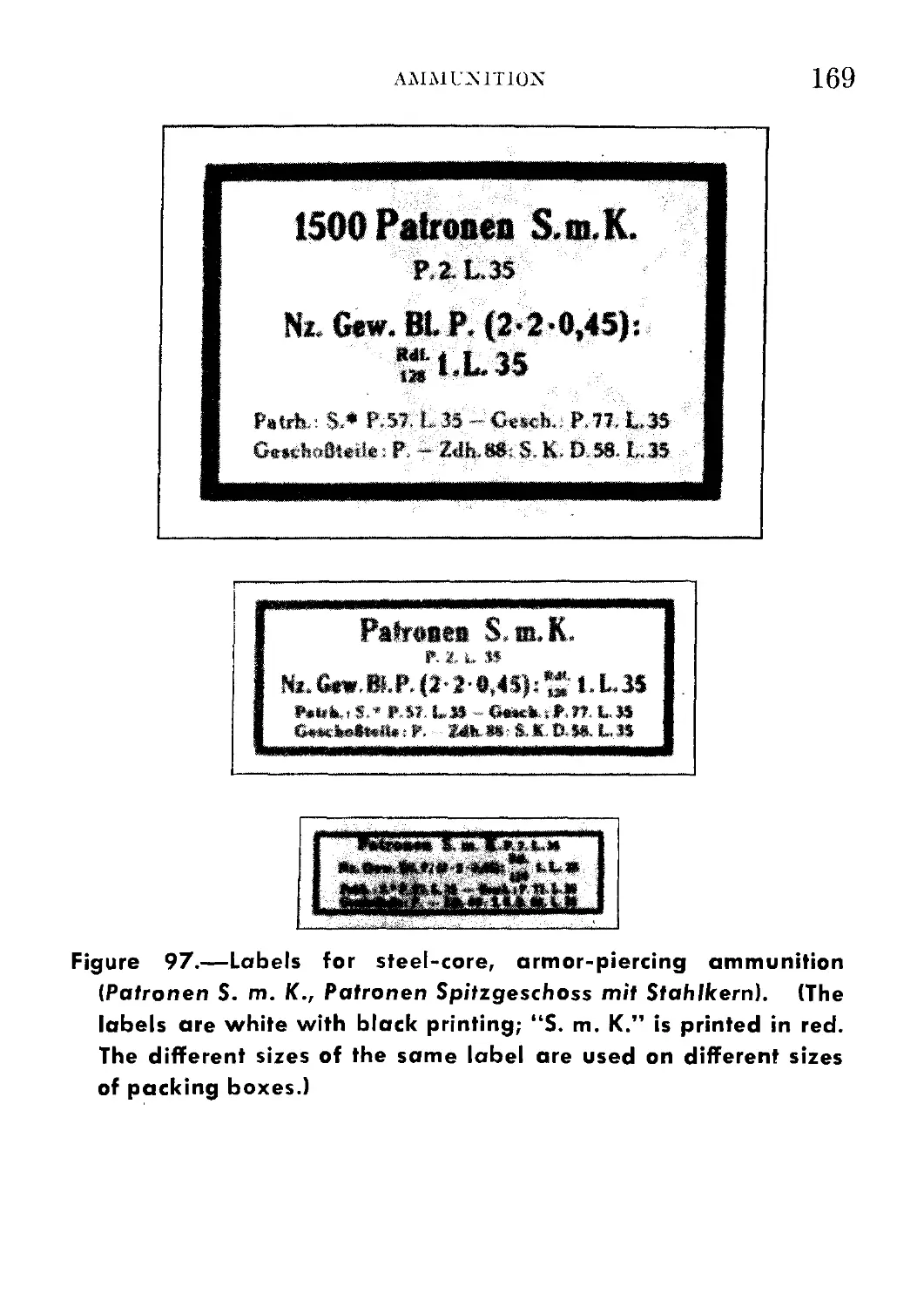
97. Labels for steel-core, armor-piercing ammunition {PatronenS.m. K.,
Patronen Spitzgeschoss mit Stahlkern)_____________________________ 169
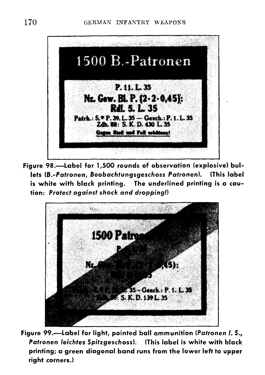
98. Label for 1,500 rounds of observation (explosive) bullets (B.~
Patronen, Beobachtungsgeschoss Patronen)__________ _ .____________ 170
99. Label for light, pointed ball ammunition {Patronen l.S, Patronen
leichtes Spitzgeschoss)_____________________________________________ 170
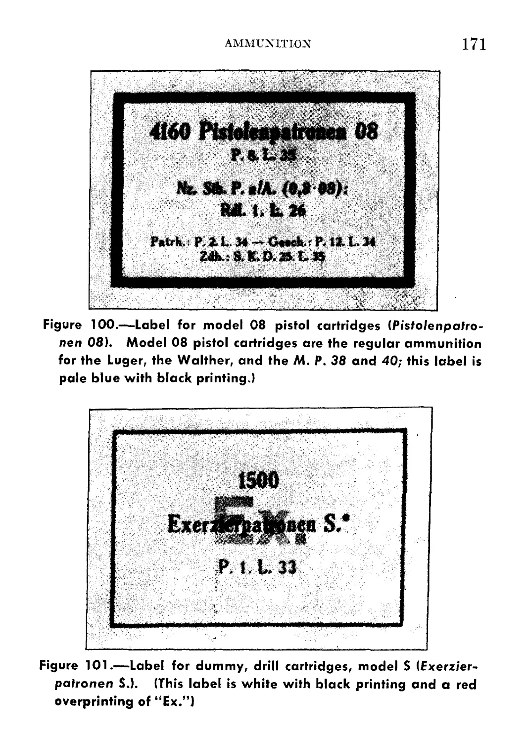
100. Label for model 08 pistol cartridges {Pistolenpatronen 08)___ 171
CONTENTS XI
Figure Page
101. Label for dummy, drill cartridges, model S (Exerzierpatronen S.) _ 171
102. Markings on base of German small-arms cartridge______________ 172
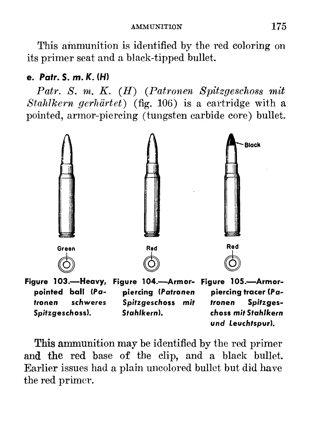
103. Heavy, pointed ball (Patronen schweres Spitzgeschoss)_________ 175
104. Armor-piercing (Patronen Spitzgeschoss mit Stahlkern)_________ 175
105. Armor-piercing tracer (Patronen Spitzgeschoss mit Stahlkern
und Leuchtspur)__ j ______________________________________________ 175
106. Super-armor-piercing with tungsten carbide core (Patronen
Spitzgeschoss mit Stahlkern gehartet)_______________________________ 177
107. Light ball, special practice (Patronen leichtes Spitzgechoss)_ 177
108. Practice tracer (Patronen leichtes Spitzgeschoss mit Leuchtspur)_ 177
109. Semi-armor-piercing (Patronen Spitzgeschoss mit Eisenkern)____ 178
110. Armor-piercing incendiary (Patronen Phosphor mit Stahlkern)___ 178
111. Observation (explosive) bullet (Reabachtangsgeschoss Patronen)-, 178
112. Dummy cartridges (Exerzierpatronen)-__________________________ 179
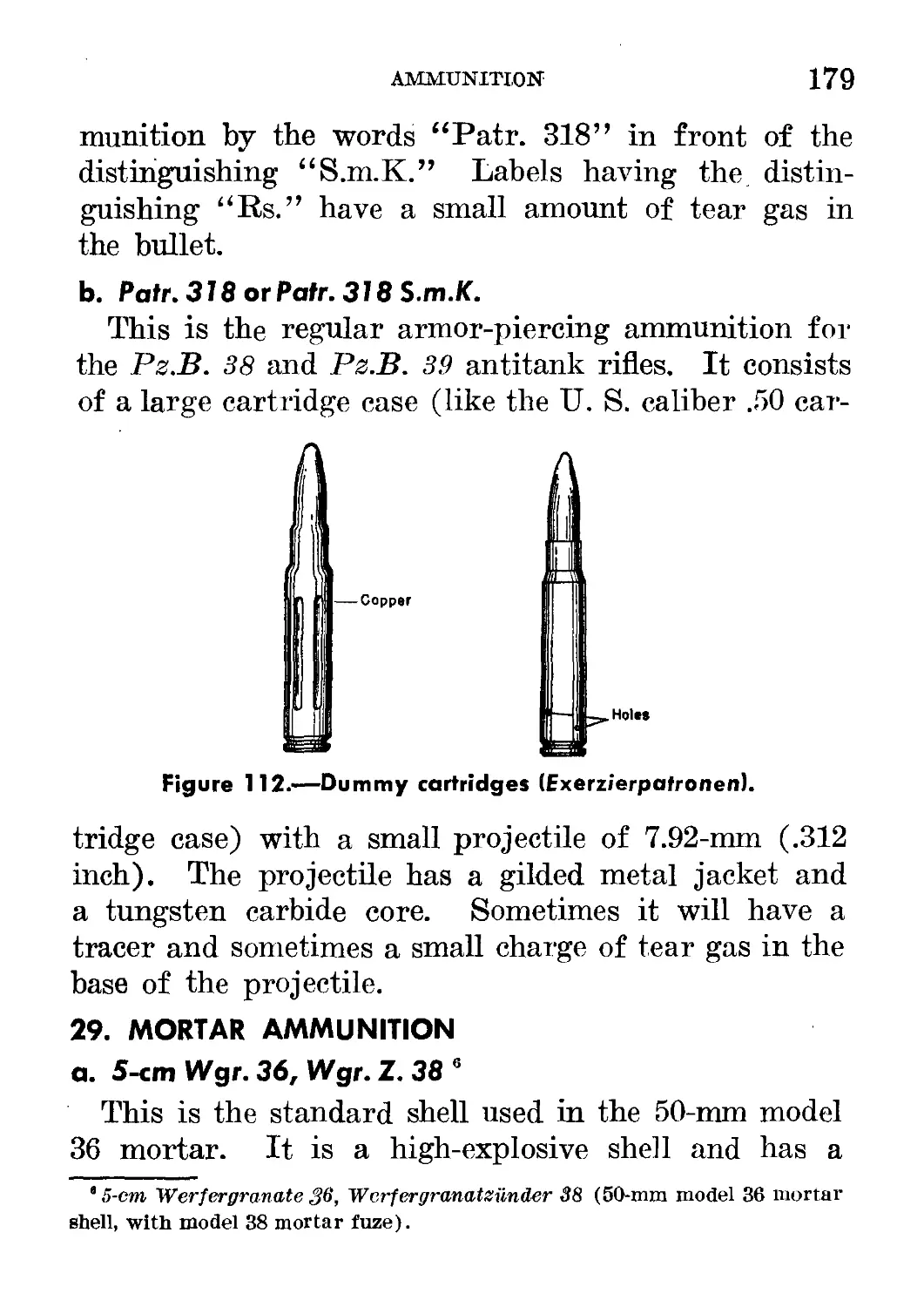
113. Blank cartridge (Platz-Patrone 88) . . _ _____________________ 180
114. Cross section of ball cartridge (scharfe Patrone S.)__________ 180
115. 8-cm mortar shell_____________________________________________ 181
— Graphic comparison of millimeters and inches_____________inside back cover
TABLES
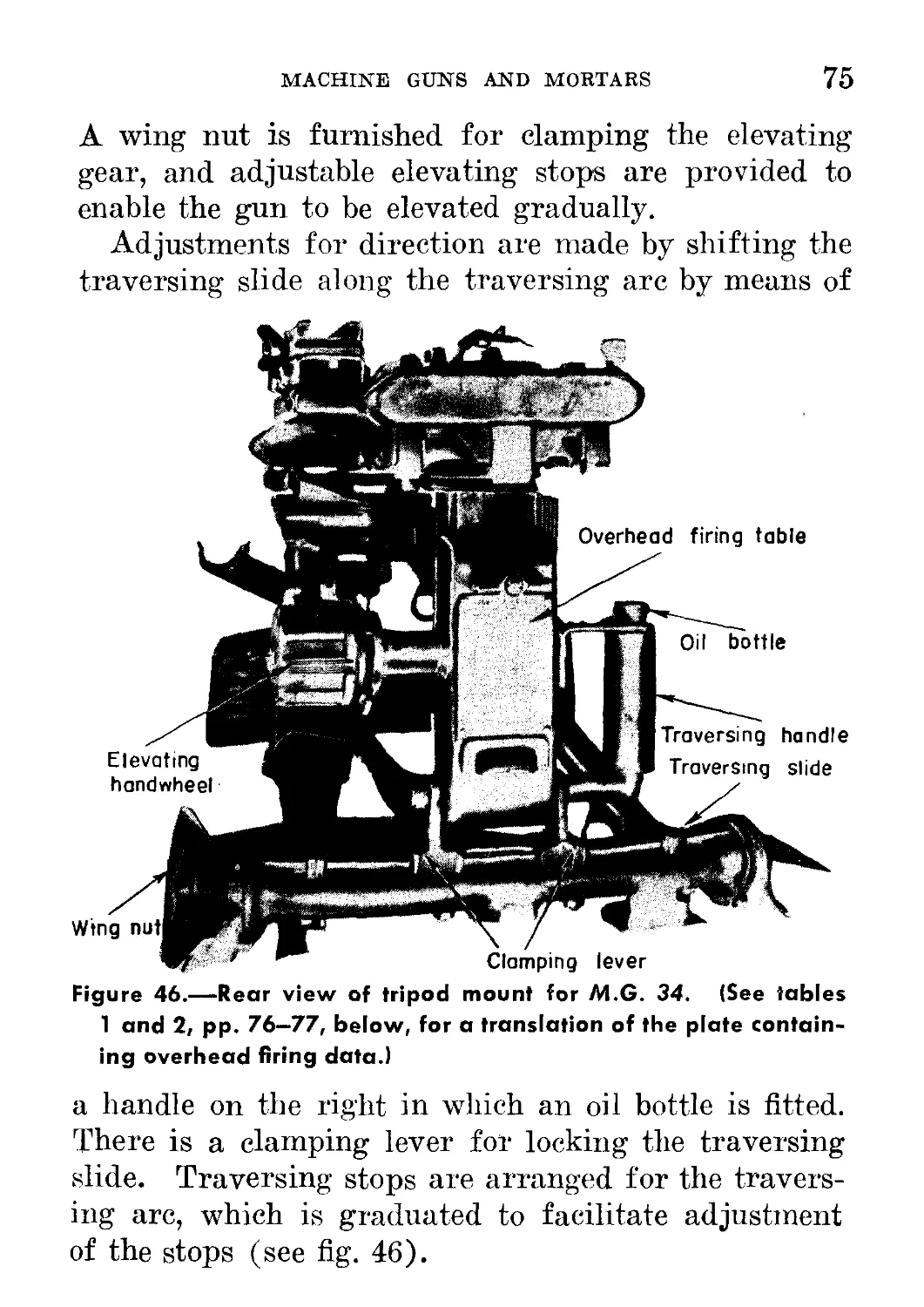
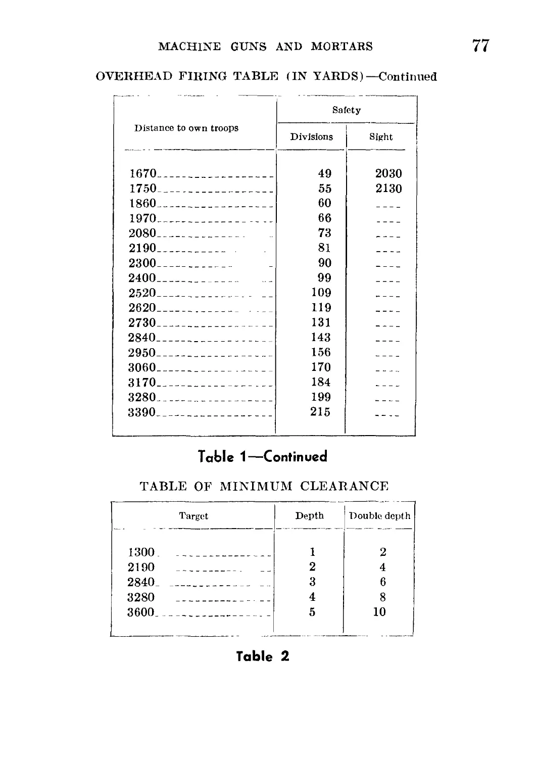
1. Overhead firing table (in yards)__________________________ 76
2. Table of minimum clearance________________________________ 77
3. Firing table, 8-cm heavy mortar, model 34 (German)____ 1 IQ
ENGINEER
AT
TRAINS
CANNON
SIGNAL
MOUNTED
INFANTRY
MTRCL
MSGR SEC
12 57-mm and/or
50-mm AT guns
4 LMG
5-mm Inf How
2 150-mm Inf How
XII
SIGNAL
RIFLE
RIFLE
RIFLE
6 81-mm Mort
9 50-mm Mort
9 7.92-mm AT rifles
12 Hv MG
36 LMG
48 SMG
? Rifles, pistols
HV MG
12 Hv MS
6 81-mm Mort
AT
LMG
1 LMG
137-mm awor
50-mm AT gun
3 50-mm Mort
12 LMG
SIGNAL
CANNON
CANNON
CANNON
CANNON
1 75-mm Inf
How
2 75-mm Inf
How
CANNON
CANNON
CANNON
1 75-mm Inf
How
1 150-mm Inf
How
1 150-mm Inf
How
The total armament of the three
Infantry battalions, the cannon company, and
the antitank company is—
2 150-mm infantry howitzers
6 75-mm Infantry howitzers
18 81-mm mortars-
27 50-mm mortars
12 37-mm and/or 50-mni antitank gons
27 7.92-mm antitank rifles
38 Heavy machine guns
112 Light machine guns
144 Submachine guns
? Rifles
? Pistols
Figure 1.—Armament and organization of German infantry regiment. (This chart shows the
principal unit which employs the weapons described herein.)
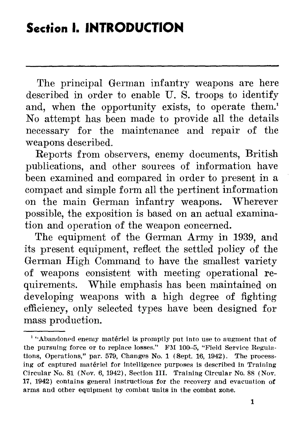
Section I. INTRODUCTION
The principal German infantry weapons are here
described in order to enable U. S. troops to identify
and, when the opportunity exists, to operate them.1
No attempt has been made to provide all the details
necessary for the maintenance and repair of the
weapons described.
Reports from observers, enemy documents, British
publications, and other sources of information have
been examined and compared in order to present in a
compact and simple form all the pertinent information
on the main German infantry weapons. Wherever
possible, the exposition is based on an actual examina-
tion and operation of the weapon concerned.
The equipment of the German Army in 1939, and
its present equipment, reflect the settled policy of the
German High Command to have the smallest variety
of weapons consistent with meeting operational re-
quirements. While emphasis has been maintained on
developing weapons writh a high degree of fighting
efficiency, only selected types have been designed for
mass production.
1 “Abandoned enemy materiel is promptly put into use to augment that of
the pursuing force or to replace losses.” FM 100-5, “Field Service Regula-
tions, Operations,” par. 579, Changes No. 1 (Sept. 16, 1942). The process-
ing of captured materiel for intelligence purposes is described in Training
Circular No. 81 (Nov. 6, 1942), Section III. Training Circular No. 88 (Nov.
17, 1942) contains general instructions for the recovery and evacuation of
arms and other equipment by combat units in the combat zone.
1
2
GERMAN INFANTRY WEAPONS
As the battle fronts have widened and the theaters
of operations become more varied, the Germans have
been forced to increase the variety of their weapons
and to improve existing materiel. In addition, they
have augmented their supply of weapons by using cap-
tured materiel.
No attempt has been made in the sections which
follow to describe experimental or new German weap-
ons which have not yet come into wide use. Nor is
captured materiel used by the Germans considered.
Therefore, on occasion U. S. troops may encounter
German infantry equipped with some weapon not in-
cluded in this study. However, a good knowledge of
the standard German weapons will usually form a
sound, basis for understanding the operation of the
newer German weapons.
For the armament and organization of the German
infantry regiment, the principal unit which employs
the weapons described herein, see figure 1.
Section II. PISTOLS, RIFLES, AND
GRENADES1
1. LUGER PISTOL
a. General
Since 1908 the Luger pistol has been an official
German military side arm. Georg Luger of the DWM
Arms Company1 2 in Germany developed this weapon,
known officially as Pistole 08, from the American
Borchart pistol invented in 1893.
The Luger is a well-balanced, accurate pistol. It
imparts a high muzzle velocity to a small-caliber bul-
let, but develops only a relatively small amount of
stopping power. Unlike the comparatively slow U. S.
45-caliber bullet, the Luger small-caliber bullet does
not often lodge itself in the target and thereby im-
part its shocking power to that which it hits. With
its high speed and small caliber it tends to pierce,
inflicting a small, clean wound.
When the Luger is kept clean, it functions well.
However, the mechanism is rather exposed to dust
and dirt.
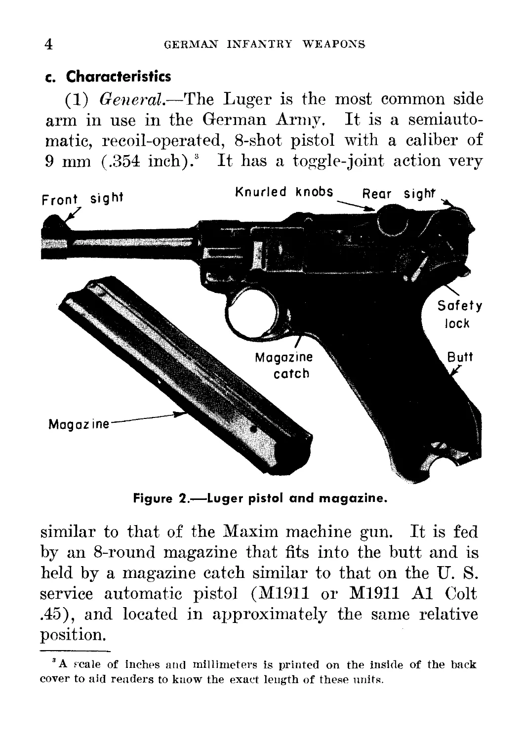
b. How to Identify
The Luger may be identified readily by its exposed
barrel, curved butt, and generally smooth lines. (See
fig- 2.)
1 The weapons discussed in this section may be operated by one man.
? Deutsche Waffen- und Munitions}abriken, Aktiengesellsch.aft.
3
4
GERMAN INFANTRY WEAPONS
c. Characteristics
(1) General.—The Luger is the most common side
arm in use in the German Army. It is a semiauto-
matic, recoil-operated, 8-shot pistol with a caliber of
9 mm (.354 inch).3 It has a toggle-joint action very
Figure 2.—Luger pistol and magazine.
similar to that of the Maxim machine gun. It is fed
by an 8-round magazine that fits into the butt and is
held by a magazine catch similar to that on the IL S.
service automatic pistol (M1911 or M1911 Al Colt
.45), and located in approximately the same relative
position.
3A scale of inches and millimeters is printed on the inside of the back
cover to aid readers to know the exact length of these units.
PISTOLS, RIFLES, AND GRENADES
5
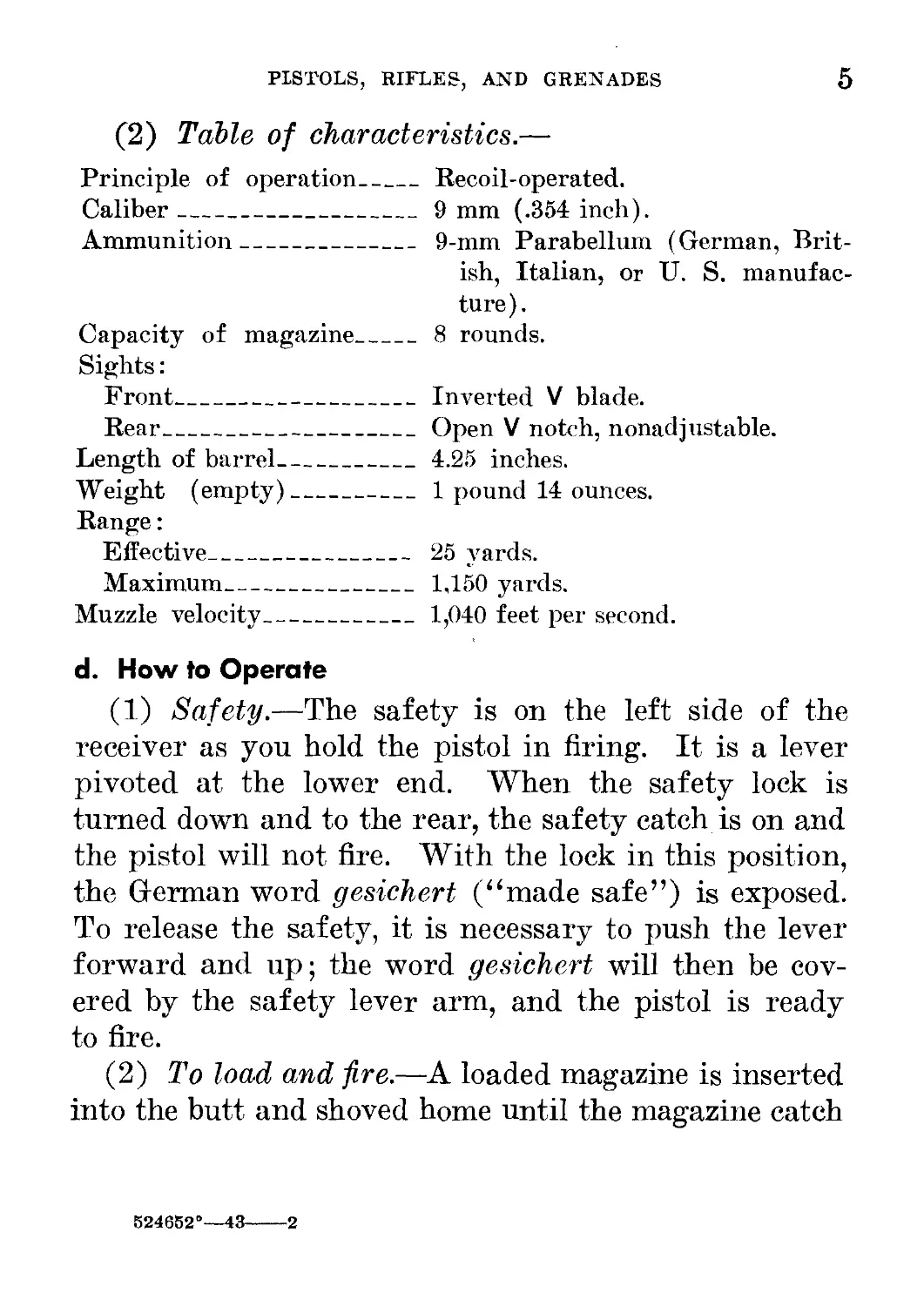
(2) Table of characteristics.—
Principle of operation____
Caliber__________________
Ammunition_______________
Capacity of magazine______
Sights:
Front___________________
Rear____________________
Length of barrel__________
Weight (empty)____________
Range:
Effective______________
Maximum_________________
Muzzle velocity___________
Recoil-operated.
9 mm (.354 inch).
9-mm Parabellum (German, Brit-
ish, Italian, or U. S. manufac
ture).
8 rounds.
Inverted V blade.
Open V notch, nonadjustable.
4.25 inches.
1 pound 14 ounces.
25 yards.
1,150 yards.
1,040 feet per second.
d. How to Operate
(1) Safety.—The safety is on the left side of the
receiver as you hold the pistol in firing. It is a lever
pivoted at the lower end. When the safety lock is
turned down and to the rear, the safety catch is on and
the pistol will not fire. With the lock in this position,
the German word gesichert (“made safe”) is exposed.
To release the safety, it is necessary to push the lever
forward and up; the word gesichert will then be cov-
ered by the safety lever arm, and the pistol is ready
to fire.
(2) To load and fire.—A loaded magazine is inserted
into the butt and shoved home until the magazine catch
524652°—43---2
6
GERMAN INFANTRY WEAPONS
clicks. This is similar to the operation used in loading
the U. S. Colt .45.
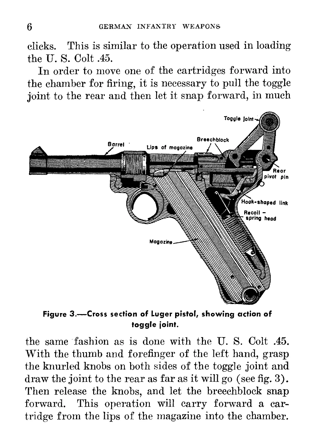
In order to move one of the cartridges forward into
the chamber for firing, it is necessary to pull the toggle
joint to the rear and then let it snap forward, in much
Figure 3.—Cross section of Luger pistol, showing action of
toggle joint.
the same fashion as is done with the U. S. Colt .45.
With the thumb and forefinger of the left hand, grasp
the knurled knobs on both sides of the toggle joint and
draw the joint to the rear as far as it will go (see fig. 3).
Then release the knobs, and let the breechblock snap
forward. This operation will carry forward a car-
tridge from the lips of the magazine into the chamber.
PISTOLS, RIFLES, AND GRENADES
7
The pistol should then be locked by moving the safety
so as to expose the word gesichert.
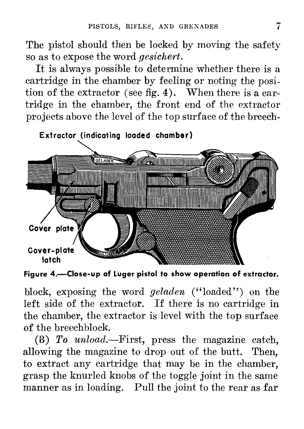
It is always possible to determine whether there is a
cartridge in the chamber by feeling or noting the posi-
tion of the extractor (see fig. 4). When there is a car-
tridge in the chamber, the front end of the extractor
projects above the level of the top surface of the breech-
Extractor (indicating loaded chamber)
Figure 4.—Close-up of Luger pistol to show operation of extractor.
block, exposing the word geladen (“loaded”) on the
left side of the extractor. If there is no cartridge in
the chamber, the extractor is level with the top surface
of the breechblock.
(8) To unload.—First, press the magazine catch,
allowing the magazine to drop out of the butt. Then,
to extract any cartridge that may be in the chamber,
grasp the knurled knobs of the toggle joint in the same
manner as in loading. Pull the joint to the rear as far
8
GERMAN INFANTRY WEAPONS
Figure 5.—Method of using German sights. (Q illustrates correct
sight picture; firing high; (з), low and right; low and right;
lower left; low shot.)
as it will come. This operation will eject any cartridge
in the chamber.
(4) Sights.—This pistol has an open V notch rear
sight and an inverted V front sight. The sights
should be aligned as in figure 5 @.
e. Ammunition
Rimless, straight-case ammunition is used. German
ammunition boxes will read Pistolenpatronen 08 (“pis-
tol cartridges 08”). These should be distinguished
from Exerzierpatronen 08 (“drill cartridges 08”).
The bullets in these cartridges have coated steel jackets
and lead cores. The edge of the primer of the ball
cartridge is painted black. British- and U. S.-made
9-mm Parabellum ammunition will function well in
this pistol; the German ammunition will of course give
the best results. (See sec. V, p. 161, below.)
PISTOLS, RIFLES, AND GRENADES
9
f. Maintenance
(1) Oiling and cleaning.—This pistol requires the
same type of care as the U. S. M1911 Colt .45 auto-
matic. The cleaning and oiling is done in a similar
manner. However, in desert countries, or in other
places where dust is prevalent, oil should be used spar-
ingly or not at all.
(2) Stripping.—In order to disassemble the weapon,
it is necessary to remove the magazine and empty the
chamber as indicated in d (3), page 7, above. Press
the muzzle against a clean, hard surface until the barrel
has moved to the rear about a half inch. Then push
the knurled section of the cover-plate latch down-
ward and remove the cover plate. Turn the pistol
upside down and slide the barrel and receiver forward
and separate them. Punch out the rear pivot pin
and remove the breechblock from the receiver. This
amount of disassembly is sufficient for purposes of
cleaning and oiling the pistol.
(3) Assembly.—To reassemble the parts of the weap-
on, first put the breechblock and receiver together
and replace the pivot pin. Slide the barrel and receiver
back onto the frame, making sure that the hook-shaped
link engages in the claws of the recoil-spring head.
Push the barrel backward, using a piece of wood
against the muzzle, and replace the cover plate. Turn
the cover-plate latch until it catches in its locked
position.
10
GERMAN INFANTRY WEAPONS
g. Accessories
There is a leather holster which carries extra am-
munition in a separate magazine. This holster also
contains a tool which can be used for disassembling
the pistol and for loading the magazine.
2. WALTHER PISTOL
a. General
The Walther, officially called Pistole 38, is coming
into more and more general use as a standard issue
in the German Army. Eventually it may replace the
Luger. Although the Walther lacks the stopping
power of the U. S. M1911 Colt .45, it is nevertheless a
handy weapon because of its double-action 4 feature and
its good balance.
b. How to Identify
The Walther may be identified by—
(1) Horizontally grooved grips.
(2) Outside hammer.
(3) Marking (“P. 38”) on the left side of the slide.
(4) Safety on the left rear of the slide.
(5) Lanyard hook on the left grip.
(6) Double action.
c. Characteristics
(1) General.—The Walther is a recoil-operated pis-
tol with a slide that moves directly to the rear (in
this respect, like the U. S. M1911 Colt .45 and unlike
4 The double-action feature enables the weapon to be fired simply by pres-
sure on the trigger without cocking the hammer. The Walther is the only
military pistol with this feature.
PISTOLS, rifles, and grenades
11
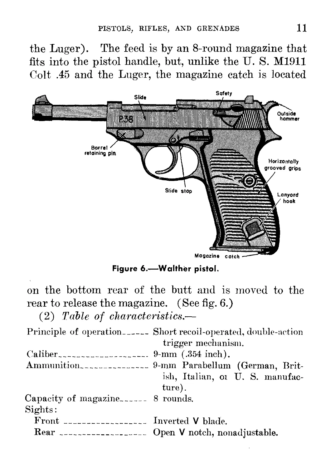
the Luger). The feed is by an 8-round magazine that
fits into the pistol handle, but, unlike the U. S. M1911
Colt .45 and the Luger, the magazine catch is located
Figure 6.—Walther pistol.
on the bottom rear of the butt and is moved to the
rear to release the magazine. (See fig. 6.)
(2) Table of characteristics.—
Principle of operation_____Short recoil-operated, double-action
trigger mechanism.
Caliber____________________ 9-mm (.354 inch).
Ammunition_________________9-mm Parabellum (German, Brit-
ish, Italian, oi U. S. manufac-
ture).
Capacity of magazine______ 8 rounds.
Sights:
Front____________________ Inverted V blade.
Rear--------------------- Open V notch, nonadj ustable.
12
german infantry weapons
Length of barrel__________
Weight:
With loaded magazine.---
With empty magazine-----
Range:
Effective ______________
Maximum_________________
Muzzle velocity___________
4.75 inches.
2 pounds 5.25 ounces.
2 pounds 1.75 ounces.
25 yards.
1,150 yards.
1,040 feet per second.
d. How to Operate
(1) Safety.—The safety is a lever located at the
left rear of the slide. In order to fire, thumb up the
safety, uncovering the letter “F” {Feuer—“fire”).
In order to lock the pistol, thumb down the safety
uncovering the letter “8” (sicher—“safe”).
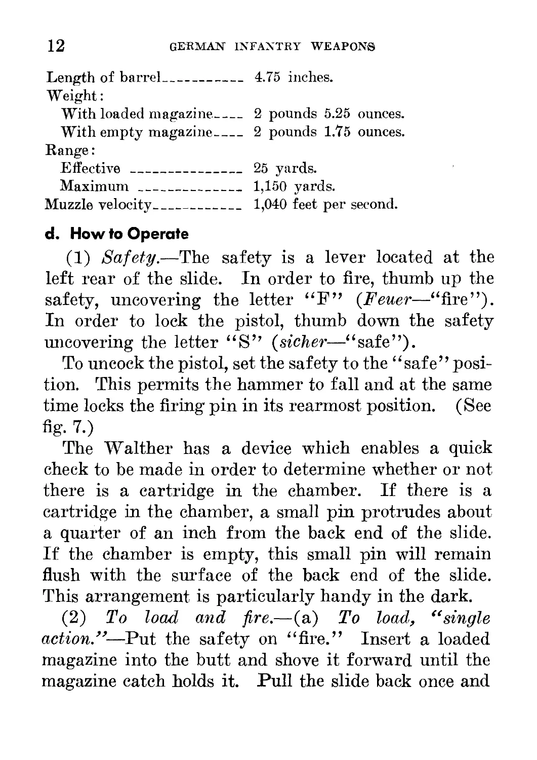
To uncock the pistol, set the safety to the “safe” posi-
tion. This permits the hammer to fall and at the same
time locks the firing pin in its rearmost position. (See
fig. 7.)
The Walther has a device which enables a quick
check to be made in order to determine whether or not
there is a cartridge in the chamber. If there is a
cartridge in the chamber, a small pin protrudes about
a quarter of an inch from the back end of the slide.
If the chamber is empty, this small pin will remain
flush with the surface of the back end of the slide.
This arrangement is particularly handy in the dark.
(2) To load and fire.—(a) To load, “single
action.”—Put the safety on “fire.” Insert a loaded
magazine into the butt and shove it forward until the
magazine catch holds it. Pull the slide back once and
PISTOLS, RIFLES, AND GRENADES
13
let it snap forward. The pistol is now loaded and
cocked. A pull on the trigger will fire the weapon.
(b) To load, ^alternate method.”—Put the safety
on “safe.” Insert the loaded magazine and work the
slide as described in d (1), on the opposite page. This
pistol is now loaded but not cocked. When ready to
Figure 7.—Diagrammatic sketch showing trigger action of Walther
pistol.
fire, put the safety on “fire” and pull the trigger. As
this pistol has a double action, the pull on the trigger
will cock the hammer and then fire the round. After
the first shot, the recoil of the slide will cock the
hammer.
(3) To unload.—Pull to the rear the magazine
catch, located on the bottom rear of the butt, and the
magazine will drop out. Work the slide back and
forth several times to be sure that the chamber is
emptied.
14
GERMAN INFANTRY WEAPONS
e. Ammunition
The following types of ammunition may be used in
the Pistole 38:
(1) German standard 9-mm Parabellum cartridge (which is
used also in the Pistole 08).
(2) British- and U. S.-manufactured 9-mm Parabellum ammu-
nition for the Sten and Lanchester submachine guns.
(3) Italian ammunition used in the Beretta submachine gun
and 9-mm pistols (other than the cartridges used in the Beretta
pistol, model 34, which will not function in the Pistole 38).
Wherever possible, German-issue ammunition should
be inserted in German pistols, which are “touchy”
about the ammunition used. Italian pistol ammuni-
tion, model 38, is likely to cause stoppages in German
9-mm weapons. Care should also be taken so as not
to mistake the dummy cartridges (Exerzierpatronen
08) used in drills for live ammunition.
f. Maintenance
(1) Stripping.—Insert an empty magazine in the
pistol. Pull the slide back until the slide stop en-
gages and holds the slide in the rear position. Turn
the barrel retaining pin clockwise about three quarters
of a turn. Remove the magazine, press down on the
slide stop, and let the slide snap forward. Pull the
trigger, and remove the slide and barrel from the re-
ceiver by pulling the slide forward. Unlock the slide
from the barrel by pushing in on the locking-cam
plunger and pulling down the locking cam.
(2) Assembly.—Assemble in the reverse order, but
be sure that the slide and barrel are locked together
PISTOLS, RIFLES, AND GRENADES
15
before being assembled to the receiver. To insure this,
pull out the locking-cam plunger and press the locking
cam upward into its groove. The barrel and slide
will remain locked together if the pistol is assembled
upside down, but the ejector and the two levers of the
safety mechanism must be pushed in so as to prevent
them from catching on the rear end of the slide.
(3) General care.—The type of care given the IT. S.
service pistol will keep the Pistole 38 in good working
order. It should be cleaned and oiled frequently. In
extremely sandy or dusty regions, oil should be used
sparingly or not at all.
g. Accessories
A leather holster, spare magazines, and a magazine
holder are issued with this weapon.
3. SUBMACHINE GUN 6 (M.P. 38 AND M.P. 40)
a. General
Although this weapon was originally designed for
use by parachute troops, it can now be found in gen-
eral use in all combat units of the German Army.
The construction is simple, and both the M.P.6 38 and
the more recent M.P. 40, which has been issued in
large quantities, are reliable weapons. They fire from
an open bolt, and the pressure in the barrel forces
the bolt back in order to extract and eject the empty
15 A submachine gun shoots pistol ammunition; the ordinary machine gun
shoots rifle ammunition.
‘M.P. is an abbreviation for Maschinenpistole, literally “machine pistol.”
16
german infantry weapons
cartridge case. The spring then forces the bolt for-
ward again, chambering and firing a new round.
b. How to Identify
The M.P. 38 and M.P. 40 may be identified by—
(1) Folding skeleton shoulder stock.
(2) Absence of wood (these guns are all metal and plastic).
(3) Fixed and folding, open rear sights.
(4) Hooded front sight.
(5) Marking (“M.P. 38” or “M.P. 40”) on top of the receiver.
(6) Corrugations on the receiver casing of the M.P. 38; smooth
surface on the receiver casing of the M.P. 40.
c. Characteristics
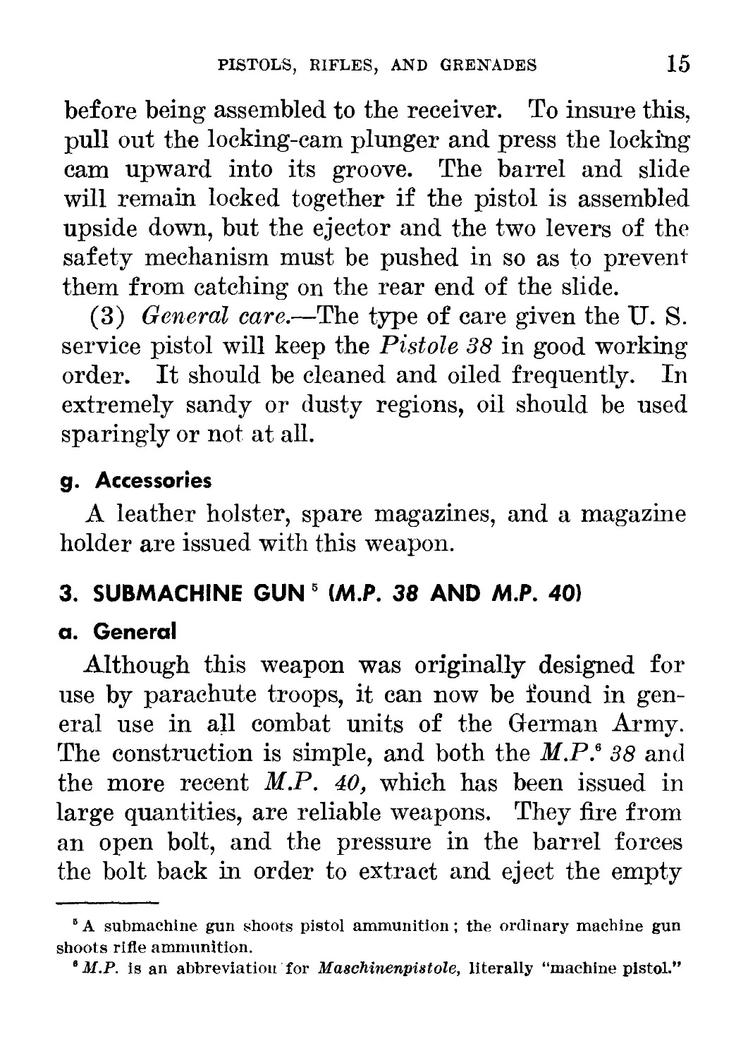
(1) General.—The M.P. 38 and M.P. 40 are simple
blow’back-operated submachine guns; they are maga-
Figure 8.—Two views of M.P. 40, showing skeleton shoulder stock
folded, and open.
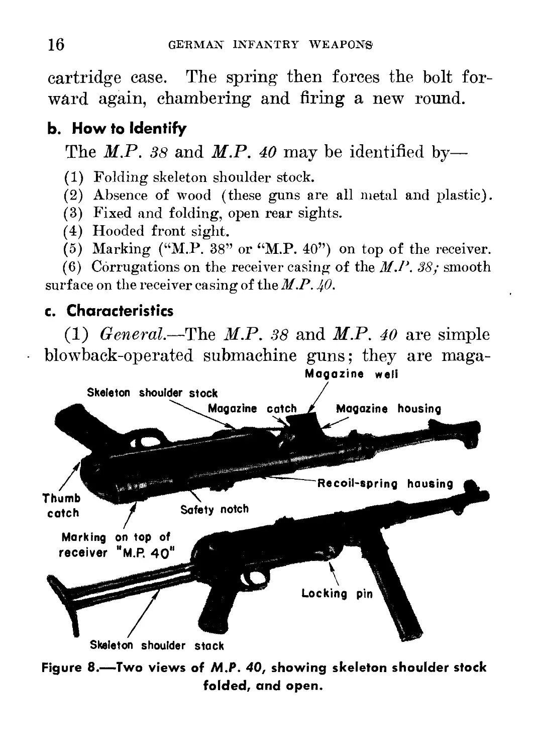
PISTOLS, RIFLES, AND GRENADES 17
zine-fed, air-cooled shoulder weapons which may also be
fired from the hip. They are used for close work and
are not effective at the longer ranges. They fire from
an open bolt and deliver full-automatic fire only. Al-
though the M.P. 40 is slightly lighter and has a slower
rate of fire, both types are the same for all practical
purposes. (See fig. 8.)
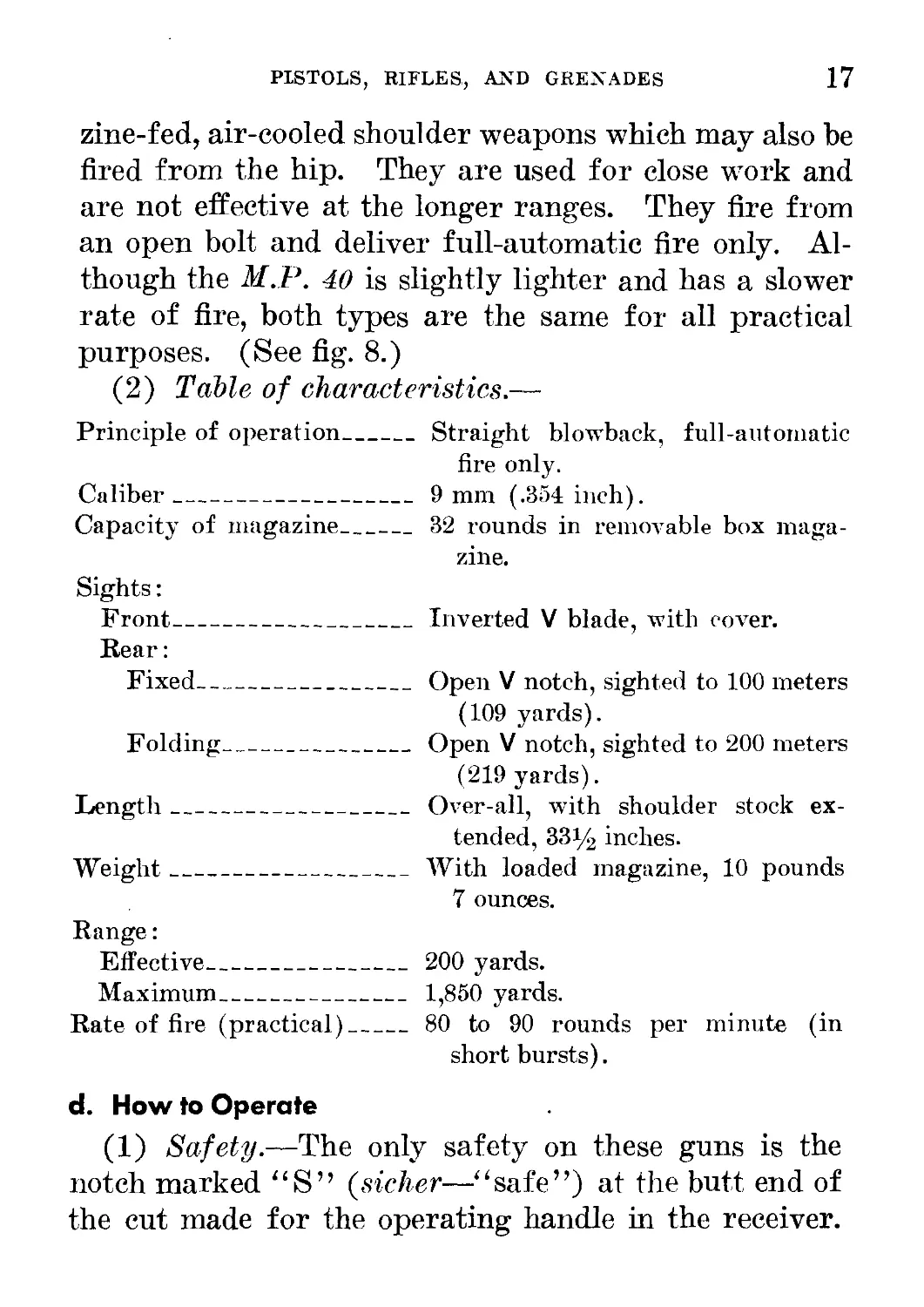
(2) Table of characteristics.—
Principle of operation____
Caliber___________________
Capacity of magazine______
Sights:
Front___________________
Rear:
Fixed_________________
Folding_______________
Length____________________
Weight____________________
Range:
Effective_______________
Maximum_________________
Rate of fire (practical)__
Straight blowback, full-automatic
fire only.
9 mm (.354 inch).
32 rounds in removable box maga-
zine.
Inverted V blade, with cover.
Open V notch, sighted to 100 meters
(109 yards).
Open V notch, sighted to 200 meters
(219 yards).
Over-all, with shoulder stock ex-
tended, 331/2 inches.
With loaded magazine, 10 pounds
7 ounces.
200 yards.
1,850 yards.
80 to 90 rounds per minute (in
short bursts).
d. How to Operate
(1) Safety.—The only safety on these guns is the
notch marked “S” (sicher—“safe”) at the butt, end of
the cut made for the operating handle in the receiver.
18
GERMAN INFANTRY WEAPONS
To make the gun “safe,” pull the operating handle back
as far as it will go and then push it upward into the
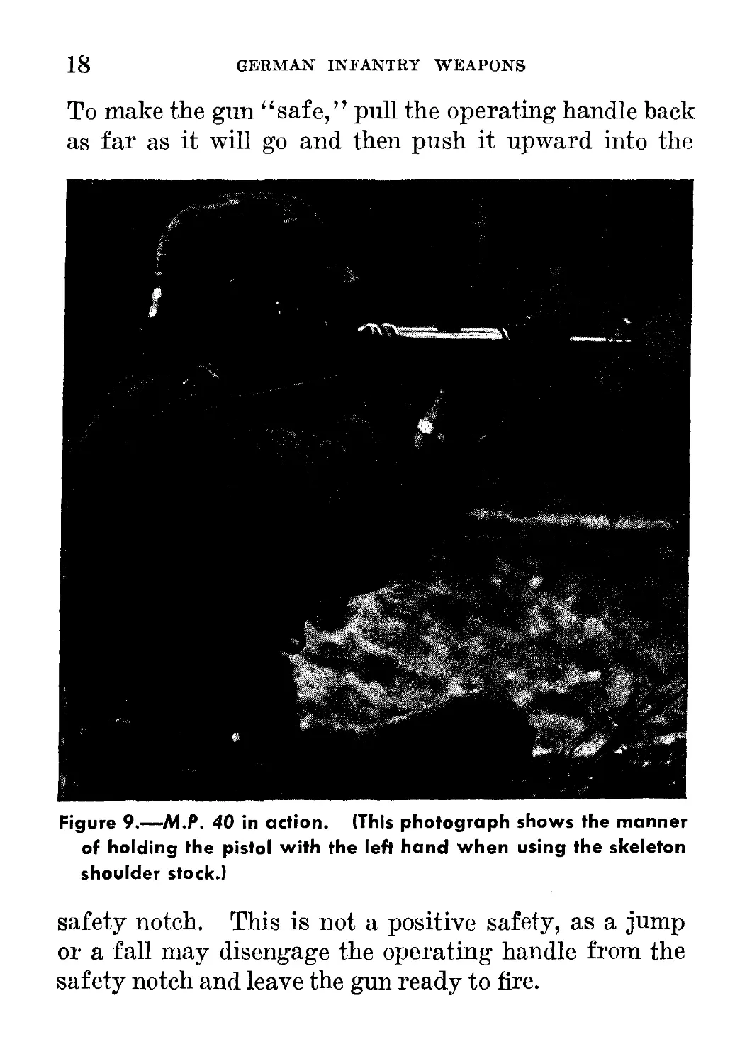
Figure 9.—M.P. 40 in action. (This photograph shows the manner
of holding the pistol with the left hand when using the skeleton
shoulder stock.)
safety notch. This is not a positive safety, as a jump
or a fall may disengage the operating handle from the
safety notch and leave the gun ready to fire.
PISTOLS, RIFLES, and grenades
19
(2) To load and fire.—Press the thumb catch above
the pistol grip in order to release the skeleton shoulder
stock from its folded position. Snap the shoulder stock
into extended position and unfold the butt plate. Pull
the operating handle back and switch it into the safety
notch. Insert a loaded magazine into the feedway on
the under side of the receiver until the magazine catch
engages. Disengage the operating handle from the
safety notch; then aim,7 and squeeze the trigger. The
magazine can serve as a grip while firing (but see fig.
9 for the German method of firing).
(3) To unload.—Press the magazine catch and re-
move the magazine. Check the chamber to be sure
that it is empty. After pressing the trigger, let the
operating handle go forward slowly.
e. Ammunition
The ammunition used in these guns is the standard
9-mm Parabellum cartridge, used in all German pistols
and submachine guns. This is a rimless, straight-case
cartridge with a round-nose, jacketed bullet. The
German nomenclature for this ammunition is Pistol-
enpatronen 08 (“pistol cartridges 08”)- It comes in
cases containing 4,160 rounds, packed in multiples of
16 rounds in cartons and packages. Ammunition
(9-mm) manufactured for the British Sten subma-
chine gun (called a machine carbine by the British)
can be used in the M.P. 38 and M.P. 40. Italian
9-mm pistol ammunition other than model 34 will also
’ See fig. 5. p. 8, above, for the method of aligning German sights.
20 GERMAN INFANTRY WEAPONS
function. But the German-issue ammunition should b<
used whenever possible.
f. Maintenance
(1) Oiling and cleaning.—These submachine guns art
cleaned and oiled in the same manner as the U. S
Figure 10.—Method of removing receiver of M.P. 40 from barrel
and from magazine housing.
Thompson submachine gun. In sandy or dusty coun-
try, oil should be used sparingly or not at all.
(2) Stripping.—First, be sure that the gun is un-
loaded and uncocked. Pull out the locking pin (see
fig. 10®) located on the bottom front portion of the
receiver behind the magazine well, and turn the pin a
PISTOLS, RIFLES, AND GRENADES 21
little to keep it unlocked. Grasp the barrel with the
left hand and the pistol grip with the right; press the
trigger, and at the same time turn the receiver in a
counterclockwise direction, holding the magazine hous-
ing in its normal position (see fig. 10 ®). It will then
be possible to separate the receiver from the barrel and
from the magazine housing. Remove the bolt and
recoil spring from the receiver by means of the operat-
ing handle. The recoil spring may be removed from
the telescoping recoil-spring housing.
(3) Assembly.—Assemble the recoil spring to the
recoil-spring housing. Replace the recoil-spring as-
sembly and bolt into the receiver. Hold the trigger
back, and assemble the receiver to the barrel and
the magazine housing by holding the magazine housing
and then inserting the receiver and turning it in a
clockwise direction. Turn the locking pin so that it
snaps in.
g. Accessories
Six magazines and a magazine filler are carried in a
web haversack. Four magazines are sometimes car-
ried on a magazine holder attached to the belt. A
small cleaning outfit is carried on the person, and a
sling is attached to these guns for carrying purposes.
4. MAUSER KAR. 98K RIFLE
a. General
The Mauser Kar. 98K, or Mauser carbine, model
98K, rifle is the standard shoulder weapon of the Ger-
524652°—43-3
22
GERMAN INFANTRY WEAPONS
man Army. Anyone who can use the U. S. М19ОЗ
(Springfield) service rifle will have little difficulty in
using this German weapon, which is a handy, accurate
short rifle. Although the German rifle has no wind-
age adjustment or peep-sight, it will give good results
at medium ranges after a little practice.
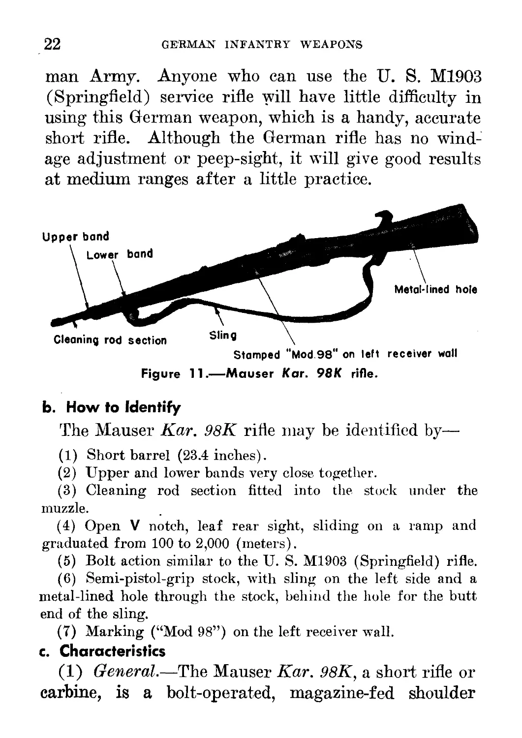
Figure 11.—Mauser Kar. 98K rifle.
b. How to Identify
The Mauser Kar. 98K rifle may be identified by—
(1) Short barrel (23.4 inches).
(2) Upper and lower bands very close together.
(3) Cleaning rod section fitted into the stock under the
muzzle.
(4) Open V notch, leaf rear sight, sliding on a ramp and
graduated from 100 to 2,000 (meters).
(5) Bolt action similar to the U. S. M1903 (Springfield) rifle.
(6) Semi-pistol-grip stock, with sling on the left side and a
metal-lined hole through the stock, behind the hole for the butt
end of the sling.
(7) Marking (“Mod 98”) on the left receiver wall.
c. Characteristics
(1) General.—The Mauser Kar. 98K, a short rifle or
carbine, is a bolt-operated, magazine-fed shoulder
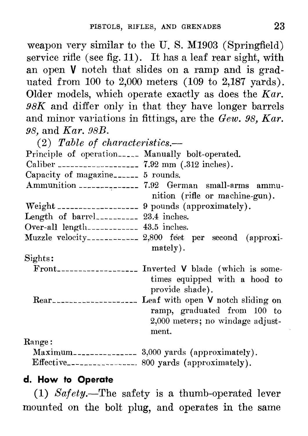
PISTOLS, RIFLES, AND GRENADES 23
weapon very similar to the U. S. M1903 (Springfield)
service rifle (see fig. 11). It has a leaf rear sight, with
an open V notch that slides on a ramp and is grad-
uated from 100 to 2,000 meters (109 to 2,187 yards).
Older models, which operate exactly as does the Kar.
98K and differ only in that they have longer barrels
and minor variations in fittings, are the Gew. 98, Kar.
98, and Kar. 98B.
(2) Table of characteristics.—
Principle of operation____
Caliber___________________
Capacity of magazine______
Ammunition________________
Weight____________________
Length of barrel__________
Over-all length___________
Muzzle velocity___________
Sights:
Front___________________
Rear__________________
Range:
Maximum_______________
Effective_____________
Manually bolt-operated.
7.92 mm (.312 inches).
5 rounds.
7.92 German small-arms ammu-
nition (rifle or machine-gun).
9 pounds (approximately).
23.4 inches.
43.5 inches.
2,800 feet per second (approxi-
mately).
Inverted V blade (which is some-
times equipped with a hood to
provide shade).
Leaf with open V notch sliding on
ramp, graduated from 100 to
2,000 meters; no windage adjust-
ment.
3,000 yards (approximately).
800 yards (approximately).
d. How to Operate
(1) Safety.—The safety is a thumb-operated lever
mounted on the bolt plug, and operates in the same
24
GERMAN INFANTRY WEAPON'S
manner as the safety on the U. S. Springfield service
rifle. The rifle can be fired and the bolt worked when
the safety lock is moved to the left. When the safety
lock is moved to the right, the piece is locked. The
safety lock can be moved only when the rifle is cocked.
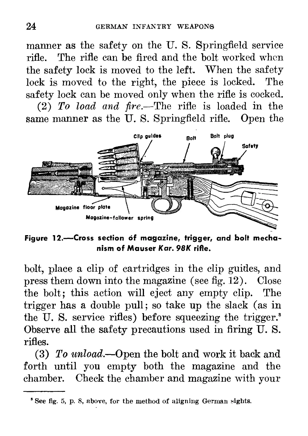
(2) To load and fire.—The rifle is loaded in the
same manner as the ГГ. S. Springfield rifle. Open the
Clip guides в.» Bolt plug
Figure 12.—Cross section of magazine, trigger, and bolt mecha-
nism of Mauser Kar. 98K rifle.
bolt, place a clip of cartridges in the clip guides, and
press them down into the magazine (see fig. 12). Close
the bolt; this action will eject any empty clip. The
trigger has a double pull; so take up the slack (as in
the U. S. service rifles) before squeezing the trigger.8
Observe all the safety precautions used in firing U. S.
rifles.
(3) To unload.—Open the bolt and work it back and
forth until you empty both the magazine and the
chamber. Check the chamber and magazine with your
’ See fig. 5, p. 8, above, for the method of aligning German fights.
PISTOLS, RIFLES, AND GRENADES 25
finger tip to make sure that they are both clear of
cartridges.
e. Ammunition
The ammunition used in this rifle includes various
types of 7.92-mm (.312-inch) small-arms ammunition.
(See pars. 20 to 30, inch, pp. 161-184, below, for an ex-
planation of the labels on ammunition cases.) Ball
ammunition is packed in cases holding 1,500 rounds, and
the label is overprinted i.L. to indicate that the ammuni-
tion in a case is packed in 5-round clips. Do not use am-
munition from cases whose labels are overprinted Ex.,
as this is “dummy,” or drill, ammunition.
f. Maintenance
(1) Stripping.—(a) To remove bolt.—Cock the rifle
by working the bolt, and set the safety lever halfway
between the safe and the locked positions. Pull the
bolt back. Then pull out the near end of the bolt stop,
which is located on the left side of the receiver near
the cutoff. Hold the bolt stop out while you remove
the bolt from the receiver.
(b) To disassemble bolt.—The bolt is stripped in the
same manner as that of the U. S. Springfield rifle. Press
in the bolt-sleeve lock and unscrew the bolt sleeve, fir-
ing pin, and spring assembly. Now place the tip
of the firing pin in the hole in the stock of the rifle.
Compress the spring, pushing down on the bolt sleeve
until the bolt sleeve clears the headless cocking piece.
Turn the cocking piece a quarter turn in either di-
rection and remove it from the firing pin shaft. Ease
26
GERMAN INFANTRY WEAPONS
up on the bolt sleeve so as not to allow the spring to
escape suddenly. Remove the bolt sleeve and firing-
pin spring from the firing pin.
(c) To remove magazine floor plate.—Insert the
point of a bullet or a pointed tool into the small hole
in the magazine floor plate, and exert pressure while at
the same time pushing the floor plate toward the trig-
ger guard. This will release the catch, and the
magazine floor-plate spring and follower can then be re-
moved and broken down into their separate units.
Further stripping is not usually necessary.
(2) Assembly.—The assembling is done in the re-
verse order to that described in f(l), above.
(3) Care and cleaning.—The care of this rifle is the
same as that required for the U. S. M19O3 and Ml
service rifles.
g. Accessories
(1) General.—Each rifle is furnished with a short
length of cleaning rod, fitted through the bayonet stud.
The rods from 3 rifles will make one full-length clean-
ing rod. A small metal case carried on the person
holds an oiler, a pull-through, brushes, and short
lengths of tow used as patches. Ammunition is car-
ried in 2 leather ammunition pouches attached to the
belt, which hold 60 rounds in 5-round clips. Additional
rifle ammunition is issued in cloth bandoleers similar
to the U. S. type. Muzzle and breech covers are some-
times used. Rifle grenade launchers may be attached
to the rifle. In addition, a short knife bayonet
PISTOLS, RIFLES, AND GRENADES
27
is made to be fixed to the rifle in a manner similar to
that of U. S. service bayonets.
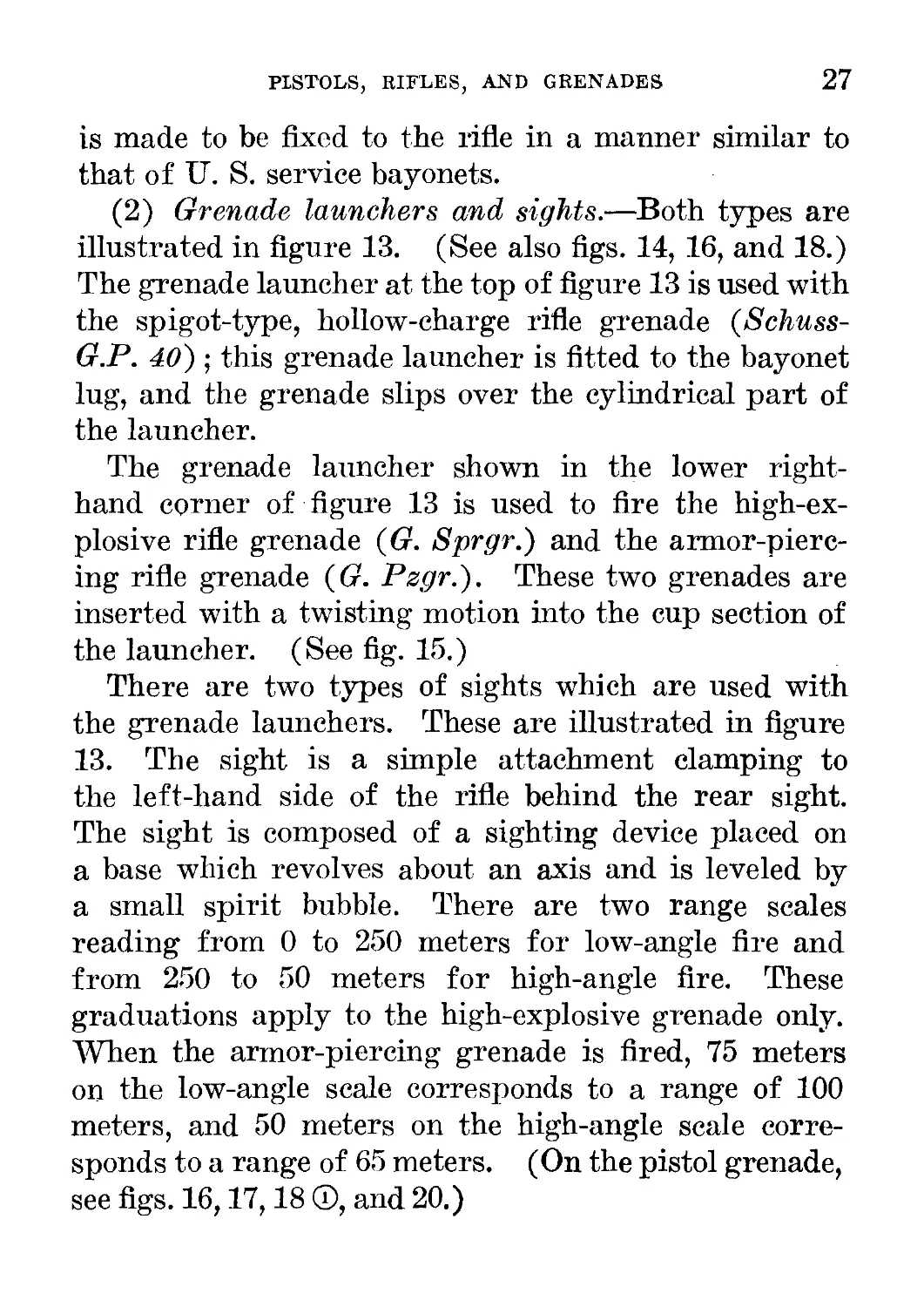
(2) Grenade launchers and sights.—Both types are
illustrated in figure 13. (See also figs. 14, 16, and 18.)
The grenade launcher at the top of figure 13 is used with
the spigot-type, hollow-charge rifle grenade (Schuss-
G.P. 40) ; this grenade launcher is fitted to the bayonet
lug, and the grenade slips over the cylindrical part of
the launcher.
The grenade launcher shown in the lower right-
hand corner of figure 13 is used to fire the high-ex-
plosive rifle grenade (G. Sprgr.) and the armor-pierc-
ing rifle grenade (G. Pzgr.). These two grenades are
inserted with a twisting motion into the cup section of
the launcher. (See fig. 15.)
There are two types of sights which are used with
the grenade launchers. These are illustrated in figure
13. The sight is a simple attachment clamping to
the left-hand side of the rifle behind the rear sight.
The sight is composed of a sighting device placed on
a base which revolves about an axis and is leveled by
a small spirit bubble. There are two range scales
reading from 0 to 250 meters for low-angle fire and
from 250 to 50 meters for high-angle fire. These
graduations apply to the high-explosive grenade only.
When the armor-piercing grenade is fired, 75 meters
on the low-angle scale corresponds to a range of 100
meters, and 50 meters on the high-angle scale corre-
sponds to a range of 65 meters. (On the pistol grenade,
see figs. 16,17,18 ®, and 20.)
28
GERMAN INFANTRY WEAPONS
Figure 13.—Mauser Kar. 98K rifle with grenade launchers and
sights.
(3) Grenades.—(a) High-explosive grenade (Gewehr
Sprenggranate, G. Sprgr.).—The high-explosive gre-
nade consists of a blackened steel body with an alumi-
num nose fuze and a grooved collar fitting into the
rifling of the bore of the launcher (see fig. 18 ®).
The fuze operates on impact, but the shock of dis-
charge also initiates a delay system in the base which,
in the event of the nose fuze’s failing to function,
detonates the filling after a delay of 4 to 5 seconds.
The collar carrying the rifling may be unscrewed from
the body and the igniter string pulled, in which case
PISTOLS, RIFLES, AND GRENADES
29
the projectile can then be thrown as a hand grenade,
operating after 4 to 5 seconds (see fig. 19). The ef-
fect is equivalent to that of a “defensive” type of
grenade, the radius of fragmentation being described by
an enemy document as about 30 yards.
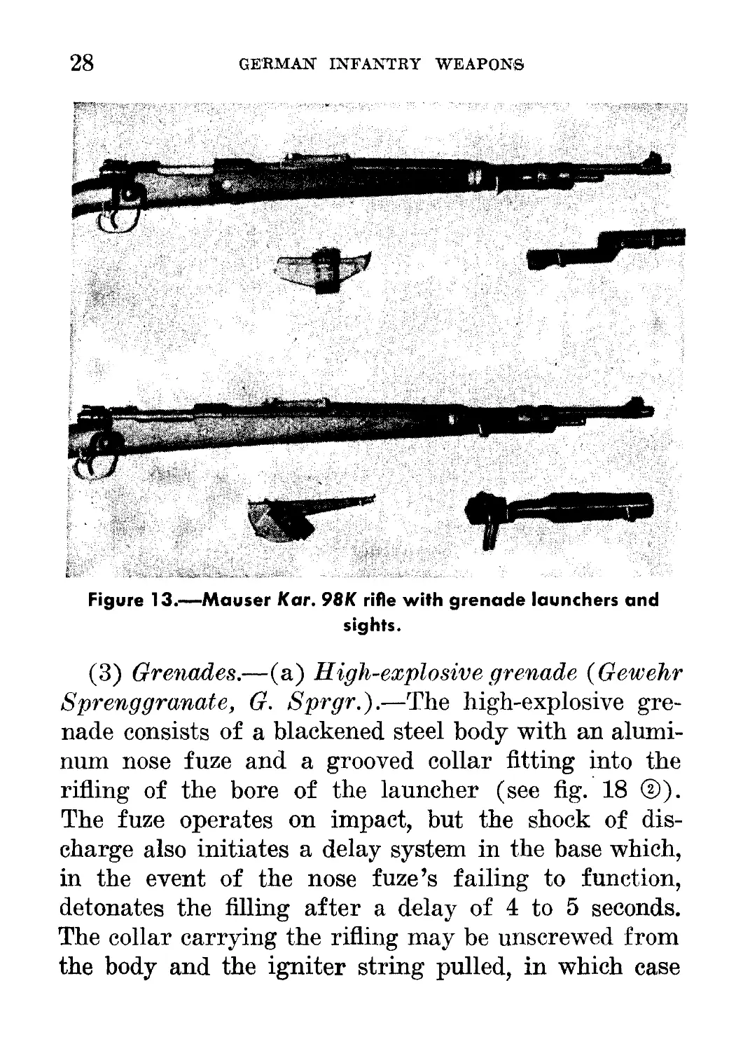
(b) Armor-piercing grenade {Gewehr Panzergra-
nate, G. Pzgr.}.—The rifle grenade for use against
armor incorporates the hollow-charge principle (see
Figure 14.—Grenade launcher,
showing method of unscrew-
ing it to aid in cleaning.
Figure 15.—Method of inserting
rifle grenade. (The cup of the
launcher being rifled, the gre-
nade is inserted with a twist-
ing motion.)
30
GERMAN INFANTRY WEAPONS
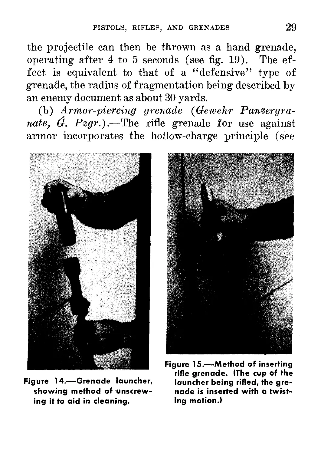
Fig ure 16.—Rifle grenade launcher and grenade firing pistol
(very light type). (Both the launcher and the pistol are rifled).
Figure 17.—Pistol grenade being breech-loaded.
PISTOLS, RIFLES, AND GRENADES
31
Figure 18.—Three types ow grenade projectiles: © pistol grenade;
@ rifle grenade, with percussion detonator fuze; © rifle grenade,
with hollow charge.
Figure 19.—Method of unscrewing base of rifle grenade and
thereby using friction fuze.
32
GERMAN INFANTRY WEAPONS
Figure 20.—Special projectile 361 for signal pistol (Wurfkorper 361
fur Leuchtpistolek
(The projectile consists of the normal egg-type hand grenade (see par. 10,
p. 47, below), with a stem in place of the combustion fuze 39. The stem
contains a combustion fuze (combustion time, approximately, 4 to .7 seconds)
on the upper end of which a No. 8 detonator is fitted. The fuze is inserted
into the detonator and then the detonator end is inserted into the grenade.
On the lower end of the stem there is the cartridge (propellant charge with
percussion cap) which expels the projectile on firing and sets off the com-
bustion fuze. The projectile is secured in the stem by a cotter pin and ring
which must be withdrawn before the projectile is loaded into the signal
pistol. When withdrawn, the projectile is “live.”
For firing the projectile, a barrel-reinforcing tube is inserted into the
barrel of the signal pistol. It is pushed in from the rear when the pistol is
broken. When the barrel is returned to position, the pistol is ready for
loading. (The barrel-reinforcing tube should be cleaned about every 100
rounds.) The stem of the projectile is introduced into the tube until ap-
preciable resistance shows that the base of the tube has been reached. The
pistol may now be cocked.
The signal pistol grenades are packed in a metal container with detona-
tors and a barrel-reinforcing tube.)
PISTOLS, RIFLES, AND GRENADES
33
fig. 18®). The grenade is a long cylinder, partly
steel and partly aluminum, with a black rounded-
metal nose cap and a base plate slotted to facilitate
removal. The forward half of the cylinder is con-
structed of steel and contains the bursting charge, a
light metal diaphragm shaping the hollow charge. The
rear aluminum half of the cylinder, which carries an
interrupted collar with eight right-hand grooves to fit
the rifling of the launcher cup, contains a fuze and
detonator. The weight of the bursting charge is ex-
ceedingly small compared with the total weight of the
projectile, and the general design is unnecessarily
complicated, with considerable waste of efficiency.
There is no provision for use as a hand grenade.
(c) Practice projectile (Gewehr Sprengranate,
Ubungsmunition, G. Sprgr., tdb.j.—This round is fitted
with a smoke generator, six holes for smoke emission
being drilled in the side of the body.
(d) Cartridge and packing.—Each rifle grenade is
packed with bulletless blank rifle cartridge in a card-
board container, which may be marked with the Ger-
man nomenclature. The cartridges are not inter-
changeable between rounds of different types. The
containers are black, with a white spot on the end for
armor-piercing grenades and gray for the high-
explosive grenades.
(e) Range.—The high-explosive grenade has a maxi-
mum range of about 250 yards. The armor-piercing
grenade probably has a maximum range of about 100
yards.
34
GERMAN INFANTRY WEAPONS
5. Pz.B.9 39 (ANTITANK RIFLE)
a. General
Antitank rifles are issued to the German Army on a
scale of one for each platoon (or equivalent unit).
There are at least two types of antitank rifles in use by
the Germans: the Polish antitank rifle (model 35),
which has been renamed the1 Taiikbiichse, and the
Pz.B. 39, a later model of the Pz.B. 38. (See figs.
21 and 22.)
b. How to Identify
Both the Pz.B. 38 and Pz.B. 39 may be identified
by—
(1) Folding shoulder stocks with a rubber shock absorber.
(2) Bipod mount and carrying handle.
(3) Muzzle brake.
(4) Single-shot, falling-block action worked by a moving
pistol grip in the Pz.B. 39 and by recoil in the Pz.B. 38.
"Pz.B. is the German abbreviation for Panzerbilchse, which means “anti-
tank rifle.” The German tactical symbol for antitank rifle is
PISTOLS, RIFLES, AND GRENADES
35
c. Characteristics
(1) General.—The Pz.B. 38 and Pz.B. 39 are light
antitank weapons carried by infantry. They are
single-shot rifles fired from a bipod mount. The bul-
let is an armor-piercing projectile with tracer com-
pound and sometimes with a tear-gas powder in the
base. The Pz.B. 38 and Pz.B. 39 are basically the
same and differ only slightly in appearance and com-
Figure 22.—Overhead view of Pz.B. 39, illustrating cutout folding
shoulder stock.
ponent parts. The description of the Pz.B. 39 which
follows will also serve for the Pz.B. 38.
(2) Table of characteristics.—
Principle of operation____
Caliber------------------
Ammunition_______________
Sights:
Front___________________
Rear____________________
Single-shot, falling-block action.
7.92 mm (.312 inch).
Caliber .50 case, necked down to
take a caliber .312 bullet.
Inverted V blade, with hood for
shade and protection.
Open V notch,nonad justable, sighted
300 meters (328 yards).
36
GERMAN INFANTRY WEAPONS
Over-all length:
With shoulder stock in
place___________________62% inches.
With shoulder stock
folded____________________50% inches.
Range:
Effective___________________ 250 to 300 yards.
Penetration_______________At 300 yards, %-inch (20° impact)
and 1-inch (normal impact)
face-hardened plate; at 100
yards, 1%-inch (normal impact)
face-hardened plate.
Muzzle velocity___________ 3,540 feet per second.
Feed______________________ By hand from two ammunition
holders that clip on each side of
stock forearm, each box holding
10 rounds of ammunition.
d. How to Operate
(1) Safety.—The safety lever is located on the tang
of the receiver just to the rear of the breechblock. To
put the rifle on “safe,” move the safety lever until
the letter “S” (sicker—“safe”) is exposed. To un-
lock, move the safety lever until the letter “F”
(Feuer—“fire”) is exposed.
(2)' To load and fire.—Press the bipod lock (see fig.
21), and adjust the height of the bipod by turning the
adjusting screw located underneath the pivot point
of the bipod. Press the stock release button and snap
the shoulder stock into place. Move the safety lever
to the “fire” position. Push the pistol grip forward
and downward, thus depressing the breechblock. In-
PISTOLS, RIFLES, AND GRENADES 37
serf one round into the chamber, which is exposed by
lowering the breechblock (see fig. 24). Close the
breechblock by pulling back and up on the pistol grip.
The piece is now ready to fire.10 The safety lever
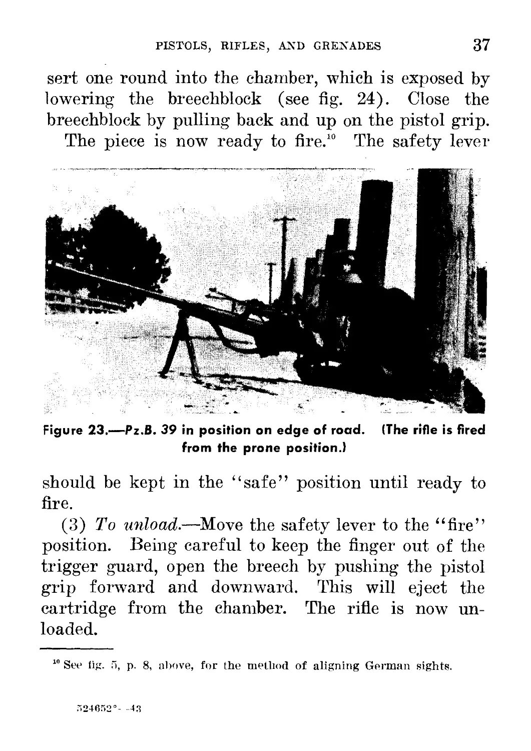
Figure 23.—Pz.B. 39 in position on edge of road. (The rifle is fired
from the prone position.)
should be kept in the “safe” position until ready to
fire.
(3) To unload.—Move the safety lever to the “fire”
position. Being careful to keep the finger out of the
trigger guard, open the breech by pushing the pistol
grip forward and downward. This will eject the
cartridge from the chamber. The rifle is now un-
loaded.
10 See iig. Г), p. 8, above, for the method of aligning German sights.
524652°- 4.3
38
GEBMAN INFANTRY WEAPONS
e. Ammunition
The ammunition used has a rimless case the ap-
proximate size of the U. S. caliber .50 case, but the
projectile is approximately the size of the U. S.
caliber .30 projectile. The German nomenclature11
for this ammunition is Patr. 318 S.m.K. for the
pointed bullet with steel core, and Patr. 318 S.m.K. (H)
for the pointed bullet with hardened-steel core. The
ammunition for the Pz.B. 38 and the Pz.B. 39, though
of the same caliber as the rifle and machine-gun am-
munition, will not function in either rifle or machine
gun, as the dimensions of the cartridge case are much
larger.
The Polish antitank rifle (model 35), the Tank-
biichse (see a, above), uses a similar cartridge, but
this cartridge will not function in either the Pz.B. 38
or the Pz.B. 39. It is known as Patr. 318 (P), or
Polish cartridge No. 318, and is packed in boxes with
green labels printed in Polish and overprinted “Patr.
318.”
f. Maintenance
(1) Oiling and cleaning.—The rifle should be given
the usual care with respect to cleaning and lubricating.
Oil should be used sparingly or not at all in hot,
sandy, or dusty country.
(2) Stripping.—Remove the pistol-grip pivot pin by
compressing its spring lock and pushing it out from left
to right. Remove the trigger pistol-grip group and *
" See fig. 93, p. 167, below, for one type of label used to identify ammuni-
tion for the antitank rifle.
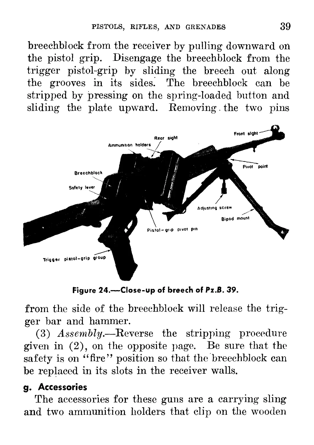
PISTOLS, RIFLES, AND GRENADES 39
breechblock from the receiver by pulling downward on
the pistol grip. Disengage the breechblock from the
trigger pistol-grip by sliding the breech out along
the grooves in its sides. The breechblock can be
stripped by pressing on the spring-loaded button and
sliding the plate upward. Removing. the two pins
Figure 24.—Close-up of breech of Pz.B. 39.
from the side of the breechblock will release the trig-
ger bar and hammer.
(3) Assembly.—Reverse the stripping procedure
given in (2), on the opposite page. Be sure that the
safety is on “fire” position so that the breechblock can
be replaced in its slots in the receiver walls.
g. Accessories
The accessories for these guns are a carrying sling
and two ammunition holders that clip on the wooden
40 GERMAN INFANTRY WEAPONS
forearm. A small cleaning kit similar to the rifle
cleaning kit is carried by the antitank rifleman.
6. HAND GRENADES
The hand grenades used by the German Army are all
of the “offensive” type: that is, they have a thin metal
casing with a high proportion of explosive filler. Being
of this type, they depend on the blast effect, instead of
on the fragmentation of the case as in the U. S. “defen-
sive-type” Mills grenades. They can be used safely by
troops advancing erect in the open, because they can be
thrown to a distance greater than their effective burst-
ing radius. The model 24 and model PH 39 stick-type,
or “potato masher’’-type, grenades are used more often
than the “egg’’-type and can be regarded as the stand-
ard hand grenades of the German Army. In addition,
there is a smoke stick grenade which differs from the
regular stick, or “potato masher,” only in the marking
on the head of the grenade.
7. STICK HAND GRENADE, MODEL 24 (STIELHANDGRA-
NATE 24)
a. How to identify
The stick hand grenade, model 24, may be identified
by—
(1) Metal casing or body screwed onto a wooden handle with
a metal cap.
(2) Model marking on the casing or body of the grenade.
(3) Porcelain ball attached to a cord in the exposed cavity
after the metal cap is unscrewed.
PISTOLS, RIFLES, AND GRENADES
41
b. Characteristics
(1) General.—This grenade consists of a thin iron
or steel casing, or head, containing the explosive filler
and screwed onto a hollow wooden handle, through the
center of which runs a double length of cord (see fig.
25). This cord is attached at one end to a lead ball
which is part of the friction-igniter-detonator system,
and at the other end of a procelain ball. The cavity
in which the porcelain ball rests is closed 'by a metal
cap that screws on. Inside the cap is a spring-actu-
ated metal disk that prevents movement of the porce-
lain ball.
(2) Table of characteristics.—
Over-all length__________________________
Weight___________________________________
Weight of explosive filler---------------
Time of delay fuze_______________________
Effective blast radius___________________
1 foot 2 inches.
1 pound 5 ounces.
6 ounces.
4 to 5 seconds.
12 to 14 yards.
c. How to Operate
(1) Safety.—(a) The detonator is not assembled to
the grenade until it is carried into combat.
(b) The metal cap on the end of the handle holds
the porcelain ball in place and is not removed until
the grenade is to be thrown.
(2) To arm and throw.-— (a) To arm grenade.—
The wooden handle is unscrewed from the head, and
the metal end of the delay fuze is exposed in the
interior of the handle. Insert a detonator into the
open end of the delay fuze. The head and the handle
are screwed together again.
42
GERMAN INFANTRY WEAPONS
Figure 25.—Sketch of Stielhandgranate 24 (stick hand grenade,
model 24), showing outside and cross section of grenade and
fuze. (The cross section of the grenade is drawn to a larger
scale than the scale of the sketch of the outside view.)
PISTOLS, RIFLES, AND GRENADES 43
(b) To throw grenade.—Unscrew the metal cap,
pull out the porcelain ball as far as it will go, and
throw. Do not throw too soon, as there is a 4- to 5-sec-
ond delay.
(3) To disarm grenade.—(a) Unscrew the handle
from the head; (b) remove the detonator from the open
end of the delay fuze; (c) replace the handle.
d. Method of Carrying
Stick hand grenades, model 24, are carried in—
(1) A metal case holding 15 grenades and 15 detonators (see
fig- 26) ;
(2) A sleeveless jacket fitting over the blouse. (In this jacket
there are 10 pockets, 5 in front and 5 in the back, in which the
grenades are carried with the heads down.)
(3) The belt with the grenades stuck in, handle first.
e. Use as a Booby Trap
This grenade may be made into a booby trap by re-
moving the delay fuze. (See fig. 25.) When troops
attempt to use the captured grenades, pulling the
friction wire causes the grenades to explode immedi-
ately without the usual4- to 5-second delay.
To see whether or not the delaying device has been
removed from the grenade, it may be tested as follows:
(1) unscrew the head (explosive cylinder) from the
wooden handle; (2) remove the detonator and the fuze
which project from the handle; (3) unscrew the cap
at the end of the handle and let the porcelain ring
hang down; (4) unscrew the delayed-action device in
the top of the handle to make sure whether the delayed-
44
GERMAN INFANTRY WEAPONS
action cylinder actually contains the column of com-
pressed black gunpowder.
To reassemble the grenade, carry out the above
operations in the reverse order.
If time is short, it may be sufficient to take one
from each batch of suspected grenades, unscrew the
Figure 26.—Method of carrying and packing stick-type grenades.
handle from it, and operate the fuze by pulling the
cord from a distance. It will then be obvious whether
the explosion takes place immediately or after an in-
terval of 4 to 5 seconds.
PISTOLS, RIFLES, AND GRENADES 45
8. STICK HAND GRENADE, MODEL PH 39 (STIELHAND-
GRANATE PH 39)
a. How to Identify
The stick hand grenade, model PH 39, may be
identified by—
(1) Metal casing or body screwed to a wooden handle with a
metal cap.
(2) Model marking on the casing or body of the grenade.
(3) Cord attached to the friction igniter being also attached
to the metal-cap (this being observed on unscrewing the metal
cap on the handle).
b. Characteristics
(1) General.—Like the model 24 stick grenade, the
model PH 39 consists of a thin iron or steel casing, or
head, containing the explosive filler. This head is
screwed onto a hollow wooden handle, through the
center of which runs a double length of cord. At one
end, this cord is attached to a lead ball which is part
of the friction-igniter-detonator system, and at the
other end to the metal cap which screws onto the end
of the handle.
(2) Table of characteristics.—
Over-all length_________________________ 1 foot 4 inches.
Weight__________________________________ 1 pound 6 ounces.
Weight of explosive filler______________7 ounces.
Time of delay fuze______________________4 to 5 seconds.
Effective blast radius__________________ 16 yards.
c. How to Operate
(1) Safety.-—(a) The detonator is not assembled to
the grenade until it is carried into combat.
46
GERMAN INFANTRY WEAPONS
(b) The metal cap on the end of the handle is not
unscrewed until the grenade is to be thrown. The cap
may be unscrewed carefully and lifted slightly to be
sure that the grenade is a model PH 39, as the cord
that starts the delay fuze is attached to the metal cap
on the model PH 39 grenade.12 However, the cap
should not be pulled away from the handle, as this
action would start the fuze burning.
(2) To arm and throw.—(a) To arm grenade.—
Before use in action, the grenade is ordinarily carried
without the detonator assembled. To arm the grenade,
the wooden handle is unscrewed from the grenade
head, and the hollow end of the delay fuze is exposed;
a detonator is inserted into the hollow end of the delay
fuze; and the casing and the handle are screwed to-
gether again.
(b) To throw grenade.—Unscrew the metal cap and
pull it away from the grenade handle to the full length
of the cord. This ignites the 4- to 5-second delay fuze,
and the grenade should then be thrown with an over-
arm motion.
(3) To disarm grenade.—The grenade is disarmed
by unscrewing the handle from the head, removing the
detonator from the open end of the delay fuze, and
then replacing the handle.
d. Method of Carrying
Like the model 24, the PH 39 grenades are carried
in—
(1) A metal case holding 15 grenades and 15 detonators.
12 In this respect it differs from the model 24.
PISTOLS, RIFLES, AND GRENADES
47
(2) A sleeveless jacket fitting over the blouse. (In this jacket
there are 10 pockets, 5 in front and 5 in back, in which the
grenades are carried with the heads down.)
(3) The belt with the grenades stuck in, handle first.
e. Use as a Booby Trap
The removal of the delay element in the fuze of this
grenade will cause the grenade to explode at once with-
out the usual 4- to 5-second delay. The grenade may
be examined in the same manner as is described for
the model 24 grenade (see par. 7e, p. 43, above).
9. SMOKE HAND GRENADE, MODEL 34 (NEBELHAND-
GRANATE 34)
The smoke grenade, model 34, which is a standard
stick grenade with the explosive filler replaced by smoke
composition, is handled in the same manner as the
other stick grenades and is identified only by a broken
white line painted around the head of the grenade
near its base.
10. EGG-TYPE HAND GRENADE, MODEL 39 (EIERHAND-
GRANATE 39)
a. How to Identify
The egg-type hand grenade may be identified by—
(1) Egg shape, of gray-green painted metal with a raised rib
around the middle.
(2) Blue knob protruding .from one end.
b. Characteristics
(1) General.—This is a small thin-cased “offen-
sive’’-type grenade with a high proportion of a low-
grade high explosive (see fig. 27). It is ignited by a
friction-type igniter and a 4- to 5-second delay fuze.
48 GERMAN INFANTRY WEAPONS
(Fig. 28 illustrates the shaving-stick grenade, which
has the same type of detonator as the egg-type.)
(2) Table of characteristics.—
Over-all length_____________ — 3 inches (approximately).
Weight___________________________ 12 ounces.
Maximum diameter___________ 2 inches.
Time of delay fuze_________ 4 to 5 seconds.
Thickness of casing________ .02 inch.
c. How to Operate
(1) Safety.—The detonator is not assembled to the
grenade until it is carried into combat.
(2) To arm and throw.—(a) To arm grenade.—
Unscrew the knob from the grenade; be sure that the
exposed pocket is clean; unscrew the protective cap
from the detonator end of the knob; draw a detonator
(standard No. 8) from its box and check the open end
to see that it is dust free and not distorted (do not use
a dusty or distorted detonator); carefully slip the det-
onator onto the detonator end of the knob, screw the
armed fuze by hand, and then use the key supplied to
tighten the fuze.
(b) To throw grenade.—Unscrew the blue 13 knob,
and pull. Throw the grenade, remembering that it has
a 4- to 5-second delay.
(3) To disarm grenade.—(a) Unscrew the knob
from the grenade; (b) remove the detonator from the
end of the knob; and (c) replace the knob. To render
the igniter inoperative, carefully unscrew the knob,
13 It has been reported that a red knob is used for those igniters having no
delay element. Blue knobs have been reported on igniters having a 4- to
5-second delay. '(See e, on the opposite page.)
PISTOLS, RIFLES, AND GRENADES 49
taking care not to exert any pull on the cord. Then
cut the cord with scissors and replace the knob with
the cord inside.
d. Method of Carrying
The egg-type grenades are carried in—
(1) The pockets.
(2) Any convenient container.
e. Use as a Booby Trap
Like all other materiel, these egg-shaped grenades
can be used as booby traps. It has been reported that
Q EXTERIOR
@ CROSS SECTION
(3> FUZE ASSEMBLY
Figure 27.—Sketch of Eierhandgranate 39 (egg-type hand grenade,
model 39).
the Germans in Africa have put red primer caps on
the grenades which are used as traps. If the red
primer cap is unscrewed and the firing string pulled,
the explosion occurs instantaneously rather than after
50
GERMAN INFANTRY WEAPONS
Figure 28.—Cross section of shaving-stick grenade.
а 4- to 5-second delay—the standard delay with the
blue cap.
11. SPECIAL USES OF STICK GRENADES14
For special demolition, antitank, and antipillbox
work, the heads of six model 24 or model PH 39 stick
" See TM 5-325, “Enemy Land Mines and Booby Traps” (April 19, 1943),
pp. 1-96, for detailed information on the construction of German land
mines and booby traps, many of which are made from grenades.
PISTOLS, RIFLES, AND GRENADES 51
grenades can be removed from their handles and
fastened securely around a seventh stick grenade from
which the handle is not removed (see figs. 29 and 30).
The whole can then be used as a convenient
Figure 29.—Concentrated charge (geballte Ladung) made from
several stick grenades. (This charge is used for demolition
purposes.)
concentrated charge (geballte Ladung) for the above
purposes.
Bangalore torpedoes for blowing paths through
barbed wire can also be made by binding the desired
52
GERMAN INFANTRY WEAPONS
number of grenade heads behind one another on a
long stick or board (see fig. 31); the grenade nearest
the operator is complete with handle and detonator,
and to it is attached a long wire or cord.
Ф ® ®
Figure 30. —(Г) Stick grenade antipersonnel mine. (This mine is
improvised from the head of a stick grenade and pressure igniter
35 (Druckzunder 35, D.Z. 35), which is screwed into the head
of the grenade.) @ Stick grenade cluster mine. (This mine is
a variation of mine Q.) ©Cross section of pressure igniter 35
(Druckzunder 35, D.Z. 35).
Figure 31. —Stick grenades used as Bangalore torpedo.
Section III. MACHINE GUNS AND
MORTARS1
12. M.G. 34 2
a. General
The M.G. 34, machine gun, model 34, is not directly
comparable to any U. S. weapon. It can be fired
without a mount (fig. 32), or it can be mounted on a
bipod (fig. 33) for use as a light machine gun,3 on a
tripod (figs. 34 and 35) for use as a heavy machine
gun,4 and on a special antiaircraft mount (fig. 36)
or on the standard tripod mount with adapter and
special sight (fig. 37) for use as an antiaircraft gun,
as well as on numerous other types of mounts on tanks
and other vehicles (fig. 38). Consequently, this all-
purpose gun is the most common German automatic
weapon in use by the German armed forces. Every
infantry squad,5 and many other types of small Ger-
man units, can be expected to be armed with the
M.G. 34.
1 The weapons discussed in this section are operated by more than one
man.
2 M.G. is the Gentian abbreviation for Maschinenffetcehr, which means
“machine gun."
3 Tile German tactical symbol for a light machine gun is T
le I
‘The German tactical symbol for a heavy machine gun is T or
A s I
5 See “The German Squad in Combat,” MIS Special Series, No. 9 (Jan.
25, 1943), for detailed descriptions of the tactical employment of the machine
gun in the German squad.
524(»5’4° —43-5 53
54
GERMAN INFANTRY WEAPONS
b. How to Identify
The M.G. 34 may be identified by—
(1) Air-cooled jacket.
(2) Shape of plastic shoulder stock.
(3) Plastic pistol grips and double trigger.
(4) Folding front and rear sights. (An auxiliary antiair-
craft ring sight that fits on the barrel jacket may also be
found.)
(5) Operating handle on the right side.
Figure 32.—M.G. 34 in action without bipod or tripod.
Air-cooled jacket
Figure 34.—M.G. 34 on tripod mount.
56
GERMAN INFANTRY WEAPONS
c. Characteristics 8
(1) General.—The M.G. 34 is a short-recoil weapon,
the bolt being locked to the barrel by means of inter-
rupted screw threads at the moment of firing and for
Figure 35.—M.G. 34 on tripod mount, and with antiaircraft
adapter.
three-sixteenths of an inch of recoil, unlocking itself
from the barrel in the next nine-sixteenths of an inch
in travel. There is no accelerator to assist the back-
’For a more detailed description of the characteristics and operation of
M.G. 34, see TM-E9—206A, “7.9-mm German Machine Gun, M. G. 34.” Cf.
M. F. Medlin, “German Light Machine Gun,” The Ordnance Sergeant, Vol. 4,
(Sept. 1942), pp. 260-273, 309; Melvin M. Johnson, Jr. and Charles T. Haven,
Automatic Arms, Their History, Development and Use (New York: William
Morrow and Co., 1941), pp. 70-77, 239-241.
MACHINE GUNS AND MORTARS
57
ward movement of the recoiling parts, but a recoil
assister on the muzzle helps to move the recoiling parts
to the rear by gas pressure on the front face of the
barrel. The same purpose is served by a similar part
Figure 36.—M.G. 34 on antiaircraft mount, using drum feed.
on the U. S. Browning caliber .30 М2 aircraft
machine gun.
Although the rate of fire is probably too high for the
weight, the gun is a handy air-cooled automatic
weapon. A simple mechanism makes it easy to ex-
change a cool barrel for a heated one. The gun is
58
GERMAN INFANTRY WEAPONS
belt- or magazine-fed, the feed usually coming from
the left. However, by substituting a special feed arm
in the feed cover, it can be made to feed from the right
side.
(2) Table of Characteristics.—
Principle of operation__Short recoil on the Solothurn 7 prin-
ciple.
Caliber_________________ 7.92 mm (.312 inch).
Ammunition______________All 7.92 ammunition not expressly
forbidden for use in the machine
gun (for example, the Patr. 318
manufactured for the Pz.B. 39
antitank rifle is unsuitable, be-
cause it will not fit in the
chamber).
Type of feed_____________ 1. Nondisintegrating metallic-link
belts, which hold 50 rounds and
may be connected together to
make longer belts.
2. 75-round double, or saddle-type,
drums used in antiaircraft or light
ground versions of the gun.
3. 50-round belts contained in a
metal drum attached to the feed
block of the gun in tank or anti-
aircraft versions of the gun.
4. Canvas containers holding 100-
round belts are also used in tanks.
’The barrel-locking ring revolves while sliding in the supporting jacket,
so that the bolt and main spring recoil in an absolutely straight line, the
whole assembly being made of very simple round parts. Compare the action
in the M.G. 42 (par. 13c, p. 85, below).
MACHINE GUNS AND MORTARS
59
Figure 37.—M.G. 34 in action on tripod mount, with antiaircraft
and telescopic sights.
Figure 38.—M.G. 34 in action on boat, showing protective shield
and drum feed.
60 GERMAN INFANTRY WEAPONS
Weight:
As light machine gun
(bipod)________________ 261/2 pounds.
As heavy machine gun
(tripod)_______________ 68V2 pounds.
Sights:
Standar4 sights__________ Rear vertical leaf sight with open
V notch, graduated from 200 to
2,000 meters (219 to 2,187 yards).
There is a folding peep sight on
the rear sight that is used with the
antiaircraft ring sight.
Auxiliary_______________ The antiaircraft ring sight, kept in
the maintenance kit, fits its base
on the barrel jacket. When used
on the tripod as a heavy machine
gun, a telescopic sight is mounted
on the tripod. This telescopic
sight is graduated up to an effec-
tive range of 3,500 meters (3,827
yards).
Muzzle velocity------------ 2,500 to 3,000 feet per second, depend-
ing on the type of ammunition
used.
Range:
Maximum_______________ 5,000 yards (heavy or light).
Effective_____________ 3,827 yards (heavy, with tripod
and telescopic sight), 2,000 yards
(light).
d. How to Operate
(1) Safety.—A manual safety is located on the left
side of the receiver, just above the trigger and in front
of the sear. To prevent the safety lever from jump-
ing from either the “safe” or the “fire” position,'a
MACHINE GUNS AND MORTARS
61
spring-actuated catch is assembled to the safety lever.
This catch engages in notches cut in the receiver at the
“8” (sicker—“safe”) and “F” (Feuer—“fire”) posi-
tions and holds the safety in the position where it is
set. This gun cannot be cocked with the safety lever
Figure 39.—Sketch showing method of inserting loaded belt in
feedway of M.G. 34.
in the “safe” position, that is, when the letter “S” is
exposed. When the letter “F” is exposed, the gun is
ready to fire.
(2) To load and fire.— (a) Using belt from belt
box.—Insert the tab of the belt (see fig. 39), with the
open ends of the links down, in the feedway on the left
side of the receiver (if you have no tab on the belt,
62
GERMAN INFANTRY WEAPONS
take two cartridges from the end of the belt and use
the empty links as a tab). This may be done with the
feed cover either open or closed. Close the cover plate,
and pull the belt through until the first round is
stopped by the three cartridge-holding pawls on the
Figure 40.—Close-up of 75-round saddle-type drum.
underside of the feed block. Now cock the gun by pull-
ing the operating handle, on the right side of the receiver,
to the rear as far as it will go. The bolt now catches
in its rearward position, and can be released only by
squeezing the trigger. The operating handle must be
returned to the forward position before firing the gun,
since otherwise injury may result from the handle
moving forward when the trigger is pulled. Check
MACHINE GUNS AND MORTARS
63
the safety lever to be sure that it is in the “fire”
position, that is, with the letter “F” exposed.
(b) For semi-automatic fire.—Cheek the sights to
see that both the front and rear sights are in position.
Press the top part of the double trigger which is
marked “E” (Einzelschussfeuer—“single-shot fire”).
(c) For full-automatic fire.—Press the bottom part
of the double trigger which is marked “D” (Dauer-
feuer—“continuous fire”). The assistant should hold
down the bipod legs, as this gun, in full-automatic
fire, has a marked tendency to jump.
(d) Using 50-round belt from drum.—Press the
catch on the sliding lever of the drum, and move the
cover to the open position so that the tab end of the
belt can be pulled from the drum. Insert the tab in
the feedway, with the open end of the links down.
Engage the hook which is on the front (narrow) end
of the drum onto the lug on the front end of the feed-
plate lower assembly. Turn the rear end of the drum
toward the gun until the spring catch on the drum en-
gages the lug on the rear end of the feedway. Now
proceed as in belt loading from a belt box (see
d(2)(a), p. 61, above).
(e) Using 75-round double drum.—If this type of
drum (fig. 40) is found with the gun, more than
likely the gun will be set up to take these drums with-
out any changes, that is, with a special feed-cover (see
fig. 41). This special feed-cover has an opening to
take the 75-round drum, and it also has a folding dust
cover to protect the breech mechanism when the drum
is not in place on the gun. No belt is used in this type
64
GERMAN INFANTRY WEAPONS
of drum. Place the drum in position, straddling the
feed opening and thereby depressing the dust cover.
Pull the operating handle to the rear and then push it
forward, thus cocking the gun and placing the operat-
ing handle in a position where it will not fly forward
when the trigger is squeezed. Use the trigger for
semi- or full-automatic fire in the same manner as in
firing belted ammunition from a belt box or drum.
Figure 41.—German method of firing M.G. 34 from bipod mount.
(3) Sights— (a) Rear sight.—The rear sight is
divided into meters. (For a conversion of the meters
into yards, see fig. 42.8)
(b) Telescopic sight.—The telescopic sight is used
with the tripod mount for aiming the machine gun in
either direct or indirect fire (see figs. 43 and 44).
When direct fire is being employed the shutter is set to
dir ekt (“ direct”), thus exposing the meter gradua-
tions of the elevation drum. The required range is
then set, in meters, on the elevation drum by turning
the elevating knob.
8 See flg. 5, p. 8, above, for the method of aligning German sights.
MACHINE GUNS AND MORTARS
65
In indirect fire the shutter is usually turned to
indirekt (“indirect”), thus covering the elevation
drum and bringing into position an index for reading
the elevation micrometer. The required elevation is
Figure 42.—Rear sight of M.G. 34, showing relation between yards
and meters.
then set, in mils, on the elevation scale and elevation
micrometer.0
A collimator (see fig. 44) is provided for use in
establishing the safety point of minimum eleva-
” Elevation in mils is read on the elevation scale (coarse, 100-mil divi-
sions) and elevation micrometer (fine, 1-mil divisions). The 300-mil setting
corresponds to 0 elevation. The elevation scale graduations read from 0 to
10 (0 to 1,000 mils) for actual elevations of from minus 300 to plus 700 mils.
66
german infantry weapons
A—Longitudinal level.
В—Azimuth knob.
C—Azimuth mi orometer.
D—Throwout lever.
E—Micrometer index.
F—Azimuth scale.
G—Seale index.
H—Light window.
J—Collimator.
К—Collimator clamping screw.
L—Eyepiece.
M—Cross level.
N—Elevation drum (direct fire).
P—Shutter.
Q—Elevating knob.
В—Wing nut.
Figure 43.—Telescopic sight on M.G. 34.
MACHINE GUNS AND MORTARS
67
tion for firing over the crest or over the heads of
friendly troops. The collimator traverses with the
telescope, but can be elevated or depressed. As one
looks into the collimator, a cross may be seen which
remains stationary as though it were at an infinite
Shutter
Elevation
micrometer '
(indirect fire)
Eyepiece
Cross level
Elevation
Collimator
Elevating knob
Collimator
clamping screw
Figure 44.—Telescopic sight for A1.G. 34 (rear view).
distance. Aiming is accomplished by lining up this
cross with the target.
(4) Immediate action.—(a) General.—If the gun
fails to fire, cock it by pulling the operating handle to
the rear, and then squeeze the trigger. In drawing
back the operating handle, the gunner must know by the
68
GERMAN INFANTRY WEAPONS
feel whether the bolt was in the extreme forward posi-
tion or whether it was halfway forward. If the bolt was
already in the extreme forward position and the car-
tridge was not fired, the gunner may, after he has made
sure that the dud cartridge has been ejected, try to fire
again. If no cartridge is ejected when the bolt is drawn
back, or if a cartridge case falls out of the ejection port,
the gunner must in no case try to fire again, but should
put the gun on “safe,” open the cover with the left hand,
and remove the belt from the feed-block lower assembly
in order to see whether a cartridge has been left in the
front part of the receiver or in the barrel. If neces-
sary, the feed-block lower assembly should be removed.
If there is a cartridge in the front part of the receiver,
it should be removed. However, if the cartridge is al-
ready in the chamber, the gunner should close the feed
cover, put the safety on “fire,” and squeeze the trigger.
If the shot does not go off, the bolt should be left in the
extreme forward position in order to prevent a “cooked-
off round” (self-ignition of the cartridge in the hot
barrel) when the breech mechanism is open. If the
cartridge has not been loosened within 5 minutes, the
lock and the barrel should be changed. Then the car-
tridge in the chamber can be removed by the gunner at
his leisure. When heated by firing, a barrel which
has a live cartridge in the chamber must never be
changed immediately. In case another cartridge be-
comes stuck in the same chamber after a short time, a
thorough cleaning of the chamber is recommended.
MACHINE GUNS AND MORTARS
69
If the bolt pulls the base off a cartridge case in ex-
tracting it, and then jams a new round into that part
of the empty case remaining in the chamber, first re-
move the new round and change the barrel. When time
permits, extract the cartridge-case remnant from the
barrel, using the extractor for ruptured cartridges
which may be found in the M.G. 34 tool kit.
(b) Stoppages.—The following chart may be helpful
in curing stoppages:
Symptom Cause Remedy
1. The cartridge does not center the feedway. The barrel is free; the bolt is in order and in the proper for- ward position. a. The cartridge is too far back in the belt (belt improperly filled; belt link bent or too wide). a. Draw back the lock, open the cover, and push the cartridge into the proper posi- tion in the link of the belt.
(When beltfeed is used) b. The belt-feed (lever) is worn. b. Load and try to fire again. If the gun does not fire, replace the worn belt-feed lever.
c. The spring of the belt-feed lever or spring of the com- pressing lever is broken. c. Put in a new spring.
d. The feed-plate lower assembly is broken. d. Put in a new feed- plate lower assembly.
524652°—43----6
70
GERMAN INFANTRY WEAPONS
Symptom
Cause
Remedy
1. The cartridge does not
center the feedway.
The barrel is free;
the bolt is in order
and in the proper for-
ward position,
(When drum feed is
used, for example, with
the 75-round saddle-
type drum)
a. The drum is im-
properly filled.
2. The cartridge is not
pushed out of the belt
or out of the drum.
The bolt is о I) -
structed in its forward
movement. It is
caught on the car-
tridge (in the belt or
the drum).
b. The spring in the
drum is too weak.
a. The reaction of the
bolt is insufficient be-
cause the recoil is too
weak; movable parts
are dirty or not oiled.
b. The contact surfaces
of bolt are too rough.
r. The camming ways
on the locking piece
are too rough or the
lock is jammed in the
cartridge chamber.
d. The recoil booster is
loose.
e. The cartridge sticks
too tightly in the belt
(bent belt-link).
a. Take the drum off
and try by shaking
to bring the cartridge
into the right posi-
tion. If this does not
work, put on a new
drum. Empty the
improperly filled
drum later and fill it
again.
b. Put on another drum
and retighten the
slack spring in the
drum.
a. Clean and oil the
dirty parts.
b. Change the bolt.
c. Change the barrel.
d. Screw the recoil
booster tighter.
e. Remove the car-
tridge from the belt
link.
MACHINE GUNS AND MORTARS
71
Symptom
Cause
Remedy
2. The cartridge is not
pushed out of the belt
or out of the drum.
The bolt is ob-
structed in its forward
movement. It is
caught on the car-
tridge (in the belt or
the drum).
3. The feed pawl does
not take hold of the
cartridge (in the belt
or the drum), in spite
of sufficient recoil and
forward movement of
the lock.
4. A round is not fired.
The bolt is in its ex-
treme forward position
In reloading, a live
cartridge is ejected.
f. The safety grip-
spring is too weak.
g. In drum feeding, the
cartridge is pressed
too hard against the
bolt.
a. The ejector is worn
out or broken.
b. The ejector spring is
weak or broken.
c. The feed pawl spring
is weak or broken.
a. The firing-pin spring
is broken or too short
b. The firing pin spring
is weak or broken.
c. The sear is worn or
broken. !
d. The bolt is broken
or the return spring
is weak or broken.
e. A deformed cartridge
is in the barrel.
f. The return - spring
rod is jammed in its
rear position.
g. There are dirty or
rough locking lugs.
f. Change the safety
grip-spring.
g. Put on another drum;
loosen the tension on
the spring in the
drum.
a and b. Change the
bolt.
c. Replace the feed pawl
spring.
a and b. Change the bolt
and replace the firing
pin (new spring).
r. Replace the sear.
d. Replace the bolt or
return spring.
e. Reload and fire again.
f. Remove burrs or
rough places on the
receiver.
g. Clean and oil the
dirty parts.
72
GERMAN INFANTRY WEAPONS
Symptom
Cause
5. Cartridge case is not
extracted.
The bullet of the
new round has struck
the cartridge case still
sticking in the cham-
ber.
I a. The extractor is
worn or broken.
b. The extractor spring
is weak or broken.
c. A cartridge case is
jammed in the cham-
ber.
6. A cartridge case is not
ejected.
The cartridge is
jammed in the ejector
opening by the closing
bolt.
d. A cartridge case is
torn off (ruptured
case).
a. The ejector is worn.
b. The ejector stud is
loose or worn.
c. The recoil is insuf-
ficient.
d. A cartridge has
bounced outside of
the gun and sprung
back into the gun
through the ejection
port.
Remedy
a. Change the bolt.
b. Repair the extractor
spring.
c. Change the belt or
drum. Let the bolt
spring forward once
more, and pull it back
again. If this does
not help, change the
barrel.
d. Change the barrel;
later remove the car-
tridge case from the
barrel.
a. Change the bolt.
b. Insert a new ejector
stud.
c. See under 2, above,
especially a and d.
d. Change the position
of the gun.
(5) To unload.—To unload (using the belt drum or
belt), cock the gun by pulling the operating handle to
the rear, and set the safety lever to the ‘ ‘ safe ’ ’ position.
Raise the feed cover by pushing forward the feed-
cover catch (at the rear end of the feed cover). Re-
move the belt from the gun. After checking to be
sure that the chamber is empty, close the feed cover,
MACHINE GUNS AND MORTARS
73
move the safety lever to the “fire” position, and ease
the bolt forward by holding the operating handle and
squeezing the trigger.
To unload when using the 75-round double drum,
proceed as in unloading with the belt or belt drum,
except that the double drum must be removed before
the feed cover is opened.
(6) To change barrels.—(a) General.—The barrels
on this gun should be changed after firing 250 rounds
in full-automatic fire, or, in cases of emergency, after
firing 400 rounds. Spare barrels are regular equip-
ment with the M.G. 34 and are carried in either
single- or double-barreled containers by the gun crew.
(b) Procedure.—Cock the gun and set the safety
lever to the “safe” position. Push in the receiver
catch (located just below the rear sight base on the left
side of the barrel jacket) and turn the receiver almost
a half turn in a counterclockwise direction (see fig.
45). Lower the shoulder stock until the barrel slides
74
GERMAN INFANTRY WEAPONS
out of the barrel jacket. Remove the hot barrel, using
an asbestos hand pad which is furnished with the
spare-parts kit. Now level the piece and insert a cool
barrel into the barrel jacket. Turn the receiver back
to the right until the receiver catch again locks to-
gether the barrel jacket and the receiver. Set the
safety lever to the “fire” position and commence firing.
(7) Tripod mount.—(a) General.—When the M.G.
34 is employed on its tripod mount, it is considered to
be a heavy machine gun. On this mount, overhead
and indirect fire may be employed. (See figs. 34 and
35.)
(b) Mounting gun on tripod.—After unfoldihg and
erecting the mount,10 first place the rear end of the
machine gun on the mount so that the projections on
each side of the gun fit into the claws on the cradle
(see fig. 34) ; then lower the muzzle end of the gun
onto the cradle. The front part of the gun is secured
by means of the hinge clamp.
(c) Elevation and traverse.—The elevating hand-
wheel is on the left of the elevating gear (see fig. 46).
10 If the tripod mount is folded, it should be unfolded and erected as fol-
lows :
(a) Release the clamping lever on the front leg, extend the front leg to
the required position, and then lock the clamping lever.
(b) Loosen the wing nuts on the rear legs and push the rear legs back.
Raise the mount to the required height and tighten the wing nuts.
(c) With one hand, grasp the handle; with the other hand, grasp the
cradle. Push the press lever forward and raise the cradle, drawing the
elevating gear smartly back (fig. 46) until it stands erect and engages the
upper part of the mount.
(d) Adjust the legs, so that the cradle is horizontal when the elevating
gear is adjusted to its old position. The machine gun can now be mounted
on the mount.
MACHINE GUNS AND MORTARS
75
A wing nut is furnished for clamping the elevating
gear, and adjustable elevating stops are provided to
enable the gun to be elevated gradually.
Adjustments for direction are made by shifting the
traversing slide along the traversing arc by means of
Figu re 46.—Rear view of tripod mount for M.G. 34. (See tables
1 and 2, pp. 7b—77, below, for a translation of the plate contain-
ing overhead firing data.)
a handle on the right in which an oil bottle is fitted.
There is a clamping lever for locking the traversing
slide. Traversing stops are arranged for the travers-
ing arc, which is graduated to facilitate adjustment
of the stops (see fig. 46).
76
GERMAN INFANTRY WEAPONS
In front of the elevating gear is an automatic
searching-fire device, operated by the recoil of the gun
in the cradle, which causes a projection on the cradle
slide to strike a roller on the device. Actuated in this
manner, the device alternately elevates the cradle step
by step and depresses it similarly each time a shot is
fired. The limits of the searching fire, and conse-
quently the distance on the ground covered by it, can
be increased or reduced by means of two levers at
the inner end of the elevating handwheel.
OVERHEAD FIRING TABLE (IN YARDS)
Distance to own troops Safety
Divisions Sight
55 61 2250
80 49 2030
110 39 1800
140 35 1730
165 31 1550
190 . 29 1500
220 .... 27 1450
250. 23 1350
280 _ 23 1350
330 . 20 1250
440 20 1250
550 .... 20 1250
660 22 1300
770 23 1350
880 27 1450
990 _ 29 1500
1100 21 1550
1200 35 1730
1300 — 37 1750
1400 41 1860
1500 44 1920
Table 1
MACHINE GUNS AND MORTARS
77
OVERHEAD FIRING TABLE (IN YARDS)—Continued
Distance to own troops Safety
Divisions Sight
1670 ___ 49 2030
1750 55 2130
1860 ___ __ _ 60
1970 66
2080 73
2190 81
2300 90
2400 99
2520 __ 109
2620 119
2730 131
2840 143
2950 _ __ _ 156
3060 ... 170
3170 . . 184
3280. ___ 199
3390 215 —
Table 1—Continued
TABLE OF MINIMUM CLEARANCE
Target Depth Double depth
1300 1 2
2190 2 4
2840- _ 3 6
3280 4 8
3600 5 10
Table 2
78
GERMAN INFANTRY WEAPONS
e. Ammunition
(1) Belts.—The belts used in this gun are of the non-
disintegrating metallie-link type. Each length holds 50
rounds. Lengths may be joined together to give a belt
Figure 47.—Method of joining metallic-link ammunition belt.
of any length, but lengths of 250 rounds are usually the
longest used. When the gun is moved frequently, and
when it is used for antiaircraft purposes, the 50-round
belt in the belt drum is employed (see fig. 47).
MACHINE GUNS AND MORTARS
79
(2) To join belts.—At one end of a belt there is a
link with a small semicircular tongue (fig. 47 ® B)
and at the other end of the belt (fig. 47 ® B)
there is a link with a small rectangular hole in the
side of the curved body of the link. To join one belt
to another, the tongue on the last link of one belt is
slipped through the hole on the first link of the
second belt until the small projection on the tongue
is over the small D-shaped hole in the center of the
curved body of the link (fig. 47 ®). Now place a
round in the link and the belts will be locked together
(fig. 47 ®). This can be done while the gun is firing.
(3) Types of ammunition.—
Type German Name Identification
Ball- Patrone schweres Spitzgeschoss {Patr. s.S.), cartridge with heavy, pointed bullet. Patrone mit Spitzgeschoss mit Stahlkern {Patr. S.m.K.), cartridge with steel-core pointed bullet. Patrone mit Spitzgeschoss mit Stahlkern and Leuchtspur {Patr. S.m. K.L’Spur), car- tridges with steel-core point- ed bullet with tracer. Green lacquer coloring around the primer seat. Red lacquer coloring around the primer seat. Red lacquer coloring around the primer seat, and black tip on the bullet.
AP __
AP tracer
Ammunition is usually packed 1,500 rounds to a case.
A case weighs about 113 pounds. Ammunition cartons
holding 5-round clips have their identification labels
overprinted with I.L. in red ink. Ammunition is not
packed in belts; it is loaded into the nondisintegrating
80
GERMAN INFANTRY WEAPONS
metallic link belts with the aid of a belt-loading machine.
These belts are not expendable.
(4) Hand-loading belt.—When there is no belt-load-
ing machine available, the belts may be loaded by hand.
Insert rounds in the belt from the end with the projec-
tion until the cannelure of the cartridge case is stopped
by the tit on the end of the projection. This will cor-
rectly place the round in the belt. Belts are connected
as stated in e (2), p. 79, above.
(5) Lubrication of belt.—The belts should be lubri-
cated with heavy oil if the cartridges are kept in them
for any purpose other than immediate use. One appli-
cation of heavy oil will last for 10 usings of the belt
in the gun.
f. Maintenance
(1) Oiling and cleaning.—The M.G. 34 is sensitive
to dirt, dust, and sand. To function well, it must be
kept cleaned and oiled at all times. The ejection-port
cover should be kept closed whenever the gun is not
firing. This ejection-port cover will automatically
open whenever either of the double triggers is pulled.
The belts should be kept oiled. The same type of
care and cleaning given to similar U. S. weapons will
suffice.
(2) Stripping.—(a) To remove bipod.—Raise the
front sight. Press the leaf spring catch of the
bipod (located underneath the barrel jacket behind
the bipod guide). Rotate the bipod until it is on top
of the barrel, and then remove it from the gun.
(b) Feed cover and feed block.—Release the feed-
cover catch (at the back end of the feed cover) by
MACHINE GUNS AND MORTARS
81
pushing it forward, and raise the feed cover. Press
the feed-cover hinge pin (see fig. 48) from right to left
and remove the feed cover. Center the belt feed slide
in the feed block and pull the feed block off the feed
cover.
(c) Shoulder stock.—Press the catch located on the
underside of the plastic shoulder stock. Give the
Figure 48.—Cross section of trigger, recoil, and feed mechanism of
M.G. 34.
shoulder stock a quarter turn (in either direction) and
then remove it.
(d) Buffer housing and return spring.—In remov-
ing the buffer housing, the large return spring will be
released. Therefore, care should be taken to maintain
pressure on the buffer housing while removing it.
Press the buffer-housing catch, which is located be-
neath the rear end of the receiver back of the pistol
grip, turn the buffer housing a quarter turn counter-
82
GERMAN INFANTRY WEAPON'S
clockwise, and allow the tension on the return spring
to be gradually relieved.
(e) Bolt.—Strike the operating handle toward the
rear with the palm of the hand, bringing the bolt back.
Withdraw the bolt from the open rear end of the
receiver, pushing with the finger if necessary.
(f) Barrel.—Proceed as stated in d (6), page 73,
above.
(3) Assembly.—Assembly is carried out in the re-
verse order to that used in the stripping procedure.
The following steps should be checked. When putting
the bolt assembly back into the receiver, insert the bolt
head in the receiver so that the bolt rollers fit into the
receiver roller grooves. Make sure that the nail-like
ejector plunger is in its forward position. When as-
sembling the feed block to the feed cover, first center
the belt-feed pawl slide on the feed block. Next, cen-
ter the feed arm extension on the feed cover. Finally,
slide the feed block onto the feed cover so that the belt
pawls will be on the left side of the gun. The raised
rib on the feed arm should match the grooves on the
stud on the top rear end of the bolt carrier.
g. Accessories
Several accessories go with the gun itself. These
are—
(1) Spare barrels, usually three, in a single- and a double-barreled holder ;
(2) Tripod for using the weapon as a heavy machine gun (this may have
an antiaircraft mount adapter) ;
(3) Antiaircraft tripod;
(4) Belts and belt boxes;
(5) Belt drums and belt-drum holders ;
MACHINE GUNS AND MORTARS
83
(6) Tool kit, containing
1 spare bolt,
1 ruptured-cartridge extractor,
1 antiaircraft auxiliary ring sight,
1 open-end wrench,
1 cartridge-extractor tool,
1 oil container,
1 plastic case containing sulphur (used with oil as a lubricant) ;
(7) Canvas or leatheroid breech cover;
(8) Spare parts (in the belt box marked with a yellow “E” (Ersatz-
stiicke—“replacements”):
1 brush,
1 screw-top metal container,
1 oil container with bristle brush on cap,
1 open-end wrench,
2 complete bolt assemblies,
1 bolt carrier,
1 firing pin,
1 flring-pin retainer,
1 firing-pin lock;
(9) Asbestos hand pad (for handling hot barrels) ;
(10) Package of rubber muzzle caps;
(11) 1 belt-feed pawl-slide housing;
(12) 1 belt-feed pawl assembly ;
(13) 1 feed-plate lower assembly.
13. M.G. 4211
a. General
Recently a new dual-purpose machine gun has ap-
peared which may eventually replace the M.G. 34 in
the German Army. Like the M.G. 34, it can be used
on a bipod (see fig. 49) as a light machine gun, on a
tripod as a heavy machine gun, as an antiaircraft
machine gun (on a special tripod), and for numerous
other special purposes on special mounts. Because of
the wide use of stamping, welding, and riveting, this
11 M.G. is file German abbreviation for Mawhinenyewehr, which means
“machine gun.”
84
GERMAN INFANTRY WEAPONS
gun is far easier to manufacture and less smooth in fin-
ished appearance than the M.G. 34. It is, however,
equally as serviceable as the older model, which is still
the main armament of all types of German units. A
new and faster method of barrel change is another out-
standing characteristic of this new model. The rate of
Figure 49.—M.G. 42.
fire has been increased over that of the M. G. 34, but a
certain decrease in accuracy has resulted.
b. How to Identify
The M.G. 42 may be identified by—
(1) Rectangular shape of receiver and barrel jacket.
(2) Barrel jacket opening on the right side to allow change of
barrel. (This change is effected by a handle, also on the right
side.)
(3) Operating handle much larger than that of the M.G. 3J±
and grooved for the fingers.
(4) Leaf rear sight sliding on ramp (unlike the M.G. 3^ rear
sight, which is of the upright leaf type).
MACHINE GUNS AND MORTARS 85
(5) Separate antiaircraft rear sight hinged on the right sight
base.
(6) Bolt of a different pattern from that of the M.G. 54,
the body being round and having a separate bolt head of a
nonrotating type.
(7) Single trigger. (The trigger mechanism is not equipped
with two triggers as in the M.G. 34, and the gun cannot fire
semi-automatically.)
c. Characteristics
(1) General.—The M.G. 42 is a combination short-
recoil blowback weapon. Instead of the rotating
bolt action of the M.G. 34,12 the bolt is locked to
the barrel by means of two movable locking studs,
located in the bolt head, and operating on two locking
cams on the barrel extension. These locking studs
resemble a wheelbarrow wheel and axle, and are placed
symmetrically in slots in the sides of the bolt head with
their axles vertical. The edges of the wheels are in
contact with the operating surfaces of the locking cams
in the barrel extension. As the bolt closes, the locking
cams force the locking wheels outward, so that their
axles, which project above and below the slots, enter
the corresponding slots in the barrel extension. The
barrel is then locked to the bolt head. On firing, the
barrel extension and the bolt recoil together a half inch,
and then the locking cams serve to unlock the locking
wheels from the barrel extension, while the blowback
pressure from the barrel drives the bolt to the rear,
operating the weapon. This system gives a high rate
21 See note 7, p. 58, above.
524652°—43---7
86
GERMAN INFANTRY WEAPON'S
of fire, which is what the Germans seem to be seeking
in this weapon.13
The feed is the same as for the M.G. 34, a belt or
drum being used (fig. 50). It is not known whether
Figure 50.—A1.G. 42 with feed cover raised to show feed
mechanism.
a special feed cover to take a 75-round saddle-type
drum is made for this gun. The tripod mount is the
same as that of the M.G. 34 except for the method of
fastening the gun to the mount. No detailed infor-
mation on the antiaircraft tripod is available.
” This increased rate of fire is not desirable from any point of view except
that of use as an antiaircraft machine gun, because the accuracy is decreased
considerably.
MACHINE GUNS AND MORTARS
87
(2) Table of characteristics.—
Principle of operation_____ Combination short recoil and blow-
back.
Caliber____________________7.92-mm (.312 inch).
Rate of fire (cyclic)______ 1,050 to 1,350 rounds per minute.
Ammunition_________________Ail types of 7.92-mm not expressly
forbidden for use in the machine
gun (for example, the Patr. 318
manufactured for the Pz.B, 39
antitank rifle is unsuitable, be-
cause it will not fit in the
chamber).
Type of feed_______________ 1. Non-disintegrating metallic-link
which holds 50 rounds and may
be connected to make longer belts.
2. 50-round belts, for use by the
light (ground) version when the
position of the gun is being
changed frequently and rapidly;
or, in antiaircraft versions of the
gun, contained in a metal drum
attached to the feedblock.
Weight as light machine gun
(bipod)___________________ 25^ pounds.
Sights:
Front______________________Inverted V adjustable for height,
on a folding post.
Rear_______________________ Leaf w’ith open V notch sliding on
ramp, graduated from 200 to
2,000 meters (219 to 2,187 yards)
(there is an antiaircraft rear
peep sight hinged on the open
rear sight base).
88
GERMAN INFANTRY WEAPONS
Auxiliary______________ Antiaircraft ring sight, kept in the
maintenance kit, and fitting on
the barrel jacket. (This is used
in conjunction with the folding
antiaircraft rear peep sight at-
tached to the rear sight base.)
d. How to Operate
(1) Safety.—There is a plunger-type safety catch
located just above the pistol grip. Unlike the M.G. 34
safety, it works from side to side. The safety catch
cannot be operated unless the gun is cocked. To put
the gun on “safe,” push the safety catch toward the
left (facing the muzzle), until the letter “S” (sicher—
“safe”) shows on its surface. To put the gun on
“fire,” push the safety catch toward the right until the
letter “F” {Feuer—“fire”) is exposed.
(2) To load and fire.—(a) Using belt from belt
box.—Insert the tab of the belt, with the open end of
the links down, in the feedway on the left side of the
receiver (if there is no tab on the belt, take two car-
tridges from the end of the belt and use the empty
links as a tab). The feed cover may be either open or
closed during this operation. Pull the belt through
until the first round can be engaged by the feed pawls
(a three-cartridge width). The cartridges in the belt
should not be pulled so far as to cover the feed opening
in the feed-plate lower assembly. Do not cock the gun
until ready to fire. When ready to fire, cock by pull-
ing the operating handle to the rear as far as it will
go. The handle should then be shoved forward again
until a “click” is heard. This will prevent a misfire,
MACHINE GUNS AND MORTARS
89
since the recoil (return) spring is not powerful enough
to close the bolt and at the same time to shove the
operating handle forward. The safety can be put on
“safe” only when the gun is cocked. To fire, move the
safety to “fire,” and press the single trigger.14 There
is no double trigger (to give provision for semiauto-
matic fire) as in the M.G. 34.
(b) Using 50-round belt from drum.—Press the
catch on the sliding cover of the drum, and move the
cover to the open position so that the tab end of the
belt can be pulled from the drum. Insert the tab in
the feedway, with the open end of the links down.
Engage the hook which is on the front (narrow) end
of the drum onto the lug on the front end of the feed-
plate lower assembly.
Turn the rear end of the drum toward the gun
until the spring catch on the rear end of the drum en-
gages the lug on the rear end of the feedway. Now
proceed as in belt-loading from a belt box (see d (2),
on the opposite page).
(c) Using 75-round double drum (if furnished with
gun).—If this type of drum is found with the gun,
more than likely the gun will be fitted to take these
drums without any changes, that is, with a special
feed cover. This special feed cover has an opening
to take the 75-round drum, and it also has a folding
dust cover to protect the breech mechanism when the
drum is not in place on the gun. No belt is used in
14 See fig. 5, p. 8, above, for the method of aligning German sights.
See par. 12d (3) (b), p. 64, above, for a description of the telescopic sight
which may also be used with the M.G. 'i<i.
90
GERMAN INFANTRY WEAPONS
this type of drum. Place the drum in position, strad-
dling the feed opening and thereby depressing the
dust cover. Pull the operating handle to the rear and
then push it forward, thus charging the gun and
placing the operating handle in a position where it
will not fly forward when the trigger is squeezed. Use
the trigger for semi- or full-automatic fire in the same
manner as in firing belted ammunition from a belt box
or drum.
(d) Immediate action.—If the gun fails to fire, pull
the operating handle to the rear and return it to its
forward position. Then pull the trigger. About the
only types of stoppage that will occur in the M.G. 42
are caused as follows: (1) by empty cases jamming in
the catch between the bolt and the operating handle, or
(2) by empty cases jamming between the bolt head
and the barrel extension. To clear the first type of
stoppage, the bolt must be drawn back a little by pull-
ing back on the operating handle, holding the bolt level
with the feed-arm roller, and moving the operating
handle back and forth. To clear the second type of
stoppage, merely hold the bolt back and shake the
gun several times. This stoppage cannot be cleared
by pushing in the end of the bolt or by using a stick
or other object to remove the jammed case.
(3) To unload.—To unload (using the belt drum or
belt), cock the gun by pulling the operating handle to
the rear, and set the safety lever to the “safe” posi-
tion. Raise the feed cover by pushing forward the
feed-cover catch (at the rear end of the feed cover).
MACHINE GUNS AND MORTARS
91
Remove the belt from the gun. After checking to be
sure that the chamber is empty, close the feed cover,
move the safety lever to the “fire” position, and ease
the bolt forward by holding the operating handle and
squeezing the trigger.
To unload when using the 75-round double drum,
proceed as in unloading with the belt or belt drum, ex-
cept that the double drum must be removed before the
feed cover is opened.
(4) To change barrels.—(a) General.—The barrel
on this gun should be changed after firing 250 rounds
in full-automatic fire, or, in cases of emergency, after
firing 400 rounds. Spare barrels are regular equip-
ment with the M.G. 42 and are carried in either
single- or double-barreled containers by the gun crew.
The single-barreled container opens up so that the hot
barrel can be laid on it and exposed to the air to facili-
tate cooling.
(b) Procedure.—Cock the gun and set the safety
catch to the “safe” position. Push the barrel-change
lever forward, and rotate the rear end to the right and
forward (see fig. 51). This will bring the rear end
of the barrel clear of the barrel jacket, and it can be
withdrawn by grasping it with the asbestos hand pad
furnished with maintenance kit. Place the cool barrel
in the loop of the barrel-change lever, and seat the
muzzle of the barrel in the front end of the barrel jacket;
then swing the barrel-change lever toward the barrel
jacket until it locks in place. Set the safety catch to
“fire” and recommence firing.
92
GERMAN INFANTRY WEAPONS
MACHINE GUNS AND MORTARS
93
e. Ammunition
The same type of ammunition may be used in both
the M.G. 42 and the M.G. 34. (See par. 12e, p. 78, above.)
f. Maintenance
(1) Oiling and cleaning.—Like the M.G. 34, the
M.G. 42 is sensitive to dust, dirt, and sand. To func-
tion well, this weapon must be kept cleaned and oiled
at all times. The ejection port should be kept closed
whenever the gun is not actually firing. The ejection-
port cover will open automatically whenever the trig-
ger is pulled back. The tracks on which the bolt slides
should be oiled carefully. The bolt head and bolt
parts should be oiled lightly. Otherwise, normal care,
such as given U. S. automatic weapons, will suffice.
(2) Stripping.—(a) To remove bipod.—Compress
the spring catch on the bipod. Rotate the bipod for-
ward, and remove it from the gun.
(b) Feed cover and feed block.—Release the feed-
cover catch (located at the back end of the feed cover)
by pushing it forward. Raise the feed cover to a 45-
degree angle (halfway). The feed-cover hinge pin
may now be removed, and the feed-cover assembly
removed from the gun. To remove the feed mecha-
nism, push back the spring-loaded cover over the pawls
to the rear. At the same time, compress the spring
clip on the feed arm and lift out the feed mechanism.
(c) Shoulder stock.—Press the catch located on the
underside of the plastic shoulder stock. Give the
94
GERMAN INFANTRY WEAPON'S
shoulder stock a quarter turn (in either direction) and
then remove.
(d) Buffer housing and return spring.—In remov-
ing the buffer housing, the large recoil, or return,
spring will be released. Therefore, care should be
taken to maintain pressure on the buffer housing while
removing it. Press the buffer-housing catch, which
is located beneath the rear end of the receiver just
back of the pistol grip, turn the buffer housing clock-
wise 180 degrees (one-half turn), and ease the buffer
housing away from the receiver, releasing gradually
the tension on the return (recoil) spring.
(e) Bolt.—First, press the trigger; then strike the
operating handle toward the rear with the palm of the
hand, thus bringing the bolt to the rear. Withdraw
the bolt from the open rear end of the receiver, if
necessary, by pushing with the finger.
(f) Barrel.—Proceed as stated in d (4), p. 91, above.
(3) Assembly.—Assembly is carried out in the re-
verse order of that used in the stripping process. The
following steps should be checked when putting the
bolt assembly back into the receiver. Insert the bolt
head, being sure that the heel of the firing pin (which
is on the bolt housing) is on top. The feed-arm op-
erating stud should also be upward, and the extractor
should be on the bottom side of the bolt.
g. Accessories
Not all the accessories of the M.G. 42 are known,
but they are probably similar to those of the M.G. 34.
MACHINE GUNS AND MORTARS
95
14. 5-CM15 * LIGHT MORTAR, MODEL 36 18
a. General
This 5-cm weapon, which is comparable to the U. S.
60-mm mortar, is the standard light mortar17 of the
German Army. It is a small light weapon, easy to
carry but somewhat slow to set up.
b. How to Identify
The l.Gr.W. 36 is identified by—
(1) Rectangular base plate (no bipod legs).
(2) Position of the traversing and elevating mechanisms.
(3) Cleaning rod clipped to the base plate.
c. Characteristics
(1) General.—Like U. S. mortars, this German
weapon is a muzzle loader, but unlike the U. S. models it
is fired by a trigger arrangement. The 5-cm is designed
for high-angle fire and cannot be depressed below a 45-
degree elevation. It is a two-man load,17 the base plate
and the traversing and cross-leveling gear being carried
by one man, and the barrel and elevating screw by an-
other. A third man carries ammunition.
“Note that the German practice Is to designate in centimeters weapons
with calibers of 20 mm and higher. (See par. 21, p. 161, below). The Ger-
man style will be followed in the descriptions of German weapons in order
to avoid confusion with similar U. S. weapons.
18 Leichter Oranatwerfer 36 (l.Gr.W. 36).
’’the German tactical symbol for a light mortar is П. or i.
18 In combat this weapon could be carried complete by one man; a second
man would then carry the ammunition.
96
GERMAN INFANTRY WEAPONS
(2) Table о/ characteristics.—
German 5-cm U. S. 60-mm
Principle of opera- tion. Weight in action Caliber Muzzle loader, trigger .. Muzzle loader, not trig- ger fired. 42 pounds. 60 mm (2.4 inches). 28.6 inches.
31 pounds _ .
50 mm (1.97 inches)
Length of barrel Maximum range Minimum range Type of shell Over-all length Maximum diam- eter. _ 18 inches _. .
568 yards _ _ 1,935 yards. 100 yards. HE.
55 yards
HE
8.5 inches. _ _ 9.54 inches.
50 mm. _ _ _ 60 mm.
Weight HE filling _ . 2 pounds _ _ 2.96 pounds. TNT.
TNT.. ...
No. of charges, or zones 1 ... 4.
Propellant Nitrocellulose.. _. N itrocellulose.
Markings Fuze.. _ _ Bomb painted maroon, stenciled in black. Percussion.. . __ _ _ HE, dull olive drab; practice, blue. Superquick.
Sights. _ _ __ __ Early models have a tele- scopic sight. Later ones are laid by means of a white line on the barrel. Elevation is established by a quadrant. 600 mils (change in deflec- tion) . 45 degrees to 90 degrees 6 rounds in 8 seconds (but this rate cannot be main- tained).
Traverse . 140 mils (70 either way).
Elevation
Rate of fire . Maximum: 1 round in
2 seconds; normal: 1 round in 4 seconds (this rate can be maintained).
MACHINE GUNS AND MORTARS
97
d. How to Operate (Figs. 52 and 53)
(1) Safety.—After releasing the mortar shell, the
loader and pointer lower their faces to the ground.
If a misfire occurs, the trigger lever should be imme-
diately pulled several times. If this fails, wait at least
1 minute before unloading.
Quick-release lever
Barrel handle
Cleaning rod
Traversing
bracket
Sliding
collar
Leveling
handle
Traversing
handwheel
------Trigger lever
------— Range indicator
- Bubble-housing cover
Barrel hinge-pin head
IIHIIIIIIIIIIIinillllllinnillllllllllllillllllllltllllllllllllllliim
Cleaning-rod brush case
Figure 52.—Left side of 5-cm mortar.
E levating-
screw
(2) To unload.—Pull out the barrel hinge pin, lower
the elevation indicator, and gently raise the bottom of
the barrel until the shell slides into the hands of the man
waiting to receive it.
98
GERMAN INFANTRY WEAPONS
(3) Preparation for action.—(a) Adjust the trav-
ersing handwheel to zero. Pull out the hinge pin con-
necting the barrel to the base plate. Be sure that the
range indicator is folded down.
(b) Hold the barrel by its handle and adjust the
elevating screw to its minimum elevation.
(c) Insert the barrel in the base-plate socket.
Squeeze the catches at the lower end of the elevating-
screw pillar, and engage them in recesses in the front
end of the traversing bracket.
Quick-release lever
Barrel handle
Trigger lever
Leveling handle
Sliding collar
Barrel hinge-pin head
Traversing
~ bracket
Elevating-
screw sleeve
Bubble-housing
cover (open)
handle
Traversing handwheel
Figure 53.—Right side of 5-cm mortar.
MACHINE GUNS AND MORTARS
99
(d) Push in the hinge pin and raise the range
indicator.
(e) If time permits, loosen the ground on which
the base plate is placed.
(f) Place the mortar in position, and lay it roughly
on the target by moving the base plate and by using
the white line on the barrel. Bed the base plate into
the ground by pressing down on the barrel-plate
handles so that the base plate will slope slightly in
the direction of the target.
(4) Leveling.—The mortar is leveled by means of
the two leveling handles situated on each side of the
base plate and connected by a cross bar. A leveling
bubble is mounted on the traversing bracket on the
left side of the barrel socket.
To center the bubble: (a) to move the bubble toward
the firer, turn both handles to the right; (b) to move
the bubble toward the target, turn both handles to the
left; (c) to move the bubble to the right, turn both
handles inward; (d) to move the bubble to the left,
turn both handles outward.
(5) Elevation.—Range is shown on an arc fixed on
the left side of the barrel by the rear edge of an indi-
cator hinged on the traversing bracket. The arc is
graduated from 60 to 520 meters (65.4 to 568.8
yards), and the indicator can be folded down when
the mortar is dismantled.
A rough adjustment of elevation can be effected in
the following manner: pressing a quick-release lever
unlocks the catch of the sliding collar connected to the
upper end of the elevating screw pillar; the collar is
100
GERMAN INFANTRY WEAPONS
then free to slide along its guide, and the barrel can
be elevated by means of the barrel handle.
As soon as the range ordered is indicated approxi-
mately on the range scale, the sliding collar is locked
in its guide by the release of the quick-release lever.
Fine adjustments are effected by rotation of the sleeve
of the elevating-screw pillar.
(6) Laying for line.—The mortar can be laid direct
or by means of aiming stakes. Rough adjustments
for line are effected by moving the base plate with the
traverse set at zero.
A deflection scale consisting of two rows of gradua-
tions is marked on the cross bar which connects the two
leveling handles. The distance between the gradua-
tions in each row is 20 mils, but the rows are offset
so that graduations on one row are halfway between
those on the other. This permits measurement of de-
flection to the nearest 10 mils.
The total traverse—300 mils right and 300 left—
is 600 mils (33°45'). Fine adjustments are made by
rotating the traversing knob until the desired deflec-
tion is shown on the traverse scale.
(7) To load and fire.—The layer’s position during
loading and firing is on the left behind the mortar.
He lies on his stomach, holding the leveling handles
and steadying the base plate with his forearms.
The loader, lying on the right of the layer, loads by
inserting the shell in the muzzle, tail first. The loader
then grasps the trigger, and both he and the layer
lower their faces to the ground, the layer still steady-
MACHINE GUNS AND MORTARS
101
ing the base plate by resting his weight on it. To fire,
the loader pulls the trigger slowly and evenly.
e. Ammunition
(1) Shell.—The 5-cm mortar shell, model 36 (5-cm
Wgr. 36),19 has a cast-steel shell casing with a fin as-
sembly screwed into the base and is fired by a propellant
charge, contained in a shot-gun cartridge-type con-
tainer, which fits into the hollow-fin assembly and is
held there by a set screw.
(2) Fuse.—The fuze (Wgr. Z. 38)20 is a nose-per-
cussion type fitted for graze, and becomes armed when
approximately 60 yards from the muzzle of the mortar
barrel.
Ammunition is carried in a steel container that holds
10 rounds and has handles for carrying.
f. Maintenance
This mortar requires no more maintenance than the
U. S. 60-mm mortar. Bearing surfaces are well pro-
tected from the entrance of dust, and the threaded
sections of the elevating and traversing mechanisms
are completely enclosed in tubes or long nuts. A
cleaning rod and brush are attached to the base plate.
” 5-cm Werfergranate 36 (50-mm mortar shell 36).
20 Werfergnnatziinder 38 (mortal1 shell fuze 38).
524052°—43---8
Х02
GERMAN INFANTRY WEAPONS
15. 8-CM2' HEAVY MORTAR, MODEL 34 21 22
a. General
The 8-cm model 34 mortar (see figs. 54 and 55) is the
standard heavy infantry mortar of the German Army
and like the U. S. 81-mm Ml mortar it is a smooth-
bore, muzzle-loading weapon for high-angle fire. For
manhandling it is broken down into three parts: (1) the
Figure 54.—8-cm mortar, model 34, in action.
base plate, (2) the tube, and (3) the bipod with the
traversing, elevation, and cross-leveling mechanisms.
It is basically similar to the U. S. 81-mm mortar, except
21 Actually this is an 8.1-cm mortar, but it is called an 8-cm by the
Germans.
Xchircrer Granatrcerfer 3't (s.Gr.W.34). The German tactical symbol
for a heavy mortar is , or Г7
MACHINE GUNS AND .MORTARS
103
that the cross-leveling mechanism is not connected with
the bipod leg, as in the U. S. 81-mm mortar, but is
controlled by a handwheel located underneath the
elevating mechanism between the bipod legs.
This weapon is so similar to the U. S. heavy mortar
that anyone who has'used the latter can handle this
Figure 55.—Right view of 8-cm mortar, model 34.
German weapon effectively after a little practice.
The German sights are graduated in mils, are basi-
cally the same as the U. S. mortar sight, and so will
not cause any difficulty. This weapon is a serviceable
mortar and should give a good account of itself in
American hands.
104
GERMAN INFANTRY WEAPONS
b. How to Identify
The 81-mm heavy mortar, model 34, may be identified
by—
(1) Rectangular base plate with only one socket to take the
ballshaped section (the spherical projection) on the breech (or
base) end of the tube.
(2) Bipod with cross-leveling hand wheel located between the
bipod legs.
c. Characteristics
(1) General.—Very similar to the U. S. heavy mor-
tar, this German weapon is a muzzle-loading, smooth-
bore mortar which is fired by dropping the mortar
shell down the barrel—not by a trigger arrangement
as with the German 5-cm light mortar. A panoramic
sight is mounted on the left side (as you face the
muzzle) of the traversing-mechanism yoke. It can be
carried by three men or loaded on a horse-drawn cart.
(2) Table о/ characteristics.—
Principle of operation____
Weight in action_________
Caliber__________________
Maximum range____________
Minimum range____________
Effective range___________
Weight of shell, model 34_
Rate of fire_____________
Sights___________________
Muzzle loader, fired by a firing pin
situated at the inside breech
end of the barrel.
125 pounds.
81.4 mm (3.2 inches).
1,900 meters (2,078 yards).
60 meters (66 yards).
400 to 1,200 meters (437 to 1,312
yards).
3.5 kilograms, or 7% pounds.
6 rounds in 8 to 9 seconds (but this
rate cannot be maintained).
Line on tube for rough laying;
panoramic sight for fine adjust-
ments.
MACHINE GUNS AND MORTARS
105
d. How to Operate (Figs. 55 and 56)
(1) Safety.—In the event of a misfire, wait one
minute; put on “safe” by pressing in the spring-actu-
ated bolt, which is located on the ball-shaped section
of the breech (or base) cap, and then turning the bolt
in a clockwise direction until the arrow on the bolt
Figure 56.—Left view of 8-cm mortar, model 34.
points to the letter “S” (sicker—“safe”) (about 90
degrees); loosen the mortar barrel clamp, rotate the
tube 90 degrees, and tighten the mortar barrel clamp
again; and finally gently raise the breech end of the
barrel until the shell slides out into an operator’s
hands. Be sure that the bore of the barrel is kept,
clean, in order to prevent shells from sticking.
106 GERMAN INFANTRY WEAPONS
(2) Preparation for action.—(a) Set the base plate
and bed it into the ground; set the ball-shaped section
of the breech cap of the tube into the base-plate socket,
with the flat section to the side. Turn the tube in
the socket until the spring-actuated bolt is on top;
spread the bipod legs, put the bipod in position with
the elevating handwheel toward the tube, and see that
the line formed by the bipod legs is parallel to the
line formed by the forward edge of the base plate; open
the mortar barrel clamp and set the elevation so that
one-third of the elevating screw shows above its tube,
and then place the barrel inside the clamp between
the position marks on the barrel itself; place the sight
on the sight base, tighten the mortar tube clamp, and
set the sight to 1200; lay the mortar roughly by mov-
ing the bipod legs and then set the legs by pressing
the spikes into the ground.
(3) Elevation.—Check the firing table (see table 3,
p. 110, below) for the elevation necessary for the range
and charge that you are using, and adjust the sight
accordingly. Set the elevation clinometer by moving
the elevating crank.
(4) To zero mortar.—Sight the upper part of the
sight on your aiming point or stake, and lay the mortar
for direction by using the deflection adjustment on the
sight. Note the angle shown on the deflection scale
of the sight.
(5) Determination of direction of fire.—Set up an
aiming stake or select an aiming point in line with
the target (see fig. 57). . With the deflection scale on
the sight at zero degrees if the aiming point or stake is
MACHINE GUNS AND MORTARS
107
in front, or at 180 degrees if the aiming point or stake
is in back of the mortar, lay accurately for line. Be
sure the cross-level bubble is kept centered while you
are determining tlie direction of fire.
Figure 57.—Laying 8-cm heavy mortar for direction during training.
108
GE RM AX INFANTRY WEAPONS
(6) Corrections for direction.—Corrections are
made by adding or subtracting the required deflection
(positive or negative) on the,deflection scale of the
sight, and then relaying the mortar by using the
traversing handwheel.
To correct for direction to the left, the extra deflec-
tion must be added to the angle on the deflection scale;
to correct to the right, it must be subtracted from that
angle. For example, if a round falls to the right of
the target and the estimated correction for direction is
30 mils to the left, the setting on the deflection scale
should be increased by 30 mils.
(7) To load and fire.—When the order to load is
given, take the shell in the right hand and insert it,
fins first, into the muzzle of the mortar, guiding it in
with the left hand. On the order “Fire,” allow the
shell to slide down the barrel and remove the left hand.
from the muzzle. At this point all members of the
crew should lie flat on the ground.
(8) Immediate action.—In case of misfires, follow
the safety precautions listed under d (1), page 105,
above. If the primer has been struck, insert another
propelling cartridge into the base of the shell. If the
primer has not been struck, a new firing pin may be
needed, or the inside of the barrel may require cleaning.
e. Ammunition
The model 34 mortar shell is of conventional type
with a percussion fuze. Charge 1, containing 154
grains of powder and giving a muzzle velocity of 246
feet per second, is fitted to the shell. Charge II, con-
MACHINE GENS AND MORTARS
109
taining 293 grains of powder and giving a muzzle
velocity of 344 feet per second, Charge III, having 432
grains of powder and giving a muzzle velocity of 427
feet per second, or Charge IV, containing 570 grains
of powder and giving a muzzle velocity of 499 feet per
second, are used as additional increments and fit be-
tween the tail fins.
Ammunition is carried in steel cases, each case hold-
ing 4 complete rounds. Twenty-four rounds are
usually carried by a mortar crew in action. (See the
firing table on p. 110, below, for elevation and charge
information.)
f. Maintenance
The mortar requires the usual care and cleaning
given to U. S. mortars. Cleaning materials will be
found with the equipment or can be improvised from
materials at hand.
по
GERMAN INFANTRY WEAPONS
FIRING TABLE
8-Cm Heavy Mortar, Model 34 (German)
8-Cm Shell No. 34
WEIGHT OF SHELL NO. 34—3.5 KILOGRAMS (7.75 POUNDS)
Range Elevation Charge Elevation Charge
Meters Yards Mils Mils
60 65. 4 1,545 1
80 87. 2 1, 526 1 — —
100 109. 0 1, 507 1 — —
120 130. 8 1, 488 1 — —
140 152. 6 1, 469 1 — —
160 174. 4 1,450 1 —
180 196. 2 1, 430 1 — —
200 218. 0 1, 410 1 —
220 239. 8 1,390 1 —
240 261. 6 1, 370 1 — —. — — —
260 283. 4 1, 349 1 - —
280 305. 2 1, 327 1 - —
300 327. 0 1, 305 1 1, 447 2
320 348. 8 1, 283 1 1, 437 2
340 370. 6 1, 259 1 1, 426 2
360 392. 4 1, 235 1 1, 415 2
380 414. 2 1, 210 1 1, 404 2
400 436. 0 1, 185 1 1, 393 2
420 457. 8 1, 157 1 1, 382 2
440 479. 6 1, 127 1 1, 371 2
460 501. 4 1, 094 1 1, 360 2
480 523. 2 1, 058 1 1, 348 2
500 545. 0 1,016 1 1, 337 2
520 566. 8 1, 325 2 — —
540 588. 6 1, 313 2 —
560 610. 4 1, 301 2 —
580 632. 2 1, 289 2 —
600 654. 0 1, 276 2 1, 383 3
620 675. 8 1, 263 2 1, 380 3
640 697. 6 1, 250 2 1, 372 3
660 719. 4 1, 237 2 1, 365 3
680 741. 2 1,224 2 1, 357 3
Table 3
MACHINE GUNS AND MORTARS
111
FIRING TABLE—Continued
Range Elevation Charge Elevation Mils Charge
Meters Yards Mils
700 763. 0 1, 210 2 1, 349 3
720 784. 8 1, 196 2 1, 341 3
740 806. 6 1, 182 2 1, 333 3
760 828. 4 1, 167 2 1, 325 3
780 850. 2 1, 152 2 1, 317 3
800 872. 0 1, 135 2 1, 309 3
820 893. 8 1, 118 2 1, 301 3
840 915. 6 1, 101 2 1, 292 3
860 937. 4 1, 082 2 1, 284 3
880 959. 2 1, 062 2 1, 275 3
900 981. 0 1, 040 2 1, 267 3
920 1, 002. 8 1, 017 2 1, 258 3
940 1, 024. 6 991 2 1, 249 3
960 1, 046. 4 962 2 1, 240 3
980 1, 068. 2 926 2 1, 231 3
1, 000 1, 090. 0 874 2 1, 222 3
1, 020 1, 111. 8 1, 212 3
1, 040 1, 133. 6 1, 203 3
1, 060 1, 155. 4 1, 193 3
1, 080 1, 177. 2 1, 183 3
1, 100 1, 199. 0 1, 173 3 1, 289 4
1, 120 1, 220. 8 1, 163 3 1, 282 4
1, 140 1, 242. 6 1, 152 3 1, 276 4
1, 160 1, 264. 4 1, 141 3 1, 269 4
1, 180 1, 286. 2 1, 130 3 1, 262 4
1, 200 1, 308. 0 1, 118 3 1, 256 4
1, 220 1, 329. 8 1, 106 3 1, 249 4
1, 240 1, 351. 6 1. 094 3 1, 242 4
1, 260 1, 273. 4 1, 081 3 1, 235 4
1, 280 1, 395. 2 1, 067 3 1, 228 4
1, 300 1, 417. 0 1, 052 3 1, 221 4
1, 320 1, 438. 8 1, 038 3 1, 214 4
1, 340 1, 460. 6 1, 021 3 1, 206 4
1, 360 1, 482. 4 1, 005 3 1, 199 4
1, 380 1, 504. 2 987 3 1, 191 4
1, 400 1, 526. 0 968 3 1, 184 4
Table 3—Continued
112
GERMAN INFANTRY WEAPONS
FIRING TABLE—Continued
Range Elevation Mils Charge Elevation Charge
Meters Yards Mils
1, 420 1, 547. 8 945 3 1, 176 4
1, 440 1, 569. 6 917 3 1, 168 4
1, 460 1, 591. 4 881 3 1, 160 4
1, 480 1, 613. 2 1, 152 4 —
1, 500 1, 635. 0 1, 143 4 —
1, 520 1, 656. 8 1, 135 4 — .
1, 540 1, 678. 6 1, 126 4 —
1, 560 1, 700. 4 1, 116 4
1, 580 1, 722. 2 1, 107 4 —
1, 600 1, 744. 0 1, 097 4 —
1, 620 1, 765. 8 1, 087 4 —
1, 640 1, 787. 6 1, 077 4 —
1, 660 1, 809. 4 1, 067 4 —
1, 680 1, 831. 2 1, 056 4 —
1, 700 1, 853. 0 1, 045 4 —
1, 720 1, 874. 8 1, 033 4 —
1, 740 1, 896. 6 1, 021 4 —
1, 760 1, 918. 4 1, 008 4
1, 780 1, 940. 2 994 4 —
1, 800 1, 962. 0 980 4 — —
1, 820 1, 983. 8 963 4 — —
1, 840 2, 005. 6 946 4 —
1, 860 2, 027. 4 925 4
1, 880 2, 049. 2 901 4 —
1, 900 2, 071. 0 869 4 —
Table 3—Continued
Section IV. ANTITANK GUNS AND
INFANTRY HOWITZERS1
16. 3.7-С/И PAK
a. General
The 3.7-cm Pak (1.45-inch antitank gun) formerly
the chief German antitank gun, has been largely re-
placed by the 5-cm Pak 38, but the 3.7-cm Pak is still
likely to be encountered (see figs. 58 and 59). It has
recently been provided with the AP 40 type of ammuni-
tion, which has a good penetration performance at
ranges up to 400 yards. A stick bomb 5.7 inches in
diameter and 11 inches long, with a rod which fits into
the bore, has also recently been introduced (see fig.
62). Its use is likely to be restricted to short ranges.
The bomb is the ho]low-charge type. The gun is also
in service with the Italian Army.
This gun, which is organic equipment of the German
infantry regiment,3 is normally towed on its own
‘The information in this section is mainly based on reports; facilities
have not been available to make an actual examination of the pieces. The
German Army provides infantry howitzers and antitank guns as accompany-
ing weapons of the infantry. These weapons are also equipment of German
artillery units. For a description of their employment under desert condi-
tions see “Artillery in the Desert,” MIS Special Series, No. 6 (Nov. 25, 1942).
2 Pak is the German abbreviation for Panzerahwehrkanone which means
“antitank gun.” Pak has gained currency as a word. Note that the German
practice is to designate artillery calibers in terms of centimeters rather than
millimeters (see par. 21, p. 1(>1, below). The German tactical symbol for
3 See fig. 1, p. xii, above.
113
114
GERMAN INFANTRY WEAPONS
wheels by a prime mover, but may also be carried in a
truck. Weighing only about 880 pounds, it is a suit-
able weapon for use by airborne troops.
b. Table of Characteristics
Muzzle velocity:
AP_________________________
AP 40____________________
Effective range____________
Rate of fire---------------
Length of gun--------------
Elevation__________________
Depression-----------------
Traverse___________________
2,625 feet per second.
3,450 feet per second.
600 yards.
8 to 10 rounds per minute.
65.52 inches.
25 degrees.
8 degrees.
60 degrees (6 degrees with trails
closed).
c. How to Operate
(1) Safety.—There are three safety arrangements:
(a) Before the breech can be opened after a misfire, the hand-
operated block stop must be released by pressing the plunger
(see fig. 59).
Figure 58.—3.7-cm Pak.
ANTITANK GUNS AND 1NFANTRT HOWITZERS
115
Figure 59.—3.7-cm Pak in action.
(b) When turned to sicher (“safe”), the safety catch on the
left prevents the sear from releasing the firing pin, and also pre-
vents the breech from opening.
(c) The gun cannot be fired when the buffer cylinder is not
correctly assembled, as a spring-loaded plunger prevents the
actuation of the sear.
(2) To load and fire.—To open the breech, set the
safety catch at Feuer (“fire”), press the hand-oper-
ated block-stop plunger (top left of the rear face of the
breech ring) and turn the breech-mechanism lever clock-
wise (see figs. 60 and 61). The plunger is pressed
back automatically by inertia when the gun is fired.
To load the gun, insert a round and give it a final
impetus in order to cause the breech to close
automatically.
116
GERMAN INFANTRY WEAPONS
To fire the gun, press the push button in the center
of the elevating handwheel. Firing may also be accom-
plished by pulling outward the trigger lever located on
the right of the breech. The firing mechanism is re-
cocked automatically during recoil.
To recock after a misfire, push the right-hand firing
lever toward the piece, and start opening the breech
until resistance is felt. The hand-operated block-stop
plunger must not be pressed in, or the breech might
open completely. The breechblock is automatically
unlocked after firing, and the block stop goes forward
by inertia. Movement of the breech-mechanism lever
then extracts the cartridge case.
(3) To open trails.—With the trails closed, the
traverse is only 106 mils (6 degrees), but with the
Figure 60.—Close-up of rear of 3.7-cm Pak
ANTITANK GUNS AND INFANTRY HOWITZERS
117
trails open it is 1,062 mils (60 degrees). To open the
trails, lift the locking lever at the trail end. Press
down the locking levers of the trail hinges. Lock the
trails in the open position by pushing up the hinge
locking levers.
(4) Sights.—The sights are mounted on an upright
bracket carried on the top of the carriage. Adjust-
ment of the sights is obtained by two pairs of adjusting
screws (one pair for vertical adjustment, the other
for horizontal).
(5) Gun crew.—The German gun crew numbers six,
with duties as follows:
Right trigger
ip lever
Breech-mechanism
lever-------------
Hand-operated
block-stop plunger
Return-spring
housing
Hand-operated
block stop
Figure 61.—Breech mechanism of 3.7-cm Pak
(viewed from top, rear).
524652°—43
-9
118
GERMAN INFANTRY WEAPONS
(a) The chief of section is responsible for seeing that all duties
are properly performed, all commands executed, and all safety
precautions observed.
(b) The gunner lays the piece.
(c) No. 1 loads and fires the piece.
(d) Nos. 2 and 3 handle the ammunition.
(e) No. 4 drives the prime mover.
d. Ammunition
The following three types of ammunition (carried in
12-round metal containers) are tired:
Type Weight of complete round Weight of projectile Fuze Marking
AP tracer shell AP 40 shot L 3 lbs 2 oz. , 21bs__ 1 lb 8 oz 12.5 oz Base (Bd.Z. (5103)) __ None .... Black shell marked 3.7- cm Pak Pzgr. Black shell marked 3.7- cm Pak Pzgr. Ifl. Gray shell marked 3.7- cm Spgr.
HE tracer shell 2 lbs 10 oz... 1 lb 6 oz Delayed action (either A. Z. 39 Uh S374 or XhS№2).
1 This projectile consists of a mild steel body, an aluminum-alloy windshield (ballistic) cap, and
tungsten carbide armor-piercing core.
In addition to the ordinary types of ammunition
listed above the Germans have developed a stick bomb
for use with the 3.7-cm Pak (see fig. 62). The stick
bomb consists of a hollow-charge projectile attached
to a perforated sleeve within which there is a rod.
The rod fits into the muzzle end of the bore; the con-
centric perforated sleeve fits over the muzzle end of
the barrel. The standard 3.7-cm shell case and primer
are used with a propellant charge of 216 grams of nitro-
cellulose. There are two fuzes, one in the nose and
another in the base.
ANTITANK GUNS AND INFANTRY HOWITZERS
119
Air space
Base fuze
Bursting charge
Sleeve, to fit
over the barrel
Figure 62.—Stick bomb for use with 3.7-cm Pak.
e. Maintenance
(1) Stripping.—(a) To disassemble breech mecha-
nism.—Press the hand-operated block stop, and open
the breech all the way by pulling the breech-mecha-
nism lever to the right rear. Insert an artillery tool
120
GERMAN INFANTRY WEAPONS
between the shoulder of the plunger and the link of
the breech-mechanism actuating shaft in order to take
the weight off the spring. Remove the axis pin and
the spring case by turning 40 degrees to the right.
Release the extractors, slightly closing the block to
remove the axis pin. Remove the extractors. Open
the breech fully and remove the actuating spindle
and the breech-mechanism lever. Remove the breech-
block.
(b) Recoil.—The recoil cylinder is hydraulic, being
filled from the center of the piston shaft at the rear
by using a screw pump. The liquid is of the glycerine
type. The cylinder contains 2 pints when full. To
disconnect the gun from the recoil system, use a small
flat bar to turn the connecting ring counterclockwise,
about one-half turn. This presses back a safety
plunger at the lower forward face of the breech ring
and locks the firing mechanism.
If, during recoil, the recoil indicator on the right of
the cradle reaches graduation 595, further firing is
unsafe.
German handbooks recommend that no one shall
stand within 35 feet directly in rear of the gun when
it is being fired, as the piece may become separated
from the cradle.
The recuperator is of the double-banked spring
type.
(2) Assembly of breech mechanism.—Insert the
hand-operated block-stop spring and retaining bush.
Place the breechblock in the breech ring in the fully
open position, insert the actuating shaft of the con-
ANTITANK GUNS AND INFANTRY HOWITZERS
121
necting arm into the breech ring, and connect the
breech-mechanism lever. Insert the actuating spindle.
Insert the extractors by slightly closing the breech to
admit the extractor axis pin, and then close the breech.
Next, insert the return spring and plunger, placing
the flats of the plunger into a link of the breech-
mechanism actuating spindle. Insert the axis pin as
far as possible. Then release the hand-operated block
stop and open the breech until it is held by the extractor
claws, and press home the axis pin. Insert the firing
pin and release the sear. Replace the main spring
and cover plate, giving the cover plate a quarter turn,
and release it.
f. Carriage
(1) Axle.—The axle incorporates an independent
suspension, which is, however, locked when firing.
The releasing and locking are controlled by the open-
ing and closing of the trail legs.
(2) Lower carriage.—The lower carriage has a pivot
housing and bearing face for the top carriage. It
also houses the axle and carries the traversing rack,
the traveling clamp, and the locking gear for the
trail legs.
(3) Traversing mechanism.—The gunner is on the
left side of the weapon and operates the traverse with
his right hand by a small handwheel (clockwise to
the right, counterclockwise to the left). (See fig. 63.)
The traverse is 60 degrees (1,062 mils), and is com-
pleted by 30y2 turns of the handwheel.
122
GERMAN INFANTRY WEAPONS
(4) Elevating mechanism.—The arc of 21 degrees
(372 mils) elevation and 13 degrees (229 mils) de-
pression is completed by ЗЗУ2 turns of the hand-
wheel, which the gunner operates with his left hand.
(See fig. 63.)
(5) Cradle.—A locking device for use when travel-
ing is mounted at the rear end and mates with the
upper carriage when fully elevated. A leather buffer
is fitted to the rear end and forms a stop for the gun
on counterrecoil.
(6) Shield.—The shield is composed of the gun
shield and the leg shield. The leg shield folds under
Lever to adjust suspension
before locking
" Lever to lock suspension
In firing position
Figure 63.—Carriage of 3.7-cm Pak, showing traversing and ele-
vating mechanisms.
ANTITANK GUNS AND INFANTRY HOWITZERS
123
the lower carriage when traveling, and folds down to
the ground level when in action. The gun shield has a
slope of approximately 45 degrees when in action, the
upper half being hinged and folded forward as
required.
17. 5-CM PAK 4 * * 38
a. General
This 50-mm (1.97-inch) antitank weapon ° (figs. 64
and 65) was introduced in the spring of 1941 to replace
the 3.7-cm Pak. Mounted on a split-trail carriage and
Figure 64.—5-cm Pak 38.
normally towed by a half-track prime mover, it is one
of the most effective German antitank guns at present
in service and is part of the equipment of the German
infantry regiment.®
The gun fires armor-piercing shell, high-explosive
shell, and armor-piercing shot (AP 40).7 The latter,
4Panzerabwchrkanone (“antitank gun”) ; see par. 16a, p. 113, note 2,
above.
° The German tactical symbol for the 5-cm Pak is
° See fig. 1. p. xii, above.
7 See paragraph 16d, p. 118, note 1,
124 GERMAN INFANTRY WEAPONS
a light shot with a “windshield” nose 8 and tungsten
carbide core, has a good performance at ranges under
500 yards. The latest type of armor-piercing shell has
a piercing cap.
b. Characteristics
(1) General.—The carriage is provided with a tu-
bular split trail and an armor-plated double shield.
The gun has a muzzle brake.
(2) Table of characteristics.—
Muzzle velocity:
AP________ ________ _____
AP 40_____________________
HE________________________
Maximum range:
AP_______________________
AP 40_____________________
HE________________________
Effective range:
AP________________________
AP 40_____________________
HE________________________
Practical rate of fire________
Over-all length of gun (including
breech ring and brake)_______'_____
Depression_______________________
Elevation.. _ _____________________
Traverse_____ ___________________
Weight (gun and mechanism)_________
Weight of complete equipment (in-
cluding extra wheel)_____________
2,700 feet per second.
3,940 feet per second.
1,800 feet per second.
1,540 yards.
770 yards.
2,640 yards.
880 yards.
500 yards.
2,000 yards.
10 to 15 rounds per min-
ute.
124.96 inches.
319 mils (18 degrees).
478 mils (27 degrees).
115 mils (65 degrees).
675 pounds.
2,145 pounds.
Ballistic cap.
ANTITANK GUNS AND INFANTRY HOWITZERS
125
Figure 65.—5-cm Pak 38 from rear.
c. How to Operate
(1) Safety.—There are three mechanical arrange-
ments which operate as safety devices: (1) unles the
breechblock is properly closed, the safety plunger will
not enter its recess and the gun cannot be fired; (2)
the safety plunger must be in its recess in the lower
face of the breech ring before the firing shaft can be
rotated; (3) the breech cannot be opened if the striker
is not cocked, because the firing shaft is engaged with
the safety plunger, which is in its recess.
(2) To load and fire.—To open the breech by hand,
recock the firing mechanism by turning the safe-and-fire
lever to sicker (“safe”) (fig. 66) and pushing it for-
126
GERMAN INFANTRY WEAPONS
ward again; then turn the breech-mechanism lever in a
clockwise direction. The breech will then be held in
the open position by the extractors.
To load the gun, insert a round smartly. The round
will then release the extractors, and the breech will
close automatically.
To fire the gun, press the push button in the middle
of the elevating handwheel (fig. 67). If this fails, pull
the firing lever backward or lift the plunger.
A semi-automatic action operates when the plunger
in the center of the front end of the spring case is
(The spring assembly for the breech-mechanism lever consists of the
spring case, which is in two parts (the front with the piston retaining cap
and the rear with the piston, piston catch, and pawl), the rack-spindle
retaining catch, the rack spindle, the semi-automatic and hand plunger, and
the inner and outer springs. When set for hand operation, the piston catch
is rotated inwards and the carriage lever does not engage it. The piston
head then has the word EIN (“in”) showing upwards.)
ANTITANK GUNS AND INFANTRY HOWITZERS
127
pressed in and turned so that the word ein (“in”)
shows upward. When the plunger is set in this posi-
tion, the breech is opened automatically during the
counterrecoil. The gun is always recocked automat-
tically during recoil. The breech is ready to close auto-
matically when a round is slammed in.
Figure 67.—Gunner's position on 5-cm Pak, showing traversing
and elevating handwheels.
(3) To open trails.—Push to the right the cradle
clamp which fixes the gun in the fully elevated position.
The trails being fully open, the weight of the gun is
taken off the road springs, and a catch on each side
locks the trails in the open position.
128
GERMAN INFANTRY WEAPONS
(4) Sights.—The sighting gear is operated from the
left side and is fitted to the left saddle trunnion. The
sight bracket carries an open or telescopic sight, and
is provided with a lateral-deflection gear, a range drum,
and means of adjustment for line and elevation.
Magnification of the telescopic sight is threefold. A
battery for lighting the graticules for night shooting
is fitted.
The range drum is graduated in black for АР (Рг.)
and in red for HE (Spr.). The figures 5-8-10-12-14
on the AP scale correspond to ranges of 500, 800,
1,000,1,200, and 1,400 meters. Ranges of 300, 700, and
1,100 meters are set on intermediate graduations,
which, however, have no figures against them.
The scale for HE is marked 4-6-8-10, etc., up to 24.
These figures correspond to ranges of 400, 600, 800,
1,000 meters, etc. Ranges in between are set on the
intermediate graduations.
A small lever with a worm screw operates the lateral
deflection gear. When a tank approaches directly from
in front, the lever should be pointed towards the gun-
ner. If the tank is moving across the line of sight,
the lever should be turned two notches in the direction
of travel (for example, the lever should be turned
to the left for engaging a tank moving from right to
left). The lever should be moved only one notch for
an oblique target. Lateral deflections may be set in
this way for targets traveling at less than 12 miles
per hour.
For targets traveling at more than 12 miles per hour
the graticules on the sight should be used. The central
ANTITANK GUNS AND INFANTRY HOWITZERS
129
mark should be employed for tanks approaching from
the front, and the left and right laying-off marks for
targets moving to the right and left, respectively.
The Germans use the following table as a guide to
avoid frequent alteration of the sight during action:
Range (yards) Range-drum setting Part of tank laid on
1,100 to 880 8 Pz Between top and center of tank.
880 to 550 8 Pz Between center and bottom of tank.
Less than 550 8 Pz Center of tank.
For example, to engage a tank 770 yards away and
traveling obliquely to the left at 18 miles per hour, the
layer sets the range drum to 8 Pz., moves the lever one
notch to the left, and lays the right laying-off mark on
the center of the target.
If the telescope is missing, an emergency open sight,
held by a lanyard on the right of the sight bracket,
can be fitted.
(5) Gun crew.—The Germans have a gun crew of
eight, whose duties in firing are as follows:
(a) The chief of section is responsible for seeing that all
duties are properly performed, all commands executed, and all
safety precautions observed.
(b) The gunner sets the announced deflection, and lays for
direction.
(c) No. 1 loads and fires the piece.
(d) Nos. 2, 3, 4, and 5 handle the ammunition.
(e) No. 6 drives the prime mover.
130
GERMAN INFANTRY WEAPONS
d. Ammunition
The following three types are fired:
Type Weight of complete round Length of com- plete round Weight of projectile Fuze Identification
AP tracer sheik.. HE shell.. AP 40 shot i 9 lbs 3 oz.... 7 lbs 3 oz 6 lbs 11 oz—. 21.4 in _ 23.7 in— 19.5 in„. 4 lbs 9 oz 3 lbs 15 oz... 2.025 lbs Base.... Nose (A.Z..TO) None Black, shell case marked 5-cm Pak 88 Pzgr. Dark green,shell case marked 8-cm Pak 38 Spgr. Black, shell case marked S-cm Pak 38 Pzgr. 40.
> See paragraph 16 d, p. 118, note 1, above.
e. Maintenance
(1) Stripping.—(a) To disassemble the breech mech-
anism.—Remove the securing pin from the spring case
of the breech-mechanism lever (fig. 66), swing the case
to the left and front, and remove the castellated nut
and case complete.
Remove the extractor releasing lever, pulling it up-
wards. Rotate the breech-mechanism lever to the right
and rear, thus moving the breechblock and extractors.
Remove the extractors (fig. 68) from the left. Close
the breech, and set the safe and fire lever to “fire”.
Press the striker cap in and remove with the spring
and striker, which must be uncocked. Open the breech
slightly until the key on the actuating shaft is in line
with the keyway on the breechblock. Remove the
breech-mechanism lever dust cap, pinion, and actuat-
ing shaft.
Withdraw the breechblock (fig. 69) and crank. Re-
move the retaining pin from the firing and recocking
ANTITANK GUNS AND INFANTRY HOWITZERS
131
Figure 68.—Extractors of 5-cm Pak.
shafts. Remove the firing and recocking shafts with
the safety plunger.
(b) Recoil cylinder.—The recoil cylinder is mounted
in the cradle. The piston rod, which is connected to
the gun lug, is hollow and fitted with a bronze piston
head. Ports are drilled in the conical part of the pis-
ton ; a tapered rod is screwed into the front plug of the
cylinder and projects into the hollow piston rod.
Counterrecoil control is effected by a brass control
plunger screwed to the end of the tapered rod. To-
ward the end of the run-out, this plunger enters a bore
of smaller diameter in the piston rod. Tapered
132
GERMAN infantry weapons
Figure 69.—Breechblock of 5—cm Pak.
(The breechblock is of the horizontal sliding-block type arranged for semi-
automatic working. The firing shaft is in two parts. The front has a toe
piece engaging the safety plunger, which, when the breech is properly
closed, is clear of the toe piece, allowing the plunger to drop into a recess
in the breech ring. The rear has a projection which engages the firing
plunger. When the breech is closed, the firing shaft holds the firing pin in
the cocked position. The recocking shaft has a safe-and-fire lever incor-
porated which can be operated independently. A recocking lever on the left
engages a cam on the cradle during recoil; the right end of the shaft engages
the firing pin and, rotating during recoil, it forces the firing pin to the rear.
When the safe-and-fire lever is set to richer (“safe”), the recocking shaft is
moved so that a projection on it retains the firing pin in the cocked position,
preventing it from moving forwards. At Feuer (“fire”), the projection is
cleared, and allows the front shoulder on the firing pin to engage the firing
shaft, ready to fire. The actuating shaft receives the breech mechanism
lever at the top, and the crank below. The rack pinion is mounted cen-
trally on it. The crank is fitted with a sliding block which engages a radial
groove in the breechblock. The rack pinion engages the rack in the spring
case when operated by hand or semi-automatically. The firing pin has a
shoulder at the front and a lug at the rear to engage the firing and actuating
shafts, and is held in position by a spring. The firing plunger, in the lug on
the front lower end of the breech ring, engages the firing shaft when firing.
ANTITANK GUNS AND INFANTRY HOWITZERS
133
grooves, which are cut in the plunger, graduate the
control.
The piston-rod stuffing box is packed with soft
packings. Normal recoil is 700 mm (27.56 inches) ;
metal to metal, 730 mm (28.74 inches). The recoil
cylinder should, according to German instructions, be
filled until the oil gauge on the near edge protrudes
44 mm (1% inches).
The safety plunger in the breechblock has a cutaway portion to engage the
firing shaft. When the breech is properly closed, the plunger can enter its
recess in the bottom of the breech ring.
To open the breech (by hand): First, set the semi-automatic plunger to
AUS (“out”). The firing pin has been recocked during recoil. When the
breech-mechanism lever is pulled to the right rear, the crank is actuated,
forcing the sliding block to the left and thereby opening the breech. The
extractors eject the cartridge case and retain the breechblock in the fully
open position.
To close the breech (by hand): Release the extractors by loading a
cartridge or actuating the extractor releasing lever. The breech should
close automatically.
To open the breech (semi-automatic): Set the spring-plunger to semi-
automatic. The word EIN (“in”) will then show upwards. On recoil a stop
fitted to the cradle overrides the piston catch. On run-out, the stop and
front face of the piston catch engage, forcing the piston to the rear and com-
pressing the inner and outer springs, until the piston catch is forced inward
and the outer spring reasserts itself. The piston with the rack spindle then
moves forward under the action of the outer spring, the rack engages the
breech-mechanism lever pinion, revolves it, and rotates the breech-mechan-
ism lever to the right rear, so opening the breech.
To close the breech (semi-automatic): Release the extractors by loading
a cartridge. The inner spring then asserts itself, allowing the rack spindle
to move forward and rotate the pinion and breech-mechanism lever to the
closed position.
To fire: The firing plunger is forced upward by a lever on the carriage,
which engages the firing lever and rotates it. The firing pin is held cocked
by the firing shaft, and is released when the cutaway portion on it is opposite
the front shoulded on the firing pin, thus firing the round. The recocking
process follows on recoil.)
524652°—------10
134
GERMAN INFANTRY WEAPONS
(c) Recuperator.—The recuperator is hydropneu-
matic. The hydropneumatic and recuperator cylin-
ders are situated one above the other in the cradle.
The recuperator piston rod is fixed to the gun lug.
(2) A s s e wbl y.—Assemble the breech-mechanism
spring case to the breech ring (fig. 70). Insert the
safety plunger in the breechblock. Insert the firing
and recocking shafts, securing them by the retaining
pin. Fit the crank to the breechblock and place the
breechblock in the breech ring.
Assemble the pinion on the actuating shaft with the
dust cap and breech-mechanism lever. Fit them to the
breechblock, with the pinion engaging the assembling
line on the rack, and the key on the actuating shaft
in line with the keyway on the breechblock. Place the
striker, spring, and cap in the breechblock.
Figure 70.—Barrel and breech of 5-cm Pak.
(The barrel is of monobloc, loose barrel construction and is fitted with
a muzzle brake. The breech ring is rectangular and is secured to the barrel
by a locking collar. A clinometer plane is provided. The recuperator sys-
tem is attached underneath the breech ring by a detachable lug. The extrac-
tors are fitted to, and kept in position, by, an extractor releasing lever which
passes through the breech ring.)
ANTITANK GUNS AND INFANTRY HOWITZERS
135
Assemble the extractors to the breechblock, and push
the block to the closed position until the extractor
releasing lever can be inserted.
f. Carriage
The carriage is of the split-trail type carried on
two disk wheels, with a third detachable wheel to in-
crease the speed of bringing the gun into action. The
carriage consists mainly of the following:
(1) Trail.—The trail has split tubular legs. The
right leg has a cradle clamp near the front and a
traversing stop. The left leg is fitted with a stop for
the cradle clamp and a lunette and locking bolt, so
that the legs can be locked together for traveling.
Each leg has a spade, lifting handle, and traversing
handle.
(2) Axle.—The axle houses a pintle to which a
traversing rack is fixed. The ends are cranked for-
ward to take the wheels.
(3) Saddle.—The saddle supports the cradle and
gun, and is pivoted to the axle. The sighting gear and
layer’s guard are mounted on the left trunnion and a
hydropneumatic compensating cylinder is fitted to the
right. The function of the cylinder, filled with air
under pressure and a small quantity of liquid, is to
balance the cradle and piece, which are muzzle-heavy.
(4) Cradle.—The cradle houses the recoil cylinder
and recuperator. The semi-automatic cam arms which
engage the recoil cylinder stop on the breech-
mechanism lever are bolted to the left side.
136
GERMAN INFANTRY WEAPONS
(5) Elevating gear.—The elevating gear gives 27
degrees (478 mils) elevation and 18 degrees (319 mils)
depression. It is operated by a handwheel on the left
side of the carriage.
(6) Traversing gear.—The traversing gear is oper-
ated from the left side of the carriage and allows about
32y2 degrees (565 mils) traverse left and right (a total
of 65 degrees (1,151 mils)).
(7) Sighting gear.—The sighting gear is operated
from the left side and is fitted to the left saddle
trunnion.
(8) Cradle firing gear.—The cradle firing gear is
operated from the elevating handwheel. A push knob,
to which is attached a cable, actuates the firing
mechanism.
(9) Shield.—The shield consists of two 4-mm sheets
of armor plate spaced about 1 inch apart. The left
side of the shield has a sight port.
18. 7.5-CM LIGHT INFANTRY HOWITZER 9
a. General
The Germans introduced the 7.5-cm 1.1.G. 1810 in
1933-34 as an infantry close-support weapon (figs. 71.
75, and 78). It is found in the cannon company of
the infantry regiment.11 There are two versions: one
on steel-type artillery wheels and the other on pneu-
"Leichtex rnfanteriegeschiitz IS. The German tactical symbol for the
iight infantry howitzer is
ог Ф
Leiehtes Infanteriegeschiitz is translated literally as “light infantry
weapon.” Sometimes Oeschiltz is translated as “gun.” But this weapon
In U. S. terminology is termed a howitzer.
11 See fig. 1. p. xii. above.
ANTITANK GUNS AND INFANTRY HOWITZERS
137
ma tic tires. The steel-wheeled carriage is also used by'
airborne troops, and is often referred to as the 7.5-cm
mountain-infantry howitzer.12
b. Characteristics
(1) General.—The howitzer is drawn by six horses
or by a motor vehicle. This weapon can be split into
six loads (a maximum of 165 pounds each) for pack
transport.
(2) Table of characteristics.—
Muzzle velocity (maximum)-----
Maximum range_________________
Theoretical rate of fire______
Length of barrel______________
Depression____________________
Elevation_____________________
Traverse______________________
Weight in action______________
730 feet per second.
3,870 yards.
15 to 20 rounds per minute.
10 calibers (10 x 7.5 cm).
177 mils (10 degrees).
1,292 mils (73 degrees).
212 mils (12 degrees).
880 pounds.
c. How to Operate
(1) Safety.—The gun cannot be fired until the
barrel is properly closed. A projection on the firing
lever must enter a recess in the breech-mechanism
lever when fully closed (figs. 72 and 73).
The breech-mechanism lever and firing lever cannot
be moved when the arrow on the safe and fire lever is
at sicher (“safe”) because (a) the toe on the breech-
mechanism lever engages the safe-and-fire lever and
prevents any movement, and (b) the toe on the safe-
and-fire lever engages a cutaway portion in the firing
lever and prevents any movement (fig. 74).
“ The German tactical symbol for the mountain-infantry howitzer is 1-
138
GERMAN INFANTRY WEAPONS
(2) To load and fire.—To open the breech, set the
arrow on the safe-and-fire lever to Feuer (“fire”).
Then disengage the retaining catch by gripping the
breech-mechanism lever handle, and pull the breech-
mechanism lever to the rear. This movement causes
the actuating link to be revolved in the slipper block.
Figure 71.—7.5-cm infantry howitzer in action.
The inner stud of the actuating link, being displaced
from the bearing center of the link, is given a circular
motion, causing the slide to be raised and drawn slightly
to the rear. The slide, dovetailed to the breech ring,
causes the barrel to be revolved about its trunnions and
the breech end to be raised to the open position.
ANTITANK GUN'S AND INFANTRY HOWITZERS
139
When the round is inserted, the extractor is carried
forward, the breech-mechanism lever is rotated, and the
actuating link causes the slide to move down and for-
ward in its groove, thus lowering the breech to the closed
position.
Figure 72.—Breech of 7.5-cm infantry howitzer.
140
GERMAN INFANTRY WEAPONS
To fire, pull the firing lever to the rear. On rotating
the firing lever to the rear, the torsion spring is put
under tension. The spring-loaded lug on the shaft en-
gages the firing pin, forcing it to the rear against its
spring and cocking it. When the lug on the shaft trips
the lug on the firing pin, the latter is allowed to move
forward and fire the gun.
The firing pin can be recocked and fired by pulling
the firing lever to the rear.
(3) Sights.—The sighting mechanism works on the
reciprocating principle (see figs. 76 and 77). It is fitted
with a range drum graduated to 1,320 meters and a
Figure 73.—Breechblock and firing mechanism of 7.5-cm
infanfry howitzer.
ANTITANK GUN'S AND INFANTRY HOWITZERS
141
correction scale for the five charges used. A rocking
platform for the sight is operated by a worm spindle
and deflection nut. A clicker arrangement is also
incorporated.
The dial sight is the Rundblickfernrohr 16 (ВЫ.
F. 16) (fig. 79).13 The Rbl.F. 16 has a magnification of
Extractor retaining catches
13 A more modern sight, the Rundblickfernrohr 32 (Rbl.F. 32), is used
on the newest equipment.
142
GERMAN INFANTRY WEAPONS
four and a 10-degree (177-mil) field of view. The
graticule shows an inverted V and a broken verticle line.
There is no means of focusing the eyepiece, and the gun-
ner must keep his eye about three-fourths of an inch
away. There is provision for illuminating the graticule
at night.
For a zero angle of site, the upper prism micrometer
head is adjusted to a setting of 300 mils.
Figure 75.—7.5-cm infantry howitzer in traveling position.
The azimuth scales are graduated from 0 to 6,400
mils, the main scale being numbered every hundredth
mil from 0 to 64 and the micrometer scale every mil
from 0 to 100.
ANTITANK GUNS AND INFANTRY HOWITZERS
143
d. Ammunition
Separate ammunition is used; the cartridge cases
are either 6341 (brass) or 6341 St (steel). Ammuni-
tion is carried in baskets holding three rounds, or in a
Figure 76.—Sighting mechanism (side view) of 7.5-cm
infantry howitzer.
more recent type of metal container also holding three
rounds. The following types of shell are used:
(1) HE shell 7 А-cm Igr. 18, with fuze Az. 33 n.A. The weight
is 12 pounds 2 ounces. The fuze can be set to instantaneous
(o.V.), or to a .15-second delay (m.V.). This shell is not provided
for the 7.6-cm l.Gebl.G. 18.
144
GERMAN INFANTRY WEAPONS
(2) HE shell 7.5-сш Igr. 18AI., with fuze Az. 83 n.A. The
weight is 12 pounds 2 ounces. When fired by l.GebJ.G. 18, a
time and percussion fuze, the Dopp. Z. (JS/60) G-еЪ., can also be
used. The letters Al are understood to indicate inclusion of a
granular, aluminium flash composition in the filling.
(3) Hollow-charge shell 7.3-cm Igr. 38, with fuze Az. 38.
It is fired with Charge V. This shell has been introduced
“Range-scale micrometer head
Figure 77.—Sighting mechanism of 7.5-cm infantry howitzer,
showing range-scale drum.
ANTITANK GUNS AND INFANTRY HOWITZERS 145
primarily for antitank purposes, but in emergency it can also
be used against personnel. Penetration is approximately 55 mm
at normal, 45 mm at 30°. There are also two practice shells:
7.5-cm Igr. (Ub.) and 7.5-cm Igr. (Ub. Al.).
Figure 78.—Manhandling 7.5-cm infantry howitzer.
e. Maintenance
(1) Stripping.—(a) To dismantle breech mecha-
nism.—Turn the safe-and-fire lever to Feuer (“fire”).
Remove the firing-pin cover by pushing in and rotating
through 90 degrees in a counterclockwise direction.
Take out the spring and firing pin. Release the firing-
lever retaining plunger by depressing and rotating the
lever, and remove the firing lever with the trsion
146
GERMAN INFANTRY WEAPON'S
spring and collar. Depress the retaining plunger of
the safe-and-fire lever and remove the latter. Hold
the breech open and remove the extractor, together
with the extractor retaining catches. After taking
out the taper pin, rotate the breech-mechanism lever to
the fully open position and remove. Operate the actu-
ating shaft until it disengages the actuating slide,
which can then be removed. If necessary, the barrel
can now be lifted out.
(b) Recoil and recuperator system.—The recoil sys-
tem is carried in the cradle, the recoil cylinder on the
left and the hydropneumatic recuperator on the right.
The hydropneumatic cylinder is placed above the
liquid cylinder. A communicating channel connects
the cylinders and a valve is fitted to regulate the flow.
The liquid cylinder has a piston and packing, and the
rear end of the piston rod is secured to the breechblock
lug. A spring-loaded valve is fitted to the front of
the hydropneumatic cylinder. The recoil cylinder,
with piston control rod with sliding valve, is closed by
a stuffing box and gland at the front. The rear end
has a nut to secure the cylinder to the breechblock lug.
(2) Assembly.—Assemble the breech mechanism by
first placing the actuating slide in its groove in the bar-
rel; then insert the actuating link in the slipper and
engage it with the slide. Replace the breech-mecha-
nism lever and taper pin. Open the barrel until the
extractor and the extractor retaining catches can be
placed in position. Insert the safe-and-fire plunger,
and spring; pass the safe-and-fire shaft in from the
ANTITANK GUNS AND INFANTRY HOWITZERS
147
right side, when it will engage and retain the extractor
retaining catches. Replace the firing shaft with the
two feathers engaging the feather ways in the recess,
the smaller feather uppermost. Place a slight tension
on the spring and push the shaft home. Insert the re-
taining plunger and spring of the cocking-and-firing
shaft. Finally, replace the firing pin, spring, and
cover.
, Upper prism
micrometer head
Eyepiece
Figure 79k—Panoramic sight (Rundblickfernrohr 16, Rbl.F. 16) used
on 7.5-cm infantry howitzer.
148
GERMAN INFANTRY WEAPONS
f. Carriage
The carriage is of the box type, supported on pneu-
matic tires. It consists of two side pieces supported
by transoms at the front. Toward the front, it is pre-
pared with bearings to receive the trunnions on the
cradle. The rear end is fitted with a spade, a lunette,
and lifting handles. Two boxes for spares are fitted,
one in the center and the other at the rear.
(1) Cradle.—The cradle is trough-shaped and fitted
with a cover plate. It is formed with trunnions which
fit the trunnion bearings on the carriage; at the front,
brackets with spring-loaded plungers are fitted for the
reception of an upper shield. The elevating arc is
secured to the under side, and the recoil indicator to
the right side.
(2) Axle.—The axle slides in bearings. Brackets
are fitted to the ends, in which the wheel suspension
springs and locking plungers are housed. When in the
firing position, the locking plungers engage in the
wheel cranks.
(3) Elevating gear.—The elevating gear, consisting
of a worm gearing, rack, pinion, and shaft, is on the
right. The elevating pinion is housed on a shaft be-
tween the side plates of the carriage.
(4) Traversing gear.—The traversing gear is oper-
ated from the left side and consists of a system of gear
wheels and shafts. The carriage is traversed along the
axle by means of a traversing nut and screw, fitted to
the right side of the axle. The traversing clamp, se-
curing the cradle to the carriage when traveling, is
fitted to the left side of the carriage.
ANTITANK GUNS AND INFANTRY HOWITZERS
149
(5) Sight bracket.—The sight bracket is fitted to the
left side of the carriage. The lower end of its con-
necting rod is secured to the left cradle trunnion, and
the upper end to the sight reader.
19. 15-CM HEAVY INFANTRY HOWITZER
a. General
The 15-cm s.I.G. 33 14 is a standard German infantry
support weapon found in the cannon company of the
infantry regiment (see figs. 80 and 81).15 It fires a
Figure 80.—15-cm infantry howitzer in action.
14 Uchweres Infanteru </e.tehiitz 33 (see p. 136. note 10, above). The Ger-
man tactical symbol for the heavy infantry howitzer is ||| or |
See fig. 1, p. xii, above.
524652°—13 11
150
GERMAN INFANTRY WEAPONS
high-explosive shell with a percussion fuze, or a smoke
shell, and is used for either high- or low-trajectory
shooting. The gun may be horse- or motor-drawn or
self-propelled (see fig. 82).
Figure 81.—15-cm infantry howitzer (rear view).
ANTITANK GUNS AND INFANTRY HOWITZERS
151
b. Table of Characteristics
Caliber________________________________
Length of piece------------------------
Maximum elevation----------------------
Maximum depression---------------------
Traverse_______________________________
Diameter of wheels---------------------
Muzzle velocity________________________
Maximum range__________________________
Weight_________________________________
149.1 mm.16
64.57 inches.17
1,300 mils.18
0 mils.
200 mils.19
43.3 inches.
790 feet per second.
6,000 yards.
1.5 tons.
c. How to Operate
(1) Safety.—The safe-and-fire shaft passes from the
right face of the breechblock to the firing-pin way. Its
right end is formed into a grip, marked with an arrow
which may be set to sicker (“safe”) or Feuer (“fire”),
so marked on the breechblock. At the other end it is
reduced to a semicircular section; it is so placed that
the flat surface either engages a surface of the firing
pin, or, if the shaft is turned through 90 degrees, is
cleared by it.
The breechblock locking plunger passes from the
rear face of the breechblock to the safe-and-fire shaft
(see figs. 83, 84, and 85). It is held against a surface
of the latter by a spring. When the safe-and-fire shaft
is set to “safe,” the rotation of the shaft forces the
locking plunger back against its spring so that it pro-
jects beyond the breechblock and engages a recess in
16149.1 mm equals 5.87 inches.
1711 calibers.
18 One turn of elevating handwheel equals 12 mils.
19 One turn of traversing handwheel equals 2.2 mils.
152
GERMAN INFANTRY WEAPONS
the breechblock way, thus locking the breechblock in
the closed position.
When the safe-and-fire shaft is set to fire, the lock-
ing plunger is enabled, under pressure of its spring,
to re-enter the block, which is then free to move.
Figure 82.—15-cm infantry howitzer on self-propelled mount.
(2) To load and fire.—To open the breech, grasp the
breech-mechanism lever and press the catch inward.
This raises the catch clear of the stop on the breech
ring, so that the breech-mechanism lever can be rotated.
Then rotate the breech-mechanism lever clockwise
ANTITANK GUNS AND INFANTRY HOWITZERS
153
through 180 degrees. The rotation of the breech-
mechanism lever forces the toe of the crank against
the right side of the groove in the top face of the block,
thrusting the block to the right into the open position.
Insert a round.
To close the breech, return the breech-mechanism
lever to its original position and release the handle,
Figure 83.—Firing mechanism of 10.5-cm light field howitzer 18
(l.F.H. 18). (This firing mechanism is similar to that of the 15-cm
infantry howitzer.)
so that the catch is held behind the stop on the breech
ring.
The rotation of the breech-mechanism lever forces
the toe of the crank against the left side of the groove
in the top face of the block, thrusting it to the left
into the closed position.
As the breech closes, a projection on the toe of the
crank comes into position behind the cam of the crank
154
GERMAN INFANTRY WEAPONS
stop so that the block is locked in the closed position.
To fire the howitzer, pull the firing lanyard to the
right rear. This rotates the firing lever on its axis
pin so that the angle of the former bears against the
Crank stop
Figure 84.—Breechblock of 10.5-cm light field howitzer 18 (I.F.H.
18). (This breechblock is similar to that of the 15-cm infantry
howitzer.)
head of the firing plunger, forcing it into the block
against its spring. The recess in the plunger in
which the upper projection of the trigger is engaged
ANTITANK GUNS AND INFANTRY HOWITZERS
155
turns the latter in a clockwise direction. The toe of
the trigger engages the toe of the tripping-piece, which
is pivoted on the firing pin, so that both the firing pin
and tripping piece are forced back against the firing-
pin spring. As the rotation of the trigger continues,
Actuating groove
Figure 85.—Breechblock (rear view) of 10.5-cm light field howitzer
(l.F.H. 18).
its toe clears the toe of the dripping piece, and
the spring of the firing pin asserts itself, driving the
striker forward on to the primer of the cartridge.
The firing lanyard is now released, and the firing
156 GERMAN INFANTRY WEAPON'S
plunger, under pressure of its spring, moves to the
right. The upper projection of the trigger, being
engaged in the recess of the plunger, turns the trigger
in a counterclockwise direction. The toe of the trig-
ger, riding on the inside of the tripping piece, forces
it to the right so that the heel of the tripping piece
forces the inner cover to the rear. At the same time
the heel of the trigger, pressing against a projection
on the striker body, forces it, too, to the rear. At
the end of this movement, the toe of the trigger trips
the toe of the tripping piece, which is returned by
the firing-pin spring to the normal position, with the fir-
ing pin half cocked and withdrawn from the firing-hole
bush.
(3) Sight.—The sight consists of (a) the sight and
socket; (b) the line-of-sight device and site clinometer;
(c) the elevation (range) mechanism; (d) the cross-
leveling gear and bubble; (e) the elevation pointer
and cradle pointer; (f) the panoramic dial sight
(Rbl.F. 16 or Rbl.F. 33).
(4) Gun crew.—The service of the gun is divided
among the gun crew as follows:
(a) The chief of section is responsible for seeing that ah
duties are properly performed, all commands ex-
ecuted, and all safety precautions observed.
(b) The gunner operates the sights.
(c) No. 1 operates the breech.
(d) No. 2 rams the round home.
(e) No. 3 operates the elevating mechanism.
(f) Nos. 4, 5, 6, and 7 handle the ammunition.
ANTITANK GUNS AND INFANTRY HOWITZERS
157
d. Ammunition
(1) General.—The following two types of high ex-
plosive shells are used in this infantry howitzer: (a)
15-cm Igr. 38 and (b) 15-cm Igr. 33. There is also
a smoke shell.
The only point of difference between these two
types is that the Igr. 33 has a screwed-in baseplate,
whereas the baseplate of the Igr. 38 is in one piece
with the shell body. The high-explosive capacity is
large (21.8 percent). The Igr. 33 is obsolescent, and
no more ammunition of this type will be issued when
present stocks are exhausted.
(2) 15-cm Igr. 38 and 15-cm Igr. 33 (HE shell').—
(a) Projectile.—
Weight (fuzed)__________________
Length (fuzed)___________________
Diameter at base________________
Diameter at driving band_________
Driving band, single, width______
HE filling----------------------
Packing---------------------
Weight of packed basket_____
38 kg (84 pounds).
589 mm (23.19 inches).
145 mm (5.71 inches).
152 mm (5.98 inches).
11 mm (.43 inch).
Pressed TNT with smoke box
and standard Z^dlg. 36 ex-
ploder system; weight of
filling, 18)4 pounds.
1 shell in wicker basket.
42 kg (92 pounds).
(b) Fuze.—The fuze s.Igr.Z. 23 is a highly sensitive,
nose-percussion fuze with an optional delay of .4 second.
It operates on impact or graze.
(c) Cartridge.—The rimmed brass cartridge case,
with a c 12 n/A percussion primer, has the following
dimensions:
158
GERMAN INFANTRY WEAPONS
External diameter at mouth__
External diameter above rim__
External diameter at rim____169 mm (6.65 inches).
Thickness of rim____________
Length______________________
Packing_____________________
Weight of box (packed)______
Markings: on base___________
155 mm (6.10 inches).
158 mm (6.22 inches).
4 mm (.16 inches).
133 mm (5.24 inches).
2 cartridges complete in wooden
box, stenciled Kart. 8.1.G. 33
9 kg (19.5 pounds).
4 P131 G W A50
6303 sFH 13
(design no.) (equipment)
The markings s F H 13 suggests that the cartridges
for the 15-cm s.Inf.G. 33 and the 15-cm s.F.H. 13 are
interchangeable.
The cartridge case is closed at the top by a cardboard
closing cap.
The propellant consists of six removable parts so
that the shell may be fired with any one of six charges.
Charge 1 consists of Part 1; charge 2 of Parts 1 and 2;
charge 3 of Parts 1, 2, and 3, etc.
Each part is contained in a silk bag on which the
details of the weight and type of propellant are sten-
cilled, as follows:
Part 1:
Large flat circular bag, with axial
hole____________________________130 gm Ngl.Bl.P.1-12.5— (40.40.0,2).’
Small hole_______________________ 40gmDigl.Bl.Pl-lO.H—( 3.3.0,8).
Part 2: Crescent-shaped bag_____101 gm Digl.Bl.P. -10.5— ( 3.3.0,8).
Part 3: Crescent-shaped bag______106 gm Digl.Bl.P. -10.5—( 3.3.0,8).
Part 4: Circular bag------------101 gm Digl.Bl.P. -10.5— ( 3.3.0,8).
Part 5: Circular bag----------------- 26 gm Digl.Bl.P. -10.5—( 3.3.0,8).
Part 6: Circular bag---------------• 41 gm Digl.Bl.P.—105—( 3.3.0,8). 1 * 3
1 Ngl.Bl.P. is the German abbreviation for Nitroglycerin BUittchen Pulver (nitro-
glycerin flaked powder).
3 This is the dimension of the flakes in millimeters : that is 40mm x 40mm x ,2mm.
e Digl.Bl.P. is the German abbreviation for Diglykolnitrat BUittchen Pulver (dlgly-
colnitrate flaked powder).
ANTITANK GUNS AND INFANTRY HOWITZERS
159
(3) 15-cm Igr. 38. Neb el (smoke shell').—This smoke
shell may be identified by the white letters “Nb” on a
field-gray projectile which weighs 38.50 kg (85 pounds).
The bursting charge consists of picric acid, and the ex-
ploder system comprises a detonator set in penthrite
wax enclosed in an aluminium container. The shell
produces a smoke cloud 50 meters (55 yards) thick.
e. Maintenance
(1) General.—Because of the complexity of the
mechanism and because of the lack of definite authorita-
tive information on this weapon, the description under
the heading of maintenance cannot be made complete.
(2) To disassemble breech mechanism.—The breech
mechanism may be removed in the following order: (a)
set the safety catch to Feuer (“fire”) ; (b) by means of
breech-mechanism lever, open the breech mechanism
until the extractor bolt is clear; (c) hold the firing lever
in the “fire” position and remove the extractor bolt;
allow the firing lever to return to its normal position
and remove the extractor; (d) crank the breechblock
clear of the cam and withdraw; (e) remove the breech-
mechanism lever by aligning the key with the keyway
and lifting.
f. Carriage
(1) General.—The carriage is of the box type. It is
fitted with a fixed spade and is also provided with an at-
tachable sand spade. Toward the front are the trunnion
bearings which receive the trunnions of the cradle, and
there is a spring compensator on each side piece. The
elevating handwheel is mounted on the right of the car-
160 GERMAN INFANTRY WEAPONS
riage, and the traversing handwheel on the left. A
shield is fitted at the front, and a box for spares at the
rear.
When traveling, the cradle is secured by a clamp to
the carriage, to the center of which the sand spade is
also secured.
(2) Cradle.—The cradle is trough-shaped and is pro-
vided with guide ways, in which guides on the gun move
as it recoils and runs out. On either side at the front
is a pad to receive the unabsorbed force of run-out, and
between them is the expansion chamber which receives
the buffer fluid forced from the buffer by expansion as
it becomes heated. Towards the rear are the two cradle
arms to which the trunnions are fixed. Each trunnion
is provided with a cranked compensator lever which
compresses the compensator spring. The elevating arc
is secured underneath, and the recoil indicator at the
right rear. The clamp is at the front of the carriage,
and is operated by a lever secured to the clamp shaft.
(3) Elevating gear.—The elevating gear is operated
from the right of the carriage. It consists of a worm
gearing, rack, pinion, and shafting.
(4) Traversing gear.—The traversing gear is oper-
ated from the left by a system of gear wheels and
shafting.
(5) Spring compensators.—The spring compensa-
tors are fitted longitudinally, one on each side of the car-
riage. They neutralize muzzle preponderance at all
angles of elevation.
Section V. AMMUNITION
20. INTRODUCTION
The primary purpose of this section is to describe
the ammunition suitable for use in German infantry
weapons. Since unidentified ammunition cannot be
used without danger to the user, considerable informa-
tion is included on the system by which the Germans
label and pack ammunition. Labels and methods of
packing ammunition can be changed easily; therefore,
the markings on the cartridge cases and bullets are
also described in detail.
21. CALIBERS
The calibers of small arms (weapons with a caliber
below 20 millimeters) are measured by the Germans
in millimeters, whereas weapons with calibers of 20
millimeters and higher are measured in centimeters:
for example, the 9-mm Pistole 08, the 7.5-cm Kanone.
This should not cause any confusion, as the conversion
from centimeters to millimeters is simply a multipli-
cation by 10.
Some confusion, however, may be caused by the Ger-
man practice of referring to calibers approximately.
The Germans refer to their rifle and machine-gun am-
munition as caliber 7.9 mm, whereas in reality it is
caliber 7.92 mm (.312 inch). Their 8-cm mortar
ammunition is actually 8.1 cm. In many instances the
exact caliber is used: for example, 3.7-cm Pak.
i6i
162
GERMAN INFANTRY WEAPONS
22. LABELS
a. General
All German ammunition containers bear labels. A
knowledge of the practice used in labeling ammunition
will enable identifications to be made readily.
b. Color of Labels
The usual practice is to have white labels with black
printing. The following special colors are used for
further identification:
(1) Yellow labels for tracer ammunition;
(2) Pale blue labels for pistol ammunition;
(3) Brick-red labels for blank ammunition.
c. Special Marks on Labels
Overprintings and other special marks are some'
times used by the Germans. The following marks have
been reported:
(1) “i.L.” in large black or red letters is used to indicate that
the ammunition is loaded in clips;
(2) “Ex.” on the labels is used to indicate dummy ammu-
nition ;
(3) “S. m. K.” printed in red is used to identify armor-
piercing ammunition;
(4) “fur M. G.”, printed usually in red, indicates cartridges
are for use in machine guns;
(5) “fiir Gew.” or “nur fiir Gewehr”, printed usually in red,
indicates cartridges are for use in rifles only;
(6) “Patr. 318” indicates cartridges for use only in antitank
rifles (the cartridge case being larger than that of the standard
7.92-mm rifle and machine-gun ammunition) ;
AMMUNITION
163
(7) “Pist. Patr. 08” indicates 9-mm pistol and submachine-
gun ammunition;
(8) A green diagonal band is used to indicate ball cartridges
with the “I.S.”, or light-weight bullet.
(9) A blue band of considerable width, running vertically,
indicates steel cartridge cases (rather than brass).
d. Special Labels
When a special label is used, it is often for the pur-
pose of marking unreliable ammunition. In some in-
stances, special labels indicate specially loaded am-
munition. The following (figs. 86 to 90, inch) are
examples of some special labels:
Figure 86.—-“Not suited for overhead fire or firing through gaps in
lines!”
Figure 87.—“To be fired only in rifles or 98КГ
164
GERMAN INFANTRY WEAPON'S
N^f* IM МдCf fl*** w hr
9 4®® W ЧГчч*вжvrWft
'ЙГ ван кЛ-*иа,' 1
TmlBMR *
Figure 88.—“To be fired only in machine guns!’’
e. Method of Reading Labels
(1) General.—On labels for small-arms ammunition,
the Germans omit in nearly all instances any reference
to the caliber. The ammunition cases are labeled to
indicate the name of the weapon for which the enclosed
ammunition is intended. The standard caliber for
pistols and submachine guns is 9 mm. Where the
caliber differs from 9 mm, it is shown on the label: for
AMMUNITION
165
example, Pist. Patr. 7.63 mm (“7.63-mm pistol car-
tridges”)- Where the caliber of 9 mm is shown on the
label, it will indicate that the ammunition is made for
use with non-standard 9-mm weapons.
Labels may be expected to contain the following in-
formation: (1) number and type of cartridges; (2) lot
number and the year of loading of the cartridges;
(3) type of powder, and also the type of weapon for
which it is intended; (4) place and year of manufac-
ture; (5) specifications of the cartridge case and bullet;
(6) specifications of the primer; (7) composition of-the
tracer (if any). In order to place all this information
on a label, abbreviations are used. To facilitate the
translation of the labels, a list of abbreviations1 and a
glossary* 2 are given in sections VI and VII (pp. 185-
190, below). The Germans use two alphabets, roman
and German gothis,3 and consequently labels may be
printed in either, or both of them.
(2) Examples—-Set forth below (figs. 90 to 101,
inch) are some typical labels for small-arms ammuni-
tion.
The label illustrated in figure 91 reads:
Line
(1) 1500 Patronen s. S.
(2) P. 24. L. 35
(3) Nz. Gew. Bl. P. (2.2.0,45) :
(4) Rdf. 17. L. 35
‘A more extensive list of German abbreviations is given in “German
Military Abbreviations,” MIS Special Series, No. 12 (April 12, 1943).
2 See also TM 30-255, “Military Dictionary, English-German, German-
English.”
8 See figs. 92 and 94.
524652°- 43----12
166
GERMAN INFANTRY WEAPONS
(5) Patrd: S’ P. 7. L. 35—Gesch.: P. 55. L. 35
(6) Zdh. 88: S. K. D. 98. L. 35
The following information is contained on this label:
Line
(1) Number and type of cartridges
(2) Lot number and year of loading of cartridges
(3) Type of powder, including type of gun for which intended
(4) Arsenal, serial number, and year of manufacture
(5) Specifications of cartridge case; specifications of bullet
(6) Specifications of primer.
A translation of this label reads as follows:
Line
(1) 1,500 rounds, heavy, pointed ball ammunition
(2) Lot 24; delivery 1935
(3) Nitrocellulose rifle flaked powder (?)
(4) Rdf.(?) arsenal; 17th delivery 1935
(5) Brass-cartridge case, lot 7, delivery 1935—Bullet lot 55, year 1935
(6) Primer capsule 88, (???) 98, delivery 1935
Figure 91.—''Label for case of 1,500 rounds of heavy, pointed ball
ammunition (Patronen s. S., Patronen schweres Spitzgeschoss).
(The label is white with black printing.)
AMMUNITION
167
Figure 92.—Label for super armor-piercing bullet, with tungsten
carbide core (Patr. S. m. К. (H), Patronen Spitzgeschoss mit Stahl-
kern gehartet). (This label is white with a red triangle, black
border and printing. The letters “S. m. К. (Н)” are in color after
Patr. but they are not reproduced in this photograph.
Figure 93.—Label for 5 rounds of armor-piercing bullet (Patronen
318). (This label consists of two triangles, one red and the other
yellow; the border and the printing are black; the edging is
white.)
Figure 94.—Label for armor-piercing incendiary bullet (Patr.
P. m. K., Patronen Phosphor mit Stahlkern). (This label is green
with black printing.)
168
GERMAN" 1N1ANTRY WEAPON'S
Figure 95.—Label for heavy, pointed ball ammunition (Pair. s. S.,
Patronen schweres Spitzgeschoss). (This label is white with
black printing. The letters “i. L.” are overprinted in red ink;
they indicate the ammunition is loaded in clips—i. L., im
Ladestriefen.)
F>9 ure 96.—Label for 1,500 rounds of heavy, pointed ball am-
munition (Pafr. s. S., Patronen schweres Spitzgeschoss). (The
label is white with black printing. A vertical blue band runs
through the center, indicating the cartridge cases are steel in-
stead of brass; notice also the word Stahl (“steel”).)
AMMUNITION
169
1500 Patronen S.m.K.
P.Z.L.35
№. C«w. BL P. (2-2 0,45):
™t.L35
Pntrh. $.* P.57. L 35 - Gooch. P.77. L.35
GoocWtede: P - Zdh.88; S.K. D.58.1..35
Patraaea S.m.K.
p. i. и м
Ni.Gow R.IM2 2 MS):£ 1.L3S
РЫА.4.’ MU»..ta*An.L.»
&жЫН»! Г. K-W: 5.Ж. О.Ж t.M
Figure 97.—Labels for steel-core, armor-piercing ammunition
(Patronen S. m. K., Patronen Spitzgeschoss mit Stahlkern). (The
labels are white with black printing; “S. m. K.” is printed in red.
The different sizes of the same label are used on different sizes
of packing boxes.)
170
GERMAN INFANTRY WEAPONS
P. li.L.35
Patch.: P.Лк» - Goch.: P. I L«
Zdh.9»: S.K.&.43OL3S
Figure 98.—Label for 1,500 rounds of observation (explosive) bul-
lets (B.-Patronen, Beobachtungsgeschoss Patronen). (This label
is white with black printing. The underlined printing is a cau-
tion: Protect against shock and dropping!)
Figure 99.—Label for light, pointed ball ammunition (Patronen I. S.,
Patronen ieichtes Spitzgeschoss). (This label is white with black
printing; a green diagonal band runs from the lower left to upper
right corners.)
AMMUNITION
171
Figure 100.—Label for model 08 pistol cartridges (Pisfolenpafro-
nen 08k Model 08 pistol cartridges are the regular ammunition
for the Luger, the Walther, and the M. P. 38 and 40; this label is
pale blue with black printing.)
Figure 101.—Label for dummy, drill cartridges, model S (Exerzier-
patronen S3. (This label is white with black printing and a red
overprinting of “Ex.”}
172
GERMAN INFANTRY WEAPONS
23. BASE MARKINGS
The following information is stamped on the base
(fig. 102) of German small-arms ammunition: (1) the
manufacturer’s mark (for example, P for Polte) ; (2)
the type of case (for example, S* for brass cartridge
case 4) ; (3) the delivery number (for example, 2 means
delivery 2; (4) the year of manufacture (for example,
38 means 1938).
Figure 102.—Markings on base of German small-arms cartridge.
Colors are used on various parts of the ammunition
itself to provide another means of identifying each
cartridge. The coloring may be applied in the primer
seat, on the tip, or as a colored band around the case.
24. BELTED AMMUNITION
German machine-gun ammunition is packed in cases,
and is not supplied in ready-belted form. The German
nondisintegrating metallic-link belts are non-expend-
able, being used over and over. The cartridges are
belted by the unit to which they are issued. Sometimes
belted ammunition is placed in canvas bags, which are
used to carry small-arms ammunition for machine guns
mounted on tanks.
25. POSSIBLE DANGERS
All ammunition which is exposed to the sun and heat
is likely to produce dangerous pressures, even in
4 St is for “steel.”
AMMUNITION
173
weapons that are in good condition. In addition, am-
munition may be dangerous for any of the following
reasons:
(a) Removal (either deliberate or accidental) of safety devices
from fuzes;
(b) Use as booby traps laid deliberately by the enemy;
(c) As a result of subjection to shelling or fire.8
Consequently, care should be exercised in the use of
any enemy materiel to be sure that both the ammuni-
tion and the weapon are in good working order.
26. STANDARD PISTOL AND SUBMACHINE-GUN AMMU-
NITION
a. Pist. Patr. 08, Pist. Patr. 08 fiir M. P., or Pist. Patr. 9 mm.
The above-named pistol ammunition types are all
standard ball ammunition for German pistols and sub-
machine guns. Each type consists of a rimless car-
tridge case and a round-nosed bullet. The bullet has
a lead core, and a steel jacket with a copper or gilding
metal coating to cut down wear on the rifling. This
ammunition may be identified by the label reading:
Pist. Patr. 08, Pist. Pa.tr. 08 fiir M. P., or Pistol Patr.
9 mm (P) (of Polish manufacture). The primer seat
is colored black.
b. Pist. Patr. 08 S. m. E.
The cartridge case of this standard 9-mm semi-armor-
piercing ammunition is the same as the ball ammunition,
but the bullet has an iron or mild-steel core and a steel
jacket. This ammunition may be identified by the
black coloring of the bullet.
’ The mechanical safety devices may have been so disarranged as to arm
the ammunition.
174 GERMAN INFANTRY WEAPONS
27. RIFLE AND MACHINE-GUN AMMUNITION (7.92-MM)
a. General
Caliber 7.92-mm ammunition is standard for German
rifles and machine guns (see figs. 103 to 114, inch).
Various types of this ammunition are used for special
purposes. The modifications are made in the size and
character of the bullet, the cartridge case being the
same for all of the various types. The case is a rimless
bottleneck case, much like the U. S. caliber .30 case
but somewhat shorter.
b. Patr.s. S.
Patr. s. S. {Patronen schweres Spitzgeschoss') (fig.
103) is the heavy, pointed ball ammunition. This is the
standard rifle and machine-gun ball round, having a
heavy, pointed bolt-tail bullet consisting of a lead core
and a steel jacket coated with gilding metal.
This ammunition is identified by its green primer
seat.
c. Patr. S. m. K.
Patr. S. m. K. {Patronen Spitzgeschoss mit Stahl-
kcrn) (fig. 104) is the cartridge with a steel-core,
pointed bullet. This type of ammunition has a steel
core and a feed sleeve with a steel jacket that is coated
with gilding metal.
This ammunition is identified by its red primer seat.
d. Patr. S. m. K. L’Spur
Patr. S. m. K. L’Spur {Patronen Spitzgeschoss mit
Stahlkern und Leuchtspur) (fig. 105) is the cartridge
with a pointed armor-piercing bullet and tracer.
AMMUNITION
175
This ammunition is identified by the red coloring on
its primer seat and a black-tipped bullet.
e. Patr. S. m. К. (H)
Patr. S. m. К. (H) (Patronen Spitzgeschoss mit
Stahlkern gerhdrtet} (fig. 106) is a cartridge with a
pointed, armor-piercing (tungsten carbide core) bullet.
Figure 105.—Armor-
piercing tracer (Pa-
tronen Spitzges-
choss mit Stahlkern
und Leuchtspur).
Figure 103.—Heavy,
pointed ball (Pa-
tronen schweres
Spitzgeschoss).
Figure 104.—Armor-
piercing (Patronen
Spitzgeschoss mit
Stahlkern).
This ammunition may be identified by the red primer
and the red base of the clip, and a black bullet.
Earlier issues had a plain uncolored bullet but did have
the red primer.
176 GERMAN INFANTRY WEAPONS
f. Patr. I. S.
Patr. I. S. (Patronen leichtes Spitzgeschoss} (fig.
107) is similar to the Patr. s. S. heavy, pointed ball
ammunition, except that instead of a lead core the core
is of aluminum. This decreases the range, and German
documents state that this type of ammunition is used
for antiaircraft practice only.
This ammunition is identified by a green band
around the base of the cartridge case.
g. Patr. I. S. L’Spur
Patr. I. S. L’Spur (Patrone leichtes Spitzgeschoss
mit Leuchtspur) (fig. 108) is a cartridge with a light,
tracer bullet. According to German manuals, these
cartridges are used only for antiaircraft practice.
This ammunition is identified by the green band
around the base of the cartridge case and by the black-
tipped bullet.
h. Patr. S. m. E.
Patr. S. m. E. (Patronen Spitzgeschoss mit Eisen-
kern) (fig. 109) is a semi-armor-piercing cartridge with
an iron or mild-steel core and pointed bullet.
This ammunition is identified by the blue color on its
primer seat.
i. Patr. P. m. K.
Patr. P. m. K. (Patronen Phospor mit Stahlkern)
(fig. 110) is an incendiary armor-piercing cartridge
with a standard case. It is said to be used only against
aircraft. It has a steel core, and a phosphorus charge
in the base cavity.
AMMUNITION
177
This ammunition is identified by the black or red
color of its primer seat; it may have a red band across
the base.
j. B. Patr.
B. Patr. {Beobachtungsgeschoss Patronen) (fig. Ill)
is an observation bullet containing a smoke producer
Figure 106. — Super-
armor- piercing
with tungsten car-
bide core (Patro-
nen Spitzgeschoss
mit Stahlkern ge-
hartet).
Figure 107.— Light
ball, special prac-
tice (Patronen
leichtes Spitzges-
choss).
Figure 108.-—Practice
t r a cer (Patronen
leichtes Spitzges-
choss mit Leucht-
spur).
Green
and explosive, and is said to be used only in peacetime
firing for checking ranges.
This ammunition is identified in earlier issues by its
chromium-tipped bullet, and in later issues by a bullet
painted black (except for the tip).
178
GERMAN INFANTRY WEAPONS
28. STANDARD ANTITANK RIFLE AMMUNITION
a. Introduction
The ammunition used in the Pz.B. 38 and Pz.B. 39
(antitank rifles) is of the armor-piercing type. The
round itself can be identified by the large cartridge
Blue
Red or Block
Black
Figure 109. — Semi-
armor- piercing
[Patronen Spitzge-
schoss mit Eisen-
kern).
Figure 110.—Armor-
piercing incendi-
ary (Patronen
Phospor mit Stahl-
kern). (The bullet
is black or red in
the primer seat, or
has a red band
across the base.)
Figure 111.—Obser-
vation (explosive)
bullet (Beobach-
tungsgeschoss Pa-
tronen). (The bul-
let is black except
for the tip; early
issues have chro-
mimum -plated
tip only.)
case, necked down to take the 7.92-mm (.312-inch)
bullet.
The German labels distinguish this ammunition
from the regular 7.92-mm rifle and machine-gun am-
AMMUNITION
179
munition by the words “Patr. 318” in front of the
distinguishing “S.m.K.” Labels having the distin-
guishing “Rs.” have a small amount of tear gas in
the bullet.
b. Patr. 318 or Patr. 318 S.m.K.
This is the regular armor-piercing ammunition for
the Pz.B. 38 and Pz.B. 39 antitank rifles. It consists
of a large cartridge case (like the U. S. caliber .50 car-
Figure 112.—Dummy cartridges (Exerzierpafronen).
tridge case) with a small projectile of 7.92-mm (.312
inch). The projectile has a gilded metal jacket and
a tungsten carbide core. Sometimes it will have a
tracer and sometimes a small charge of tear gas in the
base of the projectile.
29. MORTAR AMMUNITION
a. 5-cm Wgr. 36, Wgr. Z. 38 6
This is the standard shell used in the 50-mm model
36 mortar. It is a high-explosive shell and has a
‘5-cm Werfergranate Зв, Werfergranatziinder 38 (50-mm model 36 mortar
shell, with model 38 mortar fuze).
180
GERMAN INFANTRY WEAPONS
Figure 113.—Blank
cartridge P / a t z-
Pafrone 88).
Figure 114. — Cross
section of ball
cartridge (scharfe
Patrone S3.
percussion-nose fuze. It has only one propellant
charge, and an ignition charge in the form of a shotgun
shellcase that fits into a cavity at the center of the
tail-fin assembly. This shell may be identified by its
size and maroon color (fig. 115).
b. 8-cm Wgr. 34, Wgr. Z. 38 7
This is the standard high-explosive shell for the
German 81-mm mortar (s.Gr.W. 34). It has a per-
cussion fuze. Each shell has three increments, or
charges, which are clipped into a slot in the ammuni-
tion container which is provided for carrying the
mortar shell. This shell may be identified by its size
and maroon color.
'8-cm Werfergranate 3$, Werfergranatzilnder 38 (80-mm (actually
81-mm) HE model 34 mortar shell with model 38 mortar shell fuze).
AMMUNITION
181
e. 8-cm Wgr. 34 Nb., Wgr. Z. 38 8
This is the standard smoke shell for the German
81-mm mortar (s.Gr.W. 34). It has a percussion fuze.
Each shell has three increments, or charges, which are
clipped into a slot in the ammunition container that is
provided for carrying the mortar shells. This shell
may be identified by its size, its maroon color, and the
letters “Nb”.
8 8-cm Werfergranate 3/f Neb el, Wcrfergranatzilnder 38 (89-mm (actually
81-mm) model 34 smoke shell with model 38 mortar shell fuze).
524652’—43----13
30. CHART OF PISTOL, RIFLE, MACHINE-GUN, AND MORTAR AMMUNITION
SMALL-ARMS AMMUNITION
00
to
Caliber German abbreviation Type Identification Suitable for use in— How packed Weight of container
Color of primer seat Color of bullet
9 mm (.354 in) Pist. Patr. 08 Pistol .ball ... Black Copper or nickel. Pistole 08 (Luger); Pis- tole 38 (Walther); M. P.S8; Bergmann and Solothurn s u b m a- chine guns. Tin-lined wooden case holding 4,160 rounds in multiples of 16 rounds— 5 cartons of 832 rounds each. 127.87 lbs.
9 mm (.354 in) Pist. Patr. 08 S. m. E. Pistol, semi- armor- piercing Black Black Pistole 08 (Luger); Pis- tole 38 (Walther); M. P. 40; Bergmann and Solothurn subma- chine guns. Tin-lined wooden case holding 4,160 rounds in multiples of 16 rounds— 5 cartons of 832 rounds each. 127.87 lbs.
7.92 mm (.312 in) Patr. s. S. (i. L.) clipped, (o.L.) not in clips Heavy, point- ed ball Green Plain Mauser Gew. 98; Кот. 98К: Кат. 98 В; Кат. 98; М. G. 34; М. G. if; and 7.92-mm air- craft machine guns. Wooden case holding 1,500 rounds packed in 5 car- tons, each holding 300 rounds packed in 20 cardboard packages holding 15 rounds each. Patr. s. S. (i. L.) clipped, 117.95 lbs. Patr. s. S. (a. L.) not in clips, 113.54 lbs.
7.92 mm (.312 in) Pair. S. m. K. Armor- piercing Red Plain . Mauser Gew. 98; Kar. 98K: Kar. 98B; Kar. 98; M. G. 34; M. G. 42; and 7.92-mm air- craft machine guns. Wooden case holding 1,500 rounds packed in 5 car- tons, each holding 300 rounds packed in 20 cardboard packages holding 15 rounds each. 109.13 lbs.
7.92 mm (.312 in) Patr, S. m, K. L'Spur. Armor-pierc- ing tracer Red Black tip.- Mauser Gew. 98; Kar. 98K; Kar. 98B; Kar. 98; M. G. 34; M. G. 42; and 7.92-mm air craft machine guns. Wooden case holding 1,500 rounds packed in 5 car- tons, each holding 300 rounds packed in 20 cardboard packages holding 15 rounds each. 106.04 lbs.
7.92 mm (.312 in) Patr. S. m. К. (H) Super-armor- piercing with tung- sten carbide core Red Black-- Mauser Gew. 98; Kar. 98K; Кат. 98B; Kar. 98; M. G. 34; M. G. 42; and 7.92-mm air- craft machine guns. Wooden case holding 1,500 rounds packed in 5 car- tons, each holding 300 rounds packed in. 20 cardboard packages holding 15 rounds each. 118.61 lbs.
GERMAN INFANTRY WEAPONS
7.92 mm
(.312 in)
Patr. I. S.
Light ball,
special
practice
Green_________ Plain___________
(Green band around base of
cartridge case)
7.92 mm Patr. I. S. Practice
(.312 in) L’Spur tracer
Green band
around
base of
cartridge
case
Black tip______
7.92 mm Pair. S.m.E Semi-armor-
(.312 in)
piercing
Blue__________ Plain___________
7.92 mm (.312 in) Pair.S.m.E Armor-pierc- ing incend- iary Black or red or red band across base Plain
7.92 mm (.312 in) B. Patr Incendiary explosive Black.. Plain with chro- mium tip or black except for tip some- times with green band
7.92 mm (.312 in) Patr. SI 8 or Pair. 8. m. K.tHRi.) L’Spur Armor-pierc- ing tracer with tear gas Red Black tip
7.92 mm (.312 in) Patr. SI8 (P). Armor-pierc- ing Red None
9 mm Ex. Patr. 08- Dummy pis- tol Silver finish al over
7.92 mm
(.312 in)
Ex. Patr. s.
8.
Rifle and MG
dummy
Copper finish all over; round-nose
bullet
Mauser Gew. 98; Кат.
98K; Кот. 98В; Ка.
98; М. G. 84; М. G.
42; and 7.92-mm air-
craft machine guns.
Mauser Gew. 98; Kar.
98K; Кат. 98В; Кат.
98; M. G. 34; M. G.
42; and 7.92-mm air-
craft machine guns.
Mauser Gew. 98; Кат. 98
К; Kar. 98 В; Kar. 98;
M.G. 34; M.G. 42;
and 7.92-mm aircraft
machine guns.
Mauser Gew. 98; Кат. 98
К; Kar. 98 В; Kar. 98;
M.G. 34; M.G. 42; and
7.92-mm aircraft ma-
chine guns.
Mauser Gew. 98; Kar. 98
K; Kar. 98 B; Kar. 98;
M.G. 34; M.G. 42; and
7.92-mm aircraft ma-
chine guns.
Pz.B. 38 and Pz.B. 39
antitank rifles only.
Wooden case holding 1,500
rounds packed in 5 car-
tons, each holding 300
rounds packed in 20
cardhoard packages
holding 15 rounds each.
Wooden case holding 1,500
rounds packed in 5 car-
tons, each holding 300
rounds packed in 20
cardboard packages
holding 15 rounds each.
Wooden case holding 1,500
rounds packed in 5 car-
tons, each holding 300
rounds packed in 20
cardboard packages hold-
ing 15 rounds each.
Wooden case holding 1,500
rounds packed in 5 car-
tons, each holding 300
rounds packed in 20
cardboard packages
holding 15 rounds each.
Wooden case holding 1,500
rounds packed in 5 car-
tons, each holding 300
ropnds packed in 20
cardboard packages
holding 15 rounds each.
5 in cardboard carton;
250 rounds in each case.
AMMUNITION
Polish Maserzek, model
35, antitank rifle only
(bolt-operated shot
magazine weapon)
Pistole 08 (Luger); Pis-
tole 38(Walther); M.P.
88 and M.P. 40; Berg-
mann and Solothurn
submachine guns.
Mauser Gew. 98; Kar. 98
K; Kar. 98 B; Kar. 98;
M.G. 84;M.G. 42; and
7.92-mm aircraft ma-
chine guns.
5 in carboard carton; 250
rounds in case.
4,160 in case________________
1,450 in case.
Chart of Pistol, Rifle, Machine-Gun, and Mortar Ammunition—Continued
MORTAR AMMUNITION AND HAND GRENADES
Caliber German abbreviation Type Identification Suitable for use in— How packed Weight of container
Color of primer seat Color of bullet
50 mm 5-cm Wgr.86 [Light mortar, i m od el 36, ( smoke shell. [Maroon except for fuze and [ “Nb” in white. 5-cm light mortar, model 36. pO or 40 rounds to a case— 10 rounds— 26.90 lbs 40 rounds— 154.32 lbs
50 mm 81 mm 5-cm Wgr.S6 8-cm Wgr. $4- [Light mortar, < model 36 1 shell (HE). (Heavy mortar, < model 34, I sheU(HE). ^Maroon except for fuze j-Maroon except for fnze f5-cm light mortar,model t 36. (8-cm heavy mortar, mod- 1 el 34. jlO or 40 rounds to a case... (Packed 3 or 12 rounds per < case, with 3 increments 1 per shell packed. 10 rounds— 26.90 lbs 40 rounds— 154.32 lbs 3 rounds— 31.97 lbs 12 rounds— 175.05 lbs
81 mm 8-cm Wgr. Si Nb. [Heavy mortar, ! m 0 de 1 3i, 1 smoke shell. [•Maroon except | in white. for fuze and “Nb” 8-cm heavy mortar, mod- el 34. [Packed 3 or 12 rounds per { case, with 3 increments ( per shell packed. 3 rounds— 31.97 lbs 12 rounds— 175.05 lbs
81 mm_____ 8-cm Wgr. S8 Stielhdgr. 24. Nebelhdgr. 34* Eihdgr. S9 [Heavy mortar, I m 0 d e 1 38, 1 smoke shell I with delay. [HE stick gre- I nade, model 1 24. [Smoke stick < grenade, [ model 34. (Egg grenade, I model 39. Maroon except for fuze and “Nb” in white. Gray green color,unpain ted wood handle. Gray green head, broken white line, aud “Nb.” }Gray green body 8-cm heavymortar,mod- el 34. (Thrown by hand) (Thrown by hand) (Thrown by hand) [Packed 3 or 12 rounds per < case, with 3 increments I per shell packed. 15 rounds in steel or wood- en case, with 15 deto- nators packed. 15 rounds in steel or wooden case, with 15 detonators packed. [30 or 90 rounds packed in •! airtight case, with 30 I detonators packed. 3 rounds— 31.97 lbs 12 rounds— 175.05 lbs 33.07 lbs. 33.07 lbs. [30 rounds— 1 19.84 lbs. 190 rounds— I 105.38 lbs
GERMAN INFANTRY WEAPONS
Section VI. GLOSSARY OF GERMAN
TERMS1
aus
Beobachtungsgeschoss Patrone
Dauerfeuer (D)
Ein
Einzelschuss
Ersatzstucke (E)
Exerzierpatrone
Feuer (F)
geballte Ladung
gehartet (H)
geladen
gesichert
Eierhandgranate
Kanone
Kern
Ladestreifen
Ladung
leichter Granatwerfer
(l.Gr.W.)
Leuchtspur (L ’Spur)
Maschinengewehr (M.G.)
Nebel (N)
Nebelhandgranate
Parabellum
Patrone (Patr.)
Patrone leichtes Spitzgeschoss
(Patr. 1. S.)
out
observation (explosive) bullet
continuous fire, sustained fire
in
single-shot
spare parts, replacements
drill cartridge (dummy or
blank cartridge)
fire
concentrated charge, pole
charge
hardened (tungsten carbide core)
loaded
made safe (“safed”)
egg-type hand grenade
cannon
core
clips, rifle magazine clips
charge, propelling charge, load
light mortar
tracer
machine gun
smoke
smoke hand grenade
trade name of 9-mm German
pistol ammunition
cartridge, semi-fixed shell;
round of ammunition
heavy, pointed ball ammuni-
tion with core of aluminum
'This is a list of the German words used in the text. For an extensive German military dic-
tionary see TM 30-255, "Military Dictionary, English-German, German-English" (Aug. 5,1941).
185
186
GERMAN INFANTRY WEAPONS
Patrone mit Spitzgeschoss mit
Stahlkern (Patr. S. m. K.)
Patrone schweres Spitzgeschoss
(Patr. s. S.)
Patrone schweres Spitzgeschoss
mit Leuchtspur (Patr. s. S.
L’Spur)
Patrone Spitzgeschoss mit Eisen-
kern (Patr. S. m. E.)
Patrone Spitzgeschoss mit Stahl-
kern (gehartet) (Patr. S. m. K.
(H))
Patrone Phosphor mit Stahlkern
(Patr. P. m. K.)
Patrone Spitzgeschoss mit Stahl-
kern (Patr. S. m. K.)
Patrone Spitzgeschoss mit Stahl-
kern und Leuchtspur (Patr. S.
m. K. L’Spur)
Pistole
Pistolenpatrone
Rundblickfernrohr
schwer
schweres Infanteriegeschiitz (s.
G.)
sicher (S)
Spitzgeschoss
Spitzgeschoss mit Stahlkern (S.
m. K.)
stahl (St)
Stielhandgranate (Stielhandgran-
ate 24)
Stielhandgranate PH 39
Tankbiichse
Ziinder (Z)
cartridge with steel-core, point-
ed bullet
heavy, pointed ball ammuni-
tion
cartridge with heavy tracer
bullet
cartridge With iron or mild
steel-core, pointed bullet
cartridge with pointed, armor-
piercing (tungsten carbide
core) bullet
incendiary armor-piercing car-
tridge case
round cartridge with steel-
core, pointed bullet
cartridge with pointed, ar-
mor-piercing bullet and tracer
pistol
pistol cartridge
panoramic sight
heavy
heavy infantry gun
safe
pointed bullet
pointed bullet with steel core
steel
stick hand grenade (hand
grenade, model 24)
stick hand grenade, model PH
39
antitank rifle (model 35)
(Polish)
fuze
Section VII. GERMAN ABBREVIATIONS1
Al. Aluminum indicates inclusion of a
Az. or A.Z. Aufschlagziinder granular aluminum flash composition in filling of shell percussion fuze
В Biische rifle
Bd. z Bodenziinder base percussion fuze; base
B. Patr. Patrone mit Beobachtungs detonator fuze an observation bullet con-
D Geschoss Dauerfeuer taining a smoke producer and explosive sustained fire
Digl. Diglykolnitrat diglycolnitrate
Digl. Bl. P. Diglykolnitrat Blattchen diglycolnitrate flaked pow-
Dopp. Z. (8/60) Pulver. Doppelziinder (60 Sek. un- der combination fuze (60 seconds
D.Z. den Brennlange) Druckzunder burning time) pressure fuse, pressure ig-
E Ersatzstiicke niter spare parts, replacements
Ex. Exerzier dummy (used to indicate
F Feuer dummy or practice ammu- nition) fire
Flak Flugabwehrkanone antiaircraft gun
Geb. Gebirgs- mountain
Gesch Geschoss projectile, bullet
Gew. Gewehr rifle
H. or*H gehartet hardened (tungsten carbide
I. G. Infanteriegeschiitz core) infantry gun
Igr. Infanteriegranate infantry grenade
I.Gr.Z. (s.I.Gr. Infanteriegranatz ziinder infantry grenade fuze (heavy
z.) (schwerer Infanteriegran- infantry grenade fuze)
i.L. atz ziinder) in Ladestreifen in clips (rifle)
к kurz short
1 This is a list of German abbreviations used in the text. For an extensive dictionary of German
military abbreviations, see MIS, Special Series, No. 12, “German Military Abbreviations” (April
6, 1943).
187
188
GERMAN INFANTRY WEAPONS
Kar. Karbiner carbine
Kar. 98B Karbiner 98B carbine 98B
Kar. 98K Karbiner 98 kurz short carbine 98
Kart. Kartatsche case shot; canister shot (semi-fixed ammunition)
Kart. Kartusche cartridge
L. Lief erung delivery
L Ladung charge, propelling charge, load
l.F.H. leichte Feldhaubitze light field howitzer
l.Geb.I.G. leichtes Gebirgsinfanterie- geschiitz light mountain infantry how- itzer
l.Gr.W leichter Granatwerfer light mortar
l.I.G. leichtes Infanteriegeschiitz light infantry gun (howitzer)
l.S. leichtes Spitzgeschoss light weight, pointed bullet
m Meter meter
M Mark, Modell model
M.G. Maschinengewehr machine gun
Mod. Modell pattern, model
M.P. Maschinenpistole machine pistol, submachine gun
m.V. mit Verzogerung with delay action (fuze)
N Nebel smoke, fog (used to desig- nate gas as well as smoke)
n.A. neuer Art new type
Nb. Nebel smoke, fog
Ngl. Nitroglyzerin nitroglycerine
Ngl. Bl. P. Nitroglyzerin-Blattchen- pulver nitroglycerine, flaked pow- der
Nz. ' Nitrozellulose nitrocellulose
Nz.Gew.Bl.P. Nitrozellulose Gewehr Blatt- chenpulver nitrocellulose rifle powder (flaked)
o.L. ohne Ladestreifen without clips; not in clips
o.V. ohne Verzogerung without delay, instantaneous
P. Pulver powder
Pak Panzerabwehrkanone antitank gun
Patr. Patrone cartridge; semi-fixed shell; round of ammunition
Patrh.S. Patronenhiilse-Stahl brass cartridge case
Patr.l.S. Patrone leichtes Spitzges- choss light, pointed ball ammuni- tion with core of aluminum
Patr.P.m.K. Patrone Phospor mit Stahl- kern incendiary armor-piercing cartridge with steel core
ABBREVIATION
189
Patr.S.m.E. Patrone Spitzgeschoss mit Eisenkern cartridge with iron or mild steel-core, pointed bullet
Patr.S.m.K. Patrone Spitzgeschoss mit Stahlkern cartridge with steel-core, pointed bullet
Patr.S.m.K.H. Patrone Spitzgeschoss mit Stahlkern gehartet cartridge with pointed ar- mor-piercing (tungsten car- bide core) bullet
Patr.S.m.K. Patrone Spitzgeschoss mit cartridge with pointed ar-
L'Spur Stahlkern und Leucht- spur mor-piercing bullet and tracer
Patr.s.S. Patrone schweres Spitzge- schoss heavy, pointed ball ammu- nition
Patr.s.S. L’Spur Patrone schweres Spitzge- schoss mit Leuchtspur cartridge with heavy tracer bullet
Patr.318 S.m.K. Patrone 318 Spitzgeschoss mit Stahlkern cartridge 318, bullet with steel core
Patr. 318 S.m.K. Patrone 318 Spitzgeschoss cartridge 318, bullet with
(H) mit Stahlkern gehartet hardened steel core
Patr. 318 (P) Patronen 318 Polnisch Polish cartridge No. 318
Pist. Pistole pistol
Pist. Patr. Pistolpatrone pistol cartridge
Pz. Panzer armor, armor-plate
Pz.B. Panzerbiichse antitank rifle
Pzgr. Panzergranate • armor-piercing shell
Rbl.F. Rundblickfernrohr panoramic sight
Rdf. Rheindorf an arsenal
Rh Rheinmetal arms manufacturing company
Rs. Reizstoff irritant gas
s. schwerer heavy, medium (artillery)
S S* S 274, 222, etc. sicher safe manufacturer’s mark for brass cartridge case (72% cop- per and 28% zinc) manufacturer’s mark for a type of alloy
s.F.H. schwere Feldhaubitze heavy (medium) field howitz- er
s.Gr.W. schwerer Granatenwerfer heavy mortar
s.I.G. schweres Infanteriege- schiitz heavy infantry gun (howitzer)
S.Inf.G. schweres Infanteriege- schiitz heavy infantry gun (howitz- er)
S.K. Schnellfeuerkanone rapid-fire cannon
190
GERMAN INFANTRY WEAPONS
S.K.D. S.m.K. Selve-Kornbegel-Dornheim, small-arms ammunition fac-
A. G. Spitzgeschoss mit kern Stahl- tory
pointed bullet with steel core
S.m.K. (H) Spitzgeschoss mit kern gehartet Stahl- super armor-piercing bullet with hardened steel core
S.m.K. L’Spur Spgr. Spr. St. Ub. Wgr. Wgr.Z. Z. Zdlg. Zdh:88 Spitzgeschoss mit Stabl- kern und Leuchtspur Sprenggranate Spreng- Stahl Ubungsmunition Werfergranate Werfergranatzunder Z tinder Ziindladung Ziindhiitchen 88 pointed bullet with steel core and tracer effect high-explosive shell explosive mark for steel cartridge practice ammunition mortar shell mortar shell fuze fuze primer charge primer capsule 88
U. S. GOVERNMENT PRINTING OFFICE: 1943