/


ISBN: 0-13-317025-X


Text
LI
o
5
Fi t EI e
.
51
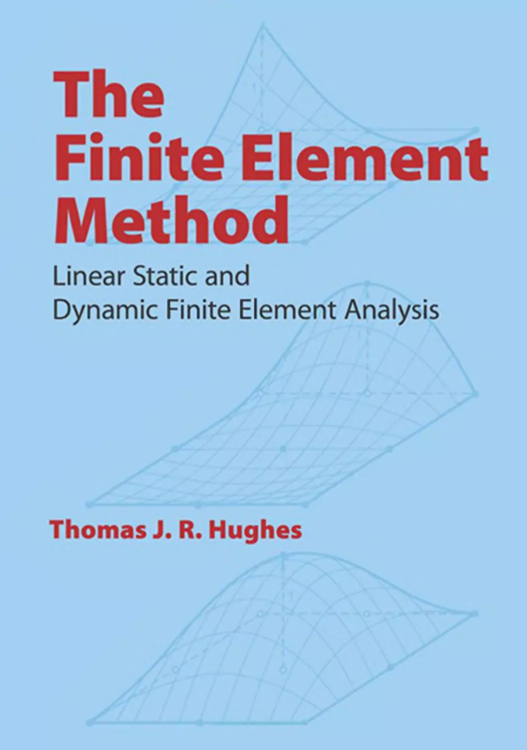
The Finite Element Method
Linear Static and Dynamic
Finite Element Analysis
Thomas J. R. Hughes
Professor of Mechanical Engineering
Chairman of the Division of Applied Mechanics
Stanford University
PRENTICE-HALL, INC., Englewood Cliffs, New Jersey 07632
Ubrary of Congress Cataloging-in-Publication Data
HUGHES, THOMAS 1. R.
The finite element method.
Bibliography.
Includes mdex.
1. Finite element method. 2. Boundary value
problems. I. Title.
tA347.F5H84 1987 620'.0042 8 22558
ISBN 0-13-317025-X
Editoriall production supervision
and interior design: Joan McCulley
Cover sketch: M. Igarashi and K. Shimomaki
Suzuki Motor Co., Ltd.
Cover design: 20/20 Services, Inc.
Manufacturing bUJfr: Rhett C nklin
@1987 by Prentice-Hall, Inc.
A Division of Simon & Schuster
Englewood Cliffs, New Jersey 07632
All rights reserved. No part of this book may be
reproduced, in any form or by any means,
without permission in writing from the publisher.
Printed in the United States of America
10 9 8 7 6 5 4 3
ISBN
0-13-317025-X
025
PRENTICE-HALL lNTERNA TlONAL (UK) LIMITED, London
PRENTICE-HALL OF AUSTRALIA Prv. LIMITED, Sydney
PRENTICE-HALL CANADA INc., Toronto
PRENTICE-HALL HIsp ANOAMERICANA IS. A. , Mexico
PRENTICE-HALL OF INDIA PRIvATE LIMITED , New Delhi
PRENTICE-HALL OF JAPAN, INc., Tokyo
PRENTICE-HALL OF SOtrrHEAST AsIA PrE. LID., Singapore
EDITORA PRENTICE-HALL DO BRASIL, LIDA., Rio de Janeiro
To my wife,
my mother,
and my children
Contents
PREFACE XV
A BRIEF GLOSSARY OF NOTATIONS XXII
Part One
Linear Static Analysis
1 FUNDAMENTAL CONCEPTS; A SIMPLE ONE-DIMENSIONAL
BOUNDARY-VALUE PROBLEM 1
1.1 Introductory Remarks and Preliminaries 1
1..2 Strong, or Classical, Fonn of the Problem 2
1.3 Weak, or Variational, Fonn of the Problem 3
1.4 Eqivalence of Strong and Weak Forms; Natural Boundary
Conditions 4
1.5 Galerkin's Approximation Method 7
1.6 Matrix Equations; Stiffness Matrix K -,-
1.7 Examples: 1 and 2 Degrees of Freedom 13
1.8 Piecewise Linear Finite Element Space 20
1.9 Properties of K 22
1.10 Mathematical Analysis 24
1.11 Interlude: Gauss Elimination; Hand-calculation
Version 31
1.12 The Element Point of View 37
1.13 Element Stiffness Matrix and Force Vector 40
1.14 Assembly of Global Stiffness Matrix and Force Vector;
LM Array 42
viii
1.15
Explicit Computation of Element Stiffness Matrix
and Force Vector 44
Exercise: Bernoulli-Euler Beam Theory and Hennite
Cubics 48
An Elementary Discussion of Continuity, Differentiability,
and Smoothness 52
References 55
1.16
Appendix 1. I
2 FORMULATION OF lWO- AND THREE-DIMENSIONAL
BOUNDARY-VALUE PROBLEMS 57
2.1 Introductory Remarks 57
2.2 Preliminaries 57
2.3 Classical Linear Heat Conduction: Strong and Weak
Fonns; Equivalence 60
2.4 Heat Conductl(\n: Galerkin Fonnulation; Symmetry
and Positive-definiteness of K 64
2.5 Heat Conduction: Element Stiffness Matrix and Force
Vector 69
2.6 Heat Conduction: Data Processing Arrays ID, IEN,
and LM 71
2.7 Classical Linear Elastostatics: Strong and Weak Fonns;
Equivalence 75
2.8 Elastostatics: Galerkin Fonnulation, Symmetry,
and Positive-definiteness of K 84
2.9 Elastostatics: Element Stiffness Matrix and Force
Vector 90
2.10 Elastostatics: Data Processing Arrays ID, IEN,
and LM 92
2.11 Summary of Important Equations for Problems Considered
in Chapters 1 and 2 98
2.12 Axisymmetric Fonnulations and Additional
Exercises 101
References 107
3
ISOPARAMETRIC ELEMENTS AND ELEMENTARY
PROGRAMMING CONCEPTS 109
3.1 Preliminary Concepts 109
3.2 Bilinear Quadrilateral Element 112
3.3 Isoparametric Elements 118
3.4 Linear Triangular Element; An Example
of "Degeneration" 120
3.5 Trilinear Hexahedral Element 123
3.6 Higher-order Elements; Lagrange Polynomials
3.7 Elements with Variable Numbers of Nodes
126
132
Contents
Contents
3.8
3.9
3.10
3.11
Appendix 3. I
Appendix 3. II
Numerical Integration; Gaussian Quadrature 137
Derivatives of Shape Functions and Shape Function
Subroutines 146
Element Stiffness Fonnulation 151
Additional Exercises 156
Triangular and Tetrahedral Elements 164
Methodology for Developing Special Shape Functions
with Application to Singularities 175
References 182
4 MIXED AND PENALTY METHODS, REDUCED AND SELECTIVE
INTEGRATION, AND SUNDRY VARIATIONAL CRIMES 185
4.1 "Best Approximation" and Error Estimates: Why the stan-
dard FEM usually works and why sometimes it
does not 185
4.2 Incompressible Elasticity and Stokes Flow 192
4.2.1 Prelude to Mixed and Penalty Methods 194
4.3 A Mixed Fonnulation of Compressible Elasticity Capable
of Representing the Incompressible Limit 197
4.3.1 Strong Fonn 198
4.3.2 Weak Fonn 198
4.3.3 Galerkin Fonnulation 200
4.3.4 Matrix Problem 200
4.3.5 Definition of Element Arrays 204
4.3.6 Illustration of a Fundamental Difficulty 207
4.3.7 Constraint Counts 209
4.3.8 Discontinuous Pressure Elements 210
4.3.9 Continuous Pressure Elements 215
4.4 Penalty Fonnulation: Reduced and Selective Integration
Techniques; Equivalence with Mixed Methods 217
4.4.1 Pressure Smoothing 226
4.5 An Extension of Reduced and Selective Integration
Techniques 232
4.5.1 _ Ax. mm e_try and Ani otropy: Prelude to Nonlinear
Analysis 232
4.5.2 Strain Projection: The B -approach 232
4.6 The Patch Test; Rank Deficiency 237
4.7 Nonconfonning Elements 242
4.8 Hourglass Stiffness 251
4.9 Additional Exercises and Projects 254
Appendix 4.1 Mathematical Preliminaries 263
4.1. 1 Basic Properties of Linear Spaces 263
4.1.2 Sobolev Nonns 266
4.1.3 Approximation Properties of Finite Element Spaces
in Sobolev Nonns 268
x Contents
4.1.4 Hypotheses on a (. , .) 273
Appendix 4.11 Advanced Topics in the Theory of Mixed and Penalty
Methods: Pressure Modes and Error Estimates 276
by David S. Malkus
4.1I.1 Pressure Modes, Spurious and OthelWise 276
4.11.2 Existence and Uniqueness of Solutions in the Pres-
ence of Modes 278
4.11.3 Two Sides of Pressure Modes 281
4.11.4 Pressure Modes in the Penalty Fonnulation 289
4.11.5 The Big Picture 292
4.n.6 Error Estimates and Pressure Smoothing 297
References 303
5 THE CO-APPROACH TO PLATES AND BEAMS 310
5.1 Introduction 310
5.2 Reissner-Mindlin Plate Theory 310
5.2.1 Main Assumptions 310
5.2.2 Constitutive Equation 313
5.2.3 Strain-displacement Equations 313
5.2.4 Summary of Plate Theory Notations 314
5.2.5 Variational Equation 314
5.2.6 Strong Fonn 317
5.2.7 Weak Fonn 317
5.2.8 Matrix Fonnulation 319
5.2.9 Finite Element Stiffness Matrix and Load
Vector 320
5.3 Plate-bending Elements 322
5.3.1 Some Convergence Criteria 322
5.3.2 Shear Constraints and Locking 323
5.3.3 Boundary Conditions 324
5.3.4 Reduced and Selective Integration Lagrange Plate
Elements 327
5.3.5 Equivalence with Mixed Methods 330
5.J.6_ Rank Deficiency 332
5.3.7 The Heterosis Element 335
5.3.8 Tl: A Correct-rank, Four-node Bilinear
Element 342
5.3.9 The Linear Triangle 355
5.3.10 The Discrete Kirchhoff Approach 359
5.3.11 Discussion of Some Quadrilateral Bending
Elements 362
5.4 Beams and Frames 363
5.4.1 Main Assumptions 363
5.4.2 Constitutive Equation 365
5.4.3 Strain-displacement Equations 366
l,;ontents
5.4.4
5.4.5
5.4.6
5.4.7
5.4.8
5.4.9
5.4.10
5.5
Definitions of Quantities Appearing
in the Theory 366
Variational Equation 368
Strong Fonn 371
Weak Fonn 372
Matrix Fonnulation of the Variational
Equation 373
Finite Element Stiffness Matrix and Load
Vector 374
Representation of Stiffness and Load in Global
Coordinates 376
Reduced Integration Beam Elements 376
References 379
6 THE CO-APPROACH TO CURVED STRUCTURAL
ELEMENTS 383
6.1 Introduction 383
6.2 Doubly Curved Shells in Three Dimensions 384
6.2.1 Geometry 384
6.2.2 Lamina Coordinate Systems 385
6.2.3 Fiber Coordinate Systems 387
6.2.4 Kinematics 388
6.2.5 Reduced Constitutive Equation 389
6.2.6 Strain-displacement Matrix 392
6.2.7 Stiffness Matrix 396
6.2.8 External Force Vector 396
6.2.9 Fiber Numerical Integration 398
6.2.10 Stress Resultants 399
6.2.11 Shell Elements 399
6.2.12 Some References to the Recent Literature 403
6.2.13 Simplifications: Shells as an Assembly of Rat
Elements 404
6.3 Shells of Revolution; Rings and Tubes in Two
Dimensions 40S
6.3.1 Geometric and Kinematic Descriptions 405
6.3.2 Reduced Constitutive Equations 407
6.3.3 Strain-displacement Matrix 409
6.3.4 Stiffness Matrix 412
6.3.5 External Force Vector 412
6.3.6 Stress Resultants 413
6.3.7 Boundary Conditions 414
6.3.8 Shell Elements 414
References 415
xii
Part Two
Linear Dynamic Analysis
7 FORMULATION OF PARABOLIC, HYPERBOLIC, AND ELLIPTIC-
EIGENVALUE PROBLEMS 418
7.1 Parabolic Case: Heat Equation 418
7.2 Hyperbolic Case: Elastodynamics and Structural
Dynamics 423
7.3 Eigenvalue Problems: Frequency Analysis
and Buckling 429
7.3.1 Standard Error Estimates 433
7.3.2 Alternative Definitions of the Mass Matrix; Lumped
and.Higher-order Mass 436
7.3.3 Estimation of Eigenvalues 452
Appendix 7.1 Error Estimates for Semidiscrete Galerlcin
Approximations 456
References 457
8 ALGORITHMS FOR PARABOLIC PROBLEMS 459
8..1 One-step Algorithms for tlte Semidiscrete Heat Equation:
Generalized Trapezoidal Method 459
8.2 Analysis of the Generalized Trapezoidal Method 462
8.2.1 Modal Reduction to SDOF Fonn 462
8.2.2 Stability 465
8.2.3 Convergence 468
8.2.4 An Alternative Approach to Stability: The Energy
Method 471
8..2.5 Additional Exercises 473
8.3 Elementary Finite Difference Equations for the One-
dimensional Heat Equation; the von Neumann Method
of Stability Analysis 479
8.4- Element-by-element (EBE) Implicit Methods 483
8.5 Modal Analysis 487
References 488
9 ALGORITHMS FOR HYPERBOLIC AND PARABOLIC-
HYPERBOLIC PROBLEMS 490
9.1 One-step Algorithms for the Semidiscrete Equation
of Motion 490
9.1..1 The Newmark Method 490
9.1.2 Analysis 492
9.1.3 Measures of Accuracy: Numerical Dissipation
and Dispersion 504
9.1.4 Matched Methods 505
9.1.5 Additional Exercises 512
Contents
Contents
9.2 Summary of Time-step Estimates for Some Simple Finite
Elements 513
9.3 Linear Multistep (LMS) Methods 523
9.3.1 LMS Methods for First-order Equations 523
9.3.2 LMS Methods for Second-order Equations 526
9.3.3 Survey of Some Commonly Used Algorithms
in Structural Dynamics 529
9.3.4 Some Recently Developed Algorithms for StIUcturaI
Dynamics 550
9.4 Algorithms Based upon Operator Splitting and Mesh
Partitions 552
9.4.1 Stability via the Energy Method 556
9.4.2 Predictor/Multicorrector Algorithms 562
9.5 Mass Matrices for Shell Elements S64
References 567
10 SOLUTION TECHNIQUES FOR EIGENVALUE
PROBLEMS 570
10.1 The Generalized Eigenproblem 570
10.2 Static Condensation 573
10.3 Discrete Rayleigh-Ritz Reduction 574
10.4 Irons-Guyan Reduction 576
10.5 Subspace Iteration 576
10.5.1 Spectrum Slicing 578
10.5.2 Inverse Iteration 579
10.6 The Lanczos Algorithm for Solution of Large Generalized
Eigenproblems 582
by Bahram Nour-Omid
10.6.1 Introduction 582
10.6.2 Spectral Transfonnation 583
10.6.3 Conditions for Real Eigenvalues 584
10.6.4 The Rayleigh-Ritz Approximation 585
10.6.5 Derivation of the Lanczos Algorithm 586
10.6.6 Reduction to Tridiagonal Fonn S89
10.6.7 Convergence Criterion for Eigenvalues 592
10.6.8 Loss of Orthogonality 595
10.6.9 Restoring Orthogonality 598
10.6.10 LANSEL Package 600
References 629
11 DLEARN-A LINEAR STATIC AND DYNAMIC FINITE ELEMENT
ANALYSIS PROGRAM 631
by Thomas J. R. Hughes, Robert M. Ferencz,
and Arthur M. Raefsky
Introduction 631
Description of Coding Techniques Used
in DLEARN 632
11.2.1 Compacted Column Storage Scheme
11.2.2 Crout Elimination 636
11.2.3 Dynamic Storage Allocation
11.3 Program Structure 650
11.3.1 Global Control 651
11.3.2 Initialization Phase 651
11.3.3 Solution Phase 653
11.4 Adding an Element to DLEARN
11.5 DLEARN User's Manual 662
11.5.1 Remarks for the New User
11.5.2 Input Instructions 663
11.5.3 Examples 691
1. Planar Truss 691
2. Static Analysis of a Plane Strain Cantilever
Beam 70S
3. Dynamic Analysis of a Plane Strain Cantilever
Beam 70S
4. Implicit-explicit Dynamic Analysis
of a Rod 715
Subroutine Index for Program Listing
Program Listing 734
References 796
xiv
11.1
11.2
11.5.4
11.5.5
INDEX 797
Contents
633
644
659
662
729
Preface
This book is based on courses that I have taught at the California Institute of Tech-
nologyand Stanford University during the last 10 years. It deals with the finite element
method in linear static and dynamic analysis. It is intended primarily for engineering
and physical science students who wish to develop comprehensive skills in finite
element methodology, from fundamental concepts to practical computer imple-
mentations.
Some sections of this book touch upon the frontiers of research and have been
used as lecture notes in a number of more advanced short courses I have taught in
Europe, Japan, and the United States. Consequently, I believe it will also be of interest
to more experienced analysts and researchers working in the finite element field.
SUBJECTS COVERED
The first chapter of the book introduces the finite element method in the context of
simple one-dimensional model problems. Chapter 2 deals with variational fonnu-
lations of two- and three-dimensional boundary-value problems in heat conduction (in
fact, all problems governed by Laplace/Poisson equations, such as electrostatics,
potential flow, elastic membranes, and flow in porous media) and elasticity theory.
These serve as the basis for finite element discretization and the techniques developed
illustrate the relationship between "strong," or classical, statements of boundary-value
problems and their "weak," or variational, counterparts. The Galerkin method of
approximate solution is emphasized in Chapter 2 and throughout the book, rather than
"variational principles " due to the significantly greater generality of the fonner ap-
proach. In Chapter 3 a variety of finite element interpolatory schemes are developed.
xv
xvi
Preface
These apply to triangles, quadrilaterals, tetrahedra, hexahedra, wedges, etc. The
isoparametric concept is emphasized, and special-purpose interpolatory strategies are
also developed (e.g., "singular elements"). Programming techniques are introduced
for numerically integrated finite elements. Chapter 4 deals with basic error estimates
for standard "displacement" finite element methods and introduces mixed methods for
constrained media applications such as incompressible elasticity and Stokes flow. A
variety of uvariational crimes" are described: for example, incompatible elements,
reduced and selective integration, strain projection (i.e. , B -) methods, etc. (Most of
these have been decriminalized in recent years.) The mathematical analysis of finite
element methods for incompressible media is rather complex. David Malkus, an
authority on this subject, explains some of the subtleties in an appendix to Chapter 4.
Chapter 5 is concerned with finite element methods for Reissner-Mindlin plates and
elastic frameworks composed of straight beam elements accounting for axial, tor-
sional, bending, and transverse shear defonnations (Le., Timoshenko beams). Chap-
ter 6 deals with three-dimensional curved shell elements and two-dimensional special
cases such as rings, tubes, and shells of revolution. The problem classes discussed in
Chapters 1-6 give rise to associated eigenvalue problems and initial-value problems.
The fonnulations of problems of these types are the subjects of Chapter 7. Chapter 8
presents time-stepping algorithms for first-order ordinary differential equation systems
such as those arising from unsteady heat conduction ("parabolic case"). Chapter 9
deals with algorithms for second-order ordinary differential equation systems such as
those emanating from elastodynamics and structural dynamics ("hyperbolic case").
Chapter 10 presents basic algorithmic strategies for symmetric elliptic eigenvalue
problems such as those encountered in free vibration and structural stability. A very
efficient major software package for matrix eigenvalue and eigenvector calculations
based on the Lanczos method is also presented in Chapter 10. The documentation of
the Lanczos algorithm and software were written by Bahram Nour-Omid, an expert
on procedures of this type. Chapter 11 presents a linear static and dynamic analysis
computer program based on the methods developed in the book. My student, Robert
Ferencz, and colleague, Arthur Raefsky, collaborated with me in the writing of the
program. The program is named DLEA and it contains a very complete library of
finite element software tools. This program is suitable for homework assignments,
projects (e. g., programming additional elements), and research studies. DLEARN is
highly structured for readability, maintainability, and extendability and has been
written specifically to complement and enhance the procedures described in the re-
mainder of the book.
LEVEL AND BACKGROUND
This book is primarily intended for the graduate level, although advanced under-
graduates will find much of it accessible. An undergraduate degree in engineering,
mathematics, computer science, or any of the physical sciences constitutes essential
background. Courses in applied linear algebra and elementary ordinary and partial
differential equations are desirable prerequisites. A working knowledge of FORTRAN
Preface
xvii
(the dominant language used in finite element programming) is also necessary for
understanding the software presented in Chapters 10 and II.
The book emphasizes heat conduction and elasticity as primary vehicles for
developing finite element methods because of the widespread interest in these theories
in the applied sciences. By virtue of the fact that the partial differential equation of
heat conduction, namely, the Laplace/Poisson equation, appears under different
names in virtually all branches of engineering and physics, most students have had
some familiarity with it. Some exposure to the theory of elasticity is also desirable.
This can be obtained, for example, in a good advanced course on strength of materials.
Students at Caltech and Stanford frequently have taken courses in elasticity simulta-
neously with finite elements. Background in structural mechanics (i.e., the theory of
beams, plates, and shells) is certainly an asset when it comes to studying this book but
is not essential. Only Chapters 5 and 6 deal exclusively with this subject, and these
chapters may be ignored by students whose primary interests lie elsewhere. It is worth
noting that students who have taken this finite element course at Stanford and Caltech
have had very diverse backgrounds (e.g., geophysics, chemical engineering, plan-
etary sciences, coastal engineering, e1ectrical engineering, computer science, mathe-
matics, bioengineering, aeronautics and astronautics, material science, physics, earth
sciences, environmental engineering, biomechanics, thennosciences, engineering de-
sign, applied mechanics, earthquake engineering, and, of course, mechanical and civil
engineering). In this spirit the book emphasizes fundamental finite element concepts
and techniques applicable to a very broad range of problems and thus constitutes a
suitable text for most students in the physical sciences.
It is my experience that most finite element methodology can and should be
taught initially within the confines of linear behavior before introducing nonlinear
effects. A solid understanding of finite elements in Hnear analysis is, of course, very
useful in its own right. In addition, it makes the subject of nonlinear finite element
analysis much more accessible.
WHA T IS UNIQUE ABOUT THIS BOOK
Although this book deals with many standard aspects of the finite element method.
there are many unique features, some of which are enumerated below.
· A comprehensive presentation and analysis of algorithms for time-dependent
phenomena.
· Beam, plate, and shell theories are derived directly from three-dimensional
elasticity theory.
· An extensive static and dynamic finite element analysis program, DLEARN,
was specially prepared based on the text material. It is written using structured
programming concepts and contains many advanced procedures.
· Although written for students without serious mathematical training, the book
contains introductory materia] on the mathematical theory of finite elements and
xviii
Preface
many important mathematical results. It thus serves as a primer for more ad-
vanced works on this subject.
· A systematic treatment of "weak, tt or variational, fonnulations for various
classes of initial- and boundary-value problems.
· Many of the procedures described are presented in book fonn for the first time,
for example, strain projection (Le., B -) methods, implicit-explicit finite element
mesh partitions in transient analysis, element-by-element iterative solvers, com-
plete computer implementation of predictor/multicorrector implicit-explicit
time-stepping algorithms based upon the Hilber-Hughes-Taylor a-method, etc.
· A Lanczos software package for eigenvalue/eigenvector extraction.
NOTA TIONAL CONVENTIONS
As far as possible, we have adoped fairly standard notations. Vectors and matrices are
denoted by boldface italic characters. Scalars and components of vectors, tensors, and
matrices are denoted by lightface italic characters. Cartesian tensor notation is used
in the presentation of heat conduction, elasticity, plates, etc. The symbol. is used
to denote the end of a proof. Unavoidably, in a book of this size and scope there are
some minor conflicts of notation. In instances when this occurs, it is hoped that
surrounding explanation and context will make the intended meaning clear. All no-
tations are defined when they are introduced. Principal notations are summarized in
a brief glossary following the Preface.
NUMBERING CONVENTIONS
The book is divided into two parts. Chapters 1-6 deal with static analysis, and
Chapters 7-11 deal with dynamic analysis. The chapters are subdivided into sections
and several of the chapters include appendices. Some of the sections are further
subdivided into subsections. Equations, tables, and figures are numbered con-
secutively within each section, with each number consisting of chapter, section, and
item number. Exercises are numbered consecutively beginning with 1 in each section.
References are numbered consecutively at the end of each chapter. Equation numbers
are enclosed in parentheses, and reference numbers appearing in the text are enclosed
in square brackets. H, for example, we wish to refer to Eq. 8 of Section 3, Chapter 4,
then we would write this as (4.3.8).
H we wish to draw the reader's attention to a subsection, then the section number
is followed by a decimal point and the subsection number. For example, subsection
2 of Section 3, Chapter 5, is written as Sec. 5.3.2.
Preface
EXERCISES
Exercises appear throughout the text. In some cases answers or complete solutions a
provided. Many of the exercises are placed in the proximity of the pertinent te.
material rather than at the ends of sections or chapters.
INTERDEPENDENCE OF CHAPTERS
Prior to consulting particular chapters it may be worthwhile to peruse the ureadit
paths," which indicate the interdependence of the chapters. Of course, if one h(
sufficient background, the suggested reading paths may be bypassed. Knowledge (
Chapters 1-3 is assumed for all subsequent chapters with the exception of Chapter l(
which is essentially self-contained.
Chapter Reading Paths
1
) 2
) 3
)
) 6
1
7
) 8
) 9
)
(For motivation only)
I
I
I
...,
10
A NOTE FOR INSTRUCTORS REGARDING
THE ORGANIZA TION OF COURSES
Several courses can be developed based on the material in this book. Here are a fev
examples.
Almost the entire book can be covered in a one-year course:
Title: Linear Static Finite Element Analysis (1 semester)
Syllabus: Chapters 1-3, selected topics from Chapters 4-6 and computing assign
ments using DLEARN (Chapter 11).
Title: Linear Dynamic Finite Element Analysis (I semester)
Syllabus: Chapters 7-10 and computing assignments using DLEARN (Chapter 11)
An abbreviated version of the above covering two quarters can be organized at
follows:
Title: Linear Static Finite Element Analysis (1 quarter)
xx
Syllabus:
Title ."
Syllabus:
Preface
Chapters 1-3, selected topics from Chapter 4, and computing assignments
using DLEARN (Chapter 11).
Linear Dynamic Finite Element Analysis (1 quarter)
Sections 1-3 of Chapter 7; Sections 1, 2, and 5 of Chapter 8; Sections 1-4
of Chapter 9; Sections 1-5 of Chapter 10; and computing assignments
using DLEARN (Chapter 11).
A course on finite element programming can be taught in one quarter or one
semester:
Title:
Syllabus :
Finite Element Programming
Chapter 11 and selected sections from earlier chapters as background
material. Lectures should describe overall program architecture
(subroutines DLEARN and DRIVER), the structure of element routines
(e.g., QUA DC and subroutines called by QUADe), equation-solving
(subroutines FACfOR and BACK), assembly routines (ADDLHS and
ADDRHS), and important finite element utility routines (BC, COLHT,
DCrNRY, DIAG, EQSEl: FORMLM, LOCAL, and MPOINT). Pro-
gramming assignments, such as adding new elements and extending capa-
bilities, are essential.
ACKNOWLEDGMENTS
I would like to thank many fonner and current students, colJeagues, and friends for
their constructive comments and criticisms, especially Ted Belytschko, Alec Brooks,
Marty Cohen, Leo Franca, Hans Hilber, Greg Hulbert, Itzhak Levit, Wing Kam Liu,
Michel Mallet, Jerry Marsden, Isidoro Miranda, Arthur Muller, Juan Simo, Gary
Stanley, Tayfun Tezduyar, Jim Winget, and Thomas Zimmennann.
I would also like to express my appreciation to those individuals who have made
contributions to the writing of this book: Bob Ferencz, David Malkus, Bahram
Nour-Omid, and Arthur Raefsky.
In addition, I would like to thank Alex Tessler who prepared notes for me on
some recent developments in plate elements, which I used as the basis of comments
included in Chapter 5.. Wanda Gooden typed most of the manuscript. I wisn to thank
her for her patience, dedication, and good-naruredness in the face of a seemingly
infinite number of corrections.
1 would like to acknowledge the following organizations for pennission to
reprint various materials: the American Society of Mechanical Engineers for Figs.
5.3.21-5.3.31; John Wiley and Sons, Ltd., for Figs. 3.II.l, 3.11.2, 9.3.1-9.3.3,
9.3.5, and Table 3.1.1; Pergamon Journals, Ltd., for Figs. 5.3.11, 5.3.13-5.3.15,
5.3.18-5.3.20; and North-Holland Publishing Co. for portions of Chapters 8 and 9,
which originally appeared in 1: J. R. Hughes, "Analysis of Transient Algorithms with
Particular Reference to Stability," pp. 67-155, Computational Methods for Transient
Analysis (eds. T. Belytschko and T. J. R. Hughes), 1983.
Preface
)()C
Finally, I would like to thank M. Igarashi and K. Shimomaki of the Suzuk
Motor Co., Ltd., for providing the mesh for the cover, and Dave Benson and Johr
Hallquist of Lawrence Livennore National Laboratory for the accompanying colo]
graphics.
NOTE: The software in this book is available on diskette and magnetic tape for severa
computers. Further infonnation and an order fonn may be obtained by writing to tht
author: Professor Thomas J. R. Hughes, Division of Applied Mechanics, Durand Build.
ing, Stanford University, Stanford, California 94305.
A Brief Glossary of Notations
Sets ndof number of degrees of
freedom
R real numbers ntd number of element
C complex numbers degrees of freedom
U set union ntl number of elements
n set intersection A,B global node numbers
0 empty set (I <: A, B <: nnp)
E is a member of; a, b element node
belongs to numbers
is not a member of; ( 1 <: a, b <: n ell )
does not belong to P,Q global equation
C is a subset of numbers
t is not a subset of (1 < P, Q <: n eq )
y for all; for each p, q- element equation
numbers
Various Integers (1 <: p, q <: nee)
e element number
nnp number of nodal (1 <: e <: nd)
points Element Arrays
n m number of element
nodes me mass matrix of the
n eq number of equations eth element
nee number of element c e damping matrix of
equations the eth element
A Brief Glossary of Notations )(
k t stiffness matrix of the 14, G. part of the boundar
,
eth element where Neumann
f force vector of the conditions are
eth element specified
at acceleration vector of 8ij Kronecker delta
the eth element 1] set of node number,
Vi velocity vector of the 1]9' 1]11; set of node nUmber
eth element at which Dirichlet
d t displacement vector conditions are
of the eth element specified
Global Arrays
M mass matrix Variational Methods
C damping matrix h mesh parameter
K stiffness matrix
J, J-;, J- collecti ons of trial
F force vector solutions
a acceleration vector «J, tV;, tV collecti ons of
v velocity vector weighting functions t,
d displacement vector J-h, J-;h, J-h finite-dimensional
A finite element collections of trial
assembly operator solutions
( nrl ) tV h , tV i h , ({)h finite-dimensional
e.g., K = Ak e collections of
e=1 weighting functions 11
U, Uit U trial solutions
Boundary-Value Problems w, Wi, W weighting functions \S
nsd number of space u h u u h finite-dimensional
, "
dimensions tria1 solutions
i, j, k, I spatial indices wit w!t w h finite-dimensional
, "
(1 -< i, j, k, I -< nsd) weighting functions s
IIi" .sd Euclidean nsd-space t, 11, , source terms
!} domain in (Rft sd 'I, fJ;, fJ Dirichlet boundarY
n closure of a data
Xi, x point in a It, n;, It Neumann boundary
r boundary of n data
ni, n unit outward nonna! qh, fjih, gh extensions of fj, /}i, ,.
vector to r respectively, to 0
, r<1i part of the boundary e, ei, e elTors
where Dirichlet L 2 (O) Hilbert space of
conditions are square-integrable
specified functions
xxiv A Brief Glossary of Notations
HS(fl} Sobolev space of Ui displacement vector
functions with s u(I,J1 symmetric part of the
square-integrable displacement
generalized gradients (equals E;j)
derivatives t; prescribed body force
II .11 L 2 nonn on fl vector
II.IL HS nonn on n '1i prescribed boundary
a(., .) symmetric bilinear displacement vector
fonn; strain-energy h. prescribed boundary
,
inner product traction vector
(., .) symmetric bilinear di)d d nodal displacements
fonn; L 2 inner prescribed nodal
fJ-iA, lJ. ;0
product on n displacements
( · t .}r symmetric bilinear B bulk modulus
fonn; L 2 inner E Young's modulus
product on r
v Poisson's ratio
Data Processing Arrays G,J-L shear modulus
IEN(a,e) element nodes matrix A Lame modulus
ID (i, A) destination matrix B,BA.,Ba strain-displacement
matrices
LM (i, a, e) location matrix --- material moduli
D,D
Heat Conduction matrices
qi heat flux vector Isoparametric Elements
K;j conducti vities fit element domain C fl
U temperature rt' boundary of fle
u. temperature gradient
,a X}, X2, X],
t prescribed heat x, y, z Cartesian coordinates
supply 0 parent domain of a
fJ- prescribed boundary quadrilateral or
temperature hexahedral element
It prescribed boundary ...t': 0 -+ fie isoparametric
heat flux mappIng
d AJ d; nodal temperature , " element natural
prescribed nodal coordinates for
fJ-A. t fJ-a
temperature quadrilaterals
Elasticity , T/7 , element natural
coordinates for
Eij infinitesimal strain hexahedra
tensor t point in 0
U;j Cauchy stress tensor J Jacobian detenninant
C ijkJ elastic coefficients of the mapping xl!(€)
A Brief Glossary of Notations
CO(O) the class of p vector of nodal
continuous functions pressures
CI:(O) the class of B:v deviatoric strain-
continuous functions displacement matr
possessing k dil dilatational strain-
Ba
continuous derivatives displacement matr
NA., N: shape functions - dil improved dilatatio:
Ba
nodal points strain-displacemen
XA., X a
r, s, 1 triangular coordinates; matrix
area coordinates Ba improved strain-
r, s, I, U tetrahedral displacement matri
coordinates; volume
coordinates Plates
la( ) Lagrange polynomial a, {3, '}',
associated with the tensor indices
ath element node (I <: a, {3, '}', <
t, location of the lth eafJ alternator tensor
integration point w transverse
WI weight assigned to lth displacement
integration point (Ja rotation vector
U 1, U 2, U 3 unifonn integration KafJ = (J(a t fJ) curvature tensor
elements '}'a shear strain vector
SI, S2, S3 selective integration C afJ)"S, C afJ elastic coefficients
elements mafJ moment tensor
Incompressible and Nearly- qa shear force vector
Incompressible Elasticity W prescribed bound
rp pressure trial solution displacement
8a prescribed boundar)
and weighting
function space rotati on s
rplt finite-dimensional F total applied
press ure trial solution transverse force
and weighting C a total applied couple
function space MtJ prescribed bound
p, q E 1J trial pressure and moments
weighting function Q prescribed boundar)
ph, qlt E 1J" fini te-dimensional shear force
trial pressure and s arc-length paramete
weighting function '" of plate boundary
.... ....
gt, G element and global (Ja = eafJ (JfJ' (Js, (In right - hand-rule
gradient matrices rotations
(gr)T, GT element and global k:, k: eth element bendin
divergence matrices and shear stiffness
xxvi A Brief Glossary of Notations
Db, DS matrices of bending za({) thickness function
and shear moduli I I I lamina basis vectors
et,e2,e3
B b , BI bending and shear e , e , e{ fiber basis vectors
s n-displacement u displacement vector
matrices
U, U a displacement of
8eams reference surface
A
V, Va'J U a fiber displacements
Wi displacements (i/ = li'E' reduced constitutive
(Ji rotations equation in the
Ka curvatures lamina basis
'Ya shear strain s mal3 moments
IE axial s n na membrane forces
t/J twist qa transverse shear
m; moments forces
qi shear forces
"'i prescribed end Dynamics
displacements
8, prescribed end t time
rotations A.t time step
F; total applied force per n time step number
unit length an, V n , d n approximations of
c; total applied couple a(t n ), v(t n ), and
per unit length d(l n ), respectively
......... -... --
M; prescribed end an, V nt d n predictor values of
moments acceleration, velocity,
Q; prescribed end shears and displacement,
A cross-sectional area respecti vel y
Aa shear areas tcrit critical time step
la moments of inertia A amplification factor
J polar moment of A amplification matrix
inertia p(A) spectral radius of
k: J kg, k:. kt eth element axial, amplification matrix
bending, shear, and T, ,. local truncation errors
torsi onal s tiffnes s, A, A It , A It eigenvalues
respectively "', eigenvectors
Shells lI) , lI) It, lI) It frequencies
algorithmic damping
x position vector ratio
X, Xa position vectors to ( T - T)/T relative period error
references surface Ocrit critical sampling
...
X, Xa fiber vectors frequency
A Brief Glossary of Notations
M', C f , K I , F I
ME, C E , KE, FE
implicit mesh
partition of mass,
damping, stiffness,
and force
explicit mesh
partition of mass,
damping, stiffness,
and force
.
Uo;,
initial displaceml
and velocities
initial temperatw
density
capacity
Uo
P
c
Fundamental Concepts;
a Simple One-Dimensional
Boundary-Value Problem
1. 1 INTRODUCTORY REMARKS AND PRELIMINARIES
The main constituents of a finite element method for the solution of a boundary-value
problem are
1. The variational or weak statement of the problem; and
11. The approximate solution of the variational equations through the use of "finite
element functions. n
To clarify concepts we shall begin with a simple example.
Suppose we want to solve the following differential equation for u:
u u + 1==0 (1.1.1)
where a comma stands for differentiation (Le., U,xx = d 2 u/d.x 2 ). We assume I is a
given smooth, scalar-valued function defined on the unit interval. We write
I : [0, 1] --+ R --(-t:-l-
where [0, 1] stands for the unit interval (Le., the set of points x such that 0 < x < I)
and IR stands for the real numbers. In words, (1.1.2) states that for a given x in [0, 1],
t(x) is a real number. (Often we will use the notation E to mean "inn or "a member
of. n Thus for each x E [0, 1], t(x) E IR.). Also, [0, 1] is said to be the domain of I,
and IR is its range.
We have described the given function I as being smooth. Intuitively, you
probably know what this means. Roughly speaking, if we sketch the graph of the
function I, we want it to be a smooth curve without discontinuities or kinks. We do
this to avoid technical difficulties. Right now we do not wish to elaborate further as
1
2
Fundamental Concepts
Chap. 1
this would divert us from the main theme. At some point prior to moving on to the
next chapter, the reader may wish to consult Appendix 1.1, "An Elementary Dis-
cussion of Continuity, Differentiability and Smoothness," for further remarks on this
important aspect of finite element work. The exercise in Sec. 1..16 already uses a little
of the language described in Appendix 1.1. The tenninology may be somewhat
unfamiliar to engineering and physical science students, but it is now widely used in
the finite element literature and therefore it is worthwhile to become accustomed to it.
Equation (1.1.1) is known to govern the transverse displacement of a string in
tension and also the longitudinal displacement of an elastic rod. In these cases,
physical parameters, such as the magnitude of tension in the string, or elastic modulus
in the case of the rod, appear in (1.1..1). We have omitted these parameters to simplify
subsequent developments.
Before going on, we introduce a few additional notations and tenninologies. Let
] 0, 1[ denote the unit interval without end points (Le., the set of points x such that
o < x < 1). ]0, 1[ and [0, 1] are referred to as open and closed unit intervals,
respectively. To simplify subsequent writing and tie in with notation employed later
on in multidimensional situations, we shaH adopt the definitions
n = ]0, 1[ (open)
n = [0, 1] (closed)
(1.1..3)
(1.1..4)
See Fig.. 1.. 1.1.
n = ) 0, 1 (
n = [0. 1 ]
o
E-
1
-E
o
1 Figure 1.1.1
At this point, considerations such as these may seem pedantic. Our purpose,
however, is to develop a language for the precise articulation of boundary-value
problems, which is necessary for good finite element work.
1.2 STRONG, OR CLASSICAL, FORM OF THE PROBLEM
A boundary-value problem for (1.1. 1) involves imposing boundary conditions on the
function u. There are a variety of possibilities. We shall assume u is required to satisfy
u(l) = fJ- (1..2.1)
-u,x(O) = It (1.2.2)
where fJ- and h are given constants9 Equations (1.2 1) and (1.2..2) require that u take
on the value fJ- at x = 1 and the derivative of u (i.e., slope) take on the value -h at
x = 0, respectively. This set of boundary conditions will later enable us to iUustrate
certain key features of variational fonnulations. For obvious reasons, boundary con-
ditions of the type (1.2.1) and (1.2.2) lead to so-caIled two-point boundary-value
problems.
Sec. 1.3
Weak, or Variational, Form of the Problem
(S)
The strong fonn of the boundary-value problem, (S), is stated as follows:
- -
Given I : n IR and constants fJ and It, find u : !l IR, such that
U,.u + I = 0 on n
u(l) = fJ
- u..r(O) = It
When we write U,u + I = 0 on fl we mean u..u{x) + I(x) = 0 for all x E C
Of course, the exact solution of (S) is trivial to obtain, namely,
u(x) = fJ + (1 - x)lt + f{K t(z) dZ} dy (1.2.3
where y and z are used to denote dummy variables. However, this is not the mail
concern here. We are interested in developing schemes for obtaining approximat
solutions to (5) that will be applicable to much more complex situations in which exac
solutions are not possible.
Some methods of approximation begin directly with the strong statement of th(
problem. The most notable example is the finite difference method (e"g., see [1]). Th(
finite element method requires a different fonnulation, which is treated in the nex
secti on.
1.3 WEAK, OR VARIATIONAL, FORM OF THE PROBLEM
To define the weak, or variational, counterpart of (5), we need to characterize twc
classes of functions. The first is to be composed of candidate, or trial, solutions. From
the outset, we shall require these possible solutions to satisfy the boundary condition
u (1) = fJ. The other boundary condition will not be required in the definition. Further-
more, so that certain expressions to be employed make sense, we shall require that the
derivatives of the trial solutions be square-integrable. That is, if u is a trial solution,
then
f (u..rF dx < 00 (1.3.0
Functions that satisfy (1.3.1) are called HI-functions; we write u E HI. Sometimes
the domain is explicitly included, -Le.-, U U E -8 1 ([0, 1]).
Thus the collection of trial solutions, denoted by J, consists of all functions
which have square-integrable derivatives and take on the value fJ at x = 1. This is
written as follows:
J = {u I u E HI, u(l) = fJ} (trial solutions) (1.3.2)
The fact that J is a collection, or set, of objects is indicated by the curly brackets
(called braces) in (1.3.2). The notation for the typical member of the set, in this case
u, comes first inside the left-hand curly bracket. Following the vertical line (I) are the
properties satisfied by members of the set.
4
Fundamental Concepts
Chap. 1
The second collection of functions is called the weighting functions, or vari-
ations. This collection is very similar to the trial solutions except we require the
homogeneous counterpart of the q-boundary condition. That is, we require weighting
functions, W, to satisfy w(l) = O. The collection is denoted by ({) and defined by
rv = {w I w E HI, w(l) = O} (weighting functions) (1.3.3)
It simplifies matters somewhat to continue to think of I : n IR as being
smooth. (However, what follows holds for a considerably larger class of I's.)
In tenns of the preceding definitions, we may now state a suitable weak form,
(W), of the boundary-value problem.
Given It q, and h, as before. Find u E J. such that for all w E ({)
(W)
E W,xU,x dx = 10 1 wI dx + W(O)/l
(1.3.4)
Fonnulations of this type are often called virtual work, or virtUlll dispillcement,
principles in mechanics. The w's are the virtual displacements.
Equation (1.3.4) is called the variational equation, or (especially in mechanics)
the equation of virtual work.
The solution of (W) is called the weak, or generalized, solution. The definition
given of a weak fonnulation is not the only one possible, but it is the most natural one
for the problems we wish to consider.
1..4 EQUIVALENCE OF STRONG AND WEAK FORMS;
NA TURAL BOUNDARY CONDITIONS
Clearly, there must be some relationship between the strong and weak versions of the
problem, or else there would be no point in introducing the weak fonn. It turns out
that the weak and strong solutions are identical. We shall establish this assuming all
functions are smooth. This will allow us to proceed expeditiously without invoking
technical conditions with which the reader is assumed to be unfamiliar. "Proofs" of
this kind are sometimes euphemistically referred to as "fonnal proofs. n The intent is
not to be completely rigorous but rather to make plausible the truth of the proposition.
With this philosophy in mind, we shall "prove" the following.
Proposition
a. Let u be a solution of (S). Then u is also a solution of (W).
b. Let u be a solution of (W). Then u is also a solution of (5).
Another result, which we shall not bother to verify but is in fact easily established,
Sec. 1.4
Equivalence of Strong and Weak Forms
5
is that both (5) and (W) possess unique solutions. Thus. by (a) and (b) the strong and
weak solutions are one and the same. Consequently, (W) is equivalent to (8).
Formal Proof
8. Since U is assumed to be a solution of (5), we may write
o = -!o' w(u.X.t + ()dx
for any w E rv. Integrating (1.4.1) by parts results in
(1.4.1)
I
o = [' w...u... dx - (I wI dx - WU... (1.4.2)
Jo Jo 0
Rearranging and making use of the fact that -u,x(O) = It and w(l) = 0 results in
lot W...U... dx = !oJ wI dx + w(O)ll
(1.4.3)
Fu rthenn ore , since U is a solution of (5), it satisfies u(l) = fJ- and therefore is in J..
Finally, since u also satisfies (1.4.3) for all w E ((), u satisfies the definition of a weak
solution given by (W).
b. Now u is assumed to be' a weak solution.. Thus u E J; consequently
u(l) = fJ-, and
!ot w...u... dx = !oJ wI dx + w(O)1t
for all w E ((). Integrating by parts and making use of the fact w(I) = 0 results in
o = f w(u.X.t + f) dx + w(O)[u.AO) + It]
To prOve u is a solution of (5) it suffices to show that (1..4.4) implies.
i. U..u + I = 0 on 0; and
ii. u..r(O) + It = 0
First we shall prove (i). Define w in (1.4.4) by
w = 4>(u y ;a + I) (1.4.5)
where c/J is smooth; c/J(x) > 0 for aU x E 0 = ]0, 1[; and 4>(0) = 4>(1) = O. For
example, we can take c/J(x) = x (1 - x), which satisfies all the stipulated requirements
(see Figure 1.4.1). It follows that w(I) = 0 and thus w E ({), so (1.4.5) defines a
(1.4.4)
Figure 1.4.1
I These equations are sometimes called the Euler-Lagrange equations of the weak formulation"
6
Fundamental Concepts
Chap. 1
legitimate member of me Substituting (1 e4.5) into (1.4.4) results in
o = L J cb u,XJC + () fix + 0
..
(1.4.6)
> 0
Since cp > 0 on 0, it follows from (1.4.6) that (i) must be satisfied.
Now that we have established (i), we may use it in (1.4.4) to prove (ii), namely,
o = w(O)[u.x(O) + It]
( 1.4. 7)
That w E rv puts no restriction whatsoever on its value at x = O. Therefore, we may
assume that the win (1.4.7) is such that w(O) =1= O. Thus (ii) is also shown to hold,
which completes the proof of the proposition. .
Remarks
1. The boundary condition -u.x(O) = It. is not explicitly mentioned in the state-
ment of (W). From the preceding proof, we see that this boundary condition is,
however, implied by the satisfaction of the variational equation. Boundary conditions
of this type are referred to as natural boundary conditions. On the other hand, trial
solutions are explicitly required to satisfy the boundary condition u (1) = fl. Boundary
conditions of this type are called essential boundary conditions. The fact that solu-
tions of the variational equation satisfy natural boundary conditions is extremely
important in more complicated situations which we will consider later on.
2. The method used to prove part (b) of the proposition goes under the name of
the fundamental lemma in the literature of the calculus of variations. In essence, it
is the methodology that enables us to deduce the differential equations and boundary
conditions implied by the weak fonnulation. To develop correct weak forms for
complex, multidimensional problems, it is essential to have a thorough understanding
of these procedures.
Now we see that to obtain approximate solutions to the original boundary-value
problem we have alternative starting points, i.e., the strong or weak statements of the
problem. Finite element methods are based upon the latter. Roughly speaking, the
basic idea is to approximate J and rv by convenient, finite-dimensional collections of
functions. (Clearly, J and rv contain infinitely many functions.) The variational
equations are then solved in this finite-dimensional context. An explicit example of
how to go about this is the subject of the next section. However, we first introduce
some additional notations to simplify subsequent writing.
Let
a(w, u) = L ' W,xU,x dx
(w, () = L ' wI dx
(1.4.8)
(1.4.9)
Sec. 1.5
Galerkin's Approximation Method
7
In tenns of (1.4.8) and (1.4.9), the variational equation takes the fonn
a(w, u) = (w, () + W(O)/l
(1.4.10)
Here, a ( ., .) and (., .) are examples of symmetric, bilinear forms. What this
means is as follows: Let CI and C2 be constants and let u, v, and w be functions. Then
the symmetry property is
a(u, v) = a (v, u)
(u, v) = (v, u)
(1.4.11)
(1.4.12)
Bilinearity means linearity in each "slot"; for example,
a(c,u + C2V, w) = Cta(u, w) + C2a(V, w)
(c.u + C2V, w) = c.(u, w) + C2(V, w)
(1.4.13)
(1.4.14)
Exercise 1. Use the defini tions of a ( ., .) and (., .) to verify the properties of symmt;try and
bilinearity.
The above notations are very concise; at the same time they capture essential
mathematical features and thus are conducive to a mathematical understanding of
variational and finite element methods. Diverse classes of physical problems can be
written in essentially similar fashion to (1.4.10). Thus ideas developed and results
obtained are seen at once to have very broad applicabilitYe
1.5 GALERKIN'S APPROXIMATION METHOD
We shall now describe a method of obtaining approximate solutions to boundary-value
problems based upon weak fonnulations. Our introduction to this subject is somewhat
of an abstract treatment. However, the meaning should be significantly reinforced by
the remaining sections of the chapter. It may be worthwhile for the reader to consult
this section again after completing the rest of the chapter to make sure a full compre-
hension of the material is attained.
The first step in developing the method is to construct finite-dimensional approx-
imations of J and ({)e These collections of functions are denoted by Jh and rrY,
respectively. The superscript refers to the association of Jh and ({J' with a mesh, or
discretization, of the domain 0, which is parameterized by a characteristic length
scale h. We wish to think of Jh and ({J' as being subsets of J and rv, respectively.
This is written as
Jh C J
rrYC({)
(Le., if u h E Jh, then u h E J)
(i.e., if w h E ({J', then w h E ({)
(1.5.1)
(1.5.2)
8
Fundamental Concepts
Chap. 1
where the precise meaning is given in parentheses. 2 Consequences of (1.5.1) and
(1.5.2) are (respectively) that if u h E Jh and w h E rrY, then
uh(l) = fJ (1.5.3)
w h (l) = 0 (1.5.4)
The collections, J., rv, J.h) and ({jt, are often referred to asfunction spaces. The
tenninology space in mathematics usually connotes a linear structure. This has the
following meaning: If CI and C2 are constants and v and w are in ({), then Cl v + C2W
is also in ({). Both ({) and ({Jh are thus seen to possess the property of a linear space.
However, this property is clearly not shared by J and Jh due to the inhomogeneous
boundary condition. For example, if Ul and U2 are members of J, then Ul + U2 fi! J.,
since u1(1) + u2(1) = tJ + fJ = 21;. in violation of the definition of J.. Nevertheless,
the tenninology function space is still (loosely) applied to J. and Jh.
(Bubnov-) Galerkin Method
Assume the collection ([J is given. Then, to each member v h E ({jt, we construct a
function u h E Jh by
u h = v h + fJh
(1.5.5)
where fJh is a given function satisfying the essential boundary condition, i. e. ,
fJh(l) = fJ
(1.5.6)
Note that (1.5.5) satisfies the requisite boundary condition also:
uh(l) = vh(l) + fJh(l)
=O+fJ
Thus (1.5.5) constitutes a definition of Jh; that is, Jh is all functions of the fonn
(1.5.5). The key point to observe is that, up to the function fJh, Jh and (l)h are composed
of identical collections of functions. This property will be shown later on to have
significant consequences for certain classes of problems.
We now write a variational equation, of the fonn of (1.4.10), in tenns of
w h E ({)h and u h E Jh:
(1.5.7)
a(w h , u h ) = (w h , () + wh(O)k
(1.5.8)
This equation is to be thought of as defining an approximate (weak) solution, u h .
2 This condition may be considered standard. However, it is often violated in practice. Strang [2]
coined the terminology uvariational crimes" to apply to this, and other, situations in which the classical
rules of variational methods are violated. Many uvariational crimes" have been given a rigorous mathe-
matical basis (e.g., see [2]). We shall have more to say about this subject in subsequent chapters.
Sec. 1.6
Matrix Equations; Stiffness Matrix K
9
Substitution of (1.5.5) into (1.5.8), and the bilinearity of a(., .) enables us to write
a(w h , v h ) = (w h , () + wh(O)/t - a(w h , lJh)
(1.5.9)
The right-hand side consists of the totality of terms associated with given data (i.e.,
(, 'I, and It). Equation (1.5.9) is to be used to define v h , the unknown part of u h ..
The (Bubnov-) Galerkin fonn of the problem, denoted by (G), is stated as
follows:
Given I, lJ, and It, as before, find u h = v h + lJh, where v h E ({jt,
(G) such that for all w h E ({jt
a(w h , v h ) = (w h , (J + }Vh(O)1t - a(w h , lJh)
Note that (G) is just a version of (W) posed in tenns of a finite-dimensional
collection of functions, namely, ({jt.
To make matters more specific, fJh and ({jt have to be explicitly defined. Before
doing this, it is worthwhile to mention a larger class of approximation methods, called
Petrov-Galerkin methods, in which v h is contained in a collection of functions other
than ({jt. Recent attention has been paid to methods of this type, especially in the
context of fluid mechanics. For the time being, we will be exclusively concerned with
the Bubnov-Galerkin method. The Bubnov-Galerkin method is commonly referred to
as simply the Galerkin method, tenninology we shall adopt henceforth. Equation
( I .5.9) is someti mes referred to as the Galerkin equation.
Approximation methods of the type considered are examples of so-called
weighted residual methods. The standard reference dealing with this subject is Fin-
layson [3]. For a more succinct presentation containing an interesting historical ac-
count, see Finlayson and Scriven [4].
1.6 MATRIX EQUATIONS; SnFFNESS MATRIX K
The Galerkin method leads to a coupled system of linear algebraic equations. To see
this we need to give further structure to the definiti on of (l)h. Let ({jt consist of all linear
combinations of given functions denoted by N A : n --+- fR, where A = 1, 2, . . . , n.
By this we mean that if w h E ({jt, then there exist constants CA, A = 1, 2, . . . , n,
such that
n
w h = 2: cAN A
A=:)
= C} N. + C2 N 2 + · · · + c"N n
(1.6.1)
The N A'S are referred to as shape, basis, or interpolation functions. We require that
each N A satisfies
NA(l) = 0,
A = 1,2, . . . , n
(1.6.2)
10
Fundamental Concepts
Chap. 1
from which it follows by (1.6.1) that w h (1) = 0, as is necessary. ({jt is said to have
dimension n, for obvious reasons.
To define members of J we need to specify f/h. To this end, we introduce
another shape function, N n + 1 : n --. IR, which has the property
N n + I (I) = I
(Note N n + 1 ((jt.) Then fJh is given by
h - 1\1
'I - y.t" liT I
(1.6.3)
(1.6.4)
and thus
fJh(l) = 'I
With these definitions, a typical u h E Jh may be written as
u h = v h + fJh
(1.6.5)
II
= L dAN". + qNn+l (1.6.6)
".= 1
where the d A ' s are constants and from which it is apparent that u h ( 1) = 'I.
Substitution of (1..6.1) and (1.6.6) into the Galerkin equation yields
a( 1 cAN A , dBN n ) = ( I cAN A , I) + [ I CANA(O)]k
- a( cAN A , qNn+l) (1.6.7)
By using the bilinearity of a (., .) and (", .), (1.6.7) becomes
n
o = L CA G A (1.6.8)
A=l
where
II
G A = La (N A , NB)d B - (N A , I) - NA(O)h + a (N"., Nil + 1)'1 (1.6.9)
B I
Now the Galerkin equation is to hold for all w h E . By (1.6.1), this means for an
cA's, A = I, 2, . . . , n. Since the CA'S are arbitrary in (1.6.8), it necessarily fo)]ows
that each G A , A = 1, 2, . .. . , n, must be identically zero, i.e.., from (1.6.9)
II
2: a(N AJ NB)d B = (N A , I) + NA(O)1t - a (N A , N II + 1 )fJ
8=1
(1.6.10)
Note that everything is known in (1.6.10) except the dB'S. Thus (1.6.10) constitutes
a system of n equations in n unknowns.. This can be written in a more concise form
as follows:
Sec. 1.6
Matrix Equations; Stiffness Matrix K
'1
Let
K AB = a(N A , N 8 )
FA = (N A , t) + NA(O)/l - a (N A , Nn+1)q.
(1.6.11)
(1.6.12)
Then (1.6.10) becomes
n
2: KABd B = FA,
8=1
Further simplicity is gained by adopting a matrix notation. Let
A = 1, 2, . . . , n
( 1 ..6. 13)
KII K J2 . . Kin
K 21 K 22 K2n
K = [K AB ] =
Knl K n2 Knn
F2
F = { } =
F,.
and
d.
d 2
d = {dB} =
d n
Now (1.6.13) may be written as
(1.6.14)
(1.6.15)
(I .6. 16)
Kd=F
(1.6.17)
The following tenninologies are frequently applied, especially when the problem
under consideration pertains to a mechanical system:
K == stiffness matrix
F = force vector
d = displacement vector
A variety of physical interpretations are of course possible.
12
Fundamental Concepts
Chap. 1
At this point, we may state the matrix equivalent, (M), of the Galerkin problem.
(M) { Given the coefficient matrix K and vector F, find d such that
Kd=F
The solution of (M) is, of course, just d = K- 1 F (assuming the inverse of K,
K- 1 , exists). Once d is known, the solution of (G) may be obtained at any point x E 0.
by employing (1.6.6), viz.,
n
uh(x) = 2: dANA(x} + fjNn+I(X}
A=l
(1.6.18)
Likewise, derivatives of u h , if required, may be obtained by tenn-by-tenn differ-
entiation. It should be emphasized, that the solution of (G) is an approximate solution
of (W). Consequently, the differential eyLiation and natural boundary condition are
only approximately satisfied. The quality of the approximation depends upon the
specific choice of NA's and the number n.
Remarks
1. The matrix K is symmetric. This follows from the symmetry of a (. , .) and
use of Galerkin's method. (Le., the same shape functions are used for the variations
and trial solutions):
K AB = a(N A , N B )
= a(N o , N A )
= K OA
(1.6.19)
In matrix notation
K = K T
(1 .6. 20)
where the superscript T denotes transpose. The symmetry of K has important com-
putational consequences.
2. Let us schematically retrace the steps leading to the matrix problem, as they
are typical of the process one must go through in developing a finite element method
for any given problem:
(S) <=> (W) = (G) <=> (M)
(1.6.21)
The only apparent approximation made thus far is in approximately solving (W) via
(G). In more complicated situations, encountered in practice, the number of approx-
imations increases. For example, the data {, fI, and It may be approximated, as well
as the domain 0., calculation of integrals, and so on. Convergence proofs and error
analyses involve consideration of each approximation.
Sec. 1.7
Examples: 1 and 2 Degrees of Freedom
13
3. It is sometimes convenient to write
n+l
Uh(X) = 2: N A (x)d A
A,= I
(1 . 6. 22)
where d,,+ 1 = fl..
1.7 EXAMPLES: 1 AND 2 DEGREES OF FREEDOM
In this section we will carry out the detailed calculations involved in fonnulating and
solving the Galerkin problem. The functions employed are extremely simple, thus
expediting computations, but they are also primitive examples of typical finite element
functions ..
Example 1 (1 degree of freedom)
In this case n = 1. Thus w h = c.N.- and un = vir + fJn = d. N. + gN2. The only
unknown is d.. The shape functions must satisfy N.(l) = 0 and N2(1) = 1 (see (1.6.2)
and (1.6.3». Let us take N.(x) = I - x and N 2 (x) = x. These are illustrated in Fig.
1.7. 1 and clearly satisfy the required conditions. Since we are dealing with only 1 degree
of freedom, the matrix paraphernalia collapses as follows:
K = [K ll ] = KI1
F = {fi} = Fj
d ::; {d.} = d.
(1.7.1)
(1.7.2)
(1 7.3)
KII = a(N.. N I ) = f dx = ]
-1 -}
(1.7.4)
Fi = (N., I) + N,{O)h - a(N., N 2 )fJ
= t (l - x)t(x) dx + It - t dxfJ
k 1 _I +1
= f (l - x)t(x) dx + It + fJ
d. = K.. 1 Fi = Fi
(1.7.5)
(1.7.6)
Consequently
u"(x) = [10 1 (l - y)t(y) dy + It + fJ](l - x) + fIX
(1.7.7)
..-
d.
In (1.7.7), Y plays the role of a dummy variable. An illustration of (1.7.7) appears in Fig.
1.7.2. To get a feel for the nature of the approximation, let us compare (1.7.7) with the
exact solution (see (1.2.3». It is helpful to consider specific forms for I.
14
Fundamental Concepts
Chap. 1
1
o
1
x
o
1
x
Figure 1.7.1 Functions for the 1 degree of freedom examples. (These functions are
secretly the simplest finite element interpolation functions in a one-element context.)
ff
d,
o
1
Figure 1.7.2 The Galerkin solution for
x the [ degree of freedom example.
i. Let I = O. Then
U h (x) = u (x) == (I + (1 - x)It
(1.7.8)
That is, the approximate solution is exact. In fact, it is clear by inspecting (1 .7.7) and
(1.2.3) that the homogeneous solution (i.e., the part of the solution corresponding to
1 = 0) is always exactly represented. The only approximation pertains to the particular
solution (i.e., the part of the solution corresponding to I =1= 0),
ii. Now let us introduce a nonzero I. Assume I(x) = p, a constant. Then the
particular solutions take the fonn
( ) p( 1 - X 2)
Upart X =
2
(1.7.9)
and
h ( ) _ p( 1 - x)
upart x -
2
Equations (1.7.9) and (1.7.10) are compared in Fig. 1.7.3. Note that u is exact at
x = 0 and x=:1 and that u .x is exact at x = 4. (It should be clear that it is impossible
for u to be exact at all x in the present circumstances. The exact solution, (1.7.9),
contains a quadratic tenn in x, whereas the approximate solution is restricted to linear
variation in x by the definitions of N I and N 2 .)
(1.7.10)
Sec. 1. 7
Examples: 1 and 2 Degrees of Freedom
15
P
2
o
.!
2
1
x
P
2
u"pain. It
o
-p
x
Figure 1.7.3 Comparison of exact and Galerkin particular solutions, Example I,
case (ii).
iii. This time let I(x) = qx, where q is a constant. This choice for ( leads to
( ) _ q( 1 - x 3) ( )
Upan X - 6 1.7. 11
and
h ( ) _ q(l - x)
U part x - 6
(1.7.12)
which are compared in Fig. 1.7.4. Again we note that the u is exact at x = 0 and
x = 1. There is one point, x == 1/\13, at which U t.x is exact.
Let us summarize what we have observed in this example:
a. The homogeneous part of u h is exact in all cases.
b. In the presence of nonzero I, U h is exact at x = 0 and x = 1.
c. For each case, there is at least one point at which u x is exact.
1
-
q 0 V3 1 x
-
6
"
q U part. It
-
6
o
1
x
q
--
2
Figure l. 7.4 Comparison of exact and Galerkin particular solutions, Example I,
case (iii).
16
Fundamental Concepts
Chap. 1
Example 2 (2 degrees of freedom)
In this case n = 2. Thus w h = ctN t + c 2 N 2 , where Nt(l) = N 2 (l) = 0, and u h =
dlN I + d 2 N 2 + rJN3, where N3(1) = 1. Let us define the NA'S as follows
N.(x) = { I - 0 2X 0 -< x -< 4
4 < X=5}
{ 2x 0=5x -< 4
N2(X) = 2(1 - x) 4 < x < I
{ 0 O=5x=5
N 3 (x) = 2x - I 4 < x :S I (1.7.8)
The shape functions are illustrated in Fig. 1.7.5. Typical w h E f1)h and u h E Jh and
their derivatives are shown in Fig. 1.7.6. Since n = 2, the matrix paraphernalia takes the
following form:
(1.7.6)
( 1.7.7)
K = [ Kl1 K12 ]
K 21 K 22
F = { }
d = { :}
(1.7.9)
(1.7.10)
(1.7.11)
KM = a(N A , Ns) = 1 1 NA.xNB.x dx = 1 1/2 NA.xNB.x dx + (I NA.xN B . x dx (1.7.12)
o 0 JI/2
K.. = 2,
K I2 = K 21 = -2,
K 22 = 4
(1.7.13)
(1.7.14)
K=2[_ - ]
FA = (N A , I) + N A (O)h - a (N,.., N 3 )f/
= 1 1 N AI dx + N A (0)1t - fiN A..x; N). x dx f/
o J'/2
( I .7. 15)
1
1
1
o
1
2
1 x
o
,
2
1 )(
o
1
2
1 )(
Figure L.7.S Functions for the 2 degree of freedom examples. (These functions are secretly
the simplest finite element functions in a two-element context.)
Sec. 1.7
Examples: 1 and 2 Degrees of Freedom
17
C 1
a
!
2
1
x
-2c
2
-
.
w h
.x
,
2(C2 - C 1 )
a
1
2
1
x
/1
2(/1- d2t
,
lft. x
- --
.
d 2
2(d 2 - d 1 t
d,
a
,
2
1
x
a
!
2
1 x
Figure 1.7.6 Typical weighting function and trial solution for the 2 degree of
freedom example.
f1/2
Fi = 10 (1 - 2x)t(x) dx It
( 1. 7 . 16)
F2 = 2 f1/2 x/ex) dx + 2 fl (I - x)/(x) dx + 2q
10 11/2
Note that due to the shape functions' discontinuities in slope at x = !, it is
convenient to express integrals over the subintervals [0,4] and [!, I] (e.g., see (1.7.12)
an __(l. 7.15». We need not worry about the value of the derivative of NA. at x = ! (it
suffers a discontinuity there and thus is not well-defined classically) sfnce it has no effect
on the integrals in (1.7.12). This amounts to employing the notion of a generalized
derivative.
We shall again analyze the three cases considered in Example 1.
i. I = O.
( 1 .7. 1 7)
F = { }
(1.7.18)
d = X-I F
Fundamental Concepts
Chap. 1
= D ]{ }
{ q + It }
= It
q+-
2
(1.7.19)
This results in
h ( It )
u = (q + It)N. + \!!' + 2 N 2 + qN 3
= l)(N. + N 2 + N 3 ) + IL I + 2 )
uh(x) = q + 1t(1 - x)
(1.7.20)
(1.7.21)
Again, the exact homogeneous solution is obtained. (The reason for this is that the exact
solution is linear, and our trial solution is capable of exactly representing any linear
function. Galerkin's method will give the exact answer whenever possible-that is,
whenever the collection of trial solutions contains the exact solution among its
members.)
ii. I(x) = p = constant.
_fl
Fj--+/L
4
(1.7.22)
F 2 == P + 2q
2
( 1 .7. 23)
I
1
2
1
2
P + "
4
+ 2q
2
P
- + (/ + "
2
3p "
-+lJ+-
8 2
( I . 7. 24)
d=
I
2
The solution takes the fonn
uh(x) = q + 1,( I - x) + u ,Ax)
h fl 3p
u = -H I + -N 2
pan 2 8
( 1 .7.25)
( I .7.26)
The approximate particular solution is compared with the exact in Fig. 1.7.7, from which
we see that agreement is achieved at x = 0, and I, and derivatives coincide at x = i
and .
iii. I(x) = qx, q = constant.
q
FI = - + "
24
( 1 .7 . 27)
(/
F 2 = - + 2q
4
(1.7.28)
1 1 3
P a 4 2 4 1 x
-
2
3p P
--
8 4
Sec. 1.7
Examples: 1 and 2 Degrees of Freedom
3p
'4
-p
a
1
2
1 x
Figure 1.7.7 Comparison of exact and Galerkin particular solutions, Example 2,
case (ii).
d=
q
-+q+/r
6
74 It
-+q+-
48 2
Again u h may be expressed in the fonn (1.7.25), where
h _ q 7q
Upart - 6 N1 + -N 2
48
A comparison is presented in Fig. 1.7.8. The Galerkin solution is seen to be ex
again at x = 0, !, and I, and the derivative is exact at two points.
Let us summarize the salient observations of Example 2:
a. The homogeneous part of u h is exact in all cases, as in Example I. (A I
for this is given after Equation (1.7.21).)
1
q 0 2 1 x
- q
6
-
7q 24
-
48
7q
24
a
x
q
2
1
1
2
Figure 1.7.8 Comparison of exact and Galerkin particular solutions, Example 2,
case (iii).
20
Fundamental Concepts
Chap. 1
b. The Galerkin solution is exact at the endpoints of each subinterval for .ill cases.
c. In each case. there is at least one point in e.ach subinterval at which u ': is exact.
After generalizing to the case of n subintervals in the follo,-,'ing section. we shall
show in Sec. 1.10 that the above observations are not accidental.
Exercise 1. If the reader has not had experience with calculations of the type presen:ed in this
section, it would be worthwhile to reproduce all results., pro\iding all omitteJ details.
1.8 PIECEWISE LINEAR FINITE ELEMENT SPACE
The examples of the preceding section employed definitions of '7.J: and J-h ""r..:ch were
special cases of the so-called piecewise linear finite elemeJ1t space. To d=fine the
general case in which (ijh is n-dimensional, we partition the domain [0, :] into n
nonoverlapping subintervals. The typical subinterval is denof.ed by (XA, XA-J'I where
XA < XA+( and A = 1,2, . . . , n. We also require Xl = 0 and Xn-l = 1. The XA'S are
called nodal points, or simply nodes. (The terminologies joinls and knots a.re also
used.) The subintervals are sometimes referred to as thefinile ekment domains, or
simply elements. Notice that the lengths of the elements, h.... = X."' + I - x_ . are not
required to be equal. The mesh parameter, h, is generally taken to be the lenf"l1 of the
maximum subinterval (i.e., h = max h A , A = 1, 2 . . . , n). The smaller h. :he more
"refined" is the partition, or mesh. If the subinterval lengths are equal, then h = 1/ n.
The shape functions are defined as follows: As.sociated to a t)-pical intenal node
(i.e., 2 < A < n)
(x - XA-t)
h A - 1
N A (x) =. (XA+I - x)
,
hI.
o elsewhere
XA - I < X < x."
XA < X <: XA - 1
(1.8.1)
....
whereas for the boundary nodes we have
X2 - X
Nj(x) = hI '
XI :.c:;; .t S X2
( 1.8.2)
X - X n
Nn+l(x) = h '
n
X n :.c:;; .t :.c:;; X n + I
(1.8.3)
The shape functions are sketched in Fig. 1.8. 1. For obvious reasons. they are :-eferred
to variously as "hat," "chapeau," and "roof' functions. Note that ;v. LrB) = EJ. AJ . where
C n - 1
C n - 2
Sec. 1.8
Piecewise Linear Finite Element Space
21'
1
N n + ,
o
x,
X 2
X3
X A - ,
X A
X A + 1
X n - 1
X n
X n + 1
Figure 1.8.1 Basis functions for the piecewise linear finite element space.
EJ AB is the Kronecker delta (i.e. t EJ AB = 1 if A = B, whereas EJ AB = 0 if A =1= B). In
words, N A takes on the value 1 at node A and is 0 at all other nodes. Furthermore, N A is
nonzero only in the subintervals that contain XA.
A typical member w h E ({j has the form =I cAN A and appears as in Fig.
1.8.2. Note that w h is continuous but has discontinuous slope across each elementl
boundary. For this reason, W,h x , the generalized derivative of w h , will be piecewise:
constant, experiencing discontinuities across element boundaries. (Such a function is
sometimes called a generalized step/unction.) Restricted to each element domain, w h
is a linear polynomial in x. In respect to the homogeneous essential boundary condi-
tion, wh(l) = O. Clearly, w h is identically zero if and only if each CA = 0, A = 1,2'1
. . . , n.
C n
C 2
n
n + 1
C,
C J
n - 2
n -1
C..
Cs
Figure 1.8.2 A typical member w'" E ({/'.
Typical members of Jh are obtained by adding fJh = fJN n + 1 to typical members 1
of ({J. This ensures that uh(l) = fJ.
The piecewise linear finite element functions are the simplest and most widely
used finite element functions for one-dimensional problems.
22
Fundamental Concepts
Chap. 1
Exercise 1. Consider the weak fonnulation of the one-dimensional model problem:
f xu.x dx = f wI dx + w(O)"
where w E ({) and u E J. are assumed to be smooth on element interiors (i.e., on ]XA,
XA+ 1[, A = I, 2, . . . , n), but may suffer slope discontinuities across element
boundaries. (Functions of this class contain the piecewise linear finite element space
described earlier.) From (1.8.4) and the assumed continuity of the functions, show that:
(1.8.4)
" L X;O\ + I
o = 2: w(u. xx + I) dx + w(O)[u.x(O+) + It]
A -= 1 XA,
"
+ 2: W(XA)[U.x(x;) - U.x(X;)]
04=2
(1.8.5)
Arguing as in Sec. 1.4, it may be concluded that the Euler-Lagrange conditions of (1.8.5)
are
1. u.xx(x) + f(x) = 0, where x E ]XA' XA+ I[ and A = 1, 2, . . . , n,
11. -u ( 0+ ) = Ie and
..1' ,
111. u. x (xi) = u. x (x;), where A = 2, 3, . . . , n.
Observe that (i) is the differential equation restricted to element interiors, and (iii) is a
continuity condition across element boundaries. This may be contrasted with the case in
which the solution is assumed smooth. In this case the continuity condition is identicalIy
satisfied and the summation of integrals over element interiors may be replaced by an
integral over the entire domain (see Sec. 1.4).
In the Galerkin finite element fonnulation, an approximate solution of (i)-(iii) is
obtained.
1.9 PROPERTIES OF K
The shape functions N A , A = 1, 2, . . . , n + 1, are zero outside a neighborhood of
node A. As a result, many of the entries of K are zero. This can be seen as follows.
Let B > A + 1. Then (see Fig. 1.9.1)
KAJj = LI ,NA''' B." x = 0
o
(1.9.1)
The symmetry of K implies, in addition, that (1.9.1) holds for A > B + 1. One says
that K is banded (i.e., its nonzero entries are located in a band about the main
diagonal). Figure 1.9.2 depicts this property. Banded matrices have significant advan-
tages in that the zero elements outside the band neither have to be stored nor operated
Sec. 1.9
Properties of K
A
A + 1
8
Figure 1.9.1 If B > A + 1, the n
zero portions of N 8 and N A. do not 0
lap.
, .
"I -Half-bandwidth = 2
K=
K 11
K'2
a
K 21
K 22
K 23
KJ2
K3J
Bandwidth = 3
Kn - 2, n - 2
o
K Kn - 1, n
n-t.n-1
0 a K n. n - 1 Knn
Figure 1.9.2 Band structure of K.
upon in the computer. The stiffness matrix arising in finite element analysis is,
general, narrowly banded, lending itself to economical formation and solution.
Definition. An n x n matrix A is said to be positive definite if
1. C T Ac > 0 for all n-vectors c; and
11. cTAc = 0 implies c = O.
Remarks
1. A symmetric positive-definite matrix posesses a unique inverse.
2. The eigenvalues of a positive-definite matrix are real and positive.
Theorem. The n x n matrix K defined by (1.6.11) is positive definite.
Proof
i. Let CAf A = I, 2, . . . , n, be the components of c (i.e., c = {CA }),
arbitrary vector. Use these CA 's to construct a member of ({)h, w h = LA=I CA N A , whl
24
Fundamental Concepts
Chap. 1
the NA's are the basis functions for ({j. Then
n
c T Kc = L cAKABCB
A.B=l
n
= L CAa (N A , N B )CB
A,B= I
= a ( i cANA, i cBN)
..4.=1 B=1 ')
= a(w h , w h )
= L ' (W ..)2 dx
o "-..-'
> 0
(definition of K AB )
(bilinearity of a ( · , · )
(definition of w h )
(by (1.4. 8)
> 0
it Assume cTKc = O. By the proof of part (i),
fa' (w ..f dx = 0
and consequently w h must be constant. Since w h E ({)h, wh(l) = O. Combining these
facts, we conclude that wh(x) = 0 for all x E [0, 1], which is possible only if each
CA = 0, A == 1, 2, . . . , n. Thus c = o. .
Note that part (ii) depended upon the definition of K and the zero essential boundary
condition built into the definition of ({j .
Summary. K, defined by (1.6.11), is
1. Symmetric
II. Banded
111. Posi ti ve-defi nite
The practical consequence of the above properties is that a very efficient com-
puter solution of Kd = F may be perfonned.
1.10 MA THEMA TICAL ANAL YSIS
In this section we will show that the observations made with reference to the example
problems of Sec. 1.7 are, in fact, general results. To establish these facts rigorously
requires only elementary mathematical techniques.
Our first objective is to establish that the Galerkin finite element solution u h is
exact at the nodes. To do this we must introduce the notion of a Green's function.
Let 8, (x) = 5(x - y) denote the Dirac delta/unction. The Dirac function is not
a function in the classical sense but rather an operator defined by its action on
Sec. 1.'0
Mathematical Analysis
2
(continuous) functions. Let w be continuous on [0, 1]; then we write
(w, 5y) = 10' w(x)5(x - y) dx
= w(y)
(1.10.1
By (1.10.1), we see why attention is restricted to continuous functions-tSy sifts 01
the value of w at y. If w were discontinuous at y, its value would be ambiguous. ]
mechanics, we think of tSy visually as representing a concentrated force of un
amplitude located at point y.
The Green 's function problem corresponding to (S) may be stated as follow
Find a function g (Le., the Green's function) such that
g,-xx + tSy = 0 on n (1.10.:
g(l) = 0 (1.10.:
g,.(O) = 0 (1.10.
Note that (1.10.2)-(1.10.4) are simply (S) in which t is replaced by Oy and fl and
are taken to be zero.
This problem may be solved by way of fonnal calculations with distribution,
or generalized functions, such as Oy. (The theory of distributions is dealt with'
Stakgold [5]. A good elementary account of formal calculations with distributions
presented in Popov [9]. This latter reference is recommended to readers having he
no previous experience with this topic.) To this end we note that the (formal) integr
of tSy is the Heaviside, or unit step, function:
Hy(x) = H(x _ y) = { O,
I,
The integral of Hy is the Macaulay bracket:
{ 0 x y
(x - y) = '
x - y, x > y
The preceding functions are depicted in Fig. 1.10.1.
x<y
x>y
(1.10.:
(1.10. 1
1
1
1-y
-
o
y
1 x
a
y
1 x
a
y
Macaulay bracket
(x - y)
Heaviside function
H( x - y) ::: <x - y>
. J(
Dirac delta function (schem
o(x - y) =H(x - Y),JC
Figure 1.10.1 Elementary generalized functions (distributions).
26
Fundamental Concepts
Chap.1
To solve the Green's function problem, (I. 10.2) is integrated, making use of
( I . 10.5), to obtain:
g.x + H y = CI
( I . I 0 . 7)
where CI is a constant of integration. A second integration and use of (I. 10.6) yields
g(x) + (x - y) = CI X + C2
(1.10.8)
where C2 is another constant of integration. Evaluation of CI and C2 is perfonned by
requiring (1.10.7) and (1.10.8) to satisfy the boundary conditions. This results in (see
Fig. 1.10.2)
g (x) = (1 - y) - (x - y)
(1.10.9)
Observe that g is piecewise linear. Thus if y = XA (i. e., if y is anode), g E ({j.
o
y
x
1 - y
g..
-1
a
y
1 x
Figure 1.10.2 Green's function.
In the ensuing analysis we will need the variational equation corresponding to
the Green's function problem. This can be deduced from (W) by replacing u by g, I
by \", and tj and It by 0, viz.,
a(w, 8) = (w, cSy) = w(y)
(1.10.10)
Equation (1.10.10) holds for all continuous w E m. The square-integrability of
deri vati ves of functions w E m actually implies the continuity of all K-" E r{) by a
well-known theorem in analysis due to Sobolev. (This result is true only in one
dimension. The square-integrability of second derivatives is also required to ensure the
continuity of functions defined on two- and three-dimensional domains.)
Theorem. Uh(XA) = U(XA)' A = 1,2, . . . ,n + I (i.e., u h is exact at the
nodes). To prove the theorem, we need to establish two preliminary results.
Lemma 1. a(u - u h , w h ) = 0 for all w h E ({j.
Proof. We have observed previously that r(J C m, so we may replace w by w h
in the variational equation:
a (w h, u) = (w h, fJ + w h (O)h ( 1 . 1 O. 11 )
Equation (1.10.11) holds for all w h E f{/'. Recall that the Galerkin equation is iden-
tical to (J .10.1 ]) except that u h appears instead of u. Subtracting the Galerkin equation
Sec. 1.10
Mathematical Analysis
2
from (1.10. 11) and using the bilinearity and symmetry of a ( · , .) yields the require
result.
Lemma 2. u(y) - uh(y) = a(u - u h , g), where g is the Green's functior
Proof
u(y) - uh(y) = (u - u h , .)
= a(u - u h , g)
Note that line 2 is true since u - u h is in ({1
Proof of Theorem. As we have remarked previously, if y = XA, a nod€:
g E ({J. Let us take this to be the case. Then
U(XA) - Uh(XA) = a(u - u h , g) (Lemma 2)
= 0 (Lemma 1)
The theorem is valid for A = 1, 2, . . . ,n + 1. Strang and Fix [6] attribute th
argument to Douglas and Dupont. Results of this kind, embodying exceptional aCCl
racy characteristics, are often referred to as superconvergence phenomena. HoweveJ
the reader should appreciate that, in more complicated situations, we will not be able
in practice, to guarantee nodal exactness. Nevertheless, as we shall see later or
weighted residual procedures provide a framework within which optimal aCCurac
properties of some sort may often be guaranteed.
( defini tion of 5,)
(by (1.10.10»
Accuracy of the Derivatives
In considering the convergence properties of the derivatives, certain elementary ne
tions of numerical analysis arise. The reader should make sure that he or she has
complete understanding of these ideas as they subsequently arise in other contexts. W
begin by introducing some preliminary mathematical results.
Taylor's Formula with Remainder
Let f: [0, 1] -+ [R possess k continuous derivatives and let y and z be two points i
[0, 1]. Then there is a point c between y and z such that
I
fez) = f{y) + (z - y)f..(y) + 2 (z - y)2fxz(y)
1
+ 3! (z - y)3/u..( y) + · · · +
1
+ k ' (z - y)k f:c . . .:c ( c)
. '-v-'
k times
(1.10.12
28
Fundamental Concepts
Chap. 1
The proof of this fonnula may be found in [7]. Equation (1.10.12) is sometimes called
afinile Taylor expansion.
Mean- Value Theorem
The mean-value theorem is a special case of (1.10.12) which is valid as long as k >- I
(i.e., f is continuously differentiable):
f(z) = f(y) + (z - y)/,:c(c)
(1.10.13)
Consider a typical subinterval [XA' XA+l]. We have already shown that u h is exact
at the endpoints (see Fig. 1.10.3). The derivative of u h in ]XA, XA+l[ is constant:
h ( ) _ U h(XA + 1) - u h(XA ) [
",x X - h A ' X E ]XA, XA+I (1.10,14)
X A
X A -+ 1 Figure 1.10.3
Theorem. Assume u is continuously differentiable. Then there exists at least
one point in ]XA' XA+l[ at which (1.10.14) is exact.
Proof By the mean value theorem, there exists a point c E ]XA, XA+.[ such that
U(XA+l) - U(XA) _ ( )
h A - U,x c (1.10.15)
(We have used (1.10.13) with U, XA, and XA+l, in place of I, y, and z, respectively.)
Since U(XA) = Uh(XA) and U(XA+I) = Uh(XA+l), we may rewrite (1.10.15) as
U h (XA+l) - Uh(XA) _ ( )
h A - ",x c (1.10,16)
Comparison of (1.10.16) with (1.10.14) yields the desired result.
.
Remarks
1. This result means that the constant value of u x must coincide with U:c
somewhere on ]XA, XA+l[; see Fig. 1.10.4. ·
2. Without knowledge of U we have no way of detennining the locations at
which the derivatives are exact. The following results are more useful in that they tell
us that the midpoints are, in a sense, optimally accurate, independent of u.
Sec. 1. 10
Mathematical Analysis
29
X A
c
XA + 1 Figure 1.10.4
Let
( ) der . h ( ) ( ) _ Uh(XA+I> - Uh(XA) ( )
e,x a - u,x a - u,x a - h A - u. x a
the error in the derivative at a E [XA, XA+I]. To establish the superiority of the
midpoints in evaluating the derivatives, we need a preliminary result.
Lemma. Assume U is three times continuously differentiable. Then
e.Aa) = ( XA+l 2 + XA - a)u.xx(a)
1 (1.10.17)
+ 3! h A [(xA+l - a)3u..r.r.r(Cl) - (XA - a)3 u ..r.r.r(c2)]
where c) and C2 are in [XA, XA+l]'
Proof. Expand U(XA+l) and U(XA) in finite Taylor expansIons about
a E [XA' XA+ I], viz.,
I
U(XA+I) = u(a) + (XA+I - a)u.x(a) + 2 (XHl - a)2u..r.r(a)
+ ;, (XA+ 1 - a)3 U.x....(cl),
CI E [a, XA+l]
1
U(XA) = u(a) + (XA - a)u.Aa) + 2 (XA - a)2u.....(a)
+ ;! (XA - apu,xx.r(c2),
C2 E [XA, a]
Subtracting and dividing through by h A yields
U(XA+I) - U(XA) = ( ) + ( XA+I + XA _ ) ( )
uxa 2 au x x a
h A . I
+ 3,lh A [(XHI - apu..r.r.r(cl) - (XA - a)3 u ..r.r.r(C2)]
30
Fundamental Concepts
Chap. 1
Replacing U (XA+') by U h(XA+ I) and U (XA) by U h(XA) in the left-hand side and rearranging
terms completes the proof. .
Discussion
To detennine what (1.10.17) tells us about the accuracy of the derivatives, we wish
to think of the situation in which the mesh is being systematically refined (i.e., we let
h A approach zero). In this case h will be much smaller than h A . Thus, for a given u,
if the right-hand side of (1.10.17) is 0 (h ), 3 the error in the derivatives will be much
smaller than if the right-hand side is only 0 (h A ). The exponent of h A is called the order
of convergence or order of accuracy. In the fonner case we would have second-order
convergence of the derivative, whereas in the latter case we would have only
first-order convergence.
As an example, assume a XA. Then
h A h
e....(xA) = 2"U. U (xA) + 3! u..x.u(c,) = O(h A )
As h A 0, the first term dominates. (We have seen from the example calculations in
Sec. 1.8 that the endpoints of the subintervals are not very accurate for the deriva-
tives.)
Clearly any point a E [XA, XA+I] achieves first-order accuracy. We are thus
naturally led to asking the question, are there any values of a at which higher...order
accuracy is achieved?
Corollary. Let XA+l/2 == (XA + XA+I)/2 (i.e., the midpoint). Then
h
e,..(XA+I/2) = 24 u..x.u(c), c E [XA, XA+']
= 0 (h )
Proof. By (1. 10. 17)
h
e....{xA+I/2) = 48 [u..r.r.r(c,) + U..r.r.r(c2)]
By the continuity of u. xxx' there is at least one point c between CI and C2 such that
I
u..r.r.r (c) = 2 [ U ,.r.r.r (c I) + u..r.r.r (C2)]
Combining these facts completes the proof.
.
Remarks
1. From the corollary we see that the derivatives are second-order accurate at
the midpoints.
3A functionf(x) is said to be o (Xl) (i.e., order xl:) ifj(x)/x t -+ a constant asx -+ O. For example,
I(x) = xl: is O(x k ), as is f(x) = I.:: x j , J O. But neither is O(XA:+I). (Verify.)
Sec. 1.1 i
Interlude: Gauss Elimination; Hand-Calculation Version
31
2. If the exact solution is quadratic (i.e., consists of a linear combination of the
monomials I, X, x 2 ), then U.:c.u = 0 and-by (1.10.17)-the derivative is exact at the
midpoints. This is the case when I(x) = p = constant.
3. In linear elastic rod theory, the derivatives are proportional to the stresses.
The midpoints of linear "elements" are sometimes called the Barlow stress points,
after Barlow [8], who first noted that points of optimal accuracy existed within
elements.
Exercise 1. Assume the mesh length is constant (i.e., h A = h, A = 1,2, . . . , n). Consider
the standard finite difference "stencil" for U.. u + I = 0 at a typical internal node,
namely,
UA+I-2uA. + UA.-I 1 - 0
h 2 + ,A -
Assuming 1 varies in piecewise linear fashion and so can be expanded as
(1.10.18)
n+1
{= 2: IAN A
A=1
(1.10.19)
where the IA. 's are the nodal values of I, set up the finite element equation associated with
node A and contrast it with (1.10.18). Deduce when (1.10.18) will also be capable of
exhibiting superconvergence phenomena. (That is, what is the restriction on I?) Set up
the finite element equation associated with node 1, accounting for nonzero It. Discuss this
equation from the point of view of fini te differences. (For further comparisons along
these lines, the interested reader is urged to consult [6], Chapter I.)
Summary. The Galerkin finite element solution u h , of the problem (5), pos-
sesses the following properties:
1. It is exact at the nodes.
ii. There exists at least one point in each element at which the derivative is exact.
Ill. The derivative is second-order accurate at the midpoints of the elements.
1.11 INTERLUDE: GAUSS ELIMINATION;
HAND-CALCULA TION VERSION
It is important for anyone who wishes to do finite element analysis to become familiar
with the efficient and sophisticated computer schemes that arise in the finite element
method. It is felt that the best way to do this is to begin with the simplest scheme,
perfonn some hand calculations, and gradually increase the sophistication as time goes
on.
To do some of the problems we will need a fairly efficient method of solving
matrix equations by hand. The following scheme is applicable to systems of equations
32
Fundamental Co ncepts
Chap. 1
Kd = F in which no pivoting (Le., reordering) is necessary. For example, symmetric,
positive-definite coefficient matrices never require pivoting. The procedure is as
follows:
Gauss Elimination
· Solve the first equation for d l and elminate d. from the remaining n - 1
equations.
· Solve the second equation for d 2 and eliminate d 2 from the remaining n - 2
equations.
· Solve the n - 1st equation for d n - t and eliminate d n - t from the nth equation.
· Solve the n-th equation for d,..
The preceding steps are calledforward reduction. The original matrix is reduced
to upper triangular fonn. For example, suppose we began with a system of four
equations as follows:
KIt K 12 K I3 K 14 d t Ft
K 21 Ku K2J K 24 d 2 F2
-
K 31 K 32 K33 K34 d 3 Fj
K 41 K 42 K43 K44 d 4 F4
The augmented matrix corresponding to this system is
Kil K 12 K I3 K I4 Fi
K 2t K 22 K 23 K 24 F2
K 31 K 32 K33 K)4 F3
K 41 K 42 K43 K44 Rt
,. J '-.r-'
K F
After the forward reduction, the augmented matrix becomes
1 K;2 K I '3 K 14
o 1 K 23 K 24
o 0 I K34
o 0 0 I
...
U
F;
Fi.
F;
d 4
'--.,.--'
F'
(1.11.1)
corresponding to the upper triangular system Ud = F'. 4 It is a simply verified fact that
if K is banded, then U will be also.
Employing the reduced augmented matrix, proceed as follows:
· Eliminate d n from equations n - 1, n - 2, . . . , 1.
4Primes will be used to denote intermediate quantities throughout this section.
Sec. 1. 11
Interlude: Gauss Elimination; Hand-Calculation Version
33
· Eliminate d n - I from equations n - 2, n - 3, . . . , I.
· Eliminate d 2 from the first equation.
This procedure is called back substitution. For example, in the example just
given, after back substitution we obtain
1 0 0 0 d.
0 1 0 0 d 2 (1.11.2)
0 0 1 0 d 3
0 0 0 1 d 4
'- .... '-.r-'
I d
corresponding to the identity Id = d. 1be solution winds up in the last column.
Hand-Calculation Algorithm
In a hand calculation, Gauss elimination can be perfonned on the augmented matrix
as follows.
Forward reduction
· Divide row 1 by Kilo
· Subtract K 21 x row 1 from row 2.
· Subtract K 31 x row 1 from row 3.
· Subtract Knl x row 1 from row n.
Consider the example of four equations. The preceding steps reduce the first
column to the fonn
1 K 12 Ki3 K 4 Fi
0 Ku Kn K" F 2
24
0 K " K33 K Fj
32
0 K" K 3 K F4
42
Note that if KAt = 0, then the computation for the Ath row can be ignored.
Now reduce the second column
· Divide row 2 by K 22 .
· Subtract K 32 x row 2 from row 3.
· Subtract K 2 x row 2 from row 4.
34
Fundamental Concepts
Chap. 1
· Subtract K 2 x row 2 from row n.
The result for the example will look like
1 K{2 K{3 K{..
o j-i-- -K 23 - K -
o I 0 K33 K
o I 0 K43 KZi
L___________
Ft'
- F m - t
2 t
F ", I
3 t
F ", I
- _'!...,
Note that only the sub matrix enclosed in dashed lines is affected in this procedure.
Repeat until columns 3 to n are reduced and the upper triangular fonn (1 . 11 .1)
is obtained.
Back substitution
· Subtract K:- ' . n x row n from row n - 1.
· Subtract K -2. n x row n from row n - 2.
· Subtract K I', II X row n from row 1.
After these steps the augmented matrix, for this example, will look like
1---------1
I I K I2 K I '3 I 0
I 0 I Kn I 0
10 0 1 10
10 0 0 I I
1______----1
F {'"
F .;.'"
d)
d 4
Note that the sub matrix enclosed in dashed lines is unaffected by these steps, and,
aside from zeroing the appropriate elements of the last column of the coefficient
matrix, only the vector F I is altered. .
Now clear the second-to-last column in the coefficient matrix:
· Subtract K -2.n-l X row n - I from row n - 2.
· Subtract K:- 3 n-l X row n - I from row n - 3.
.
· Subtract K{."-l x row n - I from row 1.
Sec. 1.11
Interlude: Gauss Elimination; Hand-Calculation Version
35
Again we mention that the only nontrivial calculations are being performed on
the last column (i.e., on F).
Repeat as above until columns n - 2, n - 3, . . . , 2 are cleared. The result is
(1.11.2).
Remarks
1. In passing we note that the above procedure is not the same as the way one
would implement Gauss elimination on a computer, which we shall treat later. In a
computer program for Gauss elimination of symmetric matrices we would want all
intennediate results to retain symmetry and thus save storage. This can be done by a
small change in the procedure. However, it is felt that the given scheme is the clearest
for hand calculations.
2. The numerical example with which we close this section illustrates the
preceding elimination scheme. Note that the band is maintained (i.e., the zeros in the
upper right-hand comer of the coefficient matrix remain zero throughout the calcula-
tions). The reader is urged to perfonn the calculations.
Example of Gauss elimination
1 -1 0 0 d. 1
-} 2 -} 0 d 2 0
-
0 -1 2 -} d 3 0
0 0 -I 2 d 4 0
Augmented matrix
} -I 0 0 1
-1 2 -I 0 0
0 -I 2 -} 0
0 0 -1 2 0
Forward reduction
1 -} 0 0 1
0 1 -} 0 I
0 -I 2 -I 0
0 0 -I 2 0
I --I 0 0 I
0 1 -} 0 1
0 0 1 -1 1
0 0 -} 2 0
1 -1 0 0 1
0 1 -I 0 1
0 0 1 -1 1
0 0 0 1 1
36 Fundamental Concepts Chap. 1
Back substitution
I -I 0 0 I
0 I -l 0 I
0 0 I 0 2
0 0 0 1 1
1 -I 0 0 I
0 I 0 0 3
0 0 1 0 2
0 0 0 1 I
I 0 0 0 4
0 I 0 0 3
0 0 1 0 2
0 0 0 1 1
d. 4
d 2 3
-
d 3 2
d 4 1
Exercise 1. Consider the boundary-value problem discussed in the previous sections:
U..u(x) + I(x) = 0
u(t) = fI
-u.x(o) = It
x E ]0, I [
Assume I = lJX, where" is constant, and q = I, == O.
a. Employing the linear finite element space with equally spaced nodes, set up and
solve the Galerkin finite element equations for n = 4(h = mesh parameter =:; ).
Recall that in Sec. 1.7 this was carried out for n = 1 and n = 2 (h = I and h = !,
respectively). Do not invert the stiffness matrix K; use Gauss elimination to solve
Kd = F or a more sophisticated direct factorization scheme if you know one. You
can check your answers since they must be exact at the nodes.
b. Let re. x = I u, - u. x I/(q /2), the relative error in u, x. Compute re. x at the
midpoints of the four elements. They should all be equal. (This was also the case
for n = 2.)
c. Employing the data for h = I, 4, and , plot In reo x versus In h.
d. Using the error analysis for re. x at the midpoints presented in Sec. 1.10, answer
the following questions:
i. What is the significance of the slope of the graph in part (c)?
ii. What is the significance of the y-intercept?
Sec. 1. 12
The Element Point of View
37
1.12 THE ELEMENT POINT OF VIEW
So far we have viewed the finite element method simply as a particular Galerkin
approximation procedure applied to the weak statement of the problem in question.
What makes what we have done a finite element procedure is the character of the
selected basis functions; particularly their piecewise smoothness and Hlocal support"
(i. e., NA, = 0 outside a neighborhood of node A). This is the mathematical point of
view; it is a global point of view in that the basis functions are considered to be defined
everywhere on the domain of the boundary-value problem. The global viewpoint is
useful in establishing the mathematical properties of the finite element method. This
can be seen in Sec. 1.10 and will be made more apparent later on.
Now we wish to discuss another point of view called the local, or element, point
of view. This viewpoint is the traditional one in engineering and is useful in the
computer implementation of the finite element method and in the development of finite
elements.
We begin our treatment of the local point of view with a question: What is a finite
element?
We shall attempt to give the answer .in tenns of the piecewise linear finite
element space that we defined previously. An individual element consists of the
following quantities.
Linear finite element (global description)
(g 1)
(g2)
(g3)
(g4)
(g 5) Interpolation function:
uh(x) = NA, (x)dA, + N A + J(x)dA,+ h X E [XA" XA,+ I]
(Recall dA, = uh(XA, ).) In words, a linear finite element is just the totality of pa-
raphernalia associated with the globally defined function u h restricted to the element
domain. The above quantities are in terms of global parameters-namely, the global
coordinates, global shape functions, global node ordering, and so on. It is fruitful to
introduce a local-set of quantities, corresponding to the global ones, so that calcu-
lations for a typical element may be standardized. These are given as follows:
Domain:
[XA" XA,+l]
{XA" XA, + t}
{dA" dA,+I}
{NA,; NA,+I}
Nodes:
Degrees of freedom:
Shape functions: 5
Linear finite element (local description)
(II)
Domain:
[g., g2]
S In weighted residual methods in which Jh and '{jt are built up from different classes of functions
(i.e., Petrov-Galerkin methods), we would also have to specify a set of weighting functions, say
{H A , N A + 1 }; the entire set of Nit's would then constitute a basis fort7Jh. In Galerkin's method N A = N A -
38
Fundamental Concepts
Chap. 1
(12)
(13)
(14)
(15)
Nodes:
Degrees of freedom:
Shape functions:
Interpolation function:
{gh g2}
{d., dJ
{N., N 2 }
uh(g) = N1(g)d 1 + N 2 (g)d 2
Note that in the local description, the nodal numbering begins with 1.
We shall relate the domains of the global and local descriptions by an "affine"
transfonnation g: [XA' XA+l] --+ [g., g], such that g(XA) = gl and g(XA+l) = . It is
standard practice to take g, = -1 and = + 1. Thus g may be represented by the
expresSion
g(X) == CI + C2 X
where Cl and C2 are constants which are detennined by
-1 = Cl + XA C 2 }
1 = Cl + XA+ICZ
(1.12.1)
(1.12.2)
Solving this system yields
(x) = 2x - .fA - XHI
h A
(Recall h A = XA+i - XA') The inverse of g is obtained by solving for x:
x( ) = hA + X A + XHI
2
In (1.12.1), g is a mapping and x is a point, whereas in (1.12.4), x is a mapping and
g is a point.
In the sequel, we adopt the notational convention that subscripts Q, b, c, . . .
pertain to the local numbering system. The subscripts A, B, C, . . . will always pertain
to the global numbering system. To control the proliferation of notations, we will
frequently use the same notation for the local and global systems (e.g., d a and d A or
N a and N A ). This generally should not cause confusion as the context will make clear
which point of view is being adopted. If there is danger of confusion, a superscript
e will be introduced to denote a quantity in the local description associated with
element number e (e.g., d = d A , N (g) = N A (Xt'(g» , where x e : [g}, g2]
[xi, x ] = [XA, XA+I], etc.).
In tenns of g, the shape functions in the local description take on a standard form
(1.12.3)
(1.12.4)
No (g) = !(l + g),
a = 1, 2
(1.12.5)
Sec. 1. 1 2
The Element Point of View
Note also that (1.12.4) may be written in tenns of (1.12.5):
2
x ( ) = 2: NQ( )x .
Q=l
This has the same fonn as the interpolation function (cf. 15).
For future reference, we note the following results:
where h = x - xf and
N - - (- 1 )Q
Q. f - 2 - 2
he
x e -
tf - 2
2
= ( xt ) -1 = _
.x .f h t
39
(1.12.6)
(1.12.7)
(1.12.8)
(1.12.9)
The local and global descriptions of the eth element are depicted in Fig. 1. 12.1.
dt!
1
N,
N 2
o
-t
1
2 = + 1
, = -1
d;
d A
N A
N A + 1
o
".
/C-
..
-1
d A + 1
x
X A + , (= x )
}
.,...
X A (= xf)
.
Figure 1.12.1 Local and global descriptions of the eth element.
40
Fundamental Concepts
Chap. 1
1.13 ELEMENT STIFFNESS MATRIX AND FORCE VECTOR
To develop the element point of view further, let us assume that our model consists
of nt!! elements, numbered as shown in Figure 1.13.1.. Clearly net = n for this case.
Let us take e to be the variable index for the elements; thus 1 < e < n ,.
( Element numbers (e)
1 2
. .
e XI x2
Nodal coordinates
3
.
x 3
.
x 4
n.,
. .
x n x n + 1
Figure 1.13.1
Now recall the definitions of the (global) stiffness matrix and force vector
K = [K AB ] ,
... 1
T
n X n
F = {FA}
n x 1
(1.13.1)
where
K AB = a(N,." N B ) = L' N,."xNB.J: dx
FA = (N A , () + £JAlk - a(N A , Nn+)f/
= L' N,.,I dx + 5"'J k - L' N,."xNn+l.x dx fJ-
(In (1.13..3) we have assumed N A (Xl) = £JAb as for the piecewise linear finite element
space.) The integrals over [0, 1] may be written as sums of integrals over the element
domains.. Thus
(1.13.2)
(1.13.3)
nel
K = L K'\
Kt! = [KMi]
(1.13.4)
e=l
nel
F = L Fe,
e=l
Fe = {F }
(1.13.5)
wher
KM1 = a(N A , NB)e = ( NA.xNB,x dx (1.13.6)
Joe
F = (N A , I)' + £Jet £J AI It - a (N A , N n + I) <J
= ( N A I dx + £Jet £J AI It - ( NA.xNn+l. x dx f/ (1.13.7)
Joe Joe
and fie = [x1, x ], the domain of the elh element.
The important observation to make is that K and F can be constructed by
K.=
Sec. 1.13
Element Stiffness Matrix and Force Vector
41
summing the contributions of elemental matrices and vectors, respectively. In the
literature, this procedure is sometimes called the direct stiffness method [10].
By the definitions of the NA, 's, we have that
KidJ = 0, if A =1= eore + 1 orB =1= e or e + 1 (1.13.8)
and
FJ. = 0,
(1. 13.9)
if A =1= e or e + 1
The situation for a typical element, e, is shown in Fig. 1.13.2.. In practice we would
not, of course, add in the zeros but merely add in the nonzero tenns to the appropriate
locations. For this purpose it is useful to define the eth element stiffness matrix k and
element force vector fe as follows:
k = [k ], f = {f }
"'-t-' "'-t-'
2 x 2 2 x 1
k = a (No, Nb)e = ( Na.xN b . x dx
Jo.e
(1.13.10)
(1.13.11)
r
fJa]h
f = r Not dx + 0
Jo.
- k 2 fI
e = 1
e = 2, 3, . . . , nel - ]
e = nel
(1.13.12)
eth column
'"
(e + 1 )st column
/
x X
X X
eth row
X
l
'-y---J Figure 1.13.2 X's indicate nonzero
n X 1 terms; all other terms are zero.
T
J
nXn
Here kt! and fe are defined with respect to the local ordering, whereas K e and F are
defined with respect to the global ordering. To detennine where the components of k t
and It "go" in K and F, respectively, requires keeping additional infonnation. This
is discussed in the following section.
42
Fundamental Concepts
Chap. 1
1. 14 ASSEMBL Y OF GLOBAL STIFFNESS MA TRIX
AND FORCE VECTOR; LM ARRA Y
In a finite element computer program, it is the task of a "finite element subroutine"
to produce k andf , e = 1, 2, . . . , n " from given data and to provide an "assembly
subroutine" enough infonnation so that the tenns in k and f can be added to the
appropriate locations in K and F, respectively. This assembly infonnation is stored in
an array named LM, the location matrix.
Let us construct the LM array for the problem under consideration. The dimen
sions of LM are n en , the number of element nodes, by the number of elements; in the
present case, the numbers are 2 and ntl, respectively. Given a particular degree of
freedom number and an element number (say a and e, respectively), the value returned
by the LM array is the corresponding global equation number, A, viz.,
A = LM(a, e) = {e : 1
if a = 1
if a = 2
(1.14.1)
The complete LM array is depicted in Fig. 1.14.1. This is the way we envision it
stored in the computer. Note that LM(2, ne/) = o. This indicates that degree of
freedom 2 of element number ntt is prescribed and is not an unknown in the global
matrix equation. Hence the tenns k , k;i / , k;£, and f;tl are not assembled into K and
F, respectively. (There are no places for them to go!)
Element numbers 1 S e S nel
...
1
2
3
e
net -1
net
Local I
node
number 2
1 2 3 . . . e . . .. n- 1 n
2 3 4 . .. . e+ 1 . . . n 0
(n en = 2)
n en x nt'
Figure 1.14.1 LM 3.lTay for example problem.
As an example, assume we want to add the eth elemental contributions, where
1 < e <:: nel-I, to the partially assembled K and F. From the LM array, we deduce
the following assembly procedure:
Kee +- Kee + k 11
Ke . e+ 1 +- K e . e+ 1 + k12
Kt+l ,t +- Ke+l.e + k 21 6
Kt+l.e+1 +- Ke+1ge+1 + k 22
(1.14.2)
(1.14.3)
(1.14.4)
(1.14.5)
6 Due to symmetry k 21 would not actually be assembled in practice.
Sec. 1.14
Assembly of Global Stiffness Matrix and Force Vector; LM Array
43
F; + f
F;+1 +I + f
where the arrow ( ) is read "is replaced by. "
For element n 1 we have only that
Knn Knn + k I'
(1.14.6)
(1.14.7)
F. F. + f nC',
n n 1
(1.14.8)
(1.14.9)
With these ideas, we may construct, in sketchy fashion, an algorithm for the
assembly of K and F; see Fig. 1.14.2.
Start
Read input
data.
Set up the
LM array.
Zero the altocated storage
for K and F.
e :::: 1
Form k and f . Use the LM array to add the components
of k. and fe to the appropriate locations of K and F,
respective I y.
e e + 1
No
Stop
Figure 1.14.2 flowchart of a finite element assembly algorithm.
44
Fundamental Concepts Chap. 1
The action of the assembly algorithm is denoted throughout by A, the assembly
operator, vis.,
"t'l
K = A (k e ),
l'=1
nt'l
F = A (ft)
l';;1
(1.14.10)
1.15 EXPLICIT COMPUTATION OF ELEMENT STIFFNESS
MA TRIX AND FORCE VECTOR
The explicit computation of k e and fe, for the problem under consideration, provides
some preliminary insight into the type of c....lculations that must be perfonned in a finite
element subroutine. Some preliminary results are required.
Change of Variables Formula (One-Dimensional Version)
Let f: [X., X2] --» [R be an integrable function and let x: [gl' g2] --+ [X., X2] be con-
tinuously differentiable, with X(gl) = Xl and X(g2) = X2. Then
1 X2 l fl
f(x) dx = f(x( »x.f( ) dg
XI I
(1.15.1)
Chain Rule
Let f and x be as above, and, in addition, assume f is differentiable. Then
a
iJ f(x( » = f.J[(x( »x. ( )
(1.15.2)
Proofs of these results may be found in [11].
The computation of k e proceeds as follows:
k b = r N o . x (x)Nb,x(x) dx
)0'
(by definition)
= fl 1 Na,Ax({»Nb,x(x( »x. ( ) d
(Change of variables, where x(g) is defined by (1.12.6))
f +l
= _I N a . ( )Nb, E( )(x. ( »-I d
Sec. 1.15
Explicit Computation of Element Stiffness Matrix and Force Vector 45
= (-l)a+b jht'
Thus
(Chain rule; Na. ( ) = (aja )Na(x( » = Na.x(x( »x. ( »
(by (1.12.7)-(1.12.9)
k = [ _; - ; ]
(1.15.3)
Observe that N a , (see (1.12.7» does not depend upon the particular element
data, as N a = Na( ). We shall see that this is generally true, and hence these com-
putations may be done once and for all.
The derivatives x, and .x do depend on the particular element data (in the
present case h ), and subroutines will be necessary to compute the analogs of these
quantities in more general cases.
Now we wish to compute Ie. However, this cannot be done without explicitly
knowing what t = t(x) is. In practice, it would be inconvenient to reprogram every
time we wanted to solve a problem involving a different function t. Generally a
convenient approximation is made. For example, we might replace t by its linear
interpolate over each element, namely,
2
t h = LiaNa
(1.15.4)
a=1
where ta = t(x( »; see Fig. 1.15.1. The notation t h is used to indicate that the
approximation depends upon the mesh. This represents an approximation that is
sufficient for most practical applications. (It is, of course, exact for constant or linear
uloading" of the element.) Now standardization of input to the program may be
facilitated; that is, the nodal values of I are the required data. Let us employ this
approximation in the explicit calculation of an element force vector:
Ioe N a (x) th(x) dx = 1-+1 1 Na(x(g»th(x( »x.E( ") dg (change of variables)
he 2 f +l
= 2 t:. _I Na(g)Nb(g) dg Ib (by (1.12.8» (1.15.5)
e
Figure 1.15.1 Approximation of I by
piecewise linear interpolation of nodal
values.
x.
1
x"
2
46
Fundamental Concepts
Chap. 1
Carrying out the integrations (f-+I I No N b dg = (I + 8 ab ) / 3) yields
r = [ ]{ J
= h' { 21t + 12 }
6 (I + 212
(+ boundary tenns,
cf. (1.13.12»
(+ boundary tenns)
(1.15.6)
Remark. It can be shown that, under suitable hypotheses, piecewise linear
nodal interpolation produces O(h 2 ) errors in the data; in this case, I. (See [12],
pp. 56-57, for basic estimates of interpolation errors.) It can be shown that, in
appropriate measures of the error, this produces at worst 0 (h 2) errors in u hand U ,hr.
The following exercise indicates that there may be better ways to approximate
given data.
Exercise 1. Suppose I{x) is quadratic (i.e., consists of a linear combination of the monomials
1, x, X 2). Determine a piecewise linear approximation not necessarily continuous-to
, over each element which results in exact nodal values.. Hint: The analysis may be
perfonned with respect to one element.
Exercise 2. The equation of a string on an elastic foundation is given by:
u. xx - Au + I = 0
ann = ]O,l[
where A, a positive constant, is a measure of the foundation stiffness. Assuming the same
boundary conditions as for the problem discussed previously in this chapter, it can be
sh own that an equivalent weak fonnul ation is:
fa (W.xU. x + wAu) dx = fa wI dx + w(O)/'
where u E J, w E rv, and so on. This can also be written as
a ( w, u) + (\t', Au) = (w, I) + w (O)/'
i. Let u h = v" + lJh. Write the Galerkin counterpart of the weak formulation:
a(w\ v h ) + I
(w h , () + w"(O)l, - a (w h , qh)
1 =
- I
Sec. 1. 15
Explicit Computation of Element Stiffness Matrix and Force Vector 47
ii. Define K AB = a (Nt, N B) + I
and
k;b = a(Na,NbY + I
iii. Detennine kf! explicitly:
k = [k;"] = [
]
iv. Show that K is symmetric.
v. Show that K is positive definite. Is it necessary to employ the boundary
condition wh(t) = O? Why?
vi. The Green's function for this problem satisfies
g.xx - Ag + 6, = 0
and can be written as
{ px + -px
g(x) = c,e C2e _ x
C3ePX + C4e P ,
OSxSy
y < x < l
where p = A 1/2 and the c' s are determined from the following four boundary and
continuity conditions:
g(l) = 0
g.x(O) = 0
g(y+) = g(y-)
g.x(Y+) = g.x(y-) -
't
Why is the piecewise linear finite element space incapable of attaining nodally exact
solutions in this case?
vii. Construct exponential element shape functions N.(x) and N 2 (x) such that
.
uh(x) = dj Ni(x) + d 2 N 2 (x),
x E il e
where
U h(X) = CI ePX + cze -px
and the c' s are determined from
d: = uh(x;),
Cl = 1 2
,
What is the attribute which this choice of functions attains?
48
Fundamenta Concepts
Chap. 1
1. 16 EXERCISE: BERNOULLI-EULER BEAM THEORY
AND HERMITE CUBICS
(5)
This problem develops basic finite element results for Bernoulli-Euler beam theory.
The strong fonn of a boundary-value problem for a thin beam (Bernoulli-Euler theory)
fixed at one end and subjected to a shear force and moment at the other end, may be
stated as follows:
Let the beam occupy the unit interval (Le., n = ]0, 1 [, 0 = [0, 1]).
Given t: 0 -+ [R and constants M and Q, find u: 0 --+ [R such that
EI u,xxxx = t on n (transverse equilibrium)
U (1) = 0 (zero transverse displacement)
u,x(I) = 0 (zero slope)
El u.xx(O) = M (prescribed moment)
El u.xxx(O) = Q (prescribed shear)
where E is Young's modulus and I is the moment of inertia, both of which are
assumed to be constant.
The setup is shown in Fig. 1.16.1.
ut J"
I
M01
I
I )r
0 1 x Figure 1.16.1
Let J = rv = {w I w E H 2 (0), w(I) = w,x(l) = 0}7. Then a corresponding
weak fonn of the problem is:
Given t, M, and Q, find u E J such that for all w E (()
(W)
a(w,u) = (w,t) - w.x(O)M + w(O)Q
where
a (w, u) = !oj w,xx EJ u,xx dx
(w,t) = !oj wi dx
7 W E H 2 (O) essentially means that "-'.xx is square-integrable (Le., .£: (W. x .a)2 dx < co).
Sec. 1.16
Exercise: Bernoulli-Euler Beam Theory and Hermite Cubics
4S:
The collection of functions, rv, may be thought of as the space of finite
strain-energy configurations of the beam, satisfying the kinematic (essential) boundary,
conditions at x = 1. It is a consequence of Sobolev's theorem that each w E rv is,
continuously differentiable. For reasonable I, these problems possess unique '
solutions.
Let J.h = ({Jh be a tinite-dimensional approximation of J.. In particular, we l
assume w h E ({Jh satisfies wh(l) = wt (l) = O.
The Galerkin statement of the problem goes as follows:
Given I, M, and Q, tind u h E J.h such that for all w h E ({Jh
(G)
a(wh,u h ) = (wh,/) - wt (O)M + wh(O)Q
8. Assuming all functions are smooth and bounded, show that the solutions of
(S) and (W) are identical. What are the natural boundary conditions?
b. Assume 0 = Xl < X2 < · · · < Xn+l = 1 and ({Jh = {w h I w h E C1 (fi ),
wh(l) = w. (l) = 0, and w h restricted to [XA, XA+I] is a cubic polynomial (i.e.,
consists of a linear combination of 1, X, X2, x3)}8. This is a space of piecewise cubic'
Hermite shape functions. Observe that w h E ({Jh need not have continuous second
derivatives at the nodes.
On each subinterval, show that w h may be written as
wh(x) = Nt(x)wh(Xt) + N 3 (x)W h (X2) + N2(X)W. (xl) + N4(X)Wt (X2)
where
N,(x) = -(x - X2)2[ -:3 + 2(xl - x)]
N ( ) = (x - Xt)(X '- X2)2
2 X h 2
N ( ) = (x - xl)l[h + 2(X2 - x)]
3 X h 3
N ( ) = (x - XI)2(X - X2)
4 x h 2
Hint: Let wh(x) = CI + C2X + C3X 2 + C4X3, where the c's are constants. Detennine
them by requiring the following four conditions hold:
Wh(XI) = CI + C2 X I + C3 X r + c4 x f
W h (X2) = CI + C2 X 2 + C3X + C4X
w (XI) = C2 + 2c 3 xl + 3C4XI
W. h x (X2) = C2 + 2C3 X 2 + 3C4X
8 The notation wit Eel means wit is continuously differentiable.
50
Fundamental Concepts
Chap. 1
Sketch the element functions Nl wV 2 , N 3 , and N 4 , and their typical global
"-
counterparts.
The finite element space descrited in part (b) results in exact nodal
displacements and slopes (first derivativei', analogous to the case presented in Sec.
1.10. In part (g). you are asked to prove mise In problems of beam bending we are
generally interested in curvatures (second derivatives) for bending moment
calculations.
c. Locate the optimal curvature ponts in the sense of Barlow. Warning: The
algebraic manipulations can be tiresome mless certain simplifications are observed.
If we work in the - element coordinatf system introduced in Sec. 1.12 (recall
= (2x - XA - xA+l)/h A ).. the location cf the Barlow curvature points may be ex-
pressed as = :: 1/0. That is, there Ire two symmetrically spaced optimal lo-
cations to compute curvature.
d. What is the rate of convergence of curvature at these points? (Ans. O(h 3 ».
e. If the segment of the beam [XA 2t+l] is unloaded (Le., U,xxxx = 0, where U
is the exact solution), which points are optimal?
f. Assume nel = 1 (i.e... one elemtnt) and I(x) = c = constant. Set up and
solve the GalerlGn-finite element equatioI8. Plot u h and u; U,h x and U. r ; and u. r and
u txx . Indicate the Locations of the Barlo\\' ,:urvature points.
g. Prove that
Uh(XA) = U(XA)
U t (XA) = Utx(XA)
where XA is a typical node (i.e.. prove th displacements and slopes are exact at the
nodes). To do the second part you .il have to be familiar with the dipole,
c5.. t {x - XA), which is the generalized dervative of the delta function.
h. Show that the Barlo". curvature Foints are exact when I(x) == c = constant.
i. Why do we require that the funcu( os in ({)h have continuous first derivatives?
j. Calculate the 4 x element st:i.fbess matrix,
k(,q = L '. S, u El N" .:.: dx
x:
1 S p, q S 4
where he = x - x1.
k. (See the exercise in Sec. 1.8.) Consider the weak formulation. Assume
w E 1) and U E J. are smooth on elem;nt interiors (Le., on ]XA, XA+l[) but may
exhibit discontinuities in second, and higb r, derivatives across element boundaries.
(Functions of this type contain the piece i.se-cubic Hermite functions.) Show that
Sec. 1.16
Exercise: Bernoulli-Euler Beam Theory and Hermite Cubics
51
n L XA + I
o = 2: w(El u. xxxx - I) dx
A = I XA
- w.x(O)(El Utxx(O+) - M)
+ w (O)(E/ U,XXX (0+) - Q)
n
- 2: W.r(XA) E{ (u,xx(x1) - U.xx(x;»
A=2
n
+ 2: W(XA) El (U.xxx(x:) - U,xxx(xi»
A=2
from which it may be concluded that the Euler-Lagrange conditions are
1. El u,xxxx (x) = I(x), where x E ]XA, XA+l [ and A = 1, 2, . . . , n
II. El utxx(O+) = M
iii. El U. XXX (0+) = Q
IV. El u.xx(x%) = El u.xx(x;), where A = 2, 3, . . . , n
v. El u,xxx(x1) = El u.xxx(x;), where A = 2, 3, . . . , n
Note that (i) is the equilibrium equation restricted to the element interiors, and (iv)
and (v) are continuity conditions across element boundaries of moment and shear,
respectively. Contrast these results with those obtained for functions W and u, which
are globally smooth.
The Galerkin finite element formulation yields a solution that approximates (i)
through (v).
Appendix
1 .1
An Elementary Discussion of ContinuityJ
Differentiability, and Smoothness
Throughout Chapter 1 we have introduced mathematical terminologies and ideas in a
gradual, as-needed format. Many of these ideas had to do with the continuity and
differentiability of functions. The presentation \\'as, admittedly, somewhat vague on
these points in order that the main ideas would not be overencumbered. Careful
characterization of the properties of functions is an essential ingredient in the devel-
opment and analysis of finite element methods. However, to pursue this subject deeply
would take us into the realm of serious mathematical analysis, which is outside the
scope of this book. Nevertheless, we feel compelled to say a few additional words on
the subject to round out the presentation in Chapter I and to expose the reader to
notations and ideas that will probably be encountered if he or she attempts to read
published papers on finite elements.
The discussion here will be restricted to one dimension. In Chapter 1 we spoke
of continuously differentiable functions. If we have a grasp of the notion of a con-
tinuous function, then continuously differentiable functions pose no problem.
Definition: A function f (} -+ IR (recall (} = ]0, 1 [) is said to be k-times
continuously differentiable, or of class e" = CA:(!l), if its derivatives of order j,
where 0 -< j -< k, exist and are continuous functions.
A CO function is simply a continuous function. A ex function is one that
possesses a continuous den vati ve of any order (i. e. ,j = 0, 1 t . . . , xL
Definition: A functionfis said to be of class e; if it is eA: and bounded (i.e.,
If(x) I < c, where c is a constant, for all x E fl).
52
App. 1.1
Continuity, Differentiability, and Smoothness
5
Example 1
The functions defined by monomials (Le.,j(x) = I, X, x 2 , etC.) are C;
Example 2
The functionj(x) = 1/ x is continuous on 11, as are all its deri\'atives; hen:e it is Coo, but
it is not bounded (i.e., there does not exist a constant c such that III : I < c for all
x E fl; see Fig. I. I. I). Consequently this function is not of class C: fer any k > o.
5
4
3
1
fIx) = -
x
2
1
"
1
Figure 1.1.1 :\ continutus function
x that is not bo:mded.
Example 3
The function
I(x} = gi2.
I
X <-
-2
1
X > '2
(1.1.1)
is continuous but not continuously differentiable (i.e., it is C but not C . Functions in
C:, k I, but nO( in C:+ 1 may be constructed by integrating (I. I.}I ( times. For
example,
x 2 1
- X <::-
2 ' - :2
j{x) = (1.1.2)
(x - *)
x >
2
is in C but not C i. (The reader may wish to verify this.)
There is no universally accepted definition of what is meant by a "smooth"
function. However, it is generally taken to mean that at least one derivati"ie exists and
is continuous (i.e., either C J or C ) and sometimes means k > 1, ever X).
54
Fundamental Concepts
Chap. 1
The C t and C: functions employ the classical notion of a derivative in their
definitions. If we employ the closed unit interval, 0 = [0, 1], instead of 0 = ]0, 1 [,
the difference between C k and Ct disappears. This is because if [is Ck([O, 1]),[(0)
and[(!) are real numbers and are not allowed to be 00. Thus unboundedness, as in the
example above, is precluded. Very often, we think of C k functions in this light.
However, in some situations the differences between Ck(O) and ct(O) must be kept
in mind.
Generally, finite element functions are smooth on element interiors (there are
exceptions, however) but possess only low-order continuity across element bound-
aries. One might be tempted to characterize them as locally smooth but globally
"rough." The piecewise linear finite element functions discussed in Sec. 1.8 are of
class C . The Hermite cubics employed in Sec. 1.16 are C . To calculate derivatives
of such functions we need to employ the notion of a "generalized derivative," as was
used in solving the Green's function problem of Sec. 1.10. For example, the first
deri vati ve of a piecewise linear finite element function is a generalized step function;
the second derivative is a generalized Dirac delta function (i.e., delta functions, of
various amplitudes, acting at the nodes). In the case of the Hermite cubics, the first
derivative is continuous, the second a generalized step function, and so on.. We have
seen in Sec. 1. 16 that other generalized functions also arise in the analysis of finite
element behavior (namely, the dipole). The useful examples of generalized functions
are by no means exhausted by what we have seen thus far. However, the ones we have
introduced are perhaps the most basic.
In the mathematical analysis of boundary-value problems, and consequently in
finite element analysis, we need to introduce classes of functions that possess gener-
alized derivatives and, in addition, certain integrability properties. We have encoun-
tered such functions in the statements of weak formulations in See. 1.3 and 1.16.
These are particular examples of Sobolev spaces of functions defined as follows:
H t = Hk(O) = {wlw E L 2 ; "'.( E L 2 ; . . . ; W. x .. x E L 2 }
'-;v-'
k times
(1.1.3)
where
L 2 = l,z(.o.) = {w I L I w 2 dx < oo}
In words, the Sobolev space of degree k, denoted by H k , consists of functions that
possess square-integrable generalized derivatives through order k. A square-integrable
function is called an L 2 - function, by virtue of (1. I .4) . From (1. 1.3), we see that
H O = L 2 and that Ht.+ 1 C Ht.. The Sobolev spaces are the most important for studying
elliptic boundary-value problems.
The question naturally arises as to the relation between Sobolev spaces and the
classical spaces of differentiable functions introduced previously. In particular, when
is an Ht-function smooth in the classical sense? The answer is provided by Sobolev's
theorem, which states that, in one dimension, Hk+l C ct. That is, if a function is of
class H t+ 1, then it is actually a C : function. For example, in See. 1.3 we required H I
functions. By Sobolev's theorem, such functions are, additionally, continuous and
bounded.. In Sec 1.16, we employed H 2 functions. These are C6 by Sobolev's theorem
and thus possess bounded, continuous, classical derivatives.
(1.1.4)
Chap. 1
References
55
Certain "singularities" are precluded by square-integrability. For example, X- 1 / 4
is in L 2 , but X- I / 2 is not. (Verify!) Such considerations become important in many
physical circumstances (e.g., in fracture mechanics).
The number of other types of function spaces that arise in mathematical analysis
is large, and many are difficult to comprehend without serious training in "functional
analysis." These topics are outside the scope of this book. The reader who wishes to
delve further may consult [13, 14, 15] and references therein.
REFERENCES
Section 1.2
1. A. R. Mitchell and D. E Griffiths, The Finite Difference Method in Partial Differential
Equations. New York: John Wiley, 1980.
Section 1.5
2. G. Strang and G. J. Fix, An Analysis of the Finite Element Method. Englewood Cliffs,
N. J.: Prentice-HaIl, 1973.
3. B. A. Finlayson, The Method of Weighted Residuals and Variational Principles. New
York: Academic Press, 1972.
4. B. A. Finlayson and L. E. Scriven, "The Method of Weighted Residuals-A Review,"
Applied Mechanics Reviews, 19, (1966), 735-738.
Section 1.10
5. I. Stakgold, Boundary-Value Problems of Mathematical Physics. Vols. I and II, l'ew
York: Macmillan, 1968.
6. G. Strang and G. J. Fix, An Analysis of the Finite Element Method. Englewood Cliffs,
N. J.: Prentice-Hall, 1973.
7. J. E. Marsden, Elementary Classical Analysis. San Francisco: W. H. Freeman, 1974.
8. J. Barlow, "Optimal Stress Locations in Finite Element Models," International Journalfor
Numerical Methods in Engineering, 10 (1976), 243-251.
9. E. Popov, Introduction to Mechanics of Solids. Englewood Cliffs, N. J.: Prentice-Hall,
1968.
Section 1.13
10. M. J. Turner, R. W. Clough, H. C. Martin, and L. 1. Topp, "Stiffness and deflection
analysis of complex structures," Journal of Aeronautical Sciences, 23 (1956), 805-823.
Section 1.15
11. J. E. Marsden, Elementary Classical Analysis. San Francisco: W. H. Freeman, 1974.
12. P J. Davis, Interpolation and Approximation. New York: Blaisdell, 1963.
56
Fundamental Concepts
Chap. 1
Appendix 1.1
13. P. G. Ciarlet, The Finite Element Method for Elliptic Problems. New York: North-
Holland, 1978.
14. J. 1: Oden and J. N. Reddy, An Introduction to the Mathematical Theory of Finite
Elements. New York: Academic Press, 1978.
15. J. T. Oden, Applied Functional Analysis. Englewood Cliffs, N. J.: Prentice-HaIl, 1979.
Form ulation of Two-
and Three-dimensional
Boundary-value Problems
2.1 INTRODUCTORY REMARKS
It makes no sense to attempt to "solve n a boundary-value problem without a precise
knowledge of what the problem is. The truth of this statement seems self-evident.
Unfortunately, attempts are often made to solve vaguely defined problems, creating
considerable confusion and, sometimes, totally erroneous results. In this chapter we
present precise statements of multidimensional boundary-value problems in classical
linear heat conduction and elastostatics. The presentation is similar in many respects
to that for the one-dimensional model problem of Chapter 1. In particular, we discuss
strong and weak forms, their equivalence, corresponding Galerkin formulations, the
definitions of element arrays, and pertinent data processing concepts. In multi-
dimensions, the data processing ideas necessarily become more involved. The reader
is urged to study them carefully as they are necessary in order to understand the
computer implementation of finite element techniques.
2.2 PRELIMINARIES
Let nst/( = 2 or 3) denote the number of space dimensions of the problem under
consideration. Let 11 c JRRsd be an open set l with piecewise smooth boundary f. A
general point in JRnsd is denoted by x. We will identify the point x with its position
vector emanating from the origin of {R"sd. The unit outward normal vector to f is
denoted by n.
J For our purposes, it is sufficient to think of an open set as one without its boundary.
57
58
Formulation of 2- and 3-dimensional Boundary-value Problems
Chap. 2
We shall employ the following alternative representations for x and n:
(nsd = 3):
x = {Xi} = { :} - {;} n = {n;} = {::} - { }
Xl n. n,r
x = {Xi} = X2 - n = {ni} = n2 - n)'
X3 n) n z
(2.2.1)
(nsd = 2):
(2.2.2)
where Xi and ni, 1 < i < nsd, are the Cartesian components of x and n, respectively;
see Figure 2.2.1. Unless otherwise specified we shall work in tenns of Cartesian
components of vectors and tensors.
1R2
n = {:: } = {:: }
Figure 2.2.1
We assume that f admits the decomposition
f = f(l U f.
(2.2.3)
where
r q n f, = 0
(2.2.4)
and flJ and fit are open sets in f. The notations are defined as follows: U is the set
union symbol. Thus f q U fit means the set of all points x contained in either f q or
fit. Also, n is the set intersection symbol. Thus ffJ n f, means the set of all points
contained in both f q and fir. The empty set is denoted by 0. Thus (2.2.4j means that
there is no point x contained in both f q and f h (i.e., f and fit do not intersect or
overlap). A bar above a set means set closure, Le., the union of the set with its
boundary. Thus
O=OUf
(2.2.5)
To understand the meaning of f(l U f" we must define the boundaries of f q and f.
in f. We shall do this with the aid of an example.
Example 1
Let {} = {x E R 2 I x 2 + Y 2 < 1, i. e., the interior of the unit disc}. The boundary of {}
is r = {x E R 2 I x 2 + y2 = I, i.e., the unit circle}. Let
r = r n {x E R 2 1 y > O} (2.2.6)
Sec. 2.2
Preliminaries
5S
The "boundary of f 9 " consists of the endpoints of the upper semicircle, I.e.,
{x E JR2 I x = -1, y = 0, and x = + I, y = O}. Thus
f9 = f n {x E JR2 J y O} (2.2.7)
Similarly, let
fit = f n {x E JR2 J Y < O}
(2.2.8)
Thus
fit = f n {x E n 2 I y s O}
(2.2.9)
Clear} y
f9 U fit = f9 U fAr = f
These sets are depicted in Fig. 2.2.2.
(2.2.10)
Q = interior of unit
circle
fg = upper unit semicircle
(open in f)
fgo = upper unit semicircle
(closed in f)
Boundary of fg
f4 = lower unit semicircle
(open in r}
r 4 = lower unit semicircle
(dosed in f)
Figure 2.2.2
We shall assume throughout that f q =1= 0 but allow for the case f. = 0.
Let the indices i, j, k, 1, run over the values 1, . . . , nsd. Differentiation is
denoted by a comma (e.g., U,i = u. x ; = au/ox;) and repeated indices imply sum-
mation (e.g., in 1R3, U.;i = U,II + U,22 + U,33 = 02U/OX 2 + 02U/oy2 + 02U/OZ 2 ).
The summation convention only applies to the indices i, j, k, and l and only to two
repeated indices. If there are three, or more, repeated indices in an expression, then
60
Formulation of 2- and 3-dimensional Boundary-value Problems
Chap. 2
the summation convention is not in effect. (This is in keeping with the usual con-
vention.)
Divergence theorem. Let f: 11 IR be C 1. Then
In Ii dO = Ir/nj df
(2.2.11)
The proof may be found in [1].
Integration by parts. ut f be as above and also let g : {} IR be C I. Then
Inf;g dO = - Inig,; dO + Ir ign ; df
(2.2.12)
Proof. We integrate the identity (Le., uproduct rules of differentiation," see [1])
(fg ).i = f.ig + fg,;
to get
In (fg ),j dO = In j;g dO + In ig,i dO
and then use the divergence theorem to convert the left-hand side into a boundary
integral. .
2.3 CLASSICAL LINEAR HEA T CONDUCTION:
STRONG AND WEAK FORMS; EQUIVALENCE
Let q; denote (Cartesian components of) the heatflux vector, let u be the temperature,
and let I be the heal supply per unit volume. Assume the heat flux vector is defined
in tenns of the temperature gradient by the generalized Fourier law 2 :
q - == -K"U .
, IJ ,J'
Kij = KJI
(symmetry)
(2.3.1)
where the conductivities, K;/S, are given functions of x+ (If the Kij'S are constant
throughout 11, the body is said to be homogeneous.) The conductivity matrix,
K = [Kii], is assumed positive definite (see the definition in Sec. 1.9). The most
common situation in practice is the isotropic case in which Kij (x) = K (x) 8 ij , where 8;j
is the Kronecker delta.
2The generalized fourier law is a constitutive equation t or equation of stale, which reflects the heat
conduction properties of the body (i.e.. fl) under consideration.
Sec. 2.3
Classical Linear Heat Conduction: Strong and Weak Forms
.,
A fonnal statemen of the strong fonn of the boundary-value problem is as
follows:
Given I : 11 ---+ IR, fJ : r q IR and I, : fir IR, find u : 11 (R such that
qi.i = I in 11 (heal equation) (2.3.2)
(S) U = fJ on f" (2.3.3)4
-qini = It on fA (2.3.4)
where q; is defined by (2.3.1).
The functions fJ and It are the prescribed boundary temperalure and heal flux,
respectively. This problem possesses a unique solution for appropriate restrictions on
the given data.
In more mathematical terminology, (2.3.2) is a generalized Poisson equation,
(2.3.3) is a Dirichlet boundary condition, and (2.3.4) is a Neumann boundary condi-
ti on.
We shall now construct a weak fonnulation of the boundary-value problem
analogous to that for the one-dimensional problem of Chapter 1. In particular, (2.3.3)
and (2.3.4) will be treated as essential and natural boundary conditions, respectively.
As before, let J denote the trial solution space and ({) the variation space. This time
J. and ru consist of real-valued functions defined on 11 satisfying certain smoothness
requirements, such that all members of J. satisfy (2.3.3), whereas if w E ru, then
w=O
on r"
(2.3.5)
The weak formulation of the problem goes as follows:
Given I : {} ---+ IR, fJ : f" IR and It : fA IR, find u E J. such that
for all w E (l)
(W)
- ( W.iq; dO = f wI d11 + J. wit df
In In 4
(2.3.6)
where q; is defined by (2.3.1).
Theorem. Assume all functions involved are smooth enough to justify the
manipulations. Then a solution of (S) is a solution of (W) and vice versa.
Proof. 1. Assume u is the solution of (S). By virtue of (2.3.3), u E d. Pick
any w E ru and proceed as follows:
:I By a formal statement, we mean one in which we do not precisely delineate the spaces to which
the functions involved belong.
"The statement u = fJ on r" means u(x) = fJ(x) for all x E r"1 and so on.
62 Formulation of 2... and 3-dimensional Boundary-value Problems Chap. 2
o = 1 W (qi. ; I) dO
n 0
(heat equation, Le., (2.3.2»
= - In W,iqj dO. + Ir wqinj dr - 10 wI dO
(integration by parts)
(generalized Fourier law, w = 0
on r(t' and heat flux boundary
condition, i. e. (2.3.4»)
Therefore (2.3.6) is satisfied and so u is a solution of (W).
2. Assume u is the solution of (W). Then u = fJ on f , and for an w E (l)
= _ 1 W.iq; dO - r wit df _ 1 wI dO
o Jr, n
o = f w.;q; dO + 1 wI dO + f wit df (by (2.3.6»)
In 0 J 4
= f W(-qi.i + f) dO + ( w(niq; + It) df (2.3.7)
In Jr"
Let
a = - q . . + 1
I, , ,..
f3 = qi nj + It
To show (2.3.2) and (2.3.4) are satisfied and thus complete the proof, we must prove
that
a=O onO
f3 = 0 on fA
First pick w = acJ> where
L cJ> > 0 on 0;
11. cJ> = 0 on f; and
111. cJ> is smooth.
(These conditions insure that w E ru) With this choice for w, (2.3.7) becomes
o = In a 2 t/> dO
which implies a = 0 on O.
Now pick w == /3f/.1, where
i'. f/.1 > 0 on f,,;
ii'. f/.1 = 0 on f (1; and
iii'. f/.1 is smooth.
(These conditions insure that w E rv) With this choice for w, (2.3.7) becomes
Sec. 2.3
Classical Linear Heat Conduction: Strong and Weak Forms
6
(making use of a = 0):
o = { f32f/1 dr
Jr4
from which it follows that {3 = 0 on r"a Thus u is a solution of (S)a
.
It is convenient to introduce an abstract version of (2.3.6). I£t
a ( w U ) = L W .K"U . dO
, , , '1 ,}
n
(2a3.8)
(w, () = In wI dO
(w, It)r = ( wit df
Jr,
(2.3.9)
(2a3.10)
Then (2.3a6) may be written as
I
a(w, u) = (w, f) + (w, It)r
(2.3.11)
Exercise 1. Verify that a (. , .), (a, .) and (. , · )r, as just defined, are symmetric bilinear
fonns. (Note that the symmetry of a (., .) follows from the symmetry of the conduc-
tivitiesa)
In manipulating tenns in theories involving vector and tensor quantities, the
indicial notation used is very explicit and convenient. However, when we come to the
Galerkin fonnulation analogous to (2.3.6), additional indices necessarily appear. The
situation becomes very complicated due to the greater number of indices involved and
due to the ranges of the various indices being differenL When we come to elasticity
theory, the situation is even worse as the corresponding tenns have an even greater
number of indices. For these reasons it is useful at this point to adopt an index-free
notation for (2.3.6). Aside from stemming the proliferation of indices, we shaH find
later on that this fonnulation is conducive to the computer implementation of the
element arrays, especially in more complicated situations such as elasticity a
In introducing our index-free notation we shall assume for definiteness that
nsd = 2a Let V denote the gradient operator; thus
Vu == {u,;} == {:::} (2.3.12)
Vw == {W,i} = {::J
(2.3.13)
64
Formulation of 2- and 3-dimensional Boundary-value Problems
Chap. 2
In the case of two space dimensions, the conductivity matrix may be written as
K = [Kij] = [::: :: ] (symmetric) (2.3.14)
In the isotropic case, (2.3.14) simplifies to
K = K[c5 ij ] = K[ ] (2.3.15)
In tenns of the above expressions, the integrand of (2.3.8) may be written in index-
free fashion:
W .K..U . = ( VW ) T K ( VU )
. I t) .J
(2.3.16)
Thus in place of (2.3.8) we may write
a(w, u) = In (Vwf K(VU) dO.
(2.3.17)
Exercise 2. Verify (2.3.16) for the cases nMl = 2 and 3.
2.4 HEAT CONDUCTION: GALERKIN FORMULATION;
SYMMETRY AND POSITIVE-DEFINITENESS OF K
Let J.h and ({jt be finite-dimensional approximations to J. and rv, respectively. We
assume all members of ({jt vanish, or vanish approximately, on r and that each
member of J-h admits the representation
U h = v" + 'I"
(2.4.1)
where v h E ({jt and qh results in satisfaction, or at least approximate satisfaction, of
the boundary condition U = 'I on r .
The (Jalerkin formulation is given as follows:
Given I, fJJ and It [as in (W)], find u" = v h + lJh E J.h such that for all
w h E ({jt (cf. Sec. 1 5):
(G)
a(wh,v h ) = (wh,/) + (wh,h)r - a(wh)lJh)
(2.4.2)
Sec. 2.4
Heat Conduction: Galerkin Formulation
65
We now view our domain as "discretized" into element domains fit'
,
1 < e < n /' In two dimensions the element domains might be simply triangles and
quadrilaterals; see Fig. 2.4.1. Nodal points may exist anywhere on the domain but
most frequently appear at the element vertices and interelement boundaries and less
often in the interiors.
o iscret iz at ion:
Q == U oe
.
Figure 2.4.1
In Sec. 1.9 the global nodal ordering and ordering of equations in the matrix
system coincided. In multidimensional applications this would prove to be an incon-
venient restriction with regard to data preparation.
In what follows, a more flexible scheme is described. Let TJ = {I, 2, . . . ,nnp},
the set of global node numbers where nnp is the number of nodal points. By the
terminology (I-node we shall mean a node, At at which it is prescribed that u h = fJ.
I£t TJlJ C TJ be the set of "(I-nodes." The complement of TJq in TJ, denoted by TJ - TJfI'
is the set of nodes at which u h is to be determined. The number of nodes in TJ - TJ",
equals n q' the number of equations.
A typical member of ({J is assumed to have the fonn
wh(x) = L N A (X)CA
AE"-"tj
(2.4.3)
where N A is the shape function associated with node number A and CA is a constant.
We assume throughout that w h = 0 if and only if CA = 0 for each A ETJ - TJfJ'
Likewise
vh(x) = L N A (x)d A
AE,,- "9
(2.4.4)
where d A is the unknown at node A (i.e., temperature) and
66
Formulation of 2.. and 3-dimensional Boundary-value Problems
Chap. 2
gh(X) = L N A (X)lJA,
AE'1q
lJA = q(x,,)
(2.4.5)
From (2.4.5), we see that (jh has been defined to be the nodal interpolate of lJ by way
of the shape functions.. s Consequently, 9_ h will be, generally t only an approximation
of lJ.. See Fig. 2.4..2. Additional sources of error are (I) the use of approximations I h
and Il h in place of 1 and It, respectively; and (2) domain approximations in which the
element boundaries do not exactly coincide with r. Analyses of these approximations
are presented in Strang and Fix [2].
("Straightened out")
r,
Figure 2.4.2 Piecewise linear approximation of boundary data (schematic).
Substituting (2.4.3)-(2.4.5) into (2.4.2) and arguing as in Sec. 1.6, results in
L a(N A , NB)d B = (N", I) + (N At It)r - L a(N A , NB)f/B,
BE'1- '1q BE17"
A E 1] - 17 Q
(2.4.6)
To define the global stiffness matrix and force vector, we need to first specify
the global ordering of equations. For this purpose we introduce the ID array, some-
times called the destination array, which assigns to node A the corresponding global
equation number, viz.,
[ Global equation
number
ID(A) = { p if A E 17 - 17 9
o if A E 17 iJ
(2.4.7)
S This is not the only possibility I nor the best from the standpoint of accuracy. However, in practice
it is generally the most convenient.
Sec. 2.4
Heat Conduction: Galerkin Formulation
67
where 1 s P s n q. The dimension of ID is nnp. As may be seen from (2.4.7), nodes
at which q is prescribed are assigned "equation number" zero. An example of the setup
of 1D and other important data-processing arrays is presented in Sec. 2.6.
The matrix equivalent of (2.4.6) is given as follows:
Kd= F
K = [K pQ ], d = {d Q }, F = {F p } , 1 < P, Q < ntq
K pQ = a (N At N B ), P = ID(A), Q = ID(B)
F p = (N A , t) + (N A , It}r - L a(N A , NB)fJ-/J
BE." IJ
(2.4.8)
(2.4.9)
(2.4.10)
(2.4.11 )
The main properties of K are established in the following theorem.
Theorem
1. K is symmetric.
2. K is positive definite.
Proof
1. The symmetry of K follows directly from the symmetry of a(- , .), viz.,
K PQ = a (N A , N B ) (by definition)
= a (N B , N A } (symmetry of a(. , .»)
= K Qp (by definition)
2. (Recall that we must show (i) cTKc > 0 and (ii) cTKc = 0 implies c = 0.)
To each neq-vector c = {cp}, we may associate a member w h E ({Jh by the
expression w h = 2AE"7-"7' NA cA , where CA = Cp, P = ID(A).
i.
cTKc = .L cpKPQcQ
P. Q= I
- L cAa(N A , NB)CB
A .BE."-.,,,
= a ( L NAc..... 2: NB CB)
A E.,,- ." II BE "7 - ." l/.
= a(w h , w h )
(bilinearity of a (. t .)}
(definition of w h )
= 1 Wh'K"Wh. dO
. I IJ .J
n 1
.
> 0
(positive-definiteness of conductivities)
> 0
68
Formulation of 2- and 3-dimensional Boundary-value Problems
Chap.. 2
ii. Assume cTKc = O. By the proof of part (i),
L Wh'K"Wh, dO = 0
. I IJ .J .J
n ...
> 0
and thus it follows that
Wh'K"W h , = 0
" IJ .J
By the positive-definiteness hypothesis on the conductivities, this requires w = 0
and so w h must be constant. However w h = 0 on r q (which is not empty) and so w h
must be zero throughout O. By the definition of w h , it follows that each Cp = 0; that
is c = 0, which was to be proved. .
Remarks
1. Observe that it is the positive-definiteness hypothesis on the constitutive
coefficients (i.e., K;j'S) and the boundary condition incorporated in the definition of
({)h which together result in the positive-definiteness of K and thus ensure its in-
vertibility..
2. The explicit structure of the shape functions, which will be delineated in
Chapter 3, will also result in K being banded.
Exercise 1. (This exercise is a multidimensional analog of the one contained in See. 1.8.) Let
( nel )
f int = U re - f
e=l
(interior element boundaries)
One side of fint is (arbitrarily) designated to be the U+ side" and the other is the "- side."
Let n + and n - be unit normals to f int which point in the plus and minus directions,
respectively. Clearly n+ = -n-. Let qt and qi- denote the values of q; obtained by
approaching..t' E fint from + and - sides, respectively. The Ujump" in qn = qin; at ..t'
is defined to be
[qlt] = (q: - qi)n:
+ + + - -
= q; n; q; n;
As may be easily verified, the jump is invariant with respect to reversing the + and -
designations.
Consider the weak formulation (i.e., (2.3.6)) and assume w and u are smooth on
the element interiors but may experience discontinuities in gradient across element
boundaries. (Functions of this type contain the standard CO finite element interpolations;
see Chapter 3.) Show that
o = ( w(q;,; - t) df1 - 1. w(qll + it) df + 1. w[qll] df
e+ 1 Joe r" rint
Sec. 2.5
Heat Conduction: Element Stiffness Matrix and Force Vector
69
from which the Euler-Lagrange conditions may be readily deduced:
"cl
I. qi.i = I in } l f1
11. -q" = It on fir
111. [q"] = 0 on r int
As may be seen, (i) is the heat equation on the element interiors and (iii) is a continuity
condition across element boundaries on the heat flux. Contrast the present results with
those obtained assuming w and u are globally smooth.
The GaIerkin finite element fonnulation obtains an approximate solution to (i)
through (iii).
2.5 HEAT CONDUCTION: ELEMENT STIFFNESS MATRIX
AND FORCE VECTOR
As before, we can break up the global arrays into sums of elemental contributions:
nd
K = 2: Kt!,
e=l
K = [KpQ]
(2.5.1)
"et
F = 2: Fit,
e= I
Fe = {Fp}
(2.5.2)
where
K pQ = a (N A , NB) = r (VNA)TK(VN B ) do'
Joe
(2.5.3)
F = (N A , t) + (N A , It)f - 2: a (N A , N s )t!9-s
BE'Iq
= { NAt d{}, + J. e NA It dr - 2: a(N A , NB)t! 'Is
Jw BE
'1 q
fZ = fit n fe, P = ID(A), Q = ID(B)
(2.5.4)
(2.5.5)
See Fig. 2.5.1 for an illustration of fi.
Figure 2.5.1
70
Formu lation cf 2- and 3-dimensional Boundary-value Problems
Chap. 2
The element stifuess, k , and element force vector, f , may be deduced from
these equations:
k = [k ],
ft = {I:},
1 < a, b < ntn
(2.5.6)
k;' = a(N a , Nb)t = ( (VNa)TK(VN b ) dfl
Jot
(2.5.7)
1. L
f: = Nat dfl + Nail dr - 2: k:bfJb
ot r: b=1
(2.5.8)
where (recall) ntn is the number of element nodes, and fJ-b = fJ(xC) if fJ is prescribed
at node number b and -!quals zero otherwise. 6
The global array . K and F may be fonned from the element arrays k t andft,
respectively. by way 0: an assembly algorithm as described in Sec. 1.14.
The element stifuess matrix can be written in a standard fonn convenient for
programmIng:
k t = r B T DB d fl
Jot
(2.5.9)
where, in the present case,
D=K
"-...--'
nsd X nsd
(2.5.10)
B = [Bh B 2 , . . . , Bn ]
______ tn
nsd X n en
(2.5.11)
Ba = VN a
------
nsd X 1
(2.5.12)
The component versio: of (2.5.9) is
k = r BIDB b dfl
Jot
(2.5.13)
6 An implicit assump: on in localizing the q-term is that if x", is not a node attached to element e,
then NA.(xl = 0 for all x E fl . Otherwise, the last term in (2.5.4) may involve (I-data of nodes not
attached to element e , whiC1 is not accounted for in (2.5.8).
Sec. 2.6
Heat Conduction: Data Processing Arrays
7
Exercise 1. Let
d
= {d:} =
dj
d 2
(2.5.14)
...........-
nett X 1
d: n
where
d: = uh(x:)
(2.5.15)7
de is called the element temperature vector. Show that the heat flux vector at point
x E fl can be calculated from the fonnula
n 1I
q(x) = -D(x)B(x)d e = -D(x) :L Bad:
(2.5.16)
G''"''I
Exercise 2. Consider the strong statement of the boundary-value problem in classical linear
heat conduction in which the It-type boundary condition (i.e., eq. (2.3.4) is replaced by
the following expression:
Au - qinj = It
on fit
(2.5.17)
where A 0 is a given function of x E fA. Generalize the weak formulation to include
(2.5.17) as a natural boundary condition. Obtain an expression for the additional
contribution to k (cf. (2.5.13» arising from (2.5.17). Show that K is positive-definite.
The boundary condition (2.5.17) is equivalent to what is often called Newton's law
of heat transfer; A is called the coefficient of heat transfer. This boundary condition
applies to the case in which the heat flux is proportional to the difference of the surface
temperatures of the body and surrounding medium, the latter formally represented by /, / A
in (2.5. 17).
2.6 HEAT CONDUCTION: DATA PROCESSING ARRAYS;
ID, lEN, AND LM
The element nodal data is stored in the array lEN, the element nodes array, which
relates local node numbers to global node numbers, viz.,
IEN(a, e) -
J ,
Local Element
node number
number
A
(2.6.1)
Global
node
number
The relationship between global node numbers and global equation numbers as
well as nodal boundary condition information is stored in the ID array (see 2.4.7). In
7 The -boundary conditions are accounted for in this definition.
72
Formulation of 2- and 3-dimensional Boundary-value Problems
Chap. 2
practice, the IEN and ID arrays are set up from input data. The LM anay, which was
described in the context of the one-dimensional model problem in Sec. 1.14, may then
be constructed from the relation
LM(a, e) = ID(IEN(a, e»
(2.6.2)
Because of the previous relationship, we often think of LM as the element
"localization" of ID. Strictly speaking the LM array is redundant. However, it is
generally convenient in computing to set up LM once and for all, rather than make use
of (2.6.2) repeatedly.
Example 1 illustrates the structure of the ID, lEN, and LM arrays.
Example 1
Consider the mesh of four-node, rectangular elements shown in Fig. 2.6.1. We aSSume
that the local node numbering begins at the lower left-hand node of each element and
proceeds in counterclockwise fashion. This is illustrated in Fig. 2.6.1 for element 2,
which is typical. We also assume that essential boundary conditions (i .e., "q.-type") are
specified at nodes 1, 4, 7, and 10. Thus there will only be eight equations in the global
system Kd = F. We adopt the usual convention that the global equation numbers run in
ascending order with respect to the ascending order of global node numbers. The ID,
lEN, and LM arrays are given in Fig. 2.6.2. The reader is urged to verify the details.
y
%
.
: 10 11
0 @
7 8
i 0 0
:
4 5(4)
CD 0
l
f L.
.. 2(1)
1
12
9
'1 :: { 1. 2, . . ., 12 }
'1,= {1, 4,7,10}
Essential
bou ndary-condition
data specified
6(3)
3(2)
x
o - Element numbers
() - Local node numbers
Figure 2.6.1 Mesh of four-node, rectangular elements; global and local node
numbers, element numbers, and essential boundary condition nodes.
Sec. 2.6
ID array:
Heat Conduction: Data Processing Arrays
Global node numbers (A)
'""
"'\
1 2 3 4 5 6 7 8 9 10 11 12 (nnp = 12)
[ 0* I 1 2 J 0 3 I 4 I 0 5 6 0 7 I 8 I
(n eq = 8)
P = ID(A)
IEN array:
Element numbers (e)
r A-
I 2 3 4 5 6 (n e / = 6)
1
Local
node 2
numbers
(a) 3
4
(n n = 4)
LM array:
1
Local
node 2
numbers
(a) 3
4
(n n = 4)
1 2 4 5 7 8
2 3 5 6 8 9
5 6 8 9 11 12
4 5 7 8 10 . 11
A = IEN(a, e)
Element numbers (e)
A-
1
2
6
(nel = 6)
3
4
5
0* 1 0 3 0 5
1 2 3 4 5 6
3 4 5 6 7 8
0 3 0 5 0 7
P = LM(a, e) = ID(IEN(a, e»
* Temperature boundary conditions C'q-type") denoted by zeros.
Figure 2.6.2. ID, lEN, and LM arrays for the mesh of Fig. 2.6.1"
74
Formulation of 2- and 3..dimensional Boundary-value Problems
Chap. 2
In tenns of the IEN and LM arrays, a precise definition of the 9-: ' s may be given
(see (2.5.8):
9-: = { o
9-A
if LM(a, e) =f:. 0
if LM(a, e) = 0, where A = IEN(a, e)
(2.6.3)
This definition may be easily programmed.
In our final example of this section we shall illustrate the assembly procedure for
a typical element subjected to essential boundary conditions.
Example 2
Consider a typical, four-noded element e. Assume values of the LM array, for this
element, are given as follows:
LM( 1, e) = 5
LM(2, e) = 0
LM(3, e) = 0
LM(4, e) = 9
We deduce from (2.6 4) that the contributions to the global arrays are given as follows: 8
(2.6.4)
KS5 +- K55 + ki.
(2.6.5)
..
K59 +- KS9 + k 4
K95 +- K95 + k 1
K99 +- K99 + k
F; +- Fs + II }
(2.6.6)
F9 <f- F9 + I
Note that all terms in the second and third rows and columns of k e do not contribute to
K. However, they may contribute to F via Ii andf , since, by (2.5.8) we have
f - k e e k e e
4 - . . . - 42 Q 2 - 43 'I 3
(2.6.7)
(2.6.8)
I - k e k e
I - . . . - 12 Q 2 - 13 q 3
in which, for clarity, we have omitted the first two terms of the right-hand side of (2.5.8).
Special subroutines are easily programmed to carry out the operations indicated in
(2.6.5)-(2.6.8) .
It is instructive to visualize the contributions of the eth element to the global
stiffness and force These contributions are depicted in Fig. 2.6.3.
We note that all necessary element assembly information is provided by the LM
array.
II Due to symmetry, k:. is not actually assembled in practice.
Sec. 2.7
Classical Linear Elastostatics: Strong and Weak Forms
7!
GJ G G GJ < )
----........""'"
I
t I 22 k 24 fe
I 23 2
k- : l______, f =
I
*1, 32 I 33 34 f,t!
I J
'------.
GJ G G I GJ <I:)
I
I
I
D
o
< )
Terms that contribute to K (terms below dashed
line not assembled in practice due to symmetry).
Terms that contribute to ft! via (2a6.7) and (2.6.8).
Terms that contribute to F.
Figure 2.6.3 Contributions of heat conduction element in Example 2 to global
arrays.
Exercise 1. Consider the accompanying mesh. Set up the IDt lEN, and LM arrays.
2
1
11
12
0 0
4 3 9 10
0 5 CD 7 0
6 8
"""",,'/
' '/. '/,1
"r . I I
\..
y
Essential boundary-condition data specified
2.7 CLASSICAL LINEAR ELASTOSTATICS:
STRONG AND WEAK FORMS; EQUIVALENCE
Classical elastostatics is a rich subject in its own right. See [3-7] for background and
references to the literature. These references range from the very physical to the very
76
Formulation of 2.. and 3-dimensional Boundary-value Problems
Chap. 2
mathematical. The most physical book is the one by Timoshenko and Goodier. In
ascending order of mathematical content are Sokolnikoff, Gurtin, Duvaut-Lions, and
Fichera.
The reader is reminded that indices i, j, k, and 1 take on values 1, . . . , nsd,
where nsd is the number of spatial dimensions, and the summation convention applies
to repeated indices i, j, k, and lonly.
Let Uij denote (Cartesian components of) the (Cauchy) stress tensor, let Ui denote
the displacement vector, and let Ii be the prescribed body force per unit volume. The
(infinitesimal) strain tensor, €ij' is defined to be the symmetric part of the displace-
ment gradients, viz.,
deL u. . + U. i
_ _ I.) '},
€ij - U(i,j) - 2
(strain-displacement equations)
(2.7.1)
The stress tensor is defined in terms of tht: strain tensor by the generalized Hooke's
law: 9
Uij = C;jkl€k/
(2.7.2)
where the Cijkl'S, the elastic coefficients, are given functions of x. (If the Cijkl'S are
constants throughout, the body is called homogeneous.) The elastic coefficients are
assumed to satisfy the following properties:
Symmetry
Cijkl = Cklij
(major symmetry)
(2.7.3)
Cijkl = Cjikl }
Cijkl = Cijlk
(minor symmetries)
(2.7.4)
Pos itive-d efi n iten ess
Cijkl (x)t/1ij I/Iki 0
Cijkl (x) I/Iij I/Ikl = 0 implies I/I;j = 0
for all x E n and all t/J;j = c/lii'
Note. The positive-definiteness condition is in terms of symmetric arrays, I/Iij.
(2.7.5)
(2.7.6)
We shall see in Sec. 2.8 that a consequence of the major symmetry (2.7.3) is
that K is symmetric. The first minor symmetry implies the symmetry of the stress
tensor (i.e., u;J = 0);).10 The positive-definiteness condition, when combined with
appropriate boundary conditions on the displacement, leads to the positive-
definiteness of K.
9This is another constitutive equation, which reflects the elastic properties of the body under
consideration.
10 From a fundamental continuum mechanics standpoint, the symmetry of the Cauchy stress tensor
emanates from the balance of angular momentum.
Sec. 2.7
Classical Linear Elastostatics: Strong and Weak Forms
77
In the present theory, the unknown is a vector (i.e., the displacement vector).
Consequently, a generalization of the boundary conditions considered previously is
necessitated. We shall assu me that r admits decompositions
r _ i U G i }
j = I, . . . , nsd
o - 1:. n G.
."., ,
For example, in two dimensions the situation might appear as in Fig. 2.. 7.1. As can
be seen there can be a different decomposition for each j = 1, 2, . . .. , nsd.
r"
r=r"u r" ,
o = r'1 () r h ,
(2.7.7)
f = r.. u r,\
"2 2
o = r, () r,
2 2
Figure 2.7.1
A formal statement of the strong fonn of the boundary-value problem goes as
follows:
Given Ii : n R, fJ-i : i R, and It; : Ik, R, find U; : n R such that
Uij.j + /-; = 0 in 11 (equilibrium equations) (2.7.8)
(5) Ui = q; on I;,; (2.7.9)
ujjnj = It; on Ik; (2.7.10)
where Uij is defined in tenns of u; by (2.7.1) and (2.7.2).
Remarks
1. The functions fJ; and It; are called the prescribed boundary displacements and
tractions, respectively.
2. (5) is sometimes referred to as the mixed boundary-value problem of linear
elastostatics. Under appropriate hypotheses on the data, (5) possesses a unique solu-
tion (see Fichera [4]).
3. The additional complexity of the present theory, when compared with heat
conduction, is that the unknown (i.e., U = {u;}) is vector-valued rather than scalar-
valued.
78
Formulation of 2- and 3-dimensional Boundary-value Problems
Chap. 2
4. In practice, it is important to be able to deal with somewhat more complicated
boundary-condition specification. In order not to encumber the present exposition, this
generalization will be considered later on in the form of an exercise (see Exercise 5
in Sec. 2.12).
Let d- i denote the trial solution space and {{}; the variation space. Each member
U; E J; satisfies Ui = fJ; on I: i , whereas each Wi E ({)i satisfies Wi = 0 on i. Equation
(2.. 7.10) will be a natural boundary condition.
The weak formulation goes as follows:
Given Ii : n R, lli : i R and Ii; : 4; R, find U; E J; such that for all
Wi E {{};,
(W)
L W(i.}10"ij dO = L W;/i dfl + (L w;lt; dr )
n n '_ I r .. .
,- I
(2.7.11)
where Uij is defined in tenns of Ui by (2.7.1) and (2.7.2).
Remarks
5. In the solid mechanics literature, (W) is sometimes referred to as the prin-
ciple of virtual work, or principle of viTt displacements, Wi being the virtual
displacements.
6. The existence and uniqueness of eak solutions is discussed in Duvaut-Lions
[3].
Note. The boundary integral in (2.7.1,1) takes on the explicit fonn:
}: ( L Wilt; dr ) = L WIlt. dr + · · . + fr wnjlnsd dr (2.7.12)
I == I., #1) '''Jd
Theorem. Assume all functions are smooth enough to justify the manipu-
lations. Then a solution of (5) is a solution of (W), and vice versa.
Remark
7. The proof of the equivalence theorem requires some preliminary results,
which we shall establish in the fonowing lemmas.
Lemma 1. (Euclidean decomposition of a second-rank tensor.) Let s,} denote
a general nonsymmetric, second-rank tensor. Then Sij = S(ill + S[ij} , where s(;j) IS
symmetric (i.e., S(ij) = s(ji) and S[ij] is skew-symmetric (i.e., S[ij) = -s[ji).
Proof. Define
So. + S ..
_ '1 l'
S(iJJ - 2
(2.7..13)
Sec. 2.7
Classical Linear Elastostatics: Strong and Weak Forms
79
_ Sij - 5ji
Sri}] - 2
It is easily verified that s(iJ1 is symmetric and S[ijJ is skew-symmetric.
(2.7.14)
.
Remark
8. s(i}1 and S[ij) are called the symmetric and skew-symmetric parts of sij' re...
spectively.
Lemma 2. Let 5ij be a nonsymmetric tensor and let Ii} be a symmetric tensor.
Then
Sijt;j = S(;})lij
(2.7.15)
Proof. By Lemma 1, 5ij = S(i}) + s[;j]_ Since
Sijlij = s(iJ1 1 ;j + 5(;jJI;j
the lemma will be established if we can show that S[ij]lij = O. We proceed as follows:
S[ij] Ii} = - SUi)lij
- - S(ji]t j ;
- - S(;j] Ii}
(skew-symmetry of S(;jJ)
(symmetry of lij)
(redefinition of dummy indices)
from which the result follows.
.
Proof of Theorem
1. Let u, be a solution of (5). Thus U; E d-;. Multiply (2.7.8) by Wi E ((); and
integrate over 0, viz.,
o = fn Wi(Uij,j + Ii) dO = - fn Wi,jUij dO + I WjUijnj dr + fn wd; dO
(inte gration by parts)
= - r W(i,})U;j dO + ( r. w;lt; dr ) + ( wil, dO
Jo ;:::; I Jr It, In
(symmetry of O';j,
Lemma 2, W; = 0
on i' and (2.7.10»
Therefore, Ui is a solution of (W).
2. Assume Ui is a solution of (W). Since U; E d-;, Ui = fJ-; on r From (2.7.11)
nul
o = - r w(i,})u;J dO + ( w;/; dO + L r w;lt; dr
Jo Jo i= I Jr"
(== Wi.jO'ij by Lemma 2)
80
Formulation of 2- and 3-dimensional Boundary-value Problems
Chap. 2
nul
= r w;(u;j,j + t;) dfl - 2: I. w;(uijnj - It,) df
Jo ;= I fA;
(integration by parts,
Wi = 0 on )
(2.7.16)
Let
a. = 0',.. . + J.
I 'l.) "'"
/3; = u,jnj - It;
Thus o complete the proof we must show that
a; = 0 on 11
/3; = 0 on 4 i
These conditions can be proved by the techniques used in Sec. 2.3. Let Wi = aicp,
where
1. cp > 0 on 11;
11. cp = 0 on f; and
111. cp is smooth.
(These conditions insure that Wi E (();.) Substituting this Wi into (2.7.16) yields
o = (aiaj cp d11
Jo ____ ____
> 0 > 0
which i plies a; = 0 on 11.
N ow take Wi = 8 it /31.p, where
i'. .p > 0 on IA 1 ;
"ii'. .p = 0 on I; and
I iii'. .p is smooth.
(Again, Wi E (()i') Substituting this Wi into (2.7.16) and making use of ai = 0 results
In
o = I. /3i.p df
fA.
from which it follows that /3. = 0 on £;'1'
We may proceed analogously to show f32 = 0" and so on. Consequently, "i is
a solution of (S). ..
The abstract notation for the present case is
Sec. 2.7
Classical Linear Elastostatics: Strong and Weak Forms
81
a(w, u) = In W(i.)}CijId U (1.lJ dO
(2.7.17)
(w, I) = In Wd-i dO
(w, h)r = (IrA; wik; dr)
(2.7.18)
(2.7.19)
Exercise 1. Verify that a(., .), (-, .) and (., - )r, as just defined, are symmetric, bilinear
fonns (cf. Sec. 1.4).
Let J. = {u I U; E d-i} and let rv = {w I Wi E ({);}. Then the weak form can be
concisely written in terms of (2.7.17-2.7.19) as follows:
Given /, 'I, and It (in which the components are defined in (W», find u E J.
such that for all w E (()
(W)
a(w, u) = (w, I) + (w, It)r
(2.7.20)
As discussed in Sec. 2.3, it is desirable to construct index-free counterparts of
the expressions on the right-hand sides of (2.7.17)-(2.7.19). For concreteness we
shall assume that nsd = 2; thus 1 :=; ;, j, k, I :=; 2.
Let 11
{ Uf. I }
E(U) = {er(u)} = U2.2
UI.2 + U2,1
{ WI, I }
E(W) = {e/(w)} = W2,2
W..2 + W2.1
[ DII DI2 DIJ ]
D = [DJ}] = D2 D 23
symmetnc D33
(2.7.21)
(2.7.22)
(2.7.23)
II According to our previous notational conventions, E = (Eij], the matrix of strain components.
However, we will have no need for this matrix, and consequently we reserve E for the "strain vector"
defined in (2.7.21). A similar notational conflict occurs with respect to the "stress vector " a, defined in
Exercise 4. Note that factors of one-half have been eliminated from the shearing components (i.e., last
components) of (2.7.21) and (2.7.22). (Compare (2.7.21) and (2.7.22) with (2.7.1).) This wiIl consid-
erably simplify subsequent writing.
82
Formulation of 2- and 3-dimensional Boundary-value Problems
Chap. 2
where
D 1J = Cijkl
in which the indices are related by the following table:
(2.7.24)
TABLE 2.7.1
1
3
3
2
1
1
2
2
1
2
1
2
As should be clear, we have "collapsed" pairs of indices (i,j, and k, I) into single
indices (I and J, respectively) taking account of the symmetries of Cijlel, "(Ie./) and w(idl.
Observe that the indices I and J take on values 1, 2, and 3. In nsd dimensions, the I
and J indices will take on values 1, 2, . . . , nsd (nsd + I) /2.
It can be shown that
W(i.j)Cijkl"(Ie./) = E( W )T D E(U)
(2.7.25)
and so
a(w, u) = fo E(w)TD E(U) dO
(2.7.26)
Exercise 2. Verify (2.7.25) for nul = 2.
Exercise 3. Construct the analog of Table 2.7.1 for the case nsd = 3. For definiteness of the
ordering, take
E(U) =
UI.I
U2.2
U3.3
U2. 3 + U 3. 2
U..3 + U3..
U 1. 2 + U2..
(2.7.27)
Exercise 4. Show that
a = D E(U)
(2.7.28)
where
Sec. 2.7
Classical Linear Elastostatics: Strong and Weak Forms
83
{ 0'1l }
a = 0'22 ,
0'12
nsd = 2
(2.7.29)
a=
0'11
0'22
U'33
0'23
0'13
0'12
n s d=3
(2.7.30)
Exercise S. If the body in question is isotropic, then
Cijk/(X) = J.L(x)(S;k6 j / + 6 it S jk ) + i\(x) 6ij6 ti
(2.7.31 )
where i\ and J.L are the Lame parameters; J.L is often referred to as the shear modulus and
denoted by G. The relationships of A and J.L to E, Young's modulus, and v, Poisson's
ratio, are given by
"E
i\=
(I + ,,)(1 - 2,,)
E
J.L = 2(1 + v)
(2.7.32)
(2.7.33)
(See Sokolnikoff [6], p. 71, for further relations with other equivalent moduli.) If
(2.7.31) is not satisfied, the body is said to be anisotropic. Using (2.7.31) set up D for
nsd = 2 and nsd = 3. Hint: The answer for nsd = 2 is
[ i\ + 2J.L A
D = A + 2J.L
Symmetric
]
(2.7.34)
This matrix manifests the plane strain hypothesis. (See Sokolnikoff [6] for elaboration.)
Remark
9. The case of isotropic plane stress may be determined from (2.7.34) by
replacing A by A , where
- 2AIL
A=
A + 2/L
(See Sokolnikoff [6] or Timoshenko and Goodier [7] for elaboration on the physical
ideas. )
(2.7.35)
84
Formulation of 2- and 3-dimensional Boundary-value Problems
Chap. 2
Exercise 6. (See Exercise 1, Sec. 2.4 for background and an analogous result.)
Let the Ujump" in O'i" = O';jnj be denoted by [O'in]. Consider the weak fonnulation
(i.e.. (2.7.11» and assume Wi and IIi are smooth on element interiors. but experience
gradient discontinuities across element boundaries. Show that
n 1 n£d 1.
o = L f w;(O'ij.j + Ii) dfi - L 1. Wi(O'm - Iti) dr - Wi[O'in] dr
= I Jo ;= I r'i fine
from which the Euler-Lagrange conditions may be read:
1I 1
1. O'ij.j + Ii = 0 in
H. O'in = It; on 4 i
111. [ O'in] = 0 on Iinr
U fie
e=1
Here (i) is the equilibrium equation on element interiors, and (iii) is a traction continuity
condition across element boundaries. Compare these results with those obtained
assuming Wi and Ui are globally smooth.
l..8 ELASTOSTATICS: GALERKIN FORMULATION,
SYMMETRY, AND POSITIVE-DEFINITENESS OF K
Let J-h and ({)h be finite-dimensional approximations to J and ({), respectively. We
assume members w h E ({)h result in satisfaction, or approximate satisfaction, of the
boundary condition Wi = 0 on i' and members of J-h admit the decomposition
U h = V h + flh
(2.8.1)
where v h E ({)h and flh results in satisfaction, or approximate satisfaction, of the
boundary condition Ui = fJi on "
The Galerkin formulation of our problem is given as follows:
Given I, fI, and h (as in (W)), find u h = v h + flh E J-h such that for all w h E ({)h
(G)
a(w h , v h ) = (w h , I) + (w h , h)r - a(w h , lJh)
(2.8.2)
To define the global stiffness matrix and force vector for elasticity, it is necessary
to introduce the ID array. This entails a generalization of the definition given in Sec.
2.6, since in the present case there will be more than 1 degree of freedom per node.
For elasticity there are nsd degrees of freedom per node, but in order to include in our
Sec. 2.8
Elastostatics; Galerkin Formulation
85
definition cases such as heat conduction, we shall take the fully general situation in
which it is assumed that there are ndof degrees of freedom per node. 12 In this case
Global equation number
1
ID(i A) = { p if A E 7J - 7Jq;
I' \ 0 if A E 7Jq;
Degree of Global node
freedom number
number
(2.8.3)
where 1 :=; i < 11oor. Thus ID has dimensions ndof X nnp. If 1loof = 1, we reduce to the
case considered previously in Sec. 2.6 (i.e., ID(i, A) = ID(A».
Recall that 7J = {I, 2, . . . , nnp} denotes the set of global node numbers. Let
T}qi C 7J be the set of nodes at which U i h = fJi and let T} - 7Jq, be the complement of
7Jqr For each node in 17 - 7Jq" the nodal value of Ui h is to be determined.
The explicit representations of v i h and fJjh, in terms of the shape functions and
nodal vaJues are
Degree of freedom number
vl' = L NAd! (no sum on i)
AE'l-'lf,J; \
GlobaJ node number
(2.8.4)
fJi h = L NAfJiA
AE'lf11
(no sum on i)
(2.8.5)
Let e; denote the ith Euclidean basis vector for (Rn sd ; e, has a 1 in slot i and zeros
elsewhere. For example
(nsd = 2)
el
{ }, e2 = {n
(2.8.6)
121n general, this is taken to mean the maximum number of degrees of freedom per node in the
global model. It is possible in practice to have elements with fewer degrees of freedom per node
contributing to the model.
86
Formulation of 2- and 3-dimensional Boundary-value Problems
Chap. 2
(nsd = 3)
e I = {g}. e2 = {!}. e] = { }
(2.8.7)
The vector versions of (2.8.4) and (2.8.5) may be defined with the aid of e;, viz.,
v h = v e.
r I
(2.8.8)
(2.8.9)
qh = fj;h ej
Likewise, a typical member w h E ({)h has the representation
W h = w e .
I "
Wi h = 2: NACiA
AE'1- '1 Qi
(no sum on i)
(2.8.10)
Substituting (2.8.4), (2.8.5), and (2.8.8)-(2.8.10) into (2.8.2) and arguing
along the lines of Sec. 1.6 results in (verify!)
!ldo( ( )
2: 2: a(NAe" Nsej)d js = (NAej. t) + (NAe;. It)r
}=I BE7J-'1q-
J
- (2: a(NAei. Nse)Qjs), A E TJ - 1111i'
)- 1 BE 7J flj
1 < i < nsd
(2.8.11)13
This is equivalent to the matrix equation
13For correct interpretation of the meaning of these equations, the sum on j should be taken first.
For example, in two dimensions
f( L a(NAe.. NBej)djll) = L a(NAe;, NBe.)dIB
j-I BE"'-"'qJ BE"-"''''I
+ L a(NAe., N B e 2)d 2lJ
BE"-'I'{12
and
( L (NAej, NBej)f/..jB ) = L a(NAei, NBe.)f/IB
j-I Be"9j BE'I'9t
+ L a(NAe;, N B e 2)f/2B
BE"9Z
Sec. 2.8 Elastostatics: Gaferkin Formulation
87
Kd=F
(2.8.12)
where
K = [K pQ ]
d = {d Q }
F = {Fp}
K pQ = a(NAe;, NBej)
F,. = (N"ej. I) + (NAej. It)r - (2: a(N"ej. Nsei)!JiS)
j= I BETJ Qj
in which
(2.8.13)
(2.8.14)
(2.8.15)
(2.8.16)
(2.8.17) 13
P = ID(i, A),
Q = ID(j, B)
(2.8.18)
Equation (2.8.16) may be written in more explicit form by using (2.7.26) and
noting that (see (2.7.21) and (2.7.22)):
E(NAe;) = BAe;
(2.8.19)
where
(nsd = 2)
[ N O . 1 N '2]
B A =
N At2 N A . 1
N A . 1 0 0
0 N A . 2 0
B A = 0 0 N A . 3
0 N A . 3 N A . 2
N A ,3 0 NA,t
NA,.2 N Atl 0
(2.8.20)
(nsd = 3)
(2.8.21)
Exercise 1. Verify (2.8.19}-(2.8.21).
With these, (2.8.16) becomes
K pQ = e; ( BIDB B dOe)
Gl 1 Jo t
equation Global node numbers
numbers Degree of freedom numbers
and the indices are related by (2.8.18).
(2.8.22)
88
Formulation of 2.. and 3-dimensional Boundary-value Problems
Chap. 2
Equation (2.8.17) is aJso amenable to explication. Note that, by (2.7.18)
(NAe;, I) = fo NAI; dO.
(2.8.23)
and likewise by (2.7.19)
(NAej, h)r = ( NAil; dr
Jrkj
Thus (2.8.17) may be written as
ft dof (
F p = ( NA/i dO. + ( NAIt; df - L L a(NAe;, NBej)l]jB
Jo J i j=\ BE
Now that we have defined K, we can establish its fundamental properties. We shall
need the following preliminary results.
Let nsd = 2 or 3 and let w : 11 Rnsd. If w(i.J) = 0 ("zero strains"), then w
admits the representations:
(no sum)
(2.8.24)
(2.8.25)14
(nsd = 2)
(nsd = 3)
Translatio n Rotation
w(x) 7+ c 3(xle2 :. X2el) ,
w(x) = CI + C2 x x
"- _ ---.J \. J
---- ..
Translation Rotation
(2.8.26)
(2.8.27)
where
c = { J
{ Cll }
c. = CI2
Cn
{ C21 }
C2 = :
(2.8.28)
and C3 are constants; and x denotes the vector cross product. Equations (2.8.26) and
(2.8.27) define infinitesimal rigid-body motions.
Assumption R
We assume that the homogeneous boundary conditions incorporated into the
definition of ({)h preclude nontriviaJ infinitesimal rigid-body motions. In other words,
we assume that if w h E ({)h is a rigid-body motion, then w h is identicaJly zero.
Theorem
1. K is symmetric.
2. If Assumption R holds, then K is aJso positive definite.
Proof of 1. Symmetry We may note that symmetry of K follows from (2.8.16)
and the symmetry of a (. , · ). However, we shall provide an alternative proof in terms
of (2.8.22).
14See footnote 13 of this chapter.
Sec. 2.8
Elastostatics: Galerkin Formulation
89
K pQ = eT 10 BIDB B dO. ej
= eJ 10 BID T B,4. dO. ej
= eJ 10 BIDB,4. dO. ej
= KQp
(symmetry of D)
.
Remark
Note that the symmetry of K followed from the symmetry of D, which was a
consequence of the major symmetry of the cijkJ' s (see (2.7.3».
Proof of 2. Positive definite (Recall from Sec. 1.9 that we must show (i)
cTKc > 0 and (ii) cTKc = 0 implies c = 0.)
Let Wjh = LAE"-"9iNACiA be a member of ({);h. Then Cp = CiA, where P =
ID(i, A), 1 -< P -< n eq , defines the components of an ntq-vector c.
.
I.
n q
c T Kc = L cpKpQcQ
P,Q=1
= , ( ci,4.a(N,4.e;, NBej)CjB) (definition of KPQ)
1.)-1 A E '1 "'Ii
BE ,,- 'I fJj
= a ( ( L CiANAe, ) . ( L CjBNBe j \ ) (bilinearity of a(., .))
j= t ,4.E"-"9/ j= 1 BE"-"9J 'l
= a{:w h , w h ) (definition of w h )
= 10 j.j)Cj:kJW k, dO. (by (2.7.5) and (2.7.17))
o
o
ii. Assume cTKc = O. By the proof of part (i), we deduce that
W ;tj)C;jkJW 11} = 0
From (2.7.6), this means that W tJ1 = 0, and so w h is an infinitesimal rigid motion.
By Assumption R, w h = 0, from which it follows that c p = 0; hence c = o. .
Remark
Positive definiteness of K is based upon two requirements: a posltlve-
definiteness condition on the constitutive coefficients and suitable boundary conditions
being incorporated into ({)h.
90
Formulation of 2- and 3-dimensional Boundary-value Problems
Chap. 2
2.9 ELASTOSTATICS: ELEMENT STIFFNESS MATRIX
AND FORCE VECTOR
As usuaJ, K and F may be decomposed into sums of elemental contributions These
results will be omitted here as the reader should now be familiar with the ideas
involved (cf. Sec 2.5). We will proceed directly to the definitions of kt! andfl!:
kt! ;: [k ],
fe = {f;} ,
k;" = er Ilk BI DBb dO. ej.
(nsd = 2)
[ Nail
Ba = 0
N at2
.... N a . 1
o
o
o
N a ,3
N al2
(nsd = 3)
Ba =
-
1 -< p, q -< nee = nednen
(2.9.1)15
p = ned(a - 1) + i,
q = ned(b - 1) + j
N . 2 ]
N a , I
o 0-
N a ,2 0
o N a ,3
N a ,3 N a ,2
o N a , I
N a . 1 0
(2.9.2)
(2.9.3)
(2.9.4)
-
and
f: = L N a /.; dO. + f. Nil.; df - kpqlJ;. f1; = f'i n
o r Ii q= I
(no sum on i)
where lJ: = '1ft, = fJj(xC) if lJj is prescribed at node b, and equals
zero otherwise.
(2.9.5)
It is useful for programming purposes to define the nodal submatrix
k e = 1 BTDB do'
'--- a b
--..--- o
ned X ned
(2.9.6a)
From (2.9.2) we see that
IS nee stands for the number of element equations and ned is the number of element degrees of
freedom (per node). It is possible in practice to have ned < ndor, although they are usually equal.
Sec. 2.9
Elastostatics: Element Stiffness Matrix and Force Vector
kf,q=erk ej
(2.9.(
This means, "the pq-component of k is the ij-component of the submatrix k ."
By (2 9.1) through (2.9.4), we see that kt! may be written as
kt:= f B T DB dfl
Jo
{2.9.
where
B = [B 1, B 2, . . . , B n " ] {2 . 9
For example, in the case of a two-dimensionaJ (i.e., n S d=nl!d=2), four-noded eleme]
k takes the form
kit k l2 k. 3 ki4
k t I kl! k 3 k 24
I 22
1
kl! = {2.9.
1
8 X 8 kjt k 2 : k 3 k
1- _ __
1
k 41 k 2 .
k43 : k
In practice, the submatrices above the dashed line are computed nd those below,
required, are determined by symmetry.
The global arrays K and F may be formed from the element arrays k e and J
respectively, by way of an assembly algorithm as outlined in Sec. 1.14.
Exercise 1. Let
d1
di
= {d:} =
nee X 1
(2 9. 1
d: n
(ned = 2)
de = { dia }
a dia
(2.9.]
(ned = 3)
{ d ia }
d: = :t
(2 9.1
where
92
Formulation of 2- and 3-dimensional Boundary-value Problems
Chap. 2
dfa = U;h(X;)
(2.9.13)16
d is called the element displacement vector. Show that the stress vector (see Exercise
4, Sec. 2.7.) at point x E fit" can be calculated from the fonnula
"fin
u(x) = D (x)B (x)dt" = D (x) L BG (x)d:
(2.9.14)
Q-l
2.10 ELASTOSTATICS: DATA PROCESSING ARRAYS ID,
lEN, AND LM
We have aJready noted that the definition of the ID array must be generalized for the
present case as indicated in Sec. 2.8. We must also generaJize our definition of the LM
array. However, the IEN array remains the same as before.
In the present and fully generaJ cases, the LM array is three-dimensional, with
dimensions n d X n n X nel, and is defined by
LM(i, a, e) = ID(i, IEN(a, e»)
j t \
Degrees of LocaJ
freedom node Element
number number number
(2.10.1)
Alternatively, it is sometimes convenient to think of LM as two-dimensional, with
d .. . 17
ImenSlons n X neh VIZ.,
LM(p, e) = LM(i, a, e),
't
LocaJ
equation Element
number number
p = ned(a - 1) + i
(2.10.2)
To see how everything works in practice, it is helpful to run through a simple example.
Example 1
Consider the mesh of four-node, rectangular elements illustrated in Fig. 2..10.1. We
assume that the local node numbering begins in the lower left-hand comer for each
element and proceeds in counterclockwise fashion.
16 The q-boundary conditions are accounted for in this definition.
17 The reader knowledgeable in FORTRAN will realize that the internal computer storage of
(2.10.1) and (2.10.2) is identical.
Sec. 2.. 10
Elastostatics: Data Processing Arrays
This is shown for element 4, which is typica1. Four displacement (i. e., "lJ- typ
boundary conditions are specified; namely, the horizontal displacement is specifiec:
nodes 1 and 10, and the vertical displacement is specified at nodes 1 and 3. Si
nnp = 12, ndof = ned = 2, and 4 displacement degrees of freedom are specified, we h
n eq = 20. As is usual, we adopt the convention that the global equation numbers rur
ascending order with respect to the ascending order of global node numbers. 18 The :
IEN, and LM arrays are given in Figure 2.10.2. The reader is urged to verify the resu
10
11
12
"
o @
8(4)
7
9(3)
0 0
4 S( 1) 6(2)
y (2) 0
2 3
:%
x
o Element numbers
( ) Local node numbers
Horizontal "roller" (vertical displacement specified*)
Vertical "roller" (horizontal displacement specified*)
"Fixity" (vertical and horizontal displacements specified")
.Possibly nonzero
Figure 2.10.1 Mesh of four-node,
rectangular, elasticity elements; glob
and local node numbers, element nun
bers, and displacement bou ndary con
tions.
In terms of the IEN and LM arrays, a precise definition of the fJ;'S may be givt
(see (2.9.5»:
{ a,
fJ; = fJla =
'1iA,
if LM(i, a, e) =1= °
where A = IEN(a, e), if LM(i, a, e) = °
(2.10.:
This definition may be easily programmed.
18 In practice, equation numbers are often renumbered internally to minimize the bandwidth of
and thus decrease storage and solution effon. This is especially important in analyzing large-scale syste n
involving tens of thousands of equations. An algorithm for reducing bandwidth is presented in [8].
94 Formulation of 2- and 3-dimensional Boundary-value Problems Chap. 2
ID array:
1
2
Global
degrees { I
of
freedom 2
(i)
L (noof = 2)
Global node numbers (A)
...
-...
11 12
3
4 5 6 7 8
10
9
0* 1 3 4 6 8 10 12 14 0 17 19
0 2 0 5 7 9 11 13 15 16 18 20
IEN array:
1
Local 2
node
numbers 3
(a)
4
(nl!R = 4)
lM array:
1
2
3
4
5
6
7
8
(nee = 8)
P = ID(i, A)
(nl!q = 20)
Element numbers (e)
....
I
4
5
2
3
6
(n 1 = 6)
I 2 4 5 7 8
2 3 5 6 8 9
5 6 8 9 11 12
4 5 7 8 10 II
1 {
2 {
3 { :
4 { :
LE1ement degree of freedom numbers (i, where
1 -< i -< nl!d and here nl!d = 2)
Local node numbers (a)
Local equation numbers (p = ned(a - 1) + i)
P = LM(p, e) = LM(i, a, e) = ID(i, IEN(a, e»
A = IEN(a, e)
r
Element numbers (e)
...
1
2
4
(n e / = 6)
3
5
6
0* 1 4 6 10 12
0 2 5 7 II 13
1 3 6 8 12 14
2 0 7 9 13 15
6 8 12 14 17 19
7 9 13 15 18 20
4 6 10 12 0 17
5 7 11 13 16 18
*Displacement boundary conditions are denoted by zeros.
Figure 2.10.2 lOt lEN, and LM arrays for the mesh of Figure 2.10.1.
(nnp = 12)
Sec. 2.10
Elastostatics: Data Processing Arrays
Example 2
As a final example, we consider a typical four-node" elasticity element in some larJ
mesh; see Fig. 2.10.3 We assume the pertinent emries of the lD array are given
follows:
10(1, 32):= 0
10(2, 32) = 0
10(1, 59) = 115
10(2, 59) = 116
10(1, 164) = 0
10(2, 164) = 325
10(1, 168) = 332
10(2, 168) = 333
(2 IO..
The entries of IEN follow from Fig 2.10.3:
IEN(l, e) = 164
IEN(2, e) == 32
IEN(3, e) == 168
IEN(4, e) == 59
(:.lO.
y
x
(. - Locaf node numbers
Figve 2.10.3 Typical four-[)()d: elas
ticiry element; global and local node
numbers .
96
Formulation of 2- and 3-dimensional Boundary-value Problems Chap. 2
Combining (2.10.4) and (2.10.5), by way of (2.10.1), yields entries of the LM array:
LM( 1, I , e) = 0
LM(2, 1, e) = 325
LM( 1, 2 , e) = 0
LM(2, 2, e) = 0
LM(l, 3, e) = 332
LM(2, 3, e) = 333
LM ( 1, 4 , e) = 115
LM(2, 4, e) = 116
The contribution to the global arrays may be deduced from LM:
(2.10.6)
Stiffness (due to symmetry, only the upper triangular portion need be assembled.)
Kits. liS <E- K liS. liS + k '1
K1I5. 116 <E- K tls . 116 + k'8
KIIS.325 <E- K lIs . 325 + kh
KIIS.332 <E- K liS. 332 + k,s
K lis . 333 K lIs . 333 + k 6
K 1I6 . 116 <E- K 1I6 . 116 + kS8
K116.32S <E- K 116. 32S + kih
K 116. 332 +- K 116. 332 + kss (2. 10.7)
K1I6.333 +- K 116. ]33 + kB6
K]2S.32S +- K 32S . ]2S + k 22
K3 . 332 <E- K]2S. 332 + k
K32S.333 +- K 32s . 333 + ku
K332.332 +- K 332 . 332 + kS5
K 332 . ]33 <E- K 332. 333 + kSt.
K 333 . 333 +- K 333 . 333 + k M
Force
Fils <E- Fils + I,
F II 6 <E- F I16 + Is
F] <E- F32S + 12 (2.10.8)
F 3 ]2 <E- F]32 + Is
F333 +- F))) + 16
Sec. 2.10
Elastostatics: Data Processing Arrays
97
where
flU
L k;'f)-:
q-I
(We have omitted the first two terms in the right-hand side of (2.9.5) in writing (2.10.9).)
In the present example, only i, and 4 may be nonzero. Therefore (2.10.9) may be
simplified to
-
Jp - · . . -
(2.10.9)
I" - k ' k e e k e
Jp - ... - plf)l - p3fJ-) - p4 4
(2.10.10)
The multiplications indicated in (2.10.10) are only performed in practice if the :'s are
nonzero. A schematic representation of the contributions of k andf to K and F is shown
in Figure 2.10.4.
,
2
3
4
5
6
1
k 8
-
UG)--1 e eGG
L.______,
I
32 I k"33
I
L. ______-,
I
k"CJ ; k".. k"45
@ @ L- Tl GJ
@ @ @LT rl GJ
@ @ @ L-c;rl
@ @ @ LT;rl
kJ1
k"34
35
k e
36
k37
k e
38
1
42
46
C7
48
f.
1
( )
f.
3
r:
f. =
(t;)
('=>
(fJ)
('I )
D
o
Terms that contribute to K (terms below
dashed line not assembJed in practice,
due to symmetry).
Terms which potentially contribute to f
via (2.10.10).
( > Terms that contribute to F.
98
Formulation of 2- and 3-dimensiona' Boundary-value Problems
Chap. 2
Exercise 1. Consider a two-dimensional elastostatic boundary-value problem. Set up the IDt
fEN, and LM arrnys for the following mesh of four-node quadrilateraIs:
5
0
a 6
0) 0
2 4
CD
1
2. 11 SUMMARY OF IMPORTANT EQUA TIONS
FOR PROBLEMS CONSIDERED IN CHAPTERS 1 AND 2
1. Classical Linear Elastostatics
u.. . + I". = 0
I).} J i
on n
(S)
Ui = fJ-i
on r 4;
on r,
I
Uijnj = Iii
where Uij = CijldEkl = CijklU(k,1)
(W)19 Find U E J, such that V w E (()
a(w, u) = (w, I) + (w t h)r
where
a ( w, u) = In w(; .)1 C ijUU(U) dO
(w, I) = In wili dO
(w, h)r = (I r 4; wit; dO)
(G) Find v h E rv", such that V w h E rv"
a(w h , Vh) = (w h , I) + (w h , h)r - a(w h , gh)
19 The notation V means "for all."
Sec. 2.11
Summary of Important Equations in Chapters 1 and 2
9
(M)
ntl n /
Kd = F, where K = A(k(!), F = FnodaI + A(fe}1JJ
e=1 e=1
k = erk bej, k = ( BrDB b do'
Jn
"ti
f; = Is Not; dO, + L Nalt; dr - 2: k 'I: (no sum on i)
fi' I Y
II II, q= I
P = ntd(a - I) + i
q = ned(b - I) + j
n,lI
Stress at a point: a(x) = D(x) 2: Ba(x)d
0=1
(S)
2. Classical Linear Heat Conduction
q . . = -' in n
'tl f-
u='I
-qini = It
on
on G
W here q . = K..U .
, I} tJ
(W) Find u E J, such that V w E rv
a(w, u) = (w, I) + (w, It)r
where
a ( w U ) = Is W .K..U . dO,
, ,I 'J .J
n
(w, n = 10 wI dO
(w, It)r = I. wit dr
r
(G) Find v h E J-h, such that V w h E ({)h
a(w h , (;h) = (w h , I) + (w h , Il)r - a(w h , qh)
20Jn defining F we have added to the element contributions the term F nodaJ, which is a vector of nodal
applied forces. The reason for this is that it is often easier in practice to directly input concentrated forces
at nodes rather than go through the element-by-element fonn and assemble procedure. The expression for
F then emphasizes that both modes of constructing F are to be accommodated in the computer imple-
mentation of problems of this type.
100 Formulation of 2- and 3-dimensional Boundary-value Problems Chap. 2
(M)
"f!1
Kd = F, where K = A(kt'),
=1
k b = IO' B DBb dO
L L "ti
f = Nat dO, + Nalt df - 2: k (jb
n' r: b=1
nf!J
F = F nodal + A(ff!)1JJ
=I
n n
Heat flux vector at a point: q(x) = -D(x) 2: Ba(x)d:
a=1
I
I
3. One-Dimensional Model Problem I
(S) U tXX + t = 0 on 0, = ]0, 1 [
u(l) = (j ( = {I})
-utx(O) = It (fA = {OJ)
(W) Find U E J, such that V w E tV
a(w, u) = (w, I) + wlt(O)
where
a(w, u) = f w...u... dx
(w, t) = L' wI dx
(G) Find v h E ({J, such that V w h E ({J
a (w h , v h ) = (w h , I) + wh(O)1t - a (w h , (jh)
n l n t
(M) Kd = F, where K = A(kt!), F = F nodal + A(ft'}20
t'= I =l
k = L Na...N b ... dx
o
{ M'al e = 1
f = L Nat dx + k" e = 2, . . . , nel - I
n (j 2a e = ne'
Sec. 2. 12
Axisymmetric Formulations and Additional Exercises
101
2.12 AXISYMMETRIC FORMULA TIONS
AND ADDITIONAL EXERCISES
Axisymmetric formulations are expressed in tenns of cylindrical coordinates:
XI = r = the radial coordinate
X2 = Z = the axial coordinate
X3 = 8 = the circumferential coordinate
The basic hypothesis ofaxisymmetry is that all functions under consideration are
independent of 8. That is, they are functions of rand z only. Thus three-dimensional
problem classes are reduced to two-dimensional ones.
Heat Conduction
The axisymmetric fonnulation for heat conduction is almost identical to the two-
dimensional Cartesian case considered previously. The only difference is that a factor
of 21Tr needs to be included in each integrand of the variational equation to account
for the correct volumetric weighting (e.g., dO = 21Tr dr dz replaces dO ::::
dXI dX2)" Since the constant 27Tis common to all tenns, it may be cancelled throughout
if desired.
Elasticity
The displacement components in cylindrical coordinates are:
UI = U r = the radial displacement
U2 = U z = the axial displacement
U3 = U8 = the circumferential displacement
In addition to the basic hypothesis ofaxisymmetry , we further assume that U8 = 0,
and thus
E r 8=E z 8=0
(2.12.1)
Note that Eoo = ur/r and therefore it is generally not zero. The constitutive moduli are
assumed to be such that the preceding kinematical hypotheses result in
U r 8 = U z 8 = 0
(2.12.2)
The preceding assumptions lead to what is called the torsionless axisymmetric case.
This formulation is, similar to but somewhat more complicated than the two-
dimensional cases of plane strain and plane stress. Here there are four nonzero
components of stress and strain:
102
Formulation of 2- and 3-dimensional Boundary-value Problems
Chap. 2
a=
Uu
U22
UI2
U33
E=
Ell
E22
2£12
E33
U rr
U u
0'17
U88
(2.12.3)
Err
€zz
2Erz
E8IJ
(2.12.4)
The ordering emanates from the following generalization of Table 2.7.1:
I 1
3 1
3 2
2 2
- - - -- -- -
4 3
The D array takes on the following form:
I
2
1
2
-....-.......-....-
3
D = [D/J] = [ y ]
1
4 X 4
(2.12.5)
[ DII DI2 DI3 ]
D33 = D 22 D 23
symmetric D33
{ DI4 }
D3 = :
(2.12.6)
(2.12.7)
where DIJ = cijU, in which the indices are related by the table. The Bo-matrix takes on
the form
...
N a . I
-
o
o N o . 2
N a . 2 N o . 1
B =
o
No
- r
(2.12.8)
o
-
Sec. 2.12
Axisymmetric Formulations and Additional Exercises
103
Again, a factor of 271T needs to be included in all integrands.
Remark
The plane strain case may be obtained from the axisymmetric fonnulation by
1. Ignoring the 271T factors; and
ii. Ignoring the fourth row of Ba and the fourth row and column of D.
Furthennore, the plane stress case may be similarly obtained if, in addition, D33
is replaced by
D33 - D3D44tD
(2.12.9)
which directly follows from the plane stress condition, (744 = O. (References [6] and
[7] may be consulted for further elaboration on the physical ideas.) Sometimes
(2.12.9) is referred to as the statically condensed elastic coefficient matrix.
Consequently, in programming the axisymmetric case, for a small amount of
additional effort both plane strain and plane stress may also be included.
Exercise 1. Under the assumption of isotropy, show that D33 is the same as the D-matrix in
(2.7 . 34). Furthermore, show that D 44 = ,\ + 2J.L and
D3 = { }
(2.12.10)
Exercise 2. Verify that for the isotropic case, (2.12.9) achieves a similar end to the procedure
described in Remark 9 of Sec. 2.7.
Exercise 3. Consider the one-dimensional model problem discussed previously _ Obtain exact
expressions for f = {f }, a = 1, 2, for the following cases (ignore q and It
contributions):
1. I = constant.
ii. I = o(x - x) , the delta function, where xt =:; x =:; X1. Specialize for the cases
x = Xb and x = (xi + x )/2.
Solution
1 .x
f = If Na(x)l(x) dx
XI
i. f = IL7 Na(x) dx = If ,f.' NoW dr.,
..
1
r = If{n
104
Formulation of 2- and 3-dimensional Boundary-value Problems
Chap, 2
ii. f = l : Na(x)8(x - X) dx = NaOO
XI
For x = Xb,
f: = Na(i) = Na(xt) = Qb
(Kronecker delta)
r = {::}
For x = (xi + x )/2,
( e + )
f = NaOO = N a XI 2 X2
1
- -
2
Therefore,
r = {:}
Exercise 4. Consider the boundary-value problem for classical linear elastostatics discussed
previously. In the linearized theory of small displacements superposed upon large, the
stiffness term in the variational equation,
In W(i.J)Ci/kIU(k. f) dO
is replaced by
In wi.jdijkluk.f dO
where
dijkJ = C ijkJ + ile u
q o - 0' 0
jl - lj
and the O' 's (Le., initial stresses) are given functions of x E O. It follows from the
symmetries of C ijlel and u that
dijlel = die"'}
Assume nsd = 2. An index-free formulation of the stiffness term is given by
WI. I T ULt
In W2.2 U2.2
WI.2 + W2.1 D U..2 + U2. I dO
'-v-'
4 x 4
WI,2 - W2. I U I. 2 - U2. I
which leads to the following definition of the element stiffness matrix:
k = e1 1 B D Bb dOe)
oe '--..-' '-v-'
2x44x44x2
Set up Ba in terms of the shape function No. Define the components of D in terms of the
d,jlel's. (The u -contribution to the stiffness is sometimes called the initial-stress stiffness
matrix. It is important to account for it in the solution of many nonlinear problems.)
Sec. 2.12
Axisymmetric Formulations and Additional Exercises
105
Exercise 5. Let !1 be a region in rR 2 and let its boundary f = r t U f 2 U f 3 U f 4
where f I, . . . , f 4 are nonoverlapping subregions of r. Let n be the unit
outward normal vector to f such that s and n form a right-hand rule basis; see
Fig. 2.12.1. Consider the following boundary-value problem in classical linear
elastostatics: Gi ven t;:!1 --+ rR; f/i: f I _rR; It;: r 2 -+- rR; fJ-n and
Its : f 3 -+- rR; and 'Is and It" : f 4 -+- rR; find U; : !1 IR such that
CTij.j + f; = 0 in !1
Ui = 'Ii
CTijnj = It i
Ui n; = fJ-n }
CTijnjS; = Its
UiS; = 'IS }
CTijnjn; = It n
on f 1
on r 2
on f3
( normal .disPlac ment )
tangenbal traction
( tangential di Placement )
normal traction
on f4
where CTij = CijkJU(k. n. Establish a weak formulation for this problem in which all "t].--type"
boundary conditions are essential and all "It-type" boundary conditions are natural. State
all requirements on the spaces J. and ro. Hint: w = wnn + wss; i.e., Wi = wnn; + WsSi.
r
YL
x
n
Figure 2.12.1
Exercise 6. In practice, it is often useful to generalize the constitutive equation of
classical elasticity to the form
Uij = CiJk/(Ek/ - E ) + CT
(2.12.11 )
where E and CT are the initial strain and initial stress, both given functions of x. The
initial strain term may be used to represent thermal expansion effects by way of
E = -8ck/
(2.12.12)
where 0 is the temperature and the Ck/'S are the thermal expansion coefficients (both
given functions). Clearly, (2.12.11) will in no way change the stiffness matrix. However
there will be additional contributions to f . Generalize the definition off; to account for
these additional terms.
Solution We begin with the weak form
1 W(i.j)Uij dO = ( WI/.; dO + (J. will; df )
o Jo i-I fI"
106
Formulation of 2- and 3-dimensional Boundary-value Problems
Chap. 2
Substituting (2.12.11) and (2.12.12) into the weak form leads to
r W(i.}1CijkJE/cJ dO = r w;l; dO + (1. Wilt; dr )
Jo Jo i- I r,;
I As before
New contributions
to right-hand side:
I
+ In W(i.}1Cijb'E dD.
- In W(i.j)U dD.
from which the additional terms in f; may be deduced:
f: = . . . + eT ( B D8c dfl - e; { B O'° dfl
In',, JO"
Anywhere
inside integral
where
{ } { O }
CII Uu
C = Cn; 0'0 = 2;..'
12 UI2
i Without loss of generality, we
may assume symmetry, i.e., Cl2 + C21 = 2CI2
Exercise 7. Consider the following boundary-value problem:
U.,u - p (p - l)x p - 2 = 0,
-u.x(O) = a
U (1) = 1
O<x<l
where p is a given constant.
1. Obtain the exact solution to this problem for p = 5. Sketch.
II. State the weak formulation of the problem.
III. State the Galerkin formulation.
IV. State the matrix formulation.
v. Solve the matrix problem assuming p = 5 and using the piecewise linear finite
element space for the following cases:
a. one element
b. two equal-length elements
VI. Compare the exact value of u.x(l) with the approximate values computed in part
v. Explain why it is impossible for these results to compare favorably.
Chap. 2
References
107
Exercise 8. In heat conduction, it is often of interest to accurately calculate the boundary heat
flux over a portion of the boundary where temperature is specified. Suppose we use the
usual Galerkin finite element formulation to calculate the temperature. However, instead
of calculating the heat flux in the usual way (i.e., by differentiating the temperature), we
introduce a post-processing which derives from the following weak formulation:
Find u E J and h E L 2 (4) such that for all w E ({).
- ( W.iqi dO = ( wi dO + { wit dr + 1. wh dr
Jo k J
where h is the unknown heat flux on 4
(Note: In this formulation, it is not assumed that w = 0 on 1;,0
1. Show, in addition to the usual differential equations and boundary conditions, that
h = -q,n, on 4
arises naturally from the new weak formulation.
11. State the Galerkin and matrix formulations corresponding to the new weak formu-
lation assuming h is approximated in the usual way, namely
hh(X) = L NA,(x)h A
Ae'l)"
(Hint: The equations governing the temperature are unchanged.)
111. Specialize this formulation to the one-dimensional problem described in Exercise
7 and calculate the boundary flux at x = 1 by the new procedure (cf. parts v and
vi of Exercise 7).
(Hint: The new method should produce exact results for these cases.)
IV. Develop a counterpart of the new formulation for elasticity. That is, introduce the
i th component of traction as an independent unknown on r,,; and carefully state the
weak formulation.
v. Prove that the new method is exact for the one-dimensional model problem of
Chapter 1.
REFERENCES
Section 2.2
1. J. E. Marsden and A. J. Tromba, Vector Calculus. San Francisco: W. H. Freeman, ]976.
Section 2.4
2. G. Strang and G. J. Fix, An Analysis o/the Finite Element Method. Englewood Cliffs, N.J.:
Prentice- Hall, 1973.
Section 2.7
3. G. Duvaut and J. L. Lions, Les lnequalions en Mecanique et en Physique. Paris: Dunod,
1972.
108
Formulation of 2- and 3-dimensional Boundary-value Problems
Chap. 2
4. G. Fichera, "Existence Theorems in Elasticity;' in Handbuch der Physik, Volume Vial2,
Mechanics of Solids II, ed. C. Truesdell. New York: Springer-Verlag, 1972.
5. M. Gurtin, "The Linear Theory of Elasticity," in Handbuch der Physik, Volume Vlal2,
Mechanics of Solids II, ed. C. Truesdell. New York: Springer-Verlag, 1972.
6. I. S. Sokolnikoff, Mathematical Theory of Elasticity (2nd 00.). New York: McGraw-Hill,
1956.
7. S. Timoshenko and J. N. Goodier, Theory of Elasticity (3rd 00.). New York: McGraw-Hill,
1969.
Section 2.10
8. N. E. Gibbs, W. G. Poole, Jr., and P. K. Stockmeyer, "An Algorithm for Reducing the
Bandwidth and Profile of a Sparse Matrix," SIAM Journal of Numerical Analysis, 13
(1976), 236-250.
Isoparametric Elements and Elementary
Programming Concepts
3. 1 PREUMINARY CONCEPTS
We wish to define the shape functions in such a way that, as the finite element mesh
is refined, the approximate Galerkin solution converges to the xact solution. The
following question arises: What conditions must the shape functioos satisfy so that this
property is guaranteed? We shall be content, for the time being, to state sufficient
conditions for convergence. These conditions are possessed by the most prevalent and
important finite element shape functions. However. 1Jt'e note that ;onvergent elements
can be constructed from shape functions which do not satisfy al] these requirements.
Nevertheless these conditions may be c.onsidered basic in that tl.cy provide the sim-
plest criteria to ensure convergence for a wide class of problem).
The basic convergence requirements are that the shape furctions be
Ct. smooth (i.e., at least C I) on each element interior<t {}, ;
C2. continuous across each element boundary ft": and
C3. complete.
Remarks
1. Conditions Cl and C2 guarantee that first derivatives of the shape functions
have, at worst, finite jumps across the element interfaces; see Fig. 3.1.1. This ensures
that all integrals necessary for the computation of element arrays (see Sec. 2.11) are
well defined, since at most first derivatives appear in the integrands. If we permit finite
discontinuities in the shape functions on element boundaries, the derivatives possess
delta functions (cf. Sec. 1.10) and we are unable to n1ake sense out of the squares of
these quantities that would appear in the stiffness integrands.
109
110
Isoparametric Elements and Elementary Programming Concepts
Chap. 3
A
Element interface
"Cut" normal to
interface
N A
n
N A . n
( Normal
derivative)
Finite
discontinuity
n
Figure 3.1.1 Ex.ample of a shape func-
tion that satisfies conditions C 1 and C2.
2. Shape functions that satisfy Cl and C2 are of class eO( O ). Finite elements
constructed from eO( O ) shape functions are often referred to as CO-elements.
3. Theories such as Bernoulli-Euler beam theory, which require higher-order
derivatives in the stiffness integrands, necessitate strengthening condition C 1 to
C 2 -continuity on fie and condition C2 to el-continuity aCross ft. Shape functions of
this type are of class CI( O ) and lead to so-called C'-elements. Examples of el( O)
shape functions are the Hermite cubics discussed in Sec. 1.16.
4. If the stiffness integrands involve derivatives of order m, Condition CI
should be strengthened to em-continuity on Ot" and Condition C2 should be strength-
ened to em-i-continuity across r e . Finite elements that satisfy this property are called
conforming, or compatible. (The use of elements that violate this property, non-
conforming or incompatible elements, is, however, common. We say more about this
later. )
5. It may be noted that C2 is equi valent to requiring that each function u h E JIt
be continuous across r tt . In specific cases it is often easier to establish this fact directly
rather than prove it for individual shape functions.
Completeness
To illustrate the completeness requirement, let us take the case of heat conduction in
which the eth element interpolation function may be written
Sec. 3.1
Preliminary Concepts
111
II II
U h = N d t
a a
0=1
(3.1.1)
where d = Uh(X ). Let nsd == 3. In this case, the shape functions are said to be
complete if
d '- + + + '
a - Co C.X a C2Yo C]Za
(3.1.2)
implies that
uh(x) = Co + Ct X + C2Y + CJZ
(3.1.3)
where Co, . . . , c] are arbitrary constants. In two dimensions, we omit the z-tenns in
(3.1.2) and (3.1.3). In words, completeness requires that the element interpolation
function is capable of exactly representing an arbitrary linear polynomial when the
nodal degrees of freedom are assigned values in accordance with it.
Completeness is a plausible requirement as the following argument indicates: As
the finite element mesh is further and further refined, the exact solution and its
derivatives approach constant values over each element domain. To ensure that these
constant values are representable, the shape functions must contain all Constant and
linear monomials. This argument was originally given in [1] and has subsequently
been proved to be the key mathematical idea for proving convergence theorems for
finite element approximations (e.g., see [2]).
For elasticity, the requirement is essentially the same. In this case we may write
n
u = 2: Nadfa
a=1
(3.1.4)
where d ia = u7 (x o ). The N" are complete if
d ' - + e + t +
ia - Co C.X a C2Yo C3 Z a
(3.1.5)
impl ies
u (x) = Co + CIX + C2Y + C3Z
(3.1.6)
Remarks
6. In elasticity, the presence of all monomials through linear terms means that
an element may exactly represent all rigid motions (i.e., rigid translations and
rotations) and Constant strain states. We thus often speak of completeness in tenns of
the ability to represent rigid motions and Constant strains (e.g., see [3], p. 33).
7. For theories involving mth derivatives in the stiffness integrands, com-
pleteness must be strengthened to mth-order polynomials.
Example I
The piecewise linear finite element space introduced in Chapter ] satisfies the
convergence conditions CI-C3. CI and C2 follow from thedetinition (see Sec. 1.8). For
C3 we proceed as follows: Assume d: = Co + CIX: and substitute in u h = L;= I Nod:,
VIZ. ,
112
Iscparametric Elements and Elementary Programming Concepts
Chap. 3
2
u h = L Nad
aRI
2
= L NQ(co + CIX:)
a-I
= ( f N.. ) CO + ( f N..x ) CI
a-I a-I
(3.1.7)
Thus to establish completeness we must show that
2
L N a = I (3.1.8)
a=1
and
2
L NQx = X (3.1.9)
a="1
By (l.12.5), NQ( ) = (1 + (-I)a }/2t from which (3.1.8) follows. Equation (3.1.9)
was stablished previously (see (1.12.6».
3.2 BIUNEAR QUADRILA TERAL ELEMENT
This elem;nt is attributed to Taig [4]."the rectangular version was proposed earlier
by Argyri in [5].
The lomain of a straight-edged quadrilateral element is defined by the locations
of its four Jodal points x:, a = 1, . . . , 4 in the 1R2- p l ane . We assume the nodal points
are labeled in ascending order corresponding to the counterclockwise direction (see
Fig. 3.2.]'. We seek a change of coordinates which maps the given quadrilateral into
the biurnt uare, as depicted in Fig. 3.2.1. The biunit square is sometimes called the
parent donain. The coordinates of a point
= { }
(3.2.1)
in the biID.it square are to be related to the coordinates of a point
x = {;}
(3.2.2)
in fit' by nappings of the form
4
x( , 11) = 2: Na( ' 11 )x
a=1
4
y( , 11) = 2: Na( ' 17 )y:
(3.2.3)
(3.2.4)
a=1
and TJ H"e sometimes called the natural coordinates. A more succinct represen-
tation of :he above formulas is
Sec. 3.2
Bilinear Ouadrilateral Element
11
t == { }
11
.
-
t
y
(X 3 , yj)
(-1,1)
4
(1,1)
3
1 2
(-1, -1)
( 1,-1)
(Xl' Y2)
Parent domain
X
,,== {;}
Figure 3.2.1 Bilinear quadrilateral element domain and local node ordering.
4
x( ) = 2: Na( )x
(3.2.5:
a=1
We obtain the functions N a by first assuming the "bilinear" expansions
x( , 71) = ao + al + a271 + a3 71
y ( , 71) = f30 . !31 + f32 TJ + f33 71
(3.2.6)
(3.2.7)
where the a's and !3's are parameters to be determined; and second, by stipulating tha:,
(3.2.6) and (3.2.7) satisfy the (respective) conditions
x( , 71a) = x:
y( , TJa) = Y:
(3.2.8:
(3.2.9:
where and 71a are defined in Table 3.2.1.
TABLE 3.2.. 1 Nodal
coordinates in -space
a 1Ja
1 -) -)
2 1 -)
3 1 I
4 -1 I
Conditions (3.2.8) and (3.2.9) impose restrictions on the functions N a ; namely t
114
Isoparametric Elements and Elementary Programming Concepts
Chap. 3
Na( ) = ab
To see this we can combine (3.2.3) and (3.2.8), viz.,
(3.2.10)1
4
xZ = x( , TJb) = L Na( b' l]b)X
(3.2.11)
a=1
which holds only if Na( ' l]b) = ab' This same restriction may be deduced by
combining (3.2.4) and (3.2.9). Equations (3.2.6) through (3.2.9) lead to the following
matrix equations:
x1 1 -I -1 I ao
x 1 I -1 -I al (3.2.12)
- 1 1 1 1
x a2
x: 1 -} 1 -1 a3
y1 1 -1 -1 1 Po
y I 1 -1 -I /31 (3.2.13)
-
y 1 1 1 1 /32
y I -1 1 -1 {33
In each case the coefficient matrix is the same. Solving these for the a's and (3's,
substituting the results into (3.2.6) and (3.2.7), and comparing with (3.2.3) and
(3.2.4) reveals that
Na( ) = Na( ' 1]) = !(1 + )(1 + 1]a1])
(3.2.14)
Note that this is precisely the product of one-dimensional shape functions derived
previously (see (1. 12.5»).
Exercise 1. Verify (3.2.14).
Observe that coordinate lines in -space (i.e., lines such that = constant or
TJ = constant) are mapped into straight lines in x-space. In particular, boundary lines
are mapped into boundary lines (see Fig. 3.2.2).
Now we shall assume that the element functions are given by similar expansions
in terms of the shape functions.
Heat conduction
4
Uh( ) = L Na( )d
a=1
(3.2.15)
'Equation (3.2.10) is sometimes referred to as the interpolation property since it implies that the
assumed expansions (e.g., (3.2.6) and (3.2.7» interpolate the nodal data (e.g., (3.2.8) and (3.2.9».
Sec. 3.2
Bilinear Quadrilateral Element
115
t
1
2
-
\ --
11=-1
\
\
E = 1
4
11
I
3
..-
E
"
Figure 3.2.2
Elastostatics
4
U ( ) = L Na( )dia
(3.2.16)
a=1
Henceforce, it will be sufficient to consider only (3.2.15). The case of elastostatics
may be deduced by viewing (3.2.15) as anyone of the nsd component functions of
(3.2.16).
(C1) Smoothness on oe. It can be shown that N a is a smooth function of x
and y, if all interior angles formed by two adjacent edges are less than 180°; see Fig.
3.2.3. (Note that No is always a smooth function of and TJ; see (3.2.14). When N a
is viewed as a function of x and y (Le., N a ( (x, y), TJ(x, y»), to ascertain smoothness
we must consider the inverse functions (x, y) and 1'](x, y), which may not be well
defined if the element is too distorted. Figure 3.2.3 illustrates when this occurs for the
four-node element. This issue is discussed from a more general perspective in the
following section.)
(C2) Continuity across r a . Let us examine a typical shape function N a . For
the moment, assume a = 1 or 2. The behavior of No along the edge connecting nodes
1 and 2 may be determined by substituting TJ = - 1 into (3.2.14). The result is
1 +
Na( ,-l)= 2 '
a = 1,2
(3.2.17)
From Table 3.2.1, 1 = -} and 2 = + 1; thus the right-hand side of (3.2.17) is the
familiar linear shape function of the one-dimensional theory (see Fig. 3.2.4). By
virtue of the fact that (3.2.17) is typical of all four edges and by (3.2.10), we conclude
116
Isoparametric Elements and Elementary Programming Concepts
Chap. 3
"-- N. fails to
be smooth.
All interior angles
less than 180 0
N. is smooth
Figure 3.2.3 Smoothness criterion for
bilinear shape functions.
1
t
o
1
-1
+1
Figure 3.2.4 Bilinear shape functions
t along edge connecting nodes 1 and 2.
o
that N a appears as in Fig. 3.2.5. N a is said to be a hyperbolic paraboloid. Similar
considerations for adjacent elements indicate that N A is continuous and appears as a
"tent" whose "pole" emanates from node A; see Fig. 3.2.6 for a typical situation at
an internal node. Consequently, Jh consists of continuous functions as each member
is a linear combination of the NA. 's (cf. (2.4.3)-(2.4.5». It is instructive to argue this
fact from a slightly different point of view.
Consider the behavior of (3.2.15) along the boundary segment connecting x to
xi. By (3.2.17), this may be written
2
Uh( , -1) = L !(l + )d
a=1
(3.2.18)
There are two important observations to be made about this result:
Sec. 3.2
Bilinear Quadrilateral Element
117
1
Figure 3.2.5 Bilinear shape function.
Figure 3.2.6 Global shape function
constructed from element bilinear shape
functions.
1. The behavior of u h along [xi, xi] is determined solely by the nodal values of u h
at the nodes xi and x .
2. The variation of u h is linear in the natural coordinate g (see Fig. 3.2.7).
t1;
df
-1
Figure 3.2.7 Graph of u h along
boundary segment joining nodes xi
t and x .
1
The same conclusion can be drawn for any other element of this type whose
boundary contains [x , X1]. Thus we see that continuity of u h is automatic across
element interfaces.
(C3) Completeness
u h = L Nad
Q=I
n ttl
= 2: Na(cQ + Ct x : + C2Y:>
Q=I
- (% Ns)co + (% NSX:) CI + ( NSY:) C 2
, x b y (3 : 2.3) · Y by (3 : 2.4)
118
Isoparametric Elements and Elementary Programming Concepts
Chap. 3
Thus it remains only to prove that the shape functions sum to value I at each point.
This may be done by explicit calculation, viz.,
I N o ({, 77) = to - {)(I - 77) + to + {)(I - 77)
0=1
+ ! (1 + g)( 1 + 17) + (1 - )( 1 + 17),
- 1
(by (3.2.14»)
(3.2.20)
3.3 ISOPARAMETRIC ELEMENTS
The isoparametric concept is generally attributed to Taig [6] and Irons [7].
Let 0 denote a parent domain in -space (e.g., the closed, biunit square in (R2).
Definition 1. Let x: 0 fit be of the form
x( ) = I No( )x
(3.3.1)
0=1
If the element interpolation function u h can be written as
"If'"
Uh( ) = 2: No( )d:
(3.3.2)
0=1
the element is said to be isoparametric.
The key point to observe in the definition is that the shape functions which define
(3.3.1) also serve to define (3.3.2).
The bilinear quadilateral, derived in the previous section, is an example of an
isoparametric element.
We shall now discuss some fundamental mathematical properties of mappings.
Based on this, we shall argue that convergence condition Cl is generally achieved for
isoparametric elements. Furthermore, a criterion, which may be used in a computer
program to determine whether or not individual elements satisfy C 1, emanates from
the discussion.
Convergence Condition C1
Definition 2. A mapping x: 0 ---+ fit' C (Rnsci is said to be one-to-one if for
each pair of points (1), (2) E 0 such that (I) *' (2), then x( (I)) * X( (2).
In words, this sta tem ent means that two different points of 0 do not get mapped
into the same point in fit!.
Definition 3. x: 0 fie is said to be onto if fit! = x(O) (i.e., each point
in fit! is the image of a point in 0 under the mapping x).
Sec. 3.3
Isoparametric Elements
, 19:
Definition 4. Let x : 0 -+ fit" be a differentiable mapping. The determinant
of the derivative, denoted by j = det(ax/ a ), is called the Jacobian determinant.
The Jacobian determinants in two and three dimensions, respectively, are given
explicitly by
j = d et [ X.t
Y.t
[ X'E
j = det Y. t
z.t
X '7 ]
Y T]
(3.3.3)
X. T] X. , ]
Y.T] Y.,
z. T] z.,
(3.3.4)
Remark
1. It is a consequence of the inverse function theorem (e.g., see [8]) that if x
IS
1. one-to-one;
11. onto;
Ill. C k , k > 1; and if
iv. j( ) > 0 for all E 0;
then the inverse mapping = X-I: fit -+ D exists and is e k .
Proposition 1. Let the mapping defined by (3.3.1) satisfy (i) through (iv).
Then the smoothness requirement (CI) is satisfied.
Proof. By virtue of the hypotheses, No = No( ) is also a C 1 function. By
Remark 1, = (x) is also CI. Thus No( ) = No( (x» is a e l function of x. (This
last fact may be proved with the aid of the chain rule.) .
Remarks
2. In practice, the mappings x : 0 -+ fie usually satisfy (i) through (iv). How-
ever, there is one exception of practical importance. It is concerned with the technique
of element "degeneration," in which nodes are coalesced. The simplest example of
this procedure, in which two nodes of the bilinear quadilateral are coalesced to form
a triangle, is presented in the next section. Further examples are presented in sub-
sequent sections. When degeneration is performed, the Jacobian determinant vanishes
at certain nodal points within the element. A way from these points it is positive, and
the mapping = (x) remains smooth (i.e., C 1 is satisfied). For reasons that will be
apparent later on, it is not usually required to calculate derivatives at these points.
3. In actual computations the sign of the Jacobian determinant is monitored at
special points to ensure condition (iv) is satisfied. If a zero or negative value is
encountered, computations are terminated. Generally this is an indication of an input-
data error or an overly distorted element.
120
Isoparametric Elements and Elementary Programming Concepts
Chap. 3
Convergence Condition (C3)
Proposition 2. If : l No = 1, then completeness condition C3 is satisfied for
isoparametric elements.
Proof. (We shall prove the assertion for the three-dimensional case.)
n n
u h = 2: Nad
a=l
n n
= 2: No(cQ + CIX + C2Y + C3Z )
0=1
= co(% N a ) + c{% NaX ) + c{% NaY:) + C3(% NaZ )
= co(% N a ) + C\X + C2Y + C3 Z (by (3.3.1))
The condition that the shape functions sum to one, assumed in Proposition 2,
is easily checked on a case-by-case basis. .
(by (3.3.2»)
The only remaining convergence condition is C2, the continuity requirement on
ft. This condition can be verified once the construction of the global shape functions
from the element shape functions is explicated. It happens that if this procedure is done
in the "obvious" way, continuity is achieved. In the sequel we shall consider this issue
on a case-by-case basis.
Summary. The importance of the isoparametric concept is that the three basic
convergence conditions are virtually automatic. In addition, isoparametric elements
may be designed to take on convenient shapes for practical analysis, including curved
boundaries, and lend themselves to concise computer implementation.
3.4 LINEAR TRIANGULAR ELEMENT; AN EXAMPLE
OF IIDEGENERA TION"
The linear triangle was one of the first finite elements conceived (see Courant [9] and
Turner et al. [10]) and is still widely used. In the structural mechanics literature it is
often referred to as the constant stress/strain triangle, or simply the CST . We shall
derive it from the bilinear quadrilateral by coalescing nodes 3 and 4; see Fig. 3.4.1.
Specifically, we set x = x in (3.2.5) and define new shape functions for the triangle
N , a = 1, 2, 3, as follows:
4
X = L Nox
a=l
3
= NIx: + N2X + (N 3 + N 4 )xj = 2: N x
0=1
(3.4.1)
Sec. 3.4
Linear Triangular Element; An Example of UDegeneration"
121
Jacobian determinant is zero at node 3
1
.......
.......
........
....... '1 = 1
tmages of lines
'1 = constant
4
'1
3
-
-t
1
2
,..
,.,
,-
,-
,-
,-
= -1
........
\2...... ......
\ ...... "'-
\ .......'1=-1
\
\
\
e = 1
Figure 3.4.1
where
N' = { Na = 1[1 + (-l)ag](J - 1])
a N 3 + N 4 = !(l + 1])
a = 1,2
a=3
(3.4.2)
The shape functions are illustrated in Fig. 3.4.2; they are "planes" above oe, and so
the derivatives with respect to coordinates x and y are constants. In this case note that
(3.4.1) is not one-to-one, since the boundary segment g E [ -}, I], TJ = 1 in -space
is mapped into the point xj in x-space. In fact, the Jacobian determinant is zero at X3..
However, as we have already seen, the derivatives with respect to x and y are well
behaved. Thus condition C 1 is satisfied.
The continuity condition C2 may be inferred form Fig. 3.4.2. A typical global
shape function is illustrated in Fig. 3.4.3. Sometimes these functions are called
pyramids, for obvious reasons. An alternative verification of continuity may be at-
tained by evaluating the element interpolation function
3
u h = L N d
a=1
(3.4.3)
along the boundaries, viz.,
(Side 1, 2)
Uh( , -1) = (1 - g)dj + !(l + )d
(3.4.4)
(Side Z, 3)
U h( I, TJ) = ! ( 1 - 1] )d + ! (1 + TJ )dj
(3.4.5)
122 Isoparametric Elements and Elementary Programming Concepts
Chap. 3
1
N'
1
1
3
2
1
2
y
3
1
x
Figure 3.4.2 Element shape functions for the linear triangle.
Figure 3.4.3 Global shape function constructed from linear triangular element
shape functions.
(Side 3, I)
uh(-l, 71) = !(l + 71)d + !(l - 71)di (3.4.6)
As is clear from (3.4.4)-(3.4.6), the behavior is linear along each edge. As this
is the same for all contiguous elements, continuity is assured. We may also freely mix
linear triangles and bilinear quadrilaterals in the same mesh and achieve continuity,
since their edge behavior is identical.
Sec. 3.5
Trilinear Hexahedral Element
123
The completeness condition C3 is automatic since we have employed the iso-
parametric concept in defining (3.4.3).
Exercise 1. Compute the Jacobian detenninant at f = 11 = 0 for the element shown in Fig.
3.4.4. Plot the result as a function of xf E [-2, 2]. Comment.
y
(0, 1)
1
(0, at
(x:' 0)
x
Figure 3 4.4
Summary. The linear triangular element may be obtained from the bilinear
quadrilateral by degeneration. Computer implementation may be performed along
similar lines once the bilinear quadrilateral is programmed.
3.5 TRILINEAR HEXAHEDRAL ELEMENT
The trilinear hexahedral element is the basic element for three-dimensional analysis.
It is a straightforward generalization of the bilinear quadrilateral presented in Sec. 3.2.
The domain 0/ (see Fig. 3.5.1) is the image of the biunit cube in -space under the
trilinear mapping
x( ) = ao + alg + a2TJ + a3' a4gTJ + asTl' + llf,g, + a7gTl'
(3.5.1)
x= (X, y, z)
5
8
2
\
\
,
\
\
- :.-
;'
./
./
./
4
3
3
--
! = (t, '1, rt
Figure 3.5.1 Trilinear hexahedral element domain and local node ordering.
124 Isoparametric Elements and Elementary Programming Concepts Chap. 3
with corresponding expressions for y ( ) and z ( ). The coefficients ao, . . . , 0:7 are
determined by the conditions
x( ) = x:, a = I, . . . ,8 (3.5.2)
(The nodal coordinates in -space are defined in Table 3.5. 1.) This gives rise to a
system of linear algebraic equations, viz.,
1 -} -} -} 1 1 1 -1 ao x
1 1 -1 -} -I 1 -} I al x
1 1 1 -} 1 -1 -} -1 0:2 x
1 -1 1 -1 -} -1 1 1 0:3 X4 (3.5.3)
-
1 -I -} 1 1 -1 -1 1 a4 Xs
1 I -} 1 -1 -1 I -1 as x
1 I 1 1 I 1 1 1 116 x
1 -1 1 1 -1 I -I -1 0:7 Xg
TABLE 3.5.1 Nodal coordinates in -space
Q 1}. "
t -) -I -}
2 1 -1 -)
3 I I -)
4 -I I -)
5 -I -I 1
6 1 -1 I
7 1 I I
8 -) 1 I
The matrix may be inverted with the aid of the computer. Solving for the a's and
substituting in (3.5.3) yields
g
x( ) = L Nu( )X
0=1
(3.5.4)
where
No ( , 11, l) = i (1 + )( I + 11a 11 )( 1 + lal)
(3.5.5)
Sec. 3.5
Trilinear Hexahedral Element
125
with similar expressions for y( ) and z( ). Observe that the right-hand side of (3.5.5)
consists of the product of the one-dimensional shape functions derived in Sec. 1. 12.
We define u h by invoking the isoparametric concept, i.e.,
8
Uh( ) = 2: No( )d:
a=1
(3.5.6)
The continuity of the interpolation functions may be seen by observing the behavior
of (3.5.6) along a face of fll'. For example, if ,= -}, (3.5.6) becomes
4
uh( , 71, -]) = L !(l + g)(l + 71aTJ)d:
0==1
(3.5.7)
As can be seen from (3.5.7), u h has hyperbolic paraboloidal variation on the face
,= -1 and is uniquely defined by the four nodal values associated with that face. The
same conclusion can be drawn for any other element of this type which shares this
face, and so the continuity of u h is assured. If the element domain, fie, is not too
distorted, the shape functions will be smooth functions of x. The completeness
condition is guaranteed by virtue of the isoparametric hypothesis.
The hexahedron, or "brick" as it is often referred to, is the most generally useful
shape in modeling three-dimensional domains. However, it is often convenient to have
a wedge-shaped element at our disposal. The technique of degeneration may be
employed to derive a wedge-shaped element from the hexahedron. Specifically, we
coalesce nodes 3 and 4, and 7 and 8 (see Fig. 3.5.2). In this case (3.5.4) degenerates
to
3 7
X = L N x: + L N x:
0=1 0=5
(3.5.8)
where
N' = { No
a No + N o + 1
a = I, 2, 5, 6
a = 3 7
,
(3.5.9)
The Jacobian determinant becomes zero along the edge connecting nodes 3 and 7, but
the x-derivatives of the shape functions are well behaved (cf. Sec. 3.4).
3
Figure 3.5.2 Wedge-shaped element
formed by degenerating the eight-node
hexahedral element.
126
Isoparametric Elements and Elementary Programming Concepts
Chap. 3
A further coalescing of nodes 5, 6 and 7 yields the well-known linear tetrahedral
element (see Fig. 3.5.3). Equation (3.5.8) becomes
3
X = '" N' xl' + N "xt'
LJ 0 0 5 5
0=1
(3.5.10)
where
N'; = N 5 + N;' + N 7
(3.5.11)
3
Figure 3.5.3 The linear tetrahedral ele-
ment formed by degenerating the wedge-
shaped element.
2
It can be shown that the x-derivatives of the shape functions are constants in this case
(cf. Sec. 3.4). The linear tetrahedron was first proposed by Gallagher et al. [11].
3.6 HIGHER-ORDER ELEMENTS; LAGRANGE POL YNOMIALS
Thus far we have considered elements for which the shape functions are constructed
from products of the linear one-dimensional shape functions. In this section we begin
consideration of higher-order elements. These elements are often capable of more
accurate representations than the linear elements considered previously and also allow
more faithful representations of element domains, as the boundary edges and surfaces
may be curved. At the same time they are generally more expensive than the basic
linear elements. Thus the cost-effectiveness of the various elements is often in dispute.
It appears that the optimal choice is very problem-dependent, so no single element is
to be preferred exclusively.
Systematic derivation of certain higher-order isoparametric elements may be
performed with the aid of the one-dimensional Lagrange polynomials. We first present
the definition of the Lagrange polynomials and then, by way of examples, indicate the
construction for multidimensional elements.
Lagrange Polynomials
The Lagrange polynomials are defined by
Sec. 3.6
Higher-Order Elements; Lagrange Polynomials
12
Order of the polynomial
I n ( - b)
,.-'--0.. b=1
l" It I C l: ) = b:;j:a
a n 1i
/ n C - tJ,)
Lnode b=1
b#:a
[a-tenn omitted
_ ( - I)C - 2) · · · C - -I)( - +I) · · · C - n ft)
C - l)( - 2) . " · ( - -I)C - +I) · · . ( - n)
[a-term omitted
(3.6.1)
If the order of the polynomial is not important we omit the superscript and simply write
la. It is simple to see from (3.6.1) that laC ) = 1 and, if b *" a, la( ) = O. In other
words
laCtJ,) = 5ab
(3.6.2)
We shall define the shape functions of an nen-noded element in one dimension by the
relation
N a = l: fI-1
(3.6.3)
The 's, as usual, denote the locations of the nodes in -space. Equation (3.6.2)
guarantees satisfaction of the interpolation property.
Example I
Consider the two-noded., one-dimensional element presented in Sec. 1.] 2. \Ve shall
derive the shape functions by way of (3.6.3). From (3.6.3), we have that
J (g - 6) ({ - 1) 1
l M) :;;; ( I - 6) :;;; -I - (+ l) :::: 2 (t - t")
H( ) = (t" - I) = (t" + 1) =! (I + )
({2 - I) I - (- 1 ) 2
(3.6.4)
(3.6.5)
As the reader may see, (3.6.4) and (3.6.5) are the familiar shape functions of the
one-dimensional, linear element.
Example 2
We shall now use (3.6.3) to derive the shape functions for a quadratic three-node
element. We assume that the nodes are located at -1, O. and + I in {..space (see Fig.
128
Isoparametric Elements and Elementary Programming Concepts
Chap. 3
3.6.1). The shape functions are given by
N,( ) = m ) = ( - 2)( - 6) = H - I) = !H - I)
({I - )({1 - {3) (-1)( -2) 2
N2( ) = H( ) = ( - I)( - 6) = ( + I)( - 1) = 1 - e
( - {t)({2 - {3) (1)( -I)
N ( ) = 12( ) = ( - I)( - 2) = ( + I) = ! ( + I)
J 3 (6 - {.)({J - ) (2)(1) 2
(3.6.6)
(3.6.7)
(3.6.8)
1
.
-1
2
.
o
3
.
1
Ii'" Figure 3.6.1 Node locations in -space
for the quadratic, three-node element.
These functions are depicted in Fig. 3.6.2.
N,
N 2
N 3
Figure 3.6.2 Shape functions for the
quadratic, three-node element.
1
Exercise I. Employ (3.6.1) to obtain the shape functions for the cubic four-noded
(i.e., n en = 4) element shown in Fig. 3.6.3. Sketch the results.
1
.
-1
2
.
1
3
3
.
1
3
4
.
1
...
Figure 3.6.3 Node locations in -space
for the cubic, four-node element.
Example 3
The shape functions for the bilinear quadrilateral may be set up by taking products of the
first order, Lagrange polynomials. The formula is
N a ({, 71) = 1 ({)l:(71)
where the relationship among the indices is given in Table 3.6.1.
(3.6.9)
TABLE 3.6.1
a b c
1 I I
2 2 1
3 2 2
4 1 2
Sec. 3.6
Higher-Order Elements; Lagrange Polynomials
129
The procedure is schematically illustrated in Fig. 3.6.4.
1]
4 3
... - .
"-E 1
2
'l
2
. ... X
2
Figure 3.6.4 Schematic relationship
between the linear. one-dimensional
shape functions and the bilinear, two-
1 dimensional shape functions.
Explicating (3.6.9), we have that
N J ({, 71) = 1:({)I:(71) = i(l - {)(t - 71)
N 2 ({, 71) = 1!({)I:(71) = i(l + {)(I - 71)
N 3 ({, 71) = 1!( )I!(71) = (l + {)(t + 71)
N 4 ({, 7]) = l:({)l ( 71) = (l - {)(1 + 71)
(3.6.10)
(3.6.11)
(3.6.12)
(3.6.13)
An analogous procedure may be employed to obtain the trilinear, three...dimensional
shape functions of the previous section.
Example 4
Higher-order, two- and three-dimensional elements may be derived by taking products
of Lagrange polynomials. We shall illustrate this idea by setting up the nine-node,
two-dimensional Lagrange element. The element shape functions are the products of
quadratic Lagrange polynomials. The setup is illustrated in Fig. 3.6.5. Note that the
element domain fl may have curved edges. The formula for the shape functions is
11
8
1I
4 7 3
9
...
-
6 E
.
/
, 5 2
2
. . .. X 2
2 3 E
Figure 3.6.5 Nine-node, two-dimensional Lagrange e1ement.
130
Iso para metric Elements and Elementary Programming Concepts
Chap. 3
Na( ' 7]) = 1 ({)1;(7])
where the relationship among the indices is given in Table 3.6.2.
(3.6.14)
TABLE 3.6.2
a b c
I I 1
2 3 1
3 3 3
4 I 3
5 2 1
6 3 2
7 2 3
8 I 2
9 2 2
Typical amongst (3.6.14) are
( c ;::r ) N M. "7) = l ( t")!i( "7) = It"''7 (t" - 1 )( "7 - 1 )
(M :e ) N s( t". "7) = H( t")li( "7) = ! "7 (I - e)( "7 - 1)
( Middle ) N9({, 7]) = l ({)I (71) = (I - {2)(1 - 71 2 )
node
(3.6.15)
(3.6.16)
(3.6.17)
These functions are shown in Fig. 3.6.6; N 9 is frequently referred to as the bubble
function, for obvious reasons.
Remark
Elements for which the shape functions are formed from products of one-
dimensional Lagrange polynomials are called Lagrange elements.
Exercise 2. Use the results of Exercise 1 to derive the shape functions for the 16-node,
two-dimensional Lagrange element.
Exercise 3. Use the quadratic one-dimensional shape functions to derive the shape functions
for the triquadratic 27 -node three-dimensional element.
Exercise 4. Use linear and quadratic shape functions to derive shape functions for the
six-node quadrilateral depicted in Fig. 3.6.7.
Corner node
Midside node
Middle node
Figure 3.6.6 Typical Lagrange shape functions for the nine-node element.
4
11,
6
3
"""- . . . .. X
-
t 1 2 3
-
1 5 2
Figure 3.6.7
1)
2
1
131
132
Isoparametric Elements and Elementary Programming Concepts
Chap. 3
3.7 ELEMENTS WITH VARIABLE NUMBERS OF NODES
In this section we shall derive the shape functions of a two-dimensional "quadrilateral"
element, which possesses four through nine nodes. When all nine nodes are present,
the element is the Lagrange element considered in the previous section. When only
four nodes are present, the element degenerates to the basic bilinear quadrilateral of
Sec. 3.2. Any of nodes 5 through 9 (see Fig. 3.6.5) may be added or omitted. Thus
either linear or quadratic behavior may be accommodated along any edge, which
permits the "mixing" of basic linear and higher-order elements in one mesh.
We begin with the bilinear shape functions of the four-node quadrilateral ele-
ment:
N Q ( , 17) = ! ( I + ) (1 + 17a 17 ) ,
a = I, 2, 3, 4
(3.7. I)
Our first objective is to add the fifth node, permitting a curved edge and quadratic
behavior along the edge connecting nodes 1 and 2 (see Fig. 3.7.1). Note that N 1 and
N 2 do not vanish at node 5 (i.e., NQ( ' 17 ) = , a = 1, 2), an essential requirement
of the shape functions of the five-node element. Shape functions 3 and 4 are satis-
factory in this regard. Thus shape functions 1 and 2 will need to be modified. Let us
first introduce a shape function for node 5. Let
N s( , 17) =
l ( )
11(17)
"-....-'
Left-node
I i near
Lagrange
polynomial
L
T
Middle-node
quadratic
Lagrange
polynomial
1 ( 2
= - 1 - )(1 - 17)
2
(3.7.2)
Note that
N ( , 1Ja) = <5a '
a = I, 2, . . . , 5
(3.7.3)
This shape function is illustrated in Fig. 3.7.2 and satisfies all requisite properties. In
11
J
4 3
Jt
--
..
-
-
5 2 5 Figure 3.7.1 Five-node element.
Sec. 3.7
Elements With Variable Numbers of Nodes
13
3
5
2
Figure 3.7.2
addition, we may employ it to correct the behavior of bilinear shape functions at node
5. To do this we subtract a multiple of N s from Nt and N 2 so that the resulting functions
vanish identically at node 5. Specifically, we define the new shape functions
1
N Q - 2 Ns ,
a = 1, 2
(3.7.4)
It is easily seen that
1
NaC{b, 11b) - 2 NS({b, 11b) = Sab,
a = 1, 2, . b = 1, 2, . . . , 5
(3.7.5)
and so (3.7.4) are appropriate shape functions for nodes 1 and 2 of the five-node
element. These functions are illustrated in Fig. 3.7.3. In summary, the shape functions
of the five-node element are given by (3.7.2), (3.7.4), and the original bilinear shape
functions for nodes 3 and 4. Observe that in addition to introducing N s , only the
bilinear shape functions associated with the nodes along the edge containing node 5
needed to be modified. A similar situation occurs if we wish to add any of the other
midside nodes. We may construct shape functions for midside nodes 6 through 8 in
analogous fashion to the construction of N s (see (3.7.2)). These are
N6( , 11) = 4(1 - 11 2 )(1 + )
N7( ' 11) = ! (I - 2)(1 + 11)
Ng( , 11) = !(l - 11 2 )(1 - )
(3.7.6)
(3.7.7)
(3.7.8)
4
3
4
3
N 1
5
2
5
2
Figure 3.7.3
If any of nodes 5, 6, 7 and 8 are absent, we may formally define N s , N 6t N 1 , and N g
to be identically zero, respectively. Then the modified shape functions for nodes 1
through 4 are
134
Isoparametric Elements and Elementary Programming Concepts
Chap. 3
Nt +- N 1 - !(N s + N g )
N 2 +- N 2 - !(N s + N 6 )
N 3 +- N 3 - !(N 6 + N 7 )
N 4 +- N 4 - !(N 7 + N g )
(3.7.9)
(3. 7 .10)
(3.7.11)
(3.7.12)
The reader may wish to verify that the modified shape functions, (3.7.9) through
(3.7.12), satisfy
Na({b, 17b) = 8ab
(3.7.13)
for all b corresponding to nodes present.
To include node 9 we introduce the bubble function:
N 9 ({, 17) = (I - {2)(1 - 17 2 )
(3.7.14)
N 9 vanishes at nodes 1 through 8. However, Nt, N 2 , . . . , N g do not in general vanish
at node 9, and therefore they must be modified. The procedure is carried out most
expeditiously if the original bilinear shape functions and N s , N 6 , N 7 , N g are first
modified to account for the presence of node 9. This is accomplished as follows:
a = 1, 2, 3, 4:
N a +- N a - lN 9
(3.7.15)
..
.J
Bilinear
shape functions; (3.7.1)
a = 5, 6, 7, 8:
Defined by (3.7.2), (3.7.6)-(3.7.8)
N = { NQ - ! N 9
a 0
(if node a is present)
(if node a is absent)
(3.7.16)
Following this modification, the corrections indicated in (3.7.9) through (3.7.12) need
be perfonned. The procedure is most succinctly summarized in a flowchart; see
Fig. 3.7.4.
Care must also be taken that high-order elements are not too distorted. For
example, in the case of the eight-node serendipity quadrilateral (see Fig. 3.7.5), all
interior angles must be less than 180 0 (as for the four-node quadrilateral) and, in
addition, the midside nodes should not migrate too far off the center of the sides. It
is recommended in [12], p. 186, that the safe zone is confined to the middle third of
the side. Although rules of thumb are useful for initiatory considerations, in general,
we need rely on numerical checks of the sign of the Jacobian determinant to determine
if the element geometry is "too distorted."
Sec. 3.7
Elements With Variable Numbers of Nodes
13!
Start
N. = (1 + . )(1 + 11.71)
a 1, 2; 3; 4
Yes
No
N g = (1 - 2)(1 - 71 2 )
N '<If- N -1 N
. ... 9
a '<If- 1, 2, 3, 4
N s = U ((1 - e)/1 - 7/1 - N g ) if node 5 is present
if node 5 is absent
N 6 = U 111 - rt)/1 + tl - N g ) if node 6 is present
if node 6 is absent
N 7 = U [(1 - t 2 1(1 + "I - N g ] jf node 7 is present
if node 7 is absent
N e = U [11 - ,,21(1 - tl - N g ) if node 8 is present
if node 8 is absent
N, '<If- N, - (N5 + N s )
N 2 .... N 2 - ( N 5 + N 6)
N J ot- N 3 - (N6 + N 7 )
N. ot- N. - (N7 + N s )
Stop
Figure 3.7.4 Calculation of a shape function for a four- through nine-node element.
Exercise I. Use the flowchart in Fig. 3.7.4 to derive explicitly the shape functions of the
eight-node serendipity quadrilateral for which the internal node (node 9) is omitted.
Exercise 2. Use the results of Exercise I and the degeneration technique to derive the shape
functions of the six-node quadratic triangle; see Fig. 3.7.5.
Exercise 3. Generalize the flowchart of Fig. 3.7.4 so that the four- through nine-node element
may be degenerated to a triangle.
136
Isoparametric Elements and Elementary Programming Concepts
Chap. 3
5
2
1
1
5
Figure 3.7.5 Degeneration of the eight-node serendipity element to the six-node
triangle.
Exercise 4. Develop a flowchart analogous to the one in Fig. 3.7.4 for an 8- through 27-
variable-number-of-nodes three-dimensional "brick" element. The node numbering is
indicated in Fig. 3.7.6.
Node 27 at E = 11 = t = 0
fl ;; -1
5
t
5
= -1
2
17
17
5
18
20
4
2
4
3
t =-1
Figure 3.7.6 Nodal numbering for the 8- through 27-variable-number-of-nodes
element.
Sec. 3.8
Numerical Integration; Gaussian Quadrature
137
Exercise 5. Generalize the flowchart of Exercise 4 so that the 8- through 27 -node element
may be degenerated to a wedge-shaped element.
Exercise 6. Develop a flowchart for a 4- through 16-variable-number-of-nodes quadrilateral
element. (The 16-node element is the bicubic Lagrange element of Exercise 2, Sec. 3.6.)
Exercise 7. Develop shape functions for a six-node quadrilateral, which exhibits cubic be-
havior along one edge and linear behavior along the other three (see the accompanying
figure).
Standard Element Families
In Fig. 3.7.7, some members of standard two-dimensional element families are
shown. (Brick, wedge, and tetrahedral three-dimension analogs may easily be envi-
sioned.) Isoparametric shape functions for all these elements may easily be derived by
the techniques described in this section.
We may note from Fig. 3.7.7 that the serendipity elements have nodeless
interiors. Beyond cubic level, the serendipity elements may be enhanced by the
inclusion of some internal nodes to achieve higher degrees of polynomial com-
pleteness. This may be understood by considering the Pascal triangles shown in Fig.
3.7.8. As may be seen, for quartic and higher-order serendipity elements, the degree
of polynomial completeness is fixed at cubic. The degree of completeness is generally
considered to be the most important measure of accuracy of an element. Thus it is seen
to be necessary to include functions associated with internal nodes in order to achieve
higher-order accurate elements.
3.8 NUMERICAL INTEGRA TION; GAUSSIAN aUADRA TURE
Let!: fie c [Rnsd -+ [R be a given function. We are interested in computing
fw!(X) df!
for purposes of constructing element arrays. (f may be thought of as any tenn in an
integrand that we have encountered so far. For example, I = B DBb, the integrand
of the stiffness matrix in heat conduction; see Sec. 2.5.) Throughout we shall assume
lis smooth and integrable, so there is no ambiguity as to the meaning of (3.8.1). We
(3.8.1)
138
Isoparametric Elements and Elementary Programming Concepts
Chap. 3
Serendipity family of quadrilateral elements
-
-
u
.
-
Lagrange family of quadrilateral elements
. .
.
. .
Standard triangu lar elements
Li
Figure 3.7.7 Standard two-dimensional element families. Note that the first mem-
bers of the Lagrange and serendipity families are identical.
will need to make use of the change of variables fonnula. In each case we will pull
back the integral over the element domain in x-space to one over the parent domain
(i.e., the biunit nsd-cube). For completeness, we begin by recalling the one-
dimensional case (see Sec. 1.15):
nsd = 1:
Iw!(X) dx = f. !(X( »X.f( ) d
(3.8.2)
The two- and three-dimensional cases are given as follows:
nsd = 2:
Iw!(X, y) dO. = f. f. !(x( , 11), y( , 11})j( , 11) d dfl
(3.8.3)
Sec. 3.8
Numerical Integration; Gaussian Quadrature
139
Lagrange quadrilaterals 1
g 17
2 g17 17 2
g3 g2 17 g17 2 17 3
g4 g3 17 2 172 3 17 4
g4 17 3172 2'13 4
gm g4 17 2 3173 g2 17 4 17 m
gm'1 4 173 g3 17 4 g17 m
gm '12 4174 g2 17 m
gm 17 3 g3 17 m
gm 174 4 17m
gm 17 m
Serendipity quadrilaterals 1
g 17
2 17 7J2
g3 217 2 7J3
g4 g37J 3 17 4
g4 17 g'1 4
{m '1 m
m17 g17 m
Triangles (internal nodal
functions included) 1
g 17
g2 17 '1 2
g3 g2 17 g17 2 '1 3
g4 g3 17 2172 g7J3 '1 4
gm gm-l7J gm- 2 17 2 g217 m - 2 17 m-I 17 m
Figure 3.7.8,0 Pascal triangles for standard two..dimensional element families.
140
Isoparametric Elements and Elementary Programming Concepts
Chap. 3
nsd = 3:
f f(x, y, z) df!
Ja c
= f. f. f. f(x( , 17, e), y( . 17, e), z( , 17, e»j( , 17. e) d d17 de
(3.8.4)
Recall thatj = det(ax/a€), the Jacobian detenninant.
In each case we have to evaluate an integral of the fonn:
J l J I
. . .
-I . -I
g (g, · · .) dg. · ·
,. J
nsd arguments nsd differentials
(3.8.5)
J
nsd times
Consider the one-dimensional case, in which we wish to evaluate
f. g( ) d
(3.8.6)
This can be approximately computed by way of a numerical integration (quadrature)
fonnula as follows:
f. g( ) d = g( l) + R - gal)
(3.8.7)
where niDt is the number of integration (quadrature) points, "l, is the coordinate of the
lth integration point, "" is the "weight" of the lth integration point, and R is the
remainder. The reader is probably familiar with some of the classical numerical
integration formulas, such as the trapezoidal and Simpson's rules. We review these
now as examples.
Example 1 (Trapezoidal rule)
nint = 2
1=-1
-...
2 = 1
"" = 1, l = 1,2
2 -
R = - 3 g, ( )
denotes some point in the interval [ - I, 1]. The trapezoidal rule is exact for constants
Sec. 3.8
Numerical Integration; Gaussian Quadrature
141
and linear polynomials but only approximate for quadratic and higher-order polynomials.
It is said to be 'second-order accurate."
Example 2 (Simpson's rule)
nint = 3
1=-1
.-
2 = 0
--
3 = 1
1
",,= =-
3
4
W 2 =-
3
_ g (4){ )
R = 90
where g(4) :::: g. . Simpson's rule integrates general cubic polynomials exactly and is
thus said to be "fourth-order accurate."
Although the above rules are widely used they are inefficient in the sense that
there exist integration rules that are just as accurate but involve fewer integration
points. This issue is of great importance in practice since the fewer the integration
points, the less the cost. Considerable savings can be engendered by choosing an
appropriate numerical integration rule.
Gaussian Quadrature
In one dimension the Gauss quadrature fonnulas are optimaL Accuracy of order 2nint
is achieved by niDt integration points. The locations of the quadrature points and
values of associated weights are detennined to attain maximum accuracy. The theory
is thoroughly discussed in [13]. We give the first three Gaussian rules in the fQIlow-
. -
Ing:
Gaussian quadrature rules.
1. nint = 1
g. = 0
Wi = 2
R = g, f{(l)
3
2. nint = 2
- -1
g. =-
V3
142
Isoparametric Elements and Elementary Programming Concepts
Chap. 3
'- 1
g2=-
V3
W;= =l
g (4)( )
R = 135
3. niDI = 3
"'1=
{. = -
g2 = 0
{)=
5
= 9
8
= 9
g (6)( )
R = 15,750
Exercise I Verify the accuracy of the preceding Gaussian rules by integrating the monomials
1. , 2. . . . in turn.
The derivation of Gaussian quadrature fonnulas is illustrated by the following
example.
Example 3 (Derivation of the Gaussian quadrature formula for niDI = 2)
We seek a rule involving two integration points that is exact for a general cubic poly-
nomial. Let g( ) = ao + a. + a2 2 + a)g3, where the a's are arbitrary constants,
and assume the integration points are equally weighted and symmetrically spaced (i.e.,
WI = and 11 = - 72, respectively). The exact integral of
I I 2
_I g( ) d = 2ao + 3 a2
(3.8.8)
and this is to be equal to
2 __ __
L g( I)"'" = 2 (ao + a2 )
1= I
(3.8.9)
This is to hold for arbitrary values of ao and a2, and it thus follows that "'2 = 1 and
12 = 1/\!3.
Sec. 3.8
Numerical Integration; Gaussian Quadrature
143
Exercise 2. Derive the Gauss quadrature rule for /lint = 3. Hint: From considerations of
-. -...-...
symmetry. assume I = - .1.. ]. = 0 and"'. ::= US.
General Gaussian Quadrature Rule
The general Gaussian quadrature rule is defined by the following:
2
= [(t - 1i)(P;ill,ff I < I < ninl
R _ 2 2t 'in'+ I(nim !)4 -
- ( 2n inl + 1)[( 2n inr)!]3 g. ({)
2niot
times
(3.8.10)
(3.8.11)
"'-
where g I is the I th zero of the Legendre pol ynomial P,. mt (g), and P mt denotes the
derivative of P'J mt ' The Legendre polynomials are defined by
1 d nint
Pnml(g) = 2 n ' d n (g2 - l)n ,nt
lOt nint. inl
(3.8.12)
See [13] for tabulated values of g I and "".
Gaussian Quadrature in Several Dimensions
Gaussian rules for integrals in several dimensions are constructed by employing
one-dimensional Gaussian rules on each coordinate separately. For example, in two
dimensions
f I f I "'- f I { n -... (I ) (1) }
_I _I g({, 11) d{ d11 = _I '( I g( {,OI, 11)W,OI d11
nO) n 2)
ani mt -- (1) ........ (2) (l) (2)
- L L g ( t(l), '1/(2)W/(f) W 1 (2)
/(1)= I /(2)= I (Gaussian quadrature
rule; 2 appl ied to
'1-coordinate)
(Gaussian quadrature
rule 1 applied to
g -coordinate)
(3.8.13)
Example 4
If the one-point rule is used in each direction (3.8. 13) specializes to
f. f. ga, Tj) dl;dTj:;: 4g(0, 0)
(3.8.14)
144
Isoparametric Elements and Elementary Programming Concepts
Chap. 3
Example 5
If the two-point rule is used in each direction, (3.8.13) specializes to
I I I I ( -I -I ) ( 1 -1 )
_I _lg( '1J)d d1J=g y} ' yJ +g y'3 ' y'3
( I 1 ) ( -I I )
+g y} ,V3 +g y} '\73
(3.8.15)
It is frequently preferable to tabulate multidimensional rules in tenns of a single
index so that in place of (3.8.13) we would have
f. fl g( , 17) d d17 - % g({J, 1}/)W/
(3.8.16)
Comparison with (3.8.13) indicates that
niDI = n f l n f l, 1 -< I -< nint (3 .8. 17)
-... -... (I )
I = /(1) (3.8.18)
-- --(2) (
711 = 71/(2) 3. 8.19)
(1) (2) (
M1 = WI(U W/(2l 3.8.20)
where a tabular relationship among the indices must be established (e.g., see Table
3.8.1)
Example 6
If the one-point rule is used in each direction, corresponding to (3.8.17) through
(3.8.20), we have
nint = I, 1 == 111 = 0, "'. = 2. 2 = 4
Thus (3.8.14), (3.8.16), and (3.8.21) are consistent.
(3.8.21)
Example 7
Consider use of the two-point rule in each direction. We assume the relationship among
the indices is as given in Table 3.8.1.
TABLE 3.8.1
1 /(1) 1(2'
1 I I
2 2 1
3 2 2
4 I 2
In this case (3.8.17) through (3.8.20) yield
Sec. 3.8
Numerical Integration; Gaussian Quadrature
145
-- -}
1 = \13 '
-1
111 = \13 '
-.. I
2 = \13 '
-I
712 = v3 '
-.. 1
3 = \13 '
1
713 = \13 '
-.. -I
4=-
\13
1
714 = -
v3
(3.8.22)
(3.8.23)
nine = 2. 2 = 4
(3.8.24)
WI = W 2 = W 3 = W 4 = I
Clearly (3.8.15), (3.8.16), and (3.8.22) through (3.8.25) are consistent.
(3.8.25)
Exercise 3. Consider use of the three-point Gauss rule in each direction. Define a relationship
between th indices I, t(1), and /(2) by constructing a table similar to Table 3.8.1.
Determine /, Til' and "",IS; I < 9.
Locations of the quadrature points for the one-point, 2 x 2, and 3 x 3 Gaussian
rules are illustrated in Fig. 3.8.1.
11 11 11
X X X
.. .. x
-
x x x x x
Figure 3.8.1 Locations of Gauss quadrature points for one-point. 2 x 2, and
3 x 3 roles.
Analogous arguments lead to the fonn of rules in three dimensions, viz.,
F. F, FJ g( , fl, ) d dfl d
nP) n(2) nP}
lOt mt -... (I) -... (2) ""(3) (I) (2) (3)
- ') ') g ( /(1), 7} 1(2), '/())W/(I) W,(2) W/())
I ' =1 /(fi: 1 l l
= g({1> 11,. I,)W,
1= 1
(3.8.26)
Exercise 4. Determine [, Ti I, 'I, and for the one-point and 2 x 2 x 2 Gaussian rules
in three dimensions.
In multidimensional cases the Gaussian quadrature rules are no longer neces-
sarily optimal. For example, in three dimensions the six-point (non-Gaussian) rule
given in Table 3.8.2 is fourth-order accurate [14]. The quadrature points are located
at the centers of the six faces of the cube. (This means that all monomials of the fonn
146
Isoparametric Elements and Elementary Programming Concepts
Chap. 3
i 77 j {k, 0 < i, j, k < 3, i + j + k -:: 3, are exactly integrated.) The fourth-order
Gaussian rule requires eight points (2 X 2 X 2 rule) and is thus more expensive to
use.
TABLE 3.8.2 Fourth-Order Accurate, Six.Point
Quadrature Rule in Three Dimensions
- -- -
I t .", "
1 1 0 0 4/3
2 -I 0 0 4/3
3 0 1 0 4/3
4 0 -1 0 4/3
5 0 0 1 4/3
6 0 0 -I 4/3
A 14-point rule for three dimensions that is sixth-order accurate is described in
[15, 16]. This rule represents a considerable savings when compared with the 27-point
(3 x 3 x 3) Gaussian rule [17].
Unfortunately, a general theory of optimal integration fonnulas for even such
simple shapes as squares and cubes does not yet seem to be known. Despite some
measure of inefficiency in multidimensional applications, Gaussian quadrature fonnu-
las are still widely used and will be sufficient for our present needs. Recent progress
toward the development of improved rules is reported in [18].
Exercise S. Consider the following four-point rule in two dimensions:
- --
I , .",
1 0 +a I
2 0 -a I
3 +a 0 I
4 -a 0 I
Determine a such that fourth-order accuracy is attained.
3.9 DERIVATIVES OF SHAPE FUNCTIONS
AND SHAPE FUNCTION SUBROUTINES
We need to calculate explicitly the derivatives of the shape functions to construct the
element stiffness matrices. For simplicity let us take the case n.'id = 2. The derivatives
Sec. 3.9
Derivatives of Shape Functions and Shape Function Subroutines 147
of N a with respect to x and y may be evaluated with the aid of the chain rule:
N =N +N T)
a.x a.{ .x a.'1".'x
N a ..\' = N a . t .y + N a , '177,)'
It is worthwhile to recast these relations in the following matrix fonn:
(3.9.1)
(3.9.2)
(N Q . ,X N a..\') = (N a. { N a. '1 ) [ . x ,y ]
77. x 77.)'
(3.9.3)
The derivatives No. and No. '1 may be explicitly computed. However, the tenns in the
matrix cannot be directly computed since we do not have explicit expressions
= (x, y) and 77 = 77(X, y). On the other hand, we do have the inverse relations
ntn
x( , 77) = 2: Na( ' 77)X
a=1
(3.9.4)
n 11
y( , 77) = 2: Na( ' l1)Y:
a=1
(3.9.5)
which enables us to calculate the matrix
x.E = [ X.{ x fI ]
Y.t Y:"
(3.9.6)
The components are:
n rn
x.t = 2: Na. :,
a=1
nt'n
X. fI = 2: N a . rrX
a==1
(3.9.7)
nt'n
Y. { = 2: N a . {Y ,
a=1
nt'n
Y. fI = 2: N a , '1Y:
a=1
(3.9.8)
The matrix (3.9.6) is the inverse of the matrix in (3.9.3), i.e.,
[ .,X .}, ] = (x,J- 1 = [ Yt " -x. '1 ]
77. x 77. y ] -Yot x,{
(3.9.9)
where
j = det(x t E) = x, {Y. '1 - x, flY,
(3.9.10)
All the preceding relations are typically evaluated in shape function subroutines. It
is convenient to segregate the calculations into those which can be perfonned once for
148
Isoparametric Elements and Elementary Programming Concepts
Chap. 3
all elements of the same type (Le., an element group) and those which need to be
repeated for each element.
For the element group, calculate integration-rule weights, shape functions, and
local derivatives:
For I = 1, . . .. , niDt
Determine:
-...
-
W" /, 711
For a = 1, .. . . , n en
-.., -... -.,
Calculate: N a ( [, Tl/), N a . t( I, Ti/), N a ,,, ( " :;;/)
Subroutine QDCSHL perfonns these calculations for the four-node bilinear quadrilat-
eral element in program DLEARN (see Chapter 11).
Given the eth element's coordinates (x , Y: where 1 < a < n tn ), calculate
global derivatives of the shape functions and Jacobian determinants:
F or I = 1, . . . , nint
Calculate:
-... n",-...
x. t( " 7i I) = 2: N a. t ( I, 711 )x:
a=1
n",
X t " ( I" Ti I) = 2: N a. " ( I" 17 I )x:
a=1
_ n",-...
Y.t( l, Ti,) = 2: N II . t ( " 71')Y:
a;:::]
-... n", -...
Y.1J( h 71/) = 2: N a .,,( l, 17/)Y:
II C ]
j( h 71') = x. t( /, 71' )Y." ( " 71/) - x, "( ,, 11/ )Y; (I" Tit)
For a = 1, . .. . , n en
Calculate:
N ( /: -.., ) = Na.lOt t . 'Tit)y.,,(t . 'TilL - Na.,,(lt. 'Tit)y,f(g" 'Tit)
II. x h 711 . ( i: - )
] I, 711
N ( - ) = -[Na,i t. 'Til)x,,,(ll. 'Ti - Na.,,(tl. 'Til)x.i"lt. 'Tit)]
a. y I, 71/ · ( i: --- )
] " 71t
Sec. 3.9
Derivatives of Shape Functions and Shape Function Subroutines 149
In obtaining the fonnulas for N a . x and N Q .}', we have combined (3.9.3) and (3.9.9).
Subroutine QDCSHG perfonns these calculations in DLEARN for both the four-node
bilinear quadrilateral and three-node linear triangle (using the "degeneration n tech-
nique of Sec. 3.4). The logical variable QUAD is used to indicate whether the element
under consideration is a quadrilateral Or triangle:
QUAD = .TRUE.
QUAD = .FALSE.
( quadrilateral)
(triangl e)
Table 3.9.1 translates the text notation into the FORTRAN names used in QDCSHL
and QDCSHG. The reader should study these routines carefully.
TABLE 3.9.1 Notation for Shape Function Subroutines ODCSHL and
ODCSHG
Notation FORTRAN name Anay dimensions
nint NINT (= 4)
nld NSD (= 2)
n en NEN (= 4)
W(L) NINT
--
, R
- S
.",
NG( 1t ;j,)
SHL(3.I,L)
N4.f( " ;j,) SHL( l.I,L) NROWSH X NEN X NINT
(= 3 X 4 X 4)
N Q .,,( E It ;j,) SHL( 2 t I ,L)
..
x: XL( 1 ,I) NSD X NEN
Y: XL(2,I)
NG( 't 7;1/) ..
SHG(3,1,L)
N«.z( Eft -;j,) SHG(l tI,L) ) ROWSH X NEN X NINT
Na,y(E/t ,) SHG(2,I,L)
..
RA(I) NEN
2
TIa SA(l) NEN
2
[x f x.] XS(I,J) NSD X NSD
Y.f Y."
j( EI' ." ,) DET(L) NINT
The case nsd = 3 proceeds analogously. The main results are summarized as
follows:
cof ll = Y. ."z" - Y. ,Z. ."
cof l2 = y,' Z. { - Y, {z. ,
(3.9.11)
(3.9.12)
50
Isoparametric Elements and Elementary Programming Concepts
Chap. 3
COf l3 = Y.tz.TJ - Y.TJz.
COf 21 = Z,fl X ., - z.,x. TJ
COf 22 = Z. ,x. - z. x.,
COf 23 = Z,fC.fI - Z.flX,(
cof 31 = x, flY.' - x, ,Y. fI
COf 32 = X. ,Yo ( - x, (Y.,
COf33 = X. (y, fI - X. "Y. (
j = x, (cof ll + x. TJCOfl2 + x. ,COf 13
N a .. = N a . (coC H + N a , T'/ ofl2 + N a , ,cof l ]
. ]
(3.9.13)
(3.9. 14)
(3.9.15)
(3.9.16)
(3.9.17)
(3.9.18)
(3.9.19)
(3.9.20)
(3.9.21)
N = N a .€cof 21 + N a . fl cof 22 + N a .,cof 23
a.y .
]
N = Na. of31 + N a . fl cof 32 + N a .,cof 33
a.Z .
]
(3.9.22)
(3 9.23)
The cof i / s are the cofactors of the matrix x, t. (Recall the definition of matrix inverse:
(X, -I = (cof)T Ij.)
Exercise 1. Program a shape function subroutine for the eight-node trilinear brick. (To do this
it will be helpful first to generalize explicitly the notation table (Table 3.9. 1) to the
three-dimensional case. Mimic the style of routines QDCSHL and QDCSHG.)
Exercise 2. Program shape function subroutines for the four- through nine-node element
described in Fig. 3.7.4. Assume the IEN array is made available to the routines through
the argument Jist and that if IEN{a) = 0, then node a is absent for the element under
consideration. The fEN array may be taken to have dimension 9 within the routines.
(Note that alJ operations performed to calculate the shape functions need also be per-
formed to calculate the derivatives.)
Exercise 3. Generalize the subroutine of Exercise 1 to allow for the possibility of degener-
ation to a wedge-shaped element. Assume that the logical variable BRICK is used where
BRICK = .TRUE.
BRICK = . FALSE.
(brick)
( wedge)
The reader may set many additional shape-function-subroutine exercises by
considering the different possibilities discussed in previous sections of this chapter.
Sec. 3.10
Element Stiffness Formulation
151
3. 10 ELEMENT STIFFNESS FORMULA TION
Programming an element stiffness matrix is an essential step in learning the finite
element method. There are several ways to go about this. In this section we describe
three of the most important implementational styles of stiffness coding. Each has
attributes and it is recommended that the reader fully understand each of these pro-
cedures.
Implementation 1. The first implementation employs the following fonn of
the stiffness:
k = ( BTDB dO = ( BTDBj dO (3.10.1)
Jn Jo
Applying numerical quadrature to (3.10.1) enables us to write
ninl
k :: 2: (B T DBj) _ "" (3.10.2)
1= I tt
It simplifies the coding to combine j and "" with D. In this case we write
D = j( ,)""D (3.10.3)
and thus
nlnt
k e -- 2: (BTDB),
1= I
(3.10.4)
In the actual FORTRAN programming D is written over D. Thus no additional storage
for D is required. This implementation is used in subroutines QDCK (qu ad rilateral
fontinuum k e ) and TRUSK (trus s k e ) in DLEARN (see Chapter 11). The main steps
are summarized next. .
For l = I, . . . , nint
Set up the strain-displacement matrix B.
--
Set up the constitutive matrix D.
--
Multiply D * B.
Multiply BT * (DB), taking account of symmetry, and accumulate
in k e .
Table 3.10.1 translates the text notation into the FORTRAN names used in QDCK and
TRUSK (see also Table 3.9.1 for names of shape function variables).
152
Isoparametric Elements and Elementary Programming Concepts
Chap. 3
TABLE 3.10.1 Notation for Element Stiffness Routines aDCK and TRUSK
Notation FORTRAN name Array dimensions
nu NEE
B B NROWBa x NEE
D C NROWB x NROWB
-
D DMAT NROWB x NROWB
--
DB DB NROWB x NEE
k' ELSTIF NEE x NEE
· NROWB is a variable used to dimension the arrays. In subroutine QDCK, NROWB == 4. This dimension
is needed. for example, in the axisymmetric case. In plane stress, however, only the first three rows are
needed. To save calculations, another variable is introduced, namely. NSTR (3 in plane stress; 4 in the
axisymmetric case). which is used to define the limits of the matrix multiplication loops. To appreciate
this point, the reader should examine the calling statement to subroutine MUl TAB in QDCK and
subroutine MUL TAB itself.
Exercise 1. Detennine fonnulas for the numbers of multiplications and additions required to
fonn an e1ement stiffness by the above procedure.
Implementation 2. In the opinion of the author the method of coding just
described is the most important because it is completely general and does not assume
any special structure of B or D. However,. if special structure is present, then greater
efficiency can be gained. For example, if there are zero entries in Band/or D, then
-.., -
operations can be saved in the multiplications D * Band B T * (DB), This requires
programming special subroutines for these calculations.
Example 1
Consider two-dimensional, isotropic, plane-stress elasticity theory. The matrices Band
D take the fonn:
B = [B I, . . . , B ,,]
[ NG'x 0 ]
Ba = a N a . y ,
N".). No,x
[ Oil 012 0 ]
D = On. a
symmetric 0 33
(3.10.5)
1 < a S n elt
(3.10.6)
(3.10.7)
Recall that k e can be written in tenns of n e " x n " nodal submatrices, k , where
(see (2.9.6) through (2.9.9))
Sec. 3.10
Element Stiffness Formulation
153
k b
'-v-"
= ( B:;DB b dO
Jot'
(3.10.8)'
nl!d X n d
We can write (3.10.8) in numerical-integration fonn as follows:
ntR( _
k - L(B DBb)1
1-1
(3.10.9)
The nodal submatrix k b has dimension 2 x 2 in two dimensions, viz.,
k = [ k -I'2b-1 k -1.2b ]
ab k e k
2Q.2b-1 2Q.2b
(3.10.10)
In the computer implementation, k may be computed by calculating the nodal sub-
matrices, namely, (3.10.10), for each a and b such that 1 < a, b < n en . Only the nodal
submatrices on or above the diagonal need be computed because the lower part is
detennined by symmetry. The procedure is given by the algorithm in the box.
For l = 1, . . . , nint
.-
Set up D.
For b :=: 1, . . . , n en
Let BI = Nb,x and B 2 = N b . y .
Multiply D * Bb' taking account of zeros in D and Bb:
[ DBII DBI2 ] [ DUB' D12B2 ]
DBb = QB 21 QB22 = Q12 B I Q22 B 2
DB 31 DB 32 D33 B 2 D33 B I
For a = I, . . . , b
Let B. = Na,x and B 2 = Na,y.
Multiply B * (DB b ), taking account of zeros in Ba, and
accumulate in k e :
[ k -..2b-1 k -I.2b ] <tE- [ kL-ll2b-t k -l.2b ]
k , 2b-1 kL,2b kL,2b-1 k 2a ,2b
+ [ (BI QBII + B 2 QB 31 ) (B 1 QBI2 + B 2 QB 32 ) ]
(B 2 DB 21 +BIDB31) (B 2 DB 22 +B.DB 32 )
Exercise 2. Detennine the numbers of multiplications and additions required to form a
four-node element stiffness by the boxed procedure. Specialize the results of Exercise 1
154
Isoparametric Elements and Elementary Programming Concepts
Chap. 3
to the present case and compare. (The savings in three dimensions are even more
impressive!)
Implementation 3. This implementation was first proposed by Gupta and
Mohraz [19]. It emanates from the following development. Consider two- and three-
dimensional elasticity theory (see Sees. 2.7 through 2.11). Note that for these cases
nt'd = nsd (i.e., the number of element degrees of freedom equals the number of space
dimensions). Let
nt'n
w7 = L ciaNa,
a=1
nt'n
u7 = L diaN a
a=1
(3.10.11)
Recall the equivalent single..index representations of the coefficients,
c p = Cia, d q = d jb
(3.10.12)
where
p = ned(a - 1) + i,
With these we may write 2
i W ;.k)Ci /ut.1) dO. = L W .kCiki/uj.l dO. (by the minor symmetries of the
n t n t Cijk/'S and Lemma 2 of Sec. 2.7)
= Cu. ( L. Na.IcCi /Nb.l do.\d ib
a, b= 1 n 1
q == ned(b - 1) + j
(3.10.13)
nt''' ntt
= L c ia k1ajb d jb = L Cpk dq
a.b= I p,q=l
from which it follows that
(3.10 14)
k = k1ajb = f Na,kCikjlNb.l dO
Jn t
(3.10.15)
It is convenient here to work with the four-indexed version of the element stiffness,
namely, k1ajb. In FORTRAN, the two--indexed version and four-indexed version are
stored in identical fashion in consecutive addresses in memory if the indices are
arranged in the order given. This enables us to deal with the array ELSTIF (i.e., k e )
as a two-dimensional array in one routine and as a four dimensional array in another.
Two-dimensional version
Four-dimensional version
DIMENSION ELSTIF(NEE, NEE)
ELSTIF(IP, JQ)
where
IP == NED*(lA - I) + I
JQ == NED*(JB - I) + J
DIMENSION ELSTIF(NED, NEN, NED, NEN)
ELSTIF(I, lA, J, JB)
(3.10.16)
2Recall that the summation over repeated spatial indices (i.e., it j. /c., I) is in force.
Sec. 3.10
Element Stiffness Formulation
155
Assume that the material occupying Ot" is isotropic, that is,
C ikj/ = J..L ( oij Ok! + Oil Okj) + A Oik Ojl (3. 10. I 7)
and homogeneous, that is, A and J..L are constants. With these assumptions, (3.10.15)
can be written as:
k1ajb = (J..L(OijOkl + Oi/okj) + AOikO j /) ( Na.kNb,1 dO
Jo
= f.L( ();j fn< Na.kN b . k dO + fn< Na,jN b .; dO )
+ A { Na.iNb,j dO
Joe'
(3.10.18)
Thus to calculate the element stiffness, the expression
r Na,;N b . j dO - (Na.;Nb.jj) m (3.10.19)
Jot /=1 if
must be evaluated first. Observe that (3. 10.19) is symmetric under the interchange of
indices (i, a) ++ (j, b). This fact reduces the number of calculations involved. The
algorithm in the following box calculates the element stiffness based upon (3.10.18)
and (3.10.19). Note that the integrals, (3..10.19), are first stored in k1ajb, which is then
overwritten by the stiffness. This procedure leads to additional savings compared with
Implementation 2.
CI: = A + J..L
C2: = J..L
C3: = A
For I = 1, . . . , nint
const = j( t)\-\1
For b = I, . . . , n en
For j = I, . . . , ned
temp = const'Nb,j( /)
For a = 1, . . . , b
For i = 1, . . . , j
-.....
kiajb .- k7ajb + temp. N a .; ( ,)
For b = 1, . . . , n en
For a = 1, . . . , b
n d
temp = L kWb
k=1
156
Isoparametric Elements and Elementary Programming Concepts
Chap. 3
For j = 1,. . . , n d
For i = 1, . . . , j
if i = j, then
kfaib <E- c( kraib + C2 temp
else
if a = h, then
kfaja <E- CI kTaja
else
kfajb <E- C3 k7ajb + C2 kJaib
endi f
endif
Exercise 3. Determine the number of multiplications and additions for a four-node element
stiffness and compare with results of Exercise 2.
Exercise 4. Determine the numbers of multiplications and additions for an eight-node brick
element for each of the three implementations. Compare.
Discussion
The first implementation is the most general and easiest to program. The second is
somewhat more specialized but registers a significant gain in efficiency. The third is
the most specialized and most efficient. In anticipation of extending the present ideas
to nonlinear situations, we may note that the matrix D is typically full. Furthennore,
a popular method for improving the behavior of elements in both linear and nonlinear
analysis engenders a full B. (This method is described in Sec. 4.5.) Under these
circumstances the first implementation is still applicable, whereas the others are not.
However, the latter two implementations are preferable for the cases to which they
pertain. The "best" implementation clearly depends upon what our goals are. For
additional infonnation on finite element programming see [20-24].
3. 11 ADDITIONAL EXERCISES
Exercise 1. Consider a boundary-value problem in which
n = {(x, y) I x E ]a, b [ , Y E ]a, b [}
A mesh of isoparametric elements is proposed for obtaining an approximate solution to
the boundary-value problem (see Figure 3.11.1), in which elements I and 2 are eight-
node quadrilaterals and elements 3 and 4 are four-node quadrilaterals. What fundamental
requirement of the finite element spaces is not met by this mesh? Without changing the
number of nodes, how would you fix the mesh?
Sec. 3.11
Additional Exercises
y
1
f1
t
b 12 16
13 15
9 0) 0) 11
(a + b) 4 8 Element numbers
2 5 6 7 are encircled.
CD 0
a
1
a
'1
t
(a + b)
2
b
)(
Figure 3.11.1
Exercise 2. Consider a one-dimensional, quadratic, three-node element shown In Fig.
3.1 1.2. The following relations hold:
3
x( ) = 2: Na(t)x:
.,-1
3
Uh(t) = 2: Na(t)d:
.,-1
N.(t) = !t(t - 1)
N2( ) = I - t 2
NJ(t) = it( + I)
h = X3 - x1
II! = {I:}
f: = 1 : Nal dx
XI
kt! = [k ]
l x'
k = ,3 Na.;cN b . x dx,
xI
I < a, b < 3
Given a "loading" I, the elements of the consistently derived .'force" vector f are
sometimes surprising, especially for higher-order elements. This problem establishes
158
Isoparametric Elements and Elementary Programming Concepts
Chap. 3
)(
1 2 3
. . . . . . )r
x. x. x" X
t 2 3
I I I ..
-1 0 1
Figure 3.11.2
some basic results concerning the calculation of f , appropriate quadrature formulas, and
Barlow stress points for the three-node element.
a. Assume I = constant and let X2 = (x + x) /2. Determine exact expressions for
/:, a = 1, 2, 3.
b. 3 Assume I = S{x - x), xi -< x -< x), (the delta function) and let X2 =
(x + x)/2. Obtain an exact expression for I:, a = 1,. 2, 3, and specialize for the
cases x = xi and x = xi.
c. Assume I = constant, but make no assumption on the location of X2 other than
x < X2 < xj. Detennine the lowest-order Gaussian quadrature fonnula (niDI = ?)
which exactly integrates f . Justify your answer.
d. Assume X2 = (x + x) /2. Detennine the lowest-order Gaussian quadrature for-
mula (niDI = ?) which exactly integrates k . Justify your answer.
e. An analysis of the quadratic element is being performed to locate the Barlow stress
points (i.e., the points at which e. x = u x - U..t optimally converges). It is as-
sumed in the analysis that xi = (x + x )/2 and the nodal values are exact, that
is, d = u(x a ). Detennine the Barlow stress points.
Solution of part (e) We present a simple solution to illustrate that we do not have to
perform a lot of algebraic manipulations to solve problems of this type.
Note that the position of node 2 implies that
3We need to be careful in changing variables when delta functions are present. Consider the
multidimensional case in which
dO = j dO
The delta function transforms by multiplication with the inverse Jacobian determinant:
x = (x - x) = j-I ( - ) = j-I Si
where
x = x ( )
In one dimension, this specializes as follows:
dx = X.f( ) d
B-x = (x - x) = (X.t)-I ( - l) = (X.t)-I t
x == x (l)
Further details concerning transformation rules for generalized functions may be found in Chapter 5 of I.
Stakgold, Boundary Value Problems of Mathematical Physics t vol. II. New York: Macmillan, 1968.
Sec. 3. 1 1
Additional Exercises
159
e - e - 2e. f
,x - .f .x - 7
Observe that if U ( ) is a quadratic polynomial, then Uh( ) = U ( ) by the assumption that
the nodal values are exact. Therefore, take U ( ) = C 3, where c is an arbitrary constant.
Compute as follows:
_ h
e.E - U.f - u.f
= c (- + ! + + 4 - 3 2)
Thus e.f = 0 at = :t I vJ, the Gauss points of the two-point rule. If a fonnal
T aylor-expansion approach is adopted, the coefficient of the u. fff tenn leads to the same
result after considerably more work!
f. Let
e e h
X2 = XI + -
4
(quarter point)
x - xf
r=
he
h = x - xi
Determine an expression for u r(r) and indicate the order of the singularity at r = 0 [Le.,
determine a, where U r = OCr-a)]. (This result is useful for the construction of crack
elements.)
Exercise 3. It is desired to develop a transition element, which will facilitate abrupt changes
in mesh refinement between domains consisting of bilinear quadrilateral elements. The
idea is illustrated in Fig. 3.11.3. The transition element is to be designed to maintain
continuity across all interfaces. A shape function associated with node 5 which achieves
this end is illustrated in Fig. 3.11.4. Starting with the usual bilinear shape functions,
determine the appropriate modifications. Sketch the modified shape function associated
with node 1.
b b
b t
b b
Key: b = bilinear quadritateral
t = transition element
Figure 3.11.3
Exercise 4. Let
{ r( '7J) } 4 { r: }
9Cf,11) = I NdCf, 11) 9:
Detennine the Na's for a sector element (see Fig. 3.11.5), so that the following condi-
tions are met:
160
Isoparametric Elements and Elementary Programming Concepts
Chap. 3
11
4
3
{ (1 - 11)(1 + )
N s =
j(1 - 11)(1 - )
t O
t>o
L
6'
-
5 2
Figure 3.11.4
'1 j I' 3/
4 +1 3 { }
-1 +1 ... 2
..
-1
2
9
Figure 3.11.5
1. Ifr4 = rlt thenr(-I, 17) = rI_
ll. If r3 = r2, then r( + I, 17) = r2.
Ill. If lh = 8" then 8( , -}) = 8._
IV. If 8 4 = (h, then 8( , + 1) = (h.
Exercise 5. (See the solution of Exercise 2, part (e).) Determine the Barlow stress points for
the four-node element in one dimension. Assume that
he
X2 = XI + -
3
e 2h
XJ = XI + -
3
h e - X e X e
- 4 - I
d: = u(x )
The regular positioning of the internal nodes implies X. = he /2. (Am.: 0, + ( )1/2.
The three Barlow points in this example do not coincide with the Gauss points of the
three-point rule!)
Sec. 3. 11
Additional Exercises
161
Exercise 6. A boundary-value problem for the convection-diffusion equation is as follows:
Given I : 0---+ /R, fJ : f q -+ /R, and /, : fit ---+ /R, find u : n ---+ /R such that
b;U.i = (KijU.j).i + I in n
U=l)
on f q
on f
KijU.jn; = It
a. Establish a weak fonnulation for this problem in which the boundary condition on
f q is essential and the boundary condition on fit is natural.
b. Establish the Galerkin formulation and obtain expressions for K pQ and F p .
c. Show that if b j . j = 0 on 0 and bjnj = 0 on fir, then the b-tenn contribution to K PQ
is skew-symmetric (i e., K := -Ktp).
Exercise 7.
a. Consider the four-node bilinear element. Prove that the one-point Gauss quad-
rature fonnula in two dimensions is sufficient to exactly integrate the area
fn r dO
b. Let
4
U ( , 1]) = 2: NQ( ' 1])dfo,
a=l
i = 1, 2
where the Na's are the bilinear shape functions. Show that if
u . ( 0 0 ) = 0
I. 1 ,
then
L u . dO = 0
I. I
n
("mean incompressibility")
(Part (b) requires some work.)
Exercise 8. Consider a bilinear quadrilateral element. Assume that the prescribed surface
traction (i.e., It;) along one edge is constant. What is the lowest-order, one-dimensional
Gauss quadrature fonnula which will exactly integrate the prescribed traction con-
tribution to Ie? Justify your answer.
Solution The setup is shown in Fig. 3.11.6. Note that
(Piecewis near shape functions
s = Na( )sQ + Nb( )Sb
Calculate as foHows:
r Nan; df = L L NQk; ds
Jrlr.; 0
(continued)
162
Isoparametric Elements and Elementary Programming Concepts
Chap. 3
I
-1
,
+1
...
E
It, = constant
.
Figure 3.11.6
f +l L
= It; -1 Na( ) 2 d
L f +l
= - 2 1tl NQ( ) d
-I
Linear
L
= -It.
2 '
Because the integral involves a linear polynomial in , one-point Gauss quadrature
suffices.
Exercise 9. Consider the eight-node isoparametric element shown:
7
4
3
8
n"
6
1 2
5
Assume the nodal coordinates are as follows:
a Xa Y.
I h h
-- --
2 2
2 h h
- --
2 2
3 h h
- -
2 2
h h
4 -- -
2 2
5 0 h
--
2
6 h 0
-
2
7 0 h
-
2
8 h 0
--
2
Sec. 3. 11
Additional Exercises
163
Consider the following body force:
I = { g};
g constant
Compute (by hand) the nodal forces for nodes I and 5, i.e.,
121 = r N 1/2 dx
Ja'
lis = r N s 12 dx
Jot>
(Note that Ita = 0, I < a < 8, and, by symmetry, 121 = 122 = 123 = 124 and
I - I t! - I e - I t! )
25 - 26 - 27 - 28.
The results of this simple computation should be somewhat surprising. Comment.
Exercise 10. Generalize Exercise 8 to the case in which the quadrilateral is of biquadratic
type. Assume that the three nodes along an edge define a curved edge (i. e., they do not
lie along a straight line). [Ans.: Two-point Gauss.]
Exercise 11. Generalize Exercise 10 to the case in which h; represents nonnal pressure. That
IS,
It; = -pn;
where p, the applied pressure, is assumed constant and n; is the unit outward normal to
the boundary. [Ans.: Three-point Gauss.]
Exercise 12. Consider a trilinear brick element subjected to nonnal pressure along one
surface. What is the lowest-order, two-dimensional Gauss quadrature fonnula which will
exactly integrate the prescribed traction contribution to Ie? Justify your answer. Hint:
The following change-of-variables fonnula is useful in situations like these:
1. f + I f + 1
Noh; dr = Nah; II x. x x. II d{ dT]
-I -I
where x denotes cross product and 11.11 is the Euclidean length.
Exercise 13. Generalize Exercise 12 to the case of the triquadratic brick element.
Appendix 3 .1
Triangular and Tetrahedral
Elem.ents
It is often stated that triangular and tetrahedral elements are responsible for the
geometric flexibility of the finite element method. This is perhaps somewhat of an
exaggeration as triangular and tetrahedral shapes are often not needed in practice.
Most regions are conveniently discretized by arbitrary quadrilateral and brick-shaped
elements, as described earlier.
It is also often stated that triangles and tetrahedra enable modeling of particularl y
intricate geometries and that these shapes facilitate transition from coarsely meshed
zones of a grid to finely meshed zones. This is, of course, true, but quadrilaterals and
bricks are capable of doing the same thing at least to some degree. To illustrate this
point, consider Fig. 3. I.l in which a triangular zone is discretized into three quadri-
laterals. Thus we see that any triangular element could be replaced by quadrilaterals.
(Mesh generation for triangular regions via quadrilaterals may be handled similarly;
see Fig. 3.1.2.) Quadrilaterals may also be used to perform mesh transition as illus-
trated in Fig. 3. I. 3.
Nevertheless, if a few triangles are desired (or tetrahedra, or wedges) in any
particular situation., they may be easily obtained from quadrilaterals (respectively,
bricks) by way of the element degeneration technique described previously. Con-
sequently, no special finite element subroutines are required.
However, because many individuals are fond of particular triangular and tet-
rahedral elements and do not perceive them as being degenerated from quadrilaterals
and bricks and because there are a number of useful triangular and tetrahedral elements
for which there are no quadrilateral and brick counterparts, we shall describe the
machinery necessary for the direct development of triangular and tetrahedral shape
functions. The following techniques should also be employed if extensive use of
triangles or tetrahedra is envisioned, because, in this case, the degeneration procedure
proves inefficient.
App. 3.1
Triangular and Tetrahedral Elements
165
Figure 3.1.1
Figure 3.1.2
Figure 3..1..3
Shape Functions for Triangles
Consider the parent triangle illustrated in Fig. 3.1.4. This serves as the counterpart
of the biunit square in , l1-space which was described in Sec. 3.2. We take rand s
a.4\ the independent natural coordinates. Note that the equation of the inclined edge is
166
Isoparametric Elements and Elementary Programming Concepts
Chap. 3
$
1
3 1
0 , , ,
0', 1 ' r
, , ,
, , ,
, , ,
, , , , ,
t = 1 t= t=1 t==1 t=O Figure 3.1.4
4 2 4
1 - r - s = o. If we define
t = t(r, s) = I - r - s
(3.1.1)
then the family of t = constant lines are parallel to the inclined edge. The triple r, s,
t defines triangular coordinates. Each is zero along one edge and takes on the value 1
at the opposite vertex. The shape functions of the piecewise linear triangle may be
concisely expressed with the aid of the triangular coordinates, viz.,
N.(r, s) = r
N 2 (r, s) = s
N 3 (r, s) = t(r, s) = I - r - s
(3.1.2)
(3.1.3)
(3.1.4)
These functions are equivalent to those computed by the degeneration technique in
Sec. 3.4. Higher-order shape functions for triangles may be systematically defined
through the use of triangular coordinates. The general formula for Lagrange-type
interpolation over triangles is given by
Na(r, s, I) = Ii(r)1}(s)IK(t)
(3.1.5)
where
Ii (r) =
1'-. ( 2r )
I 1 '
rl -
I ,
I :1= 1
I = 1
(3.1.6)
App. 3.1
Triangular and Tetrahedral Elements
11
and a = a (I, J, K) is the Connula defining the single nodal index and' in (3. 1.6) stanl
for the Lagrange interpolation fonnula (see Sec. 3.6). Illustrations of the use of (3.1"
are given in the following examples.
Example 1
Consider the three-node triangle depicted in Fig. 3.1.5. The shape functions are:
N.(r, s, t) = 12(r)7i(s)7i(t)
= l ( 2r )
r2 - 1
=r
(3.1.,
N 2 (r, s, I) = 7i(r)12(s)7i(/)
_ 11 ( 2s )
- 2 S2 - 1
=s
(3.1.:
N 3 (r, S, I) := 1i(r)7i(s)12(t)
= I ( 21 )
. 12 - 1
=1
(3. I.
2
(1, 2, 1)
1
(2, 1, 1) Figure 3.1.5
3
(1. 1, 2t
Example 2
Consider the six-node triangle shown in Fig. 3.1.6.
NJ(r, s, t) = 13(r)1i(s)7i(/)
= l ( 2r )
r3 - I
= r(2r - 1)
N 2 (r, s, t) = 7i(r)1j(s)7i(/)
(3.1.10)
_ 12 ( 2s )
- 3 S3 - 1
(continued)
168
Isoparametric Elements and Elementary Programming Concepts
2
( 1, 3, 1)
r 1 = 0, r 2 = , r 3 = 1, . . .
5
( 1, 2, 2)
3
(1,1,3)
6
(2, 1, 2)
1
(3, 1, 1) Figure 3.1.6
= s(2s - 1)
N 3 (r, s, t) = 7i(r)1j(s)1)(t)
= l ( 21 )
'3 - 1
= t(21 - 1)
N 4 (r, S, I) = 12(r)12(s)1i(t)
= l ( 2r ) / ( 2s )
r2 - 1 S2 - 1
= 4rs
Ns(r, s, I) = 1i(r)12(s)12(t)
_ 11 ( 2s ) II ( 21 )
- 2 S2 - 1 2 12 - I
= 4st
N 6 (r, s, I) = 12(I)1i(s)12(t)
= l ( 2r ) l ( 21 )
r2 - 1 12 - I
= 4rl
Example 3
Consider the IO-node triangle depicted in Fig. 3.1. 7.
N 1 (r, s, I) == 14(r)1i(s)1i(t)
_ _ 14 3 ( 2r )
(continued )
r4 - 1
C ha p. 3
(3.1.11)
(3.1.12)
(3.1.13)
(3.1.14)
(3.1.15)
App. 3.1
Triangular and Tetrahedral Elements
169
2
(1.4,1)
r 1 :: 0. r 2 = , r 3 :: . '. = 1, . . .
6
( 1, 3, 2)
7
C1, 2, 3)
3
<1, 1, 4)
8
(2, 1, 3)
9
(3, 1, 2)
1
(4, 1, 1) Figure 3.1.7
= r(r2 - r + )
N 4 (r, S, I) = 1j(r)12(s)ll(/)
(3.1.16)
_ 12 ( 2r ) 11 ( 2s )
- 3 r) - 1 2 S2 - 1
9
= 2sr(3r - 1)
N IO(r, S, I) = T 2 (r)T 2 (s)T 2 (t)
(3.1.17)
= l ( 2r ) l ( . 2s ) l} ( 21 )
r2 - 1 S2 - 1 1 2 - 1
= 27rsl
(3.1.18)
The reader may wish to calculate the remaining shape functions.
Exercise 1. Detennine the shape functions for the IS-node quartic Lagrange-type triangle.
Remark
Note that the Lagrange-type shape functions for triangles result in complete
polynomials without any extraneous monomials (see the Pascal triangle, Fig. 3.7.8).
Serendipity-type triangular elements may also be derived with the aid of trian-
gular coordinates. However, there does not seem to be much practical interest in
elements of this type.
Exercise 2. Use triangular coordinates to develop shape functions for a four-node triangle
which exhibits quadratic behavior along one edge and linear behavior along the other
two (see the accompanying figure on page 170).
170
Isoparametric Elements and Elementary Programming Concepts
Chap. 3
Shape Functions for Tetrahedra
The parent tetrahedron is illustrated in Fig. 3.1.8. The tetrahedral coordinates are r,
S, t, u. Each is zero on one surface of the tetrahedron and takes on the value 1 at the
opposite vertex. The shape functions of the linear tetrahedron are simply
Nt(r, s, t) = r
N 2 (r, s, t) = s
N 3 (r, s, t) = t
N 4 (r, s. t) = u(r, s, t) = I - r - s - t
(3.1.19)
(3.1.20)
(3.1.21)
(3.1.22)
t
r
Figure 3.1.8
As in the case of triangles, shape functions for Lagrange-type tetrahedra may be
derived with the aid of a simple formula:
Na(r, s, t, u) = 1/(r)l}(s)T K (t)1L(u)
where the Ts are again defined by (3.1.6) and a = a (I, J, K, L).
(3.1.23)
Exercise 3. Consider the to-node quadratic tetrahedron shown in Fig. 3.1.9. Using (3.1.23)
derive the shape functions and verify that they satisfy the interpolation property (i.e.,
Na(rb, Sb, tb, Ub) = ab).
App. 3.1
Triangular and Tetrahedral Elements
171
t
3
r
Figure 3.1.9
Shape Functions for Wedge-Shaped Elements
Shape functions of Lagrange-type for wedge-shaped elements may be derived by
taking products of one-dimensional and triangular shape functions.
Example 4
Consider the basic six-node wedge element illustrated in Fig. 3.1.10. Shape functions for
this element derive from the linear one-dimensional element and linear triangle, viz.,
Nl( ' r, s, t) = !(l - )r
N2( , r, s, t) = ! (I - )s
N3( , r, s, t) = !(I - )t
N4( , r, s, t) = ! (1 + )r
Ns( , r, s, t) = ! (I + )s
N6( , r, s, t) = 4(1 + )t
Higher-order wedges may be similarly derived.
(3.1.24)
(3.1.25)
(3.1.26)
(3.1.27)
(3.1.28)
(3.1.29)
Integration
The integration of monomials over straight-edged triangles and flat-surfaced tet-
rahedra may be perfonned with the aid of the following exact expressions:
172
Isoparametric Elements and Elementary Programming Concepts
Chap. 3
5
4
1
Figure 3.1.10
Triangles
1 13 n a! {3! 1! 2
ro.s (Y dJ.£ = ( a 2) ' A
f1 a+,..,+ 1+ .
(3 . 1 . 30)
where A, the area of fl, is given by
2A = de{:
XI YI ]
X2 Y2
X3 Y3
in which X" and y" are the coordinates of vertex a.
(3.1.31)
Tetrahedra
l a' {3' l' 0'
ro.s 13 ( Y u o dO = .... 6V
f1 (a + (3 + 1 + 8 + 3)!
where V, the volume of fl, is given by
(3.1.32)
1 X I YI Z I
I X 2 Y2 Z 2
1 X3 Y3 Z3
1 X4 Y4 Z4
in which Xa, Ya, and Za are the coordinates of vertex a.
In the case of distorted elements, integrands wiJl not consist simply of mono-
mials. Consequently, numerical integration needs to be used. Fonnulas that are
symmetrical with respect to the tetrahedral coordinates have been derived. References
[25-27] may be consulted for results of this kind. A sampling of results is presented
in Tables 3.1.1 and 3.1.2. Higher-order rules for tetrahedra are presented in [28].
6V = det
(3.1.33)
App. 3.1
Triangular and Tetrahedral Elements
TABLE 3.1.1 Integration Aules for Triangles [26, 27]
M', - -- -
r I
( I 1
3 -PO;1lt forn,uJa deg ree of precision 2 (2)
0.33333 33333 33333 0.66666 66666 66667 O. 16666 66666 66667 O. 16666 66666 6666 j
3 -point fOrlllu/a degree of precision 2
0.33333 33333 33333 0.5 ססoo 0ססoo 0ססoo o . 5 ססoo 0ססoo 0ססoo O. (){)(X)() 0ססoo OOOOC
4 -point formula degree of precision 3
-0.56250 0ססoo0ססoo 0.33333 33333 33333 0.33333 33333 33333 0.33333 33333 33333
0.52083 33333 33333 o .6 ססoo 0ססoo 0ססoo 0.2 ססoo 0ססoo ()()(X)() O. 2(x)(}() 0ססoo ()()()()(J
6-poinl formula degree of precision 3
O. 16666 66666 66667 0.65902 76223 74092 0.23193 33685 53031 0.10903 90090 72877
6-point formula degree of precision 4
0.10995 17436 55322 0.81684 75729 80459 0.09157 62135 09771 0.09157 62]35 09771
0.22338 ]5896 7801] 0.10810 30181 68070 0.44594 84909 15965 0.44594 84909 15965
7 -point formula degree of precision 4
0.37500 0ססoo 0ססoo 0.33333 33333 33333 0.33333 33333 33333 0.33333 33333 33333
0.10416 66666 66667 0.73671 24989 68435 0.23793 23664 72434 0.02535 51345 51932
7-point formula degree of precision 5
0.22503 ססoo 3 0ססoo 0.33333 33333 33333 0.33333 33333 33333 0.33333 33333 33333
0.12593 91805 44827 0.79742 69853 53087 O. 10128 65073 23456 0.10128 65073 23456
0.13239 41527 88506 0.47014 20641 05115 0.470]4 20641 05115 0.0597] 58717 89770
9-poinl formula degree of precision 5
0.20595 05047 60881 0.12494 95032 33232 0.43752 52483 83384 0.43752 52483 83384
0.06369 14142 86223 0.7971] 26518 60071 0.16540 99273 8984] 0.03747 74207 50088
/2-point formula degree of precision 6
0.05084 49063 70201 0.87382 19710 16996 0.06308 90144 91502 0.06308 90] 44 91502
0.11678 62757 26379 0.50142 65096 58179 0.24928 67451 70910 0.24928 67451 709J 1
0.08285 10756 18374 0.63650 24991 2]399 0.31035 24510 33785 0.05314 50498 44816
(I) The formulas are symmetric in the triangular coordinates. All pennutations of the quadrature points
accounted for.
(2/ The degree of precision refers to the order of the remainder. (One-point, cenrroidaJ quadrature achieves
precision equal to two.)
174 Isoparametric Elements and Elementary Programming Concepts Chap. 3
E 3.1. 1 Integration Rules for Triangles [26, 21] (cont. )
I M ulti-
- - - plicity°)
I "" r s t
13 -point formula degree of precision 7
7 00444 67670 0.33333 33333 33333 0.33333 33333 33333 0.33333 33333 33333 1
1 52574 33204 0.47930 80678 41923 0.26034 59660 79038 0.26034 59660 79038 3
72356 08839 0.86973 97941 95568 0.06513 01029 02216 0.06513 01029 02216 3
1 37608 90257 0.63844 41885 69809 0.31286 54960 04875 0.48690 3154253160 6
TABLE 3.1.2 Integration Rules for Tetrahedra [25]
-- -.. - "'"- Multi plicity
M1 r s t U
1-poinl formula degree of precision 2
I , 1 , ,
i i i 4
4-point formula degree of precision 3
1 0.58541020 0.13819660 0.13819660 0.13819660 4
i
5-point formula degree of precision 4
4 1 1 1 I 1
-J i 4 i 4
9 I I I 1 4
10 J 6 6 6
It is traditional to tabulate quadrature rules for triangles and tetrahedra such that
the weights sum to 1. Because the area of the parent triangle equals! and the volume
of the parent tetrahedron equals i, the proper form for a quadrature rule in these cases
IS
lIim
J IdD. - c JijIWI
f1
where c = for triangles and c = i for tetrahedra.
(3.1.34)
Derivatives of Shape Functions
To calculate derivatives of shape functions with respect to global coordinates we may
employ the techniques described in Sec. 3.9. All formulas of Sec. 3.9 may be
employed with the following substitutions.
Triangles
Replace and 1] by rand s, respectively; set t = 1 - r - s throughout.
Tetrahedra
Replace , 7}, and {by r, s, and t, respectively; set u = I - r - s - t through-
out.
Appendix 3 .11
Methodology for Developing Special
Shape Functions vvith Application
to Singularities
In many areas of finite element analysis, elements with special properties are required
to achieve maximal accuracy. As examples, we may mention infinite elements for the
representation of spatial domains that extend to infinity [29, 30] and singular elements
for modeling point and line singularities engendered by geometric features such as
reentrant comers and cracks [31-33]. In this appendix we are concerned with tech-
niques for developing shape functions for special elements in general but with partic-
ular emphasis on singularities.
Geometric features of the spatial domain may give rise to highly singular re-
sponse in the solution of a field problem [34]. Eigenfunction analyses are frequently
available for purposes of characterizing the asymptotic strength of the singularity [35].
However, the actual solution depends upon the nature of the loading and there are
situations when the singularity does not contribute significantly [36]. For this reason
it has been suggested that, ideally, singular finite elements should strike some balance
between being able to represent smooth behavior and potential singular behavior [36].
In this way the element will remain effective under all loading conditions. Translated
into analytical tenns, the finite element shape functions should be designed to repre-
sent the standard low-order polynomials as well as the singular functions emanating
from asymptotic analysis. To construct shape functions of this type gives rise to an
interpolation problem, which involves a system of linear simultaneous equations. In
special circumstances explicit representations are available for the solution of the
interpolation problem. The most well known example is the Lagrange interpolation
formula, which is the solution of the interpolation problem for polynomials passing
through distinct points. It appears that no such representation exists when different
classes of functions are merged, as seems appropriate for singular elements. Although,
in principle, the interpolation problem could be solved numerically for each singular
element durin2 formation- thi<; wn..lti hP hi,..").... :....._&4::_.:_ .. . .. -
176
Isoparametric Elements and Elementary Programming Concepts
Chap. 3
of computations required. Furthermore numerical sensitivity may manifest itself in
certain configurations. Consequently, it is of practical interest to develop techniques
for systematically defining shape functions for singularity modeling (and for devel-
oping special elements in general). which circumvent the interpolation problem. In
what follows, a highly concise algorithm for generating shape functions from an
arbitrary starting set of independent functions is presented [37]. A novel feature of the
procedure is that 110 coefficient matrix is involved (i.e., no system of simultaneous
equations need be solved). Some useful one-dimensional interpolatory schemes for
modeling singularities are developed by employing the interpolation algorithm. These
schemes are the basis for constructiong two- and three-dimensional elements for
modeling point and line singularities.
Let r = r( ) = (I + )/2 and ra = r( a)' Note that r( ) E [0, 1] for all
E [ -}, I]. The r-coordinate description is convenient for modeling singularities.
In multidimensional applications, we use boldfaced notations analogous to the pre-
ceding ones. For example, in two dimensions r = (r, s), where s = (1 + TJ)/2,
17 E '[ -1, 1].
The Lagrange polynomials are defined by
La (I) =
rn
n (f - fb)
b=l
b:l:Q
m
n (fa - Ib)
b"=l
b*a
a = 1, 2, . . . , m
( 3 .11. 1 )
where the fa's are distinct points in (R. It may be seen from (3.11.1) that La(f) is an
(m - I )st order polynomial in f that satisfies the "interpolation property"(i.e.,
la(fb) = Dab, the Kronecker delta). Note thatf may be taken to be g, r, r a , Or any other
convenient function of .
Algorithm for Constructing Interpolation Functions
Consider an n-node finite element. We assume we are given a set of "preliminary"
shape functions, N a , a = 1, 2, . . . , n, which satisfy the interpolation property on
the first m nodes only; viz., N a (rb) == Dab' where a, b = I, 2, . . . , m < n. The idea
is to modify systematically the N a ' s such that the interpolation property is satisfied on
all n nodes. The procedure is given as follows:
Step 2
Step 3
m
Nm+l(r) - 2: Nm+l(rQ)NQ(r)
a=1
Nm+1(r) +- m
Nm+l(r",+J) - 2: Nm+,(ra)Na(rm+l)
a=1
Na{r) +-Na(r) - Na(rm+l)Nm+l(r), a = 1,2, . . . , m
If m+ I < n, replace m by m + 1 and repeat Steps 1 to 3.
If m+ I = n, stop.
(3 . II. 2)
Step I
( 3 . II. 3 )
App. 3.11
Methodology for Developing Special Shape Functions
177
Remarks
1. After completing Steps I and 2, the shape functions satisfy the interpolation
property on the first m + I nodes. Clearly, after completing the entire procedure, the
desired properties are achieved.
2. In many cases, the algorithm enables the explicit hand calculation of shape
functions. However, there is no need to do this in practice, as the algorithm itself may
be programmed as part of a shape function subroutine.
3. The derivatives of shape functions may be constructed in similar fashion. The
analogs of Steps 1 and 2 are respectively
aNm+1(r)
In
aNm+l(r) - L Nm+l(ra)aNQ(r)
a=l
m
N m + I(r m + I) - L Nm+l(ra)Na(rm+ I)
a=l
(3.11.4)
and
aNo(r) +- aNo(r) - No(rm+daNm+i(r) (3.11.5)
In (3.11.4) and (3.11.5), a represents the partial differentiation operator with respect to
any of the coordinates (e.g., in two dimensions, a may represent aj ar or aj as).
4. Interpolation problems are generally fonnulated in tenns of a system of
simultaneous linear equations. It may be noted that, if m = I, the algorithm encom-
passed by Steps 1-3 solves the interpolation problem without engendering any
coefficient matrix. Thus no "storage" is required (beyond that for the N a ' s) in pro-
gramming the procedure. Another nice feature of the algorithm is that the interpolation
property possessed by the preliminary shape functions is fully exploited in that only
n - m passes through Steps 1-3 need be perfonned.
In practice, the Lagrange polynomial formula may be employed to generate a
partial set of preliminary shape functions, which satisfies the interpolation property on
the first m nodes. This is illustrated in the examples to follow.
Example 1
Consider a one-dimensional three-node element with nodes given by r. = 0, r2 = 4, and
rJ = I. We wish to construct shape functions capable of exactly representing 1., r, and
rOt. (If a = 2, we have the usual three-node quadratic element. Other values of a enable
the modeiing of singularities.) We begin with the following preliminary shape functions:
N,(r) = I - 2r,
N 2 (r) = 2r,
N)(r) = r O
(3.II.6)
Observe that No (rb) = Dab. 1 :S a, b < 2. In tenns of our algorithm, m = 2 and n = 3,
so only one pass through Steps 1 and 2 is required:
N ( ) N3(r) - N)(! )N r) _ r Q - 2( i )Ot r
)r +- I - 1
N 3( I) - N.1("2)N 2( I ) 1 - 2( 2 )Q
[ r a - 2(! )Qr ]
N.(r) <f- N.(r) - N f ( I )NJ(r) = 1 - 2r +
. t - 2( 2 )Q
(3.11. 7)
(3.11.8)
178
Isoparametric Elements and Elementary Programming Concepts
N 2 (r) N 2 (r) - N 2 (l )Nk) = 2r - 2 [ r = 1»:r ]
Likewise, the derivatives are given by:
IAT ( ) aN)(r) - N 3 (! )aN 2 (r) ar tll - I - 2( i)t11
alV 3 r <if- 1 = I
N 3 (1) - N 3 ( 2 )N 2 (1) I - 2( 2)°
[ ar tll -' - 2( ! )0 ]
aNI(r) aN.(r) - N I (l)aN 3 (r) = -2 + 1 - 2(4);
[ artll-l - 2(! )01 ]
aN2(r) aN2(r) - N2(l)aN 3 (r) = 2 - 2 I - 2(i)
(In this case aN is taken to mean aN / ar)
Chap. 3
(3.11. 9)
(3 .11. 10)
(3 . II. II )
(3 . II. 12)
Example 2
Consider a one-dimensional four-node element for which the nodes are given by rl = 0,
r2 = i, r3 = , and r4 = 1. We wish to construct shape functions capable of representing
I, r 01, r 2ex, and r J3 . The following special cases are of practical importance:
a= 1, f3 = 3: 1 23 cubic polynomial in r
, r, r , r
a= I, f3 arbitrary: I 2 j) quadratic polynomial in r plus
, r, r , r
linear polynomial in r li
a arbitrary, f3 = 1: 1 ° 20 linear polynomial in r plus
, r, r . r
quadratic polynomial in rOt
a arbitrary 'I f3 = 3a: 1 r a 20 r 30 cubic polynomial in r 0
, ,r ,
To obtain a starting set of shape functions, we may employ the Lagrange interpolation
fonnula with! = r O and m = 3, viz.,
(rO - r2)(r 01 - ,j) (3€f rO - 1)(3" r tll - 28)
N.(r) = II(r'") = ( '" 11)( 0 a) = J 2 11
rs - r2 r. - rJ
(rO - rj)(rO - rj) 3°r a (3 a r tll - 2 Q )
N 2 (r) = h(r O ) = ( II 11)( '" 0) = (1 211)
'2 - r, '2 - ,) -
(r a - ri)(r a - r2) 3 a r Ol (3 a1 ,ft - 1)
N 3 (r) = her'") = ( 0 11)( 0 II) = 2 0 (2 11 I)
,) - rl r) - r2 -
(3.11.13)
(3.11.14)
(3.11. 15)
It may be verified that N a (rb) = Sab for all a, b = I, 2, 3. The last preliminary shape
function is taken to be
N 4 (r) = ,Ii
(3.11.16)
With regard to the algorithm, m = 3 and n = 4, so only one pass through Steps I and
2 is needed, viz.,
3
N 4 (r) - 2: N 4 (r,,)N a (r)
N 4 (r) <if- )a=2
1 - 2: N 4 (r u )N a (I)
u = 2
N d (r) <if- N u (r) - N CJ ( I )N 4 ( r) .
a = I. 2, 3
(3. II. 17)
(3.11.18)
App. 3.11
Methodology for Developing Special Shape Functions
179
Equations (3.11.17) and (3.11.] 8) may be programmed in a shape function subroutine
along with corresponding expressions for derivatives.
Remarks
5. The preceding one-dimensional examples COVer most cases of practical inter-
est. If the need arises, higher-order shape functions may be constructed along similar
lines. The basic philosophy is to maximize m in order to minimize calculations in the
shape function routines.
6. For completeness, we wish to mention the simplest one-dimensional shape
functions that allow the modeling of singularities; namely, the two-node element with
rl = 0, r2 = 1, N1(r) = I - r(\ and N 2 (r) = ra.
7. Let u (r) = L:= 1 N a (r}d a , where (by construction) d a = u (r a ). The function
u is capable of exactly representing the powers of r used in deriving the N a ' s. (The d a ' s
need only be set accordingly.) In practice, it is usually desired that the same powers
of the physical coordinate, x = x(r), be representable. This will be attained if
x = x (r) is affine (i.e., of the form x(r) = c. + C2r). There are two ways of achieving
this in practice.
The first depends upon I and r being present among the powers of r used in
deriving the shape functions. In this case the isoparametric concept may be invoked;
that is, we take xCr) = L:=I Na(r}x a and equally space the nodal coordinates (i.e., xa's
in x -space).
The second procedure does not require that 1 and r be present, but it involves
an additional set of shape function calculations, so it is less efficient. In this case, we
takex{r) = L:=I Pa(r)x a , where the Pa's are the standard polynomial shape functions,
and the xa's are, again, equally spaced.
To see the necessity of adopting the second procedure when ] and r are absent
from the Na's, we need only consider the two-node element of Remark 6. If the
isoparametric concept is adopted, then u varies linearly with x (rather than x a ). To see
this we note that if X2 =1= XI, then we can write d a = CI + C2Xa, where the c's are
constants. Consequently
2
U = L Nad a
a=1
2
= L N a (CI + C2 X a)
a=J
= c{ Na) + C2( NaXa)
= C} + C2X
(3 . II. 19)
We shall now employ the above results in deriving two-dimensional finite
element shape functions for modeling line and point singularities.
Example 3
Consider the four-node quadrilateral illustrated in Fig. 3.11.1 (a). The shape functions
180
Isoparametric Elements and Elementary Programming Concepts
Chap. 3
SA
,
r = 1
,
t
1
3
s 1
s = 1
.,/"
3 .,/"/
4
I
r=O
2
>'
r
, s=O
........
.......
(a)
(b)
2
1
I
I
,= 1
Figure 3.11..1 (a) Four-node quadriJateral element. (b) Three-node triangular ele-
ment formed by degenerating the four-node quadrilatera1.
may be cunstructed from products of linear polynomial shape functions in the s -direction
and the shape functions of Remark 6 in the r -direction, viz."
N.(r, s) :: (1 - rO)(l - s)
N 2 (r, s) = r"(l - s)
NJ(r., s) = ,as
N 4 (r, s) == (1 - rO)s
(3.11.20)
(3.11.21 )
(3.11.22)
(3.11.23 )
Thus litre s) = :=l_!Va(r, s)d u is capable of exactly representing a line singularity of
order rO llong edge 14. By virtue of Remark 7. the standard po1ynomial shape functions
must be mpJoyed to define the geometry. That is x(r, s) = I Pa(r, s)x a , where
PJ(r, s) = (1 - r)(l - s)
P 2 (r, s) = ,( I - s)
P3(r, s) = rs
P 4(r, s) = (1 - r)s
This ele:nent was first proposed by Akin [38].
Example 4
A three-node triangular element (see Fig. 3.IL 1 (b») may be de\ eloped by combining the
shape fJnctions associated with nodes 1 and 4 in the previou example, viz.,
(3.11.24)
(3.11.25)
(3.11.26)
(3.11.27)
NJ(r, s) +-- N1(r, s) + N 4 ,(r. sl = I - r a
P1(r, s) +- Pt(r, s) + P (r. s) = 1 - r
(3.11.28)
(3.11.29)
The sha;--e functions of nodes 2 and 3 remain the same. This element is capable of exactly
Ar.o. 3.11
Methodology for Developing Special Shape Functions
181
representing a point singularity of order r Ct . Similar interpolations were used in [33]
and [39].
Exunple S
Consider the nine-node Lagrange-type quadrilateral illustrated in Fig. 3.I1.2(a). The
shape functions shall be constructed from products of the three-node one-dimensional
shape functions of Example 1. That is, we define N a (r), a = 1, 2, 3, by (3.11. 7)-
(3.11.9) and Pa(S) by the same expressions, with r replaced by s and a = 2. The
two-dimensional shape functions may then be defined as follows:
Nt(r, s) = Nt{r}P,{s}
N 2 (r, s) = NJ(r)Pt{s}
N)(r, s) = N 3 (r)P3(s)
N 4 (r, s) = N 1 (r)P3(s)
Ns(r, s) = N 2 (r)P 1 (s)
N 6 (r, s) = N 3 (r)P2(s)
N 7 (r, s) = N 2 {r)P3(s)
Ns(r, s) = N 1 (r)P2(s)
N 9 (r, s) = N2(r)P2(s)
(3.11.30)
(3.II.31)
(3.11. 32)
(3.11. 33)
(3.11.34)
(3.11. 35)
(3.11. 36)
(3.11.37)
(3.11. 38)
r=!
2
I
I
I
7
r = 1
I
I
I
3
s = 1
s = 1
......
;'
3 ......
1.
s-
9
s=1
2
6 ---
5=1
2
6 ---
>-
5 2 r 'x! 2 ........ is = 0
........
2 I .......
I
I
(a) '(b) , = 1
Figure 3.11.2 (a) Nine-node Lagrange quadrilateral element. (b) Seven-node trian-
gular element formed by degenerating the nine-node Lagrange quadrilateral.
in this case u(r, s) = L:=1 Na(r, s)d a is capable of exactly representing a line singularity
Jf order rOt along edge 14. Furthennore, the following monomials may be exactly
:-epresented: 1, r, s, rOt, rs, S2, rQs, s2r, and ,oS2. By virtue of the presence of 1, rand
f, either the isoparametric concept may be employed to define the geometry (i.e.,
.r{r, s) = L =t Na(r, S)'xa), or recourse may be made to the standard Lagrange poly-
182
lsoparametric Elements and Elementary Programming Concepts
Chap. 3
nomials (i.e., x(r, s) = L I Pb(r.. s)x a , where the Pa(r, s)'s may be obtained from
(3.11.30) through (3.11.38) by replacing Na(r) by Po(r}, a = 1, 2, 3).
Remark
More complicated two- and three-dimensional elements developed along the
lines sketched here are presented in [37].
REFERENCES
Section 3.1
1. G.P. Bazeley, Y.K. Cheung, B.M. Irons, and O.C. Zienkiewicz, uTriangular Elements
in Bending-Confonning and Non-conforming SoJutions,H Proceedings of the Conference
on Matrix Methods in Structural Mechanics, Wright-Patterson Air Force Base, Ohio,
1965.
2. G. Strang and G.J. Fix, An Analysis of the Finite Element Method. Englewood Cliffs, N.J.:
Prentice-Hall, 1973.
3. O. C. Zienkiewicz, The Finite Element Method. London: McGraw-Hili, 1977.
Section 3.2
4. I.C. Taig, Structural Analysis by the Matrix Displacement Method, English Electric
Aviation Report No. 5017, 1961.
5. J.H. Argyris and S. Kelsey, Energy Theorems and Structural Analysis. London: Butter-
worths, 1960 (originally published in a series of articles in Aircraft Engineering,
1954-55) .
Section 3.3
6. I.C. Taig, Structural Analysis by the Matrix Displacement Method English Electric
Aviation Report No. SO 17, 1961.
7. B. M. Irons, 'Engineering Application of Numerical Integration in Stiffness Method,u
Journal of the American Institute of Aeronautics and Astronautics 14 (1966), 2035-2037.
8. S. Lang, Real Analysis. Reading Mass.: Addison-Wesley, 1969.
Section 3.4
9. R. Courant, "Variational Methods for the Solution of Prob]ems of Equilibrium and Vi-
bration," Bulletin of the American Mathematical Society, 49 (1943), 1-23.
10. M. J. Turner, R. W. Clough, H. C. Martin, and L. P. Topp, "Stiffness and Deflection
Analysis of Complex Structures," Journal of Aeronautical Sciences, 23, no. 9 (1956),
805-823.
Section 3.5
11. R. H. Gallagher, J. Padlog t and P. P. Bijlaard, hS tress Analysis of Heated Complex
<:'\..-""'\I''o{-'' A-.".,.;rnr7 1?nrlu.., Snr;(.JfV JournaL 32. no. 5 (1962), 700-707.
Chap. 3
References
183
Section 3.7
12. O. C. Zienkiewicz, The Finite Element Method. London: McGraw-Hill, 1977.
Section 3.8
13. A. H. Stroud and D. Secrest, Gaussian Quadrature Formulas. Englewood Cliffs N.J.:
Prentice-Hall, 1966.
14. M. Abramowitz and I. A. Stegun, Handbook of Mathematical Functions. Washington,
D.C.: National Bureau of Standards, 1964.
15. P. C. Hammer and A. H. Stroud, "Numerical Evaluation of Multiple Integrals U,"
Mathematical Tables and Aids of Computation, 12, no. 64 (1958), 272-280.
16. B. M. Irons, "Quadrature Rules for Brick Based Finite Elements," International Journal
of Numerical Methods in Engineering, 3, no. 2 (1971), 293-294.
17. T. K. Hellen "Effective Quadrature Rules for Quadratic Solid Isoparametric Finite Ele-
ments," International Journal for Numerical Methods in Engineering, 4, no. 4 (1972),
597-599.
18. C. Maforano, S. Odorizzi, and R. Vitaliani, "Shortened Quadrature Rules for Finite
Elements," Advances in Engineering Software, 4, no. 2 (1982).
Section 3.10
19. A. K. Gupta and B. Mohraz, "A Method of Computing Numerically Integrated Stiffness
Matrices," International Journalfor Numerical Methods in Engineering, 5 (1972), 83-89.
20. R. L. Taylor, "Computer Procedures for Finite Element Analysis," Chapter 24 in O. C.
Zienkiewicz, The Finite Element Method. London: McGraw-Hill, 1977.
21. E. Hinton and D. R. J. Owen, Finite Element Programming. London: Academic Press,
1977.
22. K. J. Bathe and E. L. Wilson, Numerical Methods in Finite Element Analysis. Englewood
Cliffs, N. J.: Prentice-Hall, 1976.
23. D. R. J. Owen and E. Hinton, Finite Elements in Plasticity: Theory and Practice.
Swansea, U.K.: Pineridge Press, 1980.
24. J. E. Akin, Application and Implementation of Finite Element Methods. London: Aca-
demic Press, 1982.
Appendix 3.1
25. P. C. Hammer, O. P. Marlowe, and A. H. Stroud, "Numerical Integration over Sim-
plexes and Cones," Mathematical Tables and Aids to Computation, 10 (1956). 130-137.
26. G. R. Cowper, "Gaussian Quadrature Fonnulas for Triangles," International Journal for
Numerical Methods in Engineering, 7 (1973), 405-408.
27. G. Strang and G. J. Fix, An Analysis of the Finite Element Method. Englewood Cliffs,
N. J.: Prentice-Hall, 1973.
28. Y. Jinyun, ' Symmetric Gaussian Quadrature Fonnulae for Tetrahedral Regions," Com-
puter Methods in Applied Mechanics and Engineering, 43, no. 3 (1984), 349-353.
Appendix 3.11
29. D. GartJing and E. B. Becker, "Computationally Efficient Finite EJement Analysis of
184
Isoparametric Elements and Elementary Programming Concepts
Chap. 3
Viscous Flow Problems," Computational Methods in Nonlinear Mechanics, (ed. J. T.
Oden). Austin: Texas Institute for Computational Mechanics, 1974,603-614.
30. P. Bettess, "Infinite Elements," International Journal for Numerical Methods in En-
gineering, 11 (1977), 53-64.
31. w. S. Blackburn, "Calculation of Stress Intensity Factors at Crack Tips Using Special
Finite Elements," Mathematics of Finite Elements and Applications, ed. J. R. Whiteman.
London: Academic Press, (1973), 327-336.
32. R. D. Henshell and K. G. Shaw, "Crack Tip Elements are Unnecessary," International
Journal for Numerical Methods in Engineering, 9 (1975), 495-507.
33. J. E. Akin, "Generation of Elements with Singularities," International Journalfor Numer-
ical Methods in Engineering, 10 (1976), 1249-1259.
34. R. E. Barnhill and J. R. Whiteman, "Error Analysis of Finite Element Methods with
Triangles for Elliptic Boundary Value Problems," Mathematics of Finite Element Methods
and Applications, ed. J. R. Whiteman. London: Academic Press, (1973), 83-112.
35. A. K. Rao, "Stress Concentrations and Singularities at Interface Comers," ZAMM, 51
(1971), 395-406.
36. R. S. Barsoum, "On the Use of Isoparametric Finite Elements in Linear Fracture Mechan-
ics," International Journal for Numerical Methods in Engineering, 10 (1976),25--37.
37. T. J. R. Hughes and J. E. Akin, "Techniques for Developing 'Special' Finite Element
Shape Functions with Particular Reference to Singularities," International Journal for
Numerical Methods in Engineering, 15 (1980), 733-751.
38. J. E. Akin, "Elements for Problems with Line Singularities," Mathematics of Finite
Elements and Applications III, ed. J. R. Whiteman. London: Academic Press, 1978.
39. D. M. Tracey and T. S. Cook, "Analysis of Power Type Singularities Using Finite
Elements," International Journal for Numerical Methods in Engineering, 10 (1976),
1249-1259.
Mixed and Penalty Methods,
Reduced and Selective Integration,
and Sundry Variational Crimes
4. 1 "BEST APPROXIMA TION" AND ERROR ESTIMA TES:
WHY THE STANDARD FEM USUALL Y WORKS
AND WHY SOMETIMES IT DOES NOT
In this section we shall establish the convergence of the finite element methodology
considered so far and show, in addition, that in a sense it is an optimal technique. The
main results require some mathematical preliminaries that are presented in Appendix
4.1 for the uninitiated reader. We conclude the section with a caution regarding the
application of these ideas to certain classes of problems.
We assume the exact problem can be written in the following abstract
variational, or weak, form: I Find u E J such that for all w E rv,
a ( w, u) = (w, I) + (w, It)r
(4.1.1)
Recall from Chapter 2 that functions in J satisfy the given essential boundary
conditions, and functions in rv satisfy corresponding homogeneous essential
boundary conditions.
The approximate finite element problem can be stated analogously: Find
u h E Jh such that for all w h E rv h ,
a (w h, U h) = (w h, () + (w h, It)r
Throughout we shall assume that
(4.1.2)
L Jh C J and ({)h C rv.
II. a(., .), (., .) and (-, .)r are symmetric and bilinear.
I With appropriate specialization" this includes all problems considered so far.
185
186
Mixed and Penalty Methods
Chap. 4
111. a (. , .) and 11.11 m define equivalent norms on ({), that is,
cdl w II m S a (w, w) 1/2 -< c211 w II m
(4.1.3)2
where
II w 11m = [fo (W;W; + W;.jW;,j + · · . + Wi.t;;Wi,C) dfi ] 1/2 (4.1.4)
m indices m indices
and CI and C2 are constants independent of w. In (4.1.3), m is the order of derivatives
appearing in a (. , .). For example, in heat conduction and elasticity, m = 1, whereas
in Bernoulli-Euler beam theory m = 2. Equation (4.1.4) defines the mth Sobolev
norm ofw (i.e., H m norm). Also, a(w, W)I/2 is called the (strain) energy norm and
a(., .) the (strain) energy inner product.
Theorem. Let e ::: u h - u denote the error in the finite element approx-
imation.
a. a ( w h, e) = 0 for all w h E t1Jh.
b. a(e, e) -< a(U h - u, U h - u) for all U h E J-h.
Part (a) means that the error is orthogonal to the subspace ({)h C rv. Another
way of putting this is to say U u h is the projection of u onto J-h with respect to a (. , .)."
Part (b) means that there is no member of J-h that is a better approximation to
u (with respect to the energy norm) than u h , the solution of the Galerkin finite element
problem. This is referred to as the best approximation property. It may be interpreted
as meaning that the approximate solution is a least-squares best fit of the exact solution
in terms of a (', .). For the problem classes emphasized in previous chapters, this
means that the mth derivatives of u h best fit the mth derivates of u in a weighted sense.
(In elasticity, this means the accuracy of strains, or stresses, is optimized.)
Proof
a. Because ({)h C rv, we may write the exact equation as
a(w h , u) == (w h , I) + (w h , It)r
for all w h E ({)h. Substracting this equation from (4.1.2), and using the bilinearity of
a(. , .), results in
o = a(w h , u h ) - a(w h , u) = a(w h , e)
b. Let w h E ({)h. Then" by the symmetry and bilinearity of a(. , "),
a(e + w h , e + w h ) = a(e,e) + 2a(w h , e) + a(w h , w h )
"'- .J
..
o by part (a)
2 This condition is verified for the cases considered so far in Appendix 4.1.
Sec. 4.1
'18est Approximation" and Error Estimates
187
which, by virtue of a (w h , w h ) 0, implies
a(e, e) S aCe + w h , e + w h )
Any U h E J-h can be written as
U h = u h + w h
for some w h E ({)h. Because
e + w h = u h - u + w h
== U h - u
we immediately obtain the desired result:
aCe, e):5 aCe + w h , e + w h )
== a(U h - u, U h - u)
.
Corollary. ("Pythagorean Theorem")
Assume J-h = ({)h (Le., the essential boundary conditions are homogeneous).
Then
a (u, u) = a (u h, U h) + a (e, e)
Proof The hypothesis and part (a) imply
a(u h , e) = 0
Thus
a(u, u) = a(u h - e, u h - e)
= a(u h , u h ) - 2a(u h , e) + aCe, e)
.
1
o
Remarks
1. Rearranging this result in the form a (e, e) == a (u, u) - a (u h, U h) reveals
that the energy of the error equals (minus) the error of the energy.
2. It is a direct consequence of the corollary that
a (u h , u h ) <: a(u, u)
that is, the approximate solution underestimates the strain energy.
Exercise 1. Assume fJ = It = 0 and I{x) = 8(x - x)e h i.e., a Dirac delta function in the
direction e, located at Xi. Use Remark 2, above, to show that
U,h( X ) S U, (X)
188
Mixed and Penalty Methods
Chap. 4
(In the parlance of structural mechanics, the "displacement under the load" is under-
estimated by the Galerkin finite element solution.)
Exercise 2. (The Principle of Minimum Potenti41 Energy)
Let
V ff = u + E"W
(4.1.5)
where E" E IR. Note every member of S can be represented in the fonn (4.1.5) for some
W E rv and E E IR. Define the potential energy by
1
I(V c ) = 2 a (V E , Vc) - (V E , () - (V E , It)r
Establish the following results:
a. The potential energy is stationary (i .e., (dl (V E) I dE) f «=0 = 0) if and only if the
variational equation (4.1.1) is satisfied.
b. The potential energy is minimized at u, that is, 1 (u) <: I (u + E"w) for all W E ({)
and E" E IR, (Hint: Use part (a) and show that (d 2 I (Vt:)/dE 2 ) 't:=:o ==
a(w, w) :> 0.)
(Note that counterparts of (a) and (b) can be established for the Galerkin
fonnulation (4.1.2) if u, W, Vt:, S, and ({J are replaced by u h , w h , V:, Sh, and
rv h , respectively.)
c. The approximate solution overestimates the potential energy, i.e.,
I(u h ) > I(u)
Hint: This follows immediately from Sh C S.
Part (a) of the problem indicates that the variational equations are derivable from
the derivative of a potential (i .e., the potential energy). When this is the case, one says
that a variational principle exists for the equations. Vainbergfs theorem [I] asserts that
the existence of a variational principle is equivalent to the symmetry of the bilinear
form a ( " '). The subjects of variational principles and methods are fascinating ones,
which penneate the fields of solid and structural mechanics (e.g., see [2-4]). It must be
emphasized, however, that the finite element methodology presented is in no way de-
pendent upon the existence of a variational principle. On the other hand, the best
approximation property is intimately linked with the fact that the weak forms considered
so far emanate from the minimization of a potentia).
Standard Error Estimates in Sobolev Norms
The finite element function spaces discussed in Chapter 3 are endowed with an
approximation property that may be stated as follows: Given a function u possessing
r square integrable generalized derivatives], i.e.,
3 One says that u is of class Hr, or u E Hr.
Sec. 4. 1
II Best Approximation" and Error Estimates
1 ( u, u, + u. . u. . + . . · + U, 'I. , u' ',. I ) d n < or:
1 1 I.) I.J I.},. - .. I.}.. __ .
{} '--v-'
r indices r indices
189
then there exists a function U h E Sh (sometimes called the interpolate) such that
11 u - U h 11m :S c h a "U Ur
(4.1.6)
where c is a constant independent of u and h, a = min (k + 1 - m, r - m), k is the
degree of complete polynomial appearing in the element shape functions, and h is the
mesh parameter, a scalar characterizing the refinement of the finite element mesh.
The mesh parameter may be taken to be the diameter of the largest element in the mesh
(see Fig. 4.1.1). A collection of finite element spaces {Sh} (i.e.. meshes parameterized
by h) possessing the approximation property (4.1.6) is called k, m-regular. See
Appendix 4. I for elaboration.
h
Figure 4.1.1 Schematic of the mesh
parameter h is the diameter of the
smallest circle that contains the largest
element of the mesh.
Theorem. The approximation result (4.1.6) and the best approximation prop-
erty (part (b) of the last theorem) enable us to establish the fundamental error
estimate for the elliptic boundary-value problem:
II e 11m -< C h a II u Ilr
where c is a constant independent of u and h.
Proof
1
II e 11m :S - a (e , e) 1/2
c.
I
S -a(u - U h , u - U h )I/2
C}
:S C2 "U - U h 11m
CJ
(continued)
190
Mixed and Penalty Methods
Chap. 4
< C h a II u IIr
where C = CC2/ Ct.
Lines 1 and 3 follow from the assumption that a (., .) 1/2 and II-11m define equiv-
alent norms, i.e., (4.1.3). Line 2 follows from part (b) of the previous theorem. Line
4 follows from (4.1.6) by choosing V" to be the interpolate. (The choice of V h is
arbitrary by virtue of part (b) of the previous theorem.) .
Remarks
I. As long as k + 1 and r are greater than m, we have optimal convergence in
the H m norm.
2. Assume u is smooth in the sense that u E Hk+ 1. Then the error satisfies
II e 11m < C h k+ I-m H U Ili+ I
This is sometimes referred to as the standard error estimate. (Remember that k is the
degree of polynomial completeness of the element shape functions and m is the order
of the highest derivatives appearing in the energy expression.)
3. Error estimates in lower HS-norms, 0 < S < m, can be developed by the
Aubin-Nitsche method (see [5-7] for descriptions). Assuming u E H k + 1 , the main
result is
II e IL < C h tJ II U Ilk+ I
where C is a constant, independent of u and h, and f3 = min (k + I - s,
2(k + I - m)). Thus the finite element approximation is optimal in the HS-norm for
all s such that 0 < s < m. For example, let k = m = I. Then
II e I < C h 2 11 u Ih
II e III < C h II u Ih
Using mechanics terminology, the former relation gives the convergence rate in the
L 2 -norm for "displacements," and the latter gives the convergence rate in the L 2 -norm
for "displacement gradients" (i.e., strains or stresses). Increasing k increases the order
of convergence, whereas increasing m decreases the order of convergence.
Exercise 3. Use the result of Remark 3 to determine the rates of convergence of t in L 2 and
H I when m == I and k = 2 (Le., quadratic e]ements).
Exercise 4_ Determine the convergence rates of e in L 2 , HI, and H 2 for Bernoulli-Euler beam
theory (m = 2) and Hermite cubic shape functions (k = 3).
Sec. 4. 1
/I Best Approxi mati on " and Erro r Esti mates
191
Effect of Numerical Quadrature
The previously developed theory assumes that we rigorously adhere to the Galerkin
recipe" In particular, this means that an integrals need to be calculated exactly. As
indicated in Chapter 3, this would be virtually impossible for isoparametric elements
in all but the simplest configurations. Because numerically integrated stiffnesses
represent the rule rather than the exception, it is important to understand the accuracy
implications of approximate numerical integration. A theory has been presented in [5]
that provides sufficient conditions for quadrature rules to maintain the full rate of
convergence of the exactly integrated formulation. A summary of the main results
follows: Let k denote the order of the highest-order monomial present in the element
shape functions-for example, for the bilinear quadrilateral k = 2, due to the pres-
ence of €'YJ; for the biquadratic quadrilateral k = 4, due to 2 'YJ2; for the trilinear brick
- -
k = 3, due to €'YJ(, and so on. The Pascal triangle can be consulted to detennine k for
standard elements. The full rate of convergence in the energy nonn of the ex.actly
integrated procedure is attained_if the quadrature rule is capable of exactly integrating
all monomials through degree k + k - 2m. Firstorder convergence is maintained if
the rule is exact for monomials through degree k - m.
Caution. Sufficiently accurate quadrature rules turn out to be of lower order
than we might expect. Low-order rules can have a deleterious side effect: rank
deficiency. This issue is discussed further toward the end of this chapter. For now it
is sufficient to note that rank deficiency is an independent issue, \\-hich must also be
considered in selecting a suitable quadrature rule.
Example 1
For the bilinear quadrilateral in heat conduction, or elasticity, full rate of convergence
is maintained if the rule exactly integrates polynomials through degree f + k - 2m =
2 + 1 - 2 = I. So, for example, the one-point Gaussian rule is adequate from the
standpoint of accuracy (but see Sec. 4.6 concerning rank deficiency J. Likewise, for the
eight-node serendipity quadrilateral, k + k - 2m = 3 + 2 - 2 = :: thus 2 x 2 Gauss
is required. Because f - m = 3 - 1 = 2, the 2 x 2 Gauss rule is needed to maintain
first -order convergence.
Example 2
One-dimensional. elements, triangles, and tetrahedra typically employ complete poly-
nomials. Thus f = k.. and so the rule must be capable of integrating polynomials of
degree 2(k - m) to maintain full rate of convergence.
Remark
The quadrature rule determined by the above considerations can be applied to
other element integrals (e.g., the body force integral) without altering the conclusions.
This becomes important later on when we introduce mass matrices in dynamics.
192
Mixed and Penalty Methods
Chap. 4
Discussion
The preceding mathematical results should provide a degree of confidence in the
theoretical soundness of the finite element method. In fact in practice, for typical
problems, the results obtained for the Galerkin finite element method generally are
very good. The best approximation property is a significant guarantee of reasonable
behavior even when very crude meshes are employed.
What could possibly go wrong? Well, suppose the best approximation is not very
good. That is, there is no function in J-h that is a good approximation to u. This can
happen and, for typical finite elements which we have considered so far, does for
constrained media problems such as ones involving incompressible, or nearly incom--
pressible, behavior. In these cases the approximation may be so poor that it is
practically useless. Fortunately t an alternative finite element fonnulation accommo--
dates successful approximations. This is dealt with in the following sections.
'NCOMPRESSIBLE ELASTICITY AND STOKES FLOW
Many problems of physical importance involve motions that essentially preserve
volumes locally. That is, after defonnation each small portion of the medium has the
same volume as before defonnation. Media that behave in this fashion are tenned
incompressible. Ru bber is often modeled as an incompressible elastic material and
many fluid flows are assumed incompressible.
In isotropic linear elasticity the condition of incompressibility may be expressed
in tenns of Poisson's ratio 1/. As 1/ approaches!, resistance to volume change is greatly
increased assuming resistance to shearing remains constant. This may be seen by
calculating the ratio of bulk modulus, B, to shearing modulus, ([8], p. 71):
B 2( 1 + 1/)
JL - 3(1 - 2v) (4.2.1)
Clearly, as 1/-+ ! , the ratio approaches infinity. The limiting value II = ! thus repre-
sents incompressibility.
This limit creates problems in the equations of ( compressible) elasticity. Recall
that the constitutive equation in the isotropic case may be written as (see eqs. (2.7.)),
(2. 7 . 2), and (2. 7 . 3 I ) )
0:.. = Au.. 1.0-. + 211 U { . . )
'1 11(.« IJ ,- I.)
(4.2.2)
where
211IL
A.=
1 - 211
(4.2.3)
Thus the Lame parameter, At also becomes unbounded in the incompressible limit and
an alternati ve fonnulation of the theory is therefore necessary. In this fonnulation the
constitutive equation is written as
rr.. :=. - p S.. + 211 U( ' ' )
v(} '1'- I.)
(4.2.4)
Sec. 4.2
Incompressible Elasticity and Stokes Flow
193
where p = p (x) is the hydrostatic pressure. The pressure must be detennined as part
of the solution to the boundary-value problem and thus represents an additional
unknown. The additional equation that needs to be introduced is the kinematic condi-
tion of incompressibility, namely,
div u = u. ..= 0
,. I
(4.2.5)
The boundary-value problem may then be stated as follows:
Incompressible Isotropic Elasticity
Given I;, fJ;, and h; (as in Sec. 2.7), find the displacement, u" and pressure, p, such
that
U; = tJ-i on ;
u...n. = h. on L.
IJ '), ".
(4.2.6)
(4.2.7)
(4.2.8)
(4.2.9)
Uij,j + Ii = O }
in 11
u.. = 0
" I
where Uij is given by (4.2.4).
Remark
In the case of the displacement boundary-value problem, in which r = ; and
14. = 0, a consistency condition on q i follows from incompressibility:
o = L u-, d11
1.1
{l
(by (4.2. 7) )
= Ir "jnj dr
(divergence theorem, (2.2.11))
= Ir {1.i II. dr
The given fJ; must satisfy (4.2.10) or else no solution to the boundary-value problem
can exist. In the displacement boundary-value problem, the pressure is detenninable
only up to an arbitrary constant.
(by (4.2.8))
(4.2.10)
Stokes Flow
The equations of Stokes flow are identical to the equations of isotropic incompressible
elasticity. Only the physical interpretation of the variables is different. In Stokes flow
u is the velocity of the fluid and Ii is the dynamic viscosity. Stokes flow gov,erns highly
viscous phenomena, often referred to as creeping flow.
Exercise I. Use (4.2.3) and (2.7.35) to show that the coefficients of the isotropic plane stress
constitutive equation remain bounded as II -+ !. Thus a special formulation is not
required for the incompressible plane stress case.
194
Mixed and Penalty Methods
Chap. 4
4.2. 1 Prelude to Mixed and Penalty Methods
The subject of finite element approximations to incompressible elasticity problems is
replete with so-called mixed and penalty formulations. In order to introduce the
essential aspects of these methods in a context that is as simple as possible, we shall
consider the example of appending a constraint to a linear algebraic system. Suppose
we wish to solve our standard matrix problem
Kd= F
(4.2.11)
where, as usual, K is symmetric and positive-definite, subject to a constraint on one
of the degrees of freedom, namely,
d Q = Q
(4.2.12)
where the subscript Q represents the equation number in the global ordering and IJ. is
a given constant. Physically, we can think of (4.2.12) as perhaps a modification to an
original design. For example, the position of a boundary node may be altered to stiffen
a structure for some purpose. The modified problem consisting of (4.2.11) and
(4.2.12) may be formulated as a constrained variational problem. The essential
character of mixed methods is exhibited in this framework. To develop this idea, it
is helpful to think of Kd = F as arising from the minimization of a function:
fI/ d) = d T Kd - d T F (4 2 13)
IT\ 2 . ·
which is called the total potential energy function. The vector that minimizes (j
satisfies (4.2. 11). This can be seen as follows: Let E be a real parameter. Form the
one-parameter family of displacement vectors
d + ec
where c is arbitrary. q is minimized by d if
o = ( .!!....q(d + EC » )
dE .=0
for all vectors c. This calculation is carried out as follows:
( d d r](d + €C)\ = ( .!!.... «d + Ec)TK(d + EC)/2 - (d + €C)TF» )
e ).=0 dE .=0
= c T Kd/2 + d T Kc/2 - cTF
= cT(Kd - F) (symmetry of K) (4.2.16)
Thus we see that (4.2.16) must be zero for arbitrary c, which implies Kd = F. Thus
we have equivalent alternative characterizations of d: It is the solution of problem
(4.2.11) and also the minimizer of function (4.2.13). The fact that d minimizes (f
(i.e.., solves a "variational problem n ) allows us to introduce standard calculus..of-
variations methodology in order to fonnulate the modified problem consisting of
(4.2.11) and (4.2.12). For this purpose it is convenient to rephrase (4.2.12) as
(4.2..14)
(4.2.15)
Sec. 4.2
Incompressible Elasticity and Stokes Flow
195
o = f;l(d) = IJ d - tJ-
(4.2.17)
where
IJ = (0 . . . 0 1 0 . . . 0)
L Q th tenn
The angle brackets signify a row vector. Clearly, (4.2.17) is equivalent to (4.2.12).
(4.2.18)
Lagrange.Multiplier Method
Consider the following function:
1V(d, m) = r](d) + mfJ(d)
(4.2.19)
where m is a scalar parameter called the Lagrange multiplier. Rendering (4.2.19)
"stationary" is equivalent to satisfaction of the constrained problem (i.e., eqs. (4.2.11)
and (4.2.12)). The condition of stationarity is that
o = ( :€ dtJ(d + € C, m + ) ),=0 (4.2.20)
for all values of the vector c and scalar I. The multiplier m plays the role of the force
that maintains the constraint (4.2.12). It is an additional unknown corresponding to
the additional equation that must be satisfied, namely (4.2.12). Let us carry out the
calculation indicated in (4.2.20):
o = ( :e (q(d + ec) + (m + Ei)fJ(d + €c» )£-0
= cT(Kd - F) + ifJ(d) + ml c
= cT(Kd + mlQ - F) + I(lbd - q) (4.2.21)
Due to the arbitrariness of c and /, (4.2.21) implies
Kd + mlQ = F (4.2.22)
and
l d = fJ.
(4.2.23)
or, equivalently,
[ ]{ }: {:}
(4.2.24)
This is the equation system which detennines d and m, the solution of the modified
problem. To account for the constraint, the original system, (4.2.11), needed to be
modified (see (4.2.22»). This is physically reasonable.
The equation system (4.2.24) is a prototype of a mixed method, i.e., one in
which there are both displacements and forces as unknowns. Its importance in regard
196
Mixed and Penalty Methods
Chap. 4
to problems of incompressibility-a constraint-is that we have from the outset both
displacements and pressure-the forcelike variable-as unknowns. Consequently, we
may ultimately anticipate algebraic systems having features in common with (4.2.24).
Note that the coefficient matrix in (4.2.24) is symmetric but not positive-definite.
Symmetry follows from the definition of a transposed partitioned matrix:
[ A B ] T = [ A T C T ]
C D B T D T
(4.2.25)
Failure of the positive-definiteness condition (see (ii) of the definition in Sec. 1.9)
follows from:
{ r[ G l;]{n={ r{ }=o
(4.2.26)
Penalty Method
The penalty method of fonnulating the constrained problem may be viewed as an
approximation to the Lagrange-multiplier method. In the penalty fonnulation, the
Lagrange multiplier is approximated as follows:
m ::: kfJ(d)
(4.2.27)
where k is a large positive number having the physical interpretation of a stiff spring
constant. Note that k is not an unknown. With this approximation we may define a new
function,
;)(d) = (j(d) + fj(d)2
(4.2.28)
whose minimum defines an approximate solution to the constrained problem. Calcu-
lating, as before,
o = ( !!..;:;(d + €C)\
dE /E==O
= ( ( (j(d + €c) + (l(d + 8: )2»*=0
= cT(Kd - F) + kf](d)lbc
= CT«K + klQIJ)d - (F + kl/l Q »)
(4.2.29)
which implies
(K + kl Q l )d = F + kqlQ
Ex.plicating (4.2.30) yields
(4.2.30)
Sec. 4.3
A Mixed Formulation of Compressible Elasticity
197
o
o 0
k
o 0
o
d = F + kq
o
(4.2.31)
\.
o
,.
k (j appears in
the Q th row
Thus it is clear that as k --+ 00, d Q q (i.e., the constraint is satisfied) and thus the
right-hand side of (4.2.27) is an approximation to the constraining force (Lagrange
multiplier). The larger the k, the better the approximation. This fonnulation is sug-
gestive of general ways of approximating constrained problems. In the context of
elasticity, one would interpret ideas like this as approximating the incompressible case
by a slightly compressible fonnulation. That is, one for which the ratio 81 J-L, or
equivalently A/J-L, is very large (see (4.2.1) and (4.2.3)).
k appears in the
Q th diagon al en try
4.3 A MIXED FORMULA TION OF COMPRESSIBLE
ELASTICITY CAPABLE OF REPRESENTING
THE INCOMPRESSIBLE LIMIT
It is desirable to have a fonnulation of isotropic elasticity that is valid for both
compressible and incompressible behavior. To this end we may introduce a pair of
constitutive equations
0':' = - p .. + 2 11 - u( - . )
IJ U 'J r- I.J
(4.3.1)
o = u. , + p
I, i A
(4.3.2)
where the pressure parameter, p, is viewed as an independent unknown. If v = !,
(4.3.2) becomes the incompressibility condition and p is the hydrostatic pressure as
in the previous section. If v < !, p may be eliminated from (4.3.1) by way of (4.3.2)
to obtain the constitutive equation of the compressible case, namely,
u.. = A U k k D., + 211-u ( , . )
IJ . 'i r- I.)
(4.3.3)
Thus we see that (4.3.1) and (4.3.2) are valid in both the compressible and incom-
pressible cases.
Remark
Note that p may be interpreted as the hydrostatic pressure only in the incom-
pressible case. In general, the hydrostatic pressure is -0';;/3. Thus in the compressible
case, (4.3. 3) y ie 1 d s
198
Mixed and Penalty Methods
Chap. 4
-uiil3 = -(A + 2J.L/3) u,,;
\..-
T
B
(4.3.4)
whereas (4.3.2) gives
P = - Au. .
'. ,
(4.3.5)
If J.L A (nearly incompressible case), (4.3.5) is a good approximation to (4.3.4). On
the other hand, in the incompressible limit
-Uii
p=-
3
(4.3.6)
follows directly from (4.3. 1).
4.3. 1 Strong Form
With t;, lJ;, and It, given as before, we wish to find Ui and p such that
Uij,j + ti = O } in n
u' . + pi A = 0
I, ,
Uj = fJi
on f qi
on fit.
I
(4.3.7)
(4.3.8)
(4.3.9)
( 4.3. 10)
(S)
Uijnj == It;
where Uij is defined by (4.3..1)..
Remark
The fonnulation presented in this section was first proposed by Herrmann [9].
Generalizations to anisotropic Cases were proposed by Taylor, Pister, and Hemnann
[10] and Key [II]. The subject of anisotropy and incompressibility is taken up in
Sec. 4.6.
4..3.2 Weak Form
The weak fonnulation of the problem is similar to the one for compressible elasticity
(see (2.7.11) except we need to introduce a tenn that impJies satisfaction of (4..3.8).
In addition to the displacement weighting and trial solution spaces (flJ; and di,
respectively) a space of pressures, rp, is required. The functions in 1) are required
to be square-integrable {i.e., "L 2 - functions"; see Appendix 4. I). Because there are no
explicit boundary conditions on the pressures, rp suffices as both a trial solution space
and a weighting function space.
The weak fonnulation may then be stated as follows.
Sec. 4.3
A Mixed Formulation of Compressible Elasticity
199
Given t;, fJ-i, and It;, as before, find U; E d-; and p E flJ, such that for all
Wi E ({J; and q E flJ (pressure weighting function)
(W)
Jrl W(i,J)O"ij dil - In q(Ui,i + pi>") dO
nsd
= r Wi I; dil + 2: r WAi df
In . 1 J r " .
,= I
(4.3.11)
where Uij is given by (4..3..1)..
To see what equations are implied by satisfaction of (4.3..11), we need to
integrate (4.3..11) by parts (we assume all functions are smooth):
o = L w. ( a-,... + .1. ) dO
I 'J.} ,..,
n L 1
...
equilibrium
+ In q( i,i + pi ) dO
...
eq. (4.3..8)
nsd
+ Jr.; Wi ( i - T O"i jnj ? d f
traction boundary
condition
(4.3..12)
The usual arguments enable us to establish that the tenns in parentheses in (4.3.12)
vanish identicall) on their respective domains of definition (see Sec. 2.. 7 for detailed
arguments of this type).
The variational equation (4..3..11) may be written in the abstract fonn:
a (w,u) - (div w,p) - (q, div u + ) = (w,/) + (w, h)r (4.3.13)
where a (., .) is the symmetric bilinear fonn defined by
a (w, u) = In W(i.JJ C ij kI U (k,1) dil
(4.3..14)
in which
C;j kl = J.L(Dik 1 + Dil k)
(4.3..15)
Exercise 1. Verify that (4..3..11) and (4.3.13) are equivalent.
200
Mixed and Penalty Methods
Chap. 4
Exercise 2. Show that a ('. .) satisfies the definition of a symmetric bilinear form (see
( 1. 4. 11 ) and (1.4. 13».
Exercise 3. Show that if J..L > 0, then
C')J:.t c/J'j t/Jkl 0
(4.3.16)
for all symmetric t/J'J and furthermore
C'jkl c/J'j c/Jk' = 0
(4.3.17)
if and only if t/Jij = 0 (positive definiteness, see (2.7.5) and (2.7.6».
4.3.3 Galerkin Formulation
Recall that Jh and ({)h are the finite-dimensional approximations to J and ({), re-
specti vel y. Likewise, let rph be the finite-dimensional space that approximates rp. The
Galerkin fonnulation may then be stated as follows.
Given I, 'I, and h, as in (W), find u h = VII + 'III E Jh and ph E 'fY'such
that for all w h E ({)h and qh E 1Jh,
(G)
a (w h , v h ) - (div w h , ph) - (qh, div v h + phI A.)
= (wh,/) + (wh,h)r - a (wll,gh) + (qh,div gh)
(4.3.18)
4.3.4 Matrix Problem
In order to develop the matrix fonn of the problem we need to introduce interpolatory
expansions for ph. Since ph just needs to be square-integrable, it may be discontinuous
across element boundaries. (Note that no derivatives of ph, or qh, appear in the
variational equation; see (4.3. ] 8).) Thus a wider range of interpolations is pennissible
for pressure than for displacements. Possible combinations are illustrated in Fig.
4.3.1. It must, however, be emphasized that arbitrary combinations of interpolations
may lead to poor numerical performance and even nonconvergence. It is difficult to
give intuitive guidelines because seemingly "'natural" combinations may fail in prac-
tice. The subject of appropriate combinations is dealt with in Sec. 4.5.
Let us denote the pressure interpolation by
pll(X) = 2: N'A(X)PA (4.3.19)
AE'ij
where Ti is the set of pressure node numbers, N A is the pressure shape function
associated with pressure node number A, and PA is the value of pressure at node
number A.
Similarly, the pressure weighting function may be expressed as
Sec. 4.3
A Mixed Formuration of Compressible Elasticity
201
o
Continuous bilinear displacements
and discontinuous constant pressure
Continuous bilinear displacements
and pressure
Continuous biquadratic displacements
and discontinuous linear pressure
Continuous biquadratic displacements
and discontinuous bilinear pressure
Continuous biquadratic displacements
and continuous bilinear pressure
Displacements
o Pressure
Figure 4.3.1 Examples of possible dis-
placement and pressure interpolations in
two dimensions. Warning: Not all are
effective in practice.
qh(X) = 2: N A(X)qA (4.3.20)
AE'ij
Substitution of (4.3.19) and (4.3.20), along with the expressions for v h , w'., and
gh (see eqs. (2.8.4) through (2.8.10» into (4.3.18) leads to the global matrix equation,
which can be written in the following partitioned form.
202
Mixed and Penalty Methods
Chap. 4
S regated d, p..form of the matrix equation
[ T Z]{;} = { }
(4.3.21)
The arT!YS in (4.3.21) and corresponding tenns in the variational equations are
identified in Table 4.3.1. Th matrix G is the discrete gr ad ient operator, G T is the
discrete livergence operator, K and M are both symmetric, K is positive-definite, and
M is ne ative-definite, except in the case v = ! in which M = O.
TABLE 4.3.1
Global array
Tenn in Galerkin equation from which global array emanates
K
G
G T
M
F
H
li(w ll , v ll )
-(div w ll , ph)
-(q"., div ,/1)
-(q", ph/A)
(w ll , /) + (w", Ir)r - a (w", {l')
(q II, di v ,")
T.1ere are several possible ways of solving Eq. (4.3.21). Some of these pro-
cedure are described below:
ProcedJre I
l . .\1 ;# 0 (compressible case), then p can be eliminated by expanding (4.3.21),
Kd + Gp = F
GTd + Mp == H
(4.3.22)
(4.3.23)
:.lving (4.3.23) for p,
p = M-'(H - GTd)
(4.3.24)
md substituting into (4.3.22):
{K - GM- ' GT)d = F - GM-'H
"'-
K F
(4.3.25)
quation (4.3.25) has the usual format. Observe that K is symmetric and positive
jefinite. After solving (4.3.25) for d, p may be calculated from (4.3.24).
Sec. 4.3
A Mixed Formulation of Compressible Elasticity
203
Procedure 2
If M = 0 (incompressible case) the preceding elimination cannot be performed. How-
ever, the following procedure may be employed. Solve (4.3.22) for d, prenlultiply by
G T ., and empJoy (4.3.23) to obtain the discrete Poisson equation for pressure:
(GT K -1G)p = GT K -1 F - H
\.. ..
A A
K F
(4.3.26)
After p is obtained by solving (4.3.26), (4.3.22) may be used to obtain d.
Exercise 4. Generalize (4.3.26) to the case in which M ;# O.
Procedure 3
Both Procedures 1 and 2 are global in nature and are valid whether phis continuous or
discontinuous. If pressure is discontinuous between elements then, in the compressible
case, the pressure degrees of freedom may be eliminated on the element level. The
element arrays that correspond to the global arrays are notationally defined in Table
4.3.2. In this case we may write the global system in the usual way as an assembly of
element arrays, i.e.,
Kd == F
(4.3.27)
where
nel
K == A (k )
=I
(4.3.28)
nel
F == A (J )
=I
(4.3.29)
and
kf! == k - g (mf!)-I(gf!)T
If! == Ie - g (me)-l h'
(4.3.30)
(4.3.31)
Note that (4.3.30) and (4.3.31) are the element analogs of the arrays that appear in
(4.3.25). The above, although equivalent to Procedure I, is much more convenient from
a practical standpoint in that only operations on the element level are involved. Likewise,
the element vector of nodal pressures, p , can be calculated from the element nodal
displacements once the latter are determined. This can be written as
pI! = -(me)-I(g )T dt"
(4.3.32)
where d is the element displacement vector. Recall that de includes specified displace-
ment degrees of freedom (see eqs. (2.9.10) through (2.9.13»). This is the reason why no
he-term appears (compare the global counterpart of (4.3.32), i.e., (4.3.24»). By consult-
ing Table 4.3.1, the rationale behind (4.3.32) may be verified.
204
Mixed and Penalty Methods
Chap. 4
TABLE 4.3.2
Global arTaY Corresponding element array
-
K k
G g
M m
-
F f
H h
4.3.5 Definition of Element Arrays
The components of the element arrays introduced in the previous section are given in
this section.
k = [k ],
1 -< p, q -< nee
1 -< a, b -< n en
(4.3.33)
(4.3.34)
(4.3.35)
(4.3.36)
k = er k ej,
p = neJ(a - 1) + i,
k :W= r B% D Bb dfl
JOt
q = ned(b - 1) + j
J = {];}
,.
1: = f. Nal, dO, + 1. Nah; dr - 2: kf,qfl:
In r", q= I
(4.3.37)
(4.3.38)
The preceding fonnulas are close analogs of those given for el asticity in Chapter 2.
The only difference involves the appearance of the matrix D instead of D. From
(4.3.15), it may be concluded that D is the part of D in which A-tenns are omitted.
Therefore, we have the following (e.g., see eq. (2.7.34))"
Three dimensions
2
2
D=
2
1
(4.3.39)
1
1
Sec. 4.3 A Mixed Formulation of Compressible Elasticity
205
Plane strain
2
D=
2
(4.3.40)
1
Axisymmetry
2
D=J.L
2
1
(4.3.41)
2
All omitted tenns in (4.3.39) through (4.3.41) are zero.
In (4.3.33) through (4.3.38) the indexing pertains to displacement degrees of
freedom only. We assume that the element in question possesses n n pressure nodes
and that 1 <: a, Ii <: n n' where a and Ii are element pressure node numbers. With
these we may write
me = [m -,;]
(4.3.42)
(4.3.43)
L 1 - -
m b = - No Ni dO
oe A.
ge = [g;a]
g if = - ( div(Nae;)N a dO
Jn
(4.3.44)
(4.3.45)
hi! = {h }
(4.3.46)
(4.3.47)
nee
he - g e
if - - L.J pif fJ-p
p=1
In (4.3.45), div(Noe;) is given by the following.
Three dimensions and plane strain
div(Nae;) = N a ,;
(4.3.48)
Axisymmetry (see Sec. 2.12)
{ No
. N a , 1 + -
dlv(Noej) = N. r
0,2
i = 1
i = 2
(4.3.49)
206
Mixed and Penalty Methods
Chap. 4
The stress Hvector" in an element may be computed from the fonnula (compare
eq. (2.9.14):
O'(x) = -( I Na(X)P )V + D (x) I Ba(x)d;
where V is defined by
(4.3.50)
1
1
I
o
o
o
1
1
o
I
1
o
1
(three dimensions)
(4.3.51)
V=
v=
(plane strain)
(4.3.52)
v=
(axisymmetry)
(4.3.53)
Remark
In practical computing, the segregated d, p-fonn of the global matrix equation,
(4.3.21), is rarely employed. The reason for this is that the band-profile structure of
the coefficient matrix is lost unless the displacement and pressure degrees of freedom
associated with an element are grouped together in the overall equation-number
ordering. The following exercises are useful in understanding the data processing
aspects of the preceding fonnulation.
Exercise 5. Consider the mesh shown in Fig. 2.10.1. Assume that the present mixed formu-
lation of elasticity is being employed and that both displacement and pressure are
interpolated in continuous bilinear fashion over each element. Thus there are three
degrees of freedom per node, less displacement boundary conditions. Assume the pres-
sure degree of freedom at a node directly follows the displacement degrees of freedom.
Set up the ID, lEN, and LM arrays.
Sketch the band-profile structure of the global coefficient matrix. Calculate the
half-bandwidth (see Fig. 1.9.2). Reorder the rows and columns of the coefficient matrix
so that the pressure degrees of freedom come last. This ordering puts the coefficient
matrix into the segregated d, p-form, eq. (4.3.21). Calculate the new half-bandwidth and
compare the result with the previous ordering.
Exercise 6. Repeat Exercise 5, but assume that pressure is piecewise constant on each
element. Again assume three degrees of freedom per node and associate the single
element pressure degree of freedom with the last node of the element in the local
Sec. 4.3
A Mixed Formulation of Compressible Elasticity
207
ordering. The third degree of freedom at each of the first three element nodes is a dummy
degree of freedom and may be eliminated as if it were hprescribed" (i.e., set a zero in
the appropriate position of the 10 array).
Remark
It is important to realize that the matrix equation of the present fonnulation is
somewhat different than the fonn considered heretofore. The present coefficient
matrix is symmetric but not positive-definite. It possesses both positive and negative
eigenvalues. In fact, in the incompressible case, improper interpolatory combinations
may also lead to spurious zero eigenvalues, in which case the coefficient matrix is
rendered singular and solution is impossible. These are frequently referred to as
pressure modes in the literature; e.g., see Sani et al. [12]. (E,qual-order interpolations,
such as in Exercise 5, generally create this pathology. The interpolations of Exercise
6 do too under certain circumstances! See Sec. 4.5 for elaboration.)
In well-set cases in which there are no spurious pressure modes, typical sym-
metric band-profile equation solvers are also capable of solving systems of the present
type. However, some precautions must be taken. For example, an equation with a zero
diagon l element must not appear first in the global ordering. Because the global
ordering is arbitrary, this can always be accomplished. Due to the fact that some
eigenvalues will be negative, equation-solving techniques that take square roots are
inapplicable (e.g., the Cholesky decomposition). Alternatives that do not take square
roots, such as the Crout algorithm, are acceptable however (see R.L. Taylor's chapter
on computing in [13] and Sec. 11.2.2).
4.3.6 Illustration of a Fundamental Difficulty
We have already given some forewarning that arbitrary combinations of displacement
and pressure interpolations may prove ineffective in incompressible cases. An exam-
ple of one of the difficulties is illustrated by the mesh in Fig. 4.3.2. Suppose linear
displacement-constant pressure triangular elements are being employed. Further-
more, assume the left-hand side and bottom edges of the mesh are fixed (i.e., the
displacements are identically zero).
It may be concluded from the Galerkin equation, (4.3.18), that the condition of
incompressibility is
(qh, div u h ) = 0
(4.3.54)
Because
ftd
(q\ div u h ) = In< qh div u h dO (4.3.55)
and qh is an arbitrary constant on each triangle, we infer from (4.3.54) and (4.3.55)
that incompressibility is satisfied in the mean, that is
r div u h dO = 0,
Jor
l < e < n 1
(4.3.56)
208
Mixed and Penalty Methods
Chap. 4
Linear displacement-
constant pressure triangtes
8
A
-
--
-
A
:. d A == 0
I
(b) Possible displacements
of element I I
(a) Possible displacements
of element I
Figure 4.3.2 Mesh for which incompressibility dictates zero displacements.
Thus the area of each triangle must necessarily remain constant. (Due to the fact that
u h is a linear polynomial over each triangle and thus div u h is constant, (4.3.56)
actually implies the stronger pointwise condition
div u h = 0 (4.3.57)
on each Ol'. However, this result is not needed to illustrate the present difficulty.)
Let us examine what conditions (4.3.56) enforces on the kinematics of the mesh
in Fig. 4.3.2. Consider element I. We see from Fig. 4.3.2(a) that constant volume
prevents the displacement at node A, d A , from having a nonzero vertical component.
Now consider element II. For this element the constant volume condition precludes
horizontal motion of node A (see Fig. 4.3.2(b)). Taken together, d A must be identically
zero. We can now repeat the argument for elements III and IV to conclude dB must
also be zerO. In fact, identical reasoning may be used to conclude that every node in
the entire mesh must have zero displacement. Thus the only possible incompressible
displacement is u h = O. This result holds no matter how many elements are present
in each direction. Clearly, this type of mesh offers no approximation power what-
soever. This phenomenon is often referred to as mesh locking. It is but one of the
difficulties afflicting problems of incompressibility_
In the nearly incompressible case, the same phenomenon occurs, only this time
u h ::: O. Thus introducing slight compressibility does not make the problem go away.
To varying degrees, a tendency to lock afflicts many standard elements.
A mathematical convergence theory for mixed finite element methods of the type
under consideration has been established. The key technical ingredient is the cele-
brated Babuska-Brezzi, or LBB, stability condition. To establish whether or not this
condition is satisfied for elements of interest is not a trivial task. The interested reader
Sec. 4.3
A Mixed Formulation of Compressible Elasticity
209
is urged to consult Oden and Carey [30] for a detailed presentation of the mathematics.
For elements that satisfy the Babuska-Brezzi condition, error estimates of the follow-
ing fonn may be established:
II u h - u If. + II p h - plio = O(hrnin{k.I+I})
where k and l are the orders of the displacement and pressure interpolations, re-
spectively. If k = min{k, I + I}, the rate of convergence is said to be Uoptimal. '
Clearly, elements that satisfy the Babuska-Brezzi condition will not lock.
The mathematics of mixed methods and, in particular, the Babu ka-Brezzi
condition are beyond the scope of this book. Thus it is desirable to have a simple
procedure for assessing whether or not an element will lock. For this purpose the
method of constraint counting proves quite effective [14-16].
4.3.7 Constrsint Counts
This method is a heuristic approach for detennining the ability of an element to
petfonn well in incompressible and nearly incompressible applications. It should be
emphasized that this is not a precise mathematical method for assessing elements but
rather a quick and simple tool for obtaining an indication of element potential.
However, it does seem to be able to predict a propensity for locking. There are, of
course, other issues that need to be considered in an overall evaluation of element
petfonnance.
Let us introduce a standard mesh, which is illustrated in Fig. 4.3.3 for two-
dimensional problems. Let n q represent the total number of displacement equations
after boundary conditi<?ns have been imposed (i.e., the length of the vector d in
(4.3.21)) and let nc represent the total number of incompressibility constraints. As
long as the pressure equations are linearly independent, n, will equal n tq' the number
of pressure equations (i.e., length of the vector p in eq. (4.3.21 )). We shall define the
constraint ratio, r, by
n q
r=-
n("
(4.3.58)
We are interested in values of r as the number of elements per side, nt's, approaches
infinity. The conjecture is that r should mimic the behavior of the number of equi-
librium equations divided by the number of incompressibility conditions for the
governing system of partial differential equations. These are nul, the number of space
dimensions, and 1, respectively. So in two dimensions, the ideal value of r would be
2. A value of r less than 2 would indicate a tendency to lock. If r <: I, there are more
constraints on d than there are displacement degrees of freedom available, and thus
severe locking would be anticipated, such as was seen for the linear displacements-
constant pressure triangle. A value of r much greater than 2 indicates that not enough
incompressibility conditions are present, so the incompressibility condition may be
poorly approximated in some problems. A summary of these ideas foHows:
210
Displaceme t = 0
r > 2
r=2
r < 2
Mixed and Penalty Methods
Chap. 4
n..
J..
1
n..
Figure 4.3.3 Standard mesh.
too few incompressibility constraints
optimal
too many incompressibility constraints
r <: 1 locking
We shall begin by calculating r for some two-dimensional elements in which
pressure is discontinuous. In this case r is constant as a function of n tS , so r may be
detennined by considering a single element (n s == 1). (The reader may wish to verify
this statement for some of the cases considered.)
4.3.8 Discontinuous Pressure Elements
Example 1
Consider the case of the linear displacements-constant pressure triangle. See Fig.
4.3.4(a). In this case
_n eq _ n eq _2_
r-------l
nc n eq 2
which is consistent with the behavior previously deduced. This element was first studied
by Hughes and Allik [17].
Example 2
Consider the bilinear displacements-constant pressure element (see Fig. 4.3.4(b)). For
this element, incompressibility is achieved in the mean, i.e.,
r div u h dO = 0
Jf)
(4.3.59)
This may be shown by way of the same reasoning which led to (4.3.56). In this case we
have
o
,
:
;
,
o
o 0
r=2
,=1
3
"11
(a)
(b}*
(c)
r =.£
3
r=
2
L
t
r=2
-
--
o
o
,
-
----
o
o
tL
o
'/
u
o
o
o
o
o
o
-
-.
'h
"1////.
"J1JJI
(d)
(e)
( f)
r=2
L
t
r = 2.£
3
r=
3
-
o
.
o 1_0 uL
o 0
.
o
,"'''',
-
'////////7/////
.,,,::
"Jf.
(gt
(h) * it
(i)
r=4
r=2
w
,=2
.
o
(j) it it
(k) it it
(I) it.
. Displacement node
o Pressure node
* Despite the fact that this element violates the Babuska-Brezzi condition, optimal rate
of convergence (i.e., 1) can be proven under suitable assumptions, namely, the mesh
must be composed of straight-edged quadrilateral macroelements consisting of four
bilinear displacements-constant pressure elements; the pressure degrees of free-
dom need to be eliminated by way of regularization (Le., the "nearly incompressible"
approximation); and the pressure needs to be smoothed in an appropriate way (see
[33] for further details).
** These e'ements satisfy the Babuska-Brezzi condition. The rate of convergence is 1
for the elements in (j) and (k) and 2 for the elements in (h) and (I). The remaining
elements do not satisfy the Babuska-Brezzi condition.
Figure 4.3.4 Discontinuous pressure-field elements.
Z12
Mixed and Penalty Methods
Chap. 4
_n q_n q_2_
r--- ----2
l1e n q 1
Optimal behavior is indicated and this element is widely used. This element was first
proposed by Hughes and Allik [17].
From Exercise 7 of Sec. 3.11 we recall than the: mean value of div u ll occurs at the
origin of the isoparametric coordinate system (L..e.. = 1] = 0). This is the only point
in the element at which incompressibility is idemtically satisfied. The mean..value point
shifts somewhat for the case of the axisymmet:riic \"ersion of this element.
Example 3
Consider the bilinear displacements-linear presSUlfe element shown in Fig. 4.3.4(c). In
this case,
_ nt!q _ I1ft1.l _ 2
r------
nc it." 3
which indicates severe locking.
Although no improvement couLd be eXpec1ed by increasing the pressure inter-
polation to bilinear, we wish to consider this ellement (see Fig. 4.3.4(d)) since it illus-
trates a point. In this case 4
qh div II lh dO = 0
"-....-'
bilinear lineaII'
Thus there are more pressure weighting functiioos, and-consequently-incompressi-
bility conditions, than there are independent IIIIODUmials in div u ". As a result the four
incompressibility conditions are linearly deperudent and so
In.
(4.3.60)
n q
r=-==
nt:
n q 2 2
- --
nf!q - 1 4. - 1 3
as for the preceding case. Increasing the order <of pressure interpolation further does not
change r but increases the order of singularity <of the matrix system. Clearly an approx-
imation of this kind is useless, since the gloibal mauix could not be inverted in the
incompressible case.
Singularities of this type affect many ele nts in incompressible applications. it
is not always obvious that this can occur !for an element. For example, bilinear
displacements-constant pressure elements exJnibit a singularity in the global pressure
equations for the mesh shown in Fig. 4.3.5(a) as long as nf!S is even. This pathology is
referred to as the checkerboard mode since t:be pressure degrees of freedom of the
eigenvector of the global equations cOITesponding to the zero eigenvalue take the fonn
+ 1 on the "red" squares and -Ion the HbJaclc squares (Fig. 4.3.5(b». When we come
to the penalty method, we will show that cbiis mode can be removed resuJting in an
4For the standard mesh we can write = (x) ancll11 = TJ(Y), where each of these functions is
linear. Thus a bilinear expansion in and TJ can also be ..Tmen as a bilinear expansion in x and y. For
example, u/' = iXo, + ali + a2iTJ + a3, TJ = /30. + f311':« - l32;y + {33i X Y where the a's and {3.s are
parameters which depend on the nodal values of u/'. The- Ifs also depend on the lengths of the element
edges. C]ear]y, div u" = (13. ) + P22) + {332 x + /33. y. wlbidl is identically zero pointwise if and only if
o = {311 + 1322 = f332 = f33h i.e., there are three indepemdent constraints on u lr .
Sec. 4.3
A Mixed Formulation of Compressible Elasticity
213
,
n. s
k
)
pHUnF
."",,,,,. ',.
;,..
;,..
,.. 0
I 0
:
,
I
0 0
j
: .: ,,;;;;;.
;ZZ7bf.U///.
'/,
+ -
nes
- +
(a)
(b)
Figure 4.3.5 Checkerboard pressure
mode.
effective formulation for this element. See [31-33] for mathematical results employing
this idea.
In a sense all elements are subject to the problem of singularity in the incom-
pressible limit. This can easily be seen from (4.3.21). If enough displacement degrees
of freedom have been specified such that fl eq < n eq , then the matrix must be singular at
least to degree l1eq - neq.
Example 4
Consider the eight-node serendipity displacement-bilinear pressure quadrilateral shown
in Fig. 4.3.4(e). A calculation of div u h reveals that it can be expressed as a full quadratic
polynomial in x and y and thus involves six independent coefficients, which must vanish
for incompressibility to be satisfied pointwise. For a bilinear pressure expansion, the
incompressibility condition takes the form
1 qh div u h dO = 0
nt! '-.,-' '-v-"
bilinear quadratic
and thus four conditions emanate from (4.3.61). The constraint ratio is, therefore,
(4.3.61)
n eq n eq 6 3
r=-=-=-=-
fie n eq 4 2
which indicates that there are too many incompressibility constraints.
Some ostensible improvement can be made by reducing the pressure interpolation
to linear (see Fig. 4.3.4(f». In this case
_n eq _6_
r-----2
neq 3
the optimal value. However, neither of these elements (i.e., Fig. 4.3.4(e) and (f) is
currently favored.
Example 5
Consider the biquadratic displacements-bilinear pressure quadrilateral element shown in
Fig. 4.3.4(g) for which
214
Mixed and Penalty Methods
Chap. 4
n rq l1 eq 8
r=-=-=-=2
nc n q 4
Thus from a constraint ratio point of view this element appears ideal. However, it also
gives rise to a pressure mode such as that for the bilinear displacements-constant
pressure element.
Reducing the pressure interpolation to Jinear (Fig. 4.3.4(h) removes this pressure
mode and the constraint ratio increases to r = J = 2 j. This element is cwrently felt to
be one of the most effective quadrilateral elements for incompressible analysis.
Example 6
Consider the quadratic displacements-linear pressure triangle shown in Fig. 4.3.4(i).
The constraint ratio is
n eq l1 q 8 4
r=-=-=-=-
nc n q 6 3
Thus this element possesses too many incompressibility constraints. (Observe chat point-
wise satisfaction of the incompressibility constraint is attained.)
To reduce che number of incompressibility constraints, constant pressure may be
employed (see Fig. 4.3.4(j», resulting in incompressibility in the mean and a relatively
high constraint ratio of r = = 4. This element is, nevertheless, favored by some
analysts [18] because it does not possess pressure modes of the kind described pre-
viously. The drawback, however, is the crude approximation of incompressibility (i. e. ,
piecewise constant) relative to displacements (i.e., piecewise quadratic), which results
in suboptimal convergence. (For optimal rate of convergence, the complete polynomial
in the pressure field should be one order lower than che complete polynomial in the
displacements.) The convergence of chis element has been established in [19].
A more balanced approximation employing constant pressure is shown in Fig.
4.3.4(k) [20]. Each quadrilateral macroelement is composed of linear displacement-
constant pressure triangles in which quadratic displacement modes are added along the
diagonal edge. The constraint ratio is r = j = 2, which is optimal. Additionally, this
element exhibits no spurious pressure modes.
Another way to "fix" the quadratic triangle of Fig. 4.3.4(i) is to add an internal
displacement node, as in Fig. 4.3.4(1). (The displacement interpolations may be
constructed using techniques described in Chapter 3.) This element possesses an
optimal con straint ratio:
_ n eq _ n eq _ 12 _
r-------2
nc n eq 6
Convergence and error estimates have been established by Crouzeix and Raviart [19].
The remaining examples invol ve continuous pressure fields. The first to study
continuous pressure-field elements were Hughes and Allik [17].. In these cases r varies
with nes. However, it may be argued that
lim r
" S -+ tc
may be obtained by again considering the single comer element of the standard mesh
Sec. 4.3
A Mixed Formulation of Compressible Elasticity
215
and ignoring all degrees of freedom-pressure in addition to displacement-on the
left and bottom boundaries. (The reader may wish to verify this statement as an
exercise for some of the following elements.)
4.3.9 Continuous Pressure Elements
Example 7
Consider the bilinear displacements-(continuous!) bilinear pressure quadrilateral shown
in Fig. 4.3 .6(a). The constraint ratio is
lim r = 2
ntf$ -+ cc
which is optimal. However, the convergence is from below and mis element may exhibit
spurious pressure modes. This appears to be a general fact for typical elements pos-
sessing identical displacement and pressure interpolations (e.g., see Fig. 4.3.6(b)).
r=2
. .
(a)
(d).
(b) ..
(e)
(c)*
. Disp1acement nodes
o Pressure nodes
* These elements satisfy the Babuska-Brezzi condition. The convergence rate is 2. The
elements in (a) and (b) violate the Babuska-Brezzi condition, whereas the issue is still open
regarding the element in (e).
Figure 4.3.6 Continuous pressure-field elements.
Example 8
The deficiencies noted in the previous example can be corrected by lowering me pressure
interpolation. Fig. 4.3.6(c) and (d) depicts elements of this type. For both these elements
216
Mixed and Penalty Methods
Chap. 4
lim r = 8
n,.s- ox:
which is very high (i.e., there are too few incompressibility constraints). Although no
pressure modes are exhibited by these elements and the convergence rate is theoretically
optimal [21]5, very poor approximations of the incompressibility condition are frequently
noted. Nevertheless, these elements are widely used in incompressible analysis.
The constraint ratio can be reduced somewhat by removing internal displacement
degrees of freedom as, for example, in Fig. 4.3.6(e). For this element,
Urn r = 6
ne,,_OC
which is still rather high. This element has also been widely used in incompressible
analysis although, at the time of writing, the question of convergence is still open.
Remarks
1. It is an empirical observation that all elements which are effective in incom-
pressible analysis possess constraint ratios greater than or equal to nsd. We wish to
reiterate, however, that some of these elements may give rise to so-called pressure
modes (i. e., singularities in the global equations). Thus the analysis of incompressible
media is a delicate matter and care must be exercised. We consider the matter further
in subsequent sections.
2. A number of other interesting elements for incompressible media are de-
scribed in Ruas [20], Thomasset [22], Fortin [23], Griffiths [24-27], Oden and
Jacquotte [28], and Boland and Nicolaides [29].
3. The continuous-pressure macroelements illustrated in Fig. 4.3.7 have also
been shown to converge. Note that the nodal patterns are identical to Fig. 4.3.6(c) and
(d) and thus so are the constraint ratios (Le., lim..,"s-' QC r = 8). These elements repre...
sent a trade-off compared with those of Fig. 4.3.6(c) and (d): The rate of convergence
is one order higher for the elements of Fig. 4.3.6(c) and (d), but the elements of Fig.
4.3.7 are amenable to more efficient implementation. See Thomasset [22] and refer-
ences therein for fu rther detail s.
.
.
.
.
Four bilinear displacement
quadrilaterals covered with
a bilinear pressure field
Four linear dispfacement
triangles covered with
a linear pressure field
Figure 4.3.7 Some convergent, con-
tinuous pressure-field macroelements.
5 Certain cautions must be respected in specifying displacement boundary conditions. For the
quadrilateral in Fig. 4.3.6(c), displacement should be specified on at most two edges, whereas for the
triangle of Fig. 4.3.6(d), displacement should be specified on at most one edge.
Sec. 4.4
Penalty Formulation
217
4. In some recent works, convergence of equal-order interpolations is estab-
lished by adopting modified formulations of the incompressible problem. Brezzi and
PitkManta [34] propose a formulation for linear triangles and Hughes et al. [35]
develop a formulation for general classes of elements.
4.4 PENALTY FORMULATION: REDUCED AND SELECTIVE
INTEGRATION TECHNIQUES; EQUIVALENCE
WITH MIXED METHODS
Let us recall the formulations we introduced previously for modeling a single con-
straint (Sec. 4.2). These were the Lagrange multiplier method and the penalty
function formulation. In the context of the incompressibility constraint, the mixed
formulation of Sec. 4.3 is a Lagrange-multiplier-type of formulation in which the
pressure field plays the role of the Lagrange multiplier.
We also recall from Sec. 4.2 that in the penalty formulation, we simply approx-
imated the single constraint by introducing a stiff elastic spring. In the context of
incompressibility, this amounts to allowing for slight compressibility. That is, A is
taken finite, but large with respect to /-L-
Nearly incompressible case
A
- 1
/-L
This case can be easily done within the framework of Sec. 4.3 and has some advan-
tages. For example, in the case of discontinuous pressure fields, the pressure degrees
of freedom can be eliminated on the element level. The idea is to select A sufficiently
large so that compressibility errors are negligible, but not so large that numerical
problems arise. The ratio AI /-L thus depends on the floating-point word length of the
computer being utilized. In our experience with words of length 60-64 bits, we have
found that the range
(4.4.1)
101 < A < 10 9
/-L
is effective. As noted in Sec. 4.3, allowing for slight compressibility does not change
the situation with regard to elements. One must employ only those elements that are
also effective in the incompressible limit, as slight compressibility does not eliminate
the fundamental difficulties.
Once we are willing to introduce some compressibility, the theory of Chapter 2
is also applicable. The question naturally arises then as to the performance of the
standard Hdisplacement-only" elements of Chapter 3 in these circumstances. 6 The
(4.4.2)
6 The finite element methodology of Chapters 2 and 3 is generally referred to as the displacement
form.lation.
218
Mixed and Penalty Meth ds
Chap. 4
answer, as might be anticipated, is that these elements tend to perform ?<,orly in nearly
incompressible applications, frequently exhibiting a tendency to kxk. However, a
slight modification of the usual formulation enables the construction of elements that
are identical to many of the discontinuous pressure field elements generated by the
mixed formulation. The basic tools in this process are reduced and s£lective integra-
tion procedures, which are described as follows.
Reduced and Selective Integration
The expression for element stiffness in the displacement formulatioo :s given by (we
omit the element number superscript, e, for simplicity):
kpq = e r kabej
p = ned(a - 1) + i,
kab = ( BJDB b dO
Jo"
q = ned(b - I) + j
(4.4.3)
(4.4.4)
(4.4.5)
k = [k pq ],
I < p, q < nee
(4.4.6)
The material properties matrix D may be written as
D=D+ D
(4.4.7)
where D is the -part of D, defined in Sec. 4.3, and D , the remainde:-. is the A-part.
The reader may easily verify the following formulas.
Plane strain
[1 1 ]
D = A 1
symm.
Axisymmetry
1 1 0 I
D =A I 0 I
symm. 0 0
1
Three dimensions
1 1 1 0 0 0
1 1 0 0 0
D =A 1 0 0 0
0 0 0
symm. 0 0
0
Employing (4.4.7) in (4.4.6) enables us to write
(4.4.8)
(4.4.9)
(4.4.10)
Sec. 4.4
Penalty Formulation
219
kab = kab + kab
(4.4.11)
where
kab = ( BJ DB b dO
Jo
(4.4.12)
lab = ( BI D Bb dO
JOe!
(4.4.13)
Note thatk ab is the part of the stiffness thatalso appears in the mixed formulation (Sec.
4.3). Due to the fact that AI JL 1 and k is P!oportional to A, whereas k is propor-
tional to JL, the n\!merical values of terms in k tend to be very large compared with
those of k. The k-term is the part of the stiffness that attempts to maintain the
volumetricaUy stiff behavior. Because typical finite elements tend to lock (i.e., there
e proportionally too many incompressibility-type conditions), special treatment of
k is required to alleviate this tendency. One simple and practically important way
Qf going about this is to reduce the order of numerical quadrature employed to evaluate
k below that "normally" used. The basic idea is illustrated in the following example.
Example 1
Consider the four-node bilinear displacement element in plane strain. UNortnal" quad-
rature for this element is considered to be the 2 x 2 Gauss rule. The stiffness matrix turns
out to be identical to that obtained in the mix.ed fonnulation for bilinear displacements
and (discontinuous) linear pressures in which the pressure degrees of freedom are elim-
inated on the element level, as indicated in (4.3.30). This fact is known from an
equivalence theorem due to Malkus and Hughes [36]. The constraint ratio of this element
was calculated to be in Sec. 4.3, and thus locking-type behavior would be anticipated.
Recall also from See. 4.3 that by employing constant pressure over each element,
the bilinear element attains an optimal constraint ratio of 2. The equivalent displacement
model may be obtained by reducing the quadrature of the k -tenn to one-point Gauss
[36, 37]. Thus, as AI J..L 00, incompressibility in the mean is attained. The perfonnance
of this element is illustrated by the following numerical ex.ample.
Consider the equations of two-dimensional linear isotropic elasticity theory on the
domain il1ustrated in Fig. 4.4.1. The boundary conditions are given as follows:
Displacement
u.(O, 0) = U2(0, 0) = 0
UI(O, :tc) = 0
Traction
h .(x" + c) = 1'2(X" + c) = 0,
XI E ]0, L[
220
Mixed and Penalty Methods
Chap. 4
x 2
c
c
...
,
X 1
/,.
L
I
Figure 4.4.1 Domain for plane strain
elasticity problem
Il 1 (L, X2) = 0 }
1L2(L, X2) = / C2 - x )
PLx 2
Itl(O, X2) = I
X2 E ]-c, c[
P 2 2
h2(0, X2) = - 21 (c - X2)
where P is a gi ven constant and I = 2c 3/3.
The traction boundary conditions are those encountered in simple bending theory
for a cantilever beam with root section at x = O-i.e., parabolically varying end shear
and linearly varying bending stress at the root. The displacement boundary conditions
allow the root section to warp. The following data were employed in the numerical
calculations:
X2 E ]-c, O[ U ]0, c[
L = 16
,
c=2
The mesh used is depicted in Fig. 4.4.2. (Only half the domain need be modeled
since the xl-axis is a line of anti symmetry . )
:2t
T
2
1,
..
x,
I 4
16
. I
Figure 4.4.2 Element mesh and boundary conditions for plane strain elasticity problem.
Plane strain conditions were assumed and four-node quadrilateral elements were
employed .
Vertical tip displacements [i.e., u2(16, 0)] are compared in Table 4.4.1. Both the
"standard" 2 x 2 Gauss quadrature element and the selective reduced element provide
adequate results for II = 0.3. However, for the nearly incompressible case, the standard
quadrilateral degenerates, whereas the selective integration element retains accuracy.
Sec. 4.4
Penalty Formulation
221
TABLE 4.4.1 Normalized Vertical
Tip Displacements of Plane Strain
Beam
v U2 51
0.3 0.904 0.912
0.499 0.334 0.937
Key:
U2 2 x 2 unifonn integration (= exact
in present case)
S I selective integration (2 x 2 on
J.L-tenn, one-point on A-tenn)
Definitions. Selective reduced integration refers to the case in which reduced
integration is used only on the A-term, whereas normal integration is used on the
j.L-tenn. Uniform reduced integration refers to the case when both terms are
integrated with a reduced rule.
The ostensible advantage of uniform reduced integration is the economy of
element formulation. The disadvantage is that the rank of the element stiffness may
be reduced, resulting in singularity of the global matrix. Selective integration retains
the correct rank of the element stiffness, and therefore the global stiffness also
possesses correct rank. This follows from the fact that a (., .) is positive definite. (The
a (., .) term may be entirely ignored without affecting rank.)
Equivalence Theorem. The general theorem presented in Malkus and
Hughes [36] established the equivalence of many mixed and reduced and selective
integration elements. Some examples are presented in Fig. 4.4.3. It may thus be
concluded that the reduced and selective integration procedures are very simple ways
of attaining the performance of the mixed formulation without engendering the
additional complications.
The equivalence theorem states that the element stiffness of the mixed method,
namely (4.3.30), is identical to the element stiffness of the reduced or selective
integration approach and consequently the displacements are also identical. At the
Gauss points of the reduced integration rule in the reduced and selective integration
approaches,
ph = -A div u h
(4.4.14)
agrees with the pressure field of the mixed method. Elsewhere in the element, the
pressure may be determined from the displacements by interpolating the values of
(4.4.14) with the pressure shape functions. The equivalence theorem thus provides the
interpretation rule by which the pressure should be defined within the reduced and
selecti ve integration approaches.
222
Mixed and Penalty Methods
Chap. 4
Mixed element
Equivatent selective integration etement
r
.A.
A
"'\
Normal Gaussian Reduced Gaussian
Displacement Pressure quadrature · quadrature
interpotation interpolation Oe) ( k)
0 Bitinear Constant 2X2 One.point
Linear Constant One.point One-poi nt
0
- -
-
-
0 0
0 u Serendipity Bilinear 3X3 2x2
0 0
-
-
-
...
0 0
U . 0 Biquadratic B Hi near 3X3 2X2
0 0
-
-
-
/i /
.
I 0 Trilinear Constant 2X2X2 One-point
I
j.--- 1I.
v
* Also used on all terms of mixed formulation.
Figure 4.4.3 Some equivalent elements.
For example, in the case of the selectively integrated four-node bilinear element,
the constant element pressure of the mixed method agrees with the value computed
from (4.4.14) at the origin of isoparametric coordinates (i.e., = 1] = 0). As a
second example, consider the selectively integrated nine-node element. In this case,
Sec. 4.4
Penarty Formulation
223
the values of (4.4.14) computed at the 2 x 2 Gauss points need to be interpolated via
bilinear shape functions. The resulting formula is
4
ph( , 1]) = 2: N a( ' "")Pii
(4.4.15)
a=1
where
Pa = -A (div u h )(Ia,1ja)
( 4.4.16)
and I a, Tf a are the coordinates of the ifth Gauss point. The shape functions in
(4.4.15) are defined by
- I -
N ;;( , 1]) = 4(1 + 3 a )(l + 317 Ii 1]) (4.4.17)
Exercise 1. Verify that (4.4.17) satisfies the interpolation property at the reduced Gauss
points, i.e.,
N t;( I 71 t if b) = 8;;71
(4.4.18)
Exercise 2. Describe how to program the selective integration procedure.
Exercise 3. Show that for the isotropic case, the symmetric bilinear form a (', .) can be
written as
a(w, u) = a (w, u) + a (w, u)
(4.4.19)
where
a (w, u) = (div w, A div u)
(4.4.20)
This result should reinforce the assertion that it is the k -stiffness which is responsible
for enforcing the volumetrically stiff behavior.
Remarks
1. Constraint ratios may be determined for reduced nd selective integration
elements as follows: Consider the expression that leads to k , namely, (4.4.20). The
maximum number of constraints possible is given by the number of independent
monomials in div u h . Likewise, the maximum can be no greater than the number of
quadrature points used to evaluate (4.4.20). Thus
nc = min {number of independent monomials present in
div u h ; number of quadrature points used to
evaluate (4.4.20)}
As an example, consider the four-node bilinear element. Normal quadrature
results in nc = 3 (Le., the number of independent monomials in div u h ) and so r = 1.
On the other hand, if reduced one-point quadrature is used on (4.4.20), nc = I (i.e.,
number of quadrature points) and so r = 2. These values of the constraint ratio agree
with those computed for the equivalent mixed elements.
224
Mixed and Penalty Methods
Chap. 4
2. Fried [38] argued in a somewhat different way in favor of reducing the
integration rule of the A -term.. Consider the case in which A and JL are constants and
let
K = /-LKI
K = )J(2
(4.4.21 )
( 4.4. 22 )
Then
F = Kd
= ( K + K )d
= (JLK. + AK 2 )d
(4..4.23 )
Fried noted that for typical elements K 2 tended to have too great a rank (Le., too many
incompressibility constraints). In fact, in some situations K 2 is nonsingular and
therefore for A / JL I,
d = (JLKt + AK 2 )-IF
1 I
:::: A Ki F
From (4.4..24), it can be seen that as A 00, d -:, O. This situation may be seen to
be equivalent to the locking phenomenon noted in the example of Fig. 4.3.2. Thus
Fried argued that for a formulation to be successful in nearly incompressible
applications, Kl must be singular so that (4.4.24) does not hold. Fried further argued
that one way of a ch ieving this end was to reduce the order of quadrature on the element
contributions to K .
3. The linear triangular displacement element, which is equivalent to the linear
displacement-constant pressure triangular mixed element (Hughes and Allik [39]),
exhibits pathological locking on the standard mesh (Fig. 4.3.3).. However, Nagtegaal
et al. [40] found that in the cross-diagonal pattern (see Fig. 4..4.4(a») this element
improves. Ostensibly, the constraint ratio for this pattern is still 1. However, what
occurs is that the incompressibility conditions exhibit a linear dependency and thus
there are only three incompressibility constraints per quadrilateral macroelement.
Thus r = .
Mercier [41] provided an elegant argument, which established similar
improvement for quadratic triangles in the cross-diagonal pattern (see Fig. 4.4.4(b)).
(4.4.24 )
(a)
(b)
Figure 4.4.4 Quadrilateral macro-
elements fonned from triangles in the
cross-diagonal pattern.
Sec. 4.4
Penalty Formulation
225
At this point, however, there appear to be several disadvantages in adopting the
macroelement approach. First of all, since there is a necessity of assembling into
quadrilateral macroelements, no additional flexibility is gained by the use of the
triangular elements over standard quadrilateral elements. Second, when compared to
the selectively integrated Lagrange quadrilaterals of equal interpolatory order, less
accuracy is attained by the triangular macroelements despite the fact that
approximately two times as many unknowns are involved.
On the other hand, a potential advantage of the triangular macroelements is that
in the plane strain case, if the edges are straight, pointwise incompressibility may be
obtained. Incompressibility, in general, occurs only at the quadrature points of the
reduced integration rule for the selectively integrated Lagrange elements.
Exercise 4. Consider the Lagrange family of quadrilaterals and bricks in which normal
integration is used for the entire stiffness. Detennine expressions for the constraint ratio
as functions of the number of nodes along an element side, say fl. Deduce that the
constraint ratio is poorer for lower-order members of the family than for higher-order
members. Show that as n 00, r nsd (optimal). (This result is consistent with the
observation that fully integrated higher-order elements are more successful in nearly
incompressible applications than fully integrated lower-order elements.) Contrast the
results with those obtained using selective reduced integration.
Partial solution We shall do the two-dimensional case and leave the three-dimensional
case for the reader.
n q == 2( n - 1) 2
nc := n 2 - I (normal integration; exact)
2(n - 1)2 (n - I)
r== =2
n 2 - I (n + I)
For nonnal integration, r improves as the order of the element is increased. For example,
fI
r
2
3
t
6
:5
2
3
4
II
00 2 (== nsd)
Thus the necessity of reduced integration decreases as the order of the element increases.
In the case of reduced integration of the A- tenn,
fie = (n - 1)2
r = 2 (== nsd)
independent of n
226
Mixed and Penalty Methods
Chap. 4
Some Historical Remarks on Mixed and Reduced
and Selective Integration Methods
Mixed finite element formulations were first discussed by Fraeijs de Veubeke [42] and
Herrmann [43]. Herrmann developed a reduced form of Reissner's variational prin-
ciple particularly suited to problems of incompressible and nearly incompressible
elasticity and, based upon this principle, established the first effective finite elements
for such cases. This is the formulation given in SeC4 4.3. Prior to this development
many displacement models were applied to these problems, and poor behavior was
typically observed. The reasons for this were not understood at the time. Certain
elements derived from Herrmann's formulation also failed. Hughes and Allik [39]
traced this failure to a correspondence between mixed and displacement models,
contained within Fraeijs de Veubeke's limitation principle [42].
The first example of a uniform reduced integration element was apparently the
plate-shell element presented by Zienkiewicz et al. [44]. This element, among others,
is discussed in Chapter 5. The same concept was employed in other areas by
Zienkiewicz and colleagues. In particular, Naylor [ 45] and Zienkiewicz and Godbole
[46] advocated the use of the eight-node serendipity element in problems involving
incompressibility. The procedure, however, was viewed by many as more a "trick"
than a method and some bad experiences were subsequently noted for the serendipity
element.
The concept of selective integration was first employed by Doherty et al. [47]
to obtain improved bending behavior in simple four-node elasticity elements. One-
point Gauss quadrature was used on the shear-strain term, and 2 x 2 Gauss quadrature
was used to integrate the remaining tenns. Although improved behavior was noted in
some configurations, lack of invariance opened the approach to criticism.
Studies performed by Fried [38], Nagtegaal et ale [40], and Argyris et aL [48]
provided fresh insights into why the displacement approach failed in constrained
problems. Malkus [49, 50] proved the equivalence of a class of mixed models with
reduced selective integration single-field elements in linear elasticity theory. The
equivalence results of Malkus and Hughes [36] elevated the reduced and selective
integration approaches from the realm of tricks to a legitimate methodology. Consid-
erable research on the behavior of mixed and reduced and selective integration ele-
ments has taken place in recent years. A summary of more recent developments is
contained in the following sections.
4.4. 1 Pressure Smoothing
The pressure field in the reduced and selective integration penalty function formulation
is to be viewed as discontinuous from element to element. In fact, all displacement
derivatives for CO isoparametric elements are, in general, discontinuous across ele-
ment boundaries.. Thus, for plotting purposes, it is desirable to employ a smoothing
procedure, which redefines the field under consideration in terms of the displacement
shape functions N A .
With specific reference to the pressure, there is at least one other reason for
employing a smoothing procedure. It was mentioned earlier that, in certain situations,
Sec. 4.4
Penalty Formulation
227
discontinuous-pressure, mixed-method finite elements exhibit a rank-deficiency in the
assembled pressure equations. By the equivalence theorem, "problems" are also to be
expected with the pressure field of the penalty function formulation. These problems
typically manifest themselves as pressure oscillations. For example, if four-node,
quadrilateral elements are employed in a square mesh, with an even number of square
elements in each direction, subjected to all velocity boundary conditions, then a
checkerboard pressure oscillation is produced. Despite the pressure oscillations, the
velocity field remains good.
Fortunately, smoothing procedures of a least squares type [51] seem to perform
the necessary filtering as a byproduct. A comprehensive study of such techniques has
been perfonned by Lee et al. [52]. The methods we prefer for constant-pressure
elements [53], which involve slight modifications of schemes proposed in [52], are
described next.
Let the discontinuous pressure field be written as
nC'i
ph = 2: t/Jepe
e=l
(4.4.25)
where pe is the element mean pressure and t/Je is the e th element "characteristic
function," i.e.,
q,e(x) = {
if x E fie
if X fi! fie
(4.4.26)
The smoothed pressure is written
nnp
p = 2: NAPA
A=l
The standard least squares procedure gives rise to the following matrix problem: 7
(4.4.27)
Yp = P (4.4.28)
where
Y = [Y AB ] (4.4.29)
P = {Po} (4.4.30)
and
P = {P A } (4.4.31)
7 The least squares procedure defines p by minimizing
J.. ( p - ph)2 dfl.
with respect to the p" 'so The resulting equations emanate from
f ( p - ph)2 dO = 0
apA {}
for A = I, 2, . . . , nnp.
228
Mixed and Penalty Methods
Chap. 4
The indices A, B take on the values 1, 2, . . . , nnp. The construction of Y and P is
performed in the usual element-by-element fashion, viz. 8
ntl
Y = A (y ),
e=l
ntl
P = A (p )
=l
(4.4.32)
in which
ye = [Y:b],
pe = {p:},
I < a, b < n en
(4.4.33)
Y = 1 N:Nf, dfi,
fit
P: = p e 1 N: dfi
fi
(4.4.34)
As it stands, the matrix Y is symmetric and positive-definite and possesses a
band-profile structure. Additional simplification may be engendered by replacing Y by
an associated diagonal matrix. 9 This is done by approximating the first of (4.4.34);
effective procedures are summarized as follows:
n = 2; rectilinear case. The 2 x 2 product, trapezoidal integration rule may
be used to diagonalize yt, Le.,
Y b = abje( a' 7Ja)
(no sum on a)
(4.4.35)
where
je = det [ x:' f x " I ]
X2, t X2, '1
(Jacobian determinant)
(4.4.36)
rat"
xl! = 2: N x
a=1
(4.4.37)
and and 7Ja are the coordinates of node a in the element "natural" coordinate system.
Applying the same integration scheme to the second of (4.4.34) yields
p = p jt( , 7Ja)
(4.4.38)
Further simplification may be achieved by approximating je( , 7Ja) in (4.4.35) and
(4.4.38) by je(o, 0). (When fie is a parallelogram, jt! is constant and no loss of
accuracy is incurred by this procedure.)
The three-dimensional case is the straightforward generalization of the above, so
we omit the details.
n = 2; axisymmetric case. If we attempt to apply the above procedure in
the axisymmetric case, we encounter a difficulty due to the factor Xl (Le., r) in the
integrands. Along thex2-axis, Xl = 0; hence the trapezoidal integration technique will
8The "assembly operators" in (4.4.32) are not the same as those used previously. Here, no
boundary conditions are taken account of and there is only one degree of freedom per node.
9 Lee et aI. [52] have also found that higher accuracy is attained when Y is diagonal!
Sec. 4.4
Penalty Formulation
229
produce a zero diagonal entry in l: In this case we employ a urow-sum" diagonal-
ization technique in which
y = Sob ( N dn (no sum on a) (4.4.39)
Jn
The above integration, which also suffices for the second of (4.4.34), may be per-
formed by either one-point or 2 X 2 Gauss-Legendre integration-the latter scheme
being exact..
The procedures just described render the formation, storage, and solution of the
matrix equation (4.4.28) very efficient. The results produced tend to be very good at
interior nodes but leave something to be desired at boundary nodes. To improve upon
the results, a "correction" at each boundary node is performed. The procedure used
for four-node elements may be described with the aid of an example.
Consider the mesh illustrated in Fig. 4.4.5(a). The nodes are segregated into four
grou ps. The boundary node corrections are camed out in the following steps in order:
(a) Mesh
(c) Typical external
corner node
Key
.
Q
ti
e
Internal node
Noncorner boundary node
External corner node
I nternal corner node
(b) Typical noncorner
boundary node
(d) Typical internal
corner node
Figure 4.4.5 Example mesh for four-node element, pressure-smoothing algorithm.
Step 1: Noncorner, Boundary Nodes
A typical case of a noncomer, boundary node is depicted in Fig. 4.4.5(b). It may be
observed that the unaltered value of Ii A is actually a higher-order approximation to the
230
Mixed and Pena ty Methods
Chap. 4
pressure at the midpoint of the line joining nodes A and B see Barlow [54]. Thus we
redefine the p A. by way of linear extrapolation, i.e.,
if A. 'E-- 2p A. - if S (4.4.40)
Step 2: External Corner Nodes
A typical situation is depicted in Fig. 4.4.5(c). The unaltered value of if A. is precisely
the constant pressure p e, because the above procedures reduce to "do-nothing" calcu-
lations at external comers. (If checkerboarding was occuring in the pets, the value of p A.
would be grossly in elTor.) In this case linear extrapolation is employed through nodes
B, C, and D, i. e. ,
LSPB + Lci'c + LDi'D
pA. +-- L
(4.4.41)
where
L S = Ls + (X2C - XW)XIA. + (XID - XIC )X2A
l c = Lc + (xw - X2B )XIA. + (XIS - XtD )X2A
l D = L D + (x2B - X2C )XIA. + (X1C - XIS )X2A
L = L B + Lc + LD
(4.4.42)
(4.4.43)
(4.4.44)
(4.4.45)
(4.4.46)
(4.4.47)
(4.4.48)
Ls = XICXW - XIDX2C
Lc = XIDX2B - XISXW
L D = XISX2C - X1CX2B
Step 3: Internal Corner Nodes
A typical configuration is shown in Fig. 4.4.5(d). In this case the unaltered p A. is
essentially a weighted average of the pe,s associated with the three elements which have
node A in commOn. As in Step 2, if checkerboarding has occurred, the unaltered if A.
would be significantly in error. Again linear extrapolation is used; namely
(4.4.41 )-(4.4.48).
Generalizations of the above procedure may be used for smoothing pressures in
some higher-order elements.
Example (Driven Cavity Flow)
A problem description is shown in Fig. 4.4.6. This problem is a much studied example
of Stokes flow. Note that the boundary conditions are discontinuous at the upper corner.
In the example problem the comer node velocity is set as illustrated in Fig. 4.4.7. For
further discussion of the significance of the manner in which the corner discontinuity is
modeled, see [53]. The calculation was performed in double precision (64 bits/
floating-point word). The penalty parameter was defined by Alp.. = 10 7 . A 10 x 10
mesh of bilinear elements was employed with the S 1 integration scheme. The un-
smoothed pressures exhibit significant oscillations, which are removed by the method
described above; see Fig. 4.4.8.
See.. 4.4
Penalty Formulation
23
X 2 t
4
u1 =1,U2=0
Detail of boundary condition
at corner element
U 1 = 1
u 2 =0
1
U, = 0
u 2 = 0
U, = 0
u';2 =0
U , =U 2 =0 Figure 4.4..7
. ,
1
Figure 4..4.6 Driven cavity flow: problem description.
0.8
0 Element centers
Smoothed 0
-
0*6 0
0.4 x2 = 0.35
0
p
0.2
0
0
0 x,
-0.2
0
-0.4
0
-0.6
0
-0.8 Figure 4.4.8 Pressure results for the cavity flow.
232
Mixed and Penalty Methods
Chap.. 4
4.5. AN EXTENSION OF REDUCED AND SELECTIVE
INTEGRA TION TECHNIQUES
4.5. 1 Axisymmetry and Anisotropy:
Prelude to Nonlinear Analysis
As we pointed out in Sec. 4.4, reduced and selective integration procedures are in
certain cases equivalent to the mixed formulations of Sec. 4..3. The equivalence
typically holds in plane strain and three-dimensional analysis; however, it breaks
down in the axisymmetric case. It is known in this case that the mixed formulation is
superior, and thus it would be desirable to develop a pure displacement method, which
achieves commensurate results. An approach achieving this end appeared initially in
the paper of Nagtegaal et al. [55] (it is sometimes referred to as the mean-dilatation
approach) .
Another deficiency of the selective integration procedure presented in Sec. 4.4
is that it is limited to the isotropic case. Extension to orthotropic and anisotropic cases
is ambiguous and computationally inconvenient. Generalization of the mixed formu-
lation to these cases [56, 57] also tends to be somewhat complicated. It thus would
also be desirable to develop a simple, pure displacement approach, which simulta-
neously extends the selective integration procedure to anisotropic cases while attaining
the theoretical coherency of the mixed formulation. This is also important for eventual
application to nonlinear problems because in these cases the tangent moduli (i.e., the
analogs of the Cijk/S) always exhibit anisotropic character.
A procedure of the kind desired has been presented by Hughes [58] and is
described next. The approach may be simply implemented by a small change of the
standard technique and is shown to specialize to the selective integration and mean-
dilatation formulations under appropriate hypotheses.
4.5.2 Strain Projection: The B-approach.
We begin by recalling the displacement-method definitions of the element arrays in
which the strain-displacement matrix (i. e., B) appears:
kl' = L BTDB dO
fit'
(element stiffness)
(4.5.1)
Ie = L BTa dO
fit'
(element internal force)
(4.5.2)
So far we have not had much occasion to use the element internal force vector;
however, its importance increases in dynamic and nonlinear problems . We recall
further that the strain-displacement matrix may be expanded in terms of nodal sub-
matrices as follows:
Sec. 4.5
An Extension of Reduced and Selective Integration Techniques
233
B = [B t. B 2, , . . . , B n " ]
(4.5.3)
where "en is the number of element nodes. In three-dimensional analysis, a typical
submatrix, Ba, 1 <:: a < "en, may be written as
B. 0 0
0 B 2 0
0 0 B3
Ba = ....__....-..-.--- .....- (4.5.4)
0 B3 B 2
B3 0 BI
B 2 B} 0
in which
B i = iJNal ax;, 1 < ; < 3 (4.5.5)
where N a is the shape function associated with node a, and Xi is the ith Cartesian
coordinate.
These expressions are standard but must be modified to be successful in applica-
tion to nearly incompressible cases. Let B: il denote the dilitational part of Ba, i.e.,
BI B 2 B3
BI B 2 B3
B dil = ! BI B 2 B3
-----.....--...--.-. -- (4.5.6)
a 3 0 0 0
0 0 0
0 0 0
Exercise 1. Derive (4.5.6). Hint: Employ the definition of dilatational components,
48ijutt = ! 8ij 2::e,::: I Na.lt.d:O, and consult Chapter 2 for necessary background.
The deviatoric part of Ba is then defined by
B dev = B - B dil
a a
(4.5.7)
(This follows from the definition of deviatoric components, ut.)) - ! 5,ju£*.) To
achieve an effecti ve formulation for nearly incompressible applications, B :il needs to
be replaced by an "improved" dilatational contribution, which we shall denote by B : iI :
B I B 2 B )
B I 8 2 B 3
B I B 2 B 3
- d " 1 1
Ba l = 3
(4.5.8)
000
000
000
234
Mixed and Penalty Methods
Chap. 4
In place of Ba we now employ
B = B dev + B dil
D a a
(4.5.9)
which is given explicitly by
-
B5 B6 B8
B4 B7 B8
- B4 B6 B9
Ba = ----.......-- _..
0 B3 B 2
B3 0 B 1
B 2 B 1 0
... -
(4.5.10)
where
B4 = B 1 - B 1 (4.5.11)
3
Bs = B 1 + B4 (4.5.12)
B6 = B 2 - B 2 (4.5.13)
3
B7 = B 2 + B6 (4.5.14)
B8 = B3 - 8 3 (4.5.15)
3
B9 = B3 + B8 (4.5.16)
Clearly, the whole approach reduces to appropriate definitions of the B;'s. We
shall present some examples after establishing some preliminary results.
We assume a quadrature rule is specified to integrate the element stiffness matrix
and internal force vector. We wish to think of this rule as the "normal" one for the
element.
In our first two examples, another quadrature rule is introduced, which may be
thought of as a "reduced" rule. For this rule, n in. and I a denote the number of points
and locations, respe ively. A seec l set of shape funct!?ns No's, are defined with
nodal points at the 7i' s (Le., N 7i ( b) = 8a b, 1 S a, b :S iiinJ.
For example, if the element under consideration was a quadrilateral and the
reduced rule was the 2 x 2 Gauss rule, then the Na's would be bilinear functions
interpolating the 2 x 2 Gauss points. (See (4.4.17) for an explicit representation.)
Sec.. 4.5
An Extension of Reduced and Selective Integration Techniques
235
The general form of the Bi's is given by
nin(
B; ( ) = 2: No( )Bra
'D=l
( 4.5 . 1 7)
where represents the element natural coordinates and the Bra's are defined in the
following examples..
Example 1 (A Generalization of Selective Integration)
The equivalent of selective integration may be attained by taking
B ia = Bi( a)
(4.5.18)
As an example, consider the four-node bilinear quadrilateral. The normal role is
the 2 x 2 Gauss rule.. Take as the reduced role the one-point Gauss role, so that tiint =
I, Nt = I, and t := 0 (i.e.., the element "center").. Then (4..5.17) reduces to
Bi( ) = B;(O)
(4.5..19)
That is, the value at the center of the element is used to compute the dilatational
conbibution.
Example 2 (A Generalization of the Mean.dilatation Formulation)
An approach that generalizes the mean-dilatation formulation of Nagtegaal et ale [55] is
defined by
ninr
B iQ = 2: (m- I )ab f N b B i df!
b= I Joe
(4..5.20)
where
m = [mob]
mab = ( NaNi df!,
Joe
(4.5.21)
<--- b <"-
I - a, - n int
(4.5.22)
The Ia's play no role inJ.his fo rmulation. Note that (4.5.20) through (4.5.22) arise
from the Galerkin equation (N b , B i - B i ) = 0 and (4..5.17).
To see that (4.5..20) through (4..5.22) specialize to the mean-dilatation element of
Nagtegaal, consider the same setup as in the previous example. In this case (4..5..17)
becomes
f B; df!
Bj ( ) = Jo-
In< dO
(4.5..23)
236
Mixed and Penalty Methods
Chap. 4
Thus the mean value of B,. is used to compute the dilatational contribution.
In passing, we may note that this generalization of the mean-dilatation formulation
[i.e., (4.5.20) through (4.5.22)] is somewhat more involved than the generalization of
the selective integration formulation defined by (4.5.18).
Example 3 (Another Generalization of the Mean-dilatation Formulation)
In this example we show how the present formulation includes the higher-order gener-
alization of the mean-dilatation formulation originally suggested in [55].
For this case there is no need to introduce a reduced quadrature role. However, we
may still employ (4.5.20) through (4.5.22), where the Na's are here interpreted as an
arbitrary set of trior functions.
As an example of how this procedure might be used, consider the nine-node
Lagrange quadrilateral. Assume that the 3 x 3 role is to play the role of the normal
quadrature role. Take nint = 3 and assume the No's are I, XI - XI(O), and X2 - X2(O).
This assumption was proposed in [55]. 1 his element is an analog of the nine-node, linear
pressure quadrilateral of Fig. 4.3.4(h).
The main significance of the preceding ideas is that the number of functions is not
restricted to be the number of points of a quadrature rule. This restriction has limited
the success of the selective integration procedure to specific elements.
Remark
Formulations of the type described in Examples 2 and 3 may be described as
strain projections in that the dilatational strain is projected onto a simple set of
functions by way of the Galerkin method. Example 1 is not generally a projection but
is rather an interpolation procedure. In specific cases, however, it may be equivalent
to a projection. This issue is discussed further in Hughes and Malkus [59].
Torsionless Axisymmetric Analysis
The preceding ideas may be extended to torsionless axisymmetry in a straightforward
manner (compare Sec. 2.12). It is convenient in this case to introduce a cylindrical
coordinate system in which
Xl = the radial coordinate
X2 = the axial coordinate
X3 = the circumferential coordinate
Proceeding as in the development of (4.5.10), we are led to
... -
8 12 B6
8 10 B7
Ba = 8 2 8 1 (4.5.24)
.......-_.-...-...
8 11 B6
- -
Sec. 4.6
The Patch Test; Rank Deficiency
237
where
N a
Bo =-
x]
(4.5.25)
Bo - Bo
B 10 = B4 + 3
B II = Bo + B 10
B 12 = B 1 + B 10
(4.5.26)
(4.5.27)
(4.5.28)
In (4.5.26) Bo is defined by (4.5.17).
Plane Strain Analysis
Th e plane strain case may be obtained from (4.5.24) through (4.5.28) by setting
Bo = Bo = 0 and in terp reting the Xi'S as Cartesian coordinates. It is important to note
that for plane strain Ba has dimension 4 x 3, whereas the standard Ba has dimension
3 x 3 (compare (2.9.3».
Remarks
1. The preceding ideas, first proposed in Hughes [58, 60], apply to the nonlinear
case if we employ an "updated" fo nnulation for element array calculation.
2. Note that in all cases the B-fonnulation involves only one numerical integra-
tion "do loop" for element array calculations, and thus implementation is not
significantly different from the standard unifonn integration case (see Sec. 3.10).
3. The relationship of the present procedures with mixed formulations has been
explored in Hughes and Malkus [59]. Si mo and Hughes [61] and Hughes et al. [62]
have established the equivalence of the B -approach with finite element methods
derived from the Hu- W ashizu variational fonnulation.
4. The B -fonnulation is now widely used in large-scale linear and nonlinear
finite element systems. Due to the importance of the method, it was chosen for
inclusion in program DLEARN (see Chapter 11). Specifically, the mean-dilatational
four-node element is available for plane strain and axisymmetric analysis. The element
mean values of the shape functions and their global derivatives are calculated in
subroutine MEANSH and stored in an array SHGBAR. The setup of(4.5.24) for each
node and integration point is perfo rmed in subroutine QDCB. Note that (4.5.24) is a
full matrix, in contrast to the usual Ba. The reader may wish to study QDCB and
MEANSH in order to understand fully the implementation of the mean-dilatational
element.
4.6 THE PA TCH TEST; RANK DEFICIENCY
In the previous two sections we have presented methods of displacement-type which
involve "violations" of the classical Galerkin finite element fonnulation described in
Chapters I to 3 and analyzed in Sec. 4.1. The motivation for changing the standard
238
Mixed and Penalty Methods
Chap. 4
formulation is clear: It simply does not always work for problems of interest. In
subsequent sections we will consider even more drastic modifications to the standard
formulations. in partiC'..:llar, so-called incompatible, or nonconfonning, elements.
Strang has aptly termed all these violations of the Galerkin code variational crimes.
The theory oi Sec. 4.1 imply does not apply to these cases. A more general theory
is thus required, but thi would take us beyond the scope of this book. It turns out that
an essential ingredient in the mathematical analysis of nonstandard elements is based
on an idea of Irons called the "patch test". Irons' original presentation [63] was very
practically motivated and nonmathematical in nature. In fact, the test was described
in tenns of computational experiments, which would simultaneously assess the cor-
rectness of the fonnula:ion and its computer implementation. We shall refer to this
fonn of the patch test as the "engineering version." A mathematical version was
described and popularized in Strang and Fix [64]. Subsequently, the patch test has
generated some mathematical controversy (see Stummel [65]) and undergone rumi-
nation (see Irons and Loikkanen [66] and Taylor et al. [67]). In addition, in the context
of complicated theories. it is not always even clear how to pose patch tests. For these
reasons faith in the patch test has eroded in some quarters. This is unfortunate, for we
firmly beJie\'e that, 'ithin the realm of problems dealt with so far in this book, the
patch te 51 is the most prc.ctically useful technique for assessing element behavior. Thus
we wish to avoid altoge:her the mathematically controversial facets of this subject and
return to the spirit of Irons' original conception.
The Patch Test (UEngineering Version")
Basically'l the patch te t enables us to detennine whether or not an element satisfies
the completeness cond.tion. The patch test may be applied to elements employing
nonstandard features (e. g., selective integration, incompatible interpolations, etc.).
\\"e shall say tha1 the patch test is pass d for a two-dimensional element if the
states 1. x.. and y are exactly representable by an arbitrary "patch" of elements
whenever the exact sol tion behaves accordingly. What does this mean? We shall use
an example to clarify me idea.
Example
ConsideT a two-dirrensional elasticity problem in which the elastic moduli are constant
and the are no bOOy forces present. Consider the arbitrary patch of elements sketched
in Fig. ";'.6.1. We a.;sume the boundary nodal displacements are set in accord with linear
monomials as foHews:
1 st number 1a uta
u J"
1{ 1 1 0
2 0 J
{ XII 0
0 X Q
{ Ya 0
0 Y.
8
1
9
7
4
6
2
3 Figure 4.6.1 Arbitrary patch of two-
dimensional elements.
Thus we wish to solve six displacement boundary-value problems. The patch test will be
satisfied if in all cases: (1) the solution at node a = 5 is exact, i.e., takes on the value
given in the above table, and (2) the displacement gradients, and consequently strains and
stresses, are exact within each element.
In constructing an arbitrary patch, it is important to use an irregular geometry,
because some elements pass the patch test in certain special configurations but not others.
An example of this is described in Sec. 4.7.
The reader should have no trouble generalizing the above idea to three dimensions
and specializing it to the scalar heat-conduction case..
Rank Deficiency
Consider a two-dimensional bilinear elasticity element. The element stiffness may be
expressed as
k e - f B T
Jor
8x8 8x3
D
"-v-'
3 x 3
B dO
'-v--'
3 x 8
(4.6.1)
If exact integration, or 2 x 2 Gaussian integration, is perfonned on the integral in
(4.. 6.1), the resulting stiffness will have rank 5. This may be seen to be correct as
follows: The rank. will equal the number of degrees of freedom, namely, eight, minus
the number of rigid-body modes, which in this case is three (i.e., two translations and
one rotation). However, if instead of 2 x 2 Gaussian integration (or higher), we use
the one-point Gauss rule, the rank will be reduced to three. This can be seen alge-
braically by examining the one-point stiffness matrix:
kj'.pt. = 4(jB T DB)
{4.6.2)
€ = 7i =0
(Recall that j denotes the Jacobian detenninant and 4 is the weight of the one-point
rule.) By virtue of the fact that D is a 3 x 3 matrix, the rank of kf-pt. can be no greater
than three. It can be verified that it is, in fact, exactly three. This means that there are
two additional (spurious) zero-energy modes. These are the hourglass modes depicted
in Fig. 4.6.2. In a mesh fonned from such elements, the hourglass modes can
communicate to fonn a singular, or nearly singular, global stiffness K. In the singular
case, no solution is possible; in the nearly singular case, hourglass "instabilities" may
11
U 1 = CE11
U 2 = 0
I
/
/
,
\
\
\
u, = 0
Jl U 2 = C 11
,
......1
. ""
,/
/'
....
...
.....
........
.......
'........
......J
"
\
\
/
,
Figure 4.6.2 Hourglass modes; c is an
arbitrary constant.
pollute the displacement field. OUf initial reaction is, of course, to prudently avoid
elements of this type. However, with appropriate modifications, one-point integration
elements have proven to be very effective. We shall return to this theme in Sec. 4.8.
When reduced integration is used, we must be aware of the possibility of
generating spurious zero-energy modes. (These are sometimes referred to in the
literature as mechanisms.) A way of numerically assessing the presence of zero-
energy modes is to calculate the eigenvalues of the element stiffness, which are
defined by
det(k - AI) = 0
(4.6.3)
The number of zero eigenvalues equals the number of zero-energy modes. Another
way is to perform a Crout factorization of k and count the number of zero Hpivots."
This procedure is employed in the DLEARN program and is described in Exercise 3
of Sec. 4.9.
Examples of Elements with Spurious Zero-energy Modes
Example 1
The COtrect rank for the eight-node brick element in three dimensions is 18 (i.e., 24
degrees of freedom minus 6 rigid-body modes). The 2 x 2 x 2 Gaussian rule is
sufficient to assure correct rank. One-point Gaussian integration produces a rank of 6.
That is, there are 12 spurious zero-energy modes.
Example 2
The eight-node serendipity quadrilateral with reduced 2 x 2 quadrature possesses one
spurious zero-energy mode; see Fig. 4.6.3. This mode is often described as "non-
U 1 :; C (112 - "i)
U 2 = -C'1( 2 - 'i)
.,..,.------...,
/
L.
.....
/
.......7
,/
""
Figure 4.6.3 The spurious zero-energy
mode of the reduced 2 x 2 Gaussian in-
tegration eight-node serendipity quadri-
lateral; c is an arbitrary constant.
,
"-
......
.......
-------
/
..-
-
Sec. 4.6
The Patch Test; Rank Deficiency
241
communicable" because in an assembly of two or more elements no zero-energy modes I
are present. However, in certain situations problems can still occur. For example"
consider the configuration illustrated in Fig. 4.6.4. The type of loading applied to the'
steel base can arouse the spurious zero-energy mode. The contiguous soil elements may
be too soft to adeq uatel y resist it.
Steel base ("stiff")
"',
Loading
t
./"
/' "
Soil medium (nsoft u )
\
I
I
....... ./
.........
Figure 4.6.4 Stiff steel base on a soft soil medium. IUus:ration of potential mod-
eling difficulties with the 2 x 2 re{\uced integration serenapity element.
Exercise. Consider a square bilinear two-dimensional element. Assume that the glebal
coordinates are coincident with the local coordinates and jiffer only in length-scale. Thus
we may write x = hg/2 andy = hTJ/2. All derivatives 01 the hourglass patterns (see Fig.
4.6.2) vanish identically at = TJ = O. This fact and th expression for strain ene:gy,
_ 2 1 (de)T kt_pl.dt" = 2(j Urr,j)C;jklutt.:)
'{ = Yj =0
illustrate that hourglass modes possess zero strain energy when one-point quadrature is
used to obtain the stiffness matrix. The following will enable the reader to verify this and
related facts. Consider eight linearly independent deformation patterns for the square
element:
1.
{ U I = C
U2 = 0
{ UI = 0
U2 = C
(x-translation I
2.
< y-translatioD'
3.
{ Ul = CTJ
U2 = -c
(infinitesima: rotation)
{ UR = C Tl
4.
U2 = 0
5. {:: '1
6. { UR = c
U2 = 0
7. { Ut = 0
U2 = cTl
{ Ut = cTl
8.
U2 = c
Calculate the strain energy in each pattern for an exactly integrated stiffness and a
one-point quadrature stiffness. Deduce the following facts:
242
Mixed and Penalty Methods
Chap. 4
(x-hourglass)
( y-hourglass)
(uniform x-extension)
(uniform y-extension)
(uniform shear)
a. For both stiffnesses the rigid-body modes (i.e., 1 to 3) produce zero strain energy.
b. For both stiffnesses the homogeneous strain states (i.e., 6 to 8) produce nonzero
strain energy.
c. One-point quadrature produces zero strain energy in the hourglass modes, whereas
exact integration produces nonzero strain energy.
4.7 NONCONFORMING ELEMENTS
Thus far we have always constructed our finite element spaces such that they are
proper subsets of the corresponding spaces employed in the exact weak statement of
the problem. For example, this is written as follows:
J.h C J.
rv h c rv
(4.7.1)
(4.7.2)
Recall the meaning of (4.7.1) and (4.7.2): If u ll E J.h, then u h E J, and so u II inherits
the properties defining J.. That is, if members of J satisfy certain boundary conditions
and possess some degree of "regularity" (e.g., have square-integrable first deriva-
tives), then members of Sh also possess these properties, and likewise for rv and tV h .
In Chapters I and 3 we constructed finite element shape functions, which were
continuous across element boundaries. Thus, although derivatives are typically dis-
continuous across element boundaries, these functions still possess square-integrable
first derivatives. This is the class of CO finite element interpolations and is appropriate
for problems in which the expression for a ( ., .) contains products of first, but no
higher, derivatives (such as heat conduction, or classical elasticity).
It is important to note that (4.7.1) and (4.7.2) are explicitly used in establishing
convergence in Sec. 4.1. Thus there is no guarantee that convergence will be achieved
if (4.7.1) and (4.7.2) are not respected. Nevertheless, finite elements have been
Sec, 4.7
Nonconforming Elements
243
proposed, and in fact are commonly used, in which CO continuity is violated, resulting
in functions that do not possess square-integrable first derivatives. (Dirac delta distri-
butions exist in the derivatives of such functions, and the product of these is not well
defined.) Elements of this type are referred to as incompatible, or nonconforming.
We shall illustrate the ideas involved by considering the incompatible modes element
originally proposed by Wilson et al. [68].
Incompatible Modes Element
Version 1, Wilson et 81. It may be recalled that the standard four-node
quadrilaterals employed in the beam-bending elasticity example of Sec. 4..4 (see Figs.
4.4.1 and 4.4.2 and Table 4.4.1) attained a level of accuracy of approximately 90%
in the case of Poisson's ratio = 0.3. In this example, 32 elements were used to model
the upper half of the beam (see Fig. 4 4.2). For "bending" cases like this, the accuracy
level attained by simple elements tends to be somewhat disappointing. If only one
element is used through the thickness, the accuracy degrades further, leading to
worthless results. (The reason for this will be made clear in a moment..) It thus would
appear worthwhile to attempt to modify the basic four-node element so that improved
behavior is attained in bending situations. This is the motivation that prompted Wilson
et ale to propose the incompatible modes approach. They noted that if a bending
moment is applied to a single element, the element responds in shear rather than
bending, and this spurious shearing is responsible for the overly stiff behavior (see
Fig 4.7.1).. They further observed that one way of producing correct behavior in this
situation was to add quadratic modes of defonnation corresponding to the exact pure
bending solution. JO This is the essence of the incompatible modes approach. Starting
with the standard expansion in tenns of bilinear shape functions for a typical element,
quadratic modes are added as follows:
4 6
Uh( , 7]) = 2: Na( , 7])d: + 2: Na( , 7])0.:
a= I a=5
(4.7.3)
where the first four No's are the standard bilinear shape functions (see Sec. 3.2),
N5( ' 7]) = I - 2 }
( 2 (incompatible modes) (4.7.4)
N 6 , 17) = 1 - 17
and the o.a's are generalized displacements (as distinguished from nodal dis-
placements). The incompatible modes are sketched in Fig.. 4.7.2. There are no nodal
points associated with the additional modes and the Cia'S may be thought of as
"internal" element degrees of freedom. The incompatible modes result in the element
displacements being discontinuous between nodes (see Fig. 4.7.2)..
Equation (4.7.3) is used in the definition of the element stiffness, or wherever
the strain-displacement matrix, B, appears, but not elsewhere, i. e. , not in the
10 Clearly, another possibility would be simply to employ higher-order elements, such as the
eight-node serendipity, or nine-node Lagrange, quadrilateral. As might be anticipated. excellent results
may be obtained in this fashion. Here, however, the objective is to achieve good behavior without
introducing additional nodes to the basic four-node pattern.
244
Mixed and Penalty Methods
Pure bending of a
quadrilateral
0t1 = 00\+"
Exact elasticity solution
u = -0 c- 1 x y
1 0
U 2 = -OOC- t [(h 1/2 2 - x2] /2
c = E. pi ane stress
c = 41l(A + 1l)!(A + 21l), plane strain
u. = (, - 2)a,S
u = (i 1 - 2}a25
Figure 4.7.1
U , = (1 - '72 Q"6
U 2 = (1 - '7 2 )Q26
Pure bending of a typical
four-node Quadrilateral
finite element
Chap. 4
It
.
.....
II>-
Element response
U, -- xy
u2 = 0
Figure 4.7.2 Incompatible displace-
ment modes.
Sec. 4.7
Nonconforming Elements
245
definition of element body and surface forces. To see why this is the case, consider
a constant body force, I. It is reasonable to insist that the sum of the element forces
produced by I equals vol(fl ) I, where vol(flt') = .he d fl. This is easily seen to be the
case for any set of shape functions satisfying L: I N a = 1. For example, in the case
of the standard bilinear quadrilateral, we have
4 4
f: = fo.Nllldfl
4
= foe Nil dfll
I..
,.
1
= ( dfll
JOt
= vol (flt') I
(4.7.5)
If we insist on including forces associated with the additional modes, the sum total is
too great, as may be seen by calculating as above:
foe N a I dfl = [VOl (fl') + foe N a dfl] I
\ J
> 0
(4.7.6)
A similar conclusion may be drawn for surface forces.
Because the generalized displacements associated with the incompatible modes
are unique to each element, they may be eliminated on the element level. (This process
is analogous to the elimination of pressure degrees of freedom in the case of discon-
tinuous pressure fields; see Sec. 4.3, Procedure 3.) This leads to a "condensed"
element stiffness of nonnal size for a four-node quadrilateral, i.e., 8 X 8. The process
of deriving the stiffness is given as follows:
We begin with the standard definition of k, namely,
k = ( B T DB dfl
Joe
(4.7.7)
where
B = [B I B 2 B3 B4 : B5 B 6 ]
(4.7.8)
The Ba's are defined in the usual way. The appearance of B5 and B6 is due to the
presence of the incompatible modes. Each Ba has dimension 3 x 2; consequently, B
has dimension 3 x 12 and k has dimension 12 x 12. It can be written in the following
partitioned fonn:
k = [ __ __ J
kad : kaJ
(4.7.9)
246
Mixed and Penalty Methods
Chap. 4
Note that kdd is the usual 8 x 8 stiffness of the four-node quadrilateral, k da = k has
dimension 8 x 4, and kaa has dimension 4 x 4. By virtue of the fact that there are
no element forces corresponding to the incompatible modes, we can write
kat/d' + kaa Ct ' = 0 where Ct' = {:n (4.7 .10)
and solve for a e in tenns of the nodal displacements II:
at = -k kaddt
(4.7.11)
Equation (4.7.11) may then be used to eliminate the at"s from the equations.. This
process leads to the following 8 x 8 element stiffness:
-- -I
k = kdd - kdakaakcul
(4.7.12)
Equation (4.7.12) is the stiffness of the incompatible modes element. The process
used to obtain (4.7.12) is frequently referred to as static condensation in the structural
mechanics literature. At this point, element stiffness assembly may proceed in the
usual way..
Remark
The preceding developments define the original incompatible modes element of
Wilson et al. A theoretical investigation was given by Lesaint [69]. Numerical studies
indicated improved behavior for the incompatible modes element in bending applica-
tions. However, a flaw was soon discovered: When the element took the shape of an
arbitrary quadrilateral (not a rectangle or a parallelogram), erratic behavior was noted.
In this case the element was found to fail the patch test. Taylor et al. [70] further
modified the incompatible modes element so that this deficiency was corrected. This
is described next.
Version 2, Taylor et al. Taylor argued as follows: If the nodal displacements
are set in accord with a given linear polynomial in the spatial coordinates, then the
incompatible modes should not be activated (i.e., at' == 0). This is seen to be an
alternative statement of the completeness condition, discussed in Sec. 3. 1. Recall that
completeness means that the displacement field throughout the element exactly coin-
cides with the given linear polynomiaL It may be conclu ed from (4.7.10) that at' = 0
if k dt = O. By (4.7.7) and (4.7.8), (4.7.10) can be written in the fonn
(,BJa(4) dO = -f ( f,BJDBbdO ) aC, a = 5, 6 (4.7.13)
10 b=5 Jo
11 It may be argued that kaa is nonsingular.
Sec. 4.7
Nonconforming Elements
247
where
a(4){x) = DE(4)(X)
= D( Bb(X)d t )
is the stress attributable only to the nodal displacements. 12 Because the nodal values
of displacement are set in accord with a linear polynomial and the bilinear shape
functions are complete (see Chapter 3), the strains, E(4), will be constant, and thus, by
(4.7.14), so will (}"(4). The following conditions are thus equivalent:
(4.7.14)
o = f B I dO (}"(4) and 0 = kaddt!
J04r
where a = 5, 6 and (}"(4) is arbitrary. Consequently, it is required that
(4.7.15)
o = ( BI dO,
Jo
a = 5, 6,
(4.7.16)
for all configurations of the element. Employing the results of Sec. 3.9, we obtain the
following:
[ NS.X 0 ]
f Bs dO = f 0 N s . y dO
Joe Joe N N
S.y S.X
J +l f +1 [ - Y'TJ 0 ]
= 2 0 X,TJ d dTJ
-I -I C x _ C y
, ,TJ < . TJ
[ N6 t X 0 ]
f B6 dO = f 0 N 6 . y dO
Joe Joe N N
6" 6.x
f +l f +1 [ TJY, 0 ]
= 2 _ _ 0 -TJX. d dTJ
1 I - "nX "n y
",.f ",.f
From (4.7.17) and (4.7.18) we see that B5 and B6 will integrate to zero if the
derivatives of x and y with respect to and TJ are constants. It may be verified that if
the element is a rectangle or parallelogram, then the derivatives are constants. How-
(4.7.17)
(4.7.18)
12 In general, the stress for the incompatible modes element should be computed in the usual
way, l.e.,
a(x) = D(x)E(x) = D(X>[ , B.(x)d: + B.(X)OI.:]
Expression (4.7.14) is just an intennediate quantity introduced for purposes of derivation. However, if 0'
is computed at x( , 71) = x(O, 0), then 8 5 and 8 6 may be omitted because they vanish identically at this
location (see (4.7.17) and (4.7.18» and, consequently, O'(x (0, 0» = 0'(4)(X(0, 0».
248
Mixed and Penalty Methods
Chap. 4
ever, in the general quadrilateral configuration, linear tenns appear, and this is the
reason why the element fails in these cases. Taylor proposed modifying the element
by replacing the derivatives in (4.7.17) and (4.7.18) by their values at = TJ = O.
The definitions for Taylor's B 5 and B6 are then:
2 [ - Y.1J(O, 0)
Bs = ""7 0
} x. '1(0, 0)
2 [ TJY. (O, 0)
B6 = ""7 0
} - TJX. (O, 0)
x. o, 0) ]
- Y. '1 CO, 0)
-17X. (O, 0) ]
TJY. ((0, 0)
(4.7.19)
(4.7.20)
With the above modifications, the element passes the patch test for arbitrary
configurations. Calculations in support of this assertion are presented in [70]. Clearly,
version 2 is suitable for general analysis, whereas version 1 should be used only in
rectangular or parallelogrammic configurations.
Example
The bending behavior of the incompatible modes element is assessed on the elasticity
solution previously considered (see Figs. 4.4.1 and 4.4.2 and Table 4.4.1). Results are
presented in Table 4.7.1 . The superiority of the incompatible modes element in the
present situation is self-evident.
TABLE 4.7.1 Comparison of Bilinear Quadrilateral Elements
on Beam-bending Problem. Tip Displacement Normalized
by Exact Solution
U 2 with incompatible
U2 51 modes
v = 0.3 0.904 0.912 0.995
v :: 0.499 0.334 0.937 0.992
Key:
U2 2 X 2 unifonn integration (exact in the present cases)
5 I selective integration (2 x 2 on J.L-term, one-point on A term)
The behavior of the elements as Poisson's ratio approaches ! is shown in Fig.
4.7 .3. 13 As may be seen, the standard four-node element and linear triangle deteriorate
rapidly, as is to be expected. The selective integration element and incompatible modes
element maintain their accuracy even for very large ratios of AI J.L. Deterioration com-
mences at about A/ J..l = 10 9 due to the fact that rounding errors in equation solving
13 Recall that AI J.L :::: 2 v/O - 2 II).
Sec. 4.7
Nonconforming Elements
249
1.1
/ \
// ,
1.0
....._.-_----_.... -
0.9
-
c
Q,)
E
Q,)
(J 0.8
c-
.!!!
"C
.9-
t-
0.7
U2 (with incompatihle modes)
Three-node triangles
0.6
\
\
\
,
\
.. \
.. \
"
{.
,..
\ -.
, ..
\ ..
,
,
,
,
,
----
Four-node quadrilaterals
U2 (standard bilinear element)
51 (selective integration element)
.
.
.
.
0.5
.
.
.
.
.
.
1
3
5
7
9
11
13
log10 ( /JJ)
Figure 4.7.3
overwhelm the A contributions, which are nine orders of magnitude smaller than the J.L
contributions. (A 64-bit floating-point word was used in the present calculations. This
corresponds to approximately 16 digits.) The point at which deterioration begins is
beyond the region of practical importance. 14
To explain the good behavior of the incompatible modes element in nearly incom-
pressible applications, we may attempt to calculate its constraint ratio. In this case the
number of equations is six due to the presence of the four generalized displacements
associated with the incompatible modes. Because the divergence of the displacement
field is a linear polynomial, there are three incompressibility constraints. Consequently,
the constraint ratio is ;;;: 2.. the optimal value.
Remarks
1. The incompatible modes element behaves well in bending, even with only
one element through the thickness.
2. Due to the additional shape functions present and static condensation, the
element is somewhat expensive to form. An alternative, but more economical ele-
ment, which attains virtually identical results, is considered in the next section.
14 The floating-point word length determines when deterioration commences in situations like this.
If a shorter word is used, only smaller ratios of AI I-L can be effectively handled.
250
Mixed and Penalty Methods
Chap. 4
3. The following steps are required to generalize the implementation of the
standard four-node element to the incompatible modes element:
1. Add shape functions N s and N 6 and their derivatives to the shape function
subroutine. The derivatives of x and y with respect to and TJ need to be
evaluated at = TJ = 0 in these calculations as per the Taylor modification in
version 2.
11. The B matrix needs to be enlarged to account for the incompatible modes. With
particular reference to implementations 2 and 3 of Sec. 3.10, increase the
row/column index of the element nodal do loops (i.e , NEN) from four to six
to accommodate the incompatible modes.
iii. Statically condense the stiffness.
4. The generalization to three dimensions is straightforward.
5. The Wilson-Taylor element is used in several large linear structural analysis
codes. Its use in nonlinear analysis proves somewhat awkward and thus it does not
appear to be widely used in the nonlinear regime.
Exercise 1 (Linear Nonconforming Triangle). Consider a straight-edged triangle with three
nodes located at the midsides (see Fig. 4.7.4). Assume the following linear shape
functions:
N 1 (r, S, t) = I - 2r
N 2 (r, S, t) = I - 2s
N 3 (r, s, t) = I - 21
(4.7.21)
(4.7.22)
(4.7.23)
where r, S, t are triangular coordinates (see Appendix 3.1). Note that the shape functions
are nonconforming. (Sketch them!)
a. Show that f n NaN b do' = 0 if a * b. (This orthogonality property is very useful
in dynamics.)
b. Along with (4.7.21) through (4.7.23), assume a constant pressure field. Show that
the incompressibility constraint ratio is 3. (Thus the element does not lock. It has
been used successfully in incompressible problems.)
c. Derive shape functions for the analogous tetrahedron with nodes on the centers of
the faces.
These elements have a number of other interesting properties. See Thomasset [71]
for additional details. Unfortunately, the practical usefulness of elements of this type in
elasticity is limited by the fact that they can give rise to spurious mechanisms as
illustrated in Fig. 4.7.5. Element II is only attached to element I at node A. Therefore
element II can rigidly rotate about node A.
Sec. 4.8
Hourglass Stiffness
r
Figure 4.7.4
251
\
\
II \
\
\
\
'""'-
I
Figure 4.7.S
4.8 HOURGLASS STIFFNESS
Use of one-point quadrature to formulate the four-node bilinear element stiffness is
quite economical (it requires approximately one-fourth the calculational effort of the
standard 2 x 2 rule), but it results in rank deficiency as we observed in Sec. 4.6. The
two modes that are rendered singular are the so-called hourglass patterns illustrated in
Fig. 4.6.2. Kosloff and Frazier [72] have presented a very simple way to reintroduce
the stiffness of the hourglass modes, which has two important attributes: (1) The
superior bending behavior of the (modified) incompatible modes element is obtained; 15
(2) the element formulation costs are only a fraction greater than the one-point
quadrature element and therefore are much less expensive than the incompatible
modes and standard bilinear elements. The stiffness for the Kosloff-Frazier element
consists of the one-point quadrature stiffness matrix plus an hourglass stiffness matrix
which is constructed from the exact pure bending modes (see Fig. 4.7.1). The deri-
vation proceeds as follows:
First, consider the exact stress and displacement field illustrated in Fig. 4.7.1.
The nodal displacements may be written as
d 1a = - Uo vol (f}/)cPa
4c
d 2a = 0 (4.8.2)
cPa = (-l)a (hourglass mode) (4.8.3)
where a = I, 2, 3, 4, and vol (fl t ) = hth2' Recall that c = E in plane stress, and
c = 4 (A + )/(A + 2 ) in plane strain. By taking the dot product of (4.8.1) with
(4.8.1)
lS In the isotropic case, in which the material properties are also constant, the Kostoff-Frazier
element is identical to the incompatible modes element.
252
Mixed and Penalty Methods
Chap. 4
cPa we can obtain the following explicit expression for 0"0:
0"0 = - vol O") ( «Padl a ) (4.8.4)
The quantity L:=t cPadla in (4.8.4) is a measure of the amplitude of the hourglass
mode.
Next we wish to calculate the internal force vector at node a due to the given
stress field:
f nt = ( B! IT dfi = ( [ Na.x
Jo Joe 0
o Na.)' ]{ O" y } dfi
Na,y N a . x 0
= 0"0 In' {Y"5,x} dO
{ C vol (fie) 4 }
= 48 ( ,x 2«Pa I «Pbdlb
(4.8.5)
Exercise 1. Fill in the details to obtain (4.8.5).
An analogous calculat;on for the bending stress defined by
0"11 = 0"12 = 0,
0"22 = O"oX
(4.8.6)
leads to the following expression for internal force:
o
f nt = ( B! (J' dfi = c vol (fit") ( ) 2 (4.8.7)
10< 48 TJ,y «Pa Li «Pb d 2b
b=-1
The next step is to combine (4.8.5) and (4.8.7), and generalize to the case in
which the rectangular element is not aligned with the global x- and y- axes. After some
algebraic manipulations the following expressions are obtained:
f nt = {ji t} (4.8.8)
4
jJ:t = Sij cPa L cPbdjb
b=1
(sum on j = 1, 2)
(4.8.9)
c vol (fit")
sij = 48 ( ,JCi ,JCj + TJ,JCi TJ'Xj)
(4.8.10)
where XI = X and X2 = y. Clearly, (4.8.9) reduces to the previous fonnulas under the
appropriate restrictions. In general, (4.8.10) is evaluated at = TJ = O.
Exercise 2. Derive (4.8.9) and (4.8.10).
Sec. 4.8
Hourglass Stiffness
253
From (4.8.9) we may immediately deduce the fonnula for the 8 x 8 hourglass
stiffness:
k hourglass = [k urglass],
k urglass = cPa cPbS
1 < a, b < 4
(4.8.11)
(4.8.12)
where
S = [Sij.], 1 < i, j <: 2 (4.8.13)
The final step in the deri vation is to extend to the case of an arbitrary quadril-
ateral geometry. In order that the patch test be passed, the definition of the hourglass
mode, (4.8.3), needs to be generalized. The requirement set forth by Kosloff is that
the generalized hourglass mode be orthogonal to an arbitrary linear polynomial. This
may be expressed in the following way in tenns of a utrial" hourglass mode cPa:
4
L a = 0
(4.8.14)
a=!
4
L aXla = 0
a=1
(4.8.15)
4
2: aX2a = 0
a=1
( 4.8. 16)
Because the system (4.8.14) through (4.8.16) is underdetennined, we need to add an
additional condition. For this purpose let us specify 4 = 1. Then (4.8.14) through
(4.8.16) may be solved for I, 2, and 3. In addition to the previously given
orthogonality condition, cPa needs to satisfy
4
L cPi = 4
(4.8.17)
a=1
which was used in the derivation of (4.8.4). Thus the desired cPa may be obtained by
nonnalizing a:
<Pa = 2 4>a/( 4>: }/2
Equation (4.8.18) is then used in (4.8.9) and (4.8.12) to define the hourglass mode.
(4.8.18)
Remarks
1. The generalization to three dimensions is described in Kosloff and Frazier
[72]. Several examples which illustrate the effectiveness of the hourglass stiffness
elements are presented in [72].
16 This guarantees that the generalized hourglass mode will not be aroused by rigid body modes and
constant strain states, i.e., the patch test will be satisfied.
254
Mixed and Penalty Methods
Chap. 4
2. Because of the inherent economy of the hourglass stiffness approach, consid-
erable attention has been drawn to it. Among the recent developments given by
Flanagan and Belytschko (73] and Belytschko et al. [74] are techniqu s (Qr d loping
l/Ja for two- and three-dimensional problems without solving any equa ; _funda-
mental idea is presented in the following exercise.
-
Exercise 3. (T. Belytschko)
a. Let
bla = aNa
aXI
b 2n = aNa
aX2
Show that
4
L b;QXja = 8ij
a=1
Hint: Start with x/.j = 8ij and use the isoparametric expansion for Xi.
b. Let
Sa = 1,
ha = (- l)a
'"'-
Consider the following expression for tP a:
tPo = al b la + a 2 b 2n + a)Sa + ha
where the ai's are arbitrary constants. Using equations (4.8.14) through (4.8.16) and part
(a), show that
4
Q = ha - L [(h b X lb)b 1a + (hbX2b) ]
b=1
Note that this provides a direct solution for the "trial" hourglass mode; see {74] for
application to three-dimensional problems.
Notes: In the papers of Belytschko and his colleagues, the tenninology hour-
glass mode is reserved for ha = (-I)a regardless of the shape of the element, and a
is referred to as the hourglass stabilization (or suppression) operator. The notation
'Ya is used in place of a by Belytschko.
aDDITIONAL EXERCISES AND PROJECTS
Exercise 1. Consider the two-dimensional plane strain beam, Example 1 of Sec. 4.4. The
exact solution of this problem is easily derived and is given as follows:
Pxy
0"11 = -/
Sec. 4.9
Additional Exercises and Projects
255
0"22 = 0
P ( 2 2 )
0"12 = - C - Y
2/
6E 1 [
P Ut(x, y) = -y{3(L 2 - X 2 ) + (2 + V 1 )(y2 - C 2 )}
6E 1 I U2(X, y) = (x 3 - L3) - {(4 + S II I)c2 + 3L2}(X - L) + 3v. xy2
P
where x = L - x and
E I Vi
Plane stress E 11
E 11
Plane strain
I - 11 2 I - 11
Obtain approximate solutions of the above elasticity problem by using the program
DLEARN .
· Employ the following data in your calculations:
P=-l, L=16, c=2, £=1,
v = 0.3 and 0.499
(The latter value of Poisson's ratio corresponds to the "nearly incompressible
case. ")
· The mesh to be used is depicted in Fig. 4.4.2. You will need to compute nodal
forces corresponding to the traction boundary conditions along x = 0 and x = L.
· Assume plane strain conditions.
· Use four-node quadrilaterals and employ each of the following quadrature rules:
a. 2 X 2
b. B with 2 X 2
c. one-point
· Use three-node triangles in the
d. bisection pattern:
e. cross-diagonal pattern:
(There are 10 cases in all.)
r-------:J
· In each case, compare the computed vertical tip displacement (i.e., u2(16, 0)), the
horizontal displacement of the root section (i.e.., Ul(O, y), Y E [-c, c]) and the
bending and shear stress (i.e., 0'11 and 0'12, respectively) for x = 7, y E [ -c, c],
with the exact solution.
· Write a brief report summarizing your findings and inc] ude an evaluation of the
petformance of each element.
.6
Mixed and Penalty Methods
Chap. 4
rstructions for Using DLEARN
onsult the DLEARN User's Manual in Chapter 11 regarding set up. The data file for
.is problem, case (a), is presented in Table 11.5.2. Make sure you completely
1derstand it. In particular, verify the consistent nodal forces in the data file by
rforming the calculations by hand. Your first run should be a data check run (i.e.,
XEC.EQ.O). Carefully check the output to ensure that you have input your data
)rrectly. Keep using the data check mode until you are satisfied that your input data
correct. Then set IEXEC.EQ.l, which will cause the program to execute.
Run case (a) first and check the vertical tip displacement normalized by the exact
llue against the results presented in Table 4.4.1. If the comparison is satisfactory,
'oceed to the other cases. Otherwise, back to the drawing board-you've done
.mething wrong!
"ercise 2. Consider the patch of four-node quadrilateral elements shown.
y
8
7
9
4
6
1
2
3
x
The nodal coordinates are:
a x. YlJ
1 0 0
2 I 0
3 2 0
4 0 I
5 1.1 0.8
6 2 1
7 0 2
8 I 2
9 2 2
Use DLEARN to execute the following displacement boundary-value problems
(I < a < 4, 6 < a < 9):
Sec. 4.9 Additional Exercises and Projects 257
Test number d 1G d 2a
I 1 0
2 0 1
3 Xa 0
4 0 X.
5 Yd 0
6 0 Yo.
Assume the plane strain option and use the following data: E = 1.0, II = 0.3. Test the
following options:
a. 2 x 2 quadrature
b. B with 2 x 2 quadrature
c. one- point quadrature
Based upon the results you obtain, determine whether or not each element passes the
patch test. (Consider results "exact" if they are correct to one-half or more of the number
of significant digits employed. Due to rounding errors, we cannot expect truly exact
results on digital computers.)
Exercise 3. The rank check option in DLEARN can be used to determine the number of zero
eigenvalues of the global stiffness matrix K. That is, if IRANK.EQ.2, the diagonal
elements of the diagonal matrix D in the factorization K = U T DU, where U is an upper
triangular matrix, are printed. The number of zeros in D equals the number of zero
eigenvalues of K, which corresponds to the number of zero-energy modes of the structure
in question. Nonnally, there are, at most, three zero-energy modes-the rigid body
modes. Consider the single element shown:
4 3
o
1 2
a x" YG
I 0 0
2 1 0
3 1 1
4 0 1
Assume the plane strain option and use the following data: E = 1.0 and v = 0.3. Note
there are no kinematic boundary conditions. Perfonn rank check analyses for the follow-
ing options:
258
Mixed and Penalty Methods
Chap. 4
a. 2 x 2 quadrature
b. B with 2 x 2 quadrature
c. One-point quadrature
Comment on your results.
Exercise 4. It has been proposed to use CO triangular elements with complete quintic (i.e.,
fifth-order) polynomials for problems of two-dimensional elasticity. Detennine the order
of accuracy (i.e., a and b) in the following:
II e 110 s ch Q It U II.&:+ 1
II e III < ch b II U II.&:+ 1
Justify your answers.
Exercise S. A series of convergence rate studies on linear elastic boundary-value problems
was petformed. All results indicate that e = u h - u behaves as follows:
II e II. = O(h 2 )
which of the following elements was used in the studies?
. .
.
. .
..
4-node
9-node
16.node
Justify your answer.
Exercise 6. Consider the following problem:
K[ ;] { :} = { }
subject to the constraint
d, + d 2 = 0
Assume K =: 1 and E == O.
a. Fonnulate the matrix problem by way of the Lagrange-multiplier method. Deter...
mine d 1, d 2 t and the Lagrange multiplier.
b. Formulate the matrix problem by way of the penalty function approximation.
Determine the approximations of d 1 t d 2t and the Lagrange multiplier as functions
of the penalty parameter.
Exercise 7. Consider the linear system Kd = F. It is desired to modify the system so that the
following constraint is maintained:
ad p + (3d Q = )'
Sec. 4.9
Additional Exercises and Projects
259
where Q, {3, and )' are given constants, and 1 s P < Q < nl!q. Develop modified
equation systems by
a. The Lagrange multiplier method
b. The penalty method
Exercise 8. Determine the constraint ratios for the following elements.
a. The "enriched" bilinear displacements-constant pressure quadrilateral shown, in
which normal-displacement degrees of freedom are added to each edge:
Un U2
t t
- ---... U 1
-
"
" p
. 0 ---J- Un
"
,
: -
".r.rf. ..r.r
.r.r//////. -:'/.
,-,.,.", p" pc."
b. The "enriched" trilinear displacements-constant pressure brick in which normal-
displacement degrees of freedom have been added to each face. This is the
three-dimensional analog of the element in part (a).
Exercise 9. Calculate the constraint ratio for the accompanying macroelement. (This
macroelement was developed by Patrick Le Tallec and was shown to converge.)
o
o
o
o
o
o
o
o
o
o
o
o
Exercise 10. To determine if a new finite element for two-dimensional heat conduction is
convergent, a patch test is petformed. The results are as follows:
260
Mixed and Penalty Methods
Chap. 4
da
....
.....
Interior
node -+
a Xcr Ya Problem 1 Problem 2 Problem 3
I 1.0 0.0 0.0 1.0 1
2 2.0 0.0 0.0 2.0 1
3 3.0 0.0 0.0 3.0 1
4 1.0 1.0 1.0 1.0 1
5 2.1 1.2 1.2 2.0 I
6 3.0 1.0 1.0 3.0 I
7 1.0 3.0 3.0 1.0 1
8 2.0 3.0 3.0 2.0 1
9 3.0 3.0 3.Q I 3.0 I
Nodes I through 4 and 6 through 9 are boundary nodes.
Does the element pass the patch test? Justify your answer.
Exercise 11. Consider the following patch of two-dimensional elasticity elements. Define six
prescribed-displacement, boundary-value problems by setting the boundary nodes (i.e.,
1 to 4) to values in accord with linear monomials. Detennine the solution at nodes 5 to
8 that must be attained in order that the patch test is passed. The coordinates of the nodes
are:
4
3
2
Sec. 4.9
Additional Exercises and Projects
261
a .%4 YG
1 0 0
2 3 0
3 3 3
4 0 3
5 0.75 I
6 2 0.75
7 2.25 2
8 1 2.25
Projects
Various efforts have been J11ade to design four-node quadrilateral elements with
improved bending behavior. The Wilson, Taylor, and Kosloff-Frazier elements, dis-
cussed in the previous two sections, are prime examples. One of the first attempts
employed selective integration [75]. The element was successful in the rectangular
configuration if the rectangle was aligned with the global coordinate system but
behaved poorly otherwise. Kavanagh and Key [76] traced the erratic behavior to a lack
of "invariance" of the formulation. This defect can be easily corrected and is described
next. The corrected element is now used in several structural analysis computer
programs. A local rectangular Cartesian coordinate system (i.e., x', y') may be
uniquely defined by constructing it so that its axes make equal angles with the natural
, TJ-system. Coordinates are rotated into the x', y' -system and the element stiffness
and force vector are calculated with respect to x' , y'.. Before assembly, the stiffness
and force are rotated into global coordinates. The improved bending behavior is
facilitated by the use of a one-point quadrature on the shear term in the x' , y , -system,
namely,
r 4J..L WO',2') U(1'.2;} dO
Jn
y
--- 0 '
-- \
,
\
x
262
Mixed and Penalty Methods
Chap. 4
where the l' , 2' -subscripts indicate differentiation with respect to x', y' -coordinates,
respectively. The remaining stiffness terms may be integrated with the normal 2 x 2
rule. These tenns may be written as
fn o ( W(i' ,j') U(i',j') + 2JL (W(I'. 1) UO', I') + W(2'. 2') U(2', 2'»)) d n
The reason for using the x f, y' -system should be apparent: The shear term is not
invariant with respect to change of reference frame. Thus use of a local preferred
system, independent of the global x, y-system, is necessitated.
Project 1. Develop a finite element subroutine in DLEARN for the element just described.
Check out your element by petforming a rank check (correct rank of 5 should be
attained); patch tests, and several sample problems. For example, petform a comparison
of the element's behavior with other DLEARN elements on the beam bending problem
considered previously. Make sure that you have correctly programmed the trans..
fonnation between the x, y- and x ' , y , -systems. Print out the coordinates of the element
in both systems for an irregular element configuration and check by hand. Petform a
pure-bending single-element test (see Fig. 4.7.1) with a rectangular element aligned with
the x, y-system and with one skew to it. The same results should be attained if trans-
fonned to a common frame. These tests will check the invariance of the formulation.
Project 2. A criticism that may be lodged at the previous element is its obvious inability to
handle incompressible phenomena. This is due to the 2 x 2 Gauss quadrature treatment
of the A-term. A modified version designed to alleviate the incompressible locking
problem would involve one-point quadrature on
( (A WU.j) U(f,j) + 4J.L WO'. 2') U(I'. 2'») d fl
Joe
and 2 x 2 quadrature on the remainder, namely,
( 2J.L(w(I'.I') U(I'.I') + W(2'.2') U(2',2') dO
Joe
Program this element and perform the check-out tests described under Project 1. In
addition, assess the behavior in nearly incompressible situations by petforming calcu-
lations in which the ratio AI J.L is varied. Use the plane strain two-dimensional beam
problem as an example and compare your results with those presented in Fig. 4.7.3.
Project 3. The previous two projects involve elements that are applicable only to the isotropic
case. For anisotropic applications, we may use the B -formulation described in Sec. 4.5.
Set up the B matrices corresponding to the selecti ve integration schemes of Projects 1 and
2. In place of one-point quadrature treatment, use the element mean value in the
definition of B . This will cause a difference only in the axisymmetric configuration. (The
difference is beneficial; see discussion in Sec. 4.5.1.) Program the various B -elements
and evaluate as described under Projects I and 2.
Appendix 4 .1
Mathematical Preliminaries
In posing the variational form of the boundary-value problem, we found it useful to
define collections of functions that satisfied certain conditions. This leads us to the
study of linear spaces. We begin with a description of the important properties of
these spaces essential for finite element error analysis.
4.1. 1 BASIC PROPERTIES OF LINEAR SPACES
We do not wish to discuss such dry and uninteresting m'aterial as the "axioms of a
linear space." Basically, a real (as in real numbers) linear space is a collection of
objects for which the operations of addition and scalar multiplication are defined and
behave as follows: If x and y are members of the linear space and a and 13 are scalars,
then ax + l3y is also a member of the linear space. Because of this property we
sometimes say a linear space is closed under addition and scalar multiplication.
Example 1 (IRn Is a Linear Space)
IRn consists of n-tuples (i.e., points) x = (Xl, X2, . . . , x n ), where each Xi E IR,
1 <: i <: n. Addition means component by component addition:
x + Y = (x), X 2, . . . ,X n ) + (Y h Y2, . . . , Y n)
= (Xl + Ylt X2 + Y2, . . . , X n + Yn)
Scalar multiplication is defined in the usual way: Let a E IR; then
ax = (axI; aX2; . . . , aXil)
263
264
Mixed and Penalty Methods
Chap. 4
To show IRn is a linear space we must show ax + (3y is in n, where x, y E n, and a,
(3 E . .
ax + f3y = (ax" aX2, . . . , ax n ) + (13Y., (3Y2, . . . , (3y,.)
= (ax. + (3y., aX2 + (3Y2, . . . , ax" + 13Yn)
The last result is an n-tuple of real numbers. Hence
ax+f3yE n
Linear spaces often come with important additional structure; namely, inner
products and norms.
Definition. An inner product (., .) on a real linear space A is a map (.!t .):
A x A --+> IR (i.e., (., .) assigns to an ordered pair x, yEA a real number denoted
(x, y» with the following properties.
Let x, y, z E A and a E IR; then
.
1.
(x, y) = (y, x)
(ax, y) = a(x, y) }
(x + y, z) = (x, z) + (y, z)
(x, x) 0, and
(x, x) = 0 if and only if x = o.
( symmetry)
11.
(linearity)
111.
IV.
(positive-definiteness)
Example 2
Without getting technical about the spaces involved, it can be easily shown that, under
suitable hypotheses, all the a (', '), (', .), and (', .)r encountered in previous chapters
satisfy (iHiv) and therefore are inner products. Recall that the positive definiteness of
a (', .) follows from positivity requirements on the constituti ve tensor of the field theory
in question and the homogeneous, essential (i.e., ukinematic H ) boundary conditions of
the collection of functions under consideration. The latter condition is seen to be neces-
sary. For example, suppose v, w: [0, 1] and a(w, v) = J: w,xv.xdx. Then a(., .)
is positive-definite on the collection H = {w I w E HI, W (1) = O} but not on the
collection HI. The function u (x) = constant =F- 0 is in H I and a(u, u) = O.
Definition. Let {A, (", .)} be an inner product space (i.e., a linear space A with
an inner product (., .) defined on A). Then x, yEA are said to be orthogonal or
perpendicular (with respect to (., .») if (x, y) = o.
Schwarz inequality. A key property of inner products is the Schwarz in-
equality, which states that for all x and y
(x, y)2 -< (x, x) (y, y)
The proof of this fact follows directly from the definition of an inner product, and is
given as follows.
App. 4.1
Mathematical Preliminaries
26
Proof. Let a E IR. Then by definition
o < (x + ay, x + ay)
= (x, x) + 2a(x, y) + a 2 (y, y)
The last expression is a nonnegative quadratic in Q. Hence, its discriminant is non-
positive, i.e.,
(x, y)2 - (x, x)(y, y) < 0
.
Definition. A norm 11.11 on a linear space A is a map II. : A --+> IR, with the
following properties.
Let x, yEA and a E IR; then
1. II x II 0, and }
(positi ve-definiteness)
flxll = 0 if and only if x = 0
11. II ax It = I a j II x II
Ill. II x + Y JI < Ilx II + Ily II (triangle inequality)
Note that an inner product space {A, (., .)} possesses a natural norm defined by
II x II = (x, X)1/2
Exercise I. Verify that the definition of a norm is satisfied by the above expression. Hint:
Use the Schwarz inequality to prove the triangle inequality holds.
Example 3
IRn equipped with the dot product, defined by (x, y) = x · y, is an inner product space.
The natural nonn Uxll == (x . X)1/2 is the length of the vector with tail at the origin and
tip atx.
Example 4
L 2 (]O, l[), equipped with the inner product (u, v) = fal uv dx, is an inner product space.
The natural norm, denoted by 11.110, is defined by II ullo = (£ u 2 dX)I/2.
Example 5
H I ()O 1 [), equipped with the inner product (u, v) = fol (uv + u. xv. x) dx, is an inner
product space. The natural nonn, denoted by U .111 t is defined by
( I ) 1/2
" u II. = L (u 2 + U .2x) dx
Remarks
1. Each of the spaces in the preceding examples satisfies a technical condition
called completeness. Roughly speaking, completeness means that the limit of a
convergent sequence of elements in the space is also in the space. An inner product
266
Mixed and Penalty Methods
Chap. 4
space which is complete, in its natural norm, is called a Hilbert space. Hilbert spaces
have a rich mathematical theory and are particularly important to the study of linear
partial differential equations. Examples 3 through 5 are Hilbert spaces. For the
purposes we have in mind, we shall not need to delve further into this subject.
2. In terms of a natural nOnTI, the Schwarz inequality takes the form
I (x, y)1 < Ilxtlllyll
This is the fonn frequently used in applications.
Definition. A seminorm I .1 on a linear space A is a map 1.1 : A IR with the
following properties.
Let x, yEA and a E IR; then
I. I x 1 > 0 (positive-semidefiniteness)
ii. t ax I = 'a II xi
Hi. I x + Y I < I x, + I y I (triangle inequality)
Remark
The only difference between a norm and seminonn is that a norm is positive-
definite, whereas a seminorm is positi ve-semidefinite.
Example 6
I u I = U;; u. u.xdx )1/2 defines a seminorm on H I (to, I[) but not a norm.
4.1.2 SOBOLEV NORMS
Consider a domain n c IR", n > 1, and let u, v : n IR.
The L 2 (fi) inner product and norm are defined by
(u, v) = In uv dO
and
II.u I = (u, U)I!2
respecti vely.
The H l(fi) inner product and norm are defined by
(U, v). = In (uv + U,iV,i) dO
(sum, 1 -< i < n)
and
II u II. = (u, u) /2
respectively.
App. 4.1
Mathematical Preliminaries
267
Analogo,:!sly, we may define the H'(O) inner product and norm by
(U, v)s = ( (uv + U,iV,i + u.ijv.ij + · · · + u .. ij... k V , .ij... k ) dO
Jo T T
sJindices s indices
( 1 <.. k < )
sum, - I,}, . . .. - n
and
II u lis = (u, u) }/2
respecti vely .
The case in which U 9 r : fl (Rm (i.e., are vector-valued) is essentially the
same.
Let H"(fl, (Rm) be the space of (Rm-valued functions u = (u., "2, . . . "".), for
which each Ui E H"{fl), 1 < i < m.
The HS(fi, (Rm) inner product and norm are defined by
(u, v)s = L1 (u;v; + Ui,jVi,j + Ui,jkVi,p + · · · + Ui. Vi.L.;.} dO
s indices s indices
(sum, 1 < i < m, 1 < j, k, . . T . J s 11)
and
II u lis = (u, u) sl/2
res pec ti vel y .
We will also find it useful to define the H'(fi, (Rm) seminorm:
I u I, = (L1 Ui'UUi, do.r2
r indices r indices
( 1 <'< l <' k / < )
sum, - I - m, -}, ,..., - n
Remarks
1. It simplifies the writing considerably if we agree to drop the arguments in
HS(fl, (Rm), the particular .0 and IRm being understood by the.context.
2. Note that HO = L 2 .
Definition. The sth Sobolev space, denoted by HS, IS the collection of
functions u : fl (Rm with finite H S norm.
Remarks
1. Sobolev spaces are, in particular, Hilbert spaces.
2. The inclusion property
H' C H1,
r > s
follows directly from the definitions.
268
Mixed and Penalty Methods
Chap. 4
Sobolev Imbedding Theorems
The most-celebrated theorems concerning Sobolev spaces go under the name of
Sobolev imbedding theorems. A particularly useful result of this kind tells us when
functions in HS are smooth in the classical sense.
Definition. Let C1, k 0, be the space of functions u :fl (Rm which are
I. Bounded
11. Continuous and have continuous and bounded derivatives of order j, 1 -< j < k.
Theorem. If fl is an open set in (Rn (not a hypersurface!) and s > n/2 + k,
HS r: C .
Example 7
Suppose n = ]0, l[ C JR. Then functions in HI are continuous and bounded (i.e., are
cg functions). Functions in H 2 are Cl functions, etc.
Example 8
Suppose n is an open set in JR2. Then H 2 C C .
Remarks
1. The imbedding result is "sharp" in the sense that if s < n/2 + k, then there
exists a function in H' which is not in c1.
2. Note that the range space (Rm plays no role in the imbedding theorem.
Exercise 2. Let 0 = {x, y E JR21' = {x 2 + y2)1/2 S !}. Show that log (log ,-1) is In
H1(O) but not in C2(O).
4./.3 APPROXIMA TION PROPERTIES OF FINffE ELEMENT
SPACES IN SOBOLEV NORMS
The fundamental error estimates for finite element approximations to solutions of
linear elliptic boundary-value problems are stated in terms of Sobolev norms of the
error. The intent of this section is to answer the following question of approximation.
Given a Sobolev space H r and a finite element space J-h, how well can we
approximate a given u E Hr if we are allowed to pick any member of J-h? The answer
to this question is given in the work of Ciarlet and Raviart [77, 78] (and others; see
references therein). The book by Oden and Reddy [79] has a nice account of these
"approximability" theorems. Rather than get into the details of this work, which can
be rather technical, we shall just state the end results in the form of a set of hypotheses
about the finite element space under consideration. We shall try then to communicate
App. 4.1
Mathematical Preliminaries
2€:
the practical meaning of the hypotheses and point out which finite element spaces th;
we are apt to employ actually satisfy these hypotheses.
Consider a collection of finite element spaces {Jh I hE] 0, D], D:;,
diameter !}}. Each Jh is finite dimensional. If h. < h 2 , we are to think of Jht as
"refinement" of Jh2, with the dimension of Jhl, being greater than that of Jh2.
Remark
Jh need not be defined for every h E ]0, D]. However, for each E E ]0, DJ
Jh must be defined for an h < E. That is, we want to be able to take arbitrarily sma]
values of h.
Definition
A collection of finite element spaces will be called k, m-regular (or simpl
regular) if for each fixed h
1. J-h C Hm.
11. For every u E Hr, r > 0, and for all s such that 0 < s < min {r, m}, then
exist a U h E J-h and constant c, independent of u and h, such that
II u - U h Us < ch 4' u Ifr
where a = min (k + 1 - s, r - s), the rate of convergence.
Remarks
1. The essence of (ii) is that the more refined the mesh, the better U h is able to
approximate u. It is also clear that higher derivatives are approximated less accurately,
than lower derivatives.
2. To establish that a collection of finite element spaces is k, m-regular requires a
"unifonnity" condition on the mesh refinements as h o. For example, consideI;
!} C Rn and !} = U:: 1 !} .
Let
h = diameter !}e
p = diameter of largest sphere contained in !}e
h = max (hi!)
IS Snel
p = min (pt!)
lS Snel
h
U = - (aspect ratio)
p
A sufficient uniformity condition to obtain all the above results is that U < Uo
for all Jh. When this is the case, the collection of spaces is called quasi-uniform. As
may be seen, quasi -uniformity prevents the aspect ratio from ublowing up" as the mesh
is refined. For example, this precludes the mesh refinement t-om being one-dimen-
sional, as illustrated in the accompanying figure.
270
Mixed and Penalty Methods
Chap. 4
at
}02
I
h 1 = h 2
.1
Without a condition such as quasi-unifonnity, the best result typically obtainable
takes the fonn (assuming u E Hk+l)
hk+1
Ilu - uhHs < C-;-llullk+l
p
The deleterious effect of "slivers" is apparent from the above relation. Quasi-
unifonnity allows us to replace the ratio h k+ 1/ pS by h k+ 1- S (with appropriate adjustment
to the constant) and hence the definition of k, m- regular collections.
In the following examples, we give without proof some examples of k, m-regular
collections of finite element spaces. (For further reading, see the papers of Ciarlet and
Raviart [77, 78], and the book by Oden and Reddy [79].)
Example 9
Let J.h denote the piecewise linear finite element space on ]0, 1 [ consisting of N
elements. The collection {J'h I h = I IN, N a positive integer} is 1, i-regular. That is, for
each h = tiN
1. JhCH I .
11. For every u E H 2 there exists a U h E J-h such that
II u - U h II. -< ch I u 12
II u - U h no < ch 21 u b
where c is a constant independent of u and h. (If the given u is in H" but not in
H 2 , then instead of the above, we have only that ilu - uhll o < chlul..)
Example 10
The collection of piecewise quadratic finite element spaces on ] 0, 1 [ defined in identical
fashion to Example 9 is 2, I regular. Assuming u E H 3 , condition Oi) for this case
becomes
App. 4.1
Mathematical Preliminaries
271
II u - u It It. < ch 211 u Ib
II u - U h I < ch J II u Ib
If each "middle node H is located exactly at the midpoint of the element, then the norms
on the right-hand side of the above may be replaced by seminorms.
Example II
The collection of Hermite finite element spaces on ]0, I [, defined as in Example 9, is
3, 2-regular. Assuming u E H 4 , condition (ii) becomes
It u - U h 112 < ch 2 , u 14
II u - U h II. < ch 3i u t4
II u - u h I < ch 41 u 14
Example 12 (Isoparametric Elements)
a. Consider a coHection of finite element spaces consisting of isoparametric elements
on a domain il C IRn, n ;> 1. We assume there is no geometric error in modeling
the boundary of the domain, i. e., 0" = U: I ilt" . Such a collection is at least I,
I-regular. In particular
II u - V h I I < ch I u 12
If U - U h 110 < ch 21 u 12
for every u E H 2 .
b. Assume the same conditions as in part (a). In addition, assume each isoparametric
element mesh is such that its isoparametric transformation x = x( ) is a linear
polynomial in and that the element shape functions are capable of exactly
representing a complete kth-degree polynomial in . Then the collection is k,
I-regular. That is,
II u - U h II. < ch k I u Ii + .
II u -- u h 110 < ch k + II U Ik + I
for every u E Hk+l.
For example, a collection of spaces consisting of the nine-node quadri-
laterals in rectangular, or parallelogram (see the accompanying figure), configura-
tions is 2, I-regular.
.
c. Assume the same conditions as in part (a). Consider the case in which the iso-
parametric functions are not necessarily linear polynomials in but for which the
deviation from linearity is Hsmall."
272
Mixed and Pena ty Methods
Chap. 4
For example, the accompanying curved quadrilateral element illustrates what we
mean by a small deviation. As in the previous case, if the element shape functions are
capable of exactly representing a complete kth degree polynomial in then the family
of spaces in question is k, I-regular, but here
II u - U h III < chkll U Ilk+ 1
Ilu - uhl < ch k + 1 I1ullk+l
That is, in the curved case the seminonns on the right-hand side of the estimates are
replaced by nonns. Thus we have the optimal interpolation estimates for curved ele-
ments, if they are not too distorted. However, as the magnitude of distortion is increased,
the approximation capability of the elements deteriorates (see [79], p. 283). What hap-
pens is the Uconstant" c becomes progressively larger as the element is more and more
dis torted.
Remark
As is clear from the previous discussion, the main condition to ascertain in order
to detennine the approximation capability of a finite element space is the highest-
degree complete polynomial that the element is capable of exactly representing.
Values of k for some of the standard CO-elements are given in the accompanying
figures. As is clear, there are a multitude of k, 1- regular families of finite element
spaces. Constructing k, m- regular families, m > 2, is possible but not as straight-
forward.
k = 1
.
.
I
..--
,/
/
/
/
/
App. 4.1
Mathematical Preliminaries
27:
k=2
.--------
I
,
-
/ -..
"
/
/
4.1.4 HYPOTHESES ON a(., -}
All the problem classes considered thus far can be written in the form
a(w, u) = (w, I) + (w, h)r
This equation is to hold for all w E (() C H'Q, for some m > 1, where the zero
subscript on H'O indicates that certain homogeneous essential boundary conditions are
built into the definition of H'O.
Definition. Two norms, II. WI) and 11.11(2), on a linear space A, are said to be
equivalent if there exist constants c), C2 > 0, such that for all x E A,
cll'xlf<l) < nxll(2) < c21'xW n
Remarks
1. Our main hypothesis is that we assume II-11m and a( - , - )1/2 define equivalent
nonns on H , i.e., for all w E H'O
c IiI w 11m < a ( w, w) 1/2 < c211 w 11m
2. a (. , -) is sometimes called the energy inner product, and the induced
natural nonn, as defined, is called the energy norm.
The following examples are stated without proof.
Example 13
Consider a(w, v) = Ib W.xV. x dx. Then II-III and a(. t · )1/2 define equivalent norms on
274
Mixed and Penalty Methods
Chap. 4
H (]O, I [). (Recall that the subscript zero is taken to mean that members of this space
are zero at x = 1.)
Example 14
Consider the generalized heat conduction problem. Let
a ( w V ) = L W 'K"V . dO
, . I IJ .J
o
where fl C R'" I < i,j < n, and repeated indices are to be summed. The conductivities
Kij = Kj; are assumed positive definite in the sense that
Kij {x)y; Yj > SYi Yi
for a positive constant S and all Yi E !R, 1 < i < n, and all x E O. In addition, we
requIre
() < M 1 <"'<
Kij X -, - I, J - n
where M is some positive constant. Under these circumstances, 11.11. and a (. , .) 1/2 define
equivalent nonns on H (O)" .
Example 15
Consider classical elasticity theory" Let
a(w, v) = 10 w(i,J,CijkIV(k,J) dx
where fl C !R'\ 1 < i,j, k, , < n, and repeated indices are to be summed. The hypoth-
eses on the elastic coefficients read as follows: For all x E 0 and t/!,j = i, there exist
positive constants Sand M such that .
Cyk/(X) = CJik/(X) = C;j/k(X) = Cilij(X)
C ijk/ (x) r/Jij r/Jkl > Sr/Jij r/Jij
Cl}k/(X) < M
Under these circumstances 11.11 and a(. , . )1/2 are equivalent norms on Hb(O, IR").
Example 16
Consider the case of Bernoulli-Euler beam theory" Assume the domain is simply ]0, 1 [.
Define
a(w, v) = f W,n,V,.... dx
Then 1I"lh and a (. . . )1/2 define equivalent norms on H5(]O, I [). The subscript zero may
denote any physically reasonable homogeneous, essential boundary conditions, e.g.,
etc.
w(O) = w(l) = 0
w(O) = w(l) = w.x(O) = w.....(I) = 0
w(O) = w.x(O) = O }
or w ( 1) = w..( ( 1) = 0
(simply supported)
(built in)
( canti lever)
App. 4.1
Mathematical Preliminaries
275
We have asserted that all classes of boundary-value problems studied thus far,
under suitable hypotheses on constitutive coefficients and boundary conditions, define
energy nonns equivalent to an appropriate Sobolev norm. To prove some of the above
results is not so easy! The interested reader may profitably consult Mikhlin [80] and
Fichera [81].
Appendix 4 .11
Advanced Topics in the Theory
of Mixed and Penalty Methods:
Pressure Modes and Error Estimates
David S. Malkus
4.". 1 PRESSURE MODES, SPURIOUS AND OTHERWISE
There seems to be a perplexing variety of finite elements that are candidates for
employment in problems with the incompressibility constraint. As has been shown
earlier, each element seems to have drawbacks of so e kind, and none seems to be
ideall y suited to such problems. Consider the case of the bilinear displacement-
constant pressure isoparametric element: It has an "optimal" constraint ratio; it is a
simple element, well suited to nonlinear problems because of relatively low
(re- )assembly cost. However, until recently, no error estimates could be derived for
this element in the incompressible case, even for the simplest meshes. Fortin [82]
discovered the spurious pressure modes associated with this element and observed that
state-of-the-art methods for obtaining error estimates could not be applied to the
element. Even more disturbing was the development of simple, physically reasonable
test problems in which the element gave obviously meaningless results [83]. Even
though the bilinear displacement-constant pressure element was widely used in prac-
tice and seemed to be effective in many important physical applications, the seeds of
doubt were sown.
,
Many investigators tended to shy away from using any element with spurious
modes and opted for elements that were usafe" but had obvious drawbacks. A common
feature of the "safe" elements is that many seem to have a limiting constraint ratio r,
larger than two, whereas many of the elements with r = 2 exhibit spurious modes-rat
least on some types of meshes (usually very simple ones), with some types of
boundary conditions. Many of the safe elements have continuous pressure fields as
well, which appears to rule out employment in penalty methods. We will shortly
I
investigate the reasons for safe elements being classified as such, but it might be useful
to recall some safe elements:
276
App. 4.lt
Advanced Topics in the Theory of Mixed and Penalty Methods
27'
I. Quadratic displacement triangle-constant pressure (Fig. 4.3.4(j))
2. Quadratic displacement triangle-continuous linear pressure (Fig. 4.3.6(d)
3. Biquadratic quadrilateral-constant pressure
4 Biquadratic quadrilateral-linear discontinuous pressure (Fig. 4.3.4(h»
5. Biquadratic quadrilateral-continuous bilinear pressure (Fig. 4.3.6(c))
This list is not exhaustive, but it is representative. Numbers 2, 4, and 5 have'
optimal error estimates but have drawbacks that have either been mentioned or will
be explored. The reason that the standard error estimates for incompressible element
[84] steer the practitioner toward the underconstrained and inconvenient elements i
that the standard estimates demand too much from a Lagrange multiplier (or relatec,
penalty pressure). The role of the Lagrange multiplier has been seen to be a twofolc,
role of enforcer of the constraint and of pressure solution. The choice made in all five::
of the safe elements is to choose elements in which the role of enforcer has to somf
extent been sacrificed to avoid pressure modes. Before we can make a convincin
argument along these lines, however, we must say something more definitive abou1
the observations of Sani et al. [83]. At first sight, their results seem to say, simply,
that reasonable problems can be concocted for which bilinear displacement-constant
pressure elements will not work at all. To see that this is not really the case, we need
to investigate the much maligned "pressure mode" in more detail. We will show,
conclusively that pressure modes are natural and even useful phenomena, more like
sharks or buzzards than the finite element demons they have been made out to be. OUfl
investigation will be largely confined to two-dimensional elements, because these are'
ones most easily visualized, and these are the ones for which current theory is most
completely worked out. Much of what we say either carries over to three dimensions
or can be easily generalized to such cases. The reader should proceed to three-
dimensional problems with caution, however, as there are indeed important questions
unresolved about, for example, integration accuracy in isoparametric three-dimen-
sional reduced and selective formulations, and the possible generalization of macro-
elements which work in two dimensions to three dimensions. In this investigation, we
will try to get as much insight as possible from an ualgebraic" approach to the problem I
at hand rather than a "functional analytic" approach. Inevitably, some functional
analysis will creep in toward the end, but we hope not more than the reader has already
been exposed to in this text.
A pressure mode is defined to be any pressure trial function, qh ;f= 0, which
satisfies
In qh div u h dO = 0
for all u h E J-h
( 4 . II. 1 )
Although this might seem to be a very restrictive condition on qh, the existence of such
nonzero qh can be crucially dependent on boundary conditions: Let qh = constant in
fl, and apply the divergence theorem to (4. II. 1):
278
Mixed and Penalty Methods
Chap. 4
Ir u h · n df = 0
for all u h E J-h
(4.11.2)
Thus qh = constant in n satisfies (4.11.1) whenever the essential boundary conditions
imposed on J-h imply u h . n = 0 on f, that is, whenever volume is globally preserved
by the boundary conditions. It should be noted that (4.ll.1) and (4.11.2) are the same
as (4.2.10). Whenever u h . n is specified on all f, preserving volume leads to a
pressure mode; failing to preserve volume leads to no solution. Many elements used
in practice also allow other nonzero solutions to (4.11.1). Any such pressure mode,
other than the constant, has been dubbed a spurious mode.
If we consider (4.3.21) with M = 0, we can see that a pressure mode satisfies
[ T ]{:} = { }
(4.11.3)
where q is the vector of nodal values of the pressure mode. To see why this is the case,
consider the matrix form of (4. II. 1):
o = (qh, div u h ) = qTGTd for all d
where d is the vector of nodal values of a u h E J-h, and the product (. , .) denotes the
L 2 inner productof(4.II.l) and will be used wherever possible hereafter. Thus Gq = 0
as required. Note that by (4.11.3) a pressure mode is a pressure distribution that can
arise as a nonzero response to zero applied loads. The constant pressure mode in the
case when u h · n = 0 on f has a physical interpretation. Spurious modes do not, hence
their name.
4.11.2 EXISTENCE AND UNIQUENESS OF SOLUTIONS
IN THE PRESENCE OF MODES
As we indicated earlier, (4.11.3) shows that the matrix equation (4.3.21) is singular
when the element has pressure modes. Before we try to obtain a solution, it behooves
us to consider whether there are any solutions. Ominously, the answer is: not always.
Much of the controversy about spurious modes has resulted from this fact, which can
easily be overlooked-particularly when the related penalty method is employed in
place of (4.3.21). There is a subtlety about (4.3.21) as it relates to what follows.
Numerical or exact quadrature may have been used to evaluate the matrices involved.
In particular, the former may make Q = -M (slightly) different from the L 2 - inner
product. In all cases, we assume that Q is positive-definite. We also use two additional
notions of orthogonality: that implied by the usual vector dot product, and Q-
orthogonality, when quadrature is consistently applied to compute M and the vectors
involved in the dot product. We wil1 be careful to say uQ-orthogonal" when that is
what is intended. The key algebraic fact is contained in the following lemma.
Lemma. Using the notation of (4.3.21), given any vector of nodal values, H,
there is a vector of displacement nodal values, d, such that
H = GTd
App. 4.11
Advanced Topics in the Theory of Mixed and Penalty Methods
if and only if for any q such that
Gq = 0
(4.1
(i.e., q is a pressure mode),
HT q = 0
(4.1
Proof. We seek a solution to
GTd = H
(4.1
That is, we wish to know when H is in the range of G T . But the range of G T is preci
the orthogonal complement of the solutions of (4.11..4), as we will argue: If H is in
range of G T, then H = G T d for some d; thus q T H = q T G T d = 0 for all solution:
(4.11.4). Conversely, let VI, V2, . . . , Vk denote the columns of G T and supp
(4.11.5) is satisfied for all solutions to (4.11.4). The statement that qTG T = OT is
statement that q is in the orthogonal complement of Vb V2, . . . , Vi, which clea
span the range of GT (though the Vi'S need not be independent). Thus (4.11.5) says t
H is in the orthogonal complement of the orthogonal complement of the range of (
or the range of GT itself. This concludes the proof.
The lemma provides the following existence condition.
Theorem 1. The incompressible case of (4.3.21), Le, the M = 0 case, ]
solutions if and only if (4.11.5) is satisfied for all solutions to (4.11.4).
Proof. The second equation of (4.3.21) is just (4.11.6), which, in view of
lemma, is satisfied only if (4.11.5) is satisfied for all solutions to (4.11.4). Therefo
we know that there is a d. with G T d. = H. We will attempt to find a solution of 1
first equation of (4.3.21), in the form d l + do, where G T do = O. This can be done
solving
K (d. + do) + Gp = F
using the "discrete Poisson equation," (4.3.26), which we rederi ve here so we (
examine the intermediate steps:
K d o + Gp = F - K d l
do + K -1Gp = K -I F - d l
Obviously,more than one p can satisfy (4. 11.7), since do is as yet undetermined (e.
p = 0 will work). But we also have the requirement that G T do = O if we can fine
such that this is satisfied, then (4.11.7) defines an incompressible do such that d. +
satisfies the requirements of the theorem. This implies
G T K -IGp = GT K -1 F - H
(4.11
(4.11
The argument of the lemma shows that this has a solution p if and only if the right-ha
side is orthogonal to the kernel of G T K - 1 G. (The form or dimension of G T was in
way taken into account in the proof of the lemma. Here G T K -1G is symmetric, S(
plays the role of both G and G T in the lemma.) The kernel of G T K -1G is precis<
280
Mixed and Penalty Methods
Chap. 4
the subspace of solutions to (4.11.4). (This can be seen by taking LL T = K and writing
G T K -1G = (L -IG)T L -IG.) By the definition of q and assumption ci the theorem,
for any solution, q, to (4.11.4),
qTGT K -I F - qTH = 0
Thus there are solutions to (4.11.8) of the form P + q, where q is any solution to
(4.11.4) andp is orthogonal to all such q. Given any suchp + q, do is ell determined
by (4.11.7) (and depends only on p). This completes the proof. .
Coronary 1.1. When the solutions of Theorem 1 exist, {d.. p} is always
unique if p is taken to be Q-orthogonal to all solutions to (4.11.4).. When the only
solution to (4.11.4) is q == 0, {d, p} is the only solution; otherwise an - {d, p + q} is
a solution, where q solves (4.11.4).
Proof. First we show that d is unique (if it exists) in all cases: SUp;><Jse that there
are two solutions,{d a , Pa} and {db, Pb}. Subtraction of equations sho -s
K (d a - db) + G(Pa - Pb) = 0
GT(d a - db) = 0
Thus
--1
d a - db + K G(Pa - Pb) = 0
and, going again to a discrete Poisson equation:
G T K - 1 G(Pa - Pb) = 0 (4.11.10)
We deduce that Pa - Pb is in the fact a solution to (4.11.4) (by taking the Cholesky
decomposition of G T K -1G, as before). This has two important ramificltions. First, it
shows that G(Pa - Pb) = 0; thus from (4.11.9), d a = db, which pro\es the desired
unIqueness.
To discuss the second ramification of (4.11.10), we use the uniqueness result we
have just proved to write any solution of Theorem 1 as {d, p } for the fixed, unique
d and some pressure solution. The Hilbert projection theorem (with respect to Q-
orthogonality) enables us to write P as
( 4 . II. 9)
p =Po+qo
where
pl;Qqo = 0
Gqo=O
by taking qo to be the projection of P onto the null-space of G. Obse:ve that
Kd + G (Po + qo) == F
GTd = H
but also
App. 4.11
Advanced Topics in the Theory of Mixed and Penalty Methods
28
Kd + Gpo- = F
GTd = H
since Gqo = O. Thus {d, Po} is also a solution. Let {d, p} be some other solution
Similar arguments show
P == PI + 'I]
PfQqI == 0
Gql == 0
and the results of (4.11.10) shows that
G (p - p ) = 0
but
G{p - p ) = G{PI - pd = 0
A simple linear algebra argument (left to the reader} shows that if both PI and Po are
Q-orthogonal to the null space of G, then G(PJ - p)) = 0 only if PI = Po. Thus the
representative pressure solution, Q-orthogonal to the solutions of (4.11.4), call it p,
is unique as required, and all other solutions are oftbe formp + q with Gq = O. Thus
the corollary is proved in its entirety. .
We summarize developments to this point:
1. For solutions to (4.3.21) to exist, the right-hand side H -vector must be or..
thogonal to the "pressure modes ' in the seIlE-e of (4.11.5).
2. Orthogonality to the constant pressure mode.. \It hen it exists, is assured by globaJ
volume preservation of the boundary condirioos.
3. When the solvability condition of (4.11.5) is s;atsfied, the "d-part' of the solution
to (4.3.21) is unique, and there is a unique pres5ure solution Q-orthogonal to the
pressure modes, though any particular preSSll:'e solution may consist of this P
plus an arbitrary pressure mode.
4.11.3 TWO SIDES OF PRESSURE MODES
We should remind ourselves at this point just wbat the H -vector is and why it will
automatically satisfy the solvability condition wEith respect to the constant pressure
mode but may have trouble with other pressure modes: Following Table 4.3.1, (4.II.5)
requIres
(qh, div gh) = 0
( 4 . II. 11)
282
Mixed and Penalty Methods
Chap. 4
for all modes qh with nodal-values q satisfying (4.11.4). Suppose qh = constant in n
is a solution to (4.11.4); then (4.11.11) becomes (4.11.2). The solvability condition with
respect to the constant mode implies that the (small-strain) volume change is zero for
an incompressible elastic body. This must be arranged for by the analyst and (4.11.5)
says that (4.11.2) must be satisfied exactly. We must take into account the exact
volume change induced by gh. This may be tricky if the boundary is complicated and
may require a priori evaluation of boundary integrals of gh, because the interpolated
volume change implied by gh may be slightly different from the volume change in the
exact boundary conditions we are interpolating. But the point is that preserving
volume exactly makes physical sense and is something most analysts would try to
do-even if it did pose some routine technical difficulties.
When qh is a spurious pressure mode, there is no obvious physical interpretation
of (4.11.11). Spurious pressure modes place additional, apparently unphysical, con-
straints on gh, which we would be unlikely to satisfy as a matter of course. The
problem in dealing with such constraints is twofold: First the pressure modes for the
element, mesh, and boundary conditions under consideration must be characterized.
Second, the essential boundary conditions may have to be modified in such a way that
(4.II.ll) is satisfied, exactly. This seems to pose formidable obstacles for the analyst,
and at this point we might wonder whether opting for safe elements without spurious
modes might indeed be the wisest course. The fact is that we have given all the bad
news about spurious modes first, and while we cannot sweep the technical difficulties
of using elements which have them under the rug, there now is good news: First,
elements which have spurious modes seem to have some distinct advantages not
available with safe elements; second, employment of elements with spurious modes
in a penalty formulation seems to alleviate many of the potential difficulties; and third,
new analysis and error estimates have shown the way systematically to obtain good
results for some elements with spurious modes. Before we pursue these ideas further,
it seems appropriate to look at a now-classical example of the interaction between
pressure modes and boundary conditions. The problem considered is that of driven
cavity flow described in Sec. 4.4.1 and illustrated in Fig. 4.4.6. The reader more
familiar with elasticity is reminded of the formal equivalence of Stokes flow and linear
elasticity discussed in Sec. 4.2.
Example 1 (Driven Cavity Problem-A Stokes.flow Problem with Inhomogeneous
Boundary Conditions)
Let N., N 2 ,. . . ,N M be the global shape functions associated with nodes 1, 2, . . . ,M
of Fig. 4.11.1. Consider three ways of specifying the unit velocity of the driven lid,
obtained from three choices for'lh (see Table 4.3.1):
Case 1: Leaky lid
gh = { N;} = {:U
App. 4.11
Advanced Topics in the Theory of Mixed and Penalty Methods
283
Note that
{ X2
qNx.. X2) = ;
X2 0
X2 < 0
Thus div '1 h ::: 0, and (4.11.11) is automatically satisfied for any possible modes. This
was the '1 h used in Sec. 4.4.1.
x, = 0
X , = h
x 1 =1-h xt=1
1 2 3
Xt
M - 2
M -1
M
X 2 == h
X 2 = 0
1
I
1
I
Figure 4.11.1 Discretization of the driven cavity (see Fig. 4.4.6) by bilinear
displacement-constant pressure elements with M. - I elements per side. Elements
are of side length h.
Case 2: Ramp over one element
,/ = {N2 + :'=3 NI + NM-'}
In this case, we assume that M :> 4 and that the summation tenn is zero if M = 4.
Observe that instead of allowing flux through the domain as in case I, the velocity
component, U., is zero at nodes 1 and M and linearly rises to u. = 1 in the first element
and linearly falls from U f = 1 to zero in the (M - 1 )st element. In this case
284
X,X2
h 2
n h -
"#',-
x2/h
(1 - XdX2
h 2
o
and thus
X2
h 2
div '1 h =
o
-X2
h2
o
Note that
Mixed and Penalty Methods
Chap. 4
o :S XI < h, X2 > 0
h < Xl < 1 - h, X2 0
I - h $ XI =s 1, X2 >- 0
X2 < 0
o :S XI :S h, X2 >- 0
h < XI < 1 - h, X2 >- 0
1 - h < XI :S I, X2 > 0
X2 < 0
Io div ,l dO = 0
But the bilinear velocity-constant pressure element has an additional mode, the
checkerboard mode (see [86], for example):
c = (_l)i+j-M+l
i, j = 1, 2, . . . , M - 1
in the element which is the ith element in the xI-direction and thejth in the x 2 -direction.
In particular, for the top row of elements, the checkerboard mode may be expressed as
c = (-1); i = 1, 2, . . . , M - 1
Thus a simple calculation shows that
IoC diVghdO= - [l + (_1).41-1]
So for an even number of elements in the xI-direction (i.e., M odd), (4.11.11) is not
satisfied. Evidently, no solution to the discrete problem exists in this case.
Case 3: Ramp over two elements
In this case we take rJ = 0 and
oh -
..,..-1 -
XIX2
2h 2
x2/h
(1 - X.)X2
2h 2
o
o < Xl < 2h, X2 > 0
2h < XI < 1 - 2h, X2 >- 0
1 - 2h Xl :S I, X2 > 0
X2 < 0
App. 4.11
Advanced Topics in the Theory of Mixed and Penalty Methods
285
We assume here that M :> 5, so that at the very least we have nodes at Xl = 0, h, 2h,
1 - h, and 1. Equivalently, we could write fit in tenns of the N;'s as before, using nodal
values of 0, 0.5, and 1 at the first three nodes on the lid, to u ramp " UI linearly from zero
to one over the first two elements; the same nodal values in reverse order are used at the
last three nodes to bring UI down from 1 to O. We find here that
X2
2h 2
o -< XI :S 2h, X2 > 0
o
2h < XI < 1 - 2h, X2 > 0
div '1 h =
-X2
2h 2
1 - 2h :S X I :S 1, X2 > 0
o
X2 < 0
Consequently
10 mv Ii dO ::;:; 0
and
( c div '1 h dO, = l h 1 2h cZ div gh dx]dx2 + (h (I c div '1 h dx 1 dx2
Jo 0 0 Jo JI-2h
l h (l h X2 (2h X2 ]
= - 0 0 2h 2 dxI - Jh 2h 2 dx1 dX2
L h [1 1-h X2 1 1 X2 ]
- (-I)M - h 2dx1 - 2h 2 dx1 dX2 = 0
o 1-2h 2 )-h
We get zero because each bracketed tenn is zero independently. Unlike case 2, the value
of (-l)M is not crucial, and (4.11.11) is always satisfied for any M > 5.
We summarize the important observations of Example 1:
I. In all three cases, the boundary condition is the same in the limit h O.
2. In the leaky-lid case, u h . n is nonzero in the elements at the top corners of fl,
but (4. II. 2) is satisfied because u h . n is of equal magnitude and opposite in sign
at corresponding points of the first and last elements of the top row, i.e., mass
is globally conserved. In other cases, mass is globally conserved because there
is no flow through the domain boundary. These cases have obvious analogies to
preservation of volume in elasticity.
There is strong evidence to suggest that essential boundary conditions can
always be modified to satisfy (4. II. 11) without loss of accuracy, because it can be
shown-at least for interior approximation-that the checkerboard modes cannot
contribute to approximation accuracy [85]. We suspect that this result can be
generalized to approximation of boundary conditions.
286
Mixed and Penalty Methods
Chap. 4
What we have seen so far is only part of the story about spurious modes. If the
reader wonders why we dwell at such length on spurious modes and why we will
continue to do so for much of this appendix, we should say at this point that not only
is learning to understand and to live with spurious modes a practical n1atter-it allows
the analyst a much wider choice of finite elements for problems with the
incompressibility constraint-but understanding spurious modes is also the key to
understanding the whole subject of constraints in the finite element method. We now
are in a position to appreciate this fact. What we have observed about spurious modes
up to now suggests that they are invariably tied to boundary conditions, and are some
sort of unphysical artifact of elements which would best be avoided. The only spurious
modes we have actually seen so far are indeed associated with boundary conditions.
However, there is another kind of spurious mode which is illustrated by the following
example.
Example 2 (The Crossed.. Triangle Element and Redundant Constraints)
This exan1ple concerns the linear crossed-triangle macroelement discussed in Remark 3
of Sec. 4.4 which is illustrated in Fig. 4.4 .4(a). Given u h E c h consider a typical
macroeletnent and let el e2, e 'I e4 denote the four subtriangles, ordered in counter-
clockwise fashion. It is important to note that the typical macroelement under
consideration can be an arbitrary quadrilateraL. but the central node must fall on the
intersection of the diagonals of the quadrilateral. Mercier proved that
div uhlt', - div u h l t >2 + div uhl J - div u h l e4 = 0
Mercier then argued that for r/)" based on piecewise constants on the triangles, only three
of the four incompressibility constraints are independent, since setting div u h = 0 on
three triangles forces it to be zero on the fourth. As explained in Sec. 4.4, this has the
effect of modifying the apparent constraint ratio of r == I to a more acceptable r == j.
This argument, which shows that the macroelement is not overconstrained. can be
turned around to show that the macroeJement also has many modes. Consider again our
typical nlacroelement, labeled M, and define -
{ ( - I)' / a e,
.h _
'-M =
. 0
on triangle e;
outside of macroelement M
where a(', is the area of traingle e,. Now
4
( c:' div u h dO = ( M c:, div u h dO = 2: a"'(cZ, div u h )",
In Jo ;= I
since c and div u h are constant on triangles. But the definition of c and Mercier's
equation immediately lead to the conclusion that
In c:, div u h dO = 0
for any u h E c h, and thus c is a pressure mode by (4.11.1). Such a c was constructed
without the imposition of any boundary conditions, and it could have been constructed
App. 4.11
Advanced Topics in the Theory of Mixed and Penalty Methods
287
for a nlesh consisting of a single macroelement. Such a mode. then. n1ust be a nlode of
the macroelement' s "element" matrix. Note that there is one such nlode for each mac-
roelement.
:.
To summarize the salient points of Example 2:
1. There are evidently two kinds of spurious modes: There are global ones.
introduced by the imposition of certain types of boundary conditions when
certain elements are used. These are the kind discovered by Fortin and they do
not appear to be very useful. Then there is the possibility of local spurious
modes, which are spurious modes of the macroelement matrix without any
imposed boundary conditions; these are responsible for the favorable constraint
ratio of crossed triangles.
2. The crossed triangle element has the incompressibility constraint enforced in the
strongest possible way by the Lagrange multiplier-pointwise exactly.
3. A price that must be paid, it seems, for having an element that satisfies the
incompressibility constraint exactly is the presence of a global checkerboard
mode. This occurs for the crossed triangle on meshes which would have such a
mode for bilinear rectangles. The mode is identical to the mode associated with
the bilinear-constant pressure element. (The proof of this may be found in [86].)
We will refer to spurious modes of the kind observed by Fortin, induced by
boundary conditions as U(spurious) modes of the first kind," or "global (spurious)
modes. '" Those of the type that we just encountered in Example 2, which are due to
redundant constraints on the element level, we refer to as H(spurious) modes of the
second kind," or Hlocal (spurious) modes. <I' The discovery of the redundancy of
constraints is due to Nagtegaal et at. [87], and Mercier [88, 89]. Mercier showed that
crossing triangles also leads to a dramatic improvement in the constraint ratio for
quadratic triangles as well as linear ones (more about this later). These authors did not
phrase their discovery in what now can easily be seen to be a nearly paradoxical
statement: Some elements seemed to work only because they had spurious modes, but
standard error analysis predicted their failure precisely because they had spurious
modes. Something had to give, and it turns out that it was standard error analysis
which gave way. Still, at this point, it may seem a dubious proposition to employ
elements with local spurious modes: To increase the constraint ratio in any meaningful
way with local modes seems to require a very substantial number of such modes. To
arrange satisfaction of (4.11. II) for all such modes at first sight seems a tedious task
at best and hopeless at worst. Then, even if we could resolve that problem, according
to (4. II. 3), each independent pressure mode leads to an additional rank deficiency of
the system of equations to be solved. This could pose formidable computational
problems. Evidently, however, it was intended by some grand design that we should
be able to use elements with spurious modes, and each of these problems can be dealt
with easily _ In what follows we use the word "element," but with Example 2 in mind,
the element could just as well be a macroelement.
288
Mixed and Penalty Methods
Chap. 4
Theorem 2. Consider the incompressible form of (4.3.21), with a pressure
trial space, rph, based on the same nodal pattern as the displacement space, J-h, but
with discontinuous pressures (no sharing of nodal values between elements at all). If
the element gradient matrix, g , has a spurious mode, q , i.e., if
ge qe = 0 (4.11.12)
there is a corresponding spurious mode qh E rph for each such element in the mesh
such that
Gq = 0
However, such a spurious mode satisfies (4.11.11) for any fJh, Le., a spurious mode
arising from a local, or element, spurious mode is always consistent with any
inhomogeneous boundary conditions imposed via "fJ-node" specification.
Proof: To construct a pressure mode from an element mode, just extend the
element mode outside the element with a zero value on all the rest of 0; this can be
done because the pressures admit a discontinuity at the element boundary. One such
mode is thus constructed for each element in the mesh, and such modes are
Q-orthogonal since they have disjoint supports. Thus we have constructed the desired
number of independent modes.
To see the second part of the theorem, consider the constraint matrix, G T ,
associated with the space J-h x 1Y', Le., without any essential boundary conditions.
We may deduce that G q = 0 for any local q constructed as in the first part of this
proof. This follows since
G q = 0 <=> ge qe = 0
( 4. II. 13)
for the ge and qe from which q was constructed, which may in turn be attributed to
the fact that there is no nodal-value sharing. But then, fJh E J-h, and thus (4.11.13)
implies (4.11.11) when qh in (4.11.11) is taken to be the mode whose nodal values
appear in (4.11.13). This concludes the proof of the theorem. .
Theorem 2 is very important in practice: It means that no modification of
essential boundary conditions is required to accommodate the spurious modes of the
second kind, which must be numerous to be usefuL These spurious modes-indeed
any spurious modes-always have a dual displacement field which is weakly
incompressible. It is not possible to identify the spurious mode with a specific weakly
incompressible field, but rather we infer that there is such a field because each spurious
mode increases the effective constraint ratio referred to in Example 2. To see this, we
need to sharpen the definition of constraint ratio given in Sec. 4.3. The new definition
explicitly counts the redundancy of constraints and incorporates this number in the
computation of nc of the earlier definition. We note also that the new definition is based
on the constraint matrix, not the mesh; therefore it is not tied to the special test mesh
of Fig. 4.3.3. We do lose the nice property of that mesh which assured that for
discontinuous pressures, r could be found by considering only one element; it will
differ slightly because of the possibility of more or fewer 'fJ-nodes", and the
App. 4.11
Advanced Topics in the Theory of Mixed and Penalty Methods
289
possibility of spurious modes of the first kind introduced by some boundary
conditions. It will agree with the previous r in the limit of mesh refinement if the
spurious modes are properly taken into account in computing nc.
Definition. {Redefinition of the constraint ratio.) The constraint ratio, r, is
defined as the dimension of J-h divided by the number of effective constraints implied
by GT, which is the number of independent rows {equations} of G T or the number of
independent columns of G.
Theorem 3. Let "dim" denote "dimension of' (as a vector space), and "ker"
denote "kernel (null space) of". The constraint ratio (as redefined above) is given by
dim J-h
r=
n z
where
n z == dim rph - dim ker G (4.II.14)
Proof: To establish the result requires only that n z be the number of independent
rows of Gr. The law of nullity of linear algebra states that the rank of G is equal to
the dimension of the domain space, dim rph, minus the nullity of G, dim ker G. But
then the number of independent equations in GT is equal to its rank, which is also the
rank of G, by an equally basic result of linear algebra. This concludes the proof..
So actually the theorem is a linear-algebraic triviality, but by writing the
triviality in the way we did in (4.11. 14) we learn something nontrivial: Each spurious
mode reduces the number of constraints by one-in general, not just for the crossed
triangle. We next deal with the second objection to spurious modes voiced earlier; the
rank deficiency of the matrix equations, which is evidently increased by one for each
mode.
4.11.4 PRESSURE MODES IN THE PENAL TY FORMULA TION
While there may be ways to solve the resultant equations in Lagrange-multiplier fonn,
despite the singularity, we believe that the most useful elements possessing spurious
modes of the second kind are ideally suited for penalty methods. These are the crossed
triangular elements of arbitrary degree which are useful because, as we observed in
Example 2 with crossed linear triangles, exact incompressibility can be obtained by
the Lagrange-multiplier solution. For these elements the exact incompressibility of the
Lagrange-multiplier solution translates into an 0 (t) compressibility error of the
penalty solution. This is a much better compressibility error than can be expected from
most elements, which will usually have O( ) + O(h'") compressibility error, for
some m dependent on both J-h and 1Y'. This means that in most cases the h-dependent
term will dominate, and a higher degree of satisfaction of the constraint can only be
290
Mixed and Penalty Methods
Chap. 4
obtained by mesh refinement, which is unlikely to lead to a dominance of the penalty
term, even for the finest meshes. We will amplify on this theme as we go along, but
first we will pursue a question which may seem puzzling at the moment: What happens
to pressure modes in a penalty fonnulation?
We have seen in an earlier section that the penalty formulation produces
positive-definite matrices of standard finite element form; the only obstacle to a
solution procedure is penalty-induced ill-conditioning, which can be minimized by
judicious choice of the penalty. This applies to reduced and selective integration
techniques and B methods. It should be noted that in plane problems using Cartesian
coordinates, the crossed triangle family of elements can be integrated exactly, as was
implied in Example 2. (All integrands consist of polynomials as long as the global
triangle domain is an affine mapping of the parent domain.) The spurious modes of
the second kind in the limiting Lagrange-multiplier method give a favorable constraint
ratio for the penalty method. One can easily deduce that the integration must be exact
for the discontinuous pressure trial space based on the integration points to contain the
divergences of the displacements. Actually, in such cases, the reduced and selective,
B , and exactly integrated slightly compressible formulations are identical. This brings
us squarely up against the question ofaxisymmetry: Current wisdom seems to suggest
that the B approach is the best approach here; use the pressure shape functions which
give the best constraint ratio versus pressure accuracy (for the crossed triangle, for
example, this would be the pressures based on the nodes of the quadrature formula
which would have been exact in Cartesian coordinates). Use a quadrature formula to
evaluate the integrals of (4.5.1) and (4.5.2) which is "accurate enough" near the axis
of symmetry (i.e., the singularity) to give confidence in the accuracy of the evaluation
of the integrals. Use as many points-at least for the elements near the symmetry
line-as experience leads you to believe you need. You may have to experiment to
balance cost of using many points with the quality of solutions you desire. One thing
you need not worry about is the constraint ratio, since the B formulation has freed the
choice of quadrature formula from assumed pressure interpolation. If reduced
integration is used, or in the case of the crossed triangles, the formula which would
have been exact in Cartesian coordinates is used, the equivalence theorem of Sec. 4.4
between penalty method and numerically integrated mixed method still holds, but the
quadrature formula might lead to excessive integration error in the region of the
singularity at the axis of symm.etry in the numerically integrated mixed method. Thus,
although the penalty method is equivalent to a mixed method, it might not be a
particularly good mixed method. It was this difficulty that the original mean-
dilatational methods were intended to address.
The astute reader may have already guessed why we_are up against the problem
ofaxisymmetry: Whether we use accurately integrated B or try to get away with
reduced or selective integration, the advantages of the crossed triangle elements seem
to disappear in axisymmetry. Because the space "div J-h" of divergences of members
of J-h contains u h / r terms, div J-h is no longer contained in rph and thus the exact
incompressibility of the Lagrange-multiplier solution is lost. It does appear that this
problem can be circumvented by using trial functions that are not polynomials and are
specially suited to the coordinate system. This would also lead to quadrature formulas
App. 4.11
Advanced Topics in the Theory of Mixed and Penalty Methods
291
that would be e act for the crossed triangles in axisymmetry. What we say sub-
sequently will be true for axisymmetry, but the advantage of using the elements with
spurious modes of the second kind is yet to be realized in axisymmetry.
The next theorem, about modes in the penalty formulation, gives a partial
answer to the question of what happens to modes in penalty methods: They are
invisible, at least as far as the penalty pressure is concerned. Part (b) of the following
theorem requires some techniques beyond the scope of the present discussion. A proof
can be constructed based on arguments like those used in [89] to prove a similar result
for the continuous rather than discrete problem. The reader who has digested the
material in Appendix 4.1 and this appendix might be able to see how this is done, and
the bravest of readers are invited to try a proof as an exercise.
Theorem 4. Consider either a reduced or selective penalty method or a B
method and the corresponding mixed method of (4.3.21), with all matrices involved
in the mixed and penalty formulations evaluated with the appropriate numerical
quadrature to make an exact equivalence between the appropriately integrated mixed
method and penalty method (exact integration allowed), in the sense of Malkus-
Hughes [36]. Use the same quadrature on the relevant matrices of the limiting
Lagrange-multiplier method. Assume the algebraic consistency condition, (4.11.5), is
satisfied with respect to all modes of the Lagrange-multiplier method, for the penalty
method as well as the limiting Lagrange-multiplier method. Let E = J.L/ A and P: be
the penalty pressure solution corresponding to that value of E. Letph be the Lagrange
multiplier, or € = 0, solution of Corollary 1.1, which is Q-orthogonal to all pressure
modes. Then
a. P: is Q-orthogonal to all the pressure modes of the corresponding Lagrange-
multiplier method.
b. Up: - ph 110 < CE, for a constant, C, independent of E.
Proof of Part (a). In any of the penalty methods under consideration-reduced
or selective or B- the pressure is computed by a weak form of (4.4.14).
(q h, p;) = - A (q h, di v u Ir) for all q h E 1J h ( 4. II. 15)
where (', .) denotes the appropriately integrated L 2 -inner product, which implies
satisfaction of Eq. (4.4.14) at the integration points (i.e., tph-nodes) in the reduced
and selective cases. In general, (4.11.15) is equivalent to
p = M- 1 G T d (4.11.16)
where the use of numerical integration on the matrices corresponds to the use of the
appropriate (', .); PE is the vector of nodal values of P: and d the nodal values of the
penalty displacement solution. Taking the Q-inner product of a pressure mode with
nodal values, q, involves premultiplying (4.11.16) by qT QT, from which the desired
result follows immediately. This concludes the proof of part (a). .
There are a few important points related to the theorem that should be empha-
sized:
292
Mixed and Penalty Methods
Chap. 4
1. In almost all cases, the quadrature applied to M is accurate enough to imply that
the penalty p is L 2 -orthogonal to a constant pressure mode, should one exist.
This is particularly true when the quadrature is exact on M, which is true in many
practical cases.
2. While the algebraic consistency condition is assumed to hold and the penalty
pressures are free of modes, these facts alone will be seen to be not enough to
guarantee the convergence of the penalty pressures to the exact solution. We will
see that a postprocessing of the penalty pressures is often wise [85, 90].
3. It is possible to show that the same 0 (€) convergence rate holds for penalty
displacement solutions to corresponding Lagrange-multiplier solutions. The
readers who try to prove this and part (b) of the theorem should be warned that
if the element fails to satisfy the "LBB, or Babuska-Brezzi condition,"
(discussed further in the next section) the constant C may appear to be
unfavorably dependent on h. However, this does not appear to be the case in
practice.
Finally, there is a neat heuristic way to describe what happens to pressure modes
in a penalty formulation. Recall that the coefficient matrix of the linear system to be
solved in such cases is
K - GM-tG T
So the pressure modes are "trapped inside" the penalty matrix and visible on the
outside only as extra weakly incompressible modes. According to Theorem 4, the
pressure modes remain invisible even when the penalty pressure is recovered from
the displacements. The only effect of the modes is observed if we fail to modify the
essential boundary conditions to make the H-vector orthogonal to the modes. Then
the effects can produce dramatically nonsensical results [83], which caused much
confusion and consternation among researchers until all this was sorted out (to the
extent it is now).
4.11.5 THE BIG PICTURE
In what follows, we want to put together what we have observed about pressure modes
in an overall heuristic picture of the incompressibility constraint in the finite element
method. e want our picture to be painted with broad strokes, overlooking but. not
denying the kind of detailed structure we have observed to this point. We can make
things easy for ourselves by thinking of exactly integrated Lagrange-multiplier meth-
ods in Cartesian coordinates; this is the underlying prototypical method from whose
success or failure the success or failure of all subtle variants and closely related
methods will follow.
We argue that there are two types of finite elements, both of which are useful
in the constrained finite element method, both of which can lead to optimal con-
vergence rates in specific cases: "locking elements" and "nonlocking elements." To
make this distinction, we need to define two subspaces of the trial solution space. The
App. 4.11
Advanced Topics in the Theory of Mixed and Penalty Methods
293
first is composed of solutions satisfying the weak constraint,
W h = {u h E Jh I div u h rph}
where u " refers to L 2 -orthogonality. Since we are assuming exact integration, we
can see that W h is the subspace of all weakly incompressible trial solutions with
respect to the constraint as enforced by the Lagrange-multiplier method. The next
space is one to which the reader may not have given much thought: the space of all
trial solutions that are exactly pointwise-incompressible,
V h == {u h E Jhldiv u h = O}
Clearly V h C W h . Note that the definition of V h is intrinsic to the displacement space
alone and makes no reference to a pressure trial space.
Definition. Consider the test mesh of Fig. 4.3.3; an element is a locking
element if there is a constant, C I, independent of nes such that
dim V h < Cines
An element is a nonlocking element if there exists a constant, C 2 . independent of nts
such that
d " V h > C 2
1m - 2nes
We note that the determination of whether an element is of the locking or
nonlocking type is independent of any choice of pressure trial space. The prototypical
examples of the two kinds of element are as follows:
Locking elements
1. Linear triangles in nonredundant arrangements (such as Fig. 4.3.4(a))
2. All Lagrange elements
3. All serendipity elements.
Nonlocking elements
1. All triangles of degree greater than or equal to two
2. Linear crossed triangles
We are now ready to shop for a space of Lagrange multipliers and pressures,
knowing that if we try to enforce the incompressibility constraint too vigorously with
locking elements, the results can reflect what the name implies. With the nonlocking
elements we evidently can be more vigorous in enforcement of the constraint; how
vigorous we can or should be will be tempered by what follows. The first caution we
have is contained in the next theorem, which covers only the special cases in which
there is a containment relation one way or another between div Jh and rph:
Theorem 5. For an exactly integrated Lagrange-multiplier method,
294
Mixed and Penalty Methods
Chap. 4
a. If 1Jh C di V J-h, then there are no modes and incompressibility is imposed only
approximately by the weak constraint when the containment is proper.
b. If 1)h == div J-h, then there are no modes and incompressibility is imposed
exactl y .
c. If 1Jh :) di V J-h, then there are modes if the containment is proper and i ncom-
pressibility is imposed exactly.
Proof: The result follows easily from reconsidering the equation
(qh, div u h ) = 0 (4.11.17)
In case (a), if (4.11.17) is to hold for fixed qh and all u h E Sh, there is a u h with
div u h = qh by assumption; thus any qh satisfying (4.11.17) is zero. If 1)h is not all
of div J-h then there is a nonzero member of div J-h orthogonal to all of 1)11. Such a
field is not exactly incompressible but is weakly incompressible. This takes care of (a).
In case (b), we easily deduce that there are no modes for the same reason there are
none in case (a). This time there is nothing in div J-h orthogonal to all of 1)h except
the zero field. Thus all weakly incompressible fields are exactly incompressible fields.
This takes care of case (b). In case (c), weakly incompressible implies exactly
incompressible for the same reason as in case (b). When the containment is proper,
there is something nonzero in 1)h orthogonal to all of div J-h, because the latter is a
subspace of the former, but any such pressure is a mode by definition. This takes care
of case (c) and proves the theorem. .
The proof of the following corollary is left to the reader:
Corollary 5.1. When the global constant is a pressure mode, Theorem 5
holds if 1)11 is replaced by the subspace of 1)h consisting of members of 1Jh orthogonal
to constants, and the word "mode" is replaced by the words "mode other than the
global constant."
What the theorem and corollary say is that in the special case of containment
holding one way or another as described, modes result from having more pressures
than needed to enforce exact incompressibility . We are at the heart of the matter; now
is the time to bear down and hold fast to the unraveling threads.
One of the first questions which the reader is likely to ask is: Are there any
elements for which the containment relations hold? We have to hedge the answer
somewhat by saying that it is easy to find elements for which case (c) of Theorem 5
and Corollary 5. I hol d, but it is very hard to verify cases (a) and (b). The reason we
have to hedge is a crucial point: It is easy to identify the possible polynomial terms
in div J-h, and in most cases, there seem to be standard finite element spaces that could
be taken for rph and contain precisely those terms. For example, div J-h for quadratic
triangles contains pure linear terms, for quadratic serendipity elements div J-h contains
pure quadratic terms, for biquadratic elements div J-h contains just those terms
associated with quadratic serendipity elements, and so on. But div J-h always contains
fewer independent members than the total number of possible polynomial terms. The
reason is that interelement continuity enforced in J-h constrains the polynomials in the
App. 4.11
Advanced Topics in the Theory of Mixed and Penalty Methods
295
divergences to be related between elements in some complicated and hard-to-
characterize way, so that fewer than all possible combinations of piecewise
discontinuous polynomial terms available are actually allowed. If one attempts to
strike the balance of case (b)-which seems to be the golden mean for nonlocking
elements-by assuring that the correct polynomial tenns are independently present in
1Jh on each element, the results will almost surely be modes. Since it is an extremely
difficult task to assure that rph is entirely composed of members which are divergences
of continuous displacements, it is no more easy to arrange case (a) either. The only
practical course, if exact incompressibility is desired, is to match all possible
polynomial terms independently in 1Jh and engender modes. Recent work of
L. R. Scott and M. Vogelius appears to show that with higher-degree triangles and a
particular choice of boundary condition, there are-almost miraculousl y--examples
of the occurrence of case (b) [91].
Theorem 5 and its corollary are of practical importance for nonlocking elements
and triangles, in particular. It forces us to subtly reinterpret spurious modes of the
second kind: The picture we got in the wake of Theorem 3 was a picture in which (j)h
was given as if from on high. The members of rph were assumed to be independent
constraints until proven otherwise-if there were too many constraints, we could buy
back an incompressible field only at the price of a mode. Now the point of view
adopted starts by looking at V h and tries to get a 1Jh that is accurate enough and as
close as possible to div Jh; this can be done easily only by throwing in all possible
polynomial terms, and in so doing we usually get too many pressures, at least as far
as enforcing incompressibility without modes is concerned. These excess pressures
just get dumped into the mode pool; as long as we have assured at least case (b) of
Theorem 5, we could continue (uselessly) to pour on the pressures, and they would
continue to run off into the mode pool. Those readers who are familiar with
Fraeijs de V eubeke' s limitation principle [42] will now recognize our new
interpretation of modes of the second kind. We are saying that div Jh usually falls
inconveniently "in between" possible choices for 1)h, and modes result from crossing
the limitation line in choosing a convenient and accurate 1Jh.
Many of the locking elements can be successfully employed by backing off on
the incompressibility constraint to obtain some kind of analogy to case (a) of
Theorem 5. The most successful of these elements appear to be the Lagrange
elements. Taking these examples, we see that an element of the "bi-k degree" is really
an element of degree k in terms of attainable accuracy, but it contains terms of degree
2k. Apparently optimal accuracy can be obtained by choosing pressure trial spaces that
contain complete polynomials of degree k - I. The best example of this is the
biquadratic displacement-pure linear pressure element of Fig. 4.3.4(h): an optimal,
safe element, and probably the best of all safe elements. The key to the success of
Lagrange elements is that optimal pressure accuracy can be obtained without including
all the polynomial terms from the divergences of the Hpartial polynomials" of degree
higher than k - 1. Inclusion of such tenns would, of course, lock the element. Note
that the same cannot be said of triangles: A triangle of degree k has only terms of
degree k - I in di v Jh, and it seems that they all need to be included to get optimal
296
Mixed and Penalty Methods
Chap. 4
accuracy. Backing off on the constraints for triangles seems doomed to
suboptimality-unless continuous pressure fields are used. Nodal-value sharing can
reduce the constraint ratio to avoid modes while retaining full accuracy of the
pressures. Continuous pressure fields are not very suitable for pushing to the
ultimatel y low level of compressibility, because there is no recourse to penalty
methods using globally connected pressure fields if modes are incurred. And as has
been observed for equal-order interpolations (Fig. 4.3.6(a) and (b)) modes can result
without enforcing a high degree of incompressibility. Continuous pressure fields can
be employed successfully with quadrilaterals (see Fig. 4.3.4(c)), but they seem most
appropriately used to retain optimal accuracy with triangles and avoid spurious modes.
(Of course, the price of sharpness of enforcement of the constraint is extra unknowns
and lack of positive-definiteness.)
Back to biquadratics with discontinuous pressure fields: Biquadratic dis-
placement-linear pressure elements back off on the constraint as far as possible, and
there are no modes of either the first or second kind [92]. The biquadratic
displacement-bilinear pressure element (Fig. 4.3 .4(g)) moves closer to the edge and
can give a spurious mode of the first kind [92]. The advantages of the first of these
two elements is that it is safe and optimal; the advantage of the second is that it
enforces the constraint more strongly and can be used in a reduced selective
fonnulation. The biquadratic displacement-linear pressure element must be used in
B -form to avoid the integration error possible using the three-point formula. This is
no real drawback and can be done very efficiently, but it does mean that the analyst
cannot implement the element just by changing the integration formula in a
pre-existing code. We do not know if the biquadratic displacement-linear pressure
element precisely satisfies case (a) of Theorem 5 or its corollary; that is difficult to
check. The spirit of the element is very much the same as case (a): By taking a
subspace of the polynomial terms in the divergences, the effect is like taking a rph
contained in div J-h, even if precise containment is not achieved. For the biquadratic
displacement-bilinear pressure element, in many circumstances where there is a
constant pressure mode there is a partner spurious mode [92]; when this happens it
means that containment cannot hold either way between div J-h and rph. (The reader
should try to prove this as an exercise.) The biquadratic displacement-bilinear
pressure element and the bilinear displacement-constant pressure elements are sitting
on the edge of over-constraining. In fact the spurious mode of the first kind, which
often accompanies the global constant mode, can be seen to be symptomatic of this.
If no boundary conditions are enforced, G has no spurious mode. When, say
homogeneous boundary conditions are enforced all around 0, J-h-and thus
div J-h-are correspondingly reduced in dimension, but 1Jh is not reduced in size. For
the two elements under consideration, exactly two modes result: the checkerboard and
the constant, which are precisely the modes that should have been removed from rph
in a corresponding reduction in size. In general, modes of the first kind result because
enforcing some essential boundary conditions engenders one or more incom-
pressibility constraints, rendering redundant one or more of those imposed by 1Jh.
Modes of the second kind can arise because added degrees of freedom in excess of
those required to force exact incompressibility are, of necessity, redundant. Modes are
the inevitable partner of redundant constraints.
App. 4.11
Advanced Topics in the Theory of Mixed and Penalty Methods
297
4.11.6 ERROR ESTIMA TES AND PRESSURE SMOOTHING
We would like to be able to say that now that we have come to grips with modes, the
way to error estimates is clear. The way to error estimates for safe elements is clear
and has been for some time, but to say the same for some of the other elements
discussed so far would amount to journalistic excess. The fact is that recent theoretical
advances [85, 86, 90, 91, 93-95] have led to the etablishment of error estimates for
elements such as the bilinear displacement-constant pressure element, which at one
time appeared to be a lost cause-in theory t at least [93, 95]. These results apply in
the most generality to the bilinear displacement-constant pressure element, but require
quite restrictive assumptions in other cases. Also these results have so far been
established for homogeneous boundary conditions on all of f, which of course, are
automatically consistent with all modes in the sense of Theorem 1. It appears to be
an easy matter to extend these results to consistent inhomogeneous boundary
conditions, but we are not aware that anyone has done so to date. Still, these results
tend to inspire the authors to believe that more comprehensive estimates are possible.
Even though the theoretical advances are limited in scope, when they are supported
by a reinterpretation of computational experience in the light of what is now known
about pressure modes, a coherent picture seems to emerge, which suggests that many
more elements than just the safe ones can lead to convergent schemes. Now that we
understand the role of the algebraic consistency condition imposed by modes, we
know that Example 1 and other related puzzles uncovered in [83] do not mean that the
elements are useless but mean that some essential boundary conditions need to be
modified. In fact, spurious modes of the first kind are observed for some elements only
on geometrically simple meshes, and these are precisely the sorts of meshes on which
error estimates can be obtained by the new techniques. A detailed exposition of the
new analysis is beyond the scope of the present discussion. That is probably just as
well; it is often the case in mathematics that new discoveries are presented rather
awkwardly at first and neat exposition results only after repeated reworking and
refining. Here we would like to give a brief summary of an approach for obtaining
estimates in the spirit of the new analysis, because there are some important practical
consequences. The most important is that convergence of the pressures in the L 2 -nonn
cannot be guaranteed-even though it is often observed in practice. Because the
pressures may not converge, we will propose that Hsmoothing'" or "filtering" of the
pressures'be undertaken as a routine procedure when using all but the safe elements.
To make things simple and to stick to conditions for which estimates have been
worked out rigorously, let us consider a simple elasticity problem-the problem of
Sec. 4.2 with f = f9 and fJ = O. Some of the results require a to be a rectangle, but
the general prescription does not put any restriction on the domain. Restrictions arise
from trying to apply the prescription to specific elements, so we will mention them
only when the need arises. The analysis we summarize here was developed by Malkus
and Olsen [85, 86]. Much of it was inspired by a desire to synthesize the ideas found
in [88, 89, 93, 94] in a way that relates those works to the more heuristic criteria for
successful constrained finite elements that we have studied here. We wanted an error
analysis that somehow recovered the notions of "overconstraining" and
Hunderconstraining" and related those notions to actual convergence rates. A fuller
298
Mixed and Penalty Methods
Chap. 4
explanation of this synthesis may be found, as first presented, in [85] and, as later
refined, in [86]. We will deal with the estimates for the Lagrange-multiplier method
of Sec. 4.3, which leads to (4.3.21) with M = 0 in the discrete fonn. We assume that
the integrations are exact for the matrices involved. Again, to apply our general
prescription to specific elements, severe restrictions on the mesh are often required but
will be mentioned only when necessary.. In most, if not all, situations of practical
import, the deviatoric part of the strain energy, a (u, u) of (4.3.14) is positive-definite
and bounded; that is, it satisfies (4.1..3). Thus the energy is equivalent to the II-lit-norm
and will be used in its place from here on. Whenever we use the symbol II ulk, it will
be understood to mean a (u, U)I/2 in what follows..
The central idea in relating our more heuristic concept of constraint balance to
the more-rigorous notion of convergence rate estimate is projection onto the subspace
of weakly divergenceless trial functions, W h , given by
Zh : HI --+ W h (4.11.18)
which assigns to each u E HI its (deviatoric) energy best approximation from Who
(H S denotes the Sobolev spaces defined in Appendix 4.1; they consist of vector-valued
functions when associated with displacements and scalar-valued functions when
associated with pressures.) In the present case we mean projection in the sense of the
Hilbert projection theorem-not projection onto J.h as was discussed in Sec. 4.1, but
projection onto the special subspace of J.h whose members satisfy the weak constraint
imposed by the Lagrange-multiplier method. We will argue that if we could estimate
the accuracy, in the energy norm, of W h as an approximating space of functions, then
we could estimate the accuracy of the finite element displacement solution. The
functions that W h needs to approximate are possible exact solutions; as such, they are
exactly incompressible and smoother than arbitrary functions in HI. A key point is
that, under such circumstances, the estimates of the displacements can be uncoupled
from the convergence rate of the pressure solution, which cannot be guaranteed. In
[85], it is proved that if u is the exact displacement solution, u h is the finite element
solution, and p is the exact pressure solution (L 2 -orthogonal to constants), then
a (Zh u - u h , Zh U - U h )I!2 < ell qh - plio
for all qh E 1Y'
( 4. II. 19)
for a constant, C, which is equal to zero if 1Jh ::> div J.h. Some points here bear strong
emphasis:
1. The finite element pressure solution appears nowhere in (4..11.19) nor is its
accuracy required to derive the result.
2. The arbitrariness of the qh in the right-hand side of (4.11.19) means that it could
be taken to be the nodal interpolate to p (should that exist) or the L 2 -best
approximation to p, still retaining the inequality. Thus the right-hand side can
be made as small as the pressures are accurate.
App. 4.11
Advanced Topics in the Theory of Mixed and Penalty Methods
299
3. Equation (4.11.19) says that the finite element displacement solution is as close
to being the energy best approximation from W h to the exact displacement
solution as is constrained by the accuracy of the pressure trial space-except in
case (b) or (c) of Corollary 5.1, when the finite element solution ;s that best
approximation.
4. Equation (4.11.19) should be compared and contrasted to the results of See. 4.1,
where it was found that the unconstrained finite element solution was the best
energy approximation from all of J.h to the exact solution: here we have an
"almost best approximation" (best when C = 0) from a constrained sub-
space, Wh.
By (4.11.19) and the triangle inequality,
flu - uhllE < ifu - zhullE + cllqh - pljo
for all qh E 1Y'
(4.11.20)
So we have a displacement estimate if we could just estimate II u - Zh U Ik. This is
precisely what the constraint ratio was designed to give us an idea of, in its own
humble way. The constraint ratio is a measure of whether W h has a big enough
dimension to be an accurate constrained trial space. The ratio compares the dimension
of W h to the dimension of a trial space assumed to be accurate-J.h-and asks the
question: Is the dimension of W h sufficiently large to be at least half the dimension of
J.h? For heuristic reasons, it is assumed that the ratio one-half is optimal for
two-dimensional problems because the exact incompressibility constraint seems to
"use up" half the degrees of freedom of the exact solution, in that it makes one vector
component linearly dependent on the other. The three-dimensional generalization is
obvious. A delicate balance is implied by (4.11.19) and (4.11.20), as it was with our
earlier more heuristic discussion in Sec. 4.3. The displacement solution can be only
as accurate as the pressure solution allows, owing to a pressure accuracy tenn in the
displacement estimate. Pressure accuracy is what does the constraining. But we
cannot take arbitrarily accurate pressures for reasons we have already observed too
many pressures may overconstrain the problem for. locking elements. Too many
pressures cause many modes, which cannot sharpen the constraint after a certain point.
Most importantly, the best that can be done is to force V h = W h , which can only work
for a nonlocking element; this does not improve the accuracy of the displacement
solution beyond the corresponding estimate for fl u - Zh U liE, no matter how many
pressures we pour on. We will not be able to discuss it in detail here, but error
estimates for the smoothed pressures contain a displacement solution accuracy tenn,
so pouring on the pressures cannot produce a more-accurate pressure solution, no
matter how accurate the pressure trial space has the potential to be. By the way, this
last remark points out the beauty of this kind of analysis: It gives an estimate for the
displacements first, then the pressures can be considered, with a displacement estimate
already in hand. All of this presumes that we can indeed estimate II u - Zh U 11£0
300
Mixed and Penalty Methods
Chap. 4
Before we go on to discuss ways of estimating the accuracy of W h as an
approximating space, we pause to sharpen our notion of over- and underconstrained
elements. Our base accuracy level will be the accuracy in energy of J-h as an
approximating space for approximation of all-not just incompressible-fields, u
such that II u 111+1 is finite, with k as in Sec. 4.1. This level of accuracy is thus 0 (h*)
and is what will be referred to as "optimal".
Definition. (Constrained Optimality) A finite element for incompressible
media-displacement and pressure taken into consideration-will be called under-
constrained if the pressure trial space is less than 0 (h k) accurate in approximating
pressures for which UP Ik is finite. The element will be called overconstrained if
II u - Zh U liE is less than 0 (h k) accurate, no matter how smooth u is in tenns of the
Sobolev nonn. An element will be called optimally constrained if it is neither over-
nor underconstrained.
Equations (4.11.19) and (4.11.20) imply that optimally constrained elements have
optimal error estimates, at least as far as convergence rate is concerned. Some specific
error estimates require a higher than optimal degree of smoothness of the exact
displacement solution to get an optimal convergence rate. The most recent estimates
for the bilinear displacement-constant pressure element suggests that this extra
smoothness requirement is an artifact of proof technique, as opposed to a genuine
restriction. Compare the refined results of [95], which require no such extra
smoothness, to the earlier proofs for that element which did require it [93]. However,
the extra smoothness is still fonnally required to get estimates for other elements; this
is the reason for the tenninology uno matter how smooth" in the definition of
overconstrained. We want to allow elements that require extra smoothness to show
that u - ZhU liE is optimal to be counted as optimally constrained.
Examples of optimally constrained elements are bilinear displacement-constant
pressure elements and linear crossed triangles. For the fonner, the techniques of [93]
are refined in [86] and applied to rectangular elements Urectangulating" a domain,
which is essentially composed of unions of rectangles, in a grid-type called
Hrectangularly regular. ,., For the second element, it is shown that for meshes of
rectangular elements, whenever the bilinear displacement-constant pressure element
is optimal, so is the crossed triangle element. Since the bilinear displacement-
constant pressure element estimate of [93] requires the exact displacement solution to
be in H 3 , so does the crossed triangle estimate of [86]. The newer estimates of [95]
for the bilinear element require that the exact solution be only in H 2, and this translates
directly into a similar estimate for the crossed triangles on rectangularly regular
meshes, and most probably on more complicated ones. The delicate matter in showing
this optimality is that neither of the two elements satisfy the LBB-condition
[85, 86, 90]. This was proposed in its most cogent fonn by Brezzi [84], and Fortin
[82] was the first to recognize that the bilinear rectangle did not satisfy it. The
condition in most practical situations requires that there be no pressure modes-other
than the global constant, when appropriate-and that the operator represented by
GQ-J G T be a unifonnly invertible operator when restricted to the energy
orthocomplement of the incompressible trial functions. Such a restriction always
App. 4.11
Advanced Topics in the Theory of Mixed and Penalty Methods
301
makes the operator,represented by GQ-I G T algebraically invertible, but the notion of
unifonnity means that the energy nonn of its restricted inverse is bounded as the mesh
is refined. This can be detennined from a relatively simple eigenvalue problem
[85, 96], which can actually be solved numerically to find out whether an element
satisfies the LBB condition on a given sequence of meshes. One of the observations
that was at first most puzzling to those trying to untangle this whole business was that
it is possible to have boundary conditions for which, say the bilinear displacement-
constant pressure element would have no modes, yet the unifonnity requirement
would not be met. On other sequences of meshes with the same boundary conditions,
numerical evidence could be interpreted to say only that there were no modes and the
unifonnity condition was met. A convergence theory that could hold with or without
the LBB condition seemed to be required. If an element satisfies the LBB condition,
then it is automatically not overconstrained, because an immediate consequence of the
LBB condition is that II u - ZhU HE is optimal.. with no requirement of extra
smoothness on u [82, 84-86]. All the elements that we have enumerated as "safe"
satisfy the LBB condition (or a subtle variant of it, which can take its place for
continuous pressure fields). Indeed all the elements flagged as satisfying the LBB
condition in Figs. 4.3.4 and 4.3.6 satisfy the condition or its variant and have no
spurious modes. So indeed, elements that satisfy the LBB condition can be, and often
are, underconstrained.. We have already discussed that matter thoroughly.
We close this brief discussion of displacement estimates for the simple elasticity
problem by observing that nonlocking elements can be either overconstrained, under-
constrained, or optimal, depending on the choice of rph. One class of displacement
elements can serve to illustrate all the possibilities: quadratic triangles. With piecewise
constant pressures, they satisfy the LB B condition and are underconstrained (Fig.
4.3.4(j)); with pure linear, discontinuous pressures, they do not satisfy LBB, are
exactly incompressible, and in arrangements without many redundant constraints (like
Fig. 4.3.4(i)) are overconstrained and have six modes (five spurious) in the simple
elasticity problem on a square domain with square elements [85]. Crossing the qua-
dratic triangles, as with linear crossed triangles, gives an element that is optimally
constrained but has one mode of the second kind for each macroelement and an
unknown number of the first kind [88]. Finally, as observed earlier, using a continuous
linear pressure field with quadratic triangles (Fig. 4. .6(d)) yields an optimal element
with no spurious modes and convergent pressures.
At last, we close this section with the topic that is least clear to us at the time
of this writing-pressure smoothing. There is no big picture we know of that gives a
heuristic guide to what should work and what will not. In many problems with exact
displacement solutions in Hk+ 1(0.), optimal convergence to the "raw" pressure repre-
sentative, p, of Corollary 1.1 is observed, in spite of the fact that the unifonnity
requirement of the LBB condition is not met. It is not easy to see how this can be, since
the best the estimates of [85, 86, 90, 93-95] can say is that the blowup of the norm
of the inverse of the relevant operator is multiplying the error term for the finite
element pressure solution. We do have examples of problems in which the exact
displacement solution is less smooth than H*+ 1(0), so that a loss of convergence rate
due to a singularity in the exact solution would be predicted by standard analysis, and
302
Mixed and Penalty Methods
Chap. 4
where an apparent nonconvergence of the pressures is observed [85]. We also know
that the only way a pressure error estimate can be obtained for elements that do not
satisfy the LBB condition is by using some kind of pressure "filtering" or
"smoothing." This amounts to approximating the raw pressure computed by solving
the Lagrange-multiplier or penalty problem by projecting it into an auxiliary pressure
trial space, call it Xh. The idea is to choose f£;h so that the L 2 -projection operator
smooths out the spurious oscillations in the raw pressures. These oscillations may be
components of spurious modes, and in many smoothing schemes, fJjh is chosen so that
spurious modes in 'Ph are projected onto the zero member of CV h . This would have
the effect of wiping out the q-component of Corollary 1.1. But theoretically and in
practice, at least for the problems with rougher exact solutions, there is more to project
out than modes. This can be fairly certainly deduced, because oscillation of penalty
pressures can be observed in these rougher problems [85, 86], and penalty pressures
cannot be infected with a mode component, according to Theorem 4. Presumably, the
oscillations of penalty pressures can only be due to the failure of the unifonnity portion
of the LBB condition. If the LBB condition is satisfied, the raw pressures converge,
and there is no need for any smoothing. We know that it is possible in theory to choose
(ljh so that it fulfills all the remarkable requirements outlined here, because for some
elements and meshes proofs to that effect have been devised [85, 86, 93-95]. The
proofs we know of work only with even numbers of elements per side, and fJjh must
be composed of 2 x 2 composite quadrilaterals. This is hardly a desirable choice of
pressure element from the computational point of view, since it mixes global and
element level computations. There is an abstract condition, a kind of generalized LBB
condition [85], which can be applied to Cl}h and can predict when a smoothing scheme
should work, but it is so hard to prove that it has been successfully applied only in very
restrictive circumstances [85].
We and others have found, through numerical experimentation, that many
smoothing schemes will work fairly well, in spite of our inability to prove anything
about them. The one we have come to favor is the one proposed in [97] and described
in Sec. 4.4.1. It was proposed long before we had any idea of all the subtleties that
have recently emerged. This is the choice of?Jh as a continuous pressure field based
on the displacement element nodes. In the case of linear crossed triangles, the con-
tinuous pressure field 1Jh is based on the macroelement comer nodes [85, 90]. This
scheme has the advantage of referring pressures to displacement nodes, so that both
quantities are referred to the same spatial locations. The pressure approximation is
continuous, so that some of the good aspects of incompressible elements with con-
tinuous pressure fields are recovered by the smoothing scheme. It should be pointed
out that since the smoothed pressure can, at best, be expected to converge to the exact
pressure in L 2 , there is no requirement for convergence at given points. These schemes
leave remnants of the oscillations at completely unshared nodes (domain corners), and
the pressures in the strip of elements nearest to boundaries are less accurate than could
be hoped [85, 90, 97]. There are ways to correct the boundary glitches, which are
described in Sec. 4.4.1.
So we have come to the end of this not-so-brief discussion of the subtleties
involved ,in the choice of finite elements for problems with the incompressibility
Chap. 4
References
303
constraint. We have presented an overview of the subject, but we cannot hope to be
definitive at this point because this area is one in which new ideas are rapidly
developing, and old ideas are being explained in ever simpler and more unified ways.
The reader with a strong background and interest in functional analysis might prepare
himself or herself to keep abreast of these developments by further reading. We
particularly recommend study of [82, 84-86, 91, 93, 95], which provide a deeper
analysis of the problems discussed here.
REFERENCES
Section 4.1
1. M. M. Vainberg, Variational Methods for the Study of Nonlinear Operators. San Fran-
cisco: Holden- Day, 1964.
2. K. Washizu, Variational Methods in Elasticity and Plasticity. Oxford: Pergamon Press,
1968.
3. J. T. Oden and J. N. Reddy, Variational Methods in Theoretical Mechanics. Heidelberg:
Springer-Verlag, 1976.
4. G. Duvaut and J. L. Lions, Les Inequations en Mecan;que el en Physique. Paris: Dunod,
1972.
S. G. Strang and G. Fix, An Analysis of the Finite Element Method. Englewood Cliffs,
N. J.: Prentice-Hall, 1973.
6. P. G. Ciarlet, The Finite Element Method for Elliptic Problems. Amsterdam: North-
Holland, 1978.
7. J. T Oden and G. F. Carey, Finite Elements: Mathematical Aspects, Vol. IV. Englewood
Cliffs, N. J.: Prentice-HaIl, 1983.
Section 4.2
8. I. S. Sokolnikoff, Mathematical Theory of Elasticity (2nd ed.). New York: McGraw-HilJ,
1956.
Section 4.3
9. L. R. Herrmann, UElasticity Equations for Nearly Incompressible Materials by a Vari-
ational Theorem," AlAA J., 3 (1965), 1896-1900.
10. R. L. Taylor, K. S. Pister, and L. R. Herrmann, "On a Variational Theorem for Incom-
pressible and Nearly Incompressible Orthotropic Elasticity," International Journal of
Solids and Structures, 4 (1968), 875-883.
, 11. S. W. Key, "A Variational Principle for Incompressible and Nearly Incompressible Aniso-
tropic Elasticity," International Journal of Solids and Structures, 5 (1969),951-964.
12. R. L. Sani, P M. Gresho, R. L. Lee, D. F Griffiths, and M. Engleman, "The Cause and
Cure (1) of the Spurious Pressures Generated by Certain FEM Solutions of the Navier-
Stokes Equations, Parts I and II," International Journalfor Numerical Methods in Fluids,
] (1981), 17-43 and 17]-204.
304
Mixed and Penalty Methods
Chap. 4
13. O. C. Zienkiewicz. The Finite Element Method. London: McGraw-Hill, 1977.
14. J. C. NagtegaaL D. M. Parks. and J. R. Rice, .On Numerically Accurate Finite Element
Solutions in the Fully Plastic Range, H Computer Methods in Applied Mechanics and
Engineering, 4 (1974), 153-178.
IS. J. H. Argyris, C. Dunne, T. Angelopoulos, and B. Bichat, "Large Natural Strains and
Some Special Difficulties Due to Nonlinearity and Incompressibility in Finite Elements,"
Computer Methods in Applied Mechanics and Engineering. 4 (1974), 219-278.
16. D. S. Malkus and T. J. R. Hughes, "Mixed Finite Element Methods-Reduced and
Selective Integration Techniques; A Unification of Concepts," Computer Methods in
Applied Mechanics and Engineering, 15, no. I (1978).. 68-81.
17. T. J. R. Hughes and H. Allik, "Finite Elements for Compressible and Incompressible
Continua," Proceedings of the Symposium on Civil Engineering, Vanderbilt University,
Nashville. Tenn. (1969), 27-62.
18. E. G. Thompson, UAverage and Complete Incompressibility in the Finite Element
Method," International Journal for Numerical Methods in Engineering, 9 (1975),
925-932.
19. M. Crouzeix and P. A. Raviart, "Conforming and Nonconforming Finite Element Methods
for Solving the Stationary Stokes Equation:' Revue Franfaise d'Aulomatique Informatique
et Recherche Operarionel/e. R-3 (1973),33-76.
20. V. Ruas, "A Class of Asymmetric Simplicial Finite Element Methods for Solving Finite
Incompressible Elasticity Problems," Computer Methods in Applied Mechanics and En-
gineering, 27 (1981). 319-343.
21. M. Bercovier and O. Pironneau, "Error Estimates for Finite Element Solutions of the
Stokes Problem in Primitive Variables, to Numerische Mathematik, 33 (1979), 211-224.
22. F. Thomasset, Implementation of Finite Element Methods for Navier-Stokes Equations.
New York: Springer-Verlag, 1981.
23. M. Fortin. "Old and New Finite Elements for Incompressible Flows," International Jour..
l1ulloT Nunlerica/ Met/u)(/s ill Flll;lls., I (19H I) 347-.164.
24. D. F. Griffiths, "Finite: Elements for Incompressible Flows't" Mathematical Methods in
Applied Science, I (1979), 16-31.
25. D. F: Griffiths. "The Construction of Approximately Divergence-free Finite Elements,"
Mathematics of Finite Elements and Applications III. ed. J. Whiteman. London: Academic
Press. 1979,239-245.
26. D. F. Griffiths, "An Approximately Divergence-free 9-node Velocity Element (with
Variations) for Incompressible Flows.," International Journal for Numerical Methods in
Fluids, I (1981),232-346.
27. D. F. Griffiths, "The Effect of Pressure Approximations on Finite Element Calculations of
Incompressible Flows," in Numerical Methodsfor Fluid Dynamics, eds. K. W. Morton and
M. J. Baines. London; Academic Press, 1982.
28. J. T. Oden and O. Jacquotte. hA Stable Second-Order Accurate Finite Element Scheme for
the Analysis of Two-Dimensional Incompressible Viscous Aows." in Proceedings of the
Fourth International Symposium on Finite Element Methods in Flow Problems, 00.. T.
Kawai, Chuo University, Tokyo, JuJy 26-29, 1982. -
29. J. Boland and R. Nicolaides, "Stability of Finite Elements Under Divergence Constraints,"
SIAM Journal of Numerical Analysis, 20, no. 4 (1983).722-731.
30. J. T. Oden and G. F. Carey. Finite Elements: Mathematical Aspects, Vol. IV. Englewood
Cliffs, N. J.: Prentice.. Hal1, 1984.
Chap. 4
References
305
31. C. Johnson and J. PitkaratIta, ., Analysis of Some Mixed Finite Element Methods Related
to Reduced Intergration," Mathematics ofCompulation, 38 (1982),375-400.
32. J. Boland and R. Nicolaides, "Stable and Semistable Low Order Finite Elements for
Viscous Row," SIAM Journal of Numerical Analysis, 22 (1985L 474-492.
33. J. Pitkaranta and R. Stenberg, "Error Bounds for the Approximation of the Stokes Problem
Using Bilinear/Constant Elements on Irregular Quadrilateral Meshes,'" Report-MAT-
A222, Helsinki University of Technology, Institute of Mathematics, Finland, 1984.
34. F. Brezzi and J. PitkaratIta, "On the Stabilization of Finite Element Approximations of the
Stokes Equations," Report-MA T-A219, Helsinki University of Technology, Institute of
Mathematics, Finland, 1984.
35. 'I J. R. Hughes, L. Franca, and M. Balestra, "Circumventing the Babuska-Brezzi
Condition: A Stable Petrov-Galerkin Formulation of the Stokes Problem Accommodating
Equal-Order Interpolation," Computer Methods in Applied Mechanics and Engineering,
59(1986),85-99.
Section 4.4
36. D. S. Malkus and 'I J. R. Hughes, "Mixed Finite Element Methods-Reduced and
Selective Integration Techniques: A Unification of Concepts, 'It Computer Methods in
Applied Mechanics and Engineering, 15, no. 1 (1978),63-81.
37. T. J. R. Hughes, "Equivalence of Finite Elements for Nearly Incompressible Elasticity,"
Journal of Applied Mechanics, 44 (1977), 181-183.
38. I. Fried, "Finite Element Analysis of Incompressible MateriaJ by Residual Energy Bal-
ancing," International Journal of Solids and Structures, 10 (1974). 993-1002.
39. T. J. R. Hughes and H. Allik, "Finite Elements for Compressible and Incompressible
Continua:' Proceedings of the Symposium on Civil Engineering. Vanderbilt Univcrsity,
Nashville, Tenn. (1969), 27-62.
40. J. C. Nagtegaal, D. M. Parks, and J. R. Rice, "On Numerically Accurate Finite Elcment
Solutions in the Fully Plastic Range," Computer Method.... in Applied Mechanics and
Engineering, 4 (1974), 153-178.
41. B. Mercier, UA Conforming Finite Element Method for Two-Dimensional Incompressible
Elasticity," International Journal for Numerical Methods in Engineering, 14, no, 6
(1979), 942-945.
42. B. Fraeijs de Veubeke, "Displacement and Equilibrium Models in the Finite EJement
Method:' in Stress Analysis, eds. O. C. Zienkiewicz and G. S. Holister. London: John
Wiley, ]965.
43. L. R. Herrmann, "Elasticity Equations for Incompressible and Nearly Incompressible
Materials by a Variational Theorem," AlAA J" 3 (1965). 1896-1900.
44. O. C. Zienkiewicz, R. L. Taylor, and J. M. Too, "Reduced Integration Technique in
General Analysis of Plates and Shells," International Journal for Numerical Methods in
Engineering, 3 (1971), 275-290.
45. D. J. Naylor, "Stresses in Nearly Incompressible Materials by Finite Elements with
Application to the Calculation of Excess Pore Pressures," Internationa/Journalfor Numer-
ical Methods in Engineering. 8 (1974), 443-460.
46. O. C. Zienkiewicz and P. N. GodboJe, uYiscous Incompressible Flow with Special Rcfcr-
ence to Non-Newtonian (Plastic) Fluids," in Finite Element Methods in Fluid.\'. Y 01. J.
London: John Wiley, 1975.
306
Mixed and Penalty Methods
Chap. 4
47. W. P. Doherty, E. L. Wilson, and R. L. Taylor, U Stress Analysis of Axisymmetric Solids
Utilizing Higher Order Quadrilateral Finite Elements," SESM Report No. 69-3, De-
partment of Civil Engineering, University of California, Berkeley, 1969.
48. J. H. Argyris, P C. Dunne, T. Angelopoulus, and B. Bichat, '.Large Natural Strains and
Some Special Difficulties Due to Nonlinearity and Incompressibility in Finite Elements,"
Computer Methods in Applied Mechanics and Engineering, 4 (1974), 219-278.
49. D. S. Malkus, "Finite Element Analysis of Incompressible Solids," Ph. D. Thesis, Boston
University, Boston (1975).
50. D. S. Malkus, "A Finite Element Displacement Model Valid for Any Value of the
Compressibility," International Journal of Solids and Structures, 12 (1976), 731-738.
51. E. Hinton, "Least Squares Analysis Using Finite Elements," M.Sc.Thesis, Civil En-
gineering Department, University of Wales, Swansea, 1968.
52.. R. L. Lee, P. M. Gresho, and R. L. Sani, "Numerical Smoothing Techniques Applied to
Some Finite Element Solutions of the Navier-Stokes Equations," Second International
Conference on Finite Elements in Water Resources, London, England, July 10-14, 1978.
See also: "Smoothing Techniques for Certain Primitive Variable Solutions of the Navier-
Stokes Equations," International Journal for Numerical Methods in Engineering, 14
(1979),1785-1804.
53. T. J. R. Hughes, W. K. Liu, and A. Brooks, uReview of Finite Element Analysis of
Incompressible Viscous Flows by the Penalty Function Formulation," Journal of Com-
putational Physics, 30, no. 1 (1979), 1-60.
54. J. Barlow, "Optimal Stress Locations in Finite Element Models," International Journalfor
Numerical Methods in Engineering, 10 (1976),243-251.
Section 4.5
55. J. C. Nagtegaal, D. M. Parks, and J. R. Rice, "On Numerically Accurate Finite Element
Solutions in the Fully Plastic Range," Computer Methods in Applied Mechanics and
Engineering, 4 (1974), 153-178.
56. R. L. Taylor, K. S. Pister, and L. R. Herrmann, "On a Variational Theorem for Incom-
pressible and Nearly-Incompressible Orthotropic Elasticity," International Journal of Sol-
ids and Structures, 4 (1968), 875-883.
57. S. W. Key, "A Variational Principle for Incompressible and Nearly Incompressible Aniso-
tropic Elasticity," International Journal of Solids and Structures? 5 (1969), 951-964.
58. T J. R. Hughes, "Generalization of Selective Integration Procedures to Anisotropic and
Nonlinear Media," International Journal for Numerical Methods in Engineering, 15
( 1980), 1413 -1418.
59. T. J. R. Hughes and D. S. Malkus, "A General Penalty/Mixed Equivalence Theorem for
Anisotropic, Incompressible Finite Elements," in Hybrid and Mixed Finite Element Meth-
ods, eds. S. N. Atluri, R. H. Gallagher, and O. C. Zienkiewicz. London: John Wiley,
1983, 487-496.
60. T. J. R. Hughes, "Recent Developments in Computer Methods for Structural Analysis"
Nuclear Engineering and Design, 57, no. 2 (1980), 427-439.
61. J. C. Simo and T. J. R. Hughes, "On the Variational Foundations of Assumed Strain
Methods," Journal of Applied Mechanics, 53, no. 1 (1986), 51-54.
Chap. 4
References
30'1
62.. T. J. R. Hughes, J. C. Simo, T. Belytschko, and H. Stolarski, "Foundations of Assumed
Strain Methods in Finite Element Analysis," Computer Methods in Applied Mechanics atw
Engineering, to appear.
Section 4.6
63. G. P. Bazeley, Y. K. Cheung, B. M. Irons, and O.C. Zienkiewicz, "Triangular Elements
in Plate Bending-Conforming and Nonconforming Solutions," Proceedings of the First
Conference on Matrix Methods in Structural Mechanics, Wright-Patterson AFB, Ohio,
1965.
64. G. Strang and G. J. Fix, An Analysis of the Finite Element Method. Englewood Cliffs,
N. J.: Prentice-Hall, 1973.
65. E Stummel, uThe Limitations of the Patch Test," International Journal for Numerical
Methods in Engineering, 15 (1980), 177-188.
66. B. Irons and M. Loikkanen, "An Engineer's Defense of the Patch Test," International
Journal for Numerical Methods in Engineering, 19, no. 9 (1983), 1391-1401.
67. R. L. Taylor, J. C. Simo, O. C. Zienkiewicz, and A. C. Chan, "The Patch Test: A
Condition for Assessing Finite Element Convergence," International Journalfor Numer-
ical Methods in Engineering t 22, no. 1 (1986), 39-62.
Section 4.7
68. E. L. Wilson, R. L. Taylor, W. P. Doherty, and J. Ghaboussi, "Incompatible Displacement
Models," in Numerical and Computer Models in Structural Mechanics, eds. S. J. Fenves,
N. Perrone, A. R. Robinson, and W C. Schnobrich. New York: Academic Press, 1973,
43- 57 .
69. P. Lesaint, HO n the Convergence of Wilson's Non-conforming Element for Solving the
Elastic Problem," Computer Methods in Applied Mechanics and Engineering, 7 (1976),
)-16.
70. R. L. Taylor, P. J. Beresford, and E. L. Wilson, "A Nonconforming Element for Stress
Analysis," International Journalfor Numerical Methods in Engineering, 10, no. 6 (1976),
1211-1219.
71. F. Thomasset, Implementation of Finite Element Methodsfor the Navier-Stokes Equations.
New York: Springer-Verlag, 1981.
Section 4.8
72. D. Kostoff and G. A. Frazier, "Treatment of Hourglass Patterns in Low Order Finite
Element Codes," Numerical and Analytical Methods in Geomechanics 2 (1978), 57-72.
73. D. P. Flanagan and L Belytschko, HA Unifonn Strain Hexahedron and Quadrilateral with
Orthogonal Hourglass Control," International Journal for Numerical Methods in En-
gineering, 17 (1981),679-706.
74. T Belytschko, J. S-J. Ong, W. K. Liu, and J. M. Kennedy, "Hourglass Control in Linear
and Nonlinear ProbJems," Computer Methods in Applied Mechanics and Engineering, 43
(1984),251-276.
308
Mixed and Penalty Methods
Chap. 4
Section 4.9
75. W. P. Doherty, E. L. Wilson, and R. L. Taylor, "Stress Analysis of Axisymmetric Solids
Utilizing Higher Order Quadrilateral Finite Elements." SESM Report 69-3, Department of
Civil Engineering, University of California, Berkeley, 1969.
76. K. Kavanagh and S. W Key, UA Note on Selective and Reduced Integration Techniques
in the Finite Element Method," International Journal for Numerical Methods in En-
gineering, 4'J no. 1 (1972) 148-150.
Appendix 4.1
77. P. G. Ciarlet and P A. Raviart, uGeneral Lagrange and Hermite Interpolation in (Rn with
Application to the Finite Element Method," Archive for Rational Mechanics and Analysis,
46 (1972), 177-199.
78. P. G. Ciarlet and P. A. Raviart, Ulnterpolation Theory over Curved Elements," Computer
Methods in Applied Mechanics and Engineering, 1, (1972), 217-249.
79. J. T. Oden and J. N. Reddy, The Mathematical Theory of Finite Elements. New York:
Wiley-Interscience, 1976.
80. S. G. Mikhlin, Variational Methods in Mathematical Physics. Oxford; Pergamon Press,
1964.
81. G. Fichera, UExistence Theorems in Elasticity," in Mechanics of Solids II, Vol. VIa/2,
Encyclopedia of Physics. Berlin: Springer-Verlag, 1972.
Appendix 4.11
82. M. Fortin, BAn Analysis of the Convergence of Mixed Finite Element Methods," Revue
Franfaise d'Aulomatique Informatique et Recherche Operationelle, II (1977), 341-354.
83. R. L. Sani, P. M. Gresho, R. L. Lee, D. E Griffiths, and M. Engelman, "The Cause and
Cure (?) of the Spurious Pressures Generated by Certain FEM Solutions to the Navier-
Stokes Equations, Parts I and II," International Journal for Numerical Methods in Fluids.
1 (1981), 17-43 and 171-204.
84. F Brezzi, uO n the Existence, Uniqueness and Approximation of Saddle Point Problems
Arising From Lagrangian Multipliers," Revue Franfaise d'Automatique Informatique et
Recherche Operationelle, 8 (1974), 129-151.
85. D. S. Malkus and E. T. Olsen, UObtaining Error Estimates for Optimally Constrained
Finite Elements,n Computer Methods in Applied Mechanics and Engineering, 42 (1984),
331-353.
86. E. T. Olsen, "'Stable Finite Elements for Non-Newtonian Flows; First-Order Elements
which Fail the LBB Condition," Ph.D. Thesis, Illinois Institute of Technology, Chicago,
August, 1983.
87. J. C. Nagtegaal, D. M. Parks, and J. R. Rice, "On Numerically Accurate Finite Element
Solutions in the Fully Plastic Range," Computer Methods in Applied Mechanics and
Engineering, 4 (1974), ]53-178.
88. B. Mercier, "A Conforming Finite Element for Two-Dimensional Incompressible Elas-
ticity," Internalional Journal for Numerical Methods in Engineering, 14, no. 6 (1979),
942-945.
89. B. Mercier, Topics in the Finite Element Solution of Elliptic Problems, Tata Institute of
Fundamental Research Lecture Series. Berlin: Springer-Verlag, 1979.
Chap. 4
References
309
90. B. Bernstein, D: S. Malkus, and E. T. Olsen, "A Finite Element for Incompressible Plane
Aows of Ruids with Memory," International Journal for Numerical Methods in Fluids,
5 (1985), 43-70.
91. L. R. Scott and M. Vogelius, "Nonn Estimates for a Maximal Right Inverse of the
Divergence Operator in Spaces of Piecewise Polynomials," Technical Note BN-lOI3,
Institute for Physical Science and Technology, University of Maryland, November, 1983.
92. M. Engelman, R. L. Sani, P. M. Gresho, and M. Bercovier, "Consistent vs. Reduced
Integration Penalty Methods for Incompressible Media Using Several Old and New Ele-
ments," International Journal for Numerical Methods in Fluids, 2 (1981), 25-42.
93. C. Johnson and J. Pitkaranta, h Analysis of Some Mixed Methods Related to Reduced
Integration," Mathematics of Computation. 38 (1982), 375-400.
94. J. T. Oden, N. Kikuchi, and Y. J. Song, "Penalty Finite Element Methods for Stokesian
Rows," Computational Methods in Applied Mechanics and Engineering, 31 (1982),
297-329.
95. J. Pitkaranta and R. Stenberg, "Error Bounds for the Approximation of the Stokes Problem
Using Bilinear/Constant Elements on Irregular Quadrilateral Meshes," Report MA T-
A222, Helsinki University of Technology, Institute of Mathematics, Finland, 1984.
96. D. S. Malkus, "Eigenproblems Associated With the Discrete LBB Condition for Incom-
pressible Finite Elements," International Journal of Engineering Science. 19 (1981),
1299-1310.
97. T. J. R. Hughes, W. K. Liu, and A. Brooks, "Review of Finite Element Analysis of
Incompressible Viscous Rows by the Penalty Function Formulation," Journal of Com-
putational Physics, 30, no. I (1979), 1-60.
The CO-Approach to Plates
and Beams
5. 1 INTRODUCTION
The classical Poisson-Kirchhoff theory of plates requires C I-continuity, just as does
the classical Bernoulli-Euler beam theory (see Sec. 1.16). Continuous (Le., CO) finite
element interpolations are easily constructed. The same cannot be said for multi-
dimensional C I-interpolations. It has taken considerable ingenuity to develop com-
patible C I-interpolation schemes for two-dimensional plate elements based on classi-
cal theory, and the resulting schemes have always been extremely complicated in one
way or another.
More and more t there is a turning away from Poisson-Kirchhoff type elements
to elements based upon theories which accommodate transverse shear strains
(Reissner and Mindlin theories) and require only CO-continuity. This approach opens
the way to a greater variety of interpolatory schemes but is not without its own inherent
difficulties. Recently, displacement-type elements have been derived based upon
Reissner--Mindlin theory, which seem to be superior to plate elements derived here-
tofore. This chapter discusses the basic techniques and considerations involved and
summarizes recent developments in this area.
Following this, a similar approach is discussed in the context of beams' and
frames in which transverse shearing strains are accounted for. This also proves to be
extremely simple and effective.
5.2 REISSNER-MINDLIN PLA TE THEORY
5.,2. 1 Main Assumptions
All quantities are referred to a fixed system of rectangular, Cartesian coordinates A
'n
Sec. 5.2
Reissner-MindJin Plate Theory
3:
generaJ point in this system is denoted by (X., X2, X3) or (x, y, z), whichever is me
convenient. Throughout, Latin and Greek indices take on the values 1, 2, 3 and 1,
respectively..
The main assumptions of the plate theory are
1. The domain 0 is of the following special fonn:
!l = {(x, y, z) E 1R 3 1z E [ 2 1 , ; ], (x, y) E A C 1R2}
where t is the plate thickness and A is its area.. The boundary of A is denoted by
2. 0"33 = O.
3. ua(x,y,z) = -z8 a (x,y)..
4. U3(X, y, z) = w(x, y)..
Remarks
1. In Assumption 1, we may take the plate thickness t to be a function of x aTI
y, if desired..
2. Assumption 2 is the plane stress hypothesis. It contradicts Assumption 4 bl'
ultimately causes no problem. The justification of the present theory is its usefulne:
in practical structural engineering applications. No plate theory is completely consi,
tent with the three-dimensional theory and, at the same time, both simple and usefUl
Assumption 2 is to be substituted into the constitutive equation; E33 is to be solved f(1
and subsequently eliminated.
3. Assumption 3 implies that plane sections remain plane.. 8a is interpreted ,;
the rotation of a fiber initially normal to the plate midsurface (i.e., Z = 0).
4. By Assumption 4, the transverse displacement, w, does not vary through th
thickness.
The sign convention is illustrated in Fig. 5.2.1. "Right-hand-rule" rotations Oa arl'
defined by 8a = -eaP Op, where eap is the alternator tensor, viz.,
z
....
() =-8
1 ,. 2
8 2 :::: 8,
y
8 1
J\
8 2
..
...
;/
y
Figure 5.2.1 Sign conventions for ro-
ta[ions. 9 1 , ih are right-hand-rule rota-
tions; (JI, fh are rotations that simplify
the development of the plate theory.
312
The CO-Approach to Plates and Beams
Chap. 5
[eQ ] = [_ ]
(5.2.1)
We prefer to develop the theory in terms of (Ja rather than Oa because the algebra is
greatly simplified, due to the absence of alternator tensors. In typical structural
analysis computer programs, the right-hand-rule convention is usually, but not al-
ways, adopted. Consequently, it is the responsibility of the analyst to detennine which
convention is being employed. It is common when analysts use a new program that
errors are made because of lack of careful attention to this point. Whenever a plate or
shell analysis is being undertaken the analyst should check the rotation-bending
moment sign convention of the computer program being used before embarking upon
that analysis.
Plate kinematics are summarized in Fig. 5.2.2.
Deformed
geometry
'Yet = shear strain
8 (J: = fiber rotation
'Ya = W'a - 8&,
w
z
Undeformed
geometry
Fiber
x.
M idsurface
Figure 5.2.2 Plate kinematics. Transverse shear strains need not vanish in the
present theory.
Sec. 5.2
Reissner- Mindlin Plate Theory
313
5.2.2 Constitutive EquBtion
The reduced form of the constitutive equation used in the plate theory is detennined
by substituting Assumption 2 into the three-dimensional constitutive equation and
eliminating E33. For simplicity, we shall consider the isotropic case in which
(T,.. = A8"EL k + 2 J-LE '.
IJ I) I[ I)
(5.2.2)
where A and J-L are the Lame coefficients and 8;j is the Kronecker delta. Assumption
2 implies
-,\
E33 = A + 2J-L Eaa
(5.2.3)
CTafJ = A 8afJE-y-y + 2J-LEafJ
eTa] = 2J-L E a3
(5.2.4)
(5.2.5)
where
,\ = 2AJ-L
A + 2J-L
(5.2.6)
A and J-L may be eliminated in favor of E and 1/ (Young's modulus and Poisson's ratio,
respecti vel y ):
vE
A=
I - 1/2
(5.2.7)
E
J-L=
2(1 + 1/)
(5.2.8)
5.2..3 Strain-displacement Equations
Assumptions 3 and 4 lead to the following form of the strain-displacement equations:
EafJ = u(a, (3) = - z{J(a. (3)
- 8a + W a
Ea3 = U(a.3) = 2'
(5.2.9)
(5.2.10)
Note that the normal-fiber rotation (Le., (Ja) and slope (i.e., W,a) are not necessarily
the same and thus transverse shear strains are accommodated. This is to be contrasted
with classical Poisson-Kirchhoff (i.e., Hthin plate") theory in which {Ja = W. a and,
consequently, Ea3 = O. In the thin plate limit, we usually expect very small transverse
shear strains.
14
The CO-Approach to Plates and Beams
Chap.. 5
5..2.4 Summary of Plate Theory Notations
w
(transverse displacement)
(rotation vector)
(curvature tensor)
(shear strain vector)
(Ja
Ka/3 = (J(a, /3)
'Ya = -(Ja + W,a
f ,/2
m a /3 = . (Ta/3Z dz
-1/2
(moment tensor)
f '/2
qa = LTa3 dz
-1/2
(shear force vector)
w
(prescribed boundary displacement)
(prescribed boundary rotations)
Sa
f ,/2
F = t3dz + (lt 3 ) I
-'/2
(total applied transverse force
per unit area)
f '/2
C a = la z dz + (ltaz)
-1/2
(total applied couple per unit area)
f l/2
Ma = Itaz dz
-'/2
(prescribed boundary moments)
f l/2
Q == It) dz
-1/2
(prescribed boundary shear force)
5..2.5 Variational Equation
The variational equation of the plate theory is derived from the variational equation
of the three-dimensional theory by making use of the preceding relations. The main
steps are as follows.
i. Let Sq and Sit be subregions of S which satisfy SQ U Sit = sand SfJ n s" = 0.
The integrals appearing in the three-dimensional variational equations are replaced by
the following iterated integrals:
( . . . dO = r f '/2 . . . dz dA
Jo J" -1/2
(5.2.11)
r ... dr = r (. . .) dA + 1 f ,/2 . . . d z ds
Jr, JA $4 -1/2
(5.2.12)
I The operator ( ) is defined as follows: Let f be an arbitrary function of x, y, and z. Then
(f(x, y, z» = f(x, y, -t/2) + f(x, y, t/2).
Sec. 5.2
Reissner- Mindlin Plate Theory
315
The kinematic relations are also employed, yielding
L f '/2
o = [U( a9 )LTa + 2U( a.3)O"a3] dz dA
A -,/2
L f l/2
- (ua l a + u3 /3) dz dA
A -1/2
- L « u all a ) + ( U 3 /l 3» dA
L f l/2
- (U a l1.a + U3 /(3) dz ds
s" -1/2
L f ,/2
= (- Ka O"a Z + 'Ya O"a3) dz dA
A -,/2
L f '/2 -
- (- (Jala z + w I) dz dA
A - , /2
- L (- 8 a ( /l a z ) + w (h 3 » dA
i f ,/2 -
- ( - 8,/taz + W lt3) dz ds
S4 -1/2
(5.2.13)
where
Ka = 8( a. m
'Ya = - (Ja + W ,a
(5.2.14)
(5.2.15)
Note. In the preceding relations we have used quantities with superposed bars
to denote weighting functions in order to avoid notational conflicts and a proliferation
of new notations.
ii. The definitions of force resultants are used, yielding
o = L (- Ka fJmafJ + 'Ya qa) dA
- L (- 8 a C a + w F) dA
- i (- 8a Ma + w Q) ds
SII
(5.2.16)
316
The CO-Approach to Plates and Beams
Chap. 5
Ill. Integration by parts indicates, under the usual hypotheses, the differential
equations and boundary conditions that are satisfied:
o = L (Ja {ma{.i. {.i - qa + C a ) dA
A ...
moment equilibrium
- L w qa, a.+ FJ dA
transverse
equilibrium
+ L { Oa(,-m an .+ Ma) + w ( U )} ds
moment shear
boundary boundary
conditions condition
(5.2.17)
where
qn = qana
(5.2.18)
(5.2.19)
man = ma{.in{.i
iv. Explicit fonns of the constitutive equations in terms of the plate-theory
variables are computed as follows:
f (/2
ma{.i = CTa{.iZ dz
-,/2
f ' /2 -
= ( A 8 a {.iE'}'y + 2/-LEa{.i)Z dz
-'/2
,3 _
= -12 [A8 ati O')', '}' + 2JL8(a, til]
== - C afJy8 K yt5
(5.2.20)
where
t 3 _
C ati'}'/! = 12 [1£ ( 8a')' 8f3/! + 8 a /! 8 ti'}') + A 8 ati 8'}'/! ]
(5.2.21)
J '12
qa = eT a 3 dz
-t/2
f "2
= 2/-LEa3 dz
-1/2
= t/-L(-8 a + W,a)
= Ca{.iY{.i
C a{.i = t/-L8 a {.i
(5.2.22)
(5.2.23)
Sec. 5.2
Reissner-Mindlin Plate Theory
317
Remarks
1. Symmetry of the stiffness matrix will follow from the symmetries
CafJ = cf3a
(5.2.24)
(5.2.25)
C afJ = C ')'8afJ
The additional symmetries
C afJ = C f3ayB = C a y
(5.2.26)
also hold.
2. To achieve results consistent with classical bending theory it is necessary to
introduce a shear correction factor, K, in the shear force-shear strain constitutive
equation. This can be done by replacing cafJ by KCaf.i. Throughout it is assumed that
K =1
6 .
3. More-general material behavior (e.g., orthotropy) can be considered by
appropriately redefining the elastic coefficients CafJyB and cafJ'
5.2.6 Strong Form
The fonnal statement of the strong form of the plate theory boundary-value problem
is as follows.
Given F, Ca, Ma, Q, W, and ea, find wand Oa such that
maf.i = - C af.i Kyl>
in A
(5.2.27)
(5.2.28)
(5.2.29)
(5.2. 30)
(5.2.31)
(5.2.32)
(5.2.33)
(5.2.34)
(5.2.35)
(5.2.36)
mafJ.fJ - qa + C a = 0
qa.a + F = 0
qa = cafJYfJ
KafJ = 8(a.p)
"Ya = -8 a + W. a
8a = e a
w=W
}
on Sq
man _ mafJn fJ _ Mo }
qn - qana - Q
Sign conventions for stress resultants are depicted in Fig. 5.2.3..
on s"
5.2.7 Weak Form
The statement of the variational, or weak, form of the boundary-value problem is as
follows.
Given F, C a , M a, Q, W, and e a , find {Olt 8 2 , w} E J. such that, for all
{ 8 1t (h , w } E r{)
318
The CO..Approach to Plates and Beams
Chap. 5
K3
..
x, m,/ r q, m l1
mil Q1/ m '2
... K 2
X3
m l1 Q 'l/ m'2
.... K 2
m 21
.......
Figure 5.2.3 Sign convention for
stress resultants.
o = L [ 6( a,p)c a p,., 8(y, + 'Ya ca/J'YP] dA
+ L ( 8 a C a - wF) dA
+ ( ( 8 a M a - W Q) ds
JS It
(5.2.37)
We assume that if
w
u = 8 1 E J.
(h
(the trial solution space)
Sec. 5.2
Reissner- Mindrin Plate Theory
then
w W
Ot - a.
(h a 2
on Sq
and that if
w
u = 8. E r{)
8-z
(the weighting function space)
then
w
8.
(h
o
o
o
on Sq
Exercise 1. Show that (5.2.27), (5.2.28), (5.2.35), and (5.2.36) are implied by (5.2.37:
Exercise 2. Put (5.2.37) into abstract notation: a( u , u) = ( u , I) + ( u , It)r. Define 1 aJ
It and show that a(., .); (., .); and (., .)r are symmetric, bilinear fonns.
5.2.8 Matr;x Formulation
The matrix fonnulation of the variational equation is given as follows.
o = L ( KT DbK + r D'-y) dA
+ L ( 6 T e - 'WF) dA
+ ( ( 8 ™- wQ)ds
JS It
(5.2.38
where
6 = {:} 8= { : } (5.2.39
-y = { } -y= { } (5.2.40
{-
Kll Kil
K= K22 K= K22 (5.2.41
2K12 2 K .2
320
The CO-Approach to Plates and Beams
Chap. 5
Dt t Dt2 Dt3
D 2 Dt
symmetric D 3
DlJ = cafJyS,
D b =
(5.2.42)
(5.2.43)
III aly /JIB
1 1 1
2 2 2
3 1 2
DS = [ D t D12 ]
symm. D 22
(5.2.44)
D fJ = cafJ
(5.2.45)
5.2.9 Finite Element Stiffness Matrix and Load Vector
The finite element stiffness matrix and load vector may be obtained directly from the
matrix fonn of the variational equation. The finite element approximations of w, w ,
e a , and (}a are denoted by w h , w h , e , and (} , respectively. In a typical element,
possessing n en nodes,
n 1I
w h = L Naw:
a=l
(5.2.46)
ntn
w h = L Na w :
a=l
(5.2.47)
n n
8 = L N a e: a
a=1
(5.2.48)
ntn
-h _" -h
8a - L.J N a (}aa
a=l
where N a is the shape function associated with node a, and w:, w ;, e ;a, and 8 a are
the ath nodal values of w h , w h , e , and 8 , respectively.
(5.2.49)
Remark
It is not necessary to assume e and w h are defined in terms of the same shape
functions and nodal patterns. However, in the applications we have in mind, this will
be the case.
Define
d = {d;}
(5.2.50)
Sec. 5.2 Reissner-Mindlin Plate Theory 32
d e = { d; } (5.2.51
w: p=3a-2
d = O:a p=3a-} (5.2.52
p
Bfa p = 3a
-It p=3a-2
W a
de = -It p=3a-1 (5.2.53:
B'a
p
-Jr P = 3a
8 2a
K = Bbd e
K = Bb d l!
(5.2.54)
(5.2.55)
(5.2.56)
(5.2.57)
'Y = BSd e 'Y = B'de
B b = [B t, B , . . . , B n]
B S = [B f, B , . . . , B :en]
o N a . x 0
B = 0 0 N a . y
o N a .}' N a . s
B = [ Na.:x -Na 0 ]
N a . y 0 -N a
With these definitions, the following expressions for the element stiffness and load
may be obtained;
(5.2.58)
(5.2.59)
k e = kg + k
(5.2.60)
kt = 1 BbT Db B b dA
At!'
(bending stiffness)
(5.2.61)
k: = 1 BJTDSBS dA
A
(shear stiffness)
(5.2.62)
II! = {f;}
(5.2.63)
"
L NaFdA + i NaQds
A st!'nS4.
p=3a-2
f; =
- L NaC, dA - i NaM] ds
A St'nSA
p=3a-l
(5.2.64)
- L NaC2 dA - i NaM2 ds
A t s'ns",
p = 3a
..
At and se are the area and the boundary, respectively, of the eth element. The adjust-
ment to t; for prescribed displacements is given by
322
The CO-Approach to Plates and Beams
Chap. 5
f: +- f: - L kf,qQq,
q::= 1
ne = 3n en
(5.2.65)
where
W(X a , Ya)
'Ip == O,(X a , Ya)
02(X a , Ya)
p = 3a - 2
p=3a-l
p = 3a
(5.2.66)
The element stresses may be obtained from the following relations:
m xx
myy = -Db Bbd e
m xy
(bending moments)
(5.2.67)
{:J = D' B'd'
(shear resultants)
(5.2.68)
Exercise 3. (Arrays with Respect to Right-hand-rule Rotations,,) Show that jf right-hand-111 1e
rotations are being employed, Le., if O if- 0;' in (5.2.48), and, likewise, if (J if- (J :.a
in (5.2.49), then in p]ace of (5.2.58), (5.2.59), and (5.2.64), respectively, we need to
use
[ 0 0 -Na.x ]
B: == 0 Na,y 0
o /VQ.x --/Va.,
B; == [ Na.x 0 /Va ]
N a . y -N a 0
same as in (5.2.64),
_ 1 NoC2 dA - f. NaM2 ds
f; = A. SenSIt
I NoCI dA + f. /VaMl ds
A. s"ns,
p=3a-2
p=3a-}
p = 3a
5.3 PLA TE-BENDING ELEMENTS
5.3. 1 Some Convergence Criteria
It is important to realize that convergence criteria for elements derived from the
present theory are quite different than those for elements derived from thin plate
theory. Necessary conditions in the present case are:
I. All three rigid body modes must be exactly representable
2. The foUowing five constant strain states must be exactly representable:
Sec. 5.3
Plate-Bending Elements
32:
(J1.1
lJ.z. 2
!«(JI,2 + lJ.z.I)
(curvatures)
- (JI + W I
.
}
(transverse shear strains)
-(h + W,2
These conditions are satisfied for standard isoparametric elements and for the non
standard isoparametric elements described in the following sections.
5.3.2 Shear Constraints and Locking
An important consideration in the development of plate-bending elements, based UpOI
the present theory, is the number of shear strain constraints engendered in the thil
plate limit (i.e., as t 0). To see this, we consider a heuristic example.
Example 1
Assume a four-node isoparametric quadrilateral element and, for simplicity, assume th(
element is of rectangular plan and the sides are aligned with the global x- and y-axes. Ir
this case, the element expansions may be written as
w h = f30 + J3I X + {32Y + {33 X Y
8 = 'YaO + 'Yal X + 'Ycr2Y + 'Ya3 X Y
(5.3.1:
(5.3.2:
where {3; and 'Yo;, 0 <: i <: 3, are constants that depend upon the nodal parameters w
and 8 , 1 <: a <: 4, respectively. The conditions
o = 'YI
= -tn + W I
= (- 1'10 + (31) - 'YIIX + (- 'Y12 + (33)Y - 'YI3XY
o = "Y2
(5.3.3:
= -8 + W 2
= (- 1'20 + (3,.) + (-)'21 + (33)X - )'22Y - )'23xy
(5.3.4:
impose eight constraints per element and are approximately in force as I 0 if exac
integration of k is perfonned. (Two-by-two Gauss integration is exact in this case.) II
a large rectangular mesh, there are approximately three degrees-of-freedom per element
and thus the element tends to be overly constrained. In practice, worthless numerica
results are obtained [1]. To alleviate the "locking" effect, one might consider usin;
one-point Gauss quadrature for k . Clearly, this results in only two constraints pe
element, and now there are more degrees of freedom than there are constraints. Thi
element, with one-point shear integration and 2 x 2 bending integration, was propose l
and shown to be effective by Hughes et al. [2].
324
The CO-Approach to Plates and Beams
Chap. 5
Arguments similar to those in Example 1 have been used to evaluate other
possibilities (see Pugh et al. [1, 3] and Malkus and Hughes [4]).
The situation is seen to be similar to that for the incompressible problem dis-
cussed in Chapter 4. Again we shall define the constraint ratio, r, for the standard
mesh of Fig. 4.3.3 by
neq
r=-
nc
where, in the present case, n q is the total number of displacement and rotation
equations after boundary conditions have been imposed and nc is the total number of
shear strain constraints. Again, the idea is that as the number of equations in the
standard mesh approaches infinity t r should approximate the ratio of equilibrium
equations to constraints for the governing system of partial differential equations (in
the present case, 3 and 2, respectively). Consequently, here the ideal value of r would
be . Smaller values would indicate the presence of too many shear strain constraints
and a potential for locking. A larger value would indicate too few shear strain
constraints and suggest that the Kirchhoff limit might be poorly approximated. Note
that for the fully integrated four-node element discussed above, r = i, indicative of
locking, whereas if one-point Gaussian quadrature is used for k , then r = , the
optimal value.
We wish to emphasize again that the constraint ratio is only a quick device for
estimating an element's propensity to lock. (See the discussion in Sec. 4.3.7.) In fact,
the constraint ratio is not as successful for plates as for incompressible continuum
elements. (There are excellent plate elements with constraint ratios less than . See,
for example, Sec. 5.3.7.) A superior, yet still simple, methodology for assessing the
tendency of plates to lock is based upon the Kirchhoffmode concept [17, 18]. Much
of the recent work on plate element design eXplicitly or implicitly employs this
concept. The interested reader should consult [17] for a complete description.
5.3.3 Boundary Conditions
It is important to realize that boundary conditions in the present theory are not always
the same as those for the classical thin plate theory. The differences occur in the
specification of the "simply supported n case. In the present theory, there are two ways
of going about this, depending on the actual physical constraint. Rather than being an
,
additional complication, this freedom turns out to be a considerable benefit, for it
enables the solution of problems in which thin plate finite elements have heretofore
failed (see Rossow [5] and Scott [6]).
Consider a smooth portion of the plate boundary and a local s, n-coordinate
system to it (s denotes the tangential direction and n the outward nonna] direction; see
Fig. 5.3.1). The most common boundary conditions encountered in practice are given
as follows.
Sec. 5.3
Plate-Bending Elements
1\
/
0/
$
z
Clamped
Free
Simply supported
Sym metric
n
8,
.... ..
w=O
8s = 0
0" = 0
Q = 0
Ms = 0
M n = 0
SSI W = 0
M =0
.s
M = 0
"
SS2 W = 0
(J = 0
s
M n = 0
Q=O
Ms = 0
8,. = 0
32
....
tJ n
Figure 5.3.1 Local tangentia1-nonna1
coordinate system at plate boundary.
326
The CO-Approach to Plates and Beams
Chap. 5
Skew symmetric 2
w=O
8s = 0
M n = 0
In thin-plate theory, SSz is the appropriate simply supported boundary condition,
since w = 0 along the boundary necessitates awl dS = 0, and the absence of shear
strains requires Os = awl as. When curved-boundary, simply supported plates are
approximated by straight-edged, thin plate elements, SS2 leads to difficulties. For in
this case, specifying aw / as = 0 at interelement boundaries, for which s is not col-
linear (see Fig. 5.3.2), implies awl an = 0 as well. Thus, as the mesh is refined, the
clamped boundary condition is achieved. In other words, the correct solution to the
"'rong problem is attained! Strategies for circumventing this "paradox" tend to be
inconvenient from an implementational standpoint (for further details, see Scott [6]).
Actual plate
boundary
Figure 5.3..2 Approximation to curved
plate boundary by straight-edged finite
elements.
Another uparadox", discussed by Rossow [5], concerns the solution of a uni-
fonnly loaded, simply supported, rhombic thin plate. The analytic solution is singular
in the vicinity of the obtuse vertices, with moments of opposite sign. However, Sander
[7] has reported solutions in which thin-plate elements yield moments of the same
sign. This phenomenon may also be traced to an overconstraining of thin plate
elements caused by SS2. (Some numerical results for the rhombic plate are presented
in Sec. 5.3.8.)
A pleasant feature of the present theory is that the alternative. simply supported
boundary condition, SSJ, completely obviates these liparadoxes.'t In cases in which
there is no danger of overconstraining, such as simply supported rectangular plates,
SS2 may be employed to further eliminate degrees of freedom, for greater economy
of solution. Computations in support of these assertions are presented in the following
sections.
Rhee [8] has discussed the polygonal approximation to simply supported,
curved-edged, thin plates.. Rhee has demonstrated convergence of thin plate elements
for this case by setting boundary-node values of w, but not dW I aXel, equal to zero. This
simple technique appears to be the most computationally attractive strategy for oVer-
coming the convergence difficulties described above. We note, however, that this
z Observe that SSz and the skew-symmetric case are the same.
Sec. 5.3
Plate-Bending Elements
32
approach does not achieve w = 0 along the edge of the plate, except in the fine-mest
limit. '
5.3.4 Reduced and Selective Integration Lagrange
Plate Elements
To avoid shear Ulocking" in thin plates, some fonn of reduced integration is suggested
The two most obvious possibilities are uniform reduced integration and selectivl:
reduced integration.
In unifonn reduced integration, both the bending and shear tenns are integrated
with the same rule, which is of lower order than the "nonnal" one. Apparently, the
first example of a uniform reduced integration plate element was the eight-node
serendipity element of Zienkiewicz et al. [9], in which 2 x 2 Gauss quadrature was
employed. Although this element has received wide use, it has now been shown tc
behave poorly in the thin plate limit [1, 3]. Nevertheless, reduced integration stilJ
represents a considerable improvement over nonnal integration.
In selective reduced integration, the bending term is integrated with the norma)
rule, whereas the shear term is integrated with a lower-order rule.
Integration rules for Lagrange plate-bending elements are indicated in Fig.
5.3.3. These elements have been investigated by Hughes et al. [2, 10] and Pugh et al.
[ 1, 3], among others.
- - -
- -- -
H . . .
u . 4
. . . .
. - .- -
- - -
W, (J l' (J 2 Bilinear B iquadrat ic Bicubic
shape
functions
Un iform 1 X 1 2X2 3X3
reduced
mtegrat ion U1 U2 U3
Select ive 1 X 1 shear 2 X 2 shear 3 X 3 shear
reduced 2 X 2 bending 3 X 3 bending 4 X 4 bending
integrat ion 51 S2 S3
Figure 5.3.3 Lagrange plate elements. Three degrees of freedom per node:
w, 8., th.
328
The CO-Approach to Plates and Beams
Chap_ 5
Numerical Examples
Several numerical examples are presented, which indicate the accuracy attainable by
the reduced integration Lagrange elements. Bending moments are reported at "optimal
points" [11] (Le., the Gauss points of the shear integration rule). A Poisson's ratio of
0.3 and Young's modulus of 10.92 X 10 5 were used throughout. Generally, the
meshes are constructed so that there are four U 1, or S 1, elements for every U 2, or
S2, element, resulting in the same number of equations. The plates analyzed herein
may be considered thin, and so comparison is made with classical thin plate theory_
However, since shear defonnations are included in the present theory, convergence to
slightly greater displacements is to be expected.
Square plate
Convergence studies were carried out for both simply supported and clamped, thin,
square plates, which were subjected to unifonn and concentrated loads. Mesh types
are depicted in Fig. 5.3.4 and results are presented in Fig. 5.3.5. The geometric data
employed Were L = 10 and t = 0.1. Refinements were constructed by bisection. In
this problem, the SS2 simply supported boundary condition produces convergent
solutions and results in fewer equations.
r
Y A
n I 1 = 4
+
--
-
J(
L
L
L
n el 1 = number of four-node elements
Y.
n .1 2 = 1
-
r -
I. . .
+
L - -
- --
x
l
L
n e ,2 number of nine-node elements
+ denotes locat ion of Gauss point nearest center
(1 X 1 rule for four-node elements and 2 X 2 rule for nine.node elements)
Figure 5.3.4 Square plate. Due to symmetry, only one quadrant is discretized.
Circular plate
A convergence study, similar to the preceding one, was carried out for thin circular
plates. Meshes are depicted in Fig _ 5.3.6 and results are presented in Fig. 5.3. 7. The
geometric data employed Were R = 5 and t = 0.1. In this case, it is necessary to use
Sec. 5.3
Plate-Bending Elements
32!
Center displacement normaHzed with
respect to thin plate theory
1.05 1
n.,2
4
16
1.00
$52 - U
-....------
0.95
4
16
n.,1
64
1
1.05
n-,2
4
1.00
"".... ,- "
......
.......
.......
......
...."
-. .............. ......
... ... ...
..... ------
.... ............... ------ --..-....
..... ...........,1....
........................ - -
SS2 - C
0.95
4
16
n-,1
64
1
1.05
n.,2
4
16
---...-.....
"-...
-.'''''''
.......
--..
-
1.00
---
.........
.......
......--
-"
CL -U
0.95
4
16
n e ,1
64
16
n,,2
4
16
1
1.05
1.00
---
---
---
0.95
.,.
""
/'
CL -c:;:
.0.90
0.85
4
16
n.,1
64
Moment at Gauss point nearest center,
norma lized by center mOment of thin
plate theory
1
1.0
JJ.,2
4
0.9
ss -u
2
- - .. - :.: :.;: -:; =..:
---
0 8
4
16
n 1
U1 ------
U2
51
52
16
n.,2
4
16
1
1.0
0.9
...-
............................... " ...--.....:---- ...;..-
-
,,' "" --
...", ./
" ""
.-' /
," ,/
" ,/
,/ CL U
,/ -
,/
,/
64
(l.8
4
64
16
n e ,1
55 2 ::: simply supported boundary conditions
CL = clamped boundar V conditions
U = uniform load
C :: concentrated load
Figure 5.3.5 Convergence study for thin, square plate.
he SSI boundary condition to achieve convergence in the simply supported case (see
Sec. 5.3.3).
Bending moments for elements Uland S 1 are plotted in Fig. 5.3.8.
330
4 y
The CO-Approach to Plates and Beams
Chap. 5
+ denotes location of Gauss point nearest center
(1 X 1 rule for four-node elements and 2 X 2 ru Ie for nine-node e ements)
Figure 5.3.6 Circular plate. Due to symmetry, only one quadrant is discretized.
5.3.5 Equivalence with Mixed Methods
The reduced and selective integration Lagrange plate elements have been shown to be
identical to elements derived from a mixed fonnulation, in which the shear forces, q(n
are variables in addition to wand 8 a ; see Malkus and Hughes [4]. The shear variables,
with nodes at the Gauss points of the shear integration rules, are discontinuous
between elements. Some examples of equivalent elements are given below.
Example 2
Let w and 8a be approximated by bilinear shape functions and let qa take on constant
values within each element. If one-point Gauss quadrature is used to construct the
stiffness, it is equivalent to U I. If 2 x 2 Gauss quadrature is used on the bending term
and one-point Gauss quadrature is used on the remaining shear tenn, then the element
is equivalent to S 1. In each case, the constant value of qa in the mixed fonnulation is
the same as that computed from wand 8a at the centroid of U 1 or S 1, respectively.
Sec. 5.3
Plate-Bending Elements
33
Center displacement normalized with
respect to th in plate theory
1
1.1
n.,2
3
12
1
1.1
n .,2
3 12
..
..
-..
."
..
-.
..
..
..
..
'..
...
ss, - u
CL -U
1.0
1.0
0.9'
3
..-
--
/
--
--
.... -- .. - .... .- -- :...
..
. .....
...
. ..
..-
......--- .....
-- -
-----
.-...-'-
.,-......-
-- .... ... .- ".,..
--
12
n./'
48
0.9
3
12 48
n./1
1
1.05
n ,2
3 12
1
1.1
n./2
3
12
,
,
"
"
"
"
"
........ "
........ ,
........
................
.....
...
"'"
"
"
'" . ... .........
'....... ..... ...
, ....
1.00
...--."11IIII..-....----- --.-
--
, O
---
--
-
ss, - C
CL -C
0.95
3
12
n.,1
48
0.9
3
12
n.,1
48
MOment at Gauss point nearest center,
normalized by center moment of thin
plate theory
n.,2 n./2
1 3 12 1 3 \2
1.0 ... 1.0
. -. ...
".. ...,. ............ .----"
..,., ..;.................
....-
,
OJ} ",'l 0.9
,,'"
.,.. ./
,'" ./ SS -u CL-U
'" ./ 1
./
0.8 0.8
3 12 48 3 12 48
n.,1 n.,.,1
Figure 5.3.7 Convergence study for thin circular plate.
Example 3
Let w and 8a be approximated by biquadratic shape functions and let qa be approximatec
by bilinear shape functions. The nodes for qa are the 2 x 2 Gauss points. If the 2 x 2
Gauss rule is used for aU tenns, the element is equivalent to U2. If the 3 x 3 rule is used
on the bending tenn and the 2 x 2 rule is used on the shear tenns, the element is
equivalent to 52. In each case, the bilinear variation of qcr within each element in the
mixed fonnulation may be recaptured in U2 and 52, respectively, by passing a bilineaI
function through the 2 x 2 Gauss point values of qa computed from w and 8 a .
332
0.25
0.20
0.15
0.10
0.05
0
-0.05
-0.10
-0.15
-0.20
-0.25
-0.30
-0.35
0 0.2
The CO-Approach to Plates and Beams
Chap. 5
CL - U
n ., 1 = 48
Analytic
o U1. 51
0.4 0.6
xlR
0.8
1.0 Figure 5.3.8 Circular plate. Bending
moments at Gauss points nearest x-axis.
Additional details on these and related matters may be found in Malkus and
Hughes [4].
5.3.6 Rank Deficiency
Although reduced integration of Lagrange elements alleviates the shear-locking prob-
lem, it has a deleterious side effect: rank deficiency (i.e., there are zero-energy modes
in excess of the three rigid-body modes; see Table 5.3.1). This can result in oscillatory
errors in certain cases (see Sec. 5.3.7) and, occasionally, even in a singular global
stiffness matrix. As can be clearly seen, the number is lower for each selective
reduced integration element than for the corresponding unifonn reduced integration
element, an advantage of the fonner.
The four zero-energy modes of a square U 1 element are depicted in Fig. 5.3.9.
Element S 1 possesses only the w hourglass and the in-plane twist modes.
The zero-energy modes for a square U2 element are:
w = xtx - !(x + x ), 8 1 = = 0
w = 0, 8. = 0, = (x - ! )(x - !)
w = 0, 8. = (x - ! )(x - !), fh = 0
(5.3.5)
(5.3.6)
(5.3.7)
Sec. 5.3
Plate-Bending Elements
w = 0,
8 1 = XI (X - f),
Only (5.3.5) is present in S2.
333
= - x2(xl - f)
(5.3.8)
TABLE 5.3.1 Zero-energy Modes, in Excess of Rigid-body Modes, for Reduced
Integration, Lagrange, Plate Elements
Element Vi U2 U3 51 52 S3
Number of 4 4 4* 2 1 1..
zero-energy modes
* Pugh et aI. [3].
** Wong [28].
w= xy
8, = 0
8 2 = 0
w-hourglass mode
w=O
8 1 = xy
8 2 = 0
8,.hourglass mode
y
x
x
w==O
8 1 ;: -y
O 2 == x
In -p la ne tw ist mode
x
x
w:::::O
8, -= 0
8 2 := xy
o 2-hourglass mode
Figure 5.3.9 Zero-energy modes of element U 1.
334
The CO-Approach to Plates and Beams
Chap. 5
In general, boundary conditions render the assembled stiffness matrix positive-
definite, and so the zero-energy modes are not globally present. A guideline that we
have employed with SUCcess for selective integration elements is: If the boundary
conditions preclude the rigid mode from fonning in one element, it is also precluded
in the remainder of the mesh.
It turns out that a sufficient condition for satisfying the guideline for elements
S 1 and S2 is that two adjacent nodal values of w be specified in at least one element.
A critical test is provided by a point-supported, pergola roof. (We thank P. C.
Jennings for suggesting this problem to us.) The roof is assumed to be a square plate,
subjected to unifonn transverse load, and "fixed" at the center. A mesh of square S 1
elements was constructed with the center node clamped (i.e., w = 8 1 = (J2 = 0).
Rank-check analyses have revealed that the in-plane twist mode disappears in a mesh
of two or more S 1 elements, so it is not a problem. However, the w hourglass is
present unless eliminated via boundary conditions. As is clear, a global pattern, in
which each element hourglasses, is possible in the present situation, since only one
w degree of freedom is specified. (A rank-check analysis confinned this to be the case,
indicating one zero mode.) An alternative mesh was employed, in which the point
support was distributed in a diamond pattern; see Fig. 5.3.10. (In fact, this is more
in keeping with the physical situation.) Since w = 0 along an edge of each of the four
central elements, these elements cannot hourglass. A rank-check analysis revealed a
positi ve-definite stiffness, in confinnation of this. Note that it is crucial to have w = 0
at the center; otherwise the w hourglass reappears.
,a
"
It. It. .. II. .. II.
a.. II.
" ,a
, "
'III' " , ....
.,.. , " ,,,
.... , a..
" , " II' ,.-
... ,a
II' II'
..
" ...,. "III" II' .. ..,.
oil .II. .II lit. II. .... .... lit. ,a
x
denOtes nodes at which w :; 0
Figure 5.3.10 Pergola roof. Mesh of
5 1 elements exhibiting nO zero-energy
modes.
Due to the potential problems created by rank deficiency, a number of research
efforts have been undertaken to develop Reissner-Mindlin-type elements which have
correct rank and maintain accuracy in both thin and thick plate applications. Several
elements of this type are discussed in the following sections.
Before going further, we note that there has been considerable interest in the
one-point quadrature element U 1 because of its obvious economy and simplicity.
Sec. 5.3
Plate..Bending Elements
33
Some efforts hav been made to stabilize its spurious rigid body modes by way of th
hourglass-stiffness technique. The interested reader may consult [12] and [13J fo
details.
5.3.7 The Heterosis Element
The first higher-order Mindlin-type element to simultaneously achieve correct ran}
and high accuracy was the heterosis element of Hughes and Cohen [14]. The heterosi
element represents a synthesis of the selectively integrated nine-node Lagrange ele.
ment and eight-node serendipity element. The heterosis element combines the attri.
butes of its progenitors but avoids the shortcominings. It may be recalled that thf
selectively integrated nine-node Lagrange element is rank deficient; and the eight.
node serendipity element tends to be overconstrained-the shear-locking phenom-
enon-occasionally resulting in poor convergence characteristics [1, 10].
The heterosis element has consistently perfonned well on numerical tests, in-
cluding cases in which the serendipity and Lagrange elements are poor. Pertinent
information for the element is presented in Fig. 5.3.11, along with descriptions of the
serendipity and Lagrange elements. The name heterosis was chosen because, in
genetics, the improvement in characteristics exhibited by hybrids over those of the
parents is called heterosis.
Implementation
The use of two interpolatory schemes, as ostensibly necessitated by the heterosis
elements, would be a drawback. However, implementation can be made without such
considerations [15]. Specifically, we start with routines that generate the stiffness and
internal force for the Lagrange element (denoted by kL g , andfta g , respectively). Then
a transfonnation matrix, H, is constructed, which restrains the transverse displace-
ments of the internal nodes to interpolate the serendipity shape functions. The hetero-
sis stiffness, k I' and internal force, fhel, are then defined by
khet = HTkL g H
I e = H T f e
het Lag
(5.3.9)
(5.3.10)
The matrix H is defined as follows:
H = [/ 4 O .2]
h = [hh hz, . . . , hs]
N:er(O, 0) 0 0
ha = 0 0 0
o 0 0
(5.3.11)
(5.3.12)
lSas8
(5.3 13)
where 1m denotes the m x m identity matrix; Om.n denotes the m x n zero matrix; and
N:r(o, 0) is the serendipity shape function associated with node a evaluated at the
origin of isoparametric coordinates (i.e., location of node 9).
336
The CO-Approach to Plates and Beams
Chap. 5
Serendipity
Heterosis
Lagrange
w.shape Serend ipitV Serend'pity Lagrange
functions
8" 8 2. shape Serendipity Lagrange Lagrange
functtons
Integration U2 S2 52
scheme
Number of
spurious 1- 0 1
zero .energ y
modes
Constraint 1.125 1.375 1.5
ratio
Key:
e w, 6 1 , O 2 degrees of freedom
o 0 1 . O 2 degrees of freedom
U2 = 2 X 2 Gauss
52 - 'bending 3 X 3 Gauss
- 1 shear 2 X 2 Gauss
*Nor communicable in a mesh of two or more elements.
Figure 5.3.11 Quadrilateral plate elements.
The matrix multiplications in (5.3.9) and (5.3.10) are formal, and in actual
practice sparse coding may be employed to obtain khe( and ff.er efficiently. Stresses for
the heterosis element may again be obtained via (5.2.67) and (5.2.68), where the
center transverse displacement is defined by
8
W9 = 2: N;:r(o, O)w a
a=1
(5.3.14
Note that the derivation of the heterosis element arrays depends upon the serendipity
shape functions only through their values at node 9. These eight numbers are indepen-
dent of the particular element and may be stored once and for all in an element routine
through the use of a FORTRAN DATA statemenL
An alternative implementation of the heterosis element, based upon the
"hierarchical concept," has been described in [16].
Higher-order versions of the heterosis element have been proposed in [15]; see
Fig. 5.3. 12.
Sec. 5.3
Plate.Bending Elements
33
D - .-. -
[] 0 0 0 .
j. 0 0 0 j
o 0 .. 0 0 0 .
- .... -
Integration S2 53 54
scheme
Constraint 1.375 1.278 1.219
ratio
Key: . w. 8,. 8 2 degrees of freedom
o 8 " e:2 degrees of freedom
Sn { bending (n + 1) X (n + 1) Gauss
shear n X n Gauss
Figure 5.3.12 Heterosis plate ele-
ments.
Numerical Examples
A Poisson's ratio of 0.3 and a Young's modulus of 10.92 x 10 5 were used through
out.
Square plate
Mesh patterns are depicted in Fig. 5.3.13. The geometric data employed were L = l(
and t (thickness) = 0.1.
Cl
r-
LI2
"I
-
-
-
l
o
o
T
o
o
..
o
.. L/2
+
+
n./:;::: 1
n I = 4
n eJ = 16
+ denotes tocation of Gauss point (2 X 2 rule) nearest center
Figure 5.3.13 Square plate. Due to symmetry, only one quadrant is discretized.
The results of a convergence study are presented in Fig. 5.3.14. The serendipit:
element exhibits particularly poor convergence characteristics for the clamped cases
The Lagrange and heterosis elements demonstrate good convergence properties, wit]
the fonner being somewhat more accurate.
338
The CO-Approach to Plates and Beams
Chap. 5
Center displacement normalized with
respect to thin plate theory
1.05
1.05
1.00
SS2 - U
_.... _....
1.00
0.95
1
16
0.95
1
4
n.,
1.05
1.05
1.00
0.95
0.90
0.85
1
SS2 - C
1.00
..
... -
0.95
1
4
16
n.,
CL -U
4
16
n.,
CL -C
I
I
,
I
\
4
16
n el
Moment at Gauss point nearest center.
normalized by center moment of thin
plate theory
1.0
0.9
0.9
,
,
,
,
,
SS2 - U
0.8
1
4
16
0.8
1
n. t
----- serendipity
heterosis
- - Lagrange
t.O
_.-.-
\
\
\
\
\
,
CL-U
,
,
I
I
,
4
16
n.,
SS2 = simply supported boundary condition$
CL = clanlped boundary cOnditions
U = un.form load
C = concentrated load
Figure 5.3.14 COnvergence study for thin square plate.
The ability of the elements to handle extremely thin plates is illustrated in Fig.
5.3.15. Both the Lagrange and heterosis elements exhibit "stable" convergence char-
acteristics for large length-to-thickness ratios. Numerical deterioration commences at
LJ t = 10 6 because the shear stiffness is 0 (L 2 I t 2 ) times the bending stiffness, resulting
in the bending effects being overwhelmed by rounding errors. The "plateaus" ex-
hibited by the Lagrange and heterosis elements, up to Lit = 10 6 , may be extended ad
infinitum by the technique proposed in [2]. On the other hand, the serendipity element
diverges rapidly for relati vel y small values of Lit (i. e., 0 ( 10 2 ») .
Rectangular plate
Convergence studies for rectangular plates are presented in [15]. Sample results for
the meshes shown in Fig. 5.3.16 are presented in Fig. 5.3.17.
Sec. 5.3
Plate..Sending Elements
1.06
1.04
J::.
...
i
. 2 1.02
caJ::.
E+-"
... Go)
o+-"
cJ!
....0.
c c
Q,)'-
E
8 0
cv'"
:o
...
c
C1J
()
--
1.00
\
\
\
0.98 \
\
, ......- ,-. serendipity
, heterosis
,
0.96 I
, -- Lagrange
I
,
0.94 I
I
0 1 2 3 4 5 6 7 8
log 10 (LIt)
n el = 4
55 2 - U
Figure 5.3.15 Aspect ratio study for square plate.
£
,. LI24
o L
+
Yt
L- nol 1
ct.
-
0 t 0 .
.
. 0 0 .
+
-
- - -
0 . 0 0, 0
- - - -
- - -
0 . 0 04 0
-
0 . 0 0 0
- -
- -
0 o . o. 0 ,
+ -
-
33
Figure 5.3.16 Rectangular plate (aspect ratio = 2). Due to symmetry t only one
quadrant is discretized.
x
n.t = 4
ne' = 16
+ denotes location of Gauss point (2 X 2 rule) nearest center
Circular plate
The meshes for this problem are depicted in Fig. 5.3.18. A value of R
5 is use(
340 The CO-Approach to Plates and Beams Chap. 5
Center displacement normal ized with
respect to th in plate theory
1.05 1.05
SS2 - U CL -U
1.00 1.00 ,
.
,
,
0.95 , 0.95 4 16
4 16 1
n., n.,
1.05 1.05
SS2 - C 1.00
0.95 ,
1.00 ,
CL -C ,
0.90 ,
"
" ,
0.95 0.85 16
1 4 16 1 4
n., n. ,
Moment at Gauss point nearest center,
normalized by center moment of thin
plate theory
1.0 1.0
m JUt m ltlt -- ....
--
0.9 0.9 ,
,
I SS2 - U , , CL - U ,
I ,
I , ,
I , ,
, , ,
0.8 0.8
1 4 16 1 4 16
n., n.,
1.05 1.1
my... SS2 - U m" CL -U
1.00 --- 1.0
--
--
0.95 0.9
1 4 16 1 4 16
n.t nel
serendipity SS2 ::: simply supported boundary conditions
heterosis CL ::: damped boundary conditions
Lagrange U = uniform toad
C = concentrated load
Figure 5.3.17 Convergence study for thin rectangular plate (aspect ratio = 2).
for all cases. Thin plate (i.e., t = 0.1) convergence results are presented in Fig.
5.3. 19. The heterosis element is consistently superior to the serendipity element.
As we have seen so far, the presence of the spurious zero-energy mode generally
does not adversely affect the accuracy of the Lagrange element. The reason for this
is that when two adjacent nodal values of transverse displacement are set to zero, the
mode is no longer present (Le., the global stiffness matrix is not rank deficient).
However, when the element thickness-to-Iength ratio increases beyond a certain
value, the mode is only weakly coupled to the boundary and may become manifest in
certain singular situations. This is illustrated in Fig. 5.3.20, where significant oscil-
lations in transverse displacement may be noted. (In Fig. 5.3.20, r denotes the radial
Sec. 5.3
Plate-Bending Elements
34
n el = 1
o
+
?
R
...1
+ denotes location of Gauss point (2 X 2 rule) nearest center
Figure 5.3.18 Circular plate. Due to symmetry, only One quadrant is discretized.
1.1
1.0
Center displacement normalized with
respect to thin plate theory
1.1
ss -u
,
CL -u
1.0
-- ---
---
0.9 0.9
1 3 12 1 3 12
n.J n./
1.05 1.1
, SS -C CL -c
1
,
---
1.00 1.0
0.95
1
3
n. ,
1.1
12
0.9
1
3
12
n 1
Moment at Gauss point nearest center,
normalized by center moment of thin
plate theory .
1.0
1.0
0.9
1
3
nil'
----- serendipity
heterosis
--- --- Lagrange
CL -U
-- ..",...... - -
.-.- -- - -
-"""
--
0.9
..",...
ss -u
1
12
0.8
1
12
3
n ,,1
SS1 :::: simply supPOrted boundary conditions
CL == clamped boundary conditions
U == uniform load
C = concentrated load
Figure 5.3.19 Convergence study for thin circular plate.
342
The CO-Approach to Plates and Beams
Chap. 5
coordinate, D is the flexural rigidity, and P is the amplitude of the uniform load.) The
heterosis element, having correct rank, does not exhibit this deficiency. (For this
problem, the serendipity results are almost identical to the heterosis results. At points
at which the plot symbols tended to overlap, we included only the heterosis symbol.)
0.0
0.0
rlR
0.5
1.0
n.t = 12
CL -C J
t = 2 I
I
I
I
" ..... I
1.0
I
,
I
I
I
qlN I
I
t=: Q;: , ,
Q.. , , I
,
2.0 ,
,
,
,
,
,
,
,
I exact solution
, (Reissner's theory)
,
, L:J. serendipity
,
0 heterosis
-+-- Lagrange
Figure 5.3.20 Comparison of transverse displacements for thick circular plate.
5.3.8 T1: A Correct-rank, Four-node Bilinear Element
A special procedure for interpolating transverse shear strains is used in element T I
(Hughes-Tezduyar [17]) to achieve correct rank. The technique falls within the frame-
work of the B -approach, described in the preceding chapter, as will be shown shortly.
Pertinent geometric and kinematic data are shown in Fig. 5.3.21. Note that the
direction vectors have unit length (e.g., II ell 11 = 1, etc.). Let"'b and 6a denote the
transverse displacement and rotation vector, respectively, associated with node a.
Throughout, a subscript b will equal a + 1 modulo 4. That is
Sec. 5.3
Plate-Bending Elements
34
1
en
e 22 2
h 1
Figure 5.3.21 Geometric and kinematic data for the four-node y bilinear, quadri-
lateral element, T I.
a b
I 2
2 3 (5.3.15
3 4
4 I
The definition of the element shear strains is facilitated by the following steps:
1. For each element side, define a shear strain component, located at the midpoint
in a direction parallel to the side, viz.,
ga =
Wb - w a
ha
8b + 8a
- eal . 2
(5.3.16
The ga' S are schematically illustrated in Fig. 5.3.21.
2. For each node, define a shear strain vector (see Fig. 5.3.22 for a geometric
interpretation of this process).
)'b = 1bl ebl + )'b2 e b2
(5.3.17
344
The CO-Approach to Plates and Beams
Chap. 5
Figure 5.3.22 Definition of nodal
transverse shear strain vector.
)'b2 = (1 - al)-I(gb2 - gblab) (5.3.18)
)'bl = (1 - al)-I(gbl - gb2ab) (5.3.19)
ab = ebl . eb2 (5.3.20)
gbl = gb (5.3.21)
gb2 = -ga (5.3.22)
3. Interpolate the nodal values by way of the bilinear shape functions (Na's):
4
Y = 2: N a
a=1
(5.3.23)
Remarks
1. If the nodal transverse displacements and rotations are specified to consis-
tently interpolate a constant transverse shear strain field-for example, then the
preceding steps will result in "y == "y . That is, constant transverse shear deformation
modes are exactly representable in the general quadrilateral geometry.
2. In the rectangular configuration, the strains take on the following form (we
assume the origin of coordinates coincides with the element center):
)'I(X., X2) = w, .(0, 0) - 0 1 (0, 0) + X2[W,12 - 0.,2(0, 0)]
1'2(X., X2) = W,2(O, 0) - (O, 0) + Xt[W,21 - .I(O, 0)]
(5.3.24)
(5.3.25)
where W,12 = W,21 = constant. In this case the linear variations of )'1 with X2 and 'Y2
with XI may be clearly seen. Note that there are four scalar transverse shear strain
Sec. 5.3
Plate-Bending Elements
345
modes. (This qlay be concluded in generaJ from Steps 1 to 3, which amount to an
interpolation of the four scalar parameters g., g2, g3, and g4.) These modes include the
two constant transverse shear modes and the hourglass and in-plane twist modes, thus
enabling the element to achieve correct rank. In the rectangular configuration, the
transverse shear strain variation is equivalent to the selective integration scheme of
MacNeal's QUAD4 [18]. The generalizations to quadrilateral configurations differ
somewhat.
3. The constraint ratio (as defined in Sec. 5.3.2) for the present element is ,
the optimal value. This figure is arrived at by observing that the tangential component
of transverse shear strain is continuous across element boundaries, effectively halving
the number of ostensible constraints. (Spilker and Munir [19-21] have proposed an
alternative constraint-counting measure for plates called a rotational constraint in-
dex. )
Implementation
All aspects of the element fonnulation are identical to the standard four-node, bilinear
quadrilateral except that in place of the usual transverse shear strain-nodal displace-
ment ma trix, BS (see (5.2.55), (5.2.57), (5.2.59), (5.2.62), and (5.2.68», we need
to use BS, which is defined as follows (recall the relation between subscripts a and b;
see (5.3.15)):
B S = [ B B B 3 B ]
B g = [ B I B 2 B b3], 1 < b < 4
B S - h - I G h - L G
bl - a a - b b
(5.3 .26)
(5.3.27)
(5.3.28)
B S _ eL2 G a - eL1G b
b2 -
2
(5.3.29)
B S _ e 2 G a - e 1 G b
b3 -
2
(5.3.30)
G a = (1 - a;) - I N a ( eat - aa e a2) -- (I - a l ) -I N b (eb2 - ab e b I ) (5 .3.31 )
{ I }
e bl
ebl = 2
ebl
(5.3.32)
Two-by-two Gaussian quadrature is used to integrate aJI element contributions.
Numerical Examples
T 1 is compared with the four-node reduced integration elements S 1 and VI, described
previously and, in one case, the "twisted ribbon, ' comparison is made with an element
proposed by Robinson [22], dubbed LORA, and MacNeal's QUAD4 [18].
346
The CO-Approach to Plates and Beams
Chap. 5
Thin Square and Rectangular Plates
In the cases studied, the differences between S 1 and T 1 are indiscernible on the scale
of the plots. Square-plate results for T 1 are the same as the S 1 results of Fig. 5.3.5.
The meshes for rectangular plates are shown in Figs. 5.3.23 and 5.3.24, and results
are presented in Figs. 5.3.25 and 5.3.26. These problems test the response of the
elements to changes in planar aspect ratio. As can be seen, there is some deterioration
of accuracy with planar aspect ratio-a common but not well-understood phenomenon
for virtually all finite elements.
ct.
L/2
j-
L
+
1
+
+
ct.
nt/I = 4
nt/I::: 16
n. , = 64
+ denotes location of Gauss point (one-point rule) nearest center
Figure 5.3.23 Rectangular plate meshes (aspect ratio = 2). Due to symmetry, only
one quadrant is discretized.
Thin Circular Plate
These problems test the behavior of the elements in nonrectangular configurations.
The meshes are the same as shown in Fig. 5.3.6 and convergence results are presented
in Fig. 5.3.27. In this case, T 1 is generally the best performer, although all elements
perform well.
Thin Rhombic Plate
The configuration and mesh are shown in Fig. 5.3.28. The length parameter a = 100.
The plate is uniformly loaded and simply supported boundary conditions (SSt) are
employed. This problem is a difficult one, since there is a singularity at the obtuse
vertex. The analytical solution reveals that the XJ and X2 bending moments have
Sec. 5.3
Plate-Bending Elements
34'
't.
I' L/2
I ----. -
3L/
+
,.
2
+
+
't.
n el = 4
n el == 16
n el = 64
+ denotes location of Gauss point (one-point rulet nearest center
Figure 5.3.24 Rectangular plate meshes (aspect ratio = 3). Due to symmetry, only
one quadrant is discretized.
opposite signs in the vicinity of the obtuse vertex. Many thin plate elements yiel<
pathological results for this problem in that moments with the same sign are obtaine<
(see Sec. 5.3.3 for a discussion and references)" Moment results are presented in Fig
5.3,,29. The general trend for each element is correct. However, the elements have (
tendency to oscillate somewhat, as may be seen. The worst oscillations are produce<:
by U 1. Considering that the mesh is not biased to favor the singularity and that tht
problem is a numerically difficult one, the accuracy of the results obtained for S I an<
T I is considered to be fairly good.
Thick Circular Plate
This problem was considered previously for the heterosis, Lagrange, and serendipit)
, elements (see Fig. 5.3.20). In the present case, the 48-element mesh shown in Fig.
5.3.6 was employed" The singularity gives rise to almost identical oscillatory pattem
for the rank-deficient elements S 1 and U 1, as may be seen in Fig. 5.3.30. On the othe]
hand, element T 1 produces very accurate results.
348
The CO-Approach to Plates and Beams
Chap. 5
Center disp acement normalized with
respect to thin plate theory
1.05
1.00
"-, $52 - U
--
...-
-...
---. --......,.,..-- .....-...."IIIIIIMI.
----
1.05
....
"
"
"
"'"
"'"
" I
--- .. - -.....- -.t
....f
CL -U
1.00
0.95
4
18
64
0.95
4 16 64
n.,
1.05
1.00 ---- . t
....,..... ...... ...
0.95 ,r
_. - -- 7
0.90 ;
,
,
0.85
4 16 64
n
0.95
4
16
n.,
64
1.05
ss -c
2
...............-.-.--........_....
1.00 ----- --
nit!
Moment at Gauss point nearest center,
normalized by center moment of thin
plate theory
1.0
1.0
mill(
m J/(If
0.9
0.9
$$2 "":' tJ ,
0.8
4
16
n.,
64
0.8
4 16 64
n.,
1.1
"-
....
" CL -U
m.,., ....
...
,
....
1.0 ....
---.....30. -
....
,
....
1.05
m
yy
SS -lJ
2 .
1.00
0.95
4
16
64
0.9
4
16
64
n. ,
net
51, T1
U1
55 2 = stmply supported boundary conditions
CL = damped bou ndary conditions
U = uniform load
C concentrated load
Figure 5.3..25 Convergence study for thin rectangular plate (aspect ratio = 2).
Sec. 5.3
Plate-Bending Elements
349
Center displacement normalized with
respect to thin plate theory
1.05
iooo..... SS - U
-.......... 2
........
.....-
.............
1.05
1.00
1.00
0.95
4
1'6
n.,
64
0.95
4
16
64
n. f
1.05
0.95
4
16
64
1.05
1.00
0.95
0.90
0.85
4
CL: .<t
. .,. .. :t . , . -
ss -C
2
1.00
---
---
---
16
64
n.,
n,,1
Moment at Gauss po int nearest center.
normalized by center moment of thin
plate theory
1.0
1.0
!
-I
r
-- - ...
m. 1l
ss - U
2
milK
0.9
0.9
0.8 0.8
4 t6 64 4
!r.,
1.05 r" 1 1.t
my" ! '"vv
I
j
LOO t---- --.- - toO
-........-
j -7'"'---_ CL -u
0.95 0.9
4 16 64 4
11.,
I
_J
t6
iI.,
64
I
t
t
16
64
n 1
SI. T1
--- U1
SS2 = simply supported boundary conditions
CL = clamped boundary conditions
U = uniform oad
C = concentrated load
Figure 5.3.26 Convergence study for thin rectangular plate (aspect ratio = 3).
350
The CO..Approach to Plates and Beams
Chap. 5
Center displacement normalized with
respect to thin plate theory
1.1
1.1
1.00
ss -u CL -u
1
1.0
......---",........- ---
------- --,--' .--
--' ..,---
---
0.9
12 48 3 12 48
n 1 n.,
\
1.1
"' "
" "
"
" ,
" ,
'" ,
"
" ,
1.0
---
--
--
ss -C CL -c
1
0.9
12 48 3 12 48
n , n ,
1.0
0.9
3
1.05
0.95
3
Moment at Gauss point nearest center.
normalized by center moment of thin
plate theory
1.0
1.0
0.9
/'
/'
/'
/'
0.9
----
---
-- ..-
/'
/'
. $$1 - fJ
CL -y
0.8
3
12
48
0.8
3
12
48
n 1
n el
- -- 51
T1
--- --- U1
55 1 = simply supponed boundary conditions
CL :: clamped boundary conditions
U = uniform load
C = concentrated load
Figure 5.3.27
Convergence study for thin circular plate.
Sec. 5.3
Plate-Bending Elements
35
ntl = 96
X'J.
0.259a
a
c
... denotes Gauss pomts one-poInt rule) nearest x 2 = a
Figure 5.3.28 Rhombic plate mesh. Due to SYrTlJ1}etry, only one quadrant is dis-
cretized.
Twisted Ribbon
Configurations, data and results for this problem are shown in Fig. 5.3.31. 1;1 each
analysis, only one element is employed. Robinson [22] has proposed this as a critical
single element test for plate-bending elements. Comparisons are made \\'itJ1 data
presented in [22] for Robinson's element, LORA, and Macl\ears QUAD4 [18].
For cases A and B (fully fixed boundary), comparison is made with respect to
a benchmark analysis, reported upon in [22], involving 16 high-precision elements.
As may be seen, the results for T 1 are superior to the results for both LOR-\ and
Ql.," D4. Furthermore, no deterioration with increasing aspect ratio is detecteJ. For
this case, elements 5 1 and U 1 exhibit pathological behavior due to rank defi iency
(not shown).
352
0.020
0.01 5
0.010
The CO-Approach to Plates and Beams
."
.:;.........
'7
.j /'
.''I {If
q
o ..l
.. . .. /
. .,,,
. .
. -
0.005
N
-..
E
1:1 0
c:
IU
N :/
:/
.: /
::::: : / I
.- . /
.- :/
E g 1 / - Analytic
-0.005 0 51
0 U1
J
6 n
I
-0.010 I
I
I
I
-0.015 d
-0.020
o
0.05
0.15
0.25
0.20
0.10
x/a
Figure 5.3.29 Bending moments for rhombic plate.
Chap. 5
Sec. 5.3
Plate-Bending Eleme1ts
353
0.0
0.0
rlR
0.5
1.0
1.0
, \
I \
I \
1 \
, \
or I
t= Q: ,
ccQ. \
- ,
\ I
, \ I
I
,
n., ::: 48
CL -c
t = 2
"/
/
/
..... /
'cf
,
I ,
I
I
I
I
I
3.0
exact solution
(Reissner's theory)
6 Tl
o U1. 51
Figure 5.3.30 Dis;iacement results for thick circular plate.
If only half the domain is me deled and antisymmetrical boundary conditions are
em orced (cases C and D . the exa.:t solution is one of pure twist. For these cases l' S 1
and T 1 yield exact solutions, \\.hereas U 1 still behaves pathologically (not shown).
Remarks
1. A rationale for the deve opment of T I, based upon the Kirchhoff mode
concept, is presented in [17]. The basic idea emanates from [18].
2. MacNeal [23] has more re-.:ently presented a new version ofQUAD4 in which
the definition of the transverse stear strain field has essential features in common
with T 1.
30
w
"
"
Pure twi t (e)(act for ""
""
cases C and D) "
/
./ Also S1 and T1 for " ..'
LORA, cases C and D ,.,"" ...../
B / .'/
case -........... ........ /' A" ..',-
A ,,'" ....;;/
""
OunctHlull k " "" /" T1, C8SUS
analysis fOf i /," /' A and B
/ cases A ,- ./
and B ,; ,; / / .'
/ ,; ,;,; /' " '" /
,; ,; ..;- LO r RA ' .'
/ . ,.., '" "" . .......- case A
'" ..'
""" / /..... <::. 6.
" .'
/' ..'
- /':/ ....
/ ,;/"/" ...,.....,.. /" QUAD 4, cases A and B
. /' 6' .'
/ /' . / .
/' '/ .....
/ // .'
/'",- .....
'" .....
. ........... /'
""'// .' /'
"",/ ' / ....... .'
/' .
// -::ffj ..........
",,///..Y"
,.,"" ....-;;;/'
/// ..
/ .
II"" ...
... .
Fully t /
fixed ,1
J
,(
Fully
27 fixed
6
24
21
1B
M
o
..-
x 15
'fill
1.0
12
9
6
3
o
o
E = 10 7
II :: 0.25
t :::; O. 05
1
2
6.
0.5
" ;-..
L 1.0
"Y 0.5
B
3
4
6,
0.25
D
5
L
7
B
9
10
6
Figure 5.3.31 Displacement results for the twisted ribbon. One element used in all cases.
Sec. 5.3
Plate-Bending Elements
35!
5.3.9 The Linear Triangle
A three-node triangle employing linear shape functions for "} and (Ja exhibits sevef
shear locking under normal circumstances. The technique used in the previous sectioJ
to define the transverse shear strain field for T] may also be used in this case ti
alleviate locking while maintaining correct rank [24]. The development follo\\'
(5.3.15) through (5.3.23) closely. The only changes involve the nodal indices, whict
this time are defined by the relation
a b
I 2
2 3
3 I
(5.3.33
which replaces (5.3.15), and the summation in (5.3.23) is taken over Q = 1, 2, 3
wherein the Na's represent linear (instead of bilinear) shape functions. Figure 5.3.3:
depicts element geometric and kinematic quantities. Implementation follows along tht
same lines as for TI (see (5.3.26) through (5.3.32)). The only changes involvt
replacing (5.3.26) by
B S = [ B 1 B B J]
(5 . 3 . 3 ;
and limiting b < 3 in (5.3.27).
hJ
I
/
/
"-
1
"
'.'"
"
..
- ht ---
//
__-__ " J 2
Figure 5.3.32 Gc0me and kine.
matk data for the ree-node linear tn-
angular element.
Numerical Examples
Two different quadrature treatments of the linear triangle have been used: one...point
centroidal quadrature and 2 x 2 Gauss quadrature in the , 77- s ystem (see Fig.
5.3.32), which is exact in the present circumstances. (Note that cenlroidal quadrature
is not the same as one-point Gauss quadrature.) A single triangle possesses correct
rank (i.e., 6) when integrated exactly, but possesses one spurious mechanism when
356
The CO-Approach to Plates and Beams
Chap. 5
underintegrated by one-point centroidal quadrature. However in any assemblage of
two or more elements, the spurious mechanism disappears, and thus it does not appear
to be of serious consequence in practical computing.
Calculations were perfonned for simply supported, thin, square and circular
plates subjected to unifonn loads. The edge length of the square plate and radius of
the circular plate were taken to be 10.0 and 5.0, respectively. In each case, due to
symmetry, on} y one quadrant of the plate was discretized. Meshes are depicted in
Figs. 5.3.33 and 5.3.34. Note that the cross-diagonal meshes involve approximately
twice the number of unknowns as the other mesh types. The SSI boundary condition
was used in each case. The quadrature treatment of the consistent load was the same
as used for the stiffness.
Numerical results for the cases studied are presented in Tables 5.3.2 and 5.3.3.
Moment results were obtained at the centroids of the triangular elements nearest the
plate center. When the vertices of two triangles coincided with the plate center,
moments were averaged over the two elements. It is immediately apparent from Table
5.3.2 that exact quadrature behaves very poorly for mesh types A and B.
<t .. .--
A
8
Cross-
diagonal
r -:-:'
, ,
.> .
n =4
n = 16
n = 64
Figure 5.3.33 Square plate meshes. Due to symmetry, only one quadrant is dis-
cretized.
Sec. 5.3
Plate-Bending Elements
ct.
I
A
Cross-
diagonal
n=J
rt
357
n:::: 48
Figure 5.3.34 Circular plate meshes. Due to symmetry, only one quadrant is discretized.
n = 12
TABLE 5..3.2 Center Displacement and Moment for Simply Supported, Thin,
Square Plate Subjected to Uniform Load
a. Displ acement
One-point centroidal quadrature Exact quadrature
'fT
cross- cross-
" A 8 diagonal A B diagonal
4 0.681 0.883 0.912 0.681 0.002 0.912
16 0.784 0.989 0.978 0.773 0.036 0.978
64 0.947 0.999 0.994 0.827 0.363 0.994
b. Moments
One-point centroidal quadrature Exact quadrature
cros s- cross-
n A B diagonal A B diagonal
4 0.555 0.904 0.919 0.555 0.002 0.919
16 0.564 1.127 0.979 0.539 0.036 0.979
64 0.835 1.098 0.996 0.580 0.386 0.996
358
The CO-Approach to Plates and Beams
Chap. 5
TABLE 5.3.3 Center Displacement and M011ent for Simply Supported, Thin,
Circular ?Iate Subjected to Uniform Load
A Cross-diagonal
n Displacement Moment Displacement Moment
3 0.703 0.576 0.927 0.885
12 0.912 0.87 0.981 0.976
48 0.948 0.97 0.976 0.986
Results presented are for one-point rentroidal qwdrature.
On the other hand, for the cross-diagonal meshes, exact quadrature yields quite
satisfactory results. One-point centroidal01adrature represents some improvement for
mesh t) --pes A and B, but stilJ yields moments that are not satisfactory . Note that
one-point quadrature for the cross-diagonal pattern yields identical results to those
obtained by exact quadrature.
It is quite clear from the results 0: Table 5.3.2 that only the cross-diagonal
meshes yield consistently satisfactory re lts. Furthermore, there is no advantage to
exact quadrature. The economic supericrity of one-point quadrature makes it the
obvious choice for practical use.
The results for the circular plate, presented in Table 5.3.3, are satisfactory for
both me5h patterns studied.
Results for cross-diagonal meshes a:-e compared with quadrilateral T 1 elements
in Fig. 5- .3.35. The moments for T 1 are computed at the Gauss point (2 x 2 rule)
nearest me center of the plate. .-\.s may be seen, the displacement results in this case
favor T 1. whereas the moment results fo:- the linear triangle are superior. However,
the samrling points for moments is close,:- to the center for the triangles than for T 1,
and this favors the triangle results, espe( ally on coarse meshes.
Remarks
1. :\1acNeal [25] has developed a liJear triangular bending element, TRIA3, for
the MSC (MacNeal-Sch\\"endJ.er Corpor.:tion) version of the NASTRAN program.
This ele:nent is very similar te the linear :riangle presented herein, except a Hresidual
bending tlexibility" is introduc.ed to further improve behavior. The concept of residual
bending flexibility, introduced by Mac tal in [18], will be illustrated in Section 5.5
in the context of the linear be.am elemeI: .
2. A similar idea involving a "c-fa.:tor" modification [26], has been employed
by Garn t et al. [27] to alle,-iate the tende cy to lock for the standard three-node linear
triangle (This element does not employ special interpolation of the transverse shear
strain. )
Discussion
Numeri al results for the exactly integratfd linear triangle described in this section are
somev.-r.at erratic for certain mesh configcrations. However, the cross-diagonal pattern
Sec. 5.3
Plate-Bending Elements
359
Displacement
1.05 '
1.00
0.95
4
16
n
64
Moment
1.0
-- ..-.
--
--
0.9
0.8
4
16
64
Figure 5.3.35 Comparison of center
displacement and moment for triangular
and Quadrilateral elements; simply sup-
ported, thin, square plate subjected to
uniform load.
n
triangles, cross-diagonal meshes
quadrilaterals, Tl
was found to be successful for both exact and reduced integration (i.e., one-point
centroidal quadrature). Although one-point quadrature results in rank deficiency for a
single element, this is not a practical detriment, since the rank deficiency disappears
in an assemblage of two or more elements. Due to the greater economy of one-point
quadrature, it appears the obvious choice for practical use.
Comparison of results with those for the bilinear quadrilateral TI suggests that
linear triangles in the cross-diagonal pattern may be competitive. In the comparison,
cross-diagonal triangulated meshes required approximately twice the number of un-
knowns as for bilinear quadrilaterals. On the other hand, the center-node degrees of
freedom are easily eliminated via elementwise static condensation, and the one-point
evaluation over each triangle is amenable to very efficient element programming.
Techniques described in Remarks 1 and 2 have been introduced to improve the
performance of linear triangular bending elements. A firm theoretical foundation is,
however, not yet available, but it is to be hoped that this will be forthcoming so that
a coherent exposition of these ideas may be presented in the near future.
5.3.10 The Discrete Kirchhoff Approach
In the discrete Kirchhoff approach, thin plate elements are developed by insisting that
the Kirchhoff-theory constraint of zero transverse shear strains be satisfied at a discrete
number of points within the element. To illustrate the approach, we will consider the
development of the 12-degree-of-freedom, four-node quadrilateral DKQ (discrete
Kirchhoff quadrilateral [29]):
360
The C<I-Approach to Plates and Beams
Chap. 5
i. The domain of the element is a straight-edged quadrilateral. The rotations are
initially defined by
8
6 = L N a 6a
(5.3.35)
a=l
where the Na's are the eight-node serendipity shape functions (see Sec. 3.7). Thus we
begin with 16 rotational degrees of freedom. The midside degrees of freedom are
eventually eliminated.
ii. Let nand s denote normal and tangential unit vectors along a side, with
orientation as defined in Fig. 5.3.1. The normal component of 6 is required to vary
linearly along each side, i.e.,
n.9 = n.(9 a + 9 b )
c 2
(5.3.36)
where c = a + 4, a = I, 2, 3, 4, and b = 2, 3, 4, 1, respectively. This amounts to
4 constraints.
iii. The transverse displacement is defined only along the element boundary. It
is assumed to vary cubically along each edge, according to Hermite interpolation (see
Sec. 1.16). Thus nodal values of wand W. o are required to define the edge displace-
ment. This introduces 12 more degrees of freedom, for a total of 28.
iv. Kirchhoff constraints are imposed as follows:
1. Comer nodes:
W,a = 8a
(i.e... )'Q = 0)
(5.3.37)
2. Midside nodes]
W. s = 5aOo (i.e., Sa)'a = 0) (5.3.38)
where w. s = SaW.a (sum). Equation (5.3.37) represents 8 constraints and
(5.3.38) gives 4 more. These 12 Kirchhoff constraints, and the 4 normal rotation
conditions under (ii), enable reduction to 12 degrees of freedom, namely, the
comer node displacements and rotations. Furthermore, explicit formulas may
then be obtained for the rotations:
12
8 0 = L Napd;
p=t
(5.3.39)
where
{ w a
d; = Ola
(J2t;
p=3a-2
p=3a- 1
p = 3a
(5.3.40)
3 A handy formula for w, s at the midside nodes is given by:
3 I
w. re = 2h Q (Wb -.. w u ) + 4(' '.Itt -- w. )
where w,s(' == w.I(X C ); the nodal indexing is as defined under (iO; and ha is the edge length (see
Fig. 5.3.21).
Sec. 5.3
Plate-Bending Elements
361
(Expressions for the shape functions, N CIp' are somewhat lengthy. The interested
reader is referred to the original sources for further details.)
v. In the development of the element stiffness, the transverse shear teons are
simply ignored. Thus the bending stiffness is completely defined by the derivatives of
the rotation interpolations derived under (iv). (See (5.2.56) through (5.2.62)).
Remarks
1. By virtue of the fact that the tangential shear strain component vanishes at
three distinct points along each edge. it vanishes identically along the element bound-
ary. (This follows from the observation that it varies quadratically without imposition
of the Kirchhoff constraints.)
2. The exact integration of the element stiffness (in the rectangular configura-
tion) requires 3 x 3 Gaussian quadrature. However. it is observed that the 2 x 2 rule
maintains correct rank and so due to its greater economy. it is recommended in
practice [29].
3. No internal interpolation for transverse displacement is defined. This creates
ambiguities in the correct definition of consistent transverse applied forces. (The same
is true for the definition of element inertial properties in dynamics.) In [29], two ad
hoc possibilities are studied: bilinear variation, and an incomplete quartic scheme.
Both seem to perform adequately in practice.
4. It is asserted that convergence to the thin plate solution is to be expected
because the transverse shear stiffness is neglected and because the Kirchhoff hypoth-
esis is satisfied (tangentially) along the boundary.
5. A triangular element, uDKT, ' employing virtually identical concepts, was
the historical predecessor of DKQ (see [30-32]). References [31, 32] should be
consulted for additional discussion about discrete Kirchhoff elements and pertinent
references to the literature.
In addition to discrete Kirchhoff constraints. elements have been deri ved that
also employ integral Kirchhoff constraints (e.g., the area. or boundary. mean shear
strain may be required to vanish). 1\10st prominent among these are perhaps Irons'
SEMILOOF [33] and Lyons' ISOFLEX [34] elements. SEMILOOF is rather compli-
cated however, one of Lyons' elements is a four-node 12-degree-of-freedom quadri-
lateral. Crisfield [35] has developed a modified version of Lyons' four-node element
in which the Kirchhoff constraints are given in explicit algebraic fonn, thus avoiding
cumbersome element-level calculations.
A somewhat related approach has been employed by Tessler and Hughes in the
development of a four-node quadrilateral [36] and three-node triangle [37]. For the
quadrilateral. bilinear rotations are employed, and, initiaJIy, an eight-node serendipity
interpolation is used for transverse displacement. The midside transverse-displace-
ment degrees of freedom are removed by constraining the tangential component of
, ,,
transverse shear strain to be constant along each edge. The triangle is developed along
similar lines. starting with linear rotations and quadratic transverse displacements. By
virtue of the fact that transverse-shear defonnation modes are retained, these elements
differ from discrete-Kirchhoff elements in that they are applicable to moderatel) thick
362
The CO-Approach to Plates and Beams
Chap. 5
as well as thin plates. The good behavior of the elements requires a "c-factor," or
"residual bending flexibility," type of modification. See [36, 37] for further details.
5..3.. 11 Discussion of Some Quadrilateral Bending
Elements
Tl and the latest version of QUAD4 [23] have much in common. The treatment of
transverse shear is equivalent in the rectangular configuration and differs only slightly
in the general quadrilateral configuration. Three additional devices are employed in an
effort to further improve the behavior of QUAD4:
i. The shearing properties of the plate are modified to account for a "residual
bending flexibility" correction. The concept of residual bending flexibility is an in-
triguing one. In simple cases, such as beams, a clear exposition of the basic idea is
possible and its beneficial effect is obvious (see Sec. 5.5 and [18]). However, for
arbitrary geometries and in envisioning extension to nonlinear cases, it becomes less
clear how to proceed systematically. This modification tends to make QUAD4 more
flexible than T 1, which is a step in the right direction because T 1 tends to err on the
stiff side.
ii. The component of twisting cUlVature, K12, at the 2 x 2 Gauss points is
replaced by 2KI2(t) - K12(O), where t, l = 1, 2, 3, 4, represent the 2 x 2 Gauss
point coordinates. (K12 is defined with respect to a locally defined Cartesian coordinate
system) thus making sense invariantly.)
iii. A "tuning parameter" is introduced into the material properties to improve
planar aspect ratio behavior.
The interested reader may consult [18, 23] for rationale and additional details.
In some instances, these techniques lead to improved behavior compared with TI (see
Fig. 5.3.36), whereas, occasionally, the opposite is true (see Fig. 5.3.31). Whether
or not the improvements engendered justify the additional complications is a some-
what subjective matter.
Recently, Bathe and Dvorkin [38] proposed a four-node plate element. It is
immediately apparent that this element is identical to T 1 for rectangular configura-
tions. Results presented in Bathe and Dvorkin [39] indicated superiority of their
element over T 1 in rhombic configurations, but these results proved to be in error. It
has been subsequently established that the Bathe-Dvorkin element is also identical to
T 1 in rhombic configuratiC!ns.
In comparing DKQ with T 1 and QUAD4, one must first note that DKQ is a thin
plate element and thus does not apply to cases in which shear deformations must be
accounted for. In most test cases the convergence of DKQ seems somewhat slower
than Tl and QUAD4. However, in some cases it is superior. DKQ seems to be
particularly insensitive to distortion, so overall the accuracy level appears commen-
surate. The shape functions are somewhat more complicated than the bilinear ones
used for TI and QUAD4. Nevertheless, 2 x 2 quadrature suffices, so the cost of
element calculations is probably not substantially different.
There is considerable interest in the development of methodology for controlling
the spurious zero-energy modes of the one-point quadrature element (i.e., U 1).
Efficient methods have been proposed by Belytschko and Tsay [40] and Park and
Sec. 5.4
Beams and Frames
363
1.05
SS2 - U
- ""\
(
Center displacement normalized
with respect to thin plate theory
1.05
1.00
1.00
CL - U
0.95
4
16
64
0.95
4
16
64
n. ,
n./
1.05
1.05
CL - C
SS - C
2
1.00
1.00
0.95
16
0.90
0.85
4
16
64
0.95
4
64
n. ,
n./
T1
SS2 = simply supported boundary conditions
CL == clamped boundary conditions
U == uniform load
C = concentrated load
o
o QUAD4
Figure 5.3.36 Comparison of TI and QUAD4 for thin rectangular plate (aspect
ratio = 2).
Aaggs [41]. Several new improved, nine-node elements have also been proposed
recently; see Belytschko, Ong, and Liu [42], Crisfield [43], and Huang and Hinton
[44].
Plate element design is still an active area of research and we anticipate many
additional developments in the future.
5.4 BEAMS AND FRAMES
In this section we present a simple theory for finite element approximations of beam
and frame structures. Throughout, Latin indices take on the values 1, 2, 3, and Greek
indices take on the values 1, 2.
5.4.. 1 Main Assumptions
1. Domain. We assume from the start that the domain is divided into seg-
ments, or elements, interconnected at nodal points. An example of such a structure is
depicted in Fig. 5.4.1.
nel
f}, = U f},t
e=1
f},t = {(x1, x , x) E R 3 1 x E [0, h ], (xt, x ) E A C R2}
364
The CO-Approach to Plates and Beams
Chap. 5
5
4
3
6
2
3
6
1
7
z
'/
Figure 5.4.1 A structuraJ model con-
sisting of beam elements; n 1 = 8,
nllp == 7.
7
h t = length of the eth beam element
A t = cross-section area
We assume the (x1, x , x))-axes are locally defined with respect to the beam segment
and are principal axes, Le.,
o = L xf dA = L x dA = L xfx dA
Note. To save some writing, we shall frequently omit the superscript e in the
seq uel.
2. u a /3 = 0
3. U.(XI, X2, X3) = W.(X3) - x 2 6 3 (X3)
U2(Xt, X2, X3) = W2(X3) + x.6 3 (X3)
U3(Xt, X2, X3) = W3(X3) - Xl (X3) + x 2 6.(X3)
Remarks
1. In Assumption 1, the beam is taken to be prismatic. However, no essential
difficulty is encountered if we take A e to be a function of xj.
2. Assumption 2 is used in the constitutive equation to eliminate f a l3"
3. The kinematic conditions of Assumption 3 do not include warping (Le.,
plane sections remain plane).
The sign convention on Oi follows the right-hand rule and is depicted in Fig.
5.4.2.
For convenience in the sequel, we recall the equations of classical linear elas-
tici ty theory:
Uij,j + I-i = 0
O"ij = CijklEJcI
in fl
(5.4.1)
(5.4.2)
(5.4.3)
E.. = U ( ' . )
I) I.J
Sec. 5.4
Beams and Frames
365
O.
2
x;
x.
2
Figure 5.4.2
Uj = 'Ii
on f9
on fA
(5.4.4)
(5.4.5)
uijnj = It;
5.4..2 Constitutive Equation
For simplicity, we assume the homogeneous isotropic case:
uij = A Ekk 8;j + 2J.LE,}
For this case, Assumption 2 becomes
o = U a/3 = AEkk 8 a /3 + 2J.L E a/3
Contracting this relation leads to
(5.4.6)
(5.4.7)
-A
faa = 1 E33
I\+p.,
Substituting this expression into the preceding one enables us to solve for €a/3, viz.,
- A€33
€ap = 2(A + f-L) /jap (5.4.9)
(5.4.8)
The expression for Eaa can be used to obtain the classical expression for U33,
U33 = AEkk + 2p., E 33
= AEaa + (A + 2p.,)E33
I
U33 = E€33
I
(5.4.10)
In addition, we will need expressions for U a 3' which by definition are
U a 3 = 2J.L E a3
I
(5.4.11)
366
The CO-Approach to Plates and Beams
Chap. 5
5.4.3 Strain-displacement Equations
Employing the kinematic conditions stated in Assumption 3, we obtain the following
results:
Ea/3 = U(a. /3) = 0
w - X263 -
(5.4.12)
2
(5.4.13)
E13 =
E2J =
wi + XI 6) + 6.
2
(5.4.14)
E33 = W3 - XI 6 2 + x26
(5.4.15)
where the primes denote differentiation with respect to X3.
Remark
As is often the case in beam and plate theories, the stress and kinematic assump-
tions lead to "microscopic" inconsistencies. For example, from Assumption 2 we have
deduced €a/3 = - A33 Sa/3/[2(A + JL)], whereas from Assumption 3 we have Ea/3 = o.
For purposes of calculating E a /3, the former expression is preferred.
These inconsistencies ultimately cause no harm, and, as we have remarked
previously, the ultimate justification of a "macroscopic" theory such as this one is its
usefulness in practical structural engineering applications.
5.4..4 Definitions of Quantities Appearing
in the Theory
Let q be the set of node numbers at which forces and moments are applied, and let
tV be the set of node numbers at which displacements and rotations are prescribed.
(For simplicity, we shall assume q. n t]) = 0. In practice, as is always the case, we
may specify forces and moments and displacements and rotations to mutually exclu-
sive degrees of freedom at a node.) Let QA and M A denote the 3 X I vectors of applied
point loads and moments, respectively, at node A E q. (We assume the components
of M A are defined in terms of the right-hand rule.) Let W A and SA denote the vectors
of prescribed displacements and rotations, respectively, at node A E t]).
Quantity
Descri ption
Wi
8;
Ka = 8
Displacement
Rotation
Curvature
Sec. 5.4
Beams and Frames
36
Quantity
Description
F i == 1 ti dA
A'
C i = {C n, I <: e <: nei
Ci == 1 t3X2 dA
A r
C 2 == 1 /3X. dA
At
C1 ::; 1 (/2X. - /.X2) dA
At
'Yl == wi - fh. }
12 == W2 + 8.
E = w)
'" = 8 3
m. := 1 U33X2 dA
A'
m2 = 1 U33X. dA
A r
m) = 1 (UnXI - U13 X 2) dA
A'
qa == 1 Ua3 dA
A r
q3 == 1 U33 dA
A r
Wi == {W iA }, A E tzJ
6 i = {6 iA }, A E r[)
Q. == {QiA}, A E (j
M; == {MiA}, A E (j
fi = {Ff} , I < e S riel }
Shear strains
Axial strain
Twist
Bending moments
Twisting moment
Shear force
Axial force
Prescribed nodal displacements
Prescribed nodal rotations
Prescribed nodal forces
Prescribed nodal moments
Element applied forces per unit length
Element applied couples per unit length
I = 1 x dA
A r
I; = 1 xj dA
A'
J = If + I
Element cross-section properties
Local-Global Transformations
Let Xt, X2, X3 denote the coordinates of the global system. Similarly, a "hat" above
quantity will indicate components with respect to the global coordinate system. Fo!
example,
A
WI 8.
1\ A (5.4.16)
A .A and 0 8 2
w= W2 -
A
.... 8 3
W3
368
The CO-Approach to Plates and Beams
Chap. 5
are the global representations of w and 0, respectively. Let tt denote the trans-
formation matrix which rotates vector quantities in the eth local system into the global
system. For example,
wt' = ttwt
'"
Ot = tt'Ot
(5.4.17)
tt is gi ven by
tt = [I;j]
1 <' '< 3
- 't J -
(5.4.18)
(5.4.19)
Iii = e;. e j
where e; is a global unit basis vector and e j is a local unit basis vector. Since tt is
orthogonal (i.e. ,tt- I = tt T ) , it follows that
we = t eT we Ot = teTo' (5.4.20)
and so on.
5.4.5 Variational Equation
We begin with the variational equation for the three-dimensional theory and incorpo-
rate the preceding relations:
o = ( u( ;.)luij dO - ( ud ; dO - ( u Jt; df (5.4.21)
In In J
i. Iterate integrals and employ kinematic relations. Let dA = dx.dx2; then
(0 · · · dO = ,,, . dO = (h' I . . . dA dX3 (5.4.22)
J { t= I J{ l!= I Jo A
Without loss of generality, we shall assume r h = 0.
'lei {
o = 2: ( I ( 2U( a,3)Ua) + U3 .3 U 33 dA dX3
e=l Jo A
- Lh' L, UJ ; dA d X 3}
= { ( I t: [( w - X2 8 j - )U13 + ( W 2 + XI 6 3 + 8, )U23
e= I Jo A
+ ( W - XI 6 2 + X2 6j) u33] dA dx) - (h' I [( W I - X2 fh ) t.
Jo A t:
+ ( W 2 + XI (h) 12 + ( W 3 - XI 6 2 + x 2 6 1 ) 13] dA d X 3} (5.4.23)
ii. Use definitions of force resultants.
Sec. 5.4
Beams and Frames
365
o = { f'" [( w ; - (h )q, + ( w i + 6 1 )q2 + W 3q3 + 6; m, - 6i m 2 + 63 m3] dX3
...=1 Jo
- 10'" [ W lfJ + w 2F2 + W3 F3 + 6 l C I - (h C 2 + 6:J C 3 ] dX3}
(5.4.24):
iii. Integration by parts indicates the differential equations which are satisfied,
VI z. ,
" I { (
o = Jo - [ W l( ; :- fp
transverse
equilibrium
+ W 2(q2 + F;)
\..
tran s"v erse
equilibrium
+ W3 (Qj + Fj)
\..
ax"i al
equilibrium
+ 61 (m - Q2 + C.)
J
moment ec. uilibrium
(J2 (m2 - ql + C 2 )
\
. moment . equilibrium
+ 8J ] dX3}
torsional
equilibrium
+ contributions to nodal force and moment
equilibrium conditions
(5 .4. 25)
Remark
Each element contributes end forces and moments to the nodes. Since the
"barred" kinematic quantities are assumed continuous at the nodes, the sum of the
element contributions must vanish, implying the six nodal equilibrium conditions. We
shall add nodal applied forces and moments to the theory later on.
370
The CO-Approach to Plates and Beams
Chap. 5
iv. Obtain explicit fonns of the constitutive equations in terms of beam theory
variables.
ql = L 0"13 dA
= JL L (w; - X2 0 j - ) dA
= J..L A /'1
(5.4.26)
q2 = L 0"23 dA
= JL L (W2 + Xl OJ + ( 1 ) dA
= J..L A /'2
(5.4.27)
q3 = L 0"33 dA
= L (wj - Xl O 2 + X2 0;) dA
= EA E
(5.4.28)
ml = L 0"33 X 2 dA
= E L (wj - Xl O 2 + X2 0;)X2 dA
= Ell KJ
(5.4.29)
m2 = L 0"33 X l dA
= E L (W3 - XI Oi + X 2 0;)XI dA
= -E1 2 K2
m3 = L ( O"23 X l - 0"\3X2) dA
(5.4.30)
= JL L [(wi + Xl 0 3 + Ol)xl - (w; - X2 OJ - )X2] dA
= J..L J f/J
(5.4.31)
Remark
"Shear correction factors" may be introduced by suitably modifying the appro-
Sec. 5.4
Beams and Frames
371
priate terms. That is, replace
qa = }.LA ')'a
(5.4.32)
by
qa = }.LA ')'a
(no sum)
(5.4.33)
where A; is the "effective shear area" for the a direction.
5..4.6 Strong Form
The domain of the beam theory boundary-value problem consists of nd line segments
in [R3, interconnected at nodes. Each line segment corresponds to the [0, h ] portion
of the x) axis in the local, element coordinate systetn. By a slight abuse of notation,
we shall write the element domain [0, he]. For each node A, let t A be the set of element
numbers of elements attached to node A.
Let
e _ { qe(o)
qA - -q (he)
(node A corresponds to x = 0)
(node A corresponds to x = he)
(5.4.34)
q1
qe = q
qj
(5.4.35)
e _ { me(o)
mA - -me(h t )
(node A corresponds to x = 0)
(node A corresponds to x = he)
(5.4.36)
m e =
m1
e
-m2
m3
(5 4. 37)
n 1 Rei
Given F;: U [0, he] [R and C i : U [0, he] [R, QA and M A , A E tf, and and
e= 1 Rd eo:;: I R I
eA, A E '0, find Wi: U [0, he] [R and (Jj: U [0, he] --+ [R such that
e=1 e=1
qi + Fi = 0
q2 + F2 = 0
qj + Fj = 0
m; - q2 + C) = 0
m2 - ql + C 2 = 0
mj + C 3 = 0
ql = }.LA ')'1
q2 = }.LA 2 1'2
q3 = EA E
ml = EI) K(
in ] 0, h e [, 1 <: e -< net
(5.4.38)
(S .4. 39)
(5.4.40)
(5.4.41)
(5.4.42)
(5.4.43)
(5.4.44)
(5.4.45)
(5.4.46)
(5.4.47)
372
The CO...Approach to Plates and Beams Chap. 5
2: t me + M A = 0
eEt A
AECf
(5.4.48)
(5.4.49)
(5.4.50)
(5.4.51)
(5.4.52)
(5.4.53)
(5.4.54)
(5.4.55)
(5.4.56)
(5 .4.57)
(5.4.58)
(5.4.59)
m2 = -E/ 2 K2
m 3 = ILl IjJ
')'1 = w; - 8 2
')'2 = W2 + Ot
- ,
E - W3
KI = O
- 0 '
K2 - 2
IjJ = OJ
tt! W A =
t e 8;' == e A
2: t q:' + QA = 0
eElA
} A E tJ), e E tit
5..4.. 7 Weak Form
The spaces we need are as follows:
( "rl )
& = & ljl [0, ht"]
= {(w, 0) I WA = , OA = e A , A E rD}
( "tl )
({) = ({) eld 1 [0, he]
= {( w , O )IWA = 0, OA = 0, A E rD}
(5.4.60)
(5.4.61)
Given F, C, QA, M A , , and e A , as above, find (w, 0) E & such that for all
( w , O )E({1
" I {
0=2: r ( 'Y ,/LAh, + 'Y2 /LA /'l + K IE1IKI + K2 E /2 K 2 + E EAE
e = 1 Jo
+ IjJ IL l 1jJ) d xj
- r' ( w ,Fi + w 2 F 2 + W3 f3 + OI C I - (h C 2 + (h C 3 ) dX }
- 2: ( w I QA + ° I M A)
AEr'f
(5.4.62)
Sec. 5.4
Beams and Frames
3:4
This can be written in the usual way:
a ( U , u) = ( U , I) + ( U , It)r
(5.4.6:
where
...
..
".
...
WI WI Fi QI
W2 W2 F2 Q2
W3 W3 Fj Q3
u= .. u =. .. 1=' It=.
8 1 8 1 C 1 M 1
fh fh -C 2 M 2
8 3 lh C 3 M3
a( u , u) = { 'fir' ( 'Y IILAhI + I'2 ILAh2 + K . l. KI + K2 E12 2
e= 1 Jo
+ £ EAE + I/J EJt/J) dX }
( U , I) = fir' ( w .F1 + W7 f2 + W3 f3 + o. c. - (h C 2
e= t Jo
+ 8 3 C 3 ) dX3
(5.4.&
(5.4.6
(5.4.6t
( U ,It)r= 2: ( W IQA+ O MA)
AEf1
{5.4.6
As usual, a ( ., .), (., .), and (., .)r are symmetric bilinear forms.
5.4.8 Matrix Formulation of the Variational Equation
{ }
o = 10 [ rTI?s",- + + (EvA) + ,1jI(IL.J) ] dx
e-I shear bending axial torsional
- fir' [ w TF + WC] dx - 2: ( w l + 9 lM A )
1 AEf1
(5.4.6E
where
8.
8 = 8 2
8 3
8 1
0 = 8z
(5.4.69
374 The CO-Approach to Plates and Beams Chap. 5
WI
w= W2 w = (5.4.70)
W3
Y = { } y ={ :} (5.4.71)
K = {::} K = { :: } (5.4.72)
DS = [JL: JL ] (5.4.73)
Db = [E I E J (5.4.74)
5.4.9 Finite Element Stiffness Matrix and Load Vector
We shall assume that
n n
w, = 2: NaWi
a=l
(5.4.75)
n n
07 = 2: N a 8,
a=1
(5.4.76)
Remark
It is not necessary to assume the same shape functions for :ransverse and
extensional displacements or for bending and torsional rorations. Arguments can be
made, in fact, that there are some conceptual and practical advantage5 to employing
different interpolations in the present context (see Tessler [45] arrl Hughes and
Tezduyar [46]). However, for the elements we wish to emphasize iL Sec. 5.5, this
generality is unnecessary.
Define
de = {d;}
ill! = { d ;}
(5.4.77)
(5.4.78)
{ W
- IQ
d p - 6
{ -h
d e = Wia
P -h
8 ia
p=6a-6+i
p=6a-3+i
p=6a-6+i
p=6a-3+i
(5.4.79)
(5.4.80)
Sec. 5.4 Beams and Frames
375
Thus there are six degrees of freedom per node and we can write
K=Bbd e K =Bb d e
'Y = BSd
E = Bade
'Y == BS d e
E = Baile
(5.4.81)
(5.4.82)
(5.4.83)
(5 .4.84)
(5.4.85)
(5.4.86)
(5.4.87)
(5.4.88)
(5.4.89)
«/1= BIde «/1 = BI de
B b = [B t, . . . , B :cn]
B S = [B , . . . , B ]
en
B a = [B1 , . . . , B: ]
en
B I = [ B \ , . . . , B e,.]
B b = [ 0 0 0 N : 0 0 0 ]
cOO 0 0 N:
B S = [ N: 0 0 0 - N c 0 0J
cON: 0 N c 0
B = [0 0 N: 0 0 0]
B; = [0 0 0 0 0 N;]
(5.4.90)
(5.4.91)
(5.4.92)
where 1 <: C <: nen'
With these definitions, we obtain the following expressions for the stiffness and
load (with respect to the local coordinate system):
k e = kg + k: + k + ki (5.4.93)
kg = L BtJT Db B b dx (bending stiffness) (5 .4. 94)
k: = L Bs T DS BS dx (shear stiffness) (5.4.95)
k: = L BaT (EA)B a dx (axial stiffness) (5.4.96)
f"
k = 0 BIT (/Ll)B I dx (torsional stiffness) (5.4.97)
It! = {I;} (5.4.98)
rlh' p=6a-6+i
o NaF; dx
f; = (5.4.99)
(_1)i+1 Lh' N C. dx
p=6a-3+i
\.. Q, 3
0
376
The CO-Approach to Plates and Beams
Chap. 5
5.4.10 Representation of Stiffness and Load
in Global Coordinates
Before assembly it is necessary to transform k e andft" into global coordinates. Assume
all "'intemal n degrees of freedom (if any) have been statically eliminated and only the
12 degrees of freedom corresponding to the two end nodes remain (i. e. , kt" andfe have
dimension 12 x 12 and 12 x 1, respectively, with the usual ordering). Let
t e 0 0 0
Tt" 0 t e 0 0 (5.4.100)
0 0 t 0
12x 12
0 0 0 t
Then
ice = T k t Te T (5.4.101)
and
A
fe = T I!ft" (5.4.102)
are the globally oriented counterparts o ki! andfl!, r spectively. ,These formulas can
be derived as follows. First, note that dt" = Tl!di!, el! = Ttet" and Tt" is orthogonaL
Compute:
c eT ict" iJt = ee T ki! de
= ct"T(Tt ktTeT)d l
ct"Tr = eeTfi!
= ct"T(Tefe)
(5.4.103)
(5 .4. 1 04 )
A
The above are to hold for all ce and dt!. Hence, the results follow.)
Remark
It may be noted that "trusses" are special cases of the preceding theory. For a
truss. 0 nly axial extension effects are accounted for (i. e ., bending, transverse shear,
and torsion are neglected). Thus the rotational degrees of freedom may be ignored.
1.5 REDUCED INTEGRA TION BEAM ELEMENTS
Given the assumption made in Sec. 5.4 that the transverse displacements and trans-
verse rotations are interpolated with the same shape functions, there is a tendency to
"lock H if the shear term is not handled appropriately. An effecti ve strategy is to employ
uniform reduced integration in which the quadrature rule is taken to be one order lower
than the "nonnal" one. The situation is summarized Fig. 5.5.1. Correct rank is
attained in all cases. Note that the reduced rule exactly integrates all terms of the
stiffness except the transverse shear contributions.
The basic one-point quadrature, two-noded element, in which linear inter-
See. 5.5
Reduced Integration Beam Ele"1ents
37'
Shape
functions
Linear
Quadratic
Cubic
Quadrature
rule
One-po int
Two-point
Three-po i nt
Figure 5.5.1 Uniform reduced integration beam elements.
polKion functions are used for displacements and rotations, was first proposed in [47]
Although it is apparent that such low-order interpolations are incapable of exactl
rqmsenting typical bending behavior, the improvement engendered by reduced inte
grat:on is dramatic, as may be seen from the example presented in Fig. 5.5.2. Th(
Normalized Tip Displacement
Number of
elements
One-point
Two-point
I
2
4
8
16
Thick beam
0.762
0.940
0.985
0.996
0.999
Thin beam
0.750
0.938
0.984
0.996
0.999
0.416 X 10--
0.445
0.762
0.927
0.981
I
2
4
8
16
0.200 X 10- 4
0.800 X 10- 4
0.320 X 10- 4
0.128 X 10- 3
0.512 X 10- 3
Figure 5.5.2 Comparison of reduced integration (one-point) and full integration
(two-point) for linear beam element.
378
The CO-Approach to Plates and Beams
Chap. 5
reduced-integration element may be shown to be equivalent to an exactly integrated
one in which quadratic shape functions are used for transverse displacement and linear
shape functions are used for axial displacement and rotations. The middle-node
displacement needs to be statically condensed to achieve identical stiffnesses. This
observation was apparently first made by H. Allik [48].
The three-node, quadratic reduced-integration element has been in use for some
time. It is interesting to note that, upon static condensation of the internal node, the
corresponding beam element yields the "exact" stiffness matrix of structural theory,
which is based upon cubic transverse displacement interpolation (e.g., see [49]). (This
observation is also due to H. Allik [48].) The salubrious effect of reduced quadrature
is again apparent.
Residual Bending Flexibility
MacNeal [50] has used the concept of "residual bending flexibility" to further improve
the two-nod e, on e-point quadrature beam element. He has shown that if J..LAa is
replaced by J..LA , where
- def ( 1 h 2 ) -1
ILA = pA + 12E1a
then the exact stiffness of structural analysis theory is also obtained. The tenn
h2J(I2Ela) is called the residual bendingjlexibility. Thus by combining the reduced
integration and residual bending flexibility concepts, linear functions can be made to
achieve the accuracy of cubics in bending. This simple and efficient element seems
ideall y suited for most practical applications.
Exercise 1. Consider the case of two-dimensional beam bending. Neglect axial and torsional
effects as we!l as out-of-plane bending and shear. Assume further that linear shape
functions are employed; and the nodal degrees of freedom are ordered as follows: WI, 8 1 ,
W2, 8 2 (see Fig. 5.5.3).
W'1
8'( i
W2t
1 2 8 2
Figure 5.5.3
I. Derive the following expression for bending stiffness:
o
kb= EI O
h 0
o
o
1
o
-1
o
o
o
o
o
-1
o
I
Chap. 5 References 379
11. Use one-point Gaussian quadrature to derive-the following shear stiffness:
1 h -} h
2 2
h h 2 -h h 2
k(1) = 2 4 2 4
S h -1 -h 1 -h
2 2
h h 2 -h h 2
2 4 2 4
111. Use two-point Gaussian quadrature to obtain the following shear stiffness:
1 h -1 h
2 2
h h 2 -h h 2
k (2) = 2 3 2 6
S h -1 -h 1 -h
2 2
h h 2 -h h 2
2 6 2 3
IV. Show that the rank of kiJ) is one and the rank of k}2) is two.
v. Use the residual bending flexibility technique to modify the one-point shear
stiffness of part (ii). Combine this result with the bending stiffness derived in part
(i) to form the total stiffness. (This is the "exact" stiffness to which we alluded
previously.) Take the limit J.L 00 ("infinite shear stiffness") and show that the
resulting stiffness is identical to the one obtained from Bernoulli-Euler theory with
Hermite cubics (see See. 1. 16).
Exercise 2. Use the results of Problem 1 to calculate the three-dimensional 12 x 12 beam
stiffness in the local coordinate system accounting for axial and torsional effects as well
as bending and transverse shear about two planes.
REFERENCES
Section 5.3
1. E. D. L. Pugh, "The Static and Dynamic Analysis of Mindlin Plates by Isoparametric
Finite Elements," M.Sc. Thesis, C/M/125/76, Department of Civil Engineering, Univer-
sity College of Swansea, U.K., 1976.
2. T. J. R. Hughes, R. L. Taylor, and W. Kanoknukulchai, "A Simple and Efficient Element
for Plate Bending," International Journal for Numerical Methods in Engineering, II,
no. 10 (1977), 1529-1543.
3. E. D. L. Pugh, E. Hinton, and O. C. Zienkiewicz, "A Study of Quadrilateral Plate
Bending Elements with 'Reduced' Integration," International Journal for Numerical
Methods in Engineering, 12, no. 7 (1978), 1059-1079.
380
The CO-Approach to Plates and Beams
Chap. 5
4. D. S. Malleus and T. J. R. Hughes, "Mixed Finite Element Methods-Reduced and
Selective Integration Techniques: A Unification of Concepts," Computer Methods in
Applied Mechanics and Engineering, 15, no. 1 (1978), 63-81.
5. M. Rossow, "Efficient CO Finite Element Solution of Simply Supported Plates of Poly-
gonal Shape," Journal of Applied Mechanics, 44 (1977),347-349.
6. L. R. Scott, "A Survey of Displacement Methods for the Plate Bending Problem,"
U.S.-Germany Symposium on Fonnulations and Computational Algorithms in Finite
Element Analysis, Massachusetts Institute of Technology, Cambridge, Massachusetts,
August 9-13, 1976.
7. G. Sander, U Application of the Dual Analysis Principle," in High Speed Computing of
Elastic Structures, Proceedings of IUTAM Symposium, Liege, Belgium (1971), 167-207.
8. H. C. Rhee, Ph.D. Thesis, Georgia Institute of Technology, Atlanta (1976).
9. O. C. Zienkiewicz, R. L. Taylor, and J. M. Too, "Reduced Integration Technique in
General Analysis of Plates and Shells," International Journal for Numerical Methods in
Engineering, 3 (1971), 275-290.
10. T. J. R. Hughes, M. Cohen, and M. Haroun, "Reduced and Selective Integration Tech-
niques in the Finite Element Analysis of Plates," Nuclear Engineering and Design, 46
(1978), 203-222.
11. 1. Barlow, "Optimal Stress Locations in Finite Element Models," lnternational Journal for
Numerical Methods in Engineering, 10 (1976), 243-251.
12. T. Belytschko, C. S. Tsay, and W. K. Liu, "A Stabilization Matrix for the Bilinear
Mindlin Plate Element," Computer Methods in Applied Mechanics and Engineering, 29
(1981),313-327.
13. R. L. Taylor, "Finite Elements for General Shell Analysis," Preprints of the 5th Inter-
national Seminar on Computational Aspects of the Finite Element Method, West Berlin,
Germany, August 20-21, 1979.
14. T. J. R. Hughes and M. Cohen, "The 'Heterosis' Family of Plate Finite Elements,"
Proceedings of the ASCE Electronic Computations Conference, St. Louis, Missouri,
August 6-8, 1979.
15. T. J. R. Hughes and M. Cohen, "The 'Heterosis' Finite Element for Plate Bending,"
Computers and Structures, 9 (1978), 445-450.
16. D. R. J. Owen and E. Hinton, Finite Elements in Plasticity: Theory and Practice,
Swansea, U. K.: Pine ridge Press, 1980.
17. T. J. R. Hughes and T. E. Tezduyar, "Finite Elements Based Upon Mindlin Plate Theory
With Particular Reference to the Four-node Bilinear Isoparametric Element," Journal of
Applied Mechanics, (September 1981), 587-596.
18. R. H. MacNeal, "A Simple Quadrilateral Shell Element," Computers and Structures, 8
(1978), 175-183.
19. R. L. Spilker and N. I. Munir, "'The Hybrid-Stress Model for Thin Plates," International
Journalfor Numerical Methods in Engineering, 15, no. 8 (1980), 1239-1260.
20. R. L. Spilker and N. I. Munir, "A Serendipity Cubic-Displacement Hybrid-Stress Element
for Thin and Moderately Thick Plates," International Journal for Numerical Methods in
Engineering, 15, no. 8 (1980), 1261-1278.
21. R. L. Spilker and N. I. Munir, "'A Hybrid-Stress Quadratic Serendipity Displacement
Mindlin Plate Bending Element," Computers and Structures, 12 (1980), 11-21.
Chap. 5
References
381
22. J. Robinson, "LORA-An Accurate Four Node Stress Plate Bending Element, " Inter-
national Journal/or Numerical Methods in Engineering, 14, no. 2 (1979), 296-306.
23. R. H. MacNeal, "Derivation of Element Stiffness Matrices by Assumed Strain Distribu-
tions," Nuclear Engineering and Design, 70 (1982), 3-12.
24. T. 1. R. Hughes and R. L. Taylor, "The Linear Triangular Bending Element," in The
Mathematics o/Finite Elements and Applications N, MAFELAP 1981 London: Academic
Press, 1982, pp. 127-142.
25. R. H. MacNeal, "The TRIA3 Plate Element," Memo RHM-37, MacNeal Schwendler
Corporation, October 1976.
26. I. Fried and S. K. Yang, "Triangular, Nine-degree-of-freedom, CO Plate Bending Ele-
ment of Quadratic Accuracy," Quarterly Journal of Applied Mathematics, 31 (1973),
303-312.
27. H. Gamet, J. Crouzet-Pascal, and A. B. Pifko, "Aspects of a Simple Triangular Plate
Bending Finite Element," Computers and Structures, 12 (1980), 783-789.
28. T. K. Wong, "Nonlinear Analysis of Reinforced Concrete Slab Systems Using Cubic
Mindlin Plate Elements," M.Sc. Thesis, Department of Civil Engineering, University
College of Swansea, U.K., January 1981.
29. J. L. Batoz and M. Ben Tabar, "Formulation et Evaluation d'un Nouvel Element Quadril-
ateral it 12 D.L. pour la Flexion des Plaques Minces," Departement de Genie Mecanique,
Universite de Technologie, Compiegne, France.
30. J. A. Stricklin, W. Haisler, P. Tisdale, and R. Gunderson, "A Rapidly Converging
Triangular Plate Element," AlAA J., 7, no. I (1969), 180-181.
31. J. L. Batoz, K. J. Bathe, and L. W. Ho, "A Study of Three-node Triangular Plate Bending
Elements," International Journal for Numerical Methods in Engineering, 15 (1980),
1 771-18 12.
32. J. L. Batoz, "An Explicit Fonnulation for an Efficient Triangular Plate- Bending Element,"
International Journal/or Numerical Methods in Engineering, 18 (1982), 1077-1089.
33. B. M. Irons, "The Semiloof Shell Element," Finite ELements for Thin Shells and Curved
Members, (eds. D. G. Ashwell and R. H. Gallagher) London: John Wiley, 1976, Chapter
11, pp. 197-222.
34. L. P. R. Lyons, "A General Finite Element System with Special Reference to the Analysis
of Cellular Stroctures," Ph.D. Thesis, Imperial College, London, 1977.
35. M. A. Crisfield, "A Four-noded Plate Bending Element Using Shear Constraints; A
Modified Version of Lyons' Element," Computer Methods in Applied Mechanics and
Engineering, 38 (1983), 93-120.
36. A. Tessler and T. J. R. Hughes, "An Improved Treatment of Transverse Shear in the
Mindlin-type Four-node Quadrilateral Element," Computer Methods in Applied Mechanics
and Engineering, 39 (1983),311 .335.
37. A. Tessler and T. J. R. Hughes, "Three-node Mindlin Plate Element with Improved
Transverse Shear," Computer Methods in Applied Mechanics and Engineering, 50 (1985),
71-101.
38. K. J. Bathe and E. N. Dvorkin, "'A Four-node Plate Bending Element Based on
Mindlin/Reissner Plate Theory and a Mixed Interpolation, n International Journal for
Numerical Methods in Engineering, 21 (1985), 367-383.
382
The CO-Approach to Plates and Beams
Chap. 5
39. K. J. Bathe and E. N. Dvorkin, uA Fonnulation of General Shell Elements -The Use of
Mixed Interpolation of Tensorial Components," Proceedings of the Conference on Numer-
ical Methods in Engineering: Theory and Applications, University College of Swansea,
U.K., January 1985.
40. T. Belytschko and C. S. Tsay, "A Stabilization Procedure for the Quadrilateral Plate
Bending Element with One-point Quadrature," International Journalfor Numerical Meth-
ods in Engineering, 19 (1983), 405-420.
41. K. C. Park and D. L. Flaggs, "A Symbolic Fourier Synthesis of a One-point Integrated
Quadrilateral Pla e Element," Computer Methods in Applied Mechanics and Engineering,
48, no. 2 (1985), 203-236.
42. T. Belytschko, J. S.-J. Ong, and W. K. Liu, "A Consistent Control of Spurious Singular
Modes in the 9-node Lagrange Element for the Laplace and Mindlin Plate Equations,"
Computer Methods in Applied Mechanics and Engineering, 44 (1984), 269-295.
43. M. A. Crisfield, "A Quadratic Mindlin Element Using Shear Constraints," Computers and
Structures, 18 (1984), 833-852.
44. H. C. Huang and E. Hinton, "A Nine-node Lagrangian Plate Element with Enhanced Shear
Interpolation," Engineering Computations, 1 (1984), 369-379.
Section 5.4
45. A. Tessler and S. B. Dong, "On a Hierarchy ofConfonning Timoshenko Beam Elements,"
Computers and Structures, 14 (1981), 335-344.
46. T. J. R. Hughes and T. E. Tezduyar, "Finite Elements Based Upon Mindlin Plate Theory
With Particular Reference to the Four-node Bilinear Isoparametric Element," Journal of
Applied Mechanics, (September 1981), 587-596.
Section 5.5
47. T. J. R. Hughes, R. L. Taylor, and W. Kanoknukulchai, UA Simple and Efficient Element
for Plate Bending," International Journal for Numerical Methods in Engineering, 11,
no. 10 (1977), 1529-1543.
48. H. AIIik, Private communications, 1976.
49. R. D. Cook, Concepts and Applications of Finite Element Analysis, New York.: John
Wiley, 1974.
50. R. H. MacNeal, "A Simple Quadrilateral Shell Element," Computers and Structures, 8,
(1978),175-183.
The CO-Approach
to Curved Structural Elements
6.1 INTRODUCTION
In this chapter we present a general fonnulation for curved structural elements.
Throughout, transverse shear defonnations are accounted for. This enables the use 01
CO interpolations as in the plate and beam theories of Chapter 5. Despite the fact tha1
for over 20 years, intense interest has been focused on the development of shell finite
elements, there is still some dissatisfaction with available methodology. Currently, 3
number of research efforts are directed at deepening the understanding of and im-
proving shell finite element capabilities. Many different approaches have been devel-
oped in finite element shell analysis, and an enonnous literature now exists. No
attempt will be made to review the literature in this brief chapter. (A literature review
in finite element shell analysis would entail in itself a major work!) The approach
presented herein is felt to be quite general and the one currently gaining favor. The
extension of the present ideas to nonlinear analysis is relatively straightforward (see,
e.g., [1-3] and references therein). This is viewed as an important attribute of this type
of approach because practical shell analysis often involves consideration of nonlinear
effects such as buckling.
By now the reader should be familiar with the scheme of developing finite
element fonnulations advocated herein-namely, a classical statement of the
boundary-value problem is posed first. Then a corresponding weak fonnulation is
developed and subsequently discretized by introducing finite element interpolation
functions. The "shell theory" presented in this chapter is simply three-dimensional
elasticity with certain kinematic and mechanical assumptions built in. The situation is
essentially the same as in Chapter 5, where Reissner-Mindlin plate theory was devel-
383
384
The CO-Approach to Curved Structural Elements
Chap. 6
oped from three-dimensional theory. 1 To avoid a cumbersome presentation of the
basic theory, we will take advantage of the reader's familiarity with the material in
Chapters 1-5 and move ahead to the development of the finite element fonnulation.
In Sec. 6.2 we present the three-dimensional theory. The reduction to practically
important two-dimensional cases is treated in Sec. 6.3. The two-dimensional fonnu-
lation applies to shells of revolution, tubes, rings, and curved beams.
DOUBL Y CURVED SHELLS IN THREE DIMENSIONS
6.2. 1 Geometry
The geometry of a typical quadrilateral shell element is defined by the following
relations:
x( , 7], {) = x ( , 17) + XC , 17, {)
(6.2.1)
..",.
x ( , 17) = 2: Na( ' 17 )X a
(6.2.2)
a=1
..""
XC , 17, {) = 2: Na( ' 17)X a ({)
a=1
Xa({) = Za({)X a (no sum)
zaC{) = N+C{)z; + N-C')z;;
N+({) = 4(1 + {), N_({) = !(l - {)
(6.2.3)
(6.2.4)
(6.2.5)
(6.2.6)
In (6.2. 1) through (6.2.6), x denotes the position vector of a generic point of the shell;
x is the position vector of a point in the reference surface; X is a position vector based
at a point in the reference surface which defines the "fiber direction" through the point;
Xa is the position vector of nodal point a; N a denotes a two-dimensi<}nal shape function
associated with node a; n en is the number of element nodes; Xa is a unit vector
emanating from node a in the fiber direction; and Za is a "thickness function,.' associ-
ated with node a, which is defined by the location of the reference surface.
Equations (6.2.1) through (6.2.6) represent a smooth mapping of the biunit cube
into the physical shell domain; see Fig. 6.2.1. For { fixed, the surface defined by
(6.2.1) is called a lamina; for , 'TJ fixed, the line defined by (6.2.1) is called the fiber.
The fibers are generally not perpendicular to the laminae. Sometimes the fiber is
referred to as the "pseudononnal".
For a particular choice of two-dimensional sh pe functions, (6.2. I) through
(6.2.6) are precisely defined upon specification of X a , Xa, z;, and z;; (a = 1, 2, . . . ,
n e ..). It is convenient in practice to take as input the coordinates of the top and bottom
surfaces of the shell along each nodal fiber (x: and x;;, respectively) and a parameter
, E [-1, + 1], which defines the location of the reference surface. For example, if
, = -1, 0, + 1 (respectively), then the reference surface is taken to be the bottom,
I In the present context the approach is sometimes described as the "degenerated shell element U
procedure [4].
Sec. 6.2
Doubly Curved Shells in Three Dimensions
385
r t f
1--\
/' ,.., "...- "
/ I '-
/' I _
/' I __.---,
./ t.--"
\ '\
\ \
\ \
\\ \
Biunit cube
11
Physical shell element domain
Figure 6.2.1
middle, top (respectively) of the shell. This option enables compatible modeling of
shell-continuum interfaces. From these data we may calculate
1 - I -
Xa = 2 (I - Ox;; + 2 (I + Ox:
(6.2.7)
+ -
i = Xa - Xa
a II X; - X; It
+ _ 1 - II + _ II
ZQ - 2 (1 - () Xa - Xa
Z;; = - (I + n II X: - X;; II
(6.2.8)
(6.2.9)
(6.2.10)
where 11.11 denotes the Euclidean nonn (i.e., II x It = (xi + x + X )1/2). An illustra-
tion of theSe ideas is presented in Fig. 6.2.2.
The top- and bottom-surface coordinates are uniquely defined at element inter-
faces. Consequently, there are no gaps or overlaps along element boundaries.
6.2.2 Lamina Coordinate Systems
At each integration point in the element, a Cartesian reference frame is erected so that
two axes are tangent to the lamina through the point. The frame is defined by its
orthononnal basis vectors e1, e , e in which e is perpendicular to the lamina (see
Fig. 6.2.3). The basis vectors are calculated as follows.
+1
Top su rface
x(t '1, + 1)
r
o
r
............
............
.................... Reference surface
x(t '1, f) = x(t '1)
-1
Bottom surface
x(E, '1, -1)
Figure 6.2.2
Construct unit tangent vectors to the - and TJ-coordinate directions:
e = x,
Ilx,EII
e = x, TJ
TJ II x. TJ II
(6.2.11)
(6.2.12)
(6.2.11) and (6.2.12) suffice to define e :
ec x eTi
e ' - t. .,
3 -
II e x e TJ It
The vectors tangent to the lamina are selected so that the angle between e and eE is
(6.2.13)
Typical lamina
H- = constant surface)
'1 = constant
386
Figure 6.2.3 Typical lamina coordinate system.
Sec. 6.2
Doubly Curved Shells in Three Dimensions
38'
the same as the angle between e." and e and so that the e1, e ..basis is as uclos e " a
possible to the et, e.,,-basis. Thus
e1 = V; <e a - ep)
/ 'V':2 ( )
e2 = T e a + e(3
(6.2.14
(6.2.15
where
_ ! (ef + e.,,)
e a - II t (et + e.,,) II
(6.2.16:
e x e a
e(3 =
II e x e a II
(6.2.17)
Note that e is not generally tangent to the fiber direction; see Fig. 6.2.4. The
e direction is used for purposes of invoking the plane stress hypothesis.
In the sequel, it will be necessary to transform quantities from the global
coordinate system to the lamina system. This is facilitated by the following matrix:
q = [qij] = [e1 e e ]T: global lamina (6.2.18)
in which the superscript T denotes transpose. Clearly, q is orthogonal.
t(fiber direction)
e
T/ = consta nt surface
Figure 6.2.4 Lamina coordinate sys-
tems along a fiber.
6.2.3 Fiber Coordinate Systems
At each node a unique local Cartesian coordinate system is constructed, which is used
as a reference frame for rotations. The only requirement that the frame must satisfy
is that one direction coincide with the fiber direction. This in itself is not sufficient to
define the frame. In many cases, the physical situation may be such that an "obvious"
choice presents itself. For example, in the case of a cylindrical shell, it is natural to
choose the cylindrical basis vectors: ee, e z , e r . When there is no obvious choice, an
388
The CO-Approach to Curved Structural Elements
Chap. 6
A
algorithm may be employed to select the basis. For example, let X denote the unit basis
vector in the fiber direction. (We omit the nodal subscript a throughout this discussion
for notational clarity.) Let e., e2, e) denote the global Cartesian basis, i.e.,
1
el = 0
o
o
e2 == 1
o
o
e3 = 0
I
(6.2.19)
A A
The global Cartesian components of X are denoted by Xi, i = 1, 2, 3.
Algorithm
A
I. Let a; = I Xi I, i = 1, 2, 3.
2. j = 1.
3. lfal > a3, then a) = ai, andj = 2.
4. If a2 > a3, j = 3.
A
5. e = X.
A A
6. e = (XXej)/IIXxejll.
A
7. e{ = e X X.
The orthonormal fiber basis obtained (i.e., e{, e , e ) satisfies the condition that
.....
if X is "close" to e3, then e , e , e will be "close" to el, e2, e3, respectively (see Fig.
6.2.5). -
/ Fiber
I
I "
ej = X
e 3
e'
1
°1
..;.----
e 2
e,
Figure 6.2.5 Nodal fiber basis and
right-hand-rule sign convention for rota-
tio os.
6..2..4 Kinematics
The displacement of the shell is assumed to take the following fonn:
u ( , 71, {) = u (g, 71) + U (g, TIt ()
ft,."
u (g, 71) = 2: Na( ' 71) u a
a=1
(6.2.20)
(6.2.21)
Sec. 6.2
Doubly Curved Shells in Three Dimensions
389
ftt'li
V(g, 71, () = 2: N a (g, fI)V a «()
(6.2.22)
a=1
"
V a ({) = Za«()V a
(no sum)
(6.2.23)
where u is the displacement of a generic point; u is the displace ent of a point on the
reference surface; and V is the "fiber displacement". The vector Va is constructed such
that the fiber may rotate, but not stretch, viZa 2 ,
A
Va = 8a2e 1 - 8ale 2
(6.2.24)
The quantities 8al and 8 a2 represent the rotations of the fiber about the basis vectors
e l and e!2' respectively. The right-hand-rule sign convention is illustrated in
Fig. 6.2.5. The "fiber inextensibility hypothesis," manifested by (6.2.24), is anal-
ogous to plate Assumption 4, Sec. 5 a 2. 1.
6.2..5 Reduced Constitutive Equation
We begin with the constitutive equation of three-dimensional elasticity written with
respect to the lamina coordinate system at the point under consideration:
(71 = D'e' (6a2.25)
The superscript I is used to emphasize that the components are in the lamina systema
The ordering of components is given as follows:
a' = {O"f} =
I
0" II
O"k
,
0"12
I
0"23
I
0"31
,
0"33
(6.2.26)
e' = {ell =
au
ax 'I
au
ax
au l au'
---!+
ax ax
au 1 aut
+---1
ax ax
au' au'
.-2+---!
ax 1 ax
au
ax
(6.2.27)
2 Equation (6.2.24) is the linearized version of fiber inextensibility.
390
The CO-Approach to Curved Structural Elements
D 1 - C l
IJ - ijlcm
III ilk jlrn
I I 1
2 2 2
3 1 2
4 2 3
5 3 I
6 3 3
Chap. 6
(6.2.28)
(6.2.29)
The constitutive equation needs to be modified in order to enforce the zero normal-
stress condition 3 in the 3-direction of the lamina system. This amounts to solving for
the 33--component of strain in tenns of the remaining components:
- ( V /ei)
ut = 0 => e = V (6.2.30)
Equivalently, this may be expressed in tensor fonn:
- ( L d3ije/}
ij:/:33 'l
U 3 = 0 :;. e 3 = I
C 3333
Substituting (6 2.30) in (6.2.25) results in
s
uJ = L D!Je] + Dj6e
J=I
= i ( VI) - ? 6V/u ) e)
J= I D 66
and thus
(jl = D'E'
where
3 This is the analog of plate Assumption 2, Sec. 5.2.1.
(6.2.31)
(6.2.32)
(6.2.33)
Sec. 6.2
Doubly Curved Shells in Three Dimensions
39
Ci'=
0"1
O"
O"
O"
O"
{6.2.34
E1
E
E
E
E
(6.2.35:
'E'=
--, --' ]
D IJ = [D IJ ,
1 -< I, J <: 5
(6.2.36:
D - I = D I _ D16 D l,
IJ IJ D '
66
(6.2.37)
(6.2.33) is called the reduced constitutive equation. The reason for placing the
33-components in the last entries of (J' and E should now be apparent.
Exercise 1. Show that for the isotropic case
I 1I 0
1 0
1 - "
2
-,_ E
D - (1 _ ,,2)
o
o
o
o
o
o
(6.2.38)
symmetric
1 - v
2
o
1 - II
2
where E is Young's modulus and "is Poisson's ratio.
Shear Correction Factors
To attain results consistent with classical bending theory, shear correction factors
need to be introduced. In (6.2.38), this amounts to multiplying the transverse shearing
moduli by K = , viz.,
392
The CO-Approach to Curved Structural Elements
Chap. 6
- -
1 v 0 0 0
1 0 0 0
-,_ E I - v 0 0 (6.2.39)
D - (I - ,,2) 2
symmetric K(I - v) 0
2
K(I - v)
2
.... -
6.2.6 Strain-displacement Matrix
In application to shells, special treatment needs to be given to transverse shear and
membrane tenns to prevent "mesh-locking" phenomena [5-13]. A particularly effec-
tive treatment may be perfonned by employing the reduced-selective integration
concept. In the present fonnulation, we make use of the B- method introduced in
[14, 15] and presented in Chapter 4, which enables implementation of selective
integration type procedures by a simple modification of the strain-displacement ma-
trix. This technique has advantages in anisotropic situations because it engenders only
a minor change to the standard element-array implementation.
The definition of the strain-displacement matrix adopted is given as follows:
B = [B 17 B 2, . . . , B n en ]
The strain-displacement transformation may be written as
(6.2.40)
n en
E = 2: Ba
-.".. -..,......
5XI a=ISx5
(6.2.41)
5xl
where each Ba has the fonn:
bi bf
b 2 b
Ba = [bI" b/'J = b 3 b
(6.2.42)
b: b:
b s b
The b/"'s and bl's are row vectors:
bt = (bJ"m) = (bfl b'h b'b)
bl = (b/ ) = (bf) b )
(6.2.43)
(6.2.44)
Sec. 6.2
Doubly Curved Shells in Three Dimensions
39:
Explicit formulas may be obtained by calculating the displacement gradients:
aul _ 3 aUm
-- "'q -
ax ! LJ;". oX l
J m= I J
( ON a _ a(Naza) / /
- LJ q;m L.i OX! U am + ax! (8 al e amI - Bat e am2)
m= I a= I ) J
The notation
/
e ala
eta = {e !mal = e !2a
/
e a3a
(6.2.45:
(6.2.46)
has been used in (6.2.45). From (6.2.45), we may read the following definitions:
b u _ aNa
1m - qlm- a I
XI
b u aNa
2m = q2m-
OX
u _ oN a aNa
b 3m - qlm _ a I + q2m- a 1
X2 Xl
u _ aNa oNa
b 4m - q2m- a 1 + q3m- a I
X3 X2
u _ aNa aNa
b sm - q3m--;;-T + qlm
uX. UX3
b 8 _ o(Naz a )
I a - W a I a a I
XI
b 6 _ a(Naz a )
2a - W a 2a a I
X2
b 8 _ a(Naz a ) o(Naz a )
3a - Wal a a I + W a 2a a I
X2 XI
b 6 _ a(Naz a ) a(Naz a )
4a - W a 2a I + W a 3a I
aX3 aX2
b 6 _ a(Naz a ) o(Naz a )
Sa - W a 3a a I + Wal a a I
XI 3
where
3
Wail = - 2:
. f
q,m e am2
m=1
3
W a i2 = 2: qime ml
m= I
(6.2.47)
(6.2.48)
(6.2.49)
(6.2.50)
(6.2.51)
(6.2.52)
(6.2.53)
( 6. 2. 54 )
(6.2.55)
(6.2.56)
(6.2.57)
(6.2.58)
394
The CO-Approach to Curved Structural Elements
Chap. 6
The differentiations indicated in (6.2.47) through (6..2..56) are calculated by
transfonning corresponding global quantities:
a 3 0
ax! = 2: qjm ax (6.2.59)
) 1ft = 1 m
Let b denote any tenn in the matrix Ba- Suppose we wish to treat b with a reduced
lamina quadrature rule. In this case b will be replaced by its reduced quadrature
counterpart b, which is defined as follows: Assume a lamina quadrature rule is
specified to integrate the element stiffness. Think of this rule as the "nonnal" one for
the element. Another quadrature rule is introduced which may be thought of as the
"reduced" rule. For this rule, n ine and gl , 1] 1 denote the number of points and locations,
respectively.. A special set of shape functions, N, 's, is defined with nodes at the
quadrature points (i.e., N k ( , 11 1) = Sklt 1 -< k, l -< n inJ.
For example, if the element under consideration was a quadrilateral and the
reduced rule was the 2 x 2 Gauss-Legendre rule, then the N/ s would be bilinear
functions interpolating the 2 x 2 Gauss points.
The general form of b is given by
ftinl
b(g, 1]) = 2: N, (g, '1 )b( , 11' ) (6.2.60)
,= 1
As an example, consider the four-node bilinear quadrilateral. The nonnal rule
is the 2 x 2 Gauss-Legendre rule. Take as the reduced rule the one-point Gauss-
Legendre rule, so that n int = 1, N 1 = 1, and gl = 11 1 = 0 (Le.., the element center).
Then (6.2.60) reduces to
b(g, 1]) = b(O, 0)
(6.2.61)
That is, the value at the center of the element is used to compute b.
In shell elements, selective reduced integration has been used on membrane and
transverse-shear tenns to avoid locking. The tenns in the matrix Ba that are affected
are indicated next.
Reduced integration of transverse shear
b u I b 6
I I 1
b" : b 6
2 I 2
b " I b 6
3 I 3
- - -:- - -
b -" I b - 6
4 I 4
b s : l1g
Ba =
. I .
I
I
.. I .
I
- - -.- - -
I
x.x
.
x:x
(x signifies
location of
affected tenns)
(6.2.62)
Uniform reduced integration of membrane effects
B =
a
b - u , b 6
I' I
b" : b 6
2 I 2
b" I b(J
3: 3
- - -,- - -
b u I b 6
4 I 4
t
b u I b (J
5 I 5
X I ..
I
X I
I ·
,
X I ·
I
___1__-
I
. I .
I
I
. I ·
(6.2.63)
Sec. 6.2
Doubly Curved Shells in Three Dimensions
39!
Selective reduced integration of membrane effects
In this case, only the membrane shear-strain tenn is underintegrated:
Ba =
b u , b e
I I 1
I
b U I b 8
2, 2
b - U ' b e
3' 3
,
- - -,- - -
b U ' b 8
4: 4
b u · b 8
5' 5
. , .
,
I
,
,
X ' ·
.
- - .J_ __
I -
. , .
I
,
. , ..
(6.2.64:
Note that there is no "invariance" problem in this case, since the entries are definec
with respect to lamina coordinates, which in turn are defined intrinsically by th
element geometry.
Cases (6.2.62) and (6.2.63), or (6.2.62) and (6.2.64), may be combined. FOJ
example,
Reduced integration of transverse shear and membrane effects:
b U I be X , .
I: 1 ,
b" : b 8 ,
X , .
2, 2 ,
b U : be I
B = X I . (6.2.65)
3 I 3 .
a ,
- - "'1- - - - - -,- - -
- ,-
b U , be X I X
4, 4 ,
- '- ,
b U I b8 X I X
5' 5 I
Remark
In certain situations, different reduced rules may be employed on different
tenns. For example, suppose that two different reduced rule are used, one for
membrane effects (Ub-treatment") and one for transverse shear (" b -treatment"). Then
bi ' b 8 X .
: I , .
I
bi ' be X .
: 2 , .
.
bj 'be I
Ba = : 3 X I . (6.2.66)
,
- - -1- - - - - ....e- - -
= I b: .
bU I X , X
4 . I
, b ,
but X . X
5 · I
Quite elaborate schemes, involving several different rules, have been developed to
produce effective shell elements (e. g., see MacNeal's description of the QUAD4 shell
element used in NASTRAN [16]).
Exercise 2. The displacement interpolation is not fonn-identical to the geometric mapping.
Thus the elements may not be classified as isoparametric. However, it may be shown that
the displacement interpolation entails all rigid body modes and constant strain states.
Present an argument which corroborates this assertion.
396
The CO..Approach to Curved Structural Elements
Chap. 6
6..2.. 7 Stiffness Matrix
The element stiffness is defined as follows:
= [k ab ]
5ncn x 5n n
(6.2.67)
1 f +l "-
kab = BJ D' Bhj d{ dO
'-.t-' 0-1
5 x 5
fiber integral
(6.2.68)
where
1 f +l f +l
. . . dO = . . . d dTJ
o -( -)
(lamina integral)
(6.2.69)
Xl.€ Xl. 7J XI.'
j = det X2. € X2.7J X2. ,
X3. € X3. TJ X3.'
(6.2.70)
6.2.8 External Force Vector
We allow for body, surface, and edge force vectors.
Body force
The element body force vector is given by
jOO"y = {/:OOy}
'\. .J
....
(6.2.71)
5n n x 1
.fa , = fofl l NI Ij de dO
5 x 1
{6.2.72)
where
N a 0 0 I - NaZae 12 N QZae 11
I
I
N a = 0 N a 0 t - NaZae 22 NaZae 21 (6.2.73)
I
I
I - NaZae 32 NaZae 31
0 0 N a :
The definition of N a follows directly from the kinematic assumptions.
Surface force
The element surface force vector is defined by
Sec. 6.2
Doubly Curved Shells in Three Dimensions
397
f Surf = {f ;urf}
f::rr = ..6 N: hj$ dO,
r
+1 top
(6.2.74)
{=III
- 1 bottom
....
(6.2.75)
where
js = II x.I xx. '1 II
(surface Jacobian)
(6.2.76)
and It is the surface force vector (per unit surface area).
It is convenient to allow for pressure and shear surface force vectors as separate
cases.
Pressure
In this case
It = -(pn,
«(=+Ior-l)
(6.2.77)
n = et x e7J
Ilet x e 7J 11
where p is the pressure and n is the unit nonnal vector to the surface.
(6.2.78)
Shear
We assume that the shear is specified in the and/or 1] directions on the surface
in question. In this case the surface force vector is given by
It = ktet + IL7Je7J (6.2.79)
where k{ and /tTJ are the shears in the and 1] directions, respectively.
Edge force
Suppose we wish to apply a distributed loading along an 1J = + I or -1 edge.
Let It denote the distributed surface force. The nodal forces are
f +l f +l
f ge = (NI Itj )
-1 -I
d'd
'1= + 1 or - I
(6.2.80)
where
je = Ilx. x xddl (edge surface Jacobian) (6.2.81)
The case of loading along an = + 1 or -I edge is handled by interchanging and
398
The CO-Approach to Curved Structural Elements
Chap. 6
1] in (6.2.80) and (6.2.81). Note that when the reference surface is not taken to be the
midsurface, nodal moments are produced even when h is constant (Le., in general,
fa4 =1= 0, fD5 * 0).
If edge forces or moments are specified per unit edge length, then nodal forces
are computed as follows: Consider an 1] = + 1 or - 1 edge. Let I pne = I pne( ) denote
the edge force and let 11tpne = ntpn ( ) denote the edge moment. The nodal forces are
then given by
I \ine ..
I ne
f + 1 J 3 1ine
f ge = N a ___
- I 7}= + lor-I
Ilx.€11 d
(6.2.82)
m.. \ine
nt ne ..
Note that nt ine and nt ne must have the same sense as 8 1 and Oz. The result is made
applicable to an = + 1 or -1 edge if and 1] are interchanged in (6.2.82).
The element external force vector is defined by
fext = fbodY + f surf + fedge
(6.2.83)
6.2..9 Fiber Numerical Integration
In the general case, fiber integrals need be evaluated by a numerical integration
technique. Several ways of going about this present themselves, each having advan-
tages in certain circumstances.
If the integrand is a smooth function of ( (e.g., when the shell consists of one
homogeneous layer), then Gaussian quadrature is most efficient. If the reference
surface is taken to be the midsurface, then the one-point Gauss rule (i. e., midpoint
rule) senses membrane and transverse-shear effects, whereas at least two points are
required to manifest the bending behavior. In the one-layer case, an efficient alterna-
tive is to perfonn the fiber integration analytically as in [12]. See also [17] for recent
developments.
If the shell is built up from a series of layers of different materials such that the
material properties and stresses are discontinuous functions of (, then Gaussian rules
may be effectively used over each layer. If there are a large number of approximately
equal-sized layers, then the midpoint rule on each layer should suffice. If, on the other
hand, there are a small number of layers or if the layers vary considerably in thickness,
then different Gaussian rules should be assigned to individual layers. This may be
Sec. 6.2
Doubly Curved Shells in Three Dimensions
399
facilitated by allowing the user to input the location and weights of the fiber quadratur(
rule. Thus any special set of circumstances may be accommodated.
6.2.10 Stress Resultants
Bending moments, membrane forces and transverse shear resultants may be computed
at any lamina point, say, = ( , 11).
Moments
The moments may be calculated from the following expressions:
f +l
mali( ) = _I u Ii( ' {) z( , n d{ z.l( )'
z{ , () = N +«() z+( ) + N -«() z-( )
1 < a, 13 < 2
( 6. 2. 84 )
(6.2.85)
(6.2.86)
n,,,
Z :!:( ) = 2: N a (f,)za:!:
a==1
Z.l( ) = z+( ) ; z-( )
(6.2.87)
Membrane forces
The membrane forces may be computed as follows:
f +l
nali( ) = _I u p( , ,) d{ z.,( ),
1 < a, (3 < 2
(6.2.88)
Transverse shears
The shears may be computed from the following formula:
qa( ) = L ' U 3( ' () d{ z.l( )' 1 <: a <: 2 (6.2.89)
The integrations of (6.2.84), (6.2.88), and (6.2.89) are perfonned using the
quadrature points of the fiber rule.
The sign conventions for the stress resultants are illustrated in Fig. 6.2.6.
6.2. 11 Shell Elements
The development of shell elements is still an active area of research. We shall describe
only some of the simpler elements currently used.
Lagrange Elements
The lamina shape functions and quadrature rules for the Lagrange elements are shown
in Fig. 6.2. 7. In each case the appropriate reduced rule is one order lower than the
400
The CO-Approach to Curved Structural Elements
Chap. 6
Xl
1
...
n t 2 /nn x'
'4 2
-- --------
..
n22
..
n 11 / n '2
X
n'2 /n 11 X
...
X'
3
/' ---- ----- ---- m 22
m21 /'
,
...
m 11 q2
X'
2
n22
m n 22
..
Xl
t
X'
3
X'
2
X' X'
1 1
Figure 6.2.6 Sign conventions for stress resultants.
.- - -.
- - -
U . . j t
I. .
.. . . U
Ia. .- 10. .- .-
-- -
Lam i na
shape Bil inear Biquadratic Bicubic
functions
Normal
Gaussian 2x2 3x3 4X4
rule
Reduced
Gaussian 1 X 1 2 X 2 3X3
rule
Figure 6.2.7 Lagrange shell elements.
Sec. 6.2
Doubly Curved Shells in Three Dimensions
4(
nonnal rul . If the nonnal rule and reduced rule are combined, as described in Se
6.2.6, the element is called a selective integration element. If either the nonnal,
reduced rule is used exclusively, then the element is called a uniform integratil
element. Unifonn nonnal integration tends to cause elements to "lock" in thin sh(
applications.. This phenomenon is especially pronounced for low-order elements b
lessens as the order of interpolation is increased (e.g., the nonnally integrated bicub
element is felt by some to be a fairly good perfonner). On the other hand, selecti,
and unifonn reduced integration elements behave well in thin shell applications bl
may occasionally engender rank deficiency (i.e., spurious "mechanisms"). The prol
lem is less acute for the selective integration elements than for the unifonn reduce
integration elements. In some situations, the mechanisms are precluded from global]
fonning by boundary conditions, but nevertheless they represent a potentially dange
ous deficiency.
Research has been undertaken to efficiently remove mechanisms. One succes
ful procedure is described next..
Heterosis Element
The heterosis concept was originally developed in [5] to eliminate the spurious zerc
energy mode in the nine-node, selectively integrated Lagrange plate element (see als
Chapter 5). The resulting element possesses correct rank and behaves well in the thi
plate limit..
Implementation of the heterosis shell element begins by constructing the array
for the selectively integrated Lagrange element (e.g., say k Lag , fLag, etc.) Then
projection matrix, H, is constructed from the serendipity shape functions associate ,
with the element-boundary nodes. The role H plays is to eliminate all translation,
degrees of freedom from the internal (i.e.., nonboundary) nodes by restraining ther
to interpolate the serendipity shape functions (see Sec. 5.3.7 for analogous details fo
the plate). The heterosis arrays are then defined by
k het = H T k Lag H (6.2.90
fhet = H T fLag (6.2.91
At this point, if desired, the internal rotational degrees of freedom may be remove.
by static condensation. Both transverse shear and membrane effects need to be treate(
with reduced quadrature to avoid locking. The heterosis shell element has been aroun(
for a while but still remains one of the better elements for general shell analysis [17]
Example. (Pinched Cylinder [17])
A thin circular cylinder of length L, radius R, and thickness t was subjected to equal an(
opposite point loads P as shown in Fig. 6.2.8. Due to symmetry, only one octant of tht
cylinder needed to be modeled. Two end conditions were considered: free ends and end
restrained by a rigid diaphragm, Figs. 6.2.8(a) and 6.2.8(b), respectively. Unifonn an(
selective integration elements were employed in a convergence study. For the selective
integration elements, bending tenns were treated with the "nonna) rule" and membrane
and shear tenns were treated with the "reduced rule" see (6.2.65). Results for the
following elements are presented:
1.2
1.0
0.8
0.6
0.4
o
1.2
1.0
0.8
0.6
0.4
o
402
The CO-Approach to Curved Structural Elements
Chap. 6
J, PI4
S,,(1\ __ A......
<: - Disp. { '\ Symm.
\.
E :: 10.5 X 10 6
V :: 0.3125
R :: 4.953
L == 10.35
Free \:
\
"
. \.\1:
S
(a)
,lP/4
S t1' --
",........
E = 10.5 X 10 6
II = 0.3
R = 5.0
L = 10.0
R g id
diaphragm
1.2
1.0
1.2
1.0
0.8
0.6
0.4
0.2
0.0
0 3
(d)
Displacement under the load normalized
with respect to thin shell theory
-- ...
-- .....
...--
0.8 .."..-- }1a
. /
1'.'"
/'
0.6 f. /'
1./ /'
0.4 1/ /
I.
. /
0.2 /
./
0.0 £/
0 3 6 9 12 15 18 21
Number of nodes per side
(e)
R/t == 100
R/t - 2000
6
9
21
Rlt = 50
Exact
.....
, ...- . ....
. -- /" .....
f / Inextensional
/ /
. I
J I
I
9H-S2
----.... SS-U2
-- --- 4L-S1
--- - - 16L-U4
3
6
15
18
9
12
Nu moor of nodes per side
(b)
Rtt == 2000
.--..-.
. .".,...
, ...---
A----
/
/
II'
J
I
I
.
I
.
I
.
3
6
9
12
15
18
Number of nodes per side
(c)
18
12
15
Number of nodes per side
(f)
Figure 6.2.8 Convergence study for pinched cylinder.
Sec. 6.2
Doubly Curved Shells in Three Dimensions
40
9H-S 2 Nine-node heterosis element with selective integration.
8S-U 2 Eight-node serendipity element with unifonn integration.
4L-S I Four-node Lagrange element with selective integration.
16L-U 4 Sixteen-node Lagrange element with uniform integration.
The integration rules are designated by:
Un
n X n Gaussian quadrature.
{ (n + 1) X (n + I) Gaussian quadrature nonnal rule.
n X n Gaussian quadrature reduced rule.
Sn
It may be seen from the results that convergence for the open-ended case is more rapic
than for the rigid-diaphragm case. In the latter case, when Rtt = 2000, convergence i
particularly slow; see Fig. 6.2.8(f). The reason for this is the exact solution involve
highly localized defonnations in the vicinity of the load, which are poorly resolved b)
the unifonn meshes employed. Shells often exhibit fine-scale behavior, and the need fOI
locally refined meshes is apparent.
In all cases presented, the heterosis element converges fastest while the full
integrated Lagrange element (16L-U4) converges slowest. The latter element possesse
correct rank. Due to the underintegration of membrane terms, the heterosis elemen
possesses one mechanism (see Fig. 4.6.3). However, this mechanism is non
communicable in a mesh of two or more elements so, for all practical purposes, thi
element may be viewed as having correct rank. The four-node Lagrange element (4L-S 1:
possesses four mechanisms: two membrane hourglass modes (see Fig. 4.6.2); and th(
in-plane twist mode and transverse-displacement hourglass mode (see Fig. 5.3.9). Tht
three hourglass modes are communicable and, under certain circumstances, can bt
aroused globally. Consequently, extreme caution is advised in the use of this element
For further evaluations of these and other elements see [17]. Likewise, the serendipit)
element (8S -U 2) possesses two noncommunicable mechanisms.
6.2. 12 Some References to the Recent Literature
The thesis of Stanley [17] compares many existing shell elements and includes eval-
uation of some recently developed elements, such as the nine-node element of Par
and Stanley [19] and the four-node elements of Dvorkin and Bathe [20] and Park,
Stanley, and Flaggs [21]. See also Stanley, Park, and Hughes [22]. Belytschko, Liu,
and their associates have developed several new improved elements in recent years,
See, for example, Belytschko et al. [23, 24]. Most of the new elements use some fom
of strain projection or interpolation and thus may be viewed as .... B -elements" (see
Sec. 4.5.2). Another successful element within this category is the nine-node element
of Huang and Hinton [25]. Hallquist and his colleagues at the Lawrence Livennore
National Laboratory have developed an unprecedented capability for fully nonlinew
transient analysis based upon one-point quadrature elements with hourglass contro]
(e.g., see Hallquist et ale [26]).
There is great research interest in the development of shell finite element analysi5
procedures. The state of the art is summarized in Hughes and Hinton [27].
404
The CO-Approach to Curved Structural Elements
Chap. 6
6.2.13 Simplifications: Shells as an Assembly
of Flat Elements
A simple but crude approximation to curved shells may be constructed by way of flat
elements. For example, consider the shell geometry discretized into flat triangles. A
local Cartesian coordinate system is constructed in the plane of each triangle. A plate
bendirg element stiffness and umembrane" element stiffness (i.e., plane...stress two-
dimeruional element stiffness) are generated and combined in this coordinate system.
Note that there is no coupling in the local system because the plate and membrane have
different degrees of freedom. The stiffness matrix and force vector are then trans-
fonned from local coordinates to global coordinates before assembly. The procedure
is the :;ame as for the straight beam-frame element described in Chapter 5. Further
details follow:
Consider an nen-noded flat element. Assume an element Cartesian coordinate
system. defined by a basis {el, e , e3} in which e) is nonnal to the element and e1, and
e2 are In the plane of the element.. The global-local transformation is defined by
t e = [Iii] 1 <: i, j <: 3 (6.2.92)
Ii} = e; · el (6.2.93)
where el, e2, e3 is the global Cartesian basis. Let
k:' = 2n en X 2n en membrane stiffness
kb = 3n en X 3n en bending stiffness
These are placed in an element matrix of dimension 6n€n X 6n€,,:
[ k:" 0 0 ]
kif = 0 kt 0
o 0 0
(6.2.94)
i adjacent elements are in the same plane, rank deficiency can clearly occur by
virtue of the zero stiffness associated with rotations about the nonnal (see (6.2.94).
Ill-coJ.ditioning may also occur if the planes defined by adjacent elements almost
coincde. For these reasons, a "fictitious" n e " X n€n stiffness, kf, is often added to
stabilze the assemblage:
[ k:" 0 0 ]
k e == 0 kb 0
o 0 kf
(6.2.95)
The jctitious stiffness resists rotations about the nonnal to the plane of the element.
The are sometimes referred to as the driUing degrees of freedom. See [28] for a
stud! of this approach. The rows and columns of k e are now reordered so that the three
displ1cement degrees of freedom at each node precede the three rotational degrees of
freeCom. The situation is very much like that for the sttaight beam element in
three-dimensional space presented in Chapter 5. The transfonnation from local to
globl1 is perfonned as follows:
Sec. 6.3
Shells of Revolution; Rings and Tubes in Two Dimensions
405
"
k = T k T T
6nl!'n x 6n "
(6.2.96)
where Ii is the reordered version of k e and
tt 0 0
Te 0 t e (6.2.97)
-
'-v-'
6nl!'n x 6nt'n 0 t e
The (reordered) element force vector is similarly transfonned:
jt! = Tt I
6n e n T x 1
(6.2.98)
Assembly may now be perfonned in the usual fashion.
An intriguing alternative to the use of a fictitious stiffness is to employ a
membrane element that incorporates drilling degrees of freedom. Until recently, a
successful fonnulation of this type had never been developed. In an excellent paper,
Bergan and Felippa [29] have developed an accurate membrane element with drilling
degrees of freedom. Taylor and Simo [30] have also developed a triangular element
of this kind and linked it with the DKT bending element to create a CO-compatible
shell element.
6.3 SHELLS OF REVOLUTION;
RINGS AND TUBES IN TWO DIMENSIONS
6.3. 1 Geometric and Kinematic Descriptions
The geometric and kinematic assumptions for the two-dimensional cases fol1ow di-
rectly from the three-dimensional case treated in Sec. 6.2 by omitting the
-dependence and ignoring the third (out-of-plane) component of all vectors. In this
case, the geometry of the shell is represented by a two-dimensional quadrilateral
section as shown in Fig. 6.3.1. As in Sec. 6.2, the (-coordinate defines the fiber
direction, and the 71-coordinate lines coincide with shell laminae. This may be ex-
pressed by
x ( 71, () = x ( 71) + X ( 71, ()
n en nett
= LN a ( 71 ) X Q + L N a (71 )Za «()X a
a=I a=1
n ell "" .
= L N a ( 71 )( X a + Za «()X a )
(6.3.1)
a=1
\yhere N a ( 71) represents a one-dimensionallamina shape function and X a , za«(), and
Xa are defined by (6.2.5) through (6.2.10).
406
The CO-Approach to Curved Structural Elements
Chap. 6
r .
-
-
'Il
Physical shel I
element domain
Biunit square
Figure 6.3.1
lamina coordinate systems
Lamina coordinate systems are defined by (see Fig. 6.3.2)
/ { e lll } x.."
e 1 = e 2 = II x. ." II
(6.3.2)
e = e l e2 - e 2el
(6.3.3)
where
e. = { },
e2 = { }
(6.3.4)
The global-lamina transformation is defined by
q = [qi)] = [e e ]T : global lamina
(6.3.5)
jf fiber direction)
71
Figure 6.3.2 Lamina coordinate sys-
tems along a fiber.
Sec. 6.3
Shells of Revolution; Rings and Tubes in Two Dimensions
407
Fiber coordinate systems
The fiber coordinate bas:s is defined as follows:
e = i
A '"
e{ = X 2 e. - X,e2
(6.3.6)
(6.3.7)
The kinematics are defined b)
"CO"
U(1J, {) = 2: N a (1J) (u a - za({)8ae ,)
(6.3.8)
a=1
See Fig. 6.3.3 for an interprention of the nodal quantities.
x 2 . Z
Figure 6.3.3 Nodal kinematic quan-
x 1. r tities for the two-dimensional cases.
6.3.2 Reduced Ccnstitut.ive Equations
We begin with the tbree-dime':1sional constitutive equation written in lamina coor-
dinates
a' = DIE'
(6.3.9)
The ordering is indicated by r:e following
at = {uJ} =
J
Uti
I
Ul2
I
U33
I
U22
I
U23
I
U31
(6.3.10)
In what follows. ""e will assu::J.e that
408
The CO-Approach to Curved Structural Elements
Chap. 6
uk = 0
,...1 - U I - 0
u 23 - 31-
(zero nonnal stress in lamina coordinates)
(zero out -of - p lare shear stresses)
(6.3.11)
(6.3.12)
As in the three-dimensional case.. the correspJnding strain components can be elimi-
nated,
{ I } [D I D l D l ] -l [D I D ' D ' ]{ I }
€ 4 44"S 46 -#.1 42 43 E I
E = - Dr D s Dr DJI Dl2 D 3 E1
E6 D64 D6S D66 D 61 D62 D63 EJ
(6.3.13)
resulting in a statically condensed matrix of lastic coefficients:
[ D l D :! D 3 ] [ D 4
D - I = D ' 21 D I D l D '
23- 24
D l D : D 3 D
D 5 D 6 ] [ [j D 5 D!u, ] -I [ D l D 2 Di3 ]
D D 6 [). 4 D s D 6 D l D 2 D 3
D D 6 £')4 D s D:x, D I D 2 D 3
(6.3.14)
The reduced constitutive equation is
at = jj f:l
(6.3.15)
where
u I
lTll
it l = u I , etc.
- · IT 12
u I
lT31
(6.3.16)
Exercise I. Consider the isotropic case. Sho ".hat
jj!= E.,
t 1 - v-I
o v
I - v
o 2 0
(6.3.17)
"
o
I
As al'I,'ays, a shear correcti0n factor. ,. = t, needs to be introduced to match
classical bending results:
0 -
IV
I
jjt = E 0 K(l - v) : 0 (6.3.18)
t I - v 2 ) 2 I
I
-. -----------'--
I
11 0 I 1
I
-
Sec. 6.3
Shells of Revolution; Rings and Tubes in Two Dimensions
40
The above result may be used in the axisymmetric and plane strain cases. In the cas
of plane stress, further simplifications ensue. In this case the out-of-plane norm,
stress, 013, is also assumed zero. Proceeding along now familiar lines:
( 2 -I I )
E = - L D.:.. EJ
J= I D 33
""'-/ ---I
'-/ ""1 D n D 3J
D 1J <E- D rJ - "'-,
D33
(6.3.19
(6.3.20
Exercise 2. Show that in the isotropic case, the plane stress assumption causes (6.3.18) t
be replaced with:
jjt =
-
EO: 0
ICE :
o 10
2(1 + v) :
I
-------------.--
o 0 : 0
-
(6.3.21
Remark
The various two-dimensional cases have the following physical applications (se(
Fig. 6.3.4):
Axisymmetric:
Plane strain:
Plane stress:
shells of revolution subjected to axisymmetric loading.
long tubes loaded in the plane perpendicular to the generatin!
axis with the load not dependent upon the axial coordinate.
rings and curved beams with rectangular cross sections loade(
in plane.
6.3.3 Strain-displacement Matrix
The strains are defined in terms of the displacement by
au
ax
dU I au'
--2+---2
ax dX
E: 1 = {e 1 } =
( axisymmetric)
(6.3.22)
u)
XI
410
The CO-Approach to Curved Structural Elements
Chap. 6
z
I
I
I
I
I
-- ---
...- --
./ J..----........
Shell of
revolution
Symmetric
,
Do ubly
co nnected ring
X 7 t
h
x 3
E 1 = {e / } =
Multicell tube
Figure 6.3.4
au
ax
au I au!
--.!.+
ax ax
o
(plane strain and
plane stress)
(6.3.23)
where XI = r and X2 = z in axisyrmnetric analysis. It is our aim to derive an explicit
representation of the matrix Ba, where
n n r U !:ii }
-I - " B t -
E - L.J a U a 2
a= I 8a
(6.3.24)
Sec. 6.3
Shells of Revolution; Rings and Tubes in Two Dimensions
411
b u b u t b fJ
11 12: I
Ba = b u b u I b fJ
21 22 I 2
---------,---
b 31 0: b;
f bfl bf2: bf ]
= l --- J2-j- !
(axisymmetric)
(6.3.25)
(plane strain and
plane stress)
(6.3.26)
To derive fonnulas for the b's we need first to fonn the displacement gradients:
au! 2 aU m
_ a I = 2: qim _ a I
Xj m=1 Xj
_ 2 n n ( aNa _ _ a(NaZa) ) /
- 2: qim 2: ax! "am ax! Oa e ami
m= I a= 1) J
In (6.3.27) we have used the notation:
(6.3.27)
{ e ll }
e l = {e l} =
e 21
(6.3.28)
From (6.3.8) and (6.3.27) we may read the desired expressions:
aNa
bim = qlm- a /
XI
u _ aNa aNa
b 2m - qlm- a I + q2m- a I
X2 XI
b u _ N a
31 -
XI
b 8 = _ ( f ) a(Naza)
I L..J qlm e ami a I
m= t Xl
b fJ = _ ( f ) a(Naza)
2 L..J qlm e ami a I
m=1 X2
b 8 _ Nozae 11
3 - -
XI
(6.3.29)
(6.3.30)
(6.3.31)
(6.3.32)
( f ) a(Naza)
Li q2m e ami a I
m= I X I
(6.3.33)
(6.3.34)
In (6.3.31) and (6.3.34), XI is given by (6.3.1). The differentiations indicated in
(6.3.29), (6.3.30), (6.3.32), and (6.3.33) are perfonned in global coordinates and
then transfonned:
a 2 a
ax! = 2: i/ill ax
) ,,= I n
(6.3.35)
412
The CO-Approach to Curved Structural Elements
6.3..4 Stiffness Matrix
The element stiffness matrix is defined by
k
= [kab]
\.._
...
3n " x 3n 1I
J +I J +1 "-
,k J = _I _I BI DB"j d( d1]
3 x 3 \. y
Ii ber integral
..
lamina integral
where
. { J (plane strain and plane stress)
J = XI J (axisymmetric)
J = det [ XI. '1 XI. , ]
X2. ." X2, ,
6.3.5 External Force Vector
Body force
The element body force vector is given by
fbod Y = {f:OO Y }
\. -
3n n '" x I
J +I J +I
ft;xlY = NT Ii d( dT}
-I-I
3 x 1
where j is defined by (6.3.38) and (6.3.39), and
N = [ No 0: -NoZoe ll ]
o 0 No: -Nozoe 21
Surface force
The element surface force vector is given by
f surf = {f u"}
J +I
f urf = N! h js dT},
-I
(= { +1
-1
top
bottom
Chap.. 6
(6..3.36)
(6.3.37)
(6.3.38)
(6.3.39)
(6.3.40)
(6.3.41)
(6.3.42)
(6.3.43)
(6.3.44)
Sec. 6.3 Shells of Revolution; Rings and Tubes in Two Dimensions 413
where
. { }S
}s = Xlh
(plane stress and plane strain)
( axisymmetric)
(6.3.45)
Is = II x. '111
(6.3.46)
and h is the surface force vector (per unit surface area), which includes both normal
pressure and tangential shear as special cases, viz.,
Pressure
h = -{pe ,
In (6.3.47), p is the pressure.
({ = + 1 or -1)
(6.3.47)
Shear
h = IL'1e
In (6.3.48), It." is the tangential shear in the 'T} direction.
(6.3.48)
6.3.6 Stress Resultants
The stress resultants are given as follows.
Moment
f +l
mll(1}) = _I u1.(1}, ()z(1}. () d( z,,(1})
z ('T}, {) = N +«() z+( 17) + N _«()z-( 17)
fl nr
Z 1:( 17) = L N o ( 'T}) z;
(6.3.49)
(6.3.50)
(6.3.51)
0=1
( ) Z+(17) - z-( )
z;{ 'T} = 2
{6.3.52)
Membrane forces
f +l
nu ( 'T}) = u:;( 'T}, t) d t z. ,( 'T}),
-I
ii = II or 33 (no sum)
(6.3.53)
Shear
f +1
q(1}) = _I U12(1}, () d( z.,{1})
(6.3.54)
The fiber integrations may be calculated by a variety of quadrature rules.
discussion of various possibilities is presented in Sec. 6.2.9.
The sign conventions for the stress resultants are illustrated in Fig. 6.3.5.
414
The CO-Approach to Curved Structural Elements
Chap. 6
Xl
2
n 33
m 11
ny
q1
m n
Figure 6.3.5 Sign conventions for
stress resultants.
6.3.7 Boundary Conditions
The boundary conditions are essentially the same as for the three-dimensional case.
That is, the kinematic conditions are the displacements and rotation of the node, and
the mechanical conditions are the edge forces and moment. These latter quantities are
specified per unit out-of-plane thickness in the plane strain and plane stress cases, and
per unit radian in the axisymmetric case.
6.3.8 Shell Elements
The shell elements advocated herein employ one-dimensional Lagrangian inter-
polation in the 1] direction and uniform reduced quadrature (see Fig. 6.3.6). It is
essential to use reduced integration to avoid shear and membrane-bending "locking"
phenomena. Rank deficiency problems, which afflict many three-dimensional shell
Shape
functions
Linear
Quadratic
Cubic
Quadrature
rule
One-point
Two-point
Three-point
Figure 6.3.6 Uniform reduced integration two-dimensional shell elements.
Chap. 6
References
41
elements derived along similar lines, are not present at all in the two-dimensiona
uniform reduced integration Lagrange elements.
The two-node element was first suggested in [31] and developed subsequentl)
for linear applications in [32] and [33]. In [33] a number of problems were solved, ane
the accuracy and economy of the element were demonstrated. The three-node elemen1
seems to have been employed by several investigators and its origin is uncertain.
A possible improvement in the two-node element in axisymmetric application
might be made by using a "mean value" of the matrix Ba (with respect to integration:
rather than the value at 1] = O. This is in keeping with the approach originall)
presented for incompressibility by Nagtegaal et ale [34] and discussed more recentl)
in [35] (see also Chapter 4).
REFERENCES
Section 6.1
I. T. J. R. Hughes and W. K. Liu, "Nonlinear Finite Element Analysis of Shells: Part I.
Three-dimensional Shells," Computer Methods in Applied Mechanics and Engineering, 2
(1981), 331-362.
2. T. J. R. Hughes and W. K. Liu, "Nonlinear Finite Element Analysis of Shells: Part II.
Two-dimensional Shells," Computer Methods in Applied Mechanics and Engineering, 27
(1981), 167-181.
3. T. J. R. Hughes and E. Carnoy, "Nonlinear Finite Element Shell Fonnulation Accounting
for Large Membrane Strains," Computer Methods in Applied Mechanics and Engineering,
39 (1983), 69-82.
4. S. Ahmad, B. M. Irons, and O. C. Zienkiewicz, "Analysis of Thick and Thin Shell
Structures by Curved Finite Elements," International Journal for Numerical Methods in
Engineering, 2 (1970), 419-451.
Section 6.2
5. T. J. R. Hughes and M. Cohen, "The 'Heterosis' Finite Element for Plate Bending,"
Computers and Structures, 9 (1978), 445-450.
6. T. J. R. Hughes and M. Cohen, "The 'Heterosis' Family of Plate Finite Elements,"
Proceedings of the ASCE Electronic Computations Conference, St. Louis, Missouri,
August 6-8, 1979.
7. T. J. R. Hughes, M. Cohen, and M. Haroun, "Reduced and Selective Integration Tech-
niques in the Finite Element Analysis of Plates," Nuclear Engineering and Design, 46, no.
I (1978),203-222.
8. T. J. R. Hughes, R. L. Taylor, and W. Kanoknukulchai, "A Simple and Efficient Element
for Plate Bending," International Journal for Numerical Methods in Engineering, II,
no. 10 (1977), 1529-1543.
9. D. S. Malkus and T. J. R. Hughes, "Mixed Finite Element Methods-Reduced and
Selective Integration Techniques: A Unification of Concepts," Computer Methods in
Applied Mechanics and Engineering, 15, no. I (1978), 63-81.
10. E. Onate, E. Hinton, and N. Glover, Techniques for Improving the Performance of Ahmad
416
The CO-Approach to Curved Structural Elements
Chap. 6
Shell Elements, C1R/313/78, Department of Civil Engineering, University of Wales,
Swansea, U.K., 1978.
II. E. D. L. Pugh, E. Hinton, and O. C. Zienkiewicz, "A Study of Quadrilateral Plate
Bending Elements with 6 Reduced' Integration," International Journal for Numerical
Methods in Engineering, 12, no. 7 (1978), 1059-1079.
12. O. C. Zienkiewicz, R. L. Taylor, and J. M. Too, "Reduced Integration Technique in
General Analysis of Plates and Shells," I nternational Journal for Numerical Methods in
Engineering, 3 (1971),275-290.
13. H. Stolarski and T. Belytschko, "Shear and Membrane Locking in Curved CO Elements,"
Computer Methods in Applied Mechanics and Engineering, 41 (1983), 279-296.
14. T. J. R. Hughes, "Recent Developments in Computer Methods for Structural Analysis,"
Nuclear Engineering and Design, 57, no. 2 (1980), 427-439.
15. T. J. R. Hughes, "Generalization of Selective Integration Procedures to Anistropic and
Nonlinear Media," International Journal for Numerical Methods in Engineering, 15, no.
9 (1980), 1413-1418.
16. R. H. MacNeal, "A Simple Quadrilateral Shell Element," Computers and Structures, 8
(1978), 175-183.
17. G. M. Stanley, "Continuum-based Shell Elements," Ph.D. Thesis, Division of Applied
Mechanics, Stanford University, August, 1985.
18. T. J. R. Hughes, W. K. Liu, and I. Levit, "Nonlinear Dynamic Finite Element Analysis
of Shells," in Nonlinear Finite Element Analysis in Structural Mechanics, eds. W. Wun-
derlich et al., Berlin: Springer-Verlag, 1981, 151-168.
19. K. C. Park and G. M. Stanley, "A Curved CO Shell Element based on Assumed Natural-
Coordinate Strains", Journal of Applied Mechanics, 53 (1986), 278-290.
20. E. N. Dvorkin and K. J. Bathe , "A Continuum Mechanics based Four-node Shell Element
for General Nonlinear Analysis," Engineering Computations, 1 (1984), 77-88.
21. K. C. Park, G. M. Stanley, and D. L. Flaggs, "A Unifonnly Reduced Four-noded CO Shell
Element with Consistent Rank Corrections," Computers and Structures, 20 (1985),
129-139.
22. G. M. Stanley, K. C. Park, and T. J. R. Hughes, "Continuum-Based Resultant Shell
Elements," in Finite Element Methods for Plate and Shell Structures 1: Element Tech-
nology, eds. T. J. R. Hughes and E. Hinton. Swansea, U.K.: Pineridge Press, 1986.
23. T. Belytschko, W. K. Liu, J. S-J. Ong, and D. Lam, uImplementation and Application
of a 9-node Lagrange Shell Element with Spurious Mode Control," Computers and Struc-
tures, 20 (1985), 121-128.
24. T. Belytschko, H. Stolarski. W. K. Liu, N. Carpenter, and J. S-J. Ong, 'Stress Projection
for Membrane and Shear Locking in Shell Finite Elements," Computer Methods in Applied
Mechanics and Engineering, 51 (1985),221-258.
25. E. C. Huang and E. Hinton, "Elastic-Plastic and Geometrically Nonlinear Analysis of
Plates and Shells Using a New Nine-Node Element," Finite Elements for Nonlinear
Problems, eds. P. Bergan et al., Berlin: Springer-Verlag, 1986, 283-297.
26. J. O. Hallquist, D. J. Benson, and G. L. Goudreau, "Implementation of a Modified
Hughes-Liu Shell into a Fully Vectorized Explicit Finite Element Code," Finite Elements
for Nonlinear Problems, eds. P. Bergan et aI., Berlin: Springer-Verlag, 1986, 465-479.
27. T. J. R. Hughes and E. Hinton, eds., Finite Element Methodsfor Plate and Shell Struc-
tures 1: Element Technology and Finite Element Methods for Plate and Shell Structures
2: Formulations and Algorithms. Swansea, U.K.: Pineridge Press, 1986.
Chap. 6
References
417
28. W. Kanoknukulchai, "A Simple and Efficient Finite Element for General Shell Analysis,'1
International Journal for Numerical Methods in Engineering, 14 (1979), 179-200.
29. P. G. Bergan and C. A. Felippa, "A Triangular Membrane Element with Rotationa)
Degrees of Freedom," Computer Methods in Applied Mechanics and Engineering, 50
(1985), 25-69.
30. R. L. Taylor and J. C. Simo, "Bending and Membrane Elements for Analysis of Thick and
Thin Shells," pp. 587-591, Proceedings of the NUMETA '85 Conference (eds. J. Mid-
dleton and G. N. Pande) Swansea, 7-11 January 1985. Published by A. A. Balkema,
Rotterdam.
Section 6.3
31. T. J. R. Hughes, R. L. Taylor, and W. Kanoknukulchai, "A Simple and Efficient Elemen1
for Plate Bending," International Journalfor Numerical Methods in Engineering, 11, no.
10 (1977), 1529-1543.
32. G. L. Goudreau, A Computer Module for One-Step Dynamic Response of an Axisymmetric
Plane Linear Elastic Thin Shell, Lawrence Livennore Laboratory Report No. VCID.
17730, February 1978.
33. O. C. Zienkiewicz, J. Bauer, K. Morgan, and E. Onate, "A Simple Element for Axisym-
metric Shells with Shear Defonnation," International Journal for Numerical Methods it:
Engineering, 11, no. 10 (1977),1545-1558.
34. J. C. Nagtegaal, D. M. Parks, and J. R. Rice, "On Numerically Accurate Finite Elemen1
Solutions in the Fully Plastic Range," Computer Methods in Applied Mechanics am
Engineering, 4 (1974) 153-178.
35. J. C. Nagtegaal and J. E. de Jong, "Some Computational Aspects of Elastic-Plastic Largt
Strain Analysis," International Journal for Numerical Methods in Engineering, 17 (1981)
15-41 .
Formulation of Parabolic, Hyperbolic,
and Elliptic-Eigenvalue Problems
In order to understand this chapter, a detailed understanding of the material and
notational conventions of Chapter 2 is required.
17. 1. PARABOLIC CASE: HEA T EQUA TION
The heat equation is the prototypical "parabolic" partial differential equation of math-
ematical physics (e.g., see Stakgold [1]). The fonnulation given here generalizes the
fonnulation of Chapter 2, which was restricted to steady heat conduction, to time-
dependent heat conduction processes. We view all the data to be functions of time,
denoted by t, as well as space. For example, the volumetric heat source t is written
as
t : fl x ]0, T[ -+ 1R
(7 . I . 1)
which means t is a function of x Efland t E ]0, T[ , the open time interval of lel1gth
T > o. Likewise, we write t = t(x, t). Similarly, the boundary data is also time-
dependent:
g: r 9 x ]0, T[ -+ 1R
It: r k x ]0, T[ -+ 1R
(7.1.2)
(7 . 1 .3)
Note that r q and r k are assumed not to vary with time. To render the
initial/boundary-value problem well posed, an initial condition on temperature must
also be specified. We denote the initial temperature by
418
Sec. 7.1
Parabolic Case: Heat Equation
41S,
Uo : fl --+ IR (7.1.4:
Two other material properties corne into play: The density, p, and capacity, c; batt
are assumed positive functions of x E fl.
The strong form of the initial/boundary-value problem may now be stated:
Given t, fJ, It, and uo, as in (7.1.1) through (7 1.4), find u : fl x [0, T] --+
such that
p cu + q.. = t on fl x ]0, T[ (heat equation) (7.1.5)1
.f '.1
(S) f(,l x ]0, T[ (7.1.6)1
U=fJ on
-qini = It on f/[ x ]0, T[ (7 . 1. 7)1
u(x, 0) = Uo(x) xEfl (7.1.8)1
Recall from Chapter 2 that
qi = - KijU,j (7.1.9)1
where Kij = K;j(X) denotes the conductivity tensor. The notation U. 1 denotes the time
derivative of U (i.e., u" = au / at)..
Let tV denote the usual space of weighting functions satisfying zero-temperature l
boundary conditions. Note that functions in tV do not depend on time. in any way. Let I
J = d, denote the space of trial solutions. Note that d varies as a function of t due tO I
the temperature boundary condition, (7. 1.2),
J = J r = {U(. ,t)lu(x, t) = 9-(x, t), x E rip U(', t) EH' (fi)} (7.1.10)
The weak formulation consists of the following:
Given I, lj, It, and Uo, find U (t) E d t , t E [O,T] such that for all w E r(J,
(W)
(w, pcu) + a(w, u) = (w, IJ + (w, h.)r
(7.1.11):
(w, pCU (0» = (w, pcUo)
(7.1.12:
Remark
In the weak fonnulation, x is suppressed as an argument of u. Thus u(O):
represents the function U of x at time 0 [i.e., u(O) = u(.. ,0)]. The superposed dot is,
used to denote time differentiation. These notations, among other things, enable us to'
remove commas from the weak fonnulation which might be confused with those l
normally appearing in the bilinear forms. Equation (7 .1.11) is the weak fonnulatiofll
of the heat equation (7.1.5) and heat-conduction boundary condition (7. 1.7), andl
(7.1.12) is the weak fonn of the initial condition (7.1.8).
420
Parabolic, Hyperbolic, and Elliptic-Eigenvalue Problems
Chap. 7
Exercise 1. Verify the Connal equivalence of (5) and (W) by proceeding along the lines of
Sec. 2.3. The procedure is virtually identical to Sec. 2.3 if (7.1.11) is written as
a(w, u) = (w, I) + (w, h)r
where
t = I - pcu
To develop the analogous Galerkin formulation, we proceed as in Sec. 2.4. The
approximate weighting function space, , is identical to before. Functions u h E d- h
are built up in the usual way: .
u h = v" + fJh
(7 . 1. 13)
where vh(t) E ((/' (Le, for each fixed t, v h (. , t) is a function in ((j) and lJ-h enables
satisfaction of the temperature boundary condition. Note that qh(t) E d- 1 h . All the
functions in (7.1.13) depend upon both space and time, i.e.,
uh(x, t) = vh(x, t) + lJ-h(X, t) (7.1.14)
The Galerkin formulation is stated as follows:
Given I, fJ, It, and Uo, find u h = v h + fJh, uh(t) E d-,h, such that for all
w h E ((/',
(G) (w h , pcv h ) + a(w h , v h ) = (w h , () + (w h , h)r - (w h , pciJh) - a(w h , lJ-h)
(7.1.15)
(w h , pcv"(Q» = (w", pcUo) - (w h , pcqh(Q» (7.1.16)
Note that all given quantities appear on the right-hand sides of (7.1.15) and
(7.1.16). The Galerkin equation given by (7.1.15) is called a semidiscrete equation
because time is left continuous.
The matrix equations require representations of v h and qh in tenns of basis
functions. These are given by
vh(x, t) = 2: N A (x)d A (t)
(7.1. 17)
A E n-n q
qh(x, t) = 2: N A (X)q-A (t) (7.1.18)
A E nq
Note that the entire time-dependence is carried by the nodal values (i.e., the dA,'s and
lJ-A'S). The shape functions are identical to those used previously (see Chapters 2
and 3). In particular, they are not time-dependent.
Remark
Upon encountering representations such as (7.1. 17) and (7. 1. 18) for the first
time, we may wonder if the approximation is valid only when the exact solution is
"separable" in x and t (e.g., see [1] for a discussion of the separation-of-variables
Sec. 7.1
Parabolic Case: Heat Equation
421
technique). This is not the case. Even nonseparable exact solutions may be approxi.
mated arbitraril y closely by representations like (7. 1 . 17) and (7. 1.18) .
To develop the matrix equations we substitute (7.1.17) and (7.1.18) int<
(7.1.15) and (7.1.16) and proceed along the same lines as in Sees. 2.4 and 2.5. Th(
end result is the following matrix problem:
n q ntq
Given F: ]0, T[ --+ (R ,find d: [0, T]--+ (R such that
.
Md + Kd = F t E ]0, T[
d(O) = do
(7 .1.19
(7.1.20
where
nt/
M = A (me)
e=l
(7. 1.21
m = [m ]
m = ( NapcN b dO
J{}
(7 .1. 22:
(7 . 1 .23:
n /
K = A (k e )
e=l
(7.1.24:
(M)
kt! = [k ]
k: b = ( B!DB b dO
Jot
(7 . 1 . 25:
(7 . I . 26:
nrl
F (t) = F nodal (t) + A (ft!(t))
e=1
(7. 1.27:
ft = {f:}
f: = r. NtJl dO + (. NaiL dr - (k:blJ-C + m itC)
Jo Jr" b= 1
(7. 1.28:
(7.1.29:
nt/
do = M- 1 A (dt!)
t 1
(7.1.30:
(7 . I . 3 r
(7 . 1.32:
A '"
d t = {d;}
d: = ( NtJPcUo dO, - m qg(O)
JOt b=1
422
Parabolic, Hyperbolic, and Elliptic-Eigenvalue Problems
Chap. 7
Remarks
1. If we compare with the steady fonnulation of Chapter 2, we see that the only
new matrix which appears is M, the capacity matrix. That M is symmetric and
positive-definite follows directly from its definition.
2. Equation (7. 1. 19) is a coupled system of ordinary differential equations. Thus
to solve the initial-value problem, i.e., (7.1.19) and (7.1.20), we need to introduce
algorithms for solving systems of ordinary differential equations. This subject is taken
up in subsequent chapters.
3. Observe in (7.1.29) that the element capacity matrices corne into play in
accounting for the effect of specified boundary temperatures.
4. It is common in practice to simplify the specification of initial conditions. That
is, rather than employ (7.1.30) through (7.1.32), which emanate from (7.1.16), we
directly specify do such that the given nodal values are interpolated [i.e., doA =
Uo(XA), A E 1] - 1J J.
S. The element capacity matrix m t turns out to be virtually identical to the
element "mass" matrix, which will be introduced in the next section. Consequently,
we shall postpone more detailed consideration of the structure of me until later.
6. Recall that lJg(t) = 0 if degree of freedom b of element e is not specified. The
same role applies to q b.
Exercise 2. The details of aniving at (7.1.19) through (7.1.32) are straightforward given
familiarity with the analogous developments in Chapter 2. If the results are not
"obvious," the reader should fill in all details in step-by-step fashion..
Example
The one-dimensional heat equation is, of course, just a special case of the general
fonnulation above. A strong fonn of the initial/boundary-value problem can be set which
is a generalization of the one-dimensional model problem considered in Chapter 1. The
equations are
(S)
u(L, t) = lJ(t)
- KU. x (0, t) = It(t)
u(x,O) = UQ(x)
on ]0, L[ x ]0, T[
t E] 0, T[
t E] 0, T[
x E]O,L[
(7.1.33)
(7. I . 34)
(7. I .35)
(7. 1.36)
PCU. 1 - (KU.x).x = I
The element atTays are
m = ( NapcN b dO
Jn
(7.1.37)
k = f No,xKNb,x dO.
(7. 1.38)
1 nelt
f; = Nal dO + Na(O) e' It - 2: (k lJb + m qb)
n b=1
(7.1.39)
Sec. 7.2
Hyperbolic Case: Elastodynamics and Structural Dynamics
423
1.2 HYPERBOLIC CASE: ELASTODYNAMICS
AND STRUCTURAL DYNAMICS
The developments of this section generalize those of Secs. 2.7 through 2.10. The
nature of the generalization is similar in fonnat to that of the previous section and the
reader should first become familiar with Sec. 7. 1 before considering this section even
if he or she is uninterested in heat conduction.
The initial conditions this time involve specification of both displacements and
velocities. Thus
Uoi : 0-+ (R (7.2.1)
and
Uo; : 0-+ (R (7.2.2)
are given functions for each i, 1 < i < nsd' The superposed-dot notation in (7.2.2) is
symbolic rather than operational.
The remaining prescribed data are
Ii : 0 x ] 0, T[ -+ (R
91 : r 4; X ] 0, T[ -+ (R
hi : r It, x ] 0, T[ -+ (R
(7.2.3)
(7.2.4)
(7.2.5)
The density, p: 0-+ tR, assumed to be positive, needs also to be specified in the
present case.
The strong form of the initial/boundary-value problem is
Given t;, f/i, hi, Uoi and Uoi' as in (7.2.1) through (7.2.5), find Uj : f! X
[0, T] -+ tR such that
PUi.tl = O"ij.i + Ii on f! x ] 0, T[ (equation of motion) (7.2.6)
(5) U, = 91 on ff; X ]0, T[ (7.2.7)
uf/l." = h. on r It; x ] 0, T[ (7.2.8)
I 1 ,
Ui(X, 0) = Uoj(x) xEfl (7.2.9)
U;.t (x, 0) = Uo;(x) xEfl (7.2.10)
Recall that fJ;j = cijkJ U(k.l) and Cijkl = cijkJ (x). Note that the second time derivative (i. e.,
acceleration) appears in (7.2.6). This is the reason that two initial conditions are
required.
The corresponding weak formulation is: I
424
Parabolic, Hyperbolic, and Elliptic..Eigenvalue Problems Chap. 7
Given I, fJ, It, uo, and ilo, find u (t) E J" t E [0, T], such that for all w E rv,
(W)
(w, pu) + a(w, u) = (w, I) + (w, It)r
(7.2.11)
(w, pu(O» = (w, puo)
(w, pu (0» = (w, pUo)
(7.2.12)
(7.2.13)
Exercise 1. Verify the fonnal equivalence of (S) and (W). The arguments of Chapter 2 may
be used virtually unaltered if (7.2.11) is written as
-
a (w, u) = (w, t) + (w, k)r
where
-
t=/-pii
The semidiscrete Galerkin formulation of elastodynamics is:
Given I, fJ, It, uo, and uo, find u h = v h + fJh, uh(t) E J , such that for all
whe({)h,
(wh, pv h ) + a(w h , v h ) = (w h , f) + (w h , It)r - (w h , pijh) - a(w h , fJh)
(G)
(w h , pvh (0» = (w h , pUo) - (w h , pgh (0»
(w h , pith (0» = (w h , pilo) - (w h , pgh (0))
The representations of v h and fk are given by
(7 . 2. 14 )
(7.2.15)
(7.2.16)
v (x, I) = 2: N A (x )d iA (I)
AE 'l- 'l9i
(7.2.17)
Hx, I) = 2: NA(X) iA(l)
AE TJ qj
(7.2.18 )
These and the usual arguments lead to the matrix problem..
Given F: ]0, T[ -+ (R"t q , find d: ]0, T[ (Rne q such that
Md + Kd = F t E ]0, T[
d(O) = do
(7.2.19)
(7 .2.20)
Sec. 7.2 Hyperbolic Case: Elastodynamics and Structural Dynamics 425
I d(O) = do I (7.2.21)
where
nf!1
M = A (me)
=I
m = [m ] (7.2.23)
m = ij 1 NapN b dO. (7.2.24)
ot'
(Recall p = ned(a - 1) + i and q = ned(b - 1) + j)
nt'/
K = A (k e )
=I
(7.2.25)
k t = [k ]
(7 2.26)
(7.2.27)
k = ef r B DBb dO ej
Jot
(M)
nt'l
F(t) = Fnodal (t) + A (fe(t)
e=1
(7.2.28)
1 1 net'
t; = Nat; dO + Nah; df - L (k(,qq: + m iJ:)
o r =l
q (no sum on i)
(7.2.29)
(7.2.30)
It = {f;}
nil "'-
do = M- 1 A (de)
q=1
(7 .2.31)
(7 . 2. 32)
(7.2.33)
(7.2.34)
(7.2.35)
(7.2.36)
... ...
de = {d;}
d; = r NafJUo; dO - m lJ-:(O)
Jot'
nt'l... q 1
do = M- 1 A (d t )
e=1
... ...
de = {d;}
d; = L. NaPUOi dO - m ti-:(O)
426
Parabolic, Hyperbolic, and Elliptic-Eigenvalue Problems
Chap. 7
Remarks
1. The main addition to what we have encountered previously in the elastostatics
ulation of Chapter 2 is the mass matrix, M. The reader should verify that M is
metric and positive-definite. Except for the Kronecker delta and different material
eter inside the integrand, the mass and capacity matrix [(7.1.21) through
23)] are identical. To appreciate the origin of the Kronecker delta, we will sketch
of the calculation that leads to the matrix fonnulation. If we restrict attention to
th element, then
(w h , tJuh)t = ( w;h p U;h dO
JOI!
= 8;j ( W;h P uf dO
Jo
(7.2.37)
= L CiA ij ( N A P N B dO d jB (summation of i and j implied)
A.B Jo'
Equation (7.2.19) is a coupled system of second-order ordinary differential
equatio s. Algorithms for solving equations of this type are described in Chapter 9.
3. ote that the element mass is involved in the adjustment of forces due to
nonzero I undary accelerations (see (7.2.30).
4. As, mentioned in the previous section, we usually simplify the specification
of initial t nditions in practice. Nodal interpolates in this case take the fonn
cloP = Uoi (XA)
d op = Uoi (XA)
where P = 'M(i, A). Recall LM is the array described in Chapter 2.
(7.2.38)
(7.2.39)
Exercise 2. I ill in the omitted details leading to the matrix fonnulation of elastodynamics.
Viscous Darllling
In structural dynamics we often work with systems of the fonn
I Md + Cd + Kd = F
(7.2.40)
where C is the v;«ous damping matrix. A particu)ar]y convenient fonn of C is the
Rayleigh dampinlimatrix
C = aM + bK I
(7.2.41)
rameters. The two constituents of Rayleigh damping are seen to
Sec. 7.2
Hyperbolic Case: Elastodynamics and Structural Dynamics
427
be mass and stiffness proportional. We would like to enlarge our theoretical frame-
work to include Rayleigh damping. The necessary modifications are as follows:
Replace the equation of motion, (7.2.6), by ",'
PUi,tt + apUi,t = uijJ + Ii
(7.2.42)
where the generalized Hooke's law is modified to account for the stiffness proportional
effect, namely,
Uij = C;jk/(U(k.l) + b U(k.l) (7.2.43)
In addition to the appearance of the Cd-term in (7.2.40), the effect of the viscous
damping matrix is also felt in modifying the forces due to prescribed displacement
boundary conditions. Specifically,
f; = right-hand side of (7.2.30) - L c tJ:
q=l
(7.2.44)
where
c e = am e + bk e
(7.2.45)
Everything else remains the same. The parameters a and b may be selected to produce
desired damping characteristics.
Example
In one dimension, the above fonnulation leads to a wave equation. This also may be
viewed as a generalization of the one-dimensional model problem of Chapter I. Various
interpretations are possible. For example, the axial motion of an elastic rod of length L
is governed by the equation
PU,II = U,x + I
on ]0, L[ x ]0, T[
(7.2.46)
where
u= E u
,oX'
(7.2.47)
and E = E(x) is Young's modulus. Boundary and initial conditions may be specified in
analogous fashion to Chapter 1, namely,
u(L, t) = lJ(t)
-Eu,x(O, I) = !t(I)
u(x, 0) = Uo(x)
u(x, 0) = tio(x)
IE] 0, T[
IE] 0, T[
x E ]0, L[
x E ] 0, L[
(7.2.48)
(7.2.49)
(7.2.50)
(7.2.51 )
The resulting element arrays are virtually identical to the ones encountered in the
one-dimensional heat equation example at the end of Sec. 7.1, viz.,
r m = { N a pN b dO
Jn e
(7.2.52)
428
Parabolic, Hyperbolic, and Elliptic-Eigenvalue Problems
Chap. 7
kd = f Na,xE Nb,x dO
Jn
(7.2.53)
i n
/: = Not dn - N o (0)8I! J It - 2: (k t).: + m b)
n b=1
(7.2.54)
Note that in the present case, element equation and node numbers coincide (i.e., p = a
and q = b). Compare (7.1.37) through (7.1.39) with (7.2.52) through (7.2.54).
Exercise 3. In previous chapters, the element stiffness matrix, (7.2.53), was evaluated
(without E) for typical CO shape functions. Assuming p is constant, evaluate the element
mass matrix, m , for the following shape functions:
i. Piecew ise 1 i nears.
[Answer: m = [i ].]
11. Piecewise quadratics.
[Answer: m = [ _ 1 -n.]
Exercise 4. The initial/boundary-value problem for the deflection of an elastic membrane on
a Winkler foundation is stated as follows:
Given I: 0 x ]0, T[-+IR, 1/: fq. x ]0, T[-+IR, It: fit X ]0, T[-+IR,
Uo : n -+ IR, and uo : 0-+ IR, find u : n x [0, T] -+ IR such that
u = Uo
on n x ]0, T[
x E f", t E ] 0, T[
x E fit, t E ] 0, T[
x E 0, t = 0
x E n, t = °
U. ii - au + , = U.l I
U = t)
U ="
.n
U" = Uo
where U. IJ = au/an is the derivative in the direction of the outward unit normal vector
and a > 0.
Set up the following finite element paraphernalia:
a. A semidiscrete weak form of the problem in which the It-boundary condition is
"natural. "
b. The corresponding Galerkin form of the problem.
c. The matrix ordinary-differential-equation problem.
Solution
a. Find u E J. r such that for all w E ({)
(w, u) + a(w, u) = (w, () + (w, It)r
Sec. 7.3
Eigenvalue Problems: Frequency Analysis and Buckling
429
(w, u{O) - Uo) = 0
(w, u(O) - Uo) = 0
where
(w, ii) = Ira wii dO
a(w, u) = Ira (w.;u,; + awu) dO
(w, () = Ira wI dO
(w, Il)r = f. wit dr
rA:
b. Find u h = v h + f/h E J-h, v h E ({Jr such that for all w h E ('{/' (as usual)
(w h , u h ) + a(w h , u h ) = (w h , t> + (w, It)r
(w h , ijh) + a (w h , v h ) = (w h , t> + (w h , It)r - (w h , ijh) - a (w h , lJh)
(Likewise for initial conditions.)
c. Md + Kd = F; d(O) = do; d(O) = do
where
m:b = 1. Na N b dO
o
k: b = 1. (Na.; Nb.i + aNa Nb)dfl
Of'
1. nelt
f: = L NaldO + Naltdr - 2: (m:bij: + k:bl/:)
a e r1, b"'" I
(Usual assembly algorithm plus initial co ditions.)
7..3 EIGENVALUE PROBLEMS: FREOUENCY ANAL YSIS
AND BUCKLING
To each of the classes of time-dependent problems considered in Sec. 7.1 and 7.2
there are corresponding eigenvalue problems. Eigenvalue problems play particularly
important roles in the analysis of elastic solids and structures. The natural frequencies
and mode shapes of free vibration are detennined by eigenvalue problems as are
buckling loads and modes. Some examples illustrating potential applications are as
follows.
430
Parabolic, Hyperbolic, and Elliptic-Eigenvalue Problems
Chap. 7
Free Vibration of an Elastic Rod
The frequencies and mode shapes are governed by the following equation:
Apu + (Eu,x).:r = 0 x E ]0, L[ (7.3.1)
Various homogeneous boundary conditions may be employed. For example, corre-
sponding to our Hstandard" one-dimensional case we have
u(L) = 0
-Eu.x(O) = 0
(fixed)
(free)
(7.3.2)
(7.3.3)
The nontrivial solutions of (7.3.1) through (7.3.3) are countably infinite. That is, for
each k = 1, 2,. . . , 00, there is an eigenvalue Ak and corresponding eigenfunction
U(k): ]0, L[ --+ IR which satisfy (7.3.1) through (7.3.3). It is a simple exercise to show
that each Ak is positive, 0 < A. < A 2 < A3 < . . . , and that the eigenfunctions are
orthogonal in the sense that
Io L U(1) PU(/) dx = 81} (7.3.4 )
The eigenvalue Ak = wi, where Wk is the kth natural frequency and U(k) is the corre-
sponding nonnal mode shape. The eigenfunctions are determined only up to a multi-
plicative constant. The arbitrariness may be removed by the nonnalization
f pu2 dx = 1
or
max I U (x) J = 1.
xE[O, L]
A weak formulation of this problem is given by the following:
Find all eigenpairs {A, u}, u E J( = «)), such that for all w E (()
a(w, u) - A(w, pu) = 0
(7.3.5)
(W) where
a (w. u) = Io L W..r Eu..r dx
(w. pu) = f wpu dx
The essential boundary condition, u (L) = 0, needs to be built into the definition of rv..
The equivalence of strong and weak forms follows from by now standard
arguments. Note
(7.3.6)
(7.3.7)
a(w. u) - A(w, pu) = - r w(Apu + (Eu,.r)..r) dx - (wEu. ) (7.3.8)
..r=O
The remaining details are left as an exercise for the reader.
Sec. 7.3
Eigenvalue Problems: Frequency Analysis and Buckling
431
The corresponding Galerkin formulation is as follows:
Find all A hEIR and u h E J-h ( = ({J') such that for all w h E ({J'
a(w h , Uh) - Ah(w h , pu h ) = 0
(7.3.9)
Substitution of shape-function expansions for w h and u h gives rise to the matrix
eigenvalue problem.
Find eigenvalues AC and eigenvectors \fit, k = 1, 2, . . . , n tq , that satisfy
(K - At M)-fsk = 0 I
(no sum on k)
(7.3.10)
The eigenvectors \fit contain the nodal values of Ufi)' That is, the Ath component of
\fIk is Utk)(XA). In tenns of the matrix problem, the orthogonality condition may be ex-
pressed as [see (7.3.4)]
\fI [ M \fI I = SkJ (7 .3. II)
The element matrices that contribute to M and K are defined by (7.2.52) and
(7.2.53), respectively.
Buckling of a Thin Beam (#Elastic Instability")
Consider a thin (i.e., Bernoulli-Euler) beam subjected to simply supported boundary
conditions (see Fig. 7.3.1). We assume the beam is subjected to a unifonn axial
compression, A, and wish to calculate the critical value of A (Le., "buckling load").
The equations are
Au..u + (Elu..u ).:u = 0
u(O) = u(L) = 0
u..u(O) = u.u(L) = 0
(7.3.12)
(7.3.13)
(7.3.14)
There are an infinite number of eigenpairs that satisfy (7.3. 12) through (7.3. 14). The
smallest eigenvalue, Al > 0, is the critical buckling load and the corresponding
eigenfunction, U(l), is the buckling mode. An exact analysis reveals that Ai = k 2 7T 2
EI / L 2 and U{k) = sin k1TX / L.
L
.
I
A
u
b- x
Figure 7.3.1 Simply supported beam
under axial compression.
A weak formulation of the problem is:
432
Parabolic, Hyperbolic, and Elliptic-Eigenvalue Problems
Chap. 7
Find u E J( =({) such that for all w E (()
a(w, u) - Ab(w, u) = 0
(7.3.15)
(W) where
a(w, u) = r W..u Elu..u dx
b(w, u) = r W,x u. x dx
(7.3.16)
(7.3.17)
An appropriate space of functions consists of H 2 -functions (see Sec. 1.16) with
(7..3.13) as essential boundary conditions. Integration by parts and w(O) = w(L) = 0
reveals
L
a(w, u) - .\b(w, u) = (L w(.\u..u + (Elu..u)..u) dx + (w.xElu..u) (7.3.18)
Jo 0
The equivalence of strong and weak fonns may be argued in the usual way with the
aid of this expression.
The corresponding Galerkin formulation is:
Find u h E Jh(=({J') such that for all w h E ({J',
a(w h , u h ) - A h b(w h , u h ) = 0
(7.3..19)
The C 1- continuous Hennite cubics (see Sec. 1.16) serve to define ({Jr.
The matrix problem has the same form as (7.3.10). The element contributions
are defined by
k = fCl" Np,xxEl Nq,xx dx
(7.3.20)
m = fCl" Np,xNq,x dx
(7.3.21)
Strictly speaking, (7.3.21) is not a mass matrix. It is usually refered to as an initial-
stress, or geometric, stiffness in this context.
Exercise 1. Evaluate me [i.e., (7.3.21)] using Hermite cubics. (Observe that three-point
Gauss quadrature enables exact integration.) Recall that the exact expression for k was
obtained in Sec. 1.16.
Sec. 7.3
Eigenvalue Problems: Frequency Analysis and Buckling
433
Free Vibration of a Thin Beam
The vibration of a thin beam is governed by
- ApA.u + (Elu,xx ),xx = 0
(7.3.22)
where A = A (x) is the cross-sectional area. Comparison with (7.3.12) reveals that in
place of Au. xx , the tenn - ApA.u appears. In the simply supported case, the weak
fonnulation is
a(w, u) - A(w, pA.u) = 0
(7.3.23)
where a(w, u) is again defined by (7.3.16) and
(w, pAu) = f wpAu dx (7.3.24)
The matrix problem takes the fonn (7.3.10) and the element arrays are defined by
(7.3.20) and
m = r NppAN q dx
Jn
(7.3.25)
Exercise 2. Evaluate (7.3.25) using Hermite cubics.
7.3. 1 Standard Error Estimates
For the types of problems considered in Chapters I through 3, standard error estimates
are available for eigenvalues and eigenfunctions. These estimates are the counterparts
of those given in Sec. 4.1. The more-sophisticated methods presented after Sec. 4.1
and in Chapters 5 and 6 lie outside the realm of these estimates and therefore must be
considered on a separate basis. The present estimates indicate the optimality of the
Galerkin finite element method for the standard classes of elliptic eigenvalue prob-
lems. The main results are [2]:
AJ sAt < At + ch 2(k+ I-1ft) Al (k+ I)/m
II U l) - U{l) (1m < Ch(k+I-Ift) Al k + I }/2m
(7.3.26)
(7.3.27)
where c is a constant independent of h and AI.
434
Parabolic, Hyperbolic, and Elliptic-Eigenvalue Problems
Chap. 7
Remarks
1. Note that the first inequality in (7.3.26) says that the lth approximate
eigenvalue is bounded from below by the lth exact eigenvalue. This "upper-bound"
property is not preserved once the Galerkin rules are violated (e.g., when reduced
integration or incompatible modes are employed).
2. The rate of convergence (i.e., power of h) of eigenvalues is twice that of
eigenfunctions in the Hm-norm [compare (7.3.26) with (7.3.27)].
3. The appearance of powers of the eigenvalue on the right-hand sides of
(7.3.26) and (7.3.27) suggests that the quality of approximation deteriorates for
higher modes (recall 0 < AI < A 2 < A3 < . . .). This will be shown to be the case in
specifi c examples.
4. In frequency analysis we are interested in the error in wt = (AP)1/2. It turns
out that the order of error in the frequency is the same as that in the eigenvalue. This
can be seen as follows: Let
At
.:=--1
Al
(7.3.28)
Then,
Wl h ( Af ) 1/2 E
- = - = (1 + E)1/2 = 1 + - + O(E 2 )
WI A, 2
(7.3.29)
and so
Wl h
1 = 0 (E) = 0 (h 2 (k+l-m)
(7.3.30)
WI
Thus we can expect the same rate of convergence for frequencies and eigenvalues.
5. An L 2 - estimate for eigenfunctions is also available [2]:
n uin - U{l) 110 $ ch u Alk+ 1)/(2m)
(7.3.31)
where
u = min{k + 1, 2(k + 1 - m)}
(7.3.32)
6. The accuracy of the eigenvalues and eigenfunctions are measures of the
quality of both M and K, in other words, the entire spatial discretization.
Example 1
Consider an elastic boundary value problem (m = 1) and assume linear elements are
employed (k = 1). The error estimates take the fonn:
h
- 1 = O(h 2 )
WI
11 u t) - "(I) lit = 0 (h)
See.. 7.3
Eigenvalue Problems: Frequency Analysis and Buckling
435
For quadratic-level elements (k = 2) we have
W h
- 1 = O(h 4 )
WI
II U I) - U(I) II. = 0 (h 2)
Example 2
Consider the Hennite cubic beam element (m = 2, k = 3):
h
W, 4 )
- - I = 0 (h
WI
II U I) - U(O 112 = 0 (h 2)
Remark
If numerical quadrature is employed to integrate the element mass and/or stiff-
ness, the same conditions apply as described in Sec. 4. I. That is, a rule accurate
enough to exactly integrate all monomials through degree k + k - 2m is sufficient to
maintain full rate of convergence. (Recall k is the order of the highest-order monomial
appearing in the element shape functions.) A sufficient condition for convergence is
that the rule exactly integrate monomials through degree k - m.
Exercise 3. Use the "minimax" characterization of eigenvalues, i.e.,
A, = min { max rt2(u )}
E, U E EI
(7.3.33)
A 7 = min { max rt2(u h )}
E h u h E E h
I I
(7.3.34)
where rt2 denotes the Rayleigh quotient, defined by
rk?(u) = a(u, u)
(u, pu)
(7.3.35)
and E, and E: are 1- dimensional subspaces of H m and J-h, respectively, to establish
Al <: A , I = 1, 2, . . . , neq. (The bilinear form in the denominator of (7.3.35) may be
b(u, u), (u, pcu), etc., as in previously discussed cases.) This result is obtained in [2]:
Exercise 4. An isoparametric finite element is used in a series of convergence rate studies on
linear elastic eigenvalue problems. All tests indicate that the fundamental frequency
behaves as follows:
log( :" - 1) - 2 log h
where W is the exact frequency, w h is the finite element frequency, and h is the mesh
parameter.
436
Parabolic, Hyperbolic, and Elliptic-Eigenvalue Problems
Chap. 7
a. Which of the following elements was used in the study?
Justify your answer.
b. What is the rate of convergence of eigenvectors in the L 2 and H 1 norms?
Exercise 5. Consider the application of bilinear quadrilateral elements to frequency calcu-
lations in elasticity. The mass matrix is to be constructed using a Gaussian quadrature
formula. The choice is between the one-point, 2 x 2, and 3 x 3 rules. Pick the rule
involving the minimum number of points that guarantees that the full rate of convergence
of consistent mass is maintained. Explain how you arrived at your answer.
Solution for Exercise 5 The rule must exactly integrate polynomials of degree
k + k - 2m = 2 + 1 - 2 = 1 (i.e., constants and linear tenns must be integrated
exactly). The one-point Gauss rule achieves this accuracy.
7.3.2 Alternative Definitions of the Mass Matrix;
Lumped and Higher-order Mass
The recipe given by the Galerkin fonnulation for the mass matrix is sometimes
referred to as variationally "consistent." Prior to establishment of the variational
foundations of the finite element method, mass matrices were concocted in ad hoc
fashion. Archer [3] is generally acknowledged as having first pointed out the cor-
rectness of consistent mass. The consistent-mass matrix leads to the optimal error
estimates described in the preceding section . However, as is often the case in finite
element analysis, there is strong motivation for breaking the basic rules. This is
particularly true in the development of mass matrices. In practice, diagonal or
"lumped" mass matrices are often employed due to their general economy and because
they lead to some especially attractive time-integration schemes (so-called explicit
methods; see Chapters 8 and 9). There are several ways of going about the construc-
tion of lumped-mass matrices. One way is to employ nodal quadrature rules.
Mass Lumping by Nodal Quadrature
An integration fonnula with integration points at the nodes takes the form (see
Chapter 3):
r g( ) dO ::: g(t,)W a
Jo a= 1
The effect of such a rule on the mass matrix is to diagonalize it, viz.,
(7.3.36)
Sec. 7.3
Eigenvalue Problems: Frequency Analysis and Buckling
437
m = 8ij ( NapN b dO,
Jf1
= 8ij fo NapNiJ dO
n "
::: 8;j 2: Na( ) P( )Nb( )j( )
"- \.
c=l .... ,,-
8ac 8«
= {8ijP(t,g<t,Hv"
a=b
a=l=b
(no sum on a)
(7.3.37)
A theory of numerical quadrature presented in [2] and described earlier defines
under what conditions the nodal quadrature mass matrix is convergent and retains full
order of accuracy. In the one-dimensional case, full rate of convergence is maintained
if the rule is capable of exactly integrating polynomials of degree 2(k - m); the
minimum condition for convergence is a rule that can exactly integrate polynomials
of degree k - m. (It should be pointed out that these are sufficient conditions. They
may not be necessary..)
Example 1
Consider piecewise linear shape functions in one dimension and assume p = constant.
The trapezoidal rule, namely,
I = - I,
2 = 1,
WI = W 2 = 1
is sufficiently accurate to maintain full rate of convergence (i.e., 2(k m) =
2 (I - 1) = 0; thus only constants need to be exactly integrated). It may be verified that
in this case
e ph e [ I 0 ]
mlompcd = T 0 1
(7.3.38)
Example 2
Consider piecewise quadratics. Simpson's rule,
I = - 1 ,
2 = 0,
3 = I,
W - W - I
I - 3 - 3,
W -1
2 - 3
is capable of exactly integrating cubic polynomials and so attains full rate of con-
vergence. (The requirement is 2(k - m) = 2(2 - 1) = 2; i.e., quadratic polynomials.)
The lumped-mass matrix is (verify!):
e phe [ l 00 ]
mlumpcd = 6 0 4 0
001
(7.3.39)
Numerical confirmation of the convergence rate of the fundamental frequency is
presented in Fig. 7.3.2. Frequency spectra are presented in Fig. 7.3.3. The upper-bound
property of consistent mass (Le., wh/w >- 1) is clearly in evidence in Fig. 7.3.3.
438
Parabolic, Hyperbolic, and Elliptic-Eigenvalue Problems
Chap. 7
Rod u'1(J( + w 2 u = 0
Consistent mass, 2n el DOF
a
I"
n M . h
------ x, u(x)
. I
-6
-8
-
I
313 -10
.=
-12
Quadratic rod elements
-14
___ Lumped mass, 2n el DOF
( 1 4 1 )
6' 6' 6
1
2
4
8
n eJ
Figure 7.3.2 Convergence of the fundamental frequency for quadratic rod elements
(Hughes et al. [4]).
Example 3
For the standard four-node cubic element we need a rule capable of exactly integrating
quartic polynomials (i.e., 2(k - m) = 2(3 - 1) = 4). UnfortunateTy, for the usual
setup in -space, this is impossible. The restriction of interior nodal placement at = + i
limits the order of convergence to cubic:
f]1 g d 4
g L g( )
Q=I
1 2 - K'i+ + + - I
1-4
0 - - Ii'. - iW z + iKS + w - 3
2 - 4
2 2 K'i + ! + !KS + W. :;>
3' - K)=K'z
3 0 = -WI - i7 + 2 1 7 KS + \%=W 1
4 Z =I: K'i + Sll + slt KS +
s
Example 4
Let us reconsider the four-node cubic element. We need one additional parameter in
order to create a nodal rule that exactly integrates quartic polynomials. If we relax the
condition that the interior nodes are located at = + !, a sufficiently accurate rule can
Sec. 7.3
Eigenvalue Problems: Frequency Analysis and Buckling
439
1.3
Quadratic rod elements
Rod U'1CK + w 2 u = 0
1.2 ----- x, u(xt
J-+-n., · h-+1
1.1
31 3 1.0
0.9
0.8 1 Consistent mass
2 Lumped mass
71 = 1/(211.,)
0.7
0.1
0.2
0.3
0.4 0.5
77
0.6
O. 7 0.8
0.9 1.0
Figure 7.3.3 Frequency spectra for quadratic rod elements (Hughes et al. [4]). ." is
the mode number.
be developed. Consider the - space setup shown in Fig. 7.3.4. The object is to pick c
along with the weights so that an arbitrary quartic polynomial is exactly integrated. The
idea is similar to that which led to the Gauss rules. Assume == "'I and Wj == "'2. Then
g fl l g d
I 2
0
2 2
3
3 0
4 2
5
s 0
Wi(g(-l) + g(+l» + (g(-c) + g(+c))
= 2( + )
=0
= 2("'i + c 2 "'2)
=0
= 2(Wi + c 4 W 2 )
=0
There are three equations for the three unknowns. The first equation is used to eliminate
1
.
-1
2 3
i- c L-1
4
.
+1
...
E
Figure 7.3.4
440
Parabolic, Hyperbolic, and Elliptic-Eigenvalue Problems
Chap. 7
WI from the second and third. Dividing the third equation by the second yields c 2 :::; !.
Thus WI = and = i. The mass then is
1 000
phI! 0 5 0 0
mlumpcd = 12 0 0 5 0
o 0 0 1
This element mass was originally developed by Fried and Malkus {5]. Their numerical
tests confirmed the theoretically predicted convergence rate (i.e., A II - A = 0 (h 6 )).
Note that the relocation of the interior nodes necessitates the derivation of new
shape functions.
(7.3.40)
Remark
The rule derived above is an example of a Lobatto quadrature rule. The Lobano
rules are similar to the Gauss rules, except in Lobano rules the end points of the
interval are always included. The locations of the interior points are detennined to
maximize the accuracy of the rule. The trapezoidal rule and Simpson's rule are the first
two Lobatto rules. Lobatto rules for n n = 3 through n en = 10 are listed in Table
7.3.1.
TABLE 7.3.1 Lobatto quadrature rules
+ +
7 1. 0ססoo 000 0.04761 904
3 I . 0ססoo 000 0.33333 333 0.83022 390 0.27682 604
0. 0ססoo 000 1.33333 333 0.46884 879 0.43174 538
0. 0ססoo 000 0.48761 904
8 1. 0ססoo 000 0.03571 428
4 1 . 0ססoo 000 0.16666 667 0.87174 015 0.21070 422
0.44721 360 0.83333 333 0.59170 018 0.34112 270
0.20929 922 0.41245 880
9 I . 0ססoo 0ססoo 0.02777 77778
5 I . 0ססoo 000 0.1 ססoo 000 0.89975 79954 0.16549 53616
0.65465 367 0.54444 444 0.67718 62795 0.27453 87126
0. 0ססoo 000 0.71111 111 0.36311 74638 0.34641 85110
0. 0ססoo 0ססoo 0.37151 92744
10 I . 0ססoo 0ססoo 0.02222 22222
6 I . 0ססoo 000 0.06666 667 0.91953 39082 0.13330 59908
0.76505 532 0.37847 495 0.73877 38651 0.22488 93420
0.28523 152 0.55485 838 0.47792 49498 0.29204 26836
0.1652i 89577 0.32753 97612
Exercise 6. Derive the cubic shape functions of the four-node Lobatto ek nt.
Se.: 7.3
Eigenvalue Problems: Frequency Analysis and Buckling
441
E:wnple 5
Consider the Hermite cubic beam element. Because the nodes are located at the end
points, the trapezoidal rule will produce a lumped mass:
1 000
e phe 0 0 0 0
mlumped = 2 0 0 I 0 (7.3.41)
o 0 0 0
Note that half the mass is lumped at each translational degree of freedom and that there
are zero masses at the rotational (i. e., slope) degrees of freedom. In order for the full rate
of convergence of consistent mass to be guaranteed, the rule should be able to integrate
exactly polynomials of degree 2(k - m) = 2(3 - 2) = 2. The trapezoidal rule is capa-
ble of integrating only linear polynomials. Nevertheless, computational results suggest
full accuracy is achieved, i.e., (see Fig. 7.3.5),
h
WI 4 )
- - I = 0 (h
WI
(7.3.42)
(This does not contradict the numerical integration theory, which provides sufficient,
rather than necessary, conditions.)
-2
Beam U'J(KXK - w 2 u = 0
t u( x)
.H, --J- X
n., . h
-4
-6
...
I
31 3 -8
£
-10
1
4
:\.
:\..
-12
Cubic beam elements
Consistent mass, 211., OOF
-14
--- Lumped mass, n fll - 1 DOF
2
4
8
16
n.,
Figure 7.3.5 Convergence of the fundamental frequency for a simply supported
beam (Hughes et al. [4]).
442
Parabolic, Hyperbolic, and Elliptic-£igenvalue n-oblems
Chap. 7
Example 6
Optimal quadrature rules have been developed for triangles by Fn.. and Malkus [5]. The
rules are summarized in Fig. 7.3.6.
The theoretical eigenvalue convergence rate for each of the :hree triangles has been
verified numerically in [5]. Note that for the quadratic triangle nere are zero masses at
the vem(Ys. For the cubic triangle the edge nodes need to be reiocated as sliown. The
vertex masses in this case are negative. Zero and negative casses pose significant
impediments in practical applications. (See Remark I.. followi the examples.)
k::: 1
k=2
k=3
''I 1
w,
W 2
/2:t
1
W :;-
, 3
w 1 =0
w =1
2 3
_ 1
., ---
1 60
_ 1
"'2--
10
_9
"'--
3 20
c= v'3(Y3-1)
6
FIgUre 7.3.6 Optimally accurate nodal qu.adrarure rules for !"tangles.
Example 7
For n patterns that are products of one-dimensional Lobat!; patterns, products of
Lobatto r.lles may be employed. Some examples are illustrated :1 Fig. 7.3.7 below and
on the tOF of p. 443.
.i
3
Product trapezoidal
tn'l = 1, a = I, 2, 3, 4
2
Product Simpson
li = , comers
u
.
o
= ;, sides
= , center
Sec. 7.3
Eigenvalue Problems: Frequency Analysis and Buckling
443
c
.
.
Product Lobatto
= )16 ' corners
= , sides
= , interior
.
.
Trapezoidal t x Simpson
I
\i{, := 3, corners
== j, sides
-
Figure 7.3.7 Optimal nodal quadrature rules for product Lobatto patterns.
Example 8
For nodal patterns that are not products of one-dimensional patterns, optimal nodal
quadrature rules must be worked out on a case-by-case basis. As an example, consider
the eight-node serendipity element (see Fig. 7.3.8). Let the weights assigned to corner
and side nodes be denoted WI and W 2 , respectively. A rule can be developed that is
accurate for all cubic polynomials. This turns out to be of high enough precision to
guarantee full rate of convergence (i.e., k + k - 2m = 3 + 2 - 2 = 3). However, the
corner masses are negative and thus this mass matrix is unsuitable for practical use. The
calculations leading to the rule are summarized below:
fog dO 4 8
g "'- L gll + L ga
.-1 .-'5
I 4 = 4( + \i'2)
f 0 =0
." 0 =0
0 =0
f2 .. = 4"'. + 2
J
TJ1 4 = 4 + 2
J
f3 0 =0
f2TJ 0 =0
2 0 =0
.3 0 =0
11
. Ul _ I Ul _ 4
. ."'1 - - J, "'2 - J
Remarks
1. We have asserted that negative masses are unacceptable in practice. The
reason for this can be seen by considering single degree-of-freedom model equations
of parabolic and hyperbolic type:
444
Parabolic. rvperbolic, and Elliptic-Eigenvalue Problems
Chap. 7
T1 .Ii"
7
4
3
6
8 j.
...
t
1
-
-
5
2
Figure 7.3.8 Eight-node serendipity
element.
{ + A d = O.
-d + A d = O.
.. ,
{ + w:d = O.
-d + w-d = O.
d = tXp( - At )d o
d = xp('\t )d o
d = :\ sin wt + B cos wt,
d = A. sinh wt + B cosh wt
(exponential decay)
(unbounded)
(oscillatory and bounded)
(unbounded)
In each case negative mass ;,roduces nonphysical behavior. Modes in a multidegree
of freedom system will betave in this fashion, vitiating the true solution, when
negative masses are present
2. If nodal quadrature i used in axisymmetric analysis, zero masses result along
the axis of symmetry for aJJ elements. This can be seen from the following:
m = 2,l)ij I p NaNbr dr dz
Of'
= { 21T 8ijp( )r( )j( ) ,
- 0
(7.3.43)
a = b
a=l=b
(7.3.44)
Along the axis of symmelJ). r = 0, and consequently so are the masses of nodes
located there.
As we have seen, due 1,:\ a tendency to generate zero and negative masses, nodal
quadrature is not a1\vays an eiective tool for producing useful lumped-mass matrices.
Thus, other methods have b:en considered.
Row-sum t hnique
In the row-sum t&hnique th: lumped mass is defined by
r 8 ij ( pN a dO a = b
JOe!
m! =.c
lit
o a"* b
(7.3.45)
The name deriyes from t :'1Ct that
( NapNrin= {.NaP ( Nb ) d!l= (.Napdfl
b= 1 - fY J{) b= I J{}
J
T
1
(7.3.46)
Sec. 7.3
Eigenvalue Problems: Frequency Analysis and Buckling
445
That is, the elements in each row are summed and lumped on the diagonal.
The row-sum technique eliminates the problem of zero masses at nodes along the
z -axis in problems ofaxisymmetry . However, like nodal quadrature, it sometimes
produces negative masses. This is the case for comer nodes of the eight-node seren-
dipity element.
IISpecial Lumping Technique"
The special lumping technique was developed by Hinton et ale [6]. The name is not
too revealing, but the method has an important attribute: It always produces positive
lumped masses. The idea is to set the entries of the lumped-mass matrix proportional
to the diagonal entries of the consistent mass. (By virtue of positive-definiteness, the
diagonal entries of consistent mass are necessarily positive.) The constant of propor-
tionality is selected to conserve the total element mass. The formula is
" L 2
a8ij pN a dO
{}t"
= -c
a=b
me
pq
(7.3.47)
o
a*b
....
where
a= L pdQ /( tpN dn) (7 . 3 .48)
{}
.,.- \. ,.
total element sum of diagonal
mass entries of consistent
mass
The special lumping procedure has been shown numerically to work well on
stnIctural and solid mechanics problems [6]. Optimal rates of convergence are typi-
cally achieved. Presently, it is the only lumping method that can be recommended for
arbitrary elements. Unfortunately, no mathematical theory in support of it has been
forthcoming.
Exercise 7. For simple elements, the lumping procedures described above tend to produce
similar if not identical masses. Verify this assertion by calculating element masses for
the linear triangle and bilinear quadrilateral. Assume the quadrilateral is in the rectan-
gular configuration and in all cases take p = constant. Use nodal quadrature, row-sum,
and the special lumping techniques.
Exercise 8. Calculate diagonal mass matrices for the one-dimensional three-node element by
the row-sum and special lumping techniques: Compare the results with the diagonal mass
matrix obtained by Simpson's rule. Comment.
, <
Remark
Although lumped masses have often been used successfully in solid and struc-
446
Parabolic, Hyperbolic, and Elliptic-Eigenvalue Problems
Chap. 7
tura] mechanics and heat conduction, some disappointing results have been obtained
in flu:d mechanics (see Gresho et al. [7]).
Higher-Order Mass
The a:curacy of consistent mass can often be achieved by a much simpler lumped
mass - A question naturally arises: Is consistent mass the best nondiagonal element
mass The answer appears to be: not always. There are examples of element mass
matric s that exhibit superior accuracy to consistent mass. However, no general theory
of obnining higher-order accurate mass matrices exists yet.
Example 1
-:ne first and simplest example of a higher-order accurate mass matrix was presented by
Goudreau [8]. The matrix is to be viewed as an alternative for the two-node rod element.
ecall the consistent and lumped mass matrices for this element are (respectively)
ph [2 ]
m onslstent = 6" 1
ph [1 ]
miumped = 2 0
(7.3.49)
(7.3.50)
30th of these mass matrices result in second-order accurate eigenvalues. The higher-
' 'rder mass matrix is simply the average of (7.3.49) and (7.3.50):
phI! [ 5 I ]
m higher-order = 12 1 5
(7.3.51 )
?or a uniform mesh, it can be analytically shown that (7.3.51) leads to fourth-order
lCcurate frequencies [8]. Numerical results supporting this assertion are presented for a
:xed-fixed rod in Fig. 7.3.9. The same order of convergence is exhibited for a non-
:niform mesh in Fig. 7.3. 10 and for fixed-free boundary conditions in Fig. 7.3. 11 .
rreq uency spectra are presented in Fig. 9.1.4.)
For purposes of generalization to other elements it may be observed that (7.3.51)
::lay be produced by employing the quadrature rule t = - = , WI = = I, on
:Ie element mass integral [10]. Clearly this rule can be iterated for multidimensional
LtJplications.
Another way of deriving (7.3.51) is to take a linear combination of the consistent
::lass and stiffness:
I! _ I! ( 1 ) p(h )2 I!
m - mconsistent + 6 - r E k
= phI! [ 2 1 1 + phe ( ! _ )[ 1 -1 ]
6 I 2.J 6 r -) 1
(7.3.52)
Sec. 7.3
Eigenvalue Problems: Frequency Analysis and Buckling
441
-2
-4 , ,
, " J = 3
, ,
-6 " " J = 2
- , , ,
I " ,
3J 3 1 " , 1= 1
' 4 , ,
oS -8 , ,
Rod u + w 2 u = 0 , ,
'XK " , , /=3
" ,
-10 rn.f. h , ,
,
r-- h -" " 'J= 2
Linear rod elements . . "
-12 Consistent mass "
-- Higher.order mass "
,
1= 1
2
4
8
16
n el
Figure 7.3.9 Convergence of the first three frequencies for linear rod elements [9].
Clearly, for r = I we arrive at (7.3.51). The consistent and lumped mass matrices
correspond to r = and r = 0, respectively.
Example 2
A higher-order mass matrix for the Hennite cubic beam element may be derived by
taking a linear combination of the consistent mass and stiffness:
p4. (h e)4
m igher-Order = m onsistcnt + a El k e
(7.3.53)
Taylor and Iding [11] first experimented with matrices of this fonn, but did not obtain
an optimal value of a. The value a = 7 O was derived in [9] and shown to lead to
sixth-order accurate frequencies for a unifonn mesh. Numerical confirmation is
presented in Fig. 7.3.12 for a simply supported beam. Frequency spectra are presented
in Fig. 7.3. 13.
448
-4
-6
-
I
.t: 3 1 3
.: -8
-10
12
Pa rabolic, Hyperbolic, and Elliptic-Eigenvalue Problems
-2
/ = 1
'.
,
,
,
,
, ,
", 1 '-,
' '
, 4'
, ,
, ,
" \.1=2
,
,
,
,
,
'-/=1
1=2
Rod u'llJ( + w 2 u = 0
_ x,u(x!
1 All Iri
(h 1 + h z ) h 1 1
n./ 2 ; h 2 = 3'
r+-h..,
_Inear rod elemem . .
Cons.stem mass
- - Higher-order mass
2
4
8
16
n.,
Figure 7.3.10 Convergence of the first tvr'o :requencies for linear rod elements with
nonunifonn mfsh [9].
Chap. 7
Sec. 7.3
Eigenvalue Problems: Frequency Analysis and Buckling
449
h---
Linear fod element · ·
,
,
,
,
,
,
, 1
' }
,
"
,
,
,
,
,
",= 1
,
"
,
,
Rod u'J(1t + w 2 u = 0
---II- X, u(x)
n.,. h
-2
-4
I:: 2
-6
-
I
3f 3 -8
1:: 1
.E
-10
-12
-14
Consistent mass
- - Higher.order r:;as
2
8
16
n el
Figure 7.3.11 Convergence of the first two frequen;ies for linear rod elements with
one end fixed and one end free [9].
450
Parabolic, Hyperbolic, and Elliptic-Eigenvalue Problems
r+- h -"
Beam elements · ·
-4
-2 Consistent mass
- - Higher-order mass
-6
\
\
\
-8 \ \
- \
I 1
313 \ 6 \
" \ 1=3
.E -10 \ ,
\ \ \
\ \ \ /=2
\ \ \
\ \
-12 \. \
,
\ \
\
\ \ I :::; 1
-14 \ \ / = 3
Beam u'IlJl.I(J( - w 2 u = 0 \ \
t u{x) \ \
\ \
-16 .. \ \
x , \ f;= 2
n.,. h-....f
\
\
2 4 8 16
n",
Figure 7.3.12 Con vergence of the first three frequencies of a simply supported
beam [9].
Chap. 7
ec. 7.3
31 3 1.0
Eigenvalue Problems: Frequency Analysis and Buckling
1.3
Beam u'JuJ(1( - w 2 u =: 0
t u(x)
u u
r-- n., · h-+1
--------
x
1.2
1.1
0.9
J..-h-+-l
Beam element · ·
0.8
Consistent mass
2 Higher-order mass
0.7
0.25
0.15
1.25
0.5
1.0
I
1.5
1.75
2.{)
nfl'
Figure 7.3.13 Frequency spectra for the cubic beam element [9 J.
451
452
Parabolic, Hyperbolic, and Elliptic-Eigenvalue Problems
Chap. 7
7.3.3 Estimation of Eigenvalues
In time-dependent calculations it is often necessary to have a conservative estimate of
the maximum eigenvalue (i.e., >..:"/). (We will return to this point in subsequent
chapters.) It can be shown that [12,13]
>..: max (>" ax) (7.3.54)
"/
e
where >.. is the maximum eigenvalue of element e. The eigenvalues of element e
satisf y 2
(kt! - >.. t'm t')\fIt' = 0
(7.3.55)
In the remainder of this subsection we will present an argument in support of
(7 . 3 . 54) .
Lemma
>" q = max rQ(<f» (7.3.56)
<f> E Rn q
<t>*0
where rQ( <f» = <f>T K <f> / <f>TM <f> is the Rayleigh quotient, and the maximum occurs for
<f> = c \fInt'q' where c is an arbitrary nonzero constant.
Proof. The eigenvectors \fIh \fI2 , . . . , \fIfJ tq form a basis for Rnt'q. Thus we can
ex pand any vector, say <f>, as
n rq
<f> = 2: C, \fI1
1= I
(7.3.57)
and therefore
nt'q
<f>TM <f> = 2: I cl1 2
1= I
(7.3.58)
fa
cf>TK cf> = f A 71c,1 2
1= I
(7.3.59)
For <f> * 0,
A tI cI12
rQ ( ) = 1==1 <:: A h
't' ntq - n rq
2: I c/1 2
1= I
(7.3.60)
by virtue of >.. >.. . .. >..: . Because r.Q(ctJIn ) = >..: , the proof of the
q
lemma is complete. _
2So1ution of the element eigenvalue problem is actually rarely done. Whenever possible an exact
fonnula is developed for A x. Otherwise a conservative estimate is developed. This subject will be
discussed further in Chapter 9.
Sec. 7.3
Eigenvalue Problems: Frequency Analysis and Buckling
453
Let K and M be global matrices formed by assembling the collections of matrices
{kt'} el and {m } el according to some connectivity array (Le., an "LM-array"; see
Chapter 2). Consider the symmetric, block-diagonal matrices
k 1 0 0
- 0 k 2
K=
0
0 0 k nd
m i 0 0
-... 0 m 2
M=
0
0 0 m nd
(7.3.61)
(7.3.62)
The dimension of K and M, say n eq , clearly satis!!..es Eeq > neq'
The eigenvalue problems for the K, M, and K, M systems are (respectively)
(K - A h M) '" = 0
(7.3.63)
and
(K - Ih M)\fI = 0
(7.3.64)
This lemma may also be applied to the eigenvalue problem (7.3.64). Thus
-"'h
A- =
ntq
max
(f) E R"tq
(f)*O
"'" T ,-r.."" "'"
<f> K <f>
-T----
cf» M cf»
(7.3.65)
Let lR;t q denote the set of vectors 4> E Rll eq such that components of 4> that
correspond to the same degree of freedom in Rn tq under the identification of the
connectivity array used in assembling K and M are to be equal. With this definition,
it is clear that
A h = max
neq _ _
<f> E lR c nt9
4> * 0
-T -----
K<f> < A
-r ---- - "eq
<f> M
(7.3.66)
Remarks
1. The equality in (7.3.66) may be obvious to some readers. If it is not, the
following simple example should be helpful:
54
Parabolic, Hyperbolic, and Elliptic.Eigenvalue Problems
Chap. 7
Let
k e = [k11 k12 ]
k l k 2
me = [m1 1 mh]
mh
m21
e = 1, 2
kIt k}2 0
K= k 1 (k12 + kil) kI2
0 k 1 k 2
t I 0
mil ml2
M= I (m!2 + mil) 2
m21 m12
0 2 2
m21 m22
[kl :2]
K =
4'><' 4 0
[m l 2]
M =
'-v-' 0
4X4
cPt
= 4>2
c/>J
cPt
<f) </J2 E R
</J2
l/>J
The equality in (7.3.66) is established for the example under consideration by the
following calculations:
4)T l( 4) = { r k l {:} + { r p{ }
= TK
4)™ 4) = { r ml{ } + { r m2{ }
= TM
2. The inequality in (7.3.66) follows directly from (7.3.65).
In terms of the element matrices, the eigenvalue problem (7.3.64) can be
wri tten as
Sec. 7.3
Eigenvalue Problems: Frequency Analysis and Buckling
455
k 1 - Xhml 0 0 -I 0
\fI
0 k 2 - Xh m 2 -.. 2 0
-
0
0 A hmn / -.. (7.3.67j
0 kntl - ntl 0
From this expression it can be seen that the eigenvalues of (7.3.64) are the same as
the totality of eigenvalues of the uncoupled element problems
(kt: - ,\ em e) \fit' = 0,
e = 1,..., nel
(7.3.68)
Therefore
A = max (A )
n q
e
(7.3.69)
where
\frTke\fle
max
. 1.e T m e .I.e
\fie E (Rntt' 't' 't'
\fie * 0
Combining (7.3.66) with (7.3.69), we have that
,\ =
,\ h max ( ,\ e )
neq max
e
which completes the proof.
.
Appendix 7 .1
Error Estimates for Semidiscrete
Galerkin Approximations
In [14] the following error estimates are obtained (c denotes a constant).
Parabolic case
II e(t) !lo <: ch'{llu(t)llhl + exp (-A t)llu(O)I +1
+ J: exp (A ('f - t»11 Ii (T) II hi dT]
(7.1.1)
where e = u h - u and 1J.. = min {k + 1, 2(k + 1 - m)}
For each fixed t, the term in (7.1.1) in square brackets will be bounded: Thus this
result establishes the convergence of uh(t) to U (1) in the L 2 - norm as h ---+ O.
Hyperbolic case
Let E(u, Ii) = [(Ii, pil) + a(u, u)] denote the total energy. The square root of
E defines a nonn on rv x L 2 equivalent to the H m x L 2 nann. The main result is
E(e(t), e(t»1/2 <: c{h"[llu(O)lIhl + Ilu(t)lIhl]
456
Chap. 7
References
4
+ h{IIU(O)IIk+1 + Ilu(t)IIk+1 + £ 1I;;(T)llt+1 dT]} (7.1
where II = k + I - m and p.. = min {k + 1, 2(k + 1 - m)}. For each fixed t, '
tenns in square brackets are bounded. Thus E(e(t)t e(t»)1/2 -+ 0 as h -+ 0, which
turn implies the convergence of u h (t) to U (t) in H m and u h (t) to U (t) in L 2 . Becat
II < p.., the rate of convergence is II. However, note that the integral in (7.1.2) is 0
Therefore, this estimate is only good for times no smaller than O(h- m )3. Otherwi
the error is 0 (h P-t).
If you are interested in learning how to obtain results of this kind, consult [11.
Exercise 1. In the parabolic case, assume I, fj, and It are zero. Obtain the followl
growth I decay estimates:
IJU(I}llo exp (-A.I)II u(O) 110
" u h (t) II 0 ex p (- A t) II u h (0) "0
Exercise 2. In the hyperbolic case, assume I, fJ, and It are zero. Establish the conservatit
of total energy:
E(u(t), ';(1» = E(u(O), ';(0»
E(Uh(I), ,;h(t» = E(u h (0), rih(O»
REFERENCES
Section 7.1
1. I. Stakgold, Boundary-Value Problems of Mathematical Physics, Vol. II. New Yo:
Macmillan, 1968.
Section 7.3
2. G. Strang and G. J. Fix, An Analysis of the Finite Element Method. Englewood Clif
N.J.: Prentice-Hall, 1973.
3. J. S. Archer, "Consistent Mass Matrix for Distributed Systems," Proceedings of ASC
89, ST4 (1963) 161-178.
4. T. J. R. Hughes, H. M. Hilber, and R. L. Taylor, "A Reduction Scheme for Problems
Structural Dynamics," International Journal of Solids and Structures, 12 (197(
749-767.
3This statement needs to be suitably nondimensionalized to be made precise. For example, consid
the axial motion of an elastic rod (see (7.2.46) and (7.2.47»). In this case the bar wave velociJy
c = VEl p , assumed constant. Note hie has dimensions of time. Thus the rate of convergence v is go<
up to times --- (hie) -Wl_
458
Parabolic, Hyperbolic, and Elliptic-Eigenvalue Problems
Chap. 7
5. I. Fried and D. S. Malkus, UFinite Element Mass Matrix Lumping by Numerical Integra-
tion Without Convergence Rate Loss," International Journal of Solids and Structures, 11
(1976) 461-466.
6. E. Hinton, T. Rock, and O. C. Zienkiewicz, "A Note on Mass Lumping and Related
Processes in the Finite Element Method," Earthquake Engineering and Structural Dynam.
ics, 4 (1976), 245-249.
7. P. Gresho, R. Lee, and R. Sani, "Advection-dominated Flows, with Emphasis on the
Consequences of Mass Lumping," in Finite Elements in Fluids, Vol. 3, London: John
Wiley, 1978, 335-350.
8. G. L. Goudreau, "Evaluation of Discrete Methods for the Linear Dynamic Response of
Elastic and Viscoelastic Solids," UC SESM Report 69-15, University of California.
Berkeley, June 1970.
9. H. M. Hilber, T. J. R. Hughes, and R. L. Taylor, "Mass Matrices for Improved Finite
Element Eigenvalue Approximations," unpublished report, December 1975.
10. T. J. R. Hughes and T. E. Tezduyar, "Stability and Accuracy AnaJysis of Some Fully
Discrete Algorithms for the One-Dimensional Second-Order Wave Equation," Computer
and Structures, 19 (1984), 665-668.
11. R. L. Taylor and R. Iding, uApplication of Extended Variational Principles to Finite
Element Analysis," in Variational Methods in Engineering, Vol. I, Southampton Univer-
sity Press, 1973, 2.54-2.67.
12. B. M. Irons, uApplications of a Theorem on Eigenvalues to Finite Element Problems.-
(CR/132170), University of Wales, Department of Civil Engineering, Swansea, U.K..
1970.
13. T. J. R. Hughes, K. S. Pister, and R. L. Taylor, "Implicit-Explicit Finite Elements in
Nonlinear Transient Analysis." Computer Methods in Applied Mechanics and En.
gineering, 17/18 (1979), 159-182.
Appendix 7.1
14. G. Strang and G. J. Fix, An Analysis of the Finite Element Method. Englewood Cliffs.
N .J .: Prentice-Hall, 1973.
Algorithms for Parabolic Problems
8. 1 ONE-STEP ALGORITHMS FOR THE SEMIDISCRETE HEA T
EOUA TION: GENERALIZED TRAPEZOIDAL METHOD
Recall that the semidiscrete heat equation can be written as
Mil + Kd = F
(8 1.1)
where M is the capacity matrix, K is the conductivity matrix, F is the heat supply
vector, d is the temperature vector, and d is the time (t) derivative of d. The matrices
JI and K are assumed symmetric, M is positive-definite, and K is positive-semidefinite
I usually K is positive-definite too). The heat supply is a prescribed function of t. We
write F = F(t) for t E [0, T]. Equation (8.1.1) is to be thought of as a coupled
') ystem of ntq ordinary differential equations.
The initial-value problem consists of finding a function d = d(t) satisfying
\ 8.1. I), and the initial condition
d(O) = do
(8.1.2)
where do is given.
Perhaps the most well known and commonly used algorithms for solving (8.1.1)
are members of the generalized trapezoidal family of methods, which consists of the
following equations:
459
460
Algorithms for Parabolic Problems
Chap. 8
MVn+, + Kd ll + 1 = Fn+ I
d ll + I = d ll + dt V II + a
V II + a = (1 - a)v lI + a VII + I
(8.1.3)
(8.1.4)
(8.1.5)
where d ll and V n are the approximations to d(lll) and d(t n ), respectively; Fn+1 =
F(t n +l); dt is the time step, assumed constant for the time being; and a is a parameter,
taken to be in the interval [0, 1].
Some well-known members of the generalized trapezoidal family are identified
below.
a
Method
o
I
2
Forward differences; forward Euler
Trapezoidal rule; midpoint rule; Crank-Nicolson
Backward differences; backward Euler
1
So that the reader has a basic appreciation of the computations entailed by the
algorithm, we will present next a brief overview of implementational considerations.
Implementation 1: v-form
The computational problem is to detennine d n + 1 and Vn+1 given d ll and VII' The
procedure begins at n = 0 with do known. The initial value, vo, may be detennined
from the time-discrete heat equation evaluated at t = 0:
Mvo = Fa - Kd o
(8.1.6)
There are several ways of implementing the recursion relationship that takes us from
step n to step n + 1. Let the predictor value of d n + I be defined by
-...
d 11+ J = d n + ( 1 - a)d t v n
(8. 1.7)
Note that (8.1.4) and (8.1.5) can be combined and expressed in tenns of (8.1.7):
d n + 1 = d ll + 1 + adt VII+I
(8.1.8)
Substituting this expression into (8.1.3) results in an equation that may be solved for
VII + I:
(M + adt K)Vn+1 = Fn+1 - K d ll + 1
(8.1.9)
Sec. 8.1
One-step Algorithms for the Semidiscrete Heat Equation
461
Observe that the tenns on the right-hand side of (8.1.9) are known. Once Vn+1 is
detennined, (8.1.8) serves to define d n +., and so on.
Remarks
1. In the case of a = 0, the method is said to be explicit. The attribute of
explicit methods may be seen from (8.1.9) if M is assumed ulumped" (i.e., diagonal).
In this case the solution may be advanced without the necessity of equation solving.
2. If a =f 0, the method is said to be implicit. In these cases a system of
equations, with coefficient matrix (M + a6.t K), needs to be solved at each step to
advance the solution. As long as t is constant, only one factorization is required.
3. The right-hand-side vector is formed one element at a time. Recall that the
definition of F is given in this way (see (7.1.27) through (7.1.29». The product
l
Kd n + 1 = A (ked:+ I )
e=1
(8.1.10)
where d:+ I contains zeros in degrees of freedom that correspond to prescribed
boundary conditions. The effect of the boundary-condition tenns is already accounted
for in the definition of F [see (7.1.29)]. This aspect of the implementation warrants
further discussion. We will postpone the details until we consider a general
implementation of a class of hyperbolic and hyperbolic-parabolic algorithms in
Chapter 9. The general case can be specialized to the present circumstances.
4. It is useful to note that the implementation manifested by (8.1.9) can easily
be generalized to so-called implicit-explicit methods, where part of K is treated
implicitly and part explicitly. The only required change is to replace K on the left-hand
side of (8. 1.9) with the part to be treated implicitly, say K 1 . This could be the assembly
of a subset of elements, which leads to implicit-explicit element mesh partitions (see
Hughes et al. [1-3]). It may be observed that the implementation is trivial. We shall
put off a more detailed discussion until Chapter 9.
Implementation 2: d-form
Another possibility is to eliminate v n + 1 from (8.1.3) via (8.1.8). Thus in place of
(8.1.9) we have
1 1 '-
-;-(M + a t K)d n + 1 = Fn+l + --;:-M d n + 1
aut aut
In this implementation, (8.1.11) is used to detennine d n + I and then V n + I may be
detennined from (8.1.8), i.e.,
(8.1.11)
-
d n + 1 - d"+1
a t
The advantage of this implementation occurs when M is diagonal. In this case the
calculation of the right-hand side of (8.1.11) may be perfonned much more
economically than the right-hand side of (8.1.9). The equation-solving burden is of
course the same for (8.1.9) and (8.1.11).
V n + I =
(8.1.12)
462
Algorithms for Parabolic Problems
Chap. 8
Remark
Note that if adt --+ 00 in (8.1.11), the equilibrium, or steady-state solution (Le.,
one for which d = 0) is approached, viz.,
Kd n + I --+ Fn+ I
(8.1.13 )
This fact can be exploited in a transient analysis computer program if the equilibrium
solution is desired. Just select a value of a dl large enough so that (8.1.13) holds to
desired precision.
Exercise 1. Derive an implementation in which the vn's are unnecessary. This results in a
saving of computer storage. [Answer: (M + aAt K)d n + 1 = (M - (1 - a)At K)d n +
At(aF n + I + (1 - a)F n ).]
ANAL YSIS OF THE GENERALIZED TRAPEZOIDAL
METHOD
The primary requirement of the algorithms given in the last section is that they
converge. We shall call an algorithm convergent if for In fixed and dl = In/n,
d n ---+ d(ln) as dt --+ O. To establish the convergence of an algorithm, two additional
notions must be considered: stability and consistency . We shall show later on that once
stability and consistency are verified, convergence is automatic. In addition, we shall
be concerned with the accuracy of an algorithm, i.e., the rate of convergence as
dt ---+ 0, and allied topics such as the behavior of the (spurious) higher modes of the
semidiscrete system. There are several techniques that can be employed to study the
characteristics of an algorithm. In the present context the most revealing approach
appears to be the "modal approach" (sometimes called spectral, or Fourier, analysis)
in which the problem is decomposed into n eq uncoupled scalar equations. It can be
rigorously established that the behavior of the entire coupled system reduces to
consideration of the individual modal equations that comprise it. Our first step in
analyzing the family of algorithms introduced in Sec. 8.1 will be to perfonn the
reduction to single-degree-of-freedom (SDOF) fonn.
8.2. 1 Modal Reduction to SDOF Form
The essential property used in reducing to SDOF fonn is the orthogonality of the
eigenvectors of the associated eigenvalue problem. Recall that
(K - >"7 M)tfst = 0,
I E {I, 2, . . . , n eq }
(8.2.1)
where
O < \h < \h < . . . < \h
- 1\1 - 1\2 - - I\n q
(8.2.2)
and
\fiT M m = 81m
(orthonormality)
(8.2.3)
Sec. 8.2 Analysis of the Generalized Trapezoidal Method
463
where 81m is the Kronecker delta. Furthennore, the eigenvectors { l} q constitute a
basis for 1R"C!q, meaning that any element in IRn rq can be written as a linear combination
of the /'S. From the orthononnality property, it immediately follows that
T K m = A 8Jm (no sum) (8.2.4)
These properties will be used to decompose both the semidiscrete heat equation and
the generalized trapezoidal algorithm.
Semidiscrete heat equation. Let
"rq
d(t) = 2: d(m){t)-f1m
m=1
(8.2.5)
from which it follows that
n q
d(t) = 2: d(m)(t)-f1m
m=l
(8.2.6)
The scalar-valued functions d{m)(t) (Fourier coefficients) are obtained by premul-
tiplying (8.2.5) by ttlT M and invoking the orthononnality property. The result is
d(f)(t) = ttlT Md(t) (8.2.7)
(We have included the subscript in parentheses to avoid notational confusion.) The
coefficients in (8.2.6) are obtained by differentiating (8.2.7):
. T.
d(l)(t) = I M d(t) (8.2.8)
Employing (8.2.5) and (8.2.6) in (8.1.1) and premultiplying by T yields
neq
. T T T
L.J (d(m) tJll M m + d(m) l K ttlm) = tJI, F
m=l
(8.2.9)
from which it follows that
. h
del) + A Ida) = F(f)
the lth-modal equation, where F(I)(t) = +T F(t).
The initial condition for (8.2.10) is obtained by pre multiplying (8.1.2) by r M:
d(f)(O) = T M d(O)
= tJlfM do
de f do</) (8.2.11)
Solution of (8.2.10) for each mode allows us to construct the solution d of the original
problem via (8.2.5).
To simplify the subsequent writing further we shall omit the Lth -modal subscript
in (8.2.10) and (8.2.11). Thus our typical modal initial-value problem consists of the
following equations:
d + Ahd = F,
(8.2.10)
d(O) = do
t E [0, T] }
(SDOF model problem)
(8.2.12)
(8.2.13)
464
Algorithms for Parabotic Problems Chap. 8
Generalized trapezoidal algorithm. The procedure for decomposing the
generalized trapezoidal algorithm is similar to that for the semidiscrete equation. The
main results are collected here:
n q
d" = 2: d,,(mJ"'m
m=1
f1 q
d"+1 = 2: d,,+J(mJ"'m
m=1
(8.2.14)
dll(f) = tJli Md n
dn+l(f) = tVi Md n + 1
(8.2.15)
(8.2.16)
(8.2.17)
lI q
2: [d"+I(m),,,T(M + adt K)"'m
m=l
- dn(m) tVT (M - (1 - a)L\tK}tJlm] = L\ttfsr F n + a (8.2.18)
Fn+a = (1 - a)FII + aFn+1 (8.2.19)
(1 + aL\t A )dll+1(f) = (1 - (1 - a)L\t A7)d n (l) + 4t Fn+cr(f)
(8.2.20)
The initial value, dot../b is defined by (8.2.11). As before, we will omit the lth-modal
subscript in (8.2.20). Thus we may write
(1 + aL\t Ah)d n + I = (1 - (1 - a)L\tAh)d n + L\tF,.+a
do given
(temporally discretized
SDOF model problem)
(8.2.21)
Remarks
1. The convergence of d n to d(t n ) can be established by showing the Fourier
coefficients converge [i.e., dn(l) converges to d(f)(t n ) for each I E {I, 2, . . . , n q}].
The proof of this goes as follows. Let e(t n ) = d n - d(t n ) denote the error in d n , and
let e(l)(t n ) = dll(f) - d(l)(t n ) denote the lth-Fourier component of e(t n ). Then
n q
e(t"V Me(t,,) = 2.: (e(l)(t"),,,/)TM(e(m)(t,,)"'m)
I. m= I
n q
= 2.: e(/)(t")e(,;,)(t,,),,,i M\!Im
I. m=2
n q
= 2: e(l)(t,,)e(m)(t,,)S/m (orthononnality)
I, m= I
nelf
= 2.: (e(l)(t,,»2
1= I
(8.2.22)
Sec. 8.2
Analysis of the Generalized Trapezoidal Method
465
and so e(t n )" Me (t,.) 0 if and only if e(t)(t n ) 0 for each 1 E {I, 2, . . . . n q}.
Because M is assumed positive-definite, e(tn)T Me(t,.) 0 if and only if e(t n ) --+ O.
Consequently, we need consider only the SDOF problems in subsequent discussion.
2. Note that directly applying the generalized trapezoidal method to (8.2.12)
also results in (8.2.20). This fact is depicted in the following commutative diagram:
Md + Kd = F
d(O) = do
temporal
discretization
)
(M + adtK)d n + 1
= (M - (1 - a)i1IK)d n
+ dtF n + a
do given
modaJ
decomposition
1 modal
decomposition
d + Ahd = F
d(O) = do
temporal
discretization
)
(1 + adt>..h)d n + 1
= (1 - (1 - a)dIAh)d n
+ dlF,.+a
do given
8.2.2 Stability
To motivate the appropriate notion of stability for the case under consideration, we
shall investigate the behavior of the homogeneous model equation
d + >..h d = 0
(8.2.23)
This is a first-order ordinary differential equation, which can be easily solved. The
solution at time t ll + t for initial value d (t n ), t,.+ I > tn, is
d(tn+t) = exp (->..h(t n + 1 - tn»d(t n )
(8.2.24)
from which it follows that
I d (t n + 1) I < I d (In) I,
A h > 0
(8.2.25)
d(ln+l) = d(t n ),
A h = 0
466
Algorithms for Parabolic Problems
Chap. 8
The conditions in (8.2.25) are what we wish to mimic in the temporally discrete case.
The homogeneous temporally discrete model equation is
(1 + adt Ah)d n + I = (1 - (1 - a) t Ah)d n
(8.2.26)
Noting that (1 + a t Ah) > 0 for all allowable values of the parameters, we can write
(8.2.26) as
d n + 1 = Ad n
where A = (1 - (1 - a)dt A h )/(1 + adt Ah) is the amplification/actor.
Our stability requirements will be that
(8.2.27)
I d n + I I < I dnl,
A h > 0
(8.2.28)
d n + 1 = d n ,
A h = 0
From the definition of A, the second of (8.2.28) is automatic. The first condition is
equi valent to insisting that
IA 1< 1
(8 2.29)
for A h > O To determine the restrictions imposed upon a, dt, and A h , it is convenient
to rewrite (8.2 29) as -1 < A < 1, viz.,
1 (I - (1 - a)dt Ah) 1
- < <
(1 + adt Ah)
(8 2.30)
The right-hand inequality is satisfied for all allowable values of the parameters, and
the left-hand inequality is satisfied whenever a > !. However, if a < !, the left-hand
inequality requires Ahdt < 2/(1 - 2a). For a given A h this imposes an upper bound
on the size of the allowable time step. The greater the A h , the smaller the time step
req uired.
Remark
An algorithm for which stability imposes a time step restriction is called
conditionaUy stable. An algorithm for which there is no time step restriction imposed
by stability is called unconditionally stable.
The significance of the stability concept introduced may be seen from the
following example:
Example
Note that the solution of (8.2.27) may be written
d n = And o
(8.2.31 )
If d n is to behave like the solution of (8.2.23) (i.e., decay), An must converge (i.e., as
n 00, An -+ 0). If 'A I < 1, clearly this will be the case. On the other hand, if
Sec. 8.2
Analysis of the Generalized Trapezoidal Method
467
I A I > I, growth will occur. Even if the value of I A I is only slightly larger than I,
disastrous growth can occur. To see what can happen, consider the numerical data in
Table 8.2.1. The necessity of keeping IA I < 1 should be clearly apparent, or else
virtu all y unbounded errors will enter a computation.
TABLE 8.2.1 An for Various Values of A and n
100
1000
.99
1.01
.9
1.1
.37
2.70
2.66 x 10- 5
1.39 x 10'
4.32 x 10-s
2.09 x 10'
1.75 x 10- 46
2.47 X 10'1
Remarks
1. In the conditionally stable case, the stability condition dt < 2/[(1 - 2a )A h ]
must hold for all modes (i.e., all A7, l E {I, 2, . . . , n eq }) in the system. The greatest
A7, namely, A t'q' imposes the most stringent restriction upon the time step (i.e.,
dt < 2/[(1 - 2a)A t'q]). In fact, for the heat conduction problem, it can be shown
that A: eq = 0 (h- 2 ), where h is the mesh parameter, and thus the critical time step must
satisfy dt < constant · h 2. In a large system of equations (Le., n eq 1), this
condition is a severe constraint; thus unconditionally stable algorithms are generally
preferred.
2. In Fig. 8.2.1 the behavior of A as a function of Ahdt is depicted for several
values of a. The value of Ahdt for which A = 0 is called the oscillation limit because
for greater values, the sign of An changes from step to step. For the unconditionally
stable algorithms (i.e., ones for which a > ), the asymptotic value of the
amplification factor satisfies I Aoc I < 1. Thus for all fixed Ahdt, I A I < I and all
spurious high modal components decay. However, for a = ! (or very near 1) and
A h dt 1, A -- - 1, and thus high modal components will behave like (- 1)". This
Hsawtooth" pattern in time manifests itself frequently in computations. In reporting
data for a calculation in which this is the case, these spurious higher modes may be
filtered out by reporting the step-to-step averages, (d n + J + d n ) /2, because ( -1)n+ I +
( - l)n = O.
Summary: Stability for the generalized trapezoidal methods
Amplification factor:
Stability requirement:
Unconditional stability:
Conditional stability:
1 - (1 - a)dtA h
A-
- 1 + a dt A h
I A I < 1 for A h = A q (= maximum eigenvalue)
a > J
-
i
a < 2'
2
dt < (I - 2a)A "I
468
Algorithms for ParaboUc Problems
Chap. 8
- - - Exact [d(6r)/d(0)]
1.0 Approximate
o
(A.) Amplification factor
at infinite >..h l1t
0.5
a = 0.75 (-0.333)
cr = 1.0 (0)
A
---
4.0 5.0 >..h 6t
cr=O.5(-1)
-0.5
-1.0
Oscillation
Ii m it
- [S tabi l ity --
lim it
Figure 8.2.1 Amplification factor for typical one-step methods.
8.2.3 Convergence
The temporally discrete model problem may be written in the form
I
d n + I - Ad n - L" = °
(8.2.32)
where the load Ln == dtFn+o:/(l + adt A h ). If we replace d n and d n + 1 in the left-hand
side of (8.2.32) by the corresponding exact values, we obtain an expression of the form
d(tn+t) - Ad(t n ) - L" = dt . T(t n )
(8.2.33)
where T(t n ) is called the local truncation error. If I T(t) I < cdt k , for all t E [0, T],
where c is a constant independent of dt, and k > 0, the algorithm defined by (8.2.32)
is called consistent; k is called the order of accuracy or rate of convergence.
Proposition. The generalized trapezoidal methods are consistent, and further-
more k = 1 for all a E (0, 1], except a = !, in which case k = 2.
Proof. Expand d{t n +.) and d(t n ) about t n + a in finite Taylor expansions and use the
model equation to eliminate t-derivatives of d(t n + a ):
Sec. 8.2 Analysis of the Generalized Trapezoidal Method
469
d(tn+t) = d(t n + a ) + (1 - a)L\td(t n + a )
+ «(1 - 2 a ),1t)2 d(t,,+a) + «(1 - 3 ),1tP d(t,,+a) + 0(,1t 4 )
. ( - a L\ t) 2 '.
d(t n ) = d(t,,+a) + (-a,1t) d(t,,+a) + 2 d(t,,+a)
( - a L\t)3 ...
+ 3! d(t,,+a) + 0 (,1t 4 )
L\t(1 + aL\t Jt.h) T(t n )
= (1 + aL\t Jt.h) d(tn+t) - (I - (1 - a)L\t Jt.h) d(t n ) - L\tFn+a
= {(I + aL\t Jt.h) - (1 - (1 - a)L\t Ah)}d(t n + a )
+ {(I + aL\t Ah)(l - a)L\t - (1 - (1 - a)L\t Jt.h)( -aL\t)}d(t n + a )
+ {o + a,1t ,\h) «I - 2 a ),1t)2 - (l - (l - a),1t ,\h) (-a 2 ,1t)2 }d(t,,+a)
+ {O + a,1t,\h) «1 -3 ),1t)3 - 0- (I - a),1t,\h) (- t)3 }J(tn+a)
-M«a + (l - a)]F(t,,+a) + [aO - a),1t + (l - a)( -a,1t)]F(tn+a)
+ {a «I - 2 a ),1t)2 + (l - a) (_ M)2 }i(tn+a)
{ ( 1 - a) L\ t ) ( - a L\ t )3 } ...
+ a 3! + 0 - a) 3! F(t,,+a); + 0(,1t 4 )
Using d + Jt.hd = F and time derivatives of same, it can be shown that
T = (1 - 2a)0 (L\t I) + 0 (L\t 2 )
(Fill in the remaining details as an exercise.)
.
Remark
Thus the trapezoidal rule (a = !) is the only member of the family of methods
that is second-order accurate.
Theorem. Consider equations (8.2.32) and (8.2.33). Let t n be fixed (n, and
consequently L\t, are allowed to vary), and assume the following conditions hold:
1. I A I < I (stability)
11. t T(t) I < cL\t k , t E [0, T],
k>O
(consistency)
Then e(t n ) 0 as L\t O.
Proof Subtract (8.2.33) from (8.2.32):
470
Algorithms for Parabolic Problems
Chap. 8
e(t n +l) = Ae(t n ) - dt · T(t n )
error equation
(8.2.34)
Replace e (t n ) on the right-hand side by the error equation for the previous step, i.e.,
e(t n ) = Ae(t n -l) - dt · T(tn-t)
to obtain
e(trr+t) = A 2e{t n _t) - dtAT(tn-t) - dt · T(t n )
Now repeat this procedure to eliminate e (tn-I) from the right-hand side, viz.,
e(tn+l) = A 3 e(t n -2) - dtA2 T(t n -2) - dtAT(tn-l) - dt · T(t n )
and so on. The final result is
n
e (t"+I) :::;: A"+ 1 e (0) - dt 2: Ai T(t"-I)
;=0
The first term on the right vanishes since e(O) = do - d(O) = o. Taking absolute
values evaluated at t n instead of In+1 and using some elementary facts:
n-)
I e (t,,) I :::;: dt 2: AI T(t,,-H)
;=0
n-I
< dt L I A II I T(t,,-I-i) I
;=0
n-I
< dt L I T(t,,-H) I
;=0
(stability)
< t n max I T(t) I
t E [0, T]
< tnc dt k (consistency)
Therefore e (t n ) 0 as d t 0, and furthermore the rate of convergence is k (i .e. ,
e(t n ) = 0 (dt k )). .
Remarks
1. This result establishes the convergence of the generalized trapezoidal
methods. The maximal rate of convergence is 2 and is attained by the trapezoidal rule.
2. This theorem is a particular example of perhaps the most celebrated theorem
in numerical analysis, the Lax equivalence theorem, which may be stated as
"consistency plus stability is necessary and suffkient for convergence."
Exercise 1. Suppose that in (8.2.32) F,.+a is replaced by an approximation, F o, which
Sec. 8.2
Analysis of the Generalized Trapezoidal Method
471
satisfies I f;,+a - F +a I :5: constant. dt q . What condition must q satisfy to retain kth-
order accuracy?
8.2.4 An Alternative Approach to Stability:
The Energy Method
An alternative approach to stability is the energy method [4]. In the present circum..
stances the results are identical to those obtained by the modal approach. However,
the energy method is often applicable to situations in which the modal approach is
unsuccessful. We shall illustrate the energy method on the generalized trapezoidal
family of algorithms.
It simplifies the analysis if the following discrete operators are introduced:
[d n ] = d n + 1 - d n
(d n ) = d n + t 2+ d n
(undivided forward-difference operator) (8.2.35)
(mean-value operator) (8.2.36)
Note that
(d n ? M[d n ] = [d Mdn]
(8.2.37)
Equation (8.1.4) may be written as
[d n ] = t V n + a
= t(vn) + (a - ! )[v n ])
(8.2.38)
By combining the temporally discrete heat equations at steps nand n + 1, we arrive
at
MV n + a + Kd,,+a = Fn+a
(8.2.39)
This may also be written as
I .
t M[dn] + Kd n + a = F,,+a
Premultiplying (8.2.40) by {dn)T leads to
2 t [drMdn] = _(dn)T Kd n + a + (dnYF,,+a
= -(dn?K(d n ) + (a - )[dn + (dn?F,,+a
= -(dnVK(d n ) - (a H [drKd n ] + (dn)TF,,+a (8.2.41)
(8.2.40)
Rearranging (8.2.41) results in
472
Algorithms for Parabolic Problems
Chap. 8
d +IAdn+l = d Adn - 2dt(d n )T K(d n ) + 2dt(d n )T Fn+a
(8.2.42)
where
A = M + (a - D t1tK
By positive-semidefiniteness,
d +lAdn+l < d Ad" + 2dt(d n )T Fn+a
For purposes of stability, we may consider the homogeneous case:
d +IAdn+l < d Adn
(8.2.43)
(8.2.44)
(8.2.45)
From which we may conclude
d Adn < dl;Ad o ,
for all n
(8.2.46)
As long as A is positive-definite d n will not amplify. We take this as the definition of
energy stability. Let c be an arbitrary vector. We may expand c in terms of the
eigenvectors:
neq
C = 2: C(I) "'I
1= 1
(8.2.47)
Therefore
n q
c T Ac = (1 + (a - )t1t A )cro
(8.2.48)
and so
I + (a - ) l1t A7 > 0, for all I = 1, 2, . . . , n eq
is the stability condition. This condition is satisfied if a > !, or if
h 2
An q dt < 1 - 2a
These are the same stability conditions arrived at previously.
Equation (8.2.42) is a discrete analog of the growth/decay identity satisfied by
the exact solution d(t) of the semidiscrete heat equation. This can be seen as follows.
Multiply (8.1.1) by d T and integrate over the time interval [tn, t n +/]:
(8.2.49)
(8.2.50)
1 '"+1
o = d T (M d + Kd - F) dt
'II
= Lft+' G (dTMd) + dTKd - dTF) dt
(8.2.51)
Sec. 8.2
Analysis of the Generalized Trapezoidal Method
473
from which it follows that (cf. (8.2.42)):
d(tll+lYMd(tll+l) = d(tIlYMd(t ll ) - 2 L"+' (dTKd - dTF) dt
(8.2.52)
8.2.5 Additional Exercises
Exercise 2. Consider the following one-parameter (a) family of predictor-co"ector algo-
rithms:
Mv n + I + K d n + I = F n + 1
---
d n + 1 = d n + (I - a)dtv n
--
d,. + I = d n + I + ad ( v n + I
(predictor)
(corrector)
Assume a E [0, 1].
1. Detennine an expression for the amplification factor A and plot A versus A h dt.
11. Detennine under what circumstances the algorithms are stable.
111. Obtain an expression for the local truncation error.
IV. Oetennine the rate of convergence.
v. If M is diagonal, is the algorithm implicit or explicit?
Answers: The modal equations are:
V n + 1 + A lt d n+ I = Fn+ I (a)
d n + 1 = d ll + (1 - a)dtv.. (b)
..--
d,.+ I = d,,+ I + adlv n + I (c)
(a) and (c) imply (1 - ad! AIt)v II + I + Ahd n + I == Fn+ 1 (d)
Likewise at n : (1 - adl Ah)V n + Ahd n = F" (e)
(b) and (c) imply d"+1 = d" + (1 - a)dtv" + adtvlI+1 (f)
Multiply (f) by (1 - adtA It):
(e)
(I - a t),h)d"+1 = (1 - a!10,h)d ll + I(I - a) (I - a 'Ah) v + a l (I - a IAh)v"+J
n ' . ( d > -
(1 - a4r1!')d ll + 1 = (I - h)dn + !(1 - a)[f;. - Ahd n ] + adl[F;.+1 - Ah l]
d n + I = (I - dl Ah)d n + dt[(l - a)F n + af;,+ I]
..... ....
Fn +...
474
Algorithms for Parabolic Problems
Chap.S
1. A = 1 - .It,f
ii. I A I < 1 implies 6. t)..h < 2
lli. dtT(t n > = d(l -I) - (1 - dtA h ) d(t,.) - dtF n + o
. ( d (t" ) . )
= T d(t,,) + )( J.(t,,) - F(t,,) + !!.t 2 2 - aF(t,,) + O(!!.t 3 )
a
Therefore 17"(11 i :s c 4r
IV. k = I
v. Explicit
Exercise 3. Consider the following fractional-step algorithm for the homogeneous model
heat equation:
d n + I / 2 - d n + )..hd = 0
(6.tI2) If
(a)
d n - 1 - d n + I / 2 Ahd = 0
(dI12) + n+1
(b)
1. Obtain an expression for De amplification factor.
u. Detennine the conditions lnder which the algorithm is stable.
lll. hat is the rate of con" rgence of this algorithm with respect to solutions of
d + )..hd = o.
. nswers:
1. Solve (a) for d..- 1/2 and eiminate from (b) to arrive at
I - dl A h /2
A=
1 + dl A h /2
d n - 1 = Ad n ;
Observe that.A is identictt to the one obtained for Q = ! (i.e., trapezoidal rule) in
the generalized trapezoidll family.
u. Unconditionally stable
lll. k = 2
Exercise 4. Consider the homogene)us semidiscrete heat equation,
Md + Kd == 0
and the following algorithm:
dt 2
d n + I = d,. + dtv n + -an
2
MVn-J - Kd n + 1 = 0
Ma n -} - KVn+1 = 0
1. Detennine the amplificatnn factor for this algorithm and plot it versus A h dt. Hint:
Sec. 8.2
Analysis of the Generalized Trapezoidal Method
47!
tJI M(M-1 K)2tJ1m = A .
H. Determine the stability condition.
111. Assuming M is diagonal, is this algorithm implicit or explicit? Justify your answer
iv. Detennine an expression for the local truncation elTOf. Hint: Expand about In.
v. Based on the result of part (iv), detennine the order of accuracy of this algorithm,
Answers:
i. A = I - A" + (dt Ah)2 /2
11. dl < 2/ A t'q
111. Explicit '"
IV. 'T(t n ) = dt 2 d(1)/6, where 1 E [t", 1,,+1]
v. k = 2
Exercise 5. Modal decomposition of the algorithm
dt dt 2
d tt + 1 = d ll + 2(v n + VII+I) + -U(an - an+d
Mv n +. = - Kd ll + I + F,,+ 1
Man + I = -KV n +l + F,,+l
leads to the difference equation
( dt)..h (dt A h )2 ) _ ( dl).." (dl )..")2 ) dt
1 + 2 + 12 d n + 1 - 1 - 2 + 12 d n + 2(F" + &+1)
dt 2 A h dt 2 ..
- 12 (Fn - F:t+.) + 12 (f;, - F,,+.) (a)
I. Plot the amplification factor A versus dt A h . Comment on the stability of the
algorithm. [Answer: Unconditionally stable.]
11. Detennine the order of accuracy. [Answer: k = 4. This one is a lot of work!]
Remark
The matrix version of (a), which would be implemented on the computer to
obtain d n + I, involves the product K M- 1 K in the coefficient matri x. This product has
a profile structure involving approximately twice the number of tems as the original
K if M is diagonal and is full if M is consistent. Thus the algorithm involves consid-
erably more storage and computations than does the generalized trapezoidal method,
for example. It is also inconvenient to obtain the time derivatives of F required at each
step.
Exercise 6. The SDOF model problem under consideration consists of
it + (A h + Ah)d = F
d(O) = do
476
Algorithms for Parabolic Problems
Chap. 8
Assume
>..h > °
,
A h > °
Consider the following one-parameter family of algorithms:
+1 + >..hd n + 1 + A h d n + 1 = Fn+1
"'-
d n + 1 = d n + (I - a)dt
--
d n + 1 = d n + 1 + adt + I
Assume a E [0, 1].
1. Determine an expression for the amplification factor.
11. Detennine under what circumstances the algorithm is stable.
111. Obtain an expression for the local truncation error.
IV. Detennine the rate of convergence.
Answers:
1. A = [1 - adt A h - (I - a)dt(xr + Ah)]/(l + ad! >..h)
11. dt[ A h + >""(1 - 2a)] < 2
111. T(/..) = d{(a - D d(/..+a) + a Ahd(/..+a)]
IV. k = 1
Exercise 7. Consider the following one-parameter (a) family of iterative, predictor-corrector
algorithms:
MV ll + Kd + I = F,,+ 1
+ I = d" + (1 - a) t v"
d I. = +. + a tv 11
Assume a E [0, 1] and i = 0, 1, . . . , I, where I + 1 is the total number of iterations.
Define
d - d ' + t
n+t - n+l
V - V I + I
n+1 - n+1
(With I = 0, this algorithm is the same as the one considered in Exercise 2.) Take the
case I =. 1.
I. Determine an expression for the amplification factor.
n. Determine under what circumstances the algorithms are stable.
111. Obtain an expression for the local truncation error.
IV. Determine the rate of convergence as a function of a.
Sec. 8.2
Analysis of the Generalized Trapezoidal Method
477
Sol ution:
MV +1 + Kd +1 = F,.+1
MV +l + Kd +1 = F,.+I
d +1 = d,. + (1 - a) tvn
d +1 = d +, + a t v + I
d + I = d +1 + a t V +I
(a)
(b)
(c)
(d)
(e)
(f)
(g)
(a) :} v + 1 = M- 1 (F,.+1 - Kd +l)
(d) and (f):} d +1 = d +1 + a tM-I(F"+1 - Kd +I)
(b) and (g) :}Mv;+1 + Kd +1 + a tKM-tF,.+l - a tKM-1Kd +1 = 11,.+1
That is t
MV +I + K(/- a tM-1K)d +1 = (1- a tKM-I)F,.+1
Let
B = 1- a tM-IK
jj = 1 - a tKM-l.
Therefore ,
2 0 ""'-
MVn+1 + KBd n + t = BFn+1
(e) and (h) :} Mv;+ 1 + KB (d + t - a t V:+ I) = II R.+ I
Therefore,
(h)
22""'-
(M - a t KB)vlI+t + KBd"+1 = BF,.+l
V + I = V,. + 1,
d +l = d"+l
Thus
---.,
M V n + I + K d" + I = F,.+ I
d,.+l = d n + (1 - a) tVn + a tv"+1
where
Xi = M - a tKB,
-- -
K = KB, and F,,+I = BF"+l
Hence, the modal equation is
(1 - a t Ah Z )V n +1 + Ah Z d"+1 = Z&+1
where
d"+l = d" + (1 - a) tvlI + adtVn+l
and
z == 1 - a t A h
478
Algorithms for Parabolic Problems
Chap.S
Therefore
(I - aM >h) . (d"+1 - d" - (l - a)6tv,.) + >h d"+1 = ZF,.+I
a l
d n + 1 - (1 - aj).tA h z)d n - (I - a tAhz)(1 - a) tv,. = aj).tzF'",+l
but
(I - a j).t A h z)v,. + Ah Z d n = z Fn
Thus
d n + 1 - (I - aj).tAhz)d" + t(l- a)(Ahzd n - zF,,) = a tzF"+1
Therefore ,
d n + I - (I - j).t A h z) d n = j).t zF,,+a
i. Amplification factor: A = I - j).t Ah(l - aj).t Ah) = 1 - j).t A h + a(j).t Ah)2
11. Stability conditions: I A I < I, i.e., -} < A < l.
A < 1 => - j). t A h + a (j). t Ah)2 < 0
Because A h > 0 and j).t > 0, it follows that aj).tA h < 1 and t < l/aAh.
A > -1 => a(j).t Ah)2 - t A h + 2 > 0
I.e.,
(6t A")2 _ I1t A" + 2 > 0
a a
(a > 0)
f(6t A") = [6t A" - 2 (I - VI - sa)] [6t A" - 2 (I + VI - sa )] > 0
If a <: L 6t A" > 2 (I + V I - sa) or M A" < 2 (I - V I - sa).
If a > i , f(j).t Ah) > 0 for all j).t A h .
Stability conditions
If a -< _ 8 1 j).t < ( I - VI - 8a )
, 2a A h .
I 1
If a > 8, j).t < a A h .
111. Let d(t n ) = d, d(t n ) = d , . . . .
j).tT(t n ) = d(tn+t) - (I - j).t A h + a( t Ah)2)d(t n )
-aj).'(1 - a t Ah)F,.+1 - t(l - a)(l - aj).tAh)F,.
= 1 + 6td + 11 2 a + O(M 3 ) -I + MA"d - a(M A")2d
Sec. 8.3
Elementary Finite Difference Equations
479
I . t2 .' I
- (I - a t,\h) t{a n + a tF,. + aT F,. + (I - )Fn}
= dt(d + A"d - F,,) + 6t (d - 2a(A")2d - 2aF.. + 2aA"F,,)
+ O( t3)
But d + ,\hd = F,., so
611"(t,,) = d;2 (d - 2aF.. + 2aA"(F" - A"d» + 0(61 3 )
= d;2 (d - 2a (F" - A"d» + 0(61 3 )
= 6t (I - 2a)d + 0(6t 3 )
IV. If a * !, I T(t n ) f <: c t
k = I, first order
If a = !, I T(r n ) I <: c t2
k = 2, second order
8.3 ELEMENTARY FINITE DIFFERENCE EOUA TIONS
FOR THE ONE-DIMENSIONAL HEA T EOUA TION;
THE VON NEUMANN METHOD OF STABILITY ANAL YSIS
In order to appreciate some of the strengths and weaknesses of recently proposed finite
element algorithms, a basic understanding of finite difference equations and their
methods of analysis is required. All of the results obtained in this section are in the
fonn of examples and exercises.
The von Neumann Method
A clear description of this technique, and others used for stability analysis of differ-
ence equations, is presented in Mitchell and Griffiths [5]. To illustrate its use, we shall
consider only a simple example. (The reader interested in further details is urged to
consult [5] and references therein.)
Example
Consider the one-dimensional heat equation
U. I = ku. xx
(8.3.1)
where k = K/ pc, and the algorithm (FTCS: forward in time, centered in space)
u +I(m) = (1 - 2r)u (m) + r(u (m + 1) + u (m - 1) (8.3.2)
480
Algorithms for Parabolic Problems
Chap. 8
where u (m) = U (Xm), and so on, and r = kj).t/h 2 , where h is the node spacing.
Equation (8.3.2) is explicit, and so we would like to know for which values of r the
algorithm is stable. The error induced by small perturbations in initial data, rounding,
and so on, is denoted by 8n(m) and satisfies the algorithmic equation, namely,
8"+ t{m) = (1 - 2r)8 n (m) + r(8n(m + 1) + 8,.(m - 1))
Furthermore, 8n (m) is assumed to take on the following form:
8n(m} = '" exp(img), i = v'=1
Substitution of (8.3.4) into (8.3.3) leads to
{= 1 - 4r sin 2 ( ; )
The condition of stability is J 'I < 1 for all , which requires
1
r <: 2( (8.3.6)
2 sin /2)
for all , and so r -< ! is the stability result (see Remark 1 under Table 8.2.1).
(8.3.3)
(8.3.4)
(8.3.5)
Exercise 1. Consider the following algorithms for the one-dimensional heat equation:
U + t (m) = u (m) + r (u + t (m + 1) - 2u + 1 (m) + u + I (m - 1»
(BTCS: backward in time, centered in space) (8.3.7)
u +I(m) = u (m) + ; (u +I(m + 1) - 2u +I(m) + u +I(m - 1)
+ u (m + 1) - 2u (m) + u:(m - 0) (Crank-Nicolson) (8.3.8)
u + t(m) = u:-t(m) + 2r(u (m + 1) - 2u (m) + u (m - 1» (leap frog)
(8.3.9)
Determine the stability condition for each algorithm based upon the von Neumann
approach. [Answer: BTCS and Crank-Nicolson are unconditionally stable; leap frog is
unconditionally unstable.]
Local Truncation Error
The local truncation error measures how well the exact solution satisfies the algo-
rithmic equation. For example, consider the FTCS scheme (8.3.2). In this case,
u(x m , t.,+I) = (1 - 2r)u(xm, t,,) + r(u(xm+h t n ) + U(Xm-h In» + dt-T
(8.3.10)
defines the local truncation error T. To determine the form of T, Taylor expansions of
U about (x m , tn) may be employed. It can be shown that T in (8..3" 10) has the fonn
O(dt k , hi) and k = 1, l = 2 (verify!). If the algorithm in question is stable, then the
exponents k and I govern the rate of convergence of u (m) to U (x m , t n ). As long as k
and I are greater than zero, the algorithm is called consistent.
Sec. 8.3
Elementary Finite Difference Equations
481
Exercise 2. Detennine k and 1 for the algorithms considered in the previous exercise.
[Answers: BTCS, k = 1, I = 2; Crank-Nicolson and leap frog, k = I = 2.]
Exercise 3. The DuFort-Frankel scheme [6] is defined by
u +l(m) = u -I(m) + 2r(u (m + 1) - u -I(m) - u +I(m) + u (m - 1»
(8.3.11)
Show that this scheme is unconditionally stable, but the local truncation error has the
form
_ ( 2 2 j). t 2 )
T - 0 j).t , h , 1;2
(8.3.12)
Thus convergence will only be achieved if j).t 0 faster than h O. Such a scheme is
called conditionally consistent.
Remark
The DuFort-Frankel scheme is frequently described as an unconditionally stable,
explicit method. Rearranging (8.3.11) exhibits the fact that the solution may be
obtained explicitly:
(1 + 2r)U +1(m) = (1 - 2r)u -I(m) + 2r(u={m + 1) + u (m - 1»
(8.3.13)
Conditional consistency seems the price one has to pay to achieve an explicit, uncon-
ditionally stable method. The time-step restriction imposed is often much smaller than
that needed for accuracy in typical implicit methods such as Crank-Nicolson.
Exercise 4. Saul'yev's method [7] is given by
u +l(m) = u (m) + r(u (m + I) - u (m) - u:+I(m) + u +l(m - 1)
(8.3.14)
Assume that u h is specified at node.tO (i.e., m = 0). Further, assume that the equations
are solved in the order m = 1, 2, 3, . . . , and so on. In this case (8.3.14) can be
rearranged so that the solution may be obtained explicitly:
(1 + r)u + l(m) = u (m) + r(u:(m + I) - u (m) + U:+I (m - 1»)
kn wn (8. 3.15)
Show that Saul'yev's method is unconditionally stable but conditionally consistent.
Exercise 5. Assume piecewise linear finite element functions in one dimension. Assuming
t = 0 and equal node spacing, show that the semidiscrete equations at an internal node
take the form
pch ( . · · K (
6 d",-t(t) + 4d...(t) + dllldt)j - h d",-I(t) - 2d",(t) + d",+I(t)j =:; 0
(8.3.16)
where here the subscripts refer to the node number.
482
Algorithms for Parabolic Problems
Chap. 8
Exercise 6. Apply the generalized trapezoidal family of ordinary differential equation algo-
rithms to (8.3.16). Use the von Neumann method to determine the stability conditions.
Obtain local truncation error expressions. Contrast this family of methods with the other
difference schemes presented in this section. (Note that d m (t n ) = u (x m ) for comparison
with the methods of this section.)
Exercise 7. Show that if the consistent mass is replaced by (7.3.52), then (8.3.16) becomes
PCh(Vdm-l(t) + (I - 2v)d m (t) + vdm+t(t») - : 0m-t(t) - 2d m (t) + dm+1(t») = 0
(8.3.17)
Combine (8.3.17) with the trapezoidal algorithm (i.e., a = !) in time. Assuming v = .1 2
(i.e., "higher-order mass"; see Sec. 7.3.2), show that the local truncation error
is 0 (j). t 2, h 4) .
Exercise 8. Generalize (8.3.17) to include a source term:
PCh(Vdm-1(t) + (1 - 2v)d m (t) + vdm+1(t») - : (dm-t(t) - 2d m (t) + dm+t(t»)
= h [vtm-t (t) + (1 - 2 v) I-m (t) + vfm+ l(t)] (8.3.18)
Show that trapezoidal rule and v = .1 2 result in T = 0 (j).t 2 , h 4 ).
Remark
Exercise 8 illustrates that the idea of higher-order mass treatment applies to the
source tenn as well. The right-hand side of (8.3.18), with v = 1 1 2 ' can be constructed
by assuming a piecewise-linear continuous distribution of I, and by applying the
quadrature rule, 2 = - I = Y1, "'I = = 1. This is the rule that generates the
higher-order element mass matrix.
Project. Program and compare the methods described in this section. The explicit methods
are easy to program. For the implicit methods, you will need to solve a system of
equations at each time step. The equation solver in the DLEARN program can be used
for this purpose. Define, set up, and solve a simple problem of one-dimensional heat
conduction. Vary t and h. Compare the performances of the methods on the basis of
stability and accuracy.
Remarks
1. Analyses of some other fully discrete schemes for the one-dimensional heat
equation may be found in [8].
2. A multidimensional finite element generalization of the Saul'yev scheme has
been developed by Trujillo [9]. The capacity matrix is lumped and the conductivity
is split into upper and lower triangular parts, Ku and K L , respectively, such that
Ku = K[. Solution proceeds in a two-step format in which upper and lower triangular
matrices are used in alternating fashion. No factorizations are required and the process
has features in COmmon with the Gauss-Seidel iterative procedure for solving linear
equations.
Sec. 8.4
Element-By-Element (EBE) Implicit Methods
483
8.4. ELEMENT-BY-ELEMENT (ESE) IMPLICIT METHODS
Unconditionally stable, second-order accurate, implicit methods, such as the trapezoi-
dal rule, perfonn very well in heat conduction analysis. The drawbacks are the storage
and equation-solving burden engendered by the coefficient matrix. In recent years
attempts have been made to achieve the desirable properties of implicit methods in a
simpler computational setting. Methods described in this section employ the element-
by element concept. A product approximation of the element assembly is made so that
the inversion of the coefficient matrix is replaced by sequential inversions of element
matrices.
Method 1 (Hughes et at. [10)):
Recall that the generalized trapezoidal algorithm can be written in the fonn
(M + adt K) d n + 1 = (M - (I - a) dt K)d n + At F,,+a
For future reference, it is convenient to rewrite (8.4.1) as
M 1 / 2 d n + 1 = AM 1 / 2 d n + dt BM- 1 / 2 F,,+a
(8.4.1)
(8.4.2)
where
A = B (I - (1 - a) dt C)
B = (I + adt C)-l
C = M- 1 / 2 KM- 1 / 2
(8.4.3)
(8.4.4)
(8.4.5)
and M 1/2 is the square root of M and M- 1 / 2 = (M 1/2) -I. The square root of M can be
defined for the general case. However, we will restrict attention to the case in which
M is diagonal and M 1/2 has the obvious definition. For the method being described,
this is necessary in order to achieve computational efficiency. We wish to view A and
B as functions of a and At,
A = A(a, dt)
B = B(a, dt)
(8.4.6)
(8.4.7)
One-pass EBE algorithm Element counterparts of (8.4.3) through (8.4.5)
are, respectively,
At! = Bf'(1 - (1 - a) dt Ct!)
Be = (I + adt Ct')-t
Ct! = M- t / 2 KeM- t / 2
Consider the following analog of (8..4.2)
(8.4.8)
(8.4.9)
(8.4.10)
( net \ ( net \
M I/2 d"+1 = g A)M1/2 d" + dt D B)M- 1/ 2F,,+a
(8.4.11)
where
484
Algorithms for Parabolic Problems
Chap. 8
rid
IT A = A l A 2 · · · A"tI
=I
(8.4.12)
" I
11 B = B 1 B 2 . · · B"'/
«=1
(8.4.13)
The matrices (8.4..12) and (8-4.13) may be thought of as approximations to A and B,
respectively. Equation (8.4..1l) defines an algorithm in which the calculations may be
perfonned on an element-by-tlement basis. Specifically, K need never be fonned, and
equation solving involves arnys of element size only. Thus the storage requirements
of the algorithm are greatly !'educed compared with typical implicit methods. With
a >- !, unconditional stability and first-order accuracy in dt are attained by (8.4.11).
Note that the ordering of the elements is completely arbitrary and thus rio limitation
is placed on the topology of the mesh.
Two-pass EBE algorithm. Consider the following algorithm:
M1/:d"_1 = (f] AC(a, t) )(t.! A{a. d;) )MI/2d"
+ d{g B (a, d;) )(t.! B (a. t ))M-1/2 + (8.4.14)
[f a = !, unconditional st.a.h.1ity and second-order accuracy in dl are attained [10].
Remark
The computational properties of this method seem very attractive. Un-
fortunately. conditional cons.stency afflicts this procedure just as it does the DuFort-
Frankel and Sauryev methoCs described in Sec. 8.3. In an effort to retain the present
computational architecture -rut achieve the accuracy behavior of standard implicit
methods, the follo\\ring merilod has been introduced.
Method 2 (Hughes et al. . 11, 12], Winget and Hughes [13J)
In this method \\.e employ ti.e element-by-element concept in an iterative equation-
solving fonnat. The equatioJ.s of the generalized trapezoidal algorithm are iteratively
solved using preconditioned conjugate gradients (PCG) with an element-by-element
approximate factorization pr=conditioner. Thus the properties of the trapezoidal algo-
rirhm are inherited. In ordeJ to describe the details, let the algorithmic equation, for
example,
---
(M - adt K)V n +l = F,,+1 - K d n+1
(8.4.15)
be written as
Ax = b
(8.4.16)
Sec. 8.4
Element-By-Element (EBE) Implicit Methods
485
where
x = Vn+1
b = Fn+1 - Kd,,+1
(8 .4. 1 7)
(8.4.18)
(8.4.19)
A = M + a tK
Note that M may be nondiagonal in this case. Equation (8.4.16) is solved by the PeG
method (see Table 8.4.1).
TABLE 8..4.1 Flowchart of Pre-
conditioned Conjugate Gradients
Step 1. Initialization:
m = 0, Xo = 0
r = b
po = Zo = B- 1r o
Step 2. am = r Zmlp Apm
Step 3. Xm+1 = x", + amPm
Step 4. '11I+1 = r m - amAPm
Step 5. Con vergence check:
IIrm+dl < 5U'oll?
Yes: Return
No: Continue
Step 6. Z"'+1 = B- 1 r m +1
Step 7. Pm = r +I%m+l/r Zm
Step 8. P",+I = %",+1 + PmP".
Step 9. m of- m + 1, go to Step 2.
The preconditioning matrix is denoted by B in Table 8.4.1. If B = I (the identity
matrix), then we have the classical conjugate gradients procedure. The more closely
B approximates A, the faster the convergence will be. An element-by-element pro-
cedure will be used to define B. We have developed a number of these procedures in
[12, 13] but will just present here what we view to be the most effective one. To do
so it is helpful to introduce the following notations: Let C be a symmetric, positive-
definite matrix. Then we have
C = Lp(C)Dp(C)Up(C)
C = Ls(C) + Ds(C) + Us(C)
(product decomposition)
(sum decomposition)
(8.4.20)
(8.4.21)
where the subscripts p and s indicate product and sum, respectively.
Equation (8.4.20) represents the Crout factorization of C. Thus Lp and Up are
lower and upper triangular matrices, respectively, with diagonal entries equal to 1, and
Dp is a diagonal matrix.
In equation (8.4.21), Ls and U!H are lOwer and upper triangular arrays, re-
spectively, with diagonal entries equal to 0, and Ds is diagonal.
486
Algorithms for Parabolic Problems
Chap.S
By the symmetry of C,
Lp(C) = Up{C)T
Ls(C) = Us(C)T
(8.4.22)
(8 .4.23 )
Corresponding to A e, we introduce a scaled, regularized element array as
follows [13]:
Ae = I + D s (A)-t/2(At' - D s (Ae»D s (A)-1/2
(8 .4.24)
With these notations we can define the reordered Crout EBE preconditioner:
B = Ds(A)I/2(O Lp(Ae») (0 Dp(Ae»)(D, Up (Ae»)D s (A)I/2
(8.4.25)
Remarks
1. B is symmetric and positive-definite. Aside from the trivial scaling man-
ifested by the Ds(A )1/2 tenns in (8.4.25), all computations may be perfonned on the
element level. This involves processing full, small matrices. The major cost constit-
uents are element-level forward reductions-back substitutions and the function evalu-
ation required in Step 2 of Table 8.4.1, i.e., the element-level calculation
"el
Apm = L (Ae pm )
e=1
(8.4.26)
The element factorization cost is not significant because it is amortized over the
number of time steps and iterations per step required for convergence.
2. If elements are segregated into noncontiguous subgroups, then calculations
are parallelizable. For example, bricklike domains can be decomposed into eight
noncontiguous element groups (see Fig. 8.4.1). Because the elements in each sub-
group have no common degrees of freedom, they can be processed in parallel. The
eight groups, however, need to be processed sequentially. For analogous two-
dimensional domains, four element groups need to be employed. In our experiences
so far, parallel orderings have converged about as fast as sequential orderings [13].
This means that for bricklike domains the theoretical speed-up factor on a parallel
computer is n e l/8 in three dimensions and n e l/4 in two dimensions.
3. The potential of this method is greatest in three-dimensional applications
where the bandwidth of the coefficient matrix is large. The element-by-element
procedure is independent of bandwidth and thus achieves significant operation count
advantages [13]. The advantage increases in nonlinear applications where frequent
refactorizations are typically necessary [13].
Sec. 8.5
Modal Analysis
48J
4 3
2 1
4 3
2 1
5 6 5
7 8 7
5 6 5
3 4 3 4
1 2 1 2
3 4 3 4
1 2 1 2
Figure 8.4.1 Decomposition of three-dimensional domain into eight groups of
brick elements for parallel processing.
8.5 MODAL ANALYSIS
The technique of modal analysis is often used in place of step-by-step integration
procedures such as those described in the previous sections. For the problem under
consideration, modal analysis involves the following steps:
Step 1. Solve the eigenvalue problem for the pairs {A , tJI,}, I <: I <: nmodes, where
nmodes -< n eq is the desired number of modes to participate in the subsequent calculations.
The determination of nmodes is a matter of engineering judgment, which involves the
following considerations:
a. For each mode I selected, A7 and tJll should be good approximations of the exact
eigenvalue and eigenvector. This generally requires that nmode$ nf!q.
b. The spatial variation of d and F must be adequately represented by an expansion
in the first nmodes.
Step 2. Solve the scalar ordinary differential equations
. h }
d(l) = - A, d(l) + F(l)
1 < I < nmodes (8.5.1)
d(l)(Q) = dot,n
The solutions may be obtained exactly if each F(I) is a simple function of t. However.. it
488
Algorithms for Parabolic Problems
Chap. 8
is generally more convenient to use a step-by-step method. To ensure essentially exact
results, a very small time step may be employed. By virtue of the fact that the problems
are of a scalar nature, the computational expenditure is generally negligible compared
with Step I.
Step 3. The approximation to d(t) is synthesized from the modes, ViZ.9
nmo<ks
d(t) ::: L d(l)(t)"'!
(8.5.2)
,... I
The calculations on the right-hand side of (8.5.2) must be performed for each time t at
which the solution is required.
Remarks
Step-by-step methods of integration and modal analysis each have attributes that
may make them advantageous in particular circumstances. Step-by-step methods are
(1) easily coded, (2) felt to be more efficient for short-time calculations, and (3) are
generalizable to nonlinear situations. Modal analysis is felt to be more efficient (1) if
many analyses of the same configuration are necessary, (2) for long-time calculations,
and (3) if only a small number of modes are participating in the solution. The
appropriate technique depends heavily on the problem under consideration and thus
both approaches should be within the repertoire of the analyst.
REFERENCES
Section 8.1
1. T. J. R. Hughes and W. K. Liu, "Implicit-Explicit Finite Elements in Transient Analysis:
Stability Theory," Journal of Applied Mechanics, 45 (1978), 371-374.
2. T. J. R. Hughes and W. K. Liu, "Implicit-Explicit Finite Elements in Transient Analysis:
Implementation and Numerical Examples," JournaL of Applied Mechanics, 45 (1978),
375-378.
3. 1: J. R. Hughes, K. S. Pister, and R. L. Taylor, "Implicit-Explicit Finite Elements in
Nonlinear Transient Analysis," Computer Methods in Applied Mechanics and
Engineering, 17/18 (1979), 159-182.
Section 8.2
4. R. D. Richtmyer and K. W. Morton, Difference Methodsfor Initial-Value Problems (2nd
ed). New York: Interscience, 1967.
Section 8.3
5. A. R. Mitchell and D. F. Griffiths, The Finite Difference Method in Partial Differential
Equations. London: John Wiley, 1980.
6. W. F. Ames, Numerical Methodsfor Partial Differential Equations, (2nd ed.). New York:
Academic Press, 1977.
Chap. 8
References
489
7. V. K. Saul'yev, Integration of Equations of the Parabolic Type by the Method ofNers. New
York: Pergamon Press, 1964.
8. 1: J. R. Hughes and 1: E. Tezduyar, HAnalysis of Some Fully Discrete Algorithms for the
One-Dimensional Heat Equation," International Journal for Numerical Methods in
Engineering, 21 (1985), 163-168.
9. D. M. Trujillo, "An Unconditionally Stable Explicit Algorithm for Finite Element Heat
Conduction Analysis," Nuclear Engineering and Design, 32 (1975), 110-120.
Section 8.4
10. 1: J. R. Hughes, I. Levit, and J. Winget, "Element-by-Element Implicit Algorithms for
Heat Conduction," JournaL of Engineering Mechanics, 109, no. 2 (1983), 576-585.
11. T. J. R. Hughes, I. Levit, and J. Winget, "An Element-by-Element Solution Algorithm for
Problems of Structural and Solid Mechanics," Computer Methods in Applied Mechanics
and Engineering, 36, no. 2 (1983), 241-254.
12. T. J. R. Hughes, J. Winget, I. Levit, and T. E. Tezduyar, "New Alternating Direction
Procedures in Finite Element Analysis based upon EBE Approximate Factorizations", in
Recent Developments in Computer Methods for Nonlinear Solid and Structural Mechanics,
eds. S. Atluri and N. Perrone, ASME Applied Mechanics Symposia Series, New York,
1983, 75-109.
13. J. M. Winget and 1: J. R. Hughes, "Solution Algorithms for Nonlinear Transient Heat
Conduction Analysis Employing Element-by-Element Iterative Strategies," Computer
Methods in Applied Mechanics and Engineering, 52 (1985), 711-815.
Algorithms for Hyperbolic
and Parabolic-Hyperbolic Problems
9. 1 ONE-STEP ALGORITHMS FOR THE SEMIDISCRETE
EQUATION OF MOTION
9. 1. 1 The Newmark Method
Recall from Chapter 7 that the semidiscrete equation of motion is written as
Md + Cd + Kd = F
(9.1.1)
where M is the mass matrix, C is the viscous damping matrix, K is the stiffness matrix,
F is the vector of applied forces, and d, d, and d are the displacement, velocity and
acceleration vectors, respectively. We take M, C, and K to be symmetric; M is
positive-definite, and C and K are positive-semidefinite.
The initial-value problem for (9.1. 1) consists of finding a displacement,
d = d(t), satisfying (9.1.1) and the given initial data:
d(O) = do
d(O) = Vo
(9.1.2)
(9.1.3)
Perhaps the most widely used family of direct methods for solving (9.1.1) to
(9.1.3) is the Newmark family [IJ, which consists of the following equations:
1:11 2
d"+1 = d" + Atv" + T[(l - 2(3)a" + 2{3a,,+a
(9.1.4)
(9.1.5)
Man + 1 + CVII+1 + Kd n + 1 = Fn+1
490
Sec. 9.1
One-step Algorithms for the Semidiscrete Equation of Motion
491
Vn+l = V n + At[(1 - y)a n + J'Dn+l]
(9.1.6)
where d n , V n , and an are the approximations of d(t n ), d(t n ), and d(tr. l , respectively.
Equation (9.1.4) is simply the equation of motion in terms of the approximate solu-
tion, and (9.1.5) and (9.1.6) are finite difference formulas describing the evolution of
the approximate solution. The parameters {3 and ydetermine the stability and accuracy
characteristics of the algorithm under consideration. Equations (9.1.4 1 to (9.1.6) may
be thought of as three equations for determining the three unknowns d n + I, V n + I, and
a n + J, it being assumed that dn, V n , and an are known from the previous step's calcu-
lations. The Newmark family contains as special cases many well-known and widely
used methods.
Implementation: a-form
There are several possible implementations. We will sketch one, but \i.e leave further
details until Sec. 9.4, which deals with operator and mesh partitions. The results in
Sec. 9.4 include the Newmark method as a special case. Define predictors:
-- At 2
d n+1 = d n + dtv n + 2(1 - 2{3)a"
Vn+1 = VII + (1 - y)Ata n
(9.1.7)
(9.1.8)
Equations (9.1.5) and (9.1.6) may then be written as
d n + I {j 11+ 1 + I3At 2 a n + I
(9.1.9)
(9.1.10)
V n + 1 - V n + 1 + l' A !a n + I
To start the process, Do may be calculated from
Mao = F - CVo - Kdo
(9.1.11)
or specified direct! y. The recursion relation determines an + I:
(M + yAtC + I3At 2 K)a n +l = Fn+l - CVn+1 - Kd n + 1
(9.1.12)
Equations (9.1.9) and (9.1.10) may then be used to calculate d n - and V n + h re-
spectively.
This form of implementation is convenient for generalization to algorithms that
employ "mesh partitions" (see Sec. 9.4) but is not the most efficient implementation.
492
Algorithms for Hyperbolic and Parabolic-hyperbolic Problems
Chap. 9
Exercise 1. Develop an implementation in which an+1 and Vn+1 are eliminated from (9.1.4)
by way of (9.1.9) and (9.1.10). In this implementation the right-hand side of the equation
system does not entail stiffness calculations.
9. 1.2 Analysis
The convergence analysis of the Newmark family of methods is similar to the con-
vergence analysis given in the previous chapter. The main steps are (1) reduction to
an SDOF model problem; (2) definition of a suitable notion of stability, which is
shown to hold under certain circumstances; (3) determination of the local truncation
error, from which the order of accuracy is obtained, and (4) use of the latter two
conditions to prove convergence for the SDOF problem. Some assumption on the form
of C is necessary to perform the modal reduction. For example, if Rayleigh damping
is assumed, Le.,
C=aM+bK
(9.1.13)
then the symmetry and positive-definiteness of M and symmetry and posltlve-
semidefiniteness of K enable the decomposition indicated in the commutative diagram
on page 494, where CtJ is the undamped frequency of vibration and = (a/ CtJ + bCtJ)/
2 is the damping ratio.
The SDOF model problem can be recast in a first-order form analogous to
(8.2.32):
Yn+l = AYn + Ln
(9.1.14)
where A is the amplification matrix and
Yn = { :}
(9. 1.15)
Difference equations such as (9.1.14) are often referred to as one-step, multivalue
methods, the number of values being equal to the dimension of the vector Y, which
in the present case is 2. The complete analysis of the algorithm reduces to consid-
eration of (9. 1.14). Further details will be described in this section and in the follow-
ing sections.
A summary of stability conditions for the Newmark method follows [2, 3, 4].
Unconditional
1
2{3 l' -
2
(9.1.16)
Conditional
1
T' -
2
(9.1.17)
Sec. 9.1
One-step Algorithms for the Semidiscrete Equation of Motion
{3< "
2
(9.1.1:
w h At -< !lcrit
(9.1. 1
where
_ (" - !) + [,,/2 - {3 + 2(" - !)2]1/2
Oail - (1/ 2 - /3)
(critical sampling
frequency)
( 9 . 1 . 21
The stability conditions must be satisfied for each mode in the system. Consequentl:
the maximum natural frequency, W eq' is critical and therefore must satisfy (9.1.19;
As described in Chapter 7, W;,q may be bounded by the maximum frequency of tll
individual elements. Note that If " = ! viscous damping has no effect on stabilit
Furthermore, when" > ! the effect of viscous damping is to increase the critical ti 1
step of conditionally stable Newmark methods. Thus the undamped critical samplili '
frequency, i.e., !lcrit = (,,/2 - (3)-1/2, serves as a conservative value when 1]'
estimate of the modal damping coefficient is not available. (Recall that, in the ca
of Rayleigh damping, is detennined by w h .) In practice it is often more convenie]
to express (9.1.19) in terms of the period of vibration, T = 27T/ w, in which ca
(9.1.19) becomes At/T -< !lcrit/(27T).
The Newmark family contains as special cases many well-known and wide'
used methods. Properties of some classical methods are summarized in Table 9.1.
The average acceleration method is one of the most widely used methods for structur
dynamics applications. Note that the linear acceleration and Fox-Goodwin metho<,
are implicit and conditionally stable. They are not felt to be economically competiti,'
for large-scale systems when compared to implicit and unconditionally stable tee]
niques such as the average acceleration method. The central difference method
TABLE 9.1.1 Properties of Well-known Members of the Newmark Family
of Methods
Order of
Method Type J3 'Y Stability condition{2} accuracy(3)
Average acceleration Implicit 1 I Unconditional 2
4
(trapezoidal rule)
Linear acceleration Implicit I I Ocri( = 2v'3 :::: 3.464 2
6 2:
Fox-Goodwin Implicit I I Oai( :; V6 ::::: 2.449 2
T2
(royal road)
Central difference Explicit(1) 0 I Ocri( = 2 2
Notes: 1. Strictly speaking, M and C need to be diagonal for the central-
difference method to be explicit.
2. Stability is based upon the undamped case, in which g = o.
3. Second-order accuracy is achieved if and only if 'Y = !.
M d + Cd + Kd = F
d(O) = do
d(O) = Va
Modal
decomposition
a + 2 Whd + (ai)2d = F
d(O) = do
£1(0) = Vo
Temporal
discretization
Temporal
discretization
Man + 1 + CVn+l + Kd n + t = Fn+l
)
dt 2
d n + 1 = d n + dtv n + 2 {(1 - 2{3)a n + 2{3an+l}
V n +l = V n + dt{(l - l')a n + ')'tln+l}
do, Vo given
Modal 1
decomposition
)
an+l + 2 Whvn+l + (W h )2d n + 1 = F:t+J
dt 2
d n + 1 = d n + dtv n + 2 {(I - 2{3)a n + 2{3a n +,}
V n +l = V n + dt{(l - l')a n + ya n +l}
do, Vo given
Sec. 9.1
One-step Algorithms for the Semidiscrete Equation of Motion
495
conditionally stable. However, when M and C are diagonal, it is explicit. When the
time step restriction is not too severe, as is often the case in elastic wave-propagation
problems, the central difference method is generally the most economical direct
integration procedure and is thus widely used. The methods enumerated in Table 9.1.1
are numerically compared in Goudreau and Taylor [2].
Exercise 2. The name "central difference method" derives from the fact that (9.1.5) and
(9.1.6) may be combined to yield
d n + 1 - d"-t
2dt
(9.1.21)
V n =
d ll + 1 - Un + d n - I
dl 2
the classical first and second central-difference approximations, respectively. Verify this
assertion.
a" =
(9.1.22)
Exercise 3. The average acceleration method may also be derived by applying the trapezoidal
rule to the first-order fonn of the equations of motion. Let
y = { }
(9.1.23)
and
fey, r = {M:i(PCfA c,r':-Kd)}
(9. I . 24 )
Then
j = f(y, t)
(9.1.25)
defines a first-order system of 2n eq ordinary differential equations equivalent to (9.1.1).
The trapezoidal-rule approximation of (9.1.25) may be written in tenns of the following
two equations:
Zn+ 1 = f(Yn+ I, '11+ I)
(9.1.26)
dt
Y"+I = YII + 2"(Z" + Zn+l)
(9.1.27)
Here Yn and Zn are the approximations of y (t n ) and j (In). Show that (9.1.26) and (9.1.27)
are equivalent to (9.1.4) through (9.1.6) with {3 = and 'Y = t.
To analyze the Newmark algorithm, we need to derive explicit formulas for A
and LII in (9.1.14). These may be obtained by eliminating an and a n +l from
!:! (2
d"+1 = d" + Atv" + 2[(1 - 213)a" + 2,Ba,,+a (9.1.28)
VII + 1 = V n + 6,t[(1 - y)a n + )'QII+I]
(9 1.29)
496
Algorithms for Hyperbolic and Parabolic-hyperbolic Probtems
Chap. 9
by using
an + 2 WhVII + (W h )2d n = F,.
all + I + 2 WhV"+1 + (W h )2d n + 1 = Fn+l
This leads to the following expressions:
( 9. 1 . 30)
(9.1.31)
A = AtlA2
6.t 2
L" = A 11 T [ (I - 2{3)£" + 213F..+ ,J
t[(1 - y)F,. + Y +l]
(9.1.32)
(9.1.33)
1 + t2f3(Wh)2
2 t 2 f3'w h
A 1 =
(9.1.34)
ty( W h )2
1 + 26.ty wh
A 2 =
1 - M 2 (I - 213)(w h )2
2
- t(1 - Y)(W h )2
t(1 - t(1 - 2f3) Wh)
(9.1.35)
1 - 2 t(1 - Y) Wh
Convergence. The vector of local truncation errors, T is defined by
Y (t ll + I) = Ay (t n ) + Ln + dt . 1"(t n )
(9.1.36)
where
{ d(t n ) }
y (1,,) = d (1,,)
(9.1.37)
Obtaining an explicit expression for 1" is tedious, due to the complicated nature
of A and Ln. However, we can use an analysis similar to the one described in Chapter
8 to infer the correct exponent of t in the entries of 1". It may be argued that
1"(t) = 0 (6.t k ) for all t E [O,T], where k = 2 if y = ! and k = 1 otherwise.
The stability of the Newmark methods is determined by properties of the ,
amplification matrix. The convergence proof follows along the lines of the theorem
presented in Sec. 8.2.3. Here, the equation
II-}
e(t n ) = A ne(O) - 6.t 2: Ai T(t ll -l-i)
;::1:0
(9.1.38)
determined from (9.1.14) and (9.1.36), is used in place of the scalar analog in Sec.
Sec. 9.1
One-step Algorithms for the Semidiscrete Equation of Motion
497
8.2..3. Again, stability plus consistency implies convergence. The rate of convergence
is k. This result holds for an arbitrary one-step, multivalue method. Multistep meth-
ods, which will be studied subsequently, may be recast as one-step multivalue meth-
ods although the dimension of the vector y will generally be greater than 2.
Stability- Let A ;(A) d enote the eigen values of A. The modulus of Aj(A) is
written I A; (A) I = (A;(A)A;(A»1/2, where A; (A) is the complex conjugate of Aj(A). The
spectral radius of A, p(A), is defined by
p(A) = m I A; (A) I
I
(9.1.39)
The stability condition is needed to prevent amplification of A n as n becomes large.
The following conditions will be required:
1. P (A) -< 1.
ii. Eigenvalues of A of multiplicity greater than one are strictly less than one in
modulus.
Conditions (i) and (ii) define a spectrally stable A.
That spectral stability bounds the growth of A n can be seen as follows. Consider
a 2 x 2 matrix A such as for the Newmark method. Then A can be written as either
A = P A(A)P- 1 ,
A(A) = [ AI (A) 0 ]
o A 2 (A)
(9.1.40)
or
A=Q](A)Q-t, ](A)=[A ) A( )] (9.1.41)
Equations (9.1.40) and (9.1.41) correspond to the cases in which A has linearly
independent eigenvectors and linearly dependent eigenvectors, respectively. Note that
in (9.1.41) the eigenvalue A(A) has multiplicity two. The nth power of A may be
computed with the aid of (9.1.40) or (9.1.41):
An = P A(A)n p-t, A(A)n = [ AI(A)n ( 0 ) ] (9.1.42)
o A 2 A n
An = QJ( A ) " Q -t , J( A ) n = [ A(A)n nA(A)n-l ] ( 4 3 )
o A (A)n 9 · 1.
In the former case A n will be bounded as long as p(A) = max{1 At(A) f, I A 2 (A) n -< 1.
In the latter case we need to invoke the stronger condition I A (A) I < 1 so that the
off-diagonal term does not exhibit growth. Observe that I A (A) I < 1 implies
I nA(A)n-11 0 as n 00, whereas if I A(A) I was allowed to be equal to one, then
498
Algorithms for Hyperbolic and Parabolic-hyperbolic Problems
Chap. 9
n I A (A) I n-l = n. Thus the necessity of condition (ii) in the definition of spectral
stability can be appreciated. ....
Violations of condition (i) produce "explosive" instabilities, which grow like
p(A)" (cf. Table 8.2.1). If (i) is in force but (ii) is violated, the growth is much weaker
(e.g., O(n) as above). These are referred to as weak instabilities. In the general case
when the multiplicity of a modulus-one eigenvalue is m, the growth rate is 0 (n,"-l).
By virtue of the fact that the stability condition depends only upon the eigen-
values of A, it can be expressed in terms of the principal invariants of A. For a 2 x 2
amplification matrix, we have that
o = det(A - A(A)I) = A(A)2 - 2A 1 A(A) + A 2
(9.1.44)
where
AI = 4 trace A = ! (All + A 22 )
A 2 = det A = A 11 A 22 - A 12 A 21
are the principal invariants. The eigenvalues are thus
A 1 ,2(A) = Al + (At - A 2 )1/2
(9.1.45)
(9. 1 .46)
(9.1.47)
Exercise 4. For the Newmark method, use (9.1.32), (9.1.34), and (9.1.35) to show that
[ n + {}2(")' + !)/2]
Al = 1 - (9. 1 .48)
D
[2 {} + {}2(")' - )]
A 2 =1 - D (9.1.49)
where
D = 1 + 2")' {} + 13{}2
{} = whAt
(9. I .50)
(9.1.51)
For a 2 x 2 amplification matrix, the most convenient characterization of spec-
tral stability has been devised by Hilber [4] (see also [5] for the derivation): The
stability region in AI, A 2 -space satisfies (see Fig. 9.1.1)
-(A 2 + 1) A (A2 + I)
2 s 1:S; 2 ' - 1 ::; A 2 < 1
(9.1.52)
-} < AI < I, A 2 = 1 (9.1.53)
Combining (9.1.48) through (9.1.53) leads to the stability conditions quoted pre-
viously, namely (9.1.16) through (9.1.20).
High-frequency behavior. Because the higher modes of semidiscrete struc-
tural equ ations are artifacts of the discretization process and not representative of the
behavior of the governing partial differential equations, it is generally viewed as
desirable and often is considered absolutely necessary to have some form of algo-
rithmic damping present to remove the participation of the high.-frequency modal
Sec. 9.1
One-step Algorithms for the Semidiscrete Equation of Motion
499
A 2
Stability region
corresponding to (9.1.52)
A 2
Stability region
corresponding to (9.1.53)
Figure 9.1.1
components.. In terms of the Newmark method, 'Y > is necessary to introduce
high-frequency dissipation. For a fixed 'Y > !, one can select {3 such that high-
frequency dissipation is maximized. It turns out that this condition is created by
restricting the eigenvalues of the amplification matrix to be complex conjugate. From
(9.1.47) it can be seen that
\
\
\
\ /
\ /
\;
A 1
At < A 2
(9. 1.54)
is required. The subregion of the spectrally stable region of AI, A 2 -space is shown in
Fig. 9.1.2. The Newmark methods fall within this region if:>
A 2
A 1
Figure 9.1.2 Stability region for which
roots of the amplification matrix are
complex conjugates.
500
Algorithms for Hyperbolic and Parabolic-hyperbolic Problems
Chap.. 9
Unconditional
o -< < 1,
1
')' >-
- ,
2
{J :> (y + 1/2?
4
(9..1.55)
Conditional
o -< < 1,
1
')' >-
- ,
2
o < Obif
(9.1.56)
where
(')' - ) /2 + [(1' + !)2/4 - {3 + 2({j - ')'/2)]1/2
il bif = (y + t?/4 - {J
(9.1.57)
In the undamped case, (9.1.57) becomes simply
[ ( ')' + 1/2)2 ] -1/2
il bic = 4 -{J
(9.1.58)
Obif is the value of 0 at which complex conjugate eigenvalues bifurcate into real,
distinct eigenvalues. Figure 9.1.3 illustrates the significance of this condition. The
high modes decay like p(A)n.. Therefore the minimum value of (h = lim&t/T-toe-::p(A)
is the most effective in filtering out the spurious high frequencies.. This is achieved by
selecting {j = (')' + i)2/4 (Le., 0.49 = (0.9 + 0.5)2/4). Increasing or decreasing {j
reduces {h. The minimum value of {3 that retains unconditional stability is
{3 = ')'/2 = 0.45. However, as may be seen from Fig. 9.1.3, the high modes are not
damped because {h = 1. For values of /3 such that ')'/2 < (j < (')' + !)2 /4, the
eigenvalues of A bifurcate and become real beyond some 6t/T. This occurs at the
minimum points of the {j = 0..47 and 0.45 curves in Fig. 9.1.3. For {j = 0.55, no
bifurcation occurs. It may be deduced from this discussion that the ideal value of {3
is indeed (3 = (')' + !)2/4.
Viscous damping. It may seem that an obvious damping mechanism-
viscous damping-has been neglected in this discussion. The reason for this is that
viscous damping can be shown to damp an intermediate band of frequencies without
significant effect in the all-important high modes [5].
In introducing high-frequency dissipation by selecting')' > i, it is, of course,
desirable to maintain good accuracy in the low modes. Unfortunately')' =I=- ! results in
a drop to first-order accuracy, and for this reason there has been considerable research
into the development of alternative methods for algorithmically damping the higher
modes.
Sec. 9.1
One-step Algorithms for the Semidiscrete Equation of Motion
501
1.1
1.0
0.5
Newmark methods
(")' = 0.9)
J3 = 0.47
0.9
0.8
p 0.7
0.6
J3 = 0.55
J3 = 0.49
0.4
0.3
10- 3
10- 2
10- 1
1
10
10 2
J1t / T
Figure 9.1.3 Spectral radii for Newmark methods for varying {3 [9].
Exercise S. Consider the second-order ordinary differential equation
d + (W h )2d = 0
The generalized trapezoidal method (see Sec. 8.1) for this equation consists of the
following:
a n + I + (W h )2d n + I = 0
d n + 1 = d n + t{(l - a )v" + av n +.}
v n +. = V n + t{(l - a)a n + aa n +.}
Set up the 2 x 2 amplification matrix for this method and determine the stability behav-
ior and the order of accuracy for all a E [0, 1]. In particular, comment on the stability
of the forward Euler (a = 0) and backward Euler (a == I) methods. [Ans.: a > ,
unconditionally stable; a < i, unconditionally unstable; a = , second-order accurate,
otherwise first-order accurate.]
Exercise 6. Consider the trapezoidal rule {i.e., 'Y = !, f3 = ) and assume F = O. Show that
as fl 00,
d n + 1 -d n
VII+I -v"
a n +l -an
502
Algorithms for Hyperbolic and Parabolic-hyperbolic Problems
Chap. 9
and thus
d" = (- 1 )n do
V n = (-l)n Vo
an = (-l)ft llo
Remark
The results of the preceding exercise indicate that spurious high-frequency
components may be filtered for output purposes by reporting step-to-step averages,
e.g., d n + I / 2 = (d n + 1 + d n )/2; cf. Sec. 8.2.2.
Exercise 7. Consider unconditionally stable Newmark schemes (i.e., those schemes for
which 213 > 'Y > !). Let {Joe denote the asymptotic value of the spectral radius of A as
fl 00.
i. Show that if 213 = 'Y, fJo: = 1.
ii. Let 13 = ('Y + !)2/ 4 and detennine an expression for fJo:. Call this value fJo: . [Ans.:
po: = 11 - 2/ ('Y + !) I.]
111. Show that if 'Y/2 < 13 < ('Y + !)2/4, fJo: > fJo: .
IV. Show that if f3 > ('Y + 4)2/4, fJo: > po: .
v. Detennine values of 'Yand 13 such that fJo: = o. [Ans.: From part (ii), 13 = 1 and
_ 3 ]
'Y - 2.
Remark
The preceding exercise analytically establishes the trends shown in Figure 9.1.3
and shows in particular that maximal high-frequency numerical dissipation is pro-
vided by picking 13 = ('Y + !)2 / 4 for a given 'Y > !. In addition, it shows that the
algorithm 13 = I and 'Y = provides the strongest possible high-frequency dissi-
pation. Unfortunately, this algorithm achieves very poor accuracy in the low modes
and thus it is not useful for transient analysis. However, the strong damping charac-
teristics may be exploited in quickly bringing a transient solution to equilibrium.
Exercise 8. Consider the following predictor-coJTeCtor algorithm:
d ..+ I = d n + dlV,. + d 2 ,2 an }
predictors
........ h 2-
an+l + (w ) d,.+1 = 0
dt 2 _
d n + 1 = d n + dtv.. + T{(l - 2f3)a n + 213 a n+l}
Vn+1 = VII + dt{(l - 'Y)a ll + 'Yan+l}
a n + I + (W h )2d n + I = 0
correctors
Sec. 9.1
One-step Algorithms for the Semidiscrete Equation of Motion
503
1
Assume')' = 2 "
(A) Detennine the order of accuracy.
(B) Detennine an expression for the critical time step in tenns of 13 and Who
Solution
(A)
_ dt 2
d ,,+1 = d n + AlV" + -an
! 2
a n+1 + (w h )2 d ,,+1 = 0
(a)
(b)
AI 2 _
d,,+ 1 = d n + AIV n + T{(I - 2f3)a ll + 213 a n+ I}
At
VII + I = V n + 2: {an + a n+ I}
(c)
(d)
a n + I + (w h )2d n + t = 0
(e)
The truncation errors contributed by (a) through (e) are
T(a) = 0(d(2), T(b) = 0, T(e) = 0(Ar 2 ), T(d) = O(dI 2 ),
T(e) = 0
Therefore, on combining the equations as indicated above, it is clear that the algorithm
is second-order accurate.
(B)
{ dn+l } _ A { dn }
tVn+ I dtv n
Absorbing A I into th velocity degrees of freedom has no effect on the stability calcu-
lation. Eliminating d n+ I, a n+ I, and an, we get
A=
{}2 fl4
1 - - + 13-
2 2
fl4
_(}2 + ')'_
2
1 - f3fl2
1 - ')'{}2
2A. = tr A = 2 - G + 'Y )0 2 + fl4
A 2 = det A = I + G - 'Y )0 2 - 0 4
Stability conditions:
0) (ij)
{ -<A2 + 1) < 2A. < A 2 + I
I. (iii) (iv)
-1 < A 2 < 1
or
(i) (ii)
{ -l<AI<l
II.
if A 2 = 1
504
Algorithms for Hyperbolic and Parabolic-hyperbolic Problems
Chap. 9
Ii. -2 - ( - ,,)0 2 + $ 2 - ( + ,,)0 2 +
,,0 2 $ 2 0 2 $ 4 for " = )
IiLj- G + 02 + 04 $ f + G - 02 - 04
13 04 S 0 2
130 2 S 1
liii. -1 $ 1 + G - ,,)0 2 - 04 04 < 4 for" = ; )
liv. I + G - ,,)0 2 - 04 < I > 0 for" = D
IIi. 0ote" = and A 2 = 1 {3 = 0)
- 1 <! (2 - 0 2 )
2
0 2 < 4
IIi. (2 - 0 2 ) < 1
Summary ('Y = ):
(automatic)
-13 > 0
· If 13 = 0, 0 2 < 4
· If 13 > 0,
{ ( 4 ) 1/2 1 }
0 2 < min {3 ' {3 ' 4
Note. If (j = !, 0 2 ::; 4, which is the same as for the central difference method.
9. 1.3 Measures of Accuracy: Numerical Dissipation
and Dispersion
In the present application it is useful to introduce accuracy measures, other than local
truncation error, which measure numerical dissipation and dispersion. To motivate
these measures observe that the continuous SDOF model problem can be exactly
solved:
d(t) = e-Ewhl(docos w t + c sin w t)
(9.1.59)
where
Va + whdo
c=
w
w = (I - 2)1/2wh
(9.1.60)
(damped natural frequency)
(9.1.61)
Sec. 9.1
One-step Algorithms for the Semidiscrete Equation of Motion
505
In arriving at (9.1.59) through (9.1.61), we have assumed the homogeneous and
"underdamped" case (i.e., F = 0 and 0 < < 1, respectively). Likewise, the dis-
cr((.te solution can be put in the following similar form:
d n = e- i;jhln (docos W :l n + c sin W ;III) (9.1.62)
_ d. - Ald o j(A II - A 22 )d o + AI2VO
c = (A 2 - At)I/2 = (A 2 - AD 1 / 2 (9.1.63)
CiJ 3 == (1 - 2)1/2 W h (9.1.64)
Details of the derivation may be found in Hughes [5]. Comparing (9.1.59) and
(9.1.62), we see that and CiJ h are the algorithmic counterparts of and w h , re-
spectively. The measures of numerical dissipation and dispersion chosen are , the
algorithmic damping ratio, and (T - T)/T, the relative period error, where
T = 271' /w h and T = 271'/ It)h. These measures have some advantages over others that
have been introduced in the literature (see [5] for elaboration). It is difficult ana-
lytically to obtain expressions for and ( T - T) IT. Consequently, computer evalu-
ation is usually necessary. Nevertheless, a few analytical results have been obtained
for stable Newmark methods, which we collect here:
= + (1' - D o + ?(02)J
> 0
T - T = 0 (0 2 )
T
(9.1.65)
(9.1.66)
Results (9.1.65) and (9.1.66) illustrate that first-order eITors created by 'Y =1= ! enter
only as dissipation errors and not period errors. Furthermore, 'Y = leads to no
numerical dissipation whereas values of 'Y > ! create numerical dissipation. Later on
we shall graphically compare the Newmark method with other commonly used step-
by-step methods on the basis of numerical dissipation and dispersion.
Let In = T . Then
exp(- lt) htn) = exp(-271'l)
::: 1 - 271' + · · ·
and so, after one period, for small , the amplitude decay is
AD -- 271'
The accuracy measures are illustrated in the figure on page 506.
(9.1.67)
( 9. 1 .68)
9. 1.4 Matched Methods
Let us consider an elastodynamics calculation in which a member of the Newmark
family of algorithms is to be employed. Assume = 0 and 'Y == !, which implies
= 0 (Le., no amplitude decay). The periods of individual modes of the finite
element model will, however, be distorted by the particular integrator. For example,
if the trapezoidal rule is employed ({j = *), periods (frequencies, respectively) will be
506
Algorithms for Hyperbolic and Parabolic-hyperbolic Problems
Chap. 9
d
1
.....
,
o
T T
t
-1
elongated (decreased, respectively). On the other hand, if the central difference
method is employed ({3 = 0), periods (frequencies, respectively) will be shortened
(increased, respectively). I
It is important to keep in mind that the periods of the finite element model (i..e..,
"spatially discrete system") are already in error when compared with the original,
"exact" problem. We recall that if the consistent mass matrix is employed, an upper
(lower, respectively) bound property may be established for the finite element fre-
quencies (periods, respectively). Experience has indicated that lumped mass matrices
tend to behave in the opposite fashion.
These observations suggest that transient integrators and mass matrices should
be "matched" so that the induced period errors may tend to cancel [3]. For example,
trapezoidal rule and consistent mass, and central differences and lumped mass, would
be appropriate matches in that sense.
The following example, which is taken from [3], makes these ideas precise in
the context of a model problem.
Example
Consider a finite element model for the wave equation 2
U. II = U. xx
(9.1.69)
consisting of nel linear elements of equal length h = 1/ ne/. Recall that in this case the
element stiffness is given by (we drop the e superscript since all elements are the same):
k= [_ - ]
(9.1.70)
A one-parameter (r) family of element mass matrices discussed in Chapter 7 may be
written as
1 See Fig. 9.3.4.
2 We may think of (9.1.69) as governing the transient response of a linear elastic rod in which the
density, p, and Young's modulus, E, are chosen to attain unit speed of propagation. This simplifies the
development somewhat. The general case is described in Remark I at the end of this section.
Sec. 9.1
One-step Algorithms for the Semidiscrete Equation of Motion
507
1
--r r
m(r) = h 2 (9.1.71)
1
r --r
2
Recal1 that particular values of r yield the commonly used mass matrices, e.g.,
i. consistent mass (r = )
mO/6) = : n u
(9.1.72)
u. lumped mass (r = 0)
h [ I O J
m(O) == 2 0 1
(9. 1.73)
Ill. higher-order mass (r == 1 1 2 )
h [ 5 I J
m(l/J2) = 12 I 5 (9.1.74)
In what follows we will have to distinguish carefully between three different
frequency parameters, defined as follows:
w == exact frequency
w h = frequency produced by finite element spatial discretization
w h = frequency produced by time integration algorithm in conjunction with finite
element spatial discretization
Both the finite element spatial discretization and time integration algorithm intro-
duce errors. In practice we see w h , but we would like to see w.
The finite element matrix equation corresponding to (9.1.69) is obtained by assem-
bling (9.1.70) and (9.1.71) in the usual way. The result is
M(r)d + Kd = 0 (9.1.75)
Let d A (r) denote the displacement at node number A, and let
(2d A = d A + 1 - 2d A + d A - 1
(9. 1.76)
e is called the (undivided) second central difference operator. (We assume that the nodes
are labeled in ascending order from left to right.) If A represents an interior node, the
scalar equation in (9.1.75) associated with node A may be written as
.. I
h(1 + r@)d A - h @d A == 0
(9.1. 77)
Our aim is to solve (9.1.77) exactly. To this end we assume the solution has the fonn
d A (t) = SA T(t)
(9.1.78)
Substituting (9.1.78) in (9.1.77) and adding and subtracting (W h )2 T(I + r@)SA yields an
equation convenient for subsequent developments, namely,
[1' + (W h )2 T](l + r@)SA - [(W h )2(l + rf!)SA + ;2 t2SA]T = 0 (9.1.79)
508
Algorithms for Hyperbolic and Parabolic..hyperbolic Problems
Chap. 9
Satisfaction of (9.1.79) is achieved by selecting SA and T such that
'"
[(w h h)2(1 + re) + t2]SA == 0
(9.1.80)
and
i + (w h )2 T = 0
We assume the general solution of (9.1.80) takes the fonn
. AA AA
SA = c, sIn - + C2 cas -
n 1 nel
(9.1.81)
(9.1.82)
Pennissible values of A are detennined by imposing homogeneous boundary conditions.
The res ults are
Fixed-fixed }
Free-free
Free-fixed }
Fixed- free
A = 17T
(9.1.83)
A = (21 - 1) 7T
2
(9.1.84)
where I is an integer. It is easily shown that the above values of A coincide with the exact
frequencies, w, obtained by solving the eigenvalue problem associated with (9.1.69).
We shall provide a detailed study of the fixed-fixed case in what follows. The other
cases may be carried out analogously and the interested reader may wish to provide the
details as an exercise.
A consequence of the boundary conditions in the fixed-fixed case is that C2 = 0 in
(9.1.82). Under these circumstances, (9.1.80) becomes
. Aw ( A - l)w Aw. (A + I )W )
(w h h)2 Sln- + [1 + r(w h h)2J sin - 2 sin- + SIn = 0
n4!1 n4!1 n4!1 nei
(9.1.85)
Making use of the trigonometric identity sin (a :t b) = sin a cos b + sin b cos a
in (9.1.85) results in
(W;h J[1 + 2r(COS :, - 1)] + (cos =, - 1) = 0
(9. 1 . 86)
The half-angle fonnula, sin 2 a/2 = (1 - cos a)/2, can be used to simplify (9.1.86),
VIZ. ,
( W h h ) 2 [ W ] W
- 1 - 4r sin 2 - - sin 2 - = 0
2 d d
which, upon replacing ne' by l/h, leads to
(9.1.87)
h
W
sin wh/2
(wh/2)[ 1 - 4r sin2(wh/2)]'/2
(9.1.88)
w
The other boundary conditions result in identical expressions. Equation (9.1.88)
is plotted in Fig. 9.1.4 for the three cases cited previously.
We now turn our attention to a frequency expression for the Newmark method,
derived in [5], in which we assume € == 0 and 'Y ::: , viz.,
-h A [ (A2 - A 1 )1/2 ]
w t = arc tan
Aa
(9.1.89)
Sec. 9.1
One-step Algorithms for the Semidiscrete Equation of Motion
509
1.2
1 Consistent mass
1.1
1.0
0.9
313
0.8
0.7
2 Lumped mass
2
3
Higher-order mass
11'
0.6
Fixed fixed or free-free
I
71= -
n. J
(21 - 1)
71=
2n.,
Fixed.free or free.fixed
0.5
o
0.2
0.4
0.6
0.8
1.0
f1
Figure 9.1.4 Error in discrete spectrum of simple bar [2].
where
(W h At)2 }
At = 1 - [2(1 + ,8(whAt)2)].
A 2 = 1
(9.1.90)
For reasons which will become obvious, we wish to obtain an expression for
sin 2 (Wh At/2}. To do this we make use of the trigonometric identities cot a =
cot 2a + csc 2a and csc a = (cot 2 a + 1)1/2. These, (9.1.89), and (9.1.90) enable us to
write
2 whAt _ I + Al _ ( 2 ) 2
cot 2 - I-A, - -1 + 4,8+ whAt
(9.1. 91)
510
Algorithms for Hyperbolic and Parabolic-hyperbolic Problems
Chap. 9
Now we use the identity sin 2 a = 1/(1 + cot 2 a) to achieve the desired result
.....
. 2 w " t 1
sm 2 - 4f3 + (2/ w h t)2 (9.1.92)
Equation (9.1.88) is substituted into (9.1.92) to obtain the main result:
W h t
sin 2
2
sin 2 (wh/2)
4[,8 - r(h/ t)2] sin 2 (wh/2) + (h/ t}2
(9.1.93)
Note that if h = t and ,8 = r, then (9.1.93) implies that w h == w, i.e., the errors in-
troduced by finite element spatial discretization, the particular mass matrix and tempo-
ral algorithm all cancel to yield exact results. The time step t == h is called the
characteristic time step. It is equal to the transit time for a "wave" moving at unit speed
to traverse one element.
Remarks
1. If equation (9.1.69) is replaced by
U 11 = C2U.u
. .
(9. 1 .94)
where c 2 = Elp, then h should be replaced by hlc in (9.1.93). c is called the
characteristic velocity, or speed of sound; it represents the propagation speed of
solutions of (9.1.94). (See [6] for basic results on wave propagation.) Thus if we
compute at the characteristic time step, !1t = hi c, and select f3 = r, the numerical
results will be exact at the nodes no matter how few elements are employed
("superconvergence"). The combination f3 = r = 0 (Le., central difference method
and lumped mass) is the simplest in practice. We note also that for r = 0, as f3 0+,
we approach the exact solution. Numerical results along these lines are presented in
[7] and Fig. 9.1.5.
2. It is interesting to note that reducing the size of the time step while holding
the mesh length fixed can only worsen the results. In this case we converge to the exact.
solution of the spatially discrete, temporally continuous system (Le., "mass points and
springs") rather than the exact solution of (9.1.94). The characteristic time step also
represents the stability limit (i.e., critical time step) of the lumped mass, central
difference method, and, therefore, computations cannot be performed at larger time
steps. For these easons, it is generally considered advantageous to compute at a time
step as close to critical as possible.
3. So that there is no chance of confusion, we wish to emphasize that in more
general settings (e.g., unequal element lengths, variable material properties, multi-
dimensional problems, etc.), results obtained by matched methods, such as central
differences and lumped mass, will not be exact. However, it is felt that results
obtained by matched methods will generally be superior to inappropriate combina-
tions, such as consistent mass and central differences.
Sec. 9.1
One-step Algorithms for the Semi discrete Equation of Motion
511
Initial condition = 0.1 Bar 2 initially at rest
for bar 1
\=I=I=D \ \=I=I=I=TI
Contact element
Data:
L, = 10
E, =: 49
p, = 0.01
A, = 1
Ax, =0.5
L 2 = 10
E 2 = 100
P2 = 0.01
A 2 =1
Ax 2 = 0.714
At = 0.00714
::;: 0.001001
" = 0.502
(length/bar)
(Young's modulus)
(density)
(area)
(element length)
(time step)
} (Newmark parameters)
4.0
k1
I
I
--- Exact
- Finite etement
solution
N
o 3.0
-
Q)
u
...
o
-.-
....
u
ca
....
c
o
U
2.0
1.0
0 0.1 0.2 0.3 0,,4 0.5
Time
Contact force VS. time
- -- Exact - Finite element
solution
0.10
>
. 0.06 Bar 2
8
a;
>
0.02
0
-0.02
0 0.1 0.2 0.3 0.4 0.5
Time
Velocities of contact
point VS. time
Figure 9.1.5 Impact of two dissimilar bars.
512 Algorithms for Hyperbolic and Parabolic-hyperbolic Problems Chap. 9
9. 1.5 Additional Exercises
Exercise 9. Show that the trapezoidal role (i.e., f3 = *, y = !> exactly conServes total energy
when C = 0 and F = O.
Solution
In terms of undivided forward-difference and mean-value operators (Le., [ ] and ( ),
respectively, See Sec. 8.2.4), the Newmark formulas, namely, (9.1.5) and (9.1.6), may
be written as
[Vn] = 4ta,,+y
[dll] = dt(v n ) + I1t 2 (f3 - y/2}[a n ]
The total energy is defined by
E(d n , VII) = T(v lI ) + U(d n )
(9. 1.95)
(9.1_96)
(9.1.97)
where
T(v lI ) == v! Mv"
) _ 1 T
U(d,. - 2 d n Kd n
(kinetic energy)
(9.1.98)
(strain energy)
(9. 1.99)
For future use, note that (9.1.4) and the hypotheses result in
M[a n ] + K[dn] = 0
M(a n ) + K(dn) = 0
(9.1.100)
(9.1.101)
Collecting results, we obtain the following:
[T(v n )] = [VII]T M (VII) (by M = M T )
= a:+yM([dIlJ - At2 - n [a"J)
= (all> + (1' - )[a..J r M[d,,] - At2 - n [a.,]
= _(d,,)T K[d.,] - (r - ) [d..YK[dnJ
- At2 - )([T(a.,)] + 2(1' - )T([an]»)
= -[U(d..)] - 2(1' - )U([d.,])
- At2 - ) ([T(a.,)] + 2(1' - )T([an]») (9.1.102)
Therefore
Sec. 9.2
Summary of Time..step Estimates for Some Simple Finite Elements 513
[T(v,,)] + [U(d..)] + t2 - ; )[T(a..)]
= -2('Y - )U([d..]) - t2('Y - )(2P - 'Y)T([a..])
(9.1.103)
It follows from (9.1.103) that if f3 = and 'Y = i,
[E(d n , VII)] = [T(v,.)] + [U(d ll )] = 0
(9.1.104)
That is, total energy is conserved.
Remarks
1. From (9.1.103) it follows that if ;' = !, E(d", v n ) + At 2 (f3 - ;,/2)T(a n ) is
conserved.
2. If;, > and (3 = ;,/2, then, from (9.1.103), total energy is nonincreasing.
That is [E(d", v n )] -< o.
3. If 'Y > ! and f3 > ;,/2, then E(d n , v n ) + dt 2 (f3 - ;,/2)T(a n ) IS non-
. .
Increasing.
Exercise 10. (T. K. Caughey). Consider application of the trapezoidal algorithm to
d + (w h )2d = o. Define XII = «d,,-t» = (d..+ 1 + 2d n + d..- t )/4. Show that
d..
x.. = 1 + (w h d t )2 /4
It may be concluded that X n is a second-order accurate approximation to d n and acts as
a high-frequency filter because X n --+ 0 as w h dt --+ 00.
9.2 SUMMARY OF TIME-STEP ESTIMA TES
FOR SOME SIMPLE FINITE ELEMENTS
As we remarked previously, sufficient conditions for stability in finite element analysis
may be obtained from estimates of the maximum eigenvalues of individual elements.
We give some examples.
Example 1 (Two-node linear rod element)
If we assume a lumped (i.e., diagonal) mass matrix, then
2c
w h =-
max h
(9.2.1)
514
Algorithms for Hyperbolic and Parabolic-hyperbolic Problems
Chap. 9
where h is the element length and c = VEl p is the so-called bar-wave velocity, in which
E is Young's modulus and p is density. The critical time step for the Newmark method
with f3 = 0, 'Y = ! (central-difference method) is
2 h
dt S - = -
w c
(9.2.2)
which is the time required for a bar wave to traverse one element.
If we assume a consistent mass matrix, then
2V3c
w h -
max- h
(9.2.3)
resulting in a reduced critical time step, viz.,
h
dt <
V3c
(9.2.4)
This result is typical: Consistent-mass matrices tend to yield smaller critical time steps
than lumped-mass matrices.
Example 2 (Three-node quadratic rod element)
For this case, if we assume a lumped mass matrix based on a Simpson's role weighting
[8] (i.e., the ratio of the middle node mass to the end node masses is 4), we get
2V6c
w = h (9.2.5)
h
dt S
V6c
(9.2.6)
Comparison of (9.2.6) with (9.2.2) reveals that the allowable time step is about
0.4082 that for linear elements with lumped mass. This is based upon equal element
lengths. Perhaps a more equitable comparison is one based upon equal nodal spacing. In
this case the ratio doubles to 0.8164, but still the advantage is with linear elements.
Remark
Results for one-dimensional heat conduction may be deduced from the preceding
cases by employing
2
dt -< --;;-
Amax
(9.2.7)
Sec. 9.2
Summary of Time-step Estimates for Some Simple Finite Elements 515
where A = (W ax)2 and E/ p is replaced by k = K/(pc), the diffusivity coefficient.
For example, corresponding to (9.2.2) we have the classical result
h 2
At < -
2k
(9.2.8)
Example 3 (The linear beam element)
This element has been described in [9], [10], and Sec. 5.5. Transverse displacement, w,
and face rotation, 8, are assumed to vary linearly over the element. One-point Gauss
quadrature exactly integrates the bending stiffness and appropriately underintegrates the
shear stiffness to avoid "locking" [9]. We assume the trapezoidal role is used to develop
the lumped mass matrix [10]. The matrices for a typical element describing bending in
the plane are:
0 0 0 0
"El 0 1 0 -I (bending stiffness) (9.2.9)
k b = - 0 0 0 0
h
0 -1 0 1
h h
I - -1 -
2 2
h h 2 -h h 2
- - -
" 2 4 2 4
f.LA s
k =- -h -h (shear stiffness) (9.2.10)
S h
-I - 1 -
2 2
h h 2 -h h 2
- - -
2 4 2 4
1 0 0 0
J
"h 0 " 0 0
m == pA- A (mass) (9.2.11)
2 0 0 1 0
I
0 0 0 ....
A
'" '"
where here A is the cross-section area, AS is the shear area, J is the moment of inertia,
and f.L is the shear modulus. The degree-of- freedom ordering is WI, 8., W2, , where the
subscript is the node number.
Solution of the eigenvalue problem results in
{2c e cs )[ A (h)]/2} (9.2.12)
W ax = max h' h 1 + J '2 .
516
Algorithms for Hyperbolic and Parabolic-hyperbolic Problems
Chap.S
A "-
where c is the bar-wave velocity and c s 2 = }.LAs /(pA.), the beam shear-wave velocity.
Thus the critical time step for the central difference operator is given"by
{ h ( h )[ A ( h ) 2 ] -1/2 }
dt < min c ' C s I + I 2
(9.2.13)
To get a feeling for these quantities, we shall take a typical s}tuation. Assume the
cross section is rectangular with depth 1 and width 1. This results in A = 1 and I = 1 3 /12.
We assume the ratio of wave speeds c/c s = V3. This corresponds to a Poisson's ratio
of and shear correction factor K = AS / A == , so it is a reasonable approximation for
most metals. The time step incurred by the bending mode will be critical when
h
- < - :=: 0.8165
t 3
(9.2.14)
This would be the case only for a very deep beam or an extremely fine mesh and is thus
unlikely in practice. The more typical situation in structural analysis is when t h (i.e.,
very thin beams or coarse meshing). In this case the critical time step is slightly less than
t/ c, the time for a bar wave to traverse the thickness. As this is an extremely small time
step, the cost of explicit integration becomes prohibitive.
A more favorable condition can be derived by adopting different values for the
rotational lumped-mass coefficients. Specifically, take
1 000
...h 0 a 0 0
m = 114 2 0 0 1 0
o 0 0 a
(9.2.15)
and select a to achieve a more desirable critical time step, without upsetting con...
vergence. Beam mass matrices of the above type were introduced by Key and Beisinger
[11]. This time, solution of the eigenvalue problem yields
W ax = max{ ( )( r: ( S )[l + e )]/2}
(9.2.16)
and thus
. { ( h ) ( aA ) 1/2 ( h ) [ 1 ( h ) 2 ] -1/2 }
dt :5 min - - , - 1 + - -
c I C s a 2
(9.2. 17)
Taking the value a = h 2 /8 in (9.2.17) and again assuming A/I = 12/t 2 and c/ C s = V3
results in
M < nnn{ (: )( · ), }
(9.2.18)
Sec. 9.2
Summary of Time-step Estimates for Some Simple Finite Elements 517
As long as
> ..ft,::: 0.8165
(9.2.19)
bar-wave transit time or better is achieved. Condition (9.2.19) will almost certainly be
the case in practice. Analogous procedures may be applied to plate and shell elements
(see Sec. 9.5 and Hughes, Liu, and Levit [12]). The original paper of Key and Beisinger
[11] may be consulted for a treatment of the cubic, Bernoulli-Euler beam element, and
analogous shell element considerations.
Example 4 (Quadrilateral and hexahedral elements)
Flanagan and Belytschko [13] have perfonned a valuable analysis of the one-point
quadrature (four-node) quadrilateral and (eight-node) hexahedron, applicable to arbitrary
geometric configurations of the elements. They obtain the following estimate of max-
imum element frequency:
w :5 Cdg 1/2
(9.2.20)
where c; = (A + 2JwL)/ p, dilatational wave velocity; A and JwL are the Lame parameters;
and g is a geometric parameter. For example, in the case of the quadrilateral, g is defined
as follows:
4 2 4
g = A 2 L L BiaB,a
;=;t a=l
(9.2.21)
[B. ] = ! [ (y2 - Y4) (Y3 - Yt) (Y4 - Y2) (y. - Y3) ]
UJ 2 (X4 - X2) (XI - X3) (X2 - X4) (X3 - Xl)
where Xa and Ya are the coordinates of node a and A is the area. (For the definition of g
in the case of the hexahedron, see [13].) The estimate, (9.2.20), leads to a sufficient
condition for stability. For the central difference methocf (9.2.20) results in
(9.2.22)
2
dt < 1/2
Cdg
(9.2.23)
As an example of the restriction imposed by (9.2.23), consider a rectangular
element with side lengths hi and h 2 . In this case (9.2.23) becomes
1
dt < / 2 2 1/2
Cd (1 h 1 + 1/ h 2)
(9.2.24)
For higher-order elements, there appears that little of a precise nature has been
done. Most results are of the fonn (9.2.23) where the geometric factor is approximated
by trial and error. One would hope that, with the aid of automatic symbolic manipulators,
improved time-step estimates will become available in the ensuing years for more
complex elements, material properties, etc.
518
Algorithms for Hyperbolic and Parabolic-hyperbolic Problems
Chap. 9
Exercises
1. Verify the results obtained in Example 1.
2. Verify the results obtained in Example 2.
Solution of Exercise 2
The stiffness matrix and Simpson's rule lumped mass are:
k = [ - : - ]
1 -8 7
ph [ l 0 0 ]
m=- 040
6 0 0 1
The eigenvalues and eigenvectors are:
Eigenvalue Eigenvector
0 { 1 1 1 }T Rigid ttanslation
12 c 2 /h2 { -1 0 1 }T Uniform extension
24 c 2 /h2 { 1 -) lr Quadratic extension
-
2
Discussion
It is instructive to know how the eigenvalues and eigenvectors may be deduced without
going through the setup and calculation of the full eigenvalue problem. These ideas
prove extremely useful in more complicated two- and three-dimensional situations.
For example, consider the linear beam element described by (9.2.9) through (9.2.11).
The eigenvalues and eigenvectors are:
Eigenvalue Eigen vector
0 { 1 0 1 O}T Rigid translation
0 {-I 2 1 r Rigid rotation
-
h
4c 2 { 0 0 -I}T Bending
h2
( !) (l + ( n { ,. Ah r
1 Ah -I Shear
-
2/ 2/
They may be obtained as follows: First, note that from physical considerations
two of the eigenvectors must correspond to rigid motions. The rigid translation mode
is easily guessed, and it can be verified that it is indeed an eigenvector. The rigid
Sec. 9.2
Summary of Time step Estimates for Some Simple Finite Elements 519
rotation clearly must have the fonn {-I a 1 a }T, where a is a constant deter-
mined by the requirement that the shear force engendered by this mode (i.e., the
product of the shear stiffness and this vector) must be zero. This condition entails
a = 2/ h. The bending mode was guessed and it was easily verified to be an eigen-
vector, viz.,
(k b + ks - Ahm)
o
1
o
-1
= ( l _ h Ah)
o
1
o
-1
o
o
o
o
A h _ 4c 2
--
h 2
The three eigenvectors computed so far are orthogonal with respect to m. Since the
fourth eigenvector must be orthogonal to these three (with respect to m), it can be
computed by assuming it has the form {at a2 a3 a4}T, where ah . . . , a4 are to be
identified by the three orthogonality conditions
at + a3 = 0
A 2 A 2
-Aal + h /a2 + Aa3 + h /a4 = 0
a2 - a4 = 0
A ...
Taking at = 1, these equations yield the mode {I ; - 1 ; r The product of
this vector with the bending stiffness is zero, and therefore this is a pure shear
deformation. The verification that this mode is an eigenvector, and the computation
of the eigenvalue is:
1 1 0
... h
Ah - 0
- ( [ A()] ) 2
2/
(k b + ks - Ahm) "'s 2 A h ... h h
= AG h 1 +/ 2 -pA 2 -} - 0
-1
A h
Ah 0
- -
2/ 2
A
h e cS2 ) ( A(h))
A: = h 2 1 + I 2
Exercise 3. Generalize the argument of the preceding discussion to pertain to the lumped-
mass matrix given by (9.2.15). Show that the rigid modes are the same, whereas the
eigenvalues and eigenvectors of the other modes become:
Eigenvalue Eigenvector
4c 2 ( ) {O 1 0 -1 }T Bending
h 2 erA
( ! )[I + ; ( J ] {I _a h -1 -I h r Shear
a - a -
2 2
520
Algorithms for Hyperbolic and Parabolic-hyperbolic Problems
Chap. 9
Exercise 4. (Key and Beisinger [II]). Consider a thin beam element based upon the
Bemoulli-EuJer theory in which a Hennite cubic is assumed for the displacement func-
tion. The element matrices are given by
k = 2£1
h 3
pAh
ml=-
420
pAh
m2=-
2
6 3h -6
2h 2 -3h
6
3h
h 2
-3h
2h 2
symmetric
156 22h 54 -13h
4h 2 13h -3h 2
156 -22h
symmetric 4h 2
I 0 0 0
ah 2 0 0
1 0
symmetric ah 2
(consistent mass)
(lumped mass)
Detenmne critical time-step expressions for the consistent and lumped-mass cases.
Provide a discussion of the consistent mass time step comparing it with that obtained for
lumped mass.
Hint: The answer for the lumped case is
h 2 aA
6.t c ,;, = -;; (l2a + 3)1
Discussion of Exercise 4
Let us again assume a rectangular cross section, as in Example 3. If we also assume
a = b, then
Merit = [ rJ:
Since A tefit = 0 (h 2), the critical time step will be extreme} y small for fine meshes.
Comparison with the critical time step engendered by the axial beam mode (see
Example 1) reveals that bending will be critical if
h < 2
t
This condition is in force only in extremely fine meshes or when the beam is "deep."
Sec. 9.2
Summary of Time..step Estimates for Some Simple Finite Elements 521
(And for this case, the present theory is wholly inappropriate!) As long as hit > 2,
bar-wave transit time or better is achieved. This is the practically important case..
Exercise 5. In a transient frame analysis program, the critical time step must be computed
accounting for the following defonnation modes:
Axial mode
Torsional mode
Bending modes
Sbear modes (if present)
The smallest time step resulting from the above modes detennines the stable step for the
element.
Assuming linear elements and lumped mass, detennine the critical time step for
the torsional mode. (For background infonnation, see Secs. 5..4 and 5.5.) Compare this
result with that for the axial mode.
Answer: dtCrit = hie" e, = V J.LI p .. By virtue of J.L = £/[2(1 + II)], J.L < E; there-
fore {dtCrit)torsionaJ > (dtCrit)axiai.
Remark
From the preceding examples, exercises and discussions, it may be concluded
that use of special lumped-mass matrices for beam and frame elements will produce
critical time steps no worse than that governed by the axial mode (Le., bar-wave
transit time)..
Exercise 6. A finite element computer program is being written to solve the wave equation
in two-space dimensions. Bilinear quadrilaterals are to be employed. The element stiff-
ness matrices are to be evaluated with one-point Gaussian quadrature, viz.,
k = [k ], 1 < a, b < 4
k = 4e 2(jN a .; N b .;) I (0.0)
(e is a wave speed parameter.) Element lumped-mass matrices are to be evaluated by the
product trapezoidal rule, viz.,
me = [m ]
m b = j ( , 710 )8 ab (no sum)
The Newmark method with (3 = 0, 'Y = ! is to be employed for the temporal dis-
cretization (i.e., "central differences").
1.. Perfonn an analysis to detennine the critical time step, making use of the following
simplifications: Assume that the elements are rectangular and aligned parallel to
the global Cartesian coordinate system. Denote by hi and h 2 the lengths of the
sides in the XI and X2 directions, respectively. Under the present circumstances, the
isoparametric paraphernalia simplifies as follows:
Algorithms for Hyperbolic and Parabolic-hyperbolic Problems
Chap. 9
. ( ) _ hih 2
) ,11 - 4
N",I (0, 0) = 2
N a . 2 (0, 0) = ;
n. Physically interpret the result you have obtained.
Solution
1. k:u, = 4c 2(jN o. ; N b, i) I (0,0)
= 4c2 e )( 1 f + 2 ;;: )
m:a, = j( , 110)6 ab (no sum)
= e ) 80b
Given an eigenvector . = {I/Io}, the eigenvalue may be detennined from the
4 x 1
Rayleigh quotient:
L k lJIo IJIb
r:l2(.> = a, b
L m lJIo I/Ib
o.b
c 2 L ( 9, + 71a71b)lJIolJlb
a,b
L lJIa lJIo
o
It is a simple matter to deduce the eigenvectors. There must be a rigid translation
and an hourglass mode (one-point quadrature!). These are (respectively)
{I} =
1
1
1
1
{ 71a} =
I
-1
1
-1
The eigenvalue corresponding to each is zero. The remaining eigenvectors are
orthogonal to these and therefore must have the fonn
a
13
where a and 13 are constants
-a
-13
By setting up the eigenproblem, it can be verified that the eigenvectors are:
-1 -I
{71a} == -1 { } = 1
1 I
1 -1
Substituting into the Rayleigh quotient yields the eigenvalues (respectively)
Sec. 9.3
Linear Multistep (LMS) Methods
52
A h = ( r G J
The critical time step for 13 = 0, 'Y = l is 2/ w . Therefore
h
L\a t cnt = -,
c
where h = min{h., h 2 }
11. The time step equals the transit time for a wave traveling at velocity c to traverse
the shortest distance across the element.
Remark
Further time-step estimates may be found in Belytschko [14].
Exercise 7. Consider the one-dimensional second-order wave equation
u,,, = c 2 u,xx
Perfonn a von Neumann stability analysis of the central-difference finite-
difference method:
u + I (m) - 2u (m) + U -I (m) = r2(u (m + 1) - 2u (m) + u (m - 1»
where r = c dt/h. Obtain an expression for the local truncation error. (See Sec. 8.3 for
notational definitions and a description of the von Neumann method.) The central-
difference finite-difference method is identical to the use of 13 = 0, 'Y = 4 in Newmark's
method in conjunction with piecewise linear finite elements and lumped mass.
9.3 LINEAR MUL TISTEP (LMS) METHODS
9.3. 1 LMS Methods fOT First-oTder Equations
Consider a system of first-order, linear, ordinary differential equations
j =f(y, t) = Gy + H(t)
(9.3.1)
where G is a given constant matrix and H is a given vector-valued function of t. A
k-step linear multistep method for (9.3.1) is defined by the following expression:
k
L {ai Yn+l-i + dt (3i!(Yn+1-i, t n + l - i )} = 0
i=O
(9.3.2)
524
Algorithms for Hyperbolic and Parabolic-hyperbolic Problems
Chap.S
The ai's and (3i'S are parameters which define the method. Note tha! the word "linear"
in linear multistep method has nothing to do with the linearity of (9.3.1). Indeed,
(9.3.2) is perfectly well defined for a nonlinear functionf(y, t). Rather, the linearity
pertains to the fonn of (9.3.2). An excellent reference for LMS methods of this type
is Gear [15]. An LMS method is called explicit if f30 = 0; otherwise it is called
implicit. It is called a backward-difference method if {3i = 0 for all i > 1. An
example of a one-step LMS method of first-order type is the generalized trapezoidal
family discussed in Chapter 8 for which ao = - at = 1, f30 = - a, and {3. = a-I.
Recall tht a = 0 defines an explicit method, and a = 1 defines a backward difference
method. The greater the number of steps involved in the definition of an LMS method,
the greater the "historical data pool" that must be stored in computing-a practical
disadvantage.
Exercise 1. Put the semi discrete heat equation into the first-order fonn defined by (9.3.1).
Conclude that the eigenvalues of G are nonpositive real numbers. Thus the spectrum of
G resides upon the negative real axis in the complex plane C (i.e., A (G) < 0).
Exercise 2. Put the semidiscrete equation of motion in first-order fonn. Take y = {d, d}T.
Conclude that the 2n eq eigenvalues of G take on the following fonm:
i. 0 < < 1, underdamped:
A t . 2 (G) = _ Wh :t iwh Y I - 2
11. = 1, critically damped:
A I . 2 (G) = -w h (double root)
Ill. > 1, overdamped:
A t . 2 (G) = _ Wh :t Wh V 2 - 1
When = 0, the eigenvalues are complex conjugate, :tiw h , and thus reside on the
imaginary axis. In all cases, the eigenvalues ofG are confined to the negative half-plane
of C including the negative real axis (i.e., Re(A{G» < 0).
Exercise 3. Make a sketch of the complex plane and identify where the eigenvalues, A(G),
as detennined in Exercises 1 and 2, fall.
Many algorithms of practical interest take the form (9.3.2). The analysis of LMS
methods may be performed using modal techniques, as described previously. Stability
is generally phrased in terms of the roots of the polynomial associated to (9.3.2),
namely,
k
2: (a; + llt A {3;) {"+I-; = 0
(9.3.3)
i=O
Sec. 9.3
Linear Multistep (LMS) Methods
525
where A is an eigenvalue of G. (To derive (9.3.3), assume G admits the representation
G = PAP-I, where A = diag(A I , A 2 " . . , AN)andNisthedimensionofG. Show
that (9.3.2) can be reduced to an uncoupled system of scalar equations having the form
L:=o (a, + Al A {3;)Zn+l-i = 0, which has solutions Zn C (n.) An LMS method of
the form (9.3.2) is said to be absolutely stable, at a fixed A A I, if all (satisfying (9.3.3)
are such that I (I :S: 1. The region of absolute stability of an LMS method is the set
of AAI E C at which it is absolutely stable. An LMS method is A-stable if solutions
of the SDOF analog of (9.3.2) 0 as n 00 when Re(A) < O. Physically speaking,
an A..stable algorithm is one which produces solutions which decay to zero whenever
the corresponding exact solutions decay to zero. Clearly, if an algorithm is A- stable
then the region of absolute stability contains the left half-plane of C. The condition
of A-stability places no limitation on the size of dt, consequently it is closely related
to what we termed "unconditional stability" previously. The only difference is that
spectral stability allows eigenvalues of unit modulus which potentially could conserve
a solution rather than contract it to zero. It should be apparent that A-stable algorithms
are important for many physical problem classes. However, within the class of LMS
methods, the subclass of A-stable methods is severely limited. This is the content of
a celebrated theorem:
Dahlquist's Theorem [16]
I. An explicit A-stable LMS method does not exist.
2. A third-order accurate A-stable LMS method does not exist.
3. The second-order accurate A-stable LMS method with the
smallest error constant 3 is the trapezoidal rule.
The upshot of this theorem is that if we seek an A-stable LMS method that
possesses some special feature (such as high-frequency numerical dissipation), we
necessaril y entail some loss of accuracy with respect to the trapezoidal rule. Thus it
would appear that the trapezoidal rule is the canonical A-stable LMS method for
structural dynamics. The widespread use and popularity of the trapezoidal rule in this
context appears to confirm this observation. However, there are other useful A-stable
LMS methods for structural dynamics; for example, Park's method [17]. Many struc-
tural dynamics algorithms do not fall within the class of first-order LMS methods
considered so far. The Newmark family of methods may be mentioned in this regard.
Another class of LMS methods for second-order equations will be described sub-
sequently; it contains the Newmark family, among others.
Since A-stable LMS methods are at most second-order accurate, the question
arises, "Is there some weakened notion of A-stability which pertains to a physically
relevant class of problems and allows for the development of higher-order-accurate
methods?" An affirmative answer is provided by the concept of stiff stability proposed
3 The eITor constant is the coefficient of Al k in the local truncation error.
526
Algorithms for Hyperbolic and Parabolic-hyperbolic Problems
Chap. 9
by Gear [15]. A method is said to be stiffly stable if it is absolutely stable in the region
of the Adt-plane defined by Re (AAt) < - 5, where 5 is a positive constant. Gear has
developed a family of k-step, kth-order-accurate LMS methods which are stiffly stable
for k = 2, 3, . . . , 6. Each method is a backward-difference LMS method. The
second-order method is, in addition, A . stable; however, it is significantly less accurate
than the trapezoidal rule. For k > 3, the regions of instability include portions of the
imaginary axis. Consequently, these stiffly stable algorithms also appear inappropriate
for typical structural dynamics applications. Because the region of stability of each of
the methods, k = 2, 3, . . . , 6, includes the negative real axis, one would anticipate
good behavior in application to problems of heat conduction.
Park [17] has developed a second-order accurate, A-stable algorithm, which
retains good accuracy in the low frequencies and strong dissipative characteristics in
the high frequencies, by combining Gear's two-step and three-step stiffly stable
algorithms. The resultant scheme is defined by
Park's Method
k = 3,
ao=-I,
15
at = 10 '
-6
a2 = 10 '
1
a3 = 10 '
6
f30 = 10 '
f3t = /32 = /33 = °
(9.3.4)
9.3.2 LMS Methods for Second-order Equations
Consider a system of second-order, linear, ordinary differential equations written in
the form:
j = fey, j, t) = Goy + G I ; + H(t)
(9.3.5)
where Go and G. are given constant matrices. A k-step LMS method for (9.3.5) is
gi ven by (Geradin [18]):
k
L {aiYn+l-i + ill f3i G IYn+H + ill 2 'Yi[GOYII+H + H (tll+l-i)]} = 0
;=0
(9.3.6 )
The method is defined by the values of ai, f3i and ')'i, i = 0, 1, . . . , k. An
LMS method of this type is called explicit if f30 and ')'0 = O. (If G. = 0, then clearly
only ')'0 need be zero.) The method is a backward-difference method if f3; and ')'i = 0,
Sec. 9.3
Linear Multistep (LMS) Methods
527
i > 1. (Likewise, if G t = 0, only the ')';'s, i > 1, need be zero.) The equation of
motion may be put in the form of (9.3.5) simply by multiplying through by M-l.
Observe that with y = d, (9.3.6) is a displacement difference-equation form of the
algorithm. The commonly used algorithms of structural dynamics can all be put into
this form, although very few are naturally cast this way.
In the sense of an LMS method for second-order systems, Newmark's method
is a two-step method. LMS methods applied to the first-order form of the equation of
motion may likewise be recast as second-order-type LMS methods (e.g., Park's
method) .
The stability properties of second-order-type LMS methods may be investigated
in similar fashion to first-order LMS methods. Briefly, modal reduction may be
employed which, for the equation of motion, leads to the following polynomial:
k
L (a; + 2 WhM f3i + (w h Mf y;){n+t-i = 0
;=0
(9.3.7)
An analog of Dahlquist's theorem also holds for LMS methods for second-order
equations (see Krieg [19]).
Exercise 4. Derive the following displacement difference-equation form of Newmark's
algorithm:
(M+ y6.tC + 6.t2K)dn+. + [-2M + (I - 2'Y)6.tC + G - 2 + 'Y)6.t2KJdn
+ [M - (l - 'Y)6.tC + G + - 'Y)6.t2KJdn_. + 6.t 2 F,. = 0 (9.3.8)
Define Fn in tenns of Fn-I' F,., and F,. + 1.
Exercise 5. Modally reduce the homogeneous version of (9.3.8) to the fonn (9.3.7). Define
a; and (3;, i = 0, 1, 2. Show that this results in an identical equation to the one derived
from the 2 x 2 amplification matrix fonn, (9.1.44). Deduce that the roots of the stability
polynomial (9.3.7) are identical to the eigenvalues of the amplification matrix (i.e.,
( = A (A » .
Exercise 6. Consider the scalar difference equation that emanates from (9.3.1), (9.3.2) after
modal reduction:
k
L (a, + 6.tA ;)Zn+1-i = 0
;:z:O
(9.3.9)
Derive a one-step, multivalue method corresponding to (9.3.9), which has the fonn
Zn+t = AZ n
(9.3.10)
where Zn = {Zn, Zn-l, . . . , Zn+ I-Ie }T. That is, explicitly define the k x k amplification
matrix A. Establish that the eigenvalues of A are the same as the roots, (, of the stability
polynomial, (9.3.3), emanating from (9.3.9).
528
Algorithms for Hyperbolic and Parabolic-hyperbolic Problems
Chap. 9
Exercise 7. Following along the lines of the previous exercise, con ider the stability poly-
nomial:
,3 - 2A. ,2 + A2' - A3 = 0 (9.3.11)
Derive a 3 x 3 amplification matrix, as in (9.3.10), which gives rise to (9.3.11). Show
that
1
AI = - trace A
2
(9.3.12)
A 2 = sum of the principal minors of A
A3 = det A
(9.3.13)
(9.3.14)
(Equations (9.3.12) through (9.3.14) define the principal invariants of A. They arise
naturally in calculating the stability polynomial by way of det (A - ,1) = 0; cf.
(9.3.11).)
Exercise 8. The region of absolute stability of a fourth-order explicit Runge-Kutta LMS
method for the model equation y = Ay, where A is a complex number, is depicted in the
accompanying figure. (Assume the eigenvalues of the amplification matrix are distinct.)
Im(A t)
3
(t
r"
.- 2
'J
1
I I ...
-
3 2 1 1 Re( t)
-1
-2
-
--3
Detennine the stability conditions for the following cases:
i. Parabolic case. [Ans.: -2.7 < Ah6.t :S 0]
ii. Undamped hyperbolic case. [Ans.: w h 6.t < 2.5]
Exercise 9. Consider the trapezoidal-rule algorithm. Show that it is A -stable. Detennine its
region of absolute stability. [Ans.: The left-hand complex plane including the imaginary
axis; i.e., it is stable for all A h 6.t such that Re(A h 6.1) < 0.]
Exercise 10. Show that the Euler backward-difference method is A-stable. Detennine its
region of absolute stability.
Exercise 11. Determine the region of absolute stability of the Euler forward-difference
alQorithm
Sec. 9.3
Linear Multistep (LMS) Methods
529
Exercise 12. Detennine local truncation error expressions for LMS methods of type (9.3.2;
and (9.3.6).
Answer:
t
dt-r:; L {aiy(tn+l-i) + dt (3J(y(t n +l-i)' tn+l-i)}
i-O
I:
dt 2 -r:; L {aiy(t n + I -;) + dt{3;G 1 y(t n + I -,) + dt2'Yi{GOy(tn+l-i) + H(tn+,-;)]}
;=0
9.3.3 Survey of Some Commonly Used Algorithms
in Structural Dynamics
This section surveys and compares some algorithms which have been proposed for
structural dynamics applications. The algorithms considered are all LMS methods of
first-order or second-order type, and the comparison is based upon both stability
behavior and accuracy. Accuracy characteristics of LMS methods may be studied in
similar fashion to the study of accuracy for Newmark's method. The only
complication is that one needs to ignore so-called spurious roots, focusing attention
on the principal roots. For a method possessing an amplification matrix of rank k,
assuming linearly independent eigenvectors, the analog of (9.1.62) can be written as
k k
d ""' A n -twil, ( - -h + - . -h ) + ""' A n
n = L..J Cj j. = e ,. CI cos Wdtn C2 sin Wdtn L.J Cj i
i= 1 ;=3
(9.3.15)
The first two roots, Al and A 2 , are the principal roots, and the remaining k - 2 are the
spurious roots. The principal roots define g and w h through
( t "+ '-11 ) "
Al.2 = e - IIJ"- IW d al
(9.3.16)
The comparisons that follow are for the physically undamped case (i.e., g = 0).
Houbolt's Method
Houbolt's method [20] was one of the earliest employed in structural dynamics
computations. It is defined by the following formulas:
Man + I + CVn+l + Kd n + 1 = 1',.+1
2d n + 1 - 5d n + 4d n - 1 - d n - 2
an+1 == At 2
(9.3.17)
(9.3.18)
11d n + 1 - I8d n + 9d n - 1 - 2d n - 2
V n + I ==
6At
(9.3.19)
530
Algorithms for Hyperbolic and Parabolic-hyperbolic Problems
Chap. 9
Combining (9.3.17) through (9.3.19) leads to a three-step LMS method of
second-order type which is unconditionally stable and second-order accurate.
Furthermore, if C = 0, it is a backward-difference, stiffly A-stable method and thus
has many features in common with Park's method. The advantage of Park's method
is that it is more accurate. However, it entails a significantly greater historical data
pool. A disadvantage of both the Houbolt and Park methods is that they require special
starting procedures.
Exercise 13. Apply Park's method to the first-order fonn of the equations of motion. Develop
the displacement-difference equation fonn of the algorithm by eliminating v n + ]-;,
i = 0, 1, 2, 3. What is k when the algorithm is viewed as a k-step LMS method of
second-onJertype?
Exercise 14
i. Derive an amplification matrix for Houbolt's method. That is, define A such that
{ dn+ I } { dn }
d n = 4, d n - 1
d n - l 3 x 3 d n - 2
ii. Write a computer program that calculates the spectral radius of A. Plot p(A ) versus
At IT.
iii" Put Houbolt's method into displacement difference equation fonn and derive an
expression for local truncation error. Hint: See Exercise 12.
iv. The Routh-Hurwitz criterion gives sufficient conditions for the roots of a stability
polynomial, or associated amplification matrix, to be less than or equal to one in
modulus. In the present case, the Routh-Hurwitz criterion takes the fonn:
1 - 2A 1 + A 2 - A3 > 0
3 - 2A 1 - A 2 + 3A 3 0
3 + 2A t - A2 - 3A3 > 0
1 + 2A 1 + A 2 + A3 > 0
1 - A2 + A3(2A t - A 3 ) > 0
Use these expressions to show that Houbolt's method is unconditionally stable.
Collocation Schemes
Collocation methods generalize and combine aspects of the Newmark method and
Wilson-(J method [21]. A systematic analysis of collocation is contained in Hilber and
Hughes [22]. The collocation schemes are defined by the following equations:
Ma n +8 + CV n +8 + Kd n + 8 = Fn+8
I (9.3.20)
Sec 9.3
Linear Multistep (LMS) Methods
a n +8 = (1 - 6)a n + 6a n + J
Fn+8 = (I - 6)F,. + 6F,.+ J
(6 t)2
d"+9 = d" + Ot.tv" + 2 {(l - 2f3)a"
+ 2f3a n +8}
V n +8 = V n + 6 t{(1 - ')')a n + ')t7n+8}
531
(9.3.21)
(9.3 . 22)
(9.3.23)
(9.3.24)
To (9.3.20) through (9.3 24) are appended the Newmark formulas (Le., (9.1.5) and
(9.1.6» for purposes of defining d n + I and v n + 1, respectively. 6 is called the collocation
parameter. The collocation schemes can be put into the form of a three-step LMS
method of second-order type. Alternatively, the collocation schemes' model equation
can be put in amplification matrix form; see [23]. In this case, the rank of the
amplification matrix is 3.
If 6 = 1, the scheme reverts to Newmark's method. If 13 = ! and ')' = , the
Wilson-6 methods are obtained. A necessary and sufficient condition for second-order
accuracy is that')' == !. Unconditionally stable, second-order accurate schemes are
defined by
1
')' = 2 '
6 26 2 - 1
>13>
2(6 + 1) - - 4(26 3 - 1)
(J > 1,
(9.3.25)
The best-behaved collocation schemes were determined in [22]. This amounts to a
one-parameter subfamily of methods with ')' = !, and 6 = 6*(13) defined by
Table 9.3.1. These methods are referred to as optimal collocation methods and are
the only ones considered henceforth.
TABLE 9.3.1 Smallest collocation parameter, (J*, which ensures complex
conjugate principle roots as dt/ T -+ 00. Corresponding values of algorithmic
damping ratio and relative period error for d t/ T = 0.1 [22]
- ( T- T)/T
f3 8*
I 1 0 0.032
i
0.24 1.021712 0.60 X 10- 4 0.032
0.23 1.047364 0.27 X 10-] 0.033
0.22 1 .077933 0.70 X 10-] 0.034
0.21 1.114764 0.14 X 10- 2 0.036
0.20 1.159772 0.27 X 10- 2 0.039
0.19 1.215798 0.46 X 10- 2 0.043
0.18 1.287301 0.77 X 10- 2 0.050
0.17 1.381914 0.13 X 10- 1 0.060
I 1.420815 0.15 X 10-. 0.064
6
0.16 1.514951 0.21 X 10- 1 0.075
532
Algorithms for Hyperbolic and Parabolic-hyperbolic Problems
Chap. 9
a-Method (Hi/ber-Hughes- Taylor Method)
Numerical damping cannot be introduced in the Newmark method without degrading
the order of accuracy. To improve upon this situation, Hilber, Hughes, and Taylor
[24] introduced the a..method. In the a-method, the finite difference formulas of the
Newmark method are retained (i.e., (9.1.5) and (9.1.6)) whereas the time-discrete
equation of motion is modified as follows:
Man + 1 + (1 + a)Cvn+l - aCv n + (1 + a)Kd n + 1 - aKd n = F(t n + a ) (9.3.26)
where In+a = (1 + a)t n +l - at,. = tn+l + al1t. Clearly, if a = 0 we reduce to the
Newmark method. If the parameters are selected such that a E [ -!, 0], ')' =
(1 - 2a)/2, and f3 = (1 - a)2/4, an unconditionally stable, second-order accurate
scheme results [25]. At a = 0, we have the trapezoidal rule. Decreasing a increases
the amount of numerical dissipation. The a-method can be put in the form of a
three-step LMS method for second-order equations, or equivalently, in a rank-3
amplification matrix form; see [23]. The a-method is incorporated in program
DLEARN (see Chapter 11).
Comparison of Algorithms
The algorithms compared in Figs.. 9.3.1 through 9.3.4 are
1. Houbolt's method
2. Park's method
3. Optimal collocation methods
4. a-methods
These methods have the following features in common: They are implicit,
unconditionally stable, second-order accurate, and dissipative. All require approx-
imately the same computational effort. However, Park's method requires a larger
historical data pool than the others. The collocation and a-methods permit a
parametric control of numerical dissipation, whereas the Houbolt and Park methods
do not.. (For comparison purposes we also include some results for the Newmark and
Wilson-(J methods.)
In Fig. 9.3. 1 the spectral radii of the various cases are presented. The spectral
radii of the Houbolt and Park methods approach zero as At/T --+ 00, as is typical of
backward-difference schemes. Collocation schemes and a-methods are seen also to
possess strong damping in the high-frequency regime. Recall that the effect of p < I
is accumulative, e.g.., p" <:: e-n(l-p), which rapidly approaches zero as n is increased.
In Fig. 9.3..2 algorithmic damping ratios are compared. The Houbolt and
collocation methods are seen to affect the low modes (Le., I1t/T <:: 0.1) too strongly.
The inefficiency of the damping in the collocation scheme versus the a-method can
Sec. 9.3
Linear Multistep (LMS) Methods
533
1.0
0.4
Trapezoidal rule
0.9
cr method (cr = -0.05)
0.8
Newmark (Ii = 0.3025, ..., :: 0.6)
..... I . . . . ......... . .. .. .. .. .. .. . . . . . .. . . . . . ... . ... .. . . . . . . .. . . .. t.... ...... .. . .. ... .. .. .. ,..
_......................--. .......- .--....-. ........
--
/'" Wilson ({3 = i, 8 = 1.4)
/
0.7
CoHocation method
(p = 0.18, 8 = 1.287301)
0.6
p
0.5
cr method (cr = -0.3)
Collocation method
({3 = 0.16,8 = 1.514951),
0.3
0.2
10- 2
10- 1
1
10
102
103
4tIT
Figure 9.3.1 Spectral radii for a-methods, optimal collocation schemes, and Hou-
bolt, Newmark, Park, and Wilson methods [22].
be seen by comparing the cases f3 = 0.18 and a = -0.3, respectively. From
Fig. 9.3.1, a = -0.3 is seen to damp the high modes more strongly than f3 = 0.18.
On the other hand, from Fig. 9.3.2 the low modes are affected less by a = -0.3 than
by f3 = 0.18.
Relative period errors are compared in Fig. 9.3.3. The collocation schemes and
a-methods have smaller errors than the Houbolt and Park methods.
The following observations summarize the comparisons: All methods are
capable of sufficiently damping out the high modes. The Houbolt method affects the
low modes much too strongly, both from the point of view of damping ratio and of
period error. Park's method possesses good low mode damping properties; however,
its period error is higher than the collocation schemes and a-methods. The collocation
schemes damp the low modes too strongly.
In Fig. 9.3.4, period error results are presented for undamped Newmark
methods (')' = !), and comparison is made with results for the Houbolt and Wilson
algorithms. Note that for f3 < !, the methods presented are conditionally stable,
which is made evident by the abrupt increases in period error at finite t!t/T. Notice
also that the central difference method (f3 = 0) tends to shorten periods, whereas the
trapezoidal rule «(3 = !) increases periods.
As long as the method is stable, ')' = ! implies = 0 for physically undamped
534
Algorithms for Hyperbolic and Parabolic-hyperbolic Problems
Chap. 9
0.10
0.09
Houbolt
Collocation
method
U3==0.16,
8 == 1.514951)
Wilson
(/3 = i,
8 == 1.4)
0.08
0.07
Collocation
method
U3 == 0.18,
8 == 1.287301)
0.06
0.05
0.04 Q method
(Q == -0.3)j
0.03
Newmark
(/3 == 0.3025,
")' :; 0.6)
0.02 \.:..:
0.01 .
0
0 0.1 0.2 0.3 0.4
f!t IT
Figure 9.3.2 Algorithmic damping ratios for a-methoos, optimal collocation
schemes, and Houbolt, Newmark, Park, and Wilson methods [22].
Newmark methods. Recall that')' > ! produces numerical dissipation in Newmark's
method but reduces accuracy to first-order. In the physically undamped case, (9.1.65)
may be written as
= 1T(Y - ) + o (( J )
Thus the slope of the versus t!t/T curve is positive at t!t/T = 0, an indication of
first-order accuracy. This may be contrasted with the zero slopes of the second-order
methods compared in Fig. 9.3.2. To estimate (9.3.27), assume 'Y = 0.6 and
At/T = 0.1, and neglect the quadratic term. This results in == 0.011T'. Connecting
the point (A.t/T, ) = (0.1, 0.011T') to the origin with a straight line gives a fairly
accurate representation of the behavior of for the 'Y = 0.6 Newmark method,
o <:: At/T -< 0.1 (cf. Fig. 9.3.2). This excessive low-mode numerical dissipation is
the main shortcoming of damped Newmark methods.
(9.3.27)
Sec. 9.3
Linear Multistep (LMS) Methods
535
0.5
Wilson (13 = i, 8 == 1.4)
Collocation method
(13 = i, 8 = 1.420815)
0.4
Houbolt
0.3
.....
........
-
.....
t
I.....
-
a method
(a ;:; -0.3)
0.2
a method
(a = -0.05)
0.1
Collocation method
(J3 = 0.19,8 = 1.215798)
Trapezoidal rule
a
a
0.1
0.2
0.3
0.4
6tfT
Figure 9.3.3 Relative period errors for a-methods, optimal collocation schemes,
and Houbolt, Park, and Wilson methods [22].
Discussion Concerning Time-Stepping Algorithms
in Structural Dynamics
Considerable effort has gone into the development of efficient computational methods
for the step-by-step integration of the equations of structural dynamics. Although there
is no universal consensus, it is generally agreed that for a method to be competitive
it should possess the following attributes:
1.. Unconditional stability when applied to linear problems.
2. No more than one set of implicit equations to be solved at each step.
3. Second-order accuracy.
4. Controllable algorithmic dissipation in the higher modes.
5 .. Self-starting.
536
Algorithms for Hyperbolic and Parabolic..hyperbolic Problems
Chap. 9
1.0
0.0
0 .-I .-1 CD ....liD
II II II II
<:!1.. <:!1.. c:o.. <:!1.. Figure 9.3.4 Period errors for
-1.0 undamped Newmark methods ('Y =!)
0 0.2 0.4 0.6 0.8 1.0 compared with Wilson and Houbolt
ilt IT schemes [26].
Conditionally stable algorithms require that a time step be taken that is less than
a constant times the smallest period of the structure. In complicated structural models,
containing slender members exhibiting bending effects, this restriction is a stringent
one and often entails using time steps that are much smaller than those needed for
accuracy, especially when only low-mode response is of interest. For these reasons
unconditionally stable algorithms are generally preferred.
Dahlquist's theorem [16] (see also Krieg [19]) asserts that there is no
unconditionally stable explicit method amongst the class of linear multistep methods.
Thus attribute 1 necessitates the use of implicit methods, and this engenders
considerable computational effort since coefficient matrices must be stored and
factored. It is important for purposes of efficiency that this work be kept to a
minimum. This can be done by insisting that the solution of no more than one implicit
system, of the size of the mass and stiffness matrices, be required at each time step.
More elaborate schemes have been proposed that require larger implicit systems, or
two or more implicit systems of the size of the stiffness and mass to be solved at each
step, and improved properties have been obtained (see for example Argyris, Dunne
and Angelopoulos [29], Geradin [18], Hilber [23], Krieg and Key [30], and
Kurdi [31]). However, these techniques require at least twice the storage and
computational effort of the simpler methods and thus have not been widely adopted.
Experience has indicated that in structural dynamics, second-order accurate
methods are vastly superior to first-order accurate methods. Another consequence of
Dahlquist's theorem is that there is no third-order accurate unconditionally stable
linear multistep method. Thus we must be content with second-order accuracy.
Furthermore, the second-order method with the smallest error constant is the
trapezoidal rule. Hence any effort to obtain some specific property within the context
of second-order accurate unconditionally stable methods must result in some
degradation of accuracy when compared with the trapezoidal rule. It is important to
be aware of this since numerical dissipation is another desirable characteristic and one
Sec. 9.3
Linear Multistep (LMS) Methods
537
not possessed by trapezoidal rule.. (Recall, numerical dissipation is used to damp out
any spurious participation of the higher modes.)
It is also desirable that an algorithm be self-starting, since our understanding of
ones that are not is generally obscured. For example, if an algorithm requires a distinct
starting procedure, we must analyze the starting procedure in addition to the algorithm
and we must also analyze the interaction of the algorithm with all possible values
generated by the starting procedure.. A distinct starting procedure may also engender
additional coding and computational effort.
Algorithms that are not self-starting involve data from more than two time steps
to advance the solution. This requires additional storage, and since no matter how
many steps we include we are restricted to at most second-order accuracy, a point of
diminishing return is quickly reached. Furthennore, it is possible to achieve all the
aforementioned attributes within a "one-step method" (i.e., a method for which the
displacements, velocities, and accelerations at one step, along with the given forces,
suffice to advance the solution to the next step). Thus it seems that the second-order
accurate, unconditionally stable, one-step method which achieves the optimal balance
between effective numerical dissipation and loss of accuracy compared with the
trapezoidal rule is the desired algorithm for most problems of structural dynamics.
Overshoot
In [26] Goudreau and Taylor discovered a peculiar property of the Wilson-8 method.
Despite the method's unconditional stability, numerical experiments revealed a
tendency to significantly "overshoot" exact solutions in the first few steps. Argyris et
al. [27] and Ghose [28] have also drawn attention to this behavior.
The overshoot phenomenon can occur despite the fact that the method's
amplification matrix is spectrally stable. This suggests that a method's amplification
matrix should be scrutinized more carefully. To see the genesis of the overshoot
phenomenon in terms of a spectrally stable, hypothetical amplification matrix,
consider
A = [ :]
where 0 < E < 1 and k 1. The spectral radius of A is E. The effect of the spectral
radius as n --+ 00 is evident from
(9.3.28 )
[ En nE n - 1 k l
An = 0
En
(9.3.29)
in which all terms go to zero as n -+ 00. However, due to the presence of k, the term
nEn-1k, is very large for n small enough. From this example we see that the long-tenn,
or asymptotic, behavior is governed by the spectral properties of A. However, the
short-tenn potential for overshoot requires scrutiny of all the entries of A. To assess
an algorithm's tendency to overshoot, we may consider the SDOF model problem
subjected to arbitrary initial conditions do and Va and calculate d l and V1 as a function
538
Algorithms for Hyperbolic and Parabolic-hyperbolic Problems
Chap. 9
of .0.. The numerical solution may then be compared with the exact solution. Because
we naturally consider only convergent schemes, there can be no overshoot as .0. --+ o.
The other end of the spectrum, .0. --+ 00, gives an indication of the behavior of the high
frequencies in a system in which the time step is large compared with the shortest
periods present. This is a typical situation when implicit, unconditionally stable
methods are applied to large multidegree-of-freedom systems.
Example
Consider the undamped, homogeneous case (i.e., € = 0 and F = 0) and the limit
n 00. Then, the collocation and a..methods behave as follows:
Collocation schemes
( (} f3 28 2 - 1 8 1 )
2(9 + 1) :> 4(28 3 - 1)'
d l - (1 - )n2do + (1 - ;2) tH
VI (4 8 - l)n wh do + (1 - 2;(}2 )
(9.3.30)
(9.3.31)
a-methods
(/3 = (1 - a)2/4, -y = ! - a, a E [- t, 0])
d l == 0 - 2f3(l1 + a» )do
VI == (2 - l)nwhdo + (l - "1/ f3)
(9.3.32)
(9.3.33)
Retaining only significant tenns according to order of magnitude and assuming neither
9 = I nor. a = 0, we get
Collocation schemes
d l --- O(02)d o + O(dt)
VI O(O)whtfo + O(I)
(9.3.34)
(9.3.35)
a--methods
d I :::: 0 ( I )do
VI :::: O(O)whd o + O(l)Vo
(9.3.36)
(9.3.37)
Both methods exhibit a tendency to overshoot linearly in n in the velocity equation due to
the initial displacement terms. The a-methods exhibit no overshoot in displacement. On the
other hand, d l of the collocation schemes overshoots quadratically in n due to initial
displacement and linearly in At due to initial velocity. The superiority of the a.methods over
the collocation schemes with regard to overshoot'is evident.
For both families the critical condition is caused by initial displacement. In Fig. 9.3.5
numerical results for some of the present schemes are exhibited for initial data do = 1 and
= 0, and At/T = 10. The trapezoidal rule and representatives of the Newmark and
Wilson methods are included for comparison purposes. The trapezoidal rule exhibits no
overshoot in either the displacements or velocities. Mild overshooting is exhibited by the
Sec. 9.3
d n 0
v" 0
d n a
V n a
d" a
v" 0
Linear Multistep (LMS) Methods
1
-1
Trapezoidal rule
1
-1
o 5 10 15 20 25 30 35 40
n
1
-1
Newmark method
(1' = 0.6, (3 == 0.3025)
1
-1
o 5 10 15 20 25 30 35 40
n
,
-,
0: method
(0: == -0.1)
1
-,
o 5 '0 '5 20 25 30 35 40
n
60
40
20
d n 0
-20
-40
-60
V n 0
d n 0
-200
V n 0
d" 0
-200
-400
V n 0
539
1
Co lIoca t ion method
<t3:; 0.24, (J == 1.021712)
-1
o 5 10 15 20 25 30 35 40
n
200
Collocation method
<t3 ::: 0.20, (J = 1.159772)
2
-2
o 5 10 15 20 25 30 35 40
"
400
200
Wilson method
(fJ = i, 8 '= 1.4)
4
-4
o 5 10 15 20 25 30 35 40
n
Figure 9.3.5 Comparison of overshoot response for several methods [22].
540
Algorithms for Hyperbolic and Parabolic.hyperbolic Problems
Chap. 9
velocities in the Newmark and a-methods but none in displacements. The pathological
displacement overshoot characteristics of two optimal collocation scnemes and the Wilson
method are manifest, whereas the velocities for these cases overshoot only mildly. Further
discussion may be found in Hilber and Hughes [22].
Modal Analysis in Structural Dynamics
In comparing the use of step-by-step integration algorithms with the modal analysis
technique, the points articulated in Sec. 8.5 may be reiterated here. In addition, there
are other reasons that favor modal analysis for problems of structural dynamics. For
example, the frequencies and mode shapes usually need to be computed for design
purposes. Their availability effectively eliminates that most costly constituent in
modal analysis-solution of the eigenproblem. Modal analysis is also the ideal
method of "damping" the higher modes without adversely affecting the lower modes.
The retained low modes may be exactly integrated. The contribution of the rest of the
modes is eliminated completely.
Exercise 15. (This exercise illustrates how the analytical information detennined for
algorithms can be used to select stable and accurate time steps prior to perfonning a
full-scale transient analysis.) A transient analysis is being performed of an undamped
multidegree-of-freedom structure. The initial-value problem consists of the following:
..
Md + Kd = 0
d(O) = do
d(O) = 0
Engineering insight reveals that the response will be primarily in the first six modes.
Assume 0 < w? -< w -< . . . :S w t"q, w = 10w , and w t"q = lOOOw . (Recall the
period of the I th mode is 7i = 2 7T / w7. Engineering accuracy dictates that relative period
error and amplitude decay (per cycle) be no more than 5 percent for any of the first six
modes.)
Determine the largest time step permissible, as a fraction of 7i, for the following
algorithms:
a. Central difference method (/3 = 0, )' = 4).
b. Trapezoidal role ({3 = , )' := !).
c. Damped Newmark method ({3 == 0.3025, )' = 0.6). (It is safe to assume that
dissipation errors will require a smaller time step than period errors.)
d. a-method (a = -0.3).
e. Wilson-8 method (8 = 1.4).
f. Houbolt method.
g. Park method.
Hint: You need to consider the stability condition, and dissipation and dispersion errors
of each algorithm. Much of the necessary information is contained in Figs. 9.3.1-9.3.4.
Sec. 9.3
Linear Multistep (LMS) Methods
541
Solution
a. Central difference method
= 0 =:> AD = 0
The time step for stability is so small that we do not worry about relative period error.
_ _ h _ 2'71" _ 2'71"
2 - fl Crit - W n q A tcrit - r:- d tcrit - - 1000 A terit
n q 11
Therefore,
111 1
11 <: (1000'71") :::: 0.000318
b. Trapezoidal rule
= 0 AD =. 0
Unconditionally stable.
T - T I1t
'r :5 0.05 T ::5 0.125
Therefore
I1t
1i -< 0.1 x 0.125 = 0..0125
c. Damped Newmark method (1 = 0.6, 13 = 0.3025)
1
1 >-
2'
13> 1
2
Therefore, unconditionally stable.
AD :::: 2'71" ,
s 0.05 ::: 0.008 =? At s 0.03
211 16
Therefore,
I1t
- -< 0.003
7j
Cases (d), (e), (f), and (g) involve unconditionally stable algorithms, so accuracy
determines At:
d. a-method (a = -0.3)
- I1t I1t
$ 0.008 =:> - -< 0.13 =:> - -< 0.013
16 7i
T - T I1t I1t
:5 0.05 - <: 0.10 =:> - :5 0.010
T 16
e. Wilson..8 method
- I1t I1t
$ 0.008 =:> -:r S 0.08 =:> - $ 0.008
.16 11
542
Algorithms for Hyperbolic and Parabolic-hyperbolic Problems
Chap. 9
f - T <: 0.05 ::} I1t s; 0.08 ::} I1t <: 0.008 "
T 16 11
f. Houbolt method
- dt
::;> - <: 0.004 ,
1i
g. Park method
- dt
g == - s 0.012,
7i
T ; T ::} t S 0.006
T - T dt :s 00 8
T "7i o.
Remark
From the results we see that the largest time step is permitted by the trapezoidal
rule (0.0125). The second largest is attained by the a-method (0.010). The Wilson-8
and Park methods are tied for third (0.008). Houbolt's method is fifth (0.004), the
damped Newmark is sixth (0.003), and the central-difference method is seventh
(0.000318). Keep in mind that there may be other considerations: For example, the
trapezoidal rule may produce some undesirable high-frequency oscillations; potential
"overshoot" phenomena must be investigated for the Wilson-8 method; the fact that
the central-difference method is explicit may compensate for the small time-step
restriction.
Exercise 16. Consider the following system:
Md + Kd == 0
d = {::l
M = [:1 J,
K = [ (k l + k 2 ) -k2 ]
- k 2 k 2
Assume k l = 10 4 , k 2 == 1, m1 = 1, and m2 = 1.
The intent of this two-degree-of-freedom model is to represent the character of typical
large systems. The first mode is intended to represent those modes that are physically
important and must be accurately integrated. The second mode represents the spurious
high frequencies. It is desirable that the step-by-step integrator filter these high modes
from the response of the system.
a. Determine the natural frequencies WI and CO2 of this system.
b. Consider the initial-value problem for the system above with initial data given by
do = L }
Vo = {:}
(The initial condition is designed to exacerbate overshoot phenomena.)
Sec. 9.3
Linear Multistep (LMS) Methods
543
Write a computer program to solve this problem employing methods 1-7.
I. Central difference method (/3 = 0, )' = i)
2. Trapezoidal role (/3 = i, )' = )
3. Damped Newmark method ({3 = 0.3025, )' = 0.6)
4. a..method (a = -0.3)
5. Wilson-8 method (8 = 1.4)
6. Houbolt method
7. Park method
Run the pro"gram at At = r./20 over a time interval of[O, 5r.]. For the Houbolt and Park
methods, use the trapezoidal rule to establish starting values. Obtain time-history plots
for the displacements and velocities in each case. To facilitate data reduction use some
form of computer plotting. Comment on the relative effectiveness of the algorithms.
Solution Computer response is presented in Figure 9.3.6. The calculations were
performed by Alec Brooks. The reader should realize that d! = T 1 /20 leads to an un-
stable calculation with central differences. The critical time step for central differences
is 2 +- 100.005 :::: 0.019999. (Verify!) The central-difference calculations were run at
0.01999, just below the critical value. Note that this leads to a "beating" phenomenon
in the high-frequency components (see Fig. 9.3.6(a)), which has been analytically
explained by Hilber [23].
Exercise 17. Repeat Exercise 16 with k l = I and k 2 = 10 4 and the initial conditions
= e:}
Vo = {:}
9.3.4 Some Recently Developed Algorithms
for Structural Dynamics
In this section we briefty mention some more recently developed algorithms for
structural dynamics.
Bossak's Method
Bossak's method [32] is defined by the Newmark formulas (Le., (9.1.5) and (9.1.6»)
and the following version of the time-discrete equation of motion (see page 551):
o
a
a
D
o
D
o
)
)
)
)
)
20
Central Difference Method
40
60
n
Figure 9.3.6(a)
Central Difference Method
)
o
544
20
40
60
n
Figure 9.3.6(b)
80
100
80
100
2.0
d, 0
-2.0
100.0
Trapezoidal Rule
v, 0
-100.0
o
20
40
60
80
10
n
Figure 9.3.6(c)
20.0
d 2 0
-20.0
20.0
Trapezoidal Rule
V2 0
-20.0
o
20
40
60
80
100
n
Figure 9,,3.6(d)
545
-80.0
o
20.0
-20.0
10.0
-10.0
o
2.0
o
-2.0
80.0
Damped Newmark Method (13 = 0.3025, .., = 0.6)
o
20
40
80
60
100
n
Figure 9.3.6(e)
o
Damped Newmark Method (13 = 0.3025, 'Y ;: 0.6)
o
20
60
80
40
100
n
Figure 9.3.6(0
546
d 1 0
-2.0
200.0
V 1 0
-200.0
o
d 2 0
-20.0
V2 0
-10.0
o
2.0
Alpha Method (a = -0.30,13 = 0.422. 'Y = 0.8)
20
20.0
40
60
100
80
n
Figure 9.3 .6(g)
10.0
Alpha Method (a = -0.30, 13 = 0.422, .., = 0.8)
20
40
100
60
80
n
Figure 9.3.6(h)
547
200.0
o
200.0
Wilson Theta Method ({3:: ,.., = . 8 = 1.4)
400.0
o
400.0
o
20
40
60
80
100
n
Figure 9.3.6(i)
20.0
o
-20.0
Wilson Theta Method ({3 = ..., = 3.8 = 1.4)
10.0
o
-10.0
o
20
40
60
80
100
n
Figure 9.3.6(j)
548
d 1 0
-2.0
40.0
V 1 0
-40.0
o
d 2 0
-20.0
V 2 0
-10.0
o
2.0
\
Houbolt Method
-
h
, J -
\ , I I
20
80
100
40
60
n
Figure 9.3.6(k)
20.0
Houbolt Method
10.0
20
40
100
60
80
n
Figure 9.3.6(1)
549
-2.0
40.0
-40.0
o
-20.0
20.0
-20..0
o
2.0
t
--
Park Method
-
1\
, V
I I t \
o
o
20
so
100
40
60
f7
Figure 9.3.6(m)
20.0
o
Park Method
o
20
40
60
100
80
n
550
Figure 9.3.6(0)
Sec. 9.3
Linear Multistep (LMS) Methods
551
(1 - afJ)Man+1 + asMa n + CVn+1 + Kd n + 1 = Fn+1
(9.3.38)
where as is an algorithmic parameter. If as = 0, we reduce to Newmark's method.
Unconditional stability, second-order accuracy and maximal high-frequency dissi-
pation are achieved if
as < 0 (9.3.39)
'Y=!-aB (9.3.40)
and
{3 = i(l - aB)2 (9.3.41)
Bossak's method was inspired by and has features in common with the
Hilber-Hughes-Taylor a-method. A comparison of the two methods is presented in
Adams and Wood [33]. If a = as, both methods possess the same high-frequency
dissipation properties, but the Hilber-Hughes-Taylor scheme registers an advantage in
accuracy that becomes significant at values of a = as near -1/3. For additional
details the interested reader is urged to consult [32] and [33]. (The "BI-curve" in
Fig. 1, page 1565, of [32] is wrong. A corrected version is presented in [33].)
Bazzi-Anderheggen p-method
The Bazzi-Anderheggen method [34] can be written in the following form: 4
dt 2
d"+1 = d" + Mv" + (1 - a)T{(l - 2{3)a" + 2 "+1}
V n + I = V n + dt{(l - 'Y )a n + ')'tln+ I}
(9.3.42)
(9.3.43)
M[v n ] + C[d n ] + dtKd n + a = d"tF"+a
(9.3.44)
where
[d n ] = d n + I - d n , . . .
d n + a = ad n + 1 + (1 - a)d n , . . .
(9.3.45)
(9.3.46)
1
a=
1 + P
1
{3 = p(p2 + 1)
2
'Y = (p2 + 1)( p + 1)
(9.3.47)
(9.3.48)
(9.3.49)
e style of presentation here is somewhat different than in [34].
552
Algorithms for Hyperbolic and Parabolic-hyperbolic Problems
Chap. 9
where p is an algorithmic parameter that equals the value of the spectral radius of the
amplification matrix as d tiT --. 00. Thus values of p that ensure unconditional
stability are confined to the interval [0, 1], with P == 0 reducing to the trapezoidal rule.
If physical damping is absent, (Le., C = 0), the algorithm is second-order accurate.
However, if C =F 0, the algorithm is limited to first-order accuracy. For the undamped
case, the algorithm compares favorably with other commonly used methods. It is
recommended that p = 0.8. See [34] for additional details.
Unified Set of Single..Step Methods
In [35], Zienkiewicz et al. present a unified formulation of single-step methods, which
contains as special cases n1any of the popular structural dynamics schemes. The
compact fonn of the algorithm enables a number of different methods to be easily
implemented in one program. See [35] for further details.
9.4 ALGORITHMS BASED UPON OPERA TOR SPLITTING
AND MESH PARTITIONS
In recent years, methods outside the LMS realm have been introduced with
considerable success. In this section we present the procedures developed in [36-38],
which allow part of the mesh, or operator, to be treated implicitly and part to be treated
explicitly. This has considerable practical advantages in that "stiff' subdomains of
large finite element models can be treated economically with an implicit integrator. A
stiff subdomain might arise from very fine local meshing, which reduces the dl erit
considerably below what is allowable in the more coarsely meshed region. Penalty
constraints, such as described in Sec. 4.2, also entail very small dlerit and thus it is
advantageous to treat them with an unconditionally stable integrator even if the
emainder of the model is to be treated explicitly. Earlier work on this subject
endeavored to merge different integration methods, such as trapezoidal rule and
central differences, but implementation proved somewhat cumbersome [39, 40]. In
the approach presented in [36-38], only one integration procedure is used and the
distinction between implicit and explicit zones is handled entirely by the finite element
assembly algorithm. Implementation thus becomes trivially simple, and, at the same
time, the procedure is amenable to rigorous stability [36] and convergence analyses
[ 41]. Because the method does not fall within the LMS framework, the modal
approach to stability seems inapplicable. However, an energy analysis provides
necessary and sufficient conditions.
The basic ingredients in the implicit-explicit procedure advocated in [36-38] are
(1) a given implicit integrator, (2) a predictor-corrector explicit scheme, which is
constructed to be "compatible" with the given implicit integrator, and (3) a synthesis
of the implicit and explicit schemes by way of a modified time-discrete equation of
motion. We can start with any implicit integrator. For simplicity we shall employ the
Newmark family with {3 assumed positive, which gives rise to implicit methods. We
recall the integration fonnulas employed:
Sec. 9.4
Algorithms Based Upon Operator Splitting and Mesh Partitions
553
-... 2
d n + 1 = d n+1 + (3dt an+1
(9.4.1)
(correctors)
V n + I = V n+ 1 + ')' d ta n + 1
-... At 2
d n + 1 = d n + dtv n + 2(1 - 2(3)a n
(9.4.2)
Vn+1 = V n + dt(l - ')')a n
(9.4.3)
(predictors)
(9.4.4)
Implicit Newmark methods. The Newmark family is defined by (9.4.1)
through (9.4.4) and the temporally discretized equation of motion in the form
(cf. (9.1.4) through (9.1.6»):
Man+l + CV n +l + Kd n + 1 = F,.+I
(9.4.5)
For (3 > 0, (9.4.1) through (9.4.5) defines an implicit method. This is ingredient (I).
Explicit predictor-corrector methods. The "compatible" explicit scheme
is defined by (9.1.1) through (9.1.4) and a temporally discrete equation of motion in
which the stiffness and damping terms are rendered explicit:
Ma n +l + CVn+1 + Kd n + 1 = F,.+I
(9.4.6)
Note that, compared with (9.4.5), (9.4.6) amounts to replacing corrector values of
d n +, and V n + I with corresponding predictor values. Clearly, as long as M is diagonal,
a n + I may be detennined from (9.4.6) without solving equations; d n + I and V n + 1 are then
defined by (9.4.1) and (9.4.2). This defines ingredient (2).
Exercise 1. Assume)' = ! and F = O. Show that the displacement difference equation for
the explicit predictor-colTector method is independent of f3 and that if in addition C :; 0
then it is the same as that for the Newmark method with f3 = 0 and )' = !. (This means
that under the stated assumptions the explicit predictor-corrector scheme and central-
difference method become identical up to the starting procedure.)
Implicit-explicit methods. Consider a finite element model in which the
elements are divided into two groups: the implicit elements and the explicit elements.
Let I and E superscripts refer to the implicit and explicit groups, respectively. In
particular letM 1 , C f , K I , and F 1 (respectively, ME, e E , K E , and FE) be the assembled
mass, damping, stiffness and load for the implicit (respectively, explicit) group. We
assume ME is diagonal. Each of the aforementioned matrices is assumed positive-
semidefinite. The implicit-explicit methods, composites of the implicit Newmark
methods, and explicit, predictor-corrector methods, are given by (9.4.1) through
(9.4.4) and
554
Algorithms for Hyperbolic and Parabolic-hyperbolic Problems
Chap. 9
Ma"+l + C 1 V n +l + C E Vn+1 + K1d"+1 + K£ d n+l = Fn+l
(9.4.7)
where
M = M 1 + ME
C = C 1 + C E
K = K 1 + K E
F = F 1 + FE
(9.4.8)
(9.4.9)
(9.4.10)
(9.4.11)
Note that in (9.4.7) the implicit arrays multiply corrector values, whereas the explicit
arrays multiply predictor values. By using (9.4.1) and (9.4.2) in (9.4.7), we arrive at
the equation that determines a,,+ I:
M*a n +l = F,,+1 - CV"+I - Kd n + 1
M* = M + 'YdtCI + {3dt 2 K 1
(9.4.12)
(9.4.13)
Note that the only manifestation of the implicit-explicit partition is in the left-hand side
coefficient matrix where only the implicit parts of C and K appear. The Newmark
methods correspond to the choices:
C 1 = C, K 1 = K
(9.4.14)
C E = 0,
K E = 0
The explicit predictor-corrector methods correspond to:
C l = 0, K 1 = 0
(9.4.15)
C E = C, K E = K
The implicit stiffness and damping contributions engender a band-profile structure,
which corresponds to the connectivity of the implicit group only. Consequently, M * ,
which is symmetric and positive-definite, will have diagonal subregions emanating
from the explicit elements. A simple mesh that illustrates these properties is shown in
Fig. 9.4.1.
The structure of M* is fully exploited by active (compacted) column equation
solvers, in which zeros outside the profile are neither stored nor operated upon; see
Chapter 11.
It may be clear to persons familiar with the computer implementation of implicit
transient schemes that the implicit-explicit element methods advocated herein repre-
sent no additional complications and may be implemented into many existing implicit
codes with relative ease.
Many other possibilities fit within this general framework. For example, (9.4.8)
through (9.4.11) may be viewed as general definitions of "splitting" an operator. In
Sec. 9.4
Algorithms Based Upon Operator Splitting and Mesh Partitions
555
2 4
6
8
10 12
I
E
E
E
I
y
1 3
!NOde number
5
7
9 11
1 = impl icit elements
E = explicit elements
x
Finite element mesh - 2 equations per node
Equation
number 1
2
3
4
5
6
7
8
9
10
11
12
13
14
15
16
17
18
19
20
21
22
23
24
Shaded region
represents
nonzero entries
Symmetric
Profile of M*
Figure 9.4.1 Profile of effective mass matrix for implicit-explicit finite element
mesh partition.
this way, the procedures described in [42, 43] (sometimes referred to as "semi-
implicit schemes," or "triangular splittings") may be subsumed. As observed by Park
and Felippa [42], "nodal" partitions may also be encompassed by fonnulations of this
type .
Exercise 2. Develop an implicit-explicit algorithm based upon the a-method described in
Sec. 9.3.3. Ans.: The equations consist of (9.4.1) through (9.4.4) and
Man + 1 + (1 + a)C'v n +1 + (1 + a)CEv,,+ I - aCv lI
+ (1 + a)K1dn+t + (1 + a)KEd ll + 1 - aKd ll = F(t ll + a ) (9.4.16)
556
Algorithms for Hyperbolic and Parabolic-hyperbolic Problems
Chap. 9
9.4. 1 Stability via the Energy Method
The plan for obtaining stability conditions for the implicit-explicit algorithms is first
to apply the energy method to the Newmark and predictor-corrector algorithms and
then to show that the implicit-explicit algorithms may be reduced to a combination of
the previous cases. It suffices to restrict attention to the case in which F = 0 for
purposes of stability.
Newmark Methods
Equations (9.4.1) through (9.4.5) may be combined to fonn the following identity:
a +IAan+l + v +IKvn+1 = a Aan + v Kvn
- (2')' - l)[an]TB[a n ]
- 2dt(a n )TC(a,,)
(9.4. 1 7)
where
B = M + {y - ) c + dt2 - ; )x
A = B + dt(y - )c
(9.4.18)
(9.4.19)
(There should be no confusion over the present definition of the matrix A and earlier
use for denoting an amplification matrix.)
Theorem. If 'Y > 1 and B is positive definite, then an and V n are bounded.
Proof' The hypotheses imply A is positive definite and
a +IAall+1 + v +tKVn+1 < a Aall + v Kvn
(9.4.20)
which in turn implies
a Aan + v KvlI < ab"Allo + vb" Kvo,
from which the conclusions follow.
n = 1, 2, 3, . . .
(9.4.21)
.
Remarks
1. If K- 1 exists, then d n is also bounded. This follows from (9.4.5).
2. To establish the stability conditions we need only to determine when B is
positive-definite. We may use the nonnal modes to diagonalize B, from which it
follows that
Sec. 9.4
Algorithms Based Upon Operator Splitting and Mesh Partitions
557
1 + 2{(Y - D whLlt + - ) (whLlt)2 (9.4.22)
must be positive for each mode in the system. Equation (9.4.22) leads directly to the
conditions obtained earlier [cf. (9.1.16) through (9. 1.20)].
Predictor-Corrector Methods
Equations (9.4.1) through (9.4.4) and (9.4.6) lead to the identity
T - T _ T- T
a n +l Aa n+1 + vn+IKvn+1 - anAa n + vnKv n
- (2')' - 1 )[an]T B [an]
- 2dt(a n )TC(a n )
(9.4.23)
where
B = B - dt')'C - dt 2 f3K
- - ( 1 )
A = B + dt ')' - 2 C
(9.4.24)
(9.4.25)
Theorem: If ')' > ! and B is positive-definite, then an and V n are bounded.
Proof' The proof is identical to that for the previous theorem, with A in place
of A. .
Remarks
1. If K- t exists, then d n is also bounded. This follows from (9.4.6), where d n+1
and Vn+1 are eliminated by (9.4.1) and (9.4.2), respectively.
2. The stability characteristi s of the predictor-corrector methods are deter-
mined by the conditions that render B positive-definite. The same argument as before
leads to the condition that
1 - whdt - ')' (w h dt)2
2
(9.4.26)
must be positive for each mode of the system. Thus the following two conditions must
be satisfied:
1
"1 > -
2
def ( 2 + 2')')1/2 -
l"\ <: l"\ . =
..1 £ - ..1 £cnt
')'
(9.4.27)
(9.4.28)
558
Algorithms for Hyperbolic and Parabolic-hyperbolic Problems
Chap. 9
Observe that (9.4.27) and (9.4.28) are independent of f3.
....
3. It is to be expected that there are no unconditionally stable predictor-corrector
schemes, since they are all explicit linear multistep methods.
4. Spectral radii are presented in Fig. 9.4,. 2 for the case g = O. The o'crit ob-
tained from the diagram is consistent with (9.4.28). The slope discontinuity in the
spectral radius curves corresponds to the point at which the complex conjugate,
principal roots of the amplification matrix become real and bifurcate. The value of 0,
at which bifurcation occurs is
n _ 2( 1 - g)
"£bif - 'Y + !
(9.4.29)
To ensure high-frequency numerical dissipation when ( < I, 0, should be kept below
o'bif, resulting in a somewhat smaller time step than that required by o'crit; cf. (9.4.28).
1.1
1.0
1 = 0.50
x 0.9
..... . -
0:::;
(1)«1
.:! E
'Dc (1 + 1)2
nJ 0 0.8
L.._ p= 2
- -
nJ nJ 4
"'- u
... .-
=O
a. a.
wE 0.7
nJ
0.6
/
/
Locu s of .-----..;
bifurcation points I
/
0.5
0.0
1.0
.n ::: w.:.\t
Figure 9.4.2 Spectral radius of amplification matrix for predictor-corrector algorithms [3].
0.2
0.4
0.6
0.8
1.2
1.4
1.6
1.8
2.0
5. Increasing g and 'Y decreases the critical time step for the predictor-corrector
algorithms. Thus an estimate of g is essential in detennining a stable time step.
6. When viscous damping is absent, o'erit = {2/'Y)1/2. The maximum occurs for
'Y = !. That is o'Crit = 2, which is the same result as for the central difference method.
7. A local truncation-error analysis of the predictor-corrector schemes indicates
that if C = 0, 'Y = ! is a necessary and sufficient condition for second-order accuracy.
If C =F 0, then first-order accuracy is attained for all 'Y :> . (A generalization of the
basic scheme, which enables second-order accuracy to be regained under these cir-
cumstances, will be discussed subsequently.)
8. Stability conditions for the first-order case (Le., when K = 0) are easily
Sec. 9.4 Algorithms Based Upon Operator Splitting and Mesh Partitions 559
deducible from the theorem. In this case, B is positive-definite when Adt < 2, where
A is the maximum eigenvalue of M- 1 C. (Note: ')' > ! is still required.)
Implicit-Explicit Algorithms
An identity analogous to those for the previous cases may be derived from (9.4.1)
through (9.4.4) and (9.4.7):
a +l(A/ + A E)a ll +l + v +lKvII+l = a (AI + A E)a ll + v KvII
- (2')' - 1)[a ll ]T(B I + B E)[anJ
- 2dt(a n )TC(a ll )
(9.4.30)
where
B I =M I + Ll{Y - )CI + Llt2 - ; )K I
Al = B I + At(y - )CI
B E = BE - dt')'C E - dt 2 f3K£
BE = ME + Llt(y - )CE + Llt2 - ; )K E
A E = B E + Llt(y - D C E
(9.4.31)
(9.4.32)
(9.4.33)
(9.4.34)
(9.4.35)
Theorem: If 'Y > ! and B I + B £ is positive definite, then an and V n are
bounded.
Proof' Again, the proof is identical to that for the first theorem with AI + A E
in place of A. .
Remarks
1. If K- 1 exists, then d n is also bounded.
2. B I + B E is rendered positive definite, and stability is thereby achieved, when
f3, ')', and dt satisfy (9.1.16) or (9.1.17)-(9.1.20) and (9.4.28). The time-step re-
strictions, (9.1.19), (9.1.20), and (9.4.28), pertain only to the implicit and explicit
element groups, respectively.
3. In practice, one might as well achieve unconditional stability in the implicit
element group. Thus for a given value of ')' :> !, f3 could be selected according to
(9.1.55). The time-step restriction then emanates from satisfaction of (9.4.28), or
(9.4.29), in the explicit element group. For example, if')' = !, (9.1.55) yields f3 = !,
resulting in the trapezoidal rule algorithm for the implicit group. In the absence of
viscous damping in the explicit element group, (9.4.28) or (9.4.29) results in
560 Algorithms for Hyperbolic and Parabolic-hyperbolic Problems Chap. 9
fl cri' = 2. A sufficient condition for stability then is that fl 2 for the maximum
natural frequency of the explicit elements.
Derivation of (9.4. 17), (9.4.23), and (9.4.30)
We work with the undivided forward-difference and mean-value operators (i.e., [ ]
and < ») introduced earlier. Assume we have a symmetric array A. Then it may be
easily verified that
x +aA[x,,] = (x,,?A[x,,] + (a - D [X"y A [x,,] (9.4.36)
<x,,)TA[x,,] = [x Axn] (9.4.37)
Equations (9.4.1) through (9.4.4) may be written in the form:
[v n ] = dta n + y
(9.4.38)
dt 2
Ed,,] = At(v,,) + T(2f3 - y)[a,,]
(9.4.39)
Let
T(x) = XT Mx (9.4.40)
U(x) = xTKx (9.4.41)
D(x) = -xTCx (9.4.42)
Apply the [ ]-operator to the time-discrete equation of motion, assuming F = 0, and
premultiply by [v n ]T:
o == [Vn]T (M[a n ] + C[v n ] + K[d n ])
== dt a +'YM[an] + [vn]TC[v n ] + (v )K at[v n ]
At 2
+ /).ta +.,.KT(2f3 - y)[a,,] (by (9.4.38) and (9.4.39»
= /).t{[T(a,,)] + 2( y - D T([a,,])} - D ([v,,]) + /).t[U(v,,)]
+ /).t (2f3 - y){[u(a,,)] + 2(Y - )U([an])}
(by (9.4.36), (9.4.37), (9.4.40)-(9.4.42» (9.4.43)
Note that
-D([v n ]) = dt2a +'YCan+'Y
= A t 2 {<a" yc (a,,) + 2(Y - D <anYc[a"J + (y - y [a"Yc[anJ}
Sec. 9.4 Algorithms Based Upon Operator Splitting and Mesh Partitions 561
= - t2{D«a,,}) + (1' - )[D(a,,)] + (1' - YD([a,,])}
Employing (9.4.44) in (9.4.43) enables us to write
(9.4.44)
dt 2 ( 1 )
[T(a,,)] + T(2{3 - 1')[U(a,,)] - t l' - 2 [D(a n )] + [U(v,,)]
( I ) dt2 ( 1 )
= -2 l' - 2 T([a,,]) - T(2{3 - 1') 2 l' - 2 U([a,,])
- ( 1 ) 2
+ At l' - 2 D([a n ]) + dt D«a n »
(9.4.45)
Rearranging:
<a"f{M + ;2 (2{3 - 1')K + 2 t(1' - )c lEa,,] + [U(v,,)]
= -(1' - )[a"Y{M + ;2 (2{3 - 1')K + M(1' - )c}[a,,]
-At(an)T C(a n ) (9.4.46)
It follows directly from (9.4.46) that
IT IrK
2 a n + I Aa n + I + 2 v n + 1 V n + I
= a Aa" + vrKv" - (1' - )[anYB[a,,] - t<an}TC<a,,)
(9.4.47)
which is identical to (9.4.17) where A and B are defined by (9.4.19) and (9.4.18),
respectively.
To derive (9.4.23) we observe that ([11+1 and Vn+1 can be eliminated from
(9.4.6) by way of (9.4.1) and (9.4.2) respectiv ly. This results in
M a n + I + Cv lI + I + Kd ll + I = Fn+ I
(9.4.48)
where
M = M - 'Ydt C - (3dt 2 K (9.4.49)
Thus the predictor-corrector schemes consist of (9.4.1) through (9.4.4), (9.4.48) and
(9.4.49). Note that (9.4.1) through (9.4.4) and (9.4.48) are Newmark's algorithm for
an equation of motion in which the mass matrix is given by (9.4.49). Therefore the
analysis leading to (9.4.47) applies to the predictor-corrector method if M is replaced
by M . This immediately gives rise to (9.4.23) through (9.4.25).
A similar strategy is used to derive (9.4.30). Substitute (9.4.1) and (9.4.2) in
(9.4.7) to arrive at
M an + I + CV II +1 + Kd n + 1 = F..+I
(9.4.50)
562
Algorithms for Hyperbolic and Parabolic-hyperbolic Problems
Chap. 9
where
M = M - -ydt C E - f3dt 2 K£ (9.4.51)
Equation (9.4.47) with M replaced by M results in (9.4.30). (The details are left as
an exercise.) .
9.4.2 Predictor/Multicorrector Algorithms [38J
Generalization of the previously described schemes to a predictor/multicorrector
format leads to improved characteristics in some circumstances and is suggestive of
further algorithmic generalizations. The implementational sequence is given as fol-
lows:
i = 0 (i is the iteration counter)
v :l) = v,: + I + At y a :p
d :P = d ll + 1 + dt 2 13 a ::>
(corrector phase)
(9.4.52)
(9.4.53)
(9.4.54)
(9.4.55)
(9.4.56)
(9.4.57)
(9.4.58)
(9.4.59)
(9.4.60)
........ ."
d e,) - d
11+1 - 11+1
(i) - --- (p redictor P hase)
VII + 1 - VII + 1
a (i) - 0
11+ I -
1I 1
A F (;) = A (/ ext - m t a i) - C t v i) - k t d e(i) )
.u. 11+ I 11+ I 11+ I 11+ I n+ 1
e=l
M*da = dF l
a (i+l) = a t;) + da
11+1 11+1
."
..
If additional iterations are to be performed, i is replaced by ; + 1, and calculations
resume with (9.4.56). When the iterative phase is completed, the solution is defined
by the last iterates (i.e., (9.4.58) through (9.4.60).
The definition of M * emanates from the time-discrete equation of motion, which
for the predictor/multicorrector algorithms (allowing for operator and/or mesh
partitions), takes the fonn:
Ma (i+ 1) + C 1 V (i+ 1) + C E v (i) + K J d (i+ I) + K £ d (i) = F.
11+ 1 11+ I 11+ 1 11+ I n+ I 11+ I
(9.4.61)
In thi s case
M* = M + dt -y C I + dt 2 f3 K 1
(9.4.62)
Sec. 9.4
Algorithms Based Upon Operator Splitting and Mesh Partitions
563
Remarks
1. If only one pass is made through (9.4.52) through (9.4.60), the algorithm is
equivalent to the implicit-explicit scheme given earlier.
2. If any part of C is treated explicitly, an additional pass through (9.4.56)
through (9.4.60) can increase accuracy.
To see this in a simple setting, it suffices to consider the following special case:
Ma :p + CV t = 0 (9.4.63)
It may then be shown that one additional pass through (9.4.56) through (9.4.60)
results in
V n + t = (I - dtM- 1 C + y(dtM- 1 C)2)V n
(9.4.64)
which is clearly second-order accurate if 'Y = .
The stability condition is easily determined from (9.4.64): n < fl crit =
1/ 'Y = 2, where fl = Ad t and A is the maxim um eigenvalue of M- Ie. (This may be
seen by noting that the eigenvectors of M- 1 C diagonalize all matrices of the form
M(M- 1 C)j, where j is a positive integer. That is, if (C - AM)tfI = 0, then
tflT M(M- t C)j\fl = A/.) Thus there is no adverse effect on stability compared with a
one-pass formulation, which amounts to the forward-difference algorithm
(cf. Sec. 8.2.2).
3. A completely general stability analysis of partitioned predictor/multi-
corrector algorithms is not available yet. The unpartitioned case is simpler, however,
since all pertinent equations are diagonalizable. Thus one may work in terms of an
SDOF model equation. The greater the riumber of passes, the higher the order of the
stability polynomial.
4. Note the way in which the residual, or Uout-of-balance," force, (9.4.56), has
been written. The term /:x.:.. refers to the prescribed body and surface force con-
tributions to f + I, but not the prescribed displacement, velocity, and acceleration
contributions. These effects are accounted for in the remaining terms. That is, for all
kinematic degrees of freedom that are prescribed, the appropriate quantities are in-
cluded in the element vectors a + I, V + 1, and d + 1.
5. Kinematic boundary conditions can be specified in terms of displacement,
velocity, or acceleration. Whichever quantity is given, the other two can be deter-
mined from the integration formulas which define the algorithm. For example, sup-
pose acceleration is given; that is, assume we know 9-n' tin, in, and in+ 1 for a particular
degree of freedom. Then 9-n+l and 9.,.+1 are given by
A. A t 2 {( ) .. " }
9-n+ I = '1n + L.ltfjn + 2 1 - 2{3 9-n + 2f3rtn+ I
(9.4.65)
tin+t = in + dt{(l - 'Y)in + 'Yin+l}
(9.4.66)
Likewise, given anyone of 9-n+l, 4-"+1 and in+), the remaining two may be detennined
from (9.4.65) and (9.4.66). Quantities computed in this manner are set once and for
all in the element vectors d + It v + It and a + I throughout the iterative phase during
a time step (see Chapter 11).
564
Algorithms for Hyperbolic and Parabolic-hyperbolic Problems
Chap. 9
6. Note that by ignoring contributions to K, the predictor/multicorrector
schemes are applicable to the parabolic case considered in Chapter 8. Here C must be
taken to the conductivity matrix.
7. An implicit-explicit predictor/multicorrector version of the Hilber-Hughes-
Taylor a-method is implemented in program DLEARN (see Chapter 11). The reader
may wish to study the details of this implementation in order fully to appreciate the
data structure and treatment of initial and boundary conditions in transient analysis.
Exercise 3. Consider an algorithm governed by
Xn+l = AXn
where A, the amplification matrix, is spectrally stable. Let us assume the eigenvalues of
A are distinct so that A admits the representation
A = PAp-I
where P is a matrix of eigenvectors and A is a diagonal matrix of eigenvalues.
Prove that if p(A) -< 1, then Ilx n + diN < IIX n UN, where IlxiiN = (X T NX)1/2, N
is the symmetric real part of (P-I)*p-\ and * denotes Hermitian transpose.
Solution
p-I Xn+l = AP-l X n
and
X +l(p-l)*p-l Xn+1 = X (p-l)* A* AP-l X n
where
A * A == I A 1 2
which implies
II XII + IIIN < II X n IIN
IIXII = X(p-l)*P- 1 X
(p-l)* p-I is a Hermitian matrix. That is, it consists of a symmetric, real, positive
definite matrix, plus imaginary, skew-symmetric matrix (which can be ignored in the
norm) .
Remark
The above result indicates that any spectrally stable algorithm possesses a con-
servation law, or growth inequality, in terms of a noon defined by the eigenvectors P,
and thus a spectrally stable algorithm is stable with respect to the noon defined by P.
9.5 MASS MA TRICES FOR SHELL ELEMENTS
In Chapter 6 we discussed a class of CO shell elements. Consistent- and lumped-mass
matrices for these elements are presented next. The lumped matrix has scaled rota-
Sec. 9.5
Mass Matrices for Shell Elements
56i
tional degress of freedom to achieve effective critical time steps in explicit analysil
These ideas generalize those for the linear beam presented in Example 3 of Sec. 9.:
Consistent Mass
The element consistent-mass matrix is defined by
m = [mab]
mab = ( 1 + 1 NINbPj d( dO
J o -I
(9.5. J
where 1 < a, b < n n' the number of element nodes; p is the mass density; j is th
Jacobian determinant; and
fo · · · dO =
1 + I f + I
· · · d dTJ
-I -I
(three dimensions)
(9.5.2
1 +1
· · · dTJ
-I
(two dimensions)
In (9.5.1), No is the shape function matrix (see (6.2.73) and Chapter 6 for furtheJ
details).
Lumped Mass
Element lumped-mass matrices may be computed by performing the following steps
1. Calculate
f +l
J = j d(
-I
(9.5.3 i
m = fo N pJ dO
(9.5.4
(p is assumed to be independent of .)
2. For elements other than heterosis:
m disp = m rot
a a ,
a ::: 1, 2, . . . , n n
(9.5.5.
For heterosis:
m disp = fo (N a + Ns: r (0, 0)N 9 )2pJ dO
a = 1, 2, . . . , 8 (9.5. 6 :
566
Algorithms for Hyperbolic and Parabolic-hyperbolic Problems
m iSp = 0
(Ns;r is the eight-node serendipity shape function.)
3.
v = fo J dO,
M = IopJd O
Chap. 9
(9.5.7)
(9.5.8)
(9.5.9)
(9.5.10)
(9.5.11)
(9.5.12)
(9.5.13)
(9.5.14)
(9.5.15)
(9.5.16)
(9.5.17)
(9.5.18)
Remarks
I. In the axisymmetric case, j needs to be replaced throughout by rj, where r
is the radial coordinate.
2. The mass matrices may be specialized for application to the plate elements
of Chapter 5.
4. Normalization
"t'n
M rol = L m
a=1
nt'"
Mdisp = L m isp
a=1
m 1 <E- (M/M rot ) m ol
m iSp <E- (M / M diS P ) m isp
5. Adjustment to rotational inertia:
( ) = z; + z;
Za 2
[ ] - + -
Za .- Z a - Z a
f +1 1
a" = _I Z d[/2 = (zaF + 12[Za]2
1 nt'"
h = - L [Za], A = V!h
n n a = I
= max{a", }
m t <E- m aa (no sum)
Chap. 9
References
567
REFERENCES
Section 9.1
1. N. M. Newmark, "A Method of Computation for Structural Dynamics," Journal of tht
Engineering Mechanics Division, ASCE, (1959), 67-94.
2. G. L. Goudreau and R. L. Taylor, "Evaluation of Numerical Integration Methods ill
Elastodynamics," Computer Methods in Applied Mechanics and Engineering, 2 (1972),
69-97 .
3. R. D. Krieg and S. W. Key, "Transient Shell Response by Numerical Time Integration, '1
International Journal for Numerical Methods in Engineering, 7 (1973), 273-286.
4. H. M. Hilber, "Analysis and Design of Numerical Integration Methods in Structural
Dynamics," EERC Report No. 77-29, Earthquake Engineering Research Center, Univer-
sity of California, Berkeley, California, November 1976.
5. L J. R. Hughes, "Analysis of Transient Algorithms with Particular Reference to Stability
Behavior," pp. 67-155 in Computational Methods for Transient Analysis, eds. L
Belytschko and T. J. R. Hughes. Amsterdam: North-Holland, 1983.
6. H. Kolsky, Stress Waves in Solids. New York: Dover, 1963.
7. 1: J. R. Hughes, R. L. Taylor, J. L. Sackman, A. Curnier, and W. Kanoknukulchai, "A
Finite Element Method for a Class of Contact-Impact Problems," Computer Methods in
Applied Mechanics and Engineering, 8 (1976), 249-276.
Section 9.2
8. I. Fried and D. S. Malkus, "Finite Element Mass Matrix Lumping by Numerical Integra-
tion Without Convergence Rate Loss," International Journal of Solids and Structures, 11
(1976), 461-466.
9. L J. R. Hughes, R. L. Taylor, and W. Kanoknukulchai, "A Simple and Efficient Element
for Plate Bending," International Journal for Numerical Methods in Engineering, 11,
no. ]0 (1977), 1529-1543.
10. T J. R. Hughes, M. Cohen, and M. Haroun, "Reduced and Selective Integration Tech-
niques in the Finite Element Analysis of Plates," Nuclear Engineering and Design, 46,
no. 1 (1978), 203-222.
11. S. W. Key and Z. E. Beisinger, "The Transient Dynamic Analysis of Thin Shells by the
Finite Element Method," Proceedings of the 3rd'Conference on Matrix Methods in Struc-
tural Mechanics, Wright-Patterson Air Force Base, Ohio, 1971.
12. 1: J. R. Hughes, W. K. Liu, and I. Levit, "Nonlinear Dynamic Finite Element Analysis,"
pp. 151-168 in Nonlinear Finite Element Analysis in StructuraL Mechanics. eds. W.
Wunderlich et al. Berlin: Springer-Verlag, 198]. (Proceedings of the Europe-U. S. Work-
shop, Ruhr-Universitiit, Bochum, Gennany, July 28-31, 1980.)
13. D. P. Flanagan and 1: Belytschko, "A Unifonn Strain Hexahedron and Quadrilateral with
Orthogonal Hourglass Control," International Journal for Numerical Methods in En
gineering, 17 (1981), 679-706.
14. T Belytschko, "An Overview of Semidiscretization and Time Integration Procedures "
pp. 1-65 in Computational Methods for Transient Analysis eds. T Belytschko and
T. J. R. Hughes. Amsterdam: North-Holland, 1983.
Solution Techniques
for Eigenvalue Problems
10.1 THE GENERALIZED EIGENPROBLEM
In this chapter we are concerned with algorithms for solving the so-called generalized
eigenproblem arising from finite element discretizations. Recall that this takes the
fonn:
(K - AM)tfJ = 0
(10.1.1)
where K is symmetric and positive-semidefinite, M is symmetric and positive-definite,
and both matrices possess typical band/profile structure. For convenience we recall
some basic properties of the solution of (10.1.1). We assume as always that the
dimensions of K and Mare n eq x n q' There exist n eq eigenvalues and corresponding
eigenvectors 2 that satisfy (10. 1 . I). That is,
(K - AIM )tfJ/ = 0,
(no sum)
(10.1.2)
where l = 1 , 2 , . . . , n eq denotes the mode number. Furthennore,
I
o <: AI < A2 < · .. < An
eq
(10.1.3)
I Problems of this type are motivated and fonnulated in Chapter 7. To simplify subsequent writing
we Omit the superscript h on A.
2 The eigenvectors may be nonunique. 570
Sec. 1 O. 1
The Generalized Eigenproblem
57
and
tf,I f M ""1 = Ski
tf,I r K '-fI1 = AI Ski (no sum)
(M orthonormality)
(K orthogonality)
(10.1 A
(10.1.
The eigenvectors {tf,I,} ;:ql constitute a basis for IRnt"q. If, additionally, K is positive
definite, as is often the case, then (10.1.3) may be strengthened as follows:
o < A t S A, < . .. < A n
- . eq
(10.1.
In practice, we are typically interested only in the lower modes. These are thj
most important from a physical standpoint. For example, the lowest mode is the mos
important in a structural stability (i.e., "buckling") calculation and the lower fre
quencies and corresponding mode shapes are usually the most important in consid
erations of dynamic response. Additionally, the higher modes of finite element dis
cretizations are not accurate renditions of physical behavior but rather spurjou
artifacts of the discretization process. Consequently, they are of no engineerin!
interest. For these reasons, we are interested in economical computational algorithm
for extracting {AI, tf,I,}, 1 < I < nmodes, where nmodes n eq is the number of desire(
eigenpairs. In practice n q may be very large, and thus solution of the eigenvalue:
problem, even for only a few eigenpairs, may entail an extensive and costly calcu.
lation.
Most procedures used for solving the large-scale generalized eigenproblem,
(10.1.1), involve a reduced system of the fonn
(K* - A * M *)'-fI* = 0
(10.1.7)
where K* and M* are small, full, symmetric matrices. Algorithms, such as the
generalized Jacobi method [1], are available for directly solving (10.1.7).
Systems such as (10. 1.7) may also be solved by first transfonning to standard
form:
( K * - A*/) tf,I * = 0
(10.1.8)
where
K * == U - T K* U - I
tf,I * == U tf,I*
and U is the upper-triangular Cholesky factor of M *, i.e.,
M* = U T V
(10.1.9)
(10.1.10)
(lO.I.II)
572
Solution Techniques for Eigenvalue Problems
Chap. 10
(The Cholesky factor is related to the Crout factor by U = D 1/2 U, where M * =
U T D U, U is upper-triangular with ones on the diagonal and D is a diagonal matrix
of positive numbers; see Chapter 11 for further infonnation on the Crout fac-
torization.)
Observe that the eigenvalues of the standard form, (10.1.8), are identical to the
generalized form, (10.1.7). However, the eigenvectors need to be transfonned as
indicated by (10.1.10)
Exercise 1. Derive (10.1.7) from (10.1.8) through (10.1.11).
There are many classical and widely available procedures for solving (10.1.8).
For example, the Jacobi, Givens, and Householder-QR methods may be mentioned
in this regard (e.g., see Bathe [I] and Noble [2]). For general matrices, it is currently
felt that the most efficient strategy for solving the generalized eigenproblem, (10.1.7),
is to first transfonn to standard form, (10.1.8), and then use the Householder-QR
algorithm. However, under certain circumstances, such as when the subs pace iteration
procedure is employed (see Sec. 10.5), for example, direct use of the generalized
Jacobi method proves very effective. It is very difficult to make sweeping statements
about efficiency because the type of computer (e.g., sequential, vector, or parallel)
strongly influences the performance of algorithms.
Exercise 2. Consider the undamped equation of motion,
Md + Kd = F
(10.1.12)
subject to zero initial displacement and velocity. Expand the solution in tenns of the
eigenvectors of the associated eigenproblem. Diagonalize the system and exactly solve
the individual modal equations. Show that
neq { l I }
d(/) = 2: - ( F(l) (7) sin w,(1 - 7) dr "',
1=1 WI Jo
The 1/ w, factor in the expansion illustrates the diminishing influence of the higher
modes. This analysis reveals why low mode response is viewed as "most important" and
therefore, why, in practical calculations the summation in (10.1.13) is truncated at
nmodes neq.
(10.1.13)
Exercise 3. Obtain an exact solution for the static problem,
Kd= F
(10.1.14)
by way of an eigenvector expansion. Discuss the relative importance of low and high
modes for this case.
Exercise 4. Generalize Exercise 2 to account for Rayleigh damping and non-zero initial
conditions. Discuss the influence of low and high modes.
Sec. 10.2
Static Condensation
573
10.2 STA TIC CONDENSA TION
In practice one often encounters eigenvalue problems which can be written in the
following partitioned form:
([ KII K12 ] -A [ Mil O ]){ "'I } = 0
K 21 K 22 0 0 "'2
(10.2.1)
where MIl is symmetric and positive-definite. That is, many degrees of freedom are
"massless." Problems of this type arise naturally when a relatively light structure is
used to support heavy nonstructural masses which can be "lumped" at a few degrees
of freedom. In such situations the structural mass is often insignificant and may be
neglected, resulting in a system like (10.2.1). As it stands, (10.2.1) is ill-posed in the
sense that the zero-diagonal masses give rise to infinite eigenvalues. The mass matrix
can be uregularized" by the addition of small positive nonzero diagonal masses, in
which case we return to the format of the generalized eigenvalue problem originally
considered, or, alternatively, the zero-mass degrees of freedom can be eliminated by
static condensation. To arrive at the statically condensed form, we expand (10.2.1):
KIl"'1 + K12"'2 - A MIl"'1 = 0 (10.2.2)
K21"'1 + K22"'2 = 0 (10.2.3)
The next step is to solve (10.2.3) for "'2 and then substitute in (10.2.2), which results
In
(Ktl - AMII)"'I = 0
(10.2.4)
where
Kil = KII - KI2K221K21
(statically condensed stiffness)
( 10.2.5)
The advantage of transforming to statically condensed form is that the problem size
is reduced. However, Kit tends to be full. Thus, unless the size of the nonzero-mass
matrix is rather small, the reduction to statically condensed fOnTI may be un-
economical becau se the profile structure of K is lost..
Note that to calculate the statically condensed stiffness (10.2.5) efficiently, K 22
is never actually inverted.
'10.
The following steps may be used in practice:
K 22 = UTDU (Crout factorization) (10.2.6)
574
Solution Techniques for Eigenvalue Problems
Chap. 10
U D 1 / 2 Z = K 21
K 12 K;"K 21 = ZTZ
(solve for Z)
(10.2.7)
(10.2.8)
Equation (10.2.7) amounts to solution of an equation system with upper trian-
gular coefficient array and multiple right-hand sides (i.e., the columns of K 21 ).
For further computational considerations regarding static condensation, see [3].
10.3 DISCRETE RA YLEIGH-RITZ REDUCTION
In the discrete Rayleigh-Ritz approach, static load patterns, P, are selected and
corresponding displacement vectors, R, are calculated from:
K
'--.--'
n eq X neq
R
n eq X nIp
P ,
n eq X nip
nIp < n eq
(10.3.1)
where nip refers to the number of load patterns. The displacements R, referred to as
the trial vectors, are used to fonn the reduced eigenproblem, i.e., (10.1.7) by defining
K* = R T KR
M * = R T MR
(10.3.2)
(10.3.3)
The load patterns, P, are usually subject to the following criteria:
1. The columns of P should be linearly independent..
11. The columns of P should be selected to arouse the low modes by activating the
heaviest masses and most flexible areas of the model.
Remarks
1. If nip is small, K * and M * will be full, but small.
2. Equation (10.3.1) amounts to solution of a multiple right-hand-side system
with profile coefficient matrix.
3. The discrete Rayleigh-Ritz procedure is a general formalism for obtaining the
reduced system. However, the guidelines for selecting P are somewhat vague and thus
a more systematic strategy is required for practical use.
4. The discrete Rayleigh-Ritz reduction is often referred to as a Uprojection
method. "
S. The eigenvector approximations are defined by '" -- R "'*.
6. By virtue of the fact that the calculation of trial vectors from load patterns
requires solution of (10.3.1), K must be nonsingular. This precludes application to
cases in which there are zero eigenvalues (e.g., structures which possess rigid body
modes). A simple refonnulation of the original problem involving a positive shifting
of the eigenvalues allows us to handle this case: Note that by adding and subtracting
aM"', where a is a positive number, we produce an eigenproblem
Sec. 10.3
Discrete Rayleigh-Ritz Reduction
5'1
( K - A M)"" = 0
K = K + aM
A=A+a
(10.3.,
( 1 0 . 3 .,
(10.3.,
in which K is positive-definite, and the eigenvectors are unchanged. The eigenvalUi
are related by (10.3.6).
This stratagem may also be employed if some of the A's are negative. Suppo
an estimate of the smallest eigenvalue, At, is available. Then select a > 0 such th
-a < At < O. The A 's are then all positive and solution may proceed as usual.
7. Shifting is a particular example of a general class of spectral tran
formations. Let
S = (\fI 1, \fI 2 , . . . , \fI neq ]
(10.3.
and
A = diag(At, A 2 , . . . , An eq )
Then it is easily verified that
(10.3.
K = S A Sf
(10.3.
and
M = SST
(10.3.1 1
Letf = f(A) represent a scalar-valued function of A. Define a matrix-valued functi(1
f = f(K) by way of
f(K) = S diag(f(A.), f(A 2 ) ,. . . , f(An eq )) Sf (10.3.1
Then it is readily established that solutions of the eigenproblem
(f(K) - XM) = 0
(10.3.1:
are related to solutions of
(K - AM).." = 0
(10.3.1.
by
A = f(A)
+=\fI
(10.3.1.
(10.3.1.
Exercise 1. Consider the partitioned eigenproblem defined by (10.2.1). Show that the SUi
ically condensed eigenproblem, (10.2.4) and (10.2.5), can be obtained from the discre
Rayleigh-Ritz approach by selecting the trial vectors to be
R = [--=K f--K ;]
(10.3.1 1
576
Solution Techniques for Eigenvalue Problems
Chap. 10
10.4 IRONS-GUYAN REDUCTION
The Irons-Guyan reduction [4-6] fits into the discrete Rayleigh-Ritz framework de-
scribed in the previous section. To understand the method it is helpful to rewrite the
generalized eigenproblem in partitioned form:
([ :: ::] -A [Z:: Z::]){:J = 0 (l0.4.1)
The degrees of freedom in +1 are to be retained in the reduced eigenproblem, whereas
those in ""2 are to be eliminated. For these purposes R is defined by (10.3.16), which
leads to the definitions of the reduced arrays (verify!):
K* = R T K R = KII - KI2K 22 1 K 2 I
M* = R T M R = Mil - M12K;21K21 - K 12 K;2 1 (M 21 - M22K;21K21)
(10.4.2)
(10.4.3)
Note that (10.4.2) is the statically condensed stiffness and, if M 22 = 0 and M I2 =
M l = 0, then M* = Mil as in the statically condensed problem of Sec. 10.2.
The Irons-Guyan reduction may be thought of as invoking a "static relation,"
namely
-1
+2 = - K 22 K 21tf,11
(10.4.4)
to eliminate the unwanted variables. Sometimes tf,Il and tf,I2 are referred to as the
"master" and "slave" degrees of freedom, respectively. In practice, the following
guidelines are suggested:
1. Detennine the number of eigenvalues and eigenvectors required, say nmodes.
ii.. Retain a multiple of nmodes degrees of freedom (e.g., 5 x nmodes degrees of
freedom).
Ill. The degrees of freedom to be retained are identified by calculating the ratios of
diagonal elements in M and K, namely, Kpp/Mpp 1 < p < neq. The degrees of
freedom with the smallest ratios are retained (i.e., they are the degrees of
freedom in .." 1; [7]). ·
Remark
The calculation of the reduced mass, (10..4.3), is costly!
10.5 SUBSPACE ITERATION
A disadvantage of reduction techniques such as the Irons-Guyan procedure is that
there is no guarantee that the eigenvalues and eigenvectors of the reduced problem,
Sec. 10.5
Subspace Iteration
577
namely, A T and R tfI r, will be good approximations of those of the original problem,
Al and tflI, respectively. Consequently, methods have been developed in which a
reduced problem is used along with an iterative strategy to obtain exactly the lower
modes of the generalized eigenproblem. This is the underlying idea of the subspace
iteration, or block power, method, which is widely used for large-scale finite element
calculations. Roughly speaking, the procedure is as follows: Load patterns are selected
and trial vectors are calculated. The trial vectors are used to form a reduced problem,
which is solved. New load patterns are calculated from the "inertiar forces engen-
dered by the eigenvectors of the reduced problem, namely,
= M R [ tfI T, tfJ!, . . . , tfI p ] ( 1 0.5 . I )
nt!q X nip
With these load patterns the process is repeated until convergence is achieved. The
calculations are summarized in the flowchart contained in Table 10.5.1. Extensive
discussion and further details are presented in [8].
TABLE 10.5. 1 Subspace Iteration Procedure
I. Initialization
I. Form K and M.
2. Factorize K = UTDU.
3. Specify initial load patterns, P.
II. Iteration
1. Solve for mal vectors:
(U T D U)R ::;:; P
2. Compute reduced matrices
K* == R T KR = R T P
M* = R T MR
3. Solve the reduced eigenproblem:
(K * - A: M *)"': == 0,
k = 1, 2, . . . , nip
4. Calculate approximations to the eigenvectors of the original system:
R [ '" i, t1I i , . . . , :,p ]
5. Perfonn convergence checks. If the desired eigenvalues have converged, stop. Otherwise
continue.
6. Calculate improved load patterns:
P = M R [ '" \ '" i , . . . , '" :,,]
7 . Go to Step II-I.
Remarks
1. It is recommended from practical experience [8] that:
1. The number of load patterns employed should be calculated from
578
Solution Techniques for Eigenvalue Problems
Chap. 10
nIp = min {2 nmodes, nmodes + 8}, where nmodes is tl.!e number of eigenpairs
desired.
ii. In the first load pattern (Le., first column of P) a 1 should be placed in the entry
corresponding to the minimum value of Kpp / Mpp, and 0 in the remaining entries.
Likewise, a 1 should be placed in the entry of the second column corresponding
to the next smallest value of Kpp/Mpp, and so forth.
2. Wilson [9] recommends that one load pattern be generated from random
numbers in the interval [0, 1].
3. The convergence condition may be specified in terms of consecutive iterates:
(Ar)l+1 - (At)/ <:
(Ar)/ - E,
k = 1,2 !t..., nmodes
where I is the iteration number and E is a preassigned error tolerance.
4. Solution of the generalized eigenproblem in the subspace iteration algorithm
(Step 11-3 in Table 10.5.1) is efficiently carried out by way of the generalized Jacobi
method [8]. The reason for this is that after a number of iteration steps, the generalized
eigenproblem possesses diagonally dominant matrices for which the generalized Ja-
cobi method proves very effective.
10.5. 1 Spectrum Slicing
The convergence of a procedure such as subspace iteration does not necessarily
guarantee that the first 1lmodes eigenpairs of the original system have been found. An
eigenvalue can be missed if the original trial vectors are orthogonal to the correspond-
ing eigenvector. To ascertain whether or not this has occurred, a spectrum slicing may
be perfonned. 3 The steps involved are as follows: Perfonn a Crout factorization of the
matrix K - aM, where a = (1 + )Anmodes and 8 is a small positive number such that
(1 + 8)An s < A nmodes + t ' Let Da denote the diagonal matrix of pivots obtained. It
follows from Sylvester's inertia theorem that the number of eigenvalues smaller than
a will equal the number of negative entries in Da. If this number, say neB is greater
than nmodeSt then no - nmodes eigenvalues smaller than a were missed in the calculation.
If this is the case, a revised set of load patterns must be employed and the eigensolution
repeated. If na = nmodes, then a degree of confidence in the solution is attained.
Remark
Spectrum slicing can be used to detennine the number of eigenvalues in an
interval]a, /3[, where{3 > a. FactorizeK - aMandK - 13M. If Do andD{3 are the
corresponding pivots and no and n{3 are the number of negative entries of Do and D{3,
respectively, then n{3 - no is the number of eigenvalues in ]a, {3[.
3 Spectrum slicing is sometimes referred to as a Sturm sequence check [8].
Sec. 10.5
Subspace Iteration
579
10.5.2 Inverse Iteration
When the number of load patterns used in the subs pace iteration procedure is one, the
process is called inverse iteration. In this case convergence to the lowest eigenvalue
occurs as long as the initial trial vector is not orthogonal to the corresponding eigen-
vector.
By reversing the roles of K and M, convergence to the largest eigenvalue, An q'
can be achieved. This may be seen from:
o = (K - AM)", = (M - A -IK)",
Note that when working with the latter fonn, subspace iteration requires M to be
nonsingular. .
Exercise 1. Consider the following eigenvalue problem:
(K - AM)\fI = 0, A = w 2
where
M = [ m l 0 ]
o m2
K = [ (k l + k 2 ) -k2 ]
- k 2 k 2
+ = { }
Assume k. = k2 = 1, m. = 3, m2 = 2.
a. Calculate the frequencies (i.e., WI, Wl) and mode shapes (i.e., "'., \fI2).
b. Assuming that the fundamental mode load pattern is given approximately by
ml
(k. + k 2 )
p=
m2
k 2 .
use the discrete Rayleigh-Ritz reduction procedure to obtain an estimate of the
fundamental frequency and mode shape.
c. Use the Irons-Guyan procedure to reduce the problem to one degree of freedom.
Pick the degree of freedom to be retained according to the criterion presented in
Sec. 10.4. Determine the approximate fundamental frequency and mode shape.
d. Use the subspace iteration procedure to calculate the fundamental frequency and
mode shape. Initialize the computations with the load pattern
p == { }
Employ two iterations.
Solution
a.
b.
Solution Techniques for Eigenvalue Problems
Chap. 10
M = [ ] K = [_ -:]
° = det [ 2 - 3A -1 ] = 6A 2 - 7A + I
-1 1 - 2A
AI.2 = k, 1
1
Wl.2 = V6 ' I = 0.40825, I
+. = { }
+2={_:}
p={ U
KR = P
7
2
11
2
K* = RTKR = (7 II) [_ -:] L7 1 } = 65
M* = RTMR = (7 II) [ ] L7 1 } = 389
(K* - A*M*)+* = 0:;> ,\ * '" 3 6 :9 ' +* = I
R=
I
(the 2 factors may be neglected)
* _ 1 { 7 } _ { 0.64 } .
\fit = R", I - Tl 11 - I '
( 65 ) 1/2
w* == - = 0 4087
389 .
c.
KII 2
---
M ll 3
K 22 1
---
M 22 2
=> retain degree of freedom number 2
c. 10.5
Subspace Iteration
581
Reorder equations into the standard partitioned fonn.
K=[_: - ] M=[ ]
{ I } { I }
R = = 1
-K:n I K z1 2
K* = RTKR =!
2
M * = R TMR == .!..!.
4
2
A* =-
II '
( 2 ) 1/2
w* = 11 = 0.4264
\fI = 1
+. R + f = { }.
(reorder) :
+. = U }
d. P = { }
K R = P;
R = g}
K* == 2'
,
M* = 11;
2
A * = - (same as (c) iteration number 1
1 I
w* == 0.4264
+. { }
P = M +. = {!}
(same as (b»
Therefore
iteration number 2
w* = 0.4087
___ { 0.64 }
\fIl=
1
582
Solution Techniques for Eigenvalue Problems
Chap. 10
THE LANCZOS ALGORITHM FOR SOLUTION OF LARGE
GENERALIZED EIGENPROBLEMS
BAHRAM NOUR-OMID
10.6.1 Introduction
The Lanczos algorithm was first proposed in 1950. Lanczos intended his algorithm to
be used for computing a few of the extreme eigenvalues and corresponding eigen-
vectors of a symmetric matrix. However, the algorithm was taken up as a method for
reducing a symmetric matrix to tridiagonal form. Lanczos himself observed that
round-off error has a significant effect on the algorithm's performance and expensive
modifications seemed to be necessary to overcome this defect. By 1955 the House-
holder method replaced the Lanczos algorithm as a more efficient method for tri-
diagonalizing a matrix.
Most engineering applications require only a few eigenvalues at one end of the
spectrum, but for small problems the Householder-QR algorithm can find all the
eigenvalues almost as fast as a few. For large problems however it is a waste to
tridiagonalize the whole matrix. The Lanczos iteration has the property that well-
isolated eigenvalues are approximated accurately after a comparatively small number
of steps. For example, the largest eigenvalues will often be captured after 20 steps,
almost independently of the order of the problem, n. Moreover, the number of steps
taken by the Lanczos method to compute these eigenvalues will always be less than
that for the power method. This property makes the Lanczos algorithm very efficient.
However, the eigenvalues most frequently wanted are the smaller ones. The Lanczos
algorithm is so powerful that it can compute the smaller eigenvalues of a matrix
without any factorization. However, they will not be well approximated until nearly
n steps have been taken. Consequently it is necessary, in these cases, to apply the
iteration to an inverted form of the matrix. In this respect the Lanczos algorithm is just
like the subspace iteration method. See [15] for a comparison of Lanczos and
subspace iteration algorithms.
In this section we are concerned with the application of the Lanczos algorithm
to the generalized symmetric eigenproblem
(K - AM)z = 0
(10.6.1)
where K and M are n X n real symmetric matrices. We assume for the moment that
the eigenvalues of (10.6.1) are real. Later we state the conditions onK and Mthat must
hold to ensure real eigenvalues. We will derive the generalized Lanczos algorithm for
the solution of the eigenproblem (10.6.1). The relation between the Lanczos method
and vector iteration methods will be established. We then look at the effect of
round-off on the algorithm and the resulting loss of orthogonality . We consider two
possible modifications to the algorithm that can maintain a desired level of orthogo-
nality among the Lanczos vectors. Finally, we give a detailed description of the
algorithm we prefer together with a listing of the computer subprograms..
Sec. 10.6
The Lanczos Algorithm
583
10.6.2 Spectral Transformation
We turn now to an important misconception concerning the Lanczos algorithm. It is
usually thought of as a way of computing eigenpairs, (A, z), of the standard
eigenproblem
(A - A/)z = 0
(10.6.2)
The Lanczos method is so powerful that one can work directly with A to evaluate
eigenvalues at both ends of the spectrum of (10.6.2) without solving any system of
equations. Only products of A with a sequence of vectors need be computed. This
virtue blinded certain users of the Lanczos method to the great advantages to be gained
by a shift-and-invert procedure. The matrix (A - of)-1 has the same eigenvectors as
A. Using (A - of)-1 instead of A will cause eigenvectors corresponding to eigen-
values close to u to converge much more quickly. Of course there are cases when
factoring of A is not possible (e.g., when the matrix is only known implicitly) or not
desirable (e.g., when A has a given sparsity structure that can be destroyed when
factored) .
However, we are more interested in the generalized eigenproblem (10.6.1). For
this problem some form of inversion or factoring of a matrix, either explicitly or
implicitly, is required. It is interesting to note that when the structure of M is the same
as that of K, as in the case of a consistent mass matrix, then the cost of one step of
the power iteration method is exactly the same as that for the inverse iteration method.
Each requires one triangular factorization.
There are two different procedures for transfonning the generalized eigen-
problem to the standard fonn:
i. Factor Minto M = CC r . This is the Cholesky factorization of M. Then
(K - AM) = C(C-1KC- r - A/)C r (10.6.3)
and the eigenproblem of (10.6.1) reduces to the standard form (AI - A/)z = 0 where
Al = C- I KC- r and i = CTz. The eigenvalues of the standard problem are the same
as those of the generalized problem. Note that if M is positive-semidefinite, then its
Cholesky factors are singular and this transformation can not be performed.
li. Using a similar procedure, (10.6.1) can be transformed into
(A 2 - ILI)z = 0 (10.6.4)
where A 2 = CTK-IC and IL = 1/ A. Note that in this case both the eigenvalues and
the eigenvectors of A 2 are different from those of (10.6.1).
A more general form of the second transfonnation is to first perform a shift of
the origin, (Ku - (A - u)M)z = 0, where Ku = K - uM, and then perform (ii).
This results in a standard eigenproblem with Au = CTK;IC. The spectrum of Au is
related to the original spectrum through
1
v=
A-u
(10.6.5)
where v is the eigenvalue of A u [11].
584
Solution Techniques for Eigenvalue Problems
Chap. 10
The second procedure requires two triangular factorizations, one for M and one
for K. It is possible to avoid the factorization of M by working with
(K;;IM - vl)z = 0 (10.6.6)
Although the matrix of this transformation is not symmetric, it is self-adjoint with
respect to the inertial inner product defined by
(u, V)M = vTMu (10.6.7)
which is shown in the following steps:
(K;;IMu, V)M = v™ K;IMu
= (u, K;IMv)M
This unsymmetric form is particularly advantageous since it has the same eigenvectors
as the original problem [16]. The algorithm that is derived later employs the trans-
formation of equation (10.6.6).
10.6.3 Conditions for Real Eigenvalues
Contrary to common belief, the fact that K and M are symmetric is not a sufficient
condition to ensure real eigenvalues for (10.6.1). This can be illustrated using the
following simple example.
Example 1
Let K = n J and M = [ - l Then the eigenvalues of (10.6.1) with
these matrices are (I + ;v3), where ;2 = -1.
The eigenvalues of (10.6..1) are all real if some linear combination of K and M
is positive-definite; that is pi( + 7'M is positive-definite for some choice of real p
and 7.. This is only a sufficient condition that guarantees real eigenvalues, but there
is no easy way of computing p and 7.
Exercise 1. Prove that pi( + 1M being positive definite for some choice of p and T is only
a sufficient condition for (10.6.1) to have real eigenvalues.
Solution Multiply (10.6.1) by p and shift the spectrum by T:
o == (pK - pAM)z
= (pK + 1M - CpA + T)M)z
Because pK + 1M is positive definite, it possesses a Cholesky decomposition; i. e. ,
pi( + 1M = CC T . Thus, the above equation can be reduced to standard form:
(A - ILI)z = 0
where A = C- 1 MC- T , i = CTz, and J.L = 1/(pA. + 7). By the symmetry of A, the J.L'S
Sec. 10.6
The Lanczos Algorithm
585
are real. Consequently, so are the A J s . This establishes "sufficiency". Now consider the
following case. Let
K= [ - ] , and M= [ - ]
o 0 3 0 0 -I
Clearly, the eigenvalues of this problem are real. However, there is no linear combina-
tion of K and M that is positive definite. This establishes that the above is not a necessary
condition.
Fortunately, in many problems encountered in structural mechanics, either K or
M or both are positive-definite.
10.6.4 The Rayleigh-Ritz Approximation
Consider a given set of vectors, X m = [Xf, X2, · · · ,x m ], with m n. We refer to these
as trial vectors. We proceed to obtain an approximation to some of the eigenvectors
of (10.6.1) by taking a linear combination of the trial vectors. Let y = X m S =
2:;: 1 XiS; be the desired approximation. The ith component of s is the coefficient of
Xi in this representation of y. We denote the corresponding approximation to the
eigenvalues of (10.6.1) by 8. The residual, r, associated with the approximating pair
{8, y} is given by
r = Ky - ()My
(10.6.8)
The Rayleigh-Ritz method requires the residual vector be orthogonal to each of the
trial vectors; i. e . ,
X r = X Ky - 8XJ.My = 0
Substituting the representation of y in terms of the trial vectors, in the above orthog-
onality condition for r, we obtain the reduced eigenproblem
(K m - 8M m )s = 0
where Km = X KXm and M m = X MXm. The eigenvector of the reduced eigen-
problem, S(k), will determine the approximation, y(k), to the eigenvector of (10.6.1).
We refer to y(k) as the Ritz vector and to its corresponding 8(k) as the Ritz value, for
each k = 1,..., m. 4
4 Some authors refer to the trial vectors as Ritz vectors. In keeping with more prevalent usage, we
prefer to reserve the latter terminology for the y's.
586
Solution Techniques for Eigenvalue Problems
Chap. 10
10.6.5 Derivation of The Lsnczos Algorithm
The Lanczos method can be thought of as a means of constructing an orthogonal set
of vectors, known as Lanczos vectors, for use in the Rayleigh-Ritz procedure.. The
algorithm is closely related to the inverse iteration and power methods for calculating
a single eigenpair. Given a pair of matrices Ku = K - aM and M, and a starting
vector r, these basic methods generate a sequence of vectors, {r, K;'Mr,
(K;' 1 M)2 r, .. . . ,(K;.I M) j r}, during j iterations.. These vectors are referred to as the
Krylov sequence; the sequence converges (as j-+oo) to the eigenvector corresponding
to the eigenvalue, A, of (10.6.1) closest to the shift u.
The basic difference between the Lanczos method and the other two is that the
information contained in each successive vector of the Krylov sequence is used to
obtain the best approximation to the wanted eigenvectors instead of using only the last
vector in the sequence. To be more specific, the Lanczos algorithm is equivalent to
obtaining the Rayleigh-Ritz approximation with the vectors in the Krylov sequence as
the trial vectors. This involves supplementing the Krylov sequence with the Gram-
Schmidt orthogonalization process at each step. The result is a set of M -orthonormal
vectors (the Lanczos vectors) that is used in the'Rayleigh-Ritz procedure to reduce the
dimension of the eigenproblem. We show below that orthogonalization is required
only with respect to two preceding vectors; a fact recognized by Lanczos. The
Rayleigh-Ritz procedure with the M -orthonormal basis of the Krylov subspace leads
to a standard eigenproblem with a tridiagonal matrix.
To derive the Lanczos algorithm it will be assumed for the moment that the first j
Lanczos vectors, {ql, q2, · · · ,qj} have been found, and the construction of the j + 1
vector will be described. The resulting vectors all satisfy the condition q TM qj = ij.
where ij is the Kronecker delta; that is, the vectors are orthonormal with respect to
the mass matrix. To calculate qj+(, we must orthogonalize Vj = (K;IM)j r against the
j Lanczos vectors computed so far. From the definition of Vj we obtain Vj = K;; 1M Vj-I .
Now, Vj-I is the vector that is M -orthonormalized against the first j - 1 Lanczos
vectors to obtain qj' Therefore
J
Vj-l = L v;q;
;= I
where Vi is the component of Vj -- I along qi. This result is used to eliminate })-I in the
above recursive relation for Vj. We then get
Vj = i v;K;;IMqi
;=1
j-I
= VjK;.lMqj + 2: viK IMq;
i= I
Observe that each vector, K;'Mq;, in the above summation can be written as a linear
combination of the first i + 1 Lanczos vectors. Therefore the sum can be written as
a linear combination of the first j Lanczos vectors. Consequently
Vj = vjK;;JMqj + i tJ ;q;
i= I
Sec. 10.6
The Lanczos Algorithm
581
The M -orthogonalization of Vj against the preceding j Lanczos vectors will purge the
component of Vj along each of the q;'s, and therefore the final result will be unaffected
by the sum in the last equation. Therefore the next Lanczos vector, I/j+h will be
obtained by first computing a preliminary vector 1) from the previous vector, lb,
Ij = K;IMl/j (10.6.9)
and M -orthonormalizing it against all the previous Lanczos vectors. Now, in general
it may be assumed that this preliminary vector contains components from each of the
preceding vectors. Thus
,.. = r. + a' q ' + a. q . I + "\1. q . 2 + ...
J J 1 ) fJJ J- I) J-
(10.6.10)
where 1J is the "pure" component of,) orthogonal to all previous Lanczos vectors, and
aj, (3j' Yi, · · · are the amplitudes of the previous vectors contained in rj. These ampli-
tude coefficients are evaluated from the orthonormality of the Lanczos vectors. Thus,
if both sides of (10.6.10) are multiplied by qjTM, the result is
q j ™1) = qjTMrj + ajqjTMqj + (3jq j ™qj-l + --fjq j ™qj_2 + .. ·
(10.6.11)
Here the first term on the right-hand side vanishes by definition, and all terms beyond
the second vanish similarly due to M -orthogonality. The normalizing definition ap-
plied to the second term then reduces (10.6.11) to an expression for the amplitude of
qj along I):
T M -
a. = q . r.
;) ) )
(10.6.12)
The amplitude of qj-l contained in rj may be found similarly by multiplying
(10.6.10) by qJ-tM. In this case all terms except the third vanish by orthogonality, and
the coefficient of {3j is unity, so {3i = qJ-1Mrj. But, using (10.6.9) to eliminate rj this
gives {3j = qJ-1MK;lMqj and applying the transpose of (10.6.9) to the qJ-1 vector
gl ves
{3j = rJ-1Mqj
(10.6.13)
Finally, expanding "j-l in terms of its pure component, rj-l, and the preceding Lanczos
vectors, as in (10.6.10), the transpose of (10.6.13) becomes
{3i = q j ™rj_1 + aj_lqjTMqj_l + {3j-tq j ™qj-2 + --fj_lq j ™qj_3 + .'. (10.6.14)
It is evident that all terms except the first vanish on the right-hand side. Now qj is the
vector obtained by normalizing rj-l, i.e.,
1
q j = II . II rj-.
rJ-1 M
(10.6.15)
where II rj-tll M = (rJ_ 1 M1j_l)1/2. Using this expression for fJj in (10.6.14), we obtain
{3i as {3j = (1/11 rj-III M) rJ- 1 Mrj-l' or
588
Solution Techniques for Eigenvalue Problems
Chap. 10
{3/ = rJ-tMrj-t
(10.6.16)
This is an alternative to (10.6.13) for evaluating {3j. In [26] Scott established that
computing (3j using (10.6.16) is preferable to (10.6.13) and numerical experiments
also confirm his results. Using (10.6.16) ensures that the Lanczos vectors are properly
normalized even if qJ+tMqj-1 is not exactly zero.
Continuing in the same way, the amplitude of t/j-2 contained in lj is found to be
= qJ- ') (10.6.17)
Following the procedure used to derive (10.6.14), this leads to
1; = q j ™rj_2 + aj_2q j ™qj_2 + {3j-2q j ™qj-3 + "yj-2q j ™qj-4 + ... (10.6.18)
But, using the normalizing relationship equivalent to (10.6.15), IJ-2 = (3j-It/j-I.
Hence, when this is substituted into (10.6.18) all terms on the right-hand side vanish,
with the result that "Yi = O. A corresponding procedure could be used to demonstrate
that all further terms in the expansion for Tit (10.6.10), vanish; in other words, the
orthogonalization procedure used in generating each Lanczos vector need be ap-
plied only to the previous two vectors.
A summary of the Lanczos algorithm is presented in Table 10.6.1.
TABLE 10.6.1. The Lanczos Algorithm
Given an arbitrary vector To then:
1. Set
a. qo = 0
b. {31 = (T MrO)I!2
TO
C. q. = -
(3.
d. PI = Mql
2. For j = 1, 2, . . . , repeat:
- - -I
a. 1j - Ku Pi
b. = 1) - qj-l{3j
T" T A
C. Qj = qj MTj = pj Ij
A
d. I) = Ij - qj Qj
e. Pi = MIj
f. Pi+i = (r[Mrj}I!2 = (p[I))I/2
g. if enough vectors, then terminate the loop
1
h. qj+1 = -Ij
{3j+ I
1 _
1. pj+. = r;:- Pi
I'-'l+ ·
Sec. 10.6
The Lanczos Algorithm
589
The above process may be started from a random vector, ro, with qo = 0 and
{3. = (ro Mr o)I!2. At a typical step, j, the Lanczos algorithm computes ajt (3j + It and
qj+h in order. In addition to the storage needs of Ku and M, the algorithm requires
storage for five vectors of length n; one for each of the vectors, qj-J, qj, Mrj, Pj, and
rj. The total cost for one step of the algorithm involves a multiply with M, the solution
of a system of equations with Ku as the coefficient matrix, two inner products and four
products of a scalar by a vector.
10.6.6 Reduction to Tridiagonal Form
Using the results of the previous section, (10.6.10) Can be rewritten as the three-term
relation
') = 13j+t qj+l == K;lMqj - qj aj - qj-l {3j
(10.6.19)
where aj = q j ™K;l Mqj and rj is normalized with respect to the maSs matrix to
obtain qj+l with normalizing factor {3j+l = (rjTMrj) 1/2. Afterm Lanczos steps all the
quantities obtained from equation (10.6..19) can be arranged in a global matrix form
[ K;' M ] [ Qm] - [Qm lTmJ = [0 \ 0 \ . · . j O! rm] ; r m e
(10.6.20)
Here e,r = (0,0, · . .. ,0,1), Qm is an nXm matrix with columns qi, i = 1,2,... ,m, and
T m is a tridiagonal matrix of the form
a, f32
{32 a2 {3J
{33 .
Tm =
(10.6.21)
· · 13m
13m am
The orthogonality property of the Lanczos vectors, Q M Qm = 1 m , where 1m is the
m x m identity matrix, can be used in (10.6.20) to obtain
Q;. M K;l M Qm = Tm
( 1 0.. 6. 22)
Choosing the set of Lanczos vectors, Qm, for the trial vectors, the Rayleigh-Ritz
procedure can be used to obtain the best approximation to the eigenvectors of (10.6.6).
The approximating Ritz vectors will then be of the form
(m) _ Q (m) .. - 1
Yi - mSi, 1- ,...,m
(10.6.23 )
590
Solution Techniques for Eigenvalue Problems
Chap. 10
When a residual vector, {K;;IMy;(m) - 6}m)y/m)}, associated with the pair {6;(m),y;(m)}
is M -orthogonal to the set of Lanczos vectors, then {6 }m), y p!t} is a Ritz pair.
Accordingly
QJ:M{K;;tMy/m) - 6/ m )y;(m)} = 0
Using the relation between the Ritz vector, yllft) and the Lanczos vectors, given in
(10.6.23), together with the orthonormality condition of the q's, and the tridiagonal
properties of the Lanczos vectors, (10.6.22), the above equation reduces to the
tridiagonal eigenproblem
T S m) - 6 .(m) S .(m) = 0
m I "
(10.6.24)
Thus {6/ m ), s/m)} is an eigenpair of the tridiagonal matrix, Tm. As the total number of
Lanczos vectors increases, Le., as we take more Lanczos steps, the size of the
tridiagonal matrix increases and the eigenvalues of Tm converge to the eigenvalues of
the transformed problem (10.6.6), 1/(A; - u). When m = n, the order of K, then
e/ n } = 1/(A; - u) for all i, but we hope to stop long before m = n. The steps
enumerated in Step 2 of Table 10.6.1 are repeated until the Ritz pairs {6;(m\y}m)} have
sufficiently converged to the desired eigenpairs.
Example 2
39 -9 21 -11
1 -9 39 -11 21
K=- 21 -11 39 -9
80
-11 21 -9 39
For this example we assume the mass matrix is the identity. Then the eigenvalue matrix
for this problem is A = diag (k, , !, 1). The Lanczos algorithm presented here requires
the solution of a linear system of equations with K. We therefore give K- 1 explicitly for
convenience. Accordingly,
6 0 -3 I
K- 1 = ! 0 6 1 -3
2 -3 1 6 0
1 -3 0 6
Choosing a starting vector ro = (1, 0, 0, 0), then
Step 1:
{31 = Ilroll = I,
1
ro 0
q t = {31 = 0 '
o
6
K - 1 1 0
q. =-
2 -3
1
Sec. 10.6 The Lanczos Algorithm
al = qfK-1ql = 3,
Step 2:
v'iO
{32 = II rl II == 2'
I
rl = K- 1 ql - al q. = 2
o
_ rl _ 1 0
q2----
{32 ViO -3
1
- q T K - 1 q - 3
a2-2 2-,
-I _ 1
r2 = K q2 - a2q2 - {32ql - v'iO
Step 3:
3
/3J = 111"211 = v'iO '
- q T K - 1 q - 3
a3 - 3 3 - ,
v'iO
3 -
2
T 2 =
v'iO 3
-
2
o
r2 -1
q3=-=
133 0
o
o
o
-3 '
1
T. = [3]
591
5
-I I - 3
K q2 = ViO -9
3
o
-3
o
o
o
-I 1-6
K q3= 2 -1
3
o
-I 1 0
r3 = K q3 - Q3 q3 - /33 q2 = 5 2
6
3 v'iO 0
-
2
v'iO 3
T3 = - 3 v'iO
2
0 3 3
v'iO
Step 4:
4
{34 = II r311 = v'iO '
o
_ r3 _ 1 0
q4 - 134 - v'iO 1 '
3
o
-1 1-4
K q4 = v'iO 3
9
592
Solution Techniques for Eigenvalue Problems
Chap. 10
0
....
= qrK- 1 q4 = 3, r4 = K- ' q4 - q4 - (34q3 = 0
0
0
3 v'TO 0 0
-
2
v'TO 3 0
- 3 v'TO
T4 = 2
3 4
0 v'TO 3 v'TO
4 3
0 0 v'TO
The eigenvalues of the tridiagonal matrices converge to the inverses of the eigenvalues of K
in this example. This can be demonstrated by computing the eigenvalues of the tridiagonal
at each step as shown in Table 10.6.2
TABLE 10.6.2 Convergence
of the Ritz Values for the Small
4 x 4 Example
j Eigenvalues of Tj
1 3.0(K)0
2 1.4189, 4.5811
3 1.1561, 3.0(K)0, 4.8439
4 I. O(K)O, 2. O(K)O, 4. ()()()(), 5. O(K)O
In Figure 10.6.1 we plot the Ritz values for a larger example. Notice the early
convergence at both ends of the spectrum.
10.6.7 Convergence Criterion for Eigenvalues
The eigenvalues, 6;U) , i = 1,... ,j, of the tridiagonal1j are the Rayleigh-Ritz ap-
proximations to eigenvalues of (10.6.6). Asj increases these Ritz values get closer to
the eigenvalues they are approximating. Often users wait until the change in the
computed quantities is within a specified tolerance; that is
I 6(j - I) - 6(j) I
IO(J) 1 S tol (10.6.25)
Here we demonstrate the weakness of such convergence tests. Suppose one is per-
orming in verse iteration with a specified shift, 0", in an interval of interest [Ut, 0"2];
I.e.,
U = YUt + (I - Y)U2
T
V
3 VI
V I
V I
6 I V I
I VI I
I I V I
9 I VI I
I I V t I
j I I VI I I
12 I I I I V I I I
I .1 I 'VI I I I
I I I I I f;J I I I I
15 I I I I fJ I I I I I
I I I I I I V I I I I I I
I I , I I I I I I I I I
18 I I I I I I I I V I I I I I I I I
I I I I I I I I I I I I I I I I
I I I I I I I I I f;J I I I I I I I I I
21 I I I I t I I I I I I I 1 I I I I I
-12 -to -8 -6 -4 -2 0 2 4 6 8 10 12
8 j)
I
Figure 10.6.1 A typical pattern for the progress of the eigenvalues of the tridiagonal
matrix, 1j. The symbol \l indicates the last diagonal entry of 1j.
Sec. 10.6
The Lanczos Algorithm
593
where 'Y is a positive number less than 1. Further, assume that the problem has
eigenvalues, Aa and Ab outside this interval with Aa < u. and Ab > U2. Then the
corresponding eigenvalues of the transformed problem, (10.6.6), are Va =
I/(A a - u) and Vb = 1/(A b - u), with Va < 0 and Vb > o. Now, let us perform a
step of the inverse iteration method with an unfortunate starting vector, x(1) =
Za sin t/J + Zb cos t/J. Here, Za and Zb are eigenvectors corresponding to Aa and Ab,
respectively. We assume that the eigenvectors are normalized with respect to the mass
matrix. Then x(1) will also be normalized. The Ritz value due to x(1) is
6(1) = x(1) T Kx(1)
= Aa sin 2 t/J + Ab cos 2 1/J
After one step of inverse iteration the improved vector is
X(2) = 1 (val.. sin'" + VbZb COS "')
[v; sin 2 I/J + vt cos 2 I/J] 1/2
and the Ritz value associated with X(2) is
0(2) = 1 (v J Aa sin 2 '" + v Ab cos 2 "')
[v; sin 2 1/J + vt cos 2 1/J ]1/2
Now if Aa = U - T and Ab = u + T, in which case Va == -liT and Vb = liT, then
6(1) = 6(2) = (cr - T) sin 2 1/J + (cr + 1') cos 2 1/J = cr + TCOS 2 t/J
594
Solution Techniques for Eigenvalue Problems
Chap. 10
These 6's, referred to as "ghost" eigenvalues in [25], satisfy (19.6.25) and therefore
would be accepted as eigenvalues. Further, an appropriate .choice for t/J can result in
a Ritz value that is in the interval of interest. This behavior, although rare has been
observed in certain implementations of the subspace iteration method [25] and reflects
a serious difficulty. We refer to this as misconvergence in [23] and, as we observed
therein, it cannot be detected by a natural criterion such as (10.6.25). A rigorous
inexpensive termination criterion can be obtained using the residual error bound given
later.
Consider a pair {6, y}, which approximates an eigenpair {v, z}, of (10.6.6),
where 11 is the closest eigenvalue of (10.6.6) to 6. For simplicity we consider only
normalized Ritz vectors, IlyJIM = 1 where IlyliM := (y™y)112. The residual vector
associated with this approximation is given by
r = K;l My - 6y (10.6.26)
The norm of the residual vector can then be used to assess the accuracy of 6 through
the inequality
I v - 81 < II rilM
(10.6.27)
For the proof and an in-depth study see [21]. This result allows us to predict the
accuracy of any candidate eigenpair of a matrix.
We use the residual vector associated with the Ritz pair {6;(m), y;(m)} given by
(10.6.23) and (10.6.24) to check for their convergence. The tridiagonal property of
the Lanczos algorithm, (10.6.20), greatly simplifies the computation of the residual
norm. Postmultiplying (10.6.20) by s;(m) leads to
K;lMQms/m) - QmTms;(m) = rme si(m) (10.6.28)
Since s /m) is an eigenvector of T m (see 10.6.24»), we can replace T '" S i(m) by 8 j(m) S j(m) .
Further, by definition (10.6.23), Qm s;(m is simply the Ritz vector y;m and so (10.6.28)
will reduce to
K;l My;(m) - 6;(m) y;(m) = r m e s;(m)
(10.6.29)
Taking norms,
II K;; I My i(m) - 6 ;(m) y;(m) II M = II r me! S 1 m ) II M
= II r m II M Ie! s ;(m) I
= .Bm+11 (d
(10.6.30)
where (i = e s ;(m) is the bottom element of s ;(m), the normalized eigenvector of T m.
{3m+ I is a scalar quantity that is computed in the course of the Lanczos process. The
bottom element of the eigenvector of Tm can be obtained at little cost once the
Sec. 10.6
The Lanczos Algorithm
595
associated eigenvalue is found. Therefore, the residual norm associated with a Ritz
pair can be computed as Pm; = f3m+ t I (; I and the Ritz value is considered converged
once Pmi < tole There is no need to compute y;(m) until it has converged.
Multiple Eigenvalues
In exact arithmetic the simple Lanczos algorithm cannot compute a second copy of a
multiple eigenvalue. Suppose A is an eigenvalue with multiplicity two. Then there is
no unique eigenvector associated with A. In fact one can obtain two vectors, ZI and
Z2, such that any linear combination of these vectors is also an eigenvector of A.
Moreover, it is possible to obtain a linear combination of Z. and Z2, Z = I ZI + g2Z2,
that is orthogonal to ql. Then the eigenvector Z will be orthogonal to all the subsequent
Lanczos vectors. Therefore Z will never be found.
Fortunately, this argument only holds in exact arithmetic. In finite precision,
roundoff comes to the rescue. If q. is perfectly orthogonal to an eigenvector, z, then
because of roundoff error, q2 will have a small component along Z. This component,
although tiny, will eventually grow such that Z can be represented by a linear combi-
nation of the computed Lanczos vectors. However, the second copy of A will converge
some steps after the first has converged.
10..6.8 Loss of Orthogonality
In a previous section we derived the equations governing the Lanczos algorithm.
These relations are only satisfied by quantities obtained in exact arithmetic. In finite
precision, however, each computation introduces a small error and therefore each
computed quantity will differ from its exact counterpart. Our objective here is to
describe the effect of roundoff on the Lanczos process. For this purpose we need to
introduce an important quantity that measures the accuracy of the arithmetic. Let E be
the smallest number in the computer such that 1 + E > 1. It is known as the unit
roundoff error.
Although the tridiagonal relation, (10.6.20), is preserved to within roundoff, the
M -orthogonality property of the Lanczos vectors completely breaks down after a
certain number of steps, depending on E and the distribut on of the eigenvalues of
(10.6.6). The Lanczos vectors, which are orthogonal in exact arithmetic, not only lose
their orthogonality, but may even become linearly dependent. Initially it was believed
that loss of orthogonality is due to cancellations that occur each time rj is evaluated
using (10.6.19). This step is simply M -orthogonalization of K;I Mqj against qj and
qj-t. Comparing the final vector resulting from this computation to the starting vector,
one can obtain a measure of the cancellation that occurs in this step; Le., the ratio
2 _ illj Ilit f3J+ I )
Xj - I lK -1 M 11 2 - (J2 + 2 (J2 (10.6.31
(T qj M fJj ex) + fJj+1
indicates how much cancellation has occurred. Xj is the sine of the angle between the
vector K; I M qj and the plane containing the vectors qj and qj_I' When Xj is zero it
indicates that in the jth Lanczos step we are orthogonalizing a vector that is already
596
Solution Techniques for Eigenvalue Problems
Chap. 10
in this plane against qj and qj-h and therefore complete cancellation occurs. In
practice Xj rarely drops below lb . When Xj drops to I ' for instahce, it indicates that
K;I Mqj is nearly parallel to this plane, and therefore at the end of this Lanczos step
the computed rj may not be orthogonal to the plane containing qj and qj-I to working
accuracy. In such cases 1j should be orthogonalized against qj and qj-I a second time.
For a long time it was believed that loss of orthogonality was solely due to this
cancellation. Indeed if this were the case, then we would have no option other than
a complete reorthogonalization at each step. However, as we soon shall see, a com-
pletely different mechanism is at work.
Suppose for the moment the algorithm was executed in exact arithmetic for j
steps, except that at some step k < j a small error was introduced into the computation
of qk' The first k - 1 Lanczos vectors will be perfectly M -orthonormal, but they will
not be orthogonal to all the vectors computed after the kth step. The error introduced
at step k will be amplified in the subsequent steps to such an extent that linear
independency may also be lost.
Hence, the loss of orthogonality can be viewed as the subsequent amplification
of the error introduced after each computation. To analyze the way in which orthog-
onality deteriorates, we let Qm denote the computed Lanczos vectors and define the
following matrix:
Hm = Q MQm
(10.6.32)
where the i,j-component of Hm is TJi.j = q f Mqj. In exact arithmetic Hm is the identity
matrix. The off-diagonals of Hm will depend on €, the unit roundoff error. Further,
(10.6.19) will be satisfied by the computed quantities only to within roundoff error.
Now, multiply (10.6.19) by q r M and use the above definition to get the approximate
relation
q r MK;I Mqj -... aj Tli.j + f3j Tli,j-l + f3j+1 Tli,j+l (10.6.33)
A similar equation can be obtained when the above procedure is repeated for the ith
Lanczos step
q J MK;I Mq; == a; 71.i,; + f3; Tli,i-I + f3i+1 Tlj,;+l (10.6.34)
By symmetry of MK;I M, the terms on the left-hand side of (10.6.33) and (10.6.34)
are equal and therefore can be eliminated by subtraction, resulting in the relation
f3j+1 11.;+1,; == f3i+1 TJ.j,;+1 + (a; - aj)T]j,i + f3; Tli,i-I - f3j Tlj-l.i (10.6.35)
This recursion holds for j 2 and 1 < i < j - 1 and starts by assuming that the
diagonal of Hm is the identity, 'T]},j = 1 for allj > 1, and the first off-diagonal of Hm
is at roundoff level, Tlj,j-I = € for j > 2. The above relation is due to Simon [27]. It
provides a means of estimating the elements of a column of Hm from the elements of
Tm and the elements in the previous columns of Hm. This recursion can be restated in
the vector form
f3j+ 1 h j + 1 ::: Tj-t h j - ajh j - f3j h j - 1
(10.6.36)
Sec. 10.6
The Lanczos Algorithm
597
where h j _ l , h j and h j + I are vectors of length j - 1 containing the top j - 1 elements
of the (j - l)st, jth, and (j + l)st columns of (H m - 1m). Here, the bottom element
of h j _ 1 is zero.. Then, all the terms in h j depend on E. Taking nonns we can show
f3j+ III h j + III < ()I Tj-t JI + I aj 1>11 h j II + f3jH h j -.I1
< 211 Tj II max(11 h j II, "hj-III)
(10.6.37)
This result shows that the level of nonorthogonality can grow by at most a factor of
2111} II / f3j+ I after each step.. A drop in the value of f3j+ t can result in a sudden loss of
orthogonality but this rarely occurs.
An alternative characterization of the pattern in which orthogonality is lost was
presented by Paige [18-20]. Instead of examining the vector h j + I = QJ Mqj+b he
looked at a linear combination of the components in this vector.. To be more specific,
he examined the inner product between each Ritz vector y;(}1 given by (10.6.23) and
qj+ I.. That is
Y {j1 T Mq . = S (j) T Q f Mq .
i J+ 1 ; } }+ I
- S (}1 T h
- i j+ I
(10.6.38)
In exact arithmetic this value is zero. However, in his work Paige showed that
Y (J1 T Mq . = l)i E IllJ II )
i J+ I f3j+ II (d (10.6.39
Recall that (; is the bottom element of s ;(j) , the i th eigenvector of lj. Y.;i is a scalar
quantity usually close to unity. We omit the derivation of this result and refer the
interested reader to [21]. Note that Paige's result also shows that a sudden drop in f3j+ I
can result in a severe loss of orthogonality. Moreover, recall the quantity in the
denominator is also a measure of the convergence of the Ritz value 6;(Jl (see
(10..6.30». The only way the left side of (10.6.39) can rise up to values like 0..1 is
for Pj; (= f3j+ I I (;j) to drop down to 10 }Ji E 111) II, so
Loss of orthogonality =;. convergence of a Ritz value
When only a single Ritz value converges at step j, then qj+ I loses orthogonality
by tilting toward the converged Ritz vector, which in turn is a linear combination of
the previous Lanczos vectors. When more than one Ritz vector converges simulta-
neously, the picture is more complicated. In this case qj+1 tilts toward a linear
combination of these vectors.
Return of Banished Ritz Vectors
In theory, if two successive Lanczos vectors, qj-I and qj' are orthogonal to an
eigenvector, z, then all the subsequent Lanczos vectors will also be orthogonal to z.
In practice, however, a converged Ritz vector, Yi, will not remain orthogonal to all the
subsequent Lanczos vectors. This is a consequence of the same mechanism by which
598
Solution Techniques for Eigenvalue Problems
Chap. 10
multiple eigenvalues are found. Roundoff errors will add to each Lanczos vector a
small component of Yi, which will grow eventually to such a magnitude that orthog-
onality to Y; is lost. This phenomenon can also be observed in the inverse iteration
method; i.e., orthogonalizing the starting vector against the first eigenvector does not
guarantee convergence of the iteration vectors to the next eigenvector.
The state of orthogonality between a converged Ritz vector, Yi, and the current
Lanczos vector, qj, can be measured by the component of Yi along qj. We define
7J = yr Mqj. Then multiplying (10.6.19) by yrM and considering the effect of round-
off on (10.6.19) yields
f3j+lyr Mqj+1 ::: yT MK;' Mqj - ajyr Mqj - f3jyr Mqj-I
Using the fact that Yi is a converged Ritz value, i.e., K; I MYi = 6 i y;, together with the
definition of 7J we obtain
_ (6; - aj)?} - f3j'1}-1
'1J+ 1 = fJ.
fJj+ 1
(10.6.40)
This recurrence can be updated for each converged Ritz value, 6;. The magnitude of
7J can be used as an indicator for loss of orthogonality against a con verged Ritz vector.
The growth of the components of the Lanczos vectors along a converged Ritz vector is
referred to as the return of a banished Ritz vector.
10.6.9 Restoring Orthogonality
In this section we look at a number of preventive measures that we can adopt to
maintain a certain level of orthogonality. Lanczos [14] was aware of the effects of
round-off on the algorithm when he presented his work. He proposed that the newly
computed Lanczos vector, qj+ 1, be explicitly orthogonalized against all the preceding
vectors at the end of each step j . We will refer to this technique as the "full
reorthogonalization U method. This scheme is adopted in [12, 29]. With this procedure
the Lanczos vectors will meet the stringent requirement
I qT Mqj I < nt:, i =1= j (10.6.41)
Although this scheme increases the overall cost of an eigenvalue computation, for
short Lanczos runs (when the number of Lanczos steps is less than the half-bandwidth
of K) the increase in cost is small compared to the cost of solving a system of equations
with Ku. For longer runs the cost of a full reorthogonalization step will begin to
dominate the cost of a Lanczos step, although vector computers will delay this effect.
The orthogonality condition of (10.6.41) can be replaced by a more relaxed
condition,
I qT Mq] I < Vii€, i =1= j (10.6.42)
We refer to this as the semiorthogonality condition and we refer to procedures that
adopt the weaker condition as selective orthogonalization methods. Imposing the
Sec. 10.6
The Lanczos Algorithm
599
more relaxed condition can result in considerable reduction in the number of oper-
ations in the reorthogonalization step and semiorthogonality is sufficient to make Tj
exact to working precision.
We consider two different reorthogonalization schemes that adopt the more
relaxed condition of (10.6.42).
A. Orthogonalization against Ritz vectors: This procedure is a consequence of
the result of Paige [18-20]. As soon as a Ritz value converges, its corresponding Ritz
vector is computed and the component of this vector along qj+l is purged. Further, for
each converged Ritz value, the three-term recurrence for 7J is updated and whenever
'T) becomes greater than V€ in absolute value, it signals that the component of the
corresponding eigenvector has grown too much. So the new Lanczos vector is orthog-
onalized against this known eigenvector [22, 25].
B. Orthogonalization against previous Lanczos vectors: This scheme can be
based on either of the techniques given in [13,27]. In [27] the vector hj+1 is updated
using (10.6.36) and the magnitudes of its elements are monitored. Whenever the ith
element of hj+l is greater than V€then semi orthogonality is lost between fJJ+1 and q;.
At this step the appropriate Lanczos vectors are brought in from secondary storage and
their components along qj+ I are removed. This scheme is also adopted in [17].
Both schemes indicate loss of orthogonality at about the same step. The first
method performs orthogonalization against fewer vectors and therefore costs less.
However, alone it has some shortcomings. The result in (10.6.39) gives an accurate
picture at the early stages of a Lanczos run when one or two Ritz values converge.
When for a number of steps, a few Ritz values converge at the same time, then a
gradual loss of semiorthogonality may occur. This appears most often in a Lanczos
run with spectral transformation. For this reason we do not use scheme A on its own.
However, for short Lanczos runs where only a very few (less than 10) eigenpairs are
wanted, scheme A is very effective.
We advocate a combination of the above two schemes. Whenever possible we
orthogonalize against a Ritz vector (scheme A) because of lower costs. We update hj+l
using (10.6.36) and monitor its elements. If any of the elements of h j + I is greater than
V€, then semiorthogonality may have been lost. This is the only procedure we use
to determine loss of semiorthogonality, which can occur in two possible ways:
l. Convergence of a Ritz value.
ii. Growth of components of computed eigenvectors along the Lanczos vector.
We take different actions for each of these. If the observed orthogonality loss is due
to (i), then we perform a step of scheme B. The Lanczos vectors are brought in from
secondary storage and the newly computed Lanczos vector, rj, is orthogonalized
against them. Further, to minimize data transfer from secondary storage, we also
compute some of the converged Ritz vectors at the same time. Therefore the com-
putation of newly converged Ritz vectors is delayed until the Lanczos vectors are
brought back for reorthogonalization. We should note that when (i) occurs, both
methods A and B would require recalling the Lanczos vectors from secondary storage
600
Solution Techniques for Eigenvalue Problems
Chap. 10
but for different reasons: the first for computing Ritz vectors d the second for
reorthogonalization. We perform both. Our method would clearly require more oper-
ations than scheme A but has the following two advantages:
a. An eigenvector is computed in a few steps after the convergence of its
eigenvalue and therefore has more than half correct digits.
b. The gradual loss of orthogonality just mentioned will not occur with the
combined procedure.
However, if loss of orthogonality is due to (ii), then we can use scheme A, i.e.,
orthogonalize against a computed Ritz vector. For this reason, the 'T recurrence,
(10.6.40), is also monitored to establish which Ritz vector, Y'a has contaminated fb+l'
The orthogonalization of qj+ I against Yk alters the state of orthogonality among
the Lanczos vectors. The modified qj + I is given by
qj +1 = qj+l - gYk
where k = y[ Mqj+l' Let hj +1 = QjT M qj +l. Then
- T
hj+1 == Qj M(qj+1 - kYk)
= hj+1 - kSk
An approximation to k can be obtained via
k = y[Mqj+l = s{QjTMqj+1 = s{h j + 1
(10.6.43)
If the approximate result for k is used then (10.6.43) reduces to the orthogonalization
of h j + I against Sk. This simple step is used to modify h j + 1 to reflect the changes caused
by orthogonalizing fb+l against a Ritz vector. The flowchart in Fig. 10.6.5 (see p. 615)
gives a global view of our implementation of the selective orthogonalization algo-
rithm.
When it becomes necessary to restore semiorthogonality, the computed vector
fh+ 1 must be orthogonalized against some linear combination of the previous Lanczos
vectors. qj and qj-I remain unchanged at the end of this step. But, at the next step, qj
appears again in the computation of lb+2' If no action is taken, then fh+2 will be
contaminated by qj and the reorthogonalization efforts of the previous step would be
wasted. Therefore a second reorthogonalization step must be performed. If the Lanc-
zos vectors or the converged Ritz vectors reside in secondary storage, they must be
retrieved in two successive steps.
Alternatively, at the same time the orthogonality of qj+ I is being restored, we can
also perform similar modifications on qj. Then at the end of the next step, no reor-
thogonalization of qj+2 will be necessary. The number of operations for this scheme
is the same as that of the scheme above, but vectors are retrieved only once and
therefore the I/O overhead is halved.
10.6.10 LANSEL Package
In this section we describe all the ingredients that go into the LANSEL eigenpackage
and provide sufficient detail for installing LANSEL into a finite element program. The
Sec. 10.6
The Lanczos Algorithm
601
steps in each subroutine are described in sequence followed by the listing. Higher level
routines are described first.
User-Supplied Subroutines
The only interface between the algorithm and the eigenproblem is through two user-
supplied subroutines. In general, the structures of the matrices K and M vary greatly
from problem to problem. No single subroutine can be designed to take advantage of
the special structure of K and M for all problems. Furthennore, the characteristics of
a given equation solver depend strongly on the computing environment. Only the user
is aware of the properties of his or her matrices and the computer system that is being
used. Therefore, the job of solving the linear system of equations KuTj = Pi and
multiplication of a vector by the mass matrix, pj = Mrj is relegated to the user. This
has the added advantage that a shifting strategy may be implemented without mod-
ifying any part of the routines presented here. The two routines that connect K and M
with our program must take the form
1. SUBROUTINE OPK ( X, Y, N ). This solves the linear system of equations
KuY = x. N is the length of the vectors X and Y.
2. SUBROUTINE OPM ( X, Y, N ). This fonns the matrix-vector product
y = Mx. N is the length of the vectors X and Y.
A third subroutine must also be provided for the management of the Lanczos
vectors. From time to time the program calls the subroutine STORE. The subroutine
statement for STORE is
SUBROUTINE STORE ( V, N, J, ISW )
When ISW = 1 the routine must store the column vector V of length N and identifier
J in secondary storage. When ISW = 2, a vector V with identifier J that is in
secondary storage must be fetched.. This way the user can take full advantage of any
data management system that is available.
TABLE 10.6.3 List of Vector Operation Routines used by LANSEL
Name
Description
IDAMAX
Finds the index of the element of a vector with maximum
absolute value; i = arg (max 'Yi I).
; - I.n
DAXPY
Computes the product of a scalar, a, by a vector, x, adding
the result to a vector, y; y = ax + y.
Copies a vector, x, to a vector y; y = x.
Computes the Euclidean inner product of two vectors, x and
y; dot = xTy.
Scales the elements of a vector, y, by a scalar factor, a;
y = ay.
Resets the elements of a vector, y, to zero; y = O.
DCOPY
DOOT
DSCAL
DZERO
602
Solution Techniques for Eigenvalue Problems
Chap. 10
LANSEL also makes use of subroutines for performing basic vector operations,
5uch as addition of two vectors.. Some of these routines may be found in [10]. Many
.::omputers have libraries of carefully written assembly language implementations of
_hese subroutines, which are much faster. In Table 10.6.3 we give a list of vector
Jperations used by LANSEL. Alternatively, the user may wish to write his or her own
5ubroutines to perform these tasks.
>roject 1. Write a program to set up and solve the 4 x 4 example problem of Sec. 10.6.6.
The program should employ the LANSEL package described herein. You will have to
provide "user-supplied subroutines" that are general enough to handle the data of the
4 x 4 problem. Print out all intennediate calculations and compare with the results
presented in Sec. 10.6.6.
>roject 2. Modify program DLEARN (see Chapter 11) to perfonn eigenvalue/eigenvector
calculations by interfacing it with the LANSEL package. DLEARN contains several
utility routines (e.g. 7 equation-solving routines, a variety of matrix-vector manipulation
routines, etc.) which can be helpful in developing the "user-supplied subroutines" for the
LANSEL package. You will also need to write ipput and output routines for the com-
puted eigenvalues and eigenvectors. (This project requires a fairly comprehensive knowl-
edge of the DLEARN program.)
Subroutine LANDRV
LANDRV is the driver for the main subroutine LANSEL. Table 10.6.4 gives a brief
description of the list of parameters for LANDR V.
TABLE 10.6.4 Description of the Parameters for LANDRV
Name Type Dimension Description
N I scalar The dimension of the eigenprobJem. K and M are
N X N matrices.
LANMAX I scalar Upper limit to the number of Lanczos steps.
LANMAX must not exceed N.
MAXPRS I scalar Upper limit to the number of wanted eigenpairs.
MAXPRS must not exceed LANMAX.
ENDL F scalar ENDL = VL = 1/ (A L - u), where A L is the left
end of the interval containing the wanted eigen-
values (see Fig. 10.6.2).
ENDR F scalar ENDR = VR = l/(A R - u), where A R is the right
end of the interval containing the wanted eigen-
values (see Fig. 10.6.2).
NW I scalar Length of the work aITaY W. NW must be at
least 6XN + 2xMAXPRS + 10xLANMAX.
A larger NW can result in faster computation time.
NW need not be greater than 6XN + 2x MAXPRS
+ LANMAXX(6 + LANMAX).
W F NW Work array of length NW. The first N words of W
hold a user-supplied starting vector.
Sec. 10.6
The Lanczos Algorithm
603
Name Type Dimension Description
IW I MAXPRS Work array of length MAXPRS.
EIG F MAXPRS EIG will hold the converged Ritz values on return.
The Ritz values are in the order they were com-
puted.
Y F MAXPRSxN Y will hold the converged Ritz vectors on return. Y
is dimensioned as a two-dimensional array
yeN ,MAXPRS) and the Ith column of Y holds
the Ritz vector corresponding to EIG(I).
IERR I scalar IERR is an error flag. A successful execution is
indicated when !ERR = O. For a list of error
flags see Table 10.6.5.
NEIG I scalar The number of computed eigenpairs.
LANDR V acts as an interface between the user and LANSEL. It perfonns the
following tasks before calling LANSEL:
1. Checks the control parameters for possible error.
11. Allocates the working memory for LANSEL.
lII. If user does not supply a starting vector in W then LANDR V supplies a random
vector.
IV. Performs the first step of the Lanczos algorithm by calling STPONE.
If an error is detected, IERR is reset and returned as soon as the checking of the
control parameters is complete. Each bit of the integer IERR is used as an error flag..
IERR is set to zero when entering LANDRV.. The Ith bit of IERR can then be reset
to 1 using the command IERR = IERR + 2**1. For example the third bit is set to 1
by adding 8 to IERR. This way all the errors in the control parameters can be detected
at the same time. Table 10.6.5 gives a description of possible errors indicated by
IERR.
TABLE 10.6.5 List of Errors
Indicated by IERR
Bit Indicates
) N<O
2 LANMAX < 0
3 ENDR < ENDL
4 MAXPRS < 0
5 MAXPRS > LANMAX
6 LAN MAX > N
7 NW too small
In addition, IERR = -1 indicates that the maximum number of Lanczos steps in
LANSEL has been reached.
604
Solution Techniques for Eigenvalue Problems
Chap. 10
I
I
I
I
t
I
I
I
I
I
,
I
I
- - -- ----1--- - - I
t :
I I
11
I1R
_ 1
v--
-o
la
I
I
I
I
I
I
I
I
I
I
I
I
I
I
I
I
A
.A R
Figure 10.6.2 Spectral transfonnation of the interval containing the wanted eigenvalues;
a denotes the shift.
Remarks
I. LANSEL has no knowledge of the shift. The eigenvalues that it computes are
those of the transformed problem (10.6.6). The eigenvalues of the original problem
may be obtained by applying the inverse transformation A = u + 1/ v. This is the
responsibility of the user. The A's closest to u usually converge first. In particular, for
a system with positive-definite K and M, and u == 0, the A's usually converge in
ascending order starting with the smallest.
2. LANSEL may return only a single copy of multiple eigenvalues. To obtain
additional copies, restart LANSEL with a new starting vector orthogonal to the
computed eigenvectors. (The number of missed eigenvalues may be determined by the
technique of spectrum slicing; see Sec. 10.5.1.).
3. Certain rare execution errors, beyond the control of the Lanczos algorithm
c
c
C
C
C
C
C
C
C
C
C
C
C
c....
C
C
C
C
C
C
C
C
C
C
C... . II .
C
C
C
C
C
C
C....
C
C
C. . .. .
C
C
C
C
C
C
C
C
C... . . II
C
C
C
C
C
C
C
C
C
C
C
C
C
C.. .. .. ..
C
Sec. 10.6
The Lanczos Algorithm
605
may occur in subsidiary routines such as GIVENS. These are indicated by a returned
value of IERR greater than 127. The only recourse is to rerun LANSEL with a
different shift and/or starting vector.
SUBROUTINE LANDRVCN t LANMAX,MAXPRS,ENDL,ENDR,NW,W,IH,EIG,Y,IERR,
1 NE G)
*****************************************
* *
* LAN S E L *
* *
* LANCZOS ALORITHM WITH *
* SELECTIVE ORTHaGaNALIZATIaN *
* *
* B. N 0 U R - a MID *
* *
*****************************************
INPUTS
N
LANMAX
MAXPRS
ENDL
ENDR
NW
W
IW
OUTPUTS
EIG ARRAY aF LENGTH MAXPRS Ta HaLD THE CONVERGED RITZ VALUES
Y ARRAY aF LENGTH MAXPRS*N Ta HaLD THE CaNVERGED RITZ VECTaRS
IERR ERRaR FLAG
NEIG TaTAL NUMBER OF CaNVERGED EIGENPAIRS
SUBRaUTINES: DDOT,GETEPS,LANSEL,aPM,RAN,STPaNE
IMPLICIT DaUBLE PRECISIaN CA-H,a-Z)
DIMENSION NQ(5),YC1),EIGC1),WC1),IWC1)
INTEGER*2 IRANDaMl,IRANDaM2
caMMaN IDATA
EIGL INNER MaST EIGENVALUE CaNVERGED FROM LEFT END aF
TRANSFaRMED SPECTRUM
EIGR INNER MaST EIGENVALUE CaNVERGED FROM RIGHT END aF
TRANSFaRMED SPECTRUM
NEIGl TaTAL NUMBER aF CaNVEGED EIGENVALUES
caMMON /IDATA/ EIGL, EIGR, NEIGl
COMMaN RDATA
RNM NaRM aF THE RESIDUAL VECTOR IN RCNQ(l»
RNM2 SQUARE aF RNM
SPREAD WIDTH OF THE INTERVAL caNTAINING THE UNCaNVERGED
EIGENVALUES
TaL TaLERANCE FaR CaNVERGENCE aF THE EIGENVALUES
EPS caMPUTER PRECISION
EPS1 EPS*SQRTCN)
REPS SQUARE ROOT aF EPS
caMMaN /RDATA/ RNM, RNM2, SPREAD, TaL, EPS, EPS1, REPS
COMMaN /LANcaN/ ZERa, TENtH, EIGHTH, FaURTH, HALF, aNE, Twa,
1 FaUR, TEN, aNE28, THOS6, FIVE12, aRTFAC, aVRFLW
DATA ZERO TENTH, EIGHTH, FaURTH, HALF, aNE, TWO, FOUR, TEN,
1 ONE20, TwaS6, FIVE12, aRTFAC, aVRFLW /
2 O.ODO, O.'DO O.125DO, O.25DO, O.5DO, 1.0DO, 2.0DO, 4.0DO,
3 10.0DO, 128.uDO, 256.0DO, 512.0DO, 4.0DO, 1.7014D+38/
CHECK INPUT DATA
IERR = 0
MT = 6*N + 2*MAXPRS +
IF C N .LE. 0 )
IF ( LANMAX .LE. 0 )
IF ( ENDR .LE. ENDL )
I ( MAXPRS .LE. 0 )
IF ( MAXPRS .GT. lANMAX )
DIMENSIaN aF THE EIGENPRaBLEM
UPPER LIMIT Ta THE NUMBER aF LANczas STEPS
UPPER LIMIT Ta THE NUMBER aF WANTED EIGENPAIRS
LEFT END aF THE INTERVAL caNTAINING THE WANTED EIGENVALUES
RIGHT END aF THE INTERVAL caNTAINING THE WANTED EIGENVALUES
LENGTH aF THE waRK ARRAY W
waRK ARRAY aF LENGTH NW
waRK ARRAY OF LENGTH MAXPRS
10*LANMAX
I ERR =
IERR =
I ERR =
IERR =
IERR =
IERR + 1
IERR + 2
IERR + 4
IERR + 8
IERR + 16
606
Solution Techniques for Eigenvalue Problems
Chap. 10
IF ( LANMAX .GT. N ) IERR = IERR + 32
IF ( MT .GT. NW ) IERR = IERR + 64
IF ( IERR .GT. 0 ) RETURN
CaMPUTE THE MACHINE PRECISIaN
EPS = GETEPSCIBETA,IT,IRND)
REPS = SQRT(EPS)
EPS1 = EPS*SQRTCFLaATeN»
SET paINTERS AND INITIALIZE
M1 = 1 + 6*N
M2 = MAXPRS + Ml
M3 = MAXPRS + M2
M4 = LANMAX + M3
M5 = LANMAX + M4
M6 = LANMAX + M5
M7 = LANMAX + M6
M8 = LANMAX + M7
M9 = LANMAX + M8
M10 = LANMAX + M9
Ml1 = LANMAX + M10
IF MaRE STORAGE IS Ta BE ALLaCATED, MUST CHANGE MT" ABaVE
NS = NW - MT + 2*LANMAX
NQ (1) = N + 1
DO 20 I = 2,5
NQ(I) = NQ(I-1) + N
CONTINUE
CHECK FaR STARTING VECTaR
RN -12 = ZERO
Da 30 I = 1,N
RNM2 = RNM2 + ABS(WCI»
caNTINUE
IF (RNM2 .EQ. ZERO) THEN
GET RANDaM STARTING VECTaR
IRAND = N + LANMAX + MAXPRS + NW
IRANDOM1=IRAND
Da 40 I = 1,N
IRANDOM2=I
weI) = RANCIRANDaMl,IRANDaM2)
caNTINUE
END IF
CALL aPMCW,WCNQ(3»,N)
RNM2 = DDaTCN,W,1 WCNQ(3»,1>
CALL STPONE(N,WCM3),W(M4),W(M5),WCM6),W,NQ)
CALL ) LAHSELCN,lANMAX,MAXPRS,NS,ENDL,ENDR,W,WCM3),W(M4),WCM5,
1 HCM6) ,EIG,W(Ml) ,W(f'l2) ,H(M1 0) ,WeMll) ,WeM7) ,W(M8),
2 IW,Y.W(M9),NQ,IERR)
IF CIERR.GT.O) THEN
RETURN
ENDIF
NEIG = NEIGl
RETURN
END
Function GETEPS
GETEPS determines the precision of the computer being used. It evaluates the unit
roundoff error (Le., the smallest number, E, in the computer such that 1 + e > 1).
FUNCTIaN GETEPSCIBETA, IT, IRND)
IMPLICIT naUBlE PRECISIaN CA-H,a-z)
caMMaN /LANCON/ ZERa, TENTH, EIGHTH, FOURTH, HALF, aNE, Twa,
, FaUR, TEN, aNE28, TW056, FIVE12, ORTFAC, aVRFLW
DETERMINE IBETA, BETA
1 0
20
C
C. . .. .
C
30
C
C....
C
40
C
50
60
70
C
Sec. 10.6
The Lanczos Algorithm
60:
A = rlNE
A = A + A
IF «CA + ONE) - A) - rlNE .EQ. ZERO> GO Tri 10
B = ONE
B = B + B
IF (CA + B) - A .EQ. ZERO> GO TO 20
IBETA = INTCSNGL«A + B) - A»
BETA = FLrlAT(IBETA)
DETERMINE IT, IRND
IT = 0
B = ONE
IT = IT + 1
B = B * BETA
IF «(B + ONE) - B) - rlNE .EQ. ZERrI) Ga TO 30
IRND = 0
BETAM1 = BETA - rlNE
IF «(A + BETAM1) - A .NE. ZERrI) IRND = 1
DETERMINE EPS
BETAIN = rlNE / BETA
A :: aNE
Dri 40 I = 'L IT + 3
A = A * IJETAIN
CONTINUE
IF (CONE + A) - rlNE .NE. ZERrI) Gri Tri 60
A = A * BETA
Gri Ta 50
EPS = A
IF «IBETA .EQ. 2) .OR. (IRND .EQ. 0» GO Tri 70
A = (A*<ONE + A» / CONE + rlNE)
IF (CriNE + A) - rlNE .NE. ZERrI) EPS = A
GETEPS = EPS
RETURN
END
Subroutine STPONE
This routine perfonns the initialization of ALF, BET, ALPH and BET2 as well as the
first step of the Lanczos algorithm. See Sec. 10.6.5 for notation. Since qj-I = 0 at the
first step the algorithm reduces to an orthogonalization of K; 1M qt against qt. qt is
obtained by normalizing r and is stored in the array R starting at location NQ(l). Mr,
stored in starting location NQ(3) of R, is then normalized to get Mql which is put in
R starting from NQ(4). NQ(2) and NQ(5) are the location of qj-l and a temporary
vector in R, respectively.. .
C
SUBRrlUTINE STPrlNE(N.ALF,BET,ALPH,BET2,R,NQ)
C
c. ... THIS RriUTINE PERFaRMS THE FIRST STEP rlF THE LANCZrlS ALGriRITHM.
C IT PERFriRMS A STEP rlF LOCAL REORTHrlGriNALIZATIriN IF NEEDED.
C
C.... INPUT/riUTPUT
C
C . N DIMENSIriN rlF THE EIGENPRrlBLEM
CALF THE NEW DIAGaNAL rlF T
C BET THE NEW rlFF-DIAGriNAL OF T
C ALPH THE NEW DIAGriNAL OF THE DEFLATED T
C BET2 THE NEW rlFF-DIAGriNAL SQUARED aF THE DEFLATED T
C R AN ARRAY CriNTAINING [R(J),Q(J),Q(J-1),P(J),MR(J)]
C NQ(5) LriCATION PriINTERS FriR THE ARRAY R
C
C.... SUBROUTINES: DAXPY,DCOPY,DDOT,DSCAL,rlPK,rlPM
C
IMPLICIT DOUBLE PRECISIriN (A-H.O-Z)
DIMENSlrlN NQ(l),R(l)
gg g g ta /R R M¥E A ib H P &5 :R F, rlNE TWO,
1 FrlUR, TEN, ONE28, Twa56, FIVE12, rlRTFAC, rlVRFLW
C
C.... MODIFY R Ta SATISFY THE CORRECT CriNDITIONS FriR SINGULAR M
C
C
608
Solution Techniques for Eigenvalue Problems
Chap. 10
T = NE/SQRT(RNM2)
CALL DCOPY(N,RCNQ(3»t1,R(NQ(4»,1)
CALL DSCALCN,T,R(NQ(4),1)
CALL OPK(R(NQ(4»,R,N)
CAll OPM(R R(NQ(3»,N)
RNM2 = DDOT(N,R 1,R(NQ(3»,1)
RNM = SQRT(RNM2)
BET2(1) CUGHT Ta BE ZER .
BET(l) STORES THE M-NaRM F THE STARTING VECT R.
BET2 = ZERO
BET = RNM
T = NE/RNM
CALL DC PY(N,R,' R(NQ(l»,l)
CALL DSCALCN,T,RCNQ(1»,1)
CALL DC PY(N R(NQ(3»,1 R(NQ(4»,1)
CALL DSCAL(N T R(NQ(4»,1)
CALL PK(R(NQ(4»,R,N)
ALF = ZERa
DALF = DDaT(N,R,1 R(NQ(4» 1)
DC 1 0 1=1, 2
CALL DAXPY(N,-DALF R(NQC1»,1,R l}
ALF = ALF +DALF
ALPH = ALF
CALL PM(R,R(NQ(3»,N}
RNM2 = DD T(N,R,1,R(NQ(3»,1)
IF (I .EQ. 2) RETURN
DAl F = DDaT (N, R (NQ (1 ) ) ,1 , R (NQ (3) ) , 1 }
DBET = DDaT(N,R(NQ(2»,1,R(NQ(3»,1)
CALL DAXPYCN,-DBET,RCNQ(2»,1,R,1)
C NTINUE
RETURN
END
Subroutine LANSEL
LANSEL, LAN czos algorithm with SELec tive orthogonalization, perfonns the main
steps of the procedure described in the previous sections. The flowchart of Fig. 10.6.3
gives a global structure of LANSEL. After some initializations the algorithm checks
if any orthogonalization is necessary by calling PURGE. Then it calls LANSIM to
perfonn a step of simple Lanczos. The orthogonality estimates and the eigenvalues of
the tridiagonal matrix are updated by calling ORTBND and ANALZT, respectively.
When enough eigenvalues have been computed loop 10 is terminated and finally the
wanted eigenvectors are computed using RITVEC.
LANSEL terminates the iteration if any of the following conditions are satisfied:
a. The norm of Tj becomes small (indicating an invariant subspace).
b. The number of Lanczos steps reaches LANMAX, the maximum allowed. In this
case IERR is set to - 1.
c. The desired eigenvalues are computed (see LOGICAL FUNCTION ENOUGH).
If the interval [ENOL, ENDR] contains no eigenvalue, then LANSEL will continue
until an eigenvalue has converged outside each end of this interval. If the first
MAXPRS eigenvalues are wanted, then set ENDL = -00, and ENDR = +00 (Le.,
set to very large negative and positive numbers, respectively).
Structure of R: The first vector starting at location I is 1j when entering the
subroutine. The remaining five vectors are stored at locations NQ(I) through NQ(5).
609
Sec. 10.6
The Lanczos Algorithm
Start
Take the first
Lanczos step
Perform an orthog. step when
needed and compute the eigen-
vectors of just-converged 6's
Take a La ncZOs
step
Update eigenvalues of 7j
and their error bounds
No
Figure 10.6.3 A global picture of the
Lanczos method with selective orthog-
onalization indicating the way the individ-
ual modules are used.
Compute remaining
eigenvectors
Return
This eliminates the need for moving the content of one array to another for swapping.
Only the pointers of the arrays are changed. The vectors qj, qj-I, M 1J and Mq} are held
in R starting from locations NQ(l) through NQ(4), respectively. The space in R
starting from NQ(5) is used for a working vector in other parts of the program.
c
LANSEL{N LANMAX MAXPRS,NS,ENDL,ENDR,R,ALF,BET,ALPH,
BET2,EIG,TAU,alDTAU,RHa,WDRK,ETA,aLDETA,INFa,
Y, S, NQ, I ER R)
SUBRaUTINE
1
2
INPUTS
N
LANMAX
MAXPRS
NS
ENDL
ENDR
waRK
R
NQ(S)
ALF
BET
ALPH
BET2
TAU
C
C. . . .
c
C
C
C
C
C
C
C
C... .
C
C
C
C
C
C
C
C
DIMENSION aF THE EIGENPRaBLEM
UPPER LIMIT Ta THE NUMBER aF LANCZOS STEPS
UPPER LIMIT TD THE NUMBER OF WANTED EIGENPAIRS
LENGTH aF THE ARRAY S
LEFT END aF THE INTERVAL caNTAINING THE WANTED EIGENVALUES
RIGHT END aF THE INTERVAL caNTAINING THE WANTED EIGENVALUES
SPACE
HaLDS 6 VECTaRS aF LENGTH N. SEE THE TEXT FaR DETAILS.
CONTAINS THE paINTERS Ta THE BEGINING OF EACH VECTaR IN R.
ARRAY aF LENGTH LANMAX Ta HaLD DIAGaNAL aF THE TRIDIAGONAL T
ARRAY aF LENGTH LANMAX Ta HaLD aFF-DIAGaNAL aF T
DIAGaNAL aF THE DEFLATED TRIDIAGaNAL
SQUARE aF THE aFF-DIAGaNALS aF THE DEFLATED TRIDIAGaNAL
aRTHaGaNALITY ESTIMATE aF RITZ VECTaRS AT STEP J
C
C
C
C
C
C
C
C
C. . . II
C
C
C
C
C
C
C..... .
C
C
C
C
C.. II . ..
C
C
C....
C
1
C
g....
C
C
C
C....
C
1
C
C....
C
C
10
20
C
C.. . . .
C
30
40
C
C
50
610
Solution Techniques for Eigenvalue Problems
Chap. 10
ORTHOGaNALITY ESTIMATE aF RITZ VECTaRS AT STEP J-l
WORKING ARRAY USED IN DEFLAT() ,
aRTHaGaNALITY ESTIMATE aF LANCZaS VECTaRS AT STEP J
ORTHaGaNALITY ESTIMATE aF LANCZaS VECTORS AT STEP J-l
INFORMATIaN ARRAY ABaUT EIGENVECTaRS aF T
ARRAY FOR CaMPUTING THE EIGENVECTaRS aF THE TRIDIAGaNAL
WaRKING ARRAY Ta HaLD SQUARES aF ARRAY BETA
aLDTAU
RHO
ETA
aLDETA
INFa
S
WaRK
aUTPUTS
EIt ARRAY aF LENGTH MAXPRS Ta HaLD THE CaNVERGED RITZ VALUES
Y ARRAy aF LENGTH MAXPRS*N Ta HaLD THE CONVERGED RITZ VECTaRS
NEIG NUMBER OF CaMPUTED EIGENPAIRS
IERR ERROR FLAG
SUBRaUTINESr ANALZT,ENaUGH,LANSIM,aRTBND#PURGE,RITVEC
IMPLICIT DaUBLE PRECISIaN CA-H,a-Z)
gI lg 1 : ; AE : ¥ 1 s? A b( 1 ) 6 1)
DIMENSION RHa(1),WCRKC1)
LaGICAL LASTEP,ENaUGH
caMMaN /RDATA/ RNM,RNM2,SPREAD.TaL,EPs,EPS1,REPS
CCMMON /IDATA/ EIGL,EIGR NEIG
JJ = ,
ETA(1) = EPS1
EIGL = ENDL - CENDR - ENDL)
EIGR = ENDR + (ENDR - ENDL)
NEIG = 0
LANczas Laap
DO 10 J = 2,LANMAX
NBUF = NS/J
RNM = SQRTCRNM2)
RESTaRE THE aRTHaGaNALITY STATE WHEN NEEDED
CALL PURGE(R i R(NQ(1»,R(NQ(3»,R(NQ(4»,R(NQ(S»,Y,ALF L BET,S,
E G,ETA,aLDETA,TAu#aLDTAU,waRK,INFa,N,J-1.N UF,IERR)
IF (I ERR .GT. 0) RETURN
UPDATE THE RITZ VALUES
CALL ANALZTCJJ,ALPH,BET2,EIG,TAU,aLDTAU,RHa,INFa>
IF C ENaUGH(ENDL,ENDR,MAXPRS) ) Ga Ta 30
IF (RNM .LT. REPS*SPREAD) Ga Ta 20
JJ ::: JJ + 1
TAKE A LANczas STEP
CALL LANSIM(R,ALF(J),BET(J),ALPH(JJ),BET2(JJ),RNM,RNM2,NQ,
N,J)
UPDATE THE aRTHaGONALITY BaUNDS
CALL aRTBNDCALF,BET,J,EPS1,ETA,aLDETA,TAU,aLDTAU.EIG.INFa,
1 RNM,NEIG,N}
caNTINUE
J = J - 1
COMPUTE THE REMAINING RITZ VECTaRS
Da so I=1#NEIG
M = ,
Da 40 K = 1.NEIG
IF ( INFa(K) .GT. 0 ) INFaCK) = -INFa{K)
M = MINCABS(INFa(K»,M)
caNTINUE
IF ( M .EQ. 0 ) THEN
CALL RITVEC(R.R(NQ(,»,R{NQ(3»,RCNQ(4» RCNQ(S»,Y,ALF,
1 BET,EIG,S.INFa.N,J.NEIG.NBUF,.TRU .,WORK.IERR)
IF (IERR .GT. 0) THEN
RETURN
ENDIF
ELSE
Ga Ta 60
END IF
caNTINUE
Sec.. , 0.6
The Lanczos Algorithm
611'
C
60 Cc:JNTINUE
IF( J .EQ. LANMAX ) THEN
IERR = -1
END IF
C
RETURN
END
C
C
C. .. . .
C
C. .. . .
C
C
C
C
C
C
C
c
c
C
C
c....
C
C
C.... .
C
C
C
C
C
C
C
C
C
C
C
C
c....
C
Logical Function ENOUGH
ENOUGH determines if all the desired eigenvalues have converged. This is estab-
lished if one of the following conditions is satisfied:
a. The number of computed eigenvalues exceeds the maximum number requested,
MAXPRS.
b. An eigenvalue is found outside the interval [ENDL, ENDR] at each end.
Lc:JGICAL FUNCTIc:JN ENc:JUGH(ENDL,ENDR MAXPRS)
EXAMINE IF ENOUGH EIGENVALUES HAVE CONVERGED
INPUT
ENDL LEFT END c:JF THE INTERVAL Cc:JNTAINING THE WANTED EIGENVALUES
ENDR RIGHT END OF THE INTERVAL Cc:JNTAINING THE WANTED EIGENVALUES
MAXPRS UPPER LIMIT Ta THE NUMBER c:JF WANTED EIGENPAIRS
IMPLICIT DOUBLE PRECISIc:JNCA-H,c:J-Z)
PARAMETER (NMAX = 128)
Cc:JMMON/ATDATA/THETCNMAX),BJ(NMAX),WINDc:JW,NBD(2),NDST
COMMON/IDATA/EIGL,EIGR NEIG
ENc:JUGH = .TRUE.
IF ( NEIG ..GT. MAXPRS ) RETURN
ENc:JUGH = ( THET(l) .GT. ENDL .AND. THET(NDST) .LT. ENDR ) .AND.
1 « EIGL ..GT. ENDL .AND. EIGL .LT. ENDR ) .c:JR.
2 ( EIGR .GT. ENDL .AND. EIGR .LT. ENDR »
RETURN
END
Subroutine LANSIM
This routine perfonns a single step of the simple Lanczos process. The flowchart in
Fig. 10.6.4 gives a global view of the algorithm. All the vectors required in this
routine are stored in array R.
SUBRc:JUTINE LANSIM(R#ALF#BET,ALPH BET2,RNM,RNM2,NQ,N,J)
THIS Rc:JUTINE PERFc:JRMS A SINGLE STEP c:JF THE LANCZc:JS ALGc:JRITHM,
Fc:JLLc:JWED BY A STEP c:JF Lc:JCAL REc:JRTHc:JGaNALIZATIc:JN IF NEEDED.
INPUT/OUTPUT
R AN ARRAY Cc:JNTAINING [R(J),Q(J),Q(J-1),P(J),MR(J)J
ALF THE NEW DIAGc:JNAL OF T
BET THE NEW c:JFF-DIAGc:JNAL c:JF T
ALPH THE NEW DIAGc:JNAL c:JF THE DEFLATED T
BET2 THE NEW c:JFF-DIAGc:JNAL SQUARED c:JF THE DEFLATED T
RNM Nc:JRM c:JF R(J)
RNM2 RNM**2
NQ(5) Lc:JCATIc:JN Pc:JINTERS Fc:JR THE ARRAY R
N DIMENSIc:JN OF THE EIGENPRc:JBLEM
J CURRENT lANCZc:JS STEP
SUBRc:JUTINES: DAXPV,DCc:JPY,DDc:JT,DSCAL,c:JPK,c:JPM,STc:JRE
612
Solution Techniques for Eigenvalue Problems
Chap. 10
q j = r i - 1 / 6,
Pj = P,- 1/fJ,
Solve Kg = Pj for r,.
" -
'; = 'i - q,- 1 fJ j
Store q, _ 1
Q.=O
J
"r
00. =r. p .
J J I
1\
r. = r , - q .oo.
J J 1
P, = MIj
1
_ r- 2
fJ, + 1 - (r i PI)
Q. = Q. + l)Q.
I J J
No
Return
Yes
6Qj = p r q j
--T
6fJ j - P j q j - 1
fJ, = (3, + 6fJj
A
r j = r j - 6fJ,qj - 1
Figure 10.6.4 Aowchart description of
the jth step of the simple Lanczos algo-
rithm.
IMPLICIT DaUBLE PRECISIaN (A-H,a-Z)
DIMENSION NQ(1) R(1)
caMMaN /LANcaN/ ZERa, TENTH. EIGHTH FaURTH, HALF. aNE. Twa,
1 FaUR. TEN. aNE28, TW056, FIVE12. aRTFAC. aVRFLW
SWAP Q(J) AND Q(J-l)
NTMP = NQ(2)
NQ(2) = NQ(l)
NQ (1) = NTMP
Q = R/BETA
T = aNE/RNM
CALL DCapY(N.R '.R(NQ(l»,')
CALL DSCALCN.T.R(NQ(l».l)
P = PBAR/BETA
CALL DCapY(N,R(NQ(3»,1.R(NQ(4».1)
CALL DSCAL(N.T.R(NQ(4»,l)
R = ( K INVERSE ) * Q
CALL aPK(R(NQ(4»,R.N)
R = R - Q(J-l)*BETA
C
C
c....
C
C
C. . . .
c
C
C. II . II
C
c
C
C....
C
, 0
c
c
c
C....
C
c....
C
C
C
C
C
C
C
C
C
C
C
C
C
C
C
c....
c
C
C
C
C
C
C
Sec. 10.6
The Lanczos Algorithm
613
T = -RNM
CALL DAXPY(N T R(NQ(2» 1,R,1)
STORE Q(J-l)
CALL STaRE(R(NQ(2»,N J-l,1)
START LaCAL REaRTHaGaNALIZATIaN
BET = RNM
BET2 = RNM2
ALF = ZERa
ALF = ( R TRANspaSE ) * P
DAlF = DDaTCN,R,1,RCNQ(4»,1)
Da 10 1=1,2
CALL DAXPY(N,-DALF,RCNQ(1»),1IR 1)
A L F = A L F + DA L F
CALL aPMCR,R{NQ(3»,N)
RNM2 = DDaTCN,R,1,R(NQ(3»,l)
ALPH = ALF
IF CRNM2*ORTFAC .GT (ALF**2 + BET2) .aR. I .EQ.
REPEAT LaCAL REaRTHOGaNALIZATIaN WHEN WARRANTED
DALF = DDOTCN,R(NQ{1}) 1,R(NQ(3»,l)
DBET = DDaT(N,R(NQC2»,1,R{NQ{3» 5 ')
CALL DAXPY(N,-DBET,R(NQ(2»,',R,1
BET = BET + DBET
BET2 = BET**2
caNTINUE
END
2) RETURN
Subroutine ORTBND
The subroutine ORTBND updates the orthogonality bounds, h j , of (10.6.36), and the
T recurrence of (10.6.40). These quantities are later examined in subroutine PURGE
for possible loss of semiorthogonality. LANSEL is the only routine that calls
ORTBND.
aRTBND C AL F, BET , J t. EPSl , ETA, OL DETA, TAU, OL DTAU, EIG, I NFa,
RNM,NEIG"N)
THE ETA AND TAU RECURRENCES.
SUBRaUTINE
1
UPDATE
INPUTS
AL F (J)
BETeJ)
J
EPS1
ETACJ)
aLDETA(J)
TAU(NEIG)
OLDTAUCNEIG)
EIG{NEIG)
INFaCNEIG)
RNM
NEIG
N
aUTPUTS
ETACJ) ORTHaGaNAlITY ESTIMATE aF LANCZOS VECTaRS AT STEP J+1
aLDETA(J) aRTHaGaNAlITY ESTIMATE aF lANczas VECTaRS AT STEP J
TAUCNEIG) aRTHaGaNAlITY ESTIMATE aF RITZ VECTaRS AT STEP J+1
OLDTAU(NEIG) ORTHaGaNAlITY ESTIMATE OF RITZ VECTaRS AT STEP J
IMPLICIT DaUBLE PRECISIaN (A-H,a-Z)
DIMENSION ALF(1),BETC1),ETA(1),alDETA(1),TAU(1),aLDTAUC1)
DIMENSION EIG(1),INFa(1)
caMMaN /LANCON/ ZERa, TENTH, EIGHTH, FOURTH, HALF, aNE, Twa,
1 FaUR, TEN, ONE28, TW056, FIVE12, ORTFAC, aVRFLW
DIAGONAL OF THE TRIDIAGONAL T
aFF-DIAGaNAL aF T
DIMENSIaN aF T
RaUNDCFF ESTIMATE FaR DaT PRaDUCT aF Twa UNIT VECTaRS
aRTHaGaNALITY ESTIMATE aF LANczas VECTaRS AT STEP J
aRTHaGaNAlITY ESTIMATE aF LANczas VECTORS AT STEP J-1
ORTHaGaNAlITY ESTIMATE aF RITZ VECTaRS AT STEP J
aRTHaGaNAlITY ESTIMATE aF RITZ VECTaRS AT STEP J-1
ARRAY aF CaNVERGED EIGENVALUES
INFaRMATIaN ARRAY ABaUT EIGENVECTaRS aF T
NaRM aF THE NEXT RESIDUAL VECTaR
NUMBER aF CaNVERGED EIGENVALUES
DIMENSIaN aF THE EIGENPRaBLEM
614
Solution Techniques for Eigenvalue Problems
Chap. 10
IF C J . GT. 1 ) TH EN
c:JLDETA(1) = C BET(2)*ETAC2) + CALF(1) - ALF(J) ) *'ETA (1 )
I - BETCJ>*c:JLDETA(1» / RNM
Jl = J - 1
I F ( J . GT. 2) TH EN
Dc:J 100 K=2,J1
c:JLDETACK) = CBETCK+1)*ETACK+l) + (ALFCK) - ALF(J»*ETA(K)
+ BETCK)*ETA(K-l) - BETCJ)*c:JLDETA(K» / RNM
Cc:JNTINUE
END IF
Dc:J 200 K=l,Jl
T = c:JLDETACK)
c:JLDETACK) = ETA(K)
ETA(K) = T
Cc:JNTINUE
END IF
ETACJ) = EPS1*MAX(BET<2)/RNM,c:JNE)
UPDATE THE TAU RECURRENCE.
Dc:J i O(Ii F I? .NE. 0 ) THEN
T = TAUCI)
TAU (I) = (EIGCI) - AlF(J»*TAU(I) - BET(J)*c:JLDTAUCI)
c:JLDTAUCI) = T
END IF
Cc:JNTINUE
RETURN
END
Subroutine PURGE
PURGE first examines the array ETA, which holds the vector h j + l . See Sec. 10.6.8.
If the element of ETA with largest absolute value is less then REPS, vE, indicating
no loss of semiorthogonality, then PURGE does nothing and returns. Otherwise, the
elements of TAU are examined to detennine if loss of orthogonality might be due to
the return of a previously banished Ritz vector. If T AU(I) is greater than REPS in
absolute value, it indicates loss of semiorthogonality against the Ritz vector with index
I. The corresponding eigenvector of Tj is computed using GIVENS. ETA and OLD-
ETA are orthogonalized against the computed eigenvector of Tj. See Fig. 10.6.5.
The elements of ETA are examined for a second time. If ETA still holds an
element with absolute value greater than REPS, then loss of orthogonality is also due
to the convergence of a Ritz value. Then RITVEC is called and the contents of TAU,
OLDTAU, ETA, and OLD ETA are all set to EPSI = E. Otherwise, qjandrj, held
in Q and R, are orthogonalized against those Ritz vectors in columns of Y with TAU
value greater than REPS in absolute value. These elements of TAU and OLDTAU are
then set to EPS 1.
All orthogonalizations of the Lanczos vectors are perfonned with respect to the
inertial inner product, and therefore we require two vectors, QA and RA, that hold
Mqj and Mrj, respectively. At the end of PURGE, Mqj and Mrj are recomputed if qj
and rj are modified.
SUBRc:JUTINE PURGE(R,Q,RA,QA,T,y,ALF,BET1.Sl.EIG ETA,c:JLDETA,TAU,
1 c:JLDTAU,Wc:JRK,INFc:J,N,J,NBuF,I RR)
THIS Rc:JUTINE EXAMINES ETA, c:JLDETA, TAU AND c:JLDTAU TO DECIDE
WHICH Fc:JRM c:JF REc:JRTHc:JGc:JNALIZATIc:JN IF ANY SHc:JULD BE PERFc:JRMED.
INPUT/c:JUTPUT
R THE RESIDUAL VECTOR Tc:J BECOME THE NEXT LANCZc:JS VECTc:JR
Q THE CURRENT LANCZc:JS VECTc:JR
RA THE PRc:JDUCT c:JF THE MASS MATRIX AND R
QA THE PRc:JDUCT c:JF THE MASS MATRIX AND Q
c
c
C
C
C
C
C
C
C
C
C
C
C
C
C
C
C
c....
C
"
c
C
Sec. , 0.6
The Lanczos Algorithm
615
Update hi + ,
Yes
Yes
No
Orthog. r against
previous Lanczos
vectors and reset
hi and hi + 1 to ...mE
Orthog. r against
the appropriate
Ritz vectors and
modify hjand h j + 1
Return
Figure 10.6.5 A flowchart for the selec.
tive orthogonalization method.
T A TEMPaRARY VECTaR Ta HaLD THE PREVIaUS LANCZaS VECTaRS
Y CaNTAINS THE COMPUTED RITZ VECTaRS
ALF THE NEW DIAGaNAL OF T
BET THE NEW aFF-DIAGaNAL aF T
S VECTOR FaR caMPUTING EIGENVECTDRS aF TeJ)
EIG HaLDS THE CaNVERGED RITZ VALUES
ETA STATE OF aRTHaGaNALITY BETWEEN RAND PREVIaus LANczas VECTaRS
aLDETA STATE aF aRTHaGONALITY BETWEEN Q AND PREVIaus LANczas VECTaRS
TAU STATE aF aRTHaGaNALITY BETWEEN RAND caMPUTED RITZ VECTaRS
aLDTAU STATE aF aRTHOGaNALITY BETWEEN Q AND caMPUTED RITZ VECTaRS
WORK WaRKING ARRAY EXPLAINED IN LANSEL
INFa INFaRMATIaN ABaUT THE EIGENVECTaRS aF TeJ)
N DIMENSIaN aF THE EIGENPRaBLEM
J CURRENT LANczas STEP
NEIG NUMBER aF RITZ VALUES
NBUF NUMBER aF VECTaRS IN S
SUBRaUTINES: DAXPY DZERO DDaT GIVENS.IDAMAx aPM RITVEC SUBTJ
IMPLICIT DaUBLE PRECISIaN(A-H a-Z)
gI !g b ; ! A : b(g ik ;T + u { ;btD U :¥ a1 s R 1)
LaGICAL aRTHO
caMMaN/IDATA/EIGL EIGR NEIG
caMMaN/RDATA/RNM RNM2.SPREAD.DUMMY EPS EPS1 REPS
caMMON /LANCON/ ZERa, TENTH EIGHTH, FaURTH HALF, aNE Twa
, FaUR TEN aNE28, TW056 FIVE12, aRTFAC aVRFLW
ORTHa = .FALSE.
TaL = REPS*SPREAD
REPSaJ = SQRT(EPS/FLaAT(J»
K = IDAMAX(J-2,ETA 1)
IF (ABS<ETA(K» .GT. REPSaJ) THEN
616
Solution Techniques for Eigenvalue Problems
Chap. 10
DC 10 I=1,NEIG
I F (I N F c:J ( I ) . LT. 0 . AND. A B S C TAU ( I }) . G T. R E P Soc:J J ) THE N
CALL DZERc:JeJ S,')
CALL SUBTJCA(F,BET,EIG,INFc:J,Tc:JL,I,N,NEIG,J,L,K,M,
Wc:JRK,IERR)
IF CIERR .GT. 0) RETURN
CALL GIVENS(K-M+l,l-M+1,ALF(M),BETCM),EIGCI),EPS,
S,RESID,RAYCc:JR,IERR)
IF (IERR .GT. 0) RETURN
ZETA = -DDc:JTCJ,ETA.l,S,1)
CALL DAXPyeJ,ZETA,$,1,ETA,1)
ZETA = -DDc:JTeJ,c:JLDETA,l,S,l)
CALL DAXPY(J,ZETA,$,l,c:JLDETA,l)
END IF
Cc:JNTINUE
K = IDAMAXCJ-2,ETA,1)
IF (ABS(ETA(K» .GT. REPSc:JJ) THEN
GRAM-SCHMID NEEDED
c:JRTHc:J = .TRUE.
CALL RITVEC(RLQ f= RA,QA,T,Y,ALF,BET,EIG,S,INFc:J,N,J,NEIG,
N U ,.FALSE.,Wc:JRK,IERR)
IF (IERR.GT.O) RETURN
Dc:J 20 I=l,NEIG
TAUCI) = EPSl
c:JLDTAUCI) = EPSl
Cc:JNTINUE
DO 30 1=1, J-l
ETACI) = EPSl
c:JLDETA(I) = EPS1
Cc:JNTINUE
ELSE
REMc:JVE Cc:JMPc:JNENTS c:JF A RITZ VECTc:JR
c:JRTHc:J = .TRUE.
Dc:J 40 I = l,NEIG
IF (ABSeTAUCI».GT.REPSc:JJ)THEN
TAUCI) = EPSl
c:JLDTAU(I) = EPSl
ZETA = DDc:JTCN,RA,l,yel,I),l)
CALL DAXPY(N -ZETA,Y(l,I),l,R,l)
ZETA = DDc:JT(N,QA,1,Y(1,I),1)
CALL DAXPYCN,-ZETA,YC1,I),1,Q,l)
END IF
Cc:JNTINUE
END IF
END IF
IF (c:JRTHc:J) THEN
Mc:J M gR D bT(N,Q,',QA,'»
CALL DSCAL(N,c:JNE/QNc:JRM,Q,l)
CALL DSCAL{N,c:JNE/QNc:JRM,QA,1)
BET(J) = BETeJ) * QNc:JRM
ZETA = DDc:JTCN,R,l,QA,l)
ALF(J) = ALF(J) + ZETA
CALL DAXPY(N,-ZETA,Q,1,R,1)
CALL c:JPM(R,RA,N)
RNM2 = DDc:JT(N,R,l,RA,l)
RNM = SQRT(RMN2)
END IF
RETURN
END
Subroutine RITVEC
The purpose of this routine is twofold:
1. Compute the Ritz vector corresponding to a converged Ritz value.
2. Perfonn a full reorthogonalization step.
The first step of the program is to compute some eigenvectors of the tridiagonal Tj.
The eigenvectors of Tj are stored in an array 5, and the number of computed vectors
c
c
c....
c
c
C.. . . .
c
C
C
C
C
C
C
C
C
C
C
C
C
C
C
C
C
C
c....
C
c
C
C
C
C
C
C
C
c....
C
C
C.... .
C
C
Sec. , 0.6
The Lanczos Algorithm
617
depends on the available storage indicated by NBUF.. GIVENS is used to obtain the
wanted eigenvectors. The next step is to recall all the Lanczos vectors from secondary
storage (by calling STORE) and compute the Ritz vectors using (10.6.23), accumu-
lating the result in columns of Y. The old Lanczos vector that is brought in is stored
in the temporary vector T. In the same loop, when EVONLY is false, the two current
Lanczos vectors, qj and Ij, held in Q and R, are orthogonalized against the previous
Lanczos vectors held in T.. In this way the number of I/O transfers is minimized.
Amlys QA and RA that hold Mqj and MIJ, respectively, are also needed by RITVEC
to perfonn the orthogonalization with respect to the inertial inner product.
SUBRaUTINE RITVECCR,Q,RA,QA,T,Y,ALF,BET,EIG,S,INFa,N,J,NEIG,NBUF,
1 EVaNLY,WORK,IERR)
THIS RaUTINE caMPUTES saME RITZ VECTaRS AND PERFaRMS A
REORTHaGONALIZATION aF THE LANczas VECTORS.
INPUT/aUTPUT
R THE RESIDUAL VECTaR TO BEcaME THE NEXT LANczas VECTaR
Q THE CURRENT LANczas VECTaR
RA THE PRaDucT aF THE MASS MATRIX AND R
QA THE PRaDUCT aF THE MASS MATRIX AND Q
T A TEMPaRARY VECTaR Ta HaLD THE PREVIaus LANczas VECTaRS
Y CONTAINS THE COMPUTED RITZ VECTaRS
ALF THE NEW DIAGaNAL OF T
BET THE NEW aFF-DIAGaNAL aF T
EIG HOLDS THE caNVERGED RITZ VALUES
S VECTOR FaR caMPUTING EIGENVECTaRS aF TCJ)
INFO INFORMATIaN ABaUT THE EIGENVECTaRS aF TCJ)
N DIMENSIaN OF THE EIGENPROBLEM
J CURRENT LANczas STEP
NEIG NUMBER aF RITZ VALUES
NBUF NUMBER aF VECTaRS IN S
EVaNLY IF .TRUE. Na REaRTHO. IS PERFaRMED, COMPUTES aNLY RITZ VECTaRS
SUBROUTINES- DAXPy,DDaT DZERa,GIVENS,IDAMAX,NUMLES,STORE
IMPLICIT DaUBLE PRECISIaN (A-H,a-z)
DIMENSIaN R(1),Q(1),RA(1),QA(1),T(1),YCN,1),ALFC1),BETC1),S(J,1)
DIMENSIaN EIG(1),INFa(1),WORK(1)
LOGICAL EVONLY
caMMaN /RDATA/ RNM,RNM2,SPREAD,DUMMy,EPS,EPS1,REPS
caMMaN /LANcaN/ ZERa, TENTH, EIGHTH, FaURTH, HALF, aNE, Twa,
1 FOUR, TEN, aNE28, TwaS6, FIVE12, aRTFAC, aVRFlH
EPS14 = EPS**(1/4)
TaL14 = EPS**(1/4)*SPREAD
TaL34 = EPS**(3/4)*SPREAD
EPS14 = SQRTCREPS)
TaL14 = EPS14*SPREAD
TaL34 = REPS*TaL14
IBUF = 0
TaL = REPS*SPREAD
RNEPS = RNM*EPS
caMPUTE EIGENVECTaRS aF T AND PUT IN THE BUFFER..
Da i i i1' bE. 0 .AND. IBUF .LT.. NBUF) THEN
IF (EVaNLY .AND. INFaCI) .NE. 0) Ga Ta 30
IBUF = IBUF + 1
CALL DZERa(N,Y(1,I),1)
EIGCI) IsaLATED
M = 1
L ; J
K = M
CALL DZERa(J S(1,IBUF),1)
CALL GIVENS(K-M+l,L-M+l,ALFCM),BETCM),EIG{I),EPS1,
1 S{M,IBUF),RESID,RAYCaR,IERR)
IF (I ERR ..GT. 0) Ga Ta 900
IF (RESID .LE. TOL14) Ga Ta 15
618
Solution Techniques for Eigenvalue Problems
Chap. 10
CHECK THAT EIGCI) IS AN EIGENVALUE OF T
Dc:J 5 I DUM = M, L
Wc:JRK(IDUM) = BETCIDUM)*BET(IDUM)
Cc:JNTINUE
ZETA = EIGCI)*(ONE - EPS14)
NUL = NUMLESCALF(M),WORKCM),ZETA,L-M+',1,EPS)
ZETA = EIGCI)*<c:JNE + EPS14)
NUR = NUMLESCALF(M),Wc:JRKCMJ,ZETA,L-M+',1,EPS)
EIGCI) IS Nc:JT AN EIGENVALUE c:JF T GOc:JDBYE.
IF CNUR .EQ. NUL) THEN
IERR = IERR + 1024
GO Tc:J 900
ENDIF
EIGCI) IS c:J.K., NOW FIND A Gc:Jc:JD K
Dc:J tXl = R5(J,S(',IBUF),1)
CALL GIVENS(K-M+l,L-M+1,ALF(M),BET(M),EIG(I),EPS1,
S(M,IBUF),RESID,RAYCc:JR,IERR)
IF (IERR.GT.O) Gc:J Tc:J 900
IF (RESID .LE. Tc:JL14) Gc:J Tc:J 15
Cc:JNTINUE
Nc:J SUITABLE K WAS Fc:JUND, Gc:Jc:JDBYE.
IERR = IERR + 512
Gc:J Tc:J 900
Nc:JW WE CAN REFINE THE EIGENVECTc:JR
DO 20 Lc:Jc:JP = 1,10
K = IDAMAXCL-M+l,SCM,IBUF),1)+M-1
CALL DZERc:J{J,S(l,IBUF),')
CALL GIVENS(K-M+1 L-M+1,ALF(M),BET(M),EIG(I),EPS',
S(M,I UF),RESID,RAYCOR,IERR)
IF (RESID.LE.Tc:JL) GO Tc:J 25
EIG{I) = EIG(I) + RAYCOR
Cc:JNTINUE
RESID FAILED TO DIMINISH, GOc:JDBYE.
IF (RESID .GT. TOL) THEN
IERR = IERR + 2048
Gc:J TO 900
ENDIF
INFc:J(I) = N*IDAMAX(J,S(1,IBUF),1)+J-1
END IF
CONTINUE
COMPUTE THE RITZ VECTc:JRS AND PERFc:JRM G-S ORTHOGONALIZATIc:JN.
DO 50 I=1,J-1
RETRIEVING THE LANCZc:JS VECTc:JR AND PUT IT IN T
CALL STc:JRE(T,N,I,2}
KBUF = 0
Dc:J 40 K=NEIG,l,-l
IF (INFc:J(K) .GE. 0 .AND. KBUF .LT. IBUF) THEN
KBUF = KBUF + 1
SI = S (I, KBUF)
IF (ABSeSI) .GT. EPS) CAll DA PY(N,SI,T,l,Y("K),l)
END IF
CONTINUE
IF e.Nc:JT.EVONLY) THEN
ZETc:JLD = -DD T(N,QA,1,T 1)
IF ( ABSCZETc:JLD) .GT. E S ) CAll DAXPYCN,ZETc:JLD,T,1,Q,1)
ZETA = -DDc:JT(N,RA,',T,l)
IF ( ABS(ZETA) .GT. RNEPS ) CALL DAXPYCN ZETA,T,1,R,l)
END IF
CONTINUE
ADD IN Cc:JNTRIBUTIc:JN OF QJ Tc:J Y
KBUF 0
DO 60 I=NEIG,l,-l
IF (INFc:JCI) .GE. 0 .AND. KBUF .LT. IBUF) THEN
KBUF = KBUF + 1
IF (ABSCseJ,KBUF» .LT. EPS1) INFOCI) = -INFc:J(I)
CALL DAXPY(N,S(J,KBUF),Q,',YC1,I),1)
END IF
Sec. 10.6
The Lanczos Algorithm
619
60 CONTINUE
C
900 RETURN
END
C
C
c....
C
C.. . . .
C
C
C
C
C
C
C
C
c....
C
C
C
C
C
C....
C
C
C....
C
C
C....
C
C
C
C....
C
10
C
C. .. . .
C
Subroutine GIVENS
This routine computes the eigenvector of a tridiagonal corresponding to an eigenvalue
stored in THET. It first assumes a value for the bottom element of the eigenvector and
solves for the rest using the Givens recurrence [28] going backward. This phase is
terminated once the Kth element of S has been obtained. Then all the terms computed
thus far are scaled to make S(K) unity. A similar procedure is performed starting from
the top element and running the recurrence in the forward direction. Then the com-
puted vector is normalized, and finally the residual and the Rayleigh correction to
THETA are computed and returned in RES and COR, respectively. The algorithm
scales S to avoid overflow whenever it becomes necessary.
SUBROUTINE GIVENSCK,J,AlF,BET,THET,EPS,S,RES,COR,IERR)
GIVENS RECURRENCE FOR COMPUTING EIGENVECTORS OF A TRIDIAGONAL T.
INPUTS
K INDEX OF THE RIGHT HAND SIDE ECK)
J DIMENSION OF THE TRIDIAGONAL MATRIX
AlF(J) DIAGONALS OF T
BET(J) OFF-DIAGONALS OF T
THET EIGENVALUE OF T
EPS COMPUTER PRECISION
OUTPUTS
S(J) COMPUTED EIGENVECTOR
RES NORM OF THE RESIDUAL
COR RAYLEIGH CORRECTION FOR THET
SUBROUTINES : DSCAL
IMPLICIT DOUBLE PRECISION (A-H,O-Z)
DIMENSION ALF(J),BET(J),S(J)
OVRFLW IS THE MACHINE OVERFLOW THRESHOLD
COMMON /LANCON/ ZERO, TENTH, EIGHTH, FOURTH, HALF, ONE, TWO,
, FOUR, TEN, ONE28, TW056, FIVE12, ORTFAC, OVRFLW
BACKWARD RECURRENCE
BIG = SQRT(OVRFLW/FlOAT(J+1»
RES = ZERO
S(J) = ONE
SUM2 = ONE
IF ( K .LT. J ) THEN
S(J-l) = -(AlFeJ) - THET)*seJ)/BET(J)
SUM2 = SUM2 + S{J-1)**2
END IF
DO 10 I = J-l,K+1,-1
S(I-1) = -(CALFCI) - THET)*S(I) + BET(I+1)*SCI+1»/BET(!)
SCALE TO AVOID OVERFLOW
IF ( ABS(S(I-l» .GT. BIG) THEN
F = ONE/S(I-l)
S(I-l) = ONE
CAll DSCALeJ-I+1,F,SCI),1)
SUM2 = (SUM2*F)*F
END IF
SUM2 = SUM2 + S(I-1)**2
CONTINUE
STOP EXECUTION GRACEFULLY IF S(K) IS EXACTLY ZERO
IF (S<K) .EQ. ZERO) THEN
IERR = IERR + 256
620
Solution Techniques for Eigenvalue Problems
Chap 10
RETURN
ENDIF
F = ONE/SCK)
S(K) = ONE
SUM2 = CSUM2*F)*F
CALL DSCAl(J-K S F,SCK+1)t1)
IF ( K . l E. 1 GO TO 3u
FORWARD RECURRENCE
X = ZERO
S(1' = ONE
SUM1 = ONE
IF ( K .GT. 2 ) THEN
S(2) = -(CAlF(1) - THET)*S(1»/BET(2)
SUM1 = SUMl + S(2)**2
DO 20 I = 2,K-2
S(I+1) = -(CALF(I) - THET)*SCI) + BETCI)*S(I-l»/BET(I+1)
IF ( ABSeS(I.'» .GT. BIG) THEN
F = ONE/SCI+1)
S(I+1) = ONE
CAll DSCAlCI,F,S,1)
SUMl = (SUM1*F)*F
END IF
SUM1 = SUM' + S(I+1)**2
CONTINUE
X = BET(K-l'*SCK-2)
END IF
X = -ex + eAlF(K-l) - THET)*S(K-l»/BET(K)
MATCH x WITH S(K)
IF ( X .EQ. ZERO) THEN
RES = ONE
RETURN
END IF
F = SCK)/X
CALL DSCAL(K-1 F,S,1)
SUM2 = SUM2 + UM1*F**2
RES = BETCK)*SCK-l)
NORMALIZE S
F = ONE/SQRTCSUM2)
CAll DSCAlCJ,F,S,1)
RES = RES*F + (AlF(K) - THET)*S(K)
IF ( K .LT. J ) RES = RES + BET(K.l)*S(K+1)
COR = SCK)*RES
RES = ABSCRES)
RETURN
END
Subroutine SUBT J
In theory, unreduced tridiagonal matrices do not have equal eigenvalues, but in
practice they can have two eigenvalues that are so close to one another that they are
indistinguishable in finite precision. This creates certain difficulties when computing
eigenvectors with close eigenvalues. The problem is solved by working with a sub-
matrix T/tm of the tridiagonal Tj. This routine obtains an estimate of the indices I and
m that defines a submatrix for which EIG(I) is simple. INFO(I) = NxK + J stores
the two indices J and K. J is the step at which the eigenvector corresponding to EIG(I)
was computed and K is the index of the element of this eigenvector with largest
absolute value. When INFO(I) is negative it indicates that the Ritz vector in Y(I) is
converged.
SUBROUTINE SUBTJ(AlF BET,EIG,INFO,TOL,I,N,NEIG,J,l,K,M,
I U,ItRR)
THlS ROUTINE SCANS BACK THROUGH THE CONVERGED EIGENVALUES
FOR COPIES OF EIGCI) TO DETERMINE THE SUBMATRIX T{M,l) AND
THE RIGHT HAND SIDE E(K) FOR THE GIVENS RECURRENCE.
INPUTS
C
C
C
C
C
C
C
C
c....
C
C
C
C
C
C
C
c
c....
C
, 0
C
C. . , .
C
C
C. .. . .
C
20
30
C
C.. .. .. .
C
C
C.. . . .
C
40
C .
C.. . . ,
C
1
50
C
C
60
C
C... ..
C
200
21 0
C
Sec. , 0.6
The Lanczos Algorithm
621
EIGCNEIG)
INFO(NEIG)
TOL
I
N
NEIG
OUTPUTS
K INDEX OF THE RIGHT HAND SIDE FOR GIVENS
L INDEX OF THE LAST ELEMENT OF THE SUBMATRIX
M INDEX OF THE FIRST ELEMENT OF THE SUBMATRIX
IMPLICIT DOUBLE PRECISION (A-H,O-Z)
DIMENSION ALF(1),BET(1),EIG(1),INFOC1),uC1)
lCOMMON /LANCON/ a5 : t :H6N g T wo 2 R VE F6R9 C,T &RFLW
L = J
EIGI = EIGCI)
CHECK SPECIAL CASE OF EIGI = ALL ALTERNATE ALF'S
DO 10 JM = J,1,-2
IF (ABSCALFeJM)-EIGI) .GE. EPS*SPREAD) GO TO 20
CONTINUE
FALSE RITZ VALUE ACCEPTED, STOP EXECUTION GRACEFULLY.
IERR = IERR + 2048
RETURN
RUN RECURRENCE UNTIL "PIVOT = DIAGONAL" TO FIND M
U(JM> = (ALF(JM)-EIGI)*CONE - TEN*EPS)
UMIN = ABS(U(JM»
IUMIN = JM
DO 30 M = JM-1,1,-1
UCM) = ALFCM)-EIGI-BETCM+1)**2/UCM+1)
IF CABSCUCM» .LT.TOL*EIGHTH) GO TO 40
IF (ABS(UCM» .LE UMIN) THEN
UMIN = ABS(U(M»
IUMIN = M
ENDIF
CONTINUE
TEMPORARILY
M = IUMIN
LIST OF THE CONVERGED EIGENVALUES
INFORMATION ABOUT THE EIGENVECTORS
TOLERANCE FOR FINDING COPIES OF EIG(I)
INDEX OF THE EIGENVALUE CONSIDERED
DIMENSION OF THE EIGENPROBLEM
NUMBER OF EIGENVALUES IN EIG
NOW SET K
IF eM .EQ. 1) THEN
K = M
ELSE
K = M+l
ENDIF
NOW CHECK FOR CLOSE EIGENVALUES
IF CM .GT. 1) THEN
DO 50 11 = I-1,1 -1
IF (ABSCEIGI-EIGCI1».LT.ONE28*EPS*SPREAD)
GO TO 60
CONTINUE
RETURN
KPREV = MOD(ABS(INFO(Il)} N)
IF (KPREV .LE. K) K = KPREV+1
ENDIF
FIND L
DO 200 12 = I+l,NEIG
IF (ABS(EIGI - EIG(I2» .LT TOL) GO TO 210
CONTINUE
IF (12 .LE. NEIG) THEN
L = ABSCINFOCI2»/N - 1
IF (INFOCI2) .EQ. 0) L = MODCABS(INFOCI»,N)
END IF
RETURN
END
622
Solution Techniques for Eigenvalue Problems
Chap. 10
Subroutine ANALZT
The goal of this routine is to obtain the smallest possible interval that contains a single
eigenvalue of Tj (see [24] for more details). It makes full use of the corresponding
infonnation that was obtained at the previous step. When J = 2 it simply computes
the eigenvalues of the 2 x 2 tridiagonal matrix. Phase I of the routine updates the data
structure (THETA, BJ) containing those eigenvalues of T j - 1 that are about to converge
to eigenvalues of the big problem. Their residual bounds go in BJ. Phase II of the
routine appends some new items to this data structure. Any converged eigenvalue is
removed from THETA, put into EIG, and then explicitly deflated from the tridiagonal.
This routine is called by LANSEL. For a more detailed description see [24].
SUBROUTINE ANALZTCJ,ALF,BET2,EIG,TAU,OLDTAU,RHO,INFO)
. THIS ROUTINE UPDATES SOME EIGENVALUES OF A TRIDIAGONAL T(J) USING
THE EIGENVALUES OF TeJ-1).
. INPUTS
ORDER OF THE TRIDIAGONAL T.
DIAGONAL OF T.
SQUARES OF THE OFFDIAGONAL TERMS, BET2(1) = ZERO
ARRAY OF CONVERGED EIGENVALUES
ORTHOGONALITY ESTIMATE OF RITZ VECTORS AT STEP J
ORTHOGONALITY ESTIMATE OF RITZ VECTORS AT STEP J-1
WORKING ARRAY USED IN DEFLAT
INFORMATION ARRAY ABOUT EIGENVECTORS OF T
VARIABLES
EXTERIOR EIGENVALUES OF T, NEARLY CONVERGED
RITZ VALUES. THET(l)=LEFTMOST, THET(NDST)=RIGHTMOST.
SIZE OF THET AND BJ
ERROR BOUND ON THET
BJ(X) IS SET TO -1 IF THET(I) DISAPPEARS.
CONTAINS LAND R IN THE TEXT.
THET(NDST) - THET(1)
PRECISION OF ARITHMETIC OPERATIONS
IP =1 FOR UPDATING LEFT END, IP = 2 FOR THE RIGHT END.
INC=l FOR UPDATING LEFT END, INC=-l FOR THE RIGHT END.
STARTING INDEX <EITHER 1 OR NDST)
LEFT BOUND ON EIGENVALUES CINC=l), RIGHT BOUND (INC=-l)
THE OUTER END OF THE NEXT SUBINTERVAL TO BE UPDATED.
TRUE, IF THERE ARE I-INC RITZ VALUES EXTERIOR TO THE
NEW THETeI).
. SUBROUTINES: DEFLAT,MOVE1,NEWCOR,NUMLES
IMPLICIT DOUBLE PRECISION(A-H,O-Z)
PARAMETER CNMAX = 128)
DIMENSION ALF(1)l.BET2(1) EIG(1),TAU(1),OLDTAU(,),RHO(1),INFO(')
LOGICAL INSERT,INDXOK,AP END
gg g I /R E A NAg ); NB N 5 ),NDST
COMMON /IDATA/ EIGL EIGR,NtIG
COMMON /LANCON/ ZERO, TENTH, EIGHTH, FOURTH, HALF, ONE, TWO,
, FOUR, TEN, ONE28, TW056, FIVE12, ORTFAC, OVRFLH
IF (J.LE.l) RETURN
IF (J.EQ.2) THEN
NDST = 16
WINDOW = FOURTH/SQRT(REPS)
THET(l) = (ALFC1) + ALF(2) - SQRTCFOUR*BET2(2) +
CALF(l) - ALF(2»**2})*HALF
THET(NDST) = ALF(l) + ALF(2) - THET(1)
BJ(1) = SQRT(RNM2/(ONE + BET2(2)/(THETC1) - ALF(1»**2»
BJ(NDST) = SQRT(RNM2/(ONE + BET2(2)/(THETCNDST) - ALF(1»**2»
NBD(l) = 1
NBD(2) = NDST
SPREAD = THET(NDST) - THETel)
RETURN
END IF
SPREAD = THET(NDST) - THET(1)
J
ALF
BET2
EIG
TAU
OlDTAU
RHO
INFO
. INTERNAL
THET
NDST
BJ
NBD
SPREAD
EPS
IP
INC
IS
START
PROBE
INDXOK
,
C
c....
C
c....
C
c
C
C
C... .
C
C
c....
C
C
c....
C
C
C
c....
c
C
c....
c
C
c....
c
,j
c
c
g....
C
C
C
Sec. 10.6
623
The Lanczos Algorithm
,
TOL = TWO*REPS*SPREAD
W = WINDOW*TOl
BEGIN PHASE 1 .
LOOP FOR lEFT END, THEN RIGHT
DO 1 0 0 I P = 1, 2
INC = 3 - 2*IP
IS = (NDST-1)*IP - CNDST-2)
I = IS
INSERT = .FAlSE.
START = (THETCI) + ALF(J) - INC*SQRTCBET2CJ)*FOUR +
(ALF(J) - THET(I»**2»*HALF
PROBE = THETeI) - INC*BJCI)
INDXOK = NUMLESCALF,BET2,PROBE,J,INC,EPS) .EQ. 0
DO 50 IDUMMY =1,NDST
IF (I-NBDCIP) .EQ.INC) GO TO 100
EXAMINE I-TH SUBINTERVAL
IF (INDXOK) THEN
IF (INSERT) THEN
START = THETCI)
THETCI) = START + INC*MIN(B**2/
ABS(START-THET(I-INC»,B)
ELSE
IF (INT(SIGN(ONE,PROBE-START» .EQ.INC) START = PROBE
END IF
CHECK FDR DISJOINT SUBINTERVALS
IF (I .EQ. NBD{IP» THEN
PROBE=THET(I)+INC*(THET{NBD(2»-THET(NBD(1»)/(FOUR*J)
ELSE
PROBE = THET(I+INC) - INC*BJ(I+INC)
END IF
IF (INTCSIGN(ONE,PROBE-THET{I») .EQ.INC) THEN
CHECK FOR AN EXTRA RITZ VALUE
K = NUMlES(ALF,BET2,PROBE,J,INC,EPS)
IF (K.LT. ABS(I-IS+INC» THEN
THETCI) DISAPPEARS
BJ(I) = -ONE
ELSE
RECORD INDXOK FOR NEXT LOOP. USE REFINED BOUNDS.
IF (.NOT.INSERT) THEN
B = BJ(I)
INDXOK = CK .LE. ABSCI-IS+INC»
BND = MINCB**2/ABS(PROBE-THET(I»,B)
IF (INDXOK.AND.BND.lT.ABSCTHETCI)-START» THEN
START = THETCI) - INC*BND
END IF
END IF
END IF
END IF
ELSE
PREPARE FOR AN INTRUDING RITZ VALUE
IF «IS.EQ.NBDCIP).OR.BJCNBD(IP)-INC) .LT.W) .AND.
NBD(2)-NBDC1).GT.l) NBDCIP) = NBDCIP) + INC
CAll MOVE1(THET,I NBDCIP) i -INC,PROBE)
CALL MOVE1(BJ I,N D(IP),- NC,TWO*TOl)
INSERT = .TRUt:..
INDXOK = .TRUE.
END IF
IF (BJ{I) .GT.TOl) THEN
USE NEWTON ITERATION TD FIND NEW THETeI)
CALL NEWCOR(ALF,BET2,START,THET,BJ,INC,I,J,NDST)
END IF
IF CBJCI).lT.O) THEN
,
1
624
Solution Techniques for Eigenvalue Problems
Chap. 10
THET(I) DISAPPEARS
CALL MOVE1CTHET NBD(IP),I INC ZERO)
CALL MOVE'(BJ,N DCIP),I,INC.ZtRO)
NBD(IP> :: NBD(IP) - INC
INS ERT = . FA L S E .
INDXOK = .TRUE.
I = I - INC
END IF
I = I + INC
CONTINUE
END OF PHASE 1
CONTINUE
. BEGIN PHASE 2.
, APPEND MORE RITZ VALUES AND CHECK FOR CONVERGED RITZ VALUES.
DO 200 IP · 1J..2
INC = 3 - *IP
IS = (NDST-1>*IP - (NDST-2)
I ::II: IS
DO 150 IDUMMY 1,J
NREM = J - NBD(1) - CCNDST+l) - NBD(2»)
IF «I-NBDCIP»*INC,GT.O) GO TO 200
APPEND E I.EQ.NBDCIP).AND.CBJCI) .LT.H.OR.CJ.EQ.4
1 .AND.NBDCIP) .EQ.IS» .AND.NREM.GT.O
IF (APPEND) THEN
START = THET(I) + FlOATCINC)*BJ(I)
PROBE = INC*(THET(NBDC2» - THETCNBD(1»)/NREM
END IF
IF eBJeI) .lE. TOl) THEN
APPLY QR ALGOR. TO DEFLATE
CALL DEFLATCALF,BET2,THETCI),J)
INSERT THETCI) INTO EIG
NEIG = NEIG + 1
IF (IP.EQ.l) THEN
EIGL = MAXCEIGl,THETCI»
ELSE
EIGR = MINCEIGR,THETCI»
END IF
EIG(NEIG) = THETCI)
INFOCNEIG) = 0
REMOVE STABILIZED RITZ VALUES
CALL MOVE1 (THETLNBDCIP),I,INC,ZERO)
CALL MOVEl (BJ,NDDCIP) ,I,INC,ZERO)
NBDCIP) NBD(IP) - INC
I = I - INC
END IF
IF (APPEND.AND.NBDC2)-NBDC1) .GT.1) THEN
T = START + PROBE
NBDCIP} = NBDCIP) + INC
IK = ABSCIS - NBD(IP»
DO '10 IDUM = 1,J
IF CNUMLESCALF,BET2,T,J,INC,EPS) .NE.IK) GO TO 120
T = T + PRDBE
CONTINUE
THETCNBDCIP» = T
START = T - PROBE
CALL NEWCOR(AlF,BET2,START,THET,BJ,INC,NBD(IP) J,NDST)
END IF
IF CJ.GT.NDST.AND.I.EQ.NBDCIP).AND.I.NE.IS.AND.BJeI) .GT.
BJ{I-INC) .AND.BJCI-INC) .GT.W) NBDCIP) · NBDCIP) - INC
I :: I + INC
CONTINUE
CONTINUE
RE-ESTABLISH AN END MARKER, IF NECESSARY, AT EARLY STAGE
DO 300 IP = 1,2
INC = 3 - 2*IP
IS = (NDST-l)*IP - (NDST-2)
IF (NBDCIP) .EQ.IS-INCJ THEN
THETCIS) = THETCNBDC3-IP»
BJCIS) : BJ(NBDC3-IP»
Sec. , 0.6
The Lanczos Algorithm
625
NBDCIP) z::: IS
NBD(3-IP) = NBDC3-IP) + INC
END IF
300 CONTINUE
C
C
C
C....
C
C
C....
C
C
C
C
C
C
C
C
C
C....
C
C
C
C
C
C
C
C
C
C
C
C....
C
RETURN
END
Subroutine NEWCOR
The object of this routine is to find an eigenvalue of 1j in a given interval. It uses a
combination of bisection and Newton's method. For a detailed description see [24].
INDEX points to the position in THETA that will eventually hold the computed
eigenvalue. On entry THET A (INDEX) contains the eigenvalue of T j _ 1 that is also one
end of the interval; ZETA is the other. ZETA is also the starting value for Newton's
method. If this interval is too large then the algorithm perfonns a few steps of bisection
to obtain a better estimate, ZETA, to the desired eigenvalue. The eigenvalue counts
are obtained by calling NUMLES. Then Newton's iteration is used to compute the
eigenvalue to the full computer precision. The Newton correction is computed using
a recurrence that is given in [24]. The convergence of Newton's method is guaranteed
by deflating the eigenvalues exterior to ZETA implicitly. NEWCOR is called only by
AN ALZT.
SUBROUTINE NEWCOR(ALF,BET2,ZETA,THET,BJ,INC,INDX,J,NDST)
COMPUTES EXTERIOR EIGENVALUES OF A TRIDIAGONAL USING A
COMBINATION OF BISECTIONS AND NEWTON"S METHOD
INPUT
ALF DIAGONAL OF T
BET2 SQUARES OF THE OFFDIAGONAL TERMS, BET2(1) = ZERO
SPREAD THETCNDST) - THETel)
INC INC=l FOR UPDATING LEFT END, INC=-1 FOR THE RIGHTEND.
INDX INDEX OF TO-BE-UPDATED THET.
J ORDER OF THE TRIDIAGONAL T.
NDST SIZE OF THET AND BJ
INPUT/OUTPUT
ZETA EXTERIOR BOUND FOR EIGENVALUE OF T IN THETCINDX]
THET EXTERIOR EIGENVALUES OF T, NEARLY CONVERGED RITZ VALUESI
THET(l)=LEFTMOST, THET{NDST)=RIGHTMOST.
BJ ERROR BOUND ON THET
SUBROUTINES: NUMLES,QLBOT
IMPLICIT DOUBLE PRECISIONCA-H,O-Z)
PARAMETER (MAXBIS = 15, MAXNEW = 40)
DIMENSION ALF(1),BET2(1),THET(1),BJ(1)
COMMON /RDATA/ RNM,RNM2,SPREAD,TOl,EPS,EPS1,REPS
COMMON /LANCON/ ZERO, TENTH, EIGHTH, FOURTH, HALF, ONE, TWO,
1 FOUR, TEN, ONE28, TW056, FIVE12, ORTFAC, OVRFLW
ZOLD = ZETA
IF (J .EQ. 1) THEN
ZETA = THETCINDX>
THET(INDX) = ALF(J)
BJ(INDX) = SQRT(RNM2)
RETURN
END IF
PERFORM BISECTION FOR AN IMPROVED ZETA
IS = (CNDST+l) - CNDST-l)*INC)/2
FACT = FIVE12*FLOAT(J)*LOGCFLOAT(J»
WIDTH z <THETCINDX) - ZETA)*HALF
IF (WIDTH .EQ. ZERO) THEN
WIDTH = BJ(INDX)*HAlF
ENDIF
IOLD = ABS(IS - INDX)
626
Solution Techniques for Eigenvalue Problems
Chap. 10
DO 10 IDUMMY = 1,MAXBIS
IF (ABS(WIDTH)*FACT .lE. ABS(THET(NDST+1)-IS)-THET(INDX»)
, GO TO 20
ZNEH = ZETA + WIDTH
INEW = NUMlES(AlF,BET2,ZNEW,J,INC,EPS)
WIDTH = WIDTH*HAlF
IF (INEW .EQ. IOlD) THEN
ZETA = ZNEW
ENDIF
CONTINUE
CONTINUE
DO 50 IDUMMY = 1 MAXNEW
U = AlF(l) - LETA
IF ( U .EQ. ZERO) U = TENTH*EPS*BET2(2)
RAT = ONE/U
SUM = RAT
DO 30 I = 2,J
H = 15 ET 2 ( I ) / U
U = AlF(I) - ZETA - H
IF ( U .EQ. ZERO) U = TENTH*EPS*(H + BET2(I»
RAT = ( ONE + H*RAT )/U
SUM = SUM + RAT
CONTINUE
BOT2 = U*SUM
DEFLATION
DO 40 I = IS,INDX-INC j INC
DEL = ZETA - THET( )
IF (ABS(DEl) .IT,EPS*ABS(ZETA)) THEN
DEL = EPS*ABS{ZETA)
ENDIF
SUM = SUM + ONE/DEL
CONTINUE
CHECK FOR CONVERGENCE
ZNEW = ZETA + ONE/SUM
ZETA = ZNEW
IF (SPREAD+TENTH/SUM.EQ.SPREAD.OR.
1 FlOAT(INC)/SUM.lT.ZERO) THEN
GO TO 60
ENDIF
CDNTINUE
CONTINUE
CAll QlBOT(ALF,BET2,ZETA.BOT2,J)
ZNEW = THET(INDX)
THET(INDX) = ZETA
ZETA = ZNEW
BJCINDX) = SQRTCRNM2*BOT2)
RETURN
END
Subroutine DEFLA T
The subroutine DEFLA T deflates the tridiagonal matrix Tj using an eigenvalue
THET A. One step of the QR algorithm is used to perform the deflation. Each of the
last few QR rotations will be almost a row and column interchange. For a more
detailed description of the algorithm see [24]. ANALZT is the only routine that calls
DEFLAT.
SUBROUTINE DEFLAT(ALF,BET2,THET,J)
" THIS ROUTINE PERFORMS DEFLATION DF T USING SHIFT THET.
" INPUTS
AlF(J) DIAGONALS OF T
BET2(J) SQUARES OF OFF-DIAGONALS OF T
THET EIGENVALUE OF T TO BE DEFLATED EXPLICITLY
J DIMENSION OF THE TRIDIAGONAL MATRIX
OUTPUTS
AlFeJ-1) MODIFIED DIAGONALS OF T
C
C
C
C
C. . . .
C
100
200
300
C
C
C
C....
C
C
C
C
C....
C
C
C
C
C
C
C
C
C....
C
C
C
C
Sec. 1 0.6
The Lanczos Algorithm
627
BET2(J-1) MODIFIED OFF-DIAGONALS OF T
IMPLICIT DOUBLE PRECISION(A-H,O-Z)
PARAMETER (MAXITR = 3)
DIMENSION ALF(J),BET2(J)
Eg g R /R R M E A i6 tH P 6D :RA F ONE, TWO,
1 FOUR, TEN, ONE28, TW056, FIVE12, oRTFAC, OVRFLW
PWK ALGORITHM
DO 200 lOOP=1,MAXITR
C = ONE
S = ZERO
G = ALF(l) - THET
P = G**2
DO 1 00 1=1, J -,
B = BET2CI+l)
R = P + B
BET2(I) = S*R
OLDC = C
C = P/R
S = B/R
OLDG = G
A = ALFCI+1)
G = C*(A - THET) - S*OLDG
ALF(I) = OLDG + (A - G>
IF ( C .EQ. ZERO) THEN
P = OLDC*B
ELSE
P = G* (G/C)
END IF
CONTINUE
BET2(J) = S*P
ALF(J) = G + THET
IF (BET2(J) .LE. EPS*SPREAD) THEN
GOTO 300
ENDIF
CONTINUE
J = J - ,
RETURN
END
Function NUMLES
This routine performs the WL T factorization of the tridiagonal matrix Tj to obtain
eigenvalue counts for Tj - (. By Sylvester"s inertia theorem [21], D has the same
signature as Tj - (. L is not needed and therefore is not computed. The diagonal
elements of D are not preserved, but a record of the number of negative or positive
terms is kept and returned in NUMLES. NUMLES is called by ANALZT and
NEWCOR.
INTEGER FUNCTION NUMLES(ALF,BET2,ZETA,N,INC,EPS)
ROUTINE TO PERFOM THE SPECTRUM SLICING OF A TRIDIAGONAL MATRIX.
IF INC = 1, NUMLES RETURNS THE NUMBER OF EIGENVALUES BELOW ZETA.
IF INC = -1, NUMLES RETURNS THE NUMBER OF EIGENVALUES ABOVE ZETA.
INPUTS
A L F (N)
BET2 (N)
ZETA
N
INC
EPS
OUTPUTS
NUMLES THE NUMBER OF EIGENVALUES ABOVE/BELOW ZETA.
IMPLICIT DOUBLE PRECISION (A-H.O-Z)
DIMENSION ALF(1),BET2(1>
DIAGONALS OF T
SQUARE OF THE OFF-DIAGONALS OF T
THE SHIFT TO BE APPLIED TO T
DIMENSION OF THE TRIDIAGONAL MATRIX
INDEX TO INDICATE ABOVE OR BELOW
COMPUTER PRECISION
628
Solution Techniques for Eigenvalue Problems
Chap. 10
caMMaN /LANCaN/ ZERa, TENTH, EIGHTH, FaURTH, HALF, aNE, TWa,
I FaUR, TEN, aNE28, TWaS6, FIVE12, aRTFAC, aVRFlW
SAVE::: BET2(1)
BET2(1) = ZERa
DEL = aNE
K = 0
Da 1 0 J = 1 , N
DEL = (ALFeJ) - ZETA) - BET2(J)/DEl
IF ( DEL .EQ. ZERa ) DEL = EPS*BET2(J+l>*INC
IF ( DEL . l T. Z ERa ) K = K + 1
caNTINUE
NUMlES = K
IF ( INC .LT. a ) NUMlES = N - K
BET2(1) = SAVE
RETURN
END
Subroutine QLBOT
This routine computes the bottom element of the eigenvector of the tridiagonal matrix
Tj corresponding to the eigenvalue contained in THET. The algorithm performs a step
of the QL factorization. The product of the sines of the rotation angles is the desired
bottom element and is returned in BOT. NEWCOR is the only routine that calls
QLBOT.
SUBRaUTINE QlBaT(ALF,BET2,THET,BaT,J)
caMPUTE THE BaTTaM ELEMENT aF THE NaRMAlIZED EIGENVECTaR aF A
TRIDIAGaNAL MATRIX caRREspaNDING Ta EIGENVALUE THET.
INPUTS
ALF(J) DIAGaNALS aF T
BET2(J) SQUARE aF THE aFF-DIAGaNAlS aF T
THET EIGENVALUE aF T
J DIMENSIaN aF THE TRIDIAGaNAL MATRIX
aUTPUTS
BaT BaTTaM ELEMENT aF THE NaRMALIZED EIGENVECTaR
IMPLICIT DaUBLE PRECISIaN(A-H,a-z)
DIMENSIaN AlF(1),BET2(1)
caMMaN /LANcaN/ ZERa, TENTH L EIGHTH, FaURTH , HALF, aNE, Twa,
I FaUR, TEN, oNE28, TwaS6, FIVE12, aRTFAC, aVRFlW
BaT = aNE
C = aNE
S = ZERa
G = ALF(J) - THET
P = G**2
Da 100 I=J-1,1,-1
B = BET2(I+1)
R = P + B
alDC = C
C = P/R
S = B/R
alDG = G
A = ALF(I)
G = C*<A - THET) - s*aLDG
IF ( C .EQ. ZERa ) THEN
P = alDC*B
ELSE
P = G**2/C
END IF
BaT = BOT*S
caNTINUE
RETURN
END
C
C
c....
C
c....
C
C
C
C
C
C
C
C
100
C
Sec. 10.6
The Lanczos Algorithm
52!
Subroutine MOVE7
This routine inserts the value of T into the Kth location of the array Y. Elements 0
Y are shifted up or down depending on the sign of MINC. MOVEI is only called b
ANALZT for data management. .
SUBRfiUTINE MfiVE1 (Y K L,MINC T)
MfiVES THE CfiNTENT fiF Y TO fiPEN A SPACE FOR T.
INPUT/fiUTPUT
Y THE ARRAY Tfi Tfi BE REfiRGANIZED
K THE PfiSITIfiN IN Y OF THE NEW ELEMENT T
L END fiF THE DATA IN Y
MINC THE INCREMENT +1 fiR -1
T THE NEW ELEMENT Tfi BE INSERTED
IMPLICIT DfiUBLE PRECISlfiNCA-H,O-Z)
DIMENSIfiN Y(l)
Dfi 100 I=L,K-MINC,MINC
YCI> = Y(I+MINC)
CfiNTINUE
Y(K) = T
RETURN
END
REFERENCES
Section 10.1
1. K. J. Bathe, Finite Element Procedures in Engineering Analysis. Englewood Cliffs, N. J.,
Prentice- Hall, 1982.
2. B. Noble, Applied Linear Algebra. Englewood Cliffs, N.J.: Prentice-Hall, 1969.
Section 10.2
3. E. L. Wilson, "The Static Condensation Algorithm, " International Journal for Numerical
Methods in Engineering, 8 (1974), 199-203.
Section 10.4
4. B. M. Irons, "Eigenvalue Economisers in Vibration Problems," Journal of the Royall
Aeronautical S.ociety, 67 (1963), 526.
5. B. M. Irons, "Structural Eigenvalue Problems: Elimination of Unwanted Variables," AIM'
Journal, 3 (1965), 961.
6. R. J. Guyan, "Reduction of Stiffness and Mass Matrices," AlAA Journal, 3 (1965), 380,
7. R. D. Henshell and J. H. Ong, "Automatic Masters for Eigenvalue Economization,"
Earthquake Engineering and Structural Dynamics, 3 (1975), 375-383.
Section 10.5
8. K. J. Bathe, Finite Element Procedures in Engineering Analysis. Englewood Cliffs, N. J.;
Prentice- Hall, 1982.
9. E. L. Wilson, "Numerical Methods for Dynamic Analysis," International Symposium on
Numerical Methods in Offshore Engineering, Swansea, January 11-15, 1977.
630
Solution Techniques for Eigenvalue Problems
Chap. 10
Section 10.6
10. J. J. Dongarra, C. B. Moler, J. R. Bunch, and G. W. Stewart, LINPACK Users' Guide,
SIAM, Philadelphia, 1979.
11. T. Ericsson and A. Ruhe, "The Spectral Transformation Lanczos Method for the Numer-
ical Solution of Large Sparse Generalized Symmetric Eigenvalue Problems," Mathematics
of Computation, 35 (1980), 1251-1268.
12. G. Golub, R. Underwood, and J. H. Wilkinson, "The Lanczos Algorithm for the Sym-
metric Ax = ABx Problem," Tech. Rep. STAN-CS-72-720, Computer Science De-
partment, Stanford University, 1972.
13. J. Grear, "Analyses of the Lanczos Algorithm and of the Approximation Problem in
Richardson's Method," Ph.D. Thesis, University of Illinois at Urbana-Champaign, 1981.
14. C. Lanczos, "An Iteration Method for the Solution of the Eigenvalue Problem of Linear
Differential and Integral Operators," Journal of Research of the National Bureau of
Standards, 45 (1950), 255-281.
15. B. Nour-Omid, B. N. Parlett, and R. L. Taylor, "Lanczos versus Subspace Iteration for
Solution of Eigenvalue Problems," International Journal for Numerical Methods in En-
gineering, 19 (1983), 859-871.
16. B. Nour-Omid and B. N. Parlett, "How to Implement the Spectral Transformation," Tech.
Rep. PAM-224, Center for Pure and Applied Mathematics, University of California,
Berkeley, 1984.
17. B. Nour-Omid and R. W. Clough, "Dynamic Analysis of Structures Using Lanczos
Coordinates," Earthquake Engineering and Structural Dynamics, 12 (1984), 565-577.
18. C. C. Paige, "Computational Variants of the Lanczos Method for the Eigenproblem,"
Journal of the Institute for Mathematics and its Applications, 10 (1972), 373-381.
19. C. C. Paige, "Error Analysis of the Lanczos Algorithm for Tridiagonalizing a Symmetric
Matrix," Journal of the Institute for Mathematics and its Applications, 18 (1976),
341-349.
20. C. C. Paige, "Accuracy and Effectiveness of the Lanczos Algorithm for Symmetric
Eigenproblems," Linear Algebra and its Applications, 34 (1980), 235-258.
21. B. N. Parlett, The Symmetric Eigenvalue Problem. Englewood Cliffs, N.J.: Prentice-Hall,
1980.
22. B. N. Parlett and D. Scott, "The Lanczos Algorithm with Selective Orthogonalization,"
Mathematics of Computation, 33, no. 145 (1979), 217-238.
23. B. N. Parlett, H. D. Simon, and L. M. Stringer, "On Estimating the Largest Eigenvalue
with the Lanczos Algorithm," Mathematics of Computation, 38, no. 157 (1982), 153-165.
24. B. N. Parlett and B. Nour-Omid, "The Use of Refined EtTor Bounds When Updating
Eigenvalues of Tridiagonals," Linear Algebra and its Applications, 68 (1985), 179-219.
25. R. L. Taylor, private communication, 1978.
26. D. S. Scott, "Analysis of the Symmetric Lanczos Process," Tech. Rep. ERL-M78/40,
Electronics Research Laboratory, University of California, Berkeley, 1978.
27. H. D. Simon, "The Lanczos Algorithm with Partial Reorthogonalization," Mathematics of
Computation, 42, no. 165 (1984), 115-142.
28. H. D. Wilkinson, The Algebraic Eigenvalue Problem. Oxford: Clarendon, 1965.
29. E. L. Wilson, M. Yuan, and J. M. Dickens, "Dy(1amic Analysis by Direct Superposition
of Ritz Vectors," Earthquake Engineering and Structural Dynamics, 10 (1982), 813-821.
DLEARN-A Linear Static
and Dynamic Finite Element
Analysis Program
Thomas J. R. Hughes, Robert M. Ferencz,
and Arthur M. Raefsky
11. 1. INTRODUCTION
This chapter describes DLEARN, a finite element code for linear static and dynamic
analysis. For instructional purposes it may be considered a "first example" in that the
use of auxiliary disk storage to reduce memory requirements is omitted, and blocking
(segmenting large jobs via auxiliary storage) and overlay structures are avoided. Also,
the class of capabilties-linear static and dynamic analysis-is relatively simple.
Nevertheless, many sophisticated procedures are employed (e.g., compacted column
solution and data structures, dynamic storage allocation, a memory manager, element
routines, data generation routines, etc.) that are used in more advanced situations.
An important feature of DLEARN is that it has been written to be an integral
constituent of this book. Methods and data-processing techniques developed through-
out the first 10 chapters are employed in DLEARN. The names of variables and arrays
are kept as close as possible to those used in the development of the theory. It is
believed that this will expedite the learning process. Finite element methods find their
ultimate manifestations in computer programs. Unless the student comprehends the
intricacies of finite element programs, he or she will never fully appreciate the finite
element method.
The major features and capabilities of DLEARN are listed below along with
relevant subsections of the Input Instructions (these are denoted by uSee. In.'' followed
by a decimal number):
· Modular program structure to enhance readability and extendability.
· Memory pointer dictionary printed with each execution to provide storage
information and illustrate the concept of dynamic storage allocation.
· Simple, but labor-saving, nodal generation capabilities in one, two, and three
631
632
DLEARN
Chap. 11
dimensions (Sec. In.5.0) as well as element generation capabilities (Sec.
In. 10.0) .
· Complex loadings can be synthesized by combination of multiple load vectors
and load-time functions (Secs. In.7.0 and In.8.0).
· Static analysis with full stress recovery (Sec. In.2.0).
· Dynamic analysis with an a-method predictor/corrector algorithm allowing
calculation of consistent initial accelerations (Sec. In.2.0). Includes Rayleigh
viscous damping with mixed implicit-explicit element groups (Sec. In.IO.O).
· Four-node quadrilaterial, elastic continuum element, with plane stress, plane
strain, and torsionless axisymmetric capabilities. Includes a mean-dilatational B
capability for applications to nearly incompressible media. (Sec. In.l 0.1).
· Three-dimensional. elastic truss element (Sec. In.lO.2).
DLEARN is not intended to be a "full-service" analysis package with a broad range
of capabilities. For instance, the number of element types included has been purposely
limited. However, major emphasis has been placed on providing a flexible and
comprehensible program structure to which the student or researcher can profitably
add new features of his or her own choosing. Moreover, the code has been structured
around techniques having natural extensions to nonlinear analysis.
DLEARN may be used for problem solution in finite element courses and serves
the following additional purposes:
1. It is felt that the first step in learning to implement finite element methods is
to add a new element to an existing program. In this regard, DLEARN is written so
that it is very easy to add new elements. (Instructions are given in Sec.ll.4 entitled
"Adding an Element to DLEARN.") Students may elect to perfonn projects of this
kind. For this reason, only two sets of element routines are included with the listing
so that many standard element types (e.g., three-dimensional elasticity; beam, plate,
and shell elements; heat conduction elements; etc.) are available for project topics.
2. DLEARN makes available to students a good, first, finite element "software
package." The subroutines are efficiently and simply coded and, as the student be-
comes more advanced, the subroutines may be used as a set of building blocks for
more-sophisticated applications. With this idea in mind it was decided to include a
very efficient equation solver in DLEARN, which employs a compacted column
storage mode.
The reader is forwamed that the level of documentation is not considered
self-sufficient (nor is it intended to be) for fully understanding all aspects of the
program but rather is supplementary to the remainder of the text.
1.2. DESCRIPTION OF CODING TECHNIQUES USED
IN DLEARN
In keeping with contemporary programming practice, DLEARN has been written with
the objectives of readability, maintainability and extendability. The lOOO-line sub-
routines of an earlier generation of finite element codes have been eschewed in
Sec. 1 1 .2
Description of Coding Techniques Used in DLEARN
633
favor of compact subroutines with a limited number of tasks to perfonn. While large
subroutines have a place in codes dedicated to efficient solution of large-scale prob-
lems, we believe smaller program units will be more easily comprehended by students
first learning how to implement finite element methodologies. To this end, utility
subroutines are widely used to remove "in-line" code, which, though faster, might
obscure the algorithmic outline of a procedure. To understand DLEARN and ulti-
mately extend its capabilities, the user must become familiar with the data structure.
Definition. The data structure is the mode of storage, location, and history
of existence of the data employed.
In DLEARN, all the data are stored in central (U core ") memory in the unnamed
common block COMMON A(MTOT), where the size parameter MTOT is set in the
main program. Many operating systems, such as those for Control Data Corporation
(CDC) and Cray Research computers, allow greater run-time flexibility in memory
allocation if the storage vector A is kept in an unnamed COMMON block. This fact
is responsible for the commonly made remark that finite element programs store data
in "blank common." On virtual memory machines such as the Digital Equipment
Corporation (DEC) V AX- I 1/7xx series, however, no penalty is incurred by using a
named common block. The basic features of the data structure are:
Compacted column architecture This feature is engendered by the method
of equation solving employed. The solver is called variously a "profile," "skyline,"
or "active column" solver.. Since, in large problems, the dominant portion of storage
is usually that devoted to the effective mass matrix M*, the storage scheme for M*
is the most important feature of the storage.
Dynamic storage allocation Because of the variable sizes of the arrays
needed in different problems, it would be very inefficient to "fix" the dimensioning.
In the dynamic storage allocation concept the dimensions of arrays are set in the
program at the time of execution.
Element groups Many features of finite element computer programs are the
same even though the intended applications may be quite different. To some extent
this is also true of the individual finite element subroutines. However, the data
structure and options available may vary considerably from one element to another.
To accommodate these differences, the elements are read in, stored and operated upon
in groups. The data structure for the group is set up via dynamic storage allocation in
individual element subroutines.
11.2.1 Compacted Column Storage Scheme
Assume the symmetric effective mass matrix M* has dimension 8 x 8 and has zero
and nonzero elements indicated by 0 and X, respectively, in the figure on page 634.
The dashed line enveloping the nonzero tenns is sometimes called the "profile" or
"skyline. "
634
DLEARN Chap. 11
M* = [M;] =
X-X:o 0 0 0 O.X,
"'--, ,---
X X:O:X:O 0 0
--- .
X X X:O 0 0
X 0 -X-: 0 X
X X 9_IO
XXO
XX
X
M* is stored in a one-dimensional array, ALHS, column-wise beginning with
the first nonzero element in each column and ending with the diagonal tenn. The
locations of the diagonal tenns in ALHS are stored in a one-dimensional integer array
IDIAG. The dimension of IDIAG is NEQ, the number of equations (e.g., for M*,
NEQ = 8). The dimension of ALHS is NALHS, the sum of the "column heights."
The column height is the number of tenns in a column beginning with the first nonzero
tenn and ending with the diagonal tenn (e.g., for the above matrixM*, column 1 has
height 1, column 4 has height 2, column 6 has height 3, etc.). NALHS for M* is 24.
The arrays ALHS and IDIAG corresponding to M* are given explicitly as follows:
ALHS( I) = MTI } column 1
ALHS( 2) = MT2 } column 2
ALHS( 3) = Mt2
ALHS( 4) = M } column 3
ALHS( 5) = Mt3
ALHS( 6) = Mr4 } column 4
ALHS( 7) = M
ALHS( 8) = M
ALHS( 9) = Mfs column 5
ALHS(tO) = M1s
ALHS(ll) = M s
ALHS(12) = M26
ALHS(13) = M 6 column 6
ALHS(14) = M
ALHS(15) = M: 7 } column 7
ALHS(16) = M 7
Sec. 11.2
Description of Coding Techniques Used in DLEARN
635
ALHS(17) = M
ALHS(18) = M1s
ALHS(19) = Mts
ALHS(20) = Mts
ALHS(21) = Mrs
ALHS(22) = M
ALHS(23) = M s
ALHS(24) = M s
IDIAG(t) = I
IDIAG(2) = 3
IDIAG(3) = 5
IDIAG(4) = 7
IDIAG(5) = II
IDIAG(6) = 14
IDIAG(7) = 16
IDIAG(8) = 24
column 8
The zero tenns beneath the skyline must be stored because they become nonzero
during the factorization process. All infonnation in the original M* is now contained
in the arrays ALHS and IDIAG in compact fashion. For large finite element effective
mass matrices, the saving of storage is considerable.
The heights of the columns in M* are detennined by subroutine COLHT from
the element group LM arrays. The column heights are initially stored in IDIAG. When
the calculation of column heights is completed, subroutine DIAG detennines the
diagonal address and "overwrites" them into IDIAG..
The right-hand-side vector (residual, or out-of-balance, force) in
M* Aa = R
is stored in an array BRHS of dimension NEQ in the obvious way:
BRHS(I) = R 1
BRHS(2) = R 2
BRHS(8) = Rs
The elimination scheme employed is based upon the following theorem..
Theorem. Let M* be symmetric and positive-definite. Then there exists a
636
DLEARN
Chap. 11
nonsingular upper triangular matrix U, with unit diagonal ent.[ies, and a diagonal
matrix D such that
M* = UTDU
Remarks
1. In the case when M* is positive-definite, the diagonal entries of D are all
strictly positive. Thus examining the diagonal entries of D enables us to detennine the
rank of M*. This is the purpose of the rank check option in the program.
2. The matrix U has the same profile as M*. The fact that U has diagonal entries
equal to one allows us to save storage by placing the diagonal entries of D in the
diagonal entries of the array ALHS. Thus after factorization the nonzero entries of
both U and D are stOred in array ALHS. During the factorization procedure no
auxiliary storage is needed.
3. Upper triangular matrices with unit diagonal entries are sometimes referred
to as unit upper triangular matrices.
11,,2.2 Crout Elimination
The procedure used for perfonning the factorization of the left-hand-side matrix is
called Crout elimination, a convenient variant of Gauss elimination. In the Crout
algorithm, one column at a time is completely factorized, beginning with the first
column and not involving subsequent columns. This feature proves convenient in
nonlinear analysis in which only a small zone of the entire matrix is nonlinear. The
linear portion can be located in the first columns, factorized once and retained for the
duration of the calculation.
After factorization, the solution is carried out in three steps:
U T Z = R forward reduction
Dy = z
Ui1a = y
diagonal scaling
back substitution
In each step the solution is an explicit process, the coefficient matrix being triangular
or diagonal. The intennediate vectors y and z are in turn stored in the array BRHS.
Thus again no additional storage besides that for ALHS and BRHS (and IDIAG) is
needed to carry out the factorization and solution processes.
Derivation of Computational Formulas
for Crout Elimination
To simplify the notation, let us write
Ax = b
and assume x is n-dimensional. We wish to derive algorithms for
A = UrDU
U T Z = b
Dy = z
Sec. , 1.2
Description of Coding Techniques Used in DLEARN
53}
and
Vx = y
Factorization
The index version of the Crout factorization is expressed as
j
Aij = 2: UkiD/ckU kj
k==1
(1 <:: . <:: . )
- l -J
where
U .. = 1
II ,
U ij = 0, for i > j
Useful fonnulas for programming may be derived by expanding the above for j = I,
2, . . . , as follows:
All = VI1 D lI Un = Dn
A l2 = UnDn U I2 + U21DnV22
= D l1 V I2
An = U I2 D ll U 12 + U n D n U 22
= V I2 D lI U I2 + Dn
A I3 = UlI D II V I3 + U21DnU23 + U31D33U33
= DII V I3
A 23 = U I2 D II U 13 + Un D nU 23 + U32 D 33 U 33
= U 12 D II U I3 + D n U 23
A33 = U I3 D ll V I3 + U 23 D n U 23 + U33D33U33
= U 13 D II U I3 + U 23 D n U 23 + D33
A l4 = UIlDII V 14 + U21DnU24 + U31D33U34 + U 41 D 44 U 44
= DlI V I4
A 24 = U 1 2 D ll U 14 + Un D n U 24 + U 3 2 D 3 3 U 34 + U 42 D 44 U 44
= U 12 D ll U 14 + D 22 U 1A
A34 = U I3 D lI U 14 + U 23 D n U 24 + U33 D 33 U 34 + U 43 D 44 U 44
= U I 3 D ll U 14 + U 23 D n U 24 + D33 U 34
A44 = U 14 D II U l4 + U 1A D n V 1A + U34 D 33 U 34 + U 44 D 44 U 44
= U I4 D lI U I4 + U 1A D n V 1A + U34 D 33U 34 + D44
638
DLEARN
Chap. 11
And so on. These fonnulas may be solved for the Uij's and Djj's:
DlI = All
A l2
U I2 = -
DII
D 22 = A 22 - DII U 2
At3
U t3 = -
Dll
U - A 23 - U t2 D lI U l3
23 -
D 22
D33 = A33 - Dll Ut:" - D22U 3
At4
U l4 = -
Dll
U - Au - U t2 D lI U 14
24 -
D 22
U - A34 - U 13 D lI U I4 - U 23 D 22 U2 4
34-
D33
D44 = A44 - Dll Ut4 - D22U 4 - D 33 UL
And so on. For purposes of efficient programming, it is worthwhile to introduce the
auxiliary variable dcf
L.. = D..U..
'If II I}
Then, equivalent to the above, we have
DIl = All
l = A l2
U 12 = L21/Dl1
D 22 = A 22 - L 21 U I2
L 31 = A I3
L 32 = A23 - U 12 L 31
U I3 = L31/Dn
U 23 = L32/D22
D33 = A33 - L 31 U t3 - L 32 U 23
L 41 = A l4
L 42 = A 24 - U l2 L 41
Sec. 11.2
Description of Coding Techniques Used in DLEARN
639
L43 = A34 - U 13 L 41 - U 23 L 42
U I4 = L41/DIl
U u = L42/D22
U 34 = L43/ D33
D44 = A44 - L 41 U I4 - L 42 U 24 - L 43 U 34
And So on. Summarizing, for j = 1, 2, . . . , n
i-I
Ljj = Aij - L UkiLjk,
k=1
1 S i Sj - 1
Uij = Lji/D ii
j-I
Djj = A ii - L Lj;U;j
;=1
Observe that no additional storage besides that needed for A is necessary in the
factorization process if A is overwritten by U and D, viz.,
For i = 2, 3, . . . ,j - 1
i-I
Aij <E- Aij - L AkiAkj
k=l
For i = 1, 2, . . . , j - 1
T <E- Aij
A.. <E- T / A..
I) II
A.. <E-A.. - TA l "
'JJ 'JJ !J
This is the procedure coded in subroutine FACTOR in DLEARN. Additionally,
FACTOR takes account of the profile storage of the coefficient matrix. The indexing
necessary to account for the profile somewhat complicates the procedure but is neces-
sary to achieve optimal efficiency. Figures 11.2.1(a) and 11.2.1(b) are presented as
an aid for understanding the indexing and one-dimensional storage of the coefficient
matrix in FACTOR. Note that if Ai; = 0, subroutine FACTOR skips the operations in
the second do loop.
Forward Reduction
The indicial fonn of the forward reduction is
n
L U;jZ; = h j
;=1
ISTART = J - JCOLHT + 2
ISTART
I
J - 1 J
NEO
LENGTH = JLNGTH
JCOLHT
COLHT - 1
A(JJLAST)
Figure 11.2.1(a) Indexing and storage for subroutine FACfOR; the case
ICOLHT - 1 > JLNGTH.
ISTART = J - JCOLHT + 2
1
ISTART
I
J - 1 J
NEO
I
A(JJ LAST + 1)
ICOlHT - 1 {
A(U - LENGTH)
JCOLHT
LENGTH = ICOLHT - 1
A(JJ LAST)
Figure 11.2.1(b) Indexing and storage for subroutine FACfOR; the case
ICOLHT - 1 < JLNGTH.
Sec. 11.2
Description of Coding Techniques Used in DLEARN
64'
Using the properties of the Uij's, we can immediately derive
Zt = b l
Z2 = b 2 - U I2 Z t
ZJ = b 3 - U 13 z 1 - U 23 Z 2
from which we conclude that
i-i
Zj = b j - L UijZi,
;= I
(2 < j <: n)
It is clear from this fonnula that b j may be overwritten by Zj, viz.,
j-I
b . -E- b. - A..b.
} } L.J v'
i== I
(2 < j <: n)
where we have used the fact that Aij has been overwritten by U v . This procedure is
coded in subroutine BACK, which takes account of the profile storage of the
coefficient matrix. The indexing is illustrated in Fig. 11.2.2(a).
JCOlHT
J 1, . . ., NEQ
B(J - JCOlHT + 1)
II = J - JCOLHT + 1.
t . . -, J - 1
B(J)
Figure 11.2.2(a) Indexing for forward reduction phase of subroutine BACK.
642
DLEARN
Chap. 11
Diagonal Scaling
Diagonal scaling is also perfonned in subroutine BACK. Again b j is overwritten:
z.
y. =..::L
J D..
JJ
b. -E- b. I A..
J ) 'J}
(I < j < n)
If Aj) = 0, diagonal scaling is skipped in subroutine BACK.
Back Substitution
The indicial fonn of the back substitution is
n
L U;jXj = Yi
j=1
Expanding this expression, we obtain
XI = I
U 1n
X n - Ut,n-I Xn-l . . .
X n - U 2, n - I Xn-l . . .
U 13
Un
X3 - G X2
X3
2nd column
X2 = Y2
U 2n
X n -2 = Yn-2 - U n - 2 ,n X n - U n - 2 ,n-l Xn-l
3rd column
Xn-l = Yn-I -
Un-I, n
X n
(n - l)st column
X n = Yn
nth column
There are several ways of organizing the calculations. The most computationally
efficient proceeds from left to right, subtracting multiples of the columns of U.
Proceeding in this manner allows b to be overwritten with x:
For) = n,n - 1,...,2
For i = 1, 2, . . . , j - 1
b; -E- b i - Aijb j .
The indexing used in subroutine BACK is illustrated in Fig. 11.2.2(b). The number
of "flops" (floating-point operations 1) involved in Crout factorization is approximately
m 2 n/2, where m is the mean half-bandwidth (defined to be the sum of the column
heights divided by the number of equations). In obtaining this result we assume
1 m n, and thus lower-order tenns may be ignored. Given the factorized matrix,
a "solution" (which consists of a forward reduction, diagonal scaling, and back
I Roughly speaking, one flop consists of a floating-point multiply, an addition, and some sub-
scripting. For example, X = X + Y(I)*Z(J) would amount to one flop.
ISTART 3: J - JCOlHT + 1
1ST AR T
J
JCOlHT
B(lSTART)
I ; 1ST ART. . . .. J - 1
B(J - 1)
B(J)
J := NEa, . . ., 2
Figure 11.2.2(b) Indexing for back substitution phase of subroutine BACK.
(Note: 1ST ART has a different significance in this routine than in subroutine
FACTOR.)
substitution} involves approximately 2mn flops. Clearly, for large systems, fac-
torization of the coefficient matrix is much more expensive than solution. Fac-
torization costs vary quadratically with m and thus there is considerable interest in
schemes for ordering the equations to minimize m. For additional irifonnation on this
subject, see [1-4]. An excellent reference for equation solving in general is [5].
Exercise 1. Consider the system
Kd=F
where
1 -1 0 0
K= -1 2 -1 0
0 -1 2 -}
0 0 -1 2
d. 1
d= d 2 F= 0
d 3 0
d 4 0
1. Obtain the Crout factorization of K (i.e., define the diagonal matrix D and the unit
upper triangular matrix U).
11. Obtain the solution d by performing the following steps:
U T Z = F forward reduction
Dy = z
diagonal scaling
Ud = y back substitution
111. Check parts (i) and (ii) by verifying U T DU = K and Kd = F.
644
DLEARN
Chap. 11
Exercise 2. The Cholesky decomposition of a symmetric positive-d finite matrix A takes the
form
A = GTG
where G is an upper triangular matrix with positive diagonal entries. The Cholesky
decomposition may be obtained from the Crout factorization by way of
G = D 1 / 2 U
Develop an algorithm for directly determining G along the lines of the Crout factorization
presented above.
11.2.3 Dynamic Storage Allocation
Examples
In the initialization subroutine ST A TIN, memory storage is allocated for the global
arrays required for static analysis. On lines 24 and 25 the upointers" are determined for
the, X and ID arrays:
MPX = MPOINT('X
MPID == MPOINT('ID
',NSD ,NUMNP,O,IPREC)
',NDOF,NUMNP,O,1)
FUNCTION MPOINT manages memory allocation within the unnamed or "blank"
COMMON A(MTOT). The first argument is a 2A4 string, which serves as the array's
label when the storage dictionary is printed. The next three arguments a.re array dimen-
sions; in this case we see that both ID and X are two-dimensional arrays. The last
argument detennines the precision of the array (IPREC = 1 or 2 cOlTesponding to single
or double precision, respectively). Notice that as an integer array, ID is always defined
to be single precision.
The calling statements:
CALL COORD(A(MPX),NSD,NUMNP,IPRTlN)
CALL BC(A(MPID),NDOF,NUMNP,NEQ,IPRTIN)
and the cOITesponding subroutine statements:
SUBROUTINE COORD(X,NSD,NUMNP, IPRTlN)
SUBROUTINE BC(ID ,NDOF ,NUMNP ,NEQ,IPRTIN)
mean array X begins at address MPX of blank common and array ID begins at address
MPID of blank common, respectively.
In COORD and BC, the arrays X and ID are treated as two-dimensonal, as
evidenced by the DIMENSION statements:
DIMENSION X(NSD,I)
and
DIMENSION ID(NDOF,I)
Sec. 11.2
Description of Coding Techniques Used in DLEARN
645
respecti vely. It does not matter that X and 1D correspond to portions of a one-dimensional
array in the calling program ST A TIN. The significance of the dimensioning is as follows:
The arrays X and ID are stored in blank common in consecutively addressed cells by
columns. Consequently the addresses of X(M,N) and ID(M,N) in A are given by
IPREC*(NSD*(N - l)+M - 1) + MPX
and
NDOF*(N - l)+M - 1 + MPID
Thus the only infonnation necessary to determine the appropriate addresses in A are the
starting addresses (i.e., MPX and MPID, respectively), which are provided by the CALL
statements, and the number of rows (i.e., NSD and NDOF, respectively), which are
provided by the DIMENSION statements in the subroutines. This explains why it is not
necessary to define the number of columns of two-dimensional arrays "passed" to
subroutines. The 1 's in the column slots could be replaced by any positive integer; they
only serve notice that these arrays are to be regarded as two-dimensional in the
subroutine-the integer is never used. For three-dimensional arrays, the first two dimen-
sions must be precisely defined, whereas the third may be set to 1, etc.
The array names, pointers, and other dictionary entries are stored at the end of
blank common. Thus for the first two pointers declared during execution:
A(MTOT - 4) = MPSTEP = 1
A(MTOT - 11) = MPDPRT, . . . .
Note that seven words of storage are required for each entry in the dictionary. The
memory FUNCTION MPOINT monitors the blank common allocation to ensure that
data arrays starting from the beginning of blank common do not overwrite the array
pointer infonnation. If the user receives a memory eITor, he or she must reduce the size
of the problem or increase MTOT. Given the availability of sufficient machine memory
size, the latter action requires only recompiling the main program (which amounts to
only a few statements), followed by linking to create a new executable file.
The following tables present the storage arrays and associated pointers for all
global data used during static or dynamic analysis. Also, an example of local element
data storage requirements is presented for the four-node quadrilateral, elastic continuum
element QUADe.
TABLE 11.2.1
Storage in Blank Common-Time Sequence and Time History Data*
Array Pointer
Array
NSTEP(NUMSEQ)
NDPR T(NUMSEQ)
NSPRT(NUMSEQ)
NHPL T(NUMSEQ)
NITER (NUMSEQ)
ALPHA(NUMSEQ)
BETA(NUMSEQ)
MPSTEP
MPDPRT
MPSPR T
MPHPLT
MPITER
MPALPH
MPBETA
* Required for static and dynamic analysis, storage allocated in SUBROUTINE TSEQ.
TABLE 11.2.1 (cont.) Storage in Blank Common-Time Sequence and Time
Hi sto ry Data
Array Pointer
MPGAMM
MPDT
MPIDHS
MPDOUT
Array
GAMMA(NUMSEQ)
DT(NUMSEQ)
IDHIST(3,NDOUT)t
DOUT(NDOUT+ I,NPLPTS)t
where, for each time sequence I = I,NUMSEQ:
NSTEP(I) -
NDPR T(I) -
NSPRT(I) -
NHPL T(I) -
NITER(I) -
ALPHA (I) -
BETA(I) -
GAMMA(I) =
DT(I) -
End time sequence data.
I
IDHIST( I ,N) -
IDHIST(2,N) =
IDHIST(3,N) -
DOUT( I ,J) -
DOUT(N + 1 ,J) -
NDOUT -
NPLPTS =
IPREC =
number of time steps
number of time steps between printing of kinematic output
number of time steps between printing of element stress/strain output
number of time steps between plotting of output time-history data
number of iterations in corrector loop
a coefficient for time-integration algorithm
f3 coefficient for time-integration algorithm
'Y coefficient for time-integration algorithm
time step 6,1
node number for output history N
degree of freedom number for output history N
kinematic-variable-type number for output history N
value of time at plot step J (stored as single precision for IPREC = I or 2)
output history N at plot step J (stored as single precision for IPREC = 1
or 2)
number of nodal output time-histories
number of points in output time-history plots
precision flag: I single, 2 double
t If NDOUT=O, no storage is allocated for IDHIST and DOUi:
TABLE 11.2.2 Storage in Blank Common-Dynamic Analysis Data*
Array Pointer
MPVPRD
MPDPRD
MPA
MPV
where:
VPRED(I,J)
DPRED(I,J)
A(I,J)
V(I,J)
NDOF
NUMNP
Array
VPRED(NDOF,NUMNP)
DPRED(NDOF ,NUMNP)
A(NDOF ,NUMNP)
V{NDOF ,NUMNP)
- Ith predictor velocity component of node J
- Ith predictor displacement component of node J
= Ith acceleration component of node J
- Ith velocity component of node J
- number of degrees of freedom per node
- number of nodal points
* Required only for dynamic analysis; storage allocated in SUBROUTINE DYNPTS.
Sec. '1.2
Description of Coding Techniques Used in DLEARN
647
TABLE 11.2.3 Storage in Blank Common-Static Analysis Data*
Array Pointer
MPD
MPX
MPID
MPF
MPG
MPGl
MPDIAG
MPNGRP
where:
D(I,J) -
X(I,J) -
ID(I,J) -
F(I,J ,L) -
G{K,I,L) -
G(K,2,L) -
G I (L) -
IDIAG(N) -
NGRP(N) -
NDOF -
NUMNP -
NSD -
NLVECf -
NPTSLF -
NL TFfN -
NEQ -
NUMEG -
Array
D(NDOF ,NUMNP)
X(NSD,NUMNP)
ID(NDOF , NUMNP)
F(NDOF ,NUMNP ,NL VEer) t
G(NPTSLF,2,NL TFTN)*
Gl(NLTFfN)*
IDIAG(NEQ)
NGRP(NUMEG)
Ith displacement component of node J
Ith coordinate of node J
equation number for degree of freedom I, node J
Ith prescribed force/kinematic-variable* component for node J. load vector L
time II; for load-time function L
function value at time t;;, load-time function L
val ue of load-time function L at cumnt time t
location of Nth diagonal element in coefficient atTay ALHS
pointer to beginning address of element group N
number of degrees of freedom per node
number of nodal points
number of space dimensions
number of load vectors
number of points in a load-time function
number of load-time functions
number of equations
number of element groups
* Required for static and dynamic analysis; storage allocated in SUBROUTINE ST A TIN.
t .
If NL VEer = 0, no storage is allocated for F:
* If NL TFfN = 0, no storage is allocated for G and G 1.
f Displacements for static analysis; displacements, velocities or accelerations for dynamic analysis.
TABLE 11,,2.4 Storage Requirements for Four-Node Quadrilateral, Elastic
Continuum Element (NTYPE = 1)
Each element group has an associated atTay NP AR with pointer MPNP AR; group control data can be
stored in positions I through 16. This is followed immediately in blank common by the MP atTay,
which stores the memory pointers for the element group data. This allows each element type to have
a unique data structure. For the present element, MP contains 35 words and stores the following
pointers:
Array Pointer Array
MP(MW)
MP(MDET)
MP(MR)
MP(MSHL)
W(NINT)
DET(NINT)
R(NINT)
SHL(NROWSH,NEN ,NINT)
648
DLEARN
Chap. 11
TABLE 11.2.4 (cont.) Storage Requirements for Four-Node Quadrilateral, Elastic
Continuum Element (NTYPE = 1>
Array Pointer
MP(MSHG)
MP(MSHGBR)
MP(MRHO)
MP(MRDPM)
MP(MRDPK)
MP(MTH)
MP(MC)
MP(MGRA V)
Mp(MIEN)
MP(MMA T)
MP(MLM)
MP(MIELNO)
MP(MISIDE)
MP(MPRESS)
MP(MSHEAR)
MP(MISHST)
MP(MSOUT)
MP(MELEFM)
MP(MXL)
MP(MWORK)
MP(MB)
MP(MDMA T)
MP(MDB)
MP(MVL)
MP(MAL)
MP(MELRES)
MP(MDL)
MP(MSTRN)
MP(MSTRS)
MP(MPSTRN)
MP(MPSTRS)
Array
SHG(NROWSH,NEN ,NINT)
SHGBAR(NROWSH,NEN ,NRINT)
RHO(NUMA T)
RDAMPM(NUMA T)
RDAMPK(NUMA T)
TH(NUMA T)
C(NROWB,NROWB ,NUMA T)
GRA V(NESD)
IEN(NEN ,NUMEL)
MA T(NUMEL)
LM(NED ,NEN ,NUMEL)
IELNO(NSURF)
ISIDE(NSUJll")
PRESS(2,NSURF)
SHEAR(2,NSURF)
ISHIST(3,NSOUT)*
SOUT{NSOUT + 1,NPLPTS)*
ELEFFM(NEE,NEE)
XL(NESD,NEN)
WORK(16)
B(NROWB,NEE)
DMA T(NROWB,NROWB)
DB(NROWB ,NEE)
VL(NED ,NEN)
AL(NED ,NEN)
ELRES F (NEE)
DL(NED,NEN)
STRAIN(NROWB)
STRESS (NROWB)
PSTRN(NROWB)
PSTRS(NROWB)
where, for each quadrature point L= I ,NINT:
W(L) - integration-rule weight
DET(L) - Jacobian detenninant
R(L) - radius at quadrature point (axisymmetric option)
SHL( I ,J ,L) - local derivative N). f
SHL(2,J,L) - local derivative N jt ."
SHL(3,J ,L) - N J
SHG(i,J,L) - global derivative .1C1
SHG(2,J ,L) - global derivative N j . Z2
SHG(3 ,J ,L) - N j
End quadrature-point data.
* If NSOUT = 0, no storage is allocated for ISmST and SOUl:
Sec. 11.2
Description of Coding Techniques Used in DLEARN
649
TABLE 11.2.4 (cont.) Storage Requirements for Four..Node Quadrilaterar, Elastic
Continuum Element (NTYPE = 1)
For mean-dilatational B fonnulation:
SHGBAR(I,J) - 1 .XI do ll dO
ot' fit
SHGBAR(2.J) - Ill' .Jt2 dO / Ill' dO
SHGBAR(3.J) = Ill' dO / fa dO
For each material set M=l,NUMAT:
RHO(M) -
RDAMPM(M) -
RDAMPK(M) -
11I(M) -
C(I,l,M) -
End material data.
GRA V (I) -
IEN(l,NEL) -
MA T(NEL) -
LM(I,l,NEL) -
IELNO{N) -
ISIDE(N) -
PRESS( I ,N) -
PRESS(2,N) -
SHEAR{I,N) -
SHEAR(2,N) -
ISHIST(I,N) -
ISHIST(2,N) -
ISHIST(3,N) -
SOUT( I ,J) -
SOUT(N + 1,J) -
ELEFFM(I,J) -
XL(I,l) -
WORK(I) =
B(I,l) -
DMAT(I,l) -
DB(I,l) -
VL(I,l) -
AL(I,J) -
ELRESF(I) -
DL(I,l) -
STRAIN(I) -
STRESS (I) -
PSTRN(I) -
mass density
Rayleigh mass-proportional damping coefficient
Rayleigh stiffness-proportional damping coefficient
thickness
1,1 th component of material moduli matrix
gravity-load multiplier in Xi direction
global node number for local node 1 of element NEL
material set number for element NEL
global equation number for Ith degree of freedom, Jth local node of element NEL
element number of Nth applied surface force
element-side number of Nth applied surface force
pressure at local node I for Nth applied surface force t
pressure at local node 1 for Nth applied surface force t
shear at local node I for Nth applied surface force t
shear at local node 1 for Nth applied surface force t
element number for output history N
quadrature-point number for output history N
stress/strain-component number for output history N
time at plot step 1 (stored as single precision for IPREC ::: 1 or 2)
output history N at plot step 1 (stored as single precision for IPREC = I or 2)
element effective mass matrix
Ith coordinate component of lth element node
work space used for temporary calculations
strain-displacement matrix
scalar multiple of element material moduli matrix
matrix product of DMA T and B
Ith velocity component of lth element node
lth acceleration component of 1 th element node
Ith entry of element residual force vector
Ith displacement component of lth element node
strains
sues ses
principal strains
t For the four-node quadrilateral, 1 :$ I :$ 4; if I :$ 3, 1 = I + 1; if I == 4. 1 = 1.
650
DLEARN
Chap. 11
TABLE 11.2.4 (cont.) Storage Requirements for Four-Node Quadrilateral, Elastic
Continuum Element (NTYPE = 1)
PSTRS(I) -
NINT -
NUMA T -
NROWSH -
NEN -
NRINT -
NROWB* -
NUMEL -
NSURF -
NSOUT -
NPLPTS -
NEE -
NED -
principal stresses
number of integration points
number of materials in this group
number of rows in shape-function atTaYs (=3)
number of element nodes (=4)
number of reduced-integration points; for mean-dilatational B fonnulation = 1
number of rows in strain-displacement matrix (=4)
number of elements in this group
number of element surface loads in this group
number of stress/strain time-histories in this group
number of points in output time-histories.
number of element equations (=8)
number of element degrees of freedom per node (=2)
1: Note that while the strain-displacement matrix B has a constant row dimension of 4, the parameter NSTR
specified in SUBROUTINE QUADC denotes the number of nonzero strain-energy components in the
element. For plane stress (IOPT = 0), and plane strain (rOPT = 1) without mean-dilatationalli fonnu-
lation (IBBAR = 0), NSTR equals 3. However, for plane strain with B (IBBAR = 1), and torsionless
axisymmetry (IOPT = 2) with or without B, NSTR equals 4.
TABLE 11.2.5 Storage in Blank Common-Equation System Data*
Array Pointer
Array
ALHS(NALHS)
BRHS(NEQ)
MPALHS
MPBRHS
where:
ALHS(N) =
BRHS(N) =
NALHS =
NEQ -
Nth tenn of coefficient matrix stored in compacted column fonn
Nth active residual (dynamic analysis) or force (static analysis) component t
number of tenns in ALHS
number of equations
* Required for static and dynamic analysis; storage allocated in SUBROUTINE EQSET.
t Upon back substitution BRHS contains acceleration increments (dynamic analysis) or displacements
(static analysis) for active degrees of freedom.
1.3 PROGRAM STRUCTURE
In this section we present an organizational description of DLEARN, including algo-
rithmic equations when they are deemed illustrative. All FORTRAN subroutines
appear in boldface and variable names are capitalized. In the example element loops,
the tenn "generic subroutine" identifies a fundamental program unit which could be
accessed by any element type, e.g. t COLHT, or by a class of elements, e.g.,
PROP2D for two-dimensional, elastic continuum elements.
Sec. 11.3
Program Structure
651
11.3. 1 Global Control
Gl. MAIN PROGRAM
1. Set blank common capacity MTOT, and initialize addresses of first
and last available words.
2. Specify numerical precision IPREC.
3. Specify input/output unit numbers and open files.
4. Call global driver DLEARN.
5. Close files and exit program.
G2. DLEARN: Global driver
1. ECHO: IF (IECHO.EQ.l) write copy of input data (uninterpreted) to
output file.
2. Read TITLE: IF (TITLE(l).EQ.'*END') RETURN to GI.5.
3. Read execution control card. If static analysis LDYN = .FALSE.,
otherwise . TRUE. .
4. Call initialization drivers, GO TO 11.
5. IF (IEXEC.EQ.l) DRIVER: solution driver, GO TO SI.
6. IF (IWRITR.EQ.l) RSOUT: write restart file.
7. PRTDC: print memory pointer dictionary.
8. GO TO 2 (begin new problem).
11.3.2 Initialization Phase
11. TSEQ: driver to input time sequence control data.
1. Set memory pointers for time sequence data.
2. TSEQIN: read time sequence data and compute storage for time
histories. Set defaults for static analysis.
3. Set memory pointers for nodal time history data arrays.
12. IF (LDYN) DYNPTS: set pointers for dynamic analysis data arrays.
13. IF (NDOUT.GT.O) DHIST: read nodal output time-history data, store in
IDHIST(3,NDOUT).
14. STATIN: driver to set pointers for static analysis data arrays and read
geometric and boundary condition input data. IF (.NOT.LDYN)
MPDPRD = MPD, then element task 'FORM_RHS' accesses proper dis-
placement array during static analysis. (cf. SI0.1.a).
1. COORD: read/ generate nodal coordinates, store in
X(NSD,NUMNP).
652
DLEARN
Chap. l'
2. BC: read! generate nodal boundary condition codes into
....
ID(NDOF,NUMNP), then overwrite array with equation numbers.
3. IF (NLVECT.GT.O) INPUT: read!generate prescribed nodal force!
kinematic boundary condition data and store in F(NDOF, NUMNP,
NL VEer).
4. IF (NLTFrN.GT.O) LTIMEF: read load-time functions, store in
G(NPTSLF ,2,NL TFfN).
IS. IF (LDYN): input kinematic initial conditions.
1. IF (IREADR .EQ. 1) THEN
RSIN: read initial conditions from restart tile.
ELSE
INPUT: read initial conditions from input tile.
ENDIF
16. IF (LDYN .AND. NDOUT.GT.O) STORED: store kinematic initial con-
ditions for time histories in DOUT(NDOUT+ I,NPLPTS).
17. ELEMNT('INPUT _ '): loop over element groups NEG= I,NUMEG and
read! generate element detinition data; element task 1.
Example
QUADC: four-node quadrilateral, elastic continuum element.
I. Set memory pointers.
2. QDCTl: element task I.
a. QDCSHL: compute bilinear shape functions No and their local deriva-
tives No. E' No.." at integration points, store in
SHL(NROWSH,NEN,NINT); generic subroutine.
b. PROP2D: read material property data for two-dimensional elastic con-
tinuum. Compute material moduli matrix, store in
C(NROWB,NROWB, NUMAT); generic subroutine.
c. Read body-force vector GRA V(NESD).
d. GENEL: read/generate element data; store element node numbers in
IEN(NEN,NUMEL) and material set numbers in MAT(NUMEL).
e. FORMLM: fonn assembly mapping LM(NED,NEN,NUMEL); ge-
neric subroutine.
f. If element group contributes to global left-hand-side matrix, then
COLHT: detennine column heights of each element; generic sub-
routine.
g. IF (NSURF.GT.O) QDCRSF: read surface force data.
h. IF (NSOUT .GT .0) SHIST: read stress/strain output time-history data,
store in ISHIST(3,NSOUT); generic subroutine.
Sec. 11.3 Program Structure
653
18. EQSET: complete specification of data structure for global equation
system.
I. DIAG: detennine addresses of diagonal entries of globalleft-hand-side
matrix ALHS, store in IDIAG(NEQ). Set NALHS equal to number of
tenns in ALHS.
2. Allocate memory for ALHS(NALHS) and global right-hand-side vector
BRHS(NEQ).
19. Resume global driver DLEARN; GO TO G2.5.
11.3.3 Solution Phase
Time sequence loop (DO S19 NSQ = I,NUMSEQ)
St. TIMCON: set current time sequence parameters: NSTEPI, NDPRTI,
NSPRTI, NHPL TI, NITER I , ALPHA I , BET AI, GAMMA 1 , DTI and compute
coefficients for a-method transient algorithm:
COEFFI = (I + a),
COEFF2 = y t,
COEFF3 = f3 t2
COEFF4 = (I + a)y t,
COEFF5 = (I + a)/3 t2,
COEFF6 = (I + a) t,
COEFFl = (1 + a)(1 - 2(3)M 2 ,
COEFF8 = (I + a)(l - y) t.
S2. ELEMNT('FORM_LHS'): loop OVer element groups NEG=I,NUMEG
and fonn effective mass matrix M*; element task 2.
M* = ME + M 1 + (I + a)ydtC t + (I + a)/3 t2Kl (dynamic analysis)
M* = K (static analysis)
where superscripts E and I denote explicit and implicit element group contributions,
respectivel y .
Example
QUADC: four-node quadrilateral, elastic continuum element.
1. QDCT2: element task 2.
654
DLEARN
Chap. 11
DO h NEL= 1,NUMEL
"
a. CLEAR: zero element effective mass amlY ELEFFM(NEE,NEE).
b. LOCAL: localize nodal coordinates X, store in XL(NESD,NEN); generic
subroutine.
c. QDCSHG: compute shape function global derivatives No. x, N a . y at integra-
tion points, store in SHG(NROWSH,NEN,NINT); generic subroutine.
d. IF (IOPT.EQ.2), compute radial coordinates of integration points for tor-
sionless axisymmetry option, store in R(NINT). Include radial weighting
with Jacobian detenninants DET(NINT).
e. IF (LDYN . AND. IMASS.NE.2) THEN
CONTM: form consistent or lumped mass matrix for continuum
element and store in ELEFFM(NEE,NEE); generic subroutine.
m* = m* + [1 + RDAMPM(MAT(NEL»*(l + a»)'dt]m e
ENDIF
f. IF «NOT.LDYN) .OR. IMPEXP.EQ.O) THEN
QDCK: fonn stiffness matrix k e = fB T DB dO and sum to
ELEFFM(NEE,NEE).
m* = m* + [RDAMPK(MAT(NEL»*(1 + a»)'dt + (1 + a)J3dt2]k
ENDIF
g. ADDLHS: assemble ELEFFM into ALHS; generic subroutine.
h. CONTINUE to next element.
S3. FACTOR: perfonn Crout factorization of ALHS.
M* = UTDU
S4. Perfonn rank check if requested.
1. IF (IRANK.EQ.l) PIVOTS: print numbers of negative and zero
pivots; RETURN to S 19.
2. IF (IRANK.EQ.2) PRINTP: print all pivots; RETURN to S19.
Time-step loop (DO S18 N= I,NSTEPl)
SS. IF (LDYN) THEN
PREDCT: predictor update of all degrees of freedom.
.........
dO) = d n + (1 + a) tvlf
1
+ 2 (1 + a)(1 - 2(3) t2an DPRED = D + COEFF6 * V + COEFF7 * A
Sec. 11.3 Program Structure
V O > = VIf + (1 + a)(1 - 'Y)t1ta n
li{O = 0
ELSE
655
VPRED = V + COEFF8 * A
A = ZERO
CLEAR: zero displacement array D.
ENDIF
S6. IF (NL VECf. GT .0) LF AC: evaluate load-time functions at time t n + 1, store
values in Gl(NLTFfN).
S7. IF (DT1.NE.ZERO) COMPBC: overwrite predictors to account for kine-
matic boundary conditions.
1. If d n + 1 given:
IF (LDYN) THEN
d* = (1 + a)d n + 1 - ad n
-...
d* - dO)
a-(J) =
(1 + a){3t1t 2
-...
d(l) = d*
v(O = v(1) + (1 + a)'Y t1t ti(l)
ELSE
-...
d = d n + 1
ENDIF
2. If V n +l given:
v* = (1 + a)vn+1 - aV n
v* - v(J)
a(l)=
(1 + a)'Yt1t
13(0 = v*
d(1) = del) + (1 + a )(3t1t 2 ti(1)
3. If an+l given:
d(1) = d(l) + (1 + a){3t1t 2 a n +1
vet) = v(l) + (1 + a)'Y t1ta n+1
_ a (J) - a
- n+l
TEMP = COEFFI * VAL - ALPHAI * D
A = (TEMP - DPRED)/COEFF5
DPRED = TEMP
VPRED = VPRED + COEFF4 * A
DPRED = VAL
TEMP = COEFFI * VAL - ALPHA 1 * V
A = (TEMP - VPRED)/COEFF4
VPRED = TEMP
DPRED = DPRED + COEFF5 * A
DPRED = DPRED + COEFF5 * VAL
VPRED = VPRED + COEFF4 * VAL
A = VAL
656
Multicorrector iteration loop (DO S13 I=l,NITERl)
DLEARN
Chap. 11
ss. IF (NLTFfN.GT.O) LFAC: evaluate load-time functions at time tn+l+c:u
store values in G 1 (NL TFfN).
S9. IF (NL VEer .GT.O) LOAD: fonn nodal contribution to residual force,
Fn+l+a, store in BRHS(NEQ).
SlOe ELEMNT('FORM_RHS'): loop over element groups NEG= 1,NUMEG
and fonn element contributions to residual force R; element task 3.
R=
Fn+l+c:r
neJ
-M'ii(O - CV(I) - Kd(i} + f +I+tII
\.. 1
(dynamic analysis)
T
1
T
Nodal contribution
Element contribution
n 1
R = F + A Ie
e=1
Nodal contribution Element contribution
(static analysis)
Example
QUADC: four-node quadrilateral, elastic continuum element.
1. QDCT3: element task 3.
DO h NEL= 1,NUMEL
a. LOCAL: localize displacements DPREO, store in DL(NED,NEN); ge-
neric subroutine. Note: For static analysis MPDPRO = MPD, so refer-
ence to DPRED accesses the array D.
b. IF (LDYN) THEN
1. LOCAL: localize VPRED and A, store in VL(NED,NEN) and
AL(NED,NEN), respectively; generic subroutine.
11. Compute effective displacement and acceleration accounting
for Rayleigh damping:
dt! = dt! + ROAMPK * v ,
-.. -
a e = ar: + ROAM PM * vt!.
ENDIF
c. Detennine if element makes inertial (FORMMA = .TRUE.) and/or
stiffness (FORMKD = . TRUE.) contribution to right-hand-side vector.
d. IF (FORMMA .OR.FORMKD) THEN
I. LOCAL: localize nodal coordinates X, store in
XL(NESO,NEN); generic subroutine.
11. QDCSHG: compute shape function global derivatives N a . x ,
Na,y at integration points, store in
SHG(NROWSH,NEN,NINT); generic subroutine.
Sec. 11.3
Program Structure
657
iii. IF (IOPT.EQ.2) compute radial coordinates of integration
points for torsionless axisymmetry option, store in R(NINT).
Include radial weighting with Jacobian detenninants
DET(NlNT) .
ENDIF
e. IF (FORMMA) CONTMA: compute -me(7i - g ) for continuum
element and store in ELRESF(NEE); generic subroutine.
f. IF (FORMKD) QDCKD: compute internal force - k lie =
-f BTa dO, and add to ELRESF(NEE).
g. ADDRHS: assemble ELRESF into BLHS; generic subroutine.
h. CONTINUE to next element.
i. IF (NSURF.GT.O) QDCSUF: compute element surface forces and as-
semble into BRHS.
SII. BACK: perfonn forward reduction, diagonal scaling, and back substi-
tution to find a(i) (dynamic analysis) or dO) (static analysis).
S12. ITERUP: intennediate update of active degrees of freedom.
IF (LDYN) THEN
(1(;+1) = d(" + (1 + a)/3 t2 a("
V(i+1) = v(1) + (1 + a)y t a(11
a(i+l) = aU) + a('1
DPRED = DPRED + COEFF5 * BRHS
VPRED = VPRED + COEFF4 * BRHS
A = A + BRHS
ELSE
d = d(1)
ENDIF
S13. CONTINUE to next iteration (GO TO S8).
D = BRHS
S14. IF (LDYN) CORRCT: corrector update of all degrees of freedom.
d (;+1) - d n
d n + 1 = + d n , D = (DPRED - D)jCOEFFI + D
l+a
Vn+1 =
-y(i+J) - v n
+ v n
l+a
v = (VPRED - V)/COEFFI + V
a n + 1 = a(i+ I)
S15. IF (LOUT(N,NDPRTl» PRINTD: write kinematic output.
S16. IF (LOUT(N,NSPRTl» ELEMNT('STR_PRNT'): loop over element
groups NEG= 1,NUMEG and perfonn stress recovery for printing; element task 4.
658
DLEARN
Chap. 11
Example
QUADC: four-node quadrilateral, elastic continuum element.
1. QDCT4: element task 4.
DO h NEL= 1,NUMEL
a. LOCAL: localize coordinates X and displacements D, store in
XL(NESD,NEN) and DL(NED,NEN), respectively; generic subroutine.
b. QDCSHG: compute shape function global derivatives N lJ . x , N a . y at inte-
gration points, store in SHG(NROWSH,NEN ,NINT); generic sub-
routine.
c. Compute coordinates of integration points, store in XINT(NESD, NINT).
IF (IOPT.EQ.2) set R(L) = XINT(l,L) and include radial weighting in
Jacobian detenninants DET(NINT).
d. IF (IBBAR.EQ.l) MEANSH: compute volume average of global shape
function derivatives for mean-dilatationalB; IF (IOPT.EQ.2), compute
volume average of shape functions; store in SHGBR(NROWSH,NEN).
DO g L= 1,NINT
e. QDCSTR: compute stress and strain for two-dimensional continuum
element, store in STRESS(NROWB) and STRAIN(NROWB), re-
specti vel y .
f. PRTS2D: print stresses and strains for two-dimensional element; ge-
neric subroutine.
g. CONTINUE to next quadrature point.
h. CONTINUE to next element.
S17. IF (LDYN .AND. LOUT(N,NHPLTl» THEN
1. STORED: store kinematic time history data in
DOUT(NDOUT+ 1,NPLPTS).
2. ELEMNT('STR_STOR'): loop over element groups
NEG = 1,NUMEG and perfonn stress recovery for element time-
histories; element task 5.
r-
[Example
QUADC: four-node quadrilateral, elastic continuum element.
1. QDCT5: element task 5.
a. Store current time value in SOUT(l,LOCPLT).
Sec. 11.4
Adding an Element to DLEARN
659
DO h 1=I,NSOUT
b. For active element LOCAL: localize coordinates X and displacements
D, store in XL(NESD,NEN) and DL(NED,NEN), respectively; generic
subroutine.
c. QDCSHG: Compute shape function global derivatives No,x, Na,y at
integration points, store in SHG(NROWSH ,NEN ,NINT); generic sub-
routine.
d. IF (IOPT.EQ.2) compute radial coordinates of integration points, store
in R(NINT). Include radial weighting in Jacobian detenninants
DET(NINT) .
e. IF {IBBAR.EQ.I) MEANSH: compute volume average of global shape
function derivatives for mean-dilatational B ; IF (IOPT.EQ.2), compute
volume average of shape functions; store in SHGBR(NROWSH,NEN).
f. For active integration point QDCSTR: compute stress and strain for
two-dimensional continuum element, store in STRESS(NROWB) and
STRAlN(NROWB), respectively.
g. Store required stress! strain component in SOUT(I + I ,LOCPL T).
h. CONTINUE to next active element/quadrature point pair.
ENDIF
S18. CONTINUE to next time step (GO TO S5).
S19. CONTINUE to next time sequence (GO TO Sl).
S20. IF (LDYN) THEN
1. HPLOT: plot nodal time-histories.
2. ELEMNT('STR_PLOT'): loop over element groups
NEG= 1,NUMEG and plot element time-histories with HPLOT; ele-
ment task 6.
ENDIF
821. RETURN to DLEARN (GO TO G2.6).
11.4 ADDING AN ELEMENT TO DLEARN
Example
Suppose we wish to add a shell element to the program. Let us call the subroutine that
sets element group parameters and allocates blank common storage SUBROUTINE
SHELL. The steps are as follows:
I. Study and understand thoroughly the subroutines QUADC and TRUSS before
beginning. Notice the great similarity in their structure. Although a two-node truss
OLEAR N
Chap. l'
could be programmed more explicitly, Le, in the spirit of matrix structural anal-
ysis, we feel the present implementation emphasizes more generalized finite ele-
ment methodologies.
2. When studying the elements QUADC and TRUSS, note that the elements are
broken into six calls to different subroutines; the variable IT ASK defines which
routine will be called. In the global routines the call to ELEMNT defines the value
of ITASK. For example, in DRIVER, the statement CALL ELEMNT
('FORM_ LHS ') results in IT ASK having the value 2 (see routine ELEMNT). In
the routine QUADe, if ITASK has the value 2, the routine QDCf2 is executed.
Therefore, to make any new element compatible with the "global element func-
tions," the new element should be designed with these six functions in mind.
However, if the user is extending the capabilities of DLEARN, he or she is totally
free to define additional element functions. The six current functions are defined
as foHows:
1. 'INPUT
2. 'FORM_LHS'
Readl generate element input data.
Compute element contribution to globalleft-hand-side
matrix.
Compute element contribution to global right- hand-
side vector.
Compute and print element stress I strain output.
Compute element stress/ strain for output time histo-
nes.
Plot element time histories.
3. 'FORM_RHS' .
4. 'STR_PRNT'
5. 'STR _STOR'
6. 'STR_PLOT'
As an example, we present an outline of SUBROUTINE QUADe.
SUBROUTINE QUADCCITASK,NPAR,MP,NEG)
PROGRAM TO SET STORAGE AND CALL TASKS FOR THE
FOUR-NODE QUADRILATERAL, ELASTIC CONTINUUM ELEMENT
*
*
DEFINE STORAGE POINTER NAMEs
*
*
EQUIVALENCE GROUP PARAMETERS FROM NPAR ARRAY
*
*
SET ELEMENT PARAMETERS
*
*
IF (ITASK.EQ.1) THEN
SET MEMORY POINTERS
*
*
ENDIF
TASK CALLS
IF CITASK.GT.6) RETURN
GO TO C100,200,300,400,500,600),ITASK
Sec. 11.4
C
C
c....
C
C
C
C
c....
c
C
C
C
C
c....
C
C
C
C
C
C.. ill' . .
c
C
C
C
C. ill . ..
C
C
C
C
c....
C
C
Adding an Element to DLEARN
661
100
CONTINUE
INPUT ELEMENT DATA (-INPUT___')
CALL QDCT1(A(MPCMSHL »,ACMPCMW
*
*
) ,
»,A(MP(MRHO
200
RETURN
CONTINUE
FORM ELEMENT EFFECTIVE MASS AND ASSEMBLE INTO GLOBAL
LEFT-HAND-SIDE MATRIX ('FORM_LHS')
CALL QDCT2(A(MPCMELEFM»,A(MP(MIEN »,ACMPX ),
*
*
300
RETURN
CONTINUE
FORM ELEMENT RESIDUAL-FORCE VECTOR AND ASSEMBLE
RIGHT-HAND-SIDE VECTOR ('FORM_RHS')
CALL QDCT3CACMPCMMAT »,A(MPCMIEN » A(MPDPRD
*
*
) ,
INTO GLCJBAL
400
RETURN
CONTINUE
CALCULATE AND PRINT ELEMENT STRESS/STRAIN OUTPUT
IF (ISTPRT.EQ O)
& CALL QDCT4CACMP(MMAT » A{MP(MIEN »,A{MPD
*
*
) ,
( , STR_PRNT" )
500
RETURN
CONTINUE
CALCULATE AND STORE ELEMENT TIME-HISTORIES (-STR_STOR')
IF (NSOUT.GT.O)
& CALL QDCT5(A(MP(MISHST» A(MP(MSOUT }),ACMPCMMAT »,
*
*
6 00
RETURN
CONTINUE
PLOT ELEMENT TIME-HISTORIES ('STR_PLOT')
IF CNSOUT.GT.O)
& CALL HPLOTCA(MPCMISHST»,ACMPCMSOUT »,NSOUT
RETURN
END
,3,NTVPE )
3. When coding SHELL and its task routines, use existing utility routines, such as
MULTAB, whenever possible. 2
4. Code a new version of subroutine ELMLIB to include a call to SHELL. The
necessary modifications are indicated:
2 The experienced programmer will recognize that the use of utility routines such as MUL TAB is
highly inefficient. Nevertheless, this approach facilitates implementation and results in very readable
coding. Significant gains in efficiency can be made by avoiding subroutine calls and explicitly writing out
the matrix products line by line, taking account.of zeros and repeated calculations. See Sec.3.10.
662
DLEARN
Chap. 11
GO TO (100,200, 1300 I ),NTYPE
C
100 CALL QUADC(ITASK,A(MPNPAR),A(MPNPAR+ 16),NEG)
RETURN
C
200 CALL TRUSS(ITASK,A(MPNPAR),A(MPNPAR+16),NEG)
RETURN
C
300 CALL SHELL(ITASK,A(MPNPAR),A(MPNPAR+ 16),NEG)
RETURN
5. Define an array LABEL3 in BLOCK DATA and specify the desired labels for
stress, strain, and any other time-histories. Include the appropriate WRITE state-
ments in HPLOT and SHIST.
6. Write a description for the Input Instructions to be included in See.In.10, ELE-
MENT DATA. Mimic the style of Sees. In.IO.1 and In.lO.2, and use the same
variable names as far as possible.
Instructions for Debugging 3 and Running the New Element
1. Compile all your new routines separately before including them in
DLEARN .
2. Link all routines compiled and execute with simple, static, one-element
problems (e.g., homogeneous defonnation states), which are easy to check. Check all
options (e.g., gravity loads, etc.) on the one-element problems.
3. Next, proceed to "patch tests," which also should be easy to check. Finally,
after you are convinced your element is working properly, try Some interesting static
and dynamic test problems for which you have exact analytical, or reliable experi-
mental data. Assess the accuracy of the element you have programmed.
'.5 DLEARN USER'S MANUAL
11.5.1 Remarks for the New User
This section presents the necessary input instructions for the user to execute
DLEARN. The new user is advised to read all the instructions, paying particular
3 Debugging is boring and frustrating, though the use of interactive debug utilities can reduce the
tedium. When you are feeling particularly depressed by this experience, remember everyone who has ever
programmed has experienced ,what you are feeling now. Misery loves company.
Sec. 11.5
DLEARN User's Manual
6631
attention to the appended notes, to gain an initial overview of the data required to
specify an analysis task to DLEARN. Readers without prior finite element Com-
putational experience will benefit from careful study of the example problems; they,
are intended to help clarify the use of the data generation features. The amount of data
required to specify even a small problem can become burdensome if the user does notl
learn to exercise these capabilities.
Upon examining the input instructions, the reader should recognize that no
system of units is assumed by the program. Rather, it is the user's responsibility to,
specify data in the consistent units of his or her choice. Overlooking this requirementl
is a common source of erroneous results, especially in dynamic analysis.
It is often the case that new users have difficulty in getting a program to:
successfully run. It is tempting to assume that there are "bugs" in the program and thatl
the fault does not lie with oneself. DLEARN has undergone extensive testing tOI
minimize the possibility of any "bugs" being present. Thus, the new user shouldl
nonnally avoid this alibi, for the vast majority of aborted runs are the result of input:
specification errors. Train yourself to look closely at generation sequences; a single '
slipped digit can lead to unbelievably chaotic input data and frequently the legendary I
"floating point overflow I divide by zero."
Unfortunately, input errors need not be this apparent, though nonetheless cata-
strophic. For example, an error in generating initial displacements for a dynamic'
analysis may lead INPUT to write beyond the storage allocated for the D array. The'
D array is followed in COMMON A (MTOT) by the nodal coordinates array
X(NSD,NUMNP), thus INPUT would unknowingly overwrite the coordinate data.
This may later lead to an error tennination, e.g., calculation of a nonpositive Jacobian
detenninant in an element or the successful solution of the wrong initial/boundary-
value problem. All this would occur after the coordinate data are written to the output
file, making detection difficult.. This can be a frustrating task for the new user.
However, with a little experience, efficiency in recognizing errors will be gained.
Take heart, even the most seasoned analyst occasionally wastes time (and money)
searching for such anomalies.
11.5.2 Input Instructions
In.O.O Input Data Echo Card 4 (/5)
Note
Columns
Variable
Description
(I)
1-5
IECHO
Input file data echo
EQ. 0, no data echo
EQ. 1, data echo
Notes
1. Data from input file are read and written, without interpretation, at beginning of output
file before execution continues.
4 Recognizing the preponderance of interactive computing today, the tenn "card" as used here refers
to an SO-character line in the input file.
664
DLEARN
Chap. 11
In.f.O Title Card (20A4)
Note
Columns
Variable
Descri ption
(1)
1-80
TITLE(20)
Job title for heading the output
Notes
1. Each data set begins with a title card. To terminate execution, the last card in the input
file, which will be read as a new title card, must contain the characters * END in the first
four columns.
/n,,2.0 Execution Control Card (15/5)
Note Columns Variable Description
(1) 1-5 IEXEC Execution code
EQ.O, data check only
EQ.l, execution
(2) 6-10 IACODE Analysis code
EQ. 0, dynamic analysis
EQ. 1, static analysis
(3) 11-15 IREADR Read restart file code
EQ. 0, do not read restart file
EQ.l, read restart file
(4) 16-20 IWRITR Write restart file code
EQ.O, do not write restart file
EQ.I, write restart file
(5) 21-25 IPRTIN Input data print code
EQ.O, print nodal and element input data
EQ.l, do not print nodal and element input
data
(6) 26-30 IRANK Rank check code
EQ.O, do not perfonn rank check
EQ.I, print numbers of zero and negative
pi vots
EQ.2, print all pivots
(7) 31-35 NUMSEQ Number of time sequences, GE.l
(8) 36-40 NDOUT Number of nodal output time histories
(9) 41-45 NSD Number of space dimensions
46-50 NUMNP Number of nodal points
(10) 51-55 NDOF N umber of nodal degrees of freedom
(11) 56-60 NLVECf Number of load vectors
(12) 61-65 NL TFfN Number of load-time functions
(13) 66-70 NPTSLF Number of points defining a load-time
function
(14) 71-75 NUMEG Number of element groups
Sac. 11.5
DLEARN User's Manual
665
Notes
1. In the data check mode input data are printed and storage requirements are indicated.
This mode should be employed prior to making expensive calculations.
2. A static analysis consists of solution of the equilibrium equations, resulting in displace-
ment and stress output. A dynamic analysis consists of time-integration of the semi-
discrete equations of motion, resulting in displacement, velocity, acceleration, and stress
output.
3. If IREADR .EQ. 1, then initial displacement 1 velocity, and acceleration data will be read
from the file associated with FORTRAN unit IRSIN at the beginning of a dynamic
analysis (i.e. IACODE .EQ. 0).
4. If IWRITR .EQ. I, then final displacement, velocity, and acceleration data will be
written to the file associated with FORTRAN unit IRSOUT at the conclusion of a
dynamic analysis (i.e., IACODE .EQ.O).
5. If IPRTIN .EQ. 1, then only control input data, e.g., time-sequence data, is printed in
the output file. This option is useful in reducing output for very large amounts of
generated input data. However, it should only be employed after thorough checking of
data has been performed prior to execution.
6. A rank check consists of factorization of the effective mass matrix, M* = U T DU, and
either printing the numbers of zero and negative entries along the diagonal of D(IRANK
.EQ. 1), or printing the entire diagonal of D (IRANK .EQ. 2), for each time sequence.
The number of zero-energy modes can be deduced from the number of zeroes along the
diagonal of D. This option allows for the checking of elements and meshes suspected of
containing spurious zero-energy modes, such as those arising in so-called "under-
integrated" finite elements. If !RANK .GT. 0, then no other executable calculations are
perfonned (i.e., dynamic or static analysis).
7. For static analysis, a single time sequence should be adequate, although the use of
multiple sequences is not prohibited. A dynamic analysis can be subdivided into multiple
contiguous time intervals in which different time-integration constants and output param-
eters may be specified. See Sec. In.3.0.
8. Output histories are ignored in static analysis as denoted by IACODE . EQ. 1. See
Sec.ln.4.0.
9. Consult individual element routines in Sec. In. 10.0 for requirements.
10. In problems for which there are different numbers of degress of freedom at different
nodes, NDOF should be set equal to the maximum number. Consult individual element
routines in Sec. In.l0.0 for requirements. Superfluous degrees of freedom can be elim-
inated by employing boundary condition codes. See Sec. In.6.0.
11. The prescribed nodal forces and kinematic boundary conditions are synthesized by
NL VECT vectors and corresponding load-time functions. Details are presented in
Sees. In. 7.0 and In.8.0.
12. The user must define NLTFrN .GE. NLVECT. The first NLVECT load-time functions
scale the corresponding load vectors. Additional load-time functions may be defined to
scale element surface and body forces specified in the element group data.
13. The load-time functions are discretized by NPTSLF points. See Sec. In.8.0 for details.
14. The elements are read in groups.
666
DLEARN
Chap. 11
In.3.0 Time Sequence Data Cards (6/5,4F10.0)
Note Columns Variable Description
(1) 1-5 N Sequence number
6-10 NSTEP(N) Number of time steps for sequence N
(2) 11-15 NDPRT(N) Print kinematic output every NDPRT(N)
time steps
(2) 16-20 NSPRT(N) Print sttess/strain output every NSPRT(N)
time steps
(2) 21-25 NHPL T(N) Plot time history data every NHPL T(N) time
steps
26-30 NITER(N) Number of iterations in COITector loop; GE. 1
(3) 31-40 ALPHA(N) a parameter for sequence N, LE. 0.0
(3) 41-50 BET A(N) (3 parameter for sequence N, GT. 0.0
(3) 51-60 GAMMA(N) 'Y parameter for sequence N, GE. 0.0
(3) 61-70 DT(N) Time step !:J,.t for sequence N
Notes
1. NUMSEQ time sequence data cards must be defined but need not be input in any
particular order. NUMSEQ .GE. 1 is defined on the Execution Control Card; see
Sec. In.2.0.
2. If set Eq. 0, no output. In each sequence, the final print/plot state is output at sequence
time step NSTEP(N) - MOD(NSTEP(N), NDPRT(N», etc., and the output logic will
reinitialize at the beginning of the following sequence.
3. Many different transient algorithms can be realized by the proper choice of parameters
a, {3, and "y. The choice of a E [ - , 0], {3 = (l - a)2, 'Y = !(1 - 2a) leads to a
second-order accurate method, which is unconditionally stable if all element groups are
specified to be implicit. The user should be cognizant of any stability restrictions upon
the time step size de; such limitations can be severe when using explicit element groups.
To compute the consistent initial acceleration for all active degrees of freedom, specify
the first time seq uence to consist of one ti me-step with a = 0 and /::it = O. The code will
then solve M da = Fa - Milo - CVa - Kdo and update: tlo = tlo + da, Va = Va, and
do = do. The values of {3 and 'Y are irrelevant, but the user should specify
NDPRT = NSPRT = NHPLT = 1 if he or she wishes to examine the results of this
calculation. Note that there is no rational way to calculate the initial acceleration for any
node controlled by kinematic boundary conditions (see Sec. In.6.0): These data must be
specified by the user (See Sec. In.9.0).
For static analysis, the following defaults are set internally:
NSTEP(N) = MAXO(l, NSTEP(N)
NDPRT(N) = 1
NSPRT(N) = 1
NHPL T(N) = 0
NTTFR (N) = 1
a = 0.0
{3 = 1.0
'Y = 0.0
, = 1 n
Sec. 11.5
DLEARN User's Manual
667
/n.4.0 Nodal History Data Cards (3/5)
If there are no nodal output time-histories (i.e., NDOUT .EQ. 0 on the Execution
Control Card; see Sec.ln.2.0), then no nodal history data cards should be input;
proceed directly to Sec. In.5.0.
If the analysis is static (Le., IACODE .EQ. 1 on the Execution Control Card),
then output history cards are read, but subsequently ignored.
Each component requested is plotted versus time in the output file. Plots of this
type are useful in providing quick infonnation concerning the time histories of im-
portant components. Data for line plots of nodal variables are stored in array DOUT.
The user may wish to modify DLEARN to write this infonnation to a disk file for
subsequent off-line plotting.
Note
Columns
Variable
Description
(1)
1-5
6-10
11-15
IDHIST(I,N)
IDHIST(2,N)
IDHIST(3,N)
Node number; GE. 1 and LE. NUMNP
Degree of freedom number; LE. NDOF
Kinematic quantity specifier
(2)
Notes
1. History output data must be input for each node/degree of freedom combination at which
a time history output is desired. The index N in the array IDHIST corresponds to the order
in which the cards are read: 1 .LE. N .LE. NDOUT. The cards need not be specified in
any particular order. The total number of degrees offreedom to be plottedfor all nodes
must equal NDOUT, defined on the Execution Control Card (see Sec. In.2.0).
2. IDHIST(3,N) = I, displacement
IDHIST(3,N) = 2, velocity
IDHIST(3,N) = 3, acceleration
In.5.0 Coordinate Data
In.5.1 Nodal Coordinate Cards (215,NSDxF10.0J
Note
Columns
Variable
Description
(1)
(2)
1-5
6-10
N
NUMGP
Node number; GE. I and LE. NUMNP
Number of generation points;
EQ. 0, no generation
GT .0, generate nodal data
XI- coordinate of node N
Xr coordinate of node N
X3- coordinate 'of node N
(3) 11- 20 X( 1 ,N)
21-30 X(2,N)
31-40 X(3,N)
Notes
1. The coordinates of each node must be defined, but need not be input in any particular
;8
DLEARN
Chap. 11
order. If NSD is specified as 2 on the Execution Control Card (See Sec. In.2.0), any
nonzero x3-coordinates will be ignored. Terminate with a blan card.
2. If NUMGP is greater than zero, this card initiates an isoparametric data generation
sequence. Cards 2 to NUMGP of the sequence define the coordinates of the additional
generation points (see Sec. In.5.2). The final card of the sequence defines the nodal
increment infonnation (see Sec. In.5.3). After the generation sequence is completed,
additional nodal coordinate cards, or generation sequences, may follow.
The generation may be perfonned along a line, over a surface, or within a volume. A
description of each of these options follows.
Generation along a line
The line may be defined by two or three generation points (see Fig. 11.5.1), and the
physical space may be one-, two-, or three-dimensional.
N + NINC(1) · INC( 1)
Node numbers
NUMGP = 2
J == 1
N + INC(1)
N + NINC(1) * INC(1}
J=2
NUMGP = 3
N
Figure 11.S.1 Nodal generation along a line.
In the case NUMGP = 2, linear interpolation takes place, resulting in equally spaced
nodal points.
In the case NUMGP = 3, quadratic interpolation is employed and graded nodal spacing
may be achieved by placing the third generation point (J = 3) off center. Note that the
third generation point does not generally coincide with any nodal point. The spacing in
this case may be determined from the following mapping:
Sec. 11.5
DLEARN User's Manual
669
x" = x ( ,,) = " ( - l}xf + " ( " + l)x + (l - ..nx
where A is the location of node number A in fspace. The nodes are placed at equal
intervals in ..space; xf, x and xf are the coordinates of the three generation points in
x-space; and XA denotes the coordinates of the A th node in x-space (see Fig. 11.5.2).
N + N I NC (1) · I NC ( 1 )
N
N + 2 .. INC ( 1 )
J=2
A=N N+INC(1) N+2.INC(1)
. . .
-1
N + NINC(1} * INC(1)
. . ..
+1
Figure 11.5.2 Nodal generation along a line: mapping from local interval to
physical space.
Generation over a surface
The surface may be defined by four or eight generation points (see Fig. 11.5.3) and the
physical space may be two- or three-dimensional. In the three-dimensional case, the
surfaces may be curved.
In the case NUMGP = 4, bilinear interpolation is employed, resulting in equally spaced
nodal points along generating lines.
In the case NUMGP = 8, biquadratic serendipity interpolation is employed, and graded
nodal spacing may be achieved by placing generation points 5-8 off center. Note that
generation points 5-8 do not generally coincide with any nOdal points. The spacing of
the nodal points may be determined from the serendipity mapping.
Generation within a volume
The volume is brick shaped and may be defined by 8 or 20 generation points (see Fig.
11.5.4). In this case the physical space must be three-dimensional.
If NUMGP = 8, trilinear interpolation is employed, resulting in equally spaced nodal
points along generating lines.
If NUMGP = 20, triquadratic serendipity interpolation is employed and graded nodal
spacing may be achieved by placing generation points 9-20 off center. Note that gener-
ation points 9-20 do not generally coincide with any nodal points. The spacing of the
nodal points may be determined by the serendipity mapping.
3. If the coordinates of node N are input and/or generated more than one time, the last
values take precedence.
670
DLEARN
Chap. 11
N + N2 + N 1
N1 = NINC(1) · INC(1)
N2 = NINC(2} · INC(2)
N + INC(2}
N
J=3
J=4
NUMGP=4
J = 1
J=5
NUMGP=8
Figure 11.563 Nodal generation over a surface.
/n.5.2 Generation Point Coordinate Cards (2/5,NSDxF10.0)
Note
Columns
Variable
Description
(I)
1-5
6-10
M
MGEN
Node number
Generation parameter;
EQ.O, coordinates of the 1th generation point
are input on this card; M is ignored.
Sec. 11.5
DLEARN User's Manual
67'
Note
Columns
Variable
Description
11-20
21-30
31-40
TEMP(I,J)
TEMP(2,J)
TEMP(3,J)
EQ.l, coordinates of the Jth generation point
are set equal to coordinates of the Mth node
which was previously defined; coordinates on
this card are ignored.
xl-coordinate of generation point J
x2-coordinate of generation point J
x3-coordinate of generation point J
N + INC(3) + N2
(J = 7)
N + N3 + N2 + N1
I
I
N + INC(3) + N1
N + N1
(J = 2)
N + INC(1)
N + INC(3)
NUMGP=8
J=7
J=4
J = 18
J=2
J = 1
NUMGP = 20
Figure 11.5.4 Nodal generation within a volume.
672
DLEARN
Chap. 11
Notes
1. The coordinates of each generation point are defined by a generation point coordinate
card. The cards must be read in order (1 = 2, 3, . . . , NUMGP) following the nodal
coordinate card which initiated the generation sequence (1 = 1). A nodal increments card
(see Sec. In.5.3), which completes the sequence, follows the last generation point card
(1 = NUMGP).
In.5.3 Nodal Increments Card (615)
Note
Columns
Variable
Description
(I)
1-5
6-10
11-15
16-20
21-25
26-30
NINC(!)
INC(I)
NINC(2)
INC(2)
NINC(3)
INC(3)
Number of node increments for direction 1; GE.O
N ode number increment for direction 1
Number of node increments for direction 2; GE.O
Node number increment for direction 2
Number of node increments for direction 3; GE.O
Node number increment for direction 3
(I)
Notes
1. Each generation option is assigned an option code (IOPT) as follows:
IOPT Option
1 generation along a line
2 generation over a surface
3 generation within a volume
IOPT is determined by the following logic:
IOPT = 3
IF (NINC(3).EQ.O) IOPT = 2
IF (NINC(2).EQ.O) IOPT = 1
/n.6.0 Boundary Conditions Data Cards((3+NDOF) x /5J
Note Columns Variable Description
(1) 1-5 N Number of first node in sequence
GE.l and LE. NUMNP
(2) 6-10 NE Number of last node in generation sequence
LE. NUMNP
11-15 NG Generation increment
(3) 16-20 ID(l,N) Degree of freedom 1 boundary code
21-25 ID(2,N) Degree of freedom 2 boundary code
ID(NDOF ,N)
Degree of freedom NDOF boundary code
Sec. 11.5
DLEARN User's Manual
613
Notes
I. Boundary condition data must be input for each node which has one or more specified
displacements, velocities or accelerations. Cards need not be specified in any particular
order. Terminate with a blank card.
2. Each data card will generate identical boundary condition codes for the following
sequence of nodes:
N, N+NG, N+2xNG, . . . , NE-MOD(NE-N,NG)
If NG is blank or zero, no generation takes place and only boundary conditions for node
N are defined. In this case NE is ignored.
3. Boundary condition codes may be assigned the following values:
ID(I,N) = 0, unspecified displacement (active degree of freedom)
ID(I,N) = 1, specified displacement
ID(I,N) = 2, specified velocity
ID(I,N) = 3, specified acceleration
Upon exiting subroutine BC, the ID amlY holds the following values:
ID(I,N) = M ( > 0), global equation number for active degree of freedom I of node N
ID(I,N) = 0, displacement specified for degree of freedom I of node N
ID(I,N) = -1, velocity specified for degree of freedom I of node N
ID(I,N) = -2, acceleration specified for degree of freedom I of node N
In.7.0 Prescribed Nodal Forces and Kinematic Boundary
Conditions
If NLVECf .EQ. 0 on the Execution Control Card (see Sec. In.2.0), no prescribed
nodal forces and boundary condition cards should be input; proceed directly to
Sec. In.8.0.
Prescribed nodal forces and kinematic boundary conditions, i.e., displacements,
velocities or accelerations, are defined by expansions of the fonn:
NLVECT
F(XA, t) = L G;(t)F;(XA)
;=1
where F (XA, t) is the resultant force or kinematic boundary condition' at node A at time
t; G i is the ith load-time function; F; is the ith load vector; and NL VECf is the total
number of load vectors as specified on the Execution Control Card. The data prepara-
tion for the load-time functions is described in Sec. In. 8.0. In this section, the data
specification for each Fi is described.
The load vectors should be ad in the order fi, /i2, . . . , FNLvEcr. Note that
each entry of a single vector can be interpreted as a force or kinematic quantity
depending on its corresponding boundary condition code defined in Sec. In.6.0.
Data cards for a typical load vector are described next.
674
DLEARN
Chap. 11
In. 7. 1 Nodal Prescribed Forces/Kinematic Boundary Conditions
Cards (215,NDOFxF10.0J
Note Columns Variable Description
(I) 1-5 N Node number; GE.l and LE.NUMNP
(2) 6-10 NUMGP Number of generation points
EQ .0 t no generation
GT. I, generate data
(3) 11-20 F( 1 ,N) Degree of freedom I prescribed force/
kinematic boundary condition
21-30 F(2,N) Degree of freedom 2 prescribed forcel
kinematic boundary condition
F(NDOF,N)
Degree of freedom NDOF prescribed force!
kinematic boundary condition
Notes
1. Data must be included for each node subjected to a nonzero prescribed force or kinematic
boundary condition. Cards need not be specified in any particular order. Terminate input
for each load vector with a blank card.
2. If NUMGP is greater than zero, this card initiates an isopararnetric data generation
sequence. The scheme used is the same as that employed for coordinate generation
described previously in Sec. In.5. Cards 2 to NUMGP of the sequence define the
prescribed forces/kinematic boundary condition data of the additional generation points
(see Sec. In.7.2). The final card of the sequence defines the nodal increment information
(see Sec. In.5.3). After the generation sequence is completed, additional nodal
prescribed forces/kinematic boundary conditions cards, or generation sequences, may
follow.
The generation may be perfonned along a line, over a surface, or within a volume. A
description of each of these options is given below.
Generation along a line
The line may be defined by two or three generation points (see Fig. 11.5.5), and the
physical space (x-space) may be one-, two-, or three-dimensional.
In the case NUMGP = 2, linear interpolation takes place with respect to ...space. If the
nodes are equally spaced in x-space, then the variation will also be linear in x-space.
Otherwise, a nonlinear variation will be induced by the unequal nodal spacing.
In the case NUMGP = 3, quadratic interpolation is perfonned with respect to -space.
Note that the third generation point does not generally coincide with any nodal point. The
variation of the data may be detennined from the following mapping:
d A = d( ) = t ( - i)df + ! ( + I)d + (I - l)d
where A is the location of node number A in -space (recall that nodes are assumed to
be placed at equal intervals in -space); d , d , and d are the data assigned to the three
generation points in x-space; and d A denotes the prescribed force/kinematic boundary
condition data of the Ath node in x-space.
The case in which NUMGP = 2 may be deduced from the case NUMGP = 3 by setting
d = (df + d )/2.
Sec. 11.5
DLEARN User's Manual
675
d
---
---
N + NINC(1) tt INC(1)
Data generated in x-space
d
NUMGP=3
.
NUMGP = 2
I
,
I
I
I
I
// ,. I /
=o
(J = 3)
I
N + NINC( 1) · INC(1)
. JIll
=+1 E
(J = 2)
df
d 9 -
1 I
I
I
A=N N+INC(O
. .
= -1
(J = 1)
Single component of data generation in .space
Figure 11.5.5 Load vector generation.
Generation over a surface
The surface may be defined by 4 or 8 generation points. The generation points and nodal
patterns are the same as in coordinate generation (see Fig. 11.5.3).
In the case NUMGP = 4, bilinear interpolation is perfonned; for NUMGP = 8,
biquadratic serendipity interpolation is perfonned. Note that generation points 5-8 do not
generally coincide with any nodal points.
Generation within a volume
Generation of data within a brick-shaped volume may be perfonned using 8 or 20
generation po ints. The generation points and nodal patterns are the same as for coordinate
generation (see Fig. 11.5.4).
If NUMGP = 8, trilinear interpolation is perfonned; if NUMGP = 20, triquadratic
616
DLEARN
Chap. 11
serendipity interpolation is perfonned. Note that generation points 9-20 do not generally
coincide with any nodal points.
3. The elements of the array F(NDOF,NUMNP,NLVECf) are initialized to zero.
Prescribed forceslkinematic boundary conditions for node N are written within this array.
If values for node N are defined more than once, the last value will take precedence.
/n.7.2 Generation Point Prescribed Forces/Kinematic
Boundary Conditions Cards (215,NDOFx F10.0J
Note
Columns
Variable
Description
1
1-5
6-10
M
MOEN
Node number
Generation parameter;
EQ.O, prescribed forceslkinematic
boundary conditions of the lth
generation point are input on this
card; M is ignored.
EQ.17 prescribed forces/kinematic
boundary conditions of the Jth
generation point are set equal to the
prescribed forces/kinematic boundary
conditions of the Mth node which
were previously defined; prescribed
forces! kinematic boundary conditions
on this card are ignored.
Degree of freedom 1 prescribed forcel
kinematic boundary condition for
generation point 1
Degree of freedom 2 prescribed force/
kinematic boundary condition for
generation point J
11-20
TEMP( 1,1)
21-30
TEMP(2,l)
TEMP(NDOF ,J)
Degree of freedom NDOF prescribed
force/kinematic boundary condition
for generation point 1
Notes
1. The prescribed forces/kinematic boundary conditions of each generation point are
defined by a generation point prescribed forceslkinematic boundary conditions card. The
cards must be read in order (1 = 2, 3, . . . , NUMGP) following the nodal prescribed
forces/kinematic boundary conditions card which initiated the generation sequence
(J = 1). A nodal increments card (see Sec. In.5.3) follows the last generation point card
(J = NUMGP) and completes the sequence.
/n.7.3 Noda/lncrements Card (6/5)
See instructions in Sec. In.5.3.
Sec. 11.5
DLEARN User's Manual
In.B.O LOAD-TIME FUNCTIONS
677
If NLTFrN .EQ. 0 on the Execution Control Card (see Sec. In.2.0), no load-time
function cards should be input; proceed directly to Sec. In.9.0.
If NLTFTN .GT. 0, the user must input NLTFfN load-time functions, each
defined by NPTSLF pairs of time instants and function values, where NL TFTN and
NPTSLF are defined on the Execution Control Card. A schematic representation of a
typical load-time function is shown in Fig. 11.5.6. The time instants must be in
G l (tt
G l (t..)
G l (t 3 )
G L (t 2 )
G L (t,)
t,
t.
t 2
t 3
t NPTSlF-2
t NPTSLF-1
t NPTSlF
t
Figure 11.5.6 Schematic representation of load-time function L.
ascending order (Le., tk < tk+), 1 -< k -< NPTSLF - 1). Load step intervals need
not be equal and need not be the same from one load-time function to another.
However, there must be the same number of load steps (Le., NPTSLF) for each
load-time function. As may be seen from Fig. 11.5.6, the load-time function is
assumed to behave in a piecewise linear fashion between data points. For values of
t outside the interval [tl, tNPTSLF] we define G i by constant extrapolation: G; (t) = G; (t1)
for all t <: tt and G;(t) = Gj(tNPTSLF) for all t > tNPTSLF. For example, if the user
wishes to define all load-time functions with a constant magnitude for all time, he may
set NPTSLF = 1 and define a single point of G;(t) for any time t.
The load-time functions must be read in the order G t , G 2 , . . . ,G NLTfTN , where
the first NL VECf functions scale the corresponding load vectors specified in
Sec. In.7 .0. Element loads (e.g., pressure, gravity, etc.) are also multiplied by
load-time functions. The applicable function number is defined in the element group
data (see Sec. In.l 0).
Data cards for a typical load-time function are described next.
678
DLEARN
Chap. 11
In.B.1 Load-time Function Cards (2F10.0)
Note
Columns
Variable
Description
(1)
1-10
11-20
G(K,l)
G(K,2)
Time value K, Le., t1
Value of load-time function at time t1
Notes
I. The local array G(K,I) is equivalent to global array G(K,I,L) for load-time function L.
In.9.0 KINEMA TIC INITIAL CONDITION DA TA
If the analysis is static (i.e., if IACODE .EQ. 1 on the Execution Control Card, see
Sec. In.2.0) or if the program is instructed to read a restart file (Le., if IREADR .EQ.
1 on the Execution Control Card), then no nodal initial condition data cards should be
input; proceed directly to Sec. In. 10.0.
Initial nodal displacements, velocities and accelerations are specified in separate
data blocks having identical fonn. Each block is terminated with a blank. card, which
must be present even if zero initial conditions are desired at all nodes for one of the
kinematic variables. For example, if the user wishes only to specify nonzero initial
velocities, the data will have the fonn:
1. A blank card representing the absence of nonzero initial displacement data.
2. A block of initial velocity data input in the manner specified by Sees. In.9.1 to
In. 9.3 and tenninating with a blank card.
3. A blank card representing the absence of nonzero initial acceleration data.
In.9.1 Nods I Initial Condition Cards (215,NSDxF10.0)
Note
Columns
Variable
Description
(1)
(2)
1-5
6-10
N
NUMGP
Node number; GE.l and LE. NUMNP
N umber of generation points
EQ .0, no generation
GT.O t generate initial conditions
Degree of freedom 1 initial condition
Degree of freedom 2 initial condition
(3)
11-20
21-30
D(l,N)*
D(2,N)
D(NDOF ,N)
Degree of freedom NDOF initial condition
* Here the array D is used generically to refer to either displacements (D), velocities (V), or acceler-
ations (A).
Sec. 1 1 .5
DLEARN User's Manual
679
Notes
1. Data must be included for each node subjected to nonzero initial displacements, veloc-
ities, or accelerations but need not be specified in any particular nodal order. Terminate
each data block with a blank card.
2. If NUMGP is greater than zero, this card initiates an isoparametric data generation
sequence. The scheme used is the same as that for prescribed nodal force/boundary
condition data generation described in Sec. In. 7 .0. Cards 2 to NUMGP of the sequence
define the initial condition data of the additional generation points and are described in
Sec. In.9.2. The final card of the sequence defines the nodal increment information and
is identical to the one used for coordinate generation (see Sec. In.5.3). After the gener-
ation sequence is completed, additional nodal initial condition cards, or generation
sequences, may follow.
The generation may be perfonned along a line, over a surface, or within a volume. For
additional infonnation concerning these options see Note (2) of Sec. In.7 .1.
3. The elements of the arrays D(NDOF,NUMNP), V(NDOF,NUMNP) and A(NDOF,
NUMNP) are initialized to zero. If the initial condition data of node N is input and/or
generated more than one time, the last value takes precedence.
In.9.2 Generation Point Initial Condition Cards
(215,NDOFxF10.0)
Note Columns Variable Description
(1) 1-5 M Node number
6-10 MGEN Generation parameter
EQ.O, initial condition data of the Jth gener-
ation point are input on this card; M is ignored.
EQ. 1, initial condition data of the J th gener-
ation point are set equal to the initial condition
data of the Mth node which were previously
defined; initial condition data on this card are
ignored.
11-20 TEMP( 1 ,J) Degree of freedom 1 initial condition for genera-
tion point J
21-30 TEMP(2,J) Degree of freedom 2 initial condition for genera-
tion point J
TEMP(NDOF ,J)
Degree of freedom NDOF initial condition for
generation point J
Notes
1. The initial condition data of each generation point are defined by a generation point initial
condition card. The cards must be read in order (J = 2,3,... ,NUMGP) following the
nodal initial condition card that initiated the generation sequence (J = 1). A nodal
increments card (see Sec. In.5 .3), which completes the sequence, follows the last
generation point card (J = NUMGP).
680
DLEARN
Chap. 11
In.9.3 Nodal Increments Card (615)
See the discussion in Sec. In.5.3.
In.10.0 ELEMENT DATA
In. 10. 1 Two-Dimensional, Isotropic Elasticity Element
The present element may be used in triangular (three-node) or quadrilateral
(four-node) fonn for plane stress, plane strain, or torsionless axisymmetric analysis.
Two displacement degrees of freedom, in the XI- and x2-directions, are assigned to
each node. Therefore, the user must specify NSD .GE. 2 and NDOF .GE. 2 on the
Execution Control Card (see Sec. In.2.0).
Stress and strain output is computed at each of the integration points. Printed
results include stresses and strains in the global coordinate system, principal stresses
and strains, maximum shear stress or strain in the Xl, x2-plane and angle of inclination,
in degrees, of principal states (see Fig. 11.5.7). Anyone of these quantities may also
be output as a time history. All shear strains are reported according to the
"engineering" convention (i.e., twice the value of the tensor components). See
Sec. In.l0.1.6 for precise definitions of the output quantities.
X 2
Principal
direction 2
\
Principal
direction 1
Figure 11.S.7 Orientation of principal
x, axes.
The following sequence of cards is used to describe the elements in a group.
In.10.1.1 Element Group Control Card (1315)
Note
Col umns
Variable
Description
(I)
1-5
6-10
11-15
16-20
21-25
26-30
NTYPE
NUMEL
NUMAT
NSURF
NSOUT
IOPT
The number 1
Number of elements in this group; GE. 1
N umber of material sets in this group; GE. 1
Number of surface force cards
N umber of stress/strain time-history cards
Analysis option
EQ.O, plane stress
EQ.I, plane strain
EQ.2, torsionless axisymmetric
(2)
Sec. 11.5
DLEARN User's Manual
681
Note Columns Variable Description
(3) 31-35 ISTPRT Stress output print code
EQ.O, print stress output
EQ. I, do not print stress output
(4) 36-40 LFSURF Surface force load function number
(4) 41-45 LFBODY Body force load function number
(5) 46-50 NIeODE Numerical integration code
EQ.O, 2x 2 Gaussian quadrature
EQ.I, one-point Gaussian quadrature
(6) 51-55 mBAR Strain-displacement option
EQ.O, standard formulation
EQ.l, mean-dilatational B formulation
(7) 56-6(} Th1ASS Mass type code
EQ.O, consistent mass matrix
EQ.1, lumped mass matrix
EQ.2, no mass matrix
61-65 IMPEXP Implicit! explicit code
EQ.O, implicit element group
EQ.l, explicit element group
Notes
1. All data on this card are stored in an array (NPAR(I),1=1,16):
NPAR(I)=NTYPE
NPAR(2) = NUMEL
NP AR( 13) = IMPEXP
2. Output histories are ignored in static analysis as denoted by IACODE .EQ.l on the
Execution Control Card, Sec. In.2.0. See also Sec. In.l0.1.6.
3. This option is useful, especially during dynamic analysis, fqr suppressing output from
element groups in physically uninteresting regions of the mesh.
4. The user may specify any of the load-time functions defined in Sec. In.g.O.
5. The standard four-node quadrilateral employs 2 x 2 Gaussian quadrature. One-point
Gaussian quadrature produces a dangerous element in that zero energy modes of
defonnation, so-called hourglass or keystone modes, may be present, resulting in a
singular stiffness matrix. If enough displacement boundary conditions are present these
modes may be eliminated. However, one-point Gaussian quadrature should only be used
if you know exactly what you are doing. Internally, NINT denotes the number of
integration points; NICODE .EQ. O::} NINT .EQ. 4, and NICODE .EQ. I::}
NlNT .EQ. 1.
6. The use of the mean-dilatational B strain-displacement matrix is effective in the analysis
of nearly incompressible materials, where standard elements are susceptible to mesh
"locking." Use only if IOPT .EQ. 1 or 2 (i.e., plane strain or axisymmetry).
7. IMASS. EQ. 2 will cause inertial and body forces to be neglected for this element group
in both static and dynamic analysis.
682
DLEARN
Chap. 11
In. 10. 1.2 Material Properties Cards (15,5X,6F10.0)
Note Columns Variable Description
(I) 1-5 M Material identification number;
OE. 1 and LE. NUMA T
11-20 E Young's modulus
(2) 21-30 POlS Poisson's ratio
31-40 RHO(M) Mass density
(3) 41-50 RDAMPM{M) Mass matrix Rayleigh damping coeffcient
(3) 51-60 RDAMPK(M) Stiffness matrix Rayleigh damping coefficient
(4) 61-70 TH(M) Thickness
Notes
1. Material property sets may be specified in any order. Note that E and POlS are not stored
directly; rather they are used to compute the entries of the material stiffness matrix C.
2. Poisson's ratio cannot be set equal to 0.5 since it results in division by zero. A value close
to 0.5-for instance, 0.4999-can be employed for incompressible applications.
3. The element damping matrix is computed as:
c(! = RDAMPM(MAT(NEL»*m(! + RDAMPK(MAT(NEL»*k .
4. For IOPT .EQ. 1 or 2, the thickness will default to 1.0.
In. 10. 1.3 Gravity Vector Card (2F10.0)
Note
Columns
Variable
Description
(I)
1-10
11-20
GRAV(I)
ORA V(2)
Component of gravity vector in x I-direction
Component of gravity vector in xrdirection
Notes
1. These components will be scaled by the load-time function LFBODY when computing
the element body force.
In. 10. 1.4 Element Definition
In. 10. 1.4. 1 Nodal data cards (715)
Note Columns Variable Description
(1) 1-5 N Element number
6-10 M Element material number
(2) 11-15 IEN(I,N) N umber of first node
Sec. 11.5
DLEARN User's Manual
683
Note
Columns
Variable
Description
(3)
(4)
16-20
21-25
26-30
31-35
IEN(2,N)
1EN(3 t N)
IEN( 4tN}
NG
Number of second node
Number of third node
Number of fourth node
Generation parameter
EQ.O, no generation
EQ. 1, generate data
Notes
1. All elements must be input on a nodal data card or generated. Each group begins with
an element number 1. Terminate with a blank card.
2. Element nodes must be listed in counterclockwise order. See Fig. 11.5.8.
3. For triangular elements, set node number IEN (4,N) equal to IEN(3,N).
4. If the generation parameter is set to 1, an Element Generation Data Card must be input
next.
X 2
IEN(3. N)
IEN(2, Nt
X 1
Figure 11.5.8 Nodal ordering for ele...
ment number N.
In.fO. 1.4.2 Element generation data cards (615)
Note Columns Variable Description
(I) 1-5 NEL( 1) N umber of elements in direction 1; GE. 0
If EQ.O, set internally to 1.
6-10 INCEL(l) Element number increment for direction 1
If EQ. 0, set intern all y to 1.
11-15 INC(l) Node number increment for direction I
If EQ.O, set internally to 1.
16-20 NEL(2) Number of elements in direction 2; GE. 0
If EQ.O, set internally to I.
21-25 INCEL(2) Element number increment for direction 2
If EQ. 0, set intern all y to NEL( 1).
26-30 INC(2) Node number increment for direction 2
If EQ.O, set internally to (NEL(I) + 1)*INC(I).
Notes
I. See Fig. 11.5.9 for a schematic representation of the generation algorithm.
684 DLEARN Chap. 11
1+12 1+ 12 + INC(1) I + 12 + 11
... .....
.. .. .. , ..
N + N2 N + N2 N + N2 + N1
+ INCEL(1)
.. ...... .. ...
.. .. ..
I + INC(2)
...
..
N + INCEL(2) N + INCEL(2)
+ INCEL(1)
.. ..It. ..
..III' ,..
N N + INCEL(1)
...
'III ..
...
...
N + INCE L(2)
+ N1
.....
..
... I + INC(2)
.. + 11
dir. 2
N + N1
...
.....
I
1+ INC(1)
1+11
dir. 1
N1 = (NEL(1) - 1) * INCEl(1)
N2 = (NEL(2) - 1) * INCEL(2)
11 = NEL(1) * INC(1)
12:;:: N EL(2) · INC(2)
Figure 11.5.9 Element generation over a logically rectangular region.
/n.10.1.5 Element Surface Load Cards (2/5,4F10.0)
Note Columns Variable Description
(1) 1-5 IELNO(K) Element number; GE. I and LE. NUMEL
(2) 6-10 ISIDE(K) Element side number; GE. 1 and LE. 4
(3) 11- 20 PRESS( 1 ,K) Pressure at node I
21-30 PRESS(2,K) Pressure at node J
(4) 31-40 SHEAR(l,K) Shear stress at node I
41-50 SHEAR(2,K) Shear stress at node J
Notes
1. Each element side subjected to a surface load must be specified. If more than one side
of the element is loaded, one card must be input for each loaded side. The index K in
the arrays IELNO and ISIDE corresponds to the order in which the cards are read: 1 .LE.
K .LE. NSURF. The cards need not be specified in any particular order. The total number
Sec. 11.5
DLEARN User's Manual
685
of Element Surface Load Cards must equal NSURE as specified on the Element Group
Control Card (see Sec. In.IO.I.I).
2. The element side number is deduced as follows: Consider the element of Fig. 11.5.8. Let
N = IELNO(K). Side 1 connects nodes IEN(I,N) and IEN(2,N), side 2 connects nodes
IEN(2,N) and IEN(3,N), etc. For the purpose of element surface force specification,
local 1 y we refer to the node beginning the loaded side as I and the node ending the side
as J. .
3. The pressure is assumed to be positive pointing inward, and is linearly interpolated
between nodal values; see Fig. 11.5.10. In computing the element surface forces,
pressure is scaled by load-time function LFSURE
I
J
X 2
Amplitude and direction
of pressure
X ,
Figure 11.5.10
4. The shear stress is assumed to be positive pointing in a counterclockwise fashion and is
linearly interpolated between nodal values; see Fig. 11.5.11. In computing the element
surface forces, the shear stress is scaled by load-time function LFSURF.
.....----
X2
x,
Figure 11.5.11
In. 10. 1.6 Element Time History Cards (315)
If the analysis is static (i.e., IACODE .EQ. 1 on the Execution Control Card; see Sec.
In.2.0), then output history cards are read but subsequently ignored.
686
DLEAR N
Chap. 11
Note
Columns Variable
1-5 ISHIST(I tN)
6-10 ISHIST(2,N)
II-IS ISHIST(3,N)
DescQ.ption
(I)
(2)
(3)
Element number; GE. 1 and LE. NUMEL
Quadrature point number; GE. I and LE. NINT
Stress/strain component number, GE. 1 and LE. 16
Notes
I. Each desired element time history must be specified; thus an element for which the user
requests multiple time histories will engender multiple data cards. The index N in the
atT3.y ISHIST corresponds to the order in which the cards are read: 1 .LE. N . LE.
NSOUT. The cards need not be specified in any particular order. The total number of
Element Time History Cards must equal NSOUT as specified on the Element Group
Control Card (see Sec. In.10.I.I).
2. NINT denotes the number of integration points; NICODE .EQ. 0 ::} NINT .EQ. 4, and
NICODE .EQ. 1 ::} NINT .EQ. 1. In local coordinates (i.e., , .,,), the quadrature point
number defines the following locations:
- --
NINT I l 111
1 1 0 0
-1 -1
1 - -
V3 V3
I -1
2 - -
4 V3 V3
I I
3 - -
V3 V3
-I 1
4 - -
V3 V3
3. The following element components may be specified:
NCOMP Description
1 0"11, stress 11
2 0"22, stress 22
3 U12, stress 12
4 U33, stress 33
5 Ul, principal stress 1
6 U2, principal stress 2
7 T = ! I U. - u21, shear stress
8 (Ju, stress angle (Le., angle between XI and Ut axes)
9 Ell, strain 11
10 E22, strain 22
11 ')'12 = 2EI2 (Le., engineering shear strain)
12 E33, strain 33
Output Label
S 11
S 22
S 12
S 33
PS 1
PS 2
TAU
SANG
E 11
E 22
G 12
E 33
Sec. 11.5 DLEARN User's Manual
687
13 Et, principal strain I
14 E2, principal strain 2
15 l' = I EI - E21, (i.e., engineering shear strain)
16 (J , strain angle (i.e., angle between Xl and El axes)
PE 1
PE 2
GAM
EANG
In. 10.2 Three-Dimensional, Elastic Truss Element
The present element connects two or three nodes in space and transmits axial force
only. There are three degrees of freedom at each node, i.e., the x., X2, and X3
translations. When employing truss elements, the user must specify NSD .EQ. 3 and
NDOF .GE. 3 on the Execution Control Card (see Sec. In.2.0). The following
sequence of cards is used to describe truss elements:
In. 10.2. 1 Element Group Control Card (1015)
Note
Description
(1)
Columns Variable
1-5 NTVPE
6-10 NUMEL
11-15 NUMA T
16-20 NEN
21-25 NSOUT
26-30 ISTPRT
(2)
(3)
(4)
(5)
31-35
36-40
LFBODY
NINT
(6)
41-45
IMASS
46-50
IMPEXP
The number 2
Number of elements in this group; GE. I
Number of material sets in this group; GE. 1
Maximum number of nodes for all elements in this group
EQ. 2 or 3
Number of stress/sttain time-history cards
Stress output print code
EQ.O, print stress output
EQ. 1, do not print stress output
Body force load function number
Number of integration points
EQ.l, one-point Gaussian quadrature
EQ.2, two-point Gaussian quadrature
EQ. 3, three-point Gaussian quadrature
Mass type code
EQ.O, consistent mass matrix
EQ.l, lumped mass matrix
EQ.2, no mass matrix
Implicit/explicit code
EQ.O, implicit element group
EQ.l, explicit element group
Notes
1. All data on this card are stored in an may (NP AR(I) ,I = 1,16):
NPAR(I) = NTYPE
NPAR(2) = NUMEL
NP AR( 1 0) = IMPEXP
688
DLEARN
Chap. 11
2. Output histories are ignored in static analysis as denoted by IACODE .EQ. I on the
Execution Control Card, Sec. In.2.0. See also Sec. In.l0.2.5."
3. This option is useful, especially during dynamic analysis, for suppressing output from
element groups in physically uninteresting regions of the mesh.
4. The user may specify any of the load-time functions defined in Sec. In.8.0.
5. The following facts may be used to guide the selection of an appropriate integration rule:
For two-node truss elements, the stiffness is exactly integrated by the one-point Gauss
rule and the mass is exactly integrated by the two-point Gauss rule.
For three-node truss elements, if the location of the "middle node," X3, satisfies
X3 = (Xl + x2)/2, then the stiffness is exactly integrated by the two-point Gauss rule
and the mass is exactly integrated by the three-point Gauss rule.
6. IMASS .EQ. 2 will cause inertial and body forces to be neglected for this element group
in both static and dynamic analysis.
In. 10.2.2 Material Properties Cards (15,5X,5F10.0)
Note
Columns
Variable
Description
(1)
1-5
M
Material identification number
OE. 1 and LE. NUMAT
Young's modulus
Mass density
Mass matrix Rayleigh damping coefficient
Stiffness matrix Rayleigh damping coefficient
Area
(2)
(2)
11-20
21-30
31-40
41-50
51-60
E
RHO(M)
RDAMPM(M)
RDAMPK(M)
AREA(M)
Notes
1. Material property sets may be specified in any order. Note that E is stored as the single
entry in the material stiffness matrix C.
2. The element damping matrix is computed as
ct! = RDAMPM{MAT(NEL))*mt! + RDAMPK(MAT(NEL»*kt!.
In. 10.2.3 Gravity Vector Card (3F10.0)
Note Columns Variable Description
(1) 1-10 GRAV(I) Component of gravity vector in x I-direction
11- 20 ORA V(2) Component of gravity vector in x2-direction
21-30 ORA V(3) Component of gravity vector in x3-direction
Notes
1. These components will be scaled by the load-time function LFBODY when computing
the element body force.
Sec. 11.5
DLEARN User's Manuar
689
In. 10.2.4 Element Definition
In. 10.2.4. 1. Nodal Data Cards (615)
If NEN .EQ. 2, all nodal data cards in this group have the following fonn.
Note Columns Variable Description
(1) 1-5 N Element number
6-10 M Element material number
(2) 11-15 IEN(l,N) N umber of first node
16-20 IEN(2, N) Number of second node
(3) 21-25 NO Generation parameter
EQ.O, no generation
EQ. 1, generate data
If NEN .EQ. 3, all nodal data cards in this group have the following fonn.
Note Columns Variable Description
(1) 1-5 N Element number
6-10 M Element material number
(2) 11-15 IEN( I ,N) N umber of first node
16-20 IEN(2,N) Number of second node
(4) 21-25 IEN(3,N) Number of third node
(3) 26-30 NG Generation parameter
EQ.O, no generation
EQ. 1, generate data
Noles
1. All elements must be input on a nodal data card or generated. Each group begins with
an element number 1. Terminate with a blank card.
2. See Fig. 11.5.12 for definition of nodal ordering.
3. If the generation parameter is set to I, a generation data card must be input next.
4. Two-node elements may be defined within a group of three-node elements (i.e.,
NEN = 3) by setting IEN{3,N) equal to IEN(2,N).
NEN = 2
NEN = 3
IEN(2, N)
IEN(2, N)
Figure 11.5.12 Nodal ordering for the
truss element.
IEN(1,N)
IEN(1. N}
690
DLEARN
Chap. 11
In. 10.2.4.2 Element Generation Data Cards (3/5)
Note Columns Variable Description
(1) 1-5 NEL( 1) Number of elements to be generated
6-10 INCEL( 1) Element number increment
If EQ. 0, set internally to 1.
11-15 INC(I) Node number increment
If EQ. 0, set internally to 1.
Notes
1. See Fig. 11.5.13 for a schematic representation of the generation algorithm.
NEN = 2:
N N + INCEL(1) N + N1
/ A ,,. A. " / A "
e e ... ... -e e
I I + INC(1) I + 2 · IN C( 1 ) 1+ J1 1+11
NEN = 3:
N N + INCEL(1) N + N1
/" A " A " / A "
e e e e ... -e e e
I J 1+ INC(1) J + INC(H 1 + 2 · INC(1) 1+ J1 J + J1 1+11
N1 ;;: (NEL(1) - 1) * INCEL(1)
11 = NEL(1). INC(1)
J1 = (NEL(1) - 1) · INC(1)
Figlire 11.5.13 Generation of truss elements along a line.
In. 10.2.5 Element Time History Cards (3/5)
If the analysis is static (i.e., IACODE .EQ. 1 on the Execution Control Card; see Sec.
In.2.0), then output history cards are read, but subsequently ignored.
Note
(1)
(2)
(3)
Columns Variable
1-5 ISHIST( I ,N)
6-10 ISHIST(2,N)
11-15 ISHIST(3,N)
Description
Element number; GE. 1 and LE. NUMEL
Quadrature point number; GE. 1 and LE. NINT
Stress/strain component number. GE. 1 and LE. 3
Notes
1. Each desired element time history must be specified; thus an element for which the user
requests multiple time histories will engender multiple data cards. The index N in the
array ISHIST corresponds to the order in which the cards are read: 1 .LE. N . LE.
NSOUT. The cards need not be specified in any particular order. The total number of
Element Time History Cards must equal NSQUT, as specified on the Element Group
Control Card (see Sec. In.lO.2.1).
2. In the local coordinate (i.e., ), the quadrature point number corresponds to the follow-
ing locations:
Sec. 11.5
DLEARN User's Manual
691
-
NINT I ,
1 1 0
-1
I -
2 V3
1
2 -
V3
-I
1 V315
1
3 2 V315
3 0
3. The following element components may be specified:
NCOMP Description
1 Axial stress
2 Axial force
3 Axial strain
Output Label
STRS
FORC
STRN
11.5.3 Examples
Example 1 (Planar Truss)
Here we consider a planar truss, shown schematically with node numbers in
Fig. 11.5.14, subjected to multiple static loadings. Looking at the input file given in
3
4
1
?
In 0.0
In 7.0
In 2.0
In 3.0
In 5.1
In 5.2
In 5.3
In 5.1
In 5.2
In 5.3
In 6.0
In 7.1
In 7.2
In 7.3
In 7.1
In 7.2
In 7.3
In 8.1
In 10.2. 1
In 10.2.2
In 10.2.3
In 10.2.4. 1
In 10.2.4.2
692
DLEARN
Chap. 11
Table 11.5.1, note the use of generation capabilities, including the definition of the truss
elements. In the time-sequence data we request three time steps aDd have set tJ&t = 1.0,
although the code would default to this value. Two load vectors and load-time functions
have been specified. The first load vector corresponds to a linearly varying lateral load,
as might be used for preliminary seismic design. The second defines a unifonn vertical
load acting at every node. The load-time functions, shown schematically in Fig. 11.5.15,
produce three different load cases combining varying proportions of the two load vectors.
The output on pages 693 through 704 can be used to verify DLEARN upon installation
on a new computer system.
{
o
TRUSS
1
1
1
17
8
2
18
8
1
1
2
3
17
7
3
18
15
TABLE 11.5.1 Input File for Planar Truss Problem
2
1
2
1
4
5
4
9
4
1 3
4
17
4
21
4
25
4
29
4
33
4
37
4
*END
TOHER
1
3
2
o
2
2
o
2
18
o
o
2
o
2
2
o
1
0.00
1 . 00
2.00
3.00
0.00
1 .00
2.00
3.00
40
0.00
1
1
1
1
1
1
2
1
2
1
2
1
2
1
2
,
2
1
2
1
WITH STATIC
o 0
1 1
O.
48.
144.
96 .
1 0
o 1
o 1
500.0
4000.0
0.00
0.00
0.0
1 . 0
0.0
1 . 7
0.0
0.0
1 . 0
1 .3
2 2
30000000.
30000000.
-386.4
1 3
2
2 4
2
3 4
2
1 4
2
2 3
2
9 11
2
10 12
2
11 12
2
9 12
2
1 0 11
2
VERTICAL
o 0
o 1
o .
768.
o .
768.
o 1
1 1
1 1
0.00
0.00
-3000.0
-3000.0
o 0
7.30E-4
7.30E-4
0.00
1
1
1
1
1
1
1
1
1
1
AND LATERAL LOADS
1 0 3 18 3 2
0.00 1.00 0.00
} Coordinates
} Boundary conditions
0.00 }
0.00 Load vector 1
0.00 }
o . 00 Load vector 2
} Load-time function 1
} Load-time function 2
o 1 1 0
0.00 O.Ou 10.ij
0.00 0.00 6.0
.....
2 4 1
1 .00
Element group
) Element nodes
..,J
Sec. , 1.5
DLEARN User's Manual
2.0
1.0
.,.,.,...-'
G 2 (t/- .,.,.,.
/
/
/
0.0
1.0
2.0
3.0
t
Figure 11.5.15 Load-time functions for planar truss problem.
TRUSS TOWER WITH STATIC VERTICAL AND LATERAL LOADS
E X E CUT ION CON T R 0 L I N FOR MAT ION
EXECUTION CODE . .. .......... CIeXEC ) =
EQ. 0, DATA CHECK
EQ. 1, EXECUTIOU
ANALYSIS CODE. ..... ..... . (IACODE) =
EQ. 0, DYNAMIC ANALYSIS
EQ. 1. STATIC ANALYSIS
READ RESTART FILE CODE . . . . . . . . (I REA DR} =
EQ. o. DO NOT READ RESTART FILE
EQ. " READ RESTART FILE
WRITE RESTART FILE CODE.. .' ... (IWRITR) =
EQ. 0, DO NOT WRITE RESTART FILE
EQ. " WRITE RESTART FILE
INPUT DATA PRINT CODE . . . . .. .. (IPRTIN) =
EQ. 0, PRINT NODAL AND ELEMENT INPUT DATA
EQ. " DO NOT PRINT NODAL AND ELEMENT INPUT DATA
RANK CHECK CODE. .... ... .. ( I RANK ) = (
EQ. 0, DO NOT PERFORM RANK CHECK
EQ. 1, PRINT Nur1BERS OF ZERO AND NEGATIVE PIVOTS
EQ. 2. PRINT ALL PIVOTS
NUMBER OF TIME SEQUENCES . . (NUMSEQ) = 1
NUMBER OF NODAL OUTPUT TIME-HISTORIES " (NDOUT) = (I
NUMBER OF SPACE DIMENSIONS . . . . (NSD = 3
NUMBER OF NODAL POINTS . . . . CNUMNP ) = 18
NUMBER OF NODAL DEGREES-OF-FREEDOM (NDOF ) = 3
NUMBER OF LOAD VECTORS . .. '" (NLVECT) = 2
NUMBER OF LOAD-TIME FUNCTIONS. . . " (NLTFTN) = 2
NUMBER OF POINTS ON LOAD-TIME FUNCTIONS (NPTSLF) = 4
NUMB ER OF EL EMENT GROUPS . .'. (NUMEG ) = 1
DlEARN
Chap. 11
TIM ESE QUE N C E D A T A
NUMBER OF TIME SEQUENCES . . . .
(NUMSEQ ) = .... 1
(N = 1
CNSTEPCN» = 3
(NDPRTCN» = 1
(NSPRTCN» = 1
(NHPLT(N» = 0
( NIT ER ( N) ) = 1
(ALPHA(N» = o.OOOOoE+OO
( B ET A ( N ) ) = 1 .OOOOOE+OO
(GAMMA(N» = O.OOOOOE+OO
(DTCN) ) = 1 .OOOOOE+OO
TIME SEQUENCE NUMBER . .. ...
NUMBER OF TIME STEPS . .. ...
KINEMATIC PRINT INCREMENT . . .
STRESS/STRAIN PRINT INCREMENT . . .
TIME HISTORY PLOT INCREMENT . . . .
NUMBER OF ITERATIONS . . . .
FIRST INTEGRATION PARAMETER
SECOND INTEGRATION PARAMETER . . . .
THIRD INTEGRATION PARAMETER . . . .
TIME STEP . . . . . . . . . . . . .
COO R DIN ATE
D A T A
NOD A L
NODE NO.
,
2
3
4
5
6
7
8
9
, 0
, 1
12
13
14
, 5
16
17
18
X2
O.OOOoooOOE+OO
O.OOOOOOOOE+OO
9.60000000E+Ol
9.60000000E+ol
1.92000000E+02
1.92000000E+02
2.88000000E+02
2.88000000E+02
3.84000000E+02
3.84000000E+02
4.80000000E+02
4.80000000E+02
5.76000000E+02
5.76000000E+02
6.72000000E+02
6.72000000E+02
7.68000000E+02
7.68000000E+02
X3
O.OOOOOOOOE+OO
O.OOOOOOOOE+OO
O.OOOOOOOOE+OO
O.OOOOOOOOE+OO
O.OOOoOooOE+OO
O.OOOOOOOOE+OO
O.OOOOOOOOE+OO
O.OOOOOOOOE+OO
O.OOOOOOOOE+OO
O.OOOOOOooE+oo
O.OOOOOOOOE+OO
O.OOOOOOOOE+OO
O.OOOOOOOOE+Oo
O.OOOOOOOOE+OO
O.OOOOOOOOE+OO
O.OOOOOOOOE+OO
O.OOOOOOOOE+OO
O.OOOOOOOOE+OO
Xl
O.OOOOOOOOE+OO
, .44000000E+02
6.00000000E+00
1.38000000[+02
1.20000000E+ol
1.32000000E+02
1.80000000E+01
1.26000000E+02
2.40000000E+01
1.20000000E+02
3.00000000E+Ol
1 .1400000 OE+ 02
3.60000000E+Ol
1.08000000E+02
4.20000000E+ol
1 .02000000E+02
4.80000000E+Ol
9.60000000E+ol
CON D I T ION
B 0 U N D A R Y
NOD A L
COD E S
DOF3
1
,
1
1
1
,
1
1
1
,
1
1
,
1
,
1
1
1
NODE NO.
,
2:
3
4
5
6
7
8
9
, 0
1 1
12
1 3
14
, 5
16
17
18
DOFl
,
1
o
o
o
o
o
o
o
o
o
o
o
o
o
o
o
o
DOF2
,
,
o
o
o
o
o
o
o
o
o
o
o
o
o
o
o
o
PRE S C RIB E D FOR C E SAN D
B 0 U N D A R Y CON D I T ION S
LOAD VECTOR NUMBER = 1
KIN E MAT I C
NODE NO.
3
5
7
9
1 1
1 3
1 5
17
DOF1
5.00000000E+02
1.00000000E+03
, .50000000E+03
2.00000000E+03
2.50000000E+03
3.00000000E+03
3.50000000E+03
4.00000000E+03
DOF2
o.ooOOOOOOE+OO
O.OoOOOOOOE+OO
o.ooOOOOOOE+OO
o.oooooOooE+oo
O.oOOOOOOOE+OO
O.OOOOOOOOE+OO
O.OOOOOOOOE+OO
O.OoOOOOOOE+OO
DOF3
o.oOOOOOOOE+OO
o.ooOOOOOOE+OO
O.OOOOOOOOE+OO
O.OOOOOOOOE+OO
o.ooOOOOOOE+oo
O.OOOOOOOOE+OO
O.OOOOOOOOE+OO
O.ooOOOOOOE+OO
Sec. 11.5
DLEARN User's Manual
69
KIN E MAT I C
PRE S C RIB E D FOR C E SAN D
B 0 U N D A RYe 0 N D I T ION S
LOAD VECTOR NUMBER = 2
NODE NO.
3
4
5
6
7
8
9
1 0
1 1
12
13
14
1 5
16
17
18
DOFl
O.OOOOOOOOE+OO
O.OOOOOOOOE+OO
o.OOOOOOOOE+OO
O.OOOOOOOOE+OO
O.OOOOOOOOE+OO
o.ooooooooE+OO
o.OOOOOOOoE+OO
O.OOOOOOOOE+OO
O.OOOOOOOOE+OO
O.OOOOOOOOE+OO
O.OOOOOOOoE+OO
O.OOOOOOOOE+OO
o.oooOOOOOE+OO
O.OOOOOOOOE+OO
O.OOOOOOOOE+OO
O.OOOOOOOOE+OO
LOA D - TIM E FUN C T ION
NUMBER OF LOAD-TIME FUNTIONS
FUNCTION NUMBER
TIME
O.OOOOOOOOE+OO
1 .000 OOOOOE+ 00
2.00000000E+00
3.00000000E+00
1
DOF2
-3.00000000E+03
-3.00000000E+03
-3.00000000E+03
-3.00000000E+03
-3.00000000E+03
-3.00000000E+03
-3.00000000E+03
-3.00000000E+03
-3.00000000E+03
-3.00000000E+03
-3.00000000E+03
-3.00000000E+03
-3.00000000E+03
-3.00000000E+03
-3.00000000E+03
-3.00000000E+03
D A T A
. . . (NLTFTN
LOAD FACTOR
O.OOOOOOOOE+OO
1.00000000E+00
O.OOOOOOOOE+OO
1.70000000E+00
FUNCTION NUMBER
TIME
O.ooooooOOE+OO
1 .00000000E+00
2.00000000E+00
3.00000000E+00
2
LOAD FACTOR
o.ooooooooE+Oo
O.OOOOOOOOE+OO
1.00000000E+00
1.30000000E+00
DOF3
o.ooOOOOOOE+OO
O.OOOOOOOOE+OO
O.oOOOOOOOE+OO
O.OOOOOOOOE+OO
O.OOOOOOOOE+OO
O.OOOOOOOOE+OO
o.ooooooooE+OO
o.ooooooooE+OO
o.ooOOOOOOE+OO
O.OOOOOOOOE+OO
o.ooOOoOOOE+OO
o.ooOOOOOOE+OO
o.oOOOOOOOE+OO
O..OoOOOOOOE+OO
o.OOOOOOOOE+OO
O..OOOOOOOOE+OO
=
2
E L E MEN T G R 0 U P D A T A
ELEMENT GROUP NUMBER . . . CNEG ) = 1
T W o / T H R E E - N 0 D E T R U S S E L E MEN T S
ELEMENT TYPE NUMBER . . . .. . . . (NTYPE ) = 2
NUMBER OF ELEMENTS . .. .. . . ( NUMEL = 40
NUMBER OF ELEMENT MATERIAL SETS . . .. (NUMAT = 2
NUMBER OF ELEMENT NODES . . . .. . . . CNEN = 2
NUMBER OF STRESS/STRAIN TIME HISTORIES . (NSOUT ) = 0
STRESS OUTPUT PRINT CODE .. . .. (ISTPRT) = 0
EQ.O STRESS OUTPUT PRINTED
EQ.l, STRESS OUTPUT NOT PRINTED
BODY FORCE LOAD-TIME FUNCTION NUMBER . . . (LFBCDY) = 0
INTEGRATION CODE . . .. . . .. . . .. (NINT ) = 1
EQ . 1 l-POINT GAUSSIAN QUADRATURE
EQ.2, 2-POINT GAUSSIAN QUADRATURE
EQ.3 .3 - POI t T GAUSSIAN QUADRATURE
J6
DLEAR N
Chap. 11
MAT E R I A L SET D A T A
NUMBER OF MATERIAL SETS . .
. (NUMAl') =
2
SET YOUNG'S MASS MASS STIFFNESS AREA
NUMBER MODULUS DENSITY DAMPING DAMPING
1 3.0000E+07 7.3000E-04 O.OOOOE+OO O.OOOOE+OO 1.0000E+Ol
2 3.0000E+07 7.3000E-04 O.OOOOE+OO O.OOOOE+OO 6.0000E+OO
G R A V I T Y V E C T 0 R C 0 M P o N E N T S
X-1 DIRECTION . . . . . . . . = O.OOOOOOOOE+OO
X-2 DIRECTION .. . . . . . .. = -3.86400000E+02
X-3 DIRECTION . " . . = O.OOOOOOOOE+OO
E L E MEN T D A T A
ELEMENT MATERIAL NODE 1 NODE 2
1 1 , 3
2 1 3 5
3 1 5 7
4 1 7 9
5 1 2 4
6 1 4 6
7 1 6 8
8 1 8 1 0
9 1 3 4
1 0 1 5 6
1 1 1 7 B
12 1 9 1 0
13 2 1 4
14 2 3 6
15 2 5 8
16 2 7 1 0
17 2 2 3
18 2 4 5
19 2 6 7
20 2 8 9
21 2 9 1 1
22 2 1 1 13
23 2 1 3 1 5
24 2 1 5 17
25 2 1 0 12
26 2 12 14
27 2 14 16
28 2 16 18
29 2 1 1 12
30 2 13 14
31 2 1 5 16
32 2 17 18
33 2 9 12
34 2 1 1 14
35 2 13 16
36 2 1 5 18
37 2 1 0 1 1
38 2 12 13
39 2 14 1 5
40 2 16 17
Sec. 11.5
DLEARN User's Manual
697
TRUSS TOWER WITH STATIC VERTICAL AND LATERAL LOADS
E Q U A T I 0 N S Y S T E M D A T A
NUMBER OF EQUATIONS .. . . . . .. .. . . (NEQ = 32
NUMBER OF TERMS IN LEFT-HAND-SIDE MATRIX (NALHS ) = 192
MEAN HALF BANDJoIIDTH' . . . . . . . . .. CMEANDW) = 6
TOTAL LENGTH OF BLANK COMMON REQUIRED . (NWORDS) = 2012
D I S p L A C E M E N T S
STEP NUMBER = 1
TIME = , .OOOE+OO
NODE NO. DOFl DOF2 DOF3
3 -3.55458742E-02 -3.80776188E-02 O.OOOOOOOOE+OO
4 -3.39701332E-02 2.82149641E-02 o.ooooOOOOE+Oo
5 - 1 . 1 8 0 7 27 0 4 E - 0 1 -6.85865605E-02 O..OOOOOOOOE+OO
6 -1 ., 6727240E-Ol 4.99146888E-02 O.OOOOOOOOE+OO
7 -2.46087075E-01 -9.10080677E-02 O..OOOOOOOOE+OO
8 -2.44821303E-Ol 6 . 491 6 527 6 E - 0 2 O.OOOOOOOOE+OO
9 -4.15844342E-01 -1 .. 05185369E-01 O.OOOOOOOOE+OO
1 0 -4.14547637E-Ol 7.29927551E-02 O.OOOOOOOOE+OO
1 1 -6.33329338E-Ol -1.22704195E-Ol o.ooOOaOOOE+Oo
12 -6.31285639E-Ol 8.31843360E-02 O.OOOOOOOOE+OO
13 -9 .00 3G6 267 E-Ol -1.27236953E-Ol O.OOOOOOOOE+OO
14 -8..98780674E-Ol 8.21569828E-02 O.ooooOOOOE+OO
1 5 -1.20224430E+00 -1.20066166E-Ol O.OOOOOOOOE+OO
16 -1.20101352E+00 7.13913000E-02 O.OOOOOOOOE+OO
17 -1.52011008E+00 -1 .04034181 E-01 O.OOOOOOOOE+OO
18 -1.51917308E+oO 5.35084016E-02 O.OOOOOOOOE+OO
698
- N T S T RES S E S
:NT GROUP NUMBER . .
I NT. PT.
NUMBER
1
1
1
1
1
1
1
1
1
1
1
1
,
,
1
1
1
,
1
,
1
1
1
1
Xl
COORD.
3.00E+OO
9.00E+OO
1 .50E+01
2.10E+Ol
1.41E+02
1.35E+02
1 .29 E+ 02
, .23E+02
7.20E+Ol
7.20E+Ol
7.20E+Ol
7.20E+Ol
6.90E+Ol
6.90E+Ol
6.90E+Ol
6.90E+Ol
7.50E+Ol
7.50E+01
7.50E+01
7.50E+Ol
2.70E+01
3.30E+Ol
3.90E+Ol
4.50E+Ol
AND
X2
COORD.
4.80E+Ol
1 . 44E+ 02
2.40E+02
3.36E+02
4.80E+Ol
1.44E+02
2.40E+02
3.36E+02
9.60E+Ol
1.92E+02
2.88E+02
3.84E+02
4.80E+Ol
1.44E+02
2.40E+02
3.36E+02
4.80E+ol
1.44E+02
2.40E+02
3.36E+02
4.32E+02
5.28E+02
6.24E+02
7.20E+02
S T R A INS
(NEG ) =
X3
COORD.
O.OOE+OO
O.OOE+OO
O.OOE+OO
O.OOE+OO
O.OOE+OO
O.OOE+OO
O.OOE+OO
O.OOE+OO
O.OOE+OO
O.OOE+OO
O.OOE+OO
O.OOE+OO
O.OOE+OO
O.OOE+OO
O.OOE+OO
O.OOE+OO
O.OOE+OO
O.OOE+OO
O.OOE+OO
O.OOE+OO
O.OOE+OO
O.OOE+OO
O.OOE+OO
O.OOE+OO
DLEARN
1
STRESS
FCJRCE
-1.25E+04 -1.25E+05
-1.'1E+04 -1.11E+05
-9.47E+03 -9.47E+04
-7.72E+03 -7.72E+04
9.44E+03 9.44E+04
8.36E+03 8.36E+04
7.16E+03 7.16E+04
5.82E+03 5.82E+04
3.58E+02 3.58E+03
3.36E+02 3.36E+03
3.52E+02 3.52E+03
4.05E+02 4.05E+03
-2.10E+03 -1. 26E+04
-2.13E+03 -1.28E+04
-2.21E+03 -1.32E+04
-2.20E+03 -1.32E+04
1.33E+03 7.96E+03
1.56E+03 9.35E+03
1.65E+03 9.87E+03
1 .70E+03 1. 02E+04
-9.68E+03 -5.81E+04
-6.61E+03 -3.96E+04
-3.64E+03 -2.18E+04
-1.19E+03 -7.16E+03
Chap. 11
STRAIN
-4.18E-04
-3.70E-04
-3.16E-04
-2.57E-04
3.15E-04
2.79E-04
2.39E-04
1.94E-04
1.19E-05
1.12E-05
1.17E-05
1.35E-05
-7.00E-05
-7.10E-05
-7.35E-05
-7.33E-05
4.42E-05
5.20E-05
5.49E-05
5.68E-05
-3.23E-04
-2.20E-04
-1 .21 E-04
-3.98E-05
Sec. 11.5 DLEARN User's Manual 69
E L E MEN T S T RES S E S A N D S T R A I N S
ELEMENT GROUP NUMBER . . (NEG ) = ,
ELEMENT INT. PT. X, X2 X3 STRESS FORCE STRA
NUMBER NUMBER COORD. COORD. COORD.
25 1 1.17E+02 4.32E+02 O.OOE+OO 7.39E+03 4.43E+04 2.46E
26 1 1.'1E+02 5.28E+02 O.OOE+OO 4.88E+03 2.93E+04 1 .6 3E
27 1 1.05E+02 6.24E+02 O.OOE+OO 2.53E+03 1 .52E+04 8.43E
28 1 9.90E+Ol 7.20E+02 O.OOE+OO 6.23E+02 3.74E+03 2 . 08 E
29 1 7.20E+Ol 4.80E+02 O.OOE+OO 7.30E+02 4.38E+03 2.43E
30 1 7.20E+ol 5.76E+02 O.OOE+OO 6.61E+02 3.96E+03 2.20 E.
31 1 7.20E+01 6.72E+02 O.OOE+OO 6.15E+02 3.69E+03 2.05E'
32 1 7.20E+Ol 7.68E+02 O.OOE+OO 5.86E+02 3.51E+03 1 . 95 E.
33 1 6.90E+Ol 4.32E+02 O.OOE+OO -2.26E+03 -1.36E+04 -7.54E.
34 1 6.90E+01 5.28E+02 O.OOE+OO -2.04E+03 -1.22E+04 -6.79E.
35 1 6.90E+Ol 6.24E+02 O.OOE+OO -1.71E+03 -1.03E+04 - 5. 71 E.
36 1 &.90E+Ol 7.20E+02 O.OOE+OO -1.12E+03 -6.69E+03 -3.72E.
37 1 7.50E+Ol 4.32E+02 O.OOE+OO 1 .57E+03 9.39E+03 5.22E'
38 , 7.50E+Ol 5.28E+02 O.OOE+OO 1 .54E+03 9.27E+03 5. 1 5E.
39 1 7.50E+Ol 6.24E+02 O.OOE+OO 1.36E+03 8.16E+03 4.53E.
40 1 7.50E+ol 7.20E+02 O.OOE+OO 9.65E+02 5.79E+03 3.22E.
D I S P L A C E M E N T S
STEP NUMBER = 2
TIME = 2.000E+00
NODE NO. DO Fl DOF2 DOF3
3 -1.03904457E-03 -7.03705120E-03 O.OOOOOOOOE+OO
4 1.03904457E-03 -7.03705120E-03 O.OOOOOOOOE+OO
5 -7.97810718E-04 -1.32947618E-02 O.OOOOOOOOE+OO
6 7.97810718E-04 -1.32947618E-02 O.OOOOOOOOE+OO
7 -6.72223927E-04 -1.85330487E-02 O.OOOOOOOOE+OO
8 6.72223927E-04 -1.85330487E-02 O.OOOOOOOOE+OO
9 -6.43972712E-04 -2.28047225E-02 O.OOOOOOOOE+OO
10 6.43972712E-04 -2.28047225E-02 O.OOOOOOOOE+OO
, 1 -9.38067044E-04 -2.78375422E-02 O.OOOOOOOOE+OO
12 9.38067044E-04 -2.78375422E-02 O.OOOOOOOOE+OO
1 3 - 5.64200278 E- 04 -3.1 5277 555E-02 O.OOOOOOOOE+OO
14 5.64200278E-04 -3.15277555E-02 O.OOOOOOOOE+OO
1 5 -2.80376309E-04 -3.38077792E-02 O.OOOOOOOOE+OO
16 2.80376309E-04 -3.38077792E-02 O.OOOOOOOOE+OO
17 -6.37576302E-05 -3.48593216E-02 O.OOOOOOOOE+OO
18 6.37576302E-05 -3.48593216E-02 O.OOOOOOOOE+OO
700
N T S T RES S E SAN D
:NT GROUP NUMB R . . . .
INT. PT.
NUMBER
1
1
1
1
1
1
,
,
,
1
1
1
1
1
1
1
,
1
1
1
1
1
1
1
Xl
COORD.
3.00E+00
9.00E+00
1 .50E+Ol
2.10E+Ol
1.41E+02
1 .35E+02
1.29E+02
1.23E+02
7.20E+01
7.20E+ol
7.20E+Ol
7.20E+Ol
6.90E+Ol
6.90E+01
6.90E+ol
6.90E+01
7.50E+Ol
7.50E+01
7.50E+Ol
7 . 50E+ 01
2.70E+Ol
3.30E+Ol
3.90E+Ol
4.50E+Ol
X2
COORD.
4.80E+Ol
1.44E+02
2.40E+02
3.36E+02
4.80E+Ol
1.44E+02
2.40E+02
3.36E+02
9.60E+Ol
1 .92E+02
2.88E+02
3.84E+02
4.80E+Ol
1.44E+02
2.40E+02
3.36E+02
4 . 8 0 E+ 01
1.44E+02
2.40E+02
3.36E+02
4.32E+02
5.28E+02
6.24E+02
7.20E+02
S T R A INS
( N EG =
X3
COORD.
O.OOE+OO
O.OOE+OO
O.OOE+OO
o.OOE+OO
O.OOE+OO
O.OOE+OO
O.OOE+OO
O.OOE+OO
O.OOE+OO
O.OOE+OO
O.OOE+OO
O.OOE+OO
O.OOE+OO
O.OOE+OO
O.OOE+OO
O.OOE+OO
O.OOE+OO
O.OOE+OO
O.OOE+OO
O.OOE+OO
O.OOE+OO
O.OOE+OO
O.OOE+OO
O.OOE+OO
DlEARN
1
STRESS
FORCE
-2.21E+03 -2.21E+04
-1 .94E+03 -1. 94E+ 04
-1.63E+03 -1.63E+04
-1 .33E+03 -1. 33E+04
-2.21E+03 -2.21E+04
-1.94E+03 -1.94E+04
-1.63E+03 -1.63E+04
-1 .33E+03 -1.33E+04
4.72E+02 4.72E+03
3.99E+02 3.99E+03
3.73E+02 3.73E+03
4.02E+02 4.02E+03
-5.65E+02 -3.39E+03
-4.42E+02 -2.65E+03
-4.53E+02 -2.72E+03
-4.22E+02 -2.53E+03
-5.65E+02 -3.39E+03
-4.42E+02 -2.65E+03
-4.53E+02 -2.72E+03
-4.22E+02 -2.53E+03
-1.57E+03 -9.43E+03
-1.14E+03 -6.85E+03
-7.04E+02 -4.23E+03
-3.23E+02 -1.94E+03
Chap. 11
STRAIN
-7.37E-05
-6.48E-05
-5.43E-05
-4.43E-05
-7.37E-05
-6.48E-05
-5.43E-05
-4.43E-05
1 .57E-05
1.33E-05
1 .24E-05
1 .34E-05
-1.88E-05
-1.47E-05
-1 .51 E-05
-1.41E-05
-1.88E-05
-1.47E-05
-1.51E-05
-1.41E-05
-5.24E-05
-3.80E-05
-2.35E-05
-1.08E-05
Sec. 11.5
DLEARN User's Manual
E L E MEN T S T RES S E SAN D
ELEMENT GROUP NUMBER . .
ELEMENT
NUMBER
25
26
27
28
29
30
31
32
33
34
35
36
37
38
39
40
INT. PT.
NUMBER
1
1
1
1
1
1
1
1
1
1
1
1
1
1
1
1
Xl
COORD.
1.17E+02
1.11E+02
1.05E+02
9.90E+Ol
7.20E+Ol
7.20E+Ol
7.20E+ol
7 . 20E+ 01
6.90E+Ol
6.90E+01
6.90E+Ol
6.90E+Ol
7 . 50E+Ol
7 . 50E+Ol
7 . 50E+Ol
7.50E+Ol
D I S P LAC E MEN T S
STEP NUMBER = 3
TIME = 3.000E+OO
NODE NO.
3
4
5
6
7
8
9
1 0
1 1
12
13
14
1 5
16
17
18
DOF1
3.34677851E-02
3.60482223E-02
1.16477083E-Ol
1 .18322861 E-Ol
2.44742627E-Ol
2.46165751 E-Ol
4.14556396E-Ol
4.15835582E-Ol
6.31453204E-Ol
6.33161773E-Ol
8.99237866E-Ol
8.99909074E-Ol
1.20168354E+00
1 .201 57 427E+ 00
1 .51998256E+00
1.51930059E+00
S T R A INS
. .. CNEG ) =
1
X2
COORD.
4.32E+02
5.28E+02
6.24E+02
7.20E+02
4.80E+02
5.76E+02
6.72E+02
7.68E+02
4.32E+02
5.2SE+02
6.24E+OZ
7.20E+02
4.32E+02
5.28E+02
6.24E+02
7.20E+02
X3
COORD.
O.OOE+OO
O.OOE+OO
O.OOE+OO
O.OOE+OO
O.OOE+OO
O.OOE+oo
O.OOE+Oo
O.OOE+oo
O.OOE+OO
o.OOE+OO
O.OOE+OO
O.OOE+OO
O.OOE+oo
O.ooE+oo
o.ooE+oo
O.OOE+oO
DOF2
2.40035164E-02
-4.22890665E-02
4.19970369E-02
-7.65042123E-02
5 . 39 4 1 9 7 0 4 E -.02
-1 .01982625E-ol
5.95759242E-02
-1 .186 02200E-Ol
6.70291111E-02
-1.38859420E-Ol
6.41814424E-02
-1 .45212494E-01
5.24506079E-02
-1.39006859E-Ol
3.43155377E-02
-1.Z3227045E-Ol
STRESS
-1 . 57 E + 03
-1.14E+03
-7.04E+02
-3.23E+02
6.70E+02
4.70E+02
2.80E+02
7.97E+Ol
-5.90E+02
-4.65E+02
-3.61E+02
-2.04E+02
-5.90E+02
-4.65E+02
-3.61E+02
-2.04E+02
DOF3
O.OOOOOOOOE+OO
O.OOOOOOOOE+OO
O.OOOOOOOOE+OO
O.OOOOOOOOE+OO
O.OOOOOOOOE+OO
O.OOOOOOOOE+OO
O.OOOOOOOOE+OO
O.OOOOOOOOE+OO
O.OOOOOOOOE+OO
O.OOOOOOOOE+OO
O.OOOOOOOOE+OO
O.OOOOOOOOE+OO
O.OOOOOOOoE+OO
O.OOOOOOOOE+OO
O.OOOOOOOOE+OO
O.OOOOOOOOE+OO
FORCE
-9.43E+03
-6.85E+03
-4.23E+03
-1 .94E+03
4.02E+03
2.82E+03
, .68E+03
4.78E+02
-3.54E+03
-2.79E+03
-2.16E+03
-1.22E+03
-3.54E+03
-2.79E+03
-2.16E+03
-1.22E+03
701
STRAI
-5.24E-
-3.80E-
-2.35E-
-1 .08E-
2.23E-
, . 57 E-
9.35E-
2.66E-
-1 .97E-
-1 .55E-
-1.20E-
-6.79E-
-1.97E-
-1 .55E-
-1.20E-
-6.79E-
702 DlEARN Chap. 11
E MEN T S T RES S E S A N D S T R A I N S
ELEMENT GROUP NUMBER . . . CNEG ) = 1
1ENT INT. PT. Xl X2 X3 STRESS FORCE STRAIN
BER NUMBER COORD. COORD. COORD.
1 1 3.00E+00 4.80E+Ol O.OOE+OO 8.12E+03 8.12E+04 2.71E-04
2 1 9.00E+OO 1.44E+02 O.OOE+OO 7.22E+03 7.22E+04 2.41E-04
3 , 1 .50E+Ol 2.40E+02 O.OOE+OO 6.21E+03 6.21E+o4 2.07E-04
4 1 2.10E+Ol 3. 36 E+ 02 O.OOE+OO 5.06E+03 5.06E+04 1 .69E-04
5 1 1.41E+02 4.80E+Ol O.OOE+OO -1.39E+04 -1.39E+05 -4.62E-04
6 1 1.35E+02 1.44E+02 O.OOE+OO -1.23E+04 -1.23E+05 -4.08E-04
7 1 1.29E+02 2.40E+02 O.OOE+OO -1.04E+04 -1.04E+05 -3.47E-04
8 1 1.23E+02 3.36E+02 O.OOE+OO -8.47E+03 -8.47E+04 -2.82E-04
9 1 7.20E+Ol 9.60E+Ol O.OOE+OO 5.86E+02 5.86E+03 1.95E-05
10 1 7.20E+Ol 1.92E+02 O.OOE+OO 4.61E+02 4.61E+03 1 .54E-05
11 1 7.20E+Ol 2.88E+02 O.OOE+OO 3.95E+02 3.95E+03 1.32E-05
12 , 7.20E+Ol 3.84E+02 O.OOE+OO 4.00E+02 4.00E+03 1 .33E-05
13 , 6.90E+Ol 4.80E+Ol O.OOE+OO 9.71E+02 5.83E+03 3.24E-05
14 1 6.90E+Ol 1.44E+02 O.OOE+OO 1 .25E+03 7.48E+o3 4.16E-05
15 , 6.90E+Ol 2.40E+02 O.OOE+OO 1 .30E+03 7.80E+03 4.33E-05
!6 1 6.90E+ol 3 . 36 E + 02 O.OOE+OO 1 .36E+03 8.14E+03 4.52E-05
:7 1 7.50E+Ol 4.80E+Ol O.OOE+OO -2.46E+03 -1.47E+04 -8.19E-05
'8 1 7.50E+Ol 1.44E+02 o.oOE+OO -2.44E+03 -1.47E+04 -8.14E-05
9 , 7.50E+Ol 2.40E+02 O.OOE+OO -2.55E+03 -1.53E+04 -8.50E-05
O 1 7.50E+Ol 3.36E+02 O.ooE+OO -2.55E+03 -1.53E+04 -8.49E-05
, , 2.70E+Ol 4.32E+02 O.OOE+OO 6.54E+03 3.92E+04 2.18E-04
2 1 3.30E+ol 5.28E+02 O.OOE+OO 4.32E+03 2.59E+04 1.44E-04
3 1 3.90E+ol 6.24E+02 O.OOE+OO 2.23E+03 1.34E+o4 7.44E-05
4 1 4.50E+ol 7.20E+02 O..OOE+OO 5.47E+02 3.28E+03 1 .82E-05
See. 11.5
DLEARN User's Manual
E L E MEN T S T RES S E S
ELEMENT GROUP NUMBER . . . .
EL EMENT
NUMBER
25
26
27
28
29
30
31
32
33
34
35
36
37
38
39
40
INT. PT.
NUMBER
1
1
1
1
1
1
1
1
1
1
1
,
1
1
,
,
Xl
COORD.
1.17E+02
1.11E+02
1 .05E+02
9.90E+Ol
7.20E+ol
7.20E+01
7.20E+Ol
7.20E+Ol
6.90E+01
6.90E+01
6.90E+01
6.90E+01
7.50E+01
7 . 50E+01
7 . 50E+Ol
7.50E+Ol
AND
X2
COORD.
4.32E+02
5.28E+02
6.24E+02
7.20E+02
4.80E+02
5.76E+02
6.72E+02
7.68E+02
4.32E+02
5.28E+02
6.24E+02
7.20E+02
4.32E+02
5.28E+02
6.24E+02
7.20E+02
S T R A INS
( N EG ) =
X3
COORD.
O.OOE+OO
O.OOE+OO
O.OOE+OO
O.OOE+OO
O.OOE+OO
O.OOE+OO
O.OOE+OO
O.OOE+OO
O.OOE+OO
O.OOE+OO
O.OOE+OO
O.OOE+OO
O.OOE+OO
O.OOE+oo
O.OOE+OO
O.OOE+OO
1
STRESS
-1.05E+04
-7.17E+03
-3.94E+03
-1.27E+03
6.10E+02
2.80E+02
-5.46E+01
-4.26E+02
1 . 08E+ 03
1.11E+03
9.91E+02
7.08E+02
-2.75E+03
-2.47E+03
-2.08E+03
-1.37E+03
FORCE
-6.32E+04
-4.30E+04
-2.36E+04
-7.62E+03
3.66E+03
1.68E+03
-3.28E+02
-2.56E+03
6.49E+03
6.64E+03
5.94E+03
4.25E+03
-1.65E+04
-1.48E+04
-1 . 25E+ 04
-8.24E+03
703
STRAI
-3.51E-
-2.39E-
-1.31E-
-4.23E-
2. 03 E-
9 . 32 E-
-1 .82E-
-1 .42E-
3 .61 E-
3.69 E-
3.30E-
2. 36 E-
-9.15E-
-8.25E-
-6.94E-
-4.58E-
704 DlEARN Chap. 11
A M I C S T o R AGE A L L 0 C A T I o N I N FOR M A T I 0 N
..... PREC.
ARRAY NO. ARRAY ADDRESS DIMl DIM2 DIM3
1 NSTEP 1 , 0 0 1
2 NDPRT 3 1 0 0 1
3 NSPRT 5 1 0 0 ,
4 NHPLT 7 1 0 0 1
5 NITER 9 1 0 0 1
6 ALPHA 1 1 1 0 0 2
7 BETA 13 , 0 0 2
8 GAMMA 1 5 1 0 0 2
9 DT 1 7 1 0 0 2
1 0 D 19 3 18 0 2
1 1 X 127 3 18 0 2
12 ID 235 3 18 0 1
13 F 289 3 18 2 2
14 G 505 4 2 2 2
1 5 G1 537 2 0 0 2
16 IDIAG 541 32 0 0 1
17 NGRP 573 1 0 0 ,
***** BEGIN ELEMENT GROUP NUMBER 1
18 NPAR 575 '6 0 0 1
19 1P 591 29 0 0 ,
20 H 621 1 0 0 2
21 DET 623 1 0 0 2
22 SHL 625 2 2 1 2
23 SHG 633 2 2 1 2
24 } S 641 3 1 0 2
25 RtlO 647 2 0 0 2
26 RDAMPM 651 2 0 0 2
27 RDAMPK 655 2 0 0 2
28 AREA 659 2 0 0 2
29 C 663 1 1 2 2
30 GRAV 667 3 0 0 2
31 IEN 673 2 40 0 1
32 MAT 753 40 0 0 ,
33 LM 793 3 2 40 1
34 ELEFFM 1033 6 6 0 2
35 XL 1105 3 2 0 2
36 i 0 R K "'7 16 0 0 2
37 B 1149 1 6 0 2
38 DMAT 1161 1 1 0 2
39 DB 1163 1 6 0 2
40 VL 1175 3 2 0 2
41 AL "87 3 2 0 2
42 ELRESF 1199 6 0 0 2
43 DL 1211 3 2 0 2
44 STRAIN 1223 , 0 0 2
45 STRESS 1225 1 0 0 2
46 FORCE 1227 1 0 0 2
***** END ELEMENT GROUP DATA
47 ALHS 1229 192 0 0 2
48 BRHS 161 3 32 0 0 2
TRUSS TOWER WITH STATIC VERTICAL AND LATERAL LOADS
E X E C U T I 0 N T I M I N G I N F o R M A T ION
I N I T I A L I Z A T I 0 N P H A S E = 1 .578E+00
S 0 L U T I 0 N P H A S E = 2.461E+00
FORMATION OF LEFT-HAND-SIDE MATRICES = , .797E-Ol
FACTORIZATIONS = 1.953E-02
FORMATION OF RIGHT-HAND-SIDE VECTORS = 5.859E-02
FORWARD REDUCTIONS/BACK SUBSTITUTIONS = 1.953E-02
CALCULATION OF ELEMENT OUTPUT = 1.781E+00
--""-'------
SUBTOTAL = 2.059E+oO
Sec. 1 1 .5
DlEARN User's Manual
705
Example 2 (Static Analysis of a Plane Strain Cantilever Beam)
This problem illustrates the use of the four-node quadrilateral, elastic continuum ele-
ment. The mathematical model and corresponding mesh are shown in Figs. 4.4.1 and
4.4.2. In Table 11.5.2 we present the input file needed for one of the static analyses
discussed in Chapter 4. Notice that the nodes have been numbered in a manner that
rnirrirnizes the bandwidth of the effective mass matrix M* (i.e., the stiffness matrix K).
Observe that the boundary condition codes are set to allow warping of the root section
of the cantilever, which is consistent with the analytic solution. The single load vector
specified represents the consistent nodal loads f:' = f N a I d!l computed from the sur-
face tractions defined in Chapter 4. In this example, the nodal loads were computed by
hand. An alternative procedure is to use the element surface loads described in Sec.
In.l0.1.5. However, note that the element surface loads are restricted to piecewise linear
variation. The parabolic variation of end shear cannot be exactly represented by con-
tinuous piecewise linear variation, but it can be exactly represented by discontinuous
piecewise linear interpolation (see Sec. 1.15, Exercise 1).
TABLE 11.5.2 Input File for Static Analysis of Cantilever Beam
In 0.0 0
In 1.0 PLANE STRAIN CANTILEVER BEAM: STATIC ANALYSIS WITH CONSISTENT NODAL FORCES
In 2.0 1 1 0 0 0 0 1 0 2 45 2 1 1 1 1
In 3.0 1 1 1 1 0 1 0.0 0.0 0.0 1 .0
In 5.1 1 4 0.0 0.0 } Coordinates
{ 16.0 0.0
In 5.2 16 . 0 2.0
0.0 2.0
In 5.3 8 5 4 1
{ 1 1 1 } Boundary conditions
In 6.0 5 1 0
6 41 5 1 0
2 -7.500E-Ol o . 1 7383 ;;;,
3 -1.500E+00 0..13867
4 -2.250E+00 0.08008
5 O.OOOE+OO 0.01465
In 7.1 41 O.OOOE+OO -0.09280 ) Load vector
42 O.OOOE+":'O - 0 . 17383
43 O.OOOE+OO -0.13867
44 O.OOOE+OO -0.08008
45 O..OOOE+OO -0..01465
J
In 8.1 0.0 1 .0
In 10. 1. 1 1 32 1 0 0 1 0 0 0 0 0 0 0
In 10.1.2 1 1 .00 0.300 0.0 0.0 0.0 } Element
In 10.1.3
In 10.1.4.1 1 1 1 6 7 2 1 } Element nodes group
In 10.1.4.2 8 4 5 4 1 1
*END
Example 3 (Dynamic Analysis of a Plane Strain Cantilever Beam)
This problem, like the previous one, employs the configuration illustrated in Figs. 4.4.1
and 4.4.2. However, here the beam is forced dynamically. The beam is assumed initially
at rest and all loads, namely, those of the static linear elasticity solution, are applied
instantaneously at t = 0+ The following data were employed in this calculation:
pet) = l000H(t) (load factor, see Sec. 4.4)
'A = 1.2 X 10⁶ }
(Lame parameters)
JL = 0.8 X 10 6
P = 2.0 X 10- 3 (density)
706
DLEARN
Chap. 11
where H (t) denotes the Heaviside step function (i.e., H (t) = 1 if t > 0; other\Vise,
H(t) = 0).
The dynamic response is calculated with the Hilber..Hughes- Taylor a-method. The
parameters employed are
a = -0.1,
13 = 0.3025,
l' = 0.60
which results in an implicit, second-order accurate, unconditionally stable algorithm with
some high-frequency numerical dissipation. One hundred equal time steps of length
4t = 2.5 X 10- 4 were used in the analysis. This amounts to about 50 time steps for the
fundamental period * and ensures an accurate integration of the response in the funda-
mental mode. By comparing the input files of Tables 11.5.2 and 11.5.3, it may be seen
that little additional infonnation is required to specify the dynamic problem. The same
load vector is utilized as in the static case, but it is now scaled by a factor of 1000 by
way of a constant load-time function. Three blank lines are inserted to indicate zero
kinematic initial conditions. Notice that setting NDPRT and NSPRT equal to zero
minimizes the printed output. Time-history plots of the vertical displacement of the tip
(i.e., node 45) and the ull-component of stress in element 20 are requested. The output
file is presented on pages 707 through 715.
TABLE 11.5.3 Input File for Dynamic Analysis of a Plane Strain Cantilever Beam
In 0.0 0
In 1.0 PLANE STRAIN CANTILEVER BEAM= DYNAMIC ANALYSIS WITH ALPHA METHOD
In 2.0 1 0 0 0 0 0 1 1 2 45 2 1 1 1 ,
In 3.0 1 '00 0 0 2 1 -0.10 0.3025 0.60 2.50E-4
In 4.0 45 2 1 } Coordinates
In 5.1 { 1 4 0.0 0.0
16.0 0.0
In 5.2 16.0 2.0
0.0 2.0
In 5.3 8 5 4 ,
{ 1 1 1 } Boundary conditions
In 6.0 5 1 0
, 41 5 1 0
2 -7.500E-Ol o . 17383 ...
3 -1.500E+00 o . 1 3867
4 -2.250E+00 0.08008
5 O.OOOE+OO 0.01465
In 7. 1 41 O.OOOE+OO -0.09280 ) Load vector
42 O.OOOE+OO -0.17383
43 O.OOOE+OO -0.13867
44 O.OOOE+OO -0.08008
45 O.OOOE+OO - 0 . 01 46 5
InS.' { 0.0 1000.0 oJ Load-time function
In 9.1 } Initial conditions
In 70.1.1 1 32 1 0 1 1 0 0 0 0 0 0 o } Element
In 70.1.2 1 2.08E+6 0.30 0.0020 0.00 0.00
In 10. 1.3
In 10.7.4.1 1 1 1 6 7 2 1}
In 10.1.4.2 8 4 5 4 1 1 Element nodes group
In 10. 1.6 20 4 1 Element time-history
*END
* The fundamental period can be estimated from classical beam theory:
To = 21T = 21T m14 _ 21T (0.008)(16)4 _ x- 2
I W. - 1.875 2 £1 - 1.875 2 (2.08 X lo'){5.3333) - 1.23 10
where E is Young t s modulus, 1 is the cross-sectional moment of inertia, l is the length and m denotes the
mass per unit length. (See W. C. Hurty and M. F. Rubinstein, Dynamics of Structures. p. 203. En-
glewood Cliffs, N. J . : Prentice-Hall, 1964.)
Sec. 11.5
DLEARN User's Manual
707
PLANE STRAIN CANTILEVER BEAM: DYNAMIC ANALYSIS WITH ALPHA METHOD
E X E CUT ION CON T R 0 L I N FOR MAT ION
EXECUTION CODE . . . . . . . . . . . . . . (IEXEC ) = 1
EQ. 0, DATA CHECK
EQ. 1, EXECUTION
ANALYSIS CODE. . . . . . . . . . . . . . (IACODE) = 0
EQ. 0, DYNAMIC ANALYSIS
EQ. 1, STATIC ANALYSIS
READ RESTART FILE CODE . . .. .. . . . . (IREADR) = 0
EQ. 0, DO NOT READ RESTART FILE
EQ. 1. READ RESTART FILE
WRITE RESTART FILE CODE . .. . . . . . . . (IHRITR) = 0
EQ. o. DO NOT WRITE RESTART FILE
EQ. 1, WRITE RESTART FILE
INPUT DATA PRINT CODE. .. . . . .. . . . . . tIPRTIN) = 0
EQ. 0, PRINT NODAL AND ELEMENT INPUT DATA
EQ. 1, 'DO NOT PRINT NODAL AND ELEMENT INPUT DATA
RANK CHECK CODE. .. ......... .. (IRANK ) = 0
EQ. 0. DO NOT PERFORM RANK CHECK
EQ. 1, PRINT NUMBERS OF ZERO AND NEGATIVE PIVOTS
EQ. 2, PRINT ALL PIVOTS
NUMBER OF TIME SEQUENCES . .. .... (NUMSEQ) = ,
NUMBER OF NODAL OUTPUT TIME-HISTORIES . . . (NDOUT ) = 1
NUMBER OF SPACE DIMENSIONS .. . . . . . . . (NSD ) = 2
NUMBER OF ODAL POINTS .. .. . . . . (NUMNP ) = 45
NUMBER OF NODAL DEGREES-OF-FREEDOM . . . . (NDOF ) = 2
NUMBER OF LOAD VECTORS . .. . . . . . . . . (NLVECT) = ,
NUMBER OF LOAD-TIME FUNCTIONS.. . .. .. .. . . (NLTFTN) 1
NUMBER OF POINTS ON LOAD-TIME FUNCTIONS CNPTSLF) = 1
NUMBER OF ELEMENT GROUPS . . . . . . . (NUMEG ) = 1
T I M E S E QUE N C E D A T A
NUMBER OF TIME SEQUENCES . . .. (NUMSEQ ) = 1
TIME SEQUENCE NUMBER . . . .. .. . . (N ) = 1
NUMBER OF TIME STEPS . . . . . . CNSTEPCN» = 100
KINEMATIC PRINT INCREMENT . . (NDPRT(N» = 0
STRESS/STRAIN PRINT INCREMENT . .. (NSPRT (N) ) = 0
TIME HISTORY PLOT INCREMENT (NHPLTCN» = 2
NUMBER OF ITERATIONS . . . . . . .. (NITER(N» = 1
FIRST INTEGRATION PARAMETER . . . . (ALPHACN» = -1.00000E-01
SECOND INTEGRATION PARAMETER ( BET A { N} ) = 3.02500E-01
THIRD INTEGRATION PARAMETER . . CGAMMACN» = 6.0000oE-01
TIME STEP . .. . . . . . . (DT(N) ) = 2.50000E-04
N 0 D A L T I M E - HIs TOR Y I N F 0 R M A T ION
NUMBER OF NODAL TIME HISTORIES . .. . .. (NDOUT ) :. ,
NODE DOF KINEMATIC
NUMBER NUMBER TYPE
45 2 DISP
DLEARN Chap. 11
N 0 D A L C o 0 R D I N ATE D A T A
NODE NO. Xl X2
1 O.OOOOOOOOE+OO O.OOOOOOOOE+OO
2 O.OOOOOOOoE+OO 5.00000000E-01
3 O.OOOOOOOOE+OO 1 .OGOOOOOOE+OO
4 O.OOOOOOOOE+OO 1.50000000E+00
5 O.OOOOOOOOE+OO 2.00000000E+CO
6 2.00000000E+00 O.OOOOOOOOE+OO
7 2.00000000E+00 5.00000000E-Ol
8 2.00000000E+00 1.00000000E+00
9 2.00000000E+00 1.50000000E+00
10 2.00000000E+00 2.00000000E+OO
11 4.00000000E+00 O.OOOOOOOOE+OO
12 4.00000000E+00 5.00000000E-Ol
1 3 4.00000000E+OO 1.00000000E+00
14 4.00000000E+00 1.50000000E+00
1 5 4.00000000E+OO 2.00000000E+OO
16 6.00000000E+00 O.OOOOOOOOE+OO
17 6.00000000E+00 5.00000000E"01
18 6.00000000E+00 1.00000000E+00
19 6.00000000E+00 1.50000000E+00
20 6.00000000E+00 2.00000000E+OO
21 8.00000000E+OO '0 . 00000 000 E + 0 0
22 8.00000000E+00 5.00000000E-Ol
23 8.00000000E+00 1.00000000E+OO
24 8.00000000E+00 1 .50000000E+00
25 8.00000000E+00 2.00000000E+00
26 1.00000000E+Ol O.OOOOOOOOE+OO
27 1.00000000E+Ol 5.00000000E-Ol
28 1.00000000E+01 1 .OOOOOOOOE+OO
29 1.00000000E+01 1.50000000E+00
30 1.00000000E+Ol 2.00000000E+00
31 , .20000000E+Ol O.OOOOOOOQE+OO
32 1.20000000E+Ol 5.00000000E-Ol
33 , .20000000E+Ol 1 .OOOOOOOOE+OO
34 1.20000000E+Ol 1 .50000000E+00
35 1.20000000E+01 2.00000000E+00
36 , .40000000E+01 O.OOOOOOOOE+OO
37 , .40000000E+ol 5.00000000E-Ol
38 1.40000000E+Ol 1.00000000E+00
39 1.40000DOOE+Ol 1 .50000000E+00
40 1.40000000E+ol 2.00000000E+00
41 1.60000000E+Ol O.OOOOOOOOE+OO
42 1.60000000E+Ol 5.00000000E-ol
43 1.600COOOOE+Ol 1 . OOOOOOOOE+ 00
44 1.60000000E+ol 1 . 50000000E+ 00
45 1.60000000E+ol 2.00000000E+00
Sec. 11.5 DLEARN User's Manual 709
N 0 D A L B o U N D A R Y CON D I T ION COD E S
NODE NO. DOFl DOF2
1 1 1
5 1 0
6 1 0
11 , 0
16 1 0
21 1 0
26 1 0
31 1 0
36 , 0
41 1 0
PRE S C RIB E D FOR C E SAN D
B 0 U N D A R Y CON D I T ION S
LOAD VECTOR NUMBER = 1
KIN E MAT I C
NODE NO.
2
3
4
5
41
42
43
44
45
DOF1
-7 . 50000000E-01
-1.50000000E+00
-2.25000000E+OO
O.OOOOOOOOE+OO
O.OOOOOOOOE+OO
O.OOOOOOOOE+OO
O.OOOOOOOCE+OO
O.OOOOOOOOE+OO
O.OOOOOOOOE+OO
DOF2
1 .738 30000E-Ol
1 .38670000E-Ol
8.00800000E-02
1 .46 500000E- 02
-9.28000000E-02
-1 .7 3830000E-Ol
-1.38670000E-Ol
-8.00800000E-02
-1 .465000 OOE- 02
LOA D - TIM E FUN C T ION
NUMBER OF LOAD-TIME FUNTIONS
D A T A
. . . (NLTFTN ) =
1
FUNCTION NUMBER 1
TIME LOAD FACTOR
O.OOOOOOOOE+OO 1.00000000E+03
l
THERE ARE NO NONZERO INITIAL DISPLACEMENTS
THERE ARE NO NONZERO INITIAL VELOCITIES
THERE ARE NO NONZERO INITIAL ACCELERATIONS
F 0 U R - NOD E QUA D R I L ATE R A L
ELEMENT TYPE NUMBER . . . . . . . .
NUMBER OF ELEMENTS . . . .
NUMBER OF ELEMENT MATERIAL SETS ....
NUMBER OF SURFACE FORCE CARDS . ....
NUMBER OF STRESS/STRAIN TIME HISTORIES
ANALYSIS OPTION. . . . . . . . . . . . . .
EQ.O, PLANE STRESS
EQ.l PLANE STRAIN
EQ.2, AXISYMMETRIC
STRESS OUTPUT PRINT CeDE . . . . . . . . . (ISTPRT) =
EQ.O, STRESS OUTPUT PRINTED
EQ.l, STRESS OUTPUT NOT PRINTED
SURFACE FORCE LOAD-TIME FUNCTION NUMBER CLFSURF) =
BODY FORCE LOAD-TIME FUNCTION NUMBER . . . CLFBODY) =
NUMERICAL INTEGRATION CODE . . . . . . . . CNICODE) =
EQ.O, 2 X 2 GAUSSIAN QUADRATURE
EQ.l, l-POINT GAUSSIAN QUADRATURE
STRAIN-DISPLACEMENT OPTION . . . . . . . . CIBBAR ) =
EQ.O, STANDARD FORMULATION
EQ.l, B-BAR FORMULATION
MASS TYPE caDE . . . . . . . . . . . . . . (IMASS ) =
EQ.O, CONSISTENT MASS MATRIX
EQ.l, LUMPED MASS MATRIX
EQ.2, NO MASS MATRIX
IMPLICIT/EXPLICIT ceDE . . . . . . . . . . CIMPEXP} =
EQ.O, IMPLICIT ELEMENT GROUP
EQ.l, EXPLICIT ELEMENT GROUP
710
E L E MEN T G R 0 U P
ELEMENT GROUP NUMBER
D A T A
DLEARN
Chap. 11
(N G
) =
1
E L E MEN T S
(NTYPE ) = 1
(NUMEL ) = 32
(NUMAT ) = 1
(NSURF ) =
CNSOUT ) =
(IOPT ) =
o
,
1
o
o
o
o
o
o
o
M A T E R I A L SET D A T A
NUMBER OF MATERIAL SETS . . . (NUMAT ) = 1
SET YOUNG'S POISSON'S MASS MASS STIFFNESS THICKNESS
NUMBER MODULUS RATIO DENSITY DAtllP I NG DAMPING
1 2.0800E+06 3.0000E-Ol 2.0000E-03 O.OOOOE+OO O.OOOOE+OO 1.0000E+OO
G R A V I T Y V
X-1 DIRECTION
X-2 DIRECTION
E C T 0 R C 0 M P 0 N E N T S
. . . . . . = O.OOOOOOOOE+OO
. . . . . . . . . . . . . = O.OOOOOOOOE+OO
Sec. 11.5
DLEARN User's Manual
E L
E MEN T
ELEMENT
1
2
3
4
5
6
7
8
9
1 0
1 1
12
13
14
1 5
16
17
18
19
20
21
22
23
24
25
26
27
28
29
30
31
32
D A T A
MATERIAL
1
1
1
1
1
,
,
1
1
1
1
,
,
,
1
1
,
1
1
1
1
1
,
,
1
,
,
1
1
1
1
1
NODE 1
1
2
3
4
6
7
8
9
1 1
12
1 3
, 4
16
17
18
19
21
22
23
24
26
27
28
29
31
32
33
34
36
37
38
39
NODE 2
6
7
8
9
11
12
1 3
14
16
17
18
19
21
22
23
24
26
27
28
29
31
32
33
34
36
37
38
39
41
42
43
44
NODE 3
7
8
9
1 0
12
1 3
14
1 5
17
18
19
20
22
23
24
25
27
28
29
30
32
33
34
35
37
38
39
40
42
43
44
45
NODE 4
2
3
4
5
7
8
9
'0
12
13
14
1 5
17
18
19
20
22
23
24
25
27
28
29
30
32
33
34
35
37
38
39
40
71
E L E MEN T TIM E HIS TOR Y I N FOR MAT ION
NUMBER OF STRESS/STRAIN TIME HISTORIES . . (NSOUT ) = 1
ELEMENT
r-:UMBER
20
INT PT
NUl"B ER
4
COMPONENT
S 11
PLANE STRAIN CANTILEVER BEAM: DYNAMIC ANALYSIS WITH ALPHA METHOD
E QUA T ION S Y S T E M D A T A
NUMBER OF EQUATIONS . . . ... ..
NUMBER OF TERMS IN LEFT-HAND-SIDE MATRIX
MEAN HALF BANDWIDTH . ......
TOTAL LENGTH OF BLANK COMMON REQUIRED . .
(NEQ =
(NALHS ) =
(MEANBW) =
(NWORDS) =
79
872
1 1
5196
712 DLEARN Chap. l'
PLANE STRAIN CANTILEVER BEAM: DYNAMIC ANALYSIS WITH ALPHA METHOD
NODE NUMBER = 45
DOF NUMBER = 2 OUTPUTI DISP
TIME VALUE -2.1102E-Ol O.OOOOE+OO
---------- ---------- ---------- -- ---------- --------------------------
O.OOOOE+OO O.OOOOE+OO *
5.0000E-04 -5.4078E-03 *
1.0000E-03 -1.8582E-02 *
1.5000E-03 -3.3184E-02 *
2.0000E-03 -4.6195E-02 *
2.5000E-03 -6.2725E-02 *
3.0000E-03 -8.8417E-02 *
3.5000E-03 -1.1853E-01 *
4.0000E-03 -1.4416E-Ol *
4.5000E-03 -1.6146E-Ol *
5.0000E-03 -1.7541E-01 *
5.5000E-03 -1 .9146 E-Ol *
6.0000E-03 -2.0595E-Ol *
6.5000E-03 -2.1102E-Ol *
7.0000E-03 -2.0382E-Ol *
7.5000E-03 -1 .9046 E-Ol *
8.0000E-03 -1 .7812E-ol *
8.5000E-03 -1..6520E-01 *
9.0000E-03 -1 .4554E-01 *
9.5000E-03 -1.1748E-Ol *
1.0000E-02 -8.8231E-02 *
1.0500E-02 -6.5911E-02 *
1 .1 000E-02 -4.9822E-02 *
1.1500E-02 -3..4154E-02 *
1.2000E-02 -1.6705E-02 *
1 .2500E-02 -3.9318E-03 *
1.3000E-02 -2.8680E-03 *
1.3500E-02 -1.1958E-02 *
1.4000E-02 -2.3960E-02 *
1 .4500E-02 -3.4801 E-02 *
1 .5000E-02 -4.9081E-02 *
1 .5500E-02 -7.2129E-02 *
1.6000E-02 -1.0136E-Ol *
1.6500E-02 -1.2838E-Ol *
1.7000E-02 -1.4306E-Ol *
1.7500E-02 -1.6424E-Ol *
1.8000E-02 -1 .821 OE-Ol *
1.8500E-02 -1 .9972E-Ol *
1.9000E-02 -2.0945E-Ol *
1.9500E-02 -2.0710E-Ol *
2.0000E-02 -1.9753E-Ol *
2.0500E-02 -1.8743E-Ol *
2.1000E-02 -1 .7690E-Ol *
2.1500E-02 -1.6005E-Ol *
2.2000E-02 -1 .341 5E-Ol *
2.2500E-02 -1.0517E-Ol *
2.3000E-02 -8.0990E-02 *
2.3500E-02 -6.2825E-02 *
2.4000E-02 -4.5339E-02 *
2.4500E-02 -2.5752E-02 *
2.5000E-02 -9.3527E-03 *
Sec. 1 1.5 DLEARN User's Manual 71
PLANE STRAIN CANTILEVER BEAM: DYNAMIC ANALYSIS WITH ALPHA METHOD
ELEMENT NUMBER = 20
INTEGRATION POINT NUMBER = 4 OUTPUT: S , ,
TIME VALUE O.OOOOE+OO 4.4685E+03
---....------ ---------- --------- ------------ - - -------------------
O.OOOOE+OO O.OOOOE+OO *
5.0000E-04 4.6883E+02 *
1.0000E-03 1.7634E+03 *
1 .5000E-(i3 2.1571E+03 *
2.0000E-03 1.5223E+03 *
2.5000E-03 8.3195E+02 *
3.0000E-03 1 .5578E+03 *
3.5000E-03 2.9402E+03 *
4.0000E-03 3.6048E+03 *
4.5000E-03 3.0491E+03 *
5.0000E-03 2.2760E+03 *
5.5000E-03 2.8644E+03 *
6.0000E-03 4.0393E+03 *
6.5000E-03 4.4685E+03 *
7.0000E-03 3.5778E+03 *
7.5000E-03 2.5135E+03 *
8.0000E-03 2.6804E+03 *
8.5000E-03 3.4800E+03 *
9.0000E-03 3.6342E+03 *
9.5000E-03 2.4908E+03 *
1.0000E-02 1 .2421 E+03 *
1 .0500E-02 1 .2176E+03 *
1.1000E-02 1.9710E+03 *
1.1500E-02 2.2058E+03 *
1.2000E-02 1.2270E+03 *
1.2500E-02 1.9409E+02 *
1.3000E-02 3.8807E+02 *
1.3500E-C2 , .4569E+03 *
1.4000E-02 2.0683E+03 *
, .45COE-02 1 .4862E+03 *
i .5000E-02 8.0191E+02 *
1.5500E-02 1.2554E+03 *
1.6000E-G2 2.571'E+03 *
1.6S00E-02 3.3970E+03 *
1.7000E-02 2.9637E+03 *
1 .7 500E-02 2.3049E+03 *
1.8000E-02 2.6465E+03 *
1.8500E-02 3.8000E+03 *
1.9000E-02 4.4250E+03 *
1.9500E-02 3.7470E+03 *
2.0000E-02 2.7592E+03 *
2.0500E-02 2.6999 E+03 *
2.1000E-02 3.4782E+03 *
2.1500E-02 3.7809E+03 *
2.2000E-02 2.8405E+03 *
2.2500E-02 1.6044E+03 *
2.30aOE-02 1.3247E+03 *
2.3500E-02 1.9881E+03 *
2.4000E-02 2.2995E+03 *
2.4500E-02 1.4800E+03 *
2.5000E-02 4.0438E+02 *
714 DLEARN Chap. 11
I C S T o R AGE A L L 0 C A T I o N I N FOR M A T I 0 N
ARRAY NO. ARRAY ADDRESS DIM1 DIM2 DIM3 PREC.
1 NSTEP 1 1 0 0 ,
2 NDPRT 3 1 0 0 1
3 NSPRT 5 1 0 0 ,
4 NHPLT 7 , 0 0 1
5 NITER 9 , 0 0 ,
6 ALPHA 11 , 0 0 2
7 BETA 13 1 0 0 2
8 GAMMA , 5 1 0 0 2
9 DT 17 1 0 0 2
1 0 IDHIST 1 9 3 1 0 ,
1 1 DOUT 23 2 51 0 1
12 VPRED 125 2 45 0 2
13 DPRED 305 2 45 0 2
14 A 485 2 45 0 2
1 5 V 665 2 45 0 2
16 D 845 2 45 0 2
17 X 1025 2 45 0 2
18 ID 1205 2 45 0 ,
19 F 1295 2 45 1 2
20 G , 475 1 2 1 2
21 Gl 1479 1 0 0 2
22 IDIAG 1481 79 0 0 1
23 NGRP 1 561 1 0 0 ,
***** BEGIN EL EMENT GROUP NUMBER 1
24 NPAR 1 563 16 0 0 1
25 MP 1 579 35 0 0 1
26 N 1615 4 0 0 2
27 DET 1623 4 0 0 2
28 R 1631 4 0 0 2
29 SHL 1639 3 4 4 2
30 SHG 1735 3 4 4 2
31 SHGBAR 1831 3 4 1 2
32 RHO 1855 1 0 0 2
33 RDAMPM 1857 1 0 0 2
34 RDAMPK 1859 , 0 0 2
35 TH 1861 1 0 0 2
36 C 1863 4 4 1 2
37 GRAV 1895 2 0 0 2
38 IEN 1899 4 32 0 1
39 MAT 2027 32 0 0 1
40 LM 2059 2 4 32 ,
41 IELNO 2315 0 0 0 1
42 ISIDE 231 5 0 0 0 1
43 PRESS 231 5 2 0 0 2
44 SHEAR 2319 2 0 0 2
45 ISHIST 2323 3 1 0 1
46 SOUT 2327 2 51 0 ,
47 ELEFFM 2429 8 8 0 2
48 XL 2557 2 4 0 2
49 WORK 2573 16 0 0 2
50 B 2605 4 8 0 2
Sec. 11.5
DLEARN User's Manual
D Y N A M
I CST 0 R
ARRAY NO.
51
52
53
54
55
56
57
58
59
60
AGE A L
ARRAY
DMAT
DB
VL
AL
ELRESF
DL
STRAIN
STRESS
PSTRU
PSTRS
END ELEMENT
ALHS
BRHS
*****
61
62
L 0 CAT I
ADDRESS
2669
2701
2765
2781
2797
2813
2829
2837
2845
2853
GROUP DATA
2861
4605
o N I N FOR M A T ION
DIM1 DIM2 DIM3
4 4 0
4 8 0
2 4 0
2 4 0
8 0 0
2 4 0
4 0 0
4 0 0
4 0 0
4 0 0
872 0 0
79 0 0
PLANE STRAIN CANTILEVER BEAM: DYNAMIC ANALYSIS WITH ALPHA METHOD
E X E CUT ION TIM I N G
I N FOR MAT ION
I NIT I A LIZ A T ION P HAS E
SOL UTI 0 N
P HAS E
FORMATION OF LEFT-HAND-SIDE MATRICES
FACTORIZATIONS
FORMATION OF RIGHT-HAND-SIDE VECTORS
FORWARD REDUCTIONS/BACK SUBSTITUTIONS
CALCULATION OF ELEME"T OUTPUT
SUBTOTAL
= 1 .340E+00
= 9.855E+Ol
= , .891E+00
= 1 .289E-01
= 8.767E+Ol
= 3.773E+00
= 1 .006E+00
-------....--
= 9.447E+01
715
PREC.
2
2
2
2
2
2
2
2
2
2
2
2
Example 4 (Implicit-Explicit Dynamic Analysis of a Rod)
The initial-value problem consists of a rod, modeled with two-node truss elements, fixed
at the left end, and subjected to an initial displacement. The initial velocity and external
forces are assumed equal to O. The length of the rod is 10.5 and there are 21 equal-length
elements. Y oung"s modulus equals 100 in all elements except the last in which it equals
10 1 . The initial displacement varies linearly between 0 on the left end of the rod (i. e. ,
x = 0) and 0.1 at x = 10.0 and is constant over the last element. The cross-sectional area
of the rod is 1.0 and its density is 0.01. The implicit -explicit algorithm described in
Sec. 9.4 is employed. The algorithmic parameters used are
a = 0.0,
13 = 0.3025,
'Y = 0.60
The critical time step of explicit integration may be computed from (9.4.29), namely"
h 2( 1 - )
w d t < fi bif = I
'Y+2
There is no viscous damping, so = O. Assuming lumped mass, the maximum element
frequency is (see (9.2.1»:
h 2c 2 VE/p
w =-=
max h h
Evaluating these formulas reveals that the stable critical time step for the last element is
3:6 that of the first 20 elements. This suggests a mesh partition in which the last element
is treated implicitly and the first 20 elements are treated explicitly, thus enabling the
716
DLEARN
Chap. 11
larger critical time step to be employed. Specifically, 111 = 4.5 x 10- 3 was used, and
the analysis was run for 100 steps. Output histories are requestOO for displacement at the
end of the rod (Le., node 22) and stress in element 10. The initial displacements require
that the initial accelerations be computed. This is facilitated by a one...step, "zero I1t"
time sequence as described in Sec. In.3.0. The data for the analysis is presented in Table
11.5.4 and the output follows on pages 717 through 729.
Exercise 1. The addition of Rayleigh damping can significantly reduce critical time steps in
explicit integration. This can be seen from (9.4.28): ·
( 2 + 21)1/2 _
Gerlt =
1
In the physically undamped case
fi erit = -y
Estimate the fundamental mode of the rod from
C1T
Wt =-
2L
Select the stiffness-proportional damping factor RDAMPK such that the damping ratio
in the fundamental mode, namely, 1, is 10%. Detennine the maximum damping factor
from
max = (RDAMPM/ w + RDAMPK * w )
Consider the setup of Example 4. Due to implicit treatment of the single stiff element,
it may be ignored in calculating w , i.e. employ E = 100.0 and h = 0.5. Estimate
WI using E = 100.0 and L = 10.0. Assuming 1 = !, calculate the reduction in critical
time step compared with the physically undamped case namely,
[( + 21)1/2 - max]/1
V2h
[Ans. 0.189]
Repeat the calculation assuming the rod is discretized by 210 elements of length
0.05.
Sec. 11.5
DLEARN User's Manual
TABLE 11.5.4 Input File for Implicit-Explicit Dynamic Analysis of a Rod
717
In 0.0 0
In 1.0 IMPLICIT-EXPLICIT DYNAMIC ANALYSIS OF A ROD
In 2.0 1 0 0 0 0 0 2 1 3 22 3 0 0 0 2
In 3.0 ( 1 1 1 1 1 1 0.0 0.0 0.0 0.0
2 100 0 0 2 1 0.0 0.3025 0.6 0.0045
In 4.0 22 1 1
In 5.1 1 2 0.0 0.0 0.0 } Coordinates
In 5.2 10.5 0.0 0.0
In 5.3 21 1
{ 1 0 0 1 1 1 } Boundary conditions
In 6.0 2 22 1 0 1 1
In 9.1 , 2 0.0 } Initial displacements
In 9.2 0 O. 1
In 9.3 20 ,
In 9. 1 { 22 0 O. 1
2 1 1 2 0 0 0 1 ) Initial velocities/accelerations
In 10.2. 1 1 0 }
In 10.2.2 1 1 . OE+ 7 0.01 0.0 0.0 1.0
In 10.2.3 EI. group 1
In 10.2.4.7 1 1 21 22 ) Element nodes
In 10.2. 1 2 20 1 2 1 0 0 1 11:1
In 10.2.2 1 1 00. 0 o . 01 0.0 0.0 1.0
In 10.2.3
In 10.2.4.1 1 1 1 2 1 } Element nodes £/. group 2
In 10.2.4.2 20 1 1
In 10.2.5 10 1 1 EI. time-history
*END
IMPLICIT-EXPLICIT DYNAMIC ANALYSIS OF A ROD
E X
E CUT ION CON T R 0 L
EXECUTION CODE . . . . . .
EQ. 0, DATA CHECK
EQ. , EXECUTION
ANALYSIS CODE. . . . . . .
EQ. 0, DYNAMIC ANALYSIS
EQ. 1, STATIC ANALYSIS
READ RESTART FILE CODE
EQ. 0, DO NOT READ RESTART FILE
EQ. 1, READ RESTART FILE
WRITE RESTART FILE CODE.. ....... (II RITR) =
EQ. 0, DO NOT WRITE RESTART FILE
EQ. 1, WRITE RESTART FILE
INPUT DATA PRINT CCJDE .. ...... (IPRTIN) =
EQ. 0, PRINT NODAL AND ELEMENT INPUT DATA
EQ. 1, DO NOT PRINT NODAL AND ELEMENT INPUT DATA
RANK CHECK CODE . .. .. . . . . ( I RANK ) =
EQ. 0, DO NOT PERFORM RANK CHECK
EQ. 1, PRINT NUMBERS OF ZERO AND NEGATIVE PIVOTS
EQ. 2, PRINT ALL PIVOTS
NUMBER OF TIME SEQUENCES. .
NUMBER OF NODAL OUTPUT TIME-HISTORIES. .
NUMBER OF SPACE DIMENSIONS . .
NUMBER OF NODAL POINTS . . . . .
NUMBER OF NODAL DEGREES-OF-FREEDOM
NUMBER OF LOAD VECTORS . . . . . .
NUMBER OF LOAD-TIME FUNCTIONS .
NUMBER OF POINTS ON LOAD-TIME FUNCTIONS
NUMBER OF ELEMENT GROUPS ..
I N FOR MAT ION
. . . .. (IEXEC) =
. . . . . . . (IACODE) =
. . . . (IREADR) =
(NUMSEQ) =
(NDOUT ) =
(NSD
(NUMNP ) :::
(NDOF ) =
{NLVECTJ =
(NLTFTN) =
(NPTSLF) =
(NUMEG ) =
1
o
o
o
o
o
=
2
,
3
22
3
o
o
o
2
DLEARN
Chap. 11
I E S E Q U E N C E D A T A
lUMBER OF TIME SEQUENCES . . . (NUMSEQ ) = 2
'IME SEQUENCE NUMBER . . . . . . (N ) = 1
lUMBER OF TIME STEPS . . . . . . . (NSTEP(N» = 1
.INEMATIC PRINT INCREMENT . . . (NDPRTCN» = 1
,TRESS/STRAIN PRINT INCREMENT . . . (NSPRTCN» = 1
'IME HISTORY PLOT INCREMENT . . . . CNHPLT(N) = 1
lUMBER OF ITERATIONS . . . . . . . (NITERCN» = 1
'IRST INTEGRATION PARAMETER (ALPHACN» = O.OOOOOE+OO
,ECOND INTEGRATION PARAMETER . . . C BET A (N) ) = O.OOOOOE+OO
HIRD INTEGRA)'ION PARAMETER . . . . (GAMMACN) ) = O.OOODOE+OO
IME STEP . . . . . . . . C DT ( N) ) = D.OOOOOE+OO
IME SEQUENCE NUMBER . . . . (N ) = 2
UMBER OF TIME STEPS. . . . . . . (NSTEPCN» = 1 00
INEMATIC PRINT INCREMENT . . (NDPRTCN» = 0
TRESS/STRAIN PRINT INCREMENT . . CNSPRTCN» = 0
IME HISTORY PLOT INCREMENT (NHPLTCN» = 2
UMBER OF ITERATIONS . . . (NITERCN» = 1
IRST INTEGRATION PARAMETER (ALPHACN» - O.OOOOOE+OO
ECOND INTEGRATION PARAMETER CBETACN) ) = 3. 02500E- 01
HIRD INTEGRATION PARAMETER . . . . (GAMMACN» = 6.DOOOOE-Ol
IME STEP . . . . . . . . . . . . ( DT (N) = 4.50000E-03
A L TIM E - HIS TOR Y
UMBER OF NODAL TIME HISTORIES
I N FOR MAT ION
. . . . (NDOUT ) =
1
NODE
NUMBER
22
DOF
NUMBER
1
KINEMATIC
TYPE
DISP
Sec. 11.5 DLEARN User's Manual
N 0 D A L C o 0 R DIN ATE D A T A
NODE NO. Xl X2 X3
1 O.OOOOOOOOE+OO O.OOOOOOOOE+OO O.OOOOOOOOE+OO
2 5.00000000E-01 O.OOOOOOOOE+OO O.OOOOOOOOE+OO
3 1.00000000E+00 O.oooooaOOE+OO O.OOOOOOOOE+OO
4 1.50000000E+00 O.OOOOOOOOE+OO O.OOOOOOOOE+OO
5 2.00000000E+00 O.OOOOOOOOE+OO O.OOOOOOOOE+OIJ
6 2.50000000E+00 O.OOOOOOOOE+OO O.OOOOOOOOE+OIJ
7 3.00000000E+00 O.OOOOOOOOE+OO O.OOOOOOOOE+OIJ
8 3.50000000E+00 O.OOOOOOOOE+OO O.OOOOOOOOE+OC
9 4.00000000E+00 O.OOOOOOOOE+OO O.OOOOOOOOE+OIJ
10 4.5000COOOE+00 O.OOOOOOOOE+OO O.OOOOOOOOE+OC
1 1 5.00000000E+OO O.OOOOOOOOE+OO O.OOOOOOOOE+OC
12 5.50000000E+OO O.OOOOOOOOE+OO O.OOOOOOOOE+OC
13 6.00000000E+00 O.OOOOOOOOE+OO O.OOOOOOOOE+OO
14 6.50000000E+00 O.OOOOOOOOE+OO O.OOOOOOOOE+OC
1 5 7.00000000E+00 O.oaOOOOOOE+OO O.OOOQOOOCE+OO
16 7.50000000E+00 O.OOOOOOOOE+OO O.OOOOOOOOE+OC
17 8. OOOOOOOO,E+ 00 O.OOOOOOOOE+OO O.OOOOOOOOE+OC
18 8.50000000E+OO O.OOOOOOOOE+OO O OOOOOOOOE+O(]
19 9.00000000E+00 O.OOOOOOOOE+OO O OOOOOOOOE+OI]
20 9.50000000E+OO O.OOOOOOOOE+OO O.OOOOOOOOE+O(j
21 1.00000000E+Ol O.OOOOOOOOE+OO O.OOOOOOOOE+OfJ
22 1.05000000E+Ol O.OOOOOOOOE+OO O.OOOOOOOOE+OC
N 0 D A l B o U N D A R Y CON D I T I 0 N C 0 DES
NODE NO. DOFl DOF2 DOF3
1 1 1 1
2 0 1 1
3 0 1 1
0 1 1
5 0 1 1
6 0 1 1
7 a 1 1
8 a 1 1
9 0 1 ,
10 a 1 1
11 0 1 1
12 0 1 ,
13 0 1 ,
14 0 1 1
1 5 0 1 1
16 0 1 1
17 a 1 ,
'3 0 , ,
19 0 1 1
20 0 1 1
21 0 1 1
22 0 1 ,
720
I NIT I A L
STEP NUMBER
TIME
D I S P LAC E MEN T S
== 0
= O.OOOE+OO
NODE NO.
2
3
4
5
6
7
8
9
1 0
, ,
12
13
14
1 5
16
17
18
19
20
21
22
DOFl
5.00000000E-03
1.00000000E-02
1.50000000E-02
2.00000000E-02
2.50000000E-02
3.00000000E-02
3.50000000E-02
4.00000000E-02
4.50000000E-02
5.00000000E-02
5.50000000E-02
6.00000000E-02
6.50000000E-02
7.00000000E-02
7.50000000E-02
8.00000000E-02
8.50000000E-02
9.00000000E-02
9.50000000E-02
1 .OOOOOOOOE-Ol
1 .OOOOOOOOE-Ol
DOF2
O.OOOOOOOOE+OO
O.OOOOOOOOE+OO
O.OOOOOOOOE+OO
O.OOOOOOOOE+OO
O.OOOOOOOOE+OO
O.OOOOOOOOE+OO
O.OOOOOOOOE+OO
O.OOOOOOOOE+OO
O.OOOOOOOOE+OO
O.OOOOOOOOE+OO
O.OOOOOOOOE+OO
O.OOOOOOOOE+OO
O.OOOOOOOOE+OO
O.OOOOOOOOE+OO
o.oooaOOOOE+OO
O.OOOCOOOOE+OO
O.OOOOOOOOE+OO
O.OOOOOOOOE+OO
O.OOOOOOOOE+OO
O.OOOOOOOOE+OO
O.OOOOOOOOE+OO
DLEARN
Chap. 11
DOF3
O.OOOOOOOOE+OO
O.OOOOOOOOE+OO
O.OOOOOOOOE+OO
O.OOOOOOOOE+OO
O.OOOOOOOOE+OO
O.OOOOOOOOE+OO
O.OOOOOOOOE+OO
O.OOOOOOOOE+OO
O.OOOOOOOOE+OO
O.OOOOOOOOE+OO
O.OOOOOOOOE+OO
O.OOOOOOOOE+OO
O.OOOOOOOOE+OO
O.OOOOOOOOE+OO
O.OOOOOOOOE+OO
O.OOOOOOOOE+OO
O.OOOOOOOOE+OO
O.OOOOOOOOE+OO
O.OOOOOOOOE+OO
O.OOOOOOOOE+OO
O.OOOOOOOOE+OO
THERE ARE NO NONZERO INITIAL VELtJCITIES
THERE ARE NO NONZERO INITIAL ACCELERATIONS
E L E MEN T G R 0 U P D A T A
ELEMENT GROUP NUMBER . . . CNEG ) = 1
T W o / T H R E E - N 0 D E T R U S S E L E MEN T S
ELEMENT TYPE NUMBER . . . . . (NTYPE ) = 2
NUMBER OF ELEMENTS . . . . . . . . (NUMEL ) = 1
NUMBER OF ELEMENT MATERIAL SETS (NUMAT ) = 1
NUMBER OF ELEMENT NODES . . . CNEN ) = 2
NUMBER OF STRESS/STRAIN TIME HISTORIES (NSOUT ) = 0
Sec. 11.5
DLEARN User's Manual
STRESS OUTPUT PRINT CODE . . . . . . . . . (ISTPRT) = 0
EQ.O, STRESS OUTPUT PRINTED
EQ.1, STRESS OUTPUT NOT PRINTED
BODY FORCE LOAD-TIME FUNCTION NUMBER . . . (LFBODY) = 0
INTEGRATION CODE . . . . . . . . . . . . . (NINT ) = 1
EQ.l, l-POINT GAUSSIAN QUADRATURE
EQ.2, 2-POINT GAUSSIAN QUADRATURE
EQ.3, 3-POINT GAUSSIAN QUADRATURE
MASS TYPE CODE . . . . . . . .
EQ.O, CONSISTENT MASS MATRIX
EQ.l, LUMPED MASS MATRIX
EQ.2, NO MASS MATRIX
IMPLICIT/EXPLICIT CODE
EQ.O, IMPLICIT ELEMENT GROUP
EQ.l, EXPLICIT ELEMENT GROUP
. . . (IMASS ) =
,
. . . . . . (IMPEXP) =
o
MAT E R I A L SET D A T A
NUMBER OF MATERIAL SETS . . . . . . . . . . CNUMAT ) = ,
SET
NUfl1BER
1
YOUNG'S
MODULUS
1 . OOOOE+ 07
MASS
DENSITY
1 . OOOOE-02
MASS
DAMPING
O.OOOOE+OO
STIFFNESS
DAMpING
O.OOOOE+OO
AREA
, .OOOOE+OO
G R A V I T Y V E C T 0 R C o M P 0 N E N T S
X-l DIRECTION . . . . . . = O.OOOOOOOOE+OO
X-2 DIRECTION . . . . . = O.OOOOOOOOE+OO
X-3 DIRECTION . . . . . . . . . . = O.OOOOOOOOE+OO
E L E MEN T
ELEMENT
1
D A T A
MATERIAL
1
NODE 1
21
NODE 2
22
722 DLEARN Chap. 11
E L E MEN T G R 0 U P D A T A
ELEMENT GROUP NUMBER . . . . . . (N EG" ) = 2
T W o / T H R E E - N 0 D E T R U S S E L E MEN T S
ELEMENT TYPE NUMBER . . . . . CNTYPE = 2
NUMBER OF ELEMENTS . . . . . . . . (NUMEL = 20
NUMBER OF ELEMENT MATERIAL SETS . . . . (NUMAT ) = 1
NUMBER OF ELEMENT NODES . . . . . . . . (NEN = 2
NUMBER OF STRESS/STRAIN TIME HISTORIES (NSOUT ) = 1
STRESS OUTPUT PRINT CODE . . . . . (ISTPRT) = 0
EQ.O, STRESS OUTPUT PRINTED
EQ.l, STRESS OUTPUT NOT PRINTED
BODY FORCE LOAD-TIME FUNCTION NUMBER . . . (L FBODY) = 0
INTEGRATION CODE . . . . . . . . . . . (NINT ) = 1
EQ.', l-POINT GAUSSIAN QUADRATURE
EQ.2, 2-POINT GAUSSIAN QUADRATURE
EQ.3. 3-POINT GAUSSIAN QUADRATURE
MASS TYPE CODE . . . . . . . . (IMASS ) = 1
EQ.O, CONSISTENT MASS MATRIX
EQ.l, LUMPED MASS MATRIX
EQ.2. NO MASS MATRIX
IMPLICIT/EXPLICIT CODE . . . . . . ( IMPEXP) = 1
EQ.O, IMPLICIT ELEMENT GRCUP
EQ.l, EXPLICIT EL E 1ENT GROUP
M A T E R I A L SET D A T A
NUMBER OF MATERIAL SETS . . . . . (NUMAT ) = 1
SET YOUNG'S MASS MASS STIFFNESS AREA
NUfo1BER r'lODULUS DENSITY DAMPING DAMPING
1 1.0000E+02 1 .00OOE-02 O.OOOOE+OO O.OOOOE+OO , .OOOOE+OO
Sec. 11.5
DLEARN User's Manual
723
G R A V I T Y V
X-l DIRECTION
X-2 DIRECTICN
X-3 DIRECTION
E C T 0 R C 0 M P 0 N E N T S
. . . . . . . = O.OOOOOOOOE+OO
. . . . . . . . . . = O.OOOOOOOOE+OO
. . . . . . . . . = O.OOOOOOOOE+OO
E L E MEN T D A T A
ELEMENT MATERIAL NODE 1 NODE 2
1 1 1 2
2 1 2 3
3 1 3 4
4 1 4 5
5 1 5 6
6 1 6 7
7 1 7 8
8 1 8 9
9 1 9 1 0
1 0 1 10 1 1
1 1 1 , 1 12
12 1 12 13
13 1 13 14
14 1 14 1 5
1 5 1 1 5 16
16 1 16 17
17 1 17 18
18 1 18 19
19 1 19 20
20 1 20 21
E L E MEN T T I ro1 E H 1ST 0 R Y I N F o R MAT I 0 N
NUMBER OF STRESS/STRAIN TIME HISTORIES (NSOUT ) = 1
ELEMENT INT PT COMPONENT
NUMBER NUMBER
1 0 1 STRS
IMPLICIT-EXPLICIT DYNAMIC ANALYSIS OF A ROD
E Q U A T I o N S Y S T E M D A T A
NUMBER OF EQUATIONS . . . . . . . . . . (NEQ = 21
NUMBER OF TERMS IN LEFT-HAND-SIDE MATRIX (NALHS = 22
MEAN HALF BANDWIDTH .. . . . . . CMEANBW) = 1
TOTAL LENGTH OF BLANK COMMON REQUIRED . CNWORDSJ = 2542
4 DLEARN Chap. '1
D I S P LAC E M E N T S
STEP NUMBER = ,
TIME = O.OOOE+OO
NODE NO. DOFl DOF2 DOF3
2 5.00000000E-03 O.OOOOOOOOE+OO O.OOOOOOOOE+OO
3 1 .000OOOOOE-02 O.OOOOOOOOE+OO O.OOOOOOOOE+OO
4 1.50000000E-02 O.OOOOOOOOE+OO O.OOOOOOOOE+OO
5 2.00000000E-02 O.OOOOOOOOE+OO O.OOOOOOOOE+OO
6 2.50000000E-02 O.OOOOOOOOE+OO O.OOOOOOOOE+OO
7 3.00000000E-02 O.OOOOOOOOE+OO O.OOOOOOOOE+OO
8 3.50000000E-02 O.OOOOOOOOE+OO O.OOOOOOOOE+OO
9 4.00000000E-02 O.OOOOOOOOE+OO O.OOOOOOOOE+OO
10 4.50000000E-02 O.OOOOOOOOE+OO O.OOOOOOOOE+OO
1 1 5.00000000E-02 O.OOOOOOOOE+OO O.OOOOOOOOE+OO
12 5.50000000E-02 O.OOOOOOOOE+OO O.OOOOOOOOE+OO
13 6.00000000E-02 O.OOOOOOOOE+OO O.OOOOOOOOE+OO
14 6.500QOOOOE-02 O.OOOOOOOOE+OO O.OOOOOOOOE+OO
1 5 7.00000000E-02 O.OOOOOOOOE+OO O.OOOOOOOOE+OO
16 7.50000000E-02 O.OOOOOOOOE+OO O.OOOOOOOOE+OO
17 8.00000000E-02 O.OOOOOOOOE+OO O.OOOOOOOOE+OO
18 8.50000000E-02 O.OOOOOOOOE+OO O.OOOOOOOOE+OO
19 9.00000000E-02 O.OOOOOOOOE+OO O.OOOOOOOOE+OO
20 9.50000000E-02 O.OOOOOOOOE+OO O.OOOOOOOOE+OO
21 1 .OOOOOOOOE-Ol O.OOOOOOOOE+OO O.OOOOOOOOE+OO
22 1 .OOOOOOOOE-Ol O.OOOOOOOOE+OO O.OOOOOOOOE+OO
V E L 0 C I T I E S
STEP NUMBER = 1
TIME = O.OOOE+OO
NODE flO. DOFl DOF2 DOF3
THERE ARE NO NONZERO COMPONENTS
A C eEL ERA T ION S
STEP NUMBER = 1
TIME = O.OOOE+OO
NODE NO. DOFl DOF2 DOF3
3 -5.55111512E-15 O.OOOOOOOOE+OO O.OOOOOOOOE+OO
4 5.55111512E-15 O.OOOOOOOOE+OO O.OOOOOOOOE+OO
5 -2.22044605E-14 O.OOOOOOOOE+OO O.OOOOOOOOE+OO
6 -1.94289029E-14 O.OOOOOOOOE+OO O.OOOOOOOOE+OO
7 3.60822483E-14 O.OOOOOOOOE+OO O.OOOOOOOOE+OO
8 -1.66533454E-14 O.OOOOOOOOE+OO O.OOOOOOOOE+OO
9 -3.60822483E-14 O.OOOOOOOOE+OO O.OOOOOOOOE+OO
1 0 6.93889390E-14 O.OOOOOOOOE+OO O.OOOOOOOOE+OO
1 1 -1 . 02695630E-13 O.OOOOOOOOE+OO O.OOOOOOOOE+OO
12 1 . 02695630E-l 3 O.OOOOOOOOE+OO O.OOOOOOOOE+OO
13 -7.21644966E-14 O.OOOOOOOOE+OO O.OOOOOOOOE+OO
14 7.21644966E-14 O.OOOOOOOOE+OO O.OOOOOOOOE+OO
16 -6.93889390E-14 O.OOOOOOOOE+OO O.OOOOOOOOE+OO
17 1 .41553436E-13 O.OOOOOOOOE+OO O.OOOOOOOOE+OO
18 -1 .41 553436 E-13 O.OOOOOOOOE+OO O.OOOOOOOOE+OO
19 6.93889390E-14 O.OOOOOOOOE+OO O.OOOOOOOOE+OO
21 -2.00000000E+02 O.OOOOOOOOE+OO O.OOOOOOOOE+OO
22 2.77555756E-08 O.OOOOOOOOE+OO O.OOOOOOOOE+OO
Sec. 1 1 .5 DLEARN User's Manual 725
E l E MEN T S T RES S E S A N D S T R A I N S
ELEMENT GROUP NUMBER . . . . . CNEG = 1
ELEMENT INT. PT. Xl X2 X3 STRESS FORCE STRAIN
NUMBER NUMBER COORD. COORD. COORD.
1 1 1 .02E+Ol O.OOE+OO O.OOE+OO -6.94E-l1 -6.94E-l1 -6.94E-18
E L E MEN T S T RES S E S A N D S T R A I N S
ELEMEtlT GROUP NUMBER . . . . . . . . . . (NEG ) = 2
ELEMENT INT. PT. Xl X2 X3 STRESS FORCE STRAIN
NUMBER NUMBER COORD. COORD. COORD.
1 1 2.50E-Ol O.OOE+OO O.OOE+OO 1 .OOE+OO 1 .OOE+OO 1.00E-02
2 1 7 .50E-Ol O.OOE+OO O.OOE+OO 1.00E+OO 1.00E+00 1.00E-02
3 1 1.25E+00 O.OOE+OO O.OOE+OO 1 . 00 E+ 00 1.00E+00 1.00E-02
4 1 1.75E+00 O.OOE+OO O.OOE+OO 1.00E+00 1.00E+00 1.00E-02
5 1 2.25E+OO O.OOE+OO O.OOE+OO 1.00E+00 1.00E+00 1.00E-02
6 1 2.75E+00 O.OOE+OO O.OOE+OO 1.00E+00 1.00E+00 1.00E-02
7 1 3.25E+00 O.OOE+OO O.OOE+OO 1.00E+OO 1.00E+00 1.00E-02
8 1 3.75E+00 O.OOE+OO O.OOE+OO 1.00E+00 1.00E+00 1.00E-02
9 1 4.25E+00 O.OOE+OO O.OOE+OO 1.00E+00 1 .OOE+OO 1.00E-02
10 1 4.75E+00 O.OOE+OO O.OOE+OO 1.00E+00 1.00E+00 1.00E-02
1 1 1 5.25E+00 O.OOE+OO O.OOE+OO 1.00E+OO 1.00E+OO 1 .OOE-02
12 1 5.75E+00 O.OOE+OO O.OOE+OO 1 .OOE+OO 1 . OOE+ 0-0 1.00E-02
13 1 6.25E+00 O.OOE+OO O.OOE+OO 1 .OOE+OO 1.00E+00 1.00E-02
14 1 6.75E+00 O.OOE+OO O.OOE+OO 1.00E+00 1.00E+OO 1.00E-02
1 5 1 7.25E+00 O.OOE+OO O.OOE+OO 1.00E+OO 1 .OOE+OO 1.00E-02
16 1 7 .7 5E+ 00 O.OOE+OO O.OOE+OO 1.00E+OO 1.00E+00 1.00E-02
17 1 8.25E+00 O.OOE+OO O.OOE+OO 1 .OOE+OO 1.00E+00 1.00E-02
18 1 8.75E+00 O.OOE+OO O.OOE+OO 1.00E+00 1.00E+00 1.00E-02
19 1 9.25E+OO O.OOE+OO O.OOE+OO 1.o0E+OO 1.00E+OO 1.00E-02
20 1 9 . 7 5E+ 00 O.OOE+OO O.OOE+OO 1.00E+00 1 .OOE+OO 1.00E-02
726 DLEARN Chap. 11
IMPLICIT-EXPLICIT DYNAMIC ANALYSIS OF A ROD
NODE NUMBER = 22
DaF NUMBER = 1 OUTPUT: DISP
TIME VALUE -9.5442E-02 1 .OOOOE-Ol
-----..----- ---------- --------------- -------------------- ---- - - ---- --
O.OOOOE+OO 1 .OOOOE-Ol *
O.OOOOE+OO 1 .OOOOE-Ol *
9.0000E-03 9.5603E-02 *
1.8000E-02 8.7134E-02 *
2.7000E-02 7.8211E-02 *
3.6000E-02 6.9223E-02 *
4.5000E-02 6..0225E-OZ *
5.4000E-02 5.1225E-02 *
6.30fJOE-02 4.2225E-02 *
7.2000E-02 3.3225E-02 *
8.1000E-02 2.4225E-02 *
9.0000E-02 1.5225E-02 *
9.9000E-02 6.22S0E-03 *
1.0800E-Ol -2.7750E-03 *
1.1700E-Ol -1.1775E-02 *
1.2600E-Ol -2.0775E-02 *
1 .3500E-Ol -2..9775E-OZ *
1.4400E-Ol -3.8775E-02 *
1 .5300E-Ol -4.7775E-02 *
1.6200E-Ol -5..6775E-02 *
1 .71 OOE-Ol -6.5775E-02 *
1.tOOOE-Ol -7.4774E-02 *
1.8900E-Ol -8.3659E-OZ *
1.9800E-Ol -9.1395E-02 *
2.0100E-Ol -9.5442E-02 *
2.1600E-Ol -9.4162E-02 *
2.2500E-Ol -8.8593E-02 *
2.3400E-Ol "'8.0782E-02 *
2.4300E-Ol -7.2120E-02 *
2.5200E-Ol -6 3202E-02 *
2.6100E-Ol -5.4220E-02 *
Z. 7 OUOE- 01 -4.5224E-02 *
2.7900E-Ol -3.62Z5E-OZ *
2.8800E-Ol -2.7225E-02 *
2.9700E-Ol -1.8225E-02 *
3 0600E-Ol -9.22S0E-03 *
3.1500E-Ol -2.2500E-04 *
3.2400E-Ol 8.7750E-03 *
3.3300E-Ol 1.7715E-02 *
3.4200E-Ol 2..6775E-02 *
3.5100E-Ol 3.5775E-02 *
3.6000E-Ol 4.4775E-02 *
3.6900E-Ot 5.3776E-02 *
3.7800E-Ol 6.2782E-02 *
3.8700E-01 7.1777E-02 *
3.9600E-Ol 8.0459E-02 *
4.0500E-Ol 8.7779E-02 *
4.1400E-OT 9.2123E-02 *
4.2300E-Ol 9.2408E-02 *
4.3200E-Ol 8.8829E-02 *
4.4100E-Ol 8.2499E-02 *
4.5000E-Ol 7.4625E-02 *
Sec. 11.5
DLEARN User's Manual
72
IMPLICIT-EXPLICIT DyNAMIC ANALYSIS OF A ROD
10
1
ELEMENT NUMBER =
INTEGRATION POINT NUMBER =
TIME
-.---------
O.OOOOE+OO
O.OOOOE+OO
9.0000E-03
1.8000E-02
2.7000E-02
3.6000E-02
4.5000E-02
5.4000E-02
6.3000E-02
7.2000E-02
8.1000E-02
9.0000E-02
9.9000E-02
, .0800E-Ol
1.1700E-Ol
1.2600E-01
1 .3500E-01
, .4400E-Ol
1 .53C\OE-Ol
1..6200E-01
1 ,,71 OOE-Ol
1..8000E-Ol
1.8900E-Ol
1 .. 9800E-Ol
2.0700E-Ol
2.1600E-Ol
2.2500E-01
2..3400E-Ol
2.4300E-Ol
2.5200E-Ol
2..6100E-Ol
2.7000E-Ol
2.7900E-01
2.8800E-01
2.9700E-Ol
3.0600E-Ol
3.1500E-Ol
3.2400E-Ol
3.3300E-01
3.4200E-Ol
3..5100E-01
3.6000E-ol
3.6900E-Ol
3.7800E-Ol
3.8700E-Ol
3.9600E-Ol
4.0500E-Ol
4.1400E-Ol
4..2300E-Ol
4.3200E-01
4.4100E-01
4.. 500 OE-Ol
VALUE
--------,...-
1.0000E+00
1.0000E+00
1.0000E+00
1.0000E+00
1.0000E+00
1.0000E+00
9.8613E-01
6.9567E-Ol
2.1295E-Ol
3.7574E-02
5.5897E-03
8.4809E-04
1 .41681:-04
2.8074E-05
6.3156E-06
8.1778E-07
-1..4638E-02
- 1 . 7 536 E - 0 1
-5.3637£-01
-8.3211E-01
-9.5730E-Ol
-9.9151E-Ol
-9..9855E-01
-9.9977E-Ol
-9.9996E-Ol
-9.9999E-01
-1 . OOOOE+ 00
-1.0018E+00
-9.9913E-Ol
-9.2160E-Ol
-6.9174E-Ol
-3.9669E-Ol
-1.7502E-Ol
-6.1613E-02
-1.8053E-02
-4.5810E-03
-1 .1041 E-03
-1.Z314E-03
1.1990E-03
4.6505E-02
1.9879E-Ol
4.4648E-Ol
6.9268E-Ol
8.6165E-Ol
9.4836E"'01
9.8359E-Ol
9.9545E-Ol
9.9886E-Ol
9.9975E-Ol
1.0009E+00
1 .0021 E+OO
9.8302E-Ol
OUTPUTS STRS
-1 .0018E+00 1 .0021 E+OO
-- ------ ---- ---- - - - - ---- - -- ------ --
*
*
*
*
*
*
*
*
*
*
*
*
*
*
*
*
..
*
*
*
*
*
*
*
*
*
*'
*
*
*
*
*
*
*
*
*
*
*
*
*
*
*
*
*
*
*
*
*
*
*
*
*
728 DLEARN Chap. 11
I C S T o R AGE A L L 0 C A T I o N I N FOR M A T ION
ARRAY NO. ARRAY ADDRESS DIMl DIM2 DIM3 PREC.
1 N STEP 1 2 0 0 1
2 NDPRT 3 2 0 0 1
5 NSPRT 5 2 0 0 1
4 NHPLT 7 2 0 0 1
5 NITER 9 2 0 0 1
6 ALPHA 1 1 2 0 0 2
7 BETA 1 5 2 0 0 2
8 GAMMA 19 2 0 0 2
9 DT 23 2 0 0 2
1 0 IDHIST 27 3 1 0 ,
1 1 DOUT 31 2 52 0 1
12 VPRED 135 3 22 0 2
13 DPRED 267 3 22 0 2
14 A 399 3 22 0 2
15 V 551 3 22 0 2
16 D 663 3 22 0 2
17 X 795 5 22 0 2
18 ID 927 3 22 0 1
19 I DI AG 993 21 0 0 ,
20 NGRP 101 5 2 0 0 1
***** BEGIN ELEMENT GROUP NUMBER 1
21 NPAR 1017 16 0 0 1
22 MP 1033 29 0 0 1
23 W 1063 1 0 0 2
24 DET 1065 1 0 0 2
25 SHL 1067 2 2 1 2
26 SHG 1075 2 2 1 2
27 XS 1083 3 1 0 2
28 RHO 1089 1 0 0 2
29 RDAMPM 1091 1 0 0 2
30 RDAMPK 1093 1 0 0 2
31 Af{EA 1 095 1 0 0 2
32 C 1097 1 1 1 2
33 GRAV 1099 3 0 0 2
34 IEN '105 2 1 0 1
35 MAT 1107 1 0 0 1
36 LM 1109 3 2 1 1
37 ELEFFM 1115 6 6 0 2
3& XL 1187 3 2 0 2
39 JORK 1199 16 0 0 2
40 B 1231 1 6 0 2
41 r; r.1A T 1243 1 1 0 2
42 DB 1245 1 6 0 2
43 VL 1257 3 2 0 2
44 AL 1269 3 2 0 2
45 ELRESF '281 6 0 0 2
46 DL 1293 3 2 0 2
47 STRAIN 1305 1 0 0 2
48 STRESS 1307 1 0 0 2
49 FaRCE 1309 1 0 0 2
***** BEGIN ELEMENT GROUP NUMBER 2
50 NPAR 1 311 16 0 0 1
Sec. 1 1.5
DLEARN User's Manual
D Y N A M
I CST 0 R
ARRAY NO.
51
52
53
54
55
56
57
58
59
60
61
62
63
64
65
66
67
68
69
70
71
72
73
74
75
76
77
78
79
80
*****
81
82
AGE A L
ARRAY
MP
W
DET
SHL
SHG
XS
RHO
RDAt-1PM
RDAMPK
AREA
C
GRAV
IEN
r-1AT
Lt.'
ISHIST
SOUT
ELEFFM
XL
WORK
B
DMAT
DB
VL
AL
ELRESF
DL
STRAIN
STRESS
FORCE
END ELEMENT
ALHS
BRHS
L 0 CAT I
ADDRESS
1327
1357
1359
1361
'369
1377
1383
'385
1387
'339
1391
1393
1399
1439
1459
1 579
'583
1687
1759
1771
1803
1815
1817
1829
1841
1853
1865
1877
1879
1881
GROUP DATA
1883
1927
o N
DIM1
29
1
1
2
2
3
1
1
1
1
1
3
2
20
3
3
2
6
3
16
1
1
1
3
3
6
3
1
1
1
I N
FOR
DIM2
o
o
o
2
2
1
o
o
o
o
,
o
20
o
2
1
52
6
2
o
6
1
6
2
2
o
2
o
o
o
22
21
o
o
IMPLICIT-EXPLICIT DYNAMIC ANALYSIS OF A ROD
E X E CUT ION
TIM I N G
I NIT I A LIZ A T ION
SOL UTI 0 N
P HAS E
M A
T ION
DIM3
o
o
o
1
1
o
o
o
o
o
1
o
o
o
20
o
o
o
o
o
o
o
o
o
o
o
o
o
o
o
o
o
I N FOR MAT ION
P HAS E
FORMATION OF LEFT-HAND-SIDE MATRICES
FACTORIZATIONS
FORMATION OF RIGHT-HAND-SIDE VECTORS
FORWARD REDUCTIONS/BACK SUBSTITUTIONS
CALCULATION OF ELEMENT OUTPUT
SUBTOTAL
11.5.4 Subroutine Index for Program Listing
= 1.711E+00
= 1. 584E+ol
= 1.211E-01
= O.OOOE+OO
= 1. 1 22 E+ 01
= 1.97 3E- 01
= 4.473E-Ol
= 1.199E+Ol
729
P R EC .
1
2
2
2
2
2
2
2
2
2
2
2
1
1
1
1
1
2
2
2
2
2
2
2
2
2
2
2
2
2
2
2
Routine
Page
Description
MAIN
SUBROUTINE DLEARN
SUBROUTINE DRIVER
SUBROUTINE ADDLHS
SUBROUTINE ADDRHS
SUBROUTINE BACK
Program to set storage capacity, precision and input/output
units
Global driver program
Solution driver program
Program to add element left-hand-side matrix to global
left-hand-side matrix
Program to add element residual-force vector to global
right-hand-side vector
Program to perfonn forward reduction and back substitution
734
735
737
739
740
740
730
DLEARN
11.5.4 Subroutine Index for Program Listing (cont.)
Chap. 11
Routine
Page
JBROUTINE BC
Description
Program to read, generate and write boundary condition data
and establish equation numbers
Program to define output labels and numerical constants
Program to multiply B T DB, taking account of symmetry,
and accumulate into element stiffness matrix
Program to clear a floating-point array
Program to compute the dot product of vectors stored
column-wise
Program to compute column heights in globalleft-hand-side
matrix
Program to compute displacement, velocity and acceleration
boundary conditions
Program to fonn mass matrix for a continuum element with
NEN nodes
Program to calculate inertial and gravitylbody force
{-me * (a - ge» for a continuum element with NEN
nodes
Program to read, generate, and write coordinate data
Program to perfonn corrector update of displacements and
velocities
Program to store pointer infonnation in dictionary
Program to read, write, and store nodal time history input
Program to compute diagonal addresses of left-hand-side
matrix
Program to set memory pointers for dynamic analysis data
arrays
Program to echo input data
Program to calculate element task number
Program to read element group control card
Program to call element routines
Program to allocate storage for global equation system
Program to perfonn Crout factorization A = U T DU
Program to fonn LM array
Program to read and generate element node and material
numbers
Program to generate element node and material numbers
Program to set defaults for element node and material number
generation
Program to increment element node numbers
Program to read and generate floating-point nodal data
-DCK DATA
JBROUTINE BTDB
JBROUTINE CLEAR
JNCflON COLDOT
JBROUTINE COLHT
JBROUTINE COMPBC
JBROUTINE CONTM
JBROUTINE CONTMA
JBROUTINE COORD
JBROUTINE CORRCf
JBROUTINE DCTNRY
JBROUTINE DHIST
JBROUTINE DIAG
JBROUTINE DYNPTS
JBROUTINE ECHO
JBROUTINE ELEMNT
JBROUTINE ELCARD
JBROUTINE ELMLIB
JBROUTINE EQSET
JBROUTINE FACfOR
JBROUTINE FORMLM
JBROUTINE GENEL
JBROUTINE GENELI
UBROUTINE GENELD
UBROUTINE GENELI
UBROUTINE GENFL
741
741
742
742
742
742
743
743
745
745
746
746
746
747
747
747
747
748
748
748
749
750
750
750
751
751
751
Sec. 11.5
DLEARN User's Manual
11.5.4 Subroutine Index for Program Listing (cont.)
731
Routine
Description
Page
SUBROUTINE GENFLI
Program to generate floating-point nodal data via
isoparametric interpolation
Program to call shape function routines for isoparametric
generation
Program to compute one-dimensional shape functions for
isoparametric generation
Program to compute two-dimensional shape functions for
isoparametric generation
Program to compute three-dimensional shape functions for
isoparametric generation
Program to plot output histories
Program to clear an integer array
Program to read and generate inte ger nodal data
Program to move an integer array
Program to read, generate and write nodal input data
Program to perfonn linear interpolation
Program to perfonn intennediate update of displacements,
velocities, and accelerations during iterative loop in
predictor/colTector algorithm
Program to compute load factors at time t
Program to accumulate nodal forces and transfer into
right-hand-side vector
Program to localize a global array
Program to detennine logical switch
Program to read, write, and store load-time functions
Program to add rectangular matrices
Program to calculate mean values of shape function global
derivatives for mean-dilatationalli formulation
Program to compute the min and max in the row of a matrix
Program to move a floating-point array
Program to calculate storage pointer
Program to multiply two matrices
Program to determine the numbers of zero and negative tenns
in diagonal of array D of Crout factorization A = UTDU
Program to calculate predictor for displacements, velocities,
and accelerations
Program to compute principal values of symmetric
second-rank tensor
Program to print kinematic data
Program to print prescribed force and boundary condition data
SUBROUTINE GENSH
SUBROUTINE GENSHI
SUBROUTINE GENSH2
SUBROUTINE GENSH3
SUBROUTINE HPLOT
SUBROUTINE ICLEAR
SUBROUTINEIGEN
SUBROUTINE IMOVE
SUBROUTINE INPUT
SUBROUTINE INTERP
SUBROUTINE ITERUP
SUBROUTINE LFAC
SUBROUTINE LOAD
SUBROUTINE LOCAL
FUNCI10N LOUT
SUBROUTINE LTIMEF
SUBROUTINE MATADD
SUBROUTINE MEANSH
SUBROUTINE MINMAX
SUBROUTINE MOVE
RlNCI10N MPOINT
SUBROUTINE MULTAB
SUBROUTINE PIVOTS
SUBROUTINE PREDCr
SUBROUTINE PRINC
SUBROUTINE PRINTD
SUBROUTINE PRINTF
752
753
753
753
754
754
755
755
756
756
757
757
758
758
758
758
758
759
760
760
760
760
761
761
762
762
763
763
732
DLEARN
Chap. '1
11.5.4 Subroutine Index for Program Listing (cont.)
Routine Description Page
BROUTINE PRINTP Program to print diagonal of array D after Crout factorization
A = u T DU 764
BROUTINE PRNTEL Program to print data for element with NEN nodes 764
BROUTINE PROP2D Program to read, write and store properties for 764
two-dimensional continuum elements
BROUTINE PRTDC Program to print memory-pointer dictionary 765
BROUTINE PRTDCl Program to print memory-pointer infonnation for an array 765
BROUTINE PRTS2D Program to print stress, strain, and principal values for
two-dimensional continuum elements 766
NCI10N RCDOT Program to compute the dot product of a vector stored
row-wise with a vector stored column-wise 766
NCfION ROWDOT Program to compute the dot product of vectors stored
row-wise 766
BROUTINE RSIN Program to read restart file 767
BROUTINE RSOUT Program to write restart file 767
BROUTINE SERROR Program to print elTor message if available storage is
exceeded 767
BROUTINE SETUPD Program to calculate the D matrix 767
BROUTINE SHIST Program to read, write, and store element time-history input
data 768
BROUTINE SMULT Program to perfonn scalar multiplication of a matrix 768
BROUTINE STATIN Program to set memory pointers for static analysis data arrays
and call associated input routines 768
BROUTINE STORED Program to store nodal time histories as single-precision data 769
BROUTINE TIMCON Program to compute current time sequence parameters and
time-integration coefficients 770
BROUTINE TIMING Program to detennine elapsed cpu time 770
BROUTINE TIMLOG Program to print log of execution times 770
BROUTINE TSEQ Program to set memory pointers for time sequence and nodal
time history data arrays 770
BROUTINE TSEQIN Program to read, write and store time sequence data 771
BROUTINE ZTEST Program to detennine if an array contains only zero entries 772
BROUTINE QUADC Program to set storage and call tasks for the four-node
quadrilateral, elastic continuum element 772
BROUTINE QDCTI Program to read, generate, and write data for the four-node
quadrilateral, elastic continuum element 775
BROUTINE QDCT2 Program to calculate effective mass matrix for the four-node
quadrilateral, elastic continuum element and assemble into
the globalleft-hand-side matrix 776
Sec. 11.5
DLEARN User's Manual
11.5.4 Subroutine Index for Program Listing (cont.)
733
Routine
Description
Page
SUBROUTINE QDCf3
Program to calculate residual-force vector for the four-node
quadrilateral, elastic continuum element and assemble into
the global right-hand-side vector
Program to calculate and print stress, strain, and principal
values for the four-node quadrilateral, elastic continuum
element
Program to calculate and store element time histories for the
four-node quadrilateral, elastic continuum element
Program to set up the sttain-displacement matrix B for
two-dimensional continuum elements
Program to fonn stiffness matrix for a continuum element
with NEN nodes
Program to fonn internal force (- k * d ) for a continuum
element with NEN nodes
Program to read, write and store surface force data for the
four-node quadrilateral, elastic continuum element
Program to calculate global derivatives of shape functions and
Jacobian detenninants for a four-node quadrilateral element
Program to calculate integration-rule weights, shape
functions, and local derivatives for a four-node
quadrilateral element
Program to calculate stress, strain, and principal values at an
integration point for a two-dimensional continuum element
Program to compute consistent surface loads for the four-node
quadrilateral, elastic continuum element
Program to set storage and call tasks for the
three-dimensional, elastic truss element
Program to read, generate, and write element data for the
three-dimensional, elastic truss element
Program to calculate effective mass matrix for the
three-dimensional, elastic truss element and assemble into
the globalleft-hand-side matrix
Program to calculate residual-force vector for the
three-dimensional, elastic truss element and assemble into
the global right-hand-side vector
Program to calculate and print stress, strain, and force for the
three-dimensional, elastic truss element
Program to calculate and store element time histories for the
three-dimensional, elastic truss element
Program to set up the sttain-displacement matrix B for the
three-dimensional, elastic truss element
SUBROUTINE QDCT4
SUBROUTINE QDCT5
SUBROUTINE QDCB
SUBROUTINE QDCK
SUBROUTINE QDCKD
SUBROUTINE QDCRSF
SUBROUTINE QDCSHG
SUBROUTINE QDCSHL
SUBROUTINE QDCSTR
SUBROUTINE QDCSUF
SUBROUTINE TRUSS
SUBROUTINE TRUSTl
SUBROUTINE TRUSTI
SUBROUTINE TRUST3
SUBROUTINE TRUST4
SUBROUTINE TRUST5
SUBROUTINE TRUSB
777
719
780
780
781
782
782
783
784
784
785
785
788
789
790
791
792
792
734
DLEAR N
11.5.4 Subroutine Index for Program Listing (cont.)
Chap. 11
Routine
Description
Page
IBROUTINE TRUSHG
Program to calculate global derivatives of shape functions and
Jacobian determinants for the three-dimensional, elastic
truss element
Program to calculate integration-rule weights, shape functions
and local derivatives for a two or three node
one-dimensional element
Program to fonn stiffness matrix for the three-dimensional,
elastic truss element
Program to form internal force (- k * d ) for the
three-dimensional, elastic truss element
Program to read, write, and store properties for the
three-dimensional, elastic truss element
Program to print stress, strain, and force for the
three-dimensional, elastic truss element
Program to calculate stress, strain and force at an integration
point for the three-dimensional, elastic truss element
BROUTINE TRUSHL
BROUTINE TRUSK
BROUTINE TRUSKD
BROUTINE TRUSPR
BROUTINE TRUSPT
BROUTINE TRUSTR
793
793
794
795
795
795
796
77.5.5 Program Listing
PROGRAM MAIN
************************************************************
* *
* * * * D LEA R N * * * *
* *
* *
* A LINEAR STATIC AND DYNAMIC *
* *
* FINITE ELEMENT ANALYSIS PROGRAM *
* *
* *
* T. J. R. HUG H E S *
* *
* R. M. FER ENe Z *
* *
* A. M. RAE F SKY *
* *
************************************************************
PROGRAM TO SET STORAGE CAPACITY, PRECISION AND INPUT/OUTPUT UNITS
COMMON /BPOINT/ MFIRST.MLAST.MTOT,IPREC
C c or'a10N /IOUNIT/ IIN, IOUT, IRSIN, IRSOUT
o M 1 0 N A ( 50 0 0 0 )
MFIRST = ADDRESS OF FIRST AVAILABLE WORD IN BLANK COMMON
MLAST = ADDRESS OF LAST AVAILABLE WORD IN BLANK COMMON
MTOT = TOTAL STORAGE ALLOCATED TO BLANK COMMON
IPREC = PRECISION FLAG; EQ.1, SINGLE PRECISION
EQ.2, DOUBLE PRECISION
MFIRST =
MTOT
MLAST =
IPREC =
IIN
IQUT
IRSIN
IRSOUT =
1
= 50000
MTOT
2
= INPUT UNIT NUMBER
= OUTPUT UNIT NUMBER
= RESTART INPUT UNIT NUMBER
RESTART OUTPUT UNIT NUMBER
MAIN
MAIN
MAIN
MAIN
MAIN
MAIN
MAIN
MAIN
MAIN
MAIN
t A I N
MAIN
MAIN
MAIN
1A IN
MAIN
MAIN
MAIN
MAIN
MAIN
MAIN
1A I N
MAIN
1A I N
1 A I N
MAIN
MAIN
MAIN
MAIN
MAIN
MAIN
filA I N
MAIN
MAIN
MAIN
MAIN
1A IN
rJl A I N
MAIN
MAIN
MAIN
1
2
3
4
5
6
7
8
9
10
11
12
, 3
, 4
1 5
16
17
18
19
20
21
22
23
24
25
26
27
28
29
30
31
32
33
34
35
36
37
38
39
40
41
MAIN 42
IIN = 5 MAIN 43
lOUT = 6 MAIN 44
IRSIN = 7 MAIN 45
IRSOUT = 8 MAIN 46
MAIN 47
SYSTEM-DEPENDENT UNIT/FILE SPECIFICATIONS MAIN 48
'A IN 49
THE FOLLOWING LINES ARE APPROPRIATE FOR THE VMS OPERATING MAIN 50
SYSTEM -- CHANGE AS NECESSARY FOR OTHER OPERATING SYSTEMS MAIN 51
tAIN 52
CALL ASSIGN( IIN, 'INPUT.DAT', 9) MAIN 53
CALL ASSIGN( lOUT, , OUTPUT. DAT' ,10) MAIN 54
CALL ASSIGN( IRSIN, , RSINPUT. DAT' ,11 ) MAIN 55
CALL ASSIGN(IRSOUT,'RSOUTPUT.DAT',12) MAIN 56
MAIN 57
CALL DLEARN MAIN 58
MAIN 59
SYSTEM-DEPENDENT UNIT/FILE spECIFICATIONS MAIN 60
MAIN 61
THE FOLLOWING LINES ARE APPROPRIATE FOR THE VMS OPERATING MAIN 62
SYSTEM -- CHANGE AS NECESSARY FOR OTHER OPERATING SYSTEMS MAIN 63
MAIN 64
CALL CLOSECIIN) MAIN 65
CALL CLOSE(IOUT) MAIN 66
CALL ClOSECIRSIN) MAIN 67
CALL CLOSECIRSOUT) MAIN 68
MAIN 69
STOP MAIN 70
END MAIN 71
C MAIN 72
C*********************************************************************************
SUBROUTINE DLEARN DLEARN 1
C DLEARN 2
C.... DLEARN - A LINEAR STATIC AND DYNAMIC FINITE ELEMENT DLEARN 3
C ANALYSIS PROGRAM: GLOBAL DRIVER DLEARN 4
C DLEARN 5
DOUBLE PRECISION DLEARN 6
& TIME,ZERO,PT1667,PT25,PT5,ONE TWO,THREE,FOUR,FIVE,TEMPF, DLEARN 7
& COEFF1,COEFF2,COEFF3,COEFF4,COEFF5,COEFF6, DLEARN 8
& COEFF7,COEFF8,ALPHA1,BETAl ,GAMMA1,DTl DLEARN 9
C DLEARN 10
C.... DEACTIVATE ABOVE CARDCS) FOR SINGLE-PRECISION OPERATION DLEARN '1
C DLEARN 12
LOGICAL LDYN DLEARN 13
CHARACTER*4 TITLE,CIAO DLEARN 14
C DLEARN 15
C.... CATALOG OF COMMON STATEMENTS DLEARN 16
C DLEARN 17
COMMON /BPOINT/ MFIRST,MLAST,MTOT,IPREC DLEARN 18
COMMON /COEFFS/ COEFF1,COEFF2,COEFF3,COEFF4,COEFF5,caEFF6. DLEARN 19
& COEFF7,COEFF8,ALPHA1,BETAl ,GAMMA1,DT1 DLEARN 20
COMMON /COLHTC/ NEQ DLEARN 21
COMt10N /CONSTS/ ZERO,PT1667,PT25,PT5,ONE,TWO,THREE,FOUR,FIVE DLEARN 22
cor1MON /DPOINT/ MPSTEP,MPDPRT,MPSPRT,MPHPLT,MPITER,MPALPH,MPBETA, DLEARN 23
& MPGAMr ,MPDT ,MPIDHS,MPDOUT,MPVPRD,MPDPRD,MPA,MPV DLEARN 24
COMMON /ETIMEC/ ETIME(7) DLEARN 25
COMMON /GENELC/ N,NEL(3),INCEL(3),INC(3) DLEARN 26
cor'1MON /GEtJFLC/ TE 1P FC 6,20 ) , NF, NUMGPF, N I NCF ( 3), I NCFC 3) DL EARN 27
COMMON /HPLOTC/ NPLPTS,LOCPLT,TIME DLEARN 28
cor MON /INFO / IEXEC,IACODE,LDYN,IREADR,IWRITR,IPRTIN,IRANK, DLEARN 29
& NUMSEQ,NDOUT,NSD,NUf1NP,NDOF,NLVECT,NLTFTN,NPTSLF, DLEARN 30
& NUr1EG DL EARN 31
COMMON /IOUNIT/ IIN,IOUT,IRSIN,IRSOUT DLEARN 32
COMMON /LABELS/ LABELD(3),LABEL1(16),LABEL2(3) DLEARN 33
COMMON /SPOINT/ MPD,MPX,MPID,MPF,MPG,MPG1,MPDIAG,MPNGRP, DLEARN 34
& MPALHS,MPBRHS DLEARN 35
COMMON /TITLEC/ TITLE(20) DLEARN 36
COMMON A(1) DLEARN 37
DATA CIAO/'*END'/ DLEARN 38
C DLEARN 39
C.... INPUT PHASE DLEARN 40
C DLEARN 41
CALL ECHO DLEARN 42
100 CONTINUE DLEARN 43
DO 200 1=1.7 DLEARN 44
200 ETIME(I) = 0.0 DLEARN 45
CALL TIMING(Tl) DLEARN 46
READCIIN,1000) TITLE DLEARN 47
IF (TITLE(l >.EQ.CIAO) RETURN DLEARN 48
READ(IIN,2000) IEXEC,IACODE,IREADR,IWRITR,IPRTIN,IRANK,NUMSEQ, DLEARN 49
& NDOUT,NSD,NUMNP,NDOF,NLVECT,NLTFTN,NPTSLF,NUMEG DLEARN 50
LDYN = .TRUE. DLEARN 51
IF CIACODE.EQ.l) LDYN = .FALSE. DlEARN 52
HRITE(IOUT,3000) TITLE, IEXEC,IACODE,IREADR,IWRITR,IPRTIN DLEARN 53
WRITECIOUT,4000) IRANK ,NUMSEQ, NDOUT, NSD, NUMNp, NDOF, DLEARN 54
& NLVECT,NLTFTN,NPTSLF, NUMEG DLEARN 55
C DLEARU 56
C. ... INITIALIZATION PHASE DLEARN 57
C
C
C....
C
C
C
C
C
C
C....
C
C
C
C
C
Sec. , 1 .5
735
DLEARN User's Manual
736
DLEARN
CALL TSEQ
IF (LDYN) CALL DYNPTS
IF (NDOUT.GT.O) CALL DHISTCA(MPIDHS),NDOUT}
CALL STATIN(NEQ)
NT STEP = 0
TIME = ZERO
IF (LDYN) THEN
IF (IREADR.EQ.l) THEN
..... READ INITIAL CONDITIONS FROM RESTART FILE
CALL RSINCACMPD},A(MPV),ACMPA),NDOF,NUMNP,NTSTEP,TIME)
IF (IPRTIN.EQ.O) THEN
CALL PRINTDC' RES TAR T D I S P LAC E MEN T S
ACMPD),NDOF,NUMNP,NTSTEP,TIME)
CALL PRINTDC' RES TAR T VEL 0 C I TIE S
ACMPV),NDOF,NUMNP,NTSTEP,TIME)
CALL PRINTD(' RES TAR T A C C E L ERA T ION S
ACMPA),NDOF,NUMNP,NTSTEP,TIME)
ENDIF
ELSE
..... READ INITIAL CONDITIONS FROM INPUT FILE
CALL INPUTCACMPD),NDOF,NUMNP,l,l,IPRTIN,TIME)
CALL INPUT(ACM?V),NDOF,NUMNP,2,1,IPRTIN,TIME)
CALL INPUTCACMPA),NDOF,NUMNP,3,1,IPRTIN,TIME)
ENDIF
ENDI F
STORE INITIAL KINEMATIC DATA FOR TIME HISTORIES
IF ( LDYN .AND. NDOUT.GT.O ) THEN
LOCPLT = 1
CALL STOREDCA(MPIDHS),A(MPD),A(MPV),ACMPA),A(MPDOUT),
NDOF,NDOUT)
END IF
INPUT ELEMENT DATA
CALL ELEMNT('INPUT___' ,ACMPNGRP»
STORE INITIAL STRESS/STRAIN DATA FOR ELEMENT TIME HISTORIES
I F (L DYN) THE N
LOCPLT = 1
CALL ELEMNTC'STR_STOR. ,ACMPNGRP»
ENDIF
ALLOCATE MEMORY FOR GLOBAL EQUATION SYSTEM
CALL EQSETCNEQ,NALHS)
CALL Tlr'lING( T2)
ETIMEC 1} = T2 - Tl
SOLUTION PHASE
IF (IEXEC.EQ.l) CALL DRIVER(NTSTEP,NEQ,NALHS)
WRITE REsTART FILE
I F ( L DY N . AND . C I W R I T R . E Q . 1) )
CALL RSOUT(ACMPD),ACMPV),A(MPA),NDOF,NUMNP,NTSTEP,TIME)
PRINT MEMORY-POINTER DICTIONARY
CALL PRTDC
CALL TIMINGCT1)
ETIME( 2) = Tl - T2
PRINT ELAPSED TIME SUMMARY
CALL TIMLOG
GO TO 100
Chap. 1 1
DLEARN 58
DLEARN 59
DLEARN 60
DLEARN 61
DLEARN 62
DLEARN 63
DLEARti 64
DLEARN 65
DL EA Rt 66
DLEARN 67
DLEARN 68
DLEARN 69
DLEARN 70
DLEARN 71
DLEARN 72
DLEARN 73
, DLEARN 74
DLEARN 75
, DLEARN 76
DLEARN 77
, DLEARN 78
DLEARN 79
DLEARN 80
DLEARN 81
DLEARN 82
DLEARN 83
DLEARN 84
DLEARN 85
DLEARN 86
DLEARN 87
DLEARN 88
DLEARN 89
DLEARN 90
DLEARN 91
DLEARN 92
DLEARN 93
DLEARU 94
DLEARN 95
DLEARN 96
DLEARN 97
DLEARN 98
DLEARN 99
DLEARN 1 00
DlEARN 101
DL EARr.1 102
DLEARN 103
DLEARN 104
Dl EA RN 105
DLEARN 106
DLEARU 107
DLEARti 1 08
DLEARN 1 09
DLEARN 11 0
DL EARt 111
DLEARN 112
DLEARU '13
DLEARN 114
DLEARN 11 5
DLEARN 116
DLEARN 117
DLEARN 118
DLEARN 119
DLEARN 120
DLEARN 121
DLEARN 122
DL EARN 123
DLEARN 124
DLEARN 125
DLEARN 126
DLEARN 127
DLEARN '28
DLEARU 129
DLEARN 130
DLEARN 1 31
DLEARN 1 2
DLEARN 133
DLEARN 134
DLEARN 135
DLEARN '36
DLEARU '37
DLEARN '38
Sec. 11.5
DLEARN User's Manual
737
C DLEARN 139
1000 FORMAT(20A4) DLEARN 140
2000 FORMAT(16I5) DLEARN 141
3000 FORHAT( l' 20A4/// DLEARN 142
S' E X E CUT ION CON T R 0 L I N FOR MAT ION //5X.DLEARN 143
S' EXECUTION CODE . . .. ........ (IEXEC ) :: ' .I5//5X.DLEARN 144
S' EQ. 0, DATA CHECK /5X.DLEARN 145
S' EQ. 1. EXECUTION , //5X.DlEARN 146
8' ANALYSIS CODE. . . . . . . CIACODE) :: ' ,I5//5X.DLEARN 147
8' EQ. 0.. DYNAMIC ANALYSIS , /5X,DLEARN 148
S' EQ. 1. STATIC ANALYSIS " //5X,DLEARN 149
g' READ RESTART FILE CODE . . . . . . (IREADR) = ,I5//5X,DLEARN 150
8' EQ. 0,. DO NOT READ RESTART FILE /5X,DLEARN 151
8' EQ. 1, READ RESTART FILE , //5X,DLEARN 152
8' WRITE RESTART FILE CODE. . . . . . . . . . (IWRITR) = ',I5//5X,DLEARN 153
8' EQ. 0, DO NOT WRITE RESTART FILE /5X,DLEARN 154
8' EQ. 1. WRITE RESTART FILE , //5X.DLEARN 155
8 INPUT DATA PRINT ceDE.. . . . . . . . . . . (IPRTIN) = ',I5//5X,DLEARrt 156
8' EQ. O. PRINT NODAL AND ELEMENT INPUT DATA ',/5X,DLEARN 157
&' EQ. 1, DO NOT PRINT NODAL AND ELEMENT INPUT DATA /5X}DlEARN 158
4000 FORMAT<5X DLEARN 159
8' RANK CHECK CODE. . . . . . . . . . . . . . CIRANK ) = ' ,I5//5X,DLEARN 160
8' EQ. 0, DO NOT PERFORM RANK CHECK ' /5X.DLEARN 161
&' EQ.', PRINT NUMBERS OF ZERO AND NEGATIVE PIVOTS /5X,DLEARN 162
8' EQ. 2, PRINT ALL PIVOTS , //5X,DLEARN 163
8' NUMBER OF TIME SEQUENCES . . . . . . . . . (NUMSEQ) = ' ,I5//5X,DLEARN 164
8' NUMBER OF NODAL OUTPUT TIME-HISTORIES . . . (NDOUT ) = ',I 5//5X. DLEARN 165
8' NUMBER OF SPACE DIMENSIONS . . . . . . . . (NSD ):: ',I5//5X,DLEARN 166
8' NUMBER OF NODAL POINTS . . . . . . . . . . (NUMNP ) = ',I5//5X,DLEARN 167
8' NUMBER OF NODAL DEGREES-OF-FREEDOM . . . . (NDOF ) = ',I5//5X,DLEARN 168
8' NUMBER OF LOAD VECTORS . . . . . . . . . . CNLVECT) = ',I5//5X,DLEARN 169
8' NUMBER OF LOAD-TIME FUNCTIONS. . . .. (NLTFTN) = ',I5//5X,DLEARN 170
8' NUMBER OF POINTS ON LOAD-TIME FUNCTIONS (NPTSLF) = ' ,I5//5X.DLEARN 171
8' NUMBER OF ELEMENT GROUPS . . . . . . . . . (NUMEG ) :: ,I5//5X)DLEARN 172
DLEARN 173
END DLEARN 174
C*********************************************************************************
SUBROUTINE DRIVER(NTSTEP,NEQ,NAlHS) DRIVER 1
C DRIVER 2
C.... SOLUTION DRIVER PROGRAM DRIVER 3
C DRIVER 4
DOUBLE PRECISION DRIVER 5
& TIME,COEFF1,COEFF2,COEFF3,COEFF4,COEFF5,COEFF6, DRIVER 6
& COEFF7.COEFF8,ALPHA1.BETA1 ,GAMMA1.DT1 DRIVER 7
C DRIVER 8
C.... DEACTIVATE ABOVE CARD(S) FOR SINGLE-PRECISION OpERATION DRIVER 9
C DRIVER 10
LOGICAL LDYN,LOUT DRIVER 11
COMMON /COEFFS/ COEFF1.COEFF2,COEFF3.COEFF4.COEFF5,COEFF6. DRIVER 12
8 COEFF7,COEFF8,ALPHA1,BETAl ,GAfo1MA1,DT1 DRIVER 13
COMMON /DPOINT/ MPSTEP,MPDPRT,MPSPRT,MPHPLT,MPITER,MPALPH,MPBETA, DRIVER 14
8 MPGAMM..MPDT ,MPIDHS.MPDOUT,MPVPRD,MPDPRD,MPA,MPV DRIVER 15
COMMON /ETIMEC/ ETIME(7) DRIVER 16
COMMON /HPLOTC/ NPLPTS.LOCPLT.TIME DRIVER 17
COMMON /INFO / IEXEC,IACODE,LDYN,IREADR b IWRITR,IPRTIN,IRANK. DRIVER 18
8 NUMSEQ,NDOUT.NSD,NUMNP,N OF,NLVECT,NLTFTN,NPTSlF. DRIVER 19
8 NUMEG DRIVER 20
COMMON /SPOINT/ MPD,MPX,MPID,MPF,MPG,MPG1,MPDIAG,MPNGRP. DRIVER 21
8 MPALHS.MPBRHS DRIVER 22
COMMON A(l) DRIVER 23
DRIVER 24
TIME SEQUENCE LOOP DRIVER 25
DRIVER 26
DO 300 NSQ=l,NUMSEQ DRIVER 27
DRIVER 28
SET CURRENT TIME SEQUENCE PARAMETERS DRIVER 29
DRIVER 30
CALL TIMCON(NSQ,A(MPSTEP),A(MPDPRT).A(MPSPRT),ACMPHPLT),A(MPITER),DRIVER 31
8 NSTEP1. NDPRT1, NSPRT1, NHPL T1, NITERl , DRIVER 32
8 A<MPALPH).ACMPBETA),A(MPGAMM),A(MPDT » DRIVER 33
C DRIVER 34
C.... FORM EFFECTIVE MASS MATRIX DRIVER 35
C DRIVER 36
CALL CLEARCACMPALHS>,NALHS) DRIVER 37
CALL TIMING(T') DRIVER 38
CALL ELEMNT('FORM_LHS' ,A(MPNGRP» DRIVER 39
CAll TIMINGCT2) DRIVER 40
ETIME(3) = ETIME(3) + T2 - T1 DRIVER 41
C DRIVER 42
C.... PERFORM FACTORIZATION OF EFFECTIVE MASS MATRIX DRIVER 43
C DRIVER 44
CALL FACTORCACMPALHS),A(MPDIAG),NEQ) DRIVER 45
CALL TIMING(T1) DRIVER 46
ETIME(4) :: ETIME(4) + T1 - T2 DRIVER 47
C DRIVER 48
C.... RANK CHECK (NOTE: SUBROUTINES "PIVOTS" AND "PRINTp" DRIVER 49
RETURN TO sTATEMENT 300) DRIVER 50
C
C
C....
C
C
C....
C
C
738
DLEARN
IF <IRANK.EQ.l) CALL PIVOTS(A(MPALHS),ACMPDIAG} NEQ,N5Q,*300)
IF (IRANK.EQ.2) CALL PRINTP(A(MPALHS) ACMPDIAG) NEQ,NSQ,*300>
TIME STEP LOOP
DO 200 N=l,NSTEP1
TIME = TIME + DT1
NTSTEP = NTSTEP + 1
I F (L DY N) THE N
",_ PREDICTOR UPDATE OF ALL DEGREES-OF-FREEDOM
CALL PREDCT(ACMPD),ACMPV),ACMPA),ACMPDPRD>.ACMPVPRD),
NDOF,NUMNP)
ELSE
CALL CLEAR(ACMPD),NDOF*NUMNP)
ENDIF
IF CNLVECT.GT.O)
EVALUATE LOAD-TIME FUNCTIONS AT TIME N+l
CALL LFACCA{MPG),TIME.A(MPGl >,NLTFTN,NPTSLF)
IF C DT 1 . N E . 0 )
.,_ OVERWRITE PREDICTORS TO ACCOUNT FOR KINEMATIC
BOUNDARY CONDITIONS
CALL ) COMPBCCACMPID),A(MPD),ACMPV),A(MPA) A(MPDPRD).A(MPVPRD,
A( MPF) , A( MPGl ), NDOF, NUMNP, NL VECT , l DVN)
MULTI-CORRECTOR ITERATION LOOP
DO 100 I=1.NITER1
CALL CLEARCACMPBRHS),NEQ)
I F C N L T FT N . GT . 0 )
EVALUATE LOAD-TIME FUNCTIONS AT TIME N+l+ALPHA
CALL LFAC(ACMPG),TIME+ALPHA1*DT1,ACMPGl ),NLTFTN,NPTSLF)
IF (NL V ECT _ GT . 0 )
FORM NODAL CONTRIBUTION TO RESIDUAL FORCE VECTOR
CALL LOADCACMPID),ACMPF),ACMPBRHS),ACMPG1),NDOF,NUMNP.NLVECT)
FORM ELEMENT CONTRIBUTION TO RESIDUAL FORCE VECTOR
CAL L TIMING( Tl )
CALL ELEMNTC'FORM_RHS',ACMPNGRP»
CAL L TIt.1I NGC T2)
ETIME(5) = ETIME(5) + T2 - T1
SOLVE EQUATION SYSTEM
CALL BACKCACMPALHS),ACMPBRHS),ACMPDIAG),NEQ)
CALL TIMINGC Tl )
ETIMEC 6) = ETIMEC 6) + T1 - T2
PERFORM INTERMEDIATE UPDATE OF ACTIVE DEGREES-OF-FREEDOM
CALL ITERUPCA(MPID),ACMPD),A(MPDPRD),ACMPVPRD),ACMPA),A(MPBRHS),
NDOF,NUMNP,LDYN)
CONTINUE
IF (L DYN )
PERFORM CORRECTOR UPDATE OF ALL DEGREES-OF-FREEDOM
CALL CORRCTCACMPID),ACMPD),ACMPV),ACMPDPRD),ACMPVPRD),
NDOF,NUMNP)
I F C LOUT C N . N D P R T 1 » THE N
WRITE KINEMATIC OUTPUT
Chap. 11
DRI V ER 51
DRIVER 52
DRIVER 53
DRIVER 54
DRjVER 55
DRIVER 56
DRIVER 57
DRIVER 58
DRIVER 59
DRIVER 60
DRIVER 61
DRIVER 62
DRIVER 63
DRIVER 64
DRIVER 65
DRIVER 66
DRIVER 67
DRIVER 68
DRIVER 69
DRIVER 70
DRIVER 71
DRIVER 72
DRIVER 73
DRIVER 74
DRI V ER 75
DRIVER 76
DRIVER 77
DRIVER 78
DRIVER 79
DRIVER 80
DRIVER 81
DRIVER 82
DRIVER 83
DRIVER 84
DRIVER 85
DRIVER 86
DRIVER 87
DRIVER 88
DRIVER 89
DRIVER 90
DRIVER 91
DRIVER 92
DRIVER 93
DRIVER 94
DRIVER 95
DRIVER 96
DRIVER 97
DRIVER 98
DRIVER 99
DRIVER 100
DRIVER 1 01
DRIVER 102
DRIVER 103
DRIVER 104
DRIVER 105
DRIVER 1 06
DRIVER 107
DRIVER 1 08
DRIVER 109
DRIVER 110
DRIVER 111
DRIVER 112
DRIVER 113
DRIVER 114
DRIVER 115
DRIVER 116
DRIVER 117
DRIVER 118
DRIVER 119
DRIVER 120
DRIVER .121
DRIVER 122
DRIVER 123
DRIVER 124
DRIVER 125
DRIVER 126
DRIVER 127
DRIVER 128
DRIVER 129
DRIVER 130
DRIVER 1 31
DRIVER 132
Sec. 11.5
DLEARN User's Manual
739
CALL PRINTD( D I S P LAC E MEN T S
A(MPD) NDOF NUMNP,NTSTEP,TIME)
IF (lDYN) THEN
CALL PRINTDC# VEL 0 C I TIE S
ACMPV) NDOF NUMNP,NTSTEP TIME)
CALL PRINTD(' A C C E L ERA T ION S
& A(MPA),NDOF.NUMNP,NTSTEP TIME)
ENDIF
ENDIF
CALL TIMINGCT1)
CALCULATE AND HRITE ELEMENT OUTPUT
IF CLOUTCN,NSPRT1» CALL ELEMNT('STR_PRNT' ,ACMPNGRP»
IF (LDYN.AND.lOUTCN,NHPLT1» THEN
LOCPlT = LOCPLT + 1
C....... NOTE: VARIABLES "LOCPLT" AND "TIME" ARE PASSED INTO SUB-
ROUTINE "STORED" AND ElEr EUT ROUTINES PERFORMING
TASKS ('STR_STOR') BY WAY OF COMMON /HPLOTC/.
C....... STORE KINEMATIC TIME HISTORY DATA
CALL STORED(A(MPIDHS),A(MPD),A(MPV),A(MPA) A(MPDOUT),
NDOF,NDOUT)
C
C....... CALCULATE AND STORE ELEMENT TIME HISTORY DATA
C
DRIVER 133
DRIVER 134
DRIVER 135
DRIVER 136
DRIVER 137
DRIVER 138
DRIVER 139
DRIVER 140
DRIVER 141
DRIVER 142
DRIVER 143
DRIVER 144
DRIVER 145
DRIVER 146
DRIVER 147
DRIVER 148
DRIVER 149
DRIVER 150
DRIVER 1 51
DRIVER 152
DRIVER 153
DRIVER 154
DRIVER 155
DRIVER 156
DR I V ER 1 57
DRIVER 158
DRIVER 159
DRIVER 160
DRIVER 161
DRIVER 162
DRIVER 163
DRIVER 164
DRIVER 165
DRIVER 166
DRIVER 167
DRIVER 168
DRIVER 169
200 CONTINUE DRIVER 170
C DRIVER 171
300 CONTINUE DRIVER 112
IF (LDYN) THEN DRIVER 173
C DRIVER 174
C.. ..... PLOT NODAL TIME-HISTORIES DRIVER 175
C DRIVER 176
IF (NDOUT.GT.O) CALL HPLOT(ACMPIDHS),A(MPDOUT),NDOUT,3,O) DRIVER 177
C DRIVER 178
C....... PLoT ELEMENT TIME-HISTORIES DRIVER 179
C DRIVER 180
CALL ELEMNTC'STR_PlOT' ,ACMPNGRP» DRIVER 181
ENDIF DRIVER 182
DRIVER 183
RETURN DRIVER 184
EUD DRIVER 185
C************************************************************************ *«******
SUBROUTINE ADDlHS(ALHS,ELEFFM,IDIAG,LM,NEE,lDIAG) ADDlHS 1
ADDlHS 2
PROGRAM TO ADD ELEMENT LEFT-HAND-SIDE MATRIX TO ADDlHS 3
GLOBAL LEFT-HAND-SIDE MATRIX ADDlHS 4
ADDLIiS 5
LDIAG = .TRUE., ADD DIAGONAL ELEMENT MATRIX ADDLHS 6
A DDL ['is 7
LDIAG = .FALSE., ADD UPPER TRIANGLE OF FULL ELEMENT MATRIX ADDLHS 8
ADDltiS 9
IMPLICIT DOUBLE PRECISION (A-H,O-Z) ADDLHS 10
C ADDlHS 11
C.... DEACTIVATE ABOVE CARDCS) FOR SINGLE-PRECISION OPERATION ADDlHS 12
C ADDlHS 13
LOGICAL lDIAG ADDlHS 14
DIM ENS ION A L H S e 1 ). E L E F FM C NEE, 1 ), I D I A G ( 1 ) , l Me 1 ) ADD l H S 1 5
ADDlHS 16
IF CLDIAG) THEN ADDlHS 17
ADDlHS 18
DO 100 J=1,NEE ADDlHS 19
K = lM(J) ADDlHS 20
IF (K.GT.O) THEN ADDlHS 2 2 '
l = IDIAG{ K) ADDLtlS 2
ALHSCL) = ALHSCL) + ELEFFMeJ,J) ADDLHS 2
ENDIF ADDLHS 2
CONTINUE ADDlHS 25
ADDLHS 26
ELSE ADDLHS 27 8
ADDlHS 2
DO 300 J=1,NEE ADDlHS 29 0
K = LMeJ) ADDlHS 3
IF (K.GT.O) THEN ADDlHS 31
&
C
&
C
C
C....
C
C
C
C
C
C
C
&
CALL ELEMNTC'STR_STOR' ,A{MPNGRP»
ENDIF
CALL TIMINGCT2)
ETIME(7) = ETIME(7) + T2 - T1
C
C
C
C....
C
C
C
C
C
C
C
C
100
C
C
740
DLEARN
Chap. 11
ADDlHS 32
DO 200 I=1,J ADDLHS 33
M = LM(I) ADDLHS 34
IF (M.GT.O) THEN ADDLHS 35
IF (K.GE.M) THEN ADDLHS 36
L = IDIAGCKJ - K + M ADDLHS 37
ELSE ADDLHS 38
L = IDIAG(M) - M + K ADDlHS 39
ENDIF ADDlHS 40
ALHS(L) = ALHS(L) + ELEFFMCI,J) ADDLHS 41
ENDIF ADDLHS 42
o CONTINUE ADDLHS 43
ADDLHS 44
ENDIF ADDLHS 45
o CONTINUE ADDlHS 46
ADDLHS 47
ENDIF ADDLHS 48
ADDlHS 49
RETURN ADDlHS 50
END ADDLHS 51
.-..************************************************************* **********
SUBROUTINE ADDRHSCBRHS,ELRESF,LM,NEE) ADDRHS 1
ADDRHS .2
. PROGRAM TO ADD ELEMENT RESIDUAL-FORCE VECTOR TO ADDRHS 3
GLOBAL RIGHT-HAND-SIDE VECTOR ADDRHS 4
ADDRHS 5
I"PlICIT DOUBLE PRECISION (A-H,O-Z) ADDRHS 6
ADDRHS 7
. DEACTIVATE ABOVE CARDCS) FOR SINGLE-PRECISION OPERATION ADDRHS 8
ADDRHS 9
DIMENSION BRHS(l ),ELRESF(l ),LM(l) ADDRHS 10
ADDRHS 1 1
DO 100 J=l,NEE ADDRHS 12
K = lM(J) ADDRHS 13
IF (K.GT.O) BRHS(K) = BRHS{K) + ELRESF(J) ADDRHS 14
o CONTINUE ADDRHS 15
ADDRHS 16
RETURN ADDRHS 17
END ADDRHS 18
*..**************************************************************************
SUBROUTINE BACK(A,B,IDIAG,NEQ) BACK 1
BACK 2
. PROGRAM TO PERFORM FORWARD REDUCTION AND BACK SUBSTITUTION BACK 3
BACK 4
I"PlICIT DOUBLE PRECISION (A-H,O-Z) BACK 5
BACK 6
. DEACTIVATE ABOVE CARD(S) FOR SINGLE-PRECISION OPERATION BACK 7
BACK 8
DIMENSION A{ 1 ), BC 1 ), I DIAG( 1 ) BACK 9
COMMON /CONSTS/ ZERO,PT1667,PT25,PT5,ONE,THO.THREE,FOUR,FIVE BACK 10
BACK 11
. FORHARD REDUCTION BACK 12
BA'CK 1 3
JJ = 0 BACK 14
BA C K 1 5
DC 100 J=l,NEQ BACK 16
JJlAST = JJ BACK 17
JJ = IDIAG(J) BACK 18
JCOLHT = JJ - JJlAST BACK 19
IF (JCOLHT.GT.l) BACK 20
& B'J) = B(J) - COLDOT(A(JJLAST+1 ),B(J-JCOLHT+l ),JCOLHT-l) BACK 21
) CONTINUE BACK 22
BACK 23
. DIAGONAL SCALING BACK 24
BACK 25
DO 200 J=l,NEQ BACK 26
A J = ACIDIAG(J» BACK 27
BA CK 28
. WARNING: DIAGONAL SCALING IS NO PERFORMED IF AJJ EQUALS ZERO BACK 29
BACK 30
IF (AJJ.NE.ZERO) B(J) = B(J)/AJJ BACK 31
) CONTINUE BACK 32
BACK 33
. BACK SUBSTITUTION BACK 34
BACK 35
IF (NEQ.EQ.l) RETURN BACK 36
JJNEXT = IDIAG(NEQ) BACK 37
BACK 38
DO 400 J=NEQ,2,-1 BACK 39
JJ = JJNEXT BACK 40
J NEXT = IDIAG(J-l) BACK 41
JCOlHT = JJ - JJNEXT BACK 42
IF (JCOLHT.GT.l) THEN BACK 43
BJ = B(J) BACK 44
ISTART = J - JCOLHT + 1 BACK 45
JTEMP = JJNEXT - ISTART + 1 BACK 46
Sec. 11.5
DLEARN User's Manual
741
C
BACK 47
BACK 48
BACK 49
BACK 50
BACK 51
BACK 52
BACK 53
BACK 54
BACK 55
RETURN BACK 56
END BACK 57
C*********************************************************************************
SUBROUTINE BC(ID.NDOF,NUMNP,NEQ,IPRTIN) BC 1
BC 2
PROGRAM TO READ, GENERATE AND WRITE BOUNDARY CONDITION DATA BC 3
AND ESTABLISH EQUATION NUMBERS BC 4
BC 5
DIMENSION ID(NDOF.l) BC 6
BC 7
COMMON /IOUNIT/ IIN.Iour,IRSIN,IRSOUT BC 8
LOGICAL PFLAG BC 9
BC 10
CALL ICLEARCID,NDOF*NUMNP) BC 11
CALL IGEN(ID,NDOF) BC 12
BC 13
IF (IPRTIN.EQ.O) THEN BC 14
NN=O BC 15
DO 200 N=l.NUMNP BC 16
PFLAG = .FALSE. BC 17
BC 18
DO 100 1=1,NDOF BC 19
IF (IDCI,N).NE.O) PFLAG = .TRUE. BC 20
CONTINUE BC 21
BC 22
IF CPFLAG) THEN BC 23
NN = NN + 1 BC 24
IF (MOD(NN,50).EQ.1) WRITECIOUT.1000) (I.I=l,NDOF) BC 25
WRITE(IOUT,2000) N,(IDCI,N),I=l.NDOF) BC 26
ENDIF BC 27
CONTINUE BC 28
ENDIF BC 29
C BC 30
c.... ESTABLISH EQUATION NUMBERS BC 31
C BC 32
NEQ = 0 BC 33
BC 34
DO 400 N=l,NUMNP BC 35
BC 36
DO 300 l=l.NDOF BC 37
IF (ID(I,N).EQ.O) THEN BC 38
NEQ = NEQ + 1 BC 39
ID(I.N) = NEQ BC 40
ELSE BC 41
IDCI.N) :: 1 - IDCI.N) BC 42
ENDI F BC 43
BC 44
300 CONTINUE BC 45
BC 46
400 CONTINUE BC 47
BC 48
RETURN BC 49
BC 50
1000 FORMAT{"',' NOD A LBO U N D A R Y CON D I T ION C OBC 51
& D E S'/// BC 52
& 5X.' NO DE NO.', 3 X, 6 ( 6 X, , DOF' . 11 : ) / /) BC 53
200a FORMAT(6X.15.5X,6(5X,I5» BC 54
C BC 55
END BC 56
c*********************************************************** *********************
BLOCK DATA BLOCK 1
C BLOCK 2
c.... PROGRAM TO DEFINE OUTPUT LABELS AND NUMERICAL CONSTANTS BLOCK 3
C BLOCK 4
IMPLICIT DOUBLE PRECISION (A-H.O-Z) BLOCK 5
BLOCK 6
C.... DEACTIVATE ABOVE CARD(S) FOR SINGLE-PRECISION OPERATION BLOCK 7
C BLOCK 8
C BLOCK 9
BLOCK 10
BLOCK 11
BLOCK 12
BLOCK 13
BLOCK 14
BLOCK 15
BLOCK 16
BLOCK 17
BLOCK 18
300
DO 300 I=ISTART.J-l
B(I) = B(I) - A(JTEMP+I)*BJ
CONTINUE
ENDIF
CONTINUE
C
C
C
400
C
C
C... .
C
C
C
C
C
C
100
c
200
C
C
c
c
C
C
c
c
C
C
C
CHARACTER*4 LABELD,LABEL1.LABEL2
COM 10N /CONSTS/ ZERO,PT1667.PT25,PT5.0NE,TWO,THREE,FOUR,FIVE
COMMON /LABELS/ LABELD(3).LABEL1(16),LABEL2{3)
LABELD(3) = DISPLACEMENT, VELOCITY AND ACCELERATION LABELS
LABEL1(16) = OUTpUT LABELS FOR ELEMENT-TYPE 1
LABEL2(3) = OUTPUT LABELS FOR ELEMENT-TYPE 2
NOTE: ADD LABEL ARRAYS FOR ANY ADDITIONAL ELEMENTS
C. . . .
742
DLEARN
Chap. 11
f
I
I
I
BLOCK 19
BLOCK 20
BLOCK 21
BLOCK 22
BLOCK 23
BlaCK 24
BLOCK 25
BLOCK 26
BLOCK 27
BLOCK 28
BLOCK 29
BLOCK 30
BLOCK 31
BLOCK 32
END BLOCK 33
c*********************************************************************************
SUBROUTINE BTDB(ElSTIF,B,DB,NEE,NROWB,NSTR) BTDB 1
C BTDB 2
C.... PROGRAM TO MULTIPLY BCTRANSPOSE} * DB TAKING ACCOUNT OF SYMMETRY BTDB 3
C AND ACCUMULATE INTe ELEMENT STIFFNESS MATRIX BTDB 4
C BTDB 5
IMPLICIT DOUBLE PRECISION (A-H,O-Z) BTDB 6
C BTDB 7
c.... DEACTIVATE ABOVE CARDfS) FOR SINGLE-PRECISION OPERATION BTDB 8
C BTDB 9
DIMENSION ElSTIF(NEE,,1 ),B(NROWB,1 ),DB(NROWB,1) BTDB 10
BTDB 11
DO 200 J=l,NEE BTDB 12
BTDB 13
DO 100 I=l,J BTDB 14
ELSTIF(I,J) = ELSTIFCI,J) + COlDOT(B(l,I),DB(l,J),NSTR) BTDB 15
100 CONTINUE BTDB 16
BTDB 17
200 CONTINUE BTDB 18
BTDB 19
RETURN BTDB 20
END BTDB 21
C*********************************************************************************
SUBROUTINE CLEAR(A,M) CLEAR 1
CLEAR 2
PkOGRAM TO CLEAR A FI.OATING-POINT ARRAY CLEAR 3
CLEAR 4
IMPLICIT DOUBLE PRECISION CA-H,O-Z) CLEAR 5
CLEAR 6
DEACTIVATE ABOVE CARDCS) FOR SINGLE-PRECISION OPERATION CLEAR 7
CLEAR 8
DIMENSION A(l) CLEAR 9
COMMON /CONSTS/ ZERO,PT1667,PT25,PT5,aNE,TWO,THREE,FaUR,FIVE CLEAR 10
CL EAR 11
DO 100 I=1.M CLEAR 12
A ( I) = ZERO CL EAR 1 3
F 100 CONTINUE CLEAR 14
CL EAR 1 5
RETURN CLEAR 16
END CLEAR 17
*********************************************************************************
FUNCTION COLDOT(A,B,N) COLDOT 1
COLDOT 2
PROGRAM TO COMPUTE THE DOT PRODUCT OF VECTORS STaRED COLUMN-WISE COLDOT 3
COLDOT 4
IMPLICIT DOUBLE PRECISIaN (A-H,O-Z) caLDOT 5
COLDOT 6
DEACTIVATE ABaVE CARD(S) FOR SINGLE-PRECISIaN OPERATION COLDOT 7
COLDeT 8
DIMENSION A( 1 ), B( 1 ) COL DOT 9
COMMON /CONSTS/ ZERO,PT1667,PT25,PT5,ONE,Twa,THREE,FOUR,FIVE COLDOT 10
COLDOT 11
COlDOT = ZERa ceLDOT 12
COLDOT 13
DO 100 I=1,N COLDOT 14
COlDOT = COLDOT + A(I)*B<I) calDOT 15
100 CONTINUE COLDOT 16
COLDOT 17
RETURN COLDeT 18
END COLDOT 19
C*********************************************************************************
C SUBROUTINE COLHTCIDIAG,LM,NED,NEN,NUMEL) COLHT 1
COlHT 2
C. . .. PROGRAM Ta COMPUTE COLUMN HEIGHTS IN GLaBAL LEFT-HAND-SIDE MATRIX COLHT 3
C COLHT 4
DIMENSION IDIAG(l),lMCNED,NEN,l) COlHT 5
COMMON /COlHTC/ NEQ COlHT 6
COlHT 7
DO 500 K=l,NUMEL COlHT 8
MIN = NEQ COlHT 9
COLHT 10
DO 200 J=1,NEN COlHT 11
DATA
&
&
&
DATA
DATA
&
&
DATA
ZERO.PT1667,PT25,PT5
/0.00,0.1666666666666667,0.25,0.50/,
ONE,TWO,THREE,FOUR,FIVE
/1.00,2.00,3.00,4.00,5.00/
LABELD/'DISP' ,'VEL' ,'ACC '/
LABELl/'S 11','S 22','S 12','S 33','PS l','PS 2',
'TAU ','SAt G','E 1,','E 22','G 12','E 33',
'PE l' ,'PE 2' ,'GAM ' ,'EANG'/
LABEL2/'STRS' ,'FORC' ,'STRN'/
c
C
C
C
C
C
C
C
C
C....
C
C
c....
c
F
I
C
C
Sec. 11.5
DLEARN User's Manual
743
COlHT
DO 100 I=l,NED COlHT
NUM = LMCI,J,K) COlHT
IF CNUM.GT.O) MIN = MINOCMIN,NUM) CDlHT
100 CONTINUE COlHT
COlHT
200 CONTINUE COlHT
COlHT
DO 400 J=1,NEN COlHT
COlHT
DO 300 I=l,NED COlHT
NUM = lMCI.J,K) COlHT
IF CNUM.GT.O) THEN COlHT
M = NUM - MIN COlHT
IF (M.GT.IDIAGCNUM» IDIAGCNUM) = M CDlHT
ENDIF CDlHT
COlHT
300 CONTINUE COLHT
COlHT
400 CONTINUE COlHT
COlHT
500 CONTINUE CDlHT
CDlHT
RETURN COlHT
END COLHT
C*******************************************************************************
SUBRDUTINE COMPBCCID,D,V,A,DPRED,VPRED,F,Gl, COMPBC
& NDOF,NUMNP,NLVECT,LDYN) COMPBC
cor1PBC
PROGRAM TD CDMPUTE DISPLACEMENT, VElDCITY AND COMPBC
ACCELERATION BOUNDARY CONDITIDNS COMPBC
CDNPBC
IMPLICIT DDUBlE PRECISION (A-H,O-Z) COr1PBC
COf1PBC
DEACTIVATE ABOVE CARDC S) FOR SINGLE-PRECISION DPERATIr:lN COf1PBC
cor'1PBC
LOGICAL LDYN COMPBC
DIMENSION IDCNDDF,l ),DCNDOF,l ),VCNDr:lF,l ),A(NDOF,l), cor.1PBC
& DPREDCNDOF,l ),VPRED(NDOF,l),FCNDDF,NUMNP,l),Gl(l) COMPBC
COMPBC
COMMON /CDEFFS/ CDEFF1,Cr:lEFF2,COEFF3,CDEFF4,COEFF5,CDEFF6, COMPBC
& COEFF7, COEFF8, ALPHA1 , BETA 1 , GAf>U1A1 , DTl cor'1PBC
COMMON /CDNSTS/ ZERO,PT1667,PT25,PT5,ONE,TWO,THREE,Fr:lUR,FIVE cor1PBC
COf.1PBC
DO 700 I=l,NDDF COMPBC
CONPBC
DO 600 J=l,NUMNP COMPBC
COf.1PBC
K = ID(I,J) COMPBC
IF CK.GT.O) GD TO 500 COMPBC
VAL = ZERO COHPBC
DO 100 LV=l,NLVECT COMPBC
VAL = VAL + F(I,J,LV)*Gl(lV) COMPBC
100 CONTINUE COMPBC
CCH.1PBC
M = 1 - K COMPBC
GO TD C200,300,400>,M COMPBC
cor.1PBC
200 CONTINUE COMPBC
IF (lDYN) THEN COMPBC
TEMP = COEFF1*VAL - ALPHA1*D(I,J) COMPBC
A(I,J) = (TEMP - DPREDCI,J»/CDEFF5 COMPBC
DPRED(I,J) = TEMP COMPBC
VPRED(I,JJ = VPREDCI,J) + COEFF4*ACI,J) COMPBC
ELSE COMPBC
D(I,J) = VAL COMPBC
ENDI F COf1PBC
Gr:I TO 500 COMPBC
cor1P BC
300 TEMP = COEFF1*VAL - ALPHA1*V(I,J) COMPBC
A{I J) = (TEMP - VPREDCI,J»/COEFF4 COMPBC
VPR D(I,J) = TEMP COMPBC
DPREDCI,J) = DPREDCI,J) + COEFF5*AC!,J) COMPBC
GO TO 500 COMPBC
C COMPBC
400 DPRED( I, J) = DPREDC I, J) + Cr:lEFF5*VAl COr1PBC I
VPRED(I,J) = VPREDCI,J) + COEFF4*VAl COMPBC I
ACI,J) = VAL COMPBC I
C COMPBC I
500 CONTINUE COMPBC I
C COMPBC
600 CONTINUE COMPBC I
700 CONTINUE COMPBC :
RETURN COMPBC
END COMPBC -
C*******************************************************************************
SUBROUTINE CDNTMCSHG,XL,W,DET,ELMASS,WORK,CONSTM,IMASS,NINT, CONTM M
& NROWSH,NESD,NEN,NED,NEE,COlUMN) CONT TM
CON
C
C
C
C
C
C
C
c
C....
C
C
C
C...,
C
C
C
C
C
C
c
c
C
744
DLEARN
pROGRAM TO FORM MASS MATRIX FOR A CaNTINUUM ELEMENT
. WITH "NEN" N'DES
IMASS = MASS CODE, EQ. 0, CaNSISTENT MASS
EQ. 1, LUMPED MASS
OTHERWISE RETURN
IMPLICIT DOUBLE PRECISION CA-H,O-Z)
. DEACTIVATE ABOV£ CARD(S) FOR SINGLE-PRECISI N OPERATION
LOGICAL CaLUMN
DIMENSIaN SHGCNiCWSH,NEN,1 ),XL(NESD,l ),We1 ),DET(l)"
& ELMASS( NEE, 1 ), WaRK{ 1 )
COMMON /caNSTS/ ZERO,pT1667,PT25"PT5,ONE,TWC"THREE,FaUR,FIVE
IF (IMASS.EQ.O) THEN
CONSISTENT mss
DO 400 L =1 "NrNT
TEMP1 = caNSTM*WCL)*DETCl)
DO 300 J=1 "HEN
N = (J - 1) *14 E D
Da 200 I=1"J
M = (I - 1) *IED
TEMP2 = TEMPi*SHG(NROWSH,I,L'*SHG(NROWSH,J,L)
DO 100 K = 1 , NED
ElMASS(M + K.N + K) = ELMASSCM + K,N + K) + TEMP2
o CONTINUE
o CONTINUE
o CONTINUE
o CONTINUE
ENDIF
IF (IMASS. EQ.l) THEN
LUMPED MASS
DSUM = ZER'
TOTMAS = ZER
CALL CLEAR( RK"NEN)
DO 600 L =1 "N:NT
TEMP1 = CONS M*W(L)*DET(L)
TOTMAS = TOT AS + TEMP1
DO 500 J = 1 , N=N
TEMP2 = TEMpt*SHG(NROWSH,J,L)**2
DSUM = DSUM - TEMP2
WORK(J} = HO(KCJ) + TEMP2
10 CONTINUE
10 CONTINUE
.... SCALE DIAGON l Ta CONSERVE TaTAL MASS
TEMP1 = TOT S/DSUM
IF (COLUMN) 7HEN
....... STORE TE S IN FIRST calUMN OF MATRIX
DO 800 J=l,NEN
TEMP2 = T MPT*WORK(J)
N = (J - T) *t'ED
DO 700 K=1,NED
' 0 ElMASS(N · K,1) = ELMASS(N + K,1) + TEMP2
, CONTIt UE
to CONTINUE
ELSE
'....... STORE TE S ALONG DIAGONAL OF MATRIX
DO 1 000 J:l, NEN
TEMP2 = TEMP1*WORKeJ)
N = (J - 1) *NED
Chap. 11
CONTM <I
CONTf., 5
CONTM 6
CONTM 7
COUTM 8
CONTM 9
CONTM 10
CONTM 11
CONTM 12
CONTM 13
CONTM 14
CONTM 1 5
CONTM 16
CONTM 17
CONTM 18
CONTM 19'
CONTM 20
CONTM 21
CONTM 22
caNTM 23
CONTM 24
CONTM 25
CONTM 26
CCJNTM 27
CONTM 28
CONTM 29
CONTM 30
CONTM 31
CONTM 32
CONTM 33
CONTM 34
CONTM 35
COUTM 36
CONTM 37
CONTM 38
CONTM 39
CONTM 40
CONTM 41
CONTM 42
COUTM 43
CONTM 44
CONTM 45
CONTM 46
CONTM 47
CONTM 48
CONTM 49
CONTM 50
CONTM 51
CONTM 52
CONTM 53
CONTM 54
CONTM 55
COUTM 56
COtlTM 57
CONTM 58
CONTM 59
COUTM 60
COUTM 61
COUTM 62
COUTM 63
CONTt1 64
CONTM 65
CCJNTM 66
CCJNTM 67
CONTM 68
CONTt4 69
COUTf4 70
CCJNTM 71
CONTf1 72
CONTM 73
CONTM 74
CONTr 75
CONTM 76
COUTt., 77
COUTM 78
CONTM 79
CONTr.' 80
CONTM 81
CaNTft1 82
CONTM 83
CONTM 84
COUTM 85
CONTM 86
corlTM 87
COUTM 88
CONTM 89
CONTM 90
COUTM 91
COUTM 92
CONTM 93
CONTM 94
CONTM 95
CONTM 96
CONTM 97
CONTM 98
CONTM 99
CONTM 100
CONTf'1 101
RETURN CONTM 102
END CONTM 103
C*********************************************************************************
SUBROUTINE CONTMA(SHGIXL W,DET,AL,ELMASS,WORKIELRESF,CONSTMIIMASS,COtlTMA 1
S' NINT,NROWSH,NESD,NEN,NED,NEE) CONTf'1A 2
C CONTMA 3
C.... PROGRAM TO CALCULATE INERTIAL AND GRAVITY/BODY FORCE CH-M*CA-G)") CONTt1A 4
C FOR A CONTINUUM ELEMENT WITH "NEN" NODES CONTr'1A 5
C COHTMA 6
C IMASS = MASS CODE, EQ. 0, CONSISTENT MASS CONTMA 7
C EQ. 1, LUMPED MASS CONTMA 8
C OTHERWISE RETURN CONTMA 9
C CONTMA 10
IMPLICIT DOUBLE PRECISION (A-H10-Z) CONTMA 11
C CONTMA 12
C.... DEACTIVATE ABOVE CARDCS) FOR SINGLE-PRECISION OPERATION CONTMA 13
C CONTMA 14
DIMENS ION SHG( NRONSH, NEN, 1 ) , XL ( NESD, 1 ) , we 1 ), DETe 1 ) , CONT 1A 1 5
& AL(NED,l ),ELMASSCNEE,l ),WORK(l )IELRESF{NED,l) CONTr1A 16
CONT 1A 17
IF CIMASS.EQ.O> THEN CONTMA 18
C CONTMA 19
C....... CONSISTENT MASS CONTMA 20
C CONTMA 21
DO 300 L=l,NINT CONTMA 22
TEMP = CONSTM*WCL)*DETCL) CONTMA 23
CONTMA 24
Da 200 I=l,NED CONTMA 25
ACC = ROWDOT(SHGCNROWSH,l,L),ALCI,l ),NROWSH,NED,NEN) CONTMA 26
COUTt1A 27
DO 100 J=l,NEN CONTMA 28
ELRESF(I,J) = ELRESF(I,J) + TEMP*ACC*SHG(NROWSH,J,L) CONTMA 29
CONTINUE CONTMA 30
CONTr.1A 31
CONTINUE CONTf1A 32
cor TMA 33
caNTINUE CONTMA 34
COUTMA 35
ENDIF CONTMA 36
CONTfo1A 37
IF (IMASS.EQ.1) THEN CONTMA 38
CONTMA 39
C....... LUMPED MASS CONTMA 40
C CONTMA 41
CALL ClEAR(ElMASS,NEE) CONTMA 42
CALL CONTMCSHG,XL,W,DET,ELMASS,WORK,CONSTM,IMASS,NINT, CONTMA 43
NROHSH,NESD,NEN,NED,NEE,.TRUE.> CONTMA 44
CONTMA 45
DO 500 J=l,NEN CONTMA 46
K = (J - 1)*NED CONTMA 47
CONTf'1A 48
Da 400 I=l,NED CONTMA 49
ELRESF(IIJ) = ELRESF(I,J) + ALCI,J)*ElMASSCK + 1,1) CONTMA 50
CONTINUE CONTMA 51
CONTr-1A 52
CONTINUE CONTMA 53
CONTMA 54
ENDIF CONTMA 55
COtJTMA 56
RETURN CONTMA 57
END CONTMA 58
c*********************************************************************************
SUBROUTINE COORD(X,NSD,NUMNP,IPRTIN) COORD 1
COORD 2
PROGRAM TO READ, GENERATE AND WRITE COORDINATE DATA COORD 3 4
COORD
XCNSD,NUMNP) = COORDINATE ARRAY COORD 6 5
COORD
IMPLICIT DOUBLE PRECISIaN (A-H,O-Z) COORD 8 7
C COORD
C.... DEACTIVATE ABOVE CARDCS) FaR SINGLE-PRECISIaN OPERATION COORD 9 0
C COORD 1
DIMENSION X(NSD,l) COORD 11
COMMON /IOUNIT/ IIN,IOUT,IRSIN,IRSOUT COORD ' 3 2
COORD 1
CALL GENFleX,NSD) COORD 14 5
COORD 1
IF (IPRTIN.EQ.1) RETURN COORD 16
C
900
C
1000
C
C
C
C
C
C
C
C
C
C
C
100
200
300
C
C
C
400
500
C
C
C
C....
C
C
C
C
C
Sec. 11.5
DLEARN User's Manual
745
DO 900 K=l,NED
ELMASS(N + K,N
CONTINUE
CONTINUE
ENDIF
ENDIF
+ K)
= ELMASS(N + K,N + K) + TEMP2
&
746
DLEARN
Chap. 11
COORD 1 7
DO 100 N=l,NUMNP COORD 18
IF <MOD(N,50).EQ.1) WRITECIOUT,1000) (I,I=l,NSD) COORD 19
WRITE(IOUT,2000) N,(X(I,N),1=1,NSD) COORD 20
100 CONTINUE COORD 21
COORD 22
RETURN COORD 23
COORD 24
)00 FORMATC"',' NOD A L COO R DIN ATE D A T A '///5X. COORD 25
S' NODE NO.',3(13X,' X',Il,' ',:)//) COORD 26
JOO FORMAT(6X.I5,10X,3(lPE15.8,2X» COORD 27
END COORD 28
t*******************************************************************************
SUBROUTINE CORRCT(ID,D,V,DPRED,VPRED.NDOF,NUMNP) CORRCT 1
CORRCT 2
.,. PROGRAM TO PERFORM CORRECTOR UPDATE OF DISPLACEMENTS CORRCT 3
AND VELOCITIES CORRCT 4
CORRCT 5
IMPLICIT DOUBLE PRECISION CA-H,O-Z) CORRCT 6
CORRCT 7
DEACTIVATE ABOVE CARD(S) FOR SINGLE-PRECISION OPERATION CORRCT 8
CORRCT 9
DIMENSION ID(NDOF,' >.DCNDOF,1 ),V(NDOF,l ),DPRED{NDaF,l), CORRCT 10
& VPRED(NDOF.l) CORRCT 11
CORRCT 12
COMMON /COEFFS/ COEFF1,caEFF2.COEFF3,COEFF4,caEFF5,COEFF6, CORRCT 13
S COEFF7,caEFF8.AlPHA1,BETAl ,GAMMA1,DT CORRCT 14
COMMCN /CONSTS/ ZERO,PT1667,PT25.PT5,ONE,TWO.THREE.FaUR,FIVE CORRCT 15
CORRCT 16
TEMP = ONE/COEFFl CORRCT 17
CORRCT 18
DO 200 l=l,NDOF CORRCT 19
CORRCT 20
DC 100 J=l,NUMNP CORRCT 21
DN = D(I.J) CORRCT 22
VN = V(I,J) CORRCT 23
D(I,J) = (DPRED<I,J) - DN)*TEMP + DN CCRRCT 24
V{I,J) = (VPRED(I,J) - VN>*TEMP + VN CORRCT 25
100 CONTINUE CORRCT 26
CORRCT 27
OO CONTINUE CORRCT 28
CORRCT 29
RETURN CORRCT 30
END CORRCT 31
*******************************************************************************
SUBROUTINE DCTNRY{NAME,NDIM1,NDIM2,NDIM3,MPOINT,IPR,MlAST) DCTNRY 1
DCTNRY 2
PROGRAM TO STORE POINTER INFORMATION IN DICTIONARY DCTNRY 3
DCTNRY 4
DIMENSION NAME(2) DCTNRY 5
COMMON IA(l) DCTHRY 6
DCTNRY 7
MlAST = MlAST - 7 DCTNRY 8
IA(MlAST+l) = NAME(l} DCTNRY 9
IA(MlAST+2) = NAME(2) DCTNRY 10
IA(MlAST+3) = MPCINT DCTNRY 11
IA(MlAST+4) = NDIMl DCTNRY 12
IA(MlAST+5) = NDIM2 DCTNRY 13
IA(MlAST+6) = NDIM3 DCTNRY 14
IA(MlAST+7) = IPR DCTNRY 15
DCTNRY 16
RETURN DCTNRY 17
END DCTNRY 18
*******************************************************************************
SUBROUTINE DHIST(IDHIST.NDOUT) DHIST 1
DHIST 2
PROGRAM TO READ, WRITE AND STaRE NODAL TIME-HISTaRY INPUT DATA DHIST 3
DHIST 4
DIMENSION IDHIST(3,1) DHIST 5
COMMON /IOUNIT/ IIN,IaUT,IRSIN.IRSOUT DHIST 6
COMMON /LABElS/ lABElD(3),LABEL1(16),LABEL2(3) DHIST 7
DHIST 8
DO 100 N=l,NDCUT DHIST 9
READ(IIN,2000) NODE,IDOF,IDVA DHIST 10
IF (MOD(N,50).EQ.l) WRITECIOUT.1000) NDaUT DHIST 11
WRITE(IOUT,3000) NODE,IDOF,LABElD(IDVA) DHIST 12
IDHIST(1,N) = NODE DHIST 13
IDHIST(2,N) = IDOF DHIST 14
I DH 1ST ( 3, N) = I DV A DH 1ST 1 5
100 CONTINUE DHIST 16
DHIST 17
RETURN DHIST 18
Sec. 11.5
DLEARN User's Manual
747
C DHIST 19
1000 FDRMAT("',' N D D A L TIM E - HIS T DRY DHIST 20
S' I N FOR MAT I a N'//5X, DHIST 21
8' NUMBER DF NODAL TIME HISTORIES . . . . . . (NDDUT ) = ',15/// DHIST 22
: :: N R R NB :ER KI TIC :; ) g I
2000 FORMAT(315) DHIST 25
3000 FORMAT(7X,15,5X.I5,7X,A4) DHIST 26
C DHIST 27
END DHIST 28
c*********************************************************************************
SUBROUTINE DIAG(IDIAG,NEQ,N) DIAG 1
C DIAG 2
c.... PROGRAM TO COMPUTE DIAGONAL ADDRESSES aF LEFT-HAND-SIDE MATRIX DIAG 3
C DIAG 4
DIMENSIDN IDIAG(1) DIAG 5
C DIAG 6
N = 1 DI AG 7
IDIAG( 1) = 1 DIAG 8
IF (NEQ.EQ.l) RETURN DIAG 9
C DIAG 10
DO 100 I=2.NEQ DIAG 11
IDIAGCI) = IDIAG(I) + IDIAGCI-1) + 1 DIAG 12
, 00 CONTINUE DIAG 13
N = IDIAG( NEQ) DIAG 14
C DI AG 1 5
RETURN DIAG 16
END DIAG 1 7
c*********************************************************************************
SUBROUTINE DYNPTS DYNPTS 1
C DYNPTS 2
C. ... PROGRAM TD SET MEMORY POINTERS FOR DYNAMIC ANALYSIS DATA ARRAYS DYNPTS 3
C DYNPTS 4
LDGICAL LDYN DYNPTS 5
COf-1i4CJN /BPOI NT / MFI RST , MLAS T . MTOT . I PREC DYUPTS 6
cor MON /DPOINT/ MPSTEP.MPDPRT.MPSPRT,MPHPlT,MPITER,MPALPH.MPBETA. DYNPTS 7
8 MPGAHM,MPDT ,MPIDHS,MPDOUT.MPVPRD,MPDPRD,MPA.MPV DYNPTS 8
COMMON /INFD / IEXEC,IACODE,LDYN.IREADR.IHRITR.IPRTIN,IRA"K, DY pTS 9
8 NUMSEQ,NDOUT,NSD.NUMNP,NDOF,NLVECT,NLTFTN,NPTSLF, DYNPTS 10
& NUMEG DYNPTS 11
COMMON A(1) DYNPTS 12
C DYHPTS 13
MPVPRD = MPDINT(. VPRED ' , NDDF , NUMNP ,0, IPREC) DYflPTS 14
MPDPRD = MPaI"T( DPRED ' NDDF INUMNP ,O,IPREC) DYNPTS 15
MPA = MPDINTC.A ' ,NDOF ,NUMNP ,O.IPREC) DYNPTS 16
MPV = MPDINT( V ' ,NDDF ,NUMNP ,O,IPREC) DYNPTS 17
C DYNPTS 18
RETURN DYNPTS 19
END DYNPTS 20
C*********************************************************************************
SUBROUTINE ECHO ECHO 1
C ECHO 2
C. ... PROGRAM Ta ECHO INPUT DATA ECHO 3
C ECHO 4
DIMENSION IA(20) ECHO 5
COMMON /IOUNIT/ IIN.IDUT.IRSIN.IRSOUT ECHO 6
C ECHO 7
READCIIN.1000) IECHO ECHCJ 8
IF CIECHO.EQ.O) RETURN ECHO 9
C EC H 0 1 0
WRITE(ICJUT,2000) IECHO ECHO 11
BACKSPACE I I N ECHO 12
C ECHO 13
DO 100 1=1,100000 ECHO 14
READ(IIN.3000,END=200) IA ECHO 15
IF CMOD(I.50).EQ.1) WRITE(IaUT.4000) ECHO 16
WRITE(IOUT,5000) IA ECHO 17
1 00 CONTIUUE ECHO 18
C ECHO 19
200 CONTINUE EcHO 20
REWIND IIN ECHO 21
READ(IIN.l000) IECHD ECHO 22
C ECHO 23
RETURN ECHO 24 5
C ECHO 2
1000 FORMAT(1615) ECHO 26
2000 FORt1ATC'l'.' IN PUT D A T A F I L E . (IECH "' ) , //5X.ECHO
8' ECHO PRINT CODE. . . . . . . . · · . · · u:: ' .I5//5X,ECliO 9
8' EQ. o. NO ECHO OF INPUT DATA ' /5X.ECHO 2
8' EQ. 1. EcHO INPUT DATA , ///)ECHO 3 , 0
3000 FaRMAT(20A4> ECHO 3
4000 FORMAT(' ',8('123456789*'),//) ECHO 3 3 2 3
5000 FORNAT (' '. 20A4 ) ECHO A
END ECHO 3
C*********************************************************************************
SUBROUTINE ELEMNT{TASK.NGRP) ELEMNT ' 2
C EL EfilUT
c.... PROGRAM Ta CALCULATE ELEMENT TASK NUMBER ELEMNT 3
748
DLEARN
Chap. 11
ELEMUT 4
EL Er1UT 5
EL Et1NT 6
ELEMNT 7
E L Er.1t T 8
E L Ef'1r T 9
EL Er1NT 1 0
EL Er1NT 1 1
EL Et.1UT 1 2
ELEUNT 13
ELEMNT 14
E L EMNT 1 5
EL E 1NT 16
EL Er.1NT 17
EL Ef.1NT '8
EL E"'NT 1 9
EL E,.'NT 20
E L Er.1 NT 21
ELEMNT 22
ELEMNT 23
ELEMNT 24
ELEMNT 25
ElEMNT 26
ELEMNT 27
EL Ef'INT 28
Et.EMNT 29
ELEMNT 30
EL Ef'1NT 31
EL Ef.1NT 32
ELEMNT 33
EL Ef.1NT 34
EL E 1NT 35
ELEMNT 36
ELEMNT 37
RETURN ElEMNT 38
END ELEMNT 39
******************************************************************************
SUBROUTINE ELCARD(NPAR NEG) ELCARD 1
ElCARD 2
. PROGRAM TO READ ELEMENT GROUP CONTROL CARD ELCARD 3
ELCARD 4
DIMENSION NPAR(1) ELCARD 5
COMMON /IOUNIT/ IIN IOUT IRSIN IRSaUT ELCARD 6
ELCARD 7
READ(IIN 1000) (NPAR(I) I=1 16) ELCARD 8
WRITE(IOUT 2000) NEG ELCARD 9
ELCARD 10
RETURN ELCARD 11
ELCARD 12
10 FORMAT(1615) ELCARD 13
10 FORMAT('l' ' E l E MEN T G R a U P D A T A //5X ELCARD 14
&' EL EMENT GROUP NUMBER . . . . . . . . . (NEG ) = · I5/ / / ) EL CARD 1 5
ElCARD 16
END ELCARD 17
r******************************************************************************
SUBROUTINE ELMlIB(NTYPE,MPNPAR ITASK NEG} ELMLIB - 1
ElMLIB 2
. PROGRAM TO CALL ELEMENT ROUTINES ELMLIB 3
ELMLIB 4
COMMON A(1) ELMLIB 5
ELMLIB 6
GO TO (100 200) NTYPE ELMlIB 7
ElMLIB 8
O CONTINUE ELMLIB 9
CALL QUADC(ITASK A(MPNPAR) A(MPNPAR+16) NEG) ELMLIB 10
RETURN ELMLIB 11
E L t-1 LIB 1 2
O CONTINUE ELMLIB 13
CALL TRUSS(ITASK A(MPNPAR) A(MPNPAR+16),NEG) ELMLIB 14
RETURN ELMLIB 15
ElMLIB 16
I. ADD ADDITIONAL ELEMENTS FOR FUN AND VALUABLE PRIZES ELMLIB 17
E L r1 LIB 1 8
END ELMLIB 19
t******************************************************************************
SUBROUTINE EQSET(NEQ NALHS) EQSET 1
EQSET 2
PROGRAM TO ALL CATE STORAGE FOR GLOBAL EQUATION SYSTEM EQSET 3
EQSET 4
CHARACTER*4 TITLE EQSET 5
COMMON /BPOINT/ MFIRST MLAST MTOT IPREC EQSET 6
COMMON /IOUNIT/ IIN,IaUT,IRSIN,IRSOUT EQSET 7
COMMON /SPOINT/ MPD,MPX MPID MPF MPG MPG1.MPDIAG,MPNGRP EQSET 8
& MPALHS,MPBRHS EQSET 9
COMMON /TITLEC/ TITLE(20) EQSET 10
COMMON A(l) EQSET 11
EQSET 1 2
.. DETERMINE ADDRESSES OF DIAGONALS IN LEFT-HAND-SIDE MATRIX EQSET 13
CHARACTER*8 TASK,ELTASK(6)
LOGICAL LDYN
DIMENSION NGRP(l>
COMMON /INFO / IEXEC IACODE.LDYN IREADR IWRITR,IPRTIN,IRANK
& NUMSEQ,NDOUT NSD,NUMNP.NDOF NLVECT,NLTFTN,NPTSLF,
& NUMEG
COMMON IA(l)
DATA NTASK. ELTASK
& / 6,'INPUT [R "
& ' FORM_ ;)',
& 'FORN RHS' ,
& 'STR PRNT'.
& 'STR:STOR'
& 'STR_PLOT'/
DO 100 l=l NTASK
IF <TASK.EQ.ELTASK(I» ITASK = I
10 CONTINUE
DO 200 NEG=l,NUMEG
IF (ITASK. EQ. 1) THEN
MPNPAR = MPOINT('NPAR '.16
NGRP(NEG) = MPNPAR
CALL ELCARD(IA(MPNPAR).NEG)
ELSE
MPNPAR = NGRP(NEG)
ENDIF
NTypE = IA(MPNPAR)
CALL ELMlIB(NTYPE,MPNPAR,ITASK NEG)
10 CONTINUE
.0 0,1 )
Sec. 11.5
DLEARN User's Manual
749
C
c....
C
C
C
C
C
c....
C
EQSET 14
EQSET 15
EQSET 16
EQSET 17
EQSET 18
EQSET 1 9
EQSET 20
EQSET 21
EQSET 22
EQSET 23
EQSET 24
EQSET 25
EQSET 26
. //5X.EQSET 27
(NEQ ) = ',I8//5X.EQSET 28
(NALHS ) = · ,I8//5X.EQSET 29
CMEANBW) = · .I8//5X.EQSET 30
(NWORDS) = · ,I8 )EQSET 31
EQSET 32
END EQSET 33
c*********************************************************************************
SUBR UTINE FACTORCA,IDIAG.NEQ) FACT R 1
FACTOR 2
PROGRAM T PERF RM CR UT FACT RIZATI N: A = U(TRANSP SE) * D * U FACTOR 3
FACT R 4
ACI): COEFFICIENT MATRIX ST RED IN C MPACTED C LUMN F RM; FACTOR 5
AFTER FACTORIZATION C NTAINS D AND U FACT R 6
FACTOR 7
IMPLICIT D UBLE PRECISI N (A-H. -Z) FACTOR 8
FACTOR 9
DEACTIVATE AB VE CARDCS) F R SINGLE-PRECISI N OPERATI N FACT R 10
FACTOR 11
DIMENSI N AC 1 ). IDIAG( 1 ) FACTOR 12
COMMON /C NSTS/ ZER ,PT1667.PT25.PT5, NE,TW ,THREE,F UR.FIVE FACTOR 13
FACTOR 14
JJ = 0 FACTOR 15
FACTOR 16
D 300 J=l.NEQ FACTOR 17
FACTOR 18
JJLAST = JJ FACTOR 19
JJ = IDIAGCJ) FACT R 20
JC LHT = JJ - JJLAST FACT R 21
FACT R 22
IF (JC LHT.GT.2) THEN FACTOR 23
FACTOR 24
C. ...... FOR C LUMN J AND I.LE.J-l, REPLACE A(I,J) WITH DCI.I>*UCI,J) FACT R 25
C FACT R 26
ISTART = J - JC LHT + 2 FACT R 27
JMl = J - 1 FACTOR 28
IJ = JJLAST + 2 FACTOR 29
II = IDIAG( ISTART-l ) FACTOR 30
FACTOR 31
D 100 I=ISTART,JMl FACTOR 32
FACTOR 33
IILAST = II FACTOR 34
II = IDIAGCI) FACTOR 35
ICOLHT = II - IILAST FACTOR 36
J L NGTH = I - ISTART + 1 FACTOR 37
LENGTH = MINOCICOLHT-1.JLNGTH) FACTOR 38
IF (LENGTH.GT.O) FACTOR 39
A(IJ) = A(IJ) - C LD TCACII-LENGTH).A(IJ-LENGTH),LENGTH) FACTOR 40
IJ = IJ + 1 FACTOR 41
CONTINUE FACT R 42
FACTOR 43
ENDIF FACT R 44
FACTOR 45
IF CJC LHT.GE.2) THEN FACTOR 46
FACTOR 47
F R C LUMN J AND I.LE.J-l, REPLACE A(I,J) WITH U(I.J); FACTOR 48
REPLACE A(J,J) WITH DeJ,J). FACTOR 49
FACTOR 50
JTEMP = J - JJ FACTOR 51
FACTOR 52
D 200 IJ=JJLAST+l,JJ-l FACTOR 53
FACTOR 54
II = IDIAGCJTEMP + IJ) FACTOR 55
FACTOR 56
C....... WARNING: THE F LL WING CALCULATI NS ARE SKIPPED FACTOR 57
C IF ACII) EQUALS ZERO FACTOR 5 5 9 8
C FACTOR
IF CAC II) .NE.ZER ) THEN FACTOR 60 1
TEMP = AC IJ) FACTOR 6
ACIJ) = TEMP/A{II) FACTOR 62
ACJJ) = A(JJ) - TEMP*ACIJ) FACTOR 6 4 3
ENDIF FACTOR 6
CONTINUE FACTOR 65
FACTOR 66
ENDIF FACTOR 67
CALL DIAGCACMPDIAG).NEQ.NALHS)
MPALHS = MPOINTC'ALHS · .NALHS.O,O,IPREC)
MPBRHS = MPOINT{'BRHS ',NEQ .O,O,IPREC)
MEANBW = NALHS/NEQ
NW RDS = MT T - MLAST + MFIRST - 1
C
C.... WRITE EQUATI N SYSTEM DATA
WRITE(I UT,1000) TITLE,NEQ,NALHS.MEANBW,NW RDS
C
RETURN
1000 FORMATC'" .20A4///
&' E QUA T I N S Y S T E M D A T A
S' NUMBER F EQUATI NS . . . . . . . . . . .
S' NUMBER F TERMS IN LEFT-HAND-SIDE MATRIX
S' MEAN HALF BANDWIDTH . . . . . . . . . . .
S' TOTAL LENGTH OF BLANK C MMON REQUIRED. .
C
C
C
C
C
C
C
C
C
C
S
100
C
C
C
C.......
C
C
C
C
C
200
C
750
DLEARN
Chap. 11
FACTOR 68
o CONTINUE FACTOR 69
FACTOR 70
RETURN FACTOR 71
END FACTOR 72
******************************************************************************
SUBROUTINE FCRMLM (ID,IEN.LM.NDOF.NED,NEN,NUMEL) FORMlM 1
FORt1l M 2
PROGRAM TO FORM LM ARRAY FORMLM 3
FCRf1L M 4
DIMENSICN ID{NDCF.l ).IENCNEN.l ),LM(NED.NEN.l) FORrtLM 5
FORrtLM 6
DO 300 K=l.NUMEL FORMLM 7
FORr1LM 8
DO 200 J=l.NEN FORMlM 9
NODE=IEN(J,K) FORHlM 10
FORr1l M 11
DC 100 1=1,NDOF FORHLM 12
LM(I..J,K) = IDCI.NCDE) FORt.1LM 13
to o CONTINUE FORHLM 14
FORr1L M 1 5
CONTINUE FORMlM 16
I FORMLM 17
po CONTINUE FCRMLM 18
I FORMLM 19
I RETURN FORNLM 20
END FCRMLM 21
******************************************************************************
SUBROUTINE GENELCIEN,MAT,NEN) GENEL 1
GENEL 2
. PROGRAM TO READ AND GENERATE ELEMENT NODE AND MATERIAL NUMBERS GENEL 3
GEtJEL 4
IEN{NEN,NUMEL) = ELEMENT NCDE NUMBERS GENEL 5
MAT(NUMEL) = ELEMENT MATERIAL NUMBERS GENEL 6
NEN = NUMBER OF ELEMENT NODES (LE.27) GENEL 7
N = ELEMENT NUMBER GENEL 8
NG = GENERATION PARAMETER GENEL 9
NELCI) = NUMBER CF ELEMENTS IN DIRECTION I GENEL 10
INCEL(I) = ELEMENT NUMBER INCREMENT FOR DIRECTICN I GENEL 11
INC(I) = NODE NUMBER INCREMENT FCR DIRECTION I GENEL 12
GENEL 13
DIMENSICN IENCNEN.1 ),MAT(1).ITEMP(27) GENEL 14
COMr.10N /ICUNIT/ IIN, ICUT. IRSIN. IRSOUT GENEl 15
COMMCN /GENELC/ N.NEL(3).INCEL(3),INC(3) GENEl 16
GENEL 17
P , O CONTINUE GENEL 18
[ READ(IIN.l000) N.M,(ITEMP(I),I=l,NEN),NG GENEL 19
IF (N.EQ.O) RETURN GENEL 20
I CALL IMOVE(IEN(l,N),ITEMP,NEN) GENEL 21
MAT(N)=M GENEL 22
IF (NG.NE.O) THEN GENEL 23
GENEL 24
.... GENERATE DATA GENEL 25
I GENEL 26
READ(IIN,lOOO) (NEL(I>.INCELCI)"INC{I),I=1,,3) GEflEL 27
CALL GENEL1(IEN,MAT,NEN) GENEL 28
ENDIF GENEL 29
GC TO 100 GENEL 30
GENEL 31
f o FCRMAT(16I5,10X,14I5) GE"EL 32
GENEL 33
END GENEL 34
******************************************************************************
SUBRCUTINE GENEL1(IEN.MAT,NEN) GEUELl 1
GEUEL 1 2
. PROGRAM TO GENERATE ELEMENT NCDE AND MATERIAL NUMBERS GENELl 3
GENEL 1 4
GENEL 1 5
GEtiELl 6
GENEL 1 7
GENEL1 8
GENEL 1 9
GENEL 1 10
GEttEL 1 11
GEfiELl 12
GENEL 1 13
GEUEll 1 4
GENEL1 15
GENELl 16
GENEll 17
GENELl 18
GENEL 1 1 9
GENELl 20
GENEL 1 21
GEtlE L 1 22
GENELl 23
GEtlEL1 24
GEtiEll 25
GEtiELl 26
DIMENSICN IEN( NEN. 1 ), MAT( 1 >
COMMON /GENELC/ N.NEL(3).INCEL(3),INC(3)
SET DEFAULTS
CALL GENELD
GENERATICN ALGORITHM
IE = N
JE = N
KE = N
I I = NEL ( 1 )
JJ = tJEl(2)
KK = NEl(3)
DC 300 K=l.KK
DC 200 J=l,JJ
DC 1 00 I = 1 , I I
Sec. 11.5
DLEARN User's Manual
751
GENELl 27
IF (I.NE.II) THEN GErrELl
LE = IE GENELl 2
IE = LE + INCEL(1) GENELl 25
CALL GENELICIEN(1,IE),IEN(1,LE).INCC1}.NEN> GENELl l
MATCIE) = MATCLE) GENEL1
ENDIF GENELl 32
100 CONTINUE GENEL1
C GENELl 3
IF CJ.NE.JJ) THEN GENELl 36
LE = JE GENELl 37
JE = LE + INCEL(2) GEUEL1 3l!
CALL GENELICIEN(1,JE).IEN(1,LE),INC(2),NEN) GENELl 3
MA T ( J E) = ft1A T C L E ) G ENE L 1 4
IE = JE GEfJEL, 41
ENDIF GEUELl 42
200 CONTINUE GEUELl ct3
GEUELl 44
IF (K.NE.KK) THEN GEtlELl ctS
LE = KE GENELl 46
KE = LE + INCEL(3) GENELl 47
CALL GENElICIEN(1,KE),IEN(1,LE),INC(3'.NEN) GENELl 48
MATCKE) = MATCLE) GENELl 49
IE = KE GENELl 50
JE = KE GENELl 51
ENDI F GENEL 1 52
300 CONTINUE GENEL 1 53
GEUEL 1 54
RETURN GE' EL 1 55
END GENEL 1 56
C*********************************************************************************
SUBROUTINE GENELD GENElD 1
GENELD 2
PROGRAM TC SET DEFAULTS FCR ELEMENT NODE GENELD 3
AND MATERIAL NUMBER GENERATION GE ELD 4
GENELD 5
CO 1MON /GENELC/ N. NEL ( 3) , I NCEL C 3) . I NCC 3) GEUEL D 6
GEUELD 7
IF CNEL(1).EQ.0) NEL(1) = 1 GENELD 8
IF (NEL(2).EQ.0) NEL(2) = 1 GENELD 9
IF CNEL(3).EQ.0) NEL(3) = 1 GEUELD 10
GENELD 11
IF CINCELCl ).EQ.O) INCEL(1) = 1 GEUELD 12
IF CINCEL(2).EQ.0) INCEL(2) = NEL{1) GENELD 13
IF (INCEL(3).EQ.0) INCEL(3) = t EL(l )*NEL(2) GENELD 14
GENELD 15
IF (It-JC( 1 ). EQ. 0 > INCC 1) = 1 GENELD 16
I F C I N C C 2 ) . E Q . 0) I N C ( 2) = (1 + N E L ( 1 ) } * I N C C 1 ) G E tJ E L D 1 7
IF (INC(3).EQ.0) INC(3) = (l+NEL(2»*INC(2) GE"ELD 18
GENELD 19
RETURN GENELD 20
END GENELD 21
C****** .***************************************************************** ********
SUBROUTINE GENELICIEN2.IEN1,INC.NEN) GENELI 1
GENELI 2
PROGRAM TO INCREMENT ELEMENT NODE NUMBERS GEUELI 3
GEtiELI 4
DIMENSICN IEN1 (1 ). IEN2( 1 ) GEUELI 5
GENELI 6
DO 100 I=l.NEN GENELI 7
IF CIEN1{I).EQ.0) THEN GEtJELI 8
IEN2{I) = 0 GENELI 9
ELSE GENELI 10
IEN2(1) = IEN1CI) + INC GENELI 11
ENDI F GEUEL I 1 2
100 CONTINUE GENELI 13
GENEL I 1 4
RETURN GENELI 15
END GENELI 16
C*********************************************************************************
SUBROUTINE GENFLCA.NRA) GENFL 1
GENFL 2
PRCGRAM TO READ AND GENERATE FLOATING-PCINT NCDAL DATA GENFL 3
GEtlFL 4
A = INPUT ARRAY GEHFL 5
NRA = NU BER CF ROWS IN A (LE.6) GENFL 6 7
N = NODE NUMBER GENFL
NUMGP = NUMBER OF GENERATION POINTS GENFL 8
NINCCI) = NUMBER OF INCREMENTS F R DIRECTION I GENFL 9 0
INCCI> = INCREMENT FOR DIRECTION I GENFL ' 1
GENFL 1
IMPLICIT DOUBLE PRECISION cA-H.C-Z) GENFL '2 3
GEt FL 1
DEACTIVATE ABCVE CARDeS) FOR SINGLE-PRECISION CPERATI N GENFL , , 4 5
GENFL
DIMENS I ON AC NRA. , ) GENFL 16
cor1nON /ICUNIT / I IN. lOUT, I RSI N. IRSOUT GENFL 17
COMMON /GENFLC/ TEMPC6.20),N.NUMGP.NINC(3).INC(3) GENFL 18
C
C
C
C
C....
C
C
C
C
C
C
C
C....
C
C
C
C
C....
C
C
C
C
C
C
C
C
C
C. . . .
C
752
DLEARN
Chap. 11
GENFL 19
GENFL 20
GENFL 21
GENFL 22
GENFL 23
GENFL 24
GENFL 25
GENFL 26
GENFL 27
GENFl 28
GENFL 29
GENFL 30
GENFL 31
GENFL 32
GENFL 33
GENFl 34
GENFL 35
GENFL 36
GENFL 37
GENFL 38
I END GENFL 39
f*******************************************************************************
SUBROUTINE GENFL1(A,NRA) GENFL1 1
GENFL 1 2
PROGRAM TO GENERATE FLOATING-POINT N DAL DATA GENFL1 3
VIA ISOPARAMETRIC INTERPOLATION GENFL1 4
GENFL 1 5
IOPT = '; GENERATION ALONG A LINE GENFLl 6
= 2, GENERATION OVER A SURFACE GENFLl 7
= 3, GENERATION WITHIN A VOLUME GENFLl 8
GENFL 1 9
IMPLICIT DOUBLE PRECISION (A-H,O-Z) GENFL1 10
GENFLl 11
DEACTIVATE ABOVE CARDCS) FOR SINGLE-PRECISION OPERATION GENFLl 12
GENFL 1 1 3
DIMENSION ACNRA,l ),SHC20) GENFLl 14
COMMON /GENFLC/ TEMP(6 20) N,NUMGP NINC(3) INC(3) GENFLl 15
COMMON /CONSTS/ ZERO,PT1667,PT25,PT5,ONE,TWO,THREE,FOUR FIVE GENFLl 16
GENFL 1 17
IOPT = 3 GENFLl 18
IF (NINC(3).EQ.0) IOPT = 2 GENFLl 19
IF (NINC(2).EQ.0) IOPT = , GENFLl 20
GENFL 1 21
DR = ZERO GENFLl 22
DS = ZERO GENFLl 23
DT = ZERO GENFLl 24
GENFL1 25
IF (NINCC1).NE.O> DR = TWO/NINC(l) GENFLl 26
IF (NINC(2).NE.0) DS = TWO/NINC(2) GENFLl 27
IF (NINC(3).NE.0) DT = TWO/NINC(3) GENFLl 28
GENFLl 29
II = NINC( 1 )+1 GENFL 1 30
JJ = NINC{2)+1 GENFLl 31
KK = NINC( 3) +1 GENFL 1 32
GENFLl 33
NI = N GENFL 1 34
NJ = N GENFLl 35
NK = N GENFLl 36
GENFL 1 37
T = -ONE GENFLl 38
DO 300 K=1 KK GENFL 1 39
GENFL 1 40
S = -ONE GENFLl 41
D 200 J=l,JJ GENFL1 42
GENFL 1 43
R = -ONE GENFLl 44
DO 100 I=l II GENFLl 45
GENFL 1 46
CALL GENSHCR,S,T,SH,NUMGP,IOPT) GENFLl 47
CALL MULTABCTEMP,SH,A(1,NI),6,20,NRA,NUMGP,NRA,1,1) GENFLl 48
NI = NI + INCC 1 ) GENFL1 49
R = R + DR GENFL 1 50
1)0 CONTINUE GENFL 1 51
GENFL 1 52
NJ = NJ + INC{2) GENFLl 53
NI = NJ GENFL 1 54
S = S + DS GENFL 1 55
:00 CONTINUE GENFL 1 56
GENFL 1 57
NK = NK + INC(3) GENFLl 58
NI = NK GENFL 1 59
T = T + DT GENFLl 60
100 CONTINUE GENFL 1 61
GENFL1 62
RETURN GENFLl 63
END GENFLl 64
00 CONTINUE
READ(IIN,1000) N,NUMGP,(TEMP(I,1 ),I=1,NRA)
IF (N.EQ.O) RETURN
CALL MCVECAC1.N),TEMP,NRA)
IF (NUMGP.NE.O) THEN
DO 200 J = 2, NUf\1GP
READ(IIN,1000) M,MGEN,{TEMPCI,J),I=l,NRA)
IF (MGEN.NE.O) CALL MOVECTEMP(l,J),A(l,M),NRA)
CONTINUE
READ(IIN,2000) CNINC{I),INCCI),I=1,3)
CALL GENFL1(A,NRA)
ENDIF
GO TO 100
FORMAT{2I5,6Fl0.0)
FORMAT(1615)
OO
:00
100
C*******************************************************************************
SUBROUTINE GENSHCR,S,T,SH,NUMGP.IOPT) GENSH
C GENSH
C.... PROGRAM TO CALL SHAPE FUNCTION R UTINES GENSH
C FOR ISOPARAMETRIC GENERATION GENSH
C GENSH
IMPLICIT DOUBLE PRECISION CA-H.O-Z) GENSH
C GENSH
C.... MODIFY ABOVE CARD FOR SINGLE-PRECISION OPERATION GENsH
C GENSH
DIMENSION SH(1) GENSH 1
GENSH 1
GO TO (100,200.300>.IOPT GENSH 1
GENSH 1
100 CALL GENSH1{R.SH.NUMGP) GENSH 1
RETURN GENSH 1
GENSH 1
200 CALL GENSH2(R.S.SH,NUMGP) GENSH 1
RETURN GEflSH 1
GENSH 1
300 CALL GENSH3{R.S.T.SH.NUMGP) GENSH 2
RETURN GENSH 2
C GENSH 2
END GENSH 2
C********************************************************************************
SUBROUTINE GENSH1(R,SH.N) GENSHl
GENSHl
PROGRAM T COMPUTE lD SHAPE FUNCTIONS GENSH1
FOR ISOPARAMETRIC GENERATION GENSH1
GENSH1
IMPLICIT DOUBLE PRECISION (A-H,O-Z) GE"SHl
GENSHl
MODIFY ABOVE CARDeS) FOR SINGLE-PRECISION OPERATION GENSH1
GENSHl
DIMENSION SHe 1 ) GENSHl 1,
CO 1MON /C NSTS/ ZERO.PT'667.PT25.PT5.0NE.TW ,THREE,FOUR;FIVE GENSH1 1
GENSHl 1 ;
SH ( 2) = PT5*R GEtlSHl 1 .
SH(l) = PT5 - SH(2) GENSH1 1.
SH(2) = PT5 + SH(2) GENSH1 1 1
IF (N.EQ.3) THEN GEHSHl lj
SHe 3) = ONE - R*R GENSHl 1 .
SHe 1) = SHe 1) - PT5*SH( 3) GENSHl 1
SH(2) = SH(2) - PT5*SH(3) GENSH1 1 4
ENDI F GENSH1 21
GEtlSHl 2'
RETURN GENSHl 2:
END GENSHl 2:
C********************************************************************************
SUBROUTINE GENSH2(R.S,SH,N) GENSH2
C GENSH2 :
C.... PROGRAM TO COMPUTE 2D SHAPE FUNCTIONS GEUSH2
C FOR ISOPARAMETRIC GENERATION GENSH2 ·
C GENSH2
IMPLICIT DOUBLE PRECISION (A-H.O-Z) GENSH2
C GEflSH2
C.... MODIFY ABOVE CARD FOR SINGLE-PRECISION OPERATION GENSH2
C GENSH2
DIMENSI N SHC1} GENSH2
COMrtlON /CONS TS/ ZERO. PT1 66] , PT25.. PT 5. ONE. TWO. THREE. FOUR. FI V E GEUSH2
GEUSH2
R2 = PT5*R GENSH2
Rl = PT5 - R2 GENSH2
R2 = PT5 + R2 GENSH2
S2 = PT5*S GEHSH2
Sl : PT5 - S2 GENSH2
S2 = PT5 + S2 GENSH2
SHel) = Rl*Sl GENSH2
SH(Z) = R2*Sl GENSH2
SH(3) = R2*S2 GEUSH2
SH(4) = R1*S2 GENSH2
IF (N.EQ.4) RETURN GENSH2
GENSH2
R3 = ONE - R*R GENSH2
S3 = ONE - S*S GENSH2
SHeS) = R3*Sl GENSH2
SH(6) = S3*R2 GENSH2
SHe]) = R3*S2 GENSH2
SHeS) = S3*Rl GENSH2
SHC 1) = SHe 1) - PT5*( SHe 5) + SHeS» GENSH2
SHeZ) = SH(2) - PT5*(SH(6} + SH(5» GENSH2
SH{3} = SH(3) - PT5*(SH(]) + SH(6» GENSH2
SH(4) = SH(4) - PT5*(SH(S) + SHe]» GENSH2
GENSH2
RETURN GENSH2
END GENSH2
C
c
C
C
C
C....
C
C
C
C....
C
C
C
c
C
c
Sec. 11.5
DLEARN User's Manual
753
,
l
(
1 (
11
1
1
1':
1
1
1 J
1
1
2C
21
22
23
24
25
26
27
2a
29
30
31
32
33
34
35
36
37
754
DLEARN
Chap. 11
,*****************************************************************************
SUBROUTINE GENSH3(R,S,T,SH,N) GENSH3 1
GENSH3 2
PROGRAM TO COMPUTE 3D SHAPE FUNCTIONS GENSH3 3
FOR ISOPARAMETRIC GENERATION GENSH3 4
GENSH3 5
IMPLICIT DOUBLE PRECISION (A-H,O-Z) GENSH3 6
GENSH3 7
MODIFY ABOVE CARD FOR SINGLE-PRECISION OPERATION GENSH3 8
GENSH3 9
DIMENSION SH{l) GENSH3 10
COMM N /CONSTS/ ZERO,PT1667,PT25,PT5,ONE,TWO,THREE,FOUR,FIVE GENSH3 11
GENSH3 1 2
R2 = PT5*R GENSH3 13
R1 = PT5 - R2 GENSH3 14
R2 = PT5 + R2 GENSH3 15
S2 = PT5*S GENSH3 16
S1 = PT5 - S2 GENSH3 17
S2 = PT5 + S2 GENSH3 18
T2 = PT5*T GENSH3 19
T1 = PT5 - T2 GENSH3 20
T2 = PT5 + T2 GENSH3 21
GENSH3 22
RS1 = Rl*Sl GENSH3 23
RS2 = R2*S1 GENSH3 24
RS3 = R2*S2 GENSH3 25
RS4 = Rl*S2 GENSH3 26
SHel) = RS1*Tl GENSH3 27
SH(2) = RS2*Tl GENSH3 28
SH(3) = RS3*Tl GENSH3 29
SH(4) = RS4*Tl GENSH3 30
SHeS) = RS1*T2 GENSH3 31
SH(6) = RS2*T2 GENSH3 32
SH(7) = RS3*T2 GENSH3 33
SH(8) = RS4*T2 GENSH3 34
IF (N.EQ.8) RETURN GENSH3 35
GENSH3 36
R3 = ONE - R*R GENSH3 37
S3 = ONE - S*S GENSH3 38
T3 = ONE - T*T GENSH3 39
SH(17) = T3*RS1 GENSH3 40
SH(18) : T3*RS2 GENSH3 41
SH(19) = T3*RS3 GENSH3 42
SH(20) = T3*RS4 GENSH3 43
RSl = R3*S1 GENSH3 44
RS2 = S3*R2 GENSH3 45
RS3 = R3*S2 GENSH3 46
RS4 = S3*R1 GENSH3 47
S 1 9) = R '*T1 GENSH3 48
SH(10) = RS2*Tl GENSH3 49
SHe 11) = RS3*T1 GEUSH3 50
SH(12) = RS4*T1 GENSH3 51
SH(13) = RS1*T2 GEUSH3 52
SH(14) :: RS2*T2 GENSH3 53
SH(15) = RS3*T2 GENSH3 54
SH(16) = RS4*T2 GENSH3 55
GENSH3 56
SH(1) = SH(1) PT5*(SH( 9) + SH(12) + SH(l7» GENSH3 57
SH(2) = SH(2) PT5*(SHC 9) + SH(10) + SH(18» GENSH3 58
SHe 3) = SHe 3) PT5*( SHe 1 0) + SHe 11) + SHe 1 9) ) GENSH3 59
SH(4) = SH(4) PT5*(SH(11) + SH(12) + SH(20» GENSH3 60
SHeS) = SHeS) PT5*(SH<13) + SH(16) + SH(17» GENSH3 61
SH(6) :: SH(6) PT5*<SH(13) + SH(14) + SH(18» GENSH3 62
SH(7) :: SH(7) PT5*(SHC14) + SH(15) + SH(19» GEUSH3 63
SH(8) :: SH(8) PT5*(SH(15) + SH(16) + SH(20» GEUSH3 64
GENSH3 65
RETURN GENSH3 66
END GENSH3 67
-*****************************************************************************
SUBROUTINE HPLOT(IH,XT,NPLOTS,NROWS,IO) HPLOT ,
HPLOT 2
PROGRAM TO PLOT UTPUT HISTORIES HPLOT 3
HPLOT 4
IHCNROWS,NPLOTS) = D F/COMPONENT INFORMATION HPLOT 5
XT(NPLOTS+l,NPLPTS) = OUTPUT HISTORY DATA HPLOT 6
XTC ',NPLPTS) = TIME RECORD HPLOT 7
NPLOTS = NUMBER OF HIST RIES TO BE PL TTED HPLOT 8
NPlPTS = NUMBER OF TIME POINTS AT WHICH HPLOT 9
DATA IS TO BE PLOTTED HPLOT 10
NROWS = NUMBER OF RO S IN IH ARRAY HPLOT l'
10 = OUTPUT CODE HPLOT 12
EQ.O, NODAL OUTPUT HISTORIES HPLOT 13
EQ.N.GT.O, ELEMENT OUTPUT HISTORIES HPLOT 14
(N = NTYPE IN CALLING ROUTINE) HPLOT 15
HPL T 16
HPLOT 17
HPLOT 18
HPLOT 19
DOUBLE PRECISION TIME
DEACTIVATE AB VE CARDeS) F R SINGLE-PRECISI N PERATION
Sec. ".5
DLEARN User's Manual
755
C HPLOT 20
CHARACTER*l IBLANK,ISTAR.LINE(53) HPLOT 21
CHARACTER*4 TITLE,LABELD,LABEL1,LABEL2 HPLOT 22
Dlf-iENSION IH( NROI'IS" 1 ), XT{ NPLOTS+l ,1) HPLOT 23
COMMON /HPLOTC/ NPLPTS.LOCPLT,TIME HPLOT 24
COMMON /IOUNIT/ IIN,IOUT,IRSIN"IRSOUT HPLOT 25
COMMON /LABELS/ LABELD(3),LABEL1C16J,LABEL2C3) HPLOT 26
CO MON /TITLEC/ TITLE( 20) HPLOT 27
C HPLOT 28
DATA IBLANK,ISTAR/' , '*'/"NCHAR/53/ HPLOT 29
C HPLOT 30
DO 300 I=l,NPLOTS HPLOT 31
C HPLOT 32
11 :: I He 1, I ) HPL OT 33
12 = IH(2,I) HPLOT 34
13 = IH(3,I) HPLOT 35
C HPLOT 36
IF CIO.EQ.O) WRITECIOUT,1000) TITLE Il,I2,LABELD(I3) HPLOT 37
IF (IO.EQ.1) WRITECIOUT,2000) TITLE,Il,I2,LABEL1(I3) HPLOT 38
IF (IO.EQ.2) WRITE(IOUT,2000) TITLE"Il,I2 LABEL2CI3) HPLOT 39
C HPLOT 40
c.... ADD IF/WRITE STATEMENTS AS ABOVE FOR ADDITIONAL ELEMENT TYPES HPLOT 41
C HPLOT 42
CALL MINMAX(XT XMAX,XMIN,NPLOTS+l,NPLPTS,I+l) HPLOT 43
IF (XMAX.EQ.XMIN) THEN HPlOT 44
C HPLOT 45
WRITECIOUT.3000) XMAX HPLOT 46
C HPLOT 47
ELSE HPLOT 48
C HPL T 49
SCALE = XMAX - XMIN HPL T 50
WRITE(IOUT,4000) XMIN,XMAX HPLOT 51
C HPLOT 52
DO 200 J=l,NPLPTS HPL T 53
T = XT(l,J) HPLOT 54
C HPLOT 55
DO 100 K = 1,NCHAR HPLOT 56
LINEC K) = IBLANK HPLOT 57
100 CONTINUE HPLOT 58
C HPLOT 59
XK = «XTCI+l,J) - XMIN)/SCALE)*NCHAR HPLOT 60
K = XK + 1 HP L OT 61
IF (K.GT.NCHAR) K = NCHAR HPLOT 62
LINE(K) = ISTAR HPLOT 63
WRITECIOUT,5000) T,XT(I+l J),(LINE(K),K=l"NCHAR) HPLOT 64
200 CONTINUE HPLOT 65
ENDIF HPLOT 66
C HPlOT 67
300 CONTINUE HPLOT 68
C HPLOT 69
RETURN HPLOT 70
C HPLOT 71
1000 FORMAT c." ,20A4/// HPLOT 72
S' NODE NUMBER = · ,I5// HPLOT 73
&' DOF NUMBER = ' ,I5,5X,.OUTPUT: ' ,A4//5X) HPLOT 74
2000 FORMAT('" ,20A4/// HPLOT 75
&. ELEMENT NUMBER = · ,15// HPL T 76
&' INTEGRATION POINT NUMBER =' I5,5X,'OUTPUT: · ,A4//5X) HPLOT 77
3 00 0 F 0 Rf1A T (' ., H P LOT 78
S. VALUE IS CONSTANT ( = ' ,lPE11.4,' ), PLOT OMITTED') HPLOT 79
4000 FORMATC" ',4X,'TIME',8X,'VALUE',6X,lPE11.4,31X,lPEll.4/ HPLOT 80
&2X,10C'-' ),3X,10C"-' ),3X,53C'-'» HPLOT 81
5000 FORMAT(' , ,lPE11.4.2X.1PE11.4,,3X,,53Al) HPLOT 82
END HPLOT 83
C*********************************************************************************
SUBROUTINE ICLEAR(IA,M) ICLEAR 1
C rCLEAR 2
C.... PROGRAM TO CLEAR AN INTEGER ARRAY ICLEAR 3
C ICLEAR 4
DIMENSION IA(1) ICLEAR 5
C ICLEAR 6
DO 100 I=l,M ICLEAR 7
IA(I) = 0 ICLEAR 8
100 CONTINUE ICLEAR 9
C ICLEAR 10
RETURN ICLEAR 11
END ICLEAR 12
C*********************************************************************************
SUBROUTINE IGENC IA, 1) IGEN 2 '
C IGEN
C. .,. PROGRAM TO READ AND GENERATE INTEGER NODAL DATA IGEN 4 3
C IGEN
C IA = INPUT ARRAY IGEN 5
C M = NUMBER OF ROWS IN IA IGEN 6 7
C N = NODE NUMBER IGEH
C NE = END NODE IN GENERATION SEQUENCE IGEN 8 9
C NG = GENERATION INCREMENT IGEN
756
DLEARN
Chap. 11
IGEN 10
DIMENSION IACM,' ),IB(13) IGEN 11
CONMON /IOUNIT/ IIN.IOUT,IRSIN,IRSOUT IGEN 12
IGEN 13
CoNTINUE IGEN 1
READ(IIN,1000) N,NE,NG,(IB(I),I=l,M) IGEN 15
IF (N.EQ.O) RETURN IGEN 16
IF (NG.EQ.o) THEN IGEN 17
NE = N IGEN 18
.NG : 1 IGEN 19
ELSE IGEN 20
NE = NE - MOD(NE-N,NG) IGEN 21
ENDIF IGEN 22
IGEN 23
DO 200 I=N,NE,NG IGEN 2
CALL IMOVECIAC1,I),IB,M) IGEN 25
CONTINUE IGEN 26
IGEN 27
GO TO 100 IGEN 28
IGEN 29
FORMAT(1615) IGEN 30
END IGEN 31
*****************************************************************************
SUBROUTINE IMOVECIA,IB,N) IMOVE 1
IMOVE 2
PROGRAM TO MOVE AN INTEGER ARRAY IMOVE 3
I r10 V E 4
DIMENSION IA( 1 ), I Be 1 ) IMOVE 5
I r., 0 V E 6
DO 100 I=1,N IMOVE 7
IA(I)=IB(I) IMOVE 8
CONTINUE IMOVE 9
I f'o10 V E 1 0
RETURN IMOVE 11
END INOVE 12
*****************************************************************************
SUBROUTINE INPUT(F,NDOF,NUMNP,J,NLVECT,IPRTIN,TIME) INPUT 1
IUPUT 2
PROGRAM TO READ, GENERATE AND WRITE NODAL INPUT DATA INPUT 3
INPUT 4
F(NDOF,NUMNP,NLVECT) = PRESCRIBED FORCES/KINEMATIC DATA (J=O) INPUT 5
= INITIAL DISPLACEMENTS (J;1) INPUT 6
= INITIAL VELOCITIES(J=2) INPUT 7
= INITIAL ACCELERATIONS (J=3) INPUT 8
INPUT 9
IMPLICIT DOUBLE PRECISION (A-H,O-Z) INPUT 10
INPUT 11
, DEACTIVATE ABOVE CARDeS) FOR SINGLE-PRECISION OPERATION INPUT 12
INPUT 13
LOGICAL LZERO INPUT 14
DIMENSION F(NDOF,NUMNP,1) INPUT 15
COMMON /CONSTS/ ZERO,PT1667,PT25,PT5,ONE,TWO,THREE,FOUR,FIVE INPUT 16
COMMON /IOUNIT/ IIN,IOUT,IRSIN,IRSOUT INPUT 17
INPUT 18
CALL CLEAR(F,NLVECT*NUMNP*NDOF) INPUT 19
INPUT 20
DO 100 NLV=l,NLVECT INPUT 21
CALL GENFLCF(1,l,NLV),NDOF) INpUT 22
CALL ZTEST(FC1,1,NLV),NDOF*NUMNP,LZERO) INPUT 23
INPUT 24
IF (IPRTIN.EQ.O) THEN INPUT 25
INPUT 26
IF (LZERO) THEN INPUT 27
IF (J.EQ.O) WRITE(IOUT,lOOO) NLV INPUT 28
IF CJ.EQ.l) WRITECIOUT,2000) INPUT 29
IF (J.EQ.2) WRITE(IOUT,3000) INPUT 30
IF (J.EQ.3) WRITE{IOUT,4000) INPUT 31
ELSE INPUT 32
IF (J.EQ.O) CALL PRINTF{F,NDOF,NUMNP,NLV) INPUT 33
INPUT 34
IF CJ.EQ.l) INPUT 35
CALL PRINTDC. I NIT I A L D I S P LAC E MEN T S , INPUT 36
F,NDOF,NUMNP,O,TIME) INPUT 37
INPUT 38
INPUT 39
, INPUT 40
INPUT 41
INPUT 42
INPUT 43
, INPUT 44
INPUT 45
INPUT 46
INPUT 47
INPUT 48
INPUT 49
INPUT 50
&
&
&
&
IF (J.EQ.2)
CALL PRINTDC. I NIT I A L VEL 0 C I TIE S
F,NDOF,NUMNP,O,TIME)
&
&
ENDIF
ENDIF
CONTINUE
IF (J. EQ . 3 )
CALL PRINTD(' I NIT I A LAC C E L ERA T ION S
F,NDOF,NUMNP,O,TIME)
INPUT 5
RETURN INPUT 5
1000 FORMATC.1'//,' THERE ARE NO NONZERO PRESCRIBED FORCES AND', INPUT 5
& 'KINEMATIC BOUNDARY CONDITIONS FOR LOAD VECTOR NUMBER · ;15) INPUT 5
2000 FORMAT('l.//,' THERE ARE NO NONZERO INITIAL DISPLACEMENTS') INPUT 5
3000 FORMATC."//;' THERE ARE NO NONZERO INITIAL VELOCITIES ') INPUT 5,
4000 FORMATC'1.//;' THERE ARE NO NONZERO INITIAL ACCELERATIONS') INPUT 5
END INPUT 5.
C********************************************************************************
SUBROUTINE INTERPeX;Y,XX,YY,N) INTERP
INTERP
PROGRAM TO PERFORM LINEAR INTERPOLATION INTERP
INTERP
XCI) = ABSCISSAS INTERP
YeI) = ORDINATES INTERP
XX = I PUT ABSCISSA INTERP
YY = OUTPUT ORDINATE INTERP
N = TOTAL NUMBER OF DATA POINTS (l.LE.I.LE.N) INTERP
INTERP 11
IMPLICIT DOUBLE PRECISION (A-H,O-Z) INTERP l'
INTERP 1;
C.... DEACTIVATE ABOVE CARDeS) FOR SINGLE-PRECISION OPERATION INTERP 1:
C INTERP 1.
DIMENSION XC 1 ), Y( 1 ) INTERP 1!
INTERP 1
IF eXX.LE.X(1» THEN INTERP 1
YY = yel) INTERP 1
INTERP 1
ELSE IF (XX.GE.XCN» THEN INTERP 2(
YY = yeN) INTERP 21
I NTERP 2.
ELSE INTERP 2
DO 100 I=1,N INTERP 2
IF eXCI).GE.XX) INTERP 2
& YY = ye I - 1) + (X X - X e I - 1 ) ) * ( Y ( I) - Y ( I - 1 ) ) / ( X ( I) - X C I - 1 )} I NT E R P 2
100 CONTINUE INTERP 24
INTERP 2
ENDIF INTERP 2
INTERP 3(
RETURN INTERP 31
END INTERP 3
C********************************************************************************+
SuBROUTINE ITERUPCID,D,DPRED,VPRED,A,BRHS,NDOF,NUMNP,LDYN) ITERUP 1
C ITERUP
C.... PROGRAM TO PERFORM INTERMEDIATE UPDATE OF DISPLACEMENTS. ITERUP
VELOCITIES AND ACCELERATIONS DURING ITERATIVE LOOP IN ITERUP
PREDICTOR/CORRECTOR ALGORITHM ITERUP ;
ITERUP 11:I
IMPLICIT DOUBLE PRECISION (A-H,O-Z) ITERUP 7
ITERUP
DEACTIVATE ABOVE CARDeS) FOR SINGLE-PRECISION OPERATION ITERUP
ITERUP 1(]
LOGICAL LDYN ITERUP 11
DIMENSION ID(NDOF,l),D(NDOF,l),DPRED(ND F.l ),VPREDCNDOF,l), ITERUP 12
& A(NDOF;l >,BRHS{l) ITERUP 13
COMMON /COEFFS/ COEFF1,COEFF2,COEFF3,COEFF4;COEFF5.COEFF6, ITERUP 14
& COEFF7,COEFF8,ALPHA1,BETA1 ,GAMMA1,DTl ITERUP 15
ITERUP 16
IF CLDYN) THEN ITERUP 17
ITERUP 18
DO 200 I=l,NDOF ITERUP 19
ITERUP 20
DO 100 J=l.NUMNP ITERUP 21
K = IDCI,J) ITERUP 22
IF (K.GT.O) THEN ITERUP 23
DPRED(I,J) = DPRED(I,J) + COEFF5*BRHS(K) ITERUP 24
VPRED(I,J) = VPREDCI,J) + COEFF4*BRHSCK) ITERUP 25
ACI,J) = AeI,J) + BRHSCK) ITERUP 26
ENDIF ITERUP 27
CONTINUE ITERUP 28
ITERUP 29
CONTINUE ITERUP 30
ITERUP 31
ELSE ITERUP 32
ITERUP 33
DO 400 I=l,NDOF ITERUP 34
ITERUP 35
DO 300 J=l,NUMNP ITERUP 36
K = IDCI,J) ITERUP 37
IF (K.GT.O) DCI,J) = BRHSCK) ITERUP 38
CONTINUE ITERUP 39
ITERUP 40
CONTINUE ITERUP 41
ITERUP 42
ENDIF ITERUP 43
ITERUP 44
RETURN ITERUP 45
END ITERUP 46
C
C
C....
C
C
C
C
C
C
C
C
C
C
C
C
C
C
C
C
C
C....
C
C
C
C
C
C
C
C
C
C
C
Sec. 11.5
DLEARN User's Manual
757
1 00
200
300
400
758
DLEARN
Chap. 11
*******************************************************************************
SUBROUTINE LFACCG.T.G1.NlTFTN.NPTSLF) LFAC 1
LFAC 2
PROGRAM TO COMPUTE LOAD FACTORS AT TIME T LFAC 3
L FAC 4
IMPLICIT DOUBLE PRECISION (A-H.o-Z) LFAC 5
L FAC 6
DEACTIVATE ABOVE CARD{S) FOR SINGLE-PRECISION aPERATIoN LFAC 7
LFAC 8
DIMENSION GCNPTSLF.2,1 ),G1(1) LFAC 9
LFAC 10
DO 100 NLF=l.NLTFTN LFAC 11
CALL INTERP(Gel.1,NLF).GC1,2.NLF),T,Gl(NLF),NPTSLF) LFAC 12
00 CONTINUE LFAC 13
L FAC 1 4
RETURN L FAC 1 5
END L FAC 1 6
*******************************************************************************
SUBROUTINE LoAD(ID,F.BRHS,Gl.NDoF,NUMNP,NLVECT) LOAD 1
LOAD 2
PROGRAM TO ACCUMULATE NnDAL FORCES AND TRANSFER INTO LOAD 3
RIGHT-HAND-SIDE VECTOR LOAD 4
LOAD 5
IMPLICIT DOUBLE PRECISION (A-H.O-Z) LOAD 6
LOAD 7
DEACTIVATE ABOVE CARDCS) FOR SINGLE-PRECISION OPERATION LOAD 8
LOAD 9
DIMENSION IDCNDoF,1 ),FCNDoF.NUMNP,1 ),BRHS(l ),G1(1) LOAD 10
LOAD 11
DO 300 l=l,NDoF LOAD 12
LOAD 13
DO 200 J=l,NUMNP LOAD 14
K = IDCI.J) LOAD 15
IF CK.GT.O) THEN LOAD 16
LOAD 17
DO 100 NLV=1.NLVECT LOAD 18
BRHS(K) = BRHS(K) + F(I.J,NLV)*G1{NLV) LOAD 19
00 CONTINUE LOAD 20
LOAD 21
ENDIF LOAD 22
LOAD 23
DO CONTINUE LOAD 24
LOAD 25
po CONTINUE LOAD 26
LOA D 27
RETURN LOAD 28
END LOAD 29
******************************************************************************
SUBROUTINE LoCALCIEN,X,XL.NEN.NROWX,i..i:OWXL) LOCAL 1
LOCAL 2
. PROGRAM TO LOCALIZE A GLOBAL ARRAY LOCAL 3
I LOCAL 4
NOTE: IT IS ASSUMED NRoWXL.LE.NROWX LOCAL 5
LOCAL 6
IMPLICIT DOUBLE PRECISION (A-H,O-Z) LOCAL 7
LOCAL 8
. DEACTIVATE ABOVE CARD(S) FOR SINGLE-PRECISION OPERATION LOCAL 9
LOCAL 10
D I ME N SID N I EN (1 ),. x ( N R 0 WX. 1 ) . XL ( N R 0 JoJ XL, 1 ) L DCA L 11
LOCAL 12
DO 200 J=l,NEN LOCAL 13
NODE = IEN{J) LOCAL 14
LOCAL 15
DO 100 l=l,NRoWXL LOCAL 16
Xl(I.J)= XCI,NoDE) LOCAL 17
o CONTI UUE LOCAL 18
LOCAL 19
o CONTINUE LOCAL 20
LOCAL 21
RETURN LOCAL 22
END LOCAL 23
**********************************************************************i *******
FUNCTION LoUTel,J) LOUT 1
LOUT 2
. PROGRAM TO DETERMINE LOGICAl SWITCH LOUT 3
LOUT 4
LOGICAL LOUT LOUT 5
LOUT 6
LOUT = . FALSE. LOUT 7
IF eJ.EQ.O) RETURN LOUT 8
IF (MOD(I.J).EQ.O) LOUT = .TRUE. LOUT 9
LOUT 10
RETURN LOUT 11
L END LOUT 12
******************************************************************************
I SUBROUTINE LTIMEFCG.NPTSLF.NLTFTN,IPRTIN) LTIMEF 1
L Tlf1EF 2
-. PROGRAM TO READ, WRITE AND STORE LOAD-TIME FUNCTIONS LTIMEF 3
LTIMEF 4
GCI_'_l) = TIME I FOR LOAD-TIME FUNCTION L LTIMEF
GCI_2_L) = LOAD FACTOR AT TIME I FOR LOAD-TIME FUNCTION L LTIMEF
LTIHEF
IMPLICIT DOUBLE PRECISION eA-H_O-Z) LTIMEF
L Tlr.1EF
DEACTIVATE ABOVE CARDeS) FOR SINGLE-PRECISION OPERATION LTI 1EF
LTINEF
DIMENSION GCNPTSLF_2_NLTFTN) LTIMEF
COf-U.10N /IOUNIT/ IIN_ lOUT _ IRSIN, IRSOUT L TI['1EF
LTlt1EF
DO 200 L=l,NLTFTN LTIMEF
LTINEF
DO 100 I=l_NPTSLF LTIMEF
READ(IIN_l000) GCI,1,L),G(I,2,L) LTIMEF
100 CONTINUE LTIMEF
C LTIMEF
200 CONTINUE LTIMEF
e LTIMEF
IF CIPRTIN.EQ.1) RETURN LTIMEF
LTIMEF
WRITECIOUT,2000) NlTFTN LTIMEF
DO 400 L=l,NLTFTN LTIMEF
LTIMEF
DO 300 I=l,NPTSLF LTIMEF
IF C r10D( I _ 50) a EQ. 1) WRITEC lOUT, 3000) L L TIf l 1EF
WRITECIOUT,4000) G(I_l,L),GCI,2_L) LTIMEF
300 CONTINUE LTIMEF
LTIMEF
400 CONTINUE LTIMEF
LTIMEF
RETURN LTIMEF
C LTIMEF
1000 FORMAT(2Fl0.0) LTIMEF
2000 FORMAT('l' _' LOA D - TIM E FUN C T ION D A T A ' ,//5X_LTIMEF
&' NUMBER OF LOAD-TIME FUNTIONS . . a . I (NLTFTN ) = ' ,IS )LTIMEF
3000 FORMAT(///5X,' FUNCTION NUMBER' ,15,// LTIMEF
& 16X,'TIME' ,13X,'LOAD FACTOR'/) LTIMEF
4000 FORMATC5X_2(lPE20.8» LTIMEF
C LTIMEF
END LTIMEF
C******************************************************************************.
SUBROUTINE MATADDCA,B,C_MA_MB,MC,M_N,IOPT> MATADD
C MATADD
C.... PROGRAM TO ADD RECTANGULAR MATRICES MATADD
Ie MATADD
IMPLICIT DOUBLE PRECISION CA-H,O-Z) MATADD
MATADD
DEACTIVATE ABOVE CARDeS) FOR SINGLE-PRECISION OPERATION MATADD
MATADD
DIMENSION A(MA,l >_B(MB,l ),CCMC,l) f-1ATADD
MATADD
GO TO (1000,2000_3000),IOPT MATADD
MA T A DD
IOPT = 1_ ADD ENTIRE MATRICES MATADD
MATADD
DO 1200 J=l,N MATADD
MATADD
DO 1100 l=l,M MATADD
CCI,J) = ACI,J) + B(I_J) MATADD
1100 CONTINUE MATADD
C MATADD
1200 CONTINUE MATADD
RETURN MATADD
C MATADD
C.... IOPT = 2, ADD LOWER TRIANGULAR AND DIAGONAL ELEMENTS MATADD
C MATADD
2000 DO 2200 J=l,N MATADD
C MATADD
DO 2100 I=J,M MATADD
CCI,J) = ACI,J) + BCI_J) MATADD
CONTINUE MATADD
MATADD
CONTINUE MATADD
RETURN MATADD
MATADD
IOPT = 3, ADD UPPER TRIANGULAR AND DIAGONAL ELEMENTS MATADD
MATADD
DO 3200 J=l,N MATADD
r1ATADD
DO 3100 I=l,J MATADD
CCI,J) = ACI,J) + BCI,J) MATADD
3100 CONTINUE MATADD
C MATADD
3200 CONTINUE MATADD
RETURN MATADD
C MATADD
END MATADD
C
C
C
C
C....
C
C
e
C
C
C
C
c
c. . . .
c
e
C
C....
C
1000
C
2100
C
2200
C
C....
C
3000
C
Sec. 11.5
DLEARN User's Manual
75
760
DLEARN
Chap. '1
*******************************************************************************
SUBROUTINE MEANSH(SHGBAR,W,DET,R,SHG,NEN,NINT,IOPT,NESD,N OWSH) MEAUSH 1
f-1EANSH 2
PROGRAM TO CALCULATE MEAN VALUES OF SHAPE FUNCTION MEAUSH 3
.. GLOBAL DERIVATIVES FOR B-BAR METHOD MEAHSH 4
f1EANSH 5
NOTE: IF IOPT.EQ.2, DET(L) = DETCL)*R(L) UPON ENTRY MEANSH 6
MEAtJSH 7
IMPLICIT DOUBLE PRECISION (A-H.O-Z) MEANSH 8
f1EANSH 9
.. DEACTIVATE ABOVE CARDCS) FOR SINGLE-PRECISION OPERATION MEAUSH 10
. MEAUSH 11
DIMENSION SHGBAR(3,1 ),W(l),DET(l),R(l) SHGCNROHSH,NEN,l) MEAHSH 12
COMMON /CONSTS/ ZERO,PT1667,PT25,PT5,ONE.TWO,THREE,FOUR,FIVE MEANSH 13
MEAUSH 14
CALL CLEAR(SHGBAR,3*NEN) MEANSH 15
MEAUSH 16
VO INV = ONE/COLDOTCW,DET,NINT) MEANSH 17
"1EAtJSH 1 8
DO 300 L =1 , NINT MEA' SH 19
TEMP1 = W(L)*DET(L,*vaLINV MEANSH 20
IF (IOPT.EQ.2) TEMP2 = TEMP1/R(L) MEANSH 21
MEAUSH 22
DO 200 J=1,NEN MEA SH 23
MEANSH 24
DO 100 I=1,NESD MEANSH 25
SHGBARCI,J) = SHGBARCI,J) + TEMP1*SHGCI,J,L) MEANSH 26
DO CONTINUE MEAtlSH 27
MEAUSH 28
IF CIOPT.EQ.2) SHGBAR(3,J) = SHGBAR(3,J) + TEMP2*SHG(3,J,L} f'1EAUSH 29
DO CONTINUE MEANSH 30
MEANSH 31
DO CONTINUE MEAUSH 32
MEANSH 33
RETURN MEANSH 34
END MEANSH 35
******************************************************************************
SUBROUTINE MINMAX(X,XMAX,XMIN,L,M,N) MINMAX 1
MI Nf.1AX 2
PROGRAM TO COMPUTE THE MIN AND MAX IN THE ROW OF A MATRIX MINMAX 3
"11 rzr.1AX 4
X = MATRIX MINMAX 5
L = Nur1BER OF RO IS IN X MINt1AX 6
M = NUMBER OF COLUMNS IN X MIHMAX 7
N = ROW NUMBER MINMAX 8
MINf.1AX 9
DIMENSIaN X(L,l' MINMAX 10
MI Nf'1AX 11
XMA X = X ( N , 1 ) M I Nr1A X 1 2
XMIN = X(N,l) MINMAX 13
MI tUtJAX 1 4
DO 100 I = 2,M MINMAX 15
IF (X(N.I).GT.XMAX) XMAX = X(N,I) MIUMAX 16
IF <X(N,I).LT.XMIN) XMIN = X(N,I) MINMAX 17
[ 0 CONTINUE MINMAX 18
MI tH.1AX 1 9
RETURN MINMAX 20
END MINMAX 21
******************************************************************************
SUBROUTINE MOVE(A,B,N) MOVE 1
MOVE 2
. PROGRAM TO MOVE A FLOATING-POINT ARRAY MOVE 3
MOVE 4
IMPLICIT DOUBLE PRECISION (A-H,O-Z) MOVE 5
MOVE 6
. DEACTIVATE ABOVE CARDeS) FOR SINGLE-PRECISIaN OPERATION MOVE 7
MOVE 8
DIMENSION A( 1 ), B( 1 ) MOVE 9
MO VEl 0
DO 100 1=1,N MOVE 11
ACI) = BCI) MOVE 12
10 CONTINUE MOVE 13
MO VEl 4
RETURN MOVE 1 5
END MOVE 16
.******************************************************************************
FUNCTION MPOINTCNAME,NDIM1,NDIM2,NDIM3,IPR) MPOINT 1
MPOINT 2
. PROGRAM TO CALCULATE STORAGE POINTER MPOINT 3
MPOINT 4
DIMENSION NAME(2) MPOINT 5
COMMON /BPOINT/ MFIRST,MLAST,MTOT,IPREC MPOINT 6
MPOINT 7
MPOINT = MFIRST MPOINT 8
IF ( IPREC.EQ.2 .AND. MODCMPOINT,2).EQ.D ) MPOINT = MPOINT + 1 MPOINT 9
CALL DCTNRYCNAME,NDIM1,NDIM2,NDIM3,MPOINT,IPR,MLAST) MPOINT 10
MFIRST = MPOINT + NDIM1*MAXO{1,NDIM2)*MAXO(l,NDIM3)*IPR MpOINT 11
IF (MFIRST.GE.MLAST) CALL SERRORCNAME,MFIRST-MLAST) MPOINT 12
MPOINT
RETURN MPOINT
END MPOINT
C******************************************************************************i
SUBROUTINE MULTAB(A,B,C,MA,MB,MC,L,M,N,IOPT) MULTAB
MULTAB
PROGRAM TO MULTIPLY TWO MATRICES MULTAB
MULTAB
L = RANGE OF DOT-pRODUCT INDEX MULTAB
M = NUMBER OF ACTIVE ROWS IN C MULTAB
N = NUMBER OF ACTIVE COLUMNS IN C MULTAB
MULTAB
IMPLICIT DOUBLE pRECISION (A-H O-Z) MULTAB
MULTAB
DEACTIVATE ABOVE CARDCS) FOR SINGLE-PRECISION OPERATION MULTAB
MULTAB
DIMENSION ACMA,l },BCMB,1 },C(MC,1) MULTAB
MULTAB
GO TO (1000,2000,3000,4000),IOPT MULTAB
MULTAB
IOPT = 1, C(I,J) = A(I,K)*B(K,J) , (C = A * B) MULTAB
1UL TA B
DO 1200 I=l,M MULTAB
MULTAB
DO 1'00 J=1,N MULTAB
C(I,J> = RCDOT(A(I,1) B(1,J),MA,L) MULTAB
1100 CONTINUE MULTAB
C MULTAB
1200 CONTINUE MULTAB
RETURN MULTAB
T MULTAB
IOPT = 2 CCI,J) = ACK,I)*B(K,J) (C = A * B) MULTAB
MULTAB
DO 2200 I=1,M MULTAB
MULTAB
DO 2100 J=l,N MULTAB
CCI,J) = CCJLDOT(AC1,I),B(1,J),L) MULTAB
CONTINUE MUlTAB
MULTAB
CONTINUE MULTAB
RETURN MULTAB
T MULTAB
IOPT = 3, C(I,J) = ACI,K)*BeJ,K) (C = A * B ) MULTAB
MULTAB
DO 3200 I:1,M MULTAB
MULTAB
DO 31 00 J = 1 , N - u ---- .-- MU L TAB
C ( I , J) = R O DOT ( A ( I l' 1 ) , B ( J 1 ), MA, M B, L ) ,.1 U L TAB
CONTINUE MULTAB
MULTAB
CONTINUE MULTAB
RETURN MULTAB
T T MULTAB
IOPT = 4, C(I,J) = ACK,I)*BtJ,K) (C = A * B ) MULTAB
'1UL TAB
DO 4200 I:1,M MULTAB
f1 U L TAB
DO 4100 J=l,N MULTAB
C(I,J) = RCDOT(BeJ,l),A(l,I),MB,L) MULTAB
4100 CONTINUE MULTAB
C MULTAB
4200 CONTINUE MULTAB
C MULTAB
RETURN MULTAB t
END MUL TAB t
C*******************************************************************************
SUBROUTINE PIVOTS(A,IDIAG,NEQ,NSQ,*) PIVOTS
C PIVOTS
C.... PROGRAM TO DETERMINE THE NUMBER OF ZERO AND NEGATIVE TERMS IN pIVOTS
C ARRAY D OF FACTORIZATION A = U(TRANSPOSE) * D * U PIVOTS
C PIVOTS
IMPLICIT DOUBLE PRECISION CA-H,O-Z) PIVOTS
C pIVOTS
C.... DEACTIVATE ABOVE CARD(S) FOR SINGLE-PRECISION OPERATION PIVOTS
C PIVOTS
DIMENSION A{1 ),IDIAG(l) PIVOTS
COMMON /IOUNIT/ IIN,IOUT,IRSIN,IRSOUT PIVOTS
PIVOTS
IZ = 0 PIVOTS
IN = 0 PIVOTS
PIVOTS
DO 100 N=l,NEQ PIVOTS
I = IDIAGCN) PIVOTS
IF (A ( I ) . EQ . 0 .) I Z = IZ + 1 PI VO T S
IF (A(I).LT.O.) IN = IN + 1 PIVOTS
100 CONTINUE PIVOTS
PIVOTS
WRITE(IOUT,1000) NSQ,IZ,IN PIVOTS
C
c
C . .. . .
C
C
C
C
C
C
C.. . . ..
C
C
C
C....
C
1000
C
C
C....
C
2000
C
2100
C
2200
C
C....
C
3000
C
3100
C
3200
C
C....
C
4000
C
C
c
C
Sec. 11.5
DLEARN User's Manual
761
1
1
,
1
1
,
1
1
1
1
L
t
762
DLEARN
Chap. 11
PIVOTS 23
PIVOTS 24
PIVOTS 25
PIVOTS 26
PIVOTS ENCOUNTERED ///5X,pIVOTS 27
. . . . CNSQ =' ,I5//5X.PIVOTS 28
. . . . = · I5//5X,PIVOTS 29
. . . . = · ,I5//5X)PIVOTS 30
pIVOTS 31
END pIVOTS 32
*****************************************************************************
SUBROUTINE PREDCT(D.V,A,DPRED,VPRED,NDOF,NUMNP) PREDCT 1
PREDCT 2
PROGRAM TO CALCULATE PREDICTOR FOR DISPLACEMENTS, VELOCITIES PREDCT 3
AND ACCELERATIONS PREDCT 4
PREDCT 5
IMPLICIT DOUBLE PRECISION (A-H,O-Z) PREDCT 6
PREDCT 7
DEACTIVATE ABOVE CARDCS) FOR SINGLE PRECISION OPERATION PREDCT 8
PREDCT 9
DIMENSION DC NDOF, 1 ), V( NDOF, 1 ). A( NDOF. 1 )" pREDCT 10
& DPREDCNDOF,l),VPREDCNDOF,l) PREDCT 11
COMMON /COEFFS/ COEFF1,COEFF2 COEFF3,COEFF4,COEFF5,COEFF6, pREDCT 12
& COEFF7,COEFF8,ALPHA1,BETA1 ,GAMMA1,DTl PREDCT 13
COMMON /CONSTS/ ZERO,PT1667,PT25,PT5 ONE,TWO,THREE.FOUR,FIVE pREDCT 14
PREDCT 15
DO 200 I=l,NDOF PREDCT 16
pREDCT 17
DO 100 J=l,NUMNP PREDCT 18
DPRED(I,J) :: DCI,J) + COEFF6*VCI,J) + COEFF7*ACI.J) pREDCT 19
VPREDCI,J) = VCI,J) + COEFF8*ACI,J) PREDCT 20
ACI,J) :: ZERO PREDCT 21
CONTINUE pREDCT 22
pREDCT 23
I CONTINUE PREDCT 24
PREDCT 25
RETURN PREDCT 26
END PREDCT 27
*****************************************************************************
SUBROUTINE PRIHCCN,S,P) PRINC 1
PRINC 2
PROGRAM TO COMPUTE PRINCIPAL VALUES OF SyMMETRIC 2ND-RANK TENSOR PRINC 3
PRINC 4
S :: SYMMETRIC SECOND-RANK TENSOR STORED AS A VECTOR pRINC 5
N = NUMBER OF DIMENSIONS C2 OR 3) PRINC 6
P = VECTOR OF PRINCIPAL VALUES PRINC 7
pRINC 8
THE COMPONENTS OF S MUST BE STORED IN THE FOLLOWING ORDERS PRINC 9
PRINC 10
2-D PROBLEMS: S11,S22.S12 PRINC 11
3-D PROBLEMS: S11,S22,S33,S12,S23.S31 PRINC 12
PRINC 13
IMPLICIT DOUBLE PRECISION (A-H,O-Z) pRINC 14
PRINC 1 5
DEACTIVATE ABOVE CARDCS) FOR SINGLE PRECISION OPERATION pRINC 16
PRINC 17
DIMEN rON SC1 ),P(l) PRINC 18
CONNON /CONSTS/ ZERO,PT1667,PT25,PT5.0NE,TWO,THREE.FOUR,FIVE PRINC 19
DATA RT2/1.41421356237309/,PI23/2.09439510239321/, PRINC 20
& TH02/22.50/,FOUR5/45.0/ pRINC 21
PRINC 22
IF (N.EQ.2) THEN PRINC 23
pRINC 24
2-D PROBLEM pRINC 25
PRINC 26
A = TW02/ATAN(ONE) PRINC 27
X :: PT 5*( S{ 1) -+- S( 2 ) ) pRI NC 28
Y = PT 5*< S( 1) - S( 2) ) PRINC 29
R :: SQRT(Y*Y + S(3)*S(3» PRINC 30
P(1) :: X + R pRINC 31
_p(2) = X - R PRINC 32
P(3) :: R PRINC 33
P(4) :: FOUR5 PRINC 34
IF (Y.NE.ZERO .OR. S(3).NE.ZERO) P(4) :: A*ATAN2CS(3),Y) PRINC 35
ENDIF PRIUC 36
PRINC 37
IF (N.EQ.3) THEN PRINC 38
PRINC 39
'... 3-D PROBLEM PRINC 40
RETURN 1
I FORMATe' .,
S' ZERO AND/OR NEGATIVE
&' TIME SEQUENCE NUMBER
&' HUMBER OF ZEROES . .
&. NUMBER OF NEGATIVES
.........,.... ..
.... iI.......
PRINC
R = ZERO PRINC
X = (S(l) + S(2) + S(3»/THREE PRINC
Y = S C 1 ) * ( S ( 2) + S ( 3 » + S ( 2 ) *S ( 3 ) P R I NC
- S(4)*S(4) - S(6)*S(6) - S(5)*S(5) PRINC
Z = S ( 1 ) * S C 2 ) * S ( 3) - T j 0 * S ( 4 ) * S C 6 ) * S ( 5) - S ( 1 ) * S ( 5 ) * S ( 5 ) P R I N C
- S(2)*S(6)*S(6) - S(3)*S(4)*S(4) PRINC
T = THREE*X*X - Y PRINC
U = ZERO PRINC
IF (T. E.ZERO) THEN PRINC
U = SQRTCTWO*T/THREE) PRINC
UCUBED = U*U*U PRINC
IF (UCUBED.NE.ZERO) THEN PRINC
A = (Z + (T - X*X)*X)*RT2/UCUBED PRINC
R = SQRTCABS(ONE - A*A» PRINC
IF C(R.NE.ZERO) .OR. (A.NE.ZERO» THEN PRINC
R = ATAN2CR,A)/THREE PRINC
ELSE PRINC
R = ZERO PRINC
END IF PRINC
ELSE PRINC
U = ZERO PRINC
ENDIF PRINC
ENDIF PRINC
P(l) = X + U*RT2*COS(R) PRINC
P(2) = X + U*RT2*COSCR - PI23) PRINC
P(3) = X + U*RT2*COSCR + PI23) PRINC
ENDIF PRINC
PRINC
RETURN PRINC
END PRINC
C*******************************************************************************.
SUBROUTINE PRINTDCNAME,DVA,NDOF,NUMNP,NTSTEP,TIME) PRINTD
PRINTD
PROGRAM TO PRINT KINEMATIC DATA PRINTD
PRINTD
IMPLICIT DOUBLE PRECISION (A-H,O-Z) PRINTD
PRINTD
DEACTIVATE ABOVE CARD(S) FOR SINGLE pRECISION OPERATION PRINTD
PRINTD
LOGICAL LZERO,LSKIP PRINTD
DIMENSION NAME(11 >,DVACNDOF,l) PRINTD
COMMON /IOUNIT/ IIN,IOUT,IRSIN,IRSOUT PRINTD
PRINTD
NN = 0 PRINTD
LSKIP = .TRUE. PRINTD
PRINTD
DO 100 N=l.NUMNP PRINTD
CALL ZTESTCDVAC1,N),NDOF,LZERO) PRINTD
IF (.NOT.LZERO) THEN PRINTD
NN = NN + 1 PRINTD
IF CMODCNN,50).EQ.l) PRINTD
WRITECIOUT,1000) NAME,NTSTEP,TIME,(I,I=l,NDOF) PRINTD
WRITECIOUT,2000) N,(DVACI,N),I=l,NDOF) PRINTD 4
L SKIP = . FALSE. PRINTD I-
ENDI F PRINTD
100 CONTINUE PRINTD
PRI NTD :;
IF (LSKIP) THEN PRINTD :;
WRITECIOUT,1000) NAME,NTSTEP,TIME,CI,I=l,NDOF) PRINTD i
WRITECIOUT,3000} PRINTD
ENDIF PRINTD
PRINTD 1
RETURN PRINTD
PRINTD
1000 FORMATC'" ,11A4//5X, pRINTD
&' STEP NUMBER = ',Il0//5X, PRINTD
8' TIME = ' ,lPE10.3///5X, PRINTD
8' NODE NO.',6(13X,'DOF',Il,:)/) PRINTD .;
2000 FORMAT(6X,I5,10X,6(lPE15.8,2X» PRINTD
3000 FORMAT(' ',//,' THERE ARE NO NONZERO COMPONENTS') PRINTD
END PRINTD
C*******************************************************************************
SUBROUTINE PRINTF(F,NDOF,NUMNP,NLV) PRINTF
PRINTF
C.... PROGRAM TO PRINT PRESCRIBED FORCE AND BOUNDARY CONDITION DATA PRINTF
C PRINTF
IMPLICIT DOUBLE PRECISION CA-H,O-Z) PRINTF
C PRINTF
C.... DEACTIVATE ABOVE CARDeS) FOR SINGLE PRECISION OPERATION PRINTF
C PRINTF
LOGICAL LZERO PRINTF
DIMENSION FCNDOF,NUMNP,l) PRINTF 1
COMMON /IOUNIT/ IIN,IOUT,IRSIN,IRSOUT PRINTF 1
PRINTF 1
NN = 0 PRINTF 1
C
1 00
C
C
C....
C
C
C .. I . .
C
c
c
c
C
c
C
C
Sec. 11.5
DLEARN User's Manual
763
8
8
8
1
1
1
1
,
4-
,
I.
764
DLEARN
Chap. 11
pRINTF 1 4
DO 100 N=l,NUMNP PRINTF 15
CALL ZTESTCF(l.N,NLV),NDOF,LZERO) PRINTF 16
IF (.NOT.LZERO) THEN PRINTF 17
NN = NN + 1 PRINTF 18
IF CMOD(NN,50).EQ.l) PRINTF 19
& WRITE(IOUT,1000) NLV,CI,I='.NDOF) PRINTF 20
WRITE(IOUT.2000) N,(FCI,N,NLV),I=l,NDOF) PRINTF 21
ENDIF PRINTF 22
JO CONTINUE PRINTF 23
PRINTF 24
RETURN PRINTF 25
PRINTF 26
)0 FORMATe'1', PRINTF 27
&. pRE S C RIB E D FOR C E SAN D KIN E MAT I C ',PRINTF 28
&' B 0 U N D A R Y CON D I T ION S"//5X, PRINTF 29
&' LOAD VECTOR NUMBER = ' ,I5///5X, PRINTF 30
&' NODE NO.',6(13X,'DOF',11,:)/) PRINTF 31
to FORMAT(6X,I5,10X,6(lPE15.8,2X» PRINTF 32
END PRINTF 33
f******************************************************************************
SUBROUTINE PRINTPCA,IDIAG,NEQ.NSQ.*) PRINTP 1
PRINTP 2
PROGRAM TO PRINT ARRAY D AFTER CROUT FACTORIZATION PRINTP 3
A = U(TRANSPOSE) * D * U PRINTP 4
PRIr'TP 5
IMPLICIT DOUBLE PRECISION (A-H,O-Z) PRINTP 6
PRINTP 7
DEACTIVATE ABOVE CARDeS) FOR SINGLE PRECISION OPERATION PRINTP 8
PRINTP 9
DIMENSION A( 1 ). IDIAG( 1 ) PRINTP 1 0
COMMON /IOUNIT/ IIN,IOUT,IRSIN,IRSOUT PRINTP 11
PRINTP 12
DO 100 N=l,NEQ PRINTP 13
IF CMOD(N,50).EQ.l) WRITECIOUT.l000) NSQ PRINTP 14
I;: IDIAGCN) PRINTP 15
WRITECIOUT,2000) N,A(I) PRINTP 16
to CONTINUE PRINTP 17
PRINTP 18
RETURN 1 PRINTP 1
PRltlTP 20
to FORMAT('1',' ARRAY D OF FACTORIZATION',/ PRINTP 21
&' A = UCTRANSPOSE) * D * U '. //SX,PRINTP 22
&. TIME SEQUENCE NUMBER ............ CNSQ) = · ,IS//5X}PRINTP 23
to FORMATC1X,I5,4X.1PE20.8) PRINTP 24
END PRINTP 25
******************************************************************************
SUBROUTINE PRNTEL(MAT,IEN.NEN,NUMEl) PRNTEL 1
PRNTEL 2
PROGRAM TO PRINT DATA FOR ELEMENT WITH "NEN" NODES PRNTEL 3
PRNTEL 4
NOTE: PRESENTLY THE LABEL FORMATS ARE LIMITED TO PRNTEL 5
ELEMENTS WITH ONE TO NINE NODES PRNTEL 6
PRNTEL 7
DIMENSION MATCl ),IENCNEN.l) PRNTEL 8
COMMON /IOUNIT/ IIN,IOUT,IRSIN,IRSOUT PRNTEL 9
PRNTEL 1 0
DO 100 N=l,NUMEl PRNTEL 11
IF (MCJ DC N, 50) . EQ . 1) WR IT E C IOU T , 1 000) (I, 1=1 , N EN) PRNTE L 1 2
WRITECIOUT,2000) N,MATCN),(IENCI,N),I=l,NEN) PRHTEL 13
10 CONTINUE PRNTEL 14
PRNTEL 1 5
RETURN PRNTEL 16
PRNTEL 1 7
10 FORMAT(' 1 · , PRNTEL 18
&' E L E MEN T D A T A' ,//5X. PRNTEL 19
&' ELEMENT MATERIAL',9C" NODE ',Il,:,2X),/5X, PRNTEL 20
&' NUMBER NUMBER'//) PRNTEL 21
10 FORMAT(6X,I5,9(5X,I5» PRNTEL 22
END PRNTEL 23
************************************************************************* ****
SUBROUTINE PROP2DCRHO,RDAMPM,RDAMPK,TH,C,NUMAT,IOPT,NROWB) PROP2D 1
PROP2D 2
. PROGRAM TO READ, WRITE AND STORE PROPERTIES FOR TWO-DIMENSIONAL PROP2D 3
CONTINUUM ELEMENTS PROP2D 4
PROP2D 5
NOTE: THIS ROUTINE IS PRESENTLY RESTRICTED TO THE PROP2D 6
ISOTROPIC LINEARLY-ELASTIC CASE PROP2D 7
PROP2D 8
IOPT = 0; PLANE STRESS PROP2D 9
= 1; PLANE STRAIN PROP2D 10
= 2; TORSIONLESS AXISYMMETRIC PROP2D 11
PROP2D 12
IMPLICIT DOUBLE pRECISION (A-H,O-Z) PROP2D 13
PROP2D 14
· DEACTIVATE ABOVE CARDCS) FOR SINGLE PRECISION OPERATION PROP2D 15
Sec. 11.5
DLEARN User's Manual
765
C PROP2D
DIMENSION RHO(l ),RDAMPM(l) RDAMPK(l),THCl ),CCNROWB,NROWB,l) PROP2D
COMMON /CONSTS/ ZERO,PT166',PT25,PT5,ONE,TWO,THREE,FOUR,FIVE PROP2D
COMMON /IOUNIT/ IIN,IOUT,IRSIN,IRSOUT PROP2D
C PROP2D
DO 100 N=1,NUMAT PROP2D
IF (MODCN,50).EQ.l) WRITE(IOUT,1000) NUMAT PROP2D
READCIIN,2000) M,E,POIS,RHOCM),RDAMPM(M),RDAMPK(M),TH(M) PROP2D
IF <TH(M).EQ.ZERO) TH(M) = ONE PROP2D
WRITE(IOUT.3000) M,E,POIS,RHOCM),RDAMPM(M),RDAMPK(M}.THCM) PROP2D
C PROP2D
c .. SET MATERIAL CONSTANTS FOR OUT-OF-PLANE COMPONENTS PROP2D
C PROP2D
AMU2 = E/(ONE + POlS) PROP2D
ALAM = AMU2*POIS/(ONE - TWO*POIS) PROP2D
C PROP2D
CC1,4,M) = ALAM PROP2D
CC2,4,M) = ALAM PROP2D
CC3,4,M) = ZERO PROP2D
C(4,4,M) = ALAM + AMU2 PROP2D
C PROP2D
CC4,1,M) = CC1,4,M) PROP2D
C(4,2,M) = CC2,4,M) PROP2D
CC4,3,M) = C(3,4,M) PROP2D
C PROP2D
C.... SET MATERIAL CONSTANTS FOR IN-PLANE COMPONENTS PROP2D
C PROP2D
IF CIOPT.EQ.O) ALAM = ALAM*AMU2/(ALAM + AMU2) PROP2D
C PROP2D
C(l,l,M) = ALAM + AMU2 PROP2D
C(1,2,M) = ALAM PROP2D
CC2,2,M) = C(l,l,M) PROP2D
CC1,3,M) = ZERO PROP2D
C(2.3,M) = ZERO PROP2D
C(3,3,M) = PT5*AMU2 PROP2D
C PROP2D
CC2,1,M) = CC1,2,M) PROP2D
C<3,1,M) = C(1,3,M) PROP2D
CC3,2,M) = C(2,3,M) PROP2D
C PROP2D
100 CONTINUE PROP2D
C PROp2D
RETURN PROP2D
C PROP2D
1000 FORMATC"', PROP2D
&' MAT E R I A L SET D A T A //5X,PROP2D
&' NUMBER OF MATERIAL SETS . . . . . . . . . (NUMAT ) = ',15///, PROP2D
& 7X,'SET' ,5X,'YOUNG"S' ,4X,'POISSON"S' ,5X,'MASS' ,BX,'MASS', PROP2D
& " 6X,'STIFFNESS',3X,'THICKNESS',/6X,'NUMBER',3X,'MODULUS, PROP2D
& 6X,'RATIO' ,6X,'DENSITY' ,5X,'DAMPING' ,5X,'DAMPING' ,/) PROP2D
2000 FORMATCI5,5X.7Fl0.0) PROP2D
3000 FORMAT{4X,I5,3X,6C2X,lPE10.4)} PROP2D
END PROP2D
C*******************************************************************************
SUBROUTINE PRTDC PRTDC
C PRTDC
C... pROGRAM TO PRINT MEMORY-POINTER DICTIONARY pRTDC
C pRTDC
COMMON /BPOINT/ MFIRST,MLAST,MTOT,IPREC PRTDC
COMMON /IOUNIT/ IIN,IOUT,IRSIN,IRSOUT PRTDC
COMMON IACl) PRTDC
C PRTDC
N = (MTOT-MLAST)/7 PRTDC
J = MTOT + 1 PRTDC
C PRTDC
DO 100 I=l,N PRTDC
IF (MODCI,50).EQ.l) WRITECIOUT,1000) PRTDC
J = J - 7 PRTDC
CALL ) PRTDC1(I,IAeJ),IA(J+2),IAeJ+3),IA(J+4),IACJ+5),IA(J+6) PRTDC
100 CONTINUE PRTDC
C pRTDC
RETURN PRTDC
C PRTDC
1000 FORMATC"', PRTDC
&' D Y N A M I CST 0 RAG E ALL 0 CAT ION', PRTDC
&' I N FOR MAT ION '// PRTDC
& 12X,'ARRAY NO.' ,5X,'ARRAY' ,BX,'ADDRESS' ,6X,'DIM1' ,6X,'DIM2', PRTDC
& 6 X, , DIM 3' , 6 X, , PRE C . ' / ) P R T DC
C PRTDC
END PRTDC
c*******************************************************************************
SUBROUTINE PRTDC1(I,INAME,IADD.NDIM1,NDIM2,NDIM3,IPR) PRTDCl
C PRTDCl
C.... PROGRAM TO PRINT MEMORY-POINTER INFORMATION FOR AN ARRAY PRTDCl
C PRTDCl
DIMENSION INAME(2) PRTDCl
COMMON /IOUNIT/ IIN,IOUT,IRSIN.IRSOUT PRTDC1 1
SAVE NEG PRTDC
DATA NELPAR,LEFTHS/'NPAR' ,'ALHS'/ PRTDCl
766
DLEARN
Chap. 11
PRTDCl 9
IF (I. EQ . 1) r EG = 1 PRTDCl 1 0
IF (INAME(l ).EQ.NELPAR) THEN PRTDC1 11
WRITE (IOUT,1000) NEG PRTDC1 12
NEG = NEG + 1 PRTDCl 1 3
ENDI F PRTDCl 14
IF (INAME(l).EQ.LEFTHS) WRITE (IOUT.2000) PRTDC1 15
WRITE(IOUT,3000) I,INAME.IADD,NDIM1,NDIM2,NDIM3,IPR PRTDCl 16
PRTDCl 1 7
RETURN PRTDCl 18
PRTDCl 1 9
00 FORMAT(/14X,'*****' ,7X,'BEGIN ELEMENT GROUP NUMBER' ,15/' ') PRTDCl 20
00 FORr-1AT(/14X,' *****' . 7X,' END ELEMENT GROUP DATA' ,/' ') PRTDC1 21
00 FORMAT(14X,IS.7X,2A4.1X,6Il0) PRTDCl 22
END PRTDCl 23
*******************************************************************************
SUBROUTINE PRTS2D(XINT,STRESS,PSTRS.STRAIN.PSTRN, PRTS2D 1
& NN,NNTOT.NEG,NEL,LINT) PRTS2D 2
PRTS2D 3
PROGRAM TO PRINT STRESS, STRAIN, AND PRINCIPAL VALUES PRTS2D 4
FOR TWO-DIMENSIONAL CONTINUUM ELEMENTS - PRTS2D 5
PRTS2D 6
IMPLICIT DOUBLE PRECISION (A-H,O-Z) PRTS2D 7
PRTS2D 8
DEACTIVATE ABOVE CARD(S) FOR SINGLE PRECISION OPERATION PRTS2D 9
PRTS2D 10
DIMENSION XINT( 2), STRESS( 4), PSTRS( 4), S', RAINC 4), PSTRN( 4) PRTS2D 11
COMMON /IOUNIT/ IIN,IOUT.IRSIN,IRSOUT PRTS2D 12
PRTS2D 13
NN = NN+l PRTS2D 14
IF (MODCNN,NNTOT).EQ.1) WRITE(IOUT,1000) NEG PRTS2D 15
WRITE(IOUT,2000) NEL,LINT,XINT,STRESS,PSTRS,STRAIN,PSTRN PRTS2D 16
PRTS2D 17
RETURN PRTS2D 18
PRTS2D 19
)0 FORMATC'l', PRTS2D 20
&' E L E MEN T S T RES S E SAN D S T R A INS " //5X.PRTS2D 21
&' ELEMENT GROUP NUMBER . . . . . . . . . . . (NEG ) = ' ,15/// PRTS2D 22
&' ELEMENT INT. PT. Xl X2' .5X. PRTS2D 23
&' STRESS STRESS STRESS STRESS PRTS2D 24
&' PRINC. PRINC. SHEAR STRESS, /, PRTS2D 25
&' NUMBER NUMBER ' ,5X. PRTS2D 26
&' 11 22 12 33" PRTS2D 27
&. STRESS 1 STRESS 2 STRESS ANGLE :.//,49X. PRTS2D 28
&' STRAIN STRAIN STRAIN STRAIN PRTS2D 29
&. PRINC. pRINC. SHEAR STRAIN:: /,49X, PRTS2D 30
&' 11 22 12 33, PRTS2D 31
&. STRAIN 1 STRAIN 2 STRAIN ANGLE' ) PRTS2D 32
)0 FORMATC/2X,I5,6X,I2,8X,2(1PE10.2),5X.8(lPE10.2)/48X,8(lPE10.2» PRTS2D 33
END PRTS2D 34
f******************************************************************************
FUNCTION RCDOT(A.B,MA,N) RCDOT 1
RCDOT 2
PROGRAM TO COMPUTE THE DOT PRODUCT OF A VECTOR STORED ROW-WISE RCDOT 3
WITH A VECTOR STORED COLUMN-WISE RCDOT 4
RCDOT 5
IMPLICIT DOUBLE PRECISION (A-H.O-Z) RCDOT 6
RCDOT 7
DEACTIVATE ABOVE CARDeS) FOR SINGLE-PRECISION OPERATION RCDOT 8
RCDOT 9
DIMENSION A( MA, 1 ), BC 1 ) RCDOT 10
COMMON /CONSTS/ ZERO,PT1667,PT25,PT5,ONE.TWO.THREE.FOUR,FIVE RCDOT 11
RCDOT 12
RCDOT = ZERO RCDOT 13
RCDOT 1 4
DO 100 I = 1 , N RC DO T 1 5
RCDOT = RCDOT + A(l,I)*B(I) RCDOT 16
)0 CONTINUE RCDOT 17
RCDOT 18
RETURN RCDOT 19
END RCDOT 2D
******************************************************************************
FUNCTION RONDOT(A.B,MA,MB,N) ROWDOT 1
ROt'!DOT 2
. PROGRAM TO COMPUTE THE DOT PRODUCT OF VECTORS STORED ROW-WISE ROJ DOT 3
RONDOT 4
IMPLICIT DOUBLE PRECISION (A-H.O-Z) ROHDOT 5
RO '!DOT 6
. DEACTIVATE ABOVE CARD(S) FOR SINGLE PRECISION OPERATION ROHDOT 7
ROt-IDO T 8
DIMENSION A(MA,l ),B(MB,') ROHDOT 9
COM ON /CONSTS/ ZERO,PT1667,PT25,PT5.0NE,TWO,THREE,FOUR,FIVE ROHDOT 10
RO "DOT 11
ROWDOT = ZERO ROWDOT 12
ROI'.DOT 1 3
DO 1 00 I = 1 , N ROt" DOT 1 4
ROWDOT = ROWDOT + A(l,I)*B(l.l) ROHDOT 15
o CONTI NUE RO -'DOT 16
RO!'J DCJT
RETURN RaHDOT
END ROHDaT
C*************************************************....*************************.
SUBROUTINE RSINCD,V,A,NDOF,NUMNP,NTSTEP,TIME) RSIN
RSIN
PRCJGRAM TCJ READ RESTART FILE RSIN
RSIN
IMPLICIT DOUBLE PRECISICJN (A-H,CJ-Z) RSIN
RSIN
C.... DEACTIVATE ABCJVE CARD(S) FOR SINGLE PRECISICJN OPERATICJN RSIN
C RSIN
DIMENSION D(NDOF,1 ),VCNDCJF,l ),ACNDOF,l) RSIN
COMMON /IOUNIT/ IIN,IOUT,IRSIN,IRSOUT RSIN
RSIN
READCIRSIN,1000) NTSTEP,TIME,IJUNK RSIN
RSIN
DCJ 100 J=l,NUMNP RSIN
READCIRSIN,2000) (DCI,J),V(I,J),ACI,J),I=l,NDOF) RSIN
100 CCJNTINUE RSIN
C RSIN
RETURN RSIN
C RSIN
1000 FCJRMATC//,15X,IS,/,15X,E12.5/,I1) RSIN
2000 FCJRMAT(3(6E16.8/» RSIN
END RSIN
C************************************************* ...- *************************.
SUBROUTINE RSOUTCD,V,A,NDOF,NUMNP,NTSTEP,TIMEJ RSOUT
RSOUT
PRCJGRAM TO WRITE RESTART FILE RSOUT
RSOUT
DCJUBLE PRECISION A,D,V,TIME RSCJUT
RSOUT
C.... DEACTIVATE ABOVE CARD(S)S FCJR SINGLE PRECISIO. OPERATICJN -RsaUT
C RSOUT
CHARACTER*4 TITLE RSOUT
DIMENSION D(NDOF,l ),VCNDOF,' ),ACNDCJF,l) RSOUT
COMMON /IOUNIT/ IIN,IOUT,IRSIN,IRSOUT RSOUT
COMMON /TITLEC/ TITlE(20) RSOUT
RSOUT
WRITE(IRSOUT,1000) TITLE,NTSTEP,TIME RSOUT
RSOUT
DCJ 100 J=l,NUMNP RSOUT
WRITECIRSCJUT,2000) CDCI,J),V(I,J),A(I,J)#I=l,MDOF) RSCJUT
100 CONTINUE RSCJUT
C RSOUT
RETURN RSOUT
RSOUT
1000 FORMATe' ',20A4/ /,,' STEP NUMBER = ." 15/" RSOUT
& · TIME = ., 1 P E1 2 . 5/' .} RSCJU T
2000 FORMAT(3(6E16.8/» RSOUT
END RSOUT
C************************************************* *************************1
SUBROUTINE SERRCJR(NAME,I) SERROR
SERROR
C.... PROGRAM TCJ PRINT ERROR MESSAGE IF AVAILABLE ST AGE IS EXCEEDED SERROR
C SERROR
DIMENSION NAME(2) SERROR
COMMON /IOUNIT/ IIN,IOUT,IRSIN,IRSOUT SERROR
SERROR
CALL PRTDC SERROR
WRITE(IOUT,1000) I,NAME SERROR
STOP SERROR
SERROR
1 00 0 FOR MA T ( 1 X , 5 ( , *' ),. , S T CJ RA G E EX C E ED E D BY' , I 1 0, S ERR 0 R
&' WORDS IN ATTEMPTING TCJ STORE ARRAY · ,2A4) SERRCJR
END SERROR
C************************************************* *************************,
SUBROUTINE SETUPDCC,DMAT,CONST,NSTR,NROWB) SETUPD
C SETUPD
C. ... PROGRAM TCJ CALCULATE THE D MATRIX SETUPD
C SETUPD
IMPLICIT DCJUBLE PRECISICJN (A-H,CJ-Z) SETUPD
SETUPD
DEACTIVATE ABOVE CARD(S) FCJR SINGLE PRECISICJN C?ERATICJN SETUPD
SETUPD
DIMENSION CCNRCJWB,l ),DMAT(NROWB,l) SETUPD
SETUPD
DCJ 200 J=l.NSTR SETUPD
SETUPD
DCJ 100 I=l,J SETUPD
DMAT(I,J) = CONST*CCI,J) SETUPD
DMATeJ,I) = DMATCI,J) SETUPD D
100 CONTINUE SETUP D
C SETUP
200 CONTINUE SETUPD
SETUPD
RETURN SETUPD
END SETUPD
C
C
C....
C
C
c
C
C
C....
C
C
C
C
C
C
C
C
c
C. . II ..
C
C
C
C
Sec. 11.5
DLEARN User's Manual
767
768
DLEARN
Chap. 11
******************************************************************************
SUBROUTINE SHIST(ISHIST,NSOUT,NTYPE) SHIST 1
SHIST 2
PROGRAM TO READ, WRITE AND STORE ELEMENT TIME-HISTORY INPUT DATA SHIST 3
SHIST 4
DIMENSION ISHIST(3,1) SHIST 5
COMMON /IOUNIT/ IIN,IOUT,IRSIN IRSOUT SHIST 6
COMMON /LABELS/ LABELD(3),LABE(1{16),lABEL2(3) SHIST 7
SHIST 8
DO 100 N=l,NSOUT SHIST 9
IF CMOD(N,50).EQ.1) WRITE(IOUT,1000) NSOUT SHIST 10
READ(IIN,2000) NEL,INTPT,NCOMP SHIST 11
IF (INTPT.EQ.O) INTPT = 1 SHIST 12
SHIST 13
IF CNTYPE.EQ.l) WRITECIOUT,3000) NEL,INTPT,lABEL1CNCOMP) SHIST 14
IF (NTYPE.EQ.2) HRITE(IOUT,3000) NEL,INTPT,lABEL2(NCOMP) SHIST 15
SHIST 16
. ADD IF/WRITE STATEMENTS AS ABOVE FOR ADDITIONAL ELEMENT TyPES SHIST 11
SHIST 18
ISHISTC1.N) = NEL SHIST 19
ISHISTC2,N) = INTPT SHIST 20
ISHIST(3,N) = NCOMP SHIST 21
D CONTINUE SHIST 22
SHIST 23
RETURN SHIST . 24
SHIST 25
D FORMATC.l', SHIST 26
&' E L E MEN T TIM E HIS TOR Y SHIST 27
&' I N FOR MAT ION '//5X, SHIST 28
&' NUMBER OF STRESS/STRAIN TIME HISTORIES CNSOUT ) = ' ,15/// StiIST 29
&5X,' ELEMENT IUT PT COMPONENT' ./, SHIST 30
&5X,' NUMBER NUMBER ' ,/) SHIST 31
D FORMATC3I5) SHIST 32
a FORMAT(7X,I5,5X,15.7X,1A4) SHIST 33
END SHIST 34
*****************************************************************************
SUBROUTINE SMULT{A,B.C,MB,MC,M.N,IOPT) SMULT 1
sr1UL T 2
. PROGRAM TO PERFORM SCALAR MULTIPLICATION OF A MATRIX SMULT 3
SNULT 4
C(I,J) = A*B(I,J) SMULT 5
SMUlT 6
IMP L I C I T DO U B L E pRE CIS I ON (A - H . 0 - Z ) S f1lJ l T 7
S 1UL T 8
. DEACTIVATE ABOVE CARDCS) FOR SINGLE PRECISION OPERATION SMULT 9
S r-1 U L T 1 0
DIMENSION B{MB,' >,C(f\1C,1) S 1ULT 11
SMUL T 12
GO TO (1000,2000,3000),IOPT SMULT 13
SMULT 14
. IOPT = 1, MULTIPLY ENTIRE MATRIX SMULT 15
SMUL T 16
) DO 1200 J=l,N SMULT 17
sr1UL T '8
DO "00 I=l,M SMULT 19
C(I,J) = A*B(I,J> SMULT 20
CONTINUE SMULT 21
S 'UL T 22
CONTINUE SMULT 23
RETURN SMULT 24
SMULT 25
. IOPT = 2, MULTIPLY LOWER TRIANGULAR AND DIAGONAL ELEMENTS SMULT 26
SMULT 27
DO 2200 J=1.N SMULT 28
SMULT 29
DO 2100 I=J,M SMUlT 30
) C(I.J) = A*BCI,J) SMULT 31
CO TI"UE SMULT 32
S 1UL T 33
) CONTINUE SMULT 34
RETURN SMULT I 35
SMULT 36
IOPT = 3, MULTIPLY UPPER TRIANGULAR AND DIAGONAL ELEMENTS SMUlT 37
sr UL T 38
DO 3200 J=l,N SMULT 39
SMULT 40
DO 3100 l=l,J SMULT 41
C(I,J) = A*B(I,J) SMULT 42
CONTINUE SMULT 43
SMULT 44
CONTINUE SMULT 45
RETURN SMULT 46
SMULT 47
END SMULT 48
*****************************************************************************
SUBROUTINE STATINCNEQ) STATIN 1
STATIN 2
, PROGRAM TO SET MEMORY POINTERS FOR STATIC ANALYSIS DATA ARRAYS, STATIN 3
AND CALL ASSOCIATED INPUT ROUTINES STATIN 4
C STATIN
DOUBLE PRECISION ZERO,PT1667,PT25,PT5,ONE,TWO.THREE,FOUR,FIVE STATIN
C STATIN
c.... DEACTIVATE ABOVE CARDCS) FOR SINGLE PRECISION OPERATION STATIN
C STATIN
LOGICAL LDYN STATIN 1
CO MON /BPOINT/ MFIRST,MLAST,MTOT,IPREC STATIN 1
COMMON /CONSTS/ ZERO.PT1667.PT25,PT5,ONE,TWO,THREE,FOUR,FIVE STATIN 1
COMMON /DPOINT/ MPSTEP,MPDPRT,MPSPRT,MPHPLT,MPITER,MPALPH,MPBETA, STATIN 1
& MPGAMM,MPDT ,MPIDHS,MPDOUT,MPVPRD,MPDPRD,MPA,MPV STATIN 1
COMMON /INFO /IEXEC,IACODE,LDYN,IREADR,IWRITR.IPRTIN,IRANK. STATIN 1
& NUMSEQ,NDOUT,NSD,NUMNP,NDOF,NLVECT,NLTFTN,NPTSLF, STATIN 1
& NUMEG STATIN 1
COMMON /SPOINT/ MPD,MPX,MPID.MPF,MPG,MPG1,MPDIAG,MPNGRP, STATIN 1
& MPALHS,MPBRHS STATIN 1
COMMON A(l) STATIN 2
STATIN 2
MPD = MPOINT('D ' ,NDOF .NUMNP ,O,IPREC) STATIN 2
IF (.NOT.LDYN) MPDPRD = MPD STATIN 2
MPX = MPOINT('X · ,NSD ,NUMNP,O ,IPREC} STATIN 2
MPID = MPOINTC'ID ',NDOF ,NUMNP.O ,1) STATIN 2
STATIN 2
IF (NLVECT.EQ.O) THEN STATIN 2
MPF = 1 STATIN 2
ELSE STATIN 2
MPF = MPOINT('F · ,NDOF ,NUMNP ,NLVECT,IPREC) STATIN 3
ENDIF STATIN 3
STATIN 3
IF CNLTFTN.EQ.O) THEN STATIN 3
MPG =, STATIN 3
MPGl = 1 STATIN 3
ELSE STATIN 3
MPG = MPOINT('G ' ,NPTSLF,2 ,NLTFTN,IPREC) STATIN 3
MPGl = MPOINTC'Gl ' ,NLTFTN,O ,0 ,IPREC) STATIN 3
ENDIF STATIN 3
C STATIN 4
C.... INPUT COORDINATE DATA STATIN 4
C STATIN 4
CALL COORD(ACMPX),NSD,NUMNP,IPRTIN) STATIN 4
STATIN 4
INPUT BOUNDARY CONDITION DATA AND ESTABLISH EQUATION NUMBERS STATIN 4
STATIN 4
CALL BCCACMPID),NDOF,NUMNP,NEQ,IPRTIN) STATIN 4
STATIN 4
INPUT NODAL FORCE AND PRESCRIBED KINEMATIC BOUNDARY-VALUE DATA STATIN 4
STATIN 5
IF (NLVECT.GT.O) CALL INPUT{ACMPF),NDOF,NUMNP,O,NLVECT, STATIN 5
& IPRTIN,ZERO) STATIN 5
C STATIN 5
C.... INPUT LOAD-TIME FUNCTIONS STATIN 5
C STATIN 5
IF (NLTFTN.GT.O) CALL LTIMEF(A(MPG),NPTSLF,NLTFTN.IPRTIN) STATIN 5
C STATIN 5
C. ... ALLOCATE MEMORY FOR IDIAG ARRAY AND CLEAR STATIN 5
C STATIN 5
MPDIAG = MPOINT('IDIAG .NEQ,O ,0 ,1) STATIN 6
CALL ICLEAR(A(MPDIAG),NEQ) STATIN 6
STATIN 6
MPNGRP = MPOINTC'NGRP ,NUMEG ,0 .0 ,1) STATIN 6
STATIN 6
RETURN STATIN 6
END STATIN 6
C********************************************************************************
SUBROUTINE STORED(IDHIST.D,V,A,DOUT,NDOF,NDOUT) STORED
STORED
PROGRAM TO STORE NODAL TIME HISTORIES AS SINGLE-PRECISION DATA STORED
STORED
IMPLICIT DOUBLE PRECISION (A-H,O-Z) STORED
STORED
DEACTIVATE ABOVE CARDeS) FOR SINGLE PRECISION OPERATION STORED
STORED
REAL DOUT( NDOUT+l .1 ) STORED
DIMENSION IDHISTC3,1 ),DCNDOF,l )"VCNDOF,l ),A(NDOF,') STORED
COMMON /HPLOTC/ NPLPTS,LOCPLT,TIME STORED
STORED
DOUT(l,LOCPLT) = REALCTIME) STORED
STORED
DO 100 I=l.NDOUT STORED
NODE = IDHIST(l.I) STORED
IDOF = IDHIST(2"I) STORED
IDVA = IDHIST(3,I) STORED
IF (IDVA .EQ. 1) DOUTCI+l,LOCPLT) = REAL(DCIDOF,NODE» STORED
IF (IDVA .EQ. 2) DOUTCI+l.LOCPLT) = REALeVCIDOF,NODE» STORED
IF (IDVA .EQ. 3) DOUT(I+l,LOCPLT) = REAL(ACIDOF,NODE» STORE E D
100 CONTINUE STaR D
STORED
RETURN STORED
END STORED
C
C
C
C
C.. . .. ....
C
C
C....
C
C
C
C
C....
C
C
C. . . ..
C
C
C
C
Sec. 11.5
DLEARN User's Manual
769
1
1
1
1
1,
,
11
"
1,
l'
2 '
2
2:
2
2,
2
770
DLEARN
Chap. 11
.**********************************************************************¥.******
SUBROUTINE TIMCON(NSQ,NSTEP ,NDPRT ,NSPRT ,NHPLT ,NITER, , TIMCO 1
& NSTEP1,NDPRT1,NSPRT1,NHPlT1,NITER1, TIMCON 2
& ALPHA ,BETA ,GAMMA ,DT ) TIMCON 3
TIMCON 4
PROGRAM TO COMPUTE CURRENT TIME SEQUENCE PARAMETERS TIMCON 5
· AND TIME- INTEGRATION COEFFICI ENTS TIr1CON 6
T Ir,1CON 7
IMPLICIT DOUBLE PRECISION CA-H,O-Z) TIMCON 8
T 1f'1CON 9
DEACTIVATE ABOVE CARD(S) FOR SINGLE PRECISION OPERATION TIMCON 10
TIMCON l'
DI 1ENSION NSTEP(l >.NDPRTCl ),NSPRT(l )"NHPlT(l >.NITER(l), TIMCON 12
& ALPHAC1 ),BETA(l) ,GAMi'1A(1) ,DT(l) TIMCON 13
COMMON /COEFFS/ COEFF1,COEFF2,COEFF3.COEFF4,COEFF5,COEFF6 TIMCON '4
& COEFF7,COEFF8,ALPHA1,BETA1 ,GAMMA1.DTl TIMCON 15
COMMON /CONSTS/ ZERO,PT1667,PT25,PT5,ONE,TWO,THREE,FOUR,FIVE TIMCON 16
TIMCON 17
NSTEP1 = NSTEPCNSQ) TIMCON 18
NDPRTl = NDPRTCNSQ) TIMCON 19
NSPRTl = NSPRTCNSQ) TIMCON 20
NHPLTl = NHPLTCNSQ> TIMCON 21
NITERl = NITERCNSQ) TIMCON 22
ALPHA' = ALPHACNSQ) TIMCON 23
BETAl = BETA{NSQ) TIMCON 24
GAMMA1 = GAMHACNSQ) TIMCON 25
DTl = DTCNSQ) TIMCON 26
TIMCON 27
COEFF1 = ONE + ALPHAl TIMCON 28
COEFF2 = GAMMA1*DT1 TIMCON 29
COEFF3 = BETA1*DT1*DTl TIMCON 30
COEFF4 = COEFF1*COEFF2 TIMCON 31
COEFF5 = COEFF1*COEFF3 TIMCON 32
COEFF6 = COEFF1*DTl TIMCON 33
COEFF7 = PT5*COEFF1*(ONE - TWO*BETAl )*DT1*DTl TIMCON 34
COEFF8 = COEFF1*(ONE - GAMMAl >*DTl TIMCON 35
TIMCON 36
RETURN TIMCON 37
END TIMCON 38
*****************************************************************************
SUBROUTINE TIMINGCTIME) TIMING 1
TIMING 2
I PROGRAM TO DETERMINE ELAPSED CPU TIME TIMING 3
TIMING 4
, **** THIS IS A SYSTEM-DEPENDENT ROU11NE **** TIMING 5
TIMING 6
NOTE: CAN ONLY ACCESS CLOCK TIME ON VAX/VMS TIMING 7
TIMING 8
TIME = SECNDSCO.O) TIMING 9
TIMING 10
RETURN TIMING 11
END TIMING 12
*****************************************************************************
SUBROUTINE TIMlOG TIMLOG 1
TIMlOG 2
, PROGRAM TO PRINT LOG OF EXECUTION TIMES TIMlOG 3
TIMlOG 4
CHARACTER*4 TITLE TIMlOG 5
COMMON /ETIMEC/ ETIME(7) TIMLOG 6
COMMON /IOUNIT/ IIN,IOUT,IRSIN,IRSOUT TIMlOG 7
COMMON /TITlEC/ TITlE(20) TIMlOG 8
Tlf'tL OG 9
SUBTOT = 0.0 TIMlOG 10
DO 100 1=3,7 TIMLOG 11
SUBTOT = SUBTOT + ETIME(I) TIMlOG 12
CONTINUE TIMLOG 13
TIMLOG 14
WRITE(IOUT.1000) TITlE,ETIME,SUBTOT TIMlOG 15
TIMlOG 16
RETURN TIMlOG 17
TIMlOG 18
t FORMATe '1' ,20A4///5X. TIMLOG' 19
&' E X E CUT ION TIM I N GIN FOR MAT ION' ///5X TIMLOG 20
&' I NIT I A l I Z A T ION P HAS E = ' ,lPE10.3///5X,TIMLOG 21
&' SOL UTI 0 N P HAS E = ' ,1PE10.3///5X,TIMLOG 22
&' FORMATION OF LEFT-HAND-SIDE MATRICES = ' ,lPE10a3 //5X.TIMLOG 23
&' FACTORIZATIONS = '.lPE10.3 //5X.TIMLOG 24
&' FORMATION OF RIGHT-HAND-SIDE VECTORS = ' ,lPE10.3 //5X.TIMLOG 25
&' FORt-lARD REDUCTIOIIS/BACK SUBSTITUTIONS = '.1 PEl 0.3 //5X. TIr-'LOG 26
&' CALCULATION OF ELEMENT OUTPUT = ' .lPE10.3 /5X,TIMLOG 27
&51X,' , //5X TIMLOG 28
&' -sOliToT1i[' , = '.1 PEl 0.3 )Tlt1l0G 29
TIMLOG 30
END TIMLOG 31
r*****************************************************************************
SUBROUTINE TSEQ TSEQ 1
TSEQ 2
PROGRAM TO SET MEMORY POINTERS FOR TIME SEQUENCE AND TSEQ 3
NODAL TIME HISTORY DATA ARRAYS TSEQ 4
Sec. 11.5
DLEARN User's Manual
TSEQ
TSEQ
TSEQ
TSEQ
TSEQ
TSEQ
TSEQ
TSEQ
TSEQ
TSEQ
TSEQ
TSEQ
TSEQ
TSEQ 1
TSEQ 1
TSEQ ;
+ g
TSEQ
TSEQ ,
TSEQ
TSEQ
TSEQ
TSEQ
TSEQ
TSEQ
TSEQ
TSEQ
TSEQ 1
TSEQ j
TSEQ .3
TSEQ 3
TSEQ .3
RETURN TSEQ 3
END TSEQ 3
C*******************************************************************************
SUBROUTINE TSEQINCNSTEP,NDPRT,NSPRT,NHPLT,NITER,ALPHA,BETA, TSEQIN
& GAMMA,DT,NUMSEQ,NPLPTS,LDYN) TSEQIN
TSEQIN
PROGRAM TO READ, WRITE AND STORE TIME SEQUENCE DATA TSEQIN
TSEQIN
NOTE: NPlPTS" IS PASSED TO SUBROUTINE HPLOT BY WAY OF TSEQIN
COMMON /HPLOTC/ TSEQIN
TSEQIN
IMPLICIT DOUBLE PRECISION (A-H,O-Z) TSEQIN
C TSEQIN
C.... DEACTIVATE ABOVE CARDCS) FOR SINGLE PRECISION OPERATION TSEQIN
C TSEQIN
LOGICAL LDYN TSEQIN
DIMENSION NSTEPCl ),NDPRT(l ),NSPRT(l ),NHPLT(l ),NITER(l) TSEQIN
& , ALPHA( 1 ), BETAe 1 ) ,GAr"i.1A( 1 ), DTC 1 ) TSEQIN
COMMON /CONSTS/ ZERO,PT1667,PT25.PT5,ONE,TWO,THREE,FOUR,FIVE TSEQIN
CO MON /IOUNIT/ IIN,IOUT,IRSIN,IRSOUT TSEQIN
TSEQIN
NPLPTS = 1 TSEQIN
TSEQIN
DO 100 I=1,NUMSEQ TSEQIN
READ(IIN,1000) N,NSTEPCN),NDPRTCN},NSPRTCN),NHPLT(N),NITER(N), TSEQIN
& ALPHACN),BETA(N) ,GAMMA(N),DTCN) TSEQIN
IF (NHPlT<N).GT.O) NPLPTS = NPLPTS + NSTEP(N)/NHPLTCN) TSEQIN
100 CONTINUE TSEQIN
C TSEQIN
C.... SET DEFAULT SEQUENCE PARAMETERS FOR STATIC ANALYSIS TSEQIN
C TSEQIN
IF C .NOT.LDYN) THEN TSEQIN
DO 200 I=l,NUMSEQ TSEQIN
NSTEP(I) = MAXO(l,NSTEP(I» TSEQIN
NDPRTCI) = 1 TSEQIN
NSPRT(I) = 1 TSEQIN
NHPLTCI) = 0 TSEQIN
NITERCI) = 1 TSEQIN
ALP HAC I} = ZERO TSEQIN
BETACI) = ONE TSEQIN
GAMMACI) = ZERO TSEQIN
DTCI) = ONE TSEQIN
CONTINUE TSEQIN
ENDIF TSEQIN
TSEQIN
DO 300 N=1,NUMSEQ TSEQIN
IF (MODCN,2).EQ.l) WRITE(IOUT,2000) NUMSEQ TSEQIN
WRITECIOUT,3000) N,NSTEP(N),NDPRTCN),NSPRTCN),NHPLT(N),NITER(N), TSEQIN
& ALPHA(N),BETA(N) ,GAMMACN),DTCN) TSEQIN
300 CONTINUE TSEQIN
TSEQIN
RETURN TSEQIN
C
C
LOGICAL LDYN
COr1,.'ON / BPO I NT /
CO l'1M 0 N / D POI NT /
&
cOMMON /HPLOTC/
COMMON /INFO /
&
&
COMMON A(1)
MPSTEP = MPOINT( NSTEP · ,NUMSEQ.O,O,l)
MPDPRT = MPOINTC.NDPRT ' ,NUMSEQ_O#O l)
MPSPRT = MPOINT(-NSPRT · ,NUMSEQ O.O,l)
MPHPlT = MPOINT('NHPlT · ,NUMSEQ,O O l)
MPITER = MPOINTC-NITER · .NUMSEQ;O O,l)
MPALPH = MPOINTC'ALPHA # ,NUMSEQ,O,O,IPREC)
MPBETA = r pOINT( BETA P,NUMSEQ,O_O IPREC)
MPGAMM = MPOINT(eGAMMA · _NUMSEQ,O.O_IPREC)
MPDT = MPOINT('DT # ,NUMSEQ,O.O,IPREC)
CALL TSEQIN(ACMPSTEP),A(MPDPRT),A(MPSPRT),A(MPHPLT),
& ACMPITER),A(MPALPH),A(MPBETA),A(MPGAMM),
& A(MPDT ),NUMSEQ,NPLPTS,LDYN)
IF (NDOUT.EQ.O) THEN
MPIDHS :: 1
1P DOUT ::: 1
ELSE
MPIDHS = MPOINT('IDHIST '.3 ,NDOUT ,0,1)
MPDOUT: MPOINT('DOUT ' ,NDOUT+1,NPLPTS,O,l)
ENDIF
MFIRST,MLAST,MTOT,IPREC
MPSTEP,MPDPRT,MPSPRT,MPHPLT,MPITER,MPALPH,MPBETA.
MPGAMM,MPDT ,MPIDHS,MPDOUT,MPVPRD,MPDPRD,MPA,MPV
NPLPTS,lOCPLT TIME
IEXEC.IACODE,(DYH,IREADR,IWRITR.IPRTIN,IRANK,
NUMSEQ,NDOUT,NSD.NUMNP,NDOF,NLVECT,NLTFTN,NPTSLF,
NUl-lEG
C
C
C
C
C. .. .. ..
C
C
C
C
c
C
200
C
C
771
1
1
,
1
1
1
1
1
1
1
2
2
2
2
2
2
2
2
2
2
3
3
3
3
3
3
3
3
3
3
4
4
4
4
4
4
4
4
4
4
772
DLEARN
Chap. 11
TSEQIN 50
TSEQIN 51
," //5X,TSEQIN 52
15/// )TSEQIN 53
TSEQIN 54
I5//5X.TSEQIN 55
I5//5X,TSEQIN 56
I5//5X,TSEQIN 57
=, I5//5X,TSEQIN 58
=. I5//5X,TSEQIN 59
=. I5//5X.TSEQIN 60
= ' ,lPE12.5//5X.TSEQIN 61
= · ,lPE12.5//5X,TSEQIN 62
= · ,1PE12.5//5X,TSEQIN 63
= · .lPE12.5////)TSEQIN 64
TSEQIN 65
END TSEQIN 66
*******************************************************************************
SUBROUTINE ZTESTCA,N,LZERO) ZTEST 1
ZTEST 2
'... PROGRAM TO DETERMINE IF AN ARRAY CONTAINS ONLY ZERO ENTRIES ZTEST 3
ZTEST 4
IMPLICIT DOUBLE PRECISION eA-H,O-Z) ZTEST 5
ZTEST 6
DEACTIVATE ABOVE CARDeS) FOR SINGLE PRECISION OPERATION ZTEST 7
ZTEST 8
DIMENSION A(l) ZTEST 9
COM 10N /CONSTS/ ZERO,PT1667,PT25,PT5.0NE,TWO,THREE,FOUR.FIVE ZTEST 10
lOGICAL LZERO ZTEST 11
ZTEST 1 2
LZERO = .TRUE. ZTEST 13
ZTEST 14
DO 100 I=l,N ZTEST 15
IF CACI).NE.ZERO) THEN ZTEST 16
LZERO = .FALSE. ZTEST 17
RETURN ZTEST 18
ENDIF ZTEST 19
100 CONTINUE ZTEST 20
ZTEST 21
RETURN ZTEST 22
END ZTEST 23
*******************************************************************************
SUBROUTINE QUADCCITASK,NPAR,MP,NEG) QUADC 1
QUADC 2
PROGRAM TO SET STORAGE AND CALL TASKS FOR THE QUADC 3
FOUR-NODE QUADRILATERAL, ELASTIC CONTINUUM ELEMENT QUADC 4
QUADC 5
DOUBLE PRECISION TIME QUADC 6
QUADC 7
DEACTIVATE ABOvE CARD(S} FOR SINGLE-PRECISION OPERATION QUADC 8
QUADC 9
lOGICAL LDYN QUADC 10
DIMENSION NPAR(1),MP(1) QUADC 11
COMMON /BPOINT/ MFIRST,MLAST.MTOT,IPREC QUADC 12
COMMON /DPOINT/ MPSTEP,MPDPRT.MPSPRT,MPHPLT.MPITER,MPAlPH,MPBETA, QUADC 13
& MPGAMM,MPDT ,MPIDHS,MPDOUT,MPVPRD,MPDPRD,MPA,MPV QUADC 14
COMMON /HPlOTC/ NPlPTS.LOCPlT TIME QUADC 15
COMMON /INFO / IEXEC,IACODE,(DYN,IREADR,IWRITR,IPRTIN,IRANK, QUADC 16
& NUMSEQ,NDOUT,NSD,NUMNP,NDOF,NLVECT,NlTFTN,NPTSLF, QUADC 17
& NUMEG QUADC 18
COMMON /SPOINT/ MPD,MPX,MPID,MPF,MPG,MPG1,MPDIAG,MPNGRP, QUADC 19
& MPAlHS,MPBRHS QUADC 20
COMMON A(l) QUADC 21
000 FORMAT(6I5,4Fl0.0)
000 FORMATC'l',' TIM ESE QUE N C E
&. NUMBER OF TIME SEQUENCES . . . . . .
000 FORMAT(5X,
&. TIME SEQUENCE NUMBER . . . . . . . .
&. NUf-1BER OF TIft1E STEPS. . . . . .
&' KINEMATIC PRINT INCREMENT .
&. STRESS/STRAIN PRINT INCREMENT . . .
&. TI E HISTORY PLOT INCREMENT
&' NUMBER OF ITERATIONS . . . .
&. FIRST INTEGRATION PARAMETER . . . .
&' SECOND INTEGRATION PARAMETER . . . .
&. THIRD INTEGRATION PARAMETER
&' TIME STEP . . . . . . . . .
D A T A
( NUMSEQ ) =
CN ) =
(NSTEP{N» =
(NDPRT(N» =
(tJSPRT( N»
(NHPLT(N»
(NITERCN»
(ALPHACN»
(BETAC N) )
( GAMMA ( N ) )
( DT ( N ) )
C
Sec. 11.5
DLEARN User's Manual
MW = 1
MDET = 2
MR = 3
MSHL = 4
MSHG = 5
MSHGBR = 6
MRHO = 7
MRDPM = 8
MRDPK = 9
MTH = 1 0
MC = '1
MGRAV = 12
MI EN =, 3
MMAT = 14
ML M = 1 5
MIELNO = 16
MISIDE = 17
MPRESS = 18
MSHEAR = 19
MISHST = 20
MSOUT = 21
MELEFM = 22
MX L = 23
Mt'lORK :: 24
MB = 25
MDMAT = 26
ft1DB = 27
MV l = 28
MA l = 29
MElRES = 30
MDL = 31
MSTRN = 32
MSTRS = 33
MPSTRN = 34
MPSTRS = 35
NTYPE = NPAR{ 1)
NUMEL = NPAR( 2)
NUMAT = HPAR( 3)
NSURF = NPAR( 4)
NSOUT = NPAR( 5)
IOPT = NPAR( 6)
ISTPRT :: PAR( 7)
LFSURF = NPAR( 8)
LFBODY = NPAR( 9)
NICODE = NPAR(10)
IBBAR = NPAR( 11 )
IMASS = NPAR(12)
IMPEXP = NPAR(13)
C
c.... SET ELEMENT PARAMETERS
C
NEN = 4
NED = 2
NEE = NEN*NED
NESD = 2
UROl-lSH = 3
NEESQ = NEE*NEE
NROWB = 4
NSTR = 3
IF ( CIOPT.EQ..2) .OR. (IBBAR EQ.1) ) NSTR = 4
NINT :: 1
IF (NICODE.EQ..O) NINT = 4
NRINT =,
IF (ITASK.EQ.l) THEN
C
c........ SET MEMORY POINTERS
C
C
C
C
C
C
C
THE MP ARRAY IS STORED DIRECTLY AFTER THE NPAR ARRAY,
BEGINNING AT LOCATION MPNPAR + 16 OF BLANK COMMON.
THE VARIABLE "JUNK" IS NOT USED SUBSEQUENTLY..
= MPDINT('MP · ,35 ,0 ,0
NOTE:
JUNK
, 1 )
773
QUADC 2
QUADC 2
QUADC 2
QUADC 2
QUADC 2
QUADC 2
QUADC 2
QUA DC 2
QUADC 3
QUADC 3
QUADC 3
QUADC 3
QUADC 3
QUADC 3
QUADC 3,
QUADC 3
QUADC 3
QUADC 3
QUADC 4
QUADC 4
QUADC 4
QUA DC 4
QUADC 4
QUADC 4
QUADC 41
QUA DC 4"
QUA DC 4
QUADC 4'
QUADC 5'
QUADC 5
QUA DC 5,
QUADC 5
QUADC 5-
QUADC 5
QUA DC 5
QUADC 5"
QUADC 5;
QUADC 5 i
QUADC 61
QUADC 6
QUADC 6:
QUADC 6
QUADC 6'
QUADC 6
QUADC 61
QUADC 6'
QUADC 6,
QUADC 6
QUADC 7
QUADC 7
QUADC 7,
QUADC 7
QUADC 7,
QUADC 7
QUADC 7j
QUADC 7'
QUADC 7;
QUADC 7'
QUADC 8
QUADC 8
QUADC 8,
QUADC 8
QUADC 8,
QUADC 8
QUADC 81
QUADC 8'
QUADC 8j
QUADC 8'
QUADC 9 1
QUADC 9 9 "
QUADC
QUADC 9,
QUADC 9,
QUADC 9
QUADC 91
IF (NSCJUT.EQ.O)
MP( MISHST) =
MpCMSOUT ) =
ELSE
MP(MISHST) =
MP(MSOUT ) =
ENDIF
MPCMELEFM) =
MPCMXL ) =
M P ( ft1W 0 R K ) =
MP(MB ) =
MPCMDMAT ) =
MP C MDB ) =
MP( MVL ) =
MPC MAL ) =
MP( MEl RES) =
MPCMDL ) =
MPCMSTRN ) =
MPCMSTRS ) =
MP( MPSTRN) =
MPCMPSTRS) =
ENDIF
TASK CALLS
IF CITASK.GT.6) RETURN
GO TCJ C100,200,300,400,500,600),ITASK
10 CONTINUE
INPUT ELEMENT DATA ('INPUT___')
CALL QDCT1CA(MP(MSHL »,A(MP(MW »,ACMPCMRHO »,
& A(MP<MRDPM »,ACMPCMRDPK »,A(MP(MTH »,
& A(MP(MC »,ACMPCMGRAV ».ACMPCMIEN »,
& A(MP(MMAT »,ACMPID ),A(MP(MlM »,
& ACMPDIAG ).ACMP(MIELNC».A(MPCMISIDE»,
& ACMPCMPRESS»,.A(MP(MSHEAR»,A(MPCMISHST»,.
& NTYPE .NUMEL ,.NUMAT ,NSURF ,.NSOUT ;IOPT ,
& ISTPRT,LFSURF,LFBODY,NICODE,NINT ,IBBAR,
& IMASS ,IMPEXP,NROWSH,NROWB ,NESD ,NEN
& NDOF ,NED ,IPRTIN,LDYN )
RETURN
O CONTINUE
FORM ELEMENT EFFECTIVE MASS AND ASSEMBLE INTCJ GLOBAL
LEFT-HAND-SIDE MATRIX ('FORM_LHS')
CALL QDCT2CA(MPCMELEFM»,ACMPCMIEN »,ACMPX ),
& A(MPCMXL »,ACMPCMMAT }),ACMP(MDET »,
& A(MP(MSHL »,ACMP(MSHG »,ACMPCMR »,.
& ACMP(MRDPM »,ACMP(MRDPK »,ACMPCMTH »,
& ACMPCMRHCJ »,ACMP(MW »,ACMPCMWORK »,
& ACMPCMSHGBR»,A(MP(MB »,ACMPCMC »,
& ACMPCMDMAT »,ACMP(MDB »,ACMPALHS ),
& ACMPDIAG ),ACMPCMlM »,
& & IMPEXP,IMASS ,NUMEL ,NEESQ ,.NEN ,.NSD
& NESD ,NINT ,NEG ,NROWSH,LDYN ,NED
IOPT ,IBBAR ,NROWB ,NSTR ,.NEE )
774
= MPOINT('W
= MPOINT('DET
= MPOINT('R
MPOINT('SHL
MPOINTC'SHG
MPOINT('SHGBAR
MPOINTC'RHO
MPOINT('RDAMPM
MPOINTC'RDAMPK
MPOINTC'TH
MPOINT('C
MPOINT('GRAV
MPOINT('IEN
MPOINTC'MAT
MPOINT('LM
MPOINTC'IELNO
MPOINTC'ISIDE
MPOINTC'PRESS
MPOINT('SHEAR
THEN
JUNK
JUNK
MPOINT('ISHIST
MPOINT('SOUT
MPCMW
MPCMDET
M P ( ft1 R
MPCMSHL ) =
NPCMSHG ) =
MP ( MSHGBR) =
MPCMRHO ) =
MP < f'1RDPM ) =
MPCMRDPK ) =
f'1 PC MT H ) =
MPC MC ) =
MP( ft1GRAV ) =
MP(MIEN ) =
M P C ft1 MAT ) =
MP C MLM ) =
M P ( M I E L NCJ) =
,..1 P C MIS IDE) =
MP(MPRESS) =
MPCMSHEAR) =
MPCJINT('ELEFFM
MPOINT('XL
MPOINT('WORK
MPOINT('B
MPOINTC'DMAT
MPCJINT('DB
MPOINT('VL
MPOINT('AL
MPOINT('ELRESF
MPOINT('DL
MpOINT('STRAIN
MPOINT('STR-ESS
MPCJINTC'PSTRN
MPOINT('PSTRS
· , N I NT
· , N I NT
, , N I NT
· ,. N R 0 ., S H
· , NRONSH
, , NROWSH
· , NUt-1AT
· ,.NUMAT
, , NUNA T
, ,. NUft1A T
· ,. N R 0 'I B
, ,. NESD
· , NEN
· ,. NUMEL
· ,. NED
· , NSURF
, , NSURF
· ,2
· , 2
, 0
, 0
, 0
,NEN
,NEN
,NEN
, 0
, 0
, 0
,. 0
, NRCJ' B
,. 0
,NUMEL
, 0
,NEN
, 0
, 0
,NSURF
,NSURF
,0
, 0
, 0
,NINT
,NINT
,NRINT
,0
,0
,0
, 0
,NUMAT
,0
, 0
,0
, NUMEL
,0
,. 0
,0
, 0
',3 ,NSCJUT ,0
, ,NSCJUT+1,NPLPTS,.0
DLEARN
,1PREC}
,IPREC)
,. I P R EC )
,.IPREC)
,IPREC)
,IPREC)
,IPREC)
,IPREC)
, IPREC)
,IPREC)
,.IPREC)
,IPREC)
,. 1 )
,. 1 )
, 1 )
,. 1 )
, , )
,IPREC)
,IPREC)
, 1 )
,. 1 )
,IPREC)
,IPREC)
,IPREC)
,IPREC)
, I P R EC )
,IPREC)
,IPREC)
,IPREC)
,IPREC)
,IPREC)
,IPREC)
,IPREC)
,IPREC)
,IPREC)
RETURN
10 CONTINUE
· FCJRM ELEMENT RESIDUAL-FORCE VECTCJR AND ASSEMBLE INTO GLCJBAl
· , NEE
, , NESD
, ,16
· , NROWB
· , NROWB
· , NROWB
, , NED
, , NED
· , NEE
· , NED
· , NROWB
, , NRONB
, , NRaWB
, , NROWB
,NEE ,0
,. NEN ,. 0
,0 ,0
,NEE ,0
,NRCJWB ,0
,NEE ,.0
,.NEN ,0
,NEN ,0
,0 ,0
,NEN ,0
, 0 , 0
,0 ,0
,0 ,.0
,.0 ,0
Chap. 11
QUADC
QUADC
QUADC
QUADC
QUADC
QUADC
QUADC
QUADC
QUADC
QUADC
QUADC
QUADC
QUADC
QUADC
QUADC
QUADC
QUADC
QUADC
QUADC
QUADC
QUADC
QUADC
QUADC
QUADC
QUA DC
QUADC
QUADC
QUADC
QUADC
QUADC
QUADC
QUADC
QUADC
QUADC
QUA DC
QUADC
QUA DC
QUADC
QUADC
QUADC
QUADC
QUADC
QUADC
QUADC
QUADC
QUADC
QUADC
QUADC
QUADC
QUADC
QUADC
QUA DC
QUADC
QUADC
QUADC
QUADC
QUADC
QUADC
QUADC
QUADC
QUADC
QUA DC
QUADC
QUADC
QUA DC
QUADC
QUADC
QUADC
QUADC
QUADC
QUADC
QUADC
QUADC
QUADC
QUADC
QUADC
QUADC
QUADC
QUADC
QUADC
QUADC
QUA DC
QUADC
QUADC
QUADC
QUADC
QUADC
QUADC
QUADC
97
98
99
100
1 01
102
103
104
105
106
107
108
, 09
11 0
111
112
113
114
115
116
117
118
119
120
121
122
123
124
125
126
'27
128
129
'30
'31
132
133
134
135
136
137
138
'39
'40
1 41
'42
143
144
145
146
147
148
149
1 50
1 51
152
153
1 54
1 55
156
1 57
1 58
159
160
161
162
163
164
165
166
167
168
169
170
171
172
173
174
175
176
177
178
179
180
181
182
183
184
185
QUADC 186
QUADC 187
QUADC 188
QUADC 189
QUADC 1 90
QUADC 191
QUADC 192
QUADC 193
QUADC 194
QUADC 195
QUADC 196
QUADC 197
QUADC 198
QUADC 199
QUADC 200
QUADC 201
QUADC 202
QUA DC 203
QUADC 204
QUADC 205
QUADC 206
QUADC 207
QUADC 208
QUADC 209
QUADC 210
QUADC 21 1
QUADC 212
QUADC 213
QUADC 214
QUADC 215
QUADC 216
QUADC 217
QUADC 218
QUADC 219
QUADC 220
QUADC 221
QUADC 222
QUA DC 223
QUADC 224
QUADC 225
QUADC 226
QUADC 227
QUADC 228
QUADC 229
QUADC 230
QUADC 231
QUADC 232
QUADC 233
QUADC 234
QUADC 235
QUADC 236
QUADC 237
QUADC 238
QUADC 239
QUADC 240
QUADC 241
QUADC 242
QUADC 243
QUADC 244
QUADC 245
QUADC 246
QUADC 247
QUADC 248
QUADC 249
QUADC 250
END QUADC 251
C*********************************************************************************
SUBROUTINE QDCT1(SHL,W ,RHO ,RDAMPM,RDAMPK,TH, QDCTl 1
& C ,GRAV ,1 EN ,MAT ,ID ,lM, QDCTl 2
& IDIAG ,IElNO ,ISIDE ,PRESS ,SHEAR ,ISHIST, QDCTl 3
& NTYPE ,NUMEl ,NUMAT ,NSURF ,NSOUT , I OPT , QDCT1 4
& ISTPRT,lFSURF,lFBODY,NICODE,NINT ,IBSAR, QDCT1 5
& IMASS ,IMPEXP,NROHSH,NROHB ,NESD ,NEN, QDCT1 6
& NDOF ,NED ,IPRTIN,LDYN ) QDCT1 7
QDCTl 8
PROGRAM TO READ, GENERATE AND WRITE DATA FOR THE QDCTl 9
FOUR-NODE QUADRILATERAL, ELASTIC CONTINUUM ELEMENT QDCTl 10
QDCTl 11
QDCTl 1 2
QDCTl 1 3
QDCT1 1 4
QDCTl 1 5
QDCT1 16
QDCTl 17
QDCTl 18
QDCTl 1 9
QDCTl 20
QDCTl 21
QDCT1 22
C
C
C
C
C
C.. . . .
C
C
C
C
C....
C
C
C
C
C....
C
C
C
Ca..a
C
C
C
C
C....
C
Sec. 11.5
DLEARN User's Manual
RIGHT-HAND-SIDE VECTOR ('FORM_RHS')
CALL QDCT3{A(MP(MMAT »,A(MP(MIEN »,ACMPDPRD ),
& A(MPCMDl »,ACMPVPRD ),ACMP(MVL »,
& A(MPA ),ACMPCMAL }),ACMP(MRDPK »,
& A{MPCMRDPM »,ACMP(MRHO »,ACMPCMGRAV »,
& ACMPCMElRES»,ACMPX },ACMPCMXl »,
& ACMP(MDET »,ACMPcMSHL »,ACMP(MSHG »,
& A(MP(MR »,A(MPGl },A(MPCMWORK »,
& ACMP(MTH »,ACMP(MW )},ACMPCMELEFM»,
& ACMP(MSHGBR»,ACMPCMB »,A(MP(MSTRN »,
& A(MP(MC »,A(MP(MSTRS »,A(MPBRHS ),
& ACMP(MLM »,ACMP(MIElNO»,ACMP(MISIDE»,
& ACMPCMPRESS)},ACMPcMSHEAR»,
& NUMEL , NED , NEN , NDOF , lDYN , NEE ,
& IMASS ,NESD ,lFBODY,NSD ,NINT ,NROWSH,
& NEG ,IOPT ,NROWB ,NSTR ,IBBAR, NSURF,
& LFSURF)
RETURN
CONTINUE
CALCULATE AND PRINT ELEMENT STRESS/STRAIN OUTPUT C'STR_PRNT')
IF CISTPRT.EQ.O)
& CALL QDCT4(ACMPCMMAT »,A(MP(MIEN »,A(MPD ),
& A(MP(MDl »,ACMPX ),A(MP(MXL »,
& ACMP(MDET »,ACMP(MSHL »,A(MP(MSHG »,
& A{MP(MWORK ».ACMP(MR »,A(MP(MSHGBR»,
& A{MP(MW »,A{MP(MB »,A{MPCMSTRN »,
& A(MP(MC »,A(MP(MSTRS »,A(MP(MPSTRN»,
& A(MP(MPSTRS»,
& NINT , NUMEL , NEN , NDOF , NED , NSD ,
& NESD ,NROWSH,NEG , I OPT ,IBBAR ,NROWB ,
& NEE , NSTR )
400
500
RETURN
CONTINUE
CALCULATE AND STORE ELEMENT TIME-HISTORIES ('STR_STOR')
IF CNSOUT.GT.O)
& CALL QDCT5(A(MP(MISHST»,AeMP(MSOUT »,A(MP{MMAT »,
& A(MP(MIEN »,A(MPD ),ACMP(MDL »,
& A(MPX ),A(MP(MXL »,A(MP(MDET ».
& A(MP(MSHL »,A(MP(MSHG »,A(MP(MR »,
& A(MP(MSHGBR»,A(MP(MW »,A(MP(MB »,
& ACMPcMSTRN »,A(MP(MC »,A(MPcMSTRS »,
& ACMP(MPSTRN»,A(MP(MPSTRS»,A(MP(MWORK »,
& NSOUT ,NEN ,NDOF ,NED ,NSD ,NESD ,
& NROWSH,NINT ,NEG , I OPT ,IBBAR ,NRaWB ,
& NEE ,NSTR )
600
RETURN
CONTINUE
PLOT ELEMENT TIME-HISTORIES ('STR_PLOT")
IF (NSOUT.GT.O)
& CALL HPLOTCA(MP(MISHST»,ACMP(MSOUT »,NSOUT
RETURN
.3,NTYPE )
IMPLICIT DOUBLE PRECISION (A-H,O-Z)
DEACTIVATE ABOVE CARD(S) FOR SINGLE-PRECISIaN OPERATION
LOGICAL LDYN
DIMENSION SHlCNROWSH,NEN,l ),W(l ),RHO(l ),RDAMPM(l ),RDAMPK(l),
& TH( 1 ) ,ce NROWB, NROWB, 1 ) ,GRAVe NESD), IEN( NEN, 1 ) ,MATC 1 ),
& I D ( N DO F , 1 ) , L f1 ( NED , N EN, 1 ) , I D I A G ( 1 ) , I E l NO ( 1 ) , I SID E C 1 ) ,
& PRESSC2,1 ),SHEAR(2,1 ),ISHIST{3,1)
COMMON /IOUNIT/ IIN,IOUT,IRSIN,IRSOUT
775
QDCTl 23
QDCTl 24
QDCTl 25
QDCTl 26
QDCTl 27
QDCTl 28
QDCTl 29
QDCTl 30
QDCT1 31
QDCT1 32
QDCTl 33
QDCTl 34
QDCT1 35
QDCT1 36
QDCTl 37
QDCTl 38
QDCTl 39
QDCTl 40
QDCTl 41
QDCT1 42
QDCTl 43
QDCTl 44
QDCTl 45
QDCT1 46
QDCTl 47
QDCTl 48
Q DCTl 49
QDCTl 50
QDCTl 51
/ /5X, QDCT1 52
) = · ,I5//5X,QDCTl 53
) = · ,I5//5X,QDCTl 54
) = · ,I5//5X,QDCTl 55
) = ',I5//5X,QDCTl 56
) = · ,I5//5X,QDCT1 57
) = · ,I5//5X,QDCTl 58
· /5X, QDCTl 59
, /5X,QDCTl 60
, //5X,QDCTl 61
(ISTPRT) = ' ,I5//5X,QDCT1 62
· /5X,QDCT1 63
, //5X,QDCTl 64
(LFSURF) = ',I5//5X,QDCTl 65
(LFBODY) = · ,15 /5X)QDCT1 66
QDCTl 67
. . . (NICODE) = ',I5//5X, QDCTl 68
, /5X,QDCTl 69
., //5X,QDCTl 70
(IBBAR ) = :,I5//5X,QDCTl 71
, /5X,QDCT1 72
/5X)QDCTl 73
QDCTl 74
. . . . . . CIMASS ) = · ,I5//5X,QDCTl 75
, /5X, QDCT1 76
/5X,QDCTl 77
, //5X,QDCTl 78
. . . . . . . . . CIMPEXP) = · ,I5//5X,QDCTl 79
GROUP ., /5X,QDCTl 80
GROUP //5X)QDCTl 81
QDCTl 82
QDCTl 83
., //5X,QDCTl 84
1PE15.8//5X,QDCTl 85
1PE15.8//5X)QDCTl 86
QDCTl 87
END QDCT1 88
******************************************************************************
SUBROUTINE QDCT2(ELEFFM,IEN,X ,XL ,MAT ,DET, QDCT2 1
& SHL ,SHG,R ,RDAMPM,RDAMPK,TH QDCT2 2
& RHO , W , WORK , SHGBAR, B , C , QDCT2 3
& DMAT ,DB ,ALHS ,IDIAG ,LM, QDCT2 4
& IMPEXP,IMASS ,NUMEL ,NEESQ ,NEN ,NSD QDCT2 5
& NESD ,NINT ,NEG ,NROWSH,LDYN ,NED, QDCT2 6
& ICPT ,IBBAR ,NROWB ,NSTR ,NEE ) QDCT2 7
QDCT2 8
. PROGRAM TO CALCULATE EFFECTIVE MASS MATRIX FOR THE QDCT2/ 9
FOUR-NODE QUADRILATERAL, ELASTIC CONTINUUM ELEMENT AND QDCT2 10
ASSEMBLE INTO THE GLOBAL LEFT-HAND-SIDE MATRIX QDCT2 l'
QDCT2 1 2
IMPEXP = 0, IMPLICIT TIME INTEGRATION QDCT2 13
= 1, EXPLICIT TIME INTEGRATION QDCT2 14
QDCT2 1 5
IMPLICIT DOUBLE PRECISION (A-H,O-Z) QDCT2 16
QDCT2 1 7
. DEACTIVATE ABOVE CARD(S) FOR SINGLE-PRECISION OPERATION QDCT2 18
776
DLEARN
WRITECIOUT,1000) NTYPE NUMEL,NUMAT,NSURF,NSOUT,IOPT,ISTP T,
& LFSUR ,LFBODY
WRITECIOUT,2000) NICODE,IBBAR
IF CLDYN) WRITECIOUT,3000) IMASS,IMPEXP
CALL QDCSHLCSHL,W,NINT)
CALL PROP2DCRHO,RDAMPM,RDAMPK,TH,C,NUMAT,IOPT,NROWB)
READ (IIN,4000) GRAV
WRITE (IOUT,5000) GRAV
CALL GENELCIEN,MAT,NEN)
IF (IPRTIN.EQ.O) CALL PRNTEL(MAT,IEN,NEN,NUMEL)
CALL FORMLM(ID,IEN,LM,NDOF,NED,NEN,NUMEL)
IF ( (.NOT.LDYN) .OR. (IMPEXP.EQ.O) .OR. (IMASS.EQ.O> )
& CALL COLHT(IDIAG,LM,NED,NEN,NUMEL)
IF (NSURF.GT.O) CALL QDCRSF(IELNO,ISIDE,PRESS,SHEAR,NSURF)
IF (NSOUT.GT.O) CALL SHIST(ISHIST,NSOUT,NTYPE)
RETURN
o FORMATe' ., # F 0 U R - NOD E',
&' QUA D R I L ATE R ALE L E MEN T
&' ELEMENT TYPE NUMBER . .. . . . · · . · .
&' NUMBER OF ELEMENTS . . .. . . · · .
&. NUMBER OF ELEMENT MATERIAL SETS . . .. ..
&. NUMBER OF SURFACE FORcE CARDS . . .. . .
&. NUMBER OF STRESS/STRAIN TIME HISTORIES
&. ANALYSIS OPTION . . . . . . . . .. . . .
&. EQ.O, PLANE STRESS
&. EQ.l, PLANE STRAIN
&. EQ.2, AXISYMMETRIC
&. STRESS OUTPUT PRINT CODE . . · · . .. .
&# EQ.O, STRESS OUTPUT PRINTED
&. EQ.l, STRESS OUTPUT NOT PRINTED
&. SURFACE FORCE LOAD-TIME FUNCTION NUMBER
&. BODY FORCE LOAD-TIME FUNCTION NUMBER .. · .
0 FOR fl A T ( 5 X ,
&' NUMERICAL INTEGRATION CODE . . . . .
&' EQ. 0, 2 X 2 GAUSSIAN QUADRATURE
&. EQ.l, l-POINT GAUSSIAN QUADRATURE
&. STRAIN-DISPLACEMENT OPTION . · · .. . .
&. EQ. 0, STANDARD FORMULATION
&' EQ..l, B-BAR FORMULATION
rO FORMATe 5X,
&' MASS TYPE CO DE . . . . . .. .. .
&' EQ. 0, CONS I STENT MASS MATRIX
&. EQ.l, LUMPED MASS MATRIX
&' EQ.2, NO MASS MATRIX
&' IMPLICIT/EXPLICIT CODE .
&' EQ.O, IMPLICIT ELEMENT
&' EQ.1, EXPLICIT ELEMENT
o FORMAT(8F10.0)
o FORMAT(////' "
&. G R A V I T Y V E C TOR COM P 0 N E N T S
&, X-l DIRECTION . . .. ... .... = .,
&. X-2 DIRECTION . . . . . . . . · . . .
S' ,
( NTYPE
(NUMEL
(NUMAT
(NSURF
(NSOUT
(IOPT
=
Chap. 1 1
Sec. 11.5
DLEARN User's Manual
777
QDCT2 1
QDCT2 2
QDCT2 2
QDCT2 2
QDCT2 2
QDCT2 2
QDCT2 2
QDCT2 2
QDCT2 2
QDCT2 2
QDCT2 2
QDCT2 3
QDCT2 3
QDCT2 3
QDCT2 3
QDCT2 3
QDCT2 3
QDCT2 3
QDCT2 3
QDCT2 3
QDCT2 3
QDCT2 4
QDCT2 4
QDCT2 4
QDCT2 4
QDCT2 4
QDCT2 4
QDCT2 4
QDCT2 4
QDCT2 4
QDCT2 4
QDCT2 5
QDCT2 5
QDCT2 5
QDCT2 5
QDCT2 5
CONSTM = CONE + RDAMPMCM)*COEFF4>*THCM)*RHOCM) QDCT2 5
IF (CONSTM.NE.ZERO) CALL CONTM(SHG,Xl,W DET.ELEFFM WORK, QDCT2 5
& CONSTM,IMASS,NINT,NROWSH NESD,NEN,NED,NEE,.FAlSE.) QDCT2 5
QDCT2 5
ENDIF QDCT2 5
QDCT2 6
IF ( (.NCT.lDYN) .OR. cIMPEXP.EQ.O) } THEN QDCT2 6
C QDCT2 6
C....... FORM STIFFNESS MATRIX QDCT2 6
C QDCT2 6
CONSTK = (COEFF4*RDAMPK(M) + COEFF5)*TH{M) QDCT2 6
CALL QDCKCSHGBAR,W,DET,R,SHG,B,C(l,l,M>,DMAT,DB,ELEFFM.CONSTK, QDCT2 6
& IBBAR,NEN,NINT,IOPT.NESD,NROWSH,NROWB,NSTR.NEE) QDCT2 6
QDCT2 6
ENDI F QDCT2 6
C QDCT2 7
C.... ASSEMBLE ELEMENT EFFECTIVE MASS MATRIX INTO GLOBAL QDCT2 7
C LEFT-HAND-SIDE MATRIX QDCT2 7
C QDCT2 7
CALL ADDlHSCALHS.ELEFFM,IDIAG,lMC1.1,NEL),NEE.lDIAG) QDCT2 7
QDCT2 7
200 CONTINUE QDCT2 7
QDCT2 7
RETURN QDCT2 7
END QDCT2 7
c********************************************************************************
SUBROUTINE QDCT3(MAT .IEN .DPRED .Dl ,VPRED ,VL. QDCT3
& A ,AL ,RDAMPK.RDAMPM.RHO .GRAV QDCT3
& ELRESF,X ,XL ,DET ,SHL ,SHG QDCT3
& R ,Gl ,WORK ,TH ,W .ELEFFM QDCT3
& SHGBAR,B ,STRAIN.C ,STRESS,BRHS QDCT3
& LM ,IElNO ,ISIDE ,PRESS .SHEAR QDCT3
& NUMEL ,NED ,NEN ,NDOF ,lDYN ,NEE, QDCT3
& IMASS .NESD ,LFBODY,NSD ,NINT ,NROWSH, QDCT3
& NEG , I OPT ,NRCWB ,NSTR ,IBBAR NSURF, QDCT3
& lFSURF) QDCT3
C QDCT3
C.... PROGRAM TO CALCULATE RESIDUAL-FORCE VECTOR FOR THE QDCT3
FOUR-NODE QUADRILATERAL, ELASTIC CONTINUUM ELEMENT AND QDCT3
ASSEMBLE INTO THE GLOBAL RIGHT-HAND-SIDE VECTOR QDCT3
QDCT3
IMPLICIT DOUBLE PRECISION (A-H,O-Z) QDCT3
C QDCT3
C.... DEACTIVATE ABOVE CARDeS) FOR SINGLE-PRECISION OPERATION QDCT3
C
LOGICAL LDYN LDIAG,LQUAD
DIMENSION ElEFFMCNEE" ).IENCNEN,1 ),X(NSD/.., >,Xl(NESD.1 ),MATC1)
& DET( 1 ), SHL( NROWSH, NEN, 1 ), SHG( NKOWSH, NEN,l ). R( 1 ),
& RDAMPMCl ),RDAMPK(1 ),THC1 ),RHO(1 ),W(l ),WCRKC1),
& SHGBAR(3,1 ) B(NROWB.' ),C(NROWB,NROWB,l ),DMATCNROWB,l),
& DB C N R 0 I B 1 ) , A L H S C 1 ), I D I A G ( 1 ) , l M ( NED, N EN, 1 )
COMMON /COEFFS/ COEFF1,COEFF2,COEFF3,COEFF4,COEFF5,COEFF6.
& COEFF7 ,COEFF8 ALPHA1, BETAl ,GA 1MA',. DTl
COMMON /CONSTS/ ZERO,PT1667,PT25,PT5 ONE,TWC,THREE,FOUR,.FIVE
LDIAG = .FALSE.
IF ( (IMPEXP.EQ.1) .AND. (IMASS.EQ.l) ) LDIAG = .TRUE.
DO 200 NEL=l,NUMEL
CALL ClEAR(ElEFFM,NEESQ)
CALL LOCAl(IEN(l NEL) X,Xl,NEN,NSD,NESD)
M = MATCNEL)
LQUAD = . TRUE.
IF (IEN(3 NEL).EQ.IEN(4,NEl» lQUAD = .FALSE.
CALL QDCSHG(Xl,DET,SHL,SHG,NINT NEl.NEG,LQUAD)
IF (IOPT.EQ.2) THEN
DC 100 l=1,NINT
R(L) = ROWDOT(SHG(NROWSH,l,l),Xl,NROWSH NESD NEN)
DET(L) = DETCL)*R(L>
CONTINUE
ENDIF
IF ( LDYN .AND. (IMASS.NE.2) ) THEN
C
C....... FORM MASS MATRIX
C
C
C
C
C
C
100
C
C
C
C
C
c
C
C
C
C
1
1
1
,
1
1
1
,
1
778
DL EAR N
Chap. 11
QDCT3
LDGICAL LDYN,FDRMMA,FDRMKD,ZEROAL,ZERDDL,ZERDG,LQUAD, QDCT3
DIMENSIDN MAT(1 ),IEN(NEN,l ),DPRED(NDOF,l ),DL(NED,l ),VPREDCNDDF,1 ),QDCT3
& VL(NED,1 ),ACNDOF,1 >.AL(NED,1 ),RDA 1PK(1 ),RDAMPM(l), QDCT3
& RHO(l ),GRAVel ),ELRESF(l ),X(NSD,l ),XL(NESD,l ),DET(l), QDCT3
& SHL( NROI'ISH, NEN, 1 ), SHG( NROWSH, NEN, 1 ), R( 1 ), Gl (1 ), WORK{ 1 ), QDCT3
& TH(1 ),Wel ),ELEFFMCNEE,l ),SHGBAR(3,1 ),BCNROWB,l), QDCT3
& STRAIN(l ),CCNRONB,NROWB,l ),STRESS(l ),BRHS(l), QDCT3
& LM(NED,NEN,l ),IELNO(l ),ISIDE(1 ),PRESS(2,1 ),SHEAR(2,1) QDCT3
CDMMON /CDNSTS/ ZERO,PT1667,PT25,PT5,ONE,TWD,THREE,FOUR,FIVE QDCT3
QDCT3
DD 600 NEL=l,NUMEL QDCT3
QDCT3
FORMMA = .FALSE. QDCT3
FORMKD = .FALSE. QDCT3
M = MAT(NEL) QDCT3
QDCT3
. NDTE: FDR STATIC ANALYSIS MPDPRD = MPD, HENCE REFERENCE TD QDCT3
ARRAY "DPRED" WILL ACCESS THE CONTENTS DF ARRAY "D". QDCT3
QDCT3
CALL LOCALCIEN(l,NEL),DPRED,Dl,NEN,NDOF,NED) QDCT3
IF (LDYN) THEN QDCT3
QDCT3
CALL LDCALCIEN(l,NEL),VPRED,VL,NEN,NDDF,NED) QDCT3
CALL LOCALCIENC1,NEL),A,AL,NEN,NDOF,NED) QDCT3
QDCT3
DO 200 J=l,NEN QDCT3
QDCT3
DD 100 I=l,NED QDCT3
DL(I,J) = DLCI,J) + RDAMPK(M)*VL(I,J) QDCT3
ALCI,J) = ALeI,J) + RDAMPMCM)*VLCI,J) QDCT3
CONTINUE QDCT3
QDCT3
CONTINUE QDCT3
QDCT3
CALL ZTESTCAL,NEE,ZERDAL) QDCT3
IF C (.NOT.ZERDAL) .AND. (IMASS.NE.2) .AND. (RHDCM).NE.ZERD) ) QDCT3
FDRMMA = .TRUE. QDCT3
QDCT3
QDCT3
QDCT3
QDCT3
QDCT3
QDCT3
QDCT3
QDCT3
QDCT3
QDCT3
QDCT3
QDCT3
QDCT3
QDCT3
QDCT3
QDCT3
QDCT3
QDCT3
QDCT3
QDCT3
QDCT3
QDCT3
QDCT3
QDCT3
QDCT3
QDCT3
QDCT3
QDCT3
QDCT3
QDCT3
QDCT3
QDCT3
QDCT3
QDCT3
QDCT3
QDCT3
QDCT3
QDCT3
QDCT3
QDCT3
QDCT3
QDCT3
....... FORM INERTIAL AND/DR BDDY FDRCE QDCT3
QDCT3
CONSTM = - THCM)*RHD(M) QDCT3
CALL CDNTMA(SHG,XL W,DET,AL,ELEFFM WDRK,ELRESF,CONSTM,IMASS,QDCT3
NINT,NROWSH,NESD,NEN,N D,NEE) QDCT3
ENDIF QDCT3
QDCT3
IF (FDRMKD) THEN QDCT3
QDCT3
10
10
10
&
ELSE
CALL CLEARCAL,NEE)
ENDIF
CALL ZTESTCDL,NEE,ZERDDL)
IF (.NDT.ZERDDL) FORMKD = .TRUE.
CALL ZTEST(GRAV,NESD,ZERDG)
IF «.NOT.ZERDG) .AND. CLFBODY.NE.O) .AND. CRHD(M).NE.ZERD)
& . AND. (I MA S S . N E . 2 » THE N
FORMMA = .TRUE.
DD 400 I=1,NED
TEMP = GRAV(I)*G1CLFBDDY)
DD 300 J=l,NEN
AL(I,J) = AL(I,J) - TEMP
CDNTINUE
CDNTINUE
ENDIF
IF (FDRMMA.DR.FDRMKD) THEN
CALL CLEARCELRESF,NEE)
CALL LOCALCIEN(l,NEL),X,XL,NEN,NSD,NESD)
LQUAD = .TRUE.
IF (IEN(3,NEL).EQ.IEN(4,NEL» LQUAD = .FALSE.
CAll QDCSHG(XL,DET,SHL,SHG,NINT,NEL,NEG,LQUAD)
IF (IOPT.EQ.2) THEN
DD 500 L=1,NINT
R(L) = ROWDOT(SHGCNROWSH,l,L),XL,NRDWSH,NESD,NEN)
DET(L) = DET(L)*R(L)
CDNTINUE
ENDIF
IF (FDRMMA) THEN
10
'0
&
19
20
21
22
23
24
25
26
27
28
29
30
31
32
33
34
35
36
37
38
39
40
41
42
43
44
45
46
47
48
49
50
51
52
53
54
55
56
57
58
59
60
61
62
63
64
65
66
67
68
69
70
71
72
73
74
75
76
77
78
79
80
81
82
83
84
85
86
87
88
89
90
91
92
93
94
95
96
97
98
99
100
1 01
102
103
104
105
1 06
107
Sec. 11.5
DLEARN User's Manual
779
C.......... FDRM INTERNAL FORCE QDCT3 1
C QDCT3 1
CONSTK = - THCM) QDCT3 1
CALL . QDCKD(SHGBAR,W,DET R,SHG.BLDL.STRAIN.C(l i l,M>,STRESS QDCT3 1
& WORK,ELRESF,CONSTK.I BAR,NEN,NINT. OPT.NROWSH. QDCT3 1
& NESD.NROWB.NEE,NSTR) QDCT3 1
ENDIF QDCT3 1
C QDCT3 1
CALL ADDRHSCBRHS,ELRESF,LM(l,l,NEL),NEE) QDCT3 1
C QDCT3 1
ENDIF QDCT3 1
C QDCT3 1
600 CONTINUE QDCT3 1
C QDCT3 1
C.... FORM SURFACE FORCE QDCT3 1
C QDCT3 1
C NOTE: ASSEMBLY OF SURFACE LOADS IS PERFORMED INSIDE QDCSUF QDCT3 1
C QDCT3 1
IF ( (NSURF.GT.O) .AND. CLFSURF.GT.O) ) QDCT3 1
& CALL QDCSUF(IELNO,IEN,X.XL,ISIDE.MAT,TH.PRESS.SHEAR,ELRESF. QDCT3 1
& BRHS,LM.Gl(LFSURF>.NSURF,NEN.NSD,NESD,NED.NEE,IOPT)QDCT3 1
C QDCT3 1
RETURN QDCT3 1
END QDCT3 1
C*******************************************************************************
SUBROUTINE QDCT4(MAT IEN D ,DL .X ,XL. QDCT4
& DET , SHL . SHG , XI NT . R , SHGBAR. QDCT4
& W,B .STRAIN,C ,STRESS,PSTRN , QDCT4
& PSTRS . QDCT4
& NINT .NUMEL .NEN ,NDOF .NED .NSD, QDCT4
& NESD ,NROWSH,NEG ,IOPT .IBBAR .NRDWB , QDCT4
& NEE ,NSTR ) QDCT4
C QDCT4
C.... PROGRAM TO CALCULATE AND PRINT STRESS. STRAIN AND QDCT4
C PRINCIPAL VALUES FOR THE FOUR-NODE QUADRILATERAL, QDCT4
C ELASTIC CONTINUUM ELEMENT QDCT4
C QDCT4
IMPLICIT DOUBLE PRECISION (A-H,O-Z) QDCT4
C QDCT4
C.... DEACTIVATE ABOVE CARD(S) FOR SINGLE-PRECISION OPERATION QDCT4
C QDCT4
LOGICAL LQUAD QDCT4
DIM ENS ION MA T ( 1 ) , I EN ( N EN, 1 ) D ( N D 0 F , 1 ), D L ( NED, 1 ) , X ( N S D, 1 ), Q DC T 4
st ; : i ? ; i B s i li ),gggi:
& C ( N ROW B . N R D " . 1 ) . S T RES S ( 1 ) , PST R N ( 1 >, PST R S (1 ) Q DC T 4
COMMON /CONSTS/ ZERO,PT1667.PT25 PT5,ONE,TWO.THREE FOUR,FIVE QDCT4
C QDCT4
NNTOT = 16 QDCT4
NN = 0 QDCT4
C QDCT4
DO 300 NEL=l,NUMEL QDCT4
C QDCT4
M = MATCNEL) QDCT4
CALL LOCALCIEN{l,NEL),D,DL.NEN,NDOF,NED) QDCT4
CALL LOCAL(IENC1,NEL>,X.XL.NEN,NSD.NESD) QDCT4
LQUAD = .TRUE. QDCT4
IF (IEN(3.NEL).EQ.IEN(4 NEL» LQUAD = .FALSE. QDCT4
CALL QDCSHG(XL.DET.SHL.SHG.NINT,NEL,NEG.LQUAD) QDCT4
C QDCT4
C.... CALCULATE COORDINATES OF INTEGRATION POINTS QDCT4
C QDCT4
DO 100 L=l.NINT QDCT4
XINTC1.L) = ROI DOTCSHG(NROWSH,',L).XL(l,l),NROWSH,NESD.NEN) QDCT4
XINT(2,L) = ROWDDTCSHG(NRDWSH.l,L).XL(2,1 >.NROWSH,NESD.NEN) QDCT4
IF CIOPT.EQ.2) THEN QDCT4
RCL) = XINT(l,L> QDCT4
DETCL) = DETCL>*R(L) QDCT4
ENDIF QDCT4
100 CONTINUE QDCT4
C QDCT4
IF (IBBAR.EQ.l > QDCT4
& CALL MEANSHCSHGBAR,W.DET,R.SHG,NEN.NINT.IOPT,NESD,NROWSH) QDCT4
C QDCT4
C.... LOOP OVER INTEGRATION POINTS QDCT4
C QDCT4
DO 200 L=l.NINT QDCT4
C QDCT4
C.... CALCULATE STRESS. STRAIN AND PRINCIPAL VALUES QDCT4
C QDCT4
CALL QDCSTRCSHGC1,1,L),SHGBAR,B,R(L),DL.STRAIN C(1,1,M),STRESS, QDCT4
& PSTRN,PSTRS.NROHSH,NESD.NROWB,IBBAR.NEN.NED,NEE,NSTR.IOPT) QDCT4
C QDCT4
C.... PRINT STRESS. STRAIN AND PRINCIPAL VALUES QDCT4
C QDCT4
CALL PRTS2DCXINT(1.L),STRESS,PSTRS,STRAIN,PSTRN. QDCT4
& NN.NNTOT,NEG,NEL,L) QDCT4
200 CONTINUE QDCT4
780
DLEARN
Chap. 11
QDCT4 64
see CONTINUE QDCT4 65
QDCT4 66
RETURN QDCT4 67
END QDCT4 68
f****** *******"************************************************************
SUBROUTINE QDCT5(ISHIST.SOUT .MAT .IEN.D ,DL, QDCT5 1
& X .XL ,DET .SHL ,SHG.R . QDCT5 2
8 SHGBAR.W,B ,STRAIN,C .STRESS, QDCT5 3
& PSTRN ,PSTRS ,HORK . QDCT5 4
& NSOUT .. NEN .. NDOF .. NED . NSD . NESD, QDCT5 5
8 NROWSH.NINT .NEG .IOPT ,IBBAR ,NROWB , QDCT5 6
& NEE . NSTR ) QDCT5 7
QDCT5 8
PROGRA" TO CAlC lATE AND STORE ELEMENT TIME-HISTORIES FOR THE QDCT5 9
FOUR-NCDE QUIDRILATERAL, ELASTIC CONTINUUM ELEMENT QDCT5 10
QDCT5 '1
IMPLICIT DOUBLE PRECISION (A-H,O-Z) QDCT5 12
QDCT5 13
. DEACTIVATE ABOVE CARD(S> FOR SINGLE-PRECISION OPERATION QDCT5 14
QDCT5 15
REAL SOUT QDCT5 16
LOGICAL LQUAD QDCT5 17
DIMENSION ISHIS (3.1 ),SOUT(NSOUT+1.11,MAT(1 ),IEN(NEN,l ),D(NDOF,l),QDCT5 18
& DLCNEl.1 >,X(NSD.l ),XLCNESD,l )..DETC1 ).SHL(NROWSH,NEN,l), QDCT5 19
& SHGCNF.'l'JWSH,NEN,l ),RCl ),SHGBAR(3.NEN,1 ),Wel >,BCNRONB,l), QDCT5 20
& STRAIt..Cl >,C{NROWB,NROWB,l ),STRESS(l ),PSTRN(1 ),PSTRSC1), QDCT5 21
& WORK( 1 } QDCT 5 22
COMMON /HPLOTC/ PLPTS.LOCPLT,TIME QDCT5 23
QDCT5 24
SOUT{1.LOCPLT) = REAL(TIME) QDCT5 25
QDCT5 26
DO 300 I=1,NSOUT QDCT5 27
QDCT5 28
NEL = ISHISTC1.I) QDCT5 29
INTPT = ISHISTC2.I) QDCT5 30
NCOHP = ISHIST(3.I) QDCT5 31
QDCT5 32
M = KAT(NELJ QDCT5 33
CALL LOCAl(IEN(l NEL),D.DL,NEN.NDOF,NED> QDCT5 34
CALL LOCAl(IEN(1.NEL>,X,XL,NEN,NSD,NESD) QDCT5 35
LQUAD = .TRUE. QDCT5 36
IF (IENC3 NEL).E .IENC4,NEL» LQUAD ; .FALSE. QDCT5 37
CALL QDCSHGCXL. T,SHL,SHG,NINT,NEL,NEG..LQUAD) QDCT5 38
QDCT5 39
IF (IOPT.EQ.2) T EN QDCT5 40
QDCT5 41
DO 100 L=1,NI'T QDCT5 42
R L) = ROWDOT SHGCNROWSH,l,L>,XL,NROWSH,NESD,NEN) QDCT5 43
DET(L} = DET(.)*R(L) QDCT5 44
P o CONTINUE QDCT5 45
QDCT5 46
ENDIF QDCT5 47
QDCT5 48
IF (IBBAR.EQ.l) QDCT5 49
& CALL MEANSHCS GBAR,W,DET,R.SHG,NEN..NINT.ICPT,NESD,NROWSH} QDCT5 50
QDCT5 51
. CALCULATE STRESS- STRAIN AND PRINCIPAL VALUES QDCT5 52
QDCT5 53
CALL QDCSTRCSHGC.,l,INTPT),SHGBAR..B,RCINTPT),DL,STRAIN,C(l,l,M}, QDCT5 54
& STRE:S.PSTRN.PSTRS,NROWSH,NESD,NROWB.IBBAR,NEN,NED, QDCT5 55
& NEE.oSTR,IOPT) QDCT5 56
QDCT 5 57
DO 200 J=l,4 QDCT5 58
WORK(J ) = SiRESS(J) QDCT5 59
WORKtJ. 4) = P TRS(J) QDCT5 60
'ORKrJ - 8) = S"7RAIN(J) QDCT5 61
WORK(J . 12) = P TRN(J} QDCT5 62
O CONTINUE QDCT5 63
QDCT5 64
SOUT{I+l,LCCPLT} = REAL(WORKCNCOMP» QDCT5 65
QDCT5; 66
10 CONTINUE QDCT5 67
QDCT 5 68
RETURN QDCT5 69
END QDCT5 70
******4."******** **********************************************************
SUBROUTINE QDCB( rlG.SHGBAR.B,R,IOPT,NROWSH,NROWB.NEN,IBBAR) QDCB 1
QDCB 2
. PROGRAH TO SET UF THE STRAIN-DISPLACEMENT MATRIX "B" FoR QDCB 3
THa-DIMENSION L CONTINUUM ELEMENTS QDCB 4
QDCB 5
IBBAR = 0, ST DARD B-MATRIX QDCB 6
QDCB 7
IBSAR = 1, MEA -DILATATIONAL B-MATRIX QDCB 8
QDCB 9
QDCB 10
IMPLICIT DOUBLE F ECISION (A-H,O-Z) QDCB 11
QDCB 12
Sec. 11.5
DLEARN User's Manual
781
c.... DEACTIVATE ABOVE CARDCS) FOR SINGLE-PRECISION OPERATION QDCB 1
C QDCB 1<
DIMENSION SHGCNROi'-JSH,l ),SHGBAR(3,1 >,BCNROWB,l) QDCB ,
COMMON /CONSTS/ ZERO,PT1667,PT25,PT5,ONE,TWO.THREE,FOUR,FIVE QDCB 16
C QDCB 17
DO 100 J=l,NEN QDCB 1a
C QDCB 1
J2 = 2*J QDCB 2C
J2Ml = J2 - 1 QDCB 21
C QDCB 22
B(1,J2Ml) = SHG(l,J) QDCB 23
B(1,J2 > = ZERO QDCB 2
B(2,J2Ml) = ZERO QDCB 25
B(2,J2 ) = SHGC2,J) QDCB 26
B ( .3 , J 2 M 1) = S H G ( 2, J ) Q DC B 27
B(3,J2 ) = SHG(l,J) QDCB 28
C QDCB 29
IF (IOPT.EQ.2) THEN QDCB 30
B(4.J2Ml) = SHG(3,J)/R QDCB 31
B(4,J2 ) = ZERO QDCB 32
ENDIF QDCB 33
C QDCB 34
100 CONTINUE QDCB 35
C QDCB 36
IF (IBBAR.EQ.O) RETURN QDCB 37
C QDCB 38
C.... ADD CONTRIBUTIONS TD FORM B-BAR QDCB 39
C QDCB 40
CONSTB = ONE/THREE QDCB 41
C QDCB 42
DO 200 J=l,NEN QDCB 43
C QDCB 44
J2 = 2*J QDCB 45
J2Ml = J2 - 1 QDCB 46
C QDCB 47
IF (IOPT.EQ.2) THEN QDCB 48
TEMP3 = CONSTB*<SHGBARC3,J) - SHG(3,J)/R) QDCB 49
B(, , J2Ml) = BC 1 , J2t-11) + TEMP3 QDCB 50
Be 2, J2Ml) = BC 2, J2Ml) + TEMP3 QDCB 5'
B(4,J2Ml) = BC4,J2Ml) + TEMP3 QDCB 52
ELSE QDCB 53
B(4,J2Ml) = ZERO QDCB 54
BC 4, J2 ) = ZERO QDCB 55
ENDIF QDCB 56
C QDCB 57
TEMPl = CONSTB*eSHGBAR(l,J) - SHGC1,J» QDCB 58
TEMP2 = CONSTB*CSHGBAR(2,J) - SHGC2,J» QDCB 59
C QDCB 60
B( 1 , J2Ml) = BC 1 , J2Ml) + TEMP1 QDCB 61
BC1,J2 ) = B(l,J2 ) + TEMP2 QDCB 62
B(2,J2Ml) = B(2.J2Ml) + TEMP1 QDCB 63
B(2,J2 ) = B(2.J2 ) + TEMP2 QDCB 64
B C 4 , J 2 M 1) = B ( 4 " J 2 M 1) + T E f'1 P 1 Q DC B 6 5
B(4,J2 ) = B(4"J2 ) + TEMP2 QDCB 66
C QDCB 67
200 CONTINUE QDCB 68
C QDCB 69
RETURN QDCB 70
END QDCB 71
C*********************************************************************************
SUBROUTINE QDCK(SHGBAR.W,DET.R,SHG,B,C,DMAT"DB,ELSTIF,CONSTK" QDCK 1
& IBBAR,NEN,NINT,IOPT,NESD,NROWSH,NROWB,NSTR"NEE) QDCK 2
C . Q DCK 3
C.... PROGRAM TO FORM STIFFNESS MATRIX FOR A CONTINUUM ELEMENT QDCK 4
C WITH .. NEN n NODES QDCK 5
C QDCK 6
C NOTE: THE B-BAR DPTION IS RESTRICTED TO THE MEAN-DILATATION QDCK 7
C FORMULATION. TO GENERALIZE TO OTHER FORMULATIONS" QDCK 8
C REDlf'1ENSION ARRAY "SHGBAR", AND REPLACE ROUTINES QDCK 9
C "NEANSH'i AND "QDCB n . QDCK 1 0
C Q DCK '1
IMPLICIT DOUBLE PRECISION CA-H,O-Z) QDCK 12 3
C QDCK 1
C.... DEACTIVATE ABoVE CARD(S) FOR SINGLE-PRECISION OPERATION QDCK 14 5
C QDCK 1
DIMENSION SHGBAR( 3, NEN, 1 ) , ,.1( 1 )" DET( 1 ), R( 1 )" SHG( NROWSH, NEN, 1 ), QDCK 16
& BCNRONB,' ),C(NROWB"l ',DMAT(NROWB,' ),DB(NROWB,' >. QDCK 17 8
& E L S T I F ( NEE, 1 ) Q DC K " 9
C QDCK
C.... CALCULATE MEAN VALUES OF SHAPE FUNCTION GLOBAL DERIVATIVES QDCK 20 ,
C FOR MEAN-DILATATIONAL B-BAR FORMULATION QDCK 2 22
C QDCK
IF (IBBAR.EQ.l) QDCK 23
& CALL MEANSH(SHGBAR"W,DET,R,SHG,NEN,NINT,IOPT,NESD"NROWSH) QDCK 2 2 4 5
C QDCK
C..,. LOOP ON INTEGRATION POINTS QDCK 2 2 6 7
C QDCK
DO 100 L=l,NINT QDCK 28
TEMP = CONSTK*WCL)*DET{L) QDCK 29
782
DLEARN
Chap. 11
QDCK 30
SET UP THE STRAIN-DISPLACEMENT MATRIX QDCK 31
QDCK 32
CALL QDCBCSHG(l,1,L),SHGBAR,B,R(L),IOPT,NROWSH.NRCWB,NEN.IBBAR) QDCK 33
QDCK 34
SET UP THE CONSTITUTIVE MATRIX QDCK 35
QDCK 36
CALL SETUPD(C DMAT,TEMP,NSTR NROWB) QDCK 37
QDCK 38
MULTIPLY D*B QDCK 39
QDCK 40
CALL MULTAB(DMAT,B.DB,NROWB.NROt B,NROWB,NSTR,NSTR,NEE,l) QDCK 41
QDCK 42
MULTIPLY B(TRANSPOSE) * DB. TAKING ACCOUNT OF SYMMETRY, QDCK 43
AND ACCUMULATE IN ELSTIF QDCK 44
QDCK 45
CALL BTDB(ELSTIF,B,DB,NEE,NROWB NSTR) QDCK 46
QDCK 47
00 CONTINUE QDCK 48
QDCK 49
RETURN QDCK 50
END QDCK 51
*******************************************************************************
SUBROUTINE QDCKDCSHGBAR,W,DET,R,SHG,B,DL,STRAIN.C.STRESS,WORK, QDCKD 1
& ELRESF.CONSTK,IBBAR.NEN.NINT,IOPT.NROWSH. QDCKD 2
& NESD,NROWB,NEE.NSTR) QDCKD 3
QDCKD 4
PROGRAM TO FORM INTERNAL FORCE ("-K*D") FOR A CONTINUUM ELEMENT QDCKD 5
WITH "NEN" NODES QDCKD 6
QDCKD 7
NOTE: THE B-BAR OPTION IS RESTRICTED TO THE MEAN-DILATATION QDCKD 8
FORMULATION. TO GENERALIZE TO OTHER FORMULATIONS. QDCKD 9
REDIMENSION ARRAY "SHGBAR", AND REPLACE ROUTINES QDCKD 10
"MEANSH" AND "QDCB.'. QDCKD 11
QDCKD 12
IMPLICIT DOUBLE PRECISION (A-H,O-Z) QDCKD 13
QDCKD 1 4
DEACTIVATE ABOVE CARDCS) FOR SINGLE-PRECISION OPERATION QDCKD 15
QDCKD 16
DIMENSION SHGBAR(3,NEN,l ),We1 ),DET(l ),R(l ),SHG(NROWSH,NEN,1), QDCKD 17
& B(NROWB.l ).DLCl ),STRAIN(l ).C{NROWB,l ).STRESSC1 >. QDCKD 18
& WORK'1 ).ELRESF{l) QDCKD 19
QDCKD 20
IF (IBBAR.EQ.l) QDCKD 21
& CALL MEANSHeSHGBAR.W.DET,R,SHG.NEN.NINT,IOPT.NESD,NROWSH) QDCKD 22
QDCKD 23
LOOP ON INTEGRATION POINTS QDCKD 24
QDCKD 25
DO 100 L=1 NINT QDCKD 26
TEMP = CONSTK*W(L)*DETCL) QDCKD 27
QDCKD 28
SET UP THE STRAIN-DISPLACEMENT MATRIX QDCKD 29
QDCKD 30
CALL QDCBCSHG(1,1.L).SHGBAR,B.R(L),IOPT.NROWSH,NRCWB,NEN,IBBAR) QDCKD 31
QDCKD 32
CALCULATE STRAINS QDCKD 33
QDCKD 34
CALL MULTABCB,DL,STRAIN,NROWB,NEE.NSTR.NEE.NSTR.1,l) QDCKD 35
QDCKD 36
CALCULATE STRESSES QDCKD 37
QDCKD 38
CALL MULTAB(C,STRAIN,STRESS.NROWB,NSTR.NSTR,NSTR.NSTR,1,1) QDCKD 39
QDCKD 40
CALCULATE ELEMENT INTERNAL FORCE QDCKD 41
QDCKD 42
CALL SMULTCTEMP.STRESS,STRESS.NSTR,NSTR.NSTR,1,1) QDCKD 43
CALL MULTABCB,STRESS,WORK,NROWB.NSTR,NEE.NSTR,NEE.l,2) QDCKD 44
CALL MATADDCELRESF,WORK.ELRESF,NEE,NEE,NEE.NEE.l.1) QDCKD 45
QDCKD 46
00 CONTINUE QDCKD 47
QDCKD 48
RETURN QDCKD 49
END QDCKD 50
*******************************************************************************
SUBROUTINE QDCRSFCIELNO,ISIDE,PRESS,SHEAR NSURF) QDCRSF 1
QDCRSF 2
PROGRAM TO READ. WRITE AND STORE SURFACE FORCE DATA FOR THE QDCRSF 3
FOUR-NODE QUADRILATERAL, ELASTIC CONTINUUM ELEMENT QDCRSF 4
QDCRSF 5
IMPLICIT DOUBLE PRECISION (A-H,O-Z) QDCRSF 6
QDCRSF 7
DEACTIVATE ABOVE CARDeS) FOR SINGLE PRECISION OPERATION QDCRSF 8
QDCRSF 9
DIMENSION IELNO(l ),ISIDE(1 ),PRESSC2,1 >,SHEAR(2,,1) QDCRSF 10
COMMON /IOUNIT/ IIN,IOUT,IRSIN,IRSOUT QDCRSF 11
Sec. 11.5
DLEARN User's Manual
QDCRSF 14
DO 100 N=l.NSURF QDCRSF 1
Ab ¥f 26g6) E El o r lg r N ? s f ). PRESS( 2, N), 2gg 1:
& SHEAR(1.N>"SHEAR(2,N) QDCRSF 1
WR I T E ( IOU T . 300 0) I E L NO ( N ) , I SID E ( N ) , PRE S S ( , , N ) . p ES S ( 2. N ) . Q DC R S F 1
& SHEAR(l.N>.SHEAR(2,N) QDCRSF II
1 00 co N T I NU E Q DC R SF 1
C QDCRSF 2(
RETURN QDCRSF 21
C QDCRSF 24
1 000 FORMAT(' 1 ' . QDCRSF 2
&. E l E MEN T SUR F ACE FaR C E D A T A , //5X.QDCRSF 2c
&' NUMBER OF SURFACE FORCE CARDS. . . . . . . ('SURF) = ',15/// QDCRSF 2!
&5X.' ELEMENT SIDE ' ,,2( , PRESSURE ' ). QDCRSF 2(
& 2( , SHEAR ' ),/ QDCRSF 2
&5X. 2( , NUMBER .), 2( , NODE I NaDE J ' ),/) QDCRSF 21
2000 FORMAT(2I5,4Fl0.0) QDCRSF 2
3000 FORMAT(6X.15,7X,I2.3X,4(2X,E12.4» QDCRSF 3(
END QDCRSF 31
C**************************************** ..... **** M.... **************************
SUBROUTINE QDCSHG(XL.DET.SHL.SHG,NINT.NEL.NEG.L;UAD) QDCSHG 1
QDCSHG 4
PROGRAM TO CALCULATE GLOBAL DERIVATIVES OF SHAPE FUNCTIONS AND QDCSHG
JACOBIAN DETERMINANTS FaR A FOUR-NODE QUADRI ATERAL ELEMENT QDCSHG
QDCSHG
Xl(J,I) = GLOBAL COORDINATES QDCSHG
DET(L) = JACOBIAN DETERMINANT QDCSHG
SHL(l,I,L) = LOCAL ("XI ) DERIVATIVE OF SHAPE FUNCTION QDCSHG
SHL(2,I,L) = LOCAL ("ETA") DERIVATIVE OF SHA E FUNCTION QDCSHG
SHL(3.I,L) = LOCAL SHAPE FUNCTION QDCSHG
SHG{l.I.L) = X-DERIVATIVE OF SHAPE FUNCTION QDCSHG
SHG(2.I.L) = Y-DERIVATIVE OF SHAPE FUNCTION QDCSHG
SHG(3,I,L) = SHLC3.I,L) QDCSHG
XS(I.J) = JACOBIAN MATRIX QDCSHG
I = LOCAL NODE NUMBER OR GLOBAL CO iDINATE NUMBER QDCSHG
J = GLOBAL COORDINATE NUMBER QDCSHG
L = INTEGRATION-POINT NU"BER QDCSHG
NINT = NUHBER OF INTEGRAfION POINTS. E . 1 OR 4 QDCSHG
QDCSHG
IMPLICIT DOUBLE PRECISION (A-H,O-Z) QDCSHG
C QDCSHG
C.... DEACTIVATE ABOVE CARDeS) FOR SINGLE PRECISION =ERATION QDCSHG
C QDCSHG
LOGICAL LQUAD QDCSHG
DIMENSION XL(2,1 ),DET(l ),SHL(3,,4,l >,SHG(3,4.1 ),1:S(2,,2) QDCSHG
COMMON /CONSTS/ ZERO,PT1667.PT25"PT5.0NE"THO.THREE,FOUR,FIVE QDCSHG
COMMON /IOUNIT/ IIN,IOUT,IRSIN"IRSOUT QDCSHG
QDCSHG
CALL M VECSHG,SHL"'2*NINT> QDCSHG
QDCSHG
DO 700 L=l,NINT QDCSHG
QDCSHG
IF (.NCT.LQUAD) THEN QDCSHG
DO 100 1=1,3 QDCSHG
SHG I.3.L) = SHL(I.3,L) + SHL(I,4.L) QDCSHG
SHGil,,4.L) = ZERO QDCSHG
CONTINUE QDCSHG
ENDIF QDCSHG
QDCSHG
DO 300 J=1,2 QDCSHG
DO 200 1=1,2 QDCSHG
XS(I.JJ = ROWDOT(SHG(I,l,L),XLCJ" ),3,2,4) QDCSHG
200 CONTINUE QDCSHG
300 CONTINUE QDCSHG
QDCSHG
DETC L) = XS( 1 ,,1 >*XS( 2,2 )-XSC 1.2 )*XS( 2" 1 ) QDCSHG
IF (DET(L).LE.ZERO) THEN QDCSHG
WRITE(IOUT.1000) NEL.NEG QDCSHG
STOP QDCSHG
ENDIF QDCSHG
QDCSHG
DO 500 J=1,2 QDCSHG
DO 400 1=1,,2 QDCSHG
XSCI.JJ = XS(I,J)/DETCL) QDCSHG
400 CONTINUE QDCSHG
500 CONTINUE QDCSHG
QDCSHG
DO 600 1=1.4 QDCSHG
TEMP = XS(2.2>*SHG{1.I,L) - XS(1,,2)*SHG(2,I,L1 QDCSHG
S HG ( 2" I , L) :: - XS ( 2, 1 ) *S HG ( 1 . I , L) + XS ( 1 , 1 ) *s-tG( 2, I, L ) Q DCS HG
SHG(l,I.L) :: TEMP QDCSHG
600 CONTINUE QDCSHG
C QDCSHG
700 CONTINUE QDCSHG
C QDCSHG
RETURN QDCSHG
C
C
C....
C
C
C
C
C
C
C
C
C
C
C
C
C
C
C
C
C
C
C
100
C
C
C
C
783
C
I
I.
,
(
1 i
1 1
1 ;
1
1 -'
, !
1 (
1
1
1
2(
21
2;
2
2-'
2!
2
2j
2
2
31
3"
3
3:
3'
3!
3
3
3l
3
4(
41
4:
4
4'
4!
4
4
4
4
51
51
5:
5:
5-'
5
5
5j
51
5
6 I
61
6
6
6.1
6
6
784
DLEARN
Chap. 11
QDCSHG 67
) FORMATC.'. ,"NON-POSITIVE DETERMINANT IN ELEMENT NUMBER " 5, QDCSHG 68
& " IN ELEMENT GROUP ",15) QDCSHG 69
END QDCSHG 70
*****************************************************************************
SUBROUTINE QDCSHL(SHL,W,NINT) QDCSHL 1
QDCSHL 2
. PROGRAM TO CALCULATE INTEGRATION-RULE WEIGHTS, SHAPE FUNCTIONS QDCSHL 3
AND LOCAL DERIVATIVES FOR A FOUR-NODE QUADRILATERAL ELEMENT QDCSHL 4
QDCSHL 5
R,S = LOCAL ELEMENT COORDINATES ("XI", "ETA , RESP.) QDCSHL 6
SHLC1,I,L) = LOCAL ("XI") DERIVATIVE OF SHAPE FUNCTION QDCSHL 7
SHL(2,I,L) = LOCAL ("ETA") DERIVATIVE OF SHAPE FUNCTION QDCSHL 8
SHL(3,I,L) = LOCAL SHAPE FUNCTION QDCSHL 9
W(L) = INTEGRATION-RULE WEIGHT QDCSHL 10
I = LOCAL NODE NUMBER QDCSHL 11
L = INTEGRATION POINT NUMBER QDCSHL 12
NINT = NUMBER OF INTEGRATION POINTS, EQ. 1 OR 4 QDCSHL 13
QDCSHL 14
IMPLICIT DOUBLE PRECISION (A-H,O-Z) QDCSHL 15
QDCSHL 16
. DEACTIVATE ABOVE CARD(S) FOR SINGLE PRECISION OPERATION QDCSHL 17
QDCSHL 18
DIMENSION SHL(3,4,1 ),W(l >,RA(4),SA(4) QDCSHL 19
COMMON /CONSTS/ ZERO,PT1667,PT25,PT5,ONE,TWO,THREE,FOUR,FIVE QDCSHL 20
DATA RA/-0.50,O.50,0.50,-0.50/,SA/-0.50,-0.50.0.50.0.50/ QDCSHL 21
QDCSHL 22
G = ZERO QDCSHL 23
W(1) = FOUR QDCSHL 24
IF CNINT.EQ.4) THEN QDCSHL 25
G = TWO/SQRT(THREE) QDCSHL 26
W( 1) = ONE QDCSHL 27
W(2) = ONE QDCSHL 28
W(3) = ONE QDCSHL 29
W(4) = ONE QDCSHL 30
ENDIF QDCSHL 31
QDCSHL 32
DO 200 L=l.NINT QDCSHL 33
R = G*RA(L) QDCSHL 34
S = G*SACL) QDCSHL 35
QDCSHL 36
DO 100 1=1,4 QDCSHL 37
TEMPR = PT5 + RACI)*R QDCSHL 38
TEMPS = PTS + SACI)*S QDCSHL 39
SHL(l.I,L) = RA(I)*TEMPS QDCSHL 40
SHL(2,I,L) = TEMPR*SACI) QDCSHL 41
SHL(3,I,L) = TEMPR*TEMPS QDCSHL 42
CONTINUE QDCSHL 43
QDCSHL 44
CONTINUE QDCSHL 45
QDCSHL 46
RETURN QDCSHL 47
END QDCSHL 48
*****************************************************************************
SUBROUTINE QDCSTR(SHG,SHGBAR,B,R,DL,STRAIN,C,STRESS,PSTRN,PSTRS, QDCSTR 1
& r;ROWSH,NESD,NROHB,IBBAR,NEN,NED,NEE,NSTR,IOPT) QDCSTR 2
QDCSTR 3
. PROGRAM TO CALCULATE STRESS, STRAIN AND PRINCIPAL VALUES AT AN QDCSTR 4
INTEGRATION POINT FOR A TWO-DIMENSIONAL CONTINUUM ELEMENT QDCSTR 5
QDCSTR 6
IMPLICIT DOUBLE PRECISION (A-H,O-Z) QDCSTR 7
QDCSTR 8
. DEACTIVATE ABOVE CARD(S) FOR SINGLE PRECISION OPERATION QDCSTR 9
QDCSTR 10
DIM ENS ION S H G ( N R O I S H , 1 ) , S H G BAR ( 3 , , ) , B ( N RON B , 1 ) , D L ( NED, 1 ) , Q DC S T R 1 1
& STRAIN(1 ),C(NROWB,l ),STRESS(l >,PSTRN(l ),PSTRSC1) QDCSTR 12
COMMON /CONSTS/ ZERO,PT1667,PT25,PT5,ONE,TWO,THREE,FOUR,FIVE QDCSTR 13
QDCSTR 14
. SET UP STRAIN-DISPLACEMENT MATRIX QDCSTR 15
QDCSTR 16
CALL QDCB(SHG.SHGBAR,B,R,IOPT,NROWSH,NROWB,NEN,IBBAR) QDCSTR 17
QDCSTR 18
. CALCULATE STRAINS QDCSTR 19
QDCSTR 20
CALL MULTAB(B,DL,STRAIN,NROWB,NEE,NSTR,NEE,NSTR.1,1) QDCSTR 21
QDCSTR 22
. CALCULATE STRESSES QDCSTR 23
QDCSTR 24
CALL MULTABCC,STRAIN,STRESS,NROWB,NSTR,NSTR,NSTR,NSTR,l,l) QDCSTR 25
QDCSTR 26
· CALCULATE PRINCIPAL STRAINS; ACCOUNT FOR ENGINEERING SHEAR TRAIN QDCSTR 27
QDCSTR 28
STRAIN(3) = PT5*STRAIN(3) QDCSTR 29
C S ALL PRINC(NESD,STRAIN,PSTRN) QDCSTR 30
P TRAIN(3) = TWO*STRAIN(3) QDCSTR 31
STRN(3) = TWO*PSTRN(3) QDCSTR 32
. CALCULATE PRINCIPAL STRESS ggg
DCSTR 3
CALL PRINCCNESD,STRESS,PSTRS) QDCSTR 3,
QDCSTR 3
IF CIOPT.EQ.O) THEN QDCSTR 3.
STRESSC 4} = ZERO QDCSTR 3'
STRAIN(4) = - ( C(4,l)*STRAINC1) + C(4,2)*STRAIN<2) QDCSTR 4
8 + C{4,3)*STRAINC3) )/C(4,4) QDCSTR 4
ENDIF QDCSTR 4
QDCSTR 4
IF C CIOPT.EQ.1) .AND. (IBBAR.EQ.O) ) THEN QDCSTR 4.
STRAIN(4) = ZERO QDCSTR 4
STRESS(4) = C(4,1)*STRAINC1) + C(4,2)*STRAIN(2) QDCSTR 41
& + C(4,3)*STRAINC3) QDCSTR 4'
ENDIF QDCSTR 4i
QDCSTR 4 4
RETURN QDCSTR 51
END QDCSTR 5'
C********************************************************************************.
SUBROUTINE QDCSUF(IELNO,IEN,X,XL,ISIDE,MAT,TH,PRESS,SHEAR,ELRESF, QDCSUF '
& BRHS,LM,FAC,NSURF,NEN,NSD,NESD,NED,NEE,IOPT) QDCSUF
QDCSUF
PROGRAM TO CDMPUTE CONSISTENT SURFACE LOADS FOR THE QDCSUF
FOUR-NODE QUADRILATERAL, ELASTIC CONTINUUM ELEMENT QDCSUF
QDCSUF
NOTE: TWO-POINT GAUSSIAN QUADRATURE IS EMPLOYED QDCSUF ,
Q DCSUF
IMPLICIT DOUBLE PRECISION CA-H,O-Z) QDCSUF C
QDCSUF 11
C.... DEACTIVATE ABOVE CARDeS) FOR SINGLE-PRECISION OPERATION QDCSUF 1
C QDCSUF 1:
DIMENSION Z(2),WORK(2),IELNO(1 ),IEN(NEN,l ),XCNSD.l ).XLCNESD,l >, QDCSUF 1
& ISIDE(l ),MATCl ),TH(l ),PRESS(2,1 ),SHEARC2,1), QDCSUF ,.
& ELRESF(NED,1 ).BRHS(l ).LMCNED,NEN.l) QDCSUF 1
COMMON /CONSTS/ ZERO,PT1667,PT25.PT5,ONE,TWO.THREE,FOUR,FIVE QDCSUF 1
QDCSUF 1
Z< 2) = PT 5/SQRT( THREE) QDCSUF 1l
Z(1) = - Z(2) QDCSUF 1
QDCSUF 2(
DO 300 K=l,NSURF QDCSUF 21
NEL = IELNO(K) QDCSUF 24
CALL LOCAL(IEN(l,NEL),X,XL,NEN,NSD,NESD) QDCSUF 2
CALL CLEARCELRESF,NEE) QDCSUF 2
I = ISIDE(K) QDCSUF 2!
J = I + 1 Q DCSUF 2
IF C J . EQ. 5) J = 1 QDCSUF 2]
DX = XLC1,J) - XL(l,I) QDCSUF 2l
DY = XLC2,J) - XL(2,I) QDCSUF 2
M = MATCNEL) QDCSUF 3(
TEMP = PT5*FAC*TH(M) QDCSUF 31
QDCSUF 3
DO 200 L=1,2 QDCSUF 3
SHI = PT5 - ZCL) QDCSUF 3
SHJ = PT5 + Z(L) QDCSUF 3
P = SHI*PRESS(l,K) + SHJ*PRESS(2,K) QDCSUF 36
S = SHI*SHEAR(l.K) + SHJ*SHEAR(2,K) QDCSUF 37
QDCSUF 3l!
IF (IOPT.EQ.2) THEN QDCSUF 3
R = SHI*XL{1,I) + SHJ*XL(l,J) QDCSUF 4C
P = P*R QDCSUF 41
S = S*R QDCSUF 42
ENDIF QDCSUF 43
QDCSUF 4
WORK(1) = TEMP*( - P*DY + S*DX) QDCSUF 45
WORK( 2) = TEMP*< P*DX + S*DY) QDCSUF 46
QDCSUF 47
DO 100 N=1,2 QDCSUF 48
ELRESFCN.I) ELRESF(N.I) + SHI*WORKCN) QDCSUF 49
ELRESFCN,J) = ELRESF(N.J) + SHJ*WORK(N) QDCSUF 50
100 CONTINUE QDCSUF 51
C QDCSUF 52
200 CONTINUE QDCSUF 53
C QDCSUF 54
CALL ADDRHSCBRHS,ELRESF.LM(l,l,NEL>.NEE) QDCSUF 55
C QDCSUF 56
300 CONTINUE QDCSUF 57
QDCSUF 58
RETURN QDCSUF 59
END QDCSUF 60
c********************************************************************************* 1
SUBROUTINE TRUSS(ITASK,NPAR,MP,NEG) TRUSS 2
C TRUSS
C.... PROGRAM TO SET STORAGE AND CALL TASKS FOR THE TRUSS
C THREE-DIMENSIONAL, ELASTIC TRUSS ELEMENT TRUSS S 5
C TRUS
DOUBLE PRECISION TIME TRUSS S 6 7
C TRUS
C.... DEACTIVATE ABOVE CARD(S) FOR SINGLE PRECISION OPERATION TRUSS 8
C
C
C
C
C
C. . . ..
C
C
C
C
C
C
C
C
c
C
C
C
Sec. 11.5
DLEARN User's Manual
785
f
786
DLEARN
LOGICAL LDYN
DIMENSION NPARC 1 ), r-1PC' )
COMMON /BPOINT/ MFIRST,MLAST,MTOT.IPREC
COMMON /DPOINT/ MPSTEP,MPDPRT,MPSPRT.MPHPLT.MPITER,MPALPH,MPBETA,
& MPGAMM,MPDT ,MPDOUT,MPIDHS,MPVPRD,MPDPRD,MPA,MPV
COMMON /HPLOTC/ NPLPTS,LOCPLT,TIME
COMMDN /INFO / IEXEC,IACODE,LDYN,IREADR,IWRITR,IPRTIN IRANK,
& NUMSEQ,NDOUT,NSD,NUMNP,NDOF,NLVECT,NLT TN,NPTSLF.
& NUMEG
COMMON /SPOINT/ MPD,MPX,MPID,MPF,MPG,MPG1,MPDIAG,MPNGRP,
& MPALHS,MPBRHS
CONMON A(l)
MW = 1
MDET = 2
MSHL = 3
MSHG = 4
MXS = 5
MRHO = 6
MRDPM = 7
MRDPK = 8
MAREA = 9
MC = 1 0
1GRAV = 1 1
MI EN = 12
MMA T = 1 3
MLM = 1 4
MISHST = 15
MSOUT = 16
MELEFM = 17
MXL = 18
Mi'!ORK = 1 9
MB = 20
MDMAT = 21
MDB = 22
MVL = 23
MAL = 24
MELRES = 25
MDL = 26
MSTRN = 27
MSTRS = 28
MFORCE = 29
NTYPE = NPAR 1)
NUMEL = NPAR( 2)
NUMAT = NPAR( 3)
NEN = NPAR( 4)
NSOUT = NPAR( 5)
ISTPRT = NPAR( 6)
LFBODY = NPARC 7)
IF CNPAR(8).EQ.0) NPARC8} = 2
NINT = NPARC 8)
IMASS = NPARC 9)
IMPEXP = NPAR(10)
. SET ELEMENT PARAMETERS
NED = 3
NEE = NEN*NED
NESD = 3
NRONSH = 2
NEESQ = NEE*NEE
NROWB = 1
NSTR = 1
IF CITASK.EQ.l) THEN
SET MEMORY POINTERS
NOTE: THE MP ARRAY IS STORED DIRECTLY AFTER THE NPAR ARRAY,
BEGINNING AT LOCATION MPNPAR + 16 OF BLANK COMMON.
THE VARIABLE f1JUNK" IS "NOT USED SUBSEQUETL Y.
JUNK = MPOINT('MP # ,29 ,0 ,0 ,1)
Chap. l'
TRUSS
TRUSS
TRUSS
TRUSS
TRUSS
TRUSS
TRUSS
TRUSS
TRUSS
TRUSS
TRUSS
TRUSS
TRUSS
TRUSS
TRUSS
TRUSS
TRUSS
TRUSS
TRUSS
TRUSS
TRUSS
TRUSS
TRUSS
TRUSS
TRUSS
TRUSS
TRUSS
TRUSS
TRUSS
TRUSS
TRUSS
TRUSS
TRUSS
TRUSS
TRUSS
TRUSS
TRUSS
TRUSS
TRUSS
TRUSS
TRUSS
TRUSS
TRUSS
TRUSS
TRUSS
TRUSS
TRUSS
TRUSS
TRUSS
TRUSS
TRUSS
TRUSS
TRUSS
TRUSS
TRUSS
TRUSS
TRUSS
TRUSS
TRUSS
TRUSS
TRUSS
TRUSS
TRUSS
TRUSS
TRUSS
TRUSS
TRUSS
TRUSS
TRUSS
TRUSS
TRUSS
TRUSS
TRUSS
TRUSS
TRUSS
TRUSS
TRUSS
9
1 0
1 1
12
13
14
1 5
16
17
18
1 9
20
21
22
23
24
25
26
27
28
29
30
31
32
33
34
35
36
37
38
39
40
41
42
43
44
45
46
47
48
49
50
51
52
53
54
55
56
57
58
59
60
61
62
63
64
65
66
67
68
69
70
71
72
73
74
75
76
77
78
79
80
81
82
83-
84
85
MPCMW ) =
MPC MDET ) =
MPC MSHL ) =
MPCMSHG ) =
MP ( MXS ) =
MPC MRHO ) =
MP(MRDPM ) =
MPCMRDPK ) =
MP(MAREA ) =
MP( MC ) =
MPC f\1GRAV ) =
MP( MIEN ) =
M P ( f\1 MAT ) =
MP( MLM ) =
IF (NSOUT.EQ.O)
MPCMISHST) =
MP(MSOUT ) =
ELSE
f\1P C MI SHST) =
MPCMSOUT ) =
ENDIF
MP( MEL EFM) =
MP(MXL ) =
MPCMWORK ) =
MPCMB ) =
f\1PC MDMAT ) =
MP ( MDB ) =
MP ( MV L ) =
MP( MAL ) =
MPCMELRES) =
MPC MDL ) =
MP(MSTRN ) =
MPCMSTRS ) =
MP C MFORCE) =
ENDIF
C
C.... TASK CALLS
C
IF CITASK.GT.6) RETURN
GO TO (100,200,300,400,500,600
100 CONTINUE
C.... INPUT ELEMENT DATA ('INPUT___')
C
CALL TRUST1(A(MP{MSHL »,A(MP(MW »,A(MP{MRHO »,
& ACMPCMRDPM »,A{MPCMRDPK »,ACMP(MAREA »,
& ACMPCMC »,ACMPCMGRAV }),ACMP(MIEN »,
& ACMPCMMAT »,ACMPID ),A(MPCMLM »,
& A(MPDIAG ),ACMPCMISHST»,
& NTYPE ,NUMEL ,NUMAT",NEN ,NSOUT ,ISTPRT,
& LFBODY,NINT ,IMASS ,IMPEXP,NROWSH,NROWB ,
& NESD ,NDOF ,NED ,IPRTIN,LDYN )
RETURN
200 CONTINUE
C
C,... FDRM ELEMENT EFFECTIVE MASS AND ASSEMBLE INTO GLOBAL
C L EFT-HAND-SI DE MATRIX (' FORM_LHS' )
C
CALL TRUST2CA(MP(MELEFM»,A(MP(MIEN »,A(MPX ),
& A(MP(MXL »,ACMP(MMAT »,A(MP(MDET »,
& A(MP(MSHL »,ACMP(MSHG »,A(MP(MRDPM }),
& A(MP(MRDPK »,A(MPCMAREA »,A{MPCMRHO »,
& ACMP(MW »,A(MPCMWORK »,ACMPCMB »,
& ACMPCMC »,ACMPCMDMAT »,A(MPCMDB »,
& A(MPALHS ),A(MPDIAG ),ACMP(MLM )},
& ACMPCMXS »,
& IMPEXP,IMASS ,NUMEL ,NEESQ ,NEN ,NSD
& NESD ,NINT ,NEG ,NROWSH,LDYN ,NED
& NROWB ,NSTR ,NEE )
RETURN
300 CONTINUE
C
C.... FORM ELEMENT RESIDUAL-FORCE VECTOR AND ASSEMBLE INTO GLOBAL
C RIGHT-HAND-SI DE VECTOR (' FORM_RHS' )
Sec. 11.5
C
C
c
C
C
C
C
c
C
DLEARN User's Manual
MPOINTC'W
MPOINT('DET
MPOINTC'SHL
MPOINTC'SHG
MPOINT('XS
MPOINTC'RHO
MPOINT('RDAMPM
MPOINT('RDAMPK
MPOINT('AREA
MPOINTC'C
MPOINT('GRAV
MPOINT('IEN
MPOINT('MAT
MPOINTC'LM
THEN
JUNK
JUNK
MPOINT('ISHIST
MPOINTC'SOUT
MPOINTC'ELEFFM
MPOINT('XL
MPOINTC'WORK
MPOINT('B
MPOINTC'DMAT
MPOINT('DB
MPOINT('VL
MPOINT('AL
MPOINTC'ELRESF
MPOINT('DL
f\1POINT( , STRAIN
MPOINT("STRESS
MPOINT('FORCE
, , N I NT
, , N I NT
, , NROWSH
, , NROWSH
, , N ES D
, , N Uf\1 AT
, , NUMAT
, , NUMAT
, , NUMAT
, , NROWB
, , N ESD
, , N EN
, , NUMEL
· , NED
, 0
, 0
,NEN
,NEN
,NINT
,0
, 0
, 0
, 0
,NROWB
, 0
, NUMEL
, 0
,NEN
, 0
, 0
,NINT
,NINT
, 0
, 0
,0
, 0
,0
, NUMAT
, 0
, 0
,0
,NUMEL
',3 ,NSOUT ,0
, ,NSOUT+1,NPLPTS,0
, , NEE
, , NESD
, , 1 6
, , NROWB
, , NROWB
, , NRO "B
, , NED
, , NED
, ,NEE
, , NED
, , NROWB
· , NROwB
, , NROWB
),ITASK
,NEE ,0
,NEN ,0
, 0 , 0
,NEE ,0
, NROWB , 0
,NEE ,0
,NEN ,0
,NEN ,0
, 0 , 0
,NEN ,0
, 0 , 0
, 0 , 0
,0 ,0
,IPREC)
,IPREC)
,IPREC)
,IPREC)
, IPREC)
,IPREC)
,IPREC)
,IPREC)
,IPREC)
,IPREC)
, I P R EC )
, 1 )
, 1 )
, 1 )
, 1 )
, 1 )
,IPREC)
,IPREC)
,IPREC)
,IPREC)
, IPREC)
,IPREC)
,IPREC)
, IPREC)
,IPREC)
,IPREC)
,.IPREC)
, I P R EC )
,. I P R EC )
,
,
TRUSS
TRUSS
TRUSS
TRUSS
TRUSS
TRUSS
TRUSS
TRUSS
TRUSS
TRUSS
TRUSS
TRUSS
TRUSS
TRUSS
TRUSS
TRUSS
TRUSS
TRUSS
TRUSS
TRUSS
TRUSS
TRUSS
TRUSS
TRUSS
TRUSS
TRUSS
TRUSS
TRUSS
TRUSS
TRUSS
TRUSS
TRUSS
TRUSS
TRUSS
TRUSS
TRUSS
TRUSS
TRUSS
TRUSS
TRUSS
TRUSS
TRUSS
TRUSS
TRUSS
TRUSS
TRUSS
TRUSS
TRUSS
TRUSS
TRUSS
TRUSS
TRUSS
TRUSS
TRUSS
TRUSS
TRUSS
TRUSS
TRUSS
TRUSS
TRUSS
TRUSS
TRUSS
TRUSS
TRUSS
TRUSS
TRUSS
TRUSS
TRUSS
TRUSS
TRUSS
TRUSS
TRUSS
TRUSS
TRUSS
TRUSS
TRUSS
TRUSS
TRUSS
TRUSS
TRUSS
TRUSS
TRUSS
787
86
87
8l!
89
90
91
92
9.3
94
95
96
97
98
99
100
1 01
102
103
104
1 05
1 06
107
108
109
110
111
112
113
114
11 5
116
117
118
11 9
120
121
122
123
124
125
126
127
128
129
130
1 31
132
133
134
135
136
137
138
139
140
1 41
142
143
144
145
146
147
148
149
1 50
1 51
152
1 53
1 54
1 55
1 56
1 57
1 58
1 59
160
161
162
163
164
165
166
167
TRUSS 168
TRUSS 169
TRUSS 170
TRUSS 171
TRUSS 172
TRUSS 173
TRUSS 174
TRUSS 175
TRUSS 176
TRUSS 177
TRUSS 178
TRUSS 179
TRUSS 180
TRUSS 181
TRUSS 182
TRUSS 183
TRUSS 184
TRUSS 185
TRUSS 186
TRUSS 187
TRUSS 188
TRUSS 189
TRUSS 190
TRUSS 1 91
TRUSS 192
TRUSS 193
TRUSS 194
TRUSS 195
TRUSS 196
TRUSS 197
TRUSS 1 98
TRUSS 1 99
TRUSS 200
TRUSS 201
TRUSS 202
TRUSS 203
TRUSS 204
TRUSS 205
TRUSS 206
TRUSS 207
TRUSS 208
TRUSS 209
TRUSS 210
TRUSS 211
TRUSS 212
TRUSS 213
TRUSS 214
TRUSS 215
TRUSS 216
TRUSS 217
TRUSS 218
TRUSS 219
TRUSS 220
TRUSS 221
TRUSS 222
TRUSS 223
TRUSS 224
TRUSS 225
TRUSS 226
END TRUSS 227
*****************************************************************************
SUBROUTINE TRUST1(SHL,W ,RHO ,RDAMPM,RDAMPK,AREA, TRUST1 1
& C ,GRAV ,I EN ,MAT ,ID ,LM , TRUST1 2
& IDIAG .ISHIST. TRUSTl 3
& NTYPE ,NUMEL ,NUMAT .NEN ,NSOUT ,ISTPRT, TRUST1 4
& LFBODY,NINT ,IMASS ,IMPEXP,NROWSH.NROWB , TRUSTl 5
& NESD ,NDOF .NED "IPRTIN,LDYN ) TRUST1 6
TRUSTl 7
PROGRAM TO READ, GENERATE AND WRITE ELEMENT DATA FOR THE TRUSTl 8
THREE-DIMENSIONAL" ELASTIC TRUSS ELEMENT TRUSTl 9
TRUSTl -1 0
IMPLICIT DOUBLE PRECISION (A-H,O-Z) TRUST1 11
TRUST1 12
DEACTIVATE ABOVE CARD(S> FOR SINGLE PRECISION OPERATION TRUSTl 13
TRUST1 14
LOGICAL LDYN TRUST1 15
DIMENSION SHLCNROWSH...NEN,l ),WC1 >,RHO(l ),RDAMPM(1 ),RDAMPKC1), TRUSTl 16
& AREACl ),C(NROWB,NROWB,1 )I'GRAVCNESD),IEN{NEN,l ),MATC1), TRUSTl 17
& IDCNDOF,1 ),LMCNED,NEN,1 ),IDIAG(l ),ISHIST(3,l) TRUSTl 18
COMMON /IOUNIT/ IIN.IOUT,IRSIN,IRSOUT TRUST1 19
TRUSTl 20
WRITECIOUT,1000) NTYPE,NUMEL,NUMAT,NEN,NSOUT,ISTPRT.LFBODY,NINT TRUSTl 21
IF CLDYN) WRITE{IOUT,2000) IMASS,IMPEXP TRUSTl 22
TRUSTl 23
CALL TRUSHL(SHL,W,NINT,NEN) TRUST1 24
TRUST1 25
CALL TRUSPRCRHO,RDAMPM,RDAMPK.AREA"C"NUMAT) TRUST1 26
788
DLEARN
) ,
) ) ,
) ) ,
) ) ,
) ) ,
) ) ,
) ) ,
) ) .
) } ,
) ) ,
TRUST3(A(MP<MMAT »,ACMP(MIEN »,ACMPDPRD
A{MP{MDL »,A(MPVPRD ),ACMPCMVL
ACMPA >,A(MPCMAL »,A{MP{MRDPK
ACMP(MRDPM »,ACMPCMRHO »,A(MPCMGRAV
ACMP(MELRES»,ACMPX ),ACMPCMXL
ACMPCMDET »,ACMP(MSHL »,ACMPCMSHG
A(MPGl ),ACMPCMWORK »,A(MP(MAREA
ACMP(MW »,ACMPCMELEFM»,ACMPCMB
A(MP(MSTRN »,ACMPCMC »,ACMPCMDMAT
A(MP(MSTRS »,A(MPBRHS >,ACMP(MLM
A(MP(MXS »,
NUr1EL , NED , NEN , NDOF , L DYN , NEE .
IMASS ,NESD ,LFBODY,NSD ,NINT ,NROWSH,
NEG ,NROWB)
CALL
&
&
&
&
&
&
&
&
&
&
&
&
&
RETURN
) CONTINUE
CALCULATE AND PRINT ELEMENT STRESS/STRAIN OUTPUT C STR_PRNT')
IF CISTPRT.EQ.O)
& CALL TRUST4(A(MP(MMAT »,ACMPCMIEN »,ACMPD
& ACMP(MDL »,ACMPX ),ACMP(MXL
& ACMPCMDET »,ACMPCMSHL »,ACMPCMSHG
& A{MPCMXS »,ACMPCMWORK »,ACMP(MB
& A(MP(MSTRN »,A(MPCMC »,ACMPCMSTRS
& ACMP(MFORCE»,A(MP(MAREA »,
& NINT "NUMEL, NEN , NDOF , NED
& NESD ,NROWSH,NEG ,NROWB ,NEE
RETURN
) CONTINUE
. CALCULATE AND STORE ELEMENT TIME-HISTORIES ( STR_STDR')
IF CNSOUT.GT.O)
& CALL TRUST5CACMPCMISHST»,A{MPCMSOUT »,A(MPCMMAT
& ACMPCMIEN »,ACMPD ),ACMPCMDL
& A(MPX ),ACMPCMXL »,ACMPCMDET
& A{MPCMSHL »,ACMPCMSHG »,ACMPCMXS
& ACMPCMB »,ACMP(MSTRN ».ACMP(MC
& A(MPCMSTRS »,ACMPCMFORCE»,A(MP(MAREA
& ACMPCMWORK »,
& NSOUT II NEN "NDOF , NED , NSD II NESD ,
& NROWSH,NINT ,NEG .NROWB ,NEE )
) ,
) ) ,
) ) ,
) ) ,
) ) ,
, NSD
)
.
) ) .
) ) ,
) ) ,
) ) ,
) ) ,
) ) ,
RETURN
b CONTINUE
. PLOT ELEMENT TIME-HISTORIES ('STR_PLOT )
IF (NSOUT.GT.O)
& CALL HPLOT(ACMPCMISHST»,ACMPCMSOUT »,NSOUT
R ET URN
,3,NTYPE )
Chap. 11
TRUSTl
TRUSTl
TRUSTl
TRUSTl
TRUSTl
TRUSTl
TRUSTl
TRUST1
TRUSTl
TRUSTl
TRUSTl
TRUST1
TRUSTl
TRUSTl '-
TRUSTl 4:
TRUSTl (
TRUSTl (
TRUST1 ot;
L E MEN T S; _//SX r TRUSTl
(NTYPE ) = ' ,IS//5X_TRUSTl
(NUMEL ) = ' ,I5//5X"TRUSTl 4
CNUMAT ) = ; r IS // 5X ,TRUSTl 4
(NEN ) = ; ,I5//5X,TRUSTl 4
(NSOUT ) = ' ,I5//5X,TRU6Tl S
CISTPRT) = ' ,I5//5X,TRUSTl S
, , /5X, TRUST1 5
, //5X,TRUSTl 5
= ',I5//5X,TRUSTl 5
= ' ,I5//5X,TRUSTl 5
, , /5X, TRUSTl 5
, /5X r TRUST1 5
, /5X )TRUSTl 5
TRUSTl 5
= ; ,I5//5X,TRUSTl 6
" /5X,TRUSTl 6
, /5X,TRUSTl 6
, //5X,TRUSTl 6
= ' ,I5//5X,TRUSTl 6
" /5X,TRUSTl 6
, //5X)TRUSTl 6
TRUSTl 6
TRUSTl 6
; //5X,TRUSTl 6
lPE1S.8//5X,TRUSTl 7
lPE15.8//5X,TRUSTl 7
1PE1S.8//5X)TRUSTl 7
TRUSTl 7
END TRUSTl 7
C********************************************************************************.
SUBROUTI N E TRUST2( EL EFFM_ I EN , X , XL , MA T , DET II TRUST2
& SHL ,SHG ,RDAMPM,RDAMPKrAREA "RHO TRUST2
a W ,WORK,B "C ,DMAT ,DB , TRUST2
a ALHS ,IDIAG, LM _ XS , TRUST2
8 IMPEXP,IMASS ,NUMEL rNEESQ _NEN _NSD" TRUST2
a NESD , NI NT , NEG "NROWSH, L DYN II NED, TRUST2
a NROWB _NSTR ,NEE ) TRUST2
TRUST2
PROGRAM TO CALCULATE EFFECTIVE MASS MATRIX FOR THE TRUST2
THREE-DIMENSIONAL, ELASTIC TRUSS ELEMENT AND TRUST2
ASSEMBLE INTO THE GLOBAL LEFT-HAND-SIDE MATRIX TRUST2
TRUST2
IMPEXP = 0, IMPLICIT TIME INTEGRATION TRUST2
= 1, EXPLICIT TIME INTEGRATION TRUST2
TRUST2
IMPLICIT DOUBLE PRECISION CA-H,O-Z) TRUST2
TRUST2
C.... DEACTIVATE ABOVE CARDCS) FOR SINGLE-PRECISION OPERATION TRUST2
C TRUST2
LOGICAL LDYN,LDIAG,LNCDE3 TRUST2
DIMENSION ELEFFMCNEE,1 ),IENCNEN_l ),XCNSD,l ),XL(NESD,l ),MAT(l)" TRUST2
a DET(1 ),SHL(NROWSH,NEN_l ),SHGCNROWSH,NEN,l ),RDAMPM(l), TRUST2
a RDAMPK(1 ),AREA(l ),RHO(l ),J-Hl )"WORKCl )_BCNROWB_l), TRUST2
a C(NROWB,NRONB,l ),Df'1ATCNROI'!!'-1 ),DBCNROWB_l ),ALHSC1), TRUST2
a IDIAG(l ),LM(NED,NEN,l )_XSCNESD,l) TRUST2
COMMON /COEFFS/ COEFF1_COEFF2,COEFF3,COEFF4,COEFF5_COEFF6, TRUST2
a COEFF7_COEFF8_ALPHA1"BETAl ,GAMMA1,DTl TRUST2
COMMON /CONSTS/ ZERO_PT1667_PT25_PT5"ONE_TWO,THREE,FOUR_FIVE TRUST2
TRUST2
LDIAG = .FALSE. TRUST2
IF ( (IMPEXP.EQ.l) .AND. (IMASS.EQ.l) ) LDIAG = .TRUE. TRUST2
TRUST2
DC 100 NEL=l,NUMEL TRUST2
TRUST2
CALL CLEARCELEFFM,NEESQ) TRUST2
CALL LOCAL(IEN(l,NEL),X,XL"NEN,NSDIINESD) TRUST2
M = MATCNEL) TRUST2
LNODE3 = .TRUE. TRUST2
IF ( NEN .EQ. 3 .AND. IENC2,NEL).EQ.IEN{3,NEL) ) LNODE3 = .FALSE, TRUST2
CALL TRUSHGCXL_DET_SHL,SHG II XS,NEN,NINT_NEL"NEG,LNODE3) TRUST2
C
C
C
C
C
C
C
C
C....
C
C
C
C
C
C
C
c
C
C
Sec. 11.5
DLEARN User's Manual
C
READ(IIN,3000) GRAV
WRITE(IOUT,4000) GRAV
CALL GENELCIEN,MAT,NEN)
IF CIPRTIN.EQ.O) CALL PRNTELCMATrIEN_NEN_NUMEL)
CALL FCRMLMCID,IENIILM,NDOF,NED,NEN,NUMEL>
IF ( (.NOT.LDYN) .OR. CIMPEXP.EQ.O) .OR. CIMASS.EQ.O) )
8 CALL COLHTCIDIAG,LM,NED,NEN,NUMEL)
IF CNSOUT.GT.O) CALL SHIST{ISHIST,NSOUT,NTYPE)
RETURN
1 000 FORMATC' "
8' TWO / T H R E E - NOD E T R U SSE
&' ELEMENT TYPE NUMBER . . .. ......
&' NUMBER OF ELEMENTS , . . . . .. ...
a' NUMBER OF ELEMENT MATERIAL SETS. . . . . ,
a' NUMBER OF ELEMENT NODES. . . . . . . . . .
&' NUMBER OF STRESS/STRAIN TIME HISTORIES
8' STRESS OUTPUT PRINT CODE . . . . . . . . .
a' EQ,O, STRESS OUTPUT PRINTED
a' EQ. 1, STRESS OUTPUT NOT PRINTED
a' BODY FORCE LOAD-TIME FUNCTION NUMBER . . . CLFBODY)
a' INTEGRATION CODE . . . . . . . . . . . . . (NINT )
a' EQ.l, l-POINT GAUSSIAN QUADRATURE
a' EQ.2_ 2-POINT GAUSSIAN QUADRATURE
&' EQ.3, 3-POINT GAUSSIAN QUADRATURE
2000 FORMATC' · _/5X,
&' MASS TYPE CODE . . . . . . . . . . . . . . (IMASS )
&. EQ. 0, CONSISTENT MASS MATRIX
a' EQ. 1, LUMPED MASS MATRIX
&' EQ.2, NO MASS MATRIX
&' IMPLICIT/EXPLICIT CODE . . . . . . . . . . (IMPEXP)
a' EQ.O_ IMPLICIT ELEMENT GROUP
&' EQ.l, EXPLICIT ELEMENT GRCUP
3000 FORMATC8F10.0)
4000 FORMAT(////' "
8' G R A V I T Y
&. X-l DIRECTION
a' X - 2 D I R ECT ION . . . . . .
a' X-,3 DIRECTION
C
V E C TOR
COM P 0 N E T S
=
. .
. . ..
,
=
789
1 ,
1 .
1 :
1
1
,
1
1
11
1
2(
21
2
2
2'-
2
2
21
2
2
3(
31
3
33
3
35
36
37
38
39
40
790
DLEARN
Chap. 11
[)O
[)O
TRUST2 41
IF ( LDYN .AND. (IMASS.NE.2) > THEN TRUST2 42
TRUST2 43
.... FORM MASS MATRIX TRUST2 44
TRUST2 45
CONSTM = (ONE + RDAMPM(M)*COEFF4)*AREA(M)*RHO(M) TRUST2 46
IF (CONSTM.NE.ZERO) CALL CONTM(SHG Xl W.DET,ELEFFM,WORK ( TRUST2 47
8 CONSTM,IMASS,NINT.NROWSH NESD.NEN,NED,NEE,.FA SE.) TRUST2 48
TRUST2 49
ENDIF TRUST2 50
TRUST2 51
IF ( (.NOT.LDYN) .OR. CIMPEXP.EQ.O> ) THEN TRUST2 52
TRUST2 53
.... FORM STIFFNESS MATRIX TRUST2 54
TRUST2 55
CONSTK = (COEFF4*RDAMPK<M) + COEFF5)*AREACM) TRUST2 56
CALL TRUSK(W.DET.SHG.XS,XL,B.C(1,1,M).DMAT,DB,ELEFFM, TRUST2 57
8 CONSTK.NEN,NINT,NESD,NROWSH,NROWB,NSTR,NEE) TRUST2 58
TRUST2 59
ENDIF TRUST2 60
TRUST2 61
. ASSEMBLE ELEMENT EFFECTIVE MASS MATRIX INTO GLOBAL TRUST2 62
LEFT-HAND-SIDE MATRIX TRUST2 63
TRUST2 64
CALL ADDlHSCALHS,ELEFFM,IDIAG,LMC1,1.NEL),NEE,LDIAG) TRUST2 6S
TRUST2 66
o CONTINUE TRUST2 67
TRUST2 68
RETURN TRUST2 69
END TRUST2 70
r******************************************************************************
SUBROUTINE TRUST3(MAT .IEN ,DPRED ,DL ,VPRED ,VL TRUST3 1
& A ,AL ,RDAMPK,RDAMPM,RHO ,GRAV, TRUST5 2
& ElRESF,X ,XL ,DET ,SHl .SHG, TRUST3 3
& Gl ,WORK ,AREA,W ,ELEFFM,B , TRUST3 4
& STRAIN.C ,DMAT ,STRESS,BRHS ,LM , TRUST3 5
8 XS . TRUST3 6
8 NUMEL ,NED ,NEN ,NDOF ,LDYN ,NEE. TRUST3 7
8 IMASS ,NESD ,lFBODY,NSD ,NINT ,NROWSH, TRUST3 8
& NEG ,NROWB) TRUST3 9
TRUST3 10
. PROGRAM TO CALCULATE RESIDUAL-FORCE VECTOR FOR THE TRUST3 11
THREE-DIMENSIONAL, ELASTIC TRUSS ELEMENT AND TRUST3 12
ASSEMBLE INTO THE GLOBAL RIGHT-HAND-SIDE VECTOR TRUST3 13
TRUST3 14
IMPLICIT DOUBLE PRECISION (A-H,O-Z) TRUST3 15
TRUST3 16
. DEACTIVATE ABOVE CARDCS) FOR SINGLE-PRECISION OPERATION TRUST3 17
TRUST 3 18
LOGICAL lDYN.FORMMA,FORMKD,ZEROAl,ZERODL,ZEROG,LNODE3 TRUST3 19
DIMENSION MATCl ),IENCNEN,l ),DPRED(NDOF,l >,DL(NED,1 ),VPREDCNDOF,l), TRUST3 20
8 VL(NED,l ),A(NDOF,l ),ALCNED.1 ),RDAMPKCl ),RDAMPM(l), TRUST3 21
& RHO(1 ),GRAVCl ).ELRESFCl ),X(NSD,1 >.XLCNESD,1 ),DETC1), TRUST3 22
& SHLCNRONSH,NEN,l >,SHG(NROWSH.NEN,1 ),Gl(l },WORK(1), TRUST3 23
8 AREA(l ),1 (1 ),ELEFFMCNEE,l >.BCNROWB,l ),STRAIN(l), TRUST3 24
& C(NROWB,NROWB,l),DMAT(NROWB,1),STRESSC1),BRHS(1), TRUST3 25
8 LM(NED,NEN,1 ),XSCNESD,') TRUST3 26
COMMON /CONSTS/ ZERO,PT1667,PT25,PT5,ONE,TWO,THREE,FOUR,FIVE TRUST3 27
TRUST3 28
DO 500 NEL=l,NUMEL TRUST3 29
TRUST3 30
FORMMA = .FALSE. TRUST3 31
FORMKD = .FALSE. TRUST3 32
M = MATCNEL) TRUST3 33
TRUST3 34
. NOTE: FOR STATIC ANALYSIS MPDPRD = MPD, HENCE REFERENCE TRUST3 35
TO ARRAY DPRED" WILL ACCESS THE CONTENTS OF ARRAY "D". TRUST3 36
TRUST3 37
CALL LOCAl(IEN(l,NEL),DPRED,Dl,NEN,NDOF,NED) TRUST3 38
IF (LDYN> THEN TRUST3 39
TRUST3 40
CALL LOCAL(IEN(l,NEL),VPRED,VL,NEN,NDOF,NED) TRUST3 41
CALL LOCAL(IEN(l,NEL),A,AL,NEN,NDOF,NED) TRUST3 42
TRUST3 43
DO 200 J=l.NEN TRUST3 44
TRUST3 45
DO 100 I=l,NED TRUST3 46
DLCI,J) = Dl(I,J) + RDAMPK(M}*VL(I,J) TRUST3 47
Al(I.J) = Al(I,J) + RDAMrM(M)*Vl(I,J) TRUST3 48
CONTINUE TRUST3 49
TRUST5 50
CONTINUE TRUST3 51
TRUST3 52
CALL ZTESTCAL,NEE,ZEROAL) TRUST3 53
IF ( (.NOT.ZEROAL) .AND. (IMASS.NE.2) .AND. (RHO(M).NE.ZERO) ) TRUST3 54
FORMMA = .TRUE. TRUST5 55
TRUST5 56
TRUST5 57
&
ELSE
C
Sec. 11.5
DLEARN User's Manual
TRUST
TRUST
TRUST
TRUST
TRUST
TRUST
TRUST
TRUST
TRUST
TRUST
TRUST
TRUST
TRUST
TRUST
TRUST
TRUST
TRUST
TRUST
TRUST
TRUST.
TRUST.
TRUST.
TRUST.
TRUST
TRUST
TRUST
TRUST
TRUST
TRUST.
TRUST
TRUST
TRUST.
TRUST.
TRUST.
TRUST.
CCNSTM = - AREA(M>*RHC(M) TRUST.
CALL CCNTMA(SHG XL W DET,Al,ElEFFM WORK,ELRESF,CONSTM,IMASS TRUST.
NINT,NROWSH NESD,NEN NED NEE) TRUST.
ENDIF TRUST.
TRUST.
IF (FCRMKD) THEN TRUST.
TRUST.
c.......... FORM INTERNAL FORCE TRUST.
TRUST:
CCNSTK = - AREACM) TRUST:
CALL TRUSKD(W DET,SHG,XS XL,B,Dl.STRAIN,C(1,1,M),DMAT, TRUST
STRESS,WORK, lRESF,CONSTK,NEN,NINT.NRCWSH, TRUST
NESD,NROWB,NEE) TRUST:
ENDIF TRUST
TRUST
CALL ADDRHSCBRHS,ELRESF,LM(l,l,NEl),NEE) TRUST
TRUST
ENDI F TRUST:
TRUST
500 CCNTINUE TRUST
TRUST
RETURN TRUST
END TRUST
C****************************************************************************i
SUBRCUTINE TRUST4CMAT IEN,D Dl ,x XL , TRUST
& DET ,SHL ,SHG XS , XI NT B , TRUST
& STRAIN,C ,STRESS FCRCE ,AREA TRUST
& NINT , NUMEl , NEN , NDOF , NED , NSD, TRUST
& NESD , NROWSH, NEG , NRCWB , NEE ) TRUST T "
C TRUS
C. . ., PROGRAM TO CALCULATE AND PRINT STRESS, STRAIN AND FORCE FCR THE TRUS S T T "
C THREE-DIMENSICNAl, ELASTIC TRUSS ELEMENT TRU ST "
C TRU I.
C IMPLICIT DOuBLE PRECISION (A-H O-Z) f t:
C.... DEACTIVATE ABOVE CARDCS) FCR SINGLE-PRECISION OPERATION TRUS ST TI.
C TRU "
LOGICAL lNODE3 TRUST"
DIMENSICN MATCl ) b IEN(NEN,l ),D(NDCF,1 ) DL(NED,1 ) X(NSD,l), TR f
& Xl(NES ,1 ),DET(1 ) SHL(NROWSH.NEN,l ),SHG(NRCWSH,NEN,l), TR RU ST '-
& XS( NESD, 1 ), XINT( NESD, 1 ), BC NRCWB, 1 ), STRAIN( 1 ), T RUST'-
& C(NROWB,NROWB,1 ),STRESS(1 ),FORCE(l ),AREA(1) fRUST'-
NNTCT = 24 TRUST'-
NN = 0 TRUST
TRUST'
DO 300 NEL:l,NUMEL f t
M = MATCNEl) TRUST'
CAll lOCAl(IEN(l.NEl),D,DL,NEN NDOF,NED) T TR RU U S s f
CAll lOCAl(IEN(l NEl),X Xl.NEN,NSD NESD) TRUST
lNCDE3 = .TRUE.
IF ( NEN .EQ. 3 .AND. IEN(2 NEl).EQ.IEN(3,NEL) ) lNODE3 = .FALSE. TRUST
CAll TRUSHG{Xl,DET,SHl SHG XS,NEN NINT,NEl.NEG,LNCDE3) TRUST
C
C
CALL ClEARCAL,NEE)
ENDIF
CALL ZTEST(Dl,NEE ZERCDl)
IF (.NCT.ZERODL) FCRMKD = .TRUE.
CAll ZTESTCGRAV,NESD.ZERCG)
IF (C.NOT.ZEROG) .AND. ClFBODY.NE.O)
& .AND. CIMASS.NE.2» THEN
FORMMA = .TRUE.
DO 400 I=l,NED
WORK(I) = GRAV(I>*Gl(lFBODY)
DO 300 J=1,NEN
Al(I,J) = AlCI,J) - WCRKCI)
CONTINUE
CONTINUE
ENDIF
.AND. (RHC(M).NE.ZERO]
C
C
C
300
C
C
400
IF (FORMMA.OR.FORMKD) THEN
CALL CLEAR(ElRESF,NEE)
CALL LOCAL(IEN(l,NEl),X,XL,NEN,NSD,NESD)
LNCDE3 = .TRUE.
IF (NEN.EQ.3 .AND. IEN(2,NEL).EQ.IEN(3,NEL» lNCDE3 = .FALSE.
CAll TRUSHG(Xl,DET,SHL,SHG,XS,NEN,NINT,NEL,NEG,lNCDE3)
C
IF (FCRMMA) THEN
C
C.......... FCRM INERTIAL AND/OR BCDY FORCE
C
C
&
C
C
C
&
&
C
C
C
C
C
C
C
792
DLEARN
Chap. 11
TRUST4 31
LOOP OVER INTEGRATION POINTS TRUST4 32
TRUST4 33
DO 200 L=l,NINT TRUST4 34
TRUST4 3S
CALCULATE COORDINATES OF INTEGRATION POINTS TRUST4 36
TRUST4 37
DO 100 I=1,NESD TRUST4 38
XINTCI,L) = ROWDOT(SHGCNROWSH,l L),XLCI,l >,NROWSH,NESD,NEN) TRUST4 39
CONTINUE TRUST4 40
r TRUST4 41
CALCULATE STRESS. STRAIN AND FORCE TRUST4 42
TRUST4 43
CALL TRUSTR(SHG('.l,L),XSC1.L),B,DL,STRAIN,C(',1,M).STRESS TRUST4 44
& FORCE,AREACM),NROWSH,NESD,NROWB,NEN,NEE) TRUST4 4S
TRUST4 46
. PRINT STRESS, STRAIN AND FORCE TRUST4 47
TRUST4 48
CALL TRUSPT(XINTC1.L).STRESS,FORCE,STRAIN,NN,NNTOT.NEG NEL,L) TRUST4 49
TRUST4 SO
) CONTINUE TRUST4 Sl
TRUST4 S2
) CONTINUE TRUST4 S3
TRUST4 S4
RETURN TRUST4 SS
END TRUST4 S6
*****************************************************************************
SUBROUTINE TRUSTS(ISHIST,SOUT ,MAT .IEN,D DL , TRUSTS 1
& X ,XL ,DET SHL ,SHG ,XS TRUSTS 2
& B ,STRAIN,C ,STRESS. FORCE ,AREA, TRUSTS 3
& ORK , TRUSTS 4
& NSOUT , NEN , NDOF , NED NSD , NESD, TRUSTS S
& NROHSH,NINT ,NEG .NROWB ,NEE ) TRUSTS 6
TRUSTS 7
, PROGRAM TO CALCULATE AND STORE ELEMENT TIME-HISTORIEs FOR THE TRUSTS 8
THREE-DIMENSIONAL, ELASTIC TRUSS ELEMENT TRUSTS 9
TRUSTS 1 0
IMPLICIT DOuBLE PRECISION (A-H.O-Z) TRUSTS 11
TRUSTS 12
DEACTIVATE ABOVE CARDCS) FOR SINGLE-PRECISION OPERATION TRUSTS 13
TRUSTS 14
REAL SOUT TRUSTS 1S
LOGICAL LNODE3 TRUSTS 16
DIMENSION ISHISTC 3,1 ), SOUT( NSOUT+l, 1 ), MAT( 1 ), IEN( NEN, 1 ), DC NDOF, 1 ), TRUSTS 17
& DL(NED,l ),XCNSD,1 ),XL(NESD,l ),DET(l ),SHLCNROWSH,NEN,l), TRUSTS 18
& SHG(NROWSH.NEN,l ),XSCNESD,l ),BCNROWB,l ) STRAIN(l >, TRUSTS 19
& C(NROWB,NROWB,1) STRESSC1) FORCE(1),AREA(' ),WORK(1) TRUSTS 20
COMMON /HPLOTC/ NPLPTS,LOCPLT,TIME TRUSTS 21
TRUSTS 22
SOUTC1,LOCPLT) = REAL(TIME) TRUSTS 23
TRUSTS 24
DO 100 I=1,NSOUT TRUSTS 2S
TRUSTS 26
NEL = ISHISTC1,1) TRUSTS 27
INTPT = ISHIST(2,1) TRUSTS 28
NCOMP = ISHISTC3,1) TRUSTS 29
TRUSTS 30
M = MATCNEL) TRUSTS 31
CALL LOCAL(IEN(l,NEL),D,DL,NEN,NDOF,NED> TRUSTS 32
CALL LOCALCIEN(l,NEL),X,XL,NEN,NSD,NESD) TRUSTS 33
LNODE3 = .TRUE. TRUSTS 34
IF C NEN .EQ. 3 .AND. IEN(2,NEL).EQ.IENC3,NEL) ) LNODE3 = .FALSE. TRUSTS 3S
CALL TRUSHG(XL,DET.SHL,SHG,XS.NEN,NINT,NEL,NEG,LNODE3) TRUSTS 36
TRUSTS 37
CALL , TRUSTR(SHG(1,l,INTPT),XSC1,INTPT),B,DL,STRAIN,C(1,1,M) TRUSTS 38
& STRESS,FORCE,AREA(M),NROWSH,NESD,NROWB,NEN,NEE) TRUSTS 39
TRUSTS 40
WORK(l) = STRESSC') TRUSTS 41
WORK(2) = FORCE(l) TRUSTS 42
WORK(3) = STRAIN(l) TRUSTS 43
SOUT(I+l,LOCPLT) = REALCWORKCNCOMP» TRUSTS 44
TRUSTS 4S
o CONTINUE TRUSTS 46
TRUSTS 47
RETURN TRUSTS 48
END TRUSTS 49
*****************************************************************************
SUBROUTINE TRUSB(B,SHG,XS,NEN,NESD,NROWB,NROWSH) TRUSB 1
TRUSB 2
. PROGRAM TO SET UP THE STRAIN-DISPLACEMENT MATRIX FOR THE TRUSB 3
THREE-DIMENSIONAL, ELASTIC TRUSS ELEMENT TRUSB 4
TRUSB S
IMPLICIT DOUBLE PRECISION (A-H,O-Z) TRUSB 6
TRUSB 7
· DEACTIVATE ABOVE CARDCS) FOR SINGLE PRECISION OPERATION TRUSB 8
TRUSB 9
DIMENSION B(NROWB,' >,SHGCNROWSH,l ),XSC1) TRUSB 10
Sec. 11.5
DLEARN User's Manual
79:
TRUSB
DO 200 J=l NEN TRUSB
K = CJ - 1 )*NESD TRUSB
TRUSB
DO 100 I=l,NESD TRUSB
B(l,K+I) = SHGC1.J)*XSCI) TRUSB
100 CONTINUE TRUSB
TRUSB
200 CONTINUE TRUSB
TRUSB
RETURN TRUSB
END TRUSB
C******************************************************************************.
SUBROUTINE TRUSHGCXL,DET,SHL,SHG.XS,NEN,NINT,NEL,NEG,LNODE3) TRUSHG
TRUSHG
PROGRAM TO CALCULATE GLOBAL DERIVATIVES OF SHAPE FUNCTIONS TRUSHG
AND JACOBIAN DETERMINANTS FOR THE THREE-DIMENSIONAL, TRUSHG
ELASTIC TRUSS ELEMENT TRUSHG
TRUSHG
XLeJ,L) = GLOBAL COORDINATES OF NODAL POINTS TRUSHG
SHL(1,I,L) = LOCAL ("XI") DERIVATIVE of SHAPE FUNCTION TRUSHG
SHL{2,I,L) = SHAPE FUNCTION TRUSHG
SHG(1,I,L) = GLOBAL ("ARC-LENGTH") DERIVATIVE OF SHAPE FTN TRUSHG
SHG(2,I,L) = SHL(2,I,L) TRUSHG
XSCJ,L) = JTH COMPONENT OF THE LOCAL DERIVATIVE TRUSHG
OF THE POSITION VECTOR; THEN SCALED TO TRUSHG
DIRECTION COSINE TRUSHG
= EUCLIDEAN LENGTH OF XS TRUSHG
= LOCAL NODE NUMBER TRUSHG
= GLOBAL COORDINATE NUMBER TRUSHG
= INTEGRATION-POINT NUf1BER TRUSHG
= NUMBER OF INTEGRATION POINTS TRUSHG
TRUSHG
IMPLICIT DOUBLE PRECISION (A-H.O-Z) TRUSHG
C TRUSHG
C.... DEACTIVATE ABOVE CARDCS) FOR SINGLE PRECISION OPERATION TRUSHG
C TRUSHG
LOGICAL LNODE3 TRUSHG
DIMENSION XL(3.1 ).DET(l ).SHL{2.NEN.1 ),SHG(2,NEN,1 ).XS(3.1) TRUSHG
COMMON /CONSTS/ ZERO,PT1667,PT25.PT5,ONE,TWO,THREE,FOUR,FIVE TRUSHG
COMMON /IOUNIT/ IIN,IOUT,IRSIN,IRSOUT TRUSHG
TRUSHG
CALL MOVE{SHG,SHL,2*NEN*NINT) TRUSHG
TRUSHG
DO 400 L=l NINT TRUSHG
IF C.NOT.LNODE3) THEN TRUSHG
TEMP = PT5*SHGC1,3,L) TRUSHG
SHGC 1 1 , L) = SHG( 1 ,1 , L) + TEMP TRUSHG
SHG(1.2,L) = SHG(1,2,L) + TEMP TRUSHG
TEMP = PT5*SHG(2,3,L) TRUSHG
SHG(2,1,L) = SHG(2,1,L) + TEMP TRUSHG
SHGC2,2,L) = SHGC2,2,L) + TEMP TRUSHG
ENDIF TRUSHG
DET(L) ZERO TRUSHG
TRUSHG
DO 100 J=1,3 TRUSHG
XS(J L) = ROWDOTCSHL(l,T.L),XLeJ,l ),2,3,NEN) TRUSHG
DETCL) = DETCL) + XS(J,L)**2 TRUSHG
100 CONTINUE TRUSHG
TRUSHG
DETCL) = SQRT(DET{L» TRUSHG
TRUSHG
IF (DET(L).LE.ZERO) THEN TRUSHG
WRITE(IOUT,1000) NEL,NEG TRUSHG G
STOP TRUSH
ENDIF TRUSHG
TRUSHG
DO 200 J=l,3 TRUSHG
XS<J,L) = XS(J,L)/DET(L) TRUS S HG G
200 CONTINUE TRU H G
C TRUSH
DO 300 I=l,NEN TRUSHG
300 SHG(l,I L) = SHL(l,I,L)/DET(L) TR g
CONTINU + USHG
C 400 CONTINUE TRUSHG
TRUSHG
RETURN TRUSHG
C TRUSHG
1000 FORMATe'l' ,'NON-POSITIVE DETERMINANT IN ELEMENT NUMBER ' ,15, TR U US S H HG G
&END ' IN ELEMENT GROUP , ,IS) t USHG
C*******************************************************************************
suBROUTINE TRUSHL(SHL,W.NINT,NEN) TRUSHL L
C TRUSH
C.... PROGRAM TO CALCULATE INTEGRATION-RULE WEIGHTS, SHAPE FUNCTIONS TRUSH L L
C AND LOCAL DERIVATIVES FOR A TWO OR THREE NODE, TRUSH L
C ONE-DIMENSIONAL ELEMENT TRUSH
C
C
C
C
C
C....
C
C
C
C
C
C
C
C
C
C
C
C
C
C
C
C
C
C
C
c
C
C
C
C
DET(L)
I
J
L
NINT
794
DLEARN
Chap. 11
TRUSHL 6
TRUSHL 7
TRUSHL 8
TRUSHL 9
TRUSHL 1 0
TRUSHL l'
TRUSHL 12
TRUSHL 13
TRUSHL 14
TRUSHL 1 5
TRUSHL 16
TRUSHL 17
TRUSHL 18
TRUSHL 1 9
TRUSHL 20
TRUSHL 21
TRUSHL 22
TRUSHL 23
TRUSHL 24
TRUSHL 25
TRUSHL 26
TRUSHL 27
TRUSHL 28
TRUSHL 29
TRUSHL 30
TRUSHl 31
TRUSHl 32
TRUSHl 33
TRUSHL 34
TRUSHL 35
TRUSHL 36
TRUSHL 37
TRUSHL 38
TRUSHL 39
TRUSHL 40
TRUSHL 41
TRUSHL 42
TRUSHL 43
TRUSHL 44
SHL{1 1 L) = - PT5 TRUSHL 45
SHl(1 2 l) = PT5 TRUSHL 46
SHL(2.1,L) = pT5*(ONE - R) TRUSHL 47
SHL(2,2,L) = PT5*(ONE + R) TRUSHL 48
TRUSHL 49
IF (NEN.EQ.3) THEN TRUSHL 50
SHL{1.3 L) = - TWO*R TRUSHl 51
SHl(2,3,l) = ONE - R**2 TRUSHL 52
TRUSHL 53
TEMP = - PT5*SHL(2,3,L) TRUSHL 54
SHl(1,l,L) = SHL(1,1,L) + R TRUSHL 55
SHLC1,2,L) = SHL(1,2,L) + R TRUSHL 56
SHL(2,l L) = SHL(2,',L) + TEMP TRUSHL 57
SHL(2,2 L) = SHl(2,2,L) + TEMP TRUSHl 58
TRUSHL 59
ENDIF TRUSHL 60
TRUSHL 61
o CONTINUE TRUSHL 62
TRUSHL 63
RETURN TRUSHL 64
END TRUSHL 65
******************************************************************************
SUBROUTINE TRUSKCW,DET,SHG.XS,XL,B,C D 1AT.DB,ELSTIF,CONSTK, TRUSK 1
& NEN,NINT,NESD,NROWSH,NROWB,NSTR,NEE> TRUSK 2
TRUSK 3
. PROGRAM TO FORM STIFFNESS MATRIX FOR THE TRUSK 4
THREE-DIMENSIONAL, ELASTIC TRUSS ELEMENT TRUSK 5
TRUSK 6
IMPLICIT DOUBLE PRECISION (A-H,O-Z) TRUSK 7
TRUSK 8
. DEACTIVATE ABOVE CARD(S) FOR SINGLE PRECISION OPERATION TRUSK 9
TRUSK 1 0
DIMENSION we1 ),DET(l ),SHGCNROWSH,NEN,1 ),XS(NESD,' ),XL(NESD.'), TRUSK 11
& BCNROwB..l ),DB(NROWB,l ),ELSTIF(NEE"l) TRUSK 12
TRUSK 13
· LOOP ON INTEGRATION POINTS TRUSK 14
TRUSK 1 5
DO 100 L=1,NINT TRUSK 16
TEMPl = CONSTK*W(L)*DET(L) TRUSK 17
. TRUSK 18
. SET UP THE STRAIN-DISPLACEMENT MATRIX TRUSK 19
TRUSK 20
CALL TRUSB(B,SHG(l,l.L),XS(l,L).NEN.NESD.NROWB,NROWSH) TRUSK 21
TRUSK 22
· SET UP THE CONSTITUTIVE "MATRIX" TRUSK 23
TRUSK 24
DMAT = C*TEMPl TRUSK 25
TRUSK 26
. MULTIPLY DMAT * B TRUSK 27
R = lOCAL ELEMENT COORDINATE ( XI )
SHL(l,I,L) = LOCAL ('tXI ) DERIVATIVE OF SHAPE FUNCTION
SHL(2,I,L) = SHAPE FUflCTION
WCL) = INTEGRATION-RULE WEIGHT
I = LOCAL NODE NUMBER
l = INTEGRATION-POINT NUMBER
NINT = NUMBER OF INTEGRATION POINTS.. EQ. 1. 2 OR 3
IMPLICIT DOUBLE PRECISION CA-H,O-Z)
DEACTIVATE ABOVE CARD(S) FOR SINGLE PRECISION OPERATION
DIMENSION SHL(2,NEN,1 ),W(l )..RA(3)
cor MON /CONSTS/ ZERO,PT1667,PT25,PTS,ONE,TWO,THREE,FOUR,FIVE
DATA RA/-1.00 1.00,0.00/,
& FIVE9/0.5555555555555555/,EIGHT9/0.8888888888888888/
IF (NINT.EQ.l > THEN
W C 1) = TNO
G = ZERO
ENDIF
IF (NINT.EQ.2) THEN
N( 1) = ONE
W{ 2) = ONE
G = ONE/SQRT(THREE)
ENDIF
IF (NINT.EQ.3) THEN
W( 1) = FIVE9
I-H 2) = F I V E 9
W(3) = EIGHT9
G = SQRT(THREE/FIVE)
ENDIF
DO 100 l=l,NINT
R = G*RA(L)
TRUSK
CALL SMULTCDMAT,B,DB,NROWB,NROWB,NSTR,NEE,l) TRUSK
TRUSK
MULTIPLY BCTRANSPOSE) * DB, TAKING ACCOUNT OF SYMMETRY, TRUSK
AND ACCUMULATE IN ELSTIF TRUSK
TRUSK
CALL BTDB{ELSTIF,B,DB,NEE,NROWB,NSTR) TRUSK
TRUSK
100 CONTINUE TRUSK
TRUSK
RETURN TRUSK
END TRUSK
C*****************************************************************************
SUBROUTINE TRUSKDCW,DET,SHG,XS,XL,B,DL,STRAIN,C,DMAT,STRESS,WORK, TRUSKD
& ELRESF,CONSTK,NEN,NINT,NROWSH,NESD,NROWB,NEE) TRUSKD
C TRUSKD
C.....PROGRAM TO FORM INTERNAL FORCE e -K*D") FOR THE TRUSKD
C THREE-DIMENSIONAL, ELASTIC TRUSS ELEMENT TRUSKD
C TRUSKD
IMPLICIT DOUBLE PRECISION (A-H,O-Z) TRUSKD
C TRUSKD
C.... DEACTIVATE ABOVE CARD(S) FOR SINGLE-PRECISION OPERATION TRUSKD
C TRUSKD
DIMENSION WC1 ),DETCl ),SHG(NROHSH,NEN,1 ),XSCNESD,1 ),XLCNESD,1), TRUSKD
& BCNROWB,l ),DL(1 ),WORK(l >,ELRESF(1) TRUSKD
TRUSKD
C.... LOOP ON INTEGRATION POINTS TRUSKD
C TRUSKD
DO 100 L=1,NINT TRUSKD
TEMP = CONSTK*W(L)*DET(L) TRUSKD
TRUSKD
SET UP THE STRAIN-DISPLACEMENT MATRIX TRUSKD
TRUSKD
CALL TRUSB(B,SHG(1,1,L),XS,NEN,NESD,NROWB,NROWSH) TRUSKD
TRUSKD
CALCULATE STRAIN TRUSKD
TRUSKD
STRAIN = RCDOT(B,DL,NROWB,NEE) TRUSKD
TRUSKD
C.... CALCULATE STRESS TRUSKD
TRUSKD
STRESS = C*STRAIN TRUSKD
TRUSKD
C.... CALCULATE ELEMENT INTERNAL FORCE TRUSKD
C TRUSKD
STRESS = TEMP*STRESS TRUSKD
CALL SMULTCSTRESS,B,WORK,NROWB,l,l,NEE,l) TRUSKD
CALL MATADD(ELRESF,WORK,ELRESF,NEE,NEE,NEE,NEE,1,1) TRUSKD
TRUSKD
100 CONTINUE TRUSKD
TRUSKD
RETURN TRUSKD
END TRUSKD
C******************************************************************************
SUBROUTINE TRUSPRCRHO,RDAMPM,RDAMPK,AREA,C,NUMAT) TRUSPR
C TRUSPR
C.... PROGRAM TO READ, WRITE AND STORE PROPERTIES FOR TRUSPR
C THREE-DIMENSIONAL, ELASTIC TRUSS ELEMENT TRUSPR
C TRUSPR
IMPLICIT DOUBLE PRECISION (A-H,O-Z) TRUSPR
C TRUSPR
C.... DEACTIVATE ABOVE CARDeS) FOR SINGLE-PRECISION OPERATION TRUSPR
C TRUSPR
DIMENSION RHO( 1 ), RDAMPM( 1 ), RDAMPK( 1 ), AREA( 1 ), C( 1 ) TRUSPR
COMMON /CONSTS/ ZERO,PT1667,PT25,PT5,ONE,TWO,THREE,FOUR,FIVE TRUSPR
COMMON /IOUNIT/ IIN,IOUT,IRSIN,IRSOUT TRUSPR
TRUSPR
DO 100 N=l,NUMAT TRUSPR
IF CMOD(N,50).EQ.l' WRITE(IOUT,1000) NUMAT TRUSPR
READCIIN,2000) M,E,RHO(M),RDAMPMCM),RDAMPKCM),AREA(M) TRUSPR
WRITECIOUT,3000) M,E,RHO(M),RDAMPMCM),RDAMPKCM),AREA(M) TRUSPR
C(M) = E TRUSPR
100 CONTINUE TRUSPR
TRUSPR
RETURN TRUSPR
TRUSPR
1000 FORMAT( l', TRUSPR
a' MAT E R I A L SET D A T A //5X,TRUSPR
&' NUMBER OF MATERIAL SETS. . . . . . . . . . (NUMAT ) = ',15///, TRUSP R R
& 7X,'SET' ,5X,'YOUNG"S' ,6X,'MASS' ,8X,'MASS', TRUSP
a 6X,'STIFFNESS' ,6X,'AREA' ,/6X,'NUMBER' ,3X,'MODULUS', TRUSPR R
& 5X,'DENSITY' ,5X,'DAMPING' ,5X,'DAMPING' ,/) TRUS S P pR
2000 FORMAT(I5,5X,7Fl0.0) TRU
3000 FORMAT(4X,15,3X,5(2X,1PE10.4» TRUS S PR R
END TRU P
c******************************************************************************
suBROUTINE TRUSPTeXINT,STRESS,FORCE,STRAIN,NN,NNTOT,NEG,NEL,LINT) TRUS S P p T T
C TRU
C.... PROGRAM TO PRINT STRESS, STRAIN AND FORCE FOR THE TRUSPT
C
C
C....
C
C
C
C
C
C
C. . . ..
C
C
C....
C
C
C
C
C
C
C
C
C
Sec. 1 1 .5
DLEARN User's Manual
7
796
DLEARN
Chap. l'
THREE-DIMENSIONAL, ELASTIC TRUSS ELEMENT TRUSPT 4
TRUSPT 5
IMPLICIT DOUBLE PRECISION (A-H,O-Z) TRUSPT 6
TRUSPT 7
., DEACTIVATE ABOVE CARD<S) FOR SINGLE-PRECISION OPERATION TRUSPT 8
TRUSPT 9
DIMENSION XINT(3) TRUSPT 10
COMMON /IOUNIT/ IIN,IOUT,IRSIN,IRSOUT TRUSPT 11
TRUSPT 12
NN = NN + 1 TRUSPT 13
TRUSPT 14
IF (MOD(NN,NNTOT).EQ.1) THEN TRUSPT 15
WRITECIOUT,1000) NEG TRUSPT 16
NN = 1 TRUSPT 17
ENDIF TRUSPT 18
TRUSPT 1 9
WRITE(IOUT,2000) NEL LINT,XINT,STRESS,FORCE STRAIN TRUSPT 20
TRUSPT 21
RETURN TRUSPT 22
TRUSPT 23
00 FORMAT('l' TRUSPT 24
a' E L E MEN T S T RES S E SAN D S T R A INS', //5X,TRUSPT 25
a' ELEMENT GROUP NUMBER . . . .. .... (NEG ) = ' ,I5///, TRUSPT 26
at EL ENE NT I NT. PT. Xl X2 X3' ,5X, TRUSPT 27
at STRESS FORCE STRAIN' ,/ TRUSPT 28
a' NUMBER NUMBER COORD. COORD. COORD.' ) TRUSPT 29
00 FORMAT(/2X,I5,7X,I2,8X,3(lPE10.2),5X,3(lPE10.2» TRUSPT 30
END TRUSPT 31
*******************************************************************************
SUBROUTINE TRUSTR{SHG,XS,B,DL,STRAIN,C,STRESS FORCE,AREA, TRUSTR 1
8 NROHSH,NESD,NROHB.NEN.NEE) TRUST 2
TRUSTR 3
PROGRAM TO CALCULATE STRESS. STRAIN AND FORCE AT AN INTEGRATION TRUSTR 4
POINT FOR THE THREE-DIMENSIONAL, ELASTIC TRUSS ELEMENT TRUSTR 5
TRUSTR 6
IMPLICIT DOUBLE PRECISION (A-H,O-Z) TRUSTR 7
TRUSTR 8
DEACTIVATE ABOVE CARD(S) FOR SINGLE PRECISION OPERATION TRUSTR 9
TRUSTR 1 0
DIMENSION SHGCNROWSH,l ).XS(NESD.1 ),B(NROWB,' ) Dl(1) TRUSTR 11
caMMON /CONSTS/ ZERO,PT1667.PT25,PT5,ONE.TWO.THREE,FOUR,FIVE TRUSTR 12
TRUSTR 13
SET UP STRAIN-DISPLACEMENT MATRIX TRUSTR 14
TRUSTR 1 5
CALL TRUSB(B.SHG.XS.NEN.NESD.NROWB.NROWSH) TRUSTR 16
TRUSTR 17
CALCULATE STRAIN TRUSTR 18
TRUSTR 19
STRAIN = RCDOT(B.DL.NROWB,NEE) TRUSTR 20
TRUSTR 21
CALCULATE STRESS TRUSTR 22
TRUSTR 23
STRESS = C*STRAIN TRUSTR 24
TRUSTR 25
CALCULATE FORCES TRUSTR 26
TRUSTR 27
TRUSTR 28
TRUSTR 29
TRUSTR 30
TRUSTR 31
FORCE = AREA*STRESS
RETURN
END
References Section 11.2
1. E. Cuthill, HSeveral Strategies for Reducing the Bandwidth of Matrices," in Sparse
Matrices and Their Applications, eds. D. J. Rose and R. A. Willoughby. New York:
Plenum Press, 1972. -
2. W.-H. Liu and A. H. Shennan, hComparitive Analysis of the Cuthill-McKee and the
Reversed Cuthill-McKee Ordering Algorithms for Sparse Matrices," SIAM Journal on
Numerical Analysis, 13 (1976), 198-213.
3. N. E. Gibbs, W. G. Poole, Jr., and P. K. Stockmeyer, "An Algorithm for Reducing
the Bandwidth and Profile of a Sparse Matrix," SIAM Journal on Numerical Analysis,
13 (1976), 236-250.
4. N. E. Gibbs, W. G. Poole, and P. K. Stockmeyer, "A Comparison of Several
Bandwidth and Profile Reduction Algorithms," Association for Computing Machinery
Transactions of Mathematical Software, 2 (1976), 322-330.
5. G. H. Golub and C. F. Van Loan, Matrix Computations. Baltimore: The Johns Hopkins
Index
Absolute stability, 52S
Accuracy, 462
Active column equation solver,
554, 633
Algorithm for constructing inter-
polation functions, 176-77
Algorithmic damping ratio, 505
a...method, 532
Amplification factor, 466
Amplification matrix, 492
Amplitude decay, 505
Assembly algorithm, 43
Assembly operator, 44
A... stab Ie , 525
Aubin-Nitsche method, 190
Augmented matrix, 32
Average acceleration method,
494-95
Axial force, 367
Axial strain, 367
Axisymmetric shells (see Shells
of revolution, rings and
tubes)
Axisymmetry, 101-3
Babuska-Brezzi condition, 208, 292
Back substitution, 33, 642
Backward difference method, 460
Backward Euler method, 460
Banded matrix, 23
Bandwidth, 23
B -approach, 232
Barlow curvature points, 50
Barlow stress points, 31
Basis, 463
Basis functions, 9
Bazzi-Anderheggen p-method,
551
Beams (see also Bernoulli-Euler
beam theory):
umptions, 363-64
cross-section properties, 367
element stiffness matrix and
load vector, 375
local-global transformations,
367
matrix formulation, 373
strain-displacement equations;
366
strong form, 371
variational equation, 369
weak form, 372
Bending moments, 367
Bernoulli - Euler beam theory,
48-51
Best approximation property, 186
Bilinear quadrilateral element,
112
Biquadratic Lagrange element,
129
Blank common, 633
Block power method, 577
Body force, 76
Bossak's method, 550
Boundary, 59
Boundary conditions, 2
Boundary heat flux calculations
107
Boundary traction calculations,
107
Brick elements, 123, 136
BTCS method, 480
Bubble function, 130, 134
Bubnov-Galerkin method, 8
Bulk modulus, 192
Ck(O), 52
Cl(O), 52
Capacity, 419
Capacity matrix, 422
Cauchy stress tensor, 76
C°-elements, 110
C l-el emen ts, 110
Central difference method,
494-95
Chain rule, 44
Change of variables formula:
Dirac delta function, 158
one dimension, 44
three dimension, 140
two dimensions, 138
7
798
..aracteristic velocity, 510
lo1esky decomposition, 644
rcular plates, 328-32, 339-42,
346, 347, 350, 358
sed unit interval, 2
"tfficient of heat transfer, 71
"1factors, 149-50
"1llocation schemes, 530
"1rnpacted column equation
solver, 554
"1mpacted column storage, 633
"1rnpatible elements, 110
"lrnpleteness of finite element
functions, 110-11
'1mpleteness of function spaces,
265
"nditional consistency, 481
"nditional stability, 466
'nductivities, 60
'nductivity matrix, 60
'nfonning elements, 110
'nservation of total energy, 457
'Insistency, 462
'Insistent mass, 436, 507
"nstitutive equation:
lastos tatics, 76
_leat conduction, 60
nstrained media problems, 192
rtonsttained variational problem,
194
'nstraint ratio, 209, 223, 289,
324
'ntinuously differentiable func-
tions, 52
ntinuous pressure elements,
215-16
nvection-diffusion equation,
161
Jnvergence, 462
nvergence criterion for eigen-
values, 592
rrectors, 553, 562, 657
uples, 367
ack elements, 159 (see also
Singular elements)
ank.-Nicolson method, 460, 480
eeping flow, 193
itically damped, 524
itical sampling frequency, 493
Ossed triangles, 224, 286
out factorization, 485, 636
lbic beam element, 520
Ibic four-node element in one
dimension, 128
Jbic Hermite shape functions,49
Jbic triangular element, 169
attue, 50, 314, 367
Dahlquist's theorem, 525
Data structure, 633
Deflation, 626
Degeneration, 120, 125, 126,
180-81
Density, 419, 423
Derivatives of shape functions,
146-50, 174
Destination array (see ill array)
Deviatoric components, 233
Diagonal scaling, 642
Dilatational components, 23J
Dipole, 50
Dirac delta function, 24, 158
Direct stiffness method, 41
Discontinuous pressure elements,
210-14
Discrete Kirchhoff approach, 359
Discrete Poisson equation for
pressure, 203
Discrete Rayleigh-Ritz approxi-
mation, 585
Discrete Rayleigh-Ritz reduction,
574
Discretization, 7, 65
Displacement, 366
Displacement difference equation
fonn, 527
Displacement vector, 11, 76
Distributions, 25
Divergence theorem, 60
DKQ, 359, 361, 362
DKT, 361
DLEARN coding techniques, 632
DLEARN examples:
dynamic anal ysis of a plane
strain cantilever beam:
description, 705-6
input file, 706
output.. 717-29
implicit-explicit dynamic analy-
sis of a rod:
description, 715-16
input file, 717
output file, 717-29
planar truss:
description, 691-92
input file, 692
output, 693-704
static analysis of a plane strain
cantilever beam:
description, 705
input file, 705
I nd ex
DLEARN input instructions:
boundary oonditions data, 672
coordinate data, 667
element data:
three-dimensional, elastic
truss element, 687
two-dimensional, isotropic
elasticity element, 680
execution control, 664
input data echo, 663
kinematic initial condition data,
678
load-time functions, 677
nodal history data, 667
prescribed nodal forces and
kinematic boundary condi-
tions, 673
time sequence data, 666
DLEARN program listing,
734-96
DLEARN program structure:
global control, 651
initialization phase, 651-53
solution phase, 653-59
DLEARN storage in blank com-
mon:
dynamic analysis data, 646
equation system data, 650
static analysis data, 647
time sequence and time history
data, 645-46
DLEARN storage requirements
for four-node element,
647-50
DLEARN subroutine index,
729-34
Domain, 1
Doubly curved shells:
element force vector, 396
element stiffness matrix, 396
fiber coordinate systems, 387
geometry, 384
kinematics, 388
lamina coordinate systems, 385
reduced constitutive equation,
389
strain-displacement matrix, 392
stress resultants, 399
Douglas, 27
Drilling degrees of freedom, 404
Driven cavity flow, 230-31,
282-85
DuFort-Frankel method, 481
Dupont, 27
Dynamic storage allocation,
633-44
Index
Eigenvalue problems:
buckling of a thin beam, 431
free vibration of an elastic rod,
430
free vibration of a thin beam,
433
generalized, 570
standard, 571
standard error estimates, 433
Elastic coefficients, 76
Elastic membrane, 428
Elastodynamics (see Hyperbolic
problems)
Elastostatics:
axisymmetric formulation,
101-3
element displacement vector,
91-92
element force vector, 90
element stiffness matrix, 90
element strain-displacement ma-
trix :
axisymmetric case, 102
three-dimensional case, 90
two-dimensional case, 90
Galerkin formulation, 84
matrix formulation, 87
strong form, 77
summary of important equa-
tions, 98-99
weak form, 78
Element body forces, 162-63
Element boundary forces, 161-63
Element-by-element (EBE) im-
plicit methods, 483
Element force vector, 41
Element groups, 633
Element nodes amlY (see !EN ar-
ray)
Elements, 20
Element stiffness implementation,
151-56
Element stiffness matrix, 41
Elements with variable numbers
of nodes, 132-35
Empty set, 58
Energy inner product, 186, 273
Energy method (see Stability via
the energy method)
Energy norm, 186, 273
Energy stability, 472
Enriched bilinear displacements-
constant pressure quadrilat-
eral,259
Equation of motion, 423
Equilibrium equations, 77
Equivalence theorem, 221, 330
Error, 186
Error equation, 470
Error estimates:
elliptic boundary-value prob-
lems, 189
elliptic eigenvalue problems,
433
semidiscrete Galeikin approxi-
mations, 456
Error in the derivative, 29
Essential boundary conditions, 6
Estimation of eigenvalues, 452
Euclidean basis vectors, 8 6
Euclidean decomposition of a sec-
ond-rank tensor, 78
Euler-Lagrange equations, 5
Explicit methods, 461
Explicit predictor-corrector meth-
ods, 553
Exponential shape functions, 47
Factorization, 637
Fiber, 384
Fiber numerical integration, 398
Finite difference equations, 479
Finite difference stencil, 31
Finite element, 20
Finite element domain, 20
Finite Taylor expansion, 28
Flop, 642
Force vector, 11
Forward difference method, 460
Forward Euler method, 460
Forward reduction, 32, 639
Fourier coefficients, 463
Fourier law, 60
Fox-Goodwin method, 493
Fractional-step algorithm, 474
Frames (see Beams)
FI'CS method, 479
Function spaces, 8
Fundamentallenuna of the cal-
culus of variations, 6
Galerkin equation, 9
Galerkin method, 8
Gauss elimination:
example, 35
hand-calculation algorithm, 33
Gaussian quadrature (see Numeri-
cal integration)
Gear's methods, 526
Generalized derivative, 17
7 <1
,.1
Generalized displacements, 243
Generalized Fourier law, 60
Generalized functions, 25
Generalized Hooke's law, 76
Generalized Jacobi method, 578
Generalized solution, 4
Generalized step function, 21
Generalized trapezoidal methods I'
commutative diagram, 465
convergence, 468
equations, 460
implementations, 460-61
modal reduction to SOOF fom'
462
SOOF model problem, 464
stability, 465-67
Geometric stiffness, 432
Ghost eigenvalues, 594
Givens method, 572, 619
Green's function, 25
Growth/decay estimates, 457
Ht(O).-.54
Half-bandwidth, 23
Heat conduction:
axisymmetric formulation, 101
element force vector, 69
element stiffness matrix, 69
element temperature vector, 71
Galerkin formulation, 64
matrix formulation, 67
strong form, 61
summary of important equa-
tions, 99-100
weak form, 61
Heat equation, 61, 419, 422
Heat flux, 107
Heat flux vector, 60
Heat supply, 60
Heaviside function, 25
Hennite shape functions, 49
Hennitian matrix, 564
Heterosis plate element, 335
Heterosis shell element, 40 1
Higher-order elements, 126
Higher-order mass, 446, 507
Hilber-Hughes- Taylor method
(see a -method)
Hilbert projection theorem, 280
Hilbert space, 266
Homogeneity:
elastic coefficients, 155
elastostatics, 76
heat conduction, 60
Hooke's law, 76
800
ubolt's method, 529
lurgl ass modes, 239, 254
lurglass stabilization operator,
254
urglass stiffness, 25 1
' seholder-QR method, 572,
582
drostatic pressure, 193
"erbolic problems:
113trix formulation, 424
..emidiscrete Galerkin formula-
tion,424
strong form, 423
weak form, 423
arra y:
definition:
elastostatics, 85
heat conduction, 66
xample:
elastostatics, 94
heat conduction, 72-73
N array:
definition, 71
xample:
elastostatics, 94
heat conduction, 72-73
plicit-explicit element mesh
partitions, 461
plicit-explicit methods, 553
plicit methods, 461
;.ompatible elements, 110, 243
ompatible modes, 243
:ompressible elasticity, 192-93
lex-free notation, 63
rtial inner product, 584
initesimal rigid-body motions,
88
initesimal strain tensor, 76
tial condition, 418
tial strain, 105
tial stress, 104-5
tial-stress stiffness matrix, 104,
432
ler product, 264
.egration by parts, 60
tterior element boundaries, 68
terpolation estimate, 189
tterpolation functions, 9
lterpolation property, 114
verse function theorem, 119
verse iteration 579
1ns-Guyan reduction, 576
.OFLEX, 361
Isoparametric elements, 118, 271
Isotropy:
elastic coefficients, 155
elastostatics, 83
heat conduction, 60
Jacobian determinant, 119
Jacobi method, 572
Joints, 20
Kinematic boundary conditions,
563, 655
Kinematic condition of inco m-
pressibility, 193
Kinetic energy, 512
Kirchhoff mode concept, 324, 353
k,m-regular, 189, 269
Knots, 20
Kronecker delta, 21
Krylov sequence, 586
L 2 (O), 54
Lagrange elements, 130, 138, 139
Lagrange-multiplier method, 195
Lagrange plate elements, 327
Lagrange polynomials, 127, 176
Lagrange shell elements, 400
Lagrange-type interpolation over
tetrahedra, 171
Lagrange-type interpolation over
triangles, 1 9
Lame parameters, 83, 192
Lamina, 384
Lanczos algorithm, 582-90
example, 590
summary (table), 588
Lanczos vectors, 586
LANSEL eigenvalue package,
600-29
Lax equivalence theorem, 470
LBB condition, 208
Leap frog method, 480
Least squares. 227
Limitation principle, 226
Linear acceleration method, 493
Linear multistep (LMS) methods
for first..order equations,
523
Linear multistep (LMS) methods
for second-order equations,
526
Index
Linear noncenforming triangle,
250
Linear one-dimensional finite ele-
ment, 37
Linear spaces, 263
Linear tetrahedral element, 126,
170
Linear triangular element, 120,
167
Linear triangular plate element,
355
LM array:
definition:
elastostatics, 92
heat conduction, 72
one-dimensional model prob-
lem, 42
example:
elastostatics, 94
heat conduction, 72-73
Lobatto element, 440
Lobatto quadrature, (see Numeri-
cal integration)
Local spurious modes, 287
Local truncation error, 468, 529
Location matrix (see LM array)
Locking, 323
Locking element, 293
LORA, 345, 351
Loss of orthogonality, 595
Lumped mass, 436-45, 507
nodal quadrature, 436
row-sum, 444
special lumping, 445
Macaulay bracket, 25
Macroelement, 224, 259
Mass, consistent (see Consistent
mass)
Mass, higher-order (see Higher-
order mass)
Mass, lumped, 436-45, 507 (see
also Lumped mass)
Mass matrices for shell elements,
564
Mass matrix, 426
Matched methods, 505
Matrix equations, 11
Mean-dilatation approach, 232
Mean incompressibility, 161
Mean-value theorem, 28
Mechanisms, 240
Memory manager, 644
Index
Memory pointer dictionary, 631,
644
Mesh, 7
Mesh locking, 208
Mesh parameter, 189
Mesh partitions, 552
Midpoint rule, 460
Minimum potential energy princi-
ple, 188
Misconvergence, 594
Mixed boundary-value problem of
linear elastostatics, 77
Mixed formulation of elasticity:
element a.rra ys, 204-6
Galerkin formulation, 200
matrix formulation, 200-204
strong form, 198
weak form, 199
Mixed method, 195. 197
Modal analysis, 487, 540
Moment tensor, 314
Multicorrector iteration, 656
Multiple eigenvalues, 595
Natural boundary conditions, 6
Natural coordinates, 112
Natural norm, 265
Nearly incompressible case, 217
Newmark method:
commutative diagram, 494
displacement-difference equa-
tion form, 527
equations, 490-91
error equation, 496
high-frequency behavior,
498-500
implementation, 491
predictors, 491
stability conditions, 492-93
truncation error, 496
viscous damping, 500
Newton · s law of heat transter. 71
Nodal points, 20
Nodes, 20
Nonconfonning elements, 110,
242
Nonlocking element, 293
Nonn, 265
Numerical dispersion, 504
Numerical dissipation, 504
Numerical integration:
Gaussian quadrature, 141-45
Lobatto quadrature, 440
rules for tetrahedra, 172, 174
roles for triangles, 172-74
Simpson's rule, 141
trapezoidal rule, 140
One-dimensional model problem:
element force vector, 41
element stiffness matrix, 41
Galerkin formulation, 9
matrix fonnulation, 11
strong form, 3
summary of important equa-
tions, 100
weak form, 4
One-step multivalue methods, 492
One-to-one, 118
Onto, 118
Open set, 57-59
Open unit interval, 2
OperatorspliUing, 552
Optimal collocation methods, 531
Optimally constrained, 300
Order of accuracy, 30, 468
Order of convergence, 30
Orthogonality, 264, 571
Orthonormality, 571
Overconstrained, 300
Overdamped, 524
Overshoot, 537
Parabolic problems:
matrix formulation, 421
semidiscrete Galerkin formula a
tion, 420
strong form, 419
weak form, 419
Parallel processing, 486
Parent domain, 112
Parent tetrahedron, 170
Parent triangle, 165
Park's method, 526
Partitioned form, 573
Pascal triangles, 139
Patch test, 238, 248, 256, 259-61
Penalty formulation of incom-
pressible elasticity, 217,
289
Penalty method, 196
Pergola roof, 334
Perpendicular, 264
Petrov-Galerkin method, 9
Pinched cylinder, 401
Plane strain, 83, 103, 237
Plane stress, 83, 103
Bel
Plate theory (see Reissner-Mindl
plate theory)
Poisson-Kirchhoff theory, 310,:
Poisson's ratio, 83
Positive-definite matrix, 23
Post processing, 107
Potential energy, 188
Preconditioned conjugate gradi-
ents (tab/e), 485
Predictor-corrector algorithms,
473,476
Predictor-multicorrector al-
gorithms, 562
Predictors, 553, 562, 654-55
Prescribed boundary displace-
ments, 77
Prescribed boundary heat flux, 6
Prescribed boundary temperature'
61
Prescribed boundary tractions, 1i
Pressure modes, 207, 277
Pressure smoothing, 227
Principal invariants, 498, 528
Principal roots, 529
Profile, 554, 633
Projects, 261-62
Pseudononnal, 384
QUAJ>4, 345, 351,362, 395
Quadratic tetrahedra1 element,
111
Quadratic three-node element in
one dimension, 128
Quadratic triangular element, 136'
168
Quasi-uniform, 269
Range, 1
Rank check, 257, 637
Rank deficiency, 191,239,278,
332-34
Rate of convergence, 468
Rayleigh damping, 426, 492
Rayleigh quotient, 435, 452
Rectangular plates, 338-40,
346-49, 363
Reduced integration, 221, 327
Reduced integration beam ele-
ments, 376
Reduced system, 571
Region of absolute stability, 525
Regular, 269
Regularized element array, 486
802
Jsner-Mindlin plate theory:
ssumptions, 310
oundary conditions, 324-26
onstitutive equation, 313
onvergence criteria, 322
,lement stiffness matrix and
load vector, 321
inematics) 311-12
18trix formulation, 319
rain-displacement equations,
313
ng form, 317
ariational equation, 315
leak form, 318
.ative error, 36
.ative period error, 505
Jrdered Crout EBE precondi-
tioner, 486
idual, 585
idual bending flexibility, 378
jdual forces, 656
toring orthogonality, 598
urn of banished Ritz vectors,
597
mbic plates, 346-47, 351,
352
gs (see Shells of revolution,
rings and tubes)
tz value, 585
:z vector, 585
tation, 314, 366
luth-Hurwitz criterion, 530
Iyal road method (see Fox-
Goodwin method)
ll'yev's method, 481
1Warz inequality, 264
OF model problem, 464
tor element, 159-60
lective orthogonalization meth-
ods, 598
Lective reduced integration,
221, 327
MILOOF, 361
niorthogonality condition, 598
.'"endipity elements, 135, 138,
139
t closure, 58
t intersection, 58
:t union, 58
ape functions, 9, 112-37,
165-71
quadrilaterals and bricks,
112-37
tetrahedra, 170-71
triangles, 165-70
Shape function subroutines,
146-50
Shear constraints, 323
Shear correction factors, 391
Shear force, 314, 367
Shear modulus, 192
Shear strain, 312, 323, 367
Shells (see Doubly curved shells)
Shells as an assembly of flat ele-
ments, 404
Shells of revolution, rings and
tubes:
boundary conditions, 414
element force vector, 412
element stiffness matrix, 412
fiber coordinate systems, 407
geometry, 405
kinematics, 407
lamina coordinate systems, 406
reduced constitutive equations,
407
strain-displacement matrix, 409
stress resultants, 412
Shifting, 574
Singular elements, 175-82
Skew-symmetric second-rank ten.
sor, 79
Skyline, 633
Slope, 50
Small displacements superposed
upon large, 104
Sobolev imbedding theorems, 268
Sobolev norms, 186, 266-67
Sobolev spaces, 54, 267
Sobolev's theorem, 54
Space of pressures, 198
Spectral radius, 497
Spectral stability, 497
Spectral transfonnations, 575,
583
Spectrum slicing, 578
Speed of sound, 510
Spurious roots, 529
Spurious zero-energy modes (see
Rank deficiency)
Squ plates, 328-29, 337-39,
356, 357, 359
Stability, 462
Stability polynomial, 524, 527
Stability via the energy method:
generalized trapezoidal meth-
ods, 471
implicit-explicit algorithms, 559
Index
Newmark methods, 556
predictor-cofrector methods,
557
Standard element families,
137-38
Standard error estimate, 190
Statically condensed elastic
coefficient matrix, 103
Static condensation, 246, 573
Static load patterns, 574
Stiffly stable, 526
Stiffness matrix, 11
Stokes flow, 193
Strain-displacement equations, 76
Strain energy, 187, 512
Strain projection, 232, 236
Strain tensor, 76
Stress tensor, 76
String on an elastic foundation,
46
Structural dynamics (see Hyper-
bolic problems)
Structural dynamics algorithms:
comparison, 532
discussion, 535
Stunn sequence check, 578
Subspace iteration method, 577
Superconvergence, 27
Sylvester's inertia theorem, 578,
627
Symmetric bilinear forms, 7
Symmetric matrix, 12
Symmetric second-rank: tensor,
79
Taylor's fonnula with remainder,
27
Temperature, 60
Tetrahedral coordinates, 170
Tetrahedral elements, 126,
170-71
Thermal expansion coefficients,
105
Thin plate, 313
Three-node quadratic element,
157-58
Time-step estimates:
linear beam elements, 515-17
quadrilateral and hexahedral el-
ements, 517
three-node quadratic rod ele-
ment, 514
two-node linear heat conduction
element, 515
Index
two-node linear rod element,
513-14
Tl. 342, 362
Torsionless axisymmetric analy-
sis, 236
Torsionless axisymmetric case,
101
Total energy, 512
Total potential energy function,
194
Tractions, 77
Transition element, 159-60
Transverse displacement, 314
Trapezoidal rule (see Average ac-
celeration method)
Trial solu tions, 3
Trial vectors, 574, 585
Triangular coordinates, 166
Triangular elements, 121, 136,
138, 139, 167-69, 180- 81
Tridiagonal matrix, 589
Trilinear exahedraI element, 123
Truncation errors, 496
Tubes (see Shells of revolution,
rings and tubes)
Twist, 367
Twisted ribbon, 351, 353, 354
Twisting moment, 367
Two-point boundary-value prob-
lems, 2
Unconditional stability, 466
Underconstrained, 300
Underdamped, 524
Unified single-step methods, 552
Uniform reduced integration, 221,
327, 414
U nit outward nonnal vector,
57-58
Unit roundoff error, 595
Unit step function, 25
Upper triangular matrices, 636
Variational crimes, 8
&
Variational equation, 4
Variations, 4
Virtual displacement principle,
78
Virtual work principle, 4, 78
V iscous damping, 426
Von Neumann method, 479, 52:
Wave equation, 427 I 506
Weak solution, 4
Wedge-shaped elements, 12S,
171-72
Weighted residual methods, 9
Weighting functions, 4
Wilson- 8 method, 530
Winkler foundation, 428
Young's modulus, 83
Zero-energy modes (see Rank
deficiency)