/


Text
No. 1741
DESCRIPTION AND INSTRUCTIONS
FOR THE USE OF
FEE AND HAND GRENADES
(FOUR PLATES)
MAY 18, 1911
REVISED JANUARY 12, 1917
WASHINGTON
GOVERNMENT PRINTING OFFICE
1917
No. 1741
DESCRIPTION AND INSTRUCTIONS
FOR THE USE OF
RIFLE AND HAND GRENADES
(FOUR PLATES)
MAY 18, 1911
REVISED JANUARY 12, 1917
WASHINGTON
GOVERNMENT PRINTING OFFICE
1917
War Department,
Office of the Chief of Ordnance,
Washington, January 12, 1917.
This manual is published for the information and government of the Regular
Army and National Guard of the United States.
By order of the Secretary of War :
William Crozier,
Brigadier General, Chief of Ordnance.
(3)
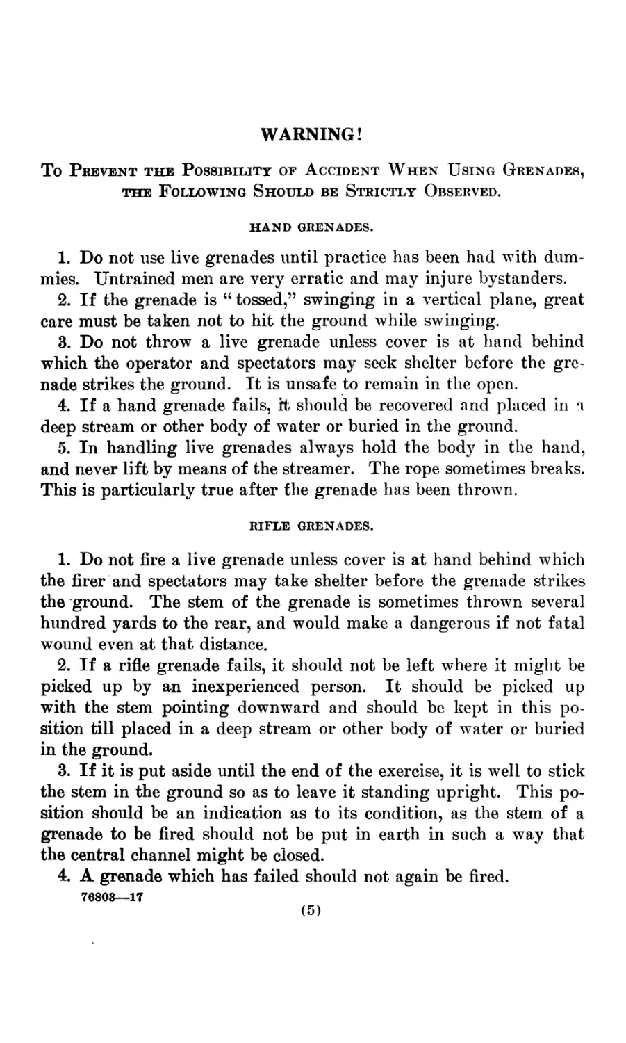
WARNING!
To Prevent the Possibility of Accident When Using Grenades,
the Following Should be Strictly Observed.
HAND GRENADES.
1. Do not use live grenades until practice has been had with dum-
mies. Untrained men are very erratic and may injure bystanders.
2. If the grenade is 66 tossed,” swinging in a vertical plane, great
care must be taken not to hit the ground while swinging.
3. Do not throw a live grenade unless cover is at hand behind
which the operator and spectators may seek shelter before the gre-
nade strikes the ground. It is unsafe to remain in the open.
4. If a hand grenade fails, ft should be recovered and placed in a
deep stream or other body of water or buried in the ground.
5. In handling live grenades always hold the body in the hand,
and never lift by means of the streamer. The rope sometimes breaks.
This is particularly true after the grenade has been thrown.
RIFLE GRENADES.
1. Do not fire a live grenade unless cover is at hand behind which
the firer and spectators may take shelter before the grenade strikes
the ground. The stem of the grenade is sometimes thrown several
hundred yards to the rear, and would make a dangerous if not fatal
wound even at that distance.
2. If a rifle grenade fails, it should not be left where it might be
picked up by an inexperienced person. It should be picked up
with the stem pointing downward and should be kept in this po-
sition till placed in a deep stream or other body of water or buried
in the ground.
3. If it is put aside until the end of the exercise, it is well to stick
the stem in the ground so as to leave it standing upright. This po-
sition should be an indication as to its condition, as the stem of a
grenade to be fired should not be put in earth in such a way that
the central channel might be closed.
4. A grenade which has failed should not again be fired.
76803—17
(5)
PLATE I.
BABBITT RIFLE GRENADE.
0 .5 / 2 INCHES.
GRENADE»
The rifle grenade adopted by the Ordnance Department is that
known as the Babbitt rifle grenade, and is illustrated in Plate I of
this pamphlet. The rifle grenade is intended to be fired from a
service magazine rifle, model of 1903, by use of a specially loaded
blank cartridge.
The hand grenade has been developed simultaneously with the
rifle grenade and the type adopted by the department is illustrated
in Plate II of this pamphlet. This grenade is thrown by hand in
much the same manner as a stone is thrown from a sling. These
grenades are high explosive missiles and should be used at short
ranges from behind cover.
Rifle and hand grenades are packed in boxes containing 32 each.
THE ACTION OF THE RIFLE GRENADE.
The construction of the rifle grenade and the nomenclature of its
component parts are indicated in Plate I.
(PLATE I.)
NOMENCLATURE.
a. Paper disk.
b. Sabot.
c. Stem.
d. Stem ring.
e. Closing screw.
/. Safety wire.
g. Safety pellet screw.
Л. Paper disk.
Л Safety pellet.
k. Safety pin.
I. Body.
m. Trinitrotoluol.
n. Detonating cup filling disk.
p. Plug.
q. Plunger locking pin.
r. Plunger.
s. Plunger restraining spring.
t. Casing.
u. Primer holder.
v. Percussion composition.
w. Primer covering.
x, Primer housing.
y. Primer charge.
z. Primer closing disk.
aa. Detonator cup.
bb. Detonating compound.
The grenade is designed to be fired at a constant angle of eleva-
tion, namely 45°, except as noted below for ranges under 50 yards.
The range attained is dependent upon the length of the stem inserted
in the bore of the rifle. Tests have shown that within considerable
limits the range is but little affected by small changes in the angle
of elevation, near 45°, while a change in the length of inserted stem
gives an appreciable change in the range.
(7)
8
The rifle grenade should be set for range as follows: The grenade
having been removed from its tin packing container, grasp the stem
with the thumb down and the thumb nail in the groove marking the
range desired. Insert the stem in the muzzle of the service rifle and
shove down until the stem ring comes against the end of the thumb
nail.
The special grenade cartridge is inserted in the chamber and the
rifle fired either from the shoulder, or better by resting the butt on
the ground, the firer kneeling to the left, fixing the direction and
estimating the desired 45° elevation. The rifle should be held as
firmly as possible.
Remove the safety wire f.
When the special blank cartridge above referred to is fired in the
gnn, the flaming gases from its charge serve the double purpose of
ejecting the grenade from the rifle and of arming the fuse of the
grenade. The latter action is accomplished as follows: The flame
passes up through the bore of the stem <?, through the passages in
the closing screw <?, and holes in the safety pellet screw g, and
ignites the safety pellets /. The compressed rifle powder pellets
serve, before being burned out, to hold the safety pins к in such
a position that their conical points engage in the circumferential
groove in the plunger r, and prevent this plunger from moving
forward. It will thus be seen that the fuse can not be armed until
after the exit of the grenade from the rifle. After the compressed
rifle powder j has been consumed, and the safety pins к released, the
plunger r is still restrained from moving forward and striking the
primer covering 7c, by means of the plunger restraining spring 5.
Upon impact with the ground, after having been fired from the
rifle in the manner stated, the plunger r moves quickly forward,
striking the primer covering ic, igniting the percussion composition
which in turn ignites the primer charge у and this in turn ignites
the detonating compound ЪЪ. The detonation of this compound
causes the detonation of the trinitrotoluol filling m.
The detonation of the grenade upon impact is violent, and the
grenade, body, and components are broken up into a number of
effective fragments which have a considerable range, making it
unsafe for the firers or observers to be in the open when the grenade
detonates. At the proving ground the stems have been found over
300 yards in rear of the point of burst. Rifle grenades may also be
fired point blank if desirable.
INSTRUCTIONS FOR USE OF THE RIFLE GRENADE.
Rifle grenades are shipped in bandoleers of olive-drab cloth, each
of which contains four rifle grenades. The grenades are packed in
9
the bandoleer in hermetically sealed tin containers, each carrying
one rifle grenade complete and one special blank cartridge for use in
propelling the grenade. The bandoleer is opened by unfastening or
tearing off the stripping tape. The tin containers are provided with
a tearing-off strip which may be removed with the fingers. This
should, however, not be done until the grenade is to be actually used.
The bandoleer is carried over the shoulder, the end tapes being passed
around the waist and tied in front or as may be most convenient.
The weight of a complete bandoleer with four grenades, containers,
and blank cartridges is 6 pounds 13.76 ounces; the weight of the
packing can including the weight of the grenade and blank cartridge
is 1 pound 10.16 ounces; tlie weight of the grenade proper is 1 pound
6.84 ounces, and the weight of the blank cartridge is 210 grains.
It will be noted that the stem c of the grenade is graduated with
circular grooves corresponding to different lengths of insertion into
the bore of the rifle, which in tjirn correspond to the various ranges.
There is one set of graduations in yards of range based upon an angle
of elevation of 45°. These graduations vary from 300 yards to 80
yards as a minimum. In order to cover the space between the mini-
mum range as marked on the stem and the firing point, an angle of
elevation of 80° may be used. With this angle of elevation, the
ranges obtained will be approximately one-fifth of the ranges marked
on the stem. The angle of elevation of 80° may be closely approxi-
mated by resting the butt of the rifle upon a level piece of ground or
upon a board, the surface of which is horizontal. In other words,
the angle between the horizontal surface and the bore of the rifle
with the rifle in the position of “order arms” is approximately 80°.
A range table giving more exact ranges for both the live and the
dummy rifle grenades is given below:
Live and dummy Live and dummy
grenades, elevation grenades, elevation
45°. , 80°.
• Range.
Insert stem
to gradua- '
tion [
marked— ,
Yards.
80
100
120 I
140 |
160
180 I
200 ,
220 ,
240
260
280 ।
300
Yards.
80
100
120
140
160
180
200
220
240
260
280
300
Insert stem
Range, to gradua-
marked—
Yards. Yards.
15 । 80
20 I 100
26 120
32 140 ।
38 160 ।
44 180 |
50 200 I
56 220 I
63 । 240 I
70 260 I
77 ; 280 1
85 , 300 ।
10
The maximum pressure obtained from the special blank cartridge
issued with the grenades is approximately 48,000 pounds per square
inch, when the stem insertion is complete, i. e., when the stem ring
stops against the closing screw of the grenade. This pressure corre-
sponds, as may be seen from the range table, page 9, to a range of
300 yards.
In firing the rifle grenade it has been found that the best results
can be obtained by resting the butt of the rifle on the ground and
estimating the angle which the barrel makes with the horizontal,
which angle, as stated above, should be either 45° or 80°, these angles
being those used for the determination of the graduation upon the
stem. It has been found that the rifle grenade is not detonated by
impact of the small-arms bullet unless it so happens that the bullet
actually strikes the fulminate composition n. It will also be observed
that no blank cartridges other than those issued by the Ordnance
Department should he used with the rifle grenade. Failure to observe
this caution may result in injury to both the men and the materiel.
Should a rifle grenade fail to detonate on impact after having been
fired from a rifle, it should be handled with extreme caution, in view
of the fact that the safety feature as described above has now been
removed. To handle such a grenade, it should be carried with the
stem down and if practicable thrown into deep water, from which its
recovery is improbable. If that be not practicable, the grenade should
be buried in the ground where it will not likely be recovered. If it
should be necessary to disassemble a grenade, either fired or unfired,
the work should be done only in the presence of a responsible person.
To do this, place the grenade, stem down, in a vise or clamp. With a
wrench unscrew the body and remove the plunger if free. If the
plunger of a fired grenade can not be removed, the safety pellets
have failed to burn out, and while the reassembled grenade would
be safe, it would probably fail again. A grenade having once failed
should not be again fired from the rifle.
DUMMY RIFLE GRENADES.
The dummy rifle grenade illustrated in Plate III is issued for
instruction purposes, and is similar to the rifle grenade in Plate
I of this pamphlet, except that the body is not provided with grooves.
It may from this feature be distinguished readily from the live
grenade. As a further precaution, this grenade is marked “ dummy.”
The stem of this grenade is graduated in a manner entirely similar
to the method used for the stem of the live grenade, and the weight
of the dummy grenade is equal to that of the live grenade. The
dummy grenade is for use in target practice. The graduations for
the stem of the dummy grenade are given for the same ranges as in
PLATE II.
PLATE III.
DUMMY R/FLf в&ТМДГ
0 -5 f 2 H1CNES.
11
the case of the live grenade, but owing to the fact that the stem of
the dummy grenade is solid and has no bore along its longitudinal
axis, the ranges obtained with it are slightly greater than those ob-
tained with the live grenade for equal lengths of stem insertion. In
other words, for this and other reasons, the stems of the dummy and
live grenades are not interchangeable. The range table for the gre-
nade, both for 45° elevation and 80° elevation, is given on page 9.
The manipulation of the dummy rifle grenade is entirely similar to
that of the live grenade, so far as the stem insertion and firing from
the rifle is concerned. The dummy grenade may be fired repeatedly.
After the stem has become deformed the dummy grenade can again
be made serviceable by the addition of a new stem. Each dummy
rifle grenade issued is accompanied by 5 extra stems and 50 blank
cartridges. These grenades are not issued in tin packing boxes or
with bandoleers.
ACTION OF THE HAND GRENADE.
The construction of the hand grenade and the nomenclature of its
component parts are indicated in Plate II:
(PLATE II.)
NOMENCLATURE.
a. Streamer. b. Streamer holder. c. Body. d. Trinitrotoluol. e. Cup detonator. f. Filling washer. ff. Primer closing disk. Л. Primer covering. j. Primer charge. k. Primer housing. 1. Percussion composition. m. Hood. n. Firing pin. p. Fulminate composition. q. Cup-detonator sleeve. r. Primer holder. 8. Closing screw. t. Safety cup. u. Firing pin holder.
The action of the hand grenade is as follows: The hood on is re-
moved from the grenade by twisting the hood in such a manner
as to release the bayonet joint. The safety cup t is then removed
and the hood replaced by repeating the motion of disassembling
in reverse order, care being exercised not to attempt to force the
hood past the stop pins, as the safety feature has naw been removed.
When the hood is in the proper position to cause the fuse to be
armed, the stud in the body which engages in the bayonet-joint
groove in the hood should be opposite the longitudinal continua-
tion of the bayonet-joint slot. The fuse is now armed, and when
the grenade is thrown so as to fall upon the firing-pin end the
weight of the grenade causes the thin sections of the hood m to
12
be sheared by the small pins resting against the shearing sections,
thus allowing the grenade to move downward into the hood, tele-
scoping therewith, and strike the firing pin n against the percussion
composition I. The impact of the firing pin ignites the percussion
composition, which in turn ignites the powder y, causing the detona-
tion of the fulminate composition p and of the trinitrotoluol d.
These detonations result in the fragmentation of the grenade. The
streamer or tail of the hand grenade is for the purpose of swinging
the grenade in throwing. Preparatory to throwing the grenade the
unravelled portion of the streamer should be wadded up in the palm
of the hand and grasped together with the knot. In flight, the
rope, acting as a tail, steadies the flight of the grenade and tends
to cause it to strike head on in an advantageous manner for the
successful action of the fuse.
INSTRUCTIONS FOR THE USE OF THE HAND GRENADE.
The grenade is issued in cylindrical tin cans, hermetically sealed,
and provided with a tin tearing strip which should not be removed
until just before the hand grenade is required for use. Four hand
grenades are packed in these tin cans and carried in an olive drab
bandoleer somewhat similar to that used for the transportation of
small-arms ammunition. These bandoleers are provided with a strap
so that the bandoleer can be suspended from the shoulders. This
strap is folded across the back to the bandoleer and stitched in place
with a weak stitching. Hooks are also provided so that the bando-
leer may be suspended from the belt if this manner of carrying is
preferred. The bandoleer pouch is divided into four compartments,
each containing a hand grenade, and all are covered by a flap secured
by a buckle so that the compartments may be readily opened for
the extraction of the grenade.
Having taken the grenade from the bandoleer, the tin box is
opened by tearing off the soldering strip, which releases the cover of
the can. The hand grenade having been removed from the container,
the grenade must be armed before it is thrown, and this is done by
removing the safety cup Л as described above. Having armed the
fuse of the grenade and replaced the hood тгъ in the proper armed
position, the grenade is ready to be thrown. In this condition the
grenade should be carefully handled and not permitted to strike
either on the ground adjacent to the thrower or in the vicinity of
friendly troops. The thrower and all friendly troops should have
cover before the grenades strike, as the fragments resulting from
their detonation have a longer range than the distance to which
the grenade as a whole may be thrown. The rope of the grenade
is made in a convenient length for the soldier of average stature, but
PLATE IV.
13
this length may be decreased by adding another knot. The manner
of throwing the grenade is dependent upon the free space available
for swinging it. When the thrower has ample space behind a
parapet, it is best to swing it around the head as with a sling, both
for accuracy and safety. Untrained men will naturally swing the
grenade in a vertical plane. The tests at the Sandy Hook Proving
Ground indicate that this method is accompanied by considerable
danger, as the thrower may strike the ground with the grenade in
the act of whirling it or may release it so that its flight will be nearly
vertical, causing the grenade to fall back near the thrower. The
ranges that can be attained with this form of grenade are not great
and vary with the strength and skill of the thrower. Prior to using
service grenades, troops should be instructed in the use of dummy
grenades. In assembling the hood after removing the safety cup £,
care should be taken not to attempt to force the hood too far upon
the butt of the grenade body, or explosion may occur. The rope of
the grenade should also be examined to make sure it is in good con-
dition and not liable to break while the grenade is being whirled.
In case a grenade which has been thrown and failed to detonate
is recovered, it should be handled with the greatest care. Such
grenades can be rendered safe for transportation by cautiously with-
drawing the hood m from the grenade body, replacing the safety cup
t in the hood, and then reassembling the hood to the grenade body.
Or in case it be desired to throw the grenade a second time, this
may be accomplished by drawing back the hood m until it will have
its normal stroke upon impact and then throwing in the usual man-
ner. However, if practicable, a grenade which has failed should be
thrown into deep water from which its recovery is improbable, or
should be buried in the ground.
The weight of the bandoleer packed with four containers and hand
grenades is 6 pounds, and the weight of one hand grenade complete
is 1 pound 5 ounces. The weight of the tin container is 1.92 ounces,
and the weight of the bandoleer is 4.32 ounces.
DUMMY HAND GRENADES.
Dummy hand grenades are issued for instruction purposes and for
practice in throwing grenades. These dummies are similar in weight
and form to the live grenade, except that the body of the grenade is
made of bronze instead of cast iron or steel and not grooved, but
smooth upon its exterior surface so as to distinguish it from the live
grenade, which is provided with grooves. The dummy hand grenade
is also marked with the word “ Dummy.” The cords attached to
the dummy grenades will, with continued use, become worn and for
14
this reason the cord should be examined before whirling the grenade,
in order to avoid accidents. To obtain accuracy and range in
throwing the hand grenade requires preliminary drill and practice
with the dummy grenade. For maximum effect the grenade should
be detonated within a few feet of the object at which it is thrown.
This requires accuracy usually acquired only by a considerable
amount of practice. The dummy hand grenade is shown in
Plate IV.
With each dummy hand grenade are issued five extra streamers.
War Department,
Office of the Chief of Ordnance,
Washington, January /2, 1917,
May 18, 1911.
Revised January 12, 1917.
Form No. 1741.
Ed. Jan. 12-17—5,000.
INDEX.
Page.
Dummy hand grenades......................................................... 13
Dummy rifle grenades........................................................ 10
General description.......................................................... 7
Hand grenade:
Action.................................................................. 11
Instructions for use.................................................... 12
Nomenclature............................................................ 11
Range table.................................................................. 9
Rifle grenade:
Action................................................................... 7
Instructions for use..................................................... 8
Nomenclature............................................................. 7
Warning...................................................................... 5
(15)
о