/


Text
1,574,701
Feb. 23,1926.
H. SCHME1SSER
SMALL ARM WITH TUBULAR CARTRIDGE MAGAZINE
Filed August 24 t 1925 3 Sheets-Sheet 1
(/i.ine.j!sser
?г s
Feb. 23,1926
1,574,701
H. SCHME1SSER
SMALL ARM WITH TUBULAR CARTRIDGE MAGAZINE
Filed August 24 f 1925 3 Sheets-Sheet 2
1,574,701
Feb. 23,1926.
H. SCHME1SSER
SMALL ARM WITH TUBULAR CARTRIDGE MAGAZINE
Filed AugUst 24 t 1925 3 Sheets-Sheet 3
m^e.2sser
Patented Feb. 23, 1926.
1,574,701
*
10
15
20
25
30
85
40
45
50
UNITED STATES PATENT OFFICE.
HANS SCHMEISSER, OF SUHL, GERMANY.
SMALL ABM WITH TUBULAR CARTRIDGE MAGAZINE.
Application filed August 24, 1925. Serial No. 52,072.
To all whom it may concern:
Be it known that I, Hans Schmeisser, a
citizen of Germany, residing at Philosophen-
weg 5, Suhl, Germany, have invented certain
new and useful Improvements in Small
Arms with Tubular Cartridge Magazines, of
which the following is a specification.
My invention relates to improvements in
small arms having a cartridge magazine
formed in a known manner as a tube or
sleeve located along the barrel. As the
cartridges are moved out of the magazine
singly by means of a spring enclosed with-
in the tube or sleeve, they will be received
by and on the usual cartridge carrier act-
ing to bring, when swinging upwards, the
cartridge to a position right opposite or in
front oi the chamber.
The chief object of my invention is to
provide improved means for pushing the
cartridge from the raised carrier into the
chamber by means of a bi-partite breech-
bolt having the one of its two parts dimen-
sioned and arranged as to be capable of en-
tering from the rear into the tubular front
end of the cartridge carrier in which the
lifted cartridge lies, in order to push the
cartridge forward into the chamber of the
barrel, and to be further adapted to disen-
gage from the tubular front end of the
carrier upon the subsequent downward
movement of the latter, while the other part
of the breech-bolt will be retained in its
rear position during the thus accomplished
charging operation and will not advance to
also engage the bottom surface of the cart-
ridge in the chamber, until the carrier has
moved down and out of the path of the
breech-bolt, to receive a next cartridge.
Preferably I construct the second mentioned
part of the breech-bolt to constitute at the
same time a firing pin or similar forma-
tion.
A further object of my invention is to
provide means for preventing the firing1
member which is combined, as hereinbefore
stated, with the one part of the breech-bolt,
from accidental firing of a shot. The said
part of the breech-bolt is retained in cocked
position by means of a suitable pawl. ВУ
mounting the latter on the detachable cover
of the breech casing on which also the bi-
partite breech-bolt is mounted, accidental
firing in case of removing the cover and if
the firing member is in cocked position and
a cartridge in the chamber, ig efficiently
prevented.
The invention further comprises a lock-
ing means on the detachable cover for re-
taining the two parts of the breech-bolt and «0
preventing the same from being ejected
from the casing by the action of the clos-
ing spring and the firing spring, in case of
removing the cover from the casing. In ~
order to enable the cover to be readily re- 85
moved from the casing, suitable ribs may be
provided at the fore end and at the rear end
thereof, adapted to engage in correspond-
ingly shaped grooves provided in the wall
of the casing. If desired another locking 70
means may be provided on the cover for the
purpose of preventing the cover from ac-
cidentally removing from the casing or, in
other words, holding the cover properly
seated with its ribs in the said grooves of 75
the casing.
The invention further comprises a clos-
ing lever mounted on the right-hand side
or on the left-hand side of the. breech-bolt
so as to be able to be moved or swung in a 80
vertical plane, a lateral recess or slot beingr
provided in the casing or in the cover for
receiving and guiding the lever which pref-
erably is shaped to form a handle afford-
ing a ready means for causing the lever 85
to engage in a suitable recess or with a
projecting part of the casing or the cover,
if required, so that the breech-bolt will
be firmly locked and the weapon may be
used for firing single shots or repeated 90
shots.
The invention furthermore comprises the
constructions and combinations of parts
hereinafter particularly described and il-
lustrated in the drawings. 98
In the accompanying drawings forming
a part of this specification, and snowing for
purposes of exemplification, a preferred
form and manner in which the invention
may be embodied and practised: 100
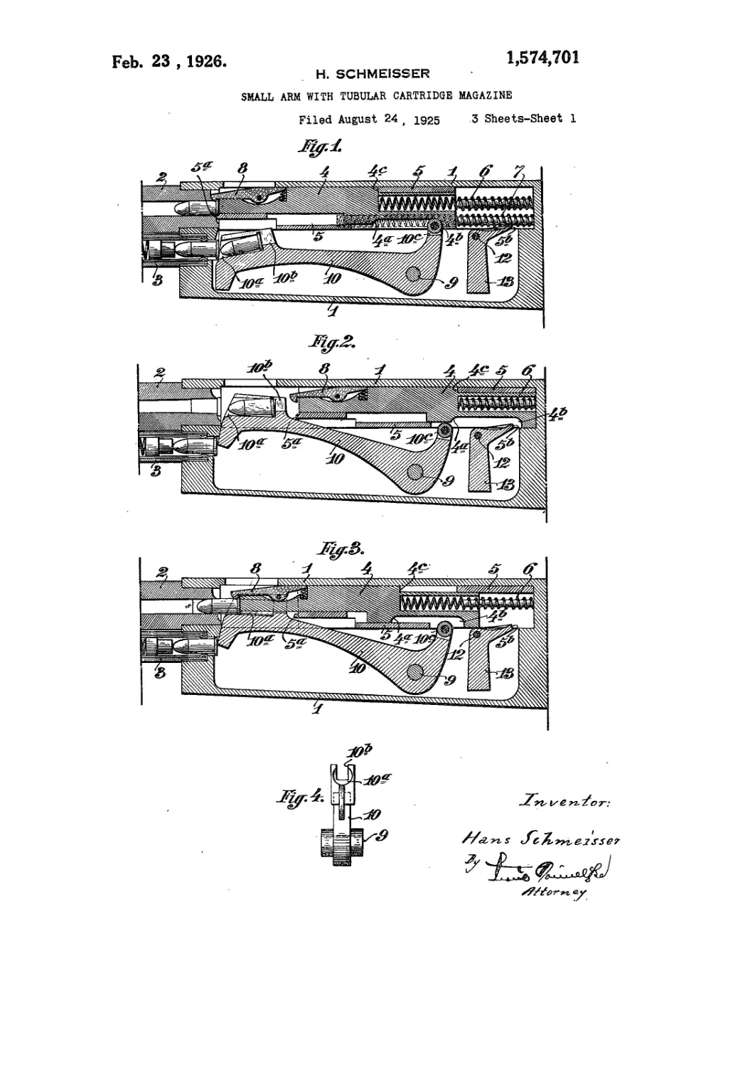
Figure 1 is a fragmentary vertical, longi-
tudinal section of the weapon with a cart-
ridge in the chamber, the parts being shown
at the firing moment;
Figure 2 is a similar view of the middle 108
part of the rifle with the breech-bolt fully
withdrawn upon firing;
Figure 3 is a similar view of the weapon
with the parts in the position, of pushing
a cartridge into the chamber; 110
55
a
'1,874,701
Figure 4 is a front view of the cartridge
carrier showing clearly the tubular front
end thereof;
Figure 5 is a vertical longitudinal sec-
15 tion of the cover or cover plate with the
breech mechanism and the locking means
mounted thereon, the parts being shown in
their uncocked position;
Figure 6 is a similar view showing the
10 parts in cocked position, the contour of the
casing being indicated in Figures 5 and 6
in dotted lines;
Figure 7 is a vertical section taken on the
line A—В in Figure 6;
15 Figure 8 is a vertical longitudinal section
of the middle part of the rifle showing the
casing viewed from the right-hand side with
the closing lever in itsx inactive position ;
Figure 9 is a similar view with the clos-
20 ing lever in its locking position;
Figure 10 is an elevation of the breech-
bolt with the closing lever pivotally at-
tached thereto;
Figure 11 is a plan view of the closing
26 lever and
Figure 12 is a side view and a plan view
of a detail.
Referring to Figures 1 to 3 the casing 1
is firmly connected with the barrel 2 and
30 the tubular cartridge magazine 3 in the
usual manner and the two parts 4 and 5
constituting the breech-bolt are mounted in
the casing 1, as shown, subject to the action
of the two coiled springs 6 and 7, respec-
36 tively. At the front end of the part 4 of
the breech-bolt a cartridge extractor 8 is
pivotally mounted in the usual manner,
whilst the front end or face of the part 5
of the breech-bolt is shaped to form a firing
40 pin 5a. When the parts 4 and 5 return
from the closing position shown in Figure
1 to the open position illustrated in Figure
2, the part 5 is taken along with by a shoul-
der 4C of the part 4.
45 The cartridge carrier 10 is mounted in
the casing to swing about a transverse pin
9 or the like. The front end of the
carrier is shaped to form a tubular seat 10®
for the reception of the cartridge to be
50 transported from the magazine to the cham-
ber. This tubular end of the carrier is re-
cessed to be open at the top and at the rear,
as shown at 10b in Figures 1, 2 and 4, but
the recess 10b is only so wide that a cartridge
•'5 cannot pass therethrough, whereas the part
4 of the breech-bolt can freely pass there-
through. The part 4 of the breech-bolt is
provided with two lugs projectnig down-
ward from the bottom side thereof, the one
80 lug 4b being at the rear end of the part 4
and the other one, 4a, being located at a
point intermediate between the two ends of
the part 4. When the latter moves back-
ward towards the butt, the lug 4a will en-
86 gage the short arm 10е of the cartridge car-
rier and cause the longer arm of the carrier
to rise and to thereby bring a cartridge into
a position in front of the chamber, as shown
in Figure 2, and when the part 4 moves
forwards towards the barrel, the lug 4b will
engage the arm 10е of the carrier 10 and
cause the longer arm thereof to descend
from the position illustrated in Figure 2 to
that shown in Figure 1.
Pivotally mounted on a pin 12 in the cas- "5
ing is a pawl 13 which will lock the part 5
of the breech-bolt, when in the full open or
rear position, by catching into a notch 5b
provided for the purpose m the bottom face
of the rear end of tne part 5. As herein- so
before stated the front arm of the carrier
10 is raised by the action of the lug 4a when
the breech:bolt moves backward or towards
the butt, so that the tubular end 10“ of the
arm will bring a cartridge from the maga- 85
zine to the chamber of the barrel 2, see
Figure 2. When subsequently the part 4
of the breech-bolt is moved in opposite di-
rection or towards the barrel, the said part
4 will pass from the rear end through the 90
recess ХО6 into the tubular seat 10* of the
carrier and push the cartridge out of the
seat 10“ into the chamber of the barrel, as
will be clearly seen upon inspection of Fig-
ure . 3. At the very moment the cartridge 95
has come out of contact with the carrier
the lug 4b of the part 4 will engage the short
arm 10е of the carrier and cause the latter
to turn about its pivot 9.thereby lowering
the front arm of the carrier into the posi- 100
tion illustrated in Figure 1, so that the tubu-
lar fore end 10“ of the arm will be in readi-
ness for the reception of a new cartridge
from the magazine. At the same time the
part 5 of the breech-bolt has been caught 105
by the pawl 13 engaging in the notch 5b
and is locked until, upon firing, the pawl 13
is moved to release the part 5 which then is
rapidly thrown forward by the action of the
compressed spring 7 in order to cover that 110
portion of the bottom face of the cartridge
in the chamber which is not covered or in
contact with the fore end of the part 4 of
the breech-bolt, and to cause at the same
time the firing pin 5“ to hit the cartridge 116
in the chamber.
Referring to Figures 5 to 7, 1 denotes
the stationary casing. The barrel and the
cartridge magazine are not shown -in Fig-
ures 5 to 7, but they are of usual construe- 120
tions and arrangement as hereinbefore
stated with reference to Figures 1 to 4.
The bipartite breech-bolt comprising a
closing member or part 4 and a firing mem-
ber or part 5, as before, is mounted on the 125
cover or cover plate 1“ so as to be capable
of moving backward and forward. The
cartridge extractor 8 is provided, as be-
fore, in the fore end of the part 4. The
locking pawl 13 pivoted on a pin 12 se- 180
1,574,701
a
cured in the cover la, is' actuated by a
spring 13“ causing the pawl to catch into
the notch 5b of the part 5 and to lock the
latter in the position shown in Figure 6,
5 when the breech bolt is moved into its ex-
treme hind position.
In the fore-end of the cover 1“ and on
the inner side or face thereof a T-shaped
groove is provided for the reception of a
10 locking latch 15 shaped to correspond to
the shape of the groove so as to be slidable
therein. The groove and the latch are lo-
cated transverse to the length of the cover
and a sjpring 15“ normally holds the latch
15 in a raised position so that its upper end
lies in the path of the breech-bolt whereby
the two parts of the latter are prevented
from being ejected over or out of the front
end of the cover if the latter is to be re-
20 moved from the casing.
Further the fore end and the rear end
of the cover are equipped with ribs lb
adapted to engage in correspondingly
shaped grooves of the casing 1. Further-
25 more a horizontal bore is provided in the
rear end of the cover to accommodate a
latch-bolt 14 having a lateral knurled head
14b. The rear or free end of the bolt 14
normally lies in a recess 14“ of the casing
;,o under the action of a spring 14c abutting
against the fore end of the bolt, as will be
clearly seen in Figures 5 and 6 whilst Fig-
gure 7 shows the parts in section.
Referring to Figures 8 to 12 showing
35 the casing 1 viewed from the other side,
the sliding breech-bolt 4 is located either
in the casing 1 or on the cover 1“ and a
coiled spring 6 is provided for moving the
same into the closed position, that is to-
40 wards the barrel not shown. The longi-
tudinal slot 1° is enlarged and shaped to
afford a locking face la lying in an arc
of a circle the centre of which is in the
pivot of the breech lever 16. When the lat-
45 ter is turned downward the arm 16c will
engage behind the face or shoulder la so
that the breech-bolt will be locked.
For the purpose of yieldingly securing
the lever 16 in its two limits or end posi-
50 tions I utilize the main spring 6. To this
end I provide in the rear end of the lever
17 two notches 16“ and 16b and I mount
onto the free end of the coiled spring 6“
a firing bolt 17, shown separately in Fig-
55 ure 12 and having a tooth 17“ adapted to
catch, under the pressure of the spring 6,
either into the notch 16“ or into the notch
16b, depending upon the position of the
lever 16, so that the latter will be resil-
00 iently fixed in either position. The bolt
17 has a vertical bore IT11 of elongated or
elliptical cross-section and I provide a ver-
tical pin 18 passing through the bore IT11
in order to guide the bolt 17 in vertical
06 direction.
I have not attempted to explain all of
the details of the construction of the rifle,
for it will be understood by those to whom
this specification is addressed, that those
parts of the rifle which are. not shown and J”
described will necessarily be of the usual
construction and relationship and will be
properly mounted and supported according
to the tenets of small-arm construction.
It seems unnecessary to reiterate the opera- 75
tion of the rifle, for the operation of the
improved parts has been (described in de-
tail and the operation of the parts which
are old and not shown is known to persons
skilled in the art. Nor does it seem nec- 80
essary to burden this specification with an
exposition of the advantages which the in-
vention possesses, for they will be apparent
to those versed in the art to which this
invention relates. . 86
It is also apparent that in carrying out
my invention some changes from the. con-
struction herein shown and described may
be made. I would, therefore, have it un-,
derstood that I do not limit myself thereto, 00
but hold myself at liberty to make such de-
partures therefrom as fairly fall within
the spirit and scope of my invention.
What I claim is:—
1. A repeating rifle of the type described 86
comprising a easing; a cover having a
groove; a breech bolt in said cover having
a closing member and a firing member; a
spring-pressed locking pawl pivoted in said
cover adapted to hold the firing member in 100
cocked position; a locking latch adapted to
slide in said groove; and means in the cover
adapted to engage in the casing.
2. A repeating rifle of the type set forth,
comprising a barrel, a tubular cartridge Ю5
magazine below the said barrel, a two-part
breech-bolt, a casing enclosing the breech
and cooperating parts, a cover on top of the
said casing, a locking lever holding the one
part of the breech-bolt in cocked position, a Ho
spring-controlled locking latch for prevent-
ing the latter from being ejected when the
cover is to be removed from the casing, and
a spring-controlled latch-bolt for securing
the said cover in its position on the said cas- l15
ing, the said breech-bolt, the lever, the lock-
ing latch and the latch-bolt being mounted
on the said removable cover, substantially as
and for the purpose set forth.
3. A repeating rifle of the type set forth, 120
comprising a barrel, a tubular cartridge
magazine below the . latter, a cartridge car-
rier adapted to swing in a vertical plane, a
breech-bolt, a casing enclosing said breech-
bolt, a coiled spring actuating the breech- 125
bolt, a cover to shut up the said casing, a
rotary closing or breech-lever mounted
laterally on the said breech-bolt, a longi-
tudinal slot with a shoulder in the said cas-
ing for guiding and arresting the said 180
4 1,674,701
lever, and a means co-operating with the spring-pressed locking pawl pivoted in said
said spring to secure the said lever in its cover adapted to hold the firing member in 10
locking position, substantially as and for cocked position; a locking latch adapted to
the purpose set forth. slide in said groove; ana ribs in the cover
5 4. A repeating rifle of the type described adapted to engage in correspondingly shaped
comprising a casing; a cover having a grooves in the casing.
groove; a breech bolt in said cover having a In testimony whereof I affix my signature.
closing member and a firing- member; a HANS SCHMEISSER.