/


Author: Gronich S. Riedesel R.G. Johnson K.P. Holl R.J.
Tags: military affairs nuclear weapons astronautics
Year: 1970


Text
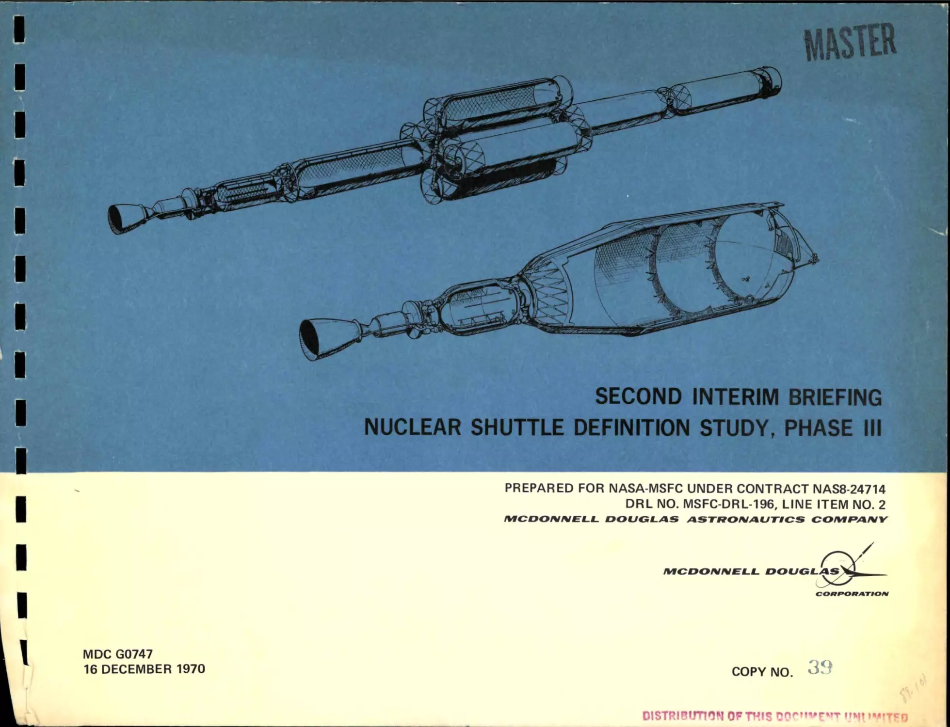
SECOND INTERIM BRIEFING
NUCLEAR SHUTTLE DEFINITION STUDY, PHASE III ^
PREPARED FOR NASA-MSFC UNDER CONTRACT NAS8-24714
DRL NO. MSFC-DRL-196, LINE ITEM NO. 2
IVICOONISI£LL
DOUGLAS
ASTKOIVAUTICS
COIt/IPAIVV
.y
MICDONMELL
MDC G0747
16 DECEMBER 1970
g»<fUGLAS}
COPY NO.
39
DISTRIBUTION OF THIS DOr'WftfT iJuj^iMtYfio
DISCLAIMER
This report was prepared as an account of work sponsored by an
agency of the United States Government. Neither the United States
Government nor any agency Thereof, nor any of their employees,
makes any warranty, express or implied, or assumes any legal
liability or responsibility for the accuracy, completeness, or
usefulness of any information, apparatus, product, or process
disclosed, or represents that its use would not infringe privately
owned rights. Reference herein to any specific commercial product,
process, or service by trade name, trademark, manufacturer, or
otherwise does not necessarily constitute or imply its endorsement,
recommendation, or favoring by the United States Government or any
agency thereof. The views and opinions of authors expressed herein
do not necessarily state or reflect those of the United States
Government or any agency thereof.
DISCLAIMER
Portions of this document may be illegible in
electronic image products. Images are produced
from the best available original document.
%mB
moumLMm
SECOND INTERIM BRIEFING
NUCLEAR SHUTTLE DEFINITION STUDY, PHASE III
16 DECEMBER 1970
PREPARED FOR NASA-MSFC UNDER CONTRACT NAS8-24714
DATA REOUIREMENTS LIST NO. MSFC-DRL-196,
LINE ITEM NO. 2
5301 Bolsa Avenue, Huntington Beach, CA 9264 7
MDC G0747
14906
PHASE III SECOND INTERIM BRIEFING
REUSABLE NUCLEAR STAGE CONCEPTS
NUCLEAR SHUTTLE SYSTEM DEFINITION STUDY
CONTRACT NAS 8-24714
16 DECEMBER 1970
1
- NOTICE-
This report was prepared as an account of work
sponsored by the United States Government. Neither
the United States nor the United States Energy
Research and Development Administration, nor any of
their employees, nor any of their contractors,
subcontractors, or their employees, makes any
warranty, express or implied, or assumes any legal
iiability or responsibiiity for the accuracy, completeness
or usefulness of any information, apparatus, product or
process disclosed, or represents that its use would not
infringe privately owned rights.
SliTiyBUnOM GF THIS >2uUUfALiii UiiLkwiiiLi
NUCLEAR SHUTTLE SYSTEM DEFINITION STUDY
During P h a s e I and P h a s e II of the nuclear flight s y s t e m definition study, the cont r a c t e d effort (1) evaluated t h r e e c l a s s e s of r e u s a b l e nuclear shuttle concepts that
could efficiently p e r f o r m m i s s i o n s from low e a r t h orbit to either lunar orbit or
synchronous e a r t h orbitj and p e r f o r m planetary m i s s i o n s in the shuttle mode, (2)
identified systemi element c h a r a c t e r i s t i c s that have major impact on the economics
of the n u c l e a r shuttle o p e r a t i o n s , and (3) defined nuclear stage c h a r a c t e r i s t i c s .
At the conclusion of this p h a s e , it was decided to p r o c e e d with a P h a s e A conceptual definition for two v a r i a t i o n s of the r e u s a b l e nuclear shuttle: (1) a 33-ft
d i a m e t e r , l o a d - c a r r y i n g tank that could be launched to e a r t h orbit by the
I n t e r m e d i a t e - 2 1 (Int-21) launch vehicle, and (2) propellant modules delivered to
low e a r t h orbit within the c a r g o hold of the Space Shuttle,
The objectives of this study a r e to define the r e u s a b l e nuclear stage concepts
m o r e completely and e s t a b l i s h integrated t e s t , manufacturing, facility and equipment, and supporting r e s e a r c h and technology plans in o r d e r that a p r e l i m i n a r y
technical plan, a development schedule, and p r o g r a m costs can be identified for
each of these concepts. A c o m p a r i s o n between the two c l a s s e s of RNS vehicles
will be made at the conclusion of this study.
2
NUCLEAR SHUTTLE SYSTEM DEFINITION STUDY
^^^
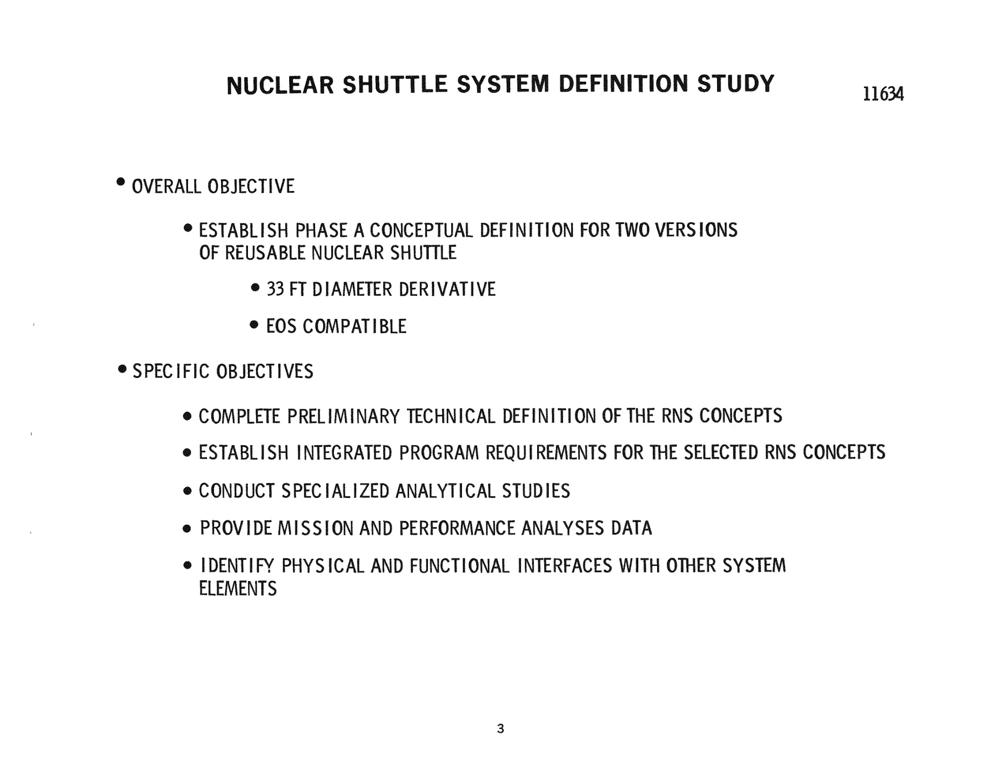
® OVERALL OBJECTIVE
® ESTABLISH PHASE A CONCEPTUAL DEFINITION FOR TWO VERSIONS
OF REUSABLE NUCLEAR SHUHLE
® 33 FT DIAMETER DERIVATIVE
® EOS COMPATIBLE
® SPECIFIC OBJECTIVES
® COMPLETE PRELIMINARY TECHNICAL DEFINITION OF THE RNS CONCEPTS
® ESTABLISH INTEGRATED PROGRAM REQUIREMENTS FOR THE SELECTED RNS CONCEPTS
® CONDUCT SPECIALIZED ANALYTICAL STUDIES
® PROVIDE MISSION AND PERFORMANCE ANALYSES DATA
® IDENTIFY PHYSICAL AND FUNCTIONAL INTERFACES WITH OTHER SYSTEM
ELEMENTS
3
BRIEFING SCHEDULE
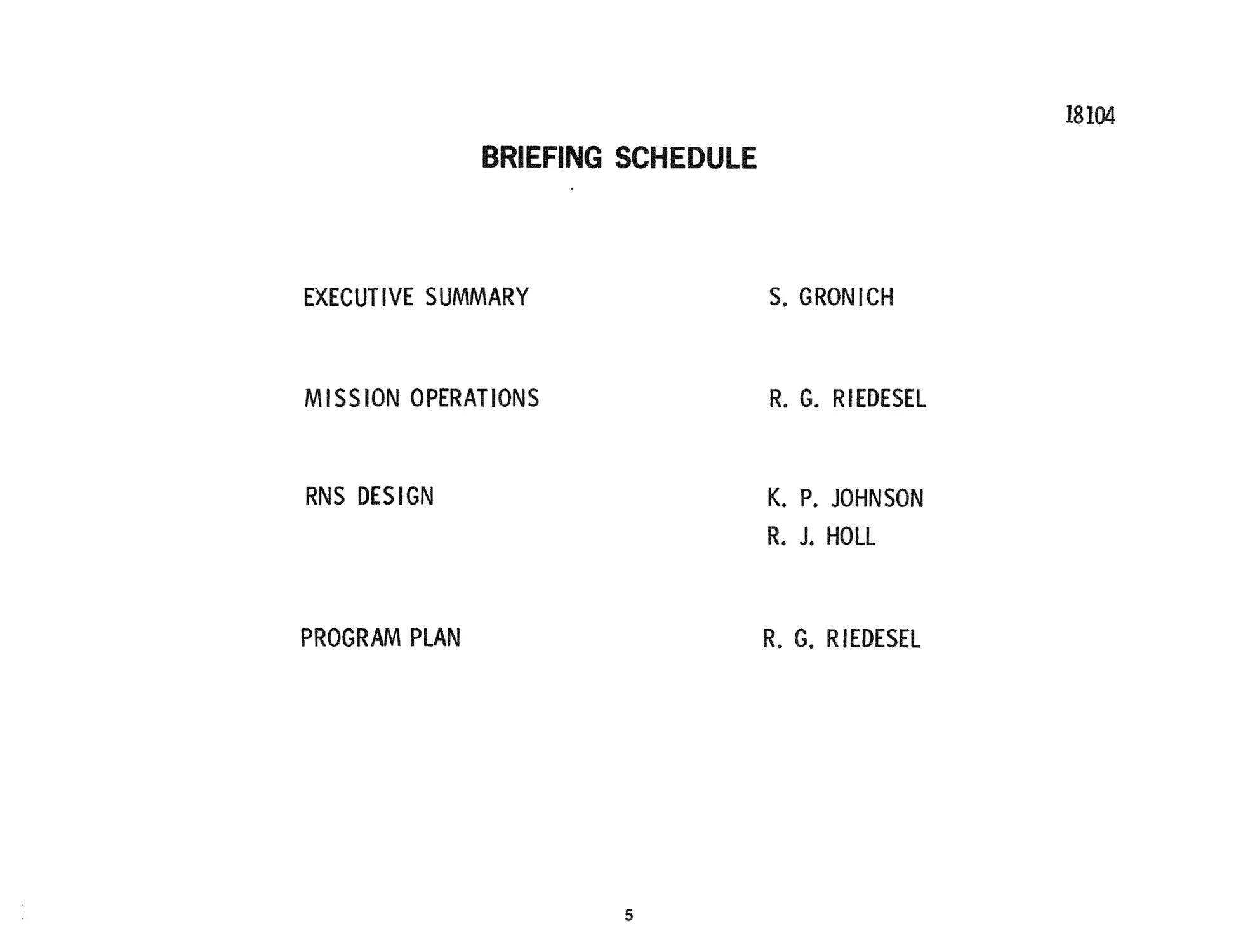
The organization of the briefing and the s p e a k e r s a r e shown in the accompanying
figure.
4
BRIEFING SCHEDULE
EXECUTIVE SUMMARY
S. GRONICH
MISSION OPERATIONS
R. G. RIEDESEL
RNS DESIGN
K. P. JOHNSON
R. J. NOLL
PROGRAM PLAN
R. G. RIEDESEL
STUDY SCHEDULE
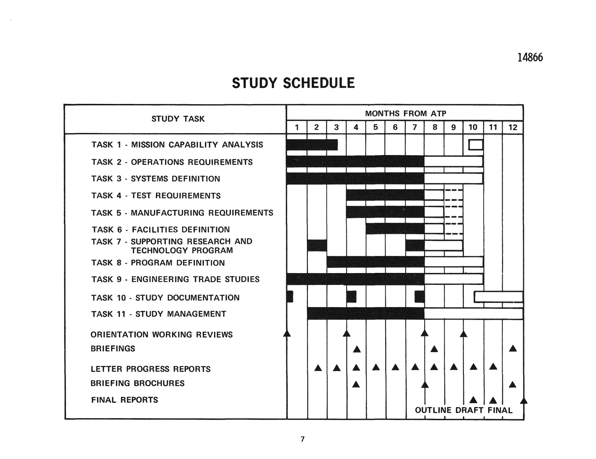
The schedule identifies the t a s k s to be p e r f o r m e d under the nuclear shuttle study
and indicates the c u r r e n t status of each of the individual efforts. The study is
b r o k e n into t h r e e p h a s e s , which consist of about 3 - 1 / 2 months each: (1) concept
definition and evaluation, (2) s y s t e m t r a d e s t u d i e s , and (3) p r o g r a m and s y s t e m
definition. As indicated on the schedule, the t a s k s initiated during the first phase
w e r e m i s s i o n capability a n a l y s i s , operations r e q u i r e m e n t s and s y s t e m s definition
of specific s u b s y s t e m s in o r d e r to p e r f o r m p r e l i m i n a r y configuration definition,
and e n g i n e - s t a g e interface definition. In addition, engineering t r a d e studies such
as engine-stage vehicle dynamics and engineering support activities (Task 9) w e r e
initiated during this phase of the study.
T r a d e analyses for s t r u c t u r e s , propulsion, a u x i l i a r y propulsion and a s t r i o n i c
s u b s y s t e m s w e r e conducted during the second portion of the P h a s e III study.
These will be r e p o r t e d on at this briefing. In addition, m i s s i o n and RNS o p e r a tions w e r e further updated and i n t e g r a t e d - p r o g r a m - p l a n - r e l a t e d t a s k s w e r e
initiated.
6
14866
STUDY SCHEDULE
MONTHS FROM ATP
STUDY TASK
2
1
TASK 1 - MISSION CAPABILITY ANALYSIS
TASK 2 - OPERATIONS REQUIREMENTS
3
4
5
6
7
e
8
12
^ ^ P B M I ^ ^ ^ ^ ^ ^ ^ ^ ^
M ^ ^ M i ^ ^ M i M ^ ^ ^ H
TASK 4 - TEST REQUIREMENTS
EBE
TASK 5 - MANUFACTURING REQUIREMENTS
TASK 6 - FACILITIES DEFINITION
TASK 7 - SUPPORTING RESEARCH AND
TECHNOLOGY PROGRAM
^
1
1
»».-,
—
N
1
TASK 8 - PROGRAM DEFINITION
!
1
i.
•
N
|
TASK 11 - STUDY MANAGEMENT
ORIENTATION WORKING REVIEWS
11
u
• • •
TASK 3 - SYSTEMS DEFINITION
TASK 10 - STUDY DOCUMENTATION
10
1
i
1
~T
A
i^
A
A
BRIEFINGS
A
LETTER PROGRESS REPORTS
A
•
A
BRIEFING BROCHURES
A
A
A
A
A
A
A
A
ik
A
A
FINAL REPORTS
A
OUTLINE DRAFT FINAL
1
7
1
!
!
ll___
CONCEPTS EVALUATED
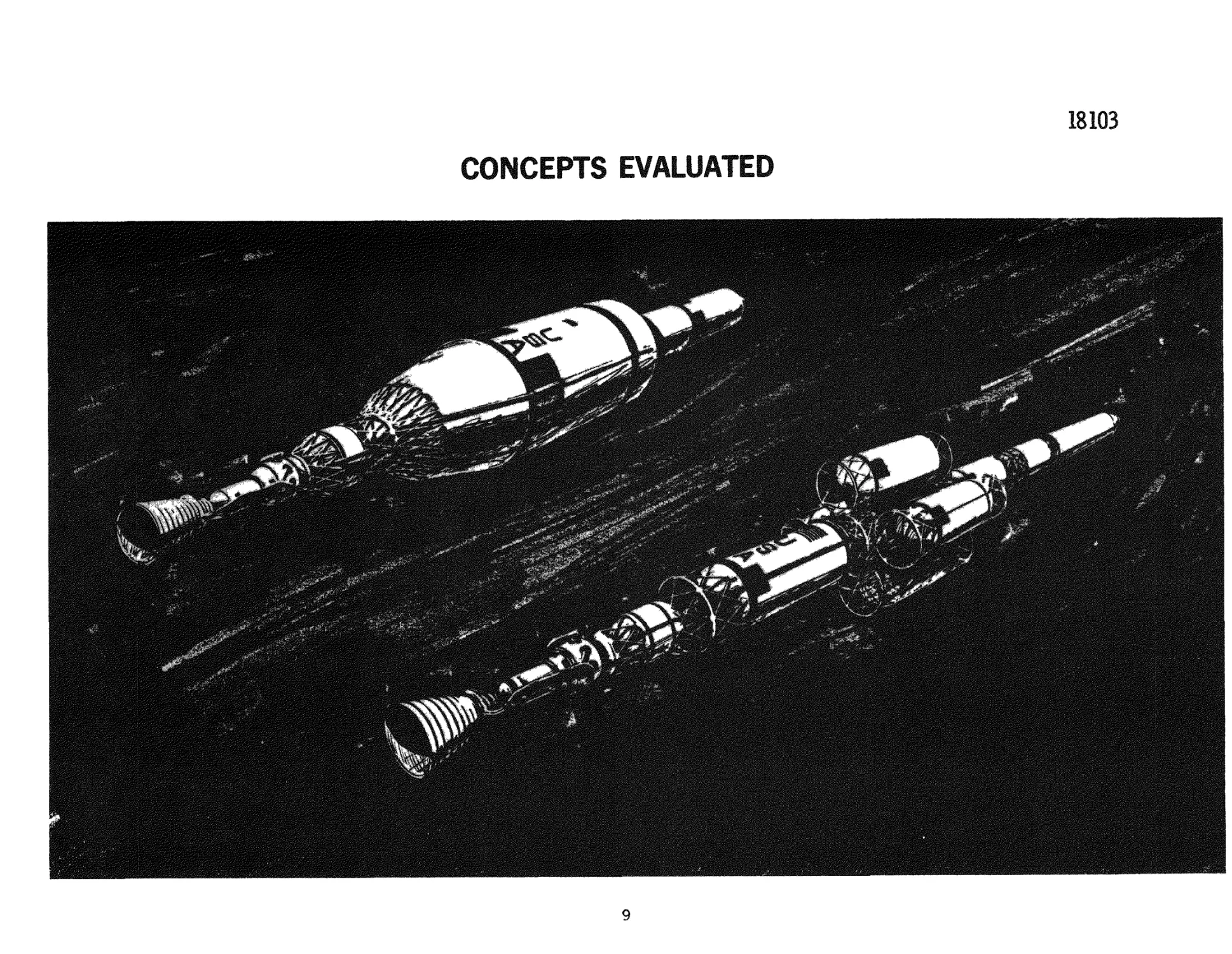
The C l a s s 1 and 3 RNS concepts a r e shown in the accompanying figure. At the
conclusion of P h a s e 11, the C l a s s 1 hybrid, which consisted of a s m a l l propellant
r u n tank and engine, delivered within the cargo hold of the space shuttle and a
33-ft d i a m e t e r propellant module delivered by the INT~21 launch vehicle, was
adopted as a p r i m a r y b a s e l i n e . Specific design analyses of a standard configuration with a 10-degree conical aft dome would also be studied to a depth sufficient to
define major technical p r o b l e m s . The aft angle for the C l a s s 1 Hybrid configuration will also be a simulated 10-degree angle in o r d e r to optimize the shield and
tank configuration of the o v e r a l l s y s t e m . The propellant tank for the C l a s s 1
hybrid is fabricated from 2014-T6 aluminum alloy and i n t e g r a l l y stiffened cylind r i c a l section. The s m a l l propellant run tank is of a monocoque construction, and
the total capacity of both tanks is about 300, 000 lb of p r o p e l l a n t . F i b e r - g l a s s heat
blocks and high-performance insulation, which can be c o m p r e s s e d during launch,
a r e used to t h e r m a l l y p r o t e c t the propellant t a n k s . A f i b e r - g l a s s bumper and
foam a r e used for the b a s i c m e t e o r o i d protection s y s t e m .
RNS equipment was placed in the forward s k i r t a r e a ; a modular configuration of
the s u b s y s t e m s was devised to provide maintainability. At the conclusion of a
t r a d e study conducted during the first t h r e e months of the c u r r e n t study effort, a
single command and control module, which would be r e m o v e d after each m i s s i o n
for r e p l e n i s h m e n t and r e p a i r , was selected over the previous design.
The planar configuration of the C l a s s 3 s y s t e m was selected at the conclusion of
P h a s e II on the b a s i s of a t r a d e analysis between shielding r e q u i r e m e n t s and
vehicle stiffness. On further investigation in the first t h r e e months of P h a s e III,
which evaluated the impact of a s s e m b l y o p e r a t i o n s , a c r u c i f o r m configuration was
s e l e c t e d . At the s a m e t i m e , further definition of fluid line deployment, flexible
e l e m e n t s , and docking and c l u s t e r i n g m e c h a n i s m s was m a d e . An i n t e g r a l n u m b e r of propellant modules was selected with a total capacity slightly g r e a t e r than
300, 000 lb. This r e p r e s e n t e d a configuration with eight m o d u l e s . The propellant
modules would be of aluminum monocoque construction, and all of the other s u b s y s t e m s would be s i m i l a r to that d e s c r i b e d for the C l a s s 1 hybrid concept. The
C l a s s 3 functional s u b s y s t e m s would be packaged in a command and control m o d u l e . Scheduled maintenance in this concept would be achieved by removing the
e n t i r e command control m o d u l e .
8
18103
CONCEPTS EVALUATED
„»»;**••
^
'
9
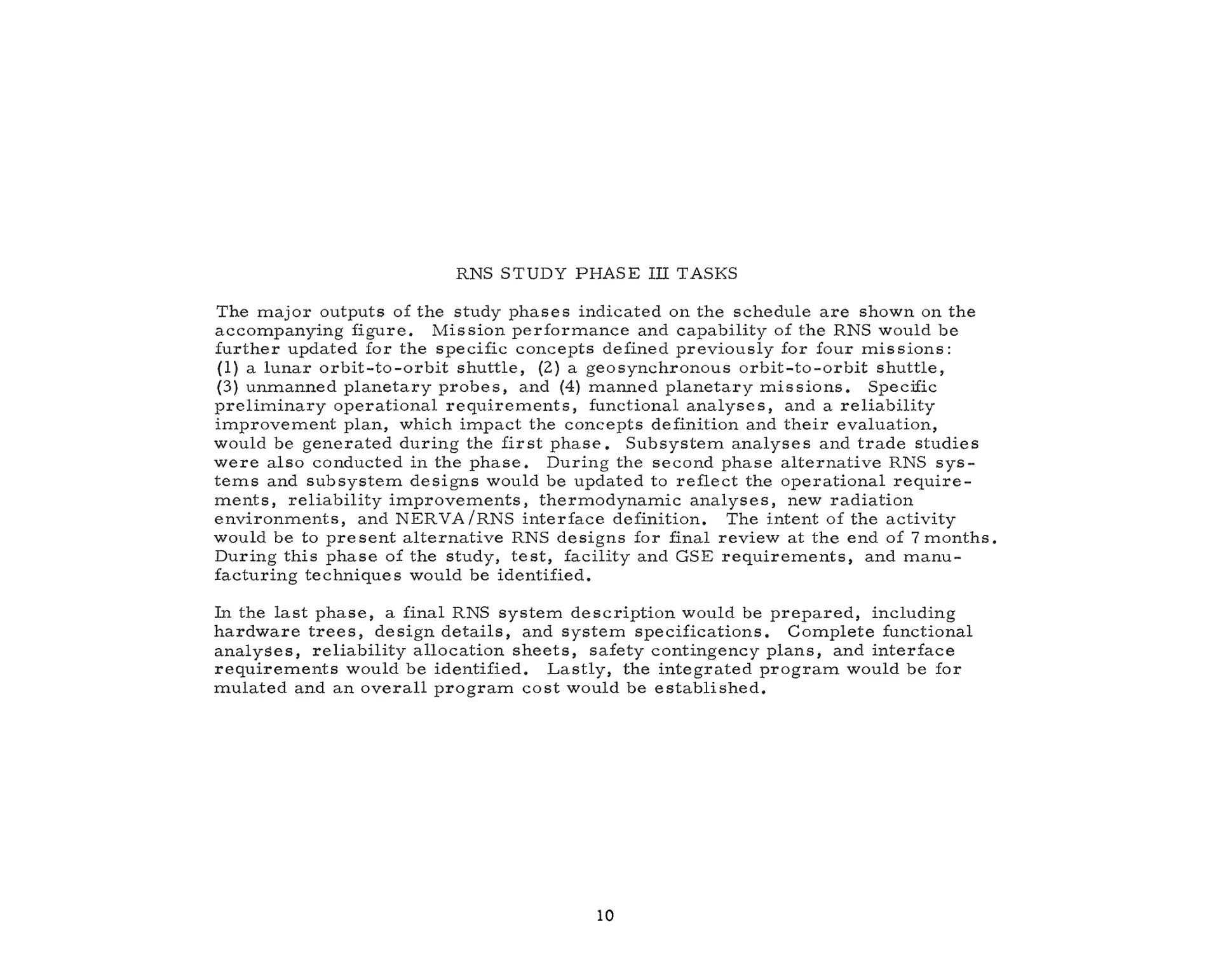
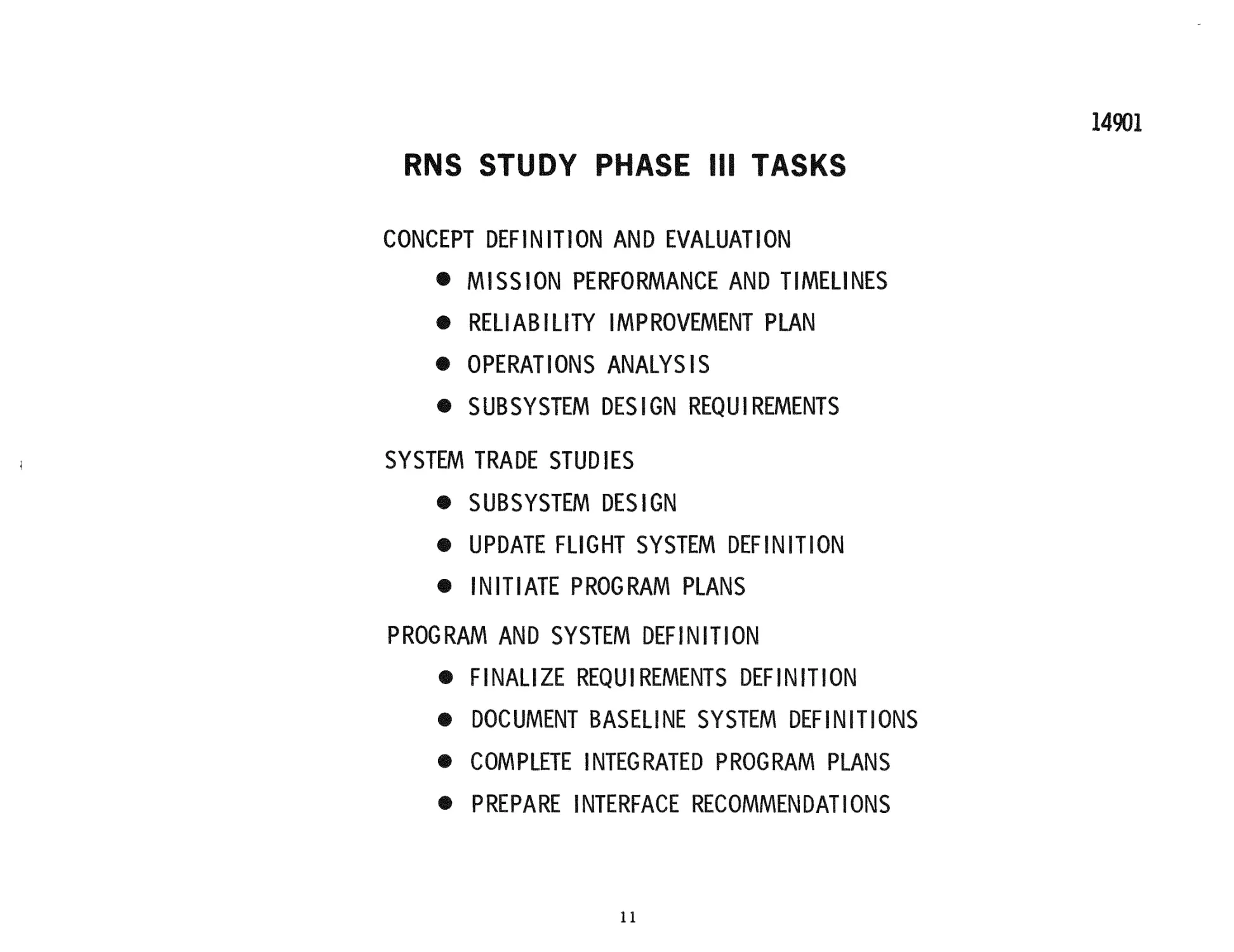
RNS STUDY PHASE IH TASKS
The major outputs of the study p h a s e s indicated on the schedule a r e shown on the
accompanying figure. Mission p e r f o r m a n c e and capability of the RNS would be
further updated for the specific concepts defined p r e v i o u s l y for four m i s s i o n s :
(1) a lunar o r b i t - t o - o r b i t shuttle, (2) a geosynchronous o r b i t - t o - o r b i t shuttle,
(3) unmanned p l a n e t a r y p r o b e s , and (4) manned p l a n e t a r y m i s s i o n s . Specific
p r e l i m i n a r y operational r e q u i r e m e n t s , functional a n a l y s e s , and a r e l i a b i l i t y
i m p r o v e m e n t plan, which impact the concepts definition and t h e i r evaluation,
would be generated during the first p h a s e . Subsystem a n a l y s e s and t r a d e studies
w e r e also conducted in the p h a s e . During the second phase a l t e r n a t i v e RNS s y s t e m s and s u b s y s t e m designs would be updated to reflect the operational r e q u i r e m e n t s , reliability i m p r o v e m e n t s , t h e r m o d y n a m i c a n a l y s e s , new radiation
e n v i r o n m e n t s , and N E R V A / R N S interface definition. The intent of the activity
would be to p r e s e n t a l t e r n a t i v e RNS designs for final review at the end of 7 m o n t h s .
During this phase of the study, t e s t , facility and GSE r e q u i r e m e n t s , and m a n u facturing techniques would be identified.
In the last p h a s e , a final RNS s y s t e m d e s c r i p t i o n would be p r e p a r e d , including
h a r d w a r e t r e e s , design d e t a i l s , and s y s t e m specifications. Complete functional
a n a l y s e s , r e l i a b i l i t y allocation s h e e t s , safety contingency p l a n s , and interface
r e q u i r e m e n t s would be identified. L a s t l y , the integrated p r o g r a m would be for
mulated and an o v e r a l l p r o g r a m cost would be e s t a b l i s h e d .
10
RNS STUDY PHASE III TASKS
CONCEPT DEFINITION AND EVALUATION
® MISSION PERFORMANCE AND TIMELINES
® RELIABILITY IMPROVEMENT PLAN
® OPERATIONS ANALYSIS
® SUBSYSTEM DESIGN REQUIREMENTS
SYSTEM TRADE STUDIES
® SUBSYSTEM DESIGN
® UPDATE FLIGHT SYSTEM DEFINITION
® INITIATE PROGRAM PLANS
PROGRAM AND SYSTEM DEFINITION
® FINALIZE REQUIREMENTS DEFINITION
® DOCUMENT BASELINE SYSTEM DEFINITIONS
® COMPLETE INTEGRATED PROGRAM PLANS
® PREPARE INTERFACE RECOMMENDATIONS
11
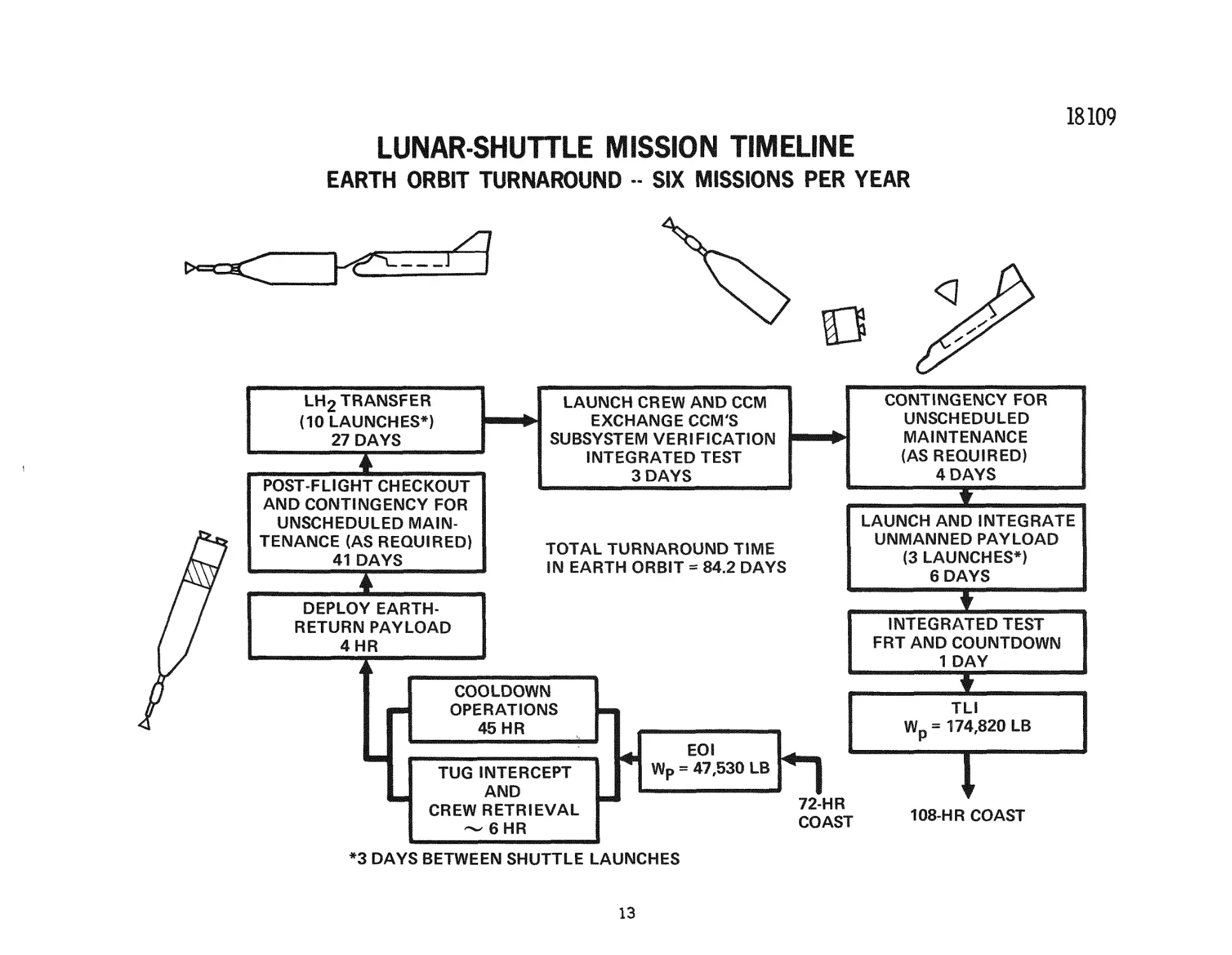
LUNAR SHUTTLE MISSION TIMELINE-EARTH ORBIT TURNAROUND
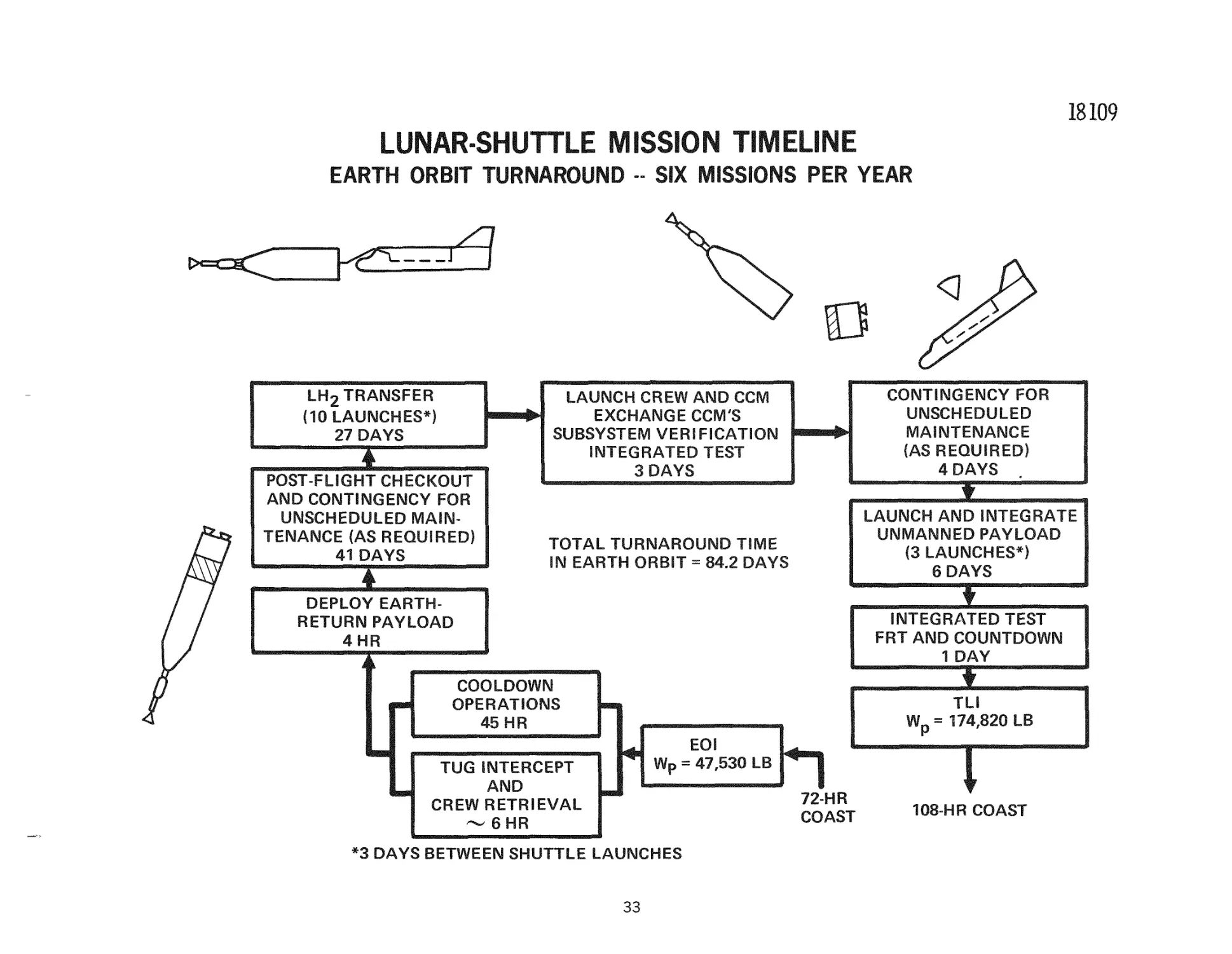
The accompanying i l l u s t r a t i o n identifies m a j o r activities o c c u r r i n g bet'ween
orbit i n s e r t i o n (EOI) following a lunar shuttle m i s s i o n and subsequent d e p a r t u r e
on another m i s s i o n . The total time available for e a r t h orbit turnaround of
84. 2 days c o r r e s p o n d s to a m i s s i o n model with a s i x - m i s s i o n s - a - y e a r
frequency. F o r this m i s s i o n model, two RNS s y s t e m s a l t e r n a t e l y p e r f o r m
lunar shuttle m i s s i o n s at a combined rate of once each 54. 6 days (every two
lunar cycles). Since the m i s s i o n s a r e p e r f o r m e d a l t e r n a t e l y by the two RNS's,
84. 2 days a r e spent in e a r t h orbit by each RNS between m i s s i o n applications.
In o r d e r to m i n i m i z e , if not eliminate, the r e q u i r e m e n t to p e r f o r m recycling
operations simultaneously on the two RNS's, only a portion of this time is
allocated for the p e r f o r m a n c e of the m a j o r operations of propellant refueling
and m i s s i o n payload launch and integration. A space shuttle launch rate of one
each t h r e e days is r e q u i r e d to fulfill this objective. Specific a r e a s investigated
included launch and prelaunch operations, lunar shuttle phasing cycles,
utilization schedules, logistic t u r n around cycles, and p e r f o r m a n c e impact
of after cooling and APS impulse r e q u i r e m e n t s . Time in the s u m m a r y
p e r m i t s only a revievA on the next chart of the p e r f o r m a n c e impact of the
t r a n s lunar after cooling. The figure indicates the combined launch of the
new command and control module and m i s s i o n cre'w. This approach is taken to
m a x i m i z e the use of the space shuttle payload capability. Should future i n v e s t i gations indicate this approach untenable because of the extended crew time
r e q u i r e d in each orbit (an additional 14 days of on-orbit time), the crew could
be launched s e p a r a t e l y , following launch and integration of the unmanned payload, at the expense of an added space shuttle launch.
12
18109
LUNAR-SHUTTLE MISSION TIMELINE
EARTH ORBIT TURNAROUND - SIX MISSIONS PER YEAR
V^ - 2 ^
13
LH2 TRANSFER
(10 LAUNCHES*)
27 DAYS
POST-FLIGHT CHECKOUT
AND CONTINGENCY FOR
UNSCHEDULED MAINTENANCE (AS REQUIRED)
41 DAYS
CONTINGENCY FOR
UNSCHEDULED
MAINTENANCE
(AS REQUIRED)
4 DAYS
LAUNCH CREW AND CCM
EXCHANGE CCM'S
SUBSYSTEM VERIFICATION
INTEGRATED TEST
3 DAYS
—~~¥—^
"
LAUNCH AND INTEGRATE
UNMANNED PAYLOAD
(3 LAUNCHES*)
6 DAYS
TOTAL TURNAROUND TIME
IN EARTH ORBIT = 84.2 DAYS
DEPLOY EARTHRETURN PAYLOAD
4HR
INTEGRATED TEST
FRT AND COUNTDOWN
1 DAY
COOLDOWN
OPERATIONS
45 HR
EOI
Ws = 47,530 LB
TUG INTERCEPT
AND
CREW RETRIEVAL
--6HR
h
72-HR
COAST
*3 DAYS BETWEEN SHUTTLE LAUNCHES
13
w.
TLI
174.820 LB
T
108-HR COAST
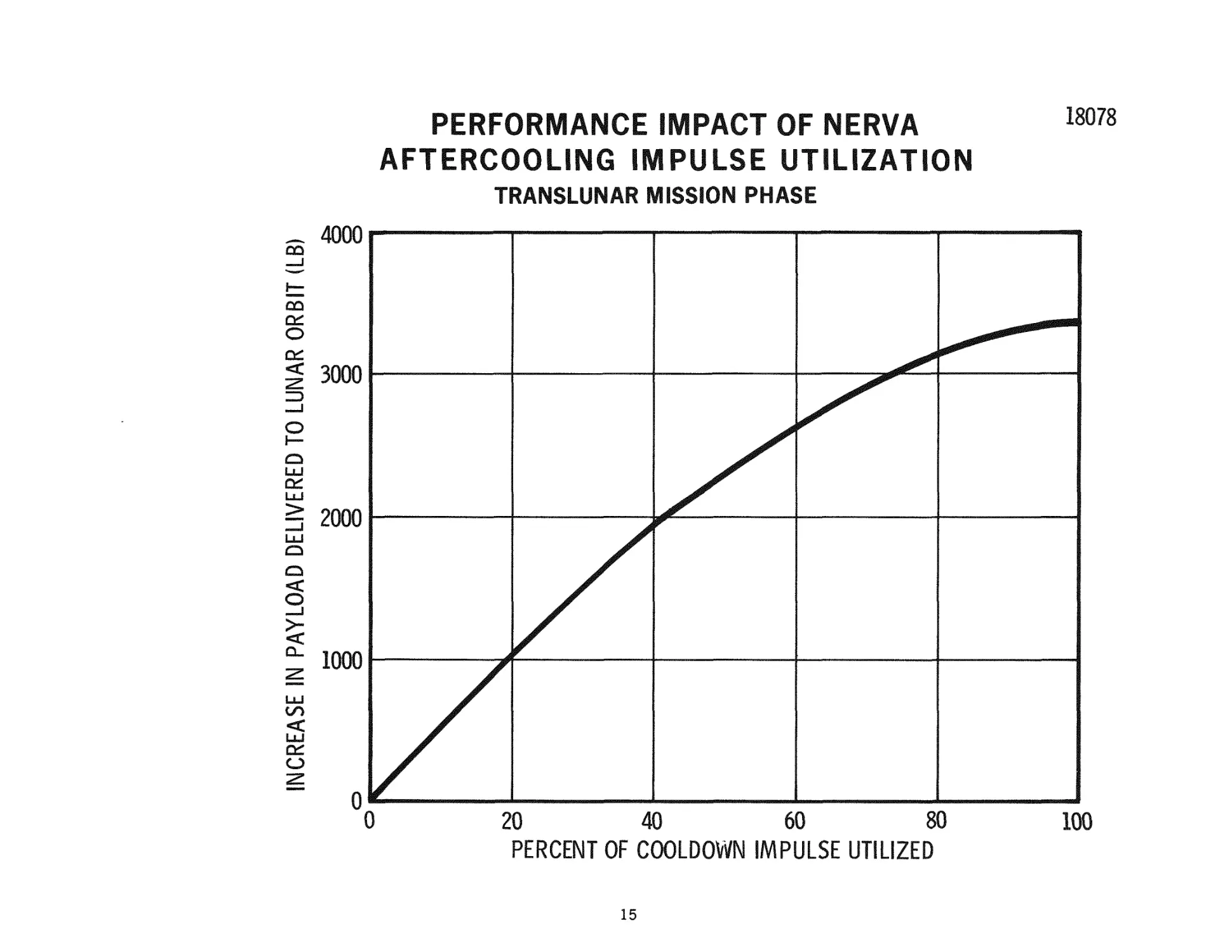
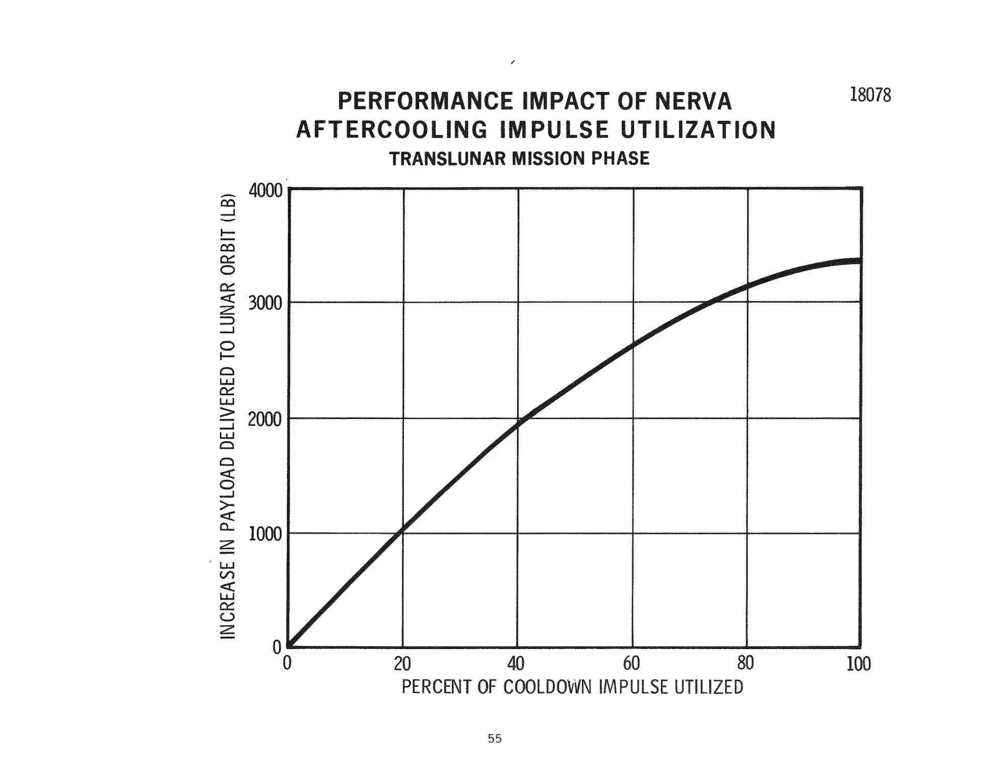
P E R F O R M A N C E I M P A C T - T R A N S L U N A R COOLDOWN U T I L I Z A T I O N
E s t i m a t e s m a d e to d a t e of t h e b a s e l i n e RNS p e r f o r m a n c e for t h e l u n a r s h u t t l e
m i s s i o n h a v e not c r e d i t e d i m p u l s e d e r i v e d d u r i n g t h e N E R V A c o o l d o w n p h a s e
t o w a r d t h e a c c o m p l i s h m e n t of m i s s i o n v e l o c i t y m a n e u v e r s . T h u s , in effect, p r o p e l l a n t c o n s u m e d f o r t h e N E R V A c o o l d o w n function w a s t r e a t e d a s a n o n p r o p u l s i v e ,
u n u s a b l e p r o p e l l a n t . T h e p e r f o r m a n c e i m p l i c a t i o n s of t h i s a s s u m i p t i o n h a v e b e e n
e v a l u a t e d u s i n g a t w o - b o d y p a t c h e d c o n i c s o l u t i o n for t h e b a s e l i n e 1 0 8 - h o u r t r a n s l u n a r m i s s i o n l e g . T h e r e f e r e n c e c o n d i t i o n ( z e r o c o o l d o w n u s e d for i m p u l s e ) w a s
a p a y l o a d d e l i v e r y c a p a b i l i t y to l u n a r o r b i t of 112,000 lb (20, 000 lb c r e w m o d u l e on
the r e t u r n l e g ) , b a s e d on a N E R V A s t e a d y - s t a t e r u n t i m e of 1, 800 s e c o n d s . T h e
c o o l d o w n i m p u l s e p r o f i l e w a s m o d e l e d p e r A e r o j e t R e p o r t S-1 3 0 - B P - 0 9 0 2 9 0 - F L P R E L , " N E R V A R e f e r e n c e Data—Full F l o w E n g i n e , " d a t e d A p r i l 1970. T h e d u r a tion of the c o o l d o w n p h a s e in t h i s c a s e is a c t u a l l y s o m e w h a t in e x c e s s of t h e
1 0 8 - h r t r a n s f e r t i m e b e t w e e n t h e e a r t h and t h e m o o n . T h e t o t a l i m p u l s e c o n t r i b u t e d d u r i n g t h e c o o l d o w n p h a s e f o r t h i s p a r t i c u l a r e n g i n e r u n t i m e w o u l d be 3. 3
X 1 0 " l b - s e c , o r an e q u i v a l e n t c h a r a c t e r i s t i c v e l o c i t y of 320 f t / s e c . T o t a l u s e of
t h e cooldo'wn i m p u l s e for t h e t r a n s l u n a r v e l o c i t y r e q u i r e m e n t r e s u l t s in a n
e q u i v a l e n t r e d u c t i o n in t h e f u l l - t h r u s t v e l o c i t y r e q u i r e m e n t of a p p r o x i m a t e l y
130 f t / s e c , r e s u l t i n g in a p e r f o r m a n c e i m p r o v e m e n t of a p p r o x i m a t e l y 3, 400 l b .
T h i s 3, 4 0 0 - l b p e r f o r m a n c e i m p r o v e m e n t w o u l d be i n c r e a s e d f u r t h e r by an a d d i t i o n a l 1 1 , 0 0 0 l b p e r f o r m a n c e g a i n if the r e q u i r e m e n t f o r e n g i n e c o o l d o w n could be
c o m p l e t e l y elimiinated. T h a t i s , t h e 7, 600 lb of p r o p e l l a n t p r e s e n t l y a l l o c a t e d for
c o o l d o w n c o u l d b e r e a s s i g n e d for u s e d u r i n g f u l l - t h r u s t o p e r a t i o n s . T h i s p o t e n t i a l
p e r f o r m a n c e i m p r o v e m e n t ( 1 1 , 000 lb) w o u l d h a v e to be p l a y e d a g a i n s t a n y s y s t e m
w e i g h t i n c r e a s e s r e q u i r e d to effect cooldown e l i m i n a t i o n (for e x a m p l e r a d i a t o r
s y s t e m s ) . T h e p e r f o r m a n c e imipact of i n c r e a s e s in RNS s y s t e m i n e r t w e i g h t is
2. 7 lb l o s t in o r b i t a l p a y l o a d p e r p o u n d i n c r e a s e in i n e r t w e i g h t , o r a p p r o x i m a t e l y
a 4, 000 lb i n e r t w e i g h t i n c r e a s e a s t h e b r e a k - e v e n p o i n t .
14
PERFORIVIANCE IfVIPACT OF NERVA
AFTERCOOLING IfViPULSE UTILIZATION
18078
i
S
8
^
S
INCREASE IN PAYLOAD DELIVERED TO LUNAR ORBIT (LB)
TRANSLUNAR WIISSfON PHASE
d
/
/
0
20
40
60
80
PERCENT OF COOLDOWN IMPULSE UTILIZED
15
100
RNS DESIGN
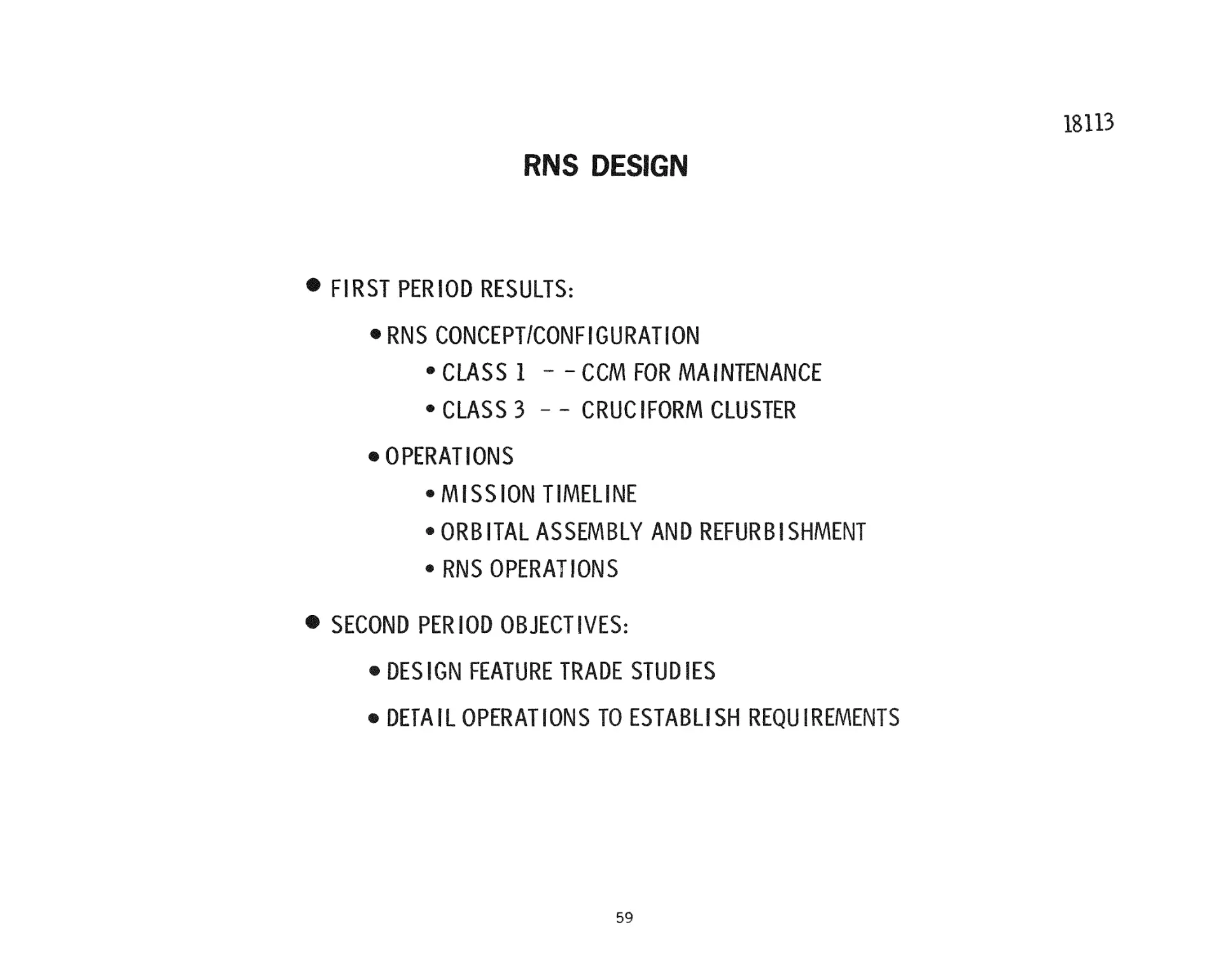
The context for the c u r r e n t phase of the RNS design activity is given on the facing
chart. P h a s e II r e s u l t e d in definition of the two basic RNS concepts—the singlemodule, 3 3 - f t - d i a m e t e r C l a s s 1 concept and the multiple-module C l a s s 3
configuration. The first period of P h a s e 3 focused on selection of m a j o r
c h a r a c t e r i s t i c s for each concept and the o v e r a l l configuration of the v e h i c l e s .
The m o s t significant selection during this period was that of a d i s c r e t e command
and control module for the C l a s s 1 concept to m o s t effectively a c c o m p l i s h orbital
m a i n t e n a n c e . Another m a j o r r e s u l t of the first period analysis was the selection
of the C l a s s 3 vehicle configuration with the modules in the form of a c r u c i f o r m
c l u s t e r . Operations w e r e analyzed in support of making the above concept/
configuration selections as well as to provide the b a s e s for m o r e detailed
definition of the RNS itself.
During the second period m a j o r design activities -were oriented tow^ard t r a d e
studies selecting specific s u b s y s t e m design f e a t u r e s . To accomiplish t h e s e t r a d e
studies, detailed operations analysis, using the s c e n a r i o s developed during the
first period, w e r e p e r f o r m e d to establish s u b s y s t e m r e q u i r e m e n t s .
Subsequent c h a r t s will show the operations analysis and s u b s y s t e m definition
for the RNS functional s u b s y s t e m s . This section will conclude with a s u m m a r y
of the inajor features selected during this period and with the c u r r e n t weight
statement for both RNS concepts which a r e s u m m a r i z e d on the next t'wo c h a r t s .
16
RNS DESIGN
® FIRST PERIOD RESULTS:
«RNS CONCEPT/CONFIGURATION
• CLASS 1 - - CCM FOR MAINTENANCE
« CLASS 3 - - CRUCIFORM CLUSTER
® OPERATIONS
« MISSION TIMELINE
® ORB ITAL ASSEMBLY AND REFURB I SHMENT
« RNS OPERATIONS
® SECOND PERIOD OBJECTIVES:
® DESIGN FEATURE TRADE STUDIES
® DETAIL OPERATIONS TO ESTABLISH REQUIREMENTS
17
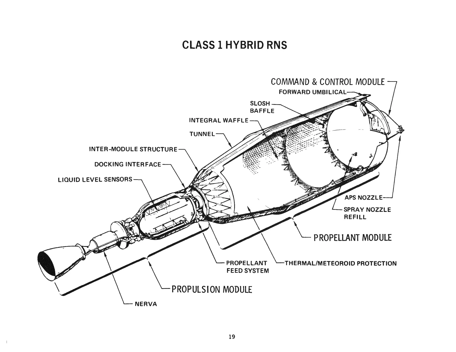
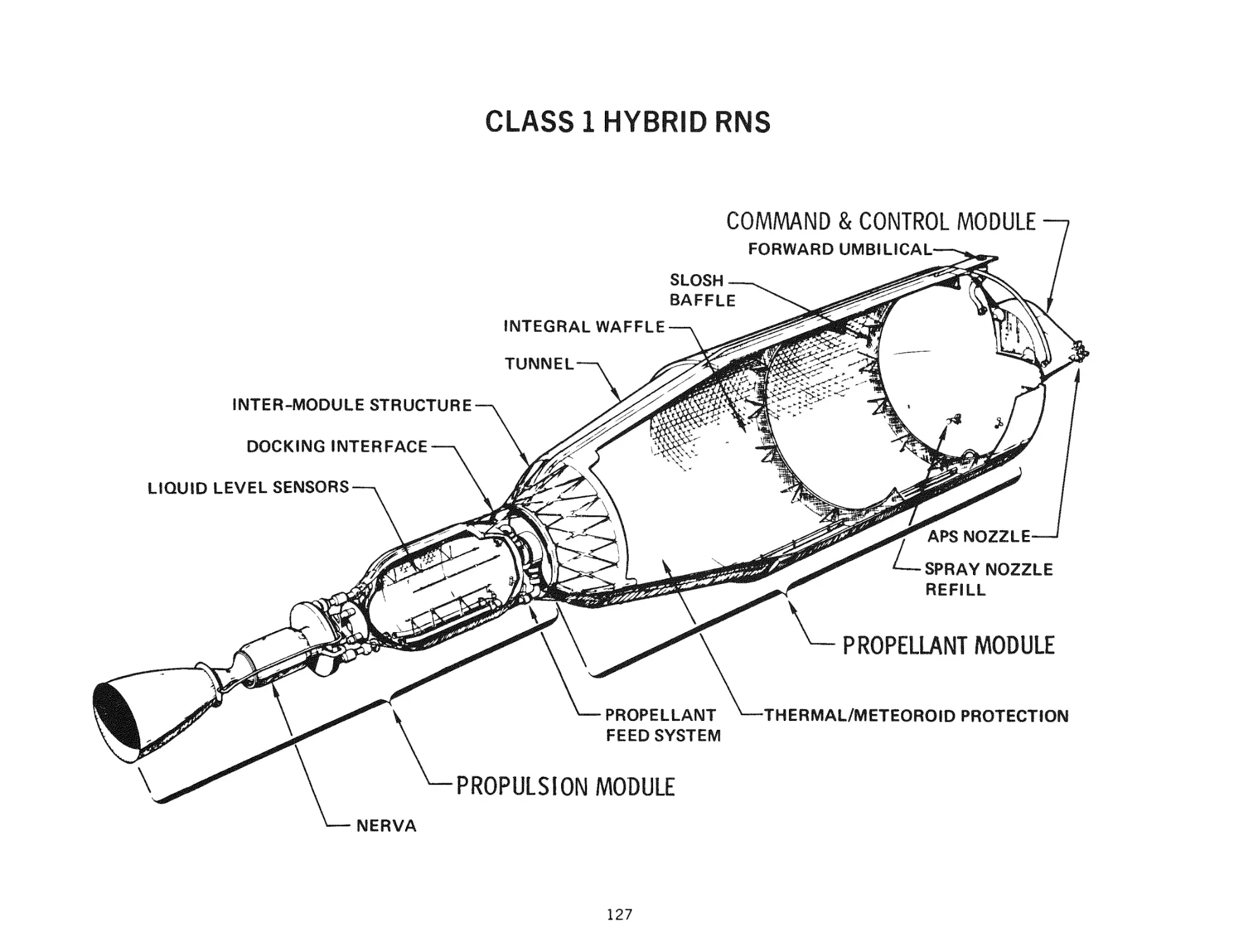
R N S C L A S S 1 HYBRID
A s k e t c h of the C l a s s 1 H y b r i d RNS c o n f i g u r a t i o n i s s h o w n on t h e f a c i n g c h a r t . It
i l l u s t r a t e s t h e c u r r e n t c o n f i g u r a t i o n and p r o v i d e s a l o c a t o r for t h e s p e c i f i c
f e a t u r e s s e l e c t e d d u r i n g t h e s e c o n d p e r i o d of t h e s t u d y w h i c h w i l l be d i s c u s s e d on
subsequent c h a r t s .
The t h r e e d i s t i n c t m o d u l e s a r e v i s i b l e a s w e l l a s t h e i r c o n t a i n m i e n t w i t h i n t h e 1 0 d e g r e e half-angle cone m e a s u r e d from the NERVA engine which was selected
d u r i n g t h e P h a s e II s h i e l d o p t i m i z a t i o n . T h e o u t r i g g e r s c o n t a i n i n g t h e a u x i l i a r y
p r o p u l s i o n e n g i n e s on t h e c o m m a n d and c o n t r o l m o d u l e s a r e a l s o v i s i b l e on t h e
p i c t u r e . S p e c i f i c d e t a i l s a r e i d e n t i f i e d by t h e c a l l o u t s .
18
CLASS 1 HYBRID RNS
COMAAAND & CONTROL MODULE
FORWARD UMBILICALSLOSH
BAFFLE
INTEGRAL WAFFLE
TUNNEL
INTER-MODULE STRUCTURE
DOCKING INTERFACE
LIQUID LEVEL SENSORS
APS NOZZLESPRAY NOZZLE
REFILL
PROPELLANT MODULE
PROPELLANT
FEED SYSTEM
PROPULSION MODULE
NERVA
19
-THERMAL/METEOROID PROTECTION
RNS CLASS 3
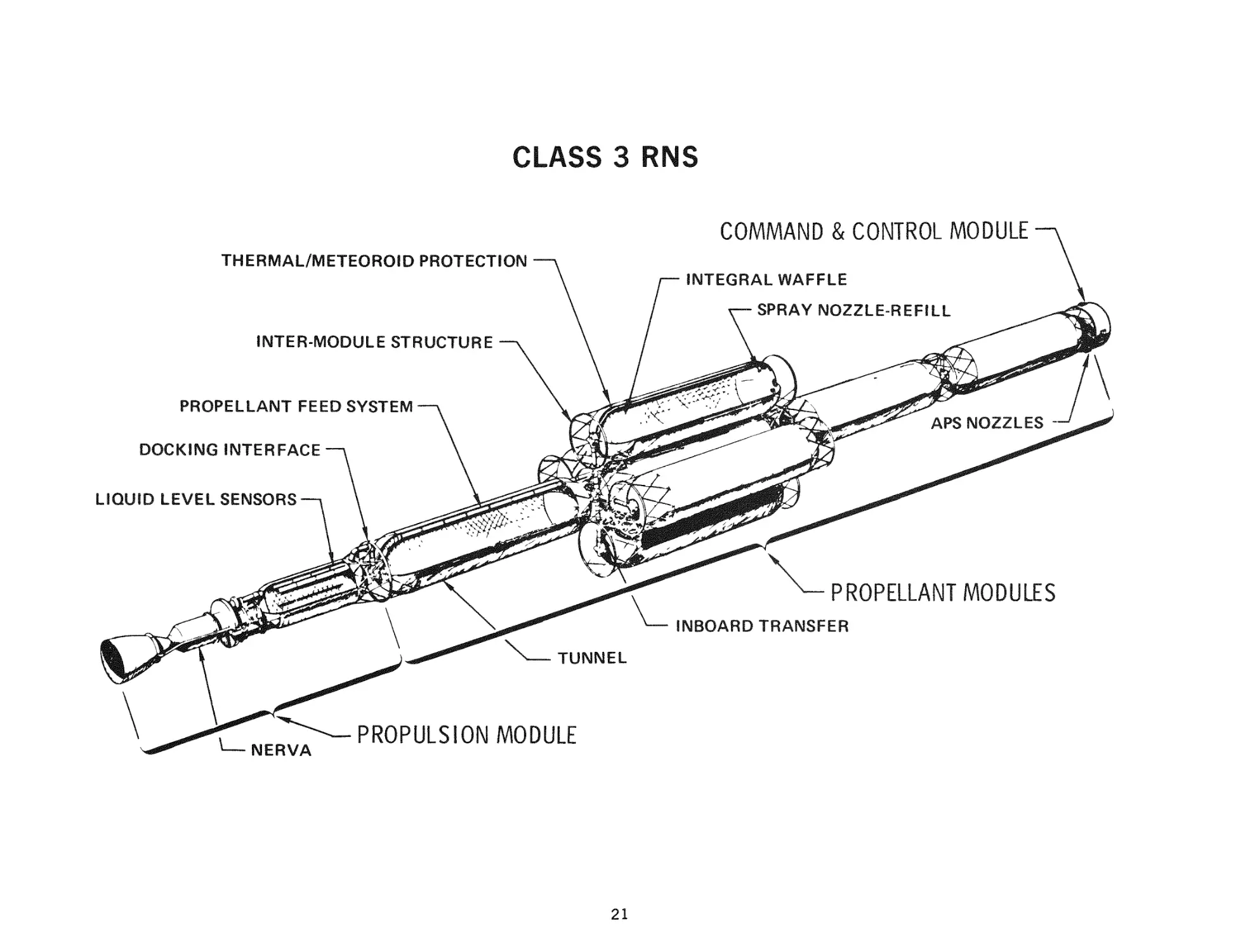
This c h a r t shows the c u r r e n t baseline configuration for the Class 3 RNS concept.
Clustering of outboard propellant modules into a c r u c i f o r m configuration at the
second propellant module level is i l l u s t r a t e d . Comparison with the previous
sketch shows how both RNS concepts have converged in t h e i r c h a r a c t e r i s t i c s by
definition of the functional m o d u l e s . It can be seen that the only basic difference
between the two concepts is the m a n n e r in which propellant is stored—within the
multiple miodules in this c a s e and in the single propellant module for the C l a s s 1
Hyb rid.
The main feed s y s t e m , providing communication from any propellant module to the
run tank on the propulsion module, is shown in this figure. Other details a r e
noted by the callouts. Again, this sketch should be used as a locator for the
discussion of the design features selected during this period.
20
CLASS 3 RNS
COMMAND & CONTROL MODULE
THERMAL/METEOROID PROTECTION
INTER-MODULE STRUCTURE
PROPELLANT FEED SYSTEM
DOCKING INTERFACE
LIQUID LEVEL SENSORS
PROPELLANT MODULES
INBOARD TRANSFER
NERVA
PROPULSION MODULE
21
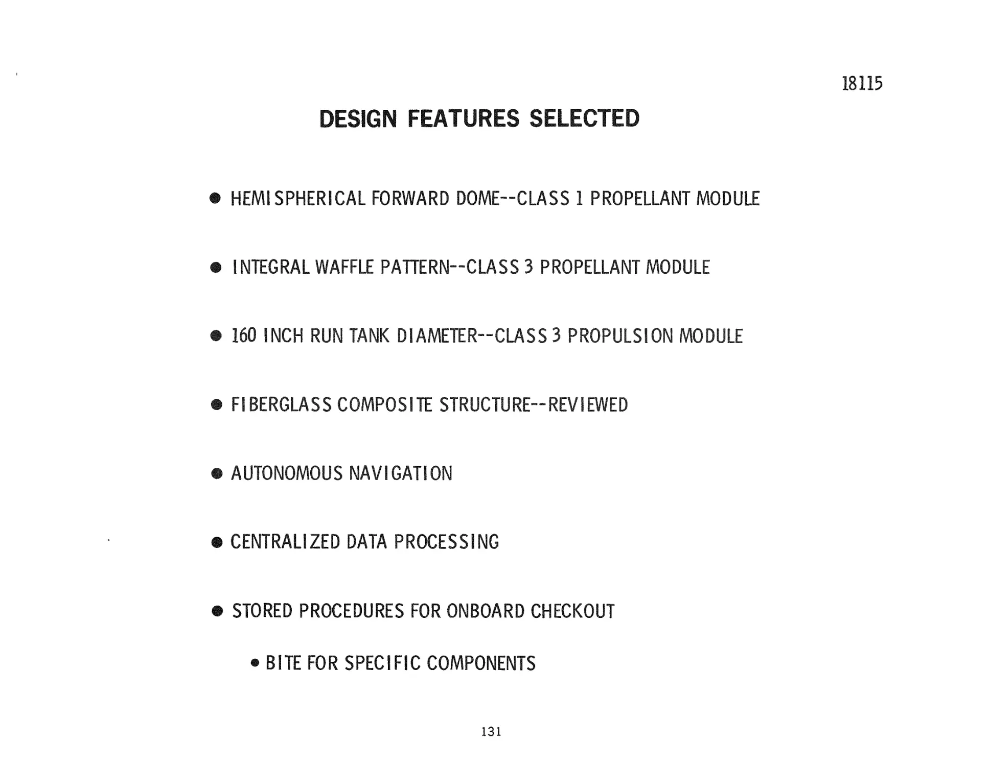
DESIGN FEATURES SELECTED
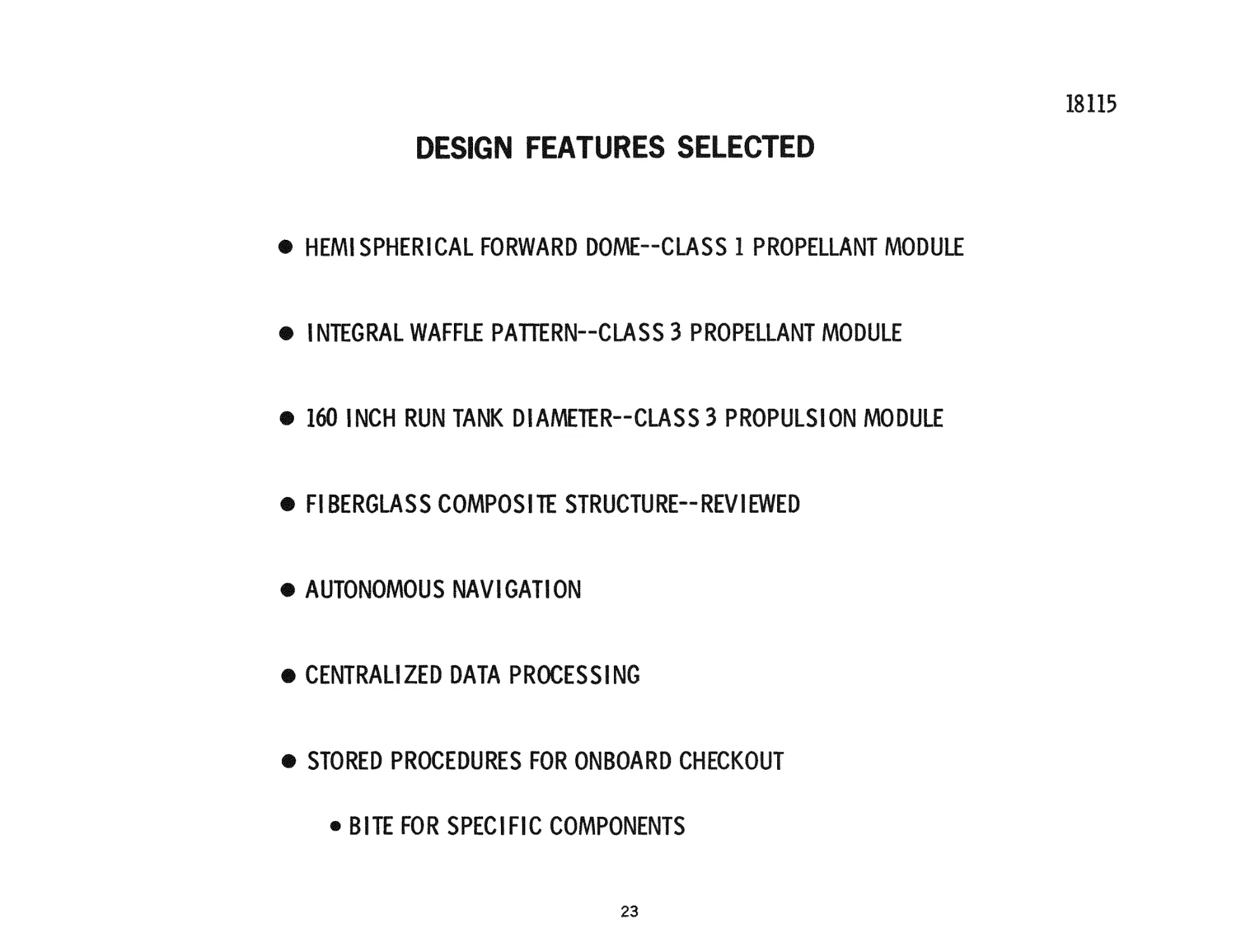
This and the next c h a r t s u m m a r i z e some of the major design f e a t u r e s which
w e r e selected during the second study period. It should be kept in mind that
many major design features w e r e selected in both the P h a s e 11 study and
during the f i r s t period of P h a s e III.
The forward dome shape for the C l a s s 1 propellant module was r e - e v a l u a t e d in
t e r m s of the c u r r e n t hybrid launch mode and m i s s i o n utilization. It was found
that approximately a 600-lb reduction in operational weight could be achieved with
only a 19-in. i n c r e a s e in the length of the module. An integral waffle p a t t e r n was
provided for all C l a s s 3 propellant modules to withstand launch loads. This
stiffening also allows t r a n s m i s s i o n of RNS operational modes through the inboard
modules to the payload without p r e s s u r e in the propellant miodule t a n k s .
Optimization of the run tank d i a m e t e r for the C l a s s 3 propulsion module yielded a
l 6 0 - i n . value. This included consideration of shielding optiinization, s t r u c t u r a l
a n a l y s i s , and o p e r a t i o n s . No biological shielding is r e q u i r e d with this configuration. The fiber glass composite s t r u c t u r e which was selected during P h a s e II for
the t h r u s t s t r u c t u r e s and intermodule s t r u c t u r e s was reviewed during this period.
Utilizing c u r r e n t values for insulation p e r f o r m a n c e and s t r u c t u r a l weight
sensitivity to stage p r e s s u r e r e i n f o r c e s the selection of fiber glass which was
made during P h a s e II.
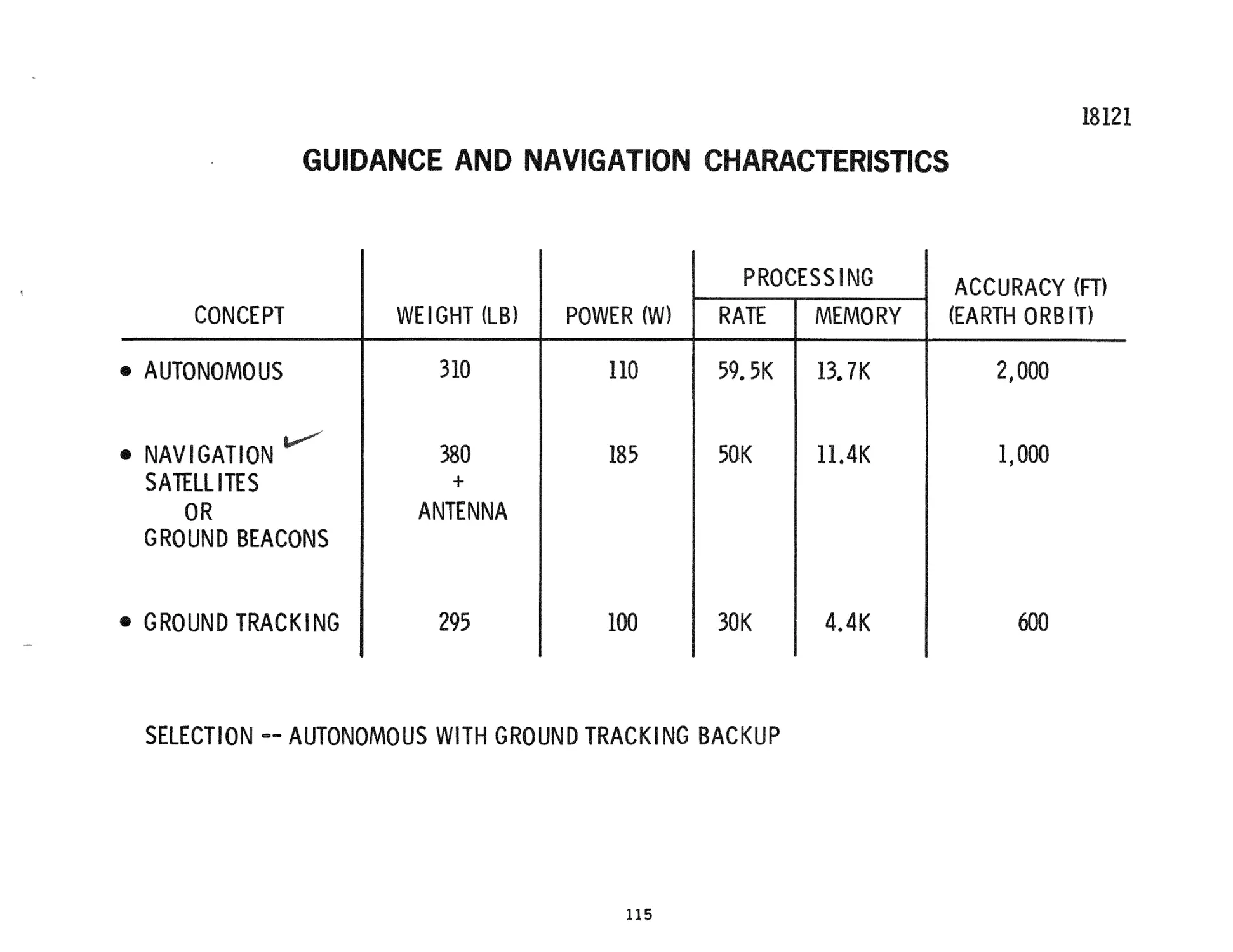
As d e s c r i b e d e a r l i e r in the p r e s e n t a t i o n , an autonomous navigation systemi was
selected with the provision of utilizing ground tracking for backup. It w a s also
shown that data p r o c e s s i n g r e q u i r e m e n t s a r e c o n s i s t e n t with the c e n t r a l i z e d
computer and that this approach could make m o s t effective u s e of equipment for
r e d u n d a n c i e s . Also as shown e a r l i e r s t o r e d p r o c e d u r e s a r e utilized for checkout
with BITE employed for specific components.
22
18115
DESIGN FEATURES SELECTED
® HEMISPHERICAL FORWARD DOME-CLASS 1 PROPELLANT MODULE
® INTEGRAL WAFFLE PAWERN-CLASS 3 PROPELLANT MODULE
® 160 INCH RUN TANK DIAMETER-CLASS 3 PROPULSION MODULE
® FIBERGLASS COMPOSITE STRUCTURE-REVIEWED
® AUTONOMOUS NAVIGATION
® CENTRALIZED DATA PROCESSING
® STORED PROCEDURES FOR ONBOARD CHECKOUT
® BITE FOR SPECIFIC COMPONENTS
23
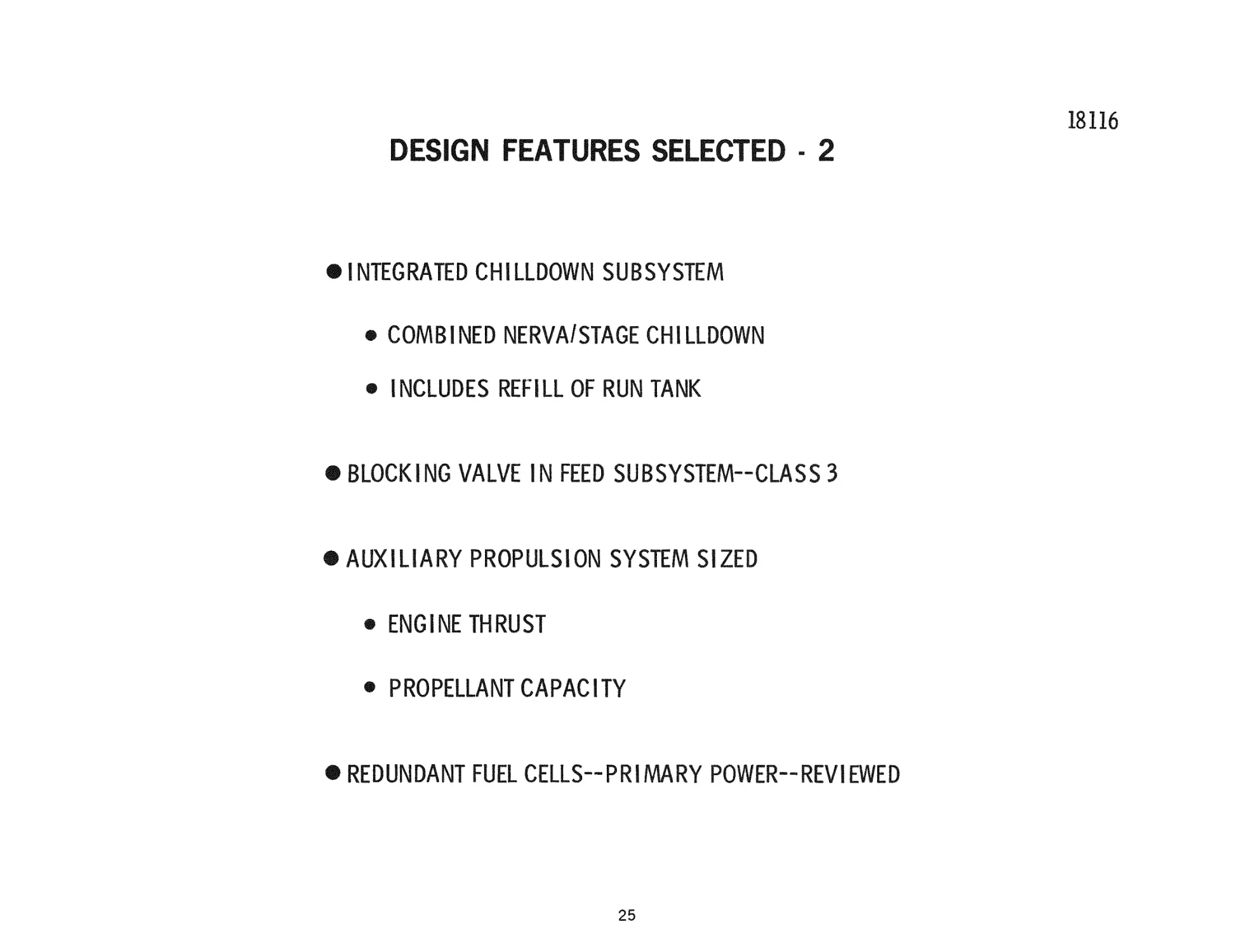
DESIGN FEATURES SELECTED ~ 2
Additional c h a r a c t e r i s t i c s for RNS s u b s y s t e m s which w e r e selected during the
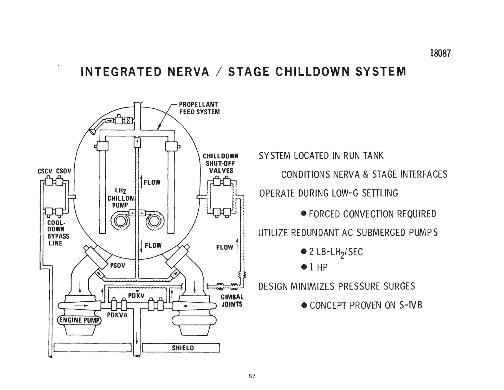
second period a r e shown on the facing c h a r t . The integrated chilldown s u b s y s t e m
which combines the NERVA and stage chilldown operations as well as including the
operations a s s o c i a t e d with refill or the run tank following depletion was d e s c r i b e d
e a r l i e r . Additionally, a blocking valve was added in the C l a s s 3 feed s y s t e m s
connecting the v a r i o u s propellant module tanks into the run tank. This enhances
feed systemi integrity as well as eliminating e x c e s s i v e liquid r e s i d u a l s following
shutdown and e x c e s s i v e t h e r m a l l e a k s .
The auxiliary propulsion s y s t e m was sized for both concepts. A engine t h r u s t -was
selected based upon performing requisite m a n e u v e r s , attitude control, and
propellant settling. Total propellant capacity was e s t a b l i s h e d for the baseline
lunar shuttle m i s s i o n .
The p r i m a r y power s o u r c e t r a d e study p e r f o r m e d during P h a s e II was reviewed in
t e r m s of c u r r e n t power r e q u i r e m e n t s . The final selection was made between fuel
cells and s o l a r cells utilizing s t a t e - o f - t h e - a r t projections for fuel cells which a r e
being employed in the space shuttle, and for s o l a r cells which a r e to be employed
in advanced space p r o g r a m s beyond Skylab, The evaluation favored fuel cells for
the RNS. Redundant fuel cells a r e provided for r e l i a b i l i t y .
24
DESIGN FEATURES SELECTED - 2
# INTEGRATED CHILLDOWN SUBSYSTEM
® COMBINED NERVA/STAGE CHILLDOWN
® INCLUDES REFILL OF RUN TANK
# BLOCKING VALVE IN FEED SUBSYSTEM-CLASS 3
# AUXILIARY PROPULSION SYSTEM SIZED
® ENGINE THRUST
® PROPELLANT CAPACITY
# REDUNDANT FUEL CELLS-PRIMARY POWER-REVIEWED
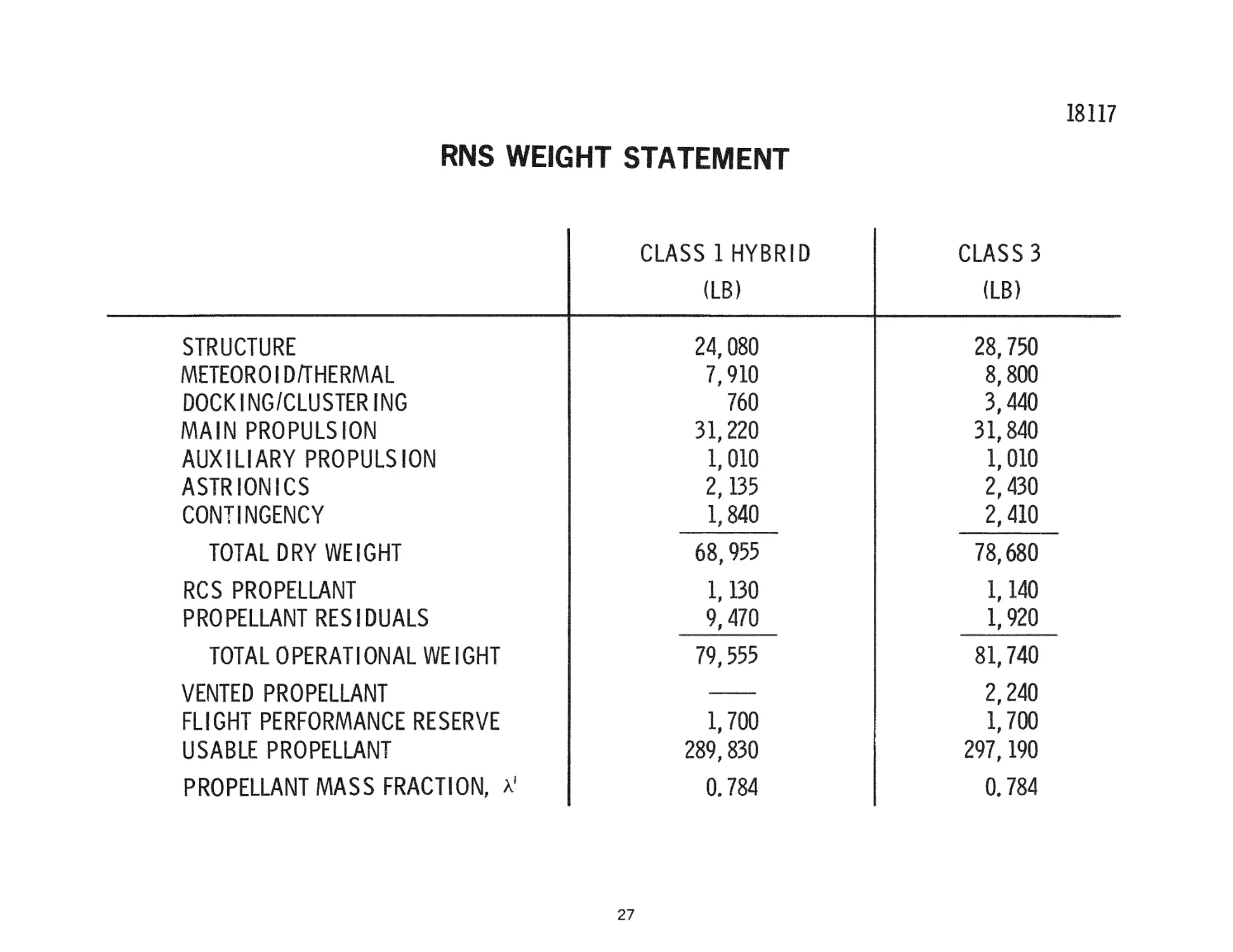
RNS WEIGHT STATEMENT
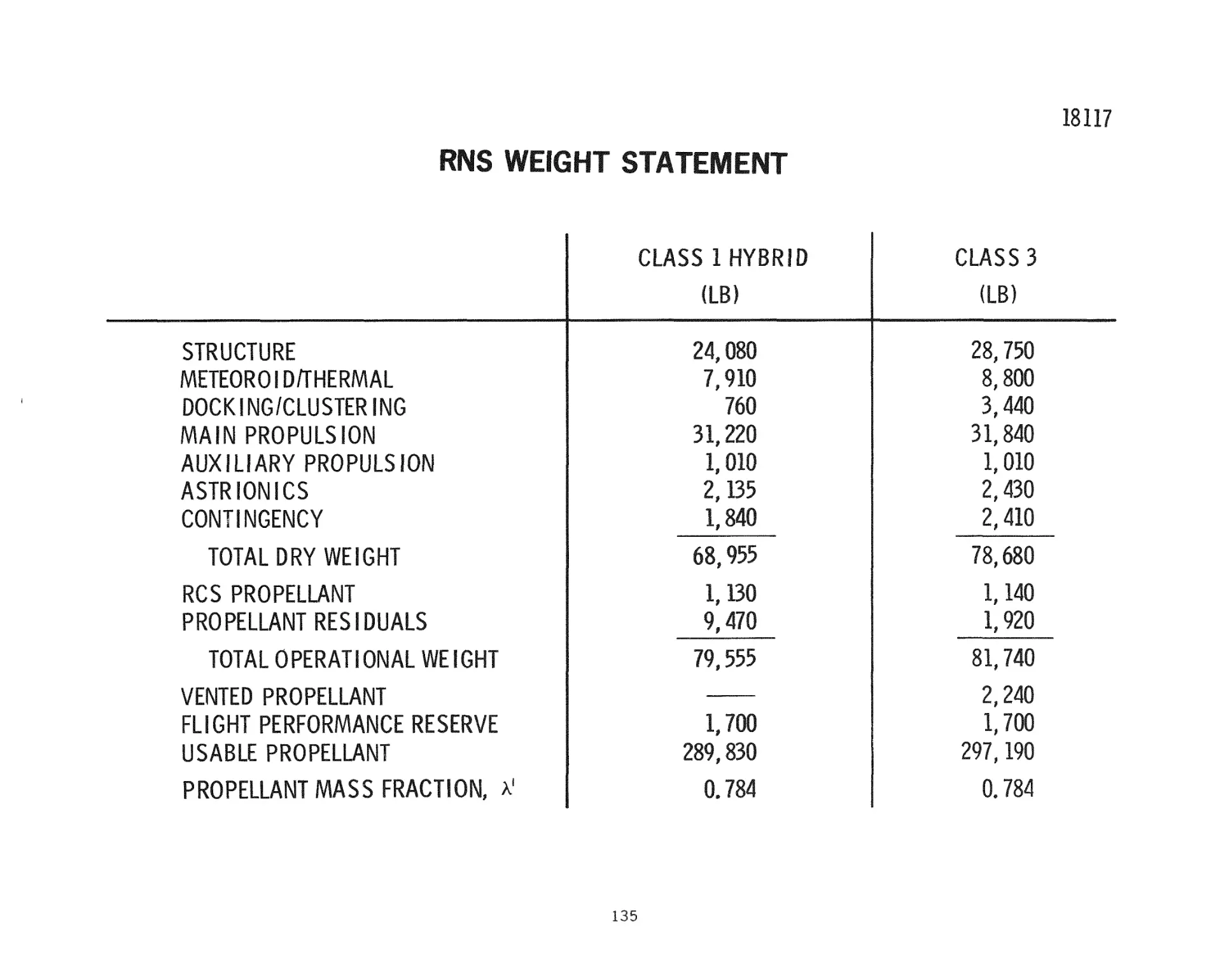
The accompanying c h a r t contains c u r r e n t weight s t a t e m e n t s for both RNS concepts.
F o r n e a r l y identical propellant capacities it can be seen that both the s t r u c t u r e ,
m e t e r o i d / t h e r m a l , and docking/clustering e n t r i e s penalize the multiple-module
C l a s s 3 concept. The main propulsion e n t r y contains a 2 , 8 0 0 - l b biological shield
for the C l a s s 1 Hybrid concept which a l m o s t offsets the g r e a t e r plumbing and
component weights for the C l a s s 3 concept. The l a s t t h r e e e n t r i e s under the dry
weight a r e n e a r l y the same for both concepts, A net d r y weight advantage of
n e a r l y 10, 000 lb a c c r u e s to the C l a s s 1 concept.
It can be seen that the RCS propellant is n e a r l y identical for both concepts, but that
the r e s i d u a l s of propellant contained in the stage at burnout a r e about 75, 000 lb
h e a v i e r for the C l a s s 1 concept than for C l a s s 3, This r e s u l t s in a net difference in
operational weight of only about 2, 000 lb favoring C l a s s 1. These g r e a t e r
r e s i d u a l s for the C l a s s 1 concept diminish the usable propellant so that the
propellant m a s s fraction, \ ' , given as the l a s t e n t r y is identical for both
configurations.
26
18117
RNS WEIGHT STATEMENT
CLASS 1 HYBRID
CLASS 3
(LB)
(LB)
STRUCTURE
METEOROIDA'HERMAL
DOCKING/CLUSTER NG
MAIN PROPULSION
AUX LIARY PROPULSION
ASTRIONICS
CONTINGENCY
24,080
7,910
760
31,220
1,010
2,135
1,840
28,750
8,800
3,440
31,840
1,010
2,430
2,410
TOTAL DRY WEIGHT
68,955
78,680
1,130
9,470
1,140
1,920
79,555
81,740
1,700
289,830
2,240
1,700
297,190
0.784
0.784
RCS PROPELLANT
PROPELLANT RESIDUALS
TOTAL OPERATIONAL WEIGHT
VENTED PROPELLANT
FLIGHT PERFORMANCE RESERVE
USABLE PROPELLANT
PROPELLANT MASS FRACTION, A'
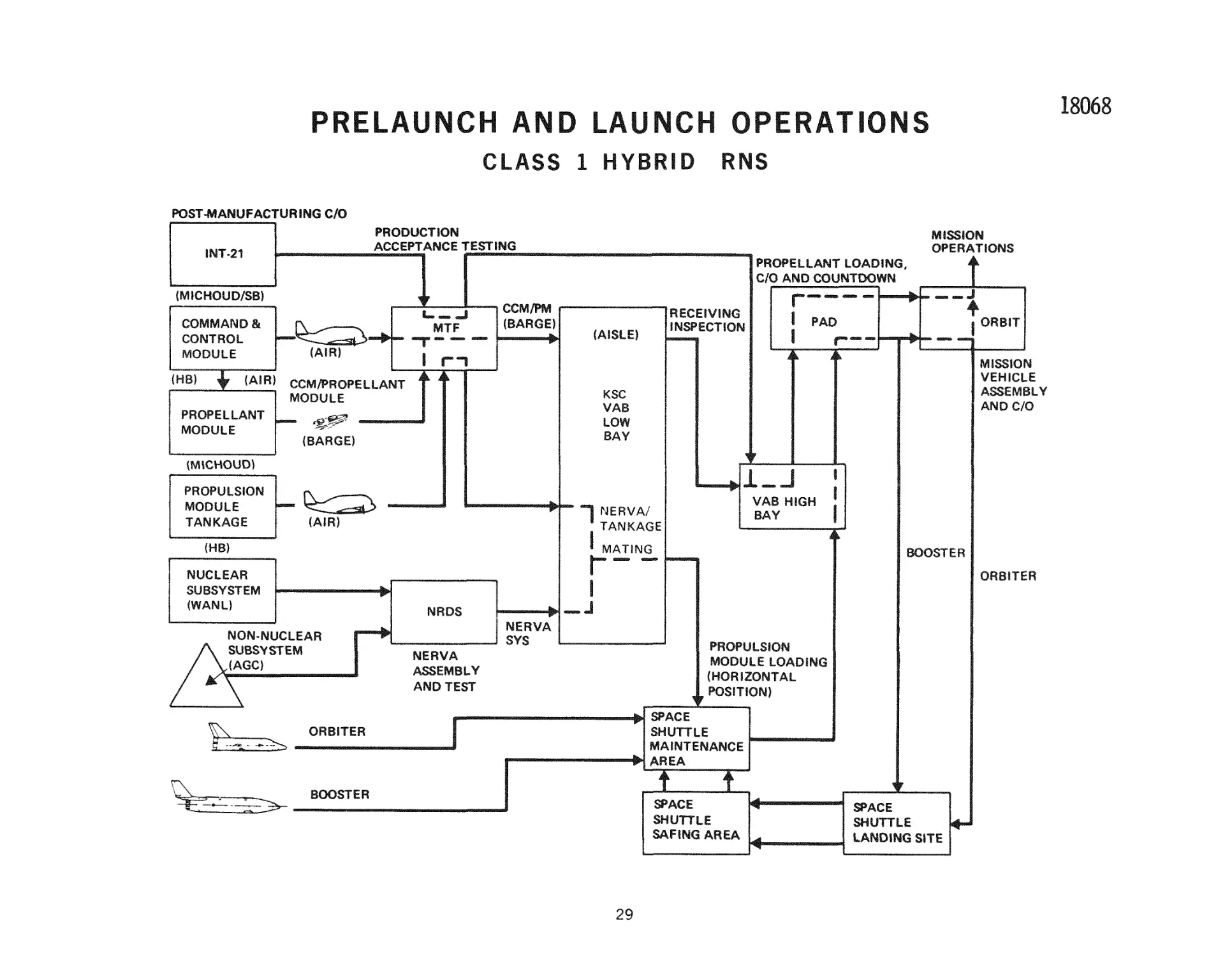
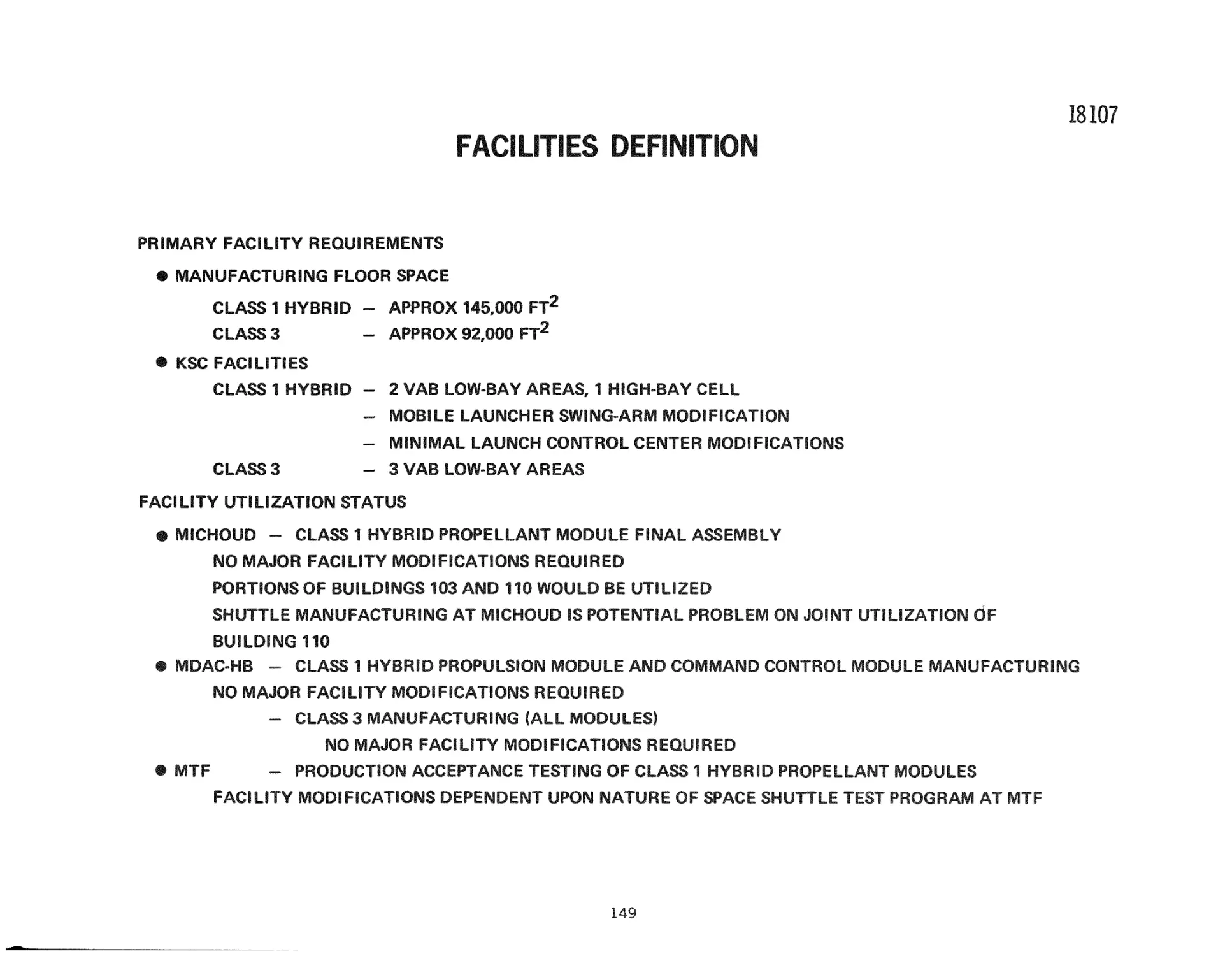
L A U N C H AND P R E L A U N C H O P E R A T I O N S - C L A S S 1 H Y B R I D
O p e r a t i o n s i n v o l v i n g t h e l a u n c h of t h e RNS w i l l b e s c h e d u l e d to m e e t t h e r e q u i r e m e n t s of t h e S p a c e
S h u t t l e . A l s o , t h e c o n f i g u r a t i o n d e m a n d s m a d e on t h e s h u t t l e w i l l b e h e l d to a m i n i m u m . T h e s e c o n s i d e r a t i o n s give r i s e to t h e e s t a b l i s h m e n t , a s a b a s e l i n e , of t h e r e c e i p t of t h e RNS e l e m e n t s in l a u n c h r e a d y c o n d i t i o n . T h e r e f o r e , the o p e r a t i o n a l p r o f i l e s p r e s e n t e d on t h i s and t h e n e x t f i g u r e s a r e b a s e d
on t h e s e a s s u m p t i o n s .
T h e r e a r e s e v e r a l additional, m o r e detailed, a s s u m p t i o n s that have shaped the baseline profile p r e s e n t e d . M a t i n g w i t h t h e s p a c e s h u t t l e w i l l b e in t h e h o r i z o n t a l p o s i t i o n in t h e s h u t t l e m a i n t e n a n c e a r e a .
T h e o r b i t e r c a r g o c o m p a r t m e n t w i l l be a c c e s s i b l e to a c r e w m e m b e r in o r b i t .
In o p e r a t i o n s t h a t i n v o l v e t h e I N T - 2 1 (i. e, , C l a s s 1 h y b r i d o p e r a t i o n s ) i t i s a s s u m e d t h a t M T F w i l l be
o p e r a t i o n a l and w i l l h a v e t h e c a p a b i l i t i e s n e e d e d to p e r f o r m a c c e p t a n c e t e s t i n g on b o t h t h e p r o p e l l a n t
m o d u l e and the propulsion m o d u l e .
The a c c o m p a n y i n g figure shows the C l a s s 1 b a s e l i n e o p e r a t i o n a l profile. The a s s u m p t i o n that the
m o d u l e w i l l be l a u n c h - r e a d y w h e n it i s r e c e i v e d i s r e f l e c t e d in t h e u s e of t h e l o w b a y a i s l e a s t h e
r e c e i v i n g i n s p e c t i o n a r e a . O p e r a t i o n s h e r e w i l l be l i m i t e d to r e m o v i n g s h i p p i n g p r o t e c t i o n and v e r i f y ing t h a t t h e o r b i t e r / p r o p u l s i o n - m o d u l e a n d t h e I N T - 2 1 / p r o p e l l a n t - m o d u l e i n t e r f a c e s a r e r e a d y f o r
m a t i n g . If r e c e i v i n g o p e r a t i o n s s h o u l d r e q u i r e s i g n i f i c a n t l y l o n g e r t i m e , t h e n r e c e i v i n g o p e r a t i o n s on
t h e p r o p e l l a n t m o d u l e w o u l d be m o v e d to one of t h e VAB h i g h b a y s if i n t e g r a t e d p r o g r a m c o n s i d e r a t i o n s
permit.
T h e p r o p e l l a n t m o d u l e a n d t h e c o m m a n d a n d c o n t r o l m o d u l e w i l l be l a u n c h e d i n t e g r a l l y . T h e y w i l l b e
m a t e d at M i c h o u d a n d m o v e d to M T F for p r o d u c t i o n a c c e p t a n c e t e s t i n g . T h e n t h e y w i l l be s h i p p e d to
KSC for l a u n c h v e h i c l e I n t e g r a t i o n , C / O , and l a u n c h .
In C l a s s 1 h y b r i d o p e r a t i o n s ( a s w e l l a s C l a s s 3) t h e s c h e d u l e of t h e p r o p u l s i o n m o d u l e w i l l be p l a n n e d
to m e e t t h e r e q u i r e m e n t s of t h e S p a c e S h u t t l e . F o r s a f e t y , the n e u t r o n s o u r c e f o r N E R V A , if r e q u i r e d ,
w i l l not b e i n s t a l l e d until o r b i t i s r e a c h e d , a n d the p o i s o n w i r e s w i l l r e m a i n in t h e c o r e u n t i l o r b i t .
Both of t h e o p e r a t i o n s w i l l r e q u i r e a c r e w m e m b e r to e n t e r t h e c a r g o c o m p a r t m e n t of t h e o r b i t e r in
o r b i t ; and t h a t h e h a v e t h e n e c e s s a r y a c c e s s to a c c o m p l i s h t h i s t a s k .
T h e p r o p u l s i o n m o d u l e w i l l h a v e i t s n u c l e a r and n o n n u c l e a r s u b s y s t e m s s h i p p e d to NRDS, m a t e d a n d
t e s t e d t h e r e . T h e y w i l l be flown to t h e C a p e w h e r e t h e y w i l l b e m a t e d w i t h t h e p r o p u l s i o n m o d u l e
t a n k a g e . O n e of t h e low b a y c e l l s w i l l b e u s e d f o r t h i s o p e r a t i o n . T h e e n g i n e w i l l h a v e b e e n fully s a f e d
by p o i s o n w i r e s a n d no s p e c i a l n u c l e a r s a f e t y p r e c a u t i o n s w i l l b e r e q u i r e d e x c e p t f o r c o n t r o l l e d a c c e s s
and p e r i o d i c m o n i t o r i n g of t h e a r e a a n d p e r s o n n e l . A d d i t i o n a l l y , t h e e n g i n e w i l l not h a v e , a t t h i s t i m e ,
t h e n e u t r o n s o u r c e i n s t a l l e d . T h i s s o u r c e w i l l be i n s t a l l e d by a m e m b e r of t h e o r b i t e r c r e w a f t e r o r b i t
h a s b e e n a c h i e v e d a n d p r i o r to h i s r e m o v i n g t h e p o i s o n w i r e s .
28
18068
PRELAUNCH AND LAUNCH OPERATIONS
CLASS 1 HYBRID
RNS
POST-MANUFACTURING C/O
PRODUCTION
ACCEPTANCE TESTING
INT-21
MISSION
OPERATIONS
PROPELLANT LOADING,
C/O AND COUNTDOWN
(MICHOUD/SB)
COMMAND &
CONTROL
MODULE
(HB)
(AIR)
PROPELLANT
MODULE
MTF
(AIR)
CCM/PM
(BARGE)
—
•
RECEIVING
INSPECTION
(AISLE)
I
PAD
ORBIT
n
CCM/PROPELLANT
MODULE
MISSION
VEHICLE
ASSEMBLY
AND C/O
KSC
VAB
LOW
BAY
(BARGE)
(MICHOUD)
PROPULSION
MODULE
TANKAGE
VAB HIGH
NERVA/
TANKAGE
(A!R)
(HB)
BAY
MATING
NUCLEAR
SUBSYSTEM
(WAND
I
BOOSTER
ORBITER
NRDS
NON-NUCLEAR
SUBSYSTEM
(AGO
NERVA
SYS
PROPULSION
MODULE LOADING
(HORIZONTAL
POSITION)
NERVA
ASSEMBLY
AND TEST
SPACE
SHUTTLE
MAINTENANCE
AREA
ORBITER
T
BOOSTER
¥
a»ACE
SHUTTLE
SAFING AREA
29
SPACE
SHUTTLE
LANDING SITE
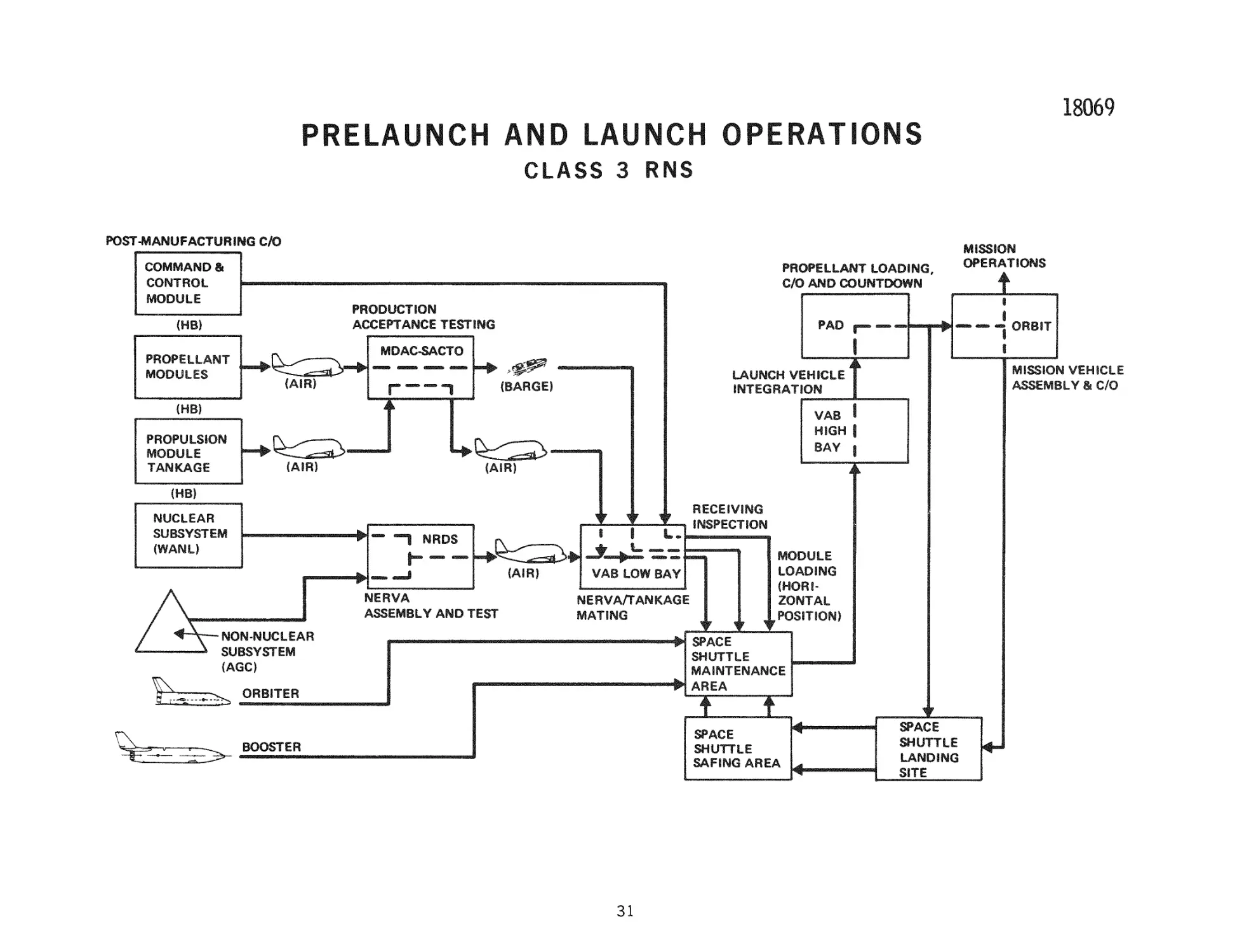
L A U N C H A N D P R E L A U N C H OPERATIONS-CLASS 3
O p e r a t i o n s for t h e C l a s s 3 RNS i n t e r f a c e only w i t h the s p a c e s h u t t l e .
C o n s e q u e n t l y t h e c o m m a n d and c o n t r o l m o d u l e vi^ill be l a u n c h e d s e p a r a t e l y f r o m
the other naodules.
The p r i m e d i f f e r e n c e b e t w e e n C l a s s 3 o p e r a t i o n s and C l a s s 1 h y b r i d o p e r a t i o n s is
in t h e u s e of S a c r a m e n t o a s a s i t e f o r p r o d u c t i o n a c c e p t a n c e t e s t i n g . T h i s diff e r e n c e r e s u l t s f r o m t h e a s s u m p t i o n t h a t t h e I N T - 2 1 i s not o p e r a t i o n a l and t h e r e f o r e M T F w i l l h a v e b e e n c l o s e d down. A n o t h e r p o s s i b i l i t y is t h a t t h e s p a c e s h u t t l e
p r o g r a m w i l l fully u t i l i z e M T F so t h a t i t i s u n a v a i l a b l e f o r t h e RNS p r o g r a m .
T h e p r o p e l l a n t m o d u l e s w i l l b e i n s p e c t e d in the VAB low b a y a r e a . T h i s r e c e i v i n g
i n s p e c t i o n w i l l b e l i m i t e d to v e r i f i c a t i o n t h a t t h e m o d u l e s h a v e n o t b e e n d a m a g e d in
s h i p m e n t , and v e r i f i c a t i o n t h a t t h e s p a c e - s h u t t l e - o r b i t e r / p r o p e l l a n t - m o d u l e i n t e r faces a r e r e a d y for m a t e .
T h e p r o p u l s i o n m o d u l e w i l l b e h a n d l e d s i m i l a r l y to t h e o p e r a t i o n s u s e d f o r t h e
Class 1 hybrid configuration. This includes mating the propulsion inodule tankage
a n d t h e N E R V A s y s t e m in t h e low b a y c e l l s of t h e V A B .
30
18069
PRELAUNCH AND LAUNCH OPERATIONS
CLASS 3 RNS
POST-MANUFACTURING C/O
COMMAND %
PROPELLANT LOADING
C/O AND COUNTDOWN
CONTROL
MODULE
PRODUCTION
ACCEPTANCE TESTING
(HB)
PROPELLANT
MODULES
MISSION VEHICLE
ASSEMBLY & C/O
LAUNCH VEHICLE
INTEGRATION
(BARGE)
(HB)
PROPULSION
MODULE
TANKAGE
(HB)
RECEIVING
INSPECTION
NUCLEAR
SUBSYSTEM
(WAND
— —% NRDS
.^::^>^JL^—=
(AIR)
A
1MERVA
\SSEMBLY AND T
l^SIE^
MODULE
LOADING
(HORIZONTAL
.POSITION)
VAB LOW BAY
NERVA/TANKAGE
MATING
-NON-NUCLEAR
SUBSYSTEM
(AGO
^
MISSION
OPERATIONS
SPACE
SHUTTLE
MAINTENANCE
AREA
ORBITER
I
SPACE
SHUTTLE
SAFING AREA
BOOSTER
31
»ACE
SHUTTLE
LANDING
SITE
L U N A R S H U T T L E MISSION T I M E L I N E - E A R T H O R B I T T U R N A R O U N D
The accompanying illustration identifies m a j o r activities o c c u r r i n g between
o r b i t i n s e r t i o n (EOI) following a l u n a r s h u t t l e m i s s i o n and s u b s e q u e n t d e p a r t u r e
on a n o t h e r m i s s i o n . T h e t o t a l t i m e a v a i l a b l e f o r e a r t h o r b i t t u r n a r o u n d of
8 4 . 2 d a y s c o r r e s p o n d s to a m i s s i o n m o d e l w i t h a s i x - m i s s i o n s - a - y e a r
f r e q u e n c y . F o r t h i s m i s s i o n m o d e l , two RNS s y s t e m s a l t e r n a t e l y p e r f o r m
l u n a r s h u t t l e m i s s i o n s at a c o m b i n e d r a t e of o n c e e a c h 54. 6 d a y s ( e v e r y two
l u n a r c y c l e s ) . S i n c e the m i s s i o n s a r e p e r f o r m e d a l t e r n a t e l y by the two R N S ,
84. 2 d a y s a r e s p e n t in e a r t h o r b i t by e a c h RNS b e t w e e n m i s s i o n a p p l i c a t i o n s .
In o r d e r to m i n i m i z e , if not e l i m i n a t e , t h e r e q u i r e m e n t to p e r f o r m r e c y c l i n g
o p e r a t i o n s s i m u l t a n e o u s l y on the two RNS, only a p o r t i o n of t h i s t i m e i s
a l l o c a t e d f o r the p e r f o r m a n c e of the m a j o r o p e r a t i o n s of p r o p e l l a n t r e f u e l i n g
and m i s s i o n p a y l o a d l a u n c h and i n t e g r a t i o n . A s p a c e s h u t t l e l a u n c h r a t e of one
e a c h t h r e e d a y s i s r e q u i r e d to fulfill t h i s o b j e c t i v e . Two t i m e b l o c k s a r e
a l l o c a t e d m t h e p r o f i l e shown to p e r f o r m u n s c h e d u l e d m a i n t e n a n c e . T h e f i r s t
b l o c k of t i m e (41 d a y s ) i m m e d i a t e l y follows the c o m p l e t i o n of c o o l d o w n
o p e r a t i o n s and m i s s i o n c r e w r e t r i e v a l . T h i s t i m e b l o c k p r o v i d e s f o r m a j o r
m a i n t e n a n c e such as propellant module r e p l a c e m e n t . A s i m i l a r , but s m a l l e r ,
b l o c k of t i m e i s a l l o c a t e d following e x c h a n g e of the RNS c o m m a n d and c o n t r o l
m o d u l e and s u b s y s t e m v e r i f i c a t i o n and i n t e g r a t e d t e s t s . T h e e x t e n t to w h i c h
t h e f i r s t u n s c h e d u l e d m a i n t e n a n c e p e r i o d (41 d a y s ) i s u s e d c o r r e s p o n d i n g l y
i n f r i n g e s upon t h e p e r f o r m a n c e of t u r n a r o u n d o p e r a t i o n s on t h e a l t e r n a t e RNS,
and w o u l d i m p o s e a g r e a t e r b u r d e n b e c a u s e of i n c r e a s e d s p a c e s h u t t l e l a u n c h
f r e q u e n c y a n d o r b i t a l a c t i v i t y . T h e f i g u r e i n d i c a t e s t h e c o m b i n e d l a u n c h of the
new c o m m a n d a n d c o n t r o l m o d u l e and m i s s i o n c r e w . T h i s a p p r o a c h i s t a k e n to
m a x i m i z e t h e u s e of t h e s p a c e s h u t t l e p a y l o a d c a p a b i l i t y . Should f u t u r e i n v e s t i g a t i o n s i n d i c a t e t h i s a p p r o a c h u n t e n a b l e b e c a u s e of t h e e x t e n d e d c r e w t i r a e
r e q u i r e d m e a r t h o r b i t (an a d d i t i o n a l 14 d a y s of o n - o r b i t t i m e ) , t h e c r e w could
be l a u n c h e d s e p a r a t e l y , following l a u n c h and i n t e g r a t i o n of t h e u n m a n n e d p a y l o a d , at the e x p e n s e of an a d d e d s p a c e s h u t t l e l a u n c h .
32
18109
LUNAR-SHUTTLE MISSION TIMEUNE
EARTH ORBIT TURNAROUND - SIX MISSIONS PER YEAR
K^ r
, ^
o
LH2 TRANSFER
(10 LAUNCHES*)
27 DAYS
POST-FLIGHT CHECKOUT
AND CONTINGENCY FOR
UNSCHEDULED MAINTENANCE (AS REQUIRED)
41 DAYS
CONTINGENCY FOR
UNSCHEDULED
MAINTENANCE
(AS REQUIRED)
4 DAYS
LAUNCH CREW AND CCM
EXCHANGE CCM'S
SUBSYSTEM VERIFICATION
INTEGRATED TEST
3 DAYS
LAUNCH AND INTEGRATE
UNMANNED PAYLOAD
(3 LAUNCHES*)
6 DAYS
TOTAL TURNAROUND TIME
IN EARTH ORBIT = 84.2 DAYS
DEPLOY EARTHRETURN PAYLOAD
4HR
INTEGRATED TEST
FRT AND COUNTDOWN
1 DAY
COOLDOWN
OPERATIONS
45 HR
EOI
Wp = 47,530 LB
TUG INTERCEPT
AND
CREW RETRIEVAL
^ 6HR
h
72-HR
COAST
*3 DAYS BETWEEN SHUTTLE LAUNCHES
33
w.
TLI
= 174,820 LB
T
108-HR COAST
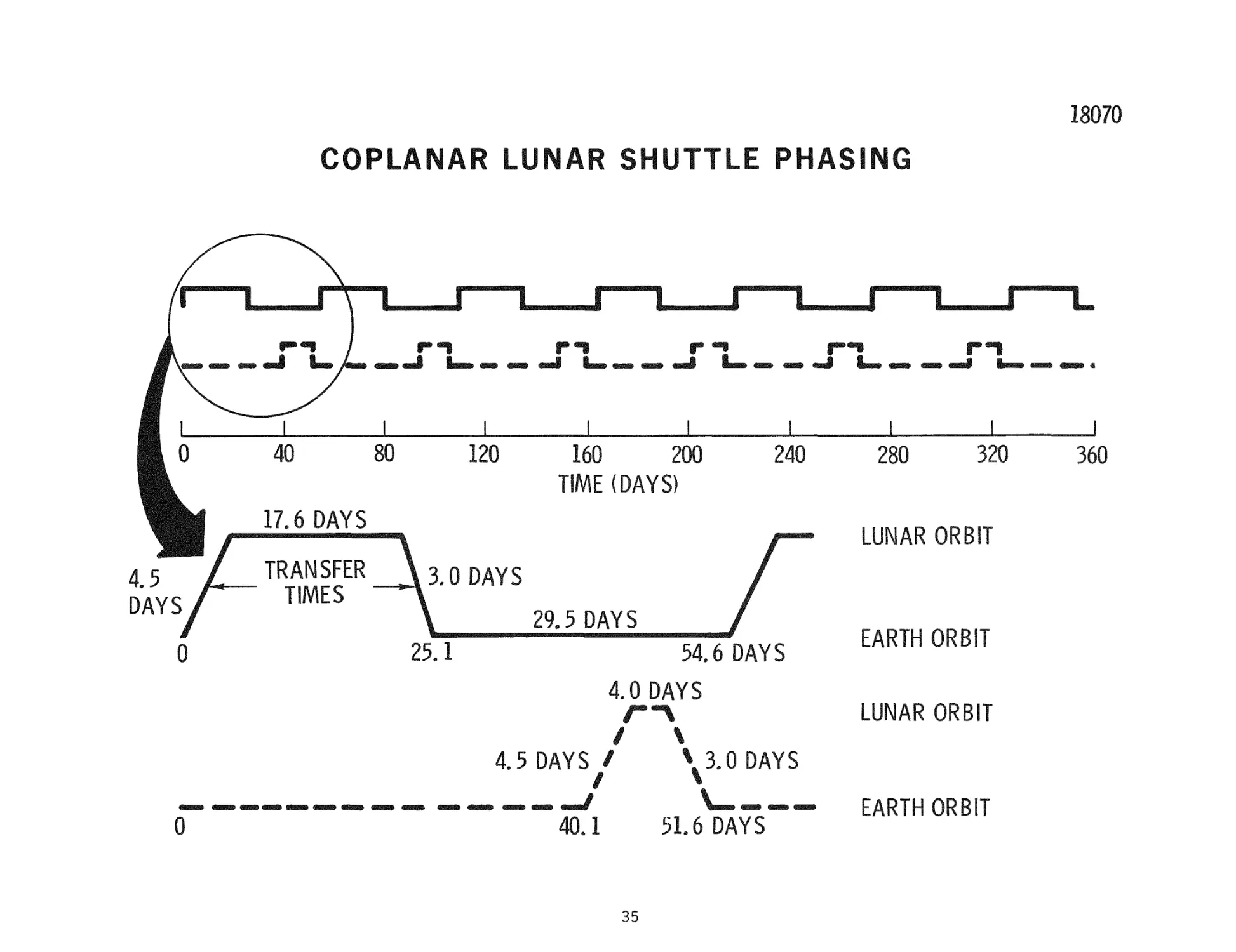
COPLANAR LUNAR SHUTTLE PHASING
T h e s p a c i n g of l u n a r s h u t t l e m i s s i o n o p p o r t u n i t i e s i s s h o w n in t h i s c h a r t . It i s
b a s e d on a t a r g e t p o l a r l u n a r o r b i t of 60 n m i , and a d e p a r t u r e f r o m a 2 6 0 - n m i ,
3 1 . 5 - d e g r e e ~ i n c l i n a t i o n , e a r t h - o p e r a t i o n s o r b i t . D u r i n g a y e a r , 13 m i s s i o n
o p p o r t u n i t i e s e x i s t , c o n s i s t i n g of s e v e n l o n g - s t a y l u n a r m i s s i o n s and s i x s h o r t stay lunar m i s s i o n s . The opportunities repeat every 54.6 days. The lower
p o r t i o n of t h e c h a r t d e t a i l s t h e t i m e l i n e a s s o c i a t e d w i t h e a c h o p p o r t u n i t y .
For
t h e l o n g e r s t a y m i s s i o n , 1 7 . 6 d a y s a r e a l l o w e d in l u n a r o r b i t , w h i l e 4. 0 d a y s a r e
a l l o w e d for t h e s h o r t e r s t a y m i s s i o n . F o r e i t h e r m i s s i o n t h e o u t b o u n d t r i p t i m e
i s 4. 5 d a y s a n d the r e t u r n l e g i s 3. 0 d a y s .
34
18070
COPLANAR LUNAR SHUTTLE PHASING
LUNAR ORBIT
54.6 DAYS
EARTH ORBIT
4 0 DAYS
LUNAR ORBIT
/
\
^ 3 . 0 DAYS
4.5 DAYS /
/
0
40.1
51.6 DAYS
35
EARTH ORBIT
RNS U T I L I Z A T I O N S C H E D U L E
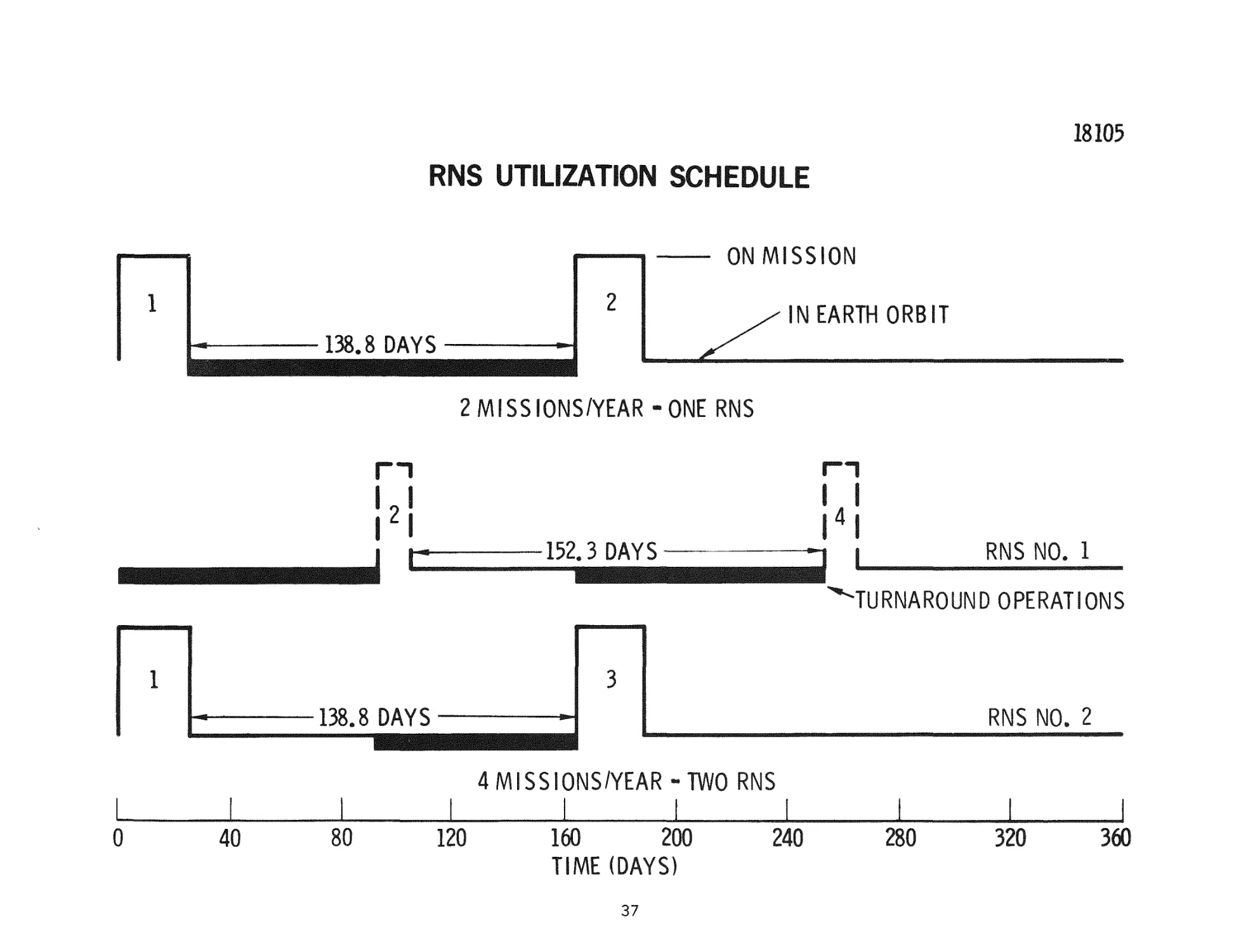
T y p i c a l RNS o p e r a t i n g p l a n s w e r e g e n e r a t e d for t r a f f i c m o d e l s of two and f o u r
m i s s i o n s a y e a r . T h e s c h e d u l e at t h e t o p of t h e c h a r t i s for two m i s s i o n s a y e a r
u s i n g o n e RNS. T h i s low t r a f f i c r a t e a l l o w s a m i n i m u m of 138. 8 d a y s in e a r t h
o r b i t f o r p e r f o r m i n g t h e t u r n a r o u n d o p e r a t i o n s and any c o n t i n g e n c y m a i n t e n a n c e .
T h e s c h e d u l e a t t h e l o w e r p o r t i o n of t h e c h a r t r e f l e c t s a t r a f f i c m o d e l of f o u r
m i s s i o n s a y e a r and u s e s two RNS s y s t e m s . RNS No. 1 p e r f o r m s s h o r t l u n a r - s t a y
m i s s i o n s w h i l e RNS N o . Z p e r f o r m s long l u n a r - s t a y m i s s i o n s . T h e m i n i m u m t i m e
b e t w e e n s u c c e s s i v e m i s s i o n s w i t h t h e s a m e RNS i s 84. 2 d a y s f o r RNS No. Z.
H o w e v e r , not a l l of t h i s t i m e i s a v a i l a b l e to p e r f o r m t h e t u r n a r o u n d o p e r a t i o n s . A
g r o u n d r u l e w a s f o r m u l a t e d r e s t r i c t i n g t u r n a r o u n d o p e r a t i o n s to one RNS at a t i m e .
A s a r e s u l t of t h i s n o n i n t e r f e r e n c e p h i l o s o p h y , only 69 d a y s a r e a v a i l a b l e to
r e s u p p l y RNS N o . 2 a f t e r r e t u r n i n g f r o m i t s f i r s t m i s s i o n . T h e i m p l i c a t i o n s of
p e r f o r m i n g t u r n a r o u n d o p e r a t i o n s on two RNS s y s t e m s c o n c u r r e n t l y a r e a d d i t i o n a l
r e q u i r e m e n t s for o r b i t a l s u p p o r t s y s t e m s , s u c h a s s p a c e t u g s .
36
18105
RNS UTILIZATION SCHEDULE
ON MISSION
INEARTH ORBIT
138,8 DAYS
ZAAISSIONS/YEAR^ONERNS
n
LI
1^1
C
•152.3 DAYS
RNS NO. 1
TURNAROUND OPERATIONS
3
138.8 DAYS
RNS N0« 2
4 MISSIONS/YEAR-TWO RNS
L
0
40
80
120
160
200
TIME (DAYS)
37
240
280
320
360
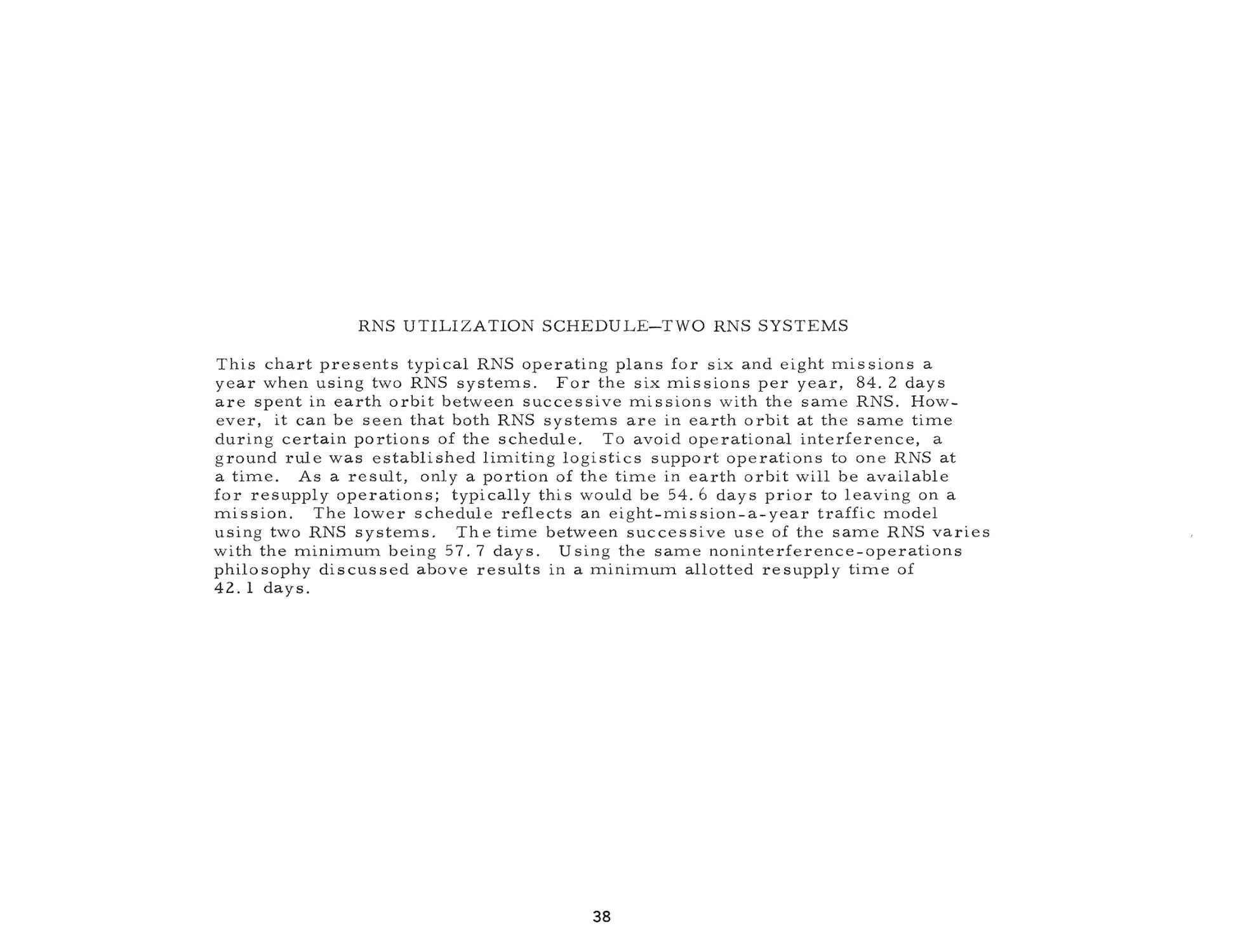
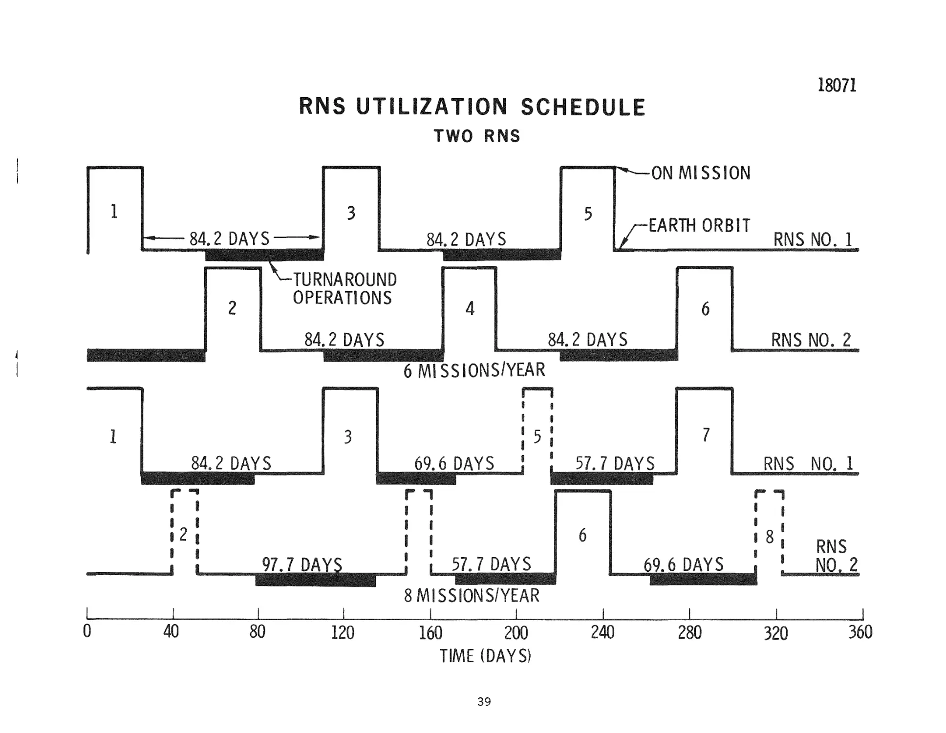
RNS U T I L I Z A T I O N S C H E D U L E - T W O RNS S Y S T E M S
T h i s c h a r t p r e s e n t s t y p i c a l RNS o p e r a t i n g p l a n s f o r six and e i g h t m i s s i o n s a
y e a r w h e n u s i n g two RNS s y s t e m s . F o r t h e s i x m i s s i o n s p e r y e a r , 84. 2 d a y s
a r e s p e n t in e a r t h o r b i t b e t w e e n s u c c e s s i v e m i s s i o n s w i t h t h e s a m e RNS. H o w e v e r , it c a n b e s e e n t h a t both RNS s y s t e m s a r e in e a r t h o r b i t at t h e s a m e t i m e
d u r i n g c e r t a i n p o r t i o n s of t h e s c h e d u l e . To a v o i d o p e r a t i o n a l i n t e r f e r e n c e , a
g r o u n d r u l e w a s e s t a b l i s h e d l i m i t i n g l o g i s t i c s s u p p o r t o p e r a t i o n s to one RNS at
a t i m e . A s a r e s u l t , only a p o r t i o n of t h e t i m e in e a r t h o r b i t w i l l be a v a i l a b l e
f o r r e s u p p l y o p e r a t i o n s ; t y p i c a l l y t h i s w o u l d be 54. 6 d a y s p r i o r to l e a v i n g on a
m i s s i o n . T h e l o w e r s c h e d u l e r e f l e c t s an e i g h t - m i s s i o n - a - y e a r t r a f f i c m o d e l
u s i n g two RNS s y s t e m s . T h e t i m e b e t w e e n s u c c e s s i v e u s e of t h e s a m e RNS v a r i e s
w i t h t h e m i n i m u m b e i n g 57. 7 d a y s . U s i n g t h e s a m e n o n i n t e r f e r e n c e - o p e r a t i o n s
p h i l o s o p h y d i s c u s s e d a b o v e r e s u l t s in a m i n i m u m a l l o t t e d r e s u p p l y t i m e of
42. 1 days.
38
18071
RNS UTILIZATION SCHEDULE
TWO RNS
•ON MISSION
r
84.2 DAYS
EARTH ORBIT
84.2 DAYS
RNS NO. 1
TURNAROUND
OPERATIONS
84.2 DAYS
84.2 DAYS
RNS NO. 2
6 MISSIONS/YEAR
69.6 DAYS
!5
5
RNS
r T
r T
i
i
i
97.7 DA
NO. 1
I
i
i
i
I
,
I 8 i
i
i
57.7 DAYS
RNS
NO. 2
8 MISSIONS/YEAR
0
40
80
120
160
200
TIME (DAYS)
39
240
280
320
360
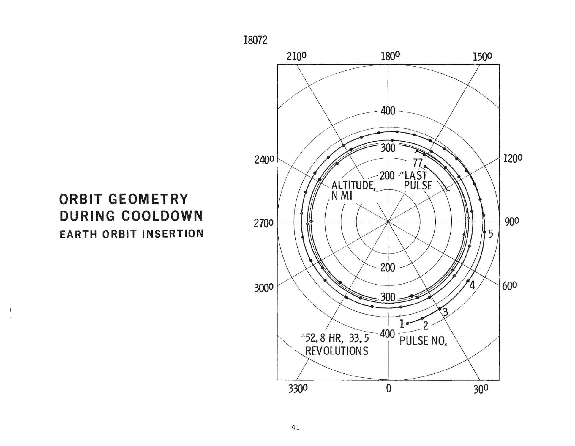
O R B I T G E O M E T R Y DURING COOLDOWN
T h e o r b i t a l g e o m e t r y r e s u l t i n g f r o m t h e cooldown i m p u l s e p r o f i l e following full p o w e r
e n g i n e o p e r a t i o n i s shown f o r a c a s e r e p r e s e n t a t i v e of t h e E O I m a n e u v e r . T h e p u l s e
i s s p e c i f i e d by i t s m i d - p o i n t a s e a c h p u l s e w a s t r e a t e d a s an i m p u l s i v e p e r t u r b a t i o n
to t h e o r b i t . T h e c o o l d o w n p h a s e i s a s s u m e d to be a c c o m p l i s h e d at z e r o a n g l e - o f a t t a c k t h r o u g h o u t , t h a t i s , t h e t h r u s t v e c t o r is a l w a y s a l i g n e d w i t h t h e v e l o c i t y v e c t o r .
Two o b s e r v a t i o n s t h a t r e l a t e to t h e c h a r a c t e r i s t i c e a r l y a c c u m u l a t i o n of t h e m a j o r i t y
of t h e c o o l d o w n i m p u l s e a r e (1) t h a t t h e d e s i r e d i n j e c t i o n o r b i t , (the o r b i t d e s i r e d at
t h e end of f u l l - p o w e r o p e r a t i o n ) is e c c e n t r i c , and (Z) t h e o r b i t b e c o m e s n e a r - c i r c u l a r
v e r y quickly.
T h e d a t a show t h a t if i n s e r t i o n o c c u r s in an i n i t i a l o r b i t of 437 n m i a p o g e e by 366 n m i
p e r i g e e (the e c c e n t r i c i t y is 0 . 0 0 9 3 ) , t h e RNS w i l l r e t r o down to a 2 6 0 - n m i c i r c u l a r
o r b i t by t h e end of t h e c o o l d o w n p h a s e . S p e c i f i c a l l y , t h e end of f u l l - t h r u s t s h u t d o w n
o c c u r s a t an a l t i t u d e of 381 m i l e s at an i n i t i a l flight p a t h a n g l e of - 0 . 4 4 d e g r e e s .
The
n e g a t i v e flight p a t h a n g l e , a n d the c l o s e n e s s of t h e i n j e c t i o n a l t i t u d e to the p e r i g e e
a l t i t u d e n o t e d , i n d i c a t e t h a t i n j e c t i o n o c c u r s p r i o r to p e r i g e e p a s s a g e . T h e t o t a l
c o o l d o w n p h a s e , in t h i s c a s e , l a s t s for 52. 8 h o u r s following s h u t d o w n , o r a t o t a l of
33. 5 o r b i t a l r e v o l u t i o n s . When c o n s i d e r i n g t h e a c c u m u l a t e d i m p u l s e d e r i v e d f r o m
c o o l d o w n d u r i n g t h i s r e t r o g r a d e p h a s e , a c o r r e s p o n d e n c e i s shown to t h e r e d u c t i o n in
a v e r a g e o r b i t a l a l t i t u d e (the s u m of a p o g e e a l t i t u d e p l u s p e r i g e e a l t i t u d e d i v i d e d by
2), a s w o u l d b e e x p e c t e d . F o r e x a m p l e , f o u r o r b i t s following i n j e c t i o n ( 2 3 , 000 s e c o n d s ) , 80 p e r c e n t of t h e c o o l d o w n i m p u l s e to b e d e r i v e d h a s b e e n d e l i v e r e d and,
c o r r e s p o n d i n g l y , 80 p e r c e n t of the a v e r a g e a l t i t u d e r e d u c t i o n h a s b e e n a c c o m p l i s h e d .
S i m i l a r l y , 90 p e r c e n t of t h e e f f e c t i v e r e d u c t i o n in a v e r a g e a l t i t u d e i s a c c o n n p l i s h e d in
l e s s t h a n n i n e o r b i t s , o r 14 h o u r s , following i n j e c t i o n . T h e t o t a l i d e a l v e l o c i t y c o n t r i b u t i o n d u r i n g t h i s c o o l d o w n p h a s e is a p p r o x i m a t e l y 470 f t / s e c , d e l i v e r e d at an
e f f e c t i v e s p e c i f i c i m p u l s e of 441 s e c o n d s .
40
18072
1200
240O
ORBIT GEOMETRY
DURING COOLDOWN
^700
EARTH ORBIT INSERTION
300O
41
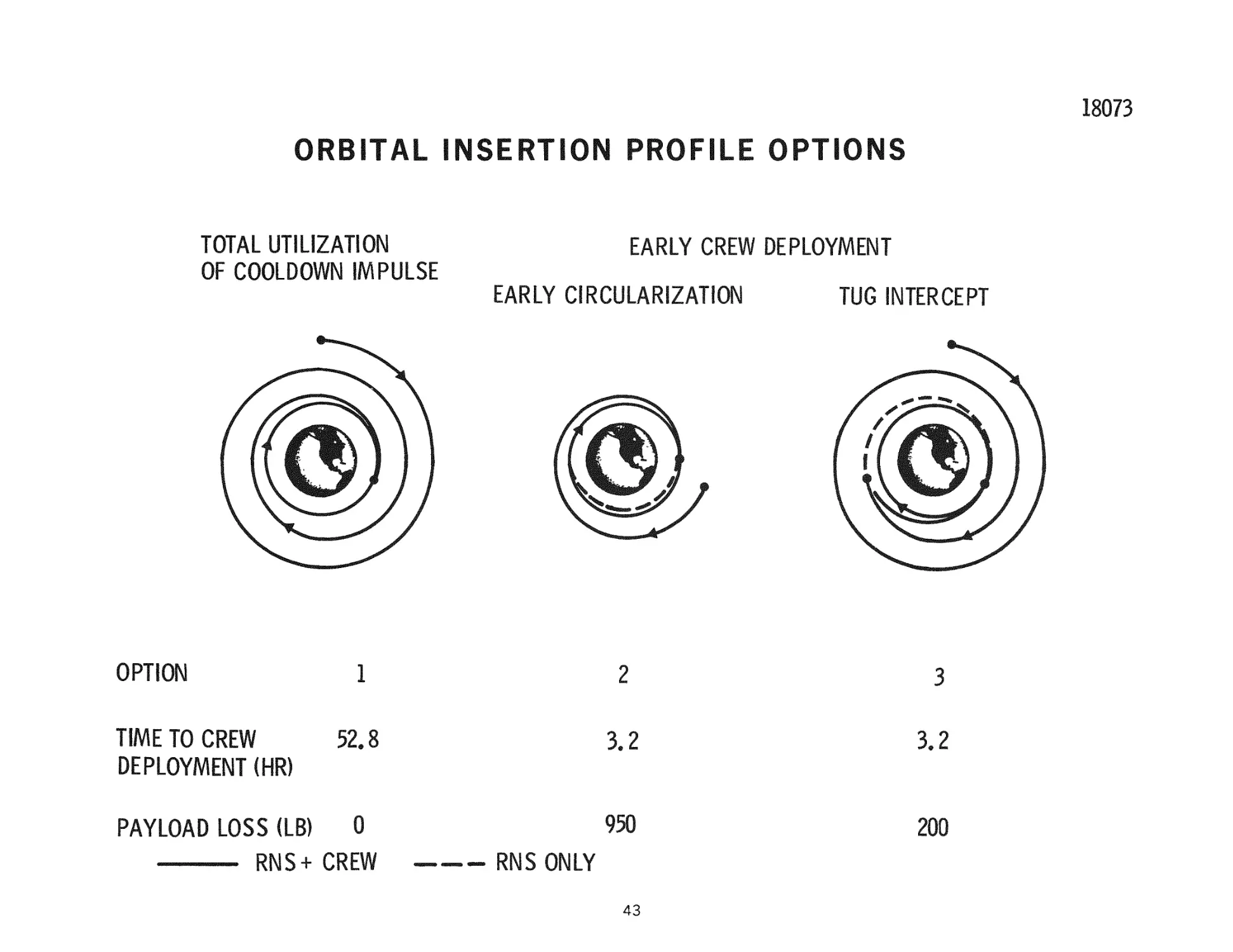
ORBITAL INSERTION PROFILE OPTIONS
Noting that approximately 53 hours (or 33-1/2 orbital revolutions) a r e r e q u i r e d to
complete the cooldown phase for the EOI m a n e u v e r , the question is r a i s e d as to
the possibility of c r e w deployment p r i o r to the t e r m i n a t i o n of the cooldown phase.
Tw^o a p p r o a c h e s to accomplishing this w e r e investigated: (1) injecting the RNS at a
lo'wer initial orbit to p e r m i t spiraling down to 260 m i l e s m o r e quickly, followed by
deploying the cre"w and allowing the RNS to complete the cooldown phase on its own,
and (2) intercepting the RNS e a r l y in the cooldown phase at a higher orbit with
another stage, such as the chemical tug, and r e t u r n i n g the c r e w to 260 nmi. In the
l a t t e r c a s e , the RNS would continue its downward s p i r a l to 260 m i l e s following
deployment of the c r e w .
In the f o r m e r of the two a l t e r n a t e s , if 260 nmi i n s e r t i o n w e r e d e s i r e d at the end of
tw^o orbital revolutions (following 40 cooldown pulses), injection m u s t occur in an
orbit with a 394~nmi apogee and a 320-nmi p e r i g e e . This c o m p a r e s with the 437
by 365 nmi initial injection orbit, which would use all of the cooldown p r i o r to
c i r c u l a r i z a t i o n at 260 nmi, as was previously d i s c u s s e d . Adopting this approach
in effect r e s u l t s in depriving the RNS of the useful impulse o c c u r r i n g following
c i r c u l a r i z a t i o n at 260 nmi. The effect is to i n c r e a s e the full - t h r u s t injection
velocity r e q u i r e d by virtue of injecting into a lower e a r t h orbit. The payload
impact of this higher energy r e q u i r e m e n t in this example is 950 lb. This payload
penalty is c o m p a r e d with an equivalent cost for the second of the two a l t e r n a t i v e s
mentioned, where a tug is a s s u m e d to i n t e r c e p t the RNS during its downward s p i r a l
in the cooldown p h a s e . These data a r e based on the r e t r i e v a l of a 20, 000-lb c r e w
module with a tug weighing 12, 000 lb (inert weight, as specified in the NASA
Guidelines) at a specific impulse of 460 seconds. Thus, the profile entails t r a n s fer of the tug from the 260-nmi orbit up to the i n t e r c e p t orbit, acquisition of the
c r e w module, followed by r e t u r n to the 260-nmi orbit. No velocity penalties -were
assigned beyond the ideal Hohmann t r a n s f e r r e q u i r e m e n t . The tug propellant
r e q u i r e m e n t to a c c o m p l i s h this sequence of events (10. 2 lb per nautical mile
between 260 nmi and the i n t e r c e p t orbit) was converted to equivalent payload
delivered to lunar orbit at the r a t e of 112, 000-lb of payload per 300, 000 lbs of
propellant, or 0. 373 lb per lb. As can be seen, the second of the two a l t e r n a t i v e s
is s u p e r i o r .
42
ORBITAL INSERTION PROFILE OPTIONS
TOTAL UTILIZATION
OF COOLDOWN IMPULSE
EARLY CREW DEPLOYMENT
EARLY CIRCULARIZATION
1
OPTION
TIME TO CREW
DEPLOYMENT (HR)
PAYLOAD LOSS (LB)
2
TUG INTERCEPT
3
52.8
3.2
3,2
0
950
200
RNS+ CREW
RNS ONLY
43
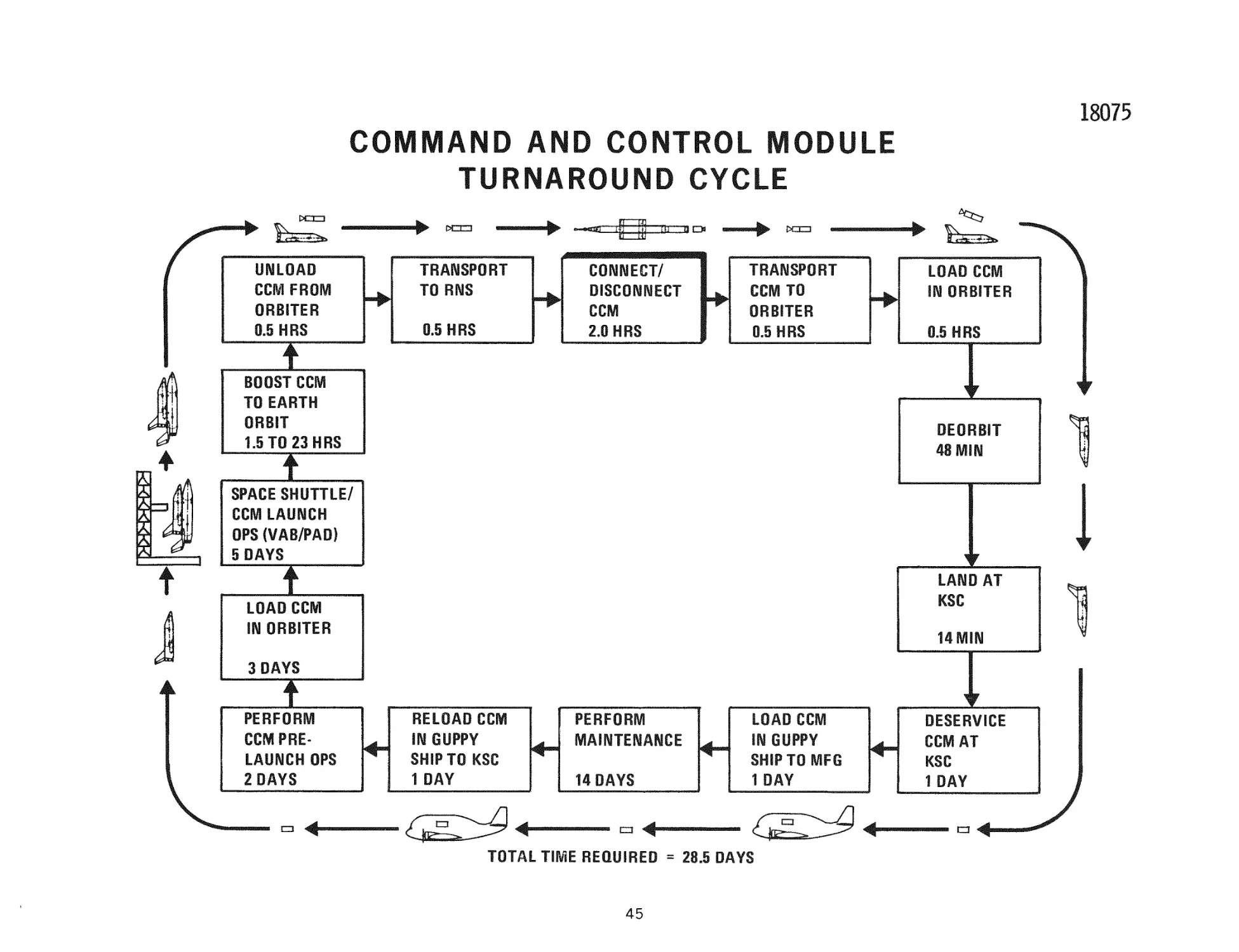
C O M M A N D AND CONTROL M O D U L E TURNAROUND CYCLE
The c u r r e n t RNS operating plan calls for the r e t u r n of the command and control
module (CCM) to the ground for maintenance and refurbishment subsequent to the
completion of e v e r y RNS m i s s i o n . The objectives a r e :
A.
Replenish CCM c o n s u m a b l e s .
B.
Verify CCM functionality.
C.
Verify CCM r e d u n d a n c i e s .
D.
Calibrate and adjust components.
E.
Replace limited-life h a r d w a r e .
The CCM turnaround cycle is i l l u s t r a t e d in the c h a r t . T r a n s p o r t a t i o n to and from
orbit is by the space shuttle, which provides a protective environment during boost
and entry. The ground maintenance could be p e r f o r m e d at KSC or at the manufacturing s i t e . The l a t t e r was selected as the m o s t cost-effective. The total
turnaround time takes about 28, 5 days, of which 14 days a r e spent at the
manufacturing site and ten days at KSC for prelaunch and launch o p e r a t i o n s . The
turnaround cycle of 28. 5 days p r e s e n t s no h a r d s h i p on performing the candidate
RNS traffic models of two to eight m i s s i o n s per y e a r .
44
18075
COMI^AND AND CONTROL MODULE
TURNAROUND CYCLE
^^s^
" ^
Uf^LOAD
CCM FBOM
ORBITER
0.B HRS
>
PTT-I
TRANSPORT
TO RNS
0.e HRS
^sure
•71.1
CONNECT/
DISCONNECT
CCM
2.0 HRS
Hm
TRANSPORT
CCM TO
ORBITER
0.5 HRS
BOOST CCM
TO EARTH
ORBIT
1.eT0 23HRS
T
^
LOAD CCM
IN ORBITER
0.5 HRS
OEORBIT
4SMIN
i
SPACE SHUTTLE/
COM LAUiyCH
OPS (VAB/PAD)
5 DAYS
i
LAND AT
KSC
LOAD CCIV!
liy ORBITER
14MIN
3 DAYS
I
PERFORM
CCM PRELAUNCH OPS
2 DAYS
RELOAD CCM
m GUPPY
SHIP TO KSC
1 DAY
^
^
:
PERFORM
MAINTENANCE
14 DAYS
LOAD CCM
IN GUPPY
SHfPTOMFG
1DAY
a
^
( ^ ^ *
^
TOTAL TIME REQUIRED = 28.5 DAYS
45
OESERVICE
CCM AT
KSC
1 DAY
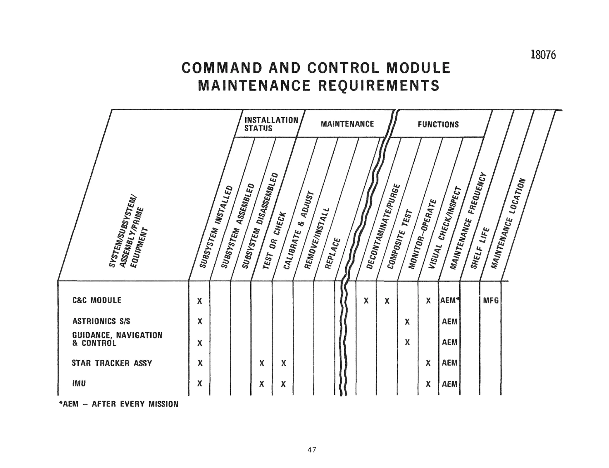
COMMAND AND CONTROL MODULE MAINTENANCE REQUIREMENTS
To establish the t e r r e s t r i a l maintenance r e q u i r e m e n t s of the CCM, End Item
Maintenance Sheets w e r e p r e p a r e d as i l l u s t r a t e d in the c h a r t . The CCM was
broken down to the major a s s e m b l y l e v e l s , e. g. , s t a r t r a c k e r a s s e m b l y . The
installation s t a t u s , maintenance function r e q u i r e d , maintenance frequency and
maintenance location v/ere established for each of these major a s s e m b l i e s .
Brief t a s k d e s c r i p t i o n s w e r e then generated for each of the identified maintenance
functions defining what is to be done. These t a s k d e s c r i p t i o n s w e r e used by the
maintenance support engineering staff and RNS study p e r s o n n e l for e s t i m a t e s of
the t a s k - h o u r s and p e r s o n n e l r e q u i r e d .
46
18076
COIVIIVIAND AND CONTROL MODULE
MAINTENANCE REQUIREMENTS
ASTRIONICS S/S
GUIDANCE, NAVIGATION
& CONTROL
STAR TRACKER ASSY
*AEM ~ AFTER EVERY MISSION
47
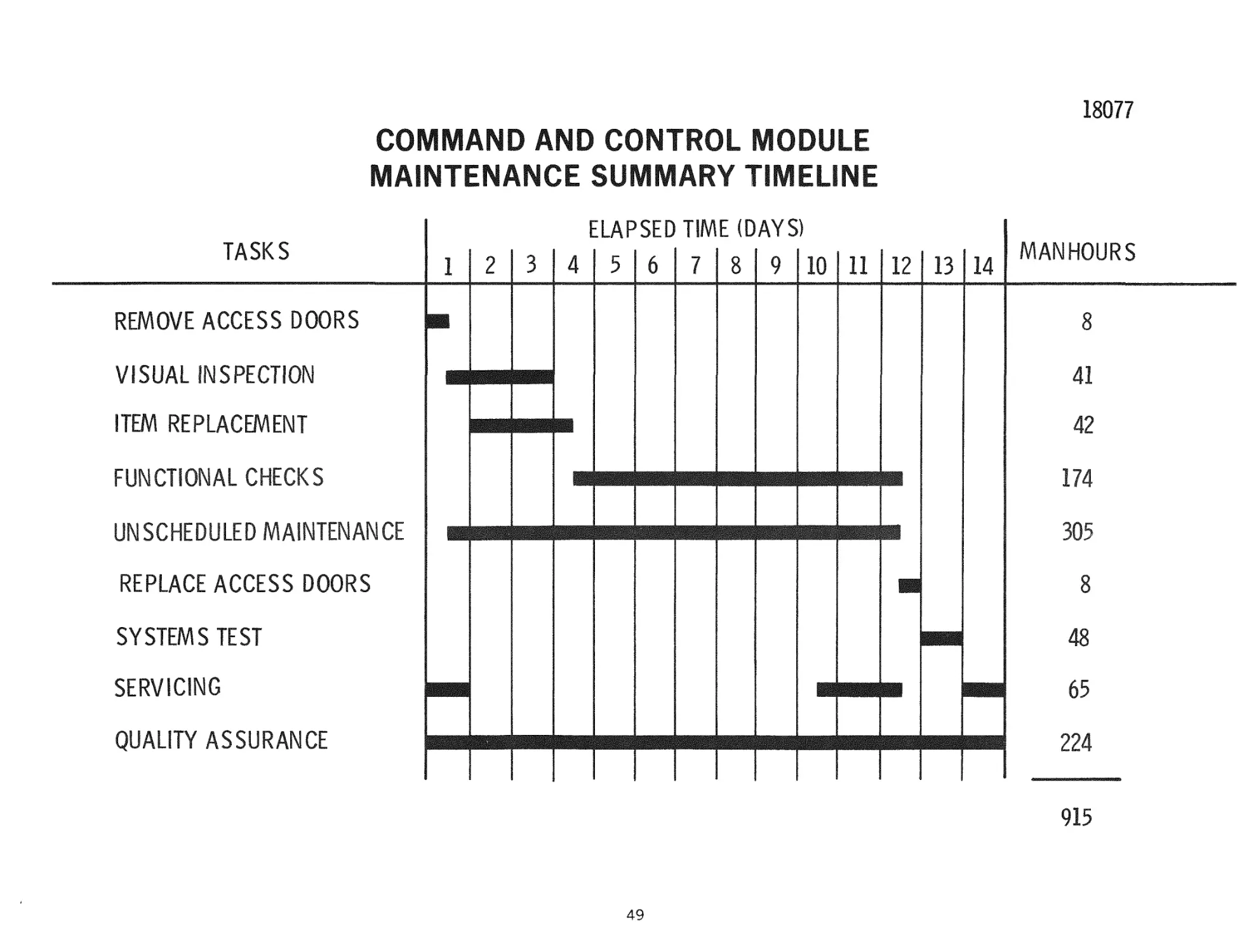
COMMAND AND CONTROL MODULE MAINTENANCE SUMMARY TIMELINE
This c h a r t p r e s e n t s a s u m m a r y CCM maintenance timeline. It is the r e s u l t of
summations of m a n - h o u r s r e q u i r e d for individual maintenance functions performed
on each major CCM a s s e m b l y . A major consideration in establishing the m a n hours r e q u i r e d for maintenance is that a high degree of automation would be used in
checkout. An additional p r e r e q u i s i t e is that inaintainability be designed into the
CCM. The unscheduled maintenance r e q u i r e m e n t is based on a i r c r a f t h i s t o r i c a l
data necessitating 1 to 1.5 m a n - h o u r s of unscheduled maintenance for e v e r y hour of
scheduled m a i n t e n a n c e . Major candidates for unscheduled maintenance a r e e l e m e n t s of the data m a n a g e m e n t s u b s y s t e m s , e. g. , the computer, a u x i l i a r y m e m o r y
unit, e t c .
48
18077
COMMAND AND CONTROL MODULE
MAINTENANCE SUMMARY TIMELINE
lAPSED TIME (DAYS)
TASKS
1
2
3
4
5
6
7
8
9 10 11 12
REMOVE ACCESS DOORS
41
•
42
FUNCTIONAL CHECKS
UNSCHEDULED MAINTENANCE
REPLACE ACCESS DOORS
MANHOURS
8
VISUAL INSPECTION
ITEM REPLACEMENT
13 14
174
B
305
8
SYSTEMS TEST
48
SERVICING
65
QUALITY ASSURANCE
224
915
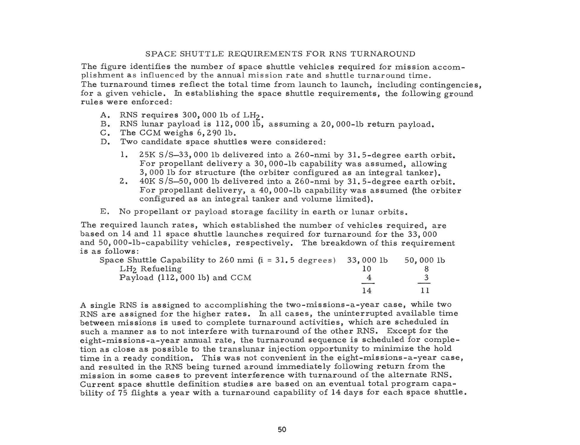
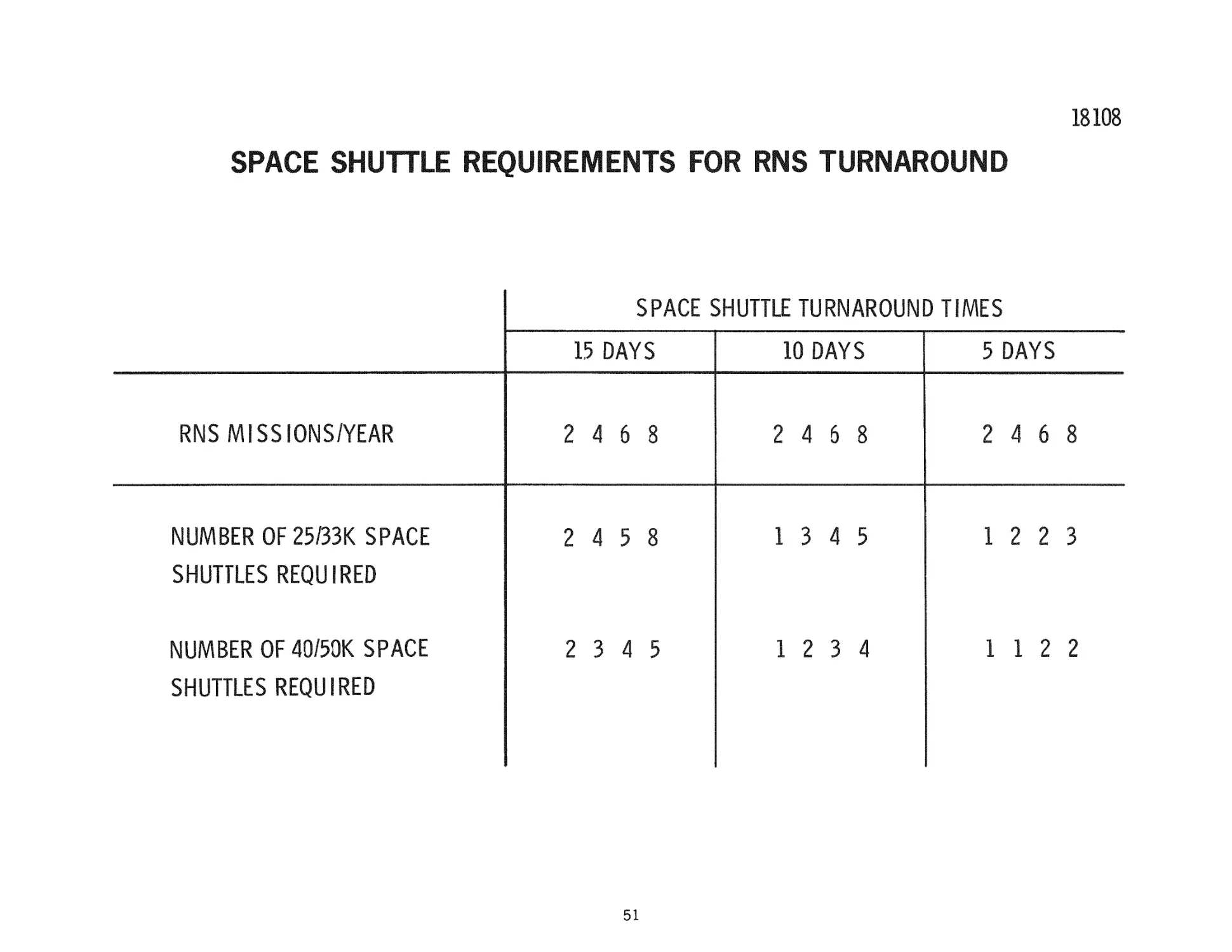
SPACE SHUTTLE REQUIREMENTS FOR RNS TURNAROUND
The figure identifies the nunaber of space shuttle vehicles r e q u i r e d for m i s s i o n accomiplishment as influenced by the annual m i s s i o n r a t e and shuttle turnaround t i m e .
The turnaround t i m e s reflect the total time from launch to launch, including contingencies,
for a given v e h i c l e . In establishing the space shuttle r e q u i r e m e n t s , the following ground
r u l e s w e r e enforced:
A.
B.
C.
D.
RNS
RNS
The
Two
r e q u i r e s 300, 000 lb of LH2.
lunar payload is 112, 000 lb, a s s u m i n g a 20, 000-lb r e t u r n payload.
COM weighs 6, 290 lb.
candidate space shuttles w e r e c o n s i d e r e d :
1.
E.
25K S/S—33, 000 lb delivered into a 260-nmi by 3 1 . 5 - d e g r e e e a r t h o r b i t .
F o r propellant d e l i v e r y a 30, 000-lb capability was a s s u m e d , allowing
3, 000 lb for s t r u c t u r e (the o r b i t e r configured as an integral t a n k e r ) .
2, 40K S/S—50, 000 lb delivered into a 260-nmi by 3 1 . 5-degree e a r t h o r b i t .
F o r propellant d e l i v e r y , a 40, 000-lb capability was a s s u m e d (the o r b i t e r
configured as an integral tanker and volume limited).
No propellant or payload storage facility in e a r t h or lunar o r b i t s .
The r e q u i r e d launch r a t e s , which established the number of vehicles r e q u i r e d , a r e
based on 14 and 11 space shuttle launches r e q u i r e d for turnaround for the 33, 000
and 50, 000-lb-capability v e h i c l e s , r e s p e c t i v e l y . The breakdown of this requirem.ent
is as follows:
Space Shuttle Capability to 260 n m i (i = 3 1 . 5 d e g r e e s )
33, 000 lb
50, 000 lb
LH2 Refueling
10
8
Payload (112,000 lb) and CCM
__4_
__3_
14
11
A single RNS is assigned to accomiplishing the t w o - m i s s i o n s - a - y e a r c a s e , while two
RNS a r e assigned for the higher r a t e s , in all c a s e s , the u n i n t e r r u p t e d available t i m e
between m i s s i o n s is used to complete turnaround a c t i v i t i e s , which a r e scheduled in
such a m a n n e r as to not i n t e r f e r e with turnaround of the other RNS. Except for the
e i g h t - m i s s i o n s - a - y e a r annual r a t e , the t u r n a r o u n d sequence is scheduled for c o m p l e tion as close as p o s s i b l e to the t r a n s l u n a r injection opportunity to m i n i m i z e the hold
t i m e in a ready condition. This was not convenient in the e i g h t - m i s s i o n s - a - y e a r c a s e ,
and r e s u l t e d in the RNS being turned around i m m e d i a t e l y following r e t u r n from the
m i s s i o n in some c a s e s to p r e v e n t i n t e r f e r e n c e with t u r n a r o u n d of the a l t e r n a t e RNS.
C u r r e n t space shuttle definition studies a r e based on an eventual total p r o g r a m c a p a bility of 75 flights a y e a r with a turnaround capability of 14 days for each space s h u t t l e .
50
18108
SPACE SHUTTLE REQUIREMENTS FOR RNS TURNAROUND
SPACE SHUTTLE TURNAROUND TIMES
RNSM SSIONS/YEAR
NUMBER OF 25/33K SPACE
15 DAYS
10 DAYS
5 DAYS
2 4 6 8
2 4 6 8
2 4 6 8
2 4 5 8
13
4 5
12
2 3 4 5
12
3 4
1 1 2
2 3
SHUTTLES REQUIRED
NUMBER OF 4050K SPACE
SHUTTLES REQUIRED
51
2
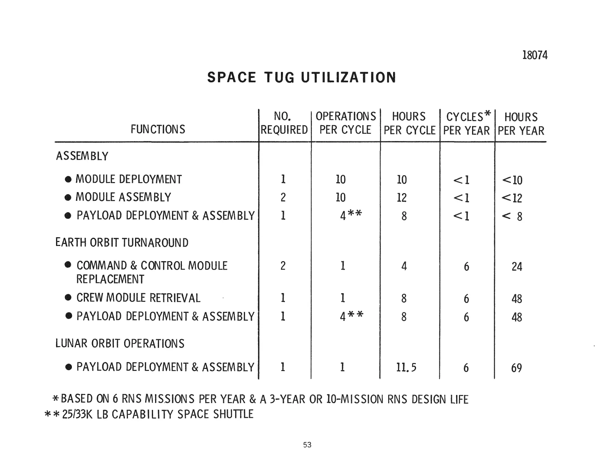
SPACE TUG UTILIZATION
The figure identifies the r e q u i r e d availability and number of tugs r e q u i r e d to
p e r f o r m requisite RNS o p e r a t i o n s . The extent of tug utilization is indicated by the
number of operations per cycle as well as an a s s o c i a t e d e s t i m a t e of hours of active
operation per cycle. Operations a r e defined as an activity r e l a t e d to the handling
of an individual module, whether it be payload or RNS, F o r example, ten o p e r a tions a r e r e q u i r e d per cycle in module deployment during RNS assenn.bly to handle
eight propellant m o d u l e s , one command and control module, and one propulsion
module. The requiremient for four operations for payload deployment and a s s e m b l y
is p r e d i c a t e d on a 33, 000-lb capability space shuttle to the 260-nmi, 31. 5 degree
inclination operational orbit (25, 000 lb to 55 degree inclination). Two tugs a r e
r e q u i r e d to p e r f o r m module a s s e m b l y , as well as command and control module
r e p l a c e m e n t , as the stabilization function is provided the RNS by the command and
control module.
52
18074
SPACE TUG UTILIZATION
NO,
OPERATIONS
HOURS
CYCLES* HOURS
REQUIRED PER CYCLE PER CYCLE PER YEAR PER YEAR
FUNCTIONS
ASSEMBLY
# MODULE DEPLOYMENT
1
10
10
<1
<10
# MODULE ASSEMBLY
2
12
<1
<12
m PAYLOAD DEPLOYMENT & ASSEMBLY
1
10
4*4f
8
<1
< 8
EARTH ORBIT TURNAROUND
# COMMAND & CONTROL MODULE
REPLACEMENT
2
1
4
6
24
# CREW MODULE RETRIEVAL
1
1
8
6
48
1
^*^
8
6
48
1
I
1L5
6
69
•
# PAYLOAD DEPLOYMENT & ASSEMBLY
LUNAR ORBIT OPERATIONS
# PAYLOAD DEPLOYMENTS ASSEMBLY
*BASED ON 6 RNS MISSIONS PER YEAR & A 3-YEAR OR lO-MISSION RNS DESIGN LIFE
**25/33K LB CAPABILITY SPACE SHUTTLE
P E R F O R M A N C E I M P A C T - T R A N S L U N A R COOLDOWN U T I L I Z A T I O N
E s t i m a t e s m a d e to d a t e of the b a s e l i n e RNS p e r f o r m a n c e for t h e l u n a r s h u t t l e
m i s s i o n h a v e not c r e d i t e d i m p u l s e d e r i v e d d u r i n g t h e N E R V A c o o l d o w n p h a s e
t o w a r d the a c c o m p l i s h m e n t of m i s s i o n v e l o c i t y m a n e u v e r s . T h u s , in effect, p r o p e l l a n t c o n s u m e d for t h e N E R V A cooldown function w a s t r e a t e d a s a n o n p r o p u l s i v e ,
u n u s a b l e p r o p e l l a n t . T h e p e r f o r m a n c e i m p l i c a t i o n s of t h i s a s s u m p t i o n h a v e b e e n
e v a l u a t e d u s i n g a t w o - b o d y p a t c h e d c o n i c s o l u t i o n for t h e b a s e l i n e 1 0 8 - h o u r t r a n s l u n a r m i s s i o n l e g . T h e r e f e r e n c e c o n d i t i o n ( z e r o c o o l d o w n u s e d for i m p u l s e ) w a s
a p a y l o a d d e l i v e r y c a p a b i l i t y to l u n a r o r b i t of 112,000 lb (20, 000 l b c r e w m o d u l e on
t h e r e t u r n l e g ) , b a s e d on a N E R V A s t e a d y - s t a t e r u n t i m e of 1, 800 s e c o n d s . T h e
cooldown i m p u l s e profile was m o d e l e d p e r A e r o j e t R e p o r t S - 1 3 0 - B P - 0 9 0 2 9 0 - F L P R E L , " N E R V A R e f e r e n c e D a t a - F u l l F l o w E n g i n e , " d a t e d A p r i l 1970. T h e d u r a tion of the cooldown p h a s e in t h i s c a s e i s a c t u a l l y s o m e w h a t in e x c e s s of t h e
1 0 8 - h r t r a n s f e r tiixie b e t w e e n t h e e a r t h a n d t h e m o o n . T h e t o t a l i m p u l s e c o n t r i b u ted d u r i n g t h e c o o l d o w n p h a s e f o r t h i s p a r t i c u l a r e n g i n e r u n t i m e w o u l d be 3. 3
X 1 0 " l b - s e c , o r an e q u i v a l e n t c h a r a c t e r i s t i c v e l o c i t y of 320 f t / s e c . T o t a l u s e of
t h e c o o l d o w n i m p u l s e for t h e t r a n s l u n a r v e l o c i t y r e q u i r e m e n t r e s u l t s in a n
e q u i v a l e n t r e d u c t i o n in t h e f u l l - t h r u s t v e l o c i t y r e q u i r e m e n t of a p p r o x i m a t e l y
130 f t / s e c , r e s u l t i n g in a p e r f o r m a n c e i m p r o v e m e n t of a p p r o x i m a t e l y 3, 400 l b .
T h i s 3, 4 0 0 - l b p e r f o r m a n c e i m p r o v e m e n t w o u l d be i n c r e a s e d f u r t h e r b y an a d d i t i o n a l 1 1 , 0 0 0 l b p e r f o r m a n c e gain if the r e q u i r e m e n t for e n g i n e c o o l d o w n could be
c o m p l e t e l y e l i m i n a t e d . T h a t i s , t h e 7, 600 lb of p r o p e l l a n t p r e s e n t l y a l l o c a t e d for
c o o l d o w n c o u l d b e r e a s s i g n e d for u s e d u r i n g f u l l - t h r u s t o p e r a t i o n s . T h i s p o t e n t i a l
p e r f o r m a n c e i m p r o v e m e n t ( 1 1 , 000 lb) w o u l d h a v e to be p l a y e d a g a i n s t any s y s t e m
w e i g h t i n c r e a s e s r e q u i r e d to effect cooldown e l i m i n a t i o n (for e x a m p l e r a d i a t o r
s y s t e m s ) . T h e p e r f o r m a n c e i m p a c t of i n c r e a s e s in RNS s y s t e m i n e r t w e i g h t is
2. 7 lb l o s t in o r b i t a l p a y l o a d p e r p o u n d i n c r e a s e in i n e r t w e i g h t , o r a p p r o x i m a t e l y
a 4, 000 lb i n e r t w e i g h t i n c r e a s e a s t h e b r e a k - e v e n p o i n t .
54
PERFORMANCE IMPACT OF NERVA
AFTERCOOLING IMPULSE UTILIZATION
18078
TRANSLUNAR MISSION PHASE
CO
1
4000
HQQ
Q^
O
D^
<
3000
ZD
!
o
hQ
LU
Q^
LU
>
2000
UJ
Q
Q
<
o!
><
a. 1000
^
LU
CO
<
UJ
Qe:
o
0
20
40
60
80
PERCENT OF COOLDOWN IMPULSE UTILIZED
55
100
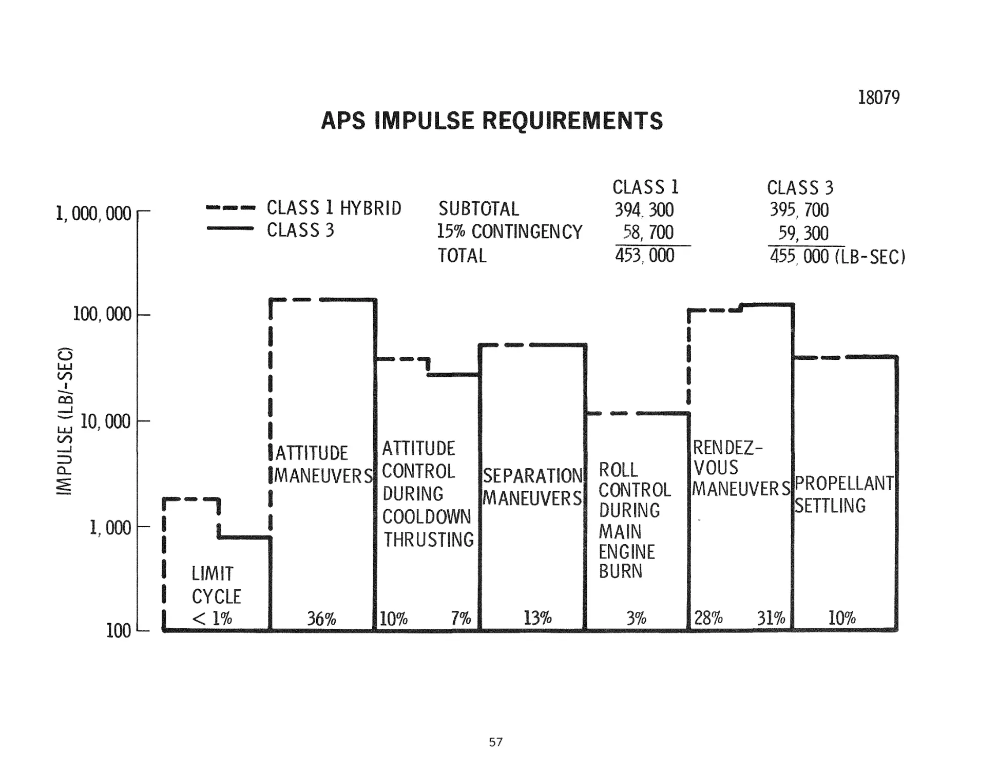
APS IMPULSE REQUIREMENTS
Impulse and t h r u s t level r e q u i r e m e n t s for the APS have been established. These
r e q u i r e m e n t s a r e displayed graphically h e r e . The total impulse for the C l a s s 1
hybrid configuration of approximately 453, 000 l b - s e c t r a n s l a t e s into 1, 132 lb of
propellant, and the C l a s s 3 configuration r e q u i r e s 1, 138 lb of propellant to provide
the 455, 0 0 0 - l b - s e c impulse r e q u i r e m e n t (Ig = 400 sec). A t h r u s t - l e v e l r e q u i r e ment of 100 lb has been selected to provide reasonable maneuver r a t e capability
for attitude m a n e u v e r s . Axial t h r u s t - l e v e l r e q u i r e m e n t s of 3 lb (positive) and
200 lb (negative) for preignition separation and rendezvous m a n e u v e r s have been
identified.
T h e r e a r e seven distinct functions p e r f o r m e d by the APS during the lunar m i s s i o n .
These a r e (1) attitude control during coast p h a s e s , (2) attitude m a n e u v e r s , (3)
attitude control during cooldown thrusting, (4) s e p a r a t i o n m a n e u v e r s p r i o r to main
stage ignition, (5) roll control during main engine b u r n s , (6) supplemental t h r u s t
during rendezvous m a n e u v e r s , and (7) a c c e l e r a t i o n for propellant settling.
Limit cycle r e q u i r e m e n t s a r e shown to be one to two o r d e r s of magnitude below
other functional r e q u i r e m e n t s . Limit cycling was a s s u m e d to be accomplished
within a plus or minus o n e - d e g r e e deadband, using a m i n i m u m impulse bit of
3 l b - s e c . Attitude m a n e u v e r s w e r e performed at a r a t e of 0. 1 d e g / s e c and include
vehicle orientation for v a r i o u s NERVA o p e r a t i o n s , coast, separation, and gravity
gradient storage in e a r t h and lunar o r b i t s . C o n t r a r y to engine operation at full
t h r u s t and in the idle mode, where vehicle attitude is provided by gimbaling the
NERVA to counteract overturning m o m e n t s , the APS is r e q u i r e d to stabilize the
vehicle during cooldown o p e r a t i o n s . The r e q u i r e m e n t s shown for this function a r e
based on an a s s u m e d 0. 1 degree m i s a l i g n m e n t between the cooldown t h r u s t vector
and the vehicle c e n t e r of gravity. A velocity provision of 2, 5 f t / s e c each for
separation from m a n n e d - l u n a r and e a r t h - o r b i t facilities p r i o r to NERVA operations
was budgeted. Roll control r e q u i r e m e n t s evolve during the s t a r t t r a n s i e n t and
s t e a d y - s t a t e engine o p e r a t i o n s . Steady-state impulse r e q u i r e m e n t s w e r e scaled at
the r a t e of 500 l b - s e c plus 0. 1 l b - s e c per second of s t e a d y - s t a t e operation, based
on experience with the J - 2 engine (scaled a p p r o p r i a t e l y ) . A velocity allocation for
rendezvous m a n e u v e r s of 10 ft/.sec each for lunar orbit and e a r t h orbit rendezvous
was m a d e .
56
18079
APS IMPULSE REQUIREMENTS
CLASS 1 HYBRID
CLASS 3
1,000.000 r
SUBTOTAL
15% CONTINGENCY
TOTAL
CLASS 1
394. 300
CLASS 3
395., 700
59, 300
455, 000 (LB-SEC)
58, 700
453,000
100.000
o
LU
m
I
, !
UJ
10,000 -
oo
a.
1,000
L
LIMIT
ATTITUDE
ATTITUDE
SEPARATION ROLL
MANEUVERS CONTROL
DURING
MANEUVERS CONTROL
DURING
COOLDOWN
MAIN
THRUSTING
ENGINE
BURN
RENDEZVOUS
MANEUVERS PROPELLANT
SETTLING
CYCLE
100 L-
<1%
36%
10%
7%
13%
57
3%
28%
31%
10%
RNS DESIGN
T h e c o n t e x t for t h e c u r r e n t p h a s e of t h e RNS d e s i g n a c t i v i t y is g i v e n on t h e f a c i n g
c h a r t . P h a s e II r e s u l t e d in d e f i n i t i o n of t h e two b a s i c RNS concepts—the s i n g l e m o d u l e , 3 3 - f t - d i a m e t e r C l a s s 1 c o n c e p t and t h e m u l t i p l e - m o d u l e C l a s s 3
c o n f i g u r a t i o n . T h e f i r s t p e r i o d of P h a s e 3 f o c u s e d on s e l e c t i o n of m a j o r
c h a r a c t e r i s t i c s f o r e a c h c o n c e p t and t h e o v e r a l l c o n f i g u r a t i o n of t h e v e h i c l e s .
T h e m o s t s i g n i f i c a n t s e l e c t i o n d u r i n g t h i s p e r i o d w a s t h a t of a d i s c r e t e c o m m a n d
and c o n t r o l m o d u l e f o r t h e C l a s s 1 c o n c e p t to m o s t e f f e c t i v e l y a c c o m p l i s h o r b i t a l
m a i n t e n a n c e . A n o t h e r m a j o r r e s u l t of t h e f i r s t p e r i o d a n a l y s i s w a s t h e s e l e c t i o n
of t h e C l a s s 3 v e h i c l e c o n f i g u r a t i o n w i t h t h e m o d u l e s in t h e f o r m of a c r u c i f o r m
c l u s t e r . O p e r a t i o n s w e r e a n a l y z e d in s u p p o r t of m a k i n g t h e a b o v e c o n c e p t /
c o n f i g u r a t i o n s e l e c t i o n s a s w e l l a s to p r o v i d e t h e b a s e s f o r m o r e d e t a i l e d
d e f i n i t i o n of the RNS i t s e l f .
During the second period m a j o r design activities w e r e oriented toward t r a d e
studies selecting specific s u b s y s t e m design f e a t u r e s . To a c c o m p l i s h t h e s e t r a d e
s t u d i e s , detailed o p e r a t i o n s a n a l y s i s , using the s c e n a r i o s developed during the
f i r s t p e r i o d , •were p e r f o r m e d to e s t a b l i s h s u b s y s t e m r e q u i r e m e n t s .
S u b s e q u e n t c h a r t s w i l l s h o w t h e o p e r a t i o n s a n a l y s i s and s u b s y s t e m d e f i n i t i o n
for t h e RNS f u n c t i o n a l s u b s y s t e m s . T h i s s e c t i o n w i l l c o n c l u d e with a s u m m a r y
of t h e m a j o r f e a t u r e s s e l e c t e d d u r i n g t h i s p e r i o d and v^ith t h e c u r r e n t w e i g h t
s t a t e m e n t f o r b o t h RNS c o n c e p t s .
58
RNS DESIGN
® FIRST PERIOD RESULTS:
®RNS CONCEPT/CONFIGURATION
® CLASS 1 - - CCM FOR MAINTENANCE
® CLASS 3 - -
CRUCIFORM CLUSTER
® OPERATIONS
® MISSION TIMELINE
^ORBITALASSEMBLY AND REFURBISHMENT
® RNS OPERATIONS
® SECOND PERIOD OBJECTIVES:
• DESIGN FEATURE TRADE STUDIES
® DETAIL OPERATIONS TO ESTABLISH REQUIREMENTS
59
RNS P R O P E L L A N T M A N A G E M E N T A P P R O A C H
T h i s p o r t i o n of t h e b r i e f i n g w i l l d e v e l o p t h e d e s i g n c o n c e p t and o p e r a t i o n s for t h e
p r o p e l l a n t m a n a g e m e n t f u n c t i o n s of t h e R N S . F u n c t i o n a l s c h e m a t i c s w i l l b e
d e v e l o p e d , b e g i n n i n g -with t h e m o s t b a s i c f u n c t i o n s r e q u i r e d f o r a s t a g e and a d d i n g
s u b s y s t e m d e s i g n c o n c e p t s s p e c i f i c a l l y r e q u i r e d f o r RNS o r b i t a l and m i s s i o n
o p e r a t i o n s . T h e a p p r o a c h w i l l b e to identify d e s i g n r e q u i r e m e n t s and i m p l i c a t i o n s
of t h e v a r i o u s o p e r a t i o n a l p h a s e s . P r i o r to c o n a m e n c i n g t h e m i s s i o n t h e r e a r e
o r b i t a l o p e r a t i o n s , i n c l u d i n g p r o p e l l a n t r e s u p p l y and c h e c k o u t , r e q u i r e d f o r
r e u s a b i l i t y of t h e s y s t e m . T h e m i s s i o n o p e r a t i o n s f o r t h e r e f e r e n c e l u n a r s h u t t l e
p r o f i l e e n c o m p a s s m u l t i p l e b u r n s in v a r i o u s N E R V A t h r u s t m o d e s . T h e a s s o c i a t e d
o p e r a t i o n s a n d s e q u e n c i n g of t h e s t a g e f u n c t i o n a l s u b s y s t e m s w i l l be d e f i n e d f o r
these requirements.
60
RNS PROPELLANT MANAGEMENT
APPROACH
DEVELOP RNS PROPELLANT MANAGEMENT SCHEMATIC
©BASIC FUNCTIONS
# ADD DESIGN CONCEPTS FOR RNS ORBITAL & MISSION OPERATIONS
IDENTIFY DESIGN REQUIREMENTS AND IMPLICATIONS OF RNS OPERATIONS
PHASES
# ORBITAL -• PROPELLANT RESUPPLY, CHECKOUT
® MISSION - LUNAR SHUTTLE PROFILE
DEFINE FUNCTIONAL SUBSYSTEMS OPERATIONS & SEQUENCING
# STARTUP
# CONTROL
# SHUTDOWN & AFTERCOOLING
BASIC P R O P E L L A N T M A N A G E M E N T S C H E M A T I C
T h e b a s i c p r o p e l l a n t m a n a g e m e n t s c h e m a t i c s h o w s t h e p r o p u l s i o n m o d u l e and a
s i n g l e p r o p e l l a n t m o d u l e . F u n c t i o n s a r e p r o v i d e d for g r o u n d , l a u n c h , and
m i n i m u m m i s s i o n o p e r a t i o n s . T h e s t a g e i n t e r m o d u l e i n t e r f a c e s a r e flight r e m o t e
couplings.
G r o u n d fill a n d d r a i n for t h e C l a s s 3 m o d u l e s u s e s t h e e x i s t i n g p r o p e l l a n t feed
s y s t e m for propellant loading inside the space shuttle. The propulsion module
is l a u n c h e d d r y , h o w e v e r . T h e C l a s s 1-H p r o p e l l a n t m o d u l e i n c o r p o r a t e s a
s e p a r a t e f i l l - a n d - d r a i n r i s e r duct, a pneumatically actuated, n o r m a l l y closed
f i l l - a n d - d r a i n v a l v e , and a n u m b i l i c a l d i s c o n n e c t .
T h e g r o u n d v e n t a n d r e l i e f s y s t e m p r o v i d e s f o r v e n t i n g of t h e fuel t a n k d u r i n g
filling and s a f e t y r e l i e f c a p a b i l i t y in t h e e v e n t of i n a d v e r t e n t p r e s s u r e b u i l d u p .
T h e s y s t e m c o n t a i n s a v e n t v a l v e and a v e n t - a n d - r e l i e f v a l v e . T h e v e n t v a l v e is
p n e u m a t i c a l l y a c t u a t e d for g r o u n d o p e r a t i o n o n l y . G r o u n d v e n t f u n c t i o n s f o r t h e
p r o p u l s i o n r a o d u l e a r e p r o v i d e d by field c o n n e c t i o n s t o t h e flight v e n t s y s t e m .
T h e flight v e n t s y s t e m u t i l i z e s q u a d - r e d u n d a n t p i l o t - o p e r a t e d s o l e n o i d v a l v e s ,
which a r e p r e s s u r e s e n s o r controlled. Nonpropulsive vent n o z z l e s a r e
incorporated.
T h e p r e s s u r i z a t i o n s y s t e m o p e r a t e s with N E R V A b l e e d g a s . It u t i l i z e s a s e t of
q u a d - r e d u n d a n t , d i r e c t - a c t i n g solenoid v a l v e s , which a r e p r e s s u r e s e n s o r
c o n t r o l l e d . S e p a r a t e f u n c t i o n s of p r e p r e s s u r i z a t i o n , e x p u l s i o n , and p r e s s u r e
control a r e provided. The p a r a l l e l redundant check valves a r e engine supplied.
A d i f f u s e r i n l e t is i n c o r p o r a t e d .
The p r o p e l l a n t feed s y s t e m p e r m i t s independent a c c e s s to each p r o p e l l a n t m o d u l e
and i n d e p e n d e n t o p e r a t i o n of t h e p r o p u l s i o n m o d u l e . It c o n s i s t s of two p a r a l l e l
8. 0 0 - i n . - d i a m e t e r m o t o r - d r i v e n shutoff v a l v e s and a 12. 0 0 - i n . - d i a m e t e r
b l o c k i n g v a l v e l o c a t e d in t h e f e e d t h r o u g h r i s e r . A n t i v o r t e x i n g and f i l t r a t i o n i s
a c c o m p l i s h e d with tank bottom s c r e e n i n g .
62
18110
BASIC PROPELLANT MANAGEMENT SCHEMATIC
FLIGHT VENT
GROUND VENT/RELIEF,
R
GROUND FILL AND DRAIN
# CLASS 1»H: PROVIDE DISCRETE SYSTEM
® CLASS 3: USE FEED SYSTEM
®PROPULSION: LAUNCH DRY
GROUND VENT AND RELIEF
® PROPELLANT: DISCRETE
® PROPULSION: USE FLIGHT VENT
FLIGHT VENT
®NON»PROPULSIVE
PRESSURIZATION
® CONFIGURED FOR NERVA BLEED
® PROVIDE SEPARATE REPRESSURIZATION.
EXPLUSION, AND CONTROL
® DIFFUSER INLET
STAGE/ENGINE
INTERFACE
PROPELLANT FEED
® INDEPENDENT ACCESS TO MODULES
PRESSURANT
SUPPLY
63
P R O P E L L A N T RESUPPLY CONCEPT
A schematic of the design concept for orbital propellant resupply is depicted in
this c h a r t . It is used for orbital fill on both propellant and propulsion m o d u l e s .
An objective of the design is to fill a propellant tank in orbit without venting or an
e x c e s s i v e p r e s s u r e r i s e . This is accomplished by using s p r a y - n o z z l e injection to
accomplish ullage c o l l a p s e , maintaining propellant orientation during the p r o p e l lant t r a n s f e r operation with axial a c c e l e r a t i o n provided by the tanker vehicle.
Also, the orbital fill s y s t e m includes a check valve and a flow m e t e r in the fill
line to control the propellant in-flow r a t e and m i n i m i z e p r e s s u r e s u r g e s during
chilldown of a w a r m tank. This r e q u i r e m e n t is imposed on modules which have
been depleted e a r l y in the m i s s i o n or have sustained a long coast in orbit before
refill. The m a i n LH^ feed duct is blocked n e a r the top of the tank to limit p e n e t r a t i o n of cold fluid into the w a r m feed duct inside the tank during chilldown and
inhibit g e y s e r i n g . The delivered propellant conditions at s t a r t u p of the RNS m i s sion depend on the propellant resupply logistics m o d e l . The v a r i a t i o n s introduced
by such models will not be considered h e r e . F o r the s i m p l e s t c a s e , the difference
between delivering the propellant to a w a r m and a cold tank is indicated.
64
18086
PROPELLANT RESUPPLY CONCEPT
TANK FILLED WITHOUT VENTING
FILL SHUT-OFF
VALVES
SPRAY NOZZLE INJECTION
ACCELERATION BY TANKER
PROVIDE CHILLDOWN OF WARM TANK
CHECK VALVE & FLOW METER CONTROL
MINIMIZE PRESSURE SURGES
SPRAY
NOZZLE
FEED LINE BLOCKED
CV
DELIVERED PROPELLANT CONDITIONS
65
COLD TANK
16 PSIA
WARM TANK -
21 PSIA
PROPELLANT M A N A G E M E N T CHECKOUT
The r e q u i r e m e n t s for RNS propellant management checkout in orbit before s t a r t i n g
the m i s s i o n consist of functional check of s u b s y s t e m s and components and leakage
check at i n t e r f a c e s , which also includes initial verification of orbital a s s e m b l y .
Candidate functional check approaches a r e delineated h e r e as either component
functional checkout or actual simulated operations of the s y s t e m . A component
functional checkout s t r a t e g y could m i n i m i z e fluid flow and expendables compared
to simulated operations, while the l a t t e r could even r e q u i r e NERVA c r i t i c a l i t y to
accomplish p r e s s u r i z a t i o n . In utilizing either approach it is d e s i r e d to impose
m i n i m a l additional components or operations on the baseline design.
66
PROPELLANT MANAGEMENT CHECKOUT
REQUIREMENTS
# FUNCTIONAL CHECK -
ALL SUBSYSTEMS AND COMPONENTS
® VERIFY OPERATION AND REDUNDANCIES
# LEAKAGE CHECK AT INTERFACES
® STATIC SEALS
® DYNAMIC SEALS (VALVES)
® REMOTE FLUID COUPLINGS (ORBITAL ASSEMBLY)
CANDIDATE FUNCTIONAL CHECK APPROACHES
# COMPONENT FUNCTIONAL CHECKOUT
® OPERATE COMPONENTS SEQUENTIALLY -
VERIFY TALKBACKS
® MINIMIZE FLUID FLOW AND EXPENDABLES
# SIMULATED OPERATIONS
® PROPELLANT SETTLING, CHILLDOWN, PRESSURIZATION,
RUN TANK REFILL, AFFERCOOLING
® NERVA CRITICALITY REQUIRED
67
COMPONENT FUNCTIONAL CHECKOUT
Approaches to component functional checkout a r e defined h e r e for t h r e e general
c l a s s e s of propellant management s u b s y s t e m configurations. F o r the f i r s t
c l a s s , quad-redundant valve configurations, it is evident that redundancy has been
imposed on m o s t flight s y s t e m s for reliability. Thus, no additional checkout
valves a r e r e q u i r e d . The checkout approach consists of sequencing valve
actuation to minimize fluid l o s s e s , verifying talkbacks from the c o n t r o l s . The
approach r e q u i r e s independent control of the valves.
The second c l a s s of propellant management s u b s y s t e m s is r e p r e s e n t e d by the LH2
feed s y s t e m . F o r this s y s t e m , blocking valves isolate each module interface,
p e r m i t t i n g actuation of the dual feed v a l v e s . Similarly, the chilldown and refill
pumps could be run with the d i s c h a r g e valves closed. These checkout operations
could be p e r f o r m e d at convenient t i m e s in the operations profile, which include the
propellant resupply period and the n o r m a l feed s y s t e m chilldown during the s t a r t u p
r a m p to m i n i m i z e the impact of t h e s e o p e r a t i o n s .
The third c l a s s of checkout items consists of ground-only functions such as the
f i l l - a n d - d r a i n and ground vent s y s t e m s . These a r e locked for flight, and orbital
checkout is not r e q u i r e d .
68
18101
COMPONENT FUNCTIONAL CHECKOUT
C U S S 1: QUAD-REDUNDANT VALVE CONFIGURATIONS
® REDUNDANCY IMPOSED ON MOST FLIGHT SYSTEMS FOR RELIABILITY-ORBITAL
FILL, PRESSURIZATION, FLIGHT VENT, CHILLDOWN, AFTERCOOLING, APS
# NO ADDITIONAL C/0 VALVES REQUIRED
# SEQUENCE ACTUATION TO MINIMIZE LOSSES
® VERIFY TALKBACKS
® REQUIRES INDEPENDENT CONTROL
CLASS 2: LH2 FEED SYSTEM
# BLOCKING VALVES ISOLATE EACH MODULE INTERFACE
# ACTUATE DUAL FEED VALVES
# RUN CHILLDOWN AND REFILL PUMPS WITH DISCHARGE VALVES CLOSED
# PERFORM AT CONVENIENT TIMES
® PROPELLANT RESUPPLY
® FEED SYSTEM CHILLDOWN (STARTUP RAMP)
CLASS 3: GROUND-ONLY FUNCTIONS (FILL AND DRAIN, GROUND VENT)
# LOCKED FOR FLIGHT - ORBITAL C/0 NOT REQUIRED
PROPELLANT M A N A G E M E N T CHECKOUT APPROACH
C o m p o n e n t f u n c t i o n a l c h e c k o u t is f a v o r e d o v e r s i m u l a t e d o p e r a t i o n s on the b a s i s
of m i n i m i z i n g o p e r a t i o n a l p e n a l t i e s . F u r t h e r n a o r e , it i s e v i d e n t t h a t t h e r e a r e
no m a j o r a d d i t i o n a l d e s i g n r e q u i r e m e n t s : s p e c i f i c a l l y , no c h e c k o u t v a l v i n g .
T h e a d d i t i o n a l r e q u i r e m e n t s f o r o p e r a t i o n a l i n s t r u m e n t a t i o n and s t i m u l i a r e
c o n s i d e r e d to b e s m a l l and the only v a r i a t i o n i m p o s e d on t h e d e s i g n is t h e
r e q u i r e m e n t f o r p r o v i d i n g i n d e p e n d e n t v a l v e c o n t r o l in q u a d - r e d u n d a n t s y s t e m s .
L e a k a g e c h e c k at i n t e r f a c e s c a n be a c c o m m o d a t e d by a n u m b e r of a p p r o a c h e s ,
w i t h t h e c o n s i d e r a t i o n t h a t t h e d e s i g n s h o u l d p r o v i d e i n s e n s i t i v i t y to s m a l l l e a k s .
S e v e r a l p r a c t i c a l c a n d i d a t e s a r e a v a i l a b l e f o r l e a k a g e c h e c k of s e a l s . D u a l s e a l
flanges and leak detection p o r t s have a l r e a d y been d e m o n s t r a t e d for static s e a l s
on S - I V B . A c o u s t i c e m i s s i o n s e n s o r s a r e p r e s e n t l y b e i n g d e v e l o p e d f o r d y n a m i c
s e a l s . F u r t h e r m o r e , it is c o n s i d e r e d t h a t o r b i t a l a s s e m b l y v e r i f i c a t i o n is
feasible for the b a s e l i n e r e m o t e , automated a s s e m b l y o p e r a t i o n s . Torque control
c a n be e m p l o y e d f o r s c r e w d r i v e s and p o s i t i o n o r t o r q u e t a l k b a c k s c a n b e
employed.
70
PROPELLANT MANAGEMENT CHECKOUT APPROACH
COMPONENT FUNCTIONAL C/0 FAVORED OVER SIMULATED OPERATIONS
^ M I N I M I Z E S OPERATIONAL PENALTIES
# M I N I M A L DESIGN REQUIREMENTS
® NO C/O VALVING
® SMALL A STIMULI AND INSTRUMENTATION
® INDEPENDENT VALVE CONTROL
LEAKAGE CHECK AT INTERFACES CAN BE ACCOMMODATED
# DESIGN FOR INSENSITIVITY TO SMALL LEAKS
# SEVERAL PRACTICAL CANDIDATES AVAILABLE
® STATIC: DUAL SEAL FLANGES AND LEAK DETECTION PORTS
® DYNAMIC: ACOUSTIC EMISSION SENSORS
# ORB ITAL ASSEMBLY VERIFICATION FEASIBLE
® TORQUE CONTROL FOR SCREW DRIVES
® POSITION OR TORQUE TALKBACKS
71
RNS OPERATIONS FOR MISSION PHASES - I
The propellant utilization and NERVA t h r u s t modes during the lunar shuttle
m i s s i o n profile, which g e n e r a t e the stage propellant management design
r e q u i r e m e n t s , a r e depicted in the next two c h a r t s for the C l a s s 3 RNS. These
show the propellant loadings in the propellant modules and the propulsion m o d ule after completion of m a i n s t a g e b u r n s . Also, the aftercoolant r e q u i r e d after
completion of the b u r n s is shown s e p a r a t e l y . In t h e s e figures the propulsion
module is blown up in scale to provide g r e a t e r definition of the propellant loadings in that module. The capacity of a Glass 3 propellant module is 36,400 lb
LH2 (8 a r e utilized) and the propulsion module capacity is 9, 700 lb LH2.
The NERVA t h r u s t modes for the various m i s s i o n m a n e u v e r s a r e indicated. The
first burn, t r a n s l u n a r injection (TLI), is p e r f o r m e d at full t h r u s t . The r e q u i r e d
propellant for pulsed aftercooling is contained in the propulsion module run tank.
The m i d - c o u r s e c o r r e c t i o n is p e r f o r m e d using the NERVA idle m o d e . Only the
propulsion module is operated for that m a n e u v e r , so only that module is depicted.
The initial elliptical lunar orbit injection m a n e u v e r (LOI-1) is also p e r f o r m e d at
full t h r u s t . Since the run tank was depleted for TLI aftercooling and the m i d c o u r s e m a n e u v e r , it m u s t be refilled before L O I - 1 . The subsequent plane change
m a n e u v e r at the moon (LOI-2) is p e r f o r m e d with the NERVA throttle mode, and
all of the r e q u i r e d propellant for that maneuver and LOI~l aftercooling is contained in the run tank. Completion of lunar orbit injection {LOI-3) is p e r f o r m e d
as a full t h r u s t operation, requiring a refill of the run tank before s t a r t u p . All
aftercooling operations and the small m a n e u v e r s which a r e p e r f o r m e d at l e s s
than full t h r u s t a r e p e r f o r m e d using only the propulsion module run tank.
72
18089
RNS OPERATIONS FOR MISSION PHASES-I
r-s
^^
p^^^
PROPELLANT
MODULES
• ^
1^^^:^
r^
^-^
r^
N
^^
PROPULSION O
MODULE
^^
BURN:
MIDCOURSE
LOI-1
LOI-2
LOI-3
THRUST:
IDLE MODE
FULL
THROTTLE
FULL
MODE
AFTERCOOLANT REQUIRED
PROPELLANT REMAINING
73
1
RNS OPERATIONS FOR MISSION PHASES-II
The remaining p h a s e s of the lunar shuttle m i s s i o n profile a r e depicted in this
chart, including the t r a n s - e a r t h injection (TEI) and e a r t h orbit injection (EOI)
m a n e u v e r s . The same general modes of operation a r e applied: t h r o t t l e mode for
the plane change at the moon and idle mode for m i d - c o u r s e , with full-thrust
operation in the main b u r n s . Again the propulsion module run tank supplies all of
the aftercoolant and the propellant r e q u i r e d for small m a n e u v e r s . It is refilled
before each full-thrust b u r n .
74
18090
RNS OPERATIONS FOR ^^ISSION PHASES-ii
p^
N
\^
.wvj
PROPELLANT
MODULES
w
PROPULSION
MODULE
n
L^w^
i^
Q
BURN:
TEI-1
TEI-2
TEI-3
MIDCOURSE
EOI
THRUST:
FULL
THROTTLE MODE
FULL
IDLE MODE
FULL
AFTERCOOLANT REQUIRED
PROPELLANT REMAINING
75
REQUIREMENTS FOR NERVA OPERATING MODES
The NERVA t h r u s t modes d e s c r i b e d on the preceding c h a r t s g e n e r a t e r e q u i r e m e n t s
for different stage propellant management functions, including propellant settling,
feed s y s t e m chilldown, p r e p r e s s u r i z a t i o n , and p r e s t a r t run tank refill. The
various NERVA t h r u s t operating modes a r e defined according to t h e i r r e s p e c t i v e
p a r a m e t e r s and r e q u i r e d RNS functions in this c h a r t . These a r e used as a b a s i s
for defining the RNS propellant management design concepts and o p e r a t i o n s .
76
18091
REQUIREIVIENTS FOR NERVA OPERATING MODES
NERVA PARAMETERS
RNS FUNCTIONS
THRUST
(LB)
FLOW
RATE
(LB/SEC)
ISP
(SEC)
FULL POWER
75,000
9L9
825
/
/
THRO! ILE MODE
45,000
55.1
825
/
/
1,000
2
500
0.7
430
NERVA
OPERATING
MODE
IDLE MODE
AFTERCOOLING
/=
300
PROPELLANT
SETTLING
REQUIRED
11
FEED
SYSTEM
CHILLDOWN
PREPRESS"
URIZATION
/
PRESTART
RUN TANK
REFILL
^l
STARTUP OPERATION PHASING SCHEMATIC
The sequencing and i n t e r r e l a t i o n of the operations of propellant settling,
propellant feed s y s t e m conditioning, NERVA t h r u s t buildup, and p r e p r e s s u r i z a t i o n
of propellant tankage a r e delineated in this s c h e m a t i c . P r o p e l l a n t settling
c o n s i s t s of two p h a s e s . The initial phase of inviscid orientation r e q u i r e s a low
a c c e l e r a t i o n provided by the APS. This is followed by a h i g h - t h r u s t , dissipative
settling p h a s e for which the n e c e s s a r y a c c e l e r a t i o n is provided by NERVA during
its s t a r t u p r a m p . The operations for preconditioning the feed s y s t e m include
chilldovAn and p r e s t a r t refilling of the run tank. These a r e a c c o m p l i s h e d during
the inviscid orientation phase after an initial settling period. P r e p r e s s u r i z a t i o n
cannot be initiated until completion of the dissipative phase of settling and NERVA
cannot operate above the throttle point without tankage p r e p r e s s u r i z a t i o n , so a
t h r u s t hold period at the throttle point is i n c o r p o r a t e d into the t h r u s t buildup r a m p .
After p r e p r e s s u r i z a t i o n of the run tank the NERVA t h r u s t can be i n c r e a s e d to full
power, although for some c a s e s it could be d e s i r a b l e to maintain the t h r u s t hold
until completion of p r e p r e s s u r i z a t i o n of the propellant module. When the p r o pellant module is p r e s s u r i z e d , it can be brought on-line to refill the run tank under
full power. The design concepts for each of t h e s e operations ^vill be defined in
subsequent c h a r t s .
78
18092
STARTUP OPERATIONS PHASING SCHEfiATIC
SYSTEM
PROPELLANT
SETTLING
FEED SYSTEM
DISSIPATIVE
INVISCID ORIENTATION
POWERED
RUN TANK
REFILL
CCBPLETE
RAMP
CHILL-PRESTART RUN
DOWN TANK REFILL
BOOT
STRAP
THRUST
HOLD
FULL POWER
RAMP
TO
THROTTLE POINT
NERVA
PRO
RUN
PELLANT
TANK
MODULE
PREPRESSURIZATION
79
PROPELLANT SETTLING
T h e p r o p e l l a n t s e t t l i n g o p e r a t i o n s a r e defined h e r e , d i v i d e d i n t o two p h a s e s .
I n i t i a l l y , t h e r e is an i n v i s c i d o r i e n t a t i o n p h a s e to l o c a t e t h e p r o p e l l a n t at t h e
b o t t o m of t h e t a n k s w h i l e i m p a r t i n g a m i n i m u m a m o u n t of k i n e t i c e n e r g y to i t .
T h e c r i t e r i o n d e t e r m i n e d f o r t h e d e s i g n i s to p r o v i d e a n i n i t i a l r u n t a n k B o n d
n u m b e r = 10 at T L I . ^JThis is p r o v i d e d jDy^3JLb^f_a_xiaJ^_£ettl_m_g_^^
A P S , c o r r e s p o n d i n g to a n i n i t i a l a c c e l e r a t i o n of 6. 7 x 10~o g. A n t i g e y s e r i n g
.».^^„_.,__---»-^^.j^^^-£;^-~^ "Yg
c o n t r o l . P r o v i d i n g s e t t l i n g f o r e a c h of t h e
b u r n s in t h e l u n a r s h u t t l e m i s s i o n p r o f i l e r e s u l t s in a t o t a l i n v i s i d p h a s e s e t t l i n g
p r o p e l l a n t c o n s u m p t i o n of 120 lb with a c r y o g e n i c A P S . D e f i n i t i o n of t h e s y s t e m
h a s i n d i c a t e d n o i n t e r f e r e n c e of t h e s e t t l i n g t i m e s with l i m i t c y c l i n g o r a f t e r c o o l ing, e v e n t h o u g h t h e r e q u i r e d i n v i s c i d s e t t l i n g t i m e s a r e long, r a n g i n g f r o m
3, 200 s e c a t T L I to 1, 700 s e c for E O I w i t h t h e C l a s s 3 R N S .
T h e s e c o n d p h a s e of s e t t l i n g r e q u i r e s h i g h t h r u s t to d i s s i p a t e t h e k i n e t i c e n e r g y of
t h e fluid, d a m p out s l o s h and e l i m i n a t e b u b b l e s . S l o s h baffles a r e i n c o r p o r a t e d to
a s s i s t e n e r g y d i s s i p a t i o n . T h e o b j e c t i v e for t h i s p h a s e i s to a c h i e v e a q u i e s c e n t
l i q u i d to p e r m i t e f f i c i e n t p r e p r e s s u r i z a t i o n w i t h a hot g a s . T h e m o s t e f f i c i e n t
d e s i g n c o n c e p t i s to u t i l i z e the N E R V A t h r u s t r a m p a n d t o hold t h e t h r u s t a t t h e
t h r o t t l e p o i n t until a d e q u a t e s e t t l i n g for p r e p r e s s u r i z a t i o n h a s b e e n a c h i e v e d .
U s i n g e x i s t i n g c r i t e r i a t h i s r e q u i r e s 10 to 60 s e c for t h e r a n g e of s t a r t u p
c o n d i t i o n s in t h e m i s s i o n .
80
18094
PROPELLANT SETTLING
INVISCID ORIENTATION PHASE
# CRITERION:
UTILIZE APS:
GEYSERING
BAFFLE-7
INITIAL RUN TANK
BOND NO. = 10
3 LB THRUST,
120 LB PROPELLANT TOTAL
NO INTERFERENCE OF SEHLING TIMES WITH
LIMIT CYCLING OR AFTERCOOLING:
SLOSH
BAFFLES
TLI 3,200 SEC, E O I I , 700 SEC
DISSIPATIVE PHASE
# CRITERION:
ELIMINATE SLOSH & BUBBLES
FOR PREPRESSURIZATION
UTILIZE NERVA THRUST RAMP - POSSIBLE HOLD
AT THROTTLE POINT
REQUIRES 10 TO 60 SECONDS
81
NERVA STARTUP THRUST R A M P
NERVA operating conditions, a c c e l e r a t i o n level, and the r e q u i r e d saturation
p r e s s u r e for 0 N P S P at the existing flow r a t e a r e indicated at v a r i o u s t i m e s
through the NERVA t h r u s t buildup r a m p . After the first 30 sec of b o o t s t r a p
operation, the a c c e l e r a t i o n level b e c o m e s adequate for the dissipative r e q u i r e m e n t s of settling. It is seen that the engine can operate up to the t h r o t t l e point
without p r e p r e s s u r i z a t i o n for the anticipated propellant h i s t o r i e s , since tank chilldown r e s u l t s in a 21-psia initial condition.
82
NERVA STARTUP THRUST RAMP
PHASE
BOOTSTRAP
RAMP UP
18095
TIME
fSEC)
FLOW
RATE
(LB/SEC)
0
12
295
253
6.3X10"^
12
25
L2
383
331
8.1 X 10⁻⁴
12
30
L8
691
375
L 5 X 10⁻³
•12
39
218
17,0%
572
3,6X10⁻²
16.2
52
55 J
44,9%
816
16X10-2
203
THROTTLE POINT
56
9L9
75,000
816
0J6
26.0
FULL THRUST
THRUST iSP ACCELERATION
(LB)
(SEC)
^ FULL RNS AT TLI
83
PSAT FOR
ONPSP
(PSIA)
CHILLDOWN REQUIREMENTS
P r i o r to s t a r t u p it is n e c e s s a r y to chilldown the active portion of the RNS feed
s y s t e m to a s s u r e propellant conditions for NERVA and to a c c o m p l i s h a p r e dictable s t a r t u p operation. The feed s y s t e m interfaces that r e q u i r e conditioning
include the two legs of the NERVA feed s y s t e m between the turbopump and the run
tank and the interfaces between the various RNS m o d u l e s . These a r e s u m m a r i z e d
in the facing c h a r t . All the stage feed ducting uses two basic types of flexible
e l e m e n t s , gimbal joints and linear p r e s s u r e volume c o m p e n s a t o r s , which account
for the m a s s e s shown for those s y s t e m s . Chilldown t i m e r e q u i r e m e n t s w e r e
based on the m i n i m a l p e r m i s s i b l e t i m e for chilldown of each interface c o n s i d e r i n g
film boiling heat t r a n s f e r for a duct initially at ambient t e m p e r a t u r e and providing
a m a r g i n of safety for flow s u r g e s .
84
18096
CHILLDOWN REQUIREI^ENTS
CHILL
TIME
(SEC)
INItRFACE
CCBPONENTS
MASS
(LB)
LENGTH
(FT)
EQUIVALENT
BOILOFF
(LB-LH2)
NERVA
(EACH SIDE)
PSOV-VALVE
9 IN, FEED DUCT*
TURBOPUMP
PDKVA-VALVE
973
8,9
92
43
RUN TANK/
PROPELLANT
MODULE
12 IN. FEED DUCT*
263
11
28
34
PROPELLANT
MODULE/
PROPELLANT
MODULE
12 IN, FEED DUCT*
217
10»2
23
24
OUTBOARD/
INBOARD
PROPELLANT
MODULES
8 IN. FEED DUCT*
116
1L5
13
17
* INCLUDES GIMBAL JOINTS
INTEGRATED NERVA/STAGE CHILLDOWN SYSTEM
This c h a r t depicts the s c h e m a t i c of the integrated N E R V A / s t a g e pump driven
chilldovm s y s t e m for p r e s t a r t chilldown of the propellant feed s y s t e m . It is l o cated in the run tank and provides conditioning for both the NERVA and stage
i n t e r f a c e s . It is operated during the low-g inviscid orientation phase of settling to
avoid s e p a r a t e o p e r a t i o n s . F o r c e d convection is r e q u i r e d for the low-g chilldown.
The indicated schematic is compatible vv^ith the c u r r e n t NERVA interface. The
propulsion module run tank contains redundant, submerged, a c - m o t o r - d r i v e n
centrifugal p u m p s . An i n v e r t e r is provided for each motor to utilize the dc power
b u s . Each pump is sized for full chilldov/n s y s t e m capacity, amounting to 2 lb LH2
per second. The dominant p r e s s u r e drop is in the NERVA turbopump (about
3.5 psi). This r e s u l t s in a pump power of about 1 HP. Fluid r e t u r n for stage feed
duct chilldown is accomplished with the refueling s p r a y nozzle bypass s y s t e m on
the run tank. Fluid r e t u r n for the NERVA feed chilldown is provided by a
s e p a r a t e gimbaled r e t u r n line and shutoff v a l v e s . Check valving is located at all
injection points to prevent s u r g e s and d i s t u r b a n c e s from being t r a n s m i t t e d to the
adjoining systenns. The indicated design is a variation on the chilldown s y s t e m
concept which has been proven in flights on the S-IVB.
86
18087
INTEGRATED NERVA / STAGE CHILLDOWN SYSTEM
PROPELLASiT
FEED SYSTEM
CSCV CSOV
SYSTEM LOCATED IN RUN TANK
CHILLOOWf^
SHUT-OFF
VALVES
CONDITIONS NERVA & STAGE INTERFACES
OPERATE DURING LOW-G SETTLING
• FORCED CONVECTION REQUIRED
UTILIZE REDUNDANT AC SUBMERGED PUMPS
• 2LB-LH2/SEC
• 1 HP
DESIGN MINIMIZES PRESSURE SURGES
• CONCEPT PROVEN ON S-IVB
87
P R E S T A R T RUN TANK R E F I L L S Y S T E M
It w a s e x p l a i n e d in t h e d e f i n i t i o n of t h e m i s s i o n o p e r a t i o n s p r o f i l e t h a t it i s
n e c e s s a r y to r e f i l l t h e r u n t a n k b e f o r e s t a r t u p f o r a l l full p o w e r b u r n s . T h e
s y s t e m f o r a c c o m p l i s h i n g r e f i l l is d e s c r i b e d h e r e . T h e o b j e c t i v e s in t h e d e s i g n of
the s y s t e m a r e to a v o i d v e n t i n g , to a c c o m m o d a t e a h i g h e r p r e s s u r e in r u n t a n k
t h a n in t h e p r o p e l l a n t m o d u l e s u p p l y , t o i n t e g r a t e t h e r e f i l l o p e r a t i o n w i t h t h e
n o r m a l s e q u e n c e of s t a r t u p o p e r a t i o n s ( a v o i d i n g s e p a r a t e o p e r a t i o n a l r e q u i r e m e n t s ) , and to p r o v i d e for d e l i v e r y of up to 8, 500 lb of LH2 d u r i n g t h e r e f i l l
o p e r a t i o n . A s d e p i c t e d in t h e s t a r t u p o p e r a t i o n p h a s i n g s c h e m a t i c , t h e r e f i l l
o p e r a t i o n w i l l b e p h a s e d s u b s e q u e n t to t h e feed s y s t e m c h i l l d o w n . T h e s y s t e m
c o n c e p t d e f i n e d in t h i s s c h e m a t i c u s e s r e d u n d a n t , a c s u b m e r g e d p u m p s l o c a t e d in
the r u n t a n k w i t h a c a p a c i t y of 5 lb LH2 p e r s e c o n d a n d a p o w e r of 1 H P , T h e
b a s e s u m p f o r t h e p u m p s i s l o c a t e d in t h e m a i n feed d u c t a n d t h e p u m p s d i s c h a r g e
t h r o u g h t h e c o n v e n t i o n a l o r b i t a l fill s y s t e m . T h e d e s i g n a p p r o a c h w o u l d
i n t e g r a t e t h e r e f i l l s y s t e m with t h e c h i l l d o w n s y s t e m by u t i l i z i n g s i n g l e - m o t o r ,
double-ended pumps.
88
18088
PRESTART RUN TANK REFILL SYSTEM
~"""^"\/~SPRAY
DESIGN OBJECTIVES
• NO VENTING
• ACCOMMODATE HIGHER PRESSURE IN RUN
TANK
• INTEGRATE REFILL WITH STARTUP
• UP TO 8,500 LB-LH2 REQUIRED
LH2
REFILL
PUMP-
PHASE WITH FEED SYSIIM CHILLDOWN
UTILIZE REDUNDANT AC SUBMERGED PUMPS
• 5LB-LH2/SEC
REFILL
SHUT-OFF
VALVES
• IHP
INTEGRATE HARDWARE WITH RUN TANK SYSTEMS
• CHILLDOWN
• ORBITAL FILL
89
SUMMARY OF RUN TANK DEPLETION DURING STARTUP
Although the run tank o p e r a t e s independently during the s t a r t u p operation, it is
d e s i r a b l e to avoid depleting its propellant level too g r e a t l y b e c a u s e of i n c r e a s e d
radiation dosage to equipment located at the top of the propulsion module. The
nominal run tank capacity is 9, 500 lb of LH2 and typically it is d e s i r a b l e to keep
the run tank level above 5, 000 lb of LH2, where the dose r a t e is a factor of 2
higher than for the full tank. The m i n i m u m run tank level (or depletion) during
the startup operations is s u m m a r i z e d in this figure for the m i s s i o n profile. The
duration of the NERVA t h r u s t hold to complete propellant settling and tankage
p r e p r e s s u r i z a t i o n operations is also indicated in the figure. The resulting
m i s s i o n p e r f o r m a n c e penalties a r e negligible. To avoid e x c e s s i v e depletion of
the run tank for the two initial b u r n s , it proved d e s i r a b l e to hold the t h r u s t at the
throttle point until completion of p r e p r e s s u r i z a t i o n . The resulting reduced flow
r a t e before the propellant module could be brought on-line avoids e x c e s s i v e run
tank depletion. After the propellant module is brought on-line, the run tank will
be refilled during full pov/er with the p r e s s u r e head differential between the tanks
by reducing the impedance of the flow control valve from its s t e a d y - s t a t e setting.
90
18097
SUMMARY OF RUN TANK DEPLETION DURING STARTUP
CLASS 3 RNS
BURN
NERVA
THRUST HOLD
(SEC)
PROPELLANT TANK
PREPESSURIZATION
TIME (SEC)
RUN TANK
DEPLtllON
(LB-LH2)
MINIMUM
TANK LEVEL
(LB-LH2)
TLI
67*
23
4,430 *
5,260*
LOI-1
59*
31
3,990 *
5,700*
LOI-3
27
26
4,620
5,070
TEhl
18
7
2,380
7,310
TEh3
16
30
4,390
5,300
EOI
14
28
4,090
5,600
* THRUST HOLD THRU PROPELLANT TANK PREPRESSURIZATION
CONCLUSION?
SUFFICIENT PROPELLANT FOR SHIELDING CAN BE MAINTAINED
TANK PRESSURE AND LIQUID L E V E L CONTROL SCHEMATIC
The p r e s s u r i z a t i o n control s y s t e m schenaatic shown u s e s independent p r e s s u r e
and flow control for the propulsion and propellant m o d u l e s .
The bang-bang p r e s s u r e control systein c o n s i s t s of p a r a l l e l redundant, n o r m a l l y closed shutoff v a l v ing that a r e controlled by s t r a i n gage p r e s s u r e t r a n s d u c e r s located in the tank
u l l a g e s . A s e p a r a t e s t e a d y - s t a t e expulsion p r e s s u r i z a t i o n leg is provided. The
propellant module s y s t e m r e q u i r e s a t h i r d operating range for the l a r g e p r e p r e s surization flow r e q u i r e m e n t and the full power run tank refill o p e r a t i o n . The flow
control s y s t e m consists of two 8 - i n . - d i a m e t e r throttle v a l v e s . These m o t o r driven throttle valves a r e controlled by sensing liquid level in the run tank. T h r e e
d i s c r e t e liquid-level s e n s o r s provide the control signal based on a voting c i r c u i t .
O v e r p r e s s u r i z a t i o n is prevented by the baseline quad-redundant flight vent s y s t e m .
92
18111
TANK PRESSURE AND LIQUID LEVEL CONTROL SCHEfVlATiC
COMTROL I
j
INDEPENDENT CONTROL OF MODULE PRESSURES
•'y%i
n.
® STRAIN-GAGE PRESSURE TRANSDUCERS
#BANG"BANG PRESSURE CONTROL VALVES
PRESSURIZATION, VENT
PRESSURIZATION
0
@
@
EXPULSION
CONTROL
PREPRESS, i
n-HONLY)
® SEPARATE EXPULSION PRESSURIZATION
®PREPRESSURIZATION
CONTROL,.
^ FLIGHT VENT
CLASS 3: USE EXPULSION
CLASS 1»H: REQUIRE DISCRETE
SYSTEM
RUN TANK LIQUID LEVEL CONTROL
^OPTICAL POINT LEVEL SENSORS
# SERVO-CONTROL FEED VALVES
93
TANK PRESSURE AND LIQUID L E V E L CONTROL SIMULATION
The dynamics of the b a s e l i n e control s y s t e m have been investigated to e s t a b l i s h
s y s t e m r e s p o n s e s and controller c h a r a c t e r i s t i c s . The simulation shown h e r e
evaluated the operation of the LH2 feed valve c o n t r o l l e r as it responded only to
liquid-level height without additional information as to the r a t e or d i r e c t i o n of
level change. The following t r a n s i e n t operations a r e p r e s e n t e d : (1) the propellant
loading in the run tank was i n c r e a s e d from 6, 000 to 9, 000 lb while supplying full
flow to the engine, (2) a step i n c r e a s e of 0.2 p s i was imposed in the propellant
module p r e s s u r e to simulate p r e s s u r a n t changes or a c c e l e r a t i o n head changes
within the propellant module, and (3) a drop in the demand of the flow r a t e to the
engine to respond to the e m e r g e n c y mode condition.
The run tank refill c a s e shows an i m m e d i a t e r e q u i r e m e n t to vent the run tank after
the LH2 feed valve is opened. The p r e s s u r e adjustment reduced the flow r a t e from
its initial refill v a l u e . Upon reaching 9, 000 lb, the command was given to i n c r e a s e
the control valve impedance to its s t e a d y - s t a t e value. The p r e s s u r e s within the
propellant module and propulsion run tank show the anticipated s e l f - r e g u l a t i n g
characteristics.
Next, a 0. 2 - p s i a p r e s s u r e p e r t u r b a t i o n was introduced in the propellant m o d e .
F o r the other functions this is c o m p a r a b l e to a head change upon switching p r o pellant m o d u l e s . The r e s u l t i n g i n c r e a s e in the p r e s s u r e of the r u n tank quickly
damped out the p e r t u r b a t i o n .
Finally, the NERVA e m e r g e n c y mode was applied. The feed valve c o n t r o l l e r
responded and achieved the new 60-lb flow r a t e after the propellant in the run tank
had i n c r e a s e d an additional 150 l b . Oscillations w e r e obtained around the 9, 200-lb
level b e c a u s e the feed valve c o n t r o l l e r was responding to the liquid level s e n s o r
before the self-regulating c h a r a c t e r i s t i c s of the p r e s s u r e s in the run tank and the
propellant tank could damp out these o s c i l l a t i o n s . This effect is only caused by
the simplified control model used for the simulation.
94
18129
TANK PRESSURE AND LIQUID LEVEL CONTROL SIMULATION
PRESSURE CONTROL SETTINGS (PSIA):
PRESSURANT
VENT
PROPULSION
26.2
26.5
PROPELLANT
27.7
28.0
LIQUID LEVEL CONTROL SETTINGS:
® 9,000 LB-LH2 NORMAL SETTING
® A IMPEDANCE = 10% PER
50 LB-LH2
100
200
TIME (SEC)
RNS OPERATION SIMULATION
95
SHUTDOWN OPERATIONS PHASING SCHEMATIC
The relationship of the shutdown operations for NERVA and the propellant and
propulsion module propellant management s y s t e m s is shown in this s c h e m a t i c .
The t h r u s t level is reduced from full power to the throttle point naaintaining all
s y s t e m s in operation. At this point, typically, the propellant module is isolated,
terminating the r e q u i r e m e n t for p r e s s u r i z a t i o n and feed s y s t e m operation for the
propellant naodule. During the t e m p e r a t u r e r e t r e a t phase of NERVA, propellant
feed is maintained through the n o r m a l NERVA feed s y s t e m . Run tank
p r e s s u r i z a t i o n can be t e r m i n a t e d at the t h r o t t l e point or continued through the
t e m p e r a t u r e r e t r e a t if d e s i r e d . After pump tailoff, the s e p a r a t e aftercooling
bypass s y s t e m is actuated to provide aftercooling p u l s e s .
96
18093
SHUTDOWN OPERATIONS PHASING SCHEMATIC
SYSTEM
FULL POWER
THROTTLE
NERVA
TEMPERATURE
RETREAT
PUMP
TAILOFF
AFTERCOOLING
PROPELLANT MODULE
PRESSURIZATION
FFFD
PROPULSION MODULE
PRESSURIZATION
FEED
PULSES
AFTERCOOLING BYPASS
97
AFTERCOOLING SYSTEM
The baseline aftercooling s y s t e m concept is depicted in this s c h e m a t i c . It
employs a surface tension pulse basket to provide liquid to the NERVA a f t e r cooling bypass s y s t e m . T h e r e a r e no operations imposed on the RNS for e i t h e r
propellant settling or p r e s s u r i z a t i o n with this concept. Only the run tank is
employed for aftercooling pulse o p e r a t i o n s .
98
AFTERCOOLING SYSTEM
SURFACE TENSION PULSE BASKET
MAIN TANK
SCREEN
# LIQUID FEED
# NO PROPELLANT SETTLING
# NO PRESSURIZATION
COURSE MESH
SCREEN
USE ONLY RUN TANK
PRESSURE
EQUALIZATION
LINE
AFTERCOOLING
BYPASS DUCT
99
RNS P R O P E L L A N T MANAGEMENT
SUMMARY AND CONCLUSIONS
To review the portion of the briefing j u s t completed, the operations and design
r e q u i r e m e n t s for the RNS propellant management systenns have been e s t a b lished for the lunar shuttle m i s s i o n profile. System design concepts, o p e r a t i o n s ,
and sequencing have been defined for each of the r e q u i r e d o p e r a t i o n s , including
those in orbit p r i o r to operation of the RNS and those r e q u i r e d during n o r m a l r a i s sion o p e r a t i o n s . The s u b s y s t e m design concepts which have been identified a r e
feasible and supported by proven S-IVB design a p p r o a c h e s . A question r e m a i n s
concerning component lifetimes for the long duration, high life cycle naission
r e q u i r e m e n t s . It should be e m p h a s i z e d that o r b i t a l e x p e r i m e n t s will be r e q u i r e d
e a r l y in the p r o g r a m to refine the design c r i t e r i a imposed on the operations of
the identified s y s t e m s . Included among the i s s u e s a d d r e s s e d h e r e a r e c r i t e r i a for
propellant settling, chilldown heat t r a n s f e r , p r e s s u r i z a t i o n r e q u i r e m e n t s , and
aftercooling s y s t e m o p e r a t i o n s .
100
18099
RNS PROPELLANT MANAGEMENT
SUMMARY AND CONCLUSIONS
OPERATIONS AND DESIGN REQUIREMENTS ESTABLISHED FOR LUNAR SHUTTLE MISSION
SYSTEM DESIGN CONCEPTS, OPERATIONS, & SEQUENCING DEFINED
® PROPELLANT RESUPPLY
®CHECKOUT
® STARTUP:
PROPELLANT SEHLING, CHILLDOWN, RUN TANK REFILL
# PRESSURE & RUN TANK LH2 LEVEL CONTROL
# SHUTDOWN & AFTERCOOLING
SELECTED DESIGN CONCEPTS FEASIBLE
# COMPONENT LI FETIMES TO BE ESTABLI SHED
# RNS DESIGN BASIS SUPPORTED BY S-IVB
ORBITAL EXPERIMENTS WILL BE REQUIRED TO REFINE DESIGN CRITERIA
ASTRIONICS APPROACH
The s y s t e m r e q u i r e m e n t s for a s t r i o n i c s w e r e e s t a b l i s h e d . The b a s e l i n e RNS
m i s s i o n r e q u i r e m e n t s w e r e utilized together with RNS operations i n c u r r e d during
all m i s s i o n p h a s e s . Several candidate a p p r o a c h e s w e r e e s t a b l i s h e d for each
subsystena. These approaches w e r e evaluated and the s u b s y s t e m c h a r a c t e r i s t i c s
d e t e r m i n e d . Special attention was paid to the onboard checkout function, including
the relationship of checkout and the maintenance s t r a t e g y . Additionally, the
sequence of checkout operations was e s t a b l i s h e d . The c h a r a c t e r i s t i c s of r e l a t i v e
d e g r e e s of autonomy for the guidance and navigation s u b s y s t e m w e r e e s t a b l i s h e d .
The data m a n a g e m e n t function v/as evaluated in the context of t h r e e s e p a r a t e types
of r e q u i r e m e n t s . The r e q u i r e m e n t s for communication between the RNS and
ground w e r e established. Additionally the p r o c e s s i n g and s t o r a g e r e q u i r e m e n t s
for the onboard p r o c e s s e r w e r e quantified. This included a review of all s u b s y s t e m and RNS r e q u i r e m e n t s . A l t e r n a t e data b u s e s w e r e c o n s i d e r e d and the
traffic on the RNS data bus d e t e r m i n e d . An a r c h i t e c t u r e for the RNS data bus w^as
established.
102
ASTRIONICS
APPROACH
# ESTABLISH SYSTEM REQUIREMENTS
MISSION
RNS OPERATION
# IDENTIFY CANDIDATE APPROACHES
® EVALUATE AND SELECT SYSTEM CHARACTERISTICS
ONBOARD CHECKOUT
GUIDANCE AND NAVIGATION
DATA MANAGEMENT
® PROCESSING
©COMMUNICATION
® DATA BUS
103
RNS MODULE DEFINITION
T h r e e distinct modules have been identified. The Comimand and Control Module
contains the e n t i r e navigation, guidance and control function including the s e n s o r s
and p r o c e s s i n g capability r e q u i r e d to i m p l e m e n t autonomous navigation. The
p r i m a r y po-wer source is also included in the Command and Control Module as well
as the a u x i l i a r y propulsion s y s t e m . The m a j o r components of NDICE a r e
physically contained in the Command and Control Module communicating to the
propulsion module via the data b u s .
The propellant module contains a m i n i m u m amount of h a r d w a r e and capability.
The function is limited to hydrogen storage and only that h a r d w a r e needed to
implement this function is included.
The propulsion module includes the run tank and a m i n i m u m of a s t r i o n i c s equipment which is effectively shielded from the radiation environment by the run tank.
Multiplexing and signal conditioning of i n s t r u m e n t a t i o n and conamand decode is
included on this module.
104
RNS fVIODULE DEFINITION
COMMAND AND CONTROL MODULE
® NAVIGATION, GUIDANCE AND CONTROL
® DATA PROCESSING
# POWER
# AUXILIARY PROPULSION
# NDICE
PROPELLANT MODULE(S)
® PROPELLANT STORAGE ONLY
® MINIMUM CAPABILITY
PROPULSION MODULE
® NERVA RELATED FUNCTIONS ONLY
® RUN TANK FOR OPERATION
105
RNS ONBOARD CHECKOUT
The maintenance s t r a t e g y defines ground r e c y c l e for the Command and Control
Module after each m i s s i o n . Space shuttle t r a n s p o r t a t i o n is postulated.
Replenishment of expendables for the fuel cells and the a u x i l i a r y propulsion s y s t e m
a r e accomplished on the ground. Scheduled maintenance operations will be
p r o g r a m m e d as r e q u i r e d . The p r i m a r y checkout functions, including calibration,
will be accomplished using the onboard checkout capability aided by ground support
equipment. The Command and Control Module includes h a r d w a r e r e q u i r e d to
perform onboard checkout. The onboard checkout s y s t e m will be designed to
accomplish orbital checkout. All other functions r e q u i r e d during the r e c y c l e
operation will be supplied by ground support equipment. All p r o c e d u r e s a r e
stored and p r o c e s s i n g is accomplished by the c e n t r a l i z e d p r o c e s s e r in the data
m a n a g e m e n t s u b s y s t e m . The NDICE included in the Command and Control Module
will effect checkout of the NERVA. The propellant module will utilize the capa ~
bility of the onboard checkout s y s t e m in the Command and Control Module to verify
its flight r e a d i n e s s . Since the propellant module is a space r e s i d e n t e l e m e n t , all
fault prediction capability is included. The propulsion module also being space
r e s i d e n t will have the sanae c h a r a c t e r i s t i c requirenaents for checkout as the
propellant m o d u l e s . Additionally, the NERVA engine checkout will be p e r f o r m e d
by NDICE,
106
RNS ONBOARD CHECKOUT
® COMMAND AND CONTROL MODULE
GROUND REFURBISHMENT EACH MISSION
® REPLENISHMENT OF EXPENDABLES
® SCHEDULED MAINTENANCE
® CHECKOUT AND CALIBRATION -
GSE SUPPORT
CHECKOUT CONTROL FOR ALL MODULES
® PROCESSING AND PROCEDURES
® NDICE FOR NERVA
® PROPELLANT MODULE(S)
® FLIGHT READINESS
® FAULT PREDICTION
® PROPULSION MODULE
® STAGE SUBSYSTEMS ® NERVA-NDICE
107
SAME AS PROPELLANT MODULE
ONBOARD CHECKOUT SEQUENCE
F o u r d i s c r e t e p h a s e s of checkout can be identified: (1) during orbital a s s e m b l y
(prior to the first nnission) or r e f u r b i s h m e n t (after subsequent m i s s i o n s ) .
A s s e m b l y verification of those modules that a r e involved in a s s e m b l y (including
pay load) will be m a d e . Rechecks on all broken fluid connections and on the
dynamic s e a l s of all c r i t i c a l valves will be m a d e . The interface between modules
and specific s u b s y s t e m s which a r e b e s t checked during this phase of the operation
will be verified. (2) During the orbital countdown all s u b s y s t e m and component
checkout will occur, including the verification of all redundancies for space r e s i d e n t
m o d u l e s . This will be a c c o m p l i s h e d by the s y s t e m a t i c p e r f o r m a n c e of a s e r i e s of
p r o c e d u r e s stored in the data manageraent s u b s y s t e m . The combination of this
s e r i e s of p r o c e d u r e s 'will verify the vehicle is ready for flight. (3) during the
operational phase of the m i s s i o n continuous s t a t u s , monitoring of a limited set of
functions will o c c u r . The status of these functions will be c o m p a r e d to soine
p r e d e t e r m i n e d standard to e n s u r e that the vehicle health is as expected. During
the operational phase, data m u s t be collected to a c c o m p l i s h fault prediction and
a limited amount of trend a n a l y s i s will be p e r f o r m e d on line. (4) Follovv'ing the
m i s s i o n the fault prediction data will be utilized to d e t e r m i n e the potential of
impending failures on space r e s i d e n t h a r d w a r e and the ground will p r o c e s s the
m i s s i o n data to d e t e r m i n e unforeseeable a n o m a l i e s .
108
ONBOARD CHECKOUT SEQUENCE
DURING ASSEMBLY/REFURBISHMENT
#
#
#
#
ASSEMBLY VERIFICATION
LEAK CHECKS
MODULE INTERFACE CHECKS
SPECIFIC SUBSYSTEMS
ORBITAL COUNTDOWN
# SUBSYSTEM AND COMPONENT CHECKOUT
# VERIFY ALL REDUNDANCIES
# VEHICLE FLIGHT READINESS
OPERATIONAL PHASE
# STATUS MONITORING
# FAULT PREDICTION DATA COLLECTION
FOLLOWING MISSION
® FAULT PREDICTION
# GROUND PROCESSING OF MISSION DATA
109
ONBOARD CHECKOUT REQUIREMENTS
Reviewing the v a r i o u s s u b s y s t e m s , o r b i t a l checkout, and utilizing S-IVB t e s t data,
it is e s t i m a t e d that 25, 000-word s t o r a g e will be r e q u i r e d for the checkout
p r o c e d u r e s . This includes both s u b s y s t e m and e m e r g e n c y p r o c e d u r e s . Although
the bulk of the p r o c e d u r e s a r e p e r f o r m e d off of peak data p r o c e s s i n g load time
(orbital operations or coast m o d e s ) , t h e r e is a r e q u i r e m e n t to p e r f o r m specific
operations during peak which is anticipated to be during engine b u r n . Reviewing
those functions that m u s t be p e r f o r m e d during peak, a total of 8, 200 equivalent
adds per second (ops) have been identified. T h e s e include p r i m a r i l y the data
management self check p r o c e d u r e s that is guaranteeing the health of the p r o c e s s o r
and the trend analysis to detect impending failures which potentially preclude an
e m e r g e n c y situation. Additionally, a s m a l l amount of p r o c e s s i n g will be utilized
for the g e n e r a l health monitor or status monitoring capability included in the data
m a n a g e m e n t functions, A review of specific s u b s y s t e m s indicates that with r a r e
exception the existing vehicle operational data acquisition capability can be used as
a p r i m a r y data s o u r c e to evaluate the p e r f o r m a n c e of each s u b s y s t e m during the
checkout p h a s e . Additionally, the control to stimulate these s u b s y s t e m s /
components can be effected by the nominal control lines of the RNS. A m i n i m u m of
additional i n s t r u m e n t a t i o n and control will be r e q u i r e d . Exceptions to this a r e the
r e q u i r e m e n t that position indications be supplied for all components to verify the
p e r f o r m a n c e of the component upon stimulation and d i s c r e t e i n s t r u m e n t a t i o n and
control be provided for all r e d u n d a n c i e s . B e c a u s e CCM checkout is a s s i s t e d by
ground support equipment, the addition of t e s t connectors will be r e q u i r e d for
a c c e s s to c r i t i c a l t e s t points for the verification of this s u b s y s t e m and the
associated redundancies.
110
ONBOARD CHECKOUT REQUIREMENTS
® PROCEDURES STORAGE " - 25,000 WORDS
® PROCESSING REQUIREMENTS
VEHICLE CHECKOUT OFF PEAK
8,200 OPERATIONS/SEC AT PEAK
® DATA MANAGEMENT SELF CHECK
® FAULT PREDICTION
® STATUS MONITORING
® PRIMARY DATA AND CONTROL VIA RNS OPERATIONAL
CHANNELS
®ADD POSITION INDICATION TO COMPONENTS
# DISCRETE INSTRUMENTATION AND CONTROL FOR
REDUNDANCIES
® TEST CONNECTORS ON CCM
111
GUIDANCE AND NAVIGATION C A N D I D A T E S
T h r e e c o n c e p t s w e r e d e v e l o p e d . E a c h of w h i c h r e p r e s e n t s a d i f f e r e n t d e g r e e of
autononny f o r the g u i d a n c e and n a v i g a t i o n s u b s y s t e m . . T h e f i r s t c o n c e p t , a u t o n o m o u s g u i d a n c e and n a v i g a t i o n , is c h a r a c t e r i z e d by a l a n d m a r k t r a c k e r in a d d i t i o n
to the s t a r t r a c k e r s , an IMU, and a h o r i z o n s e n s o r w h i c h a r e r e q u i r e d f o r a l l
c a n d i d a t e s . In t h e c a s e of the a u t o n o m o u s c o n c e p t , t h e c a p a b i l i t y f o r g r o u n d t r a c k ing a s a b a c k u p w a s i n c l u d e d . JILh:e_us^e__o£_Tmvi^ay.qn_s_a
or ground beacons
j^s^_c_onjjd_ereji_a^ttractive_fprJ;h,e sga£e_shuttj.e. B e c a u s e of the l i k e l y e x i s t e n c e of
t h i s c a p a b i l i t y d u r i n g RNS o p e r a t i o n s , it w a s i n c l u d e d as a c a n d i d a t e in the g u i d a n c e
_majk_t3La£jS£-r__ajad^,U.bAtitutioji of a ran^ing^ r ^
Tbe^Jiffi^uJlxJSdthjy^^
l i e s in the r e q u i r e m e n t s for a n a v i g a t i o n aid in l u n a r o r b i t . T h e t h i r d c a n d i d a t e is
c h a r a c t e r i s t i c of the A p o l l o a p p r o a c h of g r o u n d t r a c k i n g and is c h a r a c t e r i z e d by the
u s e of the M a n n e d S p a c e F l i g h t N e t w o r k (MSFN) on the g r o u n d and a t r a n s p o n d e r
and r e c e i v e r on the RNS.
^
a'^tlii J'-^^
c*^ '^
f<| ^^'"^ «
111
112
'\^''
r
18120
GUIDANCE AND NAVIGATION CANDIDATES
CONCEPT
AUTONOMOUS
NAV SATELLITES
OR
GROUND BEACONS
GROUND TRACKING
UNIQUE FEATURES
LANDMARK TRACKER
AND PROCESSING
® RANGING RADAR
® LUNAR ORBIT
NAVIGATION AID
®TRANSPONDER
® MSFN
113
G U I D A N C E AND N A V I G A T I O N C H A R A C T E R I S T I C S
T h e c h a r a c t e r i s t i c s of t h e t h r e e c a n d i d a t e s a r e s h o w n . G e n e r a l l y , t h e s y s t e m s
a r e c o m p a r a b l e b e c a u s e of t h e l a r g e n u m b e r of c o m m o n itenns r e q u i r e d to d e t e r m i n e a t t i t u d e and s a t i s f y o t h e r m i s s i o n r e q u i r e m e n t s . T h e w e i g h t s of t h e t h r e e
s y s t e m s a r e c o m p a r a b l e a s a r e t h e p o w e r r e q u i r e m e n t s . T h e funda,mental
^iffejr_en£e_s_arej.n Jhe__a£cura^
t r a c k i n g s.y.S-tem a n d t h e
p r o c e s s i n g r e q u i r e m e n t s to p r o v i d e f o r a u t o n o m o u s n a v i g a t i o n .
T h e i n a b i l i t y to d e t e r n n i n e t h e a v a i l a b i l i t y of t h e D S I F a n d t h e n i o d e s t i n c r e a s e in
r e q u i r e m e n t s to p r o v i d e t o t a l l y a u t o n o m o u s n a v i g a t i o n s u g g e s t s t h e s e l e c t i o n of a n
autonomous s y s t e m a s b a s e l i n e with a g r o u n d t r a c k i n g backup. Should the DSIF be
a v a i l a b l e , it w o u l d be d e s i r a b l e to p r o v i d e for a n a c c u r a c y u p d a t e of t h e a u t o n o m o u s s y s t e m w i t h i n the p r o g r a m p l a n to t a k e a d v a n t a g e of t h e h i g h - a c c u r a c y
c a p a b i l i t y of t h e g r o u n d t r a c k i n g s y s t e m .
114
t
\
18121
GUIDANCE AND NAVIGATION CHARACTERISTICS
PROCESSING
CONCEPT
® AUTONOMOUS
® NAV 1 GAT ON ^ ^
SATELLIItS
OR
GROUND BEACONS
® GROUND TRACKING
ACCURACY (FT)
(EARTH ORBIT)
WEIGHT (LB)
POWER fW)
RATE
MEMORY
310
110
59.5K
13,7K
2,000
185
50K
1L4K
1,000
100
30K
4.4K
600
380
+
ANTENNA
295
SELECTION -AUTONOMOUS WITH GROUND TRACKING BACKUP
115
GROUND COMMUNICATION
Although n u m e r o u s data interfaces can be established between the RNS and other
space p r o g r a m e l e m e n t s , the p r i m a r y r e c u r r i n g communication e x i s t s between
the RNS command and control module and the ground. The baseline s y s t e m is
r e p r e s e n t e d by using a d i r e c t link to ground stations located on E a r t h , with an
a l t e r n a t e of commiunicating through a communications s a t e l l i t e . With r e l a t i v e l y
low data r a t e s , a dump of data over each ground station can be effected. With
v e r y high data r a t e s , communication satellites m u s t be used to e s t a b l i s h continual
data flow to e a r t h .
Th,ere is a strong d e s i r e to reduce the total quantity of data t r a n s m i t t e d to e a r t h
without reducing the informational content of this data. Techniques of data c o m p r e s s i o n a r e well known to achieve this objective. Taking the total RNS data
r e q u i r e m e n t , it can be d e t e r m i n e d that t h e r e is an expected 8, 800 s a m p l e s p e r
second. F o r approximately ten bits per sanaple, 90, 000 bits per second of data
would be g e n e r a t e d . Based on Gemini data c o m p r e s s i o n s i m u l a t i o n s , c o m p r e s sion r a t i o s of about 100 to 1 can be r e a l i z e d on the type of data anticipated for the
RNS. This would reduce the total data t r a n s m i t t e d from orbit from 5 x 10^ bits
per orbit to 5 x 10" bits per o r b i t . Assuming five ground stations would be a v a i l able and the total t r a n s m i s s i o n time over t h e s e ground stations w e r e 160 minutes
per day, a t r a n s m i s s i o n r a t e to ground using data c o m p r e s s i o n would be 8. 5 x
10-^ bits p e r second. This low t r a n s m i s s i o n r a t e indicates that t h e r e is no
r e q u i r e m e n t for communication satellite r e l a y to t r a n s m i t full information content to ground. Data c o m p r e s s i o n r e q u i r e m e n t s on the data management function
r e p r e s e n t one of the l a r g e s t p r o c e s s i n g r e q u i r e m e n t s . However, it is c o n s i d e r e d
totally within the capability of a conventional p r o c e s s o r .
116
18122
GROUND COIVIIVIUNICATION
---. ^
COMMUNICATION
SATELLITE
REQUIREMENTS
® 732 MEASUREMENTS
® 8800 SAMPLES/SEC
COMPRESSED
TELEMETRY
/
® 90,000 BITS/SEC
,
GROUND COMMUNICATION WITH
DATA COMPRESSION
® 5,1 X I O ^ BITS/ORBIT
® 8 . 5 X 1 0 ^ TRANSMISSION RATE
DATA COMPRESSION PROCESSING
REQUIREMENTS
©105,000 OPS/SEC
117
1
DATA MANAGEMENT
PROCESSING AND STORAGE REQUIREMENTS
The total p r o c e s s i n g and s t o r a g e r e q u i r e m e n t s for the data management function
a r e s u m m a r i z e d in the facing c h a r t . F o r the data m a n a g e m e n t subsystenm, the
bulk of the p r o c e s s i n g r e q u i r e m e n t s a r e derived from the executive r o u t i n e .
Additionally, the p r o c e s s i n g r e q u i r e d to effect the p r o c e d u r e s s t o r e d on board a r e
included. The guidance, navigation, and control p r o c e s s i n g r e q u i r e m e n t includes
capability for totally autonomous navigation in addition to the n o r m a l guidance and
attitude control functions. P r o v i s i o n is made for p r o c e s s i n g of ground uplink data
that r e p r e s e n t s a backup to the nominal autonomous navigation s c h e m e . The
i n s t r u m e n t a t i o n command and control r e q u i r e m e n t s has the data c o m p r e s s i o n
r e q u i r e m e n t of 106, 000 operations p e r second a s its l a r g e s t e l e m e n t . The
onboard checkout p r o c e s s i n g r e q u i r e m e n t is for peak operations only because
m o s t of the checkout p r o c e d u r e s a r e p e r f o r m e d off peak.
118
18123
DATA fVIANAGEfVIENT PROCESSING
AND STORAGE REQUIREMENTS
STORAGE
PROCESSING
EQUIV ADD/SEC
AT PEAK
HIGH SPEED
(WORDS)
BULK
(WORDS)
DATA MANAGEMENT
40,000
3,700
25,000
GUIDANCE, NAVIGATION AND CONTROL
(AUTONOMOUS)
83,200
16,000
15.400
109,800
6J50
6,000
8,200
1,200
24,350
241,200
27,650
70,750
INSTRUMENTATION, COMMAND AND CONTROL
(INCLUDES DATA COMPRESSION)
ONBOARD CHECKOUT
SHARED
CORE
1
i
'
PROCSESSOR
NO. 1
CORE
i
•
^
^r
BULK
SViEMORY
^
i
PROCIESSOR
NO. 2
CORE
i
i
I/O STRUCTURE
Jlk.
ARirk r t A T A
oils?
c;ONTROLLE R
liSi
If
119
DATA BUS C A N D I D A T E S
F o u r r e p r e s e n t a t i v e concepts a r e indicated in the facing c h a r t . The four concepts
p r e s e n t l y u n d e r d e v e l o p m e n t by v a r i o u s c o n t r a c t o r s a r e t i m e - s h a r e d s y s t e n n s
u s i n g s e r i a l t r a n s n a i s s i o n on a c o a x i a l o r t w i s t e d s h i e l d e d p a i r l i n e and a l l u s e
t r a n s f o r m e r c o u p l i n g of d a t a b u s t e r m i n a l s to the d a t a b u s l i n e s . T h e TRW c o n c e p t p r e s e n t l y b e i n g d e v e l o p e d (MDAC s p a c e s h u t t l e ) is c h a r a c t e r i z e d by two
lines—one for a d d r e s s and d a t a and the o t h e r a c l o c k . H o r i z o n t a l and v e r t i c a l
p a r i t y (word and b l o c k ) a r e i n c l u d e d . T h e n a t u r e of the TRW c o n c e p t i s t h a t only
a d e v i c e - t o - c o n t r o l l e r t r a n s f e r is u s e d . T h e IBM c o n c e p t (MDAC s p a c e s t a t i o n )
is s i m i l a r but a l l o w s f o r d e v i c e - t o - d e v i c e t r a n s f e r s , h o w e v e r t h e r e is no a p p a r ent RNS r e q u i r e m e n t f o r t h i s c a p a b i l i t y . C u r r e n t m o d e t r a n s f o r n n e r c o u p l i n g and
a polling c l o c k a r e u s e d , r e p r e s e n t i n g a d i f f e r e n c e fronn the o t h e r t h r e e c o n c e p t s .
T h e c o n c e p t p r e s e n t l y u n d e r d e v e l o p n n e n t at N A S A / M S F C i n c l u d e s a t w o - l i n e
approach—one w i t h d a t a and the o t h e r w i t h a d d r e s s , comimand, and t h e c l o c k i n t e g r a t e d . W o r d p a r i t y i s u s e d w i t h one b i t f o r e a c h p o l a r i t y on f i l t e r e d b i p o l a r
d a t a . T h e r a d i a t i o n c o n c e p t u s e s a s i n g l e line w i t h t o t a l i n f o r m a t i o n c o n t e n t .
T r i p l e l i n e r e d u n d a n c y i s u s e d and c r e d i b i l i t y t e s t i n g done at e a c h d a t a
bus t e r m i n a l .
120
18124
DATA BUS CANDIDATES
CONCEPT
LINE
FUNCTION
BIT RATE
CODING
SELF
CHECK
TRW
1 DATA/ADDRESS
1 CLOCK
IMHZ
MANCHESTER
WORD +
BLOCK PARITY
IBM
IDATA
1 POLLING CLOCK
2 MHz
BIPOLAR
ADDRESS +
WORD PARITY
NASA/MSFC
IDATA
1 ADDRESS/
COMMAND/CLOCK
2 MHz
BIPOLAR
WORD PARITY
FOR EACH
POLARITY
RAD ATiON
1 FULL SERVICE
TRIPLY REDUNDANT
5 MHz
MANCHESTER
WORD PARITY
121
DATA BUS ARCHITECTURE
The data bus a r c h i t e c t u r e for the C l a s s 1 H and C l a s s 3 RNS is indicated. The
m a x i m u m traffic r a t e anticipated for an operational vehicle is about 1/4 x 10°
bits per second. The m a x i m u m load is derived p r i m a r i l y from the t r a n s m i s s i o n
of data from all modules to the data bus c o n t r o l l e r before the c o m p r e s s i o n o p e r ation. The number of data bus t e r m i n a l s includes one data bus in each propellant
module for the C l a s s 3 and one data bus t e r m i n a l fore and aft of the C l a s s 1 Hybrid
tankage. The p r o c e s s i n g r e q u i r e m e n t s for the data bus a r e quantified and a s s u m e s
the controller function is p e r f o r m e d by the data management s u b s y s t e m . A l t e r nately, a p r o c e s s i n g capability can be provided within the data bus c o n t r o l l e r . An
independent NDICE is a s s u m e d that will u s e the RNS data b u s . Typical supporting
h a r d w a r e used in each module for the generation of commands and the collection
and digitizing of module data a r e shown.
122
18112
DATA BUS ARCHITECTURE
CCM
DATA BUS
CONTROLLER
NDICE
DBT
I
MAX TRAFFIC RATE ON BUS
•
CCM
DBT'S
DEVELOPMENT-0.5X #
• OPERATIONAL-0.23X #
CMD DECODE
DATA
BUS
TERMINAL
ADC
twux
SIG
COND
INSTR
NO. OF DATA BUS TERMINALS
EACH
PROPELLANT
MODULE
CLASS 1 — 8 REQUIRED
CLASS 3 - - 1 4 REQUIRED
PROCESSING REQUIREMENT
9,000 OPS/SEC
500 WORDS STORAGE
123
BITS/SEC
BITS/SEC
N,
RNS DESIGN SUMMARY
C u r r e n t RNS designs will be briefly s u m m a r i z e d in this section starting with
sketches of the two concepts, the Class 1 Hybrid and Class 3. The m a j o r design
features which w e r e selected during the second period will be identified on s u b sequent c h a r t s . Finally, the weights for both concepts will be given.
124
RNS DESIGN SUMMARY
• RNS SCHEMATICS
CLASS 1 HYBRID
CLASS 3
• DESIGN FEATURES SELECTED DURING SECOND PERIOD
#CURRENT WEIGHT STATEMENTS
RNS CLASS 1 HYBRID
A sketch of the Class 1 Hybrid RNS configuration is shovi^n on the facing c h a r t . It
i l l u s t r a t e s the c u r r e n t configuration and p r o v i d e s a locator for the specific
features selected during the second period of the study which will be d i s c u s s e d on
subsequent c h a r t s .
The t h r e e distinct modules a r e visible as well as t h e i r containment within the 10degree half-angle cone m e a s u r e d from the NERVA engine which was selected
during the P h a s e II shield optimization. The o u t r i g g e r s containing the auxiliary
propulsion engines on the command and control modules a r e also visible on the
p i c t u r e . Specific details a r e identified by the c a l l o u t s .
126
CLASS 1 HYBRID RNS
COMAAAND & CONTROL MODULE
FORWARD UMBILICALSLOSH
BAFFLE
INTEGRAL WAFFLETUNNELINTER-IVIODULE STRUCTURE
DOCKING INTERFACE
LIQUID LEVEL SENSORS
APS NOZZLESPRAY NOZZLE
REFILL
PROPELLANTMODULE
PROPELLANT ^—THERfVIAL/fVlETEOROID PROTECTION
FEED SYSTEM
•PROPULSION MODULE
NERVA
127
RNS CLASS 3
This c h a r t shows the c u r r e n t baseline configuration for the Class 3 RNS concept.
Clustering of outboard propellant modules into a c r u c i f o r m configuration at the
second propellant module level is i l l u s t r a t e d . C o m p a r i s o n with the previous
sketch shows how both RNS concepts have converged in t h e i r c h a r a c t e r i s t i c s by
definition of the functional m o d u l e s . It can be seen that the only basic difference
between the two concepts is the m a n n e r in which propellant is stored—within the
multiple modules in this c a s e and in the single propellant module for the C l a s s 1
Hyb rid.
The main feed s y s t e m , providing communication frora any propellant module to the
run tank on the propulsion module, is shown in this figure. Other details a r e
noted by the callouts. Again, this sketch should be used as a locator for the
d i s c u s s i o n of the design f e a t u r e s selected during this period.
128
No Page 129 located in orignal document.
No Page 130 located in original document.
18115
DESIGN FEATURES SELECTED
• HEMISPHERICAL FORWARD DOME-CLASS 1 PROPELLANT MODULE
•
INTEGRAL WAFFLE PATTERN-CLASS 3 PROPELLANT MODULE
• 160 INCH RUN TANK DIAMETER-CLASS 3 PROPULSION MODULE
• FIBERGLASS COMPOSITE STRUCTURE-REVIEWED
• AUTONOMOUS NAVIGATION
• CENTRALIZED DATA PROCESSING
• STORED PROCEDURES FOR ONBOARD CHECKOUT
® BITE FOR SPECIFIC COMPONENTS
131
DESIGN FEATURES SELECTED ~ 2
Additional c h a r a c t e r i s t i c s for RNS s u b s y s t e m s which w e r e selected during the
second period a r e shown on the facing c h a r t . The integrated chilldown subsystemi
which combines the NERVA and stage chilldown operations as well as including the
operations a s s o c i a t e d with refill or the run tank following depletion was d e s c r i b e d
e a r l i e r . Additionally, a blocking valve was added in the C l a s s 3 feed s y s t e m s
connecting the v a r i o u s propellant module tanks into the run tank. This enhances
feed s y s t e m integrity as well as eliminating e x c e s s i v e liquid r e s i d u a l s following
shutdown and e x c e s s i v e t h e r m a l l e a k s .
The auxiliary propulsion s y s t e m was sized for both concepts. A engine t h r u s t was
selected based upon p e r f o r m i n g r e q u i s i t e m a n e u v e r s , attitude control, and
propellant settling. Total propellant capacity was e s t a b l i s h e d for the baseline
lunar shuttle m i s s i o n .
The p r i m a r y power s o u r c e t r a d e study p e r f o r m e d during P h a s e II was reviewed in
t e r m s of c u r r e n t power r e q u i r e m e n t s . The final selection was inade bet'ween fuel
cells and s o l a r cells utilizing s t a t e - o f - t h e - a r t projections for fuel cells which a r e
being employed in the space shuttle, and for solar cells which a r e to be employed
in advanced space p r o g r a m s beyond Skylab. The evaluation favored fuel cells for
the RNS. Redundant fuel c e l l s a r e provided for r e l i a b i l i t y .
132
18116
DESIGN FEATURES SELECTED - 2
#INTEGRATED CHILLDOWN SUBSYSTEM
® COMBINED NERVA/STAGE CHILLDOWN
® INCLUDES REFILL OF RUN TANK
# BLOCKING VALVE IN FEED SUBSYSTEM-CLASS 3
# AUXILIARY PROPULSION SYSTEM SIZED
® ENGINE THRUST
® PROPELLANT CAPACITY
# REDUNDANT FUEL CELLS-PRIMARY POWER-REVIEWED
133
RNS WEIGHT STATEMENT
The accompanying c h a r t contains c u r r e n t weight s t a t e m e n t s for both RNS concepts.
F o r n e a r l y identical propellant capacities it can be seen that both the s t r u c t u r e ,
m e t e r o i d / t h e r m a l , and d o c k i n g / c l u s t e r i n g e n t r i e s penalize the nnultiple-module
C l a s s 3 concept. The main propulsion e n t r y contains a 2, 800-lb biological shield
for the C l a s s 1 Hybrid concept which a l m o s t offsets the g r e a t e r plumbing and
component weights for the C l a s s 3 concept. The l a s t t h r e e e n t r i e s under the d r y
weight a r e n e a r l y the s a m e for both concepts. A net d r y weight advantage of
n e a r l y 10, 000 lb a c c r u e s to the C l a s s 1 concept.
It can be seen that the RCS propellant is n e a r l y identical for both concepts, but that
the r e s i d u a l s of propellant contained in the stage at burnout a r e about 75, 000 lb
heavier for the C l a s s 1 concept than for C l a s s 3. This r e s u l t s in a net difference in
operational weight of only about 2, 000 lb favoring C l a s s 1. These g r e a t e r
r e s i d u a l s for the C l a s s 1 concept diminish the usable propellant so that the
propellant m a s s fraction, \ ' , given as the l a s t e n t r y is identical for both
configurations.
134
18117
RNS WEIGHT STATEMENT
CLASS 1 HYBRID
CLASS 3
ILB)
(LB)
STRUCTURE
ME IEORO ID/THERMAL
DOCKING/CLUSTERING
MAIN PROPULSION
AUXILIARY PROPULSION
ASTRIONICS
CONTINGENCY
24,080
7,910
760
31,220
1,010
2,135
1,840
28,750
8,800
3,440
31,840
1,010
2,430
2,410
TOTAL DRY WEIGHT
68,955
78,680
RCS PROPELLANT
PROPELLANT RESIDUALS
1,130
9,470
1,140
1,920
79,555
81,740
1,700
289,830
2,240
1,700
297,190
0.784
0J84
TOTAL OPERATIONAL WEIGHT
VENTED PROPELLANT
FLIGHT PERFORMANCE RESERVE
USABLE PROPELLANT
PROPELLANT MASS FRACTION, A'
TEST DEFINITION APPROACH
The t e s t r e q u i r e m e n t s t a s k is in p r o g r e s s with a bottom-up approach employing
t e s t item and s y s t e m test candidate w o r k s h e e t s . E a c h t e s t item is examiined in the
t e s t item worksheet to d e t e r m i n e the amount and type of t e s t s that should be p e r formed to provide the n e c e s s a r y design data, to verify the design approach, and to
qualify the item for use in the RNS. Data a r e p r e s e n t e d on the t e s t itenn w o r k s h e e t
on the specific connponents on the RNS included in the t e s t item, the maintenance
category of the component, the r e l i a b i l i t y allocation, the confidence level, and the
lifetime r e q u i r e m e n t s . These data a r e used to d e t e r m i n e the amount of testing to
be accomplished. The type of testing is d e t e r m i n e d by examining the function of
the component and the operational environment. This leads to a listing of the
specific t e s t s that a r e r e q u i r e d in the r e s e a r c h and development, development,
qualification, and acceptance testing a r e a s . T e s t s in the component, s u b s y s t e m ,
and s y s t e m levels a r e delineated along with a l t e r n a t i v e s for the specified t e s t s .
The data from the t e s t item w o r k s h e e t a r e used in the System T e s t Worksheets
w h e r e all candidate t e s t s above the component level a r e examined to d e t e r m i n e the
optimum t e s t s t r a t e g y . Specific topics covered a r e a d e s c r i p t i o n of the proposed
test, why it is r e q u i r e d , the worth of the t e s t , the a l t e r n a t i v e s , and the h a r d w a r e
and facility r e q u i r e m e n t s along with the cost and schedule i m p l i c a t i o n s .
The r e s u l t s of these analyses a r e then fused into an o v e r a l l integrated t e s t plan,
which will provide the b a s i s for t e s t h a r d w a r e and ground support equipment
definition. The integrated t e s t plan formulation, as well a s definition of the t e s t
h a r d w a r e and ground support equipment, will be accomplished during J a n u a r y and
early February.
136
18080
TEST DEFINITION APPROACH
TEST ITEM WORKSHEETS
# COMPONENT IDENTIFICATION & CHARACTERISTICS (NO. COMPONENTS, MAINT
CATEGORY, REL ALLOC, ETC)
® TEST REQUIREMENTS (RES &TECHNOL, DEV, QUAL, & REL TESTING)
SYSTEM TEST WORKSHEETS
# CANDIDATE SYSTEM TESTS ARE SUBJECTED TO THE FOLLOWING QUESTIONS:
« WHAT DOES THE TEST DO?
« WHY IS THE TEST REQUIRED?
« WHAT ARE THE FACILITY/HARDWARE REQUIREMENTS?
^ WHAT IS THE ESTIMATED WORTH OF THE TEST?
- WHAT ARE THE ALTERNATIVES TO BE CONSIDERED?
« WHAT IS THE IMPACT OF ALTERNATIVES ON COST & SCHEDULES?
•WHAT IS THE FINAL DECISION REGARDING THIS SYSTEM TEST?
137
SYSTEMS INTEGRATION LABORATORY (SIL)
The Systems Integration L a b o r a t o r y , which was successfully employed on the
S-IVB p r o g r a m , is r e q u i r e d to provide the opportunity to verify that the e l e c t r i c a l
interfaces between the components, s u b s y s t e m s , m o d u l e s , NDICE, and the
g r o u n d / a e r o s p a c e support equipment is adequate to m e e t the s y s t e m r e q u i r e m e n t s
or to d e t e r m i n e that interface p r o b l e m s exist; it is also r e q u i r e d to provide the
design information r e q u i r e d for component, s u b s y s t e m , module, NDICE, or
support equipment r e d e s i g n . This t e s t is also n e c e s s a r y to develop the onboard
and ground automatic checkout s y s t e m software p r o c e d u r e s .
The SIL t e s t s will investigate the e l e c t r i c a l i n t e r f a c e s under n o r m a l and extended
p a r a m e t e r operation. The h a r d w a r e to be involved should include all e l e c t r i c a l
components ranging from the p r i m a r y e l e c t r i c a l source (fuel cells and b a t t e r i e s )
through the interconnections (cables and disconnects) to the final component
(valves, m o t o r s , e t c . ), and including the control s y s t e m ( c o m p u t e r s , m u l t i p l e x e r s , etc, ).
The data from this t e s t should provide a c c u r a t e information on the e l e c t r i c a l
interfaces under ambient environmental conditions and n o r m a l and abnormal
o p e r a t i o n s . These data should r e v e a l any p r o b l e m a r e a s or verify conformity
with RNS r e q u i r e m e n t s . The data should also provide design information useful or
r e q u i r e d in the r e d e s i g n of the components or s u b s y s t e m . Additionally, the t e s t
should provide information useful or r e q u i r e d in the design of the onboard and
ground support checkout s y s t e m s .
138
18081
SYSTEMS INTEGRATION LABORATORY
PURPOSE
©INVESTIGATE, VERIFY, PROVIDE DESIGN INFORMATION FOR
ELECTRICAL/MECHANICAL INTERFACE & SYSTEM OPERATION
# DEVELOP CHECKOUT OPERATIONS & SOFTWARE
TESTS
# MECHANICAL - CONNECTOR COVIPATIBILITY
# ELECTRICAL - VOLTAGE, CURRENT, ETC
# OPERATIONAL - TIMING, RESPOMSE, ETC
# ABNORMAL OPERATIONS - LOW VOLTAGE, HIGH IMPEDANCE, ETC
# CHECKOUT DEVELOPMENT - FAILURE ISOLATION, TREND DATA, ETC
HARDWARE
# ALL ELECTRICAL COMPONENTS
TEST LEVEL
# SUBSYSTEM, SYSTEM, MODULE, RNS
139
PROPULSION INTEGRATION LABORATORY (PIL)
T h e P r o p u l s i o n I n t e g r a t i o n L a b o r a t o r y ( P I L ) i s an a c t i v e e l e c t r i c a l , m e c h a n i c a l ,
and fluid m o c k u p of t h e p r o p u l s i o n s u b s y s t e m s . T h e t e s t w i l l i n v e s t i g a t e and
d e v e l o p t h e m e c h a n i c a l and fluid i n t e r f a c e s b e t w e e n p r o p u l s i o n s y s t e m c o m p o n e n t s , b e t w e e n m o d u l e s of t h e RNS and b e t w e e n t h e RNS and t h e N E R V A . T h e
t e s t s w i l l i n v e s t i g a t e t h e fluid c o n d i t i o n s a n d p e r f o r m a n c e of t h e p r o p u l s i o n
s y s t e m u n d e r n o r n n a l a n d a b n o r m a l c o n d i t i o n s . T h e m e c h a n i c a l a n d fluid
i n t e r f a c e s m u s t be v e r i f i e d and d e s i g n i n f o r m a t i o n o b t a i n e d f o r u s e in t h e r e d e s i g n
effort. T h e p e r f o r m a n c e of t h e p r o p u l s i o n s y s t e m a s a unit m u s t be v e r i f i e d p r i o r
to t h e t i m e t h a t t h e s y s t e m is s u b j e c t e d to h i g h e r l e v e l t e s t i n g o r t h e d e s i g n i s
c o n s i d e r e d t o b e a d e q u a t e and f u r t h e r d e s i g n i s t e r m i n a t e d .
T h e d a t a f r o m t h i s t e s t should p r o v i d e a c c u r a t e i n f o r m a t i o n on t h e m e c h a n i c a l
i n t e r f a c e s u n d e r a m b i e n t a n d c r y o g e n i c c o n d i t i o n s and n o r m a l and a b n o r m a l
o p e r a t i o n s . T h e d a t a on t h e p e r f o r m a n c e of t h e system—flow d y n a m i c s , c h i l l d o w n ,
e t c . m u s t be a d j u s t e d t o a c c o u n t f o r t h e l a c k of s p a c e c o n d i t i o n s — z e r o g r a v i t y ,
s p a c e t e m p e r a t u r e s , v a c u u m , e t c . Hov^^ever, t h e d a t a w i l l b e i n v a l u a b l e i n t h e
d e s i g n a n d a n a l y s i s p r o c e s s a s a n e x p e r i m e n t a l v e r i f i c a t i o n of t h e a n a l y t i c a l
t e c h n i q u e s u s e d in t h e p e r f o r m a n c e a n a l y s i s and d e s i g n .
The l e v e l of t h e t e s t c h o s e n w i l l be t h e s u b j e c t of a n e c o n o m i c s / t e s t r e s u l t t r a d e off. T h e l e v e l c o u l d c o n s i s t of a c o l l e c t i o n of s u b s y s t e m s (vent, p r e s s u r i z a t i o n ,
e t c . ), t h e e n t i r e p r o p u l s i o n s y s t e m of a s i n g l e m o d u l e , t h e p r o p u l s i o n s y s t e m of
s e v e r a l m o d u l e s , o r t h e p r o p u l s i o n s y s t e m of one o r s e v e r a l m o d u l e s w i t h a
NERVA simulator.
140
PROPULSION INTEGRATION LABORATORY
PURPOSE
#INVESTIGATE, VERIFY, PROVIDE DESIGN INFORMATION FOR
MECHANICAL & FLUID INTERFACE & SYSTEM OPERATION
TESTS
#MECHANICAL INTERFACE
^DIMENSIONAL
AMBIENT
CRYOGENIC
# SYSTEM OPERATION
^CHILLDOWN, PRE-PRESS, VENTING, COOLDOWN
«LH2 TRANSFER -
BETWEEN MODULES & INFLIGHT
^CHECKOUT OPERATIONS - LEAK DETECTION
HARDWARE
#ALL PROPULSION SYSTEM COMPONENTS
TEST LEVEL
#SUBSYSTEM, SYSTEM, SINGLE MODULE, MULTIPLE MODULE
141
S P E C I A L DOCKING S I M U L A T O R
T h i s t e s t is an a c t i v e m o c k u p of t h e d o c k i n g and d i s c o n n e c t c o m p o n e n t s of t h e R N S .
It w i l l i n v e s t i g a t e and d e v e l o p t h e s t a t i c and d y n a m i c m e c h a n i c a l , e l e c t r i c a l , and
o p t i c a l / l a s e r o p e r a t i o n a n d i n t e r f a c e s of t h e v a r i o u s d o c k i n g m e c h a n i s m s and d i s c o n n e c t s b e t w e e n t h e m o d u l e s of t h e RNS, b e t w e e n t h e RNS and t h e p a y l o a d , and
b e t w e e n t h e RNS a n d o t h e r s p a c e f a c i l i t i e s u n d e r n o r m a l and a b n o r m a l c o n d i t i o n s .
T h e t e s t i s r e q u i r e d to v e r i f y and p r o v i d e r e d e s i g n i n f o r m a t i o n on t h e a b i l i t y of
t h e d o c k i n g m e c h a n i s m s a n d t h e d i s c o n n e c t s to w i t h s t a n d t h e s t a t i c and d y n a m i c
l o a d i n g s d u r i n g t h e d o c k i n g o p e r a t i o n a n d t h e r e m a i n d e r of t h e RNS o p e r a t i n g c y c l e
u n d e r n o r m a l a n d a b n o r m a l c o n d i t i o n s . In a d d i t i o n , s i m p l e d i m e n s i o n a l
compatibility verification is required.
T h e l e v e l of t e s t i n g c o u l d v a r y f r o m a s i m p l e t e s t r i g t h a t would s i n a u l a t e t h e d o c k ing o p e r a t i o n s and l o a d i n g s on s i n g l e p a i r s of d o c k i n g and d i s c o n n e c t m e c h a n i s n n s
to a t e s t r i g t h a t would s i m u l a t e t h e m o d u l e s w i t h m a s s and e n v e l o p e m o c k u p s , in
a d d i t i o n t o c o m p l e t e s e t s of d o c k i n g a n d d i s c o n n e c t m e c h a n i s m s . T h e l e v e l of
t e s t c o u l d a l s o b e an a c t u a l d o c k i n g o p e r a t i o n b e t w e e n a c t u a l m o d u l e s . T h e l a t t e r
t e s t l e v e l -would p r o v i d e i n f o r m a t i o n on t h e e f f e c t s of t h e d o c k i n g o p e r a t i o n on a l l
m o d u l e c o m p o n e n t s , in a d d i t i o n t o t h e a c t u a l d o c k i n g and d i s c o n n e c t m e c h a n i s m s .
142
SPECIAL DOCKING SIMULATOR
PURPOSE
# INVESTIGATE, VERIFY, PROVIDE DESIGN INFORMATION FOR
MECHANICAL & ELECTRONIC DOCKING SYSTEM
TESTS
# MECHANICAL INTERFACE
DIMENSIONAL- STATIC TESTS
# DYNAMIC INTERFACE
DOCKING SIMULATIONS
DISCONNECT OPERATION
# OPERATIONAL
AXIAL LOAD, SHEAR, BENDING MOMENT, ETC
HARDWARE
# ALL DOCKING MECHANISMS, DISCONNECTS
TEST LEVEL
# SUBSYSTEM, SUBSYSTEM WITH MASS SIMULATOR,
MODULE
143
BATTLESHIP TEST PROGRAM
The b a t t l e s h i p t e s t is r e q u i r e d to p r o v i d e t i m e l y d a t a on t h e a d e q u a c y of t h e d e s i g n
and timiely r e d e s i g n i n f o r m a t i o n . T h e s e d a t a c a n n o t b e o b t a i n e d a t t h e c o m p o n e n t
o r s u b s y s t e m l e v e l due to t h e a b s e n c e of t h e m a n y i n t e r f a c e s . F o r e x a m p l e , t h e
t e s t i n g of a v a l v e d o e s n o t t e s t t h e d u c t i n g t h a t c o n n e c t s the v a l v e s o r t h e
c o n n e c t i o n s t h e m s e l v e s — t h e e n t i r e s u b s y s t e m o r systemi m u s t b e t e s t e d a s a unit
to i n v e s t i g a t e t h e a b i l i t y of the s y s t e m ( v a l v e s , d u c t i n g and c o n n e c t i o n s ) to w i t h s t a n d t h e r e q u i r e d p r e s s u r e a n d p r e s s u r e t r a n s i e n t s , t e m i p e r a t u r e and
t e m p e r a t u r e t r a n s i e n t s , flow r a t e and flow r a t e t r a n s i e n t s , and t h e effect t h a t e a c h
of t h e i n d i v i d u a l c o m p o n e n t s ( v a l v e s , d u c t i n g , and c o n n e c t i o n s ) h a s on t h e
p r e s s u r e , p r e s s u r e t r a n s i e n t s , t e m p e r a t u r e , t e m p e r a t u r e t r a n s i e n t s , flow r a t e
and flow r a t e t r a n s i e n t s of a l l of t h e o t h e r c o m p o n e n t s . A s u b s y s t e n a - l e v e l t e s t
( P r o p u l s i o n I n t e g r a t i o n L a b o r a t o r y ) w i l l p r o v i d e a g r e a t d e a l of t h i s i n f o r m a t i o n
and is a n e c e s s a r y s t e p in t h e e v o l u t i o n of t h e t e s t s e q u e n c e , b u t a s u b s y s t e m t e s t
will not p r o v i d e a l l of t h e r e q u i r e d i n f o r m a t i o n . F o r e x a m p l e , t e s t i n g t h e p r o p u l s i o n m o d u l e feed s y s t e n a in t h e P I L w i l l t e s t t h e feed v a l v e s and d u c t i n g but
w i l l not t e s t the p r o p u l s i o n m o d u l e t a n k , t h e c o n n e c t i o n s b e t w e e n t h e fill s y s t e m
and t h e p r o p u l s i o n m o d u l e t a n k , o r t h e effect of t h e p r e s s u r i z a t i o n and v e n t s y s t e m
on t h e o p e r a t i o n of t h e fill s y s t e m . A l s o , it w i l l t e s t t h e effect of t h e p r o p e l l a n t
m o d u l e p r o p e l l a n t t a n k , t h e p r o p e l l a n t m o d u l e feed s y s t e m , v e n t systenn. and
p r e s s u r i z a t i o n s y s t e m on t h e o p e r a t i o n of the p r o p u l s i o n m o d u l e fill s y s t e m ; the
effect of t h e N E R V A and t h e e n v i r o n m e n t it c r e a t e s on t h e p r o p u l s i o n nnodule fill
s y s t e m ; and the t h e o r y t h a t t h e p r o p u l s i o n m o d u l e fill s y s t e m i s i n d e p e n d e n t of t h e
o p e r a t i o n of t h e s e s y s t e m s . A l l of t h e s e e f f e c t s m u s t b e a n a l y z e d u n d e r n o r m a l
and a b n o r m a l c o n d i t i o n s .
The b a t t l e s h i p tank and specific s a f e t y / e m e r g e n c y s y s t e m s will be r e q u i r e d to
a l l o w e x t e n d e d p a r a m e t e r t e s t i n g (high and low p r e s s u r e , h i g h and low p r e s s u r e
r a t e s , h i g h and low t e m p e r a t u r e , e t c . ). T h i s c o n d i t i o n would be difficult if not
i m p o s s i b l e w i t h o u t a s p e c i a l (nonflight) t a n k w i t h t h i c k e r w a l l s and e x t r a p e n e t r a t i o n s . T h e r e f o r e , t h e r e q u i r e d i n f o r m a t i o n t h a t c o u l d n o t b e o b t a i n e d on an a l l s y s t e m s t e s t a r t i c l e could be o b t a i n e d a t a n e a r l y d a t e (1 to 2 y e a r s b e f o r e flight)
s u f f i c i e n t to a l l o w c o m p o n e n t , s u b s y s t e m , o r s y s t e n a r e d e s i g n p r i o r to f i r s t flight.
144
BATTLESHIP TEST PROGRAM
PURPOSE
® INVESTIGATE, VERIFY, PROVIDE DESIGN INFORMATION ON
ENTIRE SYSTEM INTERFACES & OPERATION
# VERIFY CHECKOUT OPERATION
# PROVIDE GTM FOR NERVA
TESTS
# INTEGRATION OF ALL SYSTEMS
m OPERATION OF SYSTEMS WITH PROPELLANT TANKS
FILL, PRESSURIZATION, FEED. VENT, CHILLDOWN
# OPERATION OF SYSTEM WITH NERVA
PRESSURIZATION, PREPRESSURIZATiON, FEED, CHILLDOWN
# AB NORMAL OPERATIONS
HIGH PRESSURE, HIGH FLOW RATE, HIGH IMPEDANCE
145
MANUFACTURING PROGRAM
T h e m a n u f a c t u r i n g e f f o r t s for t h e P h a s e III s t u d y i n v o l v e t h e f o r m u l a t i o n of n a a n u f a c t u r i n g p l a n s for b o t h C l a s s 1 h y b r i d a n d C l a s s 3 RNS c o n c e p t s , w i t h e a c h
m a n u f a c t u r i n g p l a n to i n c l u d e t h e d e f i n i t i o n of m a n u f a c t u r i n g a n d a s s e m i b l y
t e c h n i q u e s , a s w e l l a s e s t i m a t e s of t o o l i n g a n d f a c i l i t i e s r e q u i r e n a e n t s . T h e u s e
of a d v a n c e d m a n u f a c t u r i n g c o n c e p t s , s u c h a s l a r g e s h e e t s i z e s to m i n i m i z e
n u m b e r s of p a r t s and o p e r a t i o n s , s i n g l e p i e c e d o m e s , and e l e c t r o n b e a m w e l d i n g
a r e b e i n g c o n s i d e r e d , w h e r e p r a c t i c a l , f o r e a c h RNS c o n c e p t .
L a r g e s h e e t s t o c k (210 in. w i d e by 1,440 i n . long) is c u r r e n t l y p r o j e c t e d f o r 1971
a v a i l a b i l i t y . T h e s e s i z e s p e r m i t t h e m a n u f a c t u r e of t a n k s w i t h c o n s i d e r a b l y f e w e r
e l e n a e n t s t h a n would be r e q u i r e d u s i n g c o n v e n t i o n a l m a t e r i a l s i z e s (120 in. w i d e by
a p p r o x i n a a t e l y 1, 000 in. l o n g ) . T h e c y l i n d r i c a l and t r u n c a t e d s e c t i o n s of t h e
Class 1 hybrid propellant module could be m a d e from six longitudinal s e g m e n t s
e a c h , w h e r e a s c o n v e n t i o n a l t e c h n i q u e s ( c y l i n d r i c a l c o u r s e s ) and s h e e t s i z e s w o u l d
r e q u i r e a t l e a s t t e n e l e m e n t s for t h e c y l i n d e r and a p p r o x i m a t e l y e i g h t e l e m e n t s f o r
the t r u n c a t e d s e c t i o n s . L a r g e s h e e t u t i l i z a t i o n , c o m b i n e d w i t h s i n g l e p i e c e d o m e s ,
p r o v i d e s a t e c h n i q u e for m a k i n g C l a s s 3 p r o p e l l a n t m o d u l e t a n k a g e with only five
s t r u c t u r a l e l e m e n t s , t h u s r e d u c i n g t h e a m o u n t of w e l d l e n g t h s and o p e r a t i o n s ,
such a s fit-up, as well a s the software, e . g . , planning p a p e r , that is a s s o c i a t e d
with t h e p r o d u c t i o n p r o g r a n a .
E l e c t r o n b e a m w e l d i n g is c u r r e n t l y c o n s i d e r e d a s a s t r o n g c a n d i d a t e f o r t h e
m a n u f a c t u r e of the C l a s s 3 p r o p e l l a n t m o d u l e s , a s w e l l a s t h e p r o p u l s i o n m o d u l e
and c o m m a n d a n d c o n t r o l naodule f o r b o t h c o n c e p t s , s i n c e t h e 15-ft d i a n a e t e r i s
nauch m o r e c o m p a t i b l e with t h e c l o s e t o l e r a n c e f i t - u p r e q u i r e m e n t s a s s o c i a t e d
with e l e c t r o n b e a m w e l d i n g t h a n t h e 33-ft d i a m e t e r . T e c h n i q u e s s u c h a s p u l s e d
a r c MIG o r TIG a r e t h e c u r r e n t p r i m a r y c o n t e n d e r s f o r w e l d i n g t h e 33-ft
dianaeter propellant module.
A t o t a l of e i g h t c a n d i d a t e m a n u f a c t u r i n g p r o g r a m s c e n a r i o s a r e b e i n g e v a l u a t e d a s
p a r t of t h i s t a s k . F o r t h e C l a s s 1 h y b r i d , five p r o g r a m s a r e a s f o l l o w s : (1) p r o p e l l a n t m o d u l e a t M i c h o u d , p r o p u l s i o n m o d u l e and c o m m a n d a n d c o n t r o l m o d u l e at
H u n t i n g t o n B e a c h , (2) a l l m o d u l e s a t M i c h o u d , (3) p r o p e l l a n t m o d u l e a t
S e a l B e a c h , p r o p u l s i o n m o d u l e and c o m n a a n d a n d c o n t r o l m o d u l e at H u n t i n g t o n
B e a c h , (4) a l l m o d u l e s a t S e a l B e a c h , and (5) a l l m o d u l e s a t H u n t i n g t o n B e a c h .
F o r t h e C l a s s 3 RNS, t h e t h r e e c a n d i d a t e p r o g r a m s a r e : (1) a l l m o d u l e s a t
M i c h o u d , (2) a l l m o d u l e s a t S e a l B e a c h , a n d (3) a l l m o d u l e s a t H u n t i n g t o n B e a c h .
T h e c u r r e n t b a s e l i n e p r o g r a m s s e l e c t e d f r o m t h e s e c a n d i d a t e s a r e shown h e r e .
146
18106
MANUFACTURING PROGRAM
APPROACH
® INTRODUCE ADVANCED CONCEPTS WHERE APPLICABLE TO REDUCE NUMBER OF
OPERATIONS AND IMPROVE QUALITY OF FINISHED PRODUCT
® LARGE SHEET SIZES
® UNIQUE FORMING METHODS
® ADVANCED WELDING TECHNIQUES
® FORMULATE MANUFACTURING PLANS BASED ON MAXIMUM USE OF EXISTING FACILITIES
SIGNIFICANT RESULTS
# LARGE SHEET STOCK USED FOR CLASS-1 HYBRID PROPELLANT-MODULE CYLINDER
(6 SEGMENTS) AND CLASS-3 PROPELLANT-MODULE CYLINDER 6 SEGMENTS)
# SINGLE PIECE FORGED DOMES USED EXCLUSIVELY FOR CLASS--3, AND FOR AFT DOME OF
CLASS-1 HYBRID PROPELLANT-MODULE
# ELECTRON BEAM WELDING OF CLASS-3 MODULES CONSIDERED AS STRONG CANDIDATE
# CURRENT CLASS-1 HYBRID MANUFACTURING PROGRAM BASELINE FEATURES PROPELLANT
MODULE FINAL ASSEMBLY AT MICHOUD, PROPULSION MODULE AND COMMAND AND
CONTROL MODULE AT MDAC-HUNTINGTON BEACH
# CURRENT CLASS-3 MANUFACTURING PROGRAM BASELINE FEATURES MANUFACTURE OF
ALL MODULES AT MDAC-HUNTINGTON BEACH
147
FACILITIES DEFINITION
T h e f a c i l i t i e s a c t i v i t y is b e i n g c o n d u c t e d in t h r e e s u b t a s k s : n a m e l y , f a c i l i t i e s
r e q u i r e n a e n t s , facilities utilization study, and facilities plan. C u r r e n t efforts
h a v e f o c u s e d on t h e d e f i n i t i o n of m a n u f a c t u r i n g , t e s t i n g , and l a u n c h f a c i l i t y
r e q u i r e m e n t s , and t h e i n v e s t i g a t i o n of t h e c o m p a t i b i l i t y of c u r r e n t l y e x i s t i n g
f a c i l i t i e s with t h e r e q u i r e m e n t s d e f i n e d . T h e f a c i l i t i e s p l a n w i l l be f o r m u l a t e d
d u r i n g t h e t h i r d p h a s e of t h e s t u d y .
F o r b o t h c o n c e p t s e x i s t i n g f a c i l i t i e s c a n b e u t i l i z e d w i t h no m a j o r m o d i f i c a t i o n s .
The C l a s s 1 hybrid propellant module can be manufactured at either Michoud or
S e a l B e a c h w i t h o u t c o s t l y m o d i f i c a t i o n s to n o n s e v e r a b l e f a c i l i t i e s . At M i c h o u d ,
w h i c h is the b a s e l i n e final a s s e m b l y l o c a t i o n for t h e C l a s s 1 p r o p e l l a n t m o d u l e ,
a p p r o x i m a t e l y 123, 000 s q u a r e f e e t of f l o o r s p a c e w i l l be r e q u i r e d in B u i l d i n g 103
( h o r i z o n t a l p o s i t i o n Avork) a n d B u i l d i n g 110 ( v e r t i c a l a s s e m b l y and h y d r o s t a t i c
t e s t i n g ) . T h e C l a s s 3 RNS c a n b e m a n u f a c t u r e d in t o t a l a t MDAC—Huntington
B e a c h f a c i l i t i e s w i t h no m a j o r m o d i f i c a t i o n s o r a d d i t i o n s r e q u i r e d . T h e d e t a i l
f a b r i c a t i o n a n d final a s s e m b l y w o u l d be a c c o m p l i s h e d in B u i l d i n g 49, w i t h h y d r o s t a t i c t e s t i n g in B u i l d i n g 4 2 .
T h e i m p a c t of e i t h e r RNS c o n c e p t on KSC f a c i l i t i e s w i l l b e m i n i m a l , a s n o t e d .
T h e low b a y a r e a s r e q u i r e d w o u l d n o t h a v e to b e c h e c k o u t c e l l s e x c e p t f o r t h e
N E R V A / p r o p u l s i o n m o d u l e t a n k a g e m a t i n g o p e r a t i o n , w h i c h would p r o b a b l y be
a c c o m p l i s h e d m o s t e a s i l y w i t h b o t h e l e m e n t s in a v e r t i c a l p o s i t i o n in a low b a y
checkout cell.
148
18107
FACILITIES DEFINITION
PRIMARY FACILITY REQUIREMENTS
® MANUFACTURING FLOOR SPACE
CLASS 1 HYBRID CLASS 3
APPROX 145.000 FT^
~ APPROX 92,000 FT^
® KSC FACILITIES
CLASS 1 HYBRID -
CLASS 3
2 VAB LOW-BAY AREAS. 1 HIGH-BAY CELL
-
MOBILE LAUNCHER SWING-ARM MODIFICATION
-
MINIMAL LAUNCH CONTROL CENTER MODIFICATIONS
-
3 VAB LOW-BAY AREAS
FACILITY UTILIZATION STATUS
# MICHOUD -
CLASS 1 HYBRID PROPELLANT MODULE FINAL ASSEMBLY
NO MAJOR FACILITY MODIFICATIONS REQUIRED
PORTIONS OF BUILDINGS 103 AND 110 WOULD BE UTILIZED
SHUTTLE MANUFACTURING AT MICHOUD IS POTENTIAL PROBLEM ON JOINT UTILIZATION OF
BUILDING 110
# MDAC-HB -
CLASS 1 HYBRID PROPULSION MODULE AND COMMAND CONTROL MODULE MANUFACTURING
NO MAJOR FACILITY MODIFICATIONS REQUIRED
-
CLASS 3 MANUFACTURING {ALL MODULES)
NO MAJOR FACILITY MODIFICATIONS REQUIRED
# MTF
~~ PRODUCTION ACCEPTANCE TESTING OF CLASS 1 HYBRID PROPELLANT MODULES
FACILITY MODIFICATIONS DEPENDENT UPON NATURE OF SPACE SHUTTLE TEST PROGRAM AT MTF
149