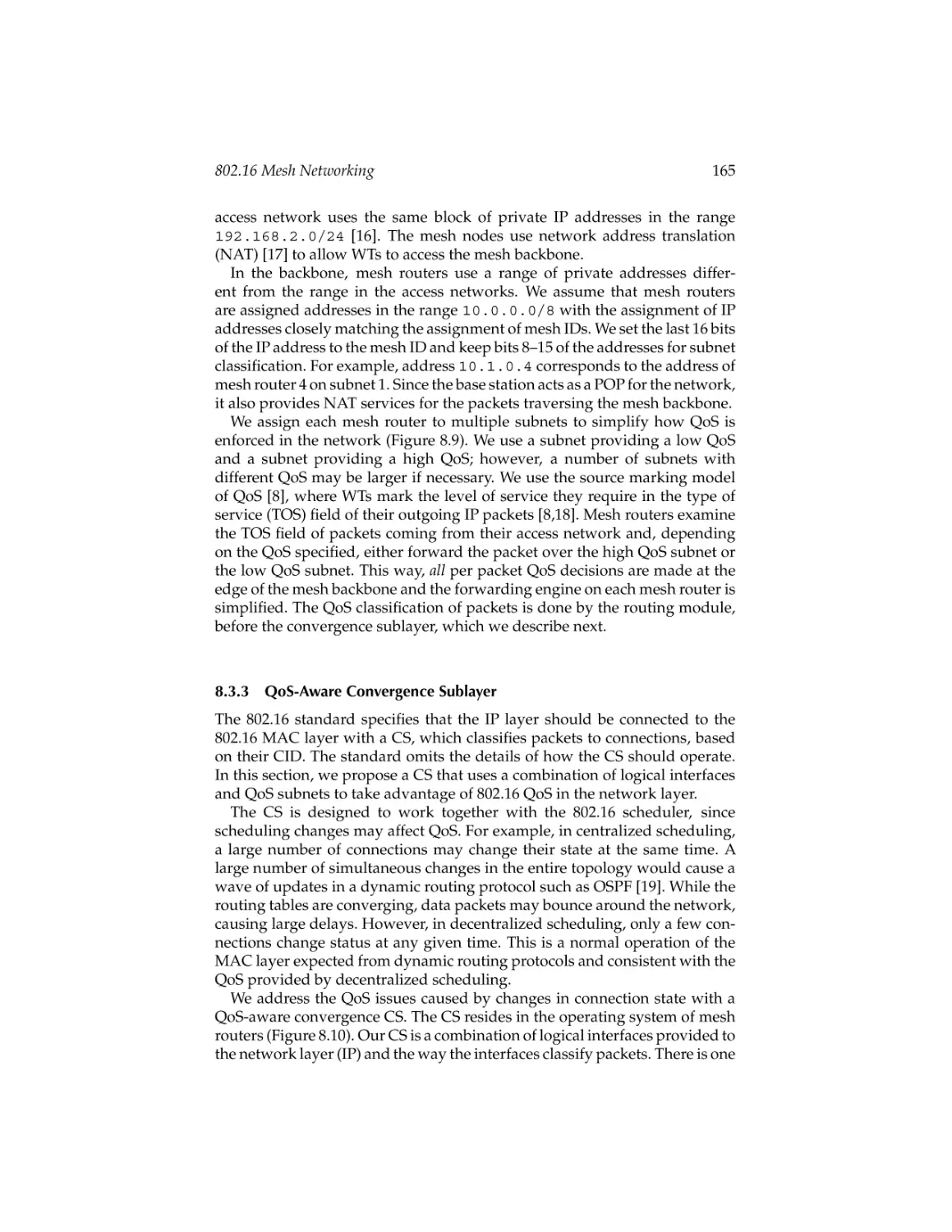
/


Author: Ahson S.A. Ilyas M.
Tags: electronics internet wireless networks
ISBN: 978-1-4200-4523-9
Year: 2008


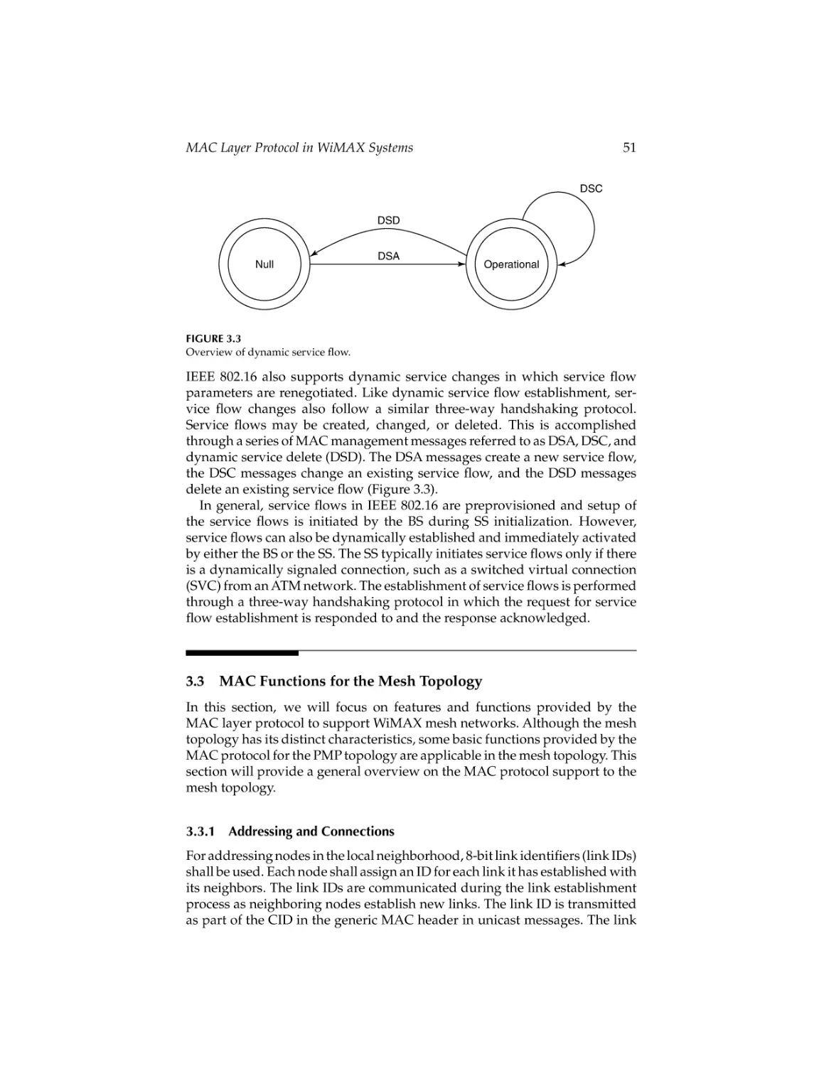
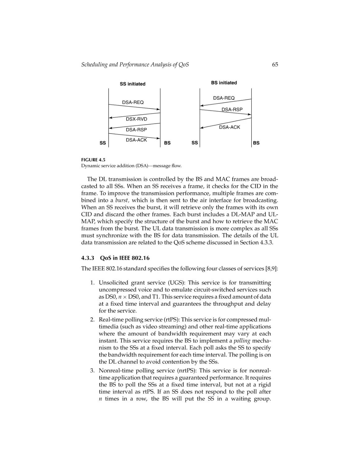
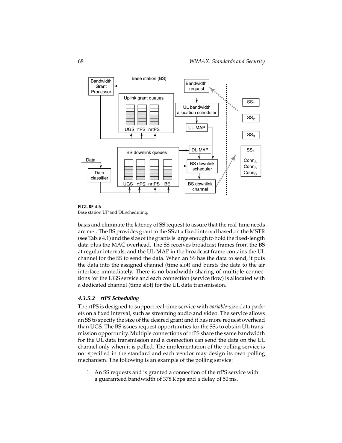
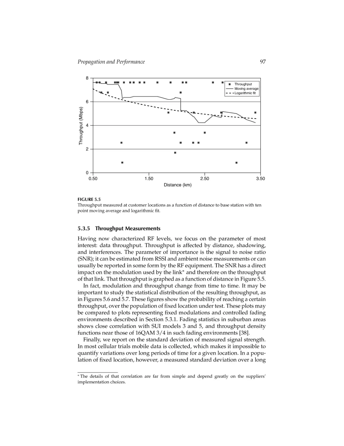
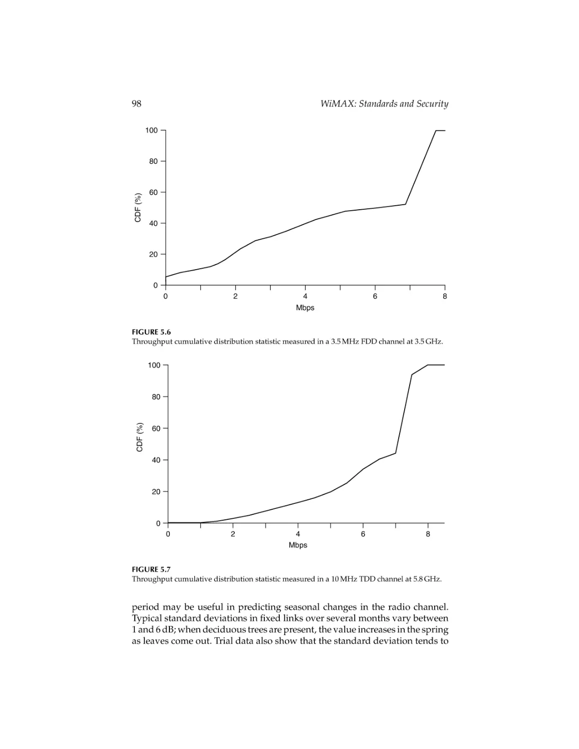
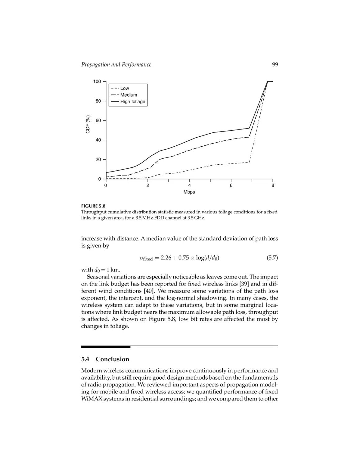
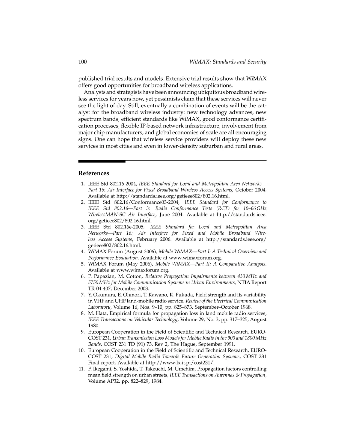
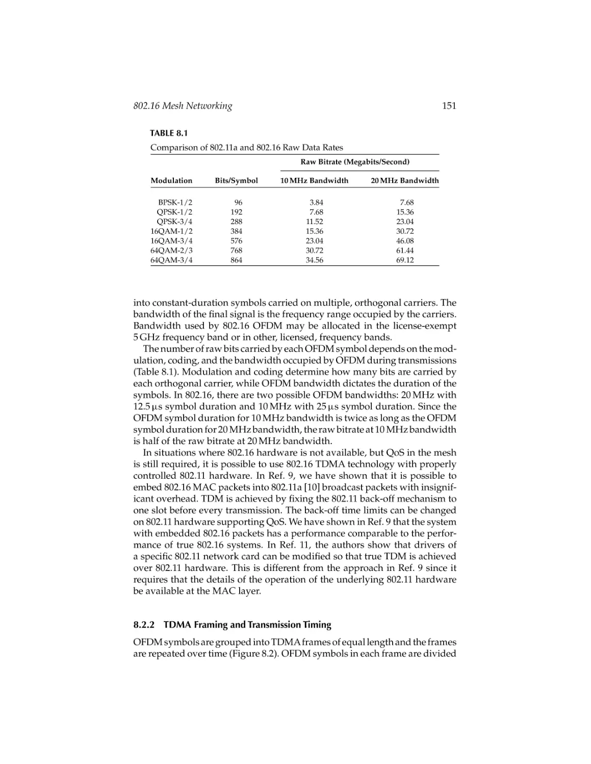
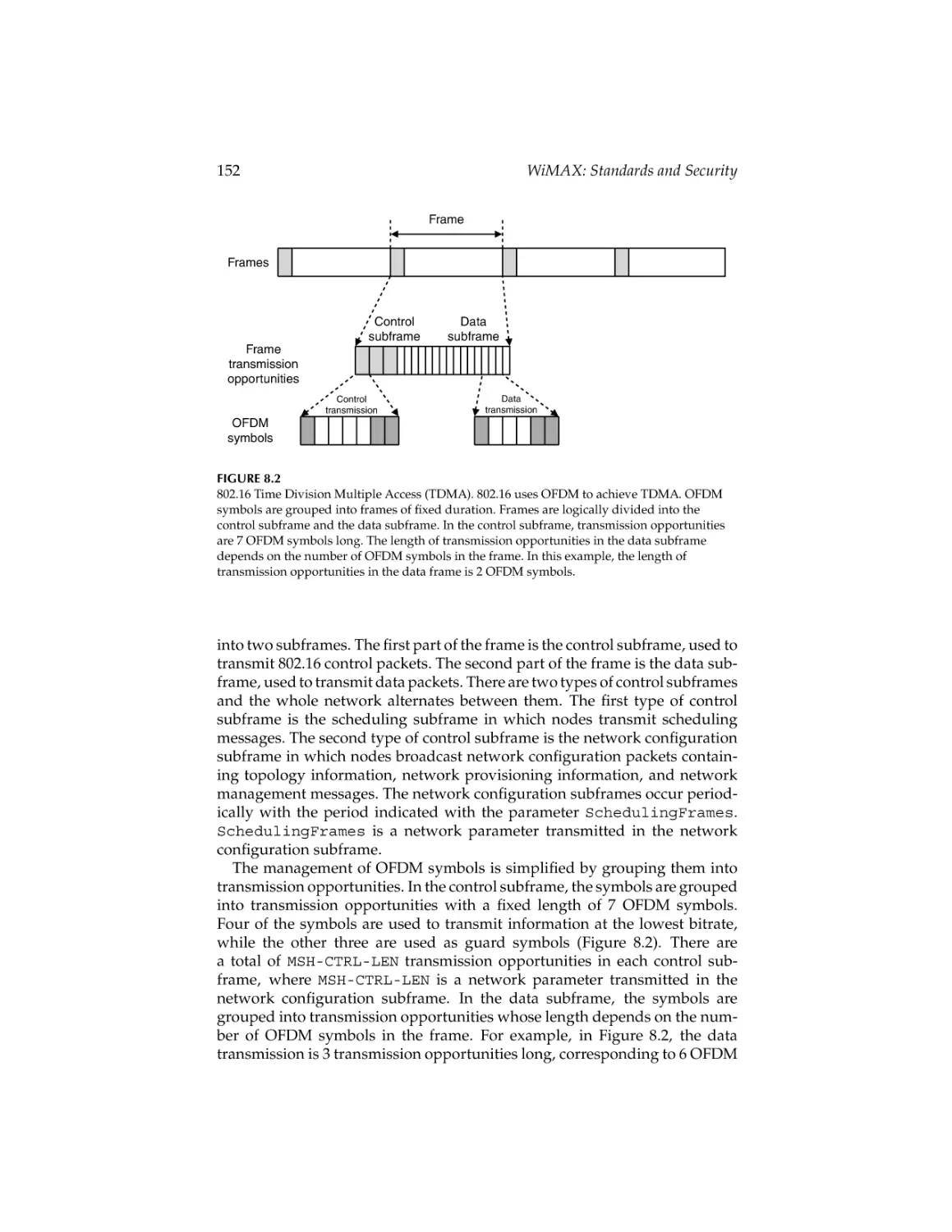
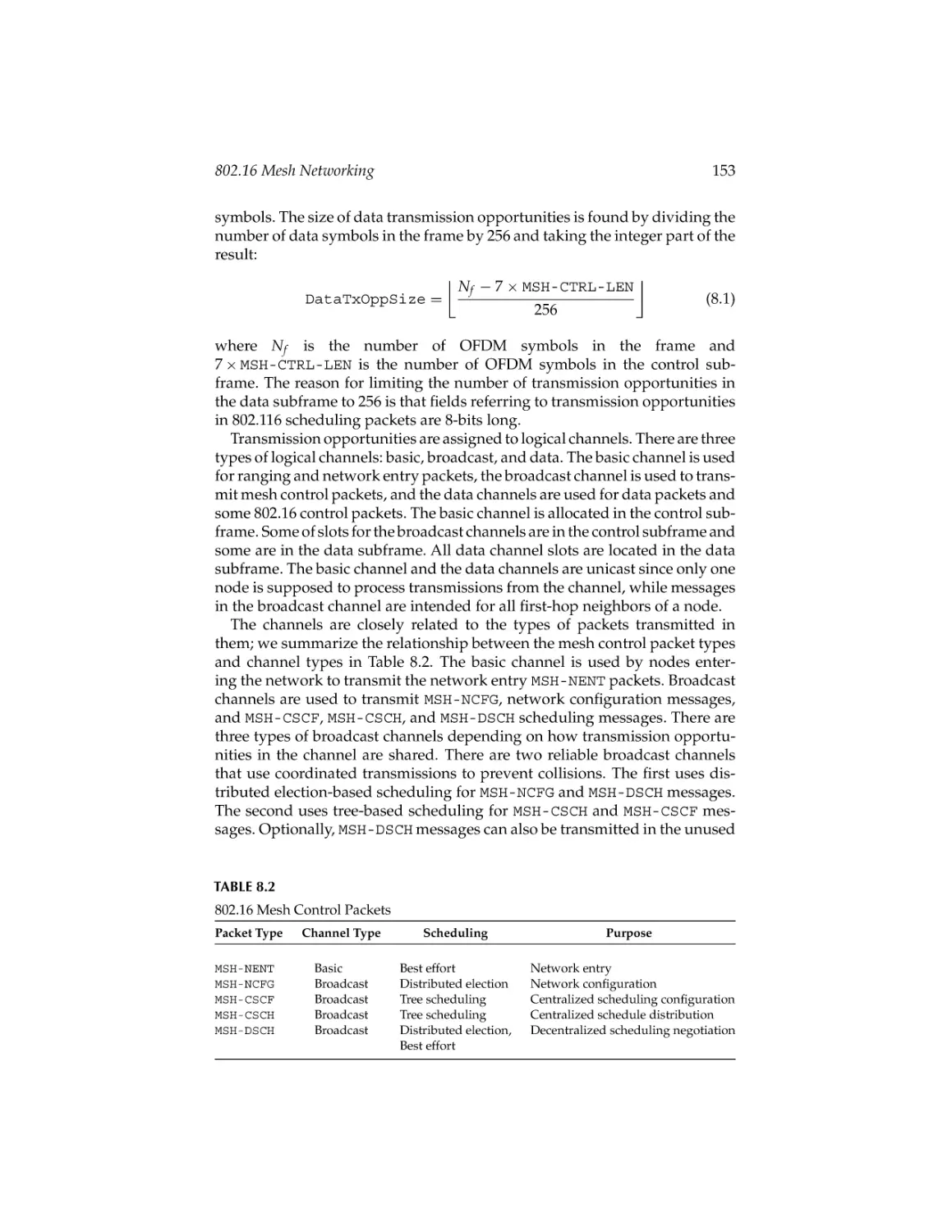
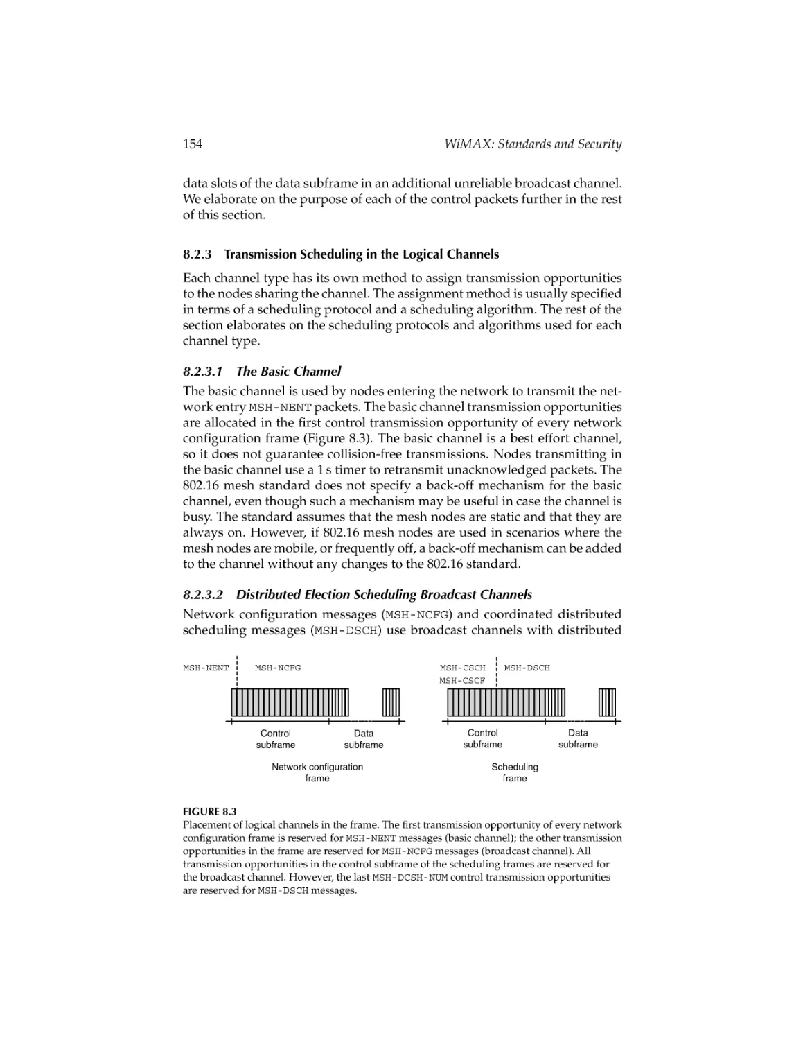
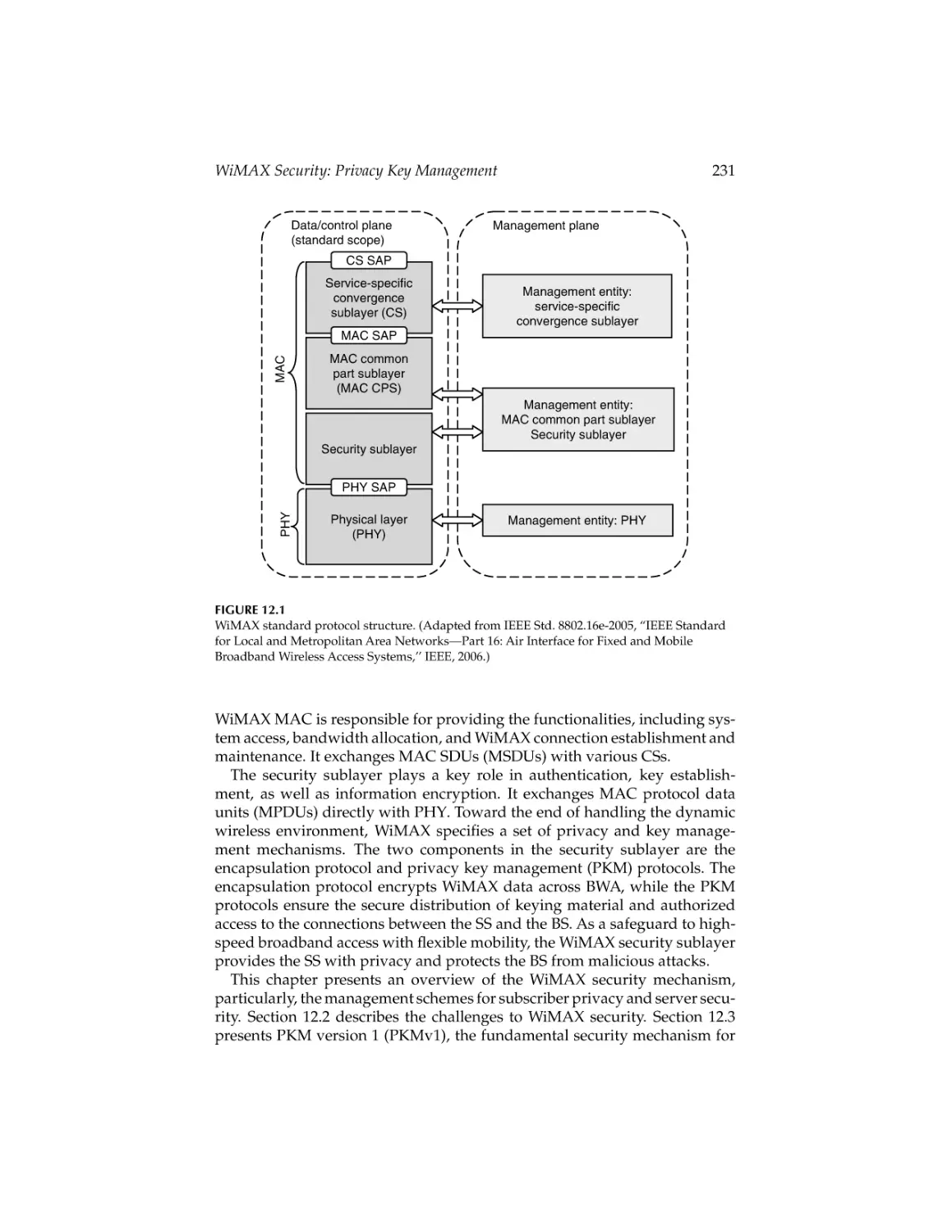
Text
CRC_45237_C000.tex
23/7/2007
10: 48
Page i
WiMAX
Standards and Security
CRC_45237_C000.tex
23/7/2007
10: 48
Page ii
The
WiMAX
Handbook
WiMAX: Technologies, Performance Analysis, and QoS
ISBN 9781420045253
WiMAX: Standards and Security
ISBN 9781420045237
WiMAX: Applications
ISBN 9781420045474
The WiMAX Handbook
Three-Volume Set
ISBN 9781420045350
Boca Raton London New York
CRC Press is an imprint of the
Taylor & Francis Group, an informa business
CRC_45237_C000.tex
23/7/2007
10: 48
Page iii
WiMAX
Standards and Security
Edited by
SYED AHSON
MOHAMMAD ILYAS
Boca Raton London New York
CRC Press is an imprint of the
Taylor & Francis Group, an informa business
CRC_45237_C000.tex
23/7/2007
10: 48
Page iv
CRC Press
Taylor & Francis Group
6000 Broken Sound Parkway NW, Suite 300
Boca Raton, FL 33487-2742
© 2008 by Taylor & Francis Group, LLC
CRC Press is an imprint of Taylor & Francis Group, an Informa business
No claim to original U.S. Government works
Printed in the United States of America on acid-free paper
10 9 8 7 6 5 4 3 2 1
International Standard Book Number-10: 1-4200-4523-7 (Hardcover)
International Standard Book Number-13: 978-1-4200-4523-9 (Hardcover)
This book contains information obtained from authentic and highly regarded sources. Reprinted
material is quoted with permission, and sources are indicated. A wide variety of references are
listed. Reasonable efforts have been made to publish reliable data and information, but the author
and the publisher cannot assume responsibility for the validity of all materials or for the consequences of their use.
No part of this book may be reprinted, reproduced, transmitted, or utilized in any form by any
electronic, mechanical, or other means, now known or hereafter invented, including photocopying,
microfilming, and recording, or in any information storage or retrieval system, without written
permission from the publishers.
For permission to photocopy or use material electronically from this work, please access www.
copyright.com (http://www.copyright.com/) or contact the Copyright Clearance Center, Inc. (CCC)
222 Rosewood Drive, Danvers, MA 01923, 978-750-8400. CCC is a not-for-profit organization that
provides licenses and registration for a variety of users. For organizations that have been granted a
photocopy license by the CCC, a separate system of payment has been arranged.
Trademark Notice: Product or corporate names may be trademarks or registered trademarks, and
are used only for identification and explanation without intent to infringe.
Library of Congress Cataloging-in-Publication Data
Ahson, Syed.
WiMAX : standards and security / Syed Ahson and Mohammad Ilyas.
p. cm.
Includes bibliographical references and index.
ISBN 978-1-4200-4523-9 (alk. paper)
1. Wireless communication systems. 2. Broadband communication systems.
3. IEEE 802.16 (Standard) I. Ilyas, Mohammad, 1953- II. Title.
TK5103.2.A432 2008
621.384--dc22
Visit the Taylor & Francis Web site at
http://www.taylorandfrancis.com
and the CRC Press Web site at
http://www.crcpress.com
2007012500
CRC_45237_C000.tex
23/7/2007
10: 48
Page v
Contents
Preface ................................................................................................................... vii
Editors .....................................................................................................................xi
Contributors .........................................................................................................xiii
Part I
Standards
1.
The Emerging Wireless Internet Architecture: Competing
and Complementary Standards to WiMAX Technology ...................... 3
William T. Kasch and Jack L. Burbank
2.
IEEE 802.16 Standards and Amendments ..............................................19
Najah Abu Ali and Hossam S. Hassanein
3.
MAC Layer Protocol in WiMAX Systems ..............................................35
Maode Ma and Yan Zhang
4.
Scheduling and Performance Analysis of QoS for IEEE 802.16
Broadband Wireless Access Network .....................................................57
James T. Yu
5.
Propagation and Performance ..................................................................77
Thomas Schwengler
6.
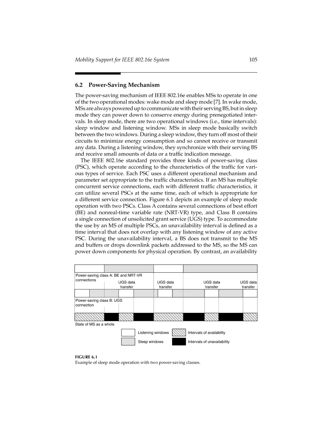
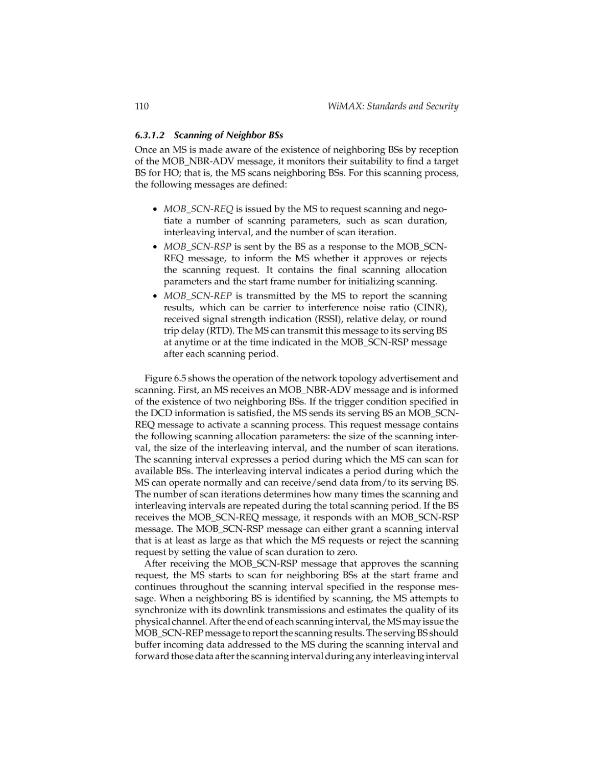
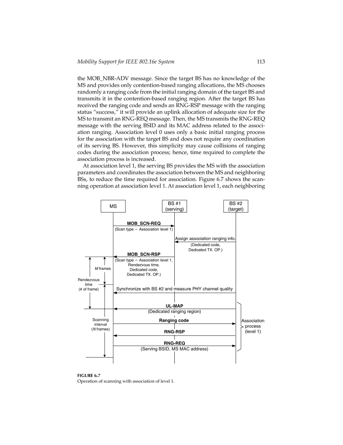
Mobility Support for IEEE 802.16e System .........................................103
Hyun-Ho Choi and Dong-Ho Cho
7.
Measured Signal-Aware Mechanism for Fast Handover
in WiMAX Networks ...............................................................................129
Jenhui Chen and Chih-Chieh Wang
8.
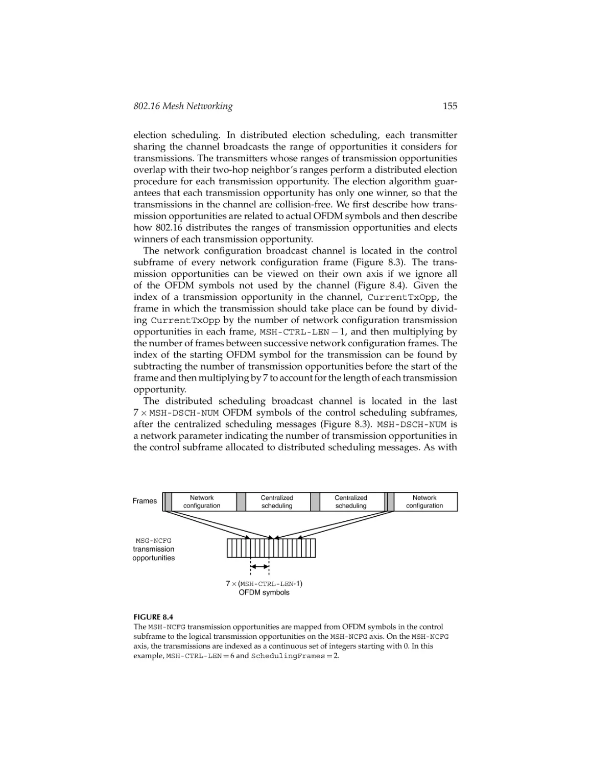
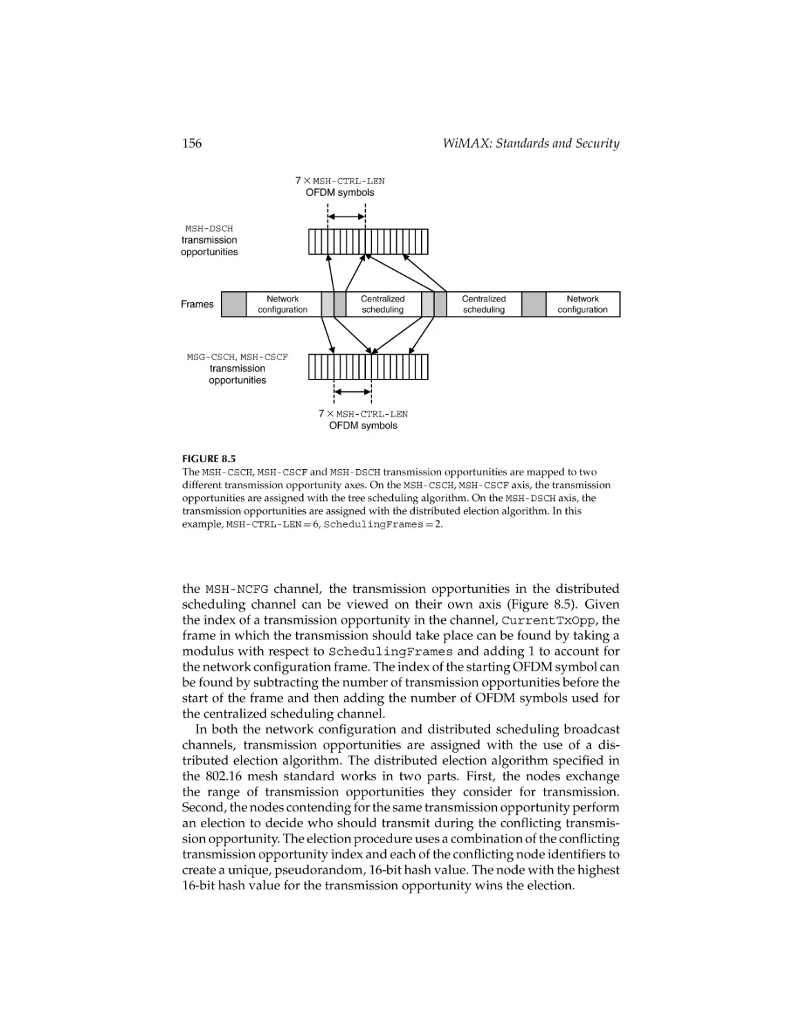
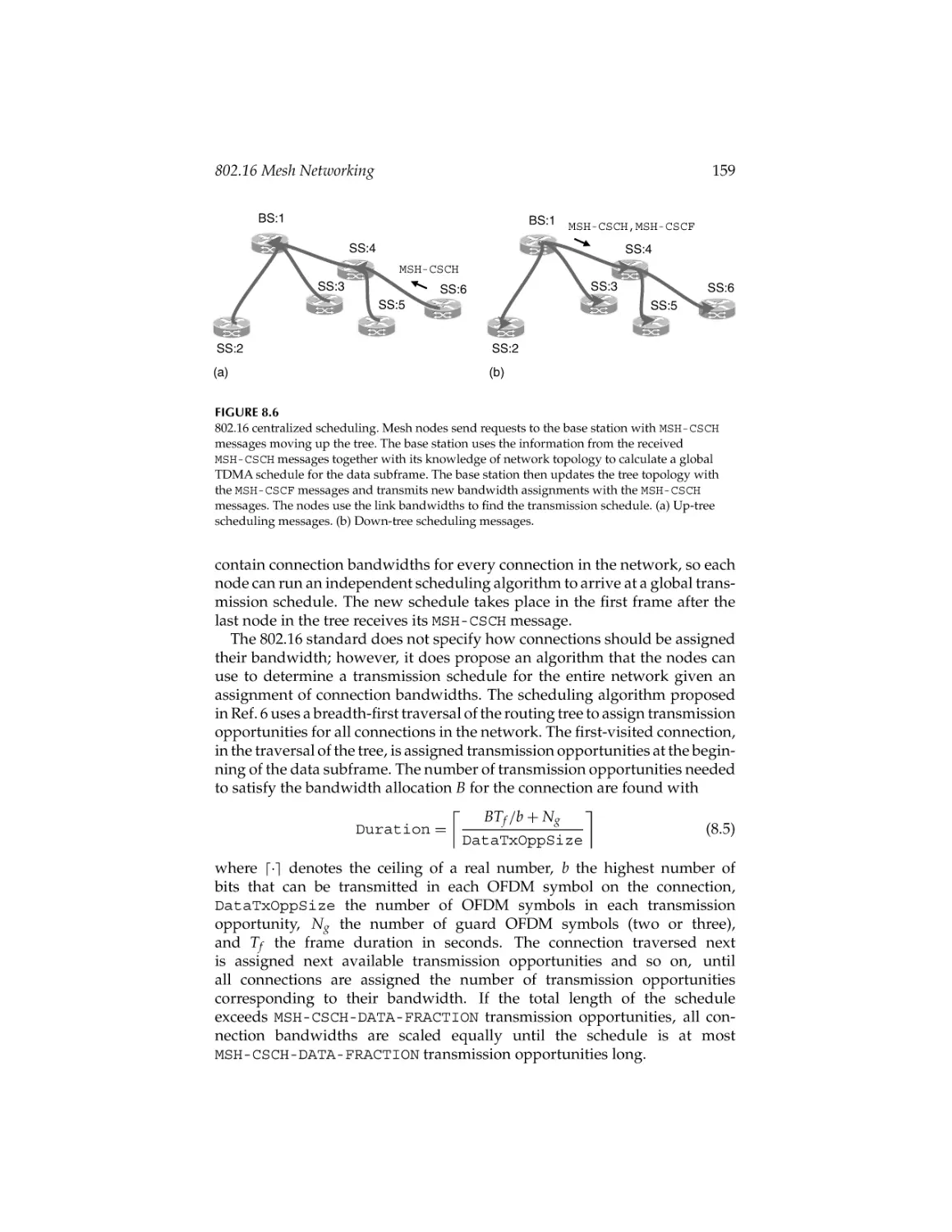
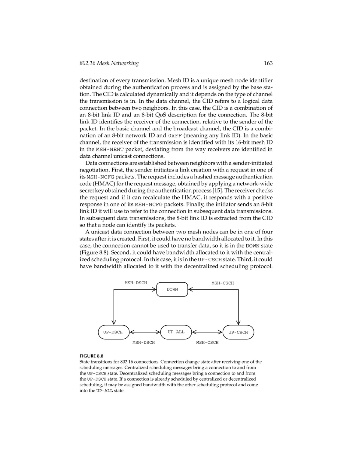
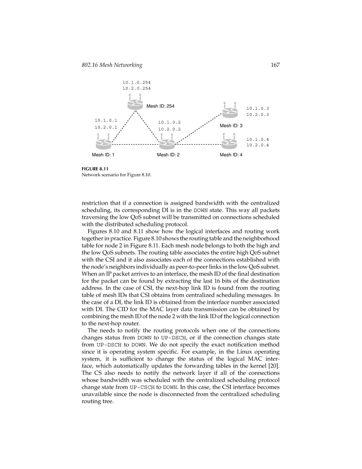
802.16 Mesh Networking ........................................................................ 147
Petar Djukic and Shahrokh Valaee
9.
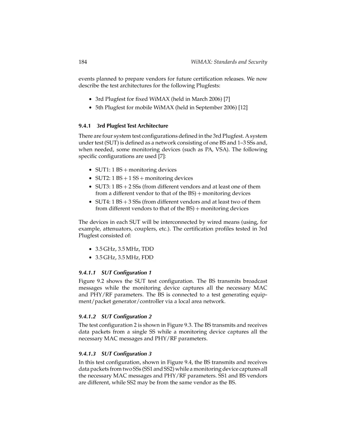
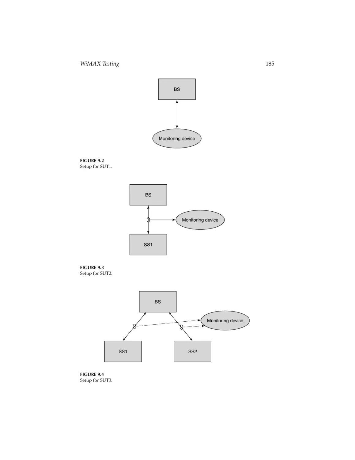
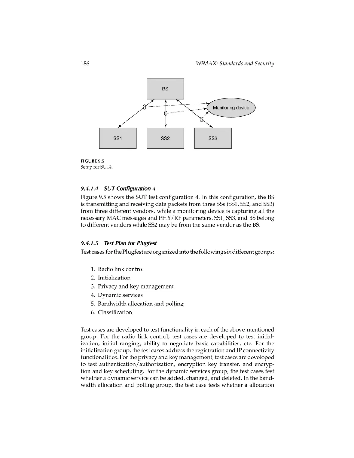
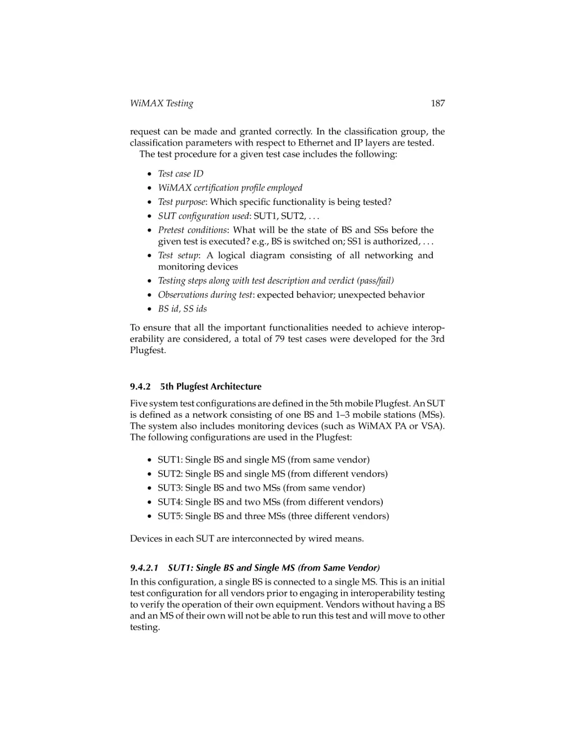
WiMAX Testing .........................................................................................175
Rana Ejaz Ahmed
v
CRC_45237_C000.tex
vi
23/7/2007
10: 48
Page vi
Contents
Part II
Security
10.
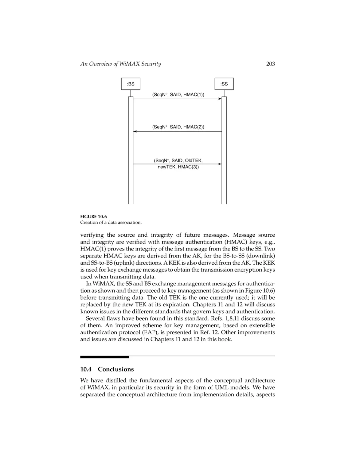
An Overview of WiMAX Security ........................................................ 197
Eduardo B. Fernandez and Michael VanHilst
11.
Privacy and Security in WiMAX Networks .........................................205
Amitabh Mishra and Nolan Glore
12.
WiMAX Security: Privacy Key Management ......................................229
Nirwan Ansari, Chao Zhang, Yuanqiu Luo, and Edwin Hou
Index .................................................................................................................... 251
CRC_45237_C000.tex
23/7/2007
10: 48
Page vii
Preface
The demand for broadband services is growing exponentially. Traditional
solutions that provide high-speed broadband access use wired access technologies, such as traditional cable, digital subscriber line, Ethernet, and
fiber optic. It is extremely difficult and expensive for carriers to build and
maintain wired networks, especially in rural and remote areas. Carriers are
unwilling to install the necessary equipment in these areas because of little
profit and potential. WiMAX will revolutionize broadband communications
in the developed world and bridge the digital divide in developing countries. Affordable wireless broadband access for all is very important for a
knowledge-based economy and society. WiMAX will provide affordable wireless broadband access for all, improving quality of life thereby leading to
economic empowerment.
Broadband wireless access technical solutions and products have been
available for some time. These technologies have primarily focused on providing high data rate connectivity wirelessly between fixed stationary sites.
These technical solutions are proprietary in nature and suffer from poor interoperability with other broadband wireless access products and have a high
cost due to the lack of economy of scale. High-speed wireless services have
already achieved great success in local area networks with the IEEE 802.11
standard and Wi-Fi certified products.
The IEEE 802.16 BWA technology family, referred to as Worldwide Interoperability for Microwave Access intends to provide a standardized BWA
solution. The IEEE Standards Board established the IEEE 802.16 working
group in 1999 to prepare formal specifications for global deployment of broadband Wireless Metropolitan Area Networks, officially called WirelessMAN.
The WiMAX Forum, created in 2003, is promoting the commercialization
of IEEE 802.16 and the European Telecommunications Standard Institute’s
high-performance radio MAN. The IEEE 802.16 specifications continue to
evolve and expand in capabilities in support of the evolving vision of WiMAX
usage and deployment. The IEEE 802.16e system called Mobile WiMAX
has been standardized to add user mobility to the original IEEE 802.16
system.
WiMAX has a strong base of standardization and industry support that provides a strong evolutionary path of its capabilities. WiMAX competes with
IEEE 802.11-based WLAN technology, broadband residential Internet technologies such as digital subscriber line and cable and third-generation cellular
technologies. WiMAX is the next step in the mobile technology evolution
path. WiMAX will broaden wireless access to metropolitan area networks.
WiMAX offers numerous advantages, such as improved performance and
vii
CRC_45237_C000.tex
viii
23/7/2007
10: 48
Page viii
Preface
robustness, end-to-end IP-based networks, secure mobility and broadband
speeds for voice, data, and video, support for fixed and mobile systems,
efficient and adaptive coding and modulation techniques, scalable channel
sizes, subchannelization schemes, multiple-input-multiple-output antenna
systems, and quality of service. WiMAX enables wireless broadband access
anywhere, anytime, and on virtually any device.
The WiMAX handbook provides technical information about all aspects
of WiMAX. The areas covered in the handbook range from basic concepts
to research-grade material including future directions. The WiMAX handbook captures the current state of wireless local area networks, and serves
as a source of comprehensive reference material on this subject. The WiMAX
handbook consists of three volumes: WiMAX: Applications; WiMAX: Standards
and Security; and WiMAX: Technologies, Performance Analysis, and QoS. It has
a total of 32 chapters authored by experts from around the world. WiMAX:
Standards and Security includes 12 chapters authored by 22 experts.
Chapter 1 (The Emerging Wireless Internet Architecture: Competing and
Complementary Standards to WiMAX Technology) describes other wireless
networking technologies that complement and compete with WiMAX technologies. This chapter provides an overview of the most prevalent current
technologies in use today, as well as a description of the similarities and
differences compared to WiMAX.
Chapter 2 (IEEE 802.16 Standards and Amendments) examines the pros
and cons of standardized versus proprietary solutions for wireless broadband access. An overview of WiMAX standards and amendments (IEEE
802.16-2001, IEEE 802.16b, IEEE 802.16c, IEEE 802.16d, IEEE 802.16-2004,
IEEE 802.16e-2005, IEEE 802.16f, IEEE 802.16g, IEEE 802.16h, IEEE 802.16fi,
and IEEE 802.16j) is presented. Key WiMAX technologies such as physical layer, medium access control layer, convergence sublayer, common part
sublayer, point-to-multipoint and mesh mode, privacy sublayer, quality of
service support, handover support, and power management are described in
detail.
Chapter 3 (MAC Layer Protocol in WiMAX Systems) reviews the functions and features of the core medium access control protocol of the WiMAX
systems including the point-to-multipoint topology and mesh topology. The
fundamental part of the medium access control protocol of the WiMAX
systems is summarized and presented.
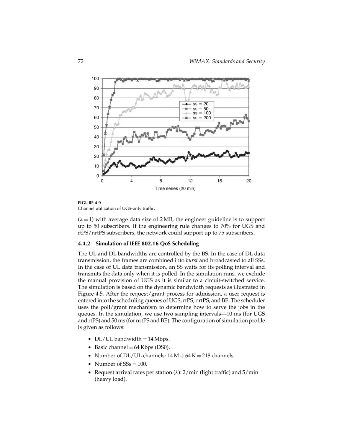
Chapter 4 (Scheduling and Performance Analysis of QoS for IEEE 802.16
Broadband Wireless Access Network) presents an architecture and its implementation of admission control and job scheduling based on the quality-ofservice requirements of IEEE 802.16. This chapter presents the concept and
requirements of quality of service as specified in the IEEE 802.16 standard,
along with an architecture to implement quality of service in a simulation
model.
Chapter 5 (Propagation and Performance) presents carriers’ perspectives
for wireless services like fixed WiMAX access. This chapter presents various aspects of propagation and performance for WiMAX radio systems; it
CRC_45237_C000.tex
Preface
23/7/2007
10: 48
Page ix
ix
reviews WiMAX radio system parameters such as link budgets, presents
relevant propagation models, and finally, analyzes system throughput and
performance for a typical suburban area.
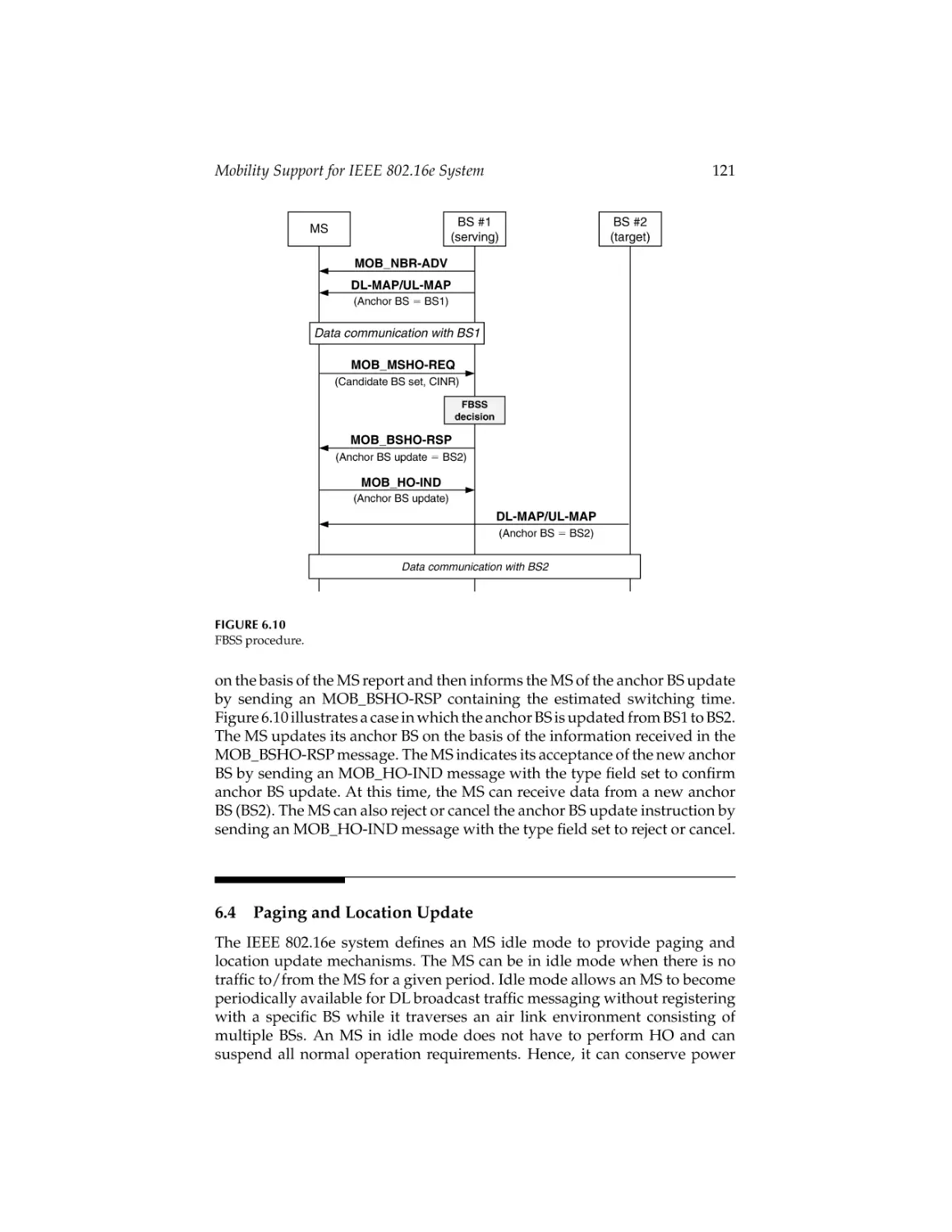
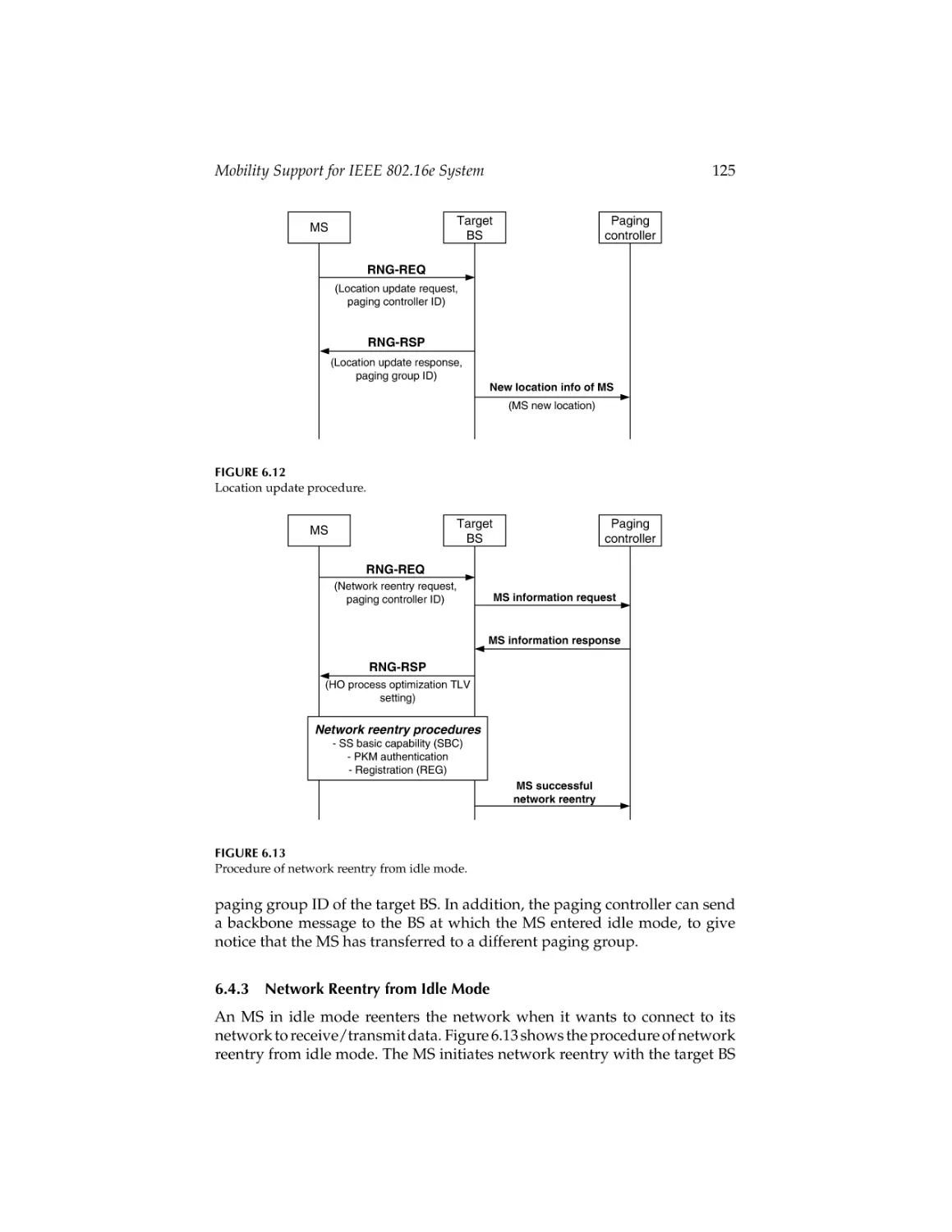
Chapter 6 (Mobility Support for IEEE 802.16e System) discusses the main
mobility functions defined in the IEEE 802.16e standard: power-saving mechanism, handover operation, paging, and location update. Power-saving
classes of type I, type II, and type III are discussed in great detail. Network
topology acquisition, basic handover operation, macro-diversity handover,
and fast base station switching are examined. Basic paging operation, location
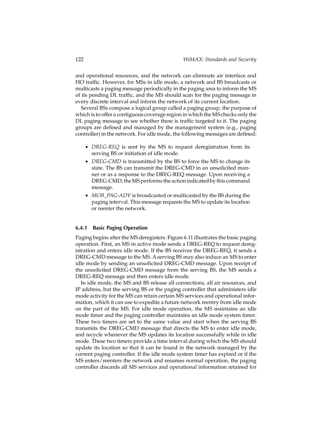
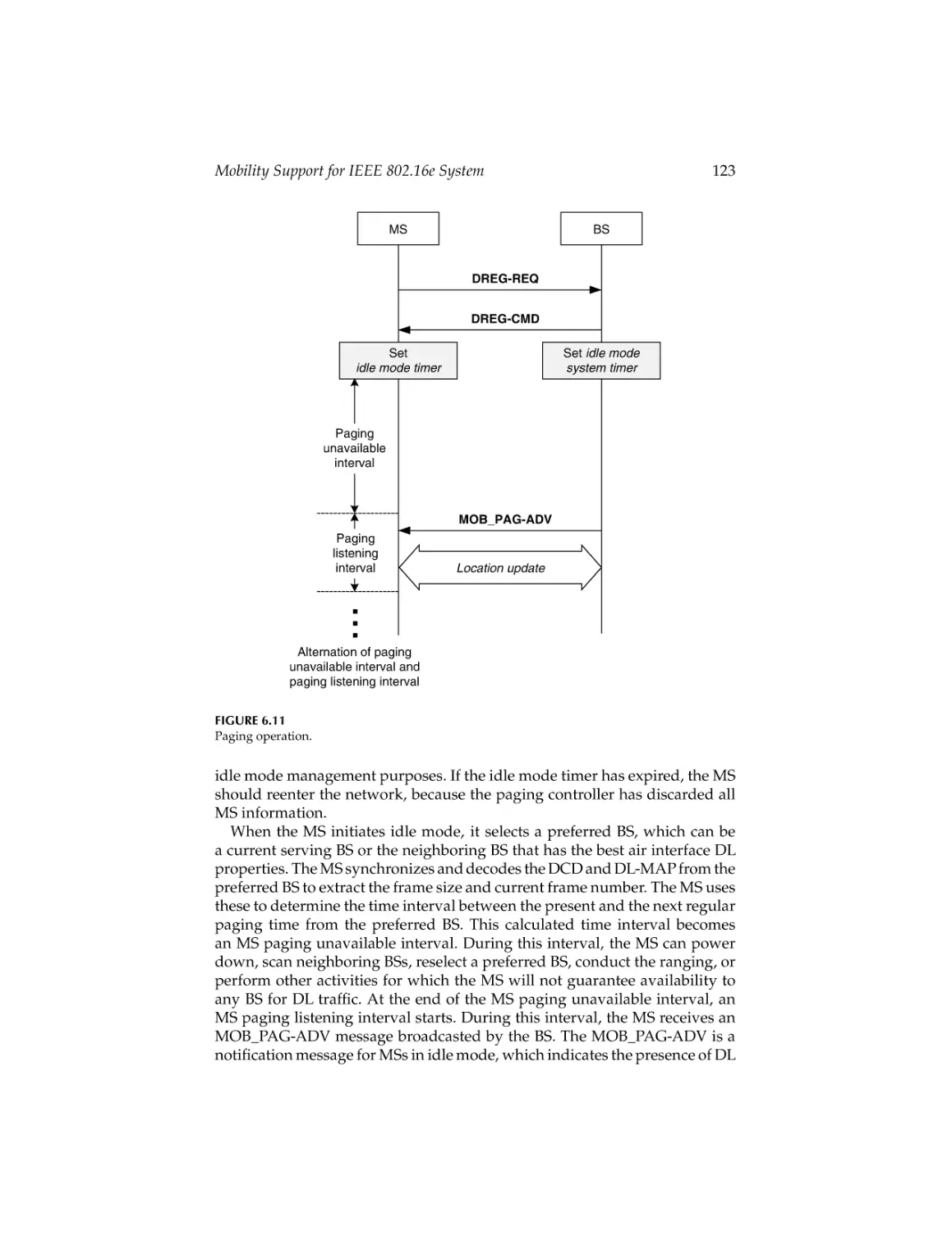
update, and network reentry from idle mode are described.
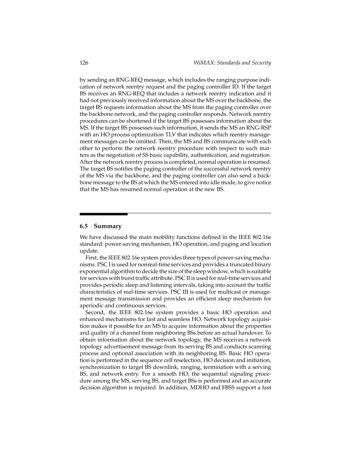
Chapter 7 (Measured Signal-Aware Mechanism for Fast Handover in
WiMAX Networks) describes how to use a measured signal-aware mechanism to aid speeding up WiMAX handover procedures. A measured signalaware mechanism for a base station initialized predicted handover scheme is
investigated, which centralized a monitor-moving mobile subscriber station
and prepared a CDMA ranging code of boundary mobile subscriber stations
beforehand.
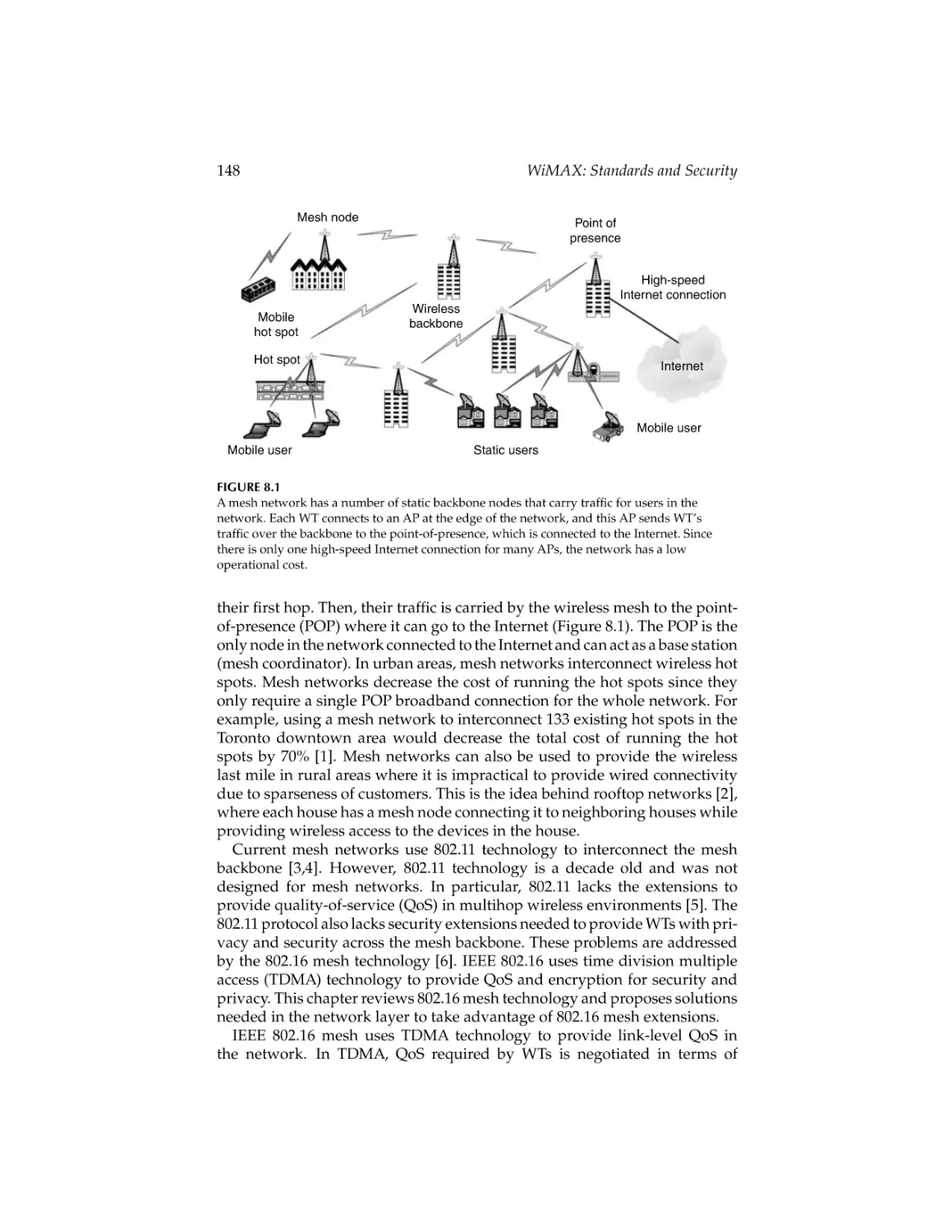
Chapter 8 (802.16 Mesh Networking) presents an overview of the 802.16
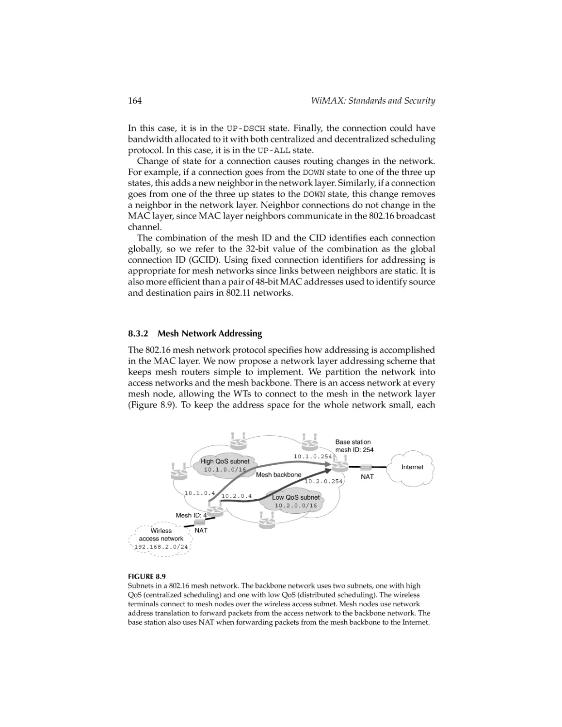
mesh protocol with a specific focus on the networking aspects of the protocol. Addressing assignments for IEEE 802.16 mesh networks that allow
the network layer to take advantage of quality of service provided by IEEE
802.16 mesh protocol is proposed. An overview of the security infrastructure
of IEEE 802.16 mesh networks and their flaws is presented. An end-to-end
security scheme that simplifies the design of IEEE 802.16 mesh routers is
proposed.
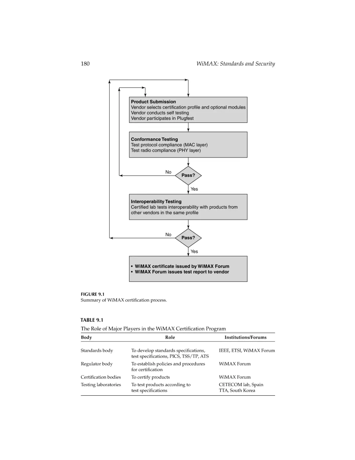
Chapter 9 (WiMAX Testing) surveys the testing and certification processes
used for WiMAX products. This chapter describes the general framework
used for conformance and interoperability testing for the WiMAX technology.
An overview of generic test equipment, test environments, and scenarios used
for WiMAX certification testing is described. It also describes the WiMAX
certification process and testing scenarios at the recently held WiMAX Forum
“Plugfest’’ events.
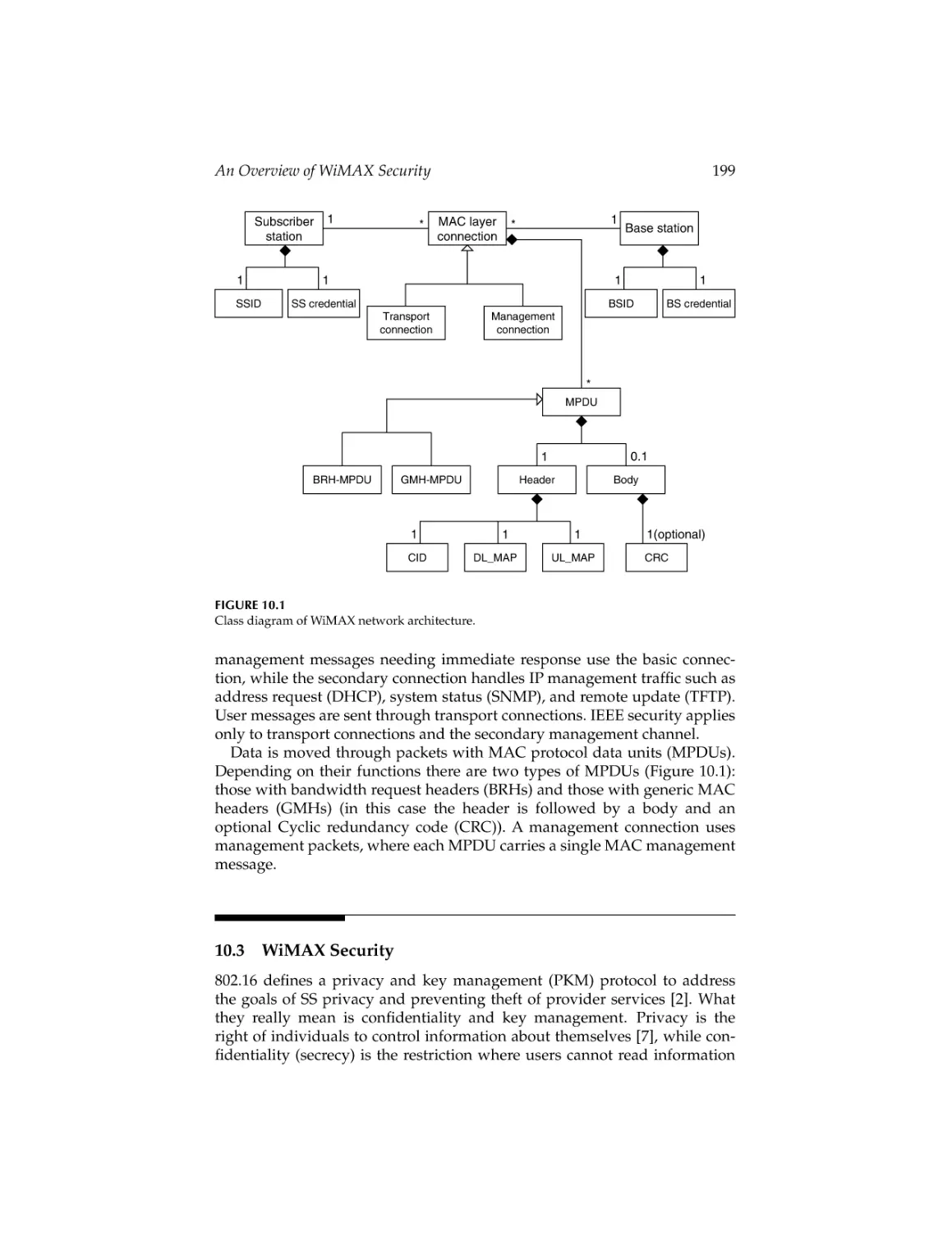
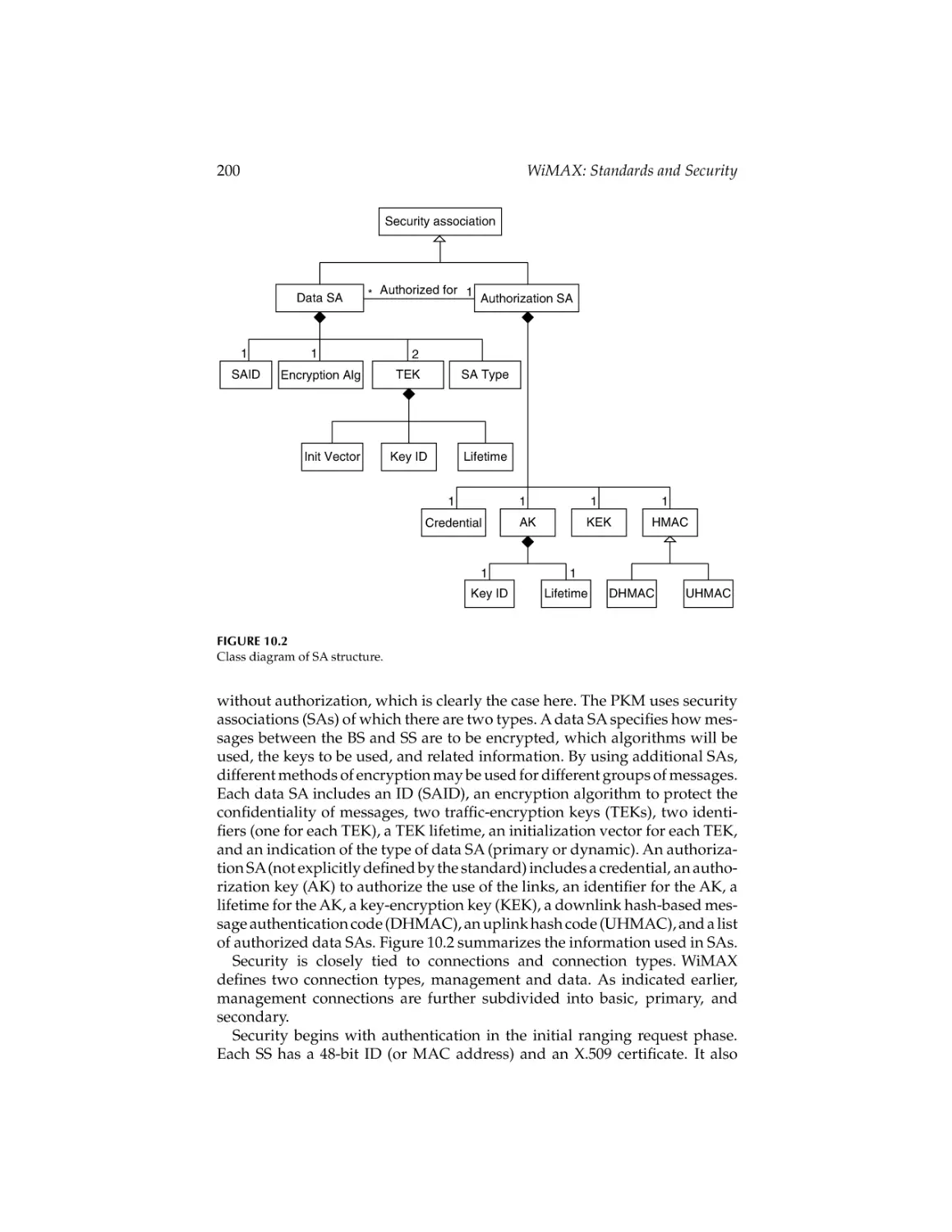
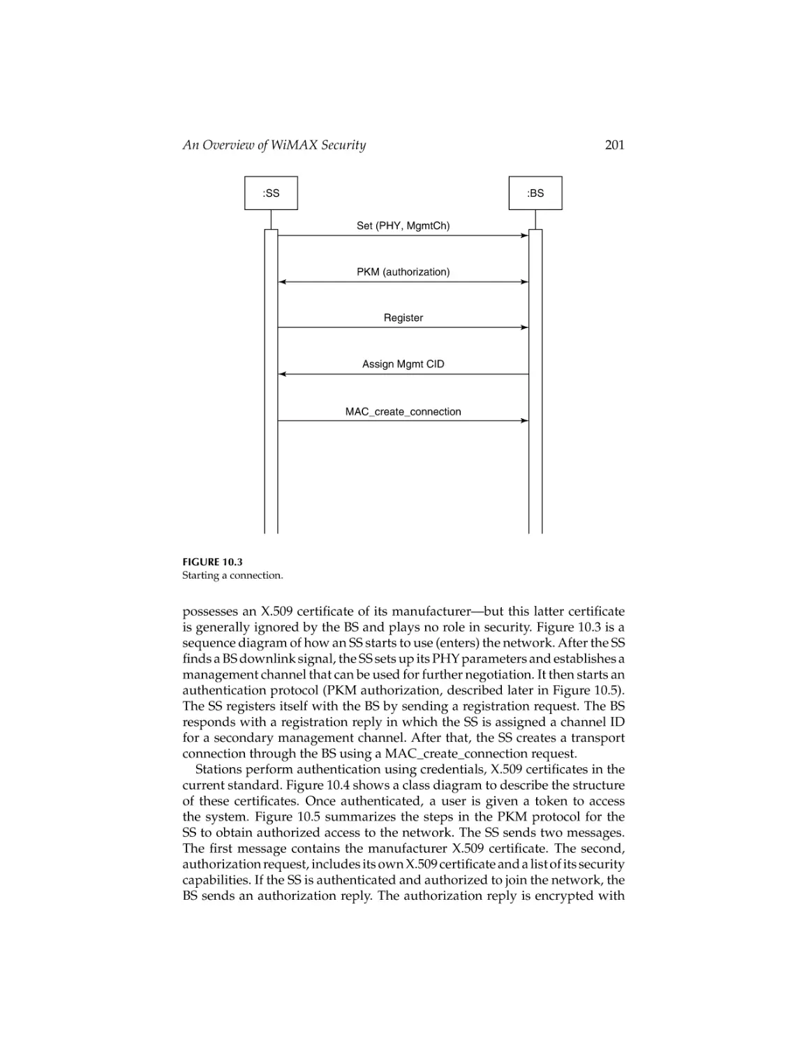
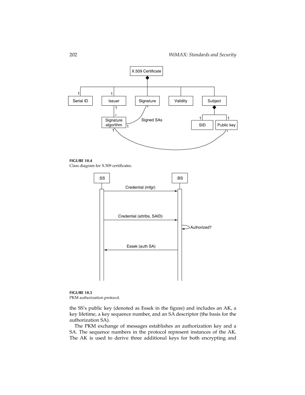
Chapter 10 (An Overview of WiMAX Security) presents an overview of
the security aspects of IEEE 802.16. Unified modeling language class and
sequence diagrams are used to describe architectural aspects. These are conceptual diagrams, intended to define the information in each unit and do not
reflect implementation details. This chapter presents a high-level overview
that can be read before getting into the details of the standard.
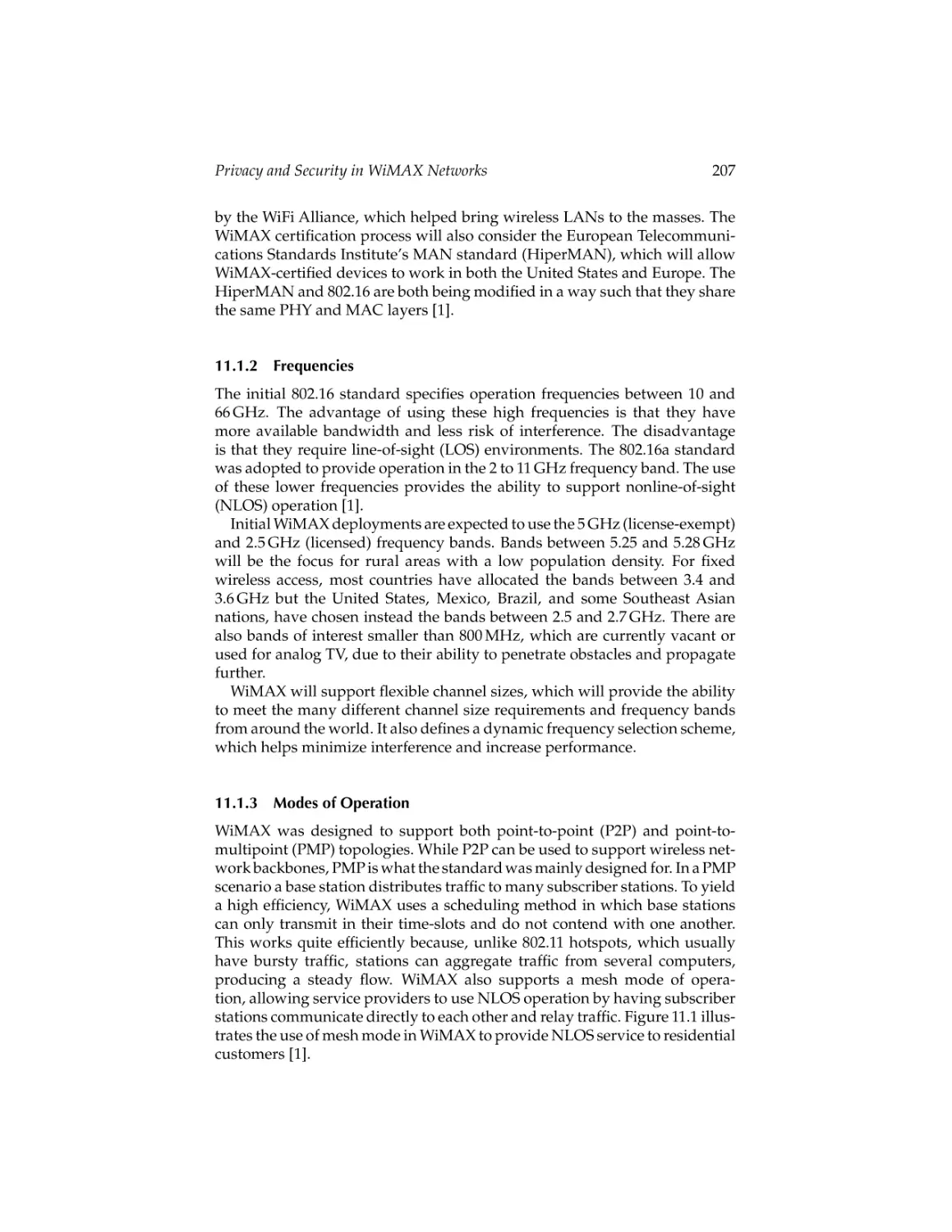
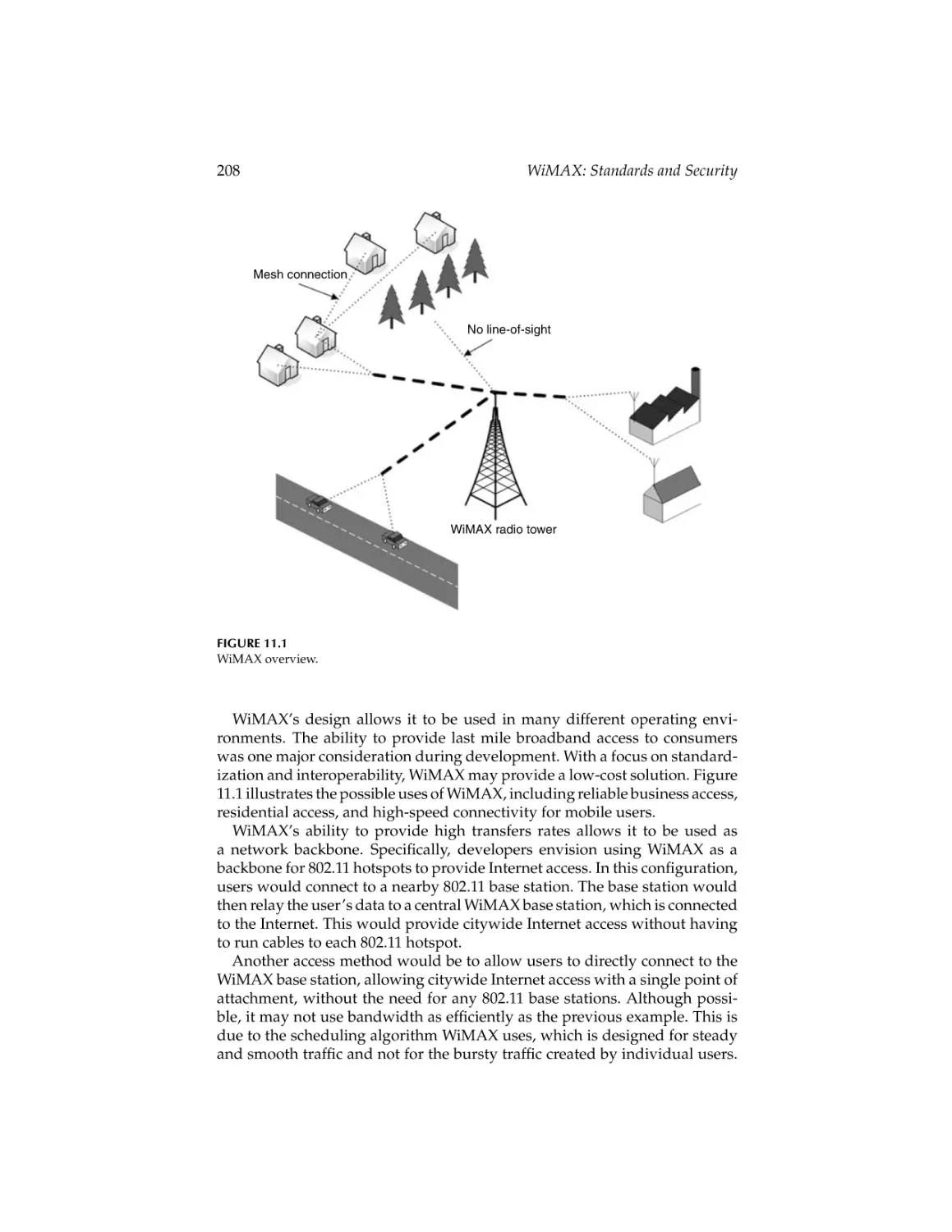
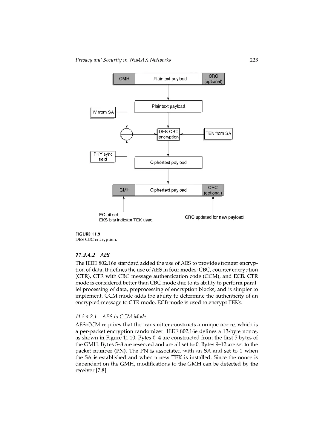
Chapter 11 (Privacy and Security in WiMAX Networks) presents an
overview of WiMAX security features. Primary, static, and dynamic security associations, contents of data security association, and contents of
authorization security association are described in detail. Hashed message
authentication codes, X.509 certificates, and the extensible authentication protocol are reviewed. Aspects of privacy and key management protocol such
as authorization and authorization key exchange, and traffic encryption key
exchange are examined.
CRC_45237_C000.tex
23/7/2007
10: 48
Page x
x
Preface
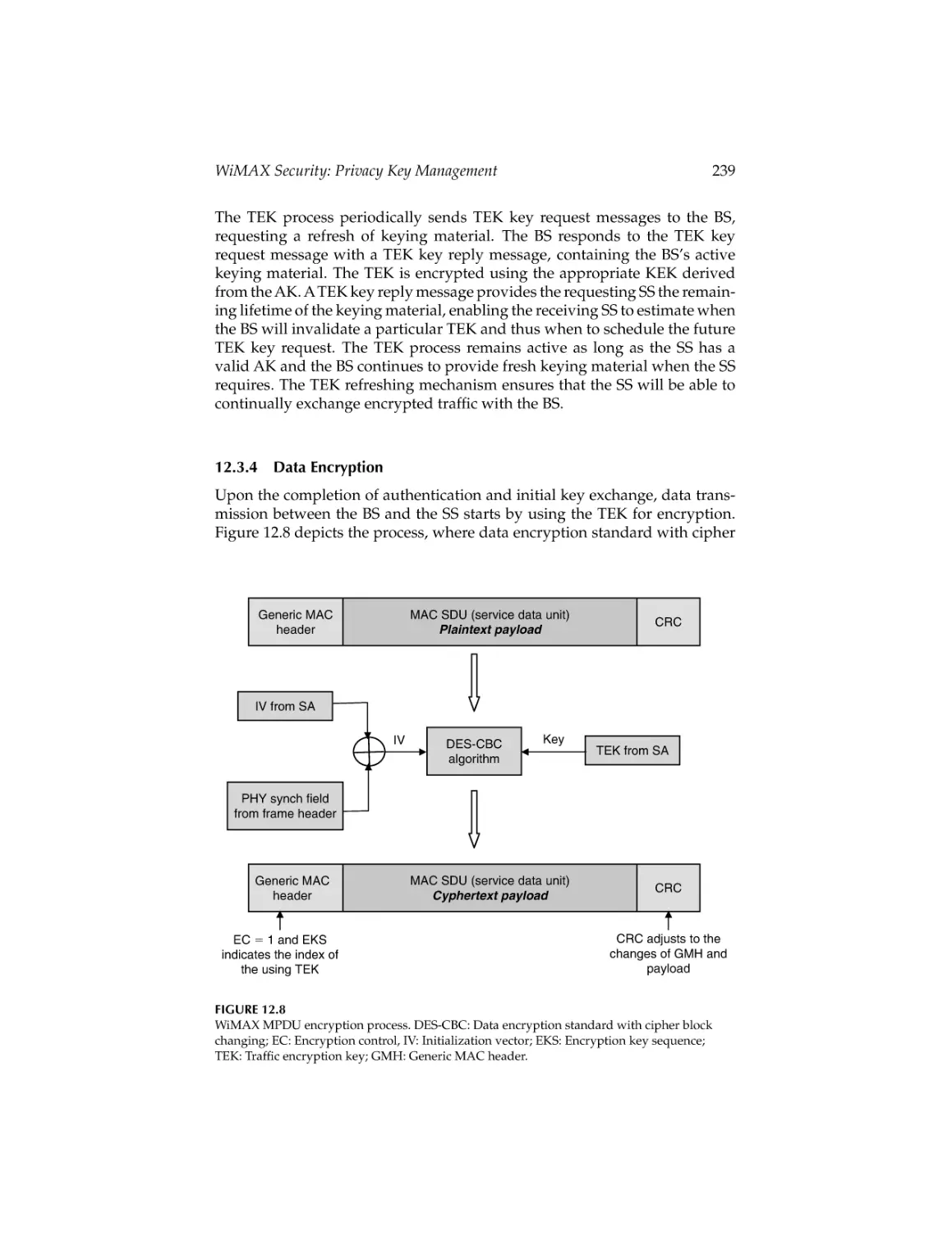
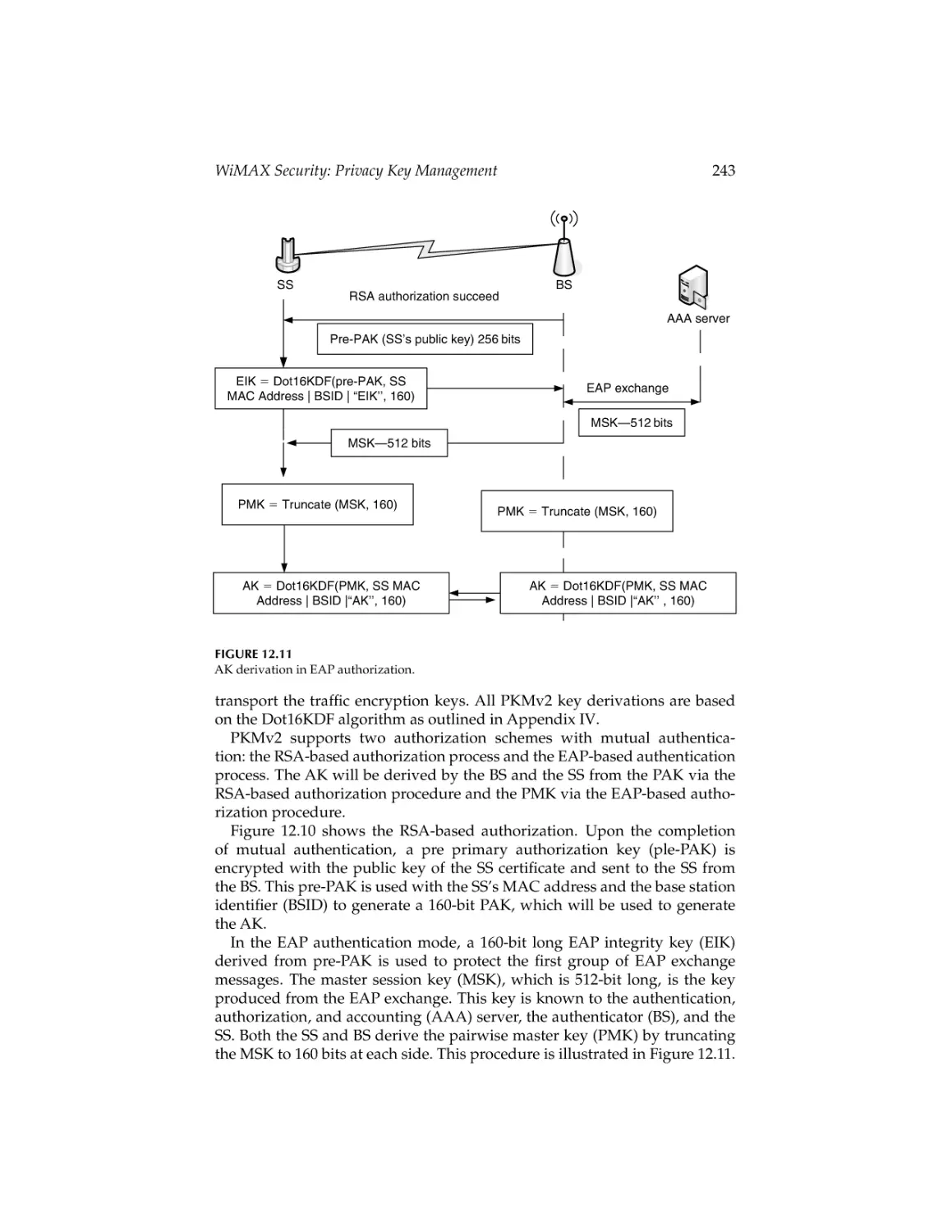
Chapter 12 (WiMAX Security: Privacy Key Management) presents a
comprehensive overview of security issues encountered in WiMAX, including
security challenges, user authentication, key exchanges, as well as data
encryption through the fixed and mobile WiMAX channels. This chapter
focuses on the privacy and key management protocols that play an important role in securing connection and transmission across broadband wireless
access.
The targeted audience for the handbook includes professionals who are
designers and planners for WiMAX networks, researchers (faculty members
and graduate students), and those who would like to learn about this field.
The handbook has the following specific salient features:
• To serve as a single comprehensive source of information and as
reference material on WiMAX networks.
• To deal with an important and timely topic of emerging communi-
cation technology of today, tomorrow, and beyond.
• To present accurate, up-to-date information on a broad range of
topics related to WiMAX networks.
• To present material authored by the experts in the field.
• To present the information in an organized and well-structured
manner.
Although the handbook is not precisely a textbook, it can certainly be used as
a textbook for graduate and research-oriented courses that deal with WiMAX.
Any comments from the readers will be highly appreciated.
Many people have contributed to this handbook in their unique ways. The
first and foremost group that deserves immense gratitude is the group of
highly talented and skilled researchers who have contributed 32 chapters to
this handbook. All of them have been extremely cooperative and professional.
It has also been a pleasure to work with Nora Konopka, Helena Redshaw,
Jessica Vakili, and Joette Lynch of Taylor & Francis and we are extremely
gratified for their support and professionalism. Our families have extended
their unconditional love and strong support throughout this project and they
all deserve very special thanks.
Syed Ahson
Plantation, FL, USA
Mohammad Ilyas
Boca Raton, FL, USA
CRC_45237_C000.tex
23/7/2007
10: 48
Page xi
Editors
Syed Ahson is a senior staff software engineer with Motorola Inc. He has
extensive experience with wireless data protocols (TCP/IP, UDP, HTTP, VoIP,
SIP, H.323), wireless data applications (Internet browsing, multimedia messaging, wireless e-mail, firmware over-the-air update), and cellular telephony
protocols (GSM, CDMA, 3G, UMTS, HSDPA). He has contributed significantly in leading roles toward the creation of several advanced and exciting
cellular phones at Motorola. Prior to joining Motorola, he was a senior software design engineer with NetSpeak Corporation (now part of Net2Phone),
a pioneer in VoIP telephony software.
Syed is a coeditor of the Handbook of Wireless Local Area Networks:
Applications, Technology, Security, and Standards (CRC Press, 2005). Syed
has authored “Smartphones’’ (International Engineering Consortium, April
2006), a research report that reflects on smartphone markets and technologies. He has published several research articles in peer-reviewed journals and
teaches computer engineering courses as adjunct faculty at Florida Atlantic
University, Florida, where he introduced a course on smartphone technology
and applications. Syed received his BSc in electrical engineering from Aligarh
University, India in 1995 and an MS in computer engineering in July 1998 at
Florida Atlantic University, Florida.
Dr. Mohammad Ilyas received his BSc in electrical engineering from the
University of Engineering and Technology, Lahore, Pakistan, in 1976.
From March 1977 to September 1978, he worked for the Water and Power
Development Authority, Pakistan. In 1978, he was awarded a scholarship for his graduate studies and he completed his MS in electrical and
electronic engineering in June 1980 at Shiraz University, Shiraz, Iran. In
September 1980, he joined the doctoral program at Queen’s University in
Kingston, Ontario, Canada. He completed his PhD in 1983. His doctoral
research was about switching and flow control techniques in computer
communication networks. Since September 1983, he has been with the College of Engineering and Computer Science at Florida Atlantic University,
Boca Raton, Florida, where he is currently associate dean for research and
industry relations. From 1994 to 2000, he was chair of the Department of Computer Science and Engineering. From July 2004 to September 2005, he served
as interim associate vice president for research and graduate studies. During
the 1993–1994 academic year, he was on his sabbatical leave with the Department of Computer Engineering, King Saud University, Riyadh, Saudi Arabia.
xi
CRC_45237_C000.tex
xii
23/7/2007
10: 48
Page xii
Editors
Dr. Ilyas has conducted successful research in various areas including traffic
management and congestion control in broadband/high-speed communication networks, traffic characterization, wireless communication networks,
performance modeling, and simulation. He has published one book, eight
handbooks, and over 150 research articles. He has supervised 11 PhD dissertations and more than 37 MS theses to completion. He has been a consultant
to several national and international organizations. Dr. Ilyas is an active
participant in several IEEE technical committees and activities.
Dr. Ilyas is a senior member of IEEE and a member of ASEE.
CRC_45237_C000.tex
23/7/2007
10: 48
Page xiii
Contributors
Rana Ejaz Ahmed
Department of Computer
Engineering
American University of Sharjah
Sharjah, United Arab Emirates
Petar Djukic
Department of Electrical and
Computer Engineering
University of Toronto
Toronto, Ontario, Canada
Najah Abu Ali
College of Information Technology
United Arab Emirates University
Al-Ain, United Arab Emirates
Eduardo B. Fernandez
Department of Computer Science
and Engineering
Florida Atlantic University
Boca Raton, Florida
Nirwan Ansari
Department of Electrical and
Computer Engineering
New Jersey Institute of Technology
Newark, New Jersey
Jack L. Burbank
The Johns Hopkins University
Applied Physics Laboratory
Laurel, Maryland
Jenhui Chen
Department of Computer Science
and Information Engineering
Chang Gung University
Taiwan, Republic of China
Dong-Ho Cho
Korea Advanced Institute of Science
and Technology
Daejeon, Republic of Korea
Hyun-Ho Choi
Korea Advanced Institute of Science
and Technology
Daejeon, Republic of Korea
Nolan Glore
Bradley Department of Electrical
and Computer Engineering
Virginia Polytechnic Institute and
State University
Blacksburg, Virginia
Hossam S. Hassanein
School of Computing
Queen’s University
Kingston, Ontario, Canada
Edwin Hou
Department of Electrical and
Computer Engineering
New Jersey Institute of Technology
Newark, New Jersey
William T. Kasch
The Johns Hopkins University
Applied Physics Laboratory
Laurel, Maryland
Yuanqiu Luo
NEC Laboratories America, Inc.
Princeton, New Jersey
xiii
CRC_45237_C000.tex
23/7/2007
10: 48
Page xiv
xiv
Maode Ma
School of Electrical and Electronic
Engineering
Nanyang Technological University
Singapore
Amitabh Mishra
Bradley Department of Electrical
and Computer Engineering
Virginia Polytechnic Institute and
State University
Blacksburg, Virginia
Thomas Schwengler
Qwest Communications
Denver, Colorado
Shahrokh Valaee
Department of Electrical and
Computer Engineering
University of Toronto
Toronto, Ontario, Canada
Contributors
Michael VanHilst
Department of Computer Science
and Engineering
Florida Atlantic University
Boca Raton, Florida
Chih-Chieh Wang
Department of Electrical
Engineering
Chang Gung University
Taiwan, Republic of China
James T. Yu
DePaul University
Chicago, Illinois
Chao Zhang
Department of Electrical and
Computer Engineering
New Jersey Institute of Technology
Newark, New Jersey
Yan Zhang
Simula Research Laboratory
Lysaker, Norway
CRC_45237_S001.tex
29/5/2007
10: 11
Page 1
Part I
Standards
CRC_45237_S001.tex
29/5/2007
10: 11
Page 2
CRC_45237_C001.tex
19/6/2007
14: 8
Page 3
1
The Emerging Wireless Internet Architecture:
Competing and Complementary Standards to
WiMAX Technology
William T. Kasch and Jack L. Burbank
CONTENTS
1.1 Introduction ................................................................................................... 3
1.2 The IEEE 802 Standards Family ................................................................. 4
1.2.1 IEEE 802.11 ........................................................................................ 6
1.2.2 IEEE 802.20 ........................................................................................ 7
1.3 Cellular Networks ........................................................................................ 8
1.4 ETSI HIPERLAN Standard ........................................................................ 11
1.5 Bluetooth ...................................................................................................... 12
1.6 Other Wireless Networking Technologies .............................................. 14
1.7 Competing Technologies ........................................................................... 14
1.7.1 IEEE 802.20 ...................................................................................... 14
1.7.2 Cellular Networks .......................................................................... 15
1.8 Complementary Technologies .................................................................. 16
1.8.1 IEEE 802.11 ...................................................................................... 16
1.8.2 IEEE 802.15 ...................................................................................... 17
1.9 Conclusion ................................................................................................... 17
References ............................................................................................................. 17
1.1
Introduction
Until the year 2000, users of the Internet accessed its contents primarily
through wired, fixed infrastructure sites (e.g., universities, home dial-up connections, and corporate and government facilities). However, technology has
evolved such that a significant number of users today access Internet services
wirelessly. This “access revolution’’ has gone hand-in-hand with the increasing usage of laptop computers and smaller mobile wireless devices such as
cellular telephones and RIM BlackBerry™ devices. The cumulative result
3
CRC_45237_C001.tex
19/6/2007
14: 8
4
Page 4
WiMAX: Standards and Security
has created an information-centric society where users rely on network services in most aspects of their day-to-day life. The emerging wireless Internet
architecture aims to continue the access revolution by supporting an increasing number of users at increased data rates, such that the user experience is
similar to the experience from a wired, high-speed connection. A variety of
wireless technologies have been proposed, both in standards organizations
and by industry consortiums, to enable wireless network access. This chapter
discusses some of the most popular technologies available today, those that
are expected to be available in the future, and how these technologies may
compete or compliment WiMAX technology.
1.2
The IEEE 802 Standards Family
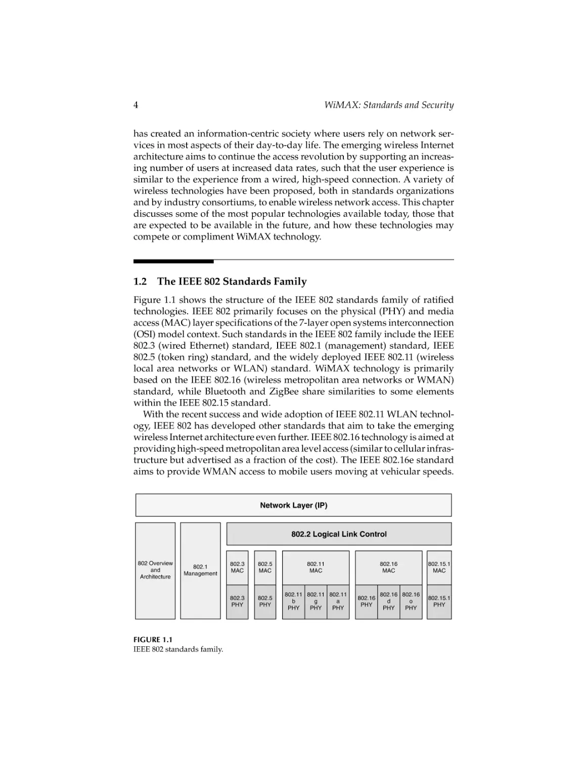
Figure 1.1 shows the structure of the IEEE 802 standards family of ratified
technologies. IEEE 802 primarily focuses on the physical (PHY) and media
access (MAC) layer specifications of the 7-layer open systems interconnection
(OSI) model context. Such standards in the IEEE 802 family include the IEEE
802.3 (wired Ethernet) standard, IEEE 802.1 (management) standard, IEEE
802.5 (token ring) standard, and the widely deployed IEEE 802.11 (wireless
local area networks or WLAN) standard. WiMAX technology is primarily
based on the IEEE 802.16 (wireless metropolitan area networks or WMAN)
standard, while Bluetooth and ZigBee share similarities to some elements
within the IEEE 802.15 standard.
With the recent success and wide adoption of IEEE 802.11 WLAN technology, IEEE 802 has developed other standards that aim to take the emerging
wireless Internet architecture even further. IEEE 802.16 technology is aimed at
providing high-speed metropolitan area level access (similar to cellular infrastructure but advertised as a fraction of the cost). The IEEE 802.16e standard
aims to provide WMAN access to mobile users moving at vehicular speeds.
Network Layer (IP)
802.2 Logical Link Control
802 Overview
and
Architecture
802.1
Management
FIGURE 1.1
IEEE 802 standards family.
802.3
MAC
802.5
MAC
802.11
MAC
802.3
PHY
802.5
PHY
802.11 802.11 802.11
b
g
a
PHY
PHY
PHY
802.16
PHY
802.16
MAC
802.15.1
MAC
802.16 802.16
d
o
PHY
PHY
802.15.1
PHY
CRC_45237_C001.tex
19/6/2007
14: 8
Page 5
The Emerging Wireless Internet Architecture
5
Each particular technology that has been released from the IEEE 802 group
is focused on a narrow set of usage cases (e.g., range, mobility speed, and
mesh networking) but deployments in the marketplace have often pushed
technologies further (e.g., range extension of IEEE 802.11).
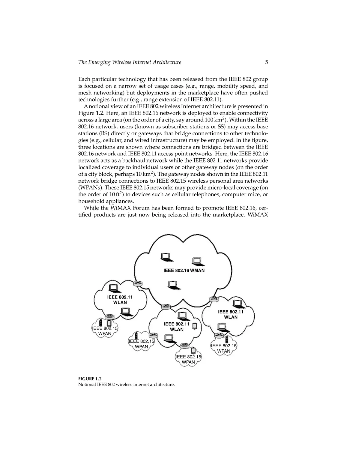
A notional view of an IEEE 802 wireless Internet architecture is presented in
Figure 1.2. Here, an IEEE 802.16 network is deployed to enable connectivity
across a large area (on the order of a city, say around 100 km2 ). Within the IEEE
802.16 network, users (known as subscriber stations or SS) may access base
stations (BS) directly or gateways that bridge connections to other technologies (e.g., cellular, and wired infrastructure) may be employed. In the figure,
three locations are shown where connections are bridged between the IEEE
802.16 network and IEEE 802.11 access point networks. Here, the IEEE 802.16
network acts as a backhaul network while the IEEE 802.11 networks provide
localized coverage to individual users or other gateway nodes (on the order
of a city block, perhaps 10 km2 ). The gateway nodes shown in the IEEE 802.11
network bridge connections to IEEE 802.15 wireless personal area networks
(WPANs). These IEEE 802.15 networks may provide micro-local coverage (on
the order of 10 ft2 ) to devices such as cellular telephones, computer mice, or
household appliances.
While the WiMAX Forum has been formed to promote IEEE 802.16, certified products are just now being released into the marketplace. WiMAX
IEEE 802.16 WMAN
IEEE 802.11
WLAN
IEEE 802.11
WLAN
IEEE 802.11
WLAN
IEEE 802.15
WPAN
IEEE 802.15
WPAN
IEEE 802.15
WPAN
IEEE 802.15
WPAN
FIGURE 1.2
Notional IEEE 802 wireless internet architecture.
CRC_45237_C001.tex
19/6/2007
14: 8
Page 6
6
WiMAX: Standards and Security
technology proliferation is expected to increase substantially as network
service providers adopt the technology. Sprint Corporation announced in
2006 that it plans to deploy a full WiMAX network across its entire U.S. coverage area to be operational in 2007. Other corporations across the world have
also announced plans to increasingly deploy WiMAX technology, especially
to underserved areas such as developing countries with limited infrastructure
options. Furthermore, Intel’s announcement to support WiMAX as part of its
wireless networking chipset in future laptop computers has further solidified
WiMAX as a likely technology candidate for the next generation of wireless
network-enabled devices.
1.2.1
IEEE 802.11
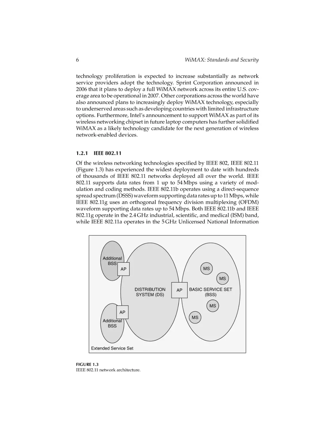
Of the wireless networking technologies specified by IEEE 802, IEEE 802.11
(Figure 1.3) has experienced the widest deployment to date with hundreds
of thousands of IEEE 802.11 networks deployed all over the world. IEEE
802.11 supports data rates from 1 up to 54 Mbps using a variety of modulation and coding methods. IEEE 802.11b operates using a direct-sequence
spread spectrum (DSSS) waveform supporting data rates up to 11 Mbps, while
IEEE 802.11g uses an orthogonal frequency division multiplexing (OFDM)
waveform supporting data rates up to 54 Mbps. Both IEEE 802.11b and IEEE
802.11g operate in the 2.4 GHz industrial, scientific, and medical (ISM) band,
while IEEE 802.11a operates in the 5 GHz Unlicensed National Information
Additional
BSS
AP
MS
MS
DISTRIBUTION
SYSTEM (DS)
AP
BASIC SERVICE SET
(BSS)
MS
AP
Additional
BSS
Extended Service Set
FIGURE 1.3
IEEE 802.11 network architecture.
MS
CRC_45237_C001.tex
19/6/2007
14: 8
The Emerging Wireless Internet Architecture
Page 7
7
Infrastructure (UNII) band. IEEE 802.11a uses the OFDM waveform specified
in IEEE 802.11g for data rates up to 54 Mbps, albeit at lower transmit powers
(around a maximum of 20 mW for IEEE 802.11a compared to a maximum of
100 mW for IEEE 802.11g). More information on these standards can be found
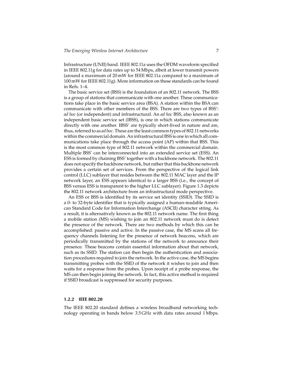
in Refs. 1–4.
The basic service set (BSS) is the foundation of an 802.11 network. The BSS
is a group of stations that communicate with one another. These communications take place in the basic service area (BSA). A station within the BSA can
communicate with other members of the BSS. There are two types of BSS’:
ad hoc (or independent) and infrastructural. An ad hoc BSS, also known as an
independent basic service set (IBSS), is one in which stations communicate
directly with one another. IBSS’ are typically short-lived in nature and are,
thus, referred to as ad hoc. These are the least common types of 802.11 networks
within the commercial domain. An infrastructural BSS is one in which all communications take place through the access point (AP) within that BSS. This
is the most common type of 802.11 network within the commercial domain.
Multiple BSS’ can be interconnected into an extended service set (ESS). An
ESS is formed by chaining BSS’ together with a backbone network. The 802.11
does not specify the backbone network, but rather that this backbone network
provides a certain set of services. From the perspective of the logical link
control (LLC) sublayer that resides between the 802.11 MAC layer and the IP
network layer, an ESS appears identical to a larger BSS (i.e., the concept of
BSS versus ESS is transparent to the higher LLC sublayer). Figure 1.3 depicts
the 802.11 network architecture from an infrastructural mode perspective.
An ESS or BSS is identified by its service set identity (SSID). The SSID is
a 0- to 32-byte identifier that is typically assigned a human-readable American Standard Code for Information Interchange (ASCII) character string. As
a result, it is alternatively known as the 802.11 network name. The first thing
a mobile station (MS) wishing to join an 802.11 network must do is detect
the presence of the network. There are two methods by which this can be
accomplished: passive and active. In the passive case, the MS scans all frequency channels listening for the presence of network beacons, which are
periodically transmitted by the stations of the network to announce their
presence. These beacons contain essential information about that network,
such as its SSID. The station can then begin the authentication and association procedures required to join the network. In the active case, the MS begins
transmitting probes with the SSID of the network it wishes to join and then
waits for a response from the probes. Upon receipt of a probe response, the
MS can then begin joining the network. In fact, this active method is required
if SSID broadcast is suppressed for security purposes.
1.2.2
IEEE 802.20
The IEEE 802.20 standard defines a wireless broadband networking technology operating in bands below 3.5 GHz with data rates around 1 Mbps.
CRC_45237_C001.tex
19/6/2007
14: 8
8
Page 8
WiMAX: Standards and Security
IEEE 802.20 aims to operate in ranges up to 15 km, supporting vehicular
motion up to 250 km/h (train speeds). Activities of this group were suspended
on June 8, 2006, but a path forward was established on September 15, 2006 by
the IEEE Standards Association to continue the development of the standard.
Currently, a draft standard has been produced but this working group is still
in its early stages and as such a final standard is expected to emerge no earlier
than late 2007.
1.3
Cellular Networks
Cellular technology has long evolved from first-generation analog technology
to today’s Internet-enabled digital cellular packet networks. Originally such
networks were designed to provide voice service, but today’s informationcentric users demand other services as well, such as e-mail, text messaging,
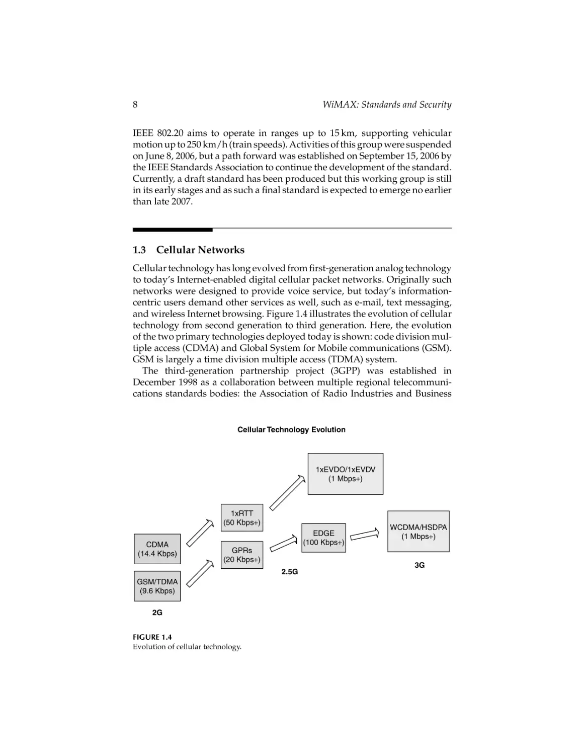
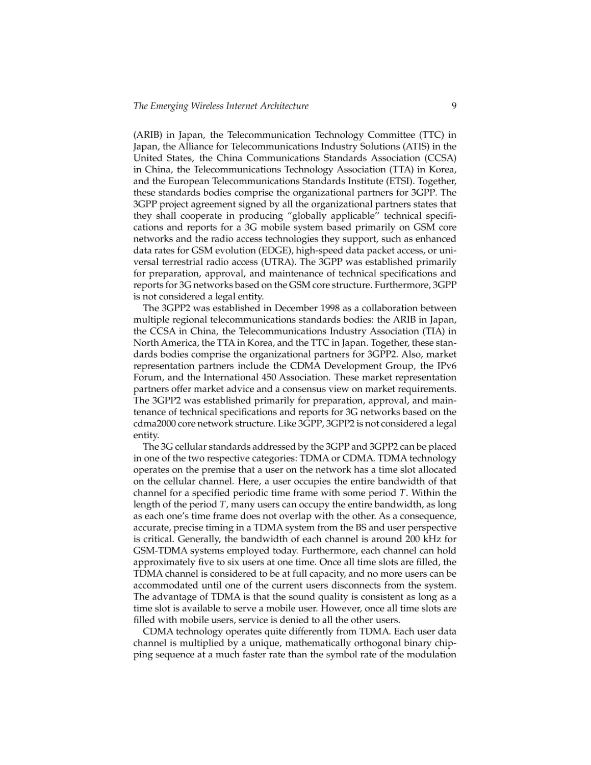
and wireless Internet browsing. Figure 1.4 illustrates the evolution of cellular
technology from second generation to third generation. Here, the evolution
of the two primary technologies deployed today is shown: code division multiple access (CDMA) and Global System for Mobile communications (GSM).
GSM is largely a time division multiple access (TDMA) system.
The third-generation partnership project (3GPP) was established in
December 1998 as a collaboration between multiple regional telecommunications standards bodies: the Association of Radio Industries and Business
Cellular Technology Evolution
1xEVDO/1xEVDV
(1 Mbps+)
1xRTT
(50 Kbps+)
CDMA
(14.4 Kbps)
EDGE
(100 Kbps+)
GPRs
(20 Kbps+)
2.5G
GSM/TDMA
(9.6 Kbps)
2G
FIGURE 1.4
Evolution of cellular technology.
WCDMA/HSDPA
(1 Mbps+)
3G
CRC_45237_C001.tex
19/6/2007
14: 8
The Emerging Wireless Internet Architecture
Page 9
9
(ARIB) in Japan, the Telecommunication Technology Committee (TTC) in
Japan, the Alliance for Telecommunications Industry Solutions (ATIS) in the
United States, the China Communications Standards Association (CCSA)
in China, the Telecommunications Technology Association (TTA) in Korea,
and the European Telecommunications Standards Institute (ETSI). Together,
these standards bodies comprise the organizational partners for 3GPP. The
3GPP project agreement signed by all the organizational partners states that
they shall cooperate in producing “globally applicable’’ technical specifications and reports for a 3G mobile system based primarily on GSM core
networks and the radio access technologies they support, such as enhanced
data rates for GSM evolution (EDGE), high-speed data packet access, or universal terrestrial radio access (UTRA). The 3GPP was established primarily
for preparation, approval, and maintenance of technical specifications and
reports for 3G networks based on the GSM core structure. Furthermore, 3GPP
is not considered a legal entity.
The 3GPP2 was established in December 1998 as a collaboration between
multiple regional telecommunications standards bodies: the ARIB in Japan,
the CCSA in China, the Telecommunications Industry Association (TIA) in
North America, the TTA in Korea, and the TTC in Japan. Together, these standards bodies comprise the organizational partners for 3GPP2. Also, market
representation partners include the CDMA Development Group, the IPv6
Forum, and the International 450 Association. These market representation
partners offer market advice and a consensus view on market requirements.
The 3GPP2 was established primarily for preparation, approval, and maintenance of technical specifications and reports for 3G networks based on the
cdma2000 core network structure. Like 3GPP, 3GPP2 is not considered a legal
entity.
The 3G cellular standards addressed by the 3GPP and 3GPP2 can be placed
in one of the two respective categories: TDMA or CDMA. TDMA technology
operates on the premise that a user on the network has a time slot allocated
on the cellular channel. Here, a user occupies the entire bandwidth of that
channel for a specified periodic time frame with some period T. Within the
length of the period T, many users can occupy the entire bandwidth, as long
as each one’s time frame does not overlap with the other. As a consequence,
accurate, precise timing in a TDMA system from the BS and user perspective
is critical. Generally, the bandwidth of each channel is around 200 kHz for
GSM-TDMA systems employed today. Furthermore, each channel can hold
approximately five to six users at one time. Once all time slots are filled, the
TDMA channel is considered to be at full capacity, and no more users can be
accommodated until one of the current users disconnects from the system.
The advantage of TDMA is that the sound quality is consistent as long as a
time slot is available to serve a mobile user. However, once all time slots are
filled with mobile users, service is denied to all the other users.
CDMA technology operates quite differently from TDMA. Each user data
channel is multiplied by a unique, mathematically orthogonal binary chipping sequence at a much faster rate than the symbol rate of the modulation
CRC_45237_C001.tex
10
19/6/2007
14: 8
Page 10
WiMAX: Standards and Security
used. This, in effect, spreads the spectrum of each user to cover a bandwidth
of about 1 MHz, so all users share the entire spectrum at the same time and
with the same power. Interference is minimized in this approach for two reasons. First, each unique chipping sequence is orthogonal to the next one in
signal space. These chipping sequences are called Walsh codes. There are 64
unique Walsh codes. Second, a high-fidelity, rapidly adapting power control mechanism employed at the BS’ and mobile users maintain near-equal
received power levels from mobile users, as seen by the BS, so no one user
has a power advantage over another. Open- and closed-loop power control
methods are employed here. The open-loop power control method employs
BS observations of power measurements from mobile users. The BS may command a mobile user to adjust its power to match the received signal levels of
the other mobile users. The open-loop method operates at a relatively slow
rate as compared to closed-loop power control in which the mobile user is
an active part of the power control and adjusts its own power based on its
observations of received power levels from the BS. CDMA has an advantage
over TDMA when considering capacity degradation. While TDMA hard limits the number of users who may use the channel at one time, CDMAallows for
a more gradual degradation in quality for each additional user. All active users
suffer slight quality degradation when another user joins the network at the
same time. However, this can result in a significant variation in sound quality,
as compared to the relative consistency of the time slot method employed in
TDMA.
While the second generation of both these technologies supported data
rates up to 14.4 Kbps (CDMA) and 9.6 Kbps (TDMA), these speeds would
not provide the necessary bandwidth to support the applications used on
today’s wireless Internet architecture. However, evolution to third-generation
technology data rates (around a megabit per second) has improved the
performance of these high-bandwidth applications.
Today, users have an option with most cellular companies to purchase a
Personal Computer Memory Card International Association (PCMCIA) network access card to connect to the Internet. Typical data rates experienced
by users range from 300 Kbps up to 1 Mbps, depending on the technology.
To date, evolved CDMA technologies such as 1xEVDO have outperformed
evolved GSM technologies such as the Universal Mobile Telecommunications
System-Wideband CDMA (UMTS-WCDMA) from a data rate perspective.
1xEVDO currently supports a downlink physical layer data rate at 2.4 Mbps
and an uplink physical layer data rate at 150 Kbps. Revision A to this standard will improve the downlink physical layer data rate to 3.1 Mbps and
increase the uplink physical layer data rate to 1.8 Mbps. The high-speed downlink packet access (HSDPA) standard for UMTS-WCDMA aims to support
downlink physical layer data rates from 1.8 up to 7.2 Mbps and beyond by
introducing another channel known as the high-speed downlink shared channel (HSDSCH) used solely for downlink communications to the mobile user.
The uplink data rate supported by HSDPA is 384 Kbps. More information on
these standards and their evolution is discussed in Ref. 5.
CRC_45237_C001.tex
19/6/2007
14: 8
The Emerging Wireless Internet Architecture
Page 11
11
Cellular network providers have adopted strategies to evolve their networks to third generation, and most have currently adopted the new
technologies available. However, cellular networks are most useful for providing their first envisioned application: voice. Nevertheless, these network
providers have noticed the evolving wireless Internet architecture unfold,
especially with the success of IEEE 802.11, and as such desire to participate
by providing increased data rates and services to compel users seeking wireless network access to utilize the cellular infrastructure. While coverage for
cellular networks is by far the most extensive of any wireless network infrastructure deployed to date (with the exception of low-bandwidth satellite),
data rates have yet to evolve to support the increasing bandwidth needs of
users.
1.4
ETSI HIPERLAN Standard
The ETSI has developed analogous standards to the IEEE 802.11 and IEEE
802.16 solutions, known as HIPERLAN and HIPERMAN, respectively. These
technologies are considered to be superior from a throughput and design
perspective compared to their IEEE 802 counterparts but nevertheless have
not been adopted or deployed widely. In addition to the IEEE 802.16 standard, the WiMAX Forum has also supported certification of ETSI HIPERMAN
standards-based equipment.
The HIPERLAN WLAN technology standard [6] was established by ETSI
as a way to enable wireless network connectivity on a variety of platforms:
third-generation cellular, home wireless LAN, and corporate wireless LAN,
for example. The ETSI Broadband Radio Access Networks (BRAN) group
has developed the second-generation HIPERLAN/2 as the follow-on standard to HIPERLAN/1, similar to the IEEE 802.11 evolution of standards
(from the 11 Mbps “b’’ standard to the 54 Mbps “g’’ standard). HIPERLAN/2
operates in the 5 GHz UNII band. It supports data rates ranging from 6 to
54 Mbps via an OFDM format. HIPERLAN/2 uses a TDMA scheme to share
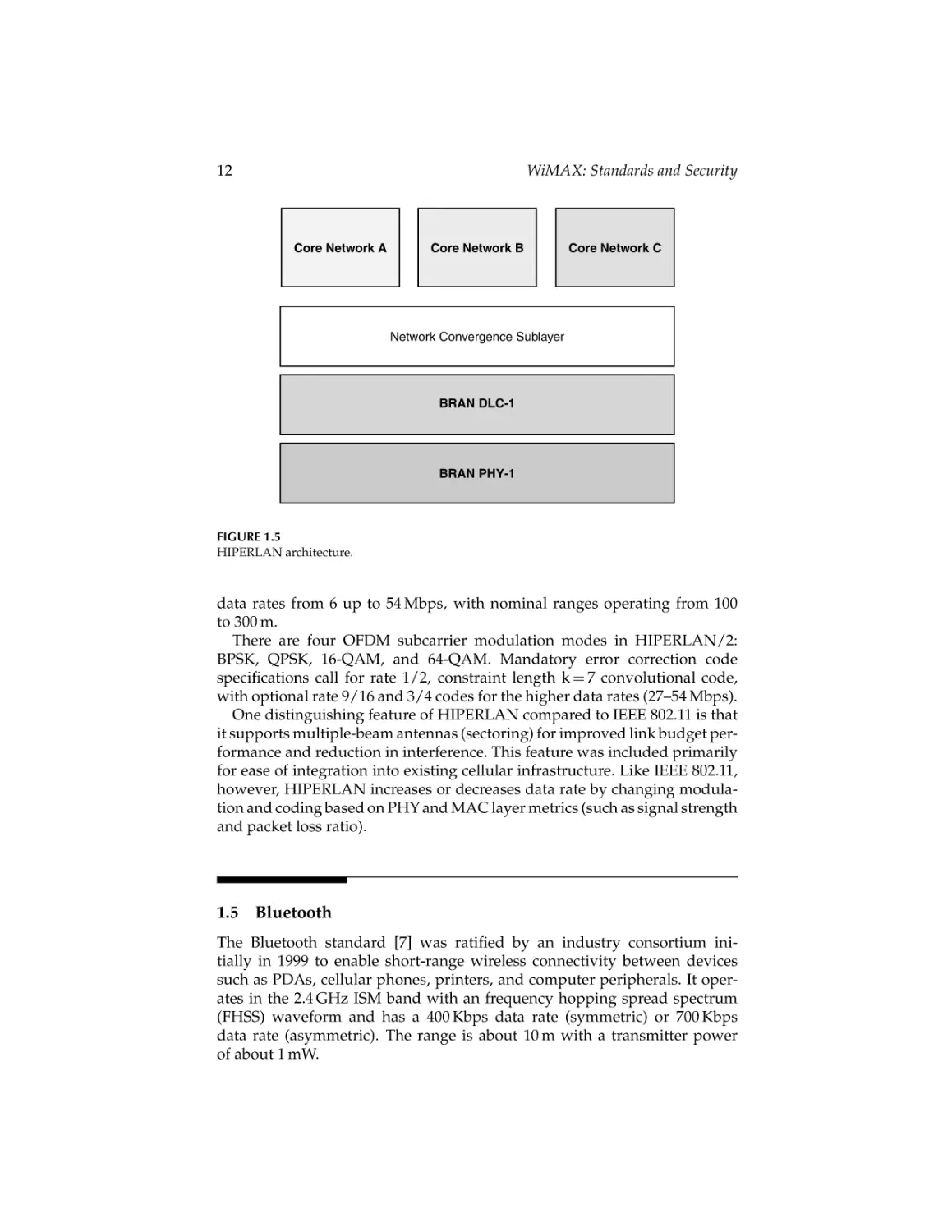
the medium among multiple users. Figure 1.5 illustrates the basic architecture
of HIPERLAN.
HIPERLAN topologies are similar to cellular infrastructure topologies, in
that there are base stations and wireless users. As it complies with the BRAN
PHY and data link control (DLC) standards it is interoperable with a variety of other European core network standards such as GSM. There are two
modes of operation within HIPERLAN: centralized and direct. Centralized
mode is analogous to the infrastructural mode within the IEEE 802.11 standard, where cellular-like infrastructure is required to relay packets from users
through base stations to other users. The direct mode is analogous to the ad hoc
mode in IEEE 802.11, where users can send and receive packets to and from
each other without traversing an infrastructure node. HIPERLAN supports
CRC_45237_C001.tex
19/6/2007
14: 8
12
Page 12
WiMAX: Standards and Security
Core Network A
Core Network B
Core Network C
Network Convergence Sublayer
BRAN DLC-1
BRAN PHY-1
FIGURE 1.5
HIPERLAN architecture.
data rates from 6 up to 54 Mbps, with nominal ranges operating from 100
to 300 m.
There are four OFDM subcarrier modulation modes in HIPERLAN/2:
BPSK, QPSK, 16-QAM, and 64-QAM. Mandatory error correction code
specifications call for rate 1/2, constraint length k = 7 convolutional code,
with optional rate 9/16 and 3/4 codes for the higher data rates (27–54 Mbps).
One distinguishing feature of HIPERLAN compared to IEEE 802.11 is that
it supports multiple-beam antennas (sectoring) for improved link budget performance and reduction in interference. This feature was included primarily
for ease of integration into existing cellular infrastructure. Like IEEE 802.11,
however, HIPERLAN increases or decreases data rate by changing modulation and coding based on PHY and MAC layer metrics (such as signal strength
and packet loss ratio).
1.5
Bluetooth
The Bluetooth standard [7] was ratified by an industry consortium initially in 1999 to enable short-range wireless connectivity between devices
such as PDAs, cellular phones, printers, and computer peripherals. It operates in the 2.4 GHz ISM band with an frequency hopping spread spectrum
(FHSS) waveform and has a 400 Kbps data rate (symmetric) or 700 Kbps
data rate (asymmetric). The range is about 10 m with a transmitter power
of about 1 mW.
CRC_45237_C001.tex
19/6/2007
14: 8
Page 13
The Emerging Wireless Internet Architecture
13
Time differential T1
Piconet
Slave 1
FHS
et
pack
S
FH
Piconet
Slave 2
Time differential T2
ket
pac
Time differential T4
FHS packet
FHS
Piconet
Slave 4
ket
pac
Piconet
Master
Node
Piconet
Slave 3
Time differential T3
FIGURE 1.6
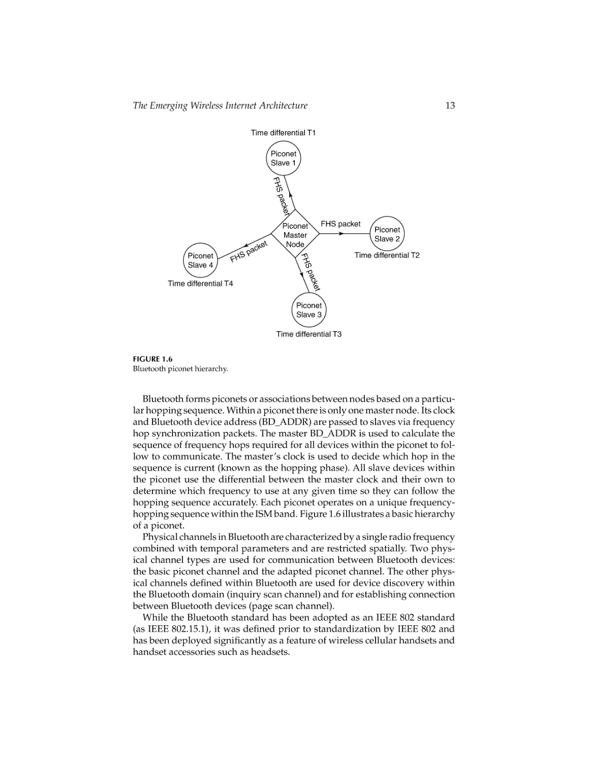
Bluetooth piconet hierarchy.
Bluetooth forms piconets or associations between nodes based on a particular hopping sequence. Within a piconet there is only one master node. Its clock
and Bluetooth device address (BD_ADDR) are passed to slaves via frequency
hop synchronization packets. The master BD_ADDR is used to calculate the
sequence of frequency hops required for all devices within the piconet to follow to communicate. The master’s clock is used to decide which hop in the
sequence is current (known as the hopping phase). All slave devices within
the piconet use the differential between the master clock and their own to
determine which frequency to use at any given time so they can follow the
hopping sequence accurately. Each piconet operates on a unique frequencyhopping sequence within the ISM band. Figure 1.6 illustrates a basic hierarchy
of a piconet.
Physical channels in Bluetooth are characterized by a single radio frequency
combined with temporal parameters and are restricted spatially. Two physical channel types are used for communication between Bluetooth devices:
the basic piconet channel and the adapted piconet channel. The other physical channels defined within Bluetooth are used for device discovery within
the Bluetooth domain (inquiry scan channel) and for establishing connection
between Bluetooth devices (page scan channel).
While the Bluetooth standard has been adopted as an IEEE 802 standard
(as IEEE 802.15.1), it was defined prior to standardization by IEEE 802 and
has been deployed significantly as a feature of wireless cellular handsets and
handset accessories such as headsets.
CRC_45237_C001.tex
19/6/2007
14
14: 8
Page 14
WiMAX: Standards and Security
1.6
Other Wireless Networking Technologies
This chapter has delineated and briefly described some of the wireless networking technologies that are expected to compete with or compliment
WiMAX. Other technologies will most certainly emerge and as such may
change the marketplace climate for WiMAX and related technologies significantly. Such technologies include
• The Wireless Broadband (WiBro) standard, a Korean standard that
is incorporated into the IEEE 802.16e standard. While the WiMAX
Forum has indeed created certification profiles for IEEE 802.16, it is
unclear as to what degree the WiMAX Forum will certify WiBroenabled equipment. This could affect deployment of the WiBro
technology.
• The IEEE 802.22 wireless regional area network (WRAN) standard is
currently emerging and aims to employ cognitive radio concepts to
enable a next-generation adaptive wireless networking technology
operating in the licensed broadcast television bands.
1.7
Competing Technologies
Some of the wireless technologies described here will undoubtedly compete
with WiMAX and its associated technologies. This section of the chapter provides a discussion of such technologies and what advantages or
disadvantages each has when compared to WiMAX.
1.7.1
IEEE 802.20
The IEEE 802.20 working group and IEEE 802.16 Task Group E have been
widely considered as developers of competing technologies. However, there
are some differences between the two standards:
• IEEE 802.20 aims to develop a standard that supports 1 Mbps
data rates for mobile users moving at speeds up to 250 km/h.
IEEE 802.16e, however, only supports users at vehicular speeds,
notionally up to 150 km/h.
• IEEE 802.16e is intended for frequencies operating from 2–6 GHz.
However, IEEE 802.20 is focused on frequencies at 3.5 GHz or below.
• IEEE 802.16e is based on prior IEEE 802.16 standards work, while
IEEE 802.20 aims to produce an original standard.
CRC_45237_C001.tex
19/6/2007
14: 8
Page 15
The Emerging Wireless Internet Architecture
15
• IEEE 802.16e is a ratified standard while IEEE 802.20 is still in the
draft form. Furthermore, contention in the IEEE 802.20 working
group may prevent any final version of the standard, similar to
what has happened in the IEEE 802.15.3a working group.
It is expected that IEEE 802.20 will not support the high data rates that
IEEE 802.16 provides, as the solution space for IEEE 802.20 focuses on highspeed mobility. However, as the IEEE 802.16e standard evolves and WiMAX
profiles are defined for various mobility classes, advancements in technology
and methods could improve mobility support up to and surpassing speeds
defined in IEEE 802.20 for implementation-specific IEEE 802.16e equipment.
Furthermore, a wide variety of industry participants have embraced IEEE
802.16 and WiMAX certification as the path to broadband wireless mobile
access, although IEEE 802.20 aimed to produce a standard that achieved this
vision.
1.7.2
Cellular Networks
Perhaps the largest competitor to WiMAX technologies, cellular networks
have been deployed all over the world. The level of investment and infrastructure deployment has been one of the most extensive of any terrestrial
wireless network in existence. Furthermore, paths to evolve to higher data
rates that support mobility from the start and provide users with an experience that approximates the wired connectivity they experience at home or
at the office is expected to materialize as the technologies evolve. However,
there are some disadvantages to cellular as compared to WiMAX:
• Cost: The expense of procuring and deploying a cellular network
infrastructure with the most advanced, high-data-rate technologies
(such as HSDPA and 1xEVDO) today is substantially larger than
a WiMAX-enabled solution. First, the cost of maintaining spectrum
licenses for cellular bands is substantial. Furthermore, base station
cost is about an order of magnitude more expensive to procure.
Finally, the complexity of such a solution is significant especially
when cellular providers must retrofit their older-generation networks and maintain separate networks to ensure users without the
latest equipment will be able to maintain access.
• Original design: Cellular systems were originally designed for voice
communications and as such have been augmented to support a
variety of data applications. The CDMA and GSM core networks
have also evolved to support IP-based communications, which has
become the de facto standard today. However, WiMAX technologies
are primarily IP-based and were designed to support data and voice
applications from the beginning.
• Throughput performance: Results in Ref. 8 suggest that, when
all other system parameters remain equal (bandwidth, antenna
CRC_45237_C001.tex
19/6/2007
14: 8
16
Page 16
WiMAX: Standards and Security
configuration, power), WiMAX technology outperforms both
HSDPA and cdma2000 3xEVDO (three 1xEVDO channels) by
28%–96%.
While there are some clear disadvantages to cellular, its key advantage over
WiMAX technology remains its large coverage footprint. However, some
cellular service providers such as Sprint Corporation in the United States
have announced plans to deploy WiMAX across their entire coverage footprint as well. In this sense, WiMAX would be considered complementary
to cellular. Many other carriers, especially those with heavy investments
in the GSM/UMTS-WCDMA technology space, have not adopted the same
coexistence strategy. Sprint’s success or failure in deploying WiMAX on a
nationwide scale will likely affect similar companies’ strategies in dealing
with WiMAX competition and deployment.
While the technologies presented in this section are expected to compete
for users that WiMAX aims to serve currently, market forces could very well
align these technologies with WiMAX in a strategy to further the deployment
and use of the emerging wireless Internet architecture.
1.8
Complementary Technologies
Technologies presented in this section are largely complementary to WiMAX.
These technologies have been proven for their intended purposes and do not
overlap significantly compared to the purposes WiMAX technologies were
designed to serve.
1.8.1
IEEE 802.11
The widespread adoption of IEEE 802.11 has resulted in a substantial increase
in the ability to connect to the Internet wirelessly. However, unlike WiMAX,
IEEE 802.11 was primarily designed for local area networks. It lacks the
complexity and power levels inherent in WiMAX that would be required
for scalability while maintaining high levels of throughput. WiMAX technologies are primarily based on time division duplex (TDD) or frequency
division duplex (FDD) access methods with access slots reallocated to users
as needed on a demand basis. IEEE 802.11, however, shares the media with
multiple users by employing a distributed-approach version of Carrier Sense
Multiple Access with Collision Avoidance (CSMA/CA), which is inherently
limited when trying to scale one single channel to support many users. In
this sense, the IEEE 802.11 WLAN standards address connecting local areas
(within 10s or 100s of feet) most efficiently—one would not prefer the complexity of a WiMAX base station to support connections with maximum
distances in this range. It is expected that within short ranges and limited
CRC_45237_C001.tex
19/6/2007
14: 8
Page 17
The Emerging Wireless Internet Architecture
17
number of users, IEEE 802.11 will outperform WiMAX technologies significantly. WiMAX deployments will not possess the bandwidth required to
support many users in a city-wide coverage area with the data rates each
would experience if there were one IEEE 802.11 access point for every few
users. Such a scenario is typical of the home-network model, where one IEEE
802.11 access point is deployed, connected to a wired infrastructure such as
a cable modem or digital subscriber line (DSL).
1.8.2
IEEE 802.15
The IEEE 802.15 family of standards focuses primarily on WPANs with ranges
only on the order of 10 ft. Obviously, WiMAX technologies were not designed
with this limited range in mind, but the need and demand for WPANs have
become increasingly prevalent as wireless networking evolves to support a
variety of platforms, including those in the home such as household appliances. Furthermore, mobile phones enabled with IEEE 802.15 technologies
benefit from the ability to connect to other phones, computers, or devices
such as headsets, albeit within a short range. As the data rate requirements for the applications running over WPANs remain relatively small
compared to WiMAX technologies, this technology clearly has delineated
a niche compared to the intended use for WiMAX.
1.9
Conclusion
The momentum built up behind WiMAX technologies has reached a critical point. Significant investment in research, development, products, and
marketing for WiMAX has been ongoing and is expected to continue. This
chapter has described other wireless networking technologies that compliment or compete with WiMAX technologies. It has also provided an overview
of the most prevalent technologies in use today, as well as a description of the
similarities and differences compared to WiMAX.
References
1. IEEE 802.11-1999, Part 11: Wireless LAN Medium Access Control (MAC) and Physical
Layer (PHY) Specifications, 1999.
2. IEEE 802.11a-1999, Part 11: Wireless LAN Medium Access Control (MAC) and Physical
Layer (PHY) Specifications: High-Speed Physical Layer in the 5 GHz Band, 1999.
3. IEEE 802.11b-1999, Part 11: Wireless LAN Medium Access Control (MAC) and
Physical Layer (PHY) Specifications: Higher-Speed Physical Layer Extension in the
2.4 GHz Band, 1999.
CRC_45237_C001.tex
18
19/6/2007
14: 8
Page 18
WiMAX: Standards and Security
4. IEEE 802.11g-2003, Part 11: Wireless LAN Medium Access Control (MAC) and
Physical Layer (PHY) Specifications: High-Speed Physical Layer in the 2.4 GHz Band,
2003.
5. IMT-2000 Network Aspects, http://www.itu.int/ITU-T/imt-2000/network.html.
6. HIPERLAN 2 Specification,
http://portal.etsi.org/bran/kta/Hiperlan/
hiperlan2tech.asp.
7. Specification of the Bluetooth System: Wireless Connections Made Easy, Version 1.2,
5 November 2003.
8. Mobile WiMAX—Part II: A Comparative Analysis, WiMAX Forum, Copyright
2006.
CRC_45237_C002.tex
19/6/2007
11: 51
Page 19
2
IEEE 802.16 Standards and Amendments
Najah Abu Ali and Hossam S. Hassanein
CONTENTS
2.1 Introduction ................................................................................................. 20
2.2 Standardized versus Proprietary Solutions ............................................ 20
2.2.1 Standardization Cons ..................................................................... 20
2.2.2 Standardization Pros ...................................................................... 20
2.3 Overview of the Standard ......................................................................... 21
2.4 IEEE 802.16-2004 ......................................................................................... 22
2.4.1 Physical Layer ................................................................................. 23
2.4.1.1 Other Features .................................................................. 24
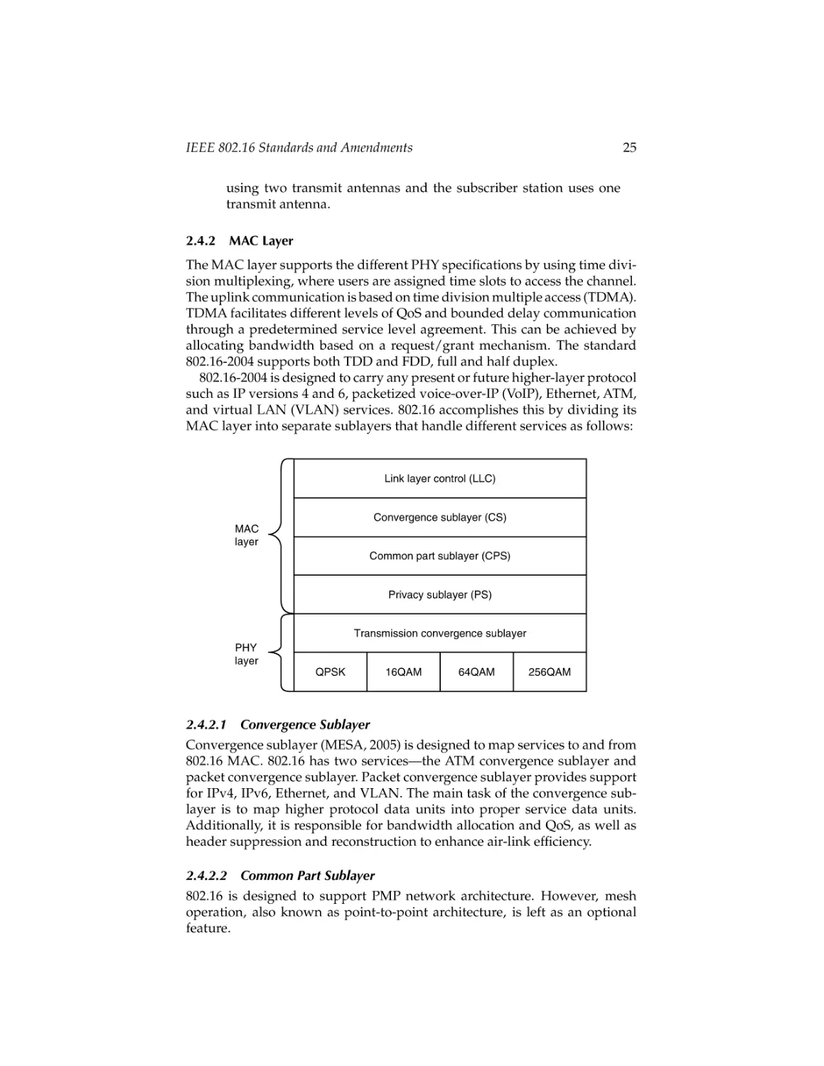
2.4.2 MAC Layer ...................................................................................... 25
2.4.2.1 Convergence Sublayer .................................................... 25
2.4.2.2 Common Part Sublayer .................................................. 25
2.4.2.3 Privacy Sublayer .............................................................. 27
2.5 IEEE 802.16e-2005 ....................................................................................... 28
2.5.1 Physical Layer ................................................................................. 28
2.5.2 MAC Layer ...................................................................................... 29
2.5.2.1 QoS Support ..................................................................... 29
2.5.2.2 Handover Support .......................................................... 29
2.5.2.3 Power Management ........................................................ 29
2.6 IEEE 802.16f ................................................................................................. 30
2.7 IEEE 802.16i ................................................................................................. 30
2.8 IEEE 802.16g ................................................................................................ 30
2.9 IEEE 802.16k ................................................................................................ 31
2.10 IEEE 802.16h ................................................................................................ 32
2.10.1 MAC Enhancement for Coexistence .......................................... 32
2.11 IEEE 802.16j .................................................................................................. 33
References ............................................................................................................. 33
19
CRC_45237_C002.tex
19/6/2007
20
11: 51
Page 20
WiMAX: Standards and Security
2.1
Introduction
The IEEE Standards Board established the IEEE 802.16 working group in 1999
to prepare formal specifications for global deployment of broadband wireless
metropolitan area networks, which is officially called WirelessMAN. The IEEE
802.16 working group, which is a unit of the IEEE 802 LAN/MAN Standards
Committee, is responsible for framing specifications of the IEEE 802.16 family
standard, but not testing them. Thus, another industrial group was established in April 2001 called the WiMAX Forum. The acronym WiMAX expands
to “Worldwide Interoperability for Microwave Access.’’ WiMAX Forum is on
a mission to advance and certify compatibility and interoperability of broadband wireless products based on IEEE 802.16 family standards. Irrespective of
the scope of the WiMAX Forum that aims to test equipments, the IEEE 802.16
family hails WiMAX from the WiMAX Forum, maybe because it is easier to
use the word WiMAX rather than IEEE 802.16.
2.2
Standardized versus Proprietary Solutions
Before proceeding to present the developments of the 802.16 family of standards, it is worthwhile to know the pros and cons of the standardized versus
proprietary solutions in WiMAX case (Alvrion, 2005).
2.2.1
Standardization Cons
1. Setting rules normally consumes long periods of time before being
available to vendors. This may encourage a change to another
technology that provides the same service, for example, 3G.
2. Gaining agreement across the standards committee may require
degrading the specifications to gain the common players’ approval.
Consequently, the resulting standard may not satisfy the user or at
least the counterpart proprietary solution may provide a superior
technical performance.
3. Forcing the vendors to comply with a standard may hinder vendors
from competition to produce innovative solutions.
2.2.2
Standardization Pros
1. Reduces supplier dependence resulting in a wider deployment of
the technology because there is no dependence on a sole producer
2. Lowers the product cost and consequently lowers the cost to the
end user
3. Lowers the deployment risk owing to interoperability
CRC_45237_C002.tex
19/6/2007
11: 51
IEEE 802.16 Standards and Amendments
Page 21
21
However, by comparing the IEEE 802.16 family of standards with other existing standards, we can see that the standardization process did not extend over
a considerably long time. Additionally, the IEEE 802.16 family of standards
includes a wide range of variations (as we will see in the following sections).
Hence, while being standard compliant, it leaves breathing space for solution
innovation by vendors.
2.3
Overview of the Standard
IEEE 802.16-2001, the first standard of the family, was approved in December 2001 and published in 2002. This standard is the result of the activity
of hundreds of participants worldwide. The working group of this standard (Air Interface for Fixed Broadband Wireless Access System) focused
on providing WirelessMAN access for fixed applications. IEEE 802.16-2001
(LAN/MAN committee, 2001) provides network access to buildings through
exterior antennas communicating with a radio base station using point-tomultipoint (PMP) infrastructure design and operating at a radio frequency
between 10 and 66 GHz with an average bandwidth performance of 70 Mbps
and a peak rate up to 268 Mbps. Thus, it is basically an alternative to cabled
access networks, cable modems, and digital subscriber line (DSL). However,
the IEEE 802.16-2001 standard was not an adequate air interface standard for
broadband wireless access. It addressed frequencies in a licensed spectrum
that introduces significant challenges to the short wavelength and is limited
to line-of-sight (LOS) propagation. It also neglects any conformance with its
European counterpart standard, HiperMAN standard, and supports a singlecarrier physical layer. Thus, the initial 802.16-2001 standard was followed by
several amendments.
The first one was IEEE 802.16c (LAN/MAN committee, 2002). The main
objective of this amendment was to ensure interoperability among the existing local multipoint distribution service (LMDS) LOS solutions working in the
10–66 GHz range. Naturally, since the 802.16c is defined over a wide range of
frequency it provides more bandwidth. However, and for the same reason, the
maximum coverage of 802.16c does not exceed 5 km. In addition to 802.16c’s
main objective, it addressed other issues such as testing, performance evaluation, and system profiling. System profiling is a vital requirement for
interoperability. 802.16c provides guidelines for vendors through mandatory and optional elements of system profiling to ensure interoperability. As
for mandatory elements of 802.16c profiling, vendors should support provisioned connections, provide IPv4 support on transport connection, and
support fragmentation. As for optional elements, 802.16c allows for different
levels of security protocols that allow vendors to provide different functionalities that differentiate their products. As a final remark on 802.16c, it is specified
to be network technology independent. Thus it can run under asynchronous
CRC_45237_C002.tex
19/6/2007
22
11: 51
Page 22
WiMAX: Standards and Security
transfer mode (ATM), internet protocol (IP), or frame relay. The second
amendment was the IEEE 802.16b, also called WirelessHUMAN (Wireless
high-speed unlicensed metropolitan area network). This amendment mainly
provided for quality of service (QoS) features to ensure differentiated service levels for different traffic types. It extended 802.16-2001 to operate under
license-exempt regulation in the 5–6 GHz range. However, 802.16b does not
exist anymore. In April 2003, 802.16a, the most eminent among amendments,
was published to standardize the lower-frequency multichannel multipoint
distribution service (MMDS) solutions in the licensed and unlicensed range
of 2–11 GHz. Working at a lower-frequency range than 802.16-2001, 802.16a
(LAN/MAN committee, 2003) has the advantage of being able to offer
nonline-of-sight (NLOS) communication and a cell coverage up to 50 km with
a bit rate up to 75 Mbps. An additional feature of 802.16a is that it provides
for mesh mode operation, which facilitates subscriber-to-subscriber communications. IEEE 802.16d project was launched to produce interoperability
specification and to provide for some fixes for 802.16a. However, the project
was transitioned into a revision project for 802.16-2001 and all its amendments. The revision project result is no longer called 802.16d, but it is formally
called 802.16-2004 (LAN/MAN committee, 2004). Yet, this active standard
was followed by different working groups to address different issues as
follows:
1. Active standards
a. IEEE 802.16e-2005 (formerly known as IEEE 802.16e)—
addressing mobility, concluded in 2005
b. 802.16f—Management Information Base
2. Drafts under development
a. 802.16g—Management Plane Procedures and Services
b. 802.16k—Bridging
c. 802.16h—Improved Coexistence Mechanisms for LicenseExempt Operation
3. Projects in predraft stage
a. 802.16i—Mobile Management Information Base
b. 802.16j—Mobile Multihop Relay
In the following sections, we present the IEEE 802.16-2004 standard and its
amendments, their status, and an overview of their specifications.
2.4
IEEE 802.16-2004
As aforementioned, the first standard of 802.16 addressed the LOS communication in the 10–66 GHz band. 802.16a extended its operation to include
CRC_45237_C002.tex
19/6/2007
11: 51
IEEE 802.16 Standards and Amendments
Page 23
23
NLOS communication in the lower-frequency band of 2–11 GHz. Thus, IEEE
802.16-2004 (LAN/MAN committee, 2004) supports communication in the
2–66 GHz band. LOS and NLOS propagation are quite different. Thus, to
design a standard that supports both bands, the physical and the medium
access control (MAC) layer should support these differences. For example,
signal propagation in high-band frequency is highly affected by obstacles,
consequently LOS propagation is utilized, which in turn results in alleviating the effect of multipath interference. Multipath results from receiving the
signal at the receiver through more than one path owing to reflection and
refraction of obstacles. However, operation in the lower band that includes
licensed and unlicensed spectrum requires its own regulations. For example,
operation in the unlicensed spectrum requires management of transmitter
output power, techniques to avoid frequency interference, etc. These issues
and others not only affect the physical layer design but also influenced the
MAC layer. Thus, the scope of 802.16-2004 standard covers the specifications
of these two lower layers in the OSI model.
2.4.1
Physical Layer
A 10–66 GHz frequency wave is a focused beam, which theoretically can
reach multiple miles through LOS propagation. Designers deemed that
single-carrier modulation was a sufficient choice and the physical layer
standard version of this band is called WirelessMAN-SC (single carrier).
WirelessMAN-SC can support frequency division duplex (FDD) and time
division duplex (TDD) modes. However, operation in the 2–11 GHz band
required changes in the physical layer specification to support NLOS
propagation. Mainly, three new PHYsical layer (PHY) specifications were
introduced to meet this requirement—a single-carrier PHY, a 256-point FFT
OFDM PHY, and a 2048-point FFT OFDMA PHY. The single-carrier PHY,
designated as WirelessMAN-SCa, is based on the WirelessMAN-SC. However, there are some differences such as framing elements that enable
improved equalization and channel estimation performance over NLOS propagation, extended delay spread channels, parameter settings, and MAC/PHY
messages that facilitate optional adaptive antenna systems (AAS) implementations. The second and third PHY specifications employ orthogonal
frequency division multiplexing (OFDM), which is a multicarrier transmission technique suitable for high-speed NLOS. OFDM uses 256 RF subcarriers
to transmit different signals simultaneously. The neighboring subcarriers are
allowed to overlap; however, they are orthogonal to each other to prevent
inter-carrier interference (ICI). The key difference between WirelessMAN SCx
and OFDM is that OFDM is more resilient to the multipath effect. OFDM
has higher bandwidth efficiency since it allows neighboring subcarriers to
overlap. Thus, OFDM modulates data at a rate of 72 Mbps over a channel
bandwidth of 20 MHz, which provides a spectral efficiency of 3.6 bps/Hz
(WiMAX Forum, 2004).
CRC_45237_C002.tex
24
19/6/2007
11: 51
Page 24
WiMAX: Standards and Security
Orthogonal frequency division multiple access (OFDMA) is a 2048 subcarrier OFDM scheme. The difference between OFDM and OFDMA is that
OFDMA organizes the time (i.e., the symbols) and the frequency (i.e., subcarriers) resources into subchannels for allocation to individual receivers,
which allows for multiple access. Thus, OFDMA operates over two dimensions, time and frequency. There are two types of subcarrier permutations
for subchannelization—diversity and contiguous (WiMAX Forum, 2006).
The diversity permutation draws subcarriers pseudorandomly to form a
subchannel. The contiguous permutation groups a block of contiguous subcarriers to form a subchannel. OFDM PHY is common between 802.16 and
ETSI HiperMAN because, for example, OFDM requires weaker frequency
synchronization and faster Fast Fourier Transform (FFT) calculation. Consequently, WiMAX Forum focuses on 256-carrier OFDM PHY in all its profiles.
One may ask, why not use code division multiple access (CDMA) as a signaling format? CDMA requires a bandwidth that is much larger than the data
throughput to maintain a processing gain capable of overcoming interference. Furthermore, OFDM and OFDMA support NLOS performance making
maximum use of the available spectrum.
2.4.1.1 Other Features
The PHY layer also has other features, some of them are mandatory and the
others are optional. These features empower the performance of the technology to provide for robust performance over a wide range of frequencies and
under different channel conditions.
• Adaptive antenna system (AAS): uses multiple antennas at both
the receiver and the transmitter ends (MIMO system) to increase
channel capacity by steering the antenna beams toward multiple
users to achieve in-cell frequency reuse. MIMO system is also beneficial in increasing the signal-to-interference ratio through coherently
combining multiple signals. Another benefit of AAS is the decrement of required power due to utilizing beams formed of adaptive
antennas.
• Adaptive modulation: 802.16-2004 allows for different modulation
schemes in the down- and uplink communication, i.e., BPSK, QPSK,
16QAM, 64QAM, and 256QAM. The 802.16 standard defines different combinations of the aforementioned modulation schemes and
coding rates, providing for a wide range of trade-offs of data rate and
robustness depending on channel conditions. Although 802.11a/g
standard uses similar modulation schemes as 802.16, there is one difference between them, 802.16 uses Reed–Solomon block code with
an inner convolution code or Turbo coding. The latter is left as an
optional feature.
• Space time coding: is an optional feature of 802.16 that can be
used in the downlink communication to provide for space transmit diversity. Space time coding assumes that the base station is
CRC_45237_C002.tex
19/6/2007
11: 51
Page 25
IEEE 802.16 Standards and Amendments
25
using two transmit antennas and the subscriber station uses one
transmit antenna.
2.4.2
MAC Layer
The MAC layer supports the different PHY specifications by using time division multiplexing, where users are assigned time slots to access the channel.
The uplink communication is based on time division multiple access (TDMA).
TDMA facilitates different levels of QoS and bounded delay communication
through a predetermined service level agreement. This can be achieved by
allocating bandwidth based on a request/grant mechanism. The standard
802.16-2004 supports both TDD and FDD, full and half duplex.
802.16-2004 is designed to carry any present or future higher-layer protocol
such as IP versions 4 and 6, packetized voice-over-IP (VoIP), Ethernet, ATM,
and virtual LAN (VLAN) services. 802.16 accomplishes this by dividing its
MAC layer into separate sublayers that handle different services as follows:
Link layer control (LLC)
Convergence sublayer (CS)
MAC
layer
Common part sublayer (CPS)
Privacy sublayer (PS)
Transmission convergence sublayer
PHY
layer
QPSK
16QAM
64QAM
256QAM
2.4.2.1 Convergence Sublayer
Convergence sublayer (MESA, 2005) is designed to map services to and from
802.16 MAC. 802.16 has two services—the ATM convergence sublayer and
packet convergence sublayer. Packet convergence sublayer provides support
for IPv4, IPv6, Ethernet, and VLAN. The main task of the convergence sublayer is to map higher protocol data units into proper service data units.
Additionally, it is responsible for bandwidth allocation and QoS, as well as
header suppression and reconstruction to enhance air-link efficiency.
2.4.2.2 Common Part Sublayer
802.16 is designed to support PMP network architecture. However, mesh
operation, also known as point-to-point architecture, is left as an optional
feature.
CRC_45237_C002.tex
26
19/6/2007
11: 51
Page 26
WiMAX: Standards and Security
2.4.2.2.1 802.16 PMP
IEEE 802.16 MAC protocol was designed as PMP connection from the base
station (BS) with sectorized antenna to multiple subscriber stations (SSs).
TDD multiplexing is used to divide transmission time into up- and downlink periods. On downlink, data to SSs are multiplexed in TDM fashion and
generally broadcasted to all SSs capable to listen to the downlink frame. Each
SS checks the connection ID in the protocol data units (PDUs) and retains the
PDUs addressed to it. The uplink is shared between SSs implementing TDMA
on demand bases.
802.16 MAC is connection oriented even for connectionless transmissions
such as IP. Connectionless transmission is mapped into a connection, which
is used as a pointer to destination and context information. In the 802.16
standard, SSs are identified by a 48-bit universal MAC address. This address
is unique and is normally used for authentication and during ranging process
to establish connections. Connections are referenced with 16-bit connection
identifiers (CID). Upon joining the network, three management connections
and at least one transport connection are established between the BS and
SS in the up- and downlink direction. The third management connection is
optional. The three management connections reflect different levels of QoS as
follows:
1. Basic connection: short-time urgent MAC management messages
2. Primary management connection: longer, more delay-tolerant
messages
3. Secondary management connection: standard-based delay tolerant management messages such as Dynamic Host Configuration
Protocol (DHCP), Trivial File Transfer Protocol (TFTP)- and Simple
Network Management Protocol (SNMP)
Transport connections are used to facilitate different QoS communication
levels for the up- and downlink. The contracted level services are unidirectional, thus, the QoS level may differ between the up- and downlink. In
addition to the aforementioned connections, there are three additional special purpose connections. One is reserved for connection-based initial access
while the other two are broadcast and multicast connection based polling.
802.16 defines the concept of service flow. Once an SS joins a network
and connection is established, the connection is mapped into the service
flows; each connection is mapped to one service flow. Service flows provide a
mechanism for up- and downlink QoS management, mainly the bandwidth
allocation process. Bandwidth is allocated to an SS by a BS as a response to
a per connection request from the SS. Bandwidth allocation may be constant
depending on the type of service, for example, T1 unchannelized services
or it may be adaptive such as that granted for the IP bursty services. As
with connection establishment, connections may undergo maintenance or
termination.
CRC_45237_C002.tex
19/6/2007
11: 51
Page 27
IEEE 802.16 Standards and Amendments
27
2.4.2.2.2 802.16 Mesh
The key difference between the PMP and mesh topology is that in the PMP
mode communication is based on a direct connection between the BS and SSs,
while in the mesh mode multihop communication is allowed, where traffic
can be routed through other SSs and can occur directly between SSs. Hence,
an SS may operate as a router to relay traffic between SSs until it arrives to a BS,
called mesh BS. Mesh BS has a direct connection to backhaul services outside
the mesh network. All the other systems of a mesh network are termed mesh
SS nodes. In mesh node, the term up- and downlink has a different meaning.
Uplink is defined as traffic in the direction of the mesh BS while downlink is
defined as traffic away from the mesh BS.
In mesh mode the up- and downlink transmission is still based on TDMA.
However, mesh mode defines another type of scheduling mechanism in addition to the centralized scheduling, distributed scheduling and a combination
of both distributed and centralized scheduling. In centralized scheduling, a
mesh BS gathers resource requests from all the mesh SSs within a certain
hop range. It determines the amount of granted resources for each link in
the network, both in down- and uplink, and communicates these grants
to all the mesh SSs within one hop range (LAN/MAN committee, 2004).
In distributed scheduling, all nodes including the mesh BS coordinate their
transmissions in their two-hop neighborhood and broadcast their available
resources, requests, and grants to all their neighbors. 802.16 defines a node
neighbor to be nodes one hop away (forming nodal neighborhood). Additionally, distributed scheduling can be established by directed uncoordinated
requests and grants between two nodes. Hence, communicating nodes are
required to ensure collision-free transmission within two hops proximity.
We remark that the 802.16 mesh operates in the licensed and unlicensed
2–11 GHz NLOS communication spectrum. We also remark that QoS over the
mesh is link based; there is no end-to-end QoS guarantees. QoS is provisioned
over links on a message-by-message basis, where each message has service
parameters in its header.
2.4.2.3 Privacy Sublayer
Privacy sublayer is a separate security sublayer that provides secure key
exchange and encryption. Privacy sublayer has two main protocols
1. An encapsulation for encrypting packet data across the 802.16
network.
2. A privacy key management (PKM) protocol to facilitate secure distribution of the keying data from the BS to the SS. PKM is enhanced
by adding digital-certified-based SS authentication to be used in the
802.16 architecture.
PKM is used in security association, which is a set of cryptographic methods
and the associated keying material. 802.16 defines three types of security
CRC_45237_C002.tex
19/6/2007
28
11: 51
Page 28
WiMAX: Standards and Security
association—primary, static, and dynamic. Primary security association is
established during the SS initialization. Static service association is provisioned within the BS while dynamic security association is initiated and terminated on demand in a response of initiation and termination of service flows.
2.5
IEEE 802.16e-2005
On July 2002, a study group called IEEE 802.16 Mobile WirelessMAN Task
Group was initiated to produce an amendment covering the PHY and MAC
layers for combined, fixed, and mobile operations in the licensed band range.
The amendment was approved in December 2005 and the new standard called
IEEE 802.16e-2005 was published in February 2006. The scope of this standard
is to provide mobility enhancement support for SS moving at the vehicular speed, in addition to corrections to 802.16-2004 fixed operation that was
developed as IEEE 802.16-2004/Cor1-2005 and published along with IEEE
802.16e-2005. 802.16e (IEEE 802.16e-TG, 2006) introduces many changes to
PHY and MAC layer protocols owing to mobility support, which required
addressing new issues that were not required in 802.16-2004, such as handoff
and power management.
2.5.1
Physical Layer
IEEE 802.16e-2005 is an amendment to IEEE 802.16-2004. Thus, we restrict
our discussion to the changes to the PHY layer introduced by IEEE
802.16e-2005:
1. 802.16e operation is limited to licensed bands suitable for mobility
below 6 GHz. This may introduce a compatibility problem between
802.16-2004 and 802.16e, since the available licensed spectrum may
need to be split between the two technologies.
2. 802.16e defines a new PHY air interface, scalable-OFDMA (SOFDMA), besides those defined by 802.16-2004. S-OFDMA uses FFT
size of 128, 512, 1024, or 2048 subcarriers. S-OFDMA uses this number of subcarriers to provide the ability to scale system bandwidth
while at the same time the subcarrier separation and symbol duration remain constant as the bandwidth changes. Thus, the BS determines the subcarrier used to adapt to its devices’ channel conditions.
3. The AAS, space time code, and closed-loop MIMO modes are
enhanced in 802.16e to improve coverage and data transmission
rate. Additionally, support for coordinated spatial division multiple
access (SDMA) is introduced (Motorola, 2005).
4. 802.16e includes an additional advanced low complexity coding
option method, low-density parity check (LDPC) to provide for
more flexible encoding. LDPC codes 6 bits for every 5 data bits with
CRC_45237_C002.tex
19/6/2007
11: 51
Page 29
IEEE 802.16 Standards and Amendments
29
a rate of 5/6. This forces higher-performance coding technique than
the methods included in 802.16-2004 that provide 3/4 code rate.
2.5.2
MAC Layer
MAC layer specification practices considerable departures from 802.16-2004
to provide support for mobility. It adds support for handoff and power
management.
2.5.2.1 QoS Support
802.16e defines new scheduling mechanisms: the extended real-time polling
service (ErtPS), which is based on two services defined in 802.16-2004; the
unsolicited grant service (UGS); and the real-time polling service (rtPS). ErtPS
is similar to UGS in providing unicast grants, thus saving the delay incurred
for requesting the bandwidth. However, ErtPS allocations are dynamic as
rtPS while UGS allocations are fixed. The ErtPS is introduced to support realtime service flows that generate periodical variable sized data packets. Thus,
ErtPS is especially important to support VoIP, since it allows for managing
traffic rates and improves latency and jitter.
2.5.2.2 Handover Support
802.16e includes new MAC-level request/grant mechanisms to achieve similar seamless mobility as that provided for cellular users. 802.16e includes
fast base station switching and hard handoff mechanisms for intercell and
intersector handover. In 802.16e, handoff process may be triggered for two
reasons. One is due to fading of the signal, interference level, etc. within the
current cell or sector. The other is due to the fact that another cell can provide a higher level of QoS for the mobile station (MS). Furthermore, 802.16e
supports macrodiversity handovers and intertechnology roaming. Macrodiversity handovers support handoffs between different sized cells, while
intertechnology roaming addresses MS handoffs from BS to backhaul or wired
network by providing roaming authentication mechanisms.
2.5.2.3 Power Management
Power management is a critical process for mobile applications to enable efficient operation of the MS. 802.16e defines two power management operations,
sleep mode and idle mode.
Idle mode operation is carried out by MS when the MS does not intend to
register to a specific BS as the MS traverses a region covered by multiple BS.
The advantage of idle mode for the BS is to avoid multiple handoffs and other
normal operations while the SS is traversing the region, and for the BS and
network is to avoid unnecessary handoffs from an inactive MS. When the MS
enters the idle mode, it needs to periodically check for broadcast messages
sent by the BS to see if new downlink frames have been sent to it (WiMAX
Forum, 2006).
CRC_45237_C002.tex
30
19/6/2007
11: 51
Page 30
WiMAX: Standards and Security
Sleep mode operation is a state in which MS sends a request to be unavailable to the BS. If the BS responds with approval, the MS is provided with a
sleep interval time vector that determines the length of the sleep mode period.
The benefit of the sleep mode operation is to minimize MS power usage and
utilization of the air interface resources of the BS. While the MS is in the sleep
mode, the MS scans other BSs to collect information required for handover
during the sleep mode.
2.6
IEEE 802.16f
IEEE 802.16’s Network Management Study Group was created in August
2004. Its scope of work was to define a management information base (MIB)
for the MAC and PHY, and associated management procedures. The working
group approved 802.16f amendment that provides MIB for fixed broadband
wireless access system in September 2005.
IEEE 802.16f (IEEE NetMan, 2005b) provides a management reference
model for 802.16-2004 based networks. The model consists of a network
management system (NMS), managed nodes, and service flow database. The
BS and managed nodes collect the required management information and
provide it to NMSs via management protocols, such as Simple Network
Management Protocol (SNMP) over the secondary management connection defined in 802.16-2004. IEEE 802.16f is based on the SNMP version 2
(SNMPv2), which is backward compatible with SNMPv1. 802.16f provides
optional support for SNMPv3.
2.7
IEEE 802.16i
IEEE 802.16i project was initiated in December 2005 within the Network Management Study Group to amend or supersede 802.16f. 802.16i is currently in
its early phase, the predraft stage. The scope of 802.16i is to provide mobility enhancements to 802.16 MIB to the MAC layer, PHY layer, and associated
management procedures. It uses protocol-neutral methodologies for network
management to specify resource models and related solution sets for the management of devices in a multivendor 802.16 mobile network (IEEE NetMan,
2006b).
2.8
IEEE 802.16g
IEEE 802.16g (IEEE NetMan, 2005a) project was initiated in August
2004 within the Network Management Study Group. The scope of 802.16g
is to produce procedures and service amendments to 802.16-2004 and
802.16e-2005; provide network management schemes to enable interoperable
CRC_45237_C002.tex
19/6/2007
11: 51
IEEE 802.16 Standards and Amendments
Page 31
31
and efficient management of network resources, mobility, spectrum; and
standardize management plane behavior in 802.16 fixed and mobile devices.
802.16g defines a generic packet convergence sublayer (GPCS) as upper
layer protocol-independent packet convergence sublayer that supports
multiple protocols over 802.16 air interface. GPCS was designed to facilitate
connection management by passing information from upper layer protocols
without a need to decode their headers. This is achieved by allowing the upper
layer protocols to explicitly pass information to the GPCS service access point
(SAP) and map the information to the proper MAC connection. GPCS provides an optional way to multiplex multiple layer protocol types over the same
802.16 connection. GPCS is not meant to replace any convergence sublayer
(CS) defined by other 802.16 standards or amendments.
Given that 802.16 devices may be part of a larger network, they require
interfacing with entities for management and control purposes. 802.16g
abstracts a network control and management system (NCMS) that interfaces
with the BSs. 802.16g is only concerned with the management and control interactions between MAC/PHY/CS layers of the 802.16 devices and
the NCMS. NCMS consists of different service entities such as paging services, gateway and router services, network management multimedia session
services, interworking services, synchronization services, data cache services, coordination services, management services, security services, network
management services, and media-independent handover function services.
These entities may be centralized or distributed across the network. The
details of the various entities that form the NCMS as well as the protocols
of NCMS are kept outside the scope of 802.16g. NCMS handles any necessary
inter-BS coordination that allows 802.16 PHY/MAC/CS layers to be independent of the network and thus allow more flexibility on the network
side. 802.16g is still under development. It is expected that 802.16g will be
submitted for approval by the start of 2007.
2.9
IEEE 802.16k
IEEE 802.16k (IEEE NetMan-TG, 2006a) was created in March 2006 by the
Network Management Study Group to develop a series of standards as
amendments to IEEE 802.16 and IEEE 802.1D for 802.16 MAC layer bridging.
The 802.16k study group is working to define the necessary procedures and
MAC layer enhancements to allow 802.16-2004 to support bridge functionality defined in 802.1D. Transparent bridges assume LAN-like communication
of all 802.x technologies, where transmission of one node is heard by all
nodes on the same LAN. However, 802.16-2004 devices may filter transmission by address, preventing its attached bridges from bridge address
learning. 802.16k (Johnston, 2006) addresses this problem by describing
how the internal sublayer service (ISS) is mapped onto the 802 convergence
sublayer and how the packets are subsequently treated so that the service
CRC_45237_C002.tex
19/6/2007
11: 51
32
Page 32
WiMAX: Standards and Security
below the ISS closely models LAN behavior sufficiently so that the bridge can
work. Furthermore, 802.16k provides explicit support for 802.1p end-to-end
priority data through explicit one-to-one mapping of user priority.
2.10
IEEE 802.16h
IEEE 802.16’s License-Exempt (LE) Task Group was initiated in December
2004 to develop a standard to improve coexistence mechanisms for licenseexempt spectrum operation. The main purpose of IEEE 802.16h (IEEE LETG, 2006) is to develop improved MAC mechanisms to enable coexistence
among licensed-exempt 802.16-2004 devices and facilitate coexistence with
other systems using the same band. The amendment is in process, with scope
for producing mechanisms that are applicable for the whole uncoordinated
frequency spectrum defined by 802.16-2004.
802.16h designs a coexistence protocol, which is defined at the IP level and
is mainly intended for BS-BS communication. The coexistence protocol introduces mechanisms for rental and negotiation of spectrum radio resources
between BSs within the interference range. The procedures used by the
coexistence protocol for interference resolution is based on separating the
interference in the frequency and time domains. The separation of interference in the frequency domain is undertaken first, followed by the separation
of remaining interference in the time domain.
2.10.1
MAC Enhancement for Coexistence
802.16h is in the process of providing MAC enhancements to support communication using license-exempt and uncoordinated bands. We list below some
of the enhancements included in (IEEE LE-TG, 2006). A complete description
of these enhancements was not ready until the time of writing this document.
1. Capability negotiation: is a mechanism provided at the MAC
layer for the BS to learn about its associated SS capabilities and
functionalities for supporting coexistence licensed-exempt band.
2. Extended channel numbering structure: is used to define the
channel bandwidth for better interference management. This procedure provides enhancement to channelization and definition
of channel numbers. It defines three channelization schemes—
extended channel number, which specifies channel number reference; base channel reference, which defines the frequency range;
and channel spacing, which defines channel spacing value in 10 kHz
increments.
3. Measurement and reporting: a process for defining mechanisms and
messages at the MAC layer to measure and report interference level
and bandwidth band usage.
CRC_45237_C002.tex
19/6/2007
11: 51
IEEE 802.16 Standards and Amendments
2.11
Page 33
33
IEEE 802.16j
IEEE 802.16’s Relay Task Group is in charge of developing amendments
to extend the IEEE 802.16e-2005 to support multihop relay operation. IEEE
802.16’s Mobile Multihop Relay Study Group was in charge of IEEE 802.16j
project since July 2005. The study group was disbanded in March 2006 and
the project was assigned to the Relay Task Group, which continues to work
on the project that is still in the predraft phase.
802.16j (IEEE Relay-TG, 2006) is intended to improve legacy 802.16
network’s coverage, throughput, and system capacity. 802.16j extends the
network infrastructure of legacy 802.16 to include three relay types: fixed
relays, nomadic relays, and mobile relays. 802.16j is required to enable the
operation of the relay nodes over the licensed band. The OFDMA PHY air
interface is the PHY layer specification chosen by the group for 802.16j operation. 802.16j is supposed to define the necessary MAC layer enhancements
while at the same time it does not change the SS specifications. However, existence of mobile relay types requires that the relaying process should be carried
out by the MS as well. To provide an efficient relaying process, MS should be
chosen efficiently and should have some knowledge of the network status,
mobility characteristics of other MSs, and the traffic. Thus, conventional MS
may not serve as a mobile multihop relay (MMR), since relay stations (RS) are
required to pretend to be a BS for MS and to be an MS for BS. Hence, 802.16j
defined the three RS types capable of supporting PMP links, MMR links, and
aggregation of traffic from multiple RSs. To facilitate RSs communication with
BS, this requires changes to BS to support MMR links and aggregation of traffic from multiple RSs. To achieve MMR requirements, 802.16j enhances the
normal frame structure at the PHY layer and adds new messages for relay at
the MAC layer (Marks, 2006).
We remark that the optional 802.16-2004 mesh mode is different from
802.16j. Actually, 802.16j is initiated to overcome mesh mode limitations
because mesh mode replaces the PMP frame structure by point-to-point structure. Consequently, conventional 802.16-2204 PMP devices are not able to
communicate with mesh devices. Thus, one of the main objectives of 802.16j
is to design MMR without modifications to SSs. Hence, to retain the PMP
backward compatible frame structure, 802.16j unlike mesh mode defines the
network architecture to be tree based with BS as the root.
References
Alvrion Company, Standards versus Proprietary Solutions: The Case for WiMAX Industry
Standards, April 25, 2005.
IEEE 802.16e Task Group, IEEE Standard for Local and Metropolitan Area Networks—Part
16: Air Interface for Fixed and Mobile Broadband Wireless Access Systems—Amendment
CRC_45237_C002.tex
34
19/6/2007
11: 51
Page 34
WiMAX: Standards and Security
2: Physical and Medium Access Control Layers for Combined Fixed and Mobile Operation
in Licensed Bands and Corrigendum 1, IEEE P802.16e/D12, February 2006.
IEEE License-Exempt (LE) Task Group, Part 16: Air Interface for Fixed Broadband
Wireless Access Systems—Amendment for Improved Coexistence Mechanisms for LicenseExempt Operation, IEEE Draft 802.16h, May 2006.
IEEE NetMan Task Group, P802.16g Baseline Document to IEEE Standard for Local and
Metropolitan Area Networks—Part 16: Air Interface for Fixed and Mobile Broadband
Wireless Access Systems—Amendment to IEEE Standard for Local and Metropolitan
Area Networks—Management Plane Procedures and Services, August 2005a.
IEEE NetMan Task Group, IEEE Standard for Local and Metropolitan Area Networks—
Part 16: Air Interface for Fixed Broadband Wireless Access Systems—Amendment 1:
Management Information Base. IEEE Standard 802.16f, September 2005b.
IEEE NetMan Task Group, P802.16k Draft Amendment to IEEE for Local and Metropolitan
Area Networks: Media Access Control (MAC) Bridges—Amendment 2: Bridging of IEEE
802.16, February 2006a.
IEEE NetMan Task Group, Draft Amendment to IEEE Standard for Local and Metropolitan
Area Networks—Part 16: Management Information Base Extensions, P802.16i Baseline
Document, October 2006b.
IEEE Relay Task Group, P802.16j Amendment to IEEE Standard for Local and Metropolitan
Area Networks—Part 16: Air Interface for Fixed and Mobile Broadband Wireless Access
Systems—Physical and Medium Access Control Layers for Mobile Multihop Relay
Specification, March 2006.
David Johnston, Bridging Support for 802.16, IEEE 802.16k Presentation, Document
number IEEE S802.16-06/001, March 2006.
LAN MAN Standards Committee of the IEEE Computer Society and the IEEE
Microwave Theory and Techniques Society, Local and Metropolitan Area Networks—
Part 16: Air Interface for Fixed Broadband Wireless Access Systems. Draft revision of
IEEE Standard 802.16-2001. IEEE Standard 802.16-2001, 2002.
LAN MAN Standards Committee of the IEEE Computer Society and the
IEEE Microwave Theory and Techniques Society, Local and Metropolitan Area
Networks—Part 16: Air Interface for Fixed Broadband Wireless Access Systems—
amendment 1: Detailed System Profiles for 10–66 GHz. IEEE Standard 802.16c2002, 2002.
LAN MAN Standards Committee of the IEEE Computer Society and the IEEE
Microwave Theory and Techniques Society, Local and Metropolitan Area Networks—
Part 16: Air Interface for Fixed Broadband Wireless Access Systems—amendment 2:
Medium access control modifications and Additional Physical Layer specifications for
2–11 GHz. IEEE Standard 802.16a-2003, 2003.
LAN MAN Standards Committee of the IEEE Computer Society and the IEEE
Microwave Theory and Techniques Society, IEEE Standard for Local and Metropolitan Area Networks—Part 16: Air Interface for Fixed Broadband Wireless Access Systems,
IEEE STD 802.16-2004, October 2004.
Roger B. Marks, IEEE 802 Tutorial: 802.16 Mobile Multihop Relay, March 2006.
MESA Project, Technologies with Potential Applicability to Project MESA, 2005.
Motorola Company, WiMAX: E vs. D. The advantages of 802.16e over 802.16d, 2005.
IEEE 802.16a Standard and WiMAX Igniting Broadband Wireless Access, 2004.
The WiMAX Forum, Mobile WiMAX, Part I: A Technical Overview and Performance
Evaluation, 2006.
CRC_45237_C003.tex
31/5/2007
9: 20
Page 35
3
MAC Layer Protocol in WiMAX Systems
Maode Ma and Yan Zhang
CONTENTS
3.1 Introduction ................................................................................................. 36
3.2 MAC Functions for the PMP Topology ................................................... 37
3.2.1 MAC PDU Composition and Transmission ............................... 38
3.2.1.1 MAC PDU Composition ................................................. 38
3.2.1.2 MPDU Transmission ....................................................... 39
3.2.1.3 MPDU Retransmission Scheme ..................................... 40
3.2.2 Services Provision and Schemes ................................................... 41
3.2.2.1 Services and Parameters ................................................. 41
3.2.2.2 Service Implementation Schemes .................................. 42
3.2.3 Connection Establishment and Maintenance ............................. 47
3.2.3.1 Network Entry and Initialization .................................. 47
3.2.3.2 Connection Maintenance ................................................ 47
3.2.4 QoS Services .................................................................................... 49
3.3 MAC Functions for the Mesh Topology .................................................. 51
3.3.1 Addressing and Connections ........................................................ 51
3.3.2 Bandwidth Allocation .................................................................... 52
3.3.2.1 Distributed Scheduling ................................................... 52
3.3.2.2 Centralized Scheduling .................................................. 53
3.3.2.3 Mesh Network Synchronization ................................... 54
3.4 Summary ...................................................................................................... 55
References ............................................................................................................. 55
The medium access control (MAC) layer protocol of any communication system will normally describe or specify the issues of message composition and
transmission, services provision and schemes, resources allocation, QoS support, and connection maintenance. This chapter will generally introduce the
above issues at the MAC layer in WiMAX networks [1,2]. There are two types
of topologies of the WiMAX system. One is the topology of point to multiple points (PMP) and the other is the mesh topology. We first introduce the
35
CRC_45237_C003.tex
36
31/5/2007
9: 20
Page 36
WiMAX: Standards and Security
operations and features of the two topologies and then describe the above
issues in general.
3.1
Introduction
A network that utilizes a shared medium shall provide an efficient sharing
mechanism. The PMP and mesh topology wireless networks are examples for
sharing wireless media. The medium is radio waves in the space.
In the PMP mode of operation, the downlink, from the base station (BS) to
subscriber stations (SSs), operates on a PMP basis. Within a given frequency
channel and coverage of the BS sector, all SSs receive the same transmission
or parts of it. The BS is the only transmitter operating in this direction. So
it transmits without having to coordinate with other stations. The downlink is used for broadcasting the information. In cases where the message
down link map (DL-MAP) does not explicitly indicate that a portion of the
downlink subframe is for a specific SS, all SSs are able to listen to that portion. The SSs check the connection identifiers (CIDs) in the received protocol
data units (PDUs) and retain only those PDUs addressed to them. SSs share
the uplink to the BS on a demand basis. Depending on the class of service at
the SSs, the SSs may be issued continuing rights to transmit or the transmission rights granted by the BS after receipt of requests from SSs. In addition to
individually addressed messages, messages may also be sent by multicast to a
group of selected SSs and broadcast to all SSs. In each sector, SSs are controlled
by the transmission protocol at the MAC layer. And they are enabled to receive
services to be tailored to the delay and bandwidth requirements of each application. It is accomplished by four types of uplink sharing schemes, which are
unsolicited bandwidth grants, polling, and bandwidth requests contention.
The transmission scheme at the MAC layer is connection-oriented. All data
communications are defined in the context of a connection. Service flows can
be provisioned at an SS and connections are associated with these service
flows, each of which is to provide transmission service at the requested
bandwidth to a connection. The service flow defines the QoS parameters for
the PDUs that are exchanged on the connection. The concept of a service flow
on a connection is a key issue to the operation of the MAC protocol. Service
flows provide a mechanism for uplink and downlink QoS management as
bandwidth allocation processes. An SS requests uplink bandwidth on a per
connection basis. Bandwidth is granted by the BS to an SS as an aggregate of
grants in response to per connection requests from the SS. Connections may
require active maintenance. And three connection management functions are
supported by using static configuration and dynamic addition, modification,
and deletion of connections. The termination of a connection is stimulated by
the BS or SS.
Different from the PMP topology, in the operation of the mesh topology,
traffic can occur directly between SSs and be routed through other SSs. The
CRC_45237_C003.tex
31/5/2007
9: 20
Page 37
MAC Layer Protocol in WiMAX Systems
37
transmission can be managed by distributed scheduling, centralized scheduling, or a combination of both. Within a mesh network, a station that has a
direct connection to backhaul services outside the mesh network is named a
mesh BS. All the other stations of a mesh network are termed mesh SSs. Within
mesh context, uplink and downlink are defined as traffic in the direction of the
mesh BS and traffic away from the mesh BS, respectively. In a mesh network,
there are neighbor, neighborhood, and extended neighborhood. The stations
with direct links to a node are called neighbors of the node and neighbors
of a node form a neighborhood. A node’s neighbors are only one hop away
from the node. An extended neighborhood contains all the neighbors of the
neighborhood.
In a mesh system, every node including the mesh BS cannot transmit
without having to coordinate with other nodes. By distributed scheduling, all the nodes shall coordinate their transmissions in their two-hop
neighborhood and shall broadcast their schedules to all their neighbors.
Optionally, the schedule may also be established by directed uncoordinated
requests and grants between two nodes. Nodes shall ensure that the resulting transmissions do not cause collisions with the data and control traffic
scheduled by any other node in the two-hop neighborhood. There is no
difference in the mechanism for determining the schedule for downlink
and uplink. By centralized scheduling, resources are granted in a more
centralized manner. The mesh BS shall gather resource requests from all
the mesh SSs within a certain hops range. It shall determine the amount
of granted resources for each link in the network, both in downlink and
uplink, and communicates these grants to all the mesh SSs within the
hops range. Grant messages will not make any schedule, which should
be determined by each node using a predetermined algorithm with given
parameters.
All the communications are in the context of a link, which is established
between two nodes. One link is used for all the data transmissions between
the two nodes. QoS is provisioned over links on a message basis. No service
or QoS parameters are associated with a link, but each unicast message has
service parameters in the header. Traffic classification and flow regulation
are performed at the ingress node by upper-layer classification/regulation
protocol.
3.2
MAC Functions for the PMP Topology
This section will introduce the major parts of the MAC protocol specified in
the IEEE802.16d standard, especially, for the functions and features of the
MAC protocol to support PMP topology.
Inside a sector of the WiMAX systems each SS has a 48-bit universal MAC
address, which uniquely defines the SS from within the set of all possible
equipment types. It is used during the initial ranging process to establish the
CRC_45237_C003.tex
31/5/2007
38
9: 20
Page 38
WiMAX: Standards and Security
appropriate connections for an SS. It is also used as part of the authentication
process for the BS and SS to verify each other. Connections are identified by
a 16-bit CID. The CID is a connection identifier of the traffic at SSs, including
connectionless traffic like IP, because it serves as a pointer to the destination
and context information. Requests for transmission are based on these CIDs
because the granted bandwidth may differ for different connections.
3.2.1
3.2.1.1
MAC PDU Composition and Transmission
MAC PDU Composition
Each MAC PDU is the basic unit of information prepared at the MAC layer and
delivered to the physical layer. The PDU begins with a fixed-length generic
MAC header. The header may be followed by the payload, which consists of
zero or more subheaders and zero or more MAC service data units (SDUs) or
fragments. The payload may vary in length so that a MAC PDU may represent
a variable number of bytes. This allows the MAC to tunnel various higherlayer traffic types without any knowledge of the formats or bit patterns of
those messages.
There are two types of MAC headers. The first type is the generic MAC
header in each MAC PDU containing either MAC management messages or
data made at the convergence layer. The second type is the bandwidth request
header for requesting additional bandwidth. Five types of subheaders may be
inserted in MAC PDUs immediately following the Generic MAC header. The
mesh subheader could exist before all the other subheaders. After this, the
Grant Management subheader will come next. And the FAST FEEDBACK
Allocation subheader always appears as the last per-PDU subheader. The
Packing and Fragmentation subheaders are mutually exclusive and both will
not be present in the same MAC PDU. A set of MAC management messages
are defined. These messages are carried in the Payload of the MAC PDU. All
MAC Management messages begin with a Management Message Type field
and may contain additional fields.
Multiple MAC PDUs could be concatenated into a single transmission
unit in either the uplink or downlink. Since each MAC PDU is identified
by a unique CID, the receiving MAC entity is able to present the MAC SDU
(after reassembling the MAC SDU from one or more received MAC PDUs)
to the correct instance of the MAC service access point (SAP). MAC Management messages, user data, and bandwidth request MAC PDUs may be
concatenated into the same transmission.
Fragmentation is the process by which a MAC SDU is divided into one
or more MAC PDUs. This process is undertaken to allow efficient use of
available bandwidth relative to the QoS requirements of a connection’s service flow. Capabilities of fragmentation and reassembly are mandatory. The
authority to fragment traffic on a connection is defined when the connection is
created by the MAC SAP. Fragmentation may be initiated by a BS for downlink
connections and by an SS for uplink connections.
CRC_45237_C003.tex
31/5/2007
9: 20
MAC Layer Protocol in WiMAX Systems
Page 39
39
The MAC protocol can pack multiple MAC SDUs into a single MAC PDU.
Packing makes use of the connection attribute indicating whether the connection carries fixed-length or variable-length packets. For packing with
fixed-length blocks, the request/transmission policy shall be set to allow
packing and prohibit fragmentation, and the SDU size shall be included
in dynamic service activate request (DSA-REQ) message when establishing the connection. The length field of the MAC header implicitly indicates
the number of MAC SDUs packed into a single MAC PDU. When packing
variable-length SDU connections, the indication of where one MAC SDU ends
and another begins is necessary. In the variable-length MAC SDU case, the
MAC attaches a Packing subheader to each MAC SDU.
3.2.1.2 MPDU Transmission
At the MAC layer, MAC protocol data unit (MPDU) transmission is supported. The following issues support the MPDU transmission.
3.2.1.2.1
Duplex Techniques
Several duplexing techniques are supported by the MAC protocol. The choice
of duplexing technique may affect certain physical layer (PHY) parameters
as well as impact the features that can be supported.
In an frequency division duplex (FDD) system, the uplink and downlink
channels are located on separate frequencies and the downlink data can be
transmitted in bursts. A fixed duration frame is used for both uplink and
downlink transmissions. This facilitates the use of different modulation
types. It also allows simultaneous use of both full-duplex SSs and, optionally, half-duplex SSs. If half-duplex SSs are used, the bandwidth controller shall not allocate uplink bandwidth for a half-duplex SS at the
same time that it is expected to receive data on the downlink channel, including allowance for the propagation delay, SS transmit/receive
transition gap (SSTTG), and SS receive/transmit transition gap (SSRTG). The
fact that the uplink and downlink channels utilize a fixed duration frame
simplifies the bandwidth allocation algorithms. A full-duplex SS is capable of
continuously listening to the downlink channel, while a half-duplex SS can
listen to the downlink channel only when it is not transmitting in the uplink
channel.
In the case of time division duplex (TDD), the uplink and downlink transmissions occur at different times and usually share the same frequency. A
TDD frame has a fixed duration and contains one downlink and one uplink
subframe. The frame is divided into an integer number of physical slots (PSs),
which help to partition the bandwidth easily. The TDD framing is adaptive in
that the bandwidth allocated to the downlink versus the uplink can vary. The
split between uplink and downlink is a system parameter and is controlled
at higher layers within the system.
The DL-MAP message defines the usage of the downlink intervals for a
burst mode PHY. The uplink bandwidth allocation map (UL-MAP) defines
CRC_45237_C003.tex
40
31/5/2007
9: 20
Page 40
WiMAX: Standards and Security
the uplink usage in terms of the offset of the burst relative to the allocation
start time.
3.2.1.2.2 Uplink Timing and Allocations
Uplink timing is referenced from the beginning of the downlink subframe.
The allocation start time in the UL-MAP is referenced from the start of the
downlink subframe and may be such that the UL-MAP references some point
in the current or a future frame. The SS shall always adjust its concept of
uplink timing based upon the timing adjustments sent in the ranging response
(RNG-RSP) messages.
For the single carrier (SC) and single carrier access (SCa) PHY layers, the
UL-MAP uses units of minislots. The size of the minislot is specified as a
function of PSs and is carried in the upper link channel descriptor (UCD)
for each uplink channel. For the orthogonal frequency division multiplexing
(OFDM) and orthogonal frequency division multiple access (OFDMA) PHY
layers, the UL-MAP uses units of symbols and subchannels.
Through the request IE, the BS specifies an uplink interval in which requests
may be made for bandwidth and for uplink data transmission. The character
of this IE changes depending on the type of CID used in the IE. If broadcast or
multicast, this is an invitation for SSs to contend for requests. If unicast, this is
an invitation for a particular SS to request bandwidth. Unicasts may be used
as part of a QoS scheduling scheme. For any uplink allocation, the SS may
optionally decide to use the allocation for data or requests (or requests piggybacked in data). PDUs transmitted in this interval shall use the bandwidth
request header format. For bandwidth request contention opportunities, the
BS shall allocate a grant that is an integer multiple of the value of “Bandwidth request opportunity size,’’ which shall be published in each UCD
transmission.
Timing information in the DL-MAP and UL-MAP is relative. The following
time instants are used as a reference for timing information: (1) DL-MAP:
The start of the first symbol (including the preamble if present) of the frame
in which the message was transmitted. (2) UL-MAP: The start of the first
symbol (including the preamble if present) of the frame in which the message
was transmitted plus the value of the allocation start time. Information in
the DL-MAP pertains to the current frame (the frame in which the message
was received). Information carried in the UL-MAP pertains to a time interval
starting at the allocation start time measured from the beginning of the current
frame and ending after the last specified allocation. This timing holds for both
the TDD and FDD variants of operation.
3.2.1.3 MPDU Retransmission Scheme
The automatic retransmission (ARQ) mechanism is a part of the MAC, which
is optional for implementation. When implemented, ARQ may be enabled
on a per connection basis. The ARQ shall be specified and negotiated during
CRC_45237_C003.tex
31/5/2007
9: 20
Page 41
MAC Layer Protocol in WiMAX Systems
41
Done
ACK
ACK
Retransmit
Transmit
Waiting for
retransmission
ACK
E
AR
IM
Q_
ET
BL
LIF
K_
OC
K_
ARQ_RETRY_TIMEOUT
or NACK
ET
OC
BL
Q_
AR
IME
Outstanding
LIF
Not sent
Discarded
FIGURE 3.1
Operations of the ARQ scheme.
connection creation. A connection cannot have a mixture of ARQ and nonARQ traffic. Similar to other properties of the MAC protocol, the scope of a
specific instance of ARQ is limited to one unidirectional connection.
For ARQ-enabled connections, enabling of fragmentation is optional.
When fragmentation is enabled, the transmitter may partition each MAC
SDU into fragments for separate transmission based on the value of the
ARQ_BLOCK_SIZE parameter. When fragmentation is not enabled, the connection shall be managed as if fragmentation was enabled. In this case,
regardless of the negotiated block size, each fragment formed for transmission
shall contain all the blocks of data associated with the parent MAC SDU. The
ARQ feedback information can be sent as a stand-alone MAC management
message on the appropriate basic management connection, or piggybacked
on an existing connection. ARQ feedback cannot be fragmented (Figure 3.1).
3.2.2
Services Provision and Schemes
3.2.2.1 Services and Parameters
Scheduling services represent the data handling mechanisms supported by
the MAC scheduler for data transport on a connection. Each connection
is associated with a single data service. Each data service is associated with
a set of QoS parameters that quantify aspects of its behavior. These parameters
are managed using the dynamic service addition (DSA) and dynamic service
change (DSC) message dialogs. Four services are supported: unsolicited grant
CRC_45237_C003.tex
31/5/2007
9: 20
42
Page 42
WiMAX: Standards and Security
service (UGS), real-time polling service (rtPS), nonreal-time polling service
(nrtPS), and best effort (BE).
The UGS is designed to support real-time data streams consisting of fixedsize data packets issued at periodic intervals, such as voice over IP without
silence suppression. The mandatory QoS service flow parameters for this
scheduling service are maximum sustained traffic rate, maximum latency,
tolerated jitter, and request/transmission policy. If present, the minimum
reserved traffic rate parameter shall have the same value as the maximum
sustained traffic rate parameter.
The rtPS is designed to support real-time data streams consisting of
variable-sized data packets that are issued at periodic intervals, such as moving pictures experts group (MPEG) video. The mandatory QoS service flow
parameters for this scheduling service are minimum reserved traffic rate,
maximum sustained traffic rate, maximum latency, and request/transmission
policy.
The nrtPS is designed to support delay-tolerant data streams consisting
of variable-sized data packets for which a minimum data rate is required,
such as FTP. The mandatory QoS service flow parameters for this scheduling
service are minimum reserved traffic rate, maximum sustained traffic rate,
traffic priority, and request/transmission policy.
The BE service is designed to support data streams for which no minimum
service level is required and therefore may be handled on a space-available
basis. The mandatory QoS service flow parameters for this scheduling service
are maximum sustained traffic rate, traffic priority, and request/transmission
policy.
3.2.2.2
Service Implementation Schemes
3.2.2.2.1 Uplink Scheduling Scheme
Uplink request/grant scheduling is performed by the BS with the intention
to provide each SS with bandwidth for uplink transmissions or opportunities
to request bandwidth. By specifying a scheduling service and its associated
QoS parameters, the BS scheduler can anticipate the throughput and latency
needs of the uplink traffic and provide polls or grants at the appropriate
times.
3.2.2.2.1.1 UGS Service
The UGS is designed to support real-time service flows that generate
fixed-size data packets on a periodic basis, such as T1/E1 and voice over
IP without silence suppression. The service offers fixed-size grants on a realtime periodic basis, which eliminate the overhead and latency of SS requests
and assure that grants are available to meet the flow’s real-time needs. The
BS shall provide data grant burst IEs to the SS at periodic intervals based
upon the maximum sustained traffic rate of the service flow. The size of these
grants shall be sufficient to hold the fixed-length data associated with the
service flow but may be larger at the discretion of the BS scheduler.
CRC_45237_C003.tex
31/5/2007
9: 20
MAC Layer Protocol in WiMAX Systems
Page 43
43
For this service to work correctly, the request/transmission policy setting shall be such that the SS is prohibited from using any contention
request opportunities for this connection. The key service IEs are the maximum sustained traffic, maximum latency, the tolerated jitter, and the
request/transmission policy. If present, the minimum reserved traffic rate
parameter shall have the same value as the maximum sustained traffic rate
parameter.
The grant management subheader is used to pass status information from
the SS to the BS regarding the state of the UGS service flow. The most significant bit of the grant management field is the slip indicator (SI) bit. The SS
shall set this flag once it detects that this service flow has exceeded its transmit
queue depth. Once the SS detects that the service flow’s transmission queue is
back within limits, it shall clear the SI flag. The flag allows the BS to provide
for long-term compensation for conditions such as lost maps or clock rate
mismatches by issuing additional grants. The poll-me (PM) bit may be used
to request to be polled for a different, non-UGS connection.
The BS shall not allocate more bandwidth than the maximum sustained
traffic rate parameter of the active QoS parameter set, excluding the case
when the SI bit of the grant management field is set. In this case, the
BS may grant up to 1% additional bandwidth for clock rate mismatch
compensation.
3.2.2.2.1.2 rtPS Service
The rtPS is designed to support real-time service flows that generate variablesize data packets on a periodic basis, such as MPEG video. The service offers
real-time, periodic, unicast request opportunities, which meet the flow’s realtime needs and allow the SS to specify the size of the desired grant. This service
requires more request overhead than UGS, but supports variable grant sizes
for optimum data transport efficiency.
The BS shall provide periodic unicast request opportunities. For this service to work correctly, the request/transmission policy setting shall be such
that the SS is prohibited from using any contention request opportunities for
that connection. The BS may issue unicast request opportunities as prescribed
by this service even if prior requests are currently unfulfilled. This results in
the SS using only unicast request opportunities to obtain uplink transmission
opportunities (the SS could still use unsolicited data grant burst types for
uplink transmission as well). All other bits of the request/transmission policy are irrelevant to the fundamental operation of this scheduling service
and should be set according to network policy. The key service IEs are
the maximum sustained traffic rate, the minimum reserved traffic rate, the
maximum latency, and the request/transmission policy.
3.2.2.2.1.3 nrtPS Service
The nrtPS offers unicast polls on a regular basis, which assures that the service
flow receives request opportunities even during network congestion. The BS
typically polls nrtPS CIDs on an interval on the order of one second or less.
CRC_45237_C003.tex
44
31/5/2007
9: 20
Page 44
WiMAX: Standards and Security
The BS shall provide timely unicast request opportunities. For this service
to work correctly, the request/transmission policy setting shall be set such
that the SS is allowed to use contention request opportunities. This results
in the SS using contention request opportunities as well as unicast request
opportunities and unsolicited data grant burst types. All other bits of the
request/transmission policy are irrelevant to the fundamental operation of
this scheduling service and should be set according to network policy.
3.2.2.2.1.4 BE Service
The intent of the BE service is to provide efficient service for best effort traffic.
For this service to work correctly, the request/transmission policy setting
shall be set such that the SS is allowed to use contention request opportunities.
This results in the SS using contention request opportunities as well as unicast
request opportunities and unsolicited data grant burst types. All other bits of
the request/transmission policy are irrelevant to the fundamental operation
of this scheduling service and should be set according to network policy.
3.2.2.2.2 Bandwidth Allocation Scheme
During network entry and initialization, every SS is assigned up to three
dedicated CIDs for the purpose of sending and receiving control messages.
These connection pairs are used to allow differentiated levels of QoS service
to be applied to the different connections carrying MAC management traffic.
Changing bandwidth requirements is necessary for all services except constant bit rate UGS connections. Demand assigned multiple access (DAMA)
services will provide resources on a demand assignment basis, as the need
arises. When an SS needs to ask for bandwidth on a connection with BE
scheduling service, it sends a message to the BS containing the immediate
requirements of the DAMA connection. QoS for the connection was established at connection establishment and is looked up by the BS. There are
numerous methods by which the SS can get the bandwidth request message
to the BS.
3.2.2.2.2.1 Requests
Requests are for SSs to indicate to the BS that they need uplink bandwidth
allocation. A request may come as a stand-alone bandwidth request header
or it may come as a piggyback request. As the uplink burst profile can change
dynamically, all requests for bandwidth shall be made in terms of the number
of bytes needed to carry the MAC header and payload, but not the PHY overhead. The bandwidth request message may be transmitted during an uplink
allocation except during an initial ranging interval. Bandwidth requests may
be incremental or aggregate. When the BS receives an incremental bandwidth
request, it shall add the quantity of bandwidth requested to its current perception of the bandwidth needs of the connection. When the BS receives an
aggregate bandwidth request, it shall replace its perception of the bandwidth
needs of the connection with the quantity of bandwidth requested. The piggybacked bandwidth requests shall always be incremental. The self-correcting
CRC_45237_C003.tex
31/5/2007
9: 20
MAC Layer Protocol in WiMAX Systems
Page 45
45
nature of the request/grant protocol requires that the SSs shall periodically
use aggregate bandwidth requests. The period may be a function of the QoS
of a service and of the link quality. Owing to the possibility of collisions,
bandwidth requests transmitted in broadcast or multicast request IEs should
be aggregate requests.
3.2.2.2.2.2 Grants
For an SS, bandwidth requests are not to individual connections while each
bandwidth grant is addressed to the SS’s basic CID. In all cases, based on the
latest information received from the BS and the status of the request, the SS
may decide to perform backoff and request again or to discard the MAC SDU.
An SS may use request IEs that are broadcast, directed at a multicast polling
group it is a member of, or directed at its basic CID. In all cases, the request IE
burst profile is used, even if the BS is capable of receiving the SS with a more
efficient burst profile. To take advantage of a more efficient burst profile, the
SS should transmit in an interval defined by a data grant IE directed at its
basic CID. Owing to this, unicast polling of an SS would normally be done
by allocating a data grant IE directed at its basic CID. Also note that in a data
grant IE directed at its basic CID, the SS may make bandwidth requests for
any of its connections.
3.2.2.2.3 Request Transmission Schemes
There are two ways to issue the bandwidth requests. In the rtPS and nrtPS
services, the requests will be issued by the control of polling scheme or
contention. In the BE service, the requests will be issued mainly by contention.
3.2.2.2.3.1 Polling
Polling is the process by which the BS allocates to the SSs bandwidth specifically for the purpose of making bandwidth requests. These allocations may be
to individual SSs or to groups of SSs. Allocations to groups of connections or
SSs actually define bandwidth request contention IEs. The allocations are not
in the form of an explicit message but are contained as a series of IEs within
the UL-MAP. Polling is done on SS basis. Bandwidth is always requested on
a connection basis and bandwidth is allocated on an SS basis.
When an SS is polled individually, it is the unicast polling scheme without an explicit message that is transmitted to poll the SS. Rather, the SS is
allocated, in the UL-MAP, bandwidth sufficient to respond with a bandwidth
request. If the SS does not need bandwidth, the allocation is padded. SSs that
have an active UGS connection of sufficient bandwidth shall not be polled
individually unless they set the PM bit in the header of a packet on the UGS
connection. This saves bandwidth over polling all SSs individually. Note that
unicast polling would normally be done on a per-SS basis by allocating a data
grant IE directed at its basic CID.
If insufficient bandwidth is available to individually poll many inactive
SSs, some SSs may be polled in multicast groups or a broadcast poll may
be issued. As with individual polling, the poll is not an explicit message,
CRC_45237_C003.tex
46
31/5/2007
9: 20
Page 46
WiMAX: Standards and Security
but bandwidth allocated in the UL-MAP. The difference is that, rather than
associating allocated bandwidth with an SS’s basic CID, the allocation is to a
multicast or broadcast CID.
When the poll is directed at a multicast or broadcast CID, an SS belonging
to the polled group may request bandwidth during any request interval allocated to that CID in the UL-MAP by a request IE. To reduce the likelihood of
collision with multicast and broadcast polling, only SS’s needing bandwidth
reply. They shall take the contention resolution algorithm to select the time
slot in which to transmit the initial bandwidth request. The SS shall assume
that the transmission has been unsuccessful if no grant has been received
in the number of subsequent UL-MAP messages specified by the parameter
contention-based reservation timeout. Note that, with a frame-based PHY
with UL-MAPs occurring at predetermined instants, erroneous UL-MAPs
may be counted towards this number. If the request is made in a multicast
or broadcast opportunity, the SS continues to run the contention resolution
algorithm.
3.2.2.2.3.2 Contention Resolution
The mandatory contention resolution method is the truncated binary exponential backoff with the initial backoff window and the maximum backoff
window controlled by the BS. When an SS has information to send and wants
to enter the contention resolution process, it sets its internal backoff window
equal to the request backoff start defined in the UCD message referenced
by the UCD count in the UL-MAP message currently in effect. The SS shall
randomly select a number within its backoff window. This random value indicates the number of contention transmission opportunities that the SS shall
defer before transmitting. An SS shall consider only contention transmission
opportunities for which this transmission would have been eligible. These
are defined by request IEs in the UL-MAP messages.
The SS shall now increase its backoff window by a factor of two, as long
as it is less than the maximum backoff window. The SS shall randomly select
a number within its new backoff window and repeat the deferring process
described above. This retry process continues until the maximum number
(i.e., request retries for bandwidth requests and contention ranging retries
for initial ranging) of retries has been reached. At this time, for bandwidth
requests, the PDU shall be discarded.
For bandwidth requests, if the SS receives a unicast request IE or data
grant burst type IE at any time while deferring for this CID, it shall stop the
contention resolution process and use the explicit transmission opportunity.
The BS has much flexibility in controlling the contention resolution. At one
extreme, the BS may choose to set up the request (or ranging) backoff start
and request (or ranging) backoff end to emulate an Ethernet-style backoff
with its associated simplicity and distributed nature as well as its fairness
and efficiency issues.
A transmission opportunity is defined as an allocation provided in a
UL-MAP or part thereof intended for a group of SSs authorized to transmit
CRC_45237_C003.tex
31/5/2007
9: 20
Page 47
MAC Layer Protocol in WiMAX Systems
47
bandwidth requests or initial ranging requests. This group may include either
all SSs having an intention to join the cell or all registered SSs or a multicast
polling group. The number of transmission opportunities associated with a
particular IE in a map is dependent on the total size of the allocation as well as
the size of an individual transmission. The size of an individual transmission
opportunity for each type of contention IE shall be published in each transmitted UCD message. The BS shall always allocate bandwidth for contention
IEs in integer multiples of these published values (Figure 3.2).
3.2.3
Connection Establishment and Maintenance
3.2.3.1 Network Entry and Initialization
This is the first step when a new SS enters and registers to one sector of the
WiMAX network with the PMP operation.
The procedure can be divided into the following phases:
(a) Scan for downlink channel and establish synchronization with
the BS
(b) Obtain transmit parameters (from UCD message)
(c) Perform ranging
(d) Negotiate basic capabilities
(e) Authorize SS and perform key exchange
(f ) Perform registration
(g)
(h)
(i)
(j)
Establish IP connectivity
Establish time of day
Transfer operational parameters
Set up connections
Implementation of phases (g), (h), and (i) at the SS is optional. These phases
shall only be performed if the SS has indicated in the registration request
(REG-REQ) message that it is a managed SS. Each SS contains the following
information when shipped from the manufacturer: (a) A48-bit universal MAC
address assigned during the manufacturing process. This is used to identify
the SS to the various provisioning servers during initialization. (b) Security
information used to authenticate the SS to the security server and authenticate
the responses from the security and provisioning servers.
3.2.3.2 Connection Maintenance
Ranging is a collection of processes by which the SS and BS maintain the
quality of the RF communication link between them. Distinct processes are
used for managing uplink and downlink. Also, some PHY modes support
ranging mechanisms unique to their capabilities.
The channel descriptors are transmitted at regular intervals by the BS.
Each descriptor contains the configuration change count, which shall remain
CRC_45237_C003.tex
31/5/2007
9: 20
48
Page 48
WiMAX: Standards and Security
Start
A
Await SDU
arrival
Incremental bandwidth
request for CIDx
Process UL-MAP
information
elements
No
Grant for
basic
CID?
Yes
Process UL-MAP
and assign
bandwidth to the
outstanding
requests
No
Timer
for aggregate
requests
expired?
Yes
Build incremental
requests
Yes
Unsatisfied
requests?
No
Build aggregate
requests
Send data (and
requests)
A
FIGURE 3.2
SS request/grant procedure.
CRC_45237_C003.tex
31/5/2007
9: 20
Page 49
MAC Layer Protocol in WiMAX Systems
49
unchanged as long as the channel descriptor remains unchanged. All
UL-MAP and DL-MAP messages allocating transmissions and receptions
using burst profiles defined in a channel descriptor with a given configuration change count value shall have a UCD/DCD count value equal to the
configuration change count of the corresponding channel descriptor. The BS
may add an SS to a multicast polling group by sending an MCA-REQ message
with the join command. Upon receiving an MCA-REQ message, the SS shall
respond by sending an MCA-RSP message.
The BS may establish a downlink multicast service by creating a connection
with each SS to be associated with the service. Any available traffic CID value
may be used for the service. To ensure proper multicast operation, the CID
used for the service is the same for all SSs on the same channel that participate in the connection. The SSs need not be aware that the connection is a
multicast connection. The data transmitted on the connection with the given
CID shall be received and processed by the MAC of each involved SS. Thus,
each multicast SDU is transmitted only once per BS channel. Since a multicast
connection is associated with a service flow, it is associated with the QoS and
traffic parameters for that service flow.
ARQ is not applicable to multicast connections. If a downlink multicast
connection is to be encrypted, each SS participating in the connection shall
have an additional security association (SA), allowing that connection to be
encrypted using keys that are independent of those used for other encrypted
transmissions between the SSs and the BS.
3.2.4
QoS Services
There are several QoS related concepts defined in the IEEE 802.16 standards.
These concepts cover the following: service flow QoS scheduling, dynamic
service establishment, and two-phase activation model.
The principal mechanism for providing QoS is to associate packets traversing the MAC interface into a service flow as identified by the transport CID.
A service flow is a unidirectional flow of packets that is provided a particular QoS. The SS and BS provide this QoS according to the QoS parameter
set defined for the service flow. Service flows exist in both the uplink and
downlink direction and may exist without actually being activated to carry
traffic. All service flows have a 32-bit service flow identified (SFID); admitted
and active service flows also have a 16-bit CID.
The primary purpose of the QoS features is to define transmission ordering
and scheduling on the air interface. However, these features often need to
work in conjunction with mechanisms beyond the air interface to provide
end-to-end QoS or to police the behavior of SSs. So, the key requirements for
QoS are listed as follows:
(a) A configuration and registration function for preconfiguring SSbased QoS service flows and traffic parameters.
CRC_45237_C003.tex
50
31/5/2007
9: 20
Page 50
WiMAX: Standards and Security
(b) A signaling function for dynamically establishing QoS-enabled
service flows and traffic parameters.
(c) Utilization of MAC scheduling and QoS traffic parameters for
uplink service flows.
(d) Utilization of QoS traffic parameters for downlink service flows.
(e) Grouping of service flow properties into named service classes, so
upper-layer entities and external applications (at both the SS and
BS) may request service flows with the desired QoS parameters in
a globally consistent way.
A service flow is a MAC transport service that provides unidirectional
transport of packets either to uplink packets transmitted by the SS or to downlink packets transmitted by the BS. A service flow is characterized by a set of
QoS parameters such as latency, jitter, and throughput assurances. To standardize operation between the SS and BS, these attributes include details of
how the SS requests uplink bandwidth allocations and the expected behavior
of the BS uplink scheduler.
To most efficiently utilize network resources such as bandwidth and memory, 802.16 adopts a two-phase activation model in which resources assigned
to a particular admitted service flow may not be actually committed until the
service flow is activated. Each admitted or active service flow is mapped to
a MAC connection with a unique CID. Generally, there are three basic types
of service flows, namely
(a) Provisioned service flows: This service flow may be provisioned
but not immediately activated and defers admission. The network
assigns a SFID for such a service flow. The BS may also require an
exchange with a policy module prior to admission.
(b) Admitted service flows: This protocol supports a two-phase activation model that is often utilized in telephony applications. In
the two-phase activation model, the resources are first “admitted’’
and once the end-to-end negotiation is completed, the resources
are “activated.’’ The two-phase model helps to conserve network resources until a complete end-to-end connection has been
established. It performs policy checks and admission control on
resources as quickly as possible and, in particular, before informing the far end of a connection request, preventing several potential
theft-of-service scenarios.
(c) Active service flows: A service flow that has a non-NULL ActiveQoSParamSet is said to be an active service flow. It is requesting
according to its request/transmission policy and being granted
bandwidth for transport of data packets. An admitted service flow
may be activated by providing an ActiveQoSParamSet, signaling
the resources actually desired at the current time. This completes
the second stage of the two-phase activation model.
CRC_45237_C003.tex
31/5/2007
9: 20
Page 51
MAC Layer Protocol in WiMAX Systems
51
DSC
DSD
Null
DSA
Operational
FIGURE 3.3
Overview of dynamic service flow.
IEEE 802.16 also supports dynamic service changes in which service flow
parameters are renegotiated. Like dynamic service flow establishment, service flow changes also follow a similar three-way handshaking protocol.
Service flows may be created, changed, or deleted. This is accomplished
through a series of MAC management messages referred to as DSA, DSC, and
dynamic service delete (DSD). The DSA messages create a new service flow,
the DSC messages change an existing service flow, and the DSD messages
delete an existing service flow (Figure 3.3).
In general, service flows in IEEE 802.16 are preprovisioned and setup of
the service flows is initiated by the BS during SS initialization. However,
service flows can also be dynamically established and immediately activated
by either the BS or the SS. The SS typically initiates service flows only if there
is a dynamically signaled connection, such as a switched virtual connection
(SVC) from an ATM network. The establishment of service flows is performed
through a three-way handshaking protocol in which the request for service
flow establishment is responded to and the response acknowledged.
3.3
MAC Functions for the Mesh Topology
In this section, we will focus on features and functions provided by the
MAC layer protocol to support WiMAX mesh networks. Although the mesh
topology has its distinct characteristics, some basic functions provided by the
MAC protocol for the PMP topology are applicable in the mesh topology. This
section will provide a general overview on the MAC protocol support to the
mesh topology.
3.3.1 Addressing and Connections
For addressing nodes in the local neighborhood, 8-bit link identifiers (link IDs)
shall be used. Each node shall assign an ID for each link it has established with
its neighbors. The link IDs are communicated during the link establishment
process as neighboring nodes establish new links. The link ID is transmitted
as part of the CID in the generic MAC header in unicast messages. The link
CRC_45237_C003.tex
31/5/2007
52
9: 20
Page 52
WiMAX: Standards and Security
IDs shall be used in distributed scheduling to identify resource requests and
grants. Since these messages are broadcast, the receiver nodes can determine
the schedule using the transmitter’s node ID in the mesh subheader, and the
link ID in the payload of the mesh mode schedule with distributed scheduling (MSH-DSCH) message. The connection ID in mesh mode is specified to
convey broadcast/unicast, service parameters, and the link identification.
3.3.2
Bandwidth Allocation
Unlike the PMP mode, there are no clearly separate downlink and uplink subframes in the mesh mode. Each station is able to create direct communication
links with a number of other stations in the network instead of communicating only with a BS. However, in typical installations there will still be certain
nodes that provide the BS function of connecting the mesh network to the
backhaul links. In fact, when using mesh-centralized scheduling, these BS
nodes perform much of the same basic functions as do the BS in PMP mode.
Thus, the key difference is that in mesh mode all the SSs may have direct links
with other SSs. Further, there is no need to have a direct link from an SS to
the BS of the mesh network. This connection can be provided through other
SSs. Communication in all these links shall be controlled by a centralized
algorithm scheduled in a distributed manner within each node’s extended
neighborhood, or scheduled using a combination of these.
3.3.2.1 Distributed Scheduling
The stations that have direct links are called neighbors and shall form a neighborhood. A node’s neighbors are considered to be “one hop’’ away from the
node. A two-hop extended neighborhood contains, additionally, all the neighbors of the neighborhood. In the coordinated distributed scheduling mode, all
the stations (BS and SSs) shall coordinate their transmissions in their extended
two-hop neighborhood.
The coordinated distributed scheduling mode uses some or the entire control portion of each frame to regularly transmit its own schedule and proposed
schedule changes on a PMP basis to all its neighbors. Within a given channel,
all neighboring stations receive the same schedule transmissions. All the
stations in a network shall use this same channel to transmit schedule information in a format of specific resource requests and grants. Coordinated
distributed scheduling ensures that transmissions are scheduled in a manner that does not rely on the operation of a BS, and that are not necessarily
directed to or from the BS.
Within the constraints of the coordinated schedules (distributed or centralized), uncoordinated distributed scheduling can be used for fast, ad hoc setup
of schedules on a link-by-link basis. Uncoordinated distributed schedules are
established by directed requests and grants between two nodes and shall be
scheduled to ensure that the resulting data transmissions (and the request and
grant packets themselves) do not cause collisions with the data and control
CRC_45237_C003.tex
31/5/2007
9: 20
Page 53
MAC Layer Protocol in WiMAX Systems
53
traffic scheduled by the coordinated distributed or the centralized scheduling methods. Both the coordinated and uncoordinated distributed scheduling
employ a three-way handshake.
• MSH-DSCH: Request is made along with MSH-DSCH: Availabili-
ties, which indicate potential slots for replies and actual schedule.
• MSH-DSCH: Grant is sent in response indicating a subset of the
suggested availabilities that fits, if possible, the request. The neighbors of this node not involved in this schedule shall assume that the
transmission takes place as granted.
• MSH-DSCH: Grant is sent by the original requester containing a
copy of the grant from the other party, to confirm the schedule to the
other party. The neighbors of this node not involved in the schedule
shall assume that the transmission takes place as granted.
The differences between coordinated and uncoordinated distributed scheduling are as follows: In the coordinated case, the MSH-DSCH messages are
scheduled in the control subframe in a collision-free manner; whereas, in the
uncoordinated case, MSH-DSCH messages may collide. Nodes responding
to a request should, in the uncoordinated case, wait a sufficient number of
minislots of the indicated availabilities before responding with a grant, such
that nodes listed earlier in the request have an opportunity to respond. The
grant confirmation is sent in the minislots immediately following the first
successful reception of an associated grant packet.
3.3.2.2
Centralized Scheduling
The schedule using centralized scheduling is determined in a centralized
manner than in the distributed scheduling mode. The network connections
and topology are the same as in the distributed scheduling mode. However,
the scheduled transmissions for the SSs shall be defined by the BS. The BS
determines the flow assignments from the resource requests from the SSs. Subsequently, the SSs determine the actual schedule from these flow assignments
by using a common algorithm that divides the frame proportionally to the
assignments. Thus, the BS acts just like the BS in a PMP network except that
not all of the SSs have to be directly connected to the BS, and the assignments
determined by the BS extends to those SSs not directly connected to the BS.
The SS resource requests and the BS assignments are both transmitted during
the control portion of the frame. Centralized scheduling ensures that transmissions are coordinated to ensure collision-free scheduling over the links in
the routing tree to and from the BS, typically in a more optimal manner than
the distributed scheduling method for traffic streams (or collections of traffic
streams that share links), which persist over a duration that is greater than
the cycle time to relay the new resource requests and distribute the updated
schedule.
CRC_45237_C003.tex
54
31/5/2007
9: 20
Page 54
WiMAX: Standards and Security
Only TDD is supported in mesh mode. Contrary to the basic PMP mode,
there are no clearly separate downlink and uplink subframes in the mesh
mode. Stations shall transmit to each other either in scheduled channels or
in random access channels as in PMP mode. All the basic functions like
scheduling and network synchronization are based on the neighbor information that all the nodes in the mesh network shall maintain. Each node (BS
or SS) maintains a physical neighborhood list.
When using coordinated distributed scheduling, all the stations in a network shall use the same channel to transmit schedule information in a format
of specific resource requests and grants in MSH-DSCH messages. A station
shall indicate its own schedule by transmitting a MSH-DSCH regularly. The
MSH-DSCH messages shall be transmitted during the control portion of the
frame. An SS that has a direct link to the BS shall synchronize to the BS while
an SS that is at least two hops from the BS shall synchronize to its neighbor
SSs that are closer to the BS.
When using centralized scheduling, the BS shall act as a centralized scheduler for the SSs. Using centralized scheduling, the BS shall provide schedule
configuration (MSH-CSCF) and assignments (MSH-CSCH) to all SSs. The BS
determines the assignments from the resource requests received from the SSs.
Intermediate SSs are responsible for forwarding these requests for SSs (listed
in the current routing tree as specified by the last MSH-CSCF modified by the
last MSH-CSCH update) that are further from the BS (i.e., more hops from
the BS) as needed. All the SSs shall listen and compute the schedule. Further,
they shall forward the MSH-CSCH message to their neighbors that are further
away from the BS.
3.3.2.3 Mesh Network Synchronization
Network configuration (MSH-NCFG) and network entry (MSH-NENT) packets provide a basic level of communication among nodes in different nearby
networks, whether from the same or different equipment vendors or wireless
operators. These packets are used to synchronize both centralized and distributed control mesh networks. This communication is used to support basic
configuration activities such as synchronization between nearby networks
used (i.e., for multiple, colocated BSs to synchronize their uplink and downlink transmission periods), communication and coordination of channel
usage by nearby networks, and discovery and basic network entry of new
nodes.
MSH-NCFG, MSH-NENT, and MSH-DSCH can assist a node in synchronizing to the start of frames. For these messages, the control subframe, which
initiates each frame, is divided into transmit opportunities. The first transmit
opportunity in a network control subframe may only contain MSH-NENT
messages, while the remainder MSH-CTRL-LEN-1 may only contain MSHNCFG messages. In scheduling control subframes, the MSH-DSCH-NUM
transmit opportunities assigned for MSH-DSCH messages come last in the
control subframe. The MSH-NCFG messages also contain the number of its
transmit opportunity, which allows nodes to easily calculate the start time of
the frame.
CRC_45237_C003.tex
31/5/2007
9: 20
MAC Layer Protocol in WiMAX Systems
3.4
Page 55
55
Summary
In this chapter, we have reviewed the functions and features of the core MAC
protocol of the WiMAX systems including the PMP topology and mesh topology. In the standard, the MAC protocol should include another two sublayers,
which are convergence sublayer and security sublayer. However, they have
not been covered in this chapter. Only the fundamental part of the MAC protocol of the WiMAX systems has been summarized and presented. As a part
of communication protocol stack, MAC protocol plays a very important role
in the communication procedure. And this is the reason why MAC protocol
has been specified in almost every communication standard by the IEEE standard committee. This chapter is expected to be a carrier of the fundamental
knowledge of the MAC protocol specified in the IEEE 802.16d and the understanding of the features and functions of the MAC protocols for the WiMAX
systems.
References
1. IEEE 802.16-2004, IEEE Standard for Local and Metropolitan Area Networks—Part 16:
Air Interface for Fixed Broadband Wireless Access Systems, October 1, 2004.
2. Frank Ohrtman, WiMax Handbook: Building 802.16 Wireless Networks, McGraw-Hill,
New York, USA, 2005.
CRC_45237_C003.tex
31/5/2007
9: 20
Page 56
CRC_45237_C004.tex
31/5/2007
11: 3
Page 57
4
Scheduling and Performance Analysis of
QoS for IEEE 802.16 Broadband
Wireless Access Network
James T. Yu
CONTENTS
4.1 Introduction ................................................................................................. 58
4.2 Background ................................................................................................. 58
4.2.1 QoS Definition ................................................................................. 58
4.2.2 QoS in Circuit-Switching Network .............................................. 60
4.2.3 QoS of Packet-Switched Network ................................................ 60
4.2.3.1 Connectionless Service (Ethernet or IP) ....................... 60
4.2.3.2 Asynchronous Transfer Mode ....................................... 60
4.2.4 QoS of Wireless Lan and 802.11e .................................................. 61
4.3 IEEE 802.16 .................................................................................................. 62
4.3.1 Basic Operation ............................................................................... 62
4.3.2 Service Flow .................................................................................... 64
4.3.3 QoS in IEEE 802.16 ......................................................................... 65
4.3.4 Admission Control ......................................................................... 67
4.3.5 QoS Scheduling ............................................................................... 67
4.3.5.1 UGS Scheduling ............................................................... 67
4.3.5.2 rtPS Scheduling ................................................................ 68
4.3.5.3 nrtPS Scheduling ............................................................. 69
4.3.5.4 BE Scheduling .................................................................. 69
4.4 Simulation of IEEE 802.16 QoS Operation .............................................. 69
4.4.1 Admission Control ......................................................................... 69
4.4.2 Simulation of IEEE 802.16 QoS Scheduling ................................ 72
4.5 Conclusions ................................................................................................. 74
4.6 Acknowledgments ...................................................................................... 74
References ............................................................................................................. 75
57
CRC_45237_C004.tex
31/5/2007
58
4.1
11: 3
Page 58
WiMAX: Standards and Security
Introduction
Over the last few years, we have seen the continual growth and demand
for broadband wireless access (BWA) for residential, business, and mobile
customers. With the standardization of IEEE 802.16-2004 [1], the industry
formed the WiMAX Forum to support product certification of conformance
to the standard and to promote interoperability among different vendors’
products. A recent data shows 48% increase in the WiMAX equipment
market, from $45M in fourth quarter of 2005 to $70M in first quarter of
2006 [2]. The same report predicts that the WiMAX market will grow to more
than $1B by 2009. The success of WiFi (as specified in 802.11) is evident on
the wireless local area network (WLAN), and many people expect to see the
same growth of WiMAX on the wide area network (WAN). In general, LAN
is based on broadcast technology with connectionless services, and WAN is
based on point-to-point (P2P) or point-to-multipoint (P2MP) technology with
connection-oriented services.
Supporting Quality of Service (QoS) is essential for WAN because it allows
for more efficient operations on the service providers’ network to meet various
customer demands. A service provider can offer differentiated services with
specific Service Level Agreement (SLA) and charge the services accordingly.
The IEEE 802.16 standard supports QoS on a per connection basis, where a connection is defined between the base station (BS) and a subscriber station (SS).
A connection could be either from the BS to an SS (a downlink or DL connection) or from an SS to the BS (an uplink or UL connection). An SS could
establish multiple connections to the BS, where each connection has its own
QoS. An SS requests for bandwidth allocation on a DL or UL channel and the
BS allocates the bandwidth to the SS based on the available resources, which
is in the radio frequency spectrum. After granting the bandwidth, the BS
enters the request into a priority queue based on its QoS. The BS then applies
a scheduling algorithm to determine when and how to serve the jobs in the
queues. The IEEE 802.16 standard provides a protocol for the request/grant
procedure. However, the standard does not provide the QoS scheduling algorithm and its implementation is open to the product vendors. In this chapter,
we present an architecture and an operation procedure of admission control
and job scheduling, and develop a simulation model to study the network
performance under various load conditions.
4.2
4.2.1
Background
QoS Definition
QoS is the guarantee of the service-level performance for a data stream from a
source to a destination [3]. Such an assurance, of course, shall not exceed the
CRC_45237_C004.tex
31/5/2007
11: 3
Page 59
Scheduling and Performance Analysis of QoS
Data stream 1
(low)
Data stream 2
(medium)
Data stream 3
(high)
Incoming traffic
59
Network
device
Outgoing traffic
FIGURE 4.1
Need for QoS.
physical capacity of the transmission media. For example, we cannot guarantee a throughput of 100 Mbps on a Cat-3 cable that supports only 10 Mbps.
Also, we cannot guarantee one-way delay faster than the speed of light on
any long-haul network. The need for QoS arises when there are multiple
data streams competing for the limited physical capacity of the transmission
media or network devices (see Figure 4.1). In the case of WiMAX, the limiting
resource is the radio frequency bandwidth. When there are multiple data streams
competing to use the same frequency bandwidth, a QoS policy is needed to
determine which data stream has the priority to use the air interface. This
QoS policy depends on the user applications that are characterized by QoS
performance metrics. For example, an e-mail application does not need any
guarantee except for reliable delivery of the data. A VoIP application needs
guarantee of low latency. A video-streaming application can afford a long
delay but requires relatively high bandwidth. The following elements are
required to implement QoS on a network:
1. QoS performance metrics: QoS is a mechanism to assure network
performance as defined by a set of metrics associated with each data
stream. Examples of performance metrics are delay, throughput,
jitter, and packet loss.
2. Request and grant: This is also known as admission control. In the
case of WiMAX, the BS is the central control point. An SS requests
a connection with certain QoS parameters. If the network does not
have the resource, the request will be rejected. If the network has
sufficient resource, the BS will check if the SS is authorized to use
the resource. After authorization, the BS will guarantee the service
throughout the connection.
3. Traffic shaping: For an incoming packet, the network device needs
to determine how to classify the packet and whether to send the
packet. If the packet delivery is not guaranteed and the network
is congested, the packet could be dropped. Otherwise, the packet
enters into a priority queue and waits for the scheduler to determine its delivery. The IEEE 802.16 standard does not require traffic
shaping as the air interface would not drop packets. The traffic
CRC_45237_C004.tex
31/5/2007
11: 3
60
Page 60
WiMAX: Standards and Security
shaping on the wireline side of the device is outside the scope of the
standard.
4. Scheduling policy: A QoS-enabled device has multiple priority
queues for different classes of services. The scheduling policy is to
determine how and when to process packets in the priority queues.
A scheduling policy could use a round-robin method to process
packets in each priority queue and allocate more resources for highpriority queues. Another scheduling policy could be to process
packets in a low-priority queue only when all high-priority queues
are empty.
4.2.2
QoS in Circuit-Switching Network
In a circuit-switched network, each data stream has a dedicated connection
(called circuit) from a source to a destination. As there is no competition from
multiple data streams, the performance is determined by (a) the network
device, (b) the transmission media, and (c) the distance of the transmission.
There is no need for QoS in a circuit-switched network because the service is
guaranteed due to the deterministic nature of the network. An example is the
traditional public switched telephone network (PSTN). If a packet-switching
technology emulates the circuit-switched network, known as circuit emulation service (CES), its performance would be guaranteed due to the nature of
a circuit-switched network.
4.2.3
QoS of Packet-Switched Network
On a wired network, congestion occurs on the device and never happens
on the media (i.e., the wired cable). For a connectionless service, the QoS
information is carried on the packet itself. For a connection-oriented service,
the QoS is configured on the device.
4.2.3.1 Connectionless Service (Ethernet or IP)
In a connectionless network (Ethernet or IP), each packet needs to carry the
QoS information in its packet header. For Ethernet, the IEEE 802.1p standard
supports a 3-bit priority scheme and it allows up to eight priority classes
[4] while most implementations support only two queues (priority = 0 and
priority = 0). An incoming Ethernet frame is put into one of the queues.
Frames in the high-priority queue are processed first. The Internet Protocol (IP) also allows IP packets to carry QoS information in the packet header,
which is a 6-bit type of service (ToS) field. An IP-router with QoS capability
has multiple queues for incoming traffic based on the ToS field. In addition,
there are various protocols to support end-to-end QoS on an IP network [3].
4.2.3.2 Asynchronous Transfer Mode
Asynchronous transfer mode (ATM) is a connection-oriented service. Each connection is called an ATM virtual circuit that inherits many essential features of
CRC_45237_C004.tex
31/5/2007
11: 3
Page 61
Scheduling and Performance Analysis of QoS
61
a circuit-switched network. The QoS parameters are specified for each virtual
circuit rather than on individual ATM cells. The ATM adaptation layer (AAL)
specifies the following QoS schemes for ATM virtual circuits:
1. Constant bit rate (CBR): A CBR connection has a guaranteed bandwidth and it supports CES that is to emulate DS0 or T1 circuit. There
is no need for QoS of a CBR connection as the services are guaranteed by the nature of circuit-switched technology. Many carriers are
using ATM CBR to carry voice traffic on their ATM backbone.
2. Variable bit rate (VBR): This is the most flexible QoS scheme.
A VBR connection has three parameters—peak cell rate (PCR), sustained cell rate (SCR), and maximum burst size (MBS). A VBR
connection guarantees the service at the SCR level. If there is
available bandwidth after SCR, it would burst the traffic to the
PCR level. For example, if a customer subscribes to the service
of SCR = 512 Kbps and PCR = 1024 Kbps, the customer is guaranteed to have a data rate up to 512 Kbps. If the network is not
busy, the customer would enjoy up to 1024 Kbps. The VBR service
includes real-time VBR (rtVBR) and nonreal-time VBR (nrtVBR),
where rtVBR provides assurance of delay for real-time applications
such as video conference.
3. Unspecified bit rate (UBR): This is also known as the best effort
service. In other words, there is no guarantee of this service. If the
network has a bandwidth, it will serve UBR connections. If the
network is congested, the UBR cells would be put on a waiting
queue. When the queue buffer is full, the cells are dropped.
There are more AAL services (such as ABR), but this chapter covers only
four—CBR, rtVBR, nrtVBR, and UBR—as they are related to the WiMAX QoS
services to be discussed later. An ATM switch with QoS capability supports
admission control that is configured via either permanent virtual circuit (PVC)
or switch virtual circuit (SVC). PVC is a manual provision and SVC uses the
Q.2931 protocol to establish a virtual circuit. If an ATM switch does not have
the capacity to support a connection request, it rejects this request. If an ATM
switch accepts a connection request, it guarantees the QoS until the connection
is terminated manually or via the Q.2931 protocol.
4.2.4
QoS of Wireless LAN and 802.11e
Like Ethernet, WLAN (802.11) is a connectionless service. However, the bottleneck of WLAN is the transmission media (i.e., the radio frequency spectrum)
rather than the network device. As a result, the QoS schemes discussed for
Ethernet, IP, and ATM do not apply to WLAN. The 802.11 standard supports
two access methods—distributed coordination function (DCF) and point
coordination function (PCF) [5]. The PCF operation requires the wireless
CRC_45237_C004.tex
31/5/2007
62
11: 3
Page 62
WiMAX: Standards and Security
access point (WAP) to function as a central control point that polls each
wireless client at a regular interval. A wireless client is allowed for data transmission only when it is polled. The WAP could implement a QoS scheme
that polls real-time applications more often than nonreal-time applications.
Although PCF has the capability to support a QoS scheme, PCF is not supported by most vendors. As a result, a new QoS scheme is proposed by the
IEEE 802.11e working group (which is still a draft). 802.11e specifies a new
access method, extended DCF (EDCF), which uses different interframe gap
(IFG) and contention windows (CW) for differentiated services. A real-time
service will have a shorter CW and IFG while a nonreal-time service will have
a longer CW and IFG. As a result, a real-time application will have a higher
probability of accessing the media. Experimental results of EDCF are mixed
[6] and few vendors are supporting the draft standard, yet.
4.3
4.3.1
IEEE 802.16
Basic Operation
The IEEE 802.16 standard supports two network architectures—P2MP mode
and mesh mode. The mesh mode is an optional architecture and the discussion of QoS performance and scheduling of the mesh mode can be found
in Ref. 7. This chapter focuses on the QoS performance and scheduling of
the P2MP mode and its network architecture is illustrated in Figure 4.2. The
Subscriber
LAN
Radio tower
Radio tower
Radio tower
ISP
backbone
Base station
Subscriber
LAN
Radio tower
Subscriber LAN
FIGURE 4.2
WiMAX P2MP network.
CRC_45237_C004.tex
31/5/2007
11: 3
Page 63
Scheduling and Performance Analysis of QoS
63
P2MP network has one BS and multiple SSs. The BS is the central control
point and regulates all the traffic on the network. IEEE 802.16 is a connectionoriented service with which each SS needs to establish a service connection
to the BS. An SS first sends a message to the BS for requesting services on the
network. The connection between the BS and an SS could be either DL (from
BS to SS) or UL (from SS to BS). The protocol stack of WiMAX is illustrated in
Figure 4.3 and the connection-oriented service is defined in the MAC sublayer.
The multiple access schemes in WiMAX include both frequency division
duplex (FDD) and time division duplex (TDD). The QoS discussion in this
chapter is on TDD only because TDD is more flexible than FDD for QoS
implementation. Within a given frequency bandwidth, IEEE 802.16 supports
an adaptive scheme to allocate time slots on UL and DL channels as illustrated
in Figure 4.4. Each frame is broken into multiple time slots, and the BS can
dynamically allocate different time slots for DL and UL. In the case of Internet application where the data transfer is mostly from the Internet down to a
subscriber, the BS allocates more time slots for DL and fewer for UL. For VoIP
applications, the BS allocates the same number of time slots for DL and UL.
Upper layer
Service specific convergence sublayer
MAC sublayer common part
Security sublayer
Transmission sublayer
QPSK
QAM-16
QAM-64
QAM-256
FIGURE 4.3
WiMAX protocol stacks.
Downlink
ts0
Guard
Uplink
tsn−1
Adaptive
(Time slots)
Fk−3
Fk−2
Fk−1
FIGURE 4.4
Time division duplex (TDD) framing.
Frame k
Fk+1
Fk+2
Fk+3
CRC_45237_C004.tex
64
31/5/2007
11: 3
Page 64
WiMAX: Standards and Security
4.3.2
Service Flow
When the BS receives a connection request from an SS, it calls for an authorization module to determine if the user has the proper authorization for the
service. The BS then determines if the physical resource (i.e., RF bandwidth)
is available to support the request. If yes, the BS associates the connection
request with a service flow with the requested QoS parameters. Each connection is identified by a 16-bit connection ID (CID). Note that IEEE 802.16 does
not use source or destination MAC addresses in the MAC frame. A service
flow has the following attributes:
a. Service flow ID (SFID): Each service flow has an SFID with its
transmission direction (DL or UL).
b. CID: A CID is mapped to an SFID after the connection is admitted.
c. Provisioned QoS parameters: QoS is provisioned via a network
management system.
d. Admitted QoS parameters: QoS parameters for which the BS is
reserving the resources. The primary resource to be reserved is the
bandwidth.
e. Active QoS parameters: QoS parameters actually provided for the
service flow. Only active service flow may send packets over the
wireless link.
A service flow could be statically provisioned through the network management system or dynamically created by the following IEEE 802.16 control
messages:
• Dynamic service addition (DSA): to create a new service flow
• Dynamic service change (DSC): to change an existing service flow
• Dynamic service deletion (DSD): to delete an existing service flow
These MAC control messages allow a service provider to add new subscribers, modify QoS for existing customers, allocate more resource (i.e., RF
bandwidth) to existing links, and reclaim unused resources. All this can
be accomplished during the operation without interfering with the active
services of existing customers.
A dynamic service request can be initiated by either the BS or an SS. In
the case of SS-initiated request, a DSA-REQ (request) message is sent from
an SS with a service flow reference and the QoS parameter set. When the
BS receives the DSA-REQ message, it sends a DSX-RVD (received) message
to inform the SS of receiving the request. After that, the BS sends DSA-RSP
(response) message to indicate the acceptance or rejection of the request. The
SS then sends an acknowledgment (DSA-ACK) . The complete message flow
diagram is illustrated in Figure 4.5. The BS-initiated request is similar except
that there is no need to send a DSX-RVD.
CRC_45237_C004.tex
31/5/2007
11: 3
Page 65
Scheduling and Performance Analysis of QoS
65
BS initiated
SS initiated
DSA-REQ
DSA-REQ
DSA-RSP
DSX-RVD
DSA-ACK
DSA-RSP
SS
DSA-ACK
BS
SS
BS
FIGURE 4.5
Dynamic service addition (DSA)—message flow.
The DL transmission is controlled by the BS and MAC frames are broadcasted to all SSs. When an SS receives a frame, it checks for the CID in the
frame. To improve the transmission performance, multiple frames are combined into a burst, which is then sent to the air interface for broadcasting.
When an SS receives the burst, it will retrieve only the frames with its own
CID and discard the other frames. Each burst includes a DL-MAP and ULMAP, which specify the structure of the burst and how to retrieve the MAC
frames from the burst. The UL data transmission is more complex as all SSs
must synchronize with the BS for data transmission. The details of the UL
data transmission are related to the QoS scheme discussed in Section 4.3.3.
4.3.3
QoS in IEEE 802.16
The IEEE 802.16 standard specifies the following four classes of services [8,9]:
1. Unsolicited grant service (UGS): This service is for transmitting
uncompressed voice and to emulate circuit-switched services such
as DS0, n × DS0, and T1. This service requires a fixed amount of data
at a fixed time interval and guarantees the throughput and delay
for the service.
2. Real-time polling service (rtPS): This service is for compressed multimedia (such as video streaming) and other real-time applications
where the amount of bandwidth requirement may vary at each
instant. This service requires the BS to implement a polling mechanism to the SSs at a fixed interval. Each poll asks the SS to specify
the bandwidth requirement for each time interval. The polling is on
the DL channel to avoid contention by the SSs.
3. Nonreal-time polling service (nrtPS): This service is for nonrealtime application that requires a guaranteed performance. It requires
the BS to poll the SSs at a fixed time interval, but not at a rigid
time interval as rtPS. If an SS does not respond to the poll after
n times in a row, the BS will put the SS in a waiting group.
CRC_45237_C004.tex
31/5/2007
11: 3
66
Page 66
WiMAX: Standards and Security
When the waiting group is polled, all SSs in the group will be contending for network access. This mechanism prevents stations with
little traffic to waste valuable polls.
4. Best effort (BE) service: This service does not require a poll. An SS
must contend with other SSs for bandwidth and network access.
Requests for bandwidth are in the time slots marked in the ULMAP as available for contention. If a request is successful, it will
be indicated in the next DL-MAP and the SS can transmit the data.
If it is not successful, the SS must try again later. It is possible to
have collisions for the request, and the same back-off algorithm for
Ethernet is applied when collision occurs.
The following is the set of performance metrics to support the above QoS
classes and the application of these metrics to specify the QoS schemes is
given in Table 4.1:
• Maximum sustained traffic rate (MSTR): The peak data rate (in bps)
of a service flow. This parameter is comparable to ATM-PCR. This
service rate shall be policed for the wireless link to assure its
conformance as measured in average over time.
• Minimum reserved traffic rate (MRTR): The minimum reserved data
rate (in bps) for a service flow. This rate is guaranteed for the service. This parameter is comparable to ATM-SCR. For example, a
user subscribes to a service of MRTR of 768 Kbps with an MSTR
doubling the rate to 1.544 Mbps. The user is guaranteed 768 Kbps
for throughput, plus other contractual service of latency and jitter.
If the service provider network has a bandwidth available beyond
MRTR, the service provider would allow the user traffic to continue
up to the specified MSTR. The user shall not send the data beyond
the MSTR level.
• Maximum traffic burst: The maximum burst size (in bytes) for a
service flow. This parameter is comparable to ATM-MBS.
• Maximum latency: The maximum latency (in milliseconds) between
the reception of a packet by BS/SS and the transmission of the packet
by SS/BS.
TABLE 4.1
QoS Classes and Parameters
Minimum reserved traffic rate
Maximum sustained traffic rate
Maximum traffic burst
Tolerated jitter
Maximum latency
UGS
rtPS
nrtPS
BE
√
√
√
√
√
√
√
√
√
√
√
CRC_45237_C004.tex
31/5/2007
11: 3
Page 67
Scheduling and Performance Analysis of QoS
67
• Tolerated jitter: The maximum delay variation (in milliseconds) of a
service flow.
4.3.4 Admission Control
A connection request could be initiated by either the BS or an SS as illustrated in Figure 4.5. IEEE 802.16 uses a mechanism of request and grant for
connection-oriented services. A request is from an SS to inform the BS that it
needs bandwidth. When an SS sends a request to the BS for a connection with
certain QoS parameters, the BS first authenticates the SS. After authentication,
the BS needs to determine if the resource is available for the request:
(all committed bandwidth) + new bandwidth request ≤ total bandwidth
In the case of UGS, the committed bandwidth is MSTR while in the case of
rtPS and nrtPS the committed bandwidth is MRTR. The BE service has no
committed bandwidth. An important note about IEEE 802.16 is that the UL
and DL bandwidth could be dynamically allocated based on the user needs.
If there are more demands for DL while many UL time slots are available, the
BS can allocate more time slots from the UL to the DL.
A bandwidth request message is usually transmitted during a UL allocation
(SS => BS), and the standard also allows an optional provision for piggyback
request. It should be noted that the request is sent in the contention mode
and could be lost (due to collision). As a result, the BS needs to issue the message DSX-RVD to confirm the reception of the DSA-REQ message. The BS
issues the bandwidth grant in the UL-MAP that is broadcasted to all SSs, and
individual SSs use CID and the UL-MAP to retrieve its own grant. After a connection is created with the service flow parameters, an incoming packet for the
transmission enters into a priority queue to be served by the QoS scheduler.
4.3.5
QoS Scheduling
When a connection request is granted, a service flow with the QoS parameters is created for the connection. Scheduling services is the data-handling
mechanism to support the MAC scheduler for data transport on a connection.
The BS controls both the UL and DL scheduling as illustrated in Figure 4.6,
and this approach is similar to the QoS architecture in Ref. 10. The scheduler
calculates the throughput and latency requirements of the UL and DL traffic
and provides the polls and grants at the appropriate time intervals. The DL is
broadcast and the scheduler fills in each burst based on the QoS parameters of
the frames in the queue. The UL scheduling uses a poll/grant scheme that is
more complex as it requires coordination between the BS and individual SSs.
4.3.5.1 UGS Scheduling
The UGS is designed to support real-time service flow of fixed-size data
packets on a fixed interval. The services provide fixed-size grants on a regular
CRC_45237_C004.tex
31/5/2007
11: 3
68
Page 68
WiMAX: Standards and Security
Bandwidth
Grant
Processor
Base station (BS)
Bandwidth
request
Uplink grant queues
SS1
UL bandwidth
allocation scheduler
SS2
UL-MAP
UGS rtPS nrtPS
SS3
BS downlink queues
Data
DL-MAP
BS downlink
scheduler
Data
classifier
UGS rtPS nrtPS
BE
SS4
ConnA
ConnB
ConnC
BS downlink
channel
FIGURE 4.6
Base station UP and DL scheduling.
basis and eliminate the latency of SS request to assure that the real-time needs
are met. The BS provides grant to the SS at a fixed interval based on the MSTR
(see Table 4.1) and the size of the grants is large enough to hold the fixed-length
data plus the MAC overhead. The SS receives broadcast frames from the BS
at regular intervals, and the UL-MAP in the broadcast frame contains the UL
channel for the SS to send the data. When an SS has the data to send, it puts
the data into the assigned channel (time slot) and bursts the data to the air
interface immediately. There is no bandwidth sharing of multiple connections for the UGS service and each connection (service flow) is allocated with
a dedicated channel (time slot) for the UL data transmission.
4.3.5.2 rtPS Scheduling
The rtPS is designed to support real-time service with variable-size data packets on a fixed interval, such as streaming audio and video. The service allows
an SS to specify the size of the desired grant and it has more request overhead
than UGS. The BS issues request opportunities for the SSs to obtain UL transmission opportunity. Multiple connections of rtPS share the same bandwidth
for the UL data transmission and a connection can send the data on the UL
channel only when it is polled. The implementation of the polling service is
not specified in the standard and each vendor may design its own polling
mechanism. The following is an example of the polling service:
1. An SS requests and is granted a connection of the rtPS service with
a guaranteed bandwidth of 378 Kbps and a delay of 50 ms.
CRC_45237_C004.tex
31/5/2007
11: 3
Page 69
Scheduling and Performance Analysis of QoS
69
2. The BS shall poll the SS at a fixed interval shorter than 50 ms.
3. Whenever the SS has data to send it first waits for its polling, which
is sent from the BS to the SS on the broadcast DL channel. The SS
checks for its own polling as indicated in the UL-MAP with its own
CID.
4. When the SS gets its polling period, the SS retrieves the bandwidth
allocation information from UL-MAP and uses the bandwidth to
send the data on the assigned UL channel.
5. If there is more data to send than the allocation, the SS shall build
the frame according to its guaranteed bandwidth of 378 Kbps and
maximum traffic burst.
6. After sending the data burst to the air interface, the SS waits for its
next poll.
4.3.5.3 nrtPS Scheduling
The nrtPS provides polls on a regular basis and assures that the service flow
receives request opportunity even under network congestion. In general, the
BS polls nrtPS connections at an interval of 1s or less. The BS shall provide the
request opportunities to SSs as specified by the QoS parameters. In addition,
the SSs are allowed to use contention request opportunities to obtain grants.
4.3.5.4 BE Scheduling
The BE service is to provide an efficient operation for best effort traffic. The SSs
are allowed to use contention request opportunities to obtain grants. Collision
could happen when multiple stations are transmitting requests at the same
time. When collision happens, each SS uses a back-off algorithm similar to
802.11, except that the contention window is controlled by the BS, which uses
the DL channel to specify the contention window size for individual SSs.
The grants to SSs are sent via the DL channel, which uses the UL-MAP to
specify the channel for UL data transmission. Note that the BS does not have
a scheduler for the BE requests as they are operating in the contention mode.
The BS scheduler, however, handles BE requests and provides grants (which
are UL channels) for UL data transmission. There is no contention for UL data
transmission.
4.4
Simulation of IEEE 802.16 QoS Operation
4.4.1 Admission Control
The policy of admission control is similar to the Erlang B model that has been
used by the voice networks for many years [11]. We apply the same concept
of the Erlang B model and use the IEEE 802.16 QoS parameters to describe the
CRC_45237_C004.tex
70
31/5/2007
11: 3
Page 70
WiMAX: Standards and Security
model behaviors. Since the UL and DL use separate channels, the admission
control is applied to DL or UL separately. The procedure of admission control
is required for UGS, rtPS, and nrtPS. BE requests are always granted as there
is no committed bandwidth. In the simulation model of admission control,
we have the following parameters:
1. Number of SSs: this is a fixed parameter during the simulation.
2. Connection requests per minute per SS (λ): This is the arrival rate
to or from each SS and it follows the Poisson distribution. During
the simulation, we use the interarrival rate (µ) to determine the time
interval of the next request
Interarrival rate (µ) = 1/λ.
This parameter (µ) follows the exponential distribution in the
simulation mode.
3. Bandwidth request (in multiples of DS0): This is either MSTR for
UGS or MRTR for rtPS/nrtPS. It follows the exponential distribution. The bandwidth request shall be at least one DS0 (64 Kbps);
otherwise, no data can be transmitted. The average bandwidth
request is set at 4 × 64 = 256 Kbps.
4. Data size (S) in bytes: This parameter also follows the exponential
distribution. The data size and bandwidth request determine the
service time of a request after its admission. For example, if the data
size is 2 Mb and the requested bandwidth is 1 Mbps, the duration of
the service will be 2M ÷ 1.0M × 8 = 16 s. This is based on the storeand-forward scheme used in most network devices. The average
data size is set at 2 MB.
5. Total bandwidth (T) in bps: This is the total bandwidth allocated to
either a DL or UL channel. As discussed earlier, bandwidth request
could be provisioned manually or dynamically allocated. If it is
statistically provisioned, the subscriber does not need to request for
admission. Therefore, the simulation model of admission control is
for dynamic service requests only. The total bandwidth is fixed at
27 Mbps for the simulation.
The first simulation is to study the blocking probability (the percentage of
rejected requests) and its relation with the number of SSs and the request
rate (λ). Each simulation run lasts for 10–20 min. The results of blocking
probability versus SSs with three different arrival rates (λ = 1, 2, and 4) are
illustrated in Figure 4.7. The second simulation is to perform a sensitivity
analysis of blocking probability and requested bandwidth with λ = 2 and
SS = 50, and the result is illustrated in Figure 4.8. The third simulation is to
measure the channel utilization versus SSs (SS = 20, 50, 100, and 200) with
fixed parameters of bandwidth = 2 and λ = 1 for a 20-min simulation run.
The results are illustrated in Figure 4.9.
CRC_45237_C004.tex
31/5/2007
11: 3
Page 71
Scheduling and Performance Analysis of QoS
71
100
λ1
90
λ2
80
λ4
Blocking (%)
70
60
50
40
30
20
10
0
40
60
80
100
120
140
160
180
200
Subscriber stations
FIGURE 4.7
Blocking probability versus number of subscriber stations.
10
9
8
Blocking (%)
7
6
5
4
3
2
1
0
0
2
4
6
8
10
12
Requested bandwidth (n 64 Kbps), where 2 and SS 50
FIGURE 4.8
Sensitivity analysis on requested bandwidth.
These simulation results provide a guideline for engineering the QoS
services for the WiMAX subscribers. For example, a network engineer
may allocate only 50% of the bandwidth for MSTR of UGS and MRTR of
rtPS/nrtPS, so that the network can have sufficient capacity to serve BE subscribers. If the arrival rate for UGS and rtPS/nrtPS is one request per minute
CRC_45237_C004.tex
31/5/2007
11: 3
72
Page 72
WiMAX: Standards and Security
100
90
80
ss 20
ss 50
ss 100
ss 200
70
60
50
40
30
20
10
0
0
4
8
12
16
20
Time series (20 min)
FIGURE 4.9
Channel utilization of UGS-only traffic.
(λ = 1) with average data size of 2 MB, the engineer guideline is to support
up to 50 subscribers. If the engineering rule changes to 70% for UGS and
rtPS/nrtPS subscribers, the network could support up to 75 subscribers.
4.4.2
Simulation of IEEE 802.16 QoS Scheduling
The UL and DL bandwidths are controlled by the BS. In the case of DL data
transmission, the frames are combined into burst and broadcasted to all SSs.
In the case of UL data transmission, an SS waits for its polling interval and
transmits the data only when it is polled. In the simulation runs, we exclude
the manual provision of UGS as it is similar to a circuit-switched service.
The simulation is based on the dynamic bandwidth requests as illustrated in
Figure 4.5. After the request/grant process for admission, a user request is
entered into the scheduling queues of UGS, rtPS, nrtPS, and BE. The scheduler
uses the poll/grant mechanism to determine how to serve the jobs in the
queues. In the simulation, we use two sampling intervals—10 ms (for UGS
and rtPS) and 50 ms (for nrtPS and BE). The configuration of simulation profile
is given as follows:
• DL/UL bandwidth = 14 Mbps.
• Basic channel = 64 Kbps (DS0).
• Number of DL/UL channels: 14 M ÷ 64 K = 218 channels.
• Number of SSs = 100.
• Request arrival rates per station (λ): 2/min (light traffic) and 5/min
(heavy load).
CRC_45237_C004.tex
31/5/2007
11: 3
Page 73
Scheduling and Performance Analysis of QoS
73
TABLE 4.2
QoS Scheduling Simulation
Light Traffic (λ = 2)
UGS
rtPS
nrtPS
BE
Heavy Traffic (λ = 5)
Comp. Jobs
Avg. bandwidth
(bps)
Comp. Jobs
Avg. bandwidth
(bps)
469
471
505
494
512
512
512
512
1164
1197
1264
677
512
510
453
15
100
UGS
rtPS
nrtPS
BE
80
%
60
40
20
0
Number of SSs 100, λ 2,
10 min run
FIGURE 4.10
Simulation of channel utilization (light traffic).
• Request profiles: equally distributed for UGS (25%), rtPS (25%),
nrtPS(25%), and BE (25%).
• Bandwidth per request: 8 × 64 Kbps. For UGS it is 100% MSTR. For
rtPS/nrtPS it is 50% MSTR and 50% MRTR. For BE it is all MSTR.
We ran the simulation for both fixed bandwidth and exponentially
distributed bandwidth. The results presented are based on fixed
bandwidth for ease of analysis.
• Average data size per request: 250 KB (exponential distribution).
• Simulation run: 10–20 min.
The results of the simulation are illustrated in Table 4.2, Figure 4.10 (light
traffic), and Figure 4.11 (heavy traffic). We observe that during the light traffic
load, each traffic class receives almost the same bandwidth allocation. During
CRC_45237_C004.tex
31/5/2007
11: 3
74
Page 74
WiMAX: Standards and Security
100
90
80
70
%
60
50
40
30
20
UGS
nrtPS
10
0
rtPS
BE
Number of SSs 100, λ 5, 10 min simulation run
FIGURE 4.11
Simulation of channel utilization (heavy traffic).
the heavy load, only the UGS class is able to maintain the same performance
level. For rtPS and nrtPS, they maintain the level of MRTR. The BE class
receives very little bandwidth allocation from the BS. This simulation results
conform to the expected behavior of WiMAX QoS, and are consistent with
other studies in the literature [12,13].
4.5
Conclusions
This chapter presents the concept and requirements of QoS as specified in the
IEEE 802.16 standard, along with an architecture to implement QoS in a simulation model. As presented in this chapter, the QoS requirements specified
in IEEE 802.16 are similar to ATM QoS, and the QoS procedure is based on
poll/grant that is similar to PCF of 802.11. The support of QoS is essential
for BWA because service providers can use it to offer differentiated services.
The IEEE 802.16 standard does not provide the details of admission control
and QoS scheduling, and this chapter fills the gap to implement a solution
for it. Another contribution of this chapter is the development of a simulation
model. The results from simulation conform to the expected behavior of QoS
as specified in IEEE 802.16 and are consistent with other studies.
4.6
Acknowledgments
This research project is partially supported by the Quality Instruction Council
(QIC) grant of DePaul University. The author would like to thank ISP, Inc.
CRC_45237_C004.tex
31/5/2007
11: 3
Scheduling and Performance Analysis of QoS
Page 75
75
at British Columbia, Canada for its generous donation of a high-capability
Linux server that is used for the simulation of this project.
References
1. IEEE 802.16-2004, Air Interface for Fixed Broadband Wireless Access System, 2004.
2. Business Communications Review, p. 6, August 2006.
3. A. S. Tanenbaum, Computer Networks, Prentice-Hall, Upper Saddle River, New
Jersey, pp. 397–417, 2003.
4. IEEE 802.1D, Medium Access Control (MAC) Bridges—including 802.1p and 802.1w,
1998.
5. IEEE 802.11, Wireless LAN Medium Access Control (MAC) and Physical Layer, 1999.
6. H. M. Liang, C. H. Ke, C. K. Shieh, W. S. Hwang, N. K. Chilamkurti, Performance
Evaluation of 802.11e EDCF in Infrastructure Mode with Real Audio/Video Traffic,
International Conference on Networks and Services, p. 92, July 2006.
7. M. Cao, W. Ma, Q. Zhang, X. Wang, W. Zhu, Modeling and Performance Analysis
of the Distributed Scheduler in IEEE 802.16 Mesh Node, MobiHoc’05, pp. 78–89,
May 25–27, 2005.
8. M. Pidutti, 802.16 Tackles Broadband Wireless QoS Issues, http://www.
commsdesign.com, ArticleID=54201623, December 2004.
9. B. Hayat, R. M. A. Nasir, 802.16-2001 MAC Layer QoS, http://www.acm.
org/ubiquity/views/v7i17_hayat.html.
10. G. Chu, D. Wang, and S. Mei, A QoS Architecture for the MAC Protocol of IEEE
802.16 BWA System, IEEE International Conference on Communications Circuits,
vol. 1, pp. 453–439, 2002.
11. H. Wang, B. He, D. P. Agrawal, Admission Control and Bandwidth Allocation
above Packet Level for IEE 802.16 Wireless MAC, 12th International Conference on
Parallel and Distributed Systems, 2006.
12. D.-H. Cho, J.-H. Song, M.-S. Kim, and K.-J. Han, Performance Analysis of the
IEEE 802.16 Wireless Metropolitan Area Network, 1st International Conference on
Distributed Frameworks for Multimedia Applications, 2005.
13. P. Neves, S. Sargento, R. L. Aguiar, Support of Real-Time Services over Integrated
802.16 Metropolitan and Local Area Networks, 11th IEEE Symposium on Computers
and Communications, June 2006.
CRC_45237_C004.tex
31/5/2007
11: 3
Page 76
CRC_45237_C005.tex
21/7/2007
15: 36
Page 77
5
Propagation and Performance
Thomas Schwengler
CONTENTS
5.1 Introduction ................................................................................................. 78
5.1.1 Fixed and Mobile ............................................................................ 78
5.1.2 Frequency ........................................................................................ 79
5.2 Propagation Environment ......................................................................... 81
5.2.1 Propagation Modeling ................................................................... 81
5.2.2 Fixed Broadband Access ................................................................ 83
5.2.3 Link Budgets ................................................................................... 84
5.2.4 Propagation Characteristics .......................................................... 84
5.2.5 In-Building Penetration ................................................................. 87
5.3 System Performance ................................................................................... 90
5.3.1 Data Rates ........................................................................................ 90
5.3.2 Experimental Data .......................................................................... 92
5.3.3 Other Trial Considerations ............................................................ 92
5.3.4 Radio Parameters Analysis and Modeling ................................. 93
5.3.5 Throughput Measurements .......................................................... 97
5.4 Conclusion ................................................................................................... 99
References ........................................................................................................... 100
Modern wireless communication systems deliver reliable high-speed data
services. Consumer expectations have become very high: cheaper rates,
higher data throughput, flexible applications, better service integration, and
almost ubiquitous availability are expected from wireless service providers.
Radio technologies and standards have been successful in delivering many
of these expectations: CDMA-based third-generation systems such as EVDO (IS-858) and HSDPA provide affordable multimegabit services, and are
available in major cities. IEEE standard 802.16 and the WiMAX Forum
are pursuing similar goals and present another high-speed access alternative. WiMAX offers both fixed and mobile systems, efficient and adaptive
77
CRC_45237_C005.tex
21/7/2007
78
15: 36
Page 78
WiMAX: Standards and Security
coding and modulation techniques, scalable channel sizes, subchannelization
schemes, MIMO antenna systems, quality of service (QoS), and more.
High-speed wireless services have already achieved great success in local
area networks (LAN) with the IEEE 802.11 standard and Wi-Fi certified products. The goal is now to broaden wireless access to metropolitan area networks
(MAN) and complement current wired services such as ADSL and cable
modem.
This chapter presents carriers’ perspectives for wireless services like fixed
WiMAX access. Of course, fundamentals of wave propagation are still of
the utmost importance, and the nature of wireless channels (including their
relative unpredictability and fading characteristics) must be well understood. Before deploying new wireless services on a large scale, service
providers need a good estimate of capacity and coverage of these systems. To this end, this chapter presents various aspects of propagation and
performance for WiMAX radio systems: it reviews WiMAX radio system
parameters such as link budgets; it presents relevant propagation models;
and it analyzes system throughput and performance for a typical suburban area.
5.1
Introduction
IEEE 802.16 is a standard for wide area wirelss networks. It includes important
service providers requirements such as QoS, security, flexible and scalable operations in different RF bands. WiMAX goes one step further and
narrows down some implementation choices of 802.16 to achieve interoperation between equipment manufacturers. WiMAX standardizes several
air interfaces and several profiles in different frequency bands. Of course,
performance varies with frequency, channel bandwidth, and other profile
characteristics; and conformance between products and suppliers exist only
in a given profile.
5.1.1
Fixed and Mobile
Two very different families of WiMAX systems exist and should be treated
separately: fixed and mobile WiMAX. In addition, a regional initiative, WiBro,
which resembles mobile WiMAX, has been standardized in Korea.
Fixed WiMAX is a reliable and efficient air interface, based on
802.16-2004 [1], used for fixed broadband access. Several profiles
exist for fixed WiMAX, including different bandwidths, carrier frequencies, and duplexing schemes: time division duplexing (TDD)
and frequency division duplexing (FDD). Its air interface is based
on orthogonal frequency division multiplexing (OFDM) and access
CRC_45237_C005.tex
21/7/2007
15: 36
Page 79
Propagation and Performance
79
between multiple users within a sector is managed by time-division
multiple access (TDMA). While equipment has been available since
2004, major milestones were achieved in 2005 when suppliers
demonstrated successful intervendor operations. Conformance testing [2] led to the first WiMAX equipments to be certified in January 2006.
Fixed WiMAX profiles at 3.5 MHz (TDD and FDD) in the 3.5 GHz
band were the first to be certified and will be examined in this
chapter; 10 MHz TDD channels at 5.8 GHz are another important
profile and will also be studied.
Mobile WiMAX is an extension of the above that includes a new
standard for mobility: 802.16e-2005 [3]. Mobile operations require
more complexity in the air interface and in the network architecture. Therefore, mobile WiMAX defines a different standard with
considerations such as location register, paging, handoff, batterysaving modes, and other network functions to manage mobility.
Its air interface is based on orthogonal frequency division multiple
access (OFDMA).
Release-1 Mobile WiMAX profiles cover 5, 7, 8.75, and 10 MHz
channel bandwidths for operations in the 2.3, 2.5, 3.3, and 3.5 GHz
frequency bands. Plugfests showing interoperability between suppliers started in September 2006.
WiBro is a Korean initiative for wireless broadband. Similar in many
ways to mobile WiMAX, WiBro includes mobility and handoff, and
is commercially available in Korea since mid-2006.
WiBro operates in 10 MHz TDD channels at 2.3 GHz and uses
OFDMA. It targets mobile usage up to 60 mph.
The standard community is now almost exclusively focusing on mobile
WiMAX, for both air interface and end-to-end network architecture [4,5]. Still,
fixed WiMAX applications should not be overlooked; small and large service
providers have conducted over 100 major fixed WiMAX trials. This precious
experience, combined with mobile cellular data expertise, give us a wealth of
information to better design future broadband access services.
5.1.2
Frequency
WiMAX is a flexible and scalable standard that may be adapted to different
frequency bands. The standard is torn between two opposite goals. On the
one hand, limiting frequency bands and channel bandwidths narrow down
the standard and make interoperability easier while on the other, profiles in
different bands and using different channel widths make the standard more
flexible.
Frequency bands and frequency channel widths are standardized in
different WiMAX profiles. There are many reasons behind the choices made
CRC_45237_C005.tex
80
21/7/2007
15: 36
Page 80
WiMAX: Standards and Security
for these bands, including spectrum availability and regulations in different
countries. The bands of highest interest for WiMAX are presented below:
2.3 GHz: In the United States, a 1997 auction for wireless communications service (WCS) addressed 30 MHz of spectrum, which was
then left unused for a long time. WiBro-related products may soon
change that.
2.5 GHz: Educational broadband services (EBS) and broadband radio
services (BRS) occupy a large band of spectrum above 2.5 GHz.∗
Renewed interest comes from the high priority given to these bands
for 802.16e mobile WiMAX products.
Broadband access at 3.4–3.7 GHz: In many countries, the spectrum
between 3.4 and 3.6 GHz was allocated (in most cases auctioned)
for fixed broadband wireless access. This band was the first to see
WiMAX certified products. In the United States, 3.65–3.7 GHz was
allocated in March 2005 for fixed and mobile service, which unfortunately provides much less spectrum. Operations in the band should
be licensed on a nationwide nonexclusive basis with all licensees
registering their fixed stations in a common database.† Protection
zones of 150 km were established around the grandfathered fixed
satellite stations.
Unlicensed spectrum at 5.4–5.8 GHz: In the WiMAX community, some
equipment manufacturers and service providers are interested in
unlicensed (or license exempt) bands of spectrum. In the United
States, these bands are governed by Part 15 of the FCC Rules & Regulations: they may not cause harmful interference to authorized
services and have to follow listen-before-talk rules.
Several unlicensed bands exist and have great potential for fixed
access, but only the highest is the focus of WiMAX. There are several
reasons for this: the 900 MHz band benefits from great propagation
characteristics but is limited in power and bandwidth; the 2.4 GHz
band is wider but has recently seen heavy deployment of Wi-Fi
LANs.
The 5 GHz band is referred to as the unlicensed national information and infrastructure (UNII) band. Its upper portion (UNII-3,
5.725–5.825 GHz) is intended for community networking communications devices operating over a range of several kilometers.
∗
Formerly MMDS and ITFS, these spectrum bands are now referred to as EBS and BRS spectrum
bands. A new band plan was proposed by FCC to transition the old 6 MHz analog TV channels
to 5.5 MHz channels.
†
The WiMAX Forum and several member companies have asked the FCC to adopt an exclusive
licensing regime for the 3.65–3.7 GHz band in the top 50 metropolitan statistical areas (MSAs),
while retaining its nonexclusive licensed approach in smaller markets.
CRC_45237_C005.tex
21/7/2007
15: 36
Page 81
Propagation and Performance
81
Combined with a new 5.475–5.725 GHz∗ band recently opened by
the FCC, over 400 MHz of spectrum is now available for unlicensed
operations.
Other bands of spectrum are of interest to the WiMAX Forum, although no
specific profiles have been defined for them yet.
UHF channels at 700 MHz: TV broadcasting spectrum is very attractive for broadband wireless applications because of its excellent
propagation and in-building penetration characteristics. In the
United States, TV broadcasters must transition to digital television
and return their 700 MHz analog frequencies by February 18, 2009.
This opens large bands of spectrum for potential use in wireless
communications. Suppliers are already developing equipment in
these bands based on 802.16 and WiMAX.
AWS at 1.7–2.1 GHz: In August 2006, the FCC auctioned 90 MHz of
spectrum for advanced wireless services (AWS). This band was
somewhat puzzling to equipment manufacturers because of its
pairing with a rather large interval between forward and reverse
links (400 MHz); still, WiMAX and 3G services can be expected in
this band.
Public safety at 4.9 GHz: In 2002, the FCC designated 50 MHz of spectrum in the 4.9 GHz band for exclusive public safety use. WiMAX
services are appropriate for public safety applications. Products
exist in that band and plugfest initiatives started in 2006 for
operations between suppliers.
5.2
Propagation Environment
Propagation environments are certainly not specific to WiMAX, but WiMAX
performance levels in different environments should be quantified. Propagation characteristics depend on the bands of operations and are reviewed in
this section.
5.2.1
Propagation Modeling
Different spectrum bands have very different propagation characteristics and
require different prediction models. Some propagation models are well-suited
for computer simulation in the presence of detailed terrain and building data;
others aim at providing simpler general path loss estimates [6].
A handful of empirical models were widely accepted for cellular communications; their success being mostly due to their simplicity and their fairly good
∗
Rules are similar to UNII-3, but with requirements around dynamic frequency selection (DFS)
capability to protect Federal Government radar systems.
CRC_45237_C005.tex
21/7/2007
15: 36
82
Page 82
WiMAX: Standards and Security
prediction for first-order modeling. The simplest approach is to estimate the
power ratio between transmitter and receiver as a function of the separation
distance d, that ratio is referred to as path loss. A physical argument like the
Friis’ power transmission formula yields:
Pr
Gt Gr λ2
=
Pt
(4πd)2
(5.1)
where Pt and Pr are the transmitted and received power, Gt and Gr the transmitter and receiver gain, λ the wavelength of the signal, and d the separation
distance. This equation shows a free-space dependence in 1/d2 . The exponent
n = 2 is referred to as the path loss exponent. If the path loss is measured in
decibel (PL = 10 × log(Pt /Pr )), it varies logarithmically with the distance of
separation. Simple models then consist of computing a path loss exponent
n from some linear regression argument on a set of field data, and deriving
a model like:
PL(dB) = PL0 + 10n × log(d/d0 )
(5.2)
where the intercept PL0 is the path loss at an arbitrary reference distance d0 .
Such models are referred to as empirical one-slope models and are countless
in the literature. For instance, the above Friis equation leads to:
PL(dB) = 32.44 + 20 × log( f /f0 ) + 20 × log(d/d0 )
(5.3)
where f0 = 1 MHz and d0 = 1 km.
One such model by Okumura [7] was derived from extensive measurements in urban and suburban areas. It was later put into equations by Hata [8].
This Okumura–Hata model, valid for 150 MHz to 1.5 GHz, was later extended
to PCS frequencies, 1.5–2 GHz, by the COST project [9,10] and is referred to
as the COST 231-Hata model; it is still widely used by cellular operators. The
model provides good path loss estimates for large urban cells (1–20 km) and a
wide range of parameters like frequency, base station height (30–200 m), and
environment (rural, suburban, or dense urban).
Another popular model is that of Walfish–Ikegami [11,12], which was also
revised by the COST project [9,10] into a COST 231-Walfish–Ikegami model.
It is based on considerations of reflection and scattering above and between
buildings in urban environments. It considers both line-of-sight (LOS) and
nonline-of-sight (NLOS) situations. It is designed for 800 MHz to 2 GHz,
base station heights of 4–50 m, and cell sizes up to 5 km, and is especially
convenient for predictions in urban corridors.
More recently, Erceg [13] proposed a model derived from a vast amount
of data at 1.9 GHz, which makes it a preferred model for PCS and higher
frequencies [14]. These models and their applications and domains of validity
are well described and analyzed, for instance, in Refs. 15–18. They provide a
first estimate used by service providers in wireless systems’ design phase.
CRC_45237_C005.tex
21/7/2007
Propagation and Performance
15: 36
Page 83
83
Further refinements to these models in which multiple path loss exponents,
n1 , n2 , . . . , are used at different separation ranges provide some improvements, especially in heavy multipath indoor environments. It turns out,
however, that variations from site to site are such that these multiple slope
improvements are fairly small, and simple one-slope models are a good
enough first approximation for outdoor propagation models. More detailed,
site-specific models are required for better results, but require additional
efforts and site-specific terrain or building data.
Two important points should be kept in mind about most propagation
models though. The first is that large amounts of empirical data were
collected at cellular and PCS frequencies (800 and 1900 MHz), and extensions to other frequencies may not have been well verified.∗ The second is
that these data points were collected while driving and may not accurately
reflect fixed wireless links, which is discussed in more detail in the following
section.
5.2.2
Fixed Broadband Access
Since our focus is on fixed broadband access, we should emphasize that the
propagation modeling of a fixed radio link has some fundamental differences
with that of a mobile link.
The problem of collecting fixed data for an empirical model is not trivial;
and many experimenters present methods to locally average data (over onehalf of a wavelength) to remove small-scale fading due to multipath. Smallscale fading is difficult to quantify accurately, and even a large number of
fixed data points would provide insufficient sampling to be able to evaluate
its impact.
Another important issue is that of antenna beamwidth (or directivity).
Mobile data collections are conducted using an omnidirectional antenna
(isotropic with respect to azimuth). It has long been known that the antenna
beamwidth and more specifically the distribution of angles of arrival with
respect to the direction of motion of a mobile are important parameters to
quantify the fading of a mobile link [16].
Consequently, fixed data models may differ in some cases from the usual
empirical models. One contribution to IEEE 802.16 [14] analyzes these details
and proposes models based on a large PCS data campaign and associated
model [13].
Good fixed models would be welcome by the industry, but the current
use of cellular and PCS models is likely to continue for a number of reasons: first, they provide a good estimate for initial design (site-specific
models and simulations are used for more precise predictions); second,
∗
Typically, some frequency extensions may be obtained by adding a frequency dependence in f 2.6
(or a 26 × log f term in dB) as suggested by Ref. 19, and used for instance in the Okumura–Hata
model [8] and the 802.16 contribution [14].
CRC_45237_C005.tex
21/7/2007
84
15: 36
Page 84
WiMAX: Standards and Security
some time is necessary to roll out large fixed wireless systems that can be
used and analyzed to provide a wide modeling range; lastly, by the time
these fixed models exist, the focus of WiMAX is likely to turn again toward
mobility.
5.2.3
Link Budgets
Link budgets are essential for radio systems coverage and performance predictions. Unfortunately, they depend largely on suppliers’ data and are often
kept proprietary. Still, important common parameters valid for most fixed
WiMAX systems are given in this section. Mobile WiMAX systems require
a different link budget analysis and is not covered here.∗
Radio parameter values are presented here for current fixed WiMAX systems [1,2]. Some of these values, such as transmitted power and antenna gain,
may change with local regulations; others, like received sensitivity, are commonly discussed in the standard community and accepted as a minimum
standard that suppliers must adhere to. Of course suppliers may improve
upon such numbers.
A variety of diversity schemes may be employed in WiMAX systems; they
have a significant impact on link budgets. Some early systems do not use any
diversity; others use simple spatial or polarization diversity schemes; and
some use advanced MIMO systems.
5.2.4
Propagation Characteristics
Between transmitter and receiver, the wireless channel is modeled by several
key parameters. These parameters vary significantly with the environment,
rural versus urban, or flat versus mountainous. Different kinds of fading
occur; they are often categorized into three types [15,16]:
Small-scale fading causes great variation within a half wavelength. It
is caused by multipath and moving scatterers. Resulting fades are
usually approximated by Rayleigh, Ricean, or similar fading statistics.† Radio systems rely on diversity, equalizing, channel coding,
and interleaving schemes to mitigate its impact.
Large-scale shadowing causes variations over larger areas because
of terrain, building, and foliage obstructions; its impact on link
budgets is detailed further in this section.
Distance dependence is approximated by PL = 10n × log(d), where n
is the path loss exponent that varies with terrain and environment.
∗
Elements of mobile WiMAX are given, for instance, in Ref. 4, pp. 32–34.
Analyses in many published papers also show that Nakagami-m and Weibull distributions also
lead to interesting results and convenient approximations.
†
CRC_45237_C005.tex
21/7/2007
15: 36
Page 85
Propagation and Performance
85
We will see later in Section 5.3.4 that n itself typically follows a
Gaussian distribution.
The large-scale fading due to various obstacles is commonly accepted to follow a log-normal distribution [18,20,21]. This means that its attenuation x
measured in dB is normally distributed N(m, σ) with mean m = x and standard deviation σ. The probability density function of x is given by the usual
Gaussian formula
1
−(x − x)2
p(x) = √ × exp
2σ 2
σ 2π
(5.4)
With this Gaussian distribution model, the probability that the received power
x at a distance d exceeds a threshold x0 (the receiver threshold that provides
an acceptable signal) is given by Ref. 22.
P(x ≥ x0 ) =
x0 − x
1
erfc
√
2
σ 2
(5.5)
where erfc is the complementary error function.∗ Equation 5.5 is used to
choose a fade margin, or excess margin, in a link budget to obtain a target service reliability (percentage of acceptable signal at the edge of planned
coverage). Without that excess margin, link budgets and propagation models
only yield a median propagation loss, corresponding to 50% edge coverage
reliability.†
The mean of log-normal shadowing is usually incorporated in path loss
model and its standard deviation σ is typically estimated by empirical measurements. Commonly accepted values for σ are between 6 and 12 dB.
Measured values of σ seem to display Gaussian distribution as well and
depend on: the radio frequency, the type of environment (rural, suburban,
or urban), and base station and subscriber station height. Reports may be
found in the literature [20–29] and are summarized in Table 5.1. The choice
is somewhat arbitrary, but given the above experimental data we chose to
follow an empirical value for suburban environment of σ = 9.6 dB (e.g., for
terrain category B in Ref. 13) and use that same estimate σ = 9.6 dB for 3.5 GHz
and 5.8 GHz. We then chose a fade margin or excess margin for a certain service reliability. For instance, service providers tend to impose a requirement
of 90% edge coverage, which when following Jakes’ method [22] yields a fade
margin of 12.3 dB.
∗
The complementary error function is defined as erfc = 1 − erf, where erf is the error function
x
2
erf(x) = √2π 0 e−u du.
†
Indeed, setting the excess margin to x0 − m = 0 yields a coverage probability of P(x ≥ x) = 50%,
since erfc(0) = 1.
CRC_45237_C005.tex
21/7/2007
15: 36
86
Page 86
WiMAX: Standards and Security
TABLE 5.1
Path Loss Exponent (n) and Log-Normal Shadowing Standard Deviation
(σ, in dB)
Source
Frequency (GHz)
Path Loss
Exponent n
σ (dB)
Seidel [23]
Erceg [13]
Feuerstein [24]
Abhayawardhana [25]
Durgin [26]
0.9
1.9
1.9
3.5
5.8
2.8
4.0
2.6
2.13
2.93
9.6
9.6
7.7
6.7–10
7.85
Porter [27]
Rautiainen [28]
Schwengler [29]
3.7
5.3
5.8
5.8
3.5
3.2
4.0
2.0
3.5
2.7
9.5
6.1
6.9
9.5
11.7
Average
3.5–5.8
3.0
8.7
Comments
Suburban (Stuttgart)
Terrain-category B
Medium antenna height
Ref. 25, tables 2 and 3
Ref. 26, figure 7,
residential
Some denser urban
Ref. 28, figures 3 and 4
LOS
NLOS
See Section 5.3.4
Summary of values for various frequencies reported for suburban or residential areas.
TABLE 5.2
WiMAX Reverse Link Budget at 3.5 GHz, for 3.5 MHz Channels, in Different
Modulations (BPSK to 64QAM)
Parameter
Unit
Equation
BPSK 1/2
64QAM 3/4
Data rate
Subscriber Tx power
Subscriber antenna gain
Subscriber cable loss
Transmitted EIRP
Base Rx antenna gain
Base cable loss
Thermal noise
Channel width
Thermal noise in channel
Base noise figure
Base noise floor
SNR required
Receiver interference margin
Base Rx sensitivity
Diversity gain
Total System gain
Mbps
dBm
dBi
dB
dBm
dBi
dB
dBm/Hz
MHz
dBm
dB
dBm/Hz
dB
dB
dBm
dB
dB
r
A
B
C
D=A+B−C
E
F
10 × log(kT) + 30
G
H = 10 × log(kTG) + 90
I
J =H +I
K
L
M=J +K+L
N
Q=D+E−F−M+N
1.4
23.0
18.0
0.0
41.0
17.0
1.0
−174.0
3.5
−108.6
4.0
−104.6
6.4
0.0
−98.2
0.0
155.2
12.7
23.0
18.0
0.0
41.0
17.0
1.0
−174.0
3.5
−108.6
4.0
−104.6
24.4
0.0
−80.2
0.0
137.2
Log-normal fading std dev
Log-normal fade margin
Building penetration loss
Maximum reverse path loss
dB
dB
dB
dB
σ
O
P
R=D+E−F−M+
N −O−P
9.6
12.3
0.0
142.9
9.6
12.3
0.0
124.9
CRC_45237_C005.tex
21/7/2007
15: 36
Page 87
Propagation and Performance
87
TABLE 5.3
WiMAX Reverse Link Budget at 5.8 GHz, for 10 MHz Channels, in Different
Modulations (BPSK to 64QAM)
Parameter
Unit
Equation
BPSK 1/2
64QAM 3/4
Data rate
Subscriber Tx power
Subscriber antenna gain
Subscriber cable loss
Transmitted EIRP
Base Rx antenna gain
Base cable loss
Thermal noise
Channel width
Thermal noise in channel
Base noise figure
Base noise floor
SNR required
Receiver interference margin
Base Rx sensitivity
Diversity gain
Total system gain
Mbps
dBm
dBi
dB
dBm
dBi
dB
dBm/Hz
MHz
dBm
dB
dBm/Hz
dB
dB
dBm
dB
dB
r
A
B
C
D=A+B−C
E
F
10 × log(kT) + 30
G
H = 10 × log(kTG) + 90
I
J =H +I
K
L
M=J +K+L
N
Q=D+E−F−M+N
2.0
18.0
16.0
0.0
34.0
16.0
1.0
−174.0
10.0
−104.0
4.0
−100.0
6.4
0.0
−93.6
0.0
142.6
18.2
18.0
16.0
0.0
34.0
16.0
1.0
−174.0
10.0
−104.0
4.0
−100.0
24.4
0.0
−75.6
0.0
124.6
Log-normal fading std dev
Log-normal fade margin
Building penetration loss
Maximum reverse path loss
dB
dB
dB
dB
σ
O
P
R=D+E−F−M+
N −O−P
9.6
12.3
0.0
130.3
9.6
12.3
0.0
112.3
We summarize parameters for licensed radio systems at 3.5 GHz with the
link budget shown in Table 5.2.
Link budgets in unlicensed bands are similar to the above but are usually
limited by a lower maximum allowed EIRP as shown in Table 5.3.
5.2.5
In-Building Penetration
Fixed wireless service may use antennas placed on individual homes, but
that comes with a number of obvious problems: customers may not welcome
structures on their homes, and installation time and cost are high. The holy
grail of wireless access consists in shipping a small device, like ADSL or
cable modem, that customers may install without on-site technician time.
Furthermore, the clear advantage of wireless data services lies in its portability
or full mobility; therefore it seems clear that the trend is to pursue small
indoor devices. Unfortunately, sending RF signal into buildings comes at an
additional cost that can be quantified by an additional building penetration
loss in the link budget.
Measurement campaigns show once again that the distribution is close to
log-normal [20]. A Gaussian function is a good approximation of the cumulative distribution function (CDF) of indoor measurements, as plotted in
CRC_45237_C005.tex
21/7/2007
15: 36
88
Page 88
WiMAX: Standards and Security
100%
80%
CDF
60%
Empirical 1.9 GHz
Empirical 5.8 GHz
Gaussian 1.9 GHz
Gaussian 5.8 GHz
40%
20%
0%
0
5
10
15
20
25
30
35
dB loss
FIGURE 5.1
Penetration loss into residential buildings, cumulative density distribution, and Gaussian
approximation for 1900 and 5800 MHz.
Figure 5.1. The mean and standard deviations of indoor penetration loss vary
with frequency, types of homes, and environment around the homes. Variations also depend on the location within the building (near an outside wall,
a window, or further inside). Finally, the angle of incidence with the outside
wall also has a significant impact [30]. Precise characterization of in-building
penetration is therefore difficult. Nonetheless, an approximation of an average penetration loss µi around 12–15 dB and a standard deviation σi between
5 and 8 dB seems to be the norm in published studies [26,31,32]. Table 5.4
summarizes some published results for residential homes.
Many similar studies are available for university or industrial campuses as
well as high-rises, but these values are typically higher than for residential
homes. They also depend heavily on the floor, height of neighboring buildings, or clutter. Let us limit our analysis to residential and suburban areas.
Few measurements are available at 3.5 GHz. The review of fairly large data
collection campaigns at 1.9, 2.5, and 5.8 GHz [29–33], as well as personal
measurements are summarized in Figure 5.1 and in Table 5.4. These results
lead us to choose empirical values of µi = 12 dB at 3.5 GHz, µi = 15 dB at
5.8 GHz, and σi = 6 dB in both cases.
With that in mind, we consider that in-building penetration is a log-normal
random variate independent of the large-scale shadowing. Therefore, the
log-normal fading
used for indoor propagation should be the normal random
variable N(µi , σ 2 + σi2 ). Both median penetration loss and modified excess
margin should be taken into account for a new indoor link budget.
CRC_45237_C005.tex
21/7/2007
15: 36
Page 89
Propagation and Performance
89
TABLE 5.4
Penetration Loss into Residential Buildings: Median Loss (µi ) and Standard
Deviation (σi ) from Experimental Results Reported at Various Frequencies
Source
Aguirre [31]
Durgin [26]
Martijn [32]
Oestges [30]
Schwengler
Schwengler [29]
Average
Frequency (GHz)
µi (dB)
σ i (dB)
1.9
5.9
5.8
1.8
2.5
1.9
5.8
11.6
16.1
14.9
12.0
12.3
12.0
14.7
7.0
9.0
5.6
4.0
–
6.0
5.5
≈2
5.8
12.0
15.2
5.7
6.7
Comments
Ref. 31, figure 3
Ref. 26, table 5 average
Ref. 32, table 1
Ref. 30, table 6 (avg. Le + Lge )
Personal measurements
Ref. 29, table 2
TABLE 5.5
WiMAX Reverse Link Budget at 3.5 GHz into Residential Buildings, for 3.5 MHz
Channels, in Different Modulations (BPSK to 64QAM)
Parameter
Unit
Equation
BPSK 1/2
64QAM 3/4
Data rate
Subscriber Tx power
Subscriber antenna gain
Subscriber cable loss
Transmitted EIRP
Base Rx antenna gain
Base cable loss
Thermal noise
Channel width
Thermal noise in channel
Base noise figure
Base noise floor
SNR required
Receiver interference margin
Base Rx sensitivity
Diversity gain
Total system gain
Mbps
dBm
dBi
dB
dBm
dBi
dB
dBm/Hz
MHz
dBm
dB
dBm/Hz
dB
dB
dBm
dB
dB
1.4
23.0
18.0
0.0
41.0
17.0
1.0
−174.0
3.5
−108.6
4.0
−104.6
6.4
0.0
−98.2
12.0
167.2
12.7
23.0
18.0
0.0
41.0
17.0
1.0
−174.0
3.5
−108.6
4.0
−104.6
24.4
0.0
−80.2
12.0
149.2
Combined log-normal std dev
Log-normal Fade Margin
Building Penetration Loss
Maximum Reverse Path Loss
dB
dB
dB
dB
r
A
B
C
D=A+B−C
E
F
10 × log(kT) + 30
G
H = 10 × log(kTG) + 90
I
J =H +I
K
L
M=J +K+L
N
Q=D+E−F−M+N
σ 2 + σi2
O
P
Q=D+E−F−M+
N −O−P
11.3
14.4
12.0
140.8
11.3
14.4
12.0
122.8
This has a significant impact on the total link budget—see Table 5.5. In
fact, some manufacturers even claim that indoor devices are impractical in
unlicensed bands, which would lead to too small a radii of coverage in the limited unlicensed power levels. In licensed bands as well, even though higher
CRC_45237_C005.tex
21/7/2007
90
15: 36
Page 90
WiMAX: Standards and Security
transmit power is allowed, indoor radio units need to somehow increase
their link budgets: advanced diversity schemes with a plurality of antennas
are usually used. Some WiMAX systems also have the ability to use subchannel groups with a dynamic number of subcarriers; link budget may then
be increased by providing full power to that group (at the cost of overall
throughput).
That same argument may be made for unlicensed frequencies as well;
advanced diversity combining schemes and MIMO may be enough to compensate for high penetration losses as well as for the low transmit powers
allowed [34].
5.3
System Performance
Service providers are in an intensive phase of trials and performance evaluations for fixed WiMAX systems and services. Initial technical evaluation
showed promising data rates and a number of more wide-scale trials were
conducted on a larger customer base throughout the world—in Europe, Asia,
and the Americas.
5.3.1
Data Rates
IEEE 802.16 and WiMAX profiles allow for several radio channel bandwidths,
which lead to very different data rates. In a given profile, physical layer data
rate of a WiMAX system is determined by the type of modulation and coding:
from BPSK 1/2 to QAM64 3/4. Theoretical data rates are quoted in standards
or by manufacturers but actual throughput vary with suppliers: a degradation of 40%–50% is often observed. Table 5.6 summarizes typical data rates
observed in a 3.5 MHz FDD channel (also see Figure 5.6). That seemingly
large difference is mainly due to timing delays necessary for scheduling and
collision avoidance between users. Actual data results vary with suppliers,
and interoperability between suppliers introduce even greater variations.
Nevertheless, the great value of WiMAX-certified products is to guarantee
some minimum performance: a service provider may rely on the fact that
WiMAX-certified products will work well with other suppliers certified for
the same profile.
These results are for one direction 3.5 MHz channel, a full duplex FDD system may see up to twice as much throughput in the total 7 MHz bandwidth.
Of course, different profiles and channel widths lead to different throughput results. An unlicensed TDD 10 MHz channel profile for instance has the
advantage of adapting to asymmetrical data demand. Similar benchmark tests
show that such a system is also capable of throughputs of around 8 Mbps (see
Figure 5.7).
CRC_45237_C005.tex
21/7/2007
15: 36
Page 91
Propagation and Performance
91
TABLE 5.6
WiMAX 3.5 MHz Channel Maximum Theoretical and Actual Measured Throughput
(at 3.5 GHz)
Modulation
3.5 MHz sensitivity (dBm)
SNR (dB)
Theoretical (Mbps)
Actual (Mbps)
BPSK 1/2
BPSK 3/4
QPSK 1/2
QPSK 3/4
16QAM 1/2
16QAM 3/4
64QAM 2/3
64QAM 3/4
−90.6
−88.6
−87.6
−85.8
−80.6
−78.8
−74.3
−72.6
6.4
8.5
9.4
11.2
16.4
18.2
22.7
24.4
1.41
2.1
2.82
4.23
5.64
8.47
11.29
12.71
0.86
1.28
1.72
2.58
3.44
5.16
6.88
7.74
TABLE 5.7
Typical Parameters for SUI-1 to 6 Channel Models
Channel
Model
Terrain
Type
RMS Delay
Spread (µs)
Doppler
Shift
Ricean
K factor (dB)
SUI-1
SUI-2
SUI-3
SUI-4
SUI-5
SUI-6
C
C
B
B
A
A
0.042 (Low)
0.069 (Low)
0.123 (Low)
0.563 (High)
1.276 (High)
2.370 (High)
Low
Low
Low
High
Low
High
14.0
6.9
2.2
1.0
0.4
0.4
Delay spread values estimated for 30-degree antennas azimuthal beamwidths, and ricean
K-factors are for 90% cell coverage.
Source: IEEE 802.16 Broadband Wireless Access Working Group, 2003.
Interferences from other cells (cochannel interferences) strongly impact
actual rates [35,36]. And in unlicensed cases, unwanted interferences in the
band are also a concern: minimum signal to noise ratios listed in Table 5.6
must be maintained for a given throughput.
To compare system performance in diverse environments, tests are usually conducted with traffic load generators and fading emulators. Service
providers can thus create repeatable benchmark tests, in a controlled environment, to compare equipment performance under different conditions. These
tests quantify the different access performances in large rural areas, suburban
areas, or dense urban cores, both for fixed access and full mobility.
Stanford University Interim (SUI) models are used to create a small number
of models that emulate different terrain types, Doppler shift, and delay spread
as summarized in Table 5.7. Terrain types are (from Ref. 13) defined as follows:
the maximum path loss category (A), hilly terrain with moderate-to-heavy
tree densities; the intermediate path loss category (B), hilly with light tree
density or flat with moderate-to-heavy tree density; the minimum path loss
category (C), mostly flat terrain with light tree densities. In some cases, these
CRC_45237_C005.tex
21/7/2007
92
15: 36
Page 92
WiMAX: Standards and Security
terrain categories are used to refer to obstructed urban, low-density suburban,
and rural environments, respectively.
5.3.2
Experimental Data
As an example, let us illustrate the above with data for fixed broadband access
in a residential suburban area. Unlike mobile cellular systems, a fixed wireless access system needs a careful selection process for qualifying customers.
Propagation tools and terrain data are used in that process, but the level of
detail is a matter of choice. A precise qualification process leads to better targeted mailing and may avoid miscalculated predictions. Service providers
cannot afford to be too optimistic nor too pessimistic in their predictions:
false negatives are a missed revenue opportunity, and false positives lead
to wasted technician time and unhappy customers. It is therefore time well
spent to refine selection criteria and tools as much as possible.
A simple selection process consists of geocoding customers’ addresses and
correlating them to terrain data as well as to a simple propagation model for
an initial estimate. Address geocoding, however, is far from a perfect process.
A customer address may not give reliable longitude and latitude, and will
rarely hint on where an outdoor antenna may be in good RF visibility of a
base station. Some manual processing and even some local knowledge of the
area may be required; and in the end, a site visit may still discard a possible
location. The quality of terrain data and RF modeling is of course also of
high importance. Terrain data can be obtained at no cost from U.S. geological
surveys (100 or 30 m accuracy), which is useful for path loss prediction, but
it will not accurately predict shadowing in all areas. More granular data,
including building data, with submeter accuracy can be obtained at a much
higher cost. Another alternative is to drive-test around the area of interest and
to optimize a propagation model in a given area. Many software packages
allow for such model optimization, which significantly improve prediction
tools. (Of course these models, as well as the drive-test optimizations, are
usually based on mobile data.)
5.3.3
Other Trial Considerations
In many cases, trial data are published and compared to existing models or
(if extensive enough) used to create a new propagation model. Many other
aspects of major customer trials are important to service providers, such as:
customer qualification, installation, support, troubleshooting, and overall
estimation of customer satisfaction.
• The overall trial goal makes a significant difference in trial results:
the customer selection process for instance may focus on capacity
limitations in a specific area, or it may be geared toward testing
distance limits of a radio system; clearly trial results will be different.
• Trial architectures vary. Most WiMAX radio systems use Ethernet
network interfaces, but many systems require a mixture of backhaul
CRC_45237_C005.tex
21/7/2007
15: 36
Page 93
Propagation and Performance
93
or longhaul transport, which include microwave, copper, or fiber
links, over TDM T1, T3, SONET, etc.
• Integration to a monitoring system is also a major portion of a tech-
nical trial. Major network element (including customer devices)
should be monitored. Maintenance, repairs, and upgrades should
be performed in a low-intrusion maintenance window to limit the
impact of downtime.
• Most network elements should be controlled remotely and cen-
trally from a network operations center. Good control of network
elements, including customer equipment, is precious for system
support, especially when it reaches large scale.
• Data collection is highly important for a trial. As a successful trial
moves into production, ongoing data analyses are still important
for network optimization.
• Customer satisfaction surveys and focus groups are also an integral
part of a complete trial; they should also continue into production
phase and be compared to network quality metrics.
5.3.4
Radio Parameters Analysis and Modeling
In an initial design phase, a simple one-slope model and low-resolution terrain data suffice for a rough estimate to qualify customers. As operations
progress, actual measurements should be compared to predictions and the
process is refined.
For instance, an initial selection process leads to the chart on Figure 5.2.
Actual measurements show the right trend, but some variations are very large
(sometimes in excess of 20 dB). Better modeling and drive testing should be
considered in this case.∗
During trials, a received signal strength indicator (RSSI), in dBm, is logged
at all customer locations. A plot of RSSI as a function of the logarithm of distance is graphed in Figure 5.3. The logarithmic scale for the distance is simply
justified by the fact that a one-slope model will show a linear approximation on the graph. Many propagation studies use this scale since it allows for
easy comparison of path loss exponents. The variations in RSSI for a given
customer location are represented by error bars at each point. Each error bar
represents a standard deviation; that is, the total width of the error bar shows
two standard deviations.
The next step in data analysis is a comparison between the data set and
typical models. For that comparison, a path loss estimate should be derived
from the empirical system. The RSSI measurement provides one term of the
path loss. The other is in the transmitted power level, which depends on base
∗
The linear approximation of scatter plot in Figure 5.2 does not cross the axis at zero; the line is
offset by almost 5 dB due to some fixed system differences between actual and measured values.
The slope of the line is 1 as it should be.
CRC_45237_C005.tex
21/7/2007
15: 36
94
Page 94
WiMAX: Standards and Security
−30
−90
−80
−70
−60
−50
−40
−30
−40
Actual RSSI (dBm)
−50
−60
−70
−80
−90
Predicted RSSI (dBm)
FIGURE 5.2
Actual RSSI measured at customer locations versus predicted RSSI from the planning model.
100 m
−1.0
−0.8
−0.6
−0.4
−0.2
−40
1 km
0.0
10 km
0.2
0.4
0.6
0.8
1.0
−50
RSSI (dBm)
−60
−70
−80
PR = −27.36 log (d/1km) −70.9
−90
Average RSSI
Linear fit
−100
log (d/1km)
FIGURE 5.3
Received power level signal strength indicator (in dBm) as a function of distance (on a
logarithmic scale).
CRC_45237_C005.tex
21/7/2007
15: 36
Page 95
Propagation and Performance
95
100 m
1 km
160
Empirical path loss
Free-space path loss
Erceg B predicted path loss
Linear (empirical path loss)
10 km
150
140
PL = 27.24 log (d/1km) + 127.2
Path loss (dB)
130
120
110
100
90
−1.0
−0.8
−0.6
−0.4
−0.2
80
0.0
0.2
log (d /1km)
0.4
0.6
0.8
1.0
FIGURE 5.4
Empirical path loss as a function of distance (on a logarithmic scale) and comparison to
prediction models.
station power, cable loss, antenna pattern, and even (to a small extent) on
the deviation from boresight of the sector’s antenna.∗ Path loss estimates are
represented in Figure 5.4.
Approximation of path loss to a one-slope model leads to the following
equation:
PL(dB) = 127.2 + 27.24 × log(d/d0 )
(5.6)
with d0 = 1 km. The trial environment is compared to typical cellular models
as discussed below.
• Path loss exponent is approximately n = 2.7. The Walfish–Ikegami
model for line-of-sight in urban corridors predicts n = 2.6. Other
reports have shown similar results for 3.5 GHz: Ref. 25 reports values of n between 2.13 and 2.7 for rural and suburban environments,
Ref. 27 reports n = 3.2. However, many other models predict higher
∗
Deviation from boresight may be easily estimated for fixed access where customer locations
were previously geocoded. From geocoded data, a bearing with respect to the serving base
combined with the known orientation of the sectors antennas yield an angle off boresight for every
customer. A specific attenuation number can then be included for a better path loss estimate. In
most designs, sectors will overlap around the 3 dB beam width, and omitting this term would not
result in more than 3 dB error in the path loss estimate. Nevertheless, the calculations involved
are easy enough to improve the path loss estimate.
CRC_45237_C005.tex
96
21/7/2007
15: 36
Page 96
WiMAX: Standards and Security
exponents for n, between 3.5 and 4.5 (see path loss exponents in
Table 5.1).
• Otherwise, approximations are fairly good with Erceg-B and C
models. Erceg-B is the best fit and is represented in Figure 5.4.
The most popular method to compute slope estimate is a least squares
error estimate. In that method, a set of error terms {ei } is defined between
each data point and a linear estimate. Minimizing the sum of these errors
yields the slope and intercept, which intuitively gives a good approximation of the data set. That method also benefits from the following important
properties [37]:
1. Least squares estimated slope and intercept are unbiased estimators.
2. Standard deviations of the slope and intercept depend only on the
known data points and the standard deviation of the error set {ei }.
3. Estimated slope and intercept are linear combinations of the
errors {ei }.
From the last point, if we assume that the errors are independent normal
random variables (as in a log-normal shadowing situation), the estimated
slope and intercept are also normally distributed. If we assume more generally
that the data points are independent, the central limit theorem implies that
for large data sets, the estimated slope and intercept tend to be normally
distributed.
For the last assumption to be true, very low correlation of the wireless
channel must exist between data points. This is the case when data points
are measured at fixed locations tens or hundreds of meters apart—in which
case measurements show very low correlations between the respective fading
channels. Similarly, this is the case even in a mobile cellular environment, from
one cell to another.
The important conclusion is that path loss exponent is approximated by a
normal (or Gaussian) random variable.
We also verify a few more key findings as in Ref. 13, for a 3.5 GHz fixed
link:
1. Free-space approximation (PL0 = 20 × log(4πd0 /λ)) works well
within 100 m.
2. Path loss exponent depends strongly on height of transmitter
(mobile height being more or less constant throughout).
3. Variations around median path loss are Gaussian within a cell (lognormal shadowing) with standard deviation σ ≈ 11.7 dB.
4. Unfortunately, our limited number of cells do not allow us to quantify the nature of the variations of σ over the population of macro
cells.
CRC_45237_C005.tex
21/7/2007
15: 36
Page 97
Propagation and Performance
97
8
Throughput
Moving average
Logarithmic fit
Throughput (Mbps)
6
4
2
0
0.50
1.50
2.50
3.50
Distance (km)
FIGURE 5.5
Throughput measured at customer locations as a function of distance to base station with ten
point moving average and logarithmic fit.
5.3.5 Throughput Measurements
Having now characterized RF levels, we focus on the parameter of most
interest: data throughput. Throughput is affected by distance, shadowing,
and interferences. The parameter of importance is the signal to noise ratio
(SNR); it can be estimated from RSSI and ambient noise measurements or can
usually be reported in some form by the RF equipment. The SNR has a direct
impact on the modulation used by the link∗ and therefore on the throughput
of that link. That throughput is graphed as a function of distance in Figure 5.5.
In fact, modulation and throughput change from time to time. It may be
important to study the statistical distribution of the resulting throughput, as
in Figures 5.6 and 5.7. These figures show the probability of reaching a certain
throughput, over the population of fixed location under test. These plots may
be compared to plots representing fixed modulations and controlled fading
environments described in Section 5.3.1. Fading statistics in suburban areas
shows close correlation with SUI models 3 and 5, and throughput density
functions near those of 16QAM 3/4 in such fading environments [38].
Finally, we report on the standard deviation of measured signal strength.
In most cellular trials mobile data is collected, which makes it impossible to
quantify variations over long periods of time for a given location. In a population of fixed location, however, a measured standard deviation over a long
∗
The details of that correlation are far from simple and depend greatly on the suppliers’
implementation choices.
CRC_45237_C005.tex
21/7/2007
15: 36
98
Page 98
WiMAX: Standards and Security
100
CDF (%)
80
60
40
20
0
0
2
4
6
8
Mbps
FIGURE 5.6
Throughput cumulative distribution statistic measured in a 3.5 MHz FDD channel at 3.5 GHz.
100
CDF (%)
80
60
40
20
0
0
2
4
Mbps
6
8
FIGURE 5.7
Throughput cumulative distribution statistic measured in a 10 MHz TDD channel at 5.8 GHz.
period may be useful in predicting seasonal changes in the radio channel.
Typical standard deviations in fixed links over several months vary between
1 and 6 dB; when deciduous trees are present, the value increases in the spring
as leaves come out. Trial data also show that the standard deviation tends to
CRC_45237_C005.tex
21/7/2007
15: 36
Page 99
Propagation and Performance
99
100
Low
Medium
High foliage
CDF (%)
80
60
40
20
0
0
2
4
Mbps
6
8
FIGURE 5.8
Throughput cumulative distribution statistic measured in various foliage conditions for a fixed
links in a given area, for a 3.5 MHz FDD channel at 3.5 GHz.
increase with distance. A median value of the standard deviation of path loss
is given by
σfixed = 2.26 + 0.75 × log(d/d0 )
(5.7)
with d0 = 1 km.
Seasonal variations are especially noticeable as leaves come out. The impact
on the link budget has been reported for fixed wireless links [39] and in different wind conditions [40]. We measure some variations of the path loss
exponent, the intercept, and the log-normal shadowing. In many cases, the
wireless system can adapt to these variations, but in some marginal locations where link budget nears the maximum allowable path loss, throughput
is affected. As shown on Figure 5.8, low bit rates are affected the most by
changes in foliage.
5.4
Conclusion
Modern wireless communications improve continuously in performance and
availability, but still require good design methods based on the fundamentals
of radio propagation. We reviewed important aspects of propagation modeling for mobile and fixed wireless access; we quantified performance of fixed
WiMAX systems in residential surroundings; and we compared them to other
CRC_45237_C005.tex
100
21/7/2007
15: 36
Page 100
WiMAX: Standards and Security
published trial results and models. Extensive trial results show that WiMAX
offers good opportunities for broadband wireless applications.
Analysts and strategists have been announcing ubiquitous broadband wireless services for years now, yet pessimists claim that these services will never
see the light of day. Still, eventually a combination of events will be the catalyst for the broadband wireless industry: new technology advances, new
spectrum bands, efficient standards like WiMAX, good conformance certification processes, flexible IP-based network infrastructure, involvement from
major chip manufacturers, and global economies of scale are all encouraging
signs. One can hope that wireless service providers will deploy these new
services in most cities and even in lower-density suburban and rural areas.
References
1. IEEE Std 802.16-2004, IEEE Standard for Local and Metropolitan Area Networks—
Part 16: Air Interface for Fixed Broadband Wireless Access Systems, October 2004.
Available at http://standards.ieee.org/getieee802/802.16.html.
2. IEEE Std 802.16/Conformance03-2004, IEEE Standard for Conformance to
IEEE Std 802.16—Part 3: Radio Conformance Tests (RCT) for 10–66 GHz
WirelessMAN-SC Air Interface, June 2004. Available at http://standards.ieee.
org/getieee802/802.16.html.
3. IEEE Std 802.16e-2005, IEEE Standard for Local and Metropolitan Area
Networks—Part 16: Air Interface for Fixed and Mobile Broadband Wireless Access Systems, February 2006. Available at http://standards.ieee.org/
getieee802/802.16.html.
4. WiMAX Forum (August 2006), Mobile WiMAX—Part I: A Technical Overview and
Performance Evaluation. Available at www.wimaxforum.org.
5. WiMAX Forum (May 2006), Mobile WiMAX—Part II: A Comparative Analysis.
Available at www.wimaxforum.org.
6. P. Papazian, M. Cotton, Relative Propagation Impairments between 430 MHz and
5750 MHz for Mobile Communication Systems in Urban Environments, NTIA Report
TR-04-407, December 2003.
7. Y. Okumura, E. Ohmori, T. Kawano, K. Fukuda, Field strength and its variability
in VHF and UHF land-mobile radio service, Review of the Electrical Communication
Laboratory, Volume 16, Nos. 9–10, pp. 825–873, September–October 1968.
8. M. Hata, Empirical formula for propagation loss in land mobile radio services,
IEEE Transactions on Vehicular Technology, Volume 29, No. 3, pp. 317–325, August
1980.
9. European Cooperation in the Field of Scientific and Technical Research, EUROCOST 231, Urban Transmission Loss Models for Mobile Radio in the 900 and 1800 MHz
Bands, COST 231 TD (91) 73. Rev 2, The Hague, September 1991.
10. European Cooperation in the Field of Scientific and Technical Research, EUROCOST 231, Digital Mobile Radio Towards Future Generation Systems, COST 231
Final report. Available at http://www.lx.it.pt/cost231/.
11. F. Ikegami, S. Yoshida, T. Takeuchi, M. Umehira, Propagation factors controlling
mean field strength on urban streets, IEEE Transactions on Antennas & Propagation,
Volume AP32, pp. 822–829, 1984.
CRC_45237_C005.tex
21/7/2007
Propagation and Performance
15: 36
Page 101
101
12. J. Walfish, H.L. Bertoni, A Theoretical model of UHF propagation in urban
environment, IEEE Transactions on Antennas & Propagation, Volume AP-36,
pp. 1788–1796, December 1988.
13. V. Erceg, L.J. Greenstein, S.Y. Tjandra, S.R. Parkoff, A. Gupta, B. Kulic, A.A. Julius,
R. Bianchi, An empirically based path loss model for wireless channels in
suburban environments, in IEEE Journal on Selected Areas in Communications,
Volume 17, No. 7, July 1999.
14. IEEE 802.16 Broadband Wireless Access Working Group, Channel Models
for Fixed Wireless Applications, contribution to 802.16a, 2003. Available at
http://wirelessman.org/tga/docs/80216a-03_01.pdf.
15. A. Goldsmith, Wireless Communications, Cambridge University Press, New York,
2005.
16. T.S. Rappaport, Wireless Communications: Principles and Practice—Second Edition,
Prentice-Hall, New Jersey, 2002.
17. W.C.Y. Lee, Wireless and Cellular Communications, 3rd ed., McGraw Hill, New
York, 2005.
18. H.L. Bertoni, Radio Propagation for Modern Wireless Systems, Prentice-Hall Inc.,
New Jersey, 2000.
19. T.-S. Chu, L.J. Greenstein, A quantification of link budget differences between
the cellular and PCS bands, IEEE Transactions on Vehicular Technology, Volume 48,
No. 1, pp. 60–65, January 1999.
20. C. Chrysanthou, H.L. Bertoni, Variability of sector averaged signals for UHF
propagation in cities, IEEE Transactions on Vehicular Technology, Volume 39,
Issue 4, pp. 352–358, November 1990.
21. L.J. Greenstein, V. Erceg, Y.S. Yeh, M.V. Clark, A new path-gain/delay-spread
propagation model for digital cellular channels, IEEE Transactions on Vehicular
Technology, Volume 46, Issue 2, pp. 477–485, May 1997.
22. W. Jakes, Microwave Mobile Communications. New York, IEEE, 1974; Reedited
IEEE Press, Piscataway, 1993.
23. S.Y. Seidel, Path loss, scattering and multipath delay statistics in four european
cities for digital cellular and microcellular radiotelephone, IEEE Transactions on
Vehicular Technology, Volume 40, Issue 4, pp. 721–730, November 1991.
24. M.J. Feuerstein, K.L. Blackard, T.S. Rappaport, S.Y. Seidel, H.H. Xia, Path loss,
delay spread, and outage models as functions of antenna height for microcellular
system, IEEE Transactions on Vehicular Technology, Volume 43, No. 3, pp. 487–498,
August 1994.
25. V.S. Abhayawardhana, I.J. Wassell, D. Crosby, M.P. Sellars, M.G. Brown,
Comparison of empirical propagation path loss models for fixed wireless access
systems, Vehicular Technology Conference, Spring 2005, Volume 1, pp. 73–77, 30
May–1 June 2005.
26. G.D. Durgin, T.S. Rappaport, H. Xu, Measurements and models for radio
path loss in and around homes and trees at 5.85 GHz, IEEE Transactions on
Communications, Volume 46, No. 11, pp. 1484–1496, November 1998.
27. J.W. Porter, I. Lisica, G. Buchwald, Wideband mobile propagation measurements
at 3.7 GHz in an urban environment, IEEE Antennas and Propagation Society
International Symposium, Volume 4, pp. 3645–3648, 20–25 June 2004.
28. T. Rautiainen, K. Kalliola, J. Juntunen, Wideband radio propagation characteristics at 5.3 GHz in suburban environments, in Proc. IEEE 16th International
Symposium on Personal, Indoor and Mobile Radio Communications, PIMRC 2005,
Volume 2, pp. 868–872, 11–14 September, 2005.
CRC_45237_C005.tex
102
21/7/2007
15: 36
Page 102
WiMAX: Standards and Security
29. T. Schwengler, M. Gilbert, Propagation models at 5.8 GHz—path loss and
building penetration, in Proc. 2000 IEEE Radio and Wireless Conference, pp. 119–124,
10–13 September, 2000.
30. C. Oestges, A.J. Paulraj, Propagation into buildings for broadband wireless
access, IEEE Transactions on Vehicular Technology, Volume 53, Issue 2, pp. 521–526,
March 2004.
31. S. Aguirre, L.H. Loew, L. Yeh, Radio propagation into buildings at 912, 1920,
and 5990 MHz using microcells, in Proc. 3rd IEEE ICUPC, pp. 129–134, October
1994.
32. E.F.T. Martijn, M.H.A.J. Herben, Characterization of radio wave propagation
into buildings at 1800 MHz, Antennas and Wireless Propagation Letters, Volume 2,
Issue 1, pp. 122–125, 2003.
33. L.H. Loew, Y. Lo, M.G. Laflin, E.E. Pol, Building Penetration Measurements
From Low-Height Base Stations at 912, 1920, and 5990 MHz, NTIA Report 95-325,
September 1995.
34. D. Tse, P. Viswanath, Fundamentals of Wireless Communications, Cambridge
University Press, New York, 2005.
35. C.F. Ball, E. Humburg, K. Ivanov, F. Treml, Performance analysis of
IEEE 802.16-based cellular MAN with OFDM-256 in mobile scenarios, in
Proc. 2005 IEEE 61st Vehicular Technology Conference, VTC 2005-Spring, Volume 3,
pp. 2061–2066, 30 May–1 June, 2005.
36. F. Wang, A. Ghosh, R. Love, K. Stewart, R. Ratasuk, R. Bachu, Y. Sun, Q. Zhao,
IEEE 802.16e system performance: Analysis and simulations, in Proc. IEEE 16th
International Symposium on Personal, Indoor and Mobile Radio Communications,
PIMRC 2005, Volume 2, pp. 900–904, 11–14 September, 2005.
37. J.A. Rice, Mathematical Statistics and Data Analysis, 2nd ed., Duxbury Press,
Pacific Grove, California 1995.
38. T. Schwengler, N. Pendharkar, Testing of fixed broadband wireless systems at
5.8 GHz, in Proc. Technical, Professional and Student Development Workshop, 2005
IEEE Region 5 and IEEE Denver Section, pp. 32–38, April 2005.
39. M.J. Gans, N. Amitay, Y.S. Yeh, T.C. Damen, R.A. Valenzuela, C. Cheon, J. Lee,
Propagation measurements for fixed wireless loops (FWL) in a suburban region
with foliage and terrain blockages, IEEE Transactions on Wireless Communications,
Volume 1, Issue 2, pp. 302–310, April 2002.
40. M.H. Hashim, S. Stavrou, Measurements and modelling of wind influence
on radiowave propagation through vegetation, IEEE Transactions on Wireless
Communications, Volume 5, Issue 5, pp. 1055–1064, May 2006.
CRC_45237_C006.tex
21/6/2007
14: 8
Page 103
6
Mobility Support for IEEE 802.16e System
Hyun-Ho Choi and Dong-Ho Cho
CONTENTS
6.1 Overview of Mobility-Supporting Functions ....................................... 104
6.2 Power-Saving Mechanism ....................................................................... 105
6.2.1 Power-Saving Class of Type I ..................................................... 106
6.2.2 Power-Saving Class of Type II .................................................... 107
6.2.3 Power-Saving Class of Type III ................................................... 108
6.3 Handover ................................................................................................... 109
6.3.1 Network Topology Acquisition .................................................. 109
6.3.1.1 Network Topology Advertisement ............................. 109
6.3.1.2 Scanning of Neighbor BSs ............................................ 110
6.3.1.3 Association ...................................................................... 111
6.3.2 Basic Handover Operation .......................................................... 114
6.3.2.1 Cell Reselection .............................................................. 115
6.3.2.2 Handover Decision and Initiation ............................... 116
6.3.2.3 Handover Cancellation ................................................. 116
6.3.2.4 Synchronization to Target BS Downlink .................... 116
6.3.2.5 Use of Scanning and Association Results ................... 117
6.3.2.6 Ranging ........................................................................... 117
6.3.2.7 Termination with the Serving BS ................................. 117
6.3.2.8 Drops during Handover ............................................... 117
6.3.2.9 Network Entry/Reentry ............................................... 118
6.3.3 Macro Diversity Handover and Fast BS Switching ................. 118
6.3.3.1 Macro Diversity Handover .......................................... 119
6.3.3.2 Fast BS Switching .......................................................... 120
6.4 Paging and Location Update .................................................................. 121
6.4.1 Basic Paging Operation ............................................................... 122
6.4.2 Location Update ........................................................................... 124
6.4.3 Network Reentry from Idle Mode ............................................. 125
6.5 Summary .................................................................................................... 126
References ........................................................................................................... 127
103
CRC_45237_C006.tex
104
6.1
21/6/2007
14: 8
Page 104
WiMAX: Standards and Security
Overview of Mobility-Supporting Functions
The IEEE 802.16e system called Mobile WiMAX [1] has been standardized
to add user mobility to the original IEEE 802.16 system (WiMAX) [2]. Since
mobility causes a number of problems and requirements in wireless systems,
to support user mobility, a mobile station (MS) and a base station (BS) in
the mobile WiMAX system need to introduce several mobility-supporting
functions to the existing WiMAX system [3].
First of all, terminals in mobile environments must rely on portable power
sources, such as batteries. Since batteries provide a limited amount of
energy, it is important for mobile terminals to have an efficient power-saving
mechanism. The basic approach to power saving in wireless systems is discontinuous reception in which an MS periodically powers off its reception
units (enters sleep state) to save power instead of continuously listening to
radio channels [4]. On this basis, the IEEE 802.16e system also provides a similar sleep mode operation that provides efficient power-saving mechanisms
that take into account the traffic attributes of various application services.
Second, an MS may move out of the coverage range of the current BS due to
its mobility. Hence, to maintain a seamless service connection, the MS should
find another BS that can serve it and establish a connection with that BS. We
call this operation of transferring an ongoing connection to another BS to
prevent loss or interruption of service as handover. The HO function enables
the MS to have unlimited mobility and continuity of service, and hence is
one of the most important functions in wireless cellular networks. The IEEE
802.16e system provides not only a basic HO function to support MS mobility,
but also various techniques that enhance HO performance [5].
Finally, in cellular networks, the location of MSs is managed by two processes: paging and location update [6]. Paging is a process by which a network
searches for dormant MSs by broadcasting/multicasting a paging message
in predetermined areas. Location update enables MSs to inform the network
of their location. A wireless system that supports the paging scheme allows
MSs to operate in two modes: active mode and idle mode. If there is no traffic
to or from an MS for a given period, the MS is allowed to change its mode
to idle. In idle mode, the MS does not have to maintain the connection with
the network and performs location update less frequently, since there is no
need for the location of the MS to be traced precisely. Therefore, the MS can
reduce its consumption of battery power and radio resources significantly,
and the BS can eliminate unnecessary air interface and HO traffic. To allow
networks to take advantage of the benefits of paging and location update, the
IEEE 802.16e system also provides MSs’ idle mode operation as an optional
support function.
We now explain in detail the operation of the main mobility functions
defined in the medium access control (MAC) layer of the IEEE 802.16e system:
power-saving mechanism, HO operation, and paging and location update.
CRC_45237_C006.tex
21/6/2007
14: 8
Page 105
Mobility Support for IEEE 802.16e System
6.2
105
Power-Saving Mechanism
The power-saving mechanism of IEEE 802.16e enables MSs to operate in one
of the two operational modes: wake mode and sleep mode [7]. In wake mode,
MSs are always powered up to communicate with their serving BS, but in sleep
mode they can power down to conserve energy during prenegotiated intervals. In sleep mode, there are two operational windows (i.e., time intervals):
sleep window and listening window. MSs in sleep mode basically switch
between the two windows. During a sleep window, they turn off most of their
circuits to minimize energy consumption and so cannot receive or transmit
any data. During a listening window, they synchronize with their serving BS
and receive small amounts of data or a traffic indication message.
The IEEE 802.16e standard provides three kinds of power-saving class
(PSC), which operate according to the characteristics of the traffic for various types of service. Each PSC uses a different operational mechanism and
parameter set appropriate to the traffic characteristics. If an MS has multiple
concurrent service connections, each with different traffic characteristics, it
can utilize several PSCs at the same time, each of which is appropriate for
a different service connection. Figure 6.1 depicts an example of sleep mode
operation with two PSCs. Class A contains several connections of best effort
(BE) and nonreal-time variable rate (NRT-VR) type, and Class B contains
a single connection of unsolicited grant service (UGS) type. To accommodate
the use by an MS of multiple PSCs, an unavailability interval is defined as a
time interval that does not overlap with any listening window of any active
PSC. During the unavailability interval, a BS does not transmit to the MS
and buffers or drops downlink packets addressed to the MS, so the MS can
power down components for physical operation. By contrast, an availability
Power-saving class A: BE and NRT-VR
connections
UGS data
transfer
UGS data
transfer
UGS data
transfer
Power-saving class B: UGS
connection
State of MS as a whole
Listening windows
Intervals of availability
Sleep windows
Intervals of unavailability
FIGURE 6.1
Example of sleep mode operation with two power-saving classes.
UGS data
transfer
CRC_45237_C006.tex
21/6/2007
14: 8
106
Page 106
WiMAX: Standards and Security
interval is a time interval that does not overlap with any unavailability interval. During the availability interval, the MS is expected to receive all downlink
transmissions in the same way as in the wake mode.
For sleep mode operation, the IEEE 802.16e standard defines management
messages as follows:
• MOB_SLP-REQ is transmitted from an MS to the BS and used to
request the activation of PSC types I, II, and III. It contains the
definition of the new PSC that is requested.
• MOB_SLP-RSP is sent from the BS to the MS in response to the
MOB_SLP-REQ message or is sent unsolicited by the BS to activate
sleep mode operation. It contains the definition of a new PSC.
• MOB_TRF-IND is sent from the BS to the MS by using broadcast or
multicast. This message indicates whether there has been any traffic
addressed to each MS that is in sleep mode. Whenever an MS enters
the listening state, it wakes up, decodes this message, and confirms
an indication addressed to itself.
6.2.1
Power-Saving Class of Type I
PSC of type I (PSC I) is recommended for BE and NRT-VR connections, which
are used for such activities as web browsing, email, and FTP. Figure 6.2
illustrates the basic sleep mode operation of PSC I in IEEE 802.16e. To start
PSC I operation, an MS sends an MOB_SLP-REQ message and a BS responds
with an MOB_SLP-RSP message. While these request and response messages
are exchanged, the sleep mode parameters, such as initial-sleep window
(Tmin ), final-sleep window (Tmax ), listening window, and start frame number, are negotiated. These parameters are used to decide the sleep interval
and listening interval in each sleep cycle during PSC I operation.
Both MS and BS initiate the sleep mode operation at the promised start
frame. The size of the first sleep window is set to the initial-sleep window Tmin .
DL packet arrival
..
MS
Wake
mode
Start frame
FIGURE 6.2
Operation of PSC I.
Listening
window
Listening
window
MOB_TRF-IND
(Positive)
Sleep
window
2Tmin
MOB_TRF-IND
(Negative)
Sleep
window
Tmin
MOB_TRF-IND
(Negative)
MOB_SLP-RSP
MOB_SLP-REQ
BS
Sleep window 4Tmin
Listening
window
...
DL/UL data
exchange
Wake
mode
CRC_45237_C006.tex
21/6/2007
14: 8
Page 107
Mobility Support for IEEE 802.16e System
107
Then, the size of each sleep window increases binary exponentially every
sleep but does not exceed the final-sleep window Tmax . If the MS has reached
Tmax , it maintains the sleep window at Tmax . That is, the size of sleep window
in ith cycle is controlled by
Ti =
2i−1 Tmin ,
Tmax ,
if 2i−1 Tmin < Tmax
(6.1)
otherwise
After each sleep interval the MS wakes up for a fixed-size listening interval,
which generally has a short length. During each listening interval, the MS
listens to the MOB_TRF-IND message that is broadcasted from the BS, which
indicates whether any packets have arrived for the MS during the sleep interval. If this message delivers a positive indication, the MS exits sleep mode and
enters wake mode to receive all the buffered packets from the BS. In addition,
PSC I operation is finished when a BS transmits MAC data during any listening window or when the MS transmits a bandwidth request with respect to
the connection belonging to the current PSC.
6.2.2
Power-Saving Class of Type II
PSC II is recommended for UGS and real-time variable rate (RT-VR) connections, such as VoIP and video-streaming. Figure 6.3 shows the basic sleep
mode operation of PSC II. Similar to the case of PSC I, PSC II is activated
by the exchange of MOB_SLP-REQ and MOB_SLP-RSP messages between
an MS and a BS. For PSC II to work, it is necessary to set three parameters:
initial-sleep window (Tmin ), listening window, and start frame number. Since
real-time traffic is generated periodically, the sleep and listening windows in
each sleep cycle have constant size. Therefore, the size of the sleep window
is set to the initial-sleep window Tmin at all times.
DL packet
arrival
MS
MOB_SLP-RSP
MOB_SLP-REQ
BS
DL/UL data
exchange
Sleep window
Tmin
Wake
mode
Sleep window
Listening
window
Start frame
UL packet arrival
FIGURE 6.3
Operation of PSC II.
Tmin
Listening
window
Listening
window
Listening
window
...
CRC_45237_C006.tex
21/6/2007
14: 8
108
Page 108
WiMAX: Standards and Security
PSC II differs from PSC I in the following respects. During the listening
interval, the BS does not transmit the traffic indication message (MOB_TRFIND). Instead, the MS and BS exchange their real-time packets with each other
directly. Hence, sleep mode is maintained uninterrupted, which is more efficient for real-time traffic because the signaling overhead required to restart
sleep mode can be eliminated. In PSC II, sleep mode is terminated by the specified management message (i.e., MOB_SLP-REQ or MOB_SLP-RSP) issued by
either the MS or BS.
6.2.3
Power-Saving Class of Type III
PSC III is recommended for multicast connections, as well as for management
operations, such as periodic ranging, dynamic service operations, and advertisement message broadcasting. Two parameters, final-sleep window and
start frame number, are required for PSC III. An MS using PSC III initiates
sleep mode operation at the start frame number, and powers off during a sleep
interval specified as the size of the final-sleep window. After the expiration of
one sleep interval, the MS powers on and PSC III operation finishes automatically. PSC III allows just one sleep cycle at a time and terminates automatically
unless another sleep request is made at the time that the final-sleep window
is finished.
Figure 6.4 shows a basic PSC III operation used for the periodic ranging. PSC
III can be activated efficiently by a next periodic ranging type/length/value
(TLV) encoding included in an RNG-RSP message. If a next periodic ranging
TLV encoding in a certain RNG-RSP message is set to a positive value during
the periodic ranging process, it activates a special PSC III associated with the
ranging process. If the MS confirms that the RNG-RSP message contains TLV
encoding, it starts PSC III operation at the next frame immediately and continues to sleep during the frames that the next periodic ranging TLV indicates.
When the MS’s sleep period ends, the MS and BS perform a periodic ranging
each other. After completing periodic ranging successfully, the BS instructs
DL packet arrival
..
MS
Wake
mode
Sleep window
N frames
Start frame
FIGURE 6.4
Operation of PSC III.
Wake
mode
Sleep window
M frames
RNG-RSP
(Next periodic
ranging TLV
M frames)
RNG-REQ
RNG-RSP
(Next periodic
rangingTLV
N frames)
RNG-REQ
RNG-RSP
RNG-REQ
BS
Wake
mode
(Next periodic
ranging TLV
0)
Wake
mode
DL/UL data
exchange
CRC_45237_C006.tex
21/6/2007
14: 8
Mobility Support for IEEE 802.16e System
Page 109
109
the MS to enter sleep mode again for the duration of the time indicated by the
next periodic ranging TLV encoding in the RNG-RSP message. If downlink
traffic addressed to the MS arrives during PSC III operation, the BS informs
the MS of this fact by sending an RNG-RSP message that includes the next
periodic ranging TLV with a value set to zero. If an MS receives the RNG-RSP
message with this indication, it immediately deactivates PSC III and resumes
normal operation with the BS to receive pending data.
6.3
Handover
The IEEE 802.16e system provides an HO function to support the mobility
of MS. When the signal quality of the current BS worsens due to fading or
interference due to mobility, the MS hands over to another BS that provides
better signal quality and quality of service (QoS). The HO procedure in the
IEEE 802.16e is mainly divided into two processes: network topology acquisition and HO operation. In addition, macro diversity HO (MDHO) and fast
BS switching (FBSS) techniques are proposed as optional modes to support
more seamless and faster HO.
6.3.1
Network Topology Acquisition
The object of the network topology acquisition is to collect information about
a channel’s description and its physical quality from an MS’s neighboring BSs
before an actual handover occurs. Information about the network topology
is acquired by performing a network topology advertisement process and
a scanning process. In addition, an MS can execute an association process
during the scanning process, which is an optional initial ranging procedure
formed between the MS and a target BS to which the MS wants to connect.
6.3.1.1 Network Topology Advertisement
A BS advertises information about the network topology by an MOB_NBRADV message, which is broadcasted periodically by the BS. It provides the
number of neighboring BSs and channel information for each neighboring
BS. It contains physical frequency, downlink channel descriptor (DCD), and
uplink channel descriptor (UCD) messages according to each neighboring
BS’s identity (BSID).
According to the IEEE 802.16e standard, the BS should transmit one
MOB_NBR-ADV message at least every 30 s. To make the MOB_NBR-ADV
message, a serving BS gathers channel information about each neighboring
BS over the backbone. If an MS receives this message, it knows how many BSs
there are nearby and their channel information (i.e., DCD and UCD contents).
This network topology information is used for the MS’s scanning process and
facilitates MS synchronization with neighboring BSs, because the MS does not
have to monitor their DCD/UCD broadcasts.
CRC_45237_C006.tex
110
21/6/2007
14: 8
Page 110
WiMAX: Standards and Security
6.3.1.2 Scanning of Neighbor BSs
Once an MS is made aware of the existence of neighboring BSs by reception
of the MOB_NBR-ADV message, it monitors their suitability to find a target
BS for HO; that is, the MS scans neighboring BSs. For this scanning process,
the following messages are defined:
• MOB_SCN-REQ is issued by the MS to request scanning and nego-
tiate a number of scanning parameters, such as scan duration,
interleaving interval, and the number of scan iteration.
• MOB_SCN-RSP is sent by the BS as a response to the MOB_SCN-
REQ message, to inform the MS whether it approves or rejects
the scanning request. It contains the final scanning allocation
parameters and the start frame number for initializing scanning.
• MOB_SCN-REP is transmitted by the MS to report the scanning
results, which can be carrier to interference noise ratio (CINR),
received signal strength indication (RSSI), relative delay, or round
trip delay (RTD). The MS can transmit this message to its serving BS
at anytime or at the time indicated in the MOB_SCN-RSP message
after each scanning period.
Figure 6.5 shows the operation of the network topology advertisement and
scanning. First, an MS receives an MOB_NBR-ADV message and is informed
of the existence of two neighboring BSs. If the trigger condition specified in
the DCD information is satisfied, the MS sends its serving BS an MOB_SCNREQ message to activate a scanning process. This request message contains
the following scanning allocation parameters: the size of the scanning interval, the size of the interleaving interval, and the number of scan iterations.
The scanning interval expresses a period during which the MS can scan for
available BSs. The interleaving interval indicates a period during which the
MS can operate normally and can receive/send data from/to its serving BS.
The number of scan iterations determines how many times the scanning and
interleaving intervals are repeated during the total scanning period. If the BS
receives the MOB_SCN-REQ message, it responds with an MOB_SCN-RSP
message. The MOB_SCN-RSP message can either grant a scanning interval
that is at least as large as that which the MS requests or reject the scanning
request by setting the value of scan duration to zero.
After receiving the MOB_SCN-RSP message that approves the scanning
request, the MS starts to scan for neighboring BSs at the start frame and
continues throughout the scanning interval specified in the response message. When a neighboring BS is identified by scanning, the MS attempts to
synchronize with its downlink transmissions and estimates the quality of its
physical channel. After the end of each scanning interval, the MS may issue the
MOB_SCN-REP message to report the scanning results. The serving BS should
buffer incoming data addressed to the MS during the scanning interval and
forward those data after the scanning interval during any interleaving interval
CRC_45237_C006.tex
21/6/2007
14: 8
Page 111
Mobility Support for IEEE 802.16e System
BS #1
(serving)
MS
111
BS #2
(target)
BS #3
(target)
MOB_NBR-ADV
(N_NEIGHBORS 2)
Receive parameters
for BS #2 and BS #3
MOB_SCN-REQ
(Scan duration N frames,
Interleaving interval P frames,
Scan iteration T times)
MOB_SCN-RSP
(Start frame M frames,
Scan duration N frames)
M frames
Iteration #1
Synchronize with BS #2 and measure PHY channel quality
Scanning
interval
(N frames)
Synchronize with BS #3 and measure PHY channel quality
Iteration #2
Nonscanning
interleaving interval
(P frames)
Data traffic
(if any)
Synchronize with BS #2 and measure PHY channel quality
Scanning
interval
(N frames)
Synchronize with BS #3 and measure PHY channel quality
Iteration #T
...
Alternation of
scanning
interval and
interleaving
interval
Synchronize with BS #2 and measure PHY channel quality
Scanning
interval
(N frames)
Synchronize with BS #3 and measure PHY channel quality
End of scanning
process,
start normal
operation
FIGURE 6.5
Operation of network topology advertisement and scanning.
or after completing the scanning operation. These scanning and interleaving
intervals are repeated alternately for the number of scan iterations specified.
6.3.1.3 Association
Association is an optional initial ranging procedure performed with one of
the neighboring BSs during the scanning interval. Association enables the
CRC_45237_C006.tex
21/6/2007
14: 8
112
Page 112
WiMAX: Standards and Security
MS to acquire and record information about ranging parameters and service
availability, for the purpose of properly selecting the HO target and expediting a potential future HO to a target BS. The recorded ranging parameters of
an associated BS can be further used to set the initial ranging values in future
ranging events during an actual HO. According to the use of BS coordination
and network assistance, there are three levels of association:
• Association level 0: Scan/association without coordination
• Association level 1: Association with coordination
• Association level 2: Network-assisted association reporting
At association level 0, the MS performs the basic initial ranging process with
each target BS during the scanning interval. Figure 6.6 shows the scanning
operation at association level 0. The exchange of the MOB_SCN-REQ and
MOB_SCN-RSP messages requires the process of association level 0 together
with the scanning process. During the scanning interval, the MS not only scans
but also performs the initial ranging process with the target BSs referred in
BS #1
(serving)
MS
BS #2
(target)
MOB_SCN-REQ
(Scan type Association level 0)
MOB_SCN-RSP
M frames
(Scan type Association level 0,
Start frame M frames,
Scan duration N frames)
Synchronize with BS #2 and measure PHY channel quality
UL-MAP
Ranging code
...
Scanning
interval
(N frames)
RNG-RSP (success)
RNG-REQ
(Serving BSID, MS MAC address)
FIGURE 6.6
Operation of scanning with association of level 0.
Association
process
(level 0)
CRC_45237_C006.tex
21/6/2007
14: 8
Page 113
Mobility Support for IEEE 802.16e System
113
the MOB_NBR-ADV message. Since the target BS has no knowledge of the
MS and provides only contention-based ranging allocations, the MS chooses
randomly a ranging code from the initial ranging domain of the target BS and
transmits it in the contention-based ranging region. After the target BS has
received the ranging code and sends an RNG-RSP message with the ranging
status “success,’’ it will provide an uplink allocation of adequate size for the
MS to transmit an RNG-REQ message. Then, the MS transmits the RNG-REQ
message with the serving BSID and its MAC address related to the association ranging. Association level 0 uses only a basic initial ranging process
for the association with the target BS and does not require any coordination
of its serving BS. However, this simplicity may cause collisions of ranging
codes during the association process; hence, time required to complete the
association process is increased.
At association level 1, the serving BS provides the MS with the association
parameters and coordinates the association between the MS and neighboring
BSs, to reduce the time required for association. Figure 6.7 shows the scanning operation at association level 1. At association level 1, each neighboring
BS #1
(serving)
MS
BS #2
(target)
MOB_SCN-REQ
(Scan type Association level 1)
Assign association ranging info.
(Dedicated code,
Dedicated TX. OP.)
MOB_SCN-RSP
M frames
Rendezvous
time
(# of frame)
(Scan type Association level 1,
Rendezvous time,
Dedicated code,
Dedicated TX. OP.)
Synchronize with BS #2 and measure PHY channel quality
UL-MAP
(Dedicated ranging region)
Scanning
interval
(N frames)
Ranging code
RNG-RSP
RNG-REQ
(Serving BSID, MS MAC address)
FIGURE 6.7
Operation of scanning with association of level 1.
Association
process
(level 1)
CRC_45237_C006.tex
21/6/2007
114
14: 8
Page 114
WiMAX: Standards and Security
BS provides the association parameters (ranging region, unique code number, and dedicated transmission opportunity) at a predefined rendezvous
time. The serving BS informs the MS of these parameters by sending an
MOB_SCN-RSP message. The rendezvous time specifies the frame in which
the neighboring BS will transmit a UL-MAP containing the definition of the
dedicated ranging region where the MS uses the assigned ranging code. The
rendezvous time is defined as units of frames, which begins at the frame
where the MOB_SCN-RSP message is transmitted. In the scanning interval, the MS synchronizes with the neighboring BS first, reads the UL-MAP
transmitted at the rendezvous time, and extracts the description of the dedicated ranging region from this UL-MAP. Then, the MS determines the specific
region where it should transmit the dedicated ranging code at the dedicated
transmission opportunity. Neighboring BSs will assign a different code or a
different transmission opportunity for the association, so there is no potential
for transmissions from different MSs to collide. Hence, association will be fast.
Association level 2 is similar to association level 1. The difference is that an
MS does not have to wait to receive the RNG-RSP from a neighboring BS after
it transmits the ranging code to it. Instead, the RNG-RSP information is sent
from each neighboring BS to the serving BS over the backbone. The serving BS
aggregates all ranging information into a single MOB_ASC-REP message and
transmits it to the MS. When receiving this report message, the MS updates
its association database (physical offsets, time offsets, and channel identities
(CIDs)) for each associated BS. Association level 2 supports fast association
without access collision and the efficient reception of aggregating association
information, but it requires more signaling overhead between the serving BS
and target BSs.
6.3.2
Basic Handover Operation
HO is essential for supporting MS mobility in mobile cellular environments,
and it enables an MS to change its air interface from one BS to another.
Figure 6.8 illustrates a basic HO procedure in the IEEE 802.16e system. An
HO observes the following procedures: (1) cell reselection, (2) HO decision
and initiation, (3) HO cancellation, (4) synchronization to target BS downlink, (5) use of scanning and association results, (6) ranging, (7) termination
with the serving BS, (8) drops during HO, and (9) network entry/reentry. The
messages related with the HO process are as follows:
• MOB_MSHO-REQ is issued by an MS to initiate an HO. It contains
the information about the recommended neighboring BSs.
• MOB_BSHO-RSP is sent by a BS in response to reception of the
MOB_MSHO-REQ message. It delivers the information about the
recommended neighboring BSs for HO.
• MOB_BSHO-REQ is issued by a BS that wants to initiate an HO. The
MS receiving this message scans the recommended neighboring BSs
specified in this message.
CRC_45237_C006.tex
21/6/2007
14: 8
Page 115
Mobility Support for IEEE 802.16e System
115
BS #1
(serving)
MS
BS #2
(target)
BS #3
(target)
MOB_NBR-ADV
Cell
reselection
Neighbor BS scanning
- Synchronization
- Association (optional)
Need to HO?
MOB_MSHO-REQ
(Candidate BS set, CINR)
HO_notification
HO_notification_response (ACK)
HO_notification
Handover
decision and
initiation
HO_notification_response (NACK)
HO_confirm
MOB_BSHO-RSP
(BS #2)
HO decision
MOB_HO-IND
(Target BSID, serving BS release/
HO cancel/HO reject)
Termination
with serving
BS
Synchronization
to target BS
downlink
Resource_Retain_Time
Release MS
Synchronize with BS #2 (FCH/DL-MAP, DCD/UCD)
UL-MAP (Fast_Ranging_IE)
RNG-REQ (code)
RNG-RSP (code)
Ranging
RNG-REQ
(Serving BSID, MS MAC address)
RNG-RSP
(HO process optimization TLV setting)
Network
entry/reentry
Network reentry procedures
- SS basic capability (SBC)
- PKM authentication
- Registration (REG)
Data traffic
FIGURE 6.8
Handover operation.
• MOB_HO-IND is transmitted from the MS to its serving BS to inform
of the final HO indication, which may result in serving BS release,
HO cancellation, or HO rejection.
6.3.2.1 Cell Reselection
Cell reselection refers to the process of an MS scanning or association with one
or more BSs to determine their availability and suitability as an HO target.
To perform cell reselection, the MS uses the information acquired from an
CRC_45237_C006.tex
116
21/6/2007
14: 8
Page 116
WiMAX: Standards and Security
MOB_NBR-ADV message and the serving BS’s scheduled scanning intervals.
Therefore, cell reselection process does not involve terminating an existing
connection with a serving BS.
6.3.2.2 Handover Decision and Initiation
An HO is initiated by a decision to handover from a serving BS to a target
BS. The decision originates at either an MS or a serving BS. The MS can initiate HO by transmitting an MOB_MSHO-REQ message. To acknowledge the
MOB_MSHO-REQ, the BS responds with an MOB_BSHO-RSP message. The
BS can initiate HO by sending an MOB_BSHO-REQ message in unsolicited
manner. If the serving BS receives the MOB_MSHO-REQ message or judges
that the MS needs to perform a HO, it sends an HO notification message
containing the MS information to one or more potential target BSs over the
backbone network, to notify that the MS intends to HO. If the serving BS
receives an HO notification response from the target BSs, it selects a target
BS suitable for the MS’s HO according to the status of the response message
(accept or reject), and then sends an HO confirm message to the selected target BS. Thereafter, the serving BS informs the MS of the selected target BS
by sending the MS the MOB_BSHO-RSP message (in the case of MS-initiated
HO) or the MOB_BSHO-REQ message (in the case of BS-initiated HO).
If the MS receives the MOB_BSHO-RSP or MOB_BSHO-REQ message,
it makes a final HO decision and sends an MOB_HO-IND message. The
MOB_HO-IND message notifies the serving BS of the final decision, which can
be a serving BS release, HO cancellation, or HO rejection. If the BS receives the
MOB_HO-IND with an option of serving BS release, it sets a resource retain
timer. When the resource retain timer expires, the MS is disconnected from
its serving BS and can no longer monitor downlink traffic from its serving BS.
6.3.2.3 Handover Cancellation
The MS can cancel the current HO at any time, regardless of whether it was
the MS or BS that initiated the HO. This cancellation is made by transmitting the MOB_HO-IND with the HO cancel option. When the serving BS
receives the MOB_HO-IND with the HO cancel option before the resource
retain timer expires, the MS and serving BS resume normal communication.
If an MS wants to attempt to handover to a different BS, whether or not that
BS was included in MOB_BSHO-RSP or MOB_BSHO-REQ, it requests the
serving BS to reject its current HO instruction by sending an MOB_HO-IND
with the HO reject option. If the BS confirms this request, it reconfigures
a list of neighboring BSs and retransmits the MOB_BSHO-RSP message,
which will include a new list of neighboring BSs.
6.3.2.4 Synchronization to Target BS Downlink
To connect with the target BS, the MS synchronizes with the downlink
transmissions of the target BS and obtains downlink (DL) and uplink (UL)
CRC_45237_C006.tex
21/6/2007
14: 8
Mobility Support for IEEE 802.16e System
Page 117
117
transmission parameters. If the MS had previously received an MOB_NBRADV message including target BSID, physical frequency, DCD, and UCD, this
synchronization process can be shortened. Otherwise, the MS synchronizes
with the target BS by scanning the possible channels of DL frequency band
until it finds a valid DL signal.
6.3.2.5 Use of Scanning and Association Results
An MS scans the target neighboring BSs and has the option to try association.
If the target BS has previously received HO notification over the backbone
from the serving BS, the target BS can place a fast ranging information element (Fast_Ranging_IE) in the UL-MAP to allocate a noncontention-based
initial ranging opportunity. Therefore, the MS can use the noncontentionbased initial ranging opportunity by scanning the UL-MAP of the target BS
for fast HO ranging process.
6.3.2.6
Ranging
An MS and a target BS conduct an initial ranging or HO ranging after
the synchronization with the target BS downlink. An MOB_BSHO-REQ
or MOB_BSHO-RSP message informs the MS of the common time interval at which the dedicated initial ranging transmission opportunity for
the MS will be provided by the target BS. Therefore, the MS can receive
the Fast_Ranging_IE in the UL-MAP of its target BS, which includes a
noncontention-based initial ranging opportunity. If the MS confirms that initial ranging opportunity, it can transmit an RNG-REQ code to the target BS
without access collision. This operation enables fast ranging because the target
BS provides a dedicated UL resource for the ranging request.
6.3.2.7 Termination with the Serving BS
If the MS decides to carry out an HO after receiving an MOB_BSHO-RSP or
MOB_BSHO-REQ message, the MS terminates service with the serving BS.
This operation is accomplished by sending an MOB_HO-IND message with
the option of serving BS release. If the BS confirms the release of its service,
it starts the resource retain timer. Until the resource retain timer expires, the
serving BS retains the MS connections, MAC state machine, and packet data
associated with the MS for service continuation. When the resource retain
timer expires, the serving BS releases all information about the MS and the
MS is disconnected from its serving BS. However, regardless of resource retain
timer, the serving BS can remove the MAC context and MAC data associated
with the MS if it receives a backbone message from the target BS that indicates
that the MS is attached to the target BS over the network.
6.3.2.8 Drops during Handover
A drop occurs when an MS has ceased to communicate with its serving BS
before the normal HO procedure has been completed. An MS can detect a drop
CRC_45237_C006.tex
21/6/2007
118
14: 8
Page 118
WiMAX: Standards and Security
by its failure to demodulate the DL, or by the failure of the periodic ranging
mechanism. When the MS has detected a drop during network reentry with
a target BS, it attempts network reentry with its preferred target BS by the cell
reselection procedure. At this time, the MS can try to resume communication
with the serving BS by sending an MOB_HO-IND message with the HO cancel
option. If the MS fails to establish network reentry with its preferred target
BS, the MS performs the initial entry procedure.
6.3.2.9 Network Entry/Reentry
An MS starts to perform network entry procedures with a new BS after a
successful ranging process. If the MS has sent an RNG-REQ that includes a
serving BSID during the ranging process, a target BS may request information
about the MS from the serving BS over a backbone network, and the serving BS may respond with the requested information, to expedite the network
entry process. Therefore, the process of network entry with the target BS can
be shortened if the target BS obtains information about the MS from the original serving BS. Depending on the amount of that information, the target BS
can decide to skip one or more steps among the following network entry
procedures: negotiate basic capabilities, privacy key management (PKM)
authentication phase, traffic encryption key (TEK) establishment phase, and
registration. This HO optimization mechanism is an effective technique for
reducing the time required for network entry in the IEEE 802.16e system.
6.3.3
Macro Diversity Handover and Fast BS Switching
In addition to the HO operation discussed above, there are two optional HO
techniques: MDHO and FBSS. The purpose of both HO schemes is to provide
a diversity gain that increases cell coverage and QoS at a cell boundary, as
well as a fast HO.
MDHO performs the diversity combining both DL and UL, since two or
more BSs transmit the same DL data to the MS and receive the same UL data
from the MS in the same time interval. FBSS HO utilizes selection diversity
and a fast switching mechanism to improve link quality. In FBSS, the MS only
transmits/receives data to/from its serving BS (called the anchor BS when
this technique is in operation) at any given frame. The anchor BS can change,
frame by frame, according to a scheme for selecting BSs.
There are several requirements that enable MDHO and FBSS to occur
between the MS and a group of BSs, as follows:
• The BSs involved in MDHO/FBSS are synchronized based on a
common time source.
• The frames sent by the BSs involved in MDHO/FBSS at a given
frame time arrive at the MS within a predetermined interval.
• The BSs involved in MDHO/FBSS have a synchronized frame
structure.
CRC_45237_C006.tex
21/6/2007
14: 8
Page 119
Mobility Support for IEEE 802.16e System
119
• The BSs involved in MDHO/FBSS have the same frequency
assignment.
• The BSs involved in MDHO/FBSS are required to share or transfer
a MAC context.
In the case of MDHO, the following two conditions are required
additionally:
• The BSs involved in MDHO use the same set of CIDs for the
connections that are established with the MS.
• The same data are sent to the MS by all BSs involved in MDHO.
6.3.3.1 Macro Diversity Handover
In MDHO, an MS and a BS manage a diversity set, which is a list of BSs that
are involved in MDHO with the MS. Among the BSs in the diversity set, an
anchor BS is defined. When operating in MDHO, the MS can communicate
with all BSs in the diversity set for UL and DL traffic. For DL MDHO, two
or more BSs provide synchronized transmission of MS DL data such that the
diversity combining can be achieved by the MS. For UL MDHO, the transmission from an MS is received by multiple BSs such that the selection diversity
can be achieved by multiple BSs.
Figure 6.9 shows a procedure of MDHO. A BS that supports MDHO or
FBSS broadcasts the DCD message that includes the H_Add and H_Delete
thresholds. These thresholds are used by an MS with FBSS/MDHO capability
to determine when the MOB_MSHO-REQ should be sent. When the longterm CINR of a neighboring BS is higher than the H_Add threshold, the MS
sends the MOB_MSHO-REQ to require that this neighboring BS be added
to a diversity set. When the long-term CINR of a serving BS is less than the
H_Delete threshold, the MS sends the MOB_MSHO-REQ to require that this
serving BS be removed from the diversity set.
In Figure 6.9, an MS that communicates with its serving BS (BS1) transmits
an MOB_MSHO-REQ message if the CINR of a neighboring BS is higher than
the H_Add threshold. The MOB_MSHO-REQ message contains not only a
possible list of BSs to be included in the MS’s diversity set, but also their channel quality evaluated using previous channel measurements. When sending
an MOB_BSHO-RSP, the BS provides a list of BSs recommended for the MS’s
diversity set. In Figure 6.9, a BS2 is added into the diversity set. Moreover, the
BSs can provide a recommended list of BSs by sending an MOB_BSHO-REQ
in an unsolicited manner. If the MS receives the MOB_BSHO-RSP message, it
chooses the actual update by considering the received diversity set and sends
an MOB_HO-IND message that contains the type field of confirm diversity
set update. Finally, the MS can receive DL-MAP/UL-MAP from BS2 as well as
from BS1 (which is the anchor BS in the diversity set), so it can communicate
with BS1 and BS2 simultaneously.
CRC_45237_C006.tex
21/6/2007
14: 8
120
Page 120
WiMAX: Standards and Security
BS #1
(serving)
MS
BS #2
(target)
MOB_NBR-ADV
DL-MAP/UL-MAP
Data communication with BS1
MOB_MSHO-REQ
(Candidate BS set, CINR)
MDHO
decision
MOB_BSHO-RSP
(Diversity set {BS1, BS2})
MOB_HO-IND
(Diversity set update)
DL-MAP/UL-MAP
(Anchor BS BS1)
DL-MAP/UL-MAP
Data communication with BS1 and BS2
FIGURE 6.9
MDHO procedure.
The MS can reject the diversity set recommended by the anchor BS by setting
the type field in MOB_HO-IND to diversity set update reject. In this case, the
BS reconfigures the diversity set list and retransmits the MOB_BSHO-RSP
message to the MS. In addition, the MS can cancel a diversity set update at
any time during a diversity set update process. The cancellation is made by
transmitting an MOB_HO-IND with the type field set to diversity set update
cancel.
6.3.3.2 Fast BS Switching
The MS and the BS involved in FBSS manage a diversity set by using the same
threshold mechanism and an anchor BS is defined in the diversity set. When
operating in FBSS, the MS only communicates with the anchor BS for UL
and DL data. The transition from one anchor BS to another BS is performed
without invoking the normal HO procedure. The FBSS procedure is shown in
Figure 6.10. Anchor BS updating begins when the MS sends an MOB_MSHOREQ or the anchor BS sends an MOB_BSHO-REQ. The preferred anchor BS is a
member of the MS’s current diversity set. The MS selects the preferred anchor
BS through a prior measurement of signal strength and reports it to the serving
BS by using the MOB_MSHO-REQ message. A BS decides the target anchor BS
CRC_45237_C006.tex
21/6/2007
14: 8
Page 121
Mobility Support for IEEE 802.16e System
121
BS #1
(serving)
MS
BS #2
(target)
MOB_NBR-ADV
DL-MAP/UL-MAP
(Anchor BS BS1)
Data communication with BS1
MOB_MSHO-REQ
(Candidate BS set, CINR)
FBSS
decision
MOB_BSHO-RSP
(Anchor BS update BS2)
MOB_HO-IND
(Anchor BS update)
DL-MAP/UL-MAP
(Anchor BS BS2)
Data communication with BS2
FIGURE 6.10
FBSS procedure.
on the basis of the MS report and then informs the MS of the anchor BS update
by sending an MOB_BSHO-RSP containing the estimated switching time.
Figure 6.10 illustrates a case in which the anchor BS is updated from BS1 to BS2.
The MS updates its anchor BS on the basis of the information received in the
MOB_BSHO-RSP message. The MS indicates its acceptance of the new anchor
BS by sending an MOB_HO-IND message with the type field set to confirm
anchor BS update. At this time, the MS can receive data from a new anchor
BS (BS2). The MS can also reject or cancel the anchor BS update instruction by
sending an MOB_HO-IND message with the type field set to reject or cancel.
6.4
Paging and Location Update
The IEEE 802.16e system defines an MS idle mode to provide paging and
location update mechanisms. The MS can be in idle mode when there is no
traffic to/from the MS for a given period. Idle mode allows an MS to become
periodically available for DL broadcast traffic messaging without registering
with a specific BS while it traverses an air link environment consisting of
multiple BSs. An MS in idle mode does not have to perform HO and can
suspend all normal operation requirements. Hence, it can conserve power
CRC_45237_C006.tex
21/6/2007
14: 8
122
Page 122
WiMAX: Standards and Security
and operational resources, and the network can eliminate air interface and
HO traffic. However, for MSs in idle mode, a network and BS broadcasts or
multicasts a paging message periodically in the paging area to inform the MS
of its pending DL traffic, and the MS should scan for the paging message in
every discrete interval and inform the network of its current location.
Several BSs compose a logical group called a paging group, the purpose of
which is to offer a contiguous coverage region in which the MS checks only the
DL paging message to see whether there is traffic targeted to it. The paging
groups are defined and managed by the management system (e.g., paging
controller) in the network. For idle mode, the following messages are defined:
• DREG-REQ is sent by the MS to request deregistration from its
serving BS or initiation of idle mode.
• DREG-CMD is transmitted by the BS to force the MS to change its
state. The BS can transmit the DREG-CMD in an unsolicited manner or as a response to the DREG-REQ message. Upon receiving a
DREG-CMD, the MS performs the action indicated by this command
message.
• MOB_PAG-ADV is broadcasted or multicasted by the BS during the
paging interval. This message requests the MS to update its location
or reenter the network.
6.4.1
Basic Paging Operation
Paging begins after the MS deregisters. Figure 6.11 illustrates the basic paging
operation. First, an MS in active mode sends a DREG-REQ to request deregistration and enters idle mode. If the BS receives the DREG-REQ, it sends a
DREG-CMD message to the MS. A serving BS may also induce an MS to enter
idle mode by sending an unsolicited DREG-CMD message. Upon receipt of
the unsolicited DREG-CMD message from the serving BS, the MS sends a
DREG-REQ message and then enters idle mode.
In idle mode, the MS and BS release all connections, all air resources, and
IP address, but the serving BS or the paging controller that administers idle
mode activity for the MS can retain certain MS services and operational information, which it can use to expedite a future network reentry from idle mode
on the part of the MS. For idle mode operation, the MS maintains an idle
mode timer and the paging controller maintains an idle mode system timer.
These two timers are set to the same value and start when the serving BS
transmits the DREG-CMD message that directs the MS to enter idle mode,
and recycle whenever the MS updates its location successfully while in idle
mode. These two timers provide a time interval during which the MS should
update its location so that it can be found in the network managed by the
current paging controller. If the idle mode system timer has expired or if the
MS enters/reenters the network and resumes normal operation, the paging
controller discards all MS services and operational information retained for
CRC_45237_C006.tex
21/6/2007
14: 8
Page 123
Mobility Support for IEEE 802.16e System
MS
123
BS
DREG-REQ
DREG-CMD
Set
idle mode timer
Set idle mode
system timer
Paging
unavailable
interval
MOB_PAG-ADV
Paging
listening
interval
Location update
...
Alternation of paging
unavailable interval and
paging listening interval
FIGURE 6.11
Paging operation.
idle mode management purposes. If the idle mode timer has expired, the MS
should reenter the network, because the paging controller has discarded all
MS information.
When the MS initiates idle mode, it selects a preferred BS, which can be
a current serving BS or the neighboring BS that has the best air interface DL
properties. The MS synchronizes and decodes the DCD and DL-MAP from the
preferred BS to extract the frame size and current frame number. The MS uses
these to determine the time interval between the present and the next regular
paging time from the preferred BS. This calculated time interval becomes
an MS paging unavailable interval. During this interval, the MS can power
down, scan neighboring BSs, reselect a preferred BS, conduct the ranging, or
perform other activities for which the MS will not guarantee availability to
any BS for DL traffic. At the end of the MS paging unavailable interval, an
MS paging listening interval starts. During this interval, the MS receives an
MOB_PAG-ADV message broadcasted by the BS. The MOB_PAG-ADV is a
notification message for MSs in idle mode, which indicates the presence of DL
CRC_45237_C006.tex
21/6/2007
14: 8
124
Page 124
WiMAX: Standards and Security
traffic pending or requests a location update. The paging listening interval
has a frame unit of constant size and is repeated every paging cycle. After
a paging listening interval, another paging unavailable interval begins. That
is, the paging unavailable interval and paging listening interval are repeated
alternately when the MS is in idle mode.
Idle mode is terminated when an MS reenters the network; when the paging
controller fails to receive a response to paging messages and so realizes that
the MS is unavailable, or when the idle mode system timer has expired. An MS
terminates idle mode and reenters the network if it decodes an MOB_PAGADV message that contains an action code of enter network. In the event that
an MOB_PAG-ADV message contains an action code of perform ranging,
the MS updates its location to the network. In both cases, ranging code and
transmission opportunities are assigned to the MS in the MOB_PAG-ADV
message, so the MS can reenter the network or update its location by using
the dedicated code and transmission opportunity without access collision.
6.4.2
Location Update
An MS in idle mode updates its location in the following circumstances:
• Paging group update: The MS updates its location when it detects a
change in paging group. If the paging group identifier contained
in an MOB_PAG-ADV broadcast message during the MS paging
listening interval does not match the paging group to which the MS
belongs, the MS determines that the paging group has changed.
• Timer update: The MS periodically updates its location prior to the
expiration of an idle mode timer.
• Power down update: The MS attempts to update its location once as a
part of its orderly power-down procedure. This mechanism enables
a paging controller to update the MS’s exact status and to delete all
information about the MS and discontinue idle mode paging control
for the MS at the time of power down.
• MAC hash skip threshold update: The MS updates its location when
the MS MAC hash skip counter exceeds the MAC hash skip threshold successively. After successful location update, the BS and MS
reinitialize their respective MAC hash skip counters.
Figure 6.12 illustrates location update. If an MS in idle mode decides to
update its location, it attempts to update with a target BS. Location is updated
by the exchange of RNG-REQ and REG-RSP messages. The MS sends an RNGREQ message, which includes the ranging purpose indication of location
update request and the paging controller ID. The target BS replies with an
RNG-RSP message, which includes the location update response and paging
group ID. If the location update is successful, the target BS notifies the paging
controller of the location of the MS via the backbone, and the MS records the
CRC_45237_C006.tex
21/6/2007
14: 8
Page 125
Mobility Support for IEEE 802.16e System
125
Target
BS
MS
Paging
controller
RNG-REQ
(Location update request,
paging controller ID)
RNG-RSP
(Location update response,
paging group ID)
New location info of MS
(MS new location)
FIGURE 6.12
Location update procedure.
Target
BS
MS
Paging
controller
RNG-REQ
(Network reentry request,
paging controller ID)
MS information request
MS information response
RNG-RSP
(HO process optimization TLV
setting)
Network reentry procedures
- SS basic capability (SBC)
- PKM authentication
- Registration (REG)
MS successful
network reentry
FIGURE 6.13
Procedure of network reentry from idle mode.
paging group ID of the target BS. In addition, the paging controller can send
a backbone message to the BS at which the MS entered idle mode, to give
notice that the MS has transferred to a different paging group.
6.4.3
Network Reentry from Idle Mode
An MS in idle mode reenters the network when it wants to connect to its
network to receive/transmit data. Figure 6.13 shows the procedure of network
reentry from idle mode. The MS initiates network reentry with the target BS
CRC_45237_C006.tex
126
21/6/2007
14: 8
Page 126
WiMAX: Standards and Security
by sending an RNG-REQ message, which includes the ranging purpose indication of network reentry request and the paging controller ID. If the target
BS receives an RNG-REQ that includes a network reentry indication and it
had not previously received information about the MS over the backbone, the
target BS requests information about the MS from the paging controller over
the backbone network, and the paging controller responds. Network reentry
procedures can be shortened if the target BS possesses information about the
MS. If the target BS possesses such information, it sends the MS an RNG-RSP
with an HO process optimization TLV that indicates which reentry management messages can be omitted. Then, the MS and BS communicate with each
other to perform the network reentry procedure with respect to such matters as the negotiation of SS basic capability, authentication, and registration.
After the network reentry process is completed, normal operation is resumed.
The target BS notifies the paging controller of the successful network reentry
of the MS via the backbone, and the paging controller can also send a backbone message to the BS at which the MS entered into idle mode, to give notice
that the MS has resumed normal operation at the new BS.
6.5
Summary
We have discussed the main mobility functions defined in the IEEE 802.16e
standard: power-saving mechanism, HO operation, and paging and location
update.
First, the IEEE 802.16e system provides three types of power-saving mechanisms. PSC I is used for nonreal-time services and provides a truncated binary
exponential algorithm to decide the size of the sleep window, which is suitable
for services with burst traffic attribute. PSC II is used for real-time services and
provides periodic sleep and listening intervals, taking into account the traffic
characteristics of real-time services. PSC III is used for multicast or management message transmission and provides an efficient sleep mechanism for
aperiodic and continuous services.
Second, the IEEE 802.16e system provides a basic HO operation and
enhanced mechanisms for fast and seamless HO. Network topology acquisition makes it possible for an MS to acquire information about the properties
and quality of a channel from neighboring BSs before an actual handover. To
obtain information about the network topology, the MS receives a network
topology advertisement message from its serving BS and conducts scanning
process and optional association with its neighboring BS. Basic HO operation is performed in the sequence cell reselection, HO decision and initiation,
synchronization to target BS downlink, ranging, termination with a serving
BS, and network entry. For a smooth HO, the sequential signaling procedure among the MS, serving BS, and target BSs is performed and an accurate
decision algorithm is required. In addition, MDHO and FBSS support a fast
CRC_45237_C006.tex
21/6/2007
14: 8
Mobility Support for IEEE 802.16e System
Page 127
127
and seamless HO, because they enable diversity combining and soft HO.
However, this operation places many requirements on the BS and MS.
Third, the IEEE 802.16e system provides paging and location update operations. Paging mechanism allows an MS to operate in idle mode. The MS only
updates its location and checks a paging message periodically when in idle
mode. This mechanism offers advantages with respect to an MS’s energy conservation and the reduction of used radio resources. Location update should
be performed between an MS and a target BS to manage the location of the
MS during idle mode operation. Network reentry is conducted when an MS
wants to exit from idle mode. Network reentry follows a general network
entry procedure, following which the MS can operate normally with a BS.
References
1. IEEE Std 802.16e-2005, Part 16: Air Interface for Fixed and Mobile Broadband Wireless
Access Systems, Feb. 2006.
2. IEEE Std 802.16-2004, Part 16: Air Interface for Fixed Broadband Wireless Access
Systems, Oct. 2004.
3. T. Kwon, H. Lee, S, Choi, J. Kim, D.-H. Cho, S. Yun, W.-H. Park, and K.-H. Kim,
Design and implementation of a simulator based on a cross-layer protocol between
MAC and PHY layers in a WiBro Compatible IEEE 802.16e OFDMA system, IEEE
Communications Magazine, Vol. 43, Issue 12, pp. 136–146, Dec. 2005.
4. A.K. Salkintzis and C. Chamzas, Performance analysis of a downlink MAC
protocol with power-saving support, IEEE Transactions on Vehicular Technology,
Vol. 49, Issue 3, pp. 1029–1040, May 2000.
5. S. Choi, G.-H. Hwang, T. Kwon, A.-R. Lim, and D.-H. Cho, Fast handover scheme
for real-time downlink services in IEEE 802.16e BWA system, Vehicular Technology
Conference 2005 Spring, Vol. 3, pp. 2028–2032, May 2005.
6. X. Wu, B. Mukherjee, and B. Bhargava, A crossing-tier location update/paging
scheme in hierarchical cellular networks, IEEE Transactions on Wireless
Communications, Vol. 5, Issue 4, pp. 839–848, Apr. 2006.
7. Y. Zhang and M. Fujise, Energy management in the IEEE 802.16e MAC, IEEE
Communications Letters, Vol. 10, Issue 4, pp. 311–313, Apr. 2006.
CRC_45237_C006.tex
21/6/2007
14: 8
Page 128
CRC_45237_C007.tex
19/6/2007
12: 43
Page 129
7
Measured Signal-Aware Mechanism for Fast
Handover in WiMAX Networks
Jenhui Chen and Chih-Chieh Wang
CONTENTS
7.1 Introduction ............................................................................................... 129
7.2 Legacy IEEE 802.16e Handover Procedures ......................................... 131
7.2.1 Association L0 ................................................................................ 132
7.2.2 Association L1 ................................................................................ 132
7.2.3 Association L2 ................................................................................ 133
7.3 Measured Signal-Aware Mechanism ..................................................... 134
7.4 Mobility Prediction .................................................................................. 136
7.5 The Predicted Handover Scheme ........................................................... 138
7.6 Simulation Handover Model and Results ............................................ 141
7.7 Conclusion ................................................................................................. 143
References ........................................................................................................... 144
7.1
Introduction
Voice over Internet protocol (VoIP) has been established in the workplace as
a transport mechanism for both fixed and wireless infrastructures. Switching
voice paths within the existing packet-switched data networks as IP packets
means that there is no need for separating voice and data infrastructures, and
the traditional private branch exchange (PBX) can be replaced by a single
server capable of supporting thousands of IP handsets. These devices look
like regular phones but are handled more like personal computers (PCs),
carrying their own unique identities with them wherever they connect to the
network.
With the demand for wireless access and high bandwidth transmissions,
fixed broadband wireless access (BWA) systems such as the local multipoint
distribution service (LMDS) are proposed to provide multimedia services to
a number of discrete subscriber sites with IP and offer numerous advantages
129
CRC_45237_C007.tex
130
19/6/2007
12: 43
Page 130
WiMAX: Standards and Security
over wired IP networks. This is accomplished by using base stations (BSs)
to provide network access services to subscriber sites based on IEEE 802.16
WirelessMAN standard [11]. The progress of the standard has been fostered by the keen interest of the wireless broadband industry to capture
the emerging worldwide interoperability for microwave access (WiMAX)
market, the next-wave wireless market that aims to provide wireless broadband Internet services. The WiMAX Forum, formed in 2003, is promoting
the commercialization of IEEE 802.16 and the European Telecommunications
Standard Institute’s (ETSI’s) high-performance radio metropolitan area networks (MANs) (HyperMANs). It provides one of the potential solutions to
beyond third generation/4th generation (B3G/4G) architecture [19,22].
IEEE 802.16e standard [16] provides a series of handover procedures for
supporting mobility in BWA networks. Three different handover levels of
association—Level 0 (L0 ), Level 1 (L1 ), and Level 2 (L2 )—are investigated
for supporting roaming in the WiMAX network. The minimum required
handover processing time (also known as service disruption time (DT))
of each levels are evaluated in Ref. 9 and are 280, 230 and 60 ms, respectively.
Banerjee and his coauthors [3] analyzed and concluded that a DT of 50 ms
is sufficient for media streams, while an interruption of 200 ms is generally
acceptable. Meanwhile, it also showed that a DT of 500 ms will cause a perceptible interruption, which is unacceptable. Hence the present version of IEEE
802.16e is not sufficient for delay-sensitive applications, such as VoIP and
video conference, since it will encounter a long handover processing delay
due to its long ranging process, reassociation, reauthorization, and network
transmission delay.
One feasible solution (to overcome this drawback) to conspicuously reduce
the handover delay time is to proportionally reduce the number of forwardand-back turnaround times. Besides, many other methods were proposed to
fulfill this goal in literature. Some of them focused on optimizing the cutoff
parameters and appropriate queue sizes that minimize the overall blocking probability as handover occurs, such as the measurement-based priority
scheme (MBPS) [24] and the signal prediction priority queueing (SPPQ) [5].
Also, some researches proposed using special or dedicated channels for handover calls, such as guard channel method (GCM) [15]. These methods will
significantly reduce the handover failure probability and hence improve the
handover performance. In addition, owing to the mobility and fading channel
effect, the received signal strength (RSS) will vary with time and dynamically
change following various environment conditions. Xhafa and Tonguz [25]
demonstrated an analytical framework of handover to analyze the dynamic
handover failure probability and estimated the order of handover calls to
raise the successful probability of a handover.
Nevertheless, none of the above-mentioned schemes deal with the mechanism that preassigns a channel to a mobile subscriber station (MSS) for
handover according to the movement of the MSS. Assume that a serving base
station (SBS) knows the exact position of the MSS, the SBS could coordinate
with the neighboring BSs (nBSs) around the MSS for handover preparation if
CRC_45237_C007.tex
19/6/2007
12: 43
Page 131
Measured Signal-Aware Mechanism for Fast Handover in WiMAX Networks 131
the MSS appears in the boundary among the nBSs. The position information
of the MSS and its corresponding movement intention could be estimated by
observing the moving history of the MSS in recent records. There have been
many measured mechanisms proposed for location management in general
[1,6,8,20], which studied random mobility model for mobility estimation in
wireless networks. Although the above-mentioned mechanism can enhance
the successful probability of handover call, none of them aim at speeding up
the handover processing time. Thus, in this chapter we will describe how
to use measured signal-aware mechanism to aid speeding up the handover
procedures. This mechanism can help the WiMAX system to support VoIP in
high-speed mobility environment.
7.2
Legacy IEEE 802.16e Handover Procedures
To begin with the introduction of the proposed mechanism, we first review
the architecture of the legacy IEEE 802.16e standard. The architecture of
IEEE 802.16e is based on the Internet connecting several BSs through wired
package-switched network as shown in Figure 7.1(1). An MSS communicates
with a BS in an active set by using WiMAX technology through the air interface
as shown in Figure 7.1(2).
Association of handover is an optional initial ranging procedure, which can
be selected by the MSS. There are three handover levels of associations—L0 ,
L1 , and L2 —in IEEE 802.16e standard.
4 L0
Buffer
.....
nonserving
9 L1
14 L2
12 L2
1 IP-based packageswitched network
6 L1
Buffer
.....
serving
2 WiMAX
SBS 11 L2
Buffer
.....
nonserving
5 L0
13 L2
TBS
FIGURE 7.1
The architecture of IEEE 802.16e.
3 L0
MS
7 L1
10 L2
PART II
Internet
8 L1
PART I
nBS
CRC_45237_C007.tex
19/6/2007
132
12: 43
Page 132
WiMAX: Standards and Security
7.2.1 Association L0
Association L0 (scan and associate without coordination) is a contention-based
ranging without coordination of handover. In general, the SBS allocates periodic intervals to MSS as shown in Figure 7.1(3). Therefore, the MSS may
choose a ranging code arbitrarily to perform the initial ranging to all nBS as
shown in Figure 7.1(4), which may include target base station (TBS) as shown
in Figure 7.1(5). This ranging code is a contention-based resolution, which is
based on the random backoff mechanism with an initial backoff countdown
interval CW = 2n+5 , n ∈ [0, 5] and the the maximum contention window size
CWmax = 1024.
After the TBS successfully receives ranging code and sends ranging
response (RNG-RSP) message with ranging status success, it will provide
uplink allocation of adequate size for the MSS to transmit ranging request
(RNG-REQ) message with type-length-value (TLV) parameters (SBS ID, MSS
MAC address) related to the association ranging. The average time required
for RNG-REQ message is denoted as TRNG . In all cases, the MSS should synchronize with the new downlink first after the connection has been released
by the SBS. The average time required to frame synchronization with the
new downlink is denoted as TSYN . The average time required during handover for reauthorization is denoted as TRA (full authentication is assumed,
where only 3-way handshake is performed instead of full authentication).
The average time required for reregistration during handover is denoted as
TRR . The average time required for contention-based ranging (TCR ) process
can be expressed as
TCR = T1 Ps + T2 Ps (1 − Ps ) + · · · + Tn Ps (1 − Ps )n−1
(7.1)
where Tn represents the mean contention window of the nth ranging and
Tn = CWn /2, n ∈ [0, 5]. Ps is the successful ranging probability, which can be
calculated by S = (CW − 1/CW)N , where N is the number of MSS. The service
disruption time is defined as starting from the time the SBS or MSS sends a
handover request to the time the MSS completes frame synchronization with
the TBS. Therefore, we can get TL0 , the service DT for L0 scheme during the
handover process by
TL0 = TCR + TRA + TRNG + TRR + TSYN
(7.2)
7.2.2 Association L1
Association L1 provides the MSS’s association with coordination. In association L1 , the SBS provides association parameters to the MSS as shown in Figure 7.1(6 and 7)—Part I. TSBSMSS is the average transmission time required
between SBS and MSS. The MSS may request to perform association with
coordination by sending the scanning interval allocation request (MOB_SCNREQ) message to the SBS with scanning type = 0b010. The SBS may also
arrange for this type of association unilaterally by sending unsolicited the
scanning interval allocation response (MOB_SCN-RSP) message. The SBS
CRC_45237_C007.tex
19/6/2007
12: 43
Page 133
Measured Signal-Aware Mechanism for Fast Handover in WiMAX Networks 133
will then coordinate the association procedure with the requested neighboring BSs over the backbone as shown in Figure 7.1(6, 8, and 9). The average
transmission time required between SBS and nBS is denoted as TSBSnBS .
TID is the average time required to Internet delay. Each neighboring BS may
assign the same code or transmission opportunity to more than one MSS, but
not both. Then, the MSS will synchronize to the neighbor BS as shown in Figure 7.1(7 and 9). The first frame immediately followed by the rendezvous time
is denoted as TR , including the uplink map (UL-MAP) transmitted time. The
typical rendezvous time is between 0 and 500 ms [18]. Afterwards, the handover process will spend handover time TRA, TRR , and extract the description
of the dedicated ranging region which will be set to 1. Therefore, we can get
TL1 , the service DT for L1 scheme during the handover process by
TL1 = TMSSSBS + TSBSnBS + TR + TRA + TRR + TID + TSYN
(7.3)
7.2.3 Association L2
Association L2 (network-assisted association reporting) is indicated in Figure
7.1(10 and 11). The MSS may request to perform association with networkassisted association reporting by sending the MOB_SCN-REQ message,
which includes the MSS-selected TBS, to the SBS with scanning type = 0b011.
Then the SBS, as shown in Figure 7.1 (12 through 14), should request the TBS
and the nBS with network-assisted association by sending the MOB_SCNRSP message. The SBS will then coordinate the association procedure with
the requested nBSs over the backbone as shown in Figure 7.1(11 through 14).
The SBS may aggregate all ranging-related information into a single association result report (MOB_ASC-REP) message, which is called the RNG-RSP
information. Afterward, the MSS is required to only transmit the code division
multiple access (CDMA) ranging code at TBS as shown in Figure 7.1(10 and
13). When receiving this message, the MSS updates its association database
(PHY offsets and CIDs) and timers for TBS. We can get TL2 , the service DT for
L2 scheme during the handover process by
TL2 = TMSSSBS + TSBSTBS + TID + TSYN
(7.4)
Table 7.1 is the comparison between the procedures of L0 , L1 , L2 and the
predicted handover scheme (PHS). From the table it is obvious how simple
the PHS is.
TABLE 7.1
Comparison of L0 , L1 , L2 , and PHS
Scheme
L0
L1
L2
PHS
Ranging
MSS SBS
SBSnBS
SBSTBS
Contention-based
Limited ranging
Fast ranging
Fast ranging
No
←
No
No
No
No
No
No
CRC_45237_C007.tex
19/6/2007
134
7.3
12: 43
Page 134
WiMAX: Standards and Security
Measured Signal-Aware Mechanism
The power received from a transmitter at separation distance d will directly
impact the received signal-to-noise ratio (SNR). The desired signal level is
represented as received power Pr in milliwatt and is given by
Pr [mW] =
Pt Gt Gr
PL(d)L
[valid if d 2D2 /λ]
(7.5)
where Pt is the transmitted power, Gt and Gr are the transmitter and receiver
antenna gains, PL(d) is the path loss (PL) with distance d, L the system
loss factor (L ≥ 1, transmission lines, etc., but not due to propagation), D
the maximum dimension of transmitting antenna, and λ the corresponding
wavelength of the propagating signal [23]. The antenna gain G = 4πAe /λ2 ;
Ae is the effective aperture of the antenna. The length of λ can be obtained by
c/f = 3 × 10⁸ /f in meters, where f is the frequency the signal carries. Besides,
Pr can be represented in dBm units as
Pr [dBm] = 10 log(Pr [mW])
= Pt + Gt + Gr − PL(d) − L
(7.6)
In the free space propagation model, the propagation condition is assumed
idle and there is only one clear line-of-sight (LOS) path between the transmitter and receiver (T-R). On unobstructed LOS path between T-R, PL(d) can
be evaluated as (4π)2 d2 /λ2 or when powers are measured in dBm units as
92.4 + 20 log( f ) + 20 log(d). We can get the desired T-R separation distance in
meters
λ
c
d=
PL(d) =
PL(d)
(7.7)
4π
4πf
However, in street canyon scenario or urban environment, the PL model can
be demonstrated through measurements using the parameter σ to denote the
rule between distance and received power [2] and be expressed as
d
PL(d) = PL(d0 ) + 10ρ log
+ X σ + Cf + CH
(7.8)
d0
where the term PL(d0 ) is for the free space PL with a known selection in reference distance d0 , which is in the far field of the transmitting antenna (typically
1 km for large urban mobile systems, 100 m for microcell systems, and 1 m
for indoor systems) and measured by PL(d0 ) = 20 log(4πd0 /λ). The term Xσ
denotes a zero-mean Gaussian distributed random variable (with units in
dB) that reflects the variation in an average received power, which naturally
occurs when PL model of this type is used [13]. The ρ is the path loss exponent, where ρ = 2 for free space and is generally higher for wireless channels.
CRC_45237_C007.tex
19/6/2007
12: 43
Page 135
Measured Signal-Aware Mechanism for Fast Handover in WiMAX Networks 135
It can be measured as ρ = (a − bHb + c/Hb ), where a, b, and c are constants for
each terrain category. The numerical values for these constants are studied
in Ref. 12, where Hb is the height of the base station and 10 m ≤ Hb ≤ 80 m.
The term Cf , which is measured by Cf = 6 log ( f/1900) [10], stands for the
frequency correction factor; it accounts for a change in diffraction loss for
different frequencies. Owing to the diffraction loss, a Cf is a simple frequency
dependent factor. CH is the receiver antenna height correction factor and H
the receiver antenna height. CH = −10.7 log(H/2) when 2 m ≤ H ≤ 8 m. This
correction factor closely matches the Hata–Okumura mobile antenna height
correction factor for a large city [14].
We know that the audio or video quality of a receiver is directly related
to the SNR. The limiting factor on a wireless link is the SNR required by the
receiver for useful reception
SNR [dB] = Pr [dBm] − N0 [dBm]
(7.9)
where N0 is the noise power in dBm. Assuming the carrier bandwidth is B,
the receiver noise figure F, the spectral efficiency rb /B, and the coding gain
Gc , the SNR for coded modulation with data rate rb can be obtained by
Pr rb
SNR [dB] = 10 log
N0 B
− Gc
(7.10)
where N0 [dBm] = −174 [dBm] + 10 log B + F [dB]. To obtain a criterion measurement of the received SNR, we force each MSS to use the lowest frequency
to contend the channel with a predefined transmission power. The BS, after
receiving a RNG-REQ message from the MSS, calculates the estimated distance between BS and MSS according to the received SNR. Assume that the BS
needs a minimum receiving power or sensitivity Pr,min , which corresponds to
a minimum required SNR, denoted as SNRmin , from each MSS to successfully
receive the signal. According to Equations 7.6 and 7.10, we have
SNRmin = Pr,min − N0
= Pt + Gt + Gr − PL(d) − L − N0
(7.11)
Substituting Equation 7.8 in Equation 7.11 leads to
SNRmin = Pt + Gt + Gr − 20 log
4πd0 f
c
− Xσ − Cf − CH − L − N0
− 10ρ log
d
d0
(7.12)
CRC_45237_C007.tex
19/6/2007
136
12: 43
Page 136
WiMAX: Standards and Security
B ⫽ 20 MHz, F ⫽ 7, Gt ⫽ 15, Gr ⫽ 18, Pt ⫽ 16 W, L ⫽ 5 dB.
20
16-QAM, coding rate 3/4
64-QAM, coding rate 3/4
18
Maximum distance (km)
16
14
ρ ⫽ 3, 4, 5
12
10
8
6
4
2
0
2
6 10 14 18 22 26 30 34 38 42 46 50 54 58 62 66
Frequency (GHz)
FIGURE 7.2
Maximum transmission distance versus frequency domains from 2 to 66 GHz in OFDM with
different modulation schemes.
Solving Equation 7.12 for maximum transmission distance d denoted as dmax ,
we obtain
dmax
4πd0 f
= d0 × 10 exp Pt + Gt + Gr − 20 log
c
− Xσ − Cf − CH − L − SNRmin − N0
10ρ
(7.13)
Figure 7.2, derived from Equation 7.13, shows the relation of the frequency
and the distance between two isotropic antennas with different modulation
schemes when the modulation is 16-QAM and 64-QAM and the required
SNRmin is 18.2 dB and 22.4 dB, respectively.
7.4
Mobility Prediction
In this section, we will discuss the mobility of the MSS in detail. To prevent
the out-of-service effect of MSSs due to mobility, we investigate a location
prediction scheme to add to the PHS for channel migration. The IEEE 802.16e
CRC_45237_C007.tex
19/6/2007
12: 43
Page 137
Measured Signal-Aware Mechanism for Fast Handover in WiMAX Networks 137
ta
di (
t)
φta
tb
φt
di,ta
di,tb
θtb
θtc
BS
Aj −1
νi t
t'c
b
di,t'c
tc
di,t
c
Aj
Aj+1
FIGURE 7.3
An illustration of mobility.
standard [16] recommends that the BS has to broadcast a REP-REQ message to all MSSs for channel measurements within 10 s to check whether
the MSS is still in the service set. Therefore, the BS can get the SNR value
by the replied REP-RSP message from each MSS to estimate the distance
periodically.
Thus, as shown in Figure 7.3, the movement distance between time ta and
tb of MSSi denoted as di (t) can be calculated by using cosine theorem as
di (t) =
2 + d2 − 2d d
di,t
i,ta i,tb cos θtb
i,tb
a
(7.14)
where θtb can be estimated by using smart antenna systems [17,21] that employ
antenna arrays coupled with adaptive signal-processing techniques at the
BS. From Equation 7.14, the average velocity vi of the MSSi is given by
vi = di (t)/t = di (t)/(tb − ta ).
To predict the maximum distance between the MSSi and the BS in time tc
denoted as tc , where tc = tb + t, we have to obtain the φta . According to the
cosine theorem, φta is obtained by
φta = cos−1
2 + [d (t)]2 − d2
di,t
i
i,tb
a
2di,ta di (t)
(7.15)
We simply suppose that each MSS moves forward directly. Then the moving distance can be estimated as d (tc − tb ) = d(t) = vi t. Therefore, the
estimated distance at time t3 will be
di,tc =
2 + [d (t) + v t]2
di,t
i
i
a
− 2di,ta [di (t) + vi t] cos φta
(7.16)
CRC_45237_C007.tex
19/6/2007
12: 43
138
Page 138
WiMAX: Standards and Security
Substituting Equation 7.14 in Equation 7.16 we have
2
2 + d2 − 2d d
di,tc = di,t
+ 2vi t di,t
i,ta i,tb cos θtb
i,tb
b
a
2vi tdi,ta (di,ta − di,tb cos θtb )
− 2
+ (vi t)2
2 − 2d d
1/2
(di,ta + di,t
cos
θ
)
t
i,t
i,t
a
b
b
b
1/2
(7.17)
Once the di,tc ≥ wj, the BS will notice the MSSi to migrate to a new channel in Ak(k = [di,tc /w]) with the message (Pt , cn ). For example, the MSS might
exceed the boundary of Aj or di,tc ≤ w(j − 1). Therefore, by using the prediction to prevent the out-of-service effect, the performance of the BWA
system can be maintained well. Besides, the overhead of prediction will not
be heavy since we only use the routine procedure of channel measurement,
which is specified in the IEEE 802.16 standard, to get the information for
estimation.
7.5
The Predicted Handover Scheme
Whenever an MSS in roaming between BSs, only two BSs need to be dealing with the handover. Consequently, the MSS should be informed for a
crucial message from the only TBS so it can perform a fast handover with
the TBS. Based on the above concept, we assume SBS will be allocated for
one available channel to MSSi in area ASBS . ASBS10 is the microcell from
one of the fragment of a six-piecewise divided macrocell, forming h concentric hexagonal cells with an equal width w. To prevent the out-of-VoIP
service effect of MSSi performing handover, we investigate a PHS developed on a BS-centralized control mechanism to deal with the problem of
handover. The SBS controls the location, distance, and direction of the MSS.
According to these parameters, the BS will periodically compute the timing of handover (THO ) which is independent of the current moving speed
of the MSS. The SBS will always periodically change the THO on receiving a report response (REP-RSP) message from each MSS. According to
the direction of MSS, the SBS will easily select the only TBS. Therefore,
SBS will actively coordinate with TBS for the handover of MSS over the
backbone.
When the SBS receives all handover-related information of the TBS, it may
simultaneously convey to MSS. However, the MSS is required to only transmit
the CDMA ranging code at the TBS, as a result, the MSS does not have to
wait for the RNG-RSP message from TBS. By using the PHS, the SBS will
handle all handover processes of the MSS and allows the MSS to easily use
its service and also share a large loading amount of MSS. In the sequence
diagram of PHS, steps (f) through (i) are defined in the IEEE 802.16e standard
CRC_45237_C007.tex
19/6/2007
12: 43
Page 139
Measured Signal-Aware Mechanism for Fast Handover in WiMAX Networks 139
Serving
BS
a
BS periodical ranging in
di1 (
t1)
BS periodical ranging in
di2 (
t2)
b
c
Select target BS
d
Predicted HO time
e
Target
BS
MSSi
Request HO and HO_ID by MOB_BSHO-REQ
Allocate a noncontention-based initial
ranging opportunities to the MS, and
put Fast_Ranging_IE in UL-MAP
Broadcast to the MS by MOB_NBR-ADV
Deliver BSID, physical frequency, DCD, and
h
i
Response agreement by MOB_BSHO-RSP
Allocate BSID, physical frequency, DCD,
and UCD to the MS
f
g
UCD of target BS
Send MOB_HO-IND for HO
FIGURE 7.4
The sequence diagram of predicted handover scheme.
[16], and we simplify the complex definition. The details of centralized control
handover processes of PHS are given in the following nine steps, as shown in
Figure 7.4:
• Step a: The IEEE 802.16e standard [16] recommends that the BS
has to broadcast a report request (REP-REQ) message to all MSSs
for channel measurements within 10 s to check whether the MSS
is still in the service set. Therefore, the BS can get the SNR value
by the replied REP-RSP message from each MSS to estimate the
distance periodically. According to Equation 7.17, for location prediction and channel migration, the SBS measures the radio quality
of MSSs and then using their SNR, determines the distance of
di1 (t1 ) of MSSi .
According to the geographic channel alignment (GCA) framework [7], we can calculate h by
h=
NC − 3
+2−1
3|C00 |
(7.18)
where NC is the number of channels for usage in a macrocell and the
number of channels in C00 is represented as |C00 |. The macrocell’s
boundary is denoted as dcell and can be obtained by
CRC_45237_C007.tex
19/6/2007
12: 43
140
Page 140
WiMAX: Standards and Security
dcell = d0 × 10 exp
Pt + Gt + Gr
4πd0 FH − (3(h − 1)2 |C00 | + 1)B
− 20 log
c
− Xσ − Cf − CH − L − SNRr,min − N0
10ρ
(7.19)
• Step b: Similarly, di2 (t2 ) of MSSi can be calculated. Thus the
movement distance between them is di2 − di1 , and the time
between them is t2 − t1 = 10 s.
−−−−−−→
• Step c: The MSSi drives in the direction of di1 di2 . Following this
direction, the SBS can decide a unique TBS for MSSi to handover.
Details can be found in Ref. 7.
• Step d: According to the velocity equation, distance divided by time,
we have
di2 − di1
= VMSSi
t2 − t1
(7.20)
The average time of velocity MSSiv(AV) will be
MSSi = VMSSi1 + VMSSi2 + · · · + VMSSix ,
V
x
x ∈ 1, 2, 3, . . .
(7.21)
By using Equation 7.5 and SBS, we can predict THO of MSSi ,
denoted as
dcell − di2
= MSSi THO
MSSi
V
(7.22)
• Step e: When MSSi approaches dHO ≥ dcell ÷ h × (h − 1), SBS
requests precoordination to TBS for handover and HO_ID by
MOB_BSHO-REQ message, which includes channel quality information channel identifier (CQICH_ID) assigned to the MSSi as
identification. The dHO is the boundary h of a macrocell.
• Steps f and g: If the resource of TBS is available, TBS will
allocate a noncontention-based initial ranging opportunity to the
MSSi . Synchronously, TBS puts fast ranging information element
(fast_ranging_IE message) in UL-MAP and responds agreement to
SBS by handover (HO) respond (MOB_BSHO-RSP) message, which
CRC_45237_C007.tex
19/6/2007
12: 43
Page 141
Measured Signal-Aware Mechanism for Fast Handover in WiMAX Networks 141
allocates BSID, physical frequency, DCD, and UCD of TBS. For this
precoordination, TBS will hold the request service for 10 s.
• Step h: SBS will prepare precoordination handover message of
boundary MSS every 10 s. When MSS requests HO, SBS broadcasts
responded agreement message from TBS to MSSi by the neighbor
advertisement (MOB_NBR-ADV) message, which includes BSID,
physical frequency, DCD, and UCD of TBS.
• Step i: When MSSi receives the TBS message, MSSi will immediately
send an HO indication (MOB_HO-IND) message, which includes
BSID, physical frequency, DCD, UCD, and fast_ranging_IE message
of TBS for HO with TBS. If the TBS is available for MSSi , MSSi can
quickly enter TBS without preceding CDMA-based initial raging
by a nonzero value of fast_ranging_IE parameter at MSSi THO in
approaching dcell . The MSSi will migrate to a new channel in ATBS .
In view of the centralized control handover processes of PHS as shown in
Figure 7.4, we can get the service DT for PHS (DTPHS ) during the handover
process by
DTPHS = TSBS→MSS + TSYN
7.6
(7.23)
Simulation Handover Model and Results
We use the QualNet 3.9.5 developer command-line simulator and design
new embedded handover module of PHS, L0 , and L2 to simulate average
service DT and handover, dropping probabilities during handover process.
In our simulation model, there are seven BSs each of them dominating
a hexagon cell and six hexagons are around one hexagon. The diameter
of each hexagon is 1000 m long. The range of operating spectrum is from
2.40 to 2.46 GHz and is divided by a fixed bandwidth (BW) 10 MHz into
several independent channels. The simulation model is operating in TDD
mode. The fast fourier transform (FFT) (NFFT ) size is 1024. The sampling
frequency (Fs ) can be calculated by Fs = (n ∗ BW ∗ 8000)/8000 as 11.42 MHz.
The subcarrier spacing (f ) can be calculated by f = Fs /NFFT as 11.16 kHz.
Tu , the useful symbol time can be calculated by Tu = 1/f as 89.64 µs.
Guard time Tg = Tu /8 as 11.2 µs. Each orthogonal frequency-discussion multiple access (OFDMA) symbol time (Ts ) is evaluated by Ts = Tu + Tg as
100.84 µs. The downlink and uplink (DL/UL) ratio is 3:2. The number of
subchannels is 30.
The OFDMA frame length is 5 ms and is also the minimum one-time transmission unit. Therefore, any message transfer must follow frame by frame
and the time of one-way transmission cannot be less than 5 ms. The initial
BS’s transmission power of the BS is 300 mW. The simulation model-specific
parameters of the IEEE 802.16e MAC protocol we used are shown in Table 7.2.
CRC_45237_C007.tex
19/6/2007
12: 43
142
Page 142
WiMAX: Standards and Security
TABLE 7.2
Parameters Used in Disruption Time
Parameter
Spectrum (GHz) (for 7 BSs)
The distance between two BSs (m)
Bandwidth (MHz) (BW)
FFT size (NFFT )
DL/UL ratio
OFDMA frame length (ms)
Sampling frequency (MHz)
Subcarrier spacing (kHz)
Useful symbol time (µs)
Guard time (µs)
OFDMA symbol time (µs)
Number of subchannels
Number of OFDMA symbol per frame
CWmin (opportunities)
CWmax (opportunities)
CW request oppurtunity per frame (OFDMA symbols)
Maximum number of CW request retry
Ranging opportunity per frame (OFDMA symbols)
Maximum number of ranging retry
Average time of contention ranging (ms) TCR
Average time of reauthorization (ms) TRA
Rendezvous time (ms) TR
Average time of reregistration (ms) TRR (2frames)
Average time of Internet delay (ms) TID
Average time of RNG-REQ (ms) TRNG
Average time of frame synchronize (ms) TSYN
MSSSBS (ms) (1frame*2way)
SBSnBS (ms) (1frame*2way)
SBSTBS (ms) (1frame*2way)
MSS←SBS (ms) (1frame)
Value
2.40–2.46
1000
10
1024
3:2
5
11.42
11.16
89.64
11.2
100.84
30
49
32
1024
12
10
12
10
120
175
50
35
50
25
5
10
10
10
5
The simulation environment is built by one serving BS with 40 MSSs and
6 nBSs concurrently within a 1500 × 1500 m square. All MSSs are randomly
developed around the BS. All MSSs execute the ranging request process by
adopting QPSK 1/2 encoding rate.
Figure 7.5 illustrates the average service DT during handover process under
a given number of MSSs with a fixed speed of 100 h/km. The DT parameters
of the IEEE 802.16e standard we used are shown in Table 7.2. The service DT
of L0 and L1 are much larger than that of L2 and PHS, because of the long
reauthorization and reregistration process. As shown in the figure, the minimum disruption time of PHS reaches 11 ms when M reaches 40. The reason
why PHS outperforms L0 , L1 , and L2 is that PHS considers a BS centralized
control mechanism to predict THO and to deal with the problem of handover
beforehand. As a result, PHS will accommodate more MSSs and thus get less
DT as the number of MSSs increases. On the contrary, L0 , L1 , and L2 only reach
their minimum disruption time at 335, 300, and 70 ms due to long process.
CRC_45237_C007.tex
19/6/2007
12: 43
Page 143
Measured Signal-Aware Mechanism for Fast Handover in WiMAX Networks 143
600
Disruption time (ms)
500
PHS
L2
L1
L0
400
300
200
100
0
40
50
60
70
80
Number of MSS
90
100
FIGURE 7.5
Disruption time versus M.
In addition, PHS still outperforms L2 as M ≤ 100 (largest number of MSSs) due
to the effect of the appropriate centralized management in SBS. This scheme
will avoid useless handover processes and transform useless messages to
MSSs, which will get lower disruption times. The saving time is achieved
by precoordination of reauthorization and reregistration with the TBS and
remitting the time of ranging with the TBS. Therefore, the service DT of PHS
is less than any other handover schemes.
7.7
Conclusion
In this chapter, we investigated a measured signal-aware mechanism for BS,
which periodically monitors on moving MSSs and prepares CDMA ranging code for handover use beforehand. Simulation results show that PHS
decreases the average service DT of the WiMAX as well as lowers handover failure probability of MSSs efficiently even in highly competitive
circumstance. Through the derived system model expression, we present
the PHS scheme to improve the lower TDT by close to 40 ms without
changing the standard IEEE 802.16e standard. Specifically, in our proposed
solutions the MAC protocol at both the BS and MSS do not need to be modified and are readily disposable over the existing network infrastructure.
CRC_45237_C007.tex
144
19/6/2007
12: 43
Page 144
WiMAX: Standards and Security
Simulations show that the PHS system model confirms the analytical results.
Moreover, by considering the mobility of MSSs, the PHS scheme can be
investigated further for supporting QoS among macrocells.
References
1. I.F. Akyildiz and W. Wang, The predictive user mobility profile framework for
wireless multimedia networks, IEEE/ACM Trans. Network. Vol. 12, No. 6, pp.
1021–1035, December 2004.
2. J.B. Andersen, T.S. Rappaport, and S. Yoshida, Propagation measurements and
models for wireless communications channels, IEEE Commun. Mag., Vol. 33, No.
1, pp. 42–49, January 1995.
3. N. Banerjee, K. Basu, and S. Das, Handoff delay analysis and measurement
in SIP-based mobility management in wireless networks, in Proc. Int. Parallel
Distrib. Process. Symp., pp. 224–231, April 2003.
4. J.J. Caffery and G.L. Stüber, Overview of radiolocation in CDMA cellular systems,
IEEE Commun. Mag., Vol. 36, No. 4, pp. 38–45, April 1998.
5. C.-J. Chang, T.-T. Su, and Y.-Y. Chiang, Analysis of A cutoff priority cellular radio
system with finite queueing and reneging/dropping, IEEE/ACM Trans. Network.
Vol. 2, pp. 166–175, April 1994.
6. J. Chen and W.-K. Tan, Predictive dynamic channel allocation scheme for
improving power saving and mobility in BWA networks, ACM/Springer Mobile
Networks and Applications (MONET), 2006.
7. J. Chen, C.-C. Wang, and J.-D. Lee, Geographic channel assignment framework
for broadband wireless access networks, IEICE Trans. Commun., Vol. E89-B, No.
11, pp. 3160–3163, November 2006.
8. K.-H. Chiang and N. Shenoy, A 2-D random-walk mobility model for locationmanagement studies in wireless networks, IEEE Trans. Veh. Technol., Vol. 53, No.
2, pp. 413–424, March 2004.
9. S. Choi, G.-H. Hwang, T. Kwon, A.-R. Lim, and D.-H. Cho, Fast handover
scheme for real-time downlink services in IEEE 802.16e BWA system, in Proc.
IEEE VTC 2005-Spring, Vol. 3, pp. 2028–2032, Stockholm, Sweden, May 2005.
10. T.-S. Chu and L.J. Greenstein, A quantification of link budget differences between
the cellular and PCS bands, IEEE Trans. Veh. Technol., Vol. 48, No. 1, pp. 60–65,
January 1999.
11. C. Eklund, R.B. Marks, K. L. Standwood, and S. Wang, IEEE Standard 802.16:
A technical overview of the wirelessman air interface for broadband wireless
access, IEEE Commun. Mag., Vol. 40, No. 6, pp. 98–107, June 2002.
12. V. Erceg, L.J. Greenstein, S.Y. Tjandra, S.R. Parkoff, A. Gupta, B. Kulic, A.A.
Julius, and R. Bianchi, An empirically based path loss model for wireless
channels in suburban environments, IEEE J. Select. Areas Commun., Vol. 17, No. 7,
pp. 1205–1211, July 1999.
13. V. Erceg, L.J. Greenstein, S.Y. Tjandra, S.R. Parkoff, A. Gupta, B. Kulic,
A.A. Julius, and R. Bianchi, A model for the multipath delay profile of fixed
wireless channels, IEEE J. Select. Areas Commun., Vol. 17, No. 3, pp. 399–410,
March 1999.
CRC_45237_C007.tex
19/6/2007
12: 43
Page 145
Measured Signal-Aware Mechanism for Fast Handover in WiMAX Networks 145
14. C. Evci and B. Fino, Spectrum management, pricing, and efficiency control in
broadband wireless communications, Proc. IEEE, Vol. 89, No. 1, pp. 105–115,
January 2001.
15. R.A. Guerin, Queueing-blocking system with two arrival streams and guard
channels, IEEE Trans. Commun., Vol. 36, pp. 153–163, February 1988.
16. IEEE 802.16 Working Group, IEEE Standard for Local and Metropolitan Area
Networks—Part 16: Air Interface for Fixed and Mobile Broadband Wireless Access Systems, Amendment 2: Physical and Medium Access Control Layers for Combined Fixed
and Mobile Operation in Licensed Bands and Corrigendum 1, IEEE Std. 802.16e–2005,
February 2006.
17. A. Kavak, M. Torlak, W.J. Vogel, and G. Xu, Vector channels for smart
AntennasXMeasurements, statistical modeling, and directional properties in
outdoor environments, IEEE Trans. Microwave Theory Tech., Vol. 48, No. 6,
pp. 930–937, June 2000.
18. W.K. Lai and J.C. Chiu, Improving handoff performance in wireless overlay
networks by switching between two-layer IPv6 and one-layer IPv6 addressing,
IEEE J. Select. Areas Commun., Vol. 23, No. 11, pp. 2129–2137, November 2005.
19. R. Laroia, S. Uppala, and L. Junyi, Designing a mobile broadband wireless access
network, IEEE Signal Process. Mag., Vol. 21, No. 5, pp. 20–28, September 2004.
20. P.N. Pathirana, A.V. Savkin, and S. Jha, Location estimation and trajectory
prediction for cellular networks with mobile base stations, IEEE Trans. Veh.
Technol., Vol. 53, No. 6, pp. 1903–1913, November 2004.
21. M. Pätzold and N. Youssef, Modelling and simulation of direction-selective
and frequency-selective mobile radio channels, Int. J. Electron. Commun.,
Vol. 55, No. 6, pp. 433–442, December 2001.
22. G. Plitsis, Coverage prediction of new elements of systems beyond 3G: The
IEEE 802.16 system as a case study, in Proc. IEEE VTC 2003-Fall, Vol. 4,
pp. 2292–2296, Orlando, Florida, October 2003.
23. T. S. Rappaport, Wireless Communications: Principles and Practice, Prentice Hall
PTR, Upper Saddle River, New Jersey, 1996.
24. S. Tekinay and B. Jabbari, A measurement-based prioritization scheme for
handovers in mobile cellular networks, IEEE J. Select. Areas Commun., Vol. 10,
pp. 1343–1350, October 1992.
25. A.E. Xhafa and O.K. Tonguz, Dynamic priority queueing of handover calls in
wireless networks: An analytical framework, IEEE J. Select. Areas Commun., Vol.
22, No. 45, pp. 904–916, June 2004.
CRC_45237_C007.tex
19/6/2007
12: 43
Page 146
CRC_45237_C008.tex
19/6/2007
12: 47
Page 147
8
802.16 Mesh Networking
Petar Djukic and Shahrokh Valaee∗
CONTENTS
8.1 Introduction ............................................................................................... 147
8.2 802.16 Time Division Multiple Access ................................................... 150
8.2.1 802.16 Physical Layer ................................................................... 150
8.2.2 TDMA Framing and Transmission Timing ............................... 151
8.2.3 Transmission Scheduling in the Logical Channels .................. 154
8.2.3.1 The Basic Channel ......................................................... 154
8.2.3.2 Distributed Election Scheduling Broadcast
Channels ......................................................................... 154
8.2.3.3 Tree-Based Scheduling Broadcast Channels .............. 157
8.2.3.4 Best Effort Broadcast Channel ..................................... 158
8.2.3.5 Transmission Scheduling in the Data Channels ........ 158
8.2.4 Network Entry and Synchronization ........................................ 161
8.3 802.16 Mesh Networking ......................................................................... 162
8.3.1 802.16 MAC Connections ............................................................ 162
8.3.2 Mesh Network Addressing ......................................................... 164
8.3.3 QoS-Aware Convergence Sublayer ............................................ 165
8.4 Network Security ...................................................................................... 168
8.4.1 Network Authentication .............................................................. 168
8.4.2 Backbone Hop-by-Hop Security ................................................ 169
8.4.3 User End-to-End Security ............................................................ 170
8.5 Conclusion ................................................................................................. 171
References ........................................................................................................... 171
8.1
Introduction
Wireless mesh networks interconnect access points (APs) spread out over
a large geographical area. Wireless terminals (WTs) connect to the APs on
∗
This work was sponsored in part by LG Electronics Corporation.
147
CRC_45237_C008.tex
19/6/2007
148
12: 47
Page 148
WiMAX: Standards and Security
Mesh node
Point of
presence
High-speed
Internet connection
Mobile
hot spot
Wireless
backbone
Hot spot
Internet
Mobile user
Mobile user
Static users
FIGURE 8.1
A mesh network has a number of static backbone nodes that carry traffic for users in the
network. Each WT connects to an AP at the edge of the network, and this AP sends WT’s
traffic over the backbone to the point-of-presence, which is connected to the Internet. Since
there is only one high-speed Internet connection for many APs, the network has a low
operational cost.
their first hop. Then, their traffic is carried by the wireless mesh to the pointof-presence (POP) where it can go to the Internet (Figure 8.1). The POP is the
only node in the network connected to the Internet and can act as a base station
(mesh coordinator). In urban areas, mesh networks interconnect wireless hot
spots. Mesh networks decrease the cost of running the hot spots since they
only require a single POP broadband connection for the whole network. For
example, using a mesh network to interconnect 133 existing hot spots in the
Toronto downtown area would decrease the total cost of running the hot
spots by 70% [1]. Mesh networks can also be used to provide the wireless
last mile in rural areas where it is impractical to provide wired connectivity
due to sparseness of customers. This is the idea behind rooftop networks [2],
where each house has a mesh node connecting it to neighboring houses while
providing wireless access to the devices in the house.
Current mesh networks use 802.11 technology to interconnect the mesh
backbone [3,4]. However, 802.11 technology is a decade old and was not
designed for mesh networks. In particular, 802.11 lacks the extensions to
provide quality-of-service (QoS) in multihop wireless environments [5]. The
802.11 protocol also lacks security extensions needed to provide WTs with privacy and security across the mesh backbone. These problems are addressed
by the 802.16 mesh technology [6]. IEEE 802.16 uses time division multiple
access (TDMA) technology to provide QoS and encryption for security and
privacy. This chapter reviews 802.16 mesh technology and proposes solutions
needed in the network layer to take advantage of 802.16 mesh extensions.
IEEE 802.16 mesh uses TDMA technology to provide link-level QoS in
the network. In TDMA, QoS required by WTs is negotiated in terms of
CRC_45237_C008.tex
19/6/2007
802.16 Mesh Networking
12: 47
Page 149
149
end-to-end bandwidth reserved for each WT on links connecting it to the
POP. QoS is enforced at each link with scheduled access to the wireless channel. Link bandwidth is allocated over frames with a fixed number of slots and
a scheduler assigns slots to links. During each slot, a number of links that do
not conflict with each other may transmit simultaneously. Two links conflict
with each other if transmissions by one link prevent packet reception at the
other. The bandwidth of each link is given by the number of slots assigned to
it in the frame and the modulation used in the slots.
The 802.16 mesh protocol specifies two scheduling protocols for assignment of link bandwidths: centralized and decentralized scheduling protocols.
The centralized scheduling protocol is used by the base station (mesh coordinator) to establish network-wide schedules. In contrast, the decentralized
scheduling protocol is used to negotiate pairwise bandwidth assignments
between mesh routers. The centralized scheduling protocol can be used
to establish network-wide end-to-end QoS; however, the decentralized
scheduling protocol is not expected to establish end-to-end QoS.
In 802.16, links between routers are managed with logical connections.
Logical connections are established between mesh routers within the wireless range of each other and remain valid as long as the network operates.
However, a connection may be inactive if it is not assigned any TDMA
slots. Using a connection-oriented protocol is appropriate for mesh networks since mesh routers are usually static with respect to each other.
The connection-oriented nature of 802.16 protocol significantly improves
the efficiency of the mesh. For example, the protocol uses a combination
of an 8-bit network ID 16-bit mesh ID, and an 8-bit link ID to associate
transmissions with links, compared to 48-bit Ethernet address pairs used
by 802.11.
Since 802.16 is a connection-oriented protocol, the network stack used on
802.11 mesh nodes is not applicable for 802.16 networks for several reasons.
First, 802.16 mesh networks do not have layer-2 broadcast capabilities and
use a convergence sublayer (CS) to multiplex Internet protocol (IP) packets to
connections. Therefore ARP [7] is not needed. Second, when a medium access
control (MAC) layer scheduling algorithm changes the state of a connection,
the routing protocol used on the node should be notified of the change so that
routes can be adjusted accordingly. A change in link status may propagate
routing changes, which affects QoS. It is therefore necessary to design a network layer that is aware of the TDMA nature of 802.16 networks. Third, since
802.16 mesh networks are intended for infrastructure-based mesh networks,
the 802.16 routers are static and always on, meaning that the connection lifetime is in the order of the network lifetime. The scale of the connection lifetime
makes it possible to establish hop-by-hop security in the mesh backbone, by
keeping a private key in sync on both sides of the connection. In 802.16, private
keys are distributed and managed with a key management protocol initiated
by the base station.
This chapter reviews the networking aspects of 802.16 mesh networks
with a focus on exposing scheduling, routing, and security problems in
CRC_45237_C008.tex
19/6/2007
150
12: 47
Page 150
WiMAX: Standards and Security
the protocol. We describe the current state-of-the-art research addressing the
problems, and we propose our solutions to some of the problems left open
in the standard. Section 8.2 presents an overview of TDMA technology used
in 802.16 mesh networks and the scheduling algorithms required to manage TDMA slots. We review the current research analyzing the scheduling
algorithms provided in the standard. We also review the research proposing
scheduling algorithms required by the standard but left open to the implementation. Section 8.3 presents an overview of the network layer architecture
in 802.16 mesh networks, including routing and addressing issues introduced
by TDMA technology. The 802.16 standard specifies that the IP layer should
be connected to the 802.16 hardware with a CS; however, the implementation details of the CS are left out. We specify a CS that takes advantage of
QoS inherently available in 802.16 mesh protocol and integrates it with IP
DiffServe architecture [8]. Section 8.4 presents an overview of the security
architecture in 802.16 mesh networks and the research exposing the security flaws in the standard. We present our security additions, which enhance
end-to-end security in the network layer.
8.2
802.16 Time Division Multiple Access
In this section, we describe the 802.16 mesh TDMA MAC technology and the
research problems posed by this technology. First, we describe the orthogonal frequency division multiplexing (OFDM) technology at the physical
layer, which provides equal-duration time division multiplexing (TDM) slots
required for TDMA. We then summarize research activities toward alternative technologies that can provide TDM timing for 802.16 MAC. Second, we
describe how TDM slots are grouped into frames and how transmissions
are scheduled with logical TDMA channels. The 802.16 standard specifies scheduling algorithms for the logical channels used for mesh control
messages. We outline the current research into the performance of those
algorithms. The scheduling algorithms for data channels are left entirely to
the implementation of the standard. We summarize the research proposing
TDMA scheduling algorithms for 802.16 networks. We conclude the section
with a description of how nodes are assigned their initial TDMA bandwidth when they enter the network, which resolves a practical problem often
ignored in research.
8.2.1
802.16 Physical Layer
IEEE 802.16 is a TDMA-based MAC protocol built on a TDM physical layer.
In TDM physical layers, the time is divided into time slots of equal length,
and during each time slot, a block of bytes is transmitted. IEEE 802.16 uses
OFDM to implement the TDM physical layer. OFDM transforms blocks of bits
CRC_45237_C008.tex
19/6/2007
12: 47
Page 151
802.16 Mesh Networking
151
TABLE 8.1
Comparison of 802.11a and 802.16 Raw Data Rates
Raw Bitrate (Megabits/Second)
Modulation
Bits/Symbol
10 MHz Bandwidth
20 MHz Bandwidth
BPSK-1/2
QPSK-1/2
QPSK-3/4
16QAM-1/2
16QAM-3/4
64QAM-2/3
64QAM-3/4
96
192
288
384
576
768
864
3.84
7.68
11.52
15.36
23.04
30.72
34.56
7.68
15.36
23.04
30.72
46.08
61.44
69.12
into constant-duration symbols carried on multiple, orthogonal carriers. The
bandwidth of the final signal is the frequency range occupied by the carriers.
Bandwidth used by 802.16 OFDM may be allocated in the license-exempt
5 GHz frequency band or in other, licensed, frequency bands.
The number of raw bits carried by each OFDM symbol depends on the modulation, coding, and the bandwidth occupied by OFDM during transmissions
(Table 8.1). Modulation and coding determine how many bits are carried by
each orthogonal carrier, while OFDM bandwidth dictates the duration of the
symbols. In 802.16, there are two possible OFDM bandwidths: 20 MHz with
12.5 µs symbol duration and 10 MHz with 25 µs symbol duration. Since the
OFDM symbol duration for 10 MHz bandwidth is twice as long as the OFDM
symbol duration for 20 MHz bandwidth, the raw bitrate at 10 MHz bandwidth
is half of the raw bitrate at 20 MHz bandwidth.
In situations where 802.16 hardware is not available, but QoS in the mesh
is still required, it is possible to use 802.16 TDMA technology with properly
controlled 802.11 hardware. In Ref. 9, we have shown that it is possible to
embed 802.16 MAC packets into 802.11a [10] broadcast packets with insignificant overhead. TDM is achieved by fixing the 802.11 back-off mechanism to
one slot before every transmission. The back-off time limits can be changed
on 802.11 hardware supporting QoS. We have shown in Ref. 9 that the system
with embedded 802.16 packets has a performance comparable to the performance of true 802.16 systems. In Ref. 11, the authors show that drivers of
a specific 802.11 network card can be modified so that true TDM is achieved
over 802.11 hardware. This is different from the approach in Ref. 9 since it
requires that the details of the operation of the underlying 802.11 hardware
be available at the MAC layer.
8.2.2 TDMA Framing and Transmission Timing
OFDM symbols are grouped into TDMAframes of equal length and the frames
are repeated over time (Figure 8.2). OFDM symbols in each frame are divided
CRC_45237_C008.tex
19/6/2007
12: 47
152
Page 152
WiMAX: Standards and Security
Frame
Frames
Control
subframe
Data
subframe
Frame
transmission
opportunities
Control
transmission
Data
transmission
OFDM
symbols
FIGURE 8.2
802.16 Time Division Multiple Access (TDMA). 802.16 uses OFDM to achieve TDMA. OFDM
symbols are grouped into frames of fixed duration. Frames are logically divided into the
control subframe and the data subframe. In the control subframe, transmission opportunities
are 7 OFDM symbols long. The length of transmission opportunities in the data subframe
depends on the number of OFDM symbols in the frame. In this example, the length of
transmission opportunities in the data frame is 2 OFDM symbols.
into two subframes. The first part of the frame is the control subframe, used to
transmit 802.16 control packets. The second part of the frame is the data subframe, used to transmit data packets. There are two types of control subframes
and the whole network alternates between them. The first type of control
subframe is the scheduling subframe in which nodes transmit scheduling
messages. The second type of control subframe is the network configuration
subframe in which nodes broadcast network configuration packets containing topology information, network provisioning information, and network
management messages. The network configuration subframes occur periodically with the period indicated with the parameter SchedulingFrames.
SchedulingFrames is a network parameter transmitted in the network
configuration subframe.
The management of OFDM symbols is simplified by grouping them into
transmission opportunities. In the control subframe, the symbols are grouped
into transmission opportunities with a fixed length of 7 OFDM symbols.
Four of the symbols are used to transmit information at the lowest bitrate,
while the other three are used as guard symbols (Figure 8.2). There are
a total of MSH-CTRL-LEN transmission opportunities in each control subframe, where MSH-CTRL-LEN is a network parameter transmitted in the
network configuration subframe. In the data subframe, the symbols are
grouped into transmission opportunities whose length depends on the number of OFDM symbols in the frame. For example, in Figure 8.2, the data
transmission is 3 transmission opportunities long, corresponding to 6 OFDM
CRC_45237_C008.tex
19/6/2007
12: 47
Page 153
802.16 Mesh Networking
153
symbols. The size of data transmission opportunities is found by dividing the
number of data symbols in the frame by 256 and taking the integer part of the
result:
Nf − 7 × MSH-CTRL-LEN
DataTxOppSize =
(8.1)
256
where Nf is the number of OFDM symbols in the frame and
7 × MSH-CTRL-LEN is the number of OFDM symbols in the control subframe. The reason for limiting the number of transmission opportunities in
the data subframe to 256 is that fields referring to transmission opportunities
in 802.116 scheduling packets are 8-bits long.
Transmission opportunities are assigned to logical channels. There are three
types of logical channels: basic, broadcast, and data. The basic channel is used
for ranging and network entry packets, the broadcast channel is used to transmit mesh control packets, and the data channels are used for data packets and
some 802.16 control packets. The basic channel is allocated in the control subframe. Some of slots for the broadcast channels are in the control subframe and
some are in the data subframe. All data channel slots are located in the data
subframe. The basic channel and the data channels are unicast since only one
node is supposed to process transmissions from the channel, while messages
in the broadcast channel are intended for all first-hop neighbors of a node.
The channels are closely related to the types of packets transmitted in
them; we summarize the relationship between the mesh control packet types
and channel types in Table 8.2. The basic channel is used by nodes entering the network to transmit the network entry MSH-NENT packets. Broadcast
channels are used to transmit MSH-NCFG, network configuration messages,
and MSH-CSCF, MSH-CSCH, and MSH-DSCH scheduling messages. There are
three types of broadcast channels depending on how transmission opportunities in the channel are shared. There are two reliable broadcast channels
that use coordinated transmissions to prevent collisions. The first uses distributed election-based scheduling for MSH-NCFG and MSH-DSCH messages.
The second uses tree-based scheduling for MSH-CSCH and MSH-CSCF messages. Optionally, MSH-DSCH messages can also be transmitted in the unused
TABLE 8.2
802.16 Mesh Control Packets
Packet Type
MSH-NENT
MSH-NCFG
MSH-CSCF
MSH-CSCH
MSH-DSCH
Channel Type
Scheduling
Basic
Broadcast
Broadcast
Broadcast
Broadcast
Best effort
Distributed election
Tree scheduling
Tree scheduling
Distributed election,
Best effort
Purpose
Network entry
Network configuration
Centralized scheduling configuration
Centralized schedule distribution
Decentralized scheduling negotiation
CRC_45237_C008.tex
19/6/2007
154
12: 47
Page 154
WiMAX: Standards and Security
data slots of the data subframe in an additional unreliable broadcast channel.
We elaborate on the purpose of each of the control packets further in the rest
of this section.
8.2.3 Transmission Scheduling in the Logical Channels
Each channel type has its own method to assign transmission opportunities
to the nodes sharing the channel. The assignment method is usually specified
in terms of a scheduling protocol and a scheduling algorithm. The rest of the
section elaborates on the scheduling protocols and algorithms used for each
channel type.
8.2.3.1 The Basic Channel
The basic channel is used by nodes entering the network to transmit the network entry MSH-NENT packets. The basic channel transmission opportunities
are allocated in the first control transmission opportunity of every network
configuration frame (Figure 8.3). The basic channel is a best effort channel,
so it does not guarantee collision-free transmissions. Nodes transmitting in
the basic channel use a 1 s timer to retransmit unacknowledged packets. The
802.16 mesh standard does not specify a back-off mechanism for the basic
channel, even though such a mechanism may be useful in case the channel is
busy. The standard assumes that the mesh nodes are static and that they are
always on. However, if 802.16 mesh nodes are used in scenarios where the
mesh nodes are mobile, or frequently off, a back-off mechanism can be added
to the channel without any changes to the 802.16 standard.
8.2.3.2 Distributed Election Scheduling Broadcast Channels
Network configuration messages (MSH-NCFG) and coordinated distributed
scheduling messages (MSH-DSCH) use broadcast channels with distributed
MSH-NENT
MSH-NCFG
Control
subframe
MSH-CSCH
MSH-CSCF
Data
subframe
Network configuration
frame
MSH-DSCH
Control
subframe
Data
subframe
Scheduling
frame
FIGURE 8.3
Placement of logical channels in the frame. The first transmission opportunity of every network
configuration frame is reserved for MSH-NENT messages (basic channel); the other transmission
opportunities in the frame are reserved for MSH-NCFG messages (broadcast channel). All
transmission opportunities in the control subframe of the scheduling frames are reserved for
the broadcast channel. However, the last MSH-DCSH-NUM control transmission opportunities
are reserved for MSH-DSCH messages.
CRC_45237_C008.tex
19/6/2007
12: 47
Page 155
802.16 Mesh Networking
155
election scheduling. In distributed election scheduling, each transmitter
sharing the channel broadcasts the range of opportunities it considers for
transmissions. The transmitters whose ranges of transmission opportunities
overlap with their two-hop neighbor’s ranges perform a distributed election
procedure for each transmission opportunity. The election algorithm guarantees that each transmission opportunity has only one winner, so that the
transmissions in the channel are collision-free. We first describe how transmission opportunities are related to actual OFDM symbols and then describe
how 802.16 distributes the ranges of transmission opportunities and elects
winners of each transmission opportunity.
The network configuration broadcast channel is located in the control
subframe of every network configuration frame (Figure 8.3). The transmission opportunities can be viewed on their own axis if we ignore all
of the OFDM symbols not used by the channel (Figure 8.4). Given the
index of a transmission opportunity in the channel, CurrentTxOpp, the
frame in which the transmission should take place can be found by dividing CurrentTxOpp by the number of network configuration transmission
opportunities in each frame, MSH-CTRL-LEN − 1, and then multiplying by
the number of frames between successive network configuration frames. The
index of the starting OFDM symbol for the transmission can be found by
subtracting the number of transmission opportunities before the start of the
frame and then multiplying by 7 to account for the length of each transmission
opportunity.
The distributed scheduling broadcast channel is located in the last
7 × MSH-DSCH-NUM OFDM symbols of the control scheduling subframes,
after the centralized scheduling messages (Figure 8.3). MSH-DSCH-NUM is
a network parameter indicating the number of transmission opportunities in
the control subframe allocated to distributed scheduling messages. As with
Frames
Network
configuration
Centralized
scheduling
Centralized
scheduling
Network
configuration
MSG-NCFG
transmission
opportunities
7 × (MSH-CTRL-LEN-1)
OFDM symbols
FIGURE 8.4
The MSH-NCFG transmission opportunities are mapped from OFDM symbols in the control
subframe to the logical transmission opportunities on the MSH-NCFG axis. On the MSH-NCFG
axis, the transmissions are indexed as a continuous set of integers starting with 0. In this
example, MSH-CTRL-LEN = 6 and SchedulingFrames = 2.
CRC_45237_C008.tex
19/6/2007
12: 47
156
Page 156
WiMAX: Standards and Security
7 ⫻ MSH-CTRL-LEN
OFDM symbols
MSH–DSCH
transmission
opportunities
Frames
Network
configuration
Centralized
scheduling
Centralized
scheduling
Network
configuration
MSG-CSCH, MSH-CSCF
transmission
opportunities
7 ⫻ MSH-CTRL-LEN
OFDM symbols
FIGURE 8.5
The MSH-CSCH, MSH-CSCF and MSH-DSCH transmission opportunities are mapped to two
different transmission opportunity axes. On the MSH-CSCH, MSH-CSCF axis, the transmission
opportunities are assigned with the tree scheduling algorithm. On the MSH-DSCH axis, the
transmission opportunities are assigned with the distributed election algorithm. In this
example, MSH-CTRL-LEN = 6, SchedulingFrames = 2.
the MSH-NCFG channel, the transmission opportunities in the distributed
scheduling channel can be viewed on their own axis (Figure 8.5). Given
the index of a transmission opportunity in the channel, CurrentTxOpp, the
frame in which the transmission should take place can be found by taking a
modulus with respect to SchedulingFrames and adding 1 to account for
the network configuration frame. The index of the starting OFDM symbol can
be found by subtracting the number of transmission opportunities before the
start of the frame and then adding the number of OFDM symbols used for
the centralized scheduling channel.
In both the network configuration and distributed scheduling broadcast
channels, transmission opportunities are assigned with the use of a distributed election algorithm. The distributed election algorithm specified in
the 802.16 mesh standard works in two parts. First, the nodes exchange
the range of transmission opportunities they consider for transmission.
Second, the nodes contending for the same transmission opportunity perform
an election to decide who should transmit during the conflicting transmission opportunity. The election procedure uses a combination of the conflicting
transmission opportunity index and each of the conflicting node identifiers to
create a unique, pseudorandom, 16-bit hash value. The node with the highest
16-bit hash value for the transmission opportunity wins the election.
CRC_45237_C008.tex
19/6/2007
12: 47
Page 157
802.16 Mesh Networking
157
For the election procedure to be deterministic, all nodes must have the
same view of which transmission opportunities are in dispute. The information about available transmission opportunities is distributed in a two-hop
neighborhood of every node. Each node transmits a range of transmission
opportunities it considers for transmission in terms of lower and upper
bounds. The nodes also rebroadcast the ranges of transmission opportunities of their one-hop neighbors, so that the transmission opportunities are
known throughout the two-hop neighborhood of the nodes. Since the size of
control packets is limited, the 802.16 mesh standard specifies that the range
of contended transmission opportunities should be compressed into a 3-bit
maximum value, Mx, and a 5-bit hold-off exponent, He. Given the encoding
for the range, the minimum number of transmission opportunities before the
next transmission by a node is calculated with
MinNextXmtTime = 2He+4 + Mx × 2He
(8.2)
and the maximum number of transmission opportunities is calculated with
MaxNextXmtTime = 2He+4 + (Mx + 1) × 2He
(8.3)
Potential transmission conflicts can be found since all nodes broadcast their
Mx and He values as well as rebroadcast all of their immediate neighbor’s Mx
and He values. Given the ranges of potential transmissions for their two-hop
neighborhood, nodes can check if their choice of next transmission time in
the channel conflicts with any transmissions with
2Hei +4 + Mxi × 2Hei ≤ NextOpportunity ≤ 2Hei +4 + (Mxi + 1) × 2Hei
(8.4)
where Mxi and Hei are associated with the two-hop neighbor i, and
NextOpportunity is the opportunity the node is considering for its next
transmission. To avoid collisions with neighbors whose Mxi and Hei are not
known, the nodes assume that those neighbors transmit all the time.
Performance of the distributed election scheme is analyzed in Ref. 12. In
that work, the authors derive an analytical expression for the average time
required to access the distributed election channel. The authors use a partial
802.16 mesh simulator to measure the distributed election access times and
compare the simulations to theoretical results. The simulations show that the
theoretical model is fairly accurate. The paper also points out that the expected
time to access the channel depends on the He value, so flows requiring quicker
access to the channel should use smaller values of He.
8.2.3.3 Tree-Based Scheduling Broadcast Channels
Centralized scheduling MSH-CSCH and MSH-CSCF messages are transmitted
in a tree-based scheduling broadcast channel. Scheduling of transmissions
CRC_45237_C008.tex
158
19/6/2007
12: 47
Page 158
WiMAX: Standards and Security
in this channel is performed by following a breadth-first traversal of a globally known tree topology. The global tree topology is first distributed with
MSH-CSCF messages, which carry the entire routing tree the messages are
multicast on. If the topology changes, further MSH-CSCF messages notify the
nodes of the changes. As nodes receive MSH-CSCF messages, they learn the
multicast routing tree, as well as which node in the topology is currently
broadcasting the MSH-CSCF message, so they can calculate the transmission
opportunity in which they should transmit. In the case of MSH-CSCH messages, the nodes know the topology prior to any transmission of messages,
so they can also calculate their next transmission opportunity the same way
they would for MSH-CSCF messages.
8.2.3.4 Best Effort Broadcast Channel
The best effort broadcast channel is used for transmission of distributed
scheduling MSH-DSCH messages. This channel consists of unused transmission opportunities in the data channel. The 802.16 standard does not set any
rules on how this channel should be accessed.
8.2.3.5 Transmission Scheduling in the Data Channels
In 802.16 mesh protocol, there are two types of data channels: the centralized scheduling data channel and the distributed scheduling data channel.
The difference between the two data channels is in how their transmission
opportunities are assigned. In the centralized scheduling data channel, the
transmission opportunities are assigned with the centralized scheduling protocol, which relies on the base station to assign connection bandwidths and
distribute them to all nodes. The nodes use the knowledge of the bandwidth
assignments to independently calculate the global transmission schedule. In
the distributed scheduling channel, the transmission opportunities are distributed with the decentralized scheduling protocol, which uses pairwise
negotiation of connection bandwidths to achieve conflict-free schedules using
only local information.
The centralized scheduling data channel uses the first MSH-CSCHDATA-FRACTION transmission opportunities of the data subframe. These
transmission opportunities are assigned with the centralized scheduling protocol. In the centralized scheduling protocol, the nodes request bandwidth
from the base station by sending MSH-CSCH messages to their parents in the
scheduling tree (Figure 8.6). Once all the requests reach the base station, the
base station uses them to calculate the bandwidth for each connection in
the network and multicasts the connection bandwidth assignments using
a new wave of MSH-CSCH messages. The connections whose centralized
scheduling bandwidth is positive, form a tree coinciding with the scheduling
tree for MSH-CSCH and MSH-CSCF messages. If by changing the connection
bandwidths, the base station also changes the routing tree for the network,
it multicasts routing changes with MSH-CSCF messages before it multicasts
MSH-CSCH messages. MSH-CSCH messages coming from the base station
CRC_45237_C008.tex
19/6/2007
12: 47
Page 159
802.16 Mesh Networking
159
BS:1
BS:1
MSH-CSCH,MSH-CSCF
SS:4
SS:4
MSH-CSCH
SS:3
SS:3
SS:6
SS:5
SS:6
SS:5
SS:2
SS:2
(a)
(b)
FIGURE 8.6
802.16 centralized scheduling. Mesh nodes send requests to the base station with MSH-CSCH
messages moving up the tree. The base station uses the information from the received
MSH-CSCH messages together with its knowledge of network topology to calculate a global
TDMA schedule for the data subframe. The base station then updates the tree topology with
the MSH-CSCF messages and transmits new bandwidth assignments with the MSH-CSCH
messages. The nodes use the link bandwidths to find the transmission schedule. (a) Up-tree
scheduling messages. (b) Down-tree scheduling messages.
contain connection bandwidths for every connection in the network, so each
node can run an independent scheduling algorithm to arrive at a global transmission schedule. The new schedule takes place in the first frame after the
last node in the tree receives its MSH-CSCH message.
The 802.16 standard does not specify how connections should be assigned
their bandwidth; however, it does propose an algorithm that the nodes can
use to determine a transmission schedule for the entire network given an
assignment of connection bandwidths. The scheduling algorithm proposed
in Ref. 6 uses a breadth-first traversal of the routing tree to assign transmission
opportunities for all connections in the network. The first-visited connection,
in the traversal of the tree, is assigned transmission opportunities at the beginning of the data subframe. The number of transmission opportunities needed
to satisfy the bandwidth allocation B for the connection are found with
BTf /b + Ng
Duration =
(8.5)
DataTxOppSize
where · denotes the ceiling of a real number, b the highest number of
bits that can be transmitted in each OFDM symbol on the connection,
DataTxOppSize the number of OFDM symbols in each transmission
opportunity, Ng the number of guard OFDM symbols (two or three),
and Tf the frame duration in seconds. The connection traversed next
is assigned next available transmission opportunities and so on, until
all connections are assigned the number of transmission opportunities
corresponding to their bandwidth. If the total length of the schedule
exceeds MSH-CSCH-DATA-FRACTION transmission opportunities, all connection bandwidths are scaled equally until the schedule is at most
MSH-CSCH-DATA-FRACTION transmission opportunities long.
CRC_45237_C008.tex
160
19/6/2007
12: 47
Page 160
WiMAX: Standards and Security
The scheduling algorithm in Ref. 6 does not take advantage of spatial reuse
in the network, so it does not efficiently use the wireless bandwidth. A different algorithm is proposed in Ref. 13. In that algorithm, the connections
are assigned transmission opportunities in rounds. In each round, one transmission opportunity is allocated to all connections whose bandwidth is not
satisfied and which are not conflicting with already-selected connections in
the round. The connections are chosen in the order of decreasing unallocated
bandwidth. The problem with this scheduling algorithm is that it assumes
connections can transmit more than once in a frame. However, in 802.16,
every transmission needs a guard time of two or three TDMA slots, meaning
that at the highest modulation each transmission has an overhead of 216 or
324 bytes. The overhead decreases the value of the algorithm in Ref. 13. We
propose an algorithm that can be used to find a global schedule in Ref. 14. Our
algorithm limits the number of connection transmissions to one per frame.
The algorithm uses the Bellman–Ford algorithm on the conflict graph for the
network to find starting transmission opportunities for each connection. In
Ref. 14, we also give a set of simple linear inequality constraints that guarantee that an allocation of connection bandwidths results in a feasible schedule.
The base station can use the linear constraints to ensure that bandwidth
assignments result in TDMA schedules without the need to scale down link
bandwidths.
The transmission opportunities after the first MSH-CSCH-DATA-FRACTION
opportunities in the data channels are reserved with distributed scheduling.
In distributed scheduling, nodes negotiate the distribution of transmission
opportunities in a pairwise fashion. First, a node wishing to change the transmission opportunity allocation for one of its connections sends a request for
transmission opportunities to its neighbors in an MSH-DSCH packet. One or
more of the neighbors correspond with a range of available transmission
opportunities. The node chooses a subrange of the available transmission
opportunities and confirms that it will use them with a third MSH-DSCH
packet. The 802.16 standard does not specify the algorithms that can be
used to calculate which slots should be requested or released during the
distributed scheduling. We provide a distributed scheduling algorithm in
Ref. 15 that can be adapted for this purpose. In our algorithm, we use a distributed Bellman–Ford algorithm to iteratively find the TDMA schedule from
connection demands. The advantage of our algorithm is that the algorithm
requires only a partial knowledge of the network topology, available from
802.16 neighbor tables, to determine a conflict-free TDMA schedule.
The centralized and distributed scheduling give rise to two different
QoS levels in the mesh network. Connections established with the centralized scheduling protocol have a guaranteed bandwidth, granted by the
base station and known throughout the network. The hop-by-hop bandwidth guarantee in the centralized scheduling routing tree allows end-to-end
QoS guarantees for the traffic flows traversing the tree. However connections established with the decentralized scheduling protocol have a transient behavior and a bandwidth dependent on the grants from the node’s
CRC_45237_C008.tex
19/6/2007
12: 47
Page 161
802.16 Mesh Networking
161
neighbors. The uncertainty in connection bandwidth translates to the best
effort QoS to end-to-end flows using the connection scheduled with the
distributed scheduling protocol.
An important question in the design of 802.16 mesh networks is the number of transmission opportunities in the data channel that should be allocated
for guaranteed traffic. Clearly, MSH-CSCH-DATA-FRACTION should be minimized so that as much bandwidth as possible be available for best effort traffic
and enough bandwidth can be allocated for the services requiring guaranteed
bandwidth. We minimize the number of slots needed to schedule links in the
centralized scheduling part of the data frame in Ref. 14. The optimization
finds the smallest value of MSH-CSCH-DATA-FRACTION required to support
the requested link bandwidths, subject to the limit on TDMA propagation
delay in the network. TDMA propagation delay occurs when an outgoing
link on a mesh node is scheduled to transmit before an incoming link in the
path of a packet [14].
8.2.4
Network Entry and Synchronization
Since 802.16 is a collision-free, TDMA-based protocol, careful network entry
is required to ensure that new nodes do not disrupt TDMA transmissions
that are already scheduled. The network entry procedure in the 802.16 mesh
standard specifies the stages of entry for the new node and logical channels
the nodes can access during the entry procedure (Figure 8.7). Initially, a node
wishing to enter the network (candidate node) synchronizes itself to the frame
boundary by listening to MSH-NCFG packets from the nodes already in the
network. When the candidate node is synchronized to the frame boundary, it
can use the basic channel to start the network entry procedure.
Basic
channel
Unsynchronized
Candidate
node
Sponsor
channel
Synchronized
Synchronize
Sponsored
Find
sponsor
Broadcast
channels
Data
channels
Authenticated
Get
authorization
Scheduled
Obtain
bandwidth
Full mesh
node
FIGURE 8.7
States of 802.16 network entry. Initially, the candidate node is only allowed to use the basic
channel. After finding a sponsor, it uses the sponsor channel to authenticate with the base
station. Once it is authenticated, the candidate node becomes a full-fledged mesh node and it
is allowed to use the broadcast channel to get a bandwidth assignment in the data channel.
CRC_45237_C008.tex
19/6/2007
162
12: 47
Page 162
WiMAX: Standards and Security
The candidate node selects the first mesh router that it receives two consecutive MSH-NCFG packets from as its sponsor node. The role of the sponsor node
is to be an intermediary between the candidate node and the rest of the mesh
network, by allocating a part of its reserved data channel as a special sponsor
channel for the candidate node. The candidate node transmits an MSH-NENT
packet to the potential sponsor node indicating that it wishes to enter the network. The sponsor node checks the credentials of the candidate node, received
in the MSH-NENT packet, and if the node decides to become a sponsor, it transmits a sponsoring confirmation in one of its MSH-NCFG packets. The sponsoring confirmation includes the range of data channel transmission opportunities that the sponsoring node assigns to the candidate node during its
network entry. The candidate node uses the sponsor channel to authenticate
itself with the base station. (We give the details of the authentication process in
Section 8.4.) After the candidate node is authenticated, it can start using the
broadcast channel to transmit its MSH-NCFG and scheduling messages, so it
closes the sponsoring channel with the final MSH-NENT packet in the basic
channel.
Network synchronization is achieved with MSH-NCFG packets. MSH-NCFG
packets are broadcast regularly and each packet includes a summary of the
two-hop neighborhood for the node. As a part of the neighbor information,
nodes transmit their propagation delay estimates for each neighbor. Each
MSH-NCFG packet also includes the number of hops from the sending node
to the base station. Given the timing information in the MSH-NCFG packets,
the nodes can synchronize with the base station. Each node synchronizes to
MSH-NCFG packets from the neighbor closest to the base station, and can use
the propagation delay estimate from the synchronizing node to itself to adjust
its timing to match the network timing.
8.3
802.16 Mesh Networking
We have shown in the previous section that the 802.16 mesh standard has
cross-layer design features, such as centralized scheduling, that cross the
boundary between the MAC layer and the IP layer on the mesh nodes. These
types of cross-layer features can be used to enhance the QoS in the mesh if they
are taken advantage of. In this section, we show how to design the addressing
in the network layer so that the network takes full advantage of QoS available
with 802.16 MAC and yet the 802.16 mesh routers can be simple, in line with
the mesh network application scenarios outlined in Section 8.1. We also design
the CS, which allows the network layer to access 802.16 QoS features.
8.3.1
802.16 MAC Connections
The 802.16 mesh standard uses a combination of a 16-bit mesh identifier
(ID) and a 16-bit connection identifier (CID) to identify the source and
CRC_45237_C008.tex
19/6/2007
12: 47
Page 163
802.16 Mesh Networking
163
destination of every transmission. Mesh ID is a unique mesh node identifier
obtained during the authentication process and is assigned by the base station. The CID is calculated dynamically and it depends on the type of channel
the transmission is in. In the data channel, the CID refers to a logical data
connection between two neighbors. In this case, the CID is a combination of
an 8-bit link ID and an 8-bit QoS description for the connection. The 8-bit
link ID identifies the receiver of the connection, relative to the sender of the
packet. In the basic channel and the broadcast channel, the CID is a combination of an 8-bit network ID and 0xFF (meaning any link ID). In the basic
channel, the receiver of the transmission is identified with its 16-bit mesh ID
in the MSH-NENT packet, deviating from the way receivers are identified in
data channel unicast connections.
Data connections are established between neighbors with a sender-initiated
negotiation. First, the sender initiates a link creation with a request in one of
its MSH-NCFG packets. The request includes a hashed message authentication
code (HMAC) for the request message, obtained by applying a network-wide
secret key obtained during the authentication process [15]. The receiver checks
the request and if it can recalculate the HMAC, it responds with a positive
response in one of its MSH-NCFG packets. Finally, the initiator sends an 8-bit
link ID it will use to refer to the connection in subsequent data transmissions.
In subsequent data transmissions, the 8-bit link ID is extracted from the CID
so that a node can identify its packets.
A unicast data connection between two mesh nodes can be in one of four
states after it is created. First, it could have no bandwidth allocated to it. In this
case, the connection cannot be used to transfer data, so it is in the DOWN state
(Figure 8.8). Second, it could have bandwidth allocated to it with the centralized scheduling protocol. In this case, it is in the UP-CSCH state. Third, it could
have bandwidth allocated to it with the decentralized scheduling protocol.
MSH-DSCH
MSH-CSCH
DOWN
UP-ALL
UP-DSCH
MSH-DSCH
UP-CSCH
MSH-CSCH
FIGURE 8.8
State transitions for 802.16 connections. Connection change state after receiving one of the
scheduling messages. Centralized scheduling messages bring a connection to and from
the UP-CSCH state. Decentralized scheduling messages bring a connection to and from
the UP-DSCH state. If a connection is already scheduled by centralized or decentralized
scheduling, it may be assigned bandwidth with the other scheduling protocol and come
into the UP-ALL state.
CRC_45237_C008.tex
19/6/2007
12: 47
164
Page 164
WiMAX: Standards and Security
In this case, it is in the UP-DSCH state. Finally, the connection could have
bandwidth allocated to it with both centralized and decentralized scheduling
protocol. In this case, it is in the UP-ALL state.
Change of state for a connection causes routing changes in the network.
For example, if a connection goes from the DOWN state to one of the three up
states, this adds a new neighbor in the network layer. Similarly, if a connection
goes from one of the three up states to the DOWN state, this change removes
a neighbor in the network layer. Neighbor connections do not change in the
MAC layer, since MAC layer neighbors communicate in the 802.16 broadcast
channel.
The combination of the mesh ID and the CID identifies each connection
globally, so we refer to the 32-bit value of the combination as the global
connection ID (GCID). Using fixed connection identifiers for addressing is
appropriate for mesh networks since links between neighbors are static. It is
also more efficient than a pair of 48-bit MAC addresses used to identify source
and destination pairs in 802.11 networks.
8.3.2
Mesh Network Addressing
The 802.16 mesh network protocol specifies how addressing is accomplished
in the MAC layer. We now propose a network layer addressing scheme that
keeps mesh routers simple to implement. We partition the network into
access networks and the mesh backbone. There is an access network at every
mesh node, allowing the WTs to connect to the mesh in the network layer
(Figure 8.9). To keep the address space for the whole network small, each
Base station
mesh ID: 254
High QoS subnet
10.1.0.0/16
10.1.0.254
Internet
Mesh backbone
10.2.0.254
10.1.0.4 10.2.0.4
NAT
Low QoS subnet
10.2.0.0/16
Mesh ID: 4
Wirless
access network
192.168.2.0/24
NAT
FIGURE 8.9
Subnets in a 802.16 mesh network. The backbone network uses two subnets, one with high
QoS (centralized scheduling) and one with low QoS (distributed scheduling). The wireless
terminals connect to mesh nodes over the wireless access subnet. Mesh nodes use network
address translation to forward packets from the access network to the backbone network. The
base station also uses NAT when forwarding packets from the mesh backbone to the Internet.
CRC_45237_C008.tex
19/6/2007
12: 47
802.16 Mesh Networking
Page 165
165
access network uses the same block of private IP addresses in the range
192.168.2.0/24 [16]. The mesh nodes use network address translation
(NAT) [17] to allow WTs to access the mesh backbone.
In the backbone, mesh routers use a range of private addresses different from the range in the access networks. We assume that mesh routers
are assigned addresses in the range 10.0.0.0/8 with the assignment of IP
addresses closely matching the assignment of mesh IDs. We set the last 16 bits
of the IP address to the mesh ID and keep bits 8–15 of the addresses for subnet
classification. For example, address 10.1.0.4 corresponds to the address of
mesh router 4 on subnet 1. Since the base station acts as a POP for the network,
it also provides NAT services for the packets traversing the mesh backbone.
We assign each mesh router to multiple subnets to simplify how QoS is
enforced in the network (Figure 8.9). We use a subnet providing a low QoS
and a subnet providing a high QoS; however, a number of subnets with
different QoS may be larger if necessary. We use the source marking model
of QoS [8], where WTs mark the level of service they require in the type of
service (TOS) field of their outgoing IP packets [8,18]. Mesh routers examine
the TOS field of packets coming from their access network and, depending
on the QoS specified, either forward the packet over the high QoS subnet or
the low QoS subnet. This way, all per packet QoS decisions are made at the
edge of the mesh backbone and the forwarding engine on each mesh router is
simplified. The QoS classification of packets is done by the routing module,
before the convergence sublayer, which we describe next.
8.3.3
QoS-Aware Convergence Sublayer
The 802.16 standard specifies that the IP layer should be connected to the
802.16 MAC layer with a CS, which classifies packets to connections, based
on their CID. The standard omits the details of how the CS should operate.
In this section, we propose a CS that uses a combination of logical interfaces
and QoS subnets to take advantage of 802.16 QoS in the network layer.
The CS is designed to work together with the 802.16 scheduler, since
scheduling changes may affect QoS. For example, in centralized scheduling,
a large number of connections may change their state at the same time. A
large number of simultaneous changes in the entire topology would cause a
wave of updates in a dynamic routing protocol such as OSPF [19]. While the
routing tables are converging, data packets may bounce around the network,
causing large delays. However, in decentralized scheduling, only a few connections change status at any given time. This is a normal operation of the
MAC layer expected from dynamic routing protocols and consistent with the
QoS provided by decentralized scheduling.
We address the QoS issues caused by changes in connection state with a
QoS-aware convergence CS. The CS resides in the operating system of mesh
routers (Figure 8.10). Our CS is a combination of logical interfaces provided to
the network layer (IP) and the way the interfaces classify packets. There is one
CRC_45237_C008.tex
19/6/2007
12: 47
166
Page 166
WiMAX: Standards and Security
Network
layer
IP
csi
rdi0 rdi1 rdi2 rdi3
Logical
interfaces
Routing Table
Address Interface Link ID
10.1.0.0/16
10.2.0.1
10.2.0.2
10.2.0.3
Convergence
10.2.0.4
sublayer
csi
rdi0
rdi1
rdi2
rdi3
0.2.3
0
1
2
3
Neighbor Table
Mesh ID
Link ID
MAC
layer
802.16 MAC
CID
0
1
2
0
2
3
4
0
1
2
3
3
FIGURE 8.10
Routing and neighbor tables in a 802.16 router. The routing table resides in the network layer
and it associates network addresses to interfaces. For the DCI, the routing table associates the
entire high QoS subnet range with the interface. For normal interfaces, the routing table
associates individual neighbor IP addresses with the interface. The neighbor link table resides
in the MAC layer and it matches mesh IDs to links. Mesh IDs are obtained from the last 16 bits
of the IP address.
logical interface for all packets traversing the centralized scheduling routing
tree (centralized scheduling interface [CSI]) and multiple logical interfaces
for each data connection on the router (data interfaces [DIs]).
The idea behind having a special interface for all connections using centralized scheduling is to hide the routing taking place in the MAC layer from the
network layer. The routing table assigns the high-quality QoS subnet to the
CSI, so that packets traversing the high QoS subnet are forwarded through
the CSI. When a packet comes to CSI, the interface finds out the mesh ID of
destination from the IP destination address and forwards the packet on the
logical connection that is the next hop in the centralized scheduling tree. The
CSI interface presents the network layer with static routes along the centralized scheduling routing tree, even though the actual routes may change if the
link schedule changes. In effect, the CSI interface performs bridging for the
high QoS traffic in the network.
Data interfaces have a one-to-one correspondance with the 802.16 connections. When an IP packet is forwarded to a DI, it is transmitted to the mesh
router linked with the corresponding logical connection, so DIs are assigned
peer addresses corresponding to their 802.16 peers. Since, some of the connections may have their bandwidth assigned with the centralized scheduling
and others may have bandwidth assigned with decentralized scheduling,
there are no guarantees on how the DI bandwidth is assigned. However, if
connections are restricted from being in the UP-ALL state, no connection will
be assigned both centralized and decentralized bandwidths. We also add a
CRC_45237_C008.tex
19/6/2007
12: 47
Page 167
802.16 Mesh Networking
167
10.1.0.254
10.2.0.254
Mesh ID: 254
10.1.0.1
10.2.0.1
10.1.0.2
10.2.0.2
10.1.0.3
10.2.0.3
Mesh ID: 3
10.1.0.4
10.2.0.4
Mesh ID: 1
Mesh ID: 2
Mesh ID: 4
FIGURE 8.11
Network scenario for Figure 8.10.
restriction that if a connection is assigned bandwidth with the centralized
scheduling, its corresponding DI is in the DOWN state. This way all packets
traversing the low QoS subnet will be transmitted on connections scheduled
with the distributed scheduling protocol.
Figures 8.10 and 8.11 show how the logical interfaces and routing work
together in practice. Figure 8.10 shows the routing table and the neighborhood
table for node 2 in Figure 8.11. Each mesh node belongs to both the high and
the low QoS subnets. The routing table associates the entire high QoS subnet
with the CSI and it also associates each of the connections established with
the node’s neighbors individually as peer-to-peer links in the low QoS subnet.
When an IP packet arrives to an interface, the mesh ID of the final destination
for the packet can be found by extracting the last 16 bits of the destination
address. In the case of CSI, the next-hop link ID is found from the routing
table of mesh IDs that CSI obtains from centralized scheduling messages. In
the case of a DI, the link ID is obtained from the interface number associated
with DI. The CID for the MAC layer data transmission can be obtained by
combining the mesh ID of the node 2 with the link ID of the logical connection
to the next-hop router.
The needs to notify the routing protocols when one of the connections
changes status from DOWN to UP-DSCH, or if the connection changes state
from UP-DSCH to DOWN. We do not specify the exact notification method
since it is operating system specific. For example, in the Linux operating
system, it is sufficient to change the status of the logical MAC interface, which automatically updates the forwarding tables in the kernel [20].
The CS also needs to notify the network layer if all of the connections
whose bandwidth was scheduled with the centralized scheduling protocol
change state from UP-CSCH to DOWN. In this case, the CSI interface becomes
unavailable since the node is disconnected from the centralized scheduling
routing tree.
CRC_45237_C008.tex
19/6/2007
12: 47
168
8.4
Page 168
WiMAX: Standards and Security
Network Security
The 802.16 MAC protocol specifies security procedures used to authenticate
new nodes and exchange and maintain private encryption keys. The private
encryption keys are used to encrypt traffic to first-hop neighbors or to the base
station. We first review the authentication process during which networkwide shared secrets are distributed to mesh routers entering the mesh. We
then review how private keys are exchanged between peer nodes so that
802.16 peers can encrypt data packets. Finally, we propose an end-to-end
security scheme to simplify security in the mesh.
8.4.1
Network Authentication
Before nodes can use the network, they authenticate themselves with the
base station. The authentication of new mesh nodes is performed with the
privacy key management (PKM) protocol [6]. The PKM protocol is also used
to distribute and maintain private keys used for traffic encryption.
During network entry, the new node (candidate node) first finds a sponsor
node, which provides a portion of its own bandwidth as the sponsor channel. The candidate node uses the sponsor channel to authenticate with the
base station (Figure 8.12). The candidate node sends a PKM-REQ packet to
the authentication server, which may reside on the base station. Since the
candidate node may not be directly connected to the base station, and the
authentication server, the sponsor node tunnels the candidate’s PKM-REQ
packet to the base station with UDP. The PKM-REQ message carries a X.509
certificate [21] belonging to the candidate node. The X.509 certificate is used
to verify the authenticity of the candidate node and it also contains the candidate’s public RSA key. If the candidate node is verified, the authentication
New
node
Open sponsor
channel
Sponsor
node
Authentication
server
MSH-NENT, MSH-NCFG
PKM-REQ
Authenticate
UDP tunnel to BS:
PKM-REQ
UDP tunnel to BS:
PKM-RSP
PKM-RSP
Close sponsor
channel
Base
station
MSH-NENT, MSH-NCFG
FIGURE 8.12
Mesh node authorization.
Verify X.509
certificate
CRC_45237_C008.tex
19/6/2007
12: 47
802.16 Mesh Networking
Page 169
169
server sends back a PKM-RSP message containing an operator-shared secret,
the list of security associations, identified with their security associated identifiers (SAIDs), and authorization keys (AKs), one for each SAID, all encrypted
with the candidate’s public RSA key.
The operator-shared secret is used to validate nodes during the link establishment process; it is used to calculate the HMACs for the link establishment
messages. Security associations are used to manage encryption information
for connections and to assign AKs to connections. AKs are used to derive key
encryption keys (KEKs) for subsequent PKM communications, as well as to
validate PKM communications within the security association with HMACs.
The security associations have a limited lifetime, so the PKM protocol requires
the nodes to periodically reauthorize and get new AKs.
The base station always sends a primary security association and it may
optionally send other static security associations. The primary security association is used for communications with the base station. Static security
associations are used for data traffic. If the base station does not send any
static traffic security association, the nodes use the primary security association. With our QoS scheme, there could be two security associations. The first
one can be used for connections in the high QoS subnet and the other can be
used for connections in the low QoS subnet.
Network authorization is vulnerable to “man-in-the-middle’’ attack.
Specifically, since the X.509 certificate sent by the entering node contains the
public key of the new node, a malicious node can masquarade itself as the
authentication node and give the false security settings [22]. The reason this
type of attack is possible is that there is no mutual trust between the new node
and the authentication node. The new node must assume that the authentication response is indeed from the authorization node. A modification to the
PKM protocol that removes these types of attacks from 802.16 mesh networks
is proposed in Ref. 22. In this version of the PKM protocol, the authentication
server sends its certification to the candidate node, allowing the new node to
authenticate the authenticator and thus establish mutual trust.
8.4.2
Backbone Hop-by-Hop Security
Data communications in 802.16 mesh networks are protected with hop-byhop encryption of packets. Data can be encrypted with 56-bit DES or with
the AES CCM algorithm. In each case, the encryption is accomplished with
a shared, private, traffic encryption key (TEK) for the connection. TEKs are
generated independently on the nodes with a pseudorandom algorithm specified in Ref. 23. The PKM protocol specifies the mechanism for TEK exchange
between nodes.
TEKs are exchanged between MAC layer neighbors. A node initiates the
exchange by sending a key request to its neighbor. The key request message contains the sender’s X.509 certificate and a hash value calculated with
the AK that the sender obtained from the base station during authorization.
CRC_45237_C008.tex
19/6/2007
12: 47
170
Page 170
WiMAX: Standards and Security
If the neighbor node can authorize the request, by verifying the hash with
its AK, it sends back a TEK encrypted with a KEK. The authentication of the
packet verifies that both nodes are still authenticated with the base station. If
one of the nodes is using an expired AK, the peer node will find out from the
incorrect HMAC value for the packet.
The TEK is encrypted with one of three algorithms: 1024-bit RSA, 3-DES,
or 128-bit AES. The key encryption method is assigned through the security association the connection is in. If 1024-bit RSA encryption is used for
TEK encryption, the node sending the TEK uses the RSA public key that the
requesting node sends in its X.509 certificate as the KEK. If 3-DES encryption
is used for TEK encryption, the node sending the TEK uses the AK it obtained
during the authorization from the base station to generate a private key. The
private key is generated by first padding the AK with 0x63 repeated 64 times,
taking the SHA-1 hash of the result and truncating it to 128 bits. If 128-bit AES
encryption is used for the TEK, the KEK is obtained in the same way as for
3-DES encryption.
8.4.3
User End-to-End Security
IEEE 802.16 provides a mechanism to encrypt traffic traversing data connections at each hop. However, manufacturing mesh routers that can perform
encryption at high speeds, available at the physical layer, may be costly. In
this section, we propose an end-to-end encryption in the network layer that
takes the encryption out of the mesh backbone. In our scheme, encryption is
handled at the edge of the network. WTs establish a VPN tunnel with a VPN
server outside of the mesh backbone, so no encryption is required by mesh
routers.
We add a VPN server after the POP, but before the traffic goes on the Internet
(Figure 8.13). The server is on a special unprotected subnet 10.0.0.0/16.
The WTs negotiate IPSec tunnels with the VPN server, and after the VPN
tunnel is established, the WTs get an IP address on the protected subnet
10.254.0.0/16. The VPN tunnel may be in any mode, e.g., encryption
VPN server
Wireless terminal
VPN tunnel
10.254.0.1
10.254.254.254
Internet
192.168.2.1
10.1.0.4
NAT
Access
node
10.1.0.254
Wireless mesh
backbone
10.0.0.254
Base
station
FIGURE 8.13
End-to-end VPN tunneling. WTs connect to the VPN server, which is on an unprotected
network (10.0.0.0/16). Once a WT establishes a VPN tunnel with the server, it is assigned
an IP address on the protected (10.254.0.0/16) subnet.
CRC_45237_C008.tex
19/6/2007
802.16 Mesh Networking
12: 47
Page 171
171
of the payload or both IP headers and the payload. This means that both the
client WT and the authentication server should support IPSec NAT traversal (NAT-T), which allows the use of IPSec over NAT [24,25]. This is not a
problem since NAT-T is a part of modern operating systems [26]. The QoS is
oblivious to IPSec since the type of service field is copied from the header of
the inner, plain text IP packet to the header of the outer, encrypted, packet
[27].
Although this end-to-end encryption scheme protects WT traffic, it does
not protect the 802.16 mesh management traffic. This means that 802.16 nodes
should still use the primary security association encryption to communicate
with the base station. However, since this presents a small amount of traffic,
implementing it in practice may not be hard.
8.5
Conclusion
We have reviewed the 802.16 mesh protocol. This protocol uses TDMA to provide QoS in the mesh backbone. QoS is available in the MAC layer, so we have
introduced a subnetting scheme in the network layer that takes advantage of
the QoS. The subnetting allows us to move all QoS decisions to the edge of the
network. We have also proposed a CS that glues together the subnetting in the
network layer to different classes of service available in 802.16 mesh networks.
IEEE 802.16 provides for hop-by-hop encryption of data traffic; however, this may be costly to implement in practice. We have proposed an
end-to-end security scheme that takes encryption away from the mesh backbone to the clients using the network. This should significantly simplify the
implementation of mesh routers.
References
1. M. Chee, The Business Case for Wireless Mesh Networks, www.nortelnetworks.
com, December 2003.
2. B. A. Chambers, The Grid Roofnet: A Rooftop ad hoc Wireless Network, M. Eng.,
Massachusetts Institute of Technology, 2002.
3. J. Camp, J. Robinson, C. Steger, and E. Knightly, Measurement Driven Deployment
of a Two-Tier Urban Mesh Access Network, Rice University, Technical Report
TREE0505, December 2005.
4. Nortel Networks, Wireless Mesh Network—Extending the Reach of Wireless LAN,
Securely and Cost-Effectively, http://www.nortelnetworks.com/solutions/ wlan/,
November, 2003.
5. S. Xu and T. Saadawi, Does the IEEE 802.11 MAC protocol work well in multihop
wireless ad hoc networks, IEEE Communications Magazine, vol. 39, no. 6, pp.
130–137, June 2001.
CRC_45237_C008.tex
172
19/6/2007
12: 47
Page 172
WiMAX: Standards and Security
6. IEEE Standard for local and metropolitan Area Networks Part 16: Air Interface for
Fixed Broadband Wireless Access Systems, 2004.
7. D. C. Plummer, Ethernet Address Resolution Protocol: Or Converting Network
Protocol Addresses to 48.bit Ethernet Address for Transmission on Ethernet Hardware,
RFC 826 (Standard), http://www.ietf.org/rfc/rfc826.txt, November 1982.
8. Y. Bernet, P. Ford, R. Yavatkar, F. Baker, L. Zhang, M. Speer, R. Braden,
B. Davie, J. Wroclawski, and E. Felstaine, A Framework for Integrated Services
Operation over Diffserv Networks, RFC 2998 (informational), http://www.ietf.
org/rfc/rfc2998.txt, November 2000.
9. P. Djukic and S. Valaee, 802.16 MCF for 802.11a based mesh networks: A case for
standards re-use, in 23rd Queen’s Biennial Symposium on Communications, 2006.
10. IEEE Standard for Local and Metropolitan Area Networks Part 11: Wireless LAN
Medium Access Control (MAC) and Physical Layer (PHY) Specifications High-Speed
Physical Layer in the 5 GHz Band, 1999.
11. M. Neufeld, J. Fifield, C. Doerr, A. Sheth, and D. Grunwald, SoftMAC—flexible
wireless research platform, HotNets, 2005.
12. M. Cao, W. Ma, Q. Zhang, X. Wang, and W. Zhu, Modeling and performance
analysis of the distributed scheduler in IEEE 802.16 mesh mode, MobiHoc, 2005,
pp. 78–89.
13. H.-Y. Wei, S. Ganguly, R. Izmailov, and Z. Haas, Interference-aware IEEE 802.16
WiMax mesh networks, VTC Spring’05, 2005.
14. P. Djukic and S. Valaee, Quality-of-Service Provisioning in Multi-Service
TDMA Mesh Networks, http://www.comm.utoronto.ca/∼ djukic/Publications/
publications.html, University of Toronto, WIRLab Technical Report, August 2006.
15. H. Krawczyk, M. Bellare, and R. Canetti, HMAC: Keyed-Hashing for Message
Authentication, RFC 2104 (informational), http://www.ietf.org/rfc/rfc2104.txt,
February 1997.
16. Y. Rekhter, B. Moskowitz, D. Karrenberg, and G. de Groot, Address Allocation for Private Internets, RFC 1597 (informational), obsoleted by RFC 1918.
http://www.ietf.org/rfc/rfc1597.txt, March 1994.
17. P. Srisuresh and K. Egevang, Traditional IP Network Address translator (Traditional
NAT), RFC 3022 (informational), http://www.ietf.org/rfc/rfc3022.txt, January
2001.
18. J. Postel, Internet Protocol, RFC 791 (Standard), updated by RFC 1349.
http://www.ietf.org/rfc/rfc791.txt, September 1981.
19. J. Moy, OSPF Version 2, RFC 1247 (draft standard), obsoleted by RFC 1583,
updated by RFC 1349. http://www.ietf.org/rfc/rfc1247.txt, July 1991.
20. Linux kernel, http://www.kernel.org/, 2006.
21. R. Housley, W. Polk, W. Ford, and D. Solo, Internet X.509 Public Key Infrastructure Certificate and Certificate Revocation List (CRL) Profile, RFC 3280 (proposed
standard), updated by RFCs 4325, 4630. http://www.ietf.org/rfc/rfc3280.txt,
April 2002.
22. S. Wattanachai, Security Architecture of the IEEE 802.16 Standard for Mesh Networks,
M.Sc., Royal Institute of Technology, Stockholm University, April 2006.
23. D. Eastlake III, S. Crocker, and J. Schiller, Randomness Recommendations for
Security, RFC 1750 (informational), obsoleted by RFC 4086. http://www.
ietf.org/rfc/rfc1750.txt, December 1994.
24. T. Kivinen, B. Swander, A. Huttunen, and V. Volpe, Negotiation of NAT-Traversal
in the IKE, RFC 3947 (proposed standard), http://www. ietf.org/rfc/rfc3947.txt,
January 2005.
CRC_45237_C008.tex
19/6/2007
802.16 Mesh Networking
12: 47
Page 173
173
25. A. Huttunen, B. Swander, V. Volpe, L. DiBurro, and M. Stenberg,
UDP Encapsulation of IPsec ESP Packets, RFC 3948 (proposed standard),
http://www.ietf.org/rfc/rfc3948.txt, January 2005.
26. IPsec NAT Traversal Overview, ser. The Cable Guy Column. Microsoft TechNet,
http://www.microsoft.com/technet/, August 2002.
27. D. Maughan, M. Schertler, M. Schneider, and J. Turner, Internet Security Association and Key Management Protocol (ISAKMP), RFC 2408 (proposed standard),
obsoleted by RFC 4306. http://www.ietf.org/rfc/rfc2408.txt, November 1998.
CRC_45237_C008.tex
19/6/2007
12: 47
Page 174
CRC_45237_C009.tex
19/6/2007
17: 34
Page 175
9
WiMAX Testing
Rana Ejaz Ahmed
CONTENTS
9.1 Introduction ............................................................................................... 176
9.2 Conformance Testing ............................................................................... 177
9.3 Interoperability and Certification Testing ............................................. 178
9.3.1 WiMAX Certification Overview ................................................. 178
9.3.2 System Profiles .............................................................................. 179
9.3.2.1 Certification Profiles ...................................................... 181
9.3.2.2 The WiMAX Forum Certification Process .................. 181
9.3.3 Abstract Test Suite ........................................................................ 182
9.3.3.1 Certification Challenges ............................................... 183
9.4 WiMAX Plugfest Testing ......................................................................... 183
9.4.1 3rd Plugfest Test Architecture ..................................................... 184
9.4.1.1 SUT Configuration 1 ..................................................... 184
9.4.1.2 SUT Configuration 2 ..................................................... 184
9.4.1.3 SUT Configuration 3 ..................................................... 184
9.4.1.4 SUT Configuration 4 ..................................................... 186
9.4.1.5 Test Plan for Plugfest .................................................... 186
9.4.2 5th Plugfest Architecture ............................................................. 187
9.4.2.1 SUT1: Single BS and Single MS
(from Same Vendor) ...................................................... 187
9.4.2.2 SUT2: Single BS and Single MS
(from Different Vendor) ................................................ 188
9.4.2.3 SUT3: Single BS and Two MS
(from Same Vendor) ...................................................... 188
9.4.2.4 SUT4: Single BS and Two MS
(from Different Vendors) .............................................. 188
9.4.2.5 SUT5: Single BS and Three MS (Three
Different Vendors) ......................................................... 188
9.5 Radio Conformance Testing and Measurements ................................. 189
9.5.1 Transmitter Power Level Control ............................................... 189
9.5.2 Transmitter Spectral Flatness ...................................................... 190
9.5.3 Transmitter Constellation Error .................................................. 190
175
CRC_45237_C009.tex
176
19/6/2007
17: 34
Page 176
WiMAX: Standards and Security
9.5.4 Transmitter Spectral Mask .......................................................... 190
9.5.5 Nonspecified Transmitter Measurements ................................. 191
9.5.6 Receiver Tests ................................................................................ 192
9.6 Conclusions and Summary ..................................................................... 193
References ........................................................................................................... 193
9.1
Introduction
Testing and certification of telecommunication products have been a challenging task owing to the rigorous and complex nature of the testing process and
the related infrastructure involved. Telecommunication product manufacturers often spend a large portion of their time and budget on testing activities, as
they are very critical to the overall success and marketability of the product.
The testing time of wireless products can easily account for 70% of the cost
of the product as engineers test for certification, government compliance,
and electromagnetic compatibility and electromagnetic interference mitigation [13]. WiMAX technology is a standard-based form of wireless broadband
in which products from different vendors are intended to be interoperable,
thus boosting competition and driving down prices through high-volume
product production. WiMAX product testing and certification are more complicated due to complexity in several factors, including radio, protocol, and
interoperability testing issues.
The telecommunications industry tests its products for performance, interoperability, conformance, integration, stress, volume, etc. Conformance
testing is the act of determining to what extent a single implementation conforms to the individual requirements of its base standard [1]. In the case of
WiMAX, the conformance testing may include unit testing, mandatory regulatory/compliance type testing, and testing against underlying standards.
The role of conformance testing is to increase the confidence that the product conforms to its specifications, and to minimize the risk of malfunctioning
when the product is put into place. Interoperability testing verifies if the endto-end functionality between (at least) two implementations of communicating systems is as required by those base systems’ standards. It is to be noted
that interoperability testing is not a substitute for conformance testing. Both
conformance and interoperability testing are needed, as one can argue that
two implementations following the same wrong specifications could be still
interoperable.
One of the main elements of WiMAX technology is the interoperability of
WiMAX products, certified by the WiMAX Forum [2], resulting in mass volume and confidence for the service providers to buy equipment from more
than one company and that such integration works together. The WiMAX
Forum defines and conducts conformance and interoperability testing to
CRC_45237_C009.tex
19/6/2007
17: 34
Page 177
WiMAX Testing
177
ensure that different vendor systems work seamlessly with one another. Those
that pass conformance and interoperability testing achieve “WiMAX Forum
Certified’’ designation and can display this mark on their products and marketing materials. The certification program demonstrates a certain measure of
compliance and interoperability. However, since it is unrealistic and impractical to test products for every single aspect of the specifications, certification
does not provide full guarantee. It gives a reasonable and acceptable degree
of confidence [3].
This chapter provides details about the different types of testing and certification needed for WiMAX products. It also describes some major test
equipment used for WiMAX product testing.
9.2
Conformance Testing
Conformance testing is the verification that a unit under test (UUT) (i.e., a
WiMAX product/implementation, system, or a subsystem) meets the formal
requirements of the protocol standard (derived from protocol implementation
conformance specifications, PICS). The family of standards related to IEEE
802.16 (IEEE standard for local and metropolitan area networks—Part 16: Air
interface for fixed broadband wireless access systems) [9] or ETSI HiperMAN
standards apply for conformance testing.
The conformance testing at the vendor site may include several other types
of testing, such as functional (unit) testing, performance testing, stress testing,
etc. In this section, we focus primarily on the testing conforming to standards.
The conformance testing involves the following phases:
• Regulatory type testing
• Functionality and performance testing for UUT
Regulatory type testing verifies whether the UUT meets the regulations of
the country where the product is going to be deployed. This type of testing may include tests for compliance for RF frequency spectrum usage, RF
emission monitoring and control (EMC), specific absorption rate (SAR), and
other safety regulations used in that country. Different frequency bands are
allocated for WiMAX in different parts of the world, and a country may also
impose a limit on the maximum power transmitted at the subscriber station
(SS) or the base station (BS). Moreover, different countries may have different
limitations on the modulation schemes and channelization used. A regulatory body in each country decides the approval procedures. For example, in
the European Union, the R&TTE directive describes safety (including SAR),
RF, and EMC standards; in the United States, the related FCC regulations are
47CFR (Parts 2, 15, 27, 90, etc.).
CRC_45237_C009.tex
19/6/2007
17: 34
178
Page 178
WiMAX: Standards and Security
The functionality and performance testing are needed to verify whether
the UUT meets the standards specifications, more specifically, with respect to
the following factors:
• Radio conformance
• Technology family and modulation type (e.g., OFDM/OFDMA,
QPSK/16QAM/64QAM)
• Access method (e.g., time division duplexing (TDD)/frequency
division duplexing (FDD)); Regulators typically mandate the use
of either TDD or FDD
• System capacity, bitrate
Several test equipment from commercial vendors are available to help in
the WiMAX testing. The test equipment includes spectrum analyzer, vector
signal analyzer (VSA), WiMAX protocol conformance tester, radio conformance tester, WiMAX protocol sniffer, and WiMAX performance and stress
test equipment.
9.3
Interoperability and Certification Testing
9.3.1 WiMAX Certification Overview
One of the key elements of WiMAX technology is the interoperability of
WiMAX equipment certified by the WiMAX Forum. Without a certification
program, it would be very difficult to ensure that the equipment interoperate
without going through independent testing. In any standards-based technology, equipment vendors try their best to develop products that comply with
the standard. However, different interpretations of standards can lead to lack
of interoperability among their products [4].
The WiMAX certification program, launched by WiMAX Forum, is
designed to address the conformance and interoperability issues by encouraging cooperation among vendors through “Plugfest’’ events, where they can
informally verify interoperability, and through the formal and official certification testing. The certification program was launched in mid-2005. The
certification process includes the following two types of tests that focus on
the physical (PHY) and medium access control (MAC) layers:
• Conformance testing to ensure that products correctly implement
the specifications defined by IEEE 802.16 and ETSI HiperMAN standards. The vendor is required to complete the PICS questionnaire
to specify which features have been implemented in the product
for conformance testing. Based on the results of conformance
CRC_45237_C009.tex
19/6/2007
WiMAX Testing
17: 34
Page 179
179
testing, the vendors may choose to modify their hardware or
firmware and formally resubmit their products for conformance
testing.
• Interoperability testing to verify that the products from different
vendors work correctly within the same network. At least three
vendors have to submit products within the same certification profile (defined by RF spectrum band, channelization, and duplexing
mode used) to start interoperability testing.
The certification testing is conducted at independent labs recommended
by the WiMAX Forum. CETECOM lab in Spain was the first lab to perform certification testing, while recently, the Telecommunications Technology
Association (TTA) in South Korea was added as the second certification lab.
The WiMAX Forum plans to announce additional labs in the future [4]. After
a successful certification testing, vendors receive a WiMAX Forum certificate
and a test report.
The WiMAX certification process is summarized in Figure 9.1. The
roles for the main players in the certification program are summarized in
Table 9.1.
It is to be noted that not all WiMAX products will (or are expected to) interoperate with each other. For example, a subscriber unit operating at 3.5 GHz
band will not be able to establish a connection with a 5.8 GHz BS; nevertheless,
both products are based on the same standards (IEEE 802.16 and ETSI HiperMAN) and meet the same requirements. The WiMAX Forum has defined
the following two types of profiles to address the need of different classes
of the products that use the same technology: system profiles and certification profiles. Working with profiles make interoperability more effective and
focused.
9.3.2
System Profiles
System profiles set a basic level of common requirements that all WiMAX
systems have to meet. To date, only one system profile has been defined and
it is based on the IEEE 802.16-2004. A second system profile is currently being
defined and will be based on the IEEE 802.16e-2005 and scalable frequency
division multiple access. The first system profile is optimized for fixed and
nomadic access; the second profile is for portable and mobile access, but also
supports fixed and nomadic access [5].
The system profiles define the key mandatory and optional features that
are tested in WiMAX products. The features listed as optional in the standards may be tested as mandatory by the certification program; however,
the certification does not include any new feature that is not included in the
standards. For example, the fixed WiMAX profile based on IEEE 802.16-2004
only allows testing on equipment using point to multipoint operations up
to 11 GHz, while IEEE 802.16-2004 equipment can operate up to 66 GHz. The
CRC_45237_C009.tex
19/6/2007
17: 34
Page 180
180
WiMAX: Standards and Security
Product Submission
Vendor selects certification profile and optional modules
Vendor conducts self testing
Vendor participates in Plugfest
Conformance Testing
Test protocol compliance (MAC layer)
Test radio compliance (PHY layer)
No
Pass?
Yes
Interoperability Testing
Certified lab tests interoperability with products from
other vendors in the same profile
No
Pass?
Yes
• WiMAX certificate issued by WiMAX Forum
• WiMAX Forum issues test report to vendor
FIGURE 9.1
Summary of WiMAX certification process.
TABLE 9.1
The Role of Major Players in the WiMAX Certification Program
Body
Role
Institutions/Forums
Standards body
To develop standards specifications,
test specifications, PICS, TSS/TP, ATS
IEEE, ETSI, WiMAX Forum
Regulator body
To establish policies and procedures
for certification
WiMAX Forum
Certification bodies
To certify products
WiMAX Forum
Testing laboratories
To test products according to
test specifications
CETECOM lab, Spain
TTA, South Korea
CRC_45237_C009.tex
19/6/2007
17: 34
Page 181
WiMAX Testing
181
TABLE 9.2
WiMAX Forum Certification Profiles Based on Fixed WiMAX (IEEE
802.16-2004, OFDM)
No.
Spectrum Band (GH2 )
Duplexing Mode
Channel Width (MH2 )
1
2
3
4
5
3.5
3.5
3.5
3.5
5.8
TDD
FDD
TDD
FDD
TDD
3.5
3.5
7
7
10
Source: From WiMAX Forum, http://www.wimaxforum.org.
WiMAX Forum defines a list of test cases to use during the certification process
for all equipment based on the same system profile.
9.3.2.1 Certification Profiles
Certification profiles are instantiation of a system profile; that is, for each
system profile there are multiple certification profiles. A certification profile
is defined by three parameters:
• Spectrum band (<11 GHz)
• Channel width (size) (1.75–10 MHz)
• Duplexing type (TDD or FDD)
All certified products fully interoperate with other products in the same
certification profile that is tested under the same release, and is backward
compatible with products tested under previous releases. The definition of
certification profiles depends on the market and vendor demand, which in
turn is linked to spectrum availability in different countries. Vendor interest
is clearly a prerequisite for interoperability, as a minimum of three vendors
are needed to initiate interoperability testing.
For 802.16-2004 system profile, five certification profiles have been defined
as shown in Table 9.2 [2].
It should be noted that the certification profiles define classes of interoperable equipment for testing purposes. The actual coverage of interoperability
among various products will vary due to the fact that multimode BSs or SSs,
may work at different frequencies or channel widths, or duplexing modes.
For example, a multimode SS will interoperate with any BS that supports any
of the certification profiles for which the SS is certified.
9.3.2.2 The WiMAX Forum Certification Process
WiMAX products need to pass two stages in the testing process to gain
certification—compliance (or conformance) testing and interoperability testing. Compliance testing ensures that the product complies (or conforms) with
CRC_45237_C009.tex
19/6/2007
17: 34
182
Page 182
WiMAX: Standards and Security
the test specification set forth in the given system profile. Interoperability
testing ensures that the subscriber units and the BSs from different vendors
operate within the same network.
As the technology and user requirements change over time, the certification
programs need to adapt to these changes. Therefore, the scope of certification
expands over time with the addition of new test cases. The list of requirements
as defined in the system profiles does not change to ensure backward compatibility. The new test cases are introduced either to include new features in
the certification process or to expand the coverage of the existing ones.
WiMAX certification testing will be performed in multiple releases and
waves. Multiple releases are necessary to test the products as they evolve over
time with new features or specifications. For each release, the procedure will
test all the new features as well as previously tested features. Each release will
be backward compatible with the previous releases. For example, release 3
testing will include testing of all requirements from release 1 and release 2. For
each release, there will also be different waves of testing, which will involve
the same tests but at different times with different vendors. For example,
vendors A, B, and C perform release 1 wave 1 testing in month 1, while
vendors D, E, and F perform release 1 wave 2 testing in month 3 [6].
Release 1 for fixed WiMAX covers only the mandatory features and includes
testing for the air interface, network entry, dynamic services, and bandwidth
allocation. Release 2 will introduce the following three optional modules:
• Quality of service (QoS) support
• Advance security with advanced encryption standard (AES)
• Automatic repeat request (ARQ)
It is quite possible that a release 1 BS supports QoS, but this feature is not
tested in release 1; therefore, interoperability, while possible, should not be
expected.
9.3.3 Abstract Test Suite
The WIMAX Forum has developed several process and procedural test documents based on IEEE 802.16 standards. The key test documents are as
follows:
• Protocol implementation conformance specifications (PICS)
• Test purposes and test suite structure (TP and TSS)
• Radio conformance test (RCT) specifications
• Protocol implementation extra information for testing (IXIT)
To evaluate conformance of a particular implementation, it is necessary
to have a statement listing the capabilities and options that have been
CRC_45237_C009.tex
19/6/2007
17: 34
Page 183
WiMAX Testing
183
implemented for a telecommunication specifications. Such a statement is
known as PICS.
The end product of the abstract test suite (ATS) are the test scripts for
conformance and interoperability testing under a number of test conditions
mentioned in the PICS document for a given WiMAX system profile.
9.3.3.1 Certification Challenges
One of the major challenges for the WiMAX certification process is to have all
the necessary test equipment, such as a protocol analyzer (PA), ready for use
by the certification lab. The WiMAX Forum is working on the development
of a PA (through a third party) to help analyze the transmitted downlink and
uplink IP packets between a BS and SS based on the PICS document [8]. Some
key features of the PA system are:
• Data packet capture and display
◦ Display multiple levels of information (summary, decode tree,
raw data packets, etc.)
◦ Time stamping
◦ Ability to correlate capture data with test results
• Display and store test log
• Display of message sequence information
• Ability to trigger on packet contents (protocol, field values, pattern)
and on extended sequences of events
• Collection and display of data statistics (packet type counters, error
counter, traffic statistics, bandwidth utilization)
• Support of a scripting interface to create customized scripts and to
automate testing process
9.4
WiMAX Plugfest Testing
The main idea of group tests or Plugfest is to provide vendors the opportunity
to address potential problems at an early stage. The Plugfest is a preview of full
interoperability testing before formal certification testing. It allows vendors
to get an early look at how well their equipment interoperates. The Plugfest
is a weeklong event carried out at a WiMAX Forum-contracted testing site.
The participating vendors must first agree on a set of RF/PHY characteristics
within a given certification profile, and a minimum of three vendors must be
available to conduct interoperability testing. The WiMAX Forum certification
working group (CWG) has indicated that the Plugfest events will be planned
about every six months. In some cases, there may be additional Plugfest
CRC_45237_C009.tex
19/6/2007
17: 34
184
Page 184
WiMAX: Standards and Security
events planned to prepare vendors for future certification releases. We now
describe the test architectures for the following Plugfests:
• 3rd Plugfest for fixed WiMAX (held in March 2006) [7]
• 5th Plugfest for mobile WiMAX (held in September 2006) [12]
9.4.1
3rd Plugfest Test Architecture
There are four system test configurations defined in the 3rd Plugfest. A system
under test (SUT) is defined as a network consisting of one BS and 1–3 SSs and,
when needed, some monitoring devices (such as PA, VSA). The following
specific configurations are used [7]:
• SUT1: 1 BS + monitoring devices
• SUT2: 1 BS + 1 SS + monitoring devices
• SUT3: 1 BS + 2 SSs (from different vendors and at least one of them
from a different vendor to that of the BS) + monitoring devices
• SUT4: 1 BS + 3 SSs (from different vendors and at least two of them
from different vendors to that of the BS) + monitoring devices
The devices in each SUT will be interconnected by wired means (using, for
example, attenuators, couplers, etc.). The certification profiles tested in 3rd
Plugfest consisted of:
• 3.5 GHz, 3.5 MHz, TDD
• 3.5 GHz, 3.5 MHz, FDD
9.4.1.1 SUT Configuration 1
Figure 9.2 shows the SUT test configuration. The BS transmits broadcast
messages while the monitoring device captures all the necessary MAC
and PHY/RF parameters. The BS is connected to a test generating equipment/packet generator/controller via a local area network.
9.4.1.2 SUT Configuration 2
The test configuration 2 is shown in Figure 9.3. The BS transmits and receives
data packets from a single SS while a monitoring device captures all the
necessary MAC messages and PHY/RF parameters.
9.4.1.3 SUT Configuration 3
In this test configuration, shown in Figure 9.4, the BS transmits and receives
data packets from two SSs (SS1 and SS2) while a monitoring device captures all
the necessary MAC messages and PHY/RF parameters. SS1 and BS vendors
are different, while SS2 may be from the same vendor as the BS.
CRC_45237_C009.tex
19/6/2007
17: 34
Page 185
WiMAX Testing
185
BS
Monitoring device
FIGURE 9.2
Setup for SUT1.
BS
Monitoring device
SS1
FIGURE 9.3
Setup for SUT2.
BS
Monitoring device
SS1
FIGURE 9.4
Setup for SUT3.
SS2
CRC_45237_C009.tex
19/6/2007
17: 34
186
Page 186
WiMAX: Standards and Security
BS
Monitoring device
SS1
SS2
SS3
FIGURE 9.5
Setup for SUT4.
9.4.1.4 SUT Configuration 4
Figure 9.5 shows the SUT test configuration 4. In this configuration, the BS
is transmitting and receiving data packets from three SSs (SS1, SS2, and SS3)
from three different vendors, while a monitoring device is capturing all the
necessary MAC messages and PHY/RF parameters. SS1, SS3, and BS belong
to different vendors while SS2 may be from the same vendor as the BS.
9.4.1.5 Test Plan for Plugfest
Test cases for the Plugfest are organized into the following six different groups:
1. Radio link control
2.
3.
4.
5.
6.
Initialization
Privacy and key management
Dynamic services
Bandwidth allocation and polling
Classification
Test cases are developed to test functionality in each of the above-mentioned
group. For the radio link control, test cases are developed to test initialization, initial ranging, ability to negotiate basic capabilities, etc. For the
initialization group, the test cases address the registration and IP connectivity
functionalities. For the privacy and key management, test cases are developed
to test authentication/authorization, encryption key transfer, and encryption and key scheduling. For the dynamic services group, the test cases test
whether a dynamic service can be added, changed, and deleted. In the bandwidth allocation and polling group, the test case tests whether a allocation
CRC_45237_C009.tex
19/6/2007
17: 34
Page 187
WiMAX Testing
187
request can be made and granted correctly. In the classification group, the
classification parameters with respect to Ethernet and IP layers are tested.
The test procedure for a given test case includes the following:
• Test case ID
• WiMAX certification profile employed
• Test purpose: Which specific functionality is being tested?
• SUT configuration used: SUT1, SUT2, . . .
• Pretest conditions: What will be the state of BS and SSs before the
given test is executed? e.g., BS is switched on; SS1 is authorized, . . .
• Test setup: A logical diagram consisting of all networking and
monitoring devices
• Testing steps along with test description and verdict (pass/fail)
• Observations during test: expected behavior; unexpected behavior
• BS id, SS ids
To ensure that all the important functionalities needed to achieve interoperability are considered, a total of 79 test cases were developed for the 3rd
Plugfest.
9.4.2
5th Plugfest Architecture
Five system test configurations are defined in the 5th mobile Plugfest. An SUT
is defined as a network consisting of one BS and 1–3 mobile stations (MSs).
The system also includes monitoring devices (such as WiMAX PA or VSA).
The following configurations are used in the Plugfest:
• SUT1: Single BS and single MS (from same vendor)
• SUT2: Single BS and single MS (from different vendors)
• SUT3: Single BS and two MSs (from same vendor)
• SUT4: Single BS and two MSs (from different vendors)
• SUT5: Single BS and three MSs (three different vendors)
Devices in each SUT are interconnected by wired means.
9.4.2.1 SUT1: Single BS and Single MS (from Same Vendor)
In this configuration, a single BS is connected to a single MS. This is an initial
test configuration for all vendors prior to engaging in interoperability testing
to verify the operation of their own equipment. Vendors without having a BS
and an MS of their own will not be able to run this test and will move to other
testing.
CRC_45237_C009.tex
19/6/2007
17: 34
188
Page 188
WiMAX: Standards and Security
9.4.2.2 SUT2: Single BS and Single MS (from Different Vendor)
In this test configuration, the BS is transmitting and receiving data packets
from a single MS. A monitoring device can be used to capture all the necessary
MAC messages and PHY/RF parameters.
9.4.2.3
SUT3: Single BS and Two MS (from Same Vendor)
In this test configuration, the BS is transmitting and receiving data packets
from two MSs. The two MSs are from the same vendor but different vendor
than the BS1.
9.4.2.4 SUT4: Single BS and Two MS (from Different Vendors)
In this test configuration, a single BS is connected to two MSs and those
MSs are from different vendors. Ideally, all three units should be from different vendors. However, one of the MS vendors may also be the BS vendor,
depending upon the equipment availability.
9.4.2.5 SUT5: Single BS and Three MS (Three Different Vendors)
In this configuration, a single BS is connected to three MSs. Each of the MSs
may be from different vendors, or two MSs may be from the same vendor,
or one of the MS could be from the same BS vendor, depending upon the
equipment availability.
The certification profiles tested in the 5th Plugfest are:
• 2.3–2.4 GHz, 5/8.75/10 MHz, TDD
• 2.496–2.69 GHz, 5/10 MHz, TDD
• 3.4–3.6 GHz, 5/7 MHz, TDD
• 4.935–4.990 GHz, 5 MHz, TDD
TABLE 9.3
Test Scenario Structure for Mobile Plugfest
Test Scenario
Major Functionality Tested
Network entry procedure
•
•
•
•
•
Traffic connections establishment
• Service flow provisioning
• Service flow activation
User data transfer
• Downlink PING
• Uplink PING
MS(s) synchronize to BS
Ranging
Capabilities negotiation
Authentication (not used)
Registration
Source: From WiMAX Forum, http://www.wimaxforum.org.
CRC_45237_C009.tex
19/6/2007
17: 34
Page 189
WiMAX Testing
189
Testing scenarios are organized into the following three groups:
• Network entry procedures
• Traffic connections establishment
• User data transfer
Table 9.3 shows the test scenario structure used at this Plugfest.
9.5
Radio Conformance Testing and Measurements
The overall WiMAX system performance largely depends on the RF characteristics of the WiMAX devices. These RF specifications are defined in
both the IEEE 802.16-2004, IEEE 802.16 radio conformance test [10], and
“WiMAX Certification’’ documents. This section describes the major testing
and measurement procedures for the RF transmitter and the receiver.
The WiMAX transmitter requirements are defined in Sections 8.3.10 and
8.5.2 of IEEE 802.16-2004, and they include:
• 8.3.10.1 Transmit power level control
• 8.3.10.1.1 Transmitter spectral flatness
• 8.3.10.1.2 Transmitter constellation error
• 8.5.2 Transmit spectral mask (for unlicensed band operations)
Some other key transmitter measurements such as adjacent channel power
ratio (ACPR), maximum output power, spurious, and harmonics are not
defined in the standards but are left to the local regulations [11].
9.5.1 Transmitter Power Level Control
The transmitter power level control requirement means that the BS and SS
must be able to adjust their output power over a defined range [11]. As
WiMAX systems can be used for nonline-of-sight applications, gain control of
the transmitter is necessary to adjust the output transmit level depending on
the channel quality. According to 802.16-2004 standards, a BS is required to
have a minimum adjustment range of 10 dB, where SS must have a minimum
adjustment range of 30 dB for devices not supporting subchannelization and
50 dB for devices that support subchannelizations. Within these ranges, step
sizes must be a minimum of 1 dB and relative accuracy of all steps less than
30 dB must be ±1.5 dB. Larger steps have a ±3 dB relative accuracy.
The recommended RF test equipment for test and measure transmitter
power level control requirement may include a spectrum analyzer, average
power meter, and VSA. For the measurement for transmit power level control, the device under test (DUT) is set to various output power settings. The
CRC_45237_C009.tex
19/6/2007
17: 34
190
Page 190
WiMAX: Standards and Security
DUT is set to transmit at valid output power with a frame structure that has
a proper preamble and data burst. The preamble symbols are transmitted at
a 3 dB higher power than the data bursts. The DUT output power of data
burst is measured with the test equipment.
9.5.2 Transmitter Spectral Flatness
During normal system operation, all uplink and downlink transmissions
in WiMAX begin with a preamble. The preamble is used to synchronize
the receiver with the transmitter and perform various channel estimation
and equalization processes. The preamble uses QPSK modulation and has
no embedded BPSK pilots. Owing to this property, the preamble is ideally
suited to specify the spectral flatness across all the subcarriers. According to
the 802.16-2004 standard, the data shall be taken from the “channel estimation step’’ (which happens to be the preamble), and the absolute difference
between adjacent subcarriers shall not exceed 0.1 dB.
For the measurement of transmitter spectral flatness, the DUT is set to
transmit at valid output with a frame structure that has a proper preamble.
The DUT spectral flatness is measured with the test equipment (VSA or spectrum analyzer) and the relative amplitude of each subcarrier with adjacent
subcarriers is compared [11].
9.5.3 Transmitter Constellation Error
Transmitter constellation error test is a measurement of the transmitter modulation accuracy. Accurate transmitter modulation is necessary to ensure that
the receiver can demodulate the signal with minimal decode errors [11]. This
measurement is quite similar to error vector magnitude (EVM) used in the
industry for other digital communications technologies. The IEEE 802.16 standard introduced a new term called relative constellation error (RCE), which
determines the magnitude error of each constellation point and RMS (root
mean squared) averages them across multiple symbols, frames, and packets.
Each of the seven burst profiles (modulation/coding types) used in WiMAX
has a specification for RCE expressed in dB. For example, RCE for the profile
(QPSK, 1/2) is −16.0 dB.
For the measurement of RCE, the DUT is set to transmit valid subframes
(preambles followed by data bursts). The DUT RCE is then measured with test
equipment (such as spectrum analyzer with support for WiMAX analysis).
The above procedure is repeated for various band edges for RF frequencies,
modulation types, and power levels.
9.5.4 Transmitter Spectral Mask
This test measures the spectral profile of the transmitter to verify that the
device is not transmitting excessive energy outside its assigned channel
bandwidth. As local regulations will control the WiMAX frequency bands,
CRC_45237_C009.tex
19/6/2007
17: 34
Page 191
WiMAX Testing
191
dB
0
⫺25
⫺32
⫺50
A
B
C
D
MHz
FIGURE 9.6
Transmitter spectral mask.
TABLE 9.4
Spectral Mask Limits Used for Figure 9.6
Channelization (MHz)
20
10
A
B
C
9.5
4.75
10.9
5.45
19.5
9.75
D
29.5
14.75
the IEEE 802.16 specification does not attempt to specify the spectral mask
for any operation other than the unlicensed band [11]. Figure 9.6 and
Table 9.4 show the spectral mask specification for 802.16 unlicensed band
operations.
For the measurement of spectral profile, the DUT is set to transmit valid
subframes (preambles followed by data bursts). The DUT spectral output is
measured using the test equipment (e.g., spectrum analyzer). The above procedure is repeated for various RF frequencies, modulation types, and power
levels.
9.5.5
Nonspecified Transmitter Measurements
The ACPR (sometimes also known as adjacent channel leakage ratio, or
ACLR) is a measure of the transmitter energy that is leaking into an adjacent
or alternate channel [11]. In practice, a very small amount of the transmitter
energy will show up in other nearby channels. A spectrum analyzer can easily
make this measurement. First, we can measure the in-channel power within
the assigned channel for the DUT. The spectrum analyzer can be retuned to a
CRC_45237_C009.tex
192
19/6/2007
17: 34
Page 192
WiMAX: Standards and Security
frequency offset one channel away and the leakage power is measured. ACPR
is the ratio of average power in the adjacent frequency channel to the average
power in the assigned channel. The acceptable value for ACPR is from 30 to
80 dB, depending upon the application [11].
The maximum output power for WiMAX applications is generally specified by local regulations, depending upon the band of operation. Higher
transmitter output power will cause unnecessary interference in the system.
Moreover, for handheld devices excessive output power will cause unnecessary battery drain. Test equipment such as power meters and spectrum
analyzers are ideal for measuring output power.
A typical RF output stage of the transmitter will have some filtering mechanism to suppress unwanted signals from being transmitted. These unwanted
signals can be classified as either harmonics or spurious signals. Harmonics
are integer multiples of the primary transmitter frequency and therefore the
frequency at which they appear is very predictable. Spurious signals are typically image frequencies caused by internal mixing of an oscillator or clock
frequency with the primary transmitter output frequency. Spectrum analyzers
are ideal instruments to be used for both harmonics and spurious measurements. Typically, harmonics are measured to at least the 5th harmonic [11].
9.5.6
Receiver Tests
The WiMAX receiver requirements are defined in Section 8.3.11 of IEEE
802.16-2004. The receiver tests include receiver sensitivity, receiver adjacent
and alternate channel rejection, receiver maximum input signal, receiver
maximum tolerable signal, and receiver image rejection.
The test for receiver sensitivity measures the receiver’s performance using
known signal conditions that include the modulation and coding rate, SNR,
and input level. Using the specified conditions (given in IEEE 802.16-2004,
Section 8.3.11), the receiver must be able to decode data bits with a bit error
rate (BER) less than 10−6 after forward error correction (FEC). The standard
specifies the test conditions for a variety of bandwidths and modulation types.
To measure receiver sensitivity, the RF signal generator is set (using software methods) to generate the test conditions defined in the standards. Any
connector and cable losses between the RF source output and the DUT input
must be compensated by adjusting the RF output level at the generator. The
DUT is set to receive and decode a continuous stream of packets that contain
the special data patterns defined in the standards. The DUT must somehow
calculate BER or provide the data bits externally to the BER test set that can
calculate BER by comparing the received data bits with the expected values.
The BER calculation is done on fully decoded payload data that does not
contain FEC. The above procedure is repeated for all valid modulation and
coding types.
The other receiver tests can be performed as variations of the receiver
sensitivity test described above.
CRC_45237_C009.tex
19/6/2007
WiMAX Testing
9.6
17: 34
Page 193
193
Conclusions and Summary
The WiMAX technology offers unique testing challenges owing to its complex nature. It is expected that a huge proportion of budget will be spent
on the testing activities of WiMAX products. The WiMAX products need
to conform to the standards (IEEE 802.16, HiperMAN) and they need to
interoperate with equipment from other vendors. Both conformance and
interoperability of WiMAX products are crucial. The IEEE standards outline
the conformance testing (including radio conformance testing) procedures.
The WiMAX Forum is taking testing to another extreme by offering certification testing, which combines conformance and interoperability testing of
the products. This chapter surveys the methodologies used in conformance,
interoperability, and radio conformance testing. It also describes the WiMAX
certification process and testing scenarios at recently held WiMAX Forum
Plugfest events.
References
1.
2.
3.
4.
5.
6.
7.
8.
9.
10.
11.
12.
13.
European Telecommunications Standards Institute (ETSI), http://www.etsi.org.
WiMAX Forum, http://www.wimaxforum.org.
A. Moreno, WiMAX Certification, http://www.cetecom.es.
Senza Fili Consulting, The WiMAX Forum Certified Program for Fixed WiMAX,
http://www.wimaxforum.org, May 2006.
M. Paolini, The Evolution of WiMAX Certification, Senza Fili Consulting,
http://www.senzafiliconsulting.com, October 2005.
WiMAX Forum Certification of Broadband Wireless Systems, Report
prepared by Redline Communications on behalf of WiMAX Forum,
http://www.wimaxforum.com, 2005.
3rd Plugfest—Sophia Antipolis, France, March 2006, White Paper by Redline
Communications, http://www.redlinecommunications.com.
E. Agis, Global, interoperable broadband wireless networks: Extending WiMAX
technology to mobility, Intel Technology Journal, Vol. 8, Issue 3, 2004.
IEEE Standard for Local and Metropolitan Area Networks—Part 16: Air Interface for
Fixed Broadband Wireless Access Systems (IEEE standard 802.16-2004).
IEEE Standard 802.16 Conformance—Part 3: Radio Conformance Tests (RCT) for
10–66 GHz WirelessMAN-SC Air Interface, 2004.
WiMAX Concepts and RF Measurements: IEEE 802.16-2004 WiMAX PHY Layer
Operation and Measurements, Application note from Agilent Technologies,
http://www.agilent.com.
5th Plugfest, Bechtel Labs, MD, USA, September 2006, White paper available
at WiMAX Forum website, http://www.wimaxforum.org.
L. Frenzel, Virtual RF design and testing, Electronic Design, 11 May, 2006.
CRC_45237_C009.tex
19/6/2007
17: 34
Page 194
CRC_45237_S002.tex
31/5/2007
15: 43
Page 195
Part II
Security
CRC_45237_S002.tex
31/5/2007
15: 43
Page 196
CRC_45237_C010.tex
19/6/2007
13: 47
Page 197
10
An Overview of WiMAX Security
Eduardo B. Fernandez and Michael VanHilst
CONTENTS
10.1 Introduction ............................................................................................. 197
10.2 Network Aspects .................................................................................... 198
10.3 WiMAX Security ..................................................................................... 199
10.4 Conclusions ............................................................................................. 203
References ........................................................................................................... 204
10.1
Introduction
The IEEE 802.16 protocol is also called WiMAX, which stands for worldwide
interoperability of microwave access. It addresses high-bandwidth wide-area
access between a service provider base station (BS) and multiple subscriber
stations (SSs), often referred to as the “last mile’’ in reference to neighborhood connections between subscribers’ homes and a phone or cable company
office. In fact, important parts of the protocol are based on the DOCSIS BPI +
(data over cable service interface specifications: baseline privacy plus interface specification) [3] protocol used in cable modems. The original 802.16
standard covers line-of-sight connections in the 10–66 GHz range, supporting
speeds up to 280 Mbps over distances up to 50 km (30 mi.). 802.16a covers nonline-of-sight connections in the 2–11 GHz range, supporting speeds
up to 75 Mbps over distances of 5–8 km (3–5 mi.). 802.16a also adds features
for mesh networks, while the 802.16e standard adds support for mobility
(i.e., station handoff) [4].
As a wireless protocol, WiMAX has an additional set of security threats
not faced in cable systems. Because the DOCSIS protocol was developed for
cable modems, not wireless systems, the original 802.16 standard does not
provide enough security for the intended purpose. The standard threats for
wireless systems still apply to WiMAX systems, in particular all the attacks
to the higher levels [5,6]. Later extensions correct some of the weaknesses.
197
CRC_45237_C010.tex
19/6/2007
198
13: 47
Page 198
WiMAX: Standards and Security
We present here an overview of the security aspects of this standard. We
use unified modeling language (UML) class and sequence diagrams to
describe architectural aspects. These are conceptual diagrams, intended to
define the information in each unit and do not reflect implementation details.
The reader is referred to Ref. 9 or similar textbooks for introductions to UML.
The idea is to present a high-level overview that can be read before getting
into the details of the standard or more advanced discussions.
Section 10.2 discusses the networking aspects of this protocol and
Section 10.3 presents an overview of its basic security aspects. We end with
some conclusions and ideas for future work.
10.2
Network Aspects
WiMAX/802.16 defines two layers of the protocol stack, physical (PHY) and
medium access control (MAC). The MAC layer manages connections and
security. The PHY handles signal connectivity and error correction, as well
as initial ranging, registration, bandwidth requests, and connection channels
for management and data. The PHY layer consists of a sequence of equallength frames transmitted through the coding and modulation of RF signals.
Physical frames, and also MAC frames, do not necessarily begin or end on
boundaries of higher layer frames—this is handled by intermediate mapping layers. Intermediate mapping gives 802.16 flexibility to support a wide
variety of traffic types and profiles in the transport layer and above, including
IP, Ethernet, and ATM, with a high level of efficiency [4].
SSs communicate with a BS through wireless links. Before connecting,
a SS scans its frequency list to find a BS, observes BS traffic to determine
parameters for timing, modulation, error correction, and power, and finally
identifies time slots (maintenance windows) to use for an initial request.
The initial sequence of packets (ranging requests) between the SS and BS
are used to refine power and timing settings, and to establish connection
reservations (time slot profiles and connection IDs or CIDs). The SS obtains
multiple CIDs for different management and data connections with different quality of service (QoS) criteria. Subsequent management messages can
change connection profiles in response to changing QoS needs and signal
quality.
A communication is divided into frames. Frames from BS to SS (downlink frames) and SS to BS (uplink frames) contain a frame header and a body
(Figure 10.1). The header has two slot maps, a downlink map (DL_MAP)
and an uplink map (UL_MAP). The maps describe the use of the slots and
their location. Each slot is part of some connection, identified by a CID.
Management connections are used to set up connections and contain aspects
such as bandwidth requests and other administration information. On connection, an SS is assigned three management connections (basic, primary,
and secondary) for management messages with different QoS needs. Short
CRC_45237_C010.tex
19/6/2007
13: 47
Page 199
An Overview of WiMAX Security
Subscriber
station
1
SSID
1
*
199
MAC layer
connection
1
*
Base station
1
1
SS credential
1
BSID
Transport
connection
BS credential
Management
connection
*
MPDU
0.1
1
BRH-MPDU
GMH-MPDU
Header
1
CID
1
DL_MAP
Body
1
UL_MAP
1(optional)
CRC
FIGURE 10.1
Class diagram of WiMAX network architecture.
management messages needing immediate response use the basic connection, while the secondary connection handles IP management traffic such as
address request (DHCP), system status (SNMP), and remote update (TFTP).
User messages are sent through transport connections. IEEE security applies
only to transport connections and the secondary management channel.
Data is moved through packets with MAC protocol data units (MPDUs).
Depending on their functions there are two types of MPDUs (Figure 10.1):
those with bandwidth request headers (BRHs) and those with generic MAC
headers (GMHs) (in this case the header is followed by a body and an
optional Cyclic redundancy code (CRC)). A management connection uses
management packets, where each MPDU carries a single MAC management
message.
10.3
WiMAX Security
802.16 defines a privacy and key management (PKM) protocol to address
the goals of SS privacy and preventing theft of provider services [2]. What
they really mean is confidentiality and key management. Privacy is the
right of individuals to control information about themselves [7], while confidentiality (secrecy) is the restriction where users cannot read information
CRC_45237_C010.tex
19/6/2007
13: 47
Page 200
200
WiMAX: Standards and Security
Security association
Data SA
1
SAID
* Authorized for 1 Authorization SA
1
Encryption Alg
Init Vector
2
TEK
SA Type
Key ID
Lifetime
1
Credential
1
Key ID
1
1
AK
KEK
1
HMAC
1
Lifetime
DHMAC
UHMAC
FIGURE 10.2
Class diagram of SA structure.
without authorization, which is clearly the case here. The PKM uses security
associations (SAs) of which there are two types. A data SA specifies how messages between the BS and SS are to be encrypted, which algorithms will be
used, the keys to be used, and related information. By using additional SAs,
different methods of encryption may be used for different groups of messages.
Each data SA includes an ID (SAID), an encryption algorithm to protect the
confidentiality of messages, two traffic-encryption keys (TEKs), two identifiers (one for each TEK), a TEK lifetime, an initialization vector for each TEK,
and an indication of the type of data SA (primary or dynamic). An authorization SA(not explicitly defined by the standard) includes a credential, an authorization key (AK) to authorize the use of the links, an identifier for the AK, a
lifetime for the AK, a key-encryption key (KEK), a downlink hash-based message authentication code (DHMAC), an uplink hash code (UHMAC), and a list
of authorized data SAs. Figure 10.2 summarizes the information used in SAs.
Security is closely tied to connections and connection types. WiMAX
defines two connection types, management and data. As indicated earlier,
management connections are further subdivided into basic, primary, and
secondary.
Security begins with authentication in the initial ranging request phase.
Each SS has a 48-bit ID (or MAC address) and an X.509 certificate. It also
CRC_45237_C010.tex
19/6/2007
13: 47
Page 201
An Overview of WiMAX Security
201
:SS
:BS
Set (PHY, MgmtCh)
PKM (authorization)
Register
Assign Mgmt CID
MAC_create_connection
FIGURE 10.3
Starting a connection.
possesses an X.509 certificate of its manufacturer—but this latter certificate
is generally ignored by the BS and plays no role in security. Figure 10.3 is a
sequence diagram of how an SS starts to use (enters) the network. After the SS
finds a BS downlink signal, the SS sets up its PHY parameters and establishes a
management channel that can be used for further negotiation. It then starts an
authentication protocol (PKM authorization, described later in Figure 10.5).
The SS registers itself with the BS by sending a registration request. The BS
responds with a registration reply in which the SS is assigned a channel ID
for a secondary management channel. After that, the SS creates a transport
connection through the BS using a MAC_create_connection request.
Stations perform authentication using credentials, X.509 certificates in the
current standard. Figure 10.4 shows a class diagram to describe the structure
of these certificates. Once authenticated, a user is given a token to access
the system. Figure 10.5 summarizes the steps in the PKM protocol for the
SS to obtain authorized access to the network. The SS sends two messages.
The first message contains the manufacturer X.509 certificate. The second,
authorization request, includes its own X.509 certificate and a list of its security
capabilities. If the SS is authenticated and authorized to join the network, the
BS sends an authorization reply. The authorization reply is encrypted with
CRC_45237_C010.tex
19/6/2007
13: 47
202
Page 202
WiMAX: Standards and Security
X.509 Certificate
1
1
Serial ID
Issuer
Signature
1
Validity
Subject
*
*
Signature
algorithm
1
1
Signed SAs
SID
1
1
Public key
*
FIGURE 10.4
Class diagram for X.509 certificates.
:SS
:BS
Credential (mfgr)
Credential (attribs, SAID)
Authorized?
Essek (auth SA)
FIGURE 10.5
PKM authorization protocol.
the SS’s public key (denoted as Essek in the figure) and includes an AK, a
key lifetime, a key sequence number, and an SA descriptor (the basis for the
authorization SA).
The PKM exchange of messages establishes an authorization key and a
SA. The sequence numbers in the protocol represent instances of the AK.
The AK is used to derive three additional keys for both encrypting and
CRC_45237_C010.tex
19/6/2007
13: 47
Page 203
An Overview of WiMAX Security
:BS
203
:SS
(SeqN°, SAID, HMAC(1))
(SeqN°, SAID, HMAC(2))
(SeqN°, SAID, OldTEK,
newTEK, HMAC(3))
FIGURE 10.6
Creation of a data association.
verifying the source and integrity of future messages. Message source
and integrity are verified with message authentication (HMAC) keys, e.g.,
HMAC(1) proves the integrity of the first message from the BS to the SS. Two
separate HMAC keys are derived from the AK, for the BS-to-SS (downlink)
and SS-to-BS (uplink) directions. A KEK is also derived from the AK. The KEK
is used for key exchange messages to obtain the transmission encryption keys
used when transmitting data.
In WiMAX, the SS and BS exchange management messages for authentication as shown and then proceed to key management (as shown in Figure 10.6)
before transmitting data. The old TEK is the one currently used; it will be
replaced by the new TEK at its expiration. Chapters 11 and 12 will discuss
known issues in the different standards that govern keys and authentication.
Several flaws have been found in this standard. Refs. 1,8,11 discuss some
of them. An improved scheme for key management, based on extensible
authentication protocol (EAP), is presented in Ref. 12. Other improvements
and issues are discussed in Chapters 11 and 12 in this book.
10.4
Conclusions
We have distilled the fundamental aspects of the conceptual architecture
of WiMAX, in particular its security in the form of UML models. We have
separated the conceptual architecture from implementation details, aspects
CRC_45237_C010.tex
204
19/6/2007
13: 47
Page 204
WiMAX: Standards and Security
that are intermingled in the standards. This separation is very important for
evolving standards like this one, where the implementation is expected to
change relatively frequently, but the conceptual architecture should remain
stable. These models can be used to understand the more complex aspects of
the standard and to analyze weaknesses and improvements to the protocol.
We are now converting these models into security patterns in the style of
Ref. 10. In the form of patterns, these models can be used to guide the design
of wireless systems and to compare standards.
References
1. M. Barbeau, WiMAX/802.16 threat analysis, in Proceedings of ACM Q2SWinet’05,
Montreal, Quebec, Canada, October 13, 2005.
2. J.L. Burbank and W.T. Kasch, IEEE 802.16 broadband wireless technology and its
application to the military problem space, in Proceedings of the 2005 IEEE Military
Communications Conference (MILCOM 2005), Vol. 3, pp. 1905–1911, October 2005.
3. Data-Over-Cable Service Interface Specifications: Baseline Privacy Plus Interface Specification SP-BPI+-I05-000714, DOCSIS, http://www.cablemodem.
com/, July 2000.
4. C. Ecklund, R.B. Marks, K.L. Stanwood, and S. Wang, IEEE Standard 802.16:
A technical overview of the wirelessMAN air interface for broadband wireless
access, IEEE Communications Magazine, Vol. 40, No. 6, pp. 98–107, June 2002.
5. E.B. Fernandez, S. Rajput, M. VanHilst, and M.M. Larrondo-Petrie, Some
security issues of wireless systems, in Proceedings of IEEE Fifth International
Symposium and School on Advanced Distributed Systems (ISSADS 2005), Guadalajara, Mexico, January 24–28, 2005, and in F.F. Ramos et al. (eds.) Lecture
Notes in Computer Science, LNCS Vol. 3563, Springer-Verlag, Berlin, Heidelberg,
pp. 388–396, 2005.
6. E.B. Fernandez, I. Jawhar, M.M. Larrondo-Petrie, and M. VanHilst, An overview
of the security of wireless networks, Chapter 3 in the Handbook of Wireless LANs,
M. Ilyas and S. Ahson (eds.), CRC Press, Boca Raton, FL, pp. 51–68, 2005.
7. D. Gollmann, Computer Security (2nd ed.), West Sussex, Wiley, 2006.
8. D. Johnston and J. Walker, Overview of IEEE 802.16 security, IEEE Security and
Privacy, pp. 40–48, May/June 2004.
9. C. Larman, Applying UML and Patterns: An Introduction to Object-Oriented Analysis and Design and Iterative Development, 3rd edition, Prentice-Hall, Upper Saddle
River, NJ, 2005.
10. M. Schumacher, E.B. Fernandez, D. Hybertson, F. Buschmann, and
P. Sommerlad, Security Patterns: Integrating Security and Systems Engineering,
Wiley, Chichester, W. Sussex, England, 2006.
11. S. Xu, M. Mathews, and C.T. Huang, Security issues in privacy and key management protocols of IEEE 802.16, in Proceedings of ACM SE’06, Melbourne, FL,
March 2006.
12. F. Yang, H. Zhou, L. Zhang, and J. Feng, An improved security scheme in
WMAN based on IEEE Standard 802.16, Wireless Communication, Networking and
Mobile Computing, Vol. 2, pp. 1191–1194, September 2005.
CRC_45237_C011.tex
19/6/2007
10: 56
Page 205
11
Privacy and Security in WiMAX Networks
Amitabh Mishra and Nolan Glore
CONTENTS
11.1 Introduction ............................................................................................. 206
11.1.1 Standardization and Certification .......................................... 206
11.1.2 Frequencies ................................................................................ 207
11.1.3 Modes of Operation .................................................................. 207
11.2 Frame Structure ....................................................................................... 209
11.2.1 Physical Layer ........................................................................... 209
11.2.2 MAC Layer ................................................................................ 210
11.2.2.1 MAC Protocol Data Unit ......................................... 210
11.2.2.2 PMP ............................................................................ 212
11.2.2.3 Mesh ........................................................................... 214
11.2.2.4 QoS ............................................................................. 214
11.3 Security Features ..................................................................................... 215
11.3.1 Security Associations ................................................................ 215
11.3.2 Authentication ........................................................................... 217
11.3.2.1 Hashed Message Authentication Code ................. 217
11.3.2.2 X.509 Certificates ...................................................... 218
11.3.2.3 Extensible Authentication Protocol ....................... 219
11.3.3 Privacy and Key Management ................................................ 219
11.3.3.1 Authorization and AK Exchange ........................... 220
11.3.3.2 TEK Exchange ........................................................... 221
11.3.4 Data Encryption ........................................................................ 222
11.3.4.1 DES ............................................................................. 222
11.3.4.2 AES ............................................................................. 223
11.4 Open Issues .............................................................................................. 226
11.4.1 Authorization Vulnerabilities .................................................. 227
11.4.2 Key Management ...................................................................... 227
References ........................................................................................................... 228
205
CRC_45237_C011.tex
19/6/2007
10: 56
206
11.1
Page 206
WiMAX: Standards and Security
Introduction
IEEE has created a new standard called IEEE 802.16 that deals with providing broadband wireless access to residential and business customers and is
popularly known as the worldwide interoperability for microwave access
(WiMAX). WiMAX is a nonprofit industry trade organization that oversees
the implementation of this standard. WiMAX is expected to replace expensive
services like cable, DSL, and T1 for last mile broadband access because it has a
target transmission rate that can exceed 100 Mbps. The transmission range for
WiMAX devices is up to 31 mi., which also far exceeds WiFi’s transmission
range of approximately 100 m [1,2]. With such a large transmission range,
a single base station may be able to provide broadband connections to an
entire city.
WiMAX was designed with the ability to provide quality of service (QoS)
in mind’s as a result, it can support delay-sensitive applications and services.
Since it is connection-oriented, it has the ability to perform per connection
QoS, allowing it to operate in both dedicated and best effort situations.
WiMAX was created to meet the growing demand for broadband wireless
access (BWA). This demand has proven to be challenging for service providers
due to the absence of a global standard. Currently, many service providers
have created proprietary solutions based on a modified version of 802.11.
Unfortunately these are costly solutions, which do not offer compatibility or
flexibility. Some providers have tried to use 802.11 to implement a citywide
deployment, despite the fact that it was designed to connect home or office
computers over short distances.
When current WLAN technologies were examined for outdoor applications, it became clear that WiFi was not well suited for outdoor BWA
applications or to provide T1 level access to businesses. A technology was
needed that could operate in an outdoor environment and provide T1 level
services to support data, voice, video, wireless backhaul for hotspots, and cellular tower backhaul services. IEEE 802.16 standard was created in response
to support these services, and while this standard was being defined a major
emphasis was placed on the physical (PHY) layer to support an outdoor environment and on the media access control (MAC) layer to provide QoS for
delay sensitive applications.
11.1.1
Standardization and Certification
A group of industry leaders (Intel, AT&T, Samsung, Motorola, Cisco, and
others) have been chartered to promote the adoption of WiMAX. Together
they make up the WiMAX Forum, which has developed a certification program for WiMAX-enabled devices [1]. The goal of the forum is to define and
conduct interoperability testing and award “WiMAX CertifiedTM ’’ labels to
vendor systems that pass these tests. The approach is similar to the one taken
CRC_45237_C011.tex
19/6/2007
10: 56
Privacy and Security in WiMAX Networks
Page 207
207
by the WiFi Alliance, which helped bring wireless LANs to the masses. The
WiMAX certification process will also consider the European Telecommunications Standards Institute’s MAN standard (HiperMAN), which will allow
WiMAX-certified devices to work in both the United States and Europe. The
HiperMAN and 802.16 are both being modified in a way such that they share
the same PHY and MAC layers [1].
11.1.2
Frequencies
The initial 802.16 standard specifies operation frequencies between 10 and
66 GHz. The advantage of using these high frequencies is that they have
more available bandwidth and less risk of interference. The disadvantage
is that they require line-of-sight (LOS) environments. The 802.16a standard
was adopted to provide operation in the 2 to 11 GHz frequency band. The use
of these lower frequencies provides the ability to support nonline-of-sight
(NLOS) operation [1].
Initial WiMAX deployments are expected to use the 5 GHz (license-exempt)
and 2.5 GHz (licensed) frequency bands. Bands between 5.25 and 5.28 GHz
will be the focus for rural areas with a low population density. For fixed
wireless access, most countries have allocated the bands between 3.4 and
3.6 GHz but the United States, Mexico, Brazil, and some Southeast Asian
nations, have chosen instead the bands between 2.5 and 2.7 GHz. There are
also bands of interest smaller than 800 MHz, which are currently vacant or
used for analog TV, due to their ability to penetrate obstacles and propagate
further.
WiMAX will support flexible channel sizes, which will provide the ability
to meet the many different channel size requirements and frequency bands
from around the world. It also defines a dynamic frequency selection scheme,
which helps minimize interference and increase performance.
11.1.3
Modes of Operation
WiMAX was designed to support both point-to-point (P2P) and point-tomultipoint (PMP) topologies. While P2P can be used to support wireless network backbones, PMP is what the standard was mainly designed for. In a PMP
scenario a base station distributes traffic to many subscriber stations. To yield
a high efficiency, WiMAX uses a scheduling method in which base stations
can only transmit in their time-slots and do not contend with one another.
This works quite efficiently because, unlike 802.11 hotspots, which usually
have bursty traffic, stations can aggregate traffic from several computers,
producing a steady flow. WiMAX also supports a mesh mode of operation, allowing service providers to use NLOS operation by having subscriber
stations communicate directly to each other and relay traffic. Figure 11.1 illustrates the use of mesh mode in WiMAX to provide NLOS service to residential
customers [1].
CRC_45237_C011.tex
208
19/6/2007
10: 56
Page 208
WiMAX: Standards and Security
Mesh connection
No line-of-sight
WiMAX radio tower
FIGURE 11.1
WiMAX overview.
WiMAX’s design allows it to be used in many different operating environments. The ability to provide last mile broadband access to consumers
was one major consideration during development. With a focus on standardization and interoperability, WiMAX may provide a low-cost solution. Figure
11.1 illustrates the possible uses of WiMAX, including reliable business access,
residential access, and high-speed connectivity for mobile users.
WiMAX’s ability to provide high transfers rates allows it to be used as
a network backbone. Specifically, developers envision using WiMAX as a
backbone for 802.11 hotspots to provide Internet access. In this configuration,
users would connect to a nearby 802.11 base station. The base station would
then relay the user’s data to a central WiMAX base station, which is connected
to the Internet. This would provide citywide Internet access without having
to run cables to each 802.11 hotspot.
Another access method would be to allow users to directly connect to the
WiMAX base station, allowing citywide Internet access with a single point of
attachment, without the need for any 802.11 base stations. Although possible, it may not use bandwidth as efficiently as the previous example. This is
due to the scheduling algorithm WiMAX uses, which is designed for steady
and smooth traffic and not for the bursty traffic created by individual users.
CRC_45237_C011.tex
19/6/2007
10: 56
Privacy and Security in WiMAX Networks
Page 209
209
Also, it is likely that base stations may only have a range of 5–6 mi. instead of
30 mi. due to the increased vulnerability of the links from the user mobility.
Developers also had cellular applications in mind when they designed
WiMAX. The first use of WiMAX for cellular applications will be a tower
backhaul service. Once the IEEE 802.16e standard is implemented, which
is optimized to support handoffs and roaming at speeds of up to 75 mph,
WiMAX can be used to connect directly to cell phones and other mobile
devices.
Many government agencies see the value of using WiMAX for both homeland security and its use in emergency situations. Agencies could deploy
WiMAX-enabled devices to monitor high-value infrastructures and transmit
the information to a central operations center for processing [3]. Emergency
mobile wireless networks are another important use for the government. During a disaster, where all communications have been lost, a WiMAX network
could be quickly set up. This would allow organizations like FEMA, Red
Cross, and NATO to communicate important information that may be crucial
to rescue operations [4].
11.2
11.2.1
Frame Structure
Physical Layer
When the 802.16 standard was introduced, it had a single carrier (SC) PHY
specification to support LOS operations in the 10–66 GHz frequency band.
With the 802.16a amendment to the standard, changes to the PHY were needed
to support the 2–11 GHz frequency band. This led to the introduction of a new
SC PHY, a 256 point FFT OFDM PHY, and a 2048 point FFT OFDMA PHY.
The 802.16e amendment to the standard provides an enhanced version of
OFDMA called scalable OFDMA (SOFDMA) [1].
The SC PHY specification is designed for LOS operation in the 10–66 GHz
frequency band. Both TDD and FDD configurations are supported to allow
for flexible spectrum usage. The SC PHY is designed for NLOS operation
in the 2–11 GHz frequency band and is based on SC technology. The OFDM
PHY uses a 256-carrier OFDM and TDMA to provide multiple access to different subscriber stations. The OFDMA PHY uses a 2048-carrier OFDM design.
Multiple access is provided by assigning a subset of the carriers to an individual subscriber station. The enhancement of the OFDMA PHY, SOFDMA,
uses the values 128, 512, 1024, and 2048 to scale the number of subcarriers in
a channel [1,5].
The WiMAX Forum decided that the first interoperable tests and certifications for 802.16 devices would support OFDM. While OFDMA can allocate
spectrum more efficiently and reduce interference, compared to OFDM it is
more complex to install and operate. Therefore, OFDMA is only required for
CRC_45237_C011.tex
210
19/6/2007
10: 56
Page 210
WiMAX: Standards and Security
802.16e certified devices, where it is needed to support mobile customers.
The WiMAX Forum has worked with the Korean standard WiBro, which
uses SOFDMA to insure the two technologies will be interoperable. Eventually, SOFDMA will be the PHY layer of choice for indoor and mobile
equipment [1].
11.2.2
MAC Layer
In a WiMAX environment, it can be difficult for subscriber stations to listen to
one another. Therefore, the MAC layer was designed to use a flexible frame
structure in which the base station schedules subscriber station transmissions
in advance. This reduces contention because subscriber stations only need to
contend when they access the channel for the first time. The overall effect is
increased efficiency, which allows one base station to serve a large number of
subscriber stations.
Generic MAC header
FIGURE 11.2
MAC PDU.
LSB
MSB
11.2.2.1 MAC Protocol Data Unit
Each protocol data unit (PDU), as seen in Figure 11.2, is comprised of a generic
MAC header (GMH), a payload, and an optional cyclic redundancy check
(CRC). The GMH defines the contents of the payload and starts at the most
significant bit (MSB). The payload consists of zero or more subheaders and
MAC service data units (SDUs). The length of the payload may vary. The CRC
is optional in the SC PHY layer but mandatory for SCa, OFDM, and OFDMA
PHY layers [5].
There are two formats defined for the MAC header. The GMH is used for
MAC PDUs that contain MAC management messages or convergence sublayer data. The bandwidth request header is used when requesting additional
bandwidth. The two headers are distinguished by the single-bit header type
(HT) field, which is zero for the generic header and one for the bandwidth
request header.
The GMH, shown in Figure 11.3, is encoded from the HT field on. It is
6 bytes in length and consists of 12 fields. Two of these fields, which are 1 bit
in length each, are reserved for future use. The remaining fields are defined
in Table 11.1.
The type field of the GMH is used to indicate what type of subheader or
special payload is included in the message. The possible type values and
corresponding meanings are defined in Table 11.2.
Payload (optional)
CRC (optional)
CRC_45237_C011.tex
19/6/2007
10: 56
Page 211
EKS (2)
Rsv (1)
CI (1)
Type (6)
211
Rsv (1)
EC (1)
LEN LSB (8)
CID MSB (8)
CID LSB (8)
HCS (8)
LEN MSB (3)
LSB
HT ⫽ 0(1) MSB
Privacy and Security in WiMAX Networks
FIGURE 11.3
Generic MAC header.
TABLE 11.1
Generic MAC Header Fields
Name
CI
Length (Bits)
Description
1
CRC indicator
1 = CRC is included in the PDU by appending it to the payload after
encryption if any
0 = No CRC is included
CID
16
EC
1
Encryption control
0 = Payload is not encrypted
1 = Payload is encrypted
EKS
2
Encryption key sequence
The index of the traffic encryption key (TEK) and initialization
vector used to encrypt the payload. This field is only meaningful if
the EC field is set to 1
HCS
8
Header check sequence
An 8-bit field used to detect errors in the header
HT
1
Header type
Shall be set to zero
LEN
11
Type
6
Connection identifier
Length
The length in bytes of the MAC PDU including the MAC header
and the CRC if present
This field indicates the subheaders and special payload types present
in the message payload
The bandwidth request PDU, shown in Figure 11.4, has no payload and
consists of only the header. It is 6 bytes in length and consists of 8 fields,
which are defined in Table 11.3. Like the GMH, the bandwidth request header
is encoded from the HT field on.
CRC_45237_C011.tex
19/6/2007
10: 56
Page 212
212
WiMAX: Standards and Security
TABLE 11.2
Type Encodings
Value
#5 (MSB)
Mesh subheader
1 = present
0 = absent
#4
ARQ feedback payload
1 = present
0 = absent
#3
Extended type
Inidicates whether the present packing or fragmentation
Subheaders are extended
1 = extended
0 = not extended
#2
Fragmentation subheader
1 = present
0 = absent
#1
Packing subheader
1 = present
0 = absent
#0 (LSB)
Downlink: FAST-FEEDBACK allocation subheader
Uplink: grant management subheader
1 = present
0 = absent
EC ⫽ 0 (1)
Type (3)
BR MSB (11)
BR LSB (8)
CID MSB (8)
CID LSB (8)
HCS (8)
LSB
HT ⫽ 1(1) MSB
Type Bit
FIGURE 11.4
Bandwidth request header.
11.2.2.2
PMP
In PMP mode, multiple subscriber stations connect to a single base station.
Each subscriber station is uniquely defined by a 48-bit universal MAC
address. It is used during the initial ranging process and during the authentication process so the base station and subscriber station can verify each
other’s identity [5].
CRC_45237_C011.tex
19/6/2007
10: 56
Page 213
Privacy and Security in WiMAX Networks
213
TABLE 11.3
Bandwidth Request Header Fields
Name Length (Bits)
Description
BR
19
Bandwidth request
The number of bytes of uplink bandwidth requested by the subscriber
station. The bandwidth request is for the CID. The request shall not
include any PHY overhead
CID
16
Connection identifier
EC
1
Always set to zero
HCS
8
Header check sequence
An 8-bit field used to detect errors in the header
HT
1
Header type = 1
Type
3
Indicates the type of bandwidth request header
When a subscriber station first connects to a base station, two pairs of management connections are created between the subscriber station and the base
station. An optional third pair of management connections may be created.
Each pair consists of one uplink and one downlink connection, identified by
a 16-bit connection ID (CID). Short, time-urgent management messages are
sent over the basic connection. Longer, delay-tolerant management messages
are sent over the primary management connection. Standards-based (i.e.,
DHCP, TFTP, SNMP) messages are sent using the secondary management
connection.
Base stations do not have to coordinate their transmissions with other
stations. They simply divide time into uplink and downlink transmission
periods using TDD. Downlink messages are generally broadcast. A downlink
map (DL-MAP) message can be used to define access to the downlink information by defining burst start times to subscriber stations. If a DL-MAP does
not explicitly indicate a portion of the downlink for a specific subscriber station, then all subscriber stations capable of listening will listen. The subscriber
stations will check the CIDs of the PDU and keep only the ones addressed to
them.
Uplink transmissions to the base station are shared among subscriber stations and are on a demand basis. Subscriber stations use an uplink map
(UL-MAP), which is obtained from the base station, to determine when it can
transmit. Four different types of uplink scheduling mechanisms are used to
control contention between users and tailor the delay and bandwidth requirements of each user application. These are implemented using unsolicited
bandwidth grants, polling, and contention procedures. Performance can be
optimized by using different combinations of these bandwidth allocation
techniques.
CRC_45237_C011.tex
214
19/6/2007
10: 56
Page 214
WiMAX: Standards and Security
11.2.2.3 Mesh
In mesh mode, subscriber stations can transmit to each other directly,
allowing traffic to be routed through subscriber stations if two nodes cannot communicate directly. The advantage of mesh mode is it can provide
NLOS communication for stations using higher frequency bands. This is
accomplished by marking a node as a mesh base station if it has a direct connection to backhaul services outside the mesh network. Otherwise it is marked
as a mesh subscriber station. Traffic can then flow from mesh subscriber
stations to mesh base stations, then out of the mesh network and vice versa [5].
Similar to PMP mode, each node is uniquely defined by a 48-bit universal
MAC address. It is used during the network entry process and the authentication process where the entry node and the network verify each other’s identity.
Once a node is authorized to the network, it requests a 16-bit node identifier
(node ID) from the mesh base station. This node ID is used to identify nodes
during operation.
Nodes view other stations in its mesh network in three different ways.
Neighbors are stations to which the node has a direct link, which are considered to be “one hop’’ away. A neighborhood consists of all the neighbors of
a node. Finally, an extended neighborhood contains all the neighbors of the
neighborhood in addition to the neighborhood itself.
All communications within a mesh network are in the context of a link. 8-bit
link identifiers (link IDs) are used to address nodes in the local neighborhood.
Each link established between a node and its neighbor shall be assigned a link
ID. As neighboring nodes establish new links, link IDs are communicated
during the link establishment process. All data transmissions between the
two nodes use the same link.
Mesh mode uses two types of scheduling, distributed and centralized. In
distributed scheduling, all the nodes must coordinate their transmissions in
their extended neighborhood. This can be accomplished by having every node
broadcasting its schedule (available resources, requests, and grants) to all
its neighbors. Schedules may also be established by directed uncoordinated
requests and grants between two nodes. Before transmitting, a node must
ensure that it will not cause collisions with the transmissions scheduled by
any other node in its extended neighborhood.
In centralized scheduling, resource request from all the mesh subscriber
stations within a certain hop range is gathered by the mesh base station. The
base station determines the amount of resources it wishes to grant on each
link in the network, and communicates the grants to all the mesh subscriber
stations in the hop range.
11.2.2.4 QoS
WiMAX was designed with QoS in mind, to provide low latency for delaysensitive services and data prioritization. QoS support resides within the
MAC layers of the base station and subscriber stations. The base station
contains a packet queue for each downlink connection. It uses the QoS
CRC_45237_C011.tex
19/6/2007
10: 56
Privacy and Security in WiMAX Networks
Page 215
215
parameters and the status of the queues to determine which queue to use for
the next SDUs to be sent. The subscriber station has similar queues for uplink
connections [6].
Bandwidth is granted to the subscriber stations from the base stations when
it is needed. Subscriber stations can request bandwidth in a few different
ways. Using unsolicited granting, during the setup of an uplink connection,
subscriber stations request a fixed amount of bandwidth on a periodic basis.
Once the connection is complete the subscriber stations cannot request any
more bandwidth. The base station can use broadcast polls to determine if subscriber stations need bandwidth. An issue arises when two or more stations
respond to the same poll causing a collision. After collision, nodes follow an
exponential backoff algorithm and wait to respond again. Bandwidth requests
can also be piggybacked on a PDU sent from the subscriber station.
The base station’s uplink scheduler uses the bandwidth requests to estimate the remaining backlog at each uplink connection. It uses this knowledge
and the set of QoS parameters to determine future uplink grants. While the
bandwidth requests are per connection, the base station grants uplink capacity to each subscriber station as a whole. Therefore, the subscriber station
also implements a scheduler within its MAC to allocate its uplink bandwidth
between its connections.
11.3
Security Features
WiMAX security has two goals, one is to provide privacy across the wireless network and the other is to provide access control to the network.
Privacy is accomplished by encrypting connections between the subscriber
station and the base station. The base station protects against unauthorized
access by enforcing encryption of service flows across the network. A privacy
and key management (PKM) protocol is used by the base station to control
the distribution of keying data to subscriber stations. This allows the subscriber and base stations to synchronize keying data. Digital-certificate-based
subscriber station authentication is included in the PKM to provide access
control [5].
11.3.1
Security Associations
A security association (SA) is the set of security information a base station and
one or more of its client subscriber stations share to support secure communication across a WiMAX network. WiMAX uses two different types of SAs,
data and authorization [5,7].
There are three different types of data SAs: primary, static, and dynamic.
Primary SAs are established by the subscriber stations during their initialization process. The base station provides the static SAs. Dynamic SAs
are established and eliminated as needed for service flows. Both static and
dynamic SAs can be shared among multiple subscriber stations [5].
CRC_45237_C011.tex
19/6/2007
216
10: 56
Page 216
WiMAX: Standards and Security
TABLE 11.4
Contents of Data SAs
16-bit SA identifier (SAID)
Encryption cipher to protect the data exchanged over the connection
Two TEKs: one for current operation and another for when the current key expires
Two 2-bit key identifiers, one for each TEK
TEK lifetime. The minimum value is 30 min and the maximum value is 7 days. The
default is half a day
Initialization vector for each TEK
Data SA type indicator (primary, static, dynamic)
Table 11.4 shows the contents of a data SA. The SA identifier (SAID) is used
to uniquely identify the data SA. The encryption cipher defines what method
of encryption will be used to encrypt data. Initially, the IEEE 802.16 standard
defined the use of the data encryption standard (DES) in cipher block chaining
(CBC) mode. Later, in the IEEE 802.16e revision, more modes were defined.
Section 11.3.4 covers data encryption in detail.
Traffic encryption keys (TEKs) are used to encrypt data transmissions
between the base stations and subscriber stations. The data SA defines two
TEKs, one for current operations and a second to be used when the current
one expires. Two TEK identifiers are included, one for each key. A TEK lifetime is also included to indicate when the TEK expires. The default lifetime
is half a day, but it can vary from 30 min to 7 days.
DES in CBC mode requires an initialization vector to operate. Therefore,
one for each TEK is included in the data SA. Both initialization vectors are
64 bits in length to accommodate the 64-bit block size used in DES encryption.
The data SA type is also included to indicate whether it is a primary, static,
or dynamic data SA.
Data SAs protect transport connections between one or more subscriber stations and a base station. Subscriber stations typically have one SA for their secondary management channel and either one SA for both uplink and downlink
transport connections or separate SAs for uplink and downlink connections.
For multicasting, each group requires an SA to be shared among its members;
therefore the standard lets many connection IDs share a single SA [7].
Authorization SAs are shared between a base station and a subscriber station. They are used by the base station to configure data SAs for the subscriber
station [7].
Table 11.5 shows the contents of an authorization SA. An X.509 certificate is included, which allows the base station to identify the subscriber
station. Section 11.3.2.2 goes into detail about X.509 certificates and how they
are used.
The 160-bit authorization key (AK) is included to allow the base station
and subscriber station to authenticate each other during TEK exchanges.
Section 11.3.3.2 describes the TEK exchange process. A 4-bit AK identifier
is used to distinguish among different AKs. An AK lifetime is also included
CRC_45237_C011.tex
19/6/2007
10: 56
Page 217
Privacy and Security in WiMAX Networks
217
TABLE 11.5
Contents of Authorization SAs
X.509 certificate identifying the subscriber station
160-bit authorization key
4-bit authorization key identifier
Authorization key lifetime. The minimum value is 1 day and the value maximum is
70 days. The default is 7 days
Key encryption key (KEK) for distributing TEKs
Downlink hash function-base message authentication code (HMAC) key
Uplink HMAC keys
List of authorized data SAs
to indicate when the AK expires. The default lifetime is 7 days, but it can
range from 1 to 70 days.
Key encryption keys (KEKs) are used to encrypt TEKs during the TEK
exchange process. Two KEKs are required for the encryption process and are
derived from the AK. The KEKs are computed by first concatenating the hex
value 0x53 repeated 64 times and the AK. Then the SHA-1 hash of this value
is computed, which outputs 160 bits. Finally, the first 128 bits of the output
are taken and divided into two 64-bit TEKs. These two TEKs are included in
the authorization SA.
Two hashed message authentication code (HMAC) keys, one for uplink and
one for downlink, are included to allow for the creation of HMACs during the
TEK exchange process. The uplink key is used to create an HMAC of messages
to be sent, while the downlink key is used to create an HMAC of messages
received, allowing the receiver to authenticate the message. The uplink key is
obtained by concatenating the hex value 0x3A repeated 64 times and the AK,
then computing the SHA-1 hash of this value, creating a 160-bit HMAC key.
The downlink key is computed in the same fashion, but the hex value 0x5C
is concatenated with the AK instead.
A list of authorized data SAs is also included in the authorization SA that
provides the subscriber station with the knowledge of the data SAs it can
request.
11.3.2 Authentication
11.3.2.1 Hashed Message Authentication Code
HMACs are used to provide message authentication. By using HMACs, the
receiver can verify who sent the message. This is possible because the sender
creates an HMAC of the message it wishes to send using a key known only
by the sender and receiver. When the receiver gets the message, it computes
its own HMAC of the message using the same key and compares the one it
computed with the one received from the sender. If the HMACs match then
the sender is confirmed.
CRC_45237_C011.tex
19/6/2007
10: 56
Page 218
218
WiMAX: Standards and Security
Key
ipad
S1
Message
SHA-1
Hash
Key
opad
H(S1 I M)
S0
H(S1 I M)
SHA-1
Hash
HMAC
FIGURE 11.5
HMAC creation.
HMACs are created as a function of a key and the message. Figure 11.5
illustrates the HMAC creation process. First, the hash key, defined in the
authorization SA, is exclusive-ored (XORed) with an ipad, which is the byte
0x36 repeated 20 times to match the size of the hash key. This 160-bit value is
appended to the beginning of the message, which is then hashed. The IEEE
802.16 standard defines the use of SHA-1 to compute the hash.
The hash key is then XORed with an opad, which is the byte 0x5C repeated
20 times to match the size of the hash key. This 160-bit value is appended to
the beginning of the output of the previous hash. These two values are then
hashed to produce the HMAC.
11.3.2.2 X.509 Certificates
X.509 certificates are used to allow the base station to identify subscriber
stations. Table 11.6 describes the required fields as defined by the IEEE 802.16
standard. While extension data may be included, the standard does not define
any [5,7].
There are two types of certificates: manufacturer certificates and subscriber station certificates. A manufacturer certificate, which identifies the
CRC_45237_C011.tex
19/6/2007
10: 56
Page 219
Privacy and Security in WiMAX Networks
219
TABLE 11.6
X.509 Certificate Fields
X.509 Certificate Fields
Version
Serial number
Signature
Issuer
Validity
Subject
Subject public key info
Issuer’s unique ID
Subject’s unique ID
Extensions
Signature algorithm
Signature value
Description
Indicates the X.509 certificate version
Unique integer assigned by the issuing CA
Object identifier and optional parameters defining algorithm used
to sign the certificate
Name of CA that issued the certificate
Period for which certificate is valid
Name of entity whose public key is certified in the subject public
key info field
Contains the public key, parameters, and the identifier of the
algorithm used with the key
Optional field to allow reuse of issuer names over time
Optional field to allow reuse of subject names over time
The extension data
Object identifier and optional parameters defining algorithm used to
sign the certificate
Digital signature of the abstract syntax notation 1 distinguished
encoding rules encoding of the rest of the certificate
manufacturer of the device, can be a self-signed certificate or issued by a
third party. A subscriber station certificate is typically created and signed by
the manufacturer of the station. It is used to identify a subscriber station and
includes the MAC address of the station in the subject field. Base stations can
use the manufacturer certificate to verify the subscriber station’s certificate,
allowing it to determine if the device is legitimate [7].
11.3.2.3 Extensible Authentication Protocol
The IEEE 802.16e standard introduced an alternative to the authentication scheme based on X.509 certificates. This new scheme is considered
to be more flexible and is based on the extensible authentication protocol
(EAP) [7].
To obtain authentication during link establishment, EAP messages are
encoded directly into management frames. Two additional PKM messages, PKM EAP request and PKM EAP response, were added to transport
EAP data.
Currently, EAP methods to support the security needs of wireless networks
is an active area of research and, therefore, the IEEE 802.16e standard does
not specify a particular EAP-based authentication method to be used.
11.3.3
Privacy and Key Management
Subscriber stations use the PKM protocol to obtain authorization and traffic keying material from the base station. The PKM protocol can be broken
CRC_45237_C011.tex
19/6/2007
10: 56
220
Page 220
WiMAX: Standards and Security
into two parts. The first handles subscriber station authorization and AK
exchange. The second handles TEK exchange [5].
11.3.3.1 Authorization and AK Exchange
PKM authorization is used to exchange an AK from the base station to the subscriber station. Once the subscriber station receives an initial authorization,
it will periodically seek reauthorization. The AK exchange is accomplished
using three messages, illustrated in Figure 11.6 [5,7].
The subscriber station initiates the exchange by sending a message containing the subscriber station manufacturer’s X.509 certificate to the base station.
The message is strictly informative and can be ignored by the base station.
However, base stations can be configured to only allow access to devices from
trusted manufacturers.
The second message is sent from the subscriber station to the base station
immediately after the first message. This message is a request for an AK and
a list of SAIDs that identify SAs the subscriber station is authorized to participate in. There are three parts to the message: a manufacturer-issued X.509
certificate, cryptographic algorithms supported by the subscriber station, and
the SAID of its primary SA.
The base station uses the subscriber station’s certification to determine if
it is authorized. If it is, the base station will respond with the third message.
The base station uses the subscriber station’s public key, obtained from its
certification, to encrypt the AK using RSA. The encrypted AK is then included
in the message along with the SeqNo, which distinguishes between successive
AKs, the key lifetime, and a list of SAIDs of the static SAs the subscriber station
is authorized to participate in.
Subscriber station
Base station
1
2
Manufacturer certification
Subscriber station certification
RSA encrypted AK
FIGURE 11.6
PKM authorization.
SeqNo
Capabilities
Lifetime
SAID
SAID list
3
CRC_45237_C011.tex
19/6/2007
10: 56
Page 221
Privacy and Security in WiMAX Networks
221
Subscriber station
Base station
2
SeqNo
SeqNo
SAID
HMAC(1)
SeqNo
SAID
HMAC(2)
Old TEK
New TEK
SAID
1
HMAC(3)
3
FIGURE 11.7
PKM TEK exchange.
11.3.3.2 TEK Exchange
Once the subscriber station has been authorized, it will establish an SA for
each SAID in the list received from the base station. This is accomplished
by initiating a TEK exchange. Once an SA is established, the subscriber station will periodically refresh keying material. The base station can also force
rekeying if needed. Figure 11.7 illustrates the TEK exchange process [5,7].
The first message of a TEK exchange is optional and allows the base station
to force rekeying. There are three parts to the message: SeqNo refers to the AK
used in creating the HMAC, the SAID refers to the SA that is being rekeyed,
and the HMAC allows the subscriber station to authenticate the message.
The second message is sent by the subscriber station in response to the
first message or if the subscriber station wants to refresh the keying material.
There are three parts to the message: SeqNo refers to the AK used in creating
the HMAC, the SAID refers to either the SAID received in the first message
or one of the SAs from the subscriber station’s authorized SAID list, and the
HMAC allows the base station to authenticate the message.
If the HMAC in the second message is valid then the base station will send
the third message. As in the first two messages, a SeqNo, the SAID, and the
HMAC are included. In addition to these the old TEK and a new TEK are
added. The old TEK just reiterates the active SA parameters while the new
TEK is to be used when the active one expires. The base station encrypts both
the old and new TEKs using triple DES in electronic code book (ECB) mode
with the KEK associated with the SA.
Figure 11.8 illustrates the TEK encryption process. Section 11.3.1 describes
how the KEK is created. Here, KEK 1 is the leftmost 64 bits of the computed
CRC_45237_C011.tex
19/6/2007
222
10: 56
Page 222
WiMAX: Standards and Security
TEK
KEK 1
DES-ECB
encryption
KEK 2
DES-ECB
decryption
KEK 1
DES-ECB
encryption
Encrypted TEK
FIGURE 11.8
TEK encryption process.
KEK and KEK 2 is the rightmost 64 bits. These two keys are used in the triple
DES encryption in which the TEK is first encrypted using KEK 1. The output
is then decrypted using KEK 2 and then encrypted using KEK 1. This process
is performed on both the old and new TEKs to produce two encrypted TEKs.
11.3.4
Data Encryption
To provide privacy for the data being transmitted in WiMAX networks, the
IEEE 802.16 standard employed the use of DES in CBC mode. Currently, DES
is considered to be insecure and has been replaced by the AES. Therefore, the
IEEE 802.16e standard defines the use of AES for use in encryption [7].
11.3.4.1 DES
Using DES in CBC mode, the payload field of the MAC PDU is encrypted,
but the GMH and CRC are not. Figure 11.9 illustrates the encryption process.
CBC mode requires an initialization vector (IV), which is computed by
taking the XOR of the IV parameter in the SA and the content of the PHY synchronization field. The DES encryption process uses the IV and the TEK from
the SA of the connection to encrypt the payload of the PDU. This ciphertext
payload then replaces the original plaintext payload. The EC bit in the GMH
will be set to 1 to indicate an encrypted payload and the EKS bits will be set to
indicate that the TEK was used to encrypt the payload. If the CRC is included,
it will be updated for the new ciphertext payload [5].
CRC_45237_C011.tex
19/6/2007
10: 56
Page 223
Privacy and Security in WiMAX Networks
GMH
223
Plaintext payload
CRC
(optional)
Plaintext payload
IV from SA
DES-CBC
encryption
PHY sync
field
TEK from SA
Ciphertext payload
GMH
Ciphertext payload
EC bit set
EKS bits indicate TEK used
CRC
(optional)
CRC updated for new payload
FIGURE 11.9
DES-CBC encryption.
11.3.4.2 AES
The IEEE 802.16e standard added the use of AES to provide stronger encryption of data. It defines the use of AES in four modes: CBC, counter encryption
(CTR), CTR with CBC message authentication code (CCM), and ECB. CTR
mode is considered better than CBC mode due to its ability to perform parallel processing of data, preprocessing of encryption blocks, and is simpler to
implement. CCM mode adds the ability to determine the authenticity of an
encrypted message to CTR mode. ECB mode is used to encrypt TEKs.
11.3.4.2.1 AES in CCM Mode
AES-CCM requires that the transmitter constructs a unique nonce, which is
a per-packet encryption randomizer. IEEE 802.16e defines a 13-byte nonce,
as shown in Figure 11.10. Bytes 0–4 are constructed from the first 5 bytes of
the GMH. Bytes 5–8 are reserved and are all set to 0. Bytes 9–12 are set to the
packet number (PN). The PN is associated with an SA and set to 1 when
the SA is established and when a new TEK is installed. Since the nonce is
dependent on the GMH, modifications to the GMH can be detected by the
receiver [7,8].
CRC_45237_C011.tex
19/6/2007
10: 56
224
Page 224
WiMAX: Standards and Security
0
4 5
8 9
First 5 bytes of GMH
0x00000000
12
Packet number
FIGURE 11.10
CCM nonce.
0
1
Flag (0x19)
13 14
Nonce
15
Length of payload
FIGURE 11.11
CCM CBC block.
0
1
Flag (0x1)
13 14
Nonce
15
Counter (i)
FIGURE 11.12
CCM counter block.
To create a message authentication code, AES-CCM uses a variation of CBC
mode. Instead of using an IV, an initial CBC block is appended to the beginning of the message before it is encrypted. As seen in Figure 11.11, the initial
CBC block consists of a flag, the packet nonce, and the length of the payload.
To encrypt the payload and the message authentication code, AES-CCM
uses CTR mode. With this mode, n counter blocks are created, where n is the
number of blocks needed to match the size of the message plus one block for
the message authentication code (AES uses 128-bit block sizes). The first block
is used for encrypting the message authentication code and the remaining
blocks are used to encrypt the payload. As seen in Figure 11.12, the counter
block consists of a flag, the packet nonce, and the block number i, where i
goes from 0 to n.
The message authentication code is created by encrypting the initial CBC
block and plaintext payload. Figure 11.13 illustrates the message authentication code creation and subsequent encryption of the message authentication code.
The first step in creating the message authentication code is to extract the
plaintext payload from the PDU and append the initial CBC block to the
beginning of it. This is then encrypted using AES in CBC mode with the TEK
from the SA of the connection. The last 128 bits (size of one AES block) of the
encrypted output is selected to represent the message authentication code.
The sender will perform this process and then encrypt the message authentication code with the message. The receiver will decrypt the message
and message authentication code and then perform the same process on
CRC_45237_C011.tex
19/6/2007
10: 56
Page 225
Privacy and Security in WiMAX Networks
GMH
225
Plaintext payload
CRC
(optional)
Plaintext payload
CCM block B0
CCM block B0
Counter block 0
Plaintext payload
AES-CBC
encryption
TEK from SA
AES-CTR
encryption
Encrypted block
Encrypted block and plaintext Last 128 bits
Message authentication code
Encrypted message
authentication code
FIGURE 11.13
AES-CCM message authentication creation and encryption.
the message. The receiver will then compare the message authentication
code it created with the one received. If they are the same, the message is
authenticated, if not the message is discarded.
Encryption of the message authentication code is accomplished by encrypting counter block 0 using AES in CTR mode with the TEK from the SA
of the connection. This encrypted block is then XORed with the message
authentication code to produce the encrypted version.
Payload encryption is accomplished by first encrypting counter blocks 1
through n with AES in CTR mode using the same TEK used to encrypt the
message authentication code. The plaintext payload is then extracted from
the PDU and XORed with the encrypted counter blocks. This produces the
ciphertext payload, as shown in Figure 11.14.
CRC_45237_C011.tex
19/6/2007
10: 56
226
Page 226
WiMAX: Standards and Security
GMH
Plaintext payload
Plaintext payload
CRC
(optional)
Counter blocks 1...n
AES-CTR
encryption
TEK from SA
Ciphertext payload
GMH
PN
Ciphertext payload
EC bit set
EKS bits indicate TEK used
Encrypted message
authentication code
CRC
(optional)
CRC updated for new payload
FIGURE 11.14
AES-CCM payload encryption.
The PN is then appended before the ciphertext payload and the message
authentication code is appended after the ciphertext payload. This set of data
then replaces the plaintext payload. The EC bit in the GMH will be set to
1 to indicate an encrypted payload and the EKS bits will be set to indicate the
TEK used to encrypt the payload. If the CRC is included, it will be updated
for the new payload.
11.4
Open Issues
In WiMAX, security threats apply to both the PHY and MAC layers. Possible
PHY level attacks include jamming of a radio spectrum, causing denial of
service to all stations, and flooding a station with frames to drain its battery.
Currently, there are no efficient techniques available to prevent PHY layer
attacks. Therefore, the focus of WiMAX security is completely at the MAC
level [7]. In this section, we discuss some of the open security issues in the
WiMAX networks.
CRC_45237_C011.tex
19/6/2007
10: 56
Privacy and Security in WiMAX Networks
Page 227
227
11.4.1 Authorization Vulnerabilities
A major vulnerability of WiMAX security is the lack of a base station
certificate, which is needed for mutual authentication. Without mutual
authentication, the subscriber stations cannot verify that authorization protocol messages received are from the base station. This leaves the subscriber
station open to forgery attacks, allowing any rogue base station to send it
responses [7].
A solution to issues with WiMAX’s authentication and authorization
procedures is proposed in Ref. 9. It proposes the wireless key management infrastructure (WKMI), which is based on the IEEE 802.11i standard.
WKMI is a key management hierarchy infrastructure that is based on the
use of X.509 certificates allowing subscriber stations and base stations to
perform mutual authentication and key negotiation.
AK generation is another concern with the authorization protocol. Though
the standard assumes a random AK generation, it imposes no requirements.
An additional weakness lies in the fact that the base stations generate the AK,
requiring the subscriber station to trust that the base station always generates
a new AK that is cryptographically separated from all other AKs previously
generated. To hold true, the base stations must have a perfect random number
generator. Allowing both the subscriber station and base station to contribute
to the AK generation could solve this issue [7].
11.4.2
Key Management
A major issue with key management in WiMAX is the size of its TEK identifier.
Currently, a 2-bit number is used, which allows only four values (0 to 3) to be
represented. This causes the TEK identifier to wrap from 3 to 0 on every fourth
key, leaving stations open to replay attacks in which an attacker could reuse
expired keys. To solve this issue, the TEK identifier’s size needs to be increased
to prevent wrapping. If the longest AK lifetime (70 days) and the shortest
TEK lifetime (30 min) are considered, then 3360 different TEKs need to be
represented, which would require 12 bits be used for the TEK identifier [7].
Another issue is the TEK lifetime, which can be set anywhere between
30 min and 7 days with a default of half a day. If DES in CBC mode is used for
encryption with the possible lifetime values, the security of the data may be
compromised. This is due to the fact that DES in CBC mode becomes insecure
after operating on 2n/2 blocks with the same encryption key, where n is the
block size. Since DES uses a 64-bit block size, after 232 blocks the encryption
will be insecure. The time it takes to happen depends on the average throughput between stations. Considering the high transfer rates WiMAX offers and
the ability to choose a larger TEK lifetime, encryption insecurity is highly
possible.
The introduction of AES in the IEEE 802.16e standard will help solve the
TEK lifetime issues. Unfortunately, implementation of this standard is still
a way off, possibly leaving current deployments of WiMAX insecure.
CRC_45237_C011.tex
228
19/6/2007
10: 56
Page 228
WiMAX: Standards and Security
References
1. Z. Abichar, P. Yanlin, and J.M. Chang, WiMAX: The emergence of wireless
broadband, IT Professional, Vol. 8, pp. 44–48, 2006.
2. J.P. Conti, The long road to WiMAX [wireless MAN standard], IEE Review, Vol.
51, pp. 38–42, 2005.
3. B. Rathgeb and C. Qiang, Utilizing the IEEE 802.16 Standard for Homeland Security
Applications, Orlando, FL, 2005.
4. M. Donahoo and B. Steckler, Emergency Mobile Wireless Networks, Atlantic City,
NJ, 2005.
5. IEEE standard for local and metropolitan area networks—Part 16: Air interface for
fixed broadband wireless access systems, IEEE Std 802.16-2004 (Revision of IEEE Std
802.16-2001), pp. 851–857, 2004.
6. C. Cicconetti, L. Lenzini, E. Mingozzi, and C. Eklund, Quality of service support
in IEEE 802.16 networks, Network, IEEE, Vol. 20, pp. 50–55, 2006.
7. D. Johnston and J. Walker, Overview of IEEE 802.16 security, IEEE Security &
Privacy, Vol. 2, pp. 40–48, 2004.
8. IEEE standard for local and metropolitan area networks—Part 16: air interface for fixed
and mobile broadband wireless access systems amendment 2: Physical and medium access
control layers for combined fixed and mobile operation in licensed bands and corrigendum
1, IEEE Std 802.16e-2005 and IEEE Std 802.16-2004/Cor 1-2005 (Amendment and
Corrigendum to IEEE Std 802.16-2004), pp. 801–822, 2006.
9. Y. Fan, Z. Huaibei, Z. Lan, and F. Jin, An Improved Security Scheme in WMAN
Based on IEEE Standard 802.16, Wuhan, China, 2005.
CRC_45237_C012.tex
19/6/2007
14: 5
Page 229
12
WiMAX Security: Privacy Key Management
Nirwan Ansari, Chao Zhang, Yuanqiu Luo, and Edwin Hou
CONTENTS
12.1 WiMAX Overview .................................................................................. 229
12.2 WiMAX Security Challenges ................................................................ 232
12.2.1 Physical Layer Threats ............................................................. 232
12.2.2 MAC Layer Threats .................................................................. 233
12.3 Privacy Key Management Protocol Version 1 .................................... 234
12.3.1 Security Procedure ................................................................... 234
12.3.2 Authentication .......................................................................... 236
12.3.3 Key Exchange ............................................................................ 237
12.3.4 Data Encryption ........................................................................ 239
12.3.5 Challenges ................................................................................. 240
12.4 Privacy Key Management Protocol Version 2 .................................... 240
12.4.1 Mutual Authentication ............................................................ 240
12.4.2 Authorization Key Derivation ................................................ 242
12.5 Advanced Security Issues in WiMAX .................................................. 244
12.6 Conclusions ............................................................................................. 244
Glossary .............................................................................................................. 245
Appendix I: X.509 Certificate ........................................................................... 246
Appendix II: EAP ............................................................................................... 247
Appendix III: RSA .............................................................................................. 247
Appendix IV: Dot16KDF for PKMv2 .............................................................. 248
References ........................................................................................................... 249
12.1
WiMAX Overview
WiMAX stands for worldwide interoperability for microwave access. It
was proposed to facilitate high-speed data distribution through wireless
metropolitan area networks (WMANs). With the advantages of rapid deployment, high scalability, and low upgrade cost, WiMAX attempts to tackle
the last mile bottleneck problem of current telecommunications networks.
229
CRC_45237_C012.tex
230
19/6/2007
14: 5
Page 230
WiMAX: Standards and Security
The IEEE 802.16 working group on broadband wireless access (BWA)
standards develops standards and recommends practices to support the
development and deployment of the WiMAX technology.
The first WiMAX standard, i.e., IEEE 802.16-2001 [1], was published in 2002.
It defines a point-to-multipoint (PMP) fixed wireless access system between a
base station (BS) and its associated subscriber stations (SSs). IEEE 802.16-2001
operates in the 10–66 GHz frequency range, which is the so-called line-of-sight
(LOS) communications. The IEEE 802.16-2004 standard [2] was published
in 2004 to extend the WiMAX specification into the 2–11 GHz frequency
range, the so-called nonline-of-sight (NLOS) operation. IEEE 802.16-2004 also
describes the WiMAX system profiles and conformance criteria to adapt to
the dynamic wireless environment. By introducing the mesh mode, IEEE
802.16-2004 is capable of forwarding traffic from a node to its neighboring
nodes. The latest WiMAX standard, IEEE 802.16e-2005 [3], was approved in
December 2005. By employing scalable orthogonal frequency division multiplexing (SOFDM), IEEE 802.16e-2005 provides full mobility support for
both licensed and unlicensed spectra. The aforementioned WiMAX standards
herald a promising new tool for broadband access in the effort to bridge the
bandwidth mismatch and to support user mobility.
As illustrated in Figure 12.1, WiMAX standards define the protocol structure at both the medium access control (MAC) layer and the physical (PHY)
layer. The WiMAX PHY layer supports flexible operation across a wide
range of spectrum allocations (from 2 to 66 GHz), including variations in
channel bandwidth, frequency division duplex, and time division duplex.
The WiMAX MAC layer is defined to provide a common feature set across
diverse PHY performance. The major MAC functionalities cover initial ranging, network entry, bandwidth requests, connection-oriented management,
as well as information security through the dynamic WiMAX environment.
Communications in WiMAX are connection-oriented. All services from the
upper protocol layer above WiMAX MAC, including the connectionless services, are mapped into connections between the SS and the BS in the WiMAX
MAC layer. One SS may have multiple connections to its associated BS with
the purpose to provide diverse services to the subscribers. Connections are
identified by 16-bit connection identifiers (CIDs). Such a connection-based
mechanism facilitates bandwidth arbitration and QoS support in the dynamic
wireless environment. The WiMAX MAC layer is thus defined to support the
connection-oriented service in an organic manner.
Among the three sublayers in WiMAX MAC, the service-specific convergence sublayer (CS) connects the MAC layer with the upper layer. After
classifying service data units (SDUs) from upper layer protocols, the CS sublayer associates the SDUs to the proper MAC service flow identifier (SFID)
and CID. For different upper layer protocols, such as ATM, Ethernet, and IP,
the CS sublayer defines different specifications accordingly. Therefore, the
MAC common part sublayer (CPS) does not need to understand the format
of or parse any information from the CS payload. The CPS sublayer of the
CRC_45237_C012.tex
19/6/2007
14: 5
Page 231
WiMAX Security: Privacy Key Management
Data/control plane
(standard scope)
231
Management plane
CS SAP
Service-specific
convergence
sublayer (CS)
Management entity:
service-specific
convergence sublayer
MAC
MAC SAP
MAC common
part sublayer
(MAC CPS)
Management entity:
MAC common part sublayer
Security sublayer
Security sublayer
PHY
PHY SAP
Physical layer
(PHY)
Management entity: PHY
FIGURE 12.1
WiMAX standard protocol structure. (Adapted from IEEE Std. 8802.16e-2005, “IEEE Standard
for Local and Metropolitan Area Networks—Part 16: Air Interface for Fixed and Mobile
Broadband Wireless Access Systems,’’ IEEE, 2006.)
WiMAX MAC is responsible for providing the functionalities, including system access, bandwidth allocation, and WiMAX connection establishment and
maintenance. It exchanges MAC SDUs (MSDUs) with various CSs.
The security sublayer plays a key role in authentication, key establishment, as well as information encryption. It exchanges MAC protocol data
units (MPDUs) directly with PHY. Toward the end of handling the dynamic
wireless environment, WiMAX specifies a set of privacy and key management mechanisms. The two components in the security sublayer are the
encapsulation protocol and privacy key management (PKM) protocols. The
encapsulation protocol encrypts WiMAX data across BWA, while the PKM
protocols ensure the secure distribution of keying material and authorized
access to the connections between the SS and the BS. As a safeguard to highspeed broadband access with flexible mobility, the WiMAX security sublayer
provides the SS with privacy and protects the BS from malicious attacks.
This chapter presents an overview of the WiMAX security mechanism,
particularly, the management schemes for subscriber privacy and server security. Section 12.2 describes the challenges to WiMAX security. Section 12.3
presents PKM version 1 (PKMv1), the fundamental security mechanism for
CRC_45237_C012.tex
19/6/2007
14: 5
232
Page 232
WiMAX: Standards and Security
WiMAX communications. Section 12.4 elaborates PKM version 2 (PKMv2), an
enhanced security mechanism with a major improvement for mutual authentication. Section 12.5 concludes this chapter with a discussion on the open
issues in WiMAX security.
12.2
WiMAX Security Challenges
As WiMAX standards expand from considering a fixed LOS and PMP highfrequency system (10–66 GHz) to including a lower frequency (2–11 GHz)
NLOS mobile system, WiMAX is open to more security threats than other
wireless systems. Attacks against the original standard, IEEE 802.16-2001,
require an adversary to physically place the attacking equipment between
the SS and the BS, and the equipment has to be able to operate at the comparatively high frequencies of 10–66 GHz. The IEEE 802.16-2004 standard defines
operations at lower frequencies, thus reducing the hardware implementation
complexity and the physical placement constraints. As a result, new security
challenges emerge especially for the mesh mode, such as the trustworthiness
of the next-hop mesh node. The IEEE 802.16e-2005 standard accommodates
user mobility, hence facilitating attackers to easily stage an attack. With less
constraint on the physical location, the management messages become more
vulnerable to attackers. Since WiMAX uses air interface for the transmission medium, both the PHY and MAC layers are readily exposed to security
threats [4,5].
12.2.1
Physical Layer Threats
Two principal threats to the WiMAX PHY are jamming and scrambling [5].
Jamming is achieved by introducing a source of noise strong enough to significantly reduce the capacity of the WiMAX channel. The information and
equipment required to perform jamming are not difficult to acquire. Resilience
to jamming can be augmented by increasing the power of signals or increasing
the bandwidth of signals via spreading techniques such as frequency hopping
or direct sequence spread spectrum. The practical options include a more
powerful WiMAX transmitter, a high gain WiMAX transmission antenna, or
a high gain WiMAX receiving antenna. It is easy to detect jamming in WiMAX
communications as it can be heard by the receiving equipment. Law enforcement can also be involved to stop jammers. Since jamming is fairly easy to
detect and address, we believe that it does not pose a significant impact on
both the WiMAX users and systems.
Scrambling is usually instigated for short intervals of time and is targeted to specific WiMAX frames or parts of frames. WiMAX scramblers can
selectively scramble control or management messages with the aim of affecting the normal operation of the network. Slots of data traffic belonging to
the targeted SSs can be scrambled selectively, forcing them to retransmit.
CRC_45237_C012.tex
19/6/2007
14: 5
Page 233
WiMAX Security: Privacy Key Management
233
The attacker, often behaved as a WiMAX SS, can reduce the effective bandwidth of the victims, i.e., other SSs, and accelerate the processing of its own
data by selectively scrambling the uplink slots of other SSs. Unlike the random
behavior of a WiMAX jammer, a scrambler needs to interpret WiMAX control
information correctly and to generate noise during specific intervals. Hence,
attacks from scrambling are intermittent, and thus exacerbate the detection
task. Monitoring anomalies beyond the performance norm is a viable means
to detect scrambling and scramblers.
12.2.2
MAC Layer Threats
MPDU is the data unit transmitted in the WiMAX MAC layer. As shown
in Figure 12.2, MPDU uses different formats to carry different information.
The common format of each MPDU consists of a MAC header, service data,
and an optional cyclic redundancy check (CRC). The unencrypted generic
MAC header format contains the specific encryption information in the MAC
header. Encryption is applied to the MAC PDU payload.
All MAC management messages shall be sent unencrypted to facilitate registration, ranging, and normal operation of the MAC. The WiMAX management messages are carried in the MPDU as illustrated in Figure 12.2b. WiMAX
encrypts neither the MAC headers nor the MAC management messages, with
the purpose to enable various operations of the MAC layer. Therefore, an
attacker, as a passive listener of the WiMAX channel, can retrieve valuable
information from unencrypted MAC management messages. Eavesdropping
of management messages may reveal network topology to the eavesdropper,
posing a critical threat to SSs as well as the WiMAX system. WiMAX requires
device-level authentication to tackle this problem. The main idea is to issue a
WiMAX device with an Rivest-Shamir-Adleman (RSA)/X.509 digital certificate from the manufacturer. The digital certificate is employed for authentication and authority detection. The unauthenticated device is blocked from
eavesdropping of the network.
Generic MAC
header
MAC SDU (service data unit)
Payload
CRC
(a)
Generic MAC
header
MAC management message
CRC
(b)
FIGURE 12.2
MAC protocol data unit structure. (a) Transport connection MPDU. (b) Management
connection MPDU.
CRC_45237_C012.tex
19/6/2007
234
14: 5
Page 234
WiMAX: Standards and Security
Identity theft is a severe threat to unlicensed services supported by WiMAX
[5,6]. A fake device can use the hardware address of another registered device
by intercepting management messages over the air. Once succeeded, an
attacker can turn a BS into a rogue BS. A rogue BS can imitate a legitimate
BS by confusing the associated SSs. Those SSs try to acquire WiMAX services
from the rogue BS, resulting in degraded service or even service termination.
The Wireless-fidelity (Wi-Fi) network employs carrier sense multiple access
(CSMA), and thus identity theft has become one of the top security threats.
The reason is that the attacker can easily capture the identity of a legitimate
access point (AP) by listening to the CSMA process, which readily reveals
information on the AP identity. The attacker can then construct a message by
using the legitimate AP’s identity, wait until the medium is idle, and distribute
the malicious message.
In WiMAX, time division multiple access (TDMA) is adopted. To steal the
identity, the attacker must transmit while the legitimate BS is transmitting,
and the signal of the attacker must arrive at the targeted SSs with high enough
strength to subside the signal of the legitimate BS in the background. Since
the transmission is divided into time slots, the attacker has to interpret the
time slot allocated to the legitimate BS successfully and detect the BS signal strength correctly, both of which make identity theft more difficult and
challenging. Besides, mutual authentication has been introduced into the latest WiMAX standard, further reducing the likelihood of identity theft. In the
following sections, we will elaborate the PKM protocols, the security management mechanism to effectively overcome identity theft and eavesdropping in
WiMAX.
12.3
Privacy Key Management Protocol Version 1
The security sublayer is defined at the bottom of the WiMAX MAC layer
to provide access control and confidentiality across the broadband wireless
network through encryption and key management.
Figure 12.3 illustrates the protocol stack of the security components of the
WiMAX system. The PKM protocol in the middle provides secure distribution
of keying data from the BS to the SS. PKM manages the key exchange process
and the procedure for applying the supported encryption and authentication algorithms to MPDUs. By specifying the synchronization of keying data
between the BS and SS, PKM enforces the conditional access to a particular
WiMAX connection.
12.3.1
Security Procedure
WiMAX communications follow the security procedure defined in PKMv1 to
ensure secure access of a connection. As shown in Figure 12.4, authentication
CRC_45237_C012.tex
19/6/2007
14: 5
Page 235
WiMAX Security: Privacy Key Management
RSA-based
authentication
235
Authorization/
SA control
EAP encapsulation/
decapsulation
PKM control management
Control message processing
Traffic data encryption/
authentication processing
Message authentication
processing
PHY SAP
FIGURE 12.3
Protocol stack of the security sublayer. (Adapted from IEEE Std. 8802.16e-2005, “IEEE Standard
for Local and Metropolitan Area Networks—Part 16: Air Interface for Fixed and Mobile
Broadband Wireless Access Systems,’’ IEEE, 2006.)
SS
BS
1. (Re)authentication
2. Key exchange
3. Data encryption
FIGURE 12.4
WiMAX security procedure.
is conducted as the first step of security enforcement prior to any data
transmission. When an SS enters the WiMAX network, the BS verifies the SS
identity, followed by the key exchange step. Once the SS identity is authenticated and a key is successfully established, the BS registers the SS into the
CRC_45237_C012.tex
19/6/2007
236
14: 5
Page 236
WiMAX: Standards and Security
network and the key is used to encrypt the data transmitted through the
WiMAX connection.
The remaining part of Section 12.3 will elaborate each step of the security
procedure.
12.3.2 Authentication
Authorization is the process for authenticating a client SS’s identity by the BS.
An SS starts authorization by sending an authentication information message
to the target BS, containing the SS manufacturer’s X.509 certificate [7] issued
by the manufacturer or an external authority. Following the authentication
information message, an authorization request message is sent immediately
to the BS to request for an authentication key, with the following information
from the SS for security authentication:
• The manufacturer-issued X.509 certificate (the requesting SS’s
identification)
• A description of the cryptographic algorithms that the requesting
SS supports (the so-called security association [SA])
• The SS’s basic CID, which is equal to its primary security association
identifier (SAID)
The detailed process of security authentication is shown in Figure 12.5. In
the authentication process, WiMAX standards define the term “security association’’ to specify the set of security information a BS and its SS (or SSs) share.
SA, identified with a SAID, is essentially the set of security information a BS
and its SSs support for secure communications. It includes the cryptographic
suites and keys for encryption. As illustrated in Figure 12.5, an SS informs the
BS of its SAID. The BS validates the requesting SS’s identity by determining
the encryption algorithms and protocols it shares with the SS. The BS also
determines whether the SS is authorized for basic unicast services and any
other services provided by the WiMAX network.
After verifying the requesting SS’s identity, the BS activates an authentication key (AK) for the SS, encrypts it with the SS’s public key, and sends
it back to the SS in an authorization reply message. Authorization reply
includes the AK encrypted with the SS’s public key, a 4-bit key sequence
number (used to distinguish between successive AKs), a key lifetime, and
the identities and properties of the SA list the SS has been authorized to
access.
With the authentication process, the BS associates the SS’s authenticated
identity to a paying subscriber, and hence to the data services that the subscriber is authorized to access. With the AK exchange, the BS determines the
authenticated identity of the client SS and the services the SS is authorized to
access. Since the BS authenticates the SS, it protects against an attacker from
employing a cloned SS, masquerading as a legitimate subscriber’s SS.
CRC_45237_C012.tex
19/6/2007
14: 5
Page 237
WiMAX Security: Privacy Key Management
SS
237
BS
Authorization information
[manufacturer’s X.509 certificate]
Authorization request
[SS’s certificate | Security capabilities | SAID]
Verify SS
certificate
Authorization reply
[RSA encrypted (SS’s public key, AK) | Key lifetime | seq No
| SAIDList]
FIGURE 12.5
The authentication process.
PKMv1 mandates the use of X.509 digital certificates together with the RSA
public-key encryption algorithm [8] to conduct authentication; readers are
referred to Appendix III for details of the RSA.
12.3.3
Key Exchange
There are five kinds of keys used to secure WiMAX communications: AK, key
encryption key (KEK), downlink hash function-based message authentication
code (HMAC) key, uplink HMAC key, and traffic encryption key (TEK). AK
is activated by a BS during the authentication process. As the shared secret
between the SS and the BS, AK is used to secure subsequent key exchanges
in PKMv1.
As shown in Figure 12.6, a 128-bit AK is used to generate the 128-bit KEK by
the BS. KEK is used for TEK encryption and distribution. The KEK is derived
from the AK by the following formula:
KEK = Truncate_128{SHA1[(AK | 044 ) ⊕ 5364 ]}
(12.1)
In Equation 12.1, AK concatenates with 044 and XORs 5364 as denoted by
(AK | 044 ) ⊕ 5364 . The result is hashed by the secure hash algorithm SHA1,
the most commonly used hash function defined by the secure hash standard.
CRC_45237_C012.tex
19/6/2007
14: 5
238
Page 238
WiMAX: Standards and Security
Authentication key (AK) — 128 bits
Key encryption key (KEK) — 128 bits
HMAC for uplink — 160 bits
HMAC for downlink — 160 bits
FIGURE 12.6
The key derivation process.
SS
BS
TEK key request
[AK sequence number, SAID, HMAC-SHA1]
TEK
generation
TEK key reply
[Encrypted TEK, TEK key lifetime, ber, CBC-IV, HMAC-SHA1]
TEK
TEK
FIGURE 12.7
The TEK exchange procedure.
Truncate_128(.) retrieves the first 128 bits of the hash result as the KEK and
discards the rest of the bits.
The downlink HMAC key and uplink HMAC key provide data authenticity
of key distribution messages from the BS to the SS and from the SS to the BS,
respectively. They are both generated from the AK in a similar way as defined
by Equation 12.1. The TEK exchange process relies on the downlink HMAC
key and the uplink HMAC key to secure the exchanging messages.
Figure 12.7 exemplifies the TEK exchange process between an SS and
the BS. The authenticated SS starts a separate TEK process for each SAID.
CRC_45237_C012.tex
19/6/2007
14: 5
Page 239
WiMAX Security: Privacy Key Management
239
The TEK process periodically sends TEK key request messages to the BS,
requesting a refresh of keying material. The BS responds to the TEK key
request message with a TEK key reply message, containing the BS’s active
keying material. The TEK is encrypted using the appropriate KEK derived
from the AK. A TEK key reply message provides the requesting SS the remaining lifetime of the keying material, enabling the receiving SS to estimate when
the BS will invalidate a particular TEK and thus when to schedule the future
TEK key request. The TEK process remains active as long as the SS has a
valid AK and the BS continues to provide fresh keying material when the SS
requires. The TEK refreshing mechanism ensures that the SS will be able to
continually exchange encrypted traffic with the BS.
12.3.4
Data Encryption
Upon the completion of authentication and initial key exchange, data transmission between the BS and the SS starts by using the TEK for encryption.
Figure 12.8 depicts the process, where data encryption standard with cipher
MAC SDU (service data unit)
Plaintext payload
Generic MAC
header
CRC
IV from SA
IV
DES-CBC
algorithm
Key
TEK from SA
PHY synch field
from frame header
Generic MAC
header
EC 1 and EKS
indicates the index of
the using TEK
MAC SDU (service data unit)
Cyphertext payload
CRC
CRC adjusts to the
changes of GMH and
payload
FIGURE 12.8
WiMAX MPDU encryption process. DES-CBC: Data encryption standard with cipher block
changing; EC: Encryption control, IV: Initialization vector; EKS: Encryption key sequence;
TEK: Traffic encryption key; GMH: Generic MAC header.
CRC_45237_C012.tex
19/6/2007
240
14: 5
Page 240
WiMAX: Standards and Security
block changing (DES-CBC) encryption enciphers the MPDU payload field.
Neither the header nor the CRC is encrypted to support diverse services.
As exemplified in Figure 12.8, when the security sublayer generates an
MPDU, it checks the SA associated with the current connection and acquires
the initialization vector (IV). The MPDU IV is generated by XORing the SA
IV with the synchronization field in the PHY frame header. The DES-CBC
algorithm then encrypts the MPDU plaintext payload by employing the generated MPDU IV and the authenticated TEKs. The encryption control (EC)
field of the MAC header is set to 1 to indicate that the payload in the MPDU
is encrypted. The 2-bit encryption key sequence (EKS) indicates which TEK
is used. The CRC field is updated in accordance with the changes in both the
payload and MAC header.
12.3.5
Challenges
PKMv1 uses a client/server model for traffic key management, where an SS
is the client, requesting keying material, and a BS is the server, responding
to the requests. The major challenge comes from the unilateral authentication. PKMv1 ensures that individual SS clients receive only keying material
authorized by the BS, i.e., the BS authenticates an SS during each process but
not vice versa. This implies that an SS is not capable of detecting a rogue BS.
As discussed in Section 12.2, the impact of a rogue BS includes identity theft,
degraded throughput, and even service termination. PKMv2 overcomes this
by introducing mutual authentication, enabling the SS to authenticate the BS
as well [10–12]. The mutual authentication process and other new features of
PKMv2 will be elaborated in Section 12.4.
12.4
Privacy Key Management Protocol Version 2
PKMv2 is defined in IEEE 802.16e-2005 and it requires mutual authentication
between SS and BS, a major deviation from PKMv1. PKMv2 also has more
enhanced security features such as new key hierarchy for AK derivation and
extensible authentication protocol (EAP) (see Appendix II for details) [9]. The
following part of this section will introduce these significant changes.
12.4.1
Mutual Authentication
To enable mutual authentication between SS and BS, the authorization process
follows these steps:
(a) The BS authenticates the client SS’s identity.
(b) The SS authenticates the BS’s identity.
CRC_45237_C012.tex
19/6/2007
14: 5
Page 241
WiMAX Security: Privacy Key Management
SS
241
BS
Authorization information
[manufacture SS certificate]
Authorization request
[RNs | SS certificate | Security capabilities | SAID]
Verify SS
certificate
Authorization reply
[RNs | RNB | pre-PAK (SS’s public key) | Key lifetime | seq No
|SAIDList | AAID | BS certificate | SIG (BS)]
Verify BS
certificate
FIGURE 12.9
The mutual authorization process between an SS and the BS.
(c) The BS provides the authenticated SS with the AK, and then a KEK
and message authentication keys are derived from this AK.
(d) The BS provides the authenticated SS with the identities (i.e., the
SAIDs) and properties of SAs from which the SS can obtain the
encryption key information for subsequent transport connections.
Figure 12.9 shows the mutual authorization process between an SS and
the BS. Similar to PKMv1, the SS sends an authorization request message to
the target BS, requesting an AK immediately after sending the authentication
information message. The authentication information message is the same as
that in PKMv1. As compared to the authorization request message in PKMv1,
an SS running PKMv2 adds a 64-bit random number NS in the authorization
request message. This NS is returned in the authorization reply message from
the BS to the SS in securing the authentication process. PKMv2 also adds a
64-bit random number NB , the BS’s X.509 certificate, and BS’s signature in the
authorization reply message. The random numbers NS and NB are included
in the exchange, and both the SS and BS can check the replied numbers to
ensure the time freshness of the message, and thus to prevent the replay attack.
Table 12.1 summarizes the contents in the authorization request and authorization reply messages.
CRC_45237_C012.tex
19/6/2007
14: 5
Page 242
242
WiMAX: Standards and Security
TABLE 12.1
Authorization Request and Authorization Reply messages
Authorization Request Message
Authorization Reply Message
The manufacturer-issued X.509
certificate
The security capabilities the requesting
SS supports
The SS’s basic CID, which is the
first static CID the BS assigns to an
SS during initial ranging
A 64-bit random number NS generated
by the SS
The BS’s X.509 certificate, used to verify the BS’s
identity
A pre-PAK encrypted with the SS’s public key
A 4-bit PAK sequence number
The lifetime of the pre-PAK
The identities (i.e., the SAIDs)
The 64-bit random number generated by the SS
A 64-bit random number NB generated by the BS
The BS’s signature
ey)
ic k
SS
ubl
’s p
S
S
(
its
AK 256 b
e-P
BS
Pr
PAK Dot16KDF (pre-PAK, SS MAC Address
| BSID | “PAK’’, 160)
AK Dot16KDF (PAK, SS MAC Address |
BSID | PAK | “PAK’’, 160)
FIGURE 12.10
AK derivation in RSA-based authorization.
12.4.2 Authorization Key Derivation
The PKMv2 key hierarchy defines the key category and the algorithms used
to generate keys. The authentication and authorization processes generate
source key materials. These keys form the roots of the key hierarchy and will
be used to derive other keys to ensure management message integrity and to
CRC_45237_C012.tex
19/6/2007
14: 5
Page 243
WiMAX Security: Privacy Key Management
SS
RSA authorization succeed
243
BS
AAA server
Pre-PAK (SS’s public key) 256 bits
EIK Dot16KDF(pre-PAK, SS
MAC Address | BSID | “EIK’’, 160)
EAP exchange
MSK—512 bits
MSK—512 bits
PMK Truncate (MSK, 160)
AK Dot16KDF(PMK, SS MAC
Address | BSID |“AK’’, 160)
PMK Truncate (MSK, 160)
AK Dot16KDF(PMK, SS MAC
Address | BSID |“AK’’ , 160)
FIGURE 12.11
AK derivation in EAP authorization.
transport the traffic encryption keys. All PKMv2 key derivations are based
on the Dot16KDF algorithm as outlined in Appendix IV.
PKMv2 supports two authorization schemes with mutual authentication: the RSA-based authorization process and the EAP-based authentication
process. The AK will be derived by the BS and the SS from the PAK via the
RSA-based authorization procedure and the PMK via the EAP-based authorization procedure.
Figure 12.10 shows the RSA-based authorization. Upon the completion
of mutual authentication, a pre primary authorization key (ple-PAK) is
encrypted with the public key of the SS certificate and sent to the SS from
the BS. This pre-PAK is used with the SS’s MAC address and the base station
identifier (BSID) to generate a 160-bit PAK, which will be used to generate
the AK.
In the EAP authentication mode, a 160-bit long EAP integrity key (EIK)
derived from pre-PAK is used to protect the first group of EAP exchange
messages. The master session key (MSK), which is 512-bit long, is the key
produced from the EAP exchange. This key is known to the authentication,
authorization, and accounting (AAA) server, the authenticator (BS), and the
SS. Both the SS and BS derive the pairwise master key (PMK) by truncating
the MSK to 160 bits at each side. This procedure is illustrated in Figure 12.11.
CRC_45237_C012.tex
244
19/6/2007
14: 5
Page 244
WiMAX: Standards and Security
After EAP-based authorization is successfully performed, if the SS or BS
negotiates for an authorization policy as the “authenticated EAP after EAP’’
mode, the SS and BS perform two rounds of EAP. After the successful first
round of EAP, the SS initiates the second round EAP conversation. Once the
second round of EAP succeeds, both the SS and the BS generate AK.
12.5
Advanced Security Issues in WiMAX
Although the PKMv2 protocols improve WiMAX security by adopting new
features such as mutual authentication and flexible key management, there
are still flaws rooted in the WiMAX standard itself.
First, since the MAC management messages are transmitted without
encryption, valuable information can be given away to attackers. For example, an attacker can passively listen to the communications between an SS and
a BS, intercept the management messages, verify the presence of the victim
SS from the management message content, and then perpetrate a crime [5].
Second, the key management mechanism depends on the 2-bit EKS field to
identify the TEK being used. The value of this field wraps from 3 to 0 on every
fourth key, and thus it is easy for an attacker to interject reused TEKs [4].
Third, the original DES-CBC algorithm uses a random IV to secure the
encryption, while in PKMv1 and PKMv2 the IV is generated as the XOR result
of the SA’s IV and the PHY synchronization field. This kind of predictable IV
impairs data security. Moreover, the DES-CBC algorithm can only secure a
limited length of data. It has been shown that DES-CBC loses its security after
encrypting 232 data blocks using the same TEK with each block containing
64 bits. Since each TEK has its lifetime, DES-CBC cannot secure data when
the incoming data length during the TEK’s lifetime is longer than 64 × 232
bits [4].
As more valuable broadband services are enabled in WiMAX, more security
concerns will emerge. For example, the mesh mode defined in WiMAX is more
vulnerable to security threats than the traditional PMP mode. With each node
being capable of forwarding traffic to its adjacent nodes, critical problems
such as malicious neighbors and authorization node spoofing challenge the
user privacy and system operation tremendously. Besides, secure WiMAX
communications with user mobility is highly desired to facilitate seamless
handoffs across different areas.
12.6
Conclusions
Driven by both the IEEE and the industrial forum, WiMAX is gaining more
support from service providers as the solution for broadband wireless access.
WiMAX is inevitably exposed to more security threats from the open-air channel to support both the LOS and NLOS spectra with flexible user mobility.
CRC_45237_C012.tex
19/6/2007
14: 5
Page 245
WiMAX Security: Privacy Key Management
245
This chapter focuses on the PKM protocols, which play an important role to
secure the connection and transmission across BWA. The processes of user
authentication, key exchange, and data encryption have been reviewed with
the emphasis on certificate verification, key derivation, and MDPU payload
encrypment, respectively. Nevertheless, new security features in the latest
standard have been covered and some open issues of WiMAX security are
highlighted for future exploration.
Glossary
AAA authentication, authorization, and accounting protocol
AK authentication key, the key activated by a BS during an SS’s network
entry
AP access point
BS wireless base station
CID connection identifier
CPS common part sublayer
CRC cyclic redundancy check
CS convergence part sublayer
CSMA carrier sense multiple access
DES-CBC data encryption standard with cipher block changing
EAP extensible authentication protocol
EC encryption control
EIK EAP integrity key
EKS encryption key sequence
GMH generic MAC header
HMAC hashed message authentication code
IEEE 802.16 the IEEE 802.16 working group on broadband wireless access
(BWA) standards, established in 1999, aims to standardize the broadband wireless metropolitan area networks (WMAN)
IV initialization vector
KEK key encryption key, the key used to encrypt the traffic encryption key
MPDU MAC protocol data unit
MSK master session key
OFDM orthogonal frequency division multiplexing, a digital modulation
scheme. It splits a bit stream into several sub streams, and transmits
them in parallel by modulating orthogonal sub carrier frequencies
PAK primary authorization key
CRC_45237_C012.tex
19/6/2007
246
14: 5
Page 246
WiMAX: Standards and Security
PHY physical layer
PKM the privacy key management protocol defined in the WiMAX security sublayer. It protects the privacy of SS or BS via processes such
as authentication and key exchange. It has two versions: PKMv1 and
PKMv2
PMK pairwise master key
PMP point to multipoint
RSA Rivest–Shamir–Adleman algorithm for public-key encryption
SA security association
SAP service access point
SAID security association identifier
SDU service data unit
SFID service flow identifier
SHA secure hash algorithm
SHA-1 SHA computes a hash value of 160 bits (20 bytes) out of an arbitrarysized binary document
SS wireless subscriber station
TEK traffic encryption key, the key used to encrypt the WiMAX traffic
WiMAX worldwide interoperability for microwave access, a technology specified by the IEEE 802.16 standards to enable the delivery of last mile
wireless broadband access
WiMAX security sublayer a protocol set defined in the WiMAX MAC layer.
It secures SSs, BSs, and transmission connections
X.509 an ITU-T standard for public key infrastructure (PKI)
X.509 certificate a digital certificate structured according to the X.509 guidelines
XOR exclusive-or
Appendix I: X.509 Certificate
The X.509 certificate is specified in IETF RFC 3280 (Internet X.509 public
key infrastructure: certificate and certificate revocation list (CRL) profile). An
X.509v3 certificate consists of three parts:
1. A certificate body containing
• The version number (currently, v3, v2, and v1 are also possible)
• A unique serial number assigned by the responsible certification
authority (CA)
CRC_45237_C012.tex
19/6/2007
14: 5
Page 247
WiMAX Security: Privacy Key Management
247
• The declaration of the signature algorithm to be used to sign the
certificate
• The ID of the CA that issued and signed the certificate
• The validity period (not valid before/not valid after)
• The subject (user) ID
• The public key of the subject (user), and
• Any number of optional v2 or v3 extensions
2. The definition of the signature algorithm used by the CA to sign the
certificate
3. The signature guaranteeing the authenticity of the certificate,
consisting of the hashed certificate body encrypted by the CA’s
private key
X.509 certificates are binary encoded using the destinct encoding rules
(DER). The size of a DER-encoded X.509v3 certificate containing a 1024-bit
RSA public key is usually between 900 and 1500 bytes, depending on the
length of the subject (user) ID, issuer IDs, and the version number being used.
Appendix II: EAP
Extensible authentication protocol is a general authentication protocol supporting multiple authentication methods such as token cards, Kerberos,
one-time passwords, certificates, public key authentication, and smart cards.
EAP is an authentication framework providing some common functions. It
typically runs directly over data link layers such as point-to-point protocol (PPP) or IEEE 802, without requiring IP. EAP provides its own support
for duplicate elimination and retransmission but is reliant on lower-layer
ordering guarantees.
In the WiMAX mode using EAP, the SS sends connection request to the
BS with its identity, and the BS transmits that identity to an authentication
server. Both the server and the SS derive a session key. The BS gets the
session key from the SS and then sends back to the server to complete the
authentication.
Appendix III: RSA
RSA, named after its inventors, Ron Rivest, Adi Shamir, and Leonard
Adleman, is a public-key encryption algorithm. RSA uses the private key and
the public key to lock or unlock a message, respectively. The receiver sends
its public key to the sender. Then the sender sends out the message encrypted
CRC_45237_C012.tex
19/6/2007
14: 5
248
Page 248
WiMAX: Standards and Security
with this public key. After receiving the message, the receiver decrypts the
message using the private key.
The RSA algorithm consists of the following steps:
• Select two different large prime numbers p and q.
• Compute n = p ∗ q.
• Select a small, odd integer e < (p − 1) ∗ (q − 1); the numbers e and
(p − 1) ∗ (q − 1) must be relatively prime, i.e., they should not share
common prime factors.
• Compute d, where d ∗ e mod ((p − 1) ∗ (q − 1)) = 1.
• The ordered pair (e, n) is the RSA public key.
• The ordered pair (d, n) is the RSA private key.
For example, given a message “M,’’ its encrypted form is the binary
message “Z.’’
Z = (Me ) mod n.
Inversely, decrypt the message “Z’’ by
M = (Zd ) mod n.
Appendix IV: Dot16KDF for PKMv2
The Dot16KDF algorithm is a counter mode encryption (CTR) construction that may be used to derive an arbitrary amount of secret key from
source keying material. The algorithm to acquire HMAC is defined by the
following:
Dot16KDF(key, astring, keylength) // generate a keylength-bit long secret key from astring
// encrypted with key
{
result = null;
Kin = Truncate (key, 160);
For (i = 0; i <= int( (keylength-1)/160 ); i++) {
result = result | SHA-1( i| astring | keylength | Kin); //encrypted astring with key using SHA-1
}
return Truncate (result, keylength);
}
The key is a cryptographic key that is used by the underlying digest algorithm SHA-1; astring is an octet string used to generate the secret key; and
keylength is the length of the secret key to be generated.
Truncate (key, y) is to retrieve the rightmost y bits (y LSBs) of the key only
if y is less than or equal to the length of the key.
CRC_45237_C012.tex
19/6/2007
14: 5
WiMAX Security: Privacy Key Management
Page 249
249
References
1. IEEE Std. 802.16-2001, IEEE Standard for Local and Metropolitan Area Networks—
Part 16: Air Interface for Fixed Broadband Wireless Access Systems, IEEE, 2001.
2. IEEE Std. 802.16-2004, IEEE Standard for Local and Metropolitan Area Networks—
Part 16: Air Interface for Fixed Broadband Wireless Access Systems, IEEE, 2004.
3. IEEE Std. 8802.16e-2005, IEEE Standard for Local and Metropolitan Area Networks—
Part 16: Air Interface for Fixed and Mobile Broadband Wireless Access Systems, IEEE,
2006.
4. D. Johnston and J. Walker, Overview of IEEE 802.16 security, IEEE Security &
Privacy Magazine, Vol. 2, No. 3, pp. 40–48, May–June 2004.
5. M. Barbeau, WiMax/802.16 threat analysis, Proceedings of the 1st ACM International Workshop on Quality of Service & Security in Wireless and Mobile Networks,
pp. 8–15, October 2005.
6. Ernst and Young, The necessity of rogue wireless device detection, White Paper,
2004.
7. CCITT Draft Recommendation X.509—The Directory Authentication Framework,
version 7, 1987.
8. RSA Cryptography Standard, RSA Public Key Cryptography Standard #1 v. 2.0,
RSA Laboratories, October 1998.
9. B. Aboba, L. Blunk, J. Vollbrecht, J. Carlson, and H. Levkowetz, Extensible
Authentication Protocol (EAP), The Internet Engineering Task Force—Request for
Comments: 3748, June 2004.
10. C. Eklund, R. B. Marks, K. L. Stanwood and S. Wang, IEEE Standard 802.16: A
technical overview of the WirelessMANTM air interface for broadband wireless
access, IEEE Communications Magazine, Vol. 40, No. 6, pp. 98–107, June 2002.
11. S. Xu, M. M. Matthews, and C.-T. Huang, Security issues in privacy and key
management protocols of IEEE 802.16, Proceedings of the 44th ACM Southeast
Conference (ACMSE 2006), March 2006.
12. S. Xu and C.-T. Huang, Attacks on PKM protocols of IEEE 802.16 and its later
versions, Proceedings of the 3rd International Symposium on Wireless Communication
Systems (ISWCS 2006), September 2006.
CRC_45237_C012.tex
19/6/2007
14: 5
Page 250
CRC_45237_Index.tex
22/6/2007
11: 59
Page 251
Index
A
abstract test suite (ATS), WiMAX Forum
system, 182–183
access methods, functionality and
performance testing, 178
access points (APs), WiMAX security threats,
234
active service flows, media access (MAC)
layer, 50–51
adaptive antenna system (AAS)
IEEE 802.16-2004 standard, 24–25
IEEE 802.16e-2005 standard, 2829
adaptive modulation, IEEE 802.16-2004
standard, 24
addressing nodes, mesh topology
media access (MAC) layer, 51–52
network addressing, 164–165
adjacent channel leakage ratio (ACLR),
transmitter measurements, 191–192
admission control, IEEE 802.16
quality-of-service standard, 67
operation simulation, 69–72
admitted service flows, media access (MAC)
layer, 50
advanced encryption standard (AES)
modes for, 223–226
WiMAX Forum certification, 182
advanced wireless services (AWS), WiMAX
performance evaluation, 81
advertisement, network topology acquisition,
109
antenna bandwidth, propagation
environments, 83–84
association procedure
handover operations, 117
levels of, 131–133
network topology acquisition, 111–114
authentication protocols
mesh networking security, 168–169
privacy key management version 1,
236–237
WiMAX security standards, 217–219
authorization keys (AKs)
mesh networking connections, 169
privacy key management (PKM) protocol,
220–221
privacy key management (PKM) protocol
version 2 derivation, 242–244
vulnerabilities, 227
WiMAX security standards, 216–217
authorization security association, WiMAX
security system, 200–203
contents of, 216–217
automatic repeat request (ARQ), 182
MPDU retransmission scheme, 40–41
B
backbone hop-by-hop security, mesh
networking, 169–170
bandwidth allocation scheme
handover model simulation and results,
141–143
IEEE 802.16 quality-of-service standard,
admission control simulation, 69–72
media access (MAC) layer, 44–45
mesh topology, 52–53
bandwidth request header, MAC protocol
data units, 211–213
base station (BS)
5th plugfest testing of, 187–189
handover operations
downlink targeting, 116–117
fast BS switching, 118, 120–121
macro diversity handover, 118–120
termination procedures, 117
media access (MAC) layer, point to
multiple point (PMP) topology,
36–37, 212–213
mesh networking security, 169
mobility support functions, 104
network security properties, 198–199
network topology acquisition
advertisement, 109
neighbor BS scanning, 109–111
plugfest testing of, 184–187
transmitter power level controls, 189–190
basic channels, mesh networking
TDMA framing and transmission timing,
153–154
transmission scheduling, 154
251
CRC_45237_Index.tex
22/6/2007
11: 59
252
basic service set (BSS), IEEE 802.11 standard,
7–8
best-effort (BE) service
IEEE 802.16 quality-of-service standard,
66
scheduling, 69
media access (MAC) layer, uplink
scheduling, 44
mesh networking, broadcast channel, 158
power-saving mechanisms, 105–109
bit error rate (BER), receiver testing, 192
blocking probability, IEEE 802.16
quality-of-service standard,
admission control simulation,
69–72
Bluetooth standard
evolution of, 4–6
structure and properties, 12–14
broadband wireless access (BWA) systems
IEEE 802.11 standard and, 206
voice over Internet protocol (VoIP),
129–131
WiMAX performance evaluation, 80
broadcast channels, mesh networking,
TDMA framing and transmission
timing, 153–154
C
cancellation, handover operations, 116
carrier sense multiple access (CSMA),
WiMAX security, 234
carrier to interference noise ratio (CINR),
network topology acquisition,
neighbor BS scanning, 109–111
CBC message authentication code (CCM),
advanced encryption standard,
223–226
cell reselection, handover operations, 115–116
cellular networks
competing technologies, 15–16
cost issues, 15
design issues, 15
evolution of, 8–11
IEEE 802.16e standard for, 209
throughput performance, 15–16
WiMAX standardization for, 209
centralized scheduling
media access (MAC) layer, mesh
topology, 53–54
mesh networking, 149–150
data channels, 158–161
quality-of-service convergence
sublayer, 165–167
Page 252
Index
certification profiles, interoperability and
certification testing, 180–183
certification program
abstract test suite, 183
WiMAX systems, 179–183, 206–207
channel quality information channel
identifier (CQICH_ID), mobile
subscriber stations, 140–141
channel utilization
IEEE 802.16 quality-of-service standard,
scheduling simulation, 72–74
mesh logical channels, transmission
scheduling, 154–161
code division multiple access (CDMA)
cellular networks, 8–11
handover operations, association levels,
132–133
predicted handover scheme, 138–141
common part sublayer, MAC architecture,
25–27
complementary error function, propagation
environments, 85–87
conformance testing
defined, 176
WiMAX systems, 177–178
connection identifiers (CID)
IEEE 802.16 PMP, 26–27
media access (MAC) layer
bandwidth allocation requests and
grants, 44–45
mesh topology, 51–52
point to multiple point (PMP)
topology, 36–37, 213
service flows, 50–51
mesh networking connections, 162–164
network security properties, 198–199
connection maintenance, media access
(MAC) layer, 47–49
constellation error, transmitter testing
for, 190
contention resolution, media access (MAC)
layer, request transmission, 46–47
control subframes, mesh networking, TDMA
framing and transmission timing,
152–154
convergence sublayer
MAC architecture, 25–26
mesh networking, 149–150
quality-of-service (QoS) levels,
165–167
coordinated distributed scheduling
messages, mesh networking,
distributed election scheduling
broadcast channels, 154–157
CRC_45237_Index.tex
22/6/2007
11: 59
Page 253
Index
cumulative distribution function (CDF),
propagation environments, 87–90
cyclic redundancy check (CRC), MAC layer
threats, 233–234
D
data channels, mesh networking
quality-of-service convergence sublayer,
165–167
TDMA framing and transmission timing,
153–154
transmission scheduling, 158–161
data encryption standard (DES)
privacy key management version 1,
238–240
WiMAX security system
protocols for, 222–223
security associations and, 216–217
data rates, WiMAX system performance,
90–92
data security association, WiMAX security
system, 200–203
contents of, 216–217
decentralized scheduling, mesh networking,
149–150
decision and initiation, handover operations,
116
demand assigned multiple access (DAMA),
media access (MAC) layer,
bandwidth allocation requests,
44–45
device under test (DUT) configuration
adjacent channel leakage ratio
measurements, 191–192
receiver testing, 192
transmitter power level controls, 189–190
transmitter spectral flatness, 190
transmitter spectral mask, 191
direct-sequence spread spectrum (DSSS)
waveform, IEEE 802.11 standard,
6–8
discontinuous reception, mobility support
functions and, 104
disruption time (DT)
handover model simulation and results,
141–143
handover procedures, 130–131
distributed election scheduling broadcast
channels, mesh transmission
scheduling, 154–157
distributed scheduling
media access (MAC) layer, mesh
topology, 52–53
mesh networking, data channels, 158–161
253
DOCSIS BPI+ protocol, WiMAX security and,
197–198
downlink channel descriptor (DCD), network
topology advertisement, 109
downlink map (DL-MAP), media access
(MAC) layer, point to multiple
point (PMP) topology, 213
downlink scheduling scheme, IEEE 802.16
quality-of-service standard,
simulation, 72–74
downlink targeting, handover
synchronization, 116–117
DREG-CMD message, paging operation,
121–124
DREG-REQ, paging operation, 121–124
drops, in handover operations, 117–118
duplex techniques, MAC PDU transmission,
39–40
dynamic security associations, WiMAX
system, 215–216
E
educational broadband services (EBS),
WiMAX performance evaluation,
80
emergency systems
IEEE 802.16e standard for, 209
WiMAX standardization for, 209
encapsulation technology, privacy sublayers,
27–28
enter network code, paging operation, 124
error vector magnitude (EVM), transmitter
constellation error, 190
ETSI HIPERLAN standard, structure and
properties, 11–12
experimental data, WiMAX system
performance, 92
extended real-time polling service (ErtPS),
IEEE 802.16e-2005 standard, 29
extended service set (ESS), IEEE 802.11
standard, 7–8
extensible authentication protocol (EAP)
message systems in, 218
WiMAX security system, 203, 219
F
fading characteristics, propagation
environments, 84–85
fast base station switching (FBSS), handover
operations overview, 118–119
fast Fourier transform (FFT), handover model
simulation and results, 141–143
CRC_45237_Index.tex
22/6/2007
11: 59
Page 254
254
5th plugfest architecture, WiMAX system
testing, 187–189
fixed broadband access, propagation
environments, 83–84
fixed WiMAX systems, performance
evaluation, 78–79
forward error correction, receiver testing, 192
frequency bands
IEEE 802.16 standards for, 207
WiMAX performance evaluation, 79–81
frequency division duplex (FDD)
MAC PDU transmission, 39–40
WiMAX system performance, data rates,
90–92
Friis’ power transmission formula,
propagation environments, 82–83
Index
hashed message authentication code
(HMAC)
creation of, 217–218
mesh networking connections, 163–164
security authentication, 169
privacy key management version 1,
237–238
WiMAX security system, 203
authentication protocols, 217–218
authorization keys, 217
high-speed downlink packet access (HSDPA)
standard, cellular networks, 10–11
HIPERLAN WLAN technology standard,
evolution of, 11–12
HiperMAN standard, development of, 207
I
G
Gaussian distribution model, propagation
environments, 85–87
generic MAC header (GMH), protocol data
units, 210–212
generic packet convergence sublayer (GPCS),
IEEE 802.16g standard, 31
Global System for Mobile communications
(GSM), cellular networks, 8–11
grant mechanisms, IEEE 802.16
quality-of-service standard, 67
guard channel method (GCM), handover
procedures, 130–131
H
handover (HO) function
base station downlink synchronization,
116–117
base station termination, 117
cancellation operations, 116
cell reselection, 115–116
decision and initiation operations, 116
drops during, 117–118
fast BS switching, 120–121
IEEE 802.16e-2005 standard, 29
legacy procedures, 131–133
mobility support and, 104
macro diversity, 118–120
mobility support operations, 114–115
network entry/reentry, 118
network topology acquisition, 109–114
ranging operations, 117
scanning and association results, 117
simulation model and results, 141–143
harmonics, transmitter measurements with,
192
identifiers, mesh networking connections,
162–164
idle mode
network reentry from, 125–126
paging operation timer, 121–124
IEEE 802.11 standard
broadband wireless access and, 206
complementary technologies, 16–17
network backbone, 208–209
structure and properties, 6–8
IEEE 802.15 standard, complementary
technologies, 17
IEEE 802.16-2001 standard, development of,
230
IEEE 802.16-2004 standard
adaptive antenna system (AAS), 24
adaptive modulation, 24
evolution of, 22–28
interoperability and certification testing,
179–183
MAC layer, 25–28
nonline-of-sight (NLOS) operation,
230–231
physical layer specifications, 23–24
space time coding, 24–25
IEEE 802.16a standard, evolution of, 22–23
IEEE 802.16b standard, evolution of, 22
IEEE 802.16c standard, evolution of, 21–22
IEEE 802.16d standard, media access (MAC)
layer, point to multiple point
(PMP) topology, 37–38
IEEE 802.16e-2005 standard
evolution of, 28–30
handover procedures, 130–131
legacy procedures, 131–133
mobility support
handover mechanisms, 109–121
CRC_45237_Index.tex
22/6/2007
11: 59
Page 255
Index
location update, 124–126
network reentry from idle model,
126–127
overview, 104
paging operations, 121–124
power-saving mechanisms, 105–109
IEEE 802.16f standard, evolution of, 30
IEEE 802.16g standard, evolution of, 30–31
IEEE 802.16h standard, evolution of, 32
IEEE 802.16i standard, evolution of, 30
IEEE 802.16j standard, 33
IEEE 802.16k standard, evolution of, 31–32
IEEE 802.16 standard
evolution of, 20, 206
fixed and mobile standards, 78–79
frequency bands, 79–81
mesh topology, 26–27
networking applications, 162–167
network security issues, 168–171
overview, 147–150
physical layer specifications, 150–151
time division multiple access, 150–162
overview of, 21–22
proprietary solutions vs., 20–21
WiMAX security and, 197–198
IEEE 802.16 Task Group E, competing
technologies, 14–15
IEEE 802.20 standard
competing technologies, 14–15
structure and properties, 8
IEEE 802.22 standard, wireless regional area
network (WRAN), 14
IEEE 802 standards
structure and properties, 4–8
implementation extra information for testing
(IXIT) protocol, abstract test suite,
182–183
in-building penetration, propagation
environments, 87–88
independent basic service set (IBSS), IEEE
802.11 standard, 7–8
industrial, scientific, and medical (ISM) band,
IEEE 802.11 standard, 6–8
interoperability testing, WiMAX systems,
179–183
J
jamming threats, WiMAX security, 232–233
K
key encryption keys (KEKs)
mesh networking connections, 169
255
privacy key management version 1,
237–238
WiMAX security associations, 217
L
License-Exempt (LE) Task Group, IEEE
802.16h standard, 32
line-of-sight (LOS) communication
IEEE 802.16-2004, 22–23
frequency limitations, 207
signal-aware mechanisms, 134–136
single carrier (SC) physical layer (PHY)
specifications, 209–210
link budgets, propagation environments,
84–90
link identifiers (link IDs), media access
(MAC) layer, mesh topology, 51–52
local multipoint distribution service (LMDS)
IEEE 802.16c standard and, 21–22
voice over Internet protocol (VoIP),
129–131
location update, handover operations,
124–125
logical connections, mesh networking,
149–160
TDMA framing and transmission timing,
153–154
transmission scheduling in, 154–161
logical link control (LLC) sublayer, IEEE
802.11 standard, 7–8
log-normal shadowing deviation,
propagation environments, 85–87
low-density parity check (LDPC), IEEE
802.16e-2005 standard, 28–29
M
MAC protocol data units (MPDUs)
security threats to, 233–234
standard protocol structure, 231–232
macro diversity handover (MDHO), basic
principles, 118–120
management information base (MIB), IEEE
802.16f standard, 30
management messages, power-saving
mechanisms, mobility support,
106–109
maximum latency, IEEE 802.16
quality-of-service standard, 66
maximum sustained traffic rate (MSTR), IEEE
802.16 quality-of-service standard,
66
maximum traffic burst, IEEE 802.16
quality-of-service standard, 66
CRC_45237_Index.tex
22/6/2007
11: 59
256
maximum transmission distance,
signal-aware mechanisms, 134–136
measurement-based priority scheme (MBPS),
handover procedures, 130–131
media access control (MAC) layer
certification, 179–180
hash skip threshold update, 124
IEEE 802.16-2004 standard, 23, 25–26, 206
mesh networking connections,
162–164
IEEE 802.16e-2005 standard, 29–30
IEEE 802.16h standard, 32
IEEE 802 standards, 4–5
mesh networking, 149–150
backbone hop-by-hop security,
169–170
IEEE 802.16 standard, 214
mesh topology functions, 51–55
addressing and connections, 51–52
bandwidth allocation, 52–53
centralized scheduling, 53–54
network synchronization, 54
network security properties, 198–199
plugfest testing configurations, 184–187
point to multiple point (PMP) topology
connection establishment and
maintenance, 47–49
IEEE 802.16 standard, 212–213
MPDU retransmission scheme, 40–41
network entry and initialization, 47
overview, 36–37
PDU composition, 38–39
PDU transmission, 39–40
quality-of-service, 49–51
service implementation schemes,
42–47
services and parameters, 41–42
protocol data unit, 210–212
quality of service support, 214–215
security threats to, 226, 233–234
WiMAX standardization for, 210
mesh topology
advanced security issues, 244
IEEE 802.16 standard, 26–27
networking applications, 162–167
network security issues, 168–171
overview, 147–150
time division multiple access, 150–162
media access (MAC) layer, 51–55
addressing and connections, 51–52
bandwidth allocation, 52–53
centralized scheduling, 53–54
network synchronization, 54
network addressing, 164–165
network schematic, 147–148
Page 256
Index
WiMAX support for, 207–209
point-to-multiple point protocol, 214
minimum reserved traffic rate (MRTR), IEEE
802.16 quality-of-service standard,
66
MOB_BSHO-REQ, handover operations,
114–118
MOB_BSHO-RSP, handover operations,
114–118
MOB_HO-IND, handover operations,
115–118
mobile stations (MS)
5th plugfest testing of, 187–189
IEEE 802.11 standard, 7–8
power-saving mechanisms, 106–107
support functions, 104
mobile subscriber station (MSS)
handover procedures, 130–131
mobility prediction, 136–138
predicted handover scheme, 138–141
mobile WiMAX systems, performance
evaluation, 78–79
mobility prediction, mobile subscriber
stations, 136–138
mobility support, IEEE 802.16e standard
handover mechanisms, 109–121
location update, 124–126
network reentry from idle model, 126–127
overview, 104
paging operations, 121–124
power-saving mechanisms, 105–109
MOB_MSHO-REQ, handover operations,
114–118
MOB_NBR-ADV message
network topology acquisition, association
procedure, 113–114
network topology advertisement, 109
MOB_SCN-REP, network topology
acquisition, neighbor BS scanning,
109–111
MOB_SCN-REQ
handover operations, association levels,
132–133
network topology acquisition
association procedure, 112–114
neighbor BS scanning, 109–111
MOB_SCN-RSP
handover operations, association levels,
131–133
network topology acquisition
association procedure, 112–114
neighbor BS scanning, 109–111
MOB_SLP-RSP message, mobility support,
106–107
CRC_45237_Index.tex
22/6/2007
11: 59
Page 257
Index
257
MOB_TRF-IND message, mobility support,
106–107
MOC_SLP-REQ message, mobility support,
106–107
modulation categories, functionality and
performance testing, 178
multicast connections, power-saving
mechanisms, 108–109
mutual authentication, privacy key
management (PKM) protocol
version 2, 240–242
nonreal-time polling service (nrtPS)
IEEE 802.16 quality-of-service standard,
scheduling, 69
media access (MAC) layer
services provisions and parameters, 42
uplink scheduling, 43–44
nonreal-time variable rate (NRT-VR) power
saving function, mobility support
and, 105–109
N
Okumura-Hata model, propagation
environments, 82–83
orthogonal frequency-discussion multiple
access (OFDMA) frame, handover
model simulation and results,
141–143
orthogonal frequency division multiplexing
(OFDM)
HIPERLAN WLAN technology standard,
12
IEEE 802.11 standard, 6–8
IEEE 802.16-2004 standard, physical layer
(PHY) specifications, 23–24,
209–210
mesh networking
distributed election scheduling
broadcast channels, 155–157
TDMA framing and transmission
timing, 152–154
time division multiple access, 150–162
neighboring base stations (nBSs)
handover procedures, 130–131
network topology acquisition,
109–111
network address translation (NAT), mesh
network addressing, 165
network configuration subframe, mesh
networking
distributed election scheduling broadcast
channels, 154–157
TDMA framing and transmission timing,
152–154
network control and management system
(NCMS), IEEE 802.16g standard, 31
network entry/reentry
handover operations, 118
from idle mode, 125–126
media access (MAC) layer, initialization,
47
mesh networking and synchronization,
161–162
network management system (NMS), IEEE
802.16f standard, 30
network security
mesh networking, 168–171
protocols for, 198–199
network synchronization, media access
(MAC) layer, mesh topology, 54
network topology acquisition, handover
(HO) function and, 109–114
advertisement, 109
association procedure, 111–114
neighbor BS scanning, 109–111
node authorization, mesh networking
security, 168–169
nonline-of-sight (NLOS) communication
IEEE 802.16-2004 support for, 207
IEEE 802.16 standards and, 22–23
mesh topology for, 207–209
point-to-multiple point protocol, 214
O
P
packet-switched data networks, voice over
Internet protocol (VoIP), 129–131
paging group update, defined, 124
paging operation, handover function,
121–124
partitioned networks, mesh network
addressing, 164–165
path loss approximation
signal-aware mechanisms, 134–136
WiMAX system performance, 95–97
payload encription, AES-CCM system,
224–226
penetration loss, propagation environments,
87–90
perform ranging code, paging operation, 124
Personal Computer Memory Card
International Association
(PCMCIA) network access, cellular
networks, 10–11
CRC_45237_Index.tex
22/6/2007
11: 59
Page 258
258
physical layer (PHY) specifications
certification, 179–180
IEEE 802.16-2004 standard, 23–24, 206
frame structure, 209–210
IEEE 802.16e-2005 standard, 28–29
IEEE 802 standards, 4–5
jamming and scrambling threats,
232–233
MAC layer, 25–26
MAC PDU transmission, 39–40
mesh networking, IEEE 802.16 standard,
150–151
MPDU transmission, uplink timing and
allocations, 40
network security properties, 198–199
plugfest testing of, 184–187
security threats to, 226
plugfest testing for WiMAX systems,
183–189
3rd test architecture, 184–186
5th architecture, 187–189
test plan, 186–187
point-of-presence (POP), mesh networking,
network schematic, 148–150
point to multiple point (PMP) topology
media access (MAC) layer
connection establishment and
maintenance, 47–49
MPDU retransmission scheme, 40–41
network entry and initialization, 47
overview, 36–37
PDU composition, 38–39
PDU transmission, 39–40
quality-of-service, 49–51
service implementation schemes,
42–47
services and parameters, 41–42
WiMAX standardization, 212–213
mesh networking
user end-to-end security, 170–171
WiMAX standardization for, 214
WiMAX support for, 207–209
point-to-point (P2P) topology, WiMAX
support for, 207–209
polling process, media access (MAC)
layer, request transmission,
45–46
power down update, 124
power level control, transmitter testing for,
189–190
power management, IEEE 802.16e-2005
standard, 29–30
mobility support, 105–109
power-saving class (PSC) categories, mobility
support functions and, 105–109
Index
predicted handover scheme (PHS)
handover operations, association levels,
132–133
mobile subscriber stations
mobility prediction, 136–138
sequence diagram, 138–141
primary security associations, WiMAX
system, 215–216
privacy key management (PKM) protocol
authorization and AK exchange, 220–221
MAC protocol data units (MPDUs),
231–232
mesh networking security, 168–169
network entry/reentry, handover
operations, 118
privacy sublayers, 27–28
version 1, 234–240
version 2, 240–244
WiMAX security system and, 199–203
authorization and AK exchange,
220–221
components of, 219–220
overview, 215
privacy sublayer, IEEE 802.16 standard, 27–28
private branch exchange (PBX), voice over
Internet protocol (VoIP), 129–131
propagation environments
characteristics, 84–87
fixed broadband access, 83–84
in-building penetration, 87–90
link budgets, 84
modeling of, 81–83
proprietary solutions, standardization vs.,
20–21
protocol analyzer (PA), WiMAX Forum
development of, 183
protocol data units (PDUs)
media access control (MAC) layer,
210–212
media access (MAC) layer
composition, 38–39
point to multiple point (PMP)
topology, 36–37
transmission, 39–40
protocol implementation conformance
indicators (PICS)
abstract test suite, 182–183
WiMAX conformance testing, 177–178
provisioned service flows, media access
(MAC) layer, 50
public safety bands, WiMAX performance
evaluation, 81
CRC_45237_Index.tex
22/6/2007
11: 59
Page 259
Index
Q
quality-of-service (QoS) levels
circuit-switching network, 60
definition, 58–60
IEEE 802.16e-2005 standard, 29
IEEE 802.16 standard
admission control simulation, 69–72
basic operation, 62–63
point to multipoint protocol, 26–27
scheduling simulation, 72–74
service classes, 65–67
service flow, 64–65
media access (MAC) layer
IEEE 802.16 standards, 49–51
protocol data unit composition, 38–39
services provisions and parameters,
41–42
mesh network addressing, 165
convergence sublayer, 165–167
network security properties, 198–199
packet-switched network, 60–61
performance metrics, 59–60
request and grant controls, 59–60
scheduling policy, 60
traffic shaping, 59–60
wide area networks, 58–59
WiMAX Forum certification, 182
WiMAX standardization for, 214–215
wireless LAN and IEEE 802.11e standard,
61–62
R
radio conformance
functionality and performance testing, 178
testing and measurements, 189–193
constellation error, 190
nonspecified transmitter
measurements, 191–192
power level control, 189–190
receiver tests, 192
spectral flatness, 190
spectral mask, 190–191
test specifications, abstract test suite, 182
radiofrequency (RF) parameters, plugfest
testing of, 184–187
radio parameters analysis and modeling,
WiMAX system performance,
93–97
ranging procedures, handover operations,
117
real-time polling service (rtPS)
IEEE 802.16e-2005 standard, 29
259
IEEE 802.16 quality-of-service standard,
65–66
scheduling, 68–69
media access (MAC) layer
services provisions and parameters, 42
uplink scheduling, 43
real-time variable rate (RT-VR) connections,
power-saving mechanisms, 107–108
received signal strength indicator (RSSI)
network topology acquisition, neighbor
BS scanning, 109–111
WiMAX system performance, 93–97
receiver testing, protocols for, 192
regulatory type testing, unit under test
verification, 117–178
relative constellation error (RCE), transmitter
testing, 190
Relay Task Group, IEEE 802.16j standard, 33
release testing, WiMAX Forum certification,
182
rendevous time, network topology
acquisition, association procedure,
114
REP-REQ message, predicted handover
scheme, 138–141
request transmission schemes
IEEE 802.16 quality-of-service standard,
67
media access (MAC) layer, 45–47
Rivest-Shamir-Adleman (RSA)/X.509 digital
certification, MAC layer security,
233–234
round trip delay (RTD), network topology
acquisition, neighbor BS scanning,
109–111
S
scalable-OFDMA
IEEE 802.16e-2005 standard, 28–29
single carrier (SC) physical layer (PHY)
specifications, 209–210
scanning procedures, handover operations,
117
scheduling protocols
mesh networking, 149–150
WiMAX operating modes, 208–209
scheduling services
IEEE 802.16 quality-of-service standard,
67–68
simulation, 72–74
MAC functions in PMP topology, 41–42
scheduling subframe, mesh networking,
TDMA framing and transmission
timing, 152–154
CRC_45237_Index.tex
22/6/2007
11: 59
Page 260
260
scrambling threats, WiMAX security, 232–233
security analysis for WiMAX systems
advanced security issues, 244
AES encryption, 223–226
authentication coding, 217–218
authorization and AK exchange, 220–221
authorization vulnerability, 227
data encryption protocols, 222–226
DES encryption, 222–223
extensible authentication protocol, 219
key management, 227
network properties, 198–199
nonline-of-sight mobile systems, 232–234
overview, 197–198
privacy and key management, 219–222
privacy key management (PKM) protocol,
version 1, 234–236
security association architecture, 199–203,
215–217
TEK exchange, 221–222
threat analysis, 226–227
X.509 certificates, 218–219
security associated identifiers (SAIDs)
mesh networking security, 169–171
WiMAX security system, 200–203
data SA contents, 216–217
security associations (SAs), WiMAX security
system, 200–203
primary, static and dynamic
classifications, 215–217
security issues, mesh networking, 168–171
service data units (SDUs), media access
(MAC) layer, composition, 38–39
service flows, media access (MAC) layer,
quality-of-service (QoS) levels,
50–51
service set identity (SSID), IEEE 802.11
standard, 7–8
serving base station (SBS)
handover procedures, 130–131
predicted handover scheme, 138–141
signal-aware mechanisms, measurement of,
134–136
signal prediction priority queueing (SPPQ),
handover procedures, 130–131
signal-to-noise ratio (SNR)
signal-aware mechanisms, 134–136
WiMAX system performance, 97–99
simulation handover model, development
and results from, 141–143
single carrier (SC) physical layer (PHY)
specifications, IEEE 802.16
standard, 209–210
sleep mode operations, mobility support
functions and, 104
Index
power management, 105–109
space time coding, IEEE 802.16-2004
standard, 24
spatial division multiple access (SDMA),
IEEE 802.16e-2005 standard, 28–29
spectral flatness, transmitter testing for, 190
spectral mask, transmitter testing, 190–191
spurious signals, transmitter measurements,
192
standardization
proprietary solutions vs., 20–21
WiMAX Forum development of, 206–207
state transitions, mesh networking, 163–164
static security associations, WiMAX system,
215–216
subscriber stations (SSs)
IEEE 802.16 quality-of-service standard,
admission control simulation,
69–72
media access (MAC) layer
bandwidth allocation requests and
grants, 44–45
PDU transmission, 39–40
point to multiple point (PMP)
topology, 36–37, 212–213
network security properties, 198–199
synchronization protocols, mesh networking,
entry and reentry, 161–162
system performance evaluation
capacity functionality and performance
testing, 178
data rates, 90–92
experimental data, 92
radio parameters analysis and modeling,
93–97
throughput measurements, 97–99
trial data, 92–93
system profiles, interoperability and
certification testing, 180–183
system under test (SUT)
3rd plugfest test architecture, 184–187
5th plugfest testing, 187–189
T
target base station (TBS)
handover operations, association levels,
131–133
predicted handover scheme, 138–141
technology family, functionality and
performance testing, 178
termination procedures, handover
operations, 117
testing for WiMAX systems
abstract test suite, 182–183
CRC_45237_Index.tex
22/6/2007
11: 59
Page 261
Index
certification testing, 178–179
challenges, 183
conformance testing, 177–178, 189–193
overview, 176–177
plugfest testing, 183–189
3rd test architecture, 184–186
5th architecture, 187–189
test plan, 186–187
radio conformance testing, 189–193
receiver tests, 192
system profiles, 179–182
certification profiles, 181
forum certification process, 182
transmitter
constellation error, 190
nonspecified measurements, 191–192
power level control, 189–190
spectral flatness, 190
spectral mask, 190–191
test purposes (TP), abstract test suite, 182–183
test suit structure, abstract test suite, 182–183
3rd plugfest test architecture, configurations
for, 184–187
third-generation partnership project (3GPP),
cellular networks, 8–11
throughput performance, 15–16
WiMAX system performance, 97–99
time division duplex (TDD), MPDU
transmission, 39–40
time division multiple access (TDMA)
cellular networks, 8–11
IEEE 802.16-2004 standard and, 25–26
MAC layer, 25–26
mesh networking
entry and synchronization, 161–162
framing and transmission timing,
152–154
IEEE 802.16 standard, 150–162
WiMAX security threats, 234
time division multiplexing (TDM) slots, mesh
networking, 150–162
time update, locations, 124
tolerated jitter, IEEE 802.16 quality-of-service
standard, 67
traffic encryption key (TEK)
management of, 227
mesh networking, 169–170
network entry/reentry, handover
operations, 118
privacy key management version 1,
237–238
WiMAX security system, 200–203
privacy and authorization, 221–222
security associations and, 216–217
transmission opportunities
261
media access (MAC) layer, contention
resolution, 46–47
mesh networking
data channels, 159–161
distributed election scheduling
broadcast channels, 155–157
TDMA framing and transmission
timing, 153–154
transmission scheduling, mesh logical
channels, 154–161
basic channel, 154
best effort broadcast channel, 158
data channels, 158–161
distributed election scheduling broadcast
channels, 154–157
tree-based scheduling broadcast channel,
157–158
transmitter testing
constellation error, 190
nonspecified measurements, 191–192
power level control, 189–190
spectral flatness, 190
spectral mask, 190–191
tree-based scheduling broadcast channels,
mesh networking, 157–158
trial data, WiMAX system performance,
92–93
type/length/value (TLV) encoding,
power-saving mechanisms,
108–109
U
UL-MAP scanning and association, handover
operations, 117
unicast data connections, mesh networking,
163–164
unified modeling language (UML) class,
WiMAX security and, 197–198
unit under test (UUT), WiMAX conformance
testing, 177–178
unlicensed spectrum, WiMAX performance
evaluation, 80
unsolicited grant service (UGS)
IEEE 802.16e-2005 standard, 29
IEEE 802.16 quality-of-service standard,
65
admission control simulation, 69–72
scheduling, 67–68
media access (MAC) layer
services provisions and parameters, 42
uplink scheduling, 42–43
mobility support, power-saving
mechanisms, 105–109
CRC_45237_Index.tex
22/6/2007
11: 59
Page 262
262
uplink channel descriptor (UCD), network
topology advertisement, 109
uplink map (UL-MAP), media access (MAC)
layer, point to multiple point
(PMP) topology, 213
uplink scheduling scheme
IEEE 802.16 quality-of-service standard,
simulation, 72–74
media access (MAC) layer, 42–44
uplink timing and allocations, MPDU
transmission, 40
user end-to-end security, mesh networking,
170–171
V
voice over Internet protocol (VoIP), basic
properties, 129–131
Index
certification process, 181–183
certification working group, plugfest
testing development, 183–189
interoperability and certification testing,
179–183
protocol analyzer development, 183
standardization and certification
development, 206–207
testing systems, 176–177
WiMAX system, standard protocol structure,
230–231
Wireless Broadband (WiBro) standard, 14
wireless local area networks (WLAN), IEEE
802.11 standard, 4–5
wireless metropolitan area networks
(WMAN), IEEE 802.16 standard,
4–6
wireless regional area network (WRAN),
IEEE 802.22 standard14
W
wake mode, mobility support, power
management, 105–109
Walfish-Ikegami model, propagation
environments, 82–83
wave features, WiMAX Forum certification,
182
WiBro system, characteristics, 79
WiMAX Forum
X
X.509 certificate
basic properties of, 217–218
WiMAX security system, 200–203, 218–219
Z
ZigBee standard, evolution of, 4–6